PROJECT MANUAL CHINA MIDDLE SCHOOL ADDITION ...
640
79 MAIN STREET, SUITE C ELLSWORTH ME 04605 TEL 207.266.5822 PROJECT MANUAL CHINA MIDDLE SCHOOL ADDITION AND RENOVATIONS BID DOCUMENTS APRIL 8, 2019
-
Upload
khangminh22 -
Category
Documents
-
view
1 -
download
0
Transcript of PROJECT MANUAL CHINA MIDDLE SCHOOL ADDITION ...

79 MAIN STREET, SUITE C ELLSWORTH ME 04605 TEL 207.266.5822
PROJECT MANUAL
CHINA MIDDLE SCHOOL ADDITION AND RENOVATIONS
BID DOCUMENTS
APRIL 8, 2019


CHINA MIDDLE SCHOOL BID DOCUMENTS
TABLE OF CONTENTS
DIVISION 00 - PROCUREMENT AND CONTRACTING REQUIREMENTS
00 01 01 PROJECT TITLE PAGE
00 11 13 ADVERTISEMENT FOR BIDS
00 21 13 INSTRUCTIONS TO BIDDERS
00 41 13 BID FORM
00 43 13 BID BOND (SAMPLE FORM)
00 52 00 AIA DOCUMENT A101-2017 STANDARD FORM OF AGREEMENT (SAMPLE FORM)
00 61 13.13 PERFORMANCE BOND (SAMPLE FORM)
00 61 13.16 PAYMENT BOND (SAMPLE FORM)
00 70 00 AIA DOCUMENT A201-2007 GENERAL CONDITIONS
00 73 00 INSURANCE REQUIREMENTS
DIVISION 01 - GENERAL REQUIREMENTS
01 10 00 SUMMARY
01 23 00 ALTERNATES
01 25 00 SUBSTITUTION PROCEDURS
01 29 00 PAYMENT PROCEDURES
01 31 00 PROJECT MANAGEMENT AND COORDINATION
01 32 00 CONSTRUCTION PROGRESS DOCUMENTATION
01 33 00 SUBMITTAL PROCEDURES
01 50 00 TEMPORARY FACILITIES AND CONTROLS
01 74 19 CONSTRUCTION WASTE MANAGEMENT AND DISPOSAL
01 77 00 CLOSEOUT PROCEDURES
01 78 23 OPERATION AND MAINTENANCE DATA
DIVISION 02 - EXISTING CONDITIONS
02 26 00 HAZARDOUS MATERIAL ASSESSMENT
02 32 00 GEOTECHNICAL INVESTIGATIONS
02 41 19 SELECTIVE DEMOLITION
DIVISION 03 - CONCRETE
03 30 00 CAST-IN-PLACE CONCRETE
DIVISION 04 - MASONRY
04 21 13 BRICK MASONRY
DIVISION 05 - METALS
05 12 00 STRUCTURAL STEEL
05 52 13 PIPE AND TUBE RAILINGS
DIVISION 06 - WOOD, PLASTICS, AND COMPOSITES
06 10 00 ROUGH CARPENTRY
06 16 43 GYPSUM SHEATHING
06 20 13 EXTERIOR FINISH CARPENTRY
06 20 23 INTERIOR FINISH CARPENTRY
APRIL 8, 2019 TABLE OF CONTENTS PAGE 1 OF 4

CHINA MIDDLE SCHOOL BID DOCUMENTS
DIVISION 07 - THERMAL AND MOISTURE PROTECTION
07 21 00 THERMAL INSULATION
07 26 00 VAPOR RETARDERS
07 27 13 AIR BARRIERS
07 31 13 ASPHALT SHINGLES
07 42 13 METAL WALL PANELS
07 53 23 EPDM ROOFING
07 62 00 SHEET METAL FLASHING AND TRIM
07 84 13 PENETRATION FIRESTOPPING
07 92 00 JOINT SEALANTS
DIVISION 08 - OPENINGS
08 11 13 HOLLOW METAL DOORS AND FRAMES
08 14 16 FLUSH WOOD DOORS
08 33 13 COILING COUNTER DOORS
08 35 13.13 ACCORDION FOLDING DOORS
08 53 13 VINYL WINDOWS
08 71 00 DOOR HARDWARE
08 87 00 GLAZING SURFACE FILMS
DIVISION 09 - FINISHES
09 22 16 NON-STRUCTURAL METAL FRAMING
09 29 00 GYPSUM BOARD
09 51 23 ACOUSTICAL TILE CEILINGS
09 65 13 RESILIENT BASE AND ACCESSORIES
09 65 16 RESILIENT SHEET FLOORING
09 65 19 RESILIENT TILE FLOORING
09 67 66 FLUID APPLIED ATHLETIC FLOORING
09 68 13 TILE CARPETING
09 72 00 WALL COVERINGS AND CORNER GUARDS
09 91 23 PAINTING
DIVISION 10 - SPECIALTIES
10 14 00 SIGNAGE
10 28 00 TOILET, BATH, AND LAUNDRY ACCESSORIES
DIVISION 11 - EQUIPMENT
11 66 53 GYMNASIUM DIVIDERS
DIVISION 12 - FURNISHINGS
12 24 13 ROLLER WINDOW SHADES
12 56 00 INSTITUTIONAL FURNITURE
APRIL 8, 2019 TABLE OF CONTENTS PAGE 2 OF 4

CHINA MIDDLE SCHOOL BID DOCUMENTS
DIVISION 22 - PLUMBING
22 05 00 COMMON WORK RESULTS FOR PLUMBING
22 05 19 THERMOMETERS AND PRESSURE GAUGES FOR PLUMBING
22 05 29 HANGERS AND SUPPORTS FOR PLUMBING PIPING AND EQUIPMENT
22 05 53 IDENTIFICATION FOR PLUMBING PIPING AND EQUIPMENT
22 07 00 PLUMBING INSULATION
22 11 16 DOMESTIC WATER PIPING
22 11 19 PLUMBING SPECIALTIES
22 13 16 PLUMBING SANITARY AND STORM PIPING
22 40 00 PLUMBING FIXTURES
DIVISION 23 - HEATING VENTILATING AND AIR CONDITIONING
23 05 00 COMMON WORK RESULTS FOR MECHANICAL
23 05 19 THERMOMETERS AND PRESSURE GAUGES
23 05 29 HANGERS AND SUPPORTS FOR PIPING AND EQUIPMENT
23 05 53 IDENTIFICATION FOR MECHANICAL
23 05 93 TESTING, ADJUSTING, AND BALANCING
23 07 00 MECHANICAL INSULATION
23 09 00 INSTRUMENTATION AND CONTROL FOR HVAC
23 09 01 VARIABLE FREQUENCY DRIVES
23 09 93 SEQUENCE OF OPERATIONS
23 21 13 HYDRONIC HVAC PIPING
23 31 13 DUCTWORK
23 34 23 POWER AND GRAVITY VENTILATORS
23 37 13 DIFFUSERS, REGISTERS, AND GRILLES
23 72 00 AIR-TO-AIR ENERGY RECOVERY EQUIPMENT
23 73 14 MODULAR CENTRAL-STATION AIR-HANDLING UNITS
23 82 16 DUCT MOUNTED HOT WATER HEATING COILS
23 82 33 CONVECTION HEATING UNITS
23 82 39 CABINET UNIT HEATERS
DIVISION 26 - ELECTRICAL
26 10 00 BASIC ELECTRICAL REQUIREMENTS
APRIL 8, 2019 TABLE OF CONTENTS PAGE 3 OF 4

CHINA MIDDLE SCHOOL BID DOCUMENTS
DIVISION 31 - EARTHWORK
31 10 00 SITE CLEARING
31 22 13 ROUGH GRADING
31 23 16 EXCAVATION
31 23 17 TRENCHING
31 23 18 ROCK REMOVAL
31 23 23 BACKFILL
31 25 13 EROSION CONTROLS
31 37 00 RIPRAP
31 38 00 GEOTEXTILES
DIVISION 32 - EXTERIOR IMPROVEMENTS
32 12 16 ASPHALTIC PAVING
32 17 13 PAVENT MARKINGS
32 91 19 LANDSCAPE GRADING
32 92 19 SEEDING
DIVISION 33 - UTILITIES
33 31 00 SANITARY SEWAGE SYSTEMS
33 41 00 STORM SEWAGE SYSTEMS
APRIL 8, 2019 TABLE OF CONTENTS PAGE 4 OF 4

CHINA MIDDLE SCHOOL BID DOCUMENTS
APRIL 8, 2019 PROJECT TITLE PAGE 00 01 01 - 1
DOCUMENT 00 01 01 - PROJECT TITLE PAGE
PROJECT MANUAL Bid Documents
China Middle School Addition and Renovations
773 Lakeview Drive, South China, ME 04358
Regional School Unit No. 18
Carl Gartley, Superintendent
Lois Bowden, Principal
Architect Project No. 719
Sealander Architects
79 Main Street, Suite C
Ellsworth, ME 04605
Phone: 207.266.5822
Web Site: sealanderarchitects.com
Issued: 08 April 2019
Copyright © 2019 Sealander Studio, LLC. All rights reserved.
END OF DOCUMENT 00 01 01


CHINA MIDDLE SCHOOL BID DOCUMENTS
APRIL 8, 2019 ADVERTISEMENT FOR BIDS 00 11 13 - 1
DOCUMENT 00 11 13 - ADVERTISEMENT FOR BIDS
1.1 PROJECT INFORMATION
A. Notice to Bidders: Qualified Bidders may submit Bids for project as described in this
Document. Submit Bids according to the Instructions to Bidders.
B. Project Identification: China Middle School Addition and Renovations.
1. Project Location: 773 Lakeview Drive, South China, ME 04358.
C. Owner: Regional School Unit (RSU) No. 18, 41 Heath Street, Oakland, ME 04963.
D. Architect: Sealander Architects. Mike Sealander, AIA, 207.266.5822.
E. Project Description: Construction of approximately 2,300 square-foot addition: office space;
raised performance platform; storage space. HVAC upgrades. Roofing. Site work.
Renovation to approximately 2,300 square-feet of interior space: demolition of existing platform stage; new bathrooms and changing rooms; fire separation barrier.
F. Construction Contract: Bids will be received for the following Work:
1. General Contract (all trades).
1.2 BID SUBMITTAL AND OPENING
A. Owner will receive sealed lump sum Bids until the Bid time and date at the location given
below. Bids shall be in an envelope plainly marked “Bid for China Middle School Addition and
Renovations” and addressed to: Carl Gartley
Superintendent
RSU No. 18 41 Heath Street
Oakland, ME 04963
Bids will be opened and read aloud at Office of the Superintendent, RSU No. 18, 41 Heath
Street, Oakland, ME 04963 at 2:00 p.m., local time, on Thursday, May 2, 2019. Bids submitted after the noted time will not be considered and will be returned unopened.
B. The Bid shall be submitted on the Bid Form (Document 00 41 13) provided in the Bid
Documents.
C. Owner reserves the right to reject any and all Bids and to waive informalities and irregularities.
D. Bid security is required on this project. Bidder shall include a satisfactory Bid Bond or a
certified or cashier’s check for 5% of the Bid amount with the completed Bid form submitted to
the Owner.
CHINA MIDDLE SCHOOL BID DOCUMENTS
APRIL 8, 2019 ADVERTISEMENT FOR BIDS 00 11 13 - 2
E. Performance and Payment Bonds are required on this project. The selected Contractor shall furnish a 100% contract Performance Bond and a 100% contract Payment Bond in the contract
amount to cover the execution of the Work.
1.3 PREBID MEETING
A. Prebid Meeting: An optional Prebid meeting for all Bidders will be held at project site, 773 Lakeview Drive, South China, ME 04358, on Thursday, April 18, 2019 at 1:00 p.m., local time.
Prospective prime Bidders are advised to attend.
1. Bidders’ Questions: Architect will provide responses at Prebid conference to Bidders’ questions received up to two business days prior to conference.
1.4 PREBID REGISTRATION
A. Bidders are advised to register with Architect in order to receive updates. To register, send an email to [email protected] with the subject line “China Middle School Addition
and Renovations Project Registration.”
B. Questions shall be submitted by email to [email protected] not later than April 23,
2019 at 2:00 p.m. local time. Responses will include the original question and be distributed to registered parties by email and otherwise made publicly available. Responses to questions will
be issued not later than April 26, 2019.
1.5 DOCUMENTS
A. Printed Procurement and Contracting Documents will be available on or about April 8, 2019.
B. Purchase by contacting Spiller’s Reprographics, 34 Lexington Street, Lewiston, ME. 207-784-
1571. [email protected]. Only complete sets of documents will be issued.
C. Electronic Procurement and Contracting Documents: Obtain PDFs at no charge by contacting
[email protected] 207-266-5822.
D. Bid Documents may be examined at:
1. AGC Maine, 188 Whitten Road, Augusta, ME 04330, 207-622-4741. 2. Construction Summary, 734 Chestnut Street, Manchester, NH 03104, 603-627-8856.
1.6 TIME OF COMPLETION AND LIQUIDATED DAMAGES
A. Successful Bidder shall begin the Work on receipt of the Notice to Proceed and shall complete the Work within the Contract Time. Owner’s intent is to award contract on or about May 15,
2019, with mobilization on June 19, 2019, and substantial completion on or before August 23,
2019. Work is subject to liquidated damages.

CHINA MIDDLE SCHOOL BID DOCUMENTS
APRIL 8, 2019 ADVERTISEMENT FOR BIDS 00 11 13 - 3
1.7 BIDDER'S QUALIFICATIONS
A. Bidders must be properly licensed under the laws governing their respective trades and be able
to obtain insurance and bonds required for the Work.
1.8 NOTIFICATION
A. Advertisement for Bids may be accessed at https://rsu18.org. This Advertisement for Bids document is issued by RSU No. 18, 41 Heath Street, Oakland, ME 04962, 207-465-7384.
END OF DOCUMENT 00 11 13

CHINA MIDDLE SCHOOL BID DOCUMENTS
APRIL 8, 2019 INSTRUCTIONS TO BIDDERS 00 21 13 - 1
DOCUMENT 00 21 13 - INSTRUCTIONS TO BIDDERS
1.1 BIDDER REQUIREMENTS
A. A Bidder is a Contractor who is qualified to Bid on the proposed project described in the Bid
Documents.
B. Contractors are not eligible to Bid on the project when their access to project design documents
prior to the Bid period distribution of documents creates an unfair Bidding advantage.
Prohibited access includes consultation with the Owner or with design professionals engaged by
the Owner regarding cost estimating, constructability review, or project scheduling. This
prohibition to Bid applies to open, competitive Bidding or pre-qualified contractor Bidding or
Filed Sub-Bidding. Owner may require additional information to determine if the activities of a
Contractor constitute an unfair Bidding advantage.
C. Each Bidder is responsible for becoming thoroughly familiar with the Bid Documents prior to
submitting a Bid. The failure of a Bidder to review evident site conditions, to attend available
pre-Bid conferences, or to receive, examine, or act on addenda to the Bid Documents shall not
relieve that Bidder for any obligation with respect to their Bid or the execution of the work as a
Contractor.
D. Prior to the award of the contract, General Contractor Bidders may be required to provide
documented evidence to the Owner showing compliance with the provisions of this section,
their business experience, financial capability, or performance on previous projects.
E. The selected General Contractor Bidder shall be required to provide proof of insurance before a
contract can be executed.
F. Each Bid shall be accompanied by a Bid security in the form and amount required as stipulated
in the Instructions to Bidders. The Bidder pledges to enter into a Contract with the Owner on
the terms stated in the Bid and will, if required, furnish bonds covering the faithful performance
of the Contract and payment of all obligations arising thereunder. Should the Bidder refuse to
enter into such Contract or fail to furnish such bonds if required, the amount of the Bid security
shall be forfeited to the Owner as liquidated damages, not as a penalty.
G. Contracts developed from this Bid shall not be assigned, sublet or transferred without the
written consent of the Owner.
H. The Bidder shall furnish bonds covering the faithful performance of the Contract and payment
of all obligations arising thereunder. Bonds may be secured through the Bidder’s usual sources.
The cost of such bonds shall be included in the Bid.
1.2 AUTHORITY OF OWNER
A. The Owner reserves the right to accept or reject any or all Bids as may best serve the interest of
the Owner.

CHINA MIDDLE SCHOOL BID DOCUMENTS
APRIL 8, 2019 INSTRUCTIONS TO BIDDERS 00 21 13 - 2
B. Subject to the Owner’s stated right to accept or reject any or all Bids, the Contractor shall be
selected on the basis of the sum of the lowest acceptable Bid plus any Alternate Bids the Owner
elects to include.
C. The Owner is exempt from the payment of Federal Excise Taxes and Federal Transportation
Tax on all shipments, as well as Maine State Sales and Use Taxes on items “…physically
incorporated in real property…”. The Bidder shall not include these taxes in their Bid.
1.3 SUBMITTING BIDS AND BID REQUIREMENTS
A. Each Bid shall be valid for a period of thirty (30) calendar days following the Project Bid
opening date and time.
B. A Bid that contains an escalation clause is considered invalid.
C. Bidders may modify Bids in writing prior to the Bid closing time. Such written amendments
shall not disclose the amount of the initial Bid. If so disclosed, the entire Bid shall be
considered invalid.
D. Bidders shall acknowledge on the Bid form all Addenda issued in a timely manner. The
Architect shall not issue Addenda affecting Bidders less than 72 hours prior to the Bid closing
time. Addenda shall be issued to all companies who are registered holders of Bid Documents.
E. A Bid may be withdrawn without penalty if a written request by the Bidder is presented to the
Owner prior to the Bid closing time. Such written withdrawal requests are subject to
verification as required by the Owner. After the Bid closing time, such written withdrawal
requests may be allowed if the Contractor provides documented evidence to the satisfaction of
the Owner that factual errors had been made on the Bid form.
END OF DOCUMENT 00 21 13

CHINA MIDDLE SCHOOL BID DOCUMENTS
APRIL 8, 2019 BID FORM - STIPULATED SUM (SINGLE-PRIME CONTRACT) 00 41 13 - 1
DOCUMENT 00 41 13 - BID FORM - STIPULATED SUM (SINGLE-PRIME CONTRACT)
1.1 BID INFORMATION
A. Bidder: _____________________________________________________________________.
B. Project Name: China Middle School Addition and Renovations.
C. Project Location: 773 Lakeview Drive, South China, ME 04358.
D. Owner: Regional School Unit (RSU) No. 18.
E. Architect: Sealander Architects.
F. Architect Project Number: 791.
1.2 CERTIFICATIONS AND BASE BID
A. Base Bid, Single-Prime (All Trades) Contract: The undersigned Bidder, having carefully
examined the Procurement and Contracting Requirements, Conditions of the Contract, Drawings, Specifications, and all subsequent Addenda, as prepared by Sealander Architects and
Architect's consultants, having visited the site, and being familiar with all conditions and
requirements of the Work, hereby agrees to furnish all material, labor, equipment and services,
including all scheduled allowances, necessary to complete the construction of the above-named project, according to the requirements of the Procurement and Contracting Documents, for the
stipulated sum of:
1. ________________________________________________ Dollars ($______________).
1.3 ALTERNATES
A. The undersigned Bidder proposes the amount below be added to or deducted from the Base Bid
if particular alternates are accepted by Owner. Amounts listed for each alternate include costs of related coordination, modification, or adjustment.
B. If the alternate does not affect the Contract Sum, the Bidder shall indicate "NO CHANGE."
C. The Bidder shall be responsible for determining from the Contract Documents the affects of
each alternate on the Contract Time and the Contract Sum.
D. Owner reserves the right to accept or reject any alternate, in any order, and to award or amend
the Contract accordingly within 60 days of the Notice of Award unless otherwise indicated in
the Contract Documents.
E. Acceptance or non-acceptance of any alternates by the Owner shall have no affect on the
Contract Time unless the "Schedule of Alternates" Article below provides a formatted space for
the adjustment of the Contract Time.

CHINA MIDDLE SCHOOL BID DOCUMENTS
APRIL 8, 2019 BID FORM - STIPULATED SUM (SINGLE-PRIME CONTRACT) 00 41 13 - 2
1.4 SCHEDULE OF ALTERNATES. SEE SECTION 01 23 00.
A. Alternate A: Reshingle Existing Gym Roof
1. ADD____ DEDUCT____ NO CHANGE____ NOT APPLICABLE____.
2. ________________________________________________ Dollars ($______________).
3. ADD____ DEDUCT____ _____calendar days to adjust the Contract Time for this alternate.
B. Alternate B: Replace Existing Gym Flooring
1. ADD____ DEDUCT____ NO CHANGE____ NOT APPLICABLE____. 2. ________________________________________________ Dollars ($______________).
3. ADD____ DEDUCT_____ ____calendar days to adjust the Contract Time for this
alternate.
C. Alternate C: Modification of Contract Time
1. ADD____ DEDUCT____ NO CHANGE____ NOT APPLICABLE____.
2. ________________________________________________ Dollars ($______________).
3. ADD 35 calendar days to adjust the Contract Time for this alternate.
1.5 BONDS
A. A completed Bid Bond form is required to be attached to the Bid Form.
B. Base Bid shall include the cost of a 100% Contract Performance Bond and 100% Contract Payment Bond.
1.6 TIME OF COMPLETION
A. The undersigned Bidder proposes and agrees hereby to commence the Work of the Contract Documents on a date specified in a written Notice to Proceed to be issued by Architect.
Contractual final completion date shall be no later than August 30, 2019. On-site work may
begin on June 19, 2019.
1.7 LIQUIDATED DAMAGES
A. $750.00 per day beyond contractual final completion date.
1.8 ACKNOWLEDGEMENT OF ADDENDA
A. The undersigned Bidder acknowledges receipt of and use of the following Addenda in the preparation of this Bid:
1. Addendum No. 1, dated ____________________.
2. Addendum No. 2, dated ____________________.
3. Addendum No. 3, dated ____________________.

CHINA MIDDLE SCHOOL BID DOCUMENTS
APRIL 8, 2019 BID FORM - STIPULATED SUM (SINGLE-PRIME CONTRACT) 00 41 13 - 3
1.9 SUBMISSION OF BID
A. The undersigned agrees, if this proposal is accepted, to sign a contract and deliver it, along with
the bonds and affidavits of all insurance specified within twelve (12) calendar days after the
date of notification of such acceptance, except if the 12th day falls on a holiday, a Saturday or Sunday, then the conditions will be fulfilled in the required documents are received before
12:00 noon on the day following the holiday, or the Monday following the Saturday or Sunday,
and as a guarantee thereof, herewith submits a certified cashier’s check or bid bond as required.
Respectfully submitted this ____ day of ____________, 2019.
Submitted By: _______________________________
(Name of Bidding firm or corporation)
Authorized Signature: _______________________________
(Handwritten signature)
Signed By: _______________________________
(Type or print name)
Title: _______________________________ (Owner/Partner/President/Vice President)
Street Address: _______________________________
City, State, Zip _______________________________
Phone: _______________________________
Federal ID No.: _______________________________
State of incorporation: _______________________________
(If Bidder is a corporation)
Names of all partners: _______________________________
(If Bidder is a partnership)
(Affix Corporate Seal Here)
END OF DOCUMENT 00 41 13


00 43 13
Contractor Bid Bond
(formerly Section 2-C1) Page 1 of 2 00 43 13 004313 Contractor Bid Bond 25 May 2012.doc
We, the undersigned, insert company name of Contractor, select type of entity of insert name of
municipality in the State of insert name of state as principal, and insert name of surety as Surety, are
hereby held and firmly bound unto select title of obligee in the penal sum of five percent of the bid
amount, for the payment of which, well and truly to be made, we hereby jointly and severally bind
ourselves, our heirs, executors, administrators, successors and assigns, signed this insert day, i.e.: 8th
day of select month, select year, which is the same date as that of the bid due date.
The condition of the above obligation is such that whereas the principal has submitted to the
Owner, or State of Maine, to a certain bid, attached hereto and hereby made a part hereof, to enter into a
contract in writing, for the construction of insert name of project as designated in the contract
documents
Now therefore:
If said bid shall be rejected, or, in the alternate,
If said bid shall be accepted and the principal shall execute and deliver a contract in the form of
contract attached hereto, properly completed in accordance with said bid, and shall furnish a bond for the
faithful performance of said contract, and for the payment of all persons performing labor or furnishing
material in connection therewith, and shall in all other respects perform the agreement created by the
acceptance of said bid, then this obligation shall be void.
Otherwise, the same shall remain in force and effect- it being expressly understood and agreed
that the liability of the Surety for any and all claims hereunder shall, in no event, exceed the penal amount
of this obligation as herein stated.
The Surety, for value received hereby stipulates and agrees that the obligation of said Surety and
its bonds shall be in no way impaired or affected by any extension of the time within which the Obligee
may accept such bid and said Surety does hereby waive notice of any such extension.

00 43 13
Contractor Bid Bond
(formerly Section 2-C1) Page 2 of 2 00 43 13 004313 Contractor Bid Bond 25 May 2012.doc
In witness whereof, the principal and the Surety have hereunto set their hands and seals, and such
of them as are corporations have caused their corporate seals to be hereto affixed and these presents to be
signed by their proper officers, the day and year first set above.
Signed and sealed this insert day, i.e.: 8th day of select month, select year, which is the same
date as that of the bid due date.
Contractor
(Signature)
insert name and title
insert company name
insert address
insert city state zip code
Surety
(Signature)
insert name and title
insert company name
insert address
insert city state zip code
If Contractor is a partnership, all partners shall execute the bond. A power of attorney document
indicating that it still is in full force and effect shall be provided by the person executing this bond.

CHINA MIDDLE SCHOOL BID DOCUMENTS
APRIL 8, 2019 STANDARD FORM OF AGREEMENT 00 52 00 - 1
DOCUMENT 00 52 00 – STANDARD FORM OF AGREEMENT
1.1 INSERT FORM OF AGREEMENT HERE
A. AIA Document A101-2017, "Standard Form of Agreement between Owner and Contractor,
Stipulated Sum."


00 61 13.13
Contractor Performance Bond
(formerly Section 2-C2) Page 1 of 2 00 61 13.13 006113.13 Contractor Performance Bond 25 May 2012.doc
Bond No.: insert bond number
We, the undersigned, insert company name of Contractor, select type of entity of insert name of
municipality in the State of insert name of state as principal, and insert name of surety as Surety, are
hereby held and firmly bound unto select title of obligee in the penal sum of the Contract Price $ insert
the Contract Price in numbers for the payment of which, well and truly to be made, we hereby jointly
and severally bind ourselves, our heirs, executors, administrators, successors and assigns.
The condition of the above obligation is such that if the principal shall promptly and faithfully
perform the contract entered into this insert day, i.e.: 8th day of select month, select year, which is the
same date as that of the construction contract, for the construction of insert name of project as designated
in the contract documents, then this obligation shall be null and void.
Otherwise, the same shall remain in force and effect- it being expressly understood and agreed
that the liability of the Surety for any and all claims hereunder shall, in no event, exceed the penal amount
of this obligation as herein stated.
The Surety, for value received hereby stipulates and agrees that the obligation of said Surety and
its bonds shall be in no way impaired or affected by any extension of the time which the Obligee may
accept during the performance of the contract and said Surety does hereby waive notice of any such
extension.

00 61 13.13
Contractor Performance Bond
(formerly Section 2-C2) Page 2 of 2 00 61 13.13 006113.13 Contractor Performance Bond 25 May 2012.doc
In witness whereof, the principal and the Surety have hereunto set their hands and seals, and such
of them as are corporations have caused their corporate seals to be hereto affixed and these presents to be
signed by their proper officers, the day and year first set above.
Signed and sealed this insert day, i.e.: 8th day of select month, select year, which is the same
date as that of the construction contract.
Contractor
(Signature)
insert name and title
insert company name
insert address
insert city state zip code
Surety
(Signature)
insert name and title
insert company name
insert address
insert city state zip code
If Contractor is a partnership, all partners shall execute the bond. A power of attorney document
indicating that it still is in full force and effect shall be provided by the person executing this bond.

00 61 13.16
Contractor Payment Bond
(formerly Section 2-C3) Page 1 of 2 00 61 13.16 006113.16 Contractor Payment Bond 25 May 2012.doc
Bond No.: insert bond number
We, the undersigned, insert company name of Contractor, select type of entity of insert name of
municipality in the State of insert name of state as principal, and insert name of surety as Surety, are
hereby held and firmly bound unto select title of obligee in the penal sum of the Contract Price $ insert
the Contract Price in numbers for the use and benefit of claimants, defined as an entity having a contract
with the principal or with a subcontractor of the principal for labor, materials, or both labor and materials,
used or reasonably required for use in the performance of the contract, for the payment of which, well and
truly to be made, we hereby jointly and severally bind ourselves, our heirs, executors, administrators,
successors and assigns.
The condition of the above obligation is such that if the principal shall promptly satisfy all claims
and demands incurred for all labor and materials, used or required by the principal in connection with the
work described in the contract entered into this insert day, i.e.: 8th day of select month, select year,
which is the same date as that of the construction contract, for the construction of insert name of project
as designated in the contract documents, and shall fully reimburse the oblige for all outlay and expense
with said oblige may incur in making good any default of said principal, then this obligation shall be null
and void.
Otherwise, the same shall remain in force and effect- it being expressly understood and agreed
that the liability of the Surety for any and all claims hereunder shall, in no event, exceed the penal amount
of this obligation as herein stated.
The Surety, for value received hereby stipulates and agrees that the obligation of said Surety and
its bonds shall be in no way impaired or affected by any extension of the time which the Obligee may
accept during the performance of the contract and said Surety does hereby waive notice of any such
extension.

00 61 13.16
Contractor Payment Bond
(formerly Section 2-C3) Page 2 of 2 00 61 13.16 006113.16 Contractor Payment Bond 25 May 2012.doc
In witness whereof, the principal and the Surety have hereunto set their hands and seals, and such
of them as are corporations have caused their corporate seals to be hereto affixed and these presents to be
signed by their proper officers, the day and year first set above.
Signed and sealed this insert day, i.e.: 8th day of select month, select year, which is the same
date as that of the construction contract.
Contractor
(Signature)
insert name and title
insert company name
insert address
insert city state zip code
Surety
(Signature)
insert name and title
insert company name
insert address
insert city state zip code
If Contractor is a partnership, all partners shall execute the bond. A power of attorney document
indicating that it still is in full force and effect shall be provided by the person executing this bond.

CHINA MIDDLE SCHOOL BID DOCUMENTS
APRIL 8, 2019 GENERAL CONDITIONS 00 70 00 - 1
DOCUMENT 00 70 00 – GENERAL CONDITIONS
1.1 INSERT GENERAL CONDITIONS HERE
A. AIA Document A201-2017, "General Conditions of the Contract for Construction.”


CHINA MIDDLE SCHOOL BID DOCUMENTS
APRIL 8, 2019 INSURANCE REQUIREMENTS 00 73 00 - 1
DOCUMENT 00 73 00 – INSURANCE REQUIREMENTS
The Contractor shall not commence work under this contract until the Contractor has obtained all
insurance required under this article and such insurance has been approved by the Owner, nor shall the
Contractor allow any Sub-Contractor to commence work on a subcontract until all similar insurance required of the Sub-Contractor has been so obtained and approved.
The Owner does not warrant or represent that the insurance required under this paragraph constitutes an insurance portfolio which adequately addresses all risks faced by the Contractor or its Sub-Contractors.
The Contractor and Sub-Contractors of every tier shall satisfy themselves as to the existence, extent and
adequacy of insurance prior to commencement of work.
The Contractor and any Sub-Contractor shall procure and maintain for the duration of the Project
insurance of the types and limits set forth under this paragraph and such insurance as will protect
themselves from claims which may arise out of or result from the Contractor’s or Sub-Contractor’s execution of the work, whether such execution be by themselves or by anyone directly or indirectly
employed by any of them or by anyone for whose acts any of them may be liable. The insurance
coverage provided by the Contractor and any Sub-Contractor will be primary coverage. All required insurance coverages shall be placed with carriers authorized to conduct business in the State of Maine.
A. Workers’ Compensation Insurance Worker’s compensation insurance for all employees on site in accordance with the statutory workers’
compensation law of the State of Maine.
Minimum acceptable limits for Employer’s Liability are: Bodily Injury By Accident $500,000
Bodily Injury by Disease $500,000 Each Employee
Bodily Injury by Disease $500,000 Policy Limit.
B. Liability Insurance
1. General Liability Insurance General liability insurance shall be on a form providing coverage not less than that of the 1996 occurrence
version of the Insurance Services Office (ISO) Commercial General Liability Policy. This insurance shall
cover bodily injury and property damage liability for all hazards of the Project including premise and operations, products and completed operations, contractual, and personal injury liabilities. It shall
include collapse and underground coverage - as well as explosion coverage if explosion hazards exist.
Aggregate limits shall apply on a per location or project basis.
Minimum acceptable limits are:
General aggregate limit: $2,000,000
Products and completed operations aggregate: $1,000,000 Each occurrence limit: $1,000,000
Personal injury aggregate: $1,000,000

CHINA MIDDLE SCHOOL BID DOCUMENTS
APRIL 8, 2019 INSURANCE REQUIREMENTS 00 73 00 - 2
2. Automobile Liability Insurance Automobile liability insurance against claims for bodily injury, death or property damage resulting from
the maintenance, Ownership or use of all owned, nonowned and hired automobiles, trucks and trailers.
Minimum acceptable limit is $1,000,000 any one accident or loss.
3. Owners Protective Liability
For Contracts exceeding $50,000 in total Contract amount, Contractor shall secure an Owners Protective Liability policy naming the Owner as the Named Insured.
Minimum acceptable limits are: General aggregate limit: $2,000,000
Each occurrence limit: $1,000,000
4. Pollution Liability In the event that any disruption, handling, abatement, remediation, encapsulation, removal, transport, or
disposal of contaminated or hazardous material is required, the Contractor or its Sub-Contractor shall
secure a pollution liability policy in addition to any other coverages contained in this section. The insurance shall be provided on an occurrence based policy and shall remain in effect for the duration of
the Project.
Minimum acceptable limit is $1,000,000 per occurrence.
C. Property Insurance
The Owner shall procure and maintain Builder’s Risk insurance.
D. Certificates of Insurance
Four original copies of all certificates of insurance in a form and issued by companies acceptable to the Owner shall be provided to the Designer prior to commencement of work. The certificates shall name the
Owner as certificate holder and shall contain a provision that coverage afforded under the insurance
policies will not be canceled or materially changed unless at least thirty (30) days prior written notice by
registered letter has been given to the Owner.
END OF DOCUMENT 00 73 00

CHINA MIDDLE SCHOOL BID DOCUMENTS
APRIL 8, 20019 SUMMARY 01 10 00 - 1
SECTION 01 10 00 - SUMMARY
PART 1 - GENERAL
1.1 SUMMARY
A. Section Includes:
1. Project information. 2. Work covered by Contract Documents.
3. Phased construction.
4. Access to site. 5. Coordination with occupants.
6. Work restrictions.
7. Specification and drawing conventions.
B. Related Requirements:
1. Section 01 50 00 "Temporary Facilities and Controls" for limitations and procedures
governing temporary use of Owner's facilities.
1.2 PROJECT INFORMATION
A. Project Identification: China Middle School Addition and Renovations.
1. Project Location: 773 Lakeview Drive, South China, ME 04368.
B. Owner: Regional School Unit (RSU) No. 18.
C. Architect: Sealander Architects, 79 Main Street, Suite C, Ellsworth, ME 04605.
[email protected] 207.266.5822.
1.3 WORK COVERED BY CONTRACT DOCUMENTS
A. The Work of Project is defined by the Contract Documents and consists of the following:
1. Construction of approximately 2,300 square-foot addition: office space; raised
performance platform; storage space. HVAC upgrades. Roofing. Site work.
Renovation to approximately 2,300 square-feet of interior space: demolition of existing platform stage; new bathrooms and changing rooms; fire separation barrier.
B. Type of Contract.
1. Project will be constructed under a single prime contract.

CHINA MIDDLE SCHOOL BID DOCUMENTS
APRIL 8, 20019 SUMMARY 01 10 00 - 2
1.4 ACCESS TO SITE
A. General: Contractor shall have limited use of Project site for construction operations as
indicated on Drawings by the Contract limits and as indicated by requirements of this Section.
B. Use of Site: Limit use of Project site to work in areas indicated. Do not disturb portions of
Project site beyond areas in which the Work is indicated. 1. Driveways, Walkways and Entrances: Keep driveways and entrances serving premises
clear and available to Owner, Owner's employees, and emergency vehicles at all times.
Do not use these areas for parking or storage of materials.
a. Schedule deliveries to minimize use of driveways and entrances by construction
operations.
C. Condition of Existing Building: Maintain portions of existing building affected by construction operations in a weathertight condition throughout construction period. Repair damage caused by
construction operations.
1.5 COORDINATION WITH OCCUPANTS
A. Full Owner Occupancy: Owner will occupy site and existing building(s) during entire construction period. Cooperate with Owner during construction operations to minimize conflicts
and facilitate Owner usage.
1. Maintain access to existing exits, corridors, and other adjacent occupied or used facilities.
2. Notify Owner not less than 72 hours in advance of activities and utility interruptions that
will affect Owner's operations.
B. Owner Limited Occupancy of Completed Areas of Construction: Owner reserves the right to occupy and to place and install equipment in completed portions of the Work, prior to
Substantial Completion of the Work, provided such occupancy does not interfere with
completion of the Work. Such placement of equipment and limited occupancy shall not
constitute acceptance of the total Work.
1.6 WORK RESTRICTIONS
A. Noise, Vibration, and Odors: Coordinate operations that may result in high levels of noise and
vibration, odors, or other disruption to Owner occupancy with Owner.
B. Controlled Substances: Use of tobacco products and other controlled substances on Project site
is not permitted.
1.7 SPECIFICATION AND DRAWING CONVENTIONS
A. Specification Content: The Specifications use certain conventions for the style of language and the intended meaning of certain terms, words, and phrases when used in particular situations.
These conventions are as follows:

CHINA MIDDLE SCHOOL BID DOCUMENTS
APRIL 8, 20019 SUMMARY 01 10 00 - 3
1. Imperative mood and streamlined language are generally used in the Specifications. The words "shall," "shall be," or "shall comply with," depending on the context, are implied
where a colon (:) is used within a sentence or phrase.
2. Specification requirements are to be performed by Contractor unless specifically stated
otherwise.
B. Division 01 General Requirements: Requirements of Sections in Division 01 apply to the Work
of all Sections in the Specifications.
C. Drawing Coordination: Requirements for materials and products identified on Drawings are described in detail in the Specifications.
PART 2 - PRODUCTS (Not Used)
PART 3 - EXECUTION (Not Used)
END OF SECTION 01 10 00


CHINA MIDDLE SCHOOL BID DOCUMENTS
APRIL 8, 2019 ALTERNATES 01 23 00 - 1
SECTION 01 23 00 – ALTERNATES
PART 1 - GENERAL
1.1 SUMMARY
A. Section includes administrative and procedural requirements for alternates.
1.2 DEFINITIONS
A. Alternate: An amount proposed by bidders and stated on the Bid Form for certain work defined
in the bidding requirements that may be added to or deducted from the base bid amount if
Owner decides to accept a corresponding change either in the amount of construction to be completed or in the products, materials, equipment, systems, or installation methods described
in the Contract Documents.
1. Alternates described in this Section are part of the Work only if enumerated in the Agreement.
2. The cost or credit for each alternate is the net addition to or deduction from the Contract
Sum to incorporate alternate into the Work. No other adjustments are made to the
Contract Sum.
1.3 PROCEDURES
A. Coordination: Revise or adjust affected adjacent work as necessary to completely integrate
work of the alternate into Project.
1. Include as part of each alternate, miscellaneous devices, accessory objects, and similar
items incidental to or required for a complete installation whether or not indicated as part
of alternate.
B. Notification: Immediately following award of the Contract, notify each party involved, in
writing, of the status of each alternate. Indicate if alternates have been accepted, rejected, or
deferred for later consideration. Include a complete description of negotiated revisions to
alternates.
C. Execute accepted alternates under the same conditions as other work of the Contract.
D. Schedule: A schedule of alternates and allowances is included at the end of this Section.
Specification Sections referenced in schedule contain requirements for materials necessary to achieve the work described under each alternate.

CHINA MIDDLE SCHOOL BID DOCUMENTS
APRIL 8, 2019 ALTERNATES 01 23 00 - 2
PART 2 - PRODUCTS (Not Used)
PART 3 - EXECUTION
3.1 SCHEDULE OF ALTERNATES
A. Alternate A: Reshingle Existing Gym Roof.
1. Base Bid: Existing asphalt shingle roofing to remain. 2. Alternate: Demolish existing asphalt shingle roofing. Provide new asphalt shingle
roofing. See 07 31 13 and Alternate A Drawings.
B. Alternate B: Replace Existing Gym Flooring. 1. Base Bid: Existing gym flooring to remain.
2. Alternate: Demolish existing gym flooring. Provide new fluid applied athletic flooring
and resilient base. See 09 67 66 and Alternate B Drawings.
C. Alternate C: Modification of Contract Time.
1. Base Bid: Contractual Final Completion date no later than August 30, 2019. Liquidated
damages of $750.00 per day beyond contractual Final Completion date.
2. Alternate: 90% completion, as evidenced by 90% of Work in place per contract sum, no later than August 30, 2019. Contractual Final Completion date no later than October 4,
2019. Liquidated damages of $750.00 per day beyond contractual Final Completion date.
END OF SECTION 01 23 00

CHINA MIDDLE SCHOOL BID DOCUMENTS
APRIL 8, 2019 SUBSTITUTION PROCEDURES 01 25 00 - 1
SECTION 01 25 00 - SUBSTITUTION PROCEDURES
PART 1 - GENERAL
1.1 SUMMARY
A. Section includes administrative and procedural requirements for substitutions.
1.2 DEFINITIONS
A. Substitutions: Changes in products, materials, equipment, and methods of construction from those required by the Contract Documents and proposed by Contractor.
1.3 ACTION SUBMITTALS
A. Substitution Requests: Identify product or fabrication or installation method to be replaced. Include Specification Section number and title and Drawing numbers and titles. 1. Documentation:
a. State the reason for the substitution. b. Provide coordination information, including changes to other parts of the Work
and to construction performed by Owner and separate contractors, that will be caused by the proposed substitution.
c. Provide a comparison of significant qualities of proposed substitution with those of the Work specified. Include annotated copy of applicable Specification Section. Significant qualities may include attributes such as performance, weight, size, durability, visual effect, sustainable design characteristics, warranties, and specific features and requirements indicated. Indicate deviations, if any, from the Work specified.
d. Provide product data, certificates, test reports, and samples where applicable. e. Identify similar installations for completed projects with project names and
addresses and names and addresses of architects and owners. f. Quantify the substitution’s affect on Contract Time. If specified product or
method of construction cannot be provided within the Contract Time, include letter from manufacturer, on manufacturer's letterhead, stating date of receipt of purchase order, lack of availability, or delays in delivery.
g. Provide cost information, including a proposal of change, if any, in the Contract Sum.
h. Certify that proposed substitution complies with requirements in the Contract Documents except as indicated in substitution request, is compatible with related materials, and is appropriate for applications indicated.
i. Provide a waiver of rights to additional payment or time that may subsequently become necessary because of failure of proposed substitution to produce indicated results.

CHINA MIDDLE SCHOOL BID DOCUMENTS
APRIL 8, 2019 SUBSTITUTION PROCEDURES 01 25 00 - 2
2. Architect's Action: If necessary, Architect will request additional information or documentation for evaluation within seven days of receipt of a request for substitution. Architect will notify Contractor of acceptance or rejection of proposed substitution within 15 days of receipt of request, or seven days of receipt of additional information or documentation, whichever is later.
PART 2 - PRODUCTS
2.1 SUBSTITUTIONS
A. Submit requests for substitution immediately on discovery of need for change, but not later than 15 days prior to time required for preparation and review of related submittals.
1. Conditions: Architect will consider Contractor's request for substitution when the requested substitution:
a. is consistent with the Contract Documents and will produce indicated results; b. will not adversely affect Contractor's construction schedule; c. has received necessary approvals of authorities having jurisdiction; d. is compatible with other portions of the Work; e. has been coordinated with other portions of the Work; f. provides specified warranty; g. has been coordinated with other portions of the Work, is uniform and consistent, is
compatible with other products, and is acceptable to all contractors involved.
PART 3 - EXECUTION (Not Used)
END OF SECTION 01 25 00

CHINA MIDDLE SCHOOL BID DOCUMENTS
APRIL 8, 2019 PAYMENT PROCEDURES 01 29 00 - 1
SECTION 01 29 00 - PAYMENT PROCEDURES
PART 1 - GENERAL
1.1 SUMMARY
A. Section includes administrative and procedural requirements necessary to prepare and process
Applications for Payment.
1.2 SCHEDULE OF VALUES
A. Coordination: Coordinate preparation of the schedule of values with preparation of Contractor's
construction schedule.
1. Coordinate line items in the schedule of values with other required administrative forms
and schedules, including the following:
a. Application for Payment forms with continuation sheets. b. Submittal schedule.
c. Items required to be indicated as separate activities in Contractor's construction
schedule.
2. Submit the schedule of values to Architect at earliest possible date but no later than seven days before the date scheduled for submittal of initial Applications for Payment.
B. Format and Content: Use Project Manual table of contents as a guide to establish line items for
the schedule of values. Provide at least one line item for each Specification Section.
1. Identification: Include the following Project identification on the schedule of values:
a. Project name and location.
b. Name of Architect. c. Architect's project number.
d. Contractor's name and address.
e. Date of submittal.
2. Provide a breakdown of the Contract Sum in enough detail to facilitate continued evaluation of Applications for Payment and progress reports. Provide multiple line items
for principal subcontract amounts in excess of five percent of the Contract Sum.
3. Round amounts to nearest whole dollar; total shall equal the Contract Sum. 4. Provide a separate line item in the schedule of values for each part of the Work where
Applications for Payment may include materials or equipment purchased or fabricated
and stored, but not yet installed.
5. Schedule Updating: Update and resubmit the schedule of values before the next Applications For Payment when Change Orders or Construction Change Directives result
in a change of the Contract Sum.

CHINA MIDDLE SCHOOL BID DOCUMENTS
APRIL 8, 2019 PAYMENT PROCEDURES 01 29 00 - 2
1.3 APPLICATIONS FOR PAYMENT
A. Each Application for Payment shall be consistent with previous applications and payments as
certified by Architect and paid for by Owner.
B. Payment Application Times: Submit monthly.
C. Application for Payment Forms: Use forms acceptable to Owner and Architect for Applications for Payment.
D. Application Preparation: Notarize and execute by a person authorized to sign legal documents
on behalf of Contractor. Architect will return incomplete applications without action.
1. Entries shall match data on the schedule of values and Contractor's construction schedule.
Use updated schedules if revisions were made.
2. Include amounts of Change Orders and Construction Change Directives issued before last day of construction period covered by application.
E. Transmittal: Submit Application for Payment to Architect by pdf.
F. Waivers of Mechanic's Lien: With each Application for Payment, submit waivers of mechanic's
lien from entities lawfully entitled to file a mechanic's lien arising out of the Contract and related to the Work covered by the payment.
1. Submit partial waivers on each item for amount requested in previous application, after
deduction for retainage, on each item. 2. When an application shows completion of an item, submit conditional final or full
waivers.
3. Owner reserves the right to designate which entities involved in the Work must submit waivers.
4. Waiver Forms: Submit executed waivers of lien on forms acceptable to Owner.
G. Initial Application for Payment: Administrative actions and submittals that must precede or
coincide with submittal of first Application for Payment include the following:
1. List of subcontractors.
2. Schedule of values.
3. Contractor's construction schedule (preliminary if not final). 4. Schedule of unit prices.
5. Submittal schedule (preliminary if not final).
6. List of Contractor's staff assignments.
7. List of Contractor's principal consultants. 8. Copies of permits.
9. Copies of authorizations and licenses from authorities having jurisdiction for
performance of the Work. 10. Initial progress report.
11. Report of preconstruction conference.
12. Certificates of insurance and insurance policies.

CHINA MIDDLE SCHOOL BID DOCUMENTS
APRIL 8, 2019 PAYMENT PROCEDURES 01 29 00 - 3
H. Application for Payment at Substantial Completion: After Architect issues the Certificate of Substantial Completion, submit an Application for Payment showing 100 percent completion
for portion of the Work claimed as substantially complete.
1. Include documentation supporting claim that the Work is substantially complete and a
statement showing an accounting of changes to the Contract Sum. 2. This application shall reflect Certificates of Partial Substantial Completion issued
previously for Owner occupancy of designated portions of the Work.
I. Final Payment Application: After completing Project closeout requirements, submit final Application for Payment with releases and supporting documentation not previously submitted
and accepted, including, but not limited, to the following:
1. Evidence of completion of Project closeout requirements. 2. Insurance certificates for products and completed operations where required and proof
that taxes, fees, and similar obligations were paid.
3. Updated final statement, accounting for final changes to the Contract Sum.
4. AIA Document G706-1994, "Contractor's Affidavit of Payment of Debts and Claims." 5. AIA Document G706A-1994, "Contractor's Affidavit of Release of Liens."
6. Evidence that claims have been settled.
PART 2 - PRODUCTS (Not Used)
PART 3 - EXECUTION (Not Used)
END OF SECTION 01 29 00


CHINA MIDDLE SCHOOL BID DOCUMENTS
APRIL 8, 2019 PROJECT MANAGEMENT AND COORDINATION 01 31 00 - 1
SECTION 01 31 00 - PROJECT MANAGEMENT AND COORDINATION
PART 1 - GENERAL
1.1 SUMMARY
A. Section includes administrative provisions for coordinating construction operations on Project
including, but not limited to, the following: 1. Requests for Information (RFIs).
2. Project meetings.
1.2 DEFINITIONS
A. RFI: Request from Owner, Architect, or Contractor seeking information required by or
clarifications of the Contract Documents.
1.3 INFORMATIONAL SUBMITTALS
A. Subcontract List: Prepare a written summary identifying individuals or firms proposed for each
portion of the Work, including those who are to furnish products or equipment fabricated to a
special design. Include the following information in tabular form:
1. Name, address, and telephone number of entity performing subcontract or supplying products.
2. Number and title of related Specification Section(s) covered by subcontract.
1.4 GENERAL COORDINATION PROCEDURES
A. Coordination: Coordinate construction operations to ensure efficient and orderly installation of
each part of the Work. Retain option in "Administrative Procedures" Paragraph below for
projects with multiple contracts.
1.5 REQUESTS FOR INFORMATION (RFIs)
A. General: Immediately on discovery of the need for additional information or interpretation of
the Contract Documents, Contractor shall prepare and submit an RFI.
1. Architect will return RFIs submitted to Architect by other entities controlled by Contractor with no response.
2. Coordinate and submit RFIs in a prompt manner so as to avoid delays in Contractor's
work or work of subcontractors.
B. Content of the RFI: Description of item needing information or interpretation and the
following:

CHINA MIDDLE SCHOOL BID DOCUMENTS
APRIL 8, 2019 PROJECT MANAGEMENT AND COORDINATION 01 31 00 - 2
1. Project name. 2. Project number.
3. Date.
4. Name of Contractor.
5. Name of Architect. 6. RFI number, numbered sequentially.
7. RFI subject.
8. Specification Section number and title and related paragraphs, as appropriate. 9. Drawing number and detail references, as appropriate.
10. Field dimensions and conditions, as appropriate.
11. Contractor's suggested resolution. If Contractor's solution(s) impacts the Contract Time or the Contract Sum, Contractor shall state impact in the RFI.
C. Architect's Action: Allow seven working days for Architect's response for each RFI. RFIs
received by Architect after 4:00 p.m. will be considered as received the following working day.
1. The following RFIs will be returned without action:
a. Requests for approval of submittals.
b. Requests for approval of substitutions.
c. Requests for adjustments in the Contract Time or the Contract Sum. d. Incomplete RFIs or inaccurately prepared RFIs.
2. Architect's action may include a request for additional information, in which case
Architect's time for response will date from time of receipt of additional information. 3. If Contractor believes the RFI response warrants change in the Contract Time or the
Contract Sum, notify Architect in writing within 10 days of receipt of the RFI response.
D. RFI Log: Prepare, maintain, and submit a tabular log of RFIs organized by the RFI number.
Submit log weekly. Include the following:
1. Project name.
2. Name and address of Contractor.
3. Name and address of Architect. 4. RFI number including RFIs that were dropped and not submitted.
5. RFI description.
6. Date the RFI was submitted.
7. Date Architect's response was received.
1.6 PROJECT MEETINGS
A. General: Schedule and conduct meetings and conferences at Project site unless otherwise
indicated.
1. Attendees: Inform participants and others involved, and individuals whose presence is
required, of date and time of each meeting. Notify Owner and Architect of scheduled
meeting dates and times. 2. Agenda: Prepare the meeting agenda. Distribute the agenda to all invited attendees.

CHINA MIDDLE SCHOOL BID DOCUMENTS
APRIL 8, 2019 PROJECT MANAGEMENT AND COORDINATION 01 31 00 - 3
3. Minutes: Entity responsible for conducting meeting will record significant discussions and agreements achieved. Distribute the meeting minutes to everyone concerned,
including Owner and Architect, within three days of the meeting.
B. Progress Meetings: Conduct progress meetings at regular intervals.
1. Attendees: Owner, Architect, Contractor, and other entities concerned with current and upcoming activities shall be invited. All participants at the meeting shall be familiar with
Project and authorized to conclude matters relating to the Work.
2. Agenda: Review and correct or approve minutes of previous progress meeting. Review other items of significance that could affect progress. Include topics for discussion as
appropriate to status of Project.
a. Contractor's Construction Schedule: Review progress since the last meeting. Determine whether each activity is on time, ahead of schedule, or behind schedule,
in relation to Contractor's construction schedule. Determine how construction
behind schedule will be expedited; secure commitments from parties involved to
do so. Discuss whether schedule revisions are required to ensure that current and subsequent activities will be completed within the Contract Time.
1) Review schedule for next period.
b. Review present and future needs of each entity present, including the following:
1) Interface requirements.
2) Sequence of operations.
3) Status of submittals. 4) Deliveries.
5) Off-site fabrication.
6) Access.
7) Site utilization. 8) Temporary facilities and controls.
9) Progress cleaning.
10) Quality and work standards. 11) Status of correction of deficient items.
12) Field observations.
13) Status of RFIs.
14) Status of proposal requests. 15) Pending changes.
16) Status of Change Orders.
17) Pending claims and disputes. 18) Documentation of information for payment requests.
3. Minutes: Entity responsible for conducting the meeting will record and distribute the
meeting minutes to each party present and to parties requiring information.
a. Schedule Updating: Revise Contractor's construction schedule after each progress
meeting where revisions to the schedule have been made or recognized. Issue
revised schedule concurrently with the report of each meeting.

CHINA MIDDLE SCHOOL BID DOCUMENTS
APRIL 8, 2019 PROJECT MANAGEMENT AND COORDINATION 01 31 00 - 4
PART 2 - PRODUCTS (Not Used)
PART 3 - EXECUTION (Not Used)
END OF SECTION 01 31 00

CHINA MIDDLE SCHOOL BID DOCUMENTS
APRIL 8, 2019 CONSTRUCTION PROGRESS DOCUMENTATION 01 32 00 - 1
SECTION 01 32 00 - CONSTRUCTION PROGRESS DOCUMENTATION
PART 1 - GENERAL
1.1 SUMMARY
A. Section includes administrative and procedural requirements for documenting the progress of
construction during performance of the Work, including the following:
1. Contractor's construction schedule.
2. Construction schedule updating reports.
3. Site condition reports. 4. Periodic construction photographs.
PART 2 - PRODUCTS
2.1 CONTRACTOR'S CONSTRUCTION SCHEDULE, GENERAL
A. Time Frame: Extend schedule from date established for commencement of the Work to date of
final completion.
B. Activities: Treat each story or separate area as a separate numbered activity for each main
element of the Work. Comply with the following:
1. Activity Duration: Define activities so no activity is longer than 20 days, unless
specifically allowed by Architect.
2. Procurement Activities: Include procurement process activities for long lead items and major items, requiring a cycle of more than 60 days, as separate activities in schedule.
Procurement cycle activities include, but are not limited to, submittals, approvals,
purchasing, fabrication, and delivery.
3. Submittal Review Time: Include review and resubmittal times indicated in
Section 013300 "Submittal Procedures" in schedule. Coordinate submittal review times
in Contractor's construction schedule with submittal schedule.
4. Substantial Completion: Indicate completion in advance of date established for Substantial Completion, and allow time for Architect's administrative procedures
necessary for certification of Substantial Completion.
5. Punch List and Final Completion: Include not more than 30 days for completion of punch list items and final completion.
C. Constraints: Include constraints and work restrictions indicated in the Contract Documents and
as follows in schedule, and show how the sequence of the Work is affected.
1. Work Restrictions: Show the effect of the following items on the schedule:
a. Coordination with existing construction.
b. Limitations of continued occupancies.
c. Uninterruptible services.

CHINA MIDDLE SCHOOL BID DOCUMENTS
APRIL 8, 2019 CONSTRUCTION PROGRESS DOCUMENTATION 01 32 00 - 2
D. Milestones: Include milestones indicated in the Contract Documents in schedule, including, but not limited to, the Notice to Proceed, Substantial Completion, and final completion.
E. Upcoming Work Summary: Prepare summary report indicating activities scheduled to occur or
commence prior to submittal of next schedule update. Summarize the following issues:
1. Unresolved issues. 2. Unanswered Requests for Information.
3. Rejected or unreturned submittals.
4. Notations on returned submittals. 5. Pending modifications affecting the Work and Contract Time.
F. Recovery Schedule: When periodic update indicates the Work is 14 or more calendar days
behind the current approved schedule, submit a separate recovery schedule indicating means by which Contractor intends to regain compliance with the schedule.
2.2 REPORTS
A. Site Condition Reports: Immediately on discovery of a difference between site conditions and
the Contract Documents, prepare and submit a detailed report. Submit with a Request for Information. Include a detailed description of the differing conditions, together with
recommendations for changing the Contract Documents.
2.3 PHOTOGRAPHIC MEDIA
A. Submit digital photographs of the Work in progress to Architect. Include photographs of wall
cavities with services immediately prior to close-up.
B. Digital Images: Provide images in JPG format, with minimum size of 8 megapixels.
PART 3 - EXECUTION (Not Used)
END OF SECTION 01 32 00
CHINA MIDDLE SCHOOL BID DOCUMENTS
APRIL 8, 2019 SUBMITTAL PROCEDURES 01 33 00 - 1
SECTION 01 33 00 - SUBMITTAL PROCEDURES
PART 1 - GENERAL
1.1 SUMMARY
A. Section includes requirements for the submittal schedule and administrative and procedural
requirements for submitting Shop Drawings, Product Data, Samples, and other submittals.
B. Related Requirements:
1. Section 01 32 00 "Construction Progress Documentation" for submitting schedules and
reports, including Contractor's construction schedule. 2. Section 01 78 23 "Operation and Maintenance Data" for submitting operation and
maintenance manuals.
1.2 DEFINITIONS
A. Action Submittals: Written and graphic information and physical samples that require
Architect's responsive action.
1.3 ACTION SUBMITTALS
A. Submittal Schedule: Submit a schedule of submittals, arranged in chronological order by dates required by construction schedule. Include time required for review, ordering, manufacturing,
fabrication, and delivery when establishing dates. Include additional time required for making
corrections or revisions to submittals noted by Architect and additional time for handling and reviewing submittals required by those corrections.
1.4 SUBMITTAL ADMINISTRATIVE REQUIREMENTS
A. Architect's Digital Data Files: Electronic copies of digital data files of the Contract Drawings will be provided by Architect for Contractor's use in preparing submittals.
1. Architect will furnish Contractor one set of digital data drawing files of the Contract
Drawings for use in preparing Shop Drawings. Architect makes no representations as to
the accuracy or completeness of digital data drawing files as they relate to the Contract Drawings.
B. Coordination: Coordinate preparation and processing of submittals with performance of
construction activities. 1. Coordinate transmittal of different types of submittals for related parts of the Work so
processing will not be delayed because of need to review submittals concurrently for
coordination.

CHINA MIDDLE SCHOOL BID DOCUMENTS
APRIL 8, 2019 SUBMITTAL PROCEDURES 01 33 00 - 2
a. Architect reserves the right to withhold action on a submittal requiring coordination with other submittals until related submittals are received.
C. Processing Time: Allow time for submittal review, including time for resubmittals, as follows.
Time for review shall commence on Architect's receipt of submittal. No extension of the
Contract Time will be authorized because of failure to transmit submittals enough in advance of the Work to permit processing, including resubmittals.
1. Initial Review: Allow 15 days for initial review of each submittal. Allow additional time
if coordination with subsequent submittals is required. Architect will advise Contractor when a submittal being processed must be delayed for coordination.
2. Intermediate Review: If intermediate submittal is necessary, process it in same manner as
initial submittal. 3. Resubmittal Review: Allow 15 days for review of each resubmittal.
D. Submittal Information:
1. Project name.
2. Date. 3. Name of Architect.
4. Name of Contractor.
5. Name of subcontractor. 6. Name of supplier.
7. Name of manufacturer.
8. Submittal number or other unique identifier, including revision identifier. a. Submittal number shall use Specification Section number followed by a decimal
point and then a sequential number (e.g., 061000.01). Resubmittals shall include
an alphabetic suffix after another decimal point (e.g., 061000.01.A).
9. Number and title of appropriate Specification Section. 10. Drawing number and detail references, as appropriate.
11. Location(s) where product is to be installed, as appropriate.
12. Indication of full or partial submittal.
E. Options: Identify options requiring selection by Architect.
F. Deviations: Identify deviations from the Contract Documents on submittals.
G. Resubmittals: Make resubmittals in same form and number of copies as initial submittal.
1. Note date and content of previous submittal. 2. Note date and content of revision in label or title block and clearly indicate extent of
revision.
3. Resubmit submittals until they are marked with approval notation from Architect's action stamp.
H. Use for Construction: Retain complete copies of submittals on Project site. Use only final action
submittals that are marked with approval notation from Architect's action stamp.

CHINA MIDDLE SCHOOL BID DOCUMENTS
APRIL 8, 2019 SUBMITTAL PROCEDURES 01 33 00 - 3
PART 2 - PRODUCTS
A. Samples: Submit Samples for review of kind, color, pattern, and texture for a check of these
characteristics with other elements and for a comparison of these characteristics between
submittal and actual component as delivered and installed.
1. Transmit Samples that contain multiple, related components such as accessories together in one submittal package.
2. Identification: Attach label on unexposed side of Samples that includes the following:
a. Generic description of Sample. b. Product name and name of manufacturer.
c. Sample source.
d. Number and title of applicable Specification Section.
3. Provide corresponding electronic submittal of Sample transmittal, digital image file
illustrating Sample characteristics, and identification information for record.
4. Disposition: Maintain sets of approved Samples at Project site, available for quality-
control comparisons throughout the course of construction activity. Sample sets may be used to determine final acceptance of construction associated with each set.
5. Samples for Initial Selection: Submit manufacturer's color charts consisting of units or
sections of units showing the full range of colors, textures, and patterns available.
a. Number of Samples: Submit one full set(s) of available choices where color,
pattern, texture, or similar characteristics are required to be selected from
manufacturer's product line. Architect will return submittal with options selected.
PART 3 - EXECUTION
3.1 CONTRACTOR'S REVIEW
A. Action and Informational Submittals: Review each submittal and check for coordination with
other Work of the Contract and for compliance with the Contract Documents. Note corrections and field dimensions. Mark with approval stamp before submitting to Architect.
B. Project Closeout and Maintenance Material Submittals: See requirements in Section 01 77 00
"Closeout Procedures."
C. Approval Stamp: Stamp each submittal with a uniform, approval stamp. Include Project name
and location, submittal number, Specification Section title and number, name of reviewer, date
of Contractor's approval, and statement certifying that submittal has been reviewed, checked,
and approved for compliance with the Contract Documents.
3.2 ARCHITECT'S ACTION
A. General: Architect will not review submittals that do not bear Contractor's approval stamp and
will return them without action.

CHINA MIDDLE SCHOOL BID DOCUMENTS
APRIL 8, 2019 SUBMITTAL PROCEDURES 01 33 00 - 4
B. Action Submittals: Architect will review each submittal, make marks to indicate corrections or revisions required, and return it. Architect will stamp each submittal with an action stamp and
will mark stamp appropriately to indicate action.
C. Informational Submittals: Architect will review each submittal and will not return it, or will
return it if it does not comply with requirements. Architect will forward each submittal to appropriate party.
D. Incomplete submittals are unacceptable, will be considered nonresponsive, and will be returned
for resubmittal without review.
E. Submittals not required by the Contract Documents may not be reviewed and may be discarded.
END OF SECTION 01 33 00
CHINA MIDDLE SCHOOL BID DOCUMENTS
APRIL 8, 2019 TEMPORARY FACILITIES AND CONTROLS 01 50 00 - 1
SECTION 01 50 00 - TEMPORARY FACILITIES AND CONTROLS
PART 1 - GENERAL
1.1 SUMMARY
A. Section includes requirements for temporary utilities, support facilities, and security and
protection facilities.
1.2 USE CHARGES
A. General: Installation and removal of and use charges for temporary facilities shall be included
in the Contract Sum unless otherwise indicated. Allow other entities to use temporary services and facilities without cost, including, but not limited to, Architect, occupants of Project, testing
agencies, and authorities having jurisdiction.
B. Water and Sewer Service from Existing System: Water from Owner's existing water system is available for use without metering and without payment of use charges. Provide connections
and extensions of services as required for construction operations.
C. Electric Power Service from Existing System: Electric power from Owner's existing system is
available for use without metering and without payment of use charges. Provide connections and extensions of services as required for construction operations.
1.3 QUALITY ASSURANCE
A. Electric Service: Comply with NECA, NEMA, and UL standards and regulations for temporary electric service. Install service to comply with NFPA 70.
B. Tests and Inspections: Arrange for authorities having jurisdiction to test and inspect each
temporary utility before use. Obtain required certifications and permits.
C. Accessible Temporary Egress: Comply with applicable provisions in the U.S. Architectural &
Transportation Barriers Compliance Board's ADA-ABA Accessibility Guidelines and
ICC/ANSI A117.1.
1.4 PROJECT CONDITIONS
A. Temporary Use of Permanent Facilities: Engage Installer of each permanent service to assume
responsibility for operation, maintenance, and protection of each permanent service during its
use as a construction facility before Owner's acceptance, regardless of previously assigned responsibilities.

CHINA MIDDLE SCHOOL BID DOCUMENTS
APRIL 8, 2019 TEMPORARY FACILITIES AND CONTROLS 01 50 00 - 2
PART 2 - PRODUCTS
2.1 EQUIPMENT
A. Fire Extinguishers: Portable, UL rated; with class and extinguishing agent as required by
locations and classes of fire exposures.
B. HVAC Equipment: Unless Owner authorizes use of permanent HVAC system, provide vented, self-contained, liquid-propane-gas or fuel-oil heaters with individual space thermostatic control.
1. Use of gasoline-burning space heaters, open-flame heaters, or salamander-type heating
units is prohibited. 2. Heating Units: Listed and labeled for type of fuel being consumed, by a qualified testing
agency acceptable to authorities having jurisdiction, and marked for intended location
and application.
PART 3 - EXECUTION
3.1 INSTALLATION, GENERAL
A. Locate facilities in coordination with Owner. Relocate and modify facilities as required by
progress of the Work.
B. Provide each facility ready for use when needed to avoid delay. Do not remove until facilities
are no longer needed or are replaced by authorized use of completed permanent facilities.
3.2 SECURITY AND PROTECTION FACILITIES INSTALLATION
A. Protection of Existing Facilities: Protect existing vegetation, equipment, structures, utilities,
and other improvements at Project site and on adjacent properties, except those indicated to be
removed or altered. Repair damage to existing facilities.
B. Environmental Protection: Provide protection, operate temporary facilities, and conduct
construction as required to comply with environmental regulations and that minimize possible
air, waterway, and subsoil contamination or pollution or other undesirable effects.
C. Temporary Erosion and Sedimentation Control: Provide measures to prevent soil erosion and discharge of soil-bearing water runoff and airborne dust to undisturbed areas and to adjacent
properties and walkways, according to requirements of 2003 EPA Construction General Permit
or authorities having jurisdiction, whichever is more stringent.
D. Stormwater Control: Comply with requirements of authorities having jurisdiction. Provide
barriers in and around excavations and subgrade construction to prevent flooding by runoff of
stormwater from heavy rains.
E. Tree and Plant Protection: Install temporary fencing located as indicated or outside the drip line of trees to protect vegetation from damage from construction operations. Protect tree root
systems from damage, flooding, and erosion.

CHINA MIDDLE SCHOOL BID DOCUMENTS
APRIL 8, 2019 TEMPORARY FACILITIES AND CONTROLS 01 50 00 - 3
F. Security Enclosure and Lockup: Install temporary enclosure around partially completed areas of construction. Provide lockable entrances to prevent unauthorized entrance, vandalism, theft,
and similar violations of security. Lock entrances at end of each work day.
G. Barricades, Warning Signs, and Lights: Comply with requirements of authorities having
jurisdiction for erecting structurally adequate barricades, including warning signs and lighting.
H. Temporary Egress: Maintain temporary egress from existing occupied facilities as indicated
and as required by authorities having jurisdiction.
I. Temporary Enclosures: Provide temporary enclosures for protection of construction, in progress and completed, from exposure, foul weather, other construction operations, and similar
activities. Provide temporary weathertight enclosure for building exterior.
1. Where heating or cooling is needed and permanent enclosure is not complete, insulate temporary enclosures.
3.3 MOISTURE AND MOLD CONTROL
A. Contractor's Moisture Protection Plan: Avoid trapping water in finished work. Document
visible signs of mold that may appear during construction.
B. Exposed Construction Phase: Before installation of weather barriers, when materials are subject
to wetting and exposure and to airborne mold spores, protect materials from water damage and
keep porous and organic materials from coming into prolonged contact with concrete.
C. Partially Enclosed Construction Phase: After installation of weather barriers but before full
enclosure and conditioning of building, when installed materials are still subject to infiltration
of moisture and ambient mold spores, protect as follows:
1. Do not load or install drywall or other porous materials or components, or items with
high organic content, into partially enclosed building.
2. Keep interior spaces reasonably clean and protected from water damage.
3. Discard or replace water-damaged and wet material. 4. Discard, replace, or clean stored or installed material that begins to grow mold.
5. Perform work in a sequence that allows any wet materials adequate time to dry before
enclosing the material in drywall or other interior finishes.
D. Controlled Construction Phase of Construction: After completing and sealing of the building
enclosure but prior to the full operation of permanent HVAC systems, maintain as follows:
1. Control moisture and humidity inside building by maintaining effective dry-in conditions.
2. Remove materials that can not be completely restored to their manufactured moisture level within 48 hours.
END OF SECTION 01 50 00


CHINA MIDDLE SCHOOL BID DOCUMENTS
APRIL 8, 2019 CONSTRUCTION WASTE MANAGEMENT AND DISPOSAL 01 74 19 - 1
SECTION 01 74 19 - CONSTRUCTION WASTE MANAGEMENT AND DISPOSAL
PART 1 - GENERAL
1.1 SUMMARY
A. Section includes administrative and procedural requirements for the following:
1. Salvaging nonhazardous demolition waste.
2. Disposing of nonhazardous demolition and construction waste.
B. Related Requirements:
1. Section 02 41 19 "Selective Demolition" for disposition of waste resulting from partial
demolition of buildings, structures, and site improvements, and for disposition of
hazardous waste.
1.2 DEFINITIONS
A. Construction Waste: Building and site improvement materials and other solid waste resulting
from construction, remodeling, renovation, or repair operations. Construction waste includes
packaging.
B. Demolition Waste: Building and site improvement materials resulting from demolition or
selective demolition operations.
C. Disposal: Removal off-site of demolition and construction waste and subsequent sale,
recycling, reuse, or deposit in landfill or incinerator acceptable to authorities having
jurisdiction.
D. Recycle: Recovery of demolition or construction waste for subsequent processing in
preparation for reuse.
E. Salvage: Recovery of demolition or construction waste and subsequent sale or reuse by Owner.
F. Salvage and Reuse: Recovery of demolition or construction waste and subsequent
incorporation into the Work.

CHINA MIDDLE SCHOOL BID DOCUMENTS
APRIL 8, 2019 CONSTRUCTION WASTE MANAGEMENT AND DISPOSAL 01 74 19 - 2
PART 2 - PRODUCTS (Not Used)
PART 3 - EXECUTION
3.1 DISPOSAL OF WASTE
A. General: Except for items or materials to be salvaged, recycled, or otherwise reused, remove
waste materials from Project site and legally dispose of them in a landfill or incinerator
acceptable to authorities having jurisdiction.
1. Except as otherwise specified, do not allow waste materials that are to be disposed of
accumulate on-site.
2. Remove and transport debris in a manner that will prevent spillage on adjacent surfaces
and areas.
B. Burning: Do not burn waste materials.
C. Disposal: Remove waste materials from Owner's property and legally dispose of them.
END OF SECTION 01 74 19

CHINA MIDDLE SCHOOL BID DOCUMENTS
APRIL 8, 2019 CLOSEOUT PROCEDURES 01 77 00 - 1
SECTION 01 77 00 - CLOSEOUT PROCEDURES
PART 1 - GENERAL
1.1 SUMMARY
A. Section includes administrative and procedural requirements for contract closeout, including,
but not limited to, the following:
1. Substantial Completion procedures.
2. Final completion procedures.
3. Warranties. 4. Final cleaning.
5. Repair of the Work.
B. Related Requirements: 1. Section 01 78 23 "Operation and Maintenance Data" for operation and maintenance
manual requirements.
1.2 ACTION SUBMITTALS
A. Product Data: For cleaning agents.
B. Contractor's List of Incomplete Items: Initial submittal at Substantial Completion.
C. Certified List of Incomplete Items: Final submittal at Final Completion.
1.3 CLOSEOUT SUBMITTALS
A. Certificates of Release: From authorities having jurisdiction.
B. Certificate of Insurance: For continuing coverage.
1.4 MAINTENANCE MATERIAL SUBMITTALS
A. Schedule of Maintenance Material Items: For maintenance material submittal items specified in
other Sections.
1.5 SUBSTANTIAL COMPLETION PROCEDURES
A. Contractor's List of Incomplete Items: Prepare and submit a list of items to be completed and corrected (Contractor's punch list), indicating the value of each item on the list and reasons why
the Work is incomplete.

CHINA MIDDLE SCHOOL BID DOCUMENTS
APRIL 8, 2019 CLOSEOUT PROCEDURES 01 77 00 - 2
B. Submittals Prior to Substantial Completion: Complete the following a minimum of 10 days prior to requesting inspection for determining date of Substantial Completion. List items below
that are incomplete at time of request.
1. Certificates of Release: Obtain and submit releases from authorities having jurisdiction
permitting Owner unrestricted use of the Work and access to services and utilities. Include occupancy permits, operating certificates, and similar releases.
2. Submit closeout submittals specified in other Division 01 Sections, including project
record documents, operation and maintenance manuals, final completion construction photographic documentation, damage or settlement surveys, property surveys, and similar
final record information.
3. Submit closeout submittals specified in individual Sections, including specific warranties, workmanship bonds, maintenance service agreements, final certifications, and similar
documents.
4. Submit maintenance material submittals specified in individual Sections, including tools,
spare parts, extra materials, and similar items, and deliver to location designated by Construction Manager. Label with manufacturer's name and model number where
applicable.
a. Schedule of Maintenance Material Items: Prepare and submit schedule of maintenance material submittal items, including name and quantity of each item
and name and number of related Specification Section. Obtain Architect's
signature for receipt of submittals.
5. Submit test/adjust/balance records.
6. Submit changeover information related to Owner's occupancy, use, operation, and
maintenance.
7. Submit as-built drawings, paper copy and pdf.
C. Procedures Prior to Substantial Completion: Complete the following a minimum of 10 days
prior to requesting inspection for determining date of Substantial Completion. List items below
that are incomplete at time of request.
1. Advise Owner of pending insurance changeover requirements.
2. Make final changeover of permanent locks and deliver keys to Owner. Advise Owner's
personnel of changeover in security provisions.
3. Complete startup and testing of systems and equipment. 4. Perform preventive maintenance on equipment used prior to Substantial Completion.
5. Instruct Owner's personnel in operation, adjustment, and maintenance of products,
equipment, and systems. 6. Terminate and remove temporary facilities from Project site, along with mockups,
construction tools, and similar elements.
7. Complete final cleaning requirements, including touchup painting. 8. Touch up and otherwise repair and restore marred exposed finishes to eliminate visual
defects.
D. Inspection: Submit a written request for inspection to determine Substantial Completion a
minimum of 10 days prior to date the work will be completed and ready for final inspection and tests. On receipt of request, Architect will either proceed with inspection or notify Contractor
of unfulfilled requirements. Architect will prepare the Certificate of Substantial Completion

CHINA MIDDLE SCHOOL BID DOCUMENTS
APRIL 8, 2019 CLOSEOUT PROCEDURES 01 77 00 - 3
after inspection or will notify Contractor of items, either on Contractor's list or additional items identified by Architect, that must be completed or corrected before certificate will be issued.
1. Reinspection: Request reinspection when the Work identified in previous inspections as
incomplete is completed or corrected.
2. Results of completed inspection will form the basis of requirements for final completion.
1.6 FINAL COMPLETION PROCEDURES
A. Preliminary Procedures: Before requesting final inspection for determining final completion,
complete the following:
1. Submit a final Application for Payment according to Section 012900 "Payment
Procedures."
2. Certified List of Incomplete Items: Submit copy of Architect's Substantial Completion inspection list of items to be completed or corrected (punch list), endorsed and dated by
Architect. Certified copy of the list shall state that each item has been completed or
otherwise resolved for acceptance.
3. Certificate of Insurance: Submit evidence of final, continuing insurance coverage complying with insurance requirements.
4. Instruct Owner's personnel in operation, adjustment, and maintenance of products,
equipment, and systems.
B. Inspection: Submit a written request for final inspection to determine acceptance. On receipt of
request, Architect will either proceed with inspection or notify Contractor of unfulfilled
requirements. Architect will prepare a final Certificate for Payment after inspection or will notify Contractor of construction that must be completed or corrected before certificate will be
issued.
1. Reinspection: Request reinspection when the Work identified in previous inspections as
incomplete is completed or corrected.
1.7 LIST OF INCOMPLETE ITEMS (PUNCH LIST)
A. Organization of List: Include name and identification of each space and area affected by
construction operations for incomplete items and items needing correction including, if necessary, areas disturbed by Contractor that are outside the limits of construction.
1. Organize list of spaces in sequential order,
2. Organize items applying to each space by major element, including categories for ceiling,
individual walls, floors, equipment, and building systems.
1.8 SUBMITTAL OF PROJECT WARRANTIES
A. Time of Submittal: Submit written warranties on request of Architect for designated portions of
the Work where commencement of warranties other than date of Substantial Completion is indicated, or when delay in submittal of warranties might limit Owner's rights under warranty.

CHINA MIDDLE SCHOOL BID DOCUMENTS
APRIL 8, 2019 CLOSEOUT PROCEDURES 01 77 00 - 4
B. Organize warranty documents into an orderly sequence based on the table of contents of the Project Manual.
C. Provide additional copies of each warranty to include in operation and maintenance manuals.
PART 2 - PRODUCTS
2.1 MATERIALS
A. Cleaning Agents: Use cleaning materials and agents recommended by manufacturer or
fabricator of the surface to be cleaned. Do not use cleaning agents that are potentially
hazardous to health or property or that might damage finished surfaces.
PART 3 - EXECUTION
3.1 FINAL CLEANING
A. General: Perform final cleaning. Conduct cleaning and waste-removal operations to comply with local laws and ordinances and Federal and local environmental and antipollution
regulations.
B. Engage a professional cleaner to perform final cleaning.
3.2 REPAIR OF THE WORK
A. Complete repair and restoration operations before requesting inspection for determination of
Substantial Completion.
B. Repair or remove and replace defective construction. Repairing includes replacing defective parts, refinishing damaged surfaces, touching up with matching materials, and properly
adjusting operating equipment. Where damaged or worn items cannot be repaired or restored,
provide replacements. Remove and replace operating components that cannot be repaired. Restore damaged construction and permanent facilities used during construction to specified
condition.
1. Remove and replace chipped, scratched, and broken glass, reflective surfaces, and other
damaged transparent materials. 2. Touch up and otherwise repair and restore marred or exposed finishes and surfaces.
Replace finishes and surfaces that already show evidence of repair or restoration.
a. Do not paint over "UL" and other required labels and identification, including mechanical and electrical nameplates.
3. Replace parts subject to operating conditions during construction that may impede
operation or reduce longevity.
4. Replace burned-out bulbs, bulbs noticeably dimmed by hours of use, and defective and noisy starters in fluorescent fixtures to comply with requirements for new fixtures.
END OF SECTION 01 77 00

CHINA MIDDLE SCHOOL BID DOCUMENTS
APRIL 8, 2019 OPERATION AND MAINTENANCE DATA 01 78 23 - 1
SECTION 01 78 23 - OPERATION AND MAINTENANCE DATA
PART 1 - GENERAL
1.1 SUMMARY
A. Section includes administrative and procedural requirements for preparing operation and
maintenance manuals, including the following:
1. Operation and maintenance documentation directory.
2. Operation and maintenance manuals for systems, subsystems, and equipment.
3. Product maintenance manuals.
1.2 CLOSEOUT SUBMITTALS
A. Manual Content: Operations and maintenance manual content is specified in individual
Specification Sections to be reviewed at the time of Section submittals. Submit reviewed manual content formatted and organized as required by this Section.
1. Architect will comment on whether content of operations and maintenance submittals are
acceptable.
2. Where applicable, clarify and update reviewed manual content to correspond to revisions and field conditions.
B. Format: Submit operations and maintenance manuals in the following format:
1. PDF electronic file. Assemble each manual into a composite electronically indexed file. Submit on digital media acceptable to Architect.
a. Name each indexed document file in composite electronic index with applicable
item name.
C. Manual Submittal: Submit each manual in final form prior to requesting inspection for
Substantial Completion and at least 15 days before commencing demonstration and training.
Architect will return copy with comments.
1. Correct or revise each manual to comply with Architect's comments. Submit copies of each corrected manual within 15 days of receipt of Architect's comments and prior to
commencing demonstration and training.

CHINA MIDDLE SCHOOL BID DOCUMENTS
APRIL 8, 2019 OPERATION AND MAINTENANCE DATA 01 78 23 - 2
PART 2 - PRODUCTS
2.1 REQUIREMENTS FOR EMERGENCY, OPERATION, AND MAINTENANCE MANUALS
A. Directory: Prepare a single, comprehensive directory of emergency, operation, and
maintenance data and materials, listing items and their location to facilitate ready access to
desired information.
B. Organization: Unless otherwise indicated, organize each manual into a separate section for each
system and subsystem, and a separate section for each piece of equipment not part of a system.
Each manual shall contain the following materials, in the order listed:
1. Title page.
2. Table of contents.
3. Manual contents.
C. Title Page: Include the following information:
1. Subject matter included in manual.
2. Name and address of Project.
3. Name and address of Owner. 4. Date of submittal.
5. Name and contact information for Contractor.
6. Name and contact information for Architect. 7. Names and contact information for major consultants to the Architect that designed the
systems contained in the manuals.
8. Cross-reference to related systems in other operation and maintenance manuals.
D. Table of Contents: List each product included in manual, identified by product name, indexed
to the content of the volume, and cross-referenced to Specification Section number in Project
Manual.
E. Manuals, Electronic Files: Submit manuals in the form of a multiple file composite electronic PDF file for each manual type required.
1. Electronic Files: Use electronic files prepared by manufacturer where available. Where
scanning of paper documents is required, configure scanned file for minimum readable file size.
2.2 OPERATION MANUALS
A. Content: In addition to requirements in this Section, include operation data required in
individual Specification Sections and the following information:
1. System, subsystem, and equipment descriptions. Use designations for systems and
equipment indicated on Contract Documents.
2. Performance and design criteria if Contractor is delegated design responsibility. 3. Operating standards.
4. Operating procedures.

CHINA MIDDLE SCHOOL BID DOCUMENTS
APRIL 8, 2019 OPERATION AND MAINTENANCE DATA 01 78 23 - 3
5. Operating logs. 6. Wiring diagrams.
7. Control diagrams.
8. Piped system diagrams.
9. Precautions against improper use. 10. License requirements including inspection and renewal dates.
B. Descriptions: Include the following:
1. Product name and model number. Use designations for products indicated on Contract Documents.
2. Manufacturer's name.
3. Equipment identification with serial number of each component. 4. Equipment function.
5. Operating characteristics.
6. Limiting conditions.
7. Performance curves. 8. Engineering data and tests.
9. Complete nomenclature and number of replacement parts.
C. Operating Procedures: Include the following, as applicable:
1. Startup procedures.
2. Equipment or system break-in procedures.
3. Routine and normal operating instructions. 4. Regulation and control procedures.
5. Instructions on stopping.
6. Normal shutdown instructions.
7. Seasonal and weekend operating instructions. 8. Required sequences for electric or electronic systems.
9. Special operating instructions and procedures.
D. Systems and Equipment Controls: Describe the sequence of operation, and diagram controls as installed.
2.3 PRODUCT MAINTENANCE MANUALS
A. Content: Organize manual into a separate section for each product, material, and finish.
Include source information, product information, maintenance procedures, repair materials and sources, and warranties and bonds, as described below.
B. Source Information: List each product included in manual, identified by product name and
arranged to match manual's table of contents. For each product, list name, address, and telephone number of Installer or supplier and maintenance service agent, and cross-reference
Specification Section number and title in Project Manual.
C. Product Information: Include the following, as applicable:
1. Product name and model number.
2. Manufacturer's name.

CHINA MIDDLE SCHOOL BID DOCUMENTS
APRIL 8, 2019 OPERATION AND MAINTENANCE DATA 01 78 23 - 4
3. Color, pattern, and texture. 4. Material and chemical composition.
5. Reordering information for specially manufactured products.
D. Maintenance Procedures: Include manufacturer's written recommendations and the following:
1. Inspection procedures. 2. Types of cleaning agents to be used and methods of cleaning.
3. List of cleaning agents and methods of cleaning detrimental to product.
4. Schedule for routine cleaning and maintenance. 5. Repair instructions.
E. Repair Materials and Sources: Include lists of materials and local sources of materials and
related services.
F. Warranties and Bonds: Include copies of warranties and bonds and lists of circumstances and
conditions that would affect validity of warranties or bonds.
2.4 SYSTEMS AND EQUIPMENT MAINTENANCE MANUALS
A. Content: For each system, subsystem, and piece of equipment not part of a system, include source information, manufacturers' maintenance documentation, maintenance procedures,
maintenance and service schedules, spare parts list and source information, maintenance service
contracts, and warranty and bond information, as described below.
B. Source Information: List each system, subsystem, and piece of equipment included in manual,
identified by product name and arranged to match manual's table of contents. For each product,
list name, address, and telephone number of Installer or supplier and maintenance service agent, and cross-reference Specification Section number and title in Project Manual.
C. Manufacturers' Maintenance Documentation: Manufacturers' maintenance documentation
including the following information for each component part or piece of equipment:
1. Standard maintenance instructions and bulletins. 2. Drawings, diagrams, and instructions required for maintenance, including disassembly
and component removal, replacement, and assembly.
3. Identification and nomenclature of parts and components. 4. List of items recommended to be stocked as spare parts.
D. Maintenance Procedures: Include the following information and items that detail essential
maintenance procedures:
1. Test and inspection instructions. 2. Troubleshooting guide.
3. Precautions against improper maintenance.
4. Disassembly; component removal, repair, and replacement; and reassembly instructions. 5. Aligning, adjusting, and checking instructions.
6. Demonstration and training video recording, if available.

CHINA MIDDLE SCHOOL BID DOCUMENTS
APRIL 8, 2019 OPERATION AND MAINTENANCE DATA 01 78 23 - 5
E. Maintenance and Service Schedules: Include service and lubrication requirements, list of required lubricants for equipment, and separate schedules for preventive and routine
maintenance and service with standard time allotment.
F. Spare Parts List and Source Information: Include lists of replacement and repair parts, with
parts identified and cross-referenced to manufacturers' maintenance documentation and local sources of maintenance materials and related services.
G. Maintenance Service Contracts: Include copies of maintenance agreements with name and
telephone number of service agent.
H. Warranties and Bonds: Include copies of warranties and bonds and lists of circumstances and
conditions that would affect validity of warranties or bonds.
PART 3 - EXECUTION (Not Used)
END OF SECTION 01 78 23


CHINA MIDDLE SCHOOL BID DOCUMENTS
APRIL 8, 2019 HAZARDOUS MATERIAL ASSESSMENT 02 26 00-1
EDWARD JURCZAK 30 Clifford Street, Auburn, Maine 04210 Tel (207) 327-1127
February 28, 2019
Mr. Jeff Sheive
RSU #18
41 Heath Street
Oakland, Maine 04963
Dear Mr. Sheive,
Please find attached the analytical results for the floor tile samples collected at the China Middle
School Gym in China, Maine on February 25, 2019
Results indicate that the floor tiles and mastics are negative for asbestos in the middle school
gym.
All information listed in this document is for the specific use of Mr. Jeff Sheive and RSU #18. If
you have any questions or comments or if I can be of further assistance, please call the above
number.
Sincerely,
Edward Jurczak Maine Asbestos Inspector AI-0131
DOCUMENT 02 26 00 - HAZARDOUS MATERIAL ASSESSMENT
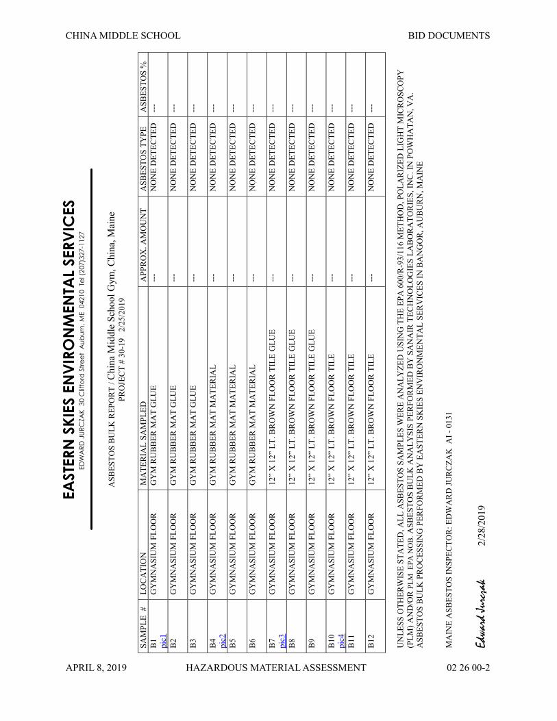
CHINA MIDDLE SCHOOL BID DOCUMENTS
APRIL 8, 2019 HAZARDOUS MATERIAL ASSESSMENT 02 26 00-2
EA
STER
N S
KIE
S E
NV
IRO
NM
EN
TA
L S
ER
VIC
ES
ED
WA
RD
JU
RC
ZAK
30 C
liffo
rd S
tre
et
Au
bu
rn,
ME
04210
Te
l (2
07)3
27-1
127
AS
BE
ST
OS
BU
LK
RE
PO
RT
/ C
hin
a M
idd
le S
cho
ol
Gym
, C
hin
a, M
ain
eP
RO
JEC
T #
30-1
9 2
/25/2
019
SA
MP
LE
#
LO
CA
TIO
NM
AT
ER
IAL
SA
MP
LE
DA
PP
RO
X. A
MO
UN
TA
SB
ES
TO
S T
YP
EA
SB
ES
TO
S %
B1
pic
1
GY
MN
AS
IUM
FL
OO
RG
YM
RU
BB
ER
MA
T G
LU
E--
-N
ON
E D
ET
EC
TE
D--
-
B2
GY
MN
AS
IUM
FL
OO
RG
YM
RU
BB
ER
MA
T G
LU
E--
-N
ON
E D
ET
EC
TE
D--
-
B3
GY
MN
AS
IUM
FL
OO
RG
YM
RU
BB
ER
MA
T G
LU
E--
-N
ON
E D
ET
EC
TE
D--
-
B4
pic
2
GY
MN
AS
IUM
FL
OO
RG
YM
RU
BB
ER
MA
T M
AT
ER
IAL
---
NO
NE
DE
TE
CT
ED
---
B5
GY
MN
AS
IUM
FL
OO
RG
YM
RU
BB
ER
MA
T M
AT
ER
IAL
---
NO
NE
DE
TE
CT
ED
---
B6
GY
MN
AS
IUM
FL
OO
RG
YM
RU
BB
ER
MA
T M
AT
ER
IAL
---
NO
NE
DE
TE
CT
ED
---
B7
pic
3
GY
MN
AS
IUM
FL
OO
R12”
X 1
2”
LT
. B
RO
WN
FL
OO
R T
ILE
GL
UE
---
NO
NE
DE
TE
CT
ED
---
B8
GY
MN
AS
IUM
FL
OO
R12”
X 1
2”
LT
. B
RO
WN
FL
OO
R T
ILE
GL
UE
---
NO
NE
DE
TE
CT
ED
---
B9
GY
MN
AS
IUM
FL
OO
R12”
X 1
2”
LT
. B
RO
WN
FL
OO
R T
ILE
GL
UE
---
NO
NE
DE
TE
CT
ED
---
B10
pic
4
GY
MN
AS
IUM
FL
OO
R12”
X 1
2”
LT
. B
RO
WN
FL
OO
R T
ILE
--
-N
ON
E D
ET
EC
TE
D--
-
B11
GY
MN
AS
IUM
FL
OO
R12”
X 1
2”
LT
. B
RO
WN
FL
OO
R T
ILE
---
NO
NE
DE
TE
CT
ED
---
B12
GY
MN
AS
IUM
FL
OO
R12”
X 1
2”
LT
. B
RO
WN
FL
OO
R T
ILE
---
NO
NE
DE
TE
CT
ED
---
UN
LE
SS
OT
HE
RW
ISE
ST
AT
ED
, A
LL
AS
BE
ST
OS
SA
MP
LE
S W
ER
E A
NA
LY
ZE
D U
SIN
G T
HE
EP
A 6
00/R
-93/1
16 M
ET
HO
D,
PO
LA
RIZ
ED
LIG
HT
MIC
RO
SC
OP
Y
(PL
M)
AN
D/O
R P
LM
E
PA
NO
B. A
SB
ES
TO
S B
UL
K A
NA
LY
SIS
PE
RF
OR
ME
D B
Y S
AN
AIR
TE
CH
NO
LO
GIE
S L
AB
OR
AT
OR
IES
, IN
C.
IN P
OW
HA
TA
N,
VA
.
AS
BE
ST
OS
BU
LK
PR
OC
ES
SIN
G P
ER
FO
RM
ED
BY
EA
ST
ER
N S
KIE
S E
NV
IRO
NM
EN
TA
L S
ER
VIC
ES
IN
BA
NG
OR
, A
UB
UR
N,
MA
INE
MA
INE
AS
BE
ST
OS
IN
SP
EC
TO
R:
ED
WA
RD
JU
RC
ZA
K A
I -
0131
Edwa
rd J
urcz
ak
2/2
8/2
01
9

CHINA MIDDLE SCHOOL BID DOCUMENTS
APRIL 8, 2019 HAZARDOUS MATERIAL ASSESSMENT 02 26 00-3
SURVEY PICTURES
China Middle School Gym, China, Maine
30-19
Rubber Mat Glue in Gym pic1 back1 Rubber Mat pic2 back2
12” x 12” Lt. Brown Floor Tile Glue pic3 back3 12” x 12” Lt. Brown Floor Tile pic4 back4

CHINA MIDDLE SCHOOL BID DOCUMENTS
APRIL 8, 2019 HAZARDOUS MATERIAL ASSESSMENT 02 26 00-4
Analyst: Tallert, Jonathan
Asbestos Bulk EPA PLM NOB EPA 600/R-93/116SanAir ID / Description Appearance % Fibrous % Non Fibrous Asbestos Types % Total Asbestos
19008708-001 / B1Gym Mat Glue
BrownNon-FibrousHomogeneous
None Detected
19008708-002 / B2Gym Mat Glue
BrownNon-FibrousHomogeneous
None Detected
19008708-003 / B3Gym Mat Glue
BrownNon-FibrousHomogeneous
None Detected
19008708-004 / B4Gym Mat
BeigeNon-FibrousHomogeneous
None Detected
19008708-005 / B5Gym Mat
BeigeNon-FibrousHomogeneous
None Detected
19008708-006 / B6Gym Mat
BeigeNon-FibrousHomogeneous
None Detected
19008708-007 / B712x12 Floor Tile Glue
BrownNon-FibrousHomogeneous
None Detected
19008708-008 / B812x12 Floor Tile Glue
BrownNon-FibrousHomogeneous
None Detected
19008708-009 / B912x12 Floor Tile Glue
BrownNon-FibrousHomogeneous
None Detected
19008708-010 / B1012x12 Floor Tile Glue
BrownNon-FibrousHomogeneous
None Detected
Analyst:
Analysis Date: 2/27/2019 Date: 2/27/2019
Approved Signatory:
30-19Project Number:P.O. Number:
Project Name: China Middle School2/25/2019Collected Date:2/26/2019 9:40:00 AMReceived Date:
2/27/2019 12:36:02 PM
19008708SanAir ID Number
FINAL REPORT
Eastern Skies Environmental ServicesName:Address: 406 Lake Street
Auburn, ME 04210207-327-1127Phone:
Page 3 of 6
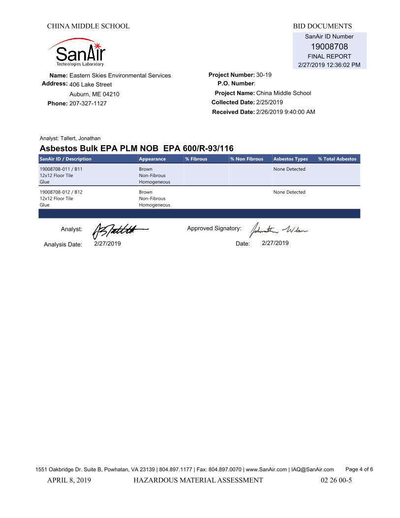
CHINA MIDDLE SCHOOL BID DOCUMENTS
APRIL 8, 2019 HAZARDOUS MATERIAL ASSESSMENT 02 26 00-5
Analyst: Tallert, Jonathan
Asbestos Bulk EPA PLM NOB EPA 600/R-93/116SanAir ID / Description Appearance % Fibrous % Non Fibrous Asbestos Types % Total Asbestos
19008708-011 / B1112x12 Floor Tile Glue
BrownNon-FibrousHomogeneous
None Detected
19008708-012 / B1212x12 Floor Tile Glue
BrownNon-FibrousHomogeneous
None Detected
Analyst:
Analysis Date: 2/27/2019 Date: 2/27/2019
Approved Signatory:
1551 Oakbridge Dr. Suite B, Powhatan, VA 23139 | 804.897.1177 | Fax: 804.897.0070 | www.SanAir.com | [email protected]
30-19Project Number:P.O. Number:
Project Name: China Middle School2/25/2019Collected Date:2/26/2019 9:40:00 AMReceived Date:
2/27/2019 12:36:02 PM
19008708SanAir ID Number
FINAL REPORT
Eastern Skies Environmental ServicesName:Address: 406 Lake Street
Auburn, ME 04210207-327-1127Phone:
Page 4 of 6

CHINA MIDDLE SCHOOL BID DOCUMENTS
APRIL 8, 2019 HAZARDOUS MATERIAL ASSESSMENT 02 26 00-6Page 6 of 6END OF SECTION 02 26 00

CHINA MIDDLE SCHOOL BID DOCUMENTS
APRIL 8, 2019 GEOTECHNICAL REPORT 02 32 00 - 1
DOCUMENT 02 32 00 – GEOTECHNICAL REPORT

REPORT 19-0094
February 13, 2019
Explorations and Geotechnical Engineering Services
Proposed Gymnasium Renovation & Addition China Middle School 773 Lakeview Drive (Route 202) China, Maine
Prepared For:RSU 18Attention: Carl Gartley, Superintendent41 Heath StreetOakland, ME 04963
Prepared By:S. W. Cole Engineering, Inc.26 Coles Crossing DriveSidney, ME 04330T: (207) 626-0600

TABLE OF CONTENTS
1.0 INTRODUCTION....................................................................................................... 1
1.1 Scope and Purpose ............................................................................................... 1
1.2 Site and Proposed Construction ............................................................................ 1
2.0 EXPLORATION AND TESTING................................................................................ 2
3.0 SUBSURFACE CONDITIONS .................................................................................. 2
3.1 Soil and Bedrock ................................................................................................... 2
3.2 Groundwater.......................................................................................................... 3
4.0 EVALUATION AND RECOMMENDATIONS............................................................. 3
4.1 General Findings ................................................................................................... 3
4.2 Site and Subgrade Preparation ............................................................................. 4
4.3 Excavation and Dewatering ................................................................................... 4
4.4 Foundations........................................................................................................... 4
4.5 Foundation Drainage ............................................................................................. 5
4.6 Slab-On-Grade ...................................................................................................... 5
4.7 Entrance Slabs and Sidewalks .............................................................................. 6
4.8 Fill, Backfill and Compaction.................................................................................. 6
4.9 Weather Considerations ........................................................................................ 7
4.10 Design Review and Construction Testing ............................................................ 7
5.0 CLOSURE................................................................................................................. 8
Appendix A Limitations
Appendix B Figures
Appendix C Exploration Logs & Key
Appendix D Laboratory Test Results

1
19-0094
February 13, 2019
RSU 18Attention: Carl Gartley, Superintendent41 Heath StreetOakland, ME 04963
Subject: Explorations and Geotechnical Engineering ServicesProposed Gymnasium Renovation & AdditionChina Middle School773 Lakeview Drive (Route 202)China, Maine
Dear Carl:
In accordance with our Proposal, dated January 24, 2019, we have performed
subsurface explorations for the subject project. This report summarizes our findings
and geotechnical recommendations and its contents are subject to the limitations set
forth in Appendix A.
1.0 INTRODUCTION
1.1 Scope and PurposeThe purpose of our services was to obtain subsurface information in order to provide
geotechnical recommendations for foundations and earthwork associated with the
proposed construction. Our scope of services included three test boring explorations,
soils laboratory testing, a geotechnical analysis of the subsurface findings and
preparation of this report.
1.2 Site and Proposed ConstructionThe project site is located at 773 Lakeview Drive (Route 202) in China, Maine. We
understand development plans call for construction of a new gymnasium addition on the
west side of the existing school and renovation of the existing gymnasium.

19-0094February 13, 2019
2
We anticipate the addition will be steel-framed with on-grade floor slab and spread
footing foundations. Details regarding proposed size, grading and structural loads are
not available at this time; however, we anticipate proposed finished floor elevation (FFE)
will match the existing gymnasium FFE of 103’-4” (project datum).
Proposed and existing site features are shown on the “Exploration Location Plan”
attached in Appendix B.
2.0 EXPLORATION AND TESTINGThree test borings (B-101 through B-103) were made at the site on February 4, 2019 by
S. W. Cole Explorations, LLC. The exploration locations were selected and established
in the field by S. W. Cole Engineering, Inc. (S.W.COLE) using measurements from
existing site features. The approximate exploration locations are shown on the
“Exploration Location Plan” attached in Appendix B. Logs of the explorations and a key
to the notes and symbols used on the logs are attached in Appendix C.
The test borings were drilled using hollow-stem auger techniques. The soils were
sampled at 2 to 5 foot intervals using a split spoon sampler and Standard Penetration
Testing (SPT) methods. SPT blow counts are shown on the logs. Soil samples
obtained from the explorations were returned to our laboratory for further classification
and testing. Moisture content test results are noted on the logs. The results of two
gradation tests are attached in Appendix D.
3.0 SUBSURFACE CONDITIONS
3.1 Soil and BedrockTest borings B-101 through B-103 were made in the area of the proposed building addition
and encountered a soils profile generally consisting of topsoil overlying loose silt with
varying amounts of sand and some gravel (fill) to a depth of about 3 feet overlying dense
glacial till. The glacial till generally consisted of silt and sand with some to trace gravel
with occasional cobbles. A refusal surface interpreted as a probable boulder was
encountered in boring B-103 at a depth of about 13 feet.

19-0094February 13, 2019
3
3.2 GroundwaterThe soils encountered at the test borings were moist to wet from the ground surface.
Saturated soils were encountered at depths varying from 15 to 18 feet. Groundwater likely
becomes perched on the relatively impervious glacial till encountered at the test borings.
Long term groundwater information is not available. It should be anticipated that
groundwater levels will fluctuate, particularly in response to periods of snowmelt and
precipitation, as well as changes in site use.
4.0 EVALUATION AND RECOMMENDATIONS
4.1 General FindingsBased on the subsurface findings, the proposed construction appears feasible from a
geotechnical standpoint. The principle geotechnical considerations include:
We recommend complete removal of the fills beneath the proposed building
addition. The over-excavated area should be backfilled with compacted Granular
Borrow.
Spread footing foundations and slab-on-grade floors bearing on properly prepared
subgrades appear suitable for the proposed building addition. Footings should bear
on at least 3 inches of compacted Crushed Stone overlying undisturbed native non-
organic soils. On-grade floor slabs should bear on at least 12-inches of properly
compacted Structural Fill overlying properly prepared subgrades.
Topsoil, organics (roots and stumps), fills and debris must be completely removed
from beneath the proposed building addition footprint and backfilled with properly
compacted Structural Fill.
Subgrades across the site will consist of moisture-sensitive glacial till soils.
Earthwork and grading activities should occur during drier, non-freezing weather of
Spring, Summer and Fall. Rubber tired construction equipment should not operate
directly on the native soils when wet. Excavation of bearing surfaces should be
completed with a smooth-edged bucket to lessen subgrade disturbance.

19-0094February 13, 2019
4
4.2 Site and Subgrade PreparationWe recommend site preparation begin with the construction of an erosion control system
to protect adjacent drainage ways and areas outside the construction limits. Surficial
organics, roots, topsoil and fill should be completely removed from the proposed addition
footprint and areas of proposed fill and construction. As much vegetation as possible
should remain outside the construction areas to lessen the potential for erosion and site
disturbance.
We recommend footings be excavated using a smooth-edged bucket and that footings be
underlain by at least 3 inches of Crushed Stone overlying properly prepared subgrades.
The Crushed Stone is intended for use as a working mat during construction. Over-
excavations to remove existing fills within the addition footprint should be backfilled with
compacted Granular Borrow.
4.3 Excavation and DewateringExcavation work will generally encounter fills and silty glacial till soils that are moisture-
sensitive and easily disturbed when wet. Care must be exercised during construction to
limit disturbance of the bearing soils. Earthwork and grading activities should occur during
drier, non-freezing weather of Spring, Summer and Fall. Rubber tired construction
equipment should not operate directly on the native glacial till, when wet. Final cuts to
subgrade should be performed with a smooth-edged bucket to help reduce strength loss
from soil disturbance.
Sumping and pumping dewatering techniques should be adequate to control groundwater
in excavations. Controlling the water levels to at least one foot below planned excavation
depths will help stabilize subgrades during construction. Excavations must be properly
shored or sloped in accordance with OSHA Regulations to prevent sloughing and caving
of the sidewalls during construction. Care must be taken to preclude undermining
adjacent structures, utilities and roadways. The design and planning of excavations,
excavation support systems, and dewatering is the responsibility of the contractor.
4.4 FoundationsWe recommend the proposed building addition be supported on spread footings
founded on at least 3-inches of Crushed Stone bearing on undisturbed dense glacial till.

19-0094February 13, 2019
5
For foundations bearing on properly prepared subgrades, we recommend the following
geotechnical parameters for design consideration:
Geotechnical Parameters for Spread Footings and Foundation WallsDesign Frost Depth (100 year AFI) 5 feetNet Allowable Soil Bearing Pressure 4.5 ksfBase Friction Factor 0.35Total Unit Weight of Backfill 125 pcfAt-Rest Lateral Earth Pressure Coefficient 0.5Internal Friction Angle of Backfill 30°Seismic Soil Site Class D (IBC 2015)Estimated Total Settlement 1-inchDifferential Settlement ½-inch
4.5 Foundation DrainageWe recommend an underdrain system be installed on the outside edge of perimeter
footings. The underdrain pipe should consist of 4-inch diameter, perforated SDR-35
foundation drain pipe bedded in Crushed Stone and wrapped in non-woven geotextile
fabric. The underdrain pipe must have a positive gravity outlet protected from freezing,
clogging and backflow. Surface grades should be sloped away from the building for
positive surface water drainage. General underdrain details are illustrated on the
“Foundation Detail Sketch” attached in Appendix B.
4.6 Slab-On-GradeOn-grade floor slabs in heated areas may be designed using a subgrade reaction
modulus of 100 pci (pounds per cubic inch) provided the slab is underlain by at least 12-
inches of compacted Structural Fill placed over properly prepared subgrades. The
structural engineer or concrete consultant must design steel reinforcing and joint
spacing appropriate to slab thickness and function.
We recommend a sub-slab vapor retarder particularly in areas of the building where the
concrete slab will be covered with an impermeable surface treatment or floor covering
that may be sensitive to moisture vapors. The vapor retarder must have a permeance
that is less than the floor cover or surface treatment that is applied to the slab. The
vapor retarder must have sufficient durability to withstand direct contact with the sub-
slab base material and construction activity. The vapor retarder material should be
placed according to the manufacturer’s recommended method, including the taping and

19-0094February 13, 2019
6
lapping of all joints and wall connections. The architect and/or flooring consultant
should select the vapor retarder products compatible with flooring and adhesive
materials.
The floor slab should be appropriately cured using moisture retention methods after
casting. Typical floor slab curing methods should be used for at least 7 days. The
architect or flooring consultant should assign curing methods consistent with current
applicable American Concrete Institute (ACI) procedures with consideration of curing
method compatibility to proposed surface treatments, flooring and adhesive materials.
4.7 Entrance Slabs and SidewalksEntrance slabs and sidewalks adjacent to the building must be designed to reduce the
effects of differential frost action between adjacent pavement, doorways, and entrances.
We recommend that non-frost susceptible Structural Fill be provided to a depth of at
least 5 feet below the top of entrance slabs. This thickness of Structural Fill should
extend the full width of the entrance slab and outward at least 5 feet, thereafter
transitioning up to the bottom of the adjacent sidewalk or pavement gravels at a 3H:1V
or flatter slope. General details of this frost transition zone are shown on the
“Foundation Detail Sketch” attached in Appendix B.
4.8 Fill, Backfill and CompactionWe recommend the following fill and backfill materials: recycled products must also be
tested in accordance with applicable environmental regulations and approved by a
qualified environmental consultant.
Granular Borrow: Fill to raise grades in building areas following over-excavation, as
well as to repair soft areas, should be sand or silty sand meeting the requirements of
2014 MaineDOT Standard Specification 703.19 Granular Borrow.
Structural Fill: Backfill for foundations, 12 inch slab base material and material below
exterior entrances slabs should be clean, non-frost susceptible sand and gravel meeting
the gradation requirements for Structural Fill as given below:

19-0094February 13, 2019
7
Structural FillSieve Size Percent Finer by Weight
4 inch 1003 inch 90 to 100¼ inch 25 to 90No. 40 0 to 30No. 200 0 to 6
Crushed Stone: Crushed Stone, used beneath foundations and for underdrain
aggregate should be washed ¾-inch crushed stone meeting the requirements of 2014
MaineDOT Standard Specification 703.22 Underdrain Backfill Material Type C.
Reuse of Site Soils: The on-site soils are unsuitable for reuse in building areas, but
may be suitable for reuse as Common Borrow in landscape areas, provided they are at
a compactable moisture content at the time of reuse.
Placement and Compaction: Fill should be placed in horizontal lifts and compacted
such that the desired density is achieved throughout the lift thickness with 3 to 5 passes
of the compaction equipment. Loose lift thicknesses for grading, fill and backfill
activities should not exceed 12 inches. We recommend that fill and backfill in building
and paved areas be compacted to at least 95 percent of its maximum dry density as
determined by ASTM D-1557. Crushed Stone should be compacted with 3 to 5 passes
of a vibratory plate compactor having a static weight of at least 500 pounds.
4.9 Weather Considerations Construction activity should be limited during wet and freezing weather and the site soils
may require drying or thawing before construction activities may continue. The contractor
should anticipate the need for water to temper fills in order to facilitate compaction during
dry weather. If construction takes place during cold weather, subgrades, foundations and
floor slabs must be protected during freezing conditions. Concrete and fill must not be
placed on frozen soil; and once placed, the concrete and soil beneath the structure must
be protected from freezing.
4.10 Design Review and Construction TestingS.W.COLE should be retained to review the construction documents prior to bidding to
determine that our earthwork and foundation recommendations have been properly
interpreted and implemented.

19-0094February 13, 2019
8
A soils and concrete testing program should be implemented during construction to
observe compliance with the design concepts, plans, and specifications. S.W.COLE is
available to observe earthwork activities, the preparation of foundation bearing surfaces
and pavement subgrades, as well as to provide testing and IBC Special Inspection
services for soils, concrete, steel, spray-applied fireproofing, structural masonry and
asphalt construction materials.
5.0 CLOSUREIt has been a pleasure to be of assistance to you with this phase of your project. We
look forward to working with you during the construction-phase of the project.
Sincerely,
S. W. Cole Engineering, Inc.
Michael A. St. Pierre, P.E.Senior Geotechnical Engineer
MAS:rec
Michael St. Pierre, P.E. 2019.02.13 13:33:28 -05'00'

APPENDIX A
Limitations
This report has been prepared for the exclusive use of RSU 18 for specific application to
the proposed China Middle School Gymnasium Renovation and Addition project at 773
Lakeview Drive (Route 202) in China, Maine. S. W. Cole Engineering, Inc. (S.W.COLE)
has endeavored to conduct our services in accordance with generally accepted soil and
foundation engineering practices. No warranty, expressed or implied, is made.
The soil profiles described in the report are intended to convey general trends in
subsurface conditions. The boundaries between strata are approximate and are based
upon interpretation of exploration data and samples.
The analyses performed during this investigation and recommendations presented in
this report are based in part upon the data obtained from subsurface explorations made
at the site. Variations in subsurface conditions may occur between explorations and
may not become evident until construction. If variations in subsurface conditions
become evident after submission of this report, it will be necessary to evaluate their
nature and to review the recommendations of this report.
Observations have been made during exploration work to assess site groundwater
levels. Fluctuations in water levels will occur due to variations in rainfall, temperature,
and other factors.
S.W.COLE’s scope of services has not included the investigation, detection, or prevention
of any Biological Pollutants at the project site or in any existing or proposed structure at the
site. The term “Biological Pollutants” includes, but is not limited to, molds, fungi, spores,
bacteria, and viruses, and the byproducts of any such biological organisms.
Recommendations contained in this report are based substantially upon information
provided by others regarding the proposed project. In the event that any changes are
made in the design, nature, or location of the proposed project, S.W.COLE should
review such changes as they relate to analyses associated with this report.
Recommendations contained in this report shall not be considered valid unless the
changes are reviewed by S.W.COLE.

APPENDIX B
Figures

L A
K E
V I
E W
D
R I
V E
( R
O U
T E
2
0 2
)
B-1
01B
-102
AP
PR
OX
IMA
TE 2
5 X
84
FOO
TA
DD
ITIO
N E
NV
ELO
PE
B-1
03
Job
No.
:D
ate
:S
cale
:S
heet
:1"
= 5
0'1
S.W
.CO
LEE N
G I N
E E R I
N G , I N
C .
LEG
EN
D:
AP
PR
OX
IMA
TE B
OR
ING
LO
CA
TIO
N
NO
TES
:
1.E
XP
LOR
ATI
ON
LO
CA
TIO
N P
LAN
WA
S P
RE
PA
RE
D F
RO
M A
1"=
30' S
CA
LE P
LAN
OF
THE
SIT
E E
NTI
TLE
D "S
ITE
PLA
N,"
PR
EP
AR
ED
BY
PLY
MO
UTH
EN
GIN
EE
RIN
G, I
NC
., D
ATE
DJU
LY 2
1, 1
998
AN
D P
RO
VID
ED
AS
A P
OR
TAB
LED
OC
UM
EN
T FO
RM
AT
(PD
F) F
ILE
.
2.TH
E B
OR
ING
S W
ER
E L
OC
ATE
D IN
TH
E F
IELD
BY
TA
PE
DM
EA
SU
RE
ME
NTS
FR
OM
EX
ISTI
NG
SIT
E F
EA
TUR
ES
.
3.TH
IS P
LAN
SH
OU
LD B
E U
SE
D IN
CO
NJU
NC
TIO
N W
ITH
TH
EA
SS
OC
IATE
D S
. W. C
OLE
EN
GIN
EE
RIN
G, I
NC
.G
EO
TEC
HN
ICA
L R
EP
OR
T.
4.TH
E P
UR
PO
SE
OF
THIS
PLA
N IS
ON
LY T
O D
EP
ICT
THE
LOC
ATI
ON
OF
THE
EX
PLO
RA
TIO
NS
IN R
ELA
TIO
N T
O T
HE
EX
ISTI
NG
CO
ND
ITIO
NS
AN
D P
RO
PO
SE
D C
ON
STR
UC
TIO
NA
ND
IS N
OT
TO B
E U
SE
D F
OR
CO
NS
TRU
CTI
ON
.
Feet
050
100
RS
U 1
8
CH
INA
MID
DLE
SC
HO
OL
773
LAK
EV
IEW
DR
IVE
(R
OU
TE 2
02)
CH
INA
, MA
INE
19-0
094
02/1
3/20
19
EX
PLO
RA
TIO
N L
OC
ATI
ON
PLA
N
R:\2
019\1
9-0
094\C
AD
\Dra
win
gs\1
9-0
094 E
LP.d
wg,
4/1
/2019 1
0:5
9:4
5 A
M, 1:1
, CEM
, S.W
. Col
e En
gine
erin
g, In
c.

STRUCTURAL FILL
STRUCTURAL FILL
SLOPEDSUBGRADE
3
1
12" M
IN.
5.0'
MIN
.
HEATED SPACEEXTERIOR
FOUNDATION WALL
ENTRANCE SLAB
PAVEMENT
PAVEMENT BASE
PAVEMENT SUBBASE
PERFORATED UNDERDRAIN PIPEBEDDED IN 3/4" CRUSHED
STONE WRAPPED IN GEOTEXTILEFILTER FABRIC PROPERLY PREPARED
SUBGRADE(SEE REPORT)
VAPOR RETARDERFLOOR SLAB
3" OF 3/4" CRUSHED STONE
THERMAL BREAK
RIGID INSULATION (TYP)
NOTE:
1. UNDERDRAIN INSTALLATIONAND MATERIAL GRADATIONRECOMMENDATIONS ARECONTAINED WITHIN THISREPORT.
2. DETAIL IS PROVIDED FORILLUSTRATIVE PURPOSES ONLY,NOT FOR CONSTRUCTION.
Job No.:Date :
Scale:Sheet:
FOUNDATION DETAIL SKETCH
Not to Scale2
RSU 18
CHINA MIDDLE SCHOOL773 LAKEVIEW DRIVE (ROUTE 202)
CHINA, MAINE
19-009402/12/2019
R:\2
019\
19-0
094\
CA
D\D
raw
ings
\19-
0094
FD
S.d
wg,
2/1
2/20
19 3
:43:
53 P
M, 1
:1, C
EM, S
. W. C
ole
Engi
neer
ing,
Inc.

APPENDIX C
Exploration Logs and Key


KEY TO NOTES & SYMBOLSTest Boring and Test Pit Explorations
Stratification lines represent the approximate boundary between soil types and the transition may be gradual.
Key to Symbols Used:
w - water content, percent (dry weight basis)qu - unconfined compressive strength, kips/sq. ft. - laboratory testSv - field vane shear strength, kips/sq. ft.Lv - lab vane shear strength, kips/sq. ft.qp - unconfined compressive strength, kips/sq. ft. – pocket penetrometer testO - organic content, percent (dry weight basis)WL - liquid limit - Atterberg testWP - plastic limit - Atterberg testWOH - advance by weight of hammerWOM - advance by weight of manWOR - advance by weight of rodsHYD - advance by force of hydraulic piston on drillRQD - Rock Quality Designator - an index of the quality of a rock mass.
T - total soil weightB - buoyant soil weight
Description of Proportions: Description of Stratified Soils
Parting: 0 to 1/16” thicknessTrace: 0 to 5% Seam: 1/16” to 1/2” thicknessSome: 5 to 12% Layer: ½” to 12” thickness“Y” 12 to 35% Varved: Alternating seams or layersAnd 35+% Occasional: one or less per foot of thicknessWith Undifferentiated Frequent: more than one per foot of thickness
REFUSAL: Test Boring Explorations - Refusal depth indicates that depth at which, in the drill foreman's opinion, sufficient resistance to the advance of the casing, auger, probe rod or sampler was encountered to render further advance impossible or impracticable by the procedures and equipment being used.
REFUSAL: Test Pit Explorations - Refusal depth indicates that depth at which sufficient resistance to the advance of the backhoe bucket was encountered to render further advance impossible or impracticable by the procedures and equipment being used.
Although refusal may indicate the encountering of the bedrock surface, it may indicate the striking of large cobbles, boulders, very dense or cemented soil, or other buried natural or man-made objects or it may indicate the encountering of a harder zone after penetrating a considerable depth through a weathered or disintegrated zone of the bedrock.

APPENDIX D
Laboratory Test Results


CHINA MIDDLE SCHOOL BID DOCUMENTS
APRIL 8, 2019 GEOTECHNICAL REPORT 02 32 00 - 24
END OF SECTION 02 32 00

CHINA MIDDLE SCHOOL BID DOCUMENTS
APRIL 8, 2019 SELECTIVE DEMOLITION 02 41 19 - 1
SECTION 02 41 19 - SELECTIVE DEMOLITION
PART 1 - GENERAL
1.1 SUMMARY
A. Section Includes:
1. Demolition and removal of selected portions of building or structure. 2. Salvage of existing items to be reused or recycled.
1.2 REFERENCES
A. ANSI/ASSE A10.6: Safety & Health Program Requirements for Demolition Operations.
B. NFPA 241: Standard for Safeguarding Construction, Alteration, and Demolition Operations.
1.3 DEFINITIONS
A. Remove (R): Detach items from existing construction and legally dispose of them off-site unless indicated to be removed and salvaged or removed and reinstalled.
B. Remove and Salvage (S): Detach items from existing construction in a manner to prevent
damage, and deliver to Owner.
C. Remove and Reinstall (P): Detach items from existing construction in a manner to prevent damage, prepare for reuse, and reinstall where indicated.
D. Existing to Remain (E): Existing items of construction that are not to be permanently removed
and that are not otherwise indicated to be removed, removed and salvaged, or removed and reinstalled.
1.4 PREINSTALLATION MEETINGS
A. Predemolition Conference: Conduct conference at Project site.
1.5 FIELD CONDITIONS
A. Owner will occupy portions of building immediately adjacent to selective demolition area.
Conduct selective demolition so Owner's operations will not be disrupted.
B. Conditions existing at time of inspection for bidding purpose will be maintained by Owner as far as practical.
1. Before selective demolition, Owner will remove the following items:

CHINA MIDDLE SCHOOL BID DOCUMENTS
APRIL 8, 2019 SELECTIVE DEMOLITION 02 41 19 - 2
a. Loose items.
C. Notify Architect of discrepancies between existing conditions and Drawings before proceeding
with selective demolition.
D. Storage or sale of removed items or materials on-site is not permitted.
1.6 WARRANTY
A. Existing Warranties: Remove, replace, patch, and repair materials and surfaces cut or damaged
during selective demolition, by methods and with materials so as not to void existing warranties.
PART 2 - PRODUCTS
2.1 PEFORMANCE REQUIREMENTS
A. Regulatory Requirements: Comply with governing EPA notification regulations before
beginning selective demolition. Comply with hauling and disposal regulations of authorities having jurisdiction.
B. Standards: Comply with ANSI/ASSE A10.6 and NFPA 241.
PART 3 - EXECUTION
3.1 EXAMINATION
A. Verify that utilities have been disconnected and capped before starting selective demolition
operations.
B. Survey existing conditions and correlate with requirements indicated to determine extent of selective demolition required.
C. When unanticipated mechanical, electrical, or structural elements that conflict with intended
function or design are encountered, investigate and measure the nature and extent of conflict. Promptly submit a written report to Architect.
3.2 UTILITY SERVICES AND MECHANICAL/ELECTRICAL SYSTEMS
A. Existing Services/Systems to Remain: Maintain services/systems indicated to remain and
protect them against damage.
B. Existing Services/Systems to Be Removed, Relocated, or Abandoned: Locate, identify,
disconnect, and seal or cap off indicated utility services and mechanical/electrical systems
serving areas to be selectively demolished. 1. Arrange to shut off indicated utilities with utility companies.

CHINA MIDDLE SCHOOL BID DOCUMENTS
APRIL 8, 2019 SELECTIVE DEMOLITION 02 41 19 - 3
2. If services/systems are required to be removed, relocated, or abandoned, provide temporary services/systems that bypass area of selective demolition and that maintain
continuity of services/systems to other parts of building.
3.3 PREPARATION
A. Site Access and Temporary Controls: Conduct selective demolition and debris-removal operations to ensure minimum interference with roads, streets, walks, walkways, and other
adjacent occupied and used facilities.
1. Comply with requirements for access and protection specified in Section 015000 "Temporary Facilities and Controls."
B. Temporary Facilities: Provide temporary barricades and other protection required to prevent
injury to people and damage to adjacent buildings and facilities to remain.
C. Temporary Shoring: Provide and maintain shoring, bracing, and structural supports as required
to preserve stability and prevent movement, settlement, or collapse of construction and finishes
to remain, and to prevent unexpected or uncontrolled movement or collapse of construction
being demolished.
3.4 SELECTIVE DEMOLITION, GENERAL
A. General: Demolish and remove existing construction only to the extent required by new
construction and as indicated. Use methods required to complete the Work within limitations of governing regulations and as follows:
1. Neatly cut openings and holes plumb, square, and true to dimensions required. Use
cutting methods least likely to damage construction to remain or adjoining construction. Use hand tools or small power tools designed for sawing or grinding, not hammering and
chopping, to minimize disturbance of adjacent surfaces. Temporarily cover openings to
remain.
2. Cut or drill from the exposed or finished side into concealed surfaces to avoid marring existing finished surfaces.
3. Do not use cutting torches until work area is cleared of flammable materials. At
concealed spaces, such as duct and pipe interiors, verify condition and contents of hidden space before starting flame-cutting operations. Maintain portable fire-suppression
devices during flame-cutting operations.
4. Locate selective demolition equipment and remove debris and materials so as not to
impose excessive loads on supporting walls, floors, or framing. 5. Dispose of demolished items and materials promptly. Comply with requirements in
Section 017419 "Construction Waste Management and Disposal."
B. Removed and Salvaged Items:
1. Clean salvaged items.
2. Pack or crate items after cleaning. Identify contents of containers.
3. Store items in a secure area until delivery to Owner. 4. Transport items to Owner's storage area designated by Owner.

CHINA MIDDLE SCHOOL BID DOCUMENTS
APRIL 8, 2019 SELECTIVE DEMOLITION 02 41 19 - 4
5. Protect items from damage during transport and storage.
C. Removed and Reinstalled Items:
1. Clean and repair items to functional condition adequate for intended reuse.
2. Pack or crate items after cleaning and repairing. Identify contents of containers.
3. Protect items from damage during transport and storage. 4. Reinstall items in locations indicated. Comply with installation requirements for new
materials and equipment. Provide connections, supports, and miscellaneous materials
necessary to make item functional for use indicated.
D. Existing Items to Remain: Protect construction indicated to remain against damage and soiling
during selective demolition. When permitted by Architect, items may be removed to a suitable,
protected storage location during selective demolition and cleaned and reinstalled in their original locations after selective demolition operations are complete.
E. Scope of Demolition: The project may require Removal, Removal and Salvage, Removal and
Reinstallation, and Patching not indicated in Drawings, but necessary to accomplish the Work
shown in the Contract Documents.
3.5 DISPOSAL OF DEMOLISHED MATERIALS
A. General: Except for items or materials indicated to be reused, salvaged, reinstalled, or
otherwise indicated to remain on Owner's property, remove demolished materials from Project site and legally dispose of them in an EPA-approved landfill.
1. Do not allow demolished materials to accumulate on-site.
2. Remove and transport debris in a manner that will prevent spillage on adjacent surfaces and areas.
3. Remove debris from elevated portions of building by chute, hoist, or other device that
will convey debris to grade level in a controlled descent.
4. Comply with requirements specified in Section 017419 "Construction Waste Management and Disposal."
B. Burning: Do not burn demolished materials.
C. Disposal: Transport demolished materials off Owner's property and legally dispose of them.
3.6 CLEANING
A. Clean adjacent structures and improvements of dust, dirt, and debris caused by selective
demolition operations. Return adjacent and proximate areas to condition existing before
selective demolition operations began.
END OF SECTION 02 41 19

CHINA MIDDLE SCHOOL BID DOCUMENTS
8 APRIL 2019 CAST-IN-PLACE CONCRETE 03 30 00 - 1 .
SECTION 03 30 00 – CAST -IN-PLACE CONCRETE
PART 1 GENERAL
1.01 RELATED DOCUMENTS
A. The drawings and general conditions of the contract including General and Supplementary
Conditions and other Division 1 Specification sections apply to work of this section.
B. Examine all other sections of the Specifications for requirements which affect work of this
Section whether or not such work is specifically mentioned in this Section.
C. Coordinate work with that of all trades affecting or affected by work of this Section. Cooperate
with such trades to assure the steady progress of all work under the Contract.
1.02 DESCRIPTION OF WORK:
A. Work included: Provide labor, materials, and equipment necessary to complete the work of this
Section and, without limiting the generality thereof, furnish and include the following:
1. The extent of cast-in-place concrete work is shown on drawings and includes (but not by
way of limitation) formwork, reinforcing, cast-in-place concrete, accessories, finishing,
and casting in of items specified under other Sections of the Specifications or furnished
by Owner that are required to be built-in with the concrete.
2. Equipment support pads indicated on mechanical drawings to be installed by the
Building Contractor.
3. Cast-in-place retaining walls, exterior slabs on grade and other concrete shown on site
drawings.
1.03 RELATED WORK:
A. Expansion Anchors - Section 05 12 00
B. Anchor Bolts: Section 05 12 00
C. Underslab Vapor Retarders/Wall Waterproofing: Division 7
1.04 QUALITY ASSURANCE:
A. Codes and Standards: Comply with provisions of the latest edition of the following except where
more stringent requirements are shown or specified:
1. ACI “Manual of Concrete Practice”.
2. ACI 117 “Standard Specifications for Tolerances for Concrete Construction and
Materials”.
3. ACI 211.1 "Standard Practice for Selecting Proportions for Normal, Heavyweight and
Mass Concrete."

CHINA MIDDLE SCHOOL BID DOCUMENTS
8 APRIL 2019 CAST-IN-PLACE CONCRETE 03 30 00 - 2 .
4. ACI 212.3R "Chemical Admixtures for Concrete."
5. ACI 301 "Specifications for Structural Concrete for Buildings."
6. ACI 302.1R "Guide for Concrete Floor and Slab Construction."
7. ACI 304R "Guide for Measuring, Mixing, Transporting and Placing Concrete."
8. ACI 304.2R "Placing Concrete by Pumping Methods."
9. ACI 306 R "Cold Weather Concreting."
10. ACI 308 “Standard Practice for Curing Concrete."
11. ACI 309R "Guide for Consolidation of Concrete."
12. ACI 315 "ACI Detailing Manual."
13. ACI 318 "Building Code Requirements for Reinforced Concrete."
14. ACI 347R "Guide to Formwork for Concrete."
15. Concrete Reinforcing Steel Institute, "Placing Reinforcing Bars."
16. AISC “Code of Standard Practice for Steel Buildings and Bridges.”
17. “Code of Federal Regulations, Part 1926” per the Occupational Safety and Health
Administration (OSHA), Department of Labor (Latest Revision).
B. Materials and installed work may require testing and retesting, as directed by the Architect, at
any time during progress of work. Allow free access to material stockpiles and facilities. Tests
not specifically indicated to be done at Owner's expense, including retesting of rejected materials
and installed work, shall be done at Contractor's expense.
1.05 SUBMITTALS:
A. Unless otherwise specified, submittals required in this section shall be submitted for review.
Submittals shall be prepared and submitted in accordance with Division 1.
B. General Contractor shall submit a Submittal Schedule to the engineer within 30 days after they
have received the Owner’s Notice to Proceed.
C. All submittals shall be reviewed and returned to the Architect within 10 working days.
D. Incomplete submittals will not be reviewed.
E. Submittals not reviewed by the General Contractor prior to submission to the Engineer will not
be reviewed. Include on the submittal statement or stamp of approval by Contractor,
representing that the Contractor has seen and examined the submittal and that all requirements
listed in this Section and Division 1 have been complied with.

CHINA MIDDLE SCHOOL BID DOCUMENTS
8 APRIL 2019 CAST-IN-PLACE CONCRETE 03 30 00 - 3 .
F. Engineer will review submittals a maximum of two review cycles as part of their normal services.
If submittals are incomplete or otherwise unacceptable and re-submitted, General Contractor
shall compensate Engineer for additional review cycles.
G. Hardcopy Submittals: Submit three prints. Prints will be reviewed by the Engineer, and then the
Architect. One marked print will be returned to Contractor for printing and distribution. Multiple
copies will not be marked by the Engineer.
H. Electronic Submittals:
1. Contractor shall include in the submittal schedule an indication of submittals that are
intended to be submitted electronically. Upon receipt of the submittal schedule, the
Engineer reserves the right to indicate submittals that will not be accepted electronically.
Paper copies of such submittals shall be furnished as referenced in this specification.
2. The Engineer reserves the right to require paper copies of submittals that are received
electronically. Provide Engineer one (1) paper copies in addition to the electronic
submittal. Paper copy will be retained and electronic copy will be returned. Review
cycle for such submittals shall not commence until such time that the paper copies are
received.
3. Electronic Submittals shall be submitted in Protected Document Format (PDF).
Electronic files shall not be broken into smaller individual files. File sizes too large to
process email or within a file transfer protocol (FTP) site shall be provided on a CD.
4. The submission of submittals electronically does not relieve the contractor of their
responsibility to review the submittal prior to transmission to the Engineer. Electronic
Submittals shall include contractor comments, and a statement and/or stamp of approval
by Contractor, representing that the Contractor has seen and examined the submittal and
that all requirements listed in this Section and Division 1 have been complied with.
Electronic submittals without the Contractor’s approval will be rejected and returned.
5. The Engineer assumes no responsibility for the printed reproduction of submittals
reviewed electronically, transmission errors or returned electronic submittals that
become corrupted or are otherwise not accessible by the Contractor’s or Subcontractor’s
computer hardware and/or software.
I. Product Data: Submit producer’s or manufacturer’s specifications and installation instructions for
the following products. Include laboratory test reports and other data to show compliance with
specifications (including specified standards).
1. Reinforcement certified mill reports covering chemical and physical properties and yield
strength.
2. Patching products.
3. Non-shrink grout.
4. Curing compounds, where applicable.
5. Admixtures.

CHINA MIDDLE SCHOOL BID DOCUMENTS
8 APRIL 2019 CAST-IN-PLACE CONCRETE 03 30 00 - 4 .
6. Expansion/Adhesive Anchors.
J. Shop Drawings:
1. Shop Drawing Preparation: Electronic files of structural drawings will not be provided
to the contractor for preparation of shop drawings. Reproduction of any portion of the
Construction Documents for use as Shop drawings is prohibited. Shop drawings created
from reproduced Construction Documents will be returned without review. Submit shop
drawings for fabrication, bending and placement of concrete reinforcement. Comply
with ACI 315, showing bar schedules, stirrup and tie spacing, diagrams of bent bars, and
arrangement of concrete reinforcement. Include special reinforcement required at
openings through concrete elements. Include supplemental reinforcing and bar supports
necessary to support reinforcing steel at proper location within forms or slabs.
a. Review of the shop drawings will be made for the size and arrangement of
reinforcement. Conformance of the Shop Drawings to the Contract Drawings
remains the responsibility of the General Contractor. Engineer’s review in no
way relieves the General Contractor of this responsibility.
b. Shop drawings will not be reviewed as partial submittals. A complete
submittal shall be provided all items listed prior. Incomplete submittals will
not be reviewed.
K. Mix designs: Submit all laboratory test reports and materials for each mix design listed within.
Prepare mixes by the field experience method and/or trial mixtures per the requirements of
chapter 5 of ACI 318. Include the calculation of average strength and standard deviation.
Proportioning by water cement ratio method will not be permitted.
L. Samples: Submit samples of materials as specified and as otherwise requested by Architect,
including names, sources and descriptions.
M. Hot and Cold Weather Concrete Procedures: Submit a detailed written procedures for placement
of concrete at the temperatures anticipated for the project. Include, but not by limitation,
subgrade protection and/or heating, production/ready mix methods, transportation and conveying
methods, placement, protection, termination of protection, curing and quality control/monitoring
procedures. Procedures shall meet the requirements of the latest edition of ACI 305.1 and ACI
306.1 for hot weather and cold weather concreting, respectively.
N. Curing Methods: Submit documentation of curing methods to be used for review. Account for
anticipated project temperature ranges and conditions in curing methods.
O. Contraction/Construction Joints: Submit plan indicating proposed location of contraction and
construction joints in walls and slabs.
P. Test Reports: Test reports shall be submitted to the Owner, Architect and Engineer within 48
hour after completion of each test.
PART 2 PRODUCTS
2.01 FORM MATERIALS:

CHINA MIDDLE SCHOOL BID DOCUMENTS
8 APRIL 2019 CAST-IN-PLACE CONCRETE 03 30 00 - 5 .
A. Forms for Exposed Finish Concrete: Unless otherwise indicated, construct formwork for
exposed concrete surfaces with plywood, metal, metal-framed plywood faced or other acceptable
panel-type materials, to provide continuous, straight, smooth, exposed surfaces. Furnish in
largest practicable sizes to minimize number of joints and to conform to joint system shown on
drawings. Provide form material with sufficient thickness to withstand pressure of newly-placed
concrete without bow or deflection.
1. Use plywood complying with U.S. Product Standard PS-1 "B-B (Concrete Form)
Plywood", Class I, Exterior Grade or better, mill-oiled and edge-sealed, with piece
bearing legible inspection trademark.
B. Forms for Unexposed Finish Concrete: Form concrete surfaces which will be unexposed in
finished structure with plywood, lumber, metal or other acceptable material. Provide lumber
dressed on at least 2 edges and one side for tight fit.
C. Form Coatings: Provide commercial formulation form-coating compounds that will not bond
with, stain nor adversely affect concrete surfaces, and will not impair subsequent treatments of
concrete surfaces.
2.02 REINFORCING MATERIALS:
A. Reinforcing Bars: ASTM A 615, Grade 60, deformed.
B. Welded Wire Fabric: ASTM A 185, welded steel wire fabric. Provide welded wire fabric in flat
sheets.
C. Supports for Reinforcement: Provide supports for reinforcement including bolsters, chairs,
spacers, and other devices for spacing, supporting and fastening reinforcing bars and welded wire
fabric in place. Use plastic, wire bar type supports or concrete block supports complying with
CRSI recommendations, unless otherwise specified. Wood, clay brick and other unspecified
devices are not acceptable.
1. For slabs-on-grade, use supports with sand plates or horizontal runners where base
material will not support chair legs.
2. For exposed-to-view concrete surfaces, where legs of supports are in contact with forms,
provide supports with legs which are plastic protected (CRSI, Class I) or stainless steel
protected (CRSI, Class 2).
2.03 CONCRETE MATERIALS:
A. Single-Source Supplier: Ready-mix concrete shall be from one supplier unless specific written
approval is received from the Structural Engineer.
B. Portland Cement: ASTM C 150, Type I or Type II, unless otherwise approved Use one brand of
cement throughout project, unless otherwise acceptable to Architect.
C. Normal Weight Aggregates: ASTM C 33. Provide from a single source for exposed concrete.
Do not use aggregates containing soluble salts or other substances such as iron sulfides, pyrite,
marcasite, or ochre which can cause stains on exposed concrete surfaces.
D. Light Weight Aggregates: ASTM C 330.

CHINA MIDDLE SCHOOL BID DOCUMENTS
8 APRIL 2019 CAST-IN-PLACE CONCRETE 03 30 00 - 6 .
E. Water: Potable.
F. Air-Entraining Admixture: ASTM C 260.
G. High-Range Water-Reducing Admixture (Super Plasticizer): ASTM C 494, Type F or Type G
containing not more than 1% chloride ions.
H. Fiber reinforcement shall be Type III Synthetic Virgin Homopolymer Polypropylene Fibers
conforming to ASTM C1116. Fiber reinforcing shall be added and distributed prior to
incorporation of Super Plasticizer.
I. Normal range water reducing admixture: ASTM C 494 Type A containing no calcium chloride.
J. Accelerating Admixture: ASTM C 494, Type C or E.
K. Air Detraining Admixture: ASTM C494, Type S, Specific Performance Admixture
L. Blast Furnace Slag: ASTM C989
M. Fly Ash: ASTM C618, Class C or F
N. Calcium Chloride is not permitted.
2.04 RELATED MATERIALS:
A. Underslab Vapor Retarder: Provide vapor retarder over prepared sub base. Refer to
architectural drawings, geotechnical report and/or division 7 specifications for additional
requirements and vapor retarder location.
B. Non-Shrink Cement-based Grout: Provide grout consisting of pre-measured, prepackaged
materials supplied by the manufacturer requiring only the addition of water. Manufacturer's
instructions must be printed on the outside of each bag.
1. Non-shrink: No shrinkage (0.0%) and a maximum 4.0% expansion when tested in
accordance with ASTM C-827. No shrinkage (0.0%) and a maximum of 0.3%
expansion in the hardened state when tested in accordance with CRD-C-621.
2. Compressive strength: A minimum 28 day compressive strength of 5000 psi when
tested in accordance with ASTM C-109.
3. Setting time: A minimum initial set time of 60 minutes when tested in accordance with
ASTM C-191.
4. Composition: Shall not contain metallic particles or expansive cement.
C. Absorptive Cover: Burlap cloth made from jute or kenaf, weighing approximately 9 oz. per sq.
yd., complying with AASHTO M182, Class 2.
D. Moisture-Retaining Cover: One of the following, complying with ANSI/ASTM C 171.
1. Waterproof paper.

CHINA MIDDLE SCHOOL BID DOCUMENTS
8 APRIL 2019 CAST-IN-PLACE CONCRETE 03 30 00 - 7 .
2. Polyethylene film.
3. Polyethylene-coated burlap.
E. Liquid Membrane-Forming Curing Compound: Liquid type membrane forming curing compound
complying with ASTM C 309, Type I, Class A unless other type acceptable to Architect. Curing
compound shall not impair bonding of any material, including floor finishes, to be applied
directly to the concrete. Demonstrate the non-impairment prior to use.
F. Preformed Expansion Joint Formers:
1. Bituminous Fiber Type, ASTM D 1751.
2. Felt Void, Poly-Styrene Cap with removable top as manufactured by SUPERIOR.
G. Slab Joint Filler: Multi-component polyurethane sealant (self-leveling type).
H. Waterstops shall be Bentonite/Butyl Rubberbased product. Use in conjunction with
manufacturer’s approved mastic. Acceptable products include:
1. “Waterstop Rx,” by American Colloid Co.
2. “Adeka Ultra Seal MC-2010,” by Asahi Denka Koeyo, Kik MN.
2.05 PROPORTIONING AND DESIGN OF MIXES:
A. Prepare design mixes for each type and strength of concrete by either laboratory trial batch or
field experience methods as specified in ACI 318. Use material, including all admixtures,
proposed for use on the project. If trial batch method used, use an independent testing facility
acceptable to Architect for preparing and reporting proposed mix designs. The testing facility
shall not be the same as used for field quality control testing unless otherwise acceptable to
Architect.
B. Submit written reports to Architect of each proposed mix for each class of concrete. Do not
begin concrete production until mixes have been reviewed by Architect.
C. Proportion design mixes to provide concrete with the following properties:
1. Footings and foundation walls
a. Strength: 3,500 psi at 28 days.
b. Aggregate: 3/4"
c. Design Air Dry Density: 145 pcf Normal Weight
d. W/C Ratio: 0.55 maximum
e. Entrained Air: 6% +/- 1.5%
f. Slump: 4" maximum

CHINA MIDDLE SCHOOL BID DOCUMENTS
8 APRIL 2019 CAST-IN-PLACE CONCRETE 03 30 00 - 8 .
2. Interior Slabs on grade:
a. Strength: 3,000 psi at 28 days
b. Aggregate: 3/4" minimum, 1 1/2" maximum
c. Design Air Dry Density: 145 pcf Normal Weight
d. W/C Ratio: 0.54 maximum
e. Entrapped Air only (no entrainment), not to exceed 3% at point of discharge
f. Slump: 4” maximum
3. Exterior Slabs and all other exposed Site Concrete not specified elsewhere:
a. Strength: 5,000 psi at 28 days
b. Aggregate: 3/4"
c. Design Air Dry Density: 145 pcf Normal Weight
d. W/C Ratio: 0.40 maximum
e. Entrained Air: 6% +/- 1.5%
f. Slump: 4" maximum
4. Add air entraining admixture at manufacturers prescribed rate to result in concrete at
point of placement having the above noted air contents.
5. Additional slump may be achieved by the addition of a mid-range or high-range water
reducing admixture. Maximum slump after the addition of admixture shall be 6 or 8
inches for mid-range or high range water reducing admixtures, respectively.
D. Adjustment to Concrete Mixes: Mix design adjustments may be requested by Contractor, when
characteristics of materials, job conditions, weather, test results, or other circumstances warrant,
at no additional cost to Owner and as accepted by Architect. Laboratory test data for revised mix
design and strength results must be submitted to and accepted by Structural Engineer before
using in work.
1. Water may be added at the project only if the maximum specified slump and design mix
maximum water/cement ratio is not exceeded.
2. Additional dosages of superplastisizer should be used when delays occur and required
slump has not been maintained. A maximum of two additional dosages will be
permitted per ACI 212.3R recommendations.
2.06 CONCRETE MIXING:
A. Job-Site Mixing will not be permitted.

CHINA MIDDLE SCHOOL BID DOCUMENTS
8 APRIL 2019 CAST-IN-PLACE CONCRETE 03 30 00 - 9 .
B. Ready-Mix Concrete: Must comply with the requirements of ASTM C 94, and as herein
specified. Provide batch ticket for each batch discharged and used in work, indicating project
name, mix type, mix time and quantity.
1. During hot weather, or under conditions contributing to rapid setting of concrete, a
shorter mixing time than specified in ASTM C94 may be required by Structural
Engineer.
2. When the air temperature is between 85 degrees F. and 90 degrees F., reduce the mixing
and delivery time from 1 1/2 hours to 75 minutes, and when the air temperature is above
90 degrees F., reduce the mixing and delivery time to 60 minutes.
PART 3 EXECUTION
3.01 FORMS:
A. Design, erect, support, brace and maintain formwork to support vertical and lateral loads that
might be applied until such loads can be supported by concrete structure. Construct formwork so
concrete members and structures are of correct size, shape, alignment, elevation and position.
B. Design, construct, erect, maintain, and remove forms for cast-in-place concrete work in
compliance with ACI 347.
C. Design formwork to be readily removable without impact, shock or damage to cast-in-place
concrete surfaces and adjacent materials.
D. Construct forms to sizes, shapes, lines and dimensions shown, and to obtain accurate alignment,
location, grades, level and plumb work in finished structures. Provide for openings, offsets,
keyways, recesses, moldings, rustications, reglets, chamfers, blocking, screeds, bulkheads,
anchorages and inserts, and other features required in work. Use selected materials to obtain
required finishes. Solidly butt joints and provide backup at joints to prevent leakage of cement
paste.
E. Fabricate forms for easy removal without hammering or prying against concrete surfaces.
Provide crush plates or wrecking plates where stripping may damage cast concrete surfaces.
Provide top forms for inclined surfaces where slope is too steep to place concrete with bottom
forms only. Kerf wood inserts for forming keyways, dovetail slots, reglets, recesses, and the like
to prevent swelling and for easy removal.
F. Provide temporary openings where interior area of formwork is inaccessible for clean out, for
inspection before concrete placement and for placement of concrete. Securely brace temporary
openings and set tightly to forms to prevent loss of concrete mortar. Locate temporary openings
on forms at inconspicuous locations.
G. Chamfer exposed corners and edges as indicated, using wood, metal, PVC or rubber chamfer
strips fabricated to produce uniform smooth lines and tight edge joints.
H. Form Ties: Factory-fabricated, adjustable-length, removable or snap-off metal form ties,
designed to prevent form deflection, and to prevent spalling concrete surfaces upon removal.

CHINA MIDDLE SCHOOL BID DOCUMENTS
8 APRIL 2019 CAST-IN-PLACE CONCRETE 03 30 00 - 10 .
1. Unless otherwise indicated, provide ties for concrete surfaces to be exposed to view in
the final condition so portion remaining within concrete after removal is 1" (minimum)
inside concrete.
2. Form ties shall not leave holes larger than 1" diameter in concrete surface. Repair holes
left by form ties after removal of formwork.
I. Provision for Other Trades: Provide openings in concrete formwork to accommodate work of
other trades. Determine size and location of openings, recesses, and chases from trades
providing such items. Accurately place and securely support items built into forms.
J. Cleaning and Tightening: Thoroughly clean forms and adjacent surfaces to receive concrete.
Remove chips, wood, sawdust, dirt or other debris just before concrete is placed. Retighten
forms and bracing after concrete placement as required to eliminate mortar leaks and maintain
proper alignment.
3.02 PLACING REINFORCEMENT:
A. Comply with Concrete Reinforcing Steel Institute's recommended practice for "Placing
Reinforcing Bars", for details and methods of reinforcement placement and supports, and as
herein specified.
1. Subgrade tolerance shall conform to a tolerance of +0/-1 1/2". Base tolerance (fine
grading) for slabs shall conform to a tolerance of +0”/-3/4” in. Confirm compliance of
above tolerances with surveyed measurements taken at 20 ft. intervals in each direction.
2. Concrete reinforcing and/or welded wire fabric shown on structural drawings is provided
for structural purposes only; additional reinforcement may be necessary for reinforcing
support, the anchorage of structural embedded items, and the anchorage of non-
structural embedded items including but not by limitation radiant tubing. This
reinforcing is not shown on the structural drawings as it is part of the contractor’s means
and methods and shall be included at no cost to the Owner.
3. Clean reinforcement of loose rust and mill scale, earth, ice, and other materials which
reduce or destroy bond with concrete.
4. Accurately position, support and secure reinforcement against displacement by
formwork, construction, or concrete placement operations. Locate and support
reinforcing by metal chairs, runners, bolsters, spacers and hangers, as required.
5. Place reinforcement to obtain specified coverage for concrete protection within
tolerances of ACI-318. Arrange, space and securely tie bars and bar supports to hold
reinforcement in position during concrete placement operations. Set wire ties so ends
are directed into concrete, not toward exposed concrete surfaces.
6. Install welded wire fabric in flat sheets in as long lengths as practicable. Lap adjoining
pieces at least one full mesh and lace splices with wire. Offset end laps in adjacent
widths to prevent continuous laps in either direction.
3.03 JOINTS:

CHINA MIDDLE SCHOOL BID DOCUMENTS
8 APRIL 2019 CAST-IN-PLACE CONCRETE 03 30 00 - 11 .
A. Construction Joints: Locate and install construction joints, which are not shown on drawings, so
as not to impair strength and appearance of the structure, as acceptable to Architect. Submit plan
indicating proposed location of construction joints for review prior to beginning work.
1. Provide keyways at least 1-1/2" deep in construction joints in walls, and slabs;
bulkheads reviewed by the Engineer, designed for this purpose may be used for slabs.
2. Roughened surfaces shall be used between walls and footings unless shown otherwise on
the drawings. The footing surface shall be roughened to at least an amplitude of 1/4" for
the width of the wall before placing the wall concrete.
3. Place construction joints perpendicular to the main reinforcement. Continue
reinforcement across construction joints.
4. Joints in slabs on grade shall be located and detailed as indicated on the drawings. If
saw-cut joints are required, the early-entry dry-cut process shall be used. Refer to ACI
302, section 8.3.12.
3.04 INSTALLATION OF EMBEDDED ITEMS:
A. General: Set, securely anchor and build into work prior to concrete placement all anchorage
devices and all other embedded items, including but not by limitation reinforcement, reinforcing
dowels, embedded plates, anchor rods, anchor inserts, sleeves, load transfer plates, diamond
dowels and shelf bulk heads required for other work that is attached to, bear upon, or supported
by, cast-in-place concrete. Use setting drawings, diagrams, instructions and directions provided
by suppliers of items to be attached thereto. Notify other trades to permit installation of their
work. Templates to be utilized for setting of anchorage devices shall be constructed in a manner
to allow mechanical consolidation of concrete without disturbance. Embedments shall be placed
in a timely fashion to permit the inspection of embedments prior to concrete placement. “Wet
Setting” of embedded items into plastic concrete is strictly prohibited.
B. Edge Forms and Screed Strips for Slabs: Set edge forms or bulkheads and intermediate screed
strips for slabs to obtain required elevations and contours in finished slab surface.
C. Provide PVC sleeves where pipes and/or conduit pass through exterior concrete or slabs.
Sleeves or penetrations shall not be placed through footings, piers, pedestals, drop caps, columns
or pilasters unless specifically noted.
D. Tolerances: Tolerances for Anchor Bolts/Rods, other embedded items and bearing surfaces shall
meet the requirement set forth in the latest edition of the American Institute of Steel Construction
“Code of Standard Practice for Steel Buildings and Bridges,” and ACI 117. The more stringent
criteria from these documents shall apply.
3.05 INSTALLATION OF GROUT
A. Place grout for base plates in accordance with manufacturer's recommendations.
B. Grout below setting plates as soon as practicable to facilitate erection of steel and prior to
removal of temporary bracing and guys. If leveling bolts or shims are used for erection grout
shall be installed prior to addition of any column load.

CHINA MIDDLE SCHOOL BID DOCUMENTS
8 APRIL 2019 CAST-IN-PLACE CONCRETE 03 30 00 - 12 .
C. Pack grout solidly between bearing surfaces and bases or plates to ensure that no voids remain.
Finish exposed surfaces, protect installed materials and allow to cure. For proprietary grout
materials, comply with manufacturer's instructions.
3.06 PREPARATION OF FORM SURFACES:
A. Coat contact surfaces of forms with a form-coating compound before reinforcement is placed.
B. Thin form-coating compounds only with thinning agent of type, and in amount, and under
conditions of form-coating material manufacturer's directions. Do not allow excess form coating
to accumulate in forms or to come into contact with concrete surfaces against which fresh
concrete will be placed. Apply in compliance with manufacturer's instructions.
3.07 CONCRETE PLACEMENT:
A. Preplacement Review: Footing bottoms are subject to review by the Geotechnical Engineer.
Reinforcement and all concrete preparation work shall be subject to review by the Structural
Engineer. Verify that reinforcing, ducts, anchors, seats, plates and other items cast into concrete
are placed and securely held. Notify Engineer/Project Special Inspector 48 hours prior to
scheduled placement and obtain approval or waiver of review prior to placement. Be sure that
all debris and foreign matter is removed from forms.
B. Concrete shall be placed in the presence of an approved testing agency.
C. General: Comply with ACI 304, and as herein specified.
1. Deposit concrete continuously or in layers of such thickness that no concrete will be
placed on concrete which has hardened sufficiently to cause the formation of seams or
planes of weakness. If a section cannot be placed continuously, provide construction
joints as herein specified. Deposit concrete as nearly as practicable to its final location
to avoid segregation due to rehandling or flowing.
2. Concrete shall be handled from the mixer to the place of final deposit as rapidly as
practicable by methods which will prevent segregation or loss of ingredients and in a
manner which will assure that the required quality of the concrete is maintained.
3. Conveying equipment shall be approved and shall be of a size and design such that
detectable setting of concrete shall not occur before adjacent concrete is placed.
Conveying equipment shall be cleaned at the end of each operation or work day.
Conveying equipment and operations shall conform to the following additional
requirements:
a. Belt conveyors shall be horizontal or at a slope which will not cause excessive
segregation or loss of ingredients. Concrete shall be protected against undue
drying or rise in temperature. An arrangement shall be used at the discharge
end to prevent apparent segregation. Mortar shall not be allowed to adhere to
the return length of the belt. Long runs shall be discharged into a hopper or
through a baffle.

CHINA MIDDLE SCHOOL BID DOCUMENTS
8 APRIL 2019 CAST-IN-PLACE CONCRETE 03 30 00 - 13 .
b. Chutes shall be metal or metal-lined and shall have a slope not exceeding 1
vertical to 2 horizontal and not less than 1 vertical to 3 horizontal. Chutes
more than 20 feet long, and chutes not meeting the slope requirements may be
used provided they discharge into a hopper before distribution.
c. Pumping or pneumatic conveying equipment shall be of suitable kind with
adequate pumping capacity. Pneumatic placement shall be controlled so that
segregation is not apparent in the discharged concrete.
d. Concrete shall not be conveyed through pipe made of aluminum alloy.
Standby equipment shall be provided on the site.
e. Tined rakes are prohibited as a means of conveying fiber reinforced concrete.
4. Do not use reinforcement as bases for runways for concrete conveying equipment or
other construction loads.
D. Placing Concrete in Forms: Deposit concrete in forms in horizontal layers not deeper than 18
inches and in a manner to avoid inclined construction joints. Where placement consists of
several layers, place each layer while preceding layer is still plastic to avoid cold joints.
1. Consolidate placed concrete by mechanical vibrating equipment. Hand-spading,
rodding or tamping as the sole means for the consolidation of concrete will only be
permitted with special permission from the Engineer. Use equipment and procedures for
consolidation of concrete in accordance with ACI recommended practices.
2. Use vibrators designed to operate with vibratory equipment submerged in concrete,
maintaining a speed of not less than 8000 impulses per minute and of sufficient
amplitude to consolidate the concrete effectively. Do not use vibrators to transport
concrete inside forms. Insert and withdraw vibrators vertically at uniformly spaced
locations not farther than visible effectiveness of machine, generally at points 18 inches
maximum apart. Place vibrators to rapidly penetrate placed layer and at least 6 inches
into the preceding layer. Do not insert vibrators into lower layers of concrete that have
begun to set. At each insertion maintain the duration of vibration for the time necessary
to consolidate concrete and complete embedment of reinforcement and other embedded
items without causing segregation of mix, generally from 5 to 15 seconds. A spare
vibrator shall be kept on the job site during all concrete placing operation.
E. Placing Concrete Slabs: Deposit and consolidate concrete slabs in a continuous operation, within
limits of construction joints, until the placing of a panel or section is completed.
1. Consolidate concrete using internal vibrators during placing operations so that concrete
is thoroughly worked around reinforcement and other embedded items and into corners.
2. Bring slab surfaces to correct level with straightedge and strike off. Use bull floats or
darbies to smooth surface, free of humps or hollows. Do not disturb slab surfaces prior
to beginning finishing operations. Do not sprinkle water on plastic surface.
3. Maintain reinforcing in proper position during concrete placement operations.

CHINA MIDDLE SCHOOL BID DOCUMENTS
8 APRIL 2019 CAST-IN-PLACE CONCRETE 03 30 00 - 14 .
4. Slab thicknesses indicated on the drawings are minimums. Provide sufficient concrete
to account for structure deflection, subgrade fluctuations, and to obtain the specified slab
elevation at the flatness and levelness indicated here within.
5. Finish: See “Monolithic Slab Finishes” in this specification for slab finish requirements.
F. Cold Weather Placing: Protect concrete work from physical damage or reduced strength which
could be caused by frost, freezing actions, or low temperatures, in compliance with ACI 306 and
as herein specified.
1. When air temperature has fallen to or is expected to fall below 40 degrees F (4 degrees
C), uniformly heat water and aggregates before mixing to obtain a concrete mixture
temperature of not less than 50 degrees F (10 degrees C), and not more than 80 degrees
F (27degrees C) at point of placement.
2. Do not use frozen materials or materials containing ice or snow. Do not place concrete
on frozen subgrade or on subgrade containing frozen materials.
3. Do not use calcium chloride, salt and other materials containing antifreeze agents or
chemical accelerators.
4. All temporary heat, form insulation, insulated blankets, coverings, hay or other
equipment and materials necessary to protect the concrete work from physical damage
caused by frost , freezing action, or low temperature shall be provided prior to start of
placing operations.
5. When the air temperature has fallen to or is expected to fall below 40 degrees F, provide
adequate means to maintain the temperature in the area where concrete is being placed
between 50 and 70 degrees F.
G. Hot Weather Placing: When hot weather conditions exist that would seriously impair quality and
strength of concrete, place concrete in compliance with ACI 305 and as herein specified.
1. Cool ingredients before mixing to maintain concrete temperature at time of placement
below 90 degrees F. Mixing water may be chilled, or chopped ice may be used to
control the concrete temperature provided the water equivalent of the ice is calculated to
the total amount of mixing water.
2. Cover reinforcing steel with water-soaked burlap if it becomes too hot, so that the steel
temperature will not exceed the ambient air temperature immediately before embedment
in concrete.
3. Wet forms thoroughly before placing concrete.
4. Do not use retarding admixtures without the written acceptance by the Architect.
3.08 FINISH OF FORMED SURFACES:
A. Rough Form Finish: For formed concrete surfaces not exposed-to-view in the finish work or by
other construction, unless otherwise indicated. This concrete surface shall have texture imparted
by form facing material, with tie holes and defective areas repaired and patched and fins and
other projections exceeding 1/4 in. in height rubbed down or chipped off.

CHINA MIDDLE SCHOOL BID DOCUMENTS
8 APRIL 2019 CAST-IN-PLACE CONCRETE 03 30 00 - 15 .
B. Smooth Form Finish: For formed concrete surfaces exposed-to-view, or that are to be covered
with a coating material applied directly to concrete, or a covering material applied directly to
concrete, such as waterproofing, damp-proofing, painting or other similar system. This as-cast
concrete surface shall be obtained with selected form facing material, arranged orderly and
symmetrically with a minimum of seams. Repair and patch defective areas with fins or other
projections completely removed and smoothed.
C. Grout Cleaned Finish: Provide grout cleaned finish to scheduled concrete surfaces which have
received smooth form finish treatment. Combine one part Portland cement to 1-1/2 parts fine
sand by volume and mix with water to consistency of thick paint. Proprietary additives may be
used at Contractor's option. Blend standard Portland cement and white Portland cement,
amounts determined by trial patches, so that final color of dry grout will closely match adjacent
surfaces.
1. Thoroughly wet concrete surfaces and apply grout to coat surfaces and fill small holes.
Remove excess grout by scraping and rubbing with clean burlap. Keep damp by fog
spray for at least 36 hours after rubbing.
D. Related Unformed Surfaces: At tops of walls and grade beams, horizontal offset surfaces
occurring adjacent to formed surfaces, strike-off, smooth and finish with a texture matching
adjacent unformed surfaces. Continue final surface treatment of formed surfaces uniformly
across adjacent unformed surfaces, unless otherwise indicated.
3.09 FLOOR FLATNESS AND LEVELNESS
A. Floor flatness/levelness tolerances: Tolerances for various floor uses shall conform to the
requirements set forth in ACI 117 and ACI 302 for “flat” floor profile.
1. Minimum Test Area Flatness/Levelness: FF35/FL25
2. Minimum Local F Number: FF25/FL15
B. Levelness criteria shall be applied to slabs-on-grade only.
C. Contractor shall measure floor finish within 72 hours after slab finishing and provide corrective
measures for finishes not within tolerance. Corrective procedures shall be reviewed by the
Architect prior to implementation.
3.10 MONOLITHIC SLAB FINISHES:
A. Scratch Finish: Apply scratch finish to monolithic slab surfaces that are to receive concrete floor
topping or mortar setting beds, and as otherwise indicated.
1. After placing slabs, plane surface to a tolerance not exceeding 1/2 in. in 10 ft. when
tested with a 10-ft. straightedge. Slope surfaces uniformly to drains where required.
After leveling, roughen surface before final set with stiff brushes, brooms or rakes.
B. Float Finish: Apply float finish to monolithic slab surfaces to receive trowel finish and other
finishes as hereinafter specified, and slab surfaces which are to be covered with membrane or
elastic waterproofing, and as otherwise indicated.

CHINA MIDDLE SCHOOL BID DOCUMENTS
8 APRIL 2019 CAST-IN-PLACE CONCRETE 03 30 00 - 16 .
C. Trowel Finish: Apply trowel finish to monolithic slab surfaces indicated, including slab surfaces
to be covered with carpet, resilient flooring, paint or other thin-film finish coating system.
D. Non-Slip Broom Finish: Apply non-slip broom finish to exterior concrete platforms, steps and
ramps, and elsewhere as indicated.
E. Slab finishes for floor coverings not indicated or exposed to view in the final condition shall be
coordinated with the Architect prior to slab placement.
F. Slab Joints: Where indicated, sawn slab contraction joints shall be “soft cut”, immediately after
concrete surface is firm enough not to be torn or damaged by the blade.
3.11 CONCRETE CURING AND PROTECTION:
A. General: Protect freshly placed concrete from premature drying and excessive cold or hot
temperatures. Protect concrete work from physical damage or reduced strength which could be
caused by frost, freezing actions, or low temperatures, in compliance with the requirements of
ACI 308 as herein specified.
B. Curing Methods: Perform curing of concrete by moist curing, by moisture-retaining cover
curing, by curing compound, and by combinations thereof, as herein specified unless noted
otherwise. Curing shall commence as soon as concrete surfaces are sufficiently hard as to
withstand surface damage.
C. Curing of Slabs-on Grade:
1. Slabs-on-grade shall be cured by wet curing methods unless otherwise noted.
2. Slabs-on-grade to receive floor coverings with moisture sensitive adhesives shall be
cured by means of a moisture retaining covering. Coordinate curing with flooring
adhesive manufacturer and flooring installer. Submit curing methods to Architect for
review and approval.
D. Curing Formed Surfaces: Cure formed concrete surfaces, including undersides of beams,
supported slabs and other similar surfaces by moist curing with forms in place for full curing
period or until forms are removed. If forms are removed, continue curing by methods specified
above, as applicable.
E. Protection From Mechanical Injury: During the curing period and duration of construction, the
concrete shall be protected from damaging mechanical disturbances, such as load stresses, heavy
shock, and excessive vibration. All finished concrete surfaces shall be protected from damage by
construction equipment, materials, or methods, by application of curing procedures, and by rain
or running water. Self-supporting structures shall not be loaded in such a way as to overstress
the concrete.
3.12 REMOVAL OF FORMS:
A. Formwork not supporting weight of concrete, such as sides of beams, walls, columns, and similar
parts of the work, may be removed after cumulatively curing at not less than 50 degrees F for 24
hours after placing concrete, provided concrete is sufficiently hard to not be damaged by form
removal operations, and provided curing and protection operations are maintained.

CHINA MIDDLE SCHOOL BID DOCUMENTS
8 APRIL 2019 CAST-IN-PLACE CONCRETE 03 30 00 - 17 .
B. Formwork supporting weight of concrete, such as joints, slabs and other structural elements, may
not be removed in fewer than 14 days or until concrete has attained design minimum
compressive strength at 28 days. Determine potential compressive strength of in-place concrete
by testing field-cured specimens representative of concrete location or members.
C. Form facing material may be removed 4 days after placement only if shores and other vertical
supports have been arranged to permit removal of form facing material without loosening or
disturbing shores and support.
3.13 REUSE OF FORMS:
A. Clean and repair surfaces of forms to be reused in work. Split, frayed, delaminated or otherwise
damaged form facing material will not be acceptable for exposed surfaces. Apply new form
coating compound as specified for new formwork.
B. When forms are extended for successive concrete placement, thoroughly clean surfaces, remove
fins and latency, and tighten forms to close joints. Align and secure joint to avoid offsets. Do
not use "patched" forms for exposed concrete surfaces, except as acceptable to Architect.
3.14 MISCELLANEOUS CONCRETE ITEMS:
A. Fill in holes and openings left in concrete structures for passage of work by other trades, unless
otherwise shown or directed, after work of other trades is in place. Mix, place, and cure concrete
as herein specified, to blend with in-place construction. Provide other miscellaneous concrete
filling shown or required to complete work.
3.15 CONCRETE SURFACE REPAIRS:
A. Patching Defective Areas: Repair and patch defective areas with cement mortar immediately
after removal of forms, when acceptable to the Architect.
1. Cut out honeycomb, rock pockets, voids over 1/4 inch in any dimension, and holes left
by tie rods and bolts, down to solid concrete but in no case to a depth of less than 1 inch.
Make edges of cuts perpendicular to the concrete surface. Thoroughly clean, dampen
with water, and brush coat the area to be patched with approved bonding agent. Place
patching mortar after bonding compound has dried.
2. For exposed-to-view surfaces, blend white Portland cement and standard Portland
cement so that, when dry, patching mortar will match color surrounding. Provide test
areas at inconspicuous location to verify mixture and color match before proceeding
with patching. Compact mortar in place and strike-off slightly higher than surrounding
surface.
B. Repair of Formed Surfaces: Remove and replace concrete having defective surfaces if defects
cannot be repaired to satisfaction of Architect. Surface defects, as such, include color and
texture irregularities, form tie holes, cracks, spalls, air bubbles, honeycomb, rock pockets, fins,
and other projections on surface and stains and other discolorations that cannot be removed by
cleaning.
3.16 QUALITY CONTROL TESTING DURING CONSTRUCTION:

CHINA MIDDLE SCHOOL BID DOCUMENTS
8 APRIL 2019 CAST-IN-PLACE CONCRETE 03 30 00 - 18 .
A. Testing Agency/Project Special Inspector shall verify reinforcement, including foundation
reinforcement and slab reinforcement (WWF or reinforcing bar). Agent shall verify WWF or
reinforcement has been chair/placed with proper clearances.
B. The Owner shall employ a Testing Laboratory to inspect, sample and test the materials and the
production of concrete and to submit test reports. Concrete testing shall be performed by
technicians certified by the Maine Concrete Technician Certification Board and/or ACI Concrete
Field Testing Technician Grade I.
C. Concrete shall be sampled and tested for quality control during placement. Quality control
testing shall include the following, unless otherwise directed by the Architect.
D. See Submittals section for report requirements.
E. Sampling Fresh Concrete: ASTM C 172.
1. Slump: ASTM C143; One test for each set of compressive strength test specimens.
Sample shall be taken from middle third of the load per ASTM C172. A slump test must
be run prior to the incorporation of the CFP fibers per recommendations of ACI 544. A
slump test must be run prior to and following the addition of a water reducer
(superplasticizer) per recommendations of ACI 301.
2. Air Content: ASTM C231 "Pressure method for normal weight concrete." One test for
each set of compressive strength specimens measured at point of discharge.
3. Concrete Temperature: Per ASTM C-1064; One test each time a set of compression test
specimens are made.
4. Compression Test Specimen: ASTM C31; one set of 5 standard cylinders for each
compressive strength test, unless otherwise directed. Mold and store cylinders for
laboratory cured test specimens except when field-cure test specimens are required.
a. An insulated Cure Box for specimen curing shall be supplied by Testing
Agency for initial curing as defined in ACI C31.
b. Means of heating or cooling the Cure Box shall be provided by the Inspection
Agency if required in order to maintain a temperature between 60 and 80
degrees F. Contractor shall provide an electrical source to the Testing Agency
when required for temperature control.
c. A maximum-minimum thermometer shall be provided in the Cure Box by the
Testing Agency to record the temperature range of the Cure Box during
specimen curing. The Testing Agency shall record the maximum/minimum
temperature of the Cure Box when transferring the specimens to the laboratory.
d. Test Specimens shall be moist cured.
e. Refer to ASTM C31 for additional requirements for Test Specimens.

CHINA MIDDLE SCHOOL BID DOCUMENTS
8 APRIL 2019 CAST-IN-PLACE CONCRETE 03 30 00 - 19 .
5. Compressive Strength Tests: ASTM C39; one set for each 50 cu. yds. or fraction
thereof, of each concrete class placed in any one day or for each 4,000 sq. ft. of surface
area placed; 1 specimen tested at 7 days, 3 specimens tested at 28 days, 1 specimen
retained in reserve for later testing if required.
6. Pumped concrete shall be tested at point of discharge per ACI 301.
F. Additional Tests: The testing service will make additional tests of in-place concrete when test
results indicate specified concrete strengths and other characteristics have not been attained in
the structure, as directed by the Architect. Testing service may conduct tests to determine
adequacy of concrete by cored cylinders complying with ASTM C42, or by other methods, as
directed. Contractor shall pay for such tests conducted, and any other additional testing as may
be required, when unacceptable concrete is verified.
END OF SECTION


CHINA MIDDLE SCHOOL BID DOCUMENTS
APRIL 8, 2019 BRICK MASONRY 04 21 13 - 1
SECTION 04 21 13 - BRICK MASONRY
PART 1 - GENERAL
1.1 SUMMARY
A. Section Includes:
1. Concrete facing brick. 2. Face brick.
1.2 REFERENCES
A. ACI 530: Building Code Requirements for Masonry Structures
B. ACI 530.1: Specifications for Masonry Structures
C. ASTM 216: Standard Specification for Facing Brick
D. ASTM C150: Standard Specification for Portland Cement
E. ASTM C207: Standard Specification for Hydrated Lime for Masonry Purposes
F. ASTM C270: Standard Specification for Mortar for Unit Masonry
G. ASTM C144: Standard Specification for Aggregates for Masonry Mortar
H. ASTM C91: Standard Specification for Masonry Cement
I. ASTM D1056: Standard Specification for Flexible Cellular Materials- Sponge or Expanded
Rubber
1.3 ACTION SUBMITTALS
A. Product Data: For each type of product indicated.
B. Samples: For each type and color of brick.
1.4 INFORMATIONAL SUBMITTALS
A. Material Certificates: For each type and size of product indicated.

CHINA MIDDLE SCHOOL BID DOCUMENTS
APRIL 8, 2019 BRICK MASONRY 04 21 13 - 2
1.5 QUALITY ASSURANCE
A. Masonry Standard: Comply with ACI 530.1/ASCE 6/TMS 602 unless modified by
requirements in the Contract Documents.
B. Sample Panel: Prior to commencing work, provide sample panel on site. Sample panel shall be
standard of comparison for bond, mortar, workmanship and appearance.
1.6 DELIVERY, STORAGE AND HANDLING
A. Store brick off ground to prevent contamination by mud, dust or materials likely to cause
staining or other defects.
1.7 PROJECT CONDITIONS
A. Cold-Weather Requirements: Do not use frozen materials or materials mixed or coated with ice
or frost. Do not build on frozen substrates. Remove and replace unit masonry damaged by frost or by freezing conditions. Comply with cold-weather construction requirements contained in
ACI 530.1/ASCE 6/TMS 602.
1. Cold-Weather Cleaning: Use liquid cleaning methods only when air temperature is 40
deg F (4 deg C) and higher and will remain so until masonry has dried, but not less than seven days after completing cleaning.
B. Hot-Weather Requirements: Comply with hot-weather construction requirements contained in
ACI 530.1/ASCE 6/TMS 602.
PART 2 - PRODUCTS
2.1 MASONRY UNITS, GENERAL
A. Defective Units: Referenced masonry unit standards may allow a certain percentage of units to contain chips, cracks, or other defects exceeding limits stated in the standard. Do not use units
where such defects will be exposed in the completed Work.
2.2 BRICK
A. General: Provide shapes indicated and as follows.
1. For ends of sills and caps and for similar applications that would otherwise expose
unfinished brick surfaces, provide units without cores or frogs and with exposed surfaces
finished. 2. Provide special shapes for applications where shapes produced by sawing would result in
sawed surfaces being exposed to view.
B. Face Brick: Facing brick complying with ASTM C 216.
CHINA MIDDLE SCHOOL BID DOCUMENTS
APRIL 8, 2019 BRICK MASONRY 04 21 13 - 3
1. Products: Subject to compliance with requirements, provide the following:
a. Morin Brick Old Port Red Range Extruded.
2. Grade: SW.
3. Type: FBS.
4. Initial Rate of Absorption: Cold water less than 2%; Boiling water less than 2.6% when tested per ASTM C 67.
5. Efflorescence: Provide brick that has been tested according to ASTM C 67 and is rated
"not effloresced." 6. Size (Actual Dimensions): 3-5/8 inches wide by 2-1/4 inches high by 7-5/8 inches long.
C. Concrete Facing Brick
1. Reuse existing. 2. Ties: HB-200X, Galvanized.
2.3 MORTAR MATERIALS
A. Portland Cement: ASTM C 150, Type I or II, except Type III may be used for cold-weather
construction. Provide natural color or white cement as required to produce mortar color indicated.
B. Masonry Cement: ASTM C91 Type N
C. Hydrated Lime: ASTM C 207, Type S.
D. Portland Cement-Lime Mix: Packaged blend of portland cement and hydrated lime containing
no other ingredients.
E. Aggregates: ASTM C404.
F. Water: Clean and potable.
G. Proportion mix according to ASTM C270 for Type N.
2.4 ADJUSTABLE MASONRY ANCHORS:
1. General: Provide anchors that allow vertical adjustment but resist tension and compression forces perpendicular to plane of wall, for attachment over sheathing to wood
or metal studs, and as follows:
a. Structural Performance Characteristics: Capable of withstanding a 100-lbf load in both tension and compression without deforming or developing play in excess of
0.05 inch.
2. Screw-Attached, Masonry-Veneer Anchors: Units consisting of a wire tie and a metal
anchor section.
a. Subject to compliance with requirements, provide the following:

CHINA MIDDLE SCHOOL BID DOCUMENTS
APRIL 8, 2019 BRICK MASONRY 04 21 13 - 4
1) Hohmann & Barnard, Inc.; Thermal Concrete 2-seal wing nut anchor sized for insulation thickness. Install at 16-inches horizontally, 24-inches
vertically.
2.5 EMBEDDED FLASHING MATERIALS
A. Metal Flashing: Provide metal flashing complying with Section 076200 "Sheet Metal Flashing and Trim" and as follows:
1. Metal Drip Edge: Fabricate from galvanized sheet metal. Extend at least 3 inches into
wall and 1/2 inch out from wall, with outer edge bent down 30 degrees and hemmed.
2.6 MISCELLANEOUS MASONRY ACCESSORIES
A. Weep/Vent Products: Use the following unless otherwise indicated:
1. Cellular Plastic Weep/Vent: One-piece, flexible extrusion made from UV-resistant polypropylene copolymer, full height and width of head joint and depth 1/8 inch less than
depth of outer wythe, in color selected from manufacturer's standard.
a. Subject to compliance with requirements, provide the following:
1) Hohmann & Barnard, Inc.; Quadro-Vent.
B. Cavity Drainage Material: Free-draining mesh, made from polymer strands that will not
degrade within the wall cavity.
1. Subject to compliance with requirements, provide the following: a. Archovations, Inc.; CavClear Masonry Mat.
C. Control Joint Sponge: Closed cell neoprene conforming to ASTM D1056 Grade 2A 1. 3/8-inch
thickness.
1. Subject to compliance with requirements, provide the following:
a. Hohmann & Barnard NS
2.7 MASONRY CLEANERS
A. Use the gentlest product and process possible, starting with clean, warm water. Use other
methods when necessary to achieve satisfactory results.
B. Proprietary Acidic Cleaner: Manufacturer's standard-strength cleaner designed for removing mortar/grout stains, efflorescence, and other new construction stains from new masonry without
discoloring or damaging masonry surfaces. Use product expressly approved for intended use by
cleaner manufacturer and manufacturer of masonry units being cleaned.
1. Subject to compliance with requirements, provide products by one of the following:
a. Diedrich Technologies, Inc.: 200 Lime-solv

CHINA MIDDLE SCHOOL BID DOCUMENTS
APRIL 8, 2019 BRICK MASONRY 04 21 13 - 5
b. EaCo Chem, Inc.: NMD 80 c. ProSoCo, Inc.: Sure Klean 600
PART 3 - EXECUTION
3.1 INSTALLATION, GENERAL
A. Use full-size units without cutting if possible. If cutting is required to provide a continuous pattern or to fit adjoining construction, cut units with motor-driven saws; provide clean, sharp,
unchipped edges. Allow units to dry before laying unless wetting of units is specified. Install
cut units with cut surfaces and, where possible, cut edges concealed.
B. Select and arrange units for exposed unit masonry to produce a uniform blend of colors and
textures.
C. Wetting of Brick: Wet brick before laying if initial rate of absorption exceeds 30 g/30 sq. in. per minute when tested per ASTM C 67. Allow units to absorb water so they are damp but not
wet at time of laying.
3.2 TOLERANCES
A. Dimensions and Locations of Elements:
1. For dimensions in cross section or elevation do not vary by more than plus 1/2 inch or
minus 1/4 inch.
2. For location of elements in plan do not vary from that indicated by more than plus or minus 1/2 inch.
3. For location of elements in elevation do not vary from that indicated by more than plus or
minus 1/4 inch in a story height or 1/2 inch total.
B. Lines and Levels:
1. For bed joints and top surfaces of bearing walls do not vary from level by more than 1/4
inch in 10 feet, or 1/2 inch maximum.
2. For conspicuous horizontal lines, such as lintels, sills, parapets, and reveals, do not vary from level by more than 1/8 inch in 10 feet, 1/4 inch in 20 feet, or 1/2 inch maximum.
3. For vertical lines and surfaces do not vary from plumb by more than 1/4 inch in 10 feet,
3/8 inch in 20 feet, or 1/2 inch maximum. 4. For conspicuous vertical lines, such as external corners, door jambs, reveals, and
expansion and control joints, do not vary from plumb by more than 1/8 inch in 10 feet,
1/4 inch in 20 feet, or 1/2 inch maximum.
5. For lines and surfaces do not vary from straight by more than 1/4 inch in 10 feet, 3/8 inch in 20 feet, or 1/2 inch maximum.
C. Joints:

CHINA MIDDLE SCHOOL BID DOCUMENTS
APRIL 8, 2019 BRICK MASONRY 04 21 13 - 6
1. For bed joints, do not vary from thickness indicated by more than plus or minus 1/8 inch, with a maximum thickness limited to 1/2 inch; do not vary from bed-joint thickness of
adjacent courses by more than 1/8 inch.
2. For exposed head joints, do not vary from thickness indicated by more than plus or minus
1/8 inch, Do not vary from adjacent bed-joint and head-joint thicknesses by more than 1/8 inch.
3.3 LAYING MASONRY WALLS
A. Lay out walls in advance for accurate spacing of surface bond patterns with uniform joint thicknesses and for accurate location of openings, movement-type joints, returns, and offsets.
Avoid using less-than-half-size units, particularly at corners, jambs, and, where possible, at
other locations.
B. Bond Pattern for Exposed Masonry: Unless otherwise indicated, lay exposed masonry in
running bond; do not use units with less than nominal 4-inch horizontal face dimensions at
corners or jambs.
C. Built-in Work: As construction progresses, build in items specified in this and other Sections. Fill in solidly with masonry around built-in items.
3.4 MORTAR BEDDING AND JOINTING
A. Lay solid masonry units with completely filled bed and head joints; butter ends with sufficient mortar to fill head joints and shove into place. Do not deeply furrow bed joints or slush head
joints.
B. Tool exposed joints slightly concave when thumbprint hard, using a jointer larger than joint thickness unless otherwise indicated.
C. Do not use mortar older than 2-1/2 hours after initial mixing.
3.5 ANCHORING MASONRY VENEERS
A. Anchor masonry veneers to wall framing with masonry-veneer anchors to comply with the following requirements:
1. Fasten screw-attached anchors through sheathing to wall framing with metal fasteners of
type indicated. 2. Space anchors as indicated, but not more than 16 inches o.c. vertically and 32 inches o.c.
horizontally with not less than 1 anchor for each 2.67 sq. ft. of wall area. Install
additional anchors within 12 inches of openings and at intervals, not exceeding 36 inches,
around perimeter.
3.6 FLASHING, WEEP HOLES, CAVITY DRAINAGE, AND VENTS
A. Install flashing as follows unless otherwise indicated:

CHINA MIDDLE SCHOOL BID DOCUMENTS
APRIL 8, 2019 BRICK MASONRY 04 21 13 - 7
1. Prepare masonry surfaces so they are smooth and free from projections that could puncture flashing. Where flashing is within mortar joint, place through-wall flashing on
sloping bed of mortar and cover with mortar. Before covering with mortar, seal
penetrations in flashing with adhesive, sealant, or tape as recommended by flashing
manufacturer. 2. At lintels and shelf angles, extend flashing a minimum of 6 inches into masonry at each
end. At heads and sills, extend flashing 6 inches at ends and turn up not less than 2
inches to form end dams. 3. Install metal drip edges beneath flexible flashing at exterior face of wall. Stop flexible
flashing 1/2 inch back from outside face of wall and adhere flexible flashing to top of
metal drip edge. 4. Install metal flashing termination beneath flexible flashing at exterior face of wall. Stop
flexible flashing 1/2 inch back from outside face of wall and adhere flexible flashing to
top of metal flashing termination.
B. Install weep holes in head joints in exterior wythes of first course of masonry immediately above embedded flashing.
1. Space weep holes 24 inches o.c. unless otherwise indicated.
C. Place cavity drainage material in cavities to comply with configuration requirements for cavity drainage material in "Miscellaneous Masonry Accessories" Article.
3.7 FIELD QUALITY CONTROL
A. Testing and Inspecting: Owner will engage special inspectors to perform tests and inspections and prepare reports. Allow inspectors access to scaffolding and work areas, as needed to
perform tests and inspections. Retesting of materials that fail to meet specified requirements
shall be done at Contractor's expense.
3.8 CLEANING
A. In-Progress Cleaning: Clean unit masonry as work progresses by dry brushing to remove
mortar fins and smears before tooling joints.
B. Final Cleaning: After mortar is thoroughly set and cured, clean exposed masonry as follows:
1. Test cleaning methods on sample wall panel; leave one-half of panel uncleaned for
comparison purposes
2. Protect adjacent surfaces from contact with cleaner.
3. Wet wall surfaces with water before applying cleaners; remove cleaners promptly by rinsing surfaces thoroughly with clear water.
4. Clean brick by bucket-and-brush hand-cleaning method described in "BIA Technical
Notes 20." 5. Clean masonry with a proprietary acidic cleaner applied according to manufacturer's
written instructions.
6. Clean concrete masonry by cleaning method indicated in NCMA TEK 8-2A applicable to type of stain on exposed surfaces.

CHINA MIDDLE SCHOOL BID DOCUMENTS
APRIL 8, 2019 BRICK MASONRY 04 21 13 - 8
3.9 MASONRY WASTE DISPOSAL
A. Waste Disposal as Fill Material: Dispose of clean masonry waste, including excess or soil-
contaminated sand, waste mortar, and broken masonry units, by crushing and mixing with fill
material as fill is placed.
1. Do not dispose of masonry waste as fill within 18 inches of finished grade.
B. Excess Masonry Waste: Remove excess clean masonry waste that cannot be used as fill, as
described above, and other masonry waste, and legally dispose of off Owner's property.
END OF SECTION 04 21 13

CHINA MIDDLE SCHOOL BID DOCUMENTS
8 APRIL 2019 STRUCTURAL STEEL 05 12 00 - 1
SECTION 05 12 00 – STRUCTURAL STEEL
PART 1 GENERAL
1.01 RELATED DOCUMENTS
A. The drawings and general conditions of the contract including General and Supplementary
Conditions and other Division 1 Specification sections apply to work of this section.
B. Examine all other sections of the Specifications for requirements which affect work of this
Section whether or not such work is specifically mentioned in this Section.
C. Coordinate work with that of all trades affecting or affected by work of this Section.
Cooperate with such trades to assure the steady progress of all work under the Contract.
1.02 DESCRIPTION OF WORK:
A. Extent of structural steel work is shown on drawings, including schedules, notes and details to
show size and location of members, typical connections, and type of steel required.
B. Structural steel is that work defined in AISC “Code of Standard Practice” and as otherwise
shown on drawings.
1.03 QUALITY ASSURANCE:
A. Codes and Standards: Comply with latest provisions of the following, except as otherwise
indicated:
1. AISC “Code of Standard Practice for Steel Buildings and Bridges”, Latest Edition.
2. AISC “Specification for Structural Steel Buildings”, including “Commentary” and
Supplements issued thereto.
3. AISC “Specifications for Structural Joints using ASTM A 325 or A 490 Bolts” approved
by the Research Council on Structural Connections of the Engineering Foundation.
4. AWS D1.1 - “Structural Welding Code” - Steel.
5. AWS D1.3 - “Structural Welding Code” - Sheet Steel.
6. ASTM A6 “General Requirements for Delivery of Rolled Steel Plates, Shapes, Sheet
Piling and Bars for Structural Use.”
7. “Code of Federal Regulations, Part 1926” per the Occupational Safety and Health
Administration (OSHA), Department of Labor (Latest Revision).
B. Qualifications for Welding Work: Qualify welding processes and welding operators in
accordance with AWS D1.1 “Standard Qualification Procedure.”
1. Provide certification that welders to be employed in work have satisfactorily passed
AWS D1.1 qualification tests and maintained a current certification. Current
certification and/or continuity log shall be submitted and be available in the field.

CHINA MIDDLE SCHOOL BID DOCUMENTS
8 APRIL 2019 STRUCTURAL STEEL 05 12 00 - 2
2. If re-certification of welders is required, retesting will be the Contractor’s responsibility.
C. Fabricator Qualifications:
1. Fabricator must be a member of the American Institute of Steel Construction (AISC), be
certified for BU – Certified Building Fabricator. Fabricator shall be certified at time of
bidding and for duration of project.
2. Alternate Acceptance Criteria: If fabricator does not hold a current AISC BU certification,
fabricator shall submit documentation exhibiting a minimum of 5 years’ continuous
experience fabricating similar scope projects. Fabricator shall submit their written
procedural and quality control manuals, and evidence of periodic auditing of fabrication
practices by an approved Inspection Agency. Inspection of project fabrication shall meet
requirements of Chapter 17 of the International Building Code and be documented by a
certified 3rd party agency at the cost of the contractor/fabricator. Documentation of
fabrication inspections shall be submitted to EOR for review/record. Any services
rendered by the design team to address non-compliant work shall be provided at the sole
expense of the contractor/fabricator.
1.04 SUBMITTALS
A. Unless otherwise specified, submittals required in this section shall be submitted for review.
Submittals shall be prepared and submitted in accordance with this section and Division 1.
B. General Contractor shall submit a Submittal Schedule to the engineer within 30 days after they
have received the Owner’s Notice to Proceed.
C. All submittals shall be reviewed and returned to the Architect within 10 working days.
D. INCOMPLETE SUBMITTALS WILL NOT BE REVIEWED.
E. Submittals not reviewed by the General Contractor prior to submission to the Engineer will not
be reviewed. Include on the submittal statement or stamp of approval by Contractor,
representing that the Contractor has seen and examined the submittal and that all requirements
listed in Division 1 have been complied with.
F. Engineer will review submittals a maximum of two review cycles as part of their normal
services. If submittals are incomplete or otherwise unacceptable and re-submitted, General
Contractor shall compensate Engineer for additional review cycles.

CHINA MIDDLE SCHOOL BID DOCUMENTS
8 APRIL 2019 STRUCTURAL STEEL 05 12 00 - 3
G. Hardcopy Submittals: Submit three prints. Prints will be reviewed by the Engineer, and then
the Architect. One marked print will be returned to Contractor for printing and distribution.
Multiple copies will not be marked by the Engineer.
H. Electronic Submittals:
1. Contractor shall include in the submittal schedule an indication of submittals that are
intended to be submitted electronically. Upon receipt of the submittal schedule, the
Engineer reserves the right to indicate submittals that will not be accepted electronically.
Paper copies of such submittals shall be furnished as referenced in this specification.
2. The Engineer reserves the right to require paper copies of submittals that are received
electronically. Provide Engineer one (1) paper copies in addition to the electronic
submittal. Paper copy will be retained and electronic copy will be returned. Review
cycle for such submittals shall not commence until such time that the paper copies are
received.
3. Electronic Submittals shall be submitted in Protected Document Format (PDF)
compatible with Bluebeam version 12 or later. Electronic files shall not be broken into
smaller individual files. File sizes too large to process email or within a file transfer
protocol (FTP) site shall be provided on a CD.
4. The submission of submittals electronically does not relieve the contractor of their
responsibility to review the submittal prior to transmission to the Engineer. Electronic
Submittals shall include contractor comments, and a statement and/or stamp of approval
by Contractor, representing that the Contractor has seen and examined the submittal and
that all requirements listed in this Section and Division 1 have been complied with.
Electronic submittals without the Contractor’s approval will be rejected and returned.
5. The Engineer assumes no responsibility for the printed reproduction of submittals
reviewed electronically, transmission errors or returned electronic submittals that
become corrupted or are otherwise not accessible by the Contractor’s or Subcontractor’s
computer hardware and/or software.
I. Product Data: Submit producer’s or manufacturer’s specifications and installation instructions
for the following products. Include laboratory test reports and other data to show compliance
with specifications (including specified standards).
1. Structural steel certified mill reports for each grade of steel covering chemical and
physical properties and yield strengths.
2. High-strength bolts (each type), including nuts and washers.
3. Structural steel primer paint (where applicable).
4. AWS D1.1 Welder certifications.
5. Expansion/Adhesive Anchors (coordinate with section 03 30 00).

CHINA MIDDLE SCHOOL BID DOCUMENTS
8 APRIL 2019 STRUCTURAL STEEL 05 12 00 - 4
J. Fabricator’s Quality Control Procedures: Fabricator shall submit their written procedural and
quality control manuals, and evidence of periodic auditing of fabrication practices by an
approved inspection Agency.
K. Fabricator’s Certificate of Compliance: At completion of fabrication, fabricator shall submit a
certificate of compliance stating that the work was performed in accordance with the
construction documents.
L. Shop Drawings:
1. Shop Drawing Review: Electronic files of structural drawings will not be provided to
the contractor for preparation of shop drawings. Reproduction of any portion of the
Construction Documents for use as Shop drawings and/or Erection Drawings is
prohibited. Shop drawings and/or Erection drawings created from reproduced
Construction Documents will be returned without review.
a. Review of the shop drawings will be made for the size and arrangement of the
members and strength of the connections. Conformance of the Shop Drawings
to the Contract Drawings remains the responsibility of the General Contractor.
Engineer’s review in no way relieves the General Contractor of this
responsibility.
b. Shop drawings will not be reviewed as partial submittals. A complete
submittal shall be provided and shall include; erection and piece drawings
indicating all members, braced frames, moment frames and connections.
Incomplete submittals will not be reviewed.
2. Connections: Unless noted otherwise, provide full depth shear tabs for beam to column
connections, plate thickness 3/8” min, 5/16” fillet welds both sides, and ¾” diameter
A325N bolts, max that can be fit per beam, U.N.O, Connections shall be subject to final
review during shop drawing submission. Provide ¼” thick cap plates on top of columns,
fully welded.
1.05 DELIVERY, STORAGE AND HANDLING:
A. Deliver materials to site at such intervals to insure uninterrupted progress of work.
B. Deliver anchor bolts and anchorage devices, which are to be embedded in cast-in-place, in
ample time to not delay work.
C. Store materials to permit easy access for inspection and identification. Keep steel members off
ground, using pallets, platforms, or other supports. Protect steel members and packaged
materials from corrosion and deterioration.
D. Do not store materials on structure in a manner that might cause distortion or damage to
members or supporting structures. Steel materials shall be stored in a manner to avoid ponding
of precipitation on members. Repair or replace damaged materials or structures as directed.
PART 2 PRODUCTS
2.01 MATERIALS:

CHINA MIDDLE SCHOOL BID DOCUMENTS
8 APRIL 2019 STRUCTURAL STEEL 05 12 00 - 5
A. Structural Steel Shapes, Plates and Bars (U.N.O): ASTM A 36 minimum, higher strength steel
is acceptable.
B. Structural Steel Hot Rolled Wide Flange Shapes: ASTM A 992 Grade 50 (ASTM A572
Grade 50 with special requirements per AISC Technical Bulletin #3, dated March 1997)
C. Steel Tube: ASTM A 500, Grade B, Fy = 46 ksi.
D. Anchor Bolts: ASTM F1554, Grade 36 weldable steel, unless noted otherwise on drawings.
Anchor rods that are to be exposed to weather, located in unheated enclosures, or in contact
with pressure treated lumber shall be hot dipped galvanized. All anchor bolts shall be headed
or double nutted. “J” or “L” type anchor bolts are not permitted. Unless otherwise noted,
specified embedment it to top face of head or nut.
E. Unfinished Threaded Fasteners: ASTM A 307, Grade A, regular low-carbon steel bolts and
nuts. Provide hexagonal heads and nuts for all connections.
F. High-Strength Threaded Fasteners: Heavy hexagon structural bolts, heavy hexagon nuts, and
hardened washers, as follows:
1. Quenched and tempered medium-carbon steel bolts, nuts and washers, complying with
ASTM A325 or ASTM A490. Refer to drawings for diameter.
2. Direct tension indicator washers or bolts may be used at Contractor’s option.
G. Electrodes for Welding:
1. Minimum 70 ksi electrodes. Filler material shall meet the grouping requirements per
AWS D1.1 Table 3.1 for matching strength of connected materials.
2. All filler metal used welding shall meet the following Charpy V-Notch (CVN)
requirements.
a. 20 ft-lb at 0 degrees Fahrenheit unless noted otherwise.
b. 20 ft-lb at -20 degrees Fahrenheit and 40 ft-lb at 70 degrees Fahrenheit at all
complete joint penetration (CJP) groove welds.
H. Structural Steel Coatings shall be as specified in the Structural Steel Coatings section of this
specification.
I. Non Shrink Cement-Based Grout: See Section 03 30 00
J. Drilled Anchors: Expansion and adhesive by HILTI, SIMPSON or POWERS/RAWL as
indicated on the drawings.
2.02 FABRICATION:
A. Shop Fabrication and Assembly: Fabricate and assemble structural assemblies in shop to
greatest extent possible. Fabricate items of structural steel in accordance with AISC
Specifications and as indicated on final shop drawings.

CHINA MIDDLE SCHOOL BID DOCUMENTS
8 APRIL 2019 STRUCTURAL STEEL 05 12 00 - 6
1. Properly mark and match-mark materials for field assembly. Fabricate for delivery
sequence which will expedite erection and minimize field handling of materials.
2. Where finishing is required, complete assembly, including welding of units, before start
of finishing operations. Provide finish surfaces of members exposed in final structure
free of markings, burrs and other defects.
B. Connections: Weld or bolt shop connections, as indicated.
1. Provide field bolted connections, except where welded connections or other connections
are indicated.
2. Provide high-strength threaded fasteners for principal bolted connections, except where
unfinished bolts are indicated.
C. High-Strength Bolted Connection: Install high-strength threaded fasteners in accordance with
AISC “Specification for Structural Joints using ASTM A 325 or A 490 Bolts”. Unless
otherwise indicated, all bolted connections are to be tightened to the snug tight condition as
defined by AISC.
D. Welded Construction: Comply with AWS Codes for procedures, appearance and quality of
welds, and methods used in correcting welding work.
E. Holes for Other Work: Provide holes required for securing other work to structural steel
framing, and for passage of other work through steel framing members, as shown on final shop
drawings.
F. Cut, drill, or punch holes perpendicular to metal surfaces. Do not flame cut holes or enlarge
holes by burning. Drill holes in bearing plates.
G. Fabricator, Erector and General Contractor shall coordinate safety requirements for the
project, in accordance with OSHA Part 1926. Provide all necessary pieces and fabrications as
required to safely erect and access the structure for the duration of project construction.
H. Camber, if any, is indicated on the drawings. Camber indicated is the required camber at time
of erection. Contractor shall survey camber prior to placing metal deck.
2.03 STRUCTURAL STEEL COATINGS
A. Coordinate coating requirements with the Architect, and with Division 9 of the specifications.
B. To the greatest extent possible, structural steel coatings shall be shop applied.
C. Follow manufacturer’s installation and safety instructions when applying coatings. Adhere to
recoat time recommendations set forth by manufacturer.

CHINA MIDDLE SCHOOL BID DOCUMENTS
8 APRIL 2019 STRUCTURAL STEEL 05 12 00 - 7
D. All steel, U.N.O.: Tnemec Series 394 unless noted otherwise. Follow manufacturer’s
instructions for surface preparation and application. Substitution shall be equal to the above
specified products, and shall be submitted for review.
E. Steel Embedded in Concrete/Below Grade: Steel which is embedded in concrete, below
grade/slab level, or as otherwise indicated on the drawings, shall be field painted with cold-
applied asphalt emulsion complying with ASTM D 1187. Paint embedded areas only. Do not
paint surfaces which are to be welded until welding is complete.
F. Field Touch-up: Touch-up all paint and galvanizing damage, including but not by limitation,
damage caused during shipping, erection, construction damage, and field welded steel. See
Division 9 specifications for additional requirements.
PART 3 EXECUTION
3.01 ERECTION:
A. General: Comply with AISC Specifications for bearing, adequacy of temporary connections,
alignment, and removal of paint on surfaces adjacent to field welds.
B. Erection Procedures: Comply with “Code of Federal Regulations, Part 1926” per the
Occupational Safety and Health Administration (OSHA), Department of Labor (Latest
Revision).
C. Surveys: Employ a Registered Land Surveyor to verify elevations of concrete bearing
surfaces, and locations of anchor bolts and similar devices, before erection work proceeds, and
report discrepancies to Architect and Structural Engineer. Do not proceed with erection until
corrections have been made, or until compensating adjustments to structural steel work have
been approved by Structural Engineer of Record. Additional surveys required to verify out-of-
alignment work and/or corrective work shall be performed at the contractor’s expense.
D. Temporary Shoring and Bracing: This is the sole responsibility of the Contractor. Provide
temporary shoring and bracing members with connections of sufficient strength to support
imposed loads. Remove temporary members and connections when all permanent members are
in place, and all final connections are made, including the floor and roof diaphragms. Provide
temporary guy lines to achieve proper alignment of structures as erection proceeds. Comply
with OSHA Standard referenced previous. Retain the services of a Specialty Structural
Engineer (Not the Engineer of Record) to design specialty shoring and bracing.
E. Anchor Bolts: Furnish anchor bolts and other connectors required for securing structural steel
to foundations and other in-place work.
1. Tighten anchor bolts after supported members have been positioned and plumbed. Do
not remove wedges or shims, but if protruding, cut off flush with edge of base or bearing
plate prior to packing with grout.
2. Welding to anchor bolts for corrective measures is strictly prohibited without prior
written approval from the Engineer.
F. Setting Plates and Base Plates:

CHINA MIDDLE SCHOOL BID DOCUMENTS
8 APRIL 2019 STRUCTURAL STEEL 05 12 00 - 8
1. Furnish templates and other devices as necessary for presetting bolts and other anchors
to accurate locations. Refer to division 3 of the project Specifications for anchor bolt
installation requirements in concrete.
2. Clean concrete bearing surfaces of bond-reducing materials. Clean bottom surface of
setting and bearing plates.
3. Set loose and attached base plates for structural members on wedges or shims until fully
grouted support is provided. If shown on drawings, anchor bolt nuts under base plates
are not intended for erection support of base plate or column.
4. Pack non-shrink grout solidly between bearing surfaces and bases or leveling plates to
ensure that no voids remain. Finish exposed surfaces, protect installed materials, and
allow to cure. For proprietary grout materials, comply with manufacturer’s instructions.
G. Concrete slabs that are part of elevated floors framing systems shall achieve 28-day design
strength prior to the application of any superimposed loads such as curtain walls, masonry
veneer, mechanical equipment and stairs. Additional testing beyond that specified in division
3 required to verify the concrete strength prior to application of superimposed loads shall be
done at the Contractor’s expense.
H. When installing expansion bolts or adhesive anchors, the contractor shall take measures to
avoid drilling or cutting any existing reinforcement or damaging adjacent concrete. Holes
shall be blown clean with compressed air and/or cleaned per manufacturer’s recommendations
prior to the installation of anchors.
I. Field Assembly:
1. Set structural frames accurately to lines and elevations indicated.
2. Align, adjust, level and plumb members of complete frame in to the tolerances indicated
in the AISC Code of Standard Practice and in accordance with OSHA regulations.
3. Clean bearing surfaces and other surfaces which will be in permanent contact before
assembly.
4. Perform necessary adjustments to compensate for discrepancies in elevations and
alignment.
5. Splice members only where indicated and accepted on shop drawings.
6. Do not enlarge unfair holes in members by burning or by use of drift pins, except in
secondary bracing members. Ream holes that must be enlarged to admit bolts.
J. Tolerances: Erection tolerances shall meet the “Code of Standard Practice” except as noted.
Cumulative tolerances of framing elements shall not exceed the available tolerances of façade
support systems to ensure and provide a plumb façade face.
K. Coat columns, base plates, and brace elements encased in concrete and/or below grade with
cold-applied asphalt emulsion. Coordinate coating with concrete work.

CHINA MIDDLE SCHOOL BID DOCUMENTS
8 APRIL 2019 STRUCTURAL STEEL 05 12 00 - 9
L. Gas Cutting: Do not use gas cutting torches in field for correcting fabrication errors in primary
structural framing. Cutting will be permitted only on secondary members which are not under
stress, as accepted by the Engineer of Record. Finish gas-cut sections equal to a sheared
appearance when permitted.
M. Welders shall have current evidence of passing and maintaining the AWS D1.1 Qualifications
test available in the field.
N. Welding electrodes, welding process, minimum preheat and interpass temperatures shall be in
accordance with AISC and AWS specifications. Any structural steel damaged in welding shall
be replaced.
3.02 QUALITY CONTROL:
A. General: Contractor is responsible for maintaining quality control in the field and for providing
a structure that is in strict compliance with the Contract Documents.
1. Required inspection and testing services are intended to assist the Contractor in
complying with the Contract Documents. These specified services, however, do not
relieve the Contractor of his responsibility for compliance, nor are they intended to limit
the Contractor’s quality control efforts in the field.
B. Testing: Owner shall engage an Independent Testing Agency to inspect all high-strength bolted
and welded connections, to perform tests and prepare reports of their findings. All connections
must pass these inspections prior to the installation of subsequent work which they support.
1. Testing agency shall conduct tests and state in each report which specific connections
were examined or tested, whether the connections comply with requirements, and
specifically state any deviations therefrom.
2. Contractor shall provide access for testing agency to places where structural steel work
is being fabricated, produced or erected so that required inspection and testing can be
accomplished. Testing agency may inspect structural steel at plant before shipment. The
Engineer, however, reserves the right, at any time before final acceptance, to reject
material not complying with specified requirements.
C. Inspection Requirements (to be performed by the Independent Testing Agency):
1. Bolted Connections: Inspect all bolted connections in accordance with procedures
outlined in the AISC “Specification for Structural Joints using ASTM A325 or A490
Bolts.
2. Snug Tight Bolted Connections:
a. The inspector shall monitor the installation of bolts to determine that all plies
of connected material have been drawn together and that the selected
procedure is used to tighten all bolts.
b. If the inspector does not monitor the installation of bolts, he shall visually
inspect the connection to determine that all plies of connected material have
been drawn together and conduct tests on a sampling connection bolts to
determine if they have been tightened to the snug tight condition. The test

CHINA MIDDLE SCHOOL BID DOCUMENTS
8 APRIL 2019 STRUCTURAL STEEL 05 12 00 - 10
sample shall consist of 10% of the bolts in the connection, but not less than two
bolts, selected at random. If more than 10% of the tested bolts fail the initial
inspection, the engineer reserves the right to increase the number of bolts
tested.
3. Field Welded Connections: inspect and test during fabrication of structural steel
assemblies, and during erection of structural steel all welded connections in accordance
with procedures outline in AWS D1.1. Record types and location of defects found in
work. Record work required and performed to correct deficiencies.
a. Certify welders and conduct inspections and tests as required. Submit welder
certifications to Engineer of Record. Perform visual inspection of all welds.
Primary and secondary welds, including fillet welds, full penetration welds,
and deck puddle welds, applied in the field and/or shop, shall be visually
inspected.
D. Inspector shall verify that all ferrules are removed when applicable and that metal deck is free
of debris prior to concrete placement.
E. Testing and inspection reports shall be submitted to the Owner, Architect and Engineer within
48 hours of completion of each test or inspection.
F. Nonconforming Work: Contractor shall be responsible for correcting deficiencies in structural
steel work which inspections laboratory test reports have indicated to be not in compliance
with requirements. Additional tests and/or surveys shall be performed, at the Contractor’s
expense, as may be necessary to show compliance of corrected work. Any costs associated
with the Engineer’s review and disposition of faulty works shall be borne by the Contractor.
END OF SECTION

CHINA MIDDLE SCHOOL BID DOCUMENTS
APRIL 8, 2019 PIPE AND TUBE RAILINGS 05 52 13 - 1
SECTION 05 52 13 - PIPE AND TUBE RAILINGS
PART 1 - GENERAL
1.1 SUMMARY
A. Section Includes:
1. Steel tube railings.
1.2 REFERENCES
A. ASTM E894 Standard Test Method for Anchorage of Permanent Metal Railing Systems and
Rails for Buildings.
B. ASTM E935 Standard Test Methods for Performance of Permanent Metal Railing Systems and
Rails for Buildings.
C. ASTM A554 Standard Specification for Welded Stainless Steel Mechanical Tubing.
D. ASTM A500 Standard Specification for Cold-Formed Welded and Seamless Carbon Steel
Structural Tubing in Rounds and Shapes.
E. ASTM A36/A36 M Standard Specification for Carbon Structural Steel.
F. ASTM A153/A153 M Standard Specification for Zinc Coating (Hot-Dip) on Iron and Steel Hardware.
G. ASTM F2329 Standard Specification for Zinc Coating, Hot-Dip, Requirements for Application
to Carbon and Alloy Steel Bolts, Screws, Washers, Nuts, and Special Threaded Fasteners.
H. Master Painters Institute (MPI) #25 Cleaner, Etching, for Galvanized Metal.
I. Society for Protective Coatings (SSPC) Paint 20, Zinc-Rich Coating Inorganic and Organic.
J. Society for Protective Coatings (SSPC) PA 1, Shop, Field, and Maintenance Painting of Steel.
K. ASTM A780 Standard Practice for Repair of Damaged and Uncoated Areas of Hot-Dip
Galvanized Coatings.
1.3 PERFORMANCE REQUIREMENTS
A. Delegated Design: Design railings, including comprehensive engineering analysis by a qualified professional engineer, using performance requirements and design criteria indicated.
B. Structural Performance: Railings shall withstand the effects of gravity loads and the following
loads and stresses within limits and under conditions indicated:

CHINA MIDDLE SCHOOL BID DOCUMENTS
APRIL 8, 2019 PIPE AND TUBE RAILINGS 05 52 13 - 2
1. Handrails and Top Rails of Guards:
a. Uniform load of 50 lbf/ ft. (0.73 kN/m) applied in any direction.
b. Concentrated load of 200 lbf (0.89 kN) applied in any direction.
c. Uniform and concentrated loads need not be assumed to act concurrently.
2. Infill of Guards:
a. Concentrated load of 50 lbf (0.22 kN) applied horizontally on an area of 1 sq. ft.
(0.093 sq. m).
b. Infill load and other loads need not be assumed to act concurrently.
C. Control of Corrosion: Prevent galvanic action and other forms of corrosion by insulating metals
and other materials from direct contact with incompatible materials.
1.4 ACTION SUBMITTALS
A. Product Data: For the following:
1. Manufacturer's product lines of mechanically connected railings.
2. Railing brackets.
3. Grout, anchoring cement, and paint products.
B. Shop Drawings: Include plans, elevations, sections, details, and attachments to other work.
C. Samples: For each type of exposed finish required.
D. Delegated-Design Submittal: For installed products indicated to comply with performance requirements and design criteria, including analysis data signed and sealed by the qualified
professional engineer responsible for their preparation.
1.5 INFORMATIONAL SUBMITTALS
A. Product Test Reports: Based on evaluation of comprehensive tests performed by a qualified
testing agency, according to ASTM E 894 and ASTM E 935.
PART 2 - PRODUCTS
2.1 MANUFACTURERS
A. Manufacturers: Custom.
2.2 METALS, GENERAL
A. Brackets, Flanges, and Anchors: Cast or formed metal of same type of material and finish as supported rails unless otherwise indicated.

CHINA MIDDLE SCHOOL BID DOCUMENTS
APRIL 8, 2019 PIPE AND TUBE RAILINGS 05 52 13 - 3
2.3 STEEL AND IRON
A. Tubing:
1. Interior Railings: ASTM A 500 (cold formed) Steel.
B. Plates, Shapes, and Bars: ASTM A 36/A 36M.
2.4 MISCELLANEOUS MATERIALS
A. Brackets for wall mounting.
B. Painting: See Section 09 91 23 "Painting."
2.5 FABRICATION
A. Cut, drill, and punch metals cleanly and accurately. Remove burrs and ease edges to a radius of
approximately 1/32 inch (1 mm) unless otherwise indicated. Remove sharp or rough areas on
exposed surfaces.
B. Form work true to line and level with accurate angles and surfaces.
C. Welded Connections: Cope components at connections to provide close fit, or use fittings
designed for this purpose. Weld all around at connections, including at fittings.
1. Use materials and methods that minimize distortion and develop strength and corrosion resistance of base metals.
2. Obtain fusion without undercut or overlap.
3. Remove flux immediately. 4. At exposed connections, finish exposed surfaces smooth and blended so no roughness
shows after finishing and welded surface matches contours of adjoining surfaces.
D. Nonwelded Connections: Connect members with concealed mechanical fasteners and fittings. Fabricate members and fittings to produce flush, smooth, rigid, hairline joints.
E. Form changes in direction by bending or by inserting prefabricated elbow fittings.
F. Bend members in jigs to produce uniform curvature without buckling or otherwise deforming
exposed surfaces.
G. Close exposed ends of railing members with prefabricated end fittings.
H. Provide wall returns at ends of wall-mounted handrails unless otherwise indicated.
I. Brackets, Flanges, Fittings, and Anchors: Provide wall brackets, flanges, miscellaneous fittings, and anchors to interconnect railing members to other work unless otherwise indicated.

CHINA MIDDLE SCHOOL BID DOCUMENTS
APRIL 8, 2019 PIPE AND TUBE RAILINGS 05 52 13 - 4
PART 3 - EXECUTION
3.1 INSTALLATION
A. Set railings accurately in location, alignment, and elevation; measured from established lines
and levels and free of rack.
1. Do not weld, cut, or abrade surfaces of railing components that have been coated or finished after fabrication and that are intended for field connection by mechanical or
other means without further cutting or fitting.
2. Set posts plumb within a tolerance of 1/16 inch in 3 feet (2 mm in 1 m). 3. Align rails so variations from level for horizontal members and variations from parallel
with rake of steps and ramps for sloping members do not exceed 1/4 inch in 12 feet (5
mm in 3 m).
B. Corrosion Protection: Coat concealed surfaces of aluminum that will be in contact with grout,
concrete, masonry, wood, or dissimilar metals, with a heavy coat of bituminous paint.
C. Anchor posts in concrete by inserting into preset metal pipe sleeves and grouting annular space.
D. Anchor railing ends at walls with round flanges anchored to wall construction.
E. Attach railings to wall with wall brackets. Use type of bracket with predrilled hole for exposed
bolt anchorage.
F. Secure wall brackets and railing end flanges to building construction as follows:
1. For concrete and solid masonry anchorage, use drilled-in expansion shields and hanger or
lag bolts.
2. For hollow masonry anchorage, use toggle bolts. 3. For wood stud partitions, use hanger or lag bolts set into studs or wood backing between
studs. Coordinate with carpentry work to locate backing members.
4. For steel-framed partitions, use hanger or lag bolts set into wood backing between studs.
Coordinate with stud installation to locate backing members. 5. For steel-framed partitions, use self-tapping screws fastened to steel framing or to
concealed steel reinforcements.
6. For steel-framed partitions, use toggle bolts installed through flanges of steel framing or through concealed steel reinforcements.
3.2 ADJUSTING AND CLEANING
A. Touchup Painting: Immediately after erection, clean field welds, bolted connections, and
abraded areas of shop paint, and paint exposed areas with the same material as used for shop painting to comply with SSPC-PA 1 for touching up shop-painted surfaces.
B. Galvanized Surfaces: Clean field welds, bolted connections, and abraded areas and repair
galvanizing to comply with ASTM A 780.
END OF SECTION 05 52 13

CHINA MIDDLE SCHOOL BID DOCUMENTS
8 APRIL 2019 ROUGH CARPENTRY 06 10 00-1
06 10 00 ROUGH CARPENTRY
PART 1 GENERAL
1.01 RELATED DOCUMENTS
A. The drawings and general conditions of the contract including General and Supplementary Conditions and other Division 1 Specification sections apply to work of this section.
B. Examine all other sections of the Specifications for requirements which affect work of this Section whether or not such work is specifically mentioned in this Section.
C. Coordinate work with that of all trades affecting or affected by work of this Section. Cooperate with such trades to assure the steady progress of all work under the Contract.
1.02 DESCRIPTION OF WORK:
A. Work Included: Provide labor, materials, and equipment necessary to complete the work of this Section, and without limiting the generality thereof furnish and install the following:
1. Wood framing, including joists, rafters, outriggers, scab-ons, headers, stringers, posts, studs, plates, truss bracing and similar members.
2. Wood grounds, nailers, blocking and sleepers.
3. Wood furring.
4. Floor, roof and wall sheathing.
5. Miscellaneous carpentry as indicated or required and not specified under other Sections of the Specifications.
6. Fasteners and accessories as indicated and required for rough carpentry.
7. Treated wood as specified.
B. Related Work Specified Elsewhere:
1. Finish carpentry: Section 06 20 00.
2. Underlayments: Division 7
3. Furnishing and installing of doors and frames: Division 8.
1.03 QUALITY ASSURANCE:
A. Codes and Standards: Comply with provisions of the latest edition of the following except where

CHINA MIDDLE SCHOOL BID DOCUMENTS
8 APRIL 2019 ROUGH CARPENTRY 06 10 00-2
more stringent requirements are shown or specified:
1. International Building Code, 2015 Edition – International Code Council
2. ANSI/AF&PA (American Forest & Paper Association) – NDS National Design Specification for Wood Construction – Latest Edition
3. AHA (American Hardboard Association) A135.4 – Basic Hardboard.
4. ALSC (American Lumber Standards Committee) – Softwood Lumber Standards.
5. ANSI A208.1 – Mat-Formed Wood Particleboard.
6. APA (American Plywood Association).
7. AWPA (American Wood Preservers Association) C1-All Timber Products – Preservative Treatment by Pressure Process.
8. AWPA (American Wood Preservers Association) C20-Structural Lumber Fire Retardant Treatment by Pressure Process.
9. NELMA (New England Lumber Manufacturer’s Association).
10. NLGA (National Lumber Grades Authority)
11. NIST (National Institute of Standards and Technology, U. S. Department of Commerce [DOC])
12. NFPA (National Forest Products Association)
13. NFPA (National Fire Protection Association)
14. SPIB (Southern Pine Inspection Bureau).
15. WCLIB (West Coast Lumber Inspection Bureau).
16. WWPA (Western Wood Products Association).
17. “Code of Federal Regulations, Part 1926” per the Occupational Safety and Health Administration (OSHA), Department of Labor (Latest Revision).
B. Lumber shall be supplied in accordance with the following agencies:
1. Lumber Grading Agency: Certified by NLGA for structural framing.
2. Sheathing Grading Agency: Certified by APA or ICBO approved certification agency. For non-APA rated plywood, provide ICC ES Evaluation report.

CHINA MIDDLE SCHOOL BID DOCUMENTS
8 APRIL 2019 ROUGH CARPENTRY 06 10 00-3
3. Grading stamp shall be on lumber and plywood.
4. Submit manufacturer's certificate certifying that products meet or exceed specified requirements.
C. Panelized/Prefabrication plant inspection: Prefabrication plant is subject to plant inspection completed by the Engineer-of-Record or an approved Third Party Inspection Agency. Inspections shall be performed at the Contractor’s expense. Plant inspection does not relieve the Contractor of the obligation to perform work in accordance with the Construction Documents or from implementing their own shop and field quality control program.
1.04 SUBMITTALS
A. Unless otherwise specified, submittals required in this section shall be submitted for review. Submittals shall be prepared and submitted in accordance with Division 1.
B. General Contractor shall submit a Submittal Schedule to the engineer within 30 days after they have received the Owner’s Notice to Proceed.
C. All submittals shall be reviewed and returned to the Architect within 10 working days.
D. Incomplete submittals will not be reviewed.
E. Submittals not reviewed by the General Contractor prior to submission to the Engineer will not be reviewed. Include on the submittal statement or stamp of approval by Contractor, representing that the Contractor has seen and examined the submittal and that all requirements listed in sections Division 1have been complied with.
F. Engineer will review submittals a maximum of two review cycles as part of their normal services. If submittals are incomplete or otherwise unacceptable and re-submitted, General Contractor shall compensate Engineer for additional review cycles.

CHINA MIDDLE SCHOOL BID DOCUMENTS
8 APRIL 2019 ROUGH CARPENTRY 06 10 00-4
G. Hardcopy Submittals: Submit three prints. Prints will be reviewed by the Engineer, and then the Architect. One marked print will be returned to Contractor for printing and distribution. Multiple copies will not be marked by the Engineer.
H. Electronic Submittals:
1. Contractor shall include in the submittal schedule an indication of submittals that are intended to be submitted electronically. Upon receipt of the submittal schedule, the Engineer reserves the right to indicate submittals that will not be accepted electronically. Paper copies of such submittals shall be furnished as referenced in this specification.
2. The Engineer reserves the right to require paper copies of submittals that are received electronically. Provide Engineer one (1) paper copies in addition to the electronic submittal. Paper copy will be retained and electronic copy will be returned. Review cycle for such submittals shall not commence until such time that the paper copies are received.
3. Electronic Submittals shall be submitted in Protected Document Format (PDF). Electronic files
shall not be broken into smaller individual files. File sizes too large to process email or within a file transfer protocol (FTP) site shall be provided on a CD.
4. The submission of submittals electronically does not relieve the contractor of their responsibility to review the submittal prior to transmission to the Engineer. Electronic Submittals shall include contractor comments, and a statement and/or stamp of approval by Contractor, representing that the Contractor has seen and examined the submittal and that all requirements listed in this Section and Division 1 have been complied with. Electronic submittals without the Contractor’s approval will be rejected and returned.
5. The Engineer assumes no responsibility for the printed reproduction of submittals reviewed electronically, transmission errors or returned electronic submittals that become corrupted or are otherwise not accessible by the Contractor’s or Subcontractor’s computer hardware and/or software.
I. Product Data: Submit producer’s or manufacturer’s specifications and installation instructions for the following products. Include laboratory test reports and other data to show compliance with specifications (including specified standards). Product data shall include ICC/ICBO Evaluation Reports indicating conformance to standards specified here within.
1. Engineered Wood Products
2. Pressure Treated Lumber
3. Sheathing
4. Samples of Exposed to View Wood Members: Submit two samples, 6 inches long, illustrating wood grain, stain, and finish.

CHINA MIDDLE SCHOOL BID DOCUMENTS
8 APRIL 2019 ROUGH CARPENTRY 06 10 00-5
5. Hangers, Hardware and Accessories
1.05 DELIVERY, STORAGE, AND PROTECTION
A. Protect materials from warping or other distortion by stacking to resist movement.
B. Follow manufacturer’s recommendations for storage of Engineered Wood Products and connection hardware.
PART 2 PRODUCTS
2.01 LUMBER MATERIALS
A. Lumber, General: Factory-mark each piece of lumber with type, grade, mill and grading agency, except omit marking from surfaces to be exposed with transparent finish or without finish.
B. Nominal sizes are indicated, except as shown by detail dimensions. Provide actual sizes as required by PS 20, for moisture content specified for each use.
1. Provide dressed lumber, S4S, unless otherwise indicated.
2. Provide seasoned lumber with 19% maximum moisture content at time of dressing.
C. For structural framing (4" and wider and from 2" to 4" thick), provide the following grade and species:
1. Spruce-Pine-Fir (SPF) #1/2 or better, NLGA Graded, unless noted otherwise on Structural Drawings, Minimum Design Stresses:
a. Fb: 875 psi
b. Ft: 450 psi
c. Fv: 135 psi
d. Fc┴: 425 psi
e. Fc: 1,150 psi
f. E: 1,400,000 psi
2. Pressure treated lumber: Southern Yellow Pine #2 or better. Minimum Design Stresses:

CHINA MIDDLE SCHOOL BID DOCUMENTS
8 APRIL 2019 ROUGH CARPENTRY 06 10 00-6
a. Fb: 1,300 psi
b. Ft: 775 psi
c. Fv: 175 psi
d. Fc┴: 565 psi
e. Fc: 1,650 psi
f. E: 1,400,000 psi
3. See structural drawings for grades and bending stress at specific locations.
D. Miscellaneous Lumber: Provide wood for support or attachment of other work including cant strips, bucks, nails, blocking, furring, grounds, stripping and similar members. Provide lumber of sizes indicated, worked into shapes shown, and as follows:
1. Moisture content: 19% maximum for lumber items not specified to receive wood preservative treatment.
2. Grade: Construction Grade light framing size lumber of any species or board size lumber as required. Provide construction grade boards (NELMA, NLGA or WCLB) or No.2 boards (SPIB, NLGA, NELMA, or WWPA).
2.02 SHEATHING LOCATIONS
A. Roof Sheathing: NIST/DOC PS-1 or PS-2 rated, Exposure 1, 5/8 inch thick, 48 x 96 inch sized sheets, square edges, unless noted. Provide H-clips per the manufacturer’s recommendations.
B. Floor Sheathing: NIST/DOC PS-1 or PS-2 rated, Exposure 1, 3/4 inch thick, 48 x 96 inch sized sheets, tongue and groove.
C. Wall Sheathing: NIST/DOC PS-1 or PS-2 rated, Exposure 1, 1/2 inch thick, 48 x 96 inch sized sheets, square edges.
D. Thicknesses indicated are nominal.
E. Sheathing shall be stamped with grading agency stamp
F. Backing Panels: For mounting electrical or telephone equipment, provide fire-retardant-treated plywood panels where required per Code requirements. Paint as required by electrical code.
2.03 ENGINEERED WOOD PRODUCTS
A. General: Provide engineered wood products acceptable to authorities having jurisdiction and for which, current model code research or evaluation reports exist that evidence compliance
CHINA MIDDLE SCHOOL BID DOCUMENTS
8 APRIL 2019 ROUGH CARPENTRY 06 10 00-7
with building code in effect for Project. Provide depths and widths as indicated.
1. Allowable Design Stresses: Provide engineered wood products with allowable design stresses, as published by manufacturer that meet or exceed those indicated. Manufacturer's published values shall be determined from empirical data or by rational engineering analysis, and demonstrated by comprehensive testing performed by a qualified independent testing agency.
2. Source and Species: Unless otherwise indicated, lumber sources in Engineered Wood Products shall be of single source and species.
3. Adhesives shall be exterior type, complying with ASTM D2559.
4. Substitutions: Substitutions of Engineered Wood Products other than those specified will be permitted only with written certification from the manufacturer that the substituted items “meets or exceeds” all properties of the specified product, including engineering, serviceability, aesthetic and durability characteristics. Substitutions shall not be made without written approval of the Architect and Engineer.
B. Laminated-Veneer Lumber (LVL): Lumber manufactured by laminating wood veneers in a continuous press using an exterior-type adhesive complying with ASTM D 2559 to produce members with grain of veneers parallel to their lengths and complying with the following requirements:
Boise Cascade Fb = 3080 psi, E = 2.0x10⁶
I-Level: Fb = 2600 psi, E = 2.0x10⁶
C. Parallel-Strand Lumber (PSL): Lumber manufactured by laying up wood strands using an exterior-
type adhesive complying with ASTM D 2559, and cured under pressure to produce members with grain of strands parallel to their lengths and complying with the following requirements:
I-Level : Fcll = 2,900 psi, , Fb=2900 psi, E = 2.0 x 10⁶
D. I-Joists: Meet manufacturer’s standards for all properties and stiffness, for I-Joist series indicated.
Boise Cascade: BCI Series, as indicated on the drawings I-Level: TJI Series, as indicated on the drawings
E. Laminated Strand Lumber (LSL): Lumber manufactured by laying up wood strands using an exterior-type adhesive complying with ASTM D 2559, and cured under pressure to produce members with laminations of strands parallel to their lengths and complying with the following requirements:
I-Level: Fb = 1,700 psi, E = 1.3 x 10⁶ (depths to 8 5/8”) Fb=1,700 psi, E = 1.7 x 10⁶ (depth 9 1/4” and up)
2.04 ACCESSORIES
A. Fasteners, Anchors, Connectors and Hardware:

CHINA MIDDLE SCHOOL BID DOCUMENTS
8 APRIL 2019 ROUGH CARPENTRY 06 10 00-8
1. Fasteners (for wood framing): Nail fasteners shall meet requirements of ASTM F1667. Unless noted otherwise, nails referenced on drawings are to be Common Nails with dimensions as follows:
a. 8d: 2 1/2" long by 0.131” diameter shank with 0.281” diameter head
b. 10d: 3” long by 0.148” diameter shank with 0.312” diameter head
c. 12d: 3 1/4" long by 0.148” diameter shank with 0.312” diameter head
d. 16d: 3 1/2" long by 0.162” diameter shank with 0.344” diameter head
2. Anchor Bolts: ASTM A307 headed and SSTB Anchor Bolts by Simpson StrongTie, unless noted otherwise. “J” or “L” type anchor bolts shall not be substituted.
3. Screw fasteners (where indicated on drawings or required to install connection hardware):
a. SD & SDS Screws by Simpson Strong Tie
b. RSS Screws by GRK Fasteners, (800) 263-0463
c. Timberlok Screws by Fasten Master.
d. Wood Screws: ANSI/ASME Standard B18.6.1
4. Lag Screws: ANSI/ASME Standard B18.2.1. Provide lead hole per NDS Chapter 11.
5. Through Bolts: ANSI/ASME Standard B18.2.1:
a. Holes for through bolts shall be a minimum of 1/32nd and a maximum of 1/16th larger than bolt diameter.
b. A standard cut washer shall be provided between the wood and bolt head, and wood and nut, unless noted otherwise.
B. Structural Framing Connectors, Hardware or Joist Hangers: As indicated on the drawings or sized to suit framing conditions, manufactured by Simpson or approved alternate.
1. Unless noted, fill all nail holes to achieve manufacturer’s maximum reaction rating.
2. Use nail diameter and length as specified by connector manufacturer. Substitutions of pneumatic nails or “joist hanger” (non standard length) nails shall not be made without written authorization of the Engineer.
C. Construction Adhesive: APA AFG-01, approved for use with type of construction panel indicated by both adhesive and panel manufacturer.

CHINA MIDDLE SCHOOL BID DOCUMENTS
8 APRIL 2019 ROUGH CARPENTRY 06 10 00-9
D. ALL ANCHORS, CONNECTORS AND FASTENERS IN CONTACT WITH PRESSURE TREATED LUMBER, AND/OR AT EXTERIOR EXPOSURE SHALL HAVE COATINGS AS FOLLOWS, UNLESS NOTED OTHERWISE:
1. Anchor Bolts/Bolts/Lag Bolts: Hot Dipped Galvanized, ASTM A123
2. Connection Hardware, unless otherwise noted: Simpson Strongtie Z-Max (G185 per ASTM A653) or Hot Dipped Galvanized (HDG, ASTM A123). Use hot dipped galvanized fasteners, ASTM A153 with these hangers.
3. Nails and Fasteners, unless otherwise noted: Hot Dipped Galvanized, ASTM A153. Use type 304 or 316 stainless steel fasteners with stainless hardware
4. Proprietary coatings used in conjunction with pressure treated fastener coatings will be permitted with written permission from the Architect and Engineer.
2.05 FACTORY WOOD TREATMENT
A. PRESSURE TREATED LUMBER (P. T.)
1. Wood Preservative (Pressure Treatment): AWPA Treatment, ACQ-C (amine formulated), ACQ-D or CA-B, ammonia free.
2. The use of ACZA and CCA treated lumber is strictly prohibited.
3. Retention:
a. Above Ground Use: ACQ: 0.25 pcf, CA-B: 0.10 pcf
b. Ground Contact Use: ACQ: 0.40 pcf, CA-B: 0.21 pcf.
4. See Section the “Fasteners, Anchors, Connectors and Hardware” portion of this specification for fastener, anchor and hardware requirements for use with pressure treated lumber.
5. Pressure treated lumber shall not contain ammonia unless authorized by the Architect and Engineer. Ammonia content shall be verified with the Pressure Treatment manufacturer.
PART 3 EXECUTION
3.01 FRAMING
A. Set members level and plumb, in correct position.
B. Unless noted otherwise, wall top plates shall be doubled. Install top plates with overlapping corners and at intersections with adjoining partitions. End joints in double top plates shall be offset at least 48 inches.

CHINA MIDDLE SCHOOL BID DOCUMENTS
8 APRIL 2019 ROUGH CARPENTRY 06 10 00-10
C. Make provisions for erection loads, and for sufficient temporary bracing to maintain structure safe, plumb, and in true alignment until completion of erection and installation of permanent bracing.
D. Place horizontal members, crown side up.
E. Construct load bearing framing members full length without splices.
F. Double members at openings over 24 inches wide and as indicated. Space short studs over and under opening to stud spacing.
G. Double joists under partitions that run parallel to joist framing.
H. Posts and columns shall be blocked at floor and/or roof levels with framing matching or exceeding post dimensions down to supporting foundation.
I. Place sill gasket directly on cementitious foundation. Puncture gasket clean and fit tight to protruding foundation anchor bolts.
J. Coordinate installation of wood decking, joist members, rafter members and/or prefabricated wood trusses.
K. Curb roof openings except where prefabricated curbs are provided. Form corners by alternating lapping side members.
L. Coordinate curb installation with installation of decking and support of deck openings, and roofing vapor retardant.
M. Rough Carpentry Fastening Schedule: Unless otherwise indicated on the drawings, provide minimum nailing and fastening per IBC Table 2304.9.1.
3.02 SHEATHING
A. Secure roof sheathing with longer edge perpendicular to framing members and with ends staggered and sheet ends over bearing provide gap between panels as recommended by manufacturer. Utilize H-clips at panel edges per manufacturer’s recommendations or as indicated. Provide blocking where indicated on the Drawings.
B. Secure floor sheathing with longer edge perpendicular to framing members and with ends staggered and sheet ends over bearing. Secure tongue in groove per manufacturers instructions. Glue and nail/screw as indicated. Provide blocking where indicated on the Drawings. Floor sheathing shall be laid out in a manner to prevent squeaks.
C. Secure wall sheathing with long dimension perpendicular to wall studs, with ends over firm bearing and staggered.
D. Install telephone and electrical panel backboards with plywood sheathing material where required. Size as indicated, 6 inch larger than panel space required or per local Code requirements.

CHINA MIDDLE SCHOOL BID DOCUMENTS
8 APRIL 2019 ROUGH CARPENTRY 06 10 00-11
3.03 TOLERANCES
A. Framing Members: 1/4 inch from true position, maximum.
B. Fasteners Driving Tolerance: Unless noted otherwise, fastener heads shall be driven flush with attached framing member or sheathing. Maximum indentation tolerance from flush shall be 1/16 inch.
END OF SECTION


CHINA MIDDLE SCHOOL BID DOCUMENTS
10 MARCH 2017 GYPSUM SHEATHING 06 16 43 - 1
SECTION 06 16 43 – GYPSUM SHEATHING
PART 1 - GENERAL
1.1 SUMMARY
A. Section Includes: Fiberglass-mat faced, moisture and mold resistant gypsum sheathing.
1.2 ACTION SUBMITTALS
A. Product Data: For each type of process and factory-fabricated product.
PART 2 - PRODUCTS
2.1 WALL SHEATHING
A. Glass-Mat Gypsum Sheathing: ASTM C 1177/1177M.
1. Type and Thickness: Regular, 1/2 inch (13 mm) thick.
B. Manufacturers: Subject to compliance with requirements, available manufacturers offering
products that may be incorporated into the Work include, but are not limited to, the following:
1. Georgia-Pacific Gypsum LLC DensGlass Sheathing.
2. USG Securock Sheathing.
2.2 FASTENERS
A. General: Provide fasteners of size and type indicated that comply with sheathing manufacturer’s
written instructions and requirements.
PART 3 - EXECUTION
3.1 INSTALLATION, GENERAL
A. Do not use materials with defects that impair quality of sheathing or pieces that are too small to
use with minimum number of joints or optimum joint arrangement. Arrange joints so that pieces
do not span between fewer than three support members.
B. Cut panels at penetrations, edges, and other obstructions of work; fit tightly against abutting
construction unless otherwise indicated.
C. Securely attach to substrate by fastening as indicated, complying with the following:
1. Table 2304.9.1, "Fastening Schedule," in the ICC's International Building Code.

CHINA MIDDLE SCHOOL BID DOCUMENTS
10 MARCH 2017 GYPSUM SHEATHING 06 16 43 - 2
D. Coordinate wall sheathing installation with flashing and joint-sealant installation so these
materials are installed in sequence and manner that prevent exterior moisture from passing
through completed assembly.
E. Do not bridge building expansion joints; cut and space edges of panels to match spacing of
structural support elements.
3.2 GYPSUM SHEATHING INSTALLATION
A. Comply with GA-253 and with manufacturer's written instructions.
1. Fasten gypsum sheathing to cold-formed metal framing with screws.
2. Install panels with a 3/8-inch (9.5-mm) gap where non-load-bearing construction abuts
structural elements.
3. Install panels with a 1/4-inch (6.4-mm) gap where they abut masonry or similar materials
that might retain moisture, to prevent wicking.
END OF SECTION 06 16 00

CHINA MIDDLE SCHOOL BID DOCUMENTS
APRIL 8, 2019 EXTERIOR FINISH CARPENTRY 06 20 13 - 1
SECTION 06 20 13 - EXTERIOR FINISH CARPENTRY
PART 1 - GENERAL
1.1 SUMMARY
A. Section Includes:
1. Fir soffits. 2. Exterior cellular PVC trim.
3. Fiber cement siding.
B. Related Requirements: 1. Section 07 92 00 “Joint Sealants.”
2. Section 09 91 23 “Painting.”
1.2 ACTION SUBMITTALS
A. Product Data: For each type of process and factory-fabricated product.
B. Samples: For each type of product involving selection of colors, profiles, or textures.
PART 2 - PRODUCTS
2.1 FIBER CEMENT SIDING
A. Basis-of-Design product:
1. Allura Fiber Cement Smooth Lap Siding. Smooth texture. Size: 5.25-inch, 4-inch
exposure. a. Color: As selected by Architect from Manufacturer’s standard range.
2.2 FIR SOFFIT
A. Clear tongue and groove fir to match existing.
2.3 EXTERIOR CELLULAR PVC TRIM
A. Subject to compliance with requirements, products which may be incorporated into the project
include, but are not limited to the following:
1. Royal S4S Trimboard extruded, expanded PVC with a small-cell microstructure, recommended by manufacturer for exterior use, made from UV- and heat-stabilized rigid
material.
2. Azek Sheet.

CHINA MIDDLE SCHOOL BID DOCUMENTS
APRIL 8, 2019 EXTERIOR FINISH CARPENTRY 06 20 13 - 2
B. Density: Not less than 31 lb/cu. ft. (500 kg/cu. m).
C. Heat Deflection Temperature: Not less than 130 deg F (54 deg C), according to ASTM D 648.
D. Water Absorption: Not more than 1 percent, according to ASTM D 570.
E. Flame-Spread Index: 75 or less, according to ASTM E 84.
2.4 FIBER CEMENT SIDING
A. Basis-of-Design product:
1. Allura Fiber Cement Smooth Lap Siding. Smooth texture. Size: 5.25-inch, 4-inch
exposure. a. Color: As selected by Architect from Manufacturer’s standard range.
2.5 MISCELLANEOUS MATERIALS
A. Fasteners for Exterior Finish Carpentry: Provide nails or screws, in sufficient length to penetrate not less than 1-1/2 inches (38 mm) into wood substrate.
1. Stainless-steel.
PART 3 - EXECUTION
3.1 INSTALLATION, GENERAL
A. Install exterior finish carpentry level, plumb, true, and aligned with adjacent materials. Use
concealed shims where necessary for alignment.
1. Scribe and cut exterior finish carpentry to fit adjoining work. Refinish and seal cuts as recommended by manufacturer.
B. Install cellular PVC trim to comply with manufacturer's written instructions.
C. Install trim with minimum number of joints as is practical, using full-length pieces from maximum lengths of lumber available. Do not use pieces less than 24 inches (610 mm) long,
except where necessary.
1. Use 45-degree scarf joints for end-to-end joints.
2. Stagger end joints in adjacent and related members.
D. Fit exterior joints to exclude water. Cope at returns and miter at corners to produce tight-fitting
joints, with full-surface contact throughout length of joint. Plane backs of casings to provide
uniform thickness across joints, where necessary for alignment.
3.2 SIDING INSTALLATION
A. Install siding to comply with manufacturer's written instructions and warranty requirements.

CHINA MIDDLE SCHOOL BID DOCUMENTS
APRIL 8, 2019 EXTERIOR FINISH CARPENTRY 06 20 13 - 3
B. Coat field-cut edges with 100% acrylic latex paint as recommended by siding manufacturer, color to match siding.
3.3 INSTALLATION, GENERAL
A. Set work to required levels and lines, with members plumb, true to line, cut, and fitted. Fit work
to other construction; scribe and cope as needed for accurate fit.
B. Framing Standard: Comply with American Forest & Paper Association Details for Conventional
Wood-frame Construction unless otherwise indicated.
END OF SECTION 06 20 13


CHINA MIDDLE SCHOOL BID DOCUMENTS
APRIL 8, 2019 INTERIOR FINISH CARPENTRY 06 20 23 - 1
SECTION 06 20 23 - INTERIOR FINISH CARPENTRY
PART 1 - GENERAL
1.1 SUMMARY
A. Section Includes:
1. Hardboard. 2. Medium Density Fiberboard.
3. Solid surface material sills.
4. Reinstallation of Tectum panels.
B. Related Requirements:
1. Section 07 92 00 “Joint Sealants.”
2. Section 09 91 23 “Painting.”
1.2 REFERENCES
A. ICPA SS-1: Performance Standard for Solid Surface Materials.
1.3 ACTION SUBMITTALS
A. Product Data: For each type of process and factory-fabricated product.
B. Samples: For each type of material exposed to view.
1.4 EXISTING MATERIALS
A. Reuse existing Tectum panels.
B. Reuse existing Masonite panels or provide new MDF of same thickness.
1.5 FIELD CONDITIONS
A. Environmental Limitations: Do not deliver or install materials until building is enclosed, wet work is complete, and HVAC system is operating and maintaining temperature and relative
humidity at occupancy levels during the remainder of the construction period.
PART 2 - PRODUCTS
2.1 HARDBOARD
A. Duron: Double-tempered Duron hardboard, painted finish. See 09 91 13, “Painting.”

CHINA MIDDLE SCHOOL BID DOCUMENTS
APRIL 8, 2019 INTERIOR FINISH CARPENTRY 06 20 23 - 2
1. WF-1 Floor: 1/4-inch thick.
B. Backprime prior to installation.
2.2 MEDIUM DENSITY FIBERBOARD
A. Panel thickness: 5/8-inch.
2.3 SOLID SURFACE MATERIAL
A. Solid Surface Material: Homogeneous-filled plastic resin complying with ICPA SS-1.
1. Manufacturers: Subject to compliance with requirements, provide Corian ½-inch thick.
a. Color: Glacier White.
B. Fabricate sills according to solid surface material manufacturer’s written instructions and to the
ASI/AWMAC/WI’s “Architectural Woodwork Standards” for countertops.
1. Grade: Custom.
C. Configuration:
1. Front: Straight, slightly eased at exposed edge.
D. Joints: Fabricate without visible joints.
E. Installation Materials: Adhesive product recommended by solid surface material manufacturer.
PART 3 - EXECUTION
3.1 PREPARATION
A. Before installing interior finish carpentry, condition materials to average prevailing humidity in installation areas for a minimum of 24 hours.
3.2 INSTALLATION, GENERAL
A. Install interior finish carpentry level, plumb, true, and aligned with adjacent materials. Use concealed shims where necessary for alignment.
1. Scribe and cut interior finish carpentry to fit adjoining work. Refinish and seal cuts as
recommended by manufacturer.
2. Install to tolerance of 1/8 inch in 96 inches (3 mm in 2438 mm) for level and plumb. Install adjoining interior finish carpentry with 1/32-inch (0.8-mm) maximum offset for
flush installation and 1/16-inch (1.5-mm) maximum offset for reveal installation.
3.3 PLATFORM FLOOR INSTALLATION
A. Offset joints from plywood substrate.

CHINA MIDDLE SCHOOL BID DOCUMENTS
APRIL 8, 2019 INTERIOR FINISH CARPENTRY 06 20 23 - 3
B. Fasten with 8d stainless ring shank nails. 8-inch o.c. at edges; 16-inch o.c. in field.
3.4 SOLID SURFACE MATERIAL INSTALLATION
A. Secure with adhesive according to solid surface material manufacturer's written instructions.
B. Bond joints with adhesive and draw tight as top is set. Mask areas of top adjacent to joints to
prevent adhesive smears.
C. Apply sealant to gaps at walls; comply with Section 07 92 00 "Joint Sealants."
END OF SECTION 062023


CHINA MIDDLE SCHOOL BID DOCUMENTS
APRIL 8, 2019 THERMAL INSULATION 07 21 00 - 1
SECTION 07 21 00 - THERMAL INSULATION
PART 1 - GENERAL
1.1 SUMMARY
A. Section Includes:
1. Spray Polyurethane foam insulation.
2. Foam-plastic board insulation.
3. Mineral wool batt insulation.
4. Insulating window bucks.
5. Polyisocyanurate roof insulation.
1.2 REFERENCES
A. ASTM C578 Standard Specification for Rigid, Cellular Polystyrene Thermal Insulation.
B. ASTM E84 Standard Test Method for Surface Burning Characteristics of Building Materials.
C. ASTM C665 Standard Specification for Mineral-Fiber Blanket Thermal Insulation for Light
Frame Construction and Manufactured Housing.
D. ASTM C1015: Standard Practice for Installation of Cellulostic and Mineral Fiber Loose-Fill Thermal Insulation.
1.3 ACTION SUBMITTALS
A. Product Data: For each type of product indicated.
1.4 INFORMATIONAL SUBMITTALS
A. Product test reports.
B. Research/evaluation reports.

CHINA MIDDLE SCHOOL BID DOCUMENTS
APRIL 8, 2019 THERMAL INSULATION 07 21 00 - 2
PART 2 - PRODUCTS
2.1 SPRAY POLYURETHANE FOAM INSULATION
A. Closed-cell, 2.0 pcf spray foam.
1. Manufacturers: Subject to compliance with requirements, available manufacturers
offering products that may be incorporated into the Work include, but are not limited to, the following:
a. The Dow Chemical Company.
2. Styrofoam CM Series.
2.2 FOAM-PLASTIC BOARD INSULATION AT WALLS
A. Extruded-Polystyrene Board Insulation: ASTM C 578, with maximum flame-spread and
smoke-developed indexes of 75 and 450, respectively, per ASTM E 84.
1. Manufacturers: Subject to compliance with requirements, available manufacturers
offering products that may be incorporated into the Work include, but are not limited to,
the following:
a. The Dow Chemical Company.
2. Styrofoam Sqare Edge, Type IV, 25 psi.
2.3 FOAM-PLASTIC BOARD INSULATION UNDER SLABS
A. Extruded-Polystyrene Board Insulation: ASTM C 578, with maximum flame-spread and smoke-developed indexes of 75 and 450, respectively, per ASTM E 84.
1. Manufacturers: Subject to compliance with requirements, available manufacturers
offering products that may be incorporated into the Work include, but are not limited to, the following:
a. The Dow Chemical Company.
2. Styrofoam Highload 60, 60 psi.
2.4 MINERAL WOOL BATT INSULATION
A. Non-combustible, lightweight, semi-rigid stone wool batt insulation to conform with ASTM
C665, Type 1.
1. Manufacturers: Subject to compliance with requirements, available manufacturers offering products that may be incorporated into the Work include, but are not limited to,
the following:
a. ROXUL Inc.
2. Comfortbatt R 15 (89 mm) at walls, R 32 (203 mm) at floor-ceilings.

CHINA MIDDLE SCHOOL BID DOCUMENTS
APRIL 8, 2019 THERMAL INSULATION 07 21 00 - 3
2.5 INSULATING WINDOW BUCKS
A. High performance rough opening extension support element.
1. Manufacturers: Subject to compliance with requirements, available manufacturers
offering products that may be incorporated into the Work include, but are not limited to,
the following: a. BRINC Building Products, Inc.
2. ThermalBuck.
a. Coating: Polyurethane/polyurea hybrid. 1) Tensile strength: 3,100 psi.
2) Tear strength: 360 psi.
b. Core: Type XIV high density EPS 1) Density: 3 pcf.
2) Compressive strength: 40 psi.
2.6 POLYISOCYANURATE ROOF INSULATON
A. General: Preformed roof insulation boards manufactured or approved by roofing system manufacturer, selected from manufacturer’s standard sizes suitable for application, and that
produce FM approvals-approved roof insulation.
B. Polyisocyanurate Board Insulation: ASTM C 1289, Type II, Class 1, Grade 2, felt or glass-fiber mat facer on both major surfaces.
1. Thickness: Two layers of 3 inch thick insulation, providing a total in place thickness of 6
inches, unless indicated otherwise.
C. Provide preformed saddles, crickets, tapered edge strips, and other insulation shapes where
indicated for sloping to drain. Fabricate to slopes indicated.
PART 3 - EXECUTION
3.1 INSTALLATION, GENERAL
A. Comply with insulation manufacturer's written instructions applicable to products and
applications indicated.
B. Install insulation that is undamaged, dry, and unsoiled and that has not been left exposed to ice, rain, or snow at any time.
C. Extend insulation to envelop entire area to be insulated. Cut and fit tightly around obstructions
and fill voids with insulation. Remove projections that interfere with placement.
D. Provide sizes to fit applications indicated and selected from manufacturer's standard thicknesses, widths, and lengths. Apply single layer of insulation units to produce thickness
indicated unless multiple layers are otherwise shown or required to make up total thickness.

CHINA MIDDLE SCHOOL BID DOCUMENTS
APRIL 8, 2019 THERMAL INSULATION 07 21 00 - 4
3.2 INSTALLATION
A. Polyiso insulation: Stagger joints to minimize air infiltration through double-layer assembly.
B. Mineral wool at ceilings: secure with steel spring wire insulation supports
3.3 ROOF INSULATION INSTALLATION
A. Coordinate installing membrane roofing system components so insulation is not exposed to precipitation or left exposed at the end of the workday.
B. Comply with membrane roofing system and insulation manufacturer's written instructions for
installing roof insulation.
C. Install tapered insulation under area of roofing to conform to slopes indicated.
D. Install insulation under area of roofing to achieve required thickness. Where overall insulation
thickness is 2.7 inches (68 mm) or greater, install two or more layers with joints of each succeeding layer staggered from joints of previous layer a minimum of 6 inches (150 mm) in
each direction.
E. Trim surface of insulation where necessary at roof drains so completed surface is fush and does
not restrict flow of water.
F. Install insulation with long joints of insulation in a continuous straight line with end joints
staggered between rows, abutting edges and ends between boards. Fill gaps exceeding ¼ inch
with insulation 1. Cut and fit insulation within ¼ inch of nailers, projections, and penetrations.
G. Loosely Laid Insulation: Loosely lay insulation units over substrate.
END OF SECTION 07 21 00

CHINA MIDDLE SCHOOL BID DOCUMENTS
APRIL 8, 2019 VAPOR RETARDERS 07 26 00 - 1
SECTION 07 26 00 - VAPOR RETARDERS
PART 1 - GENERAL
1.1 SUMMARY
A. Section Includes:
1. Under-slab vapor retarders. 2. Surface-applied vapor retarders.
3. Leveling underlayments.
1.2 DEFINITIONS
A. Vapor Retarder: Material with a water vapor transmission rating of not over 0.04g per square
foot per hour.
1.3 REFERENCES
A. ASTM E96 Standard Test Methods for Water Vapor Transmission of Materials.
B. ASTM E154 Standard Test Methods for Water Vapor Retarders Used in Contact with Earth
Under Concrete Slabs, on Walls, or as Ground Cover.
C. ASTM D1709 Standard Test Methods for Impact Resistance of Plastic Film by the Free-Falling Dart Method.
D. ASTM E1745 Standard Specification for Plastic Water Vapor Retarders Used in Contact with
Soil or Granular Fill under Concrete Slabs.
E. American Concrete Institute (ACI) 302.1R-15 Guide for Concrete Floor and Slab Construction.
F. ASTM D412 Standard Test Methods for Vulcanized Rubber and Thermoplastic Elastomers –
Tension.
G. ASTM D3767 Standard Practice for Rubber – Measurement of Dimensions.
H. International Concrete Repair Institute (ICRI) 03732 Selecting and Specifying Concrete Surface
Preparation for Sealers, Coatings, and Polymer Overlays.
I. ASTM E1643 Standard Practice for Selection, Design, Installation, and Inspection of Water Vapor Retarders Used in Contact with Earth or Granular Fill Under Concrete Slabs.
1.4 ACTION SUBMITTALS
A. Product Data: For each type of product.

CHINA MIDDLE SCHOOL BID DOCUMENTS
APRIL 8, 2019 VAPOR RETARDERS 07 26 00 - 2
1.5 INFORMATIONAL SUBMITTALS
A. Product test reports.
1.6 QUALITY ASSURANCE
A. Performance Standards: All materials shall be installed by an Authorized Applicator.
1.7 DELIVERY, STORAGE AND HANDLING
A. All materials shall be delivered in their original unopened packages and protected from damage
and exposure from the elements. Damaged or deteriorated materials shall be removed from the
premises.
PART 2 - PRODUCTS
2.1 UNDER-SLAB VAPOR RETARDERS
A. Available Products: Subject to compliance with requirements, products that may be incorporated into the Work include, but are not limited to, the following:
1. Stego Wrap by Stego Industries, LLC.
2. Perminator by W.R. Meadows, Inc.
3. Vapor Block 10 by Raven Industries.
B. Product Qualities:
1. Minimum Permeance: ASTM E96, not greater than 0.02 perms.
2. Tensile Strength: ASTM E154 – over 80 lbs/in. 3. Puncture Resistance: ASTM D1709 Method B – over 3000 grams.
4. Water Vapor Barrier: ASTM E1745, meets or exceeds Class A.
5. Thickness of Barrier (Plastic) ACI 302.1R-15, not less than 10 mils.
C. Vapor-Retarder Tape (for slabs): By Vapor Retarder manufacturer.
D. Pipe Boots: Provide manufacturer’s prefabricated pipe boots for penetrations in vapor retarder.
2.2 SURFACE-APPLIED VAPOR RETARDERS
A. Subject to compliance with requirements, provide: 1. Koster CT-235 VAP I 2000 Surface-Applied Vapor Retarder.
2.3 LEVELING UNDERLAYMENTS
A. Subject to compliance with requirements, provide:
CHINA MIDDLE SCHOOL BID DOCUMENTS
APRIL 8, 2019 VAPOR RETARDERS 07 26 00 - 3
1. Koster SL Premium Cementitious Underlayment and Koster VAP I 06 Primer for Cementitious Underlayments, self-leveling underlayment designed for leveling,
smoothing, and repairing interior concrete and engineer-approved floors.
PART 3 - EXECUTION
3.1 SURFACE-APPLIED VAPOR RETARDER INSTALLATION
A. Site Verification of Conditions:
1. Installation shall not begin until the building is enclosed, including roof, windows, doors,
and any other apertures. 2. Examine all construction substrates and conditions under which material is to be
installed. Do not proceed with the installation until unsatisfactory conditions are
corrected.
B. Before, during and after installation of vapor retarders and leveling underlayment, building
interior shall be enclosed, with adequate ventilation and heat maintained at a temperature above
50 degrees F and below 100 degrees F until structure and subfloor temperature are stabilized.
C. Substrate preparation: 1. Assure that all slabs have surface profile ICRI Guideline No. 03723 CSP 3-5 for
mechanical bond. Smooth surfaces are not acceptable, they must be shot blasted.
2. Repair defective areas such as honeycombs, cracks or other defects with a suitable repairing or manufacturer’s recommended mortar.
3. Treat saw cut and expansion joints as per manufacturer’s application guideline.
D. Follow manufacturer’s specifications and recommendations.
E. Drying: Provide and maintain correct environmental conditions to keep the building clean and
dry, and protect against infestation of moisture from a variety of potential sources. Supply
mechanical ventilation and heat if necessary to remove moisture from the area until
cementitious underlayment is dry.
3.2 UNDER-SLAB VAPOR RETARDER INSTALLATION
A. Installation shall be in accordance with manufacturer’s instructions and ASTM E1643.
1. Unroll Vapor Retarder with the longest dimension parallel with the direction of the pour. 2. Lap Vapor Retarder over footings and seal to foundation walls.
3. Overlap joints 6 inches and seal with Vapor Bond Tape or other 4-inch wide pressure-
sensitive tape.
4. Seal all penetrations (including pipes) with manufacturer’s pipe boot. 5. No penetration of the Vapor Retarder is allowed except for reinforcing steel and
permanent utilities.
6. Repair damaged areas by cutting patches of Vapor Retarder, overlapping damaged area 6 inches and taping all four sides with Vapor Bond Tape or other 4-inch wide pressure-
sensitive tape.

CHINA MIDDLE SCHOOL BID DOCUMENTS
APRIL 8, 2019 VAPOR RETARDERS 07 26 00 - 4
3.3 PROTECTION
A. Protect installed vapor retarders from damage due to harmful weather exposures, physical
abuse, and other causes. Provide temporary coverings or enclosures where vapor retarders are
subject to abuse and cannot be concealed and protected by permanent construction immediately
after installation.
B. Provide temporary wood planking over vapor retarder and cementitious underlayment where it
will be subject to wheeled or concentrated loads.
END OF SECTION 07 26 00

CHINA MIDDLE SCHOOL BID DOCUMENTS
APRIL 8, 2019 AIR BARRIERS 07 27 13 - 1
SECTION 07 27 13 - AIR BARRIERS
PART 1 - GENERAL
1.1 SUMMARY
A. Section includes:
1. Flexible flashing. 2. Sheet air barriers.
3. Sill gasket.
4. Foam sealant.
1.2 ACTION SUBMITTALS
A. Product Data: For each type of product.
1.3 QUALITY ASSURANCE
A. Installer Qualifications: An entity that employs installers and supervisors who are trained and
approved by manufacturer.
PART 2 - PRODUCTS
2.1 FLEXIBLE FLASHING
A. Flexible Flashing: Self-adhesive butyl rubber compound, bonded to a high-density
polyethylene film, aluminum foil, or spunbonded polyolefin to produce an overall thickness of
not less than 0.025 inch (0.6 mm).
1. Products: Subject to compliance with requirements, available products that may be
incorporated into the Work include, but are not limited to, the following:
a. SIGA. 2. Wigluv 60.
2.2 SELF-ADHERING SHEET AIR BARRIER
A. Self-adhering diffusion-open special PO film, elastic, impermeable to water, UV-stable with
high-performance adhesive.
1. Manufacturers: Subject to compliance with requirements, available manufacturers
offering products that may be incorporated into the Work include, but are not limited to,
the following: a. SIGA.
2. Majvest 500 SA.
CHINA MIDDLE SCHOOL BID DOCUMENTS
APRIL 8, 2019 AIR BARRIERS 07 27 13 - 2
3. Physical and Performance Properties: a. Temperature Resistance: -40 deg C to 100 deg C.
b. Water Vapor Transmission: 13 perms.
c. Thickness: 28 mils.
2.3 SILL GASKET
A. Subject to compliance with requirements, provide:
1. Dow Great Stuff.
2.4 FOAM SEALANT
A. Subject to compliance with requirements, provide:
1. Dow Great Stuff.
2.5 ACCESSORY MATERIALS
A. Requirement: Provide primers, transition strips, termination strips, joint sealants,
counterflashing strips, flashing sheets and metal termination bars, termination mastic, substrate
patching materials, adhesives, tapes, foam sealants, lap sealants, and other accessory materials
that are recommended in writing by air-barrier manufacturer to produce a complete air-barrier assembly and that are compatible with primary air-barrier material and adjacent construction to
which they may seal.
PART 3 - EXECUTION
3.1 SURFACE PREPARATION
A. Clean, prepare, treat, fill, and seal substrate and joints and cracks in substrate according to
manufacturer's written instructions and details. Provide clean, dust-free, and dry substrate for air-barrier application.
B. Mask off adjoining surfaces not covered by air barrier to prevent spillage and overspray
affecting other construction.
C. Remove fins, ridges, mortar, and other projections and fill honeycomb, aggregate pockets, holes, and other voids in concrete with substrate-patching membrane.
D. At changes in substrate plane, apply sealant or termination mastic beads at sharp corners and
edges to form a smooth transition from one plane to another.
3.2 INSTALLATION
A. Install materials according to air-barrier manufacturer's written instructions and details and
according to recommendations in ASTM D 6135 to form a seal with adjacent construction and
ensure continuity of air and water barrier.

CHINA MIDDLE SCHOOL BID DOCUMENTS
APRIL 8, 2019 AIR BARRIERS 07 27 13 - 3
B. Apply primer to substrates at required rate and allow it to dry. Limit priming to areas that will be covered by air-barrier sheet on same day. Reprime areas exposed for more than 24 hours.
C. Apply and firmly adhere air-barrier sheets over area to receive air barrier. Accurately align
sheets and maintain uniform 2-1/2-inch- (64-mm-) minimum lap widths and end laps. Overlap
and seal seams, and stagger end laps to ensure airtight installation.
1. Apply sheets in a shingled manner to shed water.
2. Roll sheets firmly to enhance adhesion to substrate.
D. Install air-barrier sheet and accessory materials to form a seal with adjacent construction and to maintain a continuous air barrier.
E. Connect and seal exterior wall air-barrier sheet continuously to roofing-membrane air barrier,
concrete below-grade structures, floor-to-floor construction, exterior glazing and window systems, glazed curtain-wall systems, storefront systems, exterior louvers, exterior door
framing, and other construction used in exterior wall openings, using accessory materials.
F. Wall Openings: Prime concealed, perimeter frame surfaces of windows, curtain walls,
storefronts, and doors. Apply transition strip so that a minimum of 3 inches (75 mm) of coverage is achieved over each substrate. Maintain 3 inches (75 mm) of contact over firm
bearing to perimeter frames, with not less than 1 inch (25 mm) of full contact.
G. Repair punctures, voids, and deficient lapped seams in air barrier. Slit and flatten fishmouths and blisters. Patch with air-barrier sheet extending 6 inches (150 mm) beyond repaired areas in
all directions.
H. Do not cover air barrier until it has been tested and inspected by testing agency.
I. Correct deficiencies in or remove air barrier that does not comply with requirements; repair
substrates and reapply air-barrier components.
3.3 CLEANING AND PROTECTION
A. Protect air-barrier system from damage during application and remainder of construction period, according to manufacturer's written instructions.
END OF SECTION 07 27 13


CHINA MIDDLE SCHOOL BID DOCUMENTS
APRIL 8, 2019 ASPHALT SHINGLES 07 31 13 - 1
SECTION 07 31 13 - ASPHALT SHINGLES
PART 1 - GENERAL
1.1 SUMMARY
A. Section Includes:
1. Asphalt shingles. 2. Underlayment.
3. Metal flashing and trim.
1.2 ACTION SUBMITTALS
A. Product Data: For each type of product.
B. Samples: For each exposed product and for each color and texture specified.
1.3 CLOSEOUT SUBMITTALS
A. Maintenance data.
1.4 WARRANTY
A. Manufacturer's Warranty: Manufacturer agrees to repair or replace asphalt shingles that fail
within specified warranty period. 1. Material Warranty Period: 30 years from date of Substantial Completion, prorated, with
first 15 years nonprorated.
2. Wind-Speed Warranty Period: Asphalt shingles will resist blow-off or damage caused by wind speeds of up to 130 mph (58 m/s) for five years from date of Substantial
Completion.
3. Algae-Resistance Warranty Period: Asphalt shingles will not discolor for 10 years from date of Substantial Completion.
4. Workmanship Warranty Period: 20 years from date of Substantial Completion.
PART 2 - PRODUCTS
2.1 PERFORMANCE REQUIREMENTS
A. Exterior Fire-Test Exposure: Provide asphalt shingles and related roofing materials identical to
those of assemblies tested for Class A fire resistance according to ASTM E 108 or UL 790 by
Underwriters Laboratories, Inc. or another testing and inspecting agency acceptable to authorities having jurisdiction. Identify products with appropriate markings of applicable testing
agency.

CHINA MIDDLE SCHOOL BID DOCUMENTS
APRIL 8, 2019 ASPHALT SHINGLES 07 31 13 - 2
2.2 GLASS-FIBER-REINFORCED ASPHALT SHINGLES
A. Verify existing product to achieve a match with existing manufacturer, color, and texture.
B. Laminated-Strip Asphalt Shingles: ASTM D 3462/D 3462M, laminated, multi-ply overlay
construction, glass-fiber reinforced, mineral-granule surfaced, and self-sealing.
1. Subject to compliance with requirements, provide Owens Corning TruDefinition Duration Shingles.
2. Butt Edge: Straight cut.
3. Strip Size: Manufacturer's standard. 4. Algae Resistance: Granules resist algae discoloration.
5. Impact Resistance: UL 2218, Class 4.
6. Color and Blends: To be selected by Architect.
2.3 UNDERLAYMENT MATERIALS
A. Synthetic Underlayment: UV-resistant cross-laminated polyolefin film with surface coatings or
treatments to improve traction underfoot and abrasion resistance; evaluated and documented to
be suitable for use as a roof underlayment under applicable codes by a testing and inspecting agency acceptable to authorities having jurisdiction.
1. Henry Company: Blueskin PE200HT.
2. Location: At roof, unless otherwise noted. a. Composition: Modified Asphalt.
b. Thickness: 40 mils.
c. Air Leakage at 75 cfm/sf: less than 0.004. d. Elongation at break: Minimum 250%.
e. Tensile Strength: Minimum 600 psi.
f. Moisture Vapor Permeance: 0.05 perms.
2.4 ACCESSORIES
A. Roofing Nails: ASTM F 1667; aluminum, stainless-steel, copper, or hot-dip galvanized-steel
wire shingle nails, minimum 0.120-inch- (3-mm-) diameter, sharp-pointed, with a minimum
3/8-inch- (9.5-mm-) diameter flat head and of sufficient length to penetrate 3/4 inch (19 mm) into solid wood decking or extend at least 1/8 inch (3 mm) through OSB or plywood sheathing.
1. Shank: Barbed.
2. Where nails are in contact with metal flashing, use nails made from same metal as
flashing.
2.5 METAL FLASHING AND TRIM
A. Sheet Metal: Zinc-tin alloy-coated steel.
B. Fabricate sheet metal flashing and trim to comply with recommendations in SMACNA's "Architectural Sheet Metal Manual" that apply to design, dimensions, metal, and other
characteristics of the item.

CHINA MIDDLE SCHOOL BID DOCUMENTS
APRIL 8, 2019 ASPHALT SHINGLES 07 31 13 - 3
PART 3 - EXECUTION
3.1 UNDERLAYMENT INSTALLATION
A. General: Comply with underlayment manufacturer's written installation instructions applicable
to products and applications indicated unless more stringent requirements apply.
B. Install on roof deck parallel with and starting at the eaves. Lap sides and ends and treat laps as recommended in writing by manufacturer. Stagger end laps between succeeding courses at
interval recommended in writing by manufacturer. Cover underlayment within period
recommended in writing by manufacturer. 1. Install in single layer on roofs sloped at 4:12 and greater.
2. Install in double layer on roofs sloped at less than 4:12.
3.2 METAL FLASHING INSTALLATION
A. Install metal flashings according to manufacturer’s written instructions and recommendations in
ARMA's "Residential Asphalt Roofing Manual" and NRCA's "NRCA Guidelines for Asphalt
Shingle Roof Systems."
3.3 ASPHALT-SHINGLE INSTALLATION
A. General: Install asphalt shingles according to manufacturer's written instructions,
recommendations in ARMA's "Residential Asphalt Roofing Manual," and recommendations in
NRCA's "NRCA Guidelines for Asphalt Shingle Roof Systems."
B. Install starter strip along lowest roof edge, consisting of an asphalt-shingle strip at least 7 inches
(175 mm) wide with self-sealing strip face up at roof edge.
1. Extend asphalt shingles 1/2 inch (13 mm) over fasciae at eaves and rakes. 2. Install starter strip along rake edge.
C. Install first and remaining courses of asphalt shingles stair-stepping diagonally across roof deck
with manufacturer's recommended offset pattern at succeeding courses, maintaining uniform
exposure.
D. Install asphalt shingles by single-strip column or racking method, maintaining uniform
exposure. Install full-length first course followed by cut second course, repeating alternating
pattern in succeeding courses. E. Fasten asphalt-shingle strips with a minimum of six roofing nails located according to
manufacturer's written instructions.
END OF SECTION 07 31 13


CHINA MIDDLE SCHOOL BID DOCUMENTS
APRIL 8, 2019 METAL WALL PANELS 07 42 13 - 1
SECTION 07 42 13 - METAL WALL PANELS
PART 1 - GENERAL
1.1 SUMMARY
A. Section Includes:
1. Flush-profile concealed fastener metal wall panels with related metal trim and accessories.
B. Related sections include the following:
1. Division 07 Section “Sheet Metal Flashing and Trim.”
1.2 REFERENCES
A. ASCE 7: Minimum Design Loads for Buildings and Other Structures.
B. ASTM A755: Standard Specification for Steel Sheet, Metallic Coated by the Hot-Dip Process and Prepainted by the Coil-Coating Process for Exterior Exposed Building Products.
C. ASTM A792: Standard Specification for Steel Sheet, 55% Aluminum-Zinc Alloy-Coated by the
Hot-Dip Process.
D. ASTM D2244: Test Method for Calculation of Color Differences from Instrumentally Measured Color Coordinates.
E. ASTM D4214: Test Methods for Evaluating Degree of Chalking of Exterior Paint Films.
F. ASTM E1592: Standard Test Method for Structural Performance of Sheet Metal Roof and Siding Systems by Uniform Static Air Pressure Difference.
1.3 PREINSTALLATION MEETINGS
A. Preinstallation Conference: Prior to erection of framing, conduct conference at Project site, attended by Owner, Architect, metal panel installer, metal panel manufacturer’s technical
representative, inspection agency and related trade contractors.
1.4 ACTION SUBMITTALS
A. Product Data: For each type of product.
B. Shop Drawings: Include fabrication and installation layouts of metal panels; details of edge
conditions, joints, panel profiles, corners, anchorages, attachment system, trim, flashings,
openings, penetrations, closures, and accessories; and special details. Make distinctions between factory and field assembled work.

CHINA MIDDLE SCHOOL BID DOCUMENTS
APRIL 8, 2019 METAL WALL PANELS 07 42 13 - 2
1. Indicate points of supporting structure that must coordinate with metal panel system installation.
2. Include structural data indicating compliance with performance requirements and
requirements of local authorities having jurisdiction.
C. Samples for Initial Selection: For each exposed product specified, including sealants. Provide representative color charts of manufacturer’s full range of colors.
D. Samples for Verification: Provide 12-inch-long section of each metal panel profile. Provide
color chip verifying color selection.
1.5 INFORMATIONAL SUBMITTALS
A. Product Test Reports: Indicating compliance of products with requirements.
B. Qualification Information: For Installer firm and Installer’s field supervisor.
C. Manufacturer’s warranty: Unexecuted sample copy of manufacturer’s warranty.
1.6 CLOSEOUT SUBMITTALS
A. Maintenance data.
B. Manufacturer’s Warranty: Executed copy of manufacturer’s warranty.
1.7 WARRANTY
A. Special Warranty: Manufacturer's standard form in which manufacturer agrees to repair or
replace components of metal panel systems that fail in materials or workmanship within specified warranty period.
1. Warranty Period: One year from date of Substantial Completion.
B. Installation Warranty:
1. Installation Contractor’s Warranty against defects in installed materials and
workmanship: Two years from date of Substantial Completion.
C. Special Warranty on Panel Finishes: Manufacturer's standard form in which manufacturer
agrees to repair finish or replace metal panels that show evidence of deterioration of factory-applied finishes within specified warranty period.
1. Fluoropolymer Two-Coat System:
a. Basis of Design System: MBCI, Signature 300. b. Color fading in excess of 5 Hunter units per ASTM D2244.
c. Chalking in excess of No. 8 rating per ASTM D4214.
d. Failure of adhesion, peeling, checking, or cracking.
e. Warranty Period: 40 years from date of Substantial Completion.

CHINA MIDDLE SCHOOL BID DOCUMENTS
APRIL 8, 2019 METAL WALL PANELS 07 42 13 - 3
1.8 QUALITY ASSURANCE
A. Manufacturer Qualifications: Manufacturer shall have a minimum of five (5) years experience
in the production of insulated wall panels. Manufacturer shall demonstrate past experience with
examples of projects of similar type and exposure.
B. Installer Qualifications: Authorized by the manufacturer and the work shall be supervised by a person having a minimum of five (5) years experience installing insulated wall panels on similar
type and size projects.
1.9 DELIVERY, STORAGE AND HANDLING
A. Deliver panel materials and components in manufacturer’s original, unopened, undamaged
packaging with identification labels intact. Comply with manufacturer’s instructions.
B. Protect products of metal panel system during shipping, handling, and storage to prevent staining, denting, deterioration of components or other damage. Protect panels and trim bundles
during shipping.
1. Deliver, unload, store, and erect metal panels and accessory items without misshaping
panels or exposing panels to surface damage from weather or construction operations. 2. Store in accordance with Manufacturer’s written instruction. Provide wood collars for
stacking and handling in the field.
PART 2 - PRODUCTS
2.1 MANUFACTURERS
A. Subject to compliance with requirements, provide products by one of the following:
1. Kingspan Insulated Panels. 2. Metl-Span.
3. Firestone Building Products.
4. MBCI Metal Roof and Wall Systems.
2.2 PERFORMANCE REQUIREMENTS
A. General: Provide metal panel systems meeting performance requirements as determined by
application of specified tests by a qualified testing facility on manufacturer’s standard
assemblies.
B. Structural Performance: Provide metal panel assemblies capable of withstanding the effects of
indicated loads and stresses within limits and under conditions indicated, as determined by
ASTM E1592:
1. Wind Loads: Determine loads based on uniform pressure, importance factor, exposure category, and basic wind speed indicated on drawings.
a. Wind Negative Pressure: Certify capacity of metal panels by actual testing of
proposed assembly.

CHINA MIDDLE SCHOOL BID DOCUMENTS
APRIL 8, 2019 METAL WALL PANELS 07 42 13 - 4
2. Deflection Limits: Withstand inward and outward wind-load design pressures in accordance with applicable building code with maximum deflection of 1/120 of the span
with no evidence of failure.
3. Seismic Performance: Comply with ASCE 7 Section 9, “Earthquake Loads.
4. Thermal Movements: Allow for thermal movements from variations in both ambient and internal temperature. Accommodate movement of support structure caused by thermal
expansion and contraction. Allow for deflection and design for thermal stresses caused
by temperature differences from one side of the panel to the other.
2.3 FORMED METAL WALL PANELS
A. Flush-Profile, Concealed Fastener Metal Wall Panels: Structural metal panels consisting of
formed metal sheet with vertical panel edges and flat pan, with flush joints between panels, field assembled with nested lapped edges, and attached to supports using concealed fasteners.
1. Basis-of-Design: MBCI, Designer Series 12.0 Flat Panel.
2. Aluminum-Zinc Alloy-Coated Steel Sheet: ASTM A792, structural quality, Grade 50,
Coating Class AZ50, prepainted by the coil-coating process per ASTM A755. a. Nominal thickness: 24 gage coated thickness, with smooth surface.
1) Exterior Finish: Fluoropolymer two-coat system.
2) Color: As selected by Architect from manufacturer’s standard colors. 3. Panel Width: 12 inches.
4. Panel Thickness: 1-3/4 inch.
2.4 MISCELLANEOUS MATERIALS
A. General: Provide complete metal panel assemblies incorporating trim, copings, fasciae, gutters
and downspouts, and miscellaneous flashings. Provide required fasteners, closure strips, and
sealants as indicated in manufacturer’s written instructions.
B. Flashing and Trim: Match material, thickness, and finish of metal panels.
C. Panel Fasteners: Self-tapping screws and other acceptable fasteners recommended by metal
panel manufacturer. Where exposed fasteners cannot be avoided, supply corrosion-resistant
fasteners with heads matching color of metal panels by means of factory-applied coating, with weathertight resilient washers.
D. Panel Sealants:
1. Sealants used inside the weatherproofing system shall comply with the following limits
for VOC content when calculated according to 40 CFR 59, Subpart D (EPA Method 24): a. Architectural Sealants: 250g/L.
2.5 FABRICATION
A. General: Fabricate and finish metal panels and accessories at the factory, by manufacturer's standard procedures and processes, as necessary to fulfill indicated performance requirements
demonstrated by laboratory testing. Comply with indicated profiles and with dimensional and
structural requirements.

CHINA MIDDLE SCHOOL BID DOCUMENTS
APRIL 8, 2019 METAL WALL PANELS 07 42 13 - 5
B. Sheet Metal Flashing and Trim: Fabricate flashing and trim to comply with manufacturer's written instructions, approved shop drawings, and project drawings.
2.6 FINISHES
A. Finishes, General: Prepare, pretreat, and apply coating to exposed metal surfaces to comply with
coating and resin manufacturer’s written instructions.
B. Fluoropolymer Two-Coat System: 0.2 to 0.3 mil primer with 0.7 to 0.8 mil 70 percent PVDF
fluoropolymer color coat, AAMA 621.
1. Basis-of-Design: MBCI Signature 300.
PART 3 - EXECUTION
3.1 EXAMINATION
A. Examine metal panel system substrate with Installer present. Inspect for erection tolerances and other conditions that would adversely affect installation of panels.
1. Inspect framing that will support metal panels to determine if support components are
installed as indicated on approved shop drawings and are within tolerances acceptable to
metal panel manufacturer and installer. Confirm presence of acceptable framing members at recommended spacing to match installation requirements of metal panels.
B. Correct out-of-tolerance work and other deficient conditions prior to proceeding with metal
panel installation.
3.2 METAL PANEL INSTALLATION
A. Concealed-Fastener Formed Metal Panels: Install metal panel system in accordance with
manufacturer’s written instructions, approved shop drawings, project drawings, and referenced publications. Install metal panels in orientation, sizes, and locations indicated. Anchor panels
and other components securely in place. Provide for thermal and structural movement.
B. Erect panels level and plumb, in proper alignment in relation to substructure framing and
established lines; follow SMACNA Architectural Sheet Metal manual and standard practices.
C. Fasten metal panels to supports with fasteners at each location and indicated on approved shop
drawings, at spacing and with fasteners recommended by manufacturer. Fasten panel to support
structure through leading panel flange. Snap-fit back flange of subsequent panel into secured flange of previous panel. Where indicated, fasten panels together through flush-fitted panel
sides.
1. Cut panels in field where required using manufacturer’s recommended methods.
2. Dissimilar materials: Where elements of metal panel system come into contact with dissimilar materials, treat faces and edges in contact with dissimilar materials as
recommended by metal panel manufacturer.
D. Attach panel flashing trim pieces to supports using recommended fasteners.

CHINA MIDDLE SCHOOL BID DOCUMENTS
APRIL 8, 2019 METAL WALL PANELS 07 42 13 - 6
3.3 ACCESSORY INSTALLATION
A. General: Install metal panel accessories with positive anchorage to building and weather tight
mounting; provide for thermal expansion. Coordinate installations with flashing and other
components.
1. Install components required for a complete metal panel assembly, including trim, copings, flashings, sealants, closure strips, and similar items.
2. Comply with details of assemblies utilized to establish compliance with performance
requirements and manufacturer’s written installation instructions. 3. Set units true to line and level as indicated. Install work with laps, joints, and seams that
will be permanently weather resistant.
3.4 CLEANING AND PROTECTION
A. Remove temporary protective coverings and strippable films, if any, as metal panels are
installed, unless otherwise indicated in manufacturer's written installation instructions. On
completion of metal panel installation, clean finished surfaces as recommended by metal panel
manufacturer. Maintain in a clean condition during construction.
B. Replace damaged panels and accessories that cannot be repaired to the satisfaction of the
Architect.
END OF SECTION 07 42 13

CHINA MIDDLE SCHOOL BID DOCUMENTS
APRIL 8, 2019 ETHYLENE-PROPYLENE-DIENE-MONOMER (EPDM) ROOFING 07 53 23 - 1
SECTION 07 53 23 - ETHYLENE-PROPYLENE-DIENE-MONOMER (EPDM) ROOFING
PART 1 - GENERAL
1.1 SUMMARY
A. Section Includes:
1. Adhered EPDM membrane roofing system. 2. Vapor retarder.
3. Walkway pads.
4. Roof drains. 5. Roof edge flashing and gutters.
6. Metal Soffit.
7. Expansion joints
B. Related sections include the following:
1. Division 07 Section “Thermal Insulation.”
2. Division 07 Section “Sheet Metal Flashing and Trim.”
1.2 REFERENCES
A. ASTM E108 Standard Test Methods for Fire Tests of Roof Coverings.
B. ASTM D4637 Standard Specification for EPDM Sheet Used In Single-Ply Roof Membrane.
C. 40 Code of Federal Regulations (CFR) 59 National Volatile Organic Compound Emission Standards for Consumer and Commercial Products.
D. FM Approvals 4470 Single-Ply, Polymer-Modified Bitumen Sheet, Built-Up Roof and Liquid
Applied Roof Assemblies for use in Class 1 and Noncombustible Roof Deck Construction.
E. ASTM C208 Standard Specification for Cellulosic Fiber Insulating Board.
1.3 PERFORMANCE REQUIREMENTS
A. General Performance: Installed membrane roofing and base flashings shall withstand specified
uplift pressures, thermally induced movement, and exposure to weather without failure due to defective manufacture, fabrication, installation, or other defects in construction. Membrane
roofing and base flashings shall remain watertight.
B. Material Compatibility: Provide roofing materials that are compatible with one another under conditions of service and application required, as demonstrated by membrane roofing
manufacturer based on testing and field experience.

CHINA MIDDLE SCHOOL BID DOCUMENTS
APRIL 8, 2019 ETHYLENE-PROPYLENE-DIENE-MONOMER (EPDM) ROOFING 07 53 23 - 2
C. Roofing System Design: Provide membrane roofing system that is identical to systems that have been successfully tested by a qualified testing and inspecting agency to resist wind speed
of 90 mph (measured 30 feet above the ground).
1.4 ACTION SUBMITTALS
A. Product Data: For each type of product indicated.
B. Shop Drawings: For roofing system. Include plans, elevations, sections, details, and
attachments to other work.
1. Base flashings and membrane terminations. 2. Roof plan showing orientation of membrane roofing and fastening spacings and patterns
for mechanically fastened membrane roofing.
3. Insulation fastening patterns for corner, perimeter, and field-of-roof locations.
C. Samples: For each product included in the roofing system.
1.5 INFORMATIONAL SUBMITTALS
A. Qualification Data: For qualified installer and manufacturer
B. Manufacturer Certificate: Signed by roofing manufacturer certifying that membrane roofing system complies with requirements specified in “Performance Requirements” Article.
C. Manufacturer’s installation rating of the roofing contractor.
D. Product Test Reports: Based on evaluation of comprehensive tests performed by manufacturer and witnessed by a qualified testing agency, for components of membrane roofing system.
E. Inspection Report: Copy of roofing system manufacturer’s inspection report of completed
roofing installation.
1.6 CLOSEOUT SUBMITTALS
A. Maintenance data.
B. Warranties.
1.7 QUALITY ASSURANCE
A. Manufacturer Qualifications: A qualified manufacturer that is UL listed for membrane roofing
system identical to that used for this Project.
B. Installer Qualifications: A qualified firm that is approved, authorized, or licensed by membrane roofing system manufacturer to install manufacturer's product and that is eligible to receive
manufacturer's special warranty. Contractor shall have installed a minimum of 500,000 square
feet and have a manufacturer’s installation rating of 9.0 or better.

CHINA MIDDLE SCHOOL BID DOCUMENTS
APRIL 8, 2019 ETHYLENE-PROPYLENE-DIENE-MONOMER (EPDM) ROOFING 07 53 23 - 3
1. Work associated with single-ply membrane roofing, including (but not limited to) insulation, flashing, and membrane sheet joint sealers, shall be performed by Installer of
this Work.
C. Source Limitations: Obtain components including for membrane roofing system from same
manufacturer as membrane roofing or approved by membrane roofing manufacturer.
D. Exterior Fire-Test Exposure: ASTM E 108, Class A; for application and roof slopes indicated,
as determined by testing identical membrane roofing materials by a qualified testing agency.
Materials shall be identified with appropriate markings of applicable testing agency.
E. Preinstallation Roofing Conference: Conduct conference at Project site.
1. Meet with Owner, Architect, Owner’s insurer if applicable, testing and inspecting agency
representative, roofing installer, roofing system manufacturer’s representative, deck installer, and installers whose work interfaces with or affects roofing, including installers
of roof accessories and roof-mounted equipment.
2. Review methods and procedures related to roofing installation, including manufacturer’s
written instructions. 3. Review and finalize construction schedule and verify availability of materials, installer’s
personnel, equipment, and facilities needed to make progress and avoid delays.
4. Review requirements for deck substrate conditions and finishes, including flatness and fastening.
5. Review structural loading limitations of roof deck during and after roofing.
6. Review base flashings, special roofing details, roof drainage, roof penetrations, equipment curbs, and condition of other construction that will affect roofing system.
7. Review governing regulations and requirements for insurance and certificates if
applicable.
8. Review temporary protection requirements for roofing system during and after installation.
9. Review roof observation and repair procedures after roofing installation.
F. Upon completion of the installation, an inspection shall be made by the system manufacturer to ascertain that the roofing system has been installed according to the applicable manufacturer’s
specifications and details. No “early bird” warranty will be accepted. The results of the
warranty inspection shall be submitted in writing to Owner for their review and records.
1.8 DELIVERY, STORAGE, AND HANDLING
A. Deliver roofing materials to Project site in original containers with seals unbroken and labeled
with manufacturer’s name, product brand name and type, date of manufacture, approval or
listing agency markings, and directions for storing and mixing with other components.
B. Store liquid materials in their original undamaged containers in a clean, dry, protected location
and within the temperature range required by roofing system manufacturer. Protect stored
liquid material from direct sunlight. 1. Discard and legally dispose of liquid material that cannot be applied within its stated
shelf life.

CHINA MIDDLE SCHOOL BID DOCUMENTS
APRIL 8, 2019 ETHYLENE-PROPYLENE-DIENE-MONOMER (EPDM) ROOFING 07 53 23 - 4
C. Protect roof insulation materials from physical damage and from deterioration by sunlight, moisture, soiling, and other sources. Store in a dry location. Comply with insulation
manufacturer’s written instructions for handling, storing, and protecting during installation.
D. Handle and store roofing materials and place equipment in a manner to avoid permanent
deflection of deck.
1.9 PROJECT CONDITIONS
A. Weather Limitations: Proceed with installation only when existing and forecasted weather
conditions permit roofing system to be installed according to manufacturer's written instructions and warranty requirements.
1.10 WARRANTY
A. General Warranty: The warranties specified in this Article shall not deprive the Owner of other rights the Owner may have under other provisions of the Contract Documents and shall be in
addition to, and run concurrent with, other warranties made by the Contractor under
requirements of the Contract Documents.
B. A manufacturer’s sole source 25-year written Total Roofing System Warranty shall be provided with a peak gust wind speed limitation of 90 mph (measured 30 feet above the ground).
Warranty shall cover both labor and materials with no dollar limitation and shall state that the
Total roofing System will remain in a watertight condition. The contractor shall provide as part of the shop drawing submittal process, certification indicating that the manufacturer has
reviewed and has agreed to such wind coverage indicated.
1. Total Roofing System is defined as the following materials and provided by the roof system manufacturer: membrane, flashings, counterflashings, adhesives, sealants,
insulation, overlayment, fasteners, fastener plates, fastener strips, hard rubber, metal
edging and gutters. Metal termination anchor bars, roof drain flashing and sealants, and
any other product utilized in this system installation. 2. The warranty shall be for 25 years starting after final acceptance of the total roofing
system by the roof system manufacturer. Defective materials or installation shall be
removed, properly disposed of, and replaced at the manufacturer’s expense. 3. The warranty shall provide that if within the warranty period the roofing system becomes
non-watertight or if the elastomeric sheet splits, tears, or separates at the seams because
of defective materials and/or materials and cost thereof shall be the responsibility of the
manufacturer. Should the manufacturer or his approved applicator fail to perform repairs within 72 hours of notification, the warranty will not be voided because of work being
performed by others to repair the roofing regardless of the manufacturer’s warranty to the
contrary. 4. The total Roofing System shall be applied by a roofing Contractor approved by the
system manufacturer. After inspection and acceptance of the installed roof system, the
warranty will be issued.

CHINA MIDDLE SCHOOL BID DOCUMENTS
APRIL 8, 2019 ETHYLENE-PROPYLENE-DIENE-MONOMER (EPDM) ROOFING 07 53 23 - 5
PART 2 - PRODUCTS
2.1 EPDM MEMBRANE ROOFING
A. EPDM: ASTM D 4637, Type I, non-reinforced, uniform, flexible EPDM sheet.
1. Manufacturers: Subject to compliance with requirements, provide products by one of the
following: a. Firestone Building Products.
2. Product: RubberGuard Platinum.
3. Thickness: 60 mils (2.2 mm), nominal. 4. Exposed Face Color: Black.
2.2 AUXILIARY MEMBRANE ROOFING MATERIALS
A. General: Auxiliary membrane roofing materials recommended by roofing system manufacturer for intended use and compatible with membrane roofing.
1. Liquid-type auxiliary materials shall comply with VOC limits of authorities having
jurisdiction.
2. Adhesives and sealants that are not on the exterior side of weather barrier shall comply with the following limits for VOC content when calculated according to 40 CFR 59,
Subpart D (EPA Method 24):
a. Plastic Foam Adhesives: 50 g/L. b. Gypsum Board and Panel Adhesives: 50 g/L.
c. Multipurpose Construction Adhesives: 70 g/L.
d. Fiberglass Adhesives: 80 g/L. e. Single-Ply Roof Membrane Adhesives: 250 g/L.
f. Single-Ply Roof Membrane Sealants: 450 g/L.
g. Nonmembrane Roof Sealants: 300 g/L.
h. Sealant Primers for Nonporous Substrates: 250 g/L. i. Sealant Primers for Porous Substrates: 775 g/L.
j. Other Adhesives and Sealants: 250 g/L.
B. Sheet Flashing: As required by manufacturer for warranty.
C. Bonding Adhesive: Manufacturer's standard.
D. Seaming Material: Manufacturer's standard, synthetic-rubber polymer primer and butyl splice
tape with release film.
E. Lap Sealant: Manufacturer’s standard, single-component sealant, colored to match membrane roofing.
F. Water Cutoff Mastic: Manufacturer’s standard butyl mastic sealant.

CHINA MIDDLE SCHOOL BID DOCUMENTS
APRIL 8, 2019 ETHYLENE-PROPYLENE-DIENE-MONOMER (EPDM) ROOFING 07 53 23 - 6
G. Metal Termination Bars: Manufacturer’s Standard, predrilled stainless-steel or aluminum bars, approximately 1 by 1/8 inch thick; with anchors.
H. Fasteners: Factory-coated steel fasteners and metal or plastic plates complying with corrosion-
resistance provisions in FM Approvals 4470, designed for fastening membrane to substrate, and
acceptable to roofing system manufacturer.
I. Miscellaneous Accessories: Provide pourable sealers, preformed cone and vent sheet flashings,
preformed inside and outside corner sheet flashings, reinforced EPDM securement strips, T-
joint covers, in-seam sealants, termination reglets, cover strips, and other accessories.
J. Roof Edge Flashing and Gutters: Hot-dipped galvanized steel sheet fabricated to details on the
drawings and furnished by roofing manufacturer.
K. Metal Soffit: Hot-dipped galvanized sheet steel, painted, fabricated to details on the drawings and furnished by roofing manufacturer.
2.3 INSULATION ACCESSORIES
A. General: Furnish roof insulation accessories recommended by insulation manufacturer for
intended use and compatibility with membrane roofing.
B. Fasteners: Factory-coated steel fasteners and metal or plastic plates complying with corrosion-
resistance provisions in FM Approvals 4470, designed for fastening roof insulation and cover
boards to substrate, and acceptable to roofing system manufacturer.
C. Cover Board: ASTM C 208, Type II, Grade 2, cellulosic-fiber insulation board, 1/2 inch (13
mm) thick.
1. Available Products: a. “Structodek” by Wood Fiber Industries.
b. High Strength Wood Fiber Roof Insulation Board by PB Co.
D. Protection Mat: Woven or nonwoven polypropylene, polyolefin, or polyester fabric, water
permeable and resistant to UV degradation, type and weight as recommended by roofing system manufacturer for application.
2.4 EXPANSION JOINTS
A. Deck-to-Deck and Deck-to-Wall Expansion Joints: Manufacturer’s standard joint system consisting of expansion joint support or support sponge, anchor plates, and flashing.
PART 3 - EXECUTION
3.1 EXAMINATION
A. Examine substrates, areas, and conditions, with Installer present, for compliance with the following requirements and other conditions affecting performance of roofing system:

CHINA MIDDLE SCHOOL BID DOCUMENTS
APRIL 8, 2019 ETHYLENE-PROPYLENE-DIENE-MONOMER (EPDM) ROOFING 07 53 23 - 7
1. Verify that roof openings and penetrations are in place and curbs are set and braced and that roof drain bodies are securely clamped in place.
2. Verify that wood blocking, curbs, and nailers are securely anchored to roof deck.
3.2 PREPARATION
A. Clean substrate of dust, debris, moisture, and other substances detrimental to roofing installation according to roofing system manufacturer’s written instructions. Remove sharp projections.
B. Prevent materials from entering and clogging roof drains and conductors and from spilling or
migrating onto surfaces of other construction. Remove roof-drain plugs when no work is taking place or when rain is forecast.
C. Complete terminations and base flashings and provide temporary seals to prevent water from
entering completed sections of roofing system at the end of the workday or when rain is forecast. Remove and discard temporary seals before beginning work on adjoining roof.
3.3 FULLY-ADHERED MEMBRANE ROOFING INSTALLATION
A. Fully adhere membrane roofing over area to receive roofing according to membrane roofing
system manufacturer's written instructions. Unroll membrane roofing and allow to relax before installing.
B. Start installation of membrane roofing in presence of roofing system manufacturer’s technical
personnel.
C. Accurately align membrane roofing and maintain uniform side and end laps of minimum
dimensions required by manufacturer. Stagger end laps.
D. Bonding Adhesive: Apply to substrate and underside of membrane roofing at rate required by manufacturer and allow to partially dry before installing membrane roofing. Do not apply to
splice area of membrane roofing.
E. In addition to adhering, mechanically fasten membrane roofing securely at terminations,
penetrations, and perimeters.
F. Apply membrane roofing with side laps shingled with slope of roof deck where possible.
G. Tape Seam Installation: Clean and prime both faces of splice areas, apply splice tape, and
firmly roll side and end laps of overlapping membrane roofing according to manufacturer's written instructions to ensure a watertight seam installation. Apply lap sealant and seal exposed
edges of membrane roofing terminations.
H. Roof Edges and Penetration: Double flash.
I. Repair tears, voids, and lapped seams in roofing that does not comply with requirements.
J. Spread sealant or mastic bed over deck drain flange at roof drains and securely seal membrane
roofing in place with clamping ring.
CHINA MIDDLE SCHOOL BID DOCUMENTS
APRIL 8, 2019 ETHYLENE-PROPYLENE-DIENE-MONOMER (EPDM) ROOFING 07 53 23 - 8
3.4 BASE FLASHING INSTALLATION
A. Install sheet flashings and preformed flashing accessories and adhere to substrates according to
membrane roofing system manufacturer's written instructions.
B. Apply bonding adhesive to substrate and underside of sheet flashing at required rate and allow
to partially dry. Do not apply to seam area of flashing.
C. Flash penetrations and field-formed inside and outside corners with cured or uncured sheet
flashing.
D. Clean splice areas, apply splicing cement, and firmly roll side and end laps of overlapping sheets to ensure a watertight seam installation. Apply lap sealant and seal exposed edges of
sheet flashing terminations.
3.5 ROOF EDGE FLASHING AND GUTTERS
A. Install sheet metal flashing and gutters in accordance with manufacturer’s recommendations to
be in compliance with roof system warranty.
3.6 METAL SOFFIT
A. Install metal soffit in accordance with manufacturer’s recommendations to be in compliance with roof system warranty.
3.7 FIELD QUALITY CONTROL
A. Final Roof Inspection: Arrange for roofing system manufacturer's technical personnel to inspect roofing installation on completion.
1. Notify Architect or Owner 48 hours in advance of the date and time of inspection.
B. Repair or remove and replace components of membrane roofing system where inspections indicate that they do not comply with specified requirements.
C. Additional inspections, at Contractor’s expense, will be performed to determine compliance of
replaced or additional work with specified requirements.
3.8 PROTECTING AND CLEANING
A. Protect membrane roofing system from damage and wear during remainder of construction
period. When remaining construction will not affect or endanger roofing, inspect roofing for
deterioration and damage, describing its nature and extent in a written report, with copies to Architect and Owner.
B. Correct deficiencies in or remove membrane roofing system that does not comply with
requirements, repair substrates and repair or reinstall membrane roofing system to a condition
free of damage and deterioration at time of Substantial Completion and according to warranty requirements.

CHINA MIDDLE SCHOOL BID DOCUMENTS
APRIL 8, 2019 ETHYLENE-PROPYLENE-DIENE-MONOMER (EPDM) ROOFING 07 53 23 - 9
C. Clean overspray and spillage from adjacent construction using cleaning agents and procedures recommended by manufacturer or affected construction.
END OF SECTION 07 53 23


CHINA MIDDLE SCHOOL BID DOCUMENTS
APRIL 8, 2019 SHEET METAL FLASHING AND TRIM 07 62 00 - 1
SECTION 07 62 00 - SHEET METAL FLASHING AND TRIM
PART 1 - GENERAL
1.1 SUMMARY
A. Section Includes:
1. Formed wall sheet metal fabrications.
1.2 EARLY INSTALLATION INSPECTION
A. Provide field sample installation of one opening for Architect’s approval prior to proceeding
with complete installation.
1.3 ACTION SUBMITTALS
A. Product Data: For each type of product.
B. Samples: For each exposed product and for each color and texture specified.
PART 2 - PRODUCTS
2.1 METAL FLASHING AND TRIM
A. Sheet Metal: Zinc-tin alloy-coated steel.
1. Exposed Coil-Coated Finish:
a. Two-Coat Fluoropolymer: AAMA 2605. Fluoropolymer finish containing not less
than 70 percent PVDF resin by weight in color coat. Prepare, pretreat, and apply
coating to exposed metal surfaces to comply with coating and resin manufacturers' written instructions.
2. Color: As selected by Architect from manufacturer's full range.
B. Fabricate sheet metal flashing and trim to comply with recommendations in the Sheet Metal and Air Conditioning Contractors’ National Association (SMACNA) "Architectural Sheet Metal
Manual" that apply to design, dimensions, metal, and other characteristics of the item.
2.2 STEEP-SLOPE ROOF SHEET METAL FABRICATIONS
A. Drip Edges: Fabricate from the following materials: 1. Galvanized sheet metal: 24 gauge.

CHINA MIDDLE SCHOOL BID DOCUMENTS
APRIL 8, 2019 SHEET METAL FLASHING AND TRIM 07 62 00 - 2
PART 3 - EXECUTION
3.1 INSTALLATION, GENERAL
A. General: Anchor sheet metal flashing and trim and other components of the Work securely in
place, with provisions for thermal and structural movement. Use fasteners, solder, protective
coatings, separators, sealants, and other miscellaneous items as required to complete sheet metal flashing and trim system.
1. Install sheet metal flashing and trim true to line, levels, and slopes. Provide uniform, neat
seams with minimum exposure of solder, welds, and sealant. 2. Install sheet metal flashing and trim to fit substrates and to result in watertight
performance. Verify shapes and dimensions of surfaces to be covered before fabricating
sheet metal. 3. Space cleats not more than 12 inches apart. Attach each cleat with at least two fasteners.
Bend tabs over fasteners.
4. Install exposed sheet metal flashing and trim with limited oil canning, and free of
buckling and tool marks. 5. Torch cutting of sheet metal flashing and trim is not permitted.
B. Metal Protection: Where dissimilar metals contact each other, or where metal contacts pressure-
treated wood or other corrosive substrates, protect against galvanic action or corrosion by painting contact surfaces with bituminous coating or by other permanent separation as
recommended by sheet metal manufacturer or cited sheet metal standard.
1. Coat concealed side of uncoated sheet metal flashing and trim with bituminous coating where flashing and trim contact wood, a dissimilar metal, or cementitious construction.
2. Underlayment: Where installing sheet metal flashing and trim directly on cementitious or
wood substrates, install underlayment and cover with slip sheet.
C. Expansion Provisions: Provide for thermal expansion of exposed flashing and trim. Space movement joints at maximum of 10 feet with no joints within 24 inches of corner or
intersection.
1. Form expansion joints of intermeshing hooked flanges, not less than 1 inch deep, filled with sealant concealed within joints.
2. Use lapped expansion joints only where indicated on Drawings.
D. Fasteners: Use fastener sizes that penetrate wood blocking or sheathing not less than 1-1/4
inches for nails and not less than 3/4 inch for wood screws substrate not less than recommended by fastener manufacturer to achieve maximum pull-out resistance.
E. Conceal fasteners and expansion provisions where possible in exposed work and locate to
minimize possibility of leakage. Cover and seal fasteners and anchors as required for a tight installation.
F. Seal joints as required for watertight construction. Prepare joints and apply sealants to comply
with requirements in Section 07 92 00 "Joint Sealants."

CHINA MIDDLE SCHOOL BID DOCUMENTS
APRIL 8, 2019 SHEET METAL FLASHING AND TRIM 07 62 00 - 3
3.2 CLEANING AND PROTECTION
A. Clean exposed metal surfaces of substances that interfere with uniform oxidation and
weathering.
B. Clean off excess sealants.
C. Remove temporary protective coverings and strippable films as sheet metal flashing and trim are installed unless otherwise indicated in manufacturer's written installation instructions.
END OF SECTION 07 62 00


CHINA MIDDLE SCHOOL BID DOCUMENTS
APRIL 8, 2019 PENETRATION FIRESTOPPING 07 84 13 - 1
SECTION 07 84 13 - PENETRATION FIRESTOPPING
PART 1 - GENERAL
1.1 SUMMARY
A. Section Includes:
1. Penetrations in fire-resistance-rated walls.
1.2 PREINSTALLATION MEETINGS
A. Preinstallation Conference: Conduct conference at Project site.
1.3 ACTION SUBMITTALS
A. Product Data: For each type of product.
1.4 INFORMATIONAL SUBMITTALS
A. Product test reports.
1.5 CLOSEOUT SUBMITTALS
A. Installer Certificates: From Installer indicating that penetration firestopping systems have been
installed in compliance with requirements and manufacturer's written instructions.
1.6 QUALITY ASSURANCE
A. Installer Qualifications: A firm that has been approved by FM Global according to
FM Global 4991, "Approval of Firestop Contractors," or been evaluated by UL and found to
comply with its "Qualified Firestop Contractor Program Requirements."
PART 2 - PRODUCTS
2.1 PENETRATION FIRESTOPPING SYSTEMS
A. Penetration Firestopping Systems: Systems that resist spread of fire, passage of smoke and other gases, and maintain original fire-resistance rating of construction penetrated. Penetration
firestopping systems shall be compatible with one another, with the substrates forming
openings, and with penetrating items if any.

CHINA MIDDLE SCHOOL BID DOCUMENTS
APRIL 8, 2019 PENETRATION FIRESTOPPING 07 84 13 - 2
B. Penetration firestopping systems with ratings determined per ASTM E 814 or UL 1479, based on testing at a positive pressure differential of 0.01-inch wg.
1. F-Rating: Not less than the fire-resistance rating of constructions penetrated.
2. T-Rating: Not less than the fire-resistance rating of constructions penetrated except for
floor penetrations within the cavity of a wall. 3. W-Rating: Provide penetration firestopping systems showing no evidence of water
leakage when tested according to UL 1479.
C. Products: Basis of design Product: 3M Fire Barrier Rated Foam FIP 1-Step.
D. Accessories: Provide components for each penetration firestopping system that are needed to
install fill materials and to maintain ratings required. Use only those components specified by
penetration firestopping system manufacturer and approved by qualified testing and inspecting agency for conditions indicated.
PART 3 - EXECUTION
3.1 INSTALLATION
A. Examine substrates and conditions, with Installer present, for compliance with requirements for opening configurations, penetrating items, substrates, and other conditions affecting
performance of the Work.
B. General: Install penetration firestopping systems to comply with manufacturer's written installation instructions and published drawings for products and applications.
C. Install forming materials and other accessories of types required to support fill materials during
their application and in the position needed to produce cross-sectional shapes and depths required to achieve fire ratings.
1. After installing fill materials and allowing them to fully cure, remove combustible
forming materials and other accessories not forming permanent components of
firestopping.
D. Install fill materials by proven techniques to produce the following results:
1. Fill voids and cavities formed by openings, forming materials, accessories and
penetrating items to achieve required fire-resistance ratings. 2. Apply materials so they contact and adhere to substrates formed by openings and
penetrating items.
3. For fill materials that will remain exposed after completing the Work, finish to produce
smooth, uniform surfaces that are flush with adjoining finishes.
3.2 IDENTIFICATION
A. Wall Identification: Permanently label walls containing penetration firestopping systems with
the words "FIRE AND/OR SMOKE BARRIER - PROTECT ALL OPENINGS," using lettering not less than 3 inches high and with minimum 0.375-inch strokes.

CHINA MIDDLE SCHOOL BID DOCUMENTS
APRIL 8, 2019 PENETRATION FIRESTOPPING 07 84 13 - 3
1. Locate in accessible concealed floor, floor-ceiling, or attic space at 15 feet from end of wall and at intervals not exceeding 30 feet.
B. Penetration Identification: Identify each penetration firestopping system with legible metal or
plastic labels. Attach labels permanently to surfaces adjacent to and within 6 inches of
penetration firestopping system edge so labels are visible to anyone seeking to remove penetrating items or firestopping systems. Use mechanical fasteners or self-adhering-type labels
with adhesives capable of permanently bonding labels to surfaces on which labels are placed.
Include the following information on labels:
1. The words "Warning - Penetration Firestopping - Do Not Disturb. Notify Building
Management of Any Damage."
2. Contractor's name, address, and phone number. 3. Designation of applicable testing and inspecting agency.
4. Date of installation.
5. Manufacturer's name.
6. Installer's name.
3.3 FIELD QUALITY CONTROL
A. Owner will engage a qualified testing agency to perform tests and inspections according to
ASTM E 2174.
B. Where deficiencies are found or penetration firestopping system is damaged or removed
because of testing, repair or replace penetration firestopping system to comply with
requirements.
C. Proceed with enclosing penetration firestopping systems with other construction only after
inspection reports are issued and installations comply with requirements.
END OF SECTION 07 84 13


CHINA MIDDLE SCHOOL BID DOCUMENTS
APRIL 8, 2019 JOINT SEALANTS 07 92 00 - 1
SECTION 07 92 00 - JOINT SEALANTS
PART 1 - GENERAL
1.1 SUMMARY
A. Section Includes:
1. Silicone joint sealants. 2. Latex joint sealants. 3. Polyurethane foam sealants. 4. Elastomeric sealants 5. Butyl sealants.
1.2 REFERENCES
A. ASTM C920: Standard Specification for Elastomeric Joint Sealants.
B. ASTM C834: Standard Specification for Latex Sealants.
C. ASTM C1330: Standard Specification for Cylindrical Sealant Backing for Use with Cold Liquid-Applied Sealants.
D. ASTM C1193: Standard Guide for Use of Joint Sealants.
1.3 ACTION SUBMITTALS
A. Product Data: For each joint-sealant product indicated.
1.4 WARRANTY
A. Special Installer's Warranty: Manufacturer's standard form in which Installer agrees to repair or replace joint sealants that do not comply with performance and other requirements specified in this Section within specified warranty period.
1. Warranty Period: Two years from date of Substantial Completion.
PART 2 - PRODUCTS
2.1 SILICONE JOINT SEALANTS
A. Single-Component, Nonsag, Neutral-Curing Silicone Joint Sealant: ASTM C 920, Type S, Grade NS, Class 100/50, for Use NT. For use at exterior weather sealing.

CHINA MIDDLE SCHOOL BID DOCUMENTS
APRIL 8, 2019 JOINT SEALANTS 07 92 00 - 2
1. Products: Subject to compliance with requirements, available products that may be incorporated into the Work include, but are not limited to, the following: a. Dow Corning Corporation; 790. b. GE Advanced Materials - Silicones; SilPruf LM 2700. c. Pecora Corporation; 890. d. Sika Corporation; Construction Products Division; SikaSil-C990. e. Tremco Incorporated; Spectrem 1.
2.2 LATEX JOINT SEALANTS
A. Acrylic latex or siliconized acrylic latex, ASTM C 834, Type OP, Grade NF. For interior and painted interior applications.
1. Products: Subject to compliance with requirements, available products that may be incorporated into the Work include, but are not limited to, the following:
a. BASF Building Systems; Sonolac. b. Bostik, Inc.; Chem-Calk 600. c. Pecora Corporation; AC-20. d. Tremco Incorporated; Tremflex 834.
2.3 JOINT SEALANT BACKING
A. Cylindrical Sealant Backings: ASTM C 1330, Type C (closed-cell material with a surface skin), and of size and density to control sealant depth and otherwise contribute to producing optimum sealant performance.
B. Bond-Breaker Tape: Polyethylene tape or other plastic tape recommended by sealant manufacturer.
2.4 POLYURETHANE FOAM SEALANTS
A. Subject to compliance with requirements, provide Dow Great Stuff Pro Window & Door Insulating Foam Sealant. For window and door installations.
2.5 BUTYL SEALANTS
A. As recommended by Insulated Metal Wall Panel Manufacturer.
2.6 ELASTOMERIC SEALANTS
A. Sealants at masonry joints: Conforming to ASTM C 920, Grade NS, Use M.
1. Tremco Dymonic 100 2. Sika Sikaflex-15 LM

CHINA MIDDLE SCHOOL BID DOCUMENTS
APRIL 8, 2019 JOINT SEALANTS 07 92 00 - 3
2.7 MISCELLANEOUS MATERIALS
A. Primer: Material recommended by joint-sealant manufacturer where required for adhesion of sealant to joint substrates indicated, as determined from preconstruction joint-sealant-substrate tests and field tests.
B. Cleaners for Nonporous Surfaces: Chemical cleaners acceptable to manufacturers of sealants and sealant backing materials.
C. Masking Tape: Nonstaining, nonabsorbent material compatible with joint sealants and surfaces adjacent to joints.
PART 3 - EXECUTION
3.1 PREPARATION
A. Surface Cleaning of Joints: Clean out joints immediately before installing joint sealants to comply with joint-sealant manufacturer's written instructions.
1. Remove laitance and form-release agents from concrete. 2. Clean nonporous joint substrate surfaces with chemical cleaners or other means that do
not stain, harm substrates, or leave residues capable of interfering with adhesion of joint sealants.
B. Joint Priming: Prime joint substrates where recommended by joint-sealant manufacturer or as indicated by preconstruction joint-sealant-substrate tests or prior experience. Apply primer to comply with joint-sealant manufacturer's written instructions. Confine primers to areas of joint-sealant bond; do not allow spillage or migration onto adjoining surfaces.
C. Masking Tape: Use masking tape where required to prevent contact of sealant or primer with adjoining surfaces that otherwise would be permanently stained or damaged by such contact or by cleaning methods required to remove sealant smears. Remove tape immediately after tooling without disturbing joint seal.
3.2 INSTALLATION
A. Sealant Installation Standard: Comply with recommendations in ASTM C 1193 for use of joint sealants as applicable to materials, applications, and conditions indicated.
B. Install sealant backings of kind indicated to support sealants during application and at position required to produce cross-sectional shapes and depths of installed sealants relative to joint widths that allow optimum sealant movement capability.
1. Do not leave gaps between ends of sealant backings. 2. Do not stretch, twist, puncture, or tear sealant backings. 3. Remove absorbent sealant backings that have become wet before sealant application and
replace them with dry materials.

CHINA MIDDLE SCHOOL BID DOCUMENTS
APRIL 8, 2019 JOINT SEALANTS 07 92 00 - 4
C. Install bond-breaker tape behind sealants where sealant backings are not used between sealants and backs of joints.
D. Install sealants using proven techniques that comply with the following and at the same time backings are installed:
1. Place sealants so they directly contact and fully wet joint substrates. 2. Completely fill recesses in each joint configuration. 3. Produce uniform, cross-sectional shapes and depths relative to joint widths that allow
optimum sealant movement capability.
E. Tooling of Nonsag Sealants: Immediately after sealant application and before skinning or curing begins, tool sealants according to requirements specified in subparagraphs below to form smooth, uniform beads of configuration indicated; to eliminate air pockets; and to ensure contact and adhesion of sealant with sides of joint.
1. Remove excess sealant from surfaces adjacent to joints. 2. Use tooling agents that are approved in writing by sealant manufacturer and that do not
discolor sealants or adjacent surfaces. 3. Provide concave joint profile per Figure 8A in ASTM C 1193, unless otherwise
indicated.
F. Clean off excess sealant or sealant smears adjacent to joints as the Work progresses by methods and with cleaning materials approved in writing by manufacturers of joint sealants and of products in which joints occur.
END OF SECTION 07 92 00

CHINA MIDDLE SCHOOL BID DOCUMENTS
APRIL 8, 2019 HOLLOW METAL DOORS AND FRAMES 08 11 13 - 1
SECTION 08 11 13 - HOLLOW METAL DOORS AND FRAMES
PART 1 - GENERAL
1.1 SUMMARY
A. Section includes hollow-metal doors and frames.
1.2 REFERENCES
A. NAAMM-HMMA 803: Steel Tables.
B. SDI A250.8: Specifications for Standard Steel Doors and Frames.
C. SDI A250.4: Test Procedure and Acceptance Criteria for Physical Endurance for Steel Doors, Frames and Frame Anchors.
D. ASTM C1363: Standard Test Method for Thermal Performance of Building Materials and
Envelope Assemblies by Means of a Hot Box Apparatus.
E. ASTM A1008: Standard Specification for Steel, Sheet, Cold-Rolled, Carbon, Structural, High-
Strength Low-Alloy, High-Strength Low-Alloy with Improved Formability, Solution Hardened,
and Bake Hardenable.
F. ASTM A1011: Standard Specification for Steel, Sheet and Strip, Hot-Rolled, Carbon, Structural, High-Strength Low-Alloy, High-Strength Low-Alloy with Improved Formability,
and Ultra-High Strength.
G. ASTM A153: Standard Specification for Zinc Coating (Hot-Dip) on Iron and Steel Hardware.
H. ASTM C665: Standard Specification for Mineral-Fiber Blanket Thermal Insulation for Light
Frame Construction and Manufactured Housing.
I. SDI A250.6: Recommended Practice for Hardware Reinforcing on Standard Steel Doors and Frames.
J. BHMA A156.115: Hardware Preparation in Steel Doors or Steel Frames.
K. SDI A250.10: Test Procedure and Acceptance Criteria for Prime Painted Steel Surfaces for
Steel Doors and Frames.
L. SDI A250.11: Recommended Erection Instructions for Steel Frames.
M. NAAMM-HMMA 840: Guide Specifications for Installation and Storage of Hollow Metal
Doors and Frames.

CHINA MIDDLE SCHOOL BID DOCUMENTS
APRIL 8, 2019 HOLLOW METAL DOORS AND FRAMES 08 11 13 - 2
1.3 DEFINITIONS
A. Minimum Thickness: Minimum thickness of base metal without coatings according to
NAAMM-HMMA 803 or SDI A250.8.
1.4 ACTION SUBMITTALS
A. Product Data: For each type of product.
B. Shop Drawings: Include elevations, door edge details, frame profiles, metal thicknesses,
preparations for hardware, and other details.
C. Samples for Initial Selection: For units with factory-applied color finishes.
D. Samples for Verification: For each type of exposed finish required.
E. Schedule: Prepared by or under the supervision of supplier, using same reference numbers for
details and openings as those on Drawings.
1.5 INFORMATIONAL SUBMITTALS
A. Product test reports.
PART 2 - PRODUCTS
2.1 MANUFACTURERS
A. Subject to compliance with requirements, provide products by the following:
1. Curries Company; an Assa Abloy Group company.
2. The Philipp Manufacturing Company.
2.2 REGULATORY REQUIREMENTS
A. Fire-Rated Assemblies: Complying with NFPA 80 and listed and labeled by a qualified testing
agency acceptable to authorities having jurisdiction for fire-protection ratings indicated, based on testing at positive pressure according to NFPA 252 or UL 10C.
1. Smoke- and Draft-Control Assemblies: Provide an assembly with gaskets listed and
labeled for smoke and draft control by a qualified testing agency acceptable to authorities
having jurisdiction, based on testing according to UL 1784 and installed in compliance with NFPA 105.
B. Fire-Rated, Borrowed-Light Assemblies: Complying with NFPA 80 and listed and labeled by a
testing and inspecting agency acceptable to authorities having jurisdiction for fire-protection ratings indicated, based on testing according to NFPA 257 or UL 9.

CHINA MIDDLE SCHOOL BID DOCUMENTS
APRIL 8, 2019 HOLLOW METAL DOORS AND FRAMES 08 11 13 - 3
2.3 INTERIOR HOLLOW-METAL DOORS AND FRAMES
A. Heavy-Duty Doors and Frames: SDI A250.8, Level 2.
1. Physical Performance: Level B according to SDI A250.4.
2. Doors:
a. Type: As indicated in the Door and Frame Schedule. b. Thickness: 1-3/4 inches (44.5 mm).
c. Face: Metallic-coated steel sheet, minimum thickness of 0.042 inch (18 ga.), with
minimum A60 (ZF180) coating. d. Edge Construction: Model 2, Seamless.
e. Core: Manufacturer's standard insulation.
3. Frames: a. Materials: Metallic-coated steel sheet, minimum thickness of 0.053 inch (1.3 mm),
with minimum A40 (ZF120) coating.
b. Construction: Face welded.
4. Exposed Finish: Prime.
2.4 FRAME ANCHORS
A. Jamb Anchors:
1. Masonry Type: Adjustable strap-and-stirrup or T-shaped anchors to suit frame size, not less than 0.042 inch (1.0 mm) thick, with corrugated or perforated straps not less than 2
inches (51 mm) wide by 10 inches (254 mm) long; or wire anchors not less than 0.177
inch (4.5 mm) thick. 2. Stud-Wall Type: Designed to engage stud, welded to back of frames; not less than 0.042
inch (1.0 mm) thick.
3. Compression Type for Drywall Slip-on Frames: Adjustable compression anchors.
4. Postinstalled Expansion Type for In-Place Concrete or Masonry: Minimum 3/8-inch- (9.5-mm-) diameter bolts with expansion shields or inserts. Provide pipe spacer from
frame to wall, with throat reinforcement plate, welded to frame at each anchor location.
2.5 MATERIALS
A. Cold-Rolled Steel Sheet: ASTM A 1008/A 1008M, Commercial Steel (CS), Type B; suitable
for exposed applications.
B. Hot-Rolled Steel Sheet: ASTM A 1011/A 1011M, Commercial Steel (CS), Type B; free of
scale, pitting, or surface defects; pickled and oiled.
C. Metallic-Coated Steel Sheet: ASTM A 653/A 653M, Commercial Steel (CS), Type B.
D. Frame Anchors: ASTM A 879/A 879M, Commercial Steel (CS), 04Z (12G) coating
designation; mill phosphatized.
E. Inserts, Bolts, and Fasteners: Hot-dip galvanized according to ASTM A 153/A 153M.

CHINA MIDDLE SCHOOL BID DOCUMENTS
APRIL 8, 2019 HOLLOW METAL DOORS AND FRAMES 08 11 13 - 4
F. Power-Actuated Fasteners in Concrete: From corrosion-resistant materials.
G. Mineral-Fiber Insulation: ASTM C 665, Type I (blankets without membrane facing).
H. Glazing:
1. At rated doors: Factory installed FireLite Plus, standard grade.
2. At non-rated doors: Factory installed 1/4-inch tempered.
2.6 FABRICATION
A. Fabricate hollow-metal work to be rigid and free of defects, warp, or buckle. Accurately form
metal to required sizes and profiles, with minimum radius for metal thickness. Where practical, fit and assemble units in manufacturer's plant. To ensure proper assembly at Project site, clearly
identify work that cannot be permanently factory assembled before shipment.
B. Hollow-Metal Frames: Where frames are fabricated in sections due to shipping or handling limitations, provide alignment plates or angles at each joint, fabricated of same thickness metal
as frames.
1. Provide countersunk, flat- or oval-head exposed screws and bolts for exposed fasteners
unless otherwise indicated. 2. Grout Guards: Weld guards to frame at back of hardware mortises in frames to be
grouted.
3. Floor Anchors: Weld anchors to bottoms of jambs with at least four spot welds per anchor; however, for slip-on drywall frames, provide anchor clips or countersunk holes at
bottoms of jambs.
4. Jamb Anchors: Provide number and spacing of anchors as follows:
a. Masonry Type: Locate anchors not more than 16 inches (406 mm) from top and
bottom of frame. Space anchors not more than 32 inches (813 mm) o.c., to match
coursing, and as follows:
1) Two anchors per jamb up to 60 inches (1524 mm) high. 2) Three anchors per jamb from 60 to 90 inches (1524 to 2286 mm) high.
3) Four anchors per jamb from 90 to 120 inches (2286 to 3048 mm) high.
4) Four anchors per jamb plus one additional anchor per jamb for each 24 inches (610 mm) or fraction thereof above 120 inches (3048 mm) high.
b. Stud-Wall Type: Locate anchors not more than 18 inches (457 mm) from top and
bottom of frame. Space anchors not more than 32 inches (813 mm) o.c. and as
follows:
1) Three anchors per jamb up to 60 inches (1524 mm) high.
2) Four anchors per jamb from 60 to 90 inches (1524 to 2286 mm) high.
3) Five anchors per jamb from 90 to 96 inches (2286 to 2438 mm) high. 4) Five anchors per jamb plus one additional anchor per jamb for each 24
inches (610 mm) or fraction thereof above 96 inches (2438 mm) high.
c. Compression Type: Not less than two anchors in each frame.

CHINA MIDDLE SCHOOL BID DOCUMENTS
APRIL 8, 2019 HOLLOW METAL DOORS AND FRAMES 08 11 13 - 5
d. Postinstalled Expansion Type: Locate anchors not more than 6 inches (152 mm) from top and bottom of frame. Space anchors not more than 26 inches (660 mm)
o.c.
5. Door Silencers: Except on weather-stripped frames, drill stops to receive door silencers.
a. Single-Door Frames: Drill stop in strike jamb to receive three door silencers.
C. Hardware Preparation: Factory prepare hollow-metal work to receive templated mortised
hardware; include cutouts, reinforcement, mortising, drilling, and tapping according to
SDI A250.6, the Door Hardware Schedule, and templates.
1. Reinforce doors and frames to receive nontemplated, mortised, and surface-mounted door
hardware.
2. Comply with applicable requirements in SDI A250.6 and BHMA A156.115 for preparation of hollow-metal work for hardware.
D. Stops and Moldings: Provide stops and moldings around glazed lites and louvers where
indicated. Form corners of stops and moldings with mitered hairline joints.
1. Single Glazed Lites: Provide fixed stops and moldings welded on secure side of hollow-metal work. Provide lite kits compatible with rated assemblies.
2. Multiple Glazed Lites: Provide fixed and removable stops and moldings so that each
glazed lite is capable of being removed independently. 3. Provide fixed frame moldings on outside of exterior and on secure side of interior doors
and frames.
4. Provide loose stops and moldings on inside of hollow-metal work. 5. Coordinate rabbet width between fixed and removable stops with glazing and installation
types indicated.
2.7 STEEL FINISHES
A. Prime Finish: Clean, pretreat, and apply manufacturer's standard primer.
1. Shop Primer: SDI A250.10, compatible with products specified in 099123 Painting.
PART 3 - EXECUTION
3.1 INSTALLATION
A. Hollow-Metal Frames: Install hollow-metal frames for doors, transoms, sidelites, borrowed
lites, and other openings, of size and profile indicated. Comply with SDI A250.11 or NAAMM-
HMMA 840 as required by standards specified.
1. Set frames accurately in position; plumbed, aligned, and braced securely until permanent anchors are set. After wall construction is complete, remove temporary braces, leaving
surfaces smooth and undamaged.

CHINA MIDDLE SCHOOL BID DOCUMENTS
APRIL 8, 2019 HOLLOW METAL DOORS AND FRAMES 08 11 13 - 6
a. Where frames are fabricated in sections because of shipping or handling limitations, field splice at approved locations by welding face joint continuously;
grind, fill, dress, and make splice smooth, flush, and invisible on exposed faces.
b. Install frames with removable stops located on secure side of opening.
c. Install door silencers in frames before grouting. d. Remove temporary braces necessary for installation only after frames have been
properly set and secured.
e. Check plumb, square, and twist of frames as walls are constructed. Shim as necessary to comply with installation tolerances.
f. Field apply bituminous coating to backs of frames that will be filled with grout
containing antifreezing agents.
2. Metal-Stud Partitions: Solidly pack mineral-fiber insulation inside frames.
3. Masonry Walls: Coordinate installation of frames to allow for solidly filling space
between frames and masonry with grout.
4. Concrete Walls: Solidly fill space between frames and concrete with mineral-fiber insulation.
5. In-Place Concrete or Masonry Construction: Secure frames in place with postinstalled
expansion anchors. Countersink anchors, and fill and make smooth, flush, and invisible on exposed faces.
6. In-Place Metal or Wood-Stud Partitions: Secure slip-on drywall frames in place
according to manufacturer's written instructions. 7. Installation Tolerances: Adjust hollow-metal door frames for squareness, alignment,
twist, and plumb to the following tolerances:
a. Squareness: Plus or minus 1/16 inch (1.6 mm), measured at door rabbet on a line
90 degrees from jamb perpendicular to frame head. b. Alignment: Plus or minus 1/16 inch (1.6 mm), measured at jambs on a horizontal
line parallel to plane of wall.
c. Twist: Plus or minus 1/16 inch (1.6 mm), measured at opposite face corners of jambs on parallel lines, and perpendicular to plane of wall.
d. Plumbness: Plus or minus 1/16 inch (1.6 mm), measured at jambs at floor.
B. Hollow-Metal Doors: Fit hollow-metal doors accurately in frames, within clearances specified
below. Shim as necessary.
1. Non-Fire-Rated Steel Doors:
a. Between Door and Frame Jambs and Head: 1/8 inch (3.2 mm) plus or minus 1/32
inch (0.8 mm). b. Between Edges of Pairs of Doors: 1/8 inch (3.2 mm) to 1/4 inch (6.3 mm) plus or
minus 1/32 inch (0.8 mm).
c. At Bottom of Door: 3/4 inch (19.1 mm) plus or minus 1/32 inch (0.8 mm). d. Between Door Face and Stop: 1/16 inch (1.6 mm) to 1/8 inch (3.2 mm) plus or
minus 1/32 inch (0.8 mm).
2. Fire-Rated Doors: Install doors with clearances according to NFPA 80.
C. Glazing: Comply with manufacturer's written instructions.

CHINA MIDDLE SCHOOL BID DOCUMENTS
APRIL 8, 2019 HOLLOW METAL DOORS AND FRAMES 08 11 13 - 7
1. Secure stops with countersunk flat- or oval-head machine screws spaced uniformly not more than 9 inches (230 mm) o.c. and not more than 2 inches (51 mm) o.c. from each
corner.
3.2 ADJUSTING AND CLEANING
A. Final Adjustments: Check and readjust operating hardware items immediately before final inspection. Leave work in complete and proper operating condition. Remove and replace
defective work, including hollow-metal work that is warped, bowed, or otherwise unacceptable.
B. Remove grout and other bonding material from hollow-metal work immediately after installation.
C. Prime-Coat Touchup: Immediately after erection, sand smooth rusted or damaged areas of
prime coat and apply touchup of compatible air-drying, rust-inhibitive primer.
D. Metallic-Coated Surface Touchup: Clean abraded areas and repair with galvanizing repair paint
according to manufacturer's written instructions.
E. Touchup Painting: Cleaning and touchup painting of abraded areas of paint are specified in
painting Sections.
END OF SECTION 08 11 13


CHINA MIDDLE SCHOOL BID DOCUMENTS
APRIL 8, 2019 FLUSH WOOD DOORS 08 14 16 - 1
SECTION 08 14 16 - FLUSH WOOD DOORS
PART 1 - GENERAL
1.1 SUMMARY
A. Section Includes:
1. Solid-core doors with hardboard or MDF faces.
2. Shop priming flush wood doors.
3. Factory fitting flush wood doors to frames and factory machining for hardware.
1.2 ACTION SUBMITTALS
A. Product Data: For each type of door.
B. Shop Drawings: Indicate location, size, and hand of each door; elevation of each kind of door;
construction details not covered in Product Data; and the following:
1. Dimensions and locations of blocking.
2. Dimensions and locations of mortises and holes for hardware.
3. Dimensions and locations of cutouts.
4. Undercuts.
5. Requirements for veneer matching.
6. Doors to be factory finished and finish requirements.
7. Fire-protection ratings for fire-rated doors.
PART 2 - PRODUCTS
2.1 MANUFACTURERS
A. Subject to compliance with requirements, available manufacturers offering products that may be
incorporated into the Work include, but are not limited to, the following:
1. Algoma Hardwoods, Inc.
2. Eggers Industries.
3. Graham Wood Doors; an Assa Abloy Group company.
4. Marshfield Door Systems, Inc.
5. Mohawk Doors; a Masonite company.
6. Oshkosh Door Company.
7. VT Industries, Inc.

CHINA MIDDLE SCHOOL BID DOCUMENTS
APRIL 8, 2019 FLUSH WOOD DOORS 08 14 16 - 2
2.2 FLUSH WOOD DOORS, GENERAL
A. Quality Standard: In addition to requirements specified, comply with AWI's, AWMAC's, and
WI's "Architectural Woodwork Standards."
1. Provide AWI Quality Certification Labels indicating that doors comply with
requirements of grades specified.
B. WDMA I.S.1-A Performance Grade:
1. Extra Heavy Duty.
C. Structural-Composite-Lumber-Core Doors:
1. Structural Composite Lumber: WDMA I.S.10.
a. Screw Withdrawal, Face: 700 lbf.
b. Screw Withdrawal, Edge: 400 lbf.
2.3 DOORS FOR OPAQUE FINISH
A. Interior Solid-Core Doors WF0:
1. Grade: Custom.
2. Faces: Hardboard or MDF.
3. Core: Structural composite lumber.
4. Construction: Five or seven plies. Stiles and rails are bonded to core, then entire unit is
abrasive planed before veneering. Faces are bonded to core using a hot press.
5. Construction: Seven plies, either bonded or nonbonded.
2.4 FABRICATION
A. Factory fit doors to suit frame-opening sizes indicated. Comply with clearance requirements of
referenced quality standard for fitting unless otherwise indicated.
1. Comply with NFPA 80 requirements for fire-rated doors.
B. Factory machine doors for hardware that is not surface applied.
C. Openings: Factory cut and trim openings through doors.
1. Light Openings: Trim openings with moldings of material and profile indicated.
2. Glazing: Factory install glazing in doors indicated to be factory finished. Comply with
applicable requirements in Section 088000 "Glazing."
3. Louvers: Factory install louvers in prepared openings.
2.5 SHOP PRIMING
A. Doors for Opaque Finish: Shop prime faces, all four edges, edges of cutouts, and mortises with
one coat of wood primer specified in Section 09 91 23 "Painting."

CHINA MIDDLE SCHOOL BID DOCUMENTS
APRIL 8, 2019 FLUSH WOOD DOORS 08 14 16 - 3
PART 3 - EXECUTION
3.1 INSTALLATION
A. Hardware: For installation, see Section 08 71 00 "Door Hardware."
B. Installation Instructions: Install doors to comply with manufacturer's written instructions and
referenced quality standard, and as indicated.
C. Job-Fitted Doors: Align and fit doors in frames with uniform clearances and bevels as indicated
below; do not trim stiles and rails in excess of limits set by manufacturer or permitted for fire-
rated doors. Machine doors for hardware. Seal edges of doors, edges of cutouts, and mortises
after fitting and machining.
1. Clearances: Provide 1/8 inch at heads, jambs, and between pairs of doors. Provide 1/8
inch from bottom of door to top of decorative floor finish or covering unless otherwise
indicated. Where threshold is shown or scheduled, provide 1/4 inch from bottom of door
to top of threshold unless otherwise indicated.
a. Comply with NFPA 80 for fire-rated doors.
D. Factory-Fitted Doors: Align in frames for uniform clearance at each edge.
END OF SECTION 08 14 16


CHINA MIDDLE SCHOOL BID DOCUMENTS
APRIL 8, 2019 COILING COUNTER DOORS 08 33 13 - 1
SECTION 08 33 13 - COILING COUNTER DOORS
PART 1 - GENERAL
1.1 SUMMARY
A. Section Includes:
1. Fire-rated counter doors.
1.2 ACTION SUBMITTALS
A. Product Data: For each type and size of coiling counter door and accessory.
B. Shop Drawings: For each installation and for special components not dimensioned or detailed in
manufacturer's product data.
1. Include points of attachment and their corresponding static and dynamic loads imposed
on structure.
2. Show locations of controls, locking devices, detectors or replaceable fusible links, and
other accessories.
3. Include diagrams for power, signal, and control wiring.
C. Samples: For each exposed product and for each color and texture specified.
1.3 CLOSEOUT SUBMITTALS
A. Maintenance data.
1.4 QUALITY ASSURANCE
A. Installer Qualifications: An entity that employs installers and supervisors who are trained and
approved by manufacturer for both installation and maintenance of units required for this
Project.
B. Fire-Rated Door Assemblies: Assemblies complying with NFPA 80 that are listed and labeled
by a qualified testing agency, for 90 minute fire-protection ratings, based on testing at as close
to neutral pressure as possible according to UL 10B.
PART 2 - PRODUCTS
2.1 COUNTER DOOR ASSEMBLY 90-MIN FIRE SHUTTER
A. Counter Door: Coiling counter door formed with curtain of interlocking metal slats.
1. Basis-of-Design Product: Cookson ERC10 Fire Rated Counter Shutter.

CHINA MIDDLE SCHOOL BID DOCUMENTS
APRIL 8, 2019 COILING COUNTER DOORS 08 33 13 - 2
2.2 MATERIALS
A. Curtain:
1. Slat Configuration: Stainless Steel. No. 1F, interlocked flat-faced slats, 1-1/2-inches high
by 1/2-inch deep, minimum 22 gauge AISI type 304 #4 finish stainless steel bottom bar
and vinyl astragal.
B. Endlocks:
1. Fabricate continuous interlocking slat sections with high strength galvanized steel
endlocks riveted to slats per UL requirements.
C. Guides:
1. Configuration and Finish: Stainless Steel. Minimum 12 gauge formed shapes. Type 304
#4 finish.
D. Counterbalance Shaft Assembly:
1. Barrel: Steel pipe capable of supporting curtain load with maximum deflection of 0.03
inches per foot of width.
2. Spring Balance: Oil-tempered, heat-treated steel helical torsion spring assembly designed
for proper balance of door to ensure that maximum effort to operate will not exceed 25
lbs. Provide wheel for applying and adjusting spring torque.
E. Brackets:
1. Fabricate from reinforced steel plate with permanently lubricated ball or roller bearings at
rotating support points to support counterbalance shaft assembly and form end closures.
a. Finish: Powder Coat: Zirconium treatment followed by a gray baked-on polyester
powder coat. Minimum 2.5 mils cured film thickness.
F. Hood and Mechanism Covers:
1. 24 gauge stainless steel with reinforced top and bottom edges. Provide minimum 1/4-
inch steel intermediate support brackets as required to prevent excessive sag. Type 304
#4 finish.
2.3 OPERATION
A. FireGard Series Manual Push-Up Operation: Conventional spring tension release operating
system.
1. Provide bottom bar lift handles and a pull-down pole with hook.
2. Activate automatic closure by activation of a failsafe release device by notification from
central alarm system or power outage.
3. Maintain automatic closure speed at an average of 6-inches per second
2.4 ACCESSORIES
A. Locking: Padlockable slide bolt on coil side on bottom bar at each jamb extending into slots in
guides.
B. Operator and Full Bracket Mechanism Cover: 24 gauge stainless steel sheet metal cover to
enclose exposed moving operating components at coil area of unit. Finish to match door hood.

CHINA MIDDLE SCHOOL BID DOCUMENTS
APRIL 8, 2019 COILING COUNTER DOORS 08 33 13 - 3
PART 3 - EXECUTION
3.1 INSTALLATION
A. Install coiling counter doors and operating equipment complete with necessary hardware,
anchors, inserts, hangers, and equipment supports; according to manufacturer's written
instructions and as specified.
B. Fire-Rated Doors: Install according to NFPA 80.
C. Adjust hardware and moving parts to function smoothly so that doors operate easily, free of
warp, twist, or distortion. Lubricate bearings and sliding parts as recommended by
manufacturer.
3.2 DEMONSTRATION
A. Engage a factory-authorized service representative to train Owner's maintenance personnel to
adjust, operate, and maintain coiling counter doors.
END OF SECTION 08 33 13


CHINA MIDDLE SCHOOL BID DOCUMENTS
APRIL 8, 2019 ACCORDION FOLDING DOORS 08 35 13.13 - 1
SECTION 08 35 13.13 – ACCORDION FOLDING DOORS
PART 1 - GENERAL
1.1 SUMMARY
A. Section Includes:
1. Accordion folding doors.
1.2 ACTION SUBMITTALS
A. Product Data: For each type of product.
B. Samples: For each exposed product and for each color and texture specified.
1.3 CLOSEOUT SUBMITTALS
A. Maintenance data.
1.4 WARRANTY
A. The installation shall be guaranteed against defects in materials and workmanship for a period
of two years from date of Final Completion. Pantographs, trolleys, and tracks are guaranteed
for ten years from the date of Final Completion.
PART 2 - PRODUCTS
2.1 ACCORDION FOLDING DOORS
A. Description: Top-supported, horizontal-sliding, manually operated accordion folding doors,
with chain controlling the spacing and extension of pantographic or X-type accordion folding frames.
1. Basis-of-Design Product: Hufcor Inc. 4100 Series accordion partition.
B. Covers: Attached to accordion folding frames with concealed fasteners that allow on-site cover removal and repair.
1. Surface-Burning Characteristics: Comply with ASTM E 84; testing by a qualified testing
agency. Identify products with appropriate markings of applicable testing agency.
a. Flame-Spread Index: 25 or less. b. Smoke-Developed Index: 50 or less.

CHINA MIDDLE SCHOOL BID DOCUMENTS
APRIL 8, 2019 ACCORDION FOLDING DOORS 08 35 13.13 - 2
2. Vinyl Cover Material: Reinforced with woven backing weighing not less than 20 oz./linear yd.
a. Color, Texture, and Pattern: Hufcor Asian Linen 44-503 Grey
C. Sweep Seals: Located at top and bottom on both sides of door.
D. Carriers: Four-wheel carriers at lead post and two-wheel carriers at intermediate spacing. Wheels are ball-bearing type and equipped with nylon tread and steel shafts.
E. Tracks: Limit track deflection, independent of structural supporting system, to no more than 80
percent of bottom clearance. Provide the following features:
1. Surface mounting Type 18.
F. Hardware:
1. Finish: Clear-anodized aluminum. 2. Latch: Operable from both sides of closed door.
3. Lock: Manufacturer's standard key-operated cylinder lock, operable from both sides .
G. Jamb Molding: At closing jamb as required for light-tight jamb closure.
1. Jamb Strip: Nonferrous for end-opening doors.
H. Posts:
1. Rolling Jamb Post: To allow door to disconnect from stack jamb.
PART 3 - EXECUTION
3.1 INSTALLATION
A. General: Install folding doors complying with manufacturer's written installation instructions.
Install track in one piece.
B. Standard Floor Clearances: 1/4 to 3/4 inch maximum (above floor finish).
END OF SECTION 08 35 13.13

CHINA MIDDLE SCHOOL BID DOCUMENTS
APRIL 8, 2019 VINYL WINDOWS 08 53 13 - 1
SECTION 08 53 13 - VINYL WINDOWS
PART 1 - GENERAL
1.1 SUMMARY
A. Section includes vinyl-framed windows.
1.2 ACTION SUBMITTALS
A. Product Data: For each type of product.
B. Shop Drawings: Include plans, elevations, sections, hardware, accessories, insect screens,
operational clearances, and details of installation, including anchor, flashing, and sealant installation.
C. Samples: For each exposed product and for each color specified.
1.3 WARRANTY
A. Manufacturer's Warranty: Manufacturer agrees to repair or replace vinyl windows that fail in
materials or workmanship within specified warranty period.
1. Warranty Period:
a. Window: 20 years from date of Substantial Completion. b. Glazing Units: 20 years from date of Substantial Completion.
PART 2 - PRODUCTS
2.1 VINYL WINDOWS
A. Basis-of-Design Product: Mathews Brothers Sanford Hills insulated window units.
1. Operating Types: As indicated on Drawings.
a. Operable openings shall comply with NFPA 101 requirements for emergency egress.
B. Frames and Sashes: Impact-resistant, UV-stabilized PVC complying with
AAMA/WDMA/CSA 101/I.S.2/A440.
1. Interior Finish: Integral color, Pearl White.
2. Exterior Finish: Gray.
3. Gypsum Board Returns: Provide at interior face of frame.

CHINA MIDDLE SCHOOL BID DOCUMENTS
APRIL 8, 2019 VINYL WINDOWS 08 53 13 - 2
C. Insulating-Glass Units: Manufacturer’s Glazing Class 6, Energy Star compliant. 1. 1-1/8” triple glazed: two panes of 8070 Low-E glass and one pane of clear glass, creating
two air spaces filled with argon gas, separated by Duralite spacers.
D. Hardware, General: Provide manufacturer's standard corrosion-resistant hardware sized to
accommodate sash weight and dimensions.
1. Exposed Hardware Color and Finish: White.
E. Projected Window Hardware:
1. Gear-Type Rotary Operators: Complying with AAMA 901 when tested according to ASTM E 405, Method A. Provide operators that function without requiring the removal
of interior screens or using screen wickets.
a. Type and Style: As selected by Architect from manufacturer's full range of types and styles.
2. Hinges: Manufacturer's standard type for sash weight and size indicated.
3. Single-Handle Locking System: Operates positive-acting arms that pull sash into locked
position. Provide one arm on sashes up to 29 inches (735 mm) tall and two arms on taller sashes.
F. Weather Stripping: Provide full-perimeter weather stripping for each operable sash unless
otherwise indicated.
G. Fasteners: Noncorrosive and compatible with window members, trim, hardware, anchors, and
other components.
1. Exposed Fasteners: Do not use exposed fasteners to greatest extent possible. For application of hardware, use fasteners that match finish hardware being fastened.
2.2 INSECT SCREENS
A. General: Fabricate insect screens to integrate with window frame. Provide screen for each
operable exterior sash. Screen wickets are not permitted.
1. Type and Location: Full, inside for project-out sashes.
B. Aluminum Frames: Complying with SMA 1004 or SMA 1201.
1. Finish for Interior Screens: Baked-on organic coating in White.
C. Glass-Fiber Mesh Fabric: 18-by-14 (1.1-by-1.4-mm) or 18-by-16 (1.0-by-1.1-mm) mesh of
PVC-coated, glass-fiber threads; woven and fused to form a fabric mesh resistant to corrosion,
shrinkage, stretch, impact damage, and weather deterioration. Comply with
ASTM D 3656/D 3656M.
1. Mesh Color: Manufacturer's standard.

CHINA MIDDLE SCHOOL BID DOCUMENTS
APRIL 8, 2019 VINYL WINDOWS 08 53 13 - 3
2.3 FABRICATION
A. Fabricate vinyl windows in sizes indicated. Include a complete system for installing and
anchoring windows.
B. Glaze vinyl windows in the factory.
C. Weather strip each operable sash to provide weathertight installation.
D. Mullions: Provide mullions and cover plates, compatible with window units, complete with
anchors for support to structure and installation of window units. Allow for erection tolerances
and provide for movement of window units due to thermal expansion and building deflections. Provide mullions and cover plates capable of withstanding design wind loads of window units.
Provide manufacturer's standard finish to match window units.
E. Hardware: Mount hardware through double walls of vinyl extrusions or provide corrosion-resistant reinforcement.
F. Complete fabrication, assembly, finishing, hardware application, and other work in the factory
to greatest extent possible. Disassemble components only as necessary for shipment and
installation. Allow for scribing, trimming, and fitting at Project site.
PART 3 - EXECUTION
3.1 INSTALLATION
A. Comply with manufacturer's written instructions for installing windows, hardware, accessories, and other components. For installation procedures and requirements not addressed in
manufacturer's written instructions, comply with installation requirements in ASTM E 2112.
B. Install windows level, plumb, square, true to line, without distortion, anchored securely in place to structural support, and in proper relation to wall flashing and other adjacent construction to
produce weathertight and airtight construction.
C. Adjust operating sashes and hardware for a tight fit at contact points and weather stripping for
smooth operation and weathertight closure.
D. Clean exposed surfaces immediately after installing windows. Remove excess sealants, glazing
materials, dirt, and other substances.
E. Remove and replace sashes if glass has been broken, chipped, cracked, abraded, or damaged during construction period.
END OF SECTION 085313


CHINA MIDDLE SCHOOL BID DOCUMENTS
APRIL 8, 2019 DOOR HARDWARE 08 71 00 - 1
SECTION 08 71 00 - DOOR HARDWARE
PART 1 - GENERAL
1.1 SUMMARY
A. This Section includes the following:
1. Commercial door hardware for swinging doors.
B. Related Sections include the following:
1. 08 11 13 “Hollow Metal Doors and Frames.”
2. 08 14 16 “Flush Wood Doors.”
1.2 REFERENCES
A. National Fire Protection Association (NFPA) 101 Life Safety Code.
B. Builders Hardware Manufacturers Association (BHMA) A156.1 Butts and Hinges.
C. BHMA A156.7 Template Hinge Dimensions.
D. BHMA A156.2 Bored and Preassembled Locks and Latches.
E. BHMA A156.16 Auxiliary Hardware.
F. BHMA A156.3 Exit Devices.
G. BHMA A156.5 Cylinders and Input Devices for Locks.
H. BHMA A156.4 Door Controls – Closers.
I. BHMA 156.22 Door Gasketing and Edge Seal Systems.
J. ASTM E283 Standard Test Method for Determining Rate of Air Leakage Through Exterior
Windows, Curtain Walls, and Doors Under Specified Pressure Differences Across the
Specimen.
K. Door and Hardware Institute (DHI) A115 Installation Guide for Doors and Hardware.
L. Steel Door Institute (SDI) ANSI A250.6 American National Standard Recommended Practice
for Hardware Reinforcing on Standard Steel Doors and Frames.

CHINA MIDDLE SCHOOL BID DOCUMENTS
APRIL 8, 2019 DOOR HARDWARE 08 71 00 - 2
1.3 SUBMITTALS
A. General: Submittals for Sections 081000 and 087100 shall be made concurrently.
B. Product Data: Include construction and installation details, material descriptions, dimensions of
individual components and profiles, and finishes.
C. Samples for Verification: Submit minimum 2-by-4-inch plate Samples of each type of finish required, except primed finish.
D. Product Test Reports: Based on evaluation of comprehensive tests performed by manufacturer
and witnessed by a qualified testing agency, for locks, latches and closers.
E. Maintenance Data: For each type of door hardware to include in maintenance manuals. Include
final hardware and keying schedule.
F. Warranty: Special warranty specified in this Section.
G. Other Action Submittals:
1. Door Hardware Sets: Prepared by or under the supervision of Architectural Hardware
Consultant, detailing fabrication and assembly of door hardware, as well as procedures
and diagrams. Coordinate the final door hardware sets with doors, frames, and related work to ensure proper size, thickness, hand, function, and finish of door hardware.
a. Format: Comply with scheduling sequence and vertical format in the Door and
Hardware Institute’s (DHI) "Sequence and Format for the Hardware Schedule." Double space entries, and number and date each page.
b. Format: Use same scheduling sequence and format and use same door numbers as
in the Contract Documents. c. Content: Include the following information:
1) Identification number, location, hand, fire rating, and material of each door
and frame.
2) Type, style, function, size, quantity, and finish of each door hardware item. Include description and function of each lockset and exit device.
3) Complete designations of every item required for each door or opening
including name and manufacturer. 4) Fastenings and other pertinent information.
5) Location of each door hardware set, cross-referenced to Drawings, both on
floor plans and in door and frame schedule.
6) Explanation of abbreviations, symbols, and codes contained in schedule. 7) Mounting locations for door hardware.
8) Door and frame sizes and materials.
9) List of related door devices specified in other Sections for each door and frame.
d. Submittal Sequence: Submit initial draft of final schedule along with essential
Product Data to facilitate the fabrication of other work that is critical in Project construction schedule. Submit the final door hardware sets after Samples, Product

CHINA MIDDLE SCHOOL BID DOCUMENTS
APRIL 8, 2019 DOOR HARDWARE 08 71 00 - 3
Data, coordination with Shop Drawings of other work, delivery schedules, and similar information has been completed and accepted.
2. Keying Schedule: Prepared by or under the supervision of Architectural Hardware
Consultant, detailing Owner's final keying instructions for locks. Include schematic
keying diagram and index each key set to unique door designations.
1.4 QUALITY ASSURANCE
A. Installer Qualifications: An experienced installer who has completed door hardware similar in
material, design, and extent to that indicated for this Project and whose work has resulted in construction with a record of successful in-service performance.
B. Architectural Hardware Consultant Qualifications: A person who is currently certified by DHI
as an Architectural Hardware Consultant and who is experienced in providing consulting services for door hardware installations that are comparable in material, design, and extent to
that indicated for this Project.
C. Source Limitations: Obtain each type and variety of door hardware from a single manufacturer,
unless otherwise indicated.
D. Regulatory Requirements: Comply with the Americans with Disabilities Act (ADA) and with
code provisions as adopted by authorities having jurisdiction.
1. Door Hardware: Provide hardware as required by accessibility regulations and requirements of authorities having jurisdiction. These include, but are not limited to, the
following:
a. Handles, Pulls, Latches, Locks, and other Operating Devices: Shape that is easy to grasp with one hand and does not require tight grasping, tight pinching, or twisting
of the wrist.
b. Door Closers: Comply with the following maximum opening-force requirements
indicated:
1) Interior Hinged Doors: 5 lbf applied perpendicular to door.
2) Sliding or Folding Doors: 5 lbf applied parallel to door at latch.
3) Fire Doors: Minimum opening force allowable by authorities having jurisdiction.
c. Thresholds: Not more than 1/2 inch high. Bevel raised thresholds with a slope of
not more than 1:2.
2. NFPA 101: Comply with the following for means of egress doors:
a. Hardware at rated doors shall be UL Listed.
1) Fire exit hardware: UL 10C.
2) Panic hardware: UL 305. b. Latches, Locks, and Exit Devices: Not more than 15 lbf to release the latch.
Locks shall not require the use of a key, tool, or special knowledge for operation.

CHINA MIDDLE SCHOOL BID DOCUMENTS
APRIL 8, 2019 DOOR HARDWARE 08 71 00 - 4
c. Door Closers: Not more than 30 lbf to set door in motion and not more than 15 lbf to open door to minimum required width.
d. Thresholds: Not more than 1/2 inch high.
E. Keying Conference: Conduct conference at Project site to comply with requirements in
Division 01 Section "Project Management and Coordination." In addition to Owner Contractor, and Architect, conference participants shall also include Installer's Architectural Hardware
Consultant. Incorporate keying conference decisions into final keying schedule after reviewing
door hardware keying system including, but not limited to, the following:
1. Function of building, flow of traffic, purpose of each area, degree of security required,
and plans for future expansion.
2. Preliminary key system schematic diagram. 3. Requirements for key control system.
4. Address for delivery of keys.
F. Preinstallation Conference: Conduct conference at Project site to comply with requirements in
Division 01 Section "Project Management and Coordination." Review methods and procedures related to electrified door hardware including, but not limited to, the following:
1. Inspect and discuss electrical roughing-in and other preparatory work performed by other
trades. 2. Review sequence of operation for each type of electrified door hardware.
3. Review and finalize construction schedule and verify availability of materials, Installer's
personnel, equipment, and facilities needed to make progress and avoid delays. 4. Review required testing, inspecting, and certifying procedures.
1.5 DELIVERY, STORAGE, AND HANDLING
A. Inventory door hardware on receipt and provide secure lock-up for door hardware delivered to
Project site.
B. Tag each item or package separately with identification related to the final door hardware sets,
and include basic installation instructions, templates, and necessary fasteners with each item or
package.
C. Hand deliver keys to Owner.
1.6 COORDINATION
A. Templates: Distribute door hardware templates for doors, frames, and other work specified to
be factory prepared for installing door hardware. Check Shop Drawings of other work to confirm that adequate provisions are made for locating and installing door hardware to comply
with indicated requirements.

CHINA MIDDLE SCHOOL BID DOCUMENTS
APRIL 8, 2019 DOOR HARDWARE 08 71 00 - 5
1.7 WARRANTY
A. Special Warranty: Manufacturer's standard form in which manufacturer agrees to repair or
replace components of door hardware that fail in materials or workmanship within specified
warranty period.
1. Failures include, but are not limited to, the following:
a. Structural failures including excessive deflection, cracking, or breakage.
b. Faulty operation of operators and door hardware.
c. Deterioration of metals, metal finishes, and other materials beyond normal weathering and use.
2. Warranty Period: One year from date of Substantial Completion, except as follows:
a. Manual Closers: 10 years from date of Substantial Completion.
1.8 MAINTENANCE SERVICE
A. Maintenance Tools and Instructions: Furnish a complete set of specialized tools and
maintenance instructions as needed for Owner's continued adjustment, maintenance, and
removal and replacement of door hardware.
PART 2 - PRODUCTS
2.1 SCHEDULED DOOR HARDWARE
A. General: Provide door hardware for each door to comply with requirements in this Section and door hardware sets indicated in Part 3 "Door Hardware Sets" Article.
1. Door Hardware Sets: Provide quantity, item, size, finish or color indicated, and named
manufacturers' products.
B. Designations: Requirements for design, grade, function, finish, size, and other distinctive
qualities of each type of door hardware are indicated in Part 3 "Door Hardware Sets" Article.
Products are identified by using door hardware designations, as follows:
1. Named Manufacturers' Products: Manufacturer and product designation are listed for each door hardware type required for the purpose of establishing minimum requirements.
C. In other Part 2 articles where titles below introduce lists, the following requirements apply to
product selection:
1. Manufacturers: Subject to compliance with requirements, provide products by the
manufacturers specified.

CHINA MIDDLE SCHOOL BID DOCUMENTS
APRIL 8, 2019 DOOR HARDWARE 08 71 00 - 6
2.2 HINGES, GENERAL
A. Quantity: Provide the following, unless otherwise indicated:
1. Two Hinges: For doors with heights up to 60 inches.
2. Three Hinges: For doors with heights 61 to 90 inches.
3. Four Hinges: For doors with heights 91 to 120 inches. 4. For doors with heights more than 120 inches, provide 4 hinges, plus 1 hinge for every 30
inches of door height greater than 120 inches.
B. Template Requirements: Except for hinges and pivots to be installed entirely (both leaves) into wood doors and frames, provide only template-produced units.
C. Hinge Weight: Unless otherwise indicated, provide the following:
1. Entrance Doors: Heavy-weight hinges. 2. Doors with Closers: Antifriction-bearing hinges.
3. Interior Doors: Antifriction-bearing hinges.
D. Hinge Base Metal: Unless otherwise indicated, provide the following:
1. Exterior Hinges: Stainless steel, with stainless-steel pin. 2. Interior Hinges: Stainless steel, with stainless-steel pin.
3. Hinges for Fire-Rated Assemblies: Stainless steel, with stainless-steel pin.
E. Hinge Options: Where indicated in door hardware sets or on Drawings:
1. Nonremovable Pins: Provide set screw in hinge barrel that, when tightened into a groove
in hinge pin, prevents removal of pin while door is closed; for outswinging exterior doors
and outswinging corridor doors with locks. 2. Corners: Square.
F. Fasteners: Comply with the following:
1. Machine Screws: For metal doors and frames. Install into drilled and tapped holes.
2. Wood Screws: For wood doors and frames. 3. Threaded-to-the-Head Wood Screws: For fire-rated wood doors.
4. Screws: Phillips flat-head; machine screws (drilled and tapped holes) for metal doors and
wood screws for wood doors and frames. Finish screw heads to match surface of hinges.
2.3 HINGES
A. Butts and Hinges: BHMA A156.1.
B. Template Hinge Dimensions: BHMA A156.7.
C. Available Manufacturers:
1. Hager Companies (HAG).
2. McKinney Products Company; an ASSA ABLOY Group company (MCK).
3. Stanley Commercial Hardware; Div. of The Stanley Works (STH).

CHINA MIDDLE SCHOOL BID DOCUMENTS
APRIL 8, 2019 DOOR HARDWARE 08 71 00 - 7
D. The following is a guide for hinge size and type required for this project.
Manufacturer Interior: Exterior
1-3/4” Doors Stanley FBB179-4 1/2" FBB191-4 1/2” up to 3’-0” wide Hager BB1279-4 1/2" BB1191-4 1/2"
McKinney TA-TB2714-4 1/2" TA-TB2314-4 1/2"
1-3/4” Doors Stanley FBB168-4 1/2" FBB199-4 1/2”
over 3’-0” wide Hager BB1168-4 1/2" BB1199-4 1/2"
McKinney T4A-T4B3786-4 1/2" T4A-T4B3386-4 1/2"
2.4 LOCKS AND LATCHES, GENERAL
A. Accessibility Requirements: Where indicated to comply with accessibility requirements,
comply with the U.S. Architectural & Transportation Barriers Compliance Board's "Americans
with Disabilities Act (ADA), Accessibility Guidelines for Buildings and Facilities (ADAAG)."
1. Provide operating devices that do not require tight grasping, pinching, or twisting of the
wrist and that operate with a force of not more than 5 lbf.
B. Latches and Locks for Means of Egress Doors: Comply with NFPA 101. Latches shall not require more than 15 lbf to release the latch. Locks shall not require use of a key, tool, or
special knowledge for operation.
C. Lock Trim:
1. Levers: Cast.
2. Escutcheons (Roses): Forged.
3. Dummy Trim: Match lever lock trim and escutcheons.
D. Lock Throw: Comply with testing requirements for length of bolts required for labeled fire doors, and as follows:
1. Bored Locks: Minimum 1/2-inch latchbolt throw.
2. Mortise Locks: Minimum 3/4-inch latchbolt throw. 3. Deadbolts: Minimum 1-inch bolt throw.
E. Rabbeted Meeting Doors: Provide special rabbeted front and strike on locksets for rabbeted
meeting stiles.
F. Backset: 2-3/4 inches, unless otherwise indicated.
G. Strikes: Manufacturer's standard strike with strike box for each latchbolt or lock bolt, with
curved lip extended to protect frame, finished to match door hardware set, and as follows:
1. Strikes for Bored Locks and Latches: BHMA A156.2. 2. Flat-Lip Strikes: For locks with three-piece antifriction latchbolts, as recommended by
manufacturer.

CHINA MIDDLE SCHOOL BID DOCUMENTS
APRIL 8, 2019 DOOR HARDWARE 08 71 00 - 8
2.5 MORTISE LOCKS AND LATCHES
A. BHMA A15613; Operational Grade 1; stamped steel case with steel or brass parts; Series 1000.
B. Manufacturers: Subject to compliance with requirements, provide products by one of the
following:
1. Mechanical Locks and Latches: a. Best Lock Corporation; a Stanley Company (BLC).
b. Corbin Russwin Architectural Hardware; an Assa Abloy Company (CR).
c. Sargent Manufacturing Company; an Assa Abloy Company (SGT). d. Schlage Lock Company; an Allegion Company (SCH).
C. Lock Trim: Comply with the following:
1. Lockset Designs: Provide the lockset design designated below or, if sets are provided by another manufacturer, provide designs that match those designated:
a. Best: 15 C
b. Corbin Russwin: NZD
c. Sargent: LL d. Schlage: Rhodes
D. Lock Functions: Lock functions as indicated in the hardware schedule shall be as follows:
FUNCTION SARGENT SCHLAGE CORBIN/RUSWIN ANSI
(1) (utility) 04 80 57 F86/F07 (2) (office) 05 53 51 F109/F04
(3) (passage) 15 10 10 F75/F01
(4) (classroom) 37 70 55 F84/F05
(5) (classroom security) 32 71 42 F88/F09 (6) (privacy) 65 40 20 F76/F02
2.6 DOOR BOLTS
A. Bolt Throw: Comply with testing requirements for length of bolts required for labeled fire doors, and as follows:
1. Mortise Flush Bolts: Minimum 3/4-inch throw.
B. Dustproof Strikes: BHMA A156.16, Grade 1.
C. Manual Flush Bolts: BHMA A156.16, Grade 1; designed for mortising into door edge.
1. Available Products for Hollow Metal Doors:
a. Ives FB458
b. Door Controls: 780. c. Rockwood: 555.

CHINA MIDDLE SCHOOL BID DOCUMENTS
APRIL 8, 2019 DOOR HARDWARE 08 71 00 - 9
2.7 EXIT DEVICES
A. Exit Devices and Auxiliary Items: BHMA A156.3.
1. Manufacturers: Subject to compliance with requirements, provide products by one of the
following:
a. SARGENT manufacturing Company; an ASSA ABLOY Group company. 1) Series HC 8800 Rim Exit Devices.
b. Von Duprin; an Allegion company.
1) Series 98 Exit Devices. 2. Panic Exit Devices: Listed and labeled by a testing and inspecting agency acceptable to
authorities having jurisdiction, for panic protection, based on testing according to UL
305.
B. Lever design shall match lock trim.
2.8 LOCK CYLINDERS
A. Standard Lock Cylinders: BHMA A156.5, Grade 1.
B. Cylinders: Manufacturer's standard tumbler type, constructed from brass or bronze, stainless steel, or nickel silver, and complying with the following:
1. Number of Pins: Six.
2. Bored-Lock Type: Cylinders with tailpieces to suit locks.
C. Construction Keying: Comply with the following:
1. Construction Master Keys: Provide cylinders with feature that permits voiding of
construction keys without cylinder removal. Provide 5 construction master keys.
D. Manufacturers: Subject to compliance with requirements, provide products by one of the
following:
1. Cylinders: Same manufacturer as for locks and latches.
2.9 KEYING
A. Keying System: Factory registered, complying with guidelines in BHMA A156.28,
Appendix A.
B. Coordinate keying with Architect. New lock cylinders shall comply with Owner’s existing system and shall be keyed appropriately.
C. Incorporate decisions made in keying conference, and as follows:
1. Master Key System: Cylinders are operated by a change key and a master key.
2. Keyed Alike: Key all cylinders to same change key.
D. Keys: Brass.

CHINA MIDDLE SCHOOL BID DOCUMENTS
APRIL 8, 2019 DOOR HARDWARE 08 71 00 - 10
1. Quantity: In addition to one extra key blank for each lock, provide the following:
a. Cylinder Change Keys: Three.
b. Master Keys: Five.
2.10 OPERATING AND PROTECTIVE TRIM UNITS
A. Operating Trim: BHMA A156.6; stainless steel, unless otherwise indicated. Corbin Russwin Armstrong ASR, Solid stainless steel escutcheon.
2.11 PUSH PLATES/PULLS
A. Push Plates: 4-inches by 16-inches by 0.05 inches 1. Ives 8200.
2. Rockwood 70 Series.
B. Pulls: 1-inch diameter by 10 inches center to center, with 3.5-inch projection and 2.5-inch clearance on 4-inch by 16-inch plate.
1. Ives 8303 8300 Plate with 8103 Pull.
2. Rockwood BF111 x 70C.
2.12 CLOSERS
A. Surface Closers: BHMA A156.4; rack-and-pinion hydraulic type with adjustable sweep and
latch speeds controlled by key-operated valves and forged-steel main arm. Comply with
manufacturer's written recommendations for size of door closers depending on size of door, exposure to weather, and anticipated frequency of use. Provide factory-sized closers, adjustable
to meet field conditions and requirements for opening force.
B. Manufacturers: Subject to compliance with requirements, provide products by one of the following:
1. Surface-Mounted Closers:
a. LCN Closers; an Ingersoll-Rand Company (LCN).
b. Sargent Manufacturing Company; Div. of ESSEX Industries, Inc. (SGT).
C. Accessibility Requirements: Where handles, pulls, latches, locks, and other operating devices
are indicated to comply with accessibility requirements, comply with the U.S. Architectural &
Transportation Barriers Compliance Board's "Americans with Disabilities Act (ADA), Accessibility Guidelines for Buildings and Facilities (ADAAG)."
1. Comply with the following maximum opening-force requirements:
a. Interior, Non-Fire-Rated Hinged Doors: 5 lbf applied perpendicular to door.
b. Sliding or Folding Doors: 5 lbf applied parallel to door at latch. c. Fire Doors: Minimum opening force allowable by authorities having jurisdiction.

CHINA MIDDLE SCHOOL BID DOCUMENTS
APRIL 8, 2019 DOOR HARDWARE 08 71 00 - 11
D. Door Closers for Means of Egress Doors: Comply with NFPA 101. Door closers shall not require more than 30 lbf to set door in motion and not more than 15 lbf to open door to
minimum required width.
E. Size of Units: Unless otherwise indicated, comply with manufacturer's written
recommendations for size of door closers depending on size of door, exposure to weather, and anticipated frequency of use. Provide factory-sized closers, adjustable to meet field conditions
and requirements for opening force.
1. LCN: a. Exterior: 4040 Series
b. Interior: 4040 Series
2. Sargent: a. Exterior: 281
b. Interior: 281
2.13 ELECTROMAGNETIC STOPS AND HOLDERS
A. Electromagnetic Door Holders: BHMA A156.15, Grade 1; wall-mounted electromagnetic single unit with strike plate attached to swinging door; coordinated with fire detectors and interface
with fire alarm system for labeled fire-rated door assemblies.
1. Rixson 990M.
2.14 STOPS AND HOLDERS
A. Stops and Bumpers: BHMA A156.16, Grade 1.
1. Provide wall stops for doors unless floor or other type stops are indicated. Do not mount floor stops where they will impede traffic. Where floor or wall stops are not appropriate,
provide overhead holders.
2. Provide matching finishes for hardware units at each door or opening, to the greatest
extent possible, and except as otherwise indicated. Reduce differences in color and textures as much as commercially possible where the base metal or metal forming
process is different for individual units of hardware exposed at the same door or opening.
In general, match items to the manufacturer's standard finish for the latch and lock set (or push-pull units if no latch-lock sets) for color and texture.
B. Wall Stops: Wall type bumpers with concealed type flange shall be used where ever possible.
1. Available Products:
a. Ives - 407 1/2 b. Door Controls - 3211T
c. Rockwood - 409
C. Wall Stop with Manual Wall Holder. 1. Available Products: Ives WS445, WS449.

CHINA MIDDLE SCHOOL BID DOCUMENTS
APRIL 8, 2019 DOOR HARDWARE 08 71 00 - 12
D. Floor Stops: Where wall type bumpers cannot be used, provide dome type, floor mounted stops of the proper height as follows:
1. Available Products:
a. Ives - 436, 438
b. Door Controls - 3310X, 3320X c. Rockwood - 440, 442
E. Silencers for Metal Door Frames: BHMA A156.16, Grade 1; neoprene or rubber, minimum
diameter 1/2 inch; fabricated for drilled-in application to frame.
2.15 DOOR GASKETING
A. Standard: BHMA A156.22.
B. Door Gasketing: BHMA A156.22; air leakage not to exceed 0.50 cfm per foot of crack length for gasketing other than for smoke control, as tested according to ASTM E 283; with resilient or
flexible seal strips that are easily replaceable and readily available from stocks maintained by
manufacturer.
C. Weatherstripping:
1. Perimeter Gasketing: Apply to head and jamb, forming seal between door and frame.
Basis-of-Design Product, No. A626A by National Guard Products or approved substitute.
2. Meeting Stile Gasketing: Fasten to meeting stiles, forming seal when doors are closed. Basis-of-Design Product, No. 600A by National Guard Products or approved substitute.
3. Door Bottoms: Apply to bottom of door, forming seal with threshold when door is
closed. Basis-of-Design Product, No. 95WH by National Guard Products or approved substitute.
D. Replaceable Seal Strips: Provide only those units where resilient or flexible seal strips are
easily replaceable and readily available from stocks maintained by manufacturer.
2.16 THRESHOLDS
A. Standard: BHMA A156.21.
B. Accessibility Requirements: Where thresholds are indicated to comply with accessibility
requirements, comply with the U.S. Architectural & Transportation Barriers Compliance Board's "Americans with Disabilities Act (ADA), Accessibility Guidelines for Buildings and
Facilities (ADAAG)."
1. Bevel raised thresholds with a slope of not more than 1:2. Provide thresholds not more
than 1/2 inch high.
C. Thresholds for Means of Egress Doors: Comply with NFPA 101. Maximum 1/2 inch high.
D. Manufacturers:

CHINA MIDDLE SCHOOL BID DOCUMENTS
APRIL 8, 2019 DOOR HARDWARE 08 71 00 - 13
1. Provide No. 896 with door bottom sweep No. 95WH by National Guard Products or approved substitute.
2.17 FABRICATION
A. Manufacturer's Nameplate: Do not provide products that have manufacturer's name or trade
name displayed in a visible location except in conjunction with required fire-rated labels and as otherwise approved by Architect.
1. Manufacturer's identification is permitted on rim of lock cylinders only.
B. Base Metals: Produce door hardware units of base metal, fabricated by forming method indicated, using manufacturer's standard metal alloy, composition, temper, and hardness.
Furnish metals of a quality equal to or greater than that of specified door hardware units and
BHMA A156.18. Do not furnish manufacturer's standard materials or forming methods if different from specified standard.
C. Fasteners: Provide door hardware manufactured to comply with published templates generally
prepared for machine, wood, and sheet metal screws. Provide screws according to
commercially recognized industry standards for application intended, except aluminum fasteners are not permitted. Provide Phillips flat-head screws with finished heads to match
surface of door hardware, unless otherwise indicated.
1. Concealed Fasteners: For door hardware units that are exposed when door is closed, except for units already specified with concealed fasteners. Do not use through bolts for
installation where bolt head or nut on opposite face is exposed unless it is the only means
of securely attaching the door hardware. Where through bolts are used on hollow door and frame construction, provide sleeves for each through bolt.
2. Steel Machine or Wood Screws: For the following fire-rated applications:
a. Mortise hinges to doors.
b. Strike plates to frames. c. Closers to doors and frames.
3. Steel Through Bolts: For the following fire-rated applications unless door blocking is
provided: a. Surface hinges to doors.
b. Closers to doors and frames.
c. Surface-mounted exit devices.
4. Spacers or Sex Bolts: For through bolting of hollow-metal doors.
2.18 FINISHES
A. Standard: BHMA A156.18, as indicated in door hardware sets.
B. Protect mechanical finishes on exposed surfaces from damage by applying a strippable, temporary protective covering before shipping.

CHINA MIDDLE SCHOOL BID DOCUMENTS
APRIL 8, 2019 DOOR HARDWARE 08 71 00 - 14
C. Appearance of Finished Work: Variations in appearance of abutting or adjacent pieces are acceptable if they are within one-half of the range of approved Samples. Noticeable variations
in the same piece are not acceptable. Variations in appearance of other components are
acceptable if they are within the range of approved Samples and are assembled or installed to
minimize contrast.
D. Provide the following finishes:
1. Butts and Hinges: 26D/32D
2. Continuous Gear Hinges 28 3. Locks & Lock Trim: 26D
4. Door Controls - Closers: Sprayed Alum. Finish
5. Door Stops 26D/32D 6. Weatherstripping Aluminum
7. Threshold Aluminum
8. Kickplates 32D
9. Pulls 32D
PART 3 - EXECUTION
3.1 EXAMINATION
A. Examine doors and frames, with Installer present, for compliance with requirements for installation tolerances, labeled fire door assembly construction, wall and floor construction, and
other conditions affecting performance.
B. Examine roughing-in for electrical power systems to verify actual locations of wiring connections before electrified door hardware installation.
C. Proceed with installation only after unsatisfactory conditions have been corrected.
3.2 PREPARATION
A. Steel Doors and Frames: Comply with DHI A115 Series.
1. Surface-Applied Door Hardware: Drill and tap doors and frames according to
ANSI A250.6.
3.3 INSTALLATION
A. Mounting Heights: Mount door hardware units at heights indicated as follows unless otherwise
indicated or required to comply with governing regulations.
1. Standard Steel Doors and Frames: DHI's "Recommended Locations for Architectural
Hardware for Standard Steel Doors and Frames."
B. Install each door hardware item to comply with manufacturer's written instructions. Where
cutting and fitting are required to install door hardware onto or into surfaces that are later to be

CHINA MIDDLE SCHOOL BID DOCUMENTS
APRIL 8, 2019 DOOR HARDWARE 08 71 00 - 15
painted or finished in another way, coordinate removal, storage, and reinstallation of surface protective trim units with finishing work specified in Division 09 Sections. Do not install
surface-mounted items until finishes have been completed on substrates involved.
1. Set units level, plumb, and true to line and location. Adjust and reinforce attachment
substrates as necessary for proper installation and operation. 2. Drill and countersink units that are not factory prepared for anchorage fasteners. Space
fasteners and anchors according to industry standards.
C. Thresholds: Set thresholds for exterior and acoustical doors in full bed of sealant complying with requirements specified in Division 07 Section "Joint Sealants."
3.4 ADJUSTING
A. Initial Adjustment: Adjust and check each operating item of door hardware and each door to ensure proper operation or function of every unit. Replace units that cannot be adjusted to
operate as intended. Adjust door control devices to compensate for final operation of heating
and ventilating equipment and to comply with referenced accessibility requirements.
1. Door Closers: Unless otherwise required by authorities having jurisdiction, adjust sweep period so that, from an open position of 70 degrees, the door will take at least 3 seconds
to move to a point 3 inches from the latch, measured to the leading edge of the door.
B. Occupancy Adjustment: Approximately six months after date of Substantial Completion, Installer shall examine and readjust, including adjusting operating forces, each item of door
hardware as necessary to ensure function of doors, door hardware, and electrified door
hardware.
3.5 CLEANING AND PROTECTION
A. Clean adjacent surfaces soiled by door hardware installation.
B. Clean operating items as necessary to restore proper function and finish.
C. Provide final protection and maintain conditions that ensure that door hardware is without damage or deterioration at time of Substantial Completion.
3.6 DEMONSTRATION
A. Engage a factory-authorized service representative to train Owner's maintenance personnel to adjust, operate, and maintain door hardware and door hardware finishes. Refer to Division 01
Section "Demonstration and Training."
3.7 DOOR HARDWARE SETS
A. The hardware sets listed below indicate the items of hardware required for each opening. It is the bidder’s responsibility to accurately furnish the proper quantities, items, sizes, weights and
functions as required by the plans and specifications. If an opening has, through error, been

CHINA MIDDLE SCHOOL BID DOCUMENTS
APRIL 8, 2019 DOOR HARDWARE 08 71 00 - 16
omitted from the following hardware sets, it shall be the bidder’s responsibility to supply hardware of equivalent quality and quantity, as that which is specified for a comparable
opening.
GROUP 1
1 1/2 Pair Butts 1 Lockset (Function Office F04)
1 Cylinder
1 Closer
GROUP 2
1 1/2 Pair Butts 1 Exit Device (Function Passage F01)
1 Closer
1 Electromagnetic Holder
GROUP 3
1 1/2 Pair Butts 1 Lockset (Function Classroom Security F09)
1 Cylinder
1 Wall Stop
GROUP 4
3 Pair Butts 1 Lockset (Function Utility F07)
1 Cylinder
1 Dummy Trim
1 Manual Flush Bolts 2 Wall Stop
GROUP 5
1 1/2 Pair Butts
1 Lockset (Function Utility F07)
1 Cylinder
GROUP 6
1 1/2 Pair Butts 1 Lockset (Function Utility F07)
1 Cylinder
1 Closer 1 Wall Stop
GROUP 7
1 1/2 Pair Butts
1 Lockset (Function Privacy F02)
1 Cylinder 1 Closer
1 Wall Stop

CHINA MIDDLE SCHOOL BID DOCUMENTS
APRIL 8, 2019 DOOR HARDWARE 08 71 00 - 17
GROUP 8
1 1/2 Pair Butts
1 Push Plate 1 Pull Bar
1 Closer
1 Wall Stop
END OF SECTION 08 71 00


CHINA MIDDLE SCHOOL BID DOCUMENTS
APRIL 8, 2019 GLAZING SURFACE FILMS 08 87 00 - 1
SECTION 08 87 00 – GLAZING SURFACE FILMS
PART 1 - GENERAL
1.1 SUMMARY
A. Section Includes:
1. Architectural Window Film.
1.2 REFERENCES
A. ASTM E84 Standard Test Method for Surface Burning Characteristics of Building Materials.
1.3 ACTION SUBMITTALS
A. Product Data: For each product.
B. Samples: For each exposed product and for each color and texture specified.
1.4 CLOSEOUT SUBMITTALS
A. Maintenance data.
1.5 QUALITY ASSURANCE
A. Installer Qualifications: An entity that employs installers and supervisors who are trained and
approved by manufacturer for installation of units required for this Project.
PART 2 - PRODUCTS
2.1 MANUFACTURERS
A. Basis-of-Design product: 3M Commercial Solutions FASARA Glass Finishes Film.
B. Material Properties:
1. General: Glass and plastic finishes field-applied to glass or plastic material as visual
opaque or decorative film. 2. Film: Polyester.
3. Decorative Pattern: Printed.
4. Adhesive: Acrylic, Pressure-sensitive, permanent.
5. Liner: Silicone-coated polyester. 6. Thickness (Average): 3.2 mils.

CHINA MIDDLE SCHOOL BID DOCUMENTS
APRIL 8, 2019 GLAZING SURFACE FILMS 08 87 00 - 2
7. Surface-Burning Characteristics: Comply with ASTM E 84; testing by a qualified testing agency. Identify products with appropriate markings of applicable testing agency.
a. Flame-Spread Index: 25 or less.
b. Smoke-Developed Index: 50 or less.
C. Optical Performance: 1. FASARA Glace Privacy Glazing Film
a. UV Transmittance: 0.1 percent.
b. Visible Light Transmittance: 56 percent. c. Visible Light Reflectance (Interior): 18 percent.
d. Solar Heat Transmittance: 58 percent.
e. Solar Heat Reflectance: 14 percent. f. Shading Coefficient at 90 degrees: 0.77.
PART 3 - EXECUTION
3.1 EXAMINATION
A. Examine glass surfaces to verify that they are free from defects and imperfections.
B. Proceed with installation after glass surfaces have been prepared according to manufacturer’s
written installation instructions and are in compliance with manufacturer’s recommended
tolerances.
3.2 PREPARATION
A. Clean surfaces thoroughly prior to installation.
B. Prepare surfaces using methods recommended by manufacturer.
3.3 INSTALLATION
A. General:
1. Install according to manufacturer's written instructions and as specified.
2. Cut film edges neatly and square at a uniform distance of 1/8-inch to 1/16-inch of window sealant. Use new blade tips after 3 to 4 cuts.
3. Spray the slip solution, composed of one capful of baby shampoo or dishwashing liquid
to 1 gallon of water, on window glass and adhesive to facilitate proper positioning of film.
4. Apply film to glass and lightly spray film with slip solution.
5. Squeegee from top to bottom of window. Spray slip solution to film and squeegee a
second time. 6. Bump film edge with lint-free towel wrapped around edge of a 5-way tool.
7. Upon completion of film application, allow 30 days for moisture from film installation to
dry thoroughly, and to allow film to dry flat with no moisture dimples when viewed under normal viewing conditions.

CHINA MIDDLE SCHOOL BID DOCUMENTS
APRIL 8, 2019 GLAZING SURFACE FILMS 08 87 00 - 3
8. If completing an exterior application, check with the manufacturer as to whether edge sealing is required.
3.4 CLEANING AND PROTECTION
A. Remove left over material and debris from Work area. Use necessary means to protect film
before, during, and after installation.
B. Touch-up, repair or replace damaged products before Substantial Completion.
C. After application of film, wash film using common window cleaning solutions, including
ammonia solutions, 30 days after application. Do not use abrasive type cleaning agents and bristle brushes to avoid scratching film. Use synthetic sponges or soft cloths.
END OF SECTION 08 87 00


CHINA MIDDLE SCHOOL BID DOCUMENTS
APRIL 8, 2019 NON-STRUCTURAL METAL FRAMING 09 22 16 - 1
SECTION 09 22 16 - NON-STRUCTURAL METAL FRAMING
PART 1 - GENERAL
1.1 SUMMARY
A. Section Includes:
1. Non-load-bearing steel framing systems for interior partitions. 2. Suspension systems for interior ceilings and soffits.
1.2 REFERENCES
A. ASTM E119 Standard Test Methods for Fire Tests of Building Construction and Materials.
B. ASTM C754 Standard Specification for Installation of Steel Framing Members to Receive
Screw-Attached Gypsum Panel Products.
C. ASTM C645 Standard Specification for Nonstructural Steel Framing Members.
D. ASTM A653/A653M Standard Specification for Steel Sheet, Zinc-Coated (Galvanized) or Zinc-
Iron Alloy-Coated (Galvannealed) by the Hot-Dip Process.
E. ASTM A1003 Standard Specification for Steel Sheet, Carbon, Metallic- and Nonmetallic-
Coated for Cold-Formed Framing Members.
F. ASTM C840 Standard Specification for Application and Finishing of Gypsum Board.
1.3 SUBMITTALS
A. Product Data: For each type of product indicated.
1.4 QUALITY ASSURANCE
A. Fire-Test-Response Characteristics: For fire-resistance-rated assemblies that incorporate non-
load-bearing steel framing, provide materials and construction identical to those tested in assembly indicated according to ASTM E 119 by an independent testing agency.
PART 2 - PRODUCTS
2.1 MANUFACTURERS
A. Available Manufacturers: Subject to compliance with requirements, manufacturers offering products that may be incorporated into the Work include, but are not limited to, the following:
CHINA MIDDLE SCHOOL BID DOCUMENTS
APRIL 8, 2019 NON-STRUCTURAL METAL FRAMING 09 22 16 - 2
1. Steel Framing and Furring:
a. Clark Dietrich Building Systems, ProSTUD™ Drywall Framing System.
b. MarinoWare; Division of Ware Ind.
c. Super Stud Building Products, Inc.
d. The Steel Network, Inc.
2.2 FRAMING SYSTEMS
A. Light Gage Framing Members, General: Comply with ASTM C 754 for conditions indicated.
1. Steel Sheet Components: Comply with ASTM C 645 requirements for metal, unless otherwise indicated.
2. Protective Coating: ASTM A 653/A 653M, G40, hot-dip galvanized or equivalent per
ASTM A1003.
B. Studs and Runners: ASTM C 645. Use either steel studs and runners or dimpled steel studs and
runners.
1. Steel Studs and Runners:
a. Minimum Base-Metal Thickness: Not less than 0.027 inch or as indicated by UL assembly. Limit deflection to L/360 at a lateral load of 7.5 psf.
b. Depth: As indicated on Drawings.
2. Dimpled Steel Studs and Runners:
a. Minimum Base-Metal Thickness: As indicated on Drawings or not less than 0.025
inch.
b. Depth: As indicated on Drawings.
C. Slip-Type Head Joints: Where partitions extend from floor to structure above, provide one of
the following:
1. Single Long-Leg Runner System: ASTM C 645 top runner with 2-inch- deep flanges in
thickness not less than indicated for studs, installed with studs friction fit into top runner and with continuous bridging located within 12 inches of the top of studs to provide
lateral bracing.
2. Double-Runner System: ASTM C 645 top runners, inside runner with 2-inch- deep flanges in thickness not less than indicated for studs and fastened to studs, and outer
runner sized to friction fit inside runner.
3. Deflection Track: Steel sheet top runner manufactured to prevent cracking of finishes
applied to interior partition framing resulting from deflection of structure above; in thickness not less than indicated for studs and in width to accommodate depth of studs.
a. Available Products: Subject to compliance with requirements, products that may
be incorporated into the Work include, but are not limited to, the following:
1) Clark Dietrich BlazeFrame DL.

CHINA MIDDLE SCHOOL BID DOCUMENTS
APRIL 8, 2019 NON-STRUCTURAL METAL FRAMING 09 22 16 - 3
D. Cold-Rolled Channel Bridging: Steel, 0.0538-inch minimum base-metal thickness, with minimum 1/2-inch-wide flanges.
1. Depth: As indicated on Drawings 1-1/2 inches.
2. Clip Angle: Not less than 1-1/2 by 1-1/2 inches, 0.068-inch-thick, galvanized steel.
E. Hat-Shaped, Rigid Furring Channels: ASTM C 645. 1. Minimum Base-Metal Thickness: 0.0179 inch.
2. Depth: As indicated on Drawings.
2.3 HEAVY GAUGE FRAMING SYSTEMS
A. Heavy Gauge Framing Members, General: Comply with ASTM C 754 for conditions indicated.
1. Steel Sheet Components: Comply with ASTM C 645 requirements for metal, unless
otherwise indicated. 2. Protective Coating: ASTM A 653/A 653M, G40, hot-dip galvanized or equivalent per
ASTM A1003.
B. Studs and Runners: ASTM C 645. Use either steel studs and runners or dimpled steel studs and
runners.
1. Steel Studs and Runners:
a. Minimum Base-Metal Thickness: Not less than 16 gauge or as indicated by UL
assembly. b. Depth: As indicated on Drawings.
2. Dimpled Steel Studs and Runners:
a. Minimum Base-Metal Thickness: Not less than 16 gauge or as indicated by UL assembly.
b. Depth: As indicated on Drawings.
C. Slip-Type Head Joints: Where indicated, provide one of the following:
1. Single Long-Leg Runner System: ASTM C 645 top runner with 2-inch- deep flanges in thickness not less than indicated for studs, installed with studs friction fit into top runner
and with continuous bridging located within 12 inches of the top of studs to provide
lateral bracing. 2. Double-Runner System: ASTM C 645 top runners, inside runner with 2-inch- deep
flanges in thickness not less than indicated for studs and fastened to studs, and outer
runner sized to friction fit inside runner.
3. Deflection Track: Steel sheet top runner manufactured to prevent cracking of finishes applied to interior partition framing resulting from deflection of structure above; in
thickness not less than indicated for studs and in width to accommodate depth of studs.
a. Available Products: Subject to compliance with requirements, products that may be incorporated into the Work include, but are not limited to, the following:
1) Clark Dietrich Cold-Formed Steel C-Studs.

CHINA MIDDLE SCHOOL BID DOCUMENTS
APRIL 8, 2019 NON-STRUCTURAL METAL FRAMING 09 22 16 - 4
2.4 AUXILIARY MATERIALS
A. General: Provide auxiliary materials that comply with referenced installation standards.
1. Fasteners for Metal Framing: Of type, material, size, corrosion resistance, holding
power, and other properties required to fasten steel members to substrates.
PART 3 - EXECUTION
3.1 EXAMINATION
A. Examine areas and substrates, with Installer present, and including welded hollow-metal frames,
cast-in anchors, and structural framing, for compliance with requirements and other conditions affecting performance.
1. Proceed with installation only after unsatisfactory conditions have been corrected.
3.2 INSTALLATION, GENERAL
A. Installation Standard: ASTM C 754, except comply with framing sizes and spacing indicated.
1. Gypsum Board Assemblies: Also comply with requirements in ASTM C 840 that apply
to framing installation.
B. Install bracing at terminations in assemblies.
C. Do not bridge building control and expansion joints with non-load-bearing steel framing
members. Frame both sides of joints independently.
3.3 INSTALLING FRAMED ASSEMBLIES
A. Where studs are installed directly against exterior masonry walls or dissimilar metals at exterior
walls, install isolation strip between studs and exterior wall.
B. Install studs so flanges within framing system point in same direction.
1. Space studs as follows:
a. Single-Layer Construction: 16 inches o.c., unless otherwise indicated.
C. Install tracks (runners) at floors and overhead supports. Extend framing full height to structural
supports or substrates above suspended ceilings, except where partitions are indicated to terminate at suspended ceilings. Continue framing around ducts penetrating partitions above
ceiling.
1. Slip-Type Head Joints: Where framing extends to overhead structural supports, install to produce joints at tops of framing systems that prevent axial loading of finished
assemblies.

CHINA MIDDLE SCHOOL BID DOCUMENTS
APRIL 8, 2019 NON-STRUCTURAL METAL FRAMING 09 22 16 - 5
2. Door Openings: Screw vertical studs at jambs to jamb anchor clips on door frames; install runner track section (for cripple studs) at head and secure to jamb studs.
a. Install two 0.312 inch (0.79 mm) (20 gage) studs at each jamb, unless otherwise
indicated.
b. Install cripple studs at head adjacent to each jamb stud, with a minimum 1/2-inch clearance from jamb stud to allow for installation of control joint in finished
assembly.
c. Extend jamb studs through suspended ceilings and attach to underside of overhead structure.
3. Other Framed Openings: Frame openings other than door openings the same as required
for door openings, unless otherwise indicated. Install framing below sills of openings to match framing required above door heads.
4. Fire-Resistance-Rated Partitions: Install framing to comply with fire-resistance-rated
assembly indicated and support closures and to make partitions continuous from floor to
underside of solid structure.
a. Firestop Track: Where indicated, install to maintain continuity of fire-resistance-
rated assembly indicated.
5. Sound-Rated Partitions: Install framing to comply with sound-rated assembly indicated. 6. Curved Partitions:
a. Bend track to uniform curve and locate straight lengths so they are tangent to arcs.
b. Begin and end each arc with a stud, and space intermediate studs equally along arcs. On straight lengths of no fewer than two studs at ends of arcs, place studs 6
inches o.c.
D. Direct Furring:
1. Screw to substrate. 2. Attach to concrete or masonry with stub nails, screws designed for masonry attachment,
or powder-driven fasteners spaced 24 inches o.c.
END OF SECTION 09 22 16


CHINA MIDDLE SCHOOL BID DOCUMENTS
APRIL 8, 2019 GYPSUM BOARD 09 29 00 - 1
SECTION 09 29 00 - GYPSUM BOARD
PART 1 - GENERAL
1.1 RELATED DOCUMENTS
A. Drawings and general provisions of the Contract, including General and Supplementary
Conditions and Division 01 Specification Sections, apply to this Section.
1.2 SUMMARY
A. This Section includes the following:
1. Interior gypsum board.
B. Related Sections include the following:
1. Division 07 Section “Thermal Insulation.”
2. Division 07 Section “Joint Sealants.” 3. Division 09 Section “Non-Structural Metal Framing.”
1.3 PREINSTALLATION MEETINGS
A. Preinstallation Conference: Conduct conference at Project site. Coordinate gypsum finishing
and paint sheetn.
1.4 REFERENCES
A. ASTM E119 Standard Test Methods for Fire Tests of Building Construction and Materials.
B. ASTM C840 Standard Specification for Application and Finishing of Gypsum Board
C. ASTM C1396/C1396M Standard Specification for Gypsum Board.
D. ASTM C1177/C1177M Standard Specification for Glass Mat Gypsum Substrate for Use as
Sheathing.
E. ASTM D3273 Standard Test Method for Resistance to growth of Mold on the Surface of
Interior Coatings in an Environmental Chamber.
F. ASTM C1047 Standard Specification for Accessories for Gypsum Wallboard and Gypsum
Veneer Base.
G. ASTM C475/C475M Standard Specification for Joint Compound and Joint Tape for Finishing
Gypsum Board.

CHINA MIDDLE SCHOOL BID DOCUMENTS
APRIL 8, 2019 GYPSUM BOARD 09 29 00 - 2
H. ASTM C1002 Standard Specification for Steel Self-Piercing Tapping Screws for Application of Gypsum Panel Products or Metal Plaster Bases to Wood Studs or Steel Studs.
I. ASTM C954 Standard Specification for Steel Drill Screws for the Application of Gypsum Panel
Products or Metal Plaster Bases to Steel Studs from 0.033 inch (0.84 mm) to 0.112 inch (2.84
mm) in Thickness.
1.5 SUBMITTALS
A. Product Data: For each type of product indicated.
B. Samples: For the following products:
1. Trim Accessories: Full-size sample in 12-inch- long length for each trim accessory
indicated.
1.6 PERFORMANCE REQUIREMENTS
A. Fire-Resistance-Rated Assemblies: For fire-resistance-rated assemblies, provide materials and
construction identical to those tested in assembly indicated according to ASTM E 119 by an
independent testing agency.
1.7 STORAGE AND HANDLING
A. Store materials inside under cover and keep them dry and protected against damage from
weather, condensation, direct sunlight, construction traffic, and other causes. Stack panels flat
to prevent sagging.
1.8 PROJECT CONDITIONS
A. Environmental Limitations: Comply with ASTM C 840 requirements or gypsum board
manufacturer's written recommendations, whichever are more stringent.
B. Do not install interior products until installation areas are enclosed and conditioned.
C. Do not install panels that are wet, those that are moisture damaged, and those that are mold
damaged.
1. Indications that panels are wet or moisture damaged include, but are not limited to, discoloration, sagging, or irregular shape.
2. Indications that panels are mold damaged include, but are not limited to, fuzzy or
splotchy surface contamination and discoloration.

CHINA MIDDLE SCHOOL BID DOCUMENTS
APRIL 8, 2019 GYPSUM BOARD 09 29 00 - 3
PART 2 - PRODUCTS
2.1 GYPSUM BOARD, GENERAL
A. Size: Provide maximum lengths and widths available that will minimize joints in each area and
that correspond with support system indicated.
2.2 INTERIOR GYPSUM BOARD
A. General: Complying with ASTM C 1396/C 1396M, as applicable to type of gypsum board
indicated and whichever is more stringent.
1. Available Manufacturers: Subject to compliance with requirements, manufacturers offering products that may be incorporated into the Work include, but are not limited to,
the following:
a. American Gypsum Co. b. Certainteed Gypsum.
c. G-P Gypsum.
d. Lafarge North America Inc.
e. National Gypsum Company. f. Temple.
g. USG Corporation.
B. Type X:
1. Thickness: 5/8 inch.
2. Long Edges: Tapered.
C. Gypsum Ceiling Board: ASTM C 1396/C 1396M.
1. Thickness: 5/8 inch.
2. Long Edges: Tapered.
D. IR GWB: Impact-Resistant Gypsum Board: ASTM C 1629/C 1629M.
1. Core: 5/8 inch, Type X. 2. Surface Abrasion: Meets or exceeds Level 2 requirements.
3. Surface Indentation: Meets or exceeds Level 1 requirements.
4. Single-Drop Soft-Body Impact: Meets or exceeds Level 2 requirements. 5. Long Edges: Tapered.
6. Mold Resistance: ASTM D 3273, score of 10 as rated according to ASTM D 3274.
2.3 TRIM ACCESSORIES
A. Interior Trim: ASTM C 1047.
1. Material:

CHINA MIDDLE SCHOOL BID DOCUMENTS
APRIL 8, 2019 GYPSUM BOARD 09 29 00 - 4
a. Galvanized or aluminum-coated steel sheet or rolled zinc. b. Trim-Tex, Super Seal Tear Away™ L Bead where abutting exterior metal doors
and windows.
2. Shapes:
a. Cornerbead. b. LC-Bead: J-shaped; exposed long flange receives joint compound.
c. Expansion (control) joint.
2.4 JOINT TREATMENT MATERIALS
A. General: Comply with ASTM C 475/C 475M.
B. Joint Tape:
1. Interior Gypsum Wallboard: Paper. 2. Tile Backing Panels: As recommended by panel manufacturer.
C. Joint Compound for Interior Gypsum Wallboard: For each coat use formulation that is
compatible with other compounds applied on previous or for successive coats.
1. Prefilling: At open joints and damaged surface areas, use setting-type taping compound. 2. Embedding and First Coat: For embedding tape and first coat on joints, fasteners, and
trim flanges, use setting-type taping or drying-type, all-purpose compound.
a. Use setting-type taping with mold-resistant gypsum wallboard.
3. Fill Coat: For second coat, use setting-type, sandable topping or drying-type, all-purpose
compound.
4. Finish Coat: For third coat, use drying-type, all-purpose compound. 5. Skim Coat: At toilets for use with semi-gloss paint finish.
2.5 AUXILIARY MATERIALS
A. General: Provide auxiliary materials that comply with referenced installation standards and
manufacturer's written recommendations.
B. Steel Drill Screws: ASTM C 1002, unless otherwise indicated.
1. Use screws complying with ASTM C 954 for fastening panels to steel members from
0.033 to 0.112 inch thick. 2. For fastening cementitious backer units, use screws of type and size recommended by
panel manufacturer.

CHINA MIDDLE SCHOOL BID DOCUMENTS
APRIL 8, 2019 GYPSUM BOARD 09 29 00 - 5
PART 3 - EXECUTION
3.1 EXAMINATION
A. Examine areas and substrates, with Installer present, and including welded hollow-metal frames
and framing, for compliance with requirements and other conditions affecting performance.
B. Examine panels before installation. Reject panels that are wet, moisture damaged, and mold damaged.
C. Proceed with installation only after unsatisfactory conditions have been corrected.
3.2 APPLYING AND FINISHING PANELS, GENERAL
A. Comply with ASTM C 840.
B. Install ceiling panels across framing to minimize the number of abutting end joints and to avoid
abutting end joints in central area of each ceiling. Stagger abutting end joints of adjacent panels not less than one framing member.
C. Install panels with face side out. Butt panels together for a light contact at edges and ends with
not more than 1/16 inch of open space between panels. Do not force into place.
D. Locate edge and end joints over supports, except in ceiling applications where intermediate supports or gypsum board back-blocking is provided behind end joints. Do not place tapered
edges against cut edges or ends. Stagger vertical joints on opposite sides of partitions. Do not
make joints other than control joints at corners of framed openings.
E. Form control and expansion joints with space between edges of adjoining gypsum panels.
F. Cover both faces of support framing with gypsum panels in concealed spaces (above ceilings,
etc.), except in chases braced internally.
1. Unless concealed application is indicated or required for sound, fire, air, or smoke
ratings, coverage may be accomplished with scraps of not less than 8 sq. ft. in area.
2. Fit gypsum panels around ducts, pipes, and conduits.
3. Where partitions intersect structural members projecting below underside of floor/roof slabs and decks, cut gypsum panels to fit profile formed by structural members; allow
1/4- to 3/8-inch- wide joints to install sealant.
G. Isolate perimeter of gypsum board applied to non-load-bearing partitions at structural abutments, except floors. Provide 1/4- to 1/2-inch- wide spaces at these locations, and trim
edges with edge trim where edges of panels are exposed. Seal joints between edges and
abutting structural surfaces with acoustical sealant.
H. Attachment to Steel Framing: Attach panels so leading edge or end of each panel is attached to open (unsupported) edges of stud flanges first.
I. Wood Framing: Install gypsum panels over wood framing, with floating internal corner
construction. Do not attach gypsum panels across the flat grain of wide-dimension lumber,
CHINA MIDDLE SCHOOL BID DOCUMENTS
APRIL 8, 2019 GYPSUM BOARD 09 29 00 - 6
including floor joists and headers. Float gypsum panels over these members, or provide control joints to counteract wood shrinkage.
3.3 APPLYING INTERIOR GYPSUM BOARD
A. Install interior gypsum board in the following locations:
1. Type X: Vertical surfaces, unless otherwise indicated.
2. Gypsum Ceiling Board: Horizontal surfaces, unless otherwise indicated.
3. Abuse-Resistant Gypsum Board: At visible areas in Gym.
B. Single-Layer Application:
1. On ceilings, apply gypsum panels before wall/partition board application to greatest
extent possible and at right angles to framing, unless otherwise indicated. 2. On partitions/walls, apply gypsum panels vertically (parallel to framing), unless
otherwise indicated or required by fire-resistance-rated assembly, and minimize end
joints.
a. Stagger abutting end joints not less than one framing member in alternate courses of panels.
3. Fastening Methods: Apply gypsum panels to supports with steel drill screws.
C. Double-Layer Application: 1. On partitions/walls, apply gypsum panels vertically (parallel to framing), unless
otherwise indicated or required by fire-resistance-rated assembly, and minimize end
joints.
a. Stagger abutting end joints not less than one framing member in alternate courses
of panels.
2. Fastening Methods: Apply gypsum panels to supports with steel drill screws.
3.4 INSTALLING TRIM ACCESSORIES
A. General: For trim with back flanges intended for fasteners, attach to framing with same
fasteners used for panels. Otherwise, attach trim according to manufacturer's written
instructions.
B. Control Joints: Install control joints at locations indicated on Drawings or according to
ASTM C 840 and in specific locations approved by Architect for visual effect.
C. Interior Trim: Install in the following locations:
1. Cornerbead: Use at outside corners, unless otherwise indicated. 2. LC-Bead: Use at exposed panel edges.

CHINA MIDDLE SCHOOL BID DOCUMENTS
APRIL 8, 2019 GYPSUM BOARD 09 29 00 - 7
3.5 FINISHING GYPSUM BOARD
A. General: Treat gypsum board joints, interior angles, edge trim, control joints, penetrations,
fastener heads, surface defects, and elsewhere as required to prepare gypsum board surfaces for
decoration. Promptly remove residual joint compound from adjacent surfaces.
B. Prefill open joints and damaged surface areas.
C. Apply joint tape over gypsum board joints, except those with trim having flanges not intended
for tape.
D. Gypsum Board Finish Levels: Finish panels to levels indicated below and according to ASTM C 840:
1. Level 1: Ceiling plenum areas, concealed areas, and where indicated.
2. Level 2: Where indicated on Drawings. 3. Level 3: Where indicated on Drawings.
4. Level 4: At panel surfaces that will be exposed to view, unless otherwise indicated.
3.6 FIELD QUALITY CONTROL
A. Above-Ceiling Observation: Before Contractor installs gypsum board ceilings, conduct an above-ceiling observation and report deficiencies in the Work observed. Do not proceed with
installation of gypsum board to ceiling support framing until deficiencies have been corrected.
1. Complete the following in areas to receive gypsum board ceilings:
a. Installation, insulation, and leak and pressure testing of water piping systems.
b. Installation of air-duct systems.
c. Installation of air devices. d. Installation of mechanical system control-air tubing.
e. Installation of ceiling support framing.
f. Installation of Penetration Firestopping.
3.7 PROTECTION
A. Protect installed products from damage from weather, condensation, direct sunlight,
construction, and other causes during remainder of the construction period.
B. Remove and replace panels that are wet, moisture damaged, and mold damaged.
1. Indications that panels are wet or moisture damaged include, but are not limited to,
discoloration, sagging, or irregular shape.
2. Indications that panels are mold damaged include, but are not limited to, fuzzy or
splotchy surface contamination and discoloration.
END OF SECTION 09 29 00


CHINA MIDDLE SCHOOL BID DOCUMENTS
APRIL 8, 2019 ACOUSTICAL TILE CEILINGS 09 51 23 - 1
SECTION 09 51 23 - ACOUSTICAL TILE CEILINGS
PART 1 - GENERAL
1.1 SUMMARY
A. Section includes acoustical tiles, and concealed suspension systems for ceilings.
1.2 REFERENCES
A. ASTM E84 Standard Test Method for Surface Burning Characteristics of Building Materials.
B. ASTM E1264 Standard Classification for Acoustical Ceiling Products.
C. ASTM C635 Standard Specification for the Manufacture, Performance, and Testing of Metal Suspension Systems for Acoustical Tile and Lay-in Panel Ceilings.
D. ASTM E795 Standard Practices for Mounting Test Specimens During Sound Absorption Tests.
E. ASTM C636/C636M Standard Practice for Installation of Metal Ceiling Suspension Systems for Acoustical Tile and Lay-in Panels.
1.3 PREINSTALLATION MEETINGS
A. Preinstallation Conference: Conduct conference at Project site.
1.4 ACTION SUBMITTALS
A. Product Data: For each type of product.
B. Samples: For each exposed product and for each color and texture specified.
1.5 INFORMATIONAL SUBMITTALS
A. Product test reports.
B. Evaluation reports.
C. Field quality-control reports.
1.6 CLOSEOUT SUBMITTALS
A. Maintenance data.
CHINA MIDDLE SCHOOL BID DOCUMENTS
APRIL 8, 2019 ACOUSTICAL TILE CEILINGS 09 51 23 - 2
1.7 QUALITY ASSURANCE
A. Testing Agency Qualifications: Qualified according to National Voluntary Laboratory
Accreditation Program.
B. Mockups: Build mockups to verify selections made under sample submittals and to
demonstrate aesthetic effects and set quality standards for materials and execution.
1. Build mockup of typical ceiling area as shown on Drawings.
2. Subject to compliance with requirements, approved mockups may become part of the
completed Work if undisturbed at time of Substantial Completion.
1.8 EXTRA MATERIALS
A. Provide extra materials in the manufacturer’s unopened packaging, with the manufacturer’s
label intact, as detailed below. 1. Acoustic Tiles: Minimum 5% of each type installed.
2. Suspension System Components: Minimum 5% of each type installed.
PART 2 - PRODUCTS
2.1 PERFORMANCE REQUIREMENTS
A. Surface-Burning Characteristics: Comply with ASTM E 84; testing by a qualified testing
agency. Identify products with appropriate markings of applicable testing agency.
1. Flame-Spread Index: Comply with ASTM E 1264 for Class A materials. 2. Smoke-Developed Index: 50 or less.
2.2 ACOUSTICAL TILE CEILINGS, GENERAL
A. Acoustical Tile Standard: Comply with ASTM E 1264.
B. Metal Suspension System Standard: Comply with ASTM C 635.
C. Attachment Devices: Size for five times the design load indicated in ASTM C 635, Table 1,
"Direct Hung," unless otherwise indicated. Comply with seismic design requirements.
2.3 CEILING SC1
A. Acoustical Tiles
1. Basis-of-Design Product: Subject to compliance with requirements, provide CertainTeed
Performa Symphony F 75 1342B-10F-1 or comparable product. 2. Color: White.
3. LR: .90.
4. NRC: .95.
5. Edge Profile Detail: Reveal.

CHINA MIDDLE SCHOOL BID DOCUMENTS
APRIL 8, 2019 ACOUSTICAL TILE CEILINGS 09 51 23 - 3
6. Thickness: 1-inch. 7. Modular Size: 24-inch by 24-inch.
8. Factory Applied Mold Prevention Treatment: CertainTeed BioShield.
9. Panel Type: Type IV, mineral base with membrane-faced overlay.
B. Metal Suspension System 1. Basis-of-Design Product: Subject to compliance with requirements, provide CertainTeed
15/16” Classic Stab System or comparable product.
2. Structural Classification: Intermediate-duty system. 3. Access: Upward.
4. Roll-Formed, Sheet-Metal Edge Moldings and Trim: Manufacturer's standard moldings
for edges and penetrations complying with seismic design requirements; formed from sheet metal of same material, finish, and color as that used for exposed flanges of
suspension-system runners.
5. Color: White.
PART 3 - EXECUTION
3.1 INSTALLATION
A. Install acoustical tile ceilings to comply with ASTM C 636/C 636M and seismic design
requirements indicated, according to manufacturer's written instructions and CISCA's "Ceiling Systems Handbook."
B. Measure each ceiling area and establish layout of acoustical tiles to balance border widths at
opposite edges of each ceiling. Avoid using less-than-half-width tiles at borders, and comply with layout shown on reflected ceiling plans.
C. Arrange directionally patterned acoustical tiles as indicated on reflected ceiling plans.
END OF SECTION 09 51 23


CHINA MIDDLE SCHOOL BID DOCUMENTS
APRIL 8, 2019 RESILIENT BASE AND ACCESSORIES 09 65 13 - 1
SECTION 09 65 13 - RESILIENT BASE AND ACCESSORIES
PART 1 - GENERAL
1.1 SUMMARY
A. Section Includes: Resilient base and accessories.
1.2 REFERENCES
A. ASTM E648 Standard Test Method for Critical Radiant Flux of Floor-Covering Systems Using
a Radiant Heat Energy Source.
B. National Fire Protection Association (NFPA) 253 Standard Method of Test for Critical Radian Flux of Floor Covering Systems Using a Radiant Heat Energy Source.
C. ASTM F1861 Standard Specification for Resilient Wall Base.
D. 40 Code of Federal Regulations (CFR) 59, Subpart D National Volatile Organic Compound Emission Standards for Architectural and Commercial Products.
1.3 ACTION SUBMITTALS
A. Product Data: For each type of product indicated.
B. Samples: For each type of product indicated, of each resilient product color required.
1.4 QUALITY ASSURANCE
A. Fire-Test-Response Characteristics: As determined by testing identical products according to
ASTM E 648 or NFPA 253 by a qualified testing agency.
1. Critical Radiant Flux Classification: Class I, not less than 0.45 W/sq. cm.
1.5 PROJECT CONDITIONS
A. Maintain ambient temperatures within range recommended by manufacturer in spaces to receive resilient products.
B. Until Substantial Completion, maintain ambient temperatures within range recommended by
manufacturer.
C. Install resilient products after other finishing operations, including painting, have been completed.

CHINA MIDDLE SCHOOL BID DOCUMENTS
APRIL 8, 2019 RESILIENT BASE AND ACCESSORIES 09 65 13 - 2
1.6 EXTRA MATERIALS
A. Furnish extra materials that match products installed and that are packaged with protective
covering for storage and identified with labels describing contents.
1. Furnish not less than 10 linear feet for every 500 linear feet or fraction thereof, of each
type, color, pattern, and size of resilient product installed.
PART 2 - PRODUCTS
2.1 RESILIENT BASE BF-01
A. Resilient Base:
1. Manufacturers: Subject to compliance with requirements, provide products by one of the
following:
a. Armstrong World Industries, Inc. b. Burke Mercer Flooring Products; Division of Burke Industries, Inc.
c. Endura Rubber Flooring; Division of Burke Industries, Inc.
d. Flexco, Inc.
e. Johnsonite. f. Musson, R. C. Rubber Co.
g. Nora Rubber Flooring; Freudenberg Building Systems, Inc.
h. Roppe Corporation, USA.
B. Resilient Base Standard: ASTM F 1861.
1. Material Requirement: Type TP (rubber, thermoplastic).
2. Manufacturing Method: Group I (solid, homogeneous). 3. Style: Cove (base with toe).
C. Minimum Thickness: 0.125 inch (3.2 mm).
D. Height: 4 inches (102 mm).
E. Lengths: Coils in manufacturer's standard length.
F. Outside Corners: Job formed.
G. Inside Corners: Job formed.
H. Colors: 1. At I-CF-1: Johnsonite 58 Windsor Blue.
2. At I-RF-1: Johnsonite 294 Bigtop.
3. At I-RF-3: Johnsonite 58 Windsor Blue.
4. At I-TF-1: Johnsonite 55 Silver Grey. 5. At I-WF-1: Johnsonite 58 Windsor Blue.
6. At (E) I-TF-1: Match existing adjacent.

CHINA MIDDLE SCHOOL BID DOCUMENTS
APRIL 8, 2019 RESILIENT BASE AND ACCESSORIES 09 65 13 - 3
2.2 VINYL MOLDING ACCESSORY
A. Manufacturers: Subject to compliance with requirements, provide products by one of the
following:
1. Armstrong World Industries, Inc.
2. Burke Mercer Flooring Products; Division of Burke Industries, Inc. 3. Endura Rubber Flooring; Division of Burke Industries, Inc.
4. Flexco, Inc.
5. Johnsonite. 6. Musson, R. C. Rubber Co.
7. Nora Rubber Flooring; Freudenberg Building Systems, Inc.
8. Roppe Corporation, USA.
B. Description: Vinyl nosing for carpet, nosing for resilient flooring, reducer strip for resilient
flooring, joiner strips, transition strips.
C. Locations: As required to create smooth transition between flooring materials.
D. Colors and Patterns: As selected by Architect from full range of industry colors.
2.3 INSTALLATION MATERIALS
A. Trowelable Leveling and Patching Compounds: Latex-modified, portland cement based or
blended hydraulic-cement-based formulation provided or approved by manufacturer for applications indicated.
B. Adhesives: Water-resistant type recommended by manufacturer to suit resilient products and
substrate conditions indicated.
1. Adhesives shall have a VOC content of 50 g/L or less when calculated according to
40 CFR 59, Subpart D (EPA Method 24).
PART 3 - EXECUTION
3.1 PREPARATION
A. Prepare substrates according to manufacturer's written instructions to ensure adhesion of
resilient products.
B. Fill cracks, holes, and depressions in substrates with trowelable leveling and patching compound and remove bumps and ridges to produce a uniform and smooth substrate.
C. Do not install resilient products until they are same temperature as the space where they are to
be installed.
1. Move resilient products and installation materials into spaces where they will be installed at least 48 hours in advance of installation.

CHINA MIDDLE SCHOOL BID DOCUMENTS
APRIL 8, 2019 RESILIENT BASE AND ACCESSORIES 09 65 13 - 4
D. Sweep and vacuum clean substrates to be covered by resilient products immediately before installation.
3.2 RESILIENT BASE INSTALLATION
A. Comply with manufacturer's written instructions for installing resilient base.
B. Apply resilient base to walls, columns, pilasters, casework and cabinets in toe spaces, and other permanent fixtures in rooms and areas where base is required.
C. Install resilient base in lengths as long as practicable without gaps at seams and with tops of
adjacent pieces aligned.
D. Tightly adhere resilient base to substrate throughout length of each piece, with base in
continuous contact with horizontal and vertical substrates.
E. Do not stretch resilient base during installation.
F. On masonry surfaces or other similar irregular substrates, fill voids along top edge of resilient
base with manufacturer’s recommended adhesive filler material.
G. Job-Formed Corners:
1. Outside Corners: Use straight pieces of maximum lengths possible. Form without producing discoloration (whitening) at bends.
2. Inside Corners: use straight pieces of maximum lengths possible.
3.3 RESILIENT ACCESSORY INSTALLATION
A. Comply with manufacturer's written instructions for installing resilient accessories.
B. Resilient Molding Accessories: Butt to adjacent materials and tightly adhere to substrates
throughout length of each piece. Install reducer strips at edges of floor covering that would otherwise be exposed.
3.4 CLEANING AND PROTECTION
A. Comply with manufacturer's written instructions for cleaning and protection of resilient
products.
B. Perform the following operations immediately after completing resilient product installation:
1. Remove adhesive and other blemishes from exposed surfaces.
2. Sweep and vacuum surfaces thoroughly. 3. Damp-mop surfaces to remove marks and soil.
C. Cover resilient products until Substantial Completion.
END OF SECTION 09 65 13

CHINA MIDDLE SCHOOL BID DOCUMENTS
APRIL 8, 2019 RESILIENT SHEET FLOORING 09 65 16 - 1
SECTION 09 65 16 - RESILIENT SHEET FLOORING
PART 1 - GENERAL
1.1 SUMMARY
A. Section includes vinyl sheet flooring.
1.2 RELATED SECTIONS
A. 097200 Wall Coverings.
1.3 REFERENCES
A. ASTM F1913 Standard Specification for Vinyl Sheet Floor Covering Without Backing.
B. ASTM D2047 Standard Test Method for Static Coefficient of Friction of Polish-Coated
Flooring Surfaces as Measured by the James Machine.
C. ASTM F710 Standard Practice for Preparing Concrete Floors to Receive Resilient Flooring.
D. ASTM F1869 Standard Test Method for Measuring Moisture Vapor Emission Rate of Concrete
Subfloor Using Anhydrous Calcium Chloride.
E. ASTM F2170 Standard Test Method for Determining Relative Humidity in Concrete Floor
Slabs Using in situ Probes.
F. ASTM F1516 Standard Practice for Sealing Seams of Resilient Flooring Products by the Heat
Weld Method (when Recommended).
G. ASTM F970 Standard Test Method for Measuring Recovery Properties of Floor Coverings after Static Loading.
1.4 ACTION SUBMITTALS
A. Product Data: For each type of product.
B. Shop Drawings: For each type of flooring. Include flooring layouts, locations of seams, edges,
columns, doorways, enclosing partitions, built-in furniture, cabinets, and cutouts.
C. Samples: For each exposed product and for each color and texture specified in manufacturer's
standard size, but not less than 6-by-9-inch (150-by-230-mm) sections.
1. For heat-welding bead, manufacturer's standard-size Samples, but not less than 9 inches
(230 mm) long, of each color required.

CHINA MIDDLE SCHOOL BID DOCUMENTS
APRIL 8, 2019 RESILIENT SHEET FLOORING 09 65 16 - 2
1.5 CLOSEOUT SUBMITTALS
A. Maintenance data.
1.6 WARRANTY
A. Manufacturer’s fifteen year warranty.
PART 2 - PRODUCTS
2.1 VINYL SHEET FLOORING I-RF-2 WITH INTEGRAL COVE BASE BF-02
A. Basis-of-Design Product: Altro XpressLay.
1. Slip Resistance: .78/D 809/W. 2. Static Load Limit: ASTM F970: 2000psi.
3. Thickness: 2.2 mm (.087 inch).
4. Sheet Width: As standard with manufacturer. 5. Seamless-Installation Method: Heat welded.
6. Colors and Patterns: Fog XL22153.
2.2 VINYL SHEET FLOORING I-RF-3
A. Basis-of-Design Product: Johnsonite Granit Safe-T Sheet Homogeneous Vinyl Sheet
1. Slip Resistance: >0.6.
2. Static Load Limit: ASTM F970: 2000psi.
3. Thickness: 2.0 mm (.080 inch). 4. Sheet Width: As standard with manufacturer.
5. Seamless-Installation Method: Heat welded.
6. Colors: 697 Yoga.
2.3 INSTALLATION MATERIALS
A. Trowelable Leveling and Patching Compounds: Latex-modified, portland cement based or
blended hydraulic-cement-based formulation provided or approved by resilient sheet flooring
manufacturer for applications indicated.
B. Adhesives: Water-resistant type recommended by flooring and adhesive manufacturers to suit
resilient sheet flooring and substrate conditions indicated.
C. Seamless-Installation Accessories:
1. Heat-Welding Bead: Manufacturer's solid-strand product for heat welding seams.
a. Color: Match flooring.

CHINA MIDDLE SCHOOL BID DOCUMENTS
APRIL 8, 2019 RESILIENT SHEET FLOORING 09 65 16 - 3
D. Integral-Flash-Cove-Base Accessories:
1. Cove Strip: Radius provided or approved by resilient sheet flooring manufacturer.
2. Cap Strip: Tapered vinyl cap provided or approved by resilient sheet flooring
manufacturer for seamless installation with vinyl wall covering.
E. Floor Polish: Provide protective, liquid floor-polish products recommended by resilient sheet flooring manufacturer.
PART 3 - EXECUTION
3.1 PREPARATION
A. Prepare substrates according to resilient sheet flooring manufacturer's written instructions to
ensure adhesion of resilient sheet flooring.
B. Concrete Substrates: Prepare according to ASTM F 710.
1. Verify that substrates are dry and free of curing compounds, sealers, and hardeners.
2. Remove substrate coatings and other substances that are incompatible with adhesives and
that contain soap, wax, oil, or silicone, using mechanical methods recommended by
resilient sheet flooring manufacturer. Do not use solvents. 3. Alkalinity and Adhesion Testing: Perform tests recommended by resilient sheet flooring
manufacturer. Proceed with installation only after substrate alkalinity falls within range
on pH scale recommended by manufacturer in writing. 4. Moisture Testing: Proceed with installation only after substrates pass testing according to
resilient sheet flooring manufacturer's written recommendations, but not less stringent
than the following: a. Perform relative humidity test using in situ probes according to ASTM F 2170.
Proceed with installation only after substrates have a maximum 75 percent relative
humidity level.
C. Fill cracks, holes, and depressions in substrates with trowelable leveling and patching compound; remove bumps and ridges to produce a uniform and smooth substrate.
D. Do not install resilient sheet flooring until it is the same temperature as the space where it is to
be installed.
E. Immediately before installation, sweep and vacuum clean substrates to be covered by resilient
sheet flooring.
3.2 RESILIENT SHEET FLOORING INSTALLATION
A. Comply with manufacturer's written instructions for installing resilient sheet flooring.
B. Unroll resilient sheet flooring and allow it to stabilize before cutting and fitting.
C. Lay out resilient sheet flooring as follows:

CHINA MIDDLE SCHOOL BID DOCUMENTS
APRIL 8, 2019 RESILIENT SHEET FLOORING 09 65 16 - 4
1. Maintain uniformity of flooring direction. 2. Minimize number of seams; place seams in inconspicuous and low-traffic areas, at least 6
inches (152 mm) away from parallel joints in flooring substrates.
3. Match edges of flooring for color shading at seams.
4. Avoid cross seams.
D. Scribe and cut resilient sheet flooring to butt neatly and tightly to vertical surfaces, permanent
fixtures, and built-in furniture including cabinets, pipes, outlets, and door frames.
E. Extend resilient sheet flooring into toe spaces, door reveals, closets, and similar openings.
F. Maintain reference markers, holes, and openings that are in place or marked for future cutting
by repeating on resilient sheet flooring as marked on substrates. Use chalk or other
nonpermanent marking device.
G. Install resilient sheet flooring on covers for telephone and electrical ducts and similar items in
installation areas. Maintain overall continuity of color and pattern between pieces of flooring
installed on covers and adjoining flooring. Tightly adhere flooring edges to substrates that abut
covers and to cover perimeters.
H. Adhere resilient sheet flooring to substrates using a full spread of adhesive applied to substrate
to produce a completed installation without open cracks, voids, raising and puckering at joints,
telegraphing of adhesive spreader marks, and other surface imperfections.
I. Seamless Installation:
1. Heat-Welded Seams: Comply with ASTM F 1516. Rout joints and heat weld with
welding bead to permanently fuse sections into a seamless flooring. Prepare, weld, and finish seams to produce surfaces flush with adjoining flooring surfaces.
J. Follow manufacturer’s written instructions to mechanically fasten flooring material to drain
outlets and cleanouts to create a permanent watertight installation.
K. Integral-Flash-Cove Base: Cove resilient sheet flooring 6 inches (152 mm) up vertical surfaces. Overlap vinyl wall covering 2 inches on top of flooring. Support flooring at horizontal and
vertical junction with cove strip. Butt at top against cap strip as recommended in writing by
manufacturer.
3.3 CLEANING AND PROTECTION
A. Comply with manufacturer's written instructions for cleaning and protecting resilient sheet
flooring.
B. Cover resilient sheet flooring until Substantial Completion.
END OF SECTION 09 65 16

CHINA MIDDLE SCHOOL BID DOCUMENTS
APRIL 8, 2019 RESILIENT TILE FLOORING 09 65 19 - 1
SECTION 09 65 19 - RESILIENT TILE FLOORING
PART 1 - GENERAL
1.1 SUMMARY
A. Section Includes:
1. Solid Vinyl Floor Tile.
1.2 ACTION SUBMITTALS
A. Product Data: For each type of product.
B. Samples: Full-size units of each color and pattern of floor tile required.
1.3 CLOSEOUT SUBMITTALS
A. Maintenance data.
PART 2 - PRODUCTS
2.1 PERFORMANCE REQUIREMENTS
A. Fire-Test-Response Characteristics: For resilient tile flooring, as determined by testing identical
products according to ASTM E 648 or NFPA 253 by a qualified testing agency.
1. Critical Radiant Flux Classification: Class I, not less than 0.45 W/sq. cm.
2.2 SOLID VINYL FLOOR TILE I-TF-1:
A. Products: Subject to compliance with requirements, provide Johnsonite Aria 3.0 Tile Flooring
or comparable product.
B. Tile Standard: ASTM F 1066, Class 2, through-pattern tile.
C. Wearing Surface: Smooth.
D. Thickness: 0.080 inch (2 mm).
E. Size: 24 by 24 inches.
F. Colors and Patterns: 655 Gypsy Moth CB.

CHINA MIDDLE SCHOOL BID DOCUMENTS
APRIL 8, 2019 RESILIENT TILE FLOORING 09 65 19 - 2
2.3 INSTALLATION MATERIALS
A. Trowelable Leveling and Patching Compounds: Latex-modified, portland cement based or
blended hydraulic-cement-based formulation provided or approved by floor tile manufacturer
for applications indicated.
B. Adhesives: Manufacturer’s adhesive recommended to suit floor tile and substrate conditions indicated.
PART 3 - EXECUTION
3.1 PREPARATION
A. Prepare substrates according to floor tile manufacturer's written instructions to ensure adhesion
of resilient products.
B. Concrete Substrates: Prepare according to ASTM F 710.
1. Verify that substrates are dry and free of curing compounds, sealers, and hardeners.
2. Remove substrate coatings and other substances that are incompatible with adhesives and
that contain soap, wax, oil, or silicone, using mechanical methods recommended by floor
tile manufacturer. Do not use solvents. 3. Alkalinity and Adhesion Testing: Perform tests recommended by floor tile manufacturer.
Proceed with installation only after substrate alkalinity falls within range on pH scale
recommended by manufacturer in writing, but not less than 5 or more than 9 pH. 4. Moisture Testing: Proceed with installation only after substrates pass testing according to
floor tile manufacturer's written recommendations, but not less stringent than the
following:
a. Perform anhydrous calcium chloride test according to ASTM F 1869. Proceed
with installation only after substrates have maximum moisture-vapor-emission rate
of Insert rate in 24 hours.
b. Perform relative humidity test using in situ probes according to ASTM F 2170. Proceed with installation only after substrates have a maximum 75 percent relative
humidity level.
C. Fill cracks, holes, and depressions in substrates with trowelable leveling and patching compound; remove bumps and ridges to produce a uniform and smooth substrate.
D. Do not install floor tiles until they are the same temperature as the space where they are to be
installed.
E. Immediately before installation, sweep and vacuum clean substrates to be covered by resilient floor tile.
3.2 FLOOR TILE INSTALLATION
A. Comply with manufacturer's written instructions for installing floor tile.

CHINA MIDDLE SCHOOL BID DOCUMENTS
APRIL 8, 2019 RESILIENT TILE FLOORING 09 65 19 - 3
B. Lay out floor tiles from center marks established with principal walls, discounting minor offsets, so tiles at opposite edges of room are of equal width. Adjust as necessary to avoid using
cut widths that equal less than one-half tile at perimeter.
1. Lay tiles in pattern indicated.
C. Match floor tiles for color and pattern by selecting tiles from cartons in the same sequence as manufactured and packaged, if so numbered. Discard broken, cracked, chipped, or deformed
tiles.
1. Lay tiles in pattern of colors and sizes indicated.
D. Scribe, cut, and fit floor tiles to butt neatly and tightly to vertical surfaces and permanent
fixtures including built-in furniture, cabinets, pipes, outlets, and door frames.
E. Extend floor tiles into toe spaces, door reveals, closets, and similar openings. Extend floor tiles to center of door openings.
F. Maintain reference markers, holes, and openings that are in place or marked for future cutting
by repeating on floor tiles as marked on substrates. Use chalk or other nonpermanent marking
device.
G. Adhere floor tiles to flooring substrates using a full spread of adhesive applied to substrate to
produce a completed installation without open cracks, voids, raising and puckering at joints,
telegraphing of adhesive spreader marks, and other surface imperfections.
3.3 CLEANING AND PROTECTION
A. Comply with manufacturer's written instructions for cleaning and protecting floor tile.
B. Cover floor tile until Substantial Completion.
END OF SECTION 09 65 19


CHINA MIDDLE SCHOOL BID DOCUMENTS
APRIL 8, 2019 FLUID-APPLIED FLOORING 09 67 00 - 1
SECTION 09 67 00 - FLUID-APPLIED FLOORING
PART 1 - GENERAL
1.1 SUMMARY
A. Section includes Fluid-Applied Athletic Flooring.
1.2 PREINSTALLATION MEETINGS
A. Preinstallation Conference: Conduct conference at Project site.
1.3 ACTION SUBMITTALS
A. Product Data: For each type of product.
B. Shop Drawings:
1. Plans, elevations, sections, and attachment details, including game line layout plans.
C. Samples: For each exposed product and for each color and texture specified.
1.4 CLOSEOUT SUBMITTALS
A. Maintenance data.
1.5 QUALITY ASSURANCE
A. Installer Qualifications: An authorized representative who is trained and approved by manufacturer.
1.6 WARRANTY
A. Manufacturer and installer agree to repair or replace flooring that fails in materials or workmanship within one year from date of Substantial Completion.
PART 2 - PRODUCTS
2.1 PERFORMANCE REQUIREMENTS
A. Surface-Burning Characteristics: Comply with ASTM E 84; testing by a qualified testing agency.
Identify products with appropriate markings of applicable testing agency.

CHINA MIDDLE SCHOOL BID DOCUMENTS
APRIL 8, 2019 FLUID-APPLIED FLOORING 09 67 00 - 2
1. Flame-Spread Index: 25 or less. 2. Smoke-Developed Index: 50 or less.
2.2 FLUID-APPLIED ATHLETIC FLOORING I-RF-1
A. Products: Subject to compliance with requirements, provide Action Floor Systems Herculan FM
800 6+2 Sport. 1. Herculan Base Mat Adhesive (UN 700), two-component polyurethane, shall bond rubber
base mat to concrete, asphalt, or wood. Apply rate .2 lbs./cubic foot minimum.
2. Herculan Base Mat a. Prefabricated rubber mat made of all recycled rubber granules bound with MDI
polyurethane and a constant thickness. Base mat shall have a density of 45 pounds
per cubic foot minimum. b. Standard base mat thickness shall be 6mm.
3. Herculan Scratch Coat (EG 120), two-component, thixotropic polyurethane compound
applied at a rate of 0.18 lbs./cubic foot.
4. Herculan Trowel Coat (EX 800), two component, pigmented, self-leveling polyurethane compound applied monolithically over the base mat to a 2mm thickness. Color to be
manufacturer’s standard color.
5. Herculan Wear Coat (PU 150W), two-component polyurethane applied at a rate of 0.03 lbs./square foot. Color: RAL 7037 Light Grey.
6. Game line paint shall be Herculan two-component polyurethane, color as selected by
Architect from manufacturer’s full range. 7. Tested per EN and DIN. No single point best results are acceptable.
8. Technical Information
a. Force Reduction (EN 14808) 22%
b. Ball Rebound (EN 12235, DIN 18032) 99% c. Vertical Deformation (EN 14904) 1.1mm
d. Surface Hardness (DIN 53505, ASTM D-2240) Shore A=80 +/-
e. Impact Resistance (EN 1517-1999, DIN 18032) 11Nm f. Tensile Strength (EN ISO 527-1, DIN 53455) 12.2 MPa
g. Elongation at Break (EN ISO 527-1, DIN 53455) 196%
h. Tear Strength (DIN 53515) 25.8 N/mm
i. Resistance to Rolling Load (1,500N) EN 1517 <0.5mm j. Resistance to Indentation (EN 1516) <0.5mm
k. Friction (EN 13036-4) 80-110
l. Flammability (DIN 51960) Class 1 (not flammable) 9. VOC Emission Requirements, grams per liter
a. Adhesive 0 Grams per Liter
b. Sealer 0 Grams per Liter c. Polyurethane 0 Grams per Liter
d. Color Coating Urethane Paint 28 Grams per Liter
e. Line Paint 28 Grams per Liter
10. Floor Score: Measured Concentration of Total Volatile Organic Compounds (TVOC): Less than/equal to 0.5 mg/m3 (in compliance with CDPH/EHLB Standard Method v1.1-
2010).

CHINA MIDDLE SCHOOL BID DOCUMENTS
APRIL 8, 2019 FLUID-APPLIED FLOORING 09 67 00 - 3
PART 3 - EXECUTION
3.1 EXAMINATION
A. Inspect concrete slab of proper tolerance and dryness, reporting in writing any discrepancies to the
general contractor, architect, and/or owner.
B. All work required to put the concrete slab in acceptable condition for installation shall be the responsibility of the general contractor.
C. The slab shall be broom cleaned by the general contractor, free of all debris and/or contaminates.
3.2 INSTALLATION
A. Concrete shall be clean and free of sealers, dirt, oil, paint, and any material that, in the opinion of
the flooring installer, will adversely affect the HERCULAN material bonding to the concrete or the
overall installation (refer to 1.03 Working Conditions).
B. Mix the two-component polyurethane adhesive and apply directly to the concrete sub floor at the
specified rate with the specified notched trowel.
C. Immediately unroll pre-relaxed mat into freshly applied adhesive.
D. Roll base mat with heavy flat roller.
E. Thoroughly mix two-component scratch coat. Apply two coats of scratch coat to rubber base mat
with a flat steel trowel. Allow each coat to cure before proceeding to the next application. After
second coat has cured, inspect base mat for ridges and voids. Sand sown ridges, and fill voids as needed.
F. Thoroughly mix two-component trowel coat. Apply mixed material using recommended notched
trowel, or notched squeegee to a thickness of 2mm. Materials must be applied continuously to create a seamless surface. Allow topcoat to cure before proceeding to next step. Repair any
imperfections in the finished surface. Clean floor with a vacuum, broom, or dry dust mop. Tack
clean prior to proceeding.
G. Thoroughly mix two-component polyurethane wear coat. Apply wear coat material with a high solvent resistant paint roller at the specified rate. Allow wear coat to cure before applying game
lines.
H. Using the highest quality masking tape, tape the floor. Thoroughly mix the two-component game line paint be for use. Remove all game line tape prior to the paint curing.
I. Install resilient base according to manufacturer’s instructions.
3.3 CLEANING AND PROTECTION
A. Comply with manufacturer’s written instructions for cleaning and protecting floor.

CHINA MIDDLE SCHOOL BID DOCUMENTS
APRIL 8, 2019 FLUID-APPLIED FLOORING 09 67 00 - 4
B. Cover floor until Substantial Completion.
END OF SECTION 09 67 00

CHINA MIDDLE SCHOOL BID DOCUMENTS
APRIL 8, 2019 TILE CARPETING 09 68 13 - 1
SECTION 09 68 13 - TILE CARPETING
PART 1 - GENERAL
1.1 SUMMARY
A. Section includes modular carpet tile.
1.2 REFERENCES
A. National Fire Protection Association (NFPA) 253 Standard Method of Test for Critical Radiant
Flux of Floor Covering Systems Using a Radiant Heat Energy Source.
B. The Carpet and Rug Institute (CRI) 104 Standard for Installation of Commercial Carpet.
C. ASTM F710 Standard Practice for Preparing Concrete Floors to Receive Resilient Flooring.
1.3 PREINSTALLATION MEETINGS
A. Preinstallation Conference: Conduct conference at Project site.
1.4 ACTION SUBMITTALS
A. Product Data: For each type of product indicated.
B. Samples: For each exposed product and for each color and texture specified.
1.5 CLOSEOUT SUBMITTALS
A. Maintenance data.
1.6 QUALITY ASSURANCE
A. Installer Qualifications: An experienced installer having not less than five years’ experience on similar installations and employing only skilled carpet layers in this work.
B. Fire-Test-Response Ratings: Where indicated, provide carpet tile identical to those of
assemblies tested for fire response according to NFPA 253 by a qualified testing agency.
1.7 DELIVERY, STORAGE, AND HANDLING
A. Comply with CRI 104.

CHINA MIDDLE SCHOOL BID DOCUMENTS
APRIL 8, 2019 TILE CARPETING 09 68 13 - 2
1.8 FIELD CONDITIONS
A. Comply with CRI 104 for temperature, humidity, and ventilation limitations.
1.9 WARRANTY
A. Special Warranty for Carpet Tiles: Manufacturer agrees to repair or replace components of
carpet tile installation that fail in materials or workmanship within specified warranty period.
1. Warranty does not include deterioration or failure of carpet tile due to unusual traffic,
failure of substrate, vandalism, or abuse.
2. Failures include, but are not limited to, more than 10 percent edge raveling, snags, runs, dimensional stability, loss of face fiber, and delamination.
3. Warranty Period: 10 years from date of Substantial Completion.
PART 2 - PRODUCTS
2.1 CARPET TILE I-CF1
A. Products: Subject to compliance with requirements, products which may be incorporated into
the project include, but are not limited to the following:
1. Milliken Remix Remastered Backbeat.
B. Color: BKB67 Snare.
C. Fiber Content: 100 percent nylon 6.
D. Pile Characteristic: Tufted, Textured Loop.
E. Tufted Face Weight: 20 oz/square yard.
F. Pile Density: 7,793.
G. Pile Thickness: 0.11 inch.
H. Backing System: PVC-Free Comfort Plus ES Cushion.
I. Size: 19.69 by 19.69 inches.
J. Applied Soil-Resistance Treatment: Manufacturer’s standard StainSmart.
K. Installation: Monolithic.
2.2 INSTALLATION ACCESSORIES
A. For on-grade installations with RH above 95, provide an ASTM E-1745 vapor retarder (Class B
minimum) placed in accordance with ACI 302-2001.

CHINA MIDDLE SCHOOL BID DOCUMENTS
APRIL 8, 2019 TILE CARPETING 09 68 13 - 3
B. Trowelable Leveling and Patching Compounds: Latex-modified, hydraulic-cement-based formulation provided or recommended by carpet tile manufacturer.
C. Adhesives: Milliken Non-Reactive Standard Adhesive.
PART 3 - EXECUTION
3.1 INSTALLATION
A. Examine substrates, areas, and conditions, with Installer present, for compliance with
requirements for maximum moisture content, alkalinity range, installation tolerances, and other
conditions affecting carpet tile performance. Examine carpet tile for type, color, pattern, and potential defects.
B. Concrete Subfloors: Verify that concrete slabs comply with ASTM F 710.
C. Proceed with installation only after unsatisfactory conditions have been corrected.
D. Preparation: Comply with CRI 104, Section 6.2, "Site Conditions; Floor Preparation," and with
carpet tile manufacturer's written installation instructions for preparing substrates indicated to
receive carpet tile installation.
E. Installation: Comply with CRI 104, Section 14, "Carpet Modules," and with carpet tile manufacturer's written installation instructions.
F. Installation Method: Manufacturer’s recommended installation applying TacTiles at each tile
corner in anchor rows and at all room perimeter walls.
G. Maintain dye lot integrity. Do not mix dye lots in same area.
H. Cut and fit carpet tile to butt tightly to vertical surfaces, permanent fixtures, and built-in
furniture including cabinets, pipes, outlets, edgings, thresholds, and nosings. Bind or seal cut edges as recommended by carpet tile manufacturer.
I. Extend carpet tile into toe spaces, door reveals, closets, open-bottomed obstructions, removable
flanges, alcoves, and similar openings.
J. Maintain reference markers, holes, and openings that are in place or marked for future cutting by repeating on finish flooring as marked on subfloor. Use nonpermanent, nonstaining marking
device.
K. Install pattern parallel to walls and borders.
L. Perform the following operations immediately after installing carpet tile:
1. Remove excess adhesive, seam sealer, and other surface blemishes using cleaner
recommended by carpet tile manufacturer.
2. Remove yarns that protrude from carpet tile surface. 3. Vacuum carpet tile using commercial machine with face-beater element.

CHINA MIDDLE SCHOOL BID DOCUMENTS
APRIL 8, 2019 TILE CARPETING 09 68 13 - 4
M. Protect installed carpet tile to comply with CRI 104, Section 16, "Protecting Indoor Installations."
END OF SECTION 09 68 13

CHINA MIDDLE SCHOOL BID DOCUMENTS
APRIL 8, 2019 WALL COVERINGS 09 72 00 - 1
SECTION 09 72 00 - WALL COVERINGS
PART 1 - GENERAL
1.1 SUMMARY
A. Section Includes:
1. Hygienic Vinyl Wall Covering.
2. Corner guards.
1.2 REFERENCES
A. ASTM E84 Standard Test Method for Surface Burning Characteristics of Building Materials.
1.3 ACTION SUBMITTALS
A. Product Data: For each type of product indicated.
B. Samples: 12 by 12 inch section of panels, each type of trim and fastener.
PART 2 - PRODUCTS
2.1 HYGIENIC VINYL WALL COVERING I-PW-1
A. Basis-of-Design Product: Subject to compliance with requirements, provide Altro Puraguard,
extruded semi-rigid PVCu sheet or comparable product. 1. Thickness: 2.0mm.
2. Impact Resistance: ASTM D5420 exceeds 64 inch pounds.
3. Mold Resistance: ASTM D3273 score of 10 minimum. 4. Color: Linen/Cream-41.
5. Finish: Smooth.
6. Panel Size: 4 feet wide.
B. Adhesive, Moldings, Trim and Caps: Panel manufacturer’s recommended products: Joint strips,
Start and Edge Trim, Internal/External Corner, Gasket, Cap Strips. standard length extruded
polypropylene or PVC pieces configured to cover panel edges and corners; longest length
possible to eliminate end joints. Color to match panels.
2.2 CORNER GUARDS
A. Material: Rubber.

CHINA MIDDLE SCHOOL BID DOCUMENTS
APRIL 8, 2019 WALL COVERINGS 09 72 00 - 2
B. Thickness: 0.0875-inch.
C. Attachment method: Field attach using construction adhesive.
D. Color: To be selected by Architect.
E. Install to 6 feet above finish floor.
PART 3 - EXECUTION
3.1 INSTALLATION
A. Comply with manufacturer’s written product data, including product technical bulletins, product
catalog, installation instructions and label instructions for installation.
1. Hygienic Wall Installation: Install in accordance with manufacturer’s installation guide.
Install joints as indicated by manufacturer for watertight system.
B. Clean substrates of substances that could impair bond of wall covering, including dirt, oil, grease, mold, mildew, and incompatible primers.
C. Prepare substrates to achieve a smooth, dry, clean, structurally sound surface free of flaking,
unsound coatings, cracks, and defects.
1. Moisture Content: Maximum of 5 percent on new plaster, concrete, and concrete masonry units when tested with an electronic moisture meter.
2. Plaster: Allow new plaster to cure. Neutralize areas of high alkalinity. Prime with
primer as recommended in writing by primer/sealer manufacturer and wall-covering manufacturer.
3. Metals: If not factory primed, clean and apply metal as recommended in writing by
primer/sealer manufacturer and wall-covering manufacturer. 4. Gypsum Board: Prime with primer as recommended in writing by primer/sealer
manufacturer and wall-covering manufacturer.
5. Painted Surfaces: Treat areas susceptible to pigment bleeding.
D. Comply with panel manufacturer’s written installation requirements.
E. Cut and drill panels with carbide-tipped saw blades or drill bits, or cut with snips.
F. Remove hardware and hardware accessories, electrical plates and covers, light fixture trims, and
similar items.
G. Acclimatize wall-covering materials by removing them from packaging in the installation areas
not less than 24 hours before installation.
H. Install panels with manufacturer’s recommended gap for panel field and corner joints.
1. Pre-drill fastener holes in panels, 1/8-inch greater in diameter than fastener. 2. Install panels in a full spread of adhesive.

CHINA MIDDLE SCHOOL BID DOCUMENTS
APRIL 8, 2019 WALL COVERINGS 09 72 00 - 3
I. Install seams vertical and plumb at least 12 inches from outside corners and 12 inches from inside corners unless a change of pattern or color exists at corner.
J. Fully bond wall covering to substrate. Remove air bubbles, wrinkles, blisters, and other defects.
K. Remove excess adhesive at finished seams, perimeter edges, and adjacent surfaces.
L. Install trim accessories with adhesive and nails or staples. Do not fasten through panels.
M. Sealant:
1. Fill in grooves in trim accessories with sealant before installing panels and bed inside
corner trim in a bed of sealant. 2. Remove excess sealant as paneling is installed. Clean with solvent recommended by
sealant manufacturer and then wipe with clean, dry cloths.
N. Reinstall hardware and hardware accessories, electrical plates and covers, light fixture trims, and similar items.
O. Clean as directed by panel manufacturer.
END OF SECTION 09 72 00


CHINA MIDDLE SCHOOL BID DOCUMENTS
APRIL 8, 2019 PAINTING 09 91 23 - 1
SECTION 09 91 23 - PAINTING
PART 1 - GENERAL
1.1 SUMMARY
A. Section includes surface preparation and the application of paint systems on interior substrates.
1. Hardboard. 2. Gypsum board.
3. Hollow metal doors and frames.
4. Pipe and Tube railings. 5. Exterior fir.
1.2 PREINSTALLATION MEETINGS
A. Preinstallation Conference: Conduct conference at Project site.
1.3 ACTION SUBMITTALS
A. Product Data: For each type of product. Include preparation requirements and application
instructions.
B. Samples: For each type of paint system and in each color and gloss of topcoat.
C. Product List: For each product indicated. Include printout of current "MPI Approved Products
List" for each product category specified in Part 2, with the proposed product highlighted.
1.4 MAINTENANCE MATERIAL SUBMITTALS
A. Furnish extra materials, from the same product run, that match products installed and that are
packaged with protective covering for storage and identified with labels describing contents.
1. Paint: 5 percent, but not less than 1 gal. (3.8 L) of each material and color applied.
PART 2 - PRODUCTS
2.1 MANUFACTURERS
A. Products: Subject to compliance with requirements, available products that may be
incorporated into the Work include, but are not limited to products listed in other Part 2 articles for the paint category indicated.

CHINA MIDDLE SCHOOL BID DOCUMENTS
APRIL 8, 2019 PAINTING 09 91 23 - 2
2.2 PAINT, GENERAL
A. MPI Standards: Provide products that comply with MPI standards indicated and that are listed
in its "MPI Approved Products List."
B. Material Compatibility:
1. Provide materials for use within each paint system that are compatible with one another and substrates indicated, under conditions of service and application as demonstrated by
manufacturer, based on testing and field experience.
2. For each coat in a paint system, provide products recommended in writing by manufacturers of topcoat for use in paint system and on substrate indicated.
C. Colors: As selected by Architect from manufacturer's full range Match Architect's samples As
indicated in a color schedule Insert requirements.
2.3 PRIMERS/SEALERS
A. Primer, Latex, for Interior Wood: Sherwin-Williams Premium Wall & Wood B28W08111.
B. Primer, Latex, for Gypsum Board: Sherwin-Williams ProMar 200 B28W2600.
2.4 METAL PRIMERS
A. Primer, Anti-Corrosive for Metal: Sherwin-Williams Pro-Cryl Universal Primer B66-310.
2.5 WATER-BASED PAINTS
A. Latex Wall Paint, Interior, Water Based, Eg-Shel: Sherwin-Williams ProMar 200 Zero VOC Interior Latex Paint, B31 Series.
B. Epoxy Coating, Interior, Water Based, Eg-Shel: Sherwin-Williams Pro Industrial Pre-Catalyzed
Water Based Epoxy, K45 Series.
C. Epoxy Coating, Interior, Water Based, Semi-Gloss: Sherwin-Williams Pro Industrial Pre-
Catalyzed Water Based Epoxy, K46 Series.
D. Latex Ceiling Paint, Interior, Flat: Sherwin-Williams ProMar Ceiling Paint A27W05050.
E. Acrylic, Water Based, Egg-Shell: Rosco Tough Prime Acrylic Polymer, Black.
F. Spar Urethane, Water Based, Satin: Minwax Helmsman Spar Urethane 10520/30520.

CHINA MIDDLE SCHOOL BID DOCUMENTS
APRIL 8, 2019 PAINTING 09 91 23 - 3
PART 3 - EXECUTION
3.1 EXAMINATION
A. Examine substrates and conditions, with Applicator present, for compliance with requirements
for maximum moisture content and other conditions affecting performance of the Work.
B. Maximum Moisture Content of Substrates: When measured with an electronic moisture meter as follows:
1. Wood: 15 percent.
2. Gypsum Board: 12 percent.
C. Verify suitability of substrates, including surface conditions and compatibility with existing
finishes and primers.
D. Proceed with coating application only after unsatisfactory conditions have been corrected.
1. Application of coating indicates acceptance of surfaces and conditions.
3.2 PREPARATION
A. Comply with manufacturer's written instructions and recommendations in "MPI Manual"
applicable to substrates indicated.
B. Remove hardware, covers, plates, and similar items already in place that are removable and are
not to be painted. If removal is impractical or impossible because of size or weight of item,
provide surface-applied protection before surface preparation and painting.
1. After completing painting operations, use workers skilled in the trades involved to
reinstall items that were removed. Remove surface-applied protection if any.
C. Clean substrates of substances that could impair bond of paints, including dust, dirt, oil, grease, and incompatible paints and encapsulants.
1. Remove incompatible primers and reprime substrate with compatible primers or apply tie
coat as required to produce paint systems indicated.
3.3 APPLICATION
A. Apply paints according to manufacturer's written instructions and to recommendations in "MPI
Manual."
B. Apply paints to produce surface films without cloudiness, spotting, holidays, laps, brush marks, roller tracking, runs, sags, ropiness, or other surface imperfections. Cut in sharp lines and color
breaks.
CHINA MIDDLE SCHOOL BID DOCUMENTS
APRIL 8, 2019 PAINTING 09 91 23 - 4
3.4 CLEANING AND PROTECTION
A. Protect work of other trades against damage from paint application. Correct damage to work of
other trades by cleaning, repairing, replacing, and refinishing, as approved by Architect, and
leave in an undamaged condition.
B. At completion of construction activities of other trades, touch up and restore damaged or defaced painted surfaces.
3.5 INTERIOR PAINTING SCHEDULE
A. Gypsum Board Substrates:
1. Flat System (at ceilings in dry rooms):
a. Prime Coat: Primer, latex interior for Gypsum Board.
b. First Coat: Latex, interior, ceiling paint, matching second coat. c. Second Coat: Latex, interior, ceiling paint, flat.
2. Semi-Gloss System (at ceilings in wet rooms):
a. Prime Coat: Primer, latex, interior for Gypsum Board.
b. First Coat: Epoxy, interior, matching second coat. c. Second Coat: Epoxy, interior, water based, Semi-Gloss.
3. Egg Shell System (at walls unless otherwise noted):
a. Prime Coat: Primer, latex, interior for Gypsum Board. b. First Coat: Epoxy, interior, matching second coat.
c. Second Coat: Epoxy, interior, water based, Eg-Shel.
B. Steel Substrates:
1. Metal System No Primer (at shop-primed hollow metal doors and frames):
a. Prime Coat: Manufacturer’s factory primer.
b. First Coat: Epoxy, interior, matching second coat. c. Second Coat: Epoxy, interior, water based, Semi-Gloss.
2. Metal System With Primer (at unprimed metals):
a. Prime Coat: Primer for metal. b. First Coat: Epoxy, interior, matching second coat.
c. Second Coat: Epoxy, interior, water based, Semi-Gloss.
C. Hardboard/MDF Substrates:
1. Hardboard System Floor (at WF-1):
a. Prime Coat: Primer, latex interior for Wood. Prime all surfaces of Hardboard.
b. First Coat (for finished sides): Acrylic, matching second coat. c. Second Coat (for finished sides): Acrylic Rosco, interior, black egg shell.
2. MDF System Floor (at wall panels):

CHINA MIDDLE SCHOOL BID DOCUMENTS
APRIL 8, 2019 PAINTING 09 91 23 - 5
a. Prime Coat: Primer, latex interior for Wood. Prime all surfaces of MDF. b. First Coat (for finished sides): Latex, interior, matching second coat.
c. Second Coat (for finished sides): Latex, interior, water based, to match sheen of
existing.
D. Exterior Wood Stubstrates: 1. Spar System. Follow manufacturer’s instructions for dry time and sanding methods.
a. Four Coats total: Spar Urethane, satin.
3.6 INTERIOR PAINT COLOR SCHEDULE
A. IP-1: Sherwin-Williams 7005 Pure White. At walls unless otherwise indicated. See Sheet A-
800 for doors and frames.
B. IP-2: Sherwin-Williams 6240 Windy Blue. At metal unless otherwise indicated. See Sheet A-800 for doors and frames.
C. IP-3: Sherwin-Williams 7650 Ellie Gray. See Sheet A-800 for doors and frames.
D. IP-4: Rosco Black 6055. At platform floor.
E. IP-5: Sherwin-Williams SW 7007 Ceiling Bright White. At ceilings unless otherwise indicated.
F. IP-6: Color to match Existing material.
END OF SECTION 099123


CHINA MIDDLE SCHOOL BID DOCUMENTS
APRIL 8, 2019 SIGNAGE 10 14 00 - 1
SECTION 10 14 00 - SIGNAGE
PART 1 - GENERAL
1.1 SUMMARY
A. Section Includes:
1. Room-identification signs.
1.2 REFERENCES
A. ASTM D4802 Standard Specification for Poly (Methyl Methacrylate) Acrylic Plastic Sheet.
1.3 ACTION SUBMITTALS
A. Shop Drawings: For panel signs.
1. Include fabrication and installation details and attachments to other work.
2. Show sign mounting heights, locations of supplementary supports to be provided by others, and accessories.
3. Show message list, typestyles, graphic elements, including raised characters and Braille,
and layout for each sign at least half size.
B. Samples: For each exposed product and for each color and texture specified.
C. Sign Schedule: Use same designations specified or indicated on Drawings or in a sign schedule.
1.4 WARRANTY
A. Special Warranty: Manufacturer agrees to repair or replace components of signs that fail in materials or workmanship within specified warranty period.
1. Warranty Period: Five years from date of Substantial Completion.
PART 2 - PRODUCTS
2.1 PERFORMANCE REQUIREMENTS
A. Accessibility Standard: Comply with applicable provisions in the U.S. Architectural &
Transportation Barriers Compliance Board's ADA-ABA Accessibility Guidelines for Buildings
and Facilities for signs.

CHINA MIDDLE SCHOOL BID DOCUMENTS
APRIL 8, 2019 SIGNAGE 10 14 00 - 2
2.2 MATERIALS
A. Acrylic Sheet: ASTM D 4802, Category A-1 (cell-cast sheet), Type UVA (UV absorbing).
B. ABS Plastic: Provide high-impact thermoplastic composed of copolymers of acrylonitrile,
butadiene, and styrene.
2.3 PANEL SIGNS
A. Available Manufacturers: Subject to compliance with requirements, manufacturers offering
products that may be incorporated in the Work include, but are not limited to, the following:
1. Neokraft, Lewiston, Maine. 2. Mohawk Sign Systems.
3. Welch Architectural Signage.
B. Substrate: Fabricate signs from 1/8 inch thick white acrylic with edges mechanically and smoothly finished to eliminate cut marks. Background color to be subsurface.
1. Background Color: Accent color border band: To match China Middle School Red, as
selected by the Architect from manufacturer’s standard colors.
2. Edge Condition: Straight. 3. Corner Condition: Rounded to 3/8 inch radius.
4. Size: 7 by 7 inch, unless noted otherwise.
C. Copy: Helvetica.
D. Letterform: route copy into face of substrate 1/32 inch deep. Chemically weld (inlay) computer
precision cut tactile copy into routed letter openings so that tactile copy is embedded in
substrate and remains at least 1/32” above surface of substrate.
1. Height: 5/8 inch minimum letter height.
E. Braille: Use engrave process for all Braille areas. Engrave Braille dots into surface of clear
material.
F. Symbols of Accessibility:
1. Accessible elements: Provide international symbol of accessibility.
a. Provide male and female symbols as required for toilets.
G. Provide characters complying with ADA Accessibility Guidelines and ICC/ANSI A117.1. Text shall be accompanied by Grade 2 braille.
2.4 FINISHES
A. Colors and Surface Textures: For exposed sign material that requires selection of materials with
integral or applied colors, surface textures or other characteristics related to appearance, provide color matches indicated, or if not indicated, as selected by the Architect from the manufacturer's
standards.

CHINA MIDDLE SCHOOL BID DOCUMENTS
APRIL 8, 2019 SIGNAGE 10 14 00 - 3
2.5 SIGN SCHEDULE:
A. RS-1: Room Sign.
B. RS-2: Bathroom Sign, Unisex.
PART 3 - EXECUTION
3.1 INSTALLATION
A. General: Locate signs where indicated. Install signs using mounting methods indicated and
according to manufacturer's written instructions.
1. Install signs level, plumb, true to line, and at locations and heights indicated, with sign surfaces free of distortion and other defects in appearance.
2. Install signs so they do not protrude or obstruct according to the accessibility standard.
3. Before installation, verify that sign surfaces are clean and free of materials or debris that would impair installation.
4. Corrosion Protection: Coat concealed surfaces of exterior aluminum in contact with
grout, concrete, masonry, wood, or dissimilar metals, with a heavy coat of bituminous
paint.
B. Mounting Methods:
1. Adhesive: Clean bond-breaking materials from substrate surface and remove loose
debris. Apply linear beads or spots of adhesive symmetrically to back of sign and of suitable quantity to support weight of sign after cure without slippage. Keep adhesive
away from edges to prevent adhesive extrusion as sign is applied and to prevent visibility
of cured adhesive at sign edges. Place sign in position, and push to engage adhesive. Temporarily support sign in position until adhesive fully sets.
2. Two-Face Tape: Clean bond-breaking materials from substrate surface and remove loose
debris. Apply tape strips symmetrically to back of sign and of suitable quantity to
support weight of sign without slippage. Keep strips away from edges to prevent visibility at sign edges. Place sign in position, and push to engage tape adhesive.
3. Standoffs: Per manufacturer’s instructions for mounting on substrate indicated.
C. Remove temporary protective coverings and strippable films as signs are installed.
END OF SECTION 10 14 00


CHINA MIDDLE SCHOOL BID DOCUMENTS
APRIL 8, 2019 TOILET, BATH, AND LAUNDRY ACCESSORIES 10 28 00 - 1
SECTION 10 28 00 - TOILET, BATH, AND LAUNDRY ACCESSORIES
PART 1 - GENERAL
1.1 SUMMARY
A. Section Includes:
1. Private-use bathroom accessories.
1.2 REFERENCES
A. ASTM A666 Standard Specification for Annealed or Cold-Worked Austenitic Stainless Steel
Sheet, Strip, Plate, and Flat Bar.
B. ASTM A153/A153 M Standard Specification for Zinc Coating (Hot-Dip) on Iron and Steel
Hardware.
C. ASTM C1503 Standard Specification for Silvered Flat Glass Mirror.
D. ASTM F446 Standard Consumer Safety Specification for Grab Bars and Accessories Installed
in the Bathing Area.
1.3 ACTION SUBMITTALS
A. Product Data: For each type of product indicated.
B. Product Schedule: Indicating types, quantities, sizes, and installation locations by room of each
accessory required.
1. Identify locations using room designations indicated. 2. Identify products using designations indicated.
1.4 INFORMATIONAL SUBMITTALS
A. Warranty: Sample of special warranty.
1.5 CLOSEOUT SUBMITTALS
A. Maintenance data.

CHINA MIDDLE SCHOOL BID DOCUMENTS
APRIL 8, 2019 TOILET, BATH, AND LAUNDRY ACCESSORIES 10 28 00 - 2
1.6 WARRANTY
A. Special Mirror Warranty: Manufacturer's standard form in which manufacturer agrees to
replace mirrors that develop visible silver spoilage defects and that fail in materials or
workmanship within specified warranty period.
1. Warranty Period: 15 years from date of Substantial Completion.
PART 2 - PRODUCTS
2.1 MATERIALS
A. Stainless Steel: ASTM A 666, Type 304, 0.031-inch minimum nominal thickness unless otherwise indicated.
B. Galvanized-Steel Mounting Devices: ASTM A 153/A 153M, hot-dip galvanized after
fabrication.
C. Fasteners: Screws, bolts, and other devices of same material as accessory unit and tamper-and
theft resistant where exposed, and of galvanized steel where concealed.
D. Mirrors: ASTM C 1503, Mirror Glazing Quality, clear-glass mirrors, nominal 6.0 mm thick.
2.2 PRIVATE-USE BATHROOM ACCESSORIES
A. Basis-of-Design Product: Subject to compliance with requirements, provide product indicated
on Drawings or comparable product by one of the following:
1. A & J Washroom Accessories, Inc. 2. American Specialties, Inc.
3. Bradley Corporation.
4. GAMCO Specialty Accessories; a division of Bobrick Washroom Equipment, Inc.
B. Toilet Tissue (Roll) Dispenser TPD-1: OFOI.
C. Grab Bars
1. Basis-of-Design Product: Bobrick 6806 Series.
2. Mounting: Flanges with concealed fasteners. 3. Material: Stainless steel, 18-gauge type-304.
a. Finish: Smooth, No. 4 finish (satin) on ends and slip-resistant texture in grip area.
4. Outside Diameter: 1-1/4 inches. 5. Length:
a. GB-1.5: 18 inches.
b. GB-3: 36 inches.
c. GB-4: 42 inches.
D. Paper Towel Dispenser/Waste Receptacle PTD-1: OFOI.

CHINA MIDDLE SCHOOL BID DOCUMENTS
APRIL 8, 2019 TOILET, BATH, AND LAUNDRY ACCESSORIES 10 28 00 - 3
E. Mirror Unit TGM-1:
1. Basis-of-Design Product: Bobrick B-290 2436.
2. Size: 24 inches wide by 36 inches tall.
3. Material: Type I transparent flat type, class 1 clear glass.
4. Glazing: Quality q1, 1/4-inch float glass conforming to ASTM C 1036. 5. Frame: 3/4-inch by 3/4-inch stainless-steel angle, polished seams and edges.
6. Mounting: Surface, with concealed theft-resistant brackets
F. Robe Hook RH-1:
1. Basis-of-Design Product: Bobrick No. B-2116.
2. Description: Single-prong unit.
3. Material and Finish: Brass casting with satin nickel-plated finish to match stainless steel.
G. Shower Seat SS-1:
1. Basis-of-Design Product: Bobrick B-5191 Folding Shower Seat.
2. Seat size: 18 inches wide, projects 15-13/16 inches from wall.
3. Seat construction: 5/16-inch thick solid phenolic. 4. Frame and mounting bracket: Type 304 stainless steel with self-locking mechanism.
H. Shower Curtain Rod SR-1:
1. Basis-of-Design Product: Bobrick B-6107 Heavy-Duty Shower Curtain Rod. 2. Length: As indicated on drawings.
3. Construction: Type 304 stainless steel, satin finish, 20-gauge, 1-inch diameter rod.
4. Flanges: 2-1/2-inches square. 5. Provide with Bobrick 204-1 Shower Curtain Hooks.
a. Construction: Type 304 stainless steel, to fit 1-inch diameter rod
6. Provide with Bobrick 204-2 Shower Curtain.
a. Size: 42-inches wide by 72-inches tall. b. Construction: Opaque, matte white vinyl, .008-inches thick, contains antibacterial
and flame retardant agents. Hemmed bottom and sides.
c. Grommets: Nickel-plated brass along top at 6-inches on center, requires seven Shower Curtain Hooks.
I. Coat Hook:
1. Basis-of-Design Product: Bobrick B-2116 Heavy Duty Clothes Hook with Concealed
Mounting. 2. Length: 3-7/16-inch.
3. Diameter: 2-3/4-inch
4. Construction: Brass casting. 5. Finish: Satin to match stainless steel.
6. Mounting: Concealed wall plate, 12-gauge case hardened steel.
7. Install to withstand 300-lb downward pull.

CHINA MIDDLE SCHOOL BID DOCUMENTS
APRIL 8, 2019 TOILET, BATH, AND LAUNDRY ACCESSORIES 10 28 00 - 4
2.3 FABRICATION
A. General: Fabricate units with tight seams and joints, and exposed edges rolled. Hang doors and
access panels with full-length, continuous hinges. Equip units for concealed anchorage and
with corrosion-resistant backing plates.
PART 3 - EXECUTION
3.1 INSTALLATION
A. Install accessories according to manufacturers' written instructions, using fasteners appropriate
to substrate indicated and recommended by unit manufacturer. Install units level, plumb, and firmly anchored in locations and at heights indicated.
B. Grab Bars: Install to withstand a downward load of at least 250 lbf (1112 N), when tested
according to ASTM F 446.
3.2 ADJUSTING AND CLEANING
A. Adjust accessories for unencumbered, smooth operation. Replace damages or defective items.
B. Remove temporary labels and protective coatings.
C. Clean and polish exposed surfaces according to manufacturer’s written recommendations.
END OF SECTION 10 28 00

CHINA MIDDLE SCHOOL BID DOCUMENTS
APRIL 8, 2019 GYMNASIUM DIVIDERS 11 66 53 - 1
SECTION 11 66 53 - GYMNASIUM DIVIDERS
PART 1 - GENERAL
1.1 SUMMARY
A. Section Includes: Roll-up divider systems.
1.2 ACTION SUBMITTALS
A. Product Data: For each type of product.
B. Shop Drawings: For gymnasium dividers.
C. Samples: For each exposed product and for each item and color specified.
1.3 CLOSEOUT SUBMITTALS
A. Operation and maintenance data.
1.4 QUALITY ASSURANCE
A. Installer Qualifications: An entity that employs installers and supervisors who are trained and
approved by manufacturer.
PART 2 - PRODUCTS
2.1 ROLL-UP DIVIDER SYSTEMS
A. Basis-of-Design Product: Subject to compliance with requirements, provide Draper Roll-Up
Divider.
B. Divider Curtain System: Electrically operated with roll-up drive pipe, and as follows:
1. Top Hem: Double-thickness mesh or solid vinyl for continuous pipe batten.
2. Outer Edge Hems: Turned and welded.
3. Belts: Manufacturer's standard width polyester or polyurethane webbing or fabric belts. 4. Support Chain and Fittings: Rated for lifting loads, with commercial-quality, corrosion-
resistant steel connectors and hangers.
5. Curtain Battens and Drive Pipe: Steel pipe or tubing.

CHINA MIDDLE SCHOOL BID DOCUMENTS
APRIL 8, 2019 GYMNASIUM DIVIDERS 11 66 53 - 2
2.2 MATERIALS
A. Support Chain and Fittings: For chains used for overhead lifting, provide Grade 80 heat-treated
alloy steel chains, complying with ASTM A 391/A 391M, with commercial-quality, hot-dip
galvanized or zinc-plated steel connectors and hangers.
B. Anchors, Fasteners, Fittings, and Hardware: Manufacturer's standard corrosion-resistant or noncorrodible units; concealed.
2.3 ELECTRIC OPERATORS
A. General: Factory-assembled electric operation system of size and capacity recommended and provided by gymnasium divider manufacturer for gymnasium dividers specified, with electric
motors, thermal-overload protection, factory-prewired motor controls, control devices, and
accessories required for proper operation. Include wiring from control stations to motors. Coordinate operator wiring requirements and electrical characteristics with building electrical
system.
B. Electrical Components, Devices, and Accessories: Listed and labeled as defined in NFPA 70, by
a qualified testing agency, and marked for intended location and application.
C. Limit Switches: Adjustable switches, interlocked with motor controls and set to automatically
stop dividers at fully extended and fully retracted positions.
D. Key Switch Control System: NEMA ICS 6; Type 1 enclosure; momentary-contact, three-position switch-operated control. Provide one key per station.
2.4 DIVIDER CURTAINS
A. Upper Curtain, Mesh: Woven mesh of polyester yarn coated with vinyl, weighing not less than 9 oz./sq. yd.
1. Mesh Color: White.
B. Lower Curtain, Solid: Woven polyester fabric coated with vinyl, 22 oz./sq. yd., 8-foot 8-inches
height above floor.
1. Fabric Color: Red.
C. Hems: Folded and electronically welded.
D. Seams: Electronically welded.
E. Overall Curtain Height: Floor to ceiling, within installation clearances required, as indicated.
F. Bottom of Curtain: Approximately 2 inches above finished floor.
G. Divider Curtain Flame-Resistance Ratings: Passes NFPA 701, Test 2.

CHINA MIDDLE SCHOOL BID DOCUMENTS
APRIL 8, 2019 GYMNASIUM DIVIDERS 11 66 53 - 3
2.5 DIVIDER ACCESSORIES
A. Safety Lock: Locks drive system when speed exceeds manufacturer's recommended speed.
B. Audible Motion Alarm: Provide alarm with intermittent warning tone when curtain is raised or
lowered.
PART 3 - EXECUTION
3.1 INSTALLATION
A. General: Comply with manufacturer's written installation instructions.
B. Gymnasium Dividers and Components: Install level, plumb, square, and true; anchored securely to supporting structure; positioned at locations and elevations indicated; in proper relation to
adjacent construction; and aligned with court layout.
C. Connections: Connect automatic operators to building electrical system.
D. Adjust movable components of gymnasium dividers to operate safely, smoothly, easily, and
quietly, free from binding, warp, distortion, uneven tension, nonalignment, misplacement,
disruption, or malfunction, throughout entire operational range. Lubricate hardware and moving
parts.
E. Limit Switch Adjustment: Set and adjust upper and lower limit controls.
3.2 CLEANING
A. After completing gymnasium divider installation, inspect components. Remove spots, dirt, and debris and touch up damaged shop-applied finishes according to manufacturer's written
instructions.
3.3 DEMONSTRATION
A. Train Owner's maintenance personnel to adjust, operate, and maintain gymnasium dividers.
END OF SECTION 11 66 53


CHINA MIDDLE SCHOOL BID DOCUMENTS
APRIL 8, 2019 ROLLER WINDOW SHADES 12 24 13 - 1
SECTION 12 24 13 - ROLLER WINDOW SHADES
PART 1 - GENERAL
1.1 SUMMARY
A. Section includes manually operated roller shades.
1.2 REFERENCES
A. WCMA A100.1: American National Standard for Safety of Corded Window Covering Products.
1.3 ACTION SUBMITTALS
A. Product Data: For each type of product.
1. Include styles, material descriptions, construction details, dimensions of individual
components and profiles, features, finishes, and operating instructions for roller shades.
B. Shop Drawings: Show fabrication and installation details for roller shades, including shadeband materials, their orientation to rollers, and their seam and batten locations.
C. Samples: For each exposed product and for each color and texture specified.
1.4 CLOSEOUT SUBMITTALS
A. Maintenance data.
PART 2 - PRODUCTS
2.1 MANUFACTURERS
A. Basis-of-Design Product: Subject to compliance with requirements, provide Draper Manual FlexShades or comparable product by one of the following:
1. Hunter Douglas Contract.
2. MechoShade Systems, Inc.
2.2 ROLLER SHADES
A. Chain-and-Clutch Operating Mechanisms: With continuous-loop bead chain and clutch that
stops shade movement when bead chain is released; permanently adjusted and lubricated.

CHINA MIDDLE SCHOOL BID DOCUMENTS
APRIL 8, 2019 ROLLER WINDOW SHADES 12 24 13 - 2
1. Bead Chains: Manufacturer's standard stainless steel.
a. Loop Length: Full length of roller shade.
b. Limit Stops: Provide upper and lower ball stops.
c. Chain-Retainer Type: Chain tensioner, jamb mounted.
2. Spring Lift-Assist Mechanisms: Manufacturer's standard for balancing roller-shade weight and lifting heavy roller shades.
a. Provide for shadebands that weigh more than 10 lb (4.5 kg) or for shades as
recommended by manufacturer, whichever criteria are more stringent.
B. Rollers: Corrosion-resistant steel or extruded-aluminum tubes of diameters and wall thicknesses
required to accommodate operating mechanisms and weights and widths of shadebands
indicated without deflection. Provide with permanently lubricated drive-end assemblies and idle-end assemblies designed to facilitate removal of shadebands for service.
1. Roller Mounting Configuration: Single roller.
2. Roller Drive-End Location: Right side of inside face of shade.
3. Direction of Shadeband Roll: Regular, from back of roller. 4. Shadeband-to-Roller Attachment: Manufacturer's standard method.
C. Mounting Hardware: Brackets or endcaps, corrosion resistant and compatible with roller
assembly, operating mechanism, installation accessories, and mounting location and conditions indicated.
D. Shadebands:
1. Shadeband Material: Draper SW7100-P02 White opaque. 2. Shadeband Bottom (Hem) Bar: Extruded aluminum.
a. Type: Enclosed in sealed pocket of shadeband material.
E. Installation Accessories:
1. Front Fascia: Aluminum extrusion that conceals front and underside of roller and operating mechanism and attaches to roller endcaps without exposed fasteners.
a. Shape: L-shaped.
b. Height: Manufacturer's standard height required to conceal roller and shadeband when shade is fully open, but not less than 3 inches (76 mm).
2. Installation Accessories Color and Finish: White.
2.3 ROLLER-SHADE FABRICATION
A. Product Safety Standard: Fabricate roller shades to comply with WCMA A 100.1, including requirements for flexible, chain-loop devices; lead content of components; and warning labels.
B. Unit Sizes: Fabricate units in sizes to fill window and other openings as follows, measured at 74
deg F (23 deg C):

CHINA MIDDLE SCHOOL BID DOCUMENTS
APRIL 8, 2019 ROLLER WINDOW SHADES 12 24 13 - 3
1. Between (Inside) Jamb Installation: Width equal to jamb-to-jamb dimension of opening in which shade is installed less 1/4 inch (6 mm) per side or 1/2-inch (13-mm) total, plus
or minus 1/8 inch (3.1 mm). Length equal to head-to-sill or -floor dimension of opening
in which shade is installed less 1/4 inch (6 mm), plus or minus 1/8 inch (3.1 mm).
2. Outside of Jamb Installation: Width and length as indicated, with terminations between shades of end-to-end installations at centerlines of mullion or other defined vertical
separations between openings.
C. Shadeband Fabrication: Fabricate shadebands without battens or seams to extent possible.
PART 3 - EXECUTION
3.1 ROLLER-SHADE INSTALLATION
A. Examine substrates, areas, and conditions, with Installer present, for compliance with requirements for installation tolerances, operational clearances,and other conditions affecting
performance of the Work.
B. Proceed with installation only after unsatisfactory conditions have been corrected.
C. Install roller shades level, plumb, and aligned with adjacent units, according to manufacturer's written instructions.
1. Opaque Shadebands: Located so shadeband is not closer than 2 inches (50 mm) to
interior face of glass. Allow clearances for window operation hardware.
D. Adjust and balance roller shades to operate smoothly, easily, safely, and free from binding or
malfunction throughout entire operational range.
E. Clean roller-shade surfaces after installation, according to manufacturer's written instructions.
F. Provide at all new exterior windows.
END OF SECTION 12 24 13


CHINA MIDDLE SCHOOL BID DOCUMENTS
APRIL 8, 2019 INSTITUTIONAL FURNITURE 12 56 00 - 1
SECTION 12 56 00 - INSTITUTIONAL FURNITURE AND EQUIPMENT
PART 1 - GENERAL
1.1 SUMMARY
A. Section Includes:
1. Locker room furnishings and accessories.
1.2 SUBMITTALS
A. Product Data: For each type of product indicated. Include construction details, material
descriptions, dimensions of individual components and profiles, and finishes for institutional furniture.
B. Shop Drawings: For institutional furniture permanently fastened to structure. Include plans,
elevations, sections, details, and attachments to other work. 1. Show elevations of institutional furniture and indicate dimensions of furniture,
preparations for receiving anchors, and locations of anchorage.
2. Show details of attachment of institutional furniture to built-in anchors.
C. Samples for Initial Selection: For institutional furniture with factory-applied fabric and color finishes.
D. Samples for Verification: For each type of institutional furniture indicated.
1. Furniture: Full-size units. Approved Samples may become part of the completed Work.
E. Product Certificates: For each type of institutional furniture, from manufacturer. Indicate fire
resistance characteristics.
F. Maintenance Data: For institutional furniture, to include in maintenance manuals.
1.3 QUALITY ASSURANCE
A. Manufacturer Qualifications: Manufacturer experienced in production of institutional furniture
with minimum 5 year record of satisfactory in-service use in conditions similar to project
facility. Provide references upon Architect's request.
B. Source Limitations for Institutional Furniture: Obtain each type of institutional furniture from
single source from single qualified manufacturer.
C. Fire-Test-Response Characteristics: Provide institutional furniture passing test requirements of California Test Bulletin No. TB-133, Flammability Test Procedure for Seating Furniture for Use
in Public Occupancies, except where other test characteristics are indicated.

CHINA MIDDLE SCHOOL BID DOCUMENTS
APRIL 8, 2019 INSTITUTIONAL FURNITURE 12 56 00 - 2
1.4 COORDINATION
A. Coordinate installation of anchorages for institutional furniture. Furnish directions for installing
anchor bolts and items with integral anchors that are to be embedded in adjacent construction.
Deliver such items to Project site in time for installation.
1.5 EXTRA MATERIALS
A. Furnish extra materials that match products installed and that are packaged with protective
covering for storage and identified with labels describing contents.
1. Security Fasteners: Furnish not less than one box for every 50 boxes or fraction thereof, of each type and size of security fastener installed.
PART 2 - PRODUCTS
2.1 MATERIALS
A. Steel: Comply with the following:
1. Steel Plates, Shapes, and Bars: ASTM A 36/A 36M, hot-dip galvanized where indicated.
2. Steel Tubing: ASTM A 500 or ASTM A 513, cold formed, hot-dip galvanized where
indicated. 3. Steel Sheet: ASTM A 1011/A 1011M, hot-dip galvanized where indicated.
4. Stainless Steel: ASTM A 666, austenitic stainless steel; Type 304 stainless-steel sheet,
strip, plate, and flat bars.
2.2 LOCKER ROOM BENCH
A. Basks-of-Design Product: Penco Locker Room Bench.
1. Top: 1-1/4 inch laminated hardwood. 2. Size: Tops 9-1/2 inch wide by 6-feet long.
3. Pedestal: Steel tubing with 10 gauge steel flanges welded to each end. Mount to floor
with tamperproof fasteners.
4. Pedestal finish: To match lockers..
2.3 LOCKERS
A. Basis-of-Design Product: Penco Vanguard or equal.
1. Finish: Painted Metal. 2. Lock: Integrated locking mechanism.
3. Size: As shown.
4. Color: To be selected by Architect from manufacturer’s full range.

CHINA MIDDLE SCHOOL BID DOCUMENTS
APRIL 8, 2019 INSTITUTIONAL FURNITURE 12 56 00 - 3
2.4 STAINLESS-STEEL FINISHES
A. General: Remove tool and die marks and stretch lines or blend into finish. Grind and polish
surfaces to produce uniform, directionally textured, polished finish indicated, free of cross
scratches. Run grain with long dimension of each piece.
B. Intermediate Polish Finish: No. 4 unless otherwise indicated.
C. All edges shall be deburred, rounded, and smooth.
D. When polishing is completed, passivate and rinse surfaces. Remove embedded foreign matter
and leave surfaces chemically clean.
PART 3 - EXECUTION
3.1 EXAMINATION
A. Examine substrates, areas, and conditions, with Installer present, for compliance with requirements for installation tolerances and other conditions affecting performance of
institutional furniture.
B. Verify locations of institutional furniture with those indicated on Shop Drawings.
C. Proceed with installation only after unsatisfactory conditions have been corrected.
3.2 INSTALLATION
A. Fastening to In-Place Construction: Provide anchorage devices and fasteners where necessary
for securing institutional furniture to in-place construction. Include threaded fasteners for concrete and masonry inserts, security fasteners, and other connectors.
B. Cutting, Fitting, and Placement: Obtain manufacturer's written approval for cutting, drilling,
and fitting required for installing institutional furniture. Set institutional furniture accurately in location, alignment, and elevation; with edges and surfaces level, plumb, true, and free of rack;
and measured from established lines and levels.
C. Fit exposed connections accurately together to form hairline joints. Weld connections that are
not to be left as exposed joints but cannot be shop welded because of shipping size limitations.
D. Assemble institutional furniture requiring field assembly with security fasteners with no
exposed fasteners on exposed faces and frames.
E. Anchor furniture with security fasteners to floors and walls at intervals required by expected loads, but not more than 12 inches (305 mm) o.c.

CHINA MIDDLE SCHOOL BID DOCUMENTS
APRIL 8, 2019 INSTITUTIONAL FURNITURE 12 56 00 - 4
3.3 CLEANING AND PROTECTION
A. Touchup Painting: Immediately after erection, clean bolted connections and abraded areas of
shop paint, and paint exposed areas with same material used for shop painting to comply with
SSPC-PA 1 for touching up shop-painted surfaces.
END OF SECTION 12 56 00

CHINA MIDDLE SCHOOL BID DOCUMENTS
8 APRIL 2019 COMMON WORK RESULTS FOR PLUMBING 220500 - 1
SECTION 220500 – COMMON WORK RESULTS FOR PLUMBING
PART 1 - GENERAL
1.1 RELATED DOCUMENTS
A. Refer to Section 230500, common work results for plumbing are included in this section.
END OF SECTION 220500


CHINA MIDDLE SCHOOL BID DOCUMENTS
8 APRIL 2019 THERMOMETERS AND PRESSURE GAUGES FOR PLUMBING 220519 - 1
SECTION 220519 – THERMOMETERS AND PRESSURE GAUGES FOR PLUMBING
PART 1 - GENERAL
1.1 RELATED DOCUMENTS
A. Refer to Section 230519 for thermometer and pressure gauges for plumbing.
END OF SECTION 220519


CHINA MIDDLE SCHOOL BID DOCUMENTS
8 APRIL 2019 HANGERS AND SUPPORTS FOR 220529 - 1PLUMBING PIPING AND EQUIPMENT
SECTION 220529 - HANGERS AND SUPPORTS FOR PLUMBING PIPING AND EQUIPMENT
PART 1 - GENERAL
1.1 RELATED DOCUMENTS
A. Refer to Section 230529 for hangers and supports for plumbing piping and equipment.
END OF SECTION 220529


CHINA MIDDLE SCHOOL BID DOCUMENTS
8 APRIL 2019 IDENTIFICATION FOR PLUMBING PIPING & EQUIPMENT 220553 - 1
SECTION 220553 – IDENTIFICATION FOR PLUMBING PIPING & EQUIPMENT
PART 1 - GENERAL
1.1 RELATED DOCUMENTS
A. Refer to Section 230553 for identification for plumbing piping and equipment.
END OF SECTION 220553


CHINA MIDDLE SCHOOL BID DOCUMENTS
8 APRIL 2019 PLUMBING INSULATION 220700 - 1
SECTION 220700 - PLUMBING INSULATION
PART 1 - GENERAL
1.1 RELATED DOCUMENTS
A. Refer to Section 230700 for plumbing insulation.
END OF SECTION 220700


CHINA MIDDLE SCHOOL BID DOCUMENTS
8 APRIL 2019 DOMESTIC WATER PIPING 221116 - 1
SECTION 221116 - DOMESTIC WATER PIPING
PART 1 - GENERAL
1.1 RELATED DOCUMENTS
A. Drawings and general provisions of the Contract, including General and Supplementary Conditions and Division 1 Specification Sections, apply to this Section.
B. Related Sections include the following:
1. Division 22 Section “Common Work Results for Plumbing”2. Division 22 Section “Hangers and Supports”3. Division 22 Section "Plumbing Specialties" for water distribution piping specialties.
1.2 SUMMARY
A. This Section includes domestic water piping from locations indicated to fixtures and equipment inside the building.
B. Drawings show the general layout of piping and accessories but do not show all required fittings and offsets that may be necessary to connect piping to equipment and to coordinate with other trades. Fabricate piping based on field measurements. Provide all necessary fittings and offsets.
C. General layout shown, provide piping to fixtures as required by the Maine Plumbing Code. A licensed master plumber shall perform or supervise the work and provide layouts, piping, and fittings as required by code.
1.3 ACTION SUBMITTALS
A. Product Data: For domestic water piping, fittings, valves and accessories.
B. Field quality-control reports.
1.4 INFORMATIONAL SUBMITTALS
A. System purging and disinfecting activities report.
B. Field quality-control reports.
1.5 QUALITY ASSURANCE
A. Piping materials shall bear label, stamp, or other markings of specified testing agency.
B. Comply with the local building and plumbing codes.

CHINA MIDDLE SCHOOL BID DOCUMENTS
8 APRIL 2019 DOMESTIC WATER PIPING 221116 - 2
C. Qualify brazing processes for copper and copper alloy pipe and tube according to ANSI/AWS C3.4.
D. Comply with NFPA 24, "Installation of Private Fire Service Mains and Their Appurtenances" and NSF 61, "Drinking Water System Components-Health Effects; Sections 1 through 9," for combined fire-protection and domestic water service piping to building.
E. Potable-water piping and components shall comply with NSF 14 and NSF 61 Annex G. Plastic piping components shall be marked with "NSF-pw."
F. Comply with NSF 372 for low lead.
PART 2 - PRODUCTS
2.1 PIPING MATERIALS
A. Refer to Part 3 "Piping Applications" Article for applications of pipe, tube, fitting, and joining materials.
B. Transition Couplings for Aboveground Pressure Piping: Coupling or other manufactured fitting the same size as, with pressure rating at least equal to and ends compatible with, piping to be joined.
C. Transition Couplings for Underground Pressure Piping: AWWA C219, metal, sleeve-type coupling or other manufactured fitting the same size as, with pressure rating at least equal to and ends compatible with, piping to be joined.
2.2 COPPER TUBING
A. Hard Copper Tube: ASTM B 88, Types L, water tube, drawn temper.
1. Copper Pressure Fittings: ASME B16.18, cast-copper-alloy or ASME B16.22, wrought- copper, solder-joint fittings. Furnish wrought-copper fittings if indicated.
2. Bronze Flanges: ASME B16.24, Class 150, with solder-joint end. Furnish Class 300 flanges if required to match piping.
3. Copper Unions: MSS SP-123, cast-copper-alloy, hexagonal-stock body, with ball-and-socket, metal-to-metal seating surfaces and solder-joint or threaded ends.
4. Copper, Grooved-End Fittings: ASTM B 75 copper tube or ASTM B 584 bronze castings.
5. Copper-Tubing, Keyed Couplings: Copper-tube dimensions and design similar to AWWA C606. Include ferrous housing sections, gasket suitable for hot water, and bolts and nuts.
B. Mechanically formed copper or steel tee connections are not acceptable.
C. Viega Pro Press Fittings: Copper and copper alloy press fittings shall conform to material requirements of ASME B16.18 or ASME B16.22 and performance criteria of IAPMO PS 117. Sealing elements for press fittings shall be EPDM. Sealing elements shall be factory installed or an alternative supplied by fitting manufacturer. Press ends shall have SC (Smart Connect)

CHINA MIDDLE SCHOOL BID DOCUMENTS
8 APRIL 2019 DOMESTIC WATER PIPING 221116 - 3
feature design (leakage path). In ProPress ½” to 4” dimensions the Smart Connect Feature assures leakage of liquids and/or gases from inside the system past the sealing element of an un-pressed connection. The function of this feature is to provide the installer quick and easy identification of connections which have not been pressed prior to putting the system into operation.
2.3 PEX PIPE AND FITTINGS
A. Manufacturers: Subject to compliance with requirements, provide products by one of the following. PEX-a manufacturer system warranty shall cover tubing for a duration of 30 years from the date of installation.
1. Uponor Wirsbo hePEX (Basis of Design)2. Rehau3. Watts Radiant4. Viega
B. Manufacturer's Warranty for Hydronic Piping: PEX-a manufacturer system warranty shall cover piping and fittings for a duration of 25 years from the date of installation. Piping system warranty shall apply to potable water distribution and water service systems constructed of pipe and fitting products sourced from the same manufacturer.
C. PEX-a (Engel-Method Crosslinked Polyethylene) Piping: ASTM F 876 and F877 (CAN/CSA-B137.5).
D. PEX-a Fittings: elbows, adapters, couplings, plugs, tees and multi-port tees (1/2 inch through 3 inch nominal pipe size): ASTM F1960 cold-expansion fitting manufactured from the following material types:
1. UNS No. C69300 Lead-free (LF) Brass.2. UNS No. C27453 Lead-free (LF) Brass.3. 20% glass-filled polysulfone as specified in ASTM D 6394.4. Unreinforced polysulfone (group 01, class 1, grade 2) as specified in ASTM D 6394.5. Polyphenylsulfone (group 03, class 1, grade 2) as specified in ASTM D 6394.6. Blend of polyphenylsulfone (55-80%) and unreinforced polysulfone (rem.) as specified in
ASTM D 6394.7. Reinforcing cold-expansion rings shall be manufactured from the same source as PEX-a
piping manufacturer and marked "F1960".
E. Multi-Port Tees: Multiple-outlet fitting complying with ASTM F 877 (CAN/CSA B137.5); with ASTM F 1960 inlets and outlets.
1. Engineered polymer branch multi-port tee.2. Engineered polymer flow-through multi-port tee.3. Engineered polymer commercial branch multi-port tee.4. Engineered polymer commercial branch multi-port elbow.5. Engineered polymer commercial flow-through multi-port tee.

CHINA MIDDLE SCHOOL BID DOCUMENTS
8 APRIL 2019 DOMESTIC WATER PIPING 221116 - 4
F. Manifolds: Multiple-outlet assembly complying with ASTM F 877 (CAN/CSA B137.5); with ASTM F 1960 outlets.
1. Engineered polymer valved manifold.2. Engineered polymer valve-less manifold.3. Lead - free copper branch manifold.4. Lead-free copper valved manifold.
G. PEX Transition Fittings: Provide fittings from the same manufacturer of the piping.
1. PEX-a to Threaded Brass Transition: One-piece brass fitting with male or female threaded adapter and ASTM F 1960 cold-expansion end, with PEX-a reinforcing cold-expansion ring.
2. PEX-a to Brass Sweat Transition: One-piece brass fitting with sweat adapter and ASTM F 1960 cold-expansion end, with PEX-a reinforcing cold-expansion ring.
3. PEX-a to Flange Transition: Two-piece fitting with one steel flange conforming to ASME B 16.5and one lead free (LF) brass adapter conforming to ASTM F 1960.
4. PEX-a to Groove Transition: One-piece lead free (LF) brass fitting with one CSA B242-05 groove end in either iron pipe size (IPS) or copper tube size (CTS) and one ASTM F1960 cold-expansion end, with PEX-a reinforcing cold-expansion ring.
5. PEX-a to Water Meter Transition: Two-piece fitting with one NPSM union thread and one ASTM F 1960 cold-expansion end, with PEX-a reinforcing cold-expansion ring.
6. PEX-a to Copper Press Transition: One-piece lead free (LF) brass fitting with one ASME B16.51 copper press end and one ASTM F1960 cold-expansion end, with PEX-a reinforcing cold-expansion ring.
7. PEX-a to CPVC Transition: Thermoplastic fitting with one spigot or socket end and one ASTM F 1960 cold-expansion end, with PEX-a reinforcing cold-expansion ring.
2.4 VALVES
A. Ball Valves
1. The valve body and adapter shall be constructed using Lead Free brass. Lead Free ball valves shall comply with state codes and standards, where applicable, requiring reduced lead content.
2. ½” to 2” ball valves: 2-piece full port lead-free brass ball valves: The valve must have a blowout proof pressure retaining 316 stainless steel stem, 316 stainless steel ball, virgin PTFE seats, seals, stem packing seal and thrust washer. Valve must have adjustable packing. Valves with O-ring stem seal only are not acceptable. Pressure rating no less than 600psi WOG non-shock, 150psi WSP. Valve shall be manufactured to the MSS-SP-110 standard and shall be a Watts Series LFB6080 (threaded) or LFB6081 (solder).
3. Valve sizes 2-1⁄2" to 4" threaded, shall be rated to 400psi WOG non-shock and 125psi WSP. Valve sizes 2-1⁄2" to 3" solder shall be rated to 400psi WOG non-shock and 125psi WSP. Valve shall be a Watts Series LFFBV-3C (threaded) or LFFBVS-3C (solder).
4. Provide locking handle where indicated.5. Comply with MSS SP-110.
CHINA MIDDLE SCHOOL BID DOCUMENTS
8 APRIL 2019 DOMESTIC WATER PIPING 221116 - 5
B. Swing check valves:
1. Construct pressure containing parts of Valves as follows: Bronze Valves: 125 or 150 psi: ANSI/ASTM B 62; Iron Body Valves: ANSI/ASTM A-126, Grade B.
2. Check valves shall be lead free.3. Comply with the following standards for design, workmanship, material and testing:
Bronze Valves: MSS SP – 80; Cast Iron Valves: MSS SP – 714. Construct valves of pressure casting free of any impregnating materials. Construct disc
and hanger as one piece. Support hanger pins by removable side plug.5. Threaded Ends 2" and Smaller: Class 125, bronze body, screwed cap, Teflon disc.6. Soldered Ends 2" and Smaller: Class 125, bronze body, screwed cap, Teflon disc.7. Flanged Ends 2-1/2" and Larger: Class 125, iron body, bronze mounted, horizontal
swing, cast-iron disc.
C. Refer to Division 22 Section "Plumbing Specialties" for balancing and drain valves.
PART 3 - EXECUTION
3.1 EXCAVATION
A. Refer to Division 31 for excavating, trenching, and backfilling.
3.2 PIPING APPLICATIONS
A. Pressure Rating: Provide components having a pressure rating equal to or greater than the system operating pressure.
B. Flanges may be used on aboveground piping, unless otherwise indicated. Piping 5” and larger: Grooved joints may be used on aboveground grooved-end piping.
C. Mechanically formed tee-branch outlets and brazed joints shall not be used.
D. Aboveground Domestic Water or Non-Potable Water Piping: Use the following piping materials for each size range:
1. NPS 3 and Smaller: Type L copper.
E. Underground piping within the building (permitted where indicated): PEX-a.
3.3 VALVE APPLICATIONS
A. Drawings indicate valve types to be used. Where specific valve types are not indicated, the following requirements apply:
1. Shutoff Duty: Use bronze ball valves for piping NPS 3 and smaller. Use cast-iron butterfly valves with flanged or grooved ends for piping NPS 4 and larger. Aquatherm: ball valves.

CHINA MIDDLE SCHOOL BID DOCUMENTS
8 APRIL 2019 DOMESTIC WATER PIPING 221116 - 6
2. Throttling Duty: Use bronze ball or globe valves for piping NPS 3 and smaller. Use cast-iron butterfly valves with flanged ends for piping NPS 4 and larger.
3. Hot-Water-Piping, Balancing Duty.4. Drain Duty: Hose-end drain valves.
3.4 VALVE INSTALLATION
A. Provide sectional valve close to water main on each branch and riser serving plumbing fixtures or equipment.
B. Provide shutoff valve on each water supply to equipment and on each water supply to plumbing fixtures without supply stops.
C. Provide hose end drain valves for equipment, at base of each water riser, at low points in horizontal piping, and where required to drain water piping.
3.5 PIPING INSTALLATION
A. Refer to Division 22 Section “Common Work Results for Plumbing” for basic piping installation.
B. Extend domestic water service piping to exterior water distribution piping in sizes and locations indicated.
C. Provide underground ductile-iron piping according to AWWA C600 and NFPA 24.
D. Provide wall penetration system where service pipes penetrate through foundation wall or floor. Make installation watertight.
E. Provide shutoff valve, hose-end drain valve, strainer, pressure gage, and test tee with valve, inside building at each domestic water service.
F. Provide dielectric fittings as specified in Section 230500.
G. Provide water-pressure regulators for municipal water supplies that exceed 80 psi. Refer to Division 22 Section "Plumbing Specialties" for water-pressure regulators. Set outlet pressure at 80 psig maximum.
H. Provide aboveground domestic water piping level and plumb, free of sags, kinks, and bends.
I. Provide firestopping as per Section 230500 “Common Work Results for HVAC”.
J. Fill water piping. Check components to determine that they are not air bound and that piping is full of water.
K. Perform the following steps before operation:
1. Close drain valves, hydrants, and hose bibbs.2. Open shutoff valves to fully open position.3. Open throttling valves to proper setting.

CHINA MIDDLE SCHOOL BID DOCUMENTS
8 APRIL 2019 DOMESTIC WATER PIPING 221116 - 7
4. Remove plugs used during testing of piping and plugs used for temporary sealing of piping during installation.
5. Remove and clean strainer screens. Close drain valves and replace drain plugs.
L. Check plumbing equipment and verify proper settings, adjustments, and operation. Do not operate water heaters before filling with water.
M. Check plumbing specialties and verify proper settings, adjustments, and operation.
3.6 JOINT CONSTRUCTION
A. Refer to Division 22 Section “Common Work Results for Plumbing” for basic piping joint construction.
3.7 PEX PIPING INSTALLATION
A. Provide PEX tubing in accordance with the tubing manufacturer's recommendations and as indicated in the installation handbook.
B. Use grommets or sleeves at the penetration for PEX tubing passing through metal studs.
C. Protect PEX tubing with sleeves where abrasion may occur. Use strike protectors where PEX tubing penetrates a stud or joist and has the potential for being struck with a screw or nail.
D. Use tubing manufacturer-supplied bend supports where bends are less than six times the outside tubing diameter.
E. Hangers and Supports:
1. Horizontal PEX-a Piping Hangers: Install CTS hangers suitable for PEX-a piping in compliance with the Uponor Commercial Piping Pocket Guide (2017) and local codes, with the following maximum spacing:
a. For IPC Jurisdictions: 3 inch and below: Maximum span, 32 inches.b. For UPC Jurisdictions: 1 inch and below: Maximum span, 32 inches.c. For UPC Jurisdictions: 1-1/4 inch and above: Maximum span, 48 inches.d. Note: The above maximum hanger spacing requirements may be extended with the
use of a continuous support channel such as Uponor PEX-a Pipe Support.
2. Horizontal PEX-a Piping with PEX-a Pipe Channel: Install hangers for PEX-a piping with horizontal support channel in accordance with local jurisdiction and manufacturer's recommendations, with the following maximum spacing:
a. 3/4 inch and below: Maximum span, 6 feet.b. 1 inch and above: Maximum span, 8 feet.
3. Vertical PEX-a Piping: Support PEX-a piping with maximum spacing of 5 feet.4. PEX-a Riser Supports: Install CTS riser clamps at the base of each floor and at the top of
every other floor for domestic hot-water systems. Install mid-story guides between each

CHINA MIDDLE SCHOOL BID DOCUMENTS
8 APRIL 2019 DOMESTIC WATER PIPING 221116 - 8
floor. Install CTS riser clamps at the base of each floor and at the top of every fourth floor for domestic cold-water systems. Install mid-story guides.
F. Pressurize PEX tubing with air in accordance with applicable codes or in the absence of applicable codes to a pressure of 25 psi above normal working pressure of the system. Comply with safety precautions when pressure testing, including use of compressed air, where applicable. Do not use water to pressurize the system if ambient air temperature has the possibility of dropping below 32°F.
3.8 HANGER AND SUPPORT INSTALLATION
A. Hanger, support, and anchor devices are specified in Division 22 Section "Hangers and Supports."
3.9 CONNECTIONS
A. Drawings indicate general arrangement of piping, fittings, and specialties.
B. Provide piping adjacent to equipment and machines to allow service and maintenance.
C. Use transition fitting to join dissimilar piping materials.
D. Connect water piping in sizes indicated, but not smaller than sizes of unit connections.
E. Provide shutoff valve and union or flange for each connection.
3.10 FIELD QUALITY CONTROL
A. Follow local code requirements.
B. Inspect domestic water piping as follows:
1. Do not enclose, cover, or put piping into operation until it is inspected and approved by authorities having jurisdiction.
2. During installation, notify authorities having jurisdiction at least 24 hours before inspection must be made. Perform tests specified below in presence of authorities having jurisdiction:
a. Roughing-in Inspection: Arrange for inspection of piping before concealing or closing-in after roughing-in and before setting fixtures.
b. Final Inspection: Arrange for final inspection by authorities having jurisdiction to observe tests specified below and to ensure compliance with requirements.
3. Reinspection: If authorities having jurisdiction find that piping will not pass test or inspection, make required corrections and arrange for reinspection.
4. Reports: Prepare inspection reports and have them signed by authorities having jurisdiction.

CHINA MIDDLE SCHOOL BID DOCUMENTS
8 APRIL 2019 DOMESTIC WATER PIPING 221116 - 9
C. Test domestic water piping as follows:
1. Test for leaks and defects in new piping and parts of existing piping that have been altered, extended, or repaired. If testing is performed in segments, submit separate report for each test, complete with diagram of portion of piping tested.
2. Leave uncovered and unconcealed new, altered, extended, or replaced domestic water piping until it has been tested and approved. Expose work that was covered or concealed before it was tested.
3. Cap and subject piping to static water pressure of 50 psig above operating pressure, without exceeding pressure rating of piping system materials. Isolate test source and allow to stand for four hours. Leaks and loss in test pressure constitute defects that must be repaired.
4. Repair leaks and defects with new materials and retest piping or portion thereof until satisfactory results are obtained.
5. Prepare reports for tests and required corrective action.
3.11 CLEANING
A. Clean interior of domestic water piping system. Remove dirt and debris as work progresses. Clean and disinfect domestic water piping per code requirements or administrative authority requirements. Sample procedure as indicated:
1. Purge new piping and parts of existing domestic water piping that have been altered, extended, or repaired before using.
2. Use purging and disinfecting procedures prescribed by authorities having jurisdiction or, if methods are not prescribed, procedures described in either AWWA C651 or AWWA C652 or as described below:
a. Flush piping system with clean, potable water until dirty water does not appear at outlets.
b. Fill and isolate system according to either of the following: Fill system or part thereof with water/chlorine solution with at least 50 ppm of chlorine. Isolate with valves and allow to stand for 24 hours. Fill system or part thereof with water/chlorine solution with at least 200 ppm of chlorine. Isolate and allow to stand for three hours.
c. Flush system with clean, potable water until no chlorine is in water coming from system after the standing time.
d. Submit water samples in sterile bottles to authorities having jurisdiction. Repeat procedures if biological examination shows contamination.
B. Prepare and submit reports of purging and disinfecting activities.
END OF SECTION 221116


CHINA MIDDLE SCHOOL BID DOCUMENTS
8 APRIL 2019 PLUMBING SPECIALTIES 221119 - 1
SECTION 221119 - PLUMBING SPECIALTIES
PART 1 - GENERAL
1.1 RELATED DOCUMENTS
A. Drawings and general provisions of the Contract, including General and Supplementary Conditions and Division 1 Specification Sections, apply to this Section.
B. Related Sections include the following: Division 22 Sections.
1.2 SUMMARY
A. This Section includes plumbing specialties.
1.3 PERFORMANCE REQUIREMENTS
A. Provide components and installation capable of producing piping systems with following minimum working-pressure ratings, unless otherwise indicated:
1. Domestic Water Piping: 125 psig. 2. Sanitary Waste and Vent Piping: 10-foot head of water. 3. Storm Drainage Piping: 10-foot head of water.
1.4 ACTION SUBMITTALS
A. Product Data: Include rated capacities and shipping, installed, and operating weights. Indicate materials, finishes, dimensions, required clearances, and methods of assembly of components; and piping and wiring connections.
1.5 CLOSEOUT SUBMITTALS
A. Operation and Maintenance Data
B. Field test reports.
1.6 QUALITY ASSURANCE
A. Plumbing specialties shall bear label, stamp, or other markings of specified testing agency.
B. Electrical Components, Devices, and Accessories: Listed and labeled as defined in NFPA 70, Article 100, by a testing agency acceptable to authorities having jurisdiction, and marked for intended use.

CHINA MIDDLE SCHOOL BID DOCUMENTS
8 APRIL 2019 PLUMBING SPECIALTIES 221119 - 2
C. Comply with the local building and plumbing codes.
D. ASME Compliance: Comply with ASME B31.9, "Building Services Piping," for piping materials and installation.
E. Water line components shall be lead-free.
F. NSF Compliance: Comply with NSF 14, "Plastics Piping Components and Related Materials," for plastic domestic water piping components. Include marking "NSF-PW" on plastic potable-water piping and "NSF-DWV" on plastic drain, waste, and vent piping. Comply with NSF 61, "Drinking Water System Components--Health Effects, Sections 1 through 9," for potable domestic water plumbing specialties.
PART 2 - PRODUCTS
2.1 ACCESS PANELS
A. Provide access panels to concealed valves, cleanouts, and components that require service access. All components shall have proper access in accordance with manufactures’ recommendations. Refer to Section 220500.
B. Individual-Fixture, Water Tempering ;Valves Point of Use
1. Basis-of-Design Product: Subject to compliance with requirements, provide Zurn Industries, LLC; Wilkins; Model ZW3870XLT (Lead-Free) or Model ZW1070XL (Lead-Free).
2. Standard: ASSE 1070 or 1016, thermostatically controlled, water tempering valve. 3. Pressure Rating: 125 psig (860 kPa) minimum unless otherwise indicated. 4. Body: Bronze body with corrosion-resistant interior components. 5. Temperature Control: Adjustable 95-115 deg F 6. Inlets and Outlet: Threaded. 7. Finish: Rough or chrome-plated bronze. 8. Tempered-Water Setting: 110 deg F max 9. Tempered-Water Design Flow Rate: .35 GPM min
2.2 STRAINERS FOR DOMESTIC WATER PIPING
A. 3” and smaller: Y-type strainer shall be domestically manufactured, and conform to MIL-S-16293, and be ANSI 3rd party certified to comply with states' lead plumbing law 0.25% maximum weighted average lead content requirement. The main body shall be low lead bronze (ASTM B 584), the access cover shall be yellow brass (ASTM B 16) or cast bronze (ASTM B 584), the strainer screen shall be 300 series stainless steel, 20 mesh. Screens shall be accessible for cleaning without removing the device from the line. The “Y” type strainer shall be a WILKINS Model YBXL. Drain: Pipe plug.

CHINA MIDDLE SCHOOL BID DOCUMENTS
8 APRIL 2019 PLUMBING SPECIALTIES 221119 - 3
2.3 MISCELLANEOUS SANITARY DRAINAGE PIPING SPECIALTIES
A. Open Drains:
1. Description: Pipe fittings assembled to make a trapped receptacle similar to a floor drain but usually without a grate. They are installed with the top above the floor level, so they are not a substitute for a floor drain.
2. Shop or field fabricate from ASTM A 74, Service class, hub-and-spigot, cast-iron, soil-pipe fittings. Include P-trap, hub-and-spigot riser section; and where required, increaser fitting joined with ASTM C 564, rubber gaskets.
3. Size: Same as connected waste piping with increaser fitting of size indicated.
B. Deep-Seal Traps:
1. Description: P-traps that are made with a deeper-than-normal water seal. 2. Cast-iron or bronze casting, with inlet and outlet matching connected piping and cleanout
trap-seal primer valve connection. 3. Size: Same as connected waste piping. NPS 2: 4-inch- minimum water seal. NPS 2-1/2
and Larger: 5-inch- minimum water seal.
C. Stack Flashing Fittings:
1. Description: devices for flashing around vent piping at roof penetrations. 2. Counter flashing-type, cast-iron fitting, with bottom recess for terminating roof membrane,
and with threaded or hub top for extending vent pipe. 3. Size: Same as connected stack vent or vent stack.
D. Expansion Joints: telescoping pipe fittings that permit the contraction or expansion movement of vertical stacks. Standard: ASME A112.21.2M. Body: Cast iron with bronze sleeve, packing, and gland.
E. Air-Gap Fittings:
1. Standard: ASME A112.1.2, for fitting designed to ensure fixed, positive air gap between installed inlet and outlet piping.
2. Size: Same as connected waste piping and with inlet large enough for associated indirect waste piping.
3. Dishwasher: ASSE 1021, fitting suitable for use with domestic dishwashers and for deck mounting; with plastic body, chrome-plated brass cover; and capacity of at least 5 gpm; and inlet pressure of at least 5 psig at temperature of at least 140°F. Provide ports for garbage disposal or dishwasher hoses as required; Airgap International, Inc. or approved equal.
4. Small AC condensate drain into sink trap: Airgap International, Inc. Drain Boa, Eco-Tech, or equal; Inlet port directly accepts 3/8" poly tubing. Dual plumbing code listed sink tailpiece fitting. Listed by NSF® and UPC®.
5. Fixed Air-Gap Fittings: Zurn Z1024/Z1025 or Precision Plumbing Products; manufactured cast-iron or bronze drainage fitting with semi-open top with threads or device to secure drainage inlet piping in top and bottom spigot or threaded outlet larger than top inlet. Include design complying with ASME A112.1.2 that will provide fixed air gap between installed inlet and outlet piping.

CHINA MIDDLE SCHOOL BID DOCUMENTS
8 APRIL 2019 PLUMBING SPECIALTIES 221119 - 4
2.4 DRAIN VALVES
A. Ball-Valve-Type, Hose-End Drain Valves:
1. Standard: MSS SP-110 for standard-port, two-piece ball valves. 2. Pressure Rating: 400-psig minimum CWP. 3. Size: NPS 3/4. 4. Body: Copper alloy. 5. Ball: Chrome-plated brass. 6. Seats and Seals: Replaceable. 7. Handle: Vinyl-covered steel. 8. Inlet: match piping. 9. Outlet: Threaded, short nipple with garden-hose thread complying with ASME B1.20.7
and cap with brass chain.
2.5 CLEANOUTS
A. Manufacturers
1. Zurn 2. Smith, Jay R. Mfg. Co. 3. Josam Co. 4. Tyler Pipe, Wade Div. 5. Watts Industries, Inc., Drainage Products Div. 6. Mifab 7. Wade
B. Cleanouts shall be easily accessible and shall be gastight and watertight. Provide a minimum clearance of 24 inches for the rodding. Size of cleanout shall be same as pipe size through 4”. Pipes 4” and larger shall have 4” cleanouts.
C. Basis of Design ZN1400-NH-5BZ1
1. Compliance: ANSI/ASME A112.36.2M. 2. Load Rating: Up to 2,000 pounds or as scheduled 3. Body: Dura Coated cast iron, with gas and water tight non-corroding ABS tapered plug
and standard or EZ1 top assembly. 4. When a waterproof membrane is used in the floor system, provide clamping collars on the
cleanouts. 5. In carpeted areas, provide carpet cleanout markers. 6. Round, square, or recessed for tile tops as required 7. Provide vandal secured top when scheduled
D. Cleanouts shall consist of "Y" fittings and (1/8 inch) bends with brass or bronze screw plugs.
E. Provide cleanouts at or near the base of the vertical stacks with the cleanout plug located approximately 24 inches above the floor. If there are no fixtures installed on the lowest floor, the cleanout shall be installed at the base of the stack Cleanout shall consist of sanitary tees. . Extend the cleanouts to the wall access cover; Zurn 1400 Series.

CHINA MIDDLE SCHOOL BID DOCUMENTS
8 APRIL 2019 PLUMBING SPECIALTIES 221119 - 5
F. In horizontal runs above grade, cleanouts shall consist of cast brass tapered screw plug in fitting or caulked/no hub cast iron ferrule. Plain end (no-hub) piping in interstitial space or above ceiling may use plain end (no-hub) blind plug and clamp.
2.6 FLOOR DRAINS
A. Manufacturers
1. Zurn Industries, Inc 2. Jay R. Smith Mfg. Co. 3. Tyler Pipe, Wade Div. 4. Watts Industries, Inc 5. Mifab 6. Wade
B. Floor drains shall comply with ASME A112.21.1M. Provide outlet type as required by piping system used.
C. Provide ½” trap primer connection as indicated on plans. Size: Same as floor drain outlet with NPS 1/2 side inlet.
D. Shower drains: see plumbing fixture specification.
2.7 TRAP SEAL PRIMER VALVES
A. Manufacturers: 1. Precision Plumbing Products, Inc. 2. Josam Co. 3. Watts. 4. Zurn 5. Mifab 6. Sioux Chief
B. Trap primer make up lines must have a continuous slope to the floor drain.
C. Electronic Trap Primer – TP-1
1. Precision Plumbing Products Model MP-500 2. Operation: A preset timer energizes a normally closed electronic solenoid valve. Potable
water flows across the air gap and is distributed via trap primer feed lines. The timer then de-energizes the solenoid allowing it to close until the next operational cycle.
3. Cabinet: Surface-mounted steel box; NEMA Type 1, UL 50, 12” x 12” x 4” - 16 gauge steel w/screw on cover ANSI 61 gray polyester powder paint.
4. Electric Controls: Pre-set timer opens once for 6 seconds every 24hours. Electrical Components, Devices, and Accessories: Listed and labeled as defined in NFPA 70, by a qualified testing agency, and marked for intended location and application. 120/1/60, 0.23 Amps. Circuit Breaker, Test Switch, Timer, Solenoid Valve UL Listed. Electrical assembly listed per UL # 73.
5. Air gap fitting

CHINA MIDDLE SCHOOL BID DOCUMENTS
8 APRIL 2019 PLUMBING SPECIALTIES 221119 - 6
6. Solenoid valve with integral strainer screen 7. Piping: ASTM B 88, Type L copper water tubing. 95-5 lead-free. Containing lead not in
the excess of 0.2%; Inlet: ½” NPT male; Outlet: ½” NPT female. 8. Provide a distribution unit for multiple outlet installations. 9. Standard: ASSE 1044.
2.8 HYDRANTS AND HOSE BIBBS
A. Manufacturers:
1. Zurn. 2. Murdock, Inc. 3. Simmons Manufacturing Co. 4. Smith, Jay R. Mfg. Co. 5. Tyler Pipe; Wade Div. 6. Watts Industries, Inc.; Drainage Products Div. 7. Woodford Manufacturing Co. 8. Zurn 9. Josam
B. General: ASME A112.21.3M, key-operation hydrant with pressure rating of 125 psig.
1. Inlet: NPS 3/4 or NPS 1 threaded or solder joint. 2. Outlet: ASME B1.20.7, garden-hose threads. 3. Operating Keys: One with each key-operation hydrant.
C. Non-freeze Concealed-Outlet Wall Hydrants: Zurn Z1320XL , Lead free encased Ecolotrol anti-siphon; ASSE 1019, ¾” pipe connection; automatic draining with flush-mounting box with cover, integral non-removable hose-connection backflow preventer, casing and operating rod to match wall thickness, concealed outlet, and wall clamp. Provide stainless steel box and hinged cover with operating key lock and “WATER” cast on cover.
2.9 WATER HAMMER ARRESTORS
A. Manufacturers:
1. Zurn 2. Oatey 3. Precision Plumbing Products, Inc. 4. Sioux Chief Manufacturing Company, Inc.
B. Lead-free 0.25% maximum weighted average lead content requirement, consist of a copper body with a low lead brass hexagonal male pipe threaded inlet, an acetal, polycarbonate or low lead brass piston with Buna Nitrile or EPDM O-rings and lead free solder; ASSE® Listed 1010, ANSI A112.26.1. The device shall be pre-charged and sealed at the factory. The Water Hammer Arrester shall be a Wilkins Model 1260XL.
2.10 TRAP SEAL PRIMER VALVES

CHINA MIDDLE SCHOOL BID DOCUMENTS
8 APRIL 2019 PLUMBING SPECIALTIES 221119 - 7
A. Manufacturers: 1. Precision Plumbing Products, Inc. 2. Josam Co. 3. Watts. 4. Zurn 5. Mifab 6. Sioux Chief
B. Trap primer make up lines must have a continuous slope to the floor drain.
C. Electronic Trap Primer – TP-1
1. Precision Plumbing Products Model MP-500 2. Operation: A preset timer energizes a normally closed electronic solenoid valve. Potable
water flows across the air gap and is distributed via trap primer feed lines. The timer then de-energizes the solenoid allowing it to close until the next operational cycle.
3. Cabinet: Surface-mounted steel box; NEMA Type 1, UL 50, 12” x 12” x 4” - 16 gauge steel w/screw on cover ANSI 61 gray polyester powder paint.
4. Electric Controls: Pre-set timer opens once for 6 seconds every 24hours. Electrical Components, Devices, and Accessories: Listed and labeled as defined in NFPA 70, by a qualified testing agency, and marked for intended location and application. 120/1/60, 0.23 Amps. Circuit Breaker, Test Switch, Timer, Solenoid Valve UL Listed. Electrical assembly listed per UL # 73.
5. Air gap fitting 6. Solenoid valve with integral strainer screen 7. Piping: ASTM B 88, Type L copper water tubing. 95-5 lead-free. Containing lead not in
the excess of 0.2%; Inlet: ½” NPT male; Outlet: ½” NPT female. 8. Provide a distribution unit for multiple outlet installations. 9. Standard: ASSE 1044.
PART 3 - EXECUTION
3.1 INSTALLATION
A. Refer to Division 22 Section "Common Work Results for Plumbing" for piping joining materials, joint construction, and basic installation requirements.
B. Provide air-gap fittings on draining-type backflow preventers and on indirect-waste piping discharge into sanitary drainage system.
C. Trap primers:
1. Provide floor-drain, trap-seal primer fittings on inlet to floor drains that require trap-seal primer connection. Primers shall be accessible for maintenance.
2. Provide trap seal primers in accordance with manufacturer's instructions. 3. Cycle trap seal primers a minimum of 6 times to ensure optimum performance. 4. Ensure flux and other debris is removed. 5. Do not install trap seal primers closer than 40 feet apart when using same potable water
supply line.

CHINA MIDDLE SCHOOL BID DOCUMENTS
8 APRIL 2019 PLUMBING SPECIALTIES 221119 - 8
6. Mount trap seal primers in a vertical position 1 foot above finished floor for every 20 feet of floor drain trap make-up water line.
7. Provide union connection above trap seal primers. 8. Provide line shut-off valve upstream of trap seal primers to shut off water supply when
performing maintenance on trap seal primers. 9. Avoid direct installation to prevent foreign material from entering directly into trap seal
primers.
D. Provide expansion joints on vertical risers, stacks, and conductors as required by code.
E. Cleanouts:
1. Provide cleanouts in aboveground piping and building drain piping according to the following, unless otherwise indicated: Size same as drainage piping up to NPS 4. Use NPS 4 for larger drainage piping unless larger cleanout is indicated. Locate at each change in direction of piping greater than 45 degrees. Locate at minimum intervals of 50 feet for piping NPS 4 and smaller and 100 feet for larger piping. Locate at base of each vertical soil and waste stack.
2. Provide cleanout deck plates with top flush with finished floor, for floor cleanouts for piping below floors.
3. Provide cleanout wall access covers, of types indicated, with frame and cover flush with finished wall, for cleanouts located in concealed piping.
4. Provide flashing flange and clamping device with each stack and cleanout passing through floors with waterproof membrane.
F. Provide floor drains in accordance with manufacturer's instructions at locations indicated on the drawings.
1. Protect installed floor drains from damage during construction. 2. Provide floor drains at low points of surface areas to be drained. Floor s shall be sloped
to floor drains. 3. Provide floor drains plumb, level, and to correct elevation. 4. Ensure top of floor drains are flush with top of finished floor. 5. Provide floor drains using manufacturer's supplied hardware. 6. Coordinate depressed/pitched slab with concrete contractor. 7. Provide floor-drain flashing collar or flange so no leakage occurs between drain and
adjoining flooring. Maintain integrity of waterproof membranes where penetrated. 8. Provide individual traps for floor drains connected to sanitary building drain, unless
otherwise indicated.
G. Fasten wall-hanging plumbing specialties securely to supports attached to building substrate if supports are specified and to building wall construction if no support is indicated. Fasten recessed-type plumbing specialties to reinforcement built into walls. Provide wood-blocking reinforcement for wall mounting and recessed-type plumbing specialties.
H. Provide individual shutoff valve in each water supply to plumbing specialties. Provide shutoff valves in accessible locations.
I. Provide air vents at piping high points. Include ball valve in inlet.
J. Provide traps on plumbing specialty drain outlets.

CHINA MIDDLE SCHOOL BID DOCUMENTS
8 APRIL 2019 PLUMBING SPECIALTIES 221119 - 9
K. Provide escutcheons at wall, floor, and ceiling penetrations in exposed finished locations and within cabinets and millwork. Use deep-pattern escutcheons if required to conceal protruding pipe fittings.
3.2 CONNECTIONS
A. Piping installation requirements are specified in other Division 22 Sections. Drawings indicate general arrangement of piping, fittings, and specialties.
B. Provide piping adjacent to equipment to allow service and maintenance.
C. Connect plumbing specialties to piping specified in other Division 22 Sections.
D. Connect plumbing specialties and devices that require power according to Electrical Specification Sections.
3.3 FIELD QUALITY CONTROL
A. Test each vacuum breaker, backflow preventer, and trap primer according to authorities having jurisdiction and the device's reference standard.
B. Domestic water piping specialties will be considered defective if they do not pass tests and inspections.
C. Prepare test and inspection reports.
D. Set field-adjustable temperature set points of temperature-actuated, water mixing valves.
END OF SECTION 221119


CHINA MIDDLE SCHOOL BID DOCUMENTS
8 APRIL 2019 PLUMBING SANITARY AND STORM PIPING 221316 - 1
SECTION 221316 – PLUMBING SANITARY AND STORM PIPING
PART 1 - GENERAL
1.1 RELATED DOCUMENTS
A. Drawings and general provisions of the Contract, including General and Supplementary Conditions and Division 1 Specification Sections, apply to this Section.
B. Related Sections include the following:
1. Division 22 Section "Common Work Results for Plumbing"2. Division 22 Section "Plumbing Specialties" for soil, waste, and vent piping systems
specialties.
1.2 SUMMARY
A. This Section includes soil and waste, sanitary drainage and vent piping inside the building and to locations indicated.
B. This Sections includes radon piping.
C. This Section includes storm-drainage piping inside the building and to locations indicated.
D. Drawings show the general layout of piping and accessories but do not show all required fittings and offsets that may be necessary to connect piping to equipment and to coordinate with other trades. Fabricate piping based on field measurements. Provide all necessary fittings and offsets.
E. General layout shown, provide piping to fixtures as required by the Maine Plumbing Code. A licensed master plumber shall perform or supervise the work and provide layouts, piping, and fittings as required by code.
1.3 PERFORMANCE REQUIREMENTS
A. Comply with the utility requirements for the connection of to the municipal utility services. Obtain and pay for all necessary permits from the applicable municipal department. Obtain authority to connect to their existing mains.
B. Provide components and installation capable of producing piping systems with working-pressure ratings per local plumbing code.
1.4 SUBMITTALS
A. Product Data: For pipe, tube, fittings, and couplings.

CHINA MIDDLE SCHOOL BID DOCUMENTS
8 APRIL 2019 PLUMBING SANITARY AND STORM PIPING 221316 - 2
B. Field Test Reports: Indicate and interpret test results for compliance with performance requirements.
1.5 QUALITY ASSURANCE
A. Piping materials shall bear label, stamp, or other markings of specified testing agency.
B. Comply with the local building and plumbing codes.
C. Comply with NSF 14, "Plastics Piping Systems Components and Related Materials," for plastic piping components.
PART 2 - PRODUCTS
2.1 PIPING MATERIALS
A. Refer to Part 3 "Piping Applications" Article for applications of pipe, tube, fitting, and joining materials.
2.2 CAST-IRON SOIL PIPING
A. Hubless
1. Hubless Cast Iron pipe and fittings shall be manufactured from gray cast iron and shall conform to ASTM A-888 and CISPI Standard 301. All pipe and fittings shall be marked with the collective trademark of the Cast Iron Soil Pipe Institute.
2. Hubless couplings shall conform to ASTM C-1540 heavy duty couplings. 3. Gaskets shall conform to ASTM C-564. All pipe and fittings to be produced by a single
manufacturer and are to be installed in accordance with manufacturer’s recommendations and local code requirements.
4. Couplings shall be installed in accordance with the manufacturer’s band tightening sequence and torque. Tighten bands with a properly calibrated torque limiting device.
B. Hub and Spigot Cast Iron Soil Pipe and Fittings:
1. Hub and Spigot Cast Iron pipe and fittings shall be manufactured from gray cast iron and shall conform to ASTM A-74. All pipe and fittings shall be marked with the collective trademark of the Cast Iron Soil Pipe Institute. Pipe and fittings to be Extra Heavy (XH).
2. Joints can be made using a compression gasket manufactured from a neoprene elastomer meeting the requirements of ASTM C-564 or lead and oakum. All pipe and fittings to be produced by a single manufacturer and are to be installed in accordance with manufacturer’s recommendations and local code requirements. The system shall be hydrostatically tested after installation to 10 ft. of head (4.3 psi maximum).

CHINA MIDDLE SCHOOL BID DOCUMENTS
8 APRIL 2019 PLUMBING SANITARY AND STORM PIPING 221316 - 3
2.3 PVC DRAINAGE PIPING
A. Pipe and fittings shall be manufactured from PVC compound with a cell class of 12454 per ASTM D-1784 and conform with National Sanitation Foundation (NSF) standard 14. Pipe shall be iron pipe size (IPS) conforming to ASTM D-1785 and ASTM D-2665. Fittings shall conform to ASTM D-2665.
B. All pipe and fittings to be produced by a single manufacturer and to be installed in accordance with manufacturer’s recommendations and local code requirements. Solvent cements shall conform to ASTM D-2564, primer shall conform to ASTM F-656. The system to be manufactured by Charlotte Pipe and Foundry Co. or approved equal; and shall be intended for non-pressure drainage applications where the temperature will not exceed 140°F.
C. Solvent cement joints for PVC pipe and fittings shall be clean from dirt and moisture. Pipe shall be cut square and pipe shall be deburred. Where surfaces to be joined are cleaned and free of dirt, moisture, oil and other foreign material, apply primer in accordance with ASTM F656.
PART 3 - EXECUTION
3.1 EXCAVATION
A. Comply with requirements for excavating, trenching, and backfilling specified in Division 31.
3.2 PIPING APPLICATIONS
A. Transition and special fittings with pressure ratings at least equal to piping pressure ratings may be used in applications below, unless otherwise indicated.
B. Aboveground and Underground, Soil, Waste, and Vent Piping: Use any of the following piping materials for each size range:
1. PVC or Cast irona. Under slabb. Concealedc. Vents
C. Vent Piping through roof/exposed above roof: Use any of the following piping materials for each size range:
1. Cast iron2. Schedule 40 PVC DWV3. ABS
3.3 PIPING INSTALLATION
A. Refer to Division 22 Section "Common Work Results for Plumbing" for basic piping installation.

CHINA MIDDLE SCHOOL BID DOCUMENTS
8 APRIL 2019 PLUMBING SANITARY AND STORM PIPING 221316 - 4
B. Provide firestopping as per Section 230500 “Common Work Results for HVAC”.
C. Install cast-iron soil piping according to CISPI's "Cast Iron Soil Pipe and Fittings Handbook," Chapter IV, "Installation of Cast Iron Soil Pipe and Fittings."
D. Install PVC soil and waste drainage and vent piping according to ASTM D 2665.
E. Install underground PVC soil and waste drainage piping according to ASTM D 2321.
F. Make changes in direction for drainage and vent piping using appropriate branches, bends, and long-sweep bends. Sanitary tees and short-sweep 1/4 bends may be used on vertical stacks if change in direction of flow is from horizontal to vertical. Use long-turn, double Y-branch and 1/8-bend fittings if 2 fixtures are installed back to back or side by side with common drain pipe. Straight tees, elbows, and crosses may be used on vent lines. Do not change direction of flow more than 90 degrees. Use proper size of standard increasers and reducers if pipes of different sizes are connected. Reducing size of drainage piping in direction of flow is prohibited.
G. Provide drainage piping beginning at low point of each system. Install true to grades and alignment indicated, with unbroken continuity of invert. Place hub ends of piping upstream. Install required gaskets according to manufacturer's written instructions for use of lubricants, cements, and other installation requirements. Maintain swab in piping and pull past each joint as completed.
H. Install drainage and vent piping at the minimum slopes as required by the local plumbing code.
I. Do not enclose, cover, or put piping into operation until it is inspected and approved by authorities having jurisdiction.
J. Install cleanouts at grade and extend to where building drains connect to site piping. Sleeves are not required for cast-iron soil piping passing through concrete slabs-on-grade if slab is without membrane waterproofing.
K. Install wall penetration system at each service pipe penetration through foundation wall. Make installation watertight. Refer to Division 22 Section "Common Work Results for Plumbing" for wall penetration systems.
3.4 JOINT CONSTRUCTION
A. Refer to Division 22 Section “Common Work Results for Plumbing" for basic piping joint construction.
B. Cast-Iron, Soil-Piping Joints: Make joints according to CISPI's "Cast Iron Soil Pipe and Fittings Handbook," Chapter IV, "Installation of Cast Iron Soil Pipe and Fittings." Gasketed Joints: Make with rubber gasket matching class of pipe and fittings. Hubless Joints: Make with rubber gasket and sleeve or clamp.
3.5 VALVE INSTALLATION
A. Shutoff Valves: Install full-port ball valve on each pump discharge.

CHINA MIDDLE SCHOOL BID DOCUMENTS
8 APRIL 2019 PLUMBING SANITARY AND STORM PIPING 221316 - 5
B. Check Valves: Install swing check valve, downstream from shutoff valve, on each pump discharge.
3.6 HANGER AND SUPPORT INSTALLATION
A. Hanger, support, and anchor devices are specified in Division 22 Section "Hangers and Supports."
3.7 CONNECTIONS
A. Drawings indicate general arrangement of piping, fittings, and specialties.
B. Connect interior drainage piping to exterior drainage piping.
C. Use transition fitting to join dissimilar piping materials.
D. Connect drainage and vent piping to fixtures and equipment as shown on the plans.
E. Connect drainage piping in sizes indicated, but not smaller than required by plumbing code.
3.8 FIELD QUALITY CONTROL
A. During installation, notify authorities having jurisdiction at least 24 hours before inspection must be made. Perform tests specified below in presence of authorities having jurisdiction.
1. Roughing-in Inspection: Arrange for inspection of piping before concealing or closing-in after roughing-in and before setting fixtures.
2. Final Inspection: Arrange for final inspection by authorities having jurisdiction to observe tests specified below and to ensure compliance with requirements.
B. Test piping according to procedures of authorities having jurisdiction or, in absence of published procedures, as follows:
1. Test for leaks and defects in new piping and parts of existing piping that have been altered, extended, or repaired. If testing is performed in segments, submit separate report for each test, complete with diagram of portion of piping tested.
2. Leave uncovered and unconcealed new, altered, extended, or replaced drainage and vent piping until it has been tested and approved. Expose work that was covered or concealed before it was tested.
3. Roughing-in Plumbing Test Procedure: Test piping on completion of roughing-in. Close openings in piping system and fill with water to point of overflow, but not less than 10-foot head of water. From 15 minutes before inspection starts to completion of inspection, water level must not drop. Inspect joints for leaks.
4. Finished Plumbing Test Procedure: After plumbing fixtures have been set and traps filled with water, test connections and prove they are gastight and watertight. Plug vent-stack openings on roof and building drains where they leave building. Introduce air into piping system equal to pressure of 1-inch wg. Use U-tube or manometer inserted in trap of water closet to measure this pressure. Air pressure must remain constant without

CHINA MIDDLE SCHOOL BID DOCUMENTS
8 APRIL 2019 PLUMBING SANITARY AND STORM PIPING 221316 - 6
introducing additional air throughout period of inspection. Inspect plumbing fixture connections for gas and water leaks.
5. Repair leaks and defects with new materials and retest piping, or portion thereof, until satisfactory results are obtained.
C. Re-inspection: If authorities having jurisdiction find that piping will not pass test or inspection, make required corrections and arrange for re-inspection.
D. Reports: Prepare inspection reports and have them signed by authorities having jurisdiction.
3.9 CLEANING
A. Clean interior of piping. Remove dirt and debris as work progresses.
B. Protect drains during remainder of construction period to avoid clogging with dirt and debris and to prevent damage from traffic and construction work.
C. Place plugs in ends of uncompleted piping at end of day and when work stops.
END OF SECTION 221316

CHINA MIDDLE SCHOOL BID DOCUMENTS
8 APRIL 2019 PLUMBING FIXTURES 224000 - 1
SECTION 224000 - PLUMBING FIXTURES
PART 1 - GENERAL
1.1 RELATED DOCUMENTS
A. Drawings and general provisions of the Contract, including General and Supplementary Conditions and Division 1 Specification Sections, apply to this Section.
B. Related Sections include the following:
1. Division 22 Section "Common Work Results for Plumbing" 2. Section 221116 – “Domestic Water Piping”. 3. Division 22 Section "Plumbing Specialties"
1.2 SUMMARY
A. This Section includes Plumbing Fixtures.
1.3 SUBMITTALS
A. Product Data: Include selected fixture and trim, fittings, accessories, appliances, appurtenances, equipment, and supports and indicate materials and finishes, dimensions, construction details, and flow-control rates for each type of fixture indicated.
B. Maintenance Data: For plumbing fixtures to include in maintenance manuals specified in Division 1.
1.4 QUALITY ASSURANCE
A. Source Limitations: Obtain plumbing fixtures, faucets, and other components of each category through one source from a single manufacturer. Exception: If fixtures, faucets, or other components are not available from a single manufacturer, obtain similar products from other manufacturers specified for that category.
B. Comply with the local building and plumbing codes.
C. Regulatory Requirements: Comply with requirements in ICC A117.1, "Accessible and Usable Buildings and Facilities"; Public Law 90-480, "Architectural Barriers Act"; and Public Law 101-336, "Americans with Disabilities Act"; about plumbing fixtures for people with disabilities.
D. Regulatory Requirements: Comply with requirements in Public Law 102-486, "Energy Policy Act," about water flow and consumption rates for plumbing fixtures.
E. NSF Standard: Comply with NSF 61, "Drinking Water System Components--Health Effects," for fixture materials that will be in contact with potable water.

CHINA MIDDLE SCHOOL BID DOCUMENTS
8 APRIL 2019 PLUMBING FIXTURES 224000 - 2
F. Comply with UL 1951 - Standard for Electric Plumbing Accessories
G. Water line components shall be lead-free.
1.5 COORDINATION
A. Coordinate roughing-in and final plumbing fixture locations, and verify that fixtures can be installed to comply with original design and referenced standards.
PART 2 - PRODUCTS
2.1 GENERAL
A. Common Plumbing Fixture Requirements
1. Vitreous china, nonabsorbent, hard-burned, and vitrified throughout the body shall be provided. Porcelain enameled ware shall have specially selected, acid-resisting enamel coating evenly applied on surfaces. No fixture will be accepted that shows cracks, crazes, blisters, thin spots, or other flaws. Fixture color shall be white except as specified herein.
2. Provide combinations of fixtures and trim, faucets, fittings, and other components that are compatible. Fixtures shall be equipped with appurtenances such as traps, faucets, stop valves, and drain fittings.
3. Coordinate fixture rough in dimensions for conflicts with surrounding structure, prior to submitting.
4. Each fixture and piece of equipment requiring connections to the drainage system shall be equipped with a trap.
5. Brass expansion or toggle bolts capped with acorn nuts shall be provided for supports, and polished chromium-plated pipe, valves, and fittings shall be provided where exposed to view.
6. Fixture supports for off-the-floor fixtures shall be of the chair-carrier type. The carrier shall provide the necessary means of mounting the fixture, with a foot or feet to anchor the assembly to the floor slab. Adjustability shall be provided to locate the fixture at the desired height and in proper relation to the wall. Support plates, in lieu of chair carrier, shall be fastened to the wall structure only where it is not possible to anchor a floor-mounted chair carrier to the floor slab.
7. Provide access panels to concealed valves and components. All components shall have proper access in accordance with manufactures’ recommendations. Refer to Section 220500.
8. Mounting heights: Refer to Architectural Plans.
2.2 FLUSH VALVE WATER CLOSETS
A. Manufacturers:

CHINA MIDDLE SCHOOL BID DOCUMENTS
8 APRIL 2019 PLUMBING FIXTURES 224000 - 3
1. American Standard 2. Kohler 3. Toto 4. Sloan
B. Water Closets - Common Requirements:
1. Comply with ASME A112.19.2 – Ceramic Plumbing Fixtures; Comply with ADA 2. Material: Vitreous china. 3. Type: Siphon jet. 4. Style: Flushometer valve. 5. Rim Contour: Elongated. 6. Water Consumption: 1.28 GPF. 7. Spud Size and Location: NPS 1-1/2; top. 8. Toilet Seats: Standard: IAPMO/ANSI Z124.5; solid polypropylene with special surface
that inhibits the growth of stain and odor causing bacteria, mold and mildew on the surface; commercial heavy duty; Shape: Elongated rim, open front; Seat Cover: Not required. Color: White.
9. Flushometers: See FLUSHOMETERS paragraph below.
C. P-1: Floor mounted, bottom outlet, top spud. American Standard Madera; Flushometer: Lever Handle.
2.3 FLUSHOMETERS
A. Flushometer Valves - Common Requirements:
1. Comply with ASSE 1037 - Pressurized Flushing Device 2. Comply with ASME A112.19.5 - Flush Valves 3. ADA Compliant 4. Include integral check stop and backflow-prevention device. 5. Material: Brass body with corrosion-resistant components. 6. Exposed Flushometer Finish: Chrome plated.
B. Lever-Handle, Piston Flushometer Valves: Style: Exposed; Sloan Crowne
2.4 VITREOUS-CHINA LAVATORIES

CHINA MIDDLE SCHOOL BID DOCUMENTS
8 APRIL 2019 PLUMBING FIXTURES 224000 - 4
A. Lavatory Manufacturers:
1. Zurn 2. American Standard 3. Kohler 4. Toto 5. Duravit
B. Lavatories – Common Requirements:
1. Standard: ASME A112.19.2/CSA B45.1; ADA. 2. Faucet-Hole Punching: Match faucet, coordinate hole locations. 3. Provide a permanent surface that inhibits the growth of stain and odor causing bacteria,
mold and mildew on the surface 4. Provide overflow. 5. Provide 304 stainless steel grid drain unless noted otherwise. 6. Risers: Supply line: supplied by fixture manufacturer, or by McGuire or Brasscraft. Shall
be lead-free, loose key standard stop lavatory supply kit, two polished chrome, solid brass angle stops with wheel handles, two 12" flexible chrome-plated lavatory risers complete with two forged brass with set screw flanges; connections: 1/2" sweat x 3/8" OD.
7. Waste Fittings: Standard: ASME A112.18.2 8. Drain: Stainless steel grid type with NPS 1-1/4 offset and straight tailpiece. 9. Trap: NPS 1-1/2 by NPS 1-1/4; Material: Chrome-plated, two-piece, cast-brass trap and
swivel elbow with 0.032-inch- thick brass tube to wall; and chrome-plated, brass or steel wall flange.
10. Provide ADA trim kits for exposed piping. a. Pipe covering kit equal to Dearborn Safety Series by Oatey; Cover opens 180° for easy
installation, EVA foam material, sized for 1 ¼” and 1 ½” cast traps, IAPMOPS-94. 11. Faucets: See LAVATORY & SINK FAUCETS paragraph below.
C. P-2: Wall Mounted: Provide ASME A112.6.1M lavatory carrier. Lavatory mounting height: See architectural plans
1. American Standard “Lucerne”; Nominal Size: Rectangular, 20.5” x 18.25”.
D. Lavatory Faucets:
1. See faucet specifications in paragraphs hereinafter.

CHINA MIDDLE SCHOOL BID DOCUMENTS
8 APRIL 2019 PLUMBING FIXTURES 224000 - 5
2. Wrist blade
2.5 LAVATORY & SINK FAUCETS
A. Faucet Manufacturers
1. Moen 2. Symmons 3. Delta Commercial 4. Chicago 5. Gerber 6. Zurn 7. Kohler 8. American Standard
B. Faucets - Common Requirements: 1. Comply with ASME A112.18.1M, NSF372-2011, ADA; UL 1951 2. Body Material: Commercial, solid cast brass. 3. Lead Free: Faucet contains ≤ 0.25% total lead content by weighted average 4. Thermostatic mixing valves (TMV), as indicated: 20" flexible stainless steel inlet hoses
with 3/8" compression fittings. ASSE 1070 certified down to 0.35 gpm
C. Metering Faucets: 1. P-2: Metering Faucet: Symmons SLS-7000 Series “Scot” metering; Single hole mount,
1/2" IPS male supply connections for cold or tempered water, adjustable flow time and 0.25 gpc at 0.5 gpm vandal resistant aerator; chrome plated; offset grid drain; provide TMV.
2.6 SHOWERS
A. Shower with Field Built Surround
1. Ceiling Shower Head: Niagara Sava showerhead with an oversized 4.4 inch diameter spray head for wide coverage, and a patented pressure compensator that ensures a consistent flow, regardless of water pressure, and delivers an exceptional shower experience while conserving water. Featuring solid, durable brass construction and a corrosion resistant high-impact ABS thermoplastic body.
a. Chrome finish

CHINA MIDDLE SCHOOL BID DOCUMENTS
8 APRIL 2019 PLUMBING FIXTURES 224000 - 6
b. Easy-to-use 360 degree swivel head that comes standard with a 10 year warranty. c. 360° ball joint swivel for adjustment d. Rubber spray nozzles for easy cleaning e. Corrosion resistant high-impact ABS thermoplastic body f. 10 year warranty g. Symmetrical/conical stream spray h. Dimensions - 4.4" x 3.1" i. Adjustable Angle j. Pressure Compensator Flow Control k. Nozzle Quantity - 39
2. Shower Faucet
a. Symmons Model BP-56-300-B30-V Temptrol II ™ Shower System with Hand Spray b. Pressure-balancing mixing valve with adjustable stop screw to limit handle turn. c. ADA compliant. d. Wall/hand shower with 5’ flexible metal hose, in-line vacuum breaker, wall
connection and flange. 30” slide bar for hand shower mounting. e. Provide modifications:
1) Suffix X: Integral service stops—allows water shut-off at valve for service 2) Suffix 1.5: 1.5 gpm flow rate
3. Floor Drain FD-1: Zurn Z415H floor and shower drain, Dura-Coated cast iron body with bottom outlet, combination invertible membrane clamp and adjustable collar with seepage slots and "TYPE H" polished nickel bronze, light-duty strainer, leveling ring, trap primer connection.
2.7 ELECTRIC WATER COOLERS
A. Manufacturers
1. Halsey Taylor. 2. Elkay Manufacturing Co. 3. Haws Corporation. 4. Oasis Corporation. 5. Sunroc Corp.
B. General
1. Adjust fixture flow regulators for proper flow and stream height. Adjust water-cooler temperature settings.
2. Waterways shall be 100% lead-free. 3. Laminar flow shall produce an even flow and eliminate splashing 4. Barrier free for full ADA access
C. Basis of Design: Elkay Model LZWS-EDFP217K electric "Hi-Lo" wall mounted barrier-free water cooler. Fully exposed two-level fountain basins are #18 gauge, 300 series stainless steel polished to a lustrous satin finish with high shine outer edge. One fountain positioned lower on the right for wheel-chair use. The other positioned on the left at standing height. Fountains have
CHINA MIDDLE SCHOOL BID DOCUMENTS
8 APRIL 2019 PLUMBING FIXTURES 224000 - 7
contoured basin that minimizes splashing. Flexi-Guard® Safety bubblers are keyed in location to prevent rotation. Fully functional, vandal-resistant front push buttons on the fountains. Flow regulator provides constant stream from 20 to 105 psi water pressure.
1. No-touch, sensor-activated bottle filler. 2. Auto 20-second shut-off. 3. WaterSentry Plus 3000-gallon capacity Filtration System, certified to NSF/ANSI 42 & 53
(Lead, Class 1 Particulate, Chlorine, Taste & odor). 4. Integrated Silver Ion Anti-microbial Protection in key areas. 5. Quick Fill Rate: 1.5 GPM. Laminar Flow provides minimal splash. Real Drain System
eliminates standing water. 6. Visual User Interface display includes: Innovative Green Ticker™ counts bottles saved
from waste. LED Visual Filter Monitor shows when replacement is necessary. 7. Stainless Steel bottle filler construction with ABS plastic alcove. 8. Provide with wall mounting frame constructed of galvanized steel.
PART 3 - EXECUTION
3.1 EXAMINATION
A. Examine roughing-in of water supply and sanitary drainage and vent piping systems to verify actual locations of piping connections before fixture installation. Use manufacturer's roughing-in data if roughing-in data are not indicated.
B. Examine walls, floors, and cabinets for suitable conditions where fixtures are to be installed.
C. Proceed with installation only after unsatisfactory conditions have been corrected.
3.2 FIXTURE INSTALLATION - GENERAL
A. Assemble and support fixtures, trim, fittings, and other components according to manufacturers' written instructions.
B. Provide fixtures level and plumb according to manufacturers' written instructions and roughing-in drawings.
C. Provide water-supply piping with stop on each supply to each fixture to be connected to water distribution piping. Attach supplies to supports or substrate within pipe spaces behind fixtures. Provide stops in locations where they can be easily reached for operation.
D. Provide traps on fixture outlets as required.
1. Provide level and plumb according to roughing-in drawings.
E. Provide supports and connections to fixtures per manufacturer’s instructions.
F. Provide escutcheons at piping wall ceiling penetrations in exposed, finished locations and within cabinets and millwork. Use deep-pattern escutcheons if required to conceal protruding fittings. Refer to Division 22 Section "Common Work Results for Plumbing" for escutcheons.

CHINA MIDDLE SCHOOL BID DOCUMENTS
8 APRIL 2019 PLUMBING FIXTURES 224000 - 8
G. Set floor mounted fixtures in a leveling bed of cement grout as per fixture manufacturer’s instructions.
H. Joint Sealing: Seal joints between fixtures and walls, floors, and counters using sanitary-type, one-part, mildew-resistant, silicone sealant. Match sealant color to water-closet color. Comply with sealant requirements specified in Division 9.
I. Wall Flange and Escutcheon Installation: Provide wall flanges or escutcheons at piping wall penetrations in exposed, finished locations and within cabinets and millwork. Provide deep-pattern escutcheons if required to conceal protruding fittings.
3.3 WATER CLOSET & URINAL INSTALLATION
A. Provide accessible, wall-mounted water closets at mounting height for handicapped/elderly, according to ICC/ANSI A117.1.
B. Provide lever-handle flushometer valves for accessible fixtures with handle mounted on open side of fixture. Provide actuators in locations that are easy for people with disabilities to reach.
C. Attach supply piping to supports or substrate within pipe spaces behind fixtures.
D. Provide toilet seats on water closets.
3.4 SINKS AND LAVATORIES
A. Provide supports, affixed to building substrate, for wall-mounted lavatories.
B. Operate and adjust lavatories and controls. Replace damaged and malfunctioning lavatories, fittings, and controls. Adjust water pressure at faucets to produce proper flow.
3.5 HOOK UPS
A. Provide plumbing hookups to Fixtures and Equipment Specified in Section 113100 “Residential Appliances”. Connect fixtures and equipment with water supplies Use size fittings required to match fixtures and equipment. Connect to plumbing piping.
3.6 CONNECTIONS
A. Piping installation requirements are specified in other Division 22 Sections. Drawings indicate general arrangement of piping, fittings, and specialties.
B. Use chrome-plated brass or copper tube, fittings, and valves in locations exposed to view. Plain copper tube, fittings, and valves may be used in concealed locations.
C. Supply and Waste Connections to Plumbing Fixtures: Connect fixtures with water supplies, stops, risers, traps, and waste piping. Use size fittings required to match fixtures. Connect to plumbing piping.

CHINA MIDDLE SCHOOL BID DOCUMENTS
8 APRIL 2019 PLUMBING FIXTURES 224000 - 9
3.7 FIELD QUALITY CONTROL
A. Verify that installed fixtures are categories and types specified for locations where installed. Check that fixtures are complete with trim, faucets, fittings, and other specified components. Inspect installed fixtures for damage. Replace damaged fixtures and components.
B. Test installed fixtures after water systems are pressurized for proper operation. Replace malfunctioning fixtures and components, then retest. Repeat procedure until units operate properly.
C. Operate and adjust fixtures. Replace damaged and malfunctioning fixtures, fittings, and controls.
D. Adjust water pressure to produce proper flow and stream.
E. Replace washers and seals of leaking and dripping faucets and stops.
3.8 CLEANING
A. After completing fixture installation, inspect unit. Remove paint splatters and other spots, dirt, and debris. Repair damaged finish to match original finish.
B. Clean fixtures and other fittings with manufacturers' recommended cleaning methods and materials. Remove faucet spouts and strainers, remove sediment and debris, and reinstall strainers and spouts. Remove sediment and debris from drains.
C. Clean fixtures, on completion of installation, according to manufacturer's written instructions.
3.9 PROTECTION
A. Provide protective covering for installed fixtures and fittings.
B. Do not allow use of fixtures for temporary facilities unless allowed in Division 1.
END OF SECTION 224000


CHINA MIDDLE SCHOOL BID DOCUMENTS
8 APRIL 2019 COMMON WORK RESULTS FOR MECHANICAL 230500 - 1
SECTION 230500 – COMMON WORK RESULTS FOR MECHANICAL
PART 1 - GENERAL
1.1 RELATED DOCUMENTS
A. Drawings and general provisions of the Contract, including General and Supplementary Conditions and Division 1 Specification Sections, apply to this Section.
B. This section applies to Division 22 & 23 sections.
1.2 GENERAL
A. This Section includes mechanical items common to all of this division specification sections.
B. Provide services, skilled and common labor, and all apparatus and materials required for the complete installation as shown and within the intent of the contract documents, field conditions, and code requirements.
C. The intention of these Contract Documents is to call for finished work, fully tested and ready for operation. Any components or labor not mentioned in the Contract Documents but required for functioning systems shall be provided. Should there appear to be any discrepancies or questions of intent, the Contractor shall refer the matter to the Architect/Engineer for decision before start of any related work.
D. Consistency and Completeness:
1. The contract documents are intended to include all components; however, the contract documents may not be perfect. Repetitive, common components (such as volume dampers, thermostats, condensate drains, trap primers, vent pipes, valves, etc.) are shown throughout. If a common component is missing in from the drawings, provide as similar per other areas. There will be no change orders for missing such components, the contractor shall provide consistent, complete, functioning systems. For example, thermostats are shown in rooms. If a thermostat was inadvertently not shown, the contractor shall provide to be consistent with the other room. Another example, if a plumbing fixture is shown with missing waste piping, provide per code and per other similar fixtures.
2. The contract documents indicate required valves, fittings, and accessories. If additional materials are required by code or manufacturer’s instructions, they shall be provided at no cost to the owner.
E. This contractor will be responsible to carry out the commissioning requirements specified. Refer to Division 1 for additional requirements.

CHINA MIDDLE SCHOOL BID DOCUMENTS
8 APRIL 2019 COMMON WORK RESULTS FOR MECHANICAL 230500 - 2
1.3 MANUFACTURERS INSTRUCTIONS
A. Provide equipment and components to comply with manufacturer's written installation instructions and published drawings.
B. Follow manufacturer’s instructions for inspection, start-up, calibration, and testing.
1.4 DEFINITIONS
A. “Furnish": Supply and deliver to Project site, ready for unloading, unpacking, assembly, installation, and similar operations.
B. "Provide": Furnish and install, complete and ready for the intended use.
C. “Shall”: The word shall is used to indicate mandatory requirements strictly to be followed in order to conform to the standard and procedures and from which no deviation is permitted.
D. Finished Spaces: Spaces other than mechanical and electrical equipment rooms, furred spaces, pipe and duct shafts, unheated spaces immediately below roof, spaces above ceilings, unexcavated spaces, crawlspaces, and attics.
E. Exposed, Interior Installations: Exposed to view indoors. Examples include finished occupied spaces and mechanical equipment rooms.
F. Exposed, Exterior Installations: Exposed to view outdoors or subject to outdoor ambient temperatures and weather conditions. Examples include rooftop locations.
G. Concealed, Interior Installations: Concealed from view and protected from physical contact by building occupants. Examples include above ceilings and in duct shafts.
H. Concealed, Exterior Installations: Concealed from view and protected from weather conditions and physical contact by building occupants but subject to outdoor ambient temperatures. Examples include installations within unheated shelters.
I. Terminal: A point where the controlled medium, such as fluid or energy, enters or leaves the distribution system.
1.5 SUBMITTALS
A. Provide in accordance with Division 1 of the specifications.
1.6 SUBSTITUTIONS
A. Provide in accordance with Division 1 of the specifications.

CHINA MIDDLE SCHOOL BID DOCUMENTS
8 APRIL 2019 COMMON WORK RESULTS FOR MECHANICAL 230500 - 3
1.7 QUALITY ASSURANCE
A. All work, materials, and equipment shall comply with the rules and regulations of all codes and ordinances of the local, state, and federal authorities. Such codes, when more restrictive, shall take precedence over these plans and specifications.
B. Multiple Units: When two or more units of materials or equipment of the same type or class are required, these units shall be products of one manufacturer.
C. Steel Support Welding: Qualify processes and operators according to AWS D1.1, "Structural Welding Code--Steel."
D. Steel Pipe Welding: Qualify processes and operators according to ASME Boiler and Pressure Vessel Code: Section IX, "Welding and Brazing Qualifications." Comply with provisions in ASME B31 Series, "Code for Pressure Piping." Certify that each welder has passed AWS qualification tests for welding processes involved and that certification is current.
E. Electrical Characteristics for Equipment: Equipment electrical characteristics different than scheduled may be furnished provided such proposed equipment is approved in writing and connecting electrical services, circuit breakers, and conduit sizes are appropriately modified at no additional cost. If minimum energy ratings or efficiencies are specified, equipment shall comply with requirements.
F. The Contractor shall hold a license to perform the work as issued by the local jurisdiction.
G. Plumbing work shall be performed by, or under, the direct supervision of a licensed master plumber.
H. Electrical work shall be performed by, or under, the direct supervision of a licensed electrician.
I. Compatibility of Options: If Contractor is given option of selecting between two or more products for use on Project, product selected shall be compatible with products previously selected, even if previously selected products were also options.
1. Each contractor is responsible for providing products and construction methods compatible with products and construction methods of other contractors.
2. If a dispute arises between contractors over concurrently selectable but incompatible products, Engineer will determine which products shall be used.
1.8 PRODUCT DELIVERY, STORAGE, AND HANDLING
A. Provide in accordance with Division 1.
B. Piping:
1. Pipe and tube required by the applicable standard to be cleaned and capped shall be delivered to the job site with factory-applied end-caps. Maintain end-caps through shipping, storage, and handling to prevent pipe-end damage and prevent entrance of dirt, debris, and moisture.

CHINA MIDDLE SCHOOL BID DOCUMENTS
8 APRIL 2019 COMMON WORK RESULTS FOR MECHANICAL 230500 - 4
2. Protect stored pipe and tube from moisture and dirt. Elevate above grade. When stored inside, do not exceed the structural capacity of the floor.
3. Protect fittings, flanges, and piping specialties from moisture and dirt.4. Store plastic pipes protected from direct sunlight. Support to prevent sagging and
bending.
1.9 COORDINATION
A. Coordinate use of project space and sequence of installation of mechanical and electrical work, which is indicated diagrammatically on drawings. Follow routings shown for pipes, ducts, and conduits as closely as practicable, with due allowance for available physical space; make runs parallel with lines of building. Utilize space efficiently to maximize accessibility for other installations, for maintenance, and for repairs.
B. The drawings show the general arrangement of systems and equipment but do not show all required fittings and offsets that may be necessary to connect pipes and ductwork to equipment, and to coordinate with other trades. Provide all necessary fittings, offsets and runs based on field measurements and at no additional cost. Coordinate with other trades for space available and relative location of equipment and accessories. Pipe and duct location on the drawings shall be altered by contractor where necessary to avoid interferences and clearance difficulties.
C. Corrections or comments made on the Shop Drawings during the review do not relieve Contractor from compliance with requirements of the drawings and specifications. The Contractor is responsible for: confirming and correcting all quantities; checking electrical characteristics and dimensions; selecting fabrication processes and techniques of construction; coordinating his work with that of all other trades; and performing his work in a safe and satisfactory manner.
D. Coordinate use of project space and sequence of installation of work.
E. Arrange for pipe spaces, chases, slots, and openings in building structure during progress of construction, to allow for installations. Coordinate installation of required supporting devices and set sleeves in poured-in-place concrete and other structural components as they are constructed.
F. Coordinate requirements for access panels and doors for items requiring access that are concealed behind finished surfaces. Access panels shall be provided for concealed valves and controls, or any item requiring inspection or maintenance. Access panels shall be of sufficient size and located so that the concealed items may be serviced, maintained, or replaced. 1. Access panels and doors are specified and provided by Division 8.
1.10 TEST ADJUST AND BALANCE READINESS
A. The Contractor shall provide and coordinate the services of qualified, responsible sub-contractors, suppliers and personnel as required to correct, repair, and/or replace any and all deficient items or conditions found during the course of this project, including the testing, adjusting, and balancing period.

CHINA MIDDLE SCHOOL BID DOCUMENTS
8 APRIL 2019 COMMON WORK RESULTS FOR MECHANICAL 230500 - 5
B. In order that all systems may be properly tested, balanced, and adjusted as required herein by these Specifications, the Contractor shall operate the systems at his expense for the length of time necessary to properly verify their completion and readiness for TAB.
C. Project Contract completion schedules shall allow for sufficient time to permit the completion of TAB services prior to Owner occupancy. The Contractor shall allow adequate time for the testing and balancing activities of the Owner provided services, during the construction period, and prior to Substantial Completion as defined in the Uniform General Conditions of this Construction Document.
D. The Drawings and Specifications indicate valves, dampers, and miscellaneous adjustment devices for the purpose of adjustment to obtain optimum operating conditions, and it will be the responsibility of the Contractor to install these devices in a manner that will leave them accessible and readily adjustable. Should any such device not be readily accessible, the Contractor shall provide access as requested by the TAB Firm. Also, any malfunction encountered by TAB personnel and reported to the Contractor shall be corrected by the Contractor immediately so that the balancing work can proceed with the minimum of delays.
E. Complete operational readiness of the HVAC systems also requires that the following be accomplished:
1. Distribution Systems:
a. Verify installation for conformity to design. All supply, return, and exhaust ducts shall be terminated and tested as required by the Specification.
b. Dampers shall be properly located and functional. Dampers shall have tight closure and open fully with smooth and free operation.
c. Supply, return, exhaust, and transfer grilles, registers, diffusers, and terminal devices shall be installed and secured in a full open position.
d. Air handling systems, units, and associated apparatus shall be sealed to eliminate uncontrolled bypass or leakage of air. Final clean filters shall be in place, coils shall be clean with fins straightened, bearings properly greased, and the system shall be completely operational. The Contractor shall verify that all systems are operating within the design pressure limits of the piping and ductwork.
e. Under normal operating conditions, check condensate drains for proper connections and functioning. Cooling coil drain pans have a positive slope to drain. Cooling coil condensate drain trap maintains an air seal.
f. Check for proper sealing of air-handling unit components.g. Fans shall be operating and verified for freedom from vibration, proper fan rotation
and belt tension; heater elements in motor starters to be of proper size and rating, as per the starter manufacturer; record motor amperage and voltage on each phase at start-up, and verify they do not exceed nameplate ratings.
h. Thermal overload protection is in place for fans and other equipment. Bearings shall be greased. Belts shall be aligned and tight
i. Terminal units shall be installed and functional (i.e. controls functioning).
2. Water Circulating Systems:
a. Verify installation for conformity to design. Hydronic systems are pressure tested, flushed, filled, and properly vented. Service and balance valves are fully open. Examine HVAC system and equipment installations to verify that indicated

CHINA MIDDLE SCHOOL BID DOCUMENTS
8 APRIL 2019 COMMON WORK RESULTS FOR MECHANICAL 230500 - 6
balancing devices are properly installed, and that their locations are accessible and appropriate for effective balancing and for efficient system and equipment operation
b. All valves shall be set to their full open position. After the system is flushed and checked for proper operation, all strainers shall be removed and cleaned. The Contractor shall repeat the operation until circulating water is clean and then the start-up strainers shall be discarded. Bearings shall be greased.
c. Record pump motor amperage on each phase and voltage after reaching rated speed. Readings shall not exceed nameplate rating. Verify that the electrical heater elements are of the proper size and rating as per the starter manufacturer.
d. In preparation of TAB, water circulating systems shall be full and free of air, expansion tanks shall be set for proper water level, and all air vents shall be installed at high points of systems and operating freely. Chemicals shall be added to closed systems to treat piping and inhibit corrosion. The system static pressure shall be adequate to completely fill the system without operating the pumps.
e. Check and set operating parameters of the heat transfer and control devices to the design requirements.
f. Proper balancing devices shall be in place and located correctly. These devices include but are not limited to flow meters, pressure taps, thermometer wells, balancing valves, etc. Heat transfer coils shall be checked for correct piping connections.
3. Automatic Controls
a. The BAS Contractor shall verify that all control components are installed in accordance with project requirements and are functional, including all electrical interlocks, damper sequences, air and water resets, fire and freeze stats, high and low temperature thermostats, safeties, etc.
b. The BAS Contractor shall verify that all controlling instruments are calibrated and set for design operating conditions with the exception of components that require input from the TAB Agency, but a default shall be set. The Control Contractor shall cooperate with the TAB Agency and provide all software and interfaces to communicate with the system.
c. The BAS Contractor shall thoroughly check all controls, sensors, operators, sequences, etc. before notifying the TAB Agency that the BAS is operational. The BAS Contractor shall provide technical support (technicians and necessary computers) to the TAB Agency for a complete check of these systems.
d. Prior to occupancy, each ventilation system shall be tested to ensure that OA dampers operate properly in accordance with system design.
e. Fire Alarm: Division 26 shall thoroughly check all detection devices, sequences, inter-locks, etc. before notifying the TAB Agency that the system is operational. Division 26 shall certify that the systems are totally operational to the Contractor prior to the TAB beginning.
1.11 RENOVATION PROJECTS
A. Project Conditions: Full Owner Occupancy: The Owner intends to occupy the project site during construction. The Contractor shall cooperate with the Owner to minimize conflicts with the Owner's operations.

CHINA MIDDLE SCHOOL BID DOCUMENTS
8 APRIL 2019 COMMON WORK RESULTS FOR MECHANICAL 230500 - 7
B. The Contractor shall study all drawings and specifications, visit the site, and get acquainted with the existing conditions and the requirements of the plans and specifications. No claim will be recognized for extra compensation due to the failure of the Contractor to be familiarized with the conditions and extent of the proposed work. The Contractor shall execute all alterations, additions, removals, relocations or new work, etc., as indicated or required to provide a complete installation in accordance with the intent of the drawing and specifications.
C. Use of Site: Limit use of premises to work in areas indicated. Do not disturb portions of site beyond areas in which the Work is indicated.
D. Driveways and Entrances: Keep driveways and entrances serving premises clear and available to Owner, Owner's employees, and emergency vehicles at all times. Do not use these areas for parking or storage of materials. Schedule deliveries to minimize use of driveways and entrances. Schedule deliveries to minimize space and time requirements for storage of materials and equipment on-site.
E. Follow the recommended procedures of the SMACNA IAQ Guidelines for Occupied Buildings under Construction.
1. Dust partitions and depressurization of the work are performed under Division 1.2. The return side of an HVAC system is, by definition, under negative pressure and thus
capable of drawing in nearby construction dust and odor. When possible, the entire system shall be shut down during heavy construction or demolition. The system shall be isolated from the surrounding environment as much as possible (e.g., all tiles in place for a ceiling plenum, duct and air handler leaks repaired) to prevent induction of pollutants.
3. Return system openings in (and immediately adjacent to) the construction area shall be sealed with plastic.
4. When the system must remain operational during construction, temporary filters shall be added to return grilles. All filters must receive frequent periodic maintenance and be replaced at end of project.
5. When the general system must remain operational, the heaviest work areas shall be dampered off or otherwise blocked if temporary imbalance of the return air system does not create a greater problem.
6. The mechanical room shall not be used to store construction or waste materials.7. Diffusers, VAV boxes, and ducts may be adequately protected in most cases where the
above measures are implemented. When the system is off for the duration of construction, diffusers shall also be sealed in plastic for further protection. Ducts, diffusers, and window units shall be inspected upon completion of the work for the amount of deposited particulate present and cleaned where needed. If significant dust deposits are observed in the system during construction, some particulate discharge can be expected during start-up. When such a discharge is only minor, delaying re-occupancy long enough to clean up the dust may be sufficient. In more severe cases, installing temporary coarse filters on diffusers or cleaning the ducts may be necessary. The condition of the main filters shall be checked whenever visible particulates are discharged from the system.
F. Continuity of Services: The building will be in use during construction operations. Maintain existing systems in operation within all rooms of building at all times. Refer to “General Conditions of the Contract for Construction” for temporary facilities for additional contract requirements. Schedules for various phases of contract work shall be coordinated with all other

CHINA MIDDLE SCHOOL BID DOCUMENTS
8 APRIL 2019 COMMON WORK RESULTS FOR MECHANICAL 230500 - 8
trades and with Owner’s Representative. Provide, as part of contract, temporary plumbing and mechanical and electrical connections and relocations as required to accomplish the above.
G. Existing Utilities: Do not interrupt utilities serving facilities occupied by Owner or others unless permitted under the following conditions and then only after arranging to provide temporary utility services. Notify Owner at least two days in advance of proposed utility interruptions. Identify extent and duration of utility interruptions. Indicate method of providing temporary utilities. Do not proceed with utility interruptions without Owner's written permission.
PART 2 - PRODUCT
2.1 PRODUCT CRITERIA
A. Standard Products: Material and equipment shall be the standard products of a manufacturer regularly engaged in the manufacture of the products for at least 3 years. See other specification sections for any exceptions.
B. Equipment Service: Products shall be supported by a service organization that maintains a complete inventory of repair parts and is located reasonably close to the site.
C. Multiple Units: When two or more units of materials or equipment of the same type or class are required, these units shall be products of one manufacturer.
D. Assembled Units: Manufacturers of equipment assemblies, which use components made by others, assume complete responsibility for the final assembled product.
E. Nameplates: Nameplate bearing manufacturer's name or identifiable trademark shall be securely affixed in a conspicuous place on equipment, or name or trademark cast integrally with equipment, stamped or otherwise permanently marked on each item of equipment.
F. Asbestos products or equipment or materials containing asbestos shall not be used.
2.2 PIPE JOINING MATERIALS
A. Refer to individual Division 22 and 23 piping Sections for pipe, tube, and fitting materials and joining methods. Refer to individual piping Sections for special joining materials not listed below.
B. Pipe Threads: ASME B1.20.1 for factory-threaded pipe and pipe fittings.
C. Pipe-Flange Gasket Materials: Suitable for chemical and thermal conditions of piping system contents.
1. ASME B16.21, nonmetallic, flat, asbestos-free, 1/8-inch maximum thickness unless thickness or specific material is indicated. Full-Face Type: For flat-face, Class 125, cast-iron and cast-bronze flanges. Narrow-Face Type: For raised-face, Class 250, cast-iron and steel flanges.

CHINA MIDDLE SCHOOL BID DOCUMENTS
8 APRIL 2019 COMMON WORK RESULTS FOR MECHANICAL 230500 - 9
2. AWWA C110, rubber, flat face, 1/8 inch thick, unless otherwise indicated; and full-face or ring type, unless otherwise indicated.
D. Flange Bolts and Nuts: ASME B18.2.1, carbon steel, unless otherwise indicated.
E. Mechanical Coupling Gasket Materials: Suitable for the chemical and thermal conditions of the piping system contents and exterior environment. Gasket design shall be such that the entire coupling housing is isolated from the system contents to prevent galvanic action and inhibit galvanic corrosion.
F. Plastic, Pipe-Flange Gasket, Bolts, and Nuts: Type and material recommended by piping system manufacturer, unless otherwise indicated.
G. Solder Filler Metals: ASTM B 32, lead-free alloys. Include water-flushable flux according to ASTM B 813.
H. Brazing Filler Metals: AWS A5.8, BCuP Series, copper-phosphorus alloys for general-duty brazing, unless otherwise indicated; and AWS A5.8, BAg1, silver alloy for refrigerant piping, unless otherwise indicated.
I. Welding Filler Metals: Comply with AWS D10.12 for welding materials appropriate for wall thickness and chemical analysis of steel pipe being welded.
J. Solvent Cements for Joining Plastic Piping: CPVC Piping: ASTM F 493. PVC Piping: ASTM D 2564. Include primer according to ASTM F 656.
K. Press connections: Copper and copper alloy press connections shall be made in accordance with the manufacturer’s installation instructions. The tubing shall be fully inserted into the fitting and the tubing marked at the shoulder of the fitting. The fitting alignment shall be checked against the mark on the tubing to assure the tubing is fully engaged (inserted) in the fitting. The joints shall be pressed using the tools approved by the manufacturer.
2.3 TRANSITION FITTINGS
A. AWWA Transition Couplings: Same size as, and with pressure rating at least equal to and with ends compatible with, piping to be joined. Underground Piping NPS 1-1/2 and Smaller: Manufactured fitting or coupling. Underground Piping NPS 2 and Larger: AWWA C219, metal sleeve-type coupling. Aboveground Pressure Piping: Pipe fitting.
B. Plastic-to-Metal Transition Fittings: one-piece fitting with manufacturer's Schedule 80 equivalent dimensions; one end with threaded brass insert, and one solvent-cement-joint end.
C. Flexible Transition Couplings for Underground Non-pressure Drainage Piping: ASTM C 1173 with elastomeric sleeve; ends same size as piping to be joined, and corrosion-resistant metal band on each end.

CHINA MIDDLE SCHOOL BID DOCUMENTS
8 APRIL 2019 COMMON WORK RESULTS FOR MECHANICAL 230500 - 10
2.4 DIELECTRIC FITTINGS
A. Provide where copper tubing and ferrous metal pipe are joined.
B. Fittings shall match piping specifications. Threaded dielectric union, ANSI B16.39. Watts Series LF3000 (lead free) or approved equal. Flange union with dielectric gasket and bolt sleeves, ANSI B16.42. Dielectric flange fittings: Watts Series LF3100.
2.5 SLEEVES
A. Cast-Iron Wall Pipes: Cast or fabricated of cast or ductile iron and equivalent to ductile-iron pressure pipe, with plain ends and integral waterstop unless otherwise indicated.
B. Galvanized-Steel Wall Pipes: ASTM A 53/A 53M, Schedule 40, with plain ends and welded steel collar; zinc coated.
C. Galvanized-Steel-Pipe Sleeves: ASTM A 53/A 53M, Type E, Grade B, Schedule 40, zinc coated, with plain ends.
D. Galvanized-Steel-Sheet Sleeves: 0.0239-inch minimum thickness; round tube closed with welded longitudinal joint.
E. Molded-PE or -PP Sleeves: Removable, tapered-cup shaped, and smooth outer surface with nailing flange for attaching to wooden forms.
F. Mechanical Sleeve Seals: Modular sealing element unit, designed for field assembly, to fill annular space between pipe and sleeve; Thunderline Link-Seal, or approved equal.
1. Sealing Elements: EPDM interlocking links shaped to fit surface of pipe. Include type and number required for pipe material and size of pipe.
2. Pressure Plates: Glass-reinforced nylon.3. Connecting Bolts and Nuts: Stainless steel, of length required to secure pressure plates to
sealing elements.
2.6 ESCUTCHEONS
A. Escutcheons shall be manufactured from nonferrous metals and shall be chrome-plated. Metals and finish shall conform to ASME A112.19.2. Escutcheons shall be one-piece type where mounted on chrome-plated pipe or tubing, and one-piece of split-pattern type elsewhere. ID shall closely fit around pipe, tube, and insulation of insulated piping and an OD that completely cover the opening.
B. All escutcheons shall have setscrews for maintaining a fixed position against a surface.
2.7 GROUT
A. Description: ASTM C 1107, Grade B, non-shrink and nonmetallic, dry hydraulic-cement grout. Characteristics: Post-hardening, volume adjusting, non-staining, non-corrosive, nongaseous,

CHINA MIDDLE SCHOOL BID DOCUMENTS
8 APRIL 2019 COMMON WORK RESULTS FOR MECHANICAL 230500 - 11
and recommended for interior and exterior applications. Design Mix: 5000-psi, 28-day compressive strength. Packaging: Premixed and factory packaged.
2.8 ROOFING
A. Coordinate roofing with Division 7.
B. Roof Edge Protection System, required for any mechanical items located within 10 feet of roof edge.
1. Roof edge protection system shall be KeeGuard Roof Edge Protection System, or approved equal. System shall be a counterweighted guardrail system with 42" min. height to provide code-compliant protection for mechanical equipment located less than 10 feet from the edge of the roof. System shall withstand a minimum load of 200 lbs. in any direction to all components per OSHA Regulation 29 CFR 1910.23.
2. Components: Pipe: ASTM A53 1-1/2 inch schedule 40, Galvanized. Rails, Posts, and fittings: 1-1/2 inch diameter steel pipe, galvanized. Mounting Bases: Galvanized steel bases to have a rubber pad placed under the plate at the job site. Counterweights: Galvanized steel counterweights to have a rubber pad placed under the plate at the job site. Finish: galvanized mill finish to the requirements of ASTM A53. Provide per manufacturers recommendations.
2.9 VIBRATION ISOLATION
A. All equipment shall be isolated to prevent vibration transmission to the building structure.
PART 3 - EXECUTION
3.1 DEMOLITION AND REMOVALS
A. Refer to Division 1 for general demolition requirements and procedures.
3.2 COMMON REQUIREMENTS
A. Provide piping, ductwork, and equipment to allow maximum possible headroom unless specific mounting heights are indicated. Provide equipment level and plumb, parallel and perpendicular to other building systems and components in exposed interior spaces, unless otherwise indicated.
B. Provide equipment to facilitate service, maintenance, and repair or replacement of components. Connect equipment for ease of disconnecting, with minimum interference to other installations. Extend grease fittings to accessible locations.
C. Coordinate location of piping, sleeves, inserts, hangers, ductwork and equipment. Locate piping, sleeves, inserts, hangers, ductwork and equipment clear of windows, doors, openings, light outlets, and other services and utilities.

CHINA MIDDLE SCHOOL BID DOCUMENTS
8 APRIL 2019 COMMON WORK RESULTS FOR MECHANICAL 230500 - 12
D. Any structural member weakened or impaired by cutting, notching, or otherwise shall be reinforced, repaired, or replaced so as to be left in safe structural condition in accordance with the local building code requirements.
E. Provide piping and ductwork in concealed locations, unless otherwise indicated and except in equipment rooms and service areas.
F. Provide piping indicated to be exposed and piping in equipment rooms and service areas at right angles or parallel to building walls. Diagonal runs are prohibited unless specifically indicated otherwise.
G. Provide systems above accessible ceilings to allow sufficient space for ceiling panel removal.
H. Provide piping to permit valve servicing.
I. Provide equipment and other components to allow right of way for piping installed at required slope.
J. Provide free of sags and bends.
K. Provide unions or flanges at connections to equipment.
L. Provide fittings for changes in direction and branch connections.
M. Make allowances for application of insulation.
N. Select system components with pressure rating equal to or greater than system operating pressure.
O. Verify final equipment locations for roughing-in.
P. Protection and Cleaning: Equipment and materials shall be carefully handled, properly stored, and adequately protected to prevent damage before and during installation, in accordance with the manufacturer's recommendations. Damaged or defective items shall be replaced. Protect all finished parts of equipment. Close duct and pipe openings with caps or plugs during installation. Tightly cover and protect fixtures and equipment against dirt, water, chemical, or mechanical injury. At completion of all work thoroughly clean fixtures, exposed materials and equipment.
3.3 PIPING JOINT CONSTRUCTION
A. Join pipe and fittings according to the following requirements and the relevant specification section specifying piping systems.
B. Ream ends of pipes and tubes and remove burrs. Remove scale, slag, dirt, and debris from inside and outside of pipe and fittings before assembly.
C. Joints shall be fabricated, joined, and tested per the piping and fitting manufacturer’s instructions. Joint preparation, setting and alignment, joining process, timing, hanger spacing, and working pressure shall be in accordance with the pipe and fitting manufacturer’s specifications.

CHINA MIDDLE SCHOOL BID DOCUMENTS
8 APRIL 2019 COMMON WORK RESULTS FOR MECHANICAL 230500 - 13
D. Installer Qualifications
1. Pipe fitters shall be qualified to the procedure used to perform the pipe joining.2. The contractor is responsible for documenting all qualification and training records of
each pipe fitter. Pipe fitters shall have current, formal training on the pipe jointing method.
3. Contractor must submit documentation that lists personnel assigned to this project prior to beginning construction who have successfully completed formal training conducted by an authorized manufacturer’s representative. The Contractor Training documentation shall be specific to the manufacturer of the pipe and fittings.
4. Personnel’s training documentation must be current and have been updated within the past two (2) years. Training received more than two years prior to operation with no evidence of activity within the past 6 months shall not be considered current.
5. Piping Warranty: Contractor shall provide and document required training and required by the piping system manufacturer in order to maintain the piping manufacturer’s warranty.
E. Pressure-Sealed Joints for Copper Tubing: Join copper tube and pressure-seal fittings with tools and procedures recommended by fitting manufacturer. Leave insertion marks on pipe after assembly.
F. Soldered Joints: Apply ASTM B 813, water-flushable flux, unless otherwise indicated, to tube end. Construct joints according to ASTM B 828 or CDA's "Copper Tube Handbook," using lead-free solder alloy complying with ASTM B 32.
G. Brazed Joints: Construct joints according to AWS's "Brazing Handbook," "Pipe and Tube" Chapter, using copper-phosphorus brazing filler metal complying with AWS A5.8/A5.8M.
H. Threaded Joints: Thread pipe with tapered pipe threads according to ASME B1.20.1. Cut threads full and clean using sharp dies. Ream threaded pipe ends to remove burrs and restore full ID. Join pipe fittings and valves as follows:
1. Apply appropriate tape or thread compound to external pipe threads unless dry seal threading is specified.
2. Damaged Threads: Do not use pipe or pipe fittings with threads that are corroded or damaged. Do not use pipe sections that have cracked or open welds.
I. Fusion Joints: The employer of the fusion machine operator is responsible for the fusion joint quality of the fusion weld made by that individual. Fusion equipment operators shall be qualified to the procedure used to perform pipe joining. Fusion equipment operators shall have current, formal training on all fusion equipment employed on the project. Training received more than two years prior to operation with no evidence of activity within the past 6 months shall not be considered current.
J. Pipe Joint Construction: PEX-a Connections: Provide per manufacturer’s recommendations. Use manufacturer-recommended cold-expansion tool for F1960 connections.
K. Welded Joints: Construct joints according to AWS D10.12, using qualified processes and welding operators according to Part 1 "Quality Assurance" Article.

CHINA MIDDLE SCHOOL BID DOCUMENTS
8 APRIL 2019 COMMON WORK RESULTS FOR MECHANICAL 230500 - 14
L. Flanged Joints: Select appropriate gasket material, size, type, and thickness for service application. Provide gasket concentrically positioned. Use suitable lubricants on bolt threads.
M. Joint Construction for Solvent-Cemented Plastic Piping: Clean and dry joining surfaces. Join pipe and fittings according to the following:
1. Comply with ASTM F 402 for safe-handling practice of cleaners, primers, and solvent cements. Apply primer.
2. CPVC Piping: Join according to ASTM D 2846/D 2846M Appendix.3. PVC Piping: Join according to ASTM D 2855.
3.4 PIPE PENETRATIONS & SLEEVES
A. Provide sealants for all pipe penetrations. All pipe penetrations shall be sealed.
B. Refer to Section 230700 “Mechanical Insulation”.
C. Provide allowance for thermal expansion and contraction of copper tubing passing through a wall, floor, ceiling or partition by wrapping with an approved tape or pipe insulation or by installing through an appropriately sized sleeve.
D. Sleeve Clearance: Sleeve through floors, walls, partitions, and beams shall be one inch greater in diameter than external diameter of pipe. Sleeve for pipe with insulation shall be large enough to accommodate the insulation.
E. Provide sleeves for pipes passing through concrete and masonry construction. Galvanized-Steel Sheet: 0.0239-inch minimum thickness; round tube closed with welded longitudinal joint. Cut sleeves to length for mounting flush with both surfaces. Provide sleeves in new walls and slabs as new walls and slabs are constructed. Provide steel pipe sleeves that are large enough to provide 1/4-inch annular clear space between sleeve and pipe or pipe insulation. Piping through concrete or masonry shall not be subject to any load from the building construction.
1. Sleeves are not required in drywall construction.2. Sleeves are not required for core-drilled holes.
F. To prevent accidental liquid spills from passing to a lower level, provide the following:
1. For sleeves: Extend sleeve 1-1/2 inch above finished floor and provide sealant for watertight joint.
2. For blocked out floor openings: Provide 1-1/2 inch angle set in silicone adhesive around opening.
3. For drilled penetrations: Provide 1-1/2 inch angle ring or square set in silicone adhesive around penetration.
G. Fire-Barrier Penetrations: Maintain indicated fire rating of walls, partitions, ceilings, and floors at pipe penetrations. Seal pipe penetrations with firestop materials. Comply with requirements for firestopping specified in Division 7.

CHINA MIDDLE SCHOOL BID DOCUMENTS
8 APRIL 2019 COMMON WORK RESULTS FOR MECHANICAL 230500 - 15
H. Exterior- Pipe Penetrations:
1. Provide sleeve-seal systems in sleeves at service piping entries into building.2. Select type, size, and number of sealing elements required for piping material and size
and for sleeve ID or hole size. Position piping in center of sleeve. Center piping in penetration, assemble sleeve-seal system components, and install in annular space between piping and sleeve. Tighten bolts against pressure plates that cause sealing elements to expand and make a watertight seal.
I. Escutcheons: Provide for penetrations in finished spaces where pipes are exposed. Install escutcheons with ID to closely fit around pipe, tube, and insulation of piping and with OD that completely covers opening.
J. Plastic and copper piping penetrating framing members, and within one-inch of the framing, shall be protected with 10-gauge steel nailing plates. The steel plate shall extend along the framing member a minimum of 1.5” beyond the OD of the pipe or tubing.
3.5 PIPING CONNECTIONS
A. Make connections according to the following, unless otherwise indicated: Provide unions, in piping NPS 2 and smaller, adjacent to each valve and at final connection to each piece of equipment. Provide flanges in piping NPS 2-1/2 and larger, adjacent to valves and at final connection to each piece of equipment.
B. Provide dielectric fittings at connection between copper and ferrous metal.
C. Swing Connections for Expansion: Connect risers and branch connections to mains with at least five pipe fittings, including tee in main. Connect mains and branch connections to terminal units with at least four pipe fittings, including tee in main.
3.6 ERECTION OF WOOD SUPPORTS AND ANCHORAGES
A. Cut, fit, and place wood grounds, nailers, blocking, and anchorages to support, and anchor materials and equipment.
B. Select fastener sizes that will not penetrate members if opposite side will be exposed to view or will receive finish materials. Tighten connections between members. Provide fasteners without splitting wood members.
C. Attach to substrates as required to support applied loads.
3.7 GROUTING
A. Provide in accordance with Division 3.
B. Mix and install grout for equipment base bearing surfaces, pump and other equipment base plates, and anchors. Clean surfaces that will come into contact with grout. Provide forms as required for placement of grout. Avoid air entrapment during placement of grout. Place grout,

CHINA MIDDLE SCHOOL BID DOCUMENTS
8 APRIL 2019 COMMON WORK RESULTS FOR MECHANICAL 230500 - 16
completely filling equipment bases. Place grout on concrete bases and provide smooth bearing surface for equipment. Place grout around anchors. Cure placed grout.
3.8 ERECTION OF METAL SUPPORTS AND ANCHORAGES
A. Provide in accordance with Division 5.
B. Cut, fit, and place miscellaneous metal supports accurately in location, alignment, and elevation to support and anchor materials and equipment. Field Welding: Comply with AWS D1.1.
3.9 FIRESTOPPING
A. Provide through-penetration firestop systems. Refer to Division 7 for materials. Seal penetrations through fire-or smoke-rated wall, partition, ceiling, or roof assemblies with firestopping systems. Refer to Architectural plans for location of rated assemblies.
3.10 PAINTING
A. Painting of plumbing and mechanical systems, equipment, and components is specified in Division 9.
B. Damage and Touchup: Repair marred and damaged factory-painted finishes with materials and procedures to match original factory finish.
3.11 ROOFING
A. Refer to Division 7.
B. Coordinate installation of roof curbs, equipment supports, and roof penetrations.
3.12 PROJECT CLOSEOUT
A. Provide Demonstration and Training in accordance Division 1.
B. Provide Project Record Documents in accordance with Division 1.
C. Follow Closeout procedures as per Division 1.
D. Provide Operation and Maintenance information in accordance with Division 1. In addition, provide the following.
1. An O&M manual describing basic data relating to the operation and maintenance of systems and equipment as installed.
2. HVAC control information consisting of diagrams, schedules, control sequence narratives, and maintenance and/or calibration information.

CHINA MIDDLE SCHOOL BID DOCUMENTS
8 APRIL 2019 COMMON WORK RESULTS FOR MECHANICAL 230500 - 17
3. TAB report4. Construction drawings of record, control drawings and final design drawings.
END OF SECTION 230500


CHINA MIDDLE SCHOOL BID DOCUMENTS
8 APRIL 2019 THERMOMETERS AND PRESSURE GAUGES 230519 - 1
SECTION 230519 – THERMOMETERS AND PRESSURE GAUGES
PART 1 - GENERAL
1.1 RELATED DOCUMENTS
A. Drawings and general provisions of the Contract, including General and Supplementary Conditions and Division 1 Specification Sections, apply to this Section.
B. Related Sections include the following:
1. Division 23 Section “Common Work Results for Mechanical”2. Mechanical equipment Sections that specify meters and gauges as part of factory-
fabricated equipment.
1.2 SUMMARY
A. This Section includes thermometers and pressure gauges.
1.3 ACTION SUBMITTALS
A. Product Data: Include scale range, ratings, and calibrated performance curves for each gauge, fitting, specialty, and accessory specified.
1.4 CLOSEOUT SUBMITTALS
A. Operation and Maintenance Data
PART 2 - PRODUCTS
2.1 MANUFACTURERS
A. Manufacturers: Subject to compliance with requirements, provide products by one of the following:
1. Ashcroft 2. Weksler3. Ernst Gauge Co.4. Trerice: H. O. Trerice Co.5. Weiss Instruments, Inc.

CHINA MIDDLE SCHOOL BID DOCUMENTS
8 APRIL 2019 THERMOMETERS AND PRESSURE GAUGES 230519 - 2
2.2 THERMOMETERS
A. Liquid-In-Glass Industrial Thermometers: shall be a blue reading (Fill Type Spirit: Blue colored, organic) liquid-in-glass adjustable angle type, 9" scale, cast aluminum case with cured polyester powder coating, clear acrylic window and brass separable thermowell. Thermometers will be Trerice BX9 Series or approved equal.
B. Scale Range: Temperature ranges for services listed are as follows: The proper range will be selected so that the operating temperature of the material being measured will fall approximately in the middle of the scale.
1. Domestic Hot Water: 30 to 180 deg F, with 2-degree scale divisions.2. Domestic Cold Water: 0 to 100°F, with 1°F scale divisions.3. Heating Hot Water: 30 to 180°F, with 2°F scale divisions.
C. Thermowells: Provide fitting with protective socket for installation in threaded pipe fitting to hold fixed thermometer stem.
1. Material: Brass, for use in copper piping.2. Material: Stainless steel, for use in steel piping.3. Where insulation thickness exceeds 2", a longer stem thermometer will be used with an
extension neck brass separable thermowell. The extension neck will be at least 2" long.4. Thermometers for measuring fluid temperatures will have stems with insertion lengths of
roughly half of the pipe diameter; minimum insertion length will be 2".5. Cap: Threaded, with chain permanently fastened to socket. Heat-Transfer Fluid:
Mixture of graphite and glycerin.
2.3 PRESSURE GAUGES
A. Pressure gauges shall be 3½" dial size with a flangeless cast aluminum case, stainless steel friction ring and glass window. Movement will be brass with a bronze bourdon tube and brass socket. Dial face will be white with black figures; pointer will be friction adjustable type. Accuracy shall be ±1% of scale range, ASME B40.1 Grade 1A. Pressure gauges will be Trerice No. 600CB approved equal.
1. Connector: Brass, NPT 1/4.2. Units of Measure: PSI3. Provide silicone-damped movement.4. Range: The proper range shall be selected so that the average operating pressure falls
approximately in the middle of the scale selected.5. Provide pressure-gauge needle valve and snubber (Trerice No. 872 pressure snubbers) in
piping to pressure gauges; ASME B40.5, NPS 1/4 brass bushing with corrosion-resistant porous-metal disc of material suitable for system fluid and working pressure.
6. Needle Valves: Trerice 735 Series; NPS 1/4 brass or 316 stainless steel needle type.
B. Scale Range: Pressure ranges for services listed are as follows: The proper range will be selected so that the operating pressure of the material being measured will fall approximately in the middle of the scale.

CHINA MIDDLE SCHOOL BID DOCUMENTS
8 APRIL 2019 THERMOMETERS AND PRESSURE GAUGES 230519 - 3
1. Domestic Hot Water: 0 to 100 psi2. Domestic Cold Water: 0 to 100 psi.3. Heating Hot Water: 0 to 60 psi.
2.4 TEST PLUGS
A. Manufacturers: Subject to compliance with requirements, provide products by one of the following:
1. Flow Design, Inc.2. Peterson Equipment Co., Inc.3. Trerice, H. O. Co.4. Watts Regulator Co.; a div. of Watts Water Technologies, Inc.5. Weiss Instruments, Inc.
B. Description: Test-station fitting made for insertion into piping tee fitting.
C. Body: Brass or stainless steel with core inserts and gasketed and threaded cap. Include extended stem on units to be installed in insulated piping.
D. Thread Size: NPS 1/4 or NPS 1/2, ASME B1.20.1 pipe thread.
E. Minimum Pressure and Temperature Rating: 500 psig at 200 deg F.
F. Core Inserts: Chlorosulfonated polyethylene synthetic and EPDM self-sealing rubber.
PART 3 - EXECUTION
3.1 INSTALLATION
A. Provide according to manufacturer's written instructions for applications where used.
B. Provide thermometers and adjust vertical and tilted positions. Provide thermowells with extension on insulated piping. Provide separable sockets in vertical position in piping tees.
C. Provide pressure gauges in piping tees with pressure-gauge valve located on pipe at most readable position. Provide valve and snubber in piping for each pressure gage for fluids.
3.2 CONNECTIONS
A. Piping installation requirements are specified in other Division 22 and 23 Sections. Drawings indicate general arrangement of piping and specialties. Provide adjacent to machines and equipment to allow service and maintenance. Connect per manufacturers recommendations.
CHINA MIDDLE SCHOOL BID DOCUMENTS
8 APRIL 2019 THERMOMETERS AND PRESSURE GAUGES 230519 - 4
3.3 ADJUSTING AND CLEANING
A. Calibrate according to manufacturer's written instructions, after installation.
B. Adjust faces to proper angle for best visibility.
C. Clean windows and clean factory-finished surfaces. Replace cracked and broken windows, and repair scratched and marred surfaces with manufacturer's touchup paint.
END OF SECTION 230519

CHINA MIDDLE SCHOOL BID DOCUMENTS
8 APRIL 2019 HANGERS AND SUPPORTS FOR PIPING AND EQUIPMENT 230529 - 1
SECTION 220529 - HANGERS AND SUPPORTS FOR PIPING AND EQUIPMENT
PART 1 - GENERAL
1.1 RELATED DOCUMENTS
A. Drawings and general provisions of the Contract, including General and Supplementary Conditions and Division 1 Specification Sections, apply to this Section.
B. Related Sections include the following:
1. Division 23 Section "Common Work Results for Mechanical"2. Division 23 Section “Mechanical Insulation”
1.2 SUMMARY
A. This Section includes hangers and supports for piping and equipment.
1.3 ACTION SUBMITTALS
A. Submit product data on all hanger and support devices, including shields and attachment methods. Product data to include, but not limited to materials, finishes, approvals, load ratings, and dimensional information.
B. Shop Drawings: Signed and sealed by a qualified professional engineer. Show fabrication and installation details and include calculations for the following; include Product Data for components:
1. Trapeze pipe hangers.2. Metal framing systems.3. Pipe stands.4. Equipment supports.
C. Delegated-Design Submittal: For trapeze hangers indicated to comply with performance requirements and design criteria, including analysis data signed and sealed by the qualified professional engineer responsible for their preparation.
1.4 QUALITY ASSURANCE
A. Provide in accordance with MSS SP69 - Manufacturers Standardization Society: Pipe Hangers and Supports- Selection and Application
B. Steel pipe hangers and supports shall have the manufacturer’s name, part number, and applicable size stamped in the part itself for identification.

CHINA MIDDLE SCHOOL BID DOCUMENTS
8 APRIL 2019 HANGERS AND SUPPORTS FOR PIPING AND EQUIPMENT 230529 - 2
C. Pipe Hangers, Supports, and Components: The materials of all pipe hanging and supporting elements shall be in accordance with MSS SP-58.
D. Welding: Qualify processes and operators according to ASME Boiler and Pressure Vessel Code: Section IX, "Welding and Brazing Qualifications."
PART 2 - PRODUCTS
2.1 MANUFACTURERS
A. Manufacturers: Subject to compliance with requirements, provide products by one of the following:1. B-Line Systems, Inc.2. Carpenter & Patterson, Inc.3. Grinnell Corp.4. Hubbard Enterprises/Holdrite5. National Pipe Hanger Corp.6. Piping Technology & Products, Inc.7. Unistrut8. Anvil International, Inc.9. Empire
2.2 PIPE HANGERS AND SUPPORTS
A. Conform to Manufacturers Standardization Society ANSI/MSS SP-69 & SP-58 – Types indicated below.
B. Hangers:
1. Uninsulated pipes 2 inch and smaller:
a. Adjustable steel swivel ring (band type) hanger, Type 10, B-Line B3170.b. Adjustable steel swivel J-hanger, Type 5, B-Line B3690.c. Malleable iron ring hanger, Type 12, B-Line B3198R or hinged ring hanger,
B3198H.d. Adjustable steel clevis hanger, Type 1, B-Line B3100.
2. Uninsulated pipes 2-1/2 inch and larger:
a. Adjustable steel clevis hanger, Type 1, B-Line B3100.b. Pipe roll with sockets, Type 41, B-Line B3114.c. Adjustable steel yoke pipe roll, Type 43, B-Line B3110.
3. Insulated pipe- Hot piping:
a. 2 inch and smaller pipes: use adjustable steel clevis with galvanized sheet metal shield. Type 1, B-Line B3100 with Type 40, B-Line B3151 series insulation protection shield.

CHINA MIDDLE SCHOOL BID DOCUMENTS
8 APRIL 2019 HANGERS AND SUPPORTS FOR PIPING AND EQUIPMENT 230529 - 3
b. 2-1/2 inch and larger pipes: Type 41 or Type 43 with Type 39A/39B, B3160-B3165 series pipe covering protection saddle.
4. Insulated pipe- Cold piping:
a. 5 inch and smaller pipes: use adjustable steel clevis with galvanized sheet metal shield. Type 1, B-Line B3100 with Type 40, B-Line B3151 series insulation protection shield.
b. 6 inch and larger pipes: Type 41 or Type 43 with Type 39A/39B, B3160-B3165 series pipe covering protection saddle.
C. Pipe Clamps: When flexibility in the hanger assembly is required due to horizontal movement, use pipe clamps with weldless eye nuts, Type 4, B-Line B3140. For insulated lines use double bolted pipe clamps, Type 3, B-Line B3144.
D. Multiple or Trapeze Hanger
1. Trapeze hangers shall be constructed from 12 gauge roll formed ASTM A1011 SS Grade 33 structural steel channel, 1-5/8 inch by 1-5/8 inch minimum, B-Line B22 strut or stronger as required.
2. Mount pipes to trapeze with 2 piece pipe straps sized for outside diameter of pipe, B-Line B2000 Series.
3. For pipes subjected to axial movement: Strut mounted roller support, B-Line B3126. Use pipe protection shield or saddles on insulated lines. Strut mounted pipe guide, B-Line B2417.
E. Wall Supports
1. Pipes 4 inch and smaller: Carbon steel J-hanger, B-Line B3690.2. Pipes larger than 4 inch: Welded strut bracket and pipe straps, Type 31 light welded steel
bracket, B-Line B3064. Provide Type 32 or Type 33 for heavier loads.
F. Floor Supports
1. Hot piping under 6 inch and all cold piping: Carbon steel adjustable pipe saddle and nipple attached to steel base stand sized for pipe elevation. Type 38 adjustable pipe saddle, B-Line B3093 and B3088T base stand; or Type 39, B3090 and B3088 base stand. Pipe saddle shall be screwed or welded to appropriate base stand.
2. Hot piping 6 inch and larger: Adjustable Roller stand with base plate, Type 46, B3118SL. Adjustable roller support and steel support sized for elevation, B-Line B3124.
G. Vertical Supports: Steel riser clamp sized to fit OD of pipe, Type 8, B-Line B3373.
H. Copper Tubing Supports
1. Hangers shall be sized to fit copper tubing outside diameters.
a. Adjustable steel swivel ring (band type) hanger, Type 10, B-Line B3170CT.b. Malleable iron ring hanger, Type 12, B-Line B3198RCT or hinged ring hanger
B3198HCT.c. Adjustable steel clevis hanger, Type 1, B-Line B3104CT.

CHINA MIDDLE SCHOOL BID DOCUMENTS
8 APRIL 2019 HANGERS AND SUPPORTS FOR PIPING AND EQUIPMENT 230529 - 4
2. For supporting copper tube to strut use epoxy painted pipe straps sized for copper tubing, B-Line B2000 series, or plastic inserted vibration isolation clamps, B-Line BVT series.
I. Plastic Pipe Supports: V-Bottom clevis hanger with galvanized 18-gauge continuous support channel, Type 1, B-Line B3106 and B3106V plastic pipe support channel, to form a continuous support system for plastic pipe or flexible tubing.
J. Supplementary Structural Supports: Design and fabricate supports using structural quality steel bolted framing materials as manufactured by Cooper B-Line. Channels shall be roll formed, 12 gauge ASTM A1011 SS Grade 33 steel, 1-5/8 inch by 1-5/8 inch or greater as required by loading conditions. Submit designs for pipe tunnels, pipe galleries, etc., to engineer for approval. Use clamps and fittings designed for use with the strut system.
2.3 UPPER ATTACHMENTS
A. Beam Clamps
1. Beam clamps shall be used where piping is to be suspended from building steel. Clamp type shall be selected on the basis of load to be supported, and load configuration.
2. C-Clamps shall have locknuts and cup point set screws, Type 23, B-Line B351L. Refer to manufacturer’s recommendation for setscrew torque. Retaining straps shall be used to maintain the clamps position on the beam where required.
B. Concrete Inserts
1. Cast in place spot concrete inserts shall be used where applicable; either steel or malleable iron body, Type 18, B-Line B2500 or B3014. Spot inserts shall allow for lateral adjustment and have means for attachment to forms. Select inserts to suit threaded hanger rod sizes, B-Line N2500 or B3014N series.
2. Continuous concrete inserts shall be used where applicable. Channels shall be 12 gauge, ASTM A1011 SS Grade 33 structural quality carbon steel, complete with Styrofoam inserts and end caps with nail holes for attachment to forms. The continuous concrete insert shall have a load rating of 2,000 lbs/ft. in concrete, B-Line B22I, 32I, or 52I. Select channel nuts suitable for strut and rod sizes.
2.4 VIBRATION ISOLATION AND SUPPORTS
A. For air conditioning and other vibrating system applications, use a clamp that has a vibration dampening insert and a nylon inserted locknut. For copper and steel tubing use B-Line BVT-Series Vibraclamps.
B. For larger tubing or piping subjected to vibration, use neoprene or spring hangers as required.
C. For base mounted equipment use vibration pads, molded neoprene mounts, or spring mounts as required.

CHINA MIDDLE SCHOOL BID DOCUMENTS
8 APRIL 2019 HANGERS AND SUPPORTS FOR PIPING AND EQUIPMENT 230529 - 5
2.5 ACCESSORIES
A. Hanger Rods shall be threaded both ends, or continuous threaded rods of circular cross section. Use adjusting locknuts at upper attachments and hangers. No wire, chain, or perforated straps are allowed.
B. Shields shall be 180 degree galvanized sheet metal, 12 inch minimum length, 18 gauge minimum thickness, designed to match outside diameter of the insulated pipe, B-Line B3151.
C. Pipe protection saddles shall be formed from carbon steel, 1/8 inch minimum thickness, sized for insulation thickness. Saddles for pipe sizes greater than 12 inch shall have a center support rib.
2.6 FINISHES
A. Indoor Finishes:
1. Hangers and clamps for support of bare copper piping shall be coated with copper colored epoxy paint, B-Line Dura-Copper®. Additional PVC coating of the epoxy painted hanger shall be used where necessary.
2. Hangers for other than bare copper pipe shall be zinc plated in accordance with ASTM B633; or shall have an electro-deposited green epoxy finish, B-Line Dura-Green®.
3. Strut channels shall be pre-galvanized in accordance with ASTM A653 SS Grade 33 G90 OR have an electro-deposited green epoxy finish, B-Line Dura-Green®.
B. Outdoor Finishes: Hangers and strut located outdoors shall be hot dip galvanized after fabrication in accordance with ASTM A123. All hanger hardware shall be hot dip galvanized or stainless steel. Zinc plated hardware is not acceptable for outdoor or corrosive use.
2.7 METAL FRAMING SYSTEMS (“UNISTRUT”)
A. MFMA Manufacturer Metal Framing Systems:
1. Manufacturers: Subject to compliance with requirements, provide products by one of the following:
a. Cooper B-Line, Inc.b. Flex-Strut Inc.c. Thomas & Betts Corporation.d. Unistrut Corporation; Tyco International, Ltd.
2. Description: Shop- or field-fabricated pipe-support assembly for supporting multiple parallel pipes.
3. Standard: MFMA-4.4. Channels: Continuous slotted steel channel with in-turned lips.5. Channel Nuts: Formed or stamped steel nuts or other devices designed to fit into channel
slot and, when tightened, prevent slipping along channel.6. Hanger Rods: Continuous-thread rod, nuts, and washer made of carbon steel.7. Coating: Unistrut Perma-green or similar.

CHINA MIDDLE SCHOOL BID DOCUMENTS
8 APRIL 2019 HANGERS AND SUPPORTS FOR PIPING AND EQUIPMENT 230529 - 6
2.8 PIPE STANDS
A. General Requirements for Pipe Stands: Shop- or field-fabricated assemblies made of manufactured corrosion-resistant components to support roof-mounted piping.
B. Compact Pipe Stand: One-piece plastic unit with integral-rod roller, pipe clamps, or V-shaped cradle to support pipe, for roof installation without membrane penetration.
C. Low-Type, Single-Pipe Stand: One-piece plastic or stainless-steel base unit with plastic roller, for roof installation without membrane penetration.
D. High-Type, Pipe Stand:
1. Description: Assembly of base, vertical and horizontal members, and pipe support, for roof installation without membrane penetration.
2. Bases: One or more; plastic.3. Vertical Members: Two or more cadmium-plated-steel or stainless-steel, continuous-
thread rods.4. Horizontal Member: Cadmium-plated-steel or stainless-steel rod with plastic or stainless-
steel, roller-type pipe support.5. Pipe Supports, multiple pipes: Galvanized-steel, clevis-type pipe hangers.
E. Curb-Mounted-Type Pipe Stands: Shop- or field-fabricated pipe supports made from structural-steel shapes, continuous-thread rods, and rollers, for mounting on permanent stationary roof curb.
PART 3 - EXECUTION
3.1 HANGER AND SUPPORT INSTALLATION
A. Metal Pipe-Hanger Installation: Comply with MSS SP-69 and MSS SP-89. Provide hangers, supports, clamps, and attachments as required to properly support piping from the building structure.
B. Metal Trapeze Pipe-Hanger Installation: Comply with MSS SP-69 and MSS SP-89. Arrange for grouping of parallel runs of horizontal piping, and support together on field-fabricated trapeze pipe hangers. Pipes of Various Sizes: Support together and space trapezes for smallest pipe size or install intermediate supports for smaller diameter pipes as specified for individual pipe hangers. Field fabricate from ASTM A 36/A 36M, carbon-steel shapes selected for loads being supported. Weld steel according to AWS D1.1/D1.1M.
C. Metal Framing System Installation: Provide per manufactures recommendations and calculations.
D. Thermal-Hanger Shield Installation: Provide in pipe hanger or shield for insulated piping.
E. Fastener System Installation: Provide powder-actuated fasteners for use in lightweight concrete or concrete slabs less than 4 inches thick in concrete after concrete is placed and completely

CHINA MIDDLE SCHOOL BID DOCUMENTS
8 APRIL 2019 HANGERS AND SUPPORTS FOR PIPING AND EQUIPMENT 230529 - 7
cured. Use operators that are licensed by powder-actuated tool manufacturer. Provide fasteners according to powder-actuated tool manufacturer's operating manual. Provide mechanical-expansion anchors in concrete after concrete is placed and completely cured. Provide fasteners according to manufacturer's written instructions.
F. Pipe Stand Installation: Provide per manufactures recommendations and calculations. Pipe Stand Types except Curb-Mounted Type: Assemble components and mount on smooth roof surface. Do not penetrate roof membrane. Curb-Mounted-Type Pipe Stands: Assemble components or fabricate pipe stand and mount on permanent, stationary roof curb.
G. Provide hangers and supports complete with necessary attachments, inserts, bolts, rods, nuts, washers, and other accessories.
H. Equipment Support Installation: Fabricate from welded-structural-steel shapes.
I. Provide hangers and supports to allow controlled thermal and seismic movement of piping systems, to permit freedom of movement between pipe anchors, and to facilitate action of expansion joints, expansion loops, expansion bends, and similar units.
J. Provide lateral bracing with pipe hangers and supports to prevent swaying.
K. Provide building attachments within concrete slabs or attach to structural steel. Provide additional attachments at concentrated loads, including valves, flanges, and strainers, NPS 2-1/2 and larger and at changes in direction of piping. Provide concrete inserts before concrete is placed; fasten inserts to forms and install reinforcing bars through openings at top of inserts.
L. Load Distribution: Provide hangers and supports so that piping live and dead loads and stresses from movement will not be transmitted to connected equipment.
M. Pipe Slopes: Provide hangers and supports to provide indicated pipe slopes and to not exceed maximum pipe deflections allowed by plumbing code and ASME B31.9 for building services piping. Piping shall be supported in such a manner as to maintain its alignment and prevent sagging.
N. Insulated Piping:
1. Attach clamps and spacers to piping.
a. Piping Operating above Ambient Air Temperature: Clamp may project through insulation.
b. Piping Operating below Ambient Air Temperature: Use thermal-hanger shield insert with clamp sized to match OD of insert.
c. Do not exceed pipe stress limits allowed by ASME B31.9 for building services piping.
2. Thermal-Hanger Shields: Provide with insulation same thickness as piping insulation.

CHINA MIDDLE SCHOOL BID DOCUMENTS
8 APRIL 2019 HANGERS AND SUPPORTS FOR PIPING AND EQUIPMENT 230529 - 8
3.2 EQUIPMENT SUPPORTS
A. Fabricate structural-steel stands to suspend equipment from structure overhead or to support equipment above floor.
B. Grouting: Place grout under supports for equipment and make bearing surface smooth.
C. Provide lateral bracing, to prevent swaying, for equipment supports.
3.3 METAL FABRICATIONS
A. Cut, drill, and fit miscellaneous metal fabrications for trapeze pipe hangers and equipment supports.
B. Fit exposed connections together to form hairline joints. Field weld connections that cannot be shop welded because of shipping size limitations.
C. Field Welding: Comply with AWS D1.1/D1.1M procedures for shielded, metal arc welding; appearance and quality of welds; and methods used in correcting welding work. Use materials and methods that minimize distortion and develop strength and corrosion resistance of base metals. Obtain fusion without undercut or overlap. Remove welding flux immediately. Finish welds at exposed connections so no roughness shows after finishing and so contours of welded surfaces match adjacent contours.
3.4 ADJUSTING
A. Hanger Adjustments: Adjust hangers to distribute loads equally on attachments and to achieve indicated slope of pipe.
B. Trim excess length of continuous-thread hanger and support rods to 1-1/2 inches.
3.5 PAINTING
A. Touchup: Clean field welds and abraded areas of shop paint. Paint exposed areas immediately after erecting hangers and supports. Use same materials as used for shop painting. Comply with SSPC-PA 1 requirements for touching up field-painted surfaces. Apply paint by brush or spray to provide a minimum dry film thickness of 2.0 mils.
B. Galvanized Surfaces: Clean welds, bolted connections, and abraded areas and apply galvanizing-repair paint to comply with ASTM A 780.
3.6 HANGER AND SUPPORT SCHEDULE
A. Specific hanger and support requirements are in Sections specifying piping systems and equipment.
B. Comply with MSS SP-69 for pipe-hanger selections and applications that are not specified in piping system Sections.

CHINA MIDDLE SCHOOL BID DOCUMENTS
8 APRIL 2019 HANGERS AND SUPPORTS FOR PIPING AND EQUIPMENT 230529 - 9
C. Use hangers and supports with galvanized metallic coatings for piping and equipment that will not have field-applied finish.
D. Comply with MSS SP-69 for trapeze pipe-hanger selections and applications that are not specified in piping system Sections.
E. Comply with MFMA-103 for metal framing system selections and applications that are not specified in piping system Sections.
F. Use powder-actuated fasteners or mechanical-expansion anchors instead of building attachments where required in concrete construction.
3.7 HANGER SPACING
A. Support piping and tubing not listed below according to MSS SP-69 and manufacturer's written instructions.
B. Provide hangers for steel piping with the following maximum horizontal spacing and minimum rod sizes:
1. NPS 1/2”: Maximum span, 6 feet; minimum rod size, 3/8 inch.2. NPS ¾ to 1: Maximum span, 8 feet; minimum rod size, 3/8 inch.3. NPS 1-1/4: Maximum span, 10 feet; minimum rod size, 3/8 inch.4. NPS 1-1/2: Maximum span, 10 feet; minimum rod size, 3/8 inch.5. NPS 2: Maximum span, 10 feet; minimum rod size, 3/8 inch.6. NPS 2-1/2: Maximum span, 10 feet; minimum rod size, 1/2 inch.7. NPS 3: Maximum span, 10 feet; minimum rod size, 1/2 inch.8. NPS 4: Maximum span, 10 feet; minimum rod size, 5/8 inch.9. NPS 5: Maximum span, 10 feet; minimum rod size, 5/8 inch.10. NPS 6: Maximum span, 10 feet; minimum rod size, 3/4 inch.11. NPS 8: Maximum span, 10 feet; minimum rod size, 3/4 inch.12. NPS 10: Maximum span, 10 feet; minimum rod size, 7/8 inch.13. NPS 12: Maximum span, 10 feet; minimum rod size, 7/8 inch.
C. Provide hangers for drawn-temper copper piping with the following maximum horizontal spacing and minimum rod sizes:
1. NPS ½ and 3/4: Maximum span, 5 feet; minimum rod size, 3/8 inch.2. NPS 1 to 1-1/2”: Maximum span, 6 feet; minimum rod size, 3/8 inch.3. NPS 2: Maximum span, 9 feet; minimum rod size, 1/2 inch.4. NPS 2-1/2: Maximum span, 9 feet; minimum rod size, 1/2 inch.5. NPS 3: Maximum span, 10 feet; minimum rod size, 1/2 inch.6. NPS 4: Maximum span, 10 feet; minimum rod size, 1/2 inch.7. Maximum vertical steel and copper pipe attachment spacing: 10 feet.
D. Piping Hangers for Plastic Piping:
1. Space hangers according to pipe manufacturer's written instructions for service conditions. Avoid point loading. Space and install hangers with the fewest practical rigid anchor points.

CHINA MIDDLE SCHOOL BID DOCUMENTS
8 APRIL 2019 HANGERS AND SUPPORTS FOR PIPING AND EQUIPMENT 230529 - 10
2. In systems where large fluctuations in temperature occur, allowances must be made for expansion and contraction of the piping system. Since changes in direction in the system are usually sufficient to allow for expansion and contraction, hangers must be placed so as not to restrict this movement.
3. Hangers shall not compress, distort, cut or abrade the piping. All piping shall be supported at intervals sufficiently close to maintain correct pipe alignment and to prevent sagging or grade reversal. Pipe should also be supported at all branch ends and at all changes of direction.
4. Hangers shall be placed next to the pipe joint not more than 18” from the point joint.5. Maximum horizontal spacing and minimum rod diameters (pipe temperature 100°F or
lower).
a. Solvent cemented PVC1) NPS 1 and smaller: 48” with 3/8-inch rod.2) NPS 1-1/4 to NPS 3: 48” with 3/8-inch rod.3) NPS 3: 48” with 1/2-inch rod.4) NPS 4: 48” with 5/8-inch rod.5) NPS 6 and 8: 48” with 3/4-inch rod.
b. Solvent cemented CPVC1) NPS 1 and smaller: 36” with 3/8-inch rod.2) NPS 1-1/4 to NPS 3: 48” with 3/8-inch rod.3) NPS 3: 48” with 1/2-inch rod.4) NPS 4: 48” with 5/8-inch rod.5) NPS 6 and 8: 48” with 3/4-inch rod.
c. PEX or PP1) NPS 1 and smaller: 32” with 3/8-inch rod.2) NPS 1-1/4 to NPS 3: 48” with 3/8-inch rod.3) NPS 3: 48” with 1/2-inch rod.
6. Provide supports for vertical piping every 10 feet.
E. Support vertical piping independently of connected horizontal piping. Support vertical pipes at base and at every floor. Wherever possible, locate riser clamps directly below pipe couplings or shear lugs.
F. Place a hanger within 12 inches of each horizontal elbow.

CHINA MIDDLE SCHOOL BID DOCUMENTS
8 APRIL 2019 HANGERS AND SUPPORTS FOR PIPING AND EQUIPMENT 230529 - 11
3.8 MSS SP-69 REFERENCE
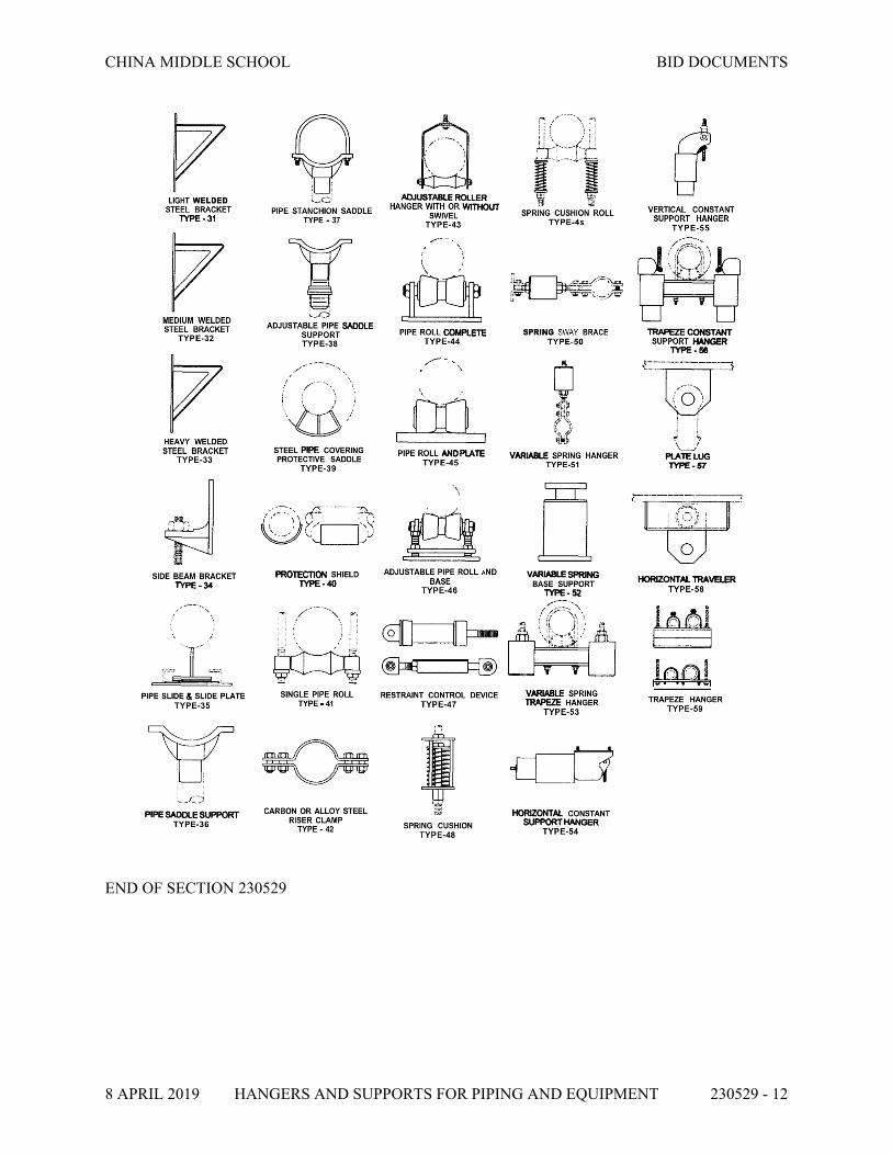
CHINA MIDDLE SCHOOL BID DOCUMENTS
8 APRIL 2019 HANGERS AND SUPPORTS FOR PIPING AND EQUIPMENT 230529 - 12
END OF SECTION 230529
CHINA MIDDLE SCHOOL BID DOCUMENTS
8 APRIL 2019 IDENTIFICATION FOR MECHANICAL 230553 - 1
SECTION 230553 – IDENTIFICATION FOR MECHANICAL
PART 1 - GENERAL
1.1 RELATED DOCUMENTS
A. Drawings and general provisions of the Contract, including General and Supplementary Conditions and Division 1 Specification Sections, apply to this Section.
B. Division 23 Section "Common Work Results for Mechanical”
1.2 SUMMARY
A. This Section includes the following mechanical identification materials and their installation.
1.3 SUBMITTALS
A. Product Data: For each type of product indicated.
B. [Valve numbering scheme. Valve Schedules: For each piping system. Furnish extra copies (in addition to mounted copies) to include in maintenance manuals.]
1.4 QUALITY ASSURANCE
A. ASME Compliance: Comply with ASME A13.1, "Scheme for the Identification of Piping Systems," for letter size, length of color field, colors, and viewing angles of identification devices for piping.
1.5 COORDINATION
A. Coordinate installation of identifying devices with completion of covering and painting of surfaces where devices are to be applied.
B. Coordinate installation of identifying devices with location of access panels and doors.
C. Provide identifying devices before installing acoustical ceilings and similar concealment.
PART 2 - PRODUCTS
2.1 EQUIPMENT IDENTIFICATION DEVICES
A. Terminology: Match schedules as closely as possible.

CHINA MIDDLE SCHOOL BID DOCUMENTS
8 APRIL 2019 IDENTIFICATION FOR MECHANICAL 230553 - 2
B. Tag and description: Example: “EF-1 - Bathroom Exhaust”
C. Equipment Markers: Custom Vinyl Decals with a clear polyester overlaminate to endure outdoor conditions and are UV and scuff resistant. Decals shall be made of flexible vinyl with a permanent pressure-sensitive adhesive backing suitable for curved surfaces. Service temperature range of -40°F to 176°F.
D. In addition to the equipment tag, equipment located above the ceiling that requires servicing shall be labeled on the ceiling grid using a labeling machine.
2.2 PIPING IDENTIFICATION DEVICES
A. Manufactured Pipe Markers, General: Seton, Brady, or approved equal; preprinted, color-coded, with lettering indicating service, and showing direction of flow.
1. Colors: Comply with ASME A13.1, unless otherwise indicated.2. Lettering: Use piping system terms indicated and abbreviate only as necessary for each
application length. Size of letters and length of color field per ASME A13.1.3. Pipes with OD, Including Insulation; Full-band snap-around pipe markers extending 360
degrees around pipe at each location.4. Arrows: Integral with piping system service lettering to accommodate both directions; or
as separate unit on each pipe marker to indicate direction of flow.5. Minimum length of color field and size of letters shall be per below:
B. Types:
1. Self-adhesive type: Seton Opti-Code.2. Snap-around type: Seton Setmark.3. Wrap-around type: Seton Ultra-mark; PVF over-laminated polyester construction seals in
and protects graphics; suitable for outdoor or harsh environments.
2.3 DUCT IDENTIFICATION DEVICES
A. Duct Markers: Engraved, color-coded laminated plastic. Include direction and quantity of airflow and duct service (such as supply, return, and exhaust). Include contact-type, permanent adhesive.

CHINA MIDDLE SCHOOL BID DOCUMENTS
8 APRIL 2019 IDENTIFICATION FOR MECHANICAL 230553 - 3
2.4 VALVE TAGS & SCHEDULES
A. Valve Tags: Stamped or engraved 1-1/2 round with 1/4-inch letters for piping system legend and 1/2-inch black-filled numbers, with numbering scheme; 3/16” hole for fastener; Material: 19-gauge brass; Valve-Tag Fasteners: Brass wire-link or beaded chain; or S-hook.
B. Valve Schedules: For each piping system, on standard-size bond paper. Tabulate valve number, piping system, system abbreviation (as shown on valve tag), location of valve (room or space), normal-operating position (open, closed, or modulating), and variations for identification. Mark valves for emergency shutoff and similar special uses.
1. Valve-Schedule Frames: Glazed display frame for removable mounting on masonry walls for each page of valve schedule. Include mounting screws.
2. Frame: aluminum.3. Glazing: ASTM C 1036, Type I, Class 1, Glazing Quality B, 2.5-mm, single-thickness
glass.
2.5 WARNING TAGS
A. Warning Tags: Preprinted or partially preprinted, accident-prevention tags; of plasticized card stock with matte finish suitable for writing.
1. Size: 3 by 5-1/4 inches minimum.2. Fasteners: Brass grommet and wire.3. Nomenclature: Large-size primary caption such as DANGER, CAUTION, or DO NOT
OPERATE.4. Color: Yellow background with black lettering.
PART 3 - EXECUTION
3.1 APPLICATIONS, GENERAL
A. Products specified are for applications referenced in other Division 22 or 23 Sections. If more than single-type material, device, or label is specified for listed applications, selection is Installer's option.
3.2 EQUIPMENT IDENTIFICATION
A. Provide equipment markers on each item of scheduled equipment. Data required for markers may be included on signs, and markers may be omitted if both are indicated.
1. Letter Size: Minimum 1/4 inch for name of units if viewing distance is less than 24 inches, 1/2 inch for viewing distances up to 72 inches, and proportionately larger lettering for greater viewing distances. Include secondary lettering two-thirds to three-fourths the size of principal lettering.

CHINA MIDDLE SCHOOL BID DOCUMENTS
8 APRIL 2019 IDENTIFICATION FOR MECHANICAL 230553 - 4
2. Data: Distinguish among multiple units, indicate operational requirements, indicate safety and emergency precautions, warn of hazards and improper operations, and identify units.
3. Locate markers where accessible and visible.
B. Equipment located above the ceiling that requires servicing shall be labeled on the ceiling using a labeling machine.
1. Ceilings 10 feet and lower: Letters shall be ¼” high, black.2. Ceilings higher than 10 feet: Letters shall be 3/8” high, black.3. Label all equipment above ceiling that requires servicing or access. 4. Locate labels on the ceiling grid, adjacent to the ceiling tile that provides the best access
to the valve or item that requires servicing.
3.3 PIPING IDENTIFICATION
A. Provide manufactured pipe markers indicating service on each piping system.
1. Provide pipe markers to manufacturer's instructions.2. Identify piping, concealed or exposed. Include service and flow direction.3. Provide in clear view and align with axis of piping.4. Locate identification at maximum 20 feet centers on straight runs including risers and
drops, adjacent to each valve and tee, at each side of penetration of structure or enclosure, and at each obstruction.
5. At access doors and similar access points that permit view of concealed piping.6. At least one per room.7. Provide per diagram below:
B. Unions covered by insulation: Stencil or label the outside insulation jacket of each union with the word "union." Match size and color of pipe labels.
3.4 DUCT IDENTIFICATION
A. Locate duct markers as follows.
1. Ducts leaving mechanical rooms.2. Ducts at riser shaft branches.

CHINA MIDDLE SCHOOL BID DOCUMENTS
8 APRIL 2019 IDENTIFICATION FOR MECHANICAL 230553 - 5
B. Provide duct markers with permanent adhesive on air ducts in the following color codes:
1. Green: For cold-air supply ducts.2. Yellow: For hot-air supply ducts.3. Blue: For return ducts.4. Red: For exhaust-, outside, or relief air ducts5. Identify by system tag and type.6. Letter Size: Minimum 1/4 inch for name of units if viewing distance is less than 24
inches, 1/2 inch for viewing distances up to 72 inches, and proportionately larger lettering for greater viewing distances. Include secondary lettering two-thirds to three-fourths the size of principal lettering.
C. Locate markers near points where ducts enter into concealed spaces and at maximum intervals of 50 feet in each space where ducts are exposed or concealed by removable ceiling system.
3.5 VALVE-TAG INSTALLATION
A. Provide tags on valves and control devices in piping systems, except check valves; valves within factory-fabricated equipment units; plumbing fixture supply stops; shutoff valves; faucets; and HVAC terminal devices and similar roughing-in connections of end-use fixtures and units. List tagged valves in a valve schedule.
B. Mount valve schedule on wall in accessible location in each major equipment room. Provide (2) copies of valve schedules burned to a DVD or memory stick; Word or Excel format.
3.6 WARNING-TAG INSTALLATION
A. Write required message on, and attach warning tags to, equipment and other items where required.
3.7 ADJUSTING
A. Relocate mechanical identification materials and devices that have become visually blocked by other work.
3.8 CLEANING
A. Clean faces of mechanical identification devices.
END OF SECTION 230553


CHINA MIDDLE SCHOOL BID DOCUMENTS
8 APRIL 2019 TESTING, ADJUSTING, AND BALANCING FOR HVAC 230593 - 1
SECTION 230593 - TESTING, ADJUSTING, AND BALANCING FOR HVAC
PART 1 - GENERAL
1.1 RELATED DOCUMENTS
A. Drawings and general provisions of the Contract, including General and Supplementary Conditions and Division 01 Specification Sections, apply to this Section.
1.2 SUMMARY
A. Section Includes Testing, Adjusting, & Balancing
1.3 INFORMATIONAL SUBMITTALS
A. Qualification Data: Within 30 days of Contractor's Notice to Proceed, submit documentation of AABC agency and personnel, including a sample copy of the AABC "National Performance Guaranty." If not submitted within the timeframe specified, the engineer has the right to choose an AABC agency at the Contractor’s expense.
B. Examination Report: Provide a summary report of the examination review required in Section 3.1, if issues are discovered that may preclude the proper testing and balancing of the systems.
1.4 ACTION SUBMITTALS
A. Use standard forms from AABC's "National Standards for Testing and Balancing Heating, Ventilating, and Air Conditioning Systems." NEBB's "Procedural Standards for Testing, Adjusting, and Balancing of Environmental Systems." SMACNA's TABB "HVAC Systems - Testing, Adjusting, and Balancing." TAB firm's forms approved by Architect. TABB "Contractors Certification Manual."
1.5 QUALITY ASSURANCE
A. Instrumentation Type, Quantity, Accuracy, and Calibration: Comply with requirements in ASHRAE 111, Section 4, "Instrumentation."
B. ASHRAE Compliance: Applicable requirements in ASHRAE 62.1, Section 7.2.2 - "Air Balancing."
C. ASHRAE/IESNA Compliance: Applicable requirements in ASHRAE/IESNA 90.1, Section 6.7.2.3 - "System Balancing."

CHINA MIDDLE SCHOOL BID DOCUMENTS
8 APRIL 2019 TESTING, ADJUSTING, AND BALANCING FOR HVAC 230593 - 2
PART 2 - PRODUCTS (Not Applicable)
PART 3 - EXECUTION
3.1 EXAMINATION
A. Examine the Contract Documents to become familiar with Project requirements and to discover conditions in systems' designs that may preclude proper T&B of systems and equipment.
B. Examine systems for installed balancing devices, such as test ports, gage cocks, thermometer wells, flow-control devices, balancing valves and fittings, and manual volume dampers. Note the locations of devices that are not accessible for testing and balancing.
C. Examine the approved submittals for HVAC systems and equipment.
D. Examine ceiling plenums and underfloor air plenums used for supply, return, or relief air to verify that are properly separated from adjacent areas.
E. Examine equipment performance data including fan and pump curves.
F. Examine HVAC equipment and filters and verify that bearings are greased, belts are aligned and tight, clean permanent filters are installed, and equipment with functioning controls is ready for operation.
G. Examine terminal units and verify that they are accessible and their controls are connected, configured by the controls contractor, and functioning.
H. Examine strainers to verify that startup screens have been replaced with permanent screens and that all strainers have been cleaned.
I. Examine control valves for proper installation and function.
J. Examine heat-transfer coils for correct piping connections and for clean and straight fins.
K. Examine air vents to verify that mechanical contractor has removed all air from all hydronic systems.
3.2 PREPARATION
A. Prepare a T&B plan that includes the following:
1. Equipment and systems to be tested.2. Strategies and step-by-step procedures for balancing the systems.3. Instrumentation to be used.4. Sample forms with specific identification for all equipment.
B. Prepare system-readiness checklists, as described in the "AABC National Standards for Total System Balance," for use by systems installers in verifying system readiness for T&B. These shall include, at a minimum, the following:

CHINA MIDDLE SCHOOL BID DOCUMENTS
8 APRIL 2019 TESTING, ADJUSTING, AND BALANCING FOR HVAC 230593 - 3
1. Airside:
a. Ductwork is complete with terminals installed.b. Volume and life-safety dampers are open and functional.c. Clean filters are installed.d. Fans are operating, free of vibration, and rotating in correct direction.e. Variable-frequency controllers' start-up is complete and safeties are verified.f. Automatic temperature-control systems are operational.g. Ceilings are installed.h. Windows and doors are installed.i. Suitable access to balancing devices and equipment is provided.
2. Hydronics:
a. Piping is complete with terminals installed.b. Water treatment is complete.c. Systems are flushed, filled and air purged.d. Strainers are pulled and cleaned.e. Control valves are functioning per the sequence of operation.f. Shutoff and balance valves have been verified to be 100 percent open.g. Pumps are started and proper rotation is verified.h. Pump gage connections are installed directly at pump inlets and outlets flange or in
discharge and suction pipe prior to valves or strainers.i. Variable-frequency controllers' start-up is complete and safeties are verified.j. Suitable access to balancing devices and equipment is provided.
3.3 GENERAL PROCEDURES FOR TESTING AND BALANCING
A. Perform testing and balancing procedures on each system according to the procedures contained in AABC's "National Standards for Total System Balance" and in this Section.
B. Mark equipment and balancing devices, including damper-control positions, valve position indicators, fan-speed-control levers, and similar controls and devices, with paint or other suitable, permanent identification material to show final settings.
C. Take and report testing and balancing measurements in inch-pound (IP) units.
3.4 GENERAL PROCEDURES FOR BALANCING AIR SYSTEMS
A. Prepare test reports for both fans and outlets. Obtain approved submittals and recommended testing procedures. Crosscheck the summation of required outlet volumes with required fan volumes.
B. Prepare single-line schematic diagram of systems for the purpose of identifying HVAC components.
C. For variable-air-volume systems, develop a plan to simulate diversity.
D. Determine the best locations in main and branch ducts for accurate duct-airflow measurements.

CHINA MIDDLE SCHOOL BID DOCUMENTS
8 APRIL 2019 TESTING, ADJUSTING, AND BALANCING FOR HVAC 230593 - 4
E. Locate start-stop and disconnect switches, electrical interlocks, and motor starters.
F. Verify that motor starters are equipped with properly sized thermal protection.
G. Check condensate drains for proper connections and functioning.
H. Check for proper sealing of air-handling-unit components.
3.5 PROCEDURES FOR CONSTANT-VOLUME AIR SYSTEMS
A. Adjust fans to deliver total indicated airflows within the maximum allowable fan speed listed by fan manufacturer.
1. Measure total airflow.
a. Set outside air, return air and relief air dampers for proper position that simulates minimum outdoor air conditions.
b. Where duct conditions allow, measure airflow by Pitot-tube traverse. If necessary, perform multiple Pitot-tube traverses to obtain total airflow.
c. Where duct conditions are not suitable for Pitot-tube traverse measurements, a coil traverse may be acceptable.
d. If a reliable Pitot-tube traverse or coil traverse is not possible, measure airflow at terminals and calculate the total airflow.
2. Measure fan static pressures as follows to determine actual static pressure:
a. Measure static pressure directly at the fan outlet or through the flexible connection.b. Measure static pressure directly at the fan inlet or through the flexible connection.c. Measure static pressure across each component that makes up the air-handling
system.d. Report any artificial loading of filters at the time static pressures are measured.
3. Do not make fan-speed adjustments that result in motor overload. Consult equipment manufacturers about fan-speed safety factors. Modulate dampers and measure fan-motor amperage to ensure that no overload will occur. Measure amperage in full-cooling, full-heating, economizer, and any other operating mode to determine the maximum required brake horsepower.
B. Adjust volume dampers for main duct, submain ducts, and major branch ducts to indicated airflows within specified tolerances.
1. Measure airflow of submain and branch ducts.2. Adjust sub-main and branch duct volume dampers for specified airflow.3. Re-measure each submain and branch duct after all have been adjusted.
C. Adjust air outlets and inlets for each space to indicated airflows
1. Set airflow patterns of adjustable outlets for proper distribution without drafts.2. Measure airflow at all inlets and outlets.

CHINA MIDDLE SCHOOL BID DOCUMENTS
8 APRIL 2019 TESTING, ADJUSTING, AND BALANCING FOR HVAC 230593 - 5
3. Adjust each inlet and outlet for specified airflow.4. Re-measure each inlet and outlet after all have been adjusted.
D. Verify final system conditions.
1. Re-measure and confirm minimum outdoor air, return and relief airflows are within design. Readjust to design if necessary.
2. Re-measure and confirm total airflow is within design.3. Re-measure all final fan operating data, rpms, volts, amps, static profile.4. Mark all final settings.5. Test system in economizer mode. Verify proper operation and adjust, if necessary. Measure
and record all operating data.6. Record final fan-performance data.
3.6 GENERAL PROCEDURES FOR HYDRONIC SYSTEMS
A. Prepare test reports for pumps, coils, and heat exchangers. Obtain approved submittals and any manufacturer-recommended testing procedures. Crosscheck the summation of required coil and heat exchanger flow rates with pump design flow rate.
B. Prepare hydronic systems for testing and balancing according to the following, in addition to the general preparation procedures specified above:
C. Verify that hydronic systems are ready for testing and balancing:
1. Check liquid level in expansion tank.2. Check that makeup water has adequate pressure to highest vent.3. Check that control valves are in their proper positions.4. Check that air has been purged from the system.5. Locate start-stop and disconnect switches, electrical interlocks, and motor starters.6. Verify that motor starters are equipped with properly sized thermal protection.
3.7 PROCEDURES FOR CONSTANT-FLOW HYDRONIC SYSTEMS
A. Adjust pumps to deliver total design gpm.
1. Measure total water flow.
a. Position valves for full flow through coils.b. Measure flow by main flow meter, if installed.c. If main flow meter is not installed determine flow by pump total dynamic head
(TDH) or exchanger pressure drop.
2. Measure pump TDH as follows:
a. Measure discharge pressure directly at the pump outlet flange or in discharge pipe prior to any valves.
b. Measure inlet pressure directly at the pump inlet flange or in suction pipe prior to any valves or strainers.

CHINA MIDDLE SCHOOL BID DOCUMENTS
8 APRIL 2019 TESTING, ADJUSTING, AND BALANCING FOR HVAC 230593 - 6
c. Convert pressure to head and correct for differences in gauge heights.d. Verify pump impeller size by measuring the TDH with the discharge valve closed.
Note the point on manufacturer's pump curve at zero flow and verify that the pump has the intended impeller size.
e. With all valves open, read pump TDH. Adjust pump discharge valve until design water flow is achieved.
3. Monitor motor performance during procedures and do not operate motor in an overloaded condition.
B. Adjust flow measuring devices installed in mains and branches to design water flows.
1. Measure flow in main and branch pipes.2. Adjust main and branch balance valves for design flow.3. Re-measure each main and branch after all have been adjusted.
C. Adjust flow measuring devices installed at terminals for each space to design water flows.
1. Measure flow at all terminals.2. Adjust each terminal to design flow.3. Re-measure each terminal after all have been adjusted.4. Position control valves to bypass the coil and adjust the bypass valve to maintain design
flow.5. Perform temperature tests after all flows have been balanced.
D. For systems with pressure-independent valves at the terminals:
1. Measure differential pressure and verify that it is within manufacturer’s specified range.2. Perform temperature tests after all flows have been verified.
E. For systems without pressure-independent valves or flow measuring devices at the terminals:
1. Measure and balance coils by either coil pressure drop or temperature method.2. If balanced by coil pressure drop, perform temperature tests after all flows have been
verified.
F. Verify final system conditions as follows:
1. Re-measure and confirm that total water flow is within design.2. Re-measure all final pump operating data, TDH, volts, amps, static profile.3. Mark all final settings.
G. Verify that all memory stops have been set.
3.8 TOLERANCES
A. Set HVAC system's air flow rates and water flow rates within the following tolerances:
1. Supply, Return, and Exhaust Fans and Equipment with Fans: Plus or minus 10 percent.2. Air Outlets and Inlets: Plus or minus 10 percent.

CHINA MIDDLE SCHOOL BID DOCUMENTS
8 APRIL 2019 TESTING, ADJUSTING, AND BALANCING FOR HVAC 230593 - 7
3. Minimum Outside Air: Zero to plus 10 percent.4. Heating-Water Flow Rate: Plus or minus 10 percent.
B. Maintaining pressure relationships as designed shall have priority over the tolerances specified above.
3.9 FINAL TEST & BALANCE REPORT
A. The report shall be a complete record of the HVAC system performance, including conditions of operation, items outstanding, and any deviations found during the T&B process. The final report also provides a reference of actual operating conditions for the owner and/or operations personnel. All measurements and test results that appear in the reports must be made on site and dated by the AABC technicians or test and balance engineers.
B. The report must be organized by systems and shall include the following information as a minimum:
1. Title Page:a. Company addressb. Company telephone numberc. Project identification number d. Locatione. Project Architectf. Project Engineerg. Project Contractorh. Project numberi. Date of report
2. Table of Contents.3. AABC National Performance Guaranty.4. Report Summary:
a. The summary shall include a list of items that do not meet design tolerances, with information that may be considered in resolving deficiencies.
5. Instrument List:
a. Type.b. Manufacturer.c. Model.d. Serial Number.e. Calibration Date.
6. T&B Data: Provide test data for specific systems and equipment as required by the most recent edition of the "AABC National Standards."
END OF SECTION 230593


CHINA MIDDLE SCHOOL BID DOCUMENTS
8 APRIL 2019 MECHANICAL INSULATION 230700 - 1
SECTION – 230700 - MECHANICAL INSULATION
PART 1 - GENERAL
1.1 RELATED DOCUMENTS
A. Drawings and general provisions of the Contract, including General and Supplementary Conditions and Division 1 Specification Sections, apply to this Section.
B. Related Sections include the following:
1. Division 7 for firestopping materials and requirements for penetrations through fire and smoke barriers.
2. Division 23 Section "Common Work Results for Mechanical"3. Division 23 Section "Hangers and Supports for Piping and Equipment" for pipe
insulation shields and protection saddles.4. Division 23 Section "Metal Ducts" for duct liner.
1.2 SUMMARY
A. This Section includes insulation and related components.
1.3 ACTION SUBMITTALS
A. Product Data: Identify thermal conductivity, Greenguard Certification, thickness, and jackets (both factory and field applied, if any), for each type of product indicated. For adhesives and sealants, provide documentation including printed a statement of VOC content.
1.4 QUALITY ASSURANCE
A. Installer Qualifications: Skilled mechanics who have successfully completed an apprenticeship program or another craft training program certified by the U.S. Department of Labor, Bureau of Apprenticeship and Training.
B. Surface-Burning Characteristics: For insulation and related materials, as determined by testing identical products according to ASTM E 84, by a testing agency acceptable to authorities having jurisdiction. Factory label insulation and jacket materials and adhesive, mastic, tapes, and cement material containers, with appropriate markings of applicable testing agency.
C. Insulation Installed Indoors: Flame-spread index of 25 or less, and smoke-developed index of 50 or less. Insulation Installed Outdoors: Flame-spread index of 75 or less, and smoke-developed index of 150 or less.

CHINA MIDDLE SCHOOL BID DOCUMENTS
8 APRIL 2019 MECHANICAL INSULATION 230700 - 2
1.5 DELIVERY, STORAGE, AND HANDLING
A. Ship insulation materials in containers marked by manufacturer with appropriate ASTM specification designation, type and grade, and maximum use temperature.
B. All of the insulation materials and accessories covered by this specification shall be delivered to the job site and stored in a safe, dry place with appropriate labels and/or other product identification.
C. Store tapes, adhesives, mastics, cements, and insulation materials in ambient conditions in accordance with the recommendations of the manufacturer.
D. Follow manufacturer’s recommended handling practices.
E. The contractor shall use whatever means are necessary to protect the insulation materials and accessories before, during, and after installation. No insulation material shall be installed that has become damaged in any way. The contractor shall also use all means necessary to protect work and materials installed by other trades.
F. Fiber Glass and Mold: Contractor shall take precaution to protect insulation. Any fiber glass insulation that becomes wet or torn should be replaced at no additional cost. Air handling insulation used in the air stream must be discarded if exposed to water.
1.6 COORDINATION
A. Coordinate size and location of supports, hangers, and insulation shields. Coordinate clearance requirements with other trades for insulation application.
B. Schedule insulation application after testing systems. Insulation application may begin on segments of systems that have satisfactory test results.
PART 2 - PRODUCTS
2.1 MANUFACTURERS
A. Manufacturers: Subject to compliance with requirements, provide products by one of the following:
1. Certainteed2. Knauf3. Owens-Corning4. John Mansville5. Armstrong6. Aeroflex USA7. Nomaco K-Flex8. Pabco.

CHINA MIDDLE SCHOOL BID DOCUMENTS
8 APRIL 2019 MECHANICAL INSULATION 230700 - 3
2.2 PIPING INSULATION MATERIALS
A. General
1. Supply fiber glass products that have achieved GREENGUARD Children & Schools Certification.
2. Surface Burning Characteristics: Insulation and related materials shall have surface burning characteristics determined by test performed on identical products per ASTM E 84 mounted and installed as per ASTM E 2231. All testing shall be performed by a testing and inspecting agency acceptable to authorities having jurisdiction. Insulation, jacket materials, adhesives, mastics, tapes and cement material containers shall be labeled with appropriate markings of applicable testing and inspecting agency. Flame-spread index of 25 or less, and smoke-developed index of 50 or less.
3. Supply fiber glass products that are manufactured using a certified 25 % minimum recycled content.
B. Provide thermal hanger shields as specified in Section 230529 “Hangers and Supports for Piping and Equipment”.
C. Glass Fiber:
1. Knauf 1000 Pipe Insulation with ECOSE Technology meeting ASTM C547 Type IV Grade A, ASTM C585, and ASTM C795; rigid, molded, noncombustible per ASTM E136; k value: ASTM C335, 0.23 at 75F mean temperature. Maximum Service Temperature: 1000F, or Johns Manville’s Micro-Lok® HP meeting ASTM C547, Type I, maximum service temperature of 850°F meeting the other requirements. Vapor Retarder Jacket: ASJ/SSL conforming to ASTM C1136 Type I, secured with self-sealing longitudinal laps and butt strips.
2. PVC Fitting Covers: The Proto Fitting Cover System or Johns Manville Zeston® polyvinyl chloride (PVC) parts shall consist of one piece and two piece pre-molded high impact UV-resistant PVC fitting covers with fiberglass inserts and accessories, which include elbows, tee/valves, end caps, mechanical line couplings, and specialty fittings. Fittings shall be made of Zeston® or LoSMOKE® grade PVC, 25/50 rated per ASTM E-84. Thermal Value of fiberglass insert: K value of 0.26 at 75°F; resistance to fungi and bacteria. (ASTM G 21, ASTM G 22): does not promote growth of fungi or bacteria.
D. Flexible Elastomeric Insulation: Closed-cell, sponge- or expanded-rubber materials. Comply with ASTM C 534, Type I for tubular materials.
1. For indoor applications, adhesive shall have a VOC content of 50 g/L or less when calculated according to 40 CFR 59, Subpart D (EPA Method 24).
2. Adhesive shall comply with the testing and product requirements of the California Department of Health Services' "Standard Practice for the Testing of Volatile Organic Emissions from Various Sources Using Small-Scale Environmental Chambers."
3. Materials shall have a maximum thermal conductivity of 0.27 Btu-in/h-ft2- °F at a 75°F mean temperature when tested in accordance with ASTM C 177 or ASTM C 518, latest revisions.
4. Materials shall have a maximum water vapor transmission of 0.08 perm-inches when tested in accordance with ASTM E 96, Procedure-A, latest revision.

CHINA MIDDLE SCHOOL BID DOCUMENTS
8 APRIL 2019 MECHANICAL INSULATION 230700 - 4
5. Materials shall have a flame spread index of less than 25 and a smoke developed index of less than 50 when tested in accordance with ASTM E 84, latest revision.
6. Provide Armaflex WB finish for outdoor exposed piping.
E. Calcium Silicate Insulation: Flat-, curved-, and grooved-block sections of noncombustible, inorganic, hydrous calcium silicate with a non-asbestos fibrous reinforcement. Comply with ASTM C 533, Type I. IIG Thermo-12 Gold, or approved equal.
F. Closed Cell Pipe Insulation: Pittsburgh Corning Foamglas, or approved equal; a lightweight, rigid insulating material composed of millions of completely sealed glass cells, each an insulating space. ASTM C 552-00 “Specification for Cellular Glass Thermal Insulation”’ operating temperatures from -450°F to +900°F; water permeability 0.00 perm-inch.
G. Pipe & Tank Insulation: Glass Fiber, Knauf with ECOSE Technology or equivalent; semi-rigid, limited combustible meeting requirements of NRC 1.36; ASTM C 795 and MIL-I-24244 C; k value: ASTM C 177, 0.25 at 75F mean temperature. Maximum Service Temperature: 850F. Compressive Strength: not less than 150 PSF @ 10% deformation for 2 inch thickness per ASTM C 165. Vapor Retarder Jacket: ASJ conforming to ASTM C 1136 Type II. Johns Manville Micro-Flex® Large Diameter Pipe and Tank Wrap meeting ASTM C1393, Type III. Limited combustible meeting k value: ASTM C 177, 0.25 at 75F mean temperature. Maximum Service Temperature: 850F. Compressive Strength: not less than 150 PSF @ 10% deformation for 2 inch thickness per ASTM C 165. Vapor Retarder Jacket: ASJ conforming to ASTM C 1136 Type II
H. Removable/reusable Insulation Blankets: Auburn Manufacturing EverGreen Cut ’n Wrap, or approved equal; engineered insulating composite with a fiberglass inner core and high-performance polymer coated woven glass fiber fabric outer layer on both sides. Kits contain a 4’x 8’ modularized blanket rated to 500°F and a roll of double sided hook and loop fastener making onsite fabrication of removable/reusable insulation blankets quick and easy. Up to 500°F; Weight, oz/ft2 7.65; Effective Thickness, in. 1.25 ± 0.25; Surface Burning Characteristics: Does not exceed 25 Flame Spread, 50 Smoke Developed when tested in accordance with ASTM E-84. Materials shall have a maximum thermal conductivity of 0.372 Btu-in/h-ft2- °F at a 100°F mean temperature when tested in accordance with ASTM C335.
2.3 FIELD-APPLIED JACKETS FOR PIPING
A. General: ASTM C 921, Type 1, unless otherwise indicated.
B. PVC: Johns Manville’s Zeston® PVC fittings, jacketing, and accessories or Proto Corporation 25/50 or Indoor/Outdoor, UV-resistant fittings, jacketing and accessories, white. Fitting cover system consists of pre-molded, high-impact PVC materials with fiber glass inserts. Fiber glass insert has a thermal conductivity (k value) of 0.26 at 75 F mean temperature. Closures: stainless steel tacks, matching PVC tape, or PVC adhesive per manufacturer’s recommendations.
C. Aluminum Jacket: Factory cut and rolled to required size. Comply with ASTM B 209, 3003 alloy, and H-14 temper. Finish and Thickness: Corrugated finish, 0.010 inch thick. Moisture Barrier: 1-mil- thick, heat-bonded polyethylene and Kraft paper. Elbows: Preformed, 45- and 90-degree, short- and long-radius elbows; same material, finish, and thickness as jacket.

CHINA MIDDLE SCHOOL BID DOCUMENTS
8 APRIL 2019 MECHANICAL INSULATION 230700 - 5
D. Stainless-Steel Jacket: ASTM A666, Type 304 or 316; 0.10 inch thick; and factory cut and rolled to required size. Moisture Barrier: 3-mil- thick, heat-bonded polyethylene and Kraft paper. Elbows: Gore type, for 45- and 90-degree elbows in same material, finish, and thickness as jacket. Jacket Bands: Stainless steel, Type 304, 3/4 inch wide.
2.4 DUCTWORK INSULATION MATERIALS
A. Flexible Fiber Glass Blanket: Glass Mineral Wool Blanket Insulation: Glass Mineral Wool bonded with a bio-based thermosetting resin. Comply with ASTM C 553, Types I, II, and III, ASTM C 1136 Type II, and ASTM C 1290, Type III. UL/ULC Classified per UL 723 for FSK, FHC 25/50 per ASTM E 84 for PSK only.
1. Factory-applied jacket: ASJ: White, kraft paper, fiberglass reinforced scrim with aluminum foil backing; complying with ASTM C 1136, Type I.
2. Basis-of-Design Product: Subject to compliance with requirements, provide Knauf Insulation; Atmosphere Duct Wrap.
3. Density: 1.0 PCF4. R-Value: R5.6 for 1-1/2” thick blanket – “out of package”.
B. Rigid Fiber Glass Board: Johns Manville’s 817 Series Spin-Glas® or Knauf Insulation Board with ECOSE Technology meeting ASTM C 612 Type IA and IB; rigid. Maximum Service Temperature: 450. Density: Minimum 3.0 PCF; R4.2 per inch. Vapor Retarder Jacket: ASJ conforming to ASTM C1136 Type I, or FSK or PSK conforming to ASTM C1136 Type II in combination with protective jacket where necessary.
2.5 ACCESSORY MATERIALS
A. Accessory materials installed as part of insulation work under his section shall include (but not be limited to):
1. Closure Materials - Butt strips, bands, wires, staples, mastics, adhesives; pressure-sensitive tapes.
2. Adhesive: As recommended by insulation material manufacturer. Materials shall be compatible with insulation materials, jackets, and substrates and for bonding insulation to itself and to surfaces to be insulated
3. Support Materials - Hanger straps, hanger rods, saddles, support rings
B. All accessory materials shall be installed in accordance with manufacturer's instructions.
C. Mastics: Materials recommended by insulation material manufacturer that are compatible with insulation materials, jackets, and substrates.

CHINA MIDDLE SCHOOL BID DOCUMENTS
8 APRIL 2019 MECHANICAL INSULATION 230700 - 6
PART 3 - EXECUTION
3.1 EXAMINATION & PREPARATION
A. Examine substrates and conditions for compliance with requirements for installation tolerances and other conditions affecting performance of insulation application. Verify that systems to be insulated have been tested and are free of defects. Verify that surfaces to be insulated are clean and dry.
B. Proceed with installation only after unsatisfactory conditions have been corrected.
C. Before starting work under this section, carefully inspect the site and installed work of other trades and verify that such work is complete to the point where installation of materials and accessories under this section can begin.
D. Ensure that all pipe and fitting surfaces over which insulation is to be installed are clean and dry. Ensure that insulation is clean, dry, and in good mechanical condition with all factory-applied vapor or weather barriers intact and undamaged. Wet, dirty, or damaged insulation shall not be acceptable for installation. Ensure that pressure testing of piping and fittings has been completed prior to installing insulation.
3.2 GENERAL APPLICATION REQUIREMENTS
A. Provide insulation materials, accessories, and finishes according to the manufacturer's written instructions; with smooth, straight, and even surfaces; free of voids throughout, including the length of ducts and fittings, valves, and specialties.
B. Provide insulation materials, vapor barriers or retarders, jackets, and thicknesses required for each system as specified in insulation system schedules.
C. Provide accessories compatible with insulation materials and suitable for the service. Provide accessories that do not corrode, soften, or otherwise attack insulation or jacket in either wet or dry state.
D. Provide insulation with longitudinal seams at top and bottom of horizontal pipe runs and equipment.
E. Provide multiple layers of insulation with longitudinal and end seams staggered.
F. Do not weld brackets, clips, or other attachment devices to piping, fittings, and specialties.
G. Seal joints and seams with vapor-retarder mastic on insulation indicated to receive a vapor retarder.
H. Keep insulation materials dry during application and finishing.
I. Provide insulation with tight longitudinal seams and end joints. Bond seams and joints with adhesive recommended by the insulation material manufacturer.

CHINA MIDDLE SCHOOL BID DOCUMENTS
8 APRIL 2019 MECHANICAL INSULATION 230700 - 7
J. Provide insulation over fittings, valves, and specialties, with continuous thermal and least number of joints practical.
K. Where vapor barrier is indicated, seal joints, seams, and penetrations in insulation at hangers, supports, anchors, and other projections with vapor-barrier mastic.
1. Install insulation continuously through hangers and specialties around anchor attachments.
2. For insulation application where vapor barriers are indicated, extend insulation on anchor legs from point of attachment to supported item to point of attachment to structure. Taper and seal ends at attachment to structure with vapor-barrier mastic.
3. Install insert materials and install insulation to tightly join the insert. Seal insulation to insulation inserts with adhesive or sealing compound recommended by insulation material manufacturer.
L. Apply adhesives, mastics, and sealants at manufacturer's recommended coverage rate and wet and dry film thicknesses.
M. Provide insulation with factory-applied jackets as follows:
1. Draw jacket tight and smooth.2. Cover circumferential joints with 3-inch- wide strips, of same material as insulation
jacket. Secure strips with adhesive and outward clinching staples along both edges of strip, spaced 4 inches o.c.
3. Overlap jacket longitudinal seams at least 1-1/2 inches. Clean and dry surface to receive self-sealing lap. Staple laps with outward clinching staples along edge at 2 inches o.c. For below ambient services, apply vapor-barrier mastic over staples.
4. Cover joints and seams with tape, according to insulation material manufacturer's written instructions, to maintain vapor seal.
5. Where vapor barriers are indicated, apply vapor-barrier mastic on seams and joints and at ends adjacent to duct flanges and fittings.
N. Cut insulation in a manner to avoid compressing insulation more than 75 percent of its nominal thickness.
O. Finish installation with systems at operating conditions. Repair joint separations and cracking due to thermal movement.
P. Repair damaged insulation facings by applying same facing material over damaged areas. Extend patches at least 4 inches beyond damaged areas. Adhere, staple, and seal patches similar to butt joints.
3.3 PIPE AND DUCTWORK PENETRATIONS
A. Insulation Installation at Roof or Aboveground Exterior Wall Penetrations: Install insulation continuously through penetrations.
1. Seal penetrations with flashing sealant.2. For applications requiring only indoor insulation, terminate insulation above roof/wall
surface and seal with joint sealant. For applications requiring indoor and outdoor

CHINA MIDDLE SCHOOL BID DOCUMENTS
8 APRIL 2019 MECHANICAL INSULATION 230700 - 8
insulation, install insulation for outdoor applications tightly joined to indoor insulation ends. Seal joint with joint sealant.
3. Extend jacket of outdoor insulation outside roof/wall flashing at least 2 inches below top of roof flashing.
4. Seal jacket to roof/wall flashing with flashing sealant.
B. Insulation Installation at Interior Wall and Partition Penetrations (That Are Not Fire Rated): Install insulation continuously through walls and partitions.
C. Insulation Installation at Fire-Rated Penetrations:
1. Fire Dampers: Terminate insulation at fire damper sleeves for fire-rated wall and partition penetrations. Externally insulate damper sleeves to match adjacent insulation and overlap duct insulation at least 2 inches.
2. Pipe or duct penetrations (no fire damper): Install insulation continuously through penetrations of fire-rated walls and partitions. Comply with requirements in Division 7 for firestopping and fire-resistive joint sealers.
3.4 INSTALLATION OF PIPING INSULATION
A. Metal shields shall be installed between hangers or supports and the piping insulation. Provide in accordance with Section 230529.
B. Insulation Installation on Fittings, Valves, Strainers, Flanges, and Unions:
1. Install insulation over fittings, valves, strainers, flanges, unions, and other specialties with continuous thermal and vapor-retarder integrity unless otherwise indicated.
2. Insulate pipe elbows using preformed fitting insulation or mitered fittings made from same material and density as adjacent pipe insulation. Each piece shall be butted tightly against adjoining piece and bonded with adhesive. Fill joints, seams, voids, and irregular surfaces with insulating cement finished to a smooth, hard, and uniform contour that is uniform with adjoining pipe insulation.
3. Insulate tee fittings with preformed fitting insulation or sectional pipe insulation of same material and thickness as used for adjacent pipe. Cut sectional pipe insulation to fit. Butt each section closely to the next and hold in place with tie wire. Bond pieces with adhesive.
4. Insulate valves using preformed fitting insulation or sectional pipe insulation of same material, density, and thickness as used for adjacent pipe. Overlap adjoining pipe insulation by not less than two times the thickness of pipe insulation, or one pipe diameter, whichever is thicker. For valves, insulate up to and including the bonnets, valve stuffing-box studs, bolts, and nuts. Fill joints, seams, and irregular surfaces with insulating cement.
5. Insulate strainers using preformed fitting insulation or sectional pipe insulation of same material, density, and thickness as used for adjacent pipe. Overlap adjoining pipe insulation by not less than two times the thickness of pipe insulation, or one pipe diameter, whichever is thicker. Fill joints, seams, and irregular surfaces with insulating cement. Insulate strainers so strainer basket flange or plug can be easily removed and replaced without damaging the insulation and jacket. Provide a removable reusable insulation cover. For below-ambient services, provide a design that maintains vapor barrier.

CHINA MIDDLE SCHOOL BID DOCUMENTS
8 APRIL 2019 MECHANICAL INSULATION 230700 - 9
6. Insulate flanges and unions using a section of oversized preformed pipe insulation. Overlap adjoining pipe insulation by not less than two times the thickness of pipe insulation, or one pipe diameter, whichever is thicker.
7. Cover segmented insulated surfaces with a layer of finishing cement and coat with a mastic. Install vapor-barrier mastic for below-ambient services and a breather mastic for above-ambient services. Reinforce the mastic with fabric-reinforcing mesh. Trowel the mastic to a smooth and well-shaped contour.
8. For services not specified to receive a field-applied jacket except for flexible elastomeric, install fitted PVC cover over elbows, tees, strainers, valves, flanges, and unions. Terminate ends with PVC end caps. Tape PVC covers to adjoining insulation facing using PVC tape.
C. Insulate instrument connections for specialties (examples: thermometers, sensors, etc.) on insulated pipes. Shape insulation at these connections by tapering it to and around the connection with insulating cement and finish with finishing cement, mastic, and flashing sealant.
D. Install removable insulation covers at fittings and equipment that require servicing and locations with service requirements.
E. Locate seams in the least visible location.
F. Insulation installed on piping operating below ambient temperatures must have a continuous vapor retarder. All joints, seams and fittings must be sealed. On systems operating above ambient, the butt joints should not be sealed.
G. Flexible Elastomeric Insulation
1. Seal longitudinal seams and end joints with manufacturers recommended adhesive to eliminate openings in insulation that allow passage of air to surface being insulated.
2. Insulation Installation on Pipe Flanges: Install pipe insulation to outer diameter of pipe flange. Make width of insulation section same as overall width of flange and bolts, plus twice the thickness of pipe insulation. Fill voids between inner circumference of flange insulation and outer circumference of adjacent straight pipe segments with cut sections of sheet insulation of same thickness as pipe insulation. Secure insulation to flanges and seal seams with manufacturers recommended adhesive to eliminate openings in insulation that allow passage of air to surface being insulated.
3. Insulation Installation on Pipe Fittings and Elbows: Install mitered sections of pipe insulation. Secure insulation materials and seal seams with manufacturer's recommended adhesive to eliminate openings in insulation that allow passage of air to surface being insulated.
4. Insulation Installation on Valves and Pipe Specialties: Install preformed valve covers manufactured of same material as pipe insulation when available. When preformed valve covers are not available, install cut sections of pipe and sheet insulation to valve body. Arrange insulation to permit access to packing and to allow valve operation without disturbing insulation. Install insulation to flanges as specified for flange insulation application. Secure insulation to valves and specialties and seal seams with manufacturer's recommended adhesive to eliminate openings in insulation that allow passage of air to surface being insulated.
5. After adhesive has fully cured, apply two coats of insulation manufacturer's recommended protective coating. Prior to applying the finish, the insulation shall be

CHINA MIDDLE SCHOOL BID DOCUMENTS
8 APRIL 2019 MECHANICAL INSULATION 230700 - 10
wiped clean with denatured alcohol. The finish shall not be tinted. To insure good adhesion, the temperature should be above 50 °F during application and drying. Outdoor exposed piping shall have the seams located on the lower half of the pipe.
6. Outdoor exposed piping shall be painted with two coats of Armaflex WB Finish. Prior to applying the Finish, the insulation shall be wiped clean with denatured alcohol. The Finish shall not be tinted. Outdoor exposed piping shall have the seams located on the lower half of the pipe.
3.5 INSTALLATION OF DUCTWORK INSULATION
A. Flexible Fiberglass Blanket Insulation Installation:
1. Secure with adhesive and insulation pins.2. Apply adhesives according to manufacturer's recommended coverage rates per unit area,
for 100 percent coverage of duct and plenum surfaces.3. Apply adhesive to entire circumference of ducts and to all surfaces of fittings and
transitions.4. Firmly butt all joints. 5. Where vapor retarder performance is required, all penetrations and damage to the facing
shall be repaired using pressure-sensitive tape matching the facing, or mastic prior to system startup. Pressure-sensitive tapes shall be a minimum 3 inches wide and shall be applied with moving pressure using a squeegee or other appropriate sealing tool. Closure shall have a 25/50 Flame Spread/Smoke Developed Rating per UL 723. The longitudinal seam of the vapor retarder must be overlapped a minimum of 2 inches.
6. Install either capacitor-discharge-weld pins and speed washers or cupped-head, capacitor-discharge-weld pins on sides and bottom of horizontal ducts and sides of vertical ducts as follows:
a. On duct sides with dimensions 18 inches and smaller, place pins along longitudinal centerline of duct. Space 3 inches maximum from insulation end joints, and 16 inches o.c.
b. On duct sides with dimensions larger than 18 inches, place pins 16 inches o.c. each way, and 3 inches maximum from insulation joints. Install additional pins to hold insulation tightly against surface at cross bracing.
c. Insulation shall be additionally secured to the bottom of rectangular ductwork over 24 inches wide using mechanical fasteners on 18-inch centers. Care should be exercised to avoid over-compression of the insulation during installation.
d. Pins may be omitted from top surface of horizontal, rectangular ducts and plenums.e. Do not over-compress insulation during installation. Install Duct Wrap using
manufacturer’s stretch-out tables to obtain specified R-value using a maximum compression of 25%.
f. Impale insulation over pins and attach speed washers.g. Cut excess portion of pins extending beyond speed washers or bend parallel with
insulation surface. Cover exposed pins and washers with tape matching insulation facing.
7. Overlap unfaced blankets a minimum of 2 inches on longitudinal seams and end joints. At end joints, secure with steel bands spaced a maximum of 18 inches o.c.

CHINA MIDDLE SCHOOL BID DOCUMENTS
8 APRIL 2019 MECHANICAL INSULATION 230700 - 11
8. Install insulation on rectangular duct elbows and transitions with a full insulation section for each surface. Install insulation on round and flat-oval duct elbows with individually mitered gores cut to fit the elbow.
9. Insulate duct stiffeners, hangers, and flanges that protrude beyond insulation surface with 6-inch- wide strips of same material used to insulate duct. Secure on alternating sides of stiffener, hanger, and flange with pins spaced 6 inches o.c.
B. Board Insulation Installation on Ducts and Plenums: Secure with adhesive and insulation pins.
1. Apply adhesives according to manufacturer's recommended coverage rates per unit area, for 100 percent coverage of duct and plenum surfaces.
2. Apply adhesive to entire circumference of ducts and to all surfaces of fittings and transitions.
3. Install either capacitor-discharge-weld pins and speed washers or cupped-head, capacitor-discharge-weld pins on sides and bottom of horizontal ducts and sides of vertical ducts as follows:
a. On duct sides with dimensions 18 inches and smaller, place pins along longitudinal centerline of duct. Space 3 inches maximum from insulation end joints, and 16 inches o.c.
b. On duct sides with dimensions larger than 18 inches, space pins 16 inches o.c. each way, and 3 inches maximum from insulation joints. Install additional pins to hold insulation tightly against surface at cross bracing.
c. Pins may be omitted from top surface of horizontal, rectangular ducts and plenums.d. Do not over-compress insulation during installation.e. Cut excess portion of pins extending beyond speed washers or bend parallel with
insulation surface. Cover exposed pins and washers with tape matching insulation facing.
4. Install insulation on rectangular duct elbows and transitions with a full insulation section for each surface. Groove and score insulation to fit as closely as possible to outside and inside radius of elbows. Install insulation on round and flat-oval duct elbows with individually mitered gores cut to fit the elbow.
5. Insulate duct stiffeners, hangers, and flanges that protrude beyond insulation surface with 6-inch- wide strips of same material used to insulate duct. Secure on alternating sides of stiffener, hanger, and flange with pins spaced 6 inches o.c.
C. For ducts and plenums with surface temperatures below ambient, install a continuous unbroken vapor barrier. Create a facing lap for longitudinal seams and end joints with insulation by removing 2 inches from one edge and one end of insulation segment. Secure laps to adjacent insulation section with 1/2-inch outward-clinching staples, 1 inch o.c. Install vapor barrier consisting of factory- or field-applied jacket, adhesive, vapor-barrier mastic, and sealant at joints, seams, and protrusions.
1. Repair punctures, tears, and penetrations with tape or mastic to maintain vapor-barrier seal.
2. Install vapor stops for ductwork and plenums operating below 50°F at 18-foot intervals. Vapor stops shall consist of vapor-barrier mastic applied in a Z-shaped pattern over insulation face, along butt end of insulation, and over the surface. Cover insulation face and surface to be insulated a width equal to two times the insulation thickness, but not less than 3 inches.

CHINA MIDDLE SCHOOL BID DOCUMENTS
8 APRIL 2019 MECHANICAL INSULATION 230700 - 12
D. Fire-rated insulation system installation: Where fire-rated insulation system is indicated, secure system to ducts and duct hangers and supports to maintain a continuous fire rating. Insulate duct access panels and doors to achieve same fire rating as duct.
3.6 INSTALLATION OF EQUIPMENT/ TANK INSULATION
A. Fiber Glass
1. Apply insulation to the equipment surface with joints firmly butted and as close as possible to the equipment surface. Insulation shall be secured as required with mechanical fasteners or banding material. Fasteners shall be located a maximum of 3″ from each edge and spaced no greater than 12″ on center.
2. For below ambient systems, vapor retarder jacketing shall overlap a minimum of 2″ at all seams and be sealed with appropriate pressure-sensitive tape or mastic. All penetrations and facing damage shall be covered with a minimum 2″ overlap of tape or mastic.
B. Flexible Elastomeric:
1. Install insulation over entire surface of tanks and vessels.2. Apply 100 percent coverage of adhesive to surface with manufacturer's recommended
adhesive.3. Seal longitudinal seams and end joints.
C. Insulation Installation on Pumps: Insulate chilled water pumps by forming a box around the pump housing. The box shall be constructed by forming the bottom and sides using joints that do not leave raw ends of insulation exposed. Bottom and sides shall be banded to form a rigid housing that does not rest on the pump. Joints between top cover and sides shall fit tightly. The top cover shall have a joint forming a female shiplap joint on the side pieces and a male joint on the top cover, making the top cover removable. Two coats of Class I adhesive shall be applied over insulation, including removable sections, with a layer of glass cloth embedded between the coats. A parting line shall be provided between the box and the removable sections allowing the removable sections to be removed without disturbing the insulation coating. The total dry thickness of the finish shall be 1/16 inch. Caulking shall be applied to parting line of the removable sections and penetrations.
3.7 FIELD-APPLIED JACKET INSTALLATION
A. Where PVC jackets are indicated, install with 1-inch overlap at longitudinal seams and end joints; for horizontal applications. Seal with manufacturers recommended adhesive. Apply two continuous beads of adhesive to seams and joints, one bead under lap and the finish bead along seam and joint edge.
B. Where metal jackets are indicated, install with 2-inch overlap at longitudinal seams and end joints. Overlap longitudinal seams arranged to shed water. Seal end joints with weatherproof sealant recommended by insulation manufacturer. Secure jacket with stainless-steel bands 12 inches o.c. and at end joints.

CHINA MIDDLE SCHOOL BID DOCUMENTS
8 APRIL 2019 MECHANICAL INSULATION 230700 - 13
3.8 FINISHES
A. Pipe Insulation with ASJ, Glass-Cloth, or other paintable jacket material: Paint jacket with paint system identified below and as specified in Division 9.
B. Color: Final color as selected by Architect. Vary first and second coats to allow visual inspection of the completed Work.
3.9 FIELD QUALITY CONTROL
A. Tests and Inspections: Inspect pipe, fittings, strainers, and valves, randomly selected by Architect, by removing field-applied jacket and insulation in layers in reverse order of their installation. Extent of inspection shall be limited to three locations of straight pipe, three locations of threaded fittings, three locations of welded fittings, two locations of threaded strainers, two locations of welded strainers, three locations of threaded valves, and three locations of flanged valves for each pipe service defined in the "Piping Insulation Schedule, General" Article.
B. All insulation applications will be considered defective Work if sample inspection reveals noncompliance with requirements.
3.10 PIPING INSULATION APPLICATION SCHEDULE
A. Application schedules identify piping system and indicate pipe size ranges and material, thickness, and jacket requirements. For piping systems not indicated, insulate to with a similar thickness and type as those specified.
B. All cold surfaces that may “sweat” must be insulated. Vapor barrier must be maintained, insulation shall be applied with a continuous, unbroken moisture and vapor seal. All hangers, supports, anchors, or other projections that are secured to cold surfaces shall be insulated and vapor sealed to prevent condensation.
C. For above-ambient services, do not install insulation to the following: testing agency labels and stamps, nameplates, and cleanouts.
D. Insulation thicknesses and installations shall meet or exceed the requirements of the local energy code, or thicknesses indicated, whichever is of superior insulating performance. If piping type is omitted from list below, provide insulation per energy code or as per similar duty.
E. Provide PVC jackets in the following locations:
1. For piping exposed in mechanical rooms within 6 feet above finished floor or high traffic areas.
2. Exposed piping in finished spaces.
F. Domestic hot water: 1/2” thickness, runouts and non-recirculated portions, except as noted below.
G. Domestic hot water: 1-1/4” and less: Glass Fiber, 1” thickness; 1-1/2 and larger: Glass Fiber, 1.5” thickness:

CHINA MIDDLE SCHOOL BID DOCUMENTS
8 APRIL 2019 MECHANICAL INSULATION 230700 - 14
1. Recirculating piping including the supply and return.2. The first 8 feet for a non-recirculating storage system.3. The inlet pipe between the storage tank and a heat trap in a non-recirculating storage
system.4. Heat traced DHW piping.
H. Domestic cold water: Glass Fiber, ½” thickness.
I. Electric water coolers: insulate the trap and drain piping within 10 feet of the cooler to prevent sweating; Flexible Elastomeric, ½” thickness.
J. Heating supply and return: 141°F to 200°F:
1. Pipe size 1-1/4” and less: Glass Fiber; 1-1/2” thickness.2. Pipe size 1-1/2” and larger: Glass Fiber; 2” thickness.3. Insulation is not required for exposed piping through floor for convectors and radiators. 4. Insulation is not required strainers, control valves, unions, and balancing valves
associated with piping 1” or less diameter. Insulate piping to within approximately 1-inch of un-insulated items.
3.11 DUCT SYSTEM APPLICATIONS
A. Insulation materials and thicknesses are specified in schedules at the end of this Section. For duct systems not indicated, insulate to with a similar thickness and type as those specified.
B. Insulation thicknesses and installations shall meet or exceed the requirements of the local energy code, or thicknesses indicated, whichever is of superior insulating performance.
C. Items Not Insulated: Unless otherwise indicated, do not apply insulation to the following systems, materials, and equipment:
1. Metal ducts with duct liner.2. Factory-insulated flexible ducts.3. Factory-insulated plenums, casings, and access doors.4. Flexible connectors.
3.12 DUCT AND PLENUM APPLICATION SCHEDULE
A. Supply Ducts: Flexible Fiber Glass Blanket;
1. Located within the conditioned space (above ceilings, mechanical rooms, concealed, etc.): Flexible Fiber Glass Blanket; 1.5” thickness.
2. Ventilated Attic: R-12, 3” thickness.3. Return Air Plenums: None4. Exposed to Air Conditioned Space: None
B. ERU or DOAS Ductwork:
1. SA between ERU and duct heating coil: Yes, R-6.1, 1.5” thickness.2. SA after heating coil: None.

CHINA MIDDLE SCHOOL BID DOCUMENTS
8 APRIL 2019 MECHANICAL INSULATION 230700 - 15
3. RA: None4. EA: Yes, see below.5. OA: Yes, see below.
C. Outside air intake ducts and plenums between the OA intake and the air handling unit: Flexible Fiber Glass Blanket; R-12, 3” thickness.
D. Relief, or exhaust ducts and plenums between the OA intake and the air handling unit: Flexible Fiber Glass Blanket; R-8.2, 2” thickness.
E. Return ducts within conditioned space: None required.
END OF SECTION 230700


CHINA MIDDLE SCHOOL BID DOCUMENTS
8 APRIL 2019 INSTRUMENTATION AND CONTROL FOR HVAC 230900 - 1
SECTION 230900 – DIRECT DIGITAL CONTROL (DDC) SYSTEM
PART 1 - GENERAL
1.1 SUMMARY
A. Provide all labor, materials, equipment, and service necessary for an extension of the existing/addition to the existing Honeywell building automation system, to facilitate renovations and addition to the existing Middle School Gymnasium as specified and outlined in the contract documents.
B. Alterations to the existing Honeywell BAS shall include but may not necessarily be limited to the following:
1. Add programming, hardware, and software as required to replace the existing Gymnasium H+V unit, with upgraded control sequence as specified.
2. Remove the current interlock between operation of economizer cooling on the Gymnasium H+V unit and the kitchen exhaust fan.
3. Control for added fintube radiation and convectors4. On/off and start/stop programming for Energy Recovery Units5. Discharge air control for Energy Recovery Units with supplemental heating coils
C. The Controls Contractor’s work shall consist of the provision of all labor, materials, special tools, equipment, enclosures, power supplies, software, software licenses, project-specific software configurations and database entries, interfaces, wiring, tubing, installation, labeling, engineering, calibration, documentation, submittals, testing, verification, training services, permits and licenses, transportation, shipping, handling, administration, supervision, management, insurance, warranty, specified services and items required by the Contract that are required for the functional turn-key operation of the complete and fully functional Controls Systems. Documents are diagrammatic only. Equipment and labor not specifically referred to herein or on the plans, which are required to meet the functional intent, shall be provided without additional cost to the Owner.
D. Related Sections include the following:
1. Drawings and general provisions of the Contract, including General and Supplementary Conditions and Division 1 Specification Sections, apply to this Section.
2. Division 26 Section "Fire Alarm”3. Division 23 Section “Common Work Results for Mechanical”4. Division 23 Sections with controller interfaces shall be integrated with the work of this
Section.5. Division 23 Section “Testing, Adjusting, and Balancing”6. Division 26

CHINA MIDDLE SCHOOL BID DOCUMENTS
8 APRIL 2019 INSTRUMENTATION AND CONTROL FOR HVAC 230900 - 2
1.2 ACTION SUBMITTALS
A. Product Data: For each type of product include the following:
1. Construction details, material descriptions, dimensions of individual components and profiles, and finishes.
2. Operating characteristics, electrical characteristics, and furnished accessories indicating process operating range, accuracy over range, control signal over range, default control signal with loss of power, calibration data specific to each unique application, electrical power requirements, and limitations of ambient operating environment, including temperature and humidity.
3. Product description with complete technical data, performance curves, and product specification sheets.
4. Installation, operation and maintenance instructions including factors effecting performance.
5. Bill of materials of indicating quantity, manufacturer, and extended model number for each unique product.
6. When manufacturer's product datasheets apply to a product series rather than a specific product model, clearly indicate and highlight only applicable information.
7. Each submitted piece of product literature shall clearly cross reference specification and drawings that submittal is to cover.
B. Software Submittal:
1. Cross-referenced listing of software to be loaded on each operator workstation and DDC controller.
2. Description and technical data of all software provided, and cross-referenced to products in which software will be installed.
3. Operating system software, operator interface and programming software, color graphic software, DDC controller software, maintenance management software, and third-party software.
4. Include a flow diagram and an outline of each subroutine that indicates each program variable name and units of measure.
5. Description of operator interface to alphanumeric and graphic programming.6. Description of each network communication protocol.7. Description of each application program and device drivers to be generated, including
specific information on data acquisition and control strategies showing their relationship to system timing, speed, processing burden and system throughout.
8. Controlled Systems: Instrumentation list with element name, type of device, manufacturer, model number, and product data. Include written description of sequence of operation including schematic diagram.
C. Shop Drawings:
1. General Requirements:
a. Include cover drawing with Project name, location, Owner, Architect, Contractor and issue date with each Shop Drawings submission.
b. Include a drawing index sheet listing each drawing number and title that matches information in each title block.
c. Prepare Drawings using CAD.

CHINA MIDDLE SCHOOL BID DOCUMENTS
8 APRIL 2019 INSTRUMENTATION AND CONTROL FOR HVAC 230900 - 3
2. Schematic drawings for each controlled HVAC system indicating the following:
a. I/O points labeled with point names shown. Indicate instrument range, normal operating set points, and alarm set points. Indicate fail position of each damper and valve, if included in Project.
b. I/O listed in table format showing point name, type of device, manufacturer, model number, and cross-reference to product data sheet number.
c. A graphic showing location of control I/O in proper relationship to HVAC system.d. Wiring diagram with each I/O point having a unique identification and indicating
labels for all wiring terminals.e. Unique identification of each I/O that shall be consistently used between different
drawings showing same point.f. Elementary wiring diagrams of controls for HVAC equipment motor circuits
including interlocks, switches, relays and interface to DDC controllers.g. Narrative sequence of operation.h. Graphic sequence of operation, showing all inputs and output logical blocks.
3. Control panel drawings indicating the following:
a. Panel dimensions, materials, size, and location of field cable, raceways, and tubing connections.
b. Interior subpanel layout, drawn to scale and showing all internal components, cabling and wiring raceways, nameplates and allocated spare space.
c. Front, rear, and side elevations and nameplate legend.d. Unique drawing for each panel.
4. DDC system network riser diagram indicating the following:
a. Each device connected to network with unique identification for each.b. Interconnection of each different network in DDC system.c. For each network, indicate communication protocol, speed and physical means of
interconnecting network devices, such as copper cable type, or fiber-optic cable type. Indicate raceway type and size for each.
d. Each network port for connection of an operator workstation or other type of operator interface with unique identification for each.
5. DDC system electrical power riser diagram indicating the following:
a. Each point of connection to field power with requirements (volts/phase//hertz/amperes/connection type) listed for each.
b. Each control power supply including, as applicable, transformers, power-line conditioners, transient voltage suppression and high filter noise units, DC power supplies, and UPS units with unique identification for each.
c. Each product requiring power with requirements (volts/phase//hertz/amperes/connection type) listed for each.
d. Power wiring type and size, race type, and size for each.
6. Monitoring and control signal diagrams indicating the following:
a. Control signal cable and wiring between controllers and I/O.b. Point-to-point schematic wiring diagrams for each product.

CHINA MIDDLE SCHOOL BID DOCUMENTS
8 APRIL 2019 INSTRUMENTATION AND CONTROL FOR HVAC 230900 - 4
7. Color graphics indicating the following:
a. Itemized list of color graphic displays to be provided.b. For each display screen to be provided, a true color copy showing layout of
pictures, graphics and data displayed.
D. System Description:
1. Full description of DDC system architecture, network configuration, operator interfaces and peripherals, servers, controller types and applications, gateways, routers and other network devices, and power supplies.
2. Complete listing and description of each report, log and trend for format and timing and events which initiate generation.
3. System and product operation under each potential failure condition including, but not limited to, the following:
a. Loss of power.b. Loss of network communication signal.c. Loss of controller signals to inputs and outpoints.d. Operator workstation failure.e. Server failure.f. Gateway failure.g. Network failureh. Controller failure.i. Instrument failure.j. Control damper and valve actuator failure.
4. Complete bibliography of documentation and media to be delivered to Owner.5. Description of testing plans and procedures.6. Description of Owner training.
E. Delegated-Design Submittal: For DDC system products and installation indicated as being delegated.
1. Supporting documentation showing DDC system design complies with performance requirements indicated, including calculations and other documentation necessary to prove compliance.
2. Schedule and design calculations for control dampers and actuators.
a. Flow at Project design and minimum flow conditions.b. Face velocity at Project design and minimum airflow conditions.c. Pressure drop across damper at Project design and minimum airflow conditions.d. AMCA 500-D damper installation arrangement used to calculate and schedule
pressure drop, as applicable to installation.e. Maximum close-off pressure.f. Leakage airflow at maximum system pressure differential (fan close-off pressure).g. Torque required at worst case condition for sizing actuator.h. Actuator selection indicating torque provided.i. Actuator signal to control damper (on, close or modulate).j. Actuator position on loss of power.k. Actuator position on loss of control signal.

CHINA MIDDLE SCHOOL BID DOCUMENTS
8 APRIL 2019 INSTRUMENTATION AND CONTROL FOR HVAC 230900 - 5
3. Schedule and design calculations for control valves and actuators.
a. Flow at Project design and minimum flow conditions.b. Pressure-differential drop across valve at Project design flow condition.c. Maximum system pressure-differential drop (pump close-off pressure) across valve
at Project minimum flow condition.d. Design and minimum control valve coefficient with corresponding valve position.e. Maximum close-off pressure.f. Leakage flow at maximum system pressure differential.g. Torque required at worst case condition for sizing actuator.h. Actuator selection indicating torque provided.i. Actuator signal to control damper (on, close or modulate).j. Actuator position on loss of power.k. Actuator position on loss of control signal.
4. Schedule and design calculations for selecting flow instruments.
a. Instrument flow range.b. Project design and minimum flow conditions with corresponding accuracy, control
signal to transmitter and output signal for remote control.c. Extreme points of extended flow range with corresponding accuracy, control signal
to transmitter and output signal for remote control.d. Pressure-differential loss across instrument at Project design flow conditions.e. Where flow sensors are mated with pressure transmitters, provide information for
each instrument separately and as an operating pair.
1.3 CLOSEOUT SUBMITTALS
A. Operation and Maintenance Data: For DDC system to include in emergency, operation and maintenance manuals.
1. In addition to items specified in Division 1, include the following:
a. Project Record Drawings of as-built versions of submittal Shop Drawings provided in electronic PDF format.
b. Testing and commissioning reports and checklists of completed final versions of reports, checklists, and trend logs.
c. As-built versions of submittal Product Data.d. Names, addresses, e-mail addresses and 24-hour telephone numbers of Installer
and service representatives for DDC system and products.e. Operator's manual with procedures for operating control systems including logging
on and off, handling alarms, producing point reports, trending data, overriding computer control and changing set points and variables.
f. Programming manuals with description of programming language and syntax, of statements for algorithms and calculations used, of point database creation and modification, of program creation and modification, and of editor use.
g. Engineering, installation, and maintenance manuals that explain how to:
1) Design and install new points, panels, and other hardware.2) Perform preventive maintenance and calibration.

CHINA MIDDLE SCHOOL BID DOCUMENTS
8 APRIL 2019 INSTRUMENTATION AND CONTROL FOR HVAC 230900 - 6
3) Debug hardware problems.4) Repair or replace hardware.
h. Documentation of all programs created using custom programming language including set points, tuning parameters, and object database.
i. Backup copy of graphic files, programs, and database on electronic media such as DVDs.
j. List of recommended spare parts with part numbers and suppliers.k. Complete original-issue documentation, installation, and maintenance information
for furnished third-party hardware including computer equipment and sensors.l. Complete original-issue copies of furnished software, including operating systems,
custom programming language, operator workstation software, and graphics software.
m. Licenses, guarantees, and warranty documents.n. Recommended preventive maintenance procedures for system components,
including schedule of tasks such as inspection, cleaning, and calibration; time between tasks; and task descriptions.
o. Owner training materials.
1.4 QUALITY ASSURANCE
A. All products used in this project installation shall be new and currently under manufacture and shall have been applied in similar installations for a minimum of two years. This installation shall not be used as a test site for any new products unless explicitly approved by the owner’s representative in writing. Spare parts shall be available for at least five years after completion of this contract.
B. All work described in this section shall be installed, wired, circuit tested and calibrated by factory certified technicians qualified for this work and in the regular employment of the temperature control system manufacturer. Use only employees who are qualified, skilled, experienced, manufacturer trained and familiar with the specific equipment, software and configurations to be provided for this Project.
C. Provide a complete, neat and workmanlike installation.
D. All work, materials, and equipment shall comply with the rules and regulations of all codes and ordinances of the local, state, and federal authorities. Such codes, when more restrictive, shall take precedence over these plans and specifications.
E. Electrical Components, Devices, and Accessories: Listed and labeled as defined in NFPA 70, by a qualified testing agency, and marked for intended location and application.
F. Comply with NFPA 90A, "Installation of Air Conditioning and Ventilation Systems."
G. Comply with ASHRAE 135 for DDC system control components.
H. The contractor shall protect all work and material from damage by his/her work or employees. The contractor shall be responsible for his/her work and equipment until finally inspected, tested, and accepted. The contractor shall protect any material that is not immediately installed.

CHINA MIDDLE SCHOOL BID DOCUMENTS
8 APRIL 2019 INSTRUMENTATION AND CONTROL FOR HVAC 230900 - 7
The contractor shall close all open ends of work with temporary covers or plugs during storage and construction to prevent entry of foreign objects.
1.5 CONTRACTOR QUALIFICATIONS
A. Qualified Bidders: System shall be as manufactured, installed and serviced by:1. Honeywell
B. Installer Qualifications: Automatic control system manufacturer's authorized representative who is trained and approved for installation of system components required for this Project.
C. The above list of manufacturers applies to operator workstation software, controller software, the custom application programming language, and controllers. All other products specified herein (e.g., sensors, valves, dampers, and actuators) need not be manufactured by the above manufacturers.
1.6 COORDINATION
A. Where the mechanical work will be installed in close proximity to, or will interfere with, work of other trades, the contractor shall assist in working out space conditions to make a satisfactory adjustment. If the contractor installs his/her work before coordinating with other trades, so as to cause any interference with work of other trades, the contractor shall make the necessary changes in his/her work to correct the condition.
B. Coordinate details of telephone line, internet service provider, and associated requirements.
C. Coordinate and schedule work with all other work in the same area, or with work that is dependent upon other work, to facilitate mutual progress.
D. Coordinate location of thermostats and other exposed control sensors with plans and room details before installation.
E. Coordination with controls specified in other sections or divisions. Other sections and/or divisions of this specification include controls and control devices that are to be part of or interfaced to the controls system specified in this section. These controls shall be integrated into the system and coordinated by the contractor.
F. Factory-Mounted Components: Where control devices specified in this Section are indicated to be factory mounted on equipment, arrange for shipping of control devices to unit manufacturer.
G. Sheet Metal Subcontractor:
1. Installation of duct-mounted control devices.2. Access doors where indicated and as required for proper servicing.
H. HVAC Contractor:
1. Installation of immersion wells and sockets, along with associated shut-off cocks.2. Installation of pipe-mounted control devices.

CHINA MIDDLE SCHOOL BID DOCUMENTS
8 APRIL 2019 INSTRUMENTATION AND CONTROL FOR HVAC 230900 - 8
I. Testing and Balancing Contractor:
1. The contractor shall furnish a single set of all tools necessary to interface to the control system for test and balance purposes.
2. The contractor shall provide training in the use of these tools. This training will be planned for a minimum of 4 hours.
3. In addition, the contractor shall provide a qualified technician to assist in the test and balance process, until the first 20 terminal units are balanced.
4. The tools used during the test and balance process shall be returned at the completion of the testing and balancing.
J. Electrical Subcontractor: Complying with the principle of "unit responsibility" all electrical work for automatic controls, except as otherwise specified, or shown on the electrical drawings shall be included in Division 23. Electrical work shall, in general, comply with the following, unless otherwise directed by Division 26:
1. Power wiring.2. All control wiring shown on electric plans such as unit heater line-voltage room
thermostats.3. Duct smoke detectors required for air handler shutdown are supplied under Division 26.
Coordinate required length of sampling tube, for full span of ductwork. The contractor shall connect the DDC system to the auxiliary contacts provided on the smoke detector for system safeties and to provide alarms to the DDC system.
4. All electrical work shall comply with the N.E.C. and local electrical codes.5. All safety devices shall be wired through both hand and auto positions of motor starting
device to insure 100% safety shut-off.6. The motor starter supplier shall provide auxiliary contacts as required for interlock by
BAS Contractor; the supplier shall estimate an allowance of at least one auxiliary contract per starter.
K. Coordinate with controls specified in other sections of divisions. Other sections and/or divisions of this specification include controls and control devices that are to be part of or interfaced to the control system specified in this section. These controls shall be integrated into the system and coordinated by the BAS contractor as follows:
1. All communication media and equipment shall be provided as specified hereinafter.2. Each supplier of a control product is responsible for the configuration, programming,
start-up, and testing of that product to meet the sequences of operation described in this section.
3. The BAS contractor shall coordinate and resolve any incompatibility issues that arise between the control products provided under this section and those provided under other sections or divisions of this specification.
4. The BAS contractor is responsible for providing all controls described in the contract documents regardless of where within the contract documents these controls are described.
5. The contractor is responsible for the interface of control products provided by multiple suppliers regardless of where this interface is described within the contract documents.

CHINA MIDDLE SCHOOL BID DOCUMENTS
8 APRIL 2019 INSTRUMENTATION AND CONTROL FOR HVAC 230900 - 9
1.7 DELIVERY, STORAGE, AND HANDLING
A. Factory-Mounted Components: Where control devices specified in this Section are indicated to be factory mounted on equipment, arrange for shipping of control devices to equipment manufacturer.
B. System Software: Update to latest version of software at Project completion.
1.8 WARRANTY
A. Refer to Division 1 Requirements.
B. At the end of the final start-up, testing, and commissioning phase, if equipment and systems are operating satisfactorily to the engineer, the engineer shall sign certificates certifying that the control system’s operation has been tested and accepted in accordance with the terms of this specification. The date of acceptance shall be the start of warranty. All work shall have a single warranty date, even when the owner has received beneficial use due to an early system start-up.
C. All components, system software, and parts supplied by the BAS contractor shall be guaranteed against defects in materials and workmanship for one year from acceptance date. The BAS contractor at no charge shall furnish Labor to repair, reprogram, or replace components during the warranty period. All corrective software modifications made during warranty periods shall be updated on all user documentation and on user and manufacturer archived software disks. The Contractor shall respond to the owner's request for warranty service within 24 hours during normal business hours.
D. Provide remote service diagnostic monitoring from the nearest service location. At the request of the owner, a service diagnostic call will be made to troubleshoot and resolve (if possible) any reported system complaints. The owner will provide a dedicated telephone line for connection to the system.
PART 2 - PRODUCTS
2.1 BUILDING AUTOMATION SYSTEM
A. Microprocessor-based monitoring and control including analog/digital conversion and program logic. A control loop or subsystem in which digital and analog information is received and processed by a microprocessor, and digital control signals are generated based on control algorithms and transmitted to field devices to achieve a set of predefined conditions.
B. DDC system shall consist of a high-speed, peer-to-peer network of distributed DDC controllers, other network devices, operator interfaces, and software. System shall use the BACnet protocol for communication to the operator workstation or web server and for communication between control modules.
C. Provide new wiring and network devices as required to provide a complete and workable control network.
CHINA MIDDLE SCHOOL BID DOCUMENTS
8 APRIL 2019 INSTRUMENTATION AND CONTROL FOR HVAC 230900 - 10
2.2 PERFORMANCE REQUIREMENTS
A. Delegated Design: Engage a qualified professional to design DDC system to satisfy requirements indicated. System Performance Objectives:
1. DDC system shall manage HVAC systems.2. DDC system control shall operate HVAC systems to achieve optimum operating costs
while using least possible energy and maintaining specified performance.3. DDC system shall respond to power failures, HVAC equipment failures, and adverse and
emergency conditions encountered through connected I/O points.4. DDC system shall operate while unattended by an operator and through operator
interaction.5. DDC system shall record trends and transaction of events and produce report information
such as performance, energy, occupancies, and equipment operation.
B. Performance Standards. System shall conform to the following minimum standards over network connections. Systems shall be tested using manufacturer’s recommended hardware and software for operator workstation (server and browser for web-based systems).
1. Graphic Display. A graphic with 20 dynamic points shall display with current data within 10 sec.
2. Graphic Refresh. A graphic with 20 dynamic points shall update with current data within 8 sec.and shall automatically refresh every 15 sec.
3. Configuration and Tuning Screens. Screens used for configuring, calibrating, or tuning points, PID loops, and similar control logic shall automatically refresh within 6 sec.
4. Object Command. Devices shall react to command of a binary object within 2 sec. Devices shall begin reacting to command of an analog object within 2 sec.
5. Alarm Response Time. An object that goes into alarm shall be annunciated at the workstation within 45 sec.
6. Program Execution Frequency. Custom and standard applications shall be capable of running as often as once every 5 sec. Select execution times consistent with the mechanical process under control.
7. Performance. Programmable controllers shall be able to completely execute DDC PID control loops at a frequency adjustable down to once per sec. Select execution times consistent with the mechanical process under control.
8. Multiple Alarm Annunciation. Each workstation on the network shall receive alarms within 5 sec of other workstations.
9. Reporting Accuracy. System shall report values with minimum end-to-end accuracy listed in Table 1.
10. Control Stability and Accuracy. Control loops shall maintain measured variable at setpoint within tolerances listed below.
11. Measured Variable and Reported Accuracy
a. Space Temperature; ±0.5ºC (±1ºF)b. Ducted Air: ±0.5ºC (±1ºF)c. Outside Air: ±1.0ºC (±2ºF)d. Dew Point: ±1.5ºC (±3ºF)e. Water Temperature: ±0.5ºC (±1ºF)f. Delta-T: ±0.15º (±0.25ºF)g. Relative Humidity: ±5% RHh. Water Flow: ±2% of full scale

CHINA MIDDLE SCHOOL BID DOCUMENTS
8 APRIL 2019 INSTRUMENTATION AND CONTROL FOR HVAC 230900 - 11
i. Airflow (terminal): ±10% of full scale; Accuracy applies to 10%–100% of scalej. Airflow (measuring stations): ±5% of full scalek. Airflow (pressurized spaces): ±3% of full scalel. Air Pressure (ducts): ±25 Pa (±0.1 in. w.g.)m. Air Pressure (space): ±3 Pa (±0.01 in. w.g.)n. Water Pressure: ±2% of full scaleo. Electrical: ±1% of reading, Not including utility-supplied metersp. Carbon Monoxide (CO): ±5% of readingq. Carbon Dioxide (CO2): ±50 ppm
12. Control Stability and Accuracy
a. Air Pressure: ±50 Pa (±0.2 in. w.g.); Range of Medium: 0–1.5 kPa (0–6 in. w.g.)b. Air Pressure: ±3 Pa (±0.01 in. w.g.); Range of Medium: 25 to 25 Pa (-0.1 to 0.1 in.
w.g.)c. Airflow: ±10% of full scaled. Space Temperature: ±1.0ºC (±2.0ºF)e. Duct Temperature: ±1.5ºC (±3ºF)f. Humidity: ±5% RHg. Fluid Pressure: ±10 kPa (±1.5 psi); Range of Medium: 1–150 psi
C. Environmental Conditions for Controllers, Gateways, Routers, Instruments and Actuators: Products shall operate without performance degradation under ambient environmental temperature, pressure and humidity conditions encountered for installed location. If product alone cannot comply with requirement, install product in a protective enclosure that is isolated and protected from conditions impacting performance. Enclosure shall be internally insulated, electrically heated, cooled and ventilated as required by product and application. Products shall be protected with NEMA enclosures suitable for the location where installed.
D. Continuity of Operation after Electric Power Interruption: Equipment and associated factory-installed controls, field-installed controls, electrical equipment, and power supply connected to building normal and backup power systems shall automatically return equipment and associated controls to operating state occurring immediately before loss of normal power, without need for manual intervention by operator when power is restored either through backup power source or through normal power if restored before backup power is brought online.
2.3 COMMUNICATION
A. Control products, communication media, connectors, repeaters, hubs, and routers shall comprise a BACnet internetwork. Controller and operator interface communication shall conform to ANSI/ASHRAE Standard 135, BACnet.
B. Install new wiring and network devices as required to provide a complete and workable control network.
C. Each controller shall have a communication port for temporary connection to a laptop computer or other operator interface. Connection shall support memory downloads and other commissioning and troubleshooting operations.

CHINA MIDDLE SCHOOL BID DOCUMENTS
8 APRIL 2019 INSTRUMENTATION AND CONTROL FOR HVAC 230900 - 12
D. Internetwork operator interface and value passing shall be transparent to internetwork architecture.
E. An operator interface connected to a controller shall allow the operator to interface with each internetwork controller as if directly connected. Controller information such as data, status, and control algorithms shall be viewable and editable from each internetwork controller.
F. Inputs, outputs, and control variables used to integrate control strategies across multiple controllers shall be readable by each controller on the internetwork. Program and test all cross-controller links required to execute control strategies specified in Section 23 09 93. An authorized operator shall be able to edit cross-controller links by typing a standard object address or by using a point-and-click interface.
G. Workstations, Building Control Panels, and Controllers with real-time clocks shall use the BACnet Time Synchronization service. System shall automatically synchronize system clocks daily from an operator-designated device via the internetwork. The system shall automatically adjust for daylight saving and standard time as applicable.
H. System shall be expandable to at least twice the required input and output objects with additional controllers, associated devices, and wiring.
2.4 DDC EQUIPMENT
A. Control Units: Modular, comprising processor board with programmable, nonvolatile, random-access memory; local operator access and display panel; integral interface equipment; and backup power source.
1. Units monitor or control each I/O point; process information; execute commands from other control units, devices, and operator stations; and download from or upload to operator workstation or diagnostic terminal unit.
2. Stand-alone mode control functions operate regardless of network status. Functions include the following:
a. Global communications.b. Discrete/digital, analog, and pulse I/O.c. Monitoring, controlling, or addressing data points.d. Software applications, scheduling, and alarm processing.e. Testing and developing control algorithms without disrupting field hardware and
controlled environment.
3. Standard Application Programs:
a. Electric Control Programs: Demand limiting, duty cycling, automatic time scheduling, start/stop time optimization, night setback/setup, on-off control with differential sequencing, staggered start, antishort cycling, PID control, DDC with fine tuning, and trend logging.
b. HVAC Control Programs: Optimal run time, supply-air reset, and enthalpy switchover.
c. Chiller Control Programs: Control function of condenser-water reset, chilled-water reset, and equipment sequencing.

CHINA MIDDLE SCHOOL BID DOCUMENTS
8 APRIL 2019 INSTRUMENTATION AND CONTROL FOR HVAC 230900 - 13
d. Programming Application Features: Include trend point; alarm processing and messaging; weekly, monthly, and annual scheduling; energy calculations; run-time totalization; and security access.
e. Remote communications.f. Maintenance management.g. Units of Measure: Inch-pound and SI (metric).
4. Local operator interface provides for download from or upload to operator workstation or diagnostic terminal unit.
5. ASHRAE 135 Compliance: Control units shall use ASHRAE 135 protocol and communicate using ISO 8802-3 (Ethernet) datalink/physical layer protocol.
B. Local Control Units: Modular, comprising processor board with electronically programmable, nonvolatile, read-only memory; and backup power source.
1. Units monitor or control each I/O point, process information, and download from or upload to operator workstation or diagnostic terminal unit.
2. Stand-alone mode control functions operate regardless of network status. Functions include the following:
a. Global communications.b. Discrete/digital, analog, and pulse I/O.c. Monitoring, controlling, or addressing data points.
3. Local operator interface provides for download from or upload to operator workstation or diagnostic terminal unit.
4. ASHRAE 135 Compliance: Control units shall use ASHRAE 135 protocol and communicate using ISO 8802-3 (Ethernet) datalink/physical layer protocol.
C. I/O Interface: Hardwired inputs and outputs may tie into system through controllers. Protect points so that shorting will cause no damage to controllers.
1. Binary Inputs: Allow monitoring of on-off signals without external power.2. Pulse Accumulation Inputs: Accept up to 10 pulses per second.3. Analog Inputs: Allow monitoring of low-voltage (0- to 10-V dc), current (4 to 20 mA),
or resistance signals.4. Binary Outputs: Provide on-off or pulsed low-voltage signal, selectable for normally
open or normally closed operation.5. Analog Outputs: Provide modulating signal, either low voltage (0- to 10-V dc) or current
(4 to 20 mA).6. Tri-State Outputs: Provide two coordinated binary outputs for control of three-point,
floating-type electronic actuators.7. Universal I/Os: Provide software selectable binary or analog outputs.
D. Power Supplies: Transformers with Class 2 current-limiting type or overcurrent protection; limit connected loads to 80 percent of rated capacity. DC power supply shall match output current and voltage requirements and be full-wave rectifier type with the following:
1. Output ripple of 5.0 mV maximum peak to peak.2. Combined 1 percent line and load regulation with 100-mic.sec. response time for 50
percent load changes.

CHINA MIDDLE SCHOOL BID DOCUMENTS
8 APRIL 2019 INSTRUMENTATION AND CONTROL FOR HVAC 230900 - 14
3. Built-in overvoltage and overcurrent protection and be able to withstand 150 percent overload for at least 3 seconds without failure.
E. Power Line Filtering: Internal or external transient voltage and surge suppression for workstations or controllers with the following:
1. Minimum dielectric strength of 1000 V.2. Maximum response time of 10 nanoseconds.3. Minimum transverse-mode noise attenuation of 65 dB.4. Minimum common-mode noise attenuation of 150 dB at 40 to 100 Hz.
2.5 UNITARY CONTROLLERS
A. Unitized, capable of stand-alone operation with sufficient memory to support its operating system, database, and programming requirements, and with sufficient I/O capacity for the application.
1. Configuration: Local keypad and display; diagnostic LEDs for power, communication, and processor; wiring termination to terminal strip or card connected with ribbon cable; memory with bios; and 72-hour battery backup.
2. Operating System: Manage I/O communication to allow distributed controllers to share real and virtual object information and allow central monitoring and alarms. Perform scheduling with real-time clock. Perform automatic system diagnostics; monitor system and report failures.
3. ASHRAE 135 Compliance: Communicate using read (execute and initiate) and write (execute and initiate) property services defined in ASHRAE 135. Reside on network using MS/TP datalink/physical layer protocol and have service communication port for connection to diagnostic terminal unit.
4. Enclosure: Dustproof rated for operation at 32 to 120 deg F.
2.6 SENSING DEVICES
A. Where feasible, provide the same sensor type throughout the project. Avoid using transmitters unless absolutely necessary.
B. Thermistors: Precision thermistors may be used in applications below 200 degrees F. Sensor accuracy over the application range shall be 0.36 degree F or less between 32 to 150 degrees F. Stability error of the thermistor over five years shall not exceed 0.25 degree F cumulative. A/D conversion resolution error shall be kept to 0.1 degree F. Total error for a thermistor circuit shall not exceed 0.5 degree F.
C. Resistance Temperature Detectors (RTDs): Provide RTD sensors with platinum elements compatible with the digital controllers. Encapsulate sensors in epoxy, series 300 stainless steel, anodized aluminum, or copper. Temperature sensor accuracy shall be 0.1 percent (1 ohm) of expected ohms (1000 ohms) at 32 degrees F. Temperature sensor stability error over five years shall not exceed 0.25 degree F cumulative. Direct connection of RTDs to digital controllers without transmitters is preferred. When RTDs are connected directly, lead resistance error shall be less than 0.25 degrees F. The total error for a RTD circuit shall not exceed 0.5 degree F.

CHINA MIDDLE SCHOOL BID DOCUMENTS
8 APRIL 2019 INSTRUMENTATION AND CONTROL FOR HVAC 230900 - 15
D. Temperature Sensor Details
1. Room Type: Provide the sensing element components within a decorative protective cover suitable for surrounding decor.
a. Provide room temperature sensors with:
1) Timed override button2) Setpoint adjustment lever or knob.3) Override switch.4) Digital temperature display.5) Insulating Bases: For temperature sensors/thermostats located on exterior
walls.6) Guards: Locking; heavy-duty, transparent plastic; mounted on separate
base.
b. Provide a communication port or 802.11x wireless support for a portable operator interface like a notebook computer or PDA.
2. Duct Probe Type: Ensure the probe is long enough to properly sense the air stream temperature.
3. Duct Averaging Type: Continuous averaging sensors shall be one foot in length for each 4 square feet of duct cross-sectional area, and a minimum length of 6 ft.
4. Pipe Immersion Type: Provide minimum three-inch immersion. Provide each sensor with a corresponding pipe-mounted sensor well, unless indicated otherwise. Sensor wells shall be stainless steel when used in steel piping, and brass when used in copper piping. Provide the sensor well with a heat-sensitive transfer agent between the sensor and the well interior.
5. Outside Air Type: Provide the sensing element on the building's north side with a protective weather shade that positions the sensor approximately 3 inches off the wall surface, does not inhibit free air flow across the sensing element, and protects the sensor from snow, ice, and rain.
E. Occupancy Sensor: Passive infrared, with time delay, daylight sensor lockout, sensitivity control, and 180-degree field of view with vertical sensing adjustment; for flush mounting.
F. Transmitters: Provide transmitters with 4 to 20 mA or 0 to 10 VDC linear output scaled to the sensed input. Transmitters shall be matched to the respective sensor, factory calibrated, and sealed. Size transmitters for an output near 50 percent of its full-scale range at normal operating conditions. The total transmitter error shall not exceed 0.1 percent at any point across the measured span. Supply voltage shall be 12 to 24 volts AC or DC. Transmitters shall have non-interactive offset and span adjustments. For temperature sensing, transmitter drift shall not exceed 0.03 degrees F a year.
G. Relative Humidity Transmitters: Provide transmitters with an accuracy equal to plus or minus 3 percent from 0 to 90% scale, and less than one percent drift per year. Sensing elements shall be the polymer type. Vaisala Model HMD50U or equal.
H. Current Transducers: Provide current transducers to monitor motor amperage, unless current switches are shown on design drawings or point tables.

CHINA MIDDLE SCHOOL BID DOCUMENTS
8 APRIL 2019 INSTRUMENTATION AND CONTROL FOR HVAC 230900 - 16
I. Shielded Space Static Pressure Sensor: The shielded space static pressure sensors shall be the S.A.P./S shielded static air probes as manufactured by Air Monitor Corporation. Shielded static pressure sensor shall be suitable for surface recessed flush mounting, complete with multiple sensing ports, pressure impulse suppression chamber, airflow shielding, all contained in an aluminum casing, with brushed finish on exposed surfaces. Probes shall be capable of sensing the static pressure in the proximity of the sensor to within 1% of the actual pressure value while being subjected to a maximum airflow of 1000 FPM from a radial source.
J. Shielded Outside Air Static Pressure Sensor: The static outside air probe shall be the S.O.A.P. as manufactured by Air Monitor Corporation, or approved equal. Outdoor static pressure sensor shall be constructed of 10-gauge Type 316 stainless steel with a 2" diameter FPT connection. The outdoor air probe shall be capable of sensing the outside atmospheric air pressure to within 2% of the actual value when subjected to radial wind velocities up to 40 miles per hour with approach angles up to 30º to the horizontal.
K. Input Switches
1. Timed Local Overrides: Provide buttons or switches to override the DDC occupancy schedule programming for each major building zone during unoccupied periods, and to return HVAC equipment to the occupied mode. This requirement is waived for zones clearly intended for 24 hour continuous operation.
2. Freeze Protection Thermostats: Provide special purpose thermostats with flexible capillary elements 20 feet minimum length for coil face areas up to 40 square feet. Provide longer elements for larger coils at 1-foot of element for every 4 square feet of coil face area, or provide additional thermostats. Provide switch contacts rated for the respective motor starter's control circuit voltage. Include auxiliary contacts for the switch's status condition. A freezing condition at any 18-inch increment along the sensing element's length shall activate the switch. The thermostat shall be equipped with a manual push-button reset switch so that when tripped, the thermostat requires manual resetting before the HVAC equipment can restart.
L. Airflow Measuring Stations: Provide where indicated, airflow traverse stations capable of continuously measuring the fan or duct capacities (air volumes) they serve. Basis of Design: VOLU-probe/VS as manufactured by Air Monitor Corporation. Each airflow traverse probe mounted within the station shall contain multiple total and static pressure sensors located along its exterior surface, and internally connected to their respective averaging manifolds. The flow sensors shall not protrude beyond the surface of the probes, and shall be the offset type for static pressure and the chamfered impact type for total pressure measurement. The airflow station's measured accuracy shall not be affected by directional flow having yaw and/or pitch angles up to 30º. The airflow measuring station(s) shall have a 14 ga. [18 ga. for circular units] galvanized steel, 6" deep welding casing with 90º connecting flanges. Total and static pressure sensors shall be located at the centers of equal areas (for rectangular ducts) or at equal concentric area centers (for circular ducts) across the station's face area. Stations shall be AMCA certified and be capable of measuring the airflow rates within an accuracy of ±2% without the use of correction factors. The maximum allowable un-recovered pressure drop caused by the station shall not exceed .025" w.c. at 2000 FPM, or .085" w.c. at 4000 FPM.

CHINA MIDDLE SCHOOL BID DOCUMENTS
8 APRIL 2019 INSTRUMENTATION AND CONTROL FOR HVAC 230900 - 17
M. Pressure Transmitters/Transducers:
1. Manufacturers:
a. BEC Controls Corporation.b. General Eastern Instruments.c. MAMAC Systems, Inc.d. ROTRONIC Instrument Corp.e. TCS/Basys Controls.f. Vaisala.g. Kele
2. Duct Differential Pressure Transmitters: Kele M30/40 and T30/40 Series, or approved equal; reliable, stable, low-air pressure transmitters with 4-20 mA outputs.
3. Duct pressure high-limit: Kele Model 1900-5-MR manual reset pressure switch is designed to monitor duct static and shut down the blower when excess pressure occurs. The switch must be manually reset before the system can start again. Switch contacts are SPDT with solder-type connections. The Model 1900-5-MR measures static pressure only, not differential pressure.
4. Air Differential Pressure Switches, Kele 1900 Series, are designed to monitor the differential pressure of air in HVAC applications. These automatic reset switches are available in ranges from 0.07" to 20" W.C. and shall have SPDT screw-type electrical connections.
5. Filter pressure drop: Kele Model A-602 air filter kit includes two static pressure tips and aluminum tubing and fittings, and it allows the a Kele 1900 Series to monitor filter pressure drop.
6. Static-Pressure Transmitter: Non-directional sensor with suitable range for expected input, and temperature compensated. Accuracy: 2 percent of full scale with repeatability of 0.5 percent. Output: 4 to 20 mA. Building Static-Pressure Range: 0- to 0.25-inch wg. Duct Static-Pressure Range: 0- to 5-inch wg.
7. Water Pressure Transducers: Stainless-steel diaphragm construction, suitable for service; minimum 150-psig operating pressure; linear output 4 to 20 mA.
8. Water Differential-Pressure Transducers: Stainless-steel diaphragm construction, suitable for service; minimum 150-psig operating pressure and tested to 300-psig; linear output 4 to 20 mA.
N. Hydronic Remote Differential Pressure Transmitters: Bell & Gossett ST Series; Setra, or approved equal. Transmitter shall provide an isolated linear 4-20 mA dc output. The unit shall be accurate to ± 0.07% of full span, and shall withstand over ranges up to a static pressure of 2300 psi with negligible change in output. It shall have stainless steel wetted parts with 1/4" NPT process connection. Unit shall be protected against radio frequency interference and shall have a water tight (NEMA Type 6/6P) electrical enclosure with ½” NPT conduit connection.
O. Occupancy Sensors. Occupancy sensors shall utilize Passive Infrared (PIR) and/or Microphonic Passive technology to detect the presence of people within a room. Sensors shall be mounted as indicated on the approved drawings. The sensor output shall be accessible by any lighting and/or HVAC controller in the system. Occupancy sensors shall be capable of being powered from the lighting or HVAC control panel, as shown on the drawings. Occupancy sensor delay shall be software adjustable through the user interface and shall not require manual adjustment at the sensor.

CHINA MIDDLE SCHOOL BID DOCUMENTS
8 APRIL 2019 INSTRUMENTATION AND CONTROL FOR HVAC 230900 - 18
2.7 OUTPUT HARDWARE
A. Motorized control dampers, unless otherwise specified elsewhere, shall be as follows:
1. Submittals shall include leakage, maximum airflow and maximum pressure ratings based on AMCA Publication 500. Dampers shall meet the leakage requirements of the International Energy Conservation Code by leaking less than 3 cfm/sq. ft. at 1" of static pressure and shall be AMCA licensed as Class 1A. Dampers shall be Ruskin model CD60, or approved equal.
2. Control dampers shall be the parallel or opposed blade type as follows: Outdoor and/or return air mixing dampers shall be parallel blade, arranged to direct airstreams toward each other. Other modulating dampers shall be the opposed blade type. Two-position shutoff dampers may be parallel or opposed blade type with blade and side seals.
3. Frame: 5 inches x minimum 16 gage roll formed, galvanized steel hat-shaped channel, reinforced at corners. Structurally equivalent to 13 gage U-channel. Damper blades shall not exceed 8 inches in width or 48 inches in length. Blades shall be suitable for medium velocity performance 2000 fpm. Blades shall be not less than 16-gauge.
4. Bearings shall be corrosion resistant, permanently lubricated stainless steel sleeve type turning in an extruded hole in the damper frame.
5. All blade edges, top, and bottom of the frame shall be provided with replaceable butyl rubber or neoprene seals. Side seals shall be spring-loaded stainless steel.
6. Individual damper sections shall not be larger than 48 in. x 60 in. Provide a minimum of one damper actuator per section.
7. Modulating dampers shall provide a linear flow characteristic where possible.8. Dampers shall have exposed linkages. Dampers over 48” in applications where
sectioning is not applicable shall be supplied with a jackshaft to provide sufficient force throughout the intended operating range.
B. Electronic damper/valve actuation shall be provided.
1. Manufactured, brand labeled or distributed by BELIMO, or approved equal.2. Size for torque required for damper seal at load conditions.3. Coupling: V-bolt dual nut clamp with a V-shaped, toothed cradle.4. Mounting: Actuators shall be capable of being mechanically and electrically paralleled to
increase torque if required.5. Overload protected electronically throughout rotation.6. Fail-Safe Operation: Mechanical, spring-return mechanism.7. Proportional Actuators shall be fully programmable through an EEPROM without the use
of actuator mounted switches.8. Proportional actuators shall have an external, built-in switch to allow the reversing of
direction of rotation.9. Proportional actuators shall accept a 0 to 10 VDC or 0 to 20 mA control signal and
provide a 2 to 10 VDC or 4 to 20 mA operating range. An actuator capable of accepting a pulse width modulating control signal and providing full proportional operation of the damper is acceptable. All actuators shall provide a 2 to 10 VDC position feedback signal.
10. Temperature Rating: -22 to +122ºF -30 to +50ºC [-58 to +122ºF -50 to +50ºC]11. Housing: Minimum requirement NEMA type 2 mounted in any orientation. .12. Agency Listings: ISO 9001, cULus, CE or CSA13. The manufacturer shall warrant all components for a period of 5 years from the date of
production, with the first two years unconditional.

CHINA MIDDLE SCHOOL BID DOCUMENTS
8 APRIL 2019 INSTRUMENTATION AND CONTROL FOR HVAC 230900 - 19
C. Control Valves: Control valves shall be two-way or three-way type for two-position or modulating service as shown.
1. Close-off (differential) Pressure Rating: Valve actuator and trim shall be furnished to provide the following minimum close-off pressure ratings:
a. Two-way: 150% of total system (pump) head.b. Three-way: 300% of pressure differential between ports A and B at design flow or
100% of total system (pump) head.
2. Water Valves: Body and trim style and materials shall be in accordance with manufacturer’s recommendations for design conditions and service shown, with equal percentage ports for modulating service.
a. Sizing Criteria:
1) Two-position service: Line size.2) Two-way modulating service: Pressure drop shall be equal to twice the
pressure drop through heat exchanger (load), 50% of the pressure difference between supply and return mains, or 5 psi, which ever is greater.
3) Three-way modulating service: Pressure drop equal to twice the pressure drop through the coil exchanger (load), 5 psi maximum.
b. Application:
1) VAV-reheat coils: two-way floating control, non spring return.2) CUH and Convectors: two-way two position, spring open 100%.3) AHU main heating coils: two-way modulating control, spring open 100%.4) Fintube radiation: zone valves. Zone valves shall have brass bodies with
female NPT or sweat ends and a stainless steel stem. Normally open zone valve actuators shall on/off and shall be available in 24VAC or 120VAC. Zone valves shall have push button for quick removal of actuator. Zone valves shall have a leakage rate of 0.1% or lower.
c. Valves ½ in. through 2 in. shall be bronze body or cast brass ANSI Class 250, spring-loaded, PTFE packing, quick opening for two-position service. Two-way valves to have replaceable composition disc or stainless steel ball.
d. Valves 2½ in. and larger shall be cast iron ANSI Class 125 with guided plug and PTFE packing.
e. Water valves shall fail normally open or closed, as specified.
D. Output Switches: Control Relays; Field installed and DDC panel relays shall be double pole, double throw, UL864 listed, with contacts rated for the intended application, indicator light, and dust proof enclosure. The indicator light shall be lit when the coil is energized and off when coil is not energized. Relays shall be the socket type, plug into a fixed base, and replaceable without tools or removing wiring. Encapsulated "PAM" type relays may be used for terminal control applications.

CHINA MIDDLE SCHOOL BID DOCUMENTS
8 APRIL 2019 INSTRUMENTATION AND CONTROL FOR HVAC 230900 - 20
2.8 STATUS SENSORS
A. Status Inputs for Electric Motors: Veris Hawkeye 908 Series, or approved equal; split-core adjustable current sensors designed to provide accurate, reliable and maintenance-free fan and pump status indication. Comply with ISA 50.00.01, current-sensing split-core transformers with self-powered transmitter, adjustable and suitable for 175 percent of rated motor current.
B. Current Switches: Self-powered, solid-state with adjustable trip current, selected to match current and system output requirements.
C. Electronic Valve/Damper Position Indicator: Visual scale indicating percent of travel and 2- to 10-V dc, feedback signal.
D. Water-Flow Switches: Bellows-actuated mercury or snap-acting type with pilot-duty rating, stainless-steel or bronze paddle, with appropriate range and differential adjustment, in NEMA 250, Type 1 enclosure.
2.9 ELECTRICAL POWER AND DISTRIBUTION
A. Transformers: Transformers shall conform to UL 506. For control power other than terminal level equipment, provide a fuse or circuit breaker on the secondary side of each transformer.
B. Surge and Transient Protection
1. Provide each digital controller with surge and transient power protection. Surge and transient protection shall consist of the following devices, installed externally to the controllers.
2. Power Line Surge Protection: Provide surge suppressors on the incoming power at each controller or grouped terminal controllers. Surge suppressors shall be rated in accordance with UL 1449, have a fault indicating light, and conform to the following:
a. The device shall be a transient voltage surge suppressor, hard-wire type individual equipment protector for 120 VAC/1 phase/2 wire plus ground.
b. The device shall react within 5 nanoseconds and automatically reset.c. The voltage protection threshold, line to neutral, shall be no more than 211 volts.d. The device shall have an independent secondary stage equal to or greater than the
primary stage joule rating.e. The primary suppression system components shall be pure silicon avalanche
diodes.f. The secondary suppression system components shall be silicon avalanche diodes or
metal oxide varistors.g. The device shall have an indication light to indicate the protection components are
functioning.h. All system functions of the transient suppression system shall be individually fused
and not short circuit the AC power line at any time.i. The device shall have an EMI/RFI noise filter with a minimum attenuation of 13
dB at 10 kHz to 300 MHz.j. The device shall comply with IEEE C62.41.1 and IEEE C62.41.2, Class "B"
requirements and be tested according to IEEE C62.45.k. The device shall be capable of operating between -20 degrees F and 122 degrees F.

CHINA MIDDLE SCHOOL BID DOCUMENTS
8 APRIL 2019 INSTRUMENTATION AND CONTROL FOR HVAC 230900 - 21
3. Telephone and Communication Line Surge Protection: Provide surge and transient protection for DDC controllers and DDC network related devices connected to phone and network communication lines. The device shall provide continuous, non-interrupting protection, and shall automatically reset after safely eliminating transient surges. The protection shall react within 5 nanoseconds using only solid-state silicon avalanche technology. The device shall be installed at the distance recommended by its manufacturer.
4. Controller Input/Output Protection: Provide controller inputs and outputs with surge protection via optical isolation, metal oxide varistors (MOV), or silicon avalanche devices. Fuses are not permitted for surge protection.
C. Wiring: Provide complete electrical wiring for the DDC System, coordinate line of demarcation with Division 26. Unless indicated otherwise, provide all normally visible or otherwise exposed wiring in conduit. Where conduit is required, control circuit wiring shall not run in the same conduit as power wiring over 100 volts. Circuits operating at more than 100 volts shall be in accordance with Division 26. Run all circuits over 100 volts in conduit, metallic tubing, covered metal raceways, or armored cable. Use plenum-rated cable for circuits under 100 volts in enclosed spaces. Examples of these spaces include HVAC plenums, within walls, attics, or above suspended ceilings.
D. Power Wiring: The following requirements are for field-installed wiring:
1. Wiring for 24 V circuits shall be insulated copper 18 AWG minimum and rated for 300 VAC service.
2. Wiring for 120 V circuits shall be insulated copper 14 AWG minimum and rated for 600 VAC service.
E. Analog Signal Wiring: Field-installed analog signal wiring shall be 18 AWG single or multiple twisted pair. Each cable shall be 100 percent shielded and have a 20 AWG drain wire. Each wire shall have insulation rated for 300 VAC service. Cables shall have an overall aluminum-polyester or tinned-copper cable-shield tape.
PART 3 - EXECUTION
3.1 EXAMINATION
A. The project plans shall be thoroughly examined for control device and equipment locations. Any discrepancies, conflicts, or omissions shall be reported to the architect/engineer for resolution before rough-in work is started.
B. The contractor shall inspect the site to verify that equipment may be installed as shown. Any discrepancies, conflicts, or omissions shall be reported to the engineer for resolution before rough-in work is started. Verify that duct-, pipe-, and equipment-mounted devices and wiring are installed before proceeding with installation.
C. The contractor shall examine the drawings and specifications for other parts of the work. If head room or space conditions appear inadequate—or if any discrepancies occur between the plans and the contractor’s work of others—the contractor shall report these discrepancies to the engineer and shall obtain written instructions for any changes necessary to accommodate the

CHINA MIDDLE SCHOOL BID DOCUMENTS
8 APRIL 2019 INSTRUMENTATION AND CONTROL FOR HVAC 230900 - 22
contractor’s work with the work of others. Any changes in the work covered by this specification made necessary by the failure or neglect of the contractor to report such discrepancies shall be made by—and the expense of—this contractor.
3.2 INSTALLATION
A. Provide software in control units and operator workstation(s). Implement all features of programs to specified requirements and as appropriate to sequence of operation. Connect and configure equipment and software to achieve sequence of operation specified.
B. Provide all components in accordance with the manufacturer’s recommendations. Perform the installation under the supervision of competent technicians regularly employed in the installation of DDC systems.
C. Provide equipment, piping, and wiring/raceway parallel to building lines (i.e., horizontal, vertical, and parallel to walls) wherever possible.
D. Provide sufficient slack and flexible connections to allow for vibration of piping and equipment.
E. All equipment, installation, and wiring shall comply with acceptable industry specifications and standards for performance, reliability, and compatibility and be executed in strict adherence to local codes and standard practices. Contractor shall continually monitor the field installation for code compliance and quality of workmanship. Contractor shall have work inspected by local and/or state authorities having jurisdiction over the work.
F. Temperature Sensors: Provide temperature sensors in locations that are accessible and provide a good representation of sensed media. Installations in dead spaces are not acceptable. Calibrate sensors according to manufacturer's instructions. Do not use sensors designed for one application in a different application.
G. Room Temperature Sensors: Verify location of thermostats and other exposed control sensors with plans and room details before installation. Mount the sensors on interior walls to sense the average room temperature at the locations indicated. Avoid locations near heat sources such as copy machines or locations by supply air outlet drafts. Mount the center of the sensor 48 inches above the floor to meet ADA requirements.
1. Provide guards on room temperature sensors as shown on the plans.
H. Duct Temperature Sensors
1. Probe Type: Provide a gasket between the sensor housing and the duct wall. Seal the duct penetration air tight. Seal the duct insulation penetration vapor tight.
2. Averaging Type (and coil freeze protection thermostats): Weave the capillary tube sensing element in a serpentine fashion perpendicular to the flow, across the duct or air handler cross-section, using durable non-metal supports. Prevent contact between the capillary and the duct or air handler internals. Provide a duct access door at the sensor location. The access door shall be hinged on the side, factory insulated, have cam type locks, and be as large as the duct will permit; maximum 18 x 18 inches. For sensors inside air handlers, the sensors shall be fully accessible through the air handler's access doors without removing any of the air handler's internals.

CHINA MIDDLE SCHOOL BID DOCUMENTS
8 APRIL 2019 INSTRUMENTATION AND CONTROL FOR HVAC 230900 - 23
I. Outside Air Temperature Sensors: Provide outside air temperature sensors in weatherproof enclosures on the north side of the building, away from exhaust hoods and other areas that may affect the reading. Provide a shield to shade the sensor from direct sunlight.
J. Provide automatic dampers according to Section 233113 "Ductwork."
K. Provide damper motors on outside of duct in warm areas, not in locations exposed to outdoor temperatures.
L. Provide labels and nameplates to identify control components according to Section 230553 "Identification for HVAC Piping and Equipment."
M. Provide hydronic instrument wells, valves, and other accessories according to Section 232116 Hydronic Piping Specialties." Provide thermowells for sensors measuring piping, tank, or pressure vessel temperatures. Locate wells to sense continuous flow conditions. Do not install wells using extension couplings. Where piping diameters are smaller than the length of the wells, provide wells in piping at elbows to sense flow across entire area of well. Wells shall not restrict flow area to less than 70 percent of pipe area. Increase piping size as required to avoid restriction. Provide thermal conductivity material within the well to fully coat the inserted sensor.
N. Provide duct volume-control dampers according to Section 233113 "Ductwork"
3.3 WIRING
A. All control and interlock wiring shall comply with national and local electrical codes, and Division 26 of this specification. Where the requirements of this section differ from Division 26, the requirements of this section shall take precedence.
B. NEC Class 1 (line voltage) wiring shall be UL listed in approved raceway according to NEC and Division 26 requirements. Low-voltage wiring shall meet NEC Class 2 requirements. Low-voltage power circuits shall be sub-fused when required to meet Class 2 current limit.
C. Where NEC Class 2 (current-limited) wires are in concealed and accessible locations, including ceiling return air plenums, approved cables not in raceway may be used provided that cables are UL listed for the intended application.
D. Do not install Class 2 wiring in raceways containing Class 1 wiring. Boxes and panels containing high-voltage wiring and equipment may not be used for low-voltage wiring except for the purpose of interfacing the two (e.g. relays and transformers).
E. Where Class 2 wiring is run exposed, wiring is to be run parallel along a surface or perpendicular to it and neatly tied at 10 ft intervals.
F. Where plenum cables are used without raceway, they shall be supported from or anchored to structural members. Cables shall not be supported by or anchored to ductwork, electrical raceways, piping, or ceiling suspension systems.
G. All wire-to-device connections shall be made at a terminal block or terminal strip. All wire-to-wire connections shall be at a terminal block.

CHINA MIDDLE SCHOOL BID DOCUMENTS
8 APRIL 2019 INSTRUMENTATION AND CONTROL FOR HVAC 230900 - 24
H. All wiring within enclosures shall be neatly bundled and anchored to permit access and prevent restriction to devices and terminals.
I. Maximum allowable voltage for control wiring shall be 120 V. If only higher voltages are available, the contractor shall provide step-down transformers.
J. All wiring shall be installed as continuous lengths, with no splices permitted between termination points.
K. Install plenum wiring in sleeves where it passes through walls and floors. Maintain fire rating at all penetrations.
L. Size of raceway and size and type of wire type shall be the responsibility of the contractor in keeping with the manufacturer’s recommendations and NEC requirements, except as noted elsewhere.
M. Include one pull string in each raceway 2.5 cm (1 in.) or larger.
N. Use color-coded conductors throughout with conductors of different colors.
O. Control and status relays are to be located in designated enclosures only. These enclosures include packaged equipment control panel enclosures unless they also contain Class 1 starters.
P. Conceal all raceways except within mechanical, electrical, or service rooms.
Q. Secure raceways with raceway clamps fastened to the structure and spaced according to code requirements. Raceways and pull boxes may not be hung on flexible duct strap or tie rods. Raceways may not be run on or attached to ductwork.
R. Adhere to this specification's Division 26 requirements where raceway crosses building expansion joints.
S. Install insulated bushings on all raceway ends and openings to enclosures. Seal top end of vertical raceways.
T. The contractor shall terminate all control and/or interlock wiring and shall maintain updated (as-built) wiring diagrams with terminations identified at the job site.
U. Flexible metal raceways and liquid-tight flexible metal raceways shall not exceed 1 m (3 ft) in length and shall be supported at each end. Flexible metal raceway less than ½ in. electrical trade size shall not be used. In areas exposed to moisture, including chiller and boiler rooms, liquid-tight, flexible metal raceways shall be used.
V. Raceway must be rigidly installed, adequately supported, properly reamed at both ends, and left clean and free of obstructions. Raceway sections shall be joined with couplings (according to code). Terminations must be made with fittings at boxes, and ends not terminating in boxes shall have bushings installed.

CHINA MIDDLE SCHOOL BID DOCUMENTS
8 APRIL 2019 INSTRUMENTATION AND CONTROL FOR HVAC 230900 - 25
3.4 COMMUNICATION WIRING
A. The contractor shall adhere to the items listed in the "Wiring" article in Part 3 of the specification. All cabling shall be installed in a neat and workmanlike manner. Follow manufacturer's installation recommendations for all communication cabling
B. Do not install communication wiring in raceways and enclosures containing Class 1 or other Class 2 wiring.
C. Maximum pulling, tension, and bend radius for the cable installation, as specified by the cable manufacturer, shall not be exceeded during installation.
D. Contractor shall verify the integrity of the entire network following cable installation. Use appropriate test measures for each particular cable.
E. When a cable enters or exits a building, a lightning arrestor must be installed between the lines and ground. The lighting arrestor shall be installed according to manufacturer’s instructions.
F. All runs of communication wiring shall be unspliced length when that length is commercially available.
G. All communication wiring shall be labeled to indicate origination and destination data.
H. Grounding of coaxial cable shall be in accordance with NEC regulations article on "Communications Circuits, Cable, and Protector Grounding."
I. BACnet MS/TP communications wiring shall be installed in accordance with ASHRAE/ANSI Standard 135. This includes but is not limited to:
1. The network shall use shielded, twisted-pair cable with characteristic impedance between 100 and 120 ohms. Distributed capacitance between conductors shall be less than 100 pF per meter (30 pF per foot.)
2. The maximum length of an MS/TP segment is 1200 meters (4000 ft) with AWG 18 cable. The use of greater distances and/or different wire gauges shall comply with the electrical specifications of EIA-485.
3. The maximum number of nodes per segment shall be 32, as specified in the EIA 485 standard. Additional nodes may be accommodated by the use of repeaters.
4. An MS/TP EIA-485 network shall have no T connections.
J. Fiber Optic Cable: Maximum pulling tensions as specified by the cable manufacturer shall not be exceeded during installation. Post-installation residual cable tension shall be within cable manufacturer's specifications. All cabling and associated components shall be installed in accordance with manufacturers' instructions. Minimum cable and unjacketed fiber bend radii, as specified by cable manufacturer, shall be maintained.
3.5 FIELD QUALITY CONTROL
A. Manufacturer's Field Service: Engage a factory-authorized service representative to inspect, test, and adjust field-assembled components and equipment installation, including connections. Report results in writing.

CHINA MIDDLE SCHOOL BID DOCUMENTS
8 APRIL 2019 INSTRUMENTATION AND CONTROL FOR HVAC 230900 - 26
1. Operational Test: After electrical circuitry has been energized, start units to confirm proper unit operation. Remove and replace malfunctioning units and retest.
2. Test and adjust controls and safeties.3. Test calibration of controllers by disconnecting input sensors and stimulating operation
with compatible signal generator.4. Test each point through its full operating range to verify that safety and operating control
set points are as required.5. Test each control loop to verify stable mode of operation and compliance with sequence
of operation. Adjust PID actions.6. Test each system for compliance with sequence of operation.7. Test software and hardware interlocks.
B. DDC Verification:
1. Verify that instruments are installed before calibration, testing, and loop or leak checks.2. Check instruments for proper location and accessibility.3. Check instrument installation for direction of flow, elevation, orientation, insertion depth,
and other applicable considerations.4. Check instrument tubing for proper fittings, slope, material, and support.5. Check installation of air supply for each instrument.6. Check flow instruments. Inspect tag number and line and bore size, and verify that inlet
side is identified and that meters are installed correctly.7. Check pressure instruments, piping slope, installation of valve manifold, and self-
contained pressure regulators.8. Check temperature instruments and material and length of sensing elements.9. Check control valves. Verify that they are in correct direction.10. Check air-operated dampers. Verify that pressure gages are provided and that proper
blade alignment, either parallel or opposed, has been provided.11. Check DDC system as follows:
a. Verify that DDC controller power supply is from emergency power supply, if applicable.
b. Verify that wires at control panels are tagged with their service designation and approved tagging system.
c. Verify that spare I/O capacity has been provided.d. Verify that DDC controllers are protected from power supply surges.
C. Replace damaged or malfunctioning controls and equipment and repeat testing procedures.
3.6 ADJUSTING
A. Calibrating and Adjusting:
1. Calibrate instruments.2. Make three-point calibration test for both linearity and accuracy for each analog
instrument.3. Calibrate equipment and procedures using manufacturer's written recommendations and
instruction manuals. Use test equipment with accuracy at least double that of instrument being calibrated.
4. Control System Inputs and Outputs:

CHINA MIDDLE SCHOOL BID DOCUMENTS
8 APRIL 2019 INSTRUMENTATION AND CONTROL FOR HVAC 230900 - 27
a. Check analog inputs at 0, 50, and 100 percent of span.b. Check analog outputs using milliampere meter at 0, 50, and 100 percent output.c. Check digital inputs using jumper wire.d. Check digital outputs using ohmmeter to test for contact making or breaking.e. Check resistance temperature inputs at 0, 50, and 100 percent of span using a
precision-resistant source.
5. Flow:
a. Set differential pressure flow transmitters for 0 and 100 percent values with 3-point calibration accomplished at 50, 90, and 100 percent of span.
b. Manually operate flow switches to verify that they make or break contact.
6. Pressure:
a. Calibrate pressure transmitters at 0, 50, and 100 percent of span.b. Calibrate pressure switches to make or break contacts, with adjustable differential
set at minimum.
7. Temperature:
a. Calibrate resistance temperature transmitters at 0, 50, and 100 percent of span using a precision-resistance source.
b. Calibrate temperature switches to make or break contacts.
8. Stroke and adjust control valves and dampers without positioners, following the manufacturer's recommended procedure, so that valve or damper is 100 percent open and closed.
9. Stroke and adjust control valves and dampers with positioners, following manufacturer's recommended procedure, so that valve and damper is 0, 50, and 100 percent closed.
10. Provide diagnostic and test instruments for calibration and adjustment of system.11. Provide written description of procedures and equipment for calibrating each type of
instrument. Submit procedures review and approval before initiating startup procedures.
B. Adjust initial temperature and humidity set points.
C. Occupancy Adjustments: When requested within 12 months of date of Substantial Completion, provide on-site assistance in adjusting system to suit actual occupied conditions. Provide up to three visits to Project during other than normal occupancy hours for this purpose.
3.7 DEMONSTRATION
A. Engage a factory-authorized service representative to train Owner's maintenance personnel to adjust, operate, and maintain HVAC instrumentation and controls. Refer to Section 017900 "Demonstration and Training."
B. Provide a qualified instructor (or instructors) with five years minimum field experience with the installation and programming of similar BACnet DDC systems. Orient training to the specific systems installed. Coordinate training times with the Owner. Training shall take place at the job site.

CHINA MIDDLE SCHOOL BID DOCUMENTS
8 APRIL 2019 INSTRUMENTATION AND CONTROL FOR HVAC 230900 - 28
C. This training shall last 8 hours and shall be conducted at the DDC system workstation, at a notebook computer connected to the DDC system in the field, and at other site locations as necessary. Upon completion of the Training, each trainee should fully understand the project's DDC system operation. The training session shall include the following:
D. Provide basic control system fundamentals training.
1. This project's list of control system components2. This project's list of points and objects3. This project's device and network communication architecture4. This project's sequences of control, and:5. Alarm capabilities6. Trending capabilities7. Troubleshooting communication errors8. Troubleshooting hardware errors
E. Provide additional project-specific training:
1. A walk-through tour of the mechanical system and the installed DDC components (controllers, valves, dampers, surge protection, switches, thermostats, sensors, etc.)
2. A discussion of the components and functions at each DDC panel3. Logging-in and navigating at each operator interface type4. Using each operator interface to find, read, and write to specific controllers and objects5. Modifying and downloading control program changes6. Modifying setpoints7. Creating, editing, and viewing trends8. Creating, editing, and viewing alarms9. Creating, editing, and viewing operating schedules and schedule objects10. Backing-up and restoring programming and data bases11. Modifying graphic text, backgrounds, dynamic data displays, and links to other graphics12. Creating new graphics and adding new dynamic data displays and links13. Alarm and Event management14. Adding and removing network devices
3.8 TEST AND BALANCE SUPPORT
A. The controls contractor shall coordinate with and provide on-site support to the test and balance (TAB) personnel This support shall include:
1. On-site operation and manipulation of control systems during the testing and balancing.2. Control setpoint adjustments for balancing all relevant mechanical systems.3. Tuning control loops with setpoints and adjustments determined by TAB personnel.
3.9 CONTROLS SYSTEM OPERATORS MANUALS
A. Provide three electronic and printed copies of a Controls System Operators Manual. The manual shall be specific to the project, written to actual project conditions, and provide a complete and concise depiction of the installed work. Provide information in detail to clearly explain all operation requirements for the control system.
CHINA MIDDLE SCHOOL BID DOCUMENTS
8 APRIL 2019 INSTRUMENTATION AND CONTROL FOR HVAC 230900 - 29
B. Provide with each manual: CDs of the project's control system drawings, control programs, data bases, graphics, and all items listed below. Include gateway back-up data and configuration tools where applicable. Provide CDs in jewel case with printed and dated project-specific labels on both the CD and the case. For text and drawings, use Adobe Acrobat or MS Office file types. When approved by the Owner, AutoCAD and Visio files are allowed. Give files descriptive English names and organize in folders.
C. Provide printed manuals in sturdy 3-ring binders with a title sheet on the outside of each binder indicating the project title, project location, contract number, and the controls contractor name, address, and telephone number. Each binder shall include a table of contents and tabbed dividers, with all material neatly organized. Manuals shall include the following:
1. A copy of the as-built control system (shop) drawings set, with all items specified under the paragraph "Submittals." Indicate all field changes and modifications.
2. A copy of the project's mechanical design drawings, including any official modifications and revisions.
3. A copy of the project's approved Product Data submittals provided under the paragraph "Submittals."
4. A copy of the project's approved Performance Verification Testing Plan and Report.5. A copy of the project's approved final TAB Report.6. Printouts of all control system programs, including controller setup pages if used. Include
plain-English narratives of application programs, flowcharts, and source code.7. Printouts of all physical input and output object properties, including tuning values, alarm
limits, calibration factors, and set points.8. A table entitled "AC Power Table" listing the electrical power source for each controller.
Include the building electrical panel number, panel location, and circuit breaker number.9. The DDC manufacturer's hardware and software manuals in both print and CD format
with printed project-specific labels. Include installation and technical manuals for all controller hardware, operator manuals for all controllers, programming manuals for all controllers, operator manuals for all workstation software, installation and technical manuals for the workstation and notebook, and programming manuals for the workstation and notebook software.
10. A list of qualified control system service organizations for the work provided under this contract. Include their addresses and telephone numbers.
11. A written statement entitled "Software Upgrades" stating software and firmware patches and updates will be provided upon request at no additional cost to the Owner for a minimum of two years from contract acceptance. Include a table of all DDC system software and firmware provided under this contract, listing the original release dates, version numbers, part numbers, and serial numbers.
3.10 CLEANING
A. The contractor shall clean up all debris resulting from his/her activities daily. The contractor shall remove all cartons, containers, crates, etc., under his/her control as soon as their contents have been removed. Waste shall be collected and placed in a designated location.
B. At the completion of work in any area, the contractor shall clean all work, equipment, etc., keeping it free from dust, dirt, and debris, etc.

CHINA MIDDLE SCHOOL BID DOCUMENTS
8 APRIL 2019 INSTRUMENTATION AND CONTROL FOR HVAC 230900 - 30
C. At the completion of work, all equipment furnished under this section shall be checked for paint damage, and any factory-finished paint that has been damaged shall be required to match the adjacent areas. Any cabinet or enclosure that has been deformed shall be replaced with new material and repainted to match the adjacent areas.
END OF SECTION 230900

CHINA MIDDLE SCHOOL BID DOCUMENTS
8 APRIL 2019 VARIABLE FREQUENCY DRIVES 230901 - 1
SECTION 230901 - VARIABLE FREQUENCY DRIVES
PART 1 - GENERAL
1.1 RELATED DOCUMENTS
A. Drawings and general provisions of the Contract, including General and Supplementary Conditions and Division 1 Specification Sections, apply to this Section.
1.2 SUMMARY
A. This Section includes solid-state, PWM, VFDs for speed control of three-phase, squirrel-cage induction motors.
B. Related Sections include the following:1. Division 23 Section “Common Work Results for Mechanical”2. Division 26
1.3 SUBMITTALS
A. Shop Drawings shall include: Wiring diagrams, electrical schematics, front and side views of enclosures, overall dimensions, conduit entrance locations and requirements, nameplate legends, physical layout and enclosure details.
B. Product Data: Provide data sheets showing; voltage, ratings of customer use switching and over-current protective devices, short circuit ratings, and weights.
C. Manufacturer's Installation Instructions and Technical Manuals: Indicate application conditions and limitations of use stipulated by product testing agency specified under regulatory requirements. Include instructions for storage, handling, protection, examination, preparation, installation, and starting of adjustable speed drive. Document the sequence of operation, cautions and warnings, trouble shooting procedures, spare parts lists and programming guidance
1.4 QUALITY ASSURANCE
A. Manufacturer Qualifications: A qualified manufacturer. Maintain, within 100 miles of Project site, a service center capable of providing training, parts, and emergency maintenance and repairs.
B. Source Limitations: Obtain VFDs of a single type through one source from a single manufacturer.
C. Electrical Components, Devices, and Accessories: Comply with NFPA 70. Listed and labeled as defined in NFPA 70, Article 100, by a testing agency acceptable to authorities having jurisdiction, and marked for intended use.

CHINA MIDDLE SCHOOL BID DOCUMENTS
8 APRIL 2019 VARIABLE FREQUENCY DRIVES 230901 - 2
D. Store VFDs indoors in clean, dry space with uniform temperature to prevent condensation. Protect VFDs from exposure to dirt, fumes, water, corrosive substances, and physical damage.
1.5 COORDINATION
A. Coordinate power wiring to VFD with Division 26.
B. Coordinate layout and installation of VFDs with other construction including conduit, piping, equipment, and adjacent surfaces. Maintain required workspace clearances and required clearances for equipment access doors and panels.
C. Coordinate features of VFDs, installed units, and accessory devices with pilot devices and control circuits to which they connect.
D. Coordinate features, accessories, and functions of each VFD and each installed unit with ratings and characteristics of supply circuit, motor, required control sequence, and duty cycle of motor and load.
PART 2 - PRODUCTS
2.1 MANUFACTURERS
A. Manufacturers: Subject to compliance with requirements, provide products by one of the following:
1. Honeywell SmartVFD2. Eaton H-Max Series3. ABB ACH5504. Cerus Industrial P Series5. Danfoss VLT HVAC Drive6. GE AF-600 FP7. Allen-Bradley PowerFlex 7008. Toshiba VF-FS19. Yaskawa E7 Series10. Siemens Micromaster
2.2 VARIABLE FREQUENCY DRIVES
A. The VFDs shall be rated for voltage as scheduled. The VFD shall provide microprocessor based control for three-phase induction motors. The controller’s full load output current rating shall be based on Variable Torque application at 40 C ambient and 1-16 kHz switching frequency below 50 HP and 1-10 kHz 50 HP and above to reduce motor noise and avoid increased motor losses.
B. The VFD shall be of the Pulse Width Modulated (PWM) design converting the utility input voltage and frequency to a variable voltage and frequency output via a two-step operation. Adjustable Current Source VFD are not accepted. Insulated Gate Bipolar Transistors (IGBT’s)

CHINA MIDDLE SCHOOL BID DOCUMENTS
8 APRIL 2019 VARIABLE FREQUENCY DRIVES 230901 - 3
shall be used in the inverter section. Bipolar Junction Transistors, GTO’s or SCR’s are not accepted. The VFD shall run at the above listed switching frequencies.
C. The VFD shall have an efficiency at full load and speed that exceeds 95% for VFD below 15 HP and 97% for drives 15 HP and above. The efficiency shall exceed 90% at 50% speed and load.
D. The VFD shall maintain a minimum line side displacement power factor of 0.96, regardless of speed and load. The VFD shall have a one (1) minute overload current rating of 110% for variable torque applications.
E. The VFD shall be capable of operating any NEMA design B squirrel cage induction motor, regardless of manufacturer, with a horsepower and current rating within the capacity of the VFD.
F. The VFD shall have an integral EMI/RFI filter as standard.
G. The VFD shall limit harmonic distortion reflected onto the utility system to voltage and current levels as defined by IEEE 519-1992 for general systems applications, by utilizing the standard 3% nominal impedance integral AC three-phase line reactor. DC link chokes are not accepted.
H. Any harmonic calculations shall be done based on the kVA capacity, X/R ratio and the impedance of the utility transformer feeding the installation, as noted on the drawings, and the total system load. The calculations shall be made with the point of common coupling (PCC) being the point where the utility feeds multiple customers.
I. Total harmonic distortion shall be calculated under worst case conditions in accordance with the procedure outlined in IEEE 519-1992. Copies of these calculations are to be made available upon request. The contractor shall provide any needed information to the VFD supplier three (3) weeks prior to requiring harmonic calculations.
J. The system containing the VFD shall comply with the 5% level of total harmonic distortion of line voltage and the line current limits as defined in IEEE 519-1992. If the system cannot meet the harmonic levels with the VFD provided with the standard input line reactor or optional input isolation transformer, the VFD manufacturer shall supply an eighteen pulse, multiple bridge rectifier, AC to DC conversion section with phase shifting transformer for all drives above 75 HP. This eighteen pulse rectifier converter shall result in a multiple pulse current waveform that will more nearly approximate a true sine wave to reduce voltage harmonic content on the utility line. The phase shifting transformer shall be of a single winding type to optimize its KVA rating and harmonic cancellation capability. Harmonic filters are not accepted above 75 HP.
K. The VFD shall be able to start into a spinning motor. The VFD shall be able to determine the motor speed in any direction and resume operation without tripping. If the motor is spinning in the reverse direction, the VFD shall start into the motor in the reverse direction, bring the motor to a controlled stop, and then accelerate the motor to the preset speed.
L. Standard operating conditions shall be:
1. Incoming Power: Three-phase, VAC as scheduled (+10% to -15%) and 50/60 Hz (+/-5 Hz) power to a fixed potential DC bus level.

CHINA MIDDLE SCHOOL BID DOCUMENTS
8 APRIL 2019 VARIABLE FREQUENCY DRIVES 230901 - 4
2. Frequency stability of +/-0.05% for 24 hours with voltage regulation of +/-1% of maximum rated output voltage.
3. Speed regulation of +/- 0.5% of base speed.4. Load inertia dependant carryover (ride-through) during utility loss.5. Insensitive to input line rotation.6. Humidity: 0 to 95% (non-condensing and non-corrosive).7. Altitude: 0 to 3,300 feet (1000 meters) above sea level.8. Ambient Temperature: -10 to 40 C (VT).9. Storage Temperature: -40 to 70 C.
M. Control Functions
1. Frequently accessed VFD programmable parameters shall be adjustable from a digital operator keypad located on the front of the VFD. The VFD shall have a 3 line alphanumeric programmable display with status indicators. Keypads must use plain English words for parameters, status, and diagnostic messages. Keypads that are difficult to read or understand are not accepted, and particularly those that use alphanumeric code and tables. Keypads shall be adjustable for contrast with large characters easily visible in normal ambient light.
2. The keypad shall include a Hand-Off-Auto membrane selection and an Inverter/Bypass membrane selection. When in “Hand” the VFD will be started and the speed will be controlled from the up/down arrows. When in “Off”, the VFD will be stopped. In “Auto”, the VFD will start via an external contact closure or a communication network and the VFD speed will be controlled via an external speed reference.
3. The keypad shall have copy / paste capability.4. Upon initial power up of the VFD, the keypad shall display a start up guide that will
sequence all the necessary parameter adjustments for general start up.5. Standard advanced programming and trouble-shooting functions shall be available by
using a personal computer’s RS-232 port and Windows™ based software. In addition the software shall permit control and monitoring via the VFD’ RS232 port. The manufacturer shall supply a diskette with the required software. An easily understood instruction manual and software help screens shall also be provided. The computer software shall be used for modifying the drive setup and reviewing diagnostic and trend information as outlined in this section through Section 18.
6. The operator shall be able to scroll through the keypad menu to choose between the following:
a. Parameter Menub. Keypad Controlc. System Menud. Expander Boardse. Monitoring Menuf. Operate Menu
7. The following setups and adjustments, at a minimum, are to be available:
a. Start command from keypad, remote or communications portb. Speed command from keypad, remote or communications portc. Motor direction selectiond. Maximum and minimum speed limitse. Acceleration and deceleration times, two settable ranges

CHINA MIDDLE SCHOOL BID DOCUMENTS
8 APRIL 2019 VARIABLE FREQUENCY DRIVES 230901 - 5
f. Critical (skip) frequency avoidanceg. Torque limith. Multiple attempt restart functioni. Multiple preset speeds adjustmentj. Catch a spinning motor start or normal start selectionk. Programmable analog output
N. The VFD shall have the following system interfaces:
1. Inputs – A minimum of six (6) programmable digital inputs, two (2) analog inputs and serial communications interface shall be provided with the following available as a minimum:
a. Remote manual/autob. Remote start/stopc. Remote forward/reversed. Remote preset speedse. Remote external tripf. Remote fault resetg. Process control speed reference interface, 4-20mA DCh. Potentiometer or process control speed reference interface, 0 -10VDCi. RS-232 programming and operation interface port
2. Outputs – A minimum of two (2) discrete programmable digital outputs, one (1) programmable open collector output, and one (1) programmable analog output shall be provided, with the following available at minimum.
a. Programmable relay outputs with one (1) set of Form C contacts for each, selectable with the following available at minimum:
1) Fault2) Run3) Ready4) Reversing5) Jogging6) At speed7) In torque limit8) Motor rotation direction opposite of commanded9) Over-temperature
b. Programmable open collector output with available 24 Vdc power supply and selectable with the following available at minimum:
1) Fault2) Run3) Ready4) Reversing5) Jogging6) At speed7) In torque limit

CHINA MIDDLE SCHOOL BID DOCUMENTS
8 APRIL 2019 VARIABLE FREQUENCY DRIVES 230901 - 6
8) Motor rotation direction opposite of commanded9) Overtemperature
c. Programmable analog output signal, selectable with the following available at minimum:
1) Output frequency2) Frequency reference3) Motor speed4) Output current5) Motor torque6) Motor power7) Motor voltage8) DC link voltage9) PID controller reference value10) PID controller actual value 111) PID controller actual value 212) PID controller error value13) PID controller output
3. Capability of two additional expandable I/O interface cards. Upon installation, software shall automatically identify the interface card and activate the appropriate parameters. This should be done without adding any new software.
O. Monitoring and Displays
1. The VFD display shall be a LCD type capable of displaying three (3) lines of text and the following thirteen (13) status indicators:
a. Runb. Forwardc. Reversed. Stope. Readyf. Alarmg. Faulth. Input/Output (I/O) Terminali. Keypadj. Bus/communicationk. Handl. Autom. Off
2. The VFD keypad shall be capable of displaying the following monitoring functions at a minimum:
a. Motor Speed (RPM and %)b. Frequency referencec. Output frequencyd. Motor currente. Motor torque

CHINA MIDDLE SCHOOL BID DOCUMENTS
8 APRIL 2019 VARIABLE FREQUENCY DRIVES 230901 - 7
f. Motor powerg. Motor voltageh. DC-link voltagei. Heat sink temperaturej. Motor run time (resettable)k. Total operating days counterl. Operating hours (resettable)m. Total megawatt hoursn. Megawatt hours (resettable)o. Voltage level of analog inputp. Current level of analog inputq. Digital inputs statusr. Digital and relay outputs statuss. Motor temperature riset. PID references
P. Protective Functions
1. The VFD shall include the following protective features at minimum:
a. Over-currentb. Over-voltagec. System faultd. Under-voltagee. Input line supervisionf. Output phase supervisiong. Under-temperatureh. Over-temperaturei. Motor stalledj. Motor over temperaturek. Motor under-loadl. Logic voltage failurem. Microprocessor failuren. Brake chopper supervisiono. DC Injection braking
2. The VFD shall provide ground fault protection during power-up, starting, and running. VFD with no ground fault protection during running are not accepted.
Q. Diagnostic Features
1. Active Faults2. The last 10 faults shall be recorded and stored in sequential order3. Fault code and description of fault shall be displayed on the keypad.4. Fault or alarm LED shall blink5. Display drive data at time of fault6. In the event several faults occur simultaneously, the sequence of active faults shall be
viewable.7. During a fault, the drive must be able to identify the following:
CHINA MIDDLE SCHOOL BID DOCUMENTS
8 APRIL 2019 VARIABLE FREQUENCY DRIVES 230901 - 8
a. Drive Speedb. Running hoursc. Running Daysd. Amps during faulte. Motor Powerf. Motor Torqueg. DC bus Voltageh. Drive Temperature
8. Fault History
a. The last 30 faults shall be recorded and stored in sequential order.b. Display drive data at time of fault
R. Additional features included in the VFD:
1. The following indicating lights shall be provided on the keypad.
a. Drive Readyb. Drive Runc. Drive Fault
2. The current withstand rating of the drive shall be 100,000 AIC. The rating of the complete drive assembly shall be UL tested and listed at 65kAIC.
3. Communication card for interface with BACnet control system.4. The VFD shall have a cooling fan that is field replaceable using non-screw accessibility.
S. Enclosure
1. The VFD shall be designed in a NEMA Type [1- general purpose] [12-drip tight] [3R-rain proof] enclosure. Packaging of the drive shall be designed and manufactured by the manufacturer of the drive for quality assurance.
2. The VFD shall have complete front accessibility with easily removable assemblies.3. Cable entry shall be bottom entry.
T. Disconnect Switch: allows a convenient means of disconnecting the drive from the line; operating mechanism can be padlocked in the OFF position; factory-mounted in the enclosure.
U. The VFD manufacturer shall maintain, as part of a national network, engineering service facilities within 250 miles of project to provide start-up service, emergency service calls, repair work, service contracts, maintenance and training of customer personnel.
PART 3 - EXECUTION
3.1 EXAMINATION
A. Examine areas, surfaces, and substrates to receive VFDs for compliance with requirements, installation tolerances, and other conditions affecting performance. Examine roughing-in for conduit systems to verify actual locations of conduit connections before VFD installation.

CHINA MIDDLE SCHOOL BID DOCUMENTS
8 APRIL 2019 VARIABLE FREQUENCY DRIVES 230901 - 9
B. Proceed with installation only after unsatisfactory conditions have been corrected.
3.2 APPLICATIONS
A. Select features of each VFD to coordinate with ratings and characteristics of supply circuit and motor; required control sequence; and duty cycle of motor, controller, and load.
B. Select horsepower rating of controllers to suit motor controlled.
3.3 INSTALLATION
A. Anchor each VFD assembly to steel-channel sills or unitstrut arranged and sized according to manufacturer's written instructions. Attach by bolting. Level and grout sills flush with mounting surface.
B. Comply with mounting and anchoring requirements specified in Division 26.
C. Controller Fuses: Install fuses in each fusible switch. Comply with requirements in Division 26.
3.4 IDENTIFICATION
A. Identify VFDs, components, and control wiring according with labeling that indicates the controlled device.
3.5 CONTROL WIRING INSTALLATION
A. Install wiring between VFDs and remote devices according to Division 26.
B. Bundle, train, and support wiring in enclosures.
C. Connect hand-off-automatic switch and other automatic-control devices where applicable.
1. Connect selector switches to bypass only manual- and automatic-control devices that have no safety functions when switch is in hand position.
2. Connect selector switches with control circuit in both hand and automatic positions for safety-type control devices such as low- and high-pressure cutouts, high-temperature cutouts, and motor overload protectors.
3.6 CONNECTIONS
A. Conduit installation requirements are specified in other Division 26 Sections. Drawings indicate general arrangement of conduit, fittings, and specialties.
B. Ground equipment according to Division 26 Section "Grounding and Bonding."

CHINA MIDDLE SCHOOL BID DOCUMENTS
8 APRIL 2019 VARIABLE FREQUENCY DRIVES 230901 - 10
3.7 FIELD QUALITY CONTROL
A. Provide the services of a qualified manufacturer's employed Field Service Engineer or authorized service representative to assist the Contractor in installation and start-up of the equipment specified under this section. Field Service personnel shall be factory trained with periodic updates and have experience with the same model of VFD’s on the job site. Sales representatives will not be accepted to perform this work. The manufacturer's service representative shall provide technical direction and assistance to the Contractor in general assembly of the equipment, installation as specified in manufacturer’s installation instructions, wiring, application dependant adjustments, and verification of proper VFD operation.
B. The following minimum work shall be performed by the Contractor under the technical direction of the manufacturer's service representative.
1. Inspection and final adjustments.2. Operational and functional checks of VFDs and spare parts.3. The contractor shall certify that he has read the drive manufacturer’s installation
instructions and has installed the VFD in accordance with those instructions.
C. The Contractor shall provide three (3) copies of the manufacturer's field start-up report before final payment is made. Perform the following field tests and inspections and prepare test reports:
1. Perform each electrical test and visual and mechanical inspection, except optional tests, stated in NETA ATS. Certify compliance with test parameters.
2. Correct malfunctioning units on-site, where possible, and retest to demonstrate compliance; otherwise, replace with new units and retest.
3.8 ADJUSTING
A. Set field-adjustable switches and circuit-breaker trip ranges.
3.9 DEMONSTRATION
A. The Contractor shall provide a training session for one normal workday with a maximum of one trip. Training and instruction time shall be in addition to that required for start-up service. The training shall be conducted by the manufacturer's qualified representative. The training program shall consist of the following:
1. Instructions on the proper operation of the equipment.2. Instructions on the proper maintenance of the equipment.
END OF SECTION 230901

CHINA MIDDLE SCHOOL BID DOCUMENTS
8 APRIL 2019 SEQUENCE OF OPERATIONS 230993 - 1
SECTION 230993 - SEQUENCE OF OPERATIONS FOR HVAC CONTROLS
PART 1 - GENERAL
1.1 RELATED DOCUMENTS
A. Drawings and general provisions of the Contract, including General and Supplementary Conditions and Division 1 Specification Sections, apply to this Section.
B. Related Sections include the following:
1. Division 23 Section “Common Work Results for Mechanical”2. Section 230900 – Instrumentation and Control for HVAC for control equipment and
devices and submittal requirements.3. Division 23 Sections – Equipment with built in DDC controllers4. Division 23 Section “Testing, Adjusting, and Balancing”5. Division 26
1.2 GENERAL
A. This Section includes control sequences for HVAC systems, subsystems, and equipment. Provide control devices, control software and control wiring as required for automatic operation of each sequence specified. The system is BAS controlled using electric actuation.
1. Provide automatic control for system operation as described herein, although word “automatic” or “automatically”, is not used.
2. Manual operation is limited only where specifically described; however, provide manual override for each automatic operation.
3. Where manual start-up is called for, also provide scheduled automatic start-stop capabilities.
B. These sequences are intended to be performance based. Implementations that provide the same functional result using different underlying detailed logic will be acceptable.
C. Unless otherwise indicated, control loops shall be enabled and disabled based on the status of the system being controlled to prevent windup. When a control loop is enabled or re-enabled, it and all its constituents (such as the proportional and integral terms) shall be set initially to a Neutral value. A control loop in Neutral shall correspond to a condition that applies the minimum control effect, i.e., valves/dampers closed, VFDs at minimum speed, etc.
D. The term “proven” (i.e., “proven on”/ “proven off”) shall mean that the equipment’s DI status point (where provided, e.g. current switch, DP switch, or VFD status) matches the state set by the equipment’s DO command point.
E. The term “software point” shall mean an analog variable, and “software switch” shall mean a digital (binary) variable, that are not associated with real I/O points. They shall be read/write capable (e.g., BACnet analog variable and binary variable).

CHINA MIDDLE SCHOOL BID DOCUMENTS
8 APRIL 2019 SEQUENCE OF OPERATIONS 230993 - 2
F. Functions called for in sequence of operations are minimum requirements and not to limit additional BAS system capabilities. Determine, through operation of the system, proportional bands, interval time, integral periods, adjustment rates, and any other input information required to provide stable operation of the control programs.
G. To avoid abrupt changes in equipment operation, the output of every control loop shall be capable of being limited by a user adjustable maximum rate of change, with a default of 25% per minute.
H. Setpoints, timers, deadbands, PID gains, etc., listed in sequences shall be adjustable by the user with appropriate access level whether indicated as adjustable in sequences or not. Software points shall be used for these variables. Fixed scalar numbers shall not be embedded in programs except for physical constants and conversion factors.
I. Values for all points, including real (hardware) points used in control sequences shall be capable of being overridden by the user with appropriate access level (e.g., for testing and commissioning). If hardware design prevents this for hardware points, they shall be equated to a software point and the software point shall be used in all sequences.
J. For each item of equipment, provide following functions which are not specifically mentioned in each Sequence of Operation:
1. Start-Stop, manual, and scheduled2. On-Off status of each piece of equipment3. Run-time4. Alarm
K. Provide Sequenced starting of HVAC equipment, whether or not specifically mentioned in each Sequence of Operation: At initial start-up; for automatic starting on emergency power, or after power blackout.
L. Setback Controls:
1. Heating systems shall be equipped with controls configured to automatically restart and temporarily operate the system as required to maintain zone temperatures above an adjustable heating setpoint at least10°F below the occupied heating setpoint.
2. Cooling systems shall be equipped with controls configured to automatically restart and temporarily operate the mechanical cooling system as required to maintain zone temperatures below an adjustable cooling setpoint at least 5°F above the occupied cooling setpoint or to prevent high space humidity levels.
3. Optimum Start Controls. Individual heating and cooling systems with setback controls shall have optimum start controls. The control algorithm shall, as a minimum, be a function of the difference between space temperature and occupied setpoint, the outdoor temperature, and the amount of time prior to scheduled occupancy.
4. Radiant heating systems configured with a setback heating setpoint at least 4°F below the occupied heating setpoint. These systems shall incorporate floor temperature into the optimum start algorithm.
M. All setpoints shall be monitored and adjustable. Setpoints listed herein are approximate. It is the responsibility of the BAS contractor to calibrate the system and all setpoints to actual working conditions once the system is on line.

CHINA MIDDLE SCHOOL BID DOCUMENTS
8 APRIL 2019 SEQUENCE OF OPERATIONS 230993 - 3
N. Variable Frequency Drives
1. To avoid operator confusion, the speed command point (and speed feedback point, if used) for VFDs should be configured so that a speed of 0% corresponds to 0 Hz and 100% corresponds to maximum speed set in the VFD, not necessarily 60 Hz. The maximum speed may be limited below 60 Hz to protect equipment or it may be above 60 Hz for direct drive equipment. Many times drives are configured such that a 0% speed signal corresponds to the minimum speed programmed into the VFD, but that causes the speed AO value and the actual speed to deviate from one another.
2. For each piece of equipment, the minimum speed shall be stored in a single software point. This value shall be written to the VFD’s minimum speed setpoint via the drive’s network interface; in the case of a hard-wired VFD interface, the minimum speed shall be the lowest speed command sent to the drive by the BAS.
3. Current VFD status and operating conditions shall be monitored through its communications interface port. The interface shall monitor the following software points: Motor RPM, motor amps, motor runtime, VFD status, “In fault condition”, and “In bypass”.
4. System Dampers:
a. Damper control typically consists of a requirement to open a damper (such as an outdoor air damper, smoke damper, isolation damper, etc.) before the motor is to operate in any mode (drive or bypass). This means that a "start" or "run" command can come from the BAS, an operator at the VFD provides a local "start" command at the VFD keypad, or the command can come from the serial communication connection.
b. After a run command is received, but before the VFD actually runs the motor, the VFD shall close a relay contact to actuate the damper. When the damper is fully open, an end switch from the damper will close and then the VFD will be allowed to operate the motor. The damper end-switches shall be mounted such that they can be adjusted during start-up so the open indication is only provided when the damper is in the fully open position.
c. Ensure that the VFD has an input that when activated, will stop the motor in any VFD operating mode as well as bypass.
d. Where dampers operate in conjunction with fan operation, the damper open signal shall precede the fan start signal by 10-23 seconds. The damper close signal shall be delayed 10-23 seconds after the fan stop signal.
O. Alarms
1. All alarms shall include a Time/Date Stamp using the standalone control module time and date.
2. Each alarm can be configured in terms of criticality (Critical/Not Critical), operator acknowledgement (Requires Acknowledgement/Does Not Require Acknowledgement), and conditions required for an alarm to clear automatically (Requires Acknowledgement of a Return to Normal/Does Not Require Acknowledgement of a Return to Normal).
3. An operator shall be able to sort alarms based on level, time/date, and current status. 4. Alarms should be reported with the following information:
a. Date and time of the alarm b. Level of the alarm c. Description of the alarm

CHINA MIDDLE SCHOOL BID DOCUMENTS
8 APRIL 2019 SEQUENCE OF OPERATIONS 230993 - 4
d. Equipment tags for the units in alarm e. Possible causes of the alarm, if provided by the fault detection routines f. The source that serves the equipment in alarm
5. There shall be 5 levels of alarm
a. Level 1: Critical/life safety b. Level 2: Significant equipment failure c. Level 3: Non-critical equipment failure/operationd. Level 4: Energy conservation monitor e. Level 5: Maintenance indication, notificationf. 19.
6. Hierarchical Alarm Suppression: For each piece of equipment or space controlled by the BAS, define its relationship (if any) to other equipment in terms of “source,” “load,” or “system.”
a. Source: A component is a “source” if it provides resources to a downstream component, such as a chiller providing chilled water to an AHU.
b. Load: A component is a “load” if it receives resources from an upstream component, such as an AHU that receives chilled water from a chiller.
c. The same component may be both a load (receiving resources from an upstream source) and a source (providing resources to a downstream load).
d. System: A set of components is a “system” if they share a load in common (i.e., collectively act as a source to downstream equipment, such as a set of chillers in a lead/lag relationship serving air handlers).
1) If a single component acts as a source for downstream loads (e.g., an AHU as a source for its VAV boxes), then that single source component shall be defined as a “system” of one element.
2) For equipment with associated pumps (chillers, boilers, cooling towers):
a) If the pumps are in a one-to-one relationship with equipment they serve, the pumps shall be treated as part of the system to which they are associated (i.e., they are not considered loads) since a pump failure will necessarily disable its associated equipment.
b) If the pumps are headered to the equipment they serve, then the pumps may be treated as a system, which is a load relative to the upstream equipment (e.g., chillers) and a source relative to downstream equipment (e.g., air handlers).
e. For each system as defined above, there shall be a SystemOK flag, which is either true or false.
f. SystemOK shall be true when all of the following are true:
1) The system is proven on. 2) The system is achieving its temperature and/or pressure setpoint(s) for at
least five minutes 3) The system is ready and able to serve its load
CHINA MIDDLE SCHOOL BID DOCUMENTS
8 APRIL 2019 SEQUENCE OF OPERATIONS 230993 - 5
g. SystemOK shall be false while the system is starting up (i.e., before reaching setpoint) or when enough of the system’s components are unavailable (in alarm, disabled, or turned off) to disrupt the ability of the system to serve its load. This threshold shall be defined by the design engineer for each system.
1) By default, Level 1 through Level 3 component alarms (indicating equipment failure) shall inhibit SystemOK. Level 4 and Level 5 component alarms (maintenance and energy efficiency alarms) shall not affect SystemOK.
2) The operator shall have the ability to individually determine which component alarms may or may not inhibit SystemOK.
h. The BAS shall selectively suppress (i.e., fail to announce; alarms may still be logged to a database) alarms for load components if SystemOK is false for the source system that serves that load.
1) If SystemOK is false for a cooling water system (i.e., chiller, cooling tower, or associated pump) then only high temperature alarms from the loads shall be suppressed.
2) If SystemOK is false for a heating water system (i.e., boiler or associated pump) then only low temperature alarms from the loads shall be suppressed.
3) If SystemOK is false for an airside system (air handler, fan coil, VAV box, etc.), then all alarms from the loads shall be suppressed.
i. This hierarchical suppression shall cascade through multiple levels of load-source relationship, such that alarms at downstream loads shall also be suppressed.
j. The following types of alarms will never be suppressed by this logic:
1) Life/safety and Level 1 alarms 2) Failure-to-start alarms (i.e., equipment is commanded on, but status point
shows equipment to be off) 3) Failure-to-stop/hand alarms (i.e., equipment is commanded off, but status
point shows equipment to be on)
P. Time-Based Suppression Block: This block is used to suppress reset requests and alarms after a change in setpoint. This includes automatic changes in setpoint, e.g., due to a change in occupancy sensor status, as well as changes made by occupants. This block shall calculate a time delay period after any change in setpoint based on the difference between the controlled variable (e.g., zone temperature) at the time of the change and the new setpoint. The default time delay period shall be:
1. For thermal zone temperature alarms: 10 minutes per °F of difference, but no longer than 120 minutes
2. For thermal zone temperature cooling requests: 5 minutes per °F of difference, but no longer than 30 minutes
3. For thermal zone heating requests: 5 minutes per °F of difference, but no longer than 30 minutes

CHINA MIDDLE SCHOOL BID DOCUMENTS
8 APRIL 2019 SEQUENCE OF OPERATIONS 230993 - 6
Q. Normal positions for controlled devices:
1. Unless noted, the following valves and dampers shall fail closed:
a. Outside air dampersb. Relief air dampersc. Exhaust air closure dampersd. Steam valves at convertorse. Cooling coil valves for coils located indoors shall close to the coil.f. Domestic hot water heat source.g. Humidifier valves.
2. Unless noted, the following valves and dampers shall fail open:
a. Heating coils.b. Cooling coil valves for coils located outdoors shall open to the coil.
1.3 GRAPHICAL USER INTERFACE
A. All points shown in the points list or described in the sequence shall be shown on the graphics.
B. All setpoints including setpoints internal to control algorithms shall be adjustable from all BAS operator interfaces. All commands shall be overridable from all BAS operator interfaces. All control points shall be adjustable or overridable from the same graphic page that displays the points.
C. All points required by the sequence of operation including, but not limited to, the points listed in the sequences of operation below, as well as all of the points’ associated values, shall be connected to the BAS and available to the BAS operators on all operator workstations and all operator interface devices as part of a graphical display that depicts the mechanical system controlled.
PART 2 - AIR HANDLING SYSTEMS
A. AHUs shall have all temperature controls furnished and installed by the Temperature Controls Contractor.
B. Coordination of Air-Handling Unit Sequences: Ensure that all coil controls have common inputs and do not overlap in function. Provide a deadband between heating and cooling stages.
C. Provided an optimal start sequence: This sequence shall use the BAS to determine the length of time required to bring each zone from night setback temperature to the occupied setpoint temperature. The system shall wait as long as possible before starting, so that the temperature in each zone reaches occupied setpoint just in time for occupancy. This optimal starting time shall be determined using the difference between actual zone temperature and occupied setpoint. The BAS shall compare the difference with the historical performance of how quickly the zone has been able to warm up or cool down.

CHINA MIDDLE SCHOOL BID DOCUMENTS
8 APRIL 2019 SEQUENCE OF OPERATIONS 230993 - 7
D. Provide an optimal stop sequence: At the end of the occupied period, the system is shut off and the temperature is allowed to drift away from occupied setpoint. Optimal stop shall use the BAS to determine how early heating and cooling can be shut off for each zone, so that the indoor temperature drifts 1F from occupied setpoint for the last hour of the day.
E. Occupied mode:
1. Occupied mode shall be determined by:
a. User defined occupancy schedule.b. Local space temperature sensor with override button that will index the unit to the
occupied mode for up to 2 hours.
2. With the H-O-A starter in the automatic position, system starts supply fan to run continuously.
3. ERV-1 is interlocked to operate whenever HV-1 is in the occupied mode. The operating sequence for ERV-1 is specified elsewhere herein.
4. Morning warm up shall be based on “optimal start” control based on building temperature and lag time to reach each zone’s setpoint. During warm up the OA and EA dampers are 100% closed, RA damper is 100% open, and heating coil control valve is 100% open (Units with VAV terminals shall have reheat coil control valves at 100% open). After each zone has reached setpoint, air system OA, RA and EA dampers go to set minimum positions, heating coil control valve modulates to maintain DA or Space setpoint (units with VAV terminals shall have control valves modulate as required to maintain space setpoints).
5. Heating mode: Air handler 3-way control valve modulates to maintain space setpoint as required for each specific system.
6. Minimum Outside Air Control:
a. When in the occupied mode, the MOD at the OA louver serving HV-1 shall be closed. Minimum outside air shall be provided by ERV-1.
b. CO2: 1) Upon detection of CO2 in the Gymnasium to levels above setpoint (800
PPM), for more than 5 minutes, the AHU OA damper controller shall open the OA damper at the louver and modulate the HV-1 OA damper open (from minimum OA to max CO2 OA Scheduled) utilizing a PI loop to reduce the CO2 level in the space. Once the space CO2 level drops below the AHU CO2 set point, the OA dampers shall modulate toward set base ventilation rate.
c. Exhaust Fan Control
1) During minimum ventilation cycles and when the outdoor air damper at the louver is closed, the relief fan shall be turned off and the relief damper closed.
2) Upon opening of the OA damper at HV-1 beyond minimum position, the exhaust fan (EF-1) MOD shall open and exhaust fan shall operate to maintain space static pressure at setpoint. A space static pressure pick-up

CHINA MIDDLE SCHOOL BID DOCUMENTS
8 APRIL 2019 SEQUENCE OF OPERATIONS 230993 - 8
shall be provided where shown on the plans or where approved. The exhaust fan PID setpoint shall be zero any time the outside air damper is closed and the exhaust system is off. Any time the ventilation mode is enabled, the PID setpoint shall be 0.05 inches of water.
7. Economizer cooling:
a. Air economizer system shall be capable of modulating OA and RA to provide up to 100% of the design SA quantity as OA for cooling.
b. Provide the following High Limit Control Settings and Type: 1) Differential Enthalpy: Setting: OA enthalpy exceeds RA enthalpy; two
enthalpy sensors shall be provided to compare total heat content of the indoor air and outdoor air to determine the most efficient air source when economizing. Differential enthalpy-based economizer change-over cycles require at least one enthalpy switch or sensor in the OA stream for the building or system and another switch or sensor in each air handling system’s return air. The control strategy is arranged to change over from economizer mode to non-economizer mode if the actual measured enthalpy of its RA is less than the current OA enthalpy.
F. Unoccupied mode:
1. OA, and Relief Air dampers 100% closed, RA damper 100% open.2. Associated relief fan shall be OFF.3. Associated ERV does not operate.4. Supply fan cycles to maintain space setpoint. 5. Systems shall have 2 hour (adj) unoccupied override ability. Associated exhaust fans
shall also operate in override mode.
G. Safeties:
1. The supply fan and all BAS Hardware control loops shall be subject to Proofs and Safeties. Safeties shall be direct-hardwire interlocked to the fan starter circuit. BAS Hardware shall monitor all proofs and safeties and failure of any proof or activation of any safety shall result in all control loops being disabled and the AHU fan being commanded off until reset.
2. Shall stop the supply fan; cause the system valves and dampers to return to their normal positions.
3. BAS Hardware reset of all proofs and safeties shall be via a local binary push-button input to the BAS Hardware.
4. A capillary freezestat shall initiate a low temperature alarm if the temperature drops below the freezestat's setpoint. Return to the normal mode of operation shall require manual reset at the freezestat. The BAS shall monitor the freezestat through auxiliary contacts and shall generate an alarm condition when the freezestat trips.
5. Duct smoke detectors shall be installed in return airstream and as indicated on the plans. Installation in ductwork and connection to control system shall be under Division 23. Detector furnished and wired to the fire alarm system by Division 26. Activated when products of combustion are detected in air stream. Smoke detector signals alarm, stops supply fan when products of combustion are detected in airstream. Restarting the supply fan shall require manual reset at the smoke detector.
6. DA high temperature limit is 105°F (adj) and low temperature limit is 50°F (adj).

CHINA MIDDLE SCHOOL BID DOCUMENTS
8 APRIL 2019 SEQUENCE OF OPERATIONS 230993 - 9
H. A status signal is wired to the supply and return fan VFDs. The BAS system uses the status to confirm the fans are in the desired state (i.e. on or off) and generates an alarm if status deviates from BAS start/stop control.
I. Display of input points thru BAS:
1. System graphic2. System occupied/unoccupied mode.3. Fan status/failure (typical all fans) (Generate an Alarm)4. Fan rpm and Hz. thru VFD (typical all fans) 5. OA-RA-EA commanded damper positions.6. Minimum outside airflow indication & setpoint.7. OA, DA, RA temperature indications and setpoints8. Coil low temperature thermostat (Generate Alarms).9. High and Low DA limit (Generate an Alarm).10. Filter air-pressure-drop indication (Generate an alarm at setpoint). 11. Supply-fan-discharge static-pressure indication and setpoint.12. Supply-fan rpm and Hz. thru VFD.13. Building static-pressure indication and setpoint for each respective air system.14. Space static-pressure indication and setpoint for each respective air system15. Relative humidity indication & setpoint16. Relative humidity commanded position, % output17. Heating-coil air-temperature indication and setpoint.18. Heating-coil pump operation indication.19. Commanded heating-coil control-valve position.20. Mixed-air-temperature indication & setpoint.21. Filter air-pressure-drop indication and high pressure alarm setpoint.
2.2 ENERGY RECOVERY UNITS
A. Simple ERU
1. Occupied mode:
a. Normally closed outside air and exhaust dampers shall be open.b. Supply and Exhaust fans operate continuously during occupied hours, subject to
damper end switches.c. Prove supply fan operation by current switch.d. Prove exhaust fan operation by current switch.e. Duct heating coil operation (ERV-2): 3-way heating coil control valve shall
modulate to maintain discharge air temperature setpoint 70°F (adj.).
2. Unoccupied mode:
a. OA and EA dampers 100% closed.b. Fans off.
3. Safety:
a. Freezestat (by unit Manufacturer and by control contractor).

CHINA MIDDLE SCHOOL BID DOCUMENTS
8 APRIL 2019 SEQUENCE OF OPERATIONS 230993 - 10
4. BAS: Display the following data:
a. Monitoring DA temperature.b. Freezestat (Shut down supply and exhaust fans, close MOD’s, generate an alarm).c. Monitor supply fan and exhaust fan status.
PART 3 - HVAC DISTRIBUTION
3.1 TERMINAL UNITS
A. The unit shall use an optimal start algorithm for morning start-up. This algorithm shall minimize the unoccupied warm-up period while still achieving comfort conditions by the start of scheduled occupied period.
B. Zone Unoccupied Override:
1. A timed local override control shall allow an occupant to override the schedule and place the unit into an occupied mode for an adjustable period of time. At the expiration of this time, control of the unit shall automatically return to the schedule. The adjustment shall be capable of being limited in software. These are absolute limits imposed by programming, which are in addition to the range limits (e.g., ±4°F) of the thermostat adjustment device. a. As a default, the active occupied heating setpoint shall be limited between 60°F
and 72°F.
C. Unit Heaters - Hydronic
1. Enable:
a. Input Device: BAS softwareb. Output Device: BAS softwarec. Action: Enable unit heaters whenever the boiler plant is in heating mode.
2. Room Temperature:
a. Input Device: Electronic temperature sensor.b. Output Device: BAS system binary output. c. Output Device: Normally-open 2-position, 3-way control valve. d. Action: Open control valve and cycle fan to maintain space temperature (occupied
& unoccupied). Minimum run time: 1 minute. Space temperature setpoint: 65°F.
D. Perimeter Heating Units
1. Radiators and Convectors; Room Temperature:
a. Input Device: Electronic temperature sensor.b. Output Device: Electronic control-valve operator.c. Action: 2-position valve controlled to maintain space temperature.
2. Sequence in operation with AHUs with duct heating coils in same zone.

CHINA MIDDLE SCHOOL BID DOCUMENTS
8 APRIL 2019 SEQUENCE OF OPERATIONS 230993 - 11
E. Operator Workstation: Display the following data:
a. DDC system graphic.b. DDC system on-off indication.c. DDC system occupied/unoccupied mode.d. Room temperature indication.e. Room temperature set point.f. Control-valve position.
END OF SECTION 230993


CHINA MIDDLE SCHOOL BID DOCUMENTS
8 APRIL 2019 HYDRONIC HVAC PIPING 232113 - 1
SECTION 232113 – HYDRONIC HVAC PIPING
PART 1 - GENERAL
1.1 RELATED DOCUMENTS
A. Drawings and general provisions of the Contract, including General and Supplementary Conditions and Division 1 Specification Sections, apply to this Section.
B. Related Sections include the following:
1. Division 7 Section for materials and methods for sealing pipe penetrations.2. Division 23 Section "Common Work Results for Mechanical"3. Division 23 Section "Hangers and Supports" for pipe supports. 4. Division 23 Section "Thermometers and Pressure Gages" 5. Division 23 Section "Mechanical Identification" for labeling and identifying.6. Division 23 controls section for temperature-control valves and sensors.
1.2 SUMMARY
A. This Section includes piping and specialties for hydronic HVAC piping.
1.3 ACTION SUBMITTALS
A. Product Data: For each type of the following:
1. Piping2. Hydronic specialties3. Chemical treatment.
B. Delegated-Design Submittal:
1. Design calculations and detailed fabrication and assembly of pipe anchors and alignment guides, hangers and supports for multiple pipes, expansion joints and loops, and attachments of the same to the building structure.
2. Locations of pipe anchors and alignment guides and expansion joints and loops.
1.4 INFORMATIONAL SUBMITTALS
A. Water Analysis: Submit a copy of the water analysis to illustrate water quality available at Project site.

CHINA MIDDLE SCHOOL BID DOCUMENTS
8 APRIL 2019 HYDRONIC HVAC PIPING 232113 - 2
1.5 CLOSEOUT SUBMITTALS
A. Operation and Maintenance Data: For air-control devices, hydronic specialties, and special-duty valves to include in emergency, operation, and maintenance manuals.
1.6 QUALITY ASSURANCE
A. Welding: Qualify processes and operators according to the ASME Boiler and Pressure Vessel Code: Section IX, "Welding and Brazing Qualifications."
B. Qualify soldering processes, procedures, and solderers for copper and copper alloy pipe and tube in accordance with ASTM B 828.
C. Qualify brazing processes for copper and copper alloy pipe and tube according to ANSI/AWS C3.4.
D. ASME Compliance: Comply with ASME B31.9, "Building Services Piping," for materials, products, and installation. Safety valves and pressure vessels shall bear the appropriate ASME label. Fabricate and stamp air separators and expansion tanks to comply with the ASME Boiler and Pressure Vessel Code, Section VIII, Division 1.
E. HVAC Water-Treatment Service Provider Qualifications: An experienced HVAC water-treatment service provider capable of analyzing water qualities, installing water-treatment equipment, and applying water treatment as specified in this Section.
1.7 COORDINATION
A. Drawings show the general layout of piping and accessories but do not show all required fittings and offsets that may be necessary to connect piping to equipment and to coordinate with other trades. Fabricate piping based on field measurements. Provide all necessary fittings and offsets.
B. Coordinate layout and installation of hydronic piping and suspension system components with other construction.
C. Coordinate pipe sleeve installations and penetrations with other trades.
D. Coordinate pipe fitting pressure classes with products specified in related Sections.
PART 2 - PRODUCTS
2.1 MANUFACTURERS
A. Manufacturers: Subject to compliance with requirements, provide products by one of the following:
1. Grooved Mechanical-Joint Fittings and Couplings:

CHINA MIDDLE SCHOOL BID DOCUMENTS
8 APRIL 2019 HYDRONIC HVAC PIPING 232113 - 3
a. Victaulic Company of America.b. Anvilc. Grinnell Corporation.
2. Balancing Valves:
a. Griswold Controls.b. ITT Bell & Gossettc. Taco, Inc.d. Tour & Andersone. Flow Design, Inc.f. Griswold Controlsg. Watts Industries Inc.h. Caleffii. Nexus
3. Hydronic Pressure-Reducing Valves:
a. Amtrol, Inc.b. Armstrong Pumps, Inc.c. Conbraco Industries, Inc.d. ITT Bell & Gossette. Spence Engineering Company, Inc.f. Caleffig. Watts Industries, Inc.
4. Safety Valves:
a. Amtrol, Inc.b. Armstrong Pumps, Inc.c. Conbraco Industries, Inc.d. ITT McDonnell & Miller.e. Kunkle Valve Division.f. Spence Engineering Company, Inc.g. Caleffih. Watts Industries Inc.
5. Air Vents and Vacuum Breakers:
a. Armstrong International, Inc.b. Barnes & Jones, Inc.c. ITT Hoffmand. Caleffie. Spirax Sarco, Inc.
2.2 PIPING MATERIALS
A. General: Refer to Part 3 "Piping Applications" Article for applications of pipe and fitting materials.

CHINA MIDDLE SCHOOL BID DOCUMENTS
8 APRIL 2019 HYDRONIC HVAC PIPING 232113 - 4
2.3 COPPER TUBE AND FITTINGS
A. Drawn-Temper Copper Tubing: ASTM B 88, Type L.
B. DWV Copper Tubing: ASTM B 306, Type DWV.
C. Fitting Standard: Copper fittings shall conform to ASME B16.18, ASME B16.22 or ASME B16.26.
D. Press Fitting: Viega Pro Press - Copper and copper alloy press fittings shall conform to material requirements of ASME B16.18 or ASME B16.22 and performance criteria of IAPMO PS 117. Sealing elements for press fittings shall be EPDM. Sealing elements shall be factory installed or an alternative supplied by fitting manufacturer. Press ends shall have SC (Smart Connect) feature design (leakage path). In Pro Press ½” to 4” dimensions the Smart Connect Feature assures leakage of liquids and/or gases from inside the system past the sealing element of an un-pressed connection. The function of this feature is to provide the installer quick and easy identification of connections which have not been pressed prior to putting the system into operation.
E. Wrought-Copper Unions: ASME B16.22.
F. Solder Filler Metals: ASTM B 32, 95-5 tin antimony.
G. Brazing Filler Metals: AWS A5.8, Classification BAg-1 (silver).
2.4 PLASTIC PIPE AND FITTINGS
A. CPVC Plastic Pipe: ASTM F 441/F 441M, Schedule 80.
B. CPVC Plastic Pipe Fittings: Socket-type pipe fittings, ASTM F 439 for Schedule 80 pipe.
C. Solvent Cements for CPVC Piping: ASTM F 493.
2.5 PLASTIC PIPE AND FITTINGS
A. Industrial Schedule 80 PVC pipe shall be manufactured from a Type I, Grade I Polyvinyl Chloride (PVC) compound with a Cell Classification of 12454 per ASTM D1784. All compound components shall be listed with NSF® and meet the requirements of NSF/ANSI Standard 61-G as suitable for Potable Water and is considered Lead Free. The pipe shall be manufactured in strict compliance to ASTM D1785, consistently meeting the Quality Assurance test requirements of this standard with regard to material, workmanship, burst pressure, flattening, and extrusion quality. Any pipe bells shall meet the requirements of ASTM D2672.
B. PVC Plastic Pipe Fittings: Socket-type pipe fittings, ASTM D 2467.
C. Solvent Cements for PVC Piping: ASTM D 2564. Include primer according to ASTM F 656.

CHINA MIDDLE SCHOOL BID DOCUMENTS
8 APRIL 2019 HYDRONIC HVAC PIPING 232113 - 5
2.6 STEEL PIPE AND FITTINGS
A. Steel Pipe, NPS 2 and Smaller: ASTM A-53, Type S (seamless) or Type F (furnace-butt welded), Grade B, Schedule 40 and 80, black steel, plain ends.
B. Steel Pipe, NPS 2-1/2 and larger: ASTM A-53, Type E (electric-resistance welded), Grade B, Schedule 40 and 80, black steel, plain ends.
C. Malleable-Iron Threaded Fittings: ASME B16.3, Classes 150 and 300.
D. Malleable-Iron Unions: ASME B16.39; Classes 150, 250, and 300.
E. Cast-Iron Pipe Flanges and Flanged Fittings: ASME B16.1, Classes 25, 125, and 250; raised ground face, and bolt holes spot faced.
F. Wrought-Steel Fittings: ASTM A-234/A 234M, wall thickness to match adjoining pipe.
G. Wrought Cast- and Forged-Steel Flanges and Flanged Fittings: ASME B16.5, including bolts, nuts, and gaskets of the following material group, end connections, and facings: Material Group: 1.1. End Connections: Butt-welding. Facings: Raised face.
H. Viega, MegaPress Fittings: ½-inch through 2-inch shall conform to IAPMO PS117 or ICC LC1002, FM, and UL. MegaPress fittings with zinc/nickel coating for use with IPS schedule 5 thru schedule 40 carbon steel pipe conforming to ASTM A53, ASTM A106, ASTM A135, or ASTM A795. Fittings shall have an EPDM sealing element, 420 stainless steel grip ring, 304 stainless steel separator ring, and Smart Connect (SC) feature that guarantees detection of an un-pressed fitting. Installation must be in accordance to manufacturer’s instructions and specifications utilizing manufacturers approved tooling. All installers shall be trained by manufacturer.
I. Mechanically formed copper or steel tee connections are not acceptable.
J. Welded Branch and Tap Connections: Forged steel weldolets, or branchlets and threadolets may be used for branch connections up to one pipe size smaller than the main. Forged steel half-couplings, ANSI B16.11 may be used for drain, vent and gage connections.
K. Welding Materials: Comply with Section II, Part C, of the ASME Boiler and Pressure Vessel Code for welding materials appropriate for wall thickness and for chemical analysis of pipe being welded.
L. Gasket Material: Thickness, material, and type suitable for fluid to be handled; and design temperatures and pressures.
2.7 HYDRONIC VALVES
A. Gate Valves
1. Threaded Ends 2" and Smaller: Class 125, bronze body, union bonnet, rising-stem, solid wedge: Hammond IB617, Nibco T-124/134, Stockham B105, Milwaukee 1152 or equal.

CHINA MIDDLE SCHOOL BID DOCUMENTS
8 APRIL 2019 HYDRONIC HVAC PIPING 232113 - 6
2. Flanged Ends 2-1/2" and Larger: Class 125, iron body, bronze mounted, bolted bonnet, rising stem, OS&Y, solid wedge: Hammond IR1140, Nibco F617-0, Stockham G623, Milwaukee F2885 or equal.
3. Solder Ends 2" and Smaller: Class 125, bronze body, union bonnet, rising-stem, solid wedge: Hammond IB648, Nibco S134, Stockham B115, Milwaukee 1169 or equal.
4. Comply with the following standards: Cast Iron Valves: MSS SP – 70; Bronze Valves: MSS SP – 80.
B. Ball Valves
1. Threaded Ends 4" and Smaller: 150 psi WP and 600psi non-shock CWP, forged brass full-port or cast bronze two piece body, hard chrome plated forged brass ball, true adjustable packing nut ("O"-ring only type stem seal not acceptable), blow-out proof stem: Watts FBV-3C series/B6080 series, Hammond 8501, Nibco T-585-70, Milwaukee BA100, Apollo 70-Series, or approved equal.
2. Soldered Ends 3" and Smaller: 150 psi WP and 600psi non-shock CWP, full-port cast bronze or forged brass two piece body, hard chrome plated forged brass ball, true adjustable packing nut ("O"-ring only type stem seal not acceptable), blow-out proof stem: Watts FBVS-3C series/B6081 series, Hammond 8511, Nibco S-585-70, Milwaukee BA150, Apollo 70-Series, approved or equal.
3. Comply with MSS SP-110.
C. Butterfly Valves
1. Basis of Design: Center Line Series 200; Lug Type, cast iron, drilled and tapped lug body, ductile iron disc, 416SS shaft, bronze bushing, EPDM seat.
2. Valve bodies shall have extended necks to provide for 2-1/4" insulation as needed.3. Comply with MSS SP-67.4. Compatible with ANSI 125/150 flanges. Dead-end capacity to 200 psi.5. Operators: 6” and smaller: handle with infinite adjustment; 8” and larger: gear w/balance-
stop hand wheel. Valves located 7 feet or higher: provide gear/chain wheel.6. Approved Manufacturers: Watts, Hammond, Nibco, Milwaukee, or approved equal.
D. Bronze Globe Valves, Class 125:
1. Description:
a. Standard: MSS SP-80, Type 1.b. CWP Rating: 200 psig.c. Body Material: ASTM B 62, bronze with integral seat and screw-in bonnet.d. Ends: Threaded or solder joint.e. Stem and Disc: Bronze.f. Packing: Asbestos free.g. Handwheel: Malleable iron.
E. Bronze Globe Valves, Class 150:
1. Description:
a. Standard: MSS SP-80, Type 2.b. CWP Rating: 300 psig.

CHINA MIDDLE SCHOOL BID DOCUMENTS
8 APRIL 2019 HYDRONIC HVAC PIPING 232113 - 7
c. Body Material: ASTM B 62, bronze with integral seat and union-ring bonnet.d. Ends: Threaded.e. Stem: Bronze.f. Disc: Bronze.g. Packing: Asbestos free.h. Handwheel: Malleable iron.
F. Iron Globe Valves, Class 125:
1. Description:
a. Standard: MSS SP-85, Type I.b. CWP Rating: 200 psig.c. Body Material: ASTM A 126, gray iron with bolted bonnet.d. Ends: Flanged.e. Trim: Bronze.f. Packing and Gasket: Asbestos free.g. Operator: Handwheel or chainwheel.
G. Iron Globe Valves, Class 250:
1. Description:
a. Standard: MSS SP-85, Type I.b. CWP Rating: 500 psig.c. Body Material: ASTM A 126, gray iron with bolted bonnet.d. Ends: Flanged.e. Trim: Bronze.f. Packing and Gasket: Asbestos free.g. Operator: Handwheel or chainwheel.
H. Wafer Check valves: Provide wafer style, butterfly type, spring actuated check valves designed to be installed with gaskets between two standard Class 125 flanges. Construct iron body valves with pressure containing parts of valves with materials conforming to ANSI/ASTM A 126, Grade B. Support hanger pin by removable side plug; Class 125, cast iron body, stainless steel trim, bronze disc, Buna-N seal:, Watts BF/DBF series, Metraflex 700 Series, Nibco W920-W, Stockham WG970, Hammond 9253, Milwaukee 1400, or approved or equal.
I. Swing check valves:
1. Construct pressure containing parts of Valves as follows: Bronze Valves: 125 or 150 psi: ANSI/ASTM B 62; Iron Body Valves: ANSI/ASTM A-126, Grade B. Comply with the following standards for design, workmanship, material and testing: Bronze Valves: MSS SP – 80; Cast Iron Valves: MSS SP – 71.
2. Construct valves of pressure casting free of any impregnating materials. Construct disc and hanger as one piece. Support hanger pins by removable side plug.
3. Threaded Ends 2" and Smaller: Class 125, bronze body, screwed cap, Teflon disc: Hammond IB904, Nibco T-413Y, Stockham B320T, Milwaukee 509 or approved equal.
4. Soldered Ends 2" and Smaller: Class 125, bronze body, screwed cap, Teflon disc: Hammond IB912, Nibco S-413-Y, Stockham B310T, Milwaukee 511 or approved equal.

CHINA MIDDLE SCHOOL BID DOCUMENTS
8 APRIL 2019 HYDRONIC HVAC PIPING 232113 - 8
5. Flanged Ends 2-1/2" and Larger: Class 125, iron body, bronze mounted, horizontal swing, cast-iron disc: Hammond IR1124, Nibco F918-B, Stockham G931, Milwaukee F2974 or approved equal.
J. Pressure-Reducing Valves: Diaphragm-operated, bronze or brass body with low inlet pressure check valve, inlet strainer removable without system shutdown, and non-corrosive valve seat and stem. Select valve size, capacity, and operating pressure to suit system. Valve shall be factory set at operating pressure and have capability for field adjustment.
K. ASME Safety Relief Valves: Bell & Gossett A-434D, or equal; diaphragm-operated, bronze or brass body with brass and rubber, wetted, internal working parts; shall suit system pressure and heat capacity and shall comply with the ASME Boiler and Pressure Vessel Code, Section IV. The fluid shall not discharge into the spring chamber. The valve shall have a low blow-down differential. The valve seat and all moving parts exposed to the fluid shall be of non-ferrous material.
2.8 HOOKUPS AND BALANCING
A. Manufacturers: Subject to compliance with requirements, provide products by one of the following.
1. Nexus (Basis of Design)2. Flow Design3. HCI4. Hays5. Griswold6. Victaulic7. Taco 8. Bell & Gossett
B. Minimum Requirements Per Coil Installation:
1. Automatic Flow Control Valve (AFCV) or Manual Flow Control Valve (MFCV) as indicated.
2. Y-strainer.3. Temperature Control Valve (TCV) – see 230900.4. Union connections at coil and TCV.5. Air vent on return side.6. Blowdown/drain valve on supply side.7. Pressure/temperature test plugs across coil and TCV.8. Full port, union end ball valves or butterfly valve for shutoff.
C. Materials Of Construction (2½” and smaller, except as noted)
1. Brass or stainless steel metals.2. Teflon, EPDM or FKM seals.

CHINA MIDDLE SCHOOL BID DOCUMENTS
8 APRIL 2019 HYDRONIC HVAC PIPING 232113 - 9
D. Installation
1. Installation shall conform to basic piping methods specifications.2. All components shall be isolated by shutoff valves.3. Flexible hoses shall be installed at coil connections as shown in the plans or at the option
of the mechanical contractor.4. Union tailpieces may be used to reduce pipe sizes to match coil and TCV valve sizes.5. Pressure/Temperature test plugs shall be installed across coil.6. A Y-strainer or combination strainer and valve shall be installed on the supply side.7. Unions shall be used to isolate the coil, AFCV and TCV.
E. Shutoff Valves (2½” and smaller) shall be forged brass ball valves, Nexus Model UX:
1. A one-piece body rated at 600 psi WP, 325° F.2. Interchangeable union ends with FKM O-ring seal (ground joint is not acceptable).3. Multiple ¼” tapped ports for test plugs, vent, and/or drain.4. Blowout-proof stem with dual KFM O-ring seals.5. Hard chrome plated stainless steel ball with Teflon seats.
F. Shutoff Valves (2½” and larger) shall be lug pattern butterfly valves, Nexus Model BV:
1. A minimum of 225 psi WP, 250° F.2. 125# Class lug pattern cast or ductile iron body.3. EPDM cartridge seat, 416 stainless steel one-piece shaft, and 304 stainless steel disc.4. Top and bottom shaft bushings.5. Provide an infinite position chrome plated steel top plate for balancing purposes.6. Epoxy coated body.
G. Automatic Flow Control Valves shall be non-clogging design, Nexus Model UM:
1. The flow cartridge’s non-clogging service design shall include no metal-to-metal contact, no segmented ports, and incorporate a flow nozzle and a metering disc controlled by a pressure compensating spring.
2. The flow cartridge shall be a single assembly, constructed with stainless steel moving parts and be accessible without removing the valve from the piping (½” thru 2½” brass valves).
3. The flow cartridge shall be 100% factory flow tested and calibrated to maintain an accuracy of ±5%; the accuracy shall be 100% maintained over the operating pressure range.
4. The flow cartridge shall carry a limited lifetime material warranty.5. Valves (2½” and smaller) shall be a forged brass Y-pattern body with ball valve, (2)
pressure/temperature ports, a tag indicating the model, flow rate and PSID range, blowout proof stem with dual FKM O-ring seals, interchangeable union end with FKM O-ring seal, hard chrome plated brass ball with Teflon seats, and rated at 600 psi WP, 325° F.
6. Valves (2½” +) shall be a wafer style or 125# / 150# Class flanged cast iron body with (2) pressure/temperature ports, a tag indicating the model, flow rate and PSID range; able to incorporate a drain and/or vent as required; and rated at 175 psi WP, 250° F.

CHINA MIDDLE SCHOOL BID DOCUMENTS
8 APRIL 2019 HYDRONIC HVAC PIPING 232113 - 10
H. Manual Flow Control Valves (2½” and smaller) shall be a combination of metering/balance type of forged brass construction, Nexus Model XB:
1. A modified venturi equipped with (2) pressure/temperature ports and an ID tag.2. A combination shutoff and memory stop device-indicating degree of opening.3. A rating of 600 WOG, 325°F.4. An interchangeable union ends with FKM O-ring type seal.5. Blowout proof stem with dual FKM O-ring seals.6. Hard chrome plated stainless steel ball with Teflon seats.
I. Manual Flow Control Valves (2½” and larger) shall be an instrument and metering station with integral Pitot Tube, multiple ports for instruments, accessories and drains, a butterfly throttling valve; Nexus Model NXFB:
1. The Pitot tube shall be twin tube design, of 316 stainless steel with blowout proof attachment to station body.
2. Ports shall include ¾” port for thermometer well, ¼” ports for pressure gauge, air vent, transmitter or other accessories, and a ½” drain port.
3. The instrument station shall be 125# Class flanged (mates to 150# Class flanges) construction.
4. The butterfly valve shall be lug pattern with a rating 225 PSIG, 250°F.The butterfly valve shall have an infinite position operator with memory stop (6” and smaller), worm gear with memory stop (6” and larger).
J. Temperature Control Valves, ref. Section 230900 & 230993.
K. Combination Strainer/Ball Valves (2½” and smaller) used for supply side shutoff and strainer requirements shall be forged brass construction, Nexus Model UY:
1. A minimum rating of 600 WOG, 325° F.2. Interchangeable union end with FKM O-ring seal.3. Multiple ¼” tapped ports for test plugs, vent, or other accessories.4. Blowout proof stem with dual FKM O-ring seals.5. Hard chrome plated stainless steel ball with Teflon seats.6. A 20 mesh 304 stainless steel filter screen, accessible without affecting the valve piping. 7. A port in the filter cap for a blowdown/drain valve.
L. Combination Strainer/Butterfly Valves (2½” and larger) used for supply side shutoff and strainer requirements shall be cast or gray iron construction, Nexus Model SXFV:
1. A minimum rating of 175 psi WP, 250° F.2. 125# Class flanges (mates to 150# Class flanges) and lug pattern butterfly valve.3. Multiple ¼” tapped accessory ports across the filter screen.4. A flanged end cap with a ¾” port for a blowdown/drain valve standard thru 8” size.5. A ¾” port for thermometer well.6. A 304 stainless steel screen, with perforations 0.045” thru 3”, and 0.125” thru 8”.
M. Y-Strainers (2½” and smaller) shall be forged brass body, Nexus Model UYX:
1. ¼” tapped accessory ports.2. A rating of 600 WOG, 325° F.

CHINA MIDDLE SCHOOL BID DOCUMENTS
8 APRIL 2019 HYDRONIC HVAC PIPING 232113 - 11
3. A 20 mesh 304 stainless steel filter screen, removable without affecting the strainer piping.
4. A port in the filter cap for a blowdown/drain valve.
N. Y-Strainers (2½” and larger) shall be 125# Class flanged cast or ductile iron body, Nexus Model SXF:
1. Multiple ¼” tapped accessory ports across the filter screen.2. A flanged end cap with a ¾” port for a blowdown valve standard thru 8” size.3. A ¾” port for thermometer well.4. A 304 stainless steel screen, with perforations 0.045” thru 3”, and 0.125” thru 8”.
O. Blowdown/Drain Valves shall be forged brass ball valve construction, Nexus Model BD:
1. A minimum rating of 600 WOG, 325° F.2. Blowout proof stem with dual FKM O-ring seals.3. Hard chrome plated brass ball with Teflon seats.4. A ¾” hose end and nylon / brass cap with retainer to protect threads.
P. Unions (2” and smaller) shall be forged brass, Nexus Model UU:
1. A minimum of 600 psi WP, 325° F.2. Multiple ¼” tapped ports for test plugs, vent and/or drain valves.3. FKM O-ring seal.
Q. Accessories to coil piping components shall conform to the following:
1. Nexus PT Pressure/Temperature test plugs shall be rated for 1000 psi, 325° F, with brass body, Nordel check plugs, and sealed cap.
2. Flexible hoses shall be designed for water, and fire retarding conform to ASTM codes E84-00, with stainless steel outer braid.
3. Hoses (½” thru 1”), Nexus UFHF.
a. Shall have a Kevlar reinforced EPDM tube core, brass end fittings, and designed for a working pressure of 400 psi, 248°F.
b. Provide dual union or swivel end fittings.
4. Hoses (1¼” thru 2”), Nexus UFHM:
a. Shall have Rayon reinforced EPDM tube core, brass end fittings, and designed for a working pressure of 300 psi, 248° F. The (2½”) hose shall have stainless steel outer braid and carbon steel Sch. 40 fittings, and designed for a working pressure of 400 psi, 70º F.
b. Provide least one union or swivel end fitting
5. Nexus MV Manual air vents shall be of brass construction and rated at 400 psi, 325° F.6. Shaft extensions (2” and smaller) for insulated pipe shall be at least 2¼” tall and
constructed of brass7. Chilled water systems: Provide extended pressure and temperature test plugs, manual air
vents and handles. Extended handles shall not break the vapor barrier when operated.

CHINA MIDDLE SCHOOL BID DOCUMENTS
8 APRIL 2019 HYDRONIC HVAC PIPING 232113 - 12
2.9 HYDRONIC SPECIALTIES
A. Manual Air Vent: Bronze body and nonferrous internal parts; 150-psig working pressure; 225 deg F operating temperature; manually operated with screwdriver or thumbscrew; with NPS 1/8 discharge connection and NPS 1/2 inlet connection.
B. Automatic Air Vent: designed to vent automatically with float principle; bronze body and nonferrous internal parts; 150-psig working pressure; 240 deg F operating temperature; with NPS 1/4 discharge connection and NPS 1/2 inlet connection. Seton, Brady, or approved equal.
C. Y-Pattern Strainers: Strainers shall be Y-type with removable basket. Body shall have cast-in arrows to indicate direction of flow. Strainer screens shall have finished ends fitted to machined screen chamber surfaces to preclude bypass flow. Strainer element material shall be AISI Type 304 corrosion-resistant steel. Provide fine-mesh start-up strainers. Strainers in sizes 3-inch and smaller shall have screwed ends; Hammond 3010, or approved equal. Body material shall be cast bronze conforming to ASTM B584-C84400. Strainer bodies fitted with screwed screen retainers shall have straight threads and shall be gasketed with nonferrous metal. Strainer screens shall have perforations not to exceed 1/32”. In sizes 4 and larger, strainers shall have flanged ends; Hammond 3030, or approved equal. Body material shall be cast iron conforming to ASTM A126 Class B. Strainer bodies fitted with bolted-on screen retainers shall have offset blowdown holes. Strainer screens shall have perforations not to exceed 1/16” (4” size); 1/8" (5” size and larger).
2.10 WATER TREATMENT FOR CLOSED LOOP HYDRONIC SYSTEMS
A. Manufacturers: Subject to compliance with requirements, provide products by the following:
1. Sentinel2. Anderson Chemical Company.3. Aqua-Chem, Inc.4. Barclay Water Management, Inc.5. General Electric Company; GE Water & Process Technologies.6. H-O-H Water Technology, Inc.7. Metro Group, Inc. (The); Metropolitan Refining Div.8. Nalco; an Ecolab company.9. Watcon, Inc.
B. Performance Requirements
1. Provide water treatment for closed-loop hydronic systems.2. Water quality for hydronic systems shall minimize corrosion, scale buildup, and
biological growth for optimum efficiency of hydronic equipment without creating a hazard to operating personnel or the environment.
3. Base HVAC water treatment on quality of water available at Project site, hydronic system equipment material characteristics and functional performance characteristics, operating personnel capabilities, and requirements and guidelines of authorities having jurisdiction.
4. Closed hydronic systems, including shall have the following water qualities:
a. pH: Maintain a value within 8.2 to 9.5.b. "P" Alkalinity: Maintain a value within 100 to 500 ppm.
CHINA MIDDLE SCHOOL BID DOCUMENTS
8 APRIL 2019 HYDRONIC HVAC PIPING 232113 - 13
c. Total Hardness : <150 ppm as caCO3.d. Chemical Oxygen Demand: Maintain a maximum value of 100 ppm.e. Soluble Copper: Maintain a maximum value of 0.20 ppm.f. TSS: Maintain a maximum value of 10 ppm.g. Ammonia: Maintain a maximum value of 20 ppm.h. Free Caustic Alkalinity: Maintain a maximum value of 20 ppm.i. Microbiological Limits:
1) Total Aerobic Plate Count: Maintain a maximum value of 1000 organisms/mL.
2) Total Anaerobic Plate Count: Maintain a maximum value of 100 organisms/mL.
3) Nitrate Reducers: Maintain a maximum value of 100 organisms/mL.4) Sulfate Reducers: Maintain a maximum value of zero organisms/mL.5) Iron Bacteria: Maintain a maximum value of zero organisms/mL.
C. Chemicals: Specially formulated, based on analysis of makeup water, to prevent accumulation of scale and corrosion in piping and connected equipment.
PART 3 - EXECUTION
3.1 HYDRONIC PIPING APPLICATIONS – ABOVE GROUND
A. Hot Water, NPS 3 and Smaller: Type L drawn-temper copper tubing with pressed or soldered joints or Schedule 40 steel pipe with threaded jointsg.
B. Drain Lines: ¾” minimum diameter; PVC or DWV Copper Tubing: ASTM B 306, Type DWV. PVC drain lines shall not be used in return air plenums.
3.2 VALVE INSTALLATION
A. Install valves with unions or flanges at each piece of equipment arranged to allow service, maintenance, and equipment removal without system shutdown.
B. Locate valves for easy access and provide separate support where necessary.
C. Install valves in horizontal piping with stem at or above center of pipe.
D. Install valves in position to allow full stem movement.
3.3 VALVE APPLICATIONS
A. Hydronic Valve Applications: Shutoff Duty: Ball and butterfly valves. Throttling Duty: Globe, ball, and butterfly valves.
B. Install shutoff duty valves at each branch connection to supply mains, at supply connection to each piece of equipment, unless only one piece of equipment is connected in the branch line.

CHINA MIDDLE SCHOOL BID DOCUMENTS
8 APRIL 2019 HYDRONIC HVAC PIPING 232113 - 14
Install throttling duty valves at each branch connection to return mains, at return connections to each piece of equipment, and elsewhere as indicated.
C. Install calibrated balancing valves in the return water line of terminal units, as indicated, and ass required to facilitate system balancing.
D. Install check valves at each pump discharge and elsewhere as required to control flow direction.
E. Install pressure-reducing valves on hot-water generators and elsewhere as required to regulate system pressure.
3.4 HYDRONIC PIPING INSTALLATIONS
A. Refer to Division 23 Section "Common Work Results for Mechanical" for basic piping installation requirements.
B. The drawings show the general arrangement of pipe and equipment but do not show all required fittings and offsets that may be necessary to connect pipes to equipment and to coordinate with other trades. Provide all necessary fittings, offsets and pipe runs at no additional cost. Coordinate with other trades for space available and relative location of HVAC equipment and accessories to be connected on ceiling grid. Pipe location on the drawings shall be altered by contractor where necessary to avoid interferences and clearance difficulties.
C. Install groups of pipes parallel to each other, spaced to permit applying insulation and servicing of valves.
D. Refer to Division 23 Section "Common Work Results for Mechanical" for joint construction requirements for soldered and brazed joints in copper tubing; threaded, welded, and flanged joints in steel piping; and solvent-welded joints for PVC and CPVC piping.
E. Press connections: Copper and copper alloy press connections shall be made in accordance with the manufacturer’s installation instructions. The tubing shall be fully inserted into the fitting and the tubing marked at the shoulder of the fitting. The fitting alignment shall be checked against the mark on the tubing to assure the tubing is fully engaged (inserted) in the fitting. The joints shall be pressed using the tools approved by the manufacturer.
F. Viega, MegaPress Systems: Sealing elements shall be verified for the intended use. Pipe ends shall be cut on a right angle (square) to the pipe. Pipe ends shall be reamed chamfered and all paint, lacquer, grease, oil or dirt shall be removed from the pipe end with an abrasive cloth, or with the Rigid MegaPress pipe end prep tool. Visually examine the fitting sealing element to ensure there is no damage. Utilizing a Viega Insertion Depth Inspection Gauge mark the tube wall, with a felt tip pen, at the appropriate location, or insert the pipe fully into the fitting and mark the pipe wall at the face of the fitting. Always examine the pipe to ensure it is fully inserted into the fitting prior to pressing the joint. MegaPress fittings shall be installed using Rigid, MegaPress Tools “Only.” MegaPress fittings shall be installed according to the most current edition of the Viega installation guidelines. Installers shall attend a Viega MegaPress installation training class.

CHINA MIDDLE SCHOOL BID DOCUMENTS
8 APRIL 2019 HYDRONIC HVAC PIPING 232113 - 15
G. Hydronic piping systems shall be provided to permit the system to be drained. Install drains, consisting of a tee fitting, NPS 3/4 ball valve, and hose-end fitting with cap, at low points in piping system mains and elsewhere as required for system drainage.
H. Install piping at a uniform grade of 0.2 percent upward in direction of flow. Pipe size at connections to equipment shall be distribution main size, not connection size. Reduce pipe sizes using eccentric reducer fitting installed with level side up. Unless otherwise indicated, install branch connections to mains using tee fittings in main pipe, with the takeoff coming out the bottom of the main pipe. For up-feed risers, install the takeoff coming out the top of the main pipe.
I. Provide dielectric fittings as specified in Section 230500. Install unions or flanges in piping, adjacent to valves, at final connections of equipment, and elsewhere as indicated.
J. Install strainers on supply side of each control valve, pressure-reducing valve, solenoid valve, and elsewhere as indicated or recommended by component manufacturer to have strainer protection. Provide valved drain and hose connection on strainer blow down connection. Install with provisions for service clearance. Remove and clean strainer after 24 hours of operation and after 30 days of operation.
K. Install safety valves on hot-water generators and elsewhere as required by the ASME Boiler and Pressure Vessel Code. Install safety-valve discharge piping, without valves, to floor. Comply with the ASME Boiler and Pressure Vessel Code, Section VIII, Division 1, for installation requirements. Check the settings and operation of each safety valve, including valves furnished by heater manufacturer. Record settings.
3.5 HANGERS AND SUPPORTS
A. Hanger, support, and anchor devices are specified in Division 23 Section "Hangers and Supports."
3.6 HYDRONIC SPECIALTIES INSTALLATION
A. Install manual air vents at high points in piping, at heat-transfer coils, and elsewhere as required for system air venting. For automatic air vents in ceiling spaces or other concealed locations, provide vent tubing to nearest drain.
3.7 CONTROL VALVE INSTALLATION
A. Perform the following as directed by the BAS contractor:
1. Install modulating control valves with minimum of 10 pipe diameters straight pipe at inlet and 5 pipe diameters straight pipe at outlet.
2. Installation of immersion wells and pressure tappings, along with associated shut-off cocks.
3. Installation of flow switches.4. Setting of automatic control valves or other control devices.

CHINA MIDDLE SCHOOL BID DOCUMENTS
8 APRIL 2019 HYDRONIC HVAC PIPING 232113 - 16
B. Valve submittals shall be coordinated for type, quantity, size, and piping configuration to ensure compatibility with pipe design.
C. Slip-stem control valves shall be installed so that the stem position is not more than 60 degrees from the vertical up position. Ball type control valves shall be installed with the stem in the horizontal position.
D. Valves shall be installed in accordance with the manufacturer’s recommendations. Control valves shall be installed so that they are accessible and serviceable and so that actuators may be services and removed without interference from structure or other pipes and/or equipment.
E. Isolation valves shall be installed so that the control valve body may be serviced without draining the supply/return side piping system. Unions shall be installed at all connections to screw-type control valves.
3.8 TERMINAL EQUIPMENT CONNECTIONS
A. Size for supply and return piping connections shall be same as for equipment connections.
B. Install control valves in accessible locations close to connected equipment.
C. Arrange piping with offsets to allow for expansion, as well as terminal unit removal.
3.9 CHEMICAL TREATMENT
A. Perform an analysis of makeup water to determine type and quantities of chemical treatment needed to keep system free of scale, corrosion, and fouling, and to sustain the water characteristics described in Part 2.
B. Provide bypass chemical feeders in each hydronic system where indicated.
1. Install in upright position with top of funnel not more than 48 inches above the floor.2. Install feeder in minimum NPS 3/4 bypass line, from main with full-size, full-port, ball
valve in the main between bypass connections.3. Install NPS 3/4 pipe from chemical feeder drain to nearest equipment drain and include a
full-size, full-port, ball valve.
C. Initial flushing: Remove loose dirt, mill scale, metal chips, weld beads, rust, and like deleterious substances without damage to any system component. Provide temporary piping or hose to bypass coils, control valves, exchangers and other factory cleaned equipment unless acceptable means of protection are provided and subsequent inspection of hide-out areas takes place. Isolate or protect clean system components, including pumps and pressure vessels, and remove any component which may be damaged. Open all valves, drains, vents and strainers at all system levels. Remove plugs, caps, spool pieces, and components to facilitate early debris discharge from system. Sectionalize system to obtain debris carrying velocity of 6 feet per second, if possible. Connect dead-end supply and return headers as necessary. Flush bottoms of risers. Install temporary strainers where necessary to protect down-stream equipment. Supply and remove flushing water and drainage by various type hose, temporary and permanent piping and Contractor's booster pumps. Flush until clean as approved by the commissioning agent.

CHINA MIDDLE SCHOOL BID DOCUMENTS
8 APRIL 2019 HYDRONIC HVAC PIPING 232113 - 17
D. Fill system with fresh water and add liquid alkaline compound with emulsifying agents and detergents to remove grease and petroleum products from piping. Circulate solution for a minimum of 24 hours, drain, clean strainer screens, and refill with fresh water. Circulate systems at normal temperature to remove adherent organic soil, hydrocarbons, flux, pipe mill varnish, pipe joint compounds, iron oxide, and like deleterious substances not removed by flushing, without chemical or mechanical damage to any system component. Removal of tightly adherent mill scale is not required. Keep isolated equipment which is "clean" and where dead-end debris accumulation cannot occur. Sectionalize system if possible, to circulate at velocities not less than 6 feet per second. Circulate each section for not less than four hours. Blow-down all strainers, or remove and clean as frequently as necessary. Drain and prepare for final flushing.
E. Final Flushing: Return systems to conditions required by initial flushing after all cleaning solution has been displaced by clean make-up. Flush all dead ends and isolated clean equipment. Gently operate all valves to dislodge any debris in valve body by throttling velocity. Flush for not less than one hour.
F. Close and fill system as soon as possible after final flushing to minimize corrosion. Add initial chemical treatment and maintain water quality in ranges noted above for the first year of operation.
G. Fill systems that glycol solutions to the concentrations indicated in the equipment schedules.
3.10 FIELD QUALITY CONTROL
A. Prepare hydronic piping according to ASME B31.9 and as follows:
1. Leave joints, including welds, uninsulated and exposed for examination during test.2. Provide temporary restraints for expansion joints that cannot sustain reactions due to test
pressure. If temporary restraints are impractical, isolate expansion joints from testing.3. Flush hydronic piping systems with clean water; then remove and clean or replace
strainer screens.4. Isolate equipment from piping. If a valve is used to isolate equipment, its closure shall be
capable of sealing against test pressure without damage to valve. Install blinds in flanged joints to isolate equipment.
5. Install safety valve, set at a pressure no more than one-third higher than test pressure, to protect against damage by expanding liquid or other source of overpressure during test.
B. Perform the following tests on hydronic piping:
1. Use ambient temperature water as a testing medium unless there is risk of damage due to freezing. Another liquid that is safe for workers and compatible with piping may be used.
2. While filling system, use vents installed at high points of system to release air. Use drains installed at low points for complete draining of test liquid.
3. Isolate expansion tanks and determine that hydronic system is full of water.4. Subject piping system to hydrostatic test pressure that is not less than 1.5 times the
system's working pressure. Test pressure shall not exceed maximum pressure for any vessel, pump, valve, or other component in system under test. Verify that stress due to pressure at bottom of vertical runs does not exceed 90 percent of specified minimum

CHINA MIDDLE SCHOOL BID DOCUMENTS
8 APRIL 2019 HYDRONIC HVAC PIPING 232113 - 18
yield strength or 1.7 times the "SE" value in Appendix A in ASME B31.9, "Building Services Piping."
5. After hydrostatic test pressure has been applied for at least 10 minutes, examine piping, joints, and connections for leakage. Eliminate leaks by tightening, repairing, or replacing components, and repeat hydrostatic test until there are no leaks.
6. After MegaPress fittings have been installed a “two step test” shall be followed. Pressurize the system with application appropriate test medium, water between 15 and 85 psi, or air/dry nitrogen between .5 and 45 psi. Check the pressure gauge for pressure loss. If the system does not hold pressure, walk the system and check for un-pressed fittings. Should you identify an un-pressed fitting/s ensure the pipe is fully inserted into the fitting, and properly marked, prior to pressing the joint. After appropriate repairs have been made, retest the system per local code, or specification requirements, not to exceed 600 psig with water or 200 psig when using air.
7. Prepare written report of testing.
C. Perform the following before operating the system:
1. Open manual valves fully.2. Inspect pumps for proper rotation.3. Set makeup pressure-reducing valves for required system pressure.4. Inspect air vents at high points of system and determine if all are installed and operating
freely (automatic type), or bleed air completely (manual type).5. Set temperature controls so all coils are calling for full flow.6. Inspect and set operating temperatures of hydronic equipment to specified values.7. Verify lubrication of motors and bearings.
END OF SECTION 232113

CHINA MIDDLE SCHOOL BID DOCUMENTS
8 APRIL 2019 DUCTWORK 233113 - 1
SECTION 233113 - DUCTWORK
PART 1 - GENERAL
1.1 RELATED DOCUMENTS
A. Drawings and general provisions of the Contract, including General and Supplementary Conditions and Division 1 Specification Sections, apply to this Section.
B. Related Sections include the following:
1. Division 8 for Access Doors 2. Division 23 Section "Common Work Results for Mechanical"3. Division 23 Section "Mechanical Insulation"4. Division 23 Section "Air Terminals" 5. Division 23 Section "Diffusers, Registers, and Grilles."6. Division 23 Control Section7. Division 23 Section "Testing, Adjusting, and Balancing".
1.2 SUMMARY
A. This Section includes ducts and accessories.
B. Wood shop dust collection ductwork and accessories.
1.3 SYSTEM DESCRIPTION
A. Drawings show the general layout of ductwork and accessories but do not show all required fittings and offsets that may be necessary to connect ducts to equipment, diffusers, grilles, etc., and to coordinate with other trades. Fabricate ductwork based on field measurements. Provide all necessary fittings and offsets. Coordinate with other trades for space available and relative location of HVAC equipment and accessories on ceiling grid. Duct sizes on the drawings are inside dimensions, which may be altered by Contractor to other dimensions with the same air handling characteristics where necessary to avoid interferences and clearance difficulties.
B. The contractor must comply with the enclosed specification in its entirety. If on inspections, the engineer finds changes have been made without prior written approval, the contractor will make the applicable changes to comply with this specification, at the contractor’s expense.
C. At the discretion of the engineer, sheet metal gauges, and reinforcing may be randomly checked to verify all duct construction is in compliance.
1.4 PERFORMANCE REQUIREMENTS
A. Delegated Duct Design: Duct construction, including sheet metal thicknesses, seam and joint construction, reinforcements, and hangers and supports, shall comply with SMACNA's "HVAC

CHINA MIDDLE SCHOOL BID DOCUMENTS
8 APRIL 2019 DUCTWORK 233113 - 2
Duct Construction Standards - Metal and Flexible" and performance requirements and design criteria indicated in "Duct Schedule" Article.
B. Structural Performance: Duct hangers and supports and seismic restraints shall withstand the effects of gravity and seismic loads and stresses within limits and under conditions described in SMACNA's "HVAC Duct Construction Standards - Metal and Flexible”, ASCE/SEI 7, and SMACNA's "Seismic Restraint Manual: Guidelines for Mechanical Systems."
C. Airstream Surfaces: Surfaces in contact with the airstream shall comply with requirements in ASHRAE 62.1. Exception: Sheet metal surfaces and fasteners.
1.5 ACTION SUBMITTALS
A. Product Data: For each type of the following products:
1. Liners and adhesives.2. Sealants and gaskets.3. Seismic-restraint devices.
B. Shop Drawings:
1. Fabrication, assembly, and installation, including plans, elevations, sections, components, and attachments to other work.
2. Factory- and shop-fabricated ducts and fittings.3. Fittings.4. Reinforcement and spacing.5. Seam and joint construction.6. Penetrations through fire-rated and other partitions.7. Equipment installation based on equipment being used on Project.8. Hangers and supports, including methods for duct and building attachment, seismic
restraints, and vibration isolation.
C. Delegated-Design Submittal:
1. Sheet metal thicknesses.2. Joint and seam construction and sealing.3. Reinforcement details and spacing.4. Materials, fabrication, assembly, and spacing of hangers and supports.
D. Ductwork Specialties Product Data; provide for the following:
1. Sealant2. Duct-mounted access doors and panels.3. Flexible ducts.4. Backdraft dampers.5. Manual-volume dampers: Damper manufacturer's printed application and performance
data including pressure, velocity and temperature limitations shall be submitted for approval.
6. Life Safety dampers: Provide complete submittal information (including installation instructions) and the manufacturer's certification of compliance with these specifications

CHINA MIDDLE SCHOOL BID DOCUMENTS
8 APRIL 2019 DUCTWORK 233113 - 3
for approval prior to bidding. Contractor shall include damper manufacturer’s Installation Instructions as part of the submittal. These instructions shall describe the applicable requirements for damper sleeve thickness, retaining angles, and methods of attachment, duct-to-sleeve connections, preparation of wall or floor openings, and all other requirements to provide an installation equivalent to that tested by the damper manufacturer during the UL Standard 555 qualification procedures. Contractor shall detail any proposed installations that deviate from these manufacturer’s instructions and explain the needed deviations.
7. Louvers: Include printed catalog pages showing specified models with appropriate AMCA Certified Ratings Seals. For units with factory-applied color finishes, provide color chart. Provide product test reports: Based on evaluation of comprehensive tests performed by a qualified testing agency or by manufacturer and witnessed by a qualified testing agency, for each type of louver.
1.6 INFORMATIONAL SUBMITTALS
A. Coordination Drawings: Plans, drawn to scale, on which the following items are shown and coordinated with each other, using input from installers of the items involved:
1. Duct installation in congested spaces, indicating coordination with general construction, building components, and other building services. Indicate proposed changes to duct layout.
2. Suspended ceiling components.3. Structural members to which duct will be attached.4. Size and location of initial access modules for acoustical tile.5. Penetrations of smoke barriers and fire-rated construction.6. Items penetrating finished ceiling – examples: lighting fixtures, sprinklers, etc.7. Areas of building where coordination drawings are required:
a. All Mechanical Roomsb. All ductwork 30” wide and larger.c. Congested areas
B. Field Test Reports: Indicate and interpret test results for compliance with performance requirements.
C. Record Drawings: Indicate actual routing, fitting details, reinforcement, support, and installed accessories and devices.
1.7 CLOSEOUT SUBMITTALS
A. Operation and Maintenance Data: For air duct accessories to include in operation and maintenance manuals.
1.8 APPLICABLE PUBLICATIONS
A. The publications listed below form a part of this specification to the extent referenced. The publications are referenced in the text by the basic designation only.

CHINA MIDDLE SCHOOL BID DOCUMENTS
8 APRIL 2019 DUCTWORK 233113 - 4
B. ASHRAE Compliance: Applicable requirements in ASHRAE 62.1, Section 5 - "Systems and Equipment" and Section 7 - "Construction and System Start-up."
C. National Fire Protection Association (NFPA)
1. 90A: Standard for the Installation of Air Conditioning and Ventilating Systems 2. 96-2008: Ventilation Control and Fire Protection of Commercial Cooking Operations
D. Sheet Metal and Air Conditioning Contractors National Association (SMACNA):
1. 3rd Edition: 2005 HVAC Duct Construction Standards, Metal and Flexible 2. 1st Edition: 2012 ANSI/SMACNA 016-2012 HVAC Air Duct Leakage Test Manual
1.9 DELIVERY, STORAGE, AND HANDLING
A. Deliver sealant and fire stopping materials to site in original unopened containers or bundles with labels indicating manufacturer, product name and designation, color, expiration period for use, pot life, curing time, and mixing instructions for multi-component materials.
B. Deliver, store and handle materials according to manufacturer's written recommendations.
C. All ductwork, equipment, and fittings delivered and stored on the job site must be capped to prevent the entry of moisture, construction dust or other debris.
PART 2 - PRODUCTS
2.1 SHEET METAL MATERIALS
A. General Material Requirements: Comply with SMACNA's "HVAC Duct Construction Standards - Metal and Flexible" for acceptable materials, material thicknesses, and duct construction methods unless otherwise indicated. Sheet metal materials shall be free of pitting, seam marks, roller marks, stains, discolorations, and other imperfections.
B. Galvanized Sheet Steel: Comply with ASTM A 653/A 653M. Galvanized Coating Designation: G60 or G90 as indicated. Finishes for Surfaces Exposed to View: Mill phosphatized.
C. Carbon-Steel Sheets: Comply with ASTM A 1008/A-1008M, with oiled, matte finish for exposed ducts.
D. Stainless-Steel Sheets: Comply with ASTM A-480/A-480M, Type 304 or 316, as indicated in the "Duct Schedule" Article; cold rolled, annealed, sheet. Exposed surface finish shall be as indicated in the "Duct Schedule" Article.
E. Aluminum Sheets: Comply with ASTM B 209 Alloy 3003, H14 temper; with mill finish for concealed ducts, and standard, one-side bright finish for duct surfaces exposed to view.
F. Reinforcement Shapes and Plates: ASTM A-36/A-36M, steel plates, shapes, and bars; black and galvanized.

CHINA MIDDLE SCHOOL BID DOCUMENTS
8 APRIL 2019 DUCTWORK 233113 - 5
G. Tie Rods: Galvanized steel, 1/4-inch minimum diameter for lengths 36 inches or less; 3/8-inch minimum diameter for lengths longer than 36 inches.
2.2 SINGLE-WALL RECTANGULAR DUCTS AND FITTINGS
A. General Fabrication Requirements: Comply with SMACNA's "HVAC Duct Construction Standards - Metal and Flexible" based on indicated static-pressure class unless otherwise indicated.
B. Transverse Joints: Select joint types and fabricate according to SMACNA's "HVAC Duct Construction Standards - Metal and Flexible," Figure 2-1, "Rectangular Duct/Transverse Joints," for static-pressure class, applicable sealing requirements, materials involved, duct-support intervals, and other provisions in SMACNA's "HVAC Duct Construction Standards - Metal and Flexible."
C. Longitudinal Seams: Select seam types and fabricate according to SMACNA's "HVAC Duct Construction Standards - Metal and Flexible," Figure 2-2, "Rectangular Duct/Longitudinal Seams," for static-pressure class, applicable sealing requirements, materials involved, duct-support intervals, and other provisions in SMACNA's "HVAC Duct Construction Standards - Metal and Flexible."
D. Cross Breaking or Cross Beading: Cross break or cross bead duct sides 19 inches and larger and 0.0359 inch thick or less, with more than 10 sq. ft. of un-braced panel area, unless ducts are lined. All large ducts must be braced as required to prevent drumming.
E. Elbows, Transitions, Offsets, Branch Connections, and Other Duct Construction: Select types and fabricate according to SMACNA's "HVAC Duct Construction Standards - Metal and Flexible," Chapter 4, "Fittings and Other Construction," for static-pressure class, applicable sealing requirements, materials involved, duct-support intervals, and other provisions in SMACNA's "HVAC Duct Construction Standards - Metal and Flexible."
1. Fig. 2-3 Rectangular Elbows: Type RE2 square throat with vanes, Type RE1 radius (1.5W minimum), or Type RE5 dual radius. Square throat is not allowed.
2. Vane support in elbows: Fig 2-4. Turning vanes shall be Harper double wall turning vanes fabricated from the same material as the duct. Mounting rails shall have friction insert tabs that align the vanes automatically. Tab spacing shall be as specified in Figure 2-3 of the 1995 SMACNA Manual, “HVAC Duct Construction Standards, Metal & Flexible” Second Edition standard. Rail systems with non-standard tab spacing shall not be accepted. Due to tensile loading, vanes shall be capable of supporting 250 pounds when secured according to the manufacturer’s instructions.
3. Fig. 2-5 Rectangular Divided Flow Branches: Type 1, Type 2, Type 4A, or 4B.4. Fig. 2-6 Branch Connections: 45-degree entry, 45-degree lead-in, bell-mouth or spin-in
(single diffuser supply only).5. Fig. 2-7 Offsets and Transitions. Use gradual offsets as shown, 90-degree offsets shall be
avoided.6. Fig 2-9 Duct Coils: Duct coils with transitions and upstream access door as shown.

CHINA MIDDLE SCHOOL BID DOCUMENTS
8 APRIL 2019 DUCTWORK 233113 - 6
2.3 ROUND DUCT FABRICATION
A. Fabricate supply ducts of galvanized steel according to SMACNA's "HVAC Duct Construction Standards--Metal and Flexible" latest edition.
B. Longitudinal Seams: Select seam types and fabricate according to SMACNA's "HVAC Duct Construction Standards - Metal and Flexible," Figure 3-2, "Round Duct Longitudinal Seams," for static-pressure class, applicable sealing requirements, materials involved, duct-support intervals, and other provisions in SMACNA's "HVAC Duct Construction Standards - Metal and Flexible."
1. Exposed Round Ducts: Shall be Spiral Seam (RL-1 seam) at 2-inch wg construction.2. Concealed Round Ducts: Shall be longitudinal Grooved Seam Flat lock (RL-5 seam) at
2-inch wg construction.3. Snap lock seams shall not be used for this project.
C. Transverse Joints: Select joint types and fabricate according to SMACNA's "HVAC Duct Construction Standards - Metal and Flexible," Figure 3-1, "Round Duct Transverse Joints," for static-pressure class, applicable sealing requirements, materials involved, duct-support intervals, and other provisions in SMACNA's "HVAC Duct Construction Standards - Metal and Flexible."
2.4 HANGERS AND SUPPORTS
A. Hanger Rods: Cadmium-plated steel rods and nuts.
B. Hanger Rods for Outdoor Environments: Electrogalvanized, all-thread rods or galvanized rods with threads painted with zinc-chromate primer after installation.
C. Strap and Rod Sizes: Comply with SMACNA's "HVAC Duct Construction Standards - Metal and Flexible," Table 5-1, "Rectangular Duct Hangers Minimum Size," and Table 5-2, "Minimum Hanger Sizes for Round Duct."
D. Steel Cables for Galvanized-Steel Ducts: Galvanized steel complying with ASTM A-603. Steel Cable End Connections: Cadmium-plated steel assemblies with brackets, swivel, and bolts designed for duct hanger service; with an automatic-locking and clamping device.
E. Duct Attachments: Sheet metal screws, blind rivets, or self-tapping metal screws; compatible with duct materials.
F. Trapeze and Riser Supports:
1. Supports for Galvanized-Steel Ducts: Galvanized-steel shapes and plates.2. Supports for Stainless-Steel Ducts: Stainless-steel shapes and plates.3. Supports for Aluminum Ducts: Aluminum or galvanized steel coated with zinc
chromate.

CHINA MIDDLE SCHOOL BID DOCUMENTS
8 APRIL 2019 DUCTWORK 233113 - 7
G. Supports For Roof Mounted Items:
1. Equipment rails shall be galvanized steel, minimum 18-gauge, with integral baseplate, continuous welded corner seams, factory installed 2x4 treated wood nailer, 18-gauge galvanized steel counter flashing cap with screws, built-in cant strip; minimum height 11 inches. Provide raised cant strip to start at the upper surface of the insulation.
2. Pipe/duct pedestals: Provide a galvanized unistrut channel welded to U-shaped mounting brackets which are secured to side of rail with galvanized lag bolts.
2.5 SEALANT MATERIALS
A. Joint Sealant/Mastic: Shall be flexible, water-based, adhesive sealant designed for use in all pressure duct systems. After curing, it shall be resistant to ultraviolet light and shall prevent the entry of water, air and moisture into the duct system. Sealer shall be UL 723 listed; UL 181A-M or 181B-M listed; and meet NFPA 90A requirements. Pressure sensitive tape shall not be used as a sealing mechanism.
1. Maximum 5 flame spread and 0 smoke-developed (ASTM E-84 Tunnel Test).2. Generally provide liquid sealant for low clearance slip joints and heavy, permanently
elastic, mastic type where clearances are larger.3. Resistance to mold, mildew and water: Excellent4. Color: Gray5. Duct sealant/mastic shall meet requirement for “LEED IEQ Credit 4.1: Low Emitting
Materials: Adhesive and Sealant”. ITW TACC Miracle Kingco water-based sealants, or approved equal.
B. Flange Gaskets: Butyl rubber, neoprene, or EPDM polymer with polyisobutylene plasticizer.
C. Round Duct Joint O-Ring Seals: Seal shall provide maximum leakage class of 3 cfm/100 sq. ft. at 1-inch wg and shall be rated for 10-inch wg static-pressure class, positive or negative. Double-lipped, EPDM O-ring seal, mechanically fastened to factory-fabricated couplings and fitting spigots.
2.6 SEISMIC-RESTRAINT DEVICES
A. Manufacturers: Subject to compliance with requirements, provide products by one of the following:
1. Cooper B-Line, Inc.; a division of Cooper Industries.2. Ductmate Industries, Inc.3. Hilti Corp.4. Kinetics Noise Control.5. Mason Industries.6. TOLCO; a brand of NIBCO INC.7. Unistrut Corporation; Tyco International, Ltd.
B. General Requirements for Restraint Components: Rated strengths, features, and applications shall be as defined in reports by an evaluation service member of the ICC Evaluation Service.

CHINA MIDDLE SCHOOL BID DOCUMENTS
8 APRIL 2019 DUCTWORK 233113 - 8
Structural Safety Factor: Allowable strength in tension, shear, and pullout force of components shall be at least four times the maximum seismic forces to which they will be subjected.
C. Channel Support System: Shop- or field-fabricated support assembly made of slotted steel channels rated in tension, compression, and torsion forces and with accessories for attachment to braced component at one end and to building structure at the other end. Include matching components and corrosion-resistant coating.
D. Restraint Cables: ASTM A 603, galvanized or ASTM A 492, stainless-steel cables with end connections made of cadmium-plated steel assemblies with brackets, swivel, and bolts designed for restraining cable service; and with an automatic-locking and clamping device or double-cable clips.
E. Hanger Rod Stiffener: Steel tube or steel slotted-support-system sleeve with internally bolted connections or reinforcing steel angle clamped to hanger rod.
F. Mechanical Anchor Bolts: Drilled-in and stud-wedge or female-wedge type. Select anchor bolts with strength required for anchor and as tested according to ASTM E 488.
2.7 FITTINGS
A. Tees, Laterals, and Conical Tees: Use 45 degree; fabricate to comply with SMACNA's "HVAC Duct Construction Standards--Metal and Flexible," with metal thicknesses specified for longitudinal seam straight duct.
B. Diverging-Flow Fittings: Fabricate with a reduced entrance to branch taps with no excess material projecting from body onto branch tap entrance.
C. Elbows: Diameters 3 through 8 inches shall be two-section die stamped; all others shall be gored construction, maximum 18 degree angle, with all seams continuously welded or standing seam. Coat galvanized areas of fittings damaged by welding with corrosion resistant aluminum paint or galvanized repair compound.
D. Low-point drains: Ductmate moisture drain with funnel collection design; ¾” connection with drain fitting and cap.
2.8 LOUVERS
A. Manufacturers: Subject to compliance with requirements, provide products by one of the following:
1. Ruskin Company2. American Warming and Ventilating, Inc.3. Arrow United Industries.4. Cesco Products.5. Construction Specialties, Inc.6. Greenheck.

CHINA MIDDLE SCHOOL BID DOCUMENTS
8 APRIL 2019 DUCTWORK 233113 - 9
B. Louvers shall be AMCA Licensed. Louvers shall comply with recommendations in SMACNA's "Architectural Sheet Metal Manual" for fabrication, construction details, and installation procedures.
C. Fabrication: Design: Stationary drainable louver type with drain gutters in each blade and head with downspouts in jambs and mullions with all welded construction. Hidden vertical supports to allow continuous line appearance up to 120 inches. Steeply angled integral sill. Frame Depth: 4 inches; Wall Thickness: 0.081 inch nominal. Material: Extruded aluminum, Alloy 6063-T6. Blades: Style: Drainable. 45 degrees at 4 inches nominal. Wall Thickness: 0.081 inch nominal. Material: Extruded aluminum, Alloy 6063-T6. Recycled Content: 18% post-consumer. 55% pre-consumer, post-industrial, total 73% by weight.
D. Performance Data: Based on testing 48 inch x 48 inch size unit in accordance with AMCA 500.
1. Free Area: 52 percent, nominal. 2. Free Area Size: 8.34 square feet.3. Maximum Recommended Air Flow through Free Area: 1075 feet per minute.4. Air Flow: 8966 cubic feet per minute.5. Maximum Pressure Drop (Intake): 0.225 inches w.g.6. Water Penetration: Maximum of 0.01 ounces per square foot of free area at an air flow of
1075 feet per minute free area velocity when tested for 15 minutes.7. Design Wind load: Per Code.8. Louvers shall be factory engineered to withstand the specified seismic loads. Minimum
design loads shall be calculated to comply with ASCE – 7, or local requirements of Authority Having Jurisdiction (AHJ).
E. Bird Screen: aluminum, 5/8” mesh, removable frame, re-wireable.
F. Premium Kynar Paint Finish: Before paint application, louvers shall be thoroughly cleaned and pretreated. Cleaning includes complete submersion in alkali cleaner, detergent deoxidization, amorphous chrome phosphate conversion ® ® coating and acidulated final rinse. Kynar 500 or Hylar 5000 finish shall be applied to provide 1.2 mils factory applied, baked-on film build in accordance with AAMA 2605-98* “Voluntary Specification Performance Requirements and Test Procedures for Superior Performing Organic Coatings on Architectural Extrusions and Panels”. Color shall be as selected by Architect.
G. Accessories
1. Insulated Blank-Off Panels: 0.040 aluminum sheet, 2 inches thick, aluminum skin insulated core, factory installed with removable fasteners and neoprene gaskets.
2. Aluminum Insect Screen - 18-16 mesh, mill finish, .011 inch wire.
2.9 MANUAL-VOLUME DAMPERS
A. Manual balancing dampers meeting the following specifications shall be furnished and installed on all branch ducts and where shown on plans. Testing and ratings to be in accordance with AMCA Standard 500-D.
B. Single-Blade Rectangular Dampers shall consist of: an 18 ga. galvanized steel frame with 3-1/2 in. depth; blades fabricated from 20 ga. galvanized steel; integral 1/2 in. diameter axles. Damper

CHINA MIDDLE SCHOOL BID DOCUMENTS
8 APRIL 2019 DUCTWORK 233113 - 10
suitable for pressures to 1.0 in. wg, velocities to 2000 fpm and temperatures to 180°F. Basis of design is Greenheck model MBD-10.
C. Multi-Blade Rectangular Dampers shall consist of: a 16 ga. galvanized steel hat channel frame with 5 in. depth; triple V type blades fabricated from 16 ga. galvanized steel; ½ in. dia. plated steel axles; external (out of the airstream) blade-to-blade linkage. Damper suitable for pressures to 4.0 in. w.g. (996 Pa), velocities to 2000 fpm and temperatures to 180°F. Basis of design is Greenheck model MBD15.
D. Round dampers shall consist of: a 20 ga. galvanized steel frame with 6 in. depth; blades fabricated from 20 ga. galvanized steel; 3/8 in. square plated steel axles turning in acetal bearings. Damper suitable for pressures to 1.0 in. wg, velocities to 2000 fpm and temperatures to 180°F. Basis of design is Greenheck model MBDR50.
2.10 FIRE DAMPERS
A. Manufacturers: Subject to compliance with requirements, provide products by one of the following:
1. Air Balance Inc.2. Cesco Products3. Greenheck Fan Corporation.4. METALAIRE, Inc.5. Nailor Industries Inc.6. Prefco7. Ruskin Company.
B. Dynamic dampers: Closing rating in ducts up to 4-inch wg static pressure class and minimum 4000-fpm velocity.
C. Fire Rating: 1-1/2 hours.
D. Frame: Curtain type with blades outside airstream except when located behind grille where blades may be inside airstream; fabricated with roll-formed, 0.034-inch- thick galvanized steel; with mitered and interlocking corners.
E. Mounting Sleeve: Factory-provided.
F. Mounting Orientation: Vertical or horizontal as indicated.
G. Blades: Roll-formed, interlocking, 0.034-inch- thick, galvanized sheet steel. In place of interlocking blades, use full-length, 0.034-inch- thick, galvanized-steel blade connectors.
H. Horizontal Dampers: Include blade lock and stainless-steel closure spring.
I. Heat-Responsive Device: Replaceable, 165°F rated, fusible links.

CHINA MIDDLE SCHOOL BID DOCUMENTS
8 APRIL 2019 DUCTWORK 233113 - 11
2.11 DUCT-MOUNTED ACCESS DOORS
A. Manufacturers: Subject to compliance with requirements, provide products by one of the following:
1. Ductmate Industries, Inc.2. Greenheck Fan Corporation.3. McGill Air Flow LLC.4. Nailor Industries Inc.5. Durodyne6. Cesco 7. Buckley
B. Duct-Mounted Access Doors: Fabricate access panels according to SMACNA's "HVAC Duct Construction Standards - Metal and Flexible"; Figures 2-10, "Duct Access Doors and Panels," and 2-11, "Access Panels - Round Duct."
1. Door: Double wall, rated for up to 4.5” static pressure. Door panel filled with 1" fiberglass insulation; ¾ lb. density. Hinges and Latches: 1-by-1-inch continuous piano hinge and cam latches. Fabricate doors airtight and suitable for duct pressure class.
2. Frame: Galvanized sheet steel, with bend-over tabs.3. Provide 1/8” thick neoprene gaskets.4. Locks: Access doors less than 16 Inches Square: Two cam locks. Doors over 16” shall
have four locks.
C. Grease Duct Access Doors: Ductmate Grease Duct Sandwich Access Door or approved equal; two layers of precision stamped, hot-dipped galvanized steel, and one 16 gauge black iron backing plate. Doors shall be tested to -20” W.C. with no leakage noted. The backing plate shall be spot welded to the inside panel. Gasket: Ceramic Fiber Gasket (2300ºF max—meets NFPA 96 standards) shall be permanently bonded to the outside panel of the access door to eliminate leakage. Zinc plated conical springs shall be installed between the inner and outer door, to facilitate opening. Provide zinc coated wing nuts for access; zinc plated carriage bolts, welded and sealed to the inner door. Provide a self adhesive template for the exact size of duct opening required.
2.12 FLEXIBLE CONNECTORS
A. Provide for all air moving equipment. General: Flame-retarded or noncombustible fabrics, coatings, and adhesives complying with UL 181, Class 0 or 1. Factory fabricated with a strip of fabric 3-1/2 inches wide attached to two strips of 2-3/4-inch- wide, 0.028-inch- thick, galvanized, sheet steel or 0.032-inch aluminum sheets. Select metal compatible with connected ducts. Duro-Dyne, Hardcast, or approved equal.
B. Indoor Flexible Connector Fabric: Glass fabric double coated with polychloroprene or neoprene. Minimum Weight: 26 oz. /sq. yd. Tensile Strength: 480 lbf/inch in the warp, and 360 lbf/inch in the filling.

CHINA MIDDLE SCHOOL BID DOCUMENTS
8 APRIL 2019 DUCTWORK 233113 - 12
2.13 FLEXIBLE DUCTS
A. General: Comply with UL 181, Class 0 0r 1. Flame Spread: Less than 25; Smoke Developed: Less than 50.
B. All products shall be certified by Greenguard Environmental Institute; independent testing of products for emissions of respirable particles and Volatile Organic Compounds (VOC’s), including formaldehyde and other specific product-related pollutants. Greenguard provides independent, third-party certification of IAQ performance. Certification is based upon criteria used by EPA, OSHA and WHO.
C. Rated Positive Pressure: 10" w.g. per UL-181. Maximum negative pressure: ¾”.
D. Flexible Ducts, Insulated: Factory-fabricated, insulated, round duct, with an outer jacket enclosing glass-fiber insulation around a continuous inner liner.
1. R6 insulation, Basis of Design: Atco #862. Reinforcement: Steel-wire helix encapsulated in inner liner.3. Jacket (inner and outer): Polyethylene film.
E. Exhaust/Return Flexible Ducts, not insulated: Atco#50 Factory-fabricated, round duct. Reinforcement: Triple lamination of tough metallized polyester, aluminum foil and polyester encapsulates a steel wire helix. Rated for ¾” w.g. negative pressure.
F. Flexible Duct Clamps: Stainless-steel band with cadmium-plated hex screw to tighten band with a worm-gear action, in sizes 3 to 18 inches to suit duct size.
G. Hangers shall be band type, 1” wide minimum.
PART 3 - EXECUTION
3.1 DUCT INSTALLATION, GENERAL
A. Drawings show the general layout of ductwork and accessories but do not show all required fittings and offsets that may be necessary to connect ducts to equipment, diffusers, grilles, etc., and to coordinate with other trades. Fabricate ductwork based on field measurements. Provide all necessary fittings and offsets at no additional cost. Coordinate with other trades for space available and relative location of HVAC equipment and accessories on ceiling grid. Duct sizes on the drawings are inside dimensions which shall be altered by Contractor to other dimensions with the same air handling characteristics where necessary to avoid interferences and clearance difficulties.
B. Provide volume dampers at all branch ducts to RGD’s. If volume dampers are inadvertently not shown, contractor shall provide, the intent is to provide volume dampers at all branches.
C. Provide ducts and accessories according to SMACNA's "HVAC Duct Construction Standards - Metal and Flexible" unless otherwise indicated.
D. Construct and install each duct system for the specific duct pressure classification indicated.

CHINA MIDDLE SCHOOL BID DOCUMENTS
8 APRIL 2019 DUCTWORK 233113 - 13
E. Properly seam, brace, stiffen, support and render ducts mechanically airtight. Adjust ducts to suit job conditions. Dimensions may be changed as approved, if cross sectional area is maintained.
F. Provide ducts in lengths not less than 12 feet, unless interrupted by fittings. Provide ducts with fewest possible joints.
G. Provide fabricated fittings for changes in directions, changes in size and shape, and connections.
H. Provide couplings tight to duct wall surface with a minimum of projections into duct.
I. Provide ductwork to allow maximum headroom. Provide ducts, unless otherwise indicated, vertically and horizontally, parallel and perpendicular to building lines; avoid diagonal runs. Provide ducts close to walls, overhead construction, columns, and other structural and permanent enclosure elements of building.
J. Provide ducts with a clearance of 1 inch, plus allowance for insulation thickness.
K. Conceal ducts from view in finished spaces. Do not encase horizontal runs in solid partitions, unless specifically indicated.
L. Coordinate layout with suspended ceiling, lighting layouts, and similar finished work.
M. Electrical Equipment Spaces: Route ductwork to avoid passing through transformer vaults and electrical equipment spaces and enclosures.
N. Exterior ductwork shall have a pitch of at least 3 degrees on the top, to allow water runoff, prevent ice buildup.
3.2 INSTALLATION OF EXPOSED DUCTWORK
A. Protect ducts exposed in finished spaces from being dented, scratched, or damaged.
B. Hangers Exposed to View: Threaded rod and angle or channel supports.
C. Trim duct sealants flush with metal. Create a smooth and uniform exposed bead. Do not use two-part tape sealing system. Seal duct joints to prevent dirt marks.
D. Grind welds to provide smooth surface free of burrs, sharp edges, and weld splatter. When welding stainless steel with a No. 3 or 4 finish, grind the welds flush, polish the exposed welds, and treat the welds to remove discoloration caused by welding.
E. Maintain consistency, symmetry, and uniformity in the arrangement and fabrication of fittings, hangers and supports, duct accessories, and air outlets.
F. Repair or replace damaged sections and finished work that does not comply with these requirements.

CHINA MIDDLE SCHOOL BID DOCUMENTS
8 APRIL 2019 DUCTWORK 233113 - 14
3.3 MATERIALS
A. Hangers, accessories, and dampers shall be same material as parent duct.
B. Refer to Specification Section 230700 for sheet metal covering of rigid insulation for protection from maintenance personnel crossing insulated ductwork in mechanical spaces.
C. All ducts shall be G60 galvanized steel except as follows:
1. Louver sleeves and plenums: G90 galvanized steel.2. Un-insulated exterior ductwork: G90 galvanized steel.3. Exterior ductwork: Hangers and attachments shall be electro-galvanized, all-thread rod or
galvanized rods with threads painted after installation. Refer to SMACNA Fig. 5-3. All ductwork shall be pitched or sloped to prevent “ponding” of water.
4. Exposed Ductwork: Galvaneal (ready for paint)5. Swimming Pool (natatorium) ductwork: Aluminum, water-tight.6. Plenums at outside louvers: G90 galvanized steel, water-tight, pitched to drain. Provide
low-point drain fittings at low points.7. Locker Room Shower area exhaust ductwork: Aluminum8. Radon exhaust: See 221216.9. Dust collection: Galvanized steel ASTM 525, G90
3.4 DUCT CLASSIFICATIONS AND SEALING
A. Static-Pressure Classifications: Unless otherwise indicated, construct ducts to the following:
1. Supply duct upstream of VAV terminal units: 3 in. w.g. 2. Supply Ducts downstream of VAV terminal units: 2-inch wg.3. Supply Ducts: 2-inch wg.4. Supply Ducts: 3 in. w.g. 5. Return Ducts: 2-inch wg, negative pressure.6. Exhaust Ducts: 2-inch wg, negative pressure.7. Rooftop air handlers and RTU’s: The first 20 feet of ductwork (supply and return) shall
be fabricated and installed in a stiff and rigid manner, with cross bracing for minimal “drumming”; minimum 6-inch pressure class.
B. Seam And Joint Sealing
1. General: Seal duct seams and joints according to the duct pressure class indicated and as described in SMACNA's "HVAC Duct Construction Standards--Metal and Flexible."
2. Seal to SMACNA Class A; all joints, longitudinal and transverse seams, and connections in ductwork shall be securely fastened and sealed with welds, gaskets, or duct sealant. Exceptions:
a. Continuously welded and locking-type longitudinal joints and seams on ducts operating at less than 2 in. wg pressure classification.
b. Exposed exhaust or return ducts operating at less than 2 in. wg pressure classification.
c. Exposed supply ducts in the space that the duct serves.

CHINA MIDDLE SCHOOL BID DOCUMENTS
8 APRIL 2019 DUCTWORK 233113 - 15
3. Seal externally insulated ducts before insulation installation.
3.5 DUCT PENETRATIONS
A. Fire or Smoke Rated Penetrations not requiring a fire and/or smoke damper: Where ducts pass through walls, floors, or partitions that are required to have a fire resistance rating and fire dampers are not required, the opening in the construction around the duct shall be as follows:
1. Not exceeding a 1” average clearance on all sides.2. Filled solid with firestopping material as specified in Section 230500.
B. Fire or Smoke Rated Penetrations: Provide fire and/or smoke damper as specified under Duct Accessories paragraph.
C. Non-Fire-Rated Exposed Penetrations: Where ducts pass through interior partitions and exterior walls, and are exposed to view, conceal space between construction opening and duct or duct insulation with sheet metal flanges of same metal thickness as duct. Overlap opening on four sides by at least 1-1/2 inches.
D. Non-Fire-Rated Concealed Penetrations: Provide insulation infill and acoustical sealant around gaps. Tightly seal to prevent sound transmission. Neatly finish.
E. Mechanical room floor penetrations: Provide 4-inch high concrete curbs or other sealing method to prevent leakage from mechanical room into floor penetration.
F. Roof penetrations by ducts shall use counter-flashed curbs.
G. Flexible air ducts or connectors shall not pass through any wall, floor, or ceiling.
3.6 HANGER AND SUPPORT INSTALLATION
A. Comply with SMACNA's "HVAC Duct Construction Standards - Metal and Flexible," Chapter 5, "Hangers and Supports."
B. Building Attachments: Concrete inserts, powder-actuated fasteners, or structural-steel fasteners appropriate for construction materials to which hangers are being attached.
1. Where practical, install concrete inserts before placing concrete.2. Provide powder-actuated concrete fasteners after concrete is placed and completely
cured.3. Use powder-actuated concrete fasteners for standard-weight aggregate concretes or for
slabs more than 4 inches thick.4. Do not use powder-actuated concrete fasteners for lightweight-aggregate concretes or for
slabs less than 4 inches thick.5. Do not use powder-actuated concrete fasteners for seismic restraints.
C. Hanger Spacing: Comply with SMACNA's "HVAC Duct Construction Standards - Metal and Flexible," Table 5-1, "Rectangular Duct Hangers Minimum Size," and Table 5-2, "Minimum Hanger Sizes for Round Duct," for maximum hanger spacing; install hangers and supports within 24 inches of each elbow and within 48 inches of each branch intersection.

CHINA MIDDLE SCHOOL BID DOCUMENTS
8 APRIL 2019 DUCTWORK 233113 - 16
D. Support vertical ducts with steel angles or channel secured to the sides of the duct with welds, bolts, sheet metal screws, or blind rivets; support at each floor and at a maximum intervals of 16 feet.
E. Provide upper attachments to structures. Select and size upper attachments with pull-out, tension,
3.7 SEISMIC-RESTRAINT-DEVICE INSTALLATION
A. Provide ducts with hangers and braces designed to support the duct and to restrain against seismic forces required by applicable building codes. Comply with ASCE/SEI 7.
1. Space lateral supports a maximum of 40 feet o.c., and longitudinal supports a maximum of 80 feet o.c.
2. Brace a change of direction longer than 12 feet.
B. Select seismic-restraint devices with capacities adequate to carry present and future static and seismic loads.
C. Provide cables so they do not bend across edges of adjacent equipment or building structure.
D. Provide cable restraints on ducts that are suspended with vibration isolators.
E. Provide seismic-restraint devices using methods approved by an evaluation service member of the ICC Evaluation Service.
F. Attachment to Structure: If specific attachment is not indicated, anchor bracing and restraints to structure, to flanges of beams, to upper truss chords of bar joists, or to concrete members.
G. Drilling for and Setting Anchors:
1. Identify position of reinforcing steel and other embedded items prior to drilling holes for anchors. Do not damage existing reinforcement or embedded items during drilling. Notify the Architect if reinforcing steel or other embedded items are encountered during drilling. Locate and avoid prestressed tendons, electrical and telecommunications conduit, and gas lines.
2. Do not drill holes in concrete or masonry until concrete, mortar, or grout has achieved full design strength.
3. Wedge Anchors: Protect threads from damage during anchor installation. Heavy-duty sleeve anchors shall be installed with sleeve fully engaged in the structural element to which anchor is to be fastened.
4. Set anchors to manufacturer's recommended torque, using a torque wrench.5. Provide zinc-coated steel anchors for interior applications and stainless-steel anchors for
applications exposed to weather.

CHINA MIDDLE SCHOOL BID DOCUMENTS
8 APRIL 2019 DUCTWORK 233113 - 17
3.8 FLEXIBLE DUCT
A. Provide in accordance with manufacturer’s and Air Diffusion Council recommendations.
B. Flexible ducts hall be supported at manufacturer’s recommended intervals, but at no greater distance than 5 feet. Maximum permissible sag is ½” per foot of spacing between supports.
C. Provide duct fully extended; do not install in the compressed state or use excess lengths.
D. Avoid bending ducts across sharp corners or incidental contact with metal fixtures, pipes, conduits, or hot equipment. Radius at centerline shall not be less than one duct diameter.
E. Hanger or saddle material in contact with the duct shall be at least 1-1/2” wide.
F. Provide at least 2 duct diameters of straight duct at the entrance to register, grilles, and diffusers.
3.9 DUCT ACCESSORIES INSTALLATION
A. Provide duct accessories according to applicable details shown in SMACNA's "HVAC Duct Construction Standards--Metal and Flexible".
B. Provide duct transitions, offsets and connections to dampers, coils, and other equipment in accordance with SMACNA Standards
C. Each register, grille, or diffuser shall have a means of air flow adjustment. Provide volume damper in branch duct if not furnished with the RGD.
D. Adjust operable devices for proper action.
E. Perform the following as directed by the controls contractor:
1. Installation of control devices2. Access doors where indicated and as required.
F. Provide duct access panels for access components that require servicing.
1. Provide duct access panels to allow access to interior of ducts for cleaning, inspecting, adjusting, and maintaining per equipment manufacturers’ requirements.
2. Provide access panels on side of duct where adequate clearance is available.3. Locate panel upstream and/or downstream as recommended by manufacturer.4. Locations:
a. On both sides of duct coils.b. Upstream from duct filters.c. At outdoor-air intakes.d. At drain pans and seals.e. Adjacent to and close enough to life safety dampers, to reset or reinstall fusible
links. Access doors for access to dampers having fusible links shall be pressure relief access doors and shall be outward operation for access doors installed

CHINA MIDDLE SCHOOL BID DOCUMENTS
8 APRIL 2019 DUCTWORK 233113 - 18
upstream from dampers and inward operation for access doors installed downstream from dampers.
f. Control devices requiring inspection.g. Elsewhere as indicated or required by duct accessory manufacturer
5. Inspect locations of access doors and verify that purpose of access door can be performed.
G. Control Damper Installation
1. Damper submittals shall be coordinated for type, quantity, and size to ensure compatibility with sheet metal design.
2. Duct openings shall be free of any obstruction or irregularities that might interfere with blade or linkage rotation or actuator mounting. Duct openings shall measure ¼ in. larger than damper dimensions and shall be square, straight, and level.
3. Individual damper sections, as well as entire multiple section assemblies, must be completely square and free from racking, twisting, or bending. Measure diagonally from upper corners to opposite lower corners of each damper section. Both dimensions must be within 1/8 in. of each other.
4. Follow the manufacturer’s instructions for field installation of control dampers. Unless specifically designed for vertical blade application, dampers must be mounted with blade axis horizontal.
5. Damper blades, axles, and linkage must operate without binding. Before system operation, cycle damper after installation to ensure proper operation. On multiple section assemblies, all sections must open and close simultaneously.
6. Provide a visible and accessible indication of damper position on the drive shaft end.7. Support ductwork in area of damper when required to prevent sagging due to damper
weight.8. After installation of low-leakage dampers with seals, caulk between frame and duct
opening to prevent leakage around perimeter of damper.
H. Fire Damper Installation
1. Examine areas to receive dampers. Notify the Engineer of conditions that would adversely affect installation or subsequent utilization of dampers. Do not proceed with installation until unsatisfactory conditions are corrected
2. Provide dampers in accordance with manufacturer’s UL Installation Instructions, labeling, and NFPA 90A at locations indicated on the drawings. Any damper installation that is not in accordance with the manufacturer’s UL Installation Instructions must be approved prior to installation.
3. Dampers must be accessible to allow inspection, adjustment, and replacement of components. The sheet metal contractor shall furnish any access doors in ductwork or plenums required to provide this access. The general contractor shall furnish any access doors required in walls, ceilings, or other general building construction.
4. Provide dampers square and free from racking. 5. The installing contractor shall provide and install bracing for multiple section assemblies
to support assembly weight and to hold against system pressure. 6. Do not compress or stretch the damper frame into the duct or opening.7. Attach multiple damper section assemblies together in accordance with manufacturer’s
instructions. Provide support mullions as reinforcement between assemblies as required.

CHINA MIDDLE SCHOOL BID DOCUMENTS
8 APRIL 2019 DUCTWORK 233113 - 19
8. Handle dampers using the frame or sleeve. Do not lift or move dampers using blades, actuator or jackshaft.
9. Provide access door, properly located for serving.10. Tests and Inspections: Operate dampers to verify full range of movement and verify that
proper heat-response device is installed.
3.10 LOUVER INSTALLATION
A. Louvers to be furnished by Division 23; mounted and installed by the contractor responsible for the outside wall construction. Ductwork shall be connected to the louvers by Division 23.
B. Verify louver openings by field measurements before fabrication and indicate measurements on Shop Drawings. For new construction, or where field measurements cannot be made without delaying the Work, establish opening dimensions and proceed with fabricating louvers without field measurements. Coordinate construction to ensure that actual opening dimensions correspond to established dimensions. Coordinate setting drawings, diagrams, templates, instructions, and directions for installation of anchorages that are to be embedded in concrete or masonry construction. Coordinate delivery of such items to Project site.
C. Installation
1. Locate and place louvers and vents level, plumb, and at indicated alignment with adjacent work.
2. Pitch horizontal ducts and plenums connected to louvers downward toward louvers not less than 1 inch in 10 feet. Connect to louver to allow drainage to exterior. Seal duct water-tight.
3. Use concealed anchorages where possible. Provide brass or lead washers fitted to screws where required to protect metal surfaces and to make a weather tight connection.
4. Form closely fitted joints with exposed connections accurately located and secured.5. Provide perimeter reveals and openings of uniform width for sealants and joint fillers, as
indicated.6. Repair finishes damaged by cutting, welding, soldering, and grinding. Restore finishes so
no evidence remains of corrective work. Return items that cannot be refinished in the field to the factory, make required alterations, and refinish entire unit or provide new units.
7. Provide concealed gaskets, flashings, joint fillers, and insulation as louver installation progresses, where weather tight louver joints are required.
D. Clean exposed surfaces of louvers and vents that are not protected by temporary covering, to remove fingerprints and soil during construction period. Do not let soil accumulate until final cleaning. Restore louvers and vents damaged during installation and construction so no evidence remains of corrective work. If results of restoration are unsuccessful, as determined by Architect, remove damaged units and replace with new units.
3.11 FIELD QUALITY CONTROL
A. Protect duct interiors from moisture, construction debris and dust, and other foreign materials. Comply with SMACNA's "IAQ Guidelines for Occupied Buildings Under Construction," Appendix G, "Duct Cleanliness for New Construction Guidelines."

CHINA MIDDLE SCHOOL BID DOCUMENTS
8 APRIL 2019 DUCTWORK 233113 - 20
B. HVAC systems shall not be operated during construction.
C. Systems shall not be operated without filters in place.
D. Upon completion of installation duct systems and before HVAC system start-up, visually inspect the ductwork proper installation
E. Cover supply openings with filter media prior to system start-up to catch any loose material that may remain inside the ductwork. Turn the HVAC system on and allow it to run until steady state operation is reached. Remove the temporary filter media from supply openings and, along with it, any loose material blown downstream and caught by the filter media.
F. All ductwork shall be provided with temporary enclosures to keep the HVAC system free of dust and construction debris. The HVAC system includes any interior surface of the facility’s air distribution system for conditioned spaces and/or occupied zones. This includes the entire duct from the points where the air enters the system to the points where the air is discharged from the system.
G. Check all filters in accordance with their manufacturer's instructions. Use specified grade of filters at all times that system is operating.
3.12 FIELD QUALITY CONTROL
A. Perform tests and inspections.
END OF SECTION 233113

CHINA MIDDLE SCHOOL BID DOCUMENTS
8 APRIL 2019 POWER AND GRAVITY VENTILATORS 233423 - 1
SECTION 233423 - POWER AND GRAVITY VENTILATORS
PART 1 - GENERAL
1.1 RELATED DOCUMENTS
A. Drawings and general provisions of the Contract, including General and Supplementary Conditions and Division 1 Specification Sections, apply to this Section.
B. Related Sections include the following:
1. Division 23 Section "Common Work Results for Mechanical"
1.2 SUMMARY
A. This Section includes fans and ventilators.
1.3 ACTION SUBMITTALS
A. Product Data: Include rated capacities, furnished specialties, and accessories for each type of product indicated and include the following:
1. Certified fan performance curves with system operating conditions indicated.2. Certified fan sound-power ratings.3. Motor ratings and electrical characteristics, plus motor and electrical accessories.4. Material gages and finishes, including color charts.5. Dampers, including housings, linkages, and operators.6. Wiring Diagrams: Power, signal, and control wiring. 7. Vibration Isolation
1.4 CLOSEOUT SUBMITTALS
A. Operation and Maintenance Data: For power ventilators to include in emergency, operation, and maintenance manuals.
1.5 QUALITY ASSURANCE
A. Electrical Components, Devices, and Accessories: Listed and labeled as defined in NFPA 70, Article 100, by a testing agency acceptable to authorities having jurisdiction, and marked for intended use.
B. AMCA Compliance: Products shall comply with performance requirements and shall be licensed to use the AMCA-Certified Ratings Seal for sound and air performance.

CHINA MIDDLE SCHOOL BID DOCUMENTS
8 APRIL 2019 POWER AND GRAVITY VENTILATORS 233423 - 2
1. Sound-Power Level Ratings: Comply with AMCA 301, "Methods for Calculating Fan Sound Ratings from Laboratory Test Data." Factory test fans according to AMCA 300, "Reverberant Room Method for Sound Testing of Fans." Label fans with the AMCA-Certified Ratings Seal.
2. Fan Performance Ratings: Establish flow rate, pressure, power, air density, speed of rotation, and efficiency by factory tests and ratings according to AMCA 210, "Laboratory Methods of Testing Fans for Rating."
C. NEMA Compliance: Motors and electrical accessories shall comply with NEMA standards.
D. UL Standards: Power ventilators shall comply with UL 705.
1.6 DELIVERY, STORAGE, AND HANDLING
A. Deliver fans as factory-assembled unit, to the extent allowable by shipping limitations, with protective crating and covering.
B. Disassemble and reassemble units, as required for moving to final location, according to manufacturer's written instructions.
C. Lift and support units with manufacturer's designated lifting or supporting points.
1.7 COORDINATION
A. Refer to Division 23 Section "Common Work Results for Mechanical"
B. Coordinate installation of roof curbs, equipment supports, and roof penetrations.
C. Coordinate size and location of structural-steel support members.
D. Coordinate size and location of concrete bases. Cast anchor-bolt inserts into bases.
PART 2 - PRODUCTS
2.1 MANUFACTURERS
A. Manufacturers: Subject to compliance with requirements, provide products by one of the following:
1. Cook2. JennFan3. Solar & Palau Ventilation Group4. New York Blower Company5. Penn Ventilation Companies, Inc.6. Acme Engineering & Mfg. Corp.7. Greenheck Fan Corp.8. Hartzell Fan, Inc.

CHINA MIDDLE SCHOOL BID DOCUMENTS
8 APRIL 2019 POWER AND GRAVITY VENTILATORS 233423 - 3
2.2 GENERAL FAN REQUIREMENTS
A. Motors: Include built-in, thermal-overload protection and grease-lubricated ball bearings. Select each motor to be non-overloading over full range of pump performance curve. Comply with NEMA MG 1 requirements for thermally protected motors.
B. Motors Indicated to be premium efficiency, and shall meet or exceed all NEMA Standards Publication MG1 requirements and comply with NEMA premium efficiency levels Class B temperature rise; Class F insulation.
C. Motors used with VFD’s: Ratings, characteristics, and features coordinated with and approved by controller manufacturer.
1. Provide AEGIS® Shaft Grounding Ring (SGR) on either DE or NDE of motor to divert current away from the bearings and protect bearings in attached equipment.
2. Windings: Copper magnet wire with moisture-resistant insulation varnish, designed and tested to resist transient spikes, high frequencies, and short time rise pulses produced by pulse-width modulated inverters.
3. Inverter-Duty Motors: Class F temperature rise; Class H insulation.
D. Fans selected shall be capable of accommodating static pressure and flow variations of +/-15% of scheduled values.
E. Fans selected shall be capable of accommodating static pressure and flow variations of +/-15% of scheduled values.
F. Total efficiency of fans at point of operation shall be within 10% of the fan's maximum total efficiency.
2.3 ROOF OR WALL POWER VENTILATOR
A. Description: centrifugal fans consisting of housing, wheel, fan shaft, bearings, motor and disconnect switch, drive assembly, curb base, and accessories.
B. Construction: Aluminum, completely weatherproof, for curb or wall mounting, exhaust cowl or entire drive assembly readily removable for servicing.
C. Provide a factory disconnect Switch: NEMA-3R non-fusible type, with thermal-overload protection mounted inside fan housing, factory wired through an internal aluminum conduit.
D. Accessories:1. Bird Screens: Removable, 1/2-inch mesh, aluminum wire.2. Gravity Back-draft Dampers: Counterbalanced, parallel-blade, mounted in curb base;
factory set to close when fan stops.3. Motorized Dampers: Parallel-blade dampers mounted in curb base with electric actuator;
wired to close when fan stops.4. Extended lube lines to allow bearing lubrication while the fan is running.5. Provide roof curb as specified hereinafter.

CHINA MIDDLE SCHOOL BID DOCUMENTS
8 APRIL 2019 POWER AND GRAVITY VENTILATORS 233423 - 4
2.4 GRAVITY ROOF VENTILATORS
A. Unit shall be a hooded aluminum, roof mounted gravity relief ventilator or gravity intake ventilator as required for each specific application. Ventilators shall be manufactured at an ISO 9001 certified facility. Dimensions shown on drawings are clear area throat dimensions.
B. The unit shall be of bolted and welded construction utilizing corrosion resistant fasteners. The aluminum hood shall be constructed of minimum 14 gauge marine alloy aluminum, bolted to a minimum 8 gauge aluminum support structure. The aluminum base shall have continuously welded curb cap corners and rain gutters for maximum leak protection. Bird screen constructed of 1/2" mesh shall be mounted across the relief opening. Unit shall bear an engraved aluminum nameplate.
C. Accessories:
1. Provide roof curb as specified hereinafter.a. Intake ventilators; 30” minimum curb height.
2.5 ROOF CURBS
A. Ducts from fans shall be connected to fan with a flex connector; below roofline.
B. Roof Curbs: Galvanized steel; mitered and welded corners; 1-1/2-inch- thick, rigid, fiberglass insulation adhered to inside walls; and less wood nailer. Size as required to suit roof opening and fan base.
1. Configuration: per roofing manufacturer’s requirements. Coordinate with roofing contractor.
2. Provide a neoprene seal between the fan and the curb cap to help prevent insects and moisture from entering and vibration transmission in the ductwork.
3. Pitch Mounting: Manufacture curb for roof slope.4. Metal Liner: Galvanized steel.5. Overall Height: 14 inches for exhaust fan, 30” for intake gravity ventilator.6. Dampers: Counterbalanced, parallel-blade, backdraft dampers mounted in curb base;
factory set to close when fan stops.7. Motorized Dampers: Parallel-blade dampers mounted in curb base with electric actuator;
wired to close when fan stops.8. Sound Curb: Curb with sound-absorbing insulation matrix. 9. Curb shall be suitable for mounting at pitched roof.
PART 3 - EXECUTION
3.1 INSTALLATION
A. Provide power ventilators level and plumb.
B. Provide vibration isolation as specified.

CHINA MIDDLE SCHOOL BID DOCUMENTS
8 APRIL 2019 POWER AND GRAVITY VENTILATORS 233423 - 5
C. Provide floor-mounting units on concrete bases designed to withstand, without damage to equipment, the seismic force required by code. Concrete, reinforcement, and formwork requirements are specified in Division 23 “Common Work Results for Mechanical”.
D. Secure roof-mounting fans to roof curbs with cadmium-plated hardware. Refer to Division 7 for installation of roof curbs.
E. Support suspended units from structure using threaded steel rods and spring hangers.
F. Provide units with clearances for service and maintenance.
G. Label units according to requirements specified in the Division 23 HVAC Identification Section.
3.2 CONNECTIONS
A. Duct installation and connection requirements are specified in other Division 23 Sections. Drawings indicate general arrangement of ducts and duct accessories. Make final duct connections with flexible connectors. Flexible connectors are specified in Division 23 Section "Ductwork."
B. Provide ducts adjacent to power ventilators to allow service and maintenance.
3.3 FIELD QUALITY CONTROL
A. Equipment Startup Checks and Adjustments:
1. Verify that shipping, blocking, and bracing are removed.2. Verify that unit is secure on mountings and supporting devices. Verify that connections
to ducts and electrical components are complete. Verify that proper thermal-overload protection is installed in motors, starters, and disconnect switches.
3. Verify that cleaning and adjusting are complete.4. Inspect and tighten fasteners and setscrews, particularly fan mounting and bearing
fasteners.5. Disconnect fan drive from motor, verify proper motor rotation direction, and verify fan
wheel free rotation and smooth bearing operation. 6. Verify lubrication for bearings and other moving parts.7. Verify that dampers in connected ductwork systems are in fully open position.8. Adjust damper linkages for proper damper operation.9. Lubricate bearings.
B. Operational Test: After electrical circuitry has been energized, start units to confirm proper motor rotation and unit operation. Remove malfunctioning units, replace with new units, and retest.
C. Refer to Division 23 Section "Testing, Adjusting, and Balancing" for testing, adjusting, and balancing procedures.

CHINA MIDDLE SCHOOL BID DOCUMENTS
8 APRIL 2019 POWER AND GRAVITY VENTILATORS 233423 - 6
3.4 CLEANING
A. On completion of installation, internally clean fans according to manufacturer's written instructions. Remove foreign material and construction debris. Vacuum fan wheel and cabinet.
B. After completing system installation, including outlet fitting and devices, inspect exposed finish. Remove burrs, dirt, and construction debris and repair damaged finishes.
END OF SECTION 233423

CHINA MIDDLE SCHOOL BID DOCUMENTS
8 APRIL 2019 DIFFUSERS, REGISTERS, AND GRILLES 233713 - 1
SECTION 233713 - DIFFUSERS, REGISTERS, AND GRILLES
PART 1 - GENERAL
1.1 RELATED DOCUMENTS
A. Drawings and general provisions of the Contract, including General and Supplementary Conditions and Division 1 Specification Sections, apply to this Section.
B. Related Sections include the following:
1. Division 23 Section "Common Work Results for HVAC"2. Division 23 Section "Ductwork"3. Division 23 Section "Testing, Adjusting, and Balancing" for balancing diffusers,
registers, and grilles.
1.2 SUMMARY
A. This Section includes ceiling- and wall-mounted diffusers, registers, and grilles.
1.3 DEFINITIONS
A. Diffuser: Circular, square, or rectangular air distribution outlet, generally located in the ceiling and comprised of deflecting members discharging supply air in various directions and planes and arranged to promote mixing of primary air with secondary room air.
B. Grille: A louvered or perforated covering for an opening in an air passage, which can be located in a sidewall, ceiling, or floor.
C. Register: A combination grille and damper.
1.4 SUBMITTALS
A. Each manufacturer shall check noise level ratings for registers and diffusers to insure that the sizes selected will not produce noise to exceed 30 db, "A" scale, measured at occupant level; notify Owner’s representative of problems prior to shop drawing submittal.
B. Pressure drop, airflow and noise criteria selection is based on design equipment. Manufacturers not submitting design makes must provide written certification in front of submittal that equipment submitted has been checked against and performs equal to the design make.
C. Product Data: For each model indicated, include the following:
1. Data Sheet: For each type of air outlet and inlet, and accessory furnished; indicate construction, finish, and mounting details.

CHINA MIDDLE SCHOOL BID DOCUMENTS
8 APRIL 2019 DIFFUSERS, REGISTERS, AND GRILLES 233713 - 2
2. Performance Data: Include throw and drop, static-pressure drop, and noise ratings for each type of air outlet and inlet.
3. Schedule of diffusers, registers, and grilles indicating drawing designation, room location, quantity, model number, size, and accessories furnished.
4. Assembly Drawing: For each type of air outlet and inlet; indicate materials and methods of assembly of components.
D. Coordinate locations with reflected ceiling plans and wall elevations as applicable.
E. Coordinate mounting frame with associated mounting surface.
1.5 QUALITY ASSURANCE
A. Product Options: Drawings and schedules indicate specific requirements of diffusers, registers, and grilles and are based on the specific requirements of the systems indicated. Other manufacturers' products with equal performance characteristics may be considered. Refer to Division 1 Section "Substitutions."
B. NFPA Compliance: Install diffusers, registers, and grilles according to NFPA 90A, "Standard for the Installation of Air-Conditioning and Ventilating Systems."
C. Sound pressure levels shall be determined by using AHRI Standard 885-2008 “Procedure for Estimating Occupied Space Sound Levels in the Application of Air Terminals and Outlets”.
PART 2 - PRODUCTS
2.1 GENERAL
A. Diffusers, registers, and grilles are scheduled on Drawings.
B. Mounting type shall match the mounting surface. Coordinate with mounting conditions.
C. Material shall match the specified ductwork. Coordinate with Section 233113 “Ductwork”.
D. Testing: Test performance according to ASHRAE 70, "Method of Testing for Rating the Performance of Air Outlets and Inlets."
E. Provide with a White Powder Coat finish, unless noted otherwise.
F. Grille blade orientation: Vertical rectangle (wall grille with height longer than width): The blades shall run parallel to the short dimension of the grille. Horizontal rectangle: The blades shall run parallel to the long dimension of the grille.
G. Manufacturers
1. Price2. Titus3. Metal-Aire

CHINA MIDDLE SCHOOL BID DOCUMENTS
8 APRIL 2019 DIFFUSERS, REGISTERS, AND GRILLES 233713 - 3
4. Anemostat5. Nailor
2.2 RETURN OR EXHAUST
A. Return/Exhaust Grille, 45-degree deflection
1. Material: steel (Price 530 Series) or aluminum (Price 630 Series)2. Provide damper as scheduled.3. Grilles of the sizes indicated on the plans. Grilles shall be 45 degree deflection fixed
louver type with blades spaced 3/4" on center.
B. Gymnasium Return Grille
1. Material: steel (Price Model 96).2. Grilles of the sizes indicated on the plans. Grilles shall be 45-degree deflection fixed
louver type with blades spaced 3/4" on center. The outlet shall have 14 gauge steel blades and heavy duty steel support bars and frame.
2.3 SUPPLY
A. Directional Louvered-face Diffusers
1. Provide PRICE model (SMD steel, AMD aluminum) directional louvered face diffusers of the sizes and mounting types shown on the plans and air distribution schedule. Diffusers shall consist of an outer frame assembly which facilitates mounting in the application shown. A collar that allows connection to the square (or rectangular) duct size indicated shall be an integral part of the frame assembly. An inner core assembly consisting of fixed louvers capable of producing the airflow discharge pattern indicated on the plans shall be fully removable from the installed diffuser frame for access to any dampers or other ductwork components located in or near the diffuser neck. The inner core assemblies shall be identically constructed so that directional core assemblies providing different airflow discharge patterns may be interchanged between frames, provided the frame duct connections are of the same size.
PART 3 - EXECUTION
3.1 EXAMINATION
A. Examine areas where diffusers, registers, and grilles are to be installed for compliance with requirements for installation tolerances and other conditions affecting performance of equipment. Do not proceed with installation until unsatisfactory conditions have been corrected.

CHINA MIDDLE SCHOOL BID DOCUMENTS
8 APRIL 2019 DIFFUSERS, REGISTERS, AND GRILLES 233713 - 4
3.2 INSTALLATION
A. Install diffusers, registers, and grilles level and plumb, according to manufacturer's written instructions, Coordination Drawings, original design, and referenced standards.
B. Drawings indicate general arrangement of ducts, fittings, and accessories. Air outlet and inlet locations have been indicated to achieve design requirements for air volume, noise criteria, airflow pattern, throw, and pressure drop. Make final locations where indicated, as much as practicable. For units installed in lay-in ceiling panels, locate units in the center of the panel. Where architectural features or other items conflict with installation, notify Architect for a determination of final location.
C. Provide diffusers, registers, and grilles with airtight connection to ducts.
D. Provide 2 feet minimum of straight ductwork at the entrance to diffusers.
E. Plenum boxes on grilles/registers shall be 8” minimum height.
3.3 ADJUSTING
A. After installation, adjust diffusers, registers, and grilles to air patterns indicated, or as directed, before starting air balancing.
B. Adjustable outlet diffuser: adjust pattern for draft-free air distribution.
3.4 CLEANING
A. After installation of diffusers, registers, and grilles, inspect exposed finish. Clean exposed surfaces to remove burrs, dirt, and smudges. Replace diffusers, registers, and grilles that have damaged finishes.
END OF SECTION 233713

CHINA MIDDLE SCHOOL BID DOCUMENTS
8 APRIL 2019 AIR-TO-AIR ENERGY RECOVERY EQUIPMENT 237200 - 1
SECTION 237200 - AIR-TO-AIR ENERGY RECOVERY EQUIPMENT
PART 1 - GENERAL
1.1 RELATED DOCUMENTS
A. Drawings and general provisions of the Contract, including General and Supplementary Conditions and Division 1 Specification Sections, apply to this Section.
1.2 SUMMARY
A. Section Includes: Packaged Energy Recovery Units – Fixed Plate Enthalpic
1.3 SUBMITTALS
A. Product Data: For each type of product indicated. Include rated capacities, furnished specialties, and accessories.
B. Detail equipment assemblies and indicate dimensions, weights, loads, required clearances, method of field assembly, components, and location and size of each field connection.
C. Wiring Diagrams: For power, signal, and control wiring.
D. Operation and Maintenance Data: For air-to-air energy recovery equipment to include in maintenance manuals.
1.4 QUALITY ASSURANCE
A. Electrical Components, Devices, and Accessories: Listed and labeled as defined in NFPA 70, by a qualified testing agency, and marked for intended location and application.
B. ARI Compliance: Capacity ratings for air-to-air energy recovery equipment shall comply with ARI 1060, "Rating Air-to-Air Energy Recovery Equipment."
C. ASHRAE Compliance:
1. Applicable requirements in ASHRAE 62.1-2004, Section 5 - "Systems and Equipment" and Section 7 - "Construction and Startup."
2. Capacity ratings for air-to-air energy recovery equipment shall comply with ASHRAE 84, "Method of Testing Air-to-Air Heat Exchangers."
D. UL Compliance: UL 1812.

CHINA MIDDLE SCHOOL BID DOCUMENTS
8 APRIL 2019 AIR-TO-AIR ENERGY RECOVERY EQUIPMENT 237200 - 2
1.5 COORDINATION
A. Coordinate layout and installation of air-to-air energy recovery equipment and suspension system with other construction that penetrates ceilings or is supported by them.
B. Coordinate sizes and locations of concrete bases with actual equipment provided.
C. Coordinate sizes and locations of roof curbs, equipment supports, and roof penetrations with actual equipment provided.
PART 2 - PRODUCTS
2.1 PACKAGED ENERGY RECOVERY UNITS – FIXED PLATE ENTHALPIC
A. Manufacturers: Subject to compliance with requirements, provide products by one of the following:
1. Mitsubishi Electric Sales Canada Inc.2. RenewAire LLC.
B. Quality Assurance
1. The energy recovery cores used in these products shall be third party Certified by AHRI under its Standard 1060 for Energy Recovery Ventilators. AHRI published certifications shall confirm manufacture’s published performance for airflow, static pressure, temperature and total effectiveness, purge air (OACF) and exhaust air leakage (EATR). Products that are not currently AHRI Certified will not be accepted.
2. Manufacturer shall be able to provide evidence of independent testing of the core by Underwriters Laboratory (UL), verifying a maximum flame spread index (FSI) of 25 and a maximum smoke developed index (SDI) of 50 thereby meeting NFPA 90A and NFPA 90B requirements for materials in a compartment handling air intended for circulation through a duct system. The method of test shall be UL Standard 723.
3. Unit shall be Listed under UL 1812 Standard for Ducted Air to Air Heat Exchangers. Some exceptions to UL Listing may apply. Units intended for “Outdoor Use” shall be listed using the specific UL requirements for rain penetration, corrosion protection and seal durability and shall be so labeled.
4. The ERV core shall be warranted to be free of manufacturing defects and to retain its functional characteristics, under circumstances of normal use, for a period of ten years from the date of purchase. The balance-of-unit shall be warranted to be free of manufacturing defects and to retain its functional characteristics, under circumstances of normal use, for a period of two years from the date of purchase.
C. Performance
1. Energy Transfer: The ERV shall be capable of transferring both sensible and latent energy between airstreams. Latent energy transfer shall be accomplished by direct water vapor transfer from one air stream to the other, without exposing transfer media in succeeding cycles directly to the exhaust air and then to the fresh air.
2. Passive Frost Control: The ERV core shall perform without condensing or frosting under normal operating conditions (defined as outside temperatures above -10°F and inside relative humidity

CHINA MIDDLE SCHOOL BID DOCUMENTS
8 APRIL 2019 AIR-TO-AIR ENERGY RECOVERY EQUIPMENT 237200 - 3
below 40%). Occasional more extreme conditions shall not affect the usual function, performance or durability of the core. No condensate drains will be allowed.
3. Continuous Ventilation: Unit shall have the capacity to operate continuously without the need for bypass, recirculation, pre-heaters, or defrost cycles under normal operating conditions.
4. Positive Airstream Separation: Water vapor transfer shall be through molecular transport by hydroscopic resin and shall not be accomplished by “porous plate” mechanisms. Exhaust and fresh airstreams shall travel at all times in separate passages, and airstreams shall not mix.
5. Laminar Flow: Airflow through the ERV core shall be laminar over the products entire operating airflow range, avoiding deposition of particulates on the interior of the energy exchange plate material.
D. Construction
1. The energy recovery component shall be of fixed-plate cross-flow construction, with no moving parts.
2. No condensate drain pans or drains shall be allowed and unit shall be capable of operating in both winter and summer conditions without generating condensate.
3. The unit case shall be constructed of G90 galvanized, 20-gauge steel, with lapped corners and zinc plated screw fasteners. The unit roof shall be one piece or have watertight standing seam joints and shall overlap wall panels and doors in order to positively shed water.
4. Access doors shall provide easy access to blowers, ERV cores, and filters. Doors shall have an airtight compression seal using closed cell foam gaskets rated for outdoor exposure. Pressure taps, with captive plugs, shall be provided allowing cross-core pressure measurement allowing for accurate airflow measurement.
5. Weather hoods shall be screened to exclude birds and animals. Inlet weather hoods shall be sized to maintain inlet velocities below 500 fpm, and equipped with rain excluder baffles.
6. Case walls and doors shall be insulated with 1 inch, 4 pound density, foil/scrim faced, high-density fiberglass board insulation, providing a cleanable surface and eliminating the possibility of exposing the fresh air to glass fibers, and with minimum R-value of 4.3 (hrft2°F/BTU).
7. The ERV cores shall be protected by a MERV-8 rated, 2” nominal, pleated, disposable filter in both airstreams.
8. Unit shall have single-point power connection and a single-point 24 VAC contactor control connection
9. Blower motors shall be Premium Efficiency, EISA compliant for energy efficiency. The blower motors shall be totally enclosed (TEFC) and shall be supplied with factory installed motor starters.
10. Blowers shall be quiet running, forward curve type and be belt drive. Belt drive motors shall be provided with adjustable pulleys and motor mounts allowing for blower speed adjustment, proper motor shaft orientation and proper belt tensioning.
11. The unit electrical box shall include a factory installed, non-fused disconnect switch and a 24 VAC, Class II transformer/relay package.
12. The ERV shall be provided “inverter-ready” allowing for applications of inverters supplied and installed by others
E. Options (Select options based on application requirements)
1. Provide unit and duct connection orientation per project schedule.2. Provide double wall construction with 24-gauge galvanized steel liner.3. Provide factory installed disconnect fuses.

CHINA MIDDLE SCHOOL BID DOCUMENTS
8 APRIL 2019 AIR-TO-AIR ENERGY RECOVERY EQUIPMENT 237200 - 4
4. Provide factory installed filter monitors for each airstream.5. Provide factory installed Variable Frequency Drives (available for all models HE2XIN
and larger) allowing either preset or variable speed operation with appropriate 0-10 volt DC or DDC control signal.
6. Provide factory installed isolation dampers for either or both air streams (available for all models except EV450IN). The insulated dampers shall be of a low leakage design and shall not restrict the airstream, reducing airflow, in any way. The dampers shall be opened with a motor actuator powered by the standard unit transformer package and have a spring return for low off- position power consumption.
PART 3 - EXECUTION
3.1 EXAMINATION
A. Examine areas and conditions, with Installer present, for compliance with requirements for installation tolerances and other conditions affecting performance of the Work.
B. Examine casing insulation materials and filter media before air-to-air energy recovery equipment installation. Reject insulation materials and filter media that are wet, moisture damaged, or mold damaged.
C. Examine roughing-in for electrical services to verify actual locations of connections before installation.
D. Proceed with installation only after unsatisfactory conditions have been corrected.
E. Locate and orient unit to provide the shortest and most straight duct connections. Provide service clearances as indicated on the plans. Locate units distant from sound critical occupancies.
3.2 INSTALLATION
A. Install units with clearances for service and maintenance.
B. Equipment Mounting: Install floor-mounted air-to-air energy recovery equipment on concrete bases. Comply with requirements for concrete bases specified in Section 230500 “Common Work Results for HVAC”.
C. Roof Mounted Units
1. Install air-to-air energy recovery equipment on curbs and coordinate roof penetrations and flashing with roof construction specified in Division 7. Secure air-to-air energy recovery equipment to upper curb rail, and secure curb base to roof framing or concrete base with anchor bolts.
2. Install a structurally sound, weathertight, level and properly insulated roof curb with nailers, curb gasket and tie-downs to meet local wind load requirements.

CHINA MIDDLE SCHOOL BID DOCUMENTS
8 APRIL 2019 AIR-TO-AIR ENERGY RECOVERY EQUIPMENT 237200 - 5
3. Insure roof decking penetrations inside curb are properly positioned and sized for ducts. Seal all penetrations and gaps between ducts and decking with appropriate fire, weather and acoustic sealant system.
4. Install fiberglass batt insulation over the decking inside the curb. Insulation thickness to be determined by local thermal requirements.
5. Use proper rigging, including spreader bars, for safe lifting and placement.6. Ductwork shall be installed to the curb duct adaptors before unit is set in place.7. Both the return and the supply ducts shall be thermally insulated at levels appropriate to
the local climate from the unit through the curb and continuous until at least the first elbow or tee. A continuous vapor barrier shall also be provided on warm surface of the insulation.
D. Suspended Units: Suspend and brace units from structural-steel support frame using threaded steel rods and spring hangers. Comply with requirements for vibration isolation devices specified in Division 23 Section vibration/seismic specification section.
E. Install new filters at completion of equipment installation and before testing, adjusting, and balancing.
F. Sound Control: To control sound associated with the two blower outlets:
1. Provide straight, gradual transition ductwork for a minimum of 2-1/2 duct diameters downstream from the blower outlet.
2. Provide continuous acoustic insulation treatment of the duct until after the first elbow or tee.
3.3 CONNECTIONS
A. Comply with requirements for piping specified in Division 23 Section "Hydronic Piping." Drawings indicate general arrangement of piping, fittings, and specialties.
B. Comply with requirements for ductwork specified in Division 23 Section "Ductwork."
C. Install piping adjacent to machine to allow service and maintenance.
3.4 FIELD QUALITY CONTROL
A. Test and Balancing: Test and Balancing may not begin until 100% of the installation is complete and fully functional.
B. Manufacturer's Field Service: Engage a factory-authorized service representative to inspect, test, and adjust components, assemblies, and equipment installations, including connections.
C. Tests and Inspections:
1. Operational Test: After electrical circuitry has been energized, start units to confirm proper motor rotation and unit operation.
2. Test and adjust controls and safeties. Replace damaged and malfunctioning controls and equipment.
3. Set field-adjustable switches and circuit-breaker trip ranges as indicated.

CHINA MIDDLE SCHOOL BID DOCUMENTS
8 APRIL 2019 AIR-TO-AIR ENERGY RECOVERY EQUIPMENT 237200 - 6
D. Air-to-air energy recovery equipment will be considered defective if it does not pass tests and inspections.
E. Prepare test and inspection reports.
3.5 DEMONSTRATION
A. Engage a factory-authorized service representative to train Owner's maintenance personnel to adjust, operate, and maintain air-to-air energy recovery units.
END OF SECTION 237200

CHINA MIDDLE SCHOOL BID DOCUMENTS
8 APRIL 2019 MODULAR INDOOR CENTRAL-STATION AIR-HANDLING UNITS 237313 - 1
SECTION 237314 – MODULAR CENTRAL-STATION AIR-HANDLING UNITS
PART 1 - GENERAL
1.1 RELATED DOCUMENTS
A. Drawings and general provisions of the Contract, including General and Supplementary Conditions and Division 01 Specification Sections, apply to this Section.
1.2 SUMMARY
A. Section includes1. Indoor Air Handlers
1.3 PERFORMANCE REQUIREMENTS
A. Delegated Design: Design vibration isolation and seismic-restraint details, including comprehensive engineering analysis by a qualified professional engineer, using performance requirements and design criteria indicated.
B. Structural Performance: Casing panels shall be self-supporting and capable of withstanding 133 percent of internal static pressures indicated, without panel joints exceeding a deflection of L/200 where "L" is the unsupported span length within completed casings.
C. Seismic Performance: Air-handling units shall withstand the effects of earthquake motions determined according to ASCE/SEI 7.
D. Unit sound performance data shall be provided using AHRI Standard 260 test methods and reported as sound power. Fan Sound-Power Level Ratings: Comply with AMCA 301, "Methods for Calculating Fan Sound Ratings from Laboratory Test Data." Test fans according to AMCA 300, "Reverberant Room Method for Sound Testing of Fans." Fans shall bear AMCA-certified sound ratings seal.
1. AHU-1 Acoustical Performance, sound levels shall not exceed:2. AHU-2 Acoustical Performance, sound levels shall not exceed:
1.4 ACTION SUBMITTALS
A. Product Data: For each air-handling unit indicated.
1. Unit dimensions and weight.2. Cabinet material, metal thickness, finishes, insulation, and accessories.3. Fans:
a. Certified fan-performance curves with system operating conditions indicated.b. Certified fan-sound power ratings.

CHINA MIDDLE SCHOOL BID DOCUMENTS
8 APRIL 2019 MODULAR INDOOR CENTRAL-STATION AIR-HANDLING UNITS 237313 - 2
c. Fan construction and accessories.d. Motor ratings, electrical characteristics, and motor accessories.
4. Certified coil-performance ratings with system operating conditions indicated.5. Dampers, including housings, linkages, and operators.6. Filters with performance characteristics.
7. Vibration Isolation Base Details: Detail fabrication including anchorages and attachments to structure and to supported equipment. Include adjustable motor bases, rails, and frames for equipment mounting.
8. Design Calculations: Calculate requirements for selecting vibration isolators and seismic restraints and for designing vibration isolation bases.
1.5 INFORMATIONAL SUBMITTALS
A. Coordination Drawings: Floor plans and other details, drawn to scale, on which the following items are shown and coordinated with each other, using input from installers of the items involved:
1. Mechanical-room layout and relationships between components and adjacent structural and mechanical elements.
2. Support location, type, and weight.3. Field measurements.
B. Seismic Qualification Certificates: For air-handling units, accessories, and components, from manufacturer.
1. Basis for Certification: Indicate whether withstand certification is based on actual test of assembled components or on calculation.
2. Dimensioned Outline Drawings of Equipment Unit: Identify center of gravity and locate and describe mounting and anchorage provisions.
3. Detailed description of equipment anchorage devices on which the certification is based and their installation requirements.
C. Source quality-control reports.
D. Field quality-control reports.
1.6 CLOSEOUT SUBMITTALS
A. Operation and Maintenance Data: For air-handling units to include in emergency, operation, and maintenance manuals.
1.7 MAINTENANCE MATERIAL SUBMITTALS
A. Furnish extra materials that match products installed and that are packaged with protective covering for storage and identified with labels describing contents.
1. Filters: One set for each unit.

CHINA MIDDLE SCHOOL BID DOCUMENTS
8 APRIL 2019 MODULAR INDOOR CENTRAL-STATION AIR-HANDLING UNITS 237313 - 3
1.8 QUALITY ASSURANCE
A. Electrical Components, Devices, and Accessories: Listed and labeled as defined in NFPA 70, by a qualified testing agency, and marked for intended location and application.
B. NFPA Compliance: Comply with NFPA 90A for design, fabrication, and installation of air-handling units and components.
C. ARI Certification: Air-handling units and their components shall be factory tested according to ARI 430, "Central-Station Air-Handling Units," and shall be listed and labeled by ARI.
D. ASHRAE Compliance: Applicable requirements in ASHRAE 62.1, Section 5 - "Systems and Equipment" and Section 7 - "Construction and Startup."
E. ASHRAE/IESNA 90.1 Compliance: Applicable requirements in ASHRAE/IESNA 90.1, Section 6 - "Heating, Ventilating, and Air-Conditioning."
F. Comply with NFPA 70.
1.9 COORDINATION
A. Coordinate sizes and locations of concrete bases with actual equipment provided.
B. Coordinate sizes and locations of structural-steel support members, if any, with actual equipment provided.
PART 2 - PRODUCTS
2.1 MANUFACTURERS
A. Manufacturers: Subject to compliance with requirements, provide products by one of the following:
1. Trane2. Carrier3. Dunham-Bush4. McQuay5. YORK International Corporation.
2.2 AIR HANDLERS
A. Air handlers must be rigged, lifted, and installed in strict accordance with the Installation, Operation, and Maintenance manual. The units are also to be installed in strict accordance with the specifications.
B. All units shall be shipped with an integral base frame designed with the necessary number of lift points for safe installation. The lift points shall be designed to accept standard rigging devices and be removable after installation. Units shipped in sections shall have a minimum of four
CHINA MIDDLE SCHOOL BID DOCUMENTS
8 APRIL 2019 MODULAR INDOOR CENTRAL-STATION AIR-HANDLING UNITS 237313 - 4
points of lift. Units shall be shipped with a shipping skid designed for forklift transport and the integral base shall be designed with the necessary number of lift points for safe installation. The lift points shall be designed to accept standard rigging devices and removable after installation. Units shipped in sections shall have a minimum of four points of lift.
C. Per ASHRAE 62.1 recommendation, units shall be shipped stretch-wrapped to protect unit from in-transit rain and debris. Installing contractor is responsible for long-term storage in accordance with the Installation, Operation, and Maintenance manual.
D. Unit shall be UL and C-UL Listed. Air-handling performance data shall be certified in accordance with AHRI Standard 430. Coil performance shall be certified in accordance with AHRI Standard 410.
E. Seismic Qualification Testing and structural analysis shall be conducted in accordance with and strict adherence to the standards set forth within ASCE 7 by an independent approval agency with a complete list of certified models, options, and installation methods provided in an approved detailed report. The above referenced equipment shall be approved for seismic applications when properly installed and used as intended. The basis of the certification shall be obtained through a combination of testing of the active and energized components per AC156, and analysis of the main force resisting members of the unit. Additional calculations shall be conducted to ensure components, accessories, and options remained intact and attached to the unit under seismic load conditions. The certification shall be based on a maximum Design Structural Response Acceleration at Short Period (Sds) value of 1.85 g's for IBC 2006 and 2009, and 1.93 for IBC 2000 and 2003. This is obtained from the Maximum Considered Earthquake Short Period Spectral Response Acceleration, Ss, of 2.78 g's or 2.90 g's as determined by the ASCE 7 seismic maps for Soil Site Class B with 5 percent damping. When the site soil properties or final equipment installation location are not known, the soil site coefficient, Fa, defaults to the Soil Site Class D coefficient. Occupancy Category IV and Seismic Design Category C shall be covered under this certification, limited by the Sds value stated above. A seismic importance factor, Ip, of 1.5 shall apply to the certification to include essential facility requirements and life safety applications for post event functionality.
1. IBC 2006, 2009 FP/WP = 0.4 x 2/3(Ss=2.78) x (FA=1) x (IP=1.5) x (aP/RP=0.42) x (1+2(z/h=1.0)) = 1.39 g's
F. Structural floors, housekeeping pads, supporting curbs, and supporting steel must be seismically designed and approved by the project or building Structural Engineer of Record to withstand the seismic anchor loads. Installation details such as special inspection, attachment to a curb, or attachment to a non-building structure must be outlined and approved by the Engineer of Record for the project or building. The installing contractor shall be responsible for the proper installation of the equipment and must observe the seismic installation requirements set forth by the Engineer of Record.
2.3 UNIT CONSTRUCTION
A. Casing Construction
1. All unit panels shall be 2-inch solid, double-wall construction to facilitate cleaning of unit interior.

CHINA MIDDLE SCHOOL BID DOCUMENTS
8 APRIL 2019 MODULAR INDOOR CENTRAL-STATION AIR-HANDLING UNITS 237313 - 5
2. Unit panels shall be provided with a mid-span, no through metal, internal thermal break. Casing thermal performance shall be such that under 55°F supply air temperature and design conditions on the exterior of the unit of 81°F dry bulb and 73°F wet bulb, condensation shall not form on the casing exterior.
3. All exterior and interior AHU panels shall be made of galvanized steel. 4. Cooling coil sections: interior AHU casing panels shall be made of stainless steel.5. The casing shall be able to withstand up to 8 inches w.g. positive or negative static
pressure. The casing shall not exceed 0.0042 inch deflection per inch of panel span at 1.5 times design static pressure up to a maximum of +8 inches w.g. in all positive pressure sections and -8 inches w.g. in all negative pressure sections.
B. Unit Flooring: The unit floor shall be of sufficient strength to support a 300-lb. load during maintenance activities and shall deflect no more than 0.0042 inch per inch of panel span.
C. Casing Leakage: The casing air leakage shall not exceed leak class 9 (CL = 9) per ASHRAE 111 at 1.25 times maximum casing static pressure (P in inches w.g.), up to a maximum of +8 inches w.g. in all positive pressure sections and -8 inches w.g. in all negative pressure sections, where maximum casing leakage (cfm/100 ft2 of casing surface area) = CL x P0.65.
D. Insulation: Panel insulation shall provide a minimum thermal resistance (R) value of 13 ft²•h•ºF/Btu throughout the entire unit. Insulation shall completely fill the panel cavities in all directions so that no voids exist and settling of insulation is prevented. Panel insulation shall comply with NFPA 90A.
E. Access Doors
1. Access doors shall be 2-inch double-wall construction. Interior and exterior door panels shall be of the same construction as the interior and exterior wall panels, respectively. All doors downstream of cooling coils shall be provided with a thermal break construction of door panel and door frame. Gasketing shall be provided around the full perimeter of the doors to prevent air leakage.
2. Surface-mounted handles shall be provided to allow quick access to the interior of the functional section and to prevent through-cabinet penetrations that could likely weaken the casing leakage and thermal performance. Handle hardware shall be designed to prevent unintended closure.
3. Access doors shall be hinged and removable for quick, easy access. Hinges shall be interchangeable with the door handle hardware to allow for alternating door swing in the field to minimize access interference due to unforeseen job site obstructions. Door handle hardware shall be adjustable and visually indicate locking position of door latch external to the section.
4. Doors shall be a minimum of 60 inches high when sufficient height is available, or the maximum height allowed by the unit height.
5. Door handles shall be provided for each latching point of the door necessary to maintain the specified air leakage integrity of the unit. Optionally, a single-handle door shall be provided for all outward swinging doors linked to multiple latching points necessary to maintain the specified air leakage integrity of the unit.

CHINA MIDDLE SCHOOL BID DOCUMENTS
8 APRIL 2019 MODULAR INDOOR CENTRAL-STATION AIR-HANDLING UNITS 237313 - 6
2.4 FANS
A. Fan Performance Rating: Factory test fan performance for airflow, pressure, power, air density, rotation speed, and efficiency. Rate performance according to AMCA 210, "Laboratory Methods of Testing Fans for Aerodynamic Performance Rating."
B. Type
1. The fan type shall be provided as required for stable operation and optimum energy efficiency. The fan shall be statically and dynamically balanced at the factory as a complete fan assembly (fan wheel, motor, and drive). The fan shaft shall not exceed 75 percent of its first critical speed at any cataloged speed. Fan wheels shall be keyed to the fan shaft to prevent slipping. The fan shafts shall be solid steel. The fan section shall be provided with an access door on the drive side of the fan.
2. FC Fan: The fan shall be a double-width, double-inlet, multi-blade-type, forward-curved (FC) fan. The fan shall be equipped with self-aligning, antifriction bearings with an L-50 life of 200,000 hours as calculated per ANSI/AFBMA Standard 9. Fan performance shall be certified as complying with AHRI Standard 430.
C. Fan Isolation
1. Fans shall be mounted on isolation bases and isolated from the unit casing by a flexible connection.
2. The fan and motor assembly shall be internally isolated from the unit casing with 2-inch deflection spring isolators, furnished and installed by the unit manufacturer. The isolation system shall be designed to resist loads produced by external forces, such as earthquakes, and conform to the current IBC seismic requirements.
D. Fan Drives1. Fixed Pitch. The drives shall be constant speed with fixed-pitch sheaves.2. 1.2 Service Factor. The drives shall be selected at a minimum 20 percent larger than the
motor horsepower.
E. Fan Motors
1. The motor shall be integrally mounted to an isolated fan assembly furnished by the unit manufacturer. Motors shall meet or exceed all NEMA Standards Publication MG1 requirements and comply with NEMA premium efficiency levels. The motor shall have T-frame, squirrel cage with size, type, and electrical characteristics as shown on the equipment schedule.
2. Include built-in, thermal-overload protection and grease-lubricated ball bearings. Select each motor to be non-overloading over full range of pump performance curve. Comply with NEMA MG 1 requirements for thermally protected motors.
3. Provide AEGIS® Shaft Grounding Ring (SGR) on either DE or NDE of motor to divert current away from the bearings and protect bearings in attached equipment.
4. Windings: Copper magnet wire with moisture-resistant insulation varnish, designed and tested to resist transient spikes, high frequencies, and short time rise pulses produced by pulse-width modulated inverters.
5. Inverter-Duty Motors: Class F temperature rise; Class H insulation.

CHINA MIDDLE SCHOOL BID DOCUMENTS
8 APRIL 2019 MODULAR INDOOR CENTRAL-STATION AIR-HANDLING UNITS 237313 - 7
F. Bearings are selectable with life-time lubrication or with relubrication required. For any bearing requiring relubrication, the grease line shall be extended to the fan-support bracket on the drive side of the fan.
G. Fan Section Options
1. External Motor Junction Box: The fan section shall have motor leads extended to a factory-installed NEMA 4 external junction box to facilitate motor wiring and to maintain air leakage integrity of the casing.
2. Motor wiring conduit: The fan motor wiring shall be factory-wired to the unit-mounted starter/disconnect, variable frequency drive (VFD), or external motor junction box within flexible metal conduit of adequate length so that the fan vibration isolation will not be restricted.
3. Door Guard: Fans sections shall be provided with an expanded-metal guard screen for the access door, mounted on the door opening, to deter unauthorized entry and incidental contact with rotating components.
2.5 COILS
A. Coils shall be manufactured by the supplier of the air handling unit and installed such that headers and return bends are enclosed by unit casing. Coils shall be removable by unbolting the wall panels in the coil section. Coil connections shall be clearly labeled on unit exterior. Fin surfaces shall be cleaned prior to installation in the unit to remove any oil or dirt that may have accumulated on the fin surfaces during manufacturing of the coil.
B. The coil section shall be provided complete with coil and coil holding frame. Coil section side panels shall be easily removable to allow for removal and replacement of coils without impacting the structural integrity of the unit. The coils shall be installed such that headers and return bends are enclosed by unit casings. If two or more cooling coils are stacked in the unit, an intermediate drain pan shall be installed between each coil. Like the primary drain pan, the intermediate drain pan shall be designed being of sufficient size to collect all condensation produced from the coil and sloped to promote positive drainage to eliminate stagnant water conditions. The intermediate pan shall begin at the leading face of the water-producing device and be of sufficient length extending downstream to prevent condensate from passing through the air stream of the lower coil. Intermediate drain pan shall include downspouts to direct condensate to the primary drain pan. The outlet shall be located at the lowest point of the pan and shall be sufficient diameter to preclude drain pan overflow under any normally expected operating condition.
C. Inspection Section; the coil section shall include an inspection section complete with a double-wall, removable door downstream of the coil for inspection, cleaning, and maintenance. Interior and exterior door panels shall be of the same construction as the interior and exterior wall panels, respectively. All doors downstream of cooling coils shall be provided with a thermal break construction of door panel and door frame.
D. Water Coils
1. The coils shall have aluminum fins and seamless copper tubes. Copper fins may be applied to coils with 5/8-inch tubes. Fins shall have collars drawn, belled, and firmly bonded to tubes by mechanical expansion of the tubes. The coil casing may be galvanized

CHINA MIDDLE SCHOOL BID DOCUMENTS
8 APRIL 2019 MODULAR INDOOR CENTRAL-STATION AIR-HANDLING UNITS 237313 - 8
or stainless steel. The coils shall be proof-tested to 300 psig and leak-tested under water to 200 psig. Coil performance data and coils containing water or ethylene glycol shall be certified in accordance with AHRI Standard 410.
2. Headers are to be constructed of round copper pipe or cast iron. Tubes shall be copper.3. Hydronic coils may be supplied with factory installed drain and vent piping to unit casing
exterior.
2.6 FILTERS
A. Filters and Air Cleaners
1. Filter sections shall have filter racks, at least one access door for filter removal, and filter block-offs to prevent air bypass around filters. The filter sections shall be supplied with 2-inch or 4-inch flat, or 2-inch or 4-inch angled, bag, or cartridge filters.
2. Permanent Filters: The filters shall be 2-inch, all-metal, viscous-imprisonment type, capable of operating up to 625-fpm face velocity without loss of filter efficiency and holding capacity. The filter media shall be layers of cleanable wire mesh. The filter frame shall be constructed of galvanized steel. The filters shall have a MERV 2 rating when tested in accordance with the ANSI/ASHRAE Standard 52.2.
3. Throwaway Filters: The filters shall be throwaway-type and shall have 2-inch fiberglass media contained in a rigid frame. Filters shall be capable of operating up to 500-fpm face velocity without loss of filter efficiency and holding capacity. Filters shall have a rigid supporting mesh across the leaving face of the media. The filters shall have a MERV 5 rating when tested in accordance with the ANSI/ASHRAE Standard 52.2.
4. Pleated Media Filters: The filters shall be 2-inch or 4 inch, made with 100 percent synthetic fibers that are continuously laminated to a supported steel-wire grid with water repellent adhesive. Filters shall be capable of operating up to 625-fpm face velocity without loss of filter efficiency and holding capacity. The filters shall have a MERV 8 rating when tested in accordance with the ANSI/ASHRAE Standard 52.2.
B. Filter Section Option
1. Differential Pressure Gage: A factory-installed dial type differential pressure gage shall be piped to both sides of the filter to indicate status. Gage shall maintain a +/- 5 percent accuracy within operating temperature limits of -20°F to 120°F. Gage shall be flush mounted with casing outer wall. Filter sections consisting of pre- and post-filters shall have a gage for each.
2.7 DAMPERS
A. Filter/Mixing Section: A functional section shall be provided to support the damper assembly for mixing dampers.
1. Return Air Dampers:
a. Shall be arranged in a parallel-blade configuration.b. The dampers shall be of double-skin airfoil design with metal, compressible jamb
seals and extruded-vinyl blade-edge seals on all blades. The blades shall rotate on stainless-steel sleeve bearings. The dampers shall be rated for a maximum leakage

CHINA MIDDLE SCHOOL BID DOCUMENTS
8 APRIL 2019 MODULAR INDOOR CENTRAL-STATION AIR-HANDLING UNITS 237313 - 9
rate of 3 cfm/ft² at 1 in. w.g. complying with ASHRAE 90.1 maximum damper leakage. All leakage testing and pressure ratings shall be based on AMCA Standard 500-D.
2. Outside Air Dampers: (TRAQ Dampers):
a. A factory-mounted airflow measurement station certified in accordance with AMCA Standard 611 and bearing the AMCA Ratings Seal for Airflow Measurement Performance shall be provided in the outdoor and/or return air opening to measure airflow. The damper blades shall be galvanized steel, housed in a galvanized steel frame and mechanically fastened to a rotating axle rod. The dampers shall be rated for a maximum leakage rate of 4 cfm/ft² at 1 in. w.g. complying with ASHRAE 90.1 maximum damper leakage.
b. Provide the “low flow” TRAQ option.c. Airflow measurement station shall be capable of measuring from 5 percent to 100
percent of unit nominal airflow. The airflow measurement station shall adjust for temperature variations and provide a 2 to 10 VDC signal that corresponds to actual airflow for controlling and documenting airflow.
d. The accuracy of the airflow measurement station shall be ±5 percent.
2.8 OTHER SECTIONS AND OPTIONS
A. Access/Inspection Sections: A section shall be provided to allow additional access/inspection of unit components and space for field-installed components as needed. The section length shall be variable to accommodate specific access, spacing, or dimensional requirements. An access door shall be provided for easy access. All access sections shall be complete with a double-wall, removable door downstream for inspection, cleaning, and maintenance. Interior and exterior door panels shall be of the same construction as the interior and exterior wall panels, respectively. All doors downstream of cooling coils shall be provided with a thermal break construction of door panel and door frame.
PART 3 - EXECUTION
3.1 EXAMINATION
A. Examine areas and conditions, with Installer present, for compliance with requirements for installation tolerances and other conditions affecting performance of the Work.
B. Examine casing insulation materials and filter media before air-handling unit installation. Reject insulation materials and filter media that are wet, moisture damaged, or mold damaged.
C. Examine roughing-in for piping systems and electrical services to verify actual locations of connections before installation.
D. Proceed with installation only after unsatisfactory conditions have been corrected.
CHINA MIDDLE SCHOOL BID DOCUMENTS
8 APRIL 2019 MODULAR INDOOR CENTRAL-STATION AIR-HANDLING UNITS 237313 - 10
3.2 INSTALLATION
A. Install indoor floor-mounted air-handling units on cast-in-place concrete equipment bases. Comply with requirements for equipment bases and foundations specified in 230500.
B. Suspended Units: Suspend and brace units from structural-steel support frame using threaded steel rods and spring hangers.
C. Arrange installation of units to provide access space around air-handling units for service and maintenance.
D. Do not operate fan system until filters (temporary or permanent) are in place. Replace temporary filters used during construction and testing, with new, clean filters.
E. Install filter-gage, static-pressure taps upstream and downstream of filters. Mount filter gages on outside of filter housing or filter plenum in accessible position. Provide filter gages on filter banks, installed with separate static-pressure taps upstream and downstream of filters.
3.3 CONNECTIONS
A. Comply with requirements for piping specified in other Sections. Drawings indicate general arrangement of piping, fittings, and specialties.
B. Install piping adjacent to air-handling unit to allow service and maintenance.
C. Connect piping to air-handling units mounted on vibration isolators with flexible connectors.
D. Support all piping independently of the coils. Provide swing joints or flexible fittings on all connections that are adjacent to heating coils to absorb thermal expansion and contraction strains. Coil piping shall be in accordance with manufacturer’s recommendations.
E. Connect condensate drain pans using piping that matches the drain pan outlet size. Indoor units: Extend to nearest equipment or floor drain. Construct deep trap at connection to drain pan and install cleanouts at changes in direction.
F. Install shutoff valve and union or flange at each coil supply connection.
G. Connect duct to air-handling units with flexible connections.
3.4 FIELD QUALITY CONTROL
A. Perform tests and inspections. Manufacturer's Field Service: Engage a factory-authorized service representative to inspect components, assemblies, and equipment installations, including connections, and to assist in testing.
B. Tests and Inspections:
1. Leak Test: After installation, fill coils with water, and test coils and connections for leaks.

CHINA MIDDLE SCHOOL BID DOCUMENTS
8 APRIL 2019 MODULAR INDOOR CENTRAL-STATION AIR-HANDLING UNITS 237313 - 11
2. Fan Operational Test: After electrical circuitry has been energized, start units to confirm proper motor rotation and unit operation.
3. Test and adjust controls and safeties. Replace damaged and malfunctioning controls and equipment.
C. Air-handling unit or components will be considered defective if unit or components do not pass tests and inspections.
D. Prepare test and inspection reports.
3.5 STARTUP SERVICE
A. Perform startup service.
1. Complete installation and startup checks according to manufacturer's written instructions.2. Verify that shipping, blocking, and bracing are removed.3. Verify that unit is secure on mountings and supporting devices and that connections to
piping, ducts, and electrical systems are complete. Verify that proper thermal-overload protection is installed in motors, controllers, and switches.
4. Verify proper motor rotation direction, free fan wheel rotation, and smooth bearing operations.
5. Verify that bearings and other moving parts are lubricated with factory-recommended lubricants.
6. Verify that dampers open and close smoothly and are in proper positions.7. Comb coil fins for parallel orientation.8. Verify that proper thermal-overload protection is installed for electric coils.9. Install new, clean filters.
B. Starting procedures for air-handling units include the following:
1. Energize motor; verify proper operation of motor, drive system, and fan wheel. Adjust fan to indicated rpm.
2. Measure and record motor electrical values for voltage and amperage.3. Manually operate dampers from fully closed to fully open position and record fan
performance.
3.6 ADJUSTING
A. Adjust damper linkages for proper damper operation.
B. Adjust spring isolation.
3.7 CLEANING
A. After completing system installation and testing, adjusting, and balancing air-handling unit and air-distribution systems and after completing startup service, clean air-handling units internally to remove foreign material and construction dirt and dust. Clean fan wheels, cabinets, dampers, coils, and filter housings, and install new, clean filters.

CHINA MIDDLE SCHOOL BID DOCUMENTS
8 APRIL 2019 MODULAR INDOOR CENTRAL-STATION AIR-HANDLING UNITS 237313 - 12
3.8 DEMONSTRATION
A. Engage a factory-authorized service representative to train Owner's maintenance personnel to adjust, operate, and maintain air-handling units.
END OF SECTION 237314

CHINA MIDDLE SCHOOL BID DOCUMENTS
8 APRIL 2019 DUCT MOUNTED HOT WATER HEATING COILS 238216 - 1
SECTION 238216 – DUCT MOUNTED HOT WATER HEATING COILS
PART 1 - GENERAL
1.1 RELATED DOCUMENTS
A. Drawings and general provisions of the Contract, including General and Supplementary Conditions and Division 1 Specification Sections, apply to this Section.
B. Related Sections include the following:
1. Division 23 Section "Common Work Results for HVAC"
1.2 SUMMARY
A. This Section includes HW heating air coils that are not an integral part of air-handling units.
1.3 SUBMITTALS
A. Product Data: For each type of product indicated. Include construction details, material descriptions, dimensions of individual components and profiles, and finishes for each air coil. Include rated capacity and pressure drop for each air coil.
B. Operation and Maintenance Data: For air coils to include in operation and maintenance manuals.
1.4 QUALITY ASSURANCE
A. Electrical Components, Devices, and Accessories: Listed and labeled as defined in NFPA 70, Article 100, by a testing agency acceptable to authorities having jurisdiction, and marked for intended use.
B. ASHRAE Compliance: Comply with ASHRAE 33 for methods of testing heating coils.
PART 2 - PRODUCTS
2.1 WATER COILS
A. Manufacturers: Subject to compliance with requirements, provide products by one of the following:
1. Trane.2. McQuay3. Aerofin Corporation.4. Carrier Corporation.

CHINA MIDDLE SCHOOL BID DOCUMENTS
8 APRIL 2019 DUCT MOUNTED HOT WATER HEATING COILS 238216 - 2
5. Coil Company, LLC.6. Dunham-Bush, Inc.7. Greenheck8. Super Radiator Coils.9. USA Coil & Air.
B. Performance Ratings: Tested and rated according to ARI 410 and ASHRAE 33.
C. Minimum Working-Pressure/Temperature Ratings: 200 psig, 325 deg F.
D. Source Quality Control: Factory tested to 300 psig.
E. Construction
1. Tubes: ASTM B 743 copper, minimum 0.020 inch thick.2. Fins: Aluminum, minimum 0.006 inch thick.3. Headers: Seamless copper tube with brazed joints, prime coated.4. Frames: Galvanized-steel channel frame, minimum 0.052 inch thick for slip-in mounting.
PART 3 - EXECUTION
3.1 EXAMINATION
A. Examine ducts, plenums, and casings to receive air coils for compliance with requirements for installation tolerances and other conditions affecting coil performance.
B. Examine roughing-in for piping systems to verify actual locations of piping connections before coil installation.
C. Proceed with installation only after unsatisfactory conditions have been corrected.
3.2 INSTALLATION
A. Install coils level and plumb.
B. Install coils in metal ducts and casings constructed according to SMACNA's "HVAC Duct Construction Standards, Metal and Flexible."
C. Straighten bent fins on air coils.
D. Clean coils using materials and methods recommended in writing by manufacturers, and clean inside of casings and enclosures to remove dust and debris.
3.3 CONNECTIONS
A. Piping installation requirements are specified in other Division 23 Sections. Drawings indicate general arrangement of piping, fittings, and specialties.

CHINA MIDDLE SCHOOL BID DOCUMENTS
8 APRIL 2019 DUCT MOUNTED HOT WATER HEATING COILS 238216 - 3
B. Install piping adjacent to coils to allow service and maintenance.
C. Connect water piping with unions and shutoff valves to allow coils to be disconnected without draining piping.
END OF SECTION 238216


CHINA MIDDLE SCHOOL BID DOCUMENTS
8 APRIL 2019 CONVECTION HEATING UNITS 238233 - 1
SECTION 238233 - CONVECTION HEATING UNITS
PART 1 - GENERAL
1.1 RELATED DOCUMENTS
A. Drawings and general provisions of the Contract, including General and Supplementary Conditions and other Division 1 Specification Sections, apply to this Section.
B. Related Sections include the following: Division 23 Section "Common Work Results for Mechanical"
1.2 SUMMARY
A. This Section includes hydronic convection heating units.
1.3 SUBMITTALS
A. Product Data: Include rated capacities, operating characteristics, furnished specialties, and accessories for each type of product indicated. Enclosure joints, corner pieces, access doors, and other accessories.
B. Color Samples for Initial Selection: For units with factory-applied color finishes.
C. Operation and Maintenance Data: For convection heating units to include in emergency, operation, and maintenance manuals.
1.4 QUALITY ASSURANCE
A. Electrical Components, Devices, and Accessories: Listed and labeled as defined in NFPA 70, Article 100, by a testing agency acceptable to authorities having jurisdiction, and marked for intended use.
B. Factory test and rate finned-tube radiators according to Hydronic Institute's "Testing and Rating Standard for Finned-Tube (Commercial) Radiation."
C. Performance Ratings: Rate according to Hydronics Institute's "I=B=R Testing and Rating Standard for Finned-Tube (Commercial) Radiation."

CHINA MIDDLE SCHOOL BID DOCUMENTS
8 APRIL 2019 CONVECTION HEATING UNITS 238233 - 2
PART 2 - PRODUCTS
2.1 COMMERCIAL HOT-WATER FINNED-TUBE RADIATORS
A. Manufacturers: Subject to compliance with requirements, provide products by one of the following:
1. Sterling2. Trane3. Rittling4. Slant/Fin.5. Trane.6. Vulcan
B. Furnish and install where shown on all plans, Sterling Versa-Line Finned-Tube or approved equal quality and capacity.
C. Heating Elements as scheduled:
1. Seamless copper tubing suitable for soldered fittings, mechanically expanded into evenly spaced aluminum fins.
2. Tube Diameter: as scheduled.3. Fin Size: as scheduled.
D. Partial back plates shall be machine roll formed, pre-painted, 20-gauge steel with formed mounting channel into which the enclosure shall self-locate and secure.
E. All brackets and hangers shall be die-formed 14-gauge galvannealed steel with channel type wiped edge construction for rigidity. Nickel-chromium plated ball bearings inserted into a nylon isolator insert shall be used in conjunction with an 18 gauge galvannealed die-formed element support cradle to provide friction free lateral movement during expansion and contraction. Brackets shall have preformed contour at the top allowing the bracket to interlock with the back plate channel. Brackets shall be self-locating in the vertical (height) position. Full engagement enclosure locks are to be supplied with each bracket.
F. Hangers shall provide for vertical element adjustment when pitch is required. Water applications do not require adjustable hangers.
G. Finned-tube enclosures
1. Style and size as scheduled.2. Enclosure Style: Sloped top.3. Material shall be 16 gauge cold rolled steel with baked primer suitable for field painting. 4. Air discharge and/or inlet louvers shall be “pencil proof.”5. Welded male and female slip joints shall be provided at each end to allow for positive
engagement and alignment of adjoining enclosures. 6. Internal 14 gauge gussets (minimum of two) shall be welded into place at ends of each
enclosure style and design configuration.

CHINA MIDDLE SCHOOL BID DOCUMENTS
8 APRIL 2019 CONVECTION HEATING UNITS 238233 - 3
7. All bends (lateral) on enclosure are to be formed on bottoming dies to ensure continuity of all adjoining enclosures and accessories.
8. Finish: Factory-applied baked enamel in manufacturer's standard color.
2.2 LIGHT COMMERCIAL FINNED TUBE
A. Furnish and install where shown on all plans/drawings, Sterling LCS-10 Finned Tube Enclosure and Element as described or approved equal of both quality and BTU capacity.
B. The finned tube enclosure shall be manufactured from 18 gauge bonderized C.R.S. which has been degreased with a high temperature and high pressure alkaline spray, cold water rinsed, dried, sprayed with iron phosphate anti-rust solution, cold water spray rinsed, sprayed with a phosphate sealer and warm air blow dried before the application of the high solids, high polymer baked prime finish.
C. The air discharge louvers shall be die formed stamped into the steel enclosure. The louver openings shall be “Pencil Proof”. All lateral bends shall be formed on bottoming dies to ensure continuity of all adjoining enclosures and accessories.
D. The enclosure shall be fully engaged in a continuous full length mounting strip mounted to the wall. A two (2) inch joiner strip shall be to be used where two pieces of enclosure are adjoining each other in a run.
E. All accessories shall be die formed 18 gauge cold rolled steel and finished with the baked prime finish described above. The accessories shall overlap the installed enclosure and shall provide adjustment for make-up in the installed runs of enclosure. The accessories shall be provided with a return bend to the wall and will have pre-punched holes for fasteners for securing to the wall. The accessories shall be enclosure height. The brackets shall be of a one piece, die formed construction. The material shall be 14-gauge C.R.S. with a baked prime finish. The bracket shall be self locating for vertical positioning at installation. The bottom horizontal leg shall snap into bottom bend of the enclosure and is to support the element when slide shoes are used. The top horizontal leg shall support the adjustable element hanger.
F. Adjustable rod hangers shall be supplied when specified. These shall be used in conjunction with the various elements that do not incorporate a nylon slide. They shall also be used when the installation requires pitch adjustment for steam applications. The mounting strip shall be supplied in eight (8) foot lengths. It will be die formed heavy gauge, galvannealed material.
G. All elements shall be of the mechanically expanded type to ensure that proper fin to tube bonding is maximized. Copper/Aluminum elements are to be provided with one end mechanically swaged (flared) for proper assembly.
2.3 HOT-WATER CONVECTORS
A. Manufacturers: Subject to compliance with requirements, provide products by one of the following:
1. Beacon-Morris2. Sterling

CHINA MIDDLE SCHOOL BID DOCUMENTS
8 APRIL 2019 CONVECTION HEATING UNITS 238233 - 4
3. Trane4. Rittling5. Slant/Fin.6. Trane.7. Vulcan
B. Convector heating elements shall be non-ferrous consisting of 5/8" diameter copper tubing and .010 thick aluminum plate fins with full-flanged collars. The tubes shall be expanded mechanically into fin collars to form a permanent thermal bond. Fins shall be protected front and back by formed shield plates running entire length of element. Headers shall be cast brass provided with bottom threaded piping connections. Heating elements shall be tested by manufacturer at 100 P.S.I. air pressure under water. Elements shall be supported from brackets on sides of cabinet that shall allow for proper pitching of the element.
C. Cabinets shall be formed from cold rolled steel and shall be suitably braced and reinforced where necessary to provide stiffness, and accurately fitted to prevent air leakage. Cabinet front shall be flanged top and bottom for added rigidity. Top edge of cabinet fronts shall be smoothly formed with 3/8" inside radius. Air inlet and outlet louvers shall be the Venetian type. Cold rolled steel heating element support brackets shall be spot welded to inside ends of all convector cabinets.
D. After fabrication, all cabinets shall be thoroughly cleaned, and provided with a high quality prime coat. Accessory items shall be included as noted per job requirements.
E. Partially-Recessed Cabinets: Type PWG-A convectors shall be constructed from not less than #18 gauge CRS wrap-around fronts and #20 gauge CRS recessed liner. Depth of cabinet front from wall shall be 2 1/4 inches. Front shall have radiused front edges and shall extend back to wall and fasten to brackets on liner with screws. Front shall be provided with Venetian type air outlet grille integral inlet air grille. Convectors shall be 4-side overlap for wall mounting.
F. Cabinets shall be provided with tamper-proof fasteners; Allen Head Screws and Allen Head Concealed Locks shall be provided.
G. Capacity: As scheduled.
PART 3 - EXECUTION
3.1 EXAMINATION
A. Examine areas to receive convection heating units for compliance with requirements for installation tolerances and other conditions affecting performance.
B. Examine roughing-in for hydronic-piping connections to verify actual locations before convection heating unit installation.
C. Proceed with installation only after unsatisfactory conditions have been corrected.

CHINA MIDDLE SCHOOL BID DOCUMENTS
8 APRIL 2019 CONVECTION HEATING UNITS 238233 - 5
3.2 GENERAL
A. Provide units level and plumb.
B. Provide valves within reach of access door provided in enclosure.
C. Provide piping adjacent to units to allow service and maintenance.
3.3 INSTALLATION
A. Provide enclosure continuously around corners, using outside and inside corner fittings.
B. Join sections with splice plates and filler pieces to provide continuous enclosure.
C. Provide enclosure continuously from wall to wall.
D. Terminate enclosures with manufacturer's end caps, except where enclosures are indicated to extend to adjoining walls.
E. Provide expansion compensation hoses as recommended by manufacturer.
3.4 CONNECTIONS
A. Piping installation requirements are specified in Division 23 Section "Hydronic Piping." Drawings indicate general arrangement of piping, fittings, and specialties.
B. Connect hot-water units and components to piping according to Division 23 Section "Hydronic Piping."
C. Provide control valves as specified.
D. Provide piping adjacent to convection heating units to allow service and maintenance.
3.5 FIELD QUALITY CONTROL
A. Perform a leak test: After installation, charge system and test for leaks. Repair leaks and retest until no leaks exist.
B. Remove and replace convection heating units that do not pass tests and inspections and retest as specified above.
END OF SECTION 238233


CHINA MIDDLE SCHOOL BID DOCUMENTS
8 APRIL 2019 CABINET UNIT HEATERS 238239 - 1
SECTION 238239 - UNIT HEATERS
PART 1 - GENERAL
1.1 RELATED DOCUMENTS
A. Drawings and general provisions of the Contract, including General and Supplementary Conditions and Division 1 Specification Sections, apply to this Section.
B. Related Sections include the following:
1. Division 23 Section “Common Work Results for Mechanical”
1.2 SUMMARY
A. This Section includes hydronic unit heaters.
1.3 SUBMITTALS
A. Product Data: Include specialties and accessories for each unit type and configuration.
1. Plans, elevations, sections, and details.2. Power, signal, and control wiring diagrams. Differentiate between manufacturer-installed
and field-installed wiring.3. Equipment schedules to include rated capacities; shipping, installed, and operating
weights; furnished specialties; and accessories.4. Cabinet Unit Heater color samples for initial selection: Manufacturer's color charts
showing the full range of colors available for units with factory-applied color finishes.
B. Maintenance Data: For unit heaters to include in maintenance manuals specified in Division 1. Include maintenance schedules and repair parts lists for motors, coils, integral controls, and filters.
1.4 QUALITY ASSURANCE
A. Electrical Components, Devices, and Accessories: Listed and labeled as defined in NFPA 70, Article 100, by a testing agency acceptable to authorities having jurisdiction, and marked for intended use.
1.5 COORDINATION
A. Coordinate layout and installation of unit heaters and suspension system components
B. Coordinate wall construction and conditions with recessed or semi-recessed cabinet unit heater installation requirements.

CHINA MIDDLE SCHOOL BID DOCUMENTS
8 APRIL 2019 CABINET UNIT HEATERS 238239 - 2
1.6 EXTRA MATERIALS
A. Furnish extra materials described below that match products installed and that are packaged with protective covering for storage and identified with labels describing contents.
1. Cabinet Unit Heater Filters: Furnish one set of spare filter for each filter installed.
PART 2 - PRODUCTS
2.1 MANUFACTURERS
A. Manufacturers: Subject to compliance with requirements, provide products by one of the following:
1. Carrier Corp.2. Trane3. McQuay4. Sterling5. Vulcan6. Modine7. Rittling
2.2 UNIT HEATERS
A. Description: An assembly including casing, coil, fan, and motor in the following configurations as scheduled:1. Sterling horizontal discharge configuration with horizontal, adjustable louvers in blow-
through configuration.
B. Casing: Galvanized steel, with removable panels.
C. Cabinet Finish: Bonderize, phosphatized, and flow-coat with baked-on primer and manufacturer's standard paint applied to factory-assembled and -tested propeller unit heater before shipping.
D. Hot-Water Coil: Copper tube, 0.031-inch wall thickness, with mechanically bonded aluminum fins spaced no closer than 0.1 inch and rated for a minimum working pressure of 200 psig and a maximum entering water temperature of 325 deg F, with manual air vent. Test for leaks to 375 psig underwater.
E. Propeller with aluminum blades directly connected to motor.
F. Fan Motors: shaded-pole or permanent-split capacitor, with integral thermal-overload protection.
G. Units mounted shall be equipped with an OSHA fan guard. Fan guards shall be welded steel, zinc plated or painted.

CHINA MIDDLE SCHOOL BID DOCUMENTS
8 APRIL 2019 CABINET UNIT HEATERS 238239 - 3
H. Accessories
1. Horizontal Configuration: Vertical louver (in addition to standard horizontal louver).2. Vertical Configuration: Louver cone diffuser.3. Control Devices: Unit-mounted fan-speed switch and line voltage wall-mounting
thermostat.
2.3 SOURCE QUALITY CONTROL
A. Test unit heater coils according to ASHRAE 33.
PART 3 - EXECUTION
3.1 EXAMINATION
A. Examine areas to unit heaters for compliance with requirements for installation tolerances and other conditions affecting performance.
B. Examine roughing-in for piping and electrical connections to verify actual locations before cabinet unit heater installation.
C. Proceed with installation only after unsatisfactory conditions have been corrected.
3.2 INSTALLATION
A. Install unit heaters level and plumb.
B. Install unit heaters to comply with NFPA 90A.
C. Hung unit heaters shall be suspended from structure with rubber-in-shear vibration isolators (rubber hangers).
3.3 CONNECTIONS
A. Piping installation requirements are specified in other Division 23 Sections. Drawings indicate general arrangement of piping, fittings, and specialties.
B. Unless otherwise indicated, install shutoff valve and union or flange at each connection.
C. Install piping adjacent to machine to allow service and maintenance.
3.4 FIELD QUALITY CONTROL
A. Testing: Perform the following field quality-control testing and report results in writing:

CHINA MIDDLE SCHOOL BID DOCUMENTS
8 APRIL 2019 CABINET UNIT HEATERS 238239 - 4
1. After electrical circuitry has been energized, start units to confirm proper motor rotation and unit operation.
2. Test and adjust controls and safeties.
B. Repair or replace malfunctioning units. Retest as specified above after repairs or replacements are made.
3.5 CLEANING
A. After installing units, inspect unit cabinet for damage to finish. Remove paint splatters and other spots, dirt, and debris. Repair damaged finish to match original finish.
B. After installing units, clean unit heaters internally according to manufacturers written instructions.
C. Install new filters in each cabinet unit heater within two weeks after Substantial Completion.
END OF SECTION 238239

CHINA MIDDLE SCHOOL BID DOCUMENTS
8 APRIL 2019 BASIC ELECTRICAL REQUIREMENTS 261000 - 1
SECTION 261000 - BASIC ELECTRICAL REQUIREMENTS
PART 1 - GENERAL
1.1 RELATED DOCUMENTS
A. Drawings and general provisions of the Contract, including General and Supplementary Conditions and Division 01 Specification Sections, apply to this Section.
1.2 SUMMARY
A. Alternates: Refer to Division 01 to determine extent of, if any, work of this section that will be affected by any alternates if accepted.
B. Furnish all materials, equipment, labor, and supplies and perform all operations necessary to complete the electrical work in accordance with the intent of the drawings and these specifications.
C. Temporary Power and Lighting: Provide separate meter and service for construction area.
1. Power Distribution: Provide weatherproof, grounded circuits with ground-fault interruption features, with proper power characteristics and either permanently wired or plug-in connections as appropriate for intended use. Provide overload-protected disconnect switch for each circuit at distribution panel. Space 4-gang convenience outlets (20 amp circuit) so that every portion of work can be reached with 100' extension cord.
2. Temporary Lighting: Provide lighting of intensity and quality sufficient for proper and safe performance of the work and for access thereto and security thereof. (Consult OSHA requirements.)
1.3 QUALITY ASSURANCE
A. All wiring shall be in accordance with the latest issue of the National Electrical Code.
B. Provide a grounding electrode system for the service entrance. The service equipment shall be grounded at the service entrance switch enclosure. This shall also be the grounding point for the service conduit, boxes, fittings and metal enclosed equipment used in the building wiring system. The grounding electrode system for the service entrance shall include all electrodes specified in Article 250 of the National Electrical Code (NEC) that exist at the facility and made electrodes as specified herein. This resistance shall be tested.
C. The Contractor shall show evidence, upon request, of having successfully completed at least five similar projects. Installation of each system shall be under the supervision of a factory-authorized organization.
D. The Contractor shall show evidence, upon request, that he maintains a fully equipped service organization capable of furnishing adequate inspection and service to the system. The Contractor must have a service contract program for the maintenance of the system after the guarantee period.

CHINA MIDDLE SCHOOL BID DOCUMENTS
8 APRIL 2019 BASIC ELECTRICAL REQUIREMENTS 261000 - 2
E. All electrical equipment shall be listed by Underwriters Laboratories, Inc. Each system shall be products of a single manufacturer of established reputation and experience. The Contractor shall have supplied similar apparatus to comparable installations rendering satisfactory service for at least three years.
F. For each system, the manufacturer shall furnish "gratis" to the Owner a one-year contract effective from the date of installation for maintenance and inspection services of the manufacturer's equipment with a minimum of two inspections during the contract year.
1.4 SYSTEM DESCRIPTION
A. The utility providing service is Central Maine Power Company (CMP).
B. Provide a 208/120-volt, 3-phase, 4-wire secondary service to the building. Primary service will be brought to utility-owned pole-mounted transformers by the utility. All the utility charges for the service herein specified are part of Division 26 and are to be paid by the Contractor.
C. Provide a complete service entrance system from the secondary connections on the utility's transformers, to the main switch, as shown on the drawings.
D. Provide a meter socket for the utility's meter. Meters will be provided by the utility.
E. Prior to submission for review of any item of equipment, determine whether or not it will fit in the space provided. Any changes in the size or location of the material or equipment supplied, which may be necessary in order to meet field conditions or in order to avoid conflicts between trades, shall be brought to the immediate attention of the Architect/Engineer and approval received before such alterations are made.
1.5 FIRE ALARM SYSTEM
A. Modify and add to the existing fire alarm system to provide a complete and code compliant system including but not limited to: new smoke detectors, heat detectors and notification appliances in all areas required. Fire alarm systems shall generally comply with requirements of NFPA 72 for except as supplemented by this specification. All units of equipment shall be listed by Underwriters Laboratories and shall consist of a battery-backed fire alarm control station, with audio/visual and visual alarm indicating devices, heat detectors, smoke detectors, and pull stations. All equipment shall be located as shown on the plans and wired in accordance with the manufacturer's instructions to form a complete and workable emergency evacuation life safety system as hereinafter described.
B. Emergency voice evacuation shall be added to the existing fire alarm system to serve the Gym, locker rooms, and the addition.
1.6 EMERGENCY RESPONDER RADIO ANTENNA/REPEATER SYSTEM
A. Provide signal strength testing for an Emergency Responder Radio Antenna/Repeater System to serve the facility. Testing shall occur once final finishes have been applied and FFE has been installed. Results of signal strength testing will be shared and reviewed by the fire department for

CHINA MIDDLE SCHOOL BID DOCUMENTS
8 APRIL 2019 BASIC ELECTRICAL REQUIREMENTS 261000 - 3
final agreement as to whether the repeater system is required or is not. Should it be determined as a result of the signal strength testing that the antenna/repeater system is required then provide an ADD ALTERNATE price to the owner for system procurement and installation within the base bid project completion schedule
1.7 SUBMITTALS
A. In accordance with Division 01, furnish the following:
1. Manufacturer's descriptive literature: For each type of product indicated.2. Submit shop drawings which include engineering drawings of the system with
specification sheets covering all component parts of the system and interconnection diagrams.
3. Submit fire alarm battery calculations.4. Certification:
a. Prior to final inspection, deliver to the Owner's Representative certification that the material is in accordance with the drawings and specifications and has been properly installed.
b. Submit certification of system operating test.
5. Manuals: Submit copies of complete set of operating instructions including circuit diagrams and other information of system components.
1.8 PROJECT CONDITIONS
A. Regulatory Requirements:
1. Conform to the requirements of all laws and regulations applicable to the work. 2. Cooperate with all authorities having jurisdiction. 3. Compliance with laws and regulations governing the work on this project does not relieve
the Contractor from compliance with more restrictive requirements contained in these specifications.
4. If the Contract Documents are found to be at variance with any law or regulation, the Contractor shall notify the Architect/Engineer promptly in writing. The Contractor shall assume full responsibility for any work contrary to law or regulation, and shall bear all costs for the corrections thereof.
5. Minimum Requirements: The National Electrical Code (NEC), Underwriters Laboratories, Inc. (UL), the National Fire Codes, and National Fire Protection Association (NFPA) are a minimum requirement for work under this section. Design drawings and other specification sections shall govern in those instances where requirements are greater than those required by code.
B. Permits, Fees, and Inspections:
1. Secure and pay for all permits, fees, licenses, inspections, etc., required for the work under Division 26.
2. Schedule and pay for all legally required inspections and cooperate with inspecting officers.

CHINA MIDDLE SCHOOL BID DOCUMENTS
8 APRIL 2019 BASIC ELECTRICAL REQUIREMENTS 261000 - 4
3. Provide Certificates of Inspection and Approval from all regulatory authorities having jurisdiction over the work in Division 26.
C. Drawings:
1. Do not scale the drawings. The general location of the apparatus and the details of the work are shown on the drawings, which form a part of this specification. Exact locations are to be determined at the building as the work progresses, and shall be subject to the Architect/Engineer's approval. Actual field conditions shall govern all dimensions.
2. Anything shown on the drawings and not mentioned in the specifications or vice versa shall be provided as if it were both shown and specified.
3. It is not intended that the drawings shall show every wire, device, fitting, conduit or appliance, but it shall be a requirement to furnish without additional expense, all material and labor necessary to complete the systems in accordance with applicable codes and the best practice of the trade.
1.9 WARRANTY
A. The Contractor shall guarantee all equipment and wiring free from inherent mechanical or electrical defects for one year from date of acceptance.
1.10 RELATED WORK
A. Division 23 - Mechanical
PART 2 - PRODUCTS
2.1 MATERIALS
A. Switches
1. Toggle Switches: 20A, 277V, 1-pole, ivory specification grade, mount 4'-0" above finished floor at door entrance.
2. Push-Button Switches: Modular, momentary-contact, low-voltage type connected to lighting control panels. Use for all permanently installed luminaires unless otherwise noted. Mount 4'-0" above finished floor at door entrance.
B. Switchbox type occupancy sensors: Adaptive-technology type, 120/277 V, adjustable time delay up to 20 minutes, 180-degree field of view, with a minimum coverage area of 900 sq. ft. Configure for manual-on/automatic-off operation.
C. Indoor Occupancy Sensors
1. General Description: Wall- or ceiling-mounting, solid-state units with a separate relay unit.
a. Operation: Unless otherwise indicated, turn lights on when covered area is occupied and off when unoccupied; with a time delay for turning lights off, adjustable over a minimum range of 1 to 15 minutes.

CHINA MIDDLE SCHOOL BID DOCUMENTS
8 APRIL 2019 BASIC ELECTRICAL REQUIREMENTS 261000 - 5
b. Sensor Output: Contacts rated to operate the connected relay, complying with UL 773A. Sensor shall be powered from the relay unit.
c. Relay Unit: Dry contacts rated for 20-A ballast load at 120- and 277-V ac, for 13-A tungsten at 120-V ac, and for 1 hp at 120-V ac. Power supply to sensor shall be 24-V dc, 150-mA, Class 2 power source as defined by NFPA 70.
d. Mounting:
1) Sensor: Suitable for mounting in any position on a standard outlet box.2) Relay: Externally mounted through a 1/2-inch (13-mm) knockout in a
standard electrical enclosure.3) Time-Delay and Sensitivity Adjustments: Recessed and concealed behind
hinged door.
e. Indicator: LED, to show when motion is being detected during testing and normal operation of the sensor.
f. Bypass Switch: Override the on function in case of sensor failure.g. Automatic Light-Level Sensor: Adjustable from 2 to 200 fc (21.5 to 2152 lx); keep
lighting off when selected lighting level is present.
2. Dual-Technology Type: Ceiling mounting; detect occupancy by using a combination of PIR and ultrasonic detection methods in area of coverage. Particular technology or combination of technologies that controls on-off functions shall be selectable in the field by operating controls on unit.
a. Sensitivity Adjustment: Separate for each sensing technology.b. Detector Sensitivity: Detect occurrences of 6-inch- (150-mm-) minimum movement
of any portion of a human body that presents a target of not less than 36 sq. in. (232 sq. cm), and detect a person of average size and weight moving not less than 12 inches (305 mm) in either a horizontal or a vertical manner at an approximate speed of 12 inches/s (305 mm/s).
c. Detection Coverage (Standard Room): Detect occupancy anywhere within a circular area of 1000 sq. ft. (93 sq. m) when mounted on a 96-inch- (2440-mm-) high ceiling.
D. Receptacles shall be specification grade, mounted 18" above finished floor unless otherwise noted.
1. Provide type TR tamper-resistant where required by code.2. Provide type WR weather-resistant where required by code.
E. Duplex Receptacles With Ground-Fault Interrupter shall be an integral unit suitable for mounting in a standard outlet box.
1. Ground-Fault Interrupter shall consist of a differential current transformer, solid state sensing circuitry and a circuit interrupter switch. It shall be rated for operation on a 60 Hz, 120-volt, 20-ampere branch circuit. Device shall have nominal sensitivity to ground leakage current of five milliamperes and shall function to interrupt the current supply for any value of ground leakage current above five milliamperes on the load side of the device. Device shall have a minimum nominal tripping time of 1/30th of a second.
2. Receptacle shall be rated 20 amperes, 125 volts for indoor use and shall be the standard duplex, three-wire, grounding type.
3. Provide type WR weather-resistant where required by code.

CHINA MIDDLE SCHOOL BID DOCUMENTS
8 APRIL 2019 BASIC ELECTRICAL REQUIREMENTS 261000 - 6
F. Weatherproof Receptacles shall consist of a duplex GFI receptacle, as specified, mounted in a weatherproof box with a gasketed, weatherproof, cast metal cover plate. The weatherproof integrity shall not be affected when heavy duty specification or hospital grade attachment plug caps are inserted. Cover plates on outlet boxes mounted flush in the wall shall be gasketed to the wall in a watertight manner.
G. Plates shall be 302 stainless steel.
H. Boxes shall be steel minimum 2-1/2" deep.
I. Light Fixtures: The light fixtures shall be as described on the drawings or approved equal.
J. Disconnect Switches shall be heavy-duty type, horsepower rated.
K. Motor Starters:
1. Manual motor starters shall be toggle-switch type with melting alloy thermal overload relay. Thermal units shall be one-piece construction and interchangeable. Starter shall be inoperative with thermal unit removed. Contacts shall be double break, silver alloy. Starters in finished areas shall be flush mounted over the light switch at 60" above finished floor. Starters shall be mounted behind stainless steel device plate and shall have adjacent pilot lights. Square D Class 2510 Type FS-1P-FL1 or approved equal. Starters in unfinished areas shall be surface mounted 60" above finished floor. Square D Class 2510 Type FG-5P or approved equal.
2. Magnetic motor starters shall be combination circuit breaker or fused disconnect switch type, mounted in a common enclosure. Starters shall be three-pole with three melting alloy overload relays. Overload heaters shall be coordinated with Division 23. Thermal units shall be of one-piece construction and interchangeable. Starter shall be inoperative with any thermal unit removed. The disconnect operating handle shall be position indicating.
a. Provide a control device and pilot light on the cover of each combination starter. Control devices for motors with remote manual or automatic control shall be "hand-off-auto" switches. Control devices for locally controlled motors shall be "start-stop" pushbuttons.
b. 120-volt magnetic motor starters may consist of a circuit breaker or fused disconnect switch and a magnetic starter in separate enclosures mounted next to each other.
c. Control circuits shall operate at a maximum of 120 volts. Provide control transformers as required.
3. Starters shall be mounted within NEMA-1 enclosures unless specified otherwise.4. All starters shall be lockable in the "off" position.5. Overload heaters shall be sized for the motor nameplate full-load amperes per the
manufacturer's recommendations.
L. Wiring Materials:
1. Wiring shall be enclosed in electrical rigid galvanized steel, intermediate metal conduit, or electrical metallic tubing sized in accordance with code requirements for the conductors. Type MC cable may be used where concealed in walls or ceilings and allowed by code.
a. Conduit fittings shall be steel compression type.

CHINA MIDDLE SCHOOL BID DOCUMENTS
8 APRIL 2019 BASIC ELECTRICAL REQUIREMENTS 261000 - 7
b. Terminations for all conduit shall have insulated bushings or insulated throat connectors in accordance with code requirements.
c. All conduits shall be substantially supported with approved clips or hangers spaced not to exceed ten feet on center. Minimum conduit size shall be 1/2".
2. Surface Metal Raceway: UL 5 listed.
a. Boxes and fittings for surface metal raceways shall be as recommended by the manufacturer.
b. Support clips for surface metal raceways shall be the concealed type, with attachment screws concealed behind the raceway.
3. Flexible Metal Conduit shall be used for all connections to motors and vibrating equipment and shall comply with Fed. Spec. WW-C-566.
4. Liquid-Tight Flexible Metal Conduit shall consist of flexible steel conduit with a liquid-tight PVC jacket over the conduit.
a. Fittings shall incorporate a threaded grounding cone, a steel or plastic compression ring, and a gland for tightening.
b. Liquid-tight flexible metal conduit shall be used in damp or wet locations when flexible metal conduit would otherwise be used.
c. Liquid-tight flexible metal conduit shall not penetrate the roof or exterior walls, and shall not be installed in lengths exceeding 72” except where necessary for flexibility.
5. Nonmetallic Conduit: Fed. Spec. W-C-1094, Type II or Type III shall apply. Conduit shall be Schedule 40 heavy wall PVC or high density PE. Conduit shall be UL listed for use above ground and direct burial underground and be sunlight resistant.
6. All Wiring shall be type THW, XHHW, or THWN, UL labeled, copper conductors with 600-volt insulation, except as otherwise noted. Minimum size wire shall be No. 12 AWG.
7. Type MC Cable shall have minimum No. 12 AWG type THWN or XHHW insulated copper conductors with an internal bare or insulated copper ground wire.
M. Fire-Stop Material:
1. Fire-stopping material shall maintain its dimension and integrity while preventing the passage of flame, smoke, and gases under conditions of installation and use when exposed to the ASTM E 119 time-temperature curve for a time period equivalent to the rating of the assembly penetrated. Cotton waste shall not ignite when placed in contact with the non-fire side during the test. Fire-stopping material shall be noncombustible as defined by ASTM E 136; and in addition for insulation materials, melt point shall be a minimum of 1700oF for one-hour protection and 1850oF for two-hour protection.
2. Seals for floor, exterior wall, and roof shall also be watertight.
N. Panelboards:
1. Provide standard manufacturer products. All components of panelboards shall be the product and assembly of the same manufacturer. All similar units of all panelboards shall be of the same manufacturer.
2. All panels shall be dead front safety type.3. All panelboards shall be completely factory assembled with molded case circuit breakers.

CHINA MIDDLE SCHOOL BID DOCUMENTS
8 APRIL 2019 BASIC ELECTRICAL REQUIREMENTS 261000 - 8
4. Panels shall have main breaker or main lugs, bus size, voltage, phase, and flush or surface mounting all as scheduled on the drawings. Panelboards to be used as service equipment shall be listed for such use.
5. Panelboards shall have the following features:
a. Non-reduced size copper or aluminum bus bars and connection straps bolted together and rigidly supported on molded insulators. Bus bar taps shall be arranged for sequence phasing of branch circuit devices.
b. Full size neutral bar mounted on insulated supports.c. Ground bar with sufficient terminals for all grounding wires. The ground bar shall
be insulated and isolated where called for on the drawings.d. Buses braced for the available short-circuit current, but not less than scheduled and
never less than 10,000 amperes symmetrical. All panelboards shall be fully rated. Series rated assemblies are not acceptable.
e. All breakers arranged so that it will be possible to substitute a two-pole breaker for two single pole breakers or a three-pole breaker for three single pole breakers when frame size is 100 amperes or less.
f. Design interior so that protective devices can be replaced without removing adjacent units, main bus connectors and without drilling or tapping.
g. Where designated, on panel schedule as "space", include all necessary bussing, device supports and connections. Provide blank cover for each space.
h. Provide galvanized steel cabinets to house panelboards. Cabinets for panelboards may be factory primed and suitably treated with a corrosion-resisting paint finish meeting UL standard for outdoor applications.
i. Back and sides shall be of one-piece formed steel. Cabinets for panelboards may be of formed sheet steel with end and side panels welded, riveted or bolted as required.
j. Provide minimum of four interior mounted studs and necessary hardware for in and out adjustment of panel interior.
k. Fabricate trim of sheet steel consisting of frame with door attached by concealed hinges. Provide flush or surface trim as shown on the drawings.
l. Surface trim shall have the same width and height as the box.m. Provide doors with flush type latch and manufacturer's standard lock.n. In making switching devices accessible, doors shall not uncover any live parts.o. Provide concealed butt hinges welded to the doors and trims.p. Provide keyed alike system for all panelboards.q. Provide a directory card, metal holder, and transparent cover. Permanently mount
holders on inside of doors.r. Circuit breakers in panelboards shall be bolt on type on phase bus bar or branch
circuit bar. Molded case circuit breakers shall have automatic, trip free, non-adjustable, inverse time, and instantaneous magnetic trips.
O. Transient Voltage Surge Suppressors (TVSS):
1. Provide factory installed integral TVSS in panels where scheduled or indicated on the drawings. Field installed units shall not be acceptable.
2. UL Listed, UL1449.3. Noise: less than 45 dBA at 5 feet.4. 3 phase, 4 wire plus ground.5. Dedication Modes:

CHINA MIDDLE SCHOOL BID DOCUMENTS
8 APRIL 2019 BASIC ELECTRICAL REQUIREMENTS 261000 - 9
a. Line to ground (L-G)b. Line to Line (L-L)c. Neutral to Ground (N-G)d. Line to Neutral (L-N)
6. Category C with 8 x 20 microsecond waveform.7. Joule rating shall meet or exceed ANSI/IEEE C62.41.8. 5 year warranty from shipping data against part failure.9. Quality Assurance
a. The specified system shall be thoroughly factory tested before shipment. Testing of each system shall include, but shall not be limited to, quality control checks, “Hi-Pot” tests at two times rated voltage plus 1000 volts per UL requirements, IEEE C62.41 Category B surge tests, UL ground leakage test, and operational and calibration tests.
b. The product shall be life cycle tested following suggested wait times as defined by ANSI/IEEE C62.45 and shall be capable of surviving 1000 sequential Category B surges of 10,000 Amps without failure.
c. The TVSS shall be provided with computer-generated graphs or oscillograms demonstrating the TVSS clamping voltage and operability. This test shall follow procedures outlined in ANSI/IEEE C62.45 for the installation category and applicable protection modes of the TVSS.
P. Circuit Breakers: Circuit breakers to be added to existing panelboards shall match existing circuit breakers.
Q. Grounding Conductors:
1. Grounding conductors shall be soft-drawn bare copper.2. Insulated grounding wires shall be UL and NEC approved types, copper, with THWN or
XHHW insulation color identified green, except where otherwise shown on the drawings or specified.
3. Wire shall not be less than shown on the drawings and not less than required by the NEC.
R. Ground Rods:
1. Ground rods shall be copperweld steel, 5/8" diameter by ten feet long. Each rod shall be die-stamped near the top with the name or trademark of the manufacturer and the length of the rod.
2. Ground rods shall have hard, clean, smooth, continuous copper jacket surface throughout the length of the rod.
S. Ground Clamps:
1. Ground clamps shall be cast bronze or cast copper and shall be UL listed for grounding connections.
2. Ground clamps shall be sized for the specific conductor and electrode to be clamped.
T. Grounding Connections: Connections shall be of the exothermic type welding process as manufacturer by Caldweld or approved equal.

CHINA MIDDLE SCHOOL BID DOCUMENTS
8 APRIL 2019 BASIC ELECTRICAL REQUIREMENTS 261000 - 10
U. Equipment Grounding Connections: Connections shall be of the compression type solderless connectors.
V. Meter Socket: Provide meter socket approved by the utility to receive the utility's meter.
W. Surge Arrester: 0-650 volt A.C. rating, single phase, 2 pole, G.E. Model No. 9L15ECB001, or equal.
X. Fire Alarm System Components:
1. Fire alarm system components shall be compatible and listed for use with the existing Fire-Lite Alarms fire alarm system, and shall match existing similar devices or be the system manufacturer’s current recommended replacement for existing similar devices.
2. Fire Alarm Control Panel: Provide all necessary common components, power supply, battery charger, batteries, programming, etc. as required to support the addition of components provided under this section for completion of a totally operational fire alarm panel.
3. Provide a voice-evacuation emergency command center to serve project areas. Basis-of-design is Fire-Lite Alarms model ECC-50/100.
4. Strobe lights shall meet the requirements of the ADA, UL Standard 1971 and shall meet the following criteria:
a. Strobes shall be multi-candela rated and intensity shall be field selectable.b. The maximum pulse duration shall be 2/10 of one second. Clear Lexan lens in
housing.c. Strobe intensity shall meet the requirements of UL 1971.d. The flash rate shall meet the requirements of UL 1971.e. Strobes in the same area shall be synchronized.f. Outdoor units shall be weatherproof as well as any indicated on plans to be
weatherproof that are inside the building.
5. Voice/Tone Notification Appliances:
a. Comply with UL 1480.b. Speakers for Voice Notification: Locate speakers for voice notification to provide
the intelligibility requirements of the "Notification Appliances" and "Emergency Communications Systems" chapters in NFPA 72.
c. High-Range Units: Rated 2 to 15 W.d. Low-Range Units: Rated 1 to 2 W.e. Mounting: Flush.f. Matching Transformers: Tap range matched to acoustical environment of speaker
location.
6. Audible/Visual Combination Devices:
a. Shall meet the audibility requirements specified herein for horns and speakers.b. Shall meet the visibility requirements specified for strobes.

CHINA MIDDLE SCHOOL BID DOCUMENTS
8 APRIL 2019 BASIC ELECTRICAL REQUIREMENTS 261000 - 11
7. Addressable Devices - General:
a. Addressable devices shall provide an address-setting means using rotary decimal switches.
b. Addressable devices shall use simple to install and maintain decade (numbered 0 to 9) type address switches. Devices which use a binary address or special tools for setting the device address, such as a dip switch are not an allowable substitute.
c. Detectors shall be analog and addressable, and shall be capable of sensitivity adjustment through field programming of the system and automatically adjusted by the panel on a time-of-day basis.
d. Addressable smoke and thermal detectors shall provide dual (2) status LEDs. Both LEDs shall flash under normal conditions, indicating that the detector is operational and in regular communication with the control panel, and both LEDs shall be placed into steady illumination by the control panel, indicating that an alarm condition has been detected.
e. Using software in the FACP, detectors shall automatically compensate for dust accumulation and other slow environmental changes that may affect their performance. The detectors shall be listed by UL as meeting the calibrated sensitivity test requirements of NFPA Standard 72, Chapter 7.
f. The detectors shall be ceiling-mount and shall include a separate twist-lock base which includes a tamper proof feature.
g. The following auxiliary functions shall be provided where indicated on the drawings, and where required by code:
1) Form-C Relay base rated 30VDC, 2.0A2) Auxiliary relay for HVAC shutdown.
h. The detectors shall provide a test means whereby they will simulate an alarm condition and report that condition to the control panel. Such a test may be initiated at the detector itself (by activating a magnetic switch) or initiated remotely on command from the control panel.
i. Detectors shall also store an internal identifying type code that the control panel shall use to identify the type of device (ION, PHOTO, THERMAL).
8. Addressable Pull Box (manual station):
a. Addressable pull boxes shall, on command from the control panel, send data to the panel representing the state of the manual switch and the addressable communication module status. They shall use a key operated test-reset lock, and shall be designed so that after actual emergency operation, they cannot be restored to normal use except by the use of a key. Units shall be supplied with plastic tamper covers that produce an audible alarm when lifted.
b. All operated stations shall have a positive, visual indication of operation.c. Manual stations shall be constructed of metal with clearly visible operating
instructions provided on the cover. The word FIRE shall appear on the front of the stations in raised letters.

CHINA MIDDLE SCHOOL BID DOCUMENTS
8 APRIL 2019 BASIC ELECTRICAL REQUIREMENTS 261000 - 12
9. Intelligent Photoelectric Smoke Detector:
a. The detectors shall use the photoelectric (light-scattering) principal to measure smoke density and shall, on command from the control panel, send data to the panel representing the analog level of smoke density.
10. Intelligent Thermal Detectors:
a. Thermal detectors shall be intelligent addressable devices rated at 190 degrees Fahrenheit (except as otherwise indicated) and have a rate-of-rise element rated at 15 degrees F (9.4 degrees C) per minute. It shall connect via two wires to the fire alarm control panel signaling line circuit.
11. Intelligent Duct Smoke Detector:
a. The duct smoke detector housing shall accommodate an intelligent ionization detector that provides continuous analog monitoring and alarm verification from the panel.
b. When sufficient smoke is sensed, an alarm signal is initiated at the FACP, and appropriate action taken to change over air handling systems to help prevent the rapid distribution of toxic smoke and fire gases throughout the areas served by the duct system.
c. Provide sampling tubes as required by the ductwork.d. Provide remote test/indicator stations where indicated. Provide engraved nameplate
with HVAC unit designation for each station.e. The detector shall use the photoelectric principal to sense products-of-combustion
and report the measured level of such products to the control panel.
12. Provide addressable modules as required to monitor and control non-addressable devices such as solenoid valves, water flow switches, etc. indicated on the drawings and where required to provide a complete and operational system in accordance with the intent of the drawings and specifications. All shall be monitored separately.
13. Sprinkler and Standpipe Valve Supervisory Switches:
a. Valve supervisory switches shall be furnished and installed under Div. 21 and wired and connected under this section.
14. Knox Rapid Entry System:
a. Provide Knox Box as specified by the local fire department. Coordinate all required keying, options, etc., with the local fire department.
15. Conduit and Wire:
a. Wiring shall be in accordance with NEC Article 760, as shown on the drawings, and as recommended by the manufacturer of the fire alarm system. All wires shall be color-coded. Exposed wiring in unfinished areas shall be installed in metal conduit. Conduit fill shall not exceed 40 percent of interior cross sectional area. Number and size of conductors shall be as recommended by the fire alarm system manufacturer. Conduit shall be 1/2" minimum. Type MC cable that is listed for fire alarm use shall be permitted where concealed and acceptable to the Authority Having Jurisdiction.

CHINA MIDDLE SCHOOL BID DOCUMENTS
8 APRIL 2019 BASIC ELECTRICAL REQUIREMENTS 261000 - 13
b. Wires in junction boxes and cabinets shall be permanently tagged and identified with tags.
16. Terminal Boxes, Junction Boxes and Cabinets:
a. Shall be galvanized steel in accordance with UL.b. Paint red and identify with white markings as "Fire".
17. Junction boxes shall have a volume 40 percent greater than required by the NEC. Minimum sized wire shall be considered as 14 AWG for calculation purposes.
Y. Stage Lighting Dimming Controls – Refer to details on drawings for further information.
1. Basis of design product: Lutron GRAFIK Eye 4000.2. Substitutions:
a. All proposed substitutions (clearly delineated as such) must be submitted in writing for approval by the design professional a minimum of 10 working days prior to the bid date and must be made available to all bidders. Proposed substitutes must be accompanied by a review of the specification noting compliance on a line-by-line basis.
b. By using substitutions, the contractor accepts responsibility and associated costs for all required modifications to circuitry, devices, and wiring. The contractor shall provide complete engineered shop drawings (including power wiring) with deviations for the original design highlighted in an alternate color to the engineer for review and approval prior to rough-in.
3. Programming Consultation & Training
a. A factory-authorized service representative shall attend one four-hour meeting at the project site with the Architect and Owner’s Representative to determine final programming. Meeting shall be scheduled with Owner’s Representative through the Architect prior to system start-up.
b. Provide the services of a factory-authorized service representative to train the Owner’s personnel in the operation and maintenance of the system. Provide four hours of on-site training time. Training shall include but not be limited to a review of the installed system program, demonstration of programming steps needed to alter programmed groups and scenes, system capabilities, and warranty and replacement parts information. Provide video recording of training in DVD format for inclusion in operation and maintenance manuals.

CHINA MIDDLE SCHOOL BID DOCUMENTS
8 APRIL 2019 BASIC ELECTRICAL REQUIREMENTS 261000 - 14
PART 3 - EXECUTION
3.1 INSTALLATION
A. General:
1. All work shall be in accordance with the National Electrical Code's requirements as amended to date, with the local electric utility company's rules, the Fire Underwriter's requirements, and all local, state and federal laws and regulations.
2. In general, all wiring in finished areas shall be concealed in walls or above ceilings. Where wiring cannot be concealed due to existing construction, exposed wiring shall be installed in conduit or surface metal raceway as indicated on the drawings. Exposed wiring shall not be installed in finished areas without prior written authorization from the Engineer.
3. Conduits shall be of sizes required by the National Electrical Code. Exposed conduits shall be installed with runs parallel or perpendicular to walls and ceiling, with right-angle turns consisting of bends, fittings, or outlet boxes. No wire shall be installed until work that might cause damage to wires or conduits has been completed. Conduits shall be thoroughly cleaned of water or other foreign matter before wire is installed.
4. Where conduits, wireways and other electrical raceways pass through fire partitions, fire walls, or floor, install a fire-stop that provides an effective barrier against the spread of fire, smoke and gases. Fire-stop material shall be packed tight and completely fill clearances between raceways and openings. Floor, exterior wall, and roof seals shall also be made watertight.
5. Where raceways puncture roof, coordinate with Division 07.6. Raceway penetrations through roof and exterior walls shall be made with rigid metal
conduit, intermediate metal conduit, or EMT with compression fittings.7. Surface metal raceways shall be sized as required by the National Electrical code and as
recommended by the manufacturer. Surface metal raceways shall be installed with runs parallel or perpendicular to walls and ceiling. Changes in direction shall only be made at device box locations or with fittings designed for the particular application. Installation shall be as visually unobtrusive as possible:
a. Surface metal raceways shall be painted to match wall finishes.
8. All splices shall be mechanically and electrically perfect, using crimp type wire connectors.9. Provide all disconnect switches required by the N.E.C.10. Locate motor starters as shown on drawings.11. Mount disconnect switches and starters at a height of 60" above finished floor unless
otherwise noted.12. Provide all necessary hardware for mounting motor starters.13. Locate panelboards so that the present and future conduits can be conveniently connected.14. A typewritten schedule of circuits, approved by the Owner's Representative shall be on the
panel directory cards. Type the room numbers and items served on the cards. Three-complete separate copies of all directories, neatly bound, shall be delivered to the Owner's Representative.
15. Revise existing panelboard directories. Furnish new cards as needed. Directories shall be typewritten or printed using a computer.
16. Mount the panelboard so that maximum height of circuit breakers above finished floor shall not exceed 78".

CHINA MIDDLE SCHOOL BID DOCUMENTS
8 APRIL 2019 BASIC ELECTRICAL REQUIREMENTS 261000 - 15
17. Circuit numbers indicated on the drawings are the actual numbers assigned to the circuit in the panelboard and shall not be varied without the consent of the Architect/Engineer.
18. Provide all necessary hardware for mounting panelboards.19. Underground wiring may be installed in rigid nonmetallic conduit. In locations where
nonmetallic conduits are used, change to heavy wall metallic conduit of the same internal diameter before rising out of ground. Provide metallic conduit elbows.
a. Pitch conduits a minimum slope of 1:300 down toward manholes and handholes and away from buildings and equipment. Slope ducts from a high point in runs between two manholes to drain in both directions.
b. Provide a means for drainage, such a hole drilled in the bottom of the conduit, at low point of underground conduits. Coordinate drainage with Divisions 31 and 33.
20. Feeder circuit wiring shall be in conduit or EMT.21. In general, conductors shall be the same size from the last protective device to the load and
shall have an ampacity the same as or greater than the ampacity of the protective device where the wire size is not shown on the drawings. Use the 60oC ampacity rating for wire sizes No. 12 through No. 1. For 120V circuits, home runs longer than 100 feet shall be minimum No. 10 AWG, longer than 200 feet shall be minimum No. 8 AWG.
B. Grounding:
1. The entire electrical system shall be permanently and effectively grounded in accordance with Code requirements.
2. Where the domestic water entrance is an underground metal pipe suitable for use as a grounding electrode per NEC, run a grounding electrode conductor between the service entrance switch ground bus and the metallic water pipe system on the street side of the water meter.
3. Concrete-Encased Grounding Electrode (Ufer Ground): Fabricate according to NFPA 70. Bond grounding conductor to reinforcing steel in at least four locations and to anchor bolts. Extend grounding conductor below grade and connect to building's grounding grid or to grounding electrode external to concrete.
4. Grounding for Steel Building Structure: Install a driven ground rod at base of each corner column and at intermediate exterior columns at distances not more than 60 feet (18 m) apart.
5. Drive three ground rods spaced at least one rod length away from one another to serve as made electrodes.
6. Provide bonding jumpers sized per code as required to ensure that the electrical service provided under this project is bonded to the existing grounding electrode system.
7. The top of the ground rods shall be a minimum of 6" below finished grade.8. All perimeter electrical splices and connections and all connections to ground rods,
building steel, reinforcing rods, etc., shall be exothermic weld connections, Cadweld or approved equal.
9. Connections to the water service shall be made with an approved ground clamp.10. Connections to junction boxes, equipment frames, etc., shall be bolted.11. Conduit Systems:
a. Ground all metallic conduit systems.b. Conduit systems shall contain a grounding conductor sized per NEC Table 250-122
or as shown on the drawings. Increase conduit size where necessary to accommodate the grounding conductor.

CHINA MIDDLE SCHOOL BID DOCUMENTS
8 APRIL 2019 BASIC ELECTRICAL REQUIREMENTS 261000 - 16
12. Feeders and Branch Circuits: Install green grounding conductors with all feeders and branch circuits.
13. Bare copper ground conductors shall be painted with bitumastic paint where they enter and leave concrete structures.
14. Bare copper ground conductors shall be a minimum of 30" below finished grade.15. Lighting Fixtures: Conduits shall not be used for grounding fixtures. Green equipment
grounding conductor must be bonded to all fixtures.
C. Install secondary service as shown on the drawings, as directed, and in conformance with the utility's requirements.
D. Install the meter socket where shown on the drawings at 60" above finished grade.
E. Alterations:
1. The Contractor shall study all drawings and specifications, visit the site, and acquaint himself with the existing conditions and the requirements of the plans and specifications. No claim will be recognized for extra compensation due to the failure of the Contractor to familiarize himself with the conditions and extent of the proposed work.
2. The Contractor shall execute all alterations, additions, removals, relocations or new work, etc., as indicated or required to provide a complete installation in accordance with the intent of the drawing and specifications.
3. Reconnect existing circuits to remain. Remove existing equipment to be discontinued.4. Any existing work disturbed or damaged by the alterations or new work shall be repaired
or replaced to the Engineer's satisfaction.5. Equipment relocated or removed and reinstalled shall be cleaned and repaired to a first-
class condition before reinstallation.
F. Fire Alarm System Installation:
1. Installation shall be in accordance with the NEC Article 760, and the Americans with Disabilities Act and as shown on the drawings.
2. Installation shall be as shown on the drawings and on the manufacturer's wiring diagrams, and shall be performed under the supervision of a factory-trained representative.
3. All wiring shall be one wire per terminal to insure supervision. Crimp-on connectors shall not be used.
4. All wiring shall be color-coded and tagged and shall be checked for continuity, short circuiting, and resistance to ground.
5. A factory-trained technician shall be present during testing and final inspection and shall instruct the Owner in system operation.
6. Splices and taps: Use numbered terminal strips in junction, pull, and outlet boxes; cabinets; or equipment enclosures where circuit connections are made.
7. Mounting Heights:
a. Manual Stations: 48" AFFb. Visual Units: 80" above the highest floor level within the space or 6 in (152 mm)
below the ceiling, whichever is lower.

CHINA MIDDLE SCHOOL BID DOCUMENTS
8 APRIL 2019 BASIC ELECTRICAL REQUIREMENTS 261000 - 17
8. Tests:
a. Provide the service of a competent, factory-trained engineer or technician authorized by the manufacturer of the fire alarm equipment to technically supervise and participate during all of the adjustments and tests for the system. Make all adjustments and tests in the presence of the Owner's Representative.
b. When the systems have been completed and prior to the final inspection, furnish testing equipment and perform the following tests in the presence of the Owner's Representative.
1) Before energizing the cables and wires, check for correct connections and test for short circuits, ground faults, continuity, and insulation.
2) Test the insulation on all installed cable and wiring by standard methods as recommended by the equipment manufacturer.
3) Open fire alarm detector circuits to see if trouble signal actuates.4) Check installation, supervision, operation and sensitivity of smoke detectors
as recommended by the manufacturer to ascertain that they will avoid false alarm signals and will function as specified.
5) Perform any other tests recommended by the equipment manufacturer.
9. Final Inspection: At the final inspection a factory-trained representative of the manufacturer of the existing equipment shall demonstrate that the systems function properly in every respect. The demonstration shall be made in the presence of the Architect/Engineer.
G. Continuity of Services: Arrange to execute work at such times and in such locations to provide uninterrupted service to the building or any of its sections. If necessary, temporary power shall be installed to provide for this condition. Authorization for interrupting service shall be obtained in writing from the Owner. Any interruption of normal supply shall be performed during an overtime period to be scheduled with the Owner. Cost for overtime work shall be included in the bid.
H. Identification:
1. Provide tags on each end of all pulled wires giving location of other end. 2. Provide phenolic nameplates for all panelboards, motor starters, disconnect switches
(except switches located at motors), and duct smoke detector remote test/alarm-indicating stations.
3. Label each receptacle faceplate using machine-printed thermal adhesive labels to indicate source panel and branch circuit. For receptacles connected to normal power, labels shall be white with black letters. For receptacles connected to circuits from operational standby (OS) panels, labels shall be red with white letters.
I. Record Drawings: The Contractor shall keep on the job a set of prints showing any changes to the installation. These shall be given to the Engineer at the completion of the work.
J. Testing and Adjusting:
1. The entire installation shall be free from short-circuits and improper grounds. Tests shall be made in the presence of the Engineer or his representatives.

CHINA MIDDLE SCHOOL BID DOCUMENTS
8 APRIL 2019 BASIC ELECTRICAL REQUIREMENTS 261000 - 18
2. Each individual lighting circuit shall be tested at the panel; and in testing for insulation resistance to ground, the lighting equipment shall be connected for proper operation. In no case shall the insulation resistance be less than that required by the National Electrical Code. Failures shall be corrected in a manner satisfactory to the Architect/Engineer.
3. Each system shall be completely tested and shall be adjusted for proper operation as required by the Engineer.
K. Instruction: Furnish the services of a competent instructor for not less than two-four hour periods for instructing personnel in the operation and maintenance of the fire alarm system.
END OF SECTION 261000

CHINA MIDDLE SCHOOL BID DOCUMENTS
8 APRIL 2019 SITE CLEARING 311000 - 1
SECTION 311000 - SITE CLEARING
PART 1 - GENERAL
1.1 SECTION INCLUDES
A. Remove surface debris.
B. Remove paving, curb, structures and pipes.
C. Clear site of plant life and grass.
D. Remove trees and shrubs.
E. Remove root system of trees and shrubs.
F. Topsoil Excavation.
1.2 RELATED SECTIONS
A. Section 015600 - Temporary Facilities and Controls.
B. Section 312316 - Excavation.
C. Section 312318 - Rock Removal.
1.3 REGULATORY REQUIREMENTS
A. Conform to applicable code for disposal of debris.
B. Contractor is required to contact Dig Safe prior to construction.
C. Coordinate clearing Work with local utility companies.
PART 2 - EXECUTION
2.1 PREPARATION
A. Verify that existing plant life designated to remain is tagged or identified.
B. Install silt fencing in accordance with Section 01 56 00 before starting clearing.
C. Coordinate clearing work with Owner.
CHINA MIDDLE SCHOOL BID DOCUMENTS
8 APRIL 2019 SITE CLEARING 311000 - 2
2.2 PROTECTION
A. Locate, identify, and protect utilities that are to remain, from damage.
B. Protect trees, plant growth, and features designated to remain, as final landscaping.
C. Protect bench marks and existing structures from damage or displacement.
2.3 CLEARING
A. Remove paving where applicable.
B. Remove trees and shrubs within marked areas. Remove stumps, main root ball, root
system and surface rock to depth limitation on plans.
C. Clear undergrowth and deadwood using proper methodology to minimize the mixing of
topsoil.
D. Clear areas required for access to site and execution of work.
2.4 REMOVAL
A. Any debris, rock, and extracted plant life must be removed off site and disposed of at
an approved location.
B. Remove the existing culverts, valves, pipe, structures, curb and other site features as
indicated on the Contract Drawings and disposed of at an approved location. The
Owner shall have first right and refusal of the equipment and materials associated with
the site features.
1. Contractor to remove all existing storm drainage structures within the project limits
not scheduled for reuse, unless otherwise noted. Backfill with approved granular
material.
2. Contractor to remove all existing storm drainage piping within proposed trenches;
all other pipe to be abandoned in-place, unless otherwise noted.
a. Contractor to fill all abandoned pipes with flowable fill. Contractor to ensure
that entire run of abandoned pipe is filled with flowable fill.
END OF SECTION 311000

CHINA MIDDLE SCHOOL BID DOCUMENTS
8 APRIL 2019 ROUGH GRADING 312213 - 1
SECTION 312213 - ROUGH GRADING
PART 1 - GENERAL
1.1 SECTION INCLUDES
A. Completion of rough grading.
B. Removal of topsoil and subsoil. Stockpile for later reuse. Evenly distribute excess on site.
C. Grading and rough contouring the site.
1.2 RELATED SECTIONS
A. Section 013300 - Submittal Procedure.
B. Section 014000 - Quality Requirements.
C. Section 311000 – Site Clearing.
D. Section 312316 – Excavation.
E. Section 312318 - Rock Removal.
F. Section 312323 – Backfill.
G. Section 321216 - Asphaltic Paving
1.3 REFERENCES
A. ANSI/ASTM D698 - Test Methods for Moisture-Density Relations of Soils and Soil-Aggregate
Mixtures, Using 5.5 lb (2.49 Kg) Rammer and 12-inch (304.8 mm) Drop.
B. ANSI/ASTM D1556 - Test Method for Density of Soil in Place by the Sand-cone Method.
C. ANSI/ASTM D1557 - Test Methods for Moisture-Density Relations of Soils and Soil-
Aggregate Mixtures Using 10 lb (4.54 Kg) Rammer and 18-inch (457 mm) Drop.
1.4 SUBMITTALS
A. Samples: Submit 10 lb. sample of each type of fill to testing laboratory, in air-tight containers.
B. Accurately record actual locations of utilities remaining, by horizontal dimensions, elevations
or inverts, and slope gradients.
1.5 SITE CONDITIONS
A. It is the intent of this item for the Contractor to perform whatever rough grading may be
required to complete installation of utilities, dumpster pad and paved areas, and building
foundation.

CHINA MIDDLE SCHOOL BID DOCUMENTS
8 APRIL 2019 ROUGH GRADING 312213 - 2
PART 2 - PRODUCTS
2.1 MATERIALS
A. Topsoil: Excavated material, graded, free of roots, rocks larger than 1-inch subsoil, debris, and
large weeds.
B. Subsoil: Excavated material, graded, free of lumps larger than six inches, rocks larger than
three inches and debris.
PART 3 - EXCAVATION
3.1 EXAMINATION
A. Verify site conditions under provisions of Section 311000.
B. Verify that survey benchmark and intended elevations for the Work are as indicated.
3.2 PREPARATION
A. Identify required lines, levels, contours, and datum.
B. Identify known underground, above ground, and aerial utilities. Stake and flag locations.
C. Notify utility company to remove and relocate utilities if required.
D. Protect above the below grade utilities which are to remain.
E. Upon discovery of unknown utility or concealed conditions, discontinue affected Work. Notify
Architect/Engineer.
F. Protect plant life and other features remaining as a portion of final landscaping.
G. Protect bench marks, existing structures, fences, sidewalks, paving, and curbs from excavation
equipment and vehicular traffic.
3.3 TOPSOIL EXCAVATION
A. Excavate topsoil from areas to be further excavated.
B. Stockpile in area designated on site. Cover to protect from erosion. Remove excess topsoil not
being reused, from site.
C. Do not excavate wet topsoil.
3.4 SUBSOIL EXCAVATION
A. Excavate subsoil from areas to be further excavated, landscaped, or re-graded.
B. Stockpile in area designated on site. Remove excess subsoil not being reused, from site.
C. Do not excavate wet subsoil, dewater prior to excavation.

CHINA MIDDLE SCHOOL BID DOCUMENTS
8 APRIL 2019 ROUGH GRADING 312213 - 3
D. Stockpile subsoil to depth not exceeding eight feet. Cover to protect from erosion.
E. When excavation through roots is necessary, perform work by hand and cut roots with sharp
axe.
3.5 FILLING
A. Fill areas to contours and elevations with unfrozen materials.
B. Granular Fill: Place and compact materials in continuous layers not exceeding 8 inches
compacted depth, compacted to 95 percent.
C. Subsoil Fill: Place and compact material in continuous layers not exceeding 8 inches
compacted depth, compacted to 95 percent.
D. Maintain optimum moisture content of fill materials to attain required compaction density.
E. Slope grade away from building minimum six inches in 10 feet unless noted otherwise.
F. Make grade changes gradual. Blend slope into level areas.
G. Remove surplus fill materials from site.
3.6 TOLERANCES
A. Top Surface of Subgrade: Plus or minus one-inch.
3.7 FIELD QUALITY CONTROL
A. Field inspection and testing will be performed under provisions of Section 014000.
B. Compaction testing will be performed in accordance with ANSI/ASTM D1557, ANSI/ASTM
D2922, and with Section 014000.
C. If tests indicate Work does not meet specified requirements, remove Work, replace and retest at
no cost to Owner.
D. Frequency of Tests: One test per 1,000 s.f.
END OF SECTION 312213


CHINA MIDDLE SCHOOL BID DOCUMENTS
8 APRIL 2019 EXCAVATION 312316 - 1
SECTION 312316 - EXCAVATION PART 1 - GENERAL 1.1 SECTION INCLUDES A. Excavation for site structures. 1.2 RELATED SECTIONS
A. Section 311000 – Site Clearing.
B. Section 312317 - Trenching.
C. Section 312323 - Backfill. D. Section 312318 - Rock Removal. E. Section 313800 – Geotextiles. 1.3 FIELD MEASUREMENTS A. Verify that survey benchmark and intended elevations for the Work are as indicated. PART 2 - EXECUTION 2.1 PREPARATION A. Identify required lines, levels, contours, and datum. B. Identify known underground, above ground and aerial utilities. Stake and flag locations. C. Erect sheeting, shoring, and bracing as necessary for protection of persons, improvements, and
excavations and as indicated on the Drawings. D. Provide dewatering and drainage as required to accomplish work of this section. E. Protect new construction, existing structures, existing utilities, plants, trees, etc. at all times.
Report any damages immediately to Engineer and proper authorities. F. Use extreme caution when excavating near underground utilities. Employ manual excavation
where necessary. G. Inform appropriate utility or agency of all actions in vicinity of underground pipes, mains,
conducts, wires, etc. Coordinate all work with appropriate utility or agency and comply with all requirements.
2.2 EXCAVATION A. Underpin adjacent structures which may be damaged by excavation work, including utilities
and pipe chases.

CHINA MIDDLE SCHOOL BID DOCUMENTS
8 APRIL 2019 EXCAVATION 312316 - 2
B. Machine slope banks to angle of repose or less, until shored. C. Excavate all materials regardless of nature of elevations and dimensions indicated plus
sufficient space for forming, shoring, draining, inspection, etc. Excavate using open cut method unless otherwise indicated or permitted.
D. Grade top perimeter of excavation to prevent surface water from draining into excavation. E. Hand trim excavation. Remove loose matter. F. Remove lumped subsoil, boulders, and rock up to two cubic yards measured by volume. Larger
material will be removed under Section 312318. G. Allow Engineer to inspect bottom of excavation for suitability of base material. H. Remove unsuitable base material to a depth of at least six inches below any pipe or structure or
to a depth directed by the Engineer and replace with compacted screened gravel or crushed stone or provide proper base as otherwise directed by Engineer. Place no footing, wall, structure, pipe, etc. on unsuitable material.
I. Place no structure, pipe, etc. partially on earth and partially on rock. Remove rock and replace
with compacted screened gravel or crushed stone. J. Protect excavation bottoms from frost and weathering. Place no structure, pipe, etc. on frozen
or weathered ground. K. Notify Engineer of unexpected subsurface conditions and discontinue affected Work in area
until notified to resume work. L. Correct unauthorized excavation at no extra cost to Owner. M. Correct areas over-excavated by error in accordance with Section 312323. N. Stockpile excavated material in area designated on site and remove excess material not being
reused, from site. 2.3 FIELD QUALITY CONTROL A. Field inspection will be performed under provisions of Section 014000. B. Provide for visual inspection of bearing surfaces. 2.4 PROTECTION A. Protect excavations by methods required to prevent cave-in or loose soil from falling into
excavation. B. Protect bottom of excavations and soil adjacent to and beneath foundation, from freezing. END OF SECTION 312316

CHINA MIDDLE SCHOOL BID DOCUMENTS
8 APRIL 2019 TRENCHING 312317 - 1
SECTION 312317 - TRENCHING
PART 1 - GENERAL
1.1 SECTION INCLUDES
A. Excavation of trenches for utilities.
B. Bedding and backfilling of utilities.
C. Compaction of bedding and backfill material over utilities to subgrade elevations.
1.2 RELATED SECTIONS
A. Section 312316 - Excavation.
B. Section 312318 - Rock Removal.
C. Section 313700 - Riprap.
D. Section 321216 - Asphaltic Paving.
E. Section 333100 - Sanitary Sewage System.
F. Section 33400 - Storm Sewage System.
1.3 REFERENCES
A. ANSI/ASTM C136 – Method for Sieve Analysis of Fine and Coarse Aggregates.
B. ANSI/ASTM D1557 – Modified Test Methods for Moisture-Density Relations of Soils and
Soil-Aggregate Mixtures, Using 10 lb Rammer and 18-inch Drop.
1.4 FIELD MEASUREMENTS
A. Verify that survey benchmark and intended elevations for the Work are as shown on drawings.
PART 2 - PRODUCTS
2.1 FILL MATERIALS
A. Types as specified in Section 312323.
PART 3 - EXECUTION
3.1 EXAMINATION
A. Verify fill materials to be reused, are acceptable and obtain Engineer’s approval.
3.2 PREPARATION
A. Identify required lines, levels, contours, and datum.

CHINA MIDDLE SCHOOL BID DOCUMENTS
8 APRIL 2019 TRENCHING 312317 - 2
B. Maintain and protect existing utilities remaining, which pass through work area.
C. Protect plant life, lawns, rock outcropping and other features remaining as a portion of final
landscaping.
D. Protect bench marks, existing structures, fences, sidewalks, paving, and curbs from excavation
equipment and vehicular traffic.
E. Protect above and below grade utilities which are to remain.
F. Cut out soft areas of subgrade not capable of in situ compaction. Backfill with approved
granular material and compact to density equal to or greater than requirements for subsequent
backfill material.
G. Cut pavement using masonry saw, pavement breaker, or other appropriate device to provide a
uniform edge and to minimize damage to remaining pavement. Do not use removed pavement
as fill.
3.3 EXCAVATION
A. Excavate subsoil required for water service installation, culverts, sanitary sewers, storm sewers,
underground conduits, and precast light bases.
B. Cut trenches sufficiently wide to enable installation of utilities and allow inspection.
C. Excavation shall not interfere with normal 45 degree bearing splay of foundations.
D. Hand trim excavation. Hand trim for bell and spigot pipe joints. Remove loose matter.
E. Remove lumped subsoil, boulders, and rock up to two cubic yards, measured by volume.
Larger material will be removed under Section 312318.
F. Correct unauthorized excavation at no cost to Owner.
G. Correct areas over-excavated by error in accordance with Section 312323.
H. Stockpile excavated material in area designated on site and provide proper erosion control
measures. Excess material shall be removed off site and disposed of properly.
3.4 BEDDING
A. Support pipe and conduit during placement of crushed stone or specified bedding material.
B. Do not compact crushed stone over any flexible plastic pipe.
C. Bedding material thickness shall be in accordance with the Contract Drawings.
3.5 BACKFILLING
A. Backfill trenches to contours and elevations with unfrozen materials.

CHINA MIDDLE SCHOOL BID DOCUMENTS
8 APRIL 2019 TRENCHING 312317 - 3
B. Systematically backfill to allow maximum time for natural settlement. Do not backfill over
porous, wet, frozen or spongy subgrade surfaces.
C. Granular Fill: Place and compact materials in continuous layers not exceeding six inches
compacted depth.
D. Soil Fill: Place and compact material in continuous layers not exceeding eight inches
compacted depth.
E. Employ a placement method that does not disturb or damage pipe in trench.
F. Maintain optimum moisture content of fill materials to attain required compaction density.
G. Surplus fill materials shall be removed off site.
H. Fill material stockpile areas shall be compiled neatly and provided proper erosion control
protection.
3.6 TOLERANCES
A. Top Surface of Backfilling: Under Paved Areas plus or minus one half inch from required
elevations.
B. Top Surface of General Backfilling: Plus or minus one inch from required elevations.
3.7 FIELD QUALITY CONTROL
A. Field testing will be performed under provisions of Section 014000.
B. Tests and analysis of fill material will be performed in accordance with ANSI/ASTM D1557
and Section 014000.
C. Compaction testing will be performed in accordance with ANSI/ASTM D6938 and with
Section 014000.
D. If tests indicate Work does not meet specified requirements, remove Work, replace, compact,
and retest at no cost to Owner.
3.8 PROTECTION OF FINISHED WORK
A. Protect finished Work under provisions of Section 015600.
END OF SECTION 312317


CHINA MIDDLE SCHOOL BID DOCUMENTS
8 APRIL 2019 ROCK REMOVAL 312318 - 1
SECTION 312318 - ROCK REMOVAL
PART 1 - GENERAL
1.1 SECTION INCLUDES
A. Removal of rock uncovered during excavation.
B. Explosives to assist rock removal.
1.2 RELATED SECTIONS
A. Section 311000 - Site Clearing.
B. Section 312316 - Excavation.
C. Section 312317 - Trenching.
D. Section 312323 - Backfill.
1.3 REFERENCES
A. NFPA 495 - Code for Explosive Materials.
B. MDOT Standard Specifications - Highway and Bridges, current revision.
1.4 DEFINITIONS
A. Rock is defined as any stone, boulder, or pieces of concrete or masonry, two cubic yards or
more in volume, and any hard, natural material or rock ledge that will withstand removal by the
usual mechanical excavation methods such as, power shovels or toothed bulldozer blades, and
such that normally requires blasting or continuous drilling, wedging, sledging, or barring for
removal. No soft or disintegrated rock which can be removed with a hand pick or power
operated excavator shovel; no loose, shaken, or previously blasted rock or broken stone in rock
fillings or elsewhere; and no rock exterior to the maximum limits of measurements allowed,
which may fall into the excavation, will be measured or allowed. The Engineer shall be sole
judge as to whether the material encountered shall be classified as rock in accordance with the
above description.
1.5 QUALIFICATIONS
A. Seismic Survey Firm: Company specializing in seismic surveys with five years documented
experience.
B. Explosives Firm: Company specializing in explosives for disintegration of rock, with five years
documented experience.
1.6 REGULATORY REQUIREMENTS
A. Conform to applicable code for explosive disintegration of rock and to NFPA 495 for handling
explosive materials.

CHINA MIDDLE SCHOOL BID DOCUMENTS
8 APRIL 2019 ROCK REMOVAL 312318 - 2
B. Obtain permits from authorities having jurisdiction before explosives are brought to site or
drilling is started.
1.7 SCHEDULING
A. Schedule work under the provisions of Section 013000.
B. Schedule Work to avoid disruption to occupied buildings nearby.
C. No blasting is to occur until the Contractor and Engineer agree to the quantity of rock that is to
be removed. If blasting occurs otherwise, Engineer will compute quantities and those
quantities will be considered final.
PART 2 - PRODUCTS
2.1 MATERIALS
A. Explosives: Type recommended by explosive firm following seismic survey and required by
authorities having jurisdiction.
B. Delay Device: Type recommended by explosive firm.
C. Blast Mat Materials: Type recommended by explosives firm.
PART 3 - EXECUTION
3.1 EXAMINATION
A. Verify site conditions and note subsurface irregularities affecting work of this section.
B. Beginning of work of this Section means acceptance of existing conditions.
3.2 PREPARATION
A. Identify required lines, levels, contours, and datum.
B. Conduct pre-blast survey and document conditions of buildings near locations of rock removal
and prior to blasting, photograph existing conditions identifying existing irregularities. Provide
copy to Owner and Engineer for review prior to blasting.
3.3 ROCK REMOVAL - EXPLOSIVE METHOD
A. If rock is uncovered requiring the explosives method for rock disintegration, notify the Engineer
and execute as follows.
B. Advise owners of adjacent buildings or structures in writing, prior to executing seismographic
survey. Explain planned blasting and seismic operations.
C. Obtain a seismic survey prior to rock excavation to determine maximum charges that can be
used at different locations in area of excavation without damaging adjacent properties or other
work.

CHINA MIDDLE SCHOOL BID DOCUMENTS
8 APRIL 2019 ROCK REMOVAL 312318 - 3
D. Provide seismographic monitoring during progress of blasting operations.
E. Disintegrate rock and remove from excavation.
F. Remove rock at excavation bottom to form level bearing.
G. Remove shaled layers to provide a sound and unshattered base.
H. In utility trenches, excavate to 6 inches below invert elevation of pipe and 24 inches wider than
pipe diameter; and 12 inches below base elevation of structures and 24 inches wider than
structures.
I. Remove excess excavated material from site after obtaining Engineers permission.
J. Correct unauthorized rock removal in accordance with backfilling and compacting requirements
of Section 312323.
K. Perform no blasting without informing Engineer, governing authorities, and other concerned
parties. Conform to all local, State, and Federal regulations concerning blasting and pertinent
provisions of the "Manual of Accident Contractors of America, inc., of the "Construction
Safety Rules and Regulations, as adopted by the State Board of Construction Safety, Augusta,
Maine, and Maine Department of Transportation "Standard Specifications" Section 107.12, Use
of Explosives.
L. Blast only with such quantities and strength of explosives and in such manner as will break the
rock approximately to the intended lines and grades and yet will leave the rock not to be
excavated in an unshattered condition. Avoid excessive cracking of the rock upon or against
which any structure will be built and to prevent injury to existing pipes or other structures and
property above or below ground. Cover rock where necessary.
M. Blast no closer than 20 feet from completed pipes, manholes, or other structure. Any damages
to the work resulting from blasting shall be repaired at the Contractor's expense.
N. The Contractor shall maintain and submit (if requested) to the Engineer accurate record of each
blast. Show the general location of the blast, the depth and number of drill holes, the kind and
quantity of explosive used, and other data required for a complete record.
3.4 FIELD QUALITY CONTROL
A. Field inspection and testing will be performed under provisions of Section 014000.
B. Provide for visual inspection of foundation bearing surfaces and cavities formed by removed
rock.
END OF SECTION 312318


CHINA MIDDLE SCHOOL BID DOCUMENTS
8 APRIL 2019 BACKFILL 312323 - 1
SECTION 312323 - BACKFILL PART 1 - GENERAL 1.1 SECTION INCLUDES
A. Site filling and backfilling.
B. Fill, aggregate subbase, and aggregate base under paving.
C. Consolidation and compaction.
D. Fill for over-excavation. 1.2 RELATED SECTION A. Section 312316 - Excavation. B. Section 312317 - Trenching. C. Section 312318 - Rock Removal. D. Section 313700 - Riprap. E. Section 321216 - Asphaltic Paving. 1.3 REFERENCES
A. ANSI/ASTM C136 - Method for Sieve Analysis of Fine and Coarse Aggregates. B. ANSI/ASTM D1557 – Modified Test Method for Moisture Density Relations of Soils and Soil
Aggregate Mixtures, Using 10 lb Rammer and 18-inch Drop. D. ASTM D6938 – Standard Test Method for In-Place Density and water content of soil and soil
aggregate by Nuclear Methods (Shallow Depth). E. ASTM D2487 - Classification of Soils for Engineering Purposes. F. ASTM 4318 - Test Method For Liquid Limit, Plastic Limit, and Plasticity Index of Soils. G. ASTM D1140 - Test Method For Amount of Material in Soils Finer than the No. 200 (75 -μm)
sieve. PART 2 - PRODUCTS 2.1 SUITABLE FILL AND BACKFILL MATERIAL REQUIREMENT A. General: Fill, backfill, and embankment materials shall be suitable selected or processed clean,
fine earth, rock or sand, free from grass, roots, brush, or other vegetation. B. Fill and backfill to be placed within 6 inches of any structure or pipe shall be free of rocks or
unbroken masses of earth materials having a maximum dimension no larger than 3 inches for structures, and 1 inch for DI, PVC and HDPE pipe.

CHINA MIDDLE SCHOOL BID DOCUMENTS
8 APRIL 2019 BACKFILL 312323 - 2
C. Suitable Materials: Soils not classified as unsuitable as defined in paragraph entitled, "Unsuitable Material" herein, are defined as suitable material and may be used in fills, backfilling, and embankment construction subject to approval by Engineer, some of the material listed as unsuitable may be used when thoroughly mixed with suitable material to form a stable composite.
D. Suitable materials may be obtained from on-site excavations, may be processed on-site
materials, or may be imported. If imported materials are required to meet the requirements of the section or to meet the quantity requirements of the project, the Contractor shall provide the imported materials at no additional expense to the Owner, unless a unit price item is included for imported materials in the bidding schedule.
E. The following types of suitable materials are designated and defined as follows: 1. COMMON BORROW
Common borrow shall consist of earth, suitable for embankment construction. It shall be free from frozen material, perishable rubbish, peat, and other unsuitable material.
The moisture content shall be sufficient to provide the required compaction and stable embankment. In no case shall the moisture content exceed 4 percent above optimum.
The optimum moisture content shall be determined in accordance with ASTM D1557.
2. CRUSHED STONE/BEDDING MATERIAL
Crushed stone shall be durable crushed rock consisting of the angular fragments obtained by breaking and crushing solid or shattered natural rock and reasonably free from thin, flat, elongated, or other objectionable pieces. The crushed stone shall be reasonably free from sand, clay, loam, chemical decay, or deleterious materials and not more than one percent of material passing a No. 200 sieve will be allowed to adhere to the crushed stone. The crushed stone shall be uniformly blended according to the grading requirements listed in the following table:
3/4 inch crushed stone: Sieve Size Weight Passing (%) 1" 100 3/4" 95-100 1/2" 35-70 3/8" 0-25 1½ inch crushed stone: Sieve Size Weight Passing (%) 2" 100 1" 0-60 3/4" 0-30 1/2" 0-15 3/8" 0-25

CHINA MIDDLE SCHOOL BID DOCUMENTS
8 APRIL 2019 BACKFILL 312323 - 3
3. SAND
Sand shall be well graded coarse sand without excessive fines and free from loam, clay, and organic matter. Beach sand shall not be used. The grading requirements are as follows:
Sieve Size Weight Passing (%) 3/8" 100 No. 4 95-100 No. 16 50- 85 No. 50 0-30 No. 100 2-10
4. AGGREGATE SUBBASE
Aggregate subbase shall be sand or gravel consisting of hard durable particles which are free from vegetable matter, lumps, or balls of clay, and other deleterious substances. The gradation of the portion which will pass a 3-inch sieve shall meet the grading requirements of the following table:
Sieve Size Weight Passing (%) 1/4" 25-70 No. 40 0-30 No. 200 0-7
Granular subbase and gravel subbase shall not contain particles of rock which will not pass the 6-inch square mesh sieve.
Gradation tests shall conform to ASTM C136 except that the material may be separated on the ½ inch sieve.
5. AGGREGATE BASE
Aggregate Base shall be screened or crushed gravel consisting of hard durable particles which are free from vegetable matter, lumps or balls of clay, and other deleterious substances. The gradation shall meet the grading requirements of the following table:
Sieve Size Weight Passing (%) 1/2" 45-70 1/4" 30-55 No. 40 0-20 No. 200 0-5
Screened or crushed gravel base shall not contain particles or rock which will not pass the 2 inch square mesh sieve.
Gradation tests shall conform to ASTM C136 except that the material may be separated on the ½ inch sieve.
6. STRUCTURAL FILL AND BACKFILL
Structural fill shall be a material free from organic matter, frozen material and other deleterious substances. Maximum particle size should not exceed two-thirds of the proposed loose lift thickness. All fill will be compacted to at least 95% of its a maximum dry density as determined by ASTM D-6938.

CHINA MIDDLE SCHOOL BID DOCUMENTS
8 APRIL 2019 BACKFILL 312323 - 4
Fill placed adjacent to foundations as backfill will be a clean granular material meeting the gradation requirements of the following table.
Sieve Size Weight Passing (%) 4" 100 3" 90-100 ¼" 25-90 #40 0-30 #200 0-5
7. REFILL MATERIAL
Refill material for replacement of unsuitable material or rock excavation below grade shall be aggregate subbase material or crushed stone of 3/4 inch maximum size, free from silt, loam, and clay.
8. BEDDING MATERIAL
Where any of the above material is to be used for bedding materials, it shall further meet the following additional criteria. Bedding material shall be so graded that 100% will pass a one (1) inch screen and not more than 10%will pass a 200-mesh sieve. Gradation test results of the bedding material shall be submitted to the Engineer for approval. In the event abnormally unstable or wet conditions are encountered, bedding material shall be crushed stone, if directed by the Engineer.
2.2 UNSUITABLE MATERIAL
A. Unsuitable soils for fill and backfill material shall include soils which, when classified under the standard method for "Classification of Soils for Engineering Purposes"(ASTM D2487), fall in the classifications of Pt, OH, CH, MH, or OL.
B. In addition, any soil containing organic matter, having a plastic limit of less than 8 percent
when tested in accordance with the requirements of ASTM D4318 and containing more than 25 percent of material, by weight, passing the No. 200 sieve when analyzed according to the requirements of ANSI/ASTM D1140, or any soil which cannot be compacted sufficiently to achieve the percentage of maximum density specified for the intended use, shall be classed as unsuitable material.
2.3 SUBMITTALS A. Contractor shall submit testing in accordance with Section 014000. PART 3 - EXECUTION 3.1 EXAMINATION
A. Verify fill materials to be reused are acceptable.
3.2 PREPARATION
A. Scarify and recompact subgrade to density required for subsequent backfill materials.

CHINA MIDDLE SCHOOL BID DOCUMENTS
8 APRIL 2019 BACKFILL 312323 - 5
B. Cut out soft areas of subgrade not capable of insitu compaction. Backfill with an approved granular material and compact to a density equal to or greater than requirements for subsequent backfill material.
C. Prior to placement of aggregate subbase course material at paved areas, compact subsoil to 95
percent of its maximum dry density as analyzed in accordance with ANSI/ASTM D1557 and field tested in accordance with ASTM D6938.
3.3 BACKFILLING
A. Use suitable materials from excavations which conform to the requirements herein or are approved by the Engineer for backfill up to rough grade lines except where these specifications have more stringent or special requirements for certain parts of the contract work. Supply extra fill if there is not enough fill to complete the project. Use no material from any excavation as backfill unless approved by the Engineer.
B. Material within two feet of finished grade in any areas to be paved or within five feet
horizontally of any structure shall contain no stone having any dimension exceeding six inches. Excess and unsuitable excavated materials shall be stock piled onsite at the Owners discretion. In the event sufficient suitable excavated material is not available for backfill, supply a granular backfill.
C. Place materials in layers of thicknesses specified herein but in no case greater than 12 inches
before compaction. Wet backfill when necessary, uniformly to obtain required density. Compact each layer with vibratory compactors before placing next layer.
D. In cross-country runs, trenches shall be backfilled and mounded six inches above surrounding
grade in addition to the normal compaction procedure. E. In backfilling around structures, place material in 8 inch layers and then compact. Allow no
heavy machinery within 5 feet of structure during placement. Place no material until structure can withstand the load. Place temporary backfill where required and remove when no longer required. Bring backfill up evenly on all sides of the structure.
F. Systematically backfill to allow maximum time for natural settlement. Do not backfill
overporous, wet, frozen, or spongy subgrade surfaces. G. Maintain moisture content within 2 percent, plus or minus, of optimum moisture content of
backfill materials to attain required compaction density. 3.4 FIELD QUALITY CONTROL
A. Field inspection and testing will be performed under provisions of Section 014000. B. Tests and analysis of fill material will be performed in accordance with ANSI/ASTM D1557
and with Section 014000. C. Compaction testing will be performed in accordance with ANSI/ASTM D6938 and with
Section 014000. D. If tests indicate Work does not meet specified requirements, remove Work, replace and retest at
no cost to Owner.

CHINA MIDDLE SCHOOL BID DOCUMENTS
8 APRIL 2019 BACKFILL 312323 - 6
E. Frequency of Tests: Compaction Tests - 1. Trench - 1 test every 300 feet varying lifts. 2. Site Work / Roads - 1 test every 5,000 S.F., each lift. F. Proof roll compacted fill surfaces under paving.
G. Minimum densities following compaction shall be as follows: Fill and Backfill Location Modified Proctor Density % Top two feet under pavement 95 Under or within five feet of structures 95 Fill For Erosion Repair Areas 92 Under pavements below top two feet 92 Trenches through unpaved areas 92 In embankment (including temporary) 92 Pipe bedding and trenching 92 H. Compaction shall be accomplished by appropriate methods, i.e., vibratory compaction of
granular materials, sheepsfoot compaction of cohesive materials, etc. In no case shall trench compaction be deemed adequate with the use of a non-compactive device such as a bulldozer.
The Engineer may withhold 5 percent of the monthly requisition if in his opinion proper
compaction was not met. Improperly compacted materials shall be removed, replaced, or recompacted.
3.5 PROTECTION OF FINISHED WORK
A. Protect finished Work under provisions of Section 015600. B. Recompact fills subjected to vehicular traffic. END OF SECTION 312323
CHINA MIDDLE SCHOOL BID DOCUMENTS
8 APRIL 2019 EROSION CONTROLS 312513 - 1
SECTION 312513 - EROSION CONTROLS
PART 1 - GENERAL
1.1 SECTION INCLUDES
A. Site preparation.
B. Remove surface debris, clear site of plant life and grass.
C. Remove trees and shrubs, including root systems.
D. Install and maintain silt fencing, erosion control blanket, and other erosion control measures.
1.2 RELATED SECTIONS
A. Section 312213 - Rough Grading
B. Section 312316 - Excavating
C. Section 312318 - Rock Removal
1.3 REGULATORY REQUIREMENTS
A. Conform to applicable codes and regulations for environmental requirements and disposal of
debris.
B. Conform to “Maine Erosion and Sediment Control Handbook for Construction: Best
Management Practices, March 2003, hereinafter referred to as “Maine BMP Manual”.
C. Coordinate clearing Work with Owner.
1.4 SITE CONDITIONS
A. The intent of this item is for the Contractor to complete any site preparation work needed for
the project.
PART 2 - PRODUCTS
2.1 MATERIALS
A. Silt Fence: Standard strength, permeability of 0.3 gal/sq ft/min.
B. Erosion Control Blanket: Excelsior blanket rated for 10 fps.
PART 3 - EXECUTION
3.1 PREPARATION
A. Verify that existing plant life and features designated to remain are tagged or identified.

CHINA MIDDLE SCHOOL BID DOCUMENTS
8 APRIL 2019 EROSION CONTROLS 312513 - 2
3.2 PROTECTION
A. Locate, identify and protect utilities that remain from damage.
B. Protect trees, plant growth, and features designated to remain as final landscaping.
C. Protect bench marks and existing structures from damage or displacement.
3.3 CLEARING
A. Clear areas required for access to site and execution of Work.
B. Remove trees and shrubs within areas indicated. Remove stumps, main root ball, root system
and surface rock to a depth of 12 inches.
3.4 INSTALLATION OF EROSION CONTROL MEASURES
A. Silt Fence:
1. Install silt fence in accordance with Maine BMP Manual.
2. Install silt fence at bottom of all fill slopes and downstream edge of disturbed soil areas.
3. Install silt fence at constant elevation.
B. Check Dams: Install as required by the Maine BMP Manual.
END OF SECTION 312513

CHINA MIDDLE SCHOOL BID DOCUMENTS
8 APRIL 2019 RIPRAP 313700 - 1
SECTION 313700 - RIPRAP PART 1 - GENERAL 1.1 SECTION INCLUDES
A. Riprap for ditch and slope protection. 1.2 RELATED SECTIONS
A. Section 313800 - Geotextiles. 1.3 QUALITY ASSURANCE
A. Perform Work in accordance with MDOT Standards Specifications Highway and Bridges, current edition.
PART 2 - PRODUCTS 2.1 MATERIALS
A. Riprap Materials: 1. 4-inch D50; the size of any stone shall not exceed 8 inches when measured along its longest
axis. PART 3 - EXECUTION 3.1 EXAMINATION
A. Do not place riprap over frozen or spongy subgrade surfaces. 3.2 PLACEMENT
A. Place geotextile fabric over substrate, lap edges and ends.
B. Place riprap at embankment slopes as indicated.
C. Place riprap into position. Knead, ram, or pack the placed riprap to conform to contour of adjacent material and previously placed riprap.
D. Riprap size and thickness shall be in accordance with the Contract Drawings unless indicated
otherwise. END OF SECTION 313700


CHINA MIDDLE SCHOOL BID DOCUMENTS
8 APRIL 2019 GEOTEXTILES 313800 - 1
SECTION 313800 - GEOTEXTILES
PART 1 GENERAL
1.1 SECTION INCLUDES
A. Geotextile used for stabilization between fill materials.
1.2 RELATED SECTIONS
A. Section 313800 - Geotextiles.
1.3 SUBMITTALS
A. Product Data: Submit manufacturer design data, test reports, and installation instructions.
1.4 DELIVERY, STORAGE, AND HANDLING
A. Storage and Protection: Material to be wrapped in heavy duty protective covering during
shipment, storage, and prior to installation.
1.5 SITE CONDITIONS
A. Verify that site is prepared to receive geotextile.
PART 2 PRODUCTS
2.1 MANUFACTURERS
A. Geotextile:
1. Erosion Control Geotextile: 6oz Non-Woven Mirafi 160N
B. Substitutions: In accordance with Section 013000.
2.2 MATERIALS
A. Geotextile properties: Mirafi 160N
1. Grab Tensile Strength: 160 lbs (ASTM-D4632).
2. Grab Tensile Elongation: 50% (ASTM-D4632).
3. Trapezoidal Tear Strength: 60 lbs (ASTM-D4533).
4. Puncture Strength: 410 lbs (ASTM-D6241).
5. Apparent Opening Size: 70 (ASTM-D4751).
6. Permitivity: 1.7 (ASTM-D4491).
7. Flow Rate: 110 gal/min/sf (ASTM-D4491).
8. UV Resistance: 70 (ASTM-D4355).
9. Weight: 6.0 oz/sy (ASTM D5261)
10. Thickness: 75 mils (ASTM D5199)

CHINA MIDDLE SCHOOL BID DOCUMENTS
8 APRIL 2019 GEOTEXTILES 313800 - 2
PART 3 EXECUTION
3.1 EXAMINATION
A. Site Verification of Conditions: Verify that site is ready to receive geotextile.
3.2 PREPARATION
A. Surface Preparation: Maintain surface free of stones or projections that may damage geotextile.
3.3 INSTALLATION
A. Install in accordance with manufacturer recommendations.
B. Install in maximum practical widths and lengths, with minimum of seams and joints.
C. Provide full coverage over area where required in accordance with the drawings.
3.4 SCHEDULE
A. Mirafi 160N: Between Subgrade and Rip rap. Between Subgrade and Roof Drip Edge
Filtration System.
3.5 FIELD QUALITY CONTROL
A. Inspection: Allow Engineer to inspect installation prior to placement of any riprap.
B. Repair or replace any areas found to be unsatisfactory.
3.6 PROTECTION
A. Protect geotextile from damage prior to placement of subsequent materials.
END OF SECTION 313800

CHINA MIDDLE SCHOOL BID DOCUMENTS
8 APRIL 2019 ASPHALTIC PAVING 321216 - 1
SECTION 321216 - ASPHALTIC PAVING
PART 1 - GENERAL
1.1 SECTION INCLUDES
A. Asphaltic concrete paving.
1.2 RELATED SECTIONS
A. Section 319119 - Landscape Grading.
1.3 REFERENCES
A. Maine Department of Transportation Standard Specifications Highways and Bridges, current
edition.
1.4 QUALITY ASSURANCE
A. Perform Work in accordance with Maine Department of Transportation Standard Specification
- Highway and Bridges.
B. Mixing Plant: Conform to State of Maine Department of Transportation Standards.
C. Obtain materials from same source throughout.
1.5 REGULATORY REQUIREMENTS
A. Conform to applicable standards for paving work on public property.
1.6 ENVIRONMENTAL REQUIREMENTS
A. Do not place asphalt when base surface temperature is less than 40 degrees F, or surface is wet
or frozen.
B. Apply bituminous prime and tack coats only when the ambient temperature in the shade is at
least 50°F for 12 hours immediately prior to application.
C. Do not apply when the base surface is wet or contains an excess of moisture which would
prevent uniform distribution and the required penetration.
PART 2 - PRODUCTS
2.1 BITUMINOUS CONCRETE BASE COURSE
A. MDOT Specification, Section 702 and 703.
B. 19.0 mm Binder.
2.2 BITUMINOUS TACK COAT
A. MDOT Specification, Section 702.

CHINA MIDDLE SCHOOL BID DOCUMENTS
8 APRIL 2019 ASPHALTIC PAVING 321216 - 2
B. Type AE-90, Emulsified Asphalt, Mixing.
2.3 BITUMINOUS CONCRETE SURFACE COURSE
A. MDOT Specification, Sections 702 and 703.
B. 9.5 mm Fine.
2.4 SIDEWALKS, DRIVES AND OVERLAYS
A. MDOT Specification, Section 702 and 703.
B. 9.5 mm Fine.
2.5 TEMPORARY PATCHING
A. Hot or cold, at Contractor's option.
2.6 ACCESSORIES
A. Tack Coat: Homogeneous, medium curing, liquid asphalt, in accordance with State of Maine
Specifications.
PART 3 - EXECUTION
3.1 BITUMINOUS CONCRETE BASE COURSE
A. MDOT Specification, Section 403.
3.2 BITUMINOUS TACK COAT
A. Apply emulsified asphalt tack coat between all lifts, to curbing, gutters, manholes, pavement,
etc.to promote adequate bond.
B. Apply at a rate of 0.05 to 0.15 gallons/square yard; excess coating and/or fat spots will not be
permitted.
3.3 BITUMINOUS CONCRETE SURFACE COURSE
A. MDOT Specification, Section 403.
3.4 SIDEWALKS, DRIVES, AND SHIM
A. MDOT Specification, Section 608.
3.5 COMPACTION
A. Bituminous compaction shall take place at as high a temperature as possible without the mix
bulging excessively in front of the rolls. For most dense graded mixes this is between 260° F
and 285° F. At no time. shall the pavement be allowed to fall below 175° F without
compaction. Table 1, at the end of this Section, illustrates recommended laydown temperatures
for various mix thickness giving 15 minutes until 175° F mat temperature is reached.

CHINA MIDDLE SCHOOL BID DOCUMENTS
8 APRIL 2019 ASPHALTIC PAVING 321216 - 3
B. Pavement compacted at temperatures below 175° may be removed if specified by the Engineer.
3.6 TOLERANCES
A. Flatness: Maximum variation of 1/4 inch measured with 10-foot straight edge.
B. Scheduled Compacted Thickness: Within 1/4 inch.
C. Variation from True Elevation: Within 1/2 inch.
3.7 FIELD QUALITY CONTROL
A. Field testing will be performed under provisions of Section 014000.
3.8 PROTECTION
A. Immediately after placement, protect pavement from mechanical injury for 3 days.
3.9 SCHEDULES
A. Sidewalk: 2" of 9.5mm HMA
B. Parking Areas: Base Course: 2" of 19.0mm HMA
Surface Course: 1" of 9.5mm HMA.
C. Conform to MDOT requirements for minimum laydown temperature and cessation
requirements.
TABLE 1
CESSATION REQUIREMENTS
Recommended Minimum Laydown Temperature
Base Temp. ½" ¾" 1" 1½" 2" 3"and Greater
20 - 32 --- --- --- --- --- 2851
+32 - 40 --- --- --- 305 295 280
+40 - 50 --- --- 310 300 285 275
+50 - 60 --- 310 300 295 280 270
+60 - 70 310 300 290 285 275 265
+70 - 80 300 290 285 280 270 265
+80 - 90 290 280 275 270 265 260
+90 280 275 270 265 260 255
Rolling Time, Minutes 4 6 8 12 15 15
1 Increase by 15° when placement is on base or subbase containing frozen moisture.
END OF SECTION 321216


CHINA MIDDLE SCHOOL BID DOCUMENTS
8 APRIL 2019 PAVEMENT MARKINGS 321713- 1
SECTION 321723 - PAVEMENT MARKINGS
PART 1 GENERAL
1.1 SECTION INCLUDES
A. Thermoplastic Pavement Markings.
1.2 RELATED SECTIONS
A. Section 321216 - Asphaltic Pavement
1.3 REFERENCES
A. ASTM International:
1. ASTM D4960 - 08 Standard Test Method for Evaluation of Color for Thermoplastic Traffic
Marking Materials.
B. Manual on Uniform Traffic Control Devices (MUTCD), current edition.
1.4 SUBMITTALS
A. Section 013300 - Submittal Procedures: Requirements for submittals.
B. Product Data: Submit paint formulation for each type of paint.
C. Manufacturer's Installation Instructions: Submit instructions for application temperatures,
eradication requirements, application rate, line thickness, type of glass beads, bead embedment
and bead application rate, and any other data on proper installation.
D. Manufacturer's Certificate: Certify Products meet or exceed specified requirements.
1.5 QUALIFICATIONS
A. Manufacturer: Company specializing in manufacturing Products specified in this section with
minimum three years documented experience.
B. Applicator: Company specializing in performing work of this section with minimum three years
documented experience.
1.6 DELIVERY, STORAGE, AND HANDLING
A. Section 016000 - Product Requirements: Requirements for transporting, handling, storing, and
protecting products.
B. Material to be stored and handled as per manufacturers’ recommendations. Keep material dry
at all times. Avoid extreme storage temperatures. Packages should be stored flat.
CHINA MIDDLE SCHOOL BID DOCUMENTS
8 APRIL 2019 PAVEMENT MARKINGS 321713- 2
1.7 ENVIRONMENTAL REQUIREMENTS
A. Section 016000 - Product Requirements: Environmental conditions affecting products on site.
B. Do not apply materials when surface and ambient temperatures are outside temperature ranges
required by product manufacturer.
C. Do not apply pavement markings during rain or snow when relative humidity is outside
humidity ranges, or moisture content of surfaces exceed those required by product
manufacturer.
1.8 WARRANTY
A. Section 017000 – Execution and Contract Closeout: Requirements for warranties.
B. Furnish two-year manufacturer’s warranty for traffic paints.
1.9 MAINTENANCE SERVICE
A. Section 017000 – Execution and Contract Closeout: Requirements for maintenance service.
B. Furnish service and maintenance of traffic paints for two years from Date of Substantial
Completion.
PART 2 PRODUCTS
2.1 THERMOPLASTIC PAVEMENT MARKINGS
A. General
1. The markings must be a resilient white, yellow or other color thermoplastic product, the
surface of which must contain glass beads and abrasives in an alternating pattern. The
markings must be resistant to the detrimental effects of motor fuels, lubricants, hydraulic
fluids etc. Lines, legends and symbols are capable of being affixed to bituminous and/or
Portland cement concrete pavements by the use of the normal heat of a propane torch.
2. The markings must be capable of conforming to pavement contours, breaks and faults
through the action of traffic at normal pavement temperatures. The markings shall have
resealing characteristics, such that it is capable of fusing with itself and previously applied
thermoplastic when heated with the torch.
3. The markings shall not have minimum ambient and road temperature requirements for
application, storage, or handling.
4. Pavement Marking shall be Flint Premark with ViziGrip, or approved equal.
B. Material
1. Must be composed of an ester modified rosin resistant to degradation by motor fuels,
lubricants etc. in conjunction with aggregates, pigments, binders, abrasives, and glass beads
which have been factory produced as a finished product, and meets the requirements of the
current edition of the Manual on Uniform Traffic Control Devices for Streets and
Highways. The thermoplastic material conforms to AASHTO designation M249-79 (98),
with the exception of the relevant differences due to the material being supplied in a
preformed state.

CHINA MIDDLE SCHOOL BID DOCUMENTS
8 APRIL 2019 PAVEMENT MARKINGS 321713- 3
2. Graded Glass Beads
a. The material must contain a minimum of thirty percent (30%) intermixed graded glass
beads by weight. The intermixed beads shall be clear and transparent. Not more than
twenty percent (20%) consists of irregular fused spheroids, or silica. The index of
refraction shall not be less than 1.50.
b. The material must have factory applied coated surface beads and abrasives in addition
to the intermixed beads at a rate of 1/2 lb. (± 20%) per 11 sq. ft. The surface beads and
abrasives must be applied in an alternating arrangement across the surface of the
material so that the surface is covered in what is best described as a “checkerboard”
pattern of glass beads and abrasive materials. The abrasive material must have a
minimum hardness of 8 (Mohs scale). These factory applied coated surface beads shall
have the following specifications:
1) Minimum 80% rounds 3) Minimum SiO2 Content of 70%;
2) Minimum refractive index of 1.5 4) Maximum iron content of 0.1%;
Size Gradation
US Mesh Um Retained, % Passing, %
12 1700 0 - 2% 98 - 100%
14 1400 0 - 6% 94 - 100%
16 1180 1 - 21% 79 – 99%
18 1000 28 - 62% 38 - 72%
20 850 62 - 71% 29 – 38%
30 600 67 - 77% 23 - 33%
50 300 86 - 95% 5 – 14%
80 200 97-100% 0 - 3%
3. Pigments:
a. White: The material shall be manufactured with sufficient titanium dioxide pigment to
meet FHWA Docket No. FHWA-99-6190 Table 5 and Table 6 as revised and
corrected.
b. Red, Blue, and Yellow: The material shall be manufactured with sufficient pigment to
meet FHWA Docket No. FHWA-99-6190 Table 5 and Table 6 as revised and
corrected. The yellow pigments must be organic and must be heavy-metal free.
c. Other Colors: The pigments must be heavy-metal free.
4. Heating indicators: The top surface of the material (same side as the factory applied surface
beads) shall have regularly spaced indents. These indents shall act as a visual cue during
application that the material has reached a molten state so satisfactory adhesion and proper
bead embedment has been achieved and a post-application visual cue that the installation
procedures have been followed.
5. Skid Resistance: The surface of the preformed retroreflective marking materials, wherein
every other shaped portion contains glass beads, or abrasives with a minimum hardness of 8
(Mohs scale), shall upon application provide a minimum skid resistance value of 60 BPN
when tested according to ASTM: E 303.
6. Thickness: The material must be supplied at a minimum thickness 125 mils (3.15 mm).
7. Retroreflectivity: The preformed retroreflective marking materials upon application shall
exhibit adequate and uniform nighttime retroreflectivity. The marking materials shall have
the following retroreflectivity as measured using a Delta LTL 2000 or LTL-X
Retroreflectometer: White preformed reflective marking materials–minimum of 275
mcd•m-2•lx-1.
CHINA MIDDLE SCHOOL BID DOCUMENTS
8 APRIL 2019 PAVEMENT MARKINGS 321713- 4
8. Environmental Resistance: The material must be resistant to deterioration due to exposure
to sunlight, water, salt or adverse weather conditions and impervious to oil and gasoline.
9. Abrasives: The abrasives and surface beads must be applied in an alternating arrangement
across the surface of the material so that the surface is covered in what is best described as
a “checkerboard” pattern of glass beads and abrasive materials. The abrasive material must
have a minimum hardness of 8 (Mohs scale).
2.3 SOURCE QUALITY CONTROL
A. Section 014000 - Quality Control: Testing, inspection and analysis requirements.
PART 3 EXECUTION
3.1 EXAMINATION
A. Section 013100 – Project Management and Coordination: Verification of existing conditions
before starting work.
B. Do not apply markings to concrete surfaces until concrete has cured for 45 days.
3.2 PREPARATION
A. Maintenance and Protection of Traffic:
1. Provide short term traffic control in accordance with Section 01 50 00.
2. Prevent interference with marking operations and to prevent traffic on newly applied
markings before markings cure.
B. Surface Preparation.
1. Clean paved surface prior to applying pavement markings Clean intended application area
thoroughly. All loose particles, sand, dust, etc. must be removed. Blow or sweep surface
free of dirt, debris, oil, grease, or gasoline.
2. Ensure that no moisture is present prior to positioning the material on the pavement surface.
Surface moisture is not often visible so you should assume that some moisture is present.
Remove moisture by drying the application area with a propane fueled torch.
3.3 APPLICATION
A. Position all connecting parts of the pavement markings (lines, legends, or symbols) on to the
pavement surface with the exposed beaded side up. There should be no gaps between the
adjoining segments. You may overlap the edges slightly. Check to ensure that proper layout
and alignment is obtained before heating the material.
B. Heat the material with a propane torch of appropriate size as per the manufacturers’
recommendation. Use provided visual cues during application to determine that the material
has reached a molten state and proper bead embedment has been achieved. The material must
be heated to its melting temperature to achieve a bond with the pavement. Insufficient heat will
result in inadequate bonding and failure.
C. Heat the material slowly keeping the nozzle of the torch about 4 to 8 inches above the material,
while using a sweeping motion approximately 2 to 3 feet wide. Maintain the minimum distance
to avoid causing superficial scorching of the material without adequate melting throughout.

CHINA MIDDLE SCHOOL BID DOCUMENTS
8 APRIL 2019 PAVEMENT MARKINGS 321713- 5
D. Heat the material until the visual cues indicate that the material has reached a molten state. At
this point stop the heating process. Overheating the material will sink the top coating of beads
into the material causing the marking to be less retroreflective initially.
E. After the material has cooled to near ambient temperature, inspect the recently applied
markings to ensure that complete bonding has occurred over the entire area. Do not leave the
project until a sufficient bond has been established as attempts to reheat the material at a later
date will be unsuccessful.
F. Apply markings to indicated dimensions at indicated locations.
3.4 FIELD QUALITY CONTROL
A. Section 014000 - Quality Controls: Field inspecting, testing, adjusting, and balancing.
B. Inspect for incorrect location, insufficient thickness, line width, coverage, retention, uncured or
discolored material, and insufficient bonding.
C. Repair lines and markings, which after application and curing do not meet following criteria:
1. Incorrect Location: Remove and replace incorrectly placed patterns.
2. Insufficient Thickness, Line Width, Glass Bead Coverage or Retention.
3. Uncured or Discolored Material, Insufficient Bonding: Remove defective markings in
accordance with this Section and clean pavement surface. Apply new markings on cleaned
surface in accordance with this Section.
D. Replace defective pavement markings as specified throughout 2 year warranted period. Replace
markings damaged by anti-skid materials, studded tires, tire chains, chemical deicers, snow
plowing, or other loss of marking material regardless of cause. When markings are damaged by
pavement failure or by Owner’s painting, crack sealing, or pavement repair operations,
Contractor is released from warranty requirements for damaged work.
E. Prepare list of defective areas and areas requiring additional inspection and evaluation to decide
where material may need replaced. Provide traffic control as necessary if markings require
more detailed evaluation.
F. Replace pavement marking material under warranty using original or better type material.
3.5 PROTECTION OF FINISHED WORK
A. Section 017000 – Execution and Contract Closeout: Requirements for protecting finished
Work.
B. Protect painted pavement markings from vehicular and pedestrian traffic until pavement
markings have cured.
END OF SECTION 321723


CHINA MIDDLE SCHOOL BID DOCUMENTS
8 APRIL 2019 LANDSCAPE GRADING 329119 - 1
SECTION 329119 - LANDSCAPE GRADING
PART 1 - GENERAL
1.1 SECTION INCLUDES
A. Final grade topsoil for finish landscaping.
1.2 RELATED SECTIONS
A. Section 321216– Asphaltic Paving.
B. Section 329219 - Seeding.
1.3 REFERENCES
A. ASTM C 602 - Specification For Agricultural Liming Materials.
B. FS O-F-241 - Fertilizers, Mixed Commercial.
PART 2 - PRODUCTS
2.1 MATERIAL
A. Imported Topsoil: Loam shall be screened, loose, friable and shall be free from admixture of
subsoil, refuse, large stones, clods, roots or other undesirable foreign matter. It shall be free of
weeds, roots or rhizomes. The pH shall be 5.5-8.0 percent by volume and meet the
requirements of MDOT 615.02.
PART 3 - EXECUTION
3.1 EXAMINATION
A. Verify site has been inspected.
B. Verify substrate base has been contoured and compacted.
3.2 SUBSTRATE PREPARATION
A. Remove existing concrete, stumps, or pavement. Place and compact common borrow to bottom
of new topsoil elevation.
B. Eliminate uneven areas and low spots.
C. Remove debris, roots, branches, stones, in excess of 1 inch in size. Remove subsoil
contaminated with petroleum products.
D. Scarify subgrade to depth of 3 inches where topsoil is scheduled. Scarify in areas where
equipment is used for hauling and spreading topsoil and has compacted subsoil.

CHINA MIDDLE SCHOOL BID DOCUMENTS
8 APRIL 2019 LANDSCAPE GRADING 329119 - 2
3.3 PLACING TOPSOIL
A. Place topsoil in areas where seeding, sodding, and/or planting is scheduled. Place topsoil
during dry weather.
B. Fine grade topsoil eliminating rough or low areas. Maintain profiles and contour of subgrade.
C. Remove roots, weeds, rocks and foreign material while spreading.
D. Manually spread topsoil close to trees, plants, building, and structures to prevent damage.
E. Roll placed topsoil.
F. Remove surplus subsoil and topsoil from site.
G. Leave stockpile area and site clean and raked, ready to receive landscaping.
3.4 SOIL CONDITIONERS
A. Dolomitic Limestone: ASTM C 602.
B. Aluminum Sulphate: Standard commercial grade.
C. Peat: FS Q-P-166, Type I, Class B.
D. Perlite: Standard horticultural grade.
E. Manure: Rotted a minimum of 6 months.
F. Sawdust: Rotted a minimum of 24 months.
G. Pesticides: As recommended by Department of Agriculture/Pesticide Control Board and
MDOT.
H. Fertilizer:
1. FS O-F-241, Type I, Grade B
2. Available nutrients, percent by weight.
a. 10 N
b. 6 P2O5
c. 4 K2O
I. Water: Harmless to plant growth.
3.5 TOLERANCES
A. Top of Topsoil: Plus or minus ½ inch.
3.6 PROTECTION
A. Protect landscaping and other features remaining as final work.
B. Protect existing structures, fences, sidewalks, utilities, paving and curbs.

CHINA MIDDLE SCHOOL BID DOCUMENTS
8 APRIL 2019 LANDSCAPE GRADING 329119 - 3
3.7 SCHEDULES
A. Compacted topsoil thickness at the following areas:
1. Lawn areas: 4 inches.
END OF SECTION 329119


CHINA MIDDLE SCHOOL BID DOCUMENTS
8 APRIL 2019 SEEDING 329219 - 1
SECTION 329219 - SEEDING
PART 1 - GENERAL
1.1 SECTION INCLUDES
A. Fertilizing.
B. Seeding.
C. Hydroseeding.
D. Seed Protection.
E. Maintenance.
1.2 RELATED WORK
A. Section 329119 - Landscape Grading.
1.3 QUALITY ASSURANCE
A. Comply with all local, State and Federal regulations concerning seeding.
1.4 REFERENCE STANDARDS
A. American Association of State Highway and Transportation Officials (AASHTO):
1. M145-74, Classification of Soils and Soil-Aggregate Mixtures for Highway Construction
Purposes.
B. American Society for Testing and Materials (ASTM):
1. C 602-69 (1975), Agricultural Liming Materials.
2. D 2487-69 (1975), Classification of Soils for Engineering Purposes.
3. D 977-73, Emulsified Asphalt.
C. Federal Specifications:
1. O-F-241, Fertilizer, Mixed, Commercial.
2. O-P-166E, Peat Moss, Peat Humus, Peat, Reed-Sedge.
D. Maine Department of Transportation (MDOT):
1. Standard Specifications - Highways and Bridges.
1.5 SUBMITTALS
A. Test Reports
1. Provide analysis of topsoil fill.
a. Analyze to ascertain percentage of nitrogen, phosphorus, potash, soluble salt content,
organic matter content, and pH value.
2. Results of seed purity and germination tests.
3. Results of fertilizer analysis.
4. Results of peat moss analysis.
CHINA MIDDLE SCHOOL BID DOCUMENTS
8 APRIL 2019 SEEDING 329219 - 2
B. Certificates
1. Soil conditions and fertilizers.
2. Grass seed.
3. Quarantine restrictions.
1.6 PRODUCT DELIVERY, STORAGE, AND HANDLING
A. Tag seed, with botanical and common names.
B. Store and protect seed from excessive heat, cold, sun, rain, wind, and other deleterious
environmental conditions.
C. Deliver fertilizer in waterproof bags showing weight, chemical analysis, and name of
manufacturer.
1.7 JOB CONDITIONS
A. Place no frozen soils or extremely wet or dry soils.
B. The seeding process shall meet the following conditions.
1. Not on or in frozen or extremely wet or dry soils.
2. Not between June 15 and August 15 or October 1 and April 15.
3. Do not seed when wind exceeds 15 mph.
1.8 DEFINITIONS
A. Weeds: Includes Dandelion, Jimsonweed, Quackgrass, Horsetail, Morning Glory, Rush Grass,
Mustard, Lamsquarter, Chickweed, Cress, Crabgrass, Canadian Thistle, Nutgrass, Poison Oak,
Blackberry, Tansy Ragwort, Bermuda Grass, Johnson Grass, Poison Ivy, Nut Sedge, Nimble
Will, Bindweed, Bent Grass, Wild Garlic, Perennial Sorrel, and Brome Grass.
1.9 GUARANTEE
A. Guarantee seed through one full growing season after planting. Replace if necessary.
1.10 MAINTENANCE DATA
A. Submit maintenance data for continuing Owner maintenance under provisions of Section
017000.
B. Include maintenance instructions, cutting method and maximum grass height; types, application
frequency, and recommended coverage of fertilizer.
PART 2 - PRODUCTS
2.1 TOPSOIL
A. See Section 312323 - Backfill.
B. See Section 329119 - Landscape Grading.

CHINA MIDDLE SCHOOL BID DOCUMENTS
8 APRIL 2019 SEEDING 329219 - 3
2.2 SOIL CONDITIONERS
A. See Section 329119 - Landscape Grading.
2.3 SEED
A. MDOT 717.03, Method Number 2: Roadside Mixture.
2.4 MULCH
A. Clean hay, wood fiber, jute netting, cheese cloth, burlap, or asphalt emulsion (ASTM D977,
Grade SS-1) as appropriate, must meet requirements of MDOT Section 619.
2.5 ACCESSORIES
A. Herbicide: Approved chemical registered in State of Maine for stump or basal bark treatment.
B. Stakes: Softwood lumber, chisel pointed.
C. String: Inorganic fiber.
D. Edging: Galvanized steel.
PART 3 - EXECUTION
3.1 INSPECTION
A. Verify that prepared topsoil is ready to receive the work of this Section.
B. Beginning of installation means acceptance of existing site conditions.
3.2 FERTILIZING
A. Apply fertilizer at a rate of 33 pounds per 1000 square feet.
B. Apply after smooth raking of topsoil and prior to roller compaction.
C. Do not apply fertilizer at same time or with same machine as will be used to apply seed.
D. Mix thoroughly into upper 2 inches with an appropriate method.
E. Lightly water to aid the dissipation of fertilizer.
F. Water dry topsoil to a depth of 3 inches, 48 hours prior to seeding to obtain a loose, friable seed
bed.
3.3 SEEDING
A. Apply seed at a rate of 4 lbs per 1000 sq. ft. evenly in two intersecting directions. Rake in
lightly to a depth of ⅜ inch. Do not seed area in excess of that which can be mulched on same
day.

CHINA MIDDLE SCHOOL BID DOCUMENTS
8 APRIL 2019 SEEDING 329219 - 4
B. Planting Season: April 15 to June 15 or August 15 to October 1.
C. Do not sow immediately following rain, when ground is too dry, or during windy periods.
D. Roll seeded area with roller weighing a maximum of 150 lbs/foot of width.
E. Immediately following seeding and rolling, apply mulch to a thickness of ⅛ inches. Maintain
clear of shrubs and trees.
F. Apply water with a fine spray immediately after each area has been mulched. Saturated to 4
inches of soil.
3.4 HYDROSEEDING
A. Apply seeded slurry at a rate of 4 lbs per 1000 sq. ft. evenly in two intersecting directions, with
a hydraulic seeder. Do not hydroseed area in excess of that which can be mulched on same
day.
B. Immediately following seeding, apply mulch to a thickness of ⅛ inches. Maintain clear of
shrubs and trees.
C. Apply water with a fine spray immediately after each area has been mulched. Saturate to 4
inches of soil.
3.5 SEED PROTECTION
A. Cover seeded slopes where grade is 4 inches per foot (3:1 slope) or greater with erosion fabric.
Roll fabric onto slopes without stretching or pulling.
B. Lay fabric smoothly on surface, bury top end of each section in 6-inch deep excavated topsoil
trench. Provide 12-inch overlay of adjacent rolls. Backfill trench and rake smooth, level with
adjacent soil.
C. Secure outside edges and overlaps at 36 inch intervals with stakes.
D. Lightly dress slopes with topsoil to ensure close contact between fabric and soil.
E. At sides of ditches, lay fabric laps in direction of water flow. Lap ends and edges minimum 6
inches.
F. Erect warning signs and barriers to protect seeded areas.
3.6 MAINTENANCE
A. Mow grass at regular intervals to maintain at a maximum height of 2½ inches. Do not cut more
than ⅓ of grass blade at any one mowing.
B. Neatly trim edges and hand clip where necessary.
C. Immediately remove clippings after mowing and trimming.
D. Water to prevent grass and soil from drying out.

CHINA MIDDLE SCHOOL BID DOCUMENTS
8 APRIL 2019 SEEDING 329219 - 5
E. Roll surface to remove minor depressions or irregularities.
F. Control growth of weeds. Apply herbicides in accordance with manufacturer's instructions.
Remedy damage resulting from improper use of herbicides.
G. Immediately reseed areas which show bare spots.
H. Protect seeded areas with warning signs during maintenance period.
END OF SECTION 329219


CHINA MIDDLE SCHOOL BID DOCUMENTS
8 APRIL 2019 SANITARY SEWAGE SYSTEMS 333100 - 1
SECTION 333100 - SANITARY SEWAGE SYSTEMS
PART 1 - GENERAL
1.1 SECTION INCLUDES
A. Sanitary Gravity Sewer Piping.
B. Service Lateral and connection to existing sewer system.
C. Fittings.
D. Testing.
1.2 RELATED SECTIONS
A. Section 013300 - Submittal Procedure
B. Section 016000 - Product Requirements
C. Section 017700 - Closeout Procedures
D. Section 312316 - Excavating
E. Section 312317 - Trenching
F. Section 312323 - Backfilling
1.3 REFERENCES
A. ANSI/ASTM D3034 - Type PSM Poly (Vinyl Chloride) (PVC) Sewer Pipe and Fittings.
B. ANSI A3212 - Joints for Drain and Sewer Pipes using Flexible Elastomeric Seals.
C. ASTM D1784-90: Specification for rigid poly vinyl chloride (PVC) compounds and
chlorinated poly vinyl chloride (CPVC) compounds.
D. ASTM 1869: Specification for rubber rings for asbestos-cement pipe.
E. ASTM 3035, Standard Specification for Polyethylene (PE) Plastic Pipe (DR-PR) Based on
Controlled Outside Diameter
F. ASTM 3350, Standard Specification for Polyethylene Plastic Pipe and Fitting Materials
1.4 SUBMITTALS
A. Submit under provisions of Section 013300:
1. Product data for pipe, pipe accessories including documentation that products comply with
specification requirements.
2. Manufacturer's recommendations and instructions for installation.

CHINA MIDDLE SCHOOL BID DOCUMENTS
8 APRIL 2019 SANITARY SEWAGE SYSTEMS 333100 - 2
1.5 PROJECT RECORD DOCUMENTS
A. Submit under provisions of Section 017000:
1. Documents for requirements of Contract closeout, including but not limited to, warranties,
testing, adjusting, spare parts, etc.
2. Accurately record location of pipe runs, connections, manholes, and invert elevations.
3. Field measurements for locating ends of unconnected service laterals.
4. Identify and describe unexpected variations to subsoil conditions or discovery of uncharted
utilities.
1.6 PRODUCT DELIVERY, STORAGE, AND HANDLING
A. Deliver products on manufacturer's original skids, or in original unopened protective
packaging.
B. Store materials to prevent physical damage.
C. Protect material during transportation and installation to avoid physical damage.
PART 2 - PRODUCT
2.1 MANUFACTURERS
A. PVC Pipe - JM Eagle, Inc., Extrusion Technologies, Inc., or approved equal.
B. Couplings - Fernco, Inc., or approved equal.
C. Substitutions: In accordance with Section 016000.
2.2 GRAVITY SEWER PIPE MATERIALS
A. Polyvinyl Chloride (PVC) Non-pressure Sewer Pipe, conforming to ASTM Specification
D3034.
1. Class: SDR 35
2. Joints: Flexible Elastomeric Seals conforming to ASTM Specifications D3212.
a. All joints to be an integral part of pipe bell.
B. Polyvinyl Chloride Resin Compound: Conforming to ASTM 1784.
C. Rubber gaskets for use with PVC pipe; ASTM D1869, all joints to be an integral part of pipe
bell.
D. Elastomeric polyvinyl chloride fittings and reducers with stainless steel straps; meeting the
requirements of ASTM C443, C425, C564, and D1869.
2.3 PIPE ACCESSORIES
A. Fittings: Same material as pipe, molded or formed to suit pipe size and end design, in wyes,
bends, elbows, cleanouts, reducers, traps, and other configurations required.

CHINA MIDDLE SCHOOL BID DOCUMENTS
8 APRIL 2019 SANITARY SEWAGE SYSTEMS 333100 - 3
PART 3 - EXECUTION
3.1 EXAMINATION
A. Verify that trench cut is ready to receive work, and excavations, locations, dimensions, and
elevations are as indicated on Drawings.
B. Excavate test pits as necessary to verify locations and grades of existing utilities.
C. Beginning of installation means acceptance of existing conditions.
3.2 PREPARATION
A. Hand trim excavations to required elevations. Correct over-excavation with ¾-inch crushed
stone.
B. Remove large stones or other hard matter which could damage pipes or impede consistent
bedding, backfilling or compaction.
3.3 GRAVITY PIPE INSTALLATION
A. Install pipes, fittings and accessories according to manufacturer's instructions.
B. Place pipe on minimum 6-inch deep bedding.
C. Lay pipe to alignment, slope gradient and elevations noted on Drawings.
D. Joints and joint material conforming to manufacturer's recommendation.
E. Lay pipe without break, upgrade from structure to structure with bell end upstream.
F. Install bedding at bottom sides and over top of pipe, at depths shown on Drawings.
G. Manually "chink" bedding around pipe haunches for lateral support.
1. Do not mechanically compact crushed stone over flexible pipe.
H. Install and bed pipe up to spring line; do not cover pipe without the presence of the Resident
Project Representative (RPR).
1. Work backfilled without presence of RPR shall be uncovered at Contractor's expense.
I. Place bedding material over pipe as indicated on drawings.
J. Backfill and secure each pipe length prior to installing next length.
K. Continue backfill placement to finish grade level as per Section 312323.
1. Place material in maximum 12-inch lifts, compact per Section 312323.
2. Increase compaction of each successive lift per Section 312323.
3. Do not displace or damage pipe during compaction.

CHINA MIDDLE SCHOOL BID DOCUMENTS
8 APRIL 2019 SANITARY SEWAGE SYSTEMS 333100 - 4
L. Protect pipes against impact shocks and free falls.
1. Remove and replace damaged pipe.
2. Place and tamper sufficient bedding material over and around pipe to prevent damage and
movement.
M. Install a water tight plug in open pipe ends when pipe laying not in progress.
N. Do not use pipe as trench drain.
3.4 FIELD QUALITY CONTROL
A. Examine pipes for defects, weak structural components, and deviations allowable tolerances.
B. Remove rejected materials from job site.
C. Obtain Engineer certification and installation conformance to specifications prior to backfilling.
D. Install pipe to lines and grades shown on Contract Drawings.
E. Allowable Tolerances.
1. Pipe elevation: plus or minus 0.02 feet/100 feet.
2. Horizontal layout: plus or minus 0.03 feet/100 feet.
3.5 GRAVITY PIPE LEAKAGE TESTING
A. General
1. Test all lines after backfilling.
2. Lines to meet infiltration limit of 100 gal/day/inch/mile.
a. Limit inferred by air exfiltration test.
B. Low Pressure Air Test
1. Perform test according to stated procedures in presence of Architect/Engineer.
2. Equipment used, a minimum:
a. Pneumatic plugs with sealing length greater than or equal to pipe diameter.
b. Plugs to resist test pressures requiring no external bracing
c. Air used passing through single control panel.
d. Use three (3) individual hoses for following connections:
1. From control panel to pneumatic plugs for inflation.
2. From control panel to sealed line for introducing pressure air.
3. From sealed line to control panel for continually monitoring air pressure rise in
sealed line.
3. Seal test plugs prior to actual test as follows:
a. Seal both ends of a length of pipe laid on ground.
b. Introduce air to plugs to 30 psig.
c. Pressurize pipe to 5 psig.
d. Plugs must hold without movement to pass.
4. After backfilling manhole to manhole segment:
a. Clean pipe segment.
b. Cap or suitably plug service connections.
c. Place plugs in line at each manhole and inflate to 30 psig.

CHINA MIDDLE SCHOOL BID DOCUMENTS
8 APRIL 2019 SANITARY SEWAGE SYSTEMS 333100 - 5
d. Introduce air to sealed pipe to pressure of greater than or equal to 4 psig above average
groundwater backpressure on line.
e. Allow 2 minutes for air pressure stabilization.
f. Maintain minimum of 3.5 psig after stabilization.
g. Disconnect air supply from control panel.
h. A test is acceptable if 0.5 psig pressure loss is greater than time shown in following
table:
Pipe Size (Inches) Time
4 2 min. 32 sec.
6 3 min. 50 sec.
8 5 min. 6 sec.
10 6 min. 22 sec.
12 7 min. 39 sec.
5. Areas of Known Groundwater
a. Install 1/2 inch diameter capped pipe nipple 10-inches long, through manhole wall
above an inlet line.
b. Prior to performing air test determine groundwater level as follows:
1. Remove nipple cap.
2. Blow air through nipple to clear.
3. Connect clear plastic tube to nipple.
4. Hold hose vertically and measure height of water.
5. Divide height by 2.3 to obtain groundwater backpressure in psig.
6. If pipe segment fails air test:
a. Perform necessary work to meet these requirements.
7. Provide as necessary, proper plugs, weirs and necessary equipment to perform tests.
8. Testing of pipe sections to include service connection portions installed under this Contract.
9. Provide, as necessary, equipment to bypass flow around test segments.
a. Maintain service to services temporarily disconnected, capped or plugged for test.
10. Test each day's work.
a. Pipe laying may be stopped by Engineer if testing procedures or results are
unacceptable.
3.6 GRAVITY PIPE LIGHT TEST
A. Test all lines immediately after backfilling and compaction.
B. Light test manhole to manhole pipe sections.
1. True circle of light visible from manhole to manhole for acceptance.
C. Remove and/or repair any pipe displacements discovered.
3.7 GRAVITY PIPE DEFLECTION TESTING
A. Test all lines not less than 30 days after backfilling and compaction.
B. Lines to be clean and free of foreign materials prior to testing.
C. Perform test in presence of Engineer.

CHINA MIDDLE SCHOOL BID DOCUMENTS
8 APRIL 2019 SANITARY SEWAGE SYSTEMS 333100 - 6
D. Pull mandrel through pipes installed.
E. Maximum Deflection Allowable: Less than 7.5 percent of internal pipe diameter.
F. Remove and replace pipe sections failing test.
END OF SECTION 333100

CHINA MIDDLE SCHOOL BID DOCUMENTS
8 APRIL 2019 STORM SEWAGE SYSTEMS 334100 - 1
SECTION 334100 - STORM SEWAGE SYSTEMS
PART 1 - GENERAL
1.1 SECTION INCLUDES
A. Storm sewerage piping, fittings, and accessories.
B. Connection of storm water drainage systems catch basins.
C. Testing.
1.2 RELATED SECTIONS
A. Section 013300 - Submittal Procedure
B. Section 014000 - Quality Control
C. Section 016000 - Product requirements
D. Section 017000 – Execution and Contract Closeout
E. Section 312316 - Excavating
F. Section 312317 - Trenching
G. Section 312323 - Backfilling
H. Section 333114 - Manholes, Structures, Catch Basins, Covers, and Frames
1.3 REFERENCES
A. AASHTO M294 - Specification for Corrugated Polyethylene Pipe, 12"-36" diameter.
B. ASTM D2321 - Recommended Practice for Underground Installation of Flexible
Thermoplastic Sewer Pipe.
C. ASTM D3212 - Specification for Joints for Drain and Sewer Plastic Pipes Using
Flexible Elastomeric Seals.
D. ASTM D3350 - Specification for Polyethylene Plastics Pipe and Fittings Materials.
E. ASTM D2665 - Specification for PVC Plastic Drain, Waste and Vent Pipe.
F. ASTM D1784 - Specification for Type 1, Grade 1 PVC Material.
1.4 SUBMITTALS
A. Submit under provisions of Section 013300:
1. Product data for pipe, pipe accessories including documentation that the products comply with
specification requirements.
2. Manufacturer's recommendations and instructions for installation.

CHINA MIDDLE SCHOOL BID DOCUMENTS
8 APRIL 2019 STORM SEWAGE SYSTEMS 334100 - 2
1.5 PROJECT RECORD DOCUMENTS
A. Submit under provisions of Section 017000.
1. Documents for requirements of Contract Closeout, including but not limited to, operation and
maintenance data, warranties, testing, adjusting, spare parts, etc.
2. Accurately record locations of pipe runs, connections, manholes, and invert elevations.
3. Identify and describe unexpected variations to subsoil conditions or discovery of uncharted
utilities.
1.6 PRODUCT DELIVERY, STORAGE, AND HANDLING
A. Deliver products on manufacturer's original skids, or in original unopened protective packaging.
B. Store materials to prevent physical damage.
C. Protect material during transportation and installation to avoid physical damage.
1.7 COORDINATION
A. Coordinate the work with disconnection of stormwater connections to existing, sanitary sewers.
Reconnect storm water services to new storm sewer system.
PART 2 - PRODUCT
2.1 STORM DRAIN PIPE MATERIALS
A. Polyethylene Pipe: Hi-Q Sure-Lok as manufactured by Hancor, Inc., or approved equal.
B. HDPE Pipe: ASTM D3350 with a cell classification of 324420C; bell and spigot end joints
providing a minimum pull-apart strength of 400 pounds. Pipe and fittings to meet the
requirements of AASHTO M294. Joints: Flexible Elastomeric Seals conforming to ASTM
Specifications D3212, included as an integral part of the pipe bell.
C. Size: As indicated on the Contract Drawings.
D. Substitutions: In accordance with Section 016000.
2.2 PIPE ACCESSORIES
A. Fittings: Same material as pipe, molded or formed to suit pipe size and end design, in required
"T", bends, elbows, cleanouts, reducers, traps, and other configurations required. Weld fabricated
fittings on the interior and exterior at all junctions.
PART 3 - EXECUTION
3.1 EXAMINATION
A. Verify that trench cut is ready to receive work, and excavations, locations, dimensions, and
elevations are as indicated on Drawings.
B. Beginning of installation means acceptance of existing conditions.

CHINA MIDDLE SCHOOL BID DOCUMENTS
8 APRIL 2019 STORM SEWAGE SYSTEMS 334100 - 3
3.2 PREPARATION
A. Hand trim excavations to required elevations. Correct over excavation with ¾ inch crushed stone.
B. Remove large stones or other hard matter which could damage pipes or impede consistent
bedding, backfilling or compaction.
3.3 PIPE INSTALLATION
A. Install pipes, fittings and accessories according to manufacturer's instructions and
ASTM D2321.
B. Place pipe on minimum 6 inch deep bedding of ¾-inch crushed stone.
C. Lay pipe to alignment, slope gradient and elevations noted on Drawings.
D. Joints and joint material conforming to manufacturer's recommendation.
E. Lay pipe without break, upgrade from structure to structure with bell end upstream.
F. Install bedding at bottom sides and over top of pipe, at depths shown on Drawings.
G. Manually "chink" bedding around pipe haunches for lateral support.
1. Do not mechanically compact crushed stone over flexible pipe.
H. Install and bed pipe up to spring line; do not cover pipe without the presence of the Resident
Project Representative (RPR).
1. Work backfilled without presence of RPR shall be uncovered at Contractor's expense.
I. Place excavated material or select granular backfill over pipe.
1. Place material in maximum 12-inch lifts, compact per Section 312323.
2. Increase compaction of each successive lift per Section 312323.
3. Do not displace or damage pipe during compaction.
J. Backfill and secure each pipe length prior to installing next length.
K. Continue backfill placement to finish grade level as per Section 312323.
L. Protect pipes against impact shocks and free falls.
1. Remove and replace damaged pipe.
2. Place and tamper sufficient bedding material over and around pipe to prevent damage
and movement.
M. Install a water tight plug in open pipe ends when pipe laying not in progress.
3.4 FIELD QUALITY CONTROL
A. Section 014000 - Quality Control.
B. Examine pipes for defects, weak structural components, leaks, and deviations allowable
tolerances.
C. Remove rejected materials from job site.

CHINA MIDDLE SCHOOL BID DOCUMENTS
8 APRIL 2019 STORM SEWAGE SYSTEMS 334100 - 4
D. Obtain Engineer certification and installation conformance to specifications prior to backfilling.
E. Install pipe to lines and grades shown on Contract Drawings.
F. Allowable Tolerances.
1. Pipe elevation: +/- 0.02 feet/100 feet.
2. Horizontal layout: +/- 0.03 feet/100 feet.
3.5 LIGHT TEST
A. Test all lines immediately after backfilling and compaction.
B. Light test manhole to manhole pipe sections.
1. True circle of light visible from manhole to manhole for acceptance.
C. Remove and/or repair any pipe displacements discovered.
3.6 DEFLECTION TESTING
A. Test all lines 2 weeks after backfilling and compaction.
B. Lines to be clean and free of foreign materials prior to testing.
C. Perform test in presence of Engineer.
D. Pull mandrel through pipes installed.
E. Maximum Deflection Allowable: Not more than five percent of internal pipe diameter.
F. Remove and replace pipe sections failing test.
END OF SECTION 334100