Structural Dynamics for Library Annex Addition
36
Seattle Public Library NE Branch Annex Dynamic Analysis Norwich University School of Graduate and Continuing Education Victor Gumbs The Structure under consideration for this analysis is the Seattle Public Library NE Branch located at the intersection of NE 35th Avenue and 68th Streets in Seattle Washington. The original Structure was completed in the summer of 1957 at the location of 6801 35th Avenue NE, Seattle, WA 98115. Over the years the library has undergone several remodels and renovations. The last major change to the library was the addition of the new annex in 2005 to 2006 and that is the portion of the structure that is subject of this report. The structure will be analyzed in terms of both statics and dynamics with an emphasis upon the dynamical aspects.
Transcript of Structural Dynamics for Library Annex Addition

Seattle Public Library NE Branch Annex Dynamic Analysis
N o r w i c h U n i v e r s i t y S c h o o l o f
G r a d u a t e a n d C o n t i n u i n g
E d u c a t i o n
Victor Gumbs
The Structure under consideration for this analysis is the Seattle Public Library NE
Branch located at the intersection of NE 35th Avenue and 68th Streets in Seattle
Washington. The original Structure was completed in the summer of 1957 at the
location of 6801 35th Avenue NE, Seattle, WA 98115. Over the years the library
has undergone several remodels and renovations. The last major change to the
library was the addition of the new annex in 2005 to 2006 and that is the portion
of the structure that is subject of this report. The structure will be analyzed in
terms of both statics and dynamics with an emphasis upon the dynamical aspects.

Library NE Seattle Branch.sdb SAP2000 v15.1.0 27 May 2012
Victor Gumbs Norwich University Page 1 of 35
Executive Summary:
The Structure under consideration for this analysis is the Seattle Public Library NE Branch located at the
intersection of NE 35th Avenue and 68th Streets in Seattle Washington.
The original Structure was completed in the summer of 1957 at the location of 6801 35th Avenue NE,
Seattle, WA 98115.
Over the years the library has undergone several remodels and renovations. The last major change to
the library was the addition of the new annex in 2005 to 2006 and that is the portion of the structure
that is subject of this report.
The structure will be analyzed in terms of both statics and dynamics with an emphasis upon the
dynamical aspects.
That is we will take a look at all most major aspects regarding the Load Combinations, Live Loads, Wind
Loads, Snow Loads, Rain Loads, Ice Loads, Seismic Design Criteria, Seismic Response Time History,
Seismic Ground Motion and Long-Period Transition Maps, based upon the recommendations of the
ASCE-SEI 07-05 Minimum Design Loads for Buildings and Structures.
Assumptions and Observations:
Although the original portion of the portal frame structure appears to have quite inadequate and
perhaps even unstable connections to the foundation (connections of the columns to the concrete slab
with two bolts 5/8” diameter), the new addition has all of its column members sunk into the concrete
making it difficult to determine how they are fastened, and therefore it is assumed that they can be
considered fixed for the of the analysis that I will perform.

Library NE Seattle Branch.sdb SAP2000 v15.1.0 Contents 27 May 2012
Victor Gumbs Norwich University Page 2 of 35
The general description of the of building is that it consist of a simple steel portal framed structure
consisting of steel main spans of built-up beams consisting of 9” X 1” steel plate on top and 11” X 1”
plate on the bottom with a web plate that is 16“ X 1” thick, meticulously welded and 1” thick double
plated at all of the stress points and connection ties to columns and other lateral standard wide flange
beam members, which traverse the central portion of the structure, and can be seen in the photographs
and drawings in the appendix. Details may be observed in the photographs as to the roof to frame
support connections, with 18” tall by 5 ¼” wide Glulam Beams that support the lightweight concrete
roof. As it was not possible to get an absolute definitive measurement of the roof’s thickness, since it is
flanged on the ends with metallic flashing and wood it was estimated to be 5” in thickness which is a
local Northwest building construction standard for the area, per information from a local buildings
inspectors office that I inquired this information from.
Measurements of all of the exposed area of the main structure were performed with a Hilti PD 32 laser
measurement device through either its direct mode if the members were within reach or its indirect
mode for all out of reach and remote points of the structure.
Pictures of the interior were limited as I was asked not to use a flash that would disturb the patrons of
the library, as well as use of a laser device was limited to times that the premise was mostly unoccupied
in the early morning or late evening hours.
The specifics of the laser measurement device can be found under instrumentation in the appendix of
this report.

Contents 1. Model geometry ................................................................................................................................................................................................................................. 0 1.1. Joint coordinates ........................................................................................................................................................................................................................ 0 1.2. Joint restraints ............................................................................................................................................................................................................................ 2 1.3. Element connectivity .................................................................................................................................................................................................................. 3 2. Material properties ........................................................................................................................................................................................................................... 13 3. Section properties ............................................................................................................................................................................................................................ 14 3.1. Frames ..................................................................................................................................................................................................................................... 14 3.2. Areas ........................................................................................................................................................................................................................................ 17 4. Load patterns ................................................................................................................................................................................................................................... 17 4.1. Definitions ................................................................................................................................................................................................................................ 17 5. Load cases ....................................................................................................................................................................................................................................... 17 5.1. Definitions ................................................................................................................................................................................................................................ 17 5.2. Static case load assignments .................................................................................................................................................................................................. 18 5.3. Response spectrum case load assignments ........................................................................................................................................................................... 18 6. Load combinations ........................................................................................................................................................................................................................... 18 Appendix………………………………………………………………………………………………………………………………25
List of Figures Figure 1: Finite element model............................................................................................................................................................................................................... 0
List of Tables Table 1: Joint Coordinates ..................................................................................................................................................................................................................... 0 Table 2: Joint Restraint Assignments .................................................................................................................................................................................................... 3 Table 3: Connectivity - Frame ................................................................................................................................................................................................................ 3 Table 4: Frame Section Assignments .................................................................................................................................................................................................... 6 Table 5: Frame Release Assignments 1 - General, Part 1 of 2 ............................................................................................................................................................. 9 Table 5: Frame Release Assignments 1 - General, Part 2 of 2 ........................................................................................................................................................... 10 Table 6: Connectivity - Area ................................................................................................................................................................................................................. 11 Table 7: Area Section Assignments ....................................................................................................................................................... Error! Bookmark not defined. Table 8: Material Properties 02 - Basic Mechanical Properties ........................................................................................................................................................... 13 Table 9: Material Properties 03a - Steel Data ...................................................................................................................................................................................... 13 Table 10: Material Properties 03b - Concrete Data ............................................................................................................................................................................. 13 Table 11: Material Properties 03e - Rebar Data .................................................................................................................................................................................. 13 Table 12: Frame Section Properties 01 - General, Part 1 of 4 ............................................................................................................................................................ 14 Table 12: Frame Section Properties 01 - General, Part 2 of 4 ............................................................................................................................................................ 14 Table 12: Frame Section Properties 01 - General, Part 3 of 4 ............................................................................................................................................................ 15 Table 12: Frame Section Properties 01 - General, Part 4 of 4 ............................................................................................................................................................ 16 Table 13: Area Section Properties, Part 1 of 2 .................................................................................................................................................................................... 17 Table 13: Area Section Properties, Part 2 of 2 .................................................................................................................................................................................... 17 Table 14: Area Stiffness Modifiers, Part 1 of 2 ...................................................................................................................................... Error! Bookmark not defined. Table 14: Area Stiffness Modifiers, Part 2 of 2 ...................................................................................................................................... Error! Bookmark not defined. Table 15: Load Pattern Definitions ....................................................................................................................................................................................................... 17 Table 16: Load Case Definitions .......................................................................................................................................................................................................... 17 Table 17: Case - Static 1 - Load Assignments ..................................................................................................................................................................................... 18 Table 18: Function - Response Spectrum - User................................................................................................................................................................................. 18 Table 19: Combination Definitions ....................................................................................................................................................................................................... 18

1. Model geometry This section provides model geometry information, including items such as joint coordinates, joint restraints, and element connectivity.
XY XZ
YZ
Figure 1: Finite element model
1.1. Joint coordinates
Table 1: Joint Coordinates
Table 1: Joint Coordinates
Joint CoordSys CoordType GlobalX GlobalY GlobalZ
ft ft ft
13 GLOBAL Cartesian 63.0000 96.0000 13.0000
14 GLOBAL Cartesian 72.0000 96.0000 14.0000
15 GLOBAL Cartesian 81.0000 96.0000 15.0000
16 GLOBAL Cartesian 27.0000 96.0000 13.0000
17 GLOBAL Cartesian 18.0000 96.0000 14.0000
18 GLOBAL Cartesian 9.0000 96.0000 15.0000
19 GLOBAL Cartesian 72.0000 0.0000 14.0000
20 GLOBAL Cartesian 81.0000 0.0000 15.0000
21 GLOBAL Cartesian 18.0000 0.0000 14.0000
22 GLOBAL Cartesian 9.0000 0.0000 15.0000
23 GLOBAL Cartesian 72.0000 64.0000 14.0000

Library NE Seattle Branch.sdb SAP2000 v15.1.0 1. Model geometry 27 May 2012
Victor Gumbs Norwich University Page 1 of 35
Table 1: Joint Coordinates
Joint CoordSys CoordType GlobalX GlobalY GlobalZ
ft ft ft
24 GLOBAL Cartesian 81.0000 64.0000 15.0000
25 GLOBAL Cartesian 18.0000 64.0000 14.0000
26 GLOBAL Cartesian 9.0000 64.0000 15.0000
27 GLOBAL Cartesian 72.0000 80.0000 14.0000
28 GLOBAL Cartesian 81.0000 80.0000 15.0000
29 GLOBAL Cartesian 18.0000 80.0000 14.0000
30 GLOBAL Cartesian 9.0000 80.0000 15.0000
31 GLOBAL Cartesian 72.0000 48.0000 14.0000
32 GLOBAL Cartesian 81.0000 48.0000 15.0000
33 GLOBAL Cartesian 18.0000 48.0000 14.0000
34 GLOBAL Cartesian 9.0000 48.0000 15.0000
35 GLOBAL Cartesian 72.0000 32.0000 14.0000
36 GLOBAL Cartesian 54.0000 64.0000 12.0000
37 GLOBAL Cartesian 90.0000 64.0000 16.0000
38 GLOBAL Cartesian 36.0000 64.0000 12.0000
39 GLOBAL Cartesian 0.0000 64.0000 16.0000
40 GLOBAL Cartesian 0.0000 64.0000 0.0000
41 GLOBAL Cartesian 90.0000 64.0000 0.0000
42 GLOBAL Cartesian 81.0000 32.0000 15.0000
43 GLOBAL Cartesian 18.0000 32.0000 14.0000
44 GLOBAL Cartesian 36.0000 64.0000 0.0000
45 GLOBAL Cartesian 54.0000 64.0000 0.0000
46 GLOBAL Cartesian 9.0000 32.0000 15.0000
47 GLOBAL Cartesian 72.0000 16.0000 14.0000
48 GLOBAL Cartesian 81.0000 16.0000 15.0000
49 GLOBAL Cartesian 18.0000 16.0000 14.0000
50 GLOBAL Cartesian 9.0000 16.0000 15.0000
76 GLOBAL Cartesian 18.1602 80.0000 13.9822
77 GLOBAL Cartesian 27.0057 80.0000 12.9994
78 GLOBAL Cartesian 63.0023 80.0000 13.0003
79 GLOBAL Cartesian 72.0425 80.0000 14.0047
81 GLOBAL Cartesian 18.1602 64.0000 13.9822
82 GLOBAL Cartesian 27.0057 64.0000 12.9994
83 GLOBAL Cartesian 63.0023 64.0000 13.0003
84 GLOBAL Cartesian 72.0425 64.0000 14.0047
86 GLOBAL Cartesian 18.1602 48.0000 13.9822
87 GLOBAL Cartesian 27.0057 48.0000 12.9994
88 GLOBAL Cartesian 63.0023 48.0000 13.0003
89 GLOBAL Cartesian 72.0425 48.0000 14.0047
91 GLOBAL Cartesian 18.1602 32.0000 13.9822
92 GLOBAL Cartesian 27.0057 32.0000 12.9994
93 GLOBAL Cartesian 63.0023 32.0000 13.0003
94 GLOBAL Cartesian 72.0425 32.0000 14.0047
96 GLOBAL Cartesian 18.1602 16.0000 13.9822
97 GLOBAL Cartesian 27.0057 16.0000 12.9994
98 GLOBAL Cartesian 63.0023 16.0000 13.0003
99 GLOBAL Cartesian 72.0425 16.0000 14.0047
102 GLOBAL Cartesian 54.0000 80.0000 12.0000
103 GLOBAL Cartesian 90.0000 80.0000 16.0000
104 GLOBAL Cartesian 36.0000 80.0000 12.0000
105 GLOBAL Cartesian 0.0000 80.0000 16.0000
106 GLOBAL Cartesian 0.0000 80.0000 0.0000
107 GLOBAL Cartesian 90.0000 80.0000 0.0000
108 GLOBAL Cartesian 36.0000 80.0000 0.0000

Library NE Seattle Branch.sdb SAP2000 v15.1.0 1. Model geometry 27 May 2012
Victor Gumbs Norwich University Page 2 of 35
Table 1: Joint Coordinates
Joint CoordSys CoordType GlobalX GlobalY GlobalZ
ft ft ft
109 GLOBAL Cartesian 54.0000 80.0000 0.0000
110 GLOBAL Cartesian 54.0000 96.0000 12.0000
111 GLOBAL Cartesian 90.0000 96.0000 16.0000
112 GLOBAL Cartesian 36.0000 96.0000 12.0000
113 GLOBAL Cartesian 0.0000 96.0000 16.0000
114 GLOBAL Cartesian 0.0000 96.0000 0.0000
115 GLOBAL Cartesian 90.0000 96.0000 0.0000
116 GLOBAL Cartesian 36.0000 96.0000 0.0000
117 GLOBAL Cartesian 54.0000 96.0000 0.0000
118 GLOBAL Cartesian 27.0057 0.0000 12.9994
119 GLOBAL Cartesian 63.0023 0.0000 13.0003
120 GLOBAL Cartesian 72.0425 0.0000 14.0047
158 GLOBAL Cartesian 54.0000 48.0000 12.0000
159 GLOBAL Cartesian 90.0000 48.0000 16.0000
160 GLOBAL Cartesian 36.0000 48.0000 12.0000
161 GLOBAL Cartesian 0.0000 48.0000 16.0000
162 GLOBAL Cartesian 0.0000 48.0000 0.0000
163 GLOBAL Cartesian 90.0000 48.0000 0.0000
164 GLOBAL Cartesian 36.0000 48.0000 0.0000
165 GLOBAL Cartesian 54.0000 48.0000 0.0000
166 GLOBAL Cartesian 54.0000 32.0000 12.0000
167 GLOBAL Cartesian 90.0000 32.0000 16.0000
168 GLOBAL Cartesian 36.0000 32.0000 12.0000
169 GLOBAL Cartesian 0.0000 32.0000 16.0000
170 GLOBAL Cartesian 0.0000 32.0000 0.0000
171 GLOBAL Cartesian 90.0000 32.0000 0.0000
172 GLOBAL Cartesian 36.0000 32.0000 0.0000
173 GLOBAL Cartesian 54.0000 32.0000 0.0000
174 GLOBAL Cartesian 54.0000 16.0000 12.0000
175 GLOBAL Cartesian 90.0000 16.0000 16.0000
176 GLOBAL Cartesian 36.0000 16.0000 12.0000
177 GLOBAL Cartesian 0.0000 16.0000 16.0000
178 GLOBAL Cartesian 0.0000 16.0000 0.0000
179 GLOBAL Cartesian 90.0000 16.0000 0.0000
180 GLOBAL Cartesian 36.0000 16.0000 0.0000
181 GLOBAL Cartesian 54.0000 16.0000 0.0000
182 GLOBAL Cartesian 54.0000 0.0000 12.0000
183 GLOBAL Cartesian 90.0000 0.0000 16.0000
184 GLOBAL Cartesian 36.0000 0.0000 12.0000
185 GLOBAL Cartesian 0.0000 0.0000 16.0000
186 GLOBAL Cartesian 0.0000 0.0000 0.0000
187 GLOBAL Cartesian 90.0000 0.0000 0.0000
188 GLOBAL Cartesian 36.0000 0.0000 0.0000
189 GLOBAL Cartesian 54.0000 0.0000 0.0000
233 GLOBAL Cartesian 18.1602 96.0000 13.9822
234 GLOBAL Cartesian 72.0425 96.0000 14.0047
1.2. Joint restraints

Library NE Seattle Branch.sdb SAP2000 v15.1.0 1. Model geometry 27 May 2012
Victor Gumbs Norwich University Page 3 of 35
Table 2: Joint Restraint Assignments
Table 2: Joint Restraint Assignments
Joint U1 U2 U3 R1 R2 R3
40 Yes Yes Yes Yes Yes Yes
41 Yes Yes Yes Yes Yes Yes
44 Yes Yes Yes Yes Yes Yes
45 Yes Yes Yes Yes Yes Yes
106 Yes Yes Yes Yes Yes Yes
107 Yes Yes Yes Yes Yes Yes
108 Yes Yes Yes Yes Yes Yes
109 Yes Yes Yes Yes Yes Yes
114 Yes Yes Yes Yes Yes Yes
115 Yes Yes Yes Yes Yes Yes
116 Yes Yes Yes Yes Yes Yes
117 Yes Yes Yes Yes Yes Yes
162 Yes Yes Yes Yes Yes Yes
163 Yes Yes Yes Yes Yes Yes
164 Yes Yes Yes Yes Yes Yes
165 Yes Yes Yes Yes Yes Yes
170 Yes Yes Yes Yes Yes Yes
171 Yes Yes Yes Yes Yes Yes
172 Yes Yes Yes Yes Yes Yes
173 Yes Yes Yes Yes Yes Yes
178 Yes Yes Yes Yes Yes Yes
179 Yes Yes Yes Yes Yes Yes
180 Yes Yes Yes Yes Yes Yes
181 Yes Yes Yes Yes Yes Yes
186 Yes Yes Yes Yes Yes Yes
187 Yes Yes Yes Yes Yes Yes
188 Yes Yes Yes Yes Yes Yes
189 Yes Yes Yes Yes Yes Yes
1.3. Element connectivity
Table 3: Connectivity - Frame
Table 3: Connectivity - Frame
Frame JointI JointJ Length
ft
1 110 13 9.0554
2 13 14 9.0554
3 14 15 9.0554
4 15 111 9.0554
5 112 16 9.0554
6 16 17 9.0554
7 17 18 9.0554
8 18 113 9.0554
9 182 119 9.0577
10 119 19 9.0530
11 19 20 9.0554
12 20 183 9.0554
13 184 118 9.0497

Library NE Seattle Branch.sdb SAP2000 v15.1.0 1. Model geometry 27 May 2012
Victor Gumbs Norwich University Page 4 of 35
Table 3: Connectivity - Frame
Frame JointI JointJ Length
ft
14 118 21 9.0611
15 21 22 9.0554
16 22 185 9.0554
17 36 83 9.0577
18 83 23 9.0530
19 23 24 9.0554
20 24 37 9.0554
21 38 82 9.0497
22 82 25 9.0611
23 25 26 9.0554
24 22 50 16.0000
25 38 36 18.0000
26 40 39 16.0000
27 41 37 16.0000
28 26 39 9.0554
29 102 78 9.0577
30 44 38 12.0000
31 45 36 12.0000
32 78 27 9.0530
33 27 28 9.0554
34 28 103 9.0554
35 104 77 9.0497
36 77 29 9.0611
37 29 30 9.0554
38 30 105 9.0554
39 158 88 9.0577
40 88 31 9.0530
41 31 32 9.0554
42 32 159 9.0554
43 160 87 9.0497
44 87 33 9.0611
45 33 34 9.0554
46 34 161 9.0554
47 166 93 9.0577
48 93 35 9.0530
49 35 42 9.0554
50 42 167 9.0554
51 168 92 9.0497
52 92 43 9.0611
53 43 46 9.0554
54 46 169 9.0554
55 174 98 9.0577
56 98 47 9.0530
57 47 48 9.0554
58 48 175 9.0554
59 176 97 9.0497
60 97 49 9.0611
61 49 50 9.0554
62 50 177 9.0554
63 50 46 16.0000
64 46 34 16.0000
65 34 26 16.0000
66 26 30 16.0000
67 30 18 16.0000

Library NE Seattle Branch.sdb SAP2000 v15.1.0 1. Model geometry 27 May 2012
Victor Gumbs Norwich University Page 5 of 35
Table 3: Connectivity - Frame
Frame JointI JointJ Length
ft
83 104 102 18.0000
84 106 105 16.0000
85 107 103 16.0000
86 108 104 12.0000
87 109 102 12.0000
89 183 175 16.0000
90 112 110 18.0000
91 114 113 16.0000
92 115 111 16.0000
93 116 112 12.0000
94 117 110 12.0000
95 175 167 16.0000
96 167 159 16.0000
97 159 37 16.0000
98 37 103 16.0000
99 103 111 16.0000
100 15 28 16.0000
101 28 24 16.0000
102 24 32 16.0000
103 32 42 16.0000
104 42 48 16.0000
105 48 20 16.0000
106 120 99 16.0000
107 99 94 16.0000
108 94 89 16.0000
109 89 84 16.0000
110 84 79 16.0000
111 79 14 16.0001
112 13 78 16.0000
113 78 83 16.0000
114 83 88 16.0000
115 88 93 16.0000
116 93 98 16.0000
117 98 119 16.0000
118 110 102 16.0000
119 102 36 16.0000
120 36 158 16.0000
121 158 166 16.0000
122 166 174 16.0000
123 174 182 16.0000
124 112 104 16.0000
125 104 38 16.0000
126 38 160 16.0000
127 160 168 16.0000
128 168 176 16.0000
129 176 184 16.0000
130 16 77 16.0000
131 77 82 16.0000
132 82 87 16.0000
133 87 92 16.0000
134 92 97 16.0000
135 97 118 16.0000
136 21 96 16.0008
137 96 91 16.0000

Library NE Seattle Branch.sdb SAP2000 v15.1.0 1. Model geometry 27 May 2012
Victor Gumbs Norwich University Page 6 of 35
Table 3: Connectivity - Frame
Frame JointI JointJ Length
ft
138 91 86 16.0000
139 86 81 16.0000
140 81 76 16.0000
141 76 17 16.0008
148 185 177 16.0000
149 177 169 16.0000
150 169 161 16.0000
151 161 39 16.0000
152 39 105 16.0000
153 105 113 16.0000
202 160 158 18.0000
203 162 161 16.0000
204 163 159 16.0000
205 164 160 12.0000
206 165 158 12.0000
223 168 166 18.0000
224 170 169 16.0000
225 171 167 16.0000
226 172 168 12.0000
227 173 166 12.0000
244 176 174 18.0000
245 178 177 16.0000
246 179 175 16.0000
247 180 176 12.0000
248 181 174 12.0000
265 184 182 18.0000
266 186 185 16.0000
267 187 183 16.0000
268 188 184 12.0000
269 189 182 12.0000
Table 4: Frame Section Assignments
Table 4: Frame Section Assignments
Frame AnalSect DesignSect MatProp
1 LongBeam N.A. Default
2 LongBeam N.A. Default
3 LongBeam N.A. Default
4 LongBeam N.A. Default
5 LongBeam N.A. Default
6 LongBeam N.A. Default
7 LongBeam N.A. Default
8 LongBeam N.A. Default
9 LongBeam N.A. Default
10 LongBeam N.A. Default
11 LongBeam N.A. Default
12 LongBeam N.A. Default
13 LongBeam N.A. Default
14 LongBeam N.A. Default
15 LongBeam N.A. Default
16 LongBeam N.A. Default

Library NE Seattle Branch.sdb SAP2000 v15.1.0 1. Model geometry 27 May 2012
Victor Gumbs Norwich University Page 7 of 35
Table 4: Frame Section Assignments
Frame AnalSect DesignSect MatProp
17 LongBeam N.A. Default
18 LongBeam N.A. Default
19 LongBeam N.A. Default
20 LongBeam N.A. Default
21 LongBeam N.A. Default
22 LongBeam N.A. Default
23 LongBeam N.A. Default
24 LongBeam N.A. Default
25 W12X96 W12X96 Default
26 W12X120 W12X120 Default
27 W12X120 W12X120 Default
28 LongBeam N.A. Default
29 LongBeam N.A. Default
30 W12X120 W12X120 Default
31 W12X120 W12X120 Default
32 LongBeam N.A. Default
33 LongBeam N.A. Default
34 LongBeam N.A. Default
35 LongBeam N.A. Default
36 LongBeam N.A. Default
37 LongBeam N.A. Default
38 LongBeam N.A. Default
39 LongBeam N.A. Default
40 LongBeam N.A. Default
41 LongBeam N.A. Default
42 LongBeam N.A. Default
43 LongBeam N.A. Default
44 LongBeam N.A. Default
45 LongBeam N.A. Default
46 LongBeam N.A. Default
47 LongBeam N.A. Default
48 LongBeam N.A. Default
49 LongBeam N.A. Default
50 LongBeam N.A. Default
51 LongBeam N.A. Default
52 LongBeam N.A. Default
53 LongBeam N.A. Default
54 LongBeam N.A. Default
55 LongBeam N.A. Default
56 LongBeam N.A. Default
57 LongBeam N.A. Default
58 LongBeam N.A. Default
59 LongBeam N.A. Default
60 LongBeam N.A. Default
61 LongBeam N.A. Default
62 LongBeam N.A. Default
63 LongBeam N.A. Default
64 LongBeam N.A. Default
65 LongBeam N.A. Default
66 LongBeam N.A. Default
67 LongBeam N.A. Default
83 W12X96 W12X96 Default
84 W12X120 W12X120 Default
85 W12X120 W12X120 Default

Library NE Seattle Branch.sdb SAP2000 v15.1.0 1. Model geometry 27 May 2012
Victor Gumbs Norwich University Page 8 of 35
Table 4: Frame Section Assignments
Frame AnalSect DesignSect MatProp
86 W12X120 W12X120 Default
87 W12X120 W12X120 Default
89 GLULAM_BEAM N.A. Default
90 W12X96 W12X96 Default
91 W12X120 W12X120 Default
92 W12X120 W12X120 Default
93 W12X120 W12X120 Default
94 W12X120 W12X120 Default
95 GLULAM_BEAM N.A. Default
96 GLULAM_BEAM N.A. Default
97 GLULAM_BEAM N.A. Default
98 GLULAM_BEAM N.A. Default
99 GLULAM_BEAM N.A. Default
100 GLULAM_BEAM N.A. Default
101 GLULAM_BEAM N.A. Default
102 GLULAM_BEAM N.A. Default
103 GLULAM_BEAM N.A. Default
104 GLULAM_BEAM N.A. Default
105 GLULAM_BEAM N.A. Default
106 GLULAM_BEAM N.A. Default
107 GLULAM_BEAM N.A. Default
108 GLULAM_BEAM N.A. Default
109 GLULAM_BEAM N.A. Default
110 GLULAM_BEAM N.A. Default
111 GLULAM_BEAM N.A. Default
112 GLULAM_BEAM N.A. Default
113 GLULAM_BEAM N.A. Default
114 GLULAM_BEAM N.A. Default
115 GLULAM_BEAM N.A. Default
116 GLULAM_BEAM N.A. Default
117 GLULAM_BEAM N.A. Default
118 GLULAM_BEAM N.A. Default
119 GLULAM_BEAM N.A. Default
120 GLULAM_BEAM N.A. Default
121 GLULAM_BEAM N.A. Default
122 GLULAM_BEAM N.A. Default
123 GLULAM_BEAM N.A. Default
124 GLULAM_BEAM N.A. Default
125 GLULAM_BEAM N.A. Default
126 GLULAM_BEAM N.A. Default
127 GLULAM_BEAM N.A. Default
128 GLULAM_BEAM N.A. Default
129 GLULAM_BEAM N.A. Default
130 GLULAM_BEAM N.A. Default
131 GLULAM_BEAM N.A. Default
132 GLULAM_BEAM N.A. Default
133 GLULAM_BEAM N.A. Default
134 GLULAM_BEAM N.A. Default
135 GLULAM_BEAM N.A. Default
136 GLULAM_BEAM N.A. Default
137 GLULAM_BEAM N.A. Default
138 GLULAM_BEAM N.A. Default
139 GLULAM_BEAM N.A. Default
140 GLULAM_BEAM N.A. Default

Library NE Seattle Branch.sdb SAP2000 v15.1.0 1. Model geometry 27 May 2012
Victor Gumbs Norwich University Page 9 of 35
Table 4: Frame Section Assignments
Frame AnalSect DesignSect MatProp
141 GLULAM_BEAM N.A. Default
148 GLULAM_BEAM N.A. Default
149 GLULAM_BEAM N.A. Default
150 GLULAM_BEAM N.A. Default
151 GLULAM_BEAM N.A. Default
152 GLULAM_BEAM N.A. Default
153 GLULAM_BEAM N.A. Default
202 W12X96 W12X96 Default
203 W12X120 W12X120 Default
204 W12X120 W12X120 Default
205 W12X120 W12X120 Default
206 W12X120 W12X120 Default
223 W12X96 W12X96 Default
224 W12X120 W12X120 Default
225 W12X120 W12X120 Default
226 W12X120 W12X120 Default
227 W12X120 W12X120 Default
244 W12X96 W12X96 Default
245 W12X120 W12X120 Default
246 W12X120 W12X120 Default
247 W12X120 W12X120 Default
248 W12X120 W12X120 Default
265 W12X96 W12X96 Default
266 W12X120 W12X120 Default
267 W12X120 W12X120 Default
268 W12X120 W12X120 Default
269 W12X120 W12X120 Default
Table 5: Frame Release Assignments 1 - General, Part 1 of 2
Table 5: Frame Release Assignments 1 - General, Part 1 of 2
Frame PI V2I V3I TI M2I M3I
89 No No No Yes Yes Yes
95 No No No Yes Yes Yes
96 No No No Yes Yes Yes
97 No No No Yes Yes Yes
98 No No No Yes Yes Yes
99 No No No Yes Yes Yes
100 No No No Yes Yes Yes
101 No No No Yes Yes Yes
102 No No No Yes Yes Yes
103 No No No Yes Yes Yes
104 No No No Yes Yes Yes
105 No No No Yes Yes Yes
106 No No No Yes Yes Yes
107 No No No Yes Yes Yes
108 No No No Yes Yes Yes
109 No No No Yes Yes Yes
110 No No No Yes Yes Yes
111 No No No Yes Yes Yes
112 No No No Yes Yes Yes

Library NE Seattle Branch.sdb SAP2000 v15.1.0 1. Model geometry 27 May 2012
Victor Gumbs Norwich University Page 10 of 35
Table 5: Frame Release Assignments 1 - General, Part 1 of 2
Frame PI V2I V3I TI M2I M3I
113 No No No Yes Yes Yes
114 No No No Yes Yes Yes
115 No No No Yes Yes Yes
116 No No No Yes Yes Yes
117 No No No Yes Yes Yes
118 No No No Yes Yes Yes
119 No No No Yes Yes Yes
120 No No No Yes Yes Yes
121 No No No Yes Yes Yes
122 No No No Yes Yes Yes
123 No No No Yes Yes Yes
124 No No No Yes Yes Yes
125 No No No Yes Yes Yes
126 No No No Yes Yes Yes
127 No No No Yes Yes Yes
128 No No No Yes Yes Yes
129 No No No Yes Yes Yes
130 No No No Yes Yes Yes
131 No No No Yes Yes Yes
132 No No No Yes Yes Yes
133 No No No Yes Yes Yes
134 No No No Yes Yes Yes
135 No No No Yes Yes Yes
136 No No No Yes Yes Yes
137 No No No Yes Yes Yes
138 No No No Yes Yes Yes
139 No No No Yes Yes Yes
140 No No No Yes Yes Yes
141 No No No Yes Yes Yes
148 No No No Yes Yes Yes
149 No No No Yes Yes Yes
150 No No No Yes Yes Yes
151 No No No Yes Yes Yes
152 No No No Yes Yes Yes
153 No No No Yes Yes Yes
Table 5: Frame Release Assignments 1 - General, Part 2 of 2
Table 5: Frame Release Assignments 1 - General, Part 2 of 2
Frame PJ V2J V3J TJ M2J M3J
89 No No No No Yes Yes
95 No No No No Yes Yes
96 No No No No Yes Yes
97 No No No No Yes Yes
98 No No No No Yes Yes
99 No No No No Yes Yes
100 No No No No Yes Yes
101 No No No No Yes Yes
102 No No No No Yes Yes
103 No No No No Yes Yes
104 No No No No Yes Yes
105 No No No No Yes Yes

Library NE Seattle Branch.sdb SAP2000 v15.1.0 1. Model geometry 27 May 2012
Victor Gumbs Norwich University Page 11 of 35
Table 5: Frame Release Assignments 1 - General, Part 2 of 2
Frame PJ V2J V3J TJ M2J M3J
106 No No No No Yes Yes
107 No No No No Yes Yes
108 No No No No Yes Yes
109 No No No No Yes Yes
110 No No No No Yes Yes
111 No No No No Yes Yes
112 No No No No Yes Yes
113 No No No No Yes Yes
114 No No No No Yes Yes
115 No No No No Yes Yes
116 No No No No Yes Yes
117 No No No No Yes Yes
118 No No No No Yes Yes
119 No No No No Yes Yes
120 No No No No Yes Yes
121 No No No No Yes Yes
122 No No No No Yes Yes
123 No No No No Yes Yes
124 No No No No Yes Yes
125 No No No No Yes Yes
126 No No No No Yes Yes
127 No No No No Yes Yes
128 No No No No Yes Yes
129 No No No No Yes Yes
130 No No No No Yes Yes
131 No No No No Yes Yes
132 No No No No Yes Yes
133 No No No No Yes Yes
134 No No No No Yes Yes
135 No No No No Yes Yes
136 No No No No Yes Yes
137 No No No No Yes Yes
138 No No No No Yes Yes
139 No No No No Yes Yes
140 No No No No Yes Yes
141 No No No No Yes Yes
148 No No No No Yes Yes
149 No No No No Yes Yes
150 No No No No Yes Yes
151 No No No No Yes Yes
152 No No No No Yes Yes
153 No No No No Yes Yes
Table 6: Connectivity - Area
Table 6: Connectivity - Area
Area Joint1 Joint2 Joint3 Joint4
2 185 22 50 177
3 177 50 46 169
4 169 46 34 161
5 161 34 26 39

Library NE Seattle Branch.sdb SAP2000 v15.1.0 1. Model geometry 27 May 2012
Victor Gumbs Norwich University Page 12 of 35
Table 6: Connectivity - Area
Area Joint1 Joint2 Joint3 Joint4
6 39 26 30 105
7 105 30 18 113
8 22 21 96 50
9 50 49 91 46
10 46 43 86 34
11 34 33 81 26
12 26 25 76 30
13 30 29 233 18
43 21 118 97 96
44 118 184 176 97
46 49 97 92 91
47 97 176 168 92
49 43 92 87 86
50 92 168 160 87
52 33 87 82 81
53 87 160 38 82
55 25 82 77 76
56 82 38 104 77
58 29 77 16 233
59 77 104 112 16
60 184 182 174 176
61 176 174 166 168
62 168 166 158 160
63 160 158 36 38
64 38 36 102 104
65 104 102 110 112
66 182 119 98 174
68 119 120 99 98
69 120 20 48 99
70 20 183 175 48
71 174 98 93 166
72 98 99 94 93
73 99 48 42 94
74 48 175 167 42
75 166 93 88 158
76 93 94 89 88
77 94 42 32 89
78 42 167 159 32
79 158 88 83 36
80 88 89 84 83
81 89 32 24 84
82 32 159 37 24
83 36 83 78 102
84 83 84 79 78
85 84 24 28 79
86 24 37 103 28
87 102 78 13 110
88 78 79 234 13
89 79 28 15 234
90 28 103 111 15

Library NE Seattle Branch.sdb SAP2000 v15.1.0 2. Material properties 27 May 2012
Victor Gumbs Norwich University Page 13 of 35
2. Material properties This section provides material property information for materials used in the model.
Table 8: Material Properties 02 - Basic Mechanical Properties
Table 8: Material Properties 02 - Basic Mechanical Properties
Material UnitWeight UnitMass E1 G12 U12 A1
Lb/ft3 Lb-s2/ft4 Lb/ft2 Lb/ft2 1/F
4000Psi 1.5000E+02 4.6621E+00 519119496.
216299790.0
0.200000 5.5000E-06
A36 4.9000E+02 1.5230E+01 4176000000
1606153846
0.300000 6.5000E-06
A500GrB46 4.9000E+02 1.5230E+01 4176000000
1606153846
0.300000 6.5000E-06
A615Gr60 4.9000E+02 1.5230E+01 4176000000
6.5000E-06
A992Fy50 4.9000E+02 1.5230E+01 4176000000
1606153846
0.300000 6.5000E-06
GLULAM 6.3877E+04 1.9854E+03 259153920.0
97573012.05
0.328000 5.5000E-06
Table 9: Material Properties 03a - Steel Data
Table 9: Material Properties 03a - Steel Data
Material Fy Fu FinalSlope
Lb/ft2 Lb/ft2
A36 5184000.00 8352000.00 -0.100000
A500GrB46 6624000.00 8352000.00 -0.100000
A992Fy50 7200000.00 9360000.00 -0.100000
Table 10: Material Properties 03b - Concrete Data
Table 10: Material Properties 03b - Concrete Data
Material Fc FinalSlope
Lb/ft2
4000Psi 576000.00 -0.100000
Table 11: Material Properties 03e - Rebar Data
Table 11: Material Properties 03e - Rebar Data
Material Fy Fu FinalSlope
Lb/ft2 Lb/ft2
A615Gr60 8640000.00 12960000.00 -0.100000
Library NE Seattle Branch.sdb SAP2000 v15.1.0 3. Section properties 27 May 2012
Victor Gumbs Norwich University Page 14 of 35
3. Section properties This section provides section property information for objects used in the model.
3.1. Frames
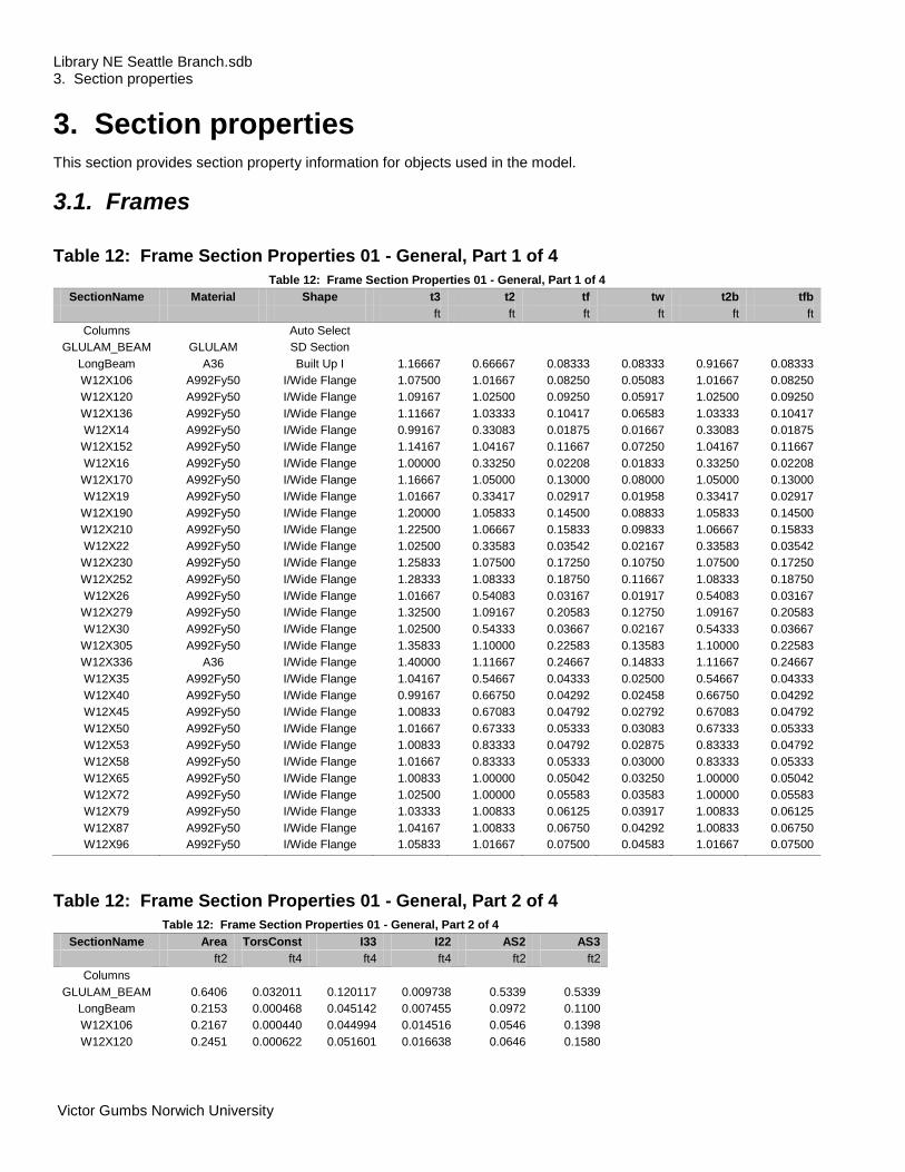
Table 12: Frame Section Properties 01 - General, Part 1 of 4
Table 12: Frame Section Properties 01 - General, Part 1 of 4
SectionName Material Shape t3 t2 tf tw t2b tfb
ft ft ft ft ft ft
Columns Auto Select
GLULAM_BEAM GLULAM SD Section
LongBeam A36 Built Up I 1.16667 0.66667 0.08333 0.08333 0.91667 0.08333
W12X106 A992Fy50 I/Wide Flange 1.07500 1.01667 0.08250 0.05083 1.01667 0.08250
W12X120 A992Fy50 I/Wide Flange 1.09167 1.02500 0.09250 0.05917 1.02500 0.09250
W12X136 A992Fy50 I/Wide Flange 1.11667 1.03333 0.10417 0.06583 1.03333 0.10417
W12X14 A992Fy50 I/Wide Flange 0.99167 0.33083 0.01875 0.01667 0.33083 0.01875
W12X152 A992Fy50 I/Wide Flange 1.14167 1.04167 0.11667 0.07250 1.04167 0.11667
W12X16 A992Fy50 I/Wide Flange 1.00000 0.33250 0.02208 0.01833 0.33250 0.02208
W12X170 A992Fy50 I/Wide Flange 1.16667 1.05000 0.13000 0.08000 1.05000 0.13000
W12X19 A992Fy50 I/Wide Flange 1.01667 0.33417 0.02917 0.01958 0.33417 0.02917
W12X190 A992Fy50 I/Wide Flange 1.20000 1.05833 0.14500 0.08833 1.05833 0.14500
W12X210 A992Fy50 I/Wide Flange 1.22500 1.06667 0.15833 0.09833 1.06667 0.15833
W12X22 A992Fy50 I/Wide Flange 1.02500 0.33583 0.03542 0.02167 0.33583 0.03542
W12X230 A992Fy50 I/Wide Flange 1.25833 1.07500 0.17250 0.10750 1.07500 0.17250
W12X252 A992Fy50 I/Wide Flange 1.28333 1.08333 0.18750 0.11667 1.08333 0.18750
W12X26 A992Fy50 I/Wide Flange 1.01667 0.54083 0.03167 0.01917 0.54083 0.03167
W12X279 A992Fy50 I/Wide Flange 1.32500 1.09167 0.20583 0.12750 1.09167 0.20583
W12X30 A992Fy50 I/Wide Flange 1.02500 0.54333 0.03667 0.02167 0.54333 0.03667
W12X305 A992Fy50 I/Wide Flange 1.35833 1.10000 0.22583 0.13583 1.10000 0.22583
W12X336 A36 I/Wide Flange 1.40000 1.11667 0.24667 0.14833 1.11667 0.24667
W12X35 A992Fy50 I/Wide Flange 1.04167 0.54667 0.04333 0.02500 0.54667 0.04333
W12X40 A992Fy50 I/Wide Flange 0.99167 0.66750 0.04292 0.02458 0.66750 0.04292
W12X45 A992Fy50 I/Wide Flange 1.00833 0.67083 0.04792 0.02792 0.67083 0.04792
W12X50 A992Fy50 I/Wide Flange 1.01667 0.67333 0.05333 0.03083 0.67333 0.05333
W12X53 A992Fy50 I/Wide Flange 1.00833 0.83333 0.04792 0.02875 0.83333 0.04792
W12X58 A992Fy50 I/Wide Flange 1.01667 0.83333 0.05333 0.03000 0.83333 0.05333
W12X65 A992Fy50 I/Wide Flange 1.00833 1.00000 0.05042 0.03250 1.00000 0.05042
W12X72 A992Fy50 I/Wide Flange 1.02500 1.00000 0.05583 0.03583 1.00000 0.05583
W12X79 A992Fy50 I/Wide Flange 1.03333 1.00833 0.06125 0.03917 1.00833 0.06125
W12X87 A992Fy50 I/Wide Flange 1.04167 1.00833 0.06750 0.04292 1.00833 0.06750
W12X96 A992Fy50 I/Wide Flange 1.05833 1.01667 0.07500 0.04583 1.01667 0.07500
Table 12: Frame Section Properties 01 - General, Part 2 of 4
Table 12: Frame Section Properties 01 - General, Part 2 of 4
SectionName Area TorsConst I33 I22 AS2 AS3
ft2 ft4 ft4 ft4 ft2 ft2
Columns
GLULAM_BEAM 0.6406 0.032011 0.120117 0.009738 0.5339 0.5339
LongBeam 0.2153 0.000468 0.045142 0.007455 0.0972 0.1100
W12X106 0.2167 0.000440 0.044994 0.014516 0.0546 0.1398
W12X120 0.2451 0.000622 0.051601 0.016638 0.0646 0.1580

Library NE Seattle Branch.sdb SAP2000 v15.1.0 3. Section properties 27 May 2012
Victor Gumbs Norwich University Page 15 of 35
Table 12: Frame Section Properties 01 - General, Part 2 of 4
SectionName Area TorsConst I33 I22 AS2 AS3
ft2 ft4 ft4 ft4 ft2 ft2
W12X136 0.2771 0.000892 0.059799 0.019194 0.0735 0.1794
W12X14 0.0289 3.395E-06 0.004273 0.000114 0.0165 0.0103
W12X152 0.3104 0.001244 0.068962 0.021894 0.0828 0.2025
W12X16 0.0327 4.967E-06 0.004967 0.000136 0.0183 0.0122
W12X170 0.3472 0.001717 0.079572 0.024932 0.0933 0.2275
W12X19 0.0387 8.681E-06 0.006269 0.000181 0.0199 0.0162
W12X190 0.3875 0.002353 0.091146 0.028405 0.1060 0.2558
W12X210 0.4292 0.003120 0.103202 0.032022 0.1205 0.2815
W12X22 0.0450 0.000014 0.007523 0.000225 0.0222 0.0198
W12X230 0.4701 0.004041 0.116705 0.035783 0.1353 0.3091
W12X252 0.5139 0.005208 0.131173 0.039931 0.1497 0.3385
W12X26 0.0531 0.000014 0.009838 0.000834 0.0195 0.0285
W12X279 0.5688 0.006896 0.149981 0.045187 0.1689 0.3745
W12X30 0.0610 0.000022 0.011478 0.000979 0.0222 0.0332
W12X305 0.6222 0.008922 0.171200 0.050637 0.1845 0.4140
W12X336 0.6861 0.011719 0.195795 0.057388 0.2077 0.4591
W12X35 0.0715 0.000036 0.013744 0.001182 0.0260 0.0395
W12X40 0.0812 0.000044 0.014805 0.002127 0.0244 0.0477
W12X45 0.0910 0.000061 0.016782 0.002411 0.0281 0.0536
W12X50 0.1014 0.000082 0.018856 0.002715 0.0313 0.0599
W12X53 0.1083 0.000076 0.020496 0.004620 0.0290 0.0666
W12X58 0.1181 0.000101 0.022907 0.005160 0.0305 0.0741
W12X65 0.1326 0.000105 0.025704 0.008391 0.0328 0.0840
W12X72 0.1465 0.000141 0.028791 0.009404 0.0367 0.0931
W12X79 0.1611 0.000185 0.031925 0.010417 0.0405 0.1029
W12X87 0.1778 0.000246 0.035687 0.011622 0.0447 0.1134
W12X96 0.1958 0.000330 0.040172 0.013021 0.0485 0.1271
Table 12: Frame Section Properties 01 - General, Part 3 of 4
Table 12: Frame Section Properties 01 - General, Part 3 of 4
SectionName S33 S22 Z33 Z22 R33 R22
ft3 ft3 ft3 ft3 ft ft
Columns
GLULAM_BEAM 0.160156 0.045600 0.240234 0.068400 0.43301 0.12329
LongBeam 0.071006 0.016265 0.091001 0.028501 0.45792 0.18609
W12X106 0.083710 0.028556 0.094907 0.043461 0.45570 0.25884
W12X120 0.094536 0.032464 0.107639 0.049421 0.45880 0.26052
W12X136 0.107103 0.037149 0.123843 0.056713 0.46456 0.26319
W12X14 0.008617 0.000688 0.010069 0.001100 0.38458 0.06277
W12X152 0.120810 0.042037 0.140625 0.064236 0.47134 0.26558
W12X16 0.009934 0.000818 0.011632 0.001308 0.38970 0.06448
W12X170 0.136409 0.047490 0.159144 0.072917 0.47871 0.26797
W12X19 0.012333 0.001085 0.014294 0.001725 0.40259 0.06847
W12X190 0.151910 0.053678 0.179977 0.082755 0.48499 0.27074
W12X210 0.168493 0.060041 0.201389 0.092014 0.49038 0.27315
W12X22 0.014679 0.001338 0.016956 0.002118 0.40888 0.07067
W12X230 0.185492 0.066573 0.223380 0.102431 0.49823 0.27588
W12X252 0.204425 0.073718 0.247685 0.113426 0.50523 0.27875
W12X26 0.019353 0.003085 0.021528 0.004728 0.43033 0.12532
W12X279 0.226386 0.082786 0.278356 0.127315 0.51352 0.28187
W12X30 0.022395 0.003604 0.024942 0.005532 0.43362 0.12664
W12X305 0.252073 0.092066 0.310764 0.141204 0.52454 0.28527

Library NE Seattle Branch.sdb SAP2000 v15.1.0 3. Section properties 27 May 2012
Victor Gumbs Norwich University Page 16 of 35
Table 12: Frame Section Properties 01 - General, Part 3 of 4
SectionName S33 S22 Z33 Z22 R33 R22
ft3 ft3 ft3 ft3 ft ft
W12X336 0.279707 0.102785 0.348958 0.158565 0.53420 0.28921
W12X35 0.026389 0.004323 0.029630 0.006655 0.43835 0.12852
W12X40 0.029859 0.006372 0.032986 0.009722 0.42687 0.16179
W12X45 0.033287 0.007189 0.037153 0.010995 0.42951 0.16281
W12X50 0.037094 0.008065 0.041609 0.012326 0.43125 0.16364
W12X53 0.040653 0.011088 0.045081 0.016840 0.43496 0.20651
W12X58 0.045063 0.012384 0.050000 0.018808 0.44050 0.20907
W12X65 0.050983 0.016782 0.056019 0.025521 0.44022 0.25152
W12X72 0.056177 0.018808 0.062500 0.028472 0.44327 0.25333
W12X79 0.061791 0.020661 0.068866 0.031424 0.44515 0.25427
W12X87 0.068519 0.023052 0.076389 0.034954 0.44804 0.25569
W12X96 0.075915 0.025615 0.085069 0.039063 0.45291 0.25786
Table 12: Frame Section Properties 01 - General, Part 4 of 4
Table 12: Frame Section Properties 01 - General, Part 4 of 4
SectionName AMod A2Mod A3Mod JMod I2Mod I3Mod MMod WMod
Columns
GLULAM_BEAM 1.000000 1.000000 1.000000 1.000000 1.000000 1.000000 1.000000 1.000000
LongBeam 1.000000 1.000000 1.000000 1.000000 1.000000 1.000000 1.000000 1.000000
W12X106 1.000000 1.000000 1.000000 1.000000 1.000000 1.000000 1.000000 1.000000
W12X120 1.000000 1.000000 1.000000 1.000000 1.000000 1.000000 1.000000 1.000000
W12X136 1.000000 1.000000 1.000000 1.000000 1.000000 1.000000 1.000000 1.000000
W12X14 1.000000 1.000000 1.000000 1.000000 1.000000 1.000000 1.000000 1.000000
W12X152 1.000000 1.000000 1.000000 1.000000 1.000000 1.000000 1.000000 1.000000
W12X16 1.000000 1.000000 1.000000 1.000000 1.000000 1.000000 1.000000 1.000000
W12X170 1.000000 1.000000 1.000000 1.000000 1.000000 1.000000 1.000000 1.000000
W12X19 1.000000 1.000000 1.000000 1.000000 1.000000 1.000000 1.000000 1.000000
W12X190 1.000000 1.000000 1.000000 1.000000 1.000000 1.000000 1.000000 1.000000
W12X210 1.000000 1.000000 1.000000 1.000000 1.000000 1.000000 1.000000 1.000000
W12X22 1.000000 1.000000 1.000000 1.000000 1.000000 1.000000 1.000000 1.000000
W12X230 1.000000 1.000000 1.000000 1.000000 1.000000 1.000000 1.000000 1.000000
W12X252 1.000000 1.000000 1.000000 1.000000 1.000000 1.000000 1.000000 1.000000
W12X26 1.000000 1.000000 1.000000 1.000000 1.000000 1.000000 1.000000 1.000000
W12X279 1.000000 1.000000 1.000000 1.000000 1.000000 1.000000 1.000000 1.000000
W12X30 1.000000 1.000000 1.000000 1.000000 1.000000 1.000000 1.000000 1.000000
W12X305 1.000000 1.000000 1.000000 1.000000 1.000000 1.000000 1.000000 1.000000
W12X336 1.000000 1.000000 1.000000 1.000000 1.000000 1.000000 1.000000 1.000000
W12X35 1.000000 1.000000 1.000000 1.000000 1.000000 1.000000 1.000000 1.000000
W12X40 1.000000 1.000000 1.000000 1.000000 1.000000 1.000000 1.000000 1.000000
W12X45 1.000000 1.000000 1.000000 1.000000 1.000000 1.000000 1.000000 1.000000
W12X50 1.000000 1.000000 1.000000 1.000000 1.000000 1.000000 1.000000 1.000000
W12X53 1.000000 1.000000 1.000000 1.000000 1.000000 1.000000 1.000000 1.000000
W12X58 1.000000 1.000000 1.000000 1.000000 1.000000 1.000000 1.000000 1.000000
W12X65 1.000000 1.000000 1.000000 1.000000 1.000000 1.000000 1.000000 1.000000
W12X72 1.000000 1.000000 1.000000 1.000000 1.000000 1.000000 1.000000 1.000000
W12X79 1.000000 1.000000 1.000000 1.000000 1.000000 1.000000 1.000000 1.000000
W12X87 1.000000 1.000000 1.000000 1.000000 1.000000 1.000000 1.000000 1.000000
W12X96 1.000000 1.000000 1.000000 1.000000 1.000000 1.000000 1.000000 1.000000

Library NE Seattle Branch.sdb SAP2000 v15.1.0 4. Load patterns 27 May 2012
Victor Gumbs Norwich University Page 17 of 35
3.2. Areas
Table 13: Area Section Properties, Part 1 of 2
Table 13: Area Section Properties, Part 1 of 2
Section Material AreaType Type DrillDOF Thickness BendThick F11Mod F22Mod F12Mod M11Mod M22Mod
ft ft
ROOF 4000Psi Shell Shell-Thin Yes 0.41667 0.41667 1.000000 1.000000 1.000000 1.000000 1.000000
Table 13: Area Section Properties, Part 2 of 2
Table 13: Area Section Properties, Part 2 of 2
Section M12Mod V13Mod V23Mod MMod WMod
ROOF 1.000000 1.000000 1.000000 1.000000 1.000000
4. Load patterns This section provides loading information as applied to the model.
4.1. Definitions
Table 15: Load Pattern Definitions
Table 15: Load Pattern Definitions
LoadPat DesignType SelfWtMult AutoLoad
PowerSpectralDensity_PSD
OTHER 0.000000
5. Load cases This section provides load case information.
5.1. Definitions
Table 16: Load Case Definitions
Table 16: Load Case Definitions
Case Type InitialCond ModalCase BaseCase DesActOpt DesignAct
MODAL LinModal Zero Prog Det Other
LIVE1 LinStatic Zero Prog Det Short-Term Composite
WIND1 LinStatic Zero Prog Det Short-Term Composite
PSD LinPower Zero MODAL Prog Det Other

Library NE Seattle Branch.sdb SAP2000 v15.1.0 6. Load combinations 27 May 2012
Victor Gumbs Norwich University Page 18 of 35
5.2. Static case load assignments
Table 17: Case - Static 1 - Load Assignments
Table 17: Case - Static 1 - Load Assignments
Case LoadType LoadName LoadSF
LIVE1 Load pattern LIVE 1.000000
WIND1 Load pattern WIND 1.000000
5.3. Response spectrum case load assignments
Table 18: Function - Response Spectrum - User
Table 18: Function - Response Spectrum - User
Name Period Accel FuncDamp
Sec
UNIFRS 0.000000 1.000000 0.050000
UNIFRS 1.000000 1.000000
6. Load combinations This section provides load combination information.
Table 19: Combination Definitions
Table 19: Combination Definitions
ComboName ComboType CaseName ScaleFactor
UDSTL1 Linear Add
UDSTL2 Linear Add
UDSTL3 Linear Add
UDSTL4 Linear Add
UDSTL5 Linear Add
UDSTL6 Linear Add
UDSTL7 Linear Add
UDSTL8 Linear Add
UDSTL9 Linear Add
UDSTL10 Linear Add LIVE1 1.600000
UDSTL11 Linear Add LIVE1 1.000000
UDSTL11 WIND1 1.600000
UDSTL12 Linear Add LIVE1 1.000000
UDSTL12 WIND1 -1.600000
UDSTL13 Linear Add WIND1 1.600000
UDSTL14 Linear Add WIND1 -1.600000
UDSTL15 Linear Add
UDSTL16 Linear Add LIVE1 1.000000

Library NE Seattle Branch.sdb SAP2000 v15.1.0 6. Load combinations 27 May 2012
Victor Gumbs Norwich University Page 19 of 35

Library NE Seattle Branch.sdb SAP2000 v15.1.0 6. Load combinations 27 May 2012
Victor Gumbs Norwich University Page 20 of 35
Appendix
References:
I. ASCE-SEI 7-05 ASCE Minimum Design Loads For Building & Structures was consulted for the review of Load
Combinations, Live Loads, Wind Loads, Snow Loads, Rain Loads, Ice Loads, Ice Loads, Seismic Design Criteria,
Seismic Response Time History, Seismic Ground Motion and Long-Period Transition Maps
II. All drawing were created and implemented with AutoCAD Civil 3D, Autodesk REVIT, Autodesk Inventor, all
Autodesk products were version 2011 and SAP2000 v 15.1.01
III. Visual Analysis was initialy used but abandoned due to issues of compatibility with computer hardware that
were unresoled at this time.
IV. Photographs and Drawings of the Structure: Seattle Public Library NE Branch
Shot from 35th Avenue NE & 68th Streets; 6801 35th Avenue NE, Seattle, WA 98115

Library NE Seattle Branch.sdb SAP2000 v15.1.0 6. Load combinations 27 May 2012
Victor Gumbs Norwich University Page 21 of 35
3D Detail Drawing of Built-Up Beam Collar Connection to Support Column and showing connection for Glulam to Roof Beam/Joist to Lighweight Concret Roof.
3D Detail Drawing of Built-Up Beam of Half Span Transitioning into Standard Wide Flage Beam for the central support of the structure.
Library NE Seattle Branch.sdb SAP2000 v15.1.0 6. Load combinations 27 May 2012
Victor Gumbs Norwich University Page 22 of 35
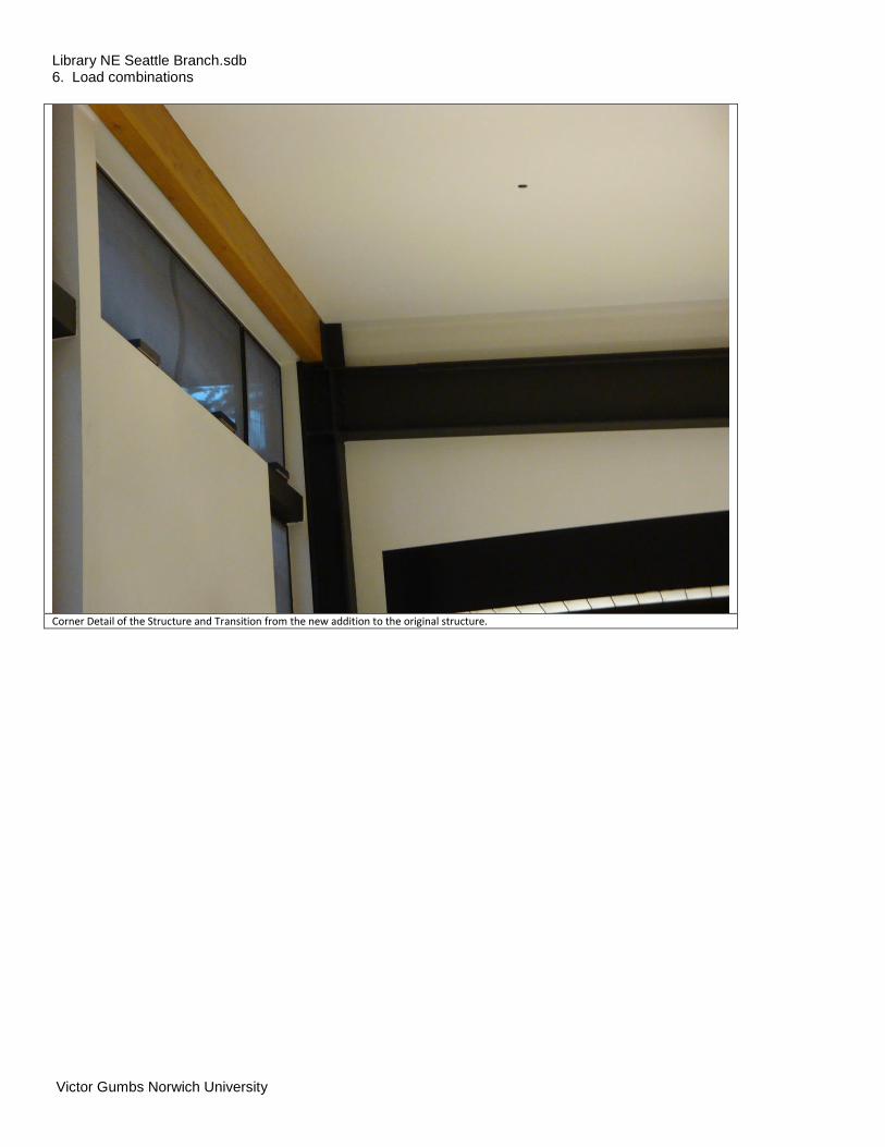
Corner Detail of the Structure and Transition from the new addition to the original structure.

Library NE Seattle Branch.sdb SAP2000 v15.1.0 6. Load combinations 27 May 2012
Victor Gumbs Norwich University Page 23 of 35
Long Span View of internal structure.

Library NE Seattle Branch.sdb SAP2000 v15.1.0 6. Load combinations 27 May 2012
Victor Gumbs Norwich University Page 24 of 35
Another Span Detail Photograph showing the Glulam to Roof Support Connection.

Library NE Seattle Branch.sdb SAP2000 v15.1.0 6. Load combinations 27 May 2012
Victor Gumbs Norwich University Page 25 of 35
V. Various Analysis Screen Shots
VI. Deformed Shape of the Structue Mode 1 Analysis
VII. Stress maping of the Roof of the Structure.

Library NE Seattle Branch.sdb SAP2000 v15.1.0 6. Load combinations 27 May 2012
Victor Gumbs Norwich University Page 26 of 35
VIII. Shear Moment Diagram under LRFD Load Combinations.
IX. Wind Load Applying Windward Positive and Leeward Negative Pressures to the Roof Structure.

Library NE Seattle Branch.sdb SAP2000 v15.1.0 6. Load combinations 27 May 2012
Victor Gumbs Norwich University Page 27 of 35
Visible Labels of easy identification for report referencing.

Library NE Seattle Branch.sdb SAP2000 v15.1.0 6. Load combinations 27 May 2012
Victor Gumbs Norwich University Page 28 of 35
PSD Plot with an Impule Load of 20000lb at each joint along the logitudnial axis of the building.
Moment Diagram for the PSD Plot with an Impule Load of 20000lb at each joint along the logitudnial axis of the building.

Library NE Seattle Branch.sdb SAP2000 v15.1.0 6. Load combinations 27 May 2012
Victor Gumbs Norwich University Page 29 of 35
Deformed Shape showing the deflection after 20000lb impulse appleid for one second to the joints alond the loginitudnal axis of the building.
Windload diagram illustrating applied positive pressure of 15lbs/sq in on the windward side of the roof panels, and a negative -6 lbs/sq in applied on the leeward roof panels of the building, per ASCE 7-05.

Library NE Seattle Branch.sdb SAP2000 v15.1.0 6. Load combinations 27 May 2012
Victor Gumbs Norwich University Page 30 of 35
Run of the full spectrum of load cases: Live, Dead, Wind, PSD (1 second impulse 20000 lbs force applied to lateral joints), Modal 1 to 4.

Library NE Seattle Branch.sdb SAP2000 v15.1.0 27 May 2012
Victor Gumbs Norwich University Page 31 of 35
X. Instrumentation:
Hilti PD 30/PD 32 laser range meters: Key Specifications Hilti Corporation www.hilti.com FL-9494 Schaan Principality of Liechtenstein
Technical data
Accuracy: ±1.5 mm (1/16 in)
Range: 5 cm to 70 m (2 in to 200 ft) w/o target plate, with target plate PDA 50 up to 200 m (600 ft)
Reference points: Front, rear, spike
Units: Meter, millimeter, inch decimal, feet/inch/fraction 1/8,
feet/inch/fraction 1/16, feet decimal, yard
Data memory: Last 5 measurements and calculation results with graphics
Laser: 635 nm, class 2 (IEC 825-1), class II (FDA 21 CFR)
IP protection: IP 54
Power supply: Standard: 2 AA alkaline batteries; Optional: 2 NiMH rechargeable batteries, charge from mains 100–240 V or car 12–24 V