Maryland Solar Decathlon 2011 Project Manual
462
U.S. Department of Energy Solar Decathlon 2011 Team Maryland As-Built Project Manual Primary Faculty Contact: Primary Student Contact: Amy Gardner Allison Wilson School of Architecture, Planning, and Preservation School of Architecture, Planning, and Preservation College Park, MD 20742 College Park, MD 20742 [email protected] [email protected] 301.405.6303 973.978.8941 11 August 2011
-
Upload
khangminh22 -
Category
Documents
-
view
6 -
download
0
Transcript of Maryland Solar Decathlon 2011 Project Manual

U.S. Department of Energy Solar Decathlon 2011
Team Maryland
As-Built Project Manual
Primary Faculty Contact: Primary Student Contact: Amy Gardner Allison Wilson
School of Architecture, Planning, and Preservation
School of Architecture, Planning, and Preservation
College Park, MD 20742 College Park, MD 20742 [email protected] [email protected]
301.405.6303 973.978.8941
11 August 2011

Team Maryland
University of Maryland
U.S. D.O.E. Solar Decathlon 2011 Page - 2 TABLE OF CONTENTS
TABLE OF CONTENTS
Cover Page 1Table of Contents 2Summary of Changes 5Rules Compliance Checklist 14Structural Calculations 17Detailed Water Budget 18Summary of Unlisted Electrical Components 19Summary of Reconfigurable Features 20Interconnection Application Form 22Energy Analysis Results and Discussion 26Liquid Desiccant System Description 54Architectural Design Narrative 59Target Market Justification 61Engineering Design Narrative 63Construction Specifications 65 Division 01 – General Requirements 01 54 19 Temporary Cranes 01 54 23 Temporary Scaffolding and Platforms Division 05 – Metals 05 12 00 Structural Steel Framing 05 52 13 Pipe and Tube Railings 05 53 00 Metal Gratings 05 58 00 Formed Metal Fabrications Division 06 – Wood, Plastics, and Composites 06 05 23 Wood, Plastic, and Composite Fastenings 06 10 00 Rough Carpentry 06 11 00 Wood Framing 06 11 13 Engineered Wood Products 06 15 33 Wood Deck 06 16 00 Sheathing 06 16 23 Subflooring 06 17 13 Laminated Veneer Lumber 06 20 13 Exterior Finish Carpentry 06 20 23 Interior Finish Carpentry 06 40 16 Interior Architectural Woodwork Division 07 – Thermal and Moisture Protection 07 21 13 Board Insulation 07 21 16 Blanket Insulation 07 21 29 Sprayed Insulation 07 27 26 Fluid-Applied Membrane Air Barriers 07 33 63 Vegetated Roofing 07 42 13 Metal Wall Panels 07 54 23 Thermoplastic-Polyolefin Roofing 07 61 13 Standing Seam Sheet Metal Roofing 07 62 00 Sheet Metal Flashing and Trim 07 71 00 Roof Specialties 07 91 16 Joint Gaskets

Team Maryland
University of Maryland
U.S. D.O.E. Solar Decathlon 2011 Page - 3 TABLE OF CONTENTS
07 92 00 Joint Sealants Division 08 – Openings 08 14 00 Wood Doors 08 45 00 Translucent Wall and Roof Assemblies 08 50 00 Windows 08 95 16 Wall Vents Division 09 – Finishes 09 29 00 Gypsum Board 09 30 13 Ceramic Tiling 09 64 19 Wood Composition Flooring 09 91 23 Interior Painting 09 93 13 Exterior Staining and Finishing 09 93 23 Interior Staining and Finishing Division 10 – Specialties 10 28 16.13 Residential Bath Accessories Division 11 – Equipment 11 30 00 Residential Equipment 11 31 13 Residential Kitchen Appliances 11 31 23 Residential Laundry Appliances Division 12 – Furnishings 12 20 00 Window Treatments 12 35 30.13 Kitchen Casework 12 36 13 Concrete Countertops Division 21 – Fire Suppression 21 13 13 Wet Pipe Sprinkler System Division 22 – Plumbing 22 11 16 Domestic Water Piping 22 11 19 Domestic Water Piping Specialties 22 11 23 Domestic Water Pumps 22 12 19 Facility Potable-Water Storage Tanks 22 13 16 Sanitary Waste and Vent Piping 22 13 53 Facility Septic Tanks 22 33 30 Residential, Electric Domestic Water Heater 22 41 13 Residential Water Closets, Urinals, and Bidets 22 41 16 Residential Lavatories and Sinks 22 41 23 Residential Shower Receptors and Basins 22 41 26 Residential Disposers 22 41 39 Residential Faucets, Supplies, and Trim Division 23 – Heating, Ventilating, and Air-Conditioning (HVAC) 23 07 00 HVAC Insulation 23 09 13 Instrumentation and Control Devices for HVAC 23 20 00 HVAC Piping and Pumps 23 23 00 Refrigerant Piping 23 23 23 Refrigerants 23 31 13 Metal Ducts 23 34 13 Axial HVAC Fans 23 37 13 Diffusers, Registers, and Grilles 23 56 13.19 Heating Solar Vacuum-Tube Collectors 23 57 00 Heat Exchangers for HVAC

Team Maryland
University of Maryland
U.S. D.O.E. Solar Decathlon 2011 Page - 4 TABLE OF CONTENTS
23 72 00 Air-to-Air Energy Recovery Equipment 23 81 26 Split-System Air-Conditioners 23 83 13.16 Radiant Heating Units 23 84 00 Humidity Control Equipment Division 25 – Integrated Automation 25 05 00 Common Work Results for Integrated Automation 25 10 00 Integrated Automation Network Equipment Division 26 – Electrical 26 05 26 Grounding and Bonding for Electrical Systems 26 05 19 Low-Voltage Electrical Power Conductors and Cables 26 05 33 Raceway and Boxes for Electrical Systems 26 24 16 Panelboards 26 27 26 Wiring Devices 26 31 00 Photovoltaic Collectors 26 32 00 Packaged Generator Assemblies 26 50 00 Lighting Division 28 – Electronic Safety and Security 28 31 46 Smoke Detection Sensors Division 31 – Earthwork 31 66 00 Special Foundations Division 32 – Exterior Improvements 32 71 00 Constructed Wetlands Division 48 – Electrical Power Generation 48 19 16 Electrical Power Generation Inverters
Appendix A: Structural Calculations

Team Maryland
University of Maryland
U.S. D.O.E. Solar Decathlon 2011 Page - 5 SUMMARY OF CHANGES
SUMMARY OF CHANGES
Team Maryland’s document set has been revised twice since its initial design development set to the Solar Decathlon. Find below two sets of changes, the first changes between the 100% Construction Documents set and this As-Built Document set and second changes between the 80% Design Development set and the 100% Construction Documents set.
CHANGES BETWEEN THE 100% CONSTRUCTION DOCUMENTS SET AND THE AS-BUILT DOCUMENT SET:
CHANGES TO THE DRAWING SET: G-102, G-103, C-102 – Ramp Slope Slope of ramp/walking surface was decreased to 1:21 or less. S-Series – Structural Carrying Beams Four triple pack beams, composed of (3)2x10 wood members, added across foundation pads in the east/west direction for lifting during transport. A-Series – Interior Wall Reveal Wall reveal at 3’6” above finish floor was deleted. Upper wall reveal expanded from 6” to 9 ½”. A-Series – Interior Baseboard Baseboard changed from extruded base to recessed base with trim detail. A-Series – Exterior Trim Material Change Doug Fir used on exterior finish carpentry on Module B (middle). A-Series – Interior Trim Material Doug Fir trim added at LVL roof joint, baseboard and around all fenestration. C-102 – Site Plan and A-100 SERIES Removed railing and gate on south and west sides of pergola deck. Added 36” platform, 18” grade. A-111 – Bathroom Material Changes Bathroom ceiling changed from corrugated metal to MDO plywood. Bathroom walls, ceiling and floor in toilet and lavatory niche changed from drywall to vertical grain bamboo panels. Shower floor changed to milled, woven strand bamboo flooring. A-301, A-313 – Interior Parapet Wall Added Parapet wall added above desk niche in Module C. A-314 – Shade Pockets Added Recessed shade pocket added in ceiling above both windows in Module B. A-200s, A300s – Foundations Perimeter jackstand footings changed to adjustable lock deck foundation pads.

Team Maryland
University of Maryland
U.S. D.O.E. Solar Decathlon 2011 Page - 6 SUMMARY OF CHANGES
A-402 – Kitchen Changes Kitchen cabinet dimensions and layout changed slightly to meet typical cabinet sizing. A-401, A-402 – Countertop Material Kitchen and bathroom countertops changed to concrete. A-411, A-412 – Wetland Finish Material Wetland modules wrapped in corrugated metal and poplar trim. A-516, E-401 – Weatherhead Din rail box changed to weatherhead on Module B roof. A-518, S-500 – Pergola Structure Pergola framing changed from aluminum to structural steel tubes. F-101 – Fire Protection Fire protection drawings replaced with drawings from “Absolute, Fire Protection, Inc” engineer. O-Series – Operations Site operation plans updated per new site information. F-SERIES – Fire Suppression Layout Third Party Fire Suppression Contractor updated fire suppression plan to comply with 2009 IRC. P-Series – LDW Added lighting to LDW specification. P-101 – Supply Tank Water Piping Updated supply tank piping to 4” PVC. P-101 – Domestic Water Piping Added Hose Bibb to West Exterior Wall of Module C. P-102 – Heating Solar Collectors Changed glycol loop piping from PEX tubing to copper piping. P-102 – Regenerator Changed location of Regenerator, updated specifications and increased size of regenerator. P-104 – HXEST Water Piping Changed mechanical room piping from PEX tubing to copper piping. P-111 – Domestic Water Piping Changed dishwasher piping to connect to kitchen sink hot water piping. P-112 – Sanitary Waste and Vent Piping Deleted Air Admittance Valves. P-112 – Sanitary Waste and Vent Piping

Team Maryland
University of Maryland
U.S. D.O.E. Solar Decathlon 2011 Page - 7 SUMMARY OF CHANGES
Changed waste and vent piping layout. P-112 – Waste Filtration System Added pumps and piping for waste filtration system. P-401 – Water Storage Tanks Changed expansion tank layout and products. P-401 – PEX Manifold Changed PEX Manifold Layout and added copper piping. M-SERIES – HVAC Insulation Added insulted flex duct to mechanical room. M-SERIES – Metal Ducts Spiral Duct substituted for hard ducting. M-SERIES – Duct Layout Revised supply and return runs. M-SERIES – Diffusers, Registers and Grilles Added and updated interior and exterior grilles. E-101 – Interior Electrical Distribution Plan Adjustments to quantity and location of outlets throughout house. E-102 – Exterior Electrical Distribution Plan Sheet added. Outlets added beneath house. E-104 – Lighting Plan Updated lighting schedule and added fixtures. Removed dimmer panel and added button stations. CHANGES TO THE PROJECT MANUAL: XX XX XX Where multiple manufacturers or products were listed, divisions have been updated to reflect product actually install in Project. 01 54 19 Temporary Cranes Crane specification changed to 130 ton model. 05 05 23 Metal Fastenings Division deleted and products listed as accessories under 26 31 00. 05 15 16 Steel Wire Rope Assemblies Division deleted to reflect changes to the scope of work. 05 05 23 Metal Fastenings Division deleted and products listed as accessories under 26 31 00.

Team Maryland
University of Maryland
U.S. D.O.E. Solar Decathlon 2011 Page - 8 SUMMARY OF CHANGES
06 20 23 Interior Finish Carpentry Division added to describe finish trim materials throughout house. 07 71 23 Manufactured Gutters and Downspouts Eliminated from project. Materials consolidated into 07 62 00 Sheet Metal Flashing and Trim. 11 31 XX Residential Appliance Appliance selections updated to different manufacturers and models. 22 41 26 Residental Disposers Division added to describe garbage disposal element. 26 05 26 Grounding and Bonding for Electrical Systems Division added to describe grounding rod. 26 32 00 Packaged Generator Assemblies Division added to describe generator to be used during competition construction. 22 41 26 Residential Disposers Division added to reflect changes to the scope of work. 25 XX XX Integrated Automated Changes in manufacturer and product selection to accommodate changes in design. 25 30 00 Integrated Automation Instrumentation and Terminal Devices Division deleted to reflect changes to the scope of work.
CHANGES BETWEEN THE 80% DESIGN DEVELOPMENT SET AND THE 100% CONSTRUCTION DOCUMENTS SET:
CHANGES TO THE DRAWING SET: A-SERIES – Stair Exterior stair off west deck was deleted per competition requirements. A-SERIES – Module B Floor Extents of wood and tile flooring were changed. A-SERIES – Shower Floor Shower floor grated added to the shower. A-SERIES – Murphy Bed Murphy Bed removed. A-101, A-302 – Pergola Structure Columns and frame become 4” x 4” aluminum tubing. Columns are clad with 3/4” of exterior finish wood material. Details were added to document changes. A-103 – PFAS

Team Maryland
University of Maryland
U.S. D.O.E. Solar Decathlon 2011 Page - 9 SUMMARY OF CHANGES
Fall arrested updated on Module C Roof; Added to Module B Roof. A-202, A-303 – Exterior Wall Cladding Exterior finish at mechanical room and solar thermal wall changed from corrugated metal panel to shiplap siding with splines. A-312, A-515 – South Wall South wall moved adjacent to house on the east deck where structure lines up with south module’s southernmost wall. Details updated to document changes. Top of wall elevated to roof break. Solar tubes moves up on wall. Bottom of tubes are above the 36” knee wall that was added below to act as a railing/barrier. C-101 – Site Location Solar Village drawing, including layout and lot numbers was updated in response to latest information provided. F-101 – Sprinkler Addition of sprinkler head in Mechanical Closet. M-101 – Mechanical Dryer Duct and Electric Radiant Floor Mat in bathroom added. P-SERIES – PEX PEX tubing runs are updated throughout the drawings. P-112 – Greywater Cistern Greywater Cistern with pumps and piping added. P-112 – Plumbing Settling Tank and Waste Water Pump added. E-101 – Receptacles Added Office Receptacles, 4 GFCI Mechanical Room Receptacles, and Weather Proof Exterior Receptacles on West wall of Module C. E-103 – Lighting Added Two “M” lights to Northwest Deck, two “M” lights to Entrance Deck, “F” rope lights to Entrance Deck, and “R” lights to South wall of Module C. Removed “A” light, three “J” lights in Kitchen, two lights in Bathroom and one in ceiling. E-104 – Hardwired Electrical Added Thermostat and switch for Radiant Floor Mat in Bathroom. E-401 – Grounding Rod Grounding Rod was added. E-6XX – Schedules Updated Schedules and included required information.

Team Maryland
University of Maryland
U.S. D.O.E. Solar Decathlon 2011 Page - 10 SUMMARY OF CHANGES
T-101 – Dimmer Panel Dimmer Panel was removed and remaining panels were relocated. CHANGES TO THE PROJECT MANUAL: 05 12 00 – Structural Steel Framing This section was removed from the scope of WaterShed’s design. 05 14 00 – Structural Aluminum Framing This section was added to the project manual to identify the structural elements of the pergola at the northwest deck. 05 15 16 – Steel Wire Rope Assemblies This section was added to the project manual to identify elements that will support plants on the green walls of the southeast deck. 06 10 00 – Rough Carpentry Section was significantly revised in order to clarify WaterShed’s carpentry specifications. Siding moved to section 06 20 13. Decking moved to section 06 15 33. All structural wood members moved to section 06 11 00. Furring strips added to this section. 06 11 00 – Wood Framing This section was added to identify wood members used for structural purposes. 06 11 13 – Engineered Wood Products Subflooring and LVL’s were removed from this section and new sections 06 16 23 and 06 17 13 were created. 06 15 33 – Wood Deck This section was added to identify exterior decking assemblies. 06 16 23 – Subflooring This section was added to identify the ¾” ceramic tile underlayment and the 1 1/8” Advantek subfloor. 06 17 13 – LVL This section added to identify the Laminated Veneer Lumber locations in WaterShed. 07 21 13 – Board Insulation This section was expanded to include the addition of Extruded Polystyrene for use on exterior of walls, and the addition of Composite Board Insulation for use on North Roof. 07 21 16 – Blanket Insulation This section added to include fiberglass-free batt insulation for use as an acoustical barrier at bathroom and washer/dryer closet. 07 21 29 – Sprayed Insulation This section expanded to include addition of Open Cell Spray Insulation for use in interior cavities of walls and ceilings.

Team Maryland
University of Maryland
U.S. D.O.E. Solar Decathlon 2011 Page - 11 SUMMARY OF CHANGES
07 25 00 – Weather Barriers This section was removed from the scope of WaterShed’s design. 07 46 23 – Wood Siding This section was removed, and elements from this section were consolidated in to division 06 20 13. 07 71 00 – Roof Specialties This section expanded to include Fall Arrest Anchors and Siding Vents. 07 91 16 – Joint Gaskets This section was added to include information about sill seal and neoprene tape. 08 10 00 – Doors and Frames This section was removed in order to provide better clarity between door types. New sections with greater specificity were created in its stead. 08 14 00 – Wood Doors This section was created to specify interior and exterior wooden doors throughout WaterShed. 08 14 23 – Clad Doors This section was created to specify exterior metal clad doors. 09 28 13 – Cementitious Boards This section was created to lend greater specificity to interior finish board materials. 09 29 00 – Gypsum Board Cementitious Board removed from this section and moved to section 09 28 13. 10 28 16.13 – Residential Bath Accessories Some content within this section was moved to Division 22 – Plumbing Fixtures. 10 71 13 – Exterior Sun Control Devices This section was eliminated and information was consolidated with section 08 14 00. 12 20 00 – Window Treatments This section was revised to reflect changes in window treatment types, and addition of hidden blind pocket assembly. 21 10 00 – Suppression Systems Section number and name changed to reflect more appropriate designation for system. Information moved to new section 21 13 13. 21 13 13 – Wet Pipe Sprinkler System This section created for better designation of fire suppression system. 21 11 00 – Facility Fire-Suppression Water-Service Piping Updated ¾” CPVC pipe to 1 ½” pipe for fire suppression system.

Team Maryland
University of Maryland
U.S. D.O.E. Solar Decathlon 2011 Page - 12 SUMMARY OF CHANGES
21 41 00 – Storage Tanks for Fire-Suppression Water This section was eliminated and information regarding the fire-suppression water storage has been included with section 22 12 19. 22 11 16 – Domestic Water Piping All valves in this section moved to section 22 11 19. PVC pipe moved to section 22 13 16. PEX changed to Uponor Type A. 22 11 19 – Domestic Water Piping Specialties Valves added from section 22 11 16. Ball Valve and PEX manifold manufacturers also updated. 22 12 19 – Facility Potable-Water Storage Tanks Manufacturer and size of pre-heat tank updated. Also added a statement noting reserves for fire suppression system to be included with main potable storage tanks. 22 14 29.16 – Submersible Sump Pumps This section was eliminated and information regarding the submersible sump pump has been included with section 32 71 00. 22 35 00 – Domestic Water Heat Exchangers This section was eliminated and information was moved to section 23 57 00. 22 41 13 – Residential Water Closets, Urinals, and Bidets In-wall plumbing system added. 22 41 00 – Residential Plumbing Fixtures Shower head moved to section 22 41 39. 22 41 23 – Residential Shower Receptors and Basins This section was added to include information about the shower drain assembly. 22 41 39 – Residential Faucets, Supplies, and Trim Shower head and shower mixing valve added to this section. 23 34 13 – Mechanical Room Ventilation Fans This section was added to describe ventilation fans to be used in mechanical room. 23 56 13.19 – Heating Solar Vacuum-Tube Collectors Glycol fluid and pump added to this section. 23 83 13.16 – Radiant Heating Units This section was added to describe the radiant flooring to be installed in WaterShed’s bath module. 26 05 33 – Raceway and Boxes for Electrical Systems ENT and NEMA 4 box for PV wiring on roof added. 26 24 16 – Panel Boards Main and sub panels were changed, and a surge breaker was added.

Team Maryland
University of Maryland
U.S. D.O.E. Solar Decathlon 2011 Page - 13 SUMMARY OF CHANGES
26 28 13 – Fuses This section was removed from the scope of WaterShed’s design. 26 31 00 – Photovoltaic Collectors Roof and Trellis mounting systems added. 28 31 46 – Smoke Detection Sensors This section added for Smoke Detectors to be used in WaterShed. 31 66 00 – Special Foundations Added post and precast concrete footing foundation systems.
Team Maryland
University of Maryland
U.S. D.O.E. Solar Decathlon 2011 Page - 14 RULES COMPLIANCE CHECKLIST
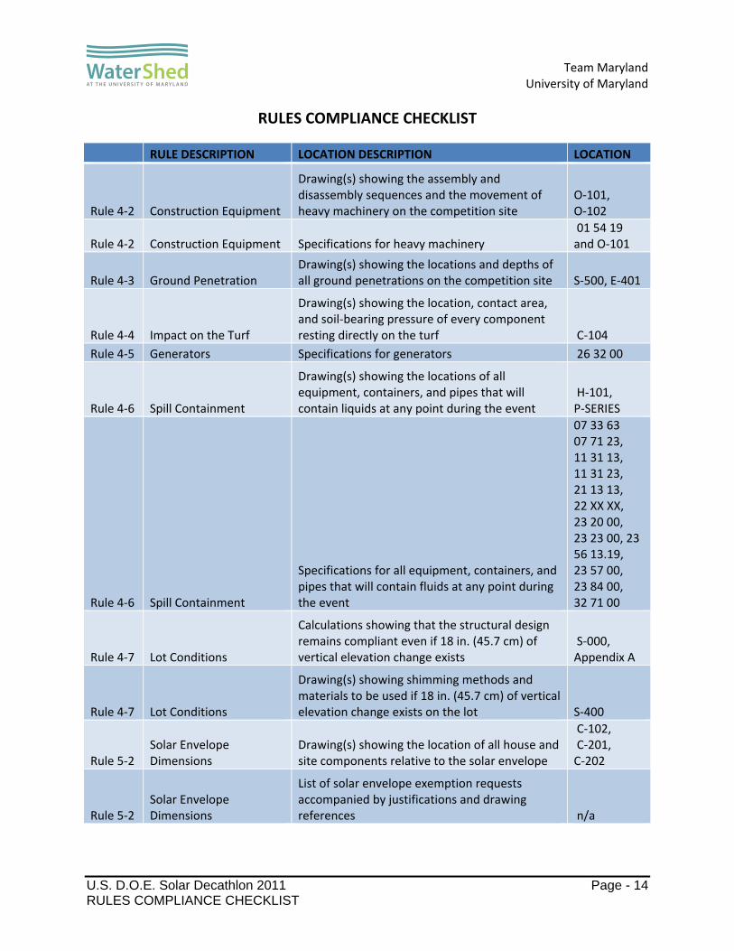
RULES COMPLIANCE CHECKLIST
RULE DESCRIPTION LOCATION DESCRIPTION LOCATION
Rule 4‐2 Construction Equipment
Drawing(s) showing the assembly and disassembly sequences and the movement of heavy machinery on the competition site
O‐101, O‐102
Rule 4‐2 Construction Equipment Specifications for heavy machinery 01 54 19 and O‐101
Rule 4‐3 Ground Penetration Drawing(s) showing the locations and depths of all ground penetrations on the competition site S‐500, E‐401
Rule 4‐4 Impact on the Turf
Drawing(s) showing the location, contact area, and soil‐bearing pressure of every component resting directly on the turf C‐104
Rule 4‐5 Generators Specifications for generators 26 32 00
Rule 4‐6 Spill Containment
Drawing(s) showing the locations of all equipment, containers, and pipes that will contain liquids at any point during the event
H‐101, P‐SERIES
Rule 4‐6 Spill Containment
Specifications for all equipment, containers, and pipes that will contain fluids at any point during the event
07 33 63 07 71 23, 11 31 13, 11 31 23, 21 13 13, 22 XX XX, 23 20 00, 23 23 00, 23 56 13.19, 23 57 00, 23 84 00, 32 71 00
Rule 4‐7 Lot Conditions
Calculations showing that the structural design remains compliant even if 18 in. (45.7 cm) of vertical elevation change exists
S‐000, Appendix A
Rule 4‐7 Lot Conditions
Drawing(s) showing shimming methods and materials to be used if 18 in. (45.7 cm) of vertical elevation change exists on the lot S‐400
Rule 5‐2 Solar Envelope Dimensions
Drawing(s) showing the location of all house and site components relative to the solar envelope
C‐102, C‐201, C‐202
Rule 5‐2 Solar Envelope Dimensions
List of solar envelope exemption requests accompanied by justifications and drawing references n/a
Team Maryland
University of Maryland
U.S. D.O.E. Solar Decathlon 2011 Page - 15 RULES COMPLIANCE CHECKLIST
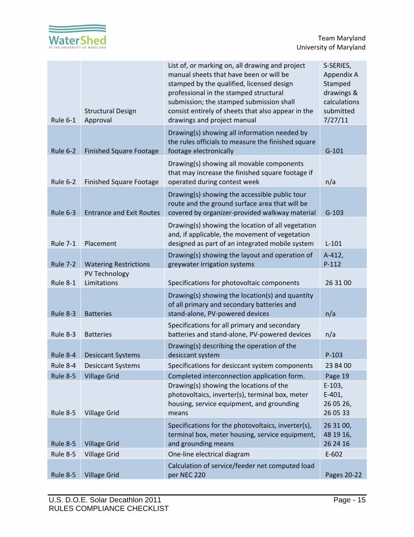
Rule 6‐1 Structural Design Approval
List of, or marking on, all drawing and project manual sheets that have been or will be stamped by the qualified, licensed design professional in the stamped structural submission; the stamped submission shall consist entirely of sheets that also appear in the drawings and project manual
S‐SERIES, Appendix A Stamped drawings & calculations submitted 7/27/11
Rule 6‐2 Finished Square Footage
Drawing(s) showing all information needed by the rules officials to measure the finished square footage electronically G‐101
Rule 6‐2 Finished Square Footage
Drawing(s) showing all movable components that may increase the finished square footage if operated during contest week n/a
Rule 6‐3 Entrance and Exit Routes
Drawing(s) showing the accessible public tour route and the ground surface area that will be covered by organizer‐provided walkway material G‐103
Rule 7‐1 Placement
Drawing(s) showing the location of all vegetation and, if applicable, the movement of vegetation designed as part of an integrated mobile system L‐101
Rule 7‐2 Watering Restrictions Drawing(s) showing the layout and operation of greywater irrigation systems
A‐412, P‐112
Rule 8‐1 PV Technology Limitations Specifications for photovoltaic components 26 31 00
Rule 8‐3 Batteries
Drawing(s) showing the location(s) and quantity of all primary and secondary batteries and stand‐alone, PV‐powered devices n/a
Rule 8‐3 Batteries Specifications for all primary and secondary batteries and stand‐alone, PV‐powered devices n/a
Rule 8‐4 Desiccant Systems Drawing(s) describing the operation of the desiccant system P‐103
Rule 8‐4 Desiccant Systems Specifications for desiccant system components 23 84 00
Rule 8‐5 Village Grid Completed interconnection application form. Page 19
Rule 8‐5 Village Grid
Drawing(s) showing the locations of the photovoltaics, inverter(s), terminal box, meter housing, service equipment, and grounding means
E‐103, E‐401, 26 05 26, 26 05 33
Rule 8‐5 Village Grid
Specifications for the photovoltaics, inverter(s), terminal box, meter housing, service equipment, and grounding means
26 31 00, 48 19 16, 26 24 16
Rule 8‐5 Village Grid One‐line electrical diagram E‐602
Rule 8‐5 Village Grid Calculation of service/feeder net computed load per NEC 220 Pages 20‐22

Team Maryland
University of Maryland
U.S. D.O.E. Solar Decathlon 2011 Page - 16 RULES COMPLIANCE CHECKLIST
Rule 8‐5 Village Grid Site plan showing the house, decks, ramps, tour paths, and terminal box E‐102
Rule 8‐5 Village Grid Elevation(s) showing the meter housing, main utility disconnect, and other service equipment E‐401
Rule 9‐1 Container Locations
Drawing(s) showing the location of all liquid containers relative to the finished square footage H‐101
Rule 9‐1 Container Locations
Drawing(s) demonstrating that the primary supply water tank(s) is fully shaded from direct solar radiation between 9 a.m. and 5 p.m. EDT or between 8 a.m. and 4 p.m. solar time on October 1 P‐101
Rule 9‐2 Team‐Provided Liquids
Quantity, specifications , and delivery date(s) of all team‐provided liquids for irrigation, thermal mass, hydronic system pressure testing, and thermodynamic system operation
Page 15, 23 84 00
Rule 9‐3 Greywater Reuse Drawing(s) showing the layout and operation of greywater reuse systems P‐112
Rule 9‐4 Rainwater Collection Drawing(s) showing the layout and operation of rainwater collection systems
A‐411, A‐412
Rule 9‐6 Thermal Mass Drawing(s) showing the locations of liquid‐based thermal mass systems n/a
Rule 9‐6 Thermal Mass Specifications for components of liquid‐based thermal mass systems n/a
Rule 9‐7 Greywater Heat Recovery
Drawing(s) showing the layout and operation of greywater heat recovery systems n/a
Rule 9‐8 Water Delivery Drawing(s) showing the complete sequence of water delivery and distribution events O‐111
Rule 9‐8 Water Delivery Specifications for the containers to which water will be delivered 22 12 19
Rule 9‐9 Water Removal Drawing(s) showing the complete sequence of water consolidation and removal events O‐111
Rule 9‐9 Water Removal Specifications for the containers from which water will be removed 22 13 53
Rule 11‐4 Public Exhibit
Interior and exterior plans showing entire accessible tour route G‐103

Team Maryland
University of Maryland
U.S. D.O.E. Solar Decathlon 2011 Page - 17 STRUCTURAL CALCULATIONS
STRUCTURAL CALCULATIONS
Structural calculations are attached in Appendix A of this document.
Team Maryland
University of Maryland
U.S. D.O.E. Solar Decathlon 2011 Page - 18 DETAILED WATER BUDGET
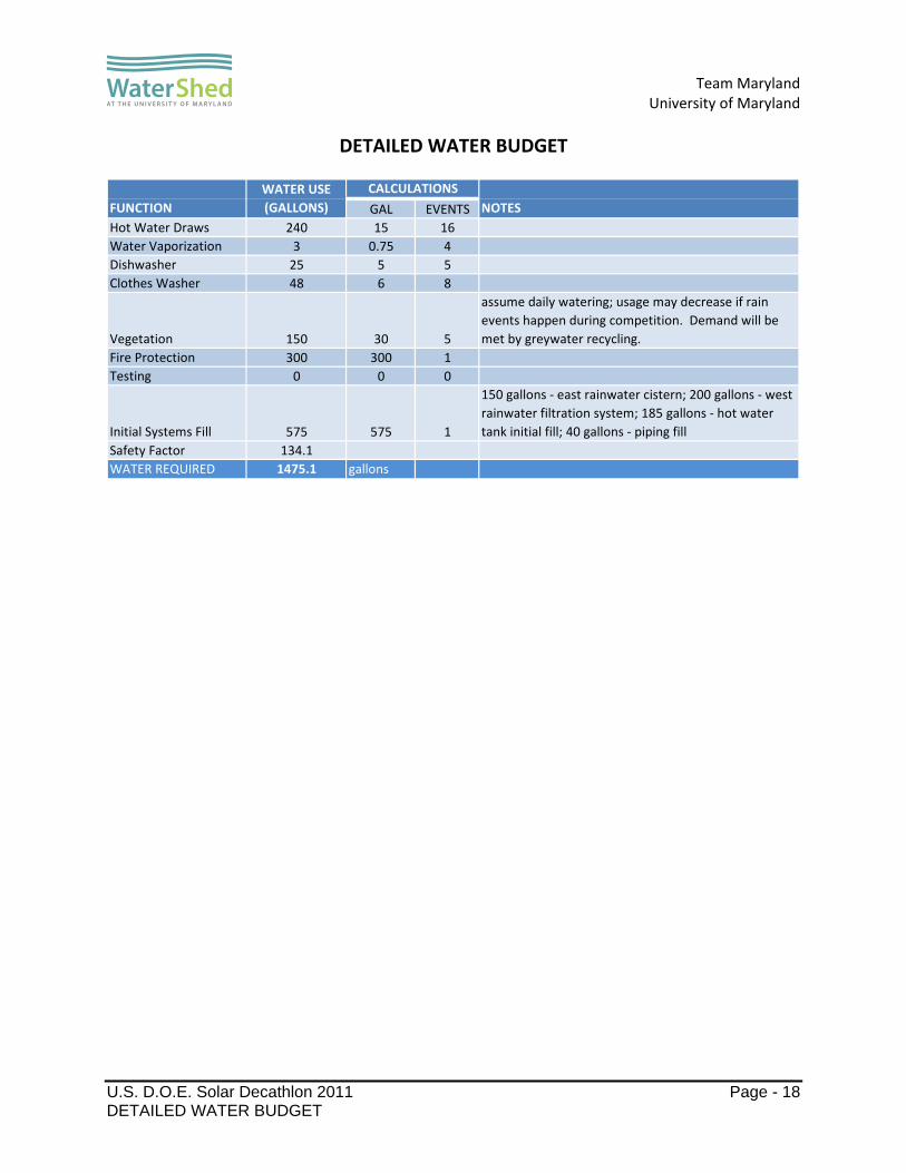
DETAILED WATER BUDGET
GAL EVENTS
Hot Water Draws 240 15 16
Water Vaporization 3 0.75 4
Dishwasher 25 5 5
Clothes Washer 48 6 8
Vegetation 150 30 5
assume daily watering; usage may decrease if rain
events happen during competition. Demand will be
met by greywater recycling.
Fire Protection 300 300 1
Testing 0 0 0
Initial Systems Fill 575 575 1
150 gallons ‐ east rainwater cistern; 200 gallons ‐ west
rainwater filtration system; 185 gallons ‐ hot water
tank initial fill; 40 gallons ‐ piping fill
Safety Factor 134.1
WATER REQUIRED 1475.1 gallons
FUNCTION
WATER USE
(GALLONS)
CALCULATIONS
NOTES

Team Maryland
University of Maryland
U.S. D.O.E. Solar Decathlon 2011 Page - 19 SUMMARY OF UNLISTED ELECTRICAL COMPONENTS
SUMMARY OF UNLISTED ELECTRICAL COMPONENTS
WaterShed is not using any unlisted electrical components.

Team Maryland
University of Maryland
U.S. D.O.E. Solar Decathlon 2011 Page - 20 SUMMARY OF RECONFIGURABLE FEATURES
SUMMARY OF RECONFIGURABLE FEATURES
Reconfigurable features of WaterShed are as follows:
1. Kitchen table This element is a combination of table and rolling cart components that can be configured as a table, a countertop, or various combinations thereof. The kitchen table consists of rolling carts supported on locking casters nested underneath and supporting table components. The cart components have space within their frames that is used to store dining stools. The entire kitchen table can be used as a wall or island counter or can be pulled apart, allowing the rolling carts and table components to be used separately. For Public Tours the typical location and configuration of the kitchen table will be as shown Figure 1.
The kitchen table will be located against the north wall of Module A between the refrigerator and the Liquid Desiccant Waterfall. The rolling carts will be in their nested positions under the table components with casters locked.
During the Dinner Party sub-contest the tables will be located in the center of the kitchen/dining space and the rolling carts will remain against the north wall of
Module A with casters locked. As shown in Figure 2.
During Public Tours and Juries information about this reconfigurable feature will be communicated through signage that has been submitted and approved as part of Team Maryland’s Public Exhibit deliverable.
Figure 1: Kitchen Table in Public Exhibit Configuration
Figure 2: Kitchen Table in Dinner Party Configuration

Team Maryland
University of Maryland
U.S. D.O.E. Solar Decathlon 2011 Page - 21 SUMMARY OF RECONFIGURABLE FEATURES
2. Bed and table This element is a piece of furniture that can be configured as a table or a bed through manual manipulation. For Public Tours, the typical location and configuration of this element will be in the table configuration as shown in figure 3.
For Public Tours and the duration of the competition this element will be configured in its table configuration demonstrating the unit as a 6 foot long table adjacent to cabinet storage. The table cannot be change into a bed by curious members of the touring public by virtue of locked hinges that require a key to release.
Information about this element will be communicated during both Public Tours and Juries through signage that has been submitted and approved as part of Team Maryland’s Public Exhibit deliverable.
Figure 3: Bed and Table Element Shown as Table

Team Maryland
University of Maryland
U.S. D.O.E. Solar Decathlon 2011 Page - 22 INTERCONNECTION APPLICATION FORM
INTERCONNECTION APPLICATION FORM
Team Maryland, Lot 304
PV Systems
Module Manufacturer Short Description of Array DC Rating of Array (sum of the DC
ratings)
Sanyo 36 Sanyo HIT Power 220A’s on a standing seam metal roof
7920 Watts
Sanyo 6 Sanyo HIT Power 220A’s integrated in trellis roof 1320 Watts Total DC power of all arrays is 9.2 kW.
Inverters
Inverter Manufacturer
Model Number Voltage Rating (kW) Quantity
Enphase M210 240 0.210 42 Total AC power of all inverters is 8.8 kW.
1. WaterShed’s one-line electrical schematic can be found on sheet E-602 of the drawing set.
2. Calculations of service/feeder net computer load and neutral load are described in the chart on the following page.
3. A plan view of the lot showing the house, decks, walking surface, tour paths and the service point can be found on sheet G-103 of the drawing set.
4. Elevation views showing the terminal box, meter, and other service equipment can be found on sheet E-401 of the drawing set.
Team Maryland’s Electrical Engineer is Steve Emling. His contact information can be found in the Team Officer Contact Information database on the Solar Decathlon Yahoo Group.

Team Maryland
University of Maryland
U.S. D.O.E. Solar Decathlon 2011 Page - 23 INTERCONNECTION APPLICATION FORM
Calculations of Service/Feeder, Net Computer Load, and Neutral Load
SERVICE FEEDER CALCS MAIN SERVICE PANEL
GENERAL LIGHTING AND RECEPTICLES (NEC210.11(C))
GENERAL LIGHTING 876 SQFT X 3VA/SQFT 2628 VASMALL APPLIANCE CIRCUITS 2 CIRCUITS X 1500VA/CIRCUIT 3000 VALAUNDRY 1 CIRCUIT X 1500VA/CIRCUIT 1500 VA
SUBTOTAL 3000 VA AT 100% + 4128 VA AT 35% 4445 VA
COOKING
COOKTOP 7700 VA AT 100% 7700 VAWALL OVEN 2400 VA AT 100% 2400 VA
SUBTOTAL (NEC TABLE 220.55 NOTE (4), COLUMN C) 7700VA+2400VA=10100VA 8000 VA
FIXED APPLIANCES
WATER HEATER (NEC 220.53) 4500 VA AT 75% 3375 VADISHWASHER (NEC 220.53) 1500 VA AT 75% 1125 VARANGE HOOD (NEC 220.53) 300 VA AT 75% 225 VADESSICANT REGENERATOR AND WALLS (NEC 220.53) 400 VA AT 75% 300 VARADIENT FLOOR (NEC 220.53) 360 VA AT 75% 270 VAWATER TANK PUMP (NEC 430.24) 1150 VA AT 100% 1150 VAGARBAGE DISPOSAL (NEC 430.24) 560 VA AT 100% 560 VASPRINKLER PUMP (NEC 430.24) 800 VA AT 100% 800 VALIVING SYSTEMS PUMPS (NEC 430.24) (6) 45 VA AT 100% 270 VARADIENT FLOOR (NEC 220.51) 360 VA AT 100% 360 VA
SUBTOTAL 8435 VA
DRYER (W=VA FROM NEC 220.54) 7200 VA AT 100% 7200 VAHVAC COMPRESSOR AND UNITS 1800 VA AT 100% 1800 VALARGEST MOTOR (NEC 220.14(C)) 1150 VA AT 25% 288 VATOTAL 30167 VATOTAL CURRENT 126 A
MAIN SERVICE PANEL BREAKER 150 A
NEUTRAL CONDUCTOR
GENERAL LIGHTING AND RECEPTICLES (NEC220.61(A)) 4445 VA AT 100% 4445 VACOOKING (NEC 220.61(B)) 8000 VA AT 70% 5600 VAFIXED APPLIANCES (NEC 220.61(A)) 8435 VA AT 100% 8165 VADRYER (NEC 220.619(B)) 7200 VA AT 70% 5040 VATOTAL 23250 VATOTAL CURRENT 97 A

Team Maryland
University of Maryland
U.S. D.O.E. Solar Decathlon 2011 Page - 24 INTERCONNECTION APPLICATION FORM
NORTH SUB SERVICE PANEL
GENERAL LIGHTING AND RECEPTICLES (NEC210.11(C))
GENERAL LIGHTING 450 SQFT X 3VA/SQFT 1350 VASMALL APPLIANCE CIRCUITS 2 CIRCUITS X 1500 VA/CIRCUIT 3000 VA
SUBTOTAL 3000 VA AT 100% + 1350 VA AT 35% 3473 VA
COOKING
COOKTOP 7700 VA AT 100% 7700 VAWALL OVEN 2400 VA AT 100% 2400 VA
SUBTOTAL (NEC TABLE 220.55 NOTE (4), COLUMN C) 7700VA+2400VA=10100VA 8000 VA
FIXED APPLIANCES
DISHWASHER (NEC 220.53) 1500 VA AT 100% 1500 VARANGE HOOD (NEC 220.53) 300 VA AT 100% 300 VADESSICANT WALL (NEC 220.53) 75 VA AT 100% 75 VAGARBAGE DISPOSAL (NEC 430.24) 560 VA AT 100% 560 VALIVING SYSTEMS PUMPS (NEC 430.24) (6) 45 VA AT 100% 270 VA
SUBTOTAL 2705 VA
LARGEST MOTOR (NEC 220.14(C)) 560 VA AT 25% 140 VATOTAL 14178 VATOTAL CURRENT 59 A
NORTH SUB SERVICE PANEL BREAKER 100 A
NEUTRAL CONDUCTOR
GENERAL LIGHTING AND RECEPTICLES (NEC220.61(A)) 3473 VA AT 100% 3473 VACOOKING (NEC 220.61(B)) 8000 VA AT 70% 5600 VAFIXED APPLIANCES (NEC 220.61(A)) 2705 VA AT 75% 2029 VATOTAL 10595 VA
TOTAL CURRENT 44 A
Team Maryland
University of Maryland
U.S. D.O.E. Solar Decathlon 2011 Page - 25 INTERCONNECTION APPLICATION FORM
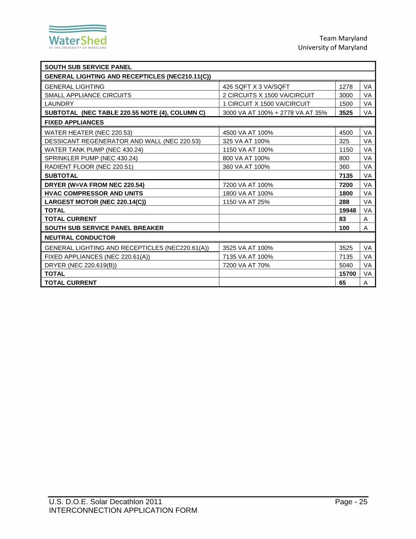
SOUTH SUB SERVICE PANEL
GENERAL LIGHTING AND RECEPTICLES (NEC210.11(C))
GENERAL LIGHTING 426 SQFT X 3 VA/SQFT 1278 VASMALL APPLIANCE CIRCUITS 2 CIRCUITS X 1500 VA/CIRCUIT 3000 VALAUNDRY 1 CIRCUIT X 1500 VA/CIRCUIT 1500 VA
SUBTOTAL (NEC TABLE 220.55 NOTE (4), COLUMN C) 3000 VA AT 100% + 2778 VA AT 35% 3525 VA
FIXED APPLIANCES
WATER HEATER (NEC 220.53) 4500 VA AT 100% 4500 VADESSICANT REGENERATOR AND WALL (NEC 220.53) 325 VA AT 100% 325 VAWATER TANK PUMP (NEC 430.24) 1150 VA AT 100% 1150 VASPRINKLER PUMP (NEC 430.24) 800 VA AT 100% 800 VARADIENT FLOOR (NEC 220.51) 360 VA AT 100% 360 VA
SUBTOTAL 7135 VA
DRYER (W=VA FROM NEC 220.54) 7200 VA AT 100% 7200 VAHVAC COMPRESSOR AND UNITS 1800 VA AT 100% 1800 VALARGEST MOTOR (NEC 220.14(C)) 1150 VA AT 25% 288 VATOTAL 19948 VATOTAL CURRENT 83 A
SOUTH SUB SERVICE PANEL BREAKER 100 A
NEUTRAL CONDUCTOR
GENERAL LIGHTING AND RECEPTICLES (NEC220.61(A)) 3525 VA AT 100% 3525 VA
FIXED APPLIANCES (NEC 220.61(A)) 7135 VA AT 100% 7135 VADRYER (NEC 220.619(B)) 7200 VA AT 70% 5040 VATOTAL 15700 VA
TOTAL CURRENT 65 A

Team Maryland
University of Maryland
U.S. D.O.E. Solar Decathlon 2011 Page - 26 ENERGY ANALYSIS AND RESULTS
ENERGY ANALYSIS AND RESULTS
1.0 Introduction 1.1 Background
As part of the U.S. Department of Energy’s Solar Decathlon 2011, the University of Maryland will compete with 19 other colleges and universities from around the globe to demonstrate the application of sustainable designs to today’s residential building market. The University’s entry into the competition, WaterShed, incorporates passive strategies with advanced technology to achieve an integrated design that is both comfortable and resource efficient.
In order to maximize energy efficiency, students, guided by faculty and mentors, have
completed numerous iterations of energy modeling to guide key design decisions pertaining to system design, envelope construction, and equipment sizing. Our modeling process is summarized as follows:
Create a baseline model of the house incorporating the geometry, preliminary envelope constructions, expected internal gains, and a preliminary HVAC system
Perform parametric studies on the baseline house to determine the ideal envelope construction that minimizes annual cooling and heating loads
Determine optimum HVAC size Predict annual electricity demand and determine optimum size of the photovoltaic
array Predict house performance in competition scenarios Our approach to energy modeling incorporates the house with all of its systems, losses,
and gains into a single model. This method allows the designer to observe how individual changes to an aspect of the model, such as lighting levels or U-values, impact the overall energy consumption of the house. Parametric studies performed on these individual aspects of the model have helped guide the team towards the current design of the house.
2.0 Tools The team has used several computer tools to build models, run parametric studies, and analyze results. These programs and a brief description of their uses are as follows: 2.1 Revit (2011)
Revit is an architectural drawing and design tool that is used in the project as the primary documentation tool and repository of information about the house design. The Revit file contains the most up-to-date geometry of the house. The geometry is exported to other tools for analysis purposes as described below.
2.2 SketchUp – OpenStudio (Version 1.0.6)
The OpenStudio plugin to Google SketchUp dramatically streamlines the task of defining 3D geometry for EnergyPlus analysis. OpenStudio also provides an interface for visualizing the output from EnergyPlus
Model views of the house, rendered in SketchUp, can be found in Appendix A.

Team Maryland
University of Maryland
U.S. D.O.E. Solar Decathlon 2011 Page - 27 ENERGY ANALYSIS AND RESULTS
2.3 EnergyPlus (Version 6.0)
Parametric energy simulation studies on the house are performed using EnergyPlus, a program distributed for free by the U.S. Department of Energy (DOE) for energy studies on residential and commercial buildings. To develop a model, the user defines the geometry of the house using SketchUp. The user then inputs a detailed array of parameters into EnergyPlus including envelope material properties, internal gains and schedules, equipment, lights, the HVAC system(s), and the photovoltaic array. The simulation uses averaged weather data for a specific region to closely estimate the building’s energy usage at user-specified intervals.
2.4 Microsoft Excel (2010) Results from EnergyPlus are output to Excel spreadsheets. The energy analysis process makes extensive use of Excel’s graphical analysis capabilities.
2.5 PVWatts (Version 2) Solar photovoltaic array sizing simulations are performed using PVWatts, a tool provided online for free by the National Renewable Energy Laboratory (NREL). The tool predicts the array’s electricity production for any region in the United States based on its nominal wattage, angle, and inverter efficiency. The calculator can be found on the PVWatts website: http://rredc.nrel.gov/solar/calculators/PVWATTS/version2/.
3.0 Geometry and Systems – A Brief Explanation 3.1 Geometry
Model views of the house can be found in Appendix A (the EnergyPlus model, viewed in SketchUp) as figures A-1 to A-4.
WaterShed is comprised of three linked modules. The two largest modules, the public and private modules, face one another. The third module, containing the bathroom, links the two. The roofs of the larger modules slope towards the center of the house, creating the home’s signature split-butterfly roof form. The south-facing roof of the public module, angled at 12.8°, supports the home’s photovoltaic (PV) system. The north-facing roof, angled at 10.0°, supports the home’s green roof.
Shaded by the overhanging roofs, the upper portions of the two large modules are comprised of gable end-walls facing east and west and clerestory windows facing north and south. Four partially shaded glass doors connect the interior and exterior spaces. Next to the bedroom’s south-facing glass door is the entrance to the unconditioned mechanical room.
Extending east from the south wall of the bedroom, a wall of vertically mounted solar thermal tubes define the boundary for the southeast entry deck and help shade the space. Extending west from the living room, vertical gardens and a photovoltaic-covered trellis shade the northwest garden deck.

Team Maryland
University of Maryland
U.S. D.O.E. Solar Decathlon 2011 Page - 28 ENERGY ANALYSIS AND RESULTS
3.2 Systems Closely integrated with one another and with the house architecture, the engineering
systems are outlined below: Heating, Ventilation, & Air Conditioning Systems (HVAC):
Mini Splits: Two indoor Mitsubishi MSZ-FE09NA mini-split heat pump units condition the space. One mini-split is housed in the public module and the other is housed in the private module. They connect to a single outdoor compressor unit.
Energy Recovery Ventilator (ERV): WaterShed’s Ultimate Air RecoupAerator 200 DX ERV provides ventilation at 70 CFM and maintains indoor air quality. The ERV saves heating and cooling energy by tempering the incoming ventilation air stream. It exchanges energy and moisture between the incoming and outgoing air streams, retaining indoor heat during the heating season and limiting incoming heat during the cooling season.
Solar Energy Systems: Solar Thermal: Two Paradigma CPC 45 Star Azzurro solar thermal evacuated tube
collectors gather thermal energy from the Sun to heat the home’s hot water tanks and regenerate the liquid desiccant solution (explained below).
Photovoltaic (PV): Photovoltaic panels on the roof and trellis convert sunlight into electricity to feed back to the grid. WaterShed supports a 9.24 kW system of 42 Sanyo 220A panels.
Fluid Systems: Liquid Desiccant Waterfall (LDW): The LDW is the home’s unique humidity control
mechanism. Liquid desiccant dehumidification is an appealing alternative to the traditional, electricity-intensive practice of cooling air to the dew point. Rather than using electricity for latent cooling, desiccant dehumidification uses primarily thermal energy, a much more efficiently obtained form of energy. Two liquid desiccant waterfalls inside the house dehumidify household air by providing a site for interaction between air and lithium chloride brine. Outside, in a desiccant regeneration unit, heat captured by the solar thermal system concentrates the brine to be reused in the waterfalls.
Heat Exchange for Excess Solar Thermal (HXEST): Heat exchangers, mounted on the LDW indoor units, heat the indoor air during the heating season with energy captured by the solar thermal tubes that is not needed to heat domestic hot water.
Control System: Smart House Adaptive Control (SHAC): SHAC provides user control, feedback, and
data collected from its various sensors inside and outside the house. It also provides automation for systems like the LDW and HXEST.
4.0 Envelope, Electrical Loads, & Internal Gain Analysis
The discussion and results presented in this section refer to the EnergyPlus model of WaterShed.
4.1 Weather Data The DOE provides weather data for over 2100 locations around the world specifically
intended for EnergyPlus simulations. EnergyPlus requires these data in order to calculate building loads. For the purposes of WaterShed’s analysis, Team Maryland used the weather

Team Maryland
University of Maryland
U.S. D.O.E. Solar Decathlon 2011 Page - 29 ENERGY ANALYSIS AND RESULTS
data for the Washington Dulles Airport region. Annual profiles for outdoor temperature (Figure 4.1a) and direct solar insolation (Figure 4.1b) are shown below as examples:
Figure 4.1a: Average Monthly Outdoor Temperature
Figure 4.1b: Average Monthly Incident Solar Radiation
For further information on the sources of these data, refer to the DOE website, http://apps1.eere.energy.gov/buildings/energyplus/weatherdata_sources.cfm.
0
10
20
30
40
50
60
70
80
Average
Monthly Outdoor Dry Bulb (F)
0.000
0.010
0.020
0.030
0.040
0.050
0.060
0.070
Average
Monthly In
cident Solar Rad
iation
(kBtu/h‐ft2)

Team Maryland
University of Maryland
U.S. D.O.E. Solar Decathlon 2011 Page - 30 ENERGY ANALYSIS AND RESULTS
4.2 Preliminary Studies 4.2.1 Envelope Studies
Given the weather data and the geometry outlined in Section 3.1, EnergyPlus was used to perform parametric studies on a range of building characteristics such as wall R-value and building performance issues such as HVAC load. Some of the key studies explored the impact of wall, roof, floor, and overhang characteristics on heating and cooling loads. The following figures illustrate the trends these studies revealed.
Figure 4.2.1a: Relationship Between Wall R-Value and Annual HVAC Load
Figure 4.2.1b: Relationship Between Roof R-Value and Annual HVAC Load
Figure 4.2.1c: Relationship Between Floor R-Value and Annual HVAC Load
Figure 4.2.1d: Relationship Between Bedroom Roof Overhang Length and Annual HVAC Load
14500
15000
15500
16000
16500
17000
20 40 60
Annual Heating & Coolin
g Load
(kB
tu)
R‐Value (hr‐ft2‐F/Btu)
14500
15000
15500
16000
16500
17000
20 30 40 50 60
Annual Heating & Coolin
g Load
(kB
tu)
R‐Value (hr‐ft2‐F/Btu)
14500
15000
15500
16000
16500
17000
20 40 60Anual Heating & Coolin
g Load
(kBtu)
R‐Value (hr‐ft2‐F/Btu)
14500
15000
15500
16000
16500
17000
0 10 20 30 40
Annual Heating & Coolin
g Load
(kBtu)
South Overhang Length (in)

Team Maryland
University of Maryland
U.S. D.O.E. Solar Decathlon 2011 Page - 31 ENERGY ANALYSIS AND RESULTS
In each of these studies, one building characteristic was varied, while the rest of the model’s parameters were held fixed. The above figures illustrate the resulting impact of the changed characteristic on the annual HVAC load (the total heating and cooling load over the course of a year). The results shown here indicate that increasing envelope insulation beyond a certain point will produce diminishing returns in overall energy efficiency. These envelope studies also reveal several other important points:
Increasing the roof and wall insulation has a greater impact on load reduction than
increasing floor insulation. R-50 insulation provides a good balance between envelope thermal efficiency and
the various construction costs of using thicker insulation. The final design R-values of WaterShed’s solid walls and roof are 48 and 51 (hr-ft2-F/Btu) respectively.
A 40-inch overhang over the bedroom clerestory provides a good balance between HVAC efficiency and the various construction costs and solar-envelope issues associated with deeper overhangs. The designed length of WaterShed’s southern overhang is 40 inches. Using these simulations, Team Maryland could readily identify the effect of building
characteristics on energy performance, establishing goals for the architecture team in designing the envelope. This process has helped make WaterShed’s envelope optimized for energy efficient.
4.2.2 HVAC Sizing
EnergyPlus uses extreme yearly conditions from the weather data to calculate the necessary sizes for the heating and cooling elements of the HVAC system. According to competition requirements, the HVAC system must maintain a comfort zone between 71°F and 76°F. In order to meet the comfort zone requirements, even on the most extreme days of the year, the simulation suggests the following:
Cooling Coil Rated Total Capacity: 17.5 kBtu/hr Heating Coil Rated Total Capacity: 17.5 kBtu/hr
This recommendation provided a basis for the final design sizes of the HVAC
system. WaterShed’s two indoor mini-split heat pumps provide a combined cooling capacity of 18 kBtu/hr and a combined heating capacity of 21.8 kBtu/hr.
4.3 WaterShed Simulation Results
Independent research by students, with input from faculty and mentors, has helped guide the choice of parameters for the EnergyPlus model. The primary parameters included in the model are outlined below.
4.3.1 Envelope Constructions
EnergyPlus models surfaces as layers of materials. In cases where a layer may be composed of multiple materials, such as stud walls with foam insulation, accurate modeling is difficult to achieve. In order to provide flexibility in our parametric modeling, we modeled the actual envelope construction with a simpler layered system with easily-defined R-values. The following envelope assemblies include the most thermally significant layers from the actual design of WaterShed, listed from outside to inside.

Team Maryland
University of Maryland
U.S. D.O.E. Solar Decathlon 2011 Page - 32 ENERGY ANALYSIS AND RESULTS
Public and Private Modules:
Lower Wall Assembly: 0.75” cooked ash wood siding, 4” XPS board insulation, 1.5” Lock-Deck sheathing, 5.5” open-cell spray foam insulation, and 0.5” gypsum board Wall R-Value: 48 hr-ft2-F/Btu
Gable Wall Assembly: 0.03” metal cladding, 0.5” wood sheathing, 3.5” closed-cell spray foam insulation, and 0.5” gypsum board Gable Wall R-Value: 25 hr-ft2-F/Btu Exterior Floor Assembly: 6” closed-cell spray foam insulation, 1-1/8” subfloor, 9/16” hardwood flooring
Floor R-Value: 42 hr-ft2-F/Btu Exterior Roof Assembly: 0.03” metal roofing, 4” Polyiso board insulation, 1.5” Lock-Deck sheathing, 3.5” closed-cell spray foam insulation, and 0.5” gypsum board Roof R-Value: 51 hr-ft2-F/Btu The green roof provides an additional insulation value of approximately R-2 to the bedroom roof.
Bath Module: Wall Assembly: Exterior walls are glazed
Floor Assembly: 6” closed-cell spray foam insulation, 0.75” subfloor, 0.75” ceramic tile
Floor R-Value: 41 hr-ft2-F/Btu
Roof Assembly: 4” XPS rigid board insulation, 1.5” Lock-Deck sheathing, 7.25” open-cell spray foam insulation, and 0.5” gypsum board
Roof R-Value: 59 hr-ft2-F/Btu Glass Fenestration Characteristics:
U-Value (Btu/hr-ft2-F) Solar Heat Gain
Coefficient (SHGC)
Fixed Windows1 0.27 0.23
Clerestory Windows 0.22 0.14
North Window2 0.28 0.23
Glass Doors3 0.30 0.32

Team Maryland
University of Maryland
U.S. D.O.E. Solar Decathlon 2011 Page - 33 ENERGY ANALYSIS AND RESULTS
1The two fixed windows face east and west and are located on either side of the central bathroom module 2The north window is located on the north wall of the public module 3All other fenestration (East, West, and South exposures) is in doors, selected to facilitate the public tours and extend the interior spaces.
4.3.2 Internal Gains Any sources of energy dissipated inside the house, unrelated to
environmental gains such as direct solar or temperature, are considered internal gains. The model includes gains due to occupants, lighting, and electric equipment. A more detailed spreadsheet of internal gains can be found in Appendix B.
4.3.2.1 Occupancy Loads
The model includes two working occupants. We assumed each occupant contributes an average of 100W of internal gain and is absent from the house for 8 hours each day between 9:00AM and 5:00PM.
4.3.2.2 Lighting Loads The model includes 1175W of internal lights. These run for 4 hours
each evening.
4.3.2.3 Electric Equipment Loads The model accounts for all electrical equipment expected to run in the
house. This includes appliances, electronics, SHAC controls, and miscellaneous loads. The electric loads are based on EnergyStar data from individual appliance specifications or on careful estimates for each specific product. Data for the total gain of each piece of equipment and the daily schedules for each can be found in greater detail in Appendix B.
4.3.3 Modeled HVAC System
We simulated the heating and cooling equipment of the HVAC system as a heat pump with a coil in the air stream (the air stream is recirculated indoor air). In the cooling mode, WaterShed’s two mini-split heat pumps have a SEER rating of 16 and a rated capacity of 18 kBtu/hr. In heating mode, the system has a COP of 4.22 and a rated capacity of 21.8 kBtu/hr. In the model, the HVAC system runs under setpoint control, maintaining an indoor air temperature range of 72.5 °F to 74.5 °F, a range well within the competition requirements.
The home’s ERV provides ventilation at a rate of 70 cfm. WaterShed’s ERV efficiently tempers incoming air with a sensible and latent effectiveness of 95%.
4.4 Simulation Results The results of these simulations illustrate a number of useful points that have impacted
the design process. Three major pieces of information resulting from the simulation are: Predicted performance of the envelope, guiding architectural design to an optimized
envelope design.

Team Maryland
University of Maryland
U.S. D.O.E. Solar Decathlon 2011 Page - 34 ENERGY ANALYSIS AND RESULTS
Predicted overall electricity use of the house & necessary PV array size required to fulfill needs.
Predicted external and internal gains to guide selection of HVAC system.
This information allowed Team Maryland to assess the energy efficiency of the building, determine areas of the design that could be improved, and develop strategies for the competition.
4.4.1 Electricity Usage Energy Plus calculates the total predicted electricity usage over the course of
the year (Table 4.4.1). Using Excel, we can visually represent the relative breakdown of electricity use (Figure 4.4.1).

Team Maryland
University of Maryland
U.S. D.O.E. Solar Decathlon 2011 Page - 35 ENERGY ANALYSIS AND RESULTS
Table 4.4.1: Annual Electricity Usage by Subcategory
End Use End Use Breakdown
Electricity Demand (kWh)
Total Electricity (kWh)
Lights
Internal 643
External 137
780
Equipment
Dryer 718
Washer 52
Fridge/Freezer 392
Stove 333
Dishwasher 117
TV 193
Computer 77
SHAC 350
Misc 500
2731
HVAC
ERV 686
Heating Coil 1763
Cooling Coil 1126
Mini Split Fans 1085
4660
Solar Thermal Glycol Pump 153
Main Water Pump 137
LDW Pumps & Fans 83 HEXST Pumps & Fans 36 Living Systems Pumps 228
Total: 8809

Team Maryland
University of Maryland
U.S. D.O.E. Solar Decathlon 2011 Page - 36 ENERGY ANALYSIS AND RESULTS
Figure 4.4.1: Annual Relative Electricity Use by Subcategory
These predictions indicate that the primary electricity draw will be the HVAC system. For typical buildings in the DC metropolitan area, energy use is dominated by heating. The EnergyPlus model for WaterShed, however, predicts that because of its highly-insulated envelope and energy-saving ERV, this will not be the case for WaterShed. The ERV alone reduces heating demand by 36% (discussion of the ERV can be found in Section 4.4.1.1). WaterShed also uses high-efficiency lights and appliances, limiting the draws from these areas as well.
4.4.1.1 Energy Recovery Ventilator (ERV)
The ERV is an important energy-saving component of the HVAC system. Compared to an equivalent home without an ERV, WaterShed saves 605 kWh annually on HVAC electricity demand. Table 4.4.1.1a illustrates the simulation results of such an equivalent home; all characteristics of the home are the same as WaterShed, but the ventilation air is not tempered by an ERV. A breakdown of the home’s HVAC electricity use (with and without an ERV) is as follows:
9%
31%
54%
2%1%
3%
Annual Predicted Electricity Use
Lights
Equipment
HVAC
Solar Thermal
LDW
Living Sys

Team Maryland
University of Maryland
U.S. D.O.E. Solar Decathlon 2011 Page - 37 ENERGY ANALYSIS AND RESULTS
Table 4.4.1.1a: HVAC Electricity Breakdown for an Equivalent House with No ERV
HVAC Component Electricity Demand (kWh)
Mechanical Ventilation 248
Heating Coil 2736
Cooling Coil 1197
Mini Split Fans 1085
Total 5265
Table 4.4.1.1b: HVAC Electricity Breakdown for WaterShed (with ERV)
HVAC Component Electricity Demand (kWh)
ERV 686
Heating Coil 1763
Cooling Coil 1126
Mini Split Fans 1085
Total 4660
The total HVAC electricity demand for an equivalent house with no ERV (Table 4.4.1.1a) is notably greater than that of WaterShed (Table 4.4.1b), especially in the heating season. The ERV saves WaterShed 36% on heating electricity (1763 kWh with an ERV, compared to 2736 kWh without one) and 11% on total HVAC electricity (5265 kWh with an ERV, compared to 4660 kWh without one). It is an indispensible component of WaterShed’s modern, energy-efficient HVAC system.
4.4.1.2 Solar PV Array Size Based on the characteristics of the model, EnergyPlus predicts that
WaterShed will consume 8809 kWh of electricity over the course of a year. Using PVWatts, we predicted the necessary PV array size to meet this electricity demand.
WaterShed’s PV array is comprised of 42 Sanyo 220A PV panels, totaling 9.24 kW. 36 of those panels are fixed to the south-facing roof, angled at 12.8° from the ground. The remaining 6 panels are fixed to the trellis, parallel to the ground. PVWatts predicts the following output from the system while on the competition site in Washington DC:

Team Maryland
University of Maryland
U.S. D.O.E. Solar Decathlon 2011 Page - 38 ENERGY ANALYSIS AND RESULTS
Table 4.4.1.2: Predicted Annual AC Electricity Production by the PV Array
Annual AC Electricity Production (kWh)
Rooftop Panels 9128
Trellis Panels 1383
Total:10511
Under the simulation conditions, this annual production of 10511 kWh
will meet all of WaterShed’s electricity demands. The size of the array provides a 19% margin of safety, allowing for weather fluctuations, additional electricity use, and any other factors not accounted for in the model.
4.4.2 Liquid Desiccant Waterfall (LDW)
Liquid desiccant dehumidification offers an elegant and effective solution to the seasonal humidity of the mid-Atlantic region. For homes like WaterShed, with limited electricity-producing rooftop area, using solar thermal energy rather than electricity to dehumidify household air is an appealing prospect.
As the team designed the LDW, latent cooling load predictions from EnergyPlus provided design criteria. Table 4.4.2 illustrates the annual cooling load breakdown:

Team Maryland
University of Maryland
U.S. D.O.E. Solar Decathlon 2011 Page - 39 ENERGY ANALYSIS AND RESULTS
Table 4.4.2: Predicted Annual Sensible & Latent Cooling Loads
Annual Cooling Load (kBtu)
Sensible Cooling Load 12936
Latent Cooling Load 1760
Total 14696
The LDW has been designed to handle as much of the latent cooling load as possible, reducing the electricity used by the mini-splits in cooling by as much as 12%.
4.4.3 Internal & External Gains It has been an important part of the design process to reduce or control
unnecessary gains into the house during the cooling season and maximize gains during the heating season. Doing so places less demand on the HVAC system.
4.4.3.1 Internal Gains
Any energy that enters the house due to day-to-day activities by the house’s inhabitants constitutes an internal gain. Sources of gains accounted for in this model include people, lights, and electric equipment. These gains are constant throughout the year and their relative daily contributions to household energy are illustrated in Figure 4.4.3.1.

Team Maryland
University of Maryland
U.S. D.O.E. Solar Decathlon 2011 Page - 40 ENERGY ANALYSIS AND RESULTS
Figure 4.4.3.1: Daily Internal Gains
Appliances such as the clothes dryer, dishwasher, and clothes washer do not contribute significant internal gains because they are drained or vented to the outdoors. Other appliances, lights, and electronics however, contribute significantly to the internal gain. These gains must then be removed in the cooling season by the HVAC system, creating energy inefficiency. In the heating season, the gains reduce the required heat input, but since the house operation will be dominated by cooling during the competition, cooling season conditions dominate design considerations. Part of the design process for WaterShed includes obtaining energy efficient appliances, lights, and electronics in order to limit unnecessary internal gain.
4.4.3.2 Windows Windows are both a visual connection to the outdoors and an energy bridge
between the interior and exterior of the building. They constitute one of the greatest sources of heat gain in WaterShed. As illustrated in Figure 4.4.3.2a, windows contribute a much larger percentage of heat gain to the building than do the internal gains, especially during the cooling season.
WaterShed employs strategic shading and thermally insulated window materials to limit unwanted gains. Compared to an equivalent home with no shading devices (no trellis, solar thermal wall, or overhangs) and less insulating glass (U value of 0.35 Btu/hr-ft2-F and SHGC of 0.35), WaterShed takes in 37% less unwanted thermal energy through windows in July, the peak cooling month, than the equivalent home. Figure 4.4.3.2b illustrates the gains of such a house for comparison.
0
2
4
6
8
10
12
Daily In
ternal Gain (kB
tu)

Team Maryland
University of Maryland
U.S. D.O.E. Solar Decathlon 2011 Page - 41 ENERGY ANALYSIS AND RESULTS
Figure 4.4.3.2a: Window Gains Relative to Internal Gains for WaterShed
Figure 4.4.3.2b: Window Gains Relative to Internal Gains for an Equivalent House with no Shading Devices and Less Insulating Window Characteristics
0
500
1000
1500
2000
2500
3000To
tal G
ain (kB
tu)
People Gain
Light Gain
Equipment Gain
Window Gain
0
500
1000
1500
2000
2500
3000
Total G
ain (kB
tu)
People Gain
Light Gain
Equipment Gain
Window Gain

Team Maryland
University of Maryland
U.S. D.O.E. Solar Decathlon 2011 Page - 42 ENERGY ANALYSIS AND RESULTS
In order to minimize the building’s HVAC demand, gains are controlled to the extent possible. While gains due to people, lights, and equipment will be relatively constant throughout the year, proper window placement and shading limit the cooling load in the summer and heating load in the winter.
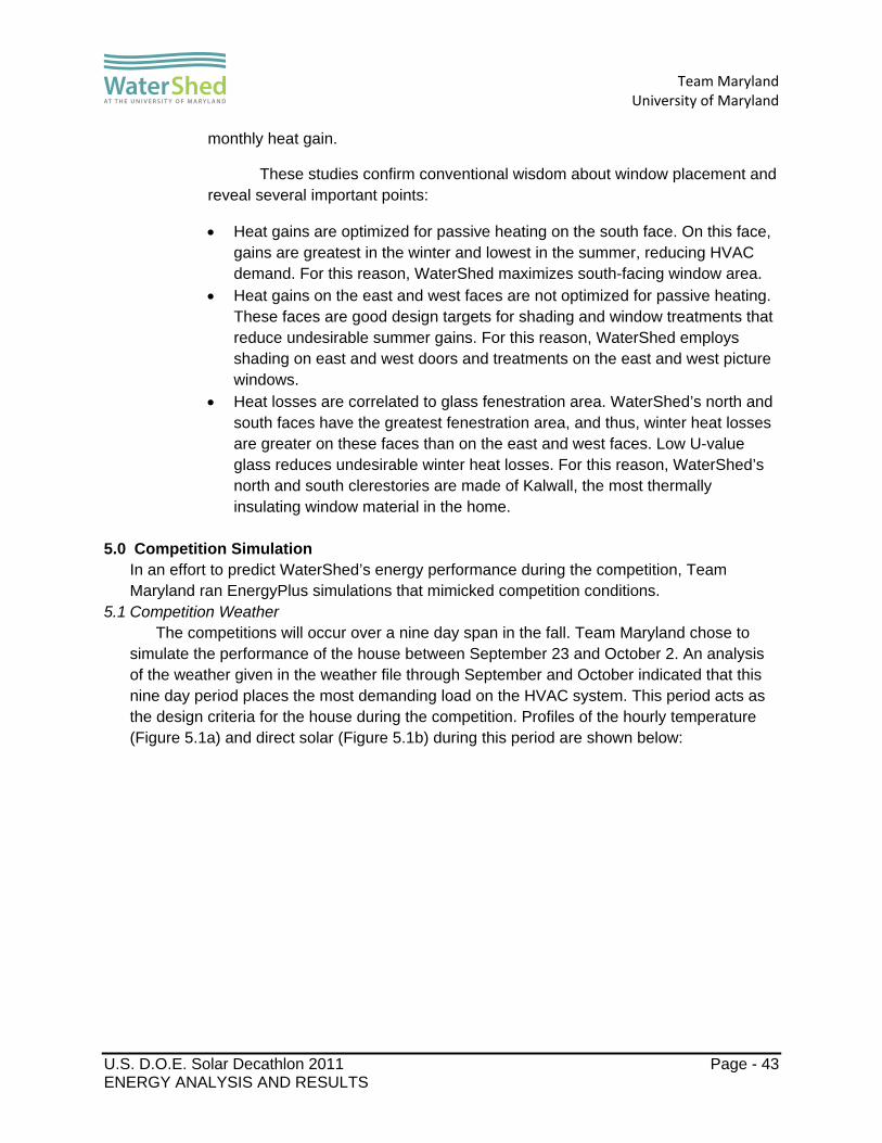
Understanding the expected heat gains and losses through the fenestrations on each surface of the house has played a role in the design process for the windows, affecting choices in size, placement, and treatments. The gains and losses through WaterShed’s cardinal faces are illustrated below in Figures 4.4.3.2c – 4.4.3.2f. Red indicates monthly heat loss and blue indicates
Figure 4.4.3.2c: North Fenestrations Monthly Heat Gains (Blue) & Losses (Red)
Figure 4.4.3.2d: East Fenestrations Monthly Heat Gains (Blue) & Losses (Red)
Figure 4.4.3.2e: West Fenestrations Monthly Heat Gains (Blue) & Losses (Red)
Figure 4.4.3.2f: South Fenestrations Monthly Heat Gains (Blue) & Losses (Red)
0
200
400
600
800
1000
January
February
March
April
May
June
July
August
September
October
November
Decem
ber
Monthly Heat Gain & Loss (kB
tu)
0
200
400
600
800
1000
January
February
March
April
May
June
July
August
September
October
November
Decem
ber
Monthly Heat Gain & Loss (kB
tu)
0
200
400
600
800
1000
January
February
March
April
May
June
July
August
September
October
November
Decem
ber
Monthly Heat Gain & Loss (kB
tu)
0
200
400
600
800
1000
January
February
March
April
May
June
July
August
September
October
November
Decem
ber
Monthly Heat Gain & Loss (kB
tu)
Team Maryland
University of Maryland
U.S. D.O.E. Solar Decathlon 2011 Page - 43 ENERGY ANALYSIS AND RESULTS
monthly heat gain.
These studies confirm conventional wisdom about window placement and reveal several important points:
Heat gains are optimized for passive heating on the south face. On this face, gains are greatest in the winter and lowest in the summer, reducing HVAC demand. For this reason, WaterShed maximizes south-facing window area.
Heat gains on the east and west faces are not optimized for passive heating. These faces are good design targets for shading and window treatments that reduce undesirable summer gains. For this reason, WaterShed employs shading on east and west doors and treatments on the east and west picture windows.
Heat losses are correlated to glass fenestration area. WaterShed’s north and south faces have the greatest fenestration area, and thus, winter heat losses are greater on these faces than on the east and west faces. Low U-value glass reduces undesirable winter heat losses. For this reason, WaterShed’s north and south clerestories are made of Kalwall, the most thermally insulating window material in the home.
5.0 Competition Simulation In an effort to predict WaterShed’s energy performance during the competition, Team Maryland ran EnergyPlus simulations that mimicked competition conditions.
5.1 Competition Weather The competitions will occur over a nine day span in the fall. Team Maryland chose to
simulate the performance of the house between September 23 and October 2. An analysis of the weather given in the weather file through September and October indicated that this nine day period places the most demanding load on the HVAC system. This period acts as the design criteria for the house during the competition. Profiles of the hourly temperature (Figure 5.1a) and direct solar (Figure 5.1b) during this period are shown below:

Team Maryland
University of Maryland
U.S. D.O.E. Solar Decathlon 2011 Page - 44 ENERGY ANALYSIS AND RESULTS
Figure 5.1a: Hourly Outdoor Temperature (September 23 – October 2)
Figure 5.1b: Hourly Direct Solar Radiation (September 23 – October 2)
5.2 The Competition Model A simulation of the WaterShed model during this nine day period helped Team Maryland
prepare for how the house might react to the environment of the competition. The competition imposes rules on how the house will be run which differ from the conditions used in the annual model. The same geometry and envelope construction outlined in
50
55
60
65
70
75
80
85
90
95
0 24 48 72 96 120 144 168 192 216
Outdoor Dry Bulb (F)
Hour
0.000
0.050
0.100
0.150
0.200
0.250
0.300
0 24 48 72 96 120 144 168 192 216
Incident Solar Rad
iation (kB
tu‐h/ft2)
Hour

Team Maryland
University of Maryland
U.S. D.O.E. Solar Decathlon 2011 Page - 45 ENERGY ANALYSIS AND RESULTS
Section 4.3.1 were used in this model; however, we redefined the internal gains and their schedules.
5.2.1 Internal Gains
The peak power and the relative gain fractions remain unchanged for each source of gain. The schedules however, approximate as closely as possible, the competition schedules over the course of the Solar Decathlon. The competition period model includes six occupants throughout the day and zero at night to account for impound hours.
5.2.2 HVAC and Tour Simulation In order to simulate the most demanding and unusual aspect of the
competition, the model incorporates tour periods. The following parameters were used to approximate these periods:
During the times of the day when a tour is scheduled, the ERV, mechanical ventilation, and mini-splits are shut off.
The building infiltration increases to 10 air exchanges/hour. The number of occupants rises to 20 people.
At the end of the tour, these parameters are returned to their normal state. This simulation approximates the impact of the public exhibit hours on WaterShed’s ability to return to the comfort zone temperatures during the Solar Decathlon.
5.3 Results
The competition simulation yielded a number of interesting results that guide Team Maryland’s strategy for operating the house during the competition week.
5.3.1 Tour Effect The tour period causes a significant disruption of the house air temperature
and humidity. When the HVAC turns off and infiltration increases, the indoor air conditions approximately equalize with the outdoor air conditions. As such, Team Maryland expects that the HVAC load following a public exhibit period will be primarily dependent on the outdoor temperature. This effect is illustrated in Figure 5.3.1.
Figure 5.3.1 displays the hourly results of the competition simulation (occurring over the nine day span of September 23 to October 2). The chart illustrates predicted indoor and outdoor temperatures. For reference, the comfort zone is indicated by two horizontal lines at 71 oF and 76 oF. Periods when the indoor air temperature leaves the bounds of the comfort zone indicate the shutoff of the HVAC system during a public exhibit period. These large indoor air temperature changes are a major design consideration for the HVAC system size.

Team Maryland
University of Maryland
U.S. D.O.E. Solar Decathlon 2011 Page - 46 ENERGY ANALYSIS AND RESULTS
Figure 5.3.1: Competition Week Indoor Temperature Fluctuations
According to the rules and competition event schedule, each team has one hour to return their house to the comfort zone following the tours, creating an extreme design criterion for the HVAC system size. In order to meet the post-tour cooling demand, EnergyPlus calculates that the size of the cooling component of the HVAC be 37 kBtu/hr which is larger than the corresponding size calculated without the tours.
These results indicate the necessity of limiting unnecessary gains during the hour after the tour. Simple strategies such as emptying the house of people, turning off electronic equipment, and shading windows will be employed.
5.3.2 Electricity Usage A prediction of household electricity use over the course of the competition is
illustrated in Table 5.3.2a. Team Maryland anticipates that the 9.2 kW PV array will be able to meet the competition demand. PVWatts predicts that the array will produce 274 kWh (Table 5.3.2b) over a 9 day span in September. The size of the array leaves a 43% margin of safety to account for unpredictable weather conditions over the competition period. Although the array is oversized for the competition period, the safety factor for the annual simulation is only 19%.
0
5
10
15
20
25
30
35
0 24 48 72 96 120 144 168 192 216
Temperature (C)
Hour
Outdoor Temperature
Indoor Temperature
Comfort Zone Upper Limit
Comfort Zone Lower Limit

Team Maryland
University of Maryland
U.S. D.O.E. Solar Decathlon 2011 Page - 47 ENERGY ANALYSIS AND RESULTS
Table 5.3.2a: Competition Week Electricity Usage by Subcategory
End Use End Use Breakdown
Electricity Demand (kWh)
Total Electricity (kWh)
Lights
Internal 33
External 7
40
Equipment
Dryer 8
Washer 2
Fridge 10
Stove 4
Dishwasher 2
TV 7
Computer 3
SHAC 9
43
HVAC
ERV 13
Heating Coil 0
Cooling Coil 57
Mini Split Fans 21
91
Solar Thermal Glycol Pump 4
Main Water Pump 1
LDW Pumps & Fans 6 HEXST Pumps & Fans 0 Living Systems Pumps 6
Total: 191

Team Maryland
University of Maryland
U.S. D.O.E. Solar Decathlon 2011 Page - 48 ENERGY ANALYSIS AND RESULTS
Table 5.3.2b: Predicted Nine Day AC Electricity Production by the PV Array in September
AC Electricity Production (kWh)
Rooftop Panels 238
Trellis Panels 36
Total:274
6.0 Conclusions
These computer models offer the team a prediction of WaterShed’s behavior annually and during the competition. Iterations of energy modeling have helped guide the design process and continue to impact competition strategy.
The necessity of controlling the flow of energy through the house is important to Team Maryland’s strategy. This means using passive concepts that limit electricity demand and lessen the load on the HVAC. This will be especially true during and immediately after the tour periods. Team Maryland expects to continue exploring ways to limit undesirable internal gains and fenestration gains as much as possible during the hour following the tours.

Team Maryland
University of Maryland
U.S. D.O.E. Solar Decathlon 2011 Page - 49 ENERGY ANALYSIS AND RESULTS
Appendix A: Model Views
The following are views of the EnergyPlus model of WaterShed as viewed in SketchUp. Yellow surfaces are walls, blue surfaces are glass fenestrations, red surfaces are roofs, and purple surfaces are shading groups (ie: the trellis, solar thermal, PV array, and roof overhangs). The solid axis colors correspond to north (green) and east (red).
Figure A- 1: South-East View

Team Maryland
University of Maryland
U.S. D.O.E. Solar Decathlon 2011 Page - 50 ENERGY ANALYSIS AND RESULTS
Figure A- 2: South-West View
Figure A- 3: North-East View

Team Maryland
University of Maryland
U.S. D.O.E. Solar Decathlon 2011 Page - 51 ENERGY ANALYSIS AND RESULTS
Figure A- 4: North-West View

Team Maryland
University of Maryland
U.S. D.O.E. Solar Decathlon 2011 Page - 52 ENERGY ANALYSIS AND RESULTS
Appendix B: Internal Gains Spreadsheet (Annual, No Tour Simulation)

Team Maryland
University of Maryland
U.S. D.O.E. Solar Decathlon 2011 Page - 53 ENERGY ANALYSIS AND RESULTS
Values included in the model come from a variety of sources. Where applicable, we have derived values from EnergyStar predictions for annual electricity. In many cases, Team Maryland followed the guidelines for internal gains required for a BuildingAmerica Building Technologies Program benchmark home. More information on this program can be found at http://www1.eere.energy.gov/buildings/building_america/.

Team Maryland
University of Maryland
U.S. D.O.E. Solar Decathlon 2011 Page - 54 LIQUID DESICCANT SYSTEM DESCRIPTION
LIQUID DESICCANT SYSTEM DESCRIPTION
The University of Maryland was the first school to include a liquid desiccant system in their U.S. Department of Energy Solar Decathlon 2007 submission, LEAFHouse. Now a patent-pending innovation, the LEAFHouse liquid desiccant waterfall (LDW) has paved the way for subsequent iterations. In the 2009 competition, two schools used liquid desiccant systems and now in 2011 the University of Maryland will be showcasing an improved liquid desiccant waterfall design.
The liquid desiccant dehumidifier works based on the ability of saline solutions to absorb
humidity from the surrounding air. The more salt dissolved in solution, the higher its propensity to capture water from the air. By using a saline solution of 42% by weight Lithium Chloride (LiCl), WaterShed’s system will be able to dehumidify air to very dry conditions. The dehumidification process occurs within two indoor wall units; one unit is in each of WaterShed’s two primary modules. Each unit will have a Plexiglas spillway where LiCl solution is pumped through packing media while air flows in the opposite direction, releasing its moisture in the process. The packing media, comprised of spherical raschig rings, is a new component added for the 2011 model; it allows the liquid to be dispersed over a wider surface area so there is more contact between the desiccant solution and the air and thus a higher rate of moisture transfer. The air is pulled through the system by a fan in each wall unit and then expelled into the room.
The more moisture taken out of the air, the more dilute the desiccant solution becomes.
As the solution gains water, the ratio of LiCl to water decreases, as does its ability to capture moisture from the air. Once the solution becomes too dilute to function as a desiccant, it is pumped to the outdoor regenerator where the excess water is evaporated. To make water leave the solution – as opposed to being absorbed by it – the working fluid must be heated until its vapor pressure is greater than that of the atmosphere. When the desiccant solution is heated, the water in the solution boils and evaporates off of the desiccant solution leaving a fully regenerated salt-rich solution that is pumped back into the house to absorb moisture from WaterShed’s conditioned spaces.
The regenerator operates in a reverse manner to the indoor units, at a higher
temperature. The desiccant is heated to 180 °F using heat generated from the evacuated solar thermal tube array. It is then sprayed down a Plexiglas spillway while air passes in the opposite direction. Because the desiccant solution is heated, instead of picking up moisture from the air, the solution evaporates it into the passing air.
Industrial desiccant systems use natural gas or electricity to produce the heat required
for regeneration. The WaterShed LDW uses renewable heat energy from the solar thermal system to regenerate, but this heat source is non-continuous on an hour-to-hour, day-to-day, and even month-to-month basis. Team Maryland created the regeneration design to work with this energy source by using a unique batch approach instead of continuous regeneration. The industry standard is for the desiccant to go through the dehumidifier once, then directly to the regenerator, then back to the dehumidifier in a continuous cyclical process. In WaterShed’s system however, the indoor solution constantly dehumidifies until it becomes dilute. At this point it is exchanged with the regenerated solution as a batch. Half of the working fluid is contained in the regenerator and the other half is split evenly between the two indoor units. Because there is always a batch of solution both inside and out, the dehumidifying process is

Team Maryland
University of Maryland
U.S. D.O.E. Solar Decathlon 2011 Page - 55 LIQUID DESICCANT SYSTEM DESCRIPTION
independent from the regeneration process. This allows the indoor units to be dehumidifying even when there is no sunlight to power the regenerator, a large advantage to the system because the sun shines less than half the day. More importantly, this gives the system the ability to dehumidify during rainy days when humidity increases but there is little sunlight. This is also useful when the solar thermal heat energy is needed by another system such as the hot water heater.

Team Maryland
University of Maryland
U.S. D.O.E. Solar Decathlon 2011 Page - 56 LIQUID DESICCANT SYSTEM DESCRIPTION
Graph Describing Vapor Pressure of LiCl Solutions Based on Temperature and Concentration
This graph, from M. Conde Engineering, 2001, shows the entire cycle of the desiccant solution. Based on these vapor pressures, it can be shown that the desiccant will either absorb
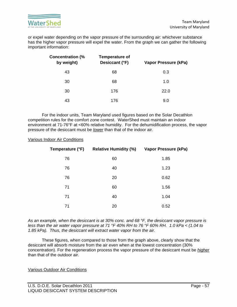
Team Maryland
University of Maryland
U.S. D.O.E. Solar Decathlon 2011 Page - 57 LIQUID DESICCANT SYSTEM DESCRIPTION
or expel water depending on the vapor pressure of the surrounding air: whichever substance has the higher vapor pressure will expel the water. From the graph we can gather the following important information:
Concentration (% by weight)
Temperature of Desiccant (°F) Vapor Pressure (kPa)
43 68 0.3
30 68 1.0
30 176 22.0
43 176 9.0
For the indoor units, Team Maryland used figures based on the Solar Decathlon
competition rules for the comfort zone contest. WaterShed must maintain an indoor environment at 71-76°F at <60% relative humidity. For the dehumidification process, the vapor pressure of the desiccant must be lower than that of the indoor air. Various Indoor Air Conditions
Temperature (°F) Relative Humidity (%) Vapor Pressure (kPa)
76 60 1.85
76 40 1.23
76 20 0.62
71 60 1.56
71 40 1.04
71 20 0.52
As an example, when the desiccant is at 30% conc. and 68 °F, the desiccant vapor pressure is less than the air water vapor pressure at 71 °F 40% RH to 76 °F 60% RH. 1.0 kPa < (1.04 to 1.85 kPa). Thus, the desiccant will extract water vapor from the air.
These figures, when compared to those from the graph above, clearly show that the
desiccant will absorb moisture from the air even when at the lowest concentration (30% concentration). For the regeneration process the vapor pressure of the desiccant must be higher than that of the outdoor air. Various Outdoor Air Conditions

Team Maryland
University of Maryland
U.S. D.O.E. Solar Decathlon 2011 Page - 58 LIQUID DESICCANT SYSTEM DESCRIPTION
Situation Temperature (°F) Relative Humidity (%) Vapor Pressure (kPa)
Spring (humid) 70 80 2.02
Spring (avg) 70 50 1.26
Summer (humid) 88 85 3.86
Summer (avg) 88 55 2.49
Fall (humid) 68 85 1.99
Fall (avg) 68 55 1.29
As an example, when the desiccant is at 43% conc. and 176 °F, the desiccant vapor pressure is greater than the air water vapor pressure under all outdoor conditions. 9.0 kPais greater than > (1.26 to 3.86). Thus, the desiccant will expel water vapor into the air.
These figures show that the desiccant will evaporate water out of solution under any outdoor conditions, even very hot and humid days. As can be seen in the graph and tables, if the desiccant is at a very high temperature (above 60 °C/140 °F) it will always successfully regenerate.
There are multiple precautions that were taken while constructing this project. LiCl is not
much different than regular table salt, but any highly concentrated salt solution has to be handled with care because it absorbs moisture from any source. The side effects of human contact with the desiccant are mild. Dermal contact can result in a mile to severe rash while eye contact results in irritation, redness, and pain. Ingestion can cause nausea, vomiting, and diarrhea. WaterShed’s system uses 40 gallons of fully regenerated 42% (by weight) solution: 10 gallons in each indoor unit and 20 in the regenerator.
During construction, elbow length rubber gloves and protective glasses were worn at all
times. Each unit has been thoroughly tested to make sure there are no leaks or splashes that could result in any solution leaving the apparatus. All pipe and tube connections have been made with secure plastic fittings. All parts touching the solution are made of plastic or titanium to eliminate the possibility of corrosion and material degradation. Metal has been eliminated from construction in all applicable situations. All piping that touches the heated solution in the regenerator is made of CPVC which can handle temperatures up to 200 °F. All air outlets have been equipped with demisters to eliminate any droplets of desiccant from escaping the units.

Team Maryland
University of Maryland
U.S. D.O.E. Solar Decathlon 2011 Page - 59 ARCHITECTURAL DESIGN NARRATIVE
ARCHITECTURAL DESIGN NARRATIVE
WaterShed’s architectural design responds to both the challenges of rethinking energy use in the built environment and concerns over American attitudes toward water. Inspired by the Chesapeake Bay, WaterShed’s architectural design is derived from four guiding principles:
water is a precious resource and should be handled conscientiously. homes should function as micro�ecosystems. a sustainable house should both conserve and produce resources. merging the best of passive and active energy strategies is the most effective way to create a
house that is in tune with its environment. The forms of the house, in plan and in section, highlight the path of water – falling from
clouds to highlands, trickling down waterways, seeping into groundwater, and ultimately evaporating back into our atmosphere. WaterShed’s split-butterfly roofline, comprised of two sheds sloping towards each other, is intended to highlight storm water runoff from each module, directing and collecting it into the celebrated water axis at the core of the home. Water used within the house intersects this axis through a consolidated mechanical core. The design physically and visually connects the home and its residents with their surroundings while demonstrating the interconnected nature of an ecosystem.
Spatially, the house is designed as two shed modules slid apart along the central water
axis and connected by a third module – the bridge. The two larger modules express the programmatic intent of a live/work environment and provide a rich variety of indoor and outdoor
WaterShed takes inspiration from the Chesapeake Bay ecosystem and seeks to interconnect the house, the landscape, and the residents who live there.

Team Maryland
University of Maryland
U.S. D.O.E. Solar Decathlon 2011 Page - 60 ARCHITECTURAL DESIGN NARRATIVE
spaces. The bridging module houses the bathroom, highlighting the connection between interior water uses and the wetland axis outside while concurrently linking the public and private spaces.
WaterShed’s design showcases the potential of living systems to improve water
management. The green roof slows rainwater runoff to the landscape while simultaneously improving the house’s energy efficiency by providing added thermal insulation. Storm water runoff is also collected from the solar array in a cistern on the east side of the water axis where it is stored for reuse in landscape irrigation. Grey water from the shower, lavatory, clothes washer, and dishwasher are collected and filtered through a constructed wetland on the west side of the water axis, nourishing the landscape without consuming potable water.
WaterShed’s design also demonstrates the potential for architecture to contribute to
healthy carbon cycles through the gardens and composting station. The process of growing vegetables in the garden, cooking and consuming those vegetables in the house, and returning the discarded food scraps to compost for gardening, directly and clearly illustrates the potential for improved health, energy and cost savings inherent in a complete carbon cycle program.
The holistic design features integrated architecture and engineering as evidenced in the
sloping forms of the modules. The sloped forms create soaring living spaces that are daylit using translucent clerestories and also allow the solar array to most efficiently create power. This energy is used by the mechanical systems to condition the space and a robust envelope ensures that once energy is used in space conditioning its value is retained.
Through integrated architecture, engineering, and living systems, WaterShed creates
inspiring spaces which bring delight to life’s every day activities.

Team Maryland
University of Maryland
U.S. D.O.E. Solar Decathlon 2011 Page - 61 MARKET VIABILITY JUSTIFICATION
MARKET VIABILITY JUSTIFICATION
WaterShed is intended for a working couple who can use the house as both a home and as an office. This demographic is highly prevalent within the Baltimore and Washington, DC markets, where many sole proprietorships exist in consulting, law, architecture and other professions. WaterShed is affordable to such residents because the upfront investment in energy‐saving and water‐saving technologies eventually provide cost‐savings to the consumer given the increasing prices of utilities. For people in the Washington, DC corridor specifically, WaterShed is affordable because it provides them the opportunity to telecommute, thus reducing commuting expenses in one of the most congested areas in the country. Simplified Target Market Identification:
Geographical Market: Baltimore – Washington, DC corridor (primary); Other Mid-Atlantic states (secondary)
Housing Configuration: For sale product: one bedroom, plus work den / one bathroom
Occupant Demographic: Self-employed couple, no kids living at home
Household Income: $75,000-$115,000 (based on 2009 FHFA AMI figures of our primary
demographic market)
To demonstrate WaterShed’s livability, a typical week for the house’s residents might include a standard work week Monday through Friday where the house functions as an office during the day and a resting place at night. One partner telecommutes three days each week, while the other manages his or her own business at an urban office. The reconfigurable furniture in the south module allows the space to easily transform from a productive workspace to a comfortable bedroom. In the evenings they spend time cooking with produce from their gardens.
On the weekends, they often host potluck dinners for friends in the north module, maximizing usage of the full-sized dining table and transformable living room furniture. Weekends are spent participating in social and community activities because WaterShed’s low-maintenance, durable materials require limited time input from the owners. The couple enjoys spending time outdoors as well as time in the city and chose not to move into an urban apartment because of their desire to control their own water and energy consumptions, a desire that is aided by WaterShed’s intuitive home automation system. The system provides the residents information about their resource consumption, allowing them to customize settings for maximum efficiency.
Water management is integrated seamlessly into daily life. Rainwater that lands on the house takes one of two paths: it travels off the photovoltaic roof, enters a collection cistern and is later filtered through the constructed wetlands or is absorbed by the green roof. The constructed wetlands also filter grey water from the shower, dishwasher, and bathroom sink. The constructed wetlands allow the residents to minimize their potable water usage because the filtered water is able to be reused onsite to irrigate the landscape.

Team Maryland
University of Maryland
U.S. D.O.E. Solar Decathlon 2011 Page - 62 MARKET VIABILITY JUSTIFICATION
On the technological side of the house, an appropriately-sized solar array powers the house year round and allows the residents to earn the best return on their initial investment. Solar thermal tubes use heat energy from the sun to heat all domestic hot water, regenerate the desiccant solution, and provide supplemental space heating. These renewable energy technologies are paired with high-efficiency systems throughout the house resulting in energy and cost savings.
WaterShed’s unique design, technology, and environmental balance make the home appealing in today’s Baltimore-Washington, DC market area. The flexible design suits a wide demographic that looks for long-term value and support for a live-work lifestyle. There is a relationship between the house, the owners, and the environment – an important balance that few homes accomplish with such simplicity. WaterShed moves the concept of housing forward into the next decade of environmental awareness and responsibility through integrated architecture, engineering, and living systems.

Team Maryland
University of Maryland
U.S. D.O.E. Solar Decathlon 2011 Page - 63 ENGINEERING DESIGN NARRATIVE
ENGINEERING DESIGN NARRATIVE
WaterShed’s engineering design features an integrated set of systems that achieve robust functionality and keep WaterShed comfortable under a wide range of climatic conditions. Like the components of the Chesapeake Bay ecosystem, the engineering systems work in harmony, each acting to increase the effectiveness of the others.
Innovative combinations of technology and passive strategies can greatly reduce energy and material waste. WaterShed’s engineering approach begins with a tight, well-insulated envelope that reduces the need for mechanical heating and cooling. An envelope with a thermal resistance of over R-40 paired with high-efficiency technologies throughout the structure to minimize the size of the photovoltaic and solar thermal arrays.
WaterShed harnesses the Sun’s power through monocrystalline photovoltaic (PV) panels and evacuated-tube solar thermal collectors. The 9.2 kW PV system is sized to fulfill the home’s annual energy needs, but is limited to a practical size to optimize the homeowners’ return on investment. WaterShed’s 106 square foot array of evacuated-tube solar thermal collectors allows the home to meet 100% of its domestic hot-water needs, 100% of the energy required to regenerate the liquid desiccant, and provides supplemental space heating in winter through an innovative system dubbed HXEST that transfers solar thermal energy to the house air.
The indoor environment is conditioned using two mini-split heat pumps. With one unit in each of WaterShed’s primary modules, the homeowners can independently control temperature of the spaces. An energy recovery ventilator or ERV exchanges indoor and outdoor air to maintain air quality while conserving energy with 96% effectiveness. A free-cooling mechanism in the ERV can be activated to cool the house with outdoor air when the temperature drops below indoor temperature resulting in energy and cost savings.
The innovative Liquid Desiccant Waterfall (LDW) originally developed by the University of
Maryland’s Solar Decathlon 2007 team is improved in the 2011 iteration in three significant ways: a more effective desiccant solution with Lithium Chloride increased contact between the working fluid and air flow using spherical raschig
rings as packing media stronger integration with the solar thermal array for desiccant regeneration.
This next-generation system provides the independent humidity control necessary for Maryland’s typically harsh, humid summers. Independent humidity control reduces the latent heat load on the mini split air conditioning units and improves the overall efficiency of the entire HVAC system. By considering systems holistically and looking for ecosystem-like synergies between components, WaterShed’s engineering systems are able to be more effective and efficient than conventional systems.
Inspired by the Chesapeake Bay ecosystem, WaterShed’s constructed wetlands are engineered to harvest rainwater from the two shed roofs of the house and filter grey water from the shower, clothes washer, and dishwasher. The wetlands system is also connected to the mini-split units as the condensate line drains into the wetland. Once water in the wetlands has been properly filtered through the plants, the water can be reused to nourish the landscape, decreasing potable water usage.

Team Maryland
University of Maryland
U.S. D.O.E. Solar Decathlon 2011 Page - 64 ENGINEERING DESIGN NARRATIVE
WaterShed is the embodiment of a way of life that is in tune with the natural processes that surround us. The engineering design supports this relationship between nature and humans by using technology to inform homeowners about the impacts their actions within the home have on the surrounding landscape. WaterShed’s home automation system, called Smart House/Adaptive Control or SHAC, is an integrated network of sensors, controllers and software. SHAC automatically monitors and adjusts the temperature, humidity, brightness, and other parameters of the engineering systems to provide maximum function with the least amount of energy use and impact on the environment. The control system informs the homeowners of their energy and water consumption and provides suggestions for reducing unnecessary use of these important resources.
WaterShed is a house as ecosystem, an answer to today's many questions about how to build a more sustainable future. The house’s engineering systems act as a unified, synergistic system which is as much a part of the environment as the water that flows through it.

Team Maryland
University of Maryland
U.S. D.O.E. Solar Decathlon 2011 Page - 1 TEMPORARY CRANES 01 54 19 - 1
SECTION 01 54 19 - TEMPORARY CRANES
PART 1 - GENERAL
1.01 SUMMARY
A. Structural Performance: Temporary cranes will withstand structural loads and lifts incurred in lifting, placing, and handling of all modular components.
B. Submittals: Product Data, and structural analysis data signed and sealed by a qualified professional engineer registered in the state where the project is located.
PART 2 - PRODUCTS
2.01 MANUFACTURERS
A. Acceptable Manufacturers 1. Liebherr International.
2.02 TEMPORARY CRANES
A. Type: 130 ton, Telescopic Crane. 1. Boom extension: 60 m 2. Lattice Jib: 33m 3. Carrier Engine/Output: Liebherr 6-cylinder, Turbo-Diesel 500 hp 4. Crane Engine/Output: Liebherr 4-cylinder, turbo-Diesel, 145 kW 5. Operational Weight: 60,000 kg 6. Total Counterweight: 42 ton
PART 3 - EXECUTION
3.01 INSTALLATION
A. Prepare ground by cleaning, removing projections, clearing obstructions, and cordoning off safe working zone, and as otherwise recommended in temporary crane manufacturer's written instructions.
B. Ground crane securely in place, per operational specifications.
C. Allow only licensed operators to operate machinery, manage lifts, and issue signals and commands.

Team Maryland
University of Maryland
U.S. D.O.E. Solar Decathlon 2011 Page - 2 TEMPORARY CRANES 01 54 19 - 2
D. Ensure placement of modular components complies with foundational spacing and load requirements.
E. Coordinate operations with structural requirements per specifications of structural engineer and crane operator.
F. Correct deficiencies in or remove and reinstall temporary cranes that do not comply with requirements.
END OF SECTION 01 54 19

Team Maryland
University of Maryland
U.S. D.O.E. Solar Decathlon 2011 Page - 1 TEMPORARY SCAFFOLDING AND PLATFORMS 01 54 23 - 1
SECTION 01 54 23 – TEMPORARY SCAFFOLDING AND PLATFORMS
PART 1 - GENERAL
1.01 SECTION REQUIREMENTS
A. Structural Performance: Design, engineer, fabricate, and install staging aids and fall protection equipment to withstand structural loads required by OSHA and ANSI Z359.1 standards.
B. Submittals: Product Data. Structural analysis data signed and sealed by a qualified professional engineer registered in the state where Project is located.
C. Structural and Accessory Components shall conform to the following Standards: 1. Steel Plates, Shapes, and Bars: ASTM A 36/A 36M. 2. Steel Tubing: Cold-formed steel tubing, ASTM A 500. 3. Aluminum Extrusions: ASTM B 221.
PART 2 - PRODUCTS
2.01 FALL PROTECTION EQUIPMENT – STANDING SEAM ROOF
A. Manufacturers 1. Guardian Fall Protection
B. Models 1. Standing Seam Roof Clamp, Model# 00250
C. Operation 1. Portable and reusable anchor for use on standing seam roofs 2. Seam spacing range: 24” – 36” 3. Retractable Rotation: 360 degrees 4. Self-retracting lifeline adaptable 5. Meets or exceeds all applicable industry standards, including OSHA and ANSI
Z359.1.
2.02 FALL PROTECTION EQUIPMENT - THERMOPLASTIC POLYOLEFIN ROOF
A. Manufacturers 1. Guardian Fall Protection
B. Models 1. CB-12 Roof Anchor, Model# 00485

Team Maryland
University of Maryland
U.S. D.O.E. Solar Decathlon 2011 Page - 2 TEMPORARY SCAFFOLDING AND PLATFORMS 01 54 23 - 2
C. Operation 1. Deck mounted anchor post 2. Load rating: 5000 lbs 3. Base and mount plates flashed into TPO membrane per manufacturer
specifications.
PART 3 - EXECUTION
3.01 INSTALLATION
A. Prepare substrate by cleaning, removing projections, filling voids, sealing joints, and as otherwise recommended in fall protection and deck eye manufacturer's written instructions.
B. Set units level, plumb, and true to line, without warp or rack of frames and panels and anchor securely in place, for permanent installation or duration of use.
C. Fasten fall protection securely in place, with provisions for thermal and structural movement.
D. Correct deficiencies in or remove and reinstall fall protection anchors that do not comply with requirements.
E. Repair, refinish, or replace fall protection anchors and deck eyes damaged during installation, as directed by Architect.
END OF SECTION 01 54 23

Team Maryland
University of Maryland
U.S. D.O.E. Solar Decathlon 2011 Page - 1 STRUCTURAL STEEL FRAMING 05 12 00 - 1
SECTION 05 12 00 - STRUCTURAL STEEL FRAMING
PART 1 - GENERAL
1.01 SECTION REQUIREMENTS
A. Structural Performance: Design, engineer, fabricate, and install structural steel framing and weldments to withstand structural loads required by International Residential Code 2006 and all applicable codes.
B. Submittals: Shop Drawings.
C. All structural steel work shall conform to the following governing standards: 1. American Society for Testing and Materials:
a. ASTM Specifications for Structural Steel b. ASTM Specification for Pipe, Welded and Seamless c. ASTM Specification for Cold-Formed Welded and Seamless Steel
Structural Tubing in Rounds and Shapes d. ASTM Specification for Hot-Formed Welded and Seamless Steel Structural
Tubing 2. American Welding Society:
a. AWS Structural Welding Code b. AWS Specifications for Welding Rods and Bare Electrodes
3. Industrial Fasteners Institute: a. IFS Handbook on Bolt, Nut, and Rivet Standards
PART 2 - PRODUCTS
2.01 PRE-FABRICATED STRUCTURAL STEEL FRAMING
A. Hot Rolled Steel Provided by Gutierrez Studios
1. 4” x 4” and 6” x 4”, 1/4” thick structural steel tube to be used in fabrication of primary load-bearing structure for deck pergola.
2. System to be constructed per drawings, using appropriate fastenings and hardware.
3. Steel components will support 6 photovoltaic panels mounted to unirac system, and shall mount onto primary structural members of pergola decking system.
2.02 FINISHES
A. Hot Rolled Steel, Prime Only

Team Maryland
University of Maryland
U.S. D.O.E. Solar Decathlon 2011 Page - 2 STRUCTURAL STEEL FRAMING 05 12 00 - 2
PART 3 - EXECUTION
3.01 INSTALLATION
A. Prepare ground surface by cleaning, removing projections, filling voids, and as otherwise recommended in steel manufacturer's written instructions.
B. Set units level, plumb, and true to line, without warp or rack of frames and panels and anchor securely in place using appropriate fastening methods.
C. Separate dissimilar metals and metal products from contact with wood or cementitious materials, by painting each metal surface in area of contact with a bituminous coating or by other permanent separation.
D. Correct deficiencies in or remove and reinstall any steel framing that does not comply with requirements.
E. Repair, refinish, or replace aluminum extrusions and connecting hardware damaged during installation, as directed by Architect.
END OF SECTION 05 12 00

Team Maryland
University of Maryland
U.S. D.O.E. Solar Decathlon 2011 Page - 1 PIPE AND TUBE RAILINGS 05 52 13 - 1
SECTION 05 52 13 – PIPE AND TUBE RAILINGS
PART 1 - GENERAL
1.01 SECTION REQUIREMENTS
A. Structural Performance: Design, engineer, fabricate, and install pipe and tube railings to withstand a uniform load of 50 lbf/ft. (0.73 kN/m) and a concentrated load of 200 lbf (0.89 kN) applied to handrails of guards in any direction. Uniform and concentrated loads need not be assumed to act concurrently.
B. Submittals: Product Data. Shop Drawings.
PART 2 - PRODUCTS
2.01 SPEED-RAIL RAILING SYSTEMS
A. Manufacturer: Hollaender Manufacturing Company
B. Material: Aluminum 6005-T5 meeting or exceeding the requirements of ASTM B 429.
2.02 FINISHES Aluminum Finishes: Anodized.
PART 3 - EXECUTION
3.01 FABRICATION
A. Assemble railing system in shop to the greatest extent possible. Use connections that maintain structural value of joined pieces.
B. Form changes in direction of railing members by use of prefabricated fittings.
C. Fabricate railing systems and handrails for connecting members with concealed mechanical fasteners and fittings.
D. Provide manufacturer's standard wall brackets, flanges, miscellaneous fittings, and anchors to connect handrail and railing members to other construction.

Team Maryland
University of Maryland
U.S. D.O.E. Solar Decathlon 2011 Page - 2 PIPE AND TUBE RAILINGS 05 52 13 - 2
3.02 PREPARATION
A. Clean surfaces thoroughly prior to installation.
B. Prepare surfaces using the methods recommended by the manufacturer for achieving the best result for the substrate under the project conditions.
3.03 INSTALLATION
A. Install in accordance with manufacturer's instructions.
B. Once installed, all handrails must be in compliance with the requirements of the all federal, state and local building codes.
C. Correct deficiencies in or remove and reinstall railings that do not comply with requirements.
END OF SECTION 05 52 13

Team Maryland
University of Maryland
U.S. D.O.E. Solar Decathlon 2011 Page - 1 METAL GRATINGS 05 53 00 - 1
SECTION 05 53 00 - METAL GRATINGS
PART 1 - GENERAL
1.01 SECTION REQUIREMENTS
A. Structural Performance: Design, engineer, fabricate, and install metal grating to withstand structural loads required by International Residential Code 2009, and per ADA Accessibility Guidelines for Buildings and Facilities.
B. Submittals: Product Data.
PART 2 - PRODUCTS
2.01 METAL GRATING
A. Manufacturer: McNichols Company 1. McNichols Quality SAFE-T-GRID® Bar Grating, Aluminum Type 6063-T6, TB-
940 Grooved, Locked by Swaging Construction, 1" x .94" Bearing Bars, 1-3/16" on Center, Regular Cross Bars 4" on Center, 36.5630" Width x 288.0000" Length (Span)
2. Item #6710316324 3. http://www.mcnichols.com/product/6710316324?navCode=cc:bar&navCode=avc:
safe-t-grid 4. Aluminum Finishes: Anodized.
2.02 STRUCTURAL ALUMINUM
A. Manufacturer: BMG Metals
B. Product Description 1. Aluminum tubing to be used in fabrication of structural bracing for metal grating.
System to be constructed per drawings, using appropriate fastenings and hardware. Aluminum components will support metal grating system and shall mount onto primary structural members.
2. 6063-T5 Aluminum Extruded Channel 3. 1-1/2” x 1-1/2” Tubing
PART 3 - EXECUTION
3.01 INSTALLATION

Team Maryland
University of Maryland
U.S. D.O.E. Solar Decathlon 2011 Page - 2 METAL GRATINGS 05 53 00 - 2
A. Prepare substrate by cleaning, removing projections, filling voids, sealing joints, and as otherwise recommended in metal grating manufacturer's written instructions.
B. Set units level, plumb, and true to line, without warp or rack of frames and panels and anchor securely in place.
C. Fasten metal gratings securely in place, with provisions for thermal and structural movement. Install with concealed fasteners, unless otherwise indicated.
D. Separate dissimilar metals and metal products from contact with wood or cementitious materials, by painting each metal surface in area of contact with a bituminous coating or by other permanent separation.
E. Correct deficiencies in or remove and reinstall metal grating that does not comply with requirements.
F. Repair, refinish, or replace metal grating damaged during installation, as directed by Architect.
END OF SECTION 05 53 00

Team Maryland
University of Maryland
U.S. D.O.E. Solar Decathlon 2011 Page - 1 FORMED METAL FABRICATIONS 05 58 00 - 1
SECTION 05 58 00 - FORMED METAL FABRICATIONS
PART 1 - GENERAL
1.01 SECTION REQUIREMENTS
A. Structural Performance: Design, engineer, fabricate, and install aluminum channel and angles to withstand structural loads required by International Residential Code 2009.
B. Submittals: Product Data.
PART 2 - PRODUCTS
2.01 ALUMINUM CHANNELS, ANGLES AND ROD
A. Manufacturer: BMG Metals 1. Aluminum channel and angles to be used in fabrication of screen element on
north side of pergola. 2. System to be constructed per drawings using appropriate fastenings and
hardware. 3. Aluminum components will support light-weight wooden screen system and shall
mount to primary structural members of exterior pergola framing system. 4. 6063-T5 Aluminum Extruded Channel 5. 1-1/2” x 1-1/8” channel 6. 1” x 3/4” channel 7. 1” x 1” aluminum angle 8. 1/2” aluminum rod
2.02 FINISHES
Mill Finish, typical for all exterior applications
PART 3 - EXECUTION
3.01 INSTALLATION
A. Prepare substrate by cleaning, removing projections, filling voids, sealing joints, and as otherwise recommended in aluminum channel and angle manufacturer's written instructions.
B. Set units level, plumb, and true to line, without warp or rack of frames and panels and anchor securely in place.

Team Maryland
University of Maryland
U.S. D.O.E. Solar Decathlon 2011 Page - 2 FORMED METAL FABRICATIONS 05 58 00 - 2
C. Fasten aluminum framework securely in place, with provisions for thermal and structural movement. Install with concealed fasteners, unless otherwise indicated.
D. Separate dissimilar metals and metal products from contact with wood or cementitious materials, by painting each metal surface in area of contact with a bituminous coating or by other permanent separation.
E. Correct deficiencies in or remove and reinstall any aluminum extrusion that does not comply with requirements.
F. Repair, refinish, or replace aluminum extrusions and connecting hardware damaged during installation, as directed by Architect.
END OF SECTION 05 58 00

Team Maryland
University of Maryland
U.S. D.O.E. Solar Decathlon 2011 Page - 1 WOOD, PLASTIC, AND COMPOSITE FASTENINGS 06 05 23 - 1
SECTION 06 05 23 - WOOD, PLASTIC, AND COMPOSITE FASTENINGS
PART 1 - GENERAL
1.01 SECTION REQUIREMENTS
A. Submittals: Product Data
PART 2 - PRODUCTS
2.01 MATERIALS
A. Sheathing nails: 8d common nails
B. Frame screws: 4” C. Simpson Strong-Tie Company Inc.
1. Joist Hangers for 2x10: Simpson LUS210-3 and Simpson HU9 2. Source: Simpson Strong-Tie Company Inc. 3. http://www.strongtie.com
B. Simpson Strong-Tie Company Inc.
1. Inverted JH: Simpson HUS210-3 2. Source: Simpson Strong-Tie Company Inc. 3. http://www.strongtie.com
C. Simpson Strong-Tie Company Inc.
1. Inverted JH: Simpson HUS210-3 2. Source: Simpson Strong-Tie Company Inc. 3. http://www.strongtie.com
D. Simpson Strong-Tie Company Inc.
1. Twist Strap: Simpson TS18 2. Source: Simpson Strong-Tie Company Inc. 3. http://www.strongtie.com
E. Simpson Strong-Tie Company Inc.
1. Module Connector: SS All-thread PCS ¾” x 15” 2. Source: Simpson Strong-Tie Company Inc. 3. http://www.strongtie.com
F. Simpson Strong-Tie Company Inc.
1. SS Nuts: ¾” 2. Source: Simpson Strong-Tie Company Inc. 3. http://www.strongtie.com

Team Maryland
University of Maryland
U.S. D.O.E. Solar Decathlon 2011 Page - 2 WOOD, PLASTIC, AND COMPOSITE FASTENINGS 06 05 23 - 2
G. Simpson Strong-Tie Company Inc.
1. SS Washers: for ¾” 2. Source: Simpson Strong-Tie Company Inc. 3. http://www.strongtie.com
PART 3 - EXECUTION
3.01 INSTALLATION
A. Provide 2”x6” blocking at all free edges.
B. Soil anchors shall not penetrate more than 18” into the soil of the competition site.
C. All sill plates shall be p.t. and anchored to foundation walls with 1/2” diameter headed anchor bolts (ASTM F1554) at 4’-0” o.c. and within 12” of all sill plate slices (min. 7” embed.).
D. Joist Hangers shall be a minimum of 18 gauge steel.
E. Built-up beams less than 8” deep shall be spiked together with two (2) 16d nails at 16” o.c.
F. Built-up beams greater than 8” deep shall be spiked together with three (3) 16d nails at 16” o.c.
END OF SECTION 06 05 23

Team Maryland
University of Maryland
U.S. D.O.E. Solar Decathlon 2011 Page - 1 ROUGH CARPENTRY 06 10 00 - 1
SECTION 06 10 00 - ROUGH CARPENTRY
PART 1 - GENERAL
1.01 SECTION REQUIREMENTS
A. Submittals: Product Data. Shop Drawings.
B. Refer to drawings for nominal size specifications.
C. Provide dressed lumber marked with grade stamp of inspection agency.
PART 2 - PRODUCTS
2.01 WOOD BLOCKING A. Miscellaneous Blocking
1. Blocking will be provided as needed. 2. Standard, Stud, or No. 3 grade with 19 percent maximum moisture
content of any species.
B. Finish Framing / Drywall Blocking 1. Provide blocking for drywall and finish framing. 2. Drywall shall be supported at a minimum at 16” on center.
2.02 PRESERVATIVE-TREATED MATERIALS
A. Adhere to AWPA C2, except that lumber not in ground contact and not exposed to the weather may be treated according to AWPA C31 with inorganic boron (SBX). 1. Use treatment containing no arsenic or chromium. 2. Kiln-dry lumber after treatment to a maximum moisture content of 19
percent. 3. Mark lumber with treatment quality mark of an inspection agency
approved by the ALSC Board of Review.
B. Provide preservative-treated materials for all rough carpentry in connection with roofing, flashing, vapor barriers, and waterproofing.
C. Provide preservative-treated materials for all rough carpentry that is less than 18 inches (460 mm) above the ground.
D. Wood Battens: 1 x 4 nom. preservative-treated furring strip provided 16” on center.

Team Maryland
University of Maryland
U.S. D.O.E. Solar Decathlon 2011 Page - 2 ROUGH CARPENTRY 06 10 00 - 2
2.04 PLYWOOD BACKING PANELS
E. Plywood, Exterior, AC, fire-retardant treated, not less than 3/4-inch (19-mm) nominal thickness.
2.05 MISCELLANEOUS PRODUCTS
F. Fasteners: Size and type indicated. Where rough carpentry is exposed to
weather, in ground contact, or in area of high relative humidity, provide fasteners with hot-dip zinc coating complying with ASTM A 153/A 153M 1. Power-Driven Fasteners: CABO NER-272. 2. Bolts: Steel bolts complying with ASTM A 307, Grade A (ASTM F 568,
Property Class 4.6); with ASTM A 563 (ASTM A 563M) hex nuts and, where indicated, flat washers.
G. Sill Sealer Closed-cell neoprene foam, 1/4 inch (6.4 mm) thick.
H. Use ply clips or other edge support as required for plywood sheathing.
PART 3 - EXECUTION
3.01 INSTALLATION
A. Set rough carpentry to required levels and lines, with members plumb, true to line, cut, and fitted. Locate nailers, blocking, and similar supports to comply with requirements for attaching other construction.
B. All plywood shall be glued and screwed to floor joists at 1/8” space at all panel edge joints using an APA approved adhesive (B.F. Goodrich PL400 or equal).
C. Leave 1/16” space at all plywood panel end joists and 1/8” space at all panel edge joints.
D. Unless noted otherwise, plywood wall sheathing shall be fastened to shear wall stud framing with 8d common nails at 4” o.c. at each sheet perimeter and 12” o.c. elsewhere. Provide 2”x6” nom. blocking at all free edges.
E. Fastening shall be in accordance with the most restrictive of: The International Building Code 2009, the 1992 CABO for 1 and 2 family dwelling, or the manufacturer’s recommended fastening schedules.
F. Lap all plates at corners and at intersection of partitions.
G. Stagger all top and bottom plate splices a minimum of 32 inches.

Team Maryland
University of Maryland
U.S. D.O.E. Solar Decathlon 2011 Page - 3 ROUGH CARPENTRY 06 10 00 - 3
H. Bridging for spans up to 14 ft., provide 1 row. Bridging for spans over 14 ft., provide 2 rows.
I. No joists shall be cut or notched without approval.
J. All light-gauge hangers supporting preservative treated wood shall meet or exceed G185 (1.85 oz of zinc per square foot). Alternatively, stainless steel connectors may be used. Fasteners shall match the selected hanger finish and material.
K. Wood furring strips shall be installed with 6” flute head screws.
END OF SECTION 06 10 00

Team Maryland
University of Maryland
U.S. D.O.E. Solar Decathlon 2011 Page - 1 WOOD FRAMING 06 11 00 - 1
SECTION 06 11 00 - WOOD FRAMING
PART 1 - GENERAL
1.01 SECTION REQUIREMENTS
A. Submittals: Product Data. Shop Drawings.
B. Provide dressed lumber marked with grade stamp of inspection agency.
C. All wood framing including details for bridging, blocking, fire stopping, etc., shall conform to the latest edition of the “National Design Specification for Wood Construction” and its supplements and shall be installed in accordance with the NFPA “Manual for House Framing”.
D. Fastening shall be in accordance with the most restrictive of: The International Building Code 2009, the 1992 CABO for 1 and 2 family dwelling, or the manufacturer’s recommended fastening schedules.
PART 2 - PRODUCTS
2.01 LUMBER
A. Dimensional Lumber: 1. Maximum Moisture Content: 19 percent 2. Non-Load-Bearing Interior Partitions: Standard, Stud, or No. 3 3. Framing Other Than Non-Load-Bearing Interior Partitions: Douglas fir-
larch: WCLIB or WWPA 4. Exposed Framing: Provide material hand-selected for uniformity of
appearance and freedom from characteristics on exposed surfaces and edges that would impair finish appearance, including decay, honeycomb, knot-holes, shake, splits, torn grain, and wane. a. Species:
1) Rafters and Joists: Southern Yellow Pine 2) Beams, Girders, and Headers: Southern Yellow Pine 3) Studs and Plates: Southern Yellow Pine
B. Timbers 5-Inch Nominal (117-mm Actual) Size and Thicker: 1. Species
a. Douglas fir-larch, b. Douglas fir-larch (north), or c. Douglas fir-south d. NLGA, WCLIB, or WWPA
2. Maximum Moisture Content: 23 percent
C. Miscellaneous Lumber:

Team Maryland
University of Maryland
U.S. D.O.E. Solar Decathlon 2011 Page - 2 WOOD FRAMING 06 11 00 - 2
1. Standard, Stud, or No. 3 grade with 19 percent maximum moisture content of any species.
2. Provide for nailers, blocking, and similar members.
PART 3 - EXECUTION
3.01 INSTALLATION
A. All flush-framed connections shall be made with approved galvanized steel joist or beam hangers, minimum 18 gauge, installed according to manufacturer’s recommendations.
B. Where framing lumber is flush framed to microlam, steel or flitch-plate girder, set these girders 1/4” clear (min.) below top of framing lumber, to allow for shrinkage.
C. Stud walls are to be constructed of 2”x4” at 16” o.c. at the interior and 2”x6” at 16” o.c. at the exterior, unless noted otherwise on plan.
D. Use double studs at ends of wall and ends of wall openings.
E. Use double trimmers and headers at all floor openings where beams are not designated.
F. Bridging for spans up to 14 ft., provide 1 row.
G. Bridging for spans over 14 ft., provide 2 rows.
H. Built-up beams less than 8” deep shall be spiked together with two (2) 16d nails at 16” o.c.
I. Built-up beams greater than 8” deep shall be spiked together with three (3) 16d nails at 16” o.c.
J. No joists shall be cut or notched without approval.
END OF SECTION 06 11 00

Team Maryland
University of Maryland
U.S. D.O.E. Solar Decathlon 2011 Page - 1 ENGINEERED WOOD PRODUCTS 06 11 13 - 1
SECTION 06 11 13 - ENGINEERED WOOD PRODUCTS
PART 1 - GENERAL
1.01 SECTION REQUIREMENTS
A. Submittals: Product Data
B. Manufacturer's published values of allowable design stresses shall be demonstrated by comprehensive testing.
PART 2 - PRODUCTS
2.01 LOCK DECK
A. Dimensions: 2” x 6” nominal, 1-1/2” x 5-1/2” actual
B. Provide continuously supported, random length laminated decking in one of the following species: 1. Douglas Fir 2. Larch 3. Southern Pine
2.02 Parrallam PSL Column
A. Dimension: 6” x 6” nominal, 5 1/4” x 5 1/2” actual
B. Solid, one-piece column members used in dry-service conditions (SC1 and SC2).
C. Loads are based on simple axial-loaded columns using the design provisions of BS5268: Part 2, 2002 edition.
D. The modification factor for compression members K12 is calculated using the equation in Annex B.
E. The eccentricity factor (d) is taken as 0.01 of the slenderness ratio (h).
F. For side loads or other combined bending and axial loads, see provisions of BS 5268: Part 2, 2002 edition
2.03 FINISHES
A. Lock Deck: Factory clear matte sealer, natural finish.

Team Maryland
University of Maryland
U.S. D.O.E. Solar Decathlon 2011 Page - 2 ENGINEERED WOOD PRODUCTS 06 11 13 - 2
B. Parrallam PSL Column: Wolmanized
PART 3 - EXECUTION
3.01 INSTALLATION
A. Lock Deck: 1. The deck must be continuous over three or more spans of approximately
equal length, with each piece of deck over at least one support. Other situations require special design.
2. Place decking to disperse end-joints as randomly as possible. 3. The distance between end-joints in adjacent rows of decking is at least two
feet. 4. The distance between end-joints in rows of decking separated by only one
row is at least one foot. 5. End spans shall be carefully planned and placed. To ensure that end spans
perform as indicated by the Span Tables, follow one of these practices: a. Eliminate end-joints in one-third of the decking courses, or b. Provide a cantilevered overhang, free of end-joints, equal to 20% of the end span, or shorten the end span by 10%. c. Where one of these practices cannot be applied, end span deflection
may exceed the values shown. 6. Toenailing along courses: 8d at 30” o.c. for 2” nominal thickness 7. Face Nailing to Supports 20d for 2” nominal thickness
B. Parallam PSL Column: 1. Install to full compliance with specifications and details of manufacturer.
END OF SECTION 06 11 13

Team Maryland
University of Maryland
U.S. D.O.E. Solar Decathlon 2011 Page - 1 WOOD DECK 06 15 33 - 1
SECTION 06 15 33 - WOOD DECK
PART 1 - GENERAL
1.01 SECTION REQUIREMENTS
A. Submittals: Product Data. Shop Drawings.
PART 2 - PRODUCTS
2.01 DECKS AND FRAMING STRUCTURE
A. Provide heat treated materials (“cooked wood”) treated as follows: heated wood up to 250c, using a water vapor as shielding gas.
B. Heat treated materials do not need to be stamped by WWPA as qualifying lumber, with the KD - HT mark.
C. Exterior Decks 1. 5/4” x 6” Heat-Treated Ash 2. Manufacturer: Heister House, Inc. 3. http://www.hhmillworks.com/
B. Deck Framing Structure: 1. 2”x8” nom. Preservative-Treated Pine Lumber
2.03 PERGOLA
A. Provide heat treated materials (“cooked wood”) treated as follows: heated wood up to 250c, using a water vapor as shielding gas.
B. Heat treated materials do not need to be stamped by WWPA as qualifying lumber, with the KD - HT mark.
C. 5/4” x 6” Heat Treated Ash 1. Manufacturer: Heister House, Inc. 2. Provide product matching same specifications as all exterior decking
2.07 MISCELLANEOUS PRODUCTS
1. IQ Hidden Fastening System a. Manufacturer: FastenMaster b. http://www.fastenmaster.com

Team Maryland
University of Maryland
U.S. D.O.E. Solar Decathlon 2011 Page - 2 WOOD DECK 06 15 33 - 2
PART 3 - EXECUTION
3.01 INSTALLATION
A. Fastening shall be in accordance with the most restrictive of: The International Building Code 2009, the 1992 CABO for 1 and 2 family dwelling, or the manufacturer’s recommended fastening schedules.
B. IQ Hidden Fastening System shall be installed on deck boards prior to being fastened to preservative treated 2 x 8 nom. structure.
C. Decking shall run perpendicular to substructure and end on a girder. Deck boards will be fastened together at butt joints with IQ Hidden Fastening System prior to installation.
D. All light-gauge hangers supporting preservative treated wood shall meet or exceed G185 (1.85 oz of zinc per square foot). Alternatively, stainless steel connectors may be used. Fasteners shall match the selected hanger finish and material.
END OF SECTION 06 15 33

Team Maryland
University of Maryland
U.S. D.O.E. Solar Decathlon 2011 Page - 1 SHEATHING 06 16 00 - 1
SECTION 06 16 00 - SHEATHING
PART 1 - GENERAL
1.01 SECTION REQUIREMENTS
A. Submittals: Product Data.
PART 2 - PRODUCTS
2.01 WOOD PANEL PRODUCTS, GENERAL
A. Plywood: DOC PS 1.
2.02 WALL SHEATHING
A. Plywood Wall Sheathing: 1/2” thick, 32/16 span rating
2.03 ROOF SHEATHING
A. Plywood Roof Sheathing: 5/8” thick, 48/24 span rating
2.04 MISCELLANEOUS PRODUCTS
A. Fasteners: 8d common nails at 4” o.c. at each sheet perimeter and 12” o.c.
B. Adhesives for Field Gluing Panels to Framing: BF Goodrich PL400 or equal
PART 3 - EXECUTION
3.01 INSTALLATION A. Securely attach to substrates, complying with the following:
1. "Alternate Attachments," in ICC's International Residential Code for One- and Two-Family Dwellings.
B. Fastening Methods: 1. Wall and Roof Sheathing:
a. Nail to wood framing. b. Screw to cold-formed metal framing.
END OF SECTION 06 16 00

Team Maryland
University of Maryland
U.S. D.O.E. Solar Decathlon 2011 Page - 1 SUBFLOORING 06 16 23 - 1
SECTION 06 16 23 - SUBFLOORING
PART 1 - GENERAL
1.01 SECTION REQUIREMENTS
A. Submittals: Product Data.
PART 2 - PRODUCTS
2.01 SUBFLOORING AND UNDERLAYMENT
A. Subflooring: 1. Plywood Subflooring: 1-1/8” thick tongue and groove, 48/24 span rating
Advantech subfloor. Glue and screw sheathing to floor beams. 2. Plywood Underlayment for Ceramic Tile: DOC PS 1, Exterior, C-C
Plugged, not less than 5/8-inch (15.9-mm) nominal thickness.
2.02 MISCELLANEOUS PRODUCTS
A. Fasteners: 8d common nails at 4” o.c. at each sheet perimeter and 12” o.c.
B. Adhesives for Field Gluing Panels to Framing: BF Goodrich PL400 or equal
PART 3 - EXECUTION
3.01 INSTALLATION A. Securely attach to substrates, complying with “Alternate Attachments,” in ICC’s International Residential Code for One- and Two- Family Dwellings.
B. Fastening Methods: 1. Combination Subfloor-Underlayment:
a. Glue and nail to wood framing. b. Screw to cold-formed metal framing.
2. Subflooring: a. Glue and nail to wood framing. b. Screw to cold-formed metal framing.
3. Underlayment: a. Nail to subflooring.
END OF SECTION 06 16 23

Team Maryland
University of Maryland
U.S. D.O.E. Solar Decathlon 2011 Page - 1 LAMINATED VENEER LUMBER 06 17 13 - 1
SECTION 06 17 13 - LAMINATED VENEER LUMBER
PART 1 - GENERAL
1.01 SECTION REQUIREMENTS
A. Submittals: Product Data
PART 2 - PRODUCTS
2.01 MATERIALS
2.02 ENGINEERED WOOD PRODUCTS
A. Rim Boards: Provide continuous 1-3/4” thick rim boards, microlam LVL as manufactured by Trusjoist Macmillan, or approved equal. Install in compliance with the manufacturer’s recommendations at the perimeter of all floor platforms.
B. Microlam Beams: Provide engineered beams, sizes as shown in drawings, microlam LVL (Fb=2600 PSI, E=1,900,00 PSI) or parallam PSL (Fb=2900 PSI, E=2,000,000 PSI) as manufactured by Trusjoist Macmillan or approved equal. Install in compliance with the manufacturer’s standard recommendations and details.
C. Laminated-Veneer Lumber: Manufactured with exterior-type adhesive complying with ASTM D 2559. Allowable design values determined according to ASTM D 5456. 1. Extreme Fiber Stress in Bending, Edgewise: 2250 psi (15.5 MPa) for 12-
inch nominal - (286-mm actual) depth members. 2. Modulus of Elasticity, Edgewise: 1,500,000 psi (10 300 MPa).
PART 3 - EXECUTION
3.01 INSTALLATION
A. Microlam LVL: 1. Install to full compliance with specifications and details of manufacturer.
END OF SECTION 06 17 13

Team Maryland
University of Maryland
U.S. D.O.E. Solar Decathlon 2011 Page - 1 EXTERIOR FINISH CARPENTRY 06 20 13 - 1
SECTION 06 20 13 - EXTERIOR FINISH CARPENTRY
PART 1 - GENERAL
1.01 SECTION REQUIREMENTS
A. Submittals: Product Data. PART 2 - PRODUCTS 2.01 WOOD SHIPLAP SIDING
A. Milled 1” x 8”, heat-treated poplar B. Manufacturer: Heister House, Inc. C. http://www.hhmillworks.com/
2.02 SIDING SPLINES
A. For north façade and mechanical room bump out as indicated in drawings. B. Milled 1”x2”, heat-treated poplar with milled drip edge C. Manufacturer: Heister House D. http://www.hhmillworks.com/
2.02 RAILINGS AND GUARDS
A. Deck Posts
1. Triple-member post, comprised of two (2) 2” x 6” nom. members on sides and one (1) 2” x 4” nom. member in center.
2. Heat-treated ash. 3. Manufacturer: Heister House, Inc. 4. http://www.hhmillworks.com/
B. Deck Post Top Rail 1. 1”x6” nom. 2. Heat-treated ash. 3. Manufacturer: Heister House 4. http://www.hhmillworks.com/
C. Deck Railing Guard Infill
1. Milled 1” x 2” with milled drip edge 2. Heat-treated poplar. 3. Manufacturer: Heister House 4. http://www.hhmillworks.com/
2.03 WINDOW AND DOOR TRIM

Team Maryland
University of Maryland
U.S. D.O.E. Solar Decathlon 2011 Page - 2 EXTERIOR FINISH CARPENTRY 06 20 13 - 2
A. Douglas Fir, 1” x 4” nom. B. Manufacturer: TW Perry C. http://www.twperry.com
2.04 EXTERIOR PAINTED TRIM
A. Douglas Fir, 1” x 4” nom. or 1” x 8” nom. as indicated in drawings. B. Manufacturer: TW Perry C. http://www.twperry.com
2.05 ACCESSORIES
A. Fasteners at Wood Stud Framing: 1. Nails: Galvanized steel
a. Type: Ring shank nails with a blunt or diamond point and a box or siding type head
b. Length: Sufficient to penetrate tongue and groove sheathing, not less than 1 1/4”
2. Screws: Corrosion resistant coating a. Type: Phillips bugle head Rock-On screw fastener b. Length: Sufficient to penetrate wood studs not less than 1”
3. Fasteners used with copper preservative treated woods shall be coated or corrosion resistant metal (hot-dipped galvanized or stainless steel) sized to suit application. a. Plates and Connectors: Hot Dip Galvanized: ASTM A653; G185
coating class b. Bolts, Shims, and Washers: Hot Dip Galvanized: ASTM A153;
G185 coating PART 3 - EXECUTION 3.01 INSTALLATION
A. Shilap Siding and Splines: 1. Follow installation of furring strips and initial finish of siding material.
2. Set siding and spline level, plumb, and true to line, allowing inconsistencies in plumbness of no more than 1/4” over 20’ and anchor securely in place as required in manufacturer’s specifications
3. Correct deficiencies in or remove and reinstall siding and splines that do not comply with requirements.
4. Repair, refinish, or replace siding and splines damaged during installation or transit, as directed by Architect
B. Railings and Guards:

Team Maryland
University of Maryland
U.S. D.O.E. Solar Decathlon 2011 Page - 3 EXTERIOR FINISH CARPENTRY 06 20 13 - 3
1. Construct railings and guards to meet required safety standards. 2. Railing and guards should be constructed parallel to deck and sloped
walking surface as indicated in drawings. 3. Set railings and guards level, plumb, and true to line, allowing
inconsistencies in plumbness of no more than 1/4” over 20’ and anchor securely in place as required in manufacturer’s specifications
4. Correct deficiencies in or remove and reinstall siding and splines that do not comply with requirements.
5. Repair, refinish, or replace siding and splines damaged during installation or transit, as directed by Architect
C. Trim:
1. Following installation of flexible flashing around wall openings, install wood trim in compliance with manufacturer’s instructions.
2. Fasteners shall be installed no more than 2” from end of each board. 3. Pre-drill nail holes if necessary to prevent breakage. 4. Touch up field cut edges before installing. 5. After installation, seal joints except lap joints of lap siding. Seal around
penetrations. Seal exposed cut edges.
END SECTION 06 20 13

Team Maryland
University of Maryland
U.S. D.O.E. Solar Decathlon 2011 Page - 1 INTERIOR FINISH CARPENTRY 06 20 23 - 1
SECTION 06 20 23 - INTERIOR FINISH CARPENTRY
PART 1 - GENERAL
1.01 Grades of interior architectural woodwork shall comply with AWI’s “Architectural Woodwork Quality Standards.”
1.02 Submittals: Product Data.
PART 2 - PRODUCTS
2.01 STANDING AND RUNNING TRIM
A. Doug Fir trim to be installed to conceal LVL in modules as indicated in drawings. 1. AWI 300 2. Transparent Finish: Premium
B. Baseboard 1. Poplar 2. Finish: Painted Black
PART 3 - EXECUTION
3.01 INSTALLATION
A. All woodwork shall comply with Custom grade, per AWI section 400.
B. Wood to be conditioned to ambient level of humidity in installation area before time of fabrication for no less than 24 hours. Moisture content of wood to meet manufacturer’s recommendations for finish carpentry.
C. Woodwork to comply with quality standard for Grade 1. Substrate to be inspected for plumb and rigidity before installation.
D. Woodwork shall be installed level, plumb, true and straight, with use of shims as required. Level and plumb shall be inspected for a tolerance of 1/8 inch in 8 feet.
E. Carpentry shall be scribed and cut to fit adjoining framing. Nails to be countersunk, then surfaces filled, sanded and refinished to match adjoining work. Blind nailing used where possible, as in interior shelving.
END OF SECTION 06 20 23

Team Maryland
University of Maryland
U.S. D.O.E. Solar Decathlon 2011 Page - 1 INTERIOR ARCHITECTURAL WOODWORK 06 40 16 - 1
SECTION 06 40 16 - INTERIOR ARCHITECTURAL WOODWORK
PART 1 - GENERAL
1.01 CERTIFICATION OF WOOD STANDARDS
A. Grades of interior architectural woodwork shall comply with AWI’s “Architectural Woodwork Quality Standards.”
B. Submittals: Product Data.
PART 1 - PRODUCTS
1.01 MATERIALS
A. Lumber (solid stock): 1. AWI 100. 2. Wood Species and Grade: Doug Fir, select clear. 3. Refer also to Schedule of Finishes on drawings.
B. Particleboard: 1. ANSI A208.1, Grade M-2.
C. Softwood veneer plywood: 1. Type DOC PS 1
D. Hardwood plywood and face veneers 1. Type HPVA HP-10, using adhesive with no urea formaldehyde. 2. Species: Birch
E. Bamboo Panels 1. Installed in bathroom niche. 2. Vertical grain carmelized bamboo flooring.
F. Shower Grate 1. Milled woven strand bamboo flooring. 2. Custom fabrication.
1.02 DOOR HARDWARE AND ACCESSORY MATERIALS
A. CRL anodized extruded aluminum track for OT series, top-hung bi-fold door 1. Manufacturer: C.R. Laurence 2. Part no. OTTR120SA, Technology LK 3. Source: C.R. Laurence Co., Inc. http://www.crlaurence.com

Team Maryland
University of Maryland
U.S. D.O.E. Solar Decathlon 2011 Page - 2 INTERIOR ARCHITECTURAL WOODWORK 06 40 16 - 2
1.03 INTERIOR WOODWORK
A. Woodwork to be sized according to dimensions given in plan and elevation drawings. Edges of shelving to be eased up to radius of 1/16 inch
B. Species of Wood: 1. Casework: Birch Veneer Plywood 2. Casing for sliding and bi-fold doors: select clear Douglas Fir 3. Shelves fixed to walls: Birch Veneer Plywood 4. Interior door frames: select clear Douglas Fir
PART 2 - EXECUTION
2.01 INSTALLATION
A. Fabrication shall be completed to maximum extent possible before shipment to site.
B. All woodwork shall comply with Custom grade, per AWI section 400.
C. Wood to be conditioned to ambient level of humidity in installation area before time of fabrication, for no less than 24 hours. Moisture content of wood to meet manufacturer’s recommendations for finish carpentry.
D. Woodwork to comply with quality standard for Grade 1 as specified above. Walls and other substrata to be inspected for plumb and rigidity before installation.
E. Woodwork shall be installed level, plumb, true and straight, with use of shims as required. Level and plumb shall be inspected for a tolerance of 1/8 inch in 8 feet.
F. Carpentry shall be scribed and cut to fit adjoining framing. Nails to be countersunk, then surfaces filled, sanded and refinished to match adjoining work. Blind nailing used where possible, as in interior shelving.
G. Shelves to be offset from cabinetry no more than maximum of 1/16”.
H. Cabinets: door hinges shall be installed with a maximums of 1/32” tolerance of vertical and horizontal alignment. Adjust hardware to true doors after installation and to provide for ease of operation.
END OF SECTION 06 40 16

Team Maryland
University of Maryland
U.S. D.O.E. Solar Decathlon 2011 Page - 1 BOARD INSULATION 07 21 13 - 1
SECTION 07 21 13 – BOARD INSULATION
PART 1 - GENERAL
1.01 SECTION REQUIREMENTS
A. Submittals: Product Data.
B. Applicable standards: ASTM C1289 – Standard Specification for Faced Rigid Cellular Polyisocyanurate Thermal Insulation Board, Type II, Class 1; ASTM C 1289, Type IV or V; ASTM C578, Type IV – Standard Specification for Rigid Cellular Polystyrene Thermal Insulation; E84 – Standard Test Method for Surface Burning Characteristics of Building Materials
C. Related sections: 079200 JOINT SEALANTS
PART 2 - PRODUCTS
2.01 POLYISOCYANURATE THERMAL INSULATION BOARD
A. Firestone Building Products ISO 95+ GL 1. Fiber-Reinforced Polyisocyanurate Board Insulation: ASTM C 1289, Type II,
Class 1, faced on both sides with fiber reinforced facers. Thermal resistance R-25; thickness 4 in., or as indicated on drawings.
2. http://www.firestonebpco.com/roofing/insulation/iso95/
2.02 TAPERED POLYISOCYANURATE THERMAL INSULATION BOARD
A. Firestone Building Products ISO 95+ GL 1. Tapered Fiber-Reinforced Polyisocyanurate Board Insulation: ASTM C 1289,
Type II, Class 1, faced on both sides with fiber reinforced facers. Tapered ¼”/ft, 4’ x 4’ boards tapering from 2” to 3” and 3” to 4.”
2. http://www.firestonebpco.com/roofing/insulation/iso95/
2.03 EXTRUDED POLYSTYRENE FOAM INSULATION
A. Dow Styrofoam Square Edge insulation 1. Extruded Polystyrene Foam Insulation: ASTM C578, Type IV. Thermal
resistance R-10; thickness 2 in., or as indicated in drawings. 2. http://building.dow.com/na/en/products/insulation/squareedge.htm
2.04 ACCESSORIES
A. Vapor Retarder: Fire-retardant, reinforced polyethylene, 6 mils (0.15 mm) thick.

Team Maryland
University of Maryland
U.S. D.O.E. Solar Decathlon 2011 Page - 2 BOARD INSULATION 07 21 13 - 2
B. Dow WEATHERMATE Construction Tape 1. Clear acrylic adhesive tape with polypropylene UV-treated film. Width 2 7/8” 2. http://building.dow.com/na/en/products/specialty/wmtape.htm
PART 3 - EXECUTION
3.01 INSTALLATION
A. Install 2 layers of 2 in. extruded polystyrene foam insulation board on all exterior walls to a total thickness of 4 in., unless otherwise indicated on drawings. All joints to be staggered and sealed with construction tape.
B. Extruded polystyrene foam insulation board to be attached using silicon sealant approved by manufacturer and mechanically fastened with cap nails as recommended by manufacturer.
C. Where indicated on drawings, install tapered polyisocyanurate insulation to allow for positive drainage per manufacturer’s instructions.
END OF SECTION 07 21 13

Team Maryland
University of Maryland
U.S. D.O.E. Solar Decathlon 2011 Page - 1 BLANKET INSULATION 07 21 16 - 1
SECTION 07 21 16 – BLANKET INSULATION
PART 1 - GENERAL
1.01 SECTION REQUIREMENTS
A. Submittals: Product Data.
B. Applicable Standards: C518 – Standard Test Method for Steady-State Thermal Transmission Properties by means of the Heat Flow Meter Apparatus; ASTM E84 – Standard Test Method for Surface Burning Characteristics of Building Materials
PART 2 - PRODUCTS
2.01 BATT THERMAL INSULATION
A. Knauf Insulation EcoBatt Insulation 1. Thermo-Acoustic Quilt manufactured from glasswool fibers. Unfaced; Thermal
Resistance, R-19; Thickness, 6.25 in.; width, 15 in., unless otherwise indicated in drawings
2. http://www.ecobatt.us/eco_batt.html
PART 3 - EXECUTION
3.01 INSTALLATION
A. Install insulation in areas and in thicknesses indicated in drawings.
B. Insulation to be friction fit between wood framing members.
END OF SECTION 07 21 16

Team Maryland
University of Maryland
U.S. D.O.E. Solar Decathlon 2011 Page - 1 SPRAYED INSULATION 07 21 29 - 1
SECTION 07 21 29 – SPRAYED INSULATION
PART 1 - GENERAL
1.01 SECTION REQUIREMENTS
A. Submittals: Product Data.
B. Applicable standards: ASTM C 518
C. Sustainability credentials: CAN/ULC 5774 – VOC Emissions from Polyurethane Foam; ASTM D 6866 – Bio-based content
PART 2 - PRODUCTS
2.01 CLOSED CELL RIGID, SPRAY APPLIED POLYURETHANE FOAM INSULATION
A. Demilec HEATLOK SOY 1. Two component spray applied rigid polyurethane foam having a nominal density
2lbs/ft³. Thermal resistance R-6.6/in. 2. http://www.demilecusa.com/Default.aspx?ip=3&sip=47
2.02 OPEN CELL SEMI-RIGID, SPRAY APPLIED POLYURETHANE FOAM INSULATION
A. Demilec SEALECTION Agribalance 1. Two component, open cell, spray applied, semi-rigid polyurethane foam. Fully
water blown system having a low in-place density. Thermal resistance R-4.45/in. 2. http://www.demilecusa.com/Repository/File/TDS_SEALECTION_Agribalance_08
2508.pdf
PART 3 - EXECUTION
3.01 INSTALLATION
A. Mask all finish surfaces and areas not to receive insulation prior to spray process.
B. Install insulation in areas and in thicknesses indicated in drawings.
END OF SECTION 07 21 29
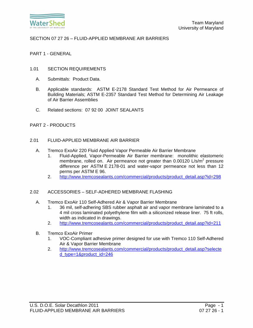
Team Maryland
University of Maryland
U.S. D.O.E. Solar Decathlon 2011 Page - 1 FLUID-APPLIED MEMBRANE AIR BARRIERS 07 27 26 - 1
SECTION 07 27 26 – FLUID-APPLIED MEMBRANE AIR BARRIERS
PART 1 - GENERAL
1.01 SECTION REQUIREMENTS
A. Submittals: Product Data.
B. Applicable standards: ASTM E-2178 Standard Test Method for Air Permeance of Building Materials; ASTM E-2357 Standard Test Method for Determining Air Leakage of Air Barrier Assemblies
C. Related sections: 07 92 00 JOINT SEALANTS
PART 2 - PRODUCTS
2.01 FLUID-APPLIED MEMBRANE AIR BARRIER
A. Tremco ExoAir 220 Fluid Applied Vapor Permeable Air Barrier Membrane 1. Fluid-Applied, Vapor-Permeable Air Barrier membrane: monolithic elastomeric
membrane, rolled on. Air permeance not greater than 0.00120 L/s/m2 pressure difference per ASTM E 2178-01 and water-vapor permeance not less than 12 perms per ASTM E 96.
2. http://www.tremcosealants.com/commercial/products/product_detail.asp?id=298
2.02 ACCESSORIES – SELF-ADHERED MEMBRANE FLASHING
A. Tremco ExoAir 110 Self-Adhered Air & Vapor Barrier Membrane 1. 36 mil, self-adhering SBS rubber asphalt air and vapor membrane laminated to a
4 mil cross laminated polyethylene film with a siliconized release liner. 75 ft rolls, width as indicated in drawings.
2. http://www.tremcosealants.com/commercial/products/product_detail.asp?id=211
B. Tremco ExoAir Primer 1. VOC-Compliant adhesive primer designed for use with Tremco 110 Self-Adhered
Air & Vapor Barrier Membrane 2. http://www.tremcosealants.com/commercial/products/product_detail.asp?selecte
d_type=1&product_id=246

Team Maryland
University of Maryland
U.S. D.O.E. Solar Decathlon 2011 Page - 2 FLUID-APPLIED MEMBRANE AIR BARRIERS 07 27 26 - 2
PART 3 - EXECUTION
3.01 INSTALLATION
A. Prepare substrate by cleaning, removing projections, filling voids, sealing joints, and as otherwise recommended in manufacturer's written instructions.
B. Fill gaps in perimeter frame surfaces of windows, curtain walls, storefronts, and doors, and miscellaneous penetrations of air-barrier membrane with foam sealant.
C. Using roller or brush, apply primer to substrates at required rate and allow to dry. Limit priming to areas that will be covered by air-barrier membrane in same day. Reprime areas exposed for more than 24 hours.
D. Install termination strips and auxiliary materials according to air-barrier manufacturer's written instructions to form a seal with adjacent construction and maintain a continuous air barrier. Install termination strips so that a minimum of 4 inches (102 mm) of coverage is achieved over both substrates.
E. Apply termination mastic at all seams of membrane flashing
F. Apply air-barrier membrane to form a seal with termination strips and to achieve a continuous air barrier according to air-barrier manufacturer's written instructions.
G. Roller apply fluid-applied air barrier to a wet thickness not less than 80 mil.
END OF SECTION 07 27 26

Team Maryland
University of Maryland
U.S. D.O.E. Solar Decathlon 2011 Page - 1 VEGETATED ROOFING 07 33 63 - 1
SECTION 07 33 63 - VEGETATED ROOFING
PART 1 - GENERAL
1.01 SECTION REQUIREMENTS
A. Submittals: Product Data, color charts showing the full range of colors available for factory-applied finishes
B. Warranties: Provide standard manufacturer’s written warranty, without monetary limitation, signed by manufacturer agreeing to promptly repair or replace products that fail in materials or workmanship for the period of 1 year.
C. LEED Credits 1. SS 5.1 Site Development, Protect or Restore Habitat 2. SS 5.2 Site Development, Maximize Open Space 3. SS 6.1 Quantity Control 4. SS 6.2 Quality Control 5. SS 7.2 Heat Island Effect–Roof 6. WE 1.1 Water Efficient Landscaping, Reduce by 50 % 7. WE 1.2 Water Efficient Landscaping, No Potable Use or No Irrigation 8. MR 4.1-4.2 Recycled Content 9. MR 5.1-5.2 Regional Materials 10. MR 6 Rapidly Renewable Materials
PART 2 - PRODUCTS
2.01 VEGETATED ROOFING
A. LiveRoof LITE 1. Modular Vegetated Roofing, manufactured in 1’ x 2’ trays. Saturated weight of
system to be approximately 15 – 17 lbs/sf. a. Trays will be 100 mil thick recycled polypropylene and colored black, gray
or clear. Tray dimensions 12 inches wide by 24 inches long and 1 ¾ inches deep. Total soil height to be 2 ½ inches.
b. Growing medium - Engineered blend of inorganic and organic components based upon German FLL granulometric guidelines modified so as to contain ecologically sustainable levels of organic content.
c. Recommended plant mixes consisting of highly drought resistant ground covers. Local horticulturalists should be consulted for specific recommendations.
2. http://www.liveroof.com/?parent=System_Specifications&page=cad_drawings#Lite
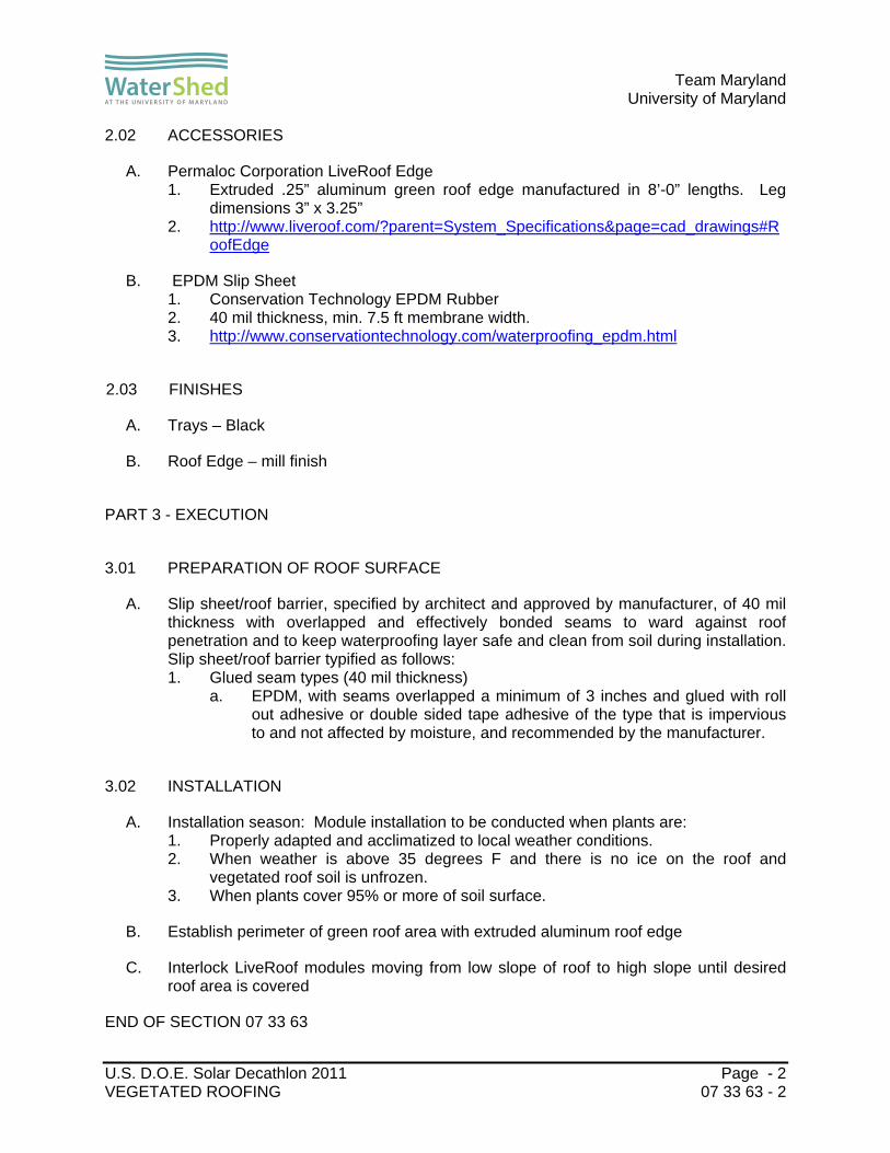
Team Maryland
University of Maryland
U.S. D.O.E. Solar Decathlon 2011 Page - 2 VEGETATED ROOFING 07 33 63 - 2
2.02 ACCESSORIES
A. Permaloc Corporation LiveRoof Edge 1. Extruded .25” aluminum green roof edge manufactured in 8’-0” lengths. Leg
dimensions 3” x 3.25” 2. http://www.liveroof.com/?parent=System_Specifications&page=cad_drawings#R
oofEdge
B. EPDM Slip Sheet 1. Conservation Technology EPDM Rubber 2. 40 mil thickness, min. 7.5 ft membrane width. 3. http://www.conservationtechnology.com/waterproofing_epdm.html
2.03 FINISHES
A. Trays – Black
B. Roof Edge – mill finish
PART 3 - EXECUTION
3.01 PREPARATION OF ROOF SURFACE
A. Slip sheet/roof barrier, specified by architect and approved by manufacturer, of 40 mil thickness with overlapped and effectively bonded seams to ward against roof penetration and to keep waterproofing layer safe and clean from soil during installation. Slip sheet/roof barrier typified as follows: 1. Glued seam types (40 mil thickness)
a. EPDM, with seams overlapped a minimum of 3 inches and glued with roll out adhesive or double sided tape adhesive of the type that is impervious to and not affected by moisture, and recommended by the manufacturer.
3.02 INSTALLATION
A. Installation season: Module installation to be conducted when plants are: 1. Properly adapted and acclimatized to local weather conditions. 2. When weather is above 35 degrees F and there is no ice on the roof and
vegetated roof soil is unfrozen. 3. When plants cover 95% or more of soil surface.
B. Establish perimeter of green roof area with extruded aluminum roof edge
C. Interlock LiveRoof modules moving from low slope of roof to high slope until desired roof area is covered
END OF SECTION 07 33 63

Team Maryland
University of Maryland
U.S. D.O.E. Solar Decathlon 2011 Page - 1 METAL WALL PANELS 07 42 13 - 1
SECTION 07 42 13 – METAL WALL PANELS
PART 1 - GENERAL
1.01 SECTION REQUIREMENTS
A. Submittals: Product Data and color Samples.
B. Fabricate flashing and trim to comply with recommendations in SMACNA's "Architectural Sheet Metal Manual" that apply to the design, dimensions, metal, and other characteristics of item indicated.
C. Warranties: Provide manufacturer's standard written warranty, signed by manufacturer agreeing to promptly repair or replace metal wall panels that show evidence of deterioration of factory-applied finishes within 20 years from date of Substantial Completion.
D. Related sections: 07 62 00 SHEET METAL FLASHING AND TRIM; 07 92 00 JOINT SEALANTS
PART 2 - PRODUCTS
2.01 CORRUGATED METAL WALL PANELS
A. Fabral Corrugated ½” 1. Corrugated Panel for Commercial-Industrial Metal Roofing and Wall Cladding.
Exposed-fastener, lap seam ½ in. corrugated metal wall panel, 2.667 in. ridge to ridge, 40 in. net coverage.
2. http://www.fabral.com/products/1-2-corrugated#specs
2.02 FLASHING AND TRIM
A. Head Flashing 1. Galvalume steel sheet; Nominal Metal Thickness: 24 ga.; 0.028 inch (0.71 mm).
B. Endwall Flashing 1. Galvalume steel sheet, Nominal Metal Thickness: 24 ga.; 0.028 inch (0.71 mm).
C. Closure Flashing 1. Galvalume steel sheet, Nominal Metal Thickness: 26 ga.; 0.022 inch (0.55 mm).

Team Maryland
University of Maryland
U.S. D.O.E. Solar Decathlon 2011 Page - 2 METAL WALL PANELS 07 42 13 - 2
2.03 FINISHES 1. Clear organic polymer surface treatment; material thickness as specified in
drawings
PART 3 - EXECUTION
3.01 FABRICATION
A. Custom fabricate sheet metal flashing and trim to comply with recommendations in SMACNA’s “Architectural Sheet Metal Manual” that apply to design, dimensions, geometry, metal thickness and other characteristics of item indicated. Fabricate items at the shop to greatest extent possible.
B. Obtain field measurements for accurate fit before shop fabrication.
3.02 INSTALLATION
A. Anchor panels securely in place, with provisions for thermal and structural movement. Field cutting exterior panels by torch is not permitted. Exposed fasteners finished to match wall panels.
B. Install gaskets, joint fillers, and sealants where indicated and where required for weatherproof performance of wall panel assemblies. Provide types of gaskets, fillers, and sealants as indicated, or as recommended by panel manufacturer.
C. Separate dissimilar metals and metal panels from contact with wood or cementitious materials, by painting each metal surface in area of contact with a bituminous coating or by other permanent separation.
END OF SECTION 07 42 13

Team Maryland
University of Maryland
U.S. D.O.E. Solar Decathlon 2011 Page - 1 THERMOPLASTIC-POLYOLEFIN ROOFING 07 54 23 - 1
SECTION 07 54 23 - THERMOPLASTIC-POLYOLEFIN ROOFING
PART 1 - GENERAL
1.01 SECTION REQUIREMENTS
A. Submittals: Product Data, and manufacturer's color charts showing the full range of colors available for factory-applied finishes.
B. Warranties: Provide standard manufacturer's written warranty, without monetary limitation, signed by manufacturer agreeing to promptly repair or replace products that fail in materials or workmanship for the period of 20 years.
PART 2 - PRODUCTS
2.01 THERMOPLASTIC POLYOLEFIN ROOFING MEMBRANE
A. Tremco TPO Single Ply Roof System 1. Mechanically fastened Thermoplastic Polyolefin roofing membrane, thickness 60
mil, 10 ft width 2. http://www.tremcoroofing.com/fileshare/specs/tpo_single_ply_roof_system_REV
_8_2009.pdf
2.02 FIBERGLASS-MAT FACED GYPSUM ROOF BOARD
A. Georgia-Pacific DensDeck Prime Roof Board 1. ½ inch (12.7 mm) thick, 4’ x 8’ gypsum roof board, fiberglass-mat surfacing; R-
Value (ASTM C518): Not less than 0.56; Compressive Strength (Applicable sections of ASTM C472): 500 – 900 psi
2. http://www.gp.com/build/product.aspx?pid=4664
2.03 ACCESSORIES – TPO FLASHING
A. Tremco TPO Unreinforced Membrane 1. Thermoplastic Polyolefin non-reinforced flashing membrane, 55 mil membrane,
8” width. 2. http://www.tremcoroofing.com/fileshare/msds/TPO055_503_U.pdf
2.04 ACCESSORIES – TERMINATION BAR
A. 0.100 inch x 1 inch mill finish aluminum bar stock.

Team Maryland
University of Maryland
U.S. D.O.E. Solar Decathlon 2011 Page - 2 THERMOPLASTIC-POLYOLEFIN ROOFING 07 54 23 - 2
2.05 FINISHES
A. Colors - white
PART 3 - EXECUTION
3.01 INSTALLATION
A. Prepare substrate by cleaning, removing projections, filling voids, sealing joints, and as otherwise recommended in manufacturer's written instructions.
B. Lay out roof substrate and fasten through to roof substrate. Fasteners to be installed of type and quantity as recommended by manufacturer.
C. Fasten membrane securely in place, with provisions for thermal and structural movement.
D. Correct deficiencies in or remove and reinstall roof membrane that does not comply with requirements.
E. Install with appropriate heat welding equipment in accordance with specifications, details and workmanship requirements.
END OF SECTION 07 54 23

Team Maryland
University of Maryland
U.S. D.O.E. Solar Decathlon 2011 Page - 1 STANDING SEAM SHEET METAL ROOFING 07 61 13 - 1
SECTION 07 61 13 – STANDING SEAM SHEET METAL ROOFING
PART 1 - GENERAL
1.01 SECTION REQUIREMENTS
A. Submittals: Product Data, Shop Drawings, manufacturer’s color charts showing the full range of colors available for factory-applied finishes
B. Comply with SMACNA's "Architectural Sheet Metal Manual" unless otherwise indicated.
C. Warranties: Provide manufacturer's standard written warranty, signed by manufacturer agreeing to promptly repair or replace roofing sheet metal that shows evidence of deterioration of factory-applied finishes within 20 years from date of Substantial Completion.
D. Warranties: Standard form in which roofing Installer agrees to repair or replace sheet metal roofing that fails in materials or workmanship within 5 years from date of Substantial Completion.
E. Related Sections: 07 62 00 – Sheet Metal Flashing and Trim; 07 92 00 – Joint Sealants
PART 2 - PRODUCTS
2.01 STANDING SEAM SHEET METAL ROOFING
A. Tremco TremLock VP 1. Factory formed double-lock, architectural standing seam metal roof panel utilizing
mechanical seaming. 2. Energy Performance of Roofing Sheet Metal: Initial solar reflectance not less
than 0.70 and emissivity not less than 0.75 when tested according to CRRC-1. 3. 2” seam height, 16” panel width, panel length to be determined by drawings. No
stiffening ribs or striations. 4. Metallic-Coated Steel Sheet: AZ-55 Hot Dipped Galvalume structural-steel
sheet, ASTM E 111-04, AZ-55; 24 ga. [0.025 in. (0.64 mm)] nominal thickness. 5. http://www.tremcoroofing.com/fileshare/specs/TremLock_VP.pdf
2.02 ACCESSORIES
A. Panel Clips 1. Firestone UNA-CLAD UC-6 Fixed Clip

Team Maryland
University of Maryland
U.S. D.O.E. Solar Decathlon 2011 Page - 2 STANDING SEAM SHEET METAL ROOFING 07 61 13 - 2
c. http://www.firestonebpco.com/templateFiles/includes/common/displayFile.ashx?fileId=12977
B. Metal Roof Trim: 1. Firestone UNA-CLAD ACRYLUME Steel Architectural Sheet
a. Matching sheet metal roofing in finish and material required for a complete weathertight roofing system, including clips, flashings, ridge closure strips, trim, copings, fasciae, gutters, and louvers.
b. Metallic-Coated Steel Sheet: AZ-55 Hot Dipped Galvalume structural-steel sheet, ASTM E 111-04, AZ-55; 24 ga. [0.025 in. (0.64 mm)] nominal thickness.
c. Profiles to be shop fabricated to thickness, material thickness and profiles as indicated in drawings; fabricated in 10’ lengths.
d. http://www.firestonebpco.com/templateFiles/includes/common/displayFile.ashx?fileId=15783
C. Roof Substrate 1. 1/2” Exterior Grade Plywood, 4’ x 8’ sheets
D. Self-Adhering Sheet Underlayment, High Temperature: 1. Met-Fab MetShield High Temperature Waterproof Underlayment Membrane
a. Rubberized asphalt; slip-resisting-polyethylene surfaced; with release paper backing; cold applied. Stable after testing at 250 deg F (121 deg C) and passes after testing at minus 40 deg F (-40 deg C); ASTM D 1970.
b. http://www.met-fab.com/products/metshield-waterproof-underlayment/
E. Slip Sheet: Red Rosin Building paper, 3-lb/100 sq. ft. (0.16-kg/sq. m) minimum, rosin sized.
F. Fasteners: Wood screws, annular-threaded nails, self-tapping screws, self-locking rivets and bolts, and other suitable fasteners. 1. Fasteners for Metallic-Coated Steel Sheet: Hot-dip galvanized steel or
Series 300 stainless steel.
G. Butyl Sealant: ASTM C 1311, single-component, solvent-release butyl rubber sealant; polyisobutylene plasticized; heavy bodied for hooked-type expansion joints with limited movement.
H. Bituminous Coating: Cold-applied asphalt emulsion complying with ASTM D 1187.
2.03 FINISHES
A. Steel Architectural Sheet, AZ-55 Hot Dipped Galvalume, thickess as specified. All metal exposed to view to have Clear Organic Polymer Surface Treatment.

Team Maryland
University of Maryland
U.S. D.O.E. Solar Decathlon 2011 Page - 3 STANDING SEAM SHEET METAL ROOFING 07 61 13 - 3
PART 3 - EXECUTION
3.01 FABRICATION
A. Fabricate sheet metal roofing to comply with details shown and recommendations in SMACNA's "Architectural Sheet Metal Manual" that apply to the design, dimensions, metal, and other characteristics of installation indicated. 1. Standing-Seam Roofing: Form standing-seam pans with finished seam height of
2 inches (38 mm) and pan width of 16 inches (406 mm).
3.02 INSTALLATION
A. Install plywood substrate in a staggered pattern and fasten to roof deck below using fasteners in quantity and pattern recommended by manufacturer.
B. Apply self-adhering sheet underlayment over entire roof area
C. Apply slip sheet over self-adhering sheet underlayment before installing metal roof panels.
D. Anchor roofing securely in place, with provisions for thermal and structural movement. Install with concealed panel clips at 16” o.c. and fasten to roof decking unless otherwise indicated.
E. Separate dissimilar metals with a bituminous coating or polymer-modified, bituminous sheet underlayment.
F. Install work with lines and corners of exposed units true and accurate. Form exposed faces flat and free of buckles, excessive waves, and avoidable tool marks, considering temper and reflectivity of metal. Provide uniform, neat seams with minimum exposure of solder and sealant. Fold back sheet metal to form a hem on concealed side of exposed edges unless otherwise indicated.
1. Install cleats to hold sheet metal panels in position. Attach each cleat with two fasteners to prevent rotation.
2. Nail cleats at 12 inches (300 mm) o.c.
G. Seal joints as shown and as required for leakproof construction. Provide low-slope transverse seams using cleats where backup of moisture may occur.
END OF SECTION 07 61 13

Team Maryland
University of Maryland
U.S. D.O.E. Solar Decathlon 2011 Page - 1 SHEET METAL FLASHING AND TRIM 07 62 00 - 1
SECTION 07 62 00 – SHEET METAL FLASHING AND TRIM
PART 1 - GENERAL
1.01 SECTION REQUIREMENTS
A. Submittals: Product Data, Shop Drawings, Product Samples.
B. Comply with SMACNA's "Architectural Sheet Metal Manual." Conform to dimensions and profiles shown unless more stringent requirements are indicated.
C. Verify dimensions by field measurements before fabrication and indicate on Shop Drawings
D. Related Sections: 07 71 00 – ROOF SPECIALTIES; 07 92 00 – JOINT SEALANTS
PART 2 - PRODUCTS
2.01 SHEET METAL
A. Galvalume Steel Sheet: Galvalume structural-steel sheet, ASTM E111-04, AZ-55, 24 ga.; 0.025-inch (0.64-mm) nominal thickness, 26 ga.; 0.019-inch (0.48 mm) nominal thickness.
B. Galvalume Steel Sheet: Galvalume structural-steel sheet, ASTM E111-04, AZ-50, 26 ga.; 0.019-inch (0.48 mm) nominal thickness
C. Galvanized structural-steel sheet, ASTM A 653/A 653M, G90, 24 ga.; 0.025-inch (0.64-mm) nominal thickness.
D. Aluminum sheet, ASTM B209; .032 inch nominal thickness.
2.02 ACCESSORIES
A. Self-Adhering Sheet Underlayment, High Temperature: Butyl or SBS-modified asphalt; slip-resisting-polyethylene surfaced; with release paper backing; cold applied. Stable after testing at 250 deg F (121 deg C) and passes after testing at minus 40 deg F (-40 deg C); ASTM D 1970.
B. Slip Sheet: Building paper, 3-lb/100 sq. ft. (0.16-kg/sq. m) minimum, rosin sized.

Team Maryland
University of Maryland
U.S. D.O.E. Solar Decathlon 2011 Page - 2 SHEET METAL FLASHING AND TRIM 07 62 00 - 2
C. Fasteners: Wood screws, annular-threaded nails, self-tapping screws, self-locking rivets and bolts, and other suitable fasteners.
1. Exposed Fasteners: Heads matching color of sheet metal roofing using plastic caps or factory-applied coating..
2. Fasteners for Metallic-Coated Steel Sheet: Hot-dip galvanized steel or Series 300 stainless steel.
D. Butyl Sealant: ASTM C 1311, solvent-release butyl rubber sealant.
E. Bituminous Coating: Cold-applied asphalt emulsion complying with ASTM D 1187.
2.03 FINISHES
A. Galvalume Steel Sheet – AZ-55 Galvalume Coating with Clear Organic Polymer Surface Coating
B. Galvalume Steel Sheet – bare AZ-50 Galvalume mill finish
C. Galvanized Structural-Steel Sheet – bare G90 mill finish
D. Aluminum Sheet – Kynar/Hylar 5000 pre-finished 1. Color – medium bronze
PART 3 - EXECUTION
3.01 FABRICATION
A. Fabricate sheet metal flashing and trim to comply with recommendations in SMACNA's "Architectural Sheet Metal Manual" that apply to the design, dimensions, metal, and other characteristics of the item indicated.
B. Fabrication Tolerances: Fabricate sheet metal flashing and trim that is capable of installation to tolerances specified in MCA's "Guide Specification for Residential Metal Roofing."
C. Window Sill flashing – fabricated from 26 ga. Galvalume
D. Window and door head flashing – fabricated from .032 aluminum
E. Clerestory sill flashing – fabricated from 24 ga. Galvalume
F. Receiver flashings and counter flashings – fabricated from 26 ga. Galvalume
G. Module C roof flashings - fabricated from 24 ga. Galvalume

Team Maryland
University of Maryland
U.S. D.O.E. Solar Decathlon 2011 Page - 3 SHEET METAL FLASHING AND TRIM 07 62 00 - 3
H. Drip edges - fabricated from 26 ga. Galvalume
I. Fasciae - fabricated from 24 ga. Galvalume
J. 6” Half-Round Gutters – fabricated from 24 ga. Galvalume
K. 4” Round Downspouts - fabricated from 24 ga. Galvalume
L. Copings – fabricated from 24 ga. Galvalume
M. Concealed Cleats – fabricated from 24 ga. Galvanized
3.02 INSTALLATION
A. Comply with SMACNA's "Architectural Sheet Metal Manual." Allow for thermal expansion; set true to line and level. Install Work with laps, joints, and seams permanently watertight and weatherproof; conceal fasteners where possible.
B. Sealed Joints: Form nonexpansion, but movable, joints in metal to accommodate elastomeric sealant to comply with SMACNA standards.
1. Do not solder metallic-coated steel
C. Separate dissimilar metals with a bituminous coating or polymer-modified, bituminous sheet underlayment.
D. Coordinate installation of sheet metal flashing and trim with interfacing and adjoining construction to provide a leakproof, secure, and noncorrosive installation.
E. Apply Self Adhering Sheet Underlayment over all pressure treated lumber prior to installing flashings.
END OF SECTION 07 62 00

Team Maryland
University of Maryland
U.S. D.O.E. Solar Decathlon 2011 Page - 1 ROOF SPECIALTIES 07 71 00 - 1
SECTION 07 71 00 – ROOF SPECIALTIES
PART 1 - GENERAL
1.01 SECTION REQUIREMENTS
A. Submittals: Product Data and Product Samples.
B. Warranties: Provide manufacturer's standard written warranty, signed by manufacturer agreeing to promptly repair or replace roof specialties that show evidence of deterioration of factory-applied finishes within 5 years from date of Substantial Completion.
C. SPRI Wind Design Standard: Provide roof-edge flashings tested according to SPRI ES-1 and capable of resisting the following design pressures:
1. Design Pressure: ANSI/SPRI ES-1 Test Method RE-1 Test for Roof Edge Termination of Single-Ply Roofing Membranes: The fascia system shall be tested to secure the membrane to minimum 100 lbs/ft
PART 2 - PRODUCTS
2.01 ROOF SPECIALTIES
A. Bar-Type Snow Guards: Rail-type assembly consisting of two 1 inch outside diameter stainless-steel bars or pipe held in place by stainless-steel clamps attached to roof substrate through insulation. 1. Alpine Snow Guards 115R Pipe SnowGuard for Membrane Roofs with Insulation
– two rail version. a. Snow Guard Bracket – 6000 Series Aluminum. b. Base Plate – 11 gage 304 stainless steel with two 5/16 inch (8 mm) 304
stainless steel machine screws welded into countersinks. c. Tubing - Stainless Steel – 304 alloy, 1 (25.4 mm) inch outside diameter and
.120 (3 mm) inch wall thickness, welded. d. Couplings - Stainless Steel – 304 alloy, internal and concealed coupling 3
inches (76.2 mm) long. e. End Caps – 304 Stainless Steel f. Ferrules – 6000 Series Aluminum 1 inch (25.4 mm) o.c. 1/8 inch (3.1 mm)
wall thickness x 24 inch (609.6 mm) long. Cut to length on site. g. http://www.alpinesnowguards.com/pdf/115r-snow-guard-spec.pdf
B. Siding Vents: heat resistant polypropylene 1. Cor-A-Vent SV-5 Siding Vent

Team Maryland
University of Maryland
U.S. D.O.E. Solar Decathlon 2011 Page - 2 ROOF SPECIALTIES 07 71 00 - 2
a. ¾” x 3” x 4’ heat resistant polypropylene siding vent, 8.5 sq. in. NFVA per lineal foot
b. http://www.cor-a-vent.com/siding-vent-sv-3.cfm
2.02 ACCESSORIES
A. Aluminum Extrusions: ASTM B 221 (ASTM B 221M), alloy and temper as recommended by manufacturer for use and finish indicated.
B. Aluminum Finish: Mill finish
C. Fasteners: Manufacturer's recommended fasteners, suitable for application and designed to meet performance requirements.
1. Exposed Penetrating Fasteners: Gasketed screws with heads matching color of metal.
2. Fasteners for Aluminum: Aluminum or Series 300 stainless steel. 3. Fasteners for Zinc-Coated (Galvanized) Steel Sheet: Series 300 stainless steel
or hot-dip zinc-coated steel.
D. Butyl Sealant: ASTM C 1311, solvent-release butyl rubber sealant.
E. Bituminous Coating: Cold-applied asphalt emulsion complying with ASTM D 1187.
2.03 FINISHES
A. Finish to be selected by Architect from manufacturer’s full range of standard colors.
PART 3 - EXECUTION
3.01 INSTALLATION
A. General: Install roof specialties according to manufacturer's written instructions. Anchor roof specialties securely in place, with provisions for thermal and structural movement.
B. Coat back side of aluminum and stainless-steel roof specialties with bituminous coating where they will contact wood, ferrous metal, or cementitious construction.
C. Bed flanges in thick coat of asphalt roofing cement where required by manufacturers of roof specialties for waterproof performance.
D. Space movement joints at a maximum of 12 feet (3.6 m) with no joints within 24 inches (609.6 mm) of corners or intersections unless indicated.

Team Maryland
University of Maryland
U.S. D.O.E. Solar Decathlon 2011 Page - 3 ROOF SPECIALTIES 07 71 00 - 3
E. Fastener Sizes: Use fasteners of sizes that will penetrate substrate not less than recommended by fastener manufacturer to achieve maximum pull-out resistance.
END OF SECTION 07 71 00

Team Maryland
University of Maryland
U.S. D.O.E. Solar Decathlon 2011 Page - 1 JOINT GASKETS 07 91 16 - 1
SECTION 07 91 16 – JOINT GASKETS
PART 1 - GENERAL
1.01 SECTION REQUIREMENTS
A. Submittals: Product Data.
PART 2 - PRODUCTS
2.01 BUILDING GASKET FOR USE IN ROOF SEPARATION JOINT:
A. Conservation Technology
1. Structural Gasket, Cellular EPDM (Ethylene propylene diene monomer); ASTM D-7465, Type I; 5” wide, 82’ lengths
2. Part number: BG65
3. http://www.conservationtechnology.com/building_gaskets.html
2.02 BUILDING GASKET FOR USE IN MODULE SEPARATION JOINT
A. Conservation Technology
1. Gap Gasket, Cellular EPDM (Ethylene propylene diene monomer); ASTM D-7465, Type I; 3/4” wide, 164’ lengths
2. Part number: BG46
3. http://www.conservationtechnology.com/building_gaskets.html
B. Conservation Technology
1. Gap Gasket, Cellular EPDM (Ethylene propylene diene monomer); ASTM D-7465, Type I; 1” wide, 82’ lengths
2. Part number: BG48
3. http://www.conservationtechnology.com/building_gaskets.html

Team Maryland
University of Maryland
U.S. D.O.E. Solar Decathlon 2011 Page - 2 JOINT GASKETS 07 91 16 - 2
PART 3 - EXECUTION
3.01 INSTALLATION
A. Prepare substrate by cleaning, removing projections and filling voids and as otherwise recommended by manufacturer’s written instructions.
B. Install joint gaskets in accordance with reviewed product data, manufacturer’s written recommendations, and as indicated on the Drawings. Install joint gaskets at the depth recommended by the sealant manufacturer. Do not use with hot-applied sealants.
3.02 COMPATIBILITY
A. Closed cell polyethylene foam is basically an inert material; and therefore, it is compatible, both physically and chemically, with virtually all known cold-applied sealants, including, but not limited to, self-leveling types.
END OF SECTION 07 91 16

Team Maryland
University of Maryland
U.S. D.O.E. Solar Decathlon 2011 Page - 1 JOINT SEALANTS 07 92 00 - 1
SECTION 07 92 00 - JOINT SEALANTS
PART 1 - GENERAL
1.01 SECTION REQUIREMENTS
A. Submittals: Product Data and color Samples.
B. Environmental Limitations: Do not proceed with installation of joint sealants when ambient and substrate temperature conditions are outside limits permitted by joint-sealant manufacturer or are below 40 deg F (4.4 deg C).
C. Compatibility: Provide joint sealants, joint fillers, and other related materials that are compatible with one another and with joint substrates under service and application conditions.
PART 2 - PRODUCTS
2.01 Gap Filler:
A. DOW
1. GREAT STUFF™ Gaps & Cracks Insulating Foam Sealant. Single-component, closed cell polyurethane post-expanding foam. UL Classified
2. http://building.dow.com/na/en/products/sealants/gapscracks.htm
B. DOW
1. GREAT STUFF™ Window & Door. Single-component closed cell polyurethane foam sealant. UL Classified.
2. http://building.dow.com/na/en/products/sealants/windowdoor.htm Joint Filler
C. TREMCO
1. Tremflex 834 gun-grade general purpose acrylic latex sealant. It can be used indoors and outdoors and is tack-free in 15 minutes and ready to paint in 30-45 minutes with latexes or oil-based paint.
2. http://www.tremcosealants.com/fileshare/pds/tflex834.pdf

Team Maryland
University of Maryland
U.S. D.O.E. Solar Decathlon 2011 Page - 2 JOINT SEALANTS 07 92 00 - 2
2.02 Sealant for TPO Roof Penetrations:
A. FIRESTONE:
1. Water-Block Seal (S-20) Butyl Rubber Sealant. Designed to provide a seal when used in compression as required by Firestone Details.
2. http://www.firestonebpco.com/templateFiles/includes/common/displayFile.ashx?fileId=2242
B. RED DEVIL
1. Butyl Rubber Sealant. A high quality, tough, butyl rubber sealant, ideal for jobsrequiring a durable watertight seal
2. http://www.reddevil.com/msds-tds/tds_0698.pdf
2.03 Sealant for Use in Interior Joints in Ceramic Tile and Other Hard Surfaces in Kitchens and Toilet Rooms and Around Plumbing Fixtures:
A. GE
1. SCS1700 Sanitary single-component, mildew-resistant silicone sealant.
2. http://www.siliconeforbuilding.com/pdf/speciality/Data_Sheet_SCS1700_Sanitary.pdf
2.04 Sealant for Exterior Use at Perimeters of Translucent Wall Panels:
A. TREMCO
1. Spectrem® 1. Ultra low modulus, high performance, one-part, moisture curing silicone joint sealant.
2. http://www.tremcosealants.com/fileshare/pds/Spectrem1DSEnglish.pdf
2.05 Fire Protection Sealant:
A. Tremco
1. Fyre-Caulk intumescent acrylic sealant. Designed for use in commonly encountered applications where both combustible and noncombustible through penetrations are present. To be used with Roxul insulation where needed to fill larger gaps in penetrations.

Team Maryland
University of Maryland
U.S. D.O.E. Solar Decathlon 2011 Page - 3 JOINT SEALANTS 07 92 00 - 3
2. http://www.tremcosealants.com/fileshare/pds/FyreCaulk_DS.pdf
2.06 Sealant for Use on Galvanized Aluminum Flashing and Gutters:
A. DAP
1. Silicone Sealant. An all-purpose, one component, acetoxy cure sealant ideal for indoor/outdoor use. It provides a watertight, flexible seal that won’t crack, crumble or shrink. It meets ASTM Specification C 920, Class 25, Type S, Grade NS and has a 50 year durability guarantee.
2. http://www.dap.com/docs/tech/00000683.pdf
2.07 MISCELLANEOUS MATERIALS
A. Provide sealant backings of material that are nonstaining; are compatible with joint substrates, sealants, primers, and other joint fillers; and are approved for applications indicated by sealant manufacturer based on field experience and laboratory testing.
B. Cylindrical Sealant Backings: ASTM C 1330, of size and density to control sealant depth and otherwise contribute to producing optimum sealant performance.
C. Bond-Breaker Tape: Polyethylene tape or other plastic tape recommended by sealant manufacturer for preventing sealant from adhering to rigid, inflexible joint-filler materials or joint surfaces at back of joint. Provide self-adhesive tape where applicable.
D. Primer: Material recommended by joint-sealant manufacturer where required for adhesion of sealant to joint substrates indicated, as determined from preconstruction joint-sealant-substrate tests and field tests.
PART 3 - EXECUTION
3.01 INSTALLATION
A. Sealants must be installed and maintained according to the manufacturer’s current instructions.
B. Prepare substrate by cleaning, removing projections, and as otherwise recommended in manufacturer's written instructions.
C. Install sealant backings to support sealants during application and to produce cross-sectional shapes and depths of installed sealants that allow optimum sealant movement capability.
D. Install bond-breaker tape behind sealants where sealant backings are not used between sealants and backs of joints.

Team Maryland
University of Maryland
U.S. D.O.E. Solar Decathlon 2011 Page - 4 JOINT SEALANTS 07 92 00 - 4
E. Acoustical Sealant Installation: At sound-rated assemblies and elsewhere as indicated, seal perimeters, control joints, openings, and penetrations with a continuous bead of acoustical sealant. Install acoustical sealant at both faces of partitions. Comply with ASTM C 919.
END OF SECTION 07 92 00

Team Maryland
University of Maryland
U.S. D.O.E. Solar Decathlon 2011 Page - 1 WOOD DOORS 08 14 00- 1
SECTION 08 14 00 – WOOD DOORS
PART 1 - GENERAL
1.01 SECTION REQUIREMENTS
A. Structural Performance: Provide doors engineered, fabricated, and installed to withstand
normal thermal movement, wind loading, and impact loading without failure, as demonstrated by testing manufacturer's standard door assemblies representing types, grades, and sizes required for this Project according to test methods indicated.
B. Submittals: Product Data. Shop Drawings.
C. Standards: Performance requirements for operating force, air infiltration, water penetration, structural performance, and forced-entry resistance for doors are those specified in NWWDA I.S. 2, "Industry Standard for Wood Window Units."
D. Test Criteria: Testing shall be performed by a qualified independent testing agency based on the following criteria:
1. Design wind velocity at Project site is 60 mph. 2. Test Procedures: Test door units according to ASTM E 283 for air infiltration,
ASTM E 547 for water penetration, and ASTM E 330 for structural performance.
E. Performance Requirements: Testing shall demonstrate compliance with requirements indicated in NWWDA I.S. 2 for water penetration and structural performance for the type and performance grade of window and door units required. Where required design pressure exceeds the minimum for the specified window grade, comply with requirements of NWWDA I.S. 2, Article 6, "Optional Performance Classifications," for higher than minimum performance grades.
1. Air-Infiltration Rate for Doors: Not more than 0.15 cfm/sq. ft. for an inward test pressure of 1.57 lbf/sq. ft. (75 Pa).
2. Water Penetration for Doors: No water penetration as defined in the test method at a static pressure of 4.16 p.s.f. after 15 minutes with water applied at a rate of five gallons per hour per square foot.
3. Structural Performance: No failure or permanent deflection in excess of 0.4 percent of any member's span after removing the imposed load, for a positive (inward) and negative (outward) test pressure of 22.5 lbf/sq. ft. (1077 Pa).

Team Maryland
University of Maryland
U.S. D.O.E. Solar Decathlon 2011 Page - 2 WOOD DOORS 08 14 00- 2
PART 2 - PRODUCTS
2.01 WOODEN EXTERIOR DOORS
A. Loewen Windows and Doors 1. Description: Swinging French Terrace, Heat Smart X, Clear Finish exterior,
Vertical Grain Douglas Fir with Clear Finish, ADA Compliant Flat Thresholds, Manual Multi-Point Locking hardware, Clear Tempered Glass.
2. Item Numbers: FD2 2224 LRA, FD2 1824 LRA, and FD2 1520 LRA 3. http://www.loewen.com/sites/default/loewen/downloads/TechGuide/TG-
TerraceDoor.pdf
B. Custom Manufactured Doors 1. Description: French Outswing Solid Wood Doors, Vertical Grain Douglas Fir with
Clear Finish, Manual Multi-Point Locking hardware
2.02 EXTERIOR DOOR HARDWARE
A. Provide manufacturer’s standard hardware necessary to operate, tightly close, limit travel, and to securely doors. Do not use aluminum in frictional contact with other metals. 1. Provide hardware with a special coating finish and plated steel or brass/bronze
operating bars and rods in finish as selected by Architect.
2. Handles and escutcheon plates: Active handle, inactive handle, interior and exterior escutcheon plates currently specified as brushed chrome.
B. Gaskets: Black Neoprene C. Locking hardware shall have a 1 inch (25 mm) throw deadbolt with Schlage key lock
cylinder. Color: Brushed aluminum. D. All components are corrosion resistant. E. Five Point locking system on primary active panels of high performance units.
Stainless steel. F. Head and sill strike plates to be made of aluminum. Color: brushed aluminum with
aluminum strike. G. Two Point flush bolt on secondary active panel. Top and bottom threaded shoot rods
are made of steel and die cast parts. Level face plate has a lacquer-coated Bright Brass finish. Head and sill strike plates are made of Light Bronze anodized aluminum.
H. Commercial grade hinges, 4-1/2” x 4-1/2” ball bearing square corner with non-removable pin in satin nickel finish.
I. Weatherstripping to meet manufacturer’s standards for performance.
2.01 WOODEN INTERIOR DOORS
A. Custom Manufactured Doors

Team Maryland
University of Maryland
U.S. D.O.E. Solar Decathlon 2011 Page - 3 WOOD DOORS 08 14 00- 3
1. Interior Doors to be both track-mounted sliding and hinged outswing. Door hardware to be purchased from Grant Hardware distributor, door structure to be of standard birch or maple veneer type.
2.02 INTERIOR DOOR HARDWARE
A. Grant Hardware 1. Top Line Grant 71-034 Hardware Set for Sliding Door 2. Wing Line Grant 1260 Series for Folding Doors 3. Grant Single Track 7001 Aluminum Extruded
2.03 EXTERIOR WOODEN DOORS FOR SUN SHADING
A. Manufacturers 1. Custom shop production based on shop drawings and field measurements
B. Description 1. Exterior wooden screen to be constructed from solid wood stiles and rails and
louvers.
2.04 EXTERIOR SUN SHADING DOOR HARDWARE
A. Grant Hardware 1. Wing Line Grant 1260 Series for Bi-Fold Doors 2. Grant Single Track 7001 Aluminum Extruded
2.05 MATERIALS
A. Wooden Framing Systems – Douglas Fir
B. Glass and Glazing Materials 1. General: Provide manufacturer's standard 5/8" Argon filled Low-E sealed clear
insulating glass units complying with the following minimum requirements: 2. Provide tempered or laminated glass insulated units for all locations.
a. Indoor Lite: Type I (transparent glass, flat), Class 1 (clear) float glass. b. Outdoor Lite: Type I (transparent glass, flat), Class 1 (clear) float glass. c. Total Unit “U” Factor: 0.29 d. Solar Heat Gain Coefficient: .40
3. Glazing Seal: Provide manufacturer's standard extruded, vinyl, or butyl glazing gasket providing weather-tight seal.
4. Safety Glazing: Provide tempered or laminated glass insulating units at doors and other locations immediately adjacent to doors and walking paths.
2.06 FINISHES 1. Clear Coat on Douglas Fir Frame
Team Maryland
University of Maryland
U.S. D.O.E. Solar Decathlon 2011 Page - 4 WOOD DOORS 08 14 00- 4
2. Handles and Hinges: Satin Nickel Finish 3. ADA Threshold: Bronze Anodized Aluminum 4. Glass: Clear Tempered Glass 5. See 09 93 13 - EXTERIOR STAINING AND FINISHING
PART 3 - EXECUTION
3.01 FABRICATION
A. General: Fabricate wood door units to comply with indicated standards. Include a complete system for assembly of components and anchorage of door units. 1. Comply with requirements of NWWDA I.S. 2 , I.S. 610, and I.S. 620 for moisture
content of lumber at time of fabrication. 2. Fabricate doors to produce units that are reglazable without dismantling sash
framing. Provide openings and mortises precut, where possible, to receive hardware and other items.
B. Factory-Glazed Door Units: Except for light sizes in excess of 100 united inches (2500 mm width plus length), glaze window and door units in the shop before delivery, unless factory glazing is not available from manufacturer. Comply with requirements of NWWDA I.S. 2.
C. Complete fabrication, assembly, finishing, hardware application, and other work before shipment to the Project site, to the maximum extent possible. Disassemble components only as necessary for shipment and installation. Where necessary for fitting at site, provide ample allowance for scribing, trimming, and fitting.
3.02 INSTALLATION
A. Prepare substrate by cleaning, removing projections, filling voids, sealing joints, and as otherwise recommended in manufacturer's written instructions.
B. Set units level, plumb, and true to line, without warp or rack of frames and panels and anchor securely in place.
C. Fasten door frames securely in place, with provisions for thermal and structural movement. Install with concealed fasteners, unless otherwise indicated.
D. Separate dissimilar metals and metal products from contact with wood or cementitious materials, by painting each metal surface in area of contact with a bituminous coating or by other permanent separation.
E. Correct deficiencies in or remove and reinstall doors, glazing, or hardware that does not comply with requirements.
F. Repair, refinish, or replace doors damaged during installation, as directed by Architect.

Team Maryland
University of Maryland
U.S. D.O.E. Solar Decathlon 2011 Page - 5 WOOD DOORS 08 14 00- 5
G. Adjust operating parts and hardware for smooth, quiet operation and weathertight closure. Lubricate hardware and moving parts.
END OF SECTION 08 14 00

Team Maryland
University of Maryland
U.S. D.O.E. Solar Decathlon 2011 Page - 1 TRANSLUCENT WALL AND ROOF ASSEMBLIES 08 45 00 - 1
SECTION 08 45 00 – TRANSLUCENT WALL AND ROOF ASSEMBLIES
PART 1 - GENERAL
1.01 SECTION REQUIREMENTS
A. Structural Performance: Design, engineer, fabricate, and install translucent wall panels to withstand structural loads required by local codes.
B. Submittals: Product Data.
C. Design Loads: Framing components shall be designed to support following loads: 1. Live Load
a. 3 psf b. As indicated on the drawings
2. Wind Load a. 90 mph per ICC maps
3. Deflection of a Framing Member in a Direction Normal to Plane of Glazing: Shall not exceed L/100.
4. Safety Factors: Allowable Stresses shall incorporate following safety factors, unless otherwise specified: a. Load Carrying Members: 1.65 b. Load Carrying Fasteners: 2.0
D. Warranties 1. Major warranties the merchandise to be equal to its established standards of
manufacture as to material and workmanship.
PART 2 - PRODUCTS
2.01 TRANSLUCENT WALL PANEL SYSTEMS
A. Major Industries 1. Description: Fiberglass translucent panels set into thermally broken aluminum
vertical-lite framing system for higher U-value performance. Wall panel thickness of 2.75,” panel lengths and widths vary per design specifications. Meets testing and certification criteria per ASTM, AAMA, ICC, and NFRC agencies.
2. Guardian 275 Wall Panel System 3. http://www.majorskylights.com/products/guardian/
2.02 FINISHES
A. Glazing: White/White .070” Ultimate Series “Silver Edition”

Team Maryland
University of Maryland
U.S. D.O.E. Solar Decathlon 2011 Page - 2 TRANSLUCENT WALL AND ROOF ASSEMBLIES 08 45 00 - 2
B. Frame: 70% Kynar Standard Black
PART 3 - EXECUTION
3.01 INSTALLATION
A. Prepare substrate by cleaning, removing projections, filling voids, sealing joints, and as otherwise recommended in translucent wall panel manufacturer's written instructions.
B. Set units level, plumb, and true to line, without warp or rack of frames and panels and anchor securely in place.
C. Framing: size framing and blocking in accordance with load-bearing requirements and manufacturer specifications. Install manufacturer framing assembly per manufacturer specifications.
D. Fasten translucent wall panel securely in place, with provisions for thermal and structural movement. Install with concealed fasteners, unless otherwise indicated.
E. Separate dissimilar metals and metal products from contact with wood or cementitious materials, by painting each metal surface in area of contact with a bituminous coating or by other permanent separation.
F. Correct deficiencies in or remove and reinstall translucent wall panels that do not comply with requirements.
G. Repair, refinish, or replace wall panels and framing assembly damaged during installation, as directed by Architect.
END OF SECTION 08 45 00

Team Maryland
University of Maryland
U.S. D.O.E. Solar Decathlon 2011 Page - 1 WINDOWS 08 50 00 - 1
SECTION 08 50 00 – WINDOWS
PART 1 - GENERAL
1.01 SECTION REQUIREMENTS
A. Structural Performance: Provide wood windows engineered, fabricated, and installed to
withstand normal thermal movement, wind loading, and impact loading without failure, as demonstrated by testing manufacturer's standard window and door assemblies representing types, grades, and sizes required for this Project according to test methods indicated.
B. Submittals: Product Data. Shop Drawings
C. Standards: Performance requirements for operating force, air infiltration, water penetration, structural performance, and forced-entry resistance for wood windows are those specified in NWWDA I.S. 2, "Industry Standard for Wood Window Units."
D. Test Criteria: Testing shall be performed by a qualified independent testing agency based on the following criteria:
1. Design wind velocity at Project site is 60 mph. 2. Test Procedures: Test window units according to ASTM E 283 for air infiltration,
ASTM E 547 for water penetration, and ASTM E 330 for structural performance.
E. Performance Requirements: Testing shall demonstrate compliance with requirements indicated in NWWDA I.S. 2 for water penetration, and structural performance for the type and performance grade of window units required. Where required design pressure exceeds the minimum for the specified window grade, comply with requirements of NWWDA I.S. 2, Article 6, "Optional Performance Classifications," for higher than minimum performance grades.
1. Air-Infiltration Rate for Windows: Not more than 0.05 cfm/sq. ft. for an inward test pressure of 6.24 lbf/sq. ft. (295 Pa).
2. Water Penetration for Windows: No water penetration as defined in the test method at a static pressure of 12 p.s.f. after 15 minutes with water applied at a rate of five gallons per hour per square foot.
3. Structural Performance: No failure or permanent deflection in excess of 0.4 percent of any member's span after removing the imposed load, for a positive (inward) and negative (outward) test pressure of 22.5 lbf/sq. ft. (1077 Pa).
PART 2 - PRODUCTS
2.01 DOUGLAS FIR WINDOWS

Team Maryland
University of Maryland
U.S. D.O.E. Solar Decathlon 2011 Page - 2 WINDOWS 08 50 00 - 2
A. Loewen Windows and Doors 1. Description and Operation
a. Fabricate windows to produce units that are reglazible without dismantling sash framing. Provide openings and mortises precut, where possible, to receive hardware and other items
b. Window Types: As indicated on drawings 1) Wood Casement, Operable 2) Wood Picture 3) Wood Awning
c. Performance Grades and Class: LC 25 d. Condensation Resistance Factor (CRF): Provide wood windows tested for
thermal performance according to AAMA 15001, showing CRF of 45 minimum.
2. Window Models a. Casement: CA1 0815 L b. Picture: PS1 1824 c. Awning: AW1 0809
3. http://www.loewen.com/windows/windowStyles/casement/relatedLinks/DouglasFir/index.html
2.02 FINISHES
A. Frame: Clear Coat on Douglas Fir Vertical Grain
B. Hardware: Satin Nickel
C. Glazing: Clear Finish
PART 3 - EXECUTION
3.01 FABRICATION
A. General: Fabricate wood window units to comply with indicated standards. Include a complete system for assembly of components and anchorage of window and door units. 1. Comply with requirements of NWWDA I.S. 2 , I.S. 610, and I.S. 620 for moisture
content of lumber at time of fabrication. 2. Fabricate.
B. Provide weather stripping at perimeter of each operating sash.
C. Factory-Glazed Window and Door Units: Except for light sizes in excess of 100 united inches (2500 mm width plus length), glaze window and door units in the shop before delivery, unless factory glazing is not available from manufacturer. Comply with requirements of NWWDA I.S. 2.

Team Maryland
University of Maryland
U.S. D.O.E. Solar Decathlon 2011 Page - 3 WINDOWS 08 50 00 - 3
D. Complete fabrication, assembly, finishing, hardware application, and other work before shipment to the Project site, to the maximum extent possible. Disassemble components only as necessary for shipment and installation. Where necessary for fitting at site, provide ample allowance for scribing, trimming, and fitting.
E. Mullions: Provide mullions and cover plates as shown, matching window units, complete with anchors for support to structure and installation of window units. Allow for erection tolerances and provide for movement of window units due to thermal expansion and building deflections, as indicated. Provide mullion and cover plates capable of withstanding design loads of window units.
3.02 INSTALLATION
A. Prepare substrate by cleaning, removing projections, filling voids, sealing joints, and as otherwise recommended in manufacturer's written instructions.
B. Set units level, plumb, and true to line, without warp or rack of frames and panels and anchor securely in place.
C. Fasten door and window frames securely in place, with provisions for thermal and structural movement. Install with concealed fasteners, unless otherwise indicated.
D. Separate dissimilar metals and metal products from contact with wood or cementitious materials, by painting each metal surface in area of contact with a bituminous coating or by other permanent separation.
E. Correct deficiencies in or remove and reinstall windows, doors, glazing, or hardware that does not comply with requirements.
F. Repair, refinish, or replace windows and doors damaged during installation, as directed by Architect.
G. Adjust operating parts and hardware for smooth, quiet operation and weathertight closure. Lubricate hardware and moving parts.
END OF SECTION 08 50 00

Team Maryland
University of Maryland
U.S. D.O.E. Solar Decathlon 2011 Page - 1 WALL VENTS 08 95 16 - 1
SECTION 08 95 16 – WALL VENTS
PART 1 - GENERAL
1.01 SECTION REQUIREMENTS
A. Submittals: Product Data
B. American Society for Testing and Materials (ASTM) Publications: 1. ASTM B26 – Aluminum-Alloy Sand Castings. 2. ASTM B85 – Aluminum-Alloy Die Castings.
PART 2 - PRODUCTS
2.01 WALL VENTS
A. Seiho 1. Material: Aluminum; Finish: Anodized; Mounting: Flush 2. Seiho SX-N 6 Aluminum Vent Caps and Seiho SB Dryer Vent 3. http://www.seiho.com/pdf/submittal/sb.pdf;
http://www.seiho.com/pdf/submittal/sx.pdf
B. Type: Anodized aluminum, fixed louver wall vent with insect screen and operable hinged flap type damper.
C. Nominal vent size: 3 inches deep with 8 inch diameter.
D. Construction: Framed vent with overlapping lover blades fabricated as cast aluminum unit. 1. Louver blades: fixed, horizontal blades deep set at 45 degrees. 2. Top frame: Flat surface with toe drip on front edge. 3. Bottom Frame: Flat surface with back water stop and front drip edge.
E. Insect Screen: Mesh aluminum screen riveted to vent behind louvers.
2.02 MATERIALS
A. Description: Anodized aluminum wall vents with fixed louvers, backdraft preventer, and insect screens for installation in wood frame exterior wall, to provide ventilation for mechanical spaces and dryer exhaust.
B. Aluminum castings: ¼” minimum thickness cast aluminum complying with ASTM B26 or ASTM B85, Alloy No. 319

Team Maryland
University of Maryland
U.S. D.O.E. Solar Decathlon 2011 Page - 2 WALL VENTS 08 95 16 - 2
C. Fasteners: Type, size, and spacing as recommended by vent manufacturer for project conditions.
D. Joint sealants as recommended by vent manufacturer.
2.03 FINISHES
A. Wall vent finish: anodized aluminum.
PART 3 - EXECUTION
3.01 COORDINATION
A. Coordinate supply of vents with construction of walls to ensure proper sizing and placement of vent openings.
3.02 INSTALLATION
A. Install vents and dampers in accordance with manufacturer’s installation instructions and approved shop drawings.
B. Do not install bent, scratched, or otherwise damaged vents. Remove damaged components from site and replace
C. Install vents secure, level, plumb, and flush with wall surface.
3.03 CLEANING
A. Remove excess sealant by moderate use of mineral spirits or other solvent acceptable to sealant manufacturer.
B. Wash exposed surfaces with solution of mild detergent applied with soft cloth. Take care to remove dirt from corners. Wipe surfaces clean.
END OF SECTION 08 95 16

Team Maryland
University of Maryland
U.S. D.O.E. Solar Decathlon 2011 Page - 1 GYPSUM BOARD 09 29 00 - 1
SECTION 09 29 00 - GYPSUM BOARD
PART 1 - GENERAL
1.01 SECTION REQUIREMENTS
A. Submittals: Product Data.
B. Product Certificate for GREENGUARD Indoor Air Quality for products and materials required to comply with requirements for minimum chemical emission.
C. ASTM C 1396 standards applicable.
PART 2 - PRODUCTS
2.01 GYPSUM BOARD
A. STANDARD GYPSUM BOARD 1. Core: Regular 2. Surface Paper: 100% recycled content paper on front, back and long edges. 3. Long Edges: Square. 4. Overall thickness: 1/2 inch.
B. MOLD AND MOISTURE RESISTANT GYPSUM BOARD 1. Core: Mold and moisture resistant gypsum core 2. Surface paper: 100% recycled content moisture/mold/mildew resistant paper on
front, back, and long edges 3. Long Edges: square 4. Overall thickness: 5/8 inch 5. Mold/Mildew Resistance: 10 when tested in accordance with ASTM D 3273
Standard Test Method for Resistance to Growth of Mold on the Surface of Interior Coatings in an Environmental Chamber
6. Environmental Requirements: Provide products that comply with testing and product requirements for low emitting materials
2.02 TILE BACKER BOARD
A. CEMENTITIOUS BACKER BOARD 1. Panel of lightweight concrete core with coated glass fiber mesh reinforcement
and high-density Portland cement surface. Long Edges: square 2. ASTM C1325 or ANSI A118.9 compliant 3. Overall thickness: 1/2 inch
B. ACCESSORY PRODUCTS 1. Tape:

Team Maryland
University of Maryland
U.S. D.O.E. Solar Decathlon 2011 Page - 2 GYPSUM BOARD 09 29 00 - 2
a. Paper Tape: 2-1/16 inches wide b. Paper Tape: 2 inches wide with metal strips laminated along the center
crease to form inside and outside corners c. Fiberglass Tape: Nominal 2 inches wide self adhering tape
2. Trims and Beads: Material: Zinc-coated steel; 26 gauge minimum, ASTM C10472 a. Corner Bead: Use at outside corners b. Control Joint: Use where indicated and specified c. J-Bead: Use where indicated and specified
3. Drying Type Compound: a. Ready Mix vinyl base compound. b. Ready Mix vinyl base compound formulated for enhanced mold and mildew
resistance. c. Ready Mix vinyl base compound formulated to reduce airborne dust during
sanding. d. Ready Mix vinyl base topping compound for finish coating. e. Ready Mix vinyl base compound for embedding joint tape, cornerbeads or
other accessories. f. Field Mix vinyl base compound.
4. Setting Compound: a. Field mixed hardening compound. b. Field mixed hardening compound for fire resistance rated construction and
penetrations.
PART 3 - EXECUTION
3.01 INSTALLATION: GYPSUM BOARD
A. Prepare substrate by cleaning, removing projections, filling voids, sealing joints, and as otherwise recommended in gypsum board manufacturer's written instructions. 1. Single Layer - 5-1/2 inch wood stud construction.
a. Apply 1/2 inch, Gypsum Panel to each side of wood studs. b. Space screws 16” (400 mm) o.c. in field and along abutting end joints.
Parallel application, space screws 16” (400 mm) o.c. in field of panels and along vertical abutting edges.
3.02 INSTALLATION: TILE BACKER BOARD
A. Cementitious backer board shall be used as a base on walls for thin set application of ceramic tile, plastic tile, and natural stone tile in areas defined as wet areas.
B. Fasten backer boards to framing members with screws 8” (200 mm) o.c. Perimeter fasteners to be at least 3/8” (10 mm) and less than 5/8” (16 mm) from ends and edges.
END OF SECTION 09 29 00

Team Maryland
University of Maryland
U.S. D.O.E. Solar Decathlon 2011 Page - 1 CERAMIC TILING 09 30 13 - 1
SECTION 09 30 13 - CERAMIC TILING
PART 1 - GENERAL 1.01 SUBMITTALS
A. Product Data. Product Samples.
PART 2 - PRODUCTS
2.01 PORCELAIN TILE
A. Manufacturer: Emil Ceremica
B. Product line: Fashion
C. Size: nominal 6” x 24” rectangular, cut to nominal 3” x 24”
D. Thickness: 3/8”
E. Color/Finish: Minimal
F. Factory Blending: For tile exhibiting color variations within ranges selected during sample submittals, blend tile in factory and package so tile units taken from one package show same range in colors as those taken from other packages and match approved samples.
G. http://www.emilamerica.com/CM/EmilProducts.aspx?ModuleId=23
2.02 SETTING AND GROUTING MATERIALS
A. REQUIREMENTS 1. Select materials which are rated as low-VOC. 2. Verify that setting and grouting materials are compatible with tile and adjacent membranes and materials. 3. Verify that setting and grouting materials are approved by tile manufacturer.
B. MATERIALS
1. Thin Set Mortar a. Portland Cement – ASTM C150, Type 1 b. Hydrated Lime – ASTM C207, Type S c. Sand – ASTM C144 d. Latex additive : as approved e. Water: clean and potable.
2. Polymer modified cement grout, sanded or unsanded, as specified in ANSI A118.7

Team Maryland
University of Maryland
U.S. D.O.E. Solar Decathlon 2011 Page - 2 CERAMIC TILING 09 30 13 - 2
a. Color as specified by Architect from manufacturer’s full range of available colors. 3. Silicone sealant : moisture and mildew resistant type.
a. Color as specified by Architect from manufacturer’s full range of products. 4. Slate Sealer : Clear penetrating type, matte finish.
2.03 DECOUPLING MEMBRANE
A. PRODUCTS & MANUFACTURERS 1. DTIRA – Schuter Systems 2. ANSI A118.10 3. Thickness: 1/8” 4. Material: high-density polyethylene membrane with a grid structure of 1/2” x 1/2”
square cavities each cut back in a dovetail configuration, and a polypropylene anchoring fleece laminated to its underside
2.04 WATERPROOF MEMBRANE
A. APPROVED PRODUCTS & MANUFACTURERS
1. KERDI - Schlüter Systems 2. ANSI A118.10 3. Description: 0.008” thick, orange polyethylene membrane, with polypropylene
fleece laminated on both sides
2.05 SHOWER WATERPROOFING SYSTEM
A. APPROVED PRODUCTS & MANUFACTURERS 1. KERDI-DRAIN-SHOWER ST/SC - Schlüter Systems 2. Thickness : 0.008” 3. Description : orange polyethylene membrane, with polypropylene fleece laminated
on both sides
2.08 THRESHOLD STRIPS
A. APPROVED PRODUCTS & MANUFACTURERS 1. Metal edging strips by Schluter Systems. 2. Profile as selected by Architect
PART 3 EXECUTION 3.01 PREPARATION
A. Verify that substrate is clean and free of debris and surface contaminants.
3.02 INSTALLATION
A. GENERAL REQUIREMENTS:

Team Maryland
University of Maryland
U.S. D.O.E. Solar Decathlon 2011 Page - 3 CERAMIC TILING 09 30 13 - 3
1. Comply with manufacturer’s instructions for installation of each material needed as well as ANSI and TCNA requirements. Installation of tile shall be in compliance with requirements as set forth in TCNA Handbook for Ceramic Tile Installation.
2. Structure Supported Floors: Thin set; TCNA F148 3. Walls : Cementitious Backer Board: Thin set; TCNA W244 4. Thresholds: TCNA TH611 5. Accurately form intersections and returns. Carefully grind edges of tile abutting
trim, finish or built in items. Fit tile closely to outlets, piping and other penetration so that plates, collars, or covers overlap tile.
6. Lay tile in patterns as indicated on Drawings. Align joints when adjoining tiles on floor, base, walls and trim are same size.
7. Layout tile work and center tile sites in both directions in each space or on each wall area. Adjust to minimize tile cutting to avoid tiles less than one half size.
8. Provide uniform joint widths as recommended by tile manufacturer. 9. Unless otherwise specifically indicated, trowel patterns, regardless of depth, shall
be square-notched and not “v” or rounded type. 10. Where tile abuts softer flooring materials, provide metal edge protection device to
help prevent edge chipping caused by impact.
END OF SECTION 09 30 13

Team Maryland
University of Maryland
U.S. D.O.E. Solar Decathlon 2011 Page - 1 WOOD COMPOSITION FLOORING 09 64 19 - 1
SECTION 09 64 19 - WOOD COMPOSITION FLOORING
PART 1 - GENERAL
1.01 QUALITY ASSURANCE
A. Installer Qualifications: Company or person specializing in performing the work of this section with minimum 10 years experience.
B. Quality Assurance Submittals: Submit manufacturer’s installation procedures that shall be basis for accepting or rejecting actual installation procedures.
1.02 SECTION REQUIRMENTS
A. Submittals: Product Data. Samples not less than 12” x 12”.
1.03 PROJECT CONDITIONS
A. Materials shall be delivered to Project in advance of installation to permit moisture content to stabilize to ambient conditions.
B. Do not install engineered wood flooring until wet construction activities are completed and ambient air at installation space has moisture content stabilized.
C. Maintain a minimum room temperature of 65°F for a period starting 7 days prior to delivery of materials to after installation.
D. Deliver and store products in manufacturer's unopened packaging until ready for installation. Boxes should be stored in protected and dry place.
PART 2 - PRODUCTS
2.01 WOOD FLOORING
A. Manufacturer: Oregon Lumber Company
B. Bellagio Microline White Oak-Fumed 1. Description: Engineered multi-ply laminated construction using non-formaldehyde
laminating adhesive 2. Planks shall meet or exceed Hardwood Plywood Veneer Association (HPVA)
Type II bond test 3. Species/Color/Finish/Pattern: Fumed White Oak with UV Polyurethane Finish 4. Width: 7” tongue and groove

Team Maryland
University of Maryland
U.S. D.O.E. Solar Decathlon 2011 Page - 2 WOOD COMPOSITION FLOORING 09 64 19 - 2
5. Length: random lengths up to 86.6” 6. Thickness: 3-ply, 9/16” minimum 7. Wear-layer: 3 mm 8. Installation: Glue 9. http://www.oregonlumber.com/engineered-and-solid-engineered/bellagio-
microline-56-engineered
2.02 ACCESSORY MATERIALS
A. Adhesives: Water resistive, formaldehyde-free type as recommended by flooring manufacturer. VOC Content: Not more than 100 g/L when calculated according to CFR 40, Part 59, Subpart D (EPA Method 24)
B. Fasteners: As recommended by manufacturer, but not less than that recommended in NWFA's "Installation Guidelines: Wood Flooring."
C. Sub-Floor Filler: Latex cement patching compound
D. Rosin paper, as recommended by manufacturer. PART 3 - EXECUTION
3.01 INSTALLATION
A. All sub-floors must be clean, level, and dry. Scrape and smooth any debris off of the
surface. Sand high areas or joints. Fill lower areas and cracks with proper compound. B. Open box just before installation. Each floor board must be properly checked before
installation. Never install damaged boards.
C. Color variation in boards may occur. It is recommended to work out of several boxes at once to create a color blend and balanced appearance of the boards.
D. Always begin installation with the groove side of the floorboard facing to the closest wall.
E. Allow a minimum ½” distance between flooring edges and the wall on all sides to
accommodate for any expansions. Use temporary spacing wedges for this purpose. Remember to remove all spacing wedges once installation is complete.
F. Place floorboards alongside each other staggering their joints at least 20” apart. G. Refer to manufactures instructions for specific steps related to floating, glue-down or nail
down installation. http://www.oregonlumber.com/sites/default/files/downloads/Bellagio%20Installation%20101705.pdf
END OF SECTION 09 64 19

Team Maryland
University of Maryland
U.S. D.O.E. Solar Decathlon 2011 Page - 1 INTERIOR PAINTING 09 91 23 - 1
SECTION 09 91 23 – INTERIOR PAINTING
PART 1 - GENERAL
1.01 SECTION REQUIREMENTS
A. Submittals:
1. Product Data. Include printout of MPI's "MPI Approved Products List" with product highlighted.
2. Samples.
B. Mockups: Full-coat finish Sample of each type of coating, color, and substrate, applied where directed.
C. Extra Materials: Deliver to Owner 1 gal. of each color and type of finish coat paint used on Project, in containers, properly labeled and sealed.
D. Compliance: 1. Product complies with MPI standards, indicated and listed in "MPI Approved
Products List." 2. Interior paints and coatings shall comply with the following limits for VOC content:
a. Flat Paints and Coatings: 50 g/L. b. Nonflat Paints, Coatings: 50 g/L. c. Primers, Sealers, and Undercoaters: 100 g/L. d. Pretreatment Wash Primers: 300 g/L.
PART 2 - PRODUCTS
2.01 PAINTS
A. Primer 1. Benjamin Moore & Co. Classic Colors (Pristine® Eco-Spec® ) 2. Paint Line: Natura Paints
B. Wall Paint 1. Benjamin Moore & Co. Classic Colors (Pristine® Eco-Spec® ) 2. Paint Line: Natura Paints 3. Color: No. 970, “White Down” (Eggshell) 4. Description: off-white, premium-quality, odorless, zero-VOC paint, 5. Resin Type: 100% Acrylic Latex 6. <http://www.benjaminmoore.com/en-us/for-architects-and-designers/natura-
interior-waterborne-paint-eggshell-513>
C. Gabel Wall Paint

Team Maryland
University of Maryland
U.S. D.O.E. Solar Decathlon 2011 Page - 2 INTERIOR PAINTING 09 91 23 - 2
1. Benjamin Moore & Co. Classic Colors (Pristine® Eco-Spec® ) 2. Paint Line: Natura Paints 3. Color: No. 971, “Olympic mountains” (Flat) 4. Description: off-white, premium-quality, odorless, zero-VOC paint 5. Resin Type: 100% Acrylic Latex 6. <http://www.benjaminmoore.com/en-us/for-architects-and-designers/natura-
interior-waterborne-paint-flat-512>
D. Ceiling Paint 1. Benjamin Moore & Co. Classic Colors (Pristine® Eco-Spec® ) 2. Paint Line: Natura Paints 3. Color: No. 971, “Olympic mountains” (Flat) 4. Description: off-white, premium-quality, odorless, zero-VOC paint 5. Resin Type: 100% Acrylic Latex 6. <http://www.benjaminmoore.com/en-us/for-architects-and-designers/natura-
interior-waterborne-paint-flat-512>
E. Material Compatibility: 1. Materials are compatible with one another and with substrates.
PART 3 - EXECUTION
3.01 PREPARATION
A. Comply with recommendations in MPI's "MPI Architectural Painting Specification Manual" applicable to substrates indicated.
B. Remove hardware, lighting fixtures, and similar items that are not to be painted. Mask items that cannot be removed. Reinstall items in each area after painting is complete.
C. Clean and prepare surfaces before beginning painting in that area. Schedule painting so cleaning operations will not damage newly painted surfaces.
3.02 APPLICATION
A. Comply with recommendations in MPI's "MPI Architectural Painting Specification Manual" applicable to substrates indicated.
B. Paint exposed surfaces, new and existing, unless otherwise indicated. 1. Paint surfaces behind movable equipment and furniture same as similar exposed
surfaces. 2. Paint surfaces behind permanently fixed equipment or furniture with prime coat
only. 3. Paint the back side of access panels. 4. Color-code mechanical piping in accessible ceiling spaces. 5. Do not paint prefinished items, items with an integral finish, operating parts, and
labels unless otherwise indicated.

Team Maryland
University of Maryland
U.S. D.O.E. Solar Decathlon 2011 Page - 3 INTERIOR PAINTING 09 91 23 - 3
C. Apply paints according to manufacturer's written instructions. 1. Use rollers for finish coat on interior walls and ceilings except where impractical.
D. Apply paints to produce surface films without cloudiness, spotting, holidays, laps, brush marks, roller tracking, runs, sags, ropiness, or other surface imperfections. Cut in sharp lines and color breaks. 1. If undercoats or other conditions show through topcoat, apply additional coats
until cured film has a uniform paint finish, color, and appearance.
END OF SECTION 09 91 23

Team Maryland
University of Maryland
U.S. D.O.E. Solar Decathlon 2011 Page - 1 EXTERIOR STAINING AND FINISHING 09 93 13 - 1
SECTION 09 93 13 – EXTERIOR STAINING AND FINISHING
PART 1 - GENERAL
1.01 SECTION INCLUDES
A. Submittal: Product Data. Selection Samples. Verification Samples.
B. Quality Assurance 1. Installer qualifications: A firm or individual experienced in applying paints and
coatings similar in material, design, and extent to those indicated for this Project, whose work has resulted in applications with a record of successful in-service performance.
2. Mock-Up: Provide a mock-up for evaluation of surface preparation techniques and application workmanship. Provide samples that designate primer and finish coats.
C. Project Conditions 1. Maintain environmental conditions (temperature, humidity, and ventilation) within
limits recommended by manufacturer for optimum results. Do not install products under environmental conditions outside manufacturer's absolute limits.
D. Extra Materials 1. Furnish one percent of each material and color to the Owner, but not less than 1
gal (3.8 l) or 1 case, as appropriate.
PART 2 - PRODUCTS
2.01 STAINS
A. Siding & Decking Stain 1. Materials: wood siding (poplar), railings (poplar), and decking (ash) 2. Manufacturer: Sikkins 3. Stain: Cetol Water based SRD translucent wood finish
a. Finish: Clear, No. SIK77000 b. Color: Natural, No.78 c. Coats: 2 d. Description: contains an optimal amount of translucent iron oxide pigments
and UV light stabilizers e. http://www.sikkens.us/en/Products/Exteriors/Pages/CetolWBSRD.aspx
B. Rafters & Roof Decking Stain 1. Materials: Southern Yellow Pine, tongue & groove lock deck 2. Manufacturer: Sikkins 3. Stain: Cetol Water based SRD translucent wood finish

Team Maryland
University of Maryland
U.S. D.O.E. Solar Decathlon 2011 Page - 2 EXTERIOR STAINING AND FINISHING 09 93 13 - 2
a. Finish: Clear, No. SIK77000 b. Color: Butternut, No.072 c. Coats: 2 d. <http://www.sikkens.us/en/Products/Exteriors/Pages/CetolWBSRD.aspx>
C. Door and Window (Doug Fir) Exterior Stain 1. Materials: Douglas Fir 2. Manufacturer: ZAR 3. Stain: Ultra Exterior Oil-Based Fast Drying Polyurethane
a. Finish: Clear Satin b. Coats: 3 c. http://www.ugl.com/zarWoodFinishing/zarExteriorPolyurethane/zarUltraExt
eriorPoly.php
PART 3 - EXECUTION
3.01 EXAMINATION
A. Do not begin installation until substrates have been properly prepared; notify Architect of unsatisfactory conditions before proceeding. If substrate preparation is the responsibility of another installer, notify Architect of unsatisfactory preparation before proceeding.
B. Proceed with work only after conditions have been corrected and approved by all parties, otherwise application of coatings will be considered as an acceptance of surface conditions.
3.02 SURFACE PREPARATION
A. General: Surfaces shall be dry and in sound condition. Remove oil, dust, dirt, loose rust, peeling paint or other contamination to ensure good adhesion.
3.03 INSTALLATION
A. Apply all coatings and materials with manufacture specifications in mind. Mix and thin coatings according to manufacturer's recommendations.
B. Do not apply to wet or damp surfaces.
C. Apply coatings using methods recommended by manufacturer.
D. Uniformly apply coatings without runs, drips, or sags, without brush marks, and with consistent sheen.
E. The coated surface must be inspected and approved by the Architect immediately prior to each coat.

Team Maryland
University of Maryland
U.S. D.O.E. Solar Decathlon 2011 Page - 3 EXTERIOR STAINING AND FINISHING 09 93 13 - 3
3.04 PROTECTION
A. Protect finished coatings from damage until completion of project.
B. Touch-up damaged coatings after substantial completion, following manufacturer's recommendation for touch up or repair of damaged coatings. Repair any defects that will hinder the performance of the coatings.
END OF SECTION 09 93 13

Team Maryland
University of Maryland
U.S. D.O.E. Solar Decathlon 2011 Page - 1 INTERIOR STAINING AND FINISHING 09 93 23 - 1
SECTION 09 93 23 – INTERIOR STAINING AND FINISHING
PART 1 - GENERAL
1.01 SECTION REQUIREMENTS
A. Submittals: Product data. Selection Samples. Verification Samples.
PART 2 - PRODUCTS
2.01 STAINS AND FINSHES
A. Door and Window Interior Stain 1. ZAR Ultra Max Waterborne Oil Modified Polyurethane 2. Satin Finish 3. http://www.ugl.com/zarWoodFinishing/zarInteriorPolyurethane/zarUltraMax.php
B. Interior Trim and Casework 1. ZAR Ultra Max Waterborne Oil Modified Polyurethane 2. Satin Finish 3. http://www.ugl.com/zarWoodFinishing/zarInteriorPolyurethane/zarUltraMax.php
C. Rafters 1. General Finishes Water-Based Stain 2. Color: Butternut
D. Casework 1. Stains
a. General Finishes Water-Based Whitewash b. Minwax Gel Stain
1) Honey Maple 604 2. Topcoat
a. General Finishes High Performance Water-Based Topcoat b. Satin Finish c. Color: Clear
E. Baseboard 1. Benjamin Moore 2. Line: Neutra 3. Finish: Semi-gloss 4. Color: Black Beauty
PART 3 - EXECUTION

Team Maryland
University of Maryland
U.S. D.O.E. Solar Decathlon 2011 Page - 2 INTERIOR STAINING AND FINISHING 09 93 23 - 2
3.01 INSTALLATION
A. Prepare substrates by cleaning, removing projections, filling voids, sealing joints, and as otherwise recommended in manufacturer's written instructions.
B. Remove or protect hardware, electrical equipment plates, mechanical grilles and louvers, lighting fixture trim, and other items not indicated to receive coatings that are adjacent to surfaces to receive coatings.
C. Prepare surfaces in compliance with manufacturer’s instructions for specified coatings and indicated materials, using only methods and materials recommended by coating manufacturer.
D. Surfaces shall be clean, dry, sound, and adequately profiled prior to application of coating systems.
E. Sand wood surfaces and edges smooth and even before finishing. Remove dust after sanding.
F. Countersink nails and fill nail holes, cracks, open joints and other defects with tinted putty or wood filler.
G. Apply coating systems in compliance with manufacturer’s instructions and using application method best suited for obtaining full, uniform coverage of surfaces to be coated.
H. Apply each coat to uniform coating thickness not exceeding manufacturer’s specified maximum spread rate for indicated surface; thins, brush marks, roller marks, orange-peel, or other application imperfections are not acceptable.
I. Make edges of finish application adjoining other materials sharp and clean, without overlapping.
J. Finish tops, bottoms and edges of doors same as faces of doors.
K. Finish all cut ends and backs of exterior siding before installation; apply second coat after installation.
L. Correct deficiencies in or remove and re-apply product that does not comply with requirements.
END OF SECTION 09 93 23

Team Maryland
University of Maryland
U.S. D.O.E. Solar Decathlon 2011 Page - 1 RESIDENTIAL BATH ACCESSORIES 10 28 16.13 - 1
SECTION 10 28 16.13 – RESIDENTIAL BATH ACCESSORIES
PART 1 - GENERAL
1.01 SECTION REQUIREMENTS
A. Submittals: Product Data.
B. ASTM A, B, & C standards applicable.
PART 2 - PRODUCTS
2.01 TOILET TISSUE DISPENSER
A. Toto Soiree Toilet Paper Holder 1. Model No: YP960#CP 2. Type: Single-roll dispenser 3. Mounting: Surface mounted with concealed anchorage 4. Material/Finish: Polished Chrome 5. Shipping Dimensions: 7-3/4"L x 5-1/4"W x 4-1/2"D 6. Capacity: Designed for 4-1/2- or 5-inch- (114- or 127-mm-) diameter-core tissue
rolls 7. <http://www.totousa.com/Default.aspx?TabId=75&ProductId=4457f979-1bf5-
4332-8a85-bd91d12d82c7&SearchId=c679ed34-66b8-4396-a246-b8ffae20afc2&PTab=0&STab=0>
2.02 MIRROR UNIT
A. Pegasus Jameson 20 in. x 26 in. Rectangular Mirror 1. Frame: Brushed nickel, adjustable tilt 2. Manufacturer Model # : 130-26-121-25 3. Manufacturer Part # : 130-26-121-25 4. <http://www.homedepot.com/webapp/wcs/stores/servlet/ProductDisplay?storeId=
10051&productId=202075100&langId=-1&catalogId=10053&N=10000003%2090043%20524255%201471>
2.03 ROBE HOOK
A. Toto Soiree Robe Hook 1. Model No: YH960#CP 2. Material/Finish: Polished Chrome 3. Shipping Dimensions: 6-1/2"L x 5-3/4"W x 2-3/4"D

Team Maryland
University of Maryland
U.S. D.O.E. Solar Decathlon 2011 Page - 2 RESIDENTIAL BATH ACCESSORIES 10 28 16.13 - 2
4. <http://www.totousa.com/Default.aspx?TabId=75&ProductId=6b1fe419-9a92-48d8-a80d-642e3321d2f2&SearchId=c679ed34-66b8-4396-a246-b8ffae20afc2&PTab=0&STab=0>
2.04 TOWEL BAR
A. Toto Soiree Towel Bar 1. Model No: YB960#CP 2. Material/Finish: Polished Chrome 3. Mounting: Flanges with concealed fasteners. 4. Shipping Weight: 2.0 lbs 5. Shipping Dimensions: 26-1/2"L x 4-3/4"W x 2-3/4"D 6. Install Length: 25.4 inches 7. <http://www.totousa.com/Default.aspx?TabId=75&ProductId=81eb2e34-1ab8-
47f8-bb82-6df6d7a93e13&SearchId=c679ed34-66b8-4396-a246-b8ffae20afc2&PTab=0&STab=0>
PART 3 - EXECUTION
3.01 INSTALLATION
A. Install accessories using fasteners appropriate to substrate indicated and recommended by unit manufacturer. Install units level, plumb, and firmly anchored in locations and at heights indicated in drawings.
1. Install grab bars to withstand a downward load of at least 250 lbf (1112 N), when tested according to method in ASTM F 446.
B. Adjust accessories for unencumbered, smooth operation and verify that mechanisms function properly. Replace damaged or defective items. Remove temporary labels and protective coatings.
C. Repair, refinish, or replace finishes damaged during installation or transit, as directed by Architect.
END OF SECTION 10 28 16.13

Team Maryland
University of Maryland
U.S. D.O.E. Solar Decathlon 2011 Page - 1 RESIDENTIAL EQUIPMENT 11 30 00 - 1
SECTION 11 30 00 - RESIDENTIAL EQUIPMENT
PART 1 - GENERAL
1.01 SECTION REQUIREMENTS
A. Submittals: Product Data.
B. Comply with NFPA 70, "National Electrical Code."
PART 2 - PRODUCTS
2.01 CEILING FAN
A. Modern Fan Company
B. Product Name: Lapa
C. Finish: Bright Nickel
D. Blade length: 42”
E. Blade color: Nickel
F. No light
G. http://www.modernfan.com/pdf/lapa_cutsheet.pdf
2.02 ACCESSORIES
A. Downrod 1. Use appropriate length downrod to have blade height at 8’-0” above finished
floor.
PART 3 - EXECUTION
3.01 INSTALLATION
A. Install per manufacturer’s instructions.
END OF SECTION 11 30 00

Team Maryland
University of Maryland
U.S. D.O.E. Solar Decathlon 2011 Page - 1 RESIDENTIAL KITCHEN APPLIANCES 11 31 13 - 1
SECTION 11 31 13 - RESIDENTIAL KITCHEN APPLIANCES
PART 1 - GENERAL
1.01 SECTION REQUIREMENTS
A. Submittals: Product Data.
B. Regulatory Requirements: Comply with provisions of the following product certifications:
1. NFPA: Provide electrical appliances listed and labeled as defined in NFPA 70, Article 100, by a testing agency acceptable to authorities having jurisdiction, and marked for intended use.
2. UL and NEMA: Provide electrical components required as part of residential appliances that are listed and labeled by UL and that comply with applicable NEMA standards.
3. NAECA: Provide residential appliances that comply with NAECA standards.
PART 2 - PRODUCTS
2.01 ELECTRIC COOKTOP
A. Miele Touch Control Induction Cooktop
B. Product Number: KM5753
C. Dimensions: 31-1/4” x 20-1/4”
D. Finish: Stainless steel
E. http://www.mieleusa.com/pdf/cooktops/KM5753.pdf
F. http://www.mieleusa.com/manuals_pdf/Residential/Cooktops/English_manuals/Operating_instructions/KM5753_5758_us.pdf
2.02 ELECTRIC WALL OVEN
A. Miele Combination Microwave Oven
B. Product Number: H 4082 BM
C. Dimensions: 23-7/16” x 21-5/16” x 17-15/16”

Team Maryland
University of Maryland
U.S. D.O.E. Solar Decathlon 2011 Page - 2 RESIDENTIAL KITCHEN APPLIANCES 11 31 13 - 2
D. Finish: Stainless steel
E. http://www.mieleusa.com/pdf/bm/H4082BM.pdf
F. http://www.mieleusa.com/manuals_pdf/Residential/Ovens/H4082BM_us.pdf
2.03 EXHAUST HOOD
A. Miele Built-in Ventilation System
B. Product Number: DA3180
C. Dimensions: 10-3/16” x 19-11/16” x 13-3/4”
D. Finish: Stainless steel
E. http://www.mieleusa.com/pdf/Hoods/DA3180.pdf
F. http://www.mieleusa.com/manuals_pdf/Residential/Hoods/DA3160_3180_3190_us.pdf
2.04 REFRIGERATOR-FREEZER
A. Summit Full-Size Refrigerator-Freezer
B. Product Number: FFBF285SS
C. Dimensions: 75.25” x 27.63” x 23.5”
D. Capacity: 13.81 cubic feet
E. Finish: Stainless steel
F. http://www.summitappliance.com/catalog/model/FFBF285SS
2.05 Dishwasher
A. Miele Slimline Dishwasher
B. Product Number: G1262SCVi
C. Dimensions: 17-5/8” x 22-1/2” x 34-5/8”
D. http://www.mieleusa.com/pdf/dishwashers/G1262SCVi.pdf
E. http://www.mieleusa.com/manuals_pdf/Residential/Dishwashers/English_manuals/Operating_Instructions/G1262_us.pdf

Team Maryland
University of Maryland
U.S. D.O.E. Solar Decathlon 2011 Page - 3 RESIDENTIAL KITCHEN APPLIANCES 11 31 13 - 3
PART 3 - EXECUTION
3.01 INSTALLATION
A. Built-in Appliances: Securely anchor to supporting cabinetry or countertops with concealed fasteners. Verify that clearances are adequate for proper functioning and rough openings are completely concealed.
B. Freestanding Appliances: Place in final locations after finishes have been completed in each area. Verify that clearances are adequate to properly operate equipment.
C. Test each product to verify proper operation. Make necessary adjustments.
D. Repair, refinish, or replace finishes damaged during installation or transit, as directed by Architect.
E. Verify that accessories required have been furnished and installed.
END OF SECTION 11 31 13

Team Maryland
University of Maryland
U.S. D.O.E. Solar Decathlon 2011 Page - 1 RESIDENTIAL LAUNDRY APPLIANCES 11 31 23 - 1
SECTION 11 31 23 - RESIDENTIAL LAUNDRY APPLIANCES
PART 1 - GENERAL
1.01 SECTION REQUIREMENTS
A. Submittals: Product Data.
B. Regulatory Requirements: Comply with provisions of the following product certifications:
1. NFPA: Provide electrical appliances listed and labeled as defined in NFPA 70, Article 100, by a testing agency acceptable to authorities having jurisdiction, and marked for intended use.
2. UL and NEMA: Provide electrical components required as part of residential appliances that are listed and labeled by UL and that comply with applicable NEMA standards.
3. NAECA: Provide residential appliances that comply with NAECA standards.
PART 2 - PRODUCTS
2.01 CLOTHES WASHER
A. LG Front Load Washer
B. Product Number: WM2140CW
C. Stackable
D. 4.0-cu. ft. capacity
E. Stainless steel tub
F. http://www.lg.com/us/appliances/washers/LG-WM2140CW.jsp
2.02 ELECTRIC CLOTHES DRYER
A. LG Front Load Electric Dryer
B. Product Number: DLE2140W
C. Stackable
D. 7.1-cu. ft. capacity

Team Maryland
University of Maryland
U.S. D.O.E. Solar Decathlon 2011 Page - 2 RESIDENTIAL LAUNDRY APPLIANCES 11 31 23 - 2
E. http://www.lg.com/us/appliances/dryers/LG-electric-dryer-DLE2140W.jsp
PART 3 - EXECUTION
3.01 INSTALLATION
A. Place in final locations after finishes have been completed in each area. Verify that clearances are adequate to properly operate equipment.
B. Stack clothes dryer securely on top of clothes washer and fasten appropriately.
C. Test each residential appliance to verify proper operation. Make necessary adjustments.
D. Repair, refinish, or replace finishes damaged during installation or transit, as directed by Architect.
E. Verify that accessories required have been furnished and installed.
END OF SECTION 11 31 23

Team Maryland
University of Maryland
U.S. D.O.E. Solar Decathlon 2011 Page - 1 WINDOW TREATMENTS 12 20 00 - 1
SECTION 12 20 00 - WINDOW TREATMENTS
PART 1 - GENERAL
1.01 SECTION REQUIREMENTS
A. Submittals: Product Data
PART 2 - PRODUCTS
2.01 ROLLER SHADE SYSTEM
A. Solar Screen Roller Shade 1. Manufacturer: Next Day Blinds 2. Model: Solar Screen 1% Roller Shade 3. Fabric: Woven PVC and Polyester 4. Edge: Hemmed 5. Light Transmittance: 1% 6. Operation: Clutch Lift System 7. Color: Cream 8. http://www.nextdayblinds.com/product_NRSolarScreens.asp
B. Extruded Aluminum Roller Shade Pocket 1. Manufacturer: Lutron 2. Model: Lutron Roller 100 3. Material: Extruded aluminum with removable closure panel 4. http://www.lutron.com
PART 3 - EXECUTION
3.01 FABRICATION
A. Shade panels shall be 100% visually inspected to ensure there are no frayed edges or defects in the cut.
B. Where applicable, shade fabric will be ultrasonically cut and friction sealed to minimize fraying.
C. Woven yarn fabrics will be interlocking and heat-treated so that all material is securely bonded.
D. Shade fabric panels shall be 100% visually inspected for defects using a light box integrated into the manufacturing line.

Team Maryland
University of Maryland
U.S. D.O.E. Solar Decathlon 2011 Page - 2 WINDOW TREATMENTS 12 20 00 - 2
E. 100% visual inspections shall be performed on each shade seam and hem bar welds and compared to strict aesthetic standards.
F. Shade seam weld strength process shall be tested on a daily basis to ensure controlled consistency of weld quality.
G. Shade panels shall be 100% checked for square (±1/16”).
3.02 INSTALLATION
A. Prepare substrate by cleaning, removing projections, filling voids, sealing joints, and as otherwise recommended in Roller Shade manufacturer's written instructions.
B. Set units level, plumb, and true to line, without warp or rack of frames and panels and anchor securely in place.
C. Install shades in windows level and plumb to provide smooth operation.
D. Install in accordance with manufacturer’s product data and approved shop drawings
E. Correct deficiencies in or remove and reinstall Roller Shade that does not comply with requirements.
F. Repair, refinish, or replace Roller Shade damaged during installation, as directed by Architect.
G. Adjust operating parts and hardware for smooth, quiet operation. Lubricate hardware and moving parts.
END OF SECTION 12 20 00

Team Maryland
University of Maryland
U.S. D.O.E. Solar Decathlon 2011 Page - 1 KITCHEN CASEWORK 12 35 30.13 - 1
SECTION 12 35 30.13 - KITCHEN CASEWORK
PART 1 - GENERAL
1.01 SECTION REQUIREMENTS
A. Submittals: Product Data, Shop Drawings, and Material Samples.
B. Verify dimensions by field measurements, measure for countertops after base cabinets are installed.
PART 2 - PRODUCTS
2.01 CASEWORK
A. Manufacturer: Décor Cabinet Company 1. http://www.decorkit.com
B. Comply with KCMA A161.1.
C. Cabinets:
1. Model: Talora 2. Face Style: Flush overlay 3. Cabinet Style: Frameless 4. Door and Drawer Fronts: Wood stiles and rails, with MDF core construction. 5. Door and Drawer Fronts: Laminate-faced particleboard 6. Exposed Cabinet End Finish: Countertop material 7. Door and Drawer Pulls: Inset flush pulls 8. Hinges: Concealed European-style self-closing hinges. 9. Drawer Guides: Epoxy-coated-metal, self-closing drawer guides with nylon-tired,
ball-bearing rollers. 10. Color: White
PART 3 - EXECUTION
3.01 INSTALLATION
A. Install cabinets with no variations in flushness of adjoining surfaces by using concealed shims. Where casework abuts other finished work, scribe and cut for accurate fit. Provide filler strips, scribe strips, and moldings in finish to match casework face.

Team Maryland
University of Maryland
U.S. D.O.E. Solar Decathlon 2011 Page - 2 KITCHEN CASEWORK 12 35 30.13 - 2
B. Install cabinets without distortion so doors and drawers fit openings properly and are aligned.
C. Install level and plumb to a tolerance of 1/8 inch in 8 feet (3.2 mm in 2.4 m).
D. Fasten each cabinet to adjacent unit and to structural members of wall construction. Fasten wall cabinets through back, near top and bottom, at ends and not less than 24 inches (600 mm) o.c.
1. Use No. 10 wafer-head screws sized for 1-inch (25-mm) penetration into wood framing, blocking, or hanging strips.
2. Use toggle bolts through metal backing behind gypsum board.
END OF SECTION 12 35 30.13

Team Maryland
University of Maryland
U.S. D.O.E. Solar Decathlon 2011 Page - 1 CONCRETE COUNTERTOPS 12 36 13 - 1
SECTION 12 36 13 – CONCRETE COUNTERTOPS
PART 1 - GENERAL
1.01 SECTION REQUIREMENTS
A. Submittals: Shop Drawings, Samples at least 12 inches square.
B. Verify dimensions of countertops by field measurements and indicate on shop drawings.
PART 2 - PRODUCTS
2.01 Concrete Countertops
A. Manufacturer: LukeWorks
B. http://www.lukeworks.com
C. Type: Factory pre-fabricated concrete countertop composed of 80% recycled content including minerals, cement, resin, glass, reinforcing fibers and admixtures.
D. Casting: Individual melamine, rubber or extruded polystyrene molds
E. Reinforcing: Steel and fiberglass mesh
F. Size and Configuration: As indicated on the drawings
G. Thickness: 1.25”
H. Integral Color: Sheddy Black
I. Finish: Polished
J. Edge: Square
K. Compressive Strength: 7000 psi
PART 3 - EXECUTION
3.01 INSTALLING COUNTERTOPS
A. Install countertops no variations in flushness of adjoining surfaces; use concealed shims.

Team Maryland
University of Maryland
U.S. D.O.E. Solar Decathlon 2011 Page - 2 CONCRETE COUNTERTOPS 12 36 13 - 2
B. Install countertop level and plumb to a tolerance of 1/8 inch in 8 feet.
C. Adhere countertop to substrate using construction adhesive. Maintain temperatures above 40 degrees F (9 degrees C) for at least 12 hours.
D. Form openings for grommets, sinks, plumbing and electrical fixtures and other countertop mounted fixtures. Use templates or patterns furnished by manufacturer. Form cut-outs to smooth, even curves.
3.02 CLEANING
A. Clean countertops as work progresses. Remove adhesive and sealant smears immediately.
B. Clean countertops with a damp cloth and ordinary soap or household ammoniated liquid detergent.
END OF SECTION 12 36 13

Team Maryland
University of Maryland
U.S. D.O.E. Solar Decathlon 2011 Page - 1 WET PIPE SPRINKLER SYSTEM 21 13 13 - 1
SECTION 21 13 13 – WET PIPE SPRINKLER SYSTEM
PART 1 - GENERAL
1.01 SECTION REQUIREMENTS
A. Submittals: Product Data for valves, sprinklers, specialties, and alarms.
1. Submit sprinkler system drawings identified as "working plans" and calculations according to NFPA 13. Submit required number of sets to authorities having jurisdiction for review, comment, and approval. Include system hydraulic calculations.
2. Submit test reports and certificates as described in NFPA 13.
B. Design and Installation Approval: Acceptable to authorities having jurisdiction.
C. Hydraulically design sprinkler systems according to NFPA 13.
D. Comply with NFPA 13D and NFPA 70, and IRC 2009 Section P2904.
E. UL-listed and -labeled and FM-approved pipe and fittings.
F. Verify dimensions in field measurements before fabrication & indicate on shop drawings.
PART 2 - PRODUCTS
2.01 PIPE AND FITTINGS
A. CPVC Plastic Pipe: ASTM F 442/F 442M, UL 1821, 175-psig rating, made in NPS for sprinkler service. Include "Listed" and "CPVC Sprinkler Pipe" marks on pipe.
B. CPVC Plastic Pipe Fittings: ASTM F 438 for NPS 3/4 to NPS 1-1/2 and ASTM F 439 for NPS 2, UL listed, 175-psig rating, for sprinkler service. Include "Listed" and "CPVC Sprinkler Fitting" marks on fittings.
C. Black steel piping shall be provided in all exposed areas.
D. Provide hangers, supports, and seismic restraints with UL listing and FM approval for fire-protection systems.

Team Maryland
University of Maryland
U.S. D.O.E. Solar Decathlon 2011 Page - 2 WET PIPE SPRINKLER SYSTEM 21 13 13 - 2
2.02 VALVES
A. Fire-Protection Service Valves: UL listed and FM approved, with 175-psig nonshock minimum working-pressure rating. Indicating valves shall be butterfly or ball type, bronze body, and integral indicating device with 115-V ac, electric, single-circuit supervisory switch indicator.
2.03 SPRINKLERS
A. Automatic Sprinklers: With heat-responsive element complying with the following: 1. UL 1626, for residential applications.
B. Sprinkler Types and Categories: Nominal 1/2-inch orifice for "Ordinary" temperature classification rating unless otherwise indicated or required by application.
C. Sprinkler types include the following:
1. Pendent Sprinkler: Tyco Rapid Response LFII Flush Residential Sprinkler Head
2. Pendent Sprinkler: Viking VK457 Concealed Sprinkler Head
3. Pendant Sprinkler: Viking VK468 Semi-Recessed Sprinkler Head
D. Sprinkler Escutcheons: steel, one piece, with finish to match sprinklers.
E. Sprinklers shall be low flow residential hidden pendent sprinklers engineered to provide a minimum design density of 0.05 gpm/ft2 over the listed coverage area.
F. Sprinkler frame and deflector shall be of bronze frame construction having a ½” NPT thread.
G. Waterseal assembly shall consist of a Teflon-coated Belleville springwasher with top-loaded extruded or cold head cup with 3 mm glass bulb containing no plastic parts, and having a temperature rating of 155°F, 165°F or 175°F.
H. Sprinklers shall have a nominal K-factor of as designed in the hydraulic sprinkler design.
PART 3 - EXECUTION
3.01 INSTALLATION
A. Fasten securely in place, with provisions for thermal and structural movement. Install with concealed fasteners, unless otherwise indicated.
B. Correct deficiencies in or remove and reinstall sprinkler that does not comply with requirements.

Team Maryland
University of Maryland
U.S. D.O.E. Solar Decathlon 2011 Page - 3 WET PIPE SPRINKLER SYSTEM 21 13 13 - 3
C. Repair, refinish, or replace sprinklers damaged during installation, as directed by Architect.
D. Adjust operating parts and hardware for smooth, quiet operation and weathertight closure. Lubricate hardware and moving parts.
3.02 PIPE AND FITTING APPLICATION
A. Use steel pipe with threaded, press-seal, roll-grooved, or cut-grooved joints; copper tube with wrought-copper fittings and brazed joints; or CPVC plastic pipe and fittings and metal-to-plastic transition fittings with solvent-cemented joints.
3.03 PIPING INSTALLATION
A. Install "Inspector's Test Connections" in sprinkler piping, complete with shutoff valve.
3.04 TESTING
A. Flush, test, and inspect sprinkler piping systems according to NFPA 13.
END OF SECTION 21 13 13

Team Maryland
University of Maryland
U.S. D.O.E. Solar Decathlon 2011 Page - 1 DOMESTIC WATER PIPING 22 11 16 - 1
SECTION 22 11 16 - DOMESTIC WATER PIPING
PART 1 - GENERAL
1.01 SECTION REQUIREMENTS
A. Comply with NSF 14 for plastic, potable domestic water piping and components.
B. Comply with NSF 61 for potable domestic water piping and components.
PART 2 - PRODUCTS
2.01 PIPE AND FITTINGS
A. Hard Copper Tubing: ASTM B 88, Type L (ASTM B 88M, Types B and C), water tube, drawn temper with wrought-copper, solder-joint fittings and ProPress fittings.
1. Copper Unions: Cast-copper-alloy, hexagonal-stock body, with ball-and-socket, metal-to-metal seating surfaces and solder-joint ends.
2. Joining Materials: Use ASTM B 813, water-flushable, lead-free flux; ASTM B 32, lead-free-alloy solder.
B. Uponor
1. PEX tubing: ½” type A 2. Part #: F2060500 (red) and F3060500 (blue) 3. PEX tubing: ¾” type A 4. Part #: F1060750
C. PVC Pipe: ASTM D 1785, Schedule 40.
1. PVC Fittings: ASTM D 2466, Schedule 40, socket type.
D. Transition Fittings: Manufactured piping coupling or specified piping system fitting. Same size as pipes to be joined and pressure rating at least equal to pipes to be joined.
PART 3 - EXECUTION
3.01 INSTALLATION
A. Comply with requirements in Division 22 Section "Common Work Results for Plumbing" for basic piping installation requirements.

Team Maryland
University of Maryland
U.S. D.O.E. Solar Decathlon 2011 Page - 2 DOMESTIC WATER PIPING 22 11 16 - 2
B. Install wall penetration system at each service pipe penetration through foundation wall. Make installation watertight. Comply with requirements in Division 22 Section "Common Work Results for Plumbing" for wall penetration systems.
C. Install shutoff valve, hose-end drain valve, strainer, pressure gage, and test tee with valve, inside the building at each domestic water service entrance. Comply with requirements in Division 22 Section "Common Work Results for Plumbing" for pressure gages and Division 22 Section "Domestic Water Piping Specialties" for drain valves and strainers.
D. Install domestic water piping without pitch for horizontal piping and plumb for vertical piping.
E. Rough-in domestic water piping for water-meter installation according to utility company's requirements.
F. Comply with requirements in Division 22 Section "Common Work Results for Plumbing" for basic piping joint construction.
1. Soldered Joints: Comply with procedures in ASTM B 828 unless otherwise indicated.
G. Comply with requirements in Division 22 Section "Common Work Results for Plumbing" for pipe hanger and support devices.
3.02 INSPECTING AND CLEANING
A. Inspect and test piping systems as follows:
1. Fill domestic water piping. Check components to determine that they are not air bound and that piping is full of water.
2. Test for leaks and defects in new piping and parts of existing piping that have been altered, extended, or repaired by visual inspection of all joints.
B. Clean and disinfect potable domestic water piping by filling system with water/chlorine solution with at least 50 ppm (50 mg/L) of chlorine. Isolate with valves and allow to stand for 24 hours. Flush system with clean, potable water until no chlorine is in water coming from system after the standing time by flushing out a volume equal to the system volume, then stopping the flow of water for one hour, and then flushing the system.
3.03 PIPING SCHEDULE
A. Aboveground Distribution Piping: PEX piping
B. Mechanical Room Piping: Copper pipe

Team Maryland
University of Maryland
U.S. D.O.E. Solar Decathlon 2011 Page - 3 DOMESTIC WATER PIPING 22 11 16 - 3
3.04 VALVE SCHEDULE
A. Drawings indicate valve types to be used. Where specific valve types are not indicated, the following requirements apply:
1. Shutoff Duty: Use bronze ball valve 2. Throttling Duty: Use bronze ball valve 3. Hot-Water-Piping, Balancing Duty 4. Drain Duty: Hose-end drain valves
B. Install ball valves on inlet to each plumbing equipment item, on each supply to each plumbing fixture not having stops on supplies, and elsewhere as indicated.
C. PVC ball, butterfly, and check valves may be used in matching piping materials.
D. Install drain valve at base of each riser, at low points of horizontal runs, and where required to drain water distribution piping system.
E. Install spring check valve on discharge side of each pump and elsewhere as indicated.
F. Install ball valves in each hot-water circulating loop and discharge side of each pump.
END OF SECTION 22 11 16

Team Maryland
University of Maryland
U.S. D.O.E. Solar Decathlon 2011 Page - 1 DOMESTIC WATER PIPING SPECIALTIES 22 11 19 - 1
SECTION 22 11 19 - DOMESTIC WATER PIPING SPECIALTIES
PART 1 - GENERAL
1.01 SECTION REQUIREMENTS
A. Submittals: Product Data.
PART 2 - PRODUCTS
2.01 BACKFLOW PREVENTER
A. Watts
1. Bronze construction. Temperature Range: 33 F – 180 F. Max pressure: 150 psi.
2. Part #: 7U2-2 3. http://media.wattswater.com/ES-7.pdf
2.02 THERMOSTATIC MIXING VALVE
A. Caleffi
1. Manually adjustable, bronze body. Includes integral temperature guage. Maximum pressure: 200 psi, Maximum temperature: 200 ˚F
2. Part #: 521519A 3. http://www.caleffi.us/en_US/Technical_brochures/01050/01050.pdf
2.03 BALL VALVES
A. Viega
1. 3/4” Ball Valve with full-port, Propress end connectors, and pressure rating of 200 PSI.
2. Part #: 22058 3. www.viega.net/cps/rde/xbcr/fr-us/TDPPBrzBVMetal0309.pdf
2.04 PEX MANIFOLDS
A. Uponor
1. Cold Water Manifold: Copper construction with one 1” inlet and eight ½” outlets.

Team Maryland
University of Maryland
U.S. D.O.E. Solar Decathlon 2011 Page - 2 DOMESTIC WATER PIPING SPECIALTIES 22 11 19 - 2
2. Part #: Q2500800
B. Uponor
1. Hot Water Manifold: Copper construction with one 1” inlet and six ½” outlets. 2. Part #: Q2500600
2.05 PRESSURE REDUCING VALVE
A. Wilkins
1. Max. working water pressure: 400 psi, Reduced pressure range: 25 – 75 PSI, FNPT connectors ANSI B1.20.1
2. Part #: NR3 3. www.airdelights.com/specifications/wilkins/NR3_spec_sheet.pdf
PART 3 - EXECUTION
3.01 INSTALLATION
A. Install backflow preventers at each water-supply connection to mechanical equipment and where required by authorities having jurisdiction.
B. Install hose bibs with integral or field-installed vacuum breaker.
END OF SECTION 22 11 19

Team Maryland
University of Maryland
U.S. D.O.E. Solar Decathlon 2011 Page - 1 DOMESTIC WATER PUMPS 22 11 23 - 1
SECTION 22 11 23 - DOMESTIC WATER PUMPS
PART 1 - GENERAL
1.01 SECTION REQUIREMENTS
A. Submittals: Product Data. Include certified performance curves with operating points plotted on curves, operating characteristics, electrical characteristics, and furnished specialties and accessories.
B. Comply with NFPA 70, "National Electrical Code."
C. Comply with UL 778 for motor-operated water pumps.
PART 2 - PRODUCTS
2.01 MAIN PRESSURIZING DOMESTIC WATER PUMP
A. Little Giant
1. 1/2 Horsepower, 115 Volt, A.O. Smith higher than standard NEMA service factor dual compartment motor
2. Part #: JPC-050-C 3. www.pexuniverse.com/docs/pdf/JPC-specs.pdf
2.02 MOTORS
A. NEMA MG 1, "Standard for Motors and Generators." Include NEMA listing and labeling.
B. Motor Sizes: Minimum size as indicated. If not indicated, large enough so driven load will not require motor to operate in service factor range above 1.0.
C. Controllers, Electrical Devices, and Wiring: Comply with requirements for electrical devices and connections specified in Division 26 Sections.
2.03 CONTROLS
A. Thermostats: Electric; adjustable for control of hot-water circulation pump.
1. Type: Water-immersion temperature sensor, for installation in piping. 2. Settings: Pump turned on and off by SHAC.

Team Maryland
University of Maryland
U.S. D.O.E. Solar Decathlon 2011 Page - 2 DOMESTIC WATER PUMPS 22 11 23 - 2
B. Square D
1. Type: Pressure sensing pump controller 2. Settings: 5-65 PSI on/off setting, 15-30 PSI differential, 220 PSI max pressure 3. Part #: 9013FSG2J20M4 4. http://ecatalog.squared.com/datasheet.cfm?partnumber=9013FSG2J20M4
PART 3 - EXECUTION
3.01 INSTALLATION
A. Comply with HI 1.4.
B. Install pumps with access for periodic maintenance, including removal of motors, impellers, couplings, and accessories.
C. Support pumps and piping so weight of piping is not supported by pump volute.
D. Install electrical connections for power, controls, and devices.
E. Connect piping with valves that are at least the same size as piping connecting to pumps.
F. Install suction and discharge pipe sizes equal to or greater than diameter of pump nozzles.
G. Install shutoff valve and strainer on suction side of pumps.
H. Install nonslam check valve and throttling valve on discharge side of pumps.
I. Install thermostats in hot-water return piping.
J. Install test plugs on suction and discharge of each pump. Install at integral pressure gauge tappings where provided.
END OF SECTION 22 11 23

Team Maryland
University of Maryland
U.S. D.O.E. Solar Decathlon 2011 Page - 1 FACILITY POTABLE-WATER STORAGE TANKS 22 12 19 - 1
SECTION 22 12 19 - FACILITY POTABLE-WATER STORAGE TANKS
PART 1 - GENERAL
1.01 SECTION REQUIREMENTS
A. Submittals: Product Data. Shop Drawings.
B. Warranties: SunMaxx Solar – 3-year warranty if installed by a certified SunMaxx Solar installer. Amtrol – 5 year limited warranty, non-transferable, covering all defects in material and workmanship.
PART 2 - PRODUCTS
2.01 105 GALLON PREHEAT TANK
A. SunMaxx Solar
1. 2” insulation thickness, Maximum T: 203 °F at 145 PSI, Maximum coil T: 320 °F at 363 PSI
2. Part #: StorMaxxPTec-105-2HX 3. http://www.siliconsolar.com/admin/kt_download.php?document_id=44935
2.02 DOMESTIC HOT WATER EXPANSION TANK
A. Amtrol
1. 10 gal. capacity, factory pre-charge 40 PSI, max P 150 PSI, max temp 200 °F 2. Part #: Therm-X-Trol ST-25V 3. http://s3.pexsupply.com/manuals/1260456430463/20373_PROD_FILE.pdf
2.03 HXEST EXPANSION TANK
A. ProFlo
1. 2 gal. capacity, factory pre-charge 12 PSI, max P 100 PSI, max temp 240 °F 2. Part #: PFXT5
2.04 WATER SUPPLY TANKS
A. Fol-Da-Tank

Team Maryland
University of Maryland
U.S. D.O.E. Solar Decathlon 2011 Page - 2 FACILITY POTABLE-WATER STORAGE TANKS 22 12 19 - 2
1. Three 525 gallon pillow tanks. Potable water fabric NSF/ANSI 61 standard, 4” FNPT PVC opening
2. Part #: PW-525 3. Will provide the necessary 300 gallons of water to the fire suppression pump and
system
PART 3 - EXECUTION
3.01 INSTALLATION
A. Set units level, plumb, and true to line, without warp or rack of frames and panels and anchor securely in place.
B. Fasten securely in place, with provisions for thermal and structural movement. Install with concealed fasteners, unless otherwise indicated.
C. Separate dissimilar metals and metal products from contact with wood or cementitious materials, by painting each metal surface in area of contact with a bituminous coating or by other permanent separation.
D. Correct deficiencies in or remove and reinstall products that do not comply with requirements.
E. Repair, refinish, or replace products damaged during installation, as directed by Architect.
F. Adjust operating parts and hardware for smooth, quiet operation.
END OF SECTION 22 12 19

Team Maryland
University of Maryland
U.S. D.O.E. Solar Decathlon 2011 Page - 1 SANITARY WASTE AND VENT PIPING 22 13 16 - 1
SECTION 22 13 16 - SANITARY WASTE AND VENT PIPING
PART 1 - GENERAL
1.01 SECTION REQUIREMENTS
A. Minimum Pressure Requirement for Soil, Waste, and Vent: 10-foot head of water (30 kPa).
B. Comply with NSF 14, "Plastic Piping Components and Related Materials," for plastic piping components.
PART 2 - PRODUCTS
2.01 PIPES AND FITTINGS
A. PVC Pipe
1. 2” pipe, ASTM D 1785, Schedule 40. 2. 1-1/2” pipe, ASTM D 1785, Schedule 40. 3. 3” pipe, ASTM D 1785, Schedule 40.
B. PVC Fittings
1. ASTM D 2466, Schedule 40, socket type.
PART 3 - EXECUTION
3.01 PIPING INSTALLATION
A. Install wall penetration system at each pipe penetration through foundation wall. Make installation watertight.
B. Make changes in direction for soil and waste drainage and vent piping using appropriate branches, bends, and long-sweep bends. Sanitary tees and short-sweep 1/4 bends may be used on vertical stacks if change in direction of flow is from horizontal to vertical. Use long-turn, double Y-branch and 1/8-bend fittings if 2 fixtures are installed back to back or side by side with common drain pipe. Straight tees, elbows, and crosses may be used on vent lines. Do not change direction of flow more than 90 degrees. Use proper size of standard increasers and reducers if pipes of different sizes are connected. Reducing size of drainage piping in direction of flow is prohibited.

Team Maryland
University of Maryland
U.S. D.O.E. Solar Decathlon 2011 Page - 2 SANITARY WASTE AND VENT PIPING 22 13 16 - 2
C. Install soil and waste drainage and vent piping at the following minimum slopes, unless otherwise indicated:
1. Building Sanitary Drain: 2 percent downward in direction of flow for piping NPS 3 (DN 80) and smaller; 1 percent downward in direction of flow for piping NPS 4 (DN 100) and larger.
2. Horizontal Sanitary Drainage Piping: 2 percent downward in direction of flow. 3. Vent Piping: 1 percent down toward vertical fixture vent or toward vent stack.
D. Install PVC soil and waste drainage and vent piping according to ASTM D 2665.
E. Do not enclose, cover, or put piping into operation until it is inspected and approved by authorities having jurisdiction.
3.02 PIPE SCHEDULE
A. Aboveground Applications: PVC plastic, DWV pipe and fittings with solvent-cemented joints
END OF SECTION 22 13 16

Team Maryland
University of Maryland
U.S. D.O.E. Solar Decathlon 2011 Page - 1 FACILITY SEPTIC TANKS 22 13 53 - 1
SECTION 22 13 53 - FACILITY SEPTIC TANKS
PART 1 - GENERAL
1.01 SECTION REQUIREMENTS
A. Submittals: Product Data.
PART 2 - PRODUCTS
2.01 SEPTIC TANKS
A. Fol-Da-Tank
1. Two 525 gallon pillow tanks. Fabric NSF/ANSI 61 standard, 4” FNPT PVC opening
2. Part #: GW-525
2.02 DISTRIBUTION PIPES AND FITTINGS
A. PVC Sewer Pipe and Fittings: ASTM D 3034, SDR 35, nonperforated, for solvent-cement or elastomeric gasket joints.
1. Solvent Cement: ASTM D 2564. 2. Gaskets: ASTM F 477, elastomeric seal.
PART 3 - EXECUTION
3.01 INSTALLATION
A. Set septic tanks level, plumb, and true to line and anchor securely in place according to manufacturer’s specifications.
END OF SECTION 22 13 53

Team Maryland
University of Maryland
U.S. D.O.E. Solar Decathlon 2011 Page - 1 RESIDENTIAL ELECTRIC DOMESTIC WATER HEATER 22 33 30 - 1
SECTION 22 33 30 – RESIDENTIAL ELECTRIC DOMESTIC WATER HEATER
PART 1 - GENERAL
1.01 SECTION REQUIREMENTS
A. Submittals: Product Data
B. Comply with NFPA 70, "National Electrical Code."
C. Warranty: 6-year limited tank and parts warranty.
PART 2 - PRODUCTS
2.01 80 GALLON HOT WATER HEATER
A. A.O. Smith
1. Foam Insulation – R-Value of 16, Glass-Lined Tank, Dielectric Nipples 2. Heating Element –4500 watt immersion type heating element for heating system back-up. 3. Part #: SUNX-80 4. http://s3.pexsupply.com/manuals/1277918330238/33850_PROD_FILE.pdf
PART 3 - EXECUTION
3.01 INSTALLATION
A. Set units level, plumb, and true to line, without warp or rack of frames and panels and anchor securely in place.
B. Fasten securely in place, with provisions for thermal and structural movement. Install with concealed fasteners, unless otherwise indicated.
C. Separate dissimilar metals and metal products from contact with wood or cementations materials, by painting each metal surface in area of contact with a bituminous coating or by other permanent separation.
D. Correct deficiencies in or remove and reinstall products that do not comply with requirements.
E. Repair, refinish, or replace products damaged during installation, as directed by Architect.
F. Adjust operating parts and hardware for smooth, quiet operation.
END OF SECTION 22 33 30

Team Maryland
University of Maryland
U.S. D.O.E. Solar Decathlon 2011 Page - 1 RESIDENTIAL WATER CLOSETS, URINALS, AND BIDETS 22 41 13 - 1
SECTION 22 41 13 – RESIDENTIAL WATER CLOSETS, URINALS, AND BIDETS
PART 1 - GENERAL
1.01 SECTION REQUIREMENTS
A. Submittals: Product Data
B. Warranties: Toto – one year limited warranty. Geberit – limited lifetime warranty on tank and carrier, 10-year warranty on fill valve and flush valve, one year warranty on actuator plate
C. ASME A112.19.2/CSA B45.1, ASME A112.19.14, ASME A112.6.2 ASME 112.19.6, ASSE 1002, CSA B125-98
PART 2 - PRODUCTS
2.01 WALL MOUNTED CERAMIC TOILET
A. Toto
1. Wall Hung, mounted to in-wall tank system, elongated front bowl and wall-mounted push-button type trip lever. Dual flush not to exceed 1.6 GPF/6.0LPF.
2. Part #: CT418FG 3. http://admin.totousa.com/Product%20Downloads/SS-
00456,%20CT418FG,%20V.03.pdf
2.02 IN-WALL TANK SYSTEM
A. Geberit
1. Adjustable 15”-19” mounting height, support up to 880 lbs, pc blow molded polyethylene tank to prevent leaks
2. Commercial 2 x 6 or optional residential installation with 2 x 4 wall studs with waste outlet kit
3. Part #: 111.335.00.5 4. http://www.geberit.us/pdf/installation/111335005.pdf
2.03 FINISHES
A. Toto CT418FG: White ceramic interior and exterior, smooth, non-porous

Team Maryland
University of Maryland
U.S. D.O.E. Solar Decathlon 2011 Page - 2 RESIDENTIAL WATER CLOSETS, URINALS, AND BIDETS 22 41 13 - 2
PART 3 - EXECUTION
3.01 INSTALLATION
A. Install per manufacturer’s installation guide.
B. Set units level, plumb, and true to line, without warp or rack of frames and panels and anchor securely in place.
C. Fasten securely in place, with provisions for thermal and structural movement. Install with concealed fasteners, unless otherwise indicated.
D. Repair, refinish, or replace products damaged during installation, as directed by Architect.
E. Adjust operating parts and hardware for smooth, quiet operation.
END OF SECTION 22 41 13

Team Maryland
University of Maryland
U.S. D.O.E. Solar Decathlon 2011 Page - 1 RESIDENTIAL LAVATORIES AND SINKS 22 41 16 - 1
SECTION 22 41 16 – RESIDENTIAL LAVATORIES AND SINKS
PART 1 - GENERAL
1.01 SECTION REQUIREMENTS
A. Submittals: Product Data
B. Warranties: Delta – Lifetime Faucet and Finish Limited Warranty to the original consumer purchaser to be free from defects in material and workmanship. Kraus – Limited lifetime warranty.
C. ADA compliant, WaterSense® Labeled Product, CA/VT compliant, ASME A112.18.1, CSA B125.1
PART 2 - PRODUCTS
2.01 ABOVE COUNTER MOUNTED CERAMIC SINK
A. Kraus
1. 1.75-inch standard drain opening, sol3id brass umbrella pop-up drain 2. White ceramic interior and exterior, smooth, non-porous 3. Part #: KVC-120 4. http://www.krausproducts.com/pdf/bathroom/ceramic-sinks/KCV-120.pdf
2.02 INSTALLATION MATERIALS
A. Sealant: White
2.03 KITCHEN SINK
A. Kraus 1. 30” Undermount Single Bowl 16 Gauge Stainless Steel Kitchen Sink 2. KHU100-30 3. http://www.krausproducts.com/kraus-30-inch-undermount-single-bowl-16-gauge-
stainless-steel-kitchen-sink-khu100-30_2706.html
PART 3 - EXECUTION
3.01 INSTALLATION

Team Maryland
University of Maryland
U.S. D.O.E. Solar Decathlon 2011 Page - 2 RESIDENTIAL LAVATORIES AND SINKS 22 41 16 - 2
A. Install per manufacturer’s installation guide.
B. Set units level, plumb, and true to line, and anchor securely in place.
C. Fasten securely in place, with provisions for thermal and structural movement. Install with concealed fasteners, unless otherwise indicated.
D. Repair, refinish, or replace products damaged during installation, as directed by Architect.
E. Adjust operating parts and hardware for smooth, quiet operation.
END OF SECTION 22 41 16

Team Maryland
University of Maryland
U.S. D.O.E. Solar Decathlon 2011 Page - 1 RESIDENTIAL SHOWER RECEPTORS AND BASINS 22 41 23 - 1
SECTION 22 41 23 - RESIDENTIAL SHOWER RECEPTORS AND BASINS
PART 1 - GENERAL
1.01 SECTION REQUIREMENTS
A. Submittals: Product
B. ANSI A118.10: Meets the American National Standard for Load Bearing, Bonded, Waterproof Membranes for Thin-Set Ceramic Tile and Dimension Stone Installations
PART 2 - PRODUCTS
2.01 SHOWER TRAY
A. Schluter 1. Trapezoid-imprinted, prefabricated, sloped tiled shower tray base, made of 2.75
lb/ft3 (44 kg/m3) density, self-extinguishing (HF-1 rating per UL-94) expanded polystyrene, with 12-5/16 inch (313 mm) diameter removable recessed section with 1/8 inch (3 mm) wide ribs on top and channels on the underside.
2. Schluter®-KERDI-SHOWER-ST 3. http://www.schluter.com/8_3_kerdi_st_sc_sr.aspx
B. Schluter
1. 0.008 inch (0.2 mm) thick, orange polyethylene membrane,with polypropylene fleece laminated on both sides, which meet or exceed the requirements of the “American national standard specifications for load bearing, bonded, waterproof membranes for thin-set ceramic tile and dimension stone installation A118.10,” and is listed by cUPC®, and is evaluated by ICC-ES (see Report No. ESR-2467).
2. Schluter®-KERDI 3. http://www.schluter.com/8_1_kerdi.aspx
2.02 MISCELLANEOUS MATERIALS
A. 1. Provide compatible KERDI-FIX sealant that are approved for applications
indicated by manufacturer based on field experience and laboratory testing.
PART 3 - EXECUTION

Team Maryland
University of Maryland
U.S. D.O.E. Solar Decathlon 2011 Page - 2 RESIDENTIAL SHOWER RECEPTORS AND BASINS 22 41 23 - 2
3.01 INSTALLATION
A. Prepare substrate by cleaning, removing projections, filling voids, sealing joints, and as otherwise recommended in KERDI manufacturer's written instructions.
B. The substrate must be clean, even, and load bearing. Any leveling must be done prior to placing the tray. If necessary, cut the KERDI tray or sheets to size prior to application.
C. Apply unmodified thin-set mortar to the substrate using a 1/4" x 3/8" (6 mm x 10 mm) square- or U-notched trowel. Place the KERDI product making certain to solidly embed the tray in the mortar. Check the underside of the tray to ensure that full coverage is achieved.
D. Correct deficiencies in or remove and reinstall KERDI that does not comply with requirements.
E. Repair, refinish, or replace KERDI damaged during installation, as directed by Architect.
END OF SECTION 22 41 23

Team Maryland
University of Maryland
U.S. D.O.E. Solar Decathlon 2011 Page - 1 RESIDENTIAL DISPOSERS 22 41 26 - 1
SECTION 22 41 26 – RESIDENTIAL DISPOSERS
PART 1 - GENERAL
1.01 SECTION REQUIREMENTS
A. Submittals: Product Data.
B. Comply with NFPA 70, "National Electrical Code."
PART 2 - PRODUCTS
2.01 GARBAGE DISPOSAL
A. Manufacturer: Insinkerator
B. Model: Evolution Compact
C. http://www.insinkerator.com/pdf/SpecSheet_COM.pdf
PART 3 - EXECUTION
3.01 INSTALLATION
A. Prepare substrate by cleaning, removing projections, filling voids, sealing joints, and as otherwise recommended in garbage disposal manufacturer’s written instructions.
B. Set units level, plumb, and true to line, without warp or rack of unit and anchor securely in place to torque pressures required in manufacturer’s specifications.
C. Correct deficiencies in or remove and reinstall unit that does not comply with requirements.
D. Repair, refinish, or replace finishes damaged during installation or transit, as directed by Architect.
END OF SECTION 22 41 26

Team Maryland
University of Maryland
U.S. D.O.E. Solar Decathlon 2011 Page - 1 RESIDENTIAL FAUCETS, SUPPLIES, AND TRIM 22 41 39 - 1
SECTION 22 41 39 – RESIDENTIAL FAUCETS, SUPPLIES, AND TRIM
PART 1 - GENERAL
1.01 SECTION REQUIREMENTS
A. Submittals: Product Data.
B. ASTM A, B, & C standards applicable.
PART 2 - PRODUCTS
2.01 BATHROOM FAUCET
A. Delta
1. Addison Single Handle Centerset Lavatory Faucet with Riser, counter mount 2. Part #: 792-SS-DST 3. http://www.deltafaucet.com/media/Product_Tech_Docs/Spec_Sheets/DSP-L-
792-DST_Rev_A_12cc3.pdf
2.02 KITCHEN FAUCET
A. Delta Addison Touch20 Pull-Down 1. Finish: Stainless steel 2. Model Number: 9192T-SS-DST 3. http://www.deltafaucet.com/kitchen/details/9192T-SS-DST.html
B. Delta Addison Pull-Down 1. Finish: Stainless steel 2. Model Number: 9192-SS-DST 3. http://www.deltafaucet.com/kitchen/details/9192-SS-DST.html
2.03 SHOWER HEAD
A. Grohe Relexa Rustic Shower Set 1. Wall mounted 2. Material: Brushed nickel 3. Reference No: 27140 EN0 4. http://www.groheamerica.com/m/25_7926/page/modules/pn/article.php?part=vie
w&action=view&product=27140G173&offset=0&amount=15

Team Maryland
University of Maryland
U.S. D.O.E. Solar Decathlon 2011 Page - 2 RESIDENTIAL FAUCETS, SUPPLIES, AND TRIM 22 41 39 - 2
PART 3 - EXECUTION
3.01 INSTALLATION
A. Install showerhead using fasteners appropriate to substrate indicated and recommended by unit manufacturer. Install units level, plumb, and firmly anchored in locations and at heights indicated.
B. Adjust accessories for unencumbered, smooth operation and verify that mechanisms function properly. Replace damaged or defective items. Remove temporary labels and protective coatings.
END OF SECTION 22 41 39

Team Maryland
University of Maryland
U.S. D.O.E. Solar Decathlon 2011 Page - 1 HVAC INSULATION 23 07 00 - 1
SECTION 23 07 00 - HVAC INSULATION
PART 1 - GENERAL
1.01 SECTION REQUIREMENTS
A. Submittals: Product Data.
B. Quality Assurance: Labeled with maximum flame-spread index of 25 and maximum smoke-developed index of 50 according to ASTM E 84.
PART 2 - PRODUCTS
2.01 INSULATION MATERIALS
A. Flexible Elastomeric 1. Closed-cell, sponge- or expanded-rubber materials. Comply with ASTM C 534,
Type I for tubular materials and Type II for sheet materials. 2. Ferguson R6RX038038 3. http://www.ferguson.com/FergusonSearch/RecordDetails.action?R=273021&sear
ch=true
B. Flexible Elastomeric and Polyolefin Adhesive: 1. Comply with MIL-A-24179A, Type II, Class I.
C. Vapor-Barrier Mastic 1. Water based 2. Suitable for indoor and outdoor use on below ambient services.
D. ASJ Tape 1. Black vapor-retarder tape matching factory-applied jacket with acrylic adhesive 2. Comply with ASTM C 1136.
E. Insulated Fiberglass Flex Duct 1. 6 inch (15 cm) diameter; R-Value 6.0. Comply with UL 181. 2. Atco13602506 3. http://www.lowes.com/pd_82445-62931-
13602506_0__?productId=3397992&Ntt=flex+duct&pl=1¤tURL=%2Fpl__0__s%3FNtt%3Dflex%2Bduct&facetInfo=

Team Maryland
University of Maryland
U.S. D.O.E. Solar Decathlon 2011 Page - 2 HVAC INSULATION 23 07 00 - 2
PART 3 - EXECUTION
3.01 INSULATION INSTALLATION
A. Comply with requirements of the Midwest Insulation Contractors Association's "National Commercial & Industrial Insulation Standards" for insulation installation on pipes and equipment.
B. Insulation Installation at Interior Wall and Partition Penetrations (That Are Not Fire Rated): Install insulation continuously through walls and partitions.
C. Insulation Installation at Fire-Rated Wall, Partition, and Floor Penetrations: Install insulation continuously through penetrations. Seal penetrations. Comply with requirements in Division 07 Section "Penetration Firestopping."
D. Flexible Elastomeric Insulation Installation:
1. Seal longitudinal seams and end joints with adhesive to eliminate openings in insulation that allow passage of air to surface being insulated.
2. Insulation Installation on Pipe Fittings and Elbows: Install mitered sections of pipe insulation. Secure insulation materials and seal seams with adhesive to eliminate openings in insulation that allow passage of air to surface being insulated.
E. Plenums and Ducts Not Insulated:
1. Metal ducts with duct liner. 2. Factory-insulated plenums and casings. 3. Flexible connectors. 4. Vibration-control devices. 5. Factory-insulated access panels and doors.
F. Piping Not Insulated: Unless otherwise indicated, do not install insulation on the following:
1. Drainage piping located in crawlspaces. 2. Chrome-plated pipes and fittings unless there is a potential for injury.
3.02 HVAC PIPING INSULATION SCHEDULE
A. Heating-Hot-Water Supply and Return: Insulation shall be the following:
1. Flexible Elastomeric: 3/8 inch (9.5 mm) thick.
B. Refrigerant Suction and Hot-Gas Piping: Insulation shall be the following:
1. Flexible Elastomeric: 3/8 inch (9.5 mm) thick.
END OF SECTION 23 07 00

Team Maryland
University of Maryland
U.S. D.O.E. Solar Decathlon 2011 Page - 1 INSTRUMENTATION AND CONTROL FOR HVAC 23 09 13 - 1
SECTION 23 09 13 - INSTRUMENTATION AND CONTROL FOR HVAC
PART 1 - GENERAL
1.01 SECTION REQUIREMENTS
A. Submittals: Shop Drawings, Product Data
B. Comply with NFPA 70, "National Electrical Code."
C. Must be compatible with Crestron house control systems, and Mitsubishi Spilt-type Heat Pumps.
PART 2 - PRODUCTS
2.01 M-NET CONVERTER
A. Mitsubishi 1. Connects MSZ Series Indoor Heat Pumps to CITY MULTI Controls network 2. M-NET Control Adaptor MAC-399IF 3. http://www.mylinkdrive.com/MrSlim/Accessories/R410a/MAC-399IF-E/MAC-
399IF_Submittal.pdf
2.02 CENTRAL CONTROLLER
A. Mitsubishi 1. Connects to the SHAC system and is able to manage the Indoor Heat Pumps in
terms of monitoring, operation, scheduling, and maintenance diagnostics. 2. GB-24 Central Controller 3. http://www.ductfree.com/UploadedFiles/Resource/GB-24A_SP_Submittal.pdf
2.03 POWER SUPPLY
A. Mitsubishi 1. Provides power to the central controller 2. PAC-SC50KUA Power Supply 3. http://www.ductfree.com/UploadedFiles/Resource/GB-24A_SP_Submittal.pdf

Team Maryland
University of Maryland
U.S. D.O.E. Solar Decathlon 2011 Page - 2 INSTRUMENTATION AND CONTROL FOR HVAC 23 09 13 - 2
PART 3 - EXECUTION
3.01 INSTALLATION
A. Connect Indoor Heat Pump to M-Net interface per manufacturer’s instructions.
B. Install control wiring concealed, except in mechanical rooms, and according to requirements specified in Division 26 Sections.
END OF SECTION 23 09 13

Team Maryland
University of Maryland
U.S. D.O.E. Solar Decathlon 2011 Page - 1 HVAC PIPING AND PUMPS 23 20 00 - 1
SECTION 23 20 00 - HVAC PIPING AND PUMPS
PART 1 - GENERAL
1.01 SECTION REQUIREMENTS
A. Submittals: Product data. Shop Drawings.
B. Comply with NFPA 70, "National Electrical Code."
PART 2 - PRODUCTS
2.01 PIPING
A. PEX Tube and Fittings 1. Comply with: ASTM F 877, SDR 9 PEX tubing and ASTM F 1807, metal insert-
type fittings with copper or stainless-steel crimp rings. 2. Uponor F2060750 PEX-a 3. http://www.pexsupply.com/Wirsbo-Uponor-F2060750-3-4-AQUAPEX-Red-300-ft-
coil-2188000-p
B. PEX Tubing 1. 3/4” type A 2. Uponor F1060750 3. http://www.pexsupply.com/Wirsbo-Uponor-F2060750-3-4-AQUAPEX-Red-300-ft-
coil-2188000-p
2.02 PUMP FOR HEAT EXCHANGER
A. Taco 1. Cast Iron construction, 0-20 GPM, 40° - 240° F water temperature, 125 psi. 2. Model 007 Cartridge Circulator 3. http://www.taco-
hvac.com/en/products/Model+007+Cartridge+Circulator/products.html?view=ProdDetail¤t_category=52&Product=10
PART 3 - EXECUTION
3.01 INSTALLATION
A. Comply with requirements for basic piping installation.

Team Maryland
University of Maryland
U.S. D.O.E. Solar Decathlon 2011 Page - 2 HVAC PIPING AND PUMPS 23 20 00 - 2
B. Install wall penetration system at each service pipe penetration through exterior wall. Make installation watertight.
C. Install shutoff valve, hose-end drain valve, strainer, pressure gage, and test tee with valve, inside the building at each domestic water service entrance.
D. Install domestic water piping with 0.25 percent slope downward toward drain for horizontal piping and plumb for vertical piping.
E. Install flexible connectors in suction and discharge piping connections to each domestic water pump and in suction and discharge manifold connections to each domestic water booster pump.
END OF SECTION 23 20 00

Team Maryland
University of Maryland
U.S. D.O.E. Solar Decathlon 2011 Page - 1 REFRIGERANT PIPING 23 23 00 - 1
SECTION 23 23 00 - REFRIGERANT PIPING
PART 1 - GENERAL
1.01 SECTION REQUIREMENTS
A. Comply with ASME B31.5, "Refrigerant Piping," and with ASHRAE 15, "Safety Code for Mechanical Refrigeration."
PART 2 - PRODUCTS
2.01 TUBES AND FITTINGS
A. Copper Tube: ASTM B 88, Types K and L (ASTM B 88M, Types A and B) and ASTM B 280, Type ACR.
B. Wrought-Copper Fittings: ASME B16.22.
C. Solder Filler Metals: ASTM B 32. Use 95-5 tin antimony or alloy HB solder to join copper socket fittings on copper pipe.
D. Brazing Filler Metals: AWS A5.8.
2.02 VALVES
A. Thermostatic Expansion Valve: Comply with ARI 750; forged brass or steel body, stainless-steel internal parts, copper tubing filled with refrigerant charge for 46 deg F (8 deg C) heating and 71 deg F (22 deg C) cooling suction temperature; 102-411 psig (710-2834 kPa) working pressure, and 240 deg F (116 deg C) operating temperature.
B. Solenoid Valves: Comply with ARI 760; 240 deg F (116 deg C) temperature rating, 400-psig (2760-kPa) working pressure, 240 deg F (116 deg C) operating temperature; and 24-V normally closed holding coil.
2.03 REFRIGERANT PIPING SPECIALTIES
A. Strainers: Welded steel with corrosion-resistant coating and 100-mesh stainless-steel screen with socket ends; 500-psig (3450-kPa) working pressure and 275 deg F (135 deg C) working temperature.
B. Moisture/Liquid Indicators: 500-psig (3450-kPa) operating pressure, 240 deg F (116 deg C) operating temperature; with replaceable, polished, optical viewing window and color-coded moisture indicator.

Team Maryland
University of Maryland
U.S. D.O.E. Solar Decathlon 2011 Page - 2 REFRIGERANT PIPING 23 23 00 - 2
C. Mufflers: Welded steel with corrosion-resistant coating and socket ends; 500-psig (3450-kPa) operating pressure; 240 deg F (116 deg C) operating temperature.
D. Refrigerant: ASHRAE 34; R-410A.
PART 3 - EXECUTION
3.01 INSTALLATION
A. Install wall penetration system at each pipe penetration through foundation wall. Make installation watertight.
B. Install refrigerant piping and charge with refrigerant according to ASHRAE 15.
C. Belowground, install copper tubing in PVC conduit. Vent conduit outdoors.
D. Insulate suction lines to comply with Division 23 Section "HVAC Insulation."
E. Slope refrigerant piping as follows:
1. Install horizontal hot-gas discharge piping with a uniform slope downward away from compressor.
2. Install horizontal suction lines with a uniform slope downward to compressor. 3. Install traps and double risers to entrain oil in vertical runs. 4. Liquid lines may be installed level.
F. Install solenoid valves upstream from each thermostatic expansion valve. Install solenoid valves in horizontal lines with coil at top.
G. Install thermostatic expansion valves as close as possible to distributors on evaporator coils.
H. Install moisture/liquid indicators in liquid line at the inlet of the thermostatic expansion valve or at the inlet of the evaporator coil capillary tube.
I. Install strainers upstream from and adjacent to solenoid valves, thermostatic expansion valves, and compressors unless they are furnished as an integral assembly for device being protected:
J. Install piping as short and direct as possible, with a minimum number of joints, elbows, and fittings.
3.02 PIPING APPLICATIONS FOR REFRIGERANT R-410A
A. Suction Lines: Copper, Type L (B), annealed- or drawn-temper tubing and wrought-copper fittings with soldered joints.

Team Maryland
University of Maryland
U.S. D.O.E. Solar Decathlon 2011 Page - 3 REFRIGERANT PIPING 23 23 00 - 3
B. Hot-Gas and Liquid Lines: Copper, Type L (B), annealed- or drawn-temper tubing and wrought-copper fittings with soldered joints.
END OF SECTION 23 23 00

Team Maryland
University of Maryland
U.S. D.O.E. Solar Decathlon 2011 Page - 1 REFRIGERANTS 23 23 23 - 1
SECTION 23 23 23 - REFRIGERANTS
PART 1 - GENERAL
1.01 SECTION REQUIREMENTS
A. Submittals: Product Data
PART 2 - PRODUCTS
2.01 REFRIGERANT
A. R-410A, ASHRAE 34. 1. Non-ozone depleting refrigerant
PART 3 - EXECUTION
3.01 INSTALLATION
A. Install refrigerant piping and charge with refrigerant according to ASHRAE 15.
END OF SECTION 23 23 23

Team Maryland
University of Maryland
U.S. D.O.E. Solar Decathlon 2011 Page - 1 METAL DUCTS 23 31 13 - 1
SECTION 23 31 13 – METAL DUCTS
PART 1 - GENERAL
1.01 SECTION REQUIREMENTS
A. Submittals: Product Data for fire and smoke dampers and Shop Drawings detailing duct layout and including locations and types of duct accessories, duct sizes, transitions, radius and vaned elbows, special supports details, and inlets and outlet types and locations.
B. Comply with NFPA 90A, "Installation of Air Conditioning and Ventilating Systems," and with NFPA 90B, "Installation of Warm Air Heating and Air Conditioning Systems."
C. Comply with NFPA 96 for ducts connected to commercial kitchen hoods.
D. Comply with UL 181 for ducts and closures.
PART 2 - PRODUCTS
2.01 DUCTS
A. Galvanized-Steel Sheet and Spiral Duct: ASTM A 653/A 653M, with G60 (Z180) hot-dip galvanized coating.
B. Joint and Seam Tape, and Sealant: Comply with UL 181A.
2.02 ACCESSORIES
A. Volume Dampers and Control Dampers: Single-blade and multiple opposed-blade dampers, standard leakage rating, and suitable for horizontal or vertical applications; factory fabricated and complete with required hardware and accessories.
B. Fire Dampers: Rated and labeled according to UL 555 by an NRTL; factory fabricated and complete with required hardware and accessories.
C. Ceiling Fire Dampers: Labeled according to UL 555C by an NRTL and complying with construction details for tested floor- and roof-ceiling assemblies as indicated in UL's "Fire Resistance Directory." Provide factory-fabricated units complete with required hardware and accessories.
D. Smoke Dampers: Labeled according to UL 555S by an NRTL. Combination fire and smoke dampers shall also be rated and labeled according to UL 555. Provide factory-fabricated units complete with required hardware and accessories.

Team Maryland
University of Maryland
U.S. D.O.E. Solar Decathlon 2011 Page - 2 METAL DUCTS 23 31 13 - 2
E. Flexible Connectors: Flame-retarded or noncombustible fabrics, coatings, and adhesives complying with UL 181, Class 1.
F. Flexible Ducts: Corrugated aluminum complying with UL 181, Class 1.
G. The EDGE™ Gasketed Spiral Duct Connectors and Turns: Meets SMANCA Class 3 leakage standards.
PART 3 - EXECUTION
3.01 INSTALLATION
A. Install ducts according to SMACNA's "HVAC Duct Construction Standards - Metal and Flexible" unless otherwise indicated.
B. Seal ducts to the following seal classes according to SMACNA's "HVAC Duct Construction Standards - Metal and Flexible":
1. Outdoor, Supply-Air Ducts: Seal Class A. 2. Outdoor, Exhaust Ducts: Seal Class C. 3. Outdoor, Return-Air Ducts: Seal Class C. 4. Unconditioned Space, Supply-Air Ducts in Pressure Classes 2-Inch wg (500 Pa)
and Lower: Seal Class B. 5. Unconditioned Space, Supply-Air Ducts in Pressure Classes Higher Than 2-Inch
wg (500 Pa): Seal Class A. 6. Unconditioned Space, Exhaust Ducts: Seal Class C. 7. Unconditioned Space, Return-Air Ducts: Seal Class B. 8. Conditioned Space, Supply-Air Ducts in Pressure Classes 2-Inch wg (500 Pa)
and Lower: Seal Class C. 9. Conditioned Space, Supply-Air Ducts in Pressure Classes Higher Than 2-Inch
wg (500 Pa): Seal Class B. 10. Conditioned Space, Exhaust Ducts: Seal Class B. 11. Conditioned Space, Return-Air Ducts: Seal Class C.
C. Conceal ducts from view in finished and occupied spaces.
D. Avoid passing through electrical equipment spaces and enclosures.
E. Support ducts to comply with SMACNA's "HVAC Duct Construction Standards - Metal and Flexible," Ch. 4, "Hangers and Supports."
F. Install duct accessories according to applicable details in SMACNA's "HVAC Duct Construction Standards - Metal and Flexible" for metal ducts and in NAIMA AH116, "Fibrous Glass Duct Construction Standards," for fibrous-glass ducts.
G. Install volume and control dampers in lined duct with methods to avoid damage to liner and to avoid erosion of duct liner.

Team Maryland
University of Maryland
U.S. D.O.E. Solar Decathlon 2011 Page - 3 METAL DUCTS 23 31 13 - 3
H. Install fire dampers according to UL listing.
I. Install fusible links in fire dampers.
J. Clean new duct system(s) before testing, adjusting, and balancing.
3.02 TESTING, ADJUSTING, AND BALANCING
A. Balance airflow within distribution systems, including submains, branches, and terminals to indicated quantities.
END OF SECTION 23 31 13

Team Maryland
University of Maryland
U.S. D.O.E. Solar Decathlon 2011 Page - 1 AXIAL HVAC FANS 23 34 13 - 1
SECTION 23 34 13 - AXIAL HVAC FANS
PART 1 - GENERAL
1.01 SECTION REQUIREMENTS
A. Submittals: Product Data, Shop Drawings, manufacturer's color charts showing the full range of colors available for factory-applied finishes.
B. Comply with NFPA 70, "National Electrical Code."
C. Verify dimensions by field measurements before fabrication and indicate on Shop Drawings.
D. Warranties: Provide standard manufacturer's written warranty, without monetary limitation, signed by manufacturer agreeing to promptly repair or replace products that fail in materials or workmanship for the period of 1 year.
PART 2 - PRODUCTS
2.01 THROUGH-THE-WALL VENTILATION FAN
A. Broan 1. Interior to exterior ventilation fan for mechanical room conditioning; 70CFM, 3.5
Sones 2. Broan 6” Through Wall Ventilation Fan 512M 3. http://www.broan.com/ImageLibrary/broan/pdf/Specifications/99042567.pdf
B. Honeywell 1. Medium duty line voltage heat-cool thermostat 2. Honeywell T651A 3018 3. http://customer.honeywell.com/techlit/pdf/63-0000s/63-2051.pdf
2.02 FINISHES
A. Seiho SX 6; Anodized aluminum finish.
PART 3 - EXECUTION
3.01 INSTALLATION
A. Install per manufacturer’s instructions.

Team Maryland
University of Maryland
U.S. D.O.E. Solar Decathlon 2011 Page - 2 AXIAL HVAC FANS 23 34 13 - 2
B. http://www.broan.com/ImageLibrary/broan/pdf/InstallGuides/99043228.pdf
END OF SECTION 23 34 13

Team Maryland
University of Maryland
U.S. D.O.E. Solar Decathlon 2011 Page - 1 DIFFUSERS, REGISTERS, AND GRILLES 23 37 13 - 1
SECTION 23 37 13 - DIFFUSERS, REGISTERS, AND GRILLES
PART 1 - GENERAL
1.01 SECTION REQUIREMENTS
A. Submittals: Product Data and color charts for factory finishes.
PART 2 - PRODUCTS
2.01 GRILLES
A. Nailor 1. Material: Steel; Finish: Appliance White; Mounting: Flush. 2. Nailor 61CD (2B) Curved Blade Directional Grilles 3. http://www.nailor.com/onlineCatalog09/CAD-08/CADGGR.pdf
B. Nailor 1. Material: Steel; Finish: Appliance White; Mounting: Flush. 2. Nailor 51CD (1A) Curved Blade Directional Grilles 3. http://www.nailor.com/onlineCatalog09/CAD-08/CADGGR.pdf
C. Nailor 1. Material: Steel; Finish: Appliance White; Mounting: Flush. 2. Nailor 67PR (-O) Type S Perforated Face Return Grilles 3. http://www.nailor.com/onlineCatalog09/CAD-08/CADGGR.pdf
D. Seiho 1. Material: Aluminum; Finish: Anodized; Mounting: Flush 2. Seiho SX-N 6, SX 6, SX 4 Aluminum Vent Caps and Seiho SB Dryer Vent 3. http://www.seiho.com/pdf/submittal/sb.pdf;
http://www.seiho.com/pdf/submittal/sx.pdf
E. Seiho 1. Material: Aluminum; Finish: Anodized; Mounting: Flush 2. Seiho SX 6 3. http://www.seiho.com/pdf/submittal/sx.pdf
F. Seiho 1. Material: Aluminum; Finish: Anodized; Mounting: Flush 2. Seiho SX 4 Aluminum Vent Caps 3. http://www.seiho.com/pdf/submittal/sx.pdf
G. Seiho 1. Material: Aluminum; Finish: Anodized; Mounting: Flush

Team Maryland
University of Maryland
U.S. D.O.E. Solar Decathlon 2011 Page - 2 DIFFUSERS, REGISTERS, AND GRILLES 23 37 13 - 2
2. Seiho SB Dryer Vent 3. http://www.seiho.com/pdf/submittal/sb.pdf
PART 3 - EXECUTION
3.01 INSTALLATION
A. Install diffusers, registers, and grilles level and plumb.
B. Ceiling-Mounted Outlets and Inlets: Drawings indicate general arrangement of ducts, fittings, and accessories. Make final locations where indicated, as much as practical. For units installed in lay-in ceiling panels, locate units in the center of panel unless otherwise indicated. Where architectural features or other items conflict with installation, notify Architect for a determination of final location.
C. After installation, adjust diffusers, registers, and grilles to air patterns indicated, or as directed, before starting air balancing.
END OF SECTION 23 37 13

Team Maryland
University of Maryland
U.S. D.O.E. Solar Decathlon 2011 Page - 1 HEATING SOLAR VACUUM-TUBE COLLECTORS 23 56 13.19 - 1
SECTION 23 56 13.19 – HEATING SOLAR VACUUM-TUBE COLLECTORS
PART 1 - GENERAL
1.01 SECTION REQUIREMENTS
A. Structural Performance: Design, engineer, fabricate, and install PARADIGMA CPC 45 STAR AZZURROS according to manufacturer specifications.
B. Submittals: Product Data Sheets; installation guidelines including preparation instructions, handling requirements & installation methods; Shop Drawings; Operation and Maintenance Instructions; Manufacturer’s Certificates
C. Verify dimensions by field measurements before fabrication and indicate on Shop Drawings.
D. Warranties: Taco - Taco, Inc. will repair or replace any Taco 00 Series circulator or circulator part that is proven defective under normal use within three (3) years from the date of manufacture.
E. Extra Materials: Deliver to owner two (2) sets of mount rail systems and collector connector packs of each color and type used on Project, securely packaged and labeled.
PART 2 - PRODUCTS
2.01 MATERIALS
A. Steel Plates, Shapes, and Bars: ASTM A 36/A 36M.
B. Aluminum Extrusions: ASTM B 221 (ASTM B 221M), alloy 6063-T6.
C. Stainless Steel Sheet: ASTM A 666, Type 302 or 304.
D. Plastic Laminate: NEMA LD 3, color, texture, and pattern as selected.
2.02 EVACUATED TUBE SOLAR PANELS
A Paradigma
1. Two 30-tube Arrays 2. Supply / return Compression fitting: mm Cu 15, max pressure: 150 psi 3. Part #: CPC 45 Star Azzurro

Team Maryland
University of Maryland
U.S. D.O.E. Solar Decathlon 2011 Page - 2 HEATING SOLAR VACUUM-TUBE COLLECTORS 23 56 13.19 - 2
2.03 GLYCOL PUMP
A Taco
1. Universal flanged connections, cast-iron casing, stainless steal cartdrige with a non-metallic impeller, 115VAC 1/25 HP
2. Part #: 008-F6 3. http://s3.pexsupply.com/manuals/1249544537780/101-031.pdf
2.04 GLYCOL FLUID
A DYN-O-FLO
1. 100% concentrate, high temperature [325ºF], non-toxic, propylene glycol antifreeze. Recommend one gallon per collector.
2. Part #: DFLO-004-004 3. https://shop.solardirect.com/pdf/water-heaters/solar-hot-water/active-
solar/collectors/dyn-o-flo-hd-fluid.pdf
2.05 PIPE AND FITTINGS
A. Hard Copper Tubing: ASTM B 88, Types L and M (ASTM B 88M, Types B and C), water tube, drawn temper with wrought-copper, solder-joint fittings. Furnish wrought-copper fittings if indicated.
1. Copper Unions: Cast-copper-alloy, hexagonal-stock body, with ball-and-socket, metal-to-metal seating surfaces and solder-joint ends.
2. Joining Materials: Use ASTM B 813, water-flushable, lead-free flux; ASTM B 32, lead-free-alloy solder.
PART 3 - EXECUTION
3.01 INSTALLATION
A. Prepare substrate by cleaning, removing projections, filling voids, sealing joints, and as otherwise recommended in PARADIGMA CPC 45 STAR AZZURRO manufacturer's written instructions.
B. Set units level, plumb, and true to line, without warp or rack of frames and panels and anchor securely in place, according to manufacturer’s instructions & shop drawings.
C. Fasten PARADIGMA CPC 45 STAR AZZURRO securely in place as outlined in manufacturer’s instructions, with provisions for thermal and structural movement. Install with concealed fasteners, unless otherwise indicated.

Team Maryland
University of Maryland
U.S. D.O.E. Solar Decathlon 2011 Page - 3 HEATING SOLAR VACUUM-TUBE COLLECTORS 23 56 13.19 - 3
D. Separate dissimilar metals and metal products from contact with wood or cementitious materials, by painting each metal surface in area of contact with a bituminous coating or by other permanent separation.
E. Correct deficiencies in or remove and reinstall PARADIGMA CPC 45 STAR AZZURRO that does not comply with requirements.
F. Repair, refinish, or replace PARADIGMA CPC 45 STAR AZZURRO damaged during installation, as directed by Project Architect.
END OF SECTION 23 56 13.19

Team Maryland
University of Maryland
U.S. D.O.E. Solar Decathlon 2011 Page - 1 HEAT EXCHANGERS FOR HVAC 23 57 00 - 1
SECTION 23 57 00 – HEAT EXCHANGERS FOR HVAC
PART 1 - GENERAL
1.01 SECTION REQUIREMENTS
A. Submittals: Product Data
B. Comply with NFPA 70, "National Electrical Code."
C. Warranties: Provide standard manufacturer's written warranty, without monetary limitation, signed by manufacturer agreeing to promptly repair or replace products that fail in materials or workmanship for the period of 5 years.
PART 2 - PRODUCTS
2.01 WATER-TO-AIR HEAT EXCHANGER
A. Eastlake Alternative Energy 1. 3/8" copper tubes with a high density of aluminum fins. Fins are spaced at 12 fins
per inch. Pressure tested to exceed 250 psi. 2. Eastlake Alternative Energy 12x12 HE. 3. http://water-to-air-heat-exchanger.com/assets/Uploads/CoilInfo.pdf
PART 3 - EXECUTION
3.01 INSTALLATION
A. Water-to-air heat exchanger is installed within the LDW.
B. Install heat exchanger according to drawings and manufacturer’s specifications.
END OF SECTION 23 57 00
Team Maryland
University of Maryland
U.S. D.O.E. Solar Decathlon 2011 Page - 1 AIR-TO-AIR ENERGY RECOVERY EQUIPMENT 23 72 00 - 1
SECTION 23 72 00 – AIR-TO-AIR ENERGY RECOVERY EQUIPMENT
PART 1 - GENERAL
1.01 SECTION REQUIREMENTS
A. Submittals: Product Data, Shop Drawings.
B. Comply with NFPA 70, "National Electrical Code."
C. Warranties: Provide standard manufacturer's written warranty, without monetary limitation, signed by manufacturer agreeing to promptly repair or replace products that fail in materials or workmanship for the period of 5 years.
PART 2 - PRODUCTS
2.01 ENERGY RECOVERY VENTILATOR
A. UltimateAir 1. Variable speed energy recovery ventilator providing filtration and ventilation,
removing particles from both incoming and outgoing air. The Econocool feature brings in cool filtered night air during the summer to reduce A/C loads.
2. Ultimate Air RecoupAerator 200 DX 3. http://www.ultimateair.com/product.php
2.02 MOUNTING KIT
A. UltimateAir 1. Ceiling mount kit allows for suspended, horizontal mounting of the
RecoupAerator 200DX. 2. Ceiling Mounting Kit for RecoupAerator 200 DX 3. http://www.ultimateair.com/product.php
PART 3 - EXECUTION
3.01 INSTALLATION
A. Install unit per Manufacturer’s inststructions under supervision of HVAC contractor.
B. Connect and install ducts as described in Section 23 31 13.
END OF SECTION 23 72 00

Team Maryland
University of Maryland
U.S. D.O.E. Solar Decathlon 2011 Page - 1 SPLIT-SYSTEM AIR-CONDITIONERS 23 81 26 - 1
SECTION 23 81 26 – SPLIT-SYSTEM AIR-CONDITIONERS
PART 1 - GENERAL
1.01 SECTION REQUIREMENTS
A. Submittals: Product Data, Shop Drawings.
B. Comply with NFPA 70, "National Electrical Code."
C. Warranties: Provide standard manufacturer's written warranty, without monetary limitation, signed by manufacturer agreeing to promptly repair or replace products that fail in materials or workmanship for the period of 7 years for compressor, 5 years for parts.
PART 2 - PRODUCTS
2.01 OUTDOOR COMPRESSOR
A. Mitsubishi MXZ-2B20NA Compressor 1. 18,000-22,000 BTU capacity, 16.5 SEER, Variable Speed Compressor that
supports up to 2 (two) indoor units. 2. http://www.mitsubishicomfort.com/media/336793/m_p_catalog.pdf
2.02 INDOOR HEAT PUMP
A. Mitsubishi MSZ-FE09NA Split-type Heat Pumps 1. 9,000-10,900 BTU capacity, 2.1 pints/hr dehumidification, variable airflow,
independently controlled units with thermal detection of uneven conditioning. 2. http://www.mitsubishicomfort.com/media/336793/m_p_catalog.pdf
2.03 INSTALLATION MATERIALS
A. MSZ-FE09NA unit comes with wall-mount installation plates, remote control holder, hardware, and Anti-Allergen and deodorizing filters.
B. DiversiTech Ultralite Equipment Pad 1. 26”x36”x2” equipment pad to be placed under outdoor compressor unit.
Withstands environmental stresses such as freezing/thawing, UV light, and fire. 2. DiversiTech UC2636-2 3. http://www.pexsupply.com/DiversiTech-UC2636-2-2-UltraLite-Equipment-Pad-
26-x-36

Team Maryland
University of Maryland
U.S. D.O.E. Solar Decathlon 2011 Page - 2 SPLIT-SYSTEM AIR-CONDITIONERS 23 81 26 - 2
PART 3 - EXECUTION
3.01 INSTALLATION
A. Installation shall be executed as per installation manuals provided by the Manufacturer.
B. Set units level, plumb, and true to line, without warp or rack of products and anchor securely in place as described in manufacturer’s specifications.
C. Correct deficiencies in or remove and reinstall units that do not comply with requirements.
D. Repair, refinish, or replace products or finishes damaged during installation or transit, as directed by Architect.
END OF SECTION 23 81 26

Team Maryland
University of Maryland
U.S. D.O.E. Solar Decathlon 2011 Page - 1 RADIANT HEATING UNITS 23 83 13.16 - 1
SECTION 23 83 13.16 - RADIANT HEATING UNITS
PART 1 - GENERAL
1.01 SECTION REQUIREMENTS
A. Submittals: Product Data, Shop Drawings.
B. Comply with NFPA 70, "National Electrical Code."
C. UL listed and CSA approved.
D. Verify dimensions by field measurements before fabrication and indicate on Shop Drawings.
E. Warranties: Provide standard manufacturer's written warranty, without monetary limitation, signed by manufacturer agreeing to promptly repair or replace products that fail in materials or workmanship for the period of 25 years.
F. EnergyStar qualified.
PART 2 - PRODUCTS
2.01 RADIANT HEAT MAT
A. NuHeat 1. Electric radiant heating unit for tile floor applications, 12 watts per square foot,
custom shape. 2. NuHeat Custom Shaped Mat. 3. http://www.nuheat.com/products/electric-floor-heat/custom-mats.html
PART 3 - EXECUTION
3.01 INSTALLATION
A. Install before tile flooring system per Manufacturer’s instructions by a qualified Installer. 1. http://www.nuheat.com/customer-care/manuals.html
END OF SECTION 23 83 13.16

Team Maryland
University of Maryland
U.S. D.O.E. Solar Decathlon 2011 Page - 1 HUMIDITY CONTROL EQUIPMENT 23 84 00 - 1
SECTION 23 84 00 - HUMIDITY CONTROL EQUIPMENT
PART 1 - GENERAL
1.01 SECTION REQUIREMENTS
A. Comply with NFPA 70, "National Electrical Code."
PART 2 - PRODUCTS
2.01 MATERIALS
A. 2”x4” planks of pine wood
B. Medium density fiberboard
C. Silicone adhesive: designed for plastic sheets
D. Epoxy fast set adhesive
E. Plastic mesh: ½” square cut openings
F. PVC pipe
G. PVC tubing
H. Plexiglas sheets: 3/16” clear acrylic
I. Screws, course threaded drywall type, 2.5”
J. Adjustable furniture levels, 600 lb capacity
K. Caulk, industrial strength
2.02 LITHIUM CHLORIDE SALT SOLUTION
A. FMC
1. 40% LiCl solution by weight 2. Part #: 7447-41-8 3. http://www.fmclithium.com/Portals/FMCLithium/content/docs/DataSheet/QS-
PDS-1057%20r0.pdf
2.03 PUMP

Team Maryland
University of Maryland
U.S. D.O.E. Solar Decathlon 2011 Page - 2 HUMIDITY CONTROL EQUIPMENT 23 84 00 - 2
A. March
1. Epoxy, polypropylene, ceramic, Viton®, 316 stainless steel. 1/40 HP, 3450 rpm, 115 Volt
2. Part #: AC-2CP-MD 3. www.pumpagents.com/pdf/MarchPumps/AC-2CP-MD.pdf
2.04 FAN
A. Sunon
1. 172 mm, 115VAC, RoHS compliant 2. Part #: A1175-HBL TC.GN 3. http://www.farnell.com/datasheets/13362.pdf
2.05 HOLDING TANK
A. Den Hartog
1. 20 Gallon Rectangle Applicator Tank 14" x 28" x 12" with a 3/4" FPT w/EPDM Fitting
2. Part #: SP0020-LC 3. http://www.usplastic.com/catalog/files/drawings/9687.pdf
2.06 PACKING MEDIA
A. Jaeger
1. Polypropylene 1” spherical packing media 2. Part #: 1” Tri-Packs® 3. http://www.jaeger.com/Brochure/Series600-09.pdf
2.07 SOLENOID VALVES
A. McMaster-Carr
1. 3/8” port, normally closed, 120 VAC, 250 PSI max, with wire leads 2. Part #: 7876K12
2.08 PEX TUBING
A. Rifeng
1. ½” diameter tubing 2. Part #: 050-100-B

Team Maryland
University of Maryland
U.S. D.O.E. Solar Decathlon 2011 Page - 3 HUMIDITY CONTROL EQUIPMENT 23 84 00 - 3
PART 3 - EXECUTION
3.01 INSTALLATION
A. Install unit plumb and anchor to walls.
B. Make plumbing connections as indicated in drawings.
C. Make electrical connections as indicated in drawings. Ensure that all metal and electrical components are grounded.
D. Test liquid connections for leak free operation.
E. Avoid contact between liquid desiccant solution and metals parts since liquid is highly corrosive to most metals.
F. In the event of a spill of the liquid desiccant solution, cleanup must include triple rinsing with water to minimize corrosion of metals.
END OF SECTION 23 84 00

Team Maryland
University of Maryland
U.S. D.O.E. Solar Decathlon 2011 Page - 1 COMMON WORK RESULTS FOR INTEGRATED AUTOMATION 25 05 00 - 1
SECTION 25 05 00 – COMMON WORK RESULTS FOR INTEGRATED AUTOMATION
PART 1 - GENERAL
1.01 SECTION REQUIREMENTS
A. Submittals: Product Data
B. Comply with NFPA 70, "National Electrical Code."
PART 2 - PRODUCTS
2.01 FINGER DUCT
A. McMaster Carr 75835K83
B. Narrow slotted finger duct 2-1/4” x 2-1/4” x 6’-6”.
C. Color: Gray
2.02 RACKS
A. Middle Atlantic HPM-4-915
B. 4U 9-15” adjustable depth hinged panel mount.
2.03 RACK SHELF
A. Middle Atlantic UTR1
B. 1U device mounting shelf 10” deep
2.04 CABLE ORGANIZER
A. Middle Atlantic PHCM-1-2
B. 1U cable management bracket
2.05 RACK POWER STRIP
A. Geist SPTN064-10

Team Maryland
University of Maryland
U.S. D.O.E. Solar Decathlon 2011 Page - 2 COMMON WORK RESULTS FOR INTEGRATED AUTOMATION 25 05 00 - 2
B. 1U 6 outlet power strip.
PART 3 - EXECUTION
3.01 INSTALLATION
A. Prepare substrate by cleaning, removing projections, filling voids, sealing joints, and as otherwise recommended in manufacturer’s written instructions.
B. Install materials according to manufacturer’s specifications.
C. Set units level, plumb, and true to line and anchor securely in place.
D. Correct deficiencies in or remove and reinstall materials that do not comply with requirements.
E. Repair, refinish, or replace substrate damaged during installation or transit, as directed by Architect.
END OF SECTION 25 05 00

Team Maryland
University of Maryland
U.S. D.O.E. Solar Decathlon 2011 Page - 1 INTEGRATED AUTOMATION NETWORK EQUIPMENT 25 10 00 - 1
SECTION 25 10 00 – INTEGRATED AUTOMATION NETWORK EQUIPMENT
PART 1 - GENERAL
1.01 SECTION REQUIREMENTS
A. Submittals: Product Data
B. Comply with NFPA 70, "National Electrical Code."
PART 2 - PRODUCTS
2.01 PATCH PANELS
A. 12 Port Patch Panel 1. Tripp Lite N050-012 2. 12 port C5E vertical patch panel
B. 24 Port Patch Panel 1. Tripp Lite N052-024 2. 24 port C5E 1U patch panel
2.02 NETWORK SWITCH
A. D-Link DSS-16+
B. 16 port 1U 10/100 network switch
2.03 ANALOG OUTPUT MODULE
A. Weeder Tech WTDAC-M
B. http://www.weedtech.com/wtdac-m.pdf
2.04 12V POWER SUPPLY
A. LTS AT1207M-D09
2.05 UPS
A. Minuteman EN-900

Team Maryland
University of Maryland
U.S. D.O.E. Solar Decathlon 2011 Page - 2 INTEGRATED AUTOMATION NETWORK EQUIPMENT 25 10 00 - 2
B. Wall mount 500W UPS
2.06 LEVEL SENSOR
A. Milone Technologies PN-6573P-8
B. Etape level sensor
2.07 FLOAT SWITCH
A. Omega LVK-131
B. Liquid level switch
2.08 STEP UP RELAY BOXES
A. Taco SR504-2 1. Step up relay box, 4 relay
B. Taco SR506-2 1. Step up relay box, 6 relay
2.09 COUNTER
A. Weeder WTPCT-M
B. Counter module
2.10 DATABASE COMPUTER
A. FoxConn NTA350-OHOW-B-A-NA
B. Barebones computer
2.11 FIREWALL/ROUTER
A. Linksys WRT54GL
2.12 MICROCONTROLLERS
A. Ocean Control KTA-225
B. Arduino boxes with 8 A/D and 8 relays

Team Maryland
University of Maryland
U.S. D.O.E. Solar Decathlon 2011 Page - 3 INTEGRATED AUTOMATION NETWORK EQUIPMENT 25 10 00 - 3
2.13 ENVOY PHOTOVOLTAIC MONITOR
A. Enphase Envoy
B. Photovoltaic system communications gateway
2.14 NETWORK SWITCH
A. Crestron CEN-SW-POW-5
B. 5-port ethernet switch
2.15 CONTROL COMPUTER
A. Crestron PRO2
B. Main datalogging computer
2.16 TEMPERATURE SENSOR
A. Analog Devices AD22100KTZ-ND
B. http://www.analog.com/static/imported-files/Data_Sheets/AD22100.pdf
2.17 HUMIDITY SENSOR
A. Honeywell 785-HIH-4010-001
B. http://sensing.honeywell.com/index.cfm/ci_id/142534/la_id/1/document/1/re_id/0
2.18 CURRENT METER
A. Eaton EAC205SP
B. http://datasheet.octopart.com/EAC205SP-Eaton-datasheet-9596518.pdf
2.19 FLOW METER
A. Grundfos VFS 5-100
B. http://www.google.com/url?sa=t&source=web&cd=1&ved=0CBkQFjAA&url=http%3A%2F%2Fnet.grundfos.com%2FAppl%2FWebCAPS%2FGrundfosliterature-145876.pdf&rct=j&q=Grundfos%20VFS%205-100&ei=SntDTu3UHqTx0gHUsd3DCQ&usg=AFQjCNH3bA2BG6rht6D5FS-Qxk6BzvrLng&sig2=_qorpvMc30Rsq0PtFetunA&cad=rja

Team Maryland
University of Maryland
U.S. D.O.E. Solar Decathlon 2011 Page - 4 INTEGRATED AUTOMATION NETWORK EQUIPMENT 25 10 00 - 4
2.20 LEVEL SENSOR
A. Milone PN-6573P-8
B. http://www.sparkfun.com/datasheets/Sensors/Flex/eTape%20Datasheet%206573P-8_030611.pdf
PART 3 - EXECUTION
3.01 INSTALLATION
A. Prepare substrate by cleaning, removing projections, filling voids, sealing joints, and as otherwise recommended in manufacturer’s written instructions.
B. Network equipment to be installed according to manufacturer’s specifications.
C. Set units level, plumb, and true to line and anchor securely in place.
D. Correct deficiencies in or remove and reinstall materials that do not comply with requirements.
E. Repair, refinish, or replace substrate damaged during installation or transit, as directed by Architect.
END OF SECTION 25 10 00

Team Maryland
University of Maryland
U.S. D.O.E. Solar Decathlon 2011 Page - 1 LOW-VOLTAGE ELECTRICAL POWER CONDUCTORS AND CABLES 26 05 19 - 1
SECTION 26 05 19 - LOW-VOLTAGE ELECTRICAL POWER CONDUCTORS AND CABLES
PART 1 - GENERAL
1.01 SECTION REQUIREMENTS
A. Submittals: Product Data
B. Comply with NFPA 70, "National Electrical Code."
PART 2 - PRODUCTS
2.01 THHN/THWN Copper Wire
A. Republic Wire 1. Used for Line Voltage power transfer to electrical device located throughout the
house. 2. Solid and Stranded Copper 3. AWG: 14/12/10/6/1 4. http://www.republicwire.com/pdf/thhn-thwnCopperConductor.pdf
2.02 CAT5E Shielded Cable
A. CableWholesale 1. Required to support both network and sensor communications (analog) runs
parallel with power lines, up to 1000 ft. 2. 10X6-521SH 3. http://www.cablewholesale.com/pdfspecs/10x6-5xxsh.pdf
2.03 Crestron Communications
A. Crestron 1. Required to facilitate 4 wire communications using Crestron Cresnet protocol, up
to 1000 ft. 2. CRESNET-NP-TL-SP1000 3. http://www.crestron.com/resources/product_and_programming_resources/catalo
gs_and_brochures/online_catalog/default.asp?jump=1&model=cresnet-np
2.04 18/2
A. Americord

Team Maryland
University of Maryland
U.S. D.O.E. Solar Decathlon 2011 Page - 2 LOW-VOLTAGE ELECTRICAL POWER CONDUCTORS AND CABLES 26 05 19 - 2
1. Required to facilitate analog signal carrying over short distances, up to 500ft of cable.
2. SKU 597 3. http://www.americord.com/18-2-bulk-wire-2-prod-621.html
2.05 Disconnects
A. Svideo 1. Inline shielded coupler required to support disconnects in CAT5e cabling. 2. CAT5e-Coupler 3. http://www.svideo.com/cat5ecoupler.html
2.06 Connectors
A. Leviton 1. Modular snap in connectors required to support cabling/terminations of CAT5e 2. 5G108-RW5 3. http://www.leviton.com/OA_HTML/ibeCCtpItmDspRte.jsp?item=156537§ion=
10234&minisite=10026
PART 3 - EXECUTION
3.01 INSTALLATION
A. Install according to manufacturer’s specification inside flexible ENT.
END OF SECTION 26 05 19

Team Maryland
University of Maryland
U.S. D.O.E. Solar Decathlon 2011 Page - 1 GROUNDING AND BONDING FOR ELECTRICAL SYSTEMS 26 05 26 - 1
SECTION 26 05 26 – GROUNDING AND BONDING FOR ELECTRICAL SYSTEMS
PART 1 - GENERAL
1.01 SECTION REQUIREMENTS
A. Submittals: Product Data.
B. Comply with NFPA 70, "National Electrical Code."
PART 2 - PRODUCTS
A. 2.01 Ground Rod 1. Ground electric system 2. Erico 615800UPC 3. http://www.thegreathardwarestore.com/Erico-5-8x10-Bonded-GreenD-Rod-
615800UPC-p/255953.htm
PART 3 - EXECUTION
3.01 INSTALLATION
A. Prepare grounding location by clearing debris and other obstructions.
B. Drive grounding rod 8’ into soil.
C. Bond Main Service Panel and PV circuit bare ground copper wires to grounding rod.
D. Correct deficiencies in or remove and reinstall wires and connectors that do not comply with requirements.
END OF SECTION 26 05 26

Team Maryland
University of Maryland
U.S. D.O.E. Solar Decathlon 2011 Page - 1 RACEWAY AND BOXES FOR ELECTRICAL SYSTEMS 26 05 33 - 1
SECTION 26 05 33 – RACEWAY AND BOXES FOR ELECTRICAL SYSTEMS
PART 1 - GENERAL
1.1 SECTION REQUIREMENTS
A. Submittals: Product Data
B. Comply with NFPA 70, "National Electrical Code."
PART 2 - PRODUCTS
2.1 RACEWAY AND CONDUIT
A. Carlon 1. Electrical Nonmetallic Tubing used as raceway or conduit walls of house 2. Flex-Plus Blue ENT 3. http://www.carlon.com/Master%20Catalog/ENT_2B43.pdf
2.2 BOXES
A. Carlon 1. Single, Double, and Four Gang Non Metallic junction box for residential and light
commercial use 2. http://www.carlon.com/Master%20Catalog/Zip%20Boxes_2B1.pdf
B. Cooper Wiring Devices 1. Single weather proof cover for outdoor receptacles 2. http://www.cooperindustries.com/content/dam/public/wiringdevices/literature/lit_p
df/CWD_WeatherBox_Broch.pdf
2.3 METER HOUSING
A. Schneider Electric 1. UTRS202B Meter Socket 2. http://products.schneider-electric.us/products-services/product-
detail/?event=productDetail&partNumber=UTRS202B&countryCode=us
PART 3 - EXECUTION

Team Maryland
University of Maryland
U.S. D.O.E. Solar Decathlon 2011 Page - 2 RACEWAY AND BOXES FOR ELECTRICAL SYSTEMS 26 05 33 - 2
3.1 INSTALLATION
A. Set units level, plumb, and true to line, without warp or rack of frames and panels and anchor securely in place.
B. Fasten raceway and boxes securely in place, with provisions for thermal and structural movement. Install with concealed fasteners, unless otherwise indicated.
C. Repair, refinish, or replace raceway or boxes damaged during installation, as directed by Electrician.
END OF SECTION 26 05 33

Team Maryland
University of Maryland
U.S. D.O.E. Solar Decathlon 2011 Page - 1 PANELBOARDS 26 24 16 - 1
SECTION 26 24 16 - PANELBOARDS
PART 1 - GENERAL
1.01 SECTION REQUIREMENTS
A. Submittals: Product Data.
B. Electrical Components, Devices, and Accessories: Listed and labeled as defined in NFPA 70, by a qualified testing agency, and marked for intended location and application.
C. Comply with NEMA PB 1.
PART 2 - PRODUCTS
2.01 GENERAL REQUIREMENTS FOR PANELBOARDS
A. Enclosures: Flush and Surface-mounted cabinets; NEMA 250, Type 1. 1. Hinged Front Cover: Entire front trim hinged to box and with standard door within
hinged trim cover.
B. Incoming Mains Location: Side
C. Phase, Neutral, and Ground Buses: Tin-plated aluminum.
D. Conductor Connectors: Suitable for use with conductor material and sizes.
1. Material: Tin-plated copper. 2. Main and Neutral Lugs: Mechanical type. 3. Ground Lugs and Bus Configured Terminators: Mechanical type.
E. Panelboard Short-Circuit Current Rating: Rated for series-connected system with integral or remote upstream overcurrent protective devices and labeled by an NRTL. Include size and type of allowable upstream and branch devices, and listed and labeled for series-connected short-circuit rating by an NRTL.
F. Panelboard Short-Circuit Current Rating: Fully rated to interrupt symmetrical short-circuit current available at terminals.
2.02 DISTRIBUTION PANELBOARDS
A. Mains: Circuit breaker

Team Maryland
University of Maryland
U.S. D.O.E. Solar Decathlon 2011 Page - 2 PANELBOARDS 26 24 16 - 2
B. Branch Overcurrent Protective Devices: For Circuit-Breaker Frame Sizes 125 A and Smaller: Plug-in circuit breakers.
C. Main Service Panel 1. Service panel for connecting grid, PV array and house sub panels 2. Schneider Electric QO12040M200 3. http://products.schneider-electric.us/products-services/product-
detail/?event=productDetail&countryCode=us&partNumber=QO12040M200
D. Sub Service Panels 1. Service panels for house electrical wiring in each module 2. Schneider Electric QO124M125 3. http://ecatalog.squared.com/fulldetail.cfm?partnumber=QO124M125
E. LIGHTING AND APPLIANCE BRANCH-CIRCUIT PANELBOARDS
F. Mains: Circuit breaker
G. Branch Overcurrent Protective Devices: Plug-in circuit breakers, replaceable without disturbing adjacent units.
H. Doors: Concealed hinges; secured with flush latch with tumbler lock; keyed alike.
2.03 DISCONNECTING AND OVERCURRENT PROTECTIVE DEVICES
A. Molded-Case Circuit Breaker (MCCB): Comply with UL 489, with interrupting capacity to meet available fault currents.
1. Application Listing: Appropriate for application; Type SWD for switching fluorescent lighting loads; Type HID for feeding fluorescent and high-intensity discharge (HID) lighting circuits.
2. GFCI Circuit Breakers: Single- and two-pole configurations with Class A ground-fault protection (6-mA trip).
B. Fused Switch: NEMA KS 1, Type HD; clips to accommodate specified fuses; lockable handle.
C. Surge Breaker 1. Protect house electric system from voltage spikes 2. Schneider Electric QO2175SB 3. http://ecatalog.squared.com/fulldetail.cfm?partnumber=QO2175SB
D. Arc Fault Breaker 1. Schneider Electric QO120CAFIC 2. http://ecatalog.squared.com/fulldetail.cfm?partnumber=QO120CAFIC

Team Maryland
University of Maryland
U.S. D.O.E. Solar Decathlon 2011 Page - 3 PANELBOARDS 26 24 16 - 3
PART 3 - EXECUTION
3.01 INSTALLATION
A. Receive, inspect, handle, store and install panelboards and accessories according to NECA 407 and NEMA PB 1.1.
B. Mount bottom of trim 55 inches above finished floor unless otherwise indicated.
C. Arrange conductors into groups; bundle and wrap with wire ties.
D. Create a directory to indicate installed circuit loads and incorporating Owner's final room designations. Obtain approval before installing. Use a computer or typewriter to create directory.
END OF SECTION 26 24 16

Team Maryland
University of Maryland
U.S. D.O.E. Solar Decathlon 2011 Page - 1 WIRING DEVICES 26 27 26 - 1
SECTION 26 27 26 - WIRING DEVICES
PART 1 - GENERAL
1.01 SECTION REQUIREMENTS
A. Submittals: Product Data.
B. Electrical Components, Devices, and Accessories: Listed and labeled as defined in NFPA 70, by a qualified testing agency, and marked for intended location and application.
C. Comply with NFPA 70.
PART 2 - PRODUCTS
2.01 DEVICES
A. Convenience Receptacles: NEMA WD 1, NEMA WD 6, Configuration 5-20R, and UL 498.
1. Products:
a. Leviton
b. TWR15-W
c. http://www.platt.com/CutSheets/Leviton/TDR15W.pdf
B. Duplex GFCI Convenience Receptacles: 125 V, 15 A, straight blade, feed-through type. NEMA WD 1, NEMA WD 6, UL 498, and UL 943, Class A, and include indicator light that is lighted when device is tripped.
1. Products:
a. Leviton
b. X7599-W
c. http://www.leviton.com/OA_HTML/ibeCCtpItmDspRte.jsp?item=680338§ion=33614&minisite=10051&language=US
C. Switches: NEMA WD 1 and UL 20. Single-pole, double-throw, momentary contact, center-off switches, 120/277 V, 20 A; for use with mechanically held lighting contactors.

Team Maryland
University of Maryland
U.S. D.O.E. Solar Decathlon 2011 Page - 2 WIRING DEVICES 26 27 26 - 2
1. Products:
a. Leviton
b. 5601-2W
c. http://www.leviton.com/OA_HTML/ibeCCtpItmDspRte.jsp?item=865319§ion=10053&minisite=10026
D. Wall Plates, Finished Areas: Smooth, high-impact thermoplastic fastened with metal screws having heads matching plate color. 1. Leviton
a. Snap-on double gang faceplate b. 30809-SA c. http://www.smarthome.com/8582A/Leviton-80309-SA-Double-Gang-
Screwless-Decora-Wall-Plate-Almond/p.aspx 2. Leviton
a. Single gang snap-on faceplate b. 80301-S0 c. http://www.leviton.com/OA_HTML/ibeCCtpItmDspRte.jsp?item=10219&sec
tion=11002
E. Wall Plates, Unfinished Areas: Smooth, high-impact thermoplastic with metal screws.
F. Wall Plates, Damp Locations: Thermoplastic with spring-loaded lift cover, and listed and labeled for use in wet locations.
PART 3 - EXECUTION
3.01 INSTALLATION
A. Comply with NECA 1, including the mounting heights listed in that standard, unless otherwise noted.
B. Install devices and assemblies plumb, level, and square with building lines.
C. When mounting into metal boxes, remove the fiber or plastic washers used to hold device mounting screws in yokes, allowing metal-to-metal contact.
D. Install unshared neutral conductors on line and load side of dimmers.
E. Mount devices flush, with long dimension vertical, and grounding terminal of receptacles on top unless otherwise indicated. Group adjacent devices under single, multigang wall plates.
END OF SECTION 26 27 26

Team Maryland
University of Maryland
U.S. D.O.E. Solar Decathlon 2011 Page - 1 PHOTOVOLTAIC COLLECTORS 26 31 00 - 1
SECTION 26 31 00 – PHOTOVOLTAIC COLLECTORS
PART 1 - GENERAL
1.01 SECTION REQUIREMENTS
A. Submittals: Product Data.
B. Comply with NFPA 70, "National Electrical Code."
C. Related sections: 48 19 16 Electrical Power Generation Inverters
PART 2 - PRODUCTS
2.01 MODULES
A. Manufacturer: Sanyo
B. Mono-crystalline photovoltaic module for electricity generation
C. Sanyo HITPower 220A
D. http://us.sanyo.com/dynamic/LinkListingItems/Files/HIT%20Power%20220A%20web-1.pdf
2.02 ACCESSORIES
A. ROOF MOUNTING CLIPS 1. S-5!
a. Required to fasten photovoltaic modules to standing seam sheet metal roof b. PV Kit and Type U-mini clamps c. http://www.s-5.com/common/downloads/S-5-PV_101510.pdf d. http://www.s-5.com/clamps/index_929.cfm e. Stainless steel finishes: No. 6, dull satin
B. PERGOLA MOUNTING 1. Unirac
a. Required to mount PV modules on trellis b. Sun Frame, Slot Rail, Cap Strip, Cap strip Screws, End Caps, Splices c. Product Numbers: 302018, 321130, 321159, 310229, 310226, 310067 d. http://www.civicsolar.com/sites/default/files/library/collateral/Sunframe_Bro
chure.pdf

Team Maryland
University of Maryland
U.S. D.O.E. Solar Decathlon 2011 Page - 2 PHOTOVOLTAIC COLLECTORS 26 31 00 - 2
PART 3 - EXECUTION
3.01 INSTALLATION
A. Prepare substrate by cleaning, removing projections, filling voids, sealing joints, and as otherwise recommended in photovoltaic mounting clip manufacturer’s written instructions.
B. Affix S-5! U-mini clamps to standing seam metal roof per manufacturer instructions with provisions for thermal and structural movements.
C. Set units level, plumb, and true to line, without warp or rack of frames or panels and anchor securely in place to torque pressures required in manufacturer’s specifications.
D. Make connections between S-5! U-mini clamps and PV Kit per manufacturer instructions.
E. Correct deficiencies in or remove and reinstall mountings and modules that do not comply with requirements.
F. Repair, refinish, or replace mountings and modules damaged during installation or transit, as directed by Architect.
END OF SECTION 26 31 00

Team Maryland
University of Maryland
U.S. D.O.E. Solar Decathlon 2011 Page - 1 PACKAGED GENERATOR ASSEMBLIES 26 32 00 - 1
SECTION 26 32 00 – PACKAGED GENERATOR ASSEMBLIES
PART 1 - GENERAL
1.01 SECTION REQUIREMENTS
A. Submittals: Product Data.
B. Comply with NFPA 54, “National Fuel Gas Code.”
C. Comply with NFPA 70, "National Electrical Code."
PART 2 - PRODUCTS
2.01 GENERATOR ASSEMBLY
A. Honda Inverter Deluxe Generator Model EM5000isAB
B. 120/240 Single-Phase, 60 Hertz gasoline-powered generator
C. Maximum AC Output 5000 Watts (41.7A @ 240 V / 20.8A @ 120V)
D. Operating Noise (at 7m) 62 dB(A) (Without Load), 68 dB(A) (Full Load)
E. http://www.advancedmower.com/honda/generators/delux/em5000is.htm
PART 3 - EXECUTION
3.01 INSTALLATION
A. Set unit level on a stable surface during use. Store in a weather-protected location when not in use.
B. Adjust operating parts and hardware for smooth, quiet operation. Lubricate hardware and moving parts.
END OF SECTION 26 32 00

Team Maryland
University of Maryland
U.S. D.O.E. Solar Decathlon 2011 Page - 1 LIGHTING 26 50 00 - 1
SECTION 26 50 00 – LIGHTING
PART 1 - GENERAL
1.01 SECTION REQUIREMENTS
A. Submittals: Product Data for each luminaire, including lamps.
B. Fixtures, Emergency Lighting Units, Electrical Components, Devices, and Accessories: Listed and labeled as defined in NFPA 70, by a qualified testing agency, and marked for intended location and application.
C. Comply with IEEE C2, "National Electrical Safety Code."
D. Coordinate ceiling-mounted luminaires with ceiling construction, mechanical work, and security and fire-prevention features mounted in ceiling space and on ceiling.
PART 2 - PRODUCTS
2.01 LIGHTING FIXTURES AND COMPONENTS, GENERAL REQUIREMENTS
A. Recessed Fixtures: Comply with NEMA LE 4 for ceiling compatibility for recessed fixtures.
B. Incandescent Fixtures: Comply with UL 1598. Where LER is specified, test according to NEMA LE 5A.
C. Fluorescent Fixtures: Comply with UL 1598. Where LER is specified, test according to NEMA LE 5 and NEMA LE 5A as applicable.
D. Exterior Luminaires: Comply with UL 1598 and listed and labeled for installation in wet locations by an NRTL acceptable to authorities having jurisdiction.
E. Comply with IESNA RP-8 for parameters of lateral light distribution patterns indicated for luminaires.
F. Plastic Parts: High resistance to yellowing and other changes due to aging, exposure to heat, and UV radiation.
2.02 REQUIREMENTS FOR INDIVIDUAL LIGHTING FIXTURES
A. Fixture 1: Flood Light

Team Maryland
University of Maryland
U.S. D.O.E. Solar Decathlon 2011 Page - 2 LIGHTING 26 50 00 - 2
1. Basis-of-Design Product: product indicated in Lighting Schedule or comparable product subject to approval by architect.
a. Hadco Floodlyte WAMLD1 W 3H
2. Voltage: 12 AC 3. Mounting: Exterior ground with mounting stake 4. Nominal Dimensions: 4 7/8” H x 6 7/8” W 5. Lamps: : 6.4W LED 6. External Finish: Bronze 7. Transformer: Hadco TC151-12
B. Fixture 2: Exterior Door Light 1. Basis-of-Design Product: product indicated in Lighting Schedule or comparable
product subject to approval by architect. a. CSL SS2010A-SA
2. Voltage: 120V AC 3. Mounting: Exterior Surface wall centered over doorway 4. Nominal Dimensions: 3” cylinder x 6 1/4” H 5. Lamps: (2) 75 W MR16 6. External Finish: Satin Aluminum
C. Fixture 3: Wetland Light 1. Basis-of-Design Product: product indicated in Lighting Schedule or comparable
product subject to approval by architect. a. Hadco UWL1 A
2. Voltage: 12V AC 3. Mounting: Submersible in Constructed Wetlands 4. Nominal Dimensions: 5” circle x 3” H 5. Lamps: 10 W T3 6. External Finish: Black 7. Transformer: Hadco TC151-12
D. Fixture 4: Cable Light 1. Basis-of-Design Product: product indicated in Lighting Schedule or comparable
product subject to approval by architect. a. TechLighting 700KHELLO3
2. Voltage: 12V AC 3. Mounting: Fixtures clipped onto cable suspended by turnbuckles attached to
house structure. Adjustable standoffs support cables over long distances. 4. Nominal Dimensions: 3.5” W x 2.3” H 5. Lamps: 37 W MR16 6. External Finish: Satin Aluminum

Team Maryland
University of Maryland
U.S. D.O.E. Solar Decathlon 2011 Page - 3 LIGHTING 26 50 00 - 3
7. Transformer: TechLighting 700-AT300T 8. Hardware
a. Kable Lite Bare Cable: 700KLABAREC b. Kable Light Center Power Feed Single Feed: 700KPCENS c. Kable Light Universal Turnbuckles: 700PARTTS d. Kable Light Adjustable Standoff: 700PRTD33S
E. Fixture 5: Undercabinet Light 1. Basis-of-Design Product: product indicated in Lighting Schedule or comparable
product subject to approval by architect. a. CSL AEBO XL-22-SA/XL-16-SA
2. Voltage: 12V AC 3. Mounting: Under cabinetry 4. Nominal Dimensions: 22” L (16” L) x 1” W x 1” H 5. Lamps: 10 W Xenon; CSL L-105 6. External Finish: Satin Aluminum 7. Transformer: CSL T-118
F. Fixture 6: Shower Light 1. Basis-of-Design Product: product indicated in Lighting Schedule or comparable
product subject to approval by architect. a. CSL EDL-ADJ-WW
2. Voltage: 120V AC 3. Mounting: Recessed ceiling 4. Lamps: 16 W LED 5. Trim: CSl EDL-1200; Glass, Round Frost Shower
G. Fixture 7: Hallway Light 1. Basis-of-Design Product: product indicated in Lighting Schedule or comparable
product subject to approval by architect. a. CSL EDL-ADJ-WW
2. Voltage: 120V AC 3. Mounting: Recessed ceiling 4. Lamps: 16 W LED 5. Trim: CSl EDL-1200; Glass, Round Frost Shower
H. Fixture 8: Translucent Wall Panel Light 1. Basis-of-Design Product: product indicated in Lighting Schedule or comparable
product subject to approval by architect. a. CSL LRL-OD-20-WW
2. Voltage: 12V DC

Team Maryland
University of Maryland
U.S. D.O.E. Solar Decathlon 2011 Page - 4 LIGHTING 26 50 00 - 4
3. Mounting: Placed in aluminum channel at base of translucent wall panels 4. Nominal Dimensions: 1/2” W x 3/16” H 5. Lamps: 1.5 W/ft LED 6. Transformer: CSL D-111 7. Hardware
a. Power Connector: LRP-OD-10
I. Fixture 9: Bathroom Light 1. Basis-of-Design Product: product indicated in Lighting Schedule or comparable
product subject to approval by architect. a. Millenium 8090-01
2. Voltage: 120V AC 3. Mounting: Wall mounted above bathroom mirror 4. Nominal Dimensions: 27” L x 3 1/2” W x 1” H 5. Lamps: 24 W T5 6. External Finish: Chrome
J. Fixture 10: Mechanical Room Light 1. Basis-of-Design Product: product indicated in Lighting Schedule or comparable
product subject to approval by architect. a. Stonco VWXL11GCN
2. Voltage: 120V AC 3. Mounting: Wall mounted 4. Nominal Dimensions: 7 1/4” D x 9 3/4” H 5. Lamps: 13 W CFL 6. External Finish: Die-cast Aluminum
K. Fixture 11: Laundry Room Light 1. Basis-of-Design Product: product indicated in Lighting Schedule or comparable
product subject to approval by architect. a. Leviton 9860-LHG
2. Voltage: 120V AC 3. Mounting: Ceiling Mounted 4. Lamps: 13 W CFL 5. External Finish: White
PART 3 - EXECUTION
3.01 INSTALLATION
A. Set units level, plumb, and square with ceiling and walls, and secure.

Team Maryland
University of Maryland
U.S. D.O.E. Solar Decathlon 2011 Page - 5 LIGHTING 26 50 00 - 5
B. Terminate appropriate fixtures with corresponding transformer and secure transformer.
C. Wire fixtures and transformers to scheduled Crestron Dimmer Panel and Button Station switch leg.
D. Correct deficiencies in or remove and reinstall mountings and modules that do not comply with requirements.
E. Repair, refinish, or replace mountings and modules damaged during installation or transit, as directed by Architect.
END OF SECTION 26 50 00

Team Maryland
University of Maryland
U.S. D.O.E. Solar Decathlon 2011 Page - 1 SMOKE DETECTION SENSORS 28 31 46 - 1
SECTION 28 31 46 – SMOKE DETECTION SENSORS
PART 1 - GENERAL
1.01 SECTION REQUIREMENTS
A. Submittals: Product Data and system operating description.
B. Submittals to Authorities Having Jurisdiction: In addition to distribution requirements for submittals, make an identical submittal to authorities having jurisdiction. To facilitate review, include copies of annotated Contract Drawings as needed to depict component locations.
C. Comply with NFPA 72.
D. UL listed and labeled.
E. Electrical Components, Devices, and Accessories: Listed and labeled as defined in NFPA 70, by a qualified testing agency, and marked for intended location and application.
PART 2 - PRODUCTS
2.01 SMOKE DETECTORS
A. Kidde PI2010 Dual Sensor, 120V AC with Battery Backup Smoke Alarm
B. Sensors: Ionization and Photoelectric
C. High-Level Chimes: 85 dBA at 10ft
2.02 WIRE AND CABLE
A. UL listed and labeled as complying with NFPA 70, Article 760.
B. Solid-copper conductors with 600-V rated, 75 deg C, color-coded insulation. No. 12 AWG or larger as required by local codes.
PART 3 - EXECUTION
3.01 INSTALLATION
A. Install and test systems according to NFPA 72. Comply with NECA 1.

Team Maryland
University of Maryland
U.S. D.O.E. Solar Decathlon 2011 Page - 2 SMOKE DETECTION SENSORS 28 31 46 - 2
B. Install wiring "fished" in concealed spaces and exposed on ceilings and walls where indicated.
C. Wire system per manufacturer specifications.
END OF SECTION 28 31 46

Team Maryland
University of Maryland
U.S. D.O.E. Solar Decathlon 2011 Page - 1 SPECIAL FOUNDATIONS 31 66 00 - 1
SECTION 31 66 00 – SPECIAL FOUNDATIONS
PART 1 - GENERAL
1.01 SECTION REQUIREMENTS
A. Structural Performance: Design, engineer, fabricate, and install foundation system to withstand structural loads required by the U.S. Department of Energy Solar Decathlon Building Code.
B. Submittals: Product Data.
PART 2 - PRODUCTS
2.01 ADJUSTABLE FOUNDATION POSTS
A. Pylex Adjustable Deck Posts 1. Model# 12105 2. Adjustable height, steel plate and post with threaded adjustment. 3. Load Rating: 2,725 lbs. 4. Minimum/Maximum Height: 6.5”/10” 5. U-plate size: 3.625” x 3” x 5.25” 6. Color: Khaki 7. Website: http://24.226.222.37/pylex/html/page_07-en.html
B. Ellis Adjustable Screw Jack 1. Model# MJ-6 2. Adjustable height, steel plate and post with threaded adjustment. 3. Load Rating: 15,000 lbs. 4. Minimum/Maximum Height: 9.5”/15” 5. Anchor plate size: 4” x 4” x .25” 6. Color: Red 7. Website: http://www.ellisok.com/ellisok/products_miniscrewjack.html
C. Ellis Adjustable Steel Shore 1. Model# STL-19 2. Adjustable height, steel plate and post with threaded adjustment. 3. Load Rating: 18,000 lbs. 4. Minimum/Maximum Height: 19”/27” 5. Anchor plate size: 6” x 6” x .375” 6. Color: Red 7. Website: http://www.ellisok.com/ellisok/products_36screw.html#SS-36
2.02 PRECAST CONCRETE FOOTINGS WITH POSTS

Team Maryland
University of Maryland
U.S. D.O.E. Solar Decathlon 2011 Page - 2 SPECIAL FOUNDATIONS 31 66 00 - 2
A. Precast Concrete Footings 1. Size: 11.5 ” x 8” x 11.5” 2. Compressive Strength: 1,900 psi 3. Color: Gray 4. ASTM Standard: C90
2.03 FINISHES
A. Steel Finishes: Cleaned, primed, and painted by manufacturer.
PART 3 - EXECUTION
3.01 INSTALLATION
A. Prepare ground by cleaning, removing projections, and as otherwise recommended in stand manufacturer's written instructions and DOE Solar Decathlon Building Code foundation provisions.
B. Set units level, plumb, and true to line, without warp or rack of materials. Adjust products to achieve level foundation within manufacturer’s specified minimum and maximum heights. Provide appropriate blocking if necessary.
C. Fasten stands securely in place, with provisions for thermal and structural movement. Install with concealed fasteners, unless otherwise indicated in drawings. Adjust as needed to integrate stability throughout system.
D. Separate dissimilar metals and metal products from contact with wood or cementitious materials, by painting each metal surface in area of contact with a bituminous coating or by other permanent separation.
E. Correct deficiencies in or remove and reinstall products that do not comply with requirements.
F. Repair, refinish, or replace products damaged during installation, as directed by Architect.
G. Lubricate hardware and moving parts.
H. Secure with approved anchoring system.
END OF SECTION 31 66 00

Team Maryland
University of Maryland
U.S. D.O.E. Solar Decathlon 2011 Page - 1 CONSTRUCTED WETLANDS 32 71 00 - 1
SECTION 32 71 00 – CONSTRUCTED WETLANDS
PART 1 - GENERAL
1.01 SECTION REQUIREMENTS
A. Structural Performance: Design, engineer, fabricate, and install the constructed wetland to withstand structural loads.
B. Submittals: Product Data.
PART 2 - PRODUCTS
2.01 PRE-FABRICATED WOOD STRUCTURAL TRUSS
A. Fabricator: Blue Ridge Truss.
B. Design, engineer, fabricate, and install wood structural trusses to withstand structural loads.
C. Wood structural trusses have varying cross-member heights per wetlands section in drawings.
2.02 SHEATHING
A. 1/2” Grade C Plywood.
2.03 FASTENINGS
A. Wood fastenings.
2.04 PIPING AND FITTINGS
A. PVC Piping 1. Use 11/2” and 2” PVC piping for module-to-module connections as per drawings.
B. PVC Fittings 1. Use 1-1/2” and 2” PVC fittings to connect PVC piping in module-to-module
connections.
C. Corrugated black hose 1. 1-1/2” diameter hose connecting house outlet to constructed wetlands inlet.

Team Maryland
University of Maryland
U.S. D.O.E. Solar Decathlon 2011 Page - 2 CONSTRUCTED WETLANDS 32 71 00 - 2
2. Install such that house outlet elevation is higher than wetlands inlet.
D. Slotted black Pipe 1. 2” diameter slotted black pipe for rainwater distribution at end of east wetland as
per drawings.
2.05 PUMPS
A. 500 gph, PM5 In-Line Submersible Pump 1. Conservation Technology. 2. Magnetic-driven. 3. Supply Voltage: 115V. 4. Current Rating: 0.39A. 5. Pumps serve to circulate within each of the systems themselves helping to
prevent water from becoming stagnant, and the growth of insects.
B. 300 gph, PM5 In-Line Submersible Pump 1. Conservation Technology. 2. Supply Voltage: 115V, Current Rating: 0.39A, Magnetic-driven. 3. Pumps serve the purpose of circulation within each of the systems themselves
helping to prevent water from becoming stagnant, and the growth of insects.
2.06 WATERPROOFING MEMBRANE
A. Tremco Vulkem 116 1. One-part polyurethane sealant for joints. 2. Use over all connection points between structural trusses and sheathing. 3. Allow minimum 30 hours cure time.
B. Tremco Vulkem Primer 171 1. Urethane sealant 2. Coat over entire sheathing surface. 3. Allow minimum 30 minutes cure time.
C. Tremco Vulkem 350NF 1. Single-component polyurethane basecoat. 2. First coat applied in a 4” diameter around joints. 3. Allow minumim 4 hours cure time between first and second coat. 4. Second coat over entire sheathing surface has 40 mil thickness. 5. Allow minimum 6 hours cure time after second coat.
D. Vulkem 951NF Topcoat 1. High-performance, two-part polyurethane coating. 2. Two coats at 12 mil each; allow minimum 6 hours cure time.
Team Maryland
University of Maryland
U.S. D.O.E. Solar Decathlon 2011 Page - 3 CONSTRUCTED WETLANDS 32 71 00 - 3
2.07 SETTLING TANK
A. TetraPond: Clear Choice PF-2 Biofilter.
B. Filtration type: Gravity/Trickle, Fittings: 3/4” and 1-1/4”, max flow: 500gph, Diameter: 4’5.5”, Height:2’5.5”.
2.08 OUTDOOR TIMER
A. UtiliTech.
B. Supply Voltage: 125 V.
C. Current Rating: 15A.
D. Used to regulate recirculation pumps in wetlands.
2.09 PLANT BAGS
A. Conservation Technology.
B. Fabric planting pot.
C. Diameter: 8” and 10”.
D. Material: Fabric.
E. Bags help to contain the growing medium, but still allow water to pass through so the root to water contact is still possible.
2.10 BIO BARRELS
A. Koiphen Aquatic-BF44.
B. Length: 1-1/2”.
C. 44’ surface area per cubic foot.
D. Barrels help to provide extra surface area for microbial organisms to grow, helping with the overall filtration process. The weight of the rocks is also supported by the bio-barrels.
2.11 FINISHES
A. River Rocks 1. The Stone Store

Team Maryland
University of Maryland
U.S. D.O.E. Solar Decathlon 2011 Page - 4 CONSTRUCTED WETLANDS 32 71 00 - 4
2. 1”-2” Black Polished Pebbles.
B. Corrugated Metal 1. Firestone Building Products UNVA-CLAD UC-601.
a. Corrugated Panel for Commerical-Industrial Metal Roofing and Wall Cladding. Exposed-fastener, lap seam1/2” corrugated metal wall panel, 2” ridge to ridge, 40” net coverage.
b. http://www.firestonebpco.com/templateFiles/includes/common/displayFile.ashx?fileId=10451
C. Cooked Poplar Trim 1. Heister House, Inc.
a. Milled, heat-treated poplar. b. http://www.hhmillworks.com/
PART 3 - EXECUTION
3.01 INSTALLATION
A. Install pre-fabricated wood structural trusses 16” o.c. maximum per drawings.
B. Connect all structural trusses to sheathing using appropriate fastenings. Install plywood sheathing Grade C face up.
C. Make plumbing penetrations in locations indicated in drawings.
D. Set units level, plumb, and true to line, without warp or rack of frames. Securely in place using appropriate fastenings.
E. Connect PVC piping to modules where indicated in drawings with provisions for thermal and structural movement. Install with concealed fasteners, unless otherwise indicated in drawings.
F. Install pumps in locations indicated on drawings.
G. Prepare substrate as recommended in waterproofing membrane manufacturer’s specifications.
H. Apply waterproofing membrane in the following order: Tremco Vulkem 116, Tremco Vulkem Primer 171, Tremco Vulkem 350NF, Tremco Vulkem 951NF Topcoat. Apply layers to locations indicated in accordance with manufacturer’s specifications allowing indicated curing times between coats.
I. Repair, refinish, or replace damaged parts during installation, as directed by Architect.
J. Adjust operating parts and hardware for smooth, quiet operation. Lubricate hardware and moving parts.

Team Maryland
University of Maryland
U.S. D.O.E. Solar Decathlon 2011 Page - 5 CONSTRUCTED WETLANDS 32 71 00 - 5
K. Install settling tank and outdoor timer according accrording to manufacturer’s written instructions.
L. Place wetland plants in plant bags and bio-barrels within the respective parts of the wetland.
M. Finish wetland by placing river rocks above bio-barrels. Bio-barrels should not be visible when installation is complete.
N. Trim wetland modules in cooked ash and corrugated metal as indicated in drawings.
END OF SECTION 32 71 00

Team Maryland
University of Maryland
U.S. D.O.E. Solar Decathlon 2011 Page - 1 ELECTRICAL POWER GENERATION INVERTERS 48 19 16 - 1
SECTION 48 19 16 - ELECTRICAL POWER GENERATION INVERTERS
PART 1 - GENERAL
1.01 SECTION REQUIREMENTS
A. Submittals: Product Data.
B. Comply with NFPA 70, "National Electrical Code."
C. Related sections: 26 31 00 Photovoltaic Collectors.
PART 2 - PRODUCTS
2.01 Microinverter
A. Enphase M210 1. DC to AC transformer for an individual photovoltaic module. 2. Provide one microinverter per installed photovoltaic module. 3. Warranty: 15 Years. 4. http://www.enphaseenergy.com/downloads/Enphase_M210_Datasheet.pdf
PART 3 - EXECUTION
3.01 INSTALLATION
A. Measure service entrance conductors to confirm AC service at the site.
B. Mark approximate centers of each PV module on mounting surface.
C. Set units level, plumb, and true to line, without warp or rack of frames and panels and anchor securely in place using S5! U-mini clamps on standing seam metal roof. On pergola attach to structure using appropriate fastenings.
D. Fasten M210 securely in place, with provisions for thermal and structural movement. Install with concealed fasteners, unless otherwise indicated on drawings.
E. Correct deficiencies in or remove and reinstall Enphase M210 microinverters that do not comply with requirements.
END SECTION 48 19 16

Team Maryland
University of Maryland
U.S. D.O.E. Solar Decathlon 2011 APPENDIX A
APPENDIX A: STRUCTURAL CALCULATIONS


WASHINGTON DC NEW YORK
STRUCTURAL DESIGN NARRATIVE General Description
The project is conceived as a custom‐designed, highly energy efficient, single‐family residence. The majority of the structure consists of mono‐slope framed roofs supported by small grid (approx. 48” o.c.) of fixed base posts, integral with the floor framing. The expectations of material and energy efficiency are high, in keeping with the life‐cycle energy efficiency of the remainder of its systems.
Foundations The design of adjustable micro footings will comply with limitations
on differential movement appropriate to the competition duration and variability of surface strata.
It is anticipated that uplift and overturning forces will be resisted by building weight and footing stance, supplemented by drill‐in‐place soil screws.
Superstructure The design of the superstructure will be driven by two factors: constructability and economy. As such, it is anticipated that the gravity and lateral forces will be resisted by the same system of elements. SUPERSTRUCTURE DETAIL:
1. Roof framing will utilize engineered and solid sawn (as visibility dictates) lumber to create the desired roof configurations and framed with spacers to allow the fixed top post interaction.
2. Roof diaphragms will consist of engineered 2x (1 7/16” true) timber decking spanning approximately 4’‐0” and fastened directly to the rafters in a random layup configuration.
3. Floor framing will utilize engineered lumber framed with spacers to allow the fixed base post interaction.
4. Floor diaphragms will consist of 3x (2 3/16” true) engineered timber decking spanning approximately 8’‐0” and fastened directly to the floor girders in a random layup configuration. As the top surface will be exposed to view, the material selection of the top lamination will likely be of very high quality. Additionally, all screws will be plugged and sanded where visible.
5. Tightly spaced (4’‐0”), fixed base posts will be used to support gravity and lateral loads. Posts may be comprised of (3) 2x laminations whose center lamination is splined down into the
1

Schematic Structural Design Narrative 2011 Solar Decathlon Competition Residence March 18, 2011 Page 2
ROBERT SILMAN ASSOCIATES
girder and up into the doubled rafter. 6. The lateral system will utilize exterior shear walls, where
possible. In‐plane bracing is not anticipated, but could be employed in less visible areas.
2

Schematic Structural Design Narrative 2011 Solar Decathlon Competition Residence March 18, 2011 Page 3
ROBERT SILMAN ASSOCIATES
STRUCTURAL DESIGN GUIDELINES Applicable Codes and Standards
The following codes and standards are specified:
A. 2011 Solar Decathlon Building Code (SDBC) B. 2009 International Residential Code (IRC), as modified by
COMAR 05.02.07 (Maryland Building Performance Standard for Modular Building Construction).
C. ASCE 7‐05, Minimum Design Loads for Buildings and Other Structures
D. EPA Comprehensive Procurement Guidelines as they relate to recycled content of construction materials, if necessary.
The following structural design codes will be followed as specified by
the governing codes and standards: A. NDS, National Design Specification for Wood Construction (NDS) B. AA‐ADM 1‐05 Aluminum Design Manual
C. AISC 360 Specification for Structural Steel Buildings D. AISC 341 Seismic Provisions for Structural Steel Buildings,
including Supplement No.1 dated 2006.
Structural Loading Uniformly Distributed Live Loading The following values are specified by the applicable codes and
standards or are higher values selected for use on this project. Occupancy or Use Live Loading
Uniform(2) Concentrated Linear (psf) (pounds) (# / lin.ft.)
Uninhabitable attics without storage 10 Uninhabitable attics with storage 20 Habitable attics and sleeping areas 30 All other areas except balconies 40 Balconies not exceeding 100 sf 60 Balconies exceeding 100 sf 100 Assembly Areas 100 2000
(1) Roof 20 250(1)
Special Floor Finishes
15‐20
(1) Non‐concurrent with uniform live load (2) 20 psf CMEP, unless noted otherwise
3

Schematic Structural Design Narrative 2011 Solar Decathlon Competition Residence March 18, 2011 Page 4
ROBERT SILMAN ASSOCIATES
Live Load Reduction The 2009 IBC allows a reduction in live loads applied to members
having an influence area of 400 ft2 or more in accordance with the following equation:
Ai
LL15
025.0
o Maximum reduction for members supporting one floor is
50% and more than one floor is 60%. o Live Load reduction is not permitted for roof loads or areas
where the live load exceeds 100 psf. o The contributory area for a column is defined as “the loaded
area directly supported by the column”. The loaded area is the cumulative total area of all the floors that are supported.
o For the design of flat plate or flat slab construction, the contributory area is half the area of the panel.
o No live load reduction is permitted for calculating shear stresses at the heads of columns in flat slab or flat plate construction.
Snow Loading Flat Roof Snow Load: 40 psf* * Sloped roof snow loads, snowdrift, and sliding snow will be
accounted for in accordance with ASCE 7. Design Earth Bearing Pressure Competition Design: 1500 psf (Reduced Factor of Safety) Permanent Design: 1500 psf (Min 5:1 Factor of Safety) Wind Loading Building Frame The 2010 IBC Section on wind loads is used to calculate the design
forces. The design base shear is found using the static force procedure with the following factors:
Basic Wind Speed 90 mph Wind Load Importance Factor 1.00 Wind Exposure C
4

Schematic Structural Design Narrative 2011 Solar Decathlon Competition Residence March 18, 2011 Page 5
ROBERT SILMAN ASSOCIATES
Seismic Parameters The 2009 IRC Section on earthquake loads is used to calculate the
design forces. The design base shear is found using the equivalent lateral force procedure with the following factors:
Short period map value (SS) 18.0% g 1‐Sec period map value (S1)
Assumed Site Class (Soil Factor) Seismic Design Category
6.3% g D C
Basic Structural System Load‐bearing post elements with base‐fixity
Seismic Resisting System Load‐bearing post elements with base‐fixity and cap rigidity, composite with wood shear walls
Lateral Bracing System Load‐bearing post elements with base‐fixity and cap rigidity, composite with wood shear walls
Design Considerations:
Stability
1. Dead Load = 2.0 x overturning [Competition ‐ 60mph] 2. Dead Load = 2.0 x sliding [Competition ‐ 60mph] 3. Dead Load + anchorage = 2.0 x overturning [Competition ‐
60mph] Lateral Deflection 1. Design (amplified) story drift due to seismic loads shall not
exceed 0.007 x story height. 2. Design story drift due to wind shall not exceed 0.002 x story
height. Floor Deflections 1. The live load deflection of wood floor framing supporting tile
or stone finishes shall not exceed 1/600 times the span length.
2. The live load deflection of wood floor framing supporting standard wood floor finishes shall not exceed 1/480 times the span length.
3. The live load deflection of steel beams and girders shall not exceed 1/360 times the span length.
4. Roof deflection under snow or wind loads shall not exceed
5

Schematic Structural Design Narrative 2011 Solar Decathlon Competition Residence March 18, 2011 Page 6
ROBERT SILMAN ASSOCIATES
1/360 times the span length. 5. The live load deflection of floor spandrels supporting exterior
wall elements shall not exceed 0.3”
Vibrations Where human comfort is the criteria for limiting pedestrian induced
motion, floor‐framing vibration due to footfall vibrations will be verified. Where running machinery causes vibrations, the machinery shall be isolated by damping devices or by the use of independent foundations. Steel floor framing members will be designed to perform within the recommended acceleration thresholds for residential framing, as defined by AISC Design Guide 11 (Murray, Allen, and Ungar, 2003) Engineered wood joists will be designed so that the assembly receives at least 45 TJ‐Pro Rating Points or equivalent perception/acceptance criteria.
Non‐Structural Components Provisions for the support of non‐structural components are as
follows: Seismic provisions of the 2009 IBC require minimum detailing
requirements for non‐load bearing walls, supports for mechanical/ electrical/plumbing equipment, etc.
Future Use/ Expansion Provisions Except provisions noted above, no provisions for future changes in
use or expansion will be included in the structural design.
6

7

8

9

10

11

12

13

14

Y
XZ R
esul
ts fo
r LC
1, I
BC
16-
8 (a
)
15

So
Pin
e
So
Pin
e
So
Pin
e
So
Pin
e
So
Pin
e
So
Pin
e
So
Pin
e
So
Pin
e
So
Pin
e
So
Pin
e
So
Pin
e
So
Pin
e
So
Pin
e
So
Pin
e
So
Pin
e
So
Pin
e
So
Pin
e
So
Pin
e
So
Pin
e
So
Pin
e
So
Pin
e
So
Pin
e
So
Pin
e
So
Pin
e
So
Pin
eS
o P
ine
So
Pin
eS
o P
ine
So
Pin
e
So
Pin
e
So
Pin
e
So
Pin
e
So
Pin
e
LVL-
PR
L 29
00Fb
LVL-
PR
L 29
00Fb LV
L-P
RL
2900
Fb
LVL-
PR
L 29
00Fb
LVL-
PR
L 29
00Fb
LVL-
PR
L 29
00Fb
LVL-
PR
L 29
00Fb
LVL-
PR
L 29
00Fb
LVL-
PR
L 29
00Fb
LVL-
PR
L 29
00Fb
LVL-
PR
L 29
00Fb
LVL-
PR
L 29
00Fb
LVL-
PR
L 29
00Fb
LVL-
PR
L 29
00Fb
LVL-
PR
L 29
00Fb
LVL-
PR
L 29
00Fb
LVL-
PR
L 29
00Fb
LVL-
PR
L 29
00Fb
LVL-
PR
L 29
00Fb
LVL-
PR
L 29
00Fb
LVL-
PR
L 29
00Fb
LVL-
PR
L 29
00Fb
LVL-
PR
L 29
00Fb
LVL-
PR
L 29
00Fb
LVL-
PR
L 29
00Fb
LVL-
PR
L 29
00Fb
LVL-
PR
L 29
00Fb
LVL-
PR
L 29
00Fb
LVL-
PR
L 29
00Fb
LVL-
PR
L 29
00Fb
So Pine
So Pine
So Pine
So Pine
So Pine
So Pine
So Pine
So Pine
So Pine
So Pine
So Pine
So Pine
So Pine
So Pine
So Pine
So Pine
So Pine
So PineSo Pine
So Pine
So Pine
So Pine
So Pine
So Pine
So Pine
So Pine
So Pine
So
Pin
e
So
Pin
e
So
Pin
e
So
Pin
e
So
Pin
e
So
Pin
e
So
Pin
e
So
Pin
e
So
Pin
e
So Pine
So Pine
SP
SP
SP
SP
SP
SP
SP
SP
SP
So Pine
So Pine
So Pine
So Pine
So Pine
So Pine
So
Pin
e
So
Pin
e
So
Pin
e
So
Pin
e
So
Pin
e
So
Pin
e
So
Pin
e
So
Pin
e
So
Pin
e
So
Pin
e
So
Pin
e
So
Pin
e
So
Pin
e
So
Pin
e
So
Pin
e
So Pine
So Pine
So Pine
So Pine
Y
XZ R
esul
ts fo
r LC
1, I
BC
16-
8 (a
)
16

3-2X
10
3-2X
10
3-2X
10
3-2X
10
3-2X
10
3-2X
10
3-2X
10
3-2X
10
3-2X
10
3-2X
10
3-2X
10
3-2X
10
3-2X
10
3-2X
10
3-2X
10
3-2X
10
3-2X
10
3-2X
10
3-2X
10
3-2X
10
3-2X
10
3-2X
10
3-2X
10
2-2X
10
2-2X
102-
2X10
2-2X
102-
2X10
2-2X
10
2-2X
10
2-2X
10
2-2X
10
2-2X
10
2X10
2X10
2X10
2X10
2X10
2X10
2X10
2X10
2X10
2X10
2X10
2X10
2X10
2X10
2X10
2X10
2X10
2X10
2X10
2X10
2X10
2X10
2X10
2X10
2X10
2X10
2-2X
12
2-2X
12
2-2X
12
2-2X
12
3-2X6
3-2X6
3-2X6
3-2X6
3-2X6
3-2X6
3-2X6
3-2X6
3-2X6
3-2X6
3-2X6
3-2X6
3-2X6
3-2X6
3-2X6
3-2X6
3-2X6
3-2X63-2X6
3-2X6
3-2X6
3-2X6
3-2X6
3-2X6
3-2X6
3-2X6
3-2X6
2-2X
10
2-2X
10
2-2X
10
2-2X
10
2-2X
10
2-2X
10
2-2X
10
2-2X
10
2-2X
10
3-2X6
3-2X6
2-2X
10
2-2X
10
2-2X
10
2-2X
10
2-2X
10
2-2X
10
2-2X
10
2-2X
10
2-2X
10
3-2X6
3-2X6
3-2X6
3-2X6
3-2X6
3-2X6
2X4
2X4
2-2X
10
2X4
2X4
2X2
2X2
2X2
2X2
2X2
2X2
2X2
2X2
2X2
2X2
4X4
4X4
4X4
4X4
Y
XZ R
esul
ts fo
r LC
1, I
BC
16-
8 (a
)
17

-.1k
/ft
-.1k
/ft
-.1k
/ft-.
1k/ft
-.1k
/ft
-.1k
/ft
-.1k
/ft
-.1k
/ft
-.1k
/ft
-.1k
/ft
-.1k
/ft
-.1k
/ft
-.1k
/ft -.1k
/ft
-.1k
/ft
-.1k
/ft
-.1k
/ft-.
1k/ft
-.1k
/ft
-.1k
/ft
-.1k
/ft
-.1k
/ft
-.1k
/ft
-.1k
/ft
-.1k
/ft
-.1k
/ft
-.05
1k/ft
-.05
1k/ft
-.05
1k/ft
-.05
1k/ft
-.01
5ksf
-.01
7ksf
Y
XZ Lo
ads:
BLC
1, D
EA
D
S
olut
ion:
Env
elop
e
18

-.05
ksf
Y
XZ Lo
ads:
BLC
2, L
IVE
Sol
utio
n: E
nvel
ope
19

-.09
1k/ft
-.09
2k/ft
-.09
1k/ft
-.09
2k/ft
-.09
1k/ft
-.09
2k/ft
-.09
1k/ft
-.09
2k/ft
-.03
1ksf
Y
XZ Lo
ads:
BLC
3, S
NO
W
S
olut
ion:
Env
elop
e
20
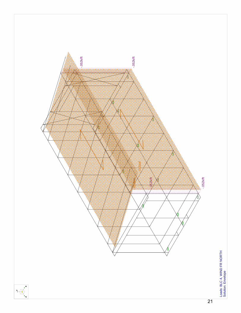
-.05
2k/ft
-.05
2k/ft
-.05
2k/ft
-.05
2k/ft
-.01
2ksf
-.01
5ksf
Y
XZ Lo
ads:
BLC
4, W
IND
FR
NO
RT
H
Sol
utio
n: E
nvel
ope
21

-.05
2k/ft
-.05
2k/ft
-.05
2k/ft
-.05
2k/ft
-.01
2ksf
-.01
5ksf
Y
XZ
Load
s: B
LC 4
, WIN
D F
R N
OR
TH
S
olut
ion:
Env
elop
e
22

-.02
3k/ft
0k/ft0k
/ft
-.02
3k/ft
-.05
2k/ft
-.05
2k/ft-.
023k
/ft
-.01
2ksf
Y
XZ Lo
ads:
BLC
6, W
IND
TO
EA
ST
S
olut
ion:
Env
elop
e
23

.036
k/ft
.036
k/ft
.054
k/ft
.054
k/ft
.018
ksf
.012
ksf
Y
XZ
Load
s: B
LC 7
, RF
WIN
D T
O E
AS
T
S
olut
ion:
Env
elop
e
24

Company : Robert Silman Associates Mar 14, 2011Designer : 6:12 PMC. Allan Cobb
UMd SD2011 - North ModuleJob Number : Checked By:_____
GlobalDisplay Sections for Member CalcsMax Internal Sections for Member CalcsInclude Shear DeformationInclude WarpingArea Load Mesh (in^2)Merge Tolerance (in)P-Delta Analysis ToleranceVertical Axis
5 97 YesYes144.120.50%Y
Hot Rolled Steel CodeCold Formed Steel CodeWood CodeWood TemperatureConcrete CodeMasonry CodeAluminum Code
AISC 360-05: ASD (Direct Analysis Method)AISI NAS-01: ASDAF&PA NDS-05: ASD< 100FACI 318-05ACI 530-05: ASDAA ADM1-05: ASD
Number of Shear RegionsRegion Spacing Increment (in)Biaxial Column MethodParme Beta Factor (PCA)Concrete Stress BlockUse Cracked SectionsBad Framing WarningsUnused Force Warnings
44PCA Load Contour.65RectangularYesNoYes
Seismic CodeSeismic Base Elevation (ft)Ct XCt ZT X (sec)T Z (sec)R XR ZCt Exp. XCt Exp. ZCaCvNvSD1SDSS1Occupancy CodeSeismic ZoneUse GroupUse Gravity Self Wt in Diaphragm MassUse Deck Self Wt in Diaphragm MassUse Lateral Self Wt in Diaphragm Mass
UBC 1997Not Entered.035.035Not EnteredNot Entered8.58.5.75.75.36.54111143IYesYesYes
Seismic Detailing CodeOm XOm ZRho XRho Z
None1111
RISA-3D Version 9.0.1 Page 1 [P:\...\...\Calcs\RSA SD2011 Modules - XBF West.r3d] 25
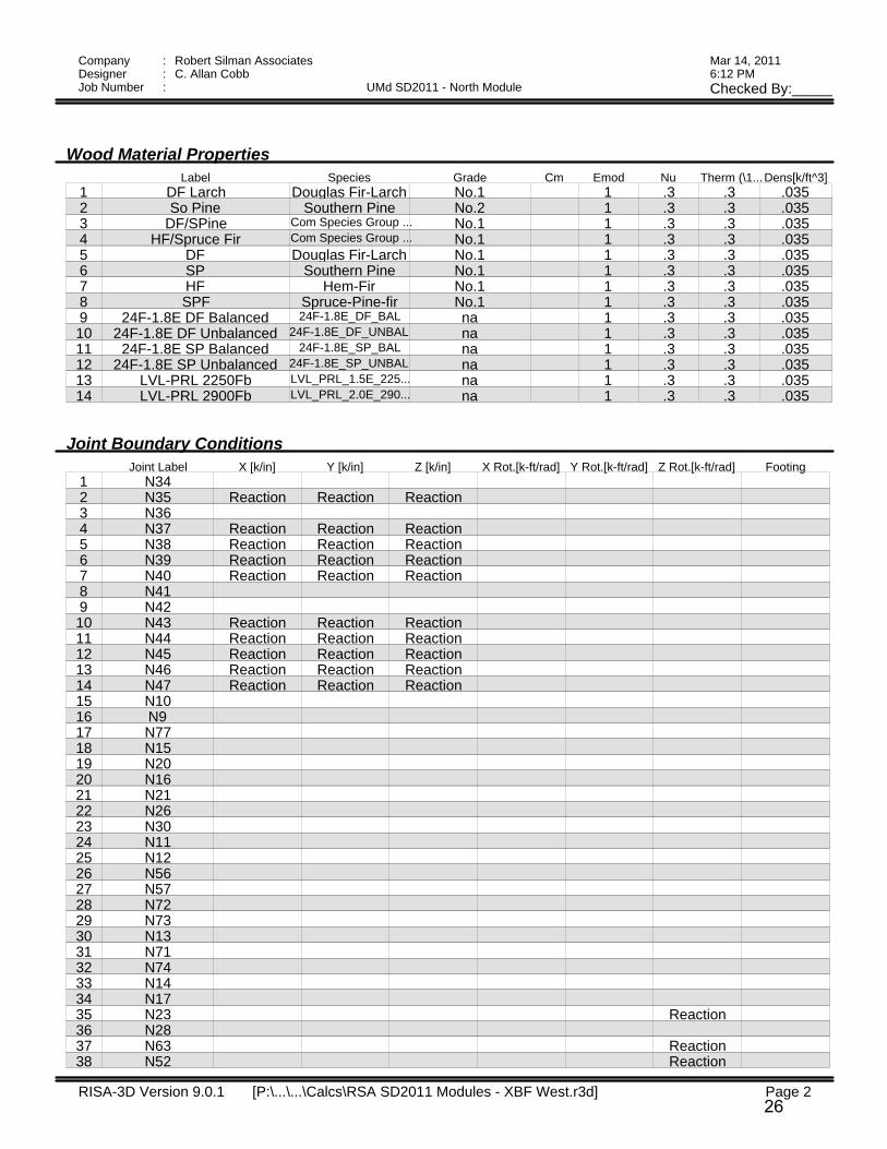
Company : Robert Silman Associates Mar 14, 2011Designer : 6:12 PMC. Allan Cobb
UMd SD2011 - North ModuleJob Number : Checked By:_____
Wood Material PropertiesLabel Species Grade Cm Emod Nu Therm (\1...Dens[k/ft^3]
1 DF Larch Douglas Fir-Larch No.1 1 .3 .3 .0352 So Pine Southern Pine No.2 1 .3 .3 .0353 DF/SPine Com Species Group ... No.1 1 .3 .3 .0354 HF/Spruce Fir Com Species Group ... No.1 1 .3 .3 .0355 DF Douglas Fir-Larch No.1 1 .3 .3 .0356 SP Southern Pine No.1 1 .3 .3 .0357 HF Hem-Fir No.1 1 .3 .3 .0358 SPF Spruce-Pine-fir No.1 1 .3 .3 .0359 24F-1.8E DF Balanced 24F-1.8E_DF_BAL na 1 .3 .3 .03510 24F-1.8E DF Unbalanced 24F-1.8E_DF_UNBAL na 1 .3 .3 .03511 24F-1.8E SP Balanced 24F-1.8E_SP_BAL na 1 .3 .3 .03512 24F-1.8E SP Unbalanced 24F-1.8E_SP_UNBAL na 1 .3 .3 .03513 LVL-PRL 2250Fb LVL_PRL_1.5E_225... na 1 .3 .3 .03514 LVL-PRL 2900Fb LVL_PRL_2.0E_290... na 1 .3 .3 .035
Joint Boundary ConditionsJoint Label X [k/in] Y [k/in] Z [k/in] X Rot.[k-ft/rad] Y Rot.[k-ft/rad] Z Rot.[k-ft/rad] Footing
1 N342 N35 Reaction Reaction Reaction3 N364 N37 Reaction Reaction Reaction5 N38 Reaction Reaction Reaction6 N39 Reaction Reaction Reaction7 N40 Reaction Reaction Reaction8 N419 N4210 N43 Reaction Reaction Reaction11 N44 Reaction Reaction Reaction12 N45 Reaction Reaction Reaction13 N46 Reaction Reaction Reaction14 N47 Reaction Reaction Reaction15 N1016 N917 N7718 N1519 N2020 N1621 N2122 N2623 N3024 N1125 N1226 N5627 N5728 N7229 N7330 N1331 N7132 N7433 N1434 N1735 N23 Reaction36 N2837 N63 Reaction38 N52 Reaction
RISA-3D Version 9.0.1 Page 2 [P:\...\...\Calcs\RSA SD2011 Modules - XBF West.r3d] 26

Company : Robert Silman Associates Mar 14, 2011Designer : 6:12 PMC. Allan Cobb
UMd SD2011 - North ModuleJob Number : Checked By:_____
Joint Boundary Conditions (Continued)Joint Label X [k/in] Y [k/in] Z [k/in] X Rot.[k-ft/rad] Y Rot.[k-ft/rad] Z Rot.[k-ft/rad] Footing
39 N24 Reaction40 N141 N242 N343 N444 N545 N646 N747 N848 N1849 N1950 N2251 N2552 N2753 N2954 N3155 N3256 N3357 N7858 N7959 N8060 N8161 N8262 N8363 N8464 N8565 N8766 N8967 N9168 N9369 N9570 N9771 N1967 Reaction Reaction Reaction72 N1968 Reaction Reaction Reaction73 N1919 Reaction Reaction Reaction74 N1882 Reaction Reaction Reaction
Wood Design ParametersLabel Shape Length[... le2[ft] le1[ft] le-bend to... le-bend bo... Kyy Kzz CV Cr y sway z sway
1 M1 3-2X10 .83 1.333 1.333 1.3332 M2 3-2X10 6 1.333 1.333 1.3333 M3 3-2X10 6 1.333 1.333 1.3334 M4 3-2X10 .83 1.333 1.333 1.3335 M5 3-2X10 .83 1.333 1.333 1.3336 M6 3-2X10 6 1.333 1.333 1.3337 M7 3-2X10 6 1.333 1.333 1.3338 M8 3-2X10 .83 1.333 1.333 1.3339 M9 3-2X10 .83 1.333 1.333 1.33310 M10 3-2X10 6 1.333 1.333 1.33311 M11 3-2X10 6 1.333 1.333 1.33312 M12 3-2X10 .83 1.333 1.333 1.33313 M13 3-2X10 .83 1.333 1.333 1.33314 M14 3-2X10 6 1.333 1.333 1.33315 M15 3-2X10 6 1.333 1.333 1.33316 M16 3-2X10 .83 1.333 1.333 1.33317 M17 3-2X10 .83 1.333 1.333 1.333
RISA-3D Version 9.0.1 Page 3 [P:\...\...\Calcs\RSA SD2011 Modules - XBF West.r3d] 27

Company : Robert Silman Associates Mar 14, 2011Designer : 6:12 PMC. Allan Cobb
UMd SD2011 - North ModuleJob Number : Checked By:_____
Wood Design Parameters (Continued)Label Shape Length[... le2[ft] le1[ft] le-bend to... le-bend bo... Kyy Kzz CV Cr y sway z sway
18 M18 3-2X10 2 1.333 1.333 1.33319 M19 3-2X10 8 1.333 1.333 1.33320 M20 3-2X10 8 1.333 1.333 1.33321 M21 3-2X10 8 1.333 1.333 1.33322 M22 3-2X10 2 1.333 1.333 1.33323 M23 3-2X10 .83 1.333 1.333 1.33324 M24 2-2X10 6.83 1.333 1.333 1.33325 M25 2-2X10 6.83 1.333 1.333 1.33326 M26 2-2X10 6.83 1.333 1.333 1.33327 M27 2-2X10 6.83 1.333 1.333 1.33328 M28 2-2X10 6.83 1.333 1.333 1.33329 M29 2-2X10 6.83 1.333 1.333 1.33330 M30 2-2X10 6.83 1.333 1.333 1.33331 M31 2-2X10 6.83 1.333 1.333 1.33332 M32 2-2X10 6.83 1.333 1.333 1.33333 M33 2-2X10 6.83 1.333 1.333 1.33334 M34 2X10 6.83 1.333 1.333 1.33335 M35 2X10 6.83 1.333 1.333 1.33336 M36 2X10 .83 1.333 1.333 1.33337 M37 2X10 2 1.333 1.333 1.33338 M38 2X10 4 1.333 1.333 1.33339 M39 2X10 4 1.333 1.333 1.33340 M40 2X10 4 1.333 1.333 1.33341 M41 2X10 4 1.333 1.333 1.33342 M42 2X10 4 1.333 1.333 1.33343 M43 2X10 4 1.333 1.333 1.33344 M44 2X10 2 1.333 1.333 1.33345 M45 2X10 .83 1.333 1.333 1.33346 M46 2X10 .83 1.333 1.333 1.33347 M47 2X10 6 1.333 1.333 1.33348 M48 2X10 6 1.333 1.333 1.33349 M49 2X10 .83 1.333 1.333 1.33350 M50 2X10 .83 1.333 1.333 1.33351 M51 2X10 2 1.333 1.333 1.33352 M52 2X10 4 1.333 1.333 1.33353 M53 2X10 4 1.333 1.333 1.33354 M54 2X10 4 1.333 1.333 1.33355 M55 2X10 4 1.333 1.333 1.33356 M56 2X10 4 1.333 1.333 1.33357 M57 2X10 4 1.333 1.333 1.33358 M58 2X10 2 1.333 1.333 1.33359 M59 2X10 .83 1.333 1.333 1.33360 M60 2-2X12 29.66 4 4 4 161 M61 2-2X12 13.66 4 4 4 162 M62 2-2X12 29.66 4 4 4 163 M63 2-2X12 13.66 4 4 4 164 M64 3-2X6 10.5 1.333 1.333 1.33365 M65 3-2X6 10.5 1.333 1.333 1.33366 M66 3-2X6 10.5 1.333 1.333 1.33367 M67 3-2X6 10.5 1.333 1.333 1.33368 M68 3-2X6 10.5 1.333 1.333 1.33369 M69 3-2X6 10.5 1.333 1.333 1.33370 M70 3-2X6 10.5 1.333 1.333 1.33371 M71 3-2X6 10.5 1.333 1.333 1.33372 M72 3-2X6 10.5 1.333 1.333 1.33373 M73 3-2X6 10.5 1.333 1.333 1.33374 M74 3-2X6 10.5 1.333 1.333 1.333
RISA-3D Version 9.0.1 Page 4 [P:\...\...\Calcs\RSA SD2011 Modules - XBF West.r3d] 28

Company : Robert Silman Associates Mar 14, 2011Designer : 6:12 PMC. Allan Cobb
UMd SD2011 - North ModuleJob Number : Checked By:_____
Wood Design Parameters (Continued)Label Shape Length[... le2[ft] le1[ft] le-bend to... le-bend bo... Kyy Kzz CV Cr y sway z sway
75 M75 3-2X6 10.5 1.333 1.333 1.33376 M76 3-2X6 10.5 1.333 1.333 1.33377 M77 3-2X6 10.5 1.333 1.333 1.33378 M78 3-2X6 10.5 1.333 1.333 1.33379 M79 3-2X6 10.5 1.333 1.333 1.33380 M80 3-2X6 10.5 1.333 1.333 1.33381 M81 3-2X6 10.5 1.333 1.333 1.33382 M82 3-2X6 3.2583 M83 3-2X6 3.2584 M84 3-2X6 3.25 1.333 1.333 1.33385 M85 3-2X6 3.2586 M86 3-2X6 3.2587 M87 3-2X6 3.2588 M88 3-2X6 3.2589 M89 3-2X6 3.2590 M90 3-2X6 3.2591 M91 2-2X10 14.041 1.33 1.33 1.33 192 M92 2-2X10 14.041 1.33 1.33 1.33 193 M93 2-2X10 14.041 1.33 1.33 1.33 194 M94 2-2X10 14.041 1.33 1.33 1.33 195 M95 2-2X10 14.041 1.33 1.33 1.33 196 M96 2-2X10 14.041 1.33 1.33 1.33 197 M97 2-2X10 14.041 1.33 1.33 1.33 198 M98 2-2X10 14.041 1.33 1.33 1.33 199 M99 2-2X10 14.041 1.33 1.33 1.33 1100 M100 3-2X6 10.5 1.333 1.333 1.333101 M101 3-2X6 10.5 1.333 1.333 1.333102 M102 2X2 2103 M103 2X2 4104 M104 2X2 4105 M105 2X2 4106 M106 2X2 4107 M107 2X2 4108 M108 2X2 4109 M109 2X2 2110 M110 2X2 28111 M111 2-2X10 3.844 1.33 1.33 1.33 1112 M112 2-2X10 3.844 1.33 1.33 1.33 1113 M113 2-2X10 3.844 1.33 1.33 1.33 1114 M114 2-2X10 3.844 1.33 1.33 1.33 1115 M115 2-2X10 3.844 1.33 1.33 1.33 1116 M116 2-2X10 3.844 1.33 1.33 1.33 1117 M117 2-2X10 3.844 1.33 1.33 1.33 1118 M118 2-2X10 3.844 1.33 1.33 1.33 1119 M119 2-2X10 3.844 1.33 1.33 1.33 1120 M120 3-2X6 10.5 1.333 1.333 1.333121 M121 3-2X6 10.5 1.333 1.333 1.333122 M122 3-2X6 10.5 1.333 1.333 1.333123 M123 3-2X6 10.5 1.333 1.333 1.333124 M124 3-2X6 10.5 1.333 1.333 1.333125 M125 3-2X6 10.5 1.333 1.333 1.333126 M126 2X4 .83127 M127 2X4 .83128 M128 2-2X10 6129 M129 2X4 .83130 M130 2X4 .83131 M131 2X2 13.66 1.333 1.333 1.333 1.333
RISA-3D Version 9.0.1 Page 5 [P:\...\...\Calcs\RSA SD2011 Modules - XBF West.r3d] 29

Company : Robert Silman Associates Mar 14, 2011Designer : 6:12 PMC. Allan Cobb
UMd SD2011 - North ModuleJob Number : Checked By:_____
Wood Design Parameters (Continued)Label Shape Length[... le2[ft] le1[ft] le-bend to... le-bend bo... Kyy Kzz CV Cr y sway z sway
132 M132 2X2 13.66 1.333 1.333 1.333 1.333133 M133 2X2 2 1.333 1.333 1.333 1.333134 M134 2X2 4 1.333 1.333 1.333 1.333135 M135 2X2 4 1.333 1.333 1.333 1.333136 M136 2X2 4 1.333 1.333 1.333 1.333137 M137 2X2 4 1.333 1.333 1.333 1.333138 M138 2X2 4 1.333 1.333 1.333 1.333139 M139 2X2 4 1.333 1.333 1.333 1.333140 M140 2X2 2 1.333 1.333 1.333 1.333141 M143 4X4 10.92 5.5 5.5 5.5 5.5142 M144 4X4 10.92 5.5 5.5 5.5 5.5143 M143A 4X4 10.92 5.5 5.5 5.5 5.5144 M144A 4X4 10.92 5.5 5.5 5.5 5.5
Member Distributed Loads (BLC 1 : DEAD)Member Label Direction Start Magnitude[k/ft,... End Magnitude[k/ft,d... Start Location[ft,%] End Location[ft,%]
1 M45 Y -.1 -.1 0 02 M44 Y -.1 -.1 0 03 M43 Y -.1 -.1 0 04 M42 Y -.1 -.1 0 05 M41 Y -.1 -.1 0 06 M40 Y -.1 -.1 0 07 M39 Y -.1 -.1 0 08 M38 Y -.1 -.1 0 09 M37 Y -.1 -.1 0 010 M36 Y -.1 -.1 0 011 M48 Y -.1 -.1 0 012 M49 Y -.1 -.1 0 013 M47 Y -.1 -.1 0 014 M46 Y -.1 -.1 0 015 M58 Y -.1 -.1 0 016 M59 Y -.1 -.1 0 017 M57 Y -.1 -.1 0 018 M56 Y -.1 -.1 0 019 M55 Y -.1 -.1 0 020 M54 Y -.1 -.1 0 021 M53 Y -.1 -.1 0 022 M52 Y -.1 -.1 0 023 M51 Y -.1 -.1 0 024 M50 Y -.1 -.1 0 025 M34 Y -.1 -.1 0 026 M35 Y -.1 -.1 0 027 M91 Y -.051 -.051 0 028 M99 Y -.051 -.051 0 029 M111 Y -.051 -.051 0 030 M119 Y -.051 -.051 0 0
Member Distributed Loads (BLC 3 : SNOW)Member Label Direction Start Magnitude[k/ft,... End Magnitude[k/ft,d... Start Location[ft,%] End Location[ft,%]
1 M91 Y -.091 -.092 0 02 M99 Y -.091 -.092 0 03 M111 Y -.091 -.092 0 04 M119 Y -.091 -.092 0 0
Member Distributed Loads (BLC 4 : WIND FR NORTH)Member Label Direction Start Magnitude[k/ft,... End Magnitude[k/ft,d... Start Location[ft,%] End Location[ft,%]
RISA-3D Version 9.0.1 Page 6 [P:\...\...\Calcs\RSA SD2011 Modules - XBF West.r3d] 30

Company : Robert Silman Associates Mar 14, 2011Designer : 6:12 PMC. Allan Cobb
UMd SD2011 - North ModuleJob Number : Checked By:_____
Member Distributed Loads (BLC 4 : WIND FR NORTH) (Continued)Member Label Direction Start Magnitude[k/ft,... End Magnitude[k/ft,d... Start Location[ft,%] End Location[ft,%]
1 M81 X -.052 -.052 0 02 M82 X -.052 -.052 0 03 M70 X -.052 -.052 0 04 M90 X -.052 -.052 0 0
Member Distributed Loads (BLC 5 : RF WIND FR NORTH)Member Label Direction Start Magnitude[k/ft,... End Magnitude[k/ft,d... Start Location[ft,%] End Location[ft,%]
1 M91 Y .033 .033 0 02 M99 Y .033 .033 0 03 M111 Y .054 .054 0 04 M119 Y .054 .054 0 0
Member Distributed Loads (BLC 6 : WIND TO EAST)Member Label Direction Start Magnitude[k/ft,... End Magnitude[k/ft,d... Start Location[ft,%] End Location[ft,%]
1 M101 Z -.052 -.052 0 02 M100 Z -.052 -.052 0 03 M63 Z -.023 0 0 04 M91 Z 0 -.023 0 05 M111 Z -.023 -.023 0 0
Member Distributed Loads (BLC 7 : RF WIND TO EAST)Member Label Direction Start Magnitude[k/ft,... End Magnitude[k/ft,d... Start Location[ft,%] End Location[ft,%]
1 M91 Y .036 .036 0 02 M99 Y .036 .036 0 03 M111 Y .054 .054 0 04 M119 Y .054 .054 0 0
Member Distributed Loads (BLC 8 : BLC 1 Transient Area Loads)Member Label Direction Start Magnitude[k/ft,... End Magnitude[k/ft,d... Start Location[ft,%] End Location[ft,%]
1 M1 Y -.052 -.052 0 .832 M2 Y -.044 -.044 .146 63 M3 Y -.044 -.044 0 5.8544 M4 Y -.052 -.052 0 .835 M5 Y -.07 -.07 0 .836 M6 Y -.059 -.059 .146 67 M7 Y -.059 -.059 4.996e-16 5.8548 M8 Y -.07 -.07 0 .839 M9 Y -.07 -.07 0 .8310 M10 Y -.059 -.059 .146 611 M11 Y -.059 -.059 2.387e-15 5.85412 M12 Y -.07 -.07 0 .8313 M13 Y -.052 -.052 0 .8314 M14 Y -.044 -.044 .146 615 M15 Y -.044 -.044 2.22e-16 5.85416 M16 Y -.052 -.052 0 .8317 M24 Y -.059 -.059 1.11e-16 6.8318 M25 Y -.059 -.059 8.327e-16 6.8319 M26 Y -.059 -.059 8.882e-16 6.8320 M27 Y -.059 -.059 0 6.8321 M28 Y -.059 -.059 3.331e-16 6.8322 M29 Y -.059 -.059 2.22e-16 6.8323 M30 Y -.03 -.03 5.551e-16 6.8324 M31 Y -.03 -.03 1.665e-15 6.8325 M32 Y -.03 -.03 6.106e-16 6.8326 M33 Y -.03 -.03 1.332e-15 6.8327 M91 Y -.017 -.017 0 13.911
RISA-3D Version 9.0.1 Page 7 [P:\...\...\Calcs\RSA SD2011 Modules - XBF West.r3d] 31

Company : Robert Silman Associates Mar 14, 2011Designer : 6:12 PMC. Allan Cobb
UMd SD2011 - North ModuleJob Number : Checked By:_____
Member Distributed Loads (BLC 8 : BLC 1 Transient Area Loads) (Continued)Member Label Direction Start Magnitude[k/ft,... End Magnitude[k/ft,d... Start Location[ft,%] End Location[ft,%]
28 M92 Y -.051 -.051 1.221e-15 13.91129 M93 Y -.068 -.068 1.055e-15 13.91130 M94 Y -.068 -.068 1.055e-15 13.91131 M95 Y -.068 -.068 1.499e-15 13.91132 M96 Y -.068 -.068 1.499e-15 13.91133 M97 Y -.068 -.068 6.106e-16 13.91134 M98 Y -.051 -.051 5.551e-16 13.91135 M99 Y -.017 -.017 9.992e-16 13.91136 M111 Y -.018 -.018 0 3.84437 M112 Y -.053 -.053 0 3.84438 M113 Y -.07 -.07 0 3.84439 M114 Y -.07 -.07 0 3.84440 M115 Y -.07 -.07 0 3.84441 M116 Y -.07 -.07 0 3.84442 M117 Y -.07 -.07 0 3.84443 M118 Y -.053 -.053 0 3.84444 M119 Y -.018 -.018 0 3.844
Member Distributed Loads (BLC 9 : BLC 2 Transient Area Loads)Member Label Direction Start Magnitude[k/ft,... End Magnitude[k/ft,d... Start Location[ft,%] End Location[ft,%]
1 M1 Y -.174 -.174 0 .832 M2 Y -.148 -.148 .146 63 M3 Y -.148 -.148 0 5.8544 M4 Y -.174 -.174 0 .835 M5 Y -.232 -.232 0 .836 M6 Y -.198 -.198 .146 67 M7 Y -.198 -.198 4.996e-16 5.8548 M8 Y -.232 -.232 0 .839 M9 Y -.232 -.232 0 .8310 M10 Y -.198 -.198 .146 611 M11 Y -.198 -.198 2.387e-15 5.85412 M12 Y -.232 -.232 0 .8313 M13 Y -.174 -.174 0 .8314 M14 Y -.148 -.148 .146 615 M15 Y -.148 -.148 2.22e-16 5.85416 M16 Y -.174 -.174 0 .8317 M24 Y -.198 -.198 1.11e-16 6.8318 M25 Y -.198 -.198 8.327e-16 6.8319 M26 Y -.198 -.198 8.882e-16 6.8320 M27 Y -.198 -.198 0 6.8321 M28 Y -.198 -.198 3.331e-16 6.8322 M29 Y -.198 -.198 2.22e-16 6.8323 M30 Y -.099 -.099 5.551e-16 6.8324 M31 Y -.099 -.099 1.665e-15 6.8325 M32 Y -.099 -.099 6.106e-16 6.8326 M33 Y -.099 -.099 1.332e-15 6.83
Member Distributed Loads (BLC 10 : BLC 3 Transient Area Loads)Member Label Direction Start Magnitude[k/ft,... End Magnitude[k/ft,d... Start Location[ft,%] End Location[ft,%]
1 M91 Y -.031 -.031 0 13.9112 M92 Y -.092 -.092 1.221e-15 13.9113 M93 Y -.123 -.123 1.055e-15 13.9114 M94 Y -.123 -.123 1.055e-15 13.9115 M95 Y -.123 -.123 1.499e-15 13.9116 M96 Y -.123 -.123 1.499e-15 13.9117 M97 Y -.123 -.123 6.106e-16 13.9118 M98 Y -.092 -.092 5.551e-16 13.911
RISA-3D Version 9.0.1 Page 8 [P:\...\...\Calcs\RSA SD2011 Modules - XBF West.r3d] 32

Company : Robert Silman Associates Mar 14, 2011Designer : 6:12 PMC. Allan Cobb
UMd SD2011 - North ModuleJob Number : Checked By:_____
Member Distributed Loads (BLC 10 : BLC 3 Transient Area Loads) (Continued)Member Label Direction Start Magnitude[k/ft,... End Magnitude[k/ft,d... Start Location[ft,%] End Location[ft,%]
9 M99 Y -.031 -.031 9.992e-16 13.91110 M111 Y -.032 -.032 0 3.84411 M112 Y -.096 -.096 0 3.84412 M113 Y -.127 -.127 0 3.84413 M114 Y -.127 -.127 0 3.84414 M115 Y -.127 -.127 0 3.84415 M116 Y -.127 -.127 0 3.84416 M117 Y -.127 -.127 0 3.84417 M118 Y -.096 -.096 0 3.84418 M119 Y -.032 -.032 0 3.844
Member Distributed Loads (BLC 11 : BLC 4 Transient Area Loads)Member Label Direction Start Magnitude[k/ft,... End Magnitude[k/ft,d... Start Location[ft,%] End Location[ft,%]
1 M68 X -.049 -.049 4.441e-16 10.52 M69 X -.037 -.037 7.772e-16 10.53 M70 X -.012 -.012 1.943e-15 10.54 M72 X -.049 -.049 4.441e-16 10.55 M74 X -.049 -.049 8.882e-16 10.56 M75 X -.049 -.049 8.882e-16 10.57 M77 X -.049 -.049 4.441e-16 10.58 M79 X -.037 -.037 1.388e-15 10.59 M81 X -.012 -.012 1.443e-15 10.510 M82 X -.012 -.012 .304 3.2511 M83 X -.036 -.036 .304 3.2512 M84 X -.048 -.048 .304 3.2513 M85 X -.048 -.048 .304 3.2514 M86 X -.048 -.048 .304 3.2515 M87 X -.048 -.048 .304 3.2516 M88 X -.048 -.048 .304 3.2517 M89 X -.036 -.036 .304 3.2518 M90 X -.012 -.012 .304 3.2519 M91 X -.015 -.015 1.11e-15 13.91120 M92 X -.045 -.045 3.331e-16 13.91121 M93 X -.06 -.06 1.055e-15 13.91122 M94 X -.06 -.06 2.831e-15 13.91123 M95 X -.06 -.06 1.943e-15 13.91124 M96 X -.06 -.06 1.665e-16 13.91125 M97 X -.06 -.06 1.055e-15 13.91126 M98 X -.045 -.045 1.055e-15 13.91127 M99 X -.015 -.015 0 13.91128 M111 X -.016 -.016 0 3.84429 M112 X -.047 -.047 0 3.84430 M113 X -.062 -.062 0 3.84431 M114 X -.062 -.062 0 3.84432 M115 X -.062 -.062 0 3.84433 M116 X -.062 -.062 0 3.84434 M117 X -.062 -.062 0 3.84435 M118 X -.047 -.047 0 3.84436 M119 X -.016 -.016 0 3.844
Member Distributed Loads (BLC 12 : BLC 5 Transient Area Loads)Member Label Direction Start Magnitude[k/ft,... End Magnitude[k/ft,d... Start Location[ft,%] End Location[ft,%]
1 M111 Y .021 .021 0 3.8442 M112 Y .049 .049 0 3.8443 M113 Y .077 .077 0 3.8444 M114 Y .07 .07 3.775e-15 3.8445 M115 Y .07 .07 0 3.844
RISA-3D Version 9.0.1 Page 9 [P:\...\...\Calcs\RSA SD2011 Modules - XBF West.r3d] 33

Company : Robert Silman Associates Mar 14, 2011Designer : 6:12 PMC. Allan Cobb
UMd SD2011 - North ModuleJob Number : Checked By:_____
Member Distributed Loads (BLC 12 : BLC 5 Transient Area Loads) (Continued)Member Label Direction Start Magnitude[k/ft,... End Magnitude[k/ft,d... Start Location[ft,%] End Location[ft,%]
6 M116 Y .07 .07 0 3.8447 M117 Y .077 .077 0 3.8448 M118 Y .049 .049 2.748e-15 3.8449 M119 Y .021 .021 3.608e-15 3.84410 M91 Y .008 .008 2.109e-15 14.04111 M92 Y .025 .025 2.109e-15 14.04112 M93 Y .033 .033 7.772e-16 14.04113 M94 Y .033 .033 3.331e-16 14.04114 M95 Y .033 .033 1.221e-15 14.04115 M96 Y .033 .033 1.221e-15 14.04116 M97 Y .033 .033 3.331e-16 14.04117 M98 Y .025 .025 2.109e-15 14.04118 M99 Y .008 .008 1.11e-16 14.041
Member Distributed Loads (BLC 13 : BLC 6 Transient Area Loads)Member Label Direction Start Magnitude[k/ft,... End Magnitude[k/ft,d... Start Location[ft,%] End Location[ft,%]
1 M100 Z -.023 -.023 5.551e-16 10.52 M101 Z -.023 -.023 0 10.53 M124 Z -.046 -.046 6.661e-16 10.54 M125 Z -.046 -.046 6.661e-16 10.5
Member Distributed Loads (BLC 14 : BLC 7 Transient Area Loads)Member Label Direction Start Magnitude[k/ft,... End Magnitude[k/ft,d... Start Location[ft,%] End Location[ft,%]
1 M111 Y .021 .021 0 3.8442 M112 Y .05 .05 0 3.8443 M113 Y .078 .078 0 3.8444 M114 Y .071 .071 3.775e-15 3.8445 M115 Y .071 .071 0 3.8446 M116 Y .071 .071 0 3.8447 M117 Y .078 .078 0 3.8448 M118 Y .05 .05 2.748e-15 3.8449 M119 Y .021 .021 3.608e-15 3.84410 M91 Y .012 .012 2.109e-15 14.04111 M92 Y .036 .036 2.109e-15 14.04112 M93 Y .048 .048 7.772e-16 14.04113 M94 Y .048 .048 3.331e-16 14.04114 M95 Y .048 .048 1.221e-15 14.04115 M96 Y .048 .048 1.221e-15 14.04116 M97 Y .048 .048 3.331e-16 14.04117 M98 Y .036 .036 2.109e-15 14.04118 M99 Y .012 .012 1.11e-16 14.041
Member Area Loads (BLC 1 : DEAD)Joint A Joint B Joint C Joint D Direction Distribution Magnitude[ksf]
1 N74 N71 N72 N73 Y A-B -.0152 N14 N15 N77 N78 Y A-B -.017
Member Area Loads (BLC 2 : LIVE)Joint A Joint B Joint C Joint D Direction Distribution Magnitude[ksf]
1 N74 N71 N72 N73 Y A-B -.05
Member Area Loads (BLC 3 : SNOW)Joint A Joint B Joint C Joint D Direction Distribution Magnitude[ksf]
1 N14 N15 N77 N78 Y A-B -.031
RISA-3D Version 9.0.1 Page 10 [P:\...\...\Calcs\RSA SD2011 Modules - XBF West.r3d] 34

Company : Robert Silman Associates Mar 14, 2011Designer : 6:12 PMC. Allan Cobb
UMd SD2011 - North ModuleJob Number : Checked By:_____
Member Area Loads (BLC 4 : WIND FR NORTH)Joint A Joint B Joint C Joint D Direction Distribution Magnitude[ksf]
1 N1 N9 N68 N70 X A-B -.0122 N78 N77 N15 N14 X A-B -.015
Member Area Loads (BLC 5 : RF WIND FR NORTH)Joint A Joint B Joint C Joint D Direction Distribution Magnitude[ksf]
1 N1 N9 N77 N78 Y A-B .0182 N14 N15 N9 N1 Y A-B .008
Member Area Loads (BLC 6 : WIND TO EAST)Joint A Joint B Joint C Joint D Direction Distribution Magnitude[ksf]
1 N33 N32 N76 N75 Z A-B -.012
Member Area Loads (BLC 7 : RF WIND TO EAST)Joint A Joint B Joint C Joint D Direction Distribution Magnitude[ksf]
1 N1 N9 N77 N78 Y A-B .0182 N14 N15 N9 N1 Y A-B .012
Basic Load CasesBLC Description Category X Gra... Y Gra... Z Gra... Joint Point Distributed Area (Me... Surfac...
1 DEAD DL 30 22 LIVE LL 13 SNOW SL 4 14 WIND FR NORTH WLX 4 25 RF WIND FR NORTH WLX+R 4 26 WIND TO EAST WLZ 5 17 RF WIND TO EAST WLZ+R 4 28 BLC 1 Transient Are... None 449 BLC 2 Transient Are... None 2610 BLC 3 Transient Are... None 1811 BLC 4 Transient Are... None 3612 BLC 5 Transient Are... None 1813 BLC 6 Transient Are... None 414 BLC 7 Transient Are... None 18
Load CombinationsDescripti... Solve PDelta SRSS BLCFac... BLC Fac... BLC Fac...BLCFac... BLC Fac...BLCFac...BLCFac...BLCFac...
1 SD/IBC 1... Yes DL 12 SD/IBC 1... Yes DL 1 LL 13 SD/IBC 1... Yes DL 1 SL 14 IBC 16-1... DL 1 WLX 1 WLX... 15 SD11 16-... Yes DL 1 WLX .44 WLX... .446 IBC 16-1... DL 1 WLZ 1 WLZ+R 17 SD11 16-... Yes DL 1 WLZ .44 WLZ+R .448 IBC 16-1... DL 1 WLX .75 LL .75 LLS .75 WL... .759 SD11 16-... Yes DL 1 WLX .33 LL .75 WL... .3310 IBC 16-1... DL 1 WLX .75 LL .75 LLS .75 SL .75 W... .7511 SD11 16-... Yes DL 1 WLX .33 LL .75 SL .75 W... .3312 IBC 16-1... DL 1 WLZ .75 LL .75 LLS .75 SL .75 W... .7513 SD11 16-... Yes DL 1 WLZ .33 LL .75 SL .75 W... .3314 IBC 16-1... DL .6 WLX 1 WLX... 115 SD11 16-... Yes DL .6 WLX .44 WLX... .4416 IBC 16-1... DL .6 WLZ 1 WLZ+R 117 SD11 16-... Yes DL .6 WLZ .44 WLZ+R .44
RISA-3D Version 9.0.1 Page 11 [P:\...\...\Calcs\RSA SD2011 Modules - XBF West.r3d] 35

Company : Robert Silman Associates Mar 14, 2011Designer : 6:12 PMC. Allan Cobb
UMd SD2011 - North ModuleJob Number : Checked By:_____
Load Combinations (Continued)Descripti... Solve PDelta SRSS BLCFac... BLC Fac... BLC Fac...BLCFac... BLC Fac...BLCFac...BLCFac...BLCFac...
18 SD11 OT... DL 1 WLX .88 WLX... .8819 SD11 OT... DL 1 WLZ .88 WLZ+R .88
Envelope Joint ReactionsJoint X [k] LC Y [k] LC Z [k] LC MX [k-ft] LC MY [k-ft] LC MZ [k-ft] LC
1 N35 max .801 15 2.217 13 .011 17 0 1 0 1 0 12 min -.015 2 .792 15 -.035 3 0 1 0 1 0 13 N37 max .127 11 7.72 3 .382 5 0 1 0 1 0 14 min .018 17 .158 15 .071 1 0 1 0 1 0 15 N38 max .019 7 4.556 11 .113 17 0 1 0 1 0 16 min -.062 15 .628 17 -.375 5 0 1 0 1 0 17 N39 max .109 15 6.034 3 .055 17 0 1 0 1 0 18 min -.032 13 .933 17 -.3 3 0 1 0 1 0 19 N40 max 0 17 5.41 11 .006 17 0 1 0 1 0 110 min -.047 11 1.24 17 -.254 3 0 1 0 1 0 111 N43 max 1.183 5 5.209 3 .121 13 0 1 0 1 0 112 min -.007 17 1.392 17 .016 15 0 1 0 1 0 113 N44 max .229 15 2.014 2 .049 7 0 1 0 1 0 114 min -.027 3 -.115 3 .012 1 0 1 0 1 0 115 N45 max .013 2 2.479 2 .134 13 0 1 0 1 0 116 min -.075 15 -.998 3 .023 15 0 1 0 1 0 117 N46 max -.01 17 2.398 2 .048 17 0 1 0 1 0 118 min -.094 11 -.967 3 -.141 11 0 1 0 1 0 119 N47 max .253 15 1.558 2 .103 17 0 1 0 1 0 120 min -.029 3 -.938 3 -.064 11 0 1 0 1 0 121 N23 max 0 1 0 1 0 1 0 1 0 1 0 322 min 0 1 0 1 0 1 0 1 0 1 0 1523 N63 max 0 1 0 1 0 1 0 1 0 1 .005 324 min 0 1 0 1 0 1 0 1 0 1 -.043 1525 N52 max 0 1 0 1 0 1 0 1 0 1 0 226 min 0 1 0 1 0 1 0 1 0 1 0 527 N24 max 0 1 0 1 0 1 0 1 0 1 .032 528 min 0 1 0 1 0 1 0 1 0 1 0 1729 N1967 max 1.331 11 4.885 3 .044 17 0 1 0 1 0 130 min .084 17 -1.694 15 -.803 11 0 1 0 1 0 131 N1968 max .689 15 5.271 11 .149 15 0 1 0 1 0 132 min -.572 3 .811 17 -.447 3 0 1 0 1 0 133 N1919 max .673 15 5.354 11 .837 13 0 1 0 1 0 134 min -.442 13 1.547 17 -.407 15 0 1 0 1 0 135 N1882 max 1.129 11 5.753 3 1.242 11 0 1 0 1 0 136 min .116 17 .502 15 .235 17 0 1 0 1 0 137 Totals: max 5.967 5 52.14 11 1.303 738 min 0 17 11.477 17 0 15
Envelope Wood Code ChecksMember Shape Code C... Loc[ft] LC Shear C... Loc[ft] Dir LC Fc' [ksi] Ft' [ksi] Fb1' [ksi] Fb2' [ksi] Fv' [ksi] Eqn
1 M1 3-2X10 .053 .83 2 .098 0 y 2 .893 .575 1.05 1.26 .175 3.9-12 M2 3-2X10 .312 6 11 .187 6 y 2 1.436 .575 1.05 1.26 .175 3.9-13 M3 3-2X10 .275 0 13 .188 0 y 2 1.436 .575 1.05 1.26 .175 3.9-14 M4 3-2X10 .052 0 2 .099 .83 y 9 .893 .575 1.05 1.26 .175 3.9-15 M5 3-2X10 .499 .83 11 .708 .83 y 11 .893 .575 1.05 1.26 .175 3.9-36 M6 3-2X10 .501 0 11 .249 0 y 11 1.436 .575 1.05 1.26 .175 3.9-17 M7 3-2X10 .850 6 13 .330 5.875 y 13 1.436 .575 1.05 1.26 .175 3.9-18 M8 3-2X10 .847 0 13 1.211 0 y 13 .893 .575 1.05 1.26 .175 3.9-39 M9 3-2X10 .605 .83 11 .881 .83 y 11 .893 .575 1.05 1.26 .175 3.9-3
RISA-3D Version 9.0.1 Page 12 [P:\...\...\Calcs\RSA SD2011 Modules - XBF West.r3d] 36

Company : Robert Silman Associates Mar 14, 2011Designer : 6:12 PMC. Allan Cobb
UMd SD2011 - North ModuleJob Number : Checked By:_____
Envelope Wood Code Checks (Continued)Member Shape Code C... Loc[ft] LC Shear C... Loc[ft] Dir LC Fc' [ksi] Ft' [ksi] Fb1' [ksi] Fb2' [ksi] Fv' [ksi] Eqn
10 M10 3-2X10 .607 0 11 .294 0 y 13 1.436 .575 1.05 1.26 .175 3.9-111 M11 3-2X10 .646 6 11 .302 5.875 y 13 1.436 .575 1.05 1.26 .175 3.9-312 M12 3-2X10 .646 0 11 .938 0 y 11 .893 .575 1.05 1.26 .175 3.9-313 M13 3-2X10 .053 .83 2 .099 0 y 2 .893 .575 1.05 1.26 .175 3.9-114 M14 3-2X10 .263 6 2 .187 6 y 2 1.436 .575 1.05 1.26 .175 3.9-315 M15 3-2X10 .263 0 2 .187 0 y 2 1.436 .575 1.05 1.26 .175 3.9-116 M16 3-2X10 .054 0 2 .099 .83 y 2 .893 .575 1.05 1.26 .175 3.9-117 M17 3-2X10 .227 .83 11 1.187 0 y 5 .893 .575 1.05 1.26 .175 3.9-118 M18 3-2X10 .302 0 11 1.094 0 y 5 .893 .575 1.05 1.26 .175 3.9-119 M19 3-2X10 .626 4 2 .218 3 y 2 1.377 .575 1.05 1.26 .175 3.9-320 M20 3-2X10 .626 4 2 .217 3 y 2 1.377 .575 1.05 1.26 .175 3.9-121 M21 3-2X10 .627 4 2 .184 4 y 2 1.377 .575 1.05 1.26 .175 3.9-322 M22 3-2X10 .552 2 11 .343 1 y 11 .893 .575 1.05 1.26 .175 3.9-123 M23 3-2X10 .517 0 11 .736 0 y 11 .893 .575 1.05 1.26 .175 3.9-124 M24 2-2X10 .402 3.415 2 .290 6.83 y 2 1.415 .575 1.05 1.26 .175 3.9-125 M25 2-2X10 .402 3.415 2 .280 0 y 2 1.415 .575 1.05 1.26 .175 3.9-126 M26 2-2X10 .401 3.415 2 .272 6.83 y 2 1.415 .575 1.05 1.26 .175 3.9-127 M27 2-2X10 .402 3.415 2 .280 0 y 2 1.415 .575 1.05 1.26 .175 3.9-128 M28 2-2X10 .401 3.415 2 .291 6.83 y 2 1.415 .575 1.05 1.26 .175 3.9-129 M29 2-2X10 .401 3.415 2 .295 0 y 2 1.415 .575 1.05 1.26 .175 3.9-130 M30 2-2X10 1.095 .996 11 1.739 .925 y 13 1.415 .575 1.05 1.26 .175 3.9-331 M31 2-2X10 1.094 5.834 13 2.179 5.905 y 11 1.415 .575 1.05 1.26 .175 3.9-132 M32 2-2X10 .933 .854 11 1.696 .783 y 11 1.415 .575 1.05 1.26 .175 3.9-333 M33 2-2X10 .864 5.976 13 1.477 6.047 y 13 1.415 .575 1.05 1.26 .175 3.9-134 M34 2X10 .517 3.842 15 .955 3.771 y 15 2.68 1.9 2.9 2.9 .285 3.9-135 M35 2X10 .607 2.988 5 1.622 3.415 y 11 2.68 1.9 2.9 2.9 .285 3.9-336 M36 2X10 .057 .83 15 .158 0 y 5 2.684 1.9 2.9 2.9 .285 3.9-137 M37 2X10 .066 0 13 .220 0 y 13 2.684 1.9 2.9 2.9 .285 3.9-338 M38 2X10 .046 4 11 .055 3 y 11 2.684 1.9 2.9 2.9 .285 3.9-139 M39 2X10 .078 4 11 .194 4 y 11 2.684 1.9 2.9 2.9 .285 3.9-340 M40 2X10 .077 0 11 .215 1 y 11 2.684 1.9 2.9 2.9 .285 3.9-341 M41 2X10 .434 4 13 .779 4 y 13 2.684 1.9 2.9 2.9 .285 3.9-342 M42 2X10 .455 4 13 .494 0 y 13 2.684 1.9 2.9 2.9 .285 3.9-143 M43 2X10 .453 0 13 .452 4 y 11 2.684 1.9 2.9 2.9 .285 3.9-144 M44 2X10 .359 0 11 .775 0 y 11 2.684 1.9 2.9 2.9 .285 3.9-145 M45 2X10 .066 0 15 .126 .83 y 5 2.684 1.9 2.9 2.9 .285 3.9-146 M46 2X10 .209 .83 15 .715 0 y 15 2.684 1.9 2.9 2.9 .285 3.9-347 M47 2X10 .221 0 15 .584 1 y 5 2.684 1.9 2.9 2.9 .285 3.9-148 M48 2X10 .303 6 11 .649 6 y 11 2.684 1.9 2.9 2.9 .285 3.9-349 M49 2X10 .299 0 11 .848 0 y 11 2.684 1.9 2.9 2.9 .285 3.9-150 M50 2X10 .062 .83 5 .162 .83 y 5 2.684 1.9 2.9 2.9 .285 3.9-351 M51 2X10 .067 0 11 .216 0 y 11 2.684 1.9 2.9 2.9 .285 3.9-352 M52 2X10 .023 4 5 .052 2 y 11 2.684 1.9 2.9 2.9 .285 3.9-153 M53 2X10 .174 4 11 .221 4 y 11 2.684 1.9 2.9 2.9 .285 3.9-154 M54 2X10 .174 0 11 .221 0 y 11 2.684 1.9 2.9 2.9 .285 3.9-355 M55 2X10 .354 4 11 .645 4 y 11 2.684 1.9 2.9 2.9 .285 3.9-356 M56 2X10 .350 0 11 .375 0 y 11 2.684 1.9 2.9 2.9 .285 3.9-357 M57 2X10 .282 0 11 .302 4 y 13 2.684 1.9 2.9 2.9 .285 3.9-158 M58 2X10 .200 0 13 .441 0 y 13 2.684 1.9 2.9 2.9 .285 3.9-159 M59 2X10 .064 0 5 .132 0 y 5 2.684 1.9 2.9 2.9 .285 3.9-360 M60 2-2X12 .220 .927 5 .668 0 y 5 .939 1.9 2.9 2.9 .285 3.9-161 M61 2-2X12 .200 9.818 15 .128 12.949 z 11 2.471 1.9 2.9 2.9 .285 3.9-162 M62 2-2X12 .226 18.846 13 .547 0 y 3 .939 1.9 2.9 2.9 .285 3.9-363 M63 2-2X12 .227 .854 11 .180 0 z 11 2.471 1.9 2.9 2.9 .285 3.9-364 M64 3-2X6 .114 0 11 .032 .875 z 15 .772 .725 1.25 1.438 .175 3.6.365 M65 3-2X6 .106 0 11 .021 0 z 15 .772 .725 1.25 1.438 .175 3.6.366 M66 3-2X6 .104 .875 13 .065 .875 z 15 .772 .725 1.25 1.438 .175 3.9-1
RISA-3D Version 9.0.1 Page 13 [P:\...\...\Calcs\RSA SD2011 Modules - XBF West.r3d] 37

Company : Robert Silman Associates Mar 14, 2011Designer : 6:12 PMC. Allan Cobb
UMd SD2011 - North ModuleJob Number : Checked By:_____
Envelope Wood Code Checks (Continued)Member Shape Code C... Loc[ft] LC Shear C... Loc[ft] Dir LC Fc' [ksi] Ft' [ksi] Fb1' [ksi] Fb2' [ksi] Fv' [ksi] Eqn
67 M67 3-2X6 .030 0 3 .071 0 z 5 .795 .834 1.438 1.653 .201 3.6.368 M68 3-2X6 .128 5.25 15 .162 0 y 11 .772 .725 1.25 1.438 .175 3.9-169 M69 3-2X6 .095 5.25 5 .107 0 y 11 .772 .725 1.25 1.438 .175 3.9-370 M70 3-2X6 .168 5.25 5 .062 10.5 y 15 .772 .725 1.25 1.438 .175 3.9-371 M71 3-2X6 .076 9.625 3 .072 9.625 z 5 .795 .834 1.438 1.653 .201 3.6.372 M72 3-2X6 .151 0 3 .141 0 y 11 .795 .834 1.438 1.653 .201 3.6.373 M73 3-2X6 .026 9.625 3 .064 9.625 z 15 .795 .834 1.438 1.653 .201 3.6.374 M74 3-2X6 .126 5.25 5 .117 9.625 y 5 .772 .725 1.25 1.438 .175 3.9-375 M75 3-2X6 .128 5.25 5 .152 10.5 y 15 .772 .725 1.25 1.438 .175 3.9-376 M76 3-2X6 .065 0 11 .064 9.625 z 5 .772 .725 1.25 1.438 .175 3.6.377 M77 3-2X6 .128 5.25 5 .128 0 z 3 .772 .725 1.25 1.438 .175 3.9-378 M78 3-2X6 .027 9.625 3 .058 9.625 y 15 .795 .834 1.438 1.653 .201 3.6.379 M79 3-2X6 .183 .875 11 .113 .875 z 3 .772 .725 1.25 1.438 .175 3.9-180 M80 3-2X6 .022 9.625 3 .058 9.625 z 15 .795 .834 1.438 1.653 .201 3.6.381 M81 3-2X6 .169 5.141 5 .059 0 y 11 .772 .725 1.25 1.438 .175 3.9-382 M82 3-2X6 .672 3.25 3 .259 0 y 3 1.029 .834 1.438 1.653 .201 3.9-383 M83 3-2X6 .461 3.25 3 .438 0 y 3 1.029 .834 1.438 1.653 .201 3.9-384 M84 3-2X6 .434 3.25 3 .527 0 y 3 1.76 .834 1.438 1.653 .201 3.9-385 M85 3-2X6 .292 3.25 11 .385 3.25 y 15 .904 .725 1.25 1.438 .175 3.9-386 M86 3-2X6 .290 3.25 11 .386 3.25 y 5 .904 .725 1.25 1.438 .175 3.9-387 M87 3-2X6 .360 3.25 11 .511 3.25 y 11 .904 .725 1.25 1.438 .175 3.9-388 M88 3-2X6 .513 3.25 11 .622 3.25 y 11 .904 .725 1.25 1.438 .175 3.9-389 M89 3-2X6 .481 3.25 11 .447 0 y 3 .904 .725 1.25 1.438 .175 3.9-390 M90 3-2X6 .673 3.25 3 .260 0 y 3 1.029 .834 1.438 1.653 .201 3.9-391 M91 2-2X10 .774 14.041 3 .517 14.041 y 11 1.083 .661 1.208 1.449 .201 3.9-192 M92 2-2X10 .559 5.851 3 .411 14.041 y 11 1.083 .661 1.208 1.449 .201 3.9-393 M93 2-2X10 .792 5.851 3 .542 14.041 y 11 1.083 .661 1.208 1.449 .201 3.9-194 M94 2-2X10 .848 6.289 3 .531 14.041 y 11 1.083 .661 1.208 1.449 .201 3.9-395 M95 2-2X10 .863 6.289 3 .507 14.041 y 11 1.083 .661 1.208 1.449 .201 3.9-396 M96 2-2X10 .848 6.289 3 .515 14.041 y 11 1.083 .661 1.208 1.449 .201 3.9-397 M97 2-2X10 .796 5.997 3 .502 14.041 y 11 1.083 .661 1.208 1.449 .201 3.9-398 M98 2-2X10 .558 5.851 3 .424 14.041 y 11 1.083 .661 1.208 1.449 .201 3.9-399 M99 2-2X10 .777 14.041 3 .514 14.041 y 11 1.083 .661 1.208 1.449 .201 3.9-1100 M100 3-2X6 .198 5.25 7 .121 10.5 y 17 .772 .725 1.25 1.438 .175 3.9-1101 M101 3-2X6 .198 5.25 7 .130 10.5 y 7 .772 .725 1.25 1.438 .175 3.9-1102 M111 2-2X10 .271 0 3 .193 0 y 3 1.08 .834 1.495 1.794 .201 3.9-3103 M112 2-2X10 .244 0 3 .149 0 y 3 1.08 .834 1.495 1.794 .201 3.9-1104 M113 2-2X10 .323 0 3 .199 0 y 3 1.08 .834 1.495 1.794 .201 3.9-3105 M114 2-2X10 .299 0 3 .199 0 y 3 1.08 .834 1.495 1.794 .201 3.9-3106 M115 2-2X10 .270 0 3 .199 0 y 3 1.08 .834 1.495 1.794 .201 3.9-3107 M116 2-2X10 .305 0 3 .199 0 y 3 1.08 .834 1.495 1.794 .201 3.9-3108 M117 2-2X10 .327 0 3 .199 0 y 3 1.08 .834 1.495 1.794 .201 3.9-3109 M118 2-2X10 .246 0 3 .149 0 y 3 1.08 .834 1.495 1.794 .201 3.9-1110 M119 2-2X10 .271 0 3 .193 0 y 3 1.08 .834 1.495 1.794 .201 3.9-3111 M120 3-2X6 .035 9.625 15 .016 5.25 z 5 .772 .725 1.25 1.438 .175 3.6.3112 M121 3-2X6 .052 .875 5 .016 0 z 11 .772 .725 1.25 1.438 .175 3.9-1113 M122 3-2X6 .050 8.75 15 .016 8.75 y 5 .772 .725 1.25 1.438 .175 3.9-1114 M123 3-2X6 .066 8.75 11 .024 5.25 y 11 .772 .725 1.25 1.438 .175 3.6.3115 M124 3-2X6 .120 5.25 7 .068 10.5 y 7 .772 .725 1.25 1.438 .175 3.9-3116 M125 3-2X6 .120 5.25 7 .060 10.5 y 17 .772 .725 1.25 1.438 .175 3.9-3117 M126 2X4 1.100 0 13 1.173 0 y 13 1.595 .825 1.5 1.65 .175 3.9-1118 M127 2X4 1.902 0 11 1.839 0 y 11 1.595 .825 1.5 1.65 .175 3.9-1119 M128 2-2X10 .000 5 3 .012 0 z 11 .437 .661 1.208 1.449 .201 3.9-1120 M129 2X4 .751 .83 3 1.035 0 y 3 1.824 .949 1.725 1.898 .201 3.9-1121 M130 2X4 .829 .83 5 1.274 0 y 5 1.595 .825 1.5 1.65 .175 3.9-3122 M131 2X2 .000 0 11 .004 0 z 11 1.488 .825 1.5 1.5 .175 3.9-1123 M132 2X2 .000 0 3 .009 0 z 5 1.677 .949 1.725 1.725 .201 3.9-1
RISA-3D Version 9.0.1 Page 14 [P:\...\...\Calcs\RSA SD2011 Modules - XBF West.r3d] 38

Company : Robert Silman Associates Mar 14, 2011Designer : 6:12 PMC. Allan Cobb
UMd SD2011 - North ModuleJob Number : Checked By:_____
Envelope Wood Code Checks (Continued)Member Shape Code C... Loc[ft] LC Shear C... Loc[ft] Dir LC Fc' [ksi] Ft' [ksi] Fb1' [ksi] Fb2' [ksi] Fv' [ksi] Eqn
124 M133 2X2 .005 1.5 3 .051 .5 z 3 1.677 .949 1.725 1.725 .201 3.9-1125 M134 2X2 .005 3 15 .106 2 y 3 1.488 .825 1.5 1.5 .175 3.6.3126 M135 2X2 .007 3 15 .094 2 y 3 1.488 .825 1.5 1.5 .175 3.6.3127 M136 2X2 .008 3 5 .025 1 y 3 1.488 .825 1.5 1.5 .175 3.6.3128 M137 2X2 .008 3 5 .033 3 y 11 1.488 .825 1.5 1.5 .175 3.6.3129 M138 2X2 .006 3 11 .069 1 y 3 1.488 .825 1.5 1.5 .175 3.6.3130 M139 2X2 .004 1 3 .125 1 y 3 1.677 .949 1.725 1.725 .201 3.9-1131 M140 2X2 .006 .5 3 .086 1.5 z 11 1.677 .949 1.725 1.725 .201 3.9-1132 M143 4X4 .131 8.19 15 .061 5.46 z 13 1.02 .825 1.5 1.5 .175 3.6.3133 M144 4X4 .219 5.46 5 .112 5.46 z 11 1.02 .825 1.5 1.5 .175 3.9-1134 M143A 4X4 .181 5.46 15 .150 5.46 y 13 1.02 .825 1.5 1.5 .175 3.9-1135 M144A 4X4 .173 2.73 5 .219 5.46 y 11 1.02 .825 1.5 1.5 .175 3.6.3
Material TakeoffMaterial Size Pieces Length[ft] Weight[K]
1 Wood2 LVL-PRL 2900Fb 2X10 26 86.6 .33 LVL-PRL 2900Fb 2-2X12 4 86.6 .74 So Pine 2-2X10 20 200.7 1.45 So Pine 2X2 19 111.3 06 So Pine 2X4 4 3.3 07 So Pine 3-2X10 23 84.3 .98 So Pine 3-2X6 35 302.3 1.89 So Pine 4X4 4 43.7 .110 SP 2-2X10 9 34.6 .211 Total Wood 144 953.4 5.5
RISA-3D Version 9.0.1 Page 15 [P:\...\...\Calcs\RSA SD2011 Modules - XBF West.r3d] 39

40

.52
.06
.52
.07
1.09
.52
.07
1.09
.52
.07
.52
1.09
.07
.52
1.09
.05
.52
.02
1.09
.52
.31
1.10
1.09
.52
.31
.02
1.09
1.09
.52
.31
.02
1.09
1.09
.31
.52
.02
1.09
1.09
.31
.23
.40
.17
.61
1.09
.30
.31
.40
.17
.61
1.09
.30
.31
1.09
.40
.17
.61
1.09
.61
.27
.63
.40
1.09
.17
.61
1.90
1.09
.61
.27
.63
.40
.50
1.09
.17
.61
.61
.50
1.09
.27
.63
.40
.50
.61
.17
1.09
.61
1.09
.27
.63
.40
.61
.50
.17
1.09
1.09
.27
.06
.40
.63
.50
.17
.07
.27
.40
.63
.50
.07
.40
.35
.27
.07
.05
.40
.63
.50
.07
.40
.35
.05
.40
.63
.50
.40
.35
.05
.40
.85
.63
.40
.35
.05
.40
.85
.63
.40
.60
.35
.61
.05
.40
.85
.63
.40
.61
.35
.08
.85
.63
.40
.61
.35
.08
.85
.40
.63
.61
.35
.08
.85
.40
.63
.61
.40
.28
.85
.08
.85
.40
.63
.61
.40
.28
.08
.40
.63
.61
.40
.28
.08
.40
.65
.63
.40
.28
.08
.40
.20
.65
.63
.40
.05
.20
.26
.08
.40
.20
.65
.63
.40
.26
.20
.43
.65
.63
.40
.06
.93
.26
.93
.43
.65
.21
.40
.63
.26
.93
.22.9
3.4
3
.65
.22
.40
.63
.26
.93
.22
.65
.43
.22
.65
.40
.63
.26
.93
.22
.46
.22
.40
.63
.26
.93
.22.9
3
.46
.22
.40
.83
.26
.55
.93
.22
.46
.22
.40
.26
.55
.93
.22
.46
.22
.40
.52
.26
.86
.30
.45
.26
.86
.30
.86
.30
.45
.26
.75
.86
.30
.86
.86
.30
.45
.26
.86
.30
.26
.30
.45
.86
.05
.30
.36
.30
.86
.36
.30
.86
.36
.30
.86
.36
.30
.30.0
7
Y
XZ
Cod
e C
heck
No
Cal
c >
1.0
.90-
1.0
.75-
.90
.50-
.75
0.-
.50
Mem
ber
Cod
e C
heck
s D
ispl
ayed
Sol
utio
n: E
nvel
ope
41

0.4 00.
3
-.9
0.9
-.20
-.4
-.4 -3
.4
1.2
-.5
0.3
-1.5
6.4 0
-.9 -4
.1
1.3
-.3
0.3
-1.3
4.9 0.
7
0.4 00.
3
-.9
0.9
-.30
-.4
-.6
-1.6
0.9
0.3
0.9
-.9
0.9
-.9
0.9
-.9
-.4
-1.7
3.7
1
0.9
-.9
0.9
-.9
0.9
-.9
0.9
-.9
0.9
-.9
0.9
-.9
1.2
-4.2
4.5
-1.5
1 -4.2
4.1 -1
.5
1.2
-1.6
1.5
-2.1
0.4
-.1
0.6
00.
1-.
1
0.1
-.5
0.5
-.1
0.1
-2.1
1.3
0-.1
-1.2
2
-.3
0.1
-.3
1.3 -10.
7 -1
0.5
-1.4
1.9 0.
1
0.1
-.4
0.6
-.1
0.1
-.1
0.2
-.6
0.6
00
-1.7
1
0.1
0
-.8
1.2
-.6
0.3
-.1
0.6
-.3
1.1
0.2
0.3
-.5
-.1
-.5
Y
XZ S
olut
ion:
Env
elop
eM
embe
r y
She
ar F
orce
s (k
)
42

0 -.3
1.7
-.5
1.5
-.5
0 -.3
2.7
2.7
-1.5
5.3
-1.6
5.3 0
3.3
3.3
-1.5
4.1
-1.5
4.1
-.3
1.5
-.5
1.5
-.5
-.3
1.3
1.8
-3.5
-3.5
-3.5
3.4
3.1
-1.5
-1.5
-1.5
-1.5
-1.5
-1.5
4.1
04.
3
-1.1
3.4
-.1
3.3
-1.2
2.6
-1
1.4
-3.1
0.1
-.2
0.4
-.1
0-.
1
0.4
-.1
0.3
-.1
2.2
-.1
2.2
-2.3
1.8
-2.3
1.8
-.3
0.1
-.3
0.8
-1.1
0.8
-1.1
1.5
-.1
1.5
0.3 0
0.3
00
-.1
0.8
-.1
0.8
-.7
1.8
-.7
1.7
-1.4
1-1
.41
0
0.3
0
0.5
-.2
0.7 -.
2
0.3
-.1
0.3
-.1
Y
XZ S
olut
ion:
Env
elop
eM
embe
r z
Ben
ding
Mom
ents
(k-
ft)
43

.22
.20
.22
.20
.78
.22
.20
.22
.22
.20
.78
.22
.20
.56
.22
.20
.78
.56
.22
.20
.78
.22
.20
.56
.78
.22
.20
.80
.00
.56
.22
.20
.78
.80
.56
.22
.20
.78 .2
0
.22
.80
.56
.20
.22
.78
.85
.20
.80
.56
.22
.20
.78
.85
.80
.20
.22
.56
.23
.78
.22
.85
.80
.23
.56
.23
.22
.86
.78
.23
.85
.80
.67
.56
.23
.22
.86
.23
.78
.85
.22
.80
.56
.27
.23
.48
.27
.22
.86
.85
.27
.80
.23
.56
.27
.22
.27
.85
.86
.27
.25
.85
.23
.80
.27
.25
.22
.27
.25
.85
.23
.27
.25
.86
.22
.85
.27
.25
.80
.27
.25
.23
.51
.27
.25
.22
.85
.86
.25
.85
.23
.25
.80
.22
.25
.79
.85
.25
.33
.86
.23
.25
.85
.33
.22
.33
.79
.23
.33
.85
.22
.86
.33
.85
.33
.23
.36
.33
.22
.79
.85
.33
.86
.23
.33
.85
.22
.33
.56
.22
.79
.33
.30
.85
.23
.22
.33
.86
.30
.22
.30
.56
.23
.30
.79
.22
.85
.30
.77
.86
.30
.23
.23
.29
.30
.56
.79
.30
.85
.77
.23
.23
.30
.86
.30
.56
.30
.27
.79
.23
.23
.30
.85
.27
.77
.27
.23
.27
.56
.79
.27
.85
.77
.27
.23
.29
.27
.23
.56
.27
.79
.23
.27
.85
.77
.27
.00
.27
.30
.56
.23
.27
.79
.30
.77
.30
.23
.30
.56
.30
.79
.30
.77
.23
.43
.30
.23
.30
.56
.23
.30
.79
.77
.30
.30
.32
.23
.30
.56
.32
.32
.23
.77
.23
.32
.23
.32
.56
.23
.32
.23
.46
.77
.23
.32
.32
.23
.23
.32
.56
.32
.77
.32
.24
.67.3
2
.24
.24
.77
.24
.24
.24
.27
.24
.27
.24
.27
.24
.27
.24
.27
.24
.27
.24
.27
.27
.27
.27
.27
.27
Y
XZ
Cod
e C
heck
No
Cal
c >
1.0
.90-
1.0
.75-
.90
.50-
.75
0.-
.50
Mem
ber
Cod
e C
heck
s D
ispl
ayed
Sol
utio
n: E
nvel
ope
44

3.2
-4.3
4
-4
0.6
0
0.4
0
0.3
0
0.2
0
0.2
0
0.2
0
0.4
0
0.4
0
0.6
0
1.1
-1.5
0.8
-1.1
1.1
-1.5
1.2
-1.4
1.2
-1.4
1.2
-1.4
1.1
-1.5
0.8
-1.1
1.1
-1.5
0.7
0
0.6
00.7
00.7
00.7
00.7
00.7
00.6
0
0.7
0
00
00
0
0
0
0
0
0
00
00
00
Y
XZ S
olut
ion:
Env
elop
eM
embe
r y
She
ar F
orce
s (k
)
45

3.3
-3
3.3
-1.5-1
.8
-1.2
-1.1
-.6
-.6
-.7
-1.1
-1.2
-1.8
3.2
-3.1
2.3
-2.4
2.5
-3.4
2-3
.6
1.8
-3.7
2-3
.6
2.5
-3.4
2.3
-2.4
3.2
-3.1
1.4
1.1
1.4
1.4
1.4
1.4
1.4
1.1
1.4
0
0
0 0
0
0
0
0
0
0
0
0
0
0
00
Y
XZ S
olut
ion:
Env
elop
eM
embe
r z
Ben
ding
Mom
ents
(k-
ft)
46
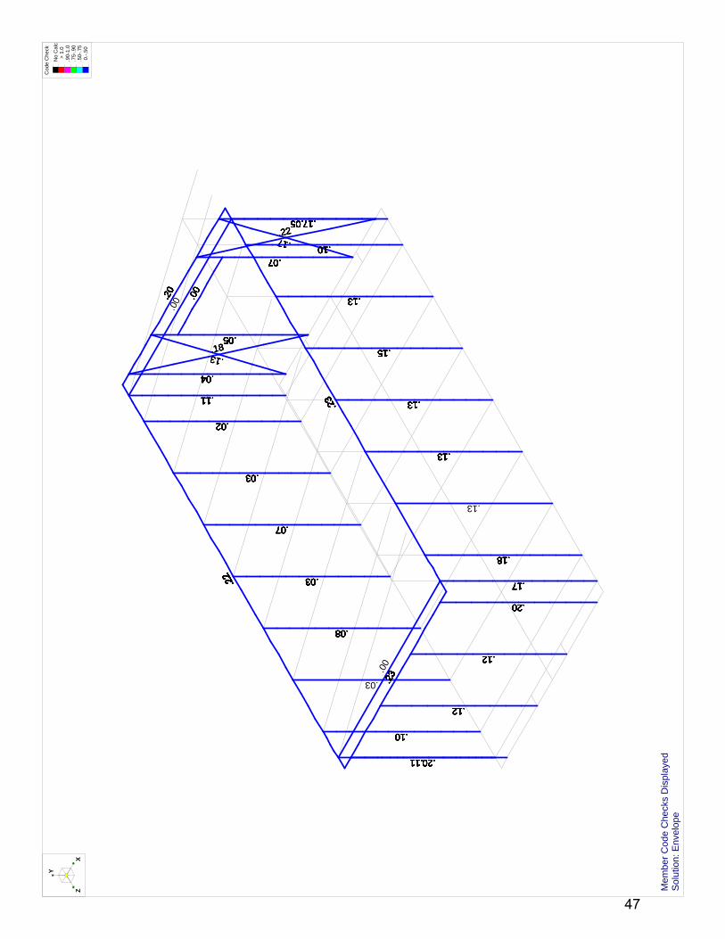
.11
.04
.11
.04
.13
.11
.04
.02
.11
.04
.02
.05
.11
.04
.18
.02
.05
.11
.04
.02
.13
.05
.11
.04
.18
.02
.05
.03
.11
.04
.02
.05
.03
.11
.04
.18
.02
.05
.03
.11
.04
.13
.02
.05
.03
.11
.04
.02
.07
.18
.05
.03
.11
.04
.22
.20
.02
.07
.07
.05
.17
.22
.03
.20
.02
.07
.22
.07
.05
.20
.03
.22
.13
.02
.07
.07
.05
.22
.00
.20
.05
.03
.07
.22.2
2
.07
.05
.20
.00
.05
.03
.07
.07
.22
.20
.17
.17.05
.00
.03
.03
.07
.07
.22
.17
.22
.20
.05
.03
.00
.03
.07
.07
.17.05
.22
.20
.03
.10
.03
.00
.07
.07
.22
.17.05
.10
.22
.20
.03
.00
.07
.00
.07
.17
.17.05
.10
.03.22
.20
.07
.07
.08
.17.05
.22
.10
.03.22
.20
.07
.07
.08
.17.05
.10
.03
.20
.22
.07
.13
.08
.17.05
.10
.03
.20
.17
.13
.22
.08
.17.05
.10
.20
.03
.13
.08
.17
.22
.05
.20
.10
.03
.13
.08
.17
.20
.22
.10
.03
.13
.08
.17
.23
.10
.22 .03
.15
.23
.13
.08
.10
.23
.15
.22
.13
.23
.08
.10
.15
.23
.22
.13
.08
.10
.23
.15
.22
.13
.08
.03
.10
.15
.23
.13
.22
.08
.13
.10
.11
.15
.23
.13
.13
.22
.10
.11
.15
.23
.13
.13
.10
.22
.20.11
.15
.23 .13
.10
.22
.11
.15
.20
.13.23
.10
.11
.15
.22
.13
.20
.13
.10
.23
.11
.15
.13
.22
.20
.13
.10
.23
.11
.15
.13
.22
.12
.13
.10
.20.11
.23
.13
.22
.13
.10
.12
.20.11
.13
.23 .13
.22
.10
.12
.11
.13
.20
.23
.22
.13
.11
.22
.12
.13
.20
.23 .13
.22
.11
.12
.13
.22
.12
.20
.23
.22
.13
.12
.12
.20
.23
.23
.13
.18
.12
.12
.23
.23
.13
.13
.18
.12
.12
.23
.23
.13
.18
.17
.20
.12
.12
.23
.18
.17
.20
.12
.18
.12
.23
.17
.23
.20
.18
.12
.23
.17
.00
.20
.18
.12
.17
.23
.18
.20
.17
.12
.23
.18
.17
.20
.12
.23
.18
.23
.17
.20
.23
.18
.17
.20
.23
.18
.17
.23
.20
.23
.17
.23
.23
.20
.23
.17
.23
.23
.23
Y
XZ
Cod
e C
heck
No
Cal
c >
1.0
.90-
1.0
.75-
.90
.50-
.75
0.-
.50
Mem
ber
Cod
e C
heck
s D
ispl
ayed
Sol
utio
n: E
nvel
ope
47

1.1
-10.
7
-.4
-.1
-.9
0.6
-.9
1.3
0.1
0 0
1.6
-.7
-.2
-2
0.8
-1.7
2.2
0.2
Y
XZ
Sol
utio
n: E
nvel
ope
Mem
ber
Axi
al F
orce
s (k
)
48

Rob
ert S
ilman
Ass
ocia
tes
C. A
llan
Cob
bU
Md
SD
2011
- N
orth
Mod
ule
App
lied
Load
s -
Sou
th M
odul
e
SK
- 1
Mar
16,
201
1 at
5:0
4 P
M
RS
A S
D20
11 M
odul
es -
Sou
th R
oof.r
3d
N2
N3
N4
N5
N6
N7
N8
N9
N15
N16
N17
N18
N19
N20
N21
N22
N23
N24
N25
N26
N27
N28
N29
N30
N77
N79
N80
N81
N82
N83
N84
N85
-.03
2ksf
-.03
2ksf
-.03
2ksf
-.03
2ksf
-.03
2ksf
-.03
2ksf
-.03
2ksf
-.03
2ksf
-.03
2ksf
-.02
3ksf
-.02
3ksf
Y
XZ Lo
ads:
LC
11,
SD
11 1
6-13
ca
Sol
utio
n: E
nvel
ope
49

Rob
ert S
ilman
Ass
ocia
tes
C. A
llan
Cob
bU
Md
SD
2011
- N
orth
Mod
ule
Nod
es -
Sou
th M
odul
e R
oof
SK
- 2
Mar
16,
201
1 at
5:0
6 P
M
RS
A S
D20
11 M
odul
es -
Sou
th R
oof.r
3d
N2
N3
N4
N5
N6
N7
N8
N9
N15
N16
N17
N18
N19
N20
N21
N22
N23
N24
N25
N26
N27
N28
N29
N30
N77
N79
N80
N81
N82
N83
N84
N85
Y
XZ S
olut
ion:
Env
elop
e
50

Rob
ert S
ilman
Ass
ocia
tes
C. A
llan
Cob
bU
Md
SD
2011
- N
orth
Mod
ule
Cod
e C
heck
- S
outh
Mod
ule
Roo
f
SK
- 3
Mar
16,
201
1 at
5:0
6 P
M
RS
A S
D20
11 M
odul
es -
Sou
th R
oof.r
3d
N2
N3
N4
N5
N6
N7
N8
N9
N15
N16
N17
N18
N19
N20
N21
N22
N23
N24
N25
N26
N27
N28
N29
N30
N77
N79
N80
N81
N82
N83
N84
N85
.50
.96
.05
.21
.80
.00
.10
.83
.40
.00
.09
.86
.35
.00
.09
.87
.36
.00
.09
.70
.34
.00
.09
.51
.37
.00
.05.3
7
.00
.05
.16
Y
XZ
Cod
e C
heck
No
Cal
c >
1.0
.90-
1.0
.75-
.90
.50-
.75
0.-
.50
Mem
ber
Cod
e C
heck
s D
ispl
ayed
Sol
utio
n: E
nvel
ope
51

Rob
ert S
ilman
Ass
ocia
tes
C. A
llan
Cob
bU
Md
SD
2011
- N
orth
Mod
ule
Ben
ding
Mom
ent D
iagr
am -
Sou
th M
odul
e R
oof
SK
- 4
Mar
16,
201
1 at
5:0
7 P
M
RS
A S
D20
11 M
odul
es -
Sou
th R
oof.r
3d
N2
N3
N4
N5
N6
N7
N8
N9
N15
N16
N17
N18
N19
N20
N21
N22
N23
N24
N25
N26
N27
N28
N29
N30
N77
N79
N80
N81
N82
N83
N84
N85
0.7
-2.2
1.6
-3
1.6
-3.6
1.4
-3.7
1.6
-3.5
1.5
-3.4
1.7
-4.1
0.9
-2.1
0.7
1.6
1.6
1.4
1.6
1.5
1.7
0.9
Y
XZ S
olut
ion:
Env
elop
eM
embe
r z
Ben
ding
Mom
ents
(k-
ft)
52

Rob
ert S
ilman
Ass
ocia
tes
C. A
llan
Cob
bU
Md
SD
2011
- N
orth
Mod
ule
She
ar D
iagr
am -
Sou
th M
odul
e R
oof
SK
- 5
Mar
16,
201
1 at
5:0
8 P
M
RS
A S
D20
11 M
odul
es -
Sou
th R
oof.r
3d
N2
N3
N4
N5
N6
N7
N8
N9
N15
N16
N17
N18
N19
N20
N21
N22
N23
N24
N25
N26
N27
N28
N29
N30
N77
N79
N80
N81
N82
N83
N84
N85
0.7
-.8
1
-1.3
1.2
-1.5
1.2
-1.5
1.2
-1.4
1.1
-1.4
1.4
-1.7
0.7
-.9
0.4
0.8
0.8
0.7
0.8
0.8
0.9
0.5
Y
XZ S
olut
ion:
Env
elop
eM
embe
r y
She
ar F
orce
s (k
)
53

Rob
ert S
ilman
Ass
ocia
tes
C. A
llan
Cob
bU
Md
SD
2011
- N
orth
Mod
ule
Mem
ber
Num
bers
- S
outh
Mod
ule
Roo
f
SK
- 6
Mar
16,
201
1 at
5:0
9 P
M
RS
A S
D20
11 M
odul
es -
Sou
th R
oof.r
3d
M83
M84
M85
M86
M87
M88
M89
M90
M92
M93
M94
M95
M96
M97
M98
M99
M11
2
M11
3
M11
4
M11
5
M11
6
M11
7
M11
8
M11
9
M13
4
M13
5
M13
6
M13
7
M13
8
M13
9
M14
0
YX
Z
Sol
utio
n: E
nvel
ope
54
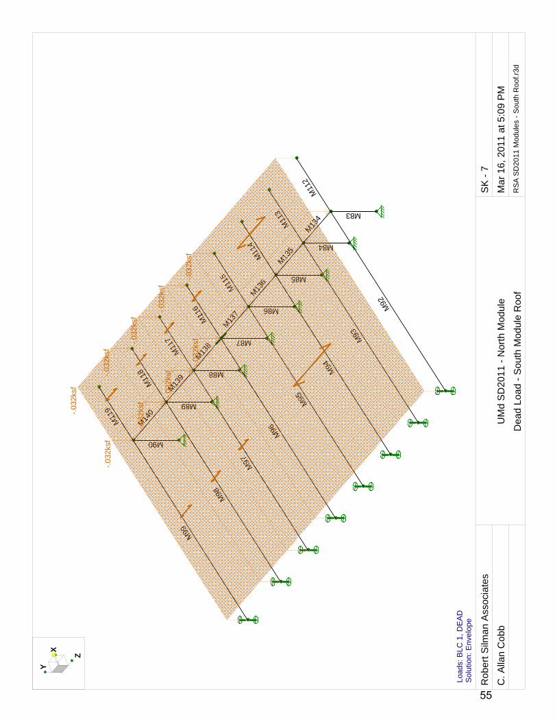
Rob
ert S
ilman
Ass
ocia
tes
C. A
llan
Cob
bU
Md
SD
2011
- N
orth
Mod
ule
Dea
d Lo
ad -
Sou
th M
odul
e R
oof
SK
- 7
Mar
16,
201
1 at
5:0
9 P
M
RS
A S
D20
11 M
odul
es -
Sou
th R
oof.r
3d
M83
M84
M85
M86
M87
M88
M89
M90
M92
M93
M94
M95
M96
M97
M98
M99
M11
2
M11
3
M11
4
M11
5
M11
6
M11
7
M11
8
M11
9
M13
4
M13
5
M13
6
M13
7
M13
8
M13
9
M14
0-.03
2ksf
-.03
2ksf
-.03
2ksf
-.03
2ksf
-.03
2ksf
-.03
2ksf
-.03
2ksf
-.03
2ksf
-.03
2ksf
YX
Z
Load
s: B
LC 1
, DE
AD
Sol
utio
n: E
nvel
ope
55

Rob
ert S
ilman
Ass
ocia
tes
C. A
llan
Cob
bU
Md
SD
2011
- N
orth
Mod
ule
Sno
w L
oad
- S
outh
Mod
ule
Roo
f
SK
- 8
Mar
16,
201
1 at
5:1
0 P
M
RS
A S
D20
11 M
odul
es -
Sou
th R
oof.r
3d
M83
M84
M85
M86
M87
M88
M89
M90
M92
M93
M94
M95
M96
M97
M98
M99
M11
2
M11
3
M11
4
M11
5
M11
6
M11
7
M11
8
M11
9
M13
4
M13
5
M13
6
M13
7
M13
8
M13
9
M14
0-.03
1ksf
-.03
1ksf
YX
Z
Load
s: B
LC 3
, SN
OW
Sol
utio
n: E
nvel
ope
56

Company : Robert Silman Associates Mar 16, 2011Designer : 5:10 PMC. Allan Cobb
UMd SD2011 - North ModuleJob Number : Checked By:_____
Envelope Wood Code ChecksMember Shape Code C... Loc[in] LC Shear C...Loc[in] Dir LC Fc' [ksi] Ft' [ksi] Fb1' [ksi] Fb2' [ksi] Fv' [ksi] Eqn
1 M83 3-2X6 .048 0 3 .000 0 z 1 1.029 .834 1.438 1.653 .201 3.6.32 M84 3-2X6 .050 0 3 .000 0 z 1 1.76 .834 1.438 1.653 .201 3.6.33 M85 3-2X6 .094 0 13 .000 0 z 1 .904 .725 1.25 1.438 .175 3.6.34 M86 3-2X6 .090 0 3 .000 0 z 1 1.029 .834 1.438 1.653 .201 3.6.35 M87 3-2X6 .091 0 13 .000 0 z 1 .904 .725 1.25 1.438 .175 3.6.36 M88 3-2X6 .087 0 13 .000 0 z 1 .904 .725 1.25 1.438 .175 3.6.37 M89 3-2X6 .103 0 3 .000 0 z 1 1.029 .834 1.438 1.653 .201 3.6.38 M90 3-2X6 .054 0 3 .000 0 z 1 1.029 .834 1.438 1.653 .201 3.6.39 M92 2-2X10 .508 73.104 13 .223 155.9... y 13 1.096 .575 1.05 1.26 .175 3.9-110 M93 2-2X10 .705 69.855 13 .346 155.9... y 13 1.096 .575 1.05 1.26 .175 3.9-111 M94 2-2X10 .870 71.479 13 .405 155.9... y 13 1.096 .575 1.05 1.26 .175 3.9-112 M95 2-2X10 .863 71.479 3 .394 155.9... y 3 1.18 .661 1.208 1.449 .201 3.9-313 M96 2-2X10 .832 71.479 13 .390 155.9... y 13 1.096 .575 1.05 1.26 .175 3.9-114 M97 2-2X10 .799 71.479 13 .374 155.9... y 13 1.096 .575 1.05 1.26 .175 3.9-115 M98 2-2X10 .957 71.479 13 .444 155.9... y 13 1.096 .575 1.05 1.26 .175 3.9-116 M99 2-2X10 .503 71.479 13 .233 155.9... y 13 1.096 .575 1.05 1.26 .175 3.9-117 M112 2-2X10 .165 0 13 .098 0 y 13 1.475 .575 1.05 1.26 .175 3.9-318 M113 2-2X10 .370 0 13 .222 0 y 13 1.475 .575 1.05 1.26 .175 3.9-319 M114 2-2X10 .370 0 13 .222 0 y 13 1.475 .575 1.05 1.26 .175 3.9-320 M115 2-2X10 .337 0 13 .202 0 y 13 1.475 .575 1.05 1.26 .175 3.9-321 M116 2-2X10 .362 0 13 .217 0 y 13 1.475 .575 1.05 1.26 .175 3.9-322 M117 2-2X10 .345 0 13 .206 0 y 13 1.475 .575 1.05 1.26 .175 3.9-323 M118 2-2X10 .400 0 13 .240 0 y 13 1.475 .575 1.05 1.26 .175 3.9-324 M119 2-2X10 .210 0 13 .126 0 y 13 1.475 .575 1.05 1.26 .175 3.9-325 M134 2X2 .000 0 1 .057 0 z 3 1.357 .743 1.35 1.35 .158 3.9-326 M135 2X2 .000 0 1 .121 0 z 1 1.357 .743 1.35 1.35 .158 3.9-327 M136 2X2 .000 0 1 .109 0 z 1 1.357 .743 1.35 1.35 .158 3.9-328 M137 2X2 .000 0 1 .085 0 z 1 1.357 .743 1.35 1.35 .158 3.9-329 M138 2X2 .000 0 1 .030 0 z 1 1.357 .743 1.35 1.35 .158 3.9-330 M139 2X2 .000 0 1 .091 0 z 3 1.357 .743 1.35 1.35 .158 3.9-331 M140 2X2 .000 0 1 .194 0 z 3 1.357 .743 1.35 1.35 .158 3.9-3
RISA-3D Version 9.0.1 Page 1 [P:\...\...\Calcs\RSA SD2011 Modules - South Roof.r3d] 57

58

59

60

61

62

63

64

65

66

67

Support Model Top Nails Face Nails Member Nails Accessories
1 - Face Mount Hanger LU28 N/A 8-10d common 6-10d x 1-1/2
2 - Face Mount Hanger LU28 N/A 8-10d common 6-10d x 1-1/2
Connector: Simpson Strong-Tie Connectors
1 piece(s) 2 x 8 Spruce-Pine-Fir No. 1 / No. 2 @ 16" OC
All Dimensions are Horizontal; Drawing is Conceptual
Design Results Actual @ Location Allowed Result LDF
Member Reaction (lbs) 568 @ 3 1/2" 3825 Passed (15%) - -
Shear (lbs) 482 @ 10 3/4" 881 Passed (55%) 0.90
Moment (Ft-lbs) 1136 @ 4' 3 1/2" 1190 Passed (95%) 0.90
Live Load Defl. (in) 0.126 @ 4' 3 1/2" 0.267 Passed (L/762) - -
Total Load Defl. (in) 0.134 @ 4' 3 1/2" 0.400 Passed (L/715) - -
TJ Pro Rating N/A N/A - - - -
System : Floor
Member Type : Joist
Building Use : Residential
Building Code : IBC
Design Methodology : ASD
Supports Total Bearing
Available Bearing
Required Bearing
Support Reactions (lbs)Dead / Floor / Roof / Snow /
Wind / SeismicAccessories
1 - 7 1/4" Beam - Spruce Pine Fir 3.50" Hanger Hanger 37 / 572 / 0 / 0 / 0 / 0 None
2 - 7 1/4" Beam - Spruce Pine Fir 3.50" Hanger Hanger 37 / 572 / 0 / 0 / 0 / 0 None
• Deflection criteria: LL (L/360) and TL (L/240).
• Design results assume a fully braced condition where sheathing is properly nailed to all compression edges at the top of the joist and that the compression edges at the bottom of the joist are properly braced to provide lateral stability.
• Bracing (Lu): All compression edges (top and bottom) must be braced at 3' 7 5/16" o/c unless detailed otherwise. Proper attachment and positioning of lateral bracing is required to achieve member stability.
• A 15% increase in the moment capacity has been added to account for repetitive member usage.
• Deflection analysis is based on composite action with a single layer of 23/32" iLevel® Edge Panel (24" Span Rating) that is glued and nailed down.
• Dimension lumber analysis is in accordance with 2005 NDS methodology.
Exterior Deck, Deck: Typ. JoistMEMBER REPORT
Loads Location Spacing DeadFloor Live
RoofLive Snow Wind Seismic Comments
(0.90) (0.90) (non-snow: 1.25) (1.15) (1.60) (1.60)
1 - Uniform(PSF) 0 to 8' 7" 16'' 6.5 100.0 0.0 0.0 0.0 0.0 Public Assembly Areas: Deck
PASSED
iLEVEL® NotesiLevel® warrants that the sizing of its products will be in accordance with iLevel® product design criteria and published design values. iLevel® expressly disclaims any other warranties related to the software. Refer to current iLevel® literature for installation details. (www.iLevel.com) Accessories (Rim Board, Blocking Panels and Squash Blocks) are not designed by this software. Use of this software is not intended to circumvent the need for a design professional as determined by the authority having jurisdiction. The designer of record, builder or framer is responsible to assure that this calculation is compatible with the overall project. iLevel® products manufactured at Weyerhaeuser facilities are third-party certified to sustainable forestry standards.The product application, input design loads, dimensions and support information have been provided by Forte Software Operator
3/15/2011 8:33:59 AMiLevel® Forte™ v2.0, Design Engine: V5.1.0.3
Page 1 of 1
DECKAN~1.4TE
Forte™ Software Operator
Kristin PottertonRobert Silman Associates(202) [email protected]
Job Notes
TYP. DECK MODULE DESIGN
68

Support Model Top Nails Face Nails Member Nails Accessories
1 - Face Mount Hanger Connector not found N/A N/A N/A
2 - Face Mount Hanger Connector not found N/A N/A N/A
Connector: Simpson Strong-Tie Connectors
3 piece(s) 2 x 8 Douglas Fir-Larch No. 1
All Dimensions are Horizontal; Drawing is Conceptual
Design Results Actual @ Location Allowed Result LDF
Member Reaction (lbs) 1737 @ 3 1/2" 16875 Passed (10%) - -
Shear (lbs) 1475 @ 10 3/4" 3524 Passed (42%) 0.90
Moment (Ft-lbs) 3474 @ 4' 3 1/2" 3548 Passed (98%) 0.90
Live Load Defl. (in) 0.152 @ 4' 3 1/2" 0.267 Passed (L/633) - -
Total Load Defl. (in) 0.165 @ 4' 3 1/2" 0.400 Passed (L/583) - -
System : Floor
Member Type : Flush Beam
Building Use : Residential
Building Code : IBC
Design Methodology : ASD
Supports Total Bearing
Available Bearing
Required Bearing
Support Reactions (lbs)Dead / Floor / Roof / Snow /
Wind / SeismicAccessories
1 - 7 1/4" Beam - Spruce Pine Fir 3.50" Hanger Hanger 145 / 1717 / 0 / 0 / 0 / 0 None
2 - 7 1/4" Beam - Spruce Pine Fir 3.50" Hanger Hanger 145 / 1717 / 0 / 0 / 0 / 0 None
• Deflection criteria: LL (L/360) and TL (L/240).
• Design results assume a fully braced condition where all compression edges (top and bottom) are properly braced to provide lateral stability.
• Bracing (Lu): All compression edges (top and bottom) must be braced at 5' 9 3/4" o/c unless detailed otherwise. Proper attachment and positioning of lateral bracing is required to achieve member stability.
• Dimension lumber analysis is in accordance with 2005 NDS methodology.
Exterior Deck, Deck: Typ. GirderMEMBER REPORT
Loads LocationTributary
Width DeadFloor Live
RoofLive Snow Wind Seismic Comments
(0.90) (0.90) (non-snow: 1.25) (1.15) (1.60) (1.60)
1 - Uniform(PSF) 0 to 8' 7" 4' 6.5 100.0 0.0 0.0 0.0 0.0 Public Assembly Areas: Deck
PASSED
iLEVEL® NotesiLevel® warrants that the sizing of its products will be in accordance with iLevel® product design criteria and published design values. iLevel® expressly disclaims any other warranties related to the software. Refer to current iLevel® literature for installation details. (www.iLevel.com) Accessories (Rim Board, Blocking Panels and Squash Blocks) are not designed by this software. Use of this software is not intended to circumvent the need for a design professional as determined by the authority having jurisdiction. The designer of record, builder or framer is responsible to assure that this calculation is compatible with the overall project. iLevel® products manufactured at Weyerhaeuser facilities are third-party certified to sustainable forestry standards.The product application, input design loads, dimensions and support information have been provided by Forte Software Operator
3/15/2011 8:35:38 AMiLevel® Forte™ v2.0, Design Engine: V5.1.0.3
Page 1 of 1
DECKAN~1.4TE
Forte™ Software Operator
Kristin PottertonRobert Silman Associates(202) [email protected]
Job Notes
TYP. DECK MODULE DESIGN
69

70

71

N1
N2
N3
N4
N5
N6
N7
N8
Y
XZ
72

N1
N2
N3
N4
N5
N6
N7
N8
6061-T6
6061-T6
6061-T6
6061-T6
6061
-T6
Y
XZ
73

N1
N2
N3
N4
N5
N6
N7
N8
RT4X4X0.250
RT4X4X0.250
RT4X4X0.250
RT4X4X0.250
RT4
X4X
0.25
0
Y
XZ
74

N1
N2
N3
N4
N5
N6
N7
N8
-.06
8k/ft
Y
XZ Lo
ads:
BLC
1, R
oof D
ead
Load
75

N1
N2
N3
N4
N5
N6
N7
N8
-.09
k/ft
Y
XZ Lo
ads:
BLC
2, R
oof L
ive
Load
76

N1
N2
N3
N4
N5
N6
N7
N8
-.09
k/ft
Y
XZ Lo
ads:
BLC
3, R
oof S
now
Loa
d
77

N1
N2
N3
N4
N5
N6
N7
N8
1.58
4kY
XZ Lo
ads:
BLC
4, W
ind
Load
78

Company : RSA Mar 15, 2011Designer : 8:58 AMKP
UMD SD2011 PergolaJob Number : Checked By:_____
GlobalDisplay Sections for Member CalcsMax Internal Sections for Member CalcsInclude Shear DeformationInclude WarpingArea Load Mesh (in^2)Merge Tolerance (in)P-Delta Analysis ToleranceVertical Axis
5 97 YesYes144.120.50%Y
Hot Rolled Steel CodeCold Formed Steel CodeWood CodeWood TemperatureConcrete CodeMasonry CodeAluminum Code
AISC 360-05: ASD (Direct Analysis Method)AISI NAS-01: ASDAF&PA NDS-05: ASD< 100FACI 318-05ACI 530-05: ASDAA ADM1-05: ASD
Number of Shear RegionsRegion Spacing Increment (in)Biaxial Column MethodParme Beta Factor (PCA)Concrete Stress BlockUse Cracked SectionsBad Framing WarningsUnused Force Warnings
44Exact Integration.65RectangularYesNoYes
Seismic CodeSeismic Base Elevation (ft)Ct XCt ZT X (sec)T Z (sec)R XR ZCt Exp. XCt Exp. ZCaCvNvSD1SDSS1TL (sec)Occupancy CodeSeismic ZoneOccupancy CatUse Gravity Self Wt in Diaphragm MassUse Deck Self Wt in Diaphragm MassUse Lateral Self Wt in Diaphragm Mass
ASCE 7-05Not Entered.035.035Not EnteredNot Entered8.58.5.75.75.36.541111Not Entered43I or IIYesYesYes
Seismic Detailing CodeOm XOm ZRho XRho Z
None1111
RISA-3D Version 9.0.1 Page 1 [P:\...\UMaryland Solar Decathlon 2011\Calcs\Pergola 2011-03-05.r3d] 79

Company : RSA Mar 15, 2011Designer : 8:58 AMKP
UMD SD2011 PergolaJob Number : Checked By:_____
Aluminum PropertiesLabel E [ksi] G [ksi] Nu Therm (...Density[...Table 3.3 kt Ftu[ksi] Fty[ksi] Fcy[ksi] Fsu[ksi] Ct
1 3003-H14 10100 3787.5 .33 1.3 .173 Table 3.... 1 19 16 13 12 1412 6061-T6 10100 3787.5 .33 1.3 .173 Table 3.... 1 38 35 35 24 1413 6063-T5 10100 3787.5 .33 1.3 .173 Table 3.... 1 22 16 16 13 1414 6063-T6 10100 3787.5 .33 1.3 .173 Table 3.... 1 30 25 25 19 1415 5052-H34 10200 3787.5 .33 1.3 .173 Table 3.... 1 34 26 24 20 1416 6061-T6 W 10100 3787.5 .33 1.3 .173 Table 3.... 1 24 15 15 15 141
Joint Boundary ConditionsJoint Label X [k/in] Y [k/in] Z [k/in] X Rot.[k-ft/rad] Y Rot.[k-ft/rad] Z Rot.[k-ft/rad] Footing
1 N1 Reaction Reaction Reaction Reaction Reaction Reaction2 N3 Reaction Reaction Reaction Reaction Reaction Reaction3 N5 Reaction Reaction Reaction Reaction Reaction Reaction4 N7 Reaction Reaction Reaction Reaction Reaction Reaction
Aluminum Design ParametersLabel Shape Length... Lbyy[ft] Lbzz[ft] Lcomp to...Lcomp b... Kyy Kzz Cm-yy Cm-zz Cb y swayz sway Function
1 M1 RT4X4X0... 10 Lateral2 M2 RT4X4X0... 10 Lateral3 M3 RT4X4X0... 10 Lateral4 M4 RT4X4X0... 10 Lateral5 M5 RT4X4X0... 13 Lateral
Member Distributed Loads (BLC 1 : Roof Dead Load)Member Label Direction Start Magnitude[k/ft,... End Magnitude[k/ft,d... Start Location[ft,%] End Location[ft,%]
1 M5 Y -.068 -.068 0 0
Member Distributed Loads (BLC 2 : Roof Live Load)Member Label Direction Start Magnitude[k/ft,... End Magnitude[k/ft,d... Start Location[ft,%] End Location[ft,%]
1 M5 Y -.09 -.09 0 0
Member Distributed Loads (BLC 3 : Roof Snow Load)Member Label Direction Start Magnitude[k/ft,... End Magnitude[k/ft,d... Start Location[ft,%] End Location[ft,%]
1 M5 Y -.09 -.09 0 0
Joint Loads and Enforced Displacements (BLC 4 : Wind Load)Joint Label L,D,M Direction Magnitude[(k,k-ft), (in,rad), (k*s^2/f...
1 N2 L X 1.584
Basic Load CasesBLC Description Category X Gravity Y Gravity Z Gravity Joint Point Distributed Area (Me...Surface (...
1 Roof Dead Load DL -1 12 Roof Live Load LL 13 Roof Snow Load SL 14 Wind Load WL 1
RISA-3D Version 9.0.1 Page 2 [P:\...\UMaryland Solar Decathlon 2011\Calcs\Pergola 2011-03-05.r3d] 80

Company : RSA Mar 15, 2011Designer : 8:58 AMKP
UMD SD2011 PergolaJob Number : Checked By:_____
Load CombinationsDescription SolvePD... SR... BLC Factor BLC Factor BLC Factor BLC Factor BLC Factor BLC Factor BLC Factor BLC Factor
1 D+W Yes 1 1 4 12 D+0.75W+0....Yes 1 1 4 .75 2 .753 D+0.75W+0....Yes 1 1 4 .75 3 .754 0.6D+W Yes 1 .6 4 1
Envelope Joint ReactionsJoint X [k] LC Y [k] LC Z [k] LC MX [k-ft] LC MY [k-ft] LC MZ [k-ft] LC
1 N1 max -.288 2 -.959 2 0 1 0 1 0 1 2.003 12 min -.383 1 -1.288 4 0 1 0 1 0 1 1.505 23 N3 max -.284 2 1.848 2 0 1 0 1 0 1 2.071 44 min -.404 4 1.48 4 0 1 0 1 0 1 1.491 25 N5 max -.332 2 .104 2 0 1 0 1 0 1 2.132 16 min -.423 1 -.845 4 0 1 0 1 0 1 1.649 27 N7 max -.284 2 1.335 1 0 1 0 1 0 1 1.99 48 min -.38 4 .998 2 0 1 0 1 0 1 1.489 29 Totals: max -1.188 2 1.99 2 0 110 min -1.584 1 .668 4 0 1
Envelope ADM 05 ASD Aluminum Code ChecksMember Shape Code ... Loc[ft] LC Shear ...Loc[ft] Dir LC Ft [ksi] Fc [ksi] Fb y-y ...Fb z-z ...Fs y-y ...Fs z-z ...Cb Cmy Cmz Eqn
1 M1 RT4X4X... .297 0 4 .016 0 y 1 19.487 8.645 21.212 21.212 12.247 12.247 2.... .6 .248 4.1.2-1
2 M2 RT4X4X... .315 0 1 .016 0 y 4 19.487 8.645 21.212 21.212 12.247 12.247 2.... .6 .237 4.1.1-3
3 M3 RT4X4X... .307 0 4 .017 0 y 1 19.487 8.645 21.212 21.212 12.247 12.247 2.... .6 .223 4.1.2-1
4 M4 RT4X4X... .296 0 1 .016 0 y 4 19.487 8.645 21.212 21.212 12.247 12.247 2.... .6 .249 4.1.1-3
5 M5 RT4X4X... .299 0 1 .061 2.438 y 1 19.487 4.946 21.212 21.212 12.247 12.247 2.... .6 .204 4.1.1-3
RISA-3D Version 9.0.1 Page 3 [P:\...\UMaryland Solar Decathlon 2011\Calcs\Pergola 2011-03-05.r3d] 81

N1
N2
N3
N4
N5
N6
N7
N8
-1-1.3 1.
8
1.5
0.1
-.9
1.3
1
1.2
0.3
Y
XZ S
olut
ion:
Env
elop
eM
embe
r A
xial
For
ces
(k)
82

N1
N2
N3
N4
N5
N6
N7
N8
0.4
0.3
0.4
0.3
0.4
0.3
0.4
0.3
0.4
-1.5
Y
XZ S
olut
ion:
Env
elop
eM
embe
r y
She
ar F
orce
s (k
)
83

N1
N2
N3
N4
N5
N6
N7
N8
2
-1.8 2.
1
-1.9
2.1
-2
2
-1.7
1.8
-1.8
Y
XZ S
olut
ion:
Env
elop
eM
embe
r z
Ben
ding
Mom
ents
(k-
ft)
84

N1
N2
N3
N4
N5
N6
N7
N8
Y
XZ
Cod
e C
heck
No
Cal
c >
1.0
.90-
1.0
.75-
.90
.50-
.75
0.-
.50
Sol
utio
n: E
nvel
ope
85
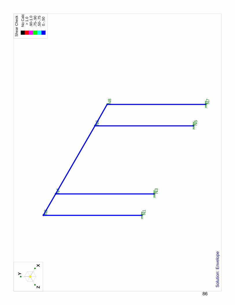
N1
N2
N3
N4
N5
N6
N7
N8
Y
XZ
She
ar C
heck
No
Cal
c >
1.0
.90-
1.0
.75-
.90
.50-
.75
0.-
.50
Sol
utio
n: E
nvel
ope
86

N1
N2
N7
N8
Y
XZ
87

N1
N2
N7
N8
6061-T6
6061-T6
6061
-T6
Y
XZ
88

N1
N2
N7
N8
RT4X4X0.500
RT4X4X0.500
RT4
X4X
0.50
0
Y
XZ
89

N1
N2
N7
N8
-.06
8k/ft
Y
XZ Lo
ads:
BLC
1, R
oof D
ead
Load
90

N1
N2
N7
N8
-.09
k/ft
Y
XZ Lo
ads:
BLC
2, R
oof L
ive
Load
91

N1
N2
N7
N8
-.09
k/ft
Y
XZ Lo
ads:
BLC
3, R
oof S
now
Loa
d
92

N1
N2
N7
N8
1.58
4kY
XZ Lo
ads:
BLC
4, W
ind
Load
93

Company : RSA Mar 15, 2011Designer : 9:14 AMKP
UMD SD2011 Pergola (2 Columns)Job Number : Checked By:_____
GlobalDisplay Sections for Member CalcsMax Internal Sections for Member CalcsInclude Shear DeformationInclude WarpingArea Load Mesh (in^2)Merge Tolerance (in)P-Delta Analysis ToleranceVertical Axis
5 97 YesYes144.120.50%Y
Hot Rolled Steel CodeCold Formed Steel CodeWood CodeWood TemperatureConcrete CodeMasonry CodeAluminum Code
AISC 360-05: ASD (Direct Analysis Method)AISI NAS-01: ASDAF&PA NDS-05: ASD< 100FACI 318-05ACI 530-05: ASDAA ADM1-05: ASD
Number of Shear RegionsRegion Spacing Increment (in)Biaxial Column MethodParme Beta Factor (PCA)Concrete Stress BlockUse Cracked SectionsBad Framing WarningsUnused Force Warnings
44Exact Integration.65RectangularYesNoYes
Seismic CodeSeismic Base Elevation (ft)Ct XCt ZT X (sec)T Z (sec)R XR ZCt Exp. XCt Exp. ZCaCvNvSD1SDSS1TL (sec)Occupancy CodeSeismic ZoneOccupancy CatUse Gravity Self Wt in Diaphragm MassUse Deck Self Wt in Diaphragm MassUse Lateral Self Wt in Diaphragm Mass
ASCE 7-05Not Entered.035.035Not EnteredNot Entered8.58.5.75.75.36.541111Not Entered43I or IIYesYesYes
Seismic Detailing CodeOm XOm ZRho XRho Z
None1111
RISA-3D Version 9.0.1 Page 4 [P:\...\...\Calcs\Pergola 2 col configuration 2011-03-05.r3d] 94
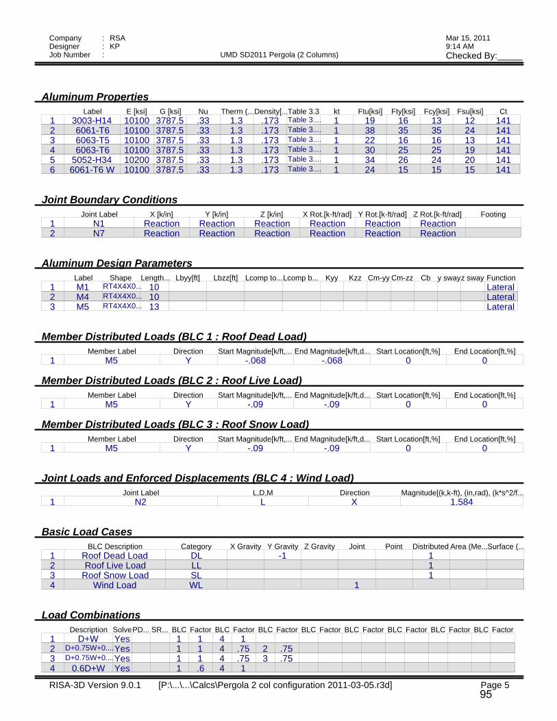
Company : RSA Mar 15, 2011Designer : 9:14 AMKP
UMD SD2011 Pergola (2 Columns)Job Number : Checked By:_____
Aluminum PropertiesLabel E [ksi] G [ksi] Nu Therm (...Density[...Table 3.3 kt Ftu[ksi] Fty[ksi] Fcy[ksi] Fsu[ksi] Ct
1 3003-H14 10100 3787.5 .33 1.3 .173 Table 3.... 1 19 16 13 12 1412 6061-T6 10100 3787.5 .33 1.3 .173 Table 3.... 1 38 35 35 24 1413 6063-T5 10100 3787.5 .33 1.3 .173 Table 3.... 1 22 16 16 13 1414 6063-T6 10100 3787.5 .33 1.3 .173 Table 3.... 1 30 25 25 19 1415 5052-H34 10200 3787.5 .33 1.3 .173 Table 3.... 1 34 26 24 20 1416 6061-T6 W 10100 3787.5 .33 1.3 .173 Table 3.... 1 24 15 15 15 141
Joint Boundary ConditionsJoint Label X [k/in] Y [k/in] Z [k/in] X Rot.[k-ft/rad] Y Rot.[k-ft/rad] Z Rot.[k-ft/rad] Footing
1 N1 Reaction Reaction Reaction Reaction Reaction Reaction2 N7 Reaction Reaction Reaction Reaction Reaction Reaction
Aluminum Design ParametersLabel Shape Length... Lbyy[ft] Lbzz[ft] Lcomp to...Lcomp b... Kyy Kzz Cm-yy Cm-zz Cb y swayz sway Function
1 M1 RT4X4X0... 10 Lateral2 M4 RT4X4X0... 10 Lateral3 M5 RT4X4X0... 13 Lateral
Member Distributed Loads (BLC 1 : Roof Dead Load)Member Label Direction Start Magnitude[k/ft,... End Magnitude[k/ft,d... Start Location[ft,%] End Location[ft,%]
1 M5 Y -.068 -.068 0 0
Member Distributed Loads (BLC 2 : Roof Live Load)Member Label Direction Start Magnitude[k/ft,... End Magnitude[k/ft,d... Start Location[ft,%] End Location[ft,%]
1 M5 Y -.09 -.09 0 0
Member Distributed Loads (BLC 3 : Roof Snow Load)Member Label Direction Start Magnitude[k/ft,... End Magnitude[k/ft,d... Start Location[ft,%] End Location[ft,%]
1 M5 Y -.09 -.09 0 0
Joint Loads and Enforced Displacements (BLC 4 : Wind Load)Joint Label L,D,M Direction Magnitude[(k,k-ft), (in,rad), (k*s^2/f...
1 N2 L X 1.584
Basic Load CasesBLC Description Category X Gravity Y Gravity Z Gravity Joint Point Distributed Area (Me...Surface (...
1 Roof Dead Load DL -1 12 Roof Live Load LL 13 Roof Snow Load SL 14 Wind Load WL 1
Load CombinationsDescription SolvePD... SR... BLC Factor BLC Factor BLC Factor BLC Factor BLC Factor BLC Factor BLC Factor BLC Factor
1 D+W Yes 1 1 4 12 D+0.75W+0....Yes 1 1 4 .75 2 .753 D+0.75W+0....Yes 1 1 4 .75 3 .754 0.6D+W Yes 1 .6 4 1
RISA-3D Version 9.0.1 Page 5 [P:\...\...\Calcs\Pergola 2 col configuration 2011-03-05.r3d] 95

Company : RSA Mar 15, 2011Designer : 9:14 AMKP
UMD SD2011 Pergola (2 Columns)Job Number : Checked By:_____
Envelope Joint ReactionsJoint X [k] LC Y [k] LC Z [k] LC MX [k-ft] LC MY [k-ft] LC MZ [k-ft] LC
1 N1 max -.373 2 .635 2 0 1 0 1 0 1 4.394 42 min -.722 4 -.161 4 0 1 0 1 0 1 2.736 23 N7 max -.815 2 1.395 2 0 1 0 1 0 1 5.011 14 min -.909 1 .852 4 0 1 0 1 0 1 4.202 25 Totals: max -1.188 2 2.029 2 0 16 min -1.584 1 .691 4 0 1
Envelope ADM 05 ASD Aluminum Code ChecksMember Shape Code ... Loc[ft] LC Shear ...Loc[ft] Dir LC Ft [ksi] Fc [ksi] Fb y-y ...Fb z-z ...Fs y-y ...Fs z-z ...Cb Cmy Cmz Eqn
1 M1 RT4X4X... .372 0 4 .015 0 y 4 19.487 7.657 21.212 21.212 12.247 12.247 2.... .6 .354 4.1.2-1
2 M4 RT4X4X... .423 0 1 .019 0 y 1 19.487 7.657 19.487 19.487 12.247 12.247 2.... .6 .287 4.1.2-1
3 M5 RT4X4X... .346 13 1 .027 13 y 2 19.487 4.381 21.212 21.212 12.247 12.247 2.... .6 .354 4.1.1-3
RISA-3D Version 9.0.1 Page 6 [P:\...\...\Calcs\Pergola 2 col configuration 2011-03-05.r3d] 96

N1
N2
N7
N8
0.6
-.2
1.4
0.8
0.9
0.8
Y
XZ S
olut
ion:
Env
elop
eM
embe
r A
xial
For
ces
(k)
97

N1
N2
N7
N8
0.7
0.4
0.9
0.8
0.6
-1.3
Y
XZ S
olut
ion:
Env
elop
eM
embe
r y
She
ar F
orce
s (k
)
98

N1
N2
N7
N8
4.4
-2.7
5
-3.9
4.1
-2.8
Y
XZ S
olut
ion:
Env
elop
eM
embe
r z
Ben
ding
Mom
ents
(k-
ft)
99

N1
N2
N7
N8
Y
XZ
Cod
e C
heck
No
Cal
c >
1.0
.90-
1.0
.75-
.90
.50-
.75
0.-
.50
Sol
utio
n: E
nvel
ope
100

N1
N2
N7
N8
Y
XZ
She
ar C
heck
No
Cal
c >
1.0
.90-
1.0
.75-
.90
.50-
.75
0.-
.50
Sol
utio
n: E
nvel
ope
101

102

103

104

105

106

107

108

109

110

111

112

113

114

115

116
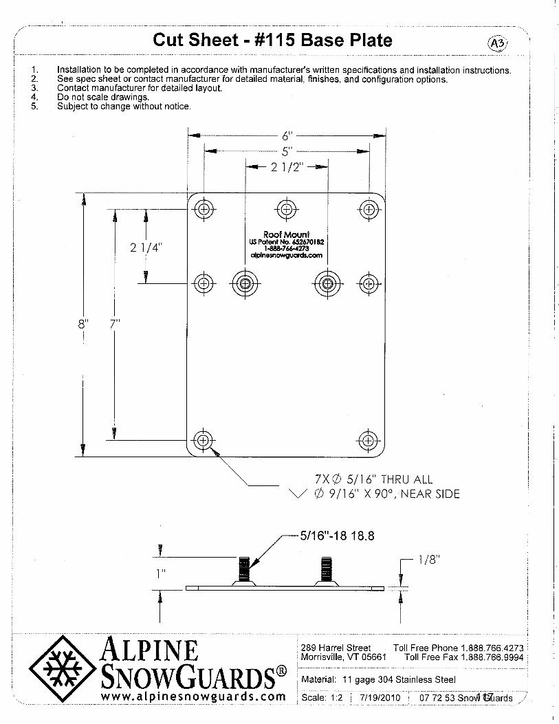
117

118

1¾"
Drainage Holes
2'
1'
½”
Ergonomic
Handles
¾”2½"
LiveRoof, LLCP.O. Box 533Spring Lake, MI 49456
(800) 875-1392www.liveroof.com
LiveRoof Lite Module
LiveRoof Engineered Soil
LiveRoof Green Roof Plants (Minimum 95% Soil Coverage At Installation)
Minimum 40-mil Polypropylene or EPDM Slip Sheet, Edges Overlapped & Seamed
EPDM, TPO, or PVC Waterproofing Membrane
Bonding Adhesive
Insulation
Insulation Adhesive
Moisture Portals™
TOP VIEW
SIDE VIEW
NOT TO SCALE
LiveRoof LITE SYSTEM
LITE AILLUSTRATIONS ARE TO CONCEPTUALLY ASSIST PROFESSIONALS IN DESIGNING LIVEROOF INSTALLATIONS. LIVEROOF DOES NOT ACCEPT RESPONSIBILTY FOR ENGINEERING BASED ON ILLUSTRATIONS. A QUALIFIEDROOFING SPECIALIST SHOULD BE CONSULTED TO DETERMINE APPROPRIATE WATERPROOFING AND ROOFDECK MATERIALS AND SUITABLE DESIGN.
119

LiveRoof, LLCP.O. Box 533Spring Lake, MI 49456
(800) 875-1392www.liveroof.com
LOADING 17PSFILLUSTRATIONS ARE TO CONCEPTUALLY ASSIST PROFESSIONALS IN DESIGN OF LIVEROOF APPLICATIONS.LIVEROOF DOES NOT ACCEPT RESPONSIBILITY FOR ENGINEERING BASED ON INFORMATION. A QUALFIEDSTRUCTURAL ENGINEER SHOULD BE CONSULTED TO DETERMINE APPROPRIATE AND SUITABLE DESIGN.
FORCE AGAINST ROOF EDGE FOR 17PSF GREEN ROOF LOADNOTE: Coefficient of friction (µ) is assumed to equal zero.
½:12
1:12
1½:12
2:12
10 20 30 40 50
1/2:12 4.20% 2.4° 7 14 21 29 36
1:12 8.30% 4.8° 14 29 43 57 71
1 1/2:12 12.50% 7.1° 21 42 64 85 106
2:12 16.70% 9.5° 28 57 85 114 142
2 1/2:12 21.00% 11.8° 36 71 107 142 178
3:12 25.00% 14.0° 42 85 127 170 212
3 1/2:12 29.20% 16.3° 50 99 149 199 249
4:12 33.30% 18.4° 57 113 170 226 283
Roof Slope
Force Against Roof Edge, F (plf)
Horizontal Run Distance (ft)
Horizontal Run Distance F
2½:12
3:12
3½:12
4:12
120

For sloping roofs, LiveRoof suggests a conservative model that assumes “zero” coefficient of frictionduring winter (as might be the case when ice forms underneath the modules). During freezingtemperatures, the green roof is capable of exerting substantial downward force against the loweredge of the roof. Such force should be resisted with appropriate engineering and design. Forsome roofs, a structural parapet may suffice. On very long roofs, structural steel supports aresometimes incorporated into the roof design.
See Loading Tables for Slope Force. See Detail Drawings SLOPE-A, SLOPE-B, & SLOPE-C.
Horizonta
l Run D
istance
Structural Steel Supports
NOT TO SCALE
Structural Parapet
Steel Rods
1” Gap for Water Flow
Drain Scuppers
Pavers
121

(800) 356-9660 PHONE: (616) 399-9600 FAX: (616) 399-9770 WWW.PERMALOC.COMPERMALOC CORPORATION, 13505 BARRY STREET HOLLAND, MI 49424
ARCHITECT NOTE: CHECK OFF APPLICABLE SIZE & FINISH DESIRED
THICK EXPOSED TOP LIPALL 8’ (2.44M) LENGTHS w/ 0.250” (6.35MM)SIZE:
6.5”
4.25”3”
x 5.5”
x 3.25”x 3.25”
(165MM x 140MM)
(108MM x 83MM)(76MM x 83MM)
MF
MFMF
BL
BLBL
FINISH LEGEND:
APPLIED BAKED ON PAINT, MEETS AAMA 2603(BL) BLACK DURAFLEX-ELECTROSTATICALLY(MF) MILL FINISH-NATURAL ALUMINUM
NOTES:
5.
4.
3.
2.
1.
VISIT: WWW.PERMALOC.COMPURCHASING INFORMATIONFOR PRODUCT ANDCONTRACTOR’S NOTE:(616) 399-9600(800) 356-9660CORPORATION, HOLLAND MI.MANUFACTURED BY PERMALOCPERMALOC GEOEDGE ASAND FORM A CONTINUOUS CORNER.CORNERS: REMOVE BASE TABSSLIDING CONNECTORS.CONNECTED WITH 2 - 2.75” (70MM)8’-0” (2.44M) SECTIONSWITH DESIGNER’S INSTRUCTIONS.*GUIDELINES” IN ACCORDANCERECOMMENDED “INSTALLATIONINSTALLATION PER MANUFACTURER’S
LR1.dwg
EDGING FOR LIVEROOF MODULESSCALE: 3”=1’-0”
EDGE ALUMINUMPERMALOC LIVEROOF
GREENROOF MODULE
PAVER OR BALLAST
WATERPROOF LAYER
(NEW OR EXISTING)CONCRETE ROOF
ISOMETRIC VIEWNTS
CONNECTOR
SLIP SHEET
GRAY SPEX FINISH**WAFER HEADTEKS 10-16 X 1”
SAFETY OF THE INSTALLATION.RESPONSIBILITY FOR VALIDITY AND *DESIGNER MAINTAINS ULTIMATE
**AVAILABLE FROM FASTENAL (507)454-5374. MODEL #32091.
TRAYS FOR ALL APPLICATIONS.MANUFACTURER RECOMMENDS EDGING BE FASTENED TO
MINIMUM OF TWO PER TRAYSPACE SCREWS EQUALLY-
AS SHOWN.TOP OF DRAINAGE HOLEPLACE TEK SCREW AT
RESTRAINT
FOR USE WITH:
122

ThermoWood®
Handbook
_______________________________________________________________Finnish Thermowood Associationc/o Wood Focus Oy, P.O. Box 284 (Snellmaninkatu 13), FIN-00171 Helsinki, FINLAND,tel. +358 9 6865 4522, fax +358 9 6865 4530www.thermowood.fi
123

_______________________________________________________________ThermoWood® Handbook 08.04.2003 2 - 0
Preface
This handbook has been produced by the members of the Finnish ThermowoodAssociation. When new products and methods of production enter the variousmarkets, it is very important to offer as much information as possible concerningthe product and process so as to raise and maintain the level of knowledge asefficiently as possible. Therefore, we hope that this handbook will act as a goodinformation source for specifiers, end users in industry, construction companies,timber merchants, etc.
The aim of the handbook is to present a good mix between theoretical material,laboratory results, information from field testing, and, finally, practical advice forworking with the product. The results have been collected from a wide range ofsources, most of which are of research institute or university status;experiences of industrial manufacturers have been included too. The resultsand experiences presented in this handbook should only be used as a guideand are subject to change.
One of the roles of the Finnish Thermowood Association will involve updatingthis handbook on a regular basis. As new results and experiences becomeavailable, new editions will be published outlining the areas that have beenupdated.
The name ThermoWood is a registered trademark, and may be used only bymembers of the Finnish ThermoWood Association.
We hope that the readers of this handbook will find it both informative anduseful.
124

_______________________________________________________________ThermoWood® Handbook 08.04.2003 3 - 0
CONTENTS
CHAPTER 0. Cover page……………………………………………………... 1 - 0 Preface... ……………..………………………………………... 2 - 0 Contents. …..………...………………..…………………….…. 3 - 0
CHAPTER 1.Introduction……….………………………………………….…. 1 - 11.1. Background…………………………....…………………. 1 - 11.2. The ThermoWood® process in brief……………………. 1 - 11.3. Changes in wood structure and chemical reactions…. 3 - 11.4. Standard ThermoWood® treatment classification…….. 4 - 11.5. List of standards………………………………………….. 6 - 1
CHAPTER 2. Raw material……………………………………………….……1 - 22.1. Factors affecting the quality of heat-treated wood……. 1 - 2
2.1.1. General…………………………………………... 1 - 22.1.2. Wood species…………………………………… 1 - 2
2.2. Sawn timber quality……………………………………….1 - 22.2.1. General Nordic Softwood timber quality
grades……………………………………………. 1 - 22.2.2. Knots……………………………………….…..… 1 - 22.2.3. Minimum requirements for raw material……… 2 - 22.2.4. Wood moisture…………………………….……. 6 - 2
CHAPTER 3. ThermoWood® process………………………………………...1 - 33.1. Equipment………………………………………………….1 - 33.2. Phases.……………………………………………………. 1 - 33.3. Energy.……………………………………………………..2 - 33.4. Environmental issues……………………………….…….2 - 3
CHAPTER 4. ThermoWood® properties………………………………….…..1 - 44.1. Chemical changes………………………………………...1 - 4
4.1.1. General…………………………………………... 1 - 44.1.2. Carbohydrates………………………………….. 2 - 44.1.3. Lignin……………………………………………. 2 - 44.1.4. Extractives………………………………………. 3 - 44.1.5. Toxicity…………………………………………... 3 - 4
4.2. Physical changes………………………………………… 4 - 44.2.1. Density………………………………………….. 4 - 44.2.2. Strength…………………………………………. 5 - 44.2.3 Hardness………………………………………… 9 - 44.2.4. Equilibrium moisture content………………… 10 - 44.2.5. Swelling and shrinkage due to moisture.…… 11 - 44.2.6. Permeability…………………………………….12 - 44.2.7. Thermal conductivity...………………………...13 - 44.2.8. Fire safety……………………………………… 13 - 44.2.9. Biological durability……………………………. 17 - 44.2.10. Resistance to insects…………………………. 19 - 44.2.11. Weather resistance…………………………….20 - 44.2.12. Colour……………………………………………24 - 44.2.13. Emissions………………….……………………25 - 4
125
_______________________________________________________________ThermoWood® Handbook 08.04.2003 4 - 0
CHAPTER 5. Working with ThermoWood® in industrial plants…………….1 - 55.1. General……………………………………………………. 1 - 55.2. Sawing ……………………………………………….…… 1 - 55.3. Planing ……………………………………………………. 1 - 55.4. Milling ……………………………………………….…… 3 - 55.5. Sanding……………………………………………………. 3 - 55.6. Industrial gluing and jointing………………….………… 3 - 55.7. Industrial surface treatment……………………………... 6 - 55.8. Fire protection…………………………………..………… 7 - 55.9. Practical experiences from a Finnish
joinery company…….……………………………………. 7 - 55.10.Health and safety………………………………………… 8 - 5
CHAPTER 6. Use of ThermoWood®…………………………………………. 1 - 66.1. Working……………………………………………….…… 1 - 66.2. Joining ……………………………………………..…….. 1 - 66.3. Gluing on site………………………………………….….. 2 - 66.4. Surface treatment…………………………………….…...3 - 66.5. ThermoWood® in sauna benches………………………. 4 - 66.6. Product maintenance…………………………………….. 4 - 66.7. Health and safety…………………………………….…... 4 - 6
CHAPTER 7.Handling and storage of ThermoWood®…………………….. 1 - 77.1. General……………………………………………………. 1 - 77.2. Handling of residual and discarded products…….…… 1 - 7
CHAPTER 8.Frequently asked questions and answers……………….…...1 - 8
REFERENCES
126

_______________________________________________________________ThermoWood® Handbook 08.04.2003 1 - 1
1. Introduction
1.1. Background
It has been known for centuries that burning the surface of wood in open fire willmake it more durable in exterior use. Even the Vikings used this method inoutdoor structures such as fences.
Heat treatment of wood was scientifically studied by Stamm and Hansen in the1930s in Germany and by White in the 1940s in the United States. In the 1950s,Germans Bavendam, Runkel, and Buro continued research into the subject.Kollman and Schneider published their findings in the 1960s, and Rusche andBurmester in the 1970’s. More recently, research work was carried out inFinland, France, and the Netherlands in the 1990s. The most intensive andcomprehensive research work was conducted by VTT in Finland. Significantpractical research is also being done by YTI (the Institute of EnvironmentalTechnology).
ThermoWood is manufactured using a method developed by VTT. The woodmaterial is heated to a temperature of at least 180 degrees Celsius while it isprotected with steam. Besides providing protection, the steam also affects thechemical changes taking place in the wood. As a result of the treatment,environmentally friendly ThermoWood is created. Its colour darkens, it is morestable than normal wood in conditions of changing humidity, and its thermalinsulation properties are improved. If carried out at a sufficiently hightemperature, treatment also makes the wood resistant to decay. On the otherhand, this has a decrease in the bending strength.
1.2. The ThermoWood process in brief
An industrial scale heat-treatment process for wood has been developed at VTTin co-operation with the Finnish wood product industry. The ThermoWoodprocess is licensed to the members of the Finnish Thermowood Association.
The ThermoWood process can divided into three main phases:– Phase 1. Temperature increase and high-temperature drying
Using heat and steam, the kiln temperature is raised rapidly to a level ofaround 100 ºC. Thereafter, the temperature is increased steadily to 130 ºC,during which time the high-temperature drying takes place and the moisturecontent in the wood decreases to nearly zero.
– Phase 2. Heat treatmentOnce high-temperature drying has taken place, the temperature inside thekiln is increased to between 185 ºC and 215 ºC. When the target level hasbeen reached, the temperature remains constant for 2–3 hours dependingon the end-use application.
– Phase 3. Cooling and moisture conditioningThe final stage is to lower the temperature by using water spray systems;when the temperature has reached 80–90 ºC, re-moisturising takes place tobring the wood moisture content to a useable level, 4–7%.
127

_______________________________________________________________ThermoWood® Handbook 08.04.2003 2 - 1
Figure 1-1. Diagram of the production process
When the temperature is raised or lowered, a special adjustment system isused in order to prevent surface and inside splitting and checking. Customisedadjustment values are used for different wood species and dimensions.
The raw material can be green or kiln-dried wood. If the process is begun withgreen wood, the wood can be dried in a very fast high-temperature dryingprocess. The method is suitable for softwood and hardwood species. However,the process must be optimised separately for each wood species.
For more specific details on the ThermoWood process, see chapter 3.
ThermoWood® process
0
50
100
150
200
250
0 12 24 36
t (h)
T (
o C)
Phase 1 Phase 2 Phase 3
128

_______________________________________________________________ThermoWood® Handbook 08.04.2003 3 - 1
1.3. Changes in wood structure and chemical reactions
As a result of the heat treatment process the wood structure is re-formed, thefollowing pictures show how the structure differs between normal untreated pineand heat treated pine.
Figure 2-1. Untreated pine Figure 3-1. Heat-treated pine
Heating wood permanently changes several of its chemical and physicalproperties. The change in properties is mainly caused by thermic degrading ofhemicelluloses. Desired changes start to appear already at about 150 ºC, andthe changes continue as the temperature is increased in stages. As a result,swelling and shrinkage due to moisture is decreased, biological durability isimproved, colour darkens, several extractives flow from the wood, the woodbecomes lighter, equilibrium moisture content decreases, pH decreases, andthermal insulation properties are improved. However, the wood’s rigidity andstrength properties are also changed.
129

_______________________________________________________________ThermoWood® Handbook 08.04.2003 4 - 1
1.4. Standard ThermoWood treatment classification
Softwood and hardwood species have a separate classification since theirproperties clearly differ. There are two classes of heat treatment. Having morethan two classes is not reasonable since wood properties change slowly at firstas the temperature increases. Once the treatment temperature exceeds 200 oC,the properties change rapidly. Using more than two classes would generate arisk of mixing properties of different classes. 215 oC is sufficient as a maximumtemperature value yet is not so high that the effects of heat treatment on thewood’s structural properties would be significant.
In the standard class of ThermoWood treatment, swelling and shrinkage ofwood due to moisture, colour change, and biological durability are emphasisedas key properties.
Since the ThermoWood material to be supplied to industrial customers isheat-treated in accordance with the agreements between the purchaser andproducer, the processing level can be carefully optimised according to the enduse application. In this case, the material will be ThermoWood that is notcategorised according to the standard treatment classification scheme.
Standard ThermoWood treatment classesThermoWood has two standard treatment classes, Thermo-S and Thermo-D.
Thermo-SThe letter ‘S’ in ‘Thermo-S’ stands for ‘stability’. Along with appearance, stabilityis a key property in the end use applications of the products in this treatmentclass. The average tangential swelling and shrinkage due to moisture forThermo-S class treated wood is 6–8%. Thermo-S class ThermoWood isclassified as relatively durable according to the standard EN 113; i.e., its naturalresistance to decay meets class 3 requirements.
Recommended end use applications for Thermo-S class heat-treated timber:
Thermo-S Softwood Thermo-S Hardwood- building components- furnishing in dry conditions- fixtures in dry conditions- furniture- garden furniture- sauna benches- door and window components
- furnishing- fixtures- furniture- flooring- sauna structures- garden furniture
Thermo-DThe letter ‘D’ in ‘Thermo-D’ stands for ‘durability’. Along with appearance,biological durability is a key property in the end use applications of products inthis treatment class. The average tangential swelling and shrinkage due tomoisture for Thermo-D class treated wood is 5–6%. Thermo-D classThermoWood is classified as durable according to the EN 113 standard; i.e., itsnatural resistance to decay meets class 2 requirements.
130

_______________________________________________________________ThermoWood® Handbook 08.04.2003 5 - 1
Recommended end use applications for Thermo-D class heat-treated timber:
Thermo-D Softwood Thermo-D Hardwood- cladding- outer doors- shutters- environmental constructions- sauna and bathroom furnishing- flooring- garden furniture
End use applications as in Thermo-S.If a darker colour is desired, Thermo-Dshould be used.
Summary of the effects of the ThermoWood process on wood properties,by treatment class
Softwoods (pine and spruce)Thermo-S Thermo- D
Treatment temperature 190 °C 212 °C
Weather resistance + ++
Dimensional stability + ++
Bending strength no change -
Colour darkness + + +
Hardwoods (birch and aspen)Thermo-S Thermo- D
Treatment temperature 185 °C 200 °C
Weather resistance no change +
Dimensional stability + +
Bending strength no change -
Colour darkness + + +
131

_______________________________________________________________ThermoWood® Handbook 08.04.2003 6 - 1
1.5. List of standards
– EN 20 – 1 Wood preservatives. Determination of the protectiveeffectiveness against Lyctus Brunneus (Stephens). Part 1:Application by surface treatment (laboratory method)
– EN 21 Wood preservatives. Determination of the toxic valuesagainst Anobium punctatum (De Geer) by larval transfer(Laboratory method)
– EN 46 Wood preservatives. Determination of the preventive actionagainst recently hatched larvae of Hylotrupes bajulus(Linnaeus) (Laboratory method)
– EN 47 Wood preservatives. Determination of the toxic valuesagainst Hylotrupes bajulus (Linnaeus) larvae (Laboratorymethod)
– EN 84 Wood preservatives. Accelerated ageing of treated woodprior to biological testing. Leaching procedure
– EN 113 Wood preservatives. Test method for determining theprotective effectiveness against wood destroyingbasidiomycetes. Determination of the toxic values
– EN 117 Wood preservatives. Determination of toxic values againstReticulitermes santonensis de Feytaud (Laboratory method)
– EN 252 Field test method for determining the relative protectiveeffectiveness of a wood preservative in ground contact
– EN 302-2 Adhesives for load-bearing timber structures; test methods;part 2: determination of resistance to delamination(laboratory method)
– EN 335 – 1 Durability of wood and wood-based products - Definition ofhazard classes of biological attack - Part 1: General
– EN 335 – 2 Durability of wood and wood-based products - Definition ofhazard classes of biological attack - Part 2: Application tosolid wood
– EN 350 – 1 Durability of wood and wood-based products. Naturaldurability of solid wood. Part 1: Guide to the principles oftesting and classification of the natural durability of wood
– EN 350 – 2 Durability of wood and wood-based products. Naturaldurability of solid wood. Part 2: Guide to natural durabilityand treatability of selected wood species of importance inEurope
– EN 392 Glued laminated timber - Shear test glue lines– EN 408 Timber structures. Structural timber and glued laminated
timber. Determination of some physical and mechanicalproperties
– EN 460 Durability of wood and wood-based products - Naturaldurability of solid wood - Guide to the durability requirementsfor wood to be used in hazard classes
– ENV 807 Wood preservatives. Determination of the effectivenessagainst soft rotting micro-fungi and other soil inhabitingmicro-organisms
– EN 927 – 1 Paints and varnishes. Coating materials and coating systemsfor exterior wood. Part 1: Classification and selection
132

_______________________________________________________________ThermoWood® Handbook 08.04.2003 7 - 1
– EN 927 – 3 Paints and varnishes. Coating materials and coating systemsfor exterior wood. Part 3: Natural weathering test
– EN 927 – 4 Paints and varnishes. Coating materials and coating systemsfor exterior wood. Part 4: Assessment of the water-vapourpermeability
– EN 927 – 5 Paints and varnishes. Coating materials and coating systemsfor exterior wood. Part 5: Assessment of the liquid waterpermeability
– EN 12037 Wood preservatives - Field test method for determining therelative protective effectiveness of a wood preservativeexposed out of ground contact - Horizontal lap-joint method
– ISO 5660 – 1 Fire tests; reaction to fire; part 1: rate of heat release frombuilding products (cone calorimeter method)
– ISO 6341 Water quality -- Determination of the inhibition of the mobilityof Daphnia magna Straus (Cladocera, Crustacea) -- Acutetoxicity test
– ASTM D 3273 Test Method for Resistance to Growth of Mold on theSurface of Interior Coatings In an Environmental Chamber
133

_______________________________________________________________ThermoWood® Handbook 08.04.2003 1 - 2
2. Raw material
2.1. Factors affecting the quality of heat-treated wood
2.1.1. General
The quality of raw material has a significant effect on the quality of the finalheat-treated wood product. In principle, all wood species can be heat-treated.However, the parameters used for the process must be optimised separately foreach wood species.
2.1.2. Wood species
In Finland, the species used for heat treatment are pine (Pinus sylvestris),spruce (Picea abies), birch (Betula pendula), and aspen (Populus tremula). Inaddition, some experience has been gained in the treatment of Radiata pine(Pinus radiata), ash (Fraxinus excelsior), larch (Larix sibirica), alder (Alnusglutinosa), beech (Fagus silvativa), and eucalyptus.
There are differences between wood species in terms of annual growth, woodcells, wood pores, the number of chemical components, etc. Moreover, differentwood species have, for example, different fibre length properties: the softwoodsfeature a wide distribution in fibre length compared with hardwoods which onaverage have much shorter fibre length and less variance.
2.2. Sawn timber quality
2.2.1. General Nordic Softwood timber quality grades
The quality of sawn timber as raw material is controlled with a general qualitygrading system. The quality grades are divided into three groups according tothe number, quality, location, and size of the knots and other features. Theseare A, B, and C grades, with Grade A divided further into sub-grades A1, A2,A3, and A4. In addition, sawmills use several customer-specific gradingapplications.
2.2.2. Knots
The figures below show different knot types, which are taken into account whenselecting the raw material. For the most part, only sawn timber grades withsound knots are selected for heat-treatment.
134

_______________________________________________________________ThermoWood® Handbook 08.04.2003 2 - 2
2.2.3. Minimum requirements for raw material
The Finnish Thermowood Association has established quality level thresholdsfor pine, spruce, and hardwood timber used as raw material for ThermoWood.These minimum quality requirements are presented in tables 1 to 3 below.
Sound knot Dry knot Barkringed Unsound knot
knot
Arris knot Horn knot Spike knot Knot cluster
Figure 1-2. Knot types
135

_______________________________________________________________ThermoWood® Handbook 08.04.2003 3 - 2
Table 1-2. Quality requirements for pine timber used for heat-treatmentQUALITY A+B furnitureKNOTS (1 on the worst 2 metres of length pcs
On face 8/2On edge 4/1
Not permitted
Sound/dead
Knots with barkKnot hole or loose knot Not permittedMaximum size of a sound knot on the face Knot size, mm
16, 19, 22, 25 * 75, 100, 115 35125, 150 55
175, 200, 225 5532, 38, * 75, 100, 115 55
125, 150 55175, 200, 225 60
44, 50, *75, 100, 115 60125, 150 60
175, 200, 225 7063, 75, * 75, 100, 115 60
125, 150 60
Dimension
175, 200, 225 65Maximum size of a sound knot on the edge Knot size, mm
16,19 = thickness22, 25 2232, 38 3044, 50 40
Timber thickness, mm
63, 75 50Other knotsTight knots in grades A and B
Maximum size in % ofsound knot size
7020
Not permitted
Knot cluster, per knot (2
Dead knot (3
Bark ringed knot (4
Unsound knot Not permittedOther faults
Max. 20% of widthTop ruptureExposed pith Permitted 1
2
3
4
If the knot size is smaller than the value given in the table, the higher number of knots ispermitted. However, the sum of knot sizes in mm (= the number of knots * diameter) maynot be exceeded for the respective types of knots.A knot cluster consists of a minimum of 4 knots with a diameter exceeding 12 mm, with alllocated within 150 mm of length on the outside face and the edges. If the knots are notclearly separated by undisturbed grain, they are classified as one knot and evaluatedaccordingly.If a knot is intergrown to more than ¾ with the surrounding wood, it is considered a soundknot.If less than ¼ of a knot is encircled by bark, it is classified as a dead knot.
136

_______________________________________________________________ThermoWood® Handbook 08.04.2003 4 - 2
Table 2-2. Quality requirements for spruce timber used for heat-treatmentQUALITY ST 1-5KNOTS (1 on the worst 2 metre of length pcs
On face 8/2On edge 4/1
Not permitted
Sound/dead
Knots with barkKnot hole or loose knot Not permittedMaximum size of a sound knot on the face Knot size, mm
16, 19, 22, 25 * 75, 100, 115 35125, 150 40
175, 200, 225 4532, 38, * 75, 100, 115 40
125, 150 45175, 200, 225 50
44, 50, *75, 100, 115 45125, 150 50
175, 200, 225 5563, 75, * 75, 100, 115 50
125, 150 55
Dimension
175, 200, 225 60Maximum size of a sound knot on the edge Knot size, mm
16,19 = thickness22, 25 2232, 38 3044, 50 40
Timber thickness, mm
63, 75 50Other knotsTight knots in grades A and B
Maximum size in % ofsound knot size
The sum of knots may notbe exceeded
20Not permitted
Knot cluster, per knot (2
Dead knot (3
Bark ringed knot (4
Unsound knot Not permittedOther faults
Max. 20% of widthTop ruptureExposed pith Permitted 1
2
3
4
If the knot size is smaller than the value given in the table, the higher number of knots ispermitted. However, the sum of knot sizes in mm (= the number of knots * diameter) maynot be exceeded for the respective types of knots.A knot cluster consists of a minimum of 4 knots with a diameter exceeding 12 mm, with alllocated within 150 mm of length on the outside face and the edges. If the knots are notclearly separated by undisturbed grain, they are classified as one knot and evaluatedaccordingly.If a knot is intergrown to more than ¾ with the surrounding wood, it is considered a soundknot.If less than ¼ of a knot is encircled by bark, it is classified as a dead knot.
137

_______________________________________________________________ThermoWood® Handbook 08.04.2003 5 - 2
Table 3-2. Quality requirements for hardwood timber used for heat-treatmentQUALITY REQUIREMENTS (applies to all hardwood timber used for heat-treatment)
GRADE EDefinition:4-side knot-free, fullyfaultless side cut
GRADE ADefinition:3-side knot-free side cut
Minimum dimensions at delivery moisture content (about 18%)Width Nominal dimension + 6%, with a few millimetres more
permittedThickness Nominal dimension + 3%, with a few millimetres more
permittedSplits / fissures Not permittedWane Not permittedSpring = 8 mm / 3 mBow = 15 mm / 3 mTwist = 10 mm / 3 mMoisture content < 20%, even in whole batchBlue stain Not permittedDelivery length > 2 100 mm, can be shorter if separately agreedPackaging According to lengths, at 100 mm intervalsHeartwood Dark or light Not permitted Not permittedDiscoloration caused by seasoning Not permittedDiscoloration caused by sawing time orstorage Not permittedEven discoloration As agreedSpecies-specific quality instructions Birch
Flame and mineral spotspermitted.
BirchOn the worse face, twoknots, max. size 10 mm, orone dead knot, max. size 10mm per timber metre ispermitted.Grey heartwood is permittedon single timber pieces max.20 mm width on 0.5 m oflength.AspenOn the worse face, somesurface knots anddiscolorations permitted onsingle timber pieces.
AspenNo wetwood or cell collapse permitted.
138

_______________________________________________________________ThermoWood® Handbook 08.04.2003 6 - 2
2.2.4. Wood moisture
With regard to the success of heat-treatment, the wood’s starting moisturecontent has no significance. Treatment can be undertaken with either green ordried wood. In any case, the wood is dried until absolutely dry in the first phaseof the treatment. Drying is the longest phase in the heat-treatment process.
Green wood contains water in two forms: free water in cell lumens and boundwater in cell walls. During drying, some of the water in the cell lumens travelsvia capillaries in the direction of the grain due to surface tension and steampressure differences. If the pores between one cell lumen and another enableits free travel, water can travel several metres. Otherwise, capillary dryingreaches only a few cells from the ends of the wood. The great majority of thewater is removed by diffusion through the cell walls in the form of steam. Thisoccurs through the cell lumens perpendicular to the grain.
139

_____________________________________________________________________________________ThermoWood® Handbook 08.04.2003 1 - 3
3. The ThermoWood prosess
3.1. Equipment
In the heat treatment process, water, steam, and high temperatures are used.The process conditions are corrosive, as are the constituent compoundsevaporating from the wood.
Heat-treatment equipment is made of stainless steel. In addition, hightemperature requires non-standard blower and radiator solutions and safetydevices.
To generate the required heat in the ThermoWood process hot oil heatingsystems can be used and fuelled by biofuel, fuel oil, or gas. Other heatingsolutions, such as direct electric heating, are utilised too. In addition, theequipment used must feature a steam generator for generating the steamrequired by the process.
Gases evaporating from the wood during the process are processed by suchmethods as burning. The primary purpose of the processing is to prevent anodour nuisance being imposed on the environment due to compoundsevaporating from the wood.
3.2. Phases
DryingDrying is the most time-consuming phase in the heat-treatment process. Thisphase is also called high-temperature drying. During this phase, the moisturecontent in the wood is reduced to nearly zero before the heat-treatment phasebegins. The duration of the drying phase depends on the initial moisture contentof the wood, wood species, and timber thickness. Raw material can be green ordried wood.
Successful drying is important in order to avoid internal checks. Since the woodbecomes elastic at high temperatures, its resistance to deformation is betterthan in traditional kiln drying.
Heat treatmentThe heat treatment is carried out in a closed chamber in which the temperatureis increased to 185–215 ºC, depending on the processing level. The heattreatment phase starts immediately after the high-temperature drying phase.Steam is used during the drying and heat treatment as a protective vapour.Protective gas prevents the wood from burning and also affects the chemicalchanges taking place in the wood. The heat-treatment phase takes 2–3 hours.
ConditioningConditioning is carried out after the heat treatment. The wood is cooled down ina controlled way after heat treatment. Care must be taken in this stage as thehigh temperature difference between the wood and outside air can causesplitting. In addition, the wood must be re-moisturised in order to bring it to an
140

_____________________________________________________________________________________ThermoWood® Handbook 08.04.2003 2 - 3
appropriate moisture level for end use. The final moisture level of the wood hasa significant effect on its working properties – it is difficult to work with wood thatis too dry. After the conditioning, the final moisture of the wood should be 5–7%. Depending on the treatment temperature and timber, the conditioningphase takes 5–15 hours.
3.3. Energy
Energy is needed mainly for drying the wood, which accounts for 80% of theheat energy used. The total energy demand is only 25% higher than that of theordinary timber drying process. The electricity requirement is the same as forordinary timber drying.
3.4. Environmental issues
Since no chemicals are required and only water and heat are used, theThermoWood process is environmentally friendly. As the process releasesextractives from the wood, these must be processed - for example, by burningto avoid an odour nuisance.
No significant amount of waste water is generated by the ThermoWoodprocess. The solid components of the generated waste water are separated outin a special settling basin, and the rest is processed at waste water works.
141

_____________________________________________________________________________________ThermoWood® Handbook 08.04.2003 1 - 4
4. ThermoWood properties
All the properties described in this chapter are based on the results of a rangeof tests, conducted over a period of several years, concerning heat treatment ofwood. These properties should be used as a guide only and are subject tovariation due to the natural differences between timber pieces. The informationis based on current knowledge. Further testing is constantly underway in orderto verify previous test results and to accumulate a statistically significantdatabase concerning the most important ThermoWood properties.
Most of the tests that have been carried out are on softwoods (pine, spruce),but some tests have also been carried out on hardwoods (birch, aspen). Thedifferences between spruce and pine are not great, but natural differences suchas density and knot type obviously exist.
4.1. Chemical changes
4.1.1. General
VTT, the Helsinki University of Technology, and the University of Helsinki havepublished several scientific papers about chemical changes in heat-treatedwood as part of their joint project entitled ‘Reaction Mechanisms of ModifiedWood’ during 1998–2001. In addition, Risto Kotilainen from the University ofJyväskylä has written a dissertation called ‘Chemical Changes in Wood duringHeating at 150–260 ºC’.
Understanding the numerous changes that take place in the physical andchemical structure of wood during the heating process requires a good basicknowledge of its chemical composition, structure, and physical properties.
Figure 1-4. Reaction mechanisms of heat-treated wood (source: VTT).
hemicellulose
cellulose amorphous
crystalline
lignin
extractives
acetic acid.
arbinose galactose xylose mannose
dimensional stability
equilibrum moisture
biological durabilitys strength
toughnesseys
weather resistancy
paintability
glueability
increase of
crystallinity increased size of crystalls
structural changes free radicals
increase
decrease
120 o C 180
o C 230 o C
230 o C
120, 230 o C
120, 180 o C
230 o C
Changes in the cell wall structure Effects on
142

_____________________________________________________________________________________ThermoWood® Handbook 08.04.2003 2 - 4
The main components of wood (cellulose, hemicelluloses, and lignin) degradein different ways under heat. Cellulose and lignin degrade more slowly and athigher temperatures than the hemicelluloses. The extractives in the wooddegrade more easily, and these compounds evaporate from the wood duringthe heat treatment.
4.1.2. Carbohydrates
Cellulose and hemicelluloses are carbohydrates that are structural componentsin wood. Cellulose constitutes 40–50% and hemicelluloses 25–35% of wood.Cellulose is a long chain (DP 5000–10000) made up of units of glucose, whilehemicelluloses are shorter chains (DP 150–200) made up of variousmonosaccharides. The composition and contents of hemicelluloses vary fromone wood species to another. During the heat treatment, both groups undergochanges, but the majority of the changes occur in hemicelluloses with highoxygen content.
Cellulose components, β-D-glycopyranoses, are joined by (1→4)-glycosidebonds. Cellulose chains are joined by bonds between hydroxyl groups. Attemperatures under 300 ºC, the degree of polymerisation in cellulosedecomposition decreases; water is eliminated; and free radicals, carbonyl,carboxyl, and hydroperoxide groups, as well as carbon monoxide, carbondioxide, and reactive wood charcoal, are generated.
The components of the hemicelluloses include D-glucose, D-mannose,D-galactose, D-xylose, L-arabinose, and small amounts of L-rhamnose,4-O-methyl-D-glucuronic acid, and D-galacturonic acid. They are joined by(1→4)- or (1→6)-bonds.
As wood is heated, acetic acid is formed from acetylated hemicelluloses byhydrolysis. The released acid serves as a catalyst in the hydrolysis ofhemicelluloses to soluble sugars. In addition, the acetic acid that has formeddepolymerises the cellulose microfibrils in the amorphous area. The acidhydrolises the bonds joining the units of glucose, breaking cellulose into shorterchains.
After the heat treatment, the wood contains a substantially lower amount ofhemicelluloses. As a result of this, the amount of fungi susceptible material issignificantly lower, providing one reason for heat-treated woods improvedresistance to fungal decay compared with normal kiln dried softwood. With thedegrading of the hemicelluloses, the concentration of water-absorbing hydroxylgroups decreases and the dimensional stability of treated wood is alsoimproved compared to normal kiln dried softwood.
The decomposition temperature of the hemicelluloses is about 200–260 ºC, andthe corresponding temperature for cellulose is about 240–350 ºC. Since theamount of hemicelluloses in hardwood species is higher than in softwoodspecies, degrading is also easier in hardwoods than softwoods. However, thebreaking of a hemicellulose chain does not reduce as much the strength of thewood as breaking of cellulose chains would do. Instead, breaking of a
143

_____________________________________________________________________________________ThermoWood® Handbook 08.04.2003 3 - 4
hemicellulose chain improves the pressability of wood and reduces thegeneration of stresses and resilience of wood.
4.1.3. Lignin
Lignin holds the wood cells together. The dark matter of wood cells’ middlelamellae is mainly lignin. It is also found at the primary and secondary cell walls.Lignin constitutes 25–30% and 20–25% of softwoods and hardwoods,respectively. The precise chemical structure of lignin has not yet beendetermined, but its precursors - i.e., components - have been known fordecades. Lignin is primarily composed of these phenylpropane units, which aretypically joined by ether- and carbon-carbon bonds (DP 10–50). Softwoodscontain mainly guaiacyl units of phenylpropane, and hardwoods contain almostequal amount of guaiacyl and syringyl units of phenylpropane. Both containminor amounts of p-hydroxyl phenylpropane.
During the heat treatment, bonds between phenylpropane units are partlybroken. Aryl ether bonds between syringyl units break more easily than bondsbetween guaiacyl units. Thermochemical reactions are more common for allylicside chains than aryl-alkyl ether bonds. The longer the autohydrolysis time is,the more condensation reactions occur. Products of condensation reactioninclude β-ketone groups and conjugated carboxylic acid groups.
Of all wood’s constituents, lignin has the best ability to withstand heat. Lignin’smass starts to decrease only when the temperature exceeds 200 ºC, when theβ-aryl ether bonds start to break. At high temperatures, lignin’s methoxy contentdecreases and some of lingnin’s non-condensed units are transformed intodiphenylmethane-type units. Accordingly, diphenylmethane-type condensationis the most typical reaction at the 120–220 ºC temperature range. This reactionhas a significant effect on lignin’s properties in heat treatment, such as itscolour, reactivity, and dissolution.
4.1.4. Extractives
Wood contains minor amounts of small-molecule constituents. Extractivesconstitute less than 5% of wood. This group includes, for example, terpenes,fats, waxes, and phenoles. Extractives are of heterogenic nature in variouswood species, and the number of compounds is very high. Extractives are notstructural components in wood, and most of the compounds evaporate easilyduring the heat treatment.
4.1.5. Toxicity
The ecotoxicity of the leachates of heat-treated spruce has been tested atCTBA (an EU project - Upgrading of non-durable wood species by appropriatepyrolysis thermal treatment, 1998). The tests were carried out on leachatesobtained after an EN 84 test. This test is applied to evaluate the fixation of thebiosides in wood cells. Small specimens were leached with water, and the water
144

_____________________________________________________________________________________ThermoWood® Handbook 08.04.2003 4 - 4
was tested according to NF-EN ISO 506341 against Daphnia magna (smallfreshwater shellfish) and microtoxicity tests on marine luminescent bacteria.The test results showed that leachates do not contain toxic substances forDaphnia magna and are harmless to bacteria.
ThermoWood has been tested as a bone substitute material (VTT & SurgicalClinic of University Hospital in Turku). Preliminary tests have shown goodresults: heat-treated birch has similar properties to bone. ThermoWood issterile, and no toxic substances have been found.
4.2. Physical changes
4.2.1. Density
Density is determined by measuring the weight and the dimensions of thesample. ThermoWood has a lower density than untreated wood. This is mainlydue to the changes of the sample mass during the treatment when wood losesits weight. As can be seen from the figure below, the density decreases ashigher treatment temperatures are used. However, deviation is high and thecoefficient of determination is low, due to natural variation in wood density.
EFFECT OF TREATMENT TEMPERATURE ON DENSITY, PINE
0
100
200
300
400
500
600
700
800
60 70 80 90 100 110 120 130 140 150 160 170 180 190 200 210 220 230 240
Treatment temperature (OC)
Den
sity
(kg
/m3 )
Model Data
Thermo-S Thermo-D
Figure 2-4. The effect of treatment temperature on the density of pine treated for3 hours at 160–240 °C. The average density in the temperature range T < 160°C is 560 kg/m3. The test material was conditioned at RH 65% (source: VTT).
145

_____________________________________________________________________________________ThermoWood® Handbook 08.04.2003 5 - 4
4.2.2. Strength
Strength of wood material in general has a strong correlation with density, andThermoWood has slightly lower density after the treatment. Therefore, it isobvious that ThermoWood in some cases has lower strength values. However,the weight-to-strength ratio can remain practically unchanged. The strength ofwood is also highly dependent on the moisture content and its relative levelbelow the grain saturation point. ThermoWood can benefit due to its lowerequilibrium moisture content.
Bending strength
Two methods for testing bending strength have been used, one usingdefect-free material over a short span and the other utilising pieces havingnatural defects over a longer span. The results (Figure 3-4) show thatsubstantial strength loss in pine starts at temperatures over 220 °C.
EFFECT OF TREATMENT TEMPERATURE ON BENDING STRENGT, PINE
0102030405060708090
100110120130140
60 70 80 90 100 110 120 130 140 150 160 170 180 190 200 210 220 230 240
Treatment temperature (OC)
Ben
din
g s
tren
gt
(N/m
m2 )
Data Control Model
Thermo-DThermo-S
Figure 3-4. The effect of heat treatment temperature on the bending strength ofpine, average density 560 kg/m3 (source: VTT)
146

_____________________________________________________________________________________ThermoWood® Handbook 08.04.2003 6 - 4
EFFECT OF TREATMENT TEMPERATURE ON THE MODULUS OF ELASTICITY, PINE
0100020003000400050006000700080009000
1000011000120001300014000150001600017000180001900020000
60 70 80 90 100 110 120 130 140 150 160 170 180 190 200 210 220 230 240
Treatment temperature (O
C)
Mo
du
lus
of
elas
tici
ty (
N/m
m2 )
Data Control Model
Thermo-S Thermo-D
Figure 4-4. Effect of heat treatment temperature on the modulus of elasticity of pine,average density 560 kg/m3 (source: VTT)
The results show that heat treatment does not significantly change the modulusof elasticity of wood (Figure 4-4).
The strength of heat-treated (230 °C, 5 hours) spruce was studied with largertest pieces according to EN 408. Prior to testing, the test pieces wereconditioned at 45% and 65% relative humidity. The results are presented intable 1-4. With timber containing knots, the strength values for heat-treatedwood are lower than those of untreated wood. This is due to, among otherfactors, the resins being extracted from the wood.
Table 1-4. Bending strength and modulus of elasticity of heat-treated spruce.Series width
(mm)
height
(mm)
length
(mm)
RH(%)
density bendingstrength 1)
N/mm2
modulus ofelasticity 1)
N/mm2
apparentmodulus ofelasticity 1)
N/mm21 38 100 1800 45 425±45 23.0 ± 11.2 11015 ±3142 9495 ±28232 38 100 1800 65 392±40 22.5 ± 9.2 12326 ± 1681 11494 ±12803 100 38 1800 45 392±25 19.0 ± 5.4 10486 ±1649 9537 ± 17054 100 38 1800 65 397±17 27.9 ± 5.9 11913 ±1422 11230 ± 12241) mean value and standard deviation
The reference values for untreated spruce at 12% moisture content are:bending strength 40–50 N/mm2 and modulus of elasticity 9,700–12,000 N/mm2.
147

_____________________________________________________________________________________ThermoWood® Handbook 08.04.2003 7 - 4
In tests conducted on ungraded timber with defects and a span of 1,800 mmtreated at 230 °C for 4 hours (Table 1-4), the bending strength was reduced byup to 40% compared with normal untreated wood. This was due to weakeningof areas around the defects. However, with wood treated at lower temperaturesof about190 °C for 4 hours, the difference in bending strength was far less.
The majority of testing so far has been performed on small, defect-free pieces.More testing is needed on full-size test pieces and with varying numbers ofknots and different knot types. In the absence of sufficient information, werecommend that ThermoWood NOT be employed in load-bearing structuralusage for the time being.
Screw holding strength
Results from the ‘heat treatment of timber’ study performed by the Institute ofEnvironmental technology in 1999 showed that the major impact on screwholding strength was due more to the general variations in wood density than tothe heat treatment itself. The study revealed that in lower-density material theresults were better when smaller, pre-drilled holes were used.
Compression strength parallel to grain
According to tests conducted by VTT with timber treated at 195 °C for 3 hours,the compression strength parallel to the grain of the heat-treated timber wasabout 30% higher than that of normal untreated timber. The test pieces in thisstudy had been submerged in water before testing.
Compression strength is mainly dependent on the actual density of the wood.Tests show that the heat treatment process does not have a negative effect oncompression strength values. Actually, the results indicate that the compressionstrength values were better than with untreated wood even when a highertreatment temperature was used (Figure 5-4).
148

_____________________________________________________________________________________ThermoWood® Handbook 08.04.2003 8 - 4
Tests show that when the maximum compression load was achieved, thepieces broke into smaller sections but didn’t buckle like normal kiln-dried timber.This revealed clearly that heat-treated timber is not as elastic as normally kiln-dried timber.
Impact bending strength (dynamic bending)
From test results (CTBA), it can be understood that the impact strength valuefor ThermoWood is less than that of normal kiln-dried timber. In testing sprucethat had been treated for 3 hours at 220 °C, it was found that the impactstrength was reduced by about 25 per cent.
Shear strength
The tests were performed (by VTT) by measuring both radial and tangentialdirections. It was found that with higher-temperature treatments (at 230 °C for 4hours) the strength properties were reduced in radial tests from 1 to 25% and intangential tests form 1 to 40%. However, lower-temperature treatments (at 190°C) had very little effect on pine, although spruce showed a 1–20% decrease inboth radial and tangential tests.
Splitting strength
The splitting tests were performed at the Institute of Environmental Technologywith spruce, pine, and birch using an extensive range of treatmenttemperatures. From the test results, it can be concluded that the splittingstrength is reduced by 30-40% and the decrease in strength is greater withtreatment at higher temperatures.
COMPRESSION STRENGT, SPRUCE
0
10
20
30
40
50
60
Reference T=220 °C, 1h T=225 °C, 2h T=220 °C, 3h
Co
mp
ress
ion
str
eng
t (N
/mm2
)
Figure 5-4. The compression strength (N/mm2) of spruce. Average density420 kg/m3 (source: VTT).
149

_____________________________________________________________________________________ThermoWood® Handbook 08.04.2003 9 - 4
4.2.3. Hardness
Brinell hardness has been tested according to prEN 1534. The results show thatthe hardness increases as the treatment temperature increases (Figure 6-4).However, the relative change is very small, therefore having no effect inpractice. As with all wood species, the Brinell hardness is highly dependent onthe density.
EFFECT OF TREATMENT TEMPERATURE TO BRINELL HARDNESS, PINE
0,00,10,20,30,40,50,60,70,80,91,01,11,21,31,41,51,61,71,81,92,0
60 70 80 90 100 110 120 130 140 150 160 170 180 190 200 210 220 230 240 250
Treatment temperature (OC)
Bri
nel
har
dn
ess
Data Model
Thermo-S Thermo-D
Figure 6-4. The effect of heat treatment on the Brinell hardness of pine.Treatment time of 3 hours (source: VTT).
150

_____________________________________________________________________________________ThermoWood® Handbook 08.04.2003 10 - 4
4.2.4. Equilibrium moisture content
Heat treatment of wood reduces the equilibrium moisture content. Comparisonshave been made of heat-treated wood with normal untreated wood at variousrelative humidities.
Heat treatment clearly reduces the equilibrium moisture content of wood, and athigh temperatures (220 °C) the equilibrium moisture content is about half that ofuntreated wood. The difference in wood moisture values is higher when therelative humidity is higher. The figure below shows the effects on materialtreated at 220–225 °C for 1–3 hours and at varying humidities.
EQUILIBRIUM MOISTURE CONTENT, SPRUCE
02468
101214161820222426
0 10 20 30 40 50 60 70 80 90 100
Relative humidity (%)
Equ
ilibr
ium
moi
stur
e co
nten
t (%
)
1h, T=220 °C 2h, T=225 °C 3h, T=220 °C Vertailu
Figure 7-4. The effect of relative humidity on moisture content of heat-treatedspruce (source: VTT).
151

_____________________________________________________________________________________ThermoWood® Handbook 08.04.2003 11 - 4
4.2.5. Swelling and shrinkage due to moisture
Heat treatment significantly reduces the tangential and radial swelling (Figures8-4 and 9-4).
RADIAL SWELLING, SPRUCE
0
1
2
3
4
5
6
7
8
9
10
0 10 20 30 40 50 60 70 80 90 100
Relative humidity (%)
Rad
ial s
wel
ling
(%
)
1h, T=220 °C 2h, T=225 °C 3h, T=220 °C Control
Figure 8-4. The radial swelling of spruce as a function of relative humidity(source: VTT).
TANGENTIAL SWELLING, SPRUCE
0
1
2
3
4
5
6
7
8
9
10
0 10 20 30 40 50 60 70 80 90 100
Relative humidity (%)
Tan
gen
tial
sw
ellin
g (
%)
1h, T=220 °C 2h, T=225 °C 3h, T=220 °C Control
Figure 9-4. The tangential swelling of spruce as a function of relative humidity(source: VTT).
152
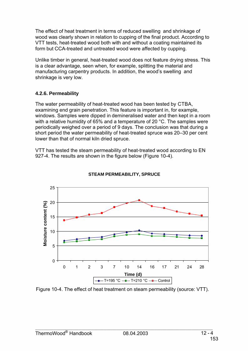
_____________________________________________________________________________________ThermoWood® Handbook 08.04.2003 12 - 4
The effect of heat treatment in terms of reduced swelling and shrinkage ofwood was clearly shown in relation to cupping of the final product. According toVTT tests, heat-treated wood both with and without a coating maintained itsform but CCA-treated and untreated wood were affected by cupping.
Unlike timber in general, heat-treated wood does not feature drying stress. Thisis a clear advantage, seen when, for example, splitting the material andmanufacturing carpentry products. In addition, the wood’s swelling andshrinkage is very low.
4.2.6. Permeability
The water permeability of heat-treated wood has been tested by CTBA,examining end grain penetration. This feature is important in, for example,windows. Samples were dipped in demineralised water and then kept in a roomwith a relative humidity of 65% and a temperature of 20 °C. The samples wereperiodically weighed over a period of 9 days. The conclusion was that during ashort period the water permeability of heat-treated spruce was 20–30 per centlower than that of normal kiln dried spruce.
VTT has tested the steam permeability of heat-treated wood according to EN927-4. The results are shown in the figure below (Figure 10-4).
STEAM PERMEABILITY, SPRUCE
0
5
10
15
20
25
0 1 2 3 7 10 14 16 17 21 24 28
Time (d)
Mo
istu
re c
on
ten
t (%
)
T=195 °C T=210 °C Control
Figure 10-4. The effect of heat treatment on steam permeability (source: VTT).
153

_____________________________________________________________________________________ThermoWood® Handbook 08.04.2003 13 - 4
Water permeability was tested by VTT according to EN 927-5 too. Permeabilitywas determined after the pieces soaked in water for 72 hours with their endsurfaces sealed. Untreated spruce gained a moisture content of 22%, while themoisture contents of wood treated at 195 °C and at 210 °C were about 12% and10%, respectively.
4.2.7. Thermal conductivity
Tests have shown that the thermal conductivity of heat treated wood is reducedby 20–25% when compared with normal untreated softwoods (Taple 2-4).Therefore, ThermoWood is well-suited for applications like outer doors,cladding, windows, and saunas.
According to the VTT tests, the thermal conductivity λ10 of Thermo-D classThermoWood is 0.099 W/(m K). The corresponding value for untreated timberaccording to Section C4 of the Finnish building code is 0.12 W/(m K).
Table 2-4. Thermal conductivityDimension
(mm)Treatment time
at 230 °C(h)
Weight loss(%)
Density(kg/m3)
Moisturecontent
(%)
Thermal conductivityλ10
W/mKPine
25 x 125 3 8,7 525 4,5 0,10725 x 125 5 12,1 474 3,6 0,101
0 505 0,130
Spruce22 x 100 3 5,8 445 5,5 0,09722 x 100 5 9,3 405 4,4 0,082
0 432 0,110
4.2.8. Fire safety
SBI test (EN 13823)
The fire resistance of construction products according to the new Euroclasseswas assessed with a SBI (Single Burning Item) test. In this test, a specimenconsisting of two vertical wings forming a right-angled corner is exposed toflames from a gas burner. The height of the specimen wings is 1.5 m, and theirwidths are 0.5 and 1.0 m. The gas burner placed at the bottom of the cornerstands for a single burning item producing a heat attack with a maximum ofabout 40 kW/m2 on the product tested.
The effect of heat treatment on RHR (Rate of Heat Release) is shown in Figure11-4. The RHR level of heat-treated pine was about 10 kW greater than that ofuntreated pine. The earlier increase of RHR towards the end of the test for thespecimen without heat treatment was due to its smaller thickness. In THR, anincrease of about 15% due to heat treatment was observed. Smoke productionwas roughly doubled. In addition, the ignition time (based on a 5 kW increase in
154

_____________________________________________________________________________________ThermoWood® Handbook 08.04.2003 14 - 4
RHR) was shortened by 30%. In conclusion, heat treatment seems to degradethe fire resistance of wood. This is probably related to release of volatilecompounds during the heat treatment. Although the temperature during thetreatment is not near the ignition temperature of wood, the constituents of woodcan still gradually disintegrate. Consequently, the material properties change,leading to slightly degraded fire resistance.
The number of tests made on ThermoWood has been too low to establish exactvalues. However it can be stated that ThermoWood does not differ significantlyfrom normal wood when it comes to fire safety. ThermoWood is in fire class D.
Table 3-4. Brandsäkra Trähus – Fas 2: SBI test results for wood-basedproductsProduct Thick-
ness(mm)
FIGRA(W/s)
THR600s
(MJ)SMOGRA
(m2/s2)TSP600s
(m2)
Spruce 18 419 18.0 4 36.3Pine (heat-treated) 25 581 32.8 6 62.5Pine 21 321 23.2 3 15.0Pine (with cavity of 22 mm) 21 329 22.3 4 35.5Pine 15 361 26.6 4 17.5Pine 45 587 23.9 12 54.4Spruce (tongue andgroove), vertical
15 452 17.0 3 34.0
Spruce (tongue andgroove), horizontal
15 494 18.4 4 50.0
Plywood (spruce) 12 596 15.8 3 45.0Plywood (pine surface) 12 437 16.6 1 21.0
0
10
20
30
40
50
60
70
80
90
100
0 5 10 15 20 25 30
Time (min)
RHR (kW)
25 mm, heat treated
21 mm, control
RATE OF HEAT RELEASE OF HEAT-TREATED WOOD, PINE
Figure 11-4. Rate of heat release of pine specimens with (2/1) and without (3/1) heattreatment. The specimen thickness was 21 and 25 mm for untreated and heat-treatedpine boards, respectively.
155

_____________________________________________________________________________________ThermoWood® Handbook 08.04.2003 15 - 4
ISO 5660 test
VTT tested the fire resistance properties of ThermoWood were tested accordingto ISO 5660. Heat treatment decreased the ignition time for both pine andspruce samples (Tables 4-4 and 5-4) to half that of untreated wood. With pinesamples, the rate of heat release (RHR) decreased 32%. The heat-treatedspruce samples showed no difference. The production of smoke was small withheat-treated pine and spruce samples in comparison to untreated samples.
Table 4-4. Cone calorimetric test ISO 5660, radiation level 50 kW/ m2, pine.Dimension(mm)
Treatment timeat 230 °C
(h)
Weightloss(%)
Ignition time(s)
RHR (60 s,ave)
(kW/m2)
Smoke
(m2/kg)
50 x 150 5 7.2 12 137 18050 x 150 8 11.8 13 136 4750 x 150 10 14.4 16 160 12050 x 150 0 19–25 150–200 25–100 (200)
Table 5-4. Cone calorimetric test ISO 5660, radiation level 25 kW/m2, spruce.Dimension(mm)
Treatment timeat 230 °C
(h)
Ignition time(s)
RHR (60 s,ave)
(kW/m2)
Smoke
(m2/kg)
50 x 150 8 97 112 2150 x 150 0 193 113 72
Test according to NF B 52501 standard
Tests were carried out by CTBA according to the NF B 52501 standard. Allsamples studied can be classified in Class M3. The tests indicate that the fireresistance of heat-treated wood has to be considered to be the same as that ofuntreated wood of corresponding species.
Test to British Standard, surface spread of flame, BS 476 Part 7
A very limited number of pine and spruce pieces treated at 210 °C were testedin the United Kingdom in accordance with Class 1 surface spread of flamestandard BS 476, Part 7. The results showed that both heat-treated woodspecies attained a class 4 rating. The standard rating for normally treated woodis class 3. The heat-treated wood exceeded the limit for class 3 within the firstminute.
Due to the very small number of test pieces used, it is concluded that the resultscannot be relied upon and more extensive testing is needed using materialtreated at varying temperatures and moisture contents. The BS tests andresults only focused on flame spread speed, and this element is only one part ofthe testing procedure set forth in new EN standards. The heat-treated wood hada clearly shorter ignition time but was better than the normally dried softwoodsin terms of heat and smoke release.
156

_____________________________________________________________________________________ThermoWood® Handbook 08.04.2003 16 - 4
Performance of ThermoWood in relation to the Finnish building codes
The fire safety requirements for structures and the products used in them aredefined in section E1, ‘Structural fire safety in buildings’, 1997, of the NationalBuilding Code of Finland. Structural fire design is performed according tosection B1, ‘Structural safety and loads’, 1998, and section B10, ‘Timberstructures’, 1983, amended 1990, of the National Building Code of Finland.
The test methods and acceptance criteria used for defining the fire reactioncharacteristics of construction materials, construction elements, and devices arepresented in ‘Ympäristöopas 35 1998, Rakennustuotteiden palotekninenhyväksyntä’ (Environment guide 35, 1998; Fire-engineering acceptance ofconstruction products) published by the Ministry of the Environment.
ThermoWood can be regarded as meeting the inflammability Class 2requirements laid out in the publication mentioned above.
157

_____________________________________________________________________________________ThermoWood® Handbook 08.04.2003 17 - 4
4.2.9. Biological durability
VTT carried out three tests to determine the biological durability of heat-treatedtimber. The tests were carried out in accordance with the EN 113 standard, witha 16-week decay time. In addition, a modification of the EN 113 test was used;the test time was accelerated by using smaller test pieces and a shorter decaytime (6 weeks). The third test was made in soil contact according to ENV 807,the test times being 8, 16, 24, and 32 weeks. The test fungi were Coniophoraputeana and Poria placenta since these are regarded as the most common andproblematic fungi.
The results revealed a remarkable ability of the heat-treated wood to resistdecay by brown rot. Against the two fungi, the heat-treated wood showedvarying results. The heat-treated wood required a higher treatment temperaturein order to gain maximum resistance against Poria placentia compared toresistance against Coniophora puteana (Figure 12-4).
The biological resistance test in accordance with EN 113 revealed very gooddurability depending on the treatment temperature and time. In order to treat thewood to meet the class 1 (very durable) requirements, temperatures of over220 °C for 3 hours are required, and to gain class 2 (durable) status, the desiredresult is achieved at about 210 °C (Figure 13-4).
EN-113 DECAY TEST, PINE
20,3
0,0
27,0
0,0
3,9
15,5
0
3
6
9
12
15
18
21
24
27
30
Control Heat treatment 180 °C Heat treatment 230 °C
Wei
gh
t lo
ss (
%)
Coniophora puteana Poria placenta
Figure 12-4. The effect of heat treatment on decay by brown rot in a modifiedEN 113 test. Heat-treated pine, treatment time of 4 hours (source: VTT).
158

_____________________________________________________________________________________ThermoWood® Handbook 08.04.2003 18 - 4
WEIGHT LOSS RATIO / TREATMENT TEMPERATURE, PINE
0
0,1
0,2
0,3
0,4
0,5
0,6
0,7
0,8
0,9
1
100 110 120 130 140 150 160 170 180 190 200 210 220 230 240
Treatment temperature (oC)
Wei
gh
t lo
ss r
atio
Data Very durable Durable Moderately durable Slightly durable Model
Thermo-S Thermo-D
Figure 13-4. The effect of temperature on the weight loss ratio. Pine, treatmenttime of 3 hours. Standard EN 350-1. Natural durability (source: VTT).
Based on the results of the field test (EN 252), it is recommended thatThermoWood not be used in deep ground applications where structuralperformance is required. It is assumed that the indicated loss of strength isdue to a moisture and not caused by any micro-organism. Establishing thereason behind this phenomenon will require further study. However practicalexperience has found that usage of Thermo-D material in ground contact wherestructural performance is not critical and periodic drying of the surfaces isallowed does not cause any significant deterioration to the material. This isespecially apparent when the ground has good drainage and is made up ofsand or shingle.
159

_____________________________________________________________________________________ThermoWood® Handbook 08.04.2003 19 - 4
4.2.10. Resistance to insects
Tests were carried out by the CTBA in France. Longhorn beetles are found insapwood of softwoods. The common furniture beetle (Anobium punctatum)attacks hardwoods in particular. Lyctus Bruneus is found in some hardwoodspecies. The tests showed that ThermoWood was resistant to all three of theabove insects.
Tests made at the University of Kuopio also prove that ThermoWood has goodresistance against longhorn beetles. The test report concludes that beetlesrecognise pine from its terpene emissions to be a suitable place for egg laying.Because terpene emissions from ThermoWood are drastically reduced incomparison to normal wood (see Section 4.2.13), it is expected that beetles willchoose normal wood over ThermoWood, whenever possible. According to thereport, the same phenomena can apply also to termites. However, more testingis needed in this area.
Concerning termites, the problem is currently more apparent in Southernhemisphere locations, but termites have already spread through France andcases have also been reported in countries further north in Europe. Termitesattack buildings from the earth below, avoiding direct sunlight wheneverpossible. Termites will attack both wood and concrete-based materials in theirquest for nutrition. Various measures have been developed to control theproblem; these include polythene membranes being installed in the foundationsof the building. Also, various bituminous paint products are available to sealpossible routes up the building. So far, the test results indicate thatThermoWood is unable to resist attack from termites. However, local tests arerecommended since termite types vary from one region to another. In addition,more research into termite attack is needed.
Figure 14-4. Longhorn beetle and a larva in tested ThermoWood (photos:Jarmo Holopainen, University of Kuopio).
160

_____________________________________________________________________________________ThermoWood® Handbook 08.04.2003 20 - 4
4.2.11. Weather resistance
Weather resistance without surface treatment
RainVarious field tests have been carried out to study the performance ofThermoWood against natural weathering. Material that had been treated at 225°C for 6 hours had about half the moisture content of untreated wood; thisdifference remained after five years’ exposure. The following diagram describesthe moisture content development in natural weather conditions of untreatedwood, ThermoWood, and CCA-treated wood.
As with all materials exposed to the natural environment, surface mould growthcan appear on ThermoWood. Due to bacteria in the air or dirt carried in the rain,fungi can grow on the untreated surface. However, this is on the surface onlyand can be removed by wiping or scraping.
MOISTURE CONTENT OF PINE PANELS DURING NATURAL EXPOSURE
0
5
10
15
20
25
30
35
1.9. 8.9. 15.9. 22.9. 29.9. 6.10. 13.10. 20.10. 27.10. 3.11. 10.11.Date
Moi
stur
e co
nten
t (%
)
Untreated Heat-treated CCA-treted
Figure 15-4. The moisture content of planed pine panels during naturalexposure, 1994 (source: VTT).
161

_____________________________________________________________________________________ThermoWood® Handbook 08.04.2003 21 - 4
Sunlight
Field tests have been conducted to measure ThermoWood’s resistance to theeffect of sunlight (ultraviolet radiation). As with most natural materials,ThermoWood is unable to resist UV radiation. As a result, the colour changesover a period of time from the original brown appearance to a grey weatheredcolour when exposed to direct sunlight. The above diagram shows the changein colour component L over a six-month period. The original ThermoWoodcolour can be preserved with pigmented or UV-protective preservatives.
Although moisture content and swelling and shrinkage due to moisture aregreatly reduced with ThermoWood, the ultraviolet radiation causes smallsurface shakes to occur on uncoated panels when exposed. Levels of surfaceshakes in ThermoWood did show signs of improvement over the untreatedcontrol material when higher temperatures were used (Figure 17-4).
The effect of the heat treatment process on surface shakes and surface fungalgrowth is shown in the following diagram. The shakes were graded as follows:
– size (0–5):0 no shakes1 the shake is seen with the loop, 10 times enlargement2 the shake is just seen by the eye3 the shake is clearly detectable4 shakes where the width is under 1 mm5 large shakes, with width over 1 mm
COLOUR CHANGE ON OUTDOOR EXPOSURE
0
10
20
30
40
50
60
70
80
90
60 70 80 90 100 110 120 130 140 150 160 170 180 190 200 210 220 230 240
Treatment temperature (oC)
Co
lou
r co
mp
on
ent L
Out 11.12.2000 Measurement 6. Jun 2001
Thermo-S Thermo-D
Figure 16-4. The effect of heat treatment temperature on colour changes due tooutdoor exposure. Pine, treatment time 3 hours (source: VTT).
162

_____________________________________________________________________________________ThermoWood® Handbook 08.04.2003 22 - 4
– density (0–5):1 one shake5 the surface is full of shakes
It can be easily concluded from the effects of sunlight (ultraviolet radiation) that,with the application of surface treatments containing pigment ThermoWoodperforms to a good level with respect to surface shakes. Surface treatment istherefore highly recommended.
Weather resistance of surface-treated ThermoWood
Field testing with five years’ outdoor exposure was carried out by VTT to studythe performance of coatings on the surface of ThermoWood and to compare itwith untreated wood. The panels were visually graded in accordance with theISO 4628 series during weathering.
It was found that the moisture content of ThermoWood was about half that ofuntreated wood. The unpigmented or low-build stains and oils protected neitherThermoWood nor untreated wood. These coatings wore away and annual ringsstarted to loosen just as in the panels without coating. The panels coated withthe low-build stains showed a strong tendency to crack.
EFFECT OF TREATMENT TEMPERATURE TO SHAKES AND SURFACE MOULD GROWTH
0
1
2
3
4
5
70 100 120 140 160 180 200 220 240
Treatment temperature (OC)Shakes, density Shakes, size Surface mould
Figure 17-4. Effect of heat treatment temperature on surface shakes and fungalgrowth of pine panels. Heat treatment time of 3 hours. Outdoor exposure time of 6months (source: VTT).
163

_____________________________________________________________________________________ThermoWood® Handbook 08.04.2003 23 - 4
The effect of the ThermoWood substrate on the joinery paint performance wasobserved after five years of exposure. The acid-curable and water-borne acrylicpaint had better performance on the heat-treated panels than on the untreatedpanels. The panels coated with these paints showed no flaking on theThermoWood substrate (Figure 18-4).
The exterior wall paints performed well on both ThermoWood and an untreatedsubstrate, and no significant effects could be found. The results indicated thatthe best coating systems for ThermoWood consisted of the priming oil andsolvent-based alkyd or water-based acrylic topcoat.
0
0,5
1
1,5
2
2,53
3,5
4
4,5
5
Untreated 1 v Heat-treated 1 v Untreated 5 v Heat-treated 5 v
EFFECT OF SUBSTRATE TO PAINT FLAKING
Size Density
Figure 18-4. The effect of substrate on flaking of water-based joinery paint onpine (source: VTT)
164

_____________________________________________________________________________________ThermoWood® Handbook 08.04.2003 24 - 4
4.2.12. Colour
The colour of ThermoWood is affected by the treatment temperature and time.The higher the temperature, the darker the appearance. As with all softwoods,the colour consistency is affected by normal variation due to density and alsodepends on whether springwood or latewood is used. In principle, the colourcan be well replicated in the process and is measured using the L component.The possibility of including measurement of the L component value in processquality control criteria is being studied.
The following picture shows the colours of pine boards treated at differenttemperatures.
EFFECT OF TREATMENT TEMPERATURE TO THE COLOUR COMPONENT L
0
10
20
30
40
50
60
70
80
90
100
60 70 80 90 100 110 120 130 140 150 160 170 180 190 200 210 220 230 240
Treatment temperature (oC)
Co
lou
r co
mp
on
ent
L
Data, sapwood Heartwood Model
Thermo-S Thermo-D
Figure 19-4. The effect of heat treatment temperature on colour component L. Pineboards, treatment time of 3 hours (source: VTT)
165

_____________________________________________________________________________________ThermoWood® Handbook 08.04.2003 25 - 4
4.2.13. Emissions
Emissions were measured from heat-treated pine boards. The samples wereheat-treated at 180 °C and 230 °C for 4 hours. The test was carried out for 7weeks (180 °C) or 8 weeks (230 °C) after the treatment.
The emission measurements were carried out at the VTT chemical technologyunit according to the KET 3300495 test method. Untreated pine showed thelargest quantity of volatile organic compounds, 1486 µg/m2h. The majority ofthis consisted of terpenes, and significant amounts of alpha-pinene, camphene,and limonene were found. Untreated pine contained hexanal and small amountsof furfural and acetic acid too.
The total emission for heat-treated pine treated at 180 °C was 828 µg/m2h. Thesample contained terpenes, furfurals, hexanal, and acetic acid. The totalemission of heat-treated pine treated at 230 °C was the lowest, at 235 µg/m2h.This consisted mostly of acetic acid (110 µg/m2h). This sample contained onlysmall amounts of terpenes. The emissions are presented in Figure 21-4.
Figure 20-4. The colour of heat-treated pine. Treatment temperatures from120 to 220°C at 20°C intervals. Treatment time (photo: VTT).
120 oC 140 oC 160 oC 180 oC 200 oC 220 oC
166

_____________________________________________________________________________________ThermoWood® Handbook 08.04.2003 26 - 4
The smoke-like smell of heat-treated wood most likely comes from furfural.Results of tests have not yet been published concerning the smell. The smellhas been found to disappear over time, and when surface treatments areapplied the smell is removed.
VOLATILE ORGANIC COMPOUNDS FROM PINE SAMPLES
5 2 43
674
232 191
29 8 3210 0 24 0 1
1486
312
78153
828
110
235
0
200
400
600
800
1000
1200
1400
1600
Acetic acid Furfural Hexanal Alpha-pinene
Camphene Limonene TVOC
VO
C(u
g/m
2 h)
Untreated 180 °C 4 h 230 °C 4 h
Figure 21-4. Volatile organic compounds from pine samples, age 2 months(source: VTT).
167

_______________________________________________________________________ThermoWood® Handbook 08.04.2003 1 - 5
5. Working with ThermoWood in industrial plants
5.1. General
In principle, the handling of ThermoWood requires a bit more care than that ofnormal kiln dried softwood, it is more susceptible to mechanical damage when itundergoes further processing. Similar handling procedures as when workingwith hardwoods is recommended. Sharp tools are highly recommended whenworking with ThermoWood. As when working with all wood materials pre-conditioning of the moisture content in relation to the sites relative humidityimproves the results.
5.2. Sawing
The internal stresses of wood are released during an appropriateheat-treatment process, and therefore no distortion occurs after the pieces aresplit.
Since ThermoWood does not contain resin, the power requirement for cuttingequipment is reduced and the life span of the equipment is significantlyincreased.
Sawing of ThermoWood does not differ from sawing of untreated wood. Whereknots are concerned, no special tearing is distinguishable compared withnormal kiln dried softwood. The only problem encountered thus far in sawing isthe wood dust. Since ThermoWood is very dry, the wood dust is very fine andspreads easily to the environment.
For the reasons mentioned above, special attention has to be paid to theoperation of an appropriate dust extraction system. The system must bewell-sealed and sufficiently effective.
Since gap-toothed saw blades can cause chipping in the edges of ThermoWoodpieces, fine-toothed blades are recommended. Blades with carbide or similartips extend the saw blade’s maintenance and sharpening intervals.
5.3. Planing
As a result of the ThermoWood heat-treatment process, cupping can occur inthe pieces although, as referred to in the section discussing stretching andcontracting of wood due to moisture, post-treatment movement is very limited.As a result of cupping, it is recommended that when planing timber pieceswhich have not been re-cut before planing, the infeed roller be changed to onethat has two narrow wheels so the contact with the piece is at the outer edgesof the convex face - see figure below. Alternatively, a single narrow wheel couldbe used so that the piece is turned with the convex face down. Both methodsenable a flat surface to be formed as the piece proceeds through the planer,
168

_______________________________________________________________________ThermoWood® Handbook 08.04.2003 2 - 5
thus reducing the risk of surface cracking and enabling higher infeed rollerpressure.
Figure 1-5. Recommended infeed rollers to avoid cracking of the boards.
In order to avoid cracking of the boards, it is advisable to make a flat basesurface with a planer or band saw first before profiling. Seinäjoki Polytechnichas performed a series of tests concerning the planing of ThermoWood.Several cutter angles were tested. In these tests, all angles worked well and thesurface quality was good too. The best results are achieved with carbide-tippedcutters, as when working with hard types of wood.
It has also been reported that ThermoWood pieces cause less friction duringinfeed and enable a smoother planing process. This is due to the lack of resin inthe wood. On the other hand, since the strength of the material is lower, theinfeed rollers must be adjusted to lower pressures to avoid cracking of theboards. Good results have been achieved by replacing the rollers as shown inthe picture above. In some planing lines, the speed must also be decreased -for example, in one case from 80 m/min to 60 m/min and in another case from100 m/min to 80 m/min. If the infeed speed is decreased, the rotation speed ofthe cutters must be decreased accordingly. Too high a ratio of rotation speed toinfeed speed can cause the wood surface to burn.
The pressure of rollers, as well as speed and other parameters, is highlydependent on the planing line and machinery. Therefore, no general values canbe cited. In the planing of ThermoWood, the parameters are set separately foreach planing machine.
It has been reported that machines (cutters and other surfaces) are very cleanafter working with ThermoWood due to the lack of resin in the wood.ThermoWood can even clean the machines of the resin-containing dust fromprevious production lots.
NO OK OK
169

_______________________________________________________________________ThermoWood® Handbook 08.04.2003 3 - 5
To achieve the best possible planing results and minimise loosening of thewood’s annual rings, it is recommended to use material that has been cut asparallel to the grain as possible. In addition, considering the best face of theboard when planing improves the result. There is a close connection betweenthe infeed roller type and pressure, the grain direction, cupping, cuttersharpness, and throughput speed. When these variables are carefullyharmonised, the best results are achieved.
5.4. Milling
Milling tests were performed by VTT using a CNC machine. In order to achievea good surface quality – especially in milling – the cutters must be sharp;otherwise tearing will occur. A higher level of tearing was observed when thewood was milled across the grain. The greatest problems with tearing occurredat the start of the milling and at the end, when the cutter comes out of the wood.Milling heat-treated wood can be regarded as similar to working with hard, brittlehardwoods.
It was found that the working order has an influence on the working propertiesof wood. The best results were achieved when there was enough solid woodmaterial behind the cutter. Therefore, working must be planned carefullybeforehand.
The cutters wear more slowly than with normal wood.
5.5. Sanding
General working is equivalent to working with untreated wood; no problemshave been reported. In many cases there is no need for sanding, asThermoWood has a good surface quality after planing or milling.
The dust generated has a small particle size, which is to be taken into accountin planning dust extraction. On the other hand, it is a light and dry dust whichdoes not impose any special requirements for dust extraction systems. As inworking with any type of wood dust, there is a risk of dust explosion in certainconditions.
5.6. Industrial gluing and jointing
GluingIn gluing ThermoWood, the adhesive manufacturer’s specific instructions mustalways be followed. Appendix 1 presents the recommendations of onemanufacturer.
VTT has studied the glueability of heat-treated wood with 1- and 2-componentPVAc adhesives, 1- and 2-component polyurethane adhesives (PU), resorsinol-phenol adhesives (RF), and emulsion-polymer-isocyanate adhesives (EPI). Theglueability test was carried out in accordance with DIN 68603. The strength of
170

_______________________________________________________________________ThermoWood® Handbook 08.04.2003 4 - 5
the glue line was determined in accordance with EN 392 (block shear test). Themoisture durability was determined in accordance with the delamination test EN302-2. The penetration of the adhesive into ThermoWood was studied with amicroscope.
The glueability is dependent on the heat-treatment class. The shear strength ofthe glue line decreases with increased treatment temperatures. This is due tochange in the strength properties of the material. It also explains the high woodfailure percentages (90–100%). The glue line broke up from the wood, not fromthe adhesive.
The penetration of the EPI adhesive into heat-treated wood was high, which canhave some effect on the strength values. The EPI adhesive is mildly alkaline,and also a long cold pressing time of several hours can improve the penetrationof the adhesive.
Experiences in one glulam beam plant using heat-treated pine as raw materialwere good. Both MUF and RF adhesives worked well. Normal productionparameters (pressing time, pressure, etc.) were used. Finger joints were madewith MUF adhesive.
With regard to gluing, the results are better with wood treated at lowertemperatures. In working with PVAc adhesives, the water content in adhesiveshould be minimised. Since the heat-treatment process changes wood'swater-bonding capability, the absorption rate of adhesive and water into thewood is decreased.
Some PVAc adhesives can cause problems in the form of significantlyprolonged drying times due to the requirement for the water to penetrate thewood, i.e,. the curing of the adhesive is based on the absorption of water intothe wood. Chemically curing adhesives have a normal drying time.
All tests carried out with PU adhesives have been successful, but it must bekept in mind that the curing reaction of PU requires water. The water can beabsorbed from either the wood or the surrounding air. The required amount ofmoisture is dependent on the adhesive, but if both wood and air are very dry,there exists a chance of unsuccessful gluing.
As always in wood gluing operations, attention has to be paid to correct workingconditions when working with ThermoWood. These include wood temperature,the wood’s moisture content, and surface cleanliness.
Finger jointingThe Seinäjoki Institute of Technology has performed finger-jointing tests with
– Four different adhesives: MUF, PVAc, 2 x PU;– Three open times: 15 s, 30 s, and 60 s;– Six pressures between 1.3 and 7.8 N/mm2 (corresponding pressure in
the glue line 0.2–1.2 Mpa).The joints were firm with all tested parameters. According to the tests, themaximum pressure was 22 N/mm2, which is over ten times the pressure that afirm glue line needs.
171

_______________________________________________________________________ThermoWood® Handbook 08.04.2003 5 - 5
Carbide-tipped cutters are recommended for machining the fingers for thejoints. It is also recommended that adhesive be applied to both ends in order toensure a firm joint.
Since working with blunt cutters can easily lead to chipping of the finger joints,sharp cutters are essential. It was also found that using slightly lower speedscaused less chipping of the joint fingers.
Various finger jointing methods have been tested successfully.Industrial tests have shown that due to the cupping of ThermoWood caused bythe treatment process, pre-planing of the material before finger jointing yields amuch better result and allows for higher throughput speed and fewer stoppages.In addition, pre-planing improves the performance of machine vision devices inautomated cutting lines.
Mechanical jointsSplitting of the material can be avoided by using self-tapping and countersinkingscrews or by pre-drilling the holes.
Figure 2-5. Self-tapping screw.
The hardware must be selected according to the application. For outdoorapplications and similar conditions, stainless steel hardware is recommended.
Good jointing results are achieved with pneumatic nailers. Attention must bepaid to the correct pressure and the nailer’s drive length.
The decreased splitting strength and also slightly decreased bending strength ofthe material is to be taken into account when designing the joints. It isrecommended that the critical joints and the details of the products be testedbefore production. Big knots (especially with respect to the size of thecross-section) are always a risk factor with ThermoWood because the woodlacks the resinous substances that in normal wood act as an adhesive betweenknot and the surrounding area.
The better dimensional stability of ThermoWood allows joints to be designedwith smaller tolerances than joints using normal wood.
172

_______________________________________________________________________ThermoWood® Handbook 08.04.2003 6 - 5
5.7. Industrial surface treatment
In terms of its material properties, ThermoWood is comparable to untreatedwood as a substrate for coatings. Since the resins have come out of theheat-treated timber, the risk of resin flow from the surroundings of the knots tothe paint surface is reduced. Therefore, knot sealer is not required beforesurface treatment.
In the application of surface treatment products to ThermoWood, the paintmanufacturer’s specific instructions must always be followed. Appendix 2presents manufacturers' recommendations.
Better surface adhesion for ThermoWood occurs with a smooth planed finish, orif springwood is brushed. Otherwise, small splinters are easily detached fromthe surface sawn with a bandsaw. Surfaces must be clean, as with any othermaterial.
Oil-based substances work as with normal wood. When one works withwater-based substances, it has to be taken into account that ThermoWood hasa lower water-absorption capacity than normal wood. However, no problemshave been reported. Water-based treatment products seem to work well, whenthey dry slowly and have enough time to penetrate the wood. UV-hardeningpaints and lacquers have shown good results, as have oils and waxes.
We are still awaiting the results of outdoor tests of Dyrup/Gori paints. Inaddition, a comprehensive series of water-based industrial application systemswith varying colours has been tested. Dyrup has also carried out acceleratedweathering tests on ThermoWood with one surface coating withoutimpregnation as well as normally impregnated softwood with a surface coating.These samples have already been in the accelerated weathering test chamberfor 2000 hours, and they show no difference in performance. The test willcontinue for a further 2000 hours to see if any differences will appear.
The tests have shown that there is a larger consumption of primer, but apartfrom this there are no other significant findings other than the excellent surfaceresults and aesthetic appearance gained with ThermoWood. Paint productswhich can already be recommend for ThermoWood are mentioned in theappendices.
As always in surface treatment operations, working with ThermoWood requiresattention to be paid to correct working conditions, such as appropriate woodtemperature, moisture content, and surface cleanliness.
173

_______________________________________________________________________ThermoWood® Handbook 08.04.2003 7 - 5
5.8. Fire protection
ThermoWood (made of pine) has shown good results in preliminary fireretardant tests. They have been carried out using Moelven Fireguard IV andInjecta F exterior fire retardants. For both substances, the uptake is higher thanwith normal untreated wood, the reason for that being the lack of resin inThermoWood. Further testing will be carried out.
5.9. Practical experiences from a Finnish joinery company
The following results are comments by a technical engineer at a Finnishpurpose-made joinery company. The company has been working withThermoWood successfully for several years.
Raw materialThe company has worked with heat-treated pine, spruce, aspen, and birch.• Aspen: the results have been good but availability is poor• Birch: good results and better availability• Pine and spruce: small fresh-knotted material good; larger dead knots a
problem; availability good• In most cases, they purchase the timber one dimension module larger than
is usual, to ensure sufficient allowance, the problem being distortions due tothe heat-treatment process
Sawing• Normal machines/tools work but must be sharp• No significant problems with split or cross-cut sawing• No internal stresses are present in heat-treated wood• The wood structure is more like that of hardwood, and tools wear
accordingly
Planing• The company uses normal machines/cutters• The machines and cutters must be well maintained and sharp• The working result can be affected by cutter techniques• The cutters wear down in the same way as when working with hardwoods• Aspen, birch, and pine are very good to work with• Spruce needs slightly more attention, but the results can be good
Milling• Risk of breaking when tennoning• The sharpness of the cutters, correct cutting angles, and cutting speed affect
the result
Sanding• No significant problems when using sanding machines• Paper wears at a similar rate as when sanding hardwood
174

_______________________________________________________________________ThermoWood® Handbook 08.04.2003 8 - 5
Nailing and screwing• A pneumatic nailer is best for nailing• For nailing with a hammer, pre-drilled holes are recommended• For screwing, pre-drilled holes are required• Handle the wood as with hardwood
Gluing• Adhesive drying and pressing time notably longer• Several adhesive options• Drying time can be shortened with higher temperatures
Surface treatment• Normal methods are suitable• Without pigment, the colour becomes light grey after a period• Good adhesion of surface treatment• The material is a good base for water-based paints
Storing the raw material• Do not store where exposed to snow or rain• Protect the packages with paper wrapping or store in a warehouse• No need for special warehouse conditions• Conditioning suggested before use
5.10. Health and safety
There is no major difference in health and safety considerations forThermoWood as compared to normal softwood or hardwood species. There arestill two detectable differences: the smell of the material and the dust generatedin the processing of ThermoWood.
ThermoWood has a smoke-like smell, which likely comes from chemicalcompounds called furfurals. Although the smell is easily detectable by thehuman senses and seems stronger than that of untreated wood, the tests showopposite results. As mentioned in section 4.2.13, the volatile organic compound(VOC) emissions from ThermoWood are only a fraction of those of normal pine.
There have been no toxic or harmful components found in ThermoWood. It haseven been tested as a bone substitute material. In any case, if a wood splinterpenetrates the skin, it should be removed as soon as possible, as with normalwood.
The Tampere University of Technology has studied, in co-operation with theLappeenranta Regional Institute of Occupational Health, the health effects ofworking with ThermoWood. ThermoWood dust has a slightly smaller particlesize than normal softwoods. It is comparable to MDF (although the density islower) or hardwood dust. No correlation to a risk of cancer was observed whenstudying ThermoWood dust.
175

_______________________________________________________________________ThermoWood® Handbook 08.04.2003 9 - 5
In processing ThermoWood, special attention has to be paid to the operation ofan appropriate dust extraction system. The system must be well-sealed andsufficiently effective.
The standard dust extraction systems in industrial environments meet thisrequirement without requiring special adjustments. Since the dust is fine, light,and resin-free, it is easily sucked into the extraction piping. Persons who areexposed to the dust on a daily basis should protect themselves with, forexample, dust masks.
When gluing or painting ThermoWood, always follow the paint or adhesivemanufacturers' specific health and safety instructions.
176

_______________________________________________________________ThermoWood® Handbook 08.04.2003 1 - 6
6. Use of ThermoWood
6.1. Working
Sawing ThermoWood is like sawing untreated wood. Where knots areconcerned, no special tearing distinct from that of normal wood has beennoticed.
Working with all kinds of hand tools - for example, in sanding, drilling, andmilling - is easy. Sanding gives excellent results, and drilling – even of knots - iseasy.
Because of the brittleness of ThermoWood, attention must be paid to itshandling. Dropping the pieces may damage the edges. Long pieces shouldn’tbe lifted by only one end.
The only problem in working with hand tools is the dust. Because ThermoWoodis normally very dry, the wood dust is fine and spreads easily to theenvironment. The best solution would be an efficient dust extraction system, butthat is often not possible; therefore, the use of a dust mask in these cases ishighly recommended.
6.2. Joining
NailingA pneumatic nailer is recommended for nailing ThermoWood. The pressuremust be tested in order to adjust the nail penetration - see the figure below. Thebest result is achieved by using a small pneumatic nailer with adjustable drivedepth.
The use of a normal hammer increases the risk of splitting when the hammerhits the wood. The final 2 to 3 mm of the nail length should be hit with a punch.
Figure 1-6. Drawing showing the correct nail penetration depth. The correctpenetration depth is about 1 mm below the surface of the piece.
177

_______________________________________________________________ThermoWood® Handbook 08.04.2003 2 - 6
Nail typesTo reduce the risk of discoloration of the wood, stainless steel nails should beused. However, if a pneumatic nailer is used, galvanised nails are suitable sincein this method no metal-to-metal contact occurs and breaks the galvanisedsurface. Galvanised nails are also best if a topcoat is applied to the cladding. Toprevent splitting, small oval-head nails would be the most suitable.
Figure 2-6. Some suitable nail types, the most recommended being the smalloval-head nail shown at the top.
ScrewingPre-drilling (close to ends) and countersinking is essential, just as when workingwith hardwood, MDF, or other brittle materials. Stainless steels screws withcountersunk heads are most suitable in outdoor usage or other humidenvironments. For the best holding strength, coarse-thread screws performbest. Self-tapping screws can be used in ThermoWood without pre-drilling.
Figure 3-6. Self-tapping screw.
6.3. Gluing on-site
In gluing ThermoWood, the adhesive manufacturer's instructions must alwaysbe followed. Appendix 1 presents recommendations from one manufacturer.
Where gluing is concerned, the results are better with wood treated at lowertemperatures, such as the ThermoWood class for interior applications. Inassembly, high compression pressures cannot be used, as the material is morebrittle than untreated wood.
Heat-treated wood absorbs water and water-based adhesives, such as PVAc,slowly. That is why longer pressing times than normal are needed when usingwater-based adhesives. Some PVAc adhesives can cause problems in the form
178

_______________________________________________________________ThermoWood® Handbook 08.04.2003 3 - 6
of significantly prolonged drying times due to the requirement for the water to beabsorbed by the wood, i.e., the curing of the adhesive depends on the wood’sabsorption of water. When one works with PVAc adhesives, the water content inadhesive should be minimised.
It is reported that PU (polyurethane) adhesives work well with ThermoWood.Although all tests carried out with PU adhesives have been successful, it mustbe kept in mind that the curing reaction of PU requires water. The water can beabsorbed from either the wood or the surrounding air. The required amount ofmoisture is dependent on the adhesive, but if both wood and air are very dry,there exists the possibility of unsuccessful gluing.
Chemically curing adhesives, such as MUF and RF resins, allow drying timesand other gluing parameters to remain unchanged.
As always in wood gluing operations, attention has to be paid to correct workingconditions when working with ThermoWood; these include wood temperature,moisture content, and surface cleanliness.
6.4. Surface treatment
As a general rule, ThermoWood® is analogous to normal wood as a base forsurface treatment. However, the ThermoWood® process affects someproperties related to surface treatment. The decreased equilibrium moisturecontent of the wood improves its stability, which in turn reduces the crackingand flaking of the surface coating in changing environmental conditions. Water-based surface treatment products require slightly longer drying/absorbing timessince ThermoWood's water-absorbing capacity has decreased along with theequilibrium moisture content. Since the high temperature of the treatmentprocess removes the resin from the wood, knots do not necessarily requirespecial procedures during the surface treatment.
Without surface treatment, the surface of ThermoWood acts like the surface ofuntreated wood. Due to the UV radiation in sunlight, the surface turns grey,microscopic cracks are formed on the surface, and the surface ages to anantique appearance over time. To retain the original colour and surface quality,surface treatment is recommended. If priming paint is to be applied manually,the best surface treatment results are achieved by using oil-based paints. If thematerial has been delivered to the site primed, the corresponding topcoats canbe applied without problems manually with a brush using either oil- or water-based paint, depending on the primer type and the manufacturer'srecommendations.
To prevent colour changes, the treatment substance should contain pigment. Inmost cases, the surface treatment is done with a transparent wood preservativewith brown pigment added to match the original ThermoWood colour as closelyas possible. This usually results in a slightly darker appearance. Differentsurface treatments have different maintenance intervals. The more pigmentused, the longer the maintenance interval. If opaque paint is used, the originalThermoWood colour and features are obscured.
179

_______________________________________________________________ThermoWood® Handbook 08.04.2003 4 - 6
It is recommended that the material be treated once before installation, with thefinishing treatment applied after the installation. If vegetable-oil-based surfacetreatment products are used for applications exposed to the elements, it isrecommended that products containing anti-mould agents be used.
In carrying out surface treatment of ThermoWood, the instructions of thesurface treatment product manufacturers must always be followed.
6.5. ThermoWood in sauna benches
Due to its highly hygienic nature, colour, and decreased thermal conductivity,ThermoWood® is well suited for sauna benches. However, fast wetting anddrying cycles in a high-temperature environment can cause benches to split atthe ends. To avoid this, it is recommended to seal the ends with oil, wax, orvarnish.
6.6. Product maintenance
Different surface treatments have different maintenance intervals. The morepigment used, the longer the maintenance interval. However, if opaque paint isused, the original ThermoWood colour and appearance are obscured. As a ruleof thumb, pigment-containing transparent surface treatment has a doubled ortripled maintenance interval in comparison to a treatment product withoutpigment. Furthermore, opaque paints have maintenance intervals twice as longas pigment-containing transparent paints.
The environment and climate have a crucial effect on the life span of a surfacetreatment. UV radiation from sunlight and moisture are major obstacles thatmust be surmounted by surface treatment. These factors mean that, forexample, the south side of a building needs maintenance more often than thenorth side. Moreover, buildings in a continental climate have a longer life spanfor their surface treatment than buildings by the sea.
To ensure maximum performance of coating and avoid damages, the surfacesshould be cleaned and checked annually, with any defects repairedimmediately.Always refer to the paint manufacturer’s specific maintenance instructions, ifavailable.
6.7. Health and safety
There is no significant difference between the health and safety considerationsfor ThermoWood and those for normal softwood or hardwood species. Thereare still two detectable differences: the smell of the material and the dustresulting from the processing of ThermoWood.
ThermoWood has a smoke-like smell, which likely comes from chemicalcompounds called furfurals. Although the human senses can easily recognise
180

_______________________________________________________________ThermoWood® Handbook 08.04.2003 5 - 6
the smell and it appears stronger than that of untreated wood, the volatileorganic compound (VOC) emissions from ThermoWood are only a fraction ofthose of normal pine.
There have been no toxic or harmful components found in ThermoWood. It haseven been tested as a bone substitute material. However, if a wood splinterpenetrates the skin, it should be removed as soon as possible, just as withnormal wood.
ThermoWood dust has a smaller particle size than dust from normal softwoods.It is comparable to MDF (although the density is lower) or hardwood dust. Thedust can cause problems for people suffering from asthma. For the reasonsmentioned above, one has to pay special attention to the utilisation of anappropriate dust extraction system.
If the dust extraction system is not sufficient, a dust mask must be used.
When gluing or painting ThermoWood, always follow the paint or adhesivemanufacturers' specific health and safety instructions.
181

_______________________________________________________________ThermoWood® Handbook 08.04.2003 1 - 7
7. Handling and storage of ThermoWood
7.1. General
ThermoWood must be stored in a dry place. Since no special storagetemperature is required, cold warehouses are among the suitable locations. Theproduct should be carefully covered or stored in a covered warehouse.
The packages should be stored horizontally with a sufficient number of supportsunder the packages to prevent the lowest boards from distortion. The packagesmust be stored so they do not touch the ground
Before use or further working where gluing and/or surface treatment is takingplace, the material must be allowed sufficient time for conditioning to thesuitable MC and temperature as per the manufacturer’s recommendations.When ThermoWood packages are lifted with a crane, forklift, or similar device,the forks should be adjusted to their maximum distance apart because of theslightly decreased bending strength of the material.
The bundles are not to be opened before use.
7.2. Handling of residual and discarded products
ThermoWood is a natural wood product without any chemicals added to it.When not glued or painted, ThermoWood waste can be handled like any otheruntreated wood waste.
ThermoWood can be burned. It produces about 30% less energy than untreatedwood because the majority of the energy containing extractives has alreadybeen removed in the heat-treatment process. ThermoWood burns with asmaller flame and produces less smoke and harmful gases because of thefactors mentioned above. Flammability is normally better due to the lowerequilibrium moisture content of the wood; i.e., the wood is drier. There is nosignificant difference between the compounds in smoke from ThermoWood andthose in the smoke from normal wood.
Pelletising and briquetting is possible, if a mixture with normal sawdust is used.Due to the dryness and lack of resin with ThermoWood, normal softwood dust isrequired to hold the pellets together.
ThermoWood can be taken to the landfill. It is non-toxic.
182

_______________________________________________________________ThermoWood® Handbook 08.04.2003 1 - 8
8. Frequently asked questions and answers
1. Can you heat-treat different wood species?The manufacturing and use of both softwood and hardwood species,such as pine, spruce, birch, and aspen, has produced highly positiveresults.
2. How long does ThermoWood last?Although evidence from long-term experience of the use of ThermoWoodis not yet available, tests have shown that the material’s resistance todecay is far superior to that of untreated softwoods and equal that ofmany tropical hardwoods. In addition, good dimensional stabilityincreases the wood’s life span. The service life can be affected by manyfactors other than resistance to decay - such as the level of maintenance,especially for the surface treatment, and general wear and tear.Following the guidelines presented in this handbook should also assist inlengthening the life expectancy of the product.
3. What are the guarantees?Although there are no specific guarantees for the product, testsconducted by several independent research institutes have shownconsistently positive results where durability is concerned.
4. Why is ThermoWood so durable despite the resin andextractives having boiled away?
The durability of ThermoWood is based on the changes in chemicalcompounds in the wood. Wood's hemicellulose (sugar compound) isdegraded, leaving no nutritive matter for fungi.
5. Are any chemicals added as part of the process?No chemical additives are used in the ThermoWood production process;only energy and steam are required. Hence, ThermoWood can beutilised/discarded like normal wood after its life span is complete.
6. Can ThermoWood be used in contact with the ground?Results have shown that even in ground contact ThermoWood does notdecay; however, when constantly immersed in water or making soilcontact, it loses its strength properties due to certain chemical reactions.The mechanisms are yet unknown, and further research is needed. Thisis why it is recommended that ThermoWood not be used in continuousdirect contact with moist soil.
7. What kind of surface treatment is needed for outdooruse?
ThermoWood can be used outdoors without surface treatment, but thiswill lead to greying and shaking of the surface, as with normal wood. Thetype of surface treatment desired varies with the end use application.Products that require the original ThermoWood appearance should betreated with transparent paint containing some brown pigment.
183

_______________________________________________________________ThermoWood® Handbook 08.04.2003 2 - 8
8. Is the smell of ThermoWood harmful?Tests have shown that there are no harmful emissions fromThermoWood, but the smell might not be appreciated by everyone.
9. Does the smell disappear?If surface treatment is applied to a product made of ThermoWood, thesmell will disappear and not return. If ThermoWood is used withoutsurface treatment, the smell will gradually dissipate until reaching a levelwhere it is no longer noticed except when smelled from a very closedistance.
10. Can ThermoWood be glued?Practical experience has shown that gluing of ThermoWood is possiblewith all adhesive types. If water-based adhesives, such as PVAcadhesive, are used, the decreased water absorption capacity ofThermoWood must be taken into account where drying time isconcerned. In the case of PVAc in particular, the adhesivemanufacturer’s specific instructions for the product and its use withThermoWood must always be followed.
11. Can ThermoWood be used in load-bearing structures?So far, most of the strength tests have been carried out with small,defect-free test pieces. Further testing is required with larger test piecesand with varying numbers of knots and different knot types. Due toinsufficient information, we recommend that ThermoWood NOT be usedstructurally for load-bearing purposes for the time being.
184

_______________________________________________________________ThermoWood® handbook 08.04.2003 1-References
References
Alén, R., Puun rakenne ja kemiallinen koostumus, luentomuistiinpanotluentosarjasta, Jyväskylän yliopisto, Kemian laitos, Soveltava kemia, Jyväskylä,1998.
Brunow, G., Lundquist, K. ja Gellerstedt, G., Ligniini. Kirjassa: Sjöström, E. jaAlén, R., (toim.), Analythical methods in wood chemistry, pulping, andpapermaking, Springer-Verlag, Berliini, Saksa, 1999, s. 77-92.
Fengel, D. ja Wegener, G., Wood - Chemistry, Ultrastructure, Reactions, Walterde Gruyter, Berliini, Saksa, 1989, s. 26-344.
Funaoka, M., Kako, T. ja Abe, I., Condenasation of lignin during heating ofwood, Wood Sci. Technol., 24(1990)277-288.
Hietala, S., Maunu, S.L., Sundholm, F., Jämsä, S. and Viitaniemi, P. Structureof Thermally Modified Wood Studied by Liquid State NMR Measurements.Holzforschung, submitted, 2001.
Ilvessalo-Pfäffli, M.-S., Puun rakenne, kirjassa: Puukemia (toim. W.Jensen),Teknillisten Tieteiden Akatemia, suomi, 1977, s. 7-81.
Juppi, T., Työilman puupölypitoisuus lämpökäsiteltyä ja muulla tavalla kuivattuapuuta hiottaessa, Projekti- ja seminaarityö, Mikkelin ammattikorkeakoulu, 1999,24 s.
Jämsä, S., Ahola, P., Viitaniemi, P. 2000. 2000. Long-term natural weatheringof coated ThermoWood. Pigment & Resin Technology . Vol. 29 (2000) No: 2,68 - 74.
Jämsä, S., Ahola, P., Viitaniemi, P. 1999. Performance of coated heat-treatedwood. Surface Coatings International JOCCA Journal of the oil & colourchemists' association. Vol. 82 (1999) No: 6, 297 - 300.
Jämsä, S., Ahola, P., Viitaniemi, P. 1988. Moisture behaviour of coatedthermowood. 5th Conference on Wood - Coatings - Moisture. VTT, Espoo, 20march, 1998.
Jämsä, S., Ahola, P., Viitaniemi, P. 1988. Performance of the coatedThermowood. Advances in exterior wood coatings and CEN standardisation.Brussels, BE, 19 - 21 Oct. 1998. Paint Research Association, Teddington. 9 p.Paper : 22.
Jämsä, S., Viitaniemi, P. 1998. Heat treatment of wood. Better durabilitywithout chemicals Nordiske Trebeskyttelsedager. Lofoten, NO, 13 - 16 Aug.1998. Nordiske Trebeskyttelseråd (1998), p. 47 - 51.
185

_______________________________________________________________ThermoWood® handbook 08.04.2003 2-References
Kotilainen, R., Chemical changes in wood during heating at 150-260 ºC,Väitöskirja, Jyväskylän yliopisto, Kemian laitos, Soveltava kemia, Jyväskylä,2000.
Kotilainen, R., Alén, R., Puhakka, I. ja Peltola, P., A rapid spectrometric /PLSmethod for evaluating rotting test results from heat-treated wood products,posteri, CAC-2000, 7th Inernational Conference on chemometrics in Analyticalchemistry, Antwerpen, Belgia, 16.-20.10. 2000.
Kärkkäinen, T., Männyn lämpökäsittelyssä haihtuvien reaktiotuotteidenkoostumus ja niiden poistaminen kondenssivesistä, Erikoistyö, Jyväskylänyliopisto, Kemian laitos, Soveltava kemia, Jyväskylä, 2000.
Liitiä,T., Maunu, S.-L. ja Hortling, B., Solid-state NMR studies of residual ligninand its association with carbohydrates, J. Pulp Paper Sci., 16(2000)323-330.
Mali, J., Koskela, K. ja Kainulainen, K., Stellac®Wood- prosessillalämpökäsitellyn puun ominaisuudet, Tutkimusraportti, Valtion teknillinentutkimuskeskus, Rakennustekniikka, Puutekniikka, Espoo, 2000.
Marttinen, J., Lämpökäsitellyn puun laadunvalvontajärjestelmänjatkokehittäminen, insinöörityö, Mikkelin ammattikorkeakoulu, Tekniikankoulutusyksikkö, metsätalouden ja puutekniikan koulutusohjelma,puutuotetekniikan suuntautumisvaihtoehto, Mikkeli, 2001.
Mikkola, E. ja Hakkarainen, T., Effect of thermal treatment on reaction to fireclassification of wood, Tutkimusraportti RTE896/01, Valtion teknillinentutkimuskeskus, Rakennustekniikka, Espoo, 2001.
Myllynen, T., Lämpökäsitellyn puun höyläystesti, tutkimusseloste,Ympäristötekniikan instituutti, Mikkeli, 2000.
Möller, K. ja Otranen L., Puun lämpökäsittely, Ympäristötekniikan instituutinjulkaisuja 4, Ympäristötekniikan instituutti, Mikkeli, 1999.
Nuopponen, M., Vuorinen, T., Jämsä, S., Viitaniemi, P. Effects of heat treatmenton the behaviour of extractives in softwood. Wood Science and Technology,submitted 2001.
Peltomäki, J., Lämpökäsitellyn puun ulkokenttätestaus eri maalisysteemeillä,tutkimusseloste, Teknos Winter Oy, 1998.
Pouru, M., Peräkorpi, K. ja Lehtonen, J., Testausseloste 00/16, Mikkelinammattikorkeakoulu, ympäristölaboratorio, Mikkeli, 2000.
Puhakka, I., Sulfaattimassan jäännösligniinin kemiallinen rakenne, Pro gradu,Jyväskylän yliopisto, Kemian laitos, Soveltava kemia, Jyväskylä, 2001.
Puhakka, I. ja Peltola, P., Spektroskopisten mittausten ja kaasunläpäisynsoveltuvuus lämpökäsitellyn puun laadunvalvontaan ja prosessinohjaukseen,
186

_______________________________________________________________ThermoWood® handbook 08.04.2003 3-References
Erikoistyö, Jyväskylän yliopisto, Kemian laitos, Soveltavan kemian osasto,Jyväskylä, 2000.
Rusche, H., Die Thermisch Zersetzung von Holz bei Temperaturen bis 200 ºC-Erste Mitteilung: Festigkeitseigenshaften von Trockenem Holz NachThermischer Behandlung, Holz Roh Werkst, 31(1973)273-281.
Sailer, M., Rapp, A.O. ja Leithoff, H., Improved resistance of Scots pine andspruce by application of an oil-heat treatment, 31st Annual Meeting of theinternational research group on wood preservation, Kona, Hawaii, USA, 14.-19.2000, IRG/WP 00-40162, s. 3-17.
Sakakibara, A., Chemistry of lignin. Kirjassa: Hon, D.N.-S. ja Shiraishi, N.,(toim.), Wood and Cellulosic Chemistry, Marcel Dekker, New York, USA, 1991,s. 113-120.
Shafizadeh, F., The chemistry of pyrolysis and combustion. Kirjassa: Comstock,M.J., (toim.), Chemistry of solid wood, American chemical society, WashingtonD.C., USA, 1984, s. 489-529.
Sivonen, H., Maunu, S.L., Sundholm, F., Jämsä, S. and Viitaniemi, P. MagneticResonance Studies of Thermally Modified Wood. Holzforschung, submitted2001.
Sjöström, E., Wood Chemistry- Fundamentals and Applications, 2. painos,Academic Press, San Diego, USA, 1993, 293 s.
Syrjänen, T. ja Kangas, E., Heat treated timber in Finland, 31st Annual Meetingof the international research group on wood preservation, Kona, Hawaii, USA,14.-19.2000, IRG/WP 00-40158, s. 2-10.
Tarvainen, V., Forsén, H. ja Hukka, A., Männyn ja kuusenkuumakuivauskaavojen kehittäminen ja kuivatun sahatavaran ominaisuudet,VTT julkaisuja 812, Valtion teknillinen tutkimuskeskus, Espoo, 1996, 99 s.
Torniainen, P., Lämpökäsittelyn vaikutus koivun kovuuteen, Ympäristötekniikaninstituutin julkaisuja, Ympäristötekniikan instituutti, Mikkeli, 2000.
Up-grading of non durable wood species by appropriate pyrolysis treatment(PYROW). Confidential, a brief summary of the results is published at Up-grading of non durable wood species by appropriate pyrolysis thermaltreatment. EU Brite-Euram III-program, project BRE-CT-5006. 30.3.1998.
Viitanen, H., Jämsä, S., Paajanen, L., Viitaniemi, P. 1994. The effect of heattreatment on the properties of spruce. Apreliminary report. Paper prepared forthe 25th Annual Meeting, Bali, Indonesia May 29 - June 3. 1994.
Viitaniemi, P. ja Jämsä, S., Heat treatment of wood, esitelmä Puu ja Metsä2001- messujen yhteydessä järjestetyssä seminaarissa 6.9.2001.
187

_______________________________________________________________ThermoWood® handbook 08.04.2003 4-References
Viitaniemi, P. ja Jämsä, S., Puun modifiointi lämpökäsittelyllä, VTT julkaisuja814, Valtion teknillinen tutkimuskeskus, Espoo, 1996.
Viitaniemi, P., Jämsä, S. Paajanen, L. Modifioidun puun reaktiomekanismit.Metsäalan tutkimusohjelma Wood Wisdom. Vuosikirja 1999. Raportti 2.Paavilainen, L. (toim). Metsäalan tutkimusohjelma. Helsinki (2000), s.121 - 125ISBN952-9621-88-4.
Viitaniemi, P., Jämsä, S., Paajanen, L. Modifioidun puun reaktiomekanismit.Metsäalan tutkimusohjelma Wood Wisdom. Vuosikirja 1998. Raportti 1/1999.Paavilainen, L. (toim). Metsäalan tutkimusohjelma. Helsinki (1999), s.103 - 105ISBN 951-53-1434-8.
Viitaniemi, P., Jämsä, S., Vuorinen, T.Sundholm, F., Maunu, S-L., Paakkari, T.Modifioidun puun reaktiomekanismit, hanke-esittely. Wood Wisdom Metsäalantutkimusohjelman tiedotuslehti (1999) No: 2, 3 - 5.
Patents and patent applications
Patent application FI 20000101.2000. Menetelmä lämpömodifioidun puunmodifiointiasteen toteamiseksi. VTT, Finland, (Viitaniemi, P., Jämsä, S. jaSundholm, F.).Appl.. 20000101, 18.1.2000. 13 p.
Pat. FI 104285 1999. Menetelmä selluloosapohjaisten tuotteidenbiohajoamiskestävyyden ja mittapysyvyyden parantamiseksi. VTT (Viitaniemi,Pertti; Jämsä, Saila; Ek, Pentti; Viitanen, Hannu). Hakemusnumero 955391,hakemispäivä 09.11.95. Julkaisupäivä 15.12.99. 17 s. + liitteet 12 s.
Pat.US-5678324, 1997. Method for improving biodegradation resistance anddimensional stability of cellulosic products. VTT (Viitaniemi, P., Jämsä, S., Ek,P. and Viitanen H.) Appl.545791, 13.5.1994. Publ. 21.10.1997. 18 p.
Pat. EP 0695408 (BE,DE,FR,ES,IT,AT,GR,PT,NL,IE,GB,CH), 2001. Method forimproving biodegradation resistance and dimensional stability of cellulosicproducts. VTT (Viitaniemi, P., Jämsä, S., Ek, P. and Viitanen H.). Appl.94915166.6, 13.5.1994. Publ. 10.1.2001.
Pat. FI 104286. 1999. Menetelmä puun sisähalkeamien estämiseksi. VTT(Viitaniemi, Pertti; Jämsä, Saila; Ek, Pentti ja Ranta-Maunus Alpo).Hakemusnumero 942209, 11.05.94. Julkaisupäivä 15.12.99. 6 s. + liitt. 4 s.
Pat. FI 103834, 1999. Menetelmä puun kuivaamiseksi. VTT (Viitaniemi, Pertti;Jämsä, Saila; Ek, Pentti). Hakemusnumero 942210, hakemispäivä 11.05.1994.Julk. 30.09.99. 6 s. + liitt. 4 s.
Pat. EP-0759137 (SE, DK, NL, GB, FR, DE), 1998. Method for processing ofwood at elevated temperatures. VTT (Viitaniemi, P., Ranta-Maunus, A., Jämsä,S. and Ek, P). Appl. EP95918005, 11.5.1995. Publ.4.2.1998. 10 p.
188

PE-18 PE-18-SQ
APPLICATIONS OUR CUSTOMERS HAVE USED THE PENETRATORS FOR SECURING:
Solar Panels - Enclosures - Shelters - Portable Buildings - Sheds -Towers - Winches Antennas - Canopies - Carports - Sports Goals - Inflatable Play Structures - Fencing - Playground Equipment - Air Conditioners - Portable Shelters - Construction Equipment
MUCH MORE!
American Earth Anchors are proudly made in the U.S.A.
Phone: 508-520-8511 Toll Free: 866-520-8511 Fax: 508-520-1252 E-mail: [email protected] Web: www.americanea.com
American earth anchors
PE18 PENETRATOR REUSABLE SCREW ANCHOR
2,500 pounds of holding power.
NSN # 4030-01-528-5749
Great for Theft Deterrence, Weather Security and All Around Stability
Class 1 Soil Class 2 Soil Class 3 Soil Class 4 Soil
Anchor Size Minimum Vertical
Depth - Feet Hard Pan
Soil Dense Sand &
Gravel Medium Sandy
Gravel
Loose Medium To Fine Sand
Loose Fine Uncompacted
Sand
18" Penetrator 18" 2,500 1,700 600 350 200
Pullout Resistance In Pounds
Tie Off Cable Developed specifically for the United States Army, the PE18 & PE18-SQ Penetrators are an 18” long, reusable screw anchor made of high quality, lightweight heat treated aluminum. The PE18 1” hex head, PE18-SQ 1/2” square drive flat head all are easy to install with either an impact wrench or ratcheting T-Handle. The 2” wide cast-in lip or optional tie-off cable makes guying or tying-off exceptionally convenient.
Low Profile With No Sharp Edges! Great in Asphalt!
Impact Wrench T-Handle
189

American Earth Anchors is a producer of high quality innovative anchoring products and accessories for the military, commercial, government and residential markets.
US Cellular - Portable Antenna
PE18
1" Hex Head
> Use a 1/2" drive with our "T" handle or impact wrench
> Screw anchor straight down ‐ do not over tighten and strip the soil.
PE18‐SQ
Flat Head 1/2" Drive
Dry Lake Bed Install
> Use a 1" socket with our "T" handle or impact wrench
> Screw anchor straight down ‐ do not over tighten and strip the soil.
Tie Off Cable Z bracket 2" Pipe hold down
Re-Usable Anchoring System - Holds 2,500 Lbs
Plate Thickness 1/4" 1/2" 3/4"
Hole Diameter 1‐1/2" 1‐5/8" 1‐5/8"
Bracket Hole Size PE18 & PE18-SQ
Tower Anchoring Plate
Ordering Instructions PE18 -
Anchor Classification Volume Packaging; Bag of (12) anchors
Call For Quantity Pricing
Examples: ♦ PE18 18" Penetrator screw anchor with 1” Hex Head
♦ PE18-B12 (12) 18" Penetrator screw anchors with 1” Hex Head
♦ PE-RTH Ratcheting “T” Handle for installation
♦ PE18-SQ 18" Penetrator screw anchor with Flat Head & 1/2” Sq Drive
♦ PE18-SQ - B12 (12) 18" Penetrator screw anchor with Flat Head & 1/2” Sq Drive
190

4x4 Post to Single Rim: 61⁄4" ThruLok
4x4 Post to Rim and Blocking: 8" ThruLok
6x6 Notched Carrying Beam: 7" ThruLok
SCREW BOLT FASTENING SYSTEM
FastenMaster800.518.3569www.FastenMaster.com
The speed of a LOK fastener. The strength of a through-bolted connection.
• No Predrilling
• Installs with an 18 volt cordless drill
• No drill bits or wrenches required
• Galvanized coating meets IRC ACQ corrosion requirement
• Lifetime performance guarantee
Photographs should not be used as a reference for fastening patterns.
FastenMaster69
www.FastenMaster.com
ThruLok-Washer™
ThruLok™ Fastener
ThruLok-Nut™
191

FastenMaster
MIN
SCREW BOLT FASTENING SYSTEM
PRODUCT FEATURES
FMTH
RCAR
D (1
010)
FASTENMASTER, 153 bowlES RoAd, AgAwAM, MA 01001800.518.3569 www.FASTENMASTER.coM
FastenMaster® and ThruLok™ are trademarks of OMG, Inc. Patent Pending. Copyright © 2010 OMG, Inc. All rights reserved.
SAFETY TOP – NO SHARP
EXPOSED POINT
MIN LINE TO ENSURE
CONNECTION INTEGRITY
GUIDE THREAD FOR INSTALLATION
AND REMOVAL
GALVANIZED COATING MEETS IRC
ACQ CORROSION REQUIREMENT
BARBED THRULOK WASHER GRIPS
WOOD
INSTALLATION PROCEDUREPut the ThruLok-Washer on the ThruLok screw with the teeth of the washer facing away from the head of the fastener. No predrilling required when properly installed. Using a ½" high torque variable speed drill (18V if cordless), drive the ThruLok until washer and hex head are just above the wood surface (approx ¼") and point of screw protrudes out other side of connection. Thread the ThruLok-Nut onto point of fastener. Hand tighten nut until flush with wood. Tighten screw with drill. Repeat to match code-compliant fastening pattern.
NOTE: Point of fastener must engage in ThruLok-Nut to “MIN” line or beyond.
Lifetime ACQ and Performance GuaranteeThruLok is coated with mechanically applied zinc in accordance with ASTM B695, Class 55. This is compliant with the 2006 International Residential Code® (R319.3) and 2009 IRC (R317.1.3) for use in ACQ pressure treated wood.
The structural and corrosion-resistant performance of the ThruLok System is guaranteed for the life of the project. Please see our written warranty at www.FastenMaster.com.
Code Approvals and Fastening PatternsThe ThruLok Technical bulletins must be reviewed and followed in order to make code approved connections. These can be found in each ThruLok package and online at www.fastenmaster.com
For technical assistance or questions regarding proper use of this fastener, please contact FastenMaster Technical Support at 800.518.3569 or visit www.FastenMaster.com.
Item #Screw Length
Quantity per Pack
Primary Application
Wood Dimension Range
FMTHR614-6 61⁄4" 64X4 Deck Post to Single Rim Joist 41⁄2" 51⁄4"
FMTHR614-24 61⁄4" 24
FMTHR007-6 7" 6Notched 6X6 Carrying Beam to two 2Xs 51⁄4" 6"
FMTHR007-24 7" 24
FMTHR008-6 8" 6 4X4 Deck Post to Double Rim Joist or Rim Joist and 2X Blocking 61⁄4" 7"
FMTHR008-24 8" 24
192

DECK RAIL POST TO RIM BOARD
FASTENMASTER TECHNICAL BULLETIN
INSTALLATION INSTRUCTIONS
Choose the correct length (61. 1⁄4" or 8") and fastening pattern for each post to rim application based on the illustrated conditions.
Mark the surface of the wood with the correct pattern. 2.
If a flush mounted head is required, use a 13. 1⁄4" spade bit to create a 1⁄4" deep recess in the rim or post.
Remove the pre-assembled ThruLok nut from the screw and 4. using a 1⁄2" drill on low speed/high torque setting, install the ThruLok screw and washer into the outside face of the application until the screw is 1⁄4" to 1⁄8" from being flush.
Thread the ThruLok nut onto the exposed threaded end of 5. the fastener. Firmly twist on the nut by hand until snug.
Return to driving the screw in the 6. remaining 1⁄4" to 1⁄8" until the washer and nut are firmly drawn together.
Make sure that the point of the 7. ThruLok fastener has passed the “MIN LINE” printed on the nut.
Repeat until all of the fasteners are 8. installed correctly according to the specifications contained in this bulletin.
153 BOWLES ROAD, AGAWAM, MA 01001 413.789.0252 800.518.3569 WWW.FASTENMASTER.COM
Effective until March 31, 2011. Updated information must be obtained after this date.
CoNNECTIoN DETAILS
According to the 2009 International Residential Code for One and Two-Family Dwellings, Table R301.5 (ICC, 2009),
guardrails and handrails must be designed to withstand a single concentrated load of 200 pounds in any direction. A
critical part of this connection is making a strong connection between the guardrail post and the rim board of the deck.
In most cases, a 1⁄2" through-bolt or carriage bolt is used to make this connection. When installed as instructed in this bul-
letin, the ThruLok System can replace 1⁄2" bolts, meeting the 200 pound design load for this part of the connection.
deck post to single rim joist deck post to doUBle rim or single rim WitH Blocking
APPLICATIONS
FastenMaster
MIN
MIN Line
SCREW BOLT FASTENING SYSTEM
193

1.
CONDITION 2 – INTERIOR MOUNTED 4X4 POST TO 2X RIM
CONDITION 3 – INTERIOR MOUNTED 4X4 CORNER POST TO 2X RIM
FASTENMASTER TECHNICAL BULLETIN
For this condition, use the 6¼" ThruLok fastener
Install first screw 1" in from the edge of 1. the post and 2" (+/- ¼") from the top of the rim board
Install second screw 1" in from the to 2. other edge of the post and 3" (+/- ¼") from the top of the rim board
Install third screw in the center of the 3. post and 2" (+/- ¼") from the bottom of the rim board
CONDITION 1 – EXTERIOR MOUNTED 4X4 POST TO 2X RIM
For this condition, use the 6¼" ThruLok fastener
Install first screw in the center of the 1. post and 2" (+/- ¼") from the top of the rim board
Install second screw 1" in from the other 2. edge of the post and 3" (+/- ¼") from the bottom of the rim board
Install third screw 1" in from the edge 3. of the post and 2" (+/- ¼") from the bottom of the rim board
For this condition, use the 6¼" ThruLok fastener
Install first screw 1" in from the edge of 1. the post and 2" (+/- ¼") from the top of the rim board
Install second screw 1" in from the other 2. edge of the post and 2" (+/- ¼") from the bottom of the rim board
Install third screw centered on both the 3. post and the rim board
194
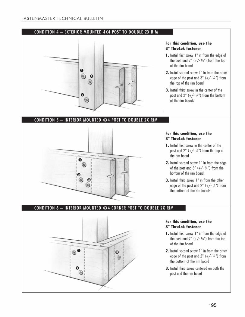
For this condition, use the 8" ThruLok fastener
Install first screw 1" in from the edge of 1. the post and 2" (+/- ¼") from the top of the rim board
Install second screw 1" in from the other 2. edge of the post and 3" (+/- ¼") from the top of the rim board
Install third screw in the center of the 3. post and 2" (+/- ¼") from the bottom of the rim boards
For this condition, use the 8" ThruLok fastener
Install first screw in the center of the 1. post and 2" (+/- ¼") from the top of the rim board
Install second screw 1" in from the edge 2. of the post and 3" (+/- ¼") from the bottom of the rim board
Install third screw 1" in from the other 3. edge of the post and 2" (+/- ¼") from the bottom of the rim boards
For this condition, use the 8" ThruLok fastener
Install first screw 1" in from the edge of 1. the post and 2" (+/- ¼") from the top of the rim board
Install second screw 1" in from the other 2. edge of the post and 2" (+/- ¼") from the bottom of the rim board
Install third screw centered on both the 3. post and the rim board
CONDITION 5 – INTERIOR MOUNTED 4X4 POST TO DOUBLE 2X RIM
CONDITION 6 – INTERIOR MOUNTED 4X4 CORNER POST TO DOUBLE 2X RIM
CONDITION 4 – EXTERIOR MOUNTED 4X4 POST TO DOUBLE 2X RIM
FASTENMASTER TECHNICAL BULLETIN
195

FASTENMASTER TECHNICAL BULLETIN
FMTE
CH-TH
RPOS
T (1
010)
FastenMaster ® and ThruLok® are trademarks of OMG, Inc.Copyright © 2010 OMG, Inc. All rights reserved.
GENERAL FASTENING GUIDELINES
Third party testing in accordance with ASTM D1761 and ICC Acceptance Criteria AC233 was conducted to determine the proper placement and number of fasteners to meet code.
The connection details shown in this bulletin apply specifically to 4x4 posts and 2x8, 2x10 or 2x12 rims and/or joists.
For different dimension lumber, wood species of lower density than Hem Fir (SYP and DF are higher density and therefore approved), or post heights greater than 37.5" off the top of the joists, please contact FastenMaster to determine the proper fastening solution.
ThruLok is coated with mechanically applied zinc in accordance with ASTM B695, Class 55. This is compliant with the 2006 International Residential Code® (R319.3) and 2009 IRC (R317.1.3) for use in ACQ pressure treated wood.
As with other bolted connections using wet treated wood, the nut should be inspected and tightened if needed after initial drying period.
The connection details in this bulletin are an acceptable means of transferring the load from guard post to rim joist only. Additional blocking or hardware may be required to transfer loads from the rim to deck joists.
Fastening patterns assume the following: All components are used (screw, washer and nut), holes are not pre-drilled, and posts are loaded in an outward direction from the deck.
For questions regarding these or other connections, please contact FastenMaster Technical Support at www.fastenmaster.com or by calling 800.518.3569.
CONDITION 7 – INTERIOR MOUNTED 4X4 POST TO 2X RIM WITH BLOCKING
CONDITION 8 – INTERIOR MOUNTED 4X4 POST TO 2X RIM WITH SIDE BLOCKING
For this condition, use the 8" ThruLok fastener
Install first screw in the center of the 1. post and 2" (+/- ¼") from the top of the rim board
Install second screw 1" in from the edge 2. of the post and 2" (+/- ¼") from the bottom of the rim board
Install third screw 1" in from the other 3. edge of the post and 3" (+/- ¼") from the bottom of the rim board
For this condition, use two, 61⁄4" and one, 8" ThruLok fasteners
Install first 61. 1⁄4" screw 1" in from the edge of the post and 2" (+/- ¼") from the top of the rim board
Install second 62. 1⁄4" screw 1" in from the other edge of the post and 2" (+/- ¼") from the bottom of the rim board
Install 8" screw centered on both the 3. post and the rim board
196

197

198

199

200

201
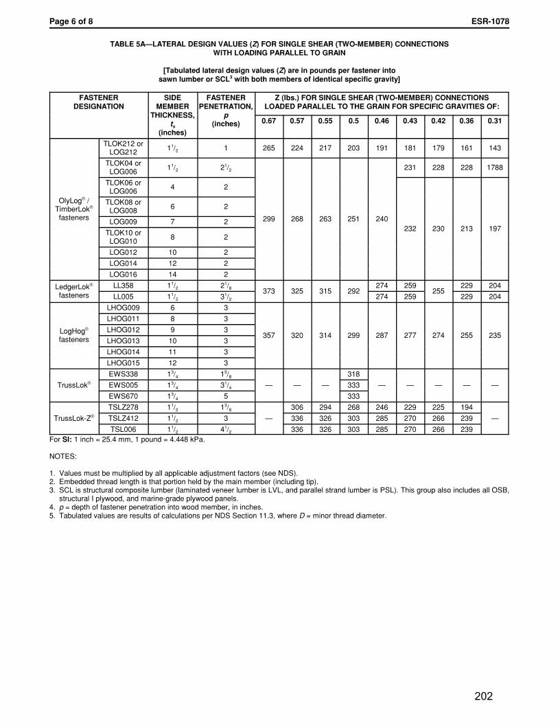
202

203

204

153 Bowles Road, agawam, ma 01001 413.789.0252 800.518.3569 www.FastenmasteR.com
Effective until December 31, 2011. Updated information must be obtained after this date.
RaFteR taIl to toP PlateConneCtion Details
CAN be used wheN rAfter is AligNed over or betweeN wAll studs
FastenMasteR teCHniCal BUlletin
The minimum fastening requirements for the rafter to top plate connection in the 2006/2009 International Residential
Code (Table R602.3) require 2-16d nails toenailed. The 2006/2009 International Building Code (Table 2304.9.1)
requires 3-8d nails toenailed. Both of these codes can be met by installing the FastenMaster TimberLok when the guide-
lines on this technical bulletin are followed. In many cases where increased wind uplift or seismic conditions require a
stronger rafter to top plate connection, this fastening method may also be used to replace metal ties and straps.
FastenIng metHod
• Use a 6" FastenMaster TimberLok.
• Where the rafter is directly over the wall stud, insert fastener point between the bottom of the top plate and the top of the stud.
• Where the rafter is located between two studs, insert fastener point on bottom surface of the top plate no greater than 1⁄2" from the inside edge of the plate.
• Drive fastener through double top plate at a 221⁄2° angle (+/– 5°)and into the center of the rafter.
• Fastener must be driven into the center of the 11⁄2" rafter edge (+/– 1⁄4") with the threads fully embedded into the rafter.
• Bring the fastener head flush with the wood surface.
SIDE VIEW
205

FastenMasteR teCHniCal BUlletin
FasteneR desIgn loads
sample wind loadsTable 2 below represents common design wind loads on rafter to top plate connections taken from the AF&PA Wood Frame Construction Manual, High Wind Zone Exposure B, Wall Connections at Load Bearing Walls.
FastenMaster ® and TimberLok® are trademarks of OMG, Inc.Copyright © 2010 OMG, Inc. All rights reserved.
The FastenMaster TimberLok load values in Table 1 can be used by a design professional to determine suitability of these fasteners in a rafter to top plate connection.
• Where the uplift and/or lateral design loads have been provided on the building plans, the allowable loads in Table 1 can be compared to the plan values to make sure they are met or exceeded by use of this fastening method.
• If ties or straps have been called for to resist uplift and lateral forces, the allowable loads in Table 1 should be compared to the manufacturer's published values for the specified connector to ensure that this fastening method meets or exceeds these loads.
• In cases where the above two methods are not available and the wind speed from IRC Figure 301.2(4) equals or exceeds 100 mph in hurricane-prone regions, or 110 mph elsewhere, the design loads of this connection can be determined by a design professional from one of the following three sources and compared to Table 1:
1. American Forest and Paper Association (AF&PA) Wood Frame Construction Manual for One- and Two-Family Dwellings (WFCM). A sample of this chart is shown below.
2. International Code Council (ICC) Standard for the Residential Construction in High Wind Regions (ICC-600).3. Minimum Design Loads for Buildings and Other Structures (ASCE-7).
TABLE 2roof framing span (ft.)
12 16 20 24 28 32 36
wInd Zone (mPH)
RaFteR sPacIng UPlIFt (lb.)
lateRal (lB.)
sHeaR (lB.)
90 16" o.c. 82 96 110 125 139 154 168 119 52
90 24" o.c. 123 144 165 187 209 230 252 178 78
100 16" o.c. 124 147 170 193 217 240 264 145 64
100 24" o.c. 186 220 255 290 325 360 396 218 96
110 16" o.c. 170 203 236 269 303 336 370 176 77
110 24" o.c. 255 304 354 404 454 504 554 264 116
120 16" o.c. 220 264 308 352 397 441 486 209 93
120 24" o.c. 331 396 462 528 595 661 728 314 140
130 16" o.c. 275 331 386 442 499 555 611 247 109
130 24" o.c. 413 496 580 664 748 833 917 370 164
This chart is used as an example only and should not be the sole source to design the connection.
FMTE
CH-R
AFTT
AIL
(121
0)
TABLE 1timberlok design loads for rafter
to top Plate Connections
wood species SPF/HF Douglas Fir Southern Pine
load type UpliftLateral/Shear Uplift
Lateral/Shear Uplift
Lateral/Shear
allowable load 420 320 540 380 620 410
• TimberLok values above are based on ICC-ES Report #1078 and independently verified through testing to ASTM D-1761.
• A standard wind load duration factor has been applied to these values per NDS Table 2.3.2. Other applicable NDS adjustment factors are at the discretion of a design professional.
• These values apply only to the top plate to rafter connection and assume that the fastener is properly installed per the instructions on this bulletin.
206