not a part of this contract - BidNet
624
-
Upload
khangminh22 -
Category
Documents
-
view
2 -
download
0
Transcript of not a part of this contract - BidNet


INFORMATION ONLY - NOT A PART OF THIS CONTRACT In accordance with SB 854 passed by the California State Senate on June 20, 2014, all contractors and subcontractors bidding and performing work on Public Works Projects are required to register with the Department of Industrial Relations (DIR) on an annual basis. See the Notice to Bidders for information on California Labor Code Section 1771.1. Division 20, Chapter 6.95 of the California Health and Safety Code, in part, requires the submission of a Business Plan for Emergency Response by the operators of sites where hazardous materials are stored and handled at or above the State of California minimum reportable amounts. These amounts currently are 55 gallons of a liquid, 500 pounds of a solid, or 200 cubic feet at standard temperature and pressure for a compressed gas. (H&S Section 25507) The Shasta County Division of Environmental Health, which has been designated by the Shasta County Board of Supervisors as the administering agency for Chapter 6.95 of the California Health and Safety Code, advises that a fee may be assessed not to exceed the actual costs of processing and for inspection, if an inspection is conducted. The State of California Franchise Tax Board requires that whenever payments are made to a non-resident independent contractor in excess of $1,500 for services rendered, 7% of the gross amount must be withheld. A non-resident is anyone who is not a resident of California. An individual who comes into the state to perform a contract of short duration is considered to be a non-resident. A corporation is also subject to the withholding requirements if it is neither incorporated nor qualified to do business in California.

Shasta County Department of Public Works 00 00 01 Riverside Avenue Fire Station 47 Project Directory Contract No: 610945 Page 1
PROJECT DIRECTORY
SECTION 00 00 01
OWNER
Shasta County Department of Public Works
1855 Placer Street Redding, CA 96001 T: (530) 225-3834
[email protected] Contact: Kevin Maple, P.E.
ARCHITECT
Nichols-Melburg and
Rossetto AIA & Associates, Inc. 300 Knollcrest Drive Redding, CA 96002 T: (530) 222-3300 F: (530) 222-3538 Contact: Kyle Matti

Shasta County Department of Public Works 00 00 01 Riverside Avenue Fire Station 47 Table of Contents Contract No: 610945 Page 1
CONTRACT BOOK
FOR RIVERSIDE AVENUE FIRE STATION 47
TABLE OF CONTENTS
DIVISION NO. SECTION TITLE PAGES INCLUSIVE
DIVISION 00 PROCUREMENT AND CONTRACTING REQUIREMENTS Section 00 00 01 Project Directory ..................................................................................................... 1 Section 00 01 10 Table of Contents .............................................................................................. 1 – 2 Section 00 11 13 Advertisement for Bids ..................................................................................... 1 – 2 Section 00 21 13 Instructions to Bidders ...................................................................................... 1 – 5 Section 00 31 13 Construction Schedule and Liquidated Damages .............................................. 1 – 2 Section 00 41 13 Bid Form ........................................................................................................... 1 – 3 Section 00 41 14 Bidder Information Sheet ........................................................................................ 1 Section 00 43 13 Bidder’s Bond ......................................................................................................... 1 Section 00 43 36 Subcontractor List Form.......................................................................................... 1 Section 00 45 19 Non-Collusion Affidavit ......................................................................................... 1 Section 00 45 26 Certifications Concerning Workers’ Compensation ............................................... 1 Section 00 45 51 Certification Regarding Debarment and Suspension .............................................. 1 Section 00 45 52 Declaration of Contractor’s License Status ............................................................. 1 Section 00 45 53 Public Contract Code Certifications .................................................................. 1 – 2 Section 00 50 70 State Wage Determination ...................................................................................... 1 Section 00 50 75 Compliance Monitoring and Enforcement by California DIR ................................ 1 Section 00 50 80 Payroll Information ................................................................................................. 1 Section 00 52 13 Contract between County of Shasta and Contractor ......................................... 1 – 4 Section 00 61 13.13 Performance and Payment Bond .......................................................................... 1-2 Section 00 61 23 Escrow Agreement for Security Deposits in Lieu of Retention ........................ 1 – 3 Section 00 65 36 Project Closeout and Warranty ......................................................................... 1 – 6 Section 00 73 12 General Conditions .......................................................................................... 1 – 44 Section 00 73 13 Supplementary Conditions ................................................................................ 1 – 3
DIVISION 01 GENERAL REQUIREMENTS Section 01 25 13 Product Substitution Procedures ....................................................................... 1 – 7 Section 01 31 19 Project Meetings ................................................................................................ 1 – 3 Section 01 32 16 Construction Progress Schedules ............................................................................ 1 Section 01 33 00 Submittal Procedures ........................................................................................ 1 – 6 Section 01 42 00 References ........................................................................................................ 1 – 10 Section 01 55 26 Traffic Control ................................................................................................... 1 - 6 Section 01 56 00 Temporary Barriers, Closures and Controls ...................................................... 1 – 3 Section 01 57 23 Temporary Water Pollution Control .................................................................. 1 - 3 Section 01 60 00 Product Requirements ....................................................................................... 1 – 3 Section 01 73 29 Cutting and Patching ......................................................................................... 1 – 4
DIVISION 02 EXISTING CONDITIONS Section 02 41 00 Demolition ......................................................................................................... 1 – 2
DIVISION 03 CONCRETE Section 03 05 00 Common Work for Concrete ............................................................................. 1 – 4 Section 03 11 00 Concrete Formwork .......................................................................................... 1 – 6

Shasta County Department of Public Works 00 00 01 Riverside Avenue Fire Station 47 Table of Contents Contract No: 610945 Page 2
Section 03 15 00 Concrete Accessories ........................................................................................ 1 – 5 Section 03 15 10 Expansion and Contraction Joints ...................................................................... 1 - 3 Section 03 21 00 Concrete Reinforcing Steel ............................................................................... 1 – 4 Section 03 30 00 Cast in Place Concrete .................................................................................... 1 – 10 Section 03 35 00 Concrete Floor Finishing ................................................................................... 1 – 3 Section 03 39 00 Concrete Curing ................................................................................................ 1 – 3 Section 03 61 00 Cement Grout ..................................................................................................... 1 - 3
DIVISION 04 MASONRY Section 04 22 00 Concrete Unit Masonry .................................................................................... 1 – 7 Section 04 42 50 Manufactured Masonry Stone Veneer ............................................................... 1 – 5
DIVISION 05 METALS Section 05 50 00 Metal Fabrications ............................................................................................. 1 – 7
DIVISION 06 WOOD, PLASTICS, AND COMPOSITES. Section 06 20 00 Finish Carpentry ............................................................................................... 1 – 3 Section 06 40 00 Custom Casework ............................................................................................. 1 – 5 Section 06 61 16 Solid Surface Products ...................................................................................... 1 – 5
DIVISION 07 THERMAL AND MOISTURE PROTECTION Section 07 21 00 Batt Insulation Systems ..................................................................................... 1 – 2 Section 07 25 00 Weather Barriers ............................................................................................... 1 – 3 Section 07 26 00 Under-Slab Vapor Barrier ................................................................................. 1 – 2 Section 07 26 50 Vapor Emission Control System ....................................................................... 1 – 8 Section 07 84 00 FireStopping ...................................................................................................... 1 – 4 Section 07 90 00 Joint Protection .................................................................................................. 1 – 5
DIVISION 08 OPENINGS Section 08 01 35 Folding Doors ................................................................................................... 1 – 4 Section 08 11 00 Hollow Metal Doors and Frames ...................................................................... 1 – 6 Section 08 14 23 Plastic Laminate Faced Wood Doors ................................................................ 1 – 3 Section 08 31 13 Access Doors ..................................................................................................... 1 – 3 Section 08 33 23 Overhead Coiling Doors.................................................................................... 1 – 4 Section 08 36 00 Sectional Glass and Aluminum Overhead Door .............................................. 1 – 4 Section 08 56 00 Vinyl Windows ................................................................................................. 1 – 5 Section 08 56 59 Aluminum Transaction Window ...................................................................... 1 – 4 Section 08 71 00 Door Hardware ................................................................................................ 1 – 11 Section 08 73 00 Automatic Door Operators ................................................................................ 1 – 3 Section 08 80 00 Glazing .............................................................................................................. 1 – 4 Section 08 91 00 Metal Louvers ................................................................................................... 1 – 3
DIVISION 09 FINISHES Section 09 21 16 Gypsum Board Assemblies ............................................................................... 1 – 4 Section 09 22 16 Metal Framing ................................................................................................... 1 – 5 Section 09 51 13 Acoustic Ceiling ................................................................................................ 1 – 5 Section 09 65 13 Resilient Base .................................................................................................... 1 – 2 Section 09 65 16 Sheet Vinyl Flooring ......................................................................................... 1 – 4 Section 09 65 66 Resilient Athletic Flooring ................................................................................ 1 – 3 Section 09 68 13 Tile Carpeting .................................................................................................... 1 – 6 Section 09 77 30 Fiberglass Wall Panels ...................................................................................... 1 – 3 Section 09 91 00 Painting and Coating ......................................................................................... 1 – 9

Shasta County Department of Public Works 00 00 01 Riverside Avenue Fire Station 47 Table of Contents Contract No: 610945 Page 3
DIVISION 10 Section 10 14 00 Signage ...................................................................................................... 1 – 4 Section 10 26 13 Corner Guards ........................................................................................... 1 – 2 Section 10 28 13 Toilet Accessories ..................................................................................... 1 – 4 Section 10 44 16 Fire Extinguishers and Cabinets ................................................................ 1 – 2 Section 10 51 00 Turnout Gear Lockers Wall Mounted ....................................................... 1 – 3 Section 10 56 13 Metal Storage Shelving ............................................................................. 1 – 2 Section 10 75 00 Flag Poles .................................................................................................. 1 – 3 Section 10 90 00 Miscellaneous Specialties ......................................................................... 1 – 2 DIVISION 12 Section 12 20 00 Window Treatments .......................................................................................... 1 – 7 Section 12 48 13 Entrance Mats & Frames ................................................................................... 1 – 3 Section 12 92 00 Site Furnishings ................................................................................................. 1 – 3
DIVISION 13 SPECIAL CONSTRUCTION Section 13 34 19 Metal Building Systems .................................................................................... 1 – 5
DIVISION 22 PLUMBING Section 22 00 00 Plumbing ......................................................................................................... 1 – 21
DIVISION 23 HEATING VENTILATING & AIR CONDITIONING Section 23 00 00 HVAC ............................................................................................................. 1 – 34 Section 23 05 93 Testing, Adjusting, And Balancing ................................................................... 1 – 6 Section 23 09 00 Controls ........................................................................................................... 1 – 22
DIVISION 26 ELECTRICAL Section 26 05 19 Low-Voltage Electrical Power Conductors and Cables .................................... 1 – 9 Section 26 05 26 Grounding and Bonding for Electrical Systems ................................................ 1 – 5 Section 26 05 29 Hangers and Supports for Electrical Systems ................................................... 1 – 4 Section 26 05 33 Raceways and Boxes for Electrical Systems ..................................................... 1 – 9 Section 26 05 53 Identification for Electrical Systems ................................................................. 1 – 4 Section 26 24 16 Panelboards ....................................................................................................... 1 – 7 Section 26 27 26 Wiring Devices .................................................................................................. 1 – 8 Section 26 28 16 Enclosed Switches and Circuit Breakers .......................................................... 1 – 4 Section 26 43 13 Surge Protection for Low-Voltage Electrical Power Circuits .......................... 1 – 3 Section 26 51 00 Interior Lighting ............................................................................................... 1 – 4 Section 26 56 00 Exterior Lighting .............................................................................................. 1 – 3
DIVISION 28 ELECTRICAL SAFETY AND SECURITY Section 28 46 21.11 Addressable Fire Alarm Systems ...................................................................... 1 – 1 DIVISION 31 Section 31 11 00 Clearing and Grubbing ..................................................................................... 1 – 2 Section 31 20 01 General Earthwork ........................................................................................... 1 – 8 Section 31 23 33 Trench Excavation and Backfill ....................................................................... 1 – 6 DIVISION 32 Section 32 11 23 Aggregate Base Courses................................................................................... 1 – 2 Section 32 12 16 Hot Mix Asphalt ............................................................................................... 1 – 4 Section 32 13 13 Concrete Pavement ........................................................................................... 1 – 3 Section 32 16 21 Curbs, Gutters, Sidewalks and Curb Ramps .................................................... 1 – 4

Shasta County Department of Public Works 00 00 01 Riverside Avenue Fire Station 47 Table of Contents Contract No: 610945 Page 4
Section 32 17 23 Pavement Striping and Marking ....................................................................... 1 – 3 Section 32 17 24 Signs ................................................................................................................. 1 – 4 Section 32 17 26 Tactile Warning Surfacing ............................................................................... 1 – 4 Section 32 31 00 Sliding Gate Operator....................................................................................... 1 – 7 Section 32 31 19 Decorative Metal Gates ..................................................................................... 1 - 6 Section 32 31 23 Chain Link Fences and Gates ........................................................................... 1 – 3 Section 32 80 00 Irrigation ........................................................................................................... 1 – 9 Section 32 90 00 Planting ............................................................................................................ 1 – 8 DIVISION 33 Section 33 11 01 Water Piping and Appurtenances ................................................................... 1 – 12 Section 33 30 00 Sanitary Sewage Systems ................................................................................. 1 – 8 Section 33 41 01 Storm Drain Piping and Appurtenances ........................................................... 1 – 5 Appendix A Public Contract Code Section 9204 .................................................................. 1 – 4
END OF SECTION 00 01 10

Shasta County Department of Public Works 00 11 13 Riverside Avenue Fire Station 47 Advertisement for Bids Contract No: 610945 Page 1
ADVERTISEMENT FOR BIDS
SECTION 00 11 13
PART 1 – GENERAL NOTICE IS GIVEN THAT SHASTA COUNTY, CALIFORNIA, will receive bids for the furnishing of all labor, materials, transportation, and services necessary for the completion of:
Shasta County Department of Public Works Riverside Avenue Fire Station 47 Contract No. 610945
1.1 BID SUBMISSION: Sealed bids will be accepted until 11:00 a.m. local time, May 6, 2021, at the
office of the Shasta County Clerk of the Board, 1450 Court Street, Suite 308B, Redding, California 96001. Mail in bids need to arrive at the above location prior to this time. Postmarks will not validate bid submissions. Walk in bids may be delivered at the same address and must be inserted into the drop box, which will be available outside of the hallway door of the Office of the Clerk of the Board at 1450 Court Street, Suite 308B, Redding, California. Bids received after 11:00 a.m. on 5/6/2021, will not be considered responsive and will be returned to the bidder unopened. Telephone and telefax bids will not be accepted. The Department will open and publicly read bids at 11:00 p.m. on 5/6/2021. Due to circumstances caused by the COVID-19 pandemic, any bidders and anyone wishing to attend the opening of bids must do so by web conference and/or conference call. The public will not be allowed to physically attend the bid opening in person. To view the bid opening, you must use “Go to Meeting” from a computer, tablet or smartphone at: https://global.gotomeeting.com/join/830955221. Bidders can also dial in by phone +1 (669) 224-3412 access code 830-955-221.
1.2 DESCRIPTION OF THE WORK: The project is located on Riverside Avenue near the intersection
with Ox Yoke Road in Anderson, CA. In general, the project consists of the construction of a new fire station for the Shasta County Fire Department and the California Department of Forestry and Fire Protection (CAL FIRE). The fire station will include an 8-bed living quarters and three fire apparatus bays. The structure will be a prefabricated metal building with metal stud walls. Other work on the building will include: interior and exterior finishes, doors, windows, case work, HVAC, electrical systems, lighting and signal systems, plumbing, mechanical, fire suppression and specialties as indicated on the project drawings. Site work involves tree removal and demolition of existing landscaping, Portland cement concrete pavement, construction of storm drainage, water, sewer/septic systems and landscaping. Off-site improvements include curb, gutter, asphalt paving along the Riverside Avenue frontage, connection to the existing City of Anderson water system and extension of an 8-inch water main to serve the fire station site.
1.3 ENGINEER’S ESTIMATE: The engineer’s estimate for the base bid is $5,430,000.00. This is an
estimate only and bidders should not rely upon this figure when preparing or submitting their bids. 1.4 REQUIRED CONTRACTOR’S LICENSE: At the time this contract is bid, the Contractor shall
possess a California “B” contractor’s license which is current and valid at the time of the bid and for the duration of the Work. Contractor and subcontractors shall possess the appropriate license for the work of their respective trades.

Shasta County Department of Public Works 00 11 13 Riverside Avenue Fire Station 47 Advertisement for Bids Contract No: 610945 Page 2
1.5 PRE-BID CONFERENCE AND SITE VISIT: County will conduct a pre-bid conference and site
visit starting at 10:00 a.m. local time, April 29, 2021. The meeting will be held at the project site on Riverside Avenue, Anderson, CA. The pre-bid conference is not mandatory. However, the bidder is required to sign that they have familiarized themselves with the local conditions including, but not limited to: inspecting in and around the work areas.
1.6 DEPARTMENT OF INDUSTRIAL RELATIONS CONTRACTOR REGISTRATION: In
accordance with California Labor Code Section 1771.1, a contractor or subcontractor shall not be qualified to bid on, be listed in a bid proposal, subject to the requirements of Section 4104 of the Public Contract Code, or engage in the performance of any contract for public work, as defined in this chapter, unless currently registered and qualified to perform public work pursuant to Section 1725.5. It is not a violation of this section for an unregistered contractor to submit a bid that is authorized by Section 7029.1 of the Business and Professions Code or by Section 10164 or 20103.5 of the Public Contract Code, provided the contractor is registered to perform public work pursuant to Section 1725.5 at the time the contract is awarded.
As noted above, all contractors and subcontractors must be registered with DIR. By requesting the DIR registration numbers of all subcontractors, bidders are hereby put on notice that if they list a subcontractor without a DIR registration number at the time of bid opening, County, in its sole discretion, may find the failure to do so intentional and find the bid non-responsive. DIR registration numbers are available online at https://efiling.dir.ca.gov/PWCR/Search.
1.7 BIDDING DOCUMENTS: Each bid must be in accordance with the bid documents, construction
drawings and specifications on file at the Shasta County Department of Public Works, 1855 Placer Street, Redding, California, 96001. These bid documents, construction drawings and specifications are available for viewing or downloading through the Shasta County Department of Public Works website at http://www.co.shasta.ca.us/html/Public_Works/pw_index.htm. Also through this website, a bidder may view and join a Document Holder’s List for this work. Joining the Document Holder’s List, and checking to see if there are addenda issued prior to bidding are the sole responsibility of the bidder. If any addendum is issued, the County will attempt to notify each document holder on the Document Holder’s List using the e-mail address and the FAX numbers entered onto the Document Holder’s List. County shall not in any way be responsible or liable for failure of a document holder to receive notification. It is the bidder’s responsibility, prior to submitting the bid, to check the website or otherwise inquire to determine whether the County has issued any Addenda.
Note that there are local blueprinting companies that can download and sell paper copies of the bid documents, construction drawings and specifications. Bidders are responsible for arranging and purchasing these paper copies if they so choose.
1.8 INQUIRIES: All inquiries regarding the Work should be directed to the office of Shasta County
Department of Public Works, Kevin Maple, PE at (530) 225-3834 (phone), (530) 225-5667 (fax), or [email protected] (email).
END OF SECTION 00 11 13

Shasta County Department of Public Works 00 21 13 Riverside Avenue Fire Station 47 Instruction to Bidders Contract No: 610945 Page 1
INSTRUCTIONS TO BIDDERS
SECTION 00 21 13
PART 1 – GENERAL 1.1 RECEIPT OF BIDS. Sealed bids will be accepted until 11:00 a.m. local time, May 6, 2021 at the
office of the Shasta County Clerk of the Board, 1450 Court Street, Suite 308B, Redding, California 96001, at which time they will be publicly opened and read. Bids received after 11:00 a.m. will not be considered responsive and will be returned to the bidder unopened. Telephone and telefax proposals will not be accepted. Each bidder should mark its bid as “Bid for Riverside Avenue Fire Station 47”. Bids shall be deemed to include the written responses to the bidder to any questions or requests for information of County made as part of bid evaluation process after submission of bid.
1.2 DETERMINATION OF APPARENT LOW BIDDER. The apparent low bid will be based on the
total amount of the bid in Section 00 41 13, “Bid Form.” 1.3 REQUIRED BID FORM. All bidders must submit bids on the forms provided in Section 00 41 13
“Bid Form”. County will reject as non-responsive any bid not submitted on the required form. Bids must be full and complete. Bidders must complete all bid items and supply all information required by the bidding documents and specifications. County reserves the right in its sole discretion to reject any bid as non-responsive as a result of any error or omission in the bid. Bidders may not modify the Bid Form or qualify their bids. Bidders must submit clearly and distinctly written bids. Bidders must clearly make any changes in their bids by crossing out original entries, entering new entries and initialing new entries. County reserves the right to reject any bid not clearly written. The Bid Form shall be signed by the bidder’s legal representative as indicated on the Bid Form. If the bid is made by an individual, it shall be signed and his/her full name and his/her address shall be given; if it is made by a partnership, it shall be signed with the co-partnership name by a member of the firm, who shall sign his/her own name and provide the name and address of each member; and if it is by a corporation, the bid shall show the name of the corporation and the state under the laws of which the corporation was chartered. When the bid is signed by the duly authorized officer or officers of the corporation, it shall be attested by the corporate seal, and the names and titles of the principal officers of the corporation shall be given. When a bid is signed by an agent, other than the officer or officers of a corporation authorized to sign contracts on its behalf or a member of a partnership, a “Power of Attorney” must be filed with the County prior to opening bids or shall be submitted with the bid; otherwise, the bid may be rejected as irregular and unauthorized. Bids submitted as joint ventures must so state and be signed by each joint venture.
1.4 REQUIRED BID SECURITY. Bidders must submit with their bids either cash, a cashier’s check, or
certified check drawn on a responsible bank in the United States, or corporation surety bond furnished by a surety authorized to do business in the State of California of not less than ten percent (10%) of aggregate amount of base bid, payable to County. Bidders shall use the required form of corporate surety bond contained in Section 00 43 13, “Bidders Bond.” County will reject as non-responsive any bid submitted without the required bid security. The County may retain a bidder’s security of other than the apparent low bidder for a period of sixty (60) days after award or full execution of the Contract, whichever first occurs. The County may award the Contract to the next apparent low bidder if the apparent low bidder is determined non-responsive or non-responsible, or fails to execute the Contract and provide the required bonds, guarantees and other documents within the required time periods. Upon full execution of the Contract, the County will return to the respective unsuccessful bidders all bid securities and bidder’s bond.

Shasta County Department of Public Works 00 21 13 Riverside Avenue Fire Station 47 Instruction to Bidders Contract No: 610945 Page 2
1.5 REQUIRED SUBCONTRACTORS LIST. All Bidders must submit with their bids, the required
information on all subcontractors in Section 00 43 36, “Subcontractor List Form,” for those subcontractors who will perform any portion of Work, including labor, rendering of service, or specially fabricating and installing a portion of the Work or improvement, in excess of one half of one percent (0.5%) of the total bid. The Subcontractor List Form shall be submitted in a separate sealed envelope. Violation of this requirement may result in a bid being deemed non-responsive and not being considered.
1.6 CONTENTS OF BID ENVELOPE. The bid envelope shall contain all of the following:
Section 00 41 13 – Bid Form Section 00 41 14 – Bidder Information Sheet Section 00 43 13 – Bidder’s Bond Section 00 43 36 – Subcontractor List Form (In a separate sealed envelope.) Section 00 45 19 – Non-Collusion Affidavit Section 00 45 26 – Certification Concerning Workers’ Compensation Section 00 45 51 – Certification Regarding Debarment and Suspensions Section 00 45 52 – Declaration of Contractor License Status Section 00 45 53 – Public Contract Code Certifications
1.7 OTHER REQUIREMENTS PRIOR TO BIDDING. Submission of a bid certifies bidder’s careful
examination of the Contract Documents and all conditions contained therein, the Work Site, and the surrounding area and complete understanding of the nature, extent and location of the Work to be performed. Submission of bid shall constitute bidder’s express representation to the County that bidder has fully completed these tasks.
1.8 ADDENDA. If any party contemplating submitting a bid for the proposed contract is in doubt as to the
true meaning of any part of the Contract Documents, or finds discrepancies in or omissions from the plans or specifications; that party may submit to the County a written request for an interpretation or correction thereof. The party submitting the request will be responsible for its prompt delivery at least five full County workdays (Monday through Friday excluding County holidays) prior to the bid opening. Answers to requests that do not give any single bidder an unfair advantage will be given orally. Otherwise, interpretations or corrections of the documents will be made only by addendum duly issued. Bidding documents, including any addenda, are available for viewing or downloading through the Shasta County Department of Public Works website at http://www.co.shasta.ca.us/html/Public_Works/pw_index.htm. Also through this website, a bidder may view and join a Document Holder’s List for this bid. Joining the Document Holder’s List, and checking to see if there are addenda issued prior to bidding are the sole responsibility of the bidder. If any addendum is issued, the County will attempt to notify each document holder on the Document Holder’s List using the e-mail address and the FAX numbers entered on the Document Holder’s List. County shall not in any way be responsible or liable for failure of a document holder to receive notification. It is the bidder’s responsibility, prior to submitting the bid, to check the website or otherwise inquire to determine whether the County has issued any Addenda. The County shall not be deemed responsible for any oral clarification nor will it be binding.
1.9 BID OPENING. The County will stamp bids with the date and time of receipt. Bids will be opened
and read publicly at the time and place indicated in Section 1.1, “Receipt of Bids,” above. Bidders or their authorized agents may be present. After opening of bids, the County will review all bids for accuracy and reserves the right to correct obvious errors. Upon completion of review, the bids will be ranked by the bid amount and the apparent low bidder will be determined and notified.

Shasta County Department of Public Works 00 21 13 Riverside Avenue Fire Station 47 Instruction to Bidders Contract No: 610945 Page 3
1.10 WITHDRAWL OF BIDS: Any bid may be withdrawn or revised by a bidder personally or upon its written or telegraphic request at any time prior to the hour set for the opening of bids, but not thereafter. It shall be the bidder's sole responsibility to see that such written or telegraphic request is received in proper time, and bidder shall confirm this action in writing over its signature within 48 hours thereafter. Unless required otherwise by law, no bidder may withdraw its bid for a period of 45 days after the date of the opening of bids.
1.11 FAILURE TO EXECUTE AND DELIVER DOCUMENTS. If the bidder to whom the Contract is
awarded shall fail or neglect, within ten (10) calendar days from the date of the receipt of a notice of award, to execute and deliver all required Contract Documents and file all required bonds, insurance certificates and other documents, County may, in its sole discretion, deposit the bidder’s surety bond, cashier’s check or certified check for collection, and retain the proceeds thereof as liquidated damages for bidder’s failure to enter into the Contract Documents. Bidder agrees that calculating the damages County may suffer as a result of bidder’s failure to execute and deliver all required Contract Documents would be extremely difficult and impractical and that the amount of bidder’s required bid security shall be the agreed and presumed amount of County’s damages.
1.12 BIDDER’S BOND, PERFORMANCE BOND AND PAYMENT BOND. Bid security must be
submitted with the bid. The successful bidder, prior to execution of the Contract, must submit a Performance Bond in the full amount of the Contract, using the form of Section 00 61 13.13, “Performance Bond.” The successful bidder, prior to execution of the Contract, must submit a Payment Bond in the full amount of the Contract, using the form of Section 00 61 13.13, “Payment Bond.”
1.13 INSURANCE. It is highly recommended that bidders confer with their respective insurance carriers or
brokers to determine in advance of bid submission the availability of the insurance certificates and endorsements required. A bidder, who executes the Contract and thereafter fails to comply strictly with the insurance requirements, will be deemed to be in breach of Contract.
1.14 WAGE RATES. Wage rates and restrictions on working days and times shall meet all requirements of
the Labor Code of the State of California for public contracts. The bidder may contact the Director of the Department of Industrial Relations, phone number (415) 703-4774, website http://www.dir.ca.gov/DLSR/statistics_research.html to obtain a schedule of general prevailing wages applicable to the location and work to be done. The Contractor and the Contractor’s subcontractors are responsible for compliance with the requirements of Sections 1777.5 and 1777.6 of the Labor Code of the State of California regarding employment of apprentices.
1.15 DEPARTMENT OF INDUSTRIAL RELATIONS CONTRACTOR REGISTRATION. The
Department of Industrial Relations (DIR) has launched an online application at https://efiling.dir.ca.gov/PWCR/ActionServlet?action=displayPWCRegistrationForm for public works contractors to meet the requirements of Senate Bill 854. Contractors must register and meet requirements using the new online application before bidding on public works contracts in California. The application also provides agencies that administer public works programs with a searchable database of qualified contractors at https://efiling.dir.ca.gov/PWCR/Search.
In accordance with California Labor Code Section 1771.1, a contractor or subcontractor shall not be qualified to bid on, be listed in a bid proposal, subject to the requirements of Section 4104 of the Public Contract Code, or engage in the performance of any contract for public work, as defined in this chapter, unless currently registered and qualified to perform public work pursuant to Section 1725.5. It is not a violation of this section for an unregistered contractor to submit a bid that is authorized by Section 7029.1 of the Business and Professions Code or by Section 10164 or 20103.5 of the Public Contract

Shasta County Department of Public Works 00 21 13 Riverside Avenue Fire Station 47 Instruction to Bidders Contract No: 610945 Page 4
Code, provided the contractor is registered to perform public work pursuant to Section 1725.5 at the time the contract is awarded. As noted above, all contractors and subcontractors must be registered with DIR. By requesting the DIR registration numbers of all subcontractors, bidders are hereby put on notice that if they list a subcontractor without a DIR registration number at the time of bid opening, County, in its sole discretion, may find the failure to do so intentional and find the bid non-responsive. DIR registration numbers are available online at https://efiling.dir.ca.gov/PWCR/Search.
1.16 EQUAL EMPLOYMENT OPPORTUNITY. Contractor shall comply with all applicable federal,
state, and local laws, rules and regulations in regard to nondiscrimination in employment because of sex, race, color, creed, ancestry, religion, national origin, physical or mental disability, sexual orientation, medical condition (cancer, HIV and AIDS), age (over 40), marital status, or other protected status, nor deny family care leave and or pregnancy disability leave.
1.17 AWARD. If the Contract is to be awarded, it will be awarded to the lowest responsible responsive
bidder per Section 1.2, “Determination of Apparent Low Bidder,” above within 45 calendar days after the bid opening.
1.18 BID PREPARATION COST. Bidders are solely responsible for the cost of preparing their bids. 1.19 RESERVATION OF RIGHTS. County specifically reserves the right, in its sole discretion, to reject
any or all bids, or re-bid, or to waive minor irregularities from bid requirements. If no bids are received, the County reserves the right to identify interested contractor(s) and negotiate directly without re-bidding.
1.20 SECURITIES IN LIEU OF RETENTION. Public Contract Code Section 22300 gives the Contractor
the option to deposit securities with an escrow agent as a substitute for retention earnings to be withheld by the County.
1.21 PRODUCT SUBSTITUTION PROCEDURES. Bidders may request a substitution of products and
materials in accordance with Section 01 25 13, “Product Substitution Procedures.”
1.22 BID PROTEST. Any bid protest must be in writing and received by the County’s Department of Public Works Office at 1855 Placer Street, Redding, California before 5:00 p.m. no later than three working days following bid opening (the “Bid Protest Deadline”) and must comply with the following requirements:
1. General. Only a bidder who has actually submitted a Bid Proposal is eligible to submit a bid protest against another bidder. Subcontractors are not eligible to submit bid protests. A bidder may not rely on the bid protest submitted by another bidder, but must timely pursue its own protest. For purposes of this Section 2-1.44, a “working day” means a day that the County is open for normal business, and excludes weekends and holidays observed by County.
2. Protest Content. The bid protest must contain a complete statement of the basis for the protest and all supporting documentation. Material submitted after the Bid Protest Deadline will not be considered. The protest must refer to the specific portion or portions of the Contract Documents upon which the protest is based. The protest must include the name, address, email address, and telephone number of the person representing the protesting bidder. The protesting bidder is solely responsible for the cost of preparing their protest.
3. Copy to Protested Bidder. A copy of the protest and all supporting documents must be concurrently transmitted by email or hand delivery, by or before the Bid Protest Deadline, to the

Shasta County Department of Public Works 00 21 13 Riverside Avenue Fire Station 47 Instruction to Bidders Contract No: 610945 Page 5
protested bidder and any other bidder who has a reasonable prospect of receiving an award depending upon the outcome of the protest. Further, verification of transmittal or delivery of all documents must be concurrently provided to the Project Engineer listed in the “Notice to Bidders.”
4. Response to Protest. The protested bidder may submit a written response to the protest, provided the response is received by County, as listed above, before 5:00 p.m., within three working days after the Bid Protest Deadline or after its actual receipt of the bid protest, whichever is sooner (the “Response Deadline”). The response must include all supporting documentation. Material submitted after the Response Deadline will not be considered. The response must include the name, address, email address, and telephone number of the person representing the protested bidder. The responding bidder is solely responsible for the cost of preparing their response.
5. Copy to Protesting Bidder. A copy of the response and all the supporting documents must be concurrently transmitted by email or hand delivery, by or before the Bid Response Deadline, to the protesting bidder and any other bidder who has a reasonable prospect of receiving an award depending upon the outcome of the protest. Further, verification of transmittal or delivery of all documents must be concurrently provided to the Project Engineer listed in the “Notice to Bidders.”
6. Exclusive Remedy. The procedure and time limits set forth in this section are mandatory and are the bidder’s sole and exclusive remedy in the event of bid protest. A bidder’s failure to comply with these procedures will constitute a waiver of any right to further pursue a bid protest, including filing a Government Code Claim or initiation of legal proceedings.
7. Right to Award. The Board of Supervisors reserves the right to award the Contract to the bidder it has determined to be the responsible bidder submitting the lowest responsive bid, and to issue a notice to proceed with the Work notwithstanding any pending or continuing challenge to its determination.
END OF SECTION 00 21 13

Shasta County Department of Public Works 00 31 13 Riverside Avenue Fire Station 47 Construction Schedule and Liquidated Damages Contract No: 610945 Page 1
CONSTRUCTION SCHEDULE AND LIQUIDATED DAMAGES
SECTION 00 31 13
PART 1 – GENERAL
1.1 CONSTRUCTION SCHEDULE
1.1.1 The Contractor must prepare a construction schedule for the Work conforming to Section 01 32 16, “Construction Schedules,” and to Part 8, “Time,” of Section 00 72 12, “General Conditions.”
1.1.2 During the construction period the Contractor must regularly provide information and input on scheduling and coordination of the Work to the County.
1.1.3 The Contractor must submit a construction schedule within five (5) calendar days of receipt of a Notice to Proceed and must submit a current construction schedule within five (5) calendar days of a written request by County. Refer to Section 01 32 16, “Construction Progress Schedules.”
1.1.4 The Contractor shall prepare a rain event action plan for any work that might allow weather damage. Contractor shall notify County before proceeding with this work, and shall submit a rain event action plan to County.
1.2 DATE OF SUBSTANTIAL COMPLETION
1.2.1 The Work shall be substantially completed 365 calendar days from the date indicated on the Notice to Proceed. This day shall be referred to as the “Date of Substantial Completion.”
1.2.2 The date of substantial completion of the work or designated portion thereof is the date certified by the County when construction is sufficiently complete, in accordance with the Contract Documents, so that the County or separate contractors can occupy or utilize the Work or a designated portion thereof for the use for which it is intended.
1.3 LIQUIDATED DAMAGES
1.3.1 In the event of failure on the part of the Contractor to complete the Work before the Time of Completion, including any approved extensions thereof, in accordance with Part 8.3.4, “Discretionary Time Extension in the Best Interest of County,” of Section 00 72 12, “General Conditions,” the Contractor shall pay County liquidated damages for each calendar day past the specified time that is required to substantially complete the Work.
The amount of liquidated damages is $1,000.00 (Three Hundred Fifty Dollars) per calendar day.
1.3.2 In the event of undue or excessive hardship resulting from an unauthorized or inexcusable delay in the completion of the Work, the County reserves the right to make a detailed written determination of the losses suffered, and to receive full recompense from the Contractor.
END OF SECTION 00 31 13

Shasta County Department of Public Works 00 41 13 Riverside Avenue Fire Station 47 Bid Form Contract No: 610945 Page 1
BID FORM
SECTION 00 41 13
PART 1 – GENERAL
1.1 GENERAL BID INFORMATION
County: Shasta County Administration Building Clerk of the Board
1450 Court Street, Suite 308B Redding, CA 96001
Bid for: Shasta County Department of Public Works
Riverside Avenue Fire Station 47 1655 West Street, Redding, CA 96001
Contract No: 610945 1.1.1 We, the undersigned, having familiarized ourselves with the local conditions (as
addressed during the pre-bid conference and site visit) including: inspecting in and around the Work areas; the construction of the existing building; operating hours of the building and limitations on noise, on access and on shutting off utilities to other areas of the building; the Work’s security requirements; and all of the Contract Documents, including the Advertisement for Bids, Instructions to Bidders, General Conditions, Bid Form, Contract Between County of Shasta and the Contractor, the Drawings and any Addenda issued by County; do hereby propose to furnish all labor, materials, necessary tools, expendables, equipment, utility and transportation services, including payment of State of California and local sales or use taxes and procurement of licenses necessary to complete the Work required in strict accordance with the Contract Documents, including all addenda.
1.1.2 The undersigned agree(s) to enter into and execute a Contract, if awarded on the basis
of this bid, and to furnish a performance bond and a payment bond, both in the full amount of the Contract, and proof of insurance in accordance with these Contract Documents, within ten (10) calendar days after date of receipt of the Contract.
1.1.3 The undersigned declare(s) that the cost of a performance bond and payment bond, both
in the full amount of the Contract, is included in this bid. 1.1.4 Liquidated Damages for Failure to Enter into the Contract:
Enclosed herewith is cash, a bidder’s bond, cashier’s check, or certified check, made payable to the County, which is not less than 10% of the total amount of the base bid. Should this bid be accepted and the undersigned thereafter fail to enter into the Contract or should the undersigned fail to provide the required bonds or proof of insurance, IT IS HEREBY UNDERSTOOD AND AGREED that it is, and will be, difficult or impossible to determine the actual damage which County will sustain in the event of, and by reason of, such failure to enter into the Contract. The undersigned further agrees that said cash, check or bidder’s bond shall be forfeited as liquidated damages (not as a

Shasta County Department of Public Works 00 41 13 Riverside Avenue Fire Station 47 Bid Form Contract No: 610945 Page 2
penalty), if the undersigned fails to enter into a Contract on the basis of this bid or fails to provide the required bonds and insurance, after receiving the Notice of Award.
1.1.5 The undersigned acknowledges receipt of the following addenda:
1. Addendum No.____ Dated________ Addendum No.____ Dated______
2. Addendum No.____ Dated________ Addendum No.____ Dated______
1.1.6 This bid is valid for forty-five (45) calendar days following the date for receiving bids. 1.1.7 The undersigned proposes to enter into the Contract for the following amount. This
amount is a lump sum bid for work included in this Contract necessary to complete the Shasta County Department of Public Works Riverside Avenue Fire Station 47 in Redding, California as shown in the Contract Documents. The Work shall be complete within the time limits specified in Section 00 31 13, “Construction Schedule and Liquidated Damages.” The undersigned is aware the Contract includes provisions for liquidated damages as specified in Part 1.4, “Liquidated Damages,” of Section 00 31 13, “Construction Schedule and Liquidated Damages,” if the Work is not completed within the agreed time of completion.

Shasta County Department of Public Works 00 41 13 Riverside Avenue Fire Station 47 Bid Form Contract No: 610945 Page 3
PART 2 – BID
2.1 BID (INCLUDING ALL ADDENDA) for all associated Work:
Shasta County Department of Public Works Riverside Avenue Fire Station 47 (Lump Sum):
$
Total Amount in Words Total Bid Submitted by: Type of Organization: (Individual, Partnership, Corporation, etc.) Company's Name: Partner's Name(s): (If Partnership) Seal (If Corporation): (Date) By: (Signature of Contractor) (Type Name of Contractor) (Address) (Telephone) Contractor License: Class: Number: Expiration Date: Attachments:
i. Section 00 41 13 – Bid Form ii. Section 00 41 14 – Bidder Information Sheet
iii. Section 00 43 13 – Bidder’s Bond iv. Section 00 43 36 – Subcontractor List Form (In a separate sealed envelope.) v. Section 00 45 19 – Non-Collusion Affidavit
vi. Section 00 45 26 – Certification Concerning Workers’ Compensation vii. Section 00 45 51 – Certification Regarding Debarment and Suspensions
viii. Section 00 45 52 – Declaration of Contractor License Status ix. Section 00 45 53 – Public Contract Code Certifications
END OF SECTION 00 41 13
Shasta County Department of Public Works 00 41 14 Riverside Avenue Fire Station 47 Bidder Information Sheet Contract No: 610945 Page 1
BIDDER INFORMATION SHEET
SECTION 00 41 14
The bidder must check one of the following classifications that fit its type of business organization and furnish all information required under that classification. Please type or print your answers. ( ) BIDDER IS AN INDIVIDUAL Bidder’s name as it appears on State Contractor’s license is:
( ) BIDDER IS A PARTNERSHIP
Bidder’s firm name, individual or partnership, as it appears on State Contractor’s License is:
The full names of all the partners as they appear on State contractor’s License are:
( ) BIDDER IS A CORPORATION The full name of the corporation as it appears on the State Contractor’s License is:
Corporation is incorporated in the State of
END OF SECTION 00 41 14

Shasta County Department of Public Works 00 43 13 Riverside Avenue Fire Station 47 Bidder’s Bond Contract No: 610945 Page 1
BIDDER’S BOND
SECTION 00 43 13
BIDDER'S BOND TO ACCOMPANY BID (Penalty of this Bond must be 10% of the Base Bid Amount)
KNOW ALL PERSONS BY THESE PRESENTS: That we, , as principal and , as surety, are held and firmly bound unto Shasta County in the sum of dollars, ($ ), to be paid to Shasta County or its certain attorney, its successors and assigns; for which payment, well and truly to be made, we bind ourselves, our heirs, executors and administrators, successors or assigns, jointly and severally, firmly by these presents.
THE CONDITION OF THIS OBLIGATION IS SUCH, that if the certain proposal of the above bounden for the Shasta County Department of Public Works Riverside Avenue Fire Station 47 dated is accepted by Shasta County and if the above bounden its heirs, executors, administrators, successors and assigns, shall duly enter into, execute and deliver a signed agreement for such construction, and shall execute and deliver the required performance bond, payment bond, liability insurance policy or endorsement and workers’ compensation policy or endorsement, within ten (10) calendar days from the date of the receipt of a notice of award to the above bounden from Shasta County, then this obligation shall become null and void; otherwise it shall be and remain in full force and virtue. In the event suit is brought upon this bond by Shasta County and judgment is recovered, the Surety shall pay all costs incurred by Shasta County in that suit, including a reasonable attorney’s fee, to be set by the court. Witness our hands this day of ______________,
Principal Seal
By Surety Seal By Agency of Record
END OF SECTION 00 43 13

Shasta County Department of Public Works 00 43 36 Riverside Avenue Fire Station 47 Subcontractor List Form Contract No: 610945 Page 1
SUBCONTRACTOR LIST FORM
SECTION 00 43 36
This attachment to the Bid Form shall be submitted with the Bid Form, but in a separate sealed envelope. If no subcontractors are to be involved and all work is to be performed by the Contractor, so state. Complete address information (including street address, city, and state), if not included on the submitted subcontractor list form at bid time, must be faxed to the County of Shasta (Fax number: 530-225-5667) within 24 hours after Bid opening.
Subcontractor List Forms submitted by unsuccessful bidders will be returned unopened.
Pursuant to the provision of Sections 4100 to 4113, inclusive, of the Public Contract Code of the State of California, every Bidder shall set forth the name, the location of the place of business, the California contractor license number, and the Department of Industrial Relations (DIR) registration number of each subcontractor who will perform work or labor in or about the construction of the Work or improvement in an amount in excess of one-half of one percent (0.5%) of the Bidder's total bid. If the Bidder fails to specify a subcontractor for any portion of the Work in excess of one-half of one percent (0.5%) of the Bidder's total bid, the Bidder agrees to perform that portion himself/herself. The following is the required list of subcontractors:
An inadvertent error in listing a subcontractor’s California contractor license number shall not be grounds for filing a bid protest or grounds for considering the bid nonresponsive if the corrected contractor’s license number is provided within 24-hours after the bid opening.
BIDDER'S LIST OF SUBCONTRACTORS (Use other side & extra sheets if necessary)
Type of Work Name and Complete Address
of Subcontractor
Subcontractor License No.
Subcontractor DIR No.
Percent or Dollar Amount
of Contract Work
___________________________________ ___________________________________ ___________________________________
___________________________________ ___________________________________ ___________________________________
___________________________________ ___________________________________ ___________________________________
___________________________________ ___________________________________ ___________________________________
Date: Bidder's Signature:
END OF SECTION 00 43 36

Shasta County Department of Public Works 00 45 19 Riverside Avenue Fire Station 47 Non-Collusion Affidavit Contract No: 610945 Page 1
NON-COLLUSION AFFIDAVIT
SECTION 00 45 19
State of California, County of Shasta, , Affiant the (Title) (Bidder) The party making the accompanying bid, having first been duly sworn, deposes and says: That such bid is genuine and not sham or collusive, nor made in the interest or behalf of any party not herein named, and that the bidder has not directly or indirectly induced or solicited any other bidder to put in a sham bid, or any other person, firm or corporation to refrain from bidding, and that the bidder has not in any manner sought by collusion to secure an advantage over any other bidder. (Signature of Bidder) (Title) Subscribed and sworn to before me this ____ day of , . Signature of Notary Public in and for the County of State of
END OF SECTION 00 45 19

Shasta County Department of Public Works 00 45 26 Riverside Avenue Fire Station 47 Certifications Concerning Workers’ Compensation Contract No: 610945 Page 1
CERTIFICATIONS CONCERNING WORKERS’ COMPENSATION
SECTION 00 45 26
STATE OF CALIFORNIA, SHASTA COUNTY The undersigned is aware of the provisions of Section 3700 of the Labor Code of the State of California which requires every employer to be insured against liability for workers’ compensation or to undertake self-insurance in accordance with the provisions of that code, and the undersigned will comply with such provisions, and will require all subcontractors to comply with such provisions, before commencing the performance of the Work of this Contract and throughout the duration of the Work. Date:
Contractor Signature:
END OF SECTION 00 45 26

Shasta County Department of Public Works 00 45 51 Riverside Avenue Fire Station 47 Certification Regarding Debarment and Suspension Contract No: 610945 Page 1
CERTIFICATION REGARDING DEBARMENT AND SUSPENSION
SECTION 00 45 51
The undersigned (authorized official signing for the bidder) certifies to the best of his or her knowledge and belief, that the bidder, defined as the primary participant in accordance with 45 CFR Part 76, and its principals: 1. are not presently debarred, suspended, proposed for debarment, declared ineligible, or voluntarily
excluded from covered transactions by any Federal Department or agency; 2. have not within a 3-year period preceding this proposal been convicted of or had a civil judgment
rendered against them for commission of fraud or a criminal offense in connection with obtaining, attempting to obtain, or performing a public (Federal, State, or local) transaction or contract under a public transaction; violation of Federal or State antitrust statutes or commission of embezzlement, theft, forgery, bribery, falsification or destruction of records, making false statements, or receiving stolen property;
3. are not presently indicted or otherwise criminally or civilly charged by a governmental entity (Federal,
State, or local) with commission of any of the offenses enumerated in paragraph (b) of this certification; and
4. have not within a 3-year period preceding this application/proposal had one or more public transactions
(Federal, State, or local) terminated for cause or default. Date: ________________ Bidder's Signature:
END OF SECTION 00 45 51

Shasta County Department of Public Works 00 45 52 Riverside Avenue Fire Station 47 Declaration of Contractor’s License Status Contract No: 610945 Page 1
DECLARATION OF CONTRACTOR’S LICENSE STATUS
SECTION 00 45 52
I, , declare under penalty of perjury under the laws of the State of California that the following is true and correct:
1. The State Contractor’s license number for the signatory Contractor is:
2. The license expiration date is:
Executed on , 20 , at , California. Contractor’s Firm Name – Print or Type Signatory’s Name – Print or Type Signature Capacity in Contracting Firm – Print or Type
END OF SECTION 00 45 52

Shasta County Department of Public Works 00 45 53 Riverside Avenue Fire Station 47 Public Contract Code Certifications Contract No: 610945 Page 1
PUBLIC CONTRACT CODE CERTIFICATIONS
SECTION 00 45 53
The undersigned (authorized official signing for the bidder) hereby declares under penalty of perjury the following: 1. In accordance with Section 6109 of the Public Contract Code, the bidder declares that bidder will not
enter into any contract with a subcontractor who/which has been debarred pursuant to Section 1771.1 or Section 1777.7 of the Labor Code. No public monies shall be paid to a debarred subcontractor, and any contract entered into for public work between a prime contractor and debarred subcontractor shall be considered void as a matter of law. Any payments made to a debarred subcontractor shall be returned to the County. The prime contractor shall be solely responsible for all payments to a debarred subcontractor. In no case shall any public money be used to pay a debarred subcontractor.
2. "NONCOLLUSION AFFIDAVIT TO BE EXECUTED BY BIDDER
AND SUBMITTED WITH BID (Public Contract Code Section 7106) State of California ) County of Shasta ) ss. ) , being first duly sworn, deposes and says that he or she is of the party making the foregoing bid that the bid is not made in the interest of, or on behalf of, any undisclosed person, partnership, company, association, organization, or corporation; that the bid is genuine and not collusive or sham; that the bidder has not directly or indirectly induced or solicited any other bidder to put in a false or sham bid, and has not directly or indirectly colluded, conspired, connived, or agreed with any bidder or anyone else to put in a sham bid, or that anyone shall refrain from bidding; that the bidder has not in any manner, directly or indirectly, sought by agreement, communication, or conference with anyone to fix the bid price of the bidder or any other bidder, or to fix any overhead, profit, or cost element of the bid price, or of that of any other bidder, or to secure any advantage against the public body awarding the contract of anyone interested in the proposed contract; that all statements contained in the bid are true; and, further, that the bidder has not, directly or indirectly, submitted his or her bid price or any breakdown thereof, or the contents thereof, or divulged information or data relative thereto, or paid, and will not pay, any fee to any corporation, partnership, company association, organization, bid depository, or to any member or agent thereof to effectuate a collusive or sham bid."
3. In accordance with Section 10162 of the Public Contract Code, has the bidder, any officer of the bidder,
or any employee of the bidder who has a proprietary interest in the bidder, ever been disqualified, removed, or otherwise prevented from bidding on, or completing a federal, state, or local government project because of a violation of law or a safety regulation?
YES ______ NO______
If the answer is yes, explain the circumstances in the following space (use additional sheets if necessary).

Shasta County Department of Public Works 00 45 53 Riverside Avenue Fire Station 47 Public Contract Code Certifications Contract No: 610945 Page 2
4. In accordance with Section 10232 of the Public Contract Code, has more than one final, unappealable finding of contempt of court by a federal court has been issued against the bidder within the immediately preceding two-year period because of the bidder's failure to comply with an order of a federal court which orders the bidder to comply with an order of the National Labor Relations Board? For purposes of this section, a finding of contempt does not include any finding which has been vacated, dismissed, or otherwise removed by the court because the contractor has complied with the order which was the basis for the finding.
YES ______ NO______
5. In accordance with Section 10285.1 of the Public Contract Code, the bidder declares that neither the
bidder nor any subcontractor to be engaged by the bidder has been convicted of any of the offenses referred to in this section within the preceding three years. These offences include if that bidder or any subcontractor to be engaged by the bidder, or any partner, member, officer, director, responsible managing officer, or responsible managing employee thereof, has been convicted by a court of competent jurisdiction of any charge of fraud, bribery, collusion, conspiracy, or any other act in violation of any state or federal antitrust law in connection with the bidding upon, award of, or performance of, any public works contract, as defined in Section 1101, with any public entity, as defined in Section 1100, including, for the purposes of this Part, the Regents of the University of California or the Trustees of the California State University.
6. In accordance with Section 1771.1 of the California Labor Code, a contractor or subcontractor shall not
be qualified to bid on, be listed in a bid proposal, subject to the requirements of Section 4104 of the Public Contract Code, or engage in the performance of any contract for public work, as defined in this chapter, unless currently registered and qualified to perform public work pursuant to Section 1725.5. It is not a violation of this section for an unregistered contractor to submit a bid that is authorized by Section 7029.1 of the Business and Professions Code or by Section 10164 or 20103.5 of the Public Contract Code, provided the contractor is registered to perform public work pursuant to Section 1725.5 at the time the contract is awarded.
By my signature I certify, under penalty of perjury under the laws of the State of California, that the foregoing questionnaire and statements of Sections 6109, 7106, 10162, 10232, 10285.1 and 1771.1 of the Public Contract Code are true and correct. Date: ____________________ Bidder's Signature:
END OF SECTION 00 45 53

Shasta County Department of Public Works 00 50 70 Riverside Avenue Fire Station 47 State Wage Determination Contract No: 610945 Page 1
STATE WAGE DETERMINATION
SECTION 00 50 70
PART 1 – GENERAL
1.1 INSTRUCTIONS:
1.1.1 The contractor is required to post the state wage determination on the job site for the work in a conspicuous location available to all workers.
END OF SECTION 00 50 70

Shasta County Department of Public Works 00 50 75 Riverside Avenue Fire Station 47 Compliance Monitoring and Enforcement Contract No: 610945 By California Department of Industrial Relations (“DIR”) Page 1
COMPLIANCE MONITORING AND ENFORCEMENT
BY CALIFORNIA DEPARTMENT OF INDUSTRIAL RELATIONS (“DIR”)
SECTION 00 50 75 PART 1 – GENERAL
1.1 Contractor shall comply with Title 8, Section 16451 of California Code of Regulations and shall be responsible for posting notice as per subsection (d).
END OF SECTION 00 50 75

Shasta County Department of Public Works 00 50 80 Riverside Avenue Fire Station 47 Payroll Information Contract No: 610945 Page 1
PAYROLL INFORMATION
SECTION 00 50 80
PART 1 – GENERAL
1.1 INSTRUCTIONS:
1.1.1 The contractor shall provide certified payroll to the project engineer for payroll on this work pursuant to labor code section 1776. The contractor will submit this certified payroll upon request and at least once a month when submitted with the monthly progress payment request. The certified payroll records will include but are not limited to: 1. Name, Address, Social Security Number, and Ethnic Code of Employee or
Employees 2. Number of Withholding Exemptions 3. Work Classification 4. Day, Date, and Hours Worked 5. Total Hours 6. Rate of Pay 7. Gross Pay 8. Deductions 9. Net Wages Paid
END OF SECTION 00 50 80

Shasta County Department of Public Works 00 52 13 Riverside Avenue Fire Station 47 Contract Between County of Shasta and Contractor Contract No: 610945 Page 1
CONTRACT BETWEEN COUNTY OF SHASTA AND CONTRACTOR
SECTION 00 52 13
CONTRACT BETWEEN
THE COUNTY OF SHASTA AND
CONTRACTOR
PART 1 – CONTRACT Made and entered into as of the last date it has been signed by both parties. BETWEEN the County: SHASTA COUNTY, STATE OF CALIFORNIA and the Contractor: The Project: Riverside Avenue Fire Station 47 The County and the Contractor agree as set forth below. 1.1 THE CONTRACT DOCUMENTS
The Contract Documents consist of this Section 00 52 13, the other Sections and documents referenced in the “Contract Book For Riverside Avenue Fire Station 47” (Contract No. 610945), the “Shasta County Department of Public Works Riverside Avenue Fire Station 47” drawings, and all Addenda issued prior to and all Modifications issued after execution of the Contract. A Modification is (1) a written amendment to the Contract signed by both parties, (2) a Change Order, (3) a written interpretation issued by the County, or (4) a written order for a minor change in the Work, issued by the County pursuant to Section 00 73 12, “General Conditions”, Part 12.4, “Minor Changes in the Work which documents are hereby incorporated into this Contract and made a part hereof. Sections of the “Contract Book for Shasta County Department of Public Works Riverside Avenue Fire Station 47” may be referenced in these Contract Documents solely by their section number, or by their section number and name. The Contract Documents shall also include the accepted Bid Form, the Payment Bond, the Performance Bond, Insurance Policy Amendments and Endorsements, and the Notice to Proceed.
1.2 THE WORK
The Work comprises the completed construction required of the Contractor by the Contract Documents, including any necessary demolition and all labor, materials, equipment, permits and services necessary to produce such construction, and all materials, other permits (see Section 00 73 12, “General Conditions,” Part 4.7.1) and equipment incorporated or to be incorporated in such construction.

Shasta County Department of Public Works 00 52 13 Riverside Avenue Fire Station 47 Contract Between County of Shasta and Contractor Contract No: 610945 Page 2
1.3 TIME OF COMMENCEMENT AND SUBSTANTIAL COMPLETION
The Work to be performed under this Contract shall be commenced no later than five (5) calendar days after the date established in the Notice to Proceed issued to the Contractor, and shall be carried out and completed according to the schedule set forth in Section 00 31 13, “Construction Schedule and Liquidated Damages.”
The Contractor agrees to pay the County liquidated damages in the amount as specified in Section 00 31 13, “Construction Schedule and Liquidated Damages.”
1.4 CONTRACT SUM The County shall pay the Contractor in current funds for the performance of the Work, subject to
additions and deductions by Change Order or as otherwise provided in the Contract Documents, the Sum of ($ ).
1.5 PROGRESS PAYMENTS Based upon Applications for Payment submitted to the County by the Contractor and Certificates for
Payment issued by the County, the County shall make progress payments on account of the Contract Sum to the Contractor as provided in the Contract Documents and as follows:
Progress Payments: The Contractor shall on or before the first day of each month, make an estimate of the work performed during the preceding month and submit same to the County for checking and approval. The County shall pay to the Contractor ninety-five percent (95%) of the value of said work in place, as checked and approved by the County, within thirty (30) calendar days of the County’s receipt of an undisputed and properly submitted progress payment request. The balance of five percent (5%) of the estimate shall be retained by the County until the time of final acceptance of said work.
1.6 FINAL PAYMENT
Final payment, constituting the entire unpaid balance of the Contract Sum, shall be paid by the County to the Contractor when the Work has been completed, the Contract fully performed, the County has issued a Certificate for Payment which approves the final payment due the Contractor, the Shasta County Board of Supervisors has formally accepted the Work as complete and the Notice of Completion has been filed by the Shasta County Assessor-Recorder’s Office.
1.7 MISCELLANEOUS PROVISIONS 1.7.1 Terms used in this Contract, which are defined in Section 00 72 12, “General Conditions,” shall
have the meanings designated in those Conditions.
1.7.2 Notices shall be addressed as follow: COUNTY CONTRACTOR Public Works Director
Shasta County Dept. of Public Works 1855 Placer Street
Redding, CA 96001

Shasta County Department of Public Works 00 52 13 Riverside Avenue Fire Station 47 Contract Between County of Shasta and Contractor Contract No: 610945 Page 3
1.7.3 Prevailing Wages. The Contractor agrees that State Prevailing Wages apply to this Work and that the Contractor will pay the rates for each trade or craft and shall require the subcontractors on the project to pay the rates for each trade and craft. The Contractor shall meet the requirements of Section 00 50 80, “Payroll Information,” and the Contractor agrees to repay the County any and all amounts paid to any subcontractor in violation of Public Contract Code Section 6109.
1.8 INDEMNIFICATION AND INSURANCE
1.8.1 To the fullest extent permitted by law, Contractor shall indemnify and hold harmless County, its elected officials, officers, employees, agents, and volunteers against all claims, suits, actions, costs, expenses, (including, but not limited to, reasonable attorney's fees of County Counsel and counsel retained by County, expert fees, litigation costs, and investigation costs), damages, judgments, or decrees arising from the work or the provision of services undertaken pursuant to this contract by Contractor, or by any of Contractor’s subcontractors, any person employed under Contractor, or under any subcontractor, or in any capacity, except when the injury or loss is caused by the sole negligence or intentional wrongdoing of County. Contractor shall also, at Contractor’s own expense, defend the County, its elected officials, officers, employees, agents, and volunteers, against any claim, suit, action or proceeding brought against County, its elected officials, officers, employees, agents, and volunteers, arising from the work or the provision of services undertaken pursuant to this contract by Contractor, or any of Contractor’s subcontractors, any person employed under Contractor, or under any Subcontractor, or in any capacity. Contractor shall also defend and indemnify County for any adverse determination made by the Internal Revenue Service or the State Franchise Tax Board and/or any other taxing or regulatory agency and shall defend, indemnify, and hold harmless County with respect to Contractor’s “independent Contractor” status that would establish a liability on County for failure to make social security deductions or contributions or income tax withholding payments, or any other legally mandated payment. The provisions of this paragraph are intended to be interpreted as broadly as permitted by applicable law. This provision shall survive the termination, expiration, or cancellation of this contract.
1.8.2 Throughout the term of this Contract, Contractor shall maintain the insurance coverage
described in Section 00 72 12, “General Conditions,” Part 11, “Insurance.”
SIGNATURE PAGE FOLLOWS

Shasta County Department of Public Works 00 52 13 Riverside Avenue Fire Station 47 Contract Between County of Shasta and Contractor Contract No: 610945 Page 4
IN WITNESS WHEREOF, the parties to these presents have hereunto set their hands the day and year first above written.
COUNTY OF SHASTA: Date: JOE CHIMENTI, CHAIR Board of Supervisors County of Shasta State of California Seal: ATTEST: MATTHEW P. PONTES Clerk of the Board of Supervisors By: Deputy APPROVED AS TO FORM: RISK MANAGEMENT APPROVAL Rubin E. Cruse, Jr. County Counsel By: By: Matthew M. McOmber James Johnson Senior Deputy County Counsel Risk Management Analyst III CONTRACTOR By: By: Print Name: Print Name: Title: Title: Date: Date: Tax I.D.# Contractors License No. NOTE: If the Contractor is a corporation, attach to this Contract a certified copy of the by-laws, resolutions, or excerpts of a meeting of the Board of Directors of the Corporation authorizing the person executing this Contract to do so for the Corporation.
END OF SECTION 00 52 13

Shasta County Department of Public Works 00 61 13.13 Riverside Avenue Fire Station 47 Performance and Payment Bond Contract No: 610945 Page 1
PERFORMANCE AND PAYMENT BOND
SECTION 00 61 13.13
PERFORMANCE BOND Whereas, the County of Shasta, hereinafter called “Obligee”, and [name of Contractor], hereinafter called
“Principal,” have entered into a contract for the construction of [Project name] located in Shasta County, California (Contract No. XXXXXX), dated [Month, Day, 20XX], whereby Principal agrees to complete certain designated work and to perform other duties and obligations as described in said contract, which is incorporated herein by this reference and made a part hereof; and Whereas, Principal is required under the terms of said contract to furnish a bond to guarantee Principal’s faithful performance of the work and all the terms and conditions of the contract; and Now, therefore, we the Principal and the undersigned, as corporate surety, are held and firmly bound unto Obligee in the penal sum of [$ Contract Amount] lawful money of the United States, for the payment of which sum well and truly be made, we bind ourselves, our heirs, successors, executors and administrators, jointly and severally, firmly by these presents. The condition of this obligation is such that if the Principal, its heirs, executors, administrators, successors or assigns, shall in all things stand to and abide by, and well and truly keep and perform the covenants, conditions, and provisions in the said contract and any alteration thereof made as therein provided, on Principal’s part, to be kept and performed at the time and in the manner therein specified, and in all respects according to their true intent and meaning, and shall indemnify and save harmless Obligee, its officers, agents, and employees, as therein stipulated, then this obligation shall become null and void; otherwise it shall be and remain in full force and effect. The above obligation shall continue after Obligee’s acceptance of the work for the duration of the guarantee period as specified in the contract during which time if the Principal fails to make full, complete, and satisfactory repair or replacement to the work and/or fails to protect Obligee from loss or damage resulting from or caused by defective materials or faulty workmanship, the obligation of surety hereunder shall continue so long as any obligation of Principal remains.
Whenever Principal shall be, and is declared by the Obligee to be, in default or breach of contract, the surety shall promptly remedy the default pursuant to Contract No. XXXX.
Surety shall not utilize Principal in completing the Project nor shall surety accept a bid from Principal for completion of the Project if the Obligee, when declaring the Principal in default, notifies surety of the Obligee’s objection to Principal’s further participation in the completion of the Project. Surety expressly agrees that Obligee may reject any contractor or subcontractor which may be proposed by surety in fulfillment of its obligations in the event of default by the Principal.
The surety, for value received, hereby stipulates and agrees that no change, extension of time, alteration or addition to the terms of the Contract Documents or to the Project to be performed thereunder shall in any way affect its obligations on this bond, and it does hereby waive notice of any such change, extension of time, alteration or addition to the terms of the Contract Documents or to the Project.
PAYMENT BOND And, whereas, Principal is required under the terms of said contract to furnish a good and sufficient payment bond to secure the claims to which reference is made in Title 3 (commencing with Section 9000) of Part 6 of Division 4 of the Civil Code of the State of California. Now, therefore, Principal and the undersigned, as corporate surety, are held firmly bound unto the Obligee and all contractors, subcontractors, laborers, material suppliers and other person employed in the performance of the aforesaid contract and referred to in the aforesaid Civil Code in the like sum of [$ Contract Amount] for materials furnished or labor thereon of any kind, or for amounts due under the Unemployment Insurance Act with respect to such work or labor, or for any amounts required to be deducted, withheld and paid over to the Franchise Tax Board from wages of employees of the contractor and the contractor’s subcontractors, that said surety will pay the same in an amount not exceeding the amount hereinabove set forth, and also in case suit is brought upon this bond, will pay, in addition to the face amount thereof, costs and reasonable expenses and fees including reasonable attorney’s fees incurred in successfully enforcing such obligation, to be awarded and fixed by the court, and to be taxed as costs and to be included in the judgment therein rendered. It is hereby stipulated and agreed that this bond shall inure to the benefit of any and all persons, companies and corporations entitled to file claims under Title 3 (commencing with Section 9000) of Part 6 of Division 4 of the Civil Code of the State of California, so as to give a right of action to them or their assigns in any suit brought upon this bond. Should this condition of this bond be fully performed, then this obligation shall become null and void; otherwise, it shall be and remain in full force and effect.

Shasta County Department of Public Works 00 61 13.13 Riverside Avenue Fire Station 47 Performance and Payment Bond Contract No: 610945 Page 2
GENERAL TERMS The surety hereby stipulates and agrees that no change, extension of time, alteration or addition to the terms of said contract or the plans and specifications accompanying the same shall in any manner affect its obligations on these bonds, and it does hereby waive notice of any such change, extension, alteration or addition. Correspondence or claims related to these bonds shall be sent to the surety at the address set forth below. Nothing herein shall limit the Obligee’s rights or surety’s obligations under the contract or applicable law, or equity, including, without limitation, California Code of Civil Procedure section 337.15. In witness whereof, this instrument has been duly executed by the Principal and surety below named on, ______________, 20XX Principal: Surety: By: By: (print name) (print name) Title: Title: ADDRESS FOR NOTICES: E-mail: Phone/Fax:
END OF SECTION 00 61 13.13

Shasta County Department of Public Works 00 61 23 Riverside Avenue Fire Station 47 Escrow Agreement for Security Deposits Contract No: 610945 In Lieu of Retention Page 1
ESCROW AGREEMENT FOR SECURITY DEPOSITS IN LIEU OF RETENTION
SECTION 00 61 23
PART 1 – GENERAL Security Substitutions and Escrow for Moneys Withheld to Insure Contractor's Performance: Pursuant to Public Contract Code Section 22300, the Contractor may deposit in an escrow, equivalent securities for any moneys withheld to insure performance and have said moneys paid directly to Contractor, or, in the alternative, have the County deposit such moneys directly into an escrow. Upon the closing of any such escrow, Contractor shall pay to each subcontractor, not later than 20 days after receipt of the closing payment, the respective amount of interest earned, net of costs attributed to retention withheld from each subcontractor, on the amount of retention withheld to insure the performance of the Contractor. Any escrow established pursuant to this Part shall be with a state or federally chartered bank, shall be at the sole expense of the Contractor, and shall be established using an escrow Agreement in substantially the following form: This Escrow Agreement is made and entered into by and between the County of Shasta, (hereinafter called "County"), ______________________________________________________ (hereinafter called "Contractor"); and __________________________________________________________, a state or federally chartered bank in California, (hereinafter called "Escrow Agent"). For the consideration hereinafter set forth, the County, Contractor, and Escrow Agent agree as follows: 1. Pursuant to Section 22300 of the Public Contract Code of the State of California, Contractor has the
option to deposit securities with Escrow Agent as a substitute for retention earnings required to be withheld by County pursuant to the Construction Contract entered into between the County and Contractor for Riverside Avenue Fire Station 47 in the amount of $ , and dated ______________ (hereinafter referred to as the "Contract"). Alternatively, on written request of the contractor, the County shall make payments of the retention earnings directly to the escrow agent. When Contractor deposits the securities as a substitute for Contract earnings, the Escrow Agent shall notify the County within ten (10) days of the deposit. The market value of the securities at the time of the substitution, as valued by the County, shall be at least equal to the cumulative total cash amount then required to be withheld as retention under the terms of the contract between County and Contractor. If the County determines that the securities are not adequate it will notify Contractor and Escrow Agent, and Contractor shall deposit additional security as further determined by the County. Securities shall be held in the name of the County and shall designate the Contractor as the beneficial owner.
2. Upon the deposit of adequate securities, County shall make progress payments to the Contractor for
such funds which otherwise would be withheld from progress payments pursuant to the Contract provisions.
3. When the County, at Contractor's written request, makes payment of retentions earned directly to the
Escrow Agent, the Escrow Agent shall hold them for the benefit of the Contractor until such time as the escrow created under this Escrow Agreement is terminated. The Contractor may direct the investment of the payments into securities. All terms and conditions of this Escrow Agreement and the rights and responsibilities of the parties shall be equally applicable and binding when the County pays the Escrow Agent directly.

Shasta County Department of Public Works 00 61 23 Riverside Avenue Fire Station 47 Escrow Agreement for Security Deposits Contract No: 610945 In Lieu of Retention Page 2
4. Contractor shall be responsible for paying all fees for the expenses incurred by the Escrow Agent in administering the Escrow Account and all expenses of the County. The County, Contractor and Escrow Agent shall determine these expenses and payment terms.
5. The interest earned on the securities or the money market accounts held in escrow and all interest
earned on that interest shall be for the sole account of Contractor and shall be subject to withdrawal by Contractor at any time and from time to time without notice to the County.
6. Contractor shall have the right to withdraw all or any part of the principal in the Escrow Account only
by written notice to Escrow Agent accompanied by written authorization from County to the Escrow Agent that County consents to the withdrawal of the amount sought to be withdrawn by Contractor.
7. The County shall have the right to draw upon the securities or any amount paid directly to Escrow
Agent in the event of default by the Contractor. Upon seven (7) days written notice to the Escrow Agent from the County of the default, the Escrow Agent shall immediately convert the securities to cash and shall distribute the cash, including any amounts paid directly to Escrow Agent, as instructed by the County. Escrow Agent shall not be concerned with the validity of any notice of default given by County pursuant to this paragraph, and shall promptly comply with County's instructions to pay over said escrowed assets. Escrow Agent further agrees to not interplead the escrowed assets in response to conflicting demands and hereby waives any present or future right of interpleader.
8. Upon receipt of written notification from the County certifying that the Contract is final and complete,
and that the Contractor has complied with all requirements and procedures applicable to the Contract, Escrow Agent shall release to Contractor all securities and interest on deposit less escrow fees and charges of the Escrow Account. The escrow shall be closed immediately upon disbursement of all moneys and securities on deposit and payment of fees and charges.
9. Escrow Agent shall rely on the written notifications from the County and Contractor pursuant to
Sections 5, 6, 7 and 8 of this Escrow Agreement and the County and Contractor shall hold Escrow Agent harmless from Escrow Agent's release and disbursement of the securities and interest as set forth above.
10. Securities eligible for investment under this Escrow Agreement, as provided by Public Contract Code
Sections 22300, shall be those listed in Section 16430 of the Government Code, bank or savings and loan certificates of deposit, interest bearing demand deposit accounts, standby letters of credit, or any other security mutually agreed to by the Contractor and County.
11. The venue of any litigation concerning the rights and obligations of the parties to this Agreement shall
be the County of Shasta and the removal provisions of Code of Civil Procedure Section 394 shall not apply to any such litigation.
12. The names of the persons who are authorized to give written notice or to receive written notice on
behalf of the County and on behalf of Contractor in connection with the foregoing, and exemplars of their respective signatures are as follows:

Shasta County Department of Public Works 00 61 23 Riverside Avenue Fire Station 47 Escrow Agreement for Security Deposits Contract No: 610945 In Lieu of Retention Page 3
On behalf of County: On behalf of Contractor: Title: Public Works Director Title: Name: Patrick J. Minturn Name: Signature: _______________________________ Signature: Address: 1855 Placer Street Address: Redding, CA 96001
On behalf of Escrow Agent:
Title: Name: Signature: Address:
At the time the Escrow Account is opened, the County and Contractor shall deliver to the Escrow Agent a fully executed counterpart of this Escrow Agreement. IN WITNESS WHEREOF, the parties have executed this Escrow Agreement by their proper officers on the date first set forth above. On behalf of County: On behalf of Contractor: Title: Public Works Director Title: Name: Patrick J. Minturn Name: Signature: _______________________________ Signature: Address: 1855 Placer Street Address: Redding, CA 96001
Escrow Agent:
Title: Name: Signature: Address:
END OF SECTION 00 61 23

Shasta County Department of Public Works 00 65 36 Riverside Avenue Fire Station 47 Project Closeout and Warranty Contract No: 610945 Page 1
PROJECT CLOSEOUT AND WARRANTY
SECTION 00 65 36
PART 1 - DESCRIPTION
1.1 This section describes the requirements for Contract closeout, including provisions for final
cleaning, record documents, operating and maintenance data, instruction of County's personnel, guarantees/warranties, service and maintenance contracts, preparation for final inspection, restoration of damaged work, remedial work, and extra materials.
PART 2 - FINAL CLEANING
2.1 Contractor shall comply with applicable regulatory requirements during the conduct of cleaning
and disposal operations. Special cleaning requirements for specific elements of the Work are included in the applicable portions of the Contract Documents.
2.2 Contractor shall use cleaning materials that do not create hazards to health or property or cause
damage to products or Work. Conduct cleaning and waste disposal operations in compliance with local laws and ordinances. Comply fully with federal, state, and local environmental and anti-pollution regulations. 2.2.1 Do not dispose of volatile wastes such as mineral spirits, oil or paint thinner in storm or
sanitary drains. 2.2.2 Burning or burying of debris, rubbish or other waste material on the premises will not
be permitted. 2.3 Contractor shall use cleaning materials and methods recommended by the manufacturers of the
products to be cleaned. 2.4 Contractor shall schedule operations to prevent dust and other contaminants resulting from
cleaning operations from adhering to wet or newly finished surfaces. 2.5 Contractor shall perform the following cleaning operations as applicable to the Work of this
Contract: 2.5.1 Remove dust, dirt, grease, stains, fingerprints, labels, spilled and spattered, and other
foreign materials from interior and exterior surfaces exposed to view.
PART 3 - RECORD DOCUMENTS 3.1 "As-Built" Drawings:
3.1.1 At time of acceptance of the Work and prior to final payment Contractor shall prepare
"As-Built" drawings on permanent, reproducible prints furnished by the County. 3.1.2 Contractor shall prepare and provide "As-Built" drawings prepared by a professional
draftsman using typical drafting devices and recording information in ink unless

Shasta County Department of Public Works 00 65 36 Riverside Avenue Fire Station 47 Project Closeout and Warranty Contract No: 610945 Page 2
otherwise acceptable to the County. PART 4 - OPERATION TESTS
4.1 Contractor shall conduct operational tests and inspections as required to demonstrate that all
systems have been completed and are in compliance with all requirements. PART 5 - OPERATING, MAINTENANCE, AND PRODUCT DATA
5.1 General: Where maintenance manuals, record data, and operating instructions are required in
the individual specification sections; and manufacturers’ product data, specifications, installation instructions, and maintenance instructions for products incorporated in the Work; Contractor shall prepare such in three-ring, durable, plastic binders sized for 8-1/2" x 11" sheets and including at least the following: 5.1.1 Identification on or readable through, the front cover with the project name and address
and the general subject matter contained in the manual. 5.1.2 Complete instructions regarding operation and maintenance of the equipment included
in the manual. 5.1.3 Complete nomenclature of replaceable parts, their part numbers, current cost, and name
and address of nearest source of parts. 5.1.4 Copy of each guarantee/warranty and service contract issued for the equipment included
in the manual. 5.1.5 Prepare and include additional data as required for the instruction of the County's
operating and maintenance personnel. 5.2 Extraneous Data: Where contents of manuals include manufacturers' catalog pages, Contractor
shall clearly indicate the items included in this installation and delete, or otherwise clearly indicate, data, which is not applicable to this installation.
5.3 Shop Drawings: With each copy of the manual, Contractor shall furnish one set of applicable
reviewed Shop Drawings showing changes made during construction. 5.4 Number of Copies Required:
5.4.1 Contractor shall transmit manuals in the following quantity which is required to be
returned, plus the following, unless otherwise specified: Two copies. 5.5 Submittal Schedule: Contractor shall comply with the following schedule for submittal of
operating and maintenance manuals. 5.5.1 Before submittal of Request for Final Payment, when each installation that requires
submittal of operating and maintenance manuals is nominally complete, Contractor shall submit two draft copies of each manual to the County for review. Include a complete index or table of contents of each manual.
5.5.2 The County will return one copy of the draft with comments within fifteen days of

Shasta County Department of Public Works 00 65 36 Riverside Avenue Fire Station 47 Project Closeout and Warranty Contract No: 610945 Page 3
receipt. 5.5.3 Contractor shall submit one copy of the manuals in final form at least fifteen days before
Final Inspection. This copy will be returned within fifteen days after Final Inspection, with comments.
5.5.4 After Final Inspection Contractor shall make corrections or modifications to comply
with the County's comments. Submit the specified number of copies of each approved manual to the County within fifteen days of receipt of the County's comments.
PART 6 - INSTRUCTION OF THE COUNTY'S PERSONNEL
6.1 Where specified in the individual specification sections, Contractor shall furnish qualified
personnel for on-the-job instruction of the County's operating and maintenance personnel. PART 7 - GUARANTEES/WARRANTIES
7.1 General:
7.1.1 Manufacturers' warranties notwithstanding, Contractor shall warrant the entire Work against defects in materials and workmanship for 12 months from the date of acceptance.
7.1.2 Contractor shall guarantee/warrant or bond the Work as required in the individual
specification Sections. 7.1.3 Warranties between the Contractor and manufacturers, and the Contractor and
suppliers, shall not affect guarantees/ warranties between the Contractor and the County.
7.1.4 The Contractor will not be held responsible for defects due to misuse, negligence,
willful damage, improper maintenance, or accident caused by persons other than its employees, subcontractors or agents, nor shall he be responsible for defective parts whose replacement is necessitated by failure of the County's maintenance forces to properly clean and service them, provided the Contractor has furnished complete maintenance instructions to the County.
7.1.5 Contractor shall compile specified guarantees/warranties and bonds. 7.1.6 Contractor shall co-execute, as required. 7.1.7 Contractor shall review guarantees/warranties and bonds to verify compliance with
Contract Documents. 7.1.8 Contractor shall transmit to the County for review.
7.2 Form of Guarantee/Warranty:
7.2.1 Contractor shall submit the guarantees/warranties, typed on the Contractor's letterhead
if for the entire Work, or on the Subcontractor's letterhead if for the Work of a specification section.

Shasta County Department of Public Works 00 65 36 Riverside Avenue Fire Station 47 Project Closeout and Warranty Contract No: 610945 Page 4
7.2.2 Contractor shall provide guarantee/warranty verbiage in compliance with the standard guarantee/warranty form provided at the end of this section.
7.3 Submittal Requirements:
7.3.1 Time of Submittal:
.1 For equipment or component parts of accepted equipment put into service for the County's benefit during the progress of the Work, Contractor shall submit guarantees/warranties within 10 days after acceptance of the Work.
.2 Otherwise, Contractor shall submit guarantees/warranties within 10 days after
date of Substantial Completion, prior to request for Final Payment. .3 For items of Work where acceptance is delayed materially beyond the date of
Substantial Completion, Contractor shall furnish updated submittal within 10 days after such delayed acceptance, listing the date of delayed acceptance as the start of the guarantee/warranty period.
7.3.2 Number of Original Signed Copies Required: Two each.
7.4 WARRANTY REQUIREMENTS
7.4.1 Related Damages and Losses: When correcting warranted work that has failed,
Contractor shall remove and replace other Work that has been damaged as a result of such failure or that must be removed and replaced to provide access for correction of warranted Work.
7.4.2 Reinstatement of Warranty: When work covered by a warranty has failed and been
corrected by replacement or rebuilding, Contractor shall reinstate in length and scope of coverage the warranty by written endorsement. The reinstated warranty shall be equal to or greater than the original warranty with an equitable adjustment for depreciation.
7.4.3 Replacement Cost: Upon determination that work covered by a warranty has failed,
Contractor shall replace or rebuild the Work to an acceptable condition complying with requirements of Contract Documents. The Contractor is responsible for the cost of replacing or rebuilding defective Work regardless of whether the County has benefited from use of the Work through a portion of its anticipated useful service life.
7.4.4 County's Recourse: Written warranties made to the County are in addition to implied
warranties, and shall not limit the duties, obligations, right and remedies otherwise available under the law, nor shall warranty periods be interpreted as limitations on time in which the County can enforce such other duties, obligations, rights, or remedies. Acceptance of the work or the issuance of a notice of completion shall not be construed to be a waiver of any remedy at law or equity. .1 Rejection of Warranties: The County reserves the right to reject warranties and
to limit selections to products with warranties not in conflict with requirements of the Contract Documents.
7.4.5 The County reserves the right to refuse to accept portions of the Work where a special
warranty, certification, or similar commitment is required on such work or part of the

Shasta County Department of Public Works 00 65 36 Riverside Avenue Fire Station 47 Project Closeout and Warranty Contract No: 610945 Page 5
work, until evidence is presented that entities required to countersign such commitments are willing to do so.
PART 8 - PREPARATION FOR FINAL INSPECTION
8.1 Contractor shall perform final cleaning as specified hereinbefore. 8.2 Contractor shall assemble guarantees/warranties, service and maintenance contracts, operating
and maintenance instructions, and other items as specified, and transmit to the County. 8.3 Contractor shall submit final payment request to the County. 8.4 The County will prepare a written "Punch List." Contractor will have completed the Punch List
items. PART 9 - RESTORATION OF DAMAGED WORK
9.1 Contractor shall restore or replace, as specified or determined by the County, material and
finishes damaged from construction activities at no additional expense to the County. 9.2 Contractor’s restoration shall be equal to the original work, and finishes shall match the
appearance of existing adjacent work. PART 10 - REMEDIAL WORK
10.1 Remedial work necessary owing to faulty workmanship or materials shall be at no additional
expense to the County. 10.2 Contractor shall coordinate remedial work with the County and performed at such time and in
such manner to cause minimal interruption and inconvenience to the County's operations.
PART 11 - EXTRA MATERIALS 11.1 Where required in the individual specification sections, Contractor shall furnish extra materials
in the quantities and manners specified. Prior to submitting any materials submit a list of all extra material required in the specification sections. Indicate name, address and phone number of closest supplier.
11.2 Delivery and certification of such extra materials shall be a prerequisite to Substantial
Completion. Deliver to County for sign-off.
GUARANTEE/WARRANTY FORM FOLLOWS
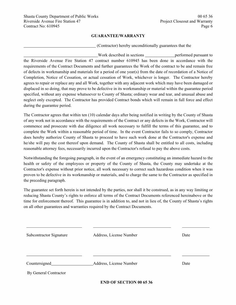
Shasta County Department of Public Works 00 65 36 Riverside Avenue Fire Station 47 Project Closeout and Warranty Contract No: 610945 Page 6
GUARANTEE/WARRANTY (Contractor) hereby unconditionally guarantees that the
Work described in sections performed pursuant to the Riverside Avenue Fire Station 47 contract number 610945 has been done in accordance with the requirements of the Contract Documents and further guarantees the Work of the contract to be and remain free of defects in workmanship and materials for a period of one year(s) from the date of recordation of a Notice of Completion, Notice of Cessation, or actual cessation of Work, whichever is longer. The Contractor hereby agrees to repair or replace any and all Work, together with any adjacent work which may have been damaged or displaced in so doing, that may prove to be defective in its workmanship or material within the guarantee period specified, without any expense whatsoever to County of Shasta; ordinary wear and tear, and unusual abuse and neglect only excepted. The Contractor has provided Contract bonds which will remain in full force and effect during the guarantee period.
The Contractor agrees that within ten (10) calendar days after being notified in writing by the County of Shasta of any work not in accordance with the requirements of the Contract or any defects in the Work, Contractor will commence and prosecute with due diligence all work necessary to fulfill the terms of this guarantee, and to complete the Work within a reasonable period of time. In the event Contractor fails to so comply, Contractor does hereby authorize County of Shasta to proceed to have such work done at the Contractor's expense and he/she will pay the cost thereof upon demand. The County of Shasta shall be entitled to all costs, including reasonable attorney fees, necessarily incurred upon the Contractor's refusal to pay the above costs.
Notwithstanding the foregoing paragraph, in the event of an emergency constituting an immediate hazard to the health or safety of the employees or property of the County of Shasta, the County may undertake at the Contractor's expense without prior notice, all work necessary to correct such hazardous condition when it was proven to be defective in its workmanship or materials, and to charge the same to the Contractor as specified in the preceding paragraph.
The guarantee set forth herein is not intended by the parties, nor shall it be construed, as in any way limiting or reducing Shasta County’s rights to enforce all terms of the Contract Documents referenced hereinabove or the time for enforcement thereof. This guarantee is in addition to, and not in lieu of, the County of Shasta’s rights on all other guarantees and warranties required by the Contract Documents.
Subcontractor Signature Address, License Number Date
Countersigned Address, License Number Date
By General Contractor
END OF SECTION 00 65 36

Shasta County Department of Public Works 00 73 12 Riverside Avenue Fire Station 47 General Conditions Contract No: 610945 Page 1
GENERAL CONDITIONS
SECTION 00 73 12
TABLE OF SUBSECTIONS 1. THE CONTRACT 2. NOT USED 3. COUNTY 4. CONTRACTOR 5. SUBCONTRACTORS 6. WORK BY COUNTY OR BY SEPARATE CONTRACTORS 7. MISCELLANEOUS PROVISIONS 8. TIME 9. PAYMENTS AND COMPLETION 10. PROTECTION OF PERSONS AND PROPERTY 11. INSURANCE 12. CHANGES IN THE WORK 13. INSPECTION, UNCOVERING AND CORRECTION OF WORK 14. TERMINATION OF THE CONTRACT 15. ADDITIONAL INSTRUCTIONS

Shasta County Department of Public Works 00 73 12 Riverside Avenue Fire Station 47 General Conditions Contract No: 610945 Page 2
PART 1 – CONTRACT DOCUMENTS
1.1 DEFINITIONS
1.1.1 THE CONTRACT
The Contract Documents, as that term is defined in Section 00 52 13 of the “Contract between County of Shasta and Contractor,” form the Contract. This Contract represents the entire and integrated Contract between the parties hereto and supersedes all prior negotiations, representations or agreements, either written or oral. Nothing contained in the Contract Documents shall create any contractual relationship between the County and any Subcontractor or Sub-subcontractor.
1.2 EXECUTION, CORRELATION AND INTENT
1.2.1 The Contract Documents shall be signed in not less than four (4) original copies by the
County and the Contractor. 1.2.2 Execution of the Contract by the Contractor is a representation that the Contractor has
visited the Work Site, reviewed relevant reports and otherwise become familiar with the local conditions under which the Work is to be performed, and has correlated personal observations with the requirements of the Contract Documents.
1.2.3 The intent of the Contract Documents is to include all items necessary for the proper
execution and completion of the Work. The Contract Documents are complementary, and what is required by anyone shall be as binding as if required by all. Work not covered in the Contract Documents will not be required unless it is consistent therewith and is reasonably inferable as being necessary to produce the intended results. Words and abbreviations that have well-known technical or trade meanings are used in the Contract Documents in accordance with such recognized meanings.
1.2.4 Subject to Part 15.10, “Application of Highest Standards and Requirements,” of these
General Conditions, in cases of discrepancy concerning dimension, quantity and location, the Drawings shall take precedence over the Specifications. Explanatory notes on the Drawings shall take precedence over conflicting drawn indications. Large-scale details shall take precedence over smaller scale details and figured dimensions shall take precedence over scaled measurement. Where figures are not shown, scale measurements shall be followed but shall in all cases be verified by measuring actual conditions of Work already in place. In cases of discrepancy concerning application of materials and non-technical requirements over materials, the specifications shall take precedence over Drawings. In the case of discrepancy between the General Conditions and the General Requirements, the General Requirements shall take precedence.
1.2.5 If the Contractor observes any errors, discrepancies or omissions in the Contract
Documents, Contractor shall promptly notify the County requesting clarification. If the Contractor proceeds with work affected by such errors, discrepancies or omissions, without having received such clarification, Contractor does so at Contractor’s own risk. Any adjustments involving such circumstances made by the Contractor, prior to approval by the County, shall be at the Contractor’s risk and the settlement of any complications or disputes arising shall be at the Contractor's sole expense and

Shasta County Department of Public Works 00 73 12 Riverside Avenue Fire Station 47 General Conditions Contract No: 610945 Page 3
Contractor shall indemnify, hold harmless and defend County, and its officers and employees, from any liability or loss with respect to said adjustments.
1.2.6 All work and material shall be the best of the respective kinds specified or indicated.
Should any workmanship or materials be required which are not directly or indirectly called for in the Contract Documents but which are necessary for proper fulfillment of the obvious intent thereof, said workmanship or materials shall be the same for similar parts that are detailed, indicated, or specified, and the Contractor agrees same to be implied and has provided for it in Contractor’s tender as if it were particularly described or delineated.
1.3 OWNERSHIP AND USE OF DOCUMENTS
1.3.1 All Drawings, Specifications and copies thereof furnished to Contractor shall remain
the property of the County. With the exception of one contract set for each party to the Contract, such documents are to be returned by Contractor on request at the completion of the Work.
PART 2 - (NOT USED) PART 3 - COUNTY
3.1 DEFINITION
3.1.1 The term County means the County of Shasta or the County's authorized representative for the Work as described in Section 00 73 13 “Supplementary Conditions”, Part 3.1.1.
3.2 INFORMATION AND SERVICES REQUIRED OF THE COUNTY
3.2.1 Except as provided in Part 4.7.1 of these General Conditions, the County shall secure
and pay for necessary approvals, easements, assessments and charges required for the construction, use or occupancy of permanent structures or for permanent changes in existing facilities.
3.2.2 Information or services under the County's control shall be furnished by the County to
the Contractor with reasonable promptness to avoid delay in the orderly progress of the Work.
3.2.3 The County shall forward all instructions to the Contractor. 3.2.4 The foregoing are in addition to other duties and responsibilities of the County
enumerated herein and especially those in respect to Work By County or By Separate Contractors, Payments and Completion, and Insurance in Part 6, “Work by County or by Separate Contractors,” Part 9, “Payments and Completion,” and Part 11, “Insurance,” of these General Conditions, respectively.
3.3 COUNTY'S RIGHT TO STOP THE WORK
3.3.1 If the Contractor fails to correct defective Work as required by Part 13.2, “Correction
of Work,” of these General Conditions, or persistently fails to carry out the Work in accordance with the Contract Documents, the County, by a written order signed

Shasta County Department of Public Works 00 73 12 Riverside Avenue Fire Station 47 General Conditions Contract No: 610945 Page 4
personally or by an agent specifically so empowered by the County in writing, may order the Contractor to stop the Work, or any portion thereof, until the cause for such order has been eliminated; however, this right of the County to stop the Work shall not give rise to any duty on the part of the County to exercise this right for the benefit of Contractor or any other person or entity, except to the extent required by Part 6.1.3 of these General Conditions.
3.4 COUNTY'S RIGHT TO CARRY OUT THE WORK
3.4.1 If the Contractor defaults or neglects to carry out the Work in accordance with the
Contract Documents, and within three (3) days fails after written notice from the County to correct such default or neglect with diligence and promptness, the County may, after an additional written notice and without prejudice to any other remedy the County may have, make good such deficiencies. In such case an appropriate Change Order shall be issued deducting from the payments then or thereafter due the Contractor the cost of correcting such deficiencies, including compensation for the additional services of a Project Manager or other Professionals made necessary by such default, neglect or failure. If the payments then or thereafter due the Contractor are not sufficient to cover such amount, the Contractor shall pay the difference to the County, or County may make claim upon performance or warranty bonds.
PART 4 – CONTRACTOR
4.1 DEFINITION
4.1.1 The Contractor is the person or entity identified as such in the Contract Documents.
The term Contractor means the Contractor or the Contractor's authorized representative.
4.2 REVIEW OF CONTRACT DOCUMENTS AND FIELD CONDITIONS
4.2.1 The Contractor shall carefully study and compare the Contract Documents and shall at once report to the County any error, inconsistency or omission that may be discovered. The Contractor shall perform no portion of the Work at any time unless authorized by the Contract Documents or, where required, approved Shop Drawings, Product Data or Samples for such portion of the Work.
4.2.2 The County does not assume any responsibility for an understanding or representation
made by any of its agents or representation prior to the execution of the Contract unless (1) such understanding or representation is expressly stated in the Contract and (2) the Contract expressly provides that responsibility therefore is assumed by the County.
4.2.3 Failure by the Contractor to become acquainted with all available information will not
relieve Contractor from responsibility for estimating properly the difficulty or cost of successfully performing the Work.
4.2.4 The Contractor shall take field measurements and verify field conditions and shall
carefully compare such field measurements and conditions and other information known to the Contractor with the Contract Documents before commencing activities. Errors, inconsistencies or omissions discovered shall be reported to the County at once.
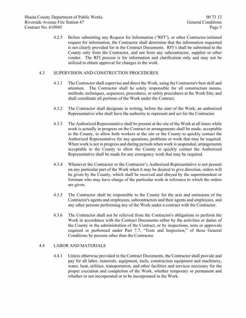
Shasta County Department of Public Works 00 73 12 Riverside Avenue Fire Station 47 General Conditions Contract No: 610945 Page 5
4.2.5 Before submitting any Request for Information (“RFI”), or other Contractor-initiated request for information, the Contractor shall determine that the information requested is not clearly provided for in the Contract Documents. RFI’s shall be submitted to the County only from the Contractor, and not from any subcontractor, supplier or other vendor. The RFI process is for information and clarification only and may not be utilized to obtain approval for changes in the work.
4.3 SUPERVISION AND CONSTRUCTION PROCEDURES
4.3.1 The Contractor shall supervise and direct the Work, using the Contractor's best skill and
attention. The Contractor shall be solely responsible for all construction means, methods, techniques, sequences, procedures, or safety procedures at the Work Site; and shall coordinate all portions of the Work under the Contract.
4.3.2 The Contractor shall designate in writing, before the start of the Work, an authorized
Representative who shall have the authority to represent and act for the Contractor. 4.3.3 The Authorized Representative shall be present at the site of the Work at all times while
work is actually in progress on the Contract or arrangements shall be made, acceptable to the County, to allow both workers at the site or the County to quickly contact the Authorized Representative for any questions, problems or work that may be required. When work is not in progress and during periods when work is suspended, arrangements acceptable to the County to allow the County to quickly contact the Authorized Representative shall be made for any emergency work that may be required.
4.3.4 Whenever the Contractor or the Contractor’s Authorized Representative is not present
on any particular part of the Work when it may be desired to give direction, orders will be given by the County, which shall be received and obeyed by the superintendent or foreman who may have charge of the particular work in reference to which the orders are given.
4.3.5 The Contractor shall be responsible to the County for the acts and omissions of the
Contractor's agents and employees, subcontractors and their agents and employees, and any other persons performing any of the Work under a contract with the Contractor.
4.3.6 The Contractor shall not be relieved from the Contractor's obligations to perform the
Work in accordance with the Contract Documents either by the activities or duties of the County in the administration of the Contract, or by inspections, tests or approvals required or performed under Part 7.7, “Tests and Inspection,” of these General Conditions by persons other than the Contractor.
4.4 LABOR AND MATERIALS
4.4.1 Unless otherwise provided in the Contract Documents, the Contractor shall provide and
pay for all labor, materials, equipment, tools, construction equipment and machinery, water, heat, utilities, transportation, and other facilities and services necessary for the proper execution and completion of the Work, whether temporary or permanent and whether or not incorporated or to be incorporated in the Work.

Shasta County Department of Public Works 00 73 12 Riverside Avenue Fire Station 47 General Conditions Contract No: 610945 Page 6
4.4.2 The Contractor shall at all-time enforce strict discipline and good order among the Contractor's employees and shall not employ on the Work any unfit person or anyone not skilled in the task assigned them.
4.4.3 The Contractor shall deliver to the County, prior to final acceptance of the Work as a
whole, signed certificates from suppliers of materials and manufactured items stating that such items conform to the Contract Documents.
4.4.4 The Contractor, immediately upon issuance of the Notice to Proceed (or where shop
drawings, samples, etc., are required, immediately upon receipt of approval thereof) shall place orders for all materials, work fabrication, and/or equipment to be employed by Contractor in the Work. The Contractor shall keep all materials, work fabrications and/or equipment specified and shall advise the County promptly, in writing, of all orders placed and of such materials, work fabrications and/or equipment which may not be available in a timely manner for the purposes of the Contract.
4.4.5 Workmen whose work is unsatisfactory to the County, or are considered by the County
to be careless, incompetent, unskilled or otherwise unfit shall be dismissed from work under the Contract upon written request to the Contractor from the County.
4.5 WARRANTY
4.5.1 The Contractor warrants to the County that all materials and equipment furnished under
this Contract will be new unless otherwise specified, and that all work will be of good quality, free from faults and defects and in conformance with the Contract Documents. All work not conforming to these requirements, including substitutions not properly approved and authorized, may at the County’s sole discretion be considered defective. If required by the County, the Contractor shall furnish satisfactory evidence as to the kind and quality of materials and equipment. This warranty is not limited by the provisions of Part 13.2, “Corrective Work,” of these General Conditions.
4.6 TAXES
4.6.1 The Contractor shall pay all sales, consumer, use and other similar taxes for the Work
or portions thereof provided by the Contractor which are legally enacted at the time bids are opened, whether or not yet effective.
4.7 PERMITS, FEES AND NOTICES
4.7.1 Unless otherwise provided in the Contract Documents, the County shall secure and pay
for any necessary building permit, permanent utility connection fee, and right-of-way encroachment permit. The Contractor shall secure and pay for temporary construction utilities, and all other permits and governmental fees, licenses and inspections necessary for the proper execution and completion of the Work which are customarily secured after execution of the Contract and which are legally required at the time bids are opened.
4.7.2 The Contractor shall give all notices and comply with all laws, ordinances, rules,
regulations and lawful orders of any public authority bearing on the performance of the Work.
Shasta County Department of Public Works 00 73 12 Riverside Avenue Fire Station 47 General Conditions Contract No: 610945 Page 7
4.7.3 It is not the responsibility of the Contractor to make certain that the Contract Documents are in accordance with applicable laws, statutes, building codes and regulations. However, if the Contractor observes that any of the Contract Documents are at variance therewith in any respect, the Contractor shall promptly notify the County in writing, and any necessary changes shall be accomplished by appropriate modification.
4.7.4 If the Contractor performs any work knowing it to be contrary to any laws, ordinances,
rules and regulations, without notice to the County, the Contractor shall assume full responsibility therefor and shall bear all costs attributable thereto.
4.7.5 Any reference in the Specifications text to codes, standard specifications or
manufacturer's instructions shall mean the latest printed edition of each in effect at the Contract date.
4.8 ALLOWANCES
4.8.1 The Contractor shall include in the Contract Sum all allowances stated in the Contract
Documents. Items covered by these allowances shall be supplied for such amounts and by such persons as the County may direct, but the Contractor will not be required to employ persons against whom the Contractor makes a reasonable objection.
4.8.2 Unless otherwise provided in the Contract Documents:
.1 this allowance shall cover the cost to the Contractor, less any applicable trade
discount, of the materials and equipment required by the allowance, delivered at the site, and all applicable taxes;
.2 the Contractor's costs for unloading and handling on the site, labor, installation
costs, overhead, profit and other expenses contemplated for the original allowance shall be included in the Contract Sum and not in the allowance;
.3 whenever the cost is more or less than the allowance, the Contract Sum shall
be adjusted accordingly by Change Order, the amount of which will recognize changes, if any, in handling costs on the site, labor, installation costs, overhead, profit and other expenses.
4.9 (NOT USED) 4.10 (NOT USED) 4.11 RECORDS, DOCUMENTS AND SAMPLES
4.11.1 The Contractor shall maintain all records of required City, County or State inspections
and shall promptly notify the County of the results of any inspection. Copies of all such records shall be provided to the County upon request.
4.11.2 The Contractor shall secure and maintain required certificates of inspection, testing or
approval and shall promptly deliver them to the County. 4.11.3 The Contractor shall maintain at the Work Site, on a current basis, one record copy of
all Drawings, Specifications, Addenda, Change Orders and other Modifications, in

Shasta County Department of Public Works 00 73 12 Riverside Avenue Fire Station 47 General Conditions Contract No: 610945 Page 8
good order and marked currently to record all changes made during construction, and approved Shop Drawings, Product Data and Samples. These shall be available to the County, and shall be delivered to the County upon completion of the Work. The Contractor shall advise the County on a current basis of all changes in the Work made during construction.
4.11.4 Prior to approval of the monthly payment application, Contractor shall review above-
referenced documents with the County to assure compliance. Approval of payment application is contingent upon above referenced records being current.
4.12 SHOP DRAWINGS, PRODUCT DATA AND SAMPLES
4.12.1 Shop Drawings are drawings, diagrams, schedules and other data specially prepared for
the Work by the Contractor or any Subcontractor, manufacturer, supplier or distributor to illustrate some portion of the Work.
4.12.2 Product Data are illustrations, standard schedules, performance charts, instructions,
brochures, diagrams and other information furnished by the Contractor to illustrate a material, product or system for some portion of the Work.
4.12.3 Samples are physical examples that illustrate materials, equipment or workmanship,
and establish standards by which the Work will be judged. 4.12.4 The Contractor shall prepare, review, approve and submit to the County, with
reasonable promptness and in such sequence as to cause no delay in the Work or in the work of the County or any separate contractor, all Shop Drawings, Product Data and Samples required by the Contract Documents.
4.12.5 By preparing, approving and submitting Shop Drawings, Product Data and Samples,
the Contractor represents that the Contractor has determined and verified all materials, field measurements and field construction criteria related thereto and has checked and coordinated the information contained within such submittals with the requirements of the Work and the Contract Documents.
4.12.6 The Contractor shall not be relieved of responsibility for any deviation from the
requirements of the Contract Documents by the County's review of Shop Drawings, Product Data or Samples, unless the Contractor has specifically informed the County in writing of such deviation at the time of submission and the County has given written approval to the specific deviation. The Contractor shall not be relieved from responsibility for errors or omissions in the Shop Drawings, Product Data or Samples by the County's approval of them.
4.12.7 When professional certification of performance criteria of materials, systems or
equipment is required by the Contract Documents, the County shall be entitled to rely upon the accuracy and completeness of such calculations and certifications. The cost of such certifications shall be borne by the Contractor. County may elect to have an independent certification performed at Contractor’s own expense. The County shall have final approving authority for performance-based items.

Shasta County Department of Public Works 00 73 12 Riverside Avenue Fire Station 47 General Conditions Contract No: 610945 Page 9
4.12.8 The Contractor shall direct specific attention, in writing or on resubmitted Shop drawings, Product Data, or Samples, to revisions other than those requested by the County on previous submittals.
4.12.9 No portion of the Work requiring submission of a Shop Drawing, Product Data or
Sample shall be commenced until the submittal has been reviewed by the County as provided in Section 01 33 00, “Submittal Procedures.” All such portions of the Work shall be in accordance with approved submittals.
4.12.10 Submission of Shop Drawings and Samples to the County is required for only those
items specifically mentioned in the Specification Sections. If Contractor submits Shop Drawings for items other than the above, the County will not be obligated to distribute or review them. Contractor shall be responsible for the procuring of Shop Drawings for Contractor’s own use as Contractor may require for the progress of the Work.
4.12.11 The term "Shop Drawings" as used herein also includes but is not limited to fabrication,
erection, layout and setting drawings, manufacturer's standard drawings, descriptive literature, catalogs, brochures, performance and test data, wiring and control diagrams, all other drawings and descriptive data pertaining to materials, equipment, piping, duct and conduit systems, and methods of construction as may be required to show that the materials, equipment or systems and the positions and layout of each conform to the Contract requirements. As used herein the term "manufactured" applies to standard units usually mass-produced and "fabricated" means items specifically assembled or made out of selected materials to meet individual design requirements. Shop Drawings shall establish the actual detail of all manufactured or fabricated items; indicate proper relation to adjoining work; amplify design details of mechanical and electrical equipment in proper relation to physical spaces in the structure; and incorporate minor changes of design or construction to suit actual conditions.
4.12.12 Drawings: Following the Contractor's review and approval, Contractor shall submit to
the County a minimum of four (4) prints of each drawing for approval. The County will check the drawings and affix a stamp to the drawings, indicating the status of acceptance, and will return same to the Contractor, each retaining prints for their records. Comments, if any, will be noted directly on the drawings. The Contractor shall then print and distribute the appropriate number of copies to the Contractor’s job personnel as required. If a drawing is stamped "Rejected", the Contractor shall correct and resubmit as outlined above. When stamped "Implement Exception Noted", or similar instructions, the Contractor shall correct and resubmit for record only, two prints of each drawing.
4.12.13 Samples: Following the Contractor's review and approval, Contractor shall submit to
the County, two samples of all materials in quantities and sizes as specified herein. Submittals shall be given to the County at a time determined by the Contractor, which allows for any necessary resubmittal and which will not cause any delay in the Work. If a sample is rejected, one sample noted so will be returned to the Contractor. If a sample is marked "Make changes as noted and continue with Work," one sample so noted will be returned. Corrected samples shall be resubmitted for approval as per the original submittal.
4.12.14 Brochures: Following the Contractor's review and approval, Contractor shall submit to
the County, six (6) copies of all manufacturer's catalogs or brochures as required. If a
Shasta County Department of Public Works 00 73 12 Riverside Avenue Fire Station 47 General Conditions Contract No: 610945 Page 10
brochure is stamped "No Exception Taken", two (2) copies will be returned to the Contractor. If stamped "Rejected by the County", one marked copy and two (2) unmarked copies will be returned. Corrected copies shall be resubmitted to County for approval as per the original submittal.
4.12.15 Manufacturer's Instructions: Where any item or work is required by the Specifications
to be furnished, installed or performed in accordance with a specified product manufacturer's instructions, Contractor shall procure and distribute the necessary copies of such instructions to the Contractor’s or Subcontractor’s personnel performing this Work and to the County.
4.12.16 When professional certification of performance criteria of materials, systems or
equipment is required by the Contract Documents, and the County has no information creating doubt as to the reliability of such certification, the County shall be entitled to rely upon the accuracy and completeness of such calculations and certifications. The County shall have final approving authority for performance-based items.
4.13 USE OF SITE
4.13.1 The Contractor shall confine operations at the Work Site to areas permitted by law, ordinances, permits and the Contract Documents, and shall not unreasonably encumber the site with any materials or equipment. The Contractor shall be liable for any and all damage caused by Contractor to County's premises. The Contractor shall hold and save the County, its agents, and representatives, free and harmless and defend them from liability of any nature or kind arising from any use, trespass, or damage occasioned by Contractor’s operations at the Work Site or by third persons.
4.13.2 The Contractor shall coordinate all of the Contractor's operations with, and secure
approval from, the County before using any portion of the Work. 4.14 CUTTING AND PATCHING OF WORK
4.14.1 The Contractor shall be responsible for all cutting, fitting or patching that may be required to complete the Work or to make its several parts fit together properly.
4.14.2 The Contractor shall not damage or endanger any portion of the Work or the work of
the County or any separate contractors by cutting, patching or otherwise altering any work, or by excavation. The Contractor shall not cut or otherwise alter the work of the County or any separate contractor except with the written consent of the County and of such separate contractor. The Contractor shall not unreasonably withhold from the County or any separate contractor consent to cutting or otherwise altering the Work.
4.14.3 In all cases Contractor shall exercise extreme care in cutting operations, and perform
such operations under adequate supervision by competent mechanics skilled in the applicable trade. Openings shall be neatly cut and shall be kept as small as possible to avoid unnecessary damage. Careless and/or avoidable cutting damage, etc., will not be tolerated, and the Contractor will be held responsible for such avoidable or willful damage.
4.14.4 All replacing, patching and repairing of all materials and surfaces cut or damaged in the
execution of the Work shall be performed by experienced mechanics of the several
Shasta County Department of Public Works 00 73 12 Riverside Avenue Fire Station 47 General Conditions Contract No: 610945 Page 11
trades involved. Such replacing, repairing or patching shall be done with the applicable materials, in such a manner that all surfaces so replaced, repaired, or patched will, upon completion of the Work, match the surrounding similar surfaces.
4.15 CLEANING UP
4.15.1 The Contractor shall at all-time keep the Work Site and its vicinity free from accumulation of waste materials or rubbish caused by the Contractor's operations. At the completion of the Work, the Contractor shall remove all the Contractor's waste materials and rubbish from and about the Work Site as well as all the Contractor's tools, construction equipment, machinery and surplus materials.
4.15.2 If the Contractor fails to clean up at the completion of the Work, the County may do so
as provided in Part 3.4, “County’s Right to Carry out the Work,” of these General Conditions and the cost thereof shall be paid by the Contractor.
4.16 ROYALTIES AND PATENTS
4.16.1 The Contractor shall pay all royalties and license fees, shall defend all suits or claims for infringement of any patent rights and shall defend and save the County harmless from loss on account thereof. If the Contractor has reason to believe that the design, process or product selected is an infringement of a patent, the Contractor shall be responsible for such loss unless such information is promptly given to the County.
4.17 INDEMNIFICATION
4.17.1 The Contractor’s attention is directed to Part 1.8 of Section 00 52 13, “Contract between County of Shasta and Contractor.”
4.17.2 In any and all claims against the County and/or the County’s consultants, or any of their
agents or employees by any employee of the Contractor, any Subcontractor, anyone directly or indirectly employed by any of them or anyone for whose acts any of them may be liable, the indemnification obligation under this Part 4.17 shall not be limited in any way by any limitation on the amount or type of damages, compensation or benefits payable by or for the Contractor or any Subcontractor under workers' compensation acts, disability benefit acts or other employee benefit acts.
4.17.3 The obligations of the Contractor under this Part 4.17 shall not extend to the giving of
or the failure to give directions or instructions by the County, its agents or employees, provided such giving or failure to give directions is the primary cause of the injury or damage.
4.18 NONDISCRIMINATION CLAUSE
4.18.1 During the performance of the Work, Contractor and its Subcontractors shall not deny benefits to any person on the basis of sex, race, color, creed, ancestry, religion, national origin, physical or mental disability, sexual orientation, medical condition (cancer, HIV and AIDS), age (over 40), marital status, or other protected status, nor shall they unlawfully discriminate, harass or allow harassment, against any employee or applicant for employment because of sex, race, color, creed, ancestry, religion, national origin, physical or mental disability, sexual orientation, medical condition (cancer, HIV and

Shasta County Department of Public Works 00 73 12 Riverside Avenue Fire Station 47 General Conditions Contract No: 610945 Page 12
AIDS), age (over 40), marital status, or other protected status, nor deny family care leave and or pregnancy disability leave.
4.18.2 Contractor and Contractor’s Subcontractors shall insure that the evaluation and
treatment of their employees and applicants for employment are free from such discrimination and harassment. Contractor and Contractor’s Subcontractors shall comply with the provisions of the Americans with Disability Act (ADA) of 1990 (42 U.S.C. section 12101, et seq.), California Fair Employment and Housing Act (Government Code, Section 12990 et seq.) and the applicable regulations promulgated thereunder (CCR, Title 2, Section 7285.0 et seq.).
4.18.3 The applicable regulations of the Fair Employment and Housing Commission
implementing Government Code Section 12990, set forth in Chapter 5 of Division 4 of Title 2 of the California Code of Regulation are incorporated into this Contract by reference and made a part hereof as if set forth in full. Contractor and Contractor’s Subcontractors shall give written notice of their obligations under this clause to labor organizations with which they have a collective bargaining or other agreement.
4.18.4 Contractor shall comply with all applicable nondiscrimination laws and regulations. 4.18.5 The Contractor and Contractor’s Subcontractors shall include the nondiscrimination
and compliance provisions of this Part 4.18 in all contracts and subcontracts to perform work under this Contract.
PART 5 – SUBCONTRACTORS
5.1 DEFINITION
5.1.1 A Subcontractor is a person or entity that has a direct contract with the Contractor to perform any of the Work. The term Subcontractor means a Subcontractor or a Subcontractor's authorized representative. The term Subcontractor does not include any separate contractor or any separate contractor's subcontractors.
5.1.2 A Sub-subcontractor is a person or entity that has a direct or indirect contract with a
Subcontractor to perform any of the Work. The term Sub-subcontractor means a Sub-sub-contractor or an authorized representative thereof.
5.2 AWARDS OF SUBCONTRACTS AND OTHER CONTRACTS FOR PORTIONS OF THE
WORK
5.2.1 The Contractor shall only use the Subcontractors included in the Contractor’s sealed bid unless first approved in writing by the County.
5.2.2 The Contractor shall not use any Subcontractor ineligible to perform work on a Public
Works Project pursuant to Section 1777.1 or 1777.7 of the Labor Code. 5.3 SUBCONTRACTUAL RELATIONS
5.3.1 By an appropriate written contract, the Contractor shall require each Subcontractor, to
the extent of the work to be performed by the Subcontractor, to be bound to the Contractor by the terms of the Contract Documents, and to assume toward the

Shasta County Department of Public Works 00 73 12 Riverside Avenue Fire Station 47 General Conditions Contract No: 610945 Page 13
Contractor all the obligations and responsibilities which the Contractor, by the Contract Documents, assumes toward the County. Said contract shall preserve and protect the rights of the County under the Contract Documents with respect to the work to be performed by the Subcontractor so that the subcontracting thereof will not prejudice such rights, and shall allow to the Subcontractor, unless specifically provided otherwise in the Contractor-Subcontractor agreement, the benefit of all rights, remedies and redress against the Contractor that the Contractor, by these Documents, has against the County. Where appropriate, the Contractor shall require each Subcontractor to enter into similar agreements with their Sub-subcontractors. The Contractor shall make available to each proposed Subcontractor, prior to the execution of the agreement, copies of the Contract Documents to which the Subcontractor will be bound by this Part 5.3, and identify to the Subcontractor any terms and conditions of the proposed agreement which may be at variance with the Contract Documents. Each Subcontractor shall similarly make copies of the Contract Documents available to their Sub-subcontractors. Nothing contained herein shall be deemed to create an agency relationship between the County and any Subcontractor, Sub-subcontractor, or material supplier.
5.3.2 The submission or addition of Subcontractors shall be permitted only as authorized by
Public Contract Code Section 4100, et. seq. The Subcontractors employed by the Contractor shall be appropriately licensed in conformity with the laws of the State of California.
5.3.3 Nothing contained in this Contract shall create any contractual relationship between any
Subcontractor, Sub-subcontractor, and the County. 5.3.4 Jurisdictional disputes between Subcontractors or between Contractor and
Subcontractor shall not be mediated or decided by the County. The Contractor shall be responsible for the resolution of all such disputes based upon Contractor’s contractual relationship with Contractor’s Subcontractors.
PART 6 – WORK BY COUNTY OR BY SEPARATE CONTRACTORS
6.1 COUNTY'S RIGHT TO PERFORM WORK AND TO AWARD SEPARATE CONTRACTS
6.1.1 The County reserves the right to perform work related to the Work with the County's
own forces, and to award separate contracts in connection with other portions of the Work or other work on the site under these or similar General Conditions of the Contract. If the Contractor claims that delay, damage or additional cost is involved because of such action by the County, the Contractor shall make such claim as provided elsewhere in the Contract Documents.
6.1.2 When separate contracts are awarded for different portions of the Work or other work,
the term “Contractor” in the Contract Documents in each case shall mean the Contractor who executes each separate contract.
6.1.3 The County shall provide for coordination of the activities of the County's own forces
and of each separate contractor with the Work of the Contractor, and the Contractor shall cooperate with them. The Contractor shall participate with other separate contractors and the County in reviewing their construction schedules when directed to do so. The Contractor shall make any revisions to the construction schedule deemed

Shasta County Department of Public Works 00 73 12 Riverside Avenue Fire Station 47 General Conditions Contract No: 610945 Page 14
necessary after a joint review and mutual agreement. The construction schedules shall then constitute the schedules to be used by the Contractor, separate contractors and the County until subsequently revised.
6.1.4 Unless otherwise provided in the Contract Documents, when the County performs
construction or operations related to the Work with the County's own forces, the County shall be deemed to have the same rights which apply to the Contractor under the conditions of the Contract including, without excluding others, those stated in Part 4, “Contractor,” this Part 6 and Part 10, “Protection of Persons and Property,” Part 11, “Insurance,” and Part 13, “Uncovering and Correction of Work,” of these General Conditions.
6.2 MUTUAL RESPONSIBILITY
6.2.1 The Contractor shall afford the County and separate contractor’s reasonable opportunity
for introduction and storage of their materials and equipment and performance of their activities and shall connect and coordinate the Contractor's construction and operations with theirs as required by the Contract Documents.
6.2.2 When any part of the Contractor's work depends for proper execution or results upon
the work of the County or any separate contractor, the Contractor shall, prior to proceeding with the work, promptly report to the County any apparent discrepancies or defects in such other work that render it unsuitable for such proper execution and results. Failure of the Contractor so to report shall constitute an acceptance of the County's or separate contractor's work as fit and proper, except as to defects that may subsequently become apparent in such work by others.
6.2.3 If, following the reporting of any discrepancy or defect as required in Part 6.2.2 above,
the Contractor suffers damage due to disruption or delay caused by the separate contractor, without fault by the County, the Contractor's remedy shall be limited to seeking recovery from the separate contractor.
6.2.4 Any costs caused by defective or ill-timed work by the Contractor shall be borne by the
Contractor. 6.2.5 Should the Contractor cause damage to the Work, Work Site, or property of the County,
or to other work or property on the Work Site, the Contractor shall promptly remedy such damage as provided in Part 10.2.5 of these General Conditions.
6.2.6 Should the Contractor wrongfully delay or cause damage to the work or property of any
separate contractor, the Contractor shall, upon due notice, promptly attempt to settle with such other contractor by agreement, or otherwise to resolve the matter. If such separate contractor sues the County on account of any delay or damage alleged to have been caused by the Contractor, the County shall notify the Contractor who shall defend such proceedings, and if any judgment or award against the County arises, the Contractor shall within 30 days pay or satisfy it and shall reimburse the County for all costs which the County has incurred.
PART 7 – MISCELLANEOUS PROVISIONS
7.1 GOVERNING LAW

Shasta County Department of Public Works 00 73 12 Riverside Avenue Fire Station 47 General Conditions Contract No: 610945 Page 15
7.1.1 This Contract shall be governed by the law of the State of California.
7.2 SUCCESSORS AND ASSIGNS
7.2.1 The County and the Contractor, respectively, bind themselves, their partners,
successors, assigns and legal representatives to the other party hereto and to the partners, successors, assigns and legal representatives of such other party with respect to all covenants, agreements and obligations contained in the Contract Documents. Neither party to the Contract shall assign the Contract or sublet it as a whole without the written consent of the other.
7.3 WRITTEN NOTICE
7.3.1 Written notice shall be deemed to have been duly served if delivered in person to the
individual or member of the firm or entity or to an officer of the corporation for whom it was intended, or if delivered at or sent by registered or certified mail to the person and address shown in this Contract.
7.4 CLAIMS AND DISPUTES RESOLUTION
7.4.1 A Claim is a demand or assertion by Contractor seeking, as a matter of right, adjustment
or interpretation of Contract terms, payment of money or an extension of time, arising out of or relating to the Contract, or a request for equitable adjustment or Change Order which cannot be resolved pursuant to the provisions of Part 12, “Changes in the Work,” of these General Conditions. Any Claim shall be reduced to writing and filed with the County, within 20 calendar days after the Contractor has notice of the condition giving rise to the Claim. Contractor hereby waives all claims not made within the aforesaid time limit. Such 20-day notice of an asserted Claim is in addition to the requirement for prompt notice required per Part 12.3, “Request for Equitable Adjustment,” of these General Conditions.
7.4.2 The Contractor shall not claim or recover any overhead cost administrative or
otherwise, particularly “Home Office” expenses, “Extended site overhead,” or any other overhead cost on the basis of any “Home Office” damages formula, “Eichleay” formula, “Total Cost” recovery formula or any other such formula.
7.4.3 Contractor shall make any Claims in writing within the time set forth above, for any
unreasonable delay or hindrance caused by County, and specifying the cause thereof as required in Part 7.4.4, “Requirements for Filing a Claim.”
7.4.4 REQUIREMENTS FOR FILING A CLAIM: Claims must be filed within the time
specified in Part 7.4.1 above, but in no event later than the date of final payment. Claims shall be submitted to the County. The Claim shall be in writing and shall be for a sum certain. The Claim shall include a statement of the reasons for the asserted entitlement, and include the documents necessary to substantiate the Claim. Such documents may include but are not limited to payroll records, purchase orders, quotations, invoices, estimates, subcontracts, daily logs, supplier contracts, subcontract billings, bid takeoffs, equipment rental invoices, ledgers, journals, daily reports, job diaries, and any documentation related to the requirements of Part 12, “Changes in the Work,” of these General Conditions. In the case of a continuing delay, only one Claim is necessary. If

Shasta County Department of Public Works 00 73 12 Riverside Avenue Fire Station 47 General Conditions Contract No: 610945 Page 16
adverse weather conditions are the basis for a Claim for additional time, such Claim shall be documented by data substantiating that weather conditions were abnormal for the period of time and could not have been reasonably anticipated, and that weather conditions had an adverse effect on the critical activities on the construction schedule.
FALSE CLAIMS: California Penal Code Section 72, provides that any person who presents for payment with intent to defraud the County, its personnel or their representatives, any false or fraudulent claim, bill, account, voucher, or writing, is punishable by fines not exceeding ten thousand dollars ($10,000.00) and/or imprisonment in the state prison. Government Code Sections 12650, et seq., pertains to civil penalties that may be recovered from persons (including corporations, etc.) for presenting a false claim for payment or approval, presents a false record or statement to get a false claim paid or approved, or other acts, to any officer or employee of any political subdivision of the State of California. Any person or corporation violating the provisions of Government Code Sections 12650 et seq. shall be liable for three times the amount of the damages of the political subdivision, plus a civil penalty, plus costs. The County is obligated to report suspected false claims to the appropriate law enforcement agency.
All Claims by Contractor shall include the following certification, properly completed and executed by Contractor or any officer of Contractor: I, ____________________________________, BEING THE (MUST BE AN OFFICER) OF (CONTRACTOR), DECLARE UNDER PENALTY OF PERJURY UNDER THE LAWS OF THE STATE OF CALIFORNIA, AND DO PERSONALLY CERTIFY AND ATTEST THAT: I HAVE THOROUGHLY REVIEWED THE ATTACHED CLAIM FOR ADDITIONAL COMPENSATION AND/OR EXTENSION OF TIME, AND KNOW ITS CONTENTS, AND SAID CLAIM IS TRUTHFUL AND ACCURATE; THAT THE AMOUNT REQUESTED ACCURATELY REFLECTS THE CONTRACT ADJUSTMENT FOR WHICH THE OWNER IS LIABLE; AND, FURTHER, THAT I AM FAMILIAR WITH CALIFORNIA PENAL CODE SECTION 72 AND CALIFORNIA GOVERNMENT CODE SECTION 12650, ET SEQ., PERTAINING TO FALSE CLAIMS, AND FURTHER KNOW AND UNDERSTAND THAT SUBMISSION OR CERTIFICATION OF A FALSE CLAIM MAY LEAD TO FINES, IMPRISONMENT AND/OR OTHER SEVERE LEGAL CONSEQUENCES.
Nothing in this subdivision is intended to extend the time limit or supersede notice requirements otherwise provided by the Contract Documents for the filing of Claims. For any Claim subject to this Part 7.4, the following requirements apply:
.1 For Claims of less than fifty thousand dollars ($50,000), the County’s Project
Engineer, shall review the facts pertinent to the Claim, obtain additional information deemed necessary for a decision (if any), and secure assistance from legal and other advisors, and render a written decision on the Claim within 45 days of receipt of the Claim. If additional information is thereafter required, it shall be requested and provided pursuant to this subdivision, upon mutual agreement of the County’s Project Engineer and Contractor. The County’s Project Engineer’s written response to the Claim, as further documented, shall be submitted to the Contractor within 15 days after receipt of the further

Shasta County Department of Public Works 00 73 12 Riverside Avenue Fire Station 47 General Conditions Contract No: 610945 Page 17
documentation or within a period of time no greater than that taken by the claimant in producing the additional information, whichever is greater.
.2 For claims of over fifty thousand dollars ($50,000), the County’s Project
Engineer shall review the facts pertinent to the Claim, obtain additional information deemed necessary for a decision (if any), and secure assistance from legal and other advisors, and render a written decision on the Claim within 60 days of receipt of the Claim, or may request, in writing, within 30 days of receipt of the Claim, any additional documentation supporting the Claim or relating to defenses or claims the County may have against the claimant. If additional information is thereafter required, it shall be requested and provided. The County’s Project Engineer’s written response to the Claim, as further documented, shall be submitted to the Contractor within 30 days after receipt of the further documents, or a period of time no greater than that taken by the claimant in producing the additional information or requested documentation, whichever is greater.
.3 If the Contractor disputes the written response of the County’s Project
Engineer, or fails to respond within the time prescribed, the Contractor may so notify the Public Works Director, in writing, either within 15 days of receipt of the County’s Project Engineer’s response or within 15 days of the County’s Project Engineer’s failure to respond within the time prescribed, respectively, and demand an informal conference to meet and confer for settlement of the issues in dispute. Upon a demand, the County’s Project Engineer shall schedule a meeting and conference within 30 days for settlement of the dispute.
.4 If following the meet and confer conference the Claim or any portion remains
in dispute, the Contractor may file a Claim pursuant to Chapter 1 (commencing with Section 900) and Chapter 2 (commencing with Section 910) of Part 3 of Division 3.6 of Title 1 of the Government Code. For purposes of those provisions, the running of the period of time within which a Claim must be filed shall be tolled from the time the Contractor submits the Contractor’s written Claim until the time the Claim is denied, including any period of time utilized by the meet and confer conference.
Submission of a Claim, in conformance with all these requirements of this Contract, and rejection of all or part of said Claim by County, is a condition precedent to any action by Contractor against County, including but not limited to, the filing of a lawsuit or making demand for arbitration, if arbitration is expressly provided for in this Contract.
7.4.5 CLAIMS AND DISPUTES EXEMPT FROM FILING REQUIREMENTS: The procedures and remedies provided in this Part 7.4 do not apply to:
.1 Any Claims by the County; .2 Any Claim for or respecting personal injury or death or reimbursement or other
compensation arising out of or resulting from liability for personal injury or death;
.3 Any Claim or dispute relating to stop payment requests or stop notices; and
Shasta County Department of Public Works 00 73 12 Riverside Avenue Fire Station 47 General Conditions Contract No: 610945 Page 18
.4 Any Claim related to the approval, refusal to approve, or substitution of
Subcontractors, regardless of tier, and suppliers. 7.4.6 PAYMENT OF UNDISPUTED PORTION OF CLAIM: County shall pay Contractor
such portion of a Claim that is undisputed except as otherwise provided in this Contract. 7.4.7 CONTINUE WORK DURING DISPUTE: In the event of any dispute between the
County and the Contractor, the Contractor shall not stop work but will prosecute the work diligently to completion in the manner directed by the County, and the dispute shall be resolved by a court of law, or otherwise, after completion of the Work. However, Contractor must submit all disputes in accordance with the provisions of this Part 7.4.
7.4.8 SUIT IN SHASTA COUNTY ONLY: Any litigation arising out of this Contract shall
be brought in Shasta County and Contractor hereby waives the removal provisions of California Code of Civil Procedure Section 394.
7.4.9 The County, or its authorized representative, shall have access, upon reasonable notice
during normal business hours, to Contractor and Subcontractors’ books, documents and accounting records, including but not limited to, bid worksheets, bids, Subcontractor bids, and proposals, estimates, cost accounting data, accounting records, payroll records, time sheets, cancelled checks, profit and loss statements, balance sheets, correspondence including but not limited to all correspondence between Contractor and Contractor’s sureties and Subcontractors/vendors, Work files, scheduling information, and other records of the Contractor and all Subcontractors directly or indirectly pertinent to the Work, original as well as change and claimed extra work, to verify and evaluate the accuracy of cost and pricing data submitted with any change order, prospective or completed, or any claim for which additional compensation has been requested or notice of potential claim has been tendered.
Such access shall include the right to examine and audit such records, and make excerpts, transcriptions and photocopies at County’s expense.
The parties agree that in the event Contractor or any Subcontractor fails to comply with this Section, it would be difficult for the County to determine its actual damages; therefore, Contractor agrees to pay County, as liquidated damages, the sum of $200.00, which Contractor agrees is reasonable under the circumstances, for each and every calendar day which Contractor or a Subcontractor fails or refuses to provide the County and/or its authorized representatives, access to the materials specified in this Section.
Contractor agrees to impose upon its Subcontractors by appropriate subcontract provision, the obligations of this Part 7.4.
7.4.10 CLAIMS, ARBITRATION, GOVERNING LAW AND VENUE: Any claim or demand, arising under or relating to the performance of this Contract, as defined in Public Contract Code section 9204(c)(1)(A-C) shall be subject to the procedures set forth in Public Contract Code section 9204 (A copy is attached hereto and made a part hereof). Any claim or demand for monetary compensation or damages, arising under or relating to the performance of this Contract, not defined in Public Contract Code section 9204(c)(1)(A-C) shall be resolved through arbitration through the rules and
Shasta County Department of Public Works 00 73 12 Riverside Avenue Fire Station 47 General Conditions Contract No: 610945 Page 19
procedures contained in California Public Contracts Code section 10240 et seq. and of the California Public Works Contract Arbitration (PWCA) Program. This Contract shall be governed by and construed in accordance with the laws of the State of California. The parties also agree that, in the event of litigation, venue shall be in the proper court located in Shasta County, California.
7.5 PERFORMANCE BOND, LABOR AND MATERIAL PAYMENT BOND AND
WARRANTY BOND
7.5.1 The Contractor shall furnish a Performance Bond in the amount of 100% of the Contract Amount and a Payment Bond in the amount of 100% of the Contract Amount.
7.5.2 All bonds required, whether Bidder’s bonds, Performance, Payment or other bonds,
shall be issued by a surety company, United States of American Treasury listed and AM Best rated, acceptable to the County and admitted to do business in the State of California. The Bidder’s Bond, Performance Bond and Payment Bond must be issued by the same admitted surety insurer. The payment, performance and warranty bonds required by this Part 7.5 will neither be accepted nor approved by the County unless the bonds are underwritten by an admitted surety and the requirements of California Code of Civil Procedure Section 995.630 are met. The County further reserves the right to satisfy itself as to the acceptability of the surety and the form of bond. Upon request of the County, the Contractor must submit the following documents:
.1 The original, or a certified copy, of the unrevoked appointment, power of
attorney, bylaws, or other instrument authorizing the person who executed the bond to do so.
.2 A certified copy of the certificate of authority of the insurer issued by the
California Insurance Commissioner. .3 A certificate from the county clerk that the certificate of authority has not been
surrendered, revoked, canceled, annulled, or suspended, or in the event that it has, that renewed authority has been granted.
.4 A financial statement of the assets and liabilities of the insurer to the end of the
quarter calendar year prior to 30 days next preceding the date of the execution of the bond, in the form of an officers' certificate as defined in Corporations Code § 173.
7.6 RIGHTS AND REMEDIES
7.6.1 The duties and obligations imposed by the Contract Documents and the rights and
remedies available shall be in addition to, and not a limitation of, any duties, obligations, rights and remedies otherwise imposed or available by law.
7.6.2 No action or failure to act by the County, or the Contractor shall constitute a waiver of
any right or duty afforded any of them under this Contract, nor shall any such action or failure to act constitute an approval of or acquiescence in any breach, except as may be specifically agreed in writing.

Shasta County Department of Public Works 00 73 12 Riverside Avenue Fire Station 47 General Conditions Contract No: 610945 Page 20
7.7 TESTS AND INSPECTION
7.7.1 The County, and any public authority having jurisdiction over the Work or funds used for the Work, shall at all times have access for the purpose of observation to all parts of the Work and to all shops wherein the Work is in preparation. The Contractor shall cooperate and furnish such facilities and assistance as needed for the County and County’s agents and the public authority having jurisdiction over the Work or funds used for the Work.
7.7.2 Where the Contract Documents, instructions by the County, laws, ordinances, or any
public authority having jurisdiction requires Work to be inspected, tested or approved before work proceeds, such work shall not proceed, nor shall it be covered up without inspection.
7.7.3 The Contractor shall give notice to the County at least two (2) days in advance of the
readiness for any Contract compliance inspection by the County. The Contractor shall give notice as required by all other inspecting and testing agencies. In all cases, the Contractor shall schedule inspections so as not to delay the Work.
7.7.4 If the County determines that any work requires special inspection, testing or approval,
which Part 7.7.1 above does not include, the County shall, instruct the Contractor to order such special inspection, testing or approval, and the Contractor shall give notice as provided in Part 7.7.3 above. If such special inspection or testing reveals a failure of the Work to comply with the requirements of the Contract Documents, the Contractor shall bear all costs of the inspection, including compensation for the County’s additional services, testing or inspections made necessary by such failure; otherwise the County shall bear such costs, and an appropriate Change Order shall be issued.
7.7.5 Required certificates of inspection, testing or approval shall be secured by the
Contractor and the Contractor shall promptly deliver them to the County. 7.7.6. If the County wishes to observe the inspections, tests or approvals required by the
Contract Documents, County shall do so promptly and, where practicable, at the source of supply.
PART 8 – TIME
8.1 DEFINITIONS
8.1.1 Unless otherwise provided, the Contract Time is the period of time allotted in Section
00 31 13, “Construction Schedule and Liquidated Damages,” for substantial completion of the Work as defined in Part 8.1.3 below, including authorized adjustments thereto.
8.1.2 The date of commencement of the Work is the date established in the Notice to Proceed. 8.1.3 The Date of Substantial Completion of the Work or designated portion thereof is the
date certified by the County when construction is sufficiently complete, in accordance with the Contract Documents, so that the County or separate contractors can occupy or utilize the Work or a designated portion thereof for the use for which it is intended.

Shasta County Department of Public Works 00 73 12 Riverside Avenue Fire Station 47 General Conditions Contract No: 610945 Page 21
8.1.4 The term “day” as used in the Contract Documents shall mean calendar day unless specifically designated otherwise.
8.2 PROGRESS AND COMPLETION
8.2.1 All time limits stated in the Contract Documents are of the essence of the Contract. 8.2.2 The Contractor shall begin the Work on the date of commencement as defined in Part
8.1.2 above. 8.2.3 The Contractor shall carry the work forward expeditiously with adequate forces and
shall achieve the Date of Substantial Completion of the Work within the Contract Time.
8.3 DELAYS AND EXTENSIONS OF TIME
8.3.1 The Contractor shall not be granted a Contract Time extension except on the issuance of a Change Order by the County, upon the County’s finding that the delay in completion was unavoidable.
Delays in prosecution of parts or classes of the work that are not demonstrated to prevent
or delay completion of the entire Work or specific milestones within the Contract Time are not "unavoidable delays" for purposes of this Part 8.3.
In all cases, the time authorized for extension of the Contract Time shall be no greater
than the number of days directly attributable to the unavoidable delay which caused delay in the completion of the Work. Contractor shall be entitled, in the case of unavoidable delays, to an extension in the Contract Time, but not the Contract price. "Unavoidable delay" for this purpose shall be defined as follows:
.1 Unavailable Materials: That materials or articles called for in the Contract
Documents are not obtainable within the time required for timely completion; provided that such materials or articles were listed by the Contractor in the construction schedule required within five (5) calendar days of receipt of a Notice to Proceed by Section 00 31 13, “Construction Schedule and Liquidated Damages;” that the Contractor demonstrates that the unavailability of the materials is in fact the cause for the delay, and could not have been procured by adjusting the Construction Schedule; and that the unavailability of such materials is due to circumstances beyond the Contractor's control. If good cause for delay is demonstrated pursuant to this Part 8.3.1, the County, at its sole discretion, may grant a time extension.
.2 Force Majeure: That delays in construction have resulted from circumstances
beyond the control of the Contractor and which the Contractor could not have provided against by the exercise of reasonable care, prudence, foresight, and diligence. Unavoidable delays within the meaning of this Part 8.3.2, “Notice of Delays,” shall be those caused by the acts of God, war, insurrection, civil disorder, fire, floods, epidemic, or strikes.
.3 Unseasonable Weather: That the delay was caused by weather which is
unsuitable for the work currently in progress, upon the findings that the weather conditions in fact caused the delay in completion of the Work and that such

Shasta County Department of Public Works 00 73 12 Riverside Avenue Fire Station 47 General Conditions Contract No: 610945 Page 22
weather conditions were not, and could not in the exercise of reasonable diligence, have been foreseen by the Contractor. Seasonable weather that, in the exercise of reasonable foresight and diligence, should be expected in the area at the time of year in question is not cause for an extension of time.
.4 Time Extensions Due to Change Orders or Work Authorizations: That a delay
in the Work is caused by the approval by the County of a Change Order or Work Authorization pursuant to Part 12 of these General Conditions. The Contractor shall be entitled to a time extension Change Order only when the extra work is demonstrated by the Contractor to have caused a delay in the Work.
.5 County-Caused Delays: That the Work is delayed by acts of the County, not
authorized by the Contract Documents, which the Contractor demonstrates will or have caused an unavoidable delay as defined in Part 8.3.2, “Notice of Delays.” The Contractor shall be entitled to a Contract Time Change Order to offset the extra time incurred by the Contractor. The Contractor will not be entitled to adjustments in the contract price. Extra time shall be limited to that which is directly identified as critical.
The Contractor specifically agrees that a time extension as provided herein is
its sole remedy for County-caused delays, and agrees to make no Claim or demand for additional damages, nor Claim an acceleration of the time for performance.
The Contractor shall not be entitled to any Contract Time extension nor
Contract Price adjustment for alleged County delays if the County has acted within the time limits specified by the Contract Documents.
8.3.2 NOTICE OF DELAYS Whenever the Contractor foresees any delay in the prosecution of the Work, and in any
event immediately upon the occurrence of any delay which the Contractor regards as grounds for an extension, the Contractor shall notify the County in writing of the potential delay or delay. Such notification shall specify with detail the cause asserted by the Contractor to constitute grounds for an extension. Failure of the Contractor to submit such a notice within ten (10) days after the initial occurrence of the event-giving rise to the potential delay or delay shall constitute a waiver by the Contractor of any request for a time extension, and no extension shall be granted as a consequence of such potential delay or delay.
With its request for time extension, the Contractor shall submit evidence to demonstrate
that the delay in prosecution in the Work will result in an unavoidable delay in completion of the entire Work. Such evidence shall include a demonstration that the delayed portion of the Work will affect scheduling of the Work. The Contractor shall also submit a proposed revised construction schedule, which accounts for the delay in completion of the Work caused by the delay in progression of part of the Work, and demonstrates how the Work will be completed within the proposed revised Contract Time.

Shasta County Department of Public Works 00 73 12 Riverside Avenue Fire Station 47 General Conditions Contract No: 610945 Page 23
8.3.3 INVESTIGATION; PROCEDURE Upon receipt of a request for a Contract Time extension, the County shall conduct an
investigation of the facts asserted by the Contractor to constitute grounds for an extension. The results of this investigation shall be reported by the County to the Contractor. The performance of this investigation by the County shall not be construed in any way as direction or recommendation to the Contractor regarding scheduling of the work. Scheduling the work is the sole responsibility of the Contractor.
The County may, at its sole discretion, defer the recommendation to allow the
accumulation of time extensions due to Work Authorizations into a periodic or final Change Order request.
If the County disallows the request, there shall be no allowance made for the time during which the request was pending, and the Contractor shall remain obligated to complete the Work in the time specified.
If the County approves a time extension Change Order, the new construction schedule
submitted by the Contractor and approved by the County shall be deemed to amend the original construction schedule approved by the County; thereafter, the amended construction schedule shall have the same force and effect as the original construction schedule.
8.3.4 DISCRETIONARY TIME EXTENSION IN THE BEST INTEREST OF COUNTY The County reserves the right to extend the Contract Time for completion of the Work
if the County’s Public Works Director determines that such extension is in the best interest of the County.
In the event that such discretionary extension is made at the request of the Contractor,
the County shall have the right to charge to the Contractor all or any part, as the County may deem proper, of the actual cost to the County for engineering, inspection, supervision, contract administration, incidental and other overhead expenses that accrue during the period of such extension, and to deduct all or any portion of such amounts from the final payment for the Work.
In the event such extension is ordered over the objection of the Contractor, the
Contractor shall be entitled to a Change Order adjusting the price paid to reflect the actual costs incurred by the Contractor as a direct and proximate result of the delay, upon Contractor’s written application, accompanied by such verification of costs as the County requires. Only additional direct costs incurred in completing the Work will be reimbursable by Change Order. Contractor will not be entitled to reimbursement of any home office overhead or similar costs or charges.
8.3.5 LIQUIDATED DAMAGES If the Work is not completed by Contractor in the time specified in the Contract
Documents or within any period of extension authorized pursuant to this Subsection, the Contractor acknowledges and admits that the County will suffer damage, and that it is impracticable and infeasible to fix the amount of actual damages. Therefore, it is agreed by and between the Contractor and the County that the Contractor shall pay to the County as fixed and liquidated damages, and not as a penalty, the sum specified in

Shasta County Department of Public Works 00 73 12 Riverside Avenue Fire Station 47 General Conditions Contract No: 610945 Page 24
Section 00 31 13, “Construction Schedule and Liquidated Damages,” for each calendar day of delay until the Work is completed and accepted, and that both the Contractor and the Contractor's surety shall be liable for the total amount, and that the County may deduct said sums from any monies due or that may become due to the Contractor.
This liquidated damages provision shall apply to all delays of any nature whatsoever,
save and except only unavoidable delays approved by the County’s Public Works Director pursuant to this Part 8.3, or discretionary time extensions approved by the Public Works Director pursuant to Part 8.3.4 above.
8.3.6 EXTENSION OF TIME NOT A WAIVER Any extension of the Contract Time granted by County pursuant to this Part 8 shall not
constitute a waiver by the County, nor a release of the Contractor, from Contractor’s obligations to perform this Contract within the Contract Time.
Granting of a time extension due to one circumstance on one request shall not constitute
a granting by the County of an extension of time for any other circumstance or the same circumstance occurring at some other time, and shall not be interpreted as a precedent for any other request for extension.
PART 9 – PAYMENTS AND COMPLETION
9.1 CONTRACT SUM
9.1.1 The Contract Sum is stated in the Contract and, including authorized adjustments thereto, is the total amount payable by the County to the Contractor for the performance of the Work under the Contract Documents.
9.2 SCHEDULE OF VALUES
9.2.1 Before the first Application for Payment, the Contractor shall submit to the County a
Schedule of Values in accordance with the Construction Specifications Institute (CSI) Divisions, supported by such data to substantiate its accuracy as the County may require. This schedule, unless objected to by the County, shall be used only as a basis for the Contractor's Applications for Payment.
9.3 PROGRESS PAYMENTS
9.3.1 Progress Payments: The Contractor shall, on or before the first day of each month,
make an estimate of the work performed during the preceding month and submit an itemized Application for Payment, supported by such data substantiating the Contractor's right to payment as the County may require, including appropriate updates to the Critical Path Method (“CPM”) construction schedule, and reflecting retention, if any, as provided elsewhere in the Contract Documents. The Contractor will assemble the Application and forward it to the County for checking and approval. AIA Document G702, “Application and Certificate for Payment” and Document G703, “Continuation Sheet,” or other substitute form supplied and required by the County shall be used. The County shall pay to the Contractor ninety-five percent (95%) of the value of said work in place, as checked and approved, within thirty (30) calendar days of the County’s

Shasta County Department of Public Works 00 73 12 Riverside Avenue Fire Station 47 General Conditions Contract No: 610945 Page 25
receipt of an undisputed and properly submitted application for payment. The balance of five (5%) percent of the estimate shall be retained by the County until the time of final acceptance of the Work. In lieu of the five percent (5%) retainage, the Contractor may substitute securities as provided for in Public Contract Code §22300. The Contractor may apply to reduce said rate of retainage as set forth in Part 5 of the Contract.
9.3.2 The Contractor warrants that title to all work, materials and equipment covered by an
Application for Payment will pass to the County, or its assignee, either by incorporation in the construction or upon receipt of payment by the Contractor, whichever occurs first, free and clear of all liens, stop notices, claims, security interest or encumbrances, hereinafter referred to in this Part 9 as "liens"; and that no work, materials or equipment covered by an Application for Payment will have been acquired by the Contractor, or by any other person performing work at the Work or furnishing materials and equipment for the Work, subject to an agreement under which an interest or an encumbrance is retained by the seller or otherwise imposed by the Contractor or such other person. With each monthly application for payment, following agreement on percentages of completion, the Contractor shall submit a conditional lien release warranting that title to all work, labor, materials and equipment covered by the application is free and clear of all liens, claims, security interests or encumbrances for that months total amount approved. The Contractor shall also submit an unconditional lien release for the prior month’s total amount approved.
9.3.3 Unless otherwise provided in the Contract Documents, payments may be made on
account of materials or equipment not incorporated in the Work but delivered and suitably stored at the Work Site and, if approved in advance by the County, payments may similarly be made for materials or equipment suitably stored at some other location agreed upon in writing. Payments for materials or equipment stored on or off the Work Site shall be conditioned upon submission by the Contractor of bills of sale or such other procedures satisfactory to the County to establish the County's title to such materials or equipment or otherwise protect the County's interest, including applicable insurance and transportation to the Work Site for those materials and equipment stored off the Work Site.
9.3.4 Pursuant to Public Contract Code §7107, in the event of a dispute between the County
and Contractor, the County may withhold from the final payment an amount not to exceed 150 percent of the disputed amount. Except as so provided, the County shall release the retention withheld within 60 days after the date of completion of the Work, as "completion" is defined in Public Contract Code § 7107. In the event that retention payments are not made within the time periods required by Public Contract Code §7107, the County may be subject to the interest provisions of Public Contract Code §7107.
9.3.5 The County shall make payment in the manner and within the time provided in the
Contract Documents after verifying the accuracy of the Application for Payment. 9.3.6 The Contractor shall promptly pay each subcontractor upon receipt of payment from
the County, out of the amount paid to the Contractor on account of such subcontractor's work, the amount to which subcontractor is entitled, reflecting the percentage actually retained, if any, from payments to the Contractor on account of such subcontractor's work. The Contractor shall, by an appropriate agreement with each subcontractor,

Shasta County Department of Public Works 00 73 12 Riverside Avenue Fire Station 47 General Conditions Contract No: 610945 Page 26
require each subcontractor to make payments to their Sub-subcontractors in similar manner.
9.3.7 The County may, at its discretion, furnish to any Subcontractor, if practicable,
information regarding the percentages of completion or the amounts applied for by the Contractor and the action taken by the County on account of work done by such Subcontractor.
9.3.8 The County shall have no obligation to pay or to see to the payment of any monies to
any Subcontractor or Material Suppliers except as may otherwise be required by law. 9.3.9 Neither certification of a progress payment, delivery of a progress payment, nor partial
or entire use or occupancy of the Work by the County, shall constitute an acceptance of any work not in accordance with the Contract Documents, nor shall it be deemed a waiver of County of any remedy it may have in law or equity.
9.4 (NOT USED) 9.5 PAYMENTS WITHHELD
9.5.1 The County may withhold payment in whole or in part to the extent necessary to
reasonably protect the County, if it is unable to verify the accuracy of the Application for Payment. If the County is unable to verify the accuracy of the Application for Payment, the County will notify the Contractor in writing. If the Contractor and the County cannot agree on a revised amount, the County will promptly process payment for those amounts for which it is able to verify. The County may also decline to make payment to protect the County from loss because of subsequently discovered:
.1 defective Work not remedied; .2 third party claims filed or reasonable evidence indicating probable filing of
such claims, including claims by separate contractors; .3 failure of the Contractor to make payments properly to Subcontractors, or for
labor, materials or equipment; .4 reasonable evidence that the Work cannot be completed for the unpaid balance
of the Contract Sum; .5 damage to the County or another contractor; .6 reasonable evidence that the Work will not be accomplished in compliance with
the Contract Time; .7 persistent failure to carry out the Work in accordance with the Contract
Documents; or .8 stop notice served upon the County.
9.5.2 When the grounds in Part 9.5.1 above are removed, payment shall be made for amounts withheld because of them.
Shasta County Department of Public Works 00 73 12 Riverside Avenue Fire Station 47 General Conditions Contract No: 610945 Page 27
9.6 SUBSTANTIAL COMPLETION 9.6.1 When the Contractor considers that the Work, or a designated portion of work, is
substantially complete as defined in Part 8.1.3 of these General Conditions, the County shall prepare a list of items to be completed or corrected. The failure to include any items on such list does not alter the responsibility of the Contractor to complete all work in accordance with the Contract Documents
9.6.2 Upon substantial completion of the Work or designated portion thereof, and upon
application by the Contractor and certification by the County, the County shall make payment, reflecting adjustments in retainage, if any, for such work completed or portion thereof as provided in the Contract Documents.
9.6.3 When the County, on the basis of inspections, determines that the Work or designated
portion thereof is substantially complete, it will then prepare a Certificate of Substantial Completion of the Work which shall establish the date of substantial completion of the Work and fix the time within which the Contractor shall complete any uncompleted items of the Certificate of Substantial Completion of the Work.
9.6.4 Warranties required by the Contract Documents shall commence on the date of the
recording of the Notice of Completion of the Work.
9.7 FINAL COMPLETION AND FINAL PAYMENT
9.7.1 Following the County’s issuance of the Certificate of Substantial Completion of the Work or designated portion thereof, and the Contractor's completion of the Work, the Contractor shall forward to the County a written notice that the Work is ready for final inspection and acceptance, and shall also forward to the County a final Application for Payment. Upon receipt, the County will promptly make such inspection. When the County finds the Work acceptable under the Contract Documents and the Contract fully performed, the County shall issue a Certificate for Payment that will approve the final payment due the Contractor. This approval will constitute a representation that, to the best of the County’s knowledge, information and belief, and on the basis of observations and inspections, the Work has been completed in accordance with the Terms and Conditions of the Contract Documents and that the entire balance found to be due the Contractor, and noted in said Certificate, is due and payable.
9.7.2 Neither the final payment nor the remaining retainage shall become due until the
Contractor submits to the County: (1) an affidavit that all payrolls, bills for materials and equipment, and other indebtedness connected with the Work for which the County or the County's property might in any way be responsible, have been paid or otherwise satisfied, (2) consent of surety, if any, to final payment, and (3) other data establishing payment or satisfaction of all such obligations, such as receipts, releases and waivers of liens arising out of the Contract, to the extent and in such form as may be designated by the County. AIA Documents G706, Contractor's Affidavit of Payment of Debts and Claims, and G706-a, Contractor's Affidavit Release of Liens, shall be used. If any Subcontractor refuses to furnish a release or waiver required by the County, the Contractor may furnish a bond satisfactory to the County to indemnify the County against any such lien. If any such lien remains unsatisfied after all payments are made, the Contractor shall refund to the County all monies that the County may be compelled to pay in discharging such lien.
Shasta County Department of Public Works 00 73 12 Riverside Avenue Fire Station 47 General Conditions Contract No: 610945 Page 28
9.7.3 If, after substantial completion of the Work, final completion is materially delayed
through no fault of the Contractor or by the issuance of Change Orders affecting final completion, the County shall, upon application by the Contractor and without terminating the Contract, make payment of the balance due for that portion of the Work fully completed and accepted. If the remaining balance for Work not fully completed or corrected is less than the retainage stipulated in the Contract Documents, and if bonds have been furnished as provided in Part 7.5, “Performance Bond, Labor and Material Payment Bond and Warranty Bond,” of Section 00 72 12, “General Conditions,” the written consent of the surety to the payment of the balance due for that portion of the Work fully completed and accepted shall be submitted by the Contractor to the County. Such payment shall be made under the Terms and Conditions governing final payments, except that it shall not constitute a waiver of claims. AIA Documents G707, Consent of Surety Company to Final Payment or if appropriate G707-A, Consent of Surety to Reduction in or Partial Release of Retainage shall be used.
9.7.4 The making of final payment shall not constitute a waiver of any claims by the County. 9.7.5 The acceptance of final payment shall, after the date of substantial completion of the
Work, constitute a waiver of all claims by the Contractor. 9.7.6 All provisions of this Contract, including without limitation those establishing
obligations and procedures, shall remain in full force and effect notwithstanding the making or acceptance of final payment.
9.7.7 Final payment will be released within 35 days after Notice of Completion is filed with
the County Recorder’s Office. PART 10 – PROTECTION OF PERSONS AND PROPERTY
10.1 SAFETY PRECAUTIONS AND PROGRAMS
10.1.1 The Contractor shall be responsible for initiating, maintaining and supervising all safety precautions and programs in connection with the Work.
10.2 SAFETY OF PERSONS AND PROPERTY
10.2.1 The Contractor shall take all reasonable precautions for the safety of, and shall provide all reasonable protection to prevent damage, injury or loss to: .1 All employees on the Work and all other persons who may be affected thereby; .2 All the work and all materials and equipment to be incorporated therein,
whether in storage or off the site, under the care, custody or control of the Contractor or any of the Contractor's Subcontractors or Sub-subcontractors;
.3 Other property at the Work Site or adjacent thereto, including trees, shrubs,
lawns, walks, pavements, roadways, structures and utilities not designated for removal, relocation or replacement in the course of construction; and
.4 The work of the County or other separate contractors relating to this contract.

Shasta County Department of Public Works 00 73 12 Riverside Avenue Fire Station 47 General Conditions Contract No: 610945 Page 29
10.2.2 The Contractor shall give all notices and comply with all applicable laws, ordinances,
rules, regulations and lawful orders of any public authority bearing on the safety of persons or property or their protection from damage, injury or loss.
10.2.3 The Contractor shall erect and maintain, as required by existing conditions and the
progress of the Work, all reasonable safeguards for safety and protection, including posting danger signs and other warnings against hazards, promulgating safety regulations and notifying County’s employees and users of adjacent facilities.
10.2.4 When the use or storage of explosives or other hazardous materials or equipment is
necessary for the execution of the Work, the Contractor shall exercise the utmost care and shall carry on such activities under the supervision of properly qualified personnel.
10.2.5 The Contractor shall promptly remedy all damage or loss to any property referred to in
the above Part 10.2.1.2 and Part 10.2.1.3 caused in whole or in part by the Contractor, any subcontractor, any sub-subcontractor, anyone directly or indirectly employed by any of them, or any one for whose acts any of them may be liable, and for which the Contractor is responsible under the above Part 10.2.1.2 and Part 10.2.1.3, except damage or loss attributable solely to the acts or omissions of the County, or anyone directly or indirectly employed by it, or by anyone for whose acts any of them may be liable, and not attributable to the fault or negligence of the Contractor. The foregoing obligations of the Contractor are in addition to the Contractor's obligations under Section 00 72 12, “General Conditions,” Part 4.17, “Indemnification.”
10.2.6 The Contractor shall designate a responsible member of the Contractor's organization
at the Work Site whose duty shall be the prevention of accidents. This person shall be the Superintendent unless otherwise designated by the Contractor in writing to the County.
10.3 EMERGENCIES
10.3.1 In any emergency affecting the safety of persons or property the Contractor shall act, at
the Contractor's discretion, to prevent threatened damage, injury or loss. Any additional compensation or extension of time claimed by the Contractor on account of emergency work shall be determined as provided in Part 12, “Changes in the Work,” of these General Conditions for Changes in the Work.
PART 11 – INSURANCE
11.1 CONTRACTOR'S INSURANCE
Bidders' attention is directed to the insurance requirements below. It is highly recommended that bidders confer with their respective insurance carriers or brokers to determine in advance of bid submission the availability of the insurance certificates and endorsements required below. A Bidder, who is awarded the Contract and thereafter fails to comply strictly with the insurance requirements, will be deemed to be in breach of Contract. Without limiting Contractor’s duties of defense and indemnification, Contractor shall procure and maintain, for the duration of the Contract, insurance against claims for injuries to persons or damages to property that may arise from or in connection with the performance of the Work

Shasta County Department of Public Works 00 73 12 Riverside Avenue Fire Station 47 General Conditions Contract No: 610945 Page 30
by the Contractor, Contractor’s agents, representatives, employees or Subcontractors. (The cost of such insurance shall be included in the Contractor's bid.) No later than 10 calendar days following the Award of the Contract, and prior to execution of the Contract for Construction by the County, the Contractor shall submit amendments or endorsements to Contractor’s policies of insurance, signed by an authorized agent of the insurer, attesting to insurance coverage of the Contractor as required by this Subsection.
11.1.1 Minimum Scope of Insurance: Coverage shall be at least as broad as:
.1 Insurance Services Office Commercial General Liability coverage "occurrence" form CG 00 01 04 13.
.2 Insurance Services Office Business Auto Coverage form number CA 00 01 03
06 covering Automobile Liability, code 1 "any auto." .3 Workers’ Compensation insurance as required by the Labor Code of the State
of California and Employers Liability insurance. .4 The Contractor shall obtain, either itself or through the applicable
Subcontractor(s) performing Work involving hazardous materials, Contractor's Pollution Liability (CPL) insurance coverage for such Work and an endorsement to either its CPL or Business Auto policies for transporting or hauling of hazardous materials.
11.1.2 Minimum Limits of Insurance: Contractor shall maintain limits no less than:
.1 General Liability: $1,000,000 combined single limit per occurrence for bodily injury, personal injury and property damage. If Commercial General Liability Insurance or other form with a general aggregate limit is used, either the general aggregate limit shall apply separately to this Work/location or the general aggregate limit shall be twice the required occurrence limit.
.2 Automobile Liability: $1,000,000 combined single limit per accident for
bodily injury and property damage. .3 Workers' Compensation and Employers Liability: Workers' compensation
limits as required by the labor Code of the State of California and Employers Liability limits of $1,000,000 per accident.
.4 Contractor's Pollution Liability-Limits of Liability: Minimum Requirement
Each Occurrence............................................. $1,000,000
Products-Completed Operations..................... $1,000,000
General Aggregate.......................................... $2,000,000 If coverage is provided on a Claims-Made form, Contractor shall evidence coverage to include a three (3)-year Extended Reporting Period beyond completion of such Work. Coverage must extend to Transportation and Hauling of hazardous materials. The County shall require a copy of the policy endorsement noting extension of Transportation coverage. If this extension of

Shasta County Department of Public Works 00 73 12 Riverside Avenue Fire Station 47 General Conditions Contract No: 610945 Page 31
coverage is not provided under the Contractor's or applicable Subcontractor's Contractor's Pollution Liability, then the Contractor/Subcontractor shall also be required to evidence the following under its Business Auto policy: Business Auto - Combined Single Limit Per Accident $1,000,000 Covering Transportation and/or Hauling of hazardous materials by amending the pollution exclusion of - ISO FORM CA 00 01 06 92 (or its equivalent) in the following manner: .1 Delete Section 11.a.(1) POLLUTION: “Being transported or towed by,
handled, or handled for movement into, onto or from, the covered “auto”;”
.2 Delete Section 11.a.(2) POLLUTION: “Otherwise in the course of
transit by or on behalf of the “insured”; or” Coverage shall include MCS-90 endorsement with the County as Additional Insured and shall be endorsed to specifically limit the reimbursement provisions of the MCS-90 to the Named Insured
11.1.3 Deductibles and Self-Insured Retentions: Any deductibles or self-insured retentions
must be declared to and approved by the County. At the option of the County, either: the insurer shall reduce or eliminate such deductibles or self-insured retentions as respects the County, its elected officials, officers, employees and volunteers; or the Contractor shall procure a bond guaranteeing payment of losses and related investigations, claim administration and defense expense.
11.1.4 Other Insurance Provisions: The policies are to contain, or be endorsed to contain, the
following provisions:
.1 General Liability and Automobile Liability Coverages.
a. The County of Shasta, its elected officials, officers, employees, agents, and volunteers while performing contract administration services are to be covered as insureds as respects: liability arising out of activities performed by or on behalf of the Contractor, including the insured's general supervision of the Contractor; products and completed operations of the Contractor; premises owned, occupied or used by the Contractor; or automobile owned, leased, hired or borrowed by the Contractor. The coverage shall contain no special limitations on the scope of protection afforded to the County, its elected officials, officers, employees, agents, or volunteers.
b. The Contractor's insurance coverage shall be primary insurance as
respects Shasta County, its elected officials, officers, employees, agents, and volunteers. Any insurance or self-insurance maintained by the County, its elected officials, officers, employees, agents, and volunteers shall be excess of the Contractor's insurance and shall not contribute with it.
Shasta County Department of Public Works 00 73 12 Riverside Avenue Fire Station 47 General Conditions Contract No: 610945 Page 32
c. Any failure to comply with reporting provisions of the policies shall not affect coverage provided to the County, its elected officials, officers, employees, agents, or volunteers.
d. The Contractor's insurance shall apply separately to each insured
against whom claim is made or suit is brought, except with respect to the limits of the insurer's liability.
e. All insurance (except workers’ compensation and professional
liability) shall include an endorsement or an amendment to the policy of insurance which names Shasta County, its elected officials, officers, employees, agents and volunteers as additional insureds and provides that when coverage is reduced or canceled, a notice of said reduction or cancellation shall be provided to the County within 24 hours. Any available insurance proceeds in excess of the specified minimum limits and coverage pursuant to the terms of this contract shall be applicable to the Additional Insured. The additional insureds coverage shall be equal to Insurance Service Office endorsement CG 20 10 for ongoing operations, and CG 20 37 for completed operations.
f. The insurer shall agree to waive all rights of subrogation against the
County, its elected officials, officers, employees, agents, and volunteers for losses arising from work performed by the Contractor for County.
g. Any of Contractor’s Excess Insurance shall contain a provision that
such coverage shall also apply on a primary and non-contributory basis for the benefit of the County.
.2 Workers’ Compensation and Employers Liability Coverage: The insurer shall
agree to waive all rights of subrogation against the County, its elected officials, officers, employees, agents, and volunteers for losses arising from work performed by the Contractor for the County.
.3 All Coverages: Each insurance policy required by this clause shall be endorsed
to state that coverage shall not be suspended, voided, canceled by either party, reduced in coverage or in limits except after thirty (30) days' prior written notice has been given to the County.
11.1.5 Acceptability of Insurers: Insurance is to be paid with insurers with a Best's rating of
no less than A: VI. 11.1.6 Verification of Coverage: Contractor shall furnish the County with endorsements or
insurance policy amendments reflecting the types of insurance and limits of coverage required by this Part 11. The endorsements or amendments for each insurance policy are to be signed by a person authorized by that insurer to bind coverage on its behalf. All endorsements or amendments are to be received and approved by the County before work commences. The County reserves the right to require complete, certified copies of all required insurance policies, at any time.

Shasta County Department of Public Works 00 73 12 Riverside Avenue Fire Station 47 General Conditions Contract No: 610945 Page 33
11.1.7 Subcontractors: Contractor shall include all subcontractors as insureds under its policies or shall furnish separate insurance policy amendments and endorsements for each subcontractor.
All coverages provided by subcontractors shall be subject to all of the requirements stated herein. Subcontractor limits will be provided as follows:
.1 General Liability: $1,000,000 combined single limit per occurrence for bodily injury, personal injury and property damage. If Commercial General Liability Insurance or other form with a general aggregate limit is used, either the general aggregate limit shall apply separately to this Work/location or the general aggregate limit shall be twice the required occurrence limit.
.2 Automobile Liability: $1,000,000 combined single limit per accident for
bodily injury and property damage. .3 Workers' Compensation and Employers Liability: Workers' compensation
limits as required by the labor Code of the State of California and Employers Liability limits of $1,000,000 per accident.
.4 Contractor's Pollution Liability-Limits of Liability: Minimum Requirement
Each Occurrence............................................. $1,000,000
Products-Completed Operations..................... $1,000,000
General Aggregate.......................................... $2,000,000
PART 12 – CHANGES IN THE WORK
12.1 CHANGE ORDERS
12.1.1 Definition: A Change Order is a written order to the Contractor signed to show the approval and authorization of the County, issued after execution of the Contract, authorizing a change in the Work or an adjustment in the Contract Sum or the Contract Time. The Contract Sum and the Contract Time shall be changed only by Change Order. A Change Order signed by the Contractor indicates the Contractor's agreement therewith, including any adjustment in the Contract Sum or the Contract Time, for full and final settlement of all costs (direct, indirect and overhead) related to the work authorized by the Change Order. The Shasta County Public Works Director or their designee, may approve and authorize Change Orders with no single Change Order exceeding ten percent (10%) of the Contract Sum specified in Part 1.4, “Contract Sum,” of Section 00 52 13, “Contract Between County of Shasta and Contractor.” A Change Order above this amount may only be approved and authorized by the Shasta County Board of Supervisors.
12.1.2 The County, without invalidating the Contract, may order changes in the Work within
the general scope of the Contract consisting of additions, deletion or other revisions, the Contract Sum and Contract Time being adjusted accordingly. All such changes in the Work shall be authorized by Change Order, and shall be performed under the applicable conditions of the Contract Documents.

Shasta County Department of Public Works 00 73 12 Riverside Avenue Fire Station 47 General Conditions Contract No: 610945 Page 34
12.1.3 Costs means an itemized breakdown of all labor (by crafts), materials, sales taxes, equipment rentals, etc. for each portion of the Work which comprises the change order including any Subcontractors itemized breakdown, plus mark up not exceeding the following, which represent all profits, overhead and administration costs: .1 Fifteen percent (15%) of the cost of that portion of the change order to be
performed by the General Contractor with its own forces. .2 Fifteen percent (15%) of the cost of that portion of the change order to be
performed by a subcontractor with its own forces, plus five percent (5%) for the General Contractor. Total combined General Contractor and Subcontractor mark up shall not exceed twenty percent (20%).
.3 Fifteen percent (15%) of the cost of that portion of the change order to be
performed by a lower tier Subcontractor with its own forces, plus five percent (5%) for the Subcontractor, plus five percent (5%) for the General Contractor. Total combined General Contractor, Subcontractor, and lower tier Subcontractor mark up shall not exceed twenty-five percent (25%).
.4 All mark ups to be calculated on actual construction costs, not marked up
figures. The cost or credit to the County resulting from a change in the Work shall be determined in one or more of the following ways:
.1 by mutual acceptance of a lump sum properly itemized and supported by
sufficient substantiating data to permit evaluation. .2 by unit prices stated in the Contract Documents or subsequently agreed upon in
writing; .3 by cost to be determined in a manner agreed upon by the parties in writing and
a mutually acceptable fixed or percentage fee; or .4 by the method provided in Part 12.1.4 and Part 12.1.5 below.
12.1.4 If none of the methods set forth in Parts 12.1.3.1, 12.1.3.2, or 12.1.3.3 above is agreed
upon, the Contractor, provided that a written order signed by the County is received, shall promptly proceed with the work involved. The cost of such work shall then be determined by the County, on the basis of reasonable expenditures or savings of those performing the Work attributable to the change, including, in the case of an increase in the Contract Sum, a reasonable allowance for overhead and profit. In such case, and also under Parts 12.1.3.3 above, the Contractor shall keep and present, in such form as the County may prescribe, an itemized accounting of actual cost together with appropriate supporting data for inclusion in a Change Order. Unless otherwise provided in the Contract Documents, cost shall be limited to the following, but only to the extent that they are directly attributable to the change: cost of materials, including sales tax and cost of delivery; cost of labor including social security, old age and unemployment insurance and fringe benefits required by agreement or custom; workers' compensation insurance; bond premiums; rental value of equipment and machinery; and the additional costs of supervision and field personnel directly attributable to the change. Upon

Shasta County Department of Public Works 00 73 12 Riverside Avenue Fire Station 47 General Conditions Contract No: 610945 Page 35
determination of cost by the County, payments to the Contractor may be made. If the Contractor disputes the cost determination, the Contractor may initiate a Claim in compliance with the Claims and disputes resolution provisions of Part 7.4 of these General Conditions.
12.1.5 Costs of change order work shall not include costs of any of the following:
.1. Superintendent(s) – unless performing physical work associated with the
change order .2. Assistant Superintendent(s) – unless performing physical work associated with
the change order .3. Project Engineer .4 Project Manager .5 Scheduler .6 Estimator .7 Drafter or Detailer .8 As-built plans .9 Small tools (replacement value that does not exceed $800) .10 Office expenses including staff, materials and supplies .11 On-site or off-site trailer and storage rental and expenses .12 Site fencing .13 Utilities, including gas, electric, sewer, water, telephone, fax or copier
equipment .14 Data processing personnel and equipment .15 Home office overhead
12.1.6 The amount or credit to be allowed by the Contractor to the County for any deletion or
change that result in a decrease in the Contract Sum will be the amount of the actual cost including reasonable overhead. When both additions and credits covering related work or substitutions are involved in any one change, the allowance for overhead and profit shall be figured in the basis of the new increase, if any, with respect to that change.
12.2 PROJECT CONDITIONS
12.2.1 Contractor has examined carefully the Work Site, and the Contract Documents, and has
satisfied itself as to the character, quality and quantity of the surface and subsurface materials or obstacles to be encountered. Contractor has satisfied itself through its own investigation as to the conditions to be encountered; the character, quality and scope of work to be performed; the materials and equipment to be furnished; and all requirements of the Contract Documents.
Where investigations of subsurface conditions have been made with respect to foundation or other structural design, and that information is made available to Contractor or shown in the Contract Documents, said information represents only the statement as to the character of materials which have been actually encountered in the investigation, and is only made available or included for the convenience of Contractor.
Investigations of subsurface conditions are made for the purpose of design, and the County assumes no responsibility whatsoever with respect to the sufficiency or accuracy of borings, the log of test borings, or other preliminary investigations, or of the interpretation thereof, and there is no guaranty; either expressed or implied, that the

Shasta County Department of Public Works 00 73 12 Riverside Avenue Fire Station 47 General Conditions Contract No: 610945 Page 36
conditions indicated are representative of those existing throughout the work, or any part of it, or that unanticipated conditions may not occur. When a log of test borings is made available to Contractor or included in the Contract Documents, it is expressly understood and agreed that said log of test borings does not constitute a part of the Contract, and represents only an opinion of the County as to the character of the materials to be encountered, and is made available or included in the Contract Documents only for the convenience of the Contractor. Making such information available to Contractor is not to be construed in any way as a waiver of the provisions of the first two paragraphs of this Part 12.2, and Contractor must, through Contractor’s own investigations, be satisfied as to the conditions to be encountered.
12.3 REQUEST FOR EQUITABLE ADJUSTMENT
12.3.1 If the Contractor considers a Request for Equitable Adjustment is justified for an
increase in the Contract Time, the Contractor shall promptly, upon first observance of the condition giving rise to the request, provide the County written notice of such condition and circumstance. This notice shall be given by the Contractor before proceeding to execute the Work, except in the case of emergency endangering life or property in which case the Contractor shall proceed in accordance with Part 10.3, “Emergencies,” of these General Conditions. No such request shall be valid unless so made. Any change in the Contract Time resulting from such Request for Equitable Adjustment shall be authorized by Change Order.
12.4 MINOR CHANGES IN THE WORK
12.4.1 The County will have authority to order minor changes in the Work not involving an
adjustment in the Contract Sum or extension of the Contract Time and not inconsistent with the intent of the Contract Documents. Such changes shall be promulgated by written order issued through the County’s Project Engineer, and shall be binding on the County and the Contractor. AIA Document G710, “Architect's Supplemental Instructions”, or other substitute form supplied and required by the County shall be used. The Contractor shall carry out such written orders promptly.
PART 13 – UNCOVERING AND CORRECTION OF WORK
13.1 UNCOVERING WORK
13.1.1 If any portion of the Work should be covered contrary to the request of the County,
public authority having jurisdiction, or to the requirements specifically expressed in the Contract Documents, it must, if required in writing by the County, be uncovered for observation and inspection, all at the Contractor’s expense.
13.1.2 If any other portion of the Work has been covered which the County or public authority
having jurisdiction has not specifically requested to observe prior to its being covered, the County may request to see such Work and it shall be uncovered by the Contractor. If such Work be found in accordance with the Contract Documents, the cost of uncovering and replacement shall, by appropriate Change Order, be charged to the County. If such Work be found not in accordance with the Contract Documents, the Contractor shall pay such costs unless it be found that this condition was caused by the County or a separate contractor as provided in Subsection 6, “Work by County or by
Shasta County Department of Public Works 00 73 12 Riverside Avenue Fire Station 47 General Conditions Contract No: 610945 Page 37
Separate Contractors,” of these General Conditions, in which event the County shall be responsible for the payment of such costs.
13.2 CORRECTION OF WORK
13.2.1 The Contractor shall promptly correct all work rejected by the County as defective or
as failing to conform to the Contract Documents whether observed before or after Substantial Completion of the Work and whether or not fabricated, installed or completed. The Contractor shall bear all costs of correcting such rejected work, including compensation for the County’s additional services made necessary thereby.
13.2.2 If, within one year after the recordation of the Notice of Completion of the Work or
designated portion, or within one year after acceptance by the County of designated equipment, or within such longer period of time as may be prescribed by the terms of any applicable special warranty required by the Contract Documents or provided by the Contractor, a subcontractor or supplier, any of the Work to be found to be defective or not in accordance with the Contract Documents, the Contractor shall correct it promptly after receipt of a written notice from the County to do so unless the County had notice of the full extent of the defect and had previously given the Contractor a written acceptance of such defective condition. This obligation shall survive both final payment for the Work or designated portion thereof and termination of the Contract. The County shall give such notice promptly after discovery of the condition.
13.2.3 The Contractor shall, at Contractor’s sole expense, remove from the Work Site all
portions of the Work that are defective or nonconforming and which have not been corrected under Parts 4.5, “Warranty,” 13.2.1 and 13.2.2 of these General Conditions, unless removal is waived by the County.
13.2.4 If the Contractor fails to correct defective or nonconforming work as provided in Parts
4.5.1, 13.2.1 and 13.2.2 of these General Conditions, the County may correct it in accordance with Subsection 3.4 of these General Conditions.
13.2.5 If the Contractor does not proceed with the correction of such defective or
nonconforming work within a reasonable time fixed by written notice, the County may remove it and may store the materials or equipment associated with the defective or nonconforming work at the expense of the Contractor and shall be disposed of or returned to the Contractor as required by law.
13.2.6 The Contractor shall bear the cost of making good all work of the County or separate
contractors destroyed or damaged by such correction or removal. 13.2.7 Nothing contained in this Part 13.2 shall be construed to establish a period of limitation
with respect to any other obligation, which the Contractor might have under the Contract Documents, including Part 4.5, “Warranty,” of these General Conditions. The establishment of the time periods noted in Part 13.2.2 above, or such longer period of time as may be prescribed by law or by the terms of any warranty required by the Contract Documents, relates only to the specific obligation of the Contractor to correct the Work, and has no relationship to the time within which the Contractor's obligation to comply with the Contract Documents may be sought to be enforced, nor to the time within which proceedings may be commenced to establish the Contractor's liability with respect to the Contractor's obligations other than specifically to correct the Work.

Shasta County Department of Public Works 00 73 12 Riverside Avenue Fire Station 47 General Conditions Contract No: 610945 Page 38
13.3 ACCEPTANCE OF DEFECTIVE OR NONCONFORMING WORK
13.3.1 If the County prefers to accept defective or nonconforming Work, the County may do
so instead of requiring its removal and correction, in which case a Change Order will be issued by the County to reflect a reduction in the Contract Sum where appropriate and equitable. Such adjustment shall be effected whether or not final payment has been made.
PART 14 – TERMINATION OF THE CONTRACT
14.1 TERMINATION BY THE CONTRACTOR
14.1.1 If the Work is stopped for a period of 30 days under an order of any court or other public authority having jurisdiction, or as a result of an act of government such as a declaration of a national emergency making materials unavailable, through no act or fault of Contractor or a subcontractor or any agents or employees or any other persons performing any of the Work under a contract with the Contractor, then the Contractor may, upon 30 additional days' written notice to the County, terminate the Contract and recover from the County payment for all work satisfactorily executed.
14.2 TERMINATION BY THE COUNTY
14.2.1 If the Contractor is adjudged bankrupt, or makes a general assignment for the benefit
of creditors, or if a receiver is appointed on account of the Contractor's insolvency, or stop notices are served upon the County, or if the Contractor persistently or repeatedly refuses or fails, except in cases for which extension of time is provided, to supply enough properly skilled workers or proper materials, or fails to make prompt payment to subcontractors or for materials or labor, or persistently disregards laws, ordinances, rules, regulations or orders of having any public authority having jurisdiction, or otherwise is guilty of a substantial violation of a provision of the Contract Documents, and fails after written notice to commence and continue correction of such default, neglect or violation with diligence and promptness, the County may, after an additional written notice and without prejudice to any other remedy the County may have, terminate the Contract, and may finish the Work by whatever methods the County may deem expedient. In such case the Contractor shall not be entitled to receive any further payment until the Work is finished.
14.2.2 County may terminate this agreement immediately upon notice should funding cease or
be materially decreased during the term of this agreement. 14.2.3 If, upon termination of the Contract by the County, the unpaid balance of the Contract
Sum exceeds the costs of finishing the Work, Contractor will only be paid for Contractor’s actual unpaid costs from such excess. If such costs exceed the unpaid balance, the Contractor shall pay the difference to the County. The amount to be paid to the Contractor or to the County, as the case may be, upon application, in the manner provided for in Part 9.3.1, “Progress Payments,” of these General Conditions and this obligation for payment shall survive the termination of the Contract.

Shasta County Department of Public Works 00 73 12 Riverside Avenue Fire Station 47 General Conditions Contract No: 610945 Page 39
PART 15 – ADDITIONAL INSTRUCTIONS
15.1 SUBSTITUTION OF MATERIALS: 15.1.1 Pursuant to Public Contract Code Section 3400, all Bidders shall submit, without
exception, all requests to substitute materials, product, things or services of “approved equal” value to those set forth in the Specifications no later than 20 days before the date of the award of the Contract. Failure to submit substitutions within such time frame shall be considered conclusive evidence that Bidder has accepted the materials, products, things or services specifically provided in the specifications. By failing to offer substitutions which may be applicable to the performance of the Work within the allotted time, Bidder waives any right Bidder may have to require County to accept materials, products, things or services of equal value to those set forth in the Specifications.
15.2 REFERENCE TO STANDARDS:
15.2.1 Reference to known standards shall mean and intend the latest edition or amendment
published prior to the date of the Specifications, unless specifically indicated otherwise, and to such portions of the Specifications that relate and apply directly to the material or installation called for on the Work.
15.2.2 Where material is specified solely by reference to standard specifications, the
Contractor shall, if requested by the County, submit for County’s approval, data on all such material proposed to be incorporated into the work of the Contractor listing the name and address of the vendor, the manufacturer or producer, and the trade or brand names of such materials.
15.3 (NOT USED)
15.4 APPROVED APPLICATORS:
15.4.1 Where specific instruction in the Contract Documents require that a particular product
and/or materials be installed and/or applied by an "approved applicator" of the manufacturer, it shall be the Contractor's responsibility to insure that any Subcontractors used for such work be approved applicators.
15.5 DELIVERY AND STORAGE OF MATERIALS:
15.5.1 Contractor shall deliver all manufactured materials in the original packages, containers
or bundles (with the seals intact) bearing the name or identification mark of all manufacturers.
15.5.2 Contractor shall deliver fabrications in as large assemblies as practicable and where
specified to be shop-primed or shop-finished, they shall be packaged or crated as required to preserve such priming or finish intact and free from abrasion.
15.5.3 Contractor shall store all materials in such manner as necessary to properly protect them
from damage. Materials or equipment damaged by handling, weather, dirt, or from any other cause will not be accepted. Contractor must replace or repair to as new condition any damaged materials or equipment.

Shasta County Department of Public Works 00 73 12 Riverside Avenue Fire Station 47 General Conditions Contract No: 610945 Page 40
15.5.4 Contractor shall store materials so as to cause no obstructions. Materials shall be stored off sidewalks, roadways, and underground services. The Contractor shall be responsible for protecting all material and equipment furnished under the Contract.
15.6 WORKMANSHIP:
15.6.1 Where not more specifically described in any of the various provisions of the Contract
Documents, workmanship shall conform to all of the methods and operations of best standards and accepted practices of the trade or trades involved, and shall include all items of fabrication, construction, or installation regularly furnished or required for completion (including any finish), and for successful operation as intended.
15.6.2 All work shall be executed by mechanics skilled in their respective lines of work. 15.6.3 When completed, all parts shall have been durably and substantially built and shall
present a neat, workman like appearance.
15.7 FINAL GUARANTEE:
15.7.1 In addition to any guarantees/warranties required elsewhere by the Contract Documents, the Contractor shall be held responsible for, and must make good any defects through faulty, improper, or inferior workmanship or materials, arising or discovered in any part of its work or structure, piping and appurtenances, within one (1) year after the filing of the Notice of Completion.
15.7.2 Contractor guarantees that all materials and workmanship shall conform to the Contract
Documents and agrees to replace, at Contractor’s sole cost and expense, and in conformity with the Contract Documents, any defective material and any and all work defectively or improperly performed or installed within a period of one (1) year after final acceptance in accordance with Part 9.7, “Final Completion and Final Payment,” of these General Conditions. The Contractor shall, within a reasonable time, but in no case longer than fifteen (15) days after receipt of written notice thereof, commence to repair and/or replace any defect in materials or workmanship which may develop or be discovered during said one-year period, and any damage to adjacent materials resulting from the repairing or replacing of such defects, at its own expense and without cost to County. In the event Contractor fails to remedy any such defect within a reasonable time, which shall not in any case be longer than thirty (30) days after receipt of such written notice (unless Contractor has commenced the repair and is diligently pursuing the repair to completion), County may proceed to have such defects remedied at Contractor's expense and Contractor shall pay the costs and charges incurred thereby. Neither acceptance nor payment nor any provision in the Contract Documents shall be deemed to be a waiver by County to relieve Contractor of any responsibility under this Contract.
15.8 HOURS OF WORK:
15.8.1 Eight (8) hours of labor shall constitute a legal day's work upon all work done
hereunder, and it is expressly stipulated that no worker employed at any time by the Contractor, or by a Subcontractor under this Contract, upon the work, shall be required or permitted to work thereon more than eight (8) hours in any one (1) calendar day and forty (40) hours in any one (1) calendar week, except as provided in Section 1810-1815

Shasta County Department of Public Works 00 73 12 Riverside Avenue Fire Station 47 General Conditions Contract No: 610945 Page 41
inclusive, of the Labor Code of the State of California, all the provisions whereof are deemed to be incorporated herein as if fully set out; and it is further expressly stipulated that for each and every violation of said stipulation, Contractor shall forfeit, as a penalty to the County, twenty-five dollars ($25.00) for each worker employed by the Contractor in the execution of this Contract, for each calendar day during which said worker is required or permitted to labor more than eight (8) hours in any one (1) calendar day and forty (40) hours in any one (1) calendar week in violation of the provisions of said Sections of the Labor Code.
15.8.2 The Contractor and each Subcontractor shall also keep or cause to be kept, an accurate
record showing the names and actual hours worked each calendar day and each calendar week by each worker employed by Contractor or Subcontractor in connection with the work contemplated by this Contract, which record shall be open at all reasonable hours to the inspection of the County or its officer or agents, and to the Division of Labor Law Enforcement of the Department of Industrial Relations, its deputies and agents.
15.8.3 Notwithstanding the above, pursuant to Section 1815 of the Labor Code, work
performed by employees of contractors in excess of eight (8) hours per day and forty (40) hours during any one week shall be permitted upon the Work upon compensation for all hours worked in excess of eight (8) hours per day at not less than one and one-half (1 1/2) times the basic rate of pay.
15.9 WAGE RATES:
15.9.1 Pursuant to Sections 1770-1781 of the Labor Code of the State of California, the
Director of the Department of Industrial Relations has determined the general prevailing rate of per diem wages and rates for legal holidays and overtime in the locality in which the work to complete the Work is to be performed, for each craft or type of worker or mechanic needed to execute this contract. Copies of the prevailing rate of per diem wages are on file at the County’s Department of Public Works, located at 1855 Placer Street, Redding, California, and are available to Contractor on request.
15.9.2 It shall be mandatory upon the Contractor, and upon any Subcontractor to pay not less
than the said specified rates to all laborers, worker, and mechanics employed by them in the execution of the Contract, and to pay all laborers, workers and mechanics not less often than once weekly. Contractor shall post a copy of the determination of prevailing wages at the job site. The Contractor shall require all Subcontractors to comply with Sections 1770-1781 of the Labor Code of the State of California and shall insert into every subcontract the requirements contained therein.
15.9.3 It is hereby further agreed that the Contractor shall forfeit to the County, as a penalty,
twenty-five dollars ($25.00) for each laborer, worker, or mechanic employed for each calendar day or portion thereof, who is paid less than the said stipulated rates for any work done under the Contract, by the Contractor or by any Subcontractor. The difference between said stipulated rates and the amount paid to each worker for each calendar day or portion thereof for which each worker was paid less than said stipulated rate shall be paid to each worker by the Contractor. The Contractor, and each Subcontractor, shall keep or cause to be kept an accurate record showing the name, address, social security number, work classification, straight time and overtime hours worked each day and week, and the actual per diem wages paid to each journeyman, apprentice, worker or other employee employed in connection with the Work. The records shall be open at all reasonable hours to the inspection of the County, to its

Shasta County Department of Public Works 00 73 12 Riverside Avenue Fire Station 47 General Conditions Contract No: 610945 Page 42
officers and agents, and to the Division of Labor Law Enforcement of the State Department of Industrial Relations, its deputies and agents.
15.9.4 In case it becomes necessary for the Contractor or any Subcontractor to employ on the
work under this Contract any person in a trade or occupation (except executive, supervisory, administrative, clerical or other non-manual workers as such) for which no minimum wage rate is specified, the Contractor shall immediately notify the County and the County shall promptly thereafter determine the prevailing rate for such additional trade or occupation from the time of the initial employment of the person affected and during the continuance of such employment.
15.10 APPLICATION OF HIGHEST STANDARDS AND REQUIREMENTS:
15.10.1 Whenever two or more standards or requirements appear in any other part of the Contract Documents, the highest standard or requirement shall be applied and followed in the performance under this Contract.
15.11 NONDISCRIMINATION IN EMPLOYMENT:
15.11.1 Federal and State Laws prohibit discrimination in employment. The California Fair
Employment and Housing Act (Government Code, Section 12990 et seq.) prohibits discrimination in employment on the basis of sex, race, color, creed, ancestry, religion, national origin, physical or mental disability, sexual orientation, medical condition (cancer, HIV and AIDS), age (over 40), marital status, or other protected status, nor deny family care leave and or pregnancy disability leave, and applies to all employers, employment agencies and labor organizations.
15.11.2 Title VII of the Federal 1964 Civil Rights Act (42 U.S.C. Section 2000e - 2000e - 17)
prohibits employment discrimination on the basis of race, color, sex, religion, or national origin, and applies to all employers that employ at least 15 workers during each working day in each of 20 or more calendars weeks in the current or preceding year.
15.11.3 In addition, there are other Federal and State laws that prohibit employment
discrimination in particular cases. 15.11.4 To the extent required by law, the Contractor shall meet all requirements of law relating
to the participation of minority, women, and disabled veteran business enterprise contracting goals, and shall comply with Public Contract Code Sections 10115 et seq. and all applicable regulations. Contractor further agrees that, when required, Contractor will ensure compliance by all Subcontractors and will complete all forms required by all agencies exercising jurisdiction over the Work.
15.12 EMPLOYMENT OF APPRENTICES
15.12.1 Contractor agrees to comply with Labor Code Sections 1777.5 and 1777.6, and 3077 et seq., each of which is incorporated by reference into this Contract. In summary, these sections require that contractors and subcontractors employ apprentices in apprenticeable occupations in the ratio stipulated in the apprenticeship standards under which the apprenticeship program operates, but in no case shall the ratio be less than one hour worked by an apprentice for each five hours worked by a journeyman, unless an exemption is granted, and that contractors and subcontractors shall not discriminate among otherwise qualified employees as indentured apprentices on any public works on the ground of race, religious creed, color, national origin, ancestry, sex, or age,

Shasta County Department of Public Works 00 73 12 Riverside Avenue Fire Station 47 General Conditions Contract No: 610945 Page 43
except as provided in Labor Code Section 3077, which provides that an apprentice is to be at least 16 years of age. Only apprentices who are in training under written apprenticeship agreements will be employed on public works in apprenticeable occupations. The responsibility for compliance with these provisions for all apprenticeable occupations rests with Contractor.
15.13 PROVISIONS REQUIRED BY LAW DEEMED INSERTED
15.13.1 Every provision of law and clause required by law to be inserted in this Contract shall
be deemed to be inserted, and this Contract shall be read and enforced as though it were included, and if through mistake or otherwise any provision is not inserted or is not correctly inserted, upon application of either party the Contract shall be amended to make the insertion or correction.
15.14 DRUG FREE WORKPLACE CERTIFICATION
15.14.1 The Contractor shall comply with Government Code Section 8355 in matters relating
to providing a drug-free workplace. 15.14.2 The Contractor shall publish a statement notifying employees that unlawful
manufacture, distribution, dispensation, possession, or use of controlled substance is prohibited and specifying actions to be taken against employees for violations, as required by Government Code Section 8355(a)(1).
15.14.3 The Contractor shall establish a Drug-Free Awareness Program as required by
Government Code Section 8355(a) (2), to inform employees about all of the following:
.1 The dangers of drug abuse in the workplace, .2 The person’s or organization’s policy in maintaining a drug-free workplace, .3 Any available counseling, rehabilitation and employee assistance programs, .4 Penalties that may be imposed upon employees for drug abuse violations.
15.14.4 As required by Government Code Section 8355(a) (3), everyone who works on the
Contract:
.1 Shall receive a copy of the Contractor’s drug-free policy statement, and .2 Shall agree to abide by the terms of the company’s statement as a condition of
employment on the contract.
15.15 GRANT REQUIRED LANGUAGE 15.15.1 The Contractor shall maintain adequate fiscal and project books, records, documents
and other evidence pertinent to the Contractor’s work on the Work in accordance with generally accepted accounting principles. Adequate supporting documentation shall be maintained in such detail so as to permit tracing transactions from the invoices, to the financial statement, to the accounting records and to the supporting documentation. All of the Contractor’s records contained in the official project file must be preserved for a

Shasta County Department of Public Works 00 73 12 Riverside Avenue Fire Station 47 General Conditions Contract No: 610945 Page 44
minimum of three years after the last date on which no lease revenue bonds are outstanding. If any litigation, claim, negotiation, audit, or other action involving the records has been started before the expiration of the relevant time period as set forth in the previous sentence, the related records must be retained until the completion of the action and resolution of all issues which arise from it if such date is later than the end of the aforementioned three-year period. These records shall be protected from fire and other damage.
END OF SECTION 00 72 12
Shasta County Department of Public Works 00 73 13 Riverside Avenue Fire Station 47 Supplementary Conditions Contract No: 610945 Page 1
SUPPLEMENTARY CONDITIONS
SECTION 00 73 13
PART 1 - GENERAL
1.1 INSTRUCTIONS
1.1.1. If any provision of this Section 00 73 13, “Supplementary Conditions” should conflict with any other provision of the Contract Documents, this Section shall control.
PART 2 – PRODUCTS (NOT USED) PART 3 – EXECUTION 3.1 COUNTY PERSONNEL
3.1.1 The term "County's authorized representative for the Work," is defined as follows:
.1 County Project Engineer: Kevin Maple, PE Shasta County Department of Public Works 1855 Placer Street Redding, CA 96001 (530) 225-3834 (530) 225-5667 - Fax [email protected]
3.2 ROLE OF PROJECT ENGINEER
3.2.1 The Project Engineer is the County’s authorized representative for the Work. The Project Engineer represents the County for all purposes relevant to this Work.
3.3 ADDITIONAL PERSONNEL OR CHANGE IN PERSONNEL 3.3.1 The County reserves the right to assign additional persons to the positions set forth in
this Section, or to change the personnel assigned to the positions so set forth. 3.3.2 The Shasta County Public Works Director shall notify the Contractor in writing of a
change in Project Engineer. The Project Engineer shall notify the Contractor in writing of the change of other designated County personnel.
3.3.3 In all cases, the Project Engineer reserves the right to obtain assistance from either of
County’s personnel or independent contractors or consultants employed by the County.
3.4 ABNORMAL WEATHER CONDITIONS
3.4.1 If adverse weather conditions are the basis for a Claim for additional time, such Claim
Shasta County Department of Public Works 00 73 13 Riverside Avenue Fire Station 47 Supplementary Conditions Contract No: 610945 Page 2
shall be documented by data substantiating that weather conditions were abnormal for the period of time and could not have been reasonably anticipated, and that weather conditions had an adverse effect on the scheduled construction.
3.4.2 A rain, windstorm, high water or other natural phenomenon of the specific locality of
the Work, which might reasonably have been anticipated from historical records of the general locality of the Work, shall not be construed as abnormal. It is hereby agreed that rainfall greater than the following cannot be reasonably anticipated.
.1 Daily rainfall equal to or greater than 1 inch during a month when the monthly
precipitation exceeds the normal monthly average by 15% or more. Historic monthly precipitation shall be the then-current “Precip.” row for REDDING MUNICIPAL AP as reported at:
http://www.water.ca.gov/floodmgmt/hafoo/csc/climate_data/sacriver.cfm . .2 Daily rainfall equal to, or greater than, the 5-year storm, 24-hour duration at
any time. Daily rainfall data shall be that measured at the Redding Fire Station (“RFS”) as reported by the California Data Exchange Center.
3.5 TIME OF COMPLETION
3.5.1 Milestones:
.1 The Work shall be started and completed in the times set forth in Section 00 31
13, “Construction Schedule and Liquidated Damages.” .2 Days are from the date established in the Notice to Proceed, and represent
calendar days.
3.5.2 The County will acknowledge, in writing, the date of Substantial Completion. Such acknowledgment will not constitute acceptance.
3.6 LIQUIDATED DAMAGES
3.6.1 Liquidated Damages for failure to be substantially complete within the specified time
will be as set forth in Section 00 31 13, “Construction Schedule and Liquidated Damages,” and Part 1.1.4, “Liquidated Damages,” of Section 00 72 12, “General Conditions.”
3.7 SITE SECURITY
3.7.1 Contractor is responsible for the security of all items within the Work Site and all items
in adjacent delivery or storage areas. 3.8 ATTIRE AND DECORUM
3.8.1 The Work Site will be adjacent to and on active public buildings. The contractor shall
take extreme care to limit noise at all times. Loud, unnecessary or offensive conversation shall be prohibited. The playing of radios, tapes, compact discs, MP-3 players, or any other broadcasting device shall be strictly limited to low volumes.

Shasta County Department of Public Works 00 73 13 Riverside Avenue Fire Station 47 Supplementary Conditions Contract No: 610945 Page 3
Noise, which in the opinion of the County, is disturbing or disruptive to the operation of the existing facility, shall be scheduled for periods as required to minimize such disturbances, at no additional cost to the County. County, in its sole discretion, may prohibit use of radios, tapes, compact discs, MP-3 players, or any other broadcasting device.
3.8.2 The Contractor shall control the conduct of its employees, and shall require
subcontractors to control their own employees, so as to prevent unwanted interaction with staff or other individuals adjacent to the Work Site. This includes without limitation, whistling at or initiating conversations with passersby.
END OF SECTION 00 73 13

Shasta County Department of Public Works 01 25 13 Riverside Avenue Fire Station 47 Product Substitution Procedures Contract No: 610945 Page 1
PRODUCT SUBSTITUTION PROCEDURES
SECTION 01 25 13
PART 1 – GENERAL
1.1 SUMMARY
1.1.1 There are two time periods allowed for submission of data substantiating a request for a substitution of "an approved equal" item:
.1 Bidders may request a substitution up to six (6) calendar days prior to the time
indicated for receipt of bids in Notice to Bidders. The burden of proof as to the quality and suitability of alternatives shall be upon the Contractor, and the Contractor shall furnish all information necessary as required by County. County shall be the sole judge as to the quality and suitability of alternative articles or materials, and the County's decision shall be final. The Contractor’s attention is directed to these Special Provisions.
.2 Contractor may request a substitution after the award of the contract for a period
of twenty (20) calendar days immediately following award of the contract. The Contractor’s attention is directed to Section 6-1.05, “Trade Names and Alternatives,” of the Standard Specifications.
1.1.2 Contractor shall provide products from one manufacturer for each type or kind as
applicable. Contractor shall provide secondary materials as recommended by manufacturers of primary materials.
1.1.3 Contractor shall provide products selected or approved equal. Products submitted for
substitution as an approved equal shall be submitted with acceptable documentation, and include costs of substitution including related work. References to any product, material, equipment, article, system, service or patented process, by trade, catalogue number, name brand product or product manufacturer is for information only and shall not be construed as limiting competition.
1.1.4 Substitutions will only be considered when one or more of the following conditions are
met:
.1 All aspects of the proposed substitution meet or exceed the criteria for the specified product.
.2 The proposed changes are in keeping with the general intent of the Contract
Documents. .3 The request is fully documented and timely and properly submitted. .4 The specified product cannot be provided within the Contract Time.

Shasta County Department of Public Works 01 25 13 Riverside Avenue Fire Station 47 Product Substitution Procedures Contract No: 610945 Page 2
.5 The request is directly related to an “or approved equal” clause or similar language in the Contract Documents.
.6 The request offers County a substantial advantage in cost, time, energy
conservation, or other considerations, after deducting additional responsibilities that County must assume. County’s additional responsibilities may include, but not be limited to, compensation to Consultants for redesign and/or evaluation services and increased cost of other construction by County.
.7 The specified product becomes unavailable through no fault of Contractor. .8 The specified product cannot receive necessary approvals by governing
authorities and the requested substitution can be approved by governing authorities in a timely manner.
.9 It can be demonstrated that the specified product cannot be coordinated with
other materials and Contractor certifies that the proposed substitution will overcome the incompatibility.
.10 It can be demonstrated that the specified product cannot be coordinated with
other materials and Contractor certifies that the proposed substitution can be coordinated.
.11 The specified product cannot provide the warranty required by the Contract
Documents and Contractor certifies that the proposed substitution provides the required warranty.
1.1.5 Substitutions will not be considered when one or more of the following conditions
occur:
.1 Acceptances would require revisions to the Contract Documents, Contract Time extensions or an increase in the Contract Sum.
.2 They are indicated or implied on shop drawing or product data submittals,
without separate written request. .3 When the specified product cannot be provided as a result of failure of
Contractor to pursue the Work in a timely manner or properly coordinate construction activities.
1.1.6 In those cases where the Specifications designate a product, material, equipment,
article, system, service or patented process by specific brand or trade name and there is only one brand or trade name listed, the item involved is:
.1 Required to be used since it is a unique or novel product application, or .2 Required to match other products in use by the County, or .3 Is the only brand or trade name known to the Engineer.

Shasta County Department of Public Works 01 25 13 Riverside Avenue Fire Station 47 Product Substitution Procedures Contract No: 610945 Page 3
1.1.7 Document each request on Substitution Request Form attached at the end of this Section with complete data substantiating compliance of proposed Substitution with the Contract Documents. The burden of proof as to comparative quality, suitability and performance of proposed product(s), material(s), equipment, article(s), system(s) or patented process(es) shall be upon Contractor. Engineer will be the sole judge of the equality of the proposed substitution versus the specified item(s).
1.1.8 A substitution request constitutes a representation that Contractor:
.1 Has investigated proposed product and determined that it meets or exceeds the quality level of the specified products.
.2 Will provide the same warranty for the Substitution as for the specified product. .3 Will coordinate installation and make changes to other Work which may be
required for the Work to be complete with no additional cost to County. .4 Waives claims for additional costs or time extensions which may subsequently
become apparent. .5 Will reimburse County for review services associated with approvals by
authorities having jurisdiction. 1.1.9 Substitution Submittal Procedure:
.1 Submit three copies of request for Substitution for consideration. Limit each request to one proposed Substitution.
.2 Submit shop drawings, product data, and certified test results attesting to the
proposed product equivalence. .3 Engineer will notify Contractor, in writing, or decision to accept or reject
request. .4 Incomplete Substitution Request package will not be reviewed and will be
returned to Contractor. Contractor shall then provide the specified item. .5 Only on request for substitution will be allowed. If proposed substitution is not
accepted by Engineer, Contractor shall provide the specified item. .6 Use of accepted substitutions shall in no way relieve Contractor from
responsibility for compliance with Drawings and Specifications. The use of accepted substitutions will require that all extra costs caused by the use of such substitutions where they affect other work or trades shall be borne by Contractor.
.7 All substitutions affecting structural or fire/life safety items will require
approval from all authorities having jurisdiction prior to fabrication and installation on the project.

Shasta County Department of Public Works 01 25 13 Riverside Avenue Fire Station 47 Product Substitution Procedures Contract No: 610945 Page 4
1.1.10 Approval of shop drawings, product data, or samples is not a substitution approval unless clearly presented as a substitution at the time of submittal.
1.1.11 For convenience in designation on the plans or in the specifications, certain articles or
materials to be incorporated in the Work may be designated under a trade name or the name of a manufacturer and the manufacturer's catalogue information. The use of an alternative article or material which is of equal quality and of the required characteristics for the purpose intended will be permitted, subject to the following requirements:
.1 The burden of proof as to the quality and suitability of alternatives shall be upon
the Contractor and the Contractor shall furnish all information necessary as required by the County. The County shall be the sole judge as to the quality and suitability of alternative articles or materials, and the County's decision shall be final.
.2 Whenever the Specifications permit the substitution of a similar or equivalent
material or article, no tests or action relating to the approval of the substitute material will be made until the request for substitution is made in writing by the Contractor accompanied by complete data as to the equality of the material or article proposed. The request shall be made in ample time to permit approval without delaying the Work.
SUBSTITUTION REQUEST FORM TO FOLLOW

Shasta County Department of Public Works 01 25 13 Riverside Avenue Fire Station 47 Product Substitution Procedures Contract No: 610945 Page 5
SUBSTITUTION REQUEST FORM SUBSTITUTION REQUEST NUMBER: ______________________________________________________
TO: __________________________________________________________________________________
PROJECT: _______________________________________________________________________________
SPECIFIED ITEM:
_________________ __________ ______________ __________________________________________
Section Page Paragraph Description
Proposed Substitution (Manufacturer, Model # or Name, Color, Etc.):
__________________________________________________________________________________
History: ___ New Product, ___ Available 2-5 Years, ___ Available 6-10 Years, ___ Available 10+ Years
Provide UL, ITS, WHI, (or other) listing / rating of proposed substitution: ____________________________
Attached data shall include, but not be limited to, product, specification, drawings, performance and test data adequate for evaluation of the request for the proposed substitution product and the specified product, with applicable portions of the proposed substitution and the specified product data clearly identified in a point-by-point direct comparison chart. Incomplete form and attachments will result in rejection of substitution request.
Requestor shall address the following items on this Substitution Request Form. Use a separate attached sheet as needed:
1. Reason for not providing specified item:
2. Will proposed substitution affect dimensions indicated on Drawings? ____(Yes) ____(No)
If yes, how? ___________________________________________________________________________
3. Will proposed substitution affect Electrical, Mechanical, Structural, Architectural, etc.? ____(Yes) ____(No) If yes, explain: _________________________________________________________________
4. Is proposed substitution larger or smaller than specified product? ____(Yes) ____(No) If yes, state size of substitute product: ______________________________________________________
5. Does proposed substitution weight less/more than specified product? ____(Yes) ____(No) If yes, state weight of substitute product:
6. Will proposed substitution affect other trades and/or parts of the Work? ____(Yes) ____(No) If yes, explain all effects:

Shasta County Department of Public Works 01 25 13 Riverside Avenue Fire Station 47 Product Substitution Procedures Contract No: 610945 Page 6
7. Comparison between proposed substitution and specified product (Similarities / Differences)?
8. If Substitution Request is accepted, County will receive a credit of $____________. The Contract Sum will be adjusted accordingly.
9. Will proposed substitution affect the Contract Time? ____(Yes) ____(No) If yes, ____(Add) ____(Deduct) ________ calendar days.
INITIAL UNDERSIGNED CERTIFIES:
______ Proposed substitution has been fully investigated and determined to be equal or superior in all respects to specified product.
______ Proposed substitution has same or better warranty as specified product.
______ Proposed substitution has same or better maintenance service and availability of replacement parts as specified product.
______ Proposed substitution will not affect or delay the Construction Schedule.
______ Claims for additional costs related to accepted substitution, which may subsequently become apparent, are hereby waived.
______ Proposed substitution will not affect dimensions and functional clearances.
______ Coordination, installation, and changes in the Work as necessary for installation of accepted substitution will be complete in all respects, at no additional cost to County.
______ Contractor will pay for all costs associated with changes to the project’s design, including, but not limited to, architectural or engineering design fees, detailing, County approvals and construction costs caused by the requested substitution.
______ The function, appearance and quality of the proposed substitution is equivalent or superior to the specified item.
The undersigned certifies that the above is accurate and correct.
Signature:
Company:
Address:
Date:
Telephone:
Attachments: ___Drawings ___Product Data ___Samples ___Tests ___Reports ___Other (Describe)

Shasta County Department of Public Works 01 25 13 Riverside Avenue Fire Station 47 Product Substitution Procedures Contract No: 610945 Page 7
County’s Review and Action:
______ Substitution Accepted – Make submittals in accordance with Specification Section 01 33 00, “Submittal Procedures”.
______ Substitution Accepted as Noted - Make submittals in accordance with Specification Section 01 33 00, “Submittal Procedures”.
______ Substitution Rejected – Provide specified product.
______ Substitution Request Received Too Late – Provide specified product.
By: Date:_______________________
Remarks:
END OF SECTION 01 25 13

Shasta County Department of Public Works 01 31 19 Riverside Avenue Fire Station 47 Project Meetings Contract No: 610945 Page 1
PROJECT MEETINGS
SECTION 01 31 19
PART 1 – GENERAL REQUIREMENTS
1.1 RELATED DOCUMENTS:
1.1.1 Documents affecting work of this Section include, but are not necessarily limited to, General Conditions bidding documents and drawings.
1.2 PRECONSTRUCTION CONFERENCE
1.2.1 The Preconstruction Conference will be scheduled within 15 working days after the
County has issued the Notice to Proceed, but prior to actual start of the Work.
1.2.2 Attendance: Representative of County, Contractor, contractor’s superintendent.
1.2.3 Minimum agenda: Data will be distributed and discussed on:
.1 Organizational arrangement of Contractor's forces and personnel, and those of subcontractors, materials suppliers, and the County.
.2 Channels and procedures for communication.
.3 Review set-up area.
.4 Review all required permits.
.5 Review insurance requirements.
.6 Construction schedule, including sequence of critical work.
.7 Contract Documents, including distribution of required copies of Drawings and
revisions.
.8 Processing of Shop Drawings and other data submitted to the County for review.
.9 Processing of field decisions and Change Orders.
.10 Rules and regulations governing performance of the work. How will
Contractor's people on site respond to fire accident or other emergencies.
.11 Procedures for safety and first aid, security, quality control, housekeeping, and related matters.
.12 How will Contractor work with the security, noise and access limitations of this
facility and the agencies that occupy this facility.

Shasta County Department of Public Works 01 31 19 Riverside Avenue Fire Station 47 Project Meetings Contract No: 610945 Page 2
.13 How will Contractor get materials to and from the roofs?
1.3 PROGRESS MEETINGS
1.3.1 Will be scheduled by the County weekly.
1.3.2 Attendance: County, Contractor, Job Superintendent, Subcontractors and
representatives of the agency that occupy the building, as appropriate.
1.3.3 Minimum Agenda:
.1 Review of work progress. .2 Field observations, problems, and decisions. .3 Identification of problems which impede planned progress. .4 Maintenance of progress schedule. .5 Corrective measures to regain projected schedules. .6 Planned progress during succeeding work period. .7 Coordination of projected progress. .8 Maintenance of quality and work standards. .9 Effect of proposed changes on progress, schedule, and coordination. .10 Impacts of the work on the agencies occupying the building. .11 Other business relating to work.
1.4 PRE-FINAL INSPECTION
1.4.1 Contractor must inform material supplier and County that Contractor is ready for pre-
final inspection and that the pre-final inspection will then be scheduled.
1.4.2 Installations or details noted as deficient during inspection must be repaired and corrected by applicator.
1.4.3 Once corrections have been made, contractor must inform material supplier and County
so a second inspection can be scheduled. 1.5 FINAL INSPECTION
1.5.1 Scheduled by Contractor upon job completion.
1.5.2 Attendance: County or designated representative, Contractor.

Shasta County Department of Public Works 01 31 19 Riverside Avenue Fire Station 47 Project Meetings Contract No: 610945 Page 3
1.5.3 Minimum Agenda:
.1 Walkover inspection.
.2 Identification of needed corrections to be completed by Contractor and final approval from warrantor.
END OF SECTION 01 31 19

Shasta County Department of Public Works 01 32 16 Riverside Avenue Fire Station 47 Construction Progress Schedules Contract No: 610945 Page 1
CONSTRUCTION PROGRESS SCHEDULES
SECTION 01 32 16
PART 1 – GENERAL
1.1 The Contractor shall submit to the County construction schedules as required by and conforming to Section 00 31 13, “Construction Schedule and Liquidated Damages;” to Part 8, “Time,” of Section 00 72 12, “General Conditions;” and to Section 01 33 00, “Submittal Procedures.”
1.2 The Contractor may furnish the construction schedule on a form of its choice. 1.3 The construction schedule shall show the order in which the Contractor proposes to carry out
the Work, the dates on which he will start the salient features of the Work (including the submission of required submittals and the procurement of materials), the proposed dates and times of utility shut downs or any contractor operation that might impact the Work Site’s operations, and the contemplated dates for completing the said salient features. The Contractor shall coordinate Contractor’s activities with the County's use of the Work Site.
1.4 The construction schedules submitted shall be consistent in all respects with the time and order
of work requirements of the Contract, conform to Section 00 31 13, “Construction Schedule and Liquidated Damages;” to Part 8, “Time,” of Section 00 72 12, “General Conditions.”
PART 2 – PRODUCTS (NOT USED) PART 3 – EXECUTION (NOT USED)
END OF SECTION 01 32 16

Shasta County Department of Public Works 01 33 00 Riverside Avenue Fire Station 47 Submittal Procedures Contract No: 610945 Page 1
SUBMITTAL PROCEDURES
SECTION 01 33 00
PART 1 – GENERAL
1.1 SUMMARY
1.1.1 Section includes:
.1 Shop drawings.
.2 Product data.
.3 Samples
.4 Manufacturers' certificates.
.5 Deferred County Approvals.
1.2 DESCRIPTION
1.2.1 Types of SUBMITTALS: Submittal procedures specified in this section include construction progress schedules, shop drawings, product data, samples, and manufacturer's installation instructions.
1.2.2 Intent: County’s review of shop drawings is intended to be a preview of what the Contractor intends to provide, and will function as an effort to foresee unacceptable materials or assemblies and to avoid the possibility of their rejection at the Project Site. County will review submittals only for conformance with the design concept of the Project and with the information given in the Contract Documents.
1.2.3 The County’s review of shop drawings will be general and shall not be construed:
.1 As permitting departure from the Contract requirements except as otherwise provided for under "substitution" provisions of Section 01 60 00, “Product Requirements”;
.2 As relieving Contractor of responsibility for omissions or errors, including details, dimensions, materials, etc.;
.3 That review of a separate item indicates acceptance of an assembly in which the item functions. Engineer will only review acceptance of an assembly in which the item functions. Engineer will only review submittals required by Contract Documents for conformance with design concept of the Project and with the information given in the Contract Documents.
1.3 GENERAL SUBMITTAL PROCEDURES
1.3.1 Submittals shall be classified as either electronic or physical. Procedures for each type of submittal, as described below, shall be followed.
1.3.2 Transmit each submittal with AIA Form G810 or other County-accepted form.

Shasta County Department of Public Works 01 33 00 Riverside Avenue Fire Station 47 Submittal Procedures Contract No: 610945 Page 2
1.3.3 Number the submittals and transmittal forms as shown in each section requiring submittals with the project manual section number from which the submittal is being requested (I.E. 01 33 00). Resubmittals are to have original number followed by an underscore and an additional numerical suffix beginning with ‘1’ and then consecutively thereafter with each resubmittal. (I.E. 01 33 00_1)
1.3.4 Identify Project, Contractor, Subcontractor or supplier; pertinent Drawing sheet and detail number(s), and specification Section number, as appropriate.
1.3.5 Apply Contractor's stamp and signature or initial (electronically or physically) certifying that review, verification of Products required, field dimensions, adjacent construction Work, and coordination of information, is in accordance with the requirements of the Work and Contract Documents.
1.3.6 Unless otherwise authorized by the County, all of the submittals required by a specification section shall be submitted together at the same time. Electronic submittals of product data, shop drawings, etc. may be submitted ahead of physical color samples with approval of the County. Submittals that do not include all required submittals for a given specification section will be returned without review.
1.3.7 Schedule submittals to expedite the Project, and deliver to Project Engineer at business address. Coordinate submission of related items.
1.3.8 Identify variations from Contract Documents and Product or system limitations that may be detrimental to successful performance of the completed Work.
1.3.9 Substitutions must be submitted according to Section 01 60 00, “Product Requirements”. Substitutions submitted without following this procedure will be rejected.
1.3.10 Provide space for Contractor, County and Consultant’s review stamps.
1.3.11 Revise and resubmit submittals as required, identify all changes made since previous submittal.
1.3.12 Distribute copies of reviewed submittals to concerned parties. Instruct parties to promptly report any inability to comply with provisions.
1.4 ELECTRONIC SUBMITTAL PROCEDURES
1.4.1 Construction Progress Schedules, Product Data, Shop Drawings, and Manufacture’s Installation Instructions may, with Engineer’s approval, be submitted electronically.
1.4.2 Electronic submittals shall be uploaded to Alliance System in full size PDF format. Do not reduce Shop Drawings from original sheet size.
1.4.3 One PDF copy of electronic submittals will be returned to the Contractor. Contractor may distribute submittals to the concerned parties electronically or physically. Any printing costs for physical distribution of submittals shall be borne by the Contractor. The County will not print copies for distribution.
1.4.4 Follow all General Submittal Procedures as described above.

Shasta County Department of Public Works 01 33 00 Riverside Avenue Fire Station 47 Submittal Procedures Contract No: 610945 Page 3
1.5 PHYSICAL SUBMITTAL PROCEDURES
1.5.1 Samples, Color Charts, and County Deferred Approvals shall be physical submittals. Construction Progress Schedules, Product Data, Shop Drawings and Manufacturer’s Installation Instructions may, with the Engineer’s approval, be physical submittals.
1.5.2 The Engineer will retain a minimum of two samples, submit the number that will be needed by contractor plus two.
1.5.3 Follow all General Submittal Procedures as described above.
1.6 CONTRACTOR RESPONSIBILITIES
1.6.1 Review shop drawings, product data and samples prior to submission.
1.6.2 Determine and verify:
1. Field measurements. 2. Field construction criteria. 3. Catalog numbers and similar data. 4. Conformance with specifications. 5. Conformance with applicable codes.
1.6.3 Submittals giving inadequate indication of contractor review and approval will be returned without review, for resubmission.
1.6.4 Coordinate each submittal with requirements of the Work and of the Contract Documents.
1.6.5 Notify the Engineer in writing, at time of submission, of any deviations in the submittals from requirements of the Contract Documents.
1.6.6 Begin no fabrication or construction activity that requires submittals until return of submittals with Engineers stamp and initials or signature indicating finish review.
1.6.7 After County’s final review, distribute copies.
1.7 SHOP DRAWINGS
1.7.1 Submit electronically, or the number of opaque reproductions that Contractor requires, plus four copies that will be retained by the County.
1.7.2 After review and distribution in accordance with Submittal Procedures, retain one copy of all reviewed shop drawings at the job and label them "PROJECT RECORD" as described in Section 00 65 36, “Project Closeout and Warranty”.
1.7.3 In addition to shop drawings required elsewhere, the following systems shall be electronically and multiple trade coordinated on a Revit or an AutoCAD background file(s) of the floor plan at time of award of contract. The backgrounds provided shall be used as x-references to the contractor’s files so that the backgrounds may be updated at the Engineer’s discretion. These coordination drawings shall include mechanical

Shasta County Department of Public Works 01 33 00 Riverside Avenue Fire Station 47 Submittal Procedures Contract No: 610945 Page 4
system component locations referenced vertically and horizontally to adjacent column grids and finished floor / ceiling elevations for the following systems:
.1 Supply, return and exhaust air systems
.2 Access to balancing devices
.3 Steam and condensate return piping (including slope data)
.4 Supply and return heating hot water
.5 Domestic hot and cold water
.6 Sanitary sewer and vent
.7 Documented interface with existing storm drain system
.8 Access to all equipment requiring service
.9 Accessibility to all isolation valves
.10 Location of piping system labeling per specifications
.11 Fire Protection and fire sprinkler system piping
.12 Primary electrical conduits
.13 Specialty equipment with specialty support requirements
.14 Light fixtures and their depths at locations of potential conflict.
1.7.4 The intent is for this to be a coordinated shop drawing reflecting, with only minor modifications, an as built document. This document shall be updated and submitted as a record document per Section 00 65 36. Provide electronic files to the Project Engineer of all mechanical coordination drawing record document files with the record documents. If AutoCAD is not the CAD package used to view / edit the data, the Contractor may choose to translate the data into another CAD program.
1.7.5 The Contractor is responsible for translating the data coming to and from that format, without loss of data integrity. Project Engineer will only receive data in the AutoCAD format in which the background(s) are provided.
1.8 PRODUCT DATA
1.8.1 Submit electronically, or the number of copies that the Contractor requires, plus four copies that will be retained by the Project Engineer.
1.8.2 Mark each copy to identify applicable products, models, options, and other data. Supplement manufacturers' standard data to provide information unique to this Project.
1.8.3 After review, distribute in accordance with Submittal Procedures and provide copies for Record Documents as described in Section 00 65 36, “Project Closeout and Warranty”.
1.8.4 Show dimensions and clearances required.
1.9 MANUFACTURER'S INSTRUCTIONS
1.10.1 When specified in individual specification Sections, submit manufacturers' printed instructions for delivery, storage, assembly, installation, start-up, adjusting, and finishing, in quantities specified for Product Data.
1.10.2 Identify conflicts between manufacturers' instructions and Contract Documents.

Shasta County Department of Public Works 01 33 00 Riverside Avenue Fire Station 47 Submittal Procedures Contract No: 610945 Page 5
1.10 MANUFACTURER'S CERTIFICATES
1.10.1 When specified in individual specification Sections, submit manufacturers' certificate to Engineer for review, in quantities specified for Product Data.
1.10.2 Indicate material or product conforms to or exceeds specified requirements. Submit supporting reference data, affidavits, and certifications as appropriate.
1.10.3 Certificates may be recent or previous test results on material or Product, but must be acceptable to the County.
1.11 ACTION ON SUBMITTALS
1.11.1 Engineer's Action: Engineer will review each submittal, mark with "Action" and where possible, return within a reasonable period of time from date of receipt. Where submittal must be held for coordination; Contractor will be so advised without delay. Action markings shall be interpreted as follows:
.1 No Exceptions Noted (NEN): Work may proceed, provided it complies with Contract Documents.
.2 Furnish As Corrected (FAC) ; Work may proceed, provided it complies with notations and corrections indicated on submittal and with Contract Documents.
.3 Revise And Resubmit (RAR): Do not proceed with work. Revise submittal in accordance with notations thereon, and resubmit without delay to obtain a different action marking.
.4 Submit Additional Material (SAM): Do not proceed with work. Resubmit submittal with additional material as requested without delay to obtain a different action marking.
.5 Rejected (REJ): Do not proceed with work. Revise submittal in accordance with notations thereon, and resubmit without delay to obtain a different action marking.
.6 See Summary Sheet (SSS): Refer to summary sheet attached to submittal for direction.
.7 Reviewed By Consultant (RBC): Submittal has been reviewed by the Engineer’s consultant. Refer to consultant submittal stamp for direction.

Shasta County Department of Public Works 01 33 00 Riverside Avenue Fire Station 47 Submittal Procedures Contract No: 610945 Page 6
.8 1.11.2 Sample Action Stamp:
PART 2 – PRODUCTS (NOT USED)
PART 3 – EXECUTION (NOT USED)
END OF SECTION 01 33 00

Shasta County Department of Public Works 01 42 00 Riverside Avenue Fire Station 47 References Contract No: 610945 Page 1
REFERENCES
SECTION 01 42 00
PART 1 – GENERAL
1.1 SECTION INCLUDES
1.1.1 Reference Standards. 1.1.2 Industry Standards. 1.1.3 Definitions. 1.1.4 Specification format and content explanation. 1.1.5 Codes, regulations and governing agencies. 1.1.6 References, abbreviations, and acronyms.
1.2 REFERENCE STANDARDS
1.2.1 General: References are made throughout the Specification to various codes, reference standards, practices and requirements for materials, work quality, installation, inspections and tests which are published and issued by government agencies, professional and trade organizations, societies, associations and testing agencies. References to these publications are made by acronyms or abbreviations as listed in this Section.
1.2.2 Obtain copies of reference standards, manuals and codes directly from publication
sources as needed for proper performance and completion of the Work. 1.2.3 Standards, manuals and codes referenced in the Specifications form part of these
Specifications to the extent referenced. No provisions of any such standard, specification, manual, or code or instruction shall be effective to change the duties and responsibilities of County, or Contractor; any of their subcontractors, consultants, agents, or employees from those set forth in the Contract Documents; nor shall it be effective to assign to County or any of County’s consultants, agents, or employees, a duty or authority to supervise or direct the furnishing or performance of the Work or any duty or authority to undertake responsibility inconsistent with the provisions of the Contract Documents.
1.2.4 Reference to standards, manuals, and codes refer to the latest edition of such standards,
manuals, and codes as of the date of issue of this Contract Book unless noted otherwise.
1.3 INDUSTRY STANDARDS
1.3.1 Applicability of Standards: Except where the Contract Documents include more stringent requirements, applicable construction industry standards have the same force and effect as if bound or copied directly into the Contract Documents. Such standards

Shasta County Department of Public Works 01 42 00 Riverside Avenue Fire Station 47 References Contract No: 610945 Page 2
are made a part of the Contract Documents by reference. Individual Sections indicate which codes and standards the Contractor must keep available at the Work Site for reference.
1.3.2 Publication Dates: Where the date of issue of a referenced standard is not specified, comply with the standard in effect as of date of these specifications.
1.3.3 Updated Standards: At the request of the County, Contractor, or authority having jurisdiction, submit a Change Order Request where an applicable code or standard has been revised and reissued after the date of the Contract Documents and before performance of Work affected. The County will decide whether to issue a Proposal Request to proceed with the updated standard.
1.3.4 Conflicting Requirements: Where compliance with two or more standards is specified, and they establish different or conflicting requirements for minimum quantities or quality levels, the most stringent requirement will be enforced, unless the Contract Documents indicate otherwise. Refer requirements that are different, but apparently equal, and uncertainties as to which quality level is more stringent to the County for a decision before proceeding.
1.3.5 Minimum Quantity or Quality Levels: In every instance the quantity or quality level shown or specified shall be the minimum to be provided or performed. The actual installation may comply exactly, within specified tolerances, with the minimum quantity or quality specified, or it may exceed that minimum within reasonable limits. In complying with these requirements, indicated numeric values are minimum or maximum values, as noted, or appropriate for the context of the requirements. Refer instances of uncertainty to the County for a decision before proceeding.
1.3.6 Copies of Standards: Each entity engaged in construction on the Work is required to be familiar with industry standards applicable to that entity's construction activity. Copies of applicable standards are not bound with the Contract Documents.
.1 Where copies of standards are needed for performance of a required construction activity, the Contractor shall obtain copies directly from the publication source.
1.3.7 Abbreviations and Names: Trade association names and titles of general standards are
frequently abbreviated. Where such acronyms or abbreviations are used in the Specifications or other Contract Documents, they mean the recognized name of the trade association, standards generating organization, authority having jurisdiction, or other entity applicable to the context of the text provision. Refer to the "Encyclopedia of Associations," published by Gale Research Co., available in most libraries.
1.4 DEFINITIONS
1.4.1 General: Words and abbreviations used in the Specifications are given meaning as defined in “The American Heritage Dictionary of the English Language” and as commonly used and accepted in the construction industry. Abbreviations and symbols used on Drawings are identified on Drawings.
1.4.2 Words and Terms: The following words and terms used in the Specifications shall mean as indicated.

Shasta County Department of Public Works 01 42 00 Riverside Avenue Fire Station 47 References Contract No: 610945 Page 3
.1 Approved Equal: Reviewed and approved by County as being equal in quality, utility, and appearance.
.2 Words and terms “or Approved Equal” and “or Equal” used in the
Specifications shall have the same meaning as “Accepted Equal.” .3 Contractor Shall: To be concise; sentences, statements, and clauses used in the
Specifications that exclude any form of the verb “shall”, which is normally expressed in a verb phrase with verbs such as “furnish”, “install”, “provide”, “perform”, “construct”, “erect”, “comply”, “apply”, “submit”, etc. Any such sentences, statements, and clauses are to be interpreted to include applicable form of phrase “Contractor shall”.
.4 Furnish: Supply and deliver to Work Site, ready for installation; unload and
inspect for damage. .5 Install: Anchor, fasten, or connect in place and adjust for use; place or apply
in proper position and location; establish in place for use or service including all necessary labor, tools, equipment, and implements necessary to perform work indicated, ready for operation or use.
.6 Observe: Used in reference to Project Engineer’s means to become familiar
with the process and quality of the Work and to determine if the Work is proceeding in general accordance with the Contract Documents based on what is plainly visible at the construction site, without removal of its materials or other construction that is in place.
.7 Products: New material, machinery, components, equipment, fixtures, and
systems forming the Work, but does not include machinery and equipment used for preparation, fabrication, conveying and erection of the Work.
.8 Provide: Furnish and install all items necessary to complete work, ready for
operation or use. .9 “Indicated” refers to graphic representations, notes or schedules on the
Drawings, or other Paragraphs or Schedules in Specifications, and similar requirements in Contract Documents. Where terms such as "shown," "noted," "scheduled," and "specified" are used, it is to help locate the reference; no limitation on location is intended except as specifically noted.
.10 Directed: Terms such as "directed", "requested", "authorized", "selected",
"approved", "required", and "permitted" mean "directed by the County", "requested by the County", and similar phrases. However, no implied meaning shall be interpreted to extend the County's responsibility into the Contractor's area of construction supervision.
.11 Approve: The term "approved," where used in conjunction with the County's
action on the Contractor's submittals, applications, and requests, is limited to the duties and responsibilities of the County as stated in General and Supplementary Conditions. Such approval shall not release the Contractor
Shasta County Department of Public Works 01 42 00 Riverside Avenue Fire Station 47 References Contract No: 610945 Page 4
from responsibility to fulfill Contract requirements unless otherwise provided in the Contract Documents.
.12 Regulation: The term "Regulation” includes laws, ordinances, statutes,
regulations, and lawful orders issued by authorities having jurisdiction, as well as rules, conventions, and agreements within the construction industry that control performance of the Work, whether lawfully imposed by authorities having jurisdiction or not.
.13 Unless otherwise indicated, the term "experienced," when used with the term
"Installer" means having a minimum of 5 previous projects similar in size and scope to this Work, being familiar with the precautions required, and having complied with requirements of the authority having jurisdiction.
.14 “Work Site” is the space available to the Contractor for performance of
construction activities, either exclusively or in conjunction with others performing other construction activities as part of the Work.
.15 Installer: An "Installer" is the Contractor or an entity engaged by the
Contractor, either as an employee, subcontractor, or sub-subcontractor for performance of a particular construction activity, including installation, erection, application, and similar operations. Installers are required to be experienced in the operations they are engaged to perform.
.16 Demolish: Unless otherwise indicated, to demolish an item indicates that the
Contractor shall take apart, remove and dispose of the subsequent materials. "Demo" shall mean the same as demolish.
1.5 SPECIFICATION FORMAT AND CONTENT EXPLANATION
1.5.1 Specification Format: These Specifications are organized into Divisions and Sections based on the Construction Specifications Institute's 48-Division format and Master Format numbering system.
1.5.2 Specification Content: This Specification uses certain conventions in the use of language and the intended meaning of certain terms, words, and phrases when used in particular situations or circumstances. These conventions are explained as follows:
.1 Abbreviated Language: Language used in the Specifications and other Contract Documents is the abbreviated type. Implied words and meanings will be appropriately interpreted. Singular words will be interpreted as plural and plural words interpreted as singular where applicable and where the full context of the Contract Documents so indicates.
.2 Imperative and streamlined language is used generally in the Specifications. Requirements expressed in the imperative mood are to be performed by the Contractor. At certain locations in the text, for clarity, subjective language is used to describe responsibilities that must be fulfilled indirectly by the Contractor, or by others when so noted.
a. The words "shall be" shall be included by inference wherever a colon
(:) is used within a sentence or phrase.

Shasta County Department of Public Works 01 42 00 Riverside Avenue Fire Station 47 References Contract No: 610945 Page 5
1.5.3 Assignment of Specialists: The Specification requires that certain specific construction activities shall be performed by specialists who are recognized experts in the operations to be performed. The specialists must be engaged for those activities, and assignments are requirements over which the Contractor has no choice or option. Nevertheless, the ultimate responsibility for fulfilling Contract requirements remains with the Contractor.
.1 This requirement shall not be interpreted to conflict with enforcement of building codes and similar regulations governing the Work. It is also not intended to interfere with local trade union jurisdictional settlements and similar conventions.
.2 Trades: Use of titles such as "carpentry" is not intended to imply that certain construction activities must be performed by accredited or unionized individuals of a corresponding generic name, such as "carpenter." It also does not imply that requirements specified apply exclusively to tradespersons of the corresponding generic name.
1.6 CODES, REGULATIONS AND GOVERNING AGENCIES
1.6.1 California Code of Regulations (CCR).
.1 Title 8, Division 1, Chapter 3.2 – California Occupational Safety and Health Regulations (Cal/OSHA).
.2 Title 8, Division 1, Chapter 4, Subchapter 4 – Construction Safety Orders. .3 Title 8, Division 1, Chapter 4, Subchapter 6 – Elevator Safety Orders .4 Title 19, Division 1 – Regulations of the State Fire Marshal (SFM). .5 Title 24 – California Building Standards Code (CBSC).
a. Part 1 – California Administrative Code (CAC). b. Part 2 – California Building Code (CBC). c. Part 3 – California Electrical Code (CEC). d. Part 4 – California Mechanical Code (CMC). e. Part 5 – California Plumbing Code (CPC). f. Part 6 – California Energy Code. g. Part 7 – California Elevator Safety Construction Code. h. Part 8 – California Historical Building Code. i. Part 9 – California Fire Code. j. Part 10 – California Existing Building Code. k. Part 11 – California Green Building Standards Code.

Shasta County Department of Public Works 01 42 00 Riverside Avenue Fire Station 47 References Contract No: 610945 Page 6
l. Part 12 – California Referenced Standards Code.
1.6.2 California Department of Transportation (Caltrans).
1.6.3 California Department of General Services (DGS).
1.6.4 California Environmental Protection Agency (Cal/EPA).
.1 California Air Resources Board (ARB).
.2 California State Water Resources Control Board (SWRCB).
.3 Department of Pesticide Regulation (DPR).
1.6.5 Code of Federal Regulations (CFR) Title 28, Part 36 – ADA Standards for Accessible Design, Appendix A – ADA Accessibility Guidelines (ADAAG) for Buildings and Facilities.
1.6.6 Occupational Safety and Health Act (OSHA).
1.6.7 U.S. Environmental Protection Agency (EPA).
1.6.8 U.S. Department of Energy (DOE).
1.7 REFERENCES, ABBREVIATIONS AND ACRONYMS
AA Aluminum Association. AAADM American Association of Automatic Door Manufacturers. AABC Associated Air Balance Council. AAC Aluminum Anodizes Council. AAMA American Architectural Manufacturers Association. AASHTO American Association of State Highway and Transportation Officials. AATCC American Association of Textile Chemists and Colorists. ABMA American Boiler Manufacturer’s Association. ACGIH American Conference of Government Industrial Hygienists, Inc. ACI American Concrete Institute. ACPA American Concrete Pipe Association. AF&PA American Forest and Paper Assoc. (formerly National Forest Products Association). AFBMA Anti-Friction Bearing Manufacturer’s Association. AGA American Gas Association. AGC Associated General Contractors of America. AGMA American Gear Manufacturers Association AHA American Hardboard Association. AHJ Authority Having Jurisdiction. AI Asphalt Institute. AIA American Institute of Architects. AIEE American Institute of Electrical Engineers.

Shasta County Department of Public Works 01 42 00 Riverside Avenue Fire Station 47 References Contract No: 610945 Page 7
AIHA American Industrial Hygiene Association. AISC American Institute of Steel Construction. AISI American Iron and Steel Institute. AITC American Institute of Timber Construction. ALSC American Lumber Standards Committee. AMCA Air Movement and Control Association. ANSI American National Standards Institute, Inc. APA The Engineered Wood Association. API American Petroleum Institute. APWA American Public Works Association. AQMD Air Quality Management District. ARI Air-Conditioning and Refrigeration Institute. ARMA Asphalt Roofing Manufacturers Association. ASCE American Society of Civil Engineers. ASD Advanced Simulation and Design. ASHRAE American Society of Heating Refrigerating and Air Conditioning Engineers. ASME American Society of Mechanical Engineers. ASPA American Sod Producers Association. ASSE American Society of Sanitary Engineers. ASTM American Society for Testing and Materials. ATF Academy of Textiles and Flooring. AWC American Wood Council. AWCI Association of Wall and Ceiling Industries. AWG American Wire Gage. AWI Architectural Woodwork Institute. AWPA American Wood Protection Association. AWS American Welding Society. AWWA American Water Works Association. BAAQMD Bay Area Air Quality Management District BHMA Builders Hardware Manufacturers Association. BIA Brick Industry Association. BOCA Building Officials and Code Administrators International, Inc. CAN/ULC Underwriters’ Laboratory of Canada. CAS Chemical Abstracts Service (division of the American Chemical Society). CBC California Building Code CBM Certified Ballast Manufacturers. CCR California Code of Regulations CDA Copper Development Association. CE US Army Corps of Engineers CFFA Chemical Fabrics and Film Association, Inc. CFR Code of Federal Regulations CISCA Ceiling and Interior Systems Construction Association. CISPI Cast Iron Soil Pipe Institute.

Shasta County Department of Public Works 01 42 00 Riverside Avenue Fire Station 47 References Contract No: 610945 Page 8
CLFMI Chain Link Fence Manufacturing Institute. CPA Composite Panel Association. CRA California Redwood Association. CRI Carpet and Rug Institute. CRSI Concrete Reinforcing Steel Institute. CS Commercial Standard. CSI Construction Specifications Institute. CSIAC California State Industrial Accident Commission. DHI Door Hardware Institute. EIA Electronic Industries Association. EIMA EIFS Industry Manufacturers Association. ETL Electrical Testing Laboratories. EWS Engineered Wood Systems FEMA Federal Emergency Management Agency. FM Factory Mutual Research and Engineering Corporation. FMRC Factory Mutual Research Corporation. FS Federal Specification – U.S. General Services Administration. FSC Forest Stewardship Council. GA Gypsum Association. GANA Glass Association of North America. GMA Flat Glass Marketing Association. HPVA Hardwood Plywood and Veneer Association. IAPMO International Association of Plumbing and Mechanical Officials. ICC International Code Council, Inc. ICC Interstate Commerce Commission. ICC-ES ICC Evaluation Service, Inc. ICEA Insulated Cable Engineers Association. ICRI International Concrete Repair Institute IEEE Institute of Electrical and Electronics Engineers. IESNA Illuminating Engineering Society of North America IMIAC International Masonry Industry All-Weather Council. IPCEA Insulated Power Cable Engineers Association. ISO International Standards Organization. ITS Intertek Testing Services. LEED™ Leadership in Energy and Environmental Design (USGBC standard). LRFD Load and Resistance Factor Design. LSGA Laminators Safety Glass Association. MBMA Metal Building Manufacturers Association. MFMA Maple Flooring Manufacturers Association. MFMA Metal Framing Manufacturers Association. MIA Marble Institute of America MIL Military Specifications (U.S. Department of Defense). ML/SFA Metal Lath/Steel Framing Association Division of NAAMM.

Shasta County Department of Public Works 01 42 00 Riverside Avenue Fire Station 47 References Contract No: 610945 Page 9
MPI Master Painters Institute. MS4 Municipal Separate Storm Sewer Systems. MSDS Material Safety and Data Sheet. MSJC Masonry Standards Joint Committee. MSMA Metal Stud Manufacturers Association. MSS Manufacturers Standardization Society of the Valve and Fittings Industry. MUTCD Manual of Uniform Traffic Control Devices (U.S. Department of Transportation). NAAMM National Association of Architectural Metal Manufacturers. NAFS North American Fenestration Standard (Co-published by AAMA & WDMA). NAPHCC National Association of Plumbing Heating Cooling Contractors. NBBPVI National Board of Boiler and Pressure Vessel Inspectors. NBFU National Board of Fire Underwriters. NBGQA National Building Granite Quarries Association, Inc. NCMA National Concrete Masonry Association. NCPWB National Certified Pipe Welding Bureau. NCRP National Council on Radiation Protection and Measurement. NEBB National Environmental Balancing Bureau. NEC National Electrical Code. NEHRP National Earthquake Hazards Reduction Program. NEMA National Electrical Manufacturers Association. NES National Evaluation Service, Inc. NFPA National Fire Protection Association. NFRC National Fenestration Rating Council. NIBS National Institute of Building Sciences. NIST National Institute of Science and Technology.
NOFMA National Oak Flooring Manufacturers Association. NPDES National Pollutant Discharge Elimination System. NRCA National Roofing Contractors Association. NRMCA National Ready Mixed Concrete Association. NSF National Sanitation Foundation.
NTMA National Terrazzo and Mosaic Association.
NWWDA National Wood Window and Door Association.
OSHA Occupational Safety and Health Act of 1970. PCA Portland Cement Association. PCI Precast Prestressed Concrete Institute. PDI Plumbing and Drainage Institute. PEI Porcelain Enamel Institute.
PS Voluntary Product Standard (US Department of Commerce / NIST).
RCSC Research Council on Structural Connections.
RIS Redwood Inspection Service. RMA Rubber Manufacturers Association. SC Shading Coefficient.

Shasta County Department of Public Works 01 42 00 Riverside Avenue Fire Station 47 References Contract No: 610945 Page 10
SCAQMD South Coast Air Quality Management District SDI Steel Deck Institute.
SDI Steel Door Institute.
SFBC South Florida Building Code.
SHGC Solar Heat Gain Coefficient. SIGMA Sealed Insulating Glass Manufacturers Association. SMACNA Sheet Metal and Air Conditioning Contractors National Association. SPRI Single-Ply Roofing Institute. SSMA Steel Stud Manufacturers Association.
SSPC The Society for Protective Coatings.
SWI Steel Window Institute.
SWPPP Storm Water Pollution Prevention Plan. SWRI Sealant, Waterproofing, and Restoration Institute. TCA Tile Council of America. TEMA Tubular Exchanger Manufacturers Association, Inc. TMS The Masonry Society. TPI Truss Plate Institute.
TRI Tile Roofing Institute. UL Underwriters Laboratories, Inc. ULC Underwriters Laboratories of Canada. USGBC US Green Building Council. VOC Volatile Organic Compounds.
WCLIB West Coast Lumber Inspection Bureau.
WDMA Window and Door Manufacturers Association (formerly NWWDA National Wood Window and Door Association).
WDMA Window and Door Manufacturers Association. WH Warnock Hersey. WI Woodwork Institute (formerly WIC – Woodwork Institute of California). WSRCA Western States Roofing Contractors Association. WSFI Wood and Synthetic Flooring Institute.
WWPA Western Wood Products Association.
PART 2 – PRODUCTS (NOT USED) PART 3 – EXECUTION (NOT USED)
END OF SECTION 01 42 00

Shasta County Department of Public Works 01 56 00 Riverside Avenue Fire Station 47 Temporary Barriers, Closures and Controls Contract No: 610945 Page 1
TEMPORARY BARRIERS, CLOSURES AND CONTROLS
SECTION 01 56 00
PART 1 – GENERAL
1.1 SECTION INCLUDES
1.1.1 Temporary Utilities: Electricity and water. 1.1.2 Construction Facilities: Vehicular access, parking, progress cleaning, and fire
prevention facilities. 1.1.3 Temporary Controls: Barriers, enclosures, security, water control, dust control, noise
control, and pollution control. 1.1.4 Protection of Work. 1.1.5 Removal of utilities, facilities, and controls
1.2 TEMPORARY ELECTRICITY
1.2.1 Contractor shall provide generator power for use in excess of what is available in the Work Site.
1.3 TEMPORARY WATER
1.3.1 Domestic water service is available on Site. Water in excess of that which can be conveniently be supplied by the County shall be supplied by the Contractor.
1.4 (NOT USED)
1.5 VEHICULAR ACCESS
1.5.1 Limit access of construction equipment to designated areas. 1.5.2 Extend and relocate vehicular access as Work progress requires, provide detours as
necessary for unimpeded traffic flow. 1.5.3 Provide unimpeded access for emergency vehicles. 1.5.4 Provide and maintain access to fire hydrants and control valves free of obstructions.
1.6 PARKING
1.6.1 Coordinate parking areas to accommodate construction personnel with County.

Shasta County Department of Public Works 01 56 00 Riverside Avenue Fire Station 47 Temporary Barriers, Closures and Controls Contract No: 610945 Page 2
1.7 PROGRESS CLEANING AND WASTE REMOVAL
1.7.1 Maintain exterior areas free of waste materials, debris and rubbish. Maintain site in a clean and orderly condition.
1.7.2 Remove debris and rubbish from pipe chases, plenums, attics, crawl spaces and other
closed or remote spaces prior to enclosing the space. 1.7.3 Remove waste materials, debris and rubbish from site daily and dispose off-site.
1.8 BARRIERS AND ENCLOSURES
1.8.1 Contractor shall provide and maintain temporary fencing or other barriers sufficient to prevent hazard to the public in the vicinity of the Work.
1.8.2 Provide security and facilities to protect Work and County occupied areas affected by
the Work from unauthorized entry, vandalism or theft. 1.8.3 Initiate program at mobilization. Maintain program throughout construction period.
1.9 (NOT USED)
1.10 DUST CONTROL
1.10.1 Execute Work by methods to minimize raising dust from construction operations. 1.10.2 Provide positive means to prevent air-borne dust from dispersing into atmosphere.
1.11 (NOT USED)
1.12 NOISE CONTROL
1.12.1 Provide methods, means, and facilities to minimize noise produced by construction operations.
1.13 POLLUTION CONTROL
1.13.1 Provide methods, means, and facilities to prevent contamination of soil, water, and atmosphere from discharge of noxious, toxic substances, and pollutants produced by construction operations.
1.13.2 Comply with pollution and environmental control requirements of authorities having jurisdiction.
1.14 PROTECTION OF INSTALLED WORK
1.14.1 Protect installed Work and provide special protection where specified in individual specification Sections.
1.14.2 Provide temporary and removable protection for installed Products. Control activity in
immediate work area to minimize damage.

Shasta County Department of Public Works 01 56 00 Riverside Avenue Fire Station 47 Temporary Barriers, Closures and Controls Contract No: 610945 Page 3
1.14.3 Provide protective coverings at walls, projections, jambs, sills and soffits of openings. 1.14.4 Protect finished floors, stairs and other surfaces from traffic, dirt, wear, damage or
movement of heavy objects, by protecting with durable sheet materials.
1.15 REMOVAL OF UTILITIES, FACILITIES, AND CONTROLS
1.15.1 Clean and repair damage caused by installation or use of temporary work. 1.15.2 Restore existing facilities used during construction to original condition. Restore
permanent facilities used during construction to specified condition.
PART 2 – PRODUCTS (NOT USED) PART 3 – EXECUTION (NOT USED)
END OF SECTION 01 56 00

Shasta County Department of Public Works 01 60 00 Riverside Avenue Fire Station 47 Product Requirements Contract No: 610945 Page 1
PRODUCT REQUIREMENTS
SECTION 01 60 00
PART 1 - GENERAL
1.1 SECTION INCLUDES
1.1.1 Products.
1.1.2 Product Delivery Requirements.
1.1.3 Product Storage and Handling Requirements.
1.2 PRODUCTS
1.2.1 Products: Means new material, machinery, components, equipment, fixtures, and systems forming the Work. Does not include machinery and equipment used for preparation, fabrication, conveying and erection of the Work. Products may also include existing materials or components required for reuse.
1.2.2 All products shall be new, of first class quality, and shall be delivered, installed, connected and finished in every detail, and shall be so selected and arranged as to fit correctly into the proper spaces. Where no specific kind or quality of material is given, a first-class standard article as approved by County shall be furnished. Contractor shall provide satisfactory evidence as to the kinds and quality of material and workmanship.
1.2.3 Do not use materials and equipment removed from existing premises, except as specifically permitted by the Contract Documents.
1.2.4 Furnish interchangeable components from same manufacturer for components being replaced.
1.3 PRODUCT DELIVERY REQUIREMENTS
1.3.1 Transport and handle products in accordance with manufacturer's instructions.
1.3.2 Delivery of materials to the Project site shall be coordinated by and received by Contractor or his representative, and stored in secured areas as agreed upon at the job start meeting.
1.3.3 Promptly inspect shipments to assure that products comply with requirements, quantities are correct and products are undamaged.
1.3.4 Provide equipment and personnel to handle products by methods to prevent soiling, disfigurement or damage.
1.3.5 Contractor shall take into consideration the available space and location of work site when delivery of materials is necessary.

Shasta County Department of Public Works 01 60 00 Riverside Avenue Fire Station 47 Product Requirements Contract No: 610945 Page 2
1.4 PRODUCT STORAGE AND HANDLING REQUIREMENTS
1.4.1 Store and protect products in accordance with manufacturer's instructions, with seals and labels intact and legible. Store sensitive products in weather tight, climate controlled, enclosures in an environment favorable to product.
1.4.2 For exterior storage of fabricated products, place on sloped supports above ground.
1.4.3 Provide off-site storage and protection when site does not permit on-site storage or protection.
1.4.4 Cover products subject to deterioration with impervious sheet covering. Provide ventilation to avoid condensation and degradation of products.
1.4.5 Store loose granular materials on solid flat surfaces in well-drained area. Prevent mixing with foreign matter.
1.4.6 Provide equipment and personnel to store products by methods to prevent soiling, disfigurement, or damage.
1.4.7 Arrange storage of products to permit access for inspection. Periodically inspect to assure products are undamaged and are maintained under specified conditions.
1.4.8 Contractor shall be responsible to provide all new materials in unopened manufacturer's original containers and deliver such items to Project site in good condition for use on this project. Contractor shall be responsible to store all new materials received as per manufacturer recommendations. Any and all materials discovered to be improperly stored and/or damaged will be replaced at the sole expense to Contractor. Any requests for delays or extension of the Contract Time due to the above will not be considered.
1.4.9 Contractor shall use all means necessary to protect all materials before, during and after installation and to protect the installed work and materials of all other trades and of existing structures. In event of damage, Contractor is to immediately make all repairs and replacements necessary using compatible and like materials.
PART 2 - PRODUCTS
2.1 MATERIALS
2.1.1 Materials furnished shall be new and never been used before, unless specified otherwise, and will satisfy the requirements herein and all specifications referenced by provisions within these specifications. Contractor shall furnish, upon request of County, an affidavit from the manufacturer or supplier to the effect that materials furnished shall conform to the General Conditions, the latest revision of AWWA Specifications, ASTM, and Federal Specifications that pertain. All materials shall be installed in accordance with manufacturer's recommendations and the Standard Drawings and Specifications that pertain. Material for one specific product shall be one manufacturer unless otherwise approved by County. All materials shall be subject to inspection after delivery to the site and during installation of the Work. Failure of the County or Project Engineer to note faulty material shall not relieve Contractor of the responsibility for removing or replacing any such material at no additional cost to County.
2.1.2 For the ease of maintenance and parts replacement, to the maximum extent possible use materials of a single manufacturer, delivered in manufacturer's original, unopened

Shasta County Department of Public Works 01 60 00 Riverside Avenue Fire Station 47 Product Requirements Contract No: 610945 Page 3
containers with labels intact and legible, and in sufficient quantity to allow continuity of work. Deviation from this requirement shall require written approval from County.
2.1.3 County reserves the right to reject any materials list which contains materials from various manufacturers if suitable materials can be secured from fewer manufacturers and to require that source of materials be unified to maximum extent possible.
PART 3 – EXECUTION (NOT USED)
END OF SECTION 01 60 00

Shasta County Department of Public Works 01 73 29 Riverside Avenue Fire Station 47 Cutting and Patching Project No: 610945 Page 1
CUTTING AND PATCHING
SECTION 01 73 29
PART 1 - GENERAL
1.1 DESCRIPTION
1.1.1 This Section describes the requirements for performing cutting and patching; patching includes the insertion or projection of other products in or from a surface.
1.2 QUALITY ASSURANCE
1.2.1 Design Criteria:
.1 Patching shall achieve security, strength, and weather protection, as applicable, and shall preserve continuity of existing fire ratings.
.2 Patching shall successfully duplicate undisturbed adjacent finishes, especially
in performance, colors, textures, and profiles. Where there is dispute as to whether duplication is successful or has been achieved to a reasonable degree, the County's judgment shall be final.
1.3 COORDINATION AND PROTECTION
1.3.1 Contractor shall protect from damage all portions of the Work or work of the County or separate contractors adjacent to cutting or patching operations, including excavation.
1.3.2 Contractor shall obtain written permission prior to commencing cutting, patching or
excavation operations on the work of the County or any separate contractors. 1.3.3 Contractor shall protect adjacent occupied spaces from damage during cutting and
coring. 1.3.4 Contractor shall maintain the security and weather protection of facility at all times. 1.3.5 Contractor shall, when requested in writing, allow the County or any separate contractor
to perform reasonable cutting, patching or excavation operation on the Work. 1.4 SUBMITTALS
1.4.1 Cutting and Patching Proposal: Where approval of procedures for cutting and patching is required before proceeding, Contractor shall submit a proposal describing procedures well in advance of the time cutting and patching will be performed and request approval to proceed. Include the following information, as applicable, in the proposal:
.1 Describe the extent of cutting and patching required and how it is to be
performed; indicate why it cannot be avoided.

Shasta County Department of Public Works 01 73 29 Riverside Avenue Fire Station 47 Cutting and Patching Project No: 610945 Page 2
.2 Describe anticipated results in terms of changes to existing construction; include changes to structural elements and operating components as well as changes in the building's appearance and other significant visual elements.
.3 List products to be used and firms or entities that will perform the Work. .4 Indicate dates when cutting and patching is to be performed. .5 List utilities that will be disturbed or affected, including those that will be
relocated and those that will be temporarily out-of-service. Indicate how long service will be disrupted.
.6 Where cutting and patching involves addition of reinforcement to structural
elements, submit details and engineering calculations to show how reinforcement is integrated with the original structure.
.7 Approval by the County to proceed with cutting and patching does not waive
the County's right to later require complete removal and replacement of a part of the Work found to be unsatisfactory.
PART 2 – PRODUCTS 2.1 MATERIALS
2.1.1 Materials shall be as specified in the applicable, individual Sections of the
Specifications and as required to match existing construction. Contractor shall use materials that are identical to existing materials. If identical materials are not available or cannot be used where exposed surfaces are involved, use materials that match existing adjacent surfaces to the fullest extent possible with regard to visual effect after consulting with the County. Contractor shall use materials whose installed performance will equal or surpass that of existing materials.
PART 3 – EXECUTION
3.1 GENERAL
3.1.1 Contractor shall perform cutting associated with structural reinforcing, and patching in a manner to prevent damage to other Work and to provide proper surfaces for the installation of materials, equipment, and repairs.
3.1.2 Contractor shall not cut or alter structural members without prior consultation with the
County. 3.1.3 Wherever practicable, Contractor shall employ original installer or fabricator providing
Work under this Contract to perform cutting and patching for new:
.1 Weather-exposed and moisture-resistant products. .2 Finished surfaces exposed to view.
3.1.4 Contractor shall adjust and fit products to provide a neat installation.
Shasta County Department of Public Works 01 73 29 Riverside Avenue Fire Station 47 Cutting and Patching Project No: 610945 Page 3
3.1.5 Contractor shall finish or refinish, as required, cut and patched surfaces to match adjacent finishes. Paint over complete surface plane, unless otherwise indicated. Over patched wall or ceiling surfaces, paint to nearest cutoff line for entire surface, such as intersection with adjacent wall or ceiling, beam or pilasters or to nearest opening frame, unless otherwise indicated. Painted surfaces shall not present a spotty, touched-up appearance.
3.2 INSPECTION
3.2.1 Before cutting existing surfaces, Contractor shall examine surfaces to be cut and patched and conditions under which cutting and patching is to be performed. Take corrective action before proceeding, if unsafe or unsatisfactory conditions are encountered.
.1 Before proceeding, Contractor shall meet at the Work Site with parties involved
in cutting and patching, including mechanical and electrical trades. Review areas of potential interference and conflict. Coordinate procedures and resolve potential conflicts before proceeding.
3.3 PREPARATION
3.3.1 Temporary Support: Contractor shall provide temporary support of Work to be cut.
3.3.2 Protection: Contractor shall protect existing construction during cutting and patching to prevent damage. Provide protection from adverse weather conditions for portions of the Work that might be exposed during cutting and patching operations.
3.3.3 Contractor shall avoid interference with use of adjoining areas or interruption of free
passage to adjoining areas.
3.3.4 Contractor shall take all precautions necessary to avoid cutting existing pipe, conduit or ductwork serving the building, but scheduled to be removed or relocated until provisions have been made to bypass them.
3.4 PERFORMANCE
3.4.1 General: Contractor shall employ skilled workmen to perform cutting and patching. Proceed with cutting and patching at the earliest feasible time and complete without delay.
.1 Cut existing construction to provide for installation of other components or
performance of other construction activities and the subsequent fitting and patching required restoring surfaces to their original condition.
3.4.2 Cutting: Contractor shall cut existing construction using methods least likely to damage
elements to be retained or adjoining construction. Where possible, review proposed procedures with the original installer; comply with the original installer's recommendations. .1 In general, where cutting is required use hand or small power tools designed
for sawing or grinding, not hammering and chopping. Cut holes and slots

Shasta County Department of Public Works 01 73 29 Riverside Avenue Fire Station 47 Cutting and Patching Project No: 610945 Page 4
neatly to size required with minimum disturbance of adjacent surfaces. Temporarily cover openings when not in use.
.2 To avoid marring existing finished surfaces cut or drill from the exposed or
finished side into concealed surfaces.
.3 Cut through concrete and masonry using a cutting machine such as a Carborundum saw or diamond core drill.
.4 (NOT USED) .5 Contractor shall by-pass utility services such as pipe or conduit, before cutting,
where services are shown or required to be removed, relocated or abandoned. Cut-off pipe or conduit in walls or partitions to be removed. Cap, valve or plug and seal the remaining portion of pipe or conduit to prevent entrance of moisture or other foreign matter after by-passing and cutting.
3.4.3 Patching: Contractor shall patch with durable seams that are as invisible as possible.
Comply with specified tolerances. .1 Where feasible, inspect and test patched areas to demonstrate integrity of the
installation. .2 Restore exposed finishes of patched areas and extend finish restoration into
retained adjoining construction in a manner that will eliminate evidence of patching and refinishing.
.3 Where removal of walls or partitions extends one finished area into another,
patch and repair floor and wall surfaces in the new space to provide an even surface of uniform color and appearance. Remove existing floor and wall coverings and replace with new materials, if necessary to achieve uniform color and appearance.
.4 Where patching occurs in a smooth painted surface, extend final paint coat over
entire unbroken area containing the patch, after the patched area has received primer and second coat.
.5 Patch, repair or rehang existing ceilings as necessary to provide an even plane
surface of uniform appearance. 3.5 CLEANING
3.5.1 Contractor shall thoroughly clean areas and spaces where cutting and patching is performed or used as access. Remove completely paint, mortar, oils, putty and items of similar nature. Thoroughly clean piping, conduit and similar features before painting or other finishing is applied. Restore damaged pipe covering to its original condition.
END OF SECTION 01 73 29

Shasta County Department of Public Works 01 74 18 Riverside Avenue Fire Station 47 Job Site Management Project No: 610945 Page 1
JOB SITE MANAGEMENT
SECTION 01 74 18
PART 1 - GENERAL
1.1 DESCRIPTION
This section includes specifications for performing job site management, including spill prevention and control, material management, waste management, nonstormwater management, and dewatering activities.
1.2 SUMMARY
Implement effective handling, storage, usage, and disposal practices to control material pollution and manage waste and nonstormwater at the job site before they come in contact with storm drain systems and receiving waters. Comply with this specification and the Construction Site Monitoring Program (CSMP) included in the approved Storm Water Pollution Prevention Program (SWPPP).
1.3 SUBMITTALS
Dewatering and Discharge Work Plan Before you start dewatering, submit a dewatering and discharge work plan. The dewatering and discharge work plan must include:
Title sheet and table of contents. Description of dewatering and discharge activities detailing locations, quantity
of water, equipment, and discharge point. Estimated schedule for dewatering and discharge start and end dates of
intermittent and continuous activities. Discharge alternatives, such as dust control or percolation. Visual monitoring procedures with inspection log.
Concrete Washout Submittals
Location of each concrete washout. Name and location of the off-site concrete waste disposal plant to receive the
concrete waste. Copy of the permit issued by the RWQCB for the off-site commercial disposal
plant. Copy of the permit issued by the state or local agency having jurisdiction over
the disposal plant if the disposal site is located outside the State. Retain and submit records of disposed concrete waste, including weight tickets and receipts for delivery and removal of temporary concrete washouts.
Shasta County Department of Public Works 01 74 18 Riverside Avenue Fire Station 47 Job Site Management Project No: 610945 Page 2
Informational Submittals
Submit the following informational submittals:
MSDS at least 5 business days before material is used or stored. Monthly inventory records for material used or stored.
PART 2 - CONSTRUCTION MATERIALS
2.1 TEMPORARY CONCRETE WASHOUTS
Temporary concrete washouts shall comply with the following:
Temporary Concrete Washout Facility Stakes for a temporary concrete washout facility must be wood or metal posts at least 4 feet long, and be pointed on the end to be driven into the ground. Straw bales for a temporary concrete washout facility must be:
A t least 14 inches wide, 18 inches high, 36 inches long, and weigh at least 50 pounds.
Composed entirely of vegetative matter except for the binding material. Bound by wire, nylon, or polypropylene string. Do not use jute or
cotton binding.
Gravel-filled bags for a temporary concrete washout facility must:
Be made of geosynthetic gravel-filled bag. Have inside dimensions from 24 to 32 inches long and from 16 to 20
inches wide. Have a bound opening to keep gravel. The opening must be sewn with
yarn, bound with wire, or secured with a closure device. Weigh from 30 to 50 pounds when filled with gravel.
Gravel for gravel-filled bags must be from 3/8” to 3/4” in diameter and must be clean and free of clay balls, organic matter, and other deleterious materials. The plastic liner for a temporary concrete washout facility must be:
Single ply, new polyethylene sheeting, without seams or overlapping joints.
At least 10 mils thick. Free of holes, punctures, tears or other defects.
Portable Temporary Concrete Washout
A portable temporary concrete washout must be a commercially available, watertight container with enough capacity to contain all liquid and concrete waste generated by washout activities without seepage or spills and be:

Shasta County Department of Public Works 01 74 18 Riverside Avenue Fire Station 47 Job Site Management Project No: 610945 Page 3
At least 55 gallons in capacity. Labeled for exclusive use as a concrete waste and washout facility.
Stencil "Concrete Waste Material" in 3-inch high black letters on white background where the top of stenciling is 12 inches from the top of the container.
Temporary Concrete Washout Bins A temporary concrete washout bin must be a commercially available, watertight container with enough capacity to contain all liquid and concrete waste generated by washout activities without seepage or spills and be:
At least 5 cubic yards in capacity. Roll-off type with or without folding steel ramps. Labeled for exclusive use as a concrete waste and washout facility.
The sign for a concrete washout must be plywood at least 2 by 4 feet in size. The sign legend must read "Concrete Washout" in at least 3-inch high black letters on a white background.
PART 3 - CONSTRUCTION METHODS
3.1 SPILL PREVENTION AND CONTROL
Keep material or waste storage areas clean, well organized, and equipped with enough cleanup supplies for the material being stored.
Implement spill and leak prevention procedures for chemicals and hazardous substances stored on the job site. Whenever you spill or leak chemicals or hazardous substances at the job site, you are responsible for all associated cleanup costs and related liability.
Report minor, semisignificant, and significant or hazardous spills to the Qualified SWPPP Practitioner (QSP). The QSP must notify the Engineer immediately.
As soon as it is safe, contain and clean up spills of petroleum materials and sanitary and septic waste substances listed under 40 CFR, parts 110, 117, and 302.
Minor Spills Minor spills consist of quantities of oil, gasoline, paint, or other materials that are small enough to be controlled by a first responder upon discovery of the spill.
Clean up a minor spill using the following procedures:
Contain the spread of the spill. Recover the spilled material using absorption. Clean the contaminated area. Dispose of the contaminated material and absorbents promptly and
properly.

Shasta County Department of Public Works 01 74 18 Riverside Avenue Fire Station 47 Job Site Management Project No: 610945 Page 4
Semisignificant Spills Semisignificant spills consist of spills that can be controlled by a first responder with help from other personnel. Clean up a semisignificant spill immediately using the following procedures.
Contain the spread of the spill. On paved or impervious surfaces, encircle and recover the spilled
material with absorbent materials. Do not allow the spill to spread widely.
If the spill occurs on soil, contain the spill by constructing an earthen dike and dig up the contaminated soil for disposal.
If the spill occurs during precipitation, cover the spill with 10-mil plastic sheeting or other material to prevent contamination of runoff.
Dispose of the contaminated material promptly and properly.
Significant or Hazardous Spills Significant or hazardous spills consist of spills that cannot be controlled by job site personnel. Immediately notify qualified personnel of a significant or hazardous spill. Take the following steps:
Do not attempt to clean up the spill until qualified personnel have arrived.
Notify the Engineer and follow up with a report. Obtain the immediate services of a spill contractor or hazardous material
team. Notify local emergency response teams by dialing 911 and county
officials by using the emergency phone numbers retained at the job site. Notify the California Emergency Management Agency State Warning
Center at (916) 845-8911. Notify the National Response Center at (800) 424-8802 regarding spills
of Federal reportable quantities under 40 CFR 110, 119, and 302. Notify other agencies as appropriate, including:
1. Fire Department. 2. Public Works Department. 3. Coast Guard. 4. Highway Patrol. 5. City Police or County Sheriff’s Department. 6. Department of Toxic Substances. 7. California Division of Oil and Gas. 8. Cal/OSHA. 9. Regional Water Resources Control Board.
Prevent a spill from entering stormwater runoff before and during cleanup activities. Do not bury or wash the spill with water.

Shasta County Department of Public Works 01 74 18 Riverside Avenue Fire Station 47 Job Site Management Project No: 610945 Page 5
3.2 MATERIAL MANAGEMENT
Minimize or eliminate discharge of material into the air, storm drain systems, and receiving waters while taking delivery of, using, or storing the following materials:
Hazardous chemicals, including acids, lime, glues, adhesives, paints, solvents, and curing compounds
Soil stabilizers and binders Fertilizers Detergents Plaster Petroleum materials, including fuel, oil, and grease Asphalt and concrete components Pesticides and herbicides
Employees trained in emergency spill cleanup procedures must be present during the unloading of hazardous materials or chemicals.
Use less hazardous materials if practicable.
The following activities must be performed at least 100 feet from concentrated flows of stormwater, drainage courses, and inlets if within the floodplain and at least 50 feet if outside the floodplain, unless otherwise authorized:
Stockpiling materials. Storing pile-driving equipment and liquid waste containers. Washing vehicles and equipment in outside areas. Fueling and maintaining vehicles and equipment.
Material Storage If materials are stored:
Store liquids, petroleum materials, and substances listed in 40 CFR 110, 117, and 302 and place them in secondary containment facilities as specified by USDOT for storage of hazardous materials.
Secondary containment facilities must be impervious to the materials stored there for a minimum contact time of 72 hours.
Cover secondary containment facilities during nonworking days and whenever precipitation is forecasted. Secondary containment facilities must be adequately ventilated.
Keep secondary containment facilities free of accumulated rainwater or spills. After precipitation, or in the event of spills or leaks, collect accumulated liquid and place it into drums within 24 hours. Handle the liquid as hazardous waste under section 14-11 unless testing confirms that the liquid is nonhazardous.
Do not store incompatible materials, such as chlorine and ammonia, in the same secondary containment facility.
Store materials in their original containers with the original material labels maintained in legible condition. Immediately replace damaged or illegible labels.
Shasta County Department of Public Works 01 74 18 Riverside Avenue Fire Station 47 Job Site Management Project No: 610945 Page 6
Secondary containment facilities must have the capacity to contain precipitation from a 24-hour-long, 25-year storm, plus 10 percent of the aggregate volume of all containers or the entire volume of the largest container within the facility, whichever is greater.
Store bagged or boxed material on pallets. Protect bagged or boxed material from wind and rain during nonworking days and whenever precipitation is forecasted.
Provide sufficient separation between stored containers to allow for spill cleanup or emergency response access. Storage areas must be kept clean, well organized, and equipped with cleanup supplies appropriate for the materials being stored.
Repair or replace perimeter controls, containment structures, covers, and liners as necessary. Inspect storage areas before and after precipitation and at least weekly during other times.
Stockpile Management Minimize stockpiling of materials at the job site. Implement water pollution control practices within 72 hours of stockpiling material or before a forecasted storm event, whichever occurs first. If stockpiles are being used, do not allow soil, sediment, or other debris to enter storm drains, open drainages, and watercourses. Active and inactive soil stockpiles must be:
Covered with soil stabilization material or a temporary cover. Surrounded with a linear sediment barrier.
Stockpiles of asphalt concrete and PCC rubble, HMA, aggregate base, or aggregate subbase must be:
Covered with a temporary cover. Surrounded with a linear sediment barrier.
Stockpiles of pressure-treated wood must be:
Placed on pallets. Covered with impermeable material.
Stockpiles of cold mix asphalt concrete must be:
Placed on an impervious surface. Covered with an impermeable material. Protected from stormwater run-on and runoff.
Control wind erosion year round. Repair or replace linear sediment barriers and covers as needed to keep them functioning properly. Whenever sediment accumulates to 1/3 of the linear sediment barrier height, remove the accumulated sediment.

Shasta County Department of Public Works 01 74 18 Riverside Avenue Fire Station 47 Job Site Management Project No: 610945 Page 7
3.3 WASTE MANAGEMENT
Solid Waste
Do not allow litter, trash, or debris to accumulate anywhere on the job site, including storm drain grates, trash racks, and ditch lines. Pick up and remove litter, trash, and debris from the job site at least once a week. QSP must monitor solid waste storage and disposal procedures on the job site.
If practicable, recycle nonhazardous job site waste and excess material. If recycling is not practicable, dispose of it.
Furnish enough closed-lid dumpsters of sufficient size to contain the solid waste generated by work activities. When refuse reaches the fill line, empty the dumpsters. Dumpsters must be watertight. Do not wash out dumpsters at the job site. Furnish additional containers and more frequent pickup during the demolition phase of construction.
Solid waste includes:
Brick. Mortar. Timber. Metal scraps. Sawdust. Pipe. Electrical cuttings. Nonhazardous equipment parts. Styrofoam and other packaging materials. Vegetative material and plant containers from highway planting. Litter and smoking material, including litter generated randomly by the
public. Other trash and debris.
Furnish and use trash receptacles in the job site yard, field trailers, and locations where workers gather for lunch and breaks.
Hazardous Waste
If hazardous waste is, or will be, generated on the job site, the QSD must be thoroughly familiar with proper hazardous waste handling and emergency procedures under 40 CFR § 262.34(d)(5)(iii) and must have successfully completed training under 22 CA Code of Regs § 66265.16.
The QSD must:
Oversee and enforce hazardous waste management practices. Inspect all hazardous waste storage areas daily, including all temporary
containment facilities and satellite collection locations. Oversee all hazardous waste transportation activities on the job site.
Shasta County Department of Public Works 01 74 18 Riverside Avenue Fire Station 47 Job Site Management Project No: 610945 Page 8
Hazardous Waste Management Practices: Handle, store, and dispose of hazardous waste under 22 CA Code of Regs Div 4.5. Use the following storage procedures:
Store hazardous waste and potentially hazardous waste separately from nonhazardous waste at the job site.
For hazardous waste storage, use metal containers approved by the United States Department of Transportation (US DOT) for the transportation and temporary storage of hazardous waste.
Store hazardous waste in sealed, covered containers labeled with the contents and accumulation start date under 22 CA Code of Regs, Div 4.5. Labels must comply with the provisions of 22 CA Code of Regs, Div 4.5.§ 66262.31 and § 66262.32. Immediately replace damaged or illegible labels.
Handle hazardous waste containers such that no spillage occurs. Store hazardous waste away from storm drains, watercourses, moving
vehicles, and equipment. Furnish containers with adequate storage volume at convenient satellite
locations for hazardous waste collection. Immediately move these containers to secure temporary containment facilities when no longer needed at the collection location or when full.
Store hazardous waste and potentially hazardous waste in secure temporary containment enclosures having secondary containment facilities impervious to the materials stored there for a minimum contact time of 72 hours. Temporary containment enclosures must be located away from public access. Acceptable secure enclosures include a locked chain link fenced area or a lockable shipping container located within the project limits until disposal as authorized.
Design and construct secondary containment facilities with the capacity to contain precipitation from a 24-hour-long, 25-year storm; and 10 percent of the aggregate volume of all containers, or the entire volume of the largest container within the facility, whichever is greater.
Cover secondary containment facilities during non-working days and if a storm event is predicted. Secondary containment facilities must be adequately ventilated.
Keep secondary containment facility free of accumulated rainwater or spills. After a storm event, or in the event of spills or leaks, collect accumulated liquid and place into drums within 24 hours. Handle these liquids as hazardous waste unless testing determines them to be nonhazardous.
Do not store incompatible wastes, such as chlorine and ammonia, in the same secondary containment facility.
Provide sufficient separation between stored containers to allow for spill cleanup or emergency response access. Storage areas must be kept clean, well organized, and equipped with cleanup supplies appropriate for the wastes being stored.
Repair or replace perimeter controls, containment structures, covers, and liners as necessary. Inspect storage areas before and after a storm event, and at least weekly during other times.

Shasta County Department of Public Works 01 74 18 Riverside Avenue Fire Station 47 Job Site Management Project No: 610945 Page 9
Do not:
Overfill hazardous waste containers. Spill hazardous waste or potentially hazardous waste. Mix hazardous wastes. Allow hazardous waste or potentially hazardous waste to accumulate on
the ground.
Use hazardous waste management practices if you generate waste on the job site from the following substances:
Petroleum materials. Asphalt materials. Concrete curing compound. Pesticides. Acids. Paints. Stains. Solvents. Wood preservatives. Roofing tar. Road flares. Lime. Glues and adhesives. Materials classified as hazardous waste under 22 CA Code of Regs, Div
4.5.
If hazardous waste constituent concentrations are unknown, use a laboratory certified by the Environmental Laboratory Accreditation Program under the California Department of Public Health (CDPH) to analyze a minimum of 4 discrete representative samples of the waste to determine whether it is a hazardous waste and to determine safe and lawful methods for storage and disposal. Perform sampling and analysis in compliance with US EPA Test Methods for Evaluating Solid Waste, Physical/Chemical Methods (SW-846) and under 22 CA Code of Regs, Div 4.5.
Identify contaminated soil resulting from spills or leaks by noticing discoloration, or differences in soil properties. Immediately notify the Engineer of spills or leaks. Clean up spills and leaks under the Engineer's direction and to the satisfaction of the Engineer. Soil with evidence of contamination must be sampled and analysis performed by a laboratory certified by the ELAP.
If sampling and analysis of contaminated soil demonstrates that it is a hazardous waste, handle and dispose of the soil as hazardous waste. You are the generator of hazardous waste created as the result of spills or leaks for which you are responsible.
Prevent the flow of water, including ground water, from mixing with contaminated soil by using one or a combination of the following measures:
Berms. Cofferdams.

Shasta County Department of Public Works 01 74 18 Riverside Avenue Fire Station 47 Job Site Management Project No: 610945 Page 10
Grout curtains. Freeze walls.
Concrete seal course. If water mixes with contaminated soil and becomes contaminated, sample and analyze the water using a laboratory certified by the ELAP. If analysis results demonstrate that the water is a hazardous waste, manage and dispose of the water as hazardous waste.
Upon discovery of asbestos or a hazardous substance, immediately stop working in and notify the Engineer of areas where asbestos or a hazardous substance is present if the:
Contractor reasonably believes the substance is asbestos as defined in Labor Code § 6501.7 or a hazardous substance as defined in Health & Safety Code § 25316 and § 25317.
Presence is not described in the Contract. Substance has not been made harmless.
Excavation, transportation, and handling of material containing hazardous waste or contamination must result in no visible dust migration. Have a water truck or tank on the job site at all times while clearing and grubbing and performing earthwork operations in work areas containing hazardous waste or contamination.
Do not stockpile material containing hazardous waste or contamination unless ordered by the Engineer. Stockpiles of material containing hazardous waste or contamination must not be placed where affected by surface run-on or run-off. Cover stockpiles with 13 mils minimum thickness of plastic sheeting or 1 foot of nonhazardous material. Do not place stockpiles in environmentally sensitive areas. Stockpiled material must not enter storm drains, inlets, or waters of the State.
Dispose of hazardous waste within 90 days of the start of generation. Use a hazardous waste manifest and a transporter registered with the DTSC and in compliance with the CA Highway Patrol Biennial Inspection of Terminals Program to transport hazardous waste to an appropriately permitted hazardous waste management facility.
Use your own US EPA Generator Identification Number and sign hazardous waste manifests for the hazardous waste you generate.
Submit a copy of uniform hazardous waste manifest forms within 24 hours of transporting hazardous waste.
Submit receiving landfill documentation of proper disposal within 5 business days of hazardous waste transport from the project.
Paint Waste
Clean water-based and oil-based paint from brushes or equipment within a contained area in a way that does not contaminate soil, receiving waters, or storm drain systems. Handle and dispose of the following as hazardous waste: paints, thinners, solvents, residues, and sludges that cannot be recycled or reused. When thoroughly dry, dispose of

Shasta County Department of Public Works 01 74 18 Riverside Avenue Fire Station 47 Job Site Management Project No: 610945 Page 11
the following as solid waste: dry latex paint, paint cans, used brushes, rags, absorbent materials, and drop cloths.
Concrete Waste Use practices to prevent the discharge of asphalt concrete, PCC, and HMA waste into storm drain systems and receiving waters. Collect and dispose of asphalt concrete, PCC, and HMA waste at locations where:
Concrete material, including grout, is used. Concrete dust and debris result from demolition. Sawcutting, coring, grinding, grooving, or hydro-concrete demolition
creates a residue or slurry. Concrete trucks or other concrete-coated equipment is cleaned at the job
site.
Sanitary and Septic Waste Do not bury or discharge wastewater from a sanitary or septic system within the highway. A sanitary facility discharging into a sanitary sewer system must be properly connected and free from leaks. Place a portable sanitary facility at least 50 feet away from storm drains, receiving waters, and flow lines. Comply with local health agency provisions if using an on-site disposal system.
Liquid Waste
Use practices that will prevent job-site liquid waste from entering storm drain systems and receiving waters. Liquid wastes include the following:
Drilling slurries or fluids. Grease-free and oil-free wastewater and rinse water. Dredgings, including liquid waste from cleaning drainage systems. Liquid waste running off a surface, including wash or rinse water. Other nonstormwater liquids not covered by separate permits.
Hold liquid waste in structurally sound, leak-proof containers, such as roll-off bins or portable tanks.
Liquid waste containers must be of sufficient quantity and volume to prevent overflow, spills, and leaks.
Store containers at least 50 feet from moving vehicles and equipment. Remove and dispose of deposited solids from sediment traps as solid waste
unless the Engineer authorizes another method. Liquid waste may require testing to determine hazardous material content before
disposal. Dispose of drilling fluids and residue. If an authorized location is available within the job site, fluids and residue
exempt under 23 CA Code of Regs § 2511(g) may be dried by evaporation in a leak-proof container. Dispose of the remaining solid waste.

Shasta County Department of Public Works 01 74 18 Riverside Avenue Fire Station 47 Job Site Management Project No: 610945 Page 12
3.4 NONSTORMWATER MANAGEMENT
Water Control and Conservation
Manage water used for work activities in a way that will prevent erosion and the discharge of pollutants into storm drain systems and receiving waters. Obtain authorization before washing anything at the job site with water that could discharge into a storm drain system or receiving waters. Report discharges immediately.
Implement water conservation practices if water is used at the job site. Inspect irrigation areas. Adjust watering schedules to prevent erosion, excess watering, or runoff. Shut off the water source to broken lines, sprinklers, or valves and repair breaks within 24 hours. Reuse water from waterline flushing for landscape irrigation if practicable. Sweep and vacuum paved areas. Do not wash paved areas with water.
Direct runoff water, including water from water line repair, from the job site to areas where it can infiltrate into the ground. Do not allow runoff water to enter storm drain systems and receiving waters. Do not allow spilled water to escape filling areas for water trucks. Direct water from off-site sources around the job site if practicable. Minimize the contact of off-site water with job site water.
Illicit Connection and Illegal Discharge Detection and Reporting
Before starting work, inspect the job site and the job site's perimeter for evidence of illicit connections, illegal discharges, and dumping. After starting work, inspect the job site and perimeter on a daily schedule for illicit connections and illegal dumping and discharges.
Whenever illegal connections, discharges, or dumping are discovered, notify the Engineer immediately. Do not take further action unless ordered. Assume that unlabeled or unidentifiable material is hazardous.
Look for the following evidence of illicit connections, illegal discharges, and dumping:
Debris or trash piles. Staining or discoloration on pavement or soils. Pungent odors coming from drainage systems. Discoloration or oily sheen on water. Stains and residue in ditches, channels, or drain boxes. Abnormal water flow during dry weather. Excessive sediment deposits. Nonstandard drainage junction structures. Broken concrete or other disturbances at or near junction structures.
Vehicle and Equipment Cleaning
Limit vehicle and equipment cleaning or washing at the job site except what is necessary to control vehicle tracking or hazardous waste. Notify the Engineer before cleaning vehicles and equipment at the job site with soap, solvents, or steam. Contain and recycle or dispose of resulting hazardous or liquid waste,

Shasta County Department of Public Works 01 74 18 Riverside Avenue Fire Station 47 Job Site Management Project No: 610945 Page 13
whichever is applicable. Do not use diesel to clean vehicles or equipment. Minimize the use of solvents.
Clean or wash vehicles and equipment in a structure equipped with disposal facilities. You may wash vehicles in an outside area if the area is:
Paved with asphalt concrete, HMA, or PCC. Surrounded by a containment berm. Equipped with a sump to collect and dispose of wash water.
Use as little water as practicable whenever washing vehicles and equipment with water. Hoses must be equipped with a positive shutoff valve.
Discharge liquid from wash racks to a recycling system or to another authorized system. Remove liquids and sediment as necessary.
Vehicle and Equipment Fueling and Maintenance
If practicable, perform maintenance on vehicles and equipment off-site. If fueling or maintenance must be done at the job site, assign a site or sites, and
obtain authorization before using them. Minimize mobile fueling and maintenance activities. Fueling and maintenance activities must be performed on level ground in areas protected from stormwater run-on and runoff.
Use containment berms or dikes around fueling and maintenance areas. Keep adequate quantities of absorbent spill-cleanup material and spill kits in the fueling or maintenance area and on fueling trucks. Dispose of spill-cleanup material and kits immediately after use. Use drip pans or absorbent pads during fueling or maintenance.
Do not leave fueling or maintenance areas unattended during fueling and maintenance activities. Fueling nozzles must be equipped with an automatic shutoff control. Nozzles must be equipped with vapor-recovery fueling nozzles where required by the Air Quality Management District. Secure nozzles in an upright position when not in use. Do not top off fuel tanks.
Recycle or properly dispose of used batteries and tires. If leaks cannot be repaired immediately, remove the vehicle or equipment from
the job site.
Text Paving, Sealing, Sawcutting, Grooving, and Grinding Activities
Prevent material from entering storm drain systems and receiving waters including:
Cementitious material. Asphaltic material. Aggregate or screenings. Sawcutting, grooving, and grinding residue. Pavement chunks. Shoulder backing. Methacrylate. Sandblasting residue.
Cover drainage inlets and use linear sediment barriers to protect downhill receiving waters until paving, sealing, sawcutting, grooving, and grinding

Shasta County Department of Public Works 01 74 18 Riverside Avenue Fire Station 47 Job Site Management Project No: 610945 Page 14
activities are completed and excess material has been removed. Cover drainage inlets and manholes during the application of seal coat, tack coat, slurry seal, or fog seal.
Whenever precipitation is forecasted, limit paving, sawcutting, and grinding to places where runoff can be captured.
Do not start seal coat, tack coat, slurry seal, or fog seal activities whenever precipitation is forecasted during the application and curing period. Do not excavate material from existing roadways during precipitation.
Use a vacuum to remove slurry immediately after slurry is produced. Do not allow the slurry to run onto lanes open to traffic or off the pavement.
Collect the residue from PCC grooving and grinding activities with a vacuum attachment on the grinding machine. Do not leave the residue on the pavement or allow the residue to flow across pavement.
You may stockpile material excavated from existing roadways if authorized. Do not coat asphalt trucks and equipment with substances that contain soap,
foaming agents, or toxic chemicals. Park paving equipment over drip pans or plastic sheeting with absorbent
material to catch drips if the paving equipment is not in use.
Thermoplastic Striping and Pavement Markers
Do not preheat, transfer, or load thermoplastic within 50 feet of drainage inlets and receiving waters.
Do not unload, transfer, or load bituminous material for pavement markers within 50 feet of drainage inlets and receiving waters.
Collect and dispose of bituminous material from the roadway after removing markers.
Concrete Curing
Do not overspray chemical curing compounds. Minimize the drift by spraying as close to the concrete as practicable. Do not allow runoff of curing compounds. Cover drainage inlets before applying the curing compound.
Minimize the use and discharge of water by using wet blankets or similar methods to maintain moisture when concrete is curing.
Concrete Finishing
Collect and dispose of water and solid waste from high-pressure water blasting. Collect and dispose of sand and solid waste from sandblasting. Before sandblasting, cover drainage inlets within 50 feet of sandblasting. Minimize the drift of dust and blast material by keeping the nozzle close to the surface of the concrete. If the character of the blast residue is unknown, test it for hazardous materials and dispose of it properly.
Inspect containment structures for concrete finishing for damage before each day of use and before forecasted precipitation. Remove liquid and solid waste from containment structures after each work shift.

Shasta County Department of Public Works 01 74 18 Riverside Avenue Fire Station 47 Job Site Management Project No: 610945 Page 15
3.5 SWEEPING
Sweep by hand or mechanical methods, such as vacuuming. Do not use methods that use only mechanical kick brooms.
Sweep paved roads at construction entrance and exit locations and paved areas within the job site:
During clearing and grubbing activities During earthwork activities During trenching activities During pavement structure activities When vehicles are entering and leaving the job site After soil-disturbing activities After observing off-site tracking of material
Monitor paved areas and roadways within the project. Sweep within:
1 hour whenever sediment or debris is observed during activities that require sweeping.
24 hours whenever sediment or debris is observed during activities that do not require sweeping.
Remove collected material, including sediment, from paved shoulders, drain inlets, curbs and dikes, and other drainage areas. You may stockpile collected material at the job site. Dispose of collected material at least once per week if stockpiled.
You may dispose of sediment within the job site collected during sweeping activities. Protect the disposal areas against erosion.
. Keep dust to a minimum during street sweeping activities. Use water or a vacuum whenever dust generation is excessive or sediment pickup is ineffective.
Remove and dispose of trash collected during sweeping.
3.6 DEWATERING
Dewatering consists of discharging accumulated stormwater, groundwater, or surface water from excavations or temporary containment facilities.
Perform dewatering work as specified for the work items involved, such as temporary active treatment system or dewatering and discharge.
If dewatering and discharging activities are not specified under a work item and you perform dewatering activities:
Ensure that any dewatering discharge does not cause erosion, scour, or sedimentary deposits that could impact natural bedding materials.
Discharge the water within the project limits. Dispose of the water if it cannot be discharged within project limits due to site constraints or contamination.
Do not discharge stormwater or nonstormwater that has an odor, discoloration other than sediment, an oily sheen, or foam on the surface. Notify the Engineer immediately upon discovering any such condition.

Shasta County Department of Public Works 01 74 18 Riverside Avenue Fire Station 47 Job Site Management Project No: 610945 Page 16
END OF SECTION 01 74 18

Shasta County Department of Public Works 03 05 00 Riverside Avenue Fire Station 47 Common Work for Concrete Project No: 610945 Page 1
COMMON WORK FOR CONCRETE
SECTION 03 05 00
PART 1 - GENERAL
1.1 DESCRIPTION
This section describes the requirements for common work related to concrete including, but not limited to bonding agents, chemical floor hardeners and cold and hot weather concreting.
1.2 RELATED WORK
Division 1 – General Requirements
Division 3 - Concrete
1.3 REFERENCES
ACI 301 – Specifications for Structural Concrete Buildings
Title 24, Part 2, C.C.R. – Chapter 19
ACI 318 – Building Code Requirements for Structural Concrete
ACI 305 – Hot Weather Concreting
ACI 306 – Cold Weather Concreting
1.4 SUBMITTALS
All submittals shall be submitted under the provisions of Division 1 - General Requirements.
Submittal No. 03 05 00A – Product Data:
Manufacturer's product data, specifications with application and installation instructions for proprietary materials and items, including admixtures, bonding agents, waterstops, joint systems, chemical floor hardeners, and dry shake finish materials.
1.5 QUALITY ASSURANCE
Perform Work in accordance with ACI 301 and ACI 318 Chapter 4.
Obtain materials from the same source throughout the Work.
Shasta County Department of Public Works 03 05 00 Riverside Avenue Fire Station 47 Common Work for Concrete Project No: 610945 Page 2
PART 2 - PART 2 PRODUCTS
2.1 MATERIALS
Bonding Agent:
Bonding Materials: Polyvinyl acetate, rewettable type. Use in areas not subject to moisture.
Bonding Compound: Latex, non-rewettable type. Bonding Admixture: Latex, non-wettable type. Structural Bonding Epoxy Adhesive: Two-component, 100-percent solids, 100-
percent reactive compound suitable for use on dry or damp surfaces. Patching Compound: Free-flowing, polymer-modified cementitious coating.
Non-metallic Light Reflective Hardener:
Premixed, packaged dry shake, natural aggregate hardener with cleaned and finely graded silica aggregates, color pigments and a high-strength cementitious binder. Apply to fresh concrete slabs where indicated on the Finish Schedule. Apply in accordance with Hardener manufacturer’s recommendations. Application shall be by mechanical spreader, accept in areas where machine application is impossible. Seal and cure concrete in accordance with Hardener manufacturer’s recommendations. Cover or otherwise protect areas receiving hardener from spills, dirt, debris and abrasions after installation. Color to be selected by Architect from manufacturer’s standard palette.
PART 3 - PART 3 EXECUTION
3.1 PREPARATION
Bonding: Roughen surface of set concrete at joints, except where bonding is obtained by use of concrete bonding agent, and clean surfaces of laitance, coatings, loose particles, and foreign matter.
Roughen surfaces to expose bonded aggregate uniformly; leave no laitance, loose particles of aggregate, or damaged concrete at surface.
Bond fresh concrete to new concrete that has set but is not fully cured, as follows:
At joints between footings and walls or columns, and between walls or columns and beams or slabs they support, and elsewhere unless otherwise specified, dampen, but do not saturate, roughened and cleaned surface of set concrete immediately before placing fresh concrete.
At joints in exposed work, at vertical joints in walls, at joints in girders, beams, supported slabs and other structural members, and at joints designed to contain liquids, apply a commercial bonding agent or neat cement grout to roughened and cleaned surface of set concrete.
1. Apply commercial bonding agent in accordance with the manufacturer's printed instructions.

Shasta County Department of Public Works 03 05 00 Riverside Avenue Fire Station 47 Common Work for Concrete Project No: 610945 Page 3
2. Apply neat cement grout, consisting of equal parts of portland cement and aggregate mixed with water to consistency of thick cream, to dampened concrete surfaces with stiff brush to minimum thickness of 1/16 inch. Deposit fresh concrete before grout has attained its initial set.
Bond fresh concrete to fully cured hardened concrete or existing concrete. Before depositing fresh concrete, thoroughly roughen and clean hardened surfaces.
Bond curbs and equipment pads to base slabs with bonding agent in accordance with manufacturer's directions.
Topping Slab: Prior to placement of metallic floor topping, the base slab shall be cleaned, dampened, and bonding compound or epoxy adhesive applied. Place topping mix after the rewettable bonding compound has dried or while the polymer bonding compound or epoxy adhesive is still tacky.
Cold Weather Placing: Protect concrete work from damage or reduced strength caused by frost, or low temperatures, in compliance with the requirements of ACI 306, and as specified.
When air temperature has fallen to or is expected to fall below 40 deg. F., uniformly heat water and aggregates before mixing to obtain a concrete placement temperature of not less than 50 deg. F. and not more than 80 deg, F.
Verify that forms, reinforcing steel, and adjacent concrete surfaces are free of frost, before placing concrete.
Only the specified non-corrosive non-chloride accelerator shall be used. Calcium chloride, thiocyanates or admixtures containing more than 0.05-percent chloride ions are not permitted.
Hot Weather Placing: When hot weather conditions exist that would impair quality and strength of concrete, place in compliance with ACI 305, and as specified.
Cool ingredients before mixing to maintain concrete placement temperature below 90 deg. F. Mixing water may be chilled, or chopped ice may be used provided water equivalent of ice is calculated to total amount of mixing water.
Cover reinforcing steel with water soaked burlap so that steel temperature will not exceed ambient air temperature immediately before embedment in concrete.
Fog spray forms, reinforcing steel and subgrade just prior to placing concrete. Use water reducing retarding admixture when required by high temperatures,
low humidity, or other adverse placing conditions.
3.1.4 In case of rain or inclement weather, freshly poured concrete shall be protected against infiltration of external water. Placing shall be terminated against nearest construction joint bulkhead and covered at once with tarpaulins or similar waterproof protection until concrete has set.
END OF SECTION 03 05 00

Shasta County Department of Public Works 03 11 00 Riverside Avenue Fire Station 47 Concrete Formwork Project No: 610945 Page 1
CONCRETE FORMWORK
SECTION 03 11 00
PART 1 - GENERAL
1.1 DESCRIPTION
This Section describes the requirements for providing concrete formwork, shoring and reshoring for cast in place concrete, and installation of items furnished by others, including anchor bolts, setting plates, bearing plates, anchorages, inserts, frames, nosings and other items to be embedded in concrete.
1.1.2 Related Sections:
Division 1 – General Requirements Division 3 - Concrete
1.2 QUALITY ASSURANCE
Allowable Tolerances: Design, construct, set, and maintain the formwork to ensure completed work meets the suggested tolerance limits specified in ACI 347.
Placement:
Before placement, check lines and levels of erected formwork. Make corrections and adjustments to ensure proper size and location of concrete members and stability of forming systems.
During placement, check formwork and related supports to ensure that forms are not displaced and that completed work will be within specified tolerances.
PART 2 - PRODUCTS
2.1 FORM MATERIALS
Forms for Exposed Finish Concrete: Plywood, metal, metal framed, plywood faced or other panel type materials providing as cast surfaces
Furnish in largest sizes to minimize number of joints and to conform to joint system shown on drawings.
Provide form material with sufficient thickness to withstand pressure of placed concrete without bow or deflection beyond allowable tolerances.
Plywood: APA grade B-B Plyform Class 1, not less than 5/8 inch thick; solid one side, sound undamaged sheets with straight edges.
Earth Forms: Unless otherwise indicated or required, concrete for footings may be placed directly against vertical excavated surfaces, provided the material will stand without caving, that minimum reinforcing steel clearances indicated are maintained, and suitable provisions are taken to prevent raveling of top edges or sloughing of loose

Shasta County Department of Public Works 03 11 00 Riverside Avenue Fire Station 47 Concrete Formwork Project No: 610945 Page 2
material from walls of excavation. Sides of excavation shall be made with a neat cut and the width made as indicated. Concrete, which is exposed to view on the exterior, shall be formed to a minimum depth of 6 inches below finished grade.
Lumber: Douglas Fir species; No. 1 or No. 2 grade with grade stamp clearly visible
Forms for Textured Finish Concrete: Special forming materials to produce surfaces with face design, arrangement, and configuration shown or required to meet Architect's control sample. Provide solid backing and form supports to ensure stability of textured form liners.
Corrugated Steel Forms: Fabricate of galvanized steel sheets. Metal gauge not less than 20 gauge unless heavier gauge required, or as indicated.
Cylindrical Forms:
Heavy glass fiber reinforced plastic or galvanized steel sheets. Butt sections together, with bolted or keyed joints. Finish interior joints of forms smooth so there is no visible seam on finished
concrete surfaces.
Form Ties: Factory fabricated, adjustable length cone type, removable or snap off metal form ties, designed to prevent deflection, and to prevent spalling concrete surfaces upon removal.
Unless otherwise shown, provide ties so that portion remaining within concrete after removal of exterior parts is 1 inch from outer concrete surface.
Unless otherwise indicated, provide form ties, which will leave a hole not larger than 1 inch diameter in concrete surface.
Form ties fabricated on project site and wire ties are not acceptable.
Form Release Agent: Commercial formulation release agent that will not bond with, stain, nor adversely affect concrete surfaces; will not impair subsequent treatment of concrete surfaces requiring bond or adhesion, nor impede wetting of surfaces to be cured with water or curing compounds. Form release agent shall be VOC compliant.
Inserts: Metal inserts for anchorage of materials or equipment to concrete construction, not supplied by other trades and required for work.
Adjustable wedge inserts of malleable cast iron, complete with bolts, nuts and washers; 3/4 inches bolt size unless otherwise indicated.
Threaded inserts of malleable cast iron, furnished complete with full depth bolts; 3/4 inch bolt size, unless otherwise indicated.
Sheet metal reglets formed of same type and gauge as flashing metal to be built into reglets, unless otherwise indicated. Fill reglet or cover face opening to prevent intrusion of concrete or debris.
2.1.10 Fillets for chamfered corners: wood strips ¾ inch by ¾ inch; maximum possible lengths.
Shasta County Department of Public Works 03 11 00 Riverside Avenue Fire Station 47 Concrete Formwork Project No: 610945 Page 3
2.2 DESIGN OF FORMWORK
Design, erect, support, brace and maintain formwork so that it will safely support vertical and lateral loads, until such loads can be supported by concrete structure.
Carry vertical and lateral loads to ground by formwork system and in place construction that has attained adequate strength.
Design forms and falsework to include assumed values of live load, dead load, weight of moving equipment operated on formwork, ambient temperature, foundation pressures, stresses, lateral stability, and other factors pertinent to safety of the structure during construction.
Design formwork to be removable without impact, shock or damage to cast in place concrete surfaces and adjacent materials.
Fabricate formwork to prevent leakage of cement paste during concrete placement. Solidly butt joints and provide backup material as required to prevent leakage and fins.
PART 3 - EXECUTION
3.1 FORM CONSTRUCTION
General:
Construct forms to sizes, shapes, lines and dimensions shown and required to obtain accurate location, grades, level and plumb work. Construct and erect forms in accordance with ACI 301 and ACI 347.
Provide for openings, reglets, chamfers, blocking, screeds, bulkheads, anchorages and inserts, and other features required.
Select materials to obtain required finishes.
Fabricate forms for easy removal without hammering or prying against concrete surfaces.
Provide crush plates or wrecking plates where stripping may damage cast concrete surfaces.
Provide top forms for inclined surfaces where slope is too steep to place concrete.
Kerf wood inserts for forming keyways, reglets, and recesses, to prevent swelling and allow easy removal.
Provide temporary openings where interior area of formwork is inaccessible for cleanout, inspection before concrete placement, and placement of concrete.
Brace temporary closures and set tightly to forms to prevent loss of concrete mortar.
Locate temporary openings on forms in as inconspicuous location as possible. Form intersecting planes to provide true, clean cut corners, with edge grain of
plywood not exposed as form for concrete.
Falsework: Erect falsework and support, brace, and maintain to safely support loads applied until such loads can be supported by in place concrete structures.

Shasta County Department of Public Works 03 11 00 Riverside Avenue Fire Station 47 Concrete Formwork Project No: 610945 Page 4
Provide shores and struts with positive means of adjustment capable of taking up formwork settlement during concrete placing, using wedges or jacks or a combination thereof. Provide trussed supports when adequate foundations for shores and struts cannot be secured.
Support form facing materials with structural members spaced to prevent deflection.
Provide camber in formwork as required for anticipated deflections due to weight and pressure of fresh concrete and construction loads for longspan members without intermediate supports.
Inspect falsework and formwork during and after concrete placement to determine abnormal deflection or signs of failure; make necessary adjustments to produce work of required dimension.
Forms for Exposed Concrete:
Drill forms to suit form ties used and to prevent leakage of concrete mortar around tie holes. Arrange form ties in a symmetrical and uniform pattern. Do not splinter forms by driving ties through improperly prepared holes.
Do not use metal cover plates for patching holes or defects in forms. Provide sharp, clean corners at intersecting planes, without visible edges or
offsets. Back joints with extra studs or girts to maintain true, square intersections.
Use extra studs, walers and bracing to prevent bowing of forms between studs. Assemble forms so they may be readily removed without damage to exposed
concrete surfaces. Form molding shapes, recesses and projections with smooth finish materials,
and install in forms with sealed joints to prevent displacement.
Corner Treatment: Form exposed corners of beams and columns to produce square, smooth, solid, unbroken lines, except as otherwise indicated.
Form chamfers with 3/4 inch x 3/4 inch strips, unless otherwise indicated, accurately formed and surfaced to produce uniformly straight lines and tight edge joints. Extend terminal edges to required limit and miter chamfer at changes in direction.
Unexposed corners may be formed either square or chamfered.
Control joints are specified in Section 03 30 00, "Cast In Place Concrete."
Provisions for Other Work:
Provide openings in formwork to accommodate work of other Sections, including those under separate contract (if any).
Size and location of openings, recesses and chases are responsibility of Section requiring such items.
Accurately place and securely support items to be built into forms.
Cleaning and Tightening: Thoroughly clean forms and adjacent surfaces. Remove chips, wood, sawdust, dirt and other debris just before concrete is to be placed.

Shasta County Department of Public Works 03 11 00 Riverside Avenue Fire Station 47 Concrete Formwork Project No: 610945 Page 5
3.2 FORM COATINGS
Coat form contact surfaces with form release agent before reinforcement is placed.
Do not allow excess material to accumulate in forms or to come into contact with reinforcement or surfaces that will be bonded to fresh concrete.
Apply in compliance with manufacturer's instructions.
Coat steel forms with non-staining, rust preventative release agent or otherwise protect against rusting. Rust stained steel formwork is not acceptable.
3.3 INSTALLATION OF EMBEDDED ITEMS
General:
Set and built into work, anchorage devices, anchor bolts and other embedded items attached to, or supported by, cast in place concrete.
Use setting drawings, diagrams, templates, instructions and directions furnished by suppliers of items to be embedded or attached.
Edge Forms and Screed Strips:
Set edge forms or bulkheads and intermediate screed strips for slabs to obtain required elevations and contours.
Provide and secure units to support types of screeds required.
3.4 REMOVAL OF FORMS
General:
Formwork not supporting concrete, such as sides of beams, walls, columns, and similar items may be removed after curing at not less than 50 deg. F for 24 hours after placing concrete; provided concrete is sufficiently hard to not be damaged by form removal operations and curing and protection operations are maintained.
Formwork supporting weight of concrete, such as beam, slab or joist soffits, and other structural elements may not be removed until concrete has attained seventy-five percent (75%) of specified minimum 28 day compressive strength.
Determine potential compressive strength of in place concrete by testing field cured specimens representative of concrete location or members, as specified in Section 03 30 00.
Form facing material may be removed 4 days after placement, only if shores and other vertical supports have been arranged to permit removal without loosening or disturbing shores and supports.
3.5 RE USE OF FORMS
Clean and repair surfaces of forms to be re used in work.
Split, frayed, delaminated or otherwise damaged form facing material will not be acceptable.

Shasta County Department of Public Works 03 11 00 Riverside Avenue Fire Station 47 Concrete Formwork Project No: 610945 Page 6
Apply new form release agent material to concrete contact surfaces as specified for new formwork.
When forms are extended for successive concrete placement, thoroughly clean surfaces, remove fins and laitance, and tighten forms to close joints.
Align and secure joints to avoid offsets. Do not use "patched" forms for exposed concrete surfaces, except as acceptable
to Architect.
END OF SECTION 03 11 00

Shasta County Department of Public Works 03 15 00 Riverside Avenue Fire Station 47 Concrete Accessories Project No: 610945 Page 1
CONCRETE ACCESSORIES
SECTION 03 15 00
PART 1 - GENERAL
1.1 DESCRIPTION
This Section describes the requirements for providing accessories for concrete including drilled-in anchors.
1.2 RELATED WORK
Division 1 – General Requirements
Division 3 - Concrete
1.3 REFERENCES
ASTM A36 – Structural Steel.
ASTM A193-B7 – High Strength Structural Steel.
ASTM A307 – Carbon Steel Bolts and Studs.
ASTM A615 – Deformed and Plan Billet-Steel Bars for Concrete Reinforcement.
ASTM B633 – Electrodeposited Coatings of Zinc on Iron and Steel.
ASTM B695 – Coatings of Zinc Mechanically Deposited on Iron and Steel.
ASTM C881 – Epoxy-Resin-Based Bonding Systems for Concrete.
ASTM E488 – Strength of Anchors in Concrete and Masonry Elements.
ASTM E1512 – Testing Bond Performance of Adhesive-Bonded Anchors.
ASTM F593 – Stainless Steel Bolts, Hex Cap Screws, and Studs.
ACI 318 – Building Code Requirements for Structural Concrete.
ACI 355.2 – Standard for Evaluating the Performance of Post-Installed Mechanical Anchors in Concrete.
ACI 355.4 – Qualification of Post-Installed Adhesive Anchors in Concrete.
ICC AC01 – Acceptance Criteria for Expansion Anchors in Concrete and Masonry Elements.

Shasta County Department of Public Works 03 15 00 Riverside Avenue Fire Station 47 Concrete Accessories Project No: 610945 Page 2
ICC AC58 – Acceptance Criteria for Adhesive Anchors in Masonry Elements.
ICC AC60 – Acceptance Criteria for Unreinforced Masonry Anchors.
ICC AC70 – Acceptance Criteria for Powder Driver Fasteners in Concrete, Steel and Masonry Elements.
ICC AC106 – Acceptance Criteria for Predrilled Fasteners (Screw Anchors) in Concrete or Masonry.
ICC AC193 – Acceptance Criteria for Mechanical Anchors in Concrete Elements.
ICC AC308 – Acceptance Criteria for Post-installed Adhesive Anchors in Concrete Elements.
Federal Specifications A-A-1922A, A-A-1923A, A-A-55614 for Expansion and Shield-Type Anchors.
1.4 SUBMITTALS
All submittals shall be made under the provisions of Division 1 – General Requirements.
1.5 QUALITY ASSURANCE
Perform Work in accordance with the California Building Code Title 24, Part 2, Chapter 19.
Obtain materials from the same source throughout the Work.
Anchors should be listed as ICC or IAPMO approved for material being installed in.
1.6 DELIVERY, STORAGE, AND HANDLING
Deliver materials to site in manufacturer’s packaging, undamaged and with installation instructions.
Store materials to prevent damage or deterioration.
PART 2 - PRODUCTS
2.1 MATERIALS
Drilled-In Anchors: Acceptable manufacturers for the following products are specified on the drawings. Substitutions under provisions of 01 62 00 require approval by structural engineer. Verify with the manufacturer’s installation instructions and specifications for more information including hollow substrate requirements, moisture of concrete, hole size and type of bit used to drill holes.
Expansion Anchors:

Shasta County Department of Public Works 03 15 00 Riverside Avenue Fire Station 47 Concrete Accessories Project No: 610945 Page 3
Cracked Concrete Wedge Anchors: Anchors shall be designed in accordance with ACI 318 Chapter 17, which requires anchors to be evaluated per ACI 355.2. The anchors shall also be tested in accordance with AC 193 for all mandatory and optional tests, specifically seismic and wind testing.
Wedge Anchors: Anchors shall meet the physical requirements of Federal Specification A-A-1923A, Type 4. Anchors shall have an ICC or IAPMO evaluation report and be tested in accordance with AC 01 for seismic and wind loading, combined shear and tension loads, and critical and minimum edge distance. Anchor materials include carbon steel (zinc plated or mechanically galvanized), Type 304 or 316 stainless steel complying with ASTM A493, or Type 303 stainless free-machine steel complying with ASTM A582.
Sleeve Anchors: Anchors shall meet the physical requirements of Federal Specification A-A-1922A. Anchors shall have an ICC evaluation report and be tested in accordance with AC 01 for static loading and critical and minimum edge distance and spacing. Anchor materials include carbon steel with electroplated zinc finish, Type 304 stainless steel complying with ASTM A493.
Flush-Mount, Internally Threaded Shell Anchors: Anchors shall meet the physical requirements of Federal Specification A-A-55614, Type I. Anchors shall have an ICC evaluation report and be tested in accordance with AC 01 for seismic and wind loading, combined shear and tension loads, and critical and minimum edge distance and spacing. Anchor materials include carbon steel with electroplated zinc finish, Type 316 stainless steel complying with ASTM A493, or Type 303 stainless free-machine steel complying with ASTM A582.
Adhesive Anchors: Adhesive anchors shall consist of and insert and an adhesive formula. Inserts shall meet the requirements of ASTM A307, A36, A193-B7, or F1554 for threaded rods or ASTM A615 or A706 for reinforcing steel. For exterior conditions the threaded insert shall be galvanized per ASTM A153 or be a 300 series stainless steel with nuts and washers of the same material. Use an adhesive material meeting one of the following criteria.
Epoxy Adhesives: Adhesives shall be a cartridge type, two component, solid epoxy based system dispensed and mixed through a static mixing nozzle supplied by the manufacturer. Anchors shall meet the minimum requirements of ASTM C881, have an ICC evaluation report and be tested in accordance with AC 308 for seismic and wind loading, long term creep at elevated temperatures, static loading at elevated temperatures, damp and water-filled holes, freeze-thaw conditions, and critical and minimum edge distance and spacing. Installation temperatures shall be verified with the manufacturer’s instructions.
Acrylics Adhesives: Adhesive shall be a cartridge type, two component, acrylic based system dispensed and mixed through a static mixing nozzle supplied by the manufacturer. Anchors shall meet the minimum requirements of ASTM C881, have an ICC evaluation report and be tested in accordance with AC 308 for seismic and wind loading, long term creep at elevated temperatures, static loading at elevated

Shasta County Department of Public Works 03 15 00 Riverside Avenue Fire Station 47 Concrete Accessories Project No: 610945 Page 4
temperatures, damp and water-filled holes, freeze-thaw conditions, and critical and minimum edge distance and spacing. Installation temperatures shall be verified with the manufacturer’s instructions.
Encapsulated Adhesives: Capsule shall be a two-component, vinylester based adhesive capsule-within-a-capsule system supplied in a manufacturer’s standard packaging. Capsule adhesive shall be tested in accordance with AC 308 for long term creep at elevated temperatures and critical and minimum edge distance and spacing. Installation temperatures shall be verified with the manufacturer’s instructions.
.3 Concrete Screw Anchors:
Self-Tapping Concrete Screw Anchors: Anchors shall have 360-degree contact with the concrete surface and shall not require oversized or undersized holes for installation. Fastener material shall be steel complying with AISI 10B21 or 15B21, heat-treated and zinc-plated, or mechanically galvanized. Anchors shall have an ICC report and be tested in accordance with AC 106 for static tension and shear loading and critical and minimum edge distance and spacing.
Powder Actuated Fasteners:
Fasteners shall be of drive pin and threaded stud types and be manufactured from AISI 1060 to 1065 steel with an electroplated zinc finish. The minimum yield strength shall be 90,000 psi.
Fasteners shall not be used where spalling of the concrete will occur. If spalling does occur, patch as required per Section 03 01 00.
PART 3 - EXECUTION
3.1 INSTALLATION
Anchors:
Install all anchors per the manufacturer’s instructions with the appropriate tools. Where holes are drilled for anchors, holes shall be accurately and squarely
drilled and shall be cleaned per the manufacturer’s instructions. The contractor shall arrange for a manufacturer’s field representative to provide
installation training for all products to be used, prior to commencement of work. Only trained installers shall perform post installed anchor installation. A record of training shall be kept on site and be made available to the EOR/ IOR as requested.
Adhesive anchors installed in horizontal to vertically overhead orientation to support sustained tension loads shall be done by a certified adhesive anchor installer (AAI) as certified through ACI/CRSI (ACI 318 Chapter 17). Proof of current certification kept on site and be made available to the EOR/ IOR as requested.
Adhesive anchors must be installed in concrete aged a minimum of 21 days (ACI 318 Chapter 17). For installations sooner than 21 days consult adhesive manufacturer.

Shasta County Department of Public Works 03 15 00 Riverside Avenue Fire Station 47 Concrete Accessories Project No: 610945 Page 5
3.2 FIELD QUALITY CONTROL
Provide continuous inspection of the installation of all anchors per CBC Table 1705A.3.
Pull or torque test anchors per the requirements of the CBC Section 1909.2.7 and ACI 318 Chapter 17, and the tables provided on General Structural Note’s sheets. Torque testing of adhesive anchors is not permitted.
Load test 100% of all anchors used in a structural condition (i.e. anchors or holdown bolts). See General Structural Note’s sheet for load test values.
END OF SECTION 03 15 00

Shasta County Department of Public Works 03 15 10 Riverside Avenue Fire Station 47 Expansion and Contraction Joints Project No: 610945 Page 1
EXPANSION AND CONTRACTION JOINTS
SECTION 03 15 10
PART 1 - GENERAL
1.1 WORK INCLUDED
Forming integral contraction and control joints in concrete.
Visually concealing expansion joints in concrete.
1.2 WORK FURNISHED BUT INSTALLED UNDER OTHER SECTIONS
Furnish only integral joint fillers, see Section 03 11 13 for installation.
1.3 RELATED WORK
Division 1 – General Requirements.
Division 3 - Concrete.
Division 7 – Thermal and Moisture Protection.
1.4 REFERENCES
ASTM D994 - Preformed Expansion Joint Filler for Concrete (Bituminous Type).
ASTM D1751 - Preformed Expansion Joint Fillers for Concrete Paving and Structural Construction.
1.5 SUBMITTALS
ALL SUBMITTALS SHALL BE SUBMITTED UNDER THE PROVISIONS OF DIVISION 1 – GENERAL REQUIREMENTS.
Submittal No. 03 15 10 A – Samples for Verification:
Provide 24 inch long sample of contraction joint and control joint under provisions of Section 01 33 00.
Submittal No. 03 15 10 B – Manufacturer’s Installation Instructions:
Submit manufacturer's installation instructions.
Submittal No. 03 15 10 C – Joint Layouts:
Submit proposed construction and control joint layout to Architect seven (7) days prior to forming concrete.

Shasta County Department of Public Works 03 15 10 Riverside Avenue Fire Station 47 Expansion and Contraction Joints Project No: 610945 Page 2
PART 2 - PRODUCTS
2.1 ACCEPTABLE MANUFACTURERS - INTEGRAL JOINT MATERIALS
Burke
Substitutions: Under provisions of Division 1 – General Requirements.
2.2 INTEGRAL JOINT MATERIALS
Formed Construction Joints: Minimum 26 gage thick galvanized steel; tongue and groove type profile, with removable top strip exposing sealant trough; knockout holes at 6 inches on center to receive doweling; with anchors.
Joint Filler (Fiberboard): ANSI/ASTM D994, bituminous impregnated fiberboard; of sizes detailed.
2.3 SEALANTS
Sealant and Primer: Specified in Section 07 92 00.
PART 3 - EXECUTION
3.1 INSTALLATION
Construction Joints: Locate and install construction joints as indicated or if not indicated so as to not impair strength and appearance of structure, as approved by Architect.
Provide keyways at least 1 1/2 inch deep in construction joints in walls and slabs.
Place construction joints perpendicular to main reinforcement. Continue reinforcement across construction joints.
Waterstops: Provide waterstops in construction joints as indicated.
Install waterstops to form continuous diaphragm in each joint. Make provisions to support and protect waterstops during progress of work. .3 Fabricate field joints in waterstops in accordance with manufacturer's
printed instructions.
Isolation Joints in Slabs on Grade: Provide at points of contact between slabs on grade and columns.
Control Joints in Slabs on Grade: Provide control joints in slabs on ground to form panels or patterns as indicated. Use inserts 1/8 to 1/4 inch wide x 1/4 of slab depth, unless otherwise indicated.
Form control joints by inserting premolded plastic, hardboard or fiberboard strip into fresh concrete until top surface of strip is flush with slab surface. Tool slab edges round on each side of insert.

Shasta County Department of Public Works 03 15 10 Riverside Avenue Fire Station 47 Expansion and Contraction Joints Project No: 610945 Page 3
After concrete has cured, remove inserts and clean groove of loose debris. Control joints may be produced by saw cuts 1 inch deep, using powered cutters
immediately after concrete has cured sufficiently to carry the machine weight. Unless otherwise indicated, joint spacing in slabs on grade shall be 24 to 36
times slab thickness.
Epoxy Joint Filler: Interior joints in areas receiving a metallic or mineral aggregate hardener shall be filled with specified epoxy filler. The joint filler shall be mixed and installed in accordance with manufacturer's instructions. Joints shall not be filled until at least 90-days after slab placement.
Locate fiberboard concrete control joint where indicated on Drawings.
Place formed construction joints in floor slab pattern placement sequence. Set top screed to required elevations. Secure to resist movement of wet concrete.
Install joint fillers and sealants in accordance with manufacturer's instructions.
Apply sealants in accordance with Section 07 92 00.
END OF SECTION 03 15 10

Shasta County Department of Public Works 03 21 00 Riverside Avenue Fire Station 47 Concrete Reinforcing Steel Project No: 610945 Page 1
CONCRETE REINFORCING STEEL
SECTION 03 21 00
PART 1 - GENERAL
1.1 DESCRIPTION
This Section describes the requirements for providing concrete reinforcement for:
Reinforcing steel bars, welded steel wire fabric for cast-in-place concrete Support chairs, bolsters, and bar supports for supporting reinforcement
1.2 RELATED WORK
Division 1 – General Requirements
Division 3 - Concrete
1.3 REFERENCES
ACI 318 – Specifications for Structural Concrete
ACI 315 – Details and Detailing of Concrete Reinforcement
AWS D1.4 – Structural Welding Code Reinforcing Steel
ASTM A615 – Deformed and Plain Billet-Steel Bars for Concrete Reinforcement
CBC Title 24 C.C.R., Chapter 19
CRSI Manual of Standard Practice
ASTM A706 – Low Alloy Deformed and Plain Bars for Concrete Reinforcement.
1.4 SUBMITTALS
ALL SUBMITTALS SHALL BE SUBMITTED UNDER THE PROVISIONS OF DIVISION 1 - GENERAL REQUIREMENTS.
Submittal No. 03 21 00 A - Mill Certificates:
Steel producer's certificates of mill analysis, tensile and bend tests for reinforcing steel
Submittal No. 03 21 00 B – Shop Drawings.
Comply with ACI 315

Shasta County Department of Public Works 03 21 00 Riverside Avenue Fire Station 47 Concrete Reinforcing Steel Project No: 610945 Page 2
Indicate sizes, spacing and locations and quantities of reinforcing steel, bending and cutting schedules, splice locations, stirrup and tie spacing and supporting and spacing devices.
1.5 QUALITY ASSURANCE
Reinforcement work shall comply with ACI 318 and ACI 315.
Welding procedures, welding operators and welders shall be qualified in accordance with AWS D1.4. Welders whose work fails to pass inspection shall be re-qualified before proceeding with further welding.
Test of Reinforcing Bars: Testing may be waived per CBC Section 1909.2.4 provided that certified mill test reports are provided for each shipment of reinforcement. If no reports are provided, testing of bars will be required.
1.6 DELIVERY, STORAGE AND HANDLING
Deliver reinforcement to Project site bundled, tagged and marked. Use metal tags indicating bar size, lengths, and other information corresponding to markings shown on shop drawings.
Store materials to prevent damage and accumulation of dirt or excessive rust.
1.7 FIELD SAMPLES
Provide reinforcement for field sample.
PART 2 - PRODUCTS
2.1 MATERIALS
2.1.1 Reinforcing Bars: ASTM A615, deformed, Grade 60 2.1.2 Bars for Welded Splices: ASTM A706, low alloy steel 2.1.3 Steel Wire: ASTM A82-02; 16 gauge minimum 2.1.4 Deformed Wire: ASTM A496 2.1.5 Supports for Reinforcement: Bolsters, chairs, spacers and other devices for spacing,
supporting and fastening reinforcement in place
Use wire bar type supports complying with CRSI recommendations, unless otherwise indicated. Do not use wood, brick, and other unacceptable materials.
For slabs on grade, use supports with sand plates or horizontal runners where base material will not support chair legs.
For exposed to view concrete surfaces, where legs of supports are in contact with forms, provide supports with:
Plastic protected legs (CRSI, Class 1)

Shasta County Department of Public Works 03 21 00 Riverside Avenue Fire Station 47 Concrete Reinforcing Steel Project No: 610945 Page 3
Stainless steel protected legs (CRSI, Class 2) Either plastic protected or stainless steel protected legs, at Contractor's
option.
2.2 FABRICATION
General:
Fabricate reinforcing bars to conform to required shapes and dimensions, with fabrication tolerances complying with ACI 315 and CRSI "Manual of Standard Practice".
Do not re-bend or straighten reinforcing. Unacceptable Materials: Reinforcement with one of the following defects will
not be permitted in the work:
Bar lengths, depths and bends exceeding CRSI fabrication tolerances Bends or kinks not indicated Bars with reduced cross section
2.3 SOURCE QUALITY CONTROL
The County's Project Inspector or Testing Laboratory will collect mill test reports for reinforcement.
PART 3 - EXECUTION
3.1 INSTALLATION
Comply with referenced codes and standards.
Clean reinforcement to remove loose rust and mill scale, earth, and other materials that reduce or destroy bond with concrete.
Accurately position, support and secure reinforcement against displacement by formwork, construction, or concrete placement operations. Locate and support reinforcing by metal chairs, runners, bolsters, spacers and hangers, as required.
Place reinforcement to obtain minimum coverage for concrete protection.
Ensure bar spacing meets requirements of ACI 318, except that clear distance between bars shall be 1-1/2-inches minimum.
Arrange, space, and securely tie bars and bar supports together with 16 gauge wire to hold reinforcement in position during concrete placement operations. Set wire ties so twisted ends are directed away from exposed concrete surfaces.
Provide sufficient numbers of supports of strength to carry reinforcing.
Do not place reinforcing bars more than 2-inches beyond the last leg of continuous bar supports.

Shasta County Department of Public Works 03 21 00 Riverside Avenue Fire Station 47 Concrete Reinforcing Steel Project No: 610945 Page 4
Do not use supports as bases for runways for concrete conveying equipment and similar construction loads.
Splices: Splice bars by lapping ends and tightly wire tying. Comply with requirements of ACI 318 for minimum lap of spliced bars.
Welding:
Comply with requirements of AWS D1.4 for field welding. Prior to field welding, determine weldability of reinforcing bars by laboratory
chemical analysis of steel. Only steel conforming to chemical requirements specified in AWS D12.1 may
be welded. Inspection and Test of Welds: All inspections and testing of welds shall be
conducted per the General Structural Notes, by the Building Official and the CBC.
The Architect shall be notified 48 hours before pouring concrete for form and steel placement inspection.
END OF SECTION 03 21 00

Shasta County Department of Public Works Section 03 30 00 Riverside Avenue Fire Station 47 Cast-In-Place Concrete Project No: 610945 Page 1
CAST-IN-PLACE CONCRETE
SECTION 03 30 00
PART 1 - GENERAL
1.1 DESCRIPTION
This Section describes the requirements for providing cast in place concrete.
1.2 RELATED WORK
Division 1 – General Requirements
Division 3 - Concrete
1.3 REFERENCES
ACI 301 – Specifications for Structural Concrete Buildings
ASTM C33 – Concrete Aggregates
ASTM C94 – Specifications for Ready-Mixed Concrete
ASTM C150 – Portland Cement
CBC Title 24, Part 2, C.C.R. – Chapter 19
ASTM C309 – Liquid Membrane – forming compounds for curing concrete
ACI 614 – Recommended Practice for Measuring, Mixing and Placing Concrete
ASTM C31 – Making and Curing Concrete Test Specimens in the Field
ASTM C39 – Test Method for Compressive Strength of Cylindrical Concrete Specimens
ACI 318 – Building Code Requirements for Structural Concrete
ACI 305 – Hot Weather Concreting
ACI 306 – Cold Weather Concreting
1.4 SUBMITTALS
ALL SUBMITTALS SHALL BE SUBMITTED UNDER THE PROVISIONS OF DIVISION 1 – GENERAL REQUIREMENTS.
Submittal No. 03 30 00A – Mix Designs:

Shasta County Department of Public Works Section 03 30 00 Riverside Avenue Fire Station 47 Cast-In-Place Concrete Project No: 610945 Page 2
Provide mix design for each class of concrete specified.
Submittal No. 03 30 00B – Laboratory Test Reports:
Laboratory test reports for concrete.
Submittal No. 03 30 00C – Material Certificates:
Furnish materials certificates in lieu of laboratory test reports when permitted by Architect. Material producer and Contractor certifying that each material item complies with, or exceeds specified requirements should sign material certificates.
Submittal No. 03 30 00E – Delivery Tickets:
Furnish copies of delivery tickets for each load of concrete delivered to site to Project Inspector. Provide information specified.
1.5 QUALITY ASSURANCE
Perform Work in accordance with ACI 301 and the California Building Code Title 24, Part 2, Chapter 19.
Obtain materials from the same source throughout the Work.
Concrete Testing:
County shall employ a testing laboratory experienced in design and testing concrete materials and mixes to perform material evaluation tests.
Materials and installed work may require testing and retesting, as directed by Architect, during progress of work.
Allow access to material stockpiles and facilities. Testing shall be paid for by County. Retesting of concrete that replaces
previously rejected concrete, and core testing required to establish the adequacy of in-place concrete, shall be done at Contractor's expense.
All tests as required by ACI 318 Chapter 26 and as outlined in the General Structural Notes of the construction drawing set, and the CBC.
Colored Concrete Mock-up
In consultation with County, select a small isolated area of slab, (such as an electrical closet) for mock-up.
Apply colored surface hardener in mock-up area using same equipment and installation procedure planned for balance of Project.
If accepted by Architect, mock-up may be incorporated into Work and will become the production standard for balance of Project.

Shasta County Department of Public Works Section 03 30 00 Riverside Avenue Fire Station 47 Cast-In-Place Concrete Project No: 610945 Page 3
PART 2 - PRODUCTS
2.1 CONCRETE MATERIALS
Portland Cement: ASTM C150, Type II gray color unless otherwise approved. Use only one brand of cement for each required type throughout Project, unless otherwise approved by Architect.
Normal Weight Aggregates: ASTM C33.
Water: Clean, fresh and not detrimental to concrete.
Admixtures: Use in compliance with manufacturer's printed instructions. Do not use admixtures which have not been incorporated and tested in accepted mixes, unless otherwise approved by Architect.
Water Reducing Admixture: Polymer based conforming with ASTM C494. Water Reducing, Retarding Admixture: ASTM C494. High Range Water Reducing Admixture: ASTM C494, Type F or G. Air Entraining Admixture: ASTM C260. Non-Corrosive, Non-Chloride Accelerator: ASTM C494, Type C or E. Prohibited Admixtures: Calcium chloride, thiocyanates or admixtures
containing more than 0.05-percent chloride ions are not permitted.
2.2 PROPORTIONING AND DESIGN OF MIXES
Where the concrete production facility can establish the uniformity of its production for concrete of similar strength and materials based on recent test data, the average strength used as a basis for determining mix design proportions shall exceed the specified design strength by the requirements of ACI 318 or ACI 301
When a concrete production facility does not have field test records for calculation of standard deviation, the required average strength used as the basis for determining mix design proportions shall be at least 1000 psi greater than the specified concrete strength of less than 3000 psi concrete and 1200 psi greater than the specified compressive strength of 3000 psi or greater concrete.
Mix design submission shall be accompanied by complete standard deviation analysis or trial mixture test data.
Submit written reports to Architect of each proposed mix for each type of concrete at least 15 days prior to start of work. Do not begin concrete production until mixes have been reviewed and accepted.
Admixtures:
Concrete shall contain the specified water-reducing or water-reducing retarding admixture and/or high-range water-reducing admixture. Concrete required to be air-entrained shall contain and approved air-retraining admixture. Pumped concrete, concrete for industrial slabs, fiber concrete, architectural concrete,

Shasta County Department of Public Works Section 03 30 00 Riverside Avenue Fire Station 47 Cast-In-Place Concrete Project No: 610945 Page 4
concrete required to be watertight, and concrete with a water-cement ratio below 0.50 shall contain the specified high-range water-reducing admixture.
Use air entraining admixture in exterior concrete, unless otherwise indicated. Add at manufacturer's prescribed rate to result in concrete at the point of placement having air content as specified.
Concrete Types: Concrete Strengths (all normal weight)
Slump Limits: Concrete containing the high-range water-reducing admixture shall have a maximum slump of 9-inches unless otherwise approved by the Architect. The concrete shall arrive at the Project site at a slump of 2- to 3-inches, be verified, then the high-range water-reducing admixture added to increase the slump to the approved level. All other concrete shall have a maximum slump of 4 inches for slabs and 5 inches for other members.
Chloride ion content of aggregates of constituents shall be tested by the laboratory when directed by the Architect. The total chloride ion content of the mix including all constituents shall not exceed 0.06-percent or 0.10-percent or 0.15-percent chloride ions by weight of cement.
2.3 SOURCE QUALITY CONTROL
The County's Testing Laboratory will provide source quality control as outlined in the General Structural Notes of the construction drawing set.
PART 3 - EXECUTION
3.1 PREPARATION
Pre-placement Inspection:
Before placing concrete, inspect formwork, reinforcing steel, and items to be embedded or cast in as outlined in the General Structural Notes of the construction drawing set.
Moisten wood forms immediately before placing concrete where form coatings are not used.
Soil at bottom of foundation systems is subject to testing for soil bearing value by the testing laboratory as specified in Section 31 00 00, "Earthwork." Place concrete immediately after approval of excavations.
28-day Compressive Max.Water Air Location Strength (f’c) Cement Ratio Content Footings, drilled piers, grade beams, & other below grade conc. 3000 psi 0.60 0-2% Interior slabs on grade, walls 3000 psi 0.50 0-2%

Shasta County Department of Public Works Section 03 30 00 Riverside Avenue Fire Station 47 Cast-In-Place Concrete Project No: 610945 Page 5
Coordinate installation of joint materials and moisture barriers with placement of forms and reinforcing steel.
Moisture Barrier Material: Where concrete slabs are indicated to be placed over moisture barrier; spread moisture barrier over subbase with edges and ends lapped 6 inches and sealed.
3.2 CONCRETE MIXING
Measurement: Materials for concrete shall be measured by weighing the aggregates and cement using equipment that is suitable, designed and constructed for this purpose. Each size of aggregate and the cement shall be weighed separately. The accuracy of measuring devices shall be such that quantities are measured to within the following percentages of the desired amount: 1-percent for cement and water, 2-percent for aggregates, 3-percent for admixtures. Mixing water and admixtures shall be measured by volume.
Mixing: All concrete shall be transit mixed. Deposit concrete into final position within one-hour of introduction of mixing water.
3.3 CONCRETE PLACEMENT
Notify the Architect a minimum of 48 hours prior to commencement of concreting procedures.
Placing Record: Record time and date of casting concrete in units of building; maintain record open to inspection by the Architect.
General: Place concrete in compliance with ACI 301, ACI 614 and ACI 318.
Deposit concrete continuously or in layers so that concrete will not be placed on concrete which has hardened sufficiently to cause formation of seams or planes of weakness. If a section cannot be placed continuously, provide construction joints as specified. Deposit concrete as nearly as possible to its final location to avoid segregation.
Concrete shall not be placed until reinforcement, pipes, conduits, or other set in items have been inspected and approved by the Architect. Concrete shall not be placed on soft or water soaked ground, in water, on frozen ground or surfaces, which are covered by frost. Wood forms shall be thoroughly wetted before concrete is placed.
Screed concrete to receive other construction to proper level to avoid excessive skimming or grouting.
Do not use concrete which becomes non plastic and unworkable, does not meet required quality control limits, or which has been contaminated by foreign materials.
Do not re-temper concrete. Remove rejected concrete from Project site.
Concrete Conveying: Handle concrete from point of delivery and transfer to concrete conveying equipment and to locations of final deposit as rapidly as possible by methods to prevent segregation and loss of mix materials.

Shasta County Department of Public Works Section 03 30 00 Riverside Avenue Fire Station 47 Cast-In-Place Concrete Project No: 610945 Page 6
Provide mechanical equipment for conveying concrete to ensure continuous flow at delivery end.
Provide runways for wheeled concrete conveying equipment from delivery point to locations of final deposit.
Keep interior surfaces of conveying equipment, including chutes, free of hardened concrete, debris, water, snow, ice and other deleterious materials.
Maximum height of fall of concrete shall be 4' 0", except when tremies, tubes or elephant trunks are used. Concrete mix with a temperature above 80 degrees F will not be accepted.
Placing Concrete into Forms:
Deposit in forms in horizontal layers not deeper than 24 inches, in a manner to avoid inclined construction joints.
Where placement consists of several layers, place each while preceding layer is still plastic to avoid cold joints.
Remove temporary spreaders in forms when concrete placing has reached elevations of spreaders.
Consolidate concrete by mechanical vibrating equipment supplemented by hand spading, rodding or tamping. Do not vibrate forms and reinforcing.
Do not use vibrators to transport concrete inside forms.
Insert and withdraw vibrators vertically at uniformly spaced locations not farther than the visible effectiveness of machine.
Place vibrators to rapidly penetrate at least 6 inches into preceding layer. Do not insert vibrators into lower layers of concrete that have begun to
set. At each insertion, limit duration of vibration to time necessary to
consolidate concrete and complete embedment of reinforcement and other items without causing segregation of mix.
Placing Concrete Slabs:
Deposit and consolidate concrete slabs in continuous operation, within limits of construction joints, until the panel or section is completed.
Separate exterior slabs on fill from vertical surfaces with joint filler. Extend joint filler from bottom of slab to within 1/2 inch of finished slab surface.
There shall be no variations in the concrete slab that exceed 1/8” in a 10’ radius.
Consolidate concrete during placing operations using mechanical vibrating equipment, so that concrete is thoroughly worked around reinforcement, other embedded items, and into corners.
3.3.8 Bring slab surfaces to correct level with a straightedge and strike off.
Use bull floats or darbies to smooth surface, leaving it free of humps or hollows. Do not disturb slab surface prior to beginning finishing operations.
Maintain reinforcing steel in proper position during concrete placement operations.

Shasta County Department of Public Works Section 03 30 00 Riverside Avenue Fire Station 47 Cast-In-Place Concrete Project No: 610945 Page 7
Excessive honeycomb or embedded debris in concrete is not acceptable. Notify Architect/Engineer upon discovery.
Use of additional water in mixing the concrete to promote free flow in chutes of low inclination or any other reason will not be allowed.
In case of rain or inclement weather, freshly poured concrete shall be protected against infiltration of external water. Placing shall be terminated against nearest construction joint bulkhead and covered at once with tarpaulins or similar waterproof protection until concrete has set.
3.4 FINISH ON FORMED SURFACES
Rough Form Finish: Provide as cast rough form finish to formed concrete surfaces concealed in finish work or by other construction, unless otherwise indicated.
Standard rough form finish shall be the texture imparted by the form facing material used, with tie holes and defective areas repaired and patched, and fins and other projections exceeding 1/4 inch in height rubbed down or chipped off.
Smooth Form Finish: Provide as cast smooth form finish for formed surfaces exposed to view, or that are covered with a coating material applied directly to concrete, or a covering material bonded to concrete such as waterproofing, damp proofing, painting, or similar system.
Produce smooth form finish by selecting form material to impart a smooth, hard, uniform texture and arranging them orderly and symmetrically with a minimum of seams.
Repair and patch defective areas; remove and smooth fins and other projections.
3.5 CONCRETE SURFACE REPAIRS
Patch defective areas with specified proprietary patching mortar or cement mortar immediately after removal of forms, when directed by Architect.
Cut out honeycomb, rock pockets, and voids over l/4 inch and holes left by tie rods and bolts, down to solid concrete.
Make edges of cuts perpendicular to concrete surface. Before placing patching mortar, clean, dampen with water, and brush
coat area to be patched with bonding agent.
For exposed to view surfaces, blend white portland cement and standard portland cement so that when dry, patching mortar will match color of surrounding concrete.
Provide test areas at inconspicuous locations to verify mixture and color match before proceeding with patching.
Compact mortar in place and strike off slightly higher than surrounding surface.

Shasta County Department of Public Works Section 03 30 00 Riverside Avenue Fire Station 47 Cast-In-Place Concrete Project No: 610945 Page 8
Repair of Formed Surfaces: Repair exposed to view formed concrete surfaces that contain defects impacting finish appearance.
Remove and replace concrete having defective surfaces if defects cannot be repaired to satisfaction of Architect.
Surface defects include color and texture irregularities, cracks, spalls, air bubbles, honeycomb, rock pockets; fins and other projections on surface; and stains and other discolorations that cannot be removed by cleaning.
Flush out form tie holes, fill with dry pack mortar, or precast cement plugs secured in place with bonding agent.
Repair concealed formed concrete surfaces containing defects that adversely affect durability of concrete. If defects cannot be repaired, remove and replace concrete having defective surfaces.
Repair of Unformed Surfaces: Test unformed surfaces, for smoothness and to verify surface plane to specified tolerances. Correct low and high areas as specified.
Test unformed surfaces sloped to drain for trueness of slope, in addition to smoothness, using template having required slope. Correct high and low areas as specified.
Repair finished unformed surfaces containing defects affecting durability of concrete. Surface defects include cracks in excess of 0.01 inch wide or which penetrate to reinforcement or completely through non reinforced sections regardless of width, spalling, popouts, honeycomb, rock pockets, and other conditions.
Correct high areas by grinding, after concrete has cured at least 14 days. Correct low areas during, or immediately after completion of surface finishing
operations by cutting out low area and replacing with fresh concrete. Repair defective areas, except random cracks and single holes not exceeding 1
inch diameter, by cutting out and replacing with fresh concrete.
Remove defective areas to sound concrete with clean, square cuts, and expose reinforcing steel with at least 3/4 inch clearance around.
Dampen concrete surfaces in contact with patching concrete and apply bonding compound.
Mix patching concrete to produce concrete of same type or class as original adjacent concrete.
Place, compact and finish as required to blend with adjacent finished concrete.
Cure in same manner as adjacent concrete.
Repair isolated random cracks and single holes not over 1 inch in diameter by dry pack method.
Groove top of cracks, and cut out holes to sound concrete and remove dust, dirt and loose particles.
Dampen cleaned concrete surfaces and brush with a neat cement grout coating.
Shasta County Department of Public Works Section 03 30 00 Riverside Avenue Fire Station 47 Cast-In-Place Concrete Project No: 610945 Page 9
Mix dry pack, consisting of 1 part portland cement to 2 1/2 parts fine aggregate passing a No. 16 mesh sieve, using only enough water required for handling and placing.
Place dry pack after bonding compound has dried. Compact dry pack mixture in place and finish to match adjacent
concrete. Keep patched areas moist for not less than 72 hours.
END OF SECTION 03 30 00

Shasta County Department of Public Works 03 35 00 Riverside Avenue Fire Station 47 Concrete Floor Finishing Project No: 610945 Page 1
CONCRETE FLOOR FINISHING
SECTION 03 35 00
PART 1 - GENERAL
1.1 WORK INCLUDED:
Finish concrete slabs on fill
Concrete hardener and sealer
Stained Concrete Finish
1.2 REFERENCES
ACI 301 - Specifications for Structural Concrete for Buildings
ACI 302 - Liquid Membrane-Forming Compounds for Curing Concrete
1.3 QUALITY ASSURANCE
Applicator: Company specializing in concrete floor surface finishing with three years’ experience
Furnish concrete hardener, sealer and curing compound in manufacturer's packaging with application instructions
1.4 FIELD SAMPLES
Prepare trial finish in area designated by Architect/Engineer, 4’-0” square min.
1.5 SUBMITTALS
Provide product data for specified products
Submit manufacturers' instructions
PART 2 - PRODUCTS
2.1 ACCEPTABLE MANUFACTURERS
L.M. Scotfield Co.
Solomon Colors
Symons Corporation
Or Accepted Equal

Shasta County Department of Public Works 03 35 00 Riverside Avenue Fire Station 47 Concrete Floor Finishing Project No: 610945 Page 2
2.2 MATERIALS
Curing Compound: ASTM C309, Type 1, Class B; shall be VOC compliant clear curing compound. Typical at all concrete slabs and walks
Sealer: VOC compliant, wear resistant acrylic floor sealer compound, clear color, typical at all exposed interior floor slabs
.1 Euclid Chemical Co. - "Kurez VOX" curing compound
.2 Euclid Chemical Co. - "Floor Seal VOX" sealer
Stain: Chemically reactive, water-solution of metallic salts for coloring cured concrete.
.1 Color: As indicated, as selected by Architect from manufacturer’s full range of colors where not otherwise indicated.
PART 3 - EXECUTION
3.1 INSPECTION
Verify floor surfaces are acceptable for application of this work
Ensure floor surfaces are depressed to accommodate finish materials
Beginning of installation means acceptance of surfaces
3.2 PREPARATION
Do not use calcium chloride add mixture in concrete
3.3 FLOOR FINISHING
Finish concrete floor surfaces in accordance with ACI 301
Uniformly spread, screed, and float concrete. Do not use grate tampers or mesh rollers
Mechanically float surfaces which will receive quarry tile and ceramic tile with full bed setting system
Steel trowel surfaces to receive carpeting, resilient flooring and seamless flooring
Light broom finish at concrete walkways
Steel trowel surfaces which will be left exposed
3.4 TOLERANCES
Maintain surface flatness as described in Section 03 30 00

Shasta County Department of Public Works 03 35 00 Riverside Avenue Fire Station 47 Concrete Floor Finishing Project No: 610945 Page 3
In areas of floor drains, maintain floor level at walls and slope surface uniformly to drains at 1/8 inch per foot as indicated
3.5 CURING
Apply curing compound on all horizontal finished surfaces. Apply in accordance with manufacturer's instructions
3.6 TREATMENT
After completion of all interior work, apply second coat of sealer on floor surfaces to be exposed. Apply in accordance with manufacturer's instructions.
Apply chemical coloring and curing materials in process conforming to coloring material manufacturer recommendations and instructions as required to march approved samples and mock-up.
.1 Touch-up non-uniform and weak toned areas as necessary to match approved mock-up.
END OF SECTION 03 35 00

Shasta County Department of Public Works 03 39 00 Riverside Avenue Fire Station 47 Concrete Curing Project No: 610945 Page 1
CONCRETE CURING
SECTION 03 39 00
PART 1 - PART 1 GENERAL
1.1 DESCRIPTION
This Section describes the requirements for the curing of concrete.
1.2 RELATED WORK
Division 1 – General Requirements
Division 3 - Concrete
1.3 REFERENCES
ACI 301 – Specifications for Structural Concrete Buildings
ASTM C94 – Specifications for Ready-Mixed Concrete
CBC Title 24, Part 2, C.C.R. – Chapter 19
ASTM C171 –Sheet Materials for Curing Concrete
ASTM C309 – Liquid Membrane-Forming compounds for Curing Concrete
ACI 318 – Building Code Requirements for Structural Concrete
1.4 QUALITY ASSURANCE
Perform Work in accordance with ACI 301 and ACI 318 Chapter 26.
Obtain materials from the same source throughout the Work.
PART 2 - PRODUCTS
2.1 MATERIALS
Absorptive Cover: Burlap cloth made from jute or kenaf, weighing approximately 9 ounces per sq. yd.
Moisture Retaining Cover: Polyethylene film complying with ASTM C171.
Curing Compound: VOC compliant, clear, with a drying time of 40-minutes, complying with ASTM C309, Type 1, Class B when applied at 200-square feet per gallon.

Shasta County Department of Public Works 03 39 00 Riverside Avenue Fire Station 47 Concrete Curing Project No: 610945 Page 2
PART 3 - EXECUTION
3.1 CONCRETE CURING AND PROTECTION
General: Protect freshly placed concrete from premature drying and excessive cold or hot temperatures.
Curing and Protection: Surfaces not in contact with forms.
Curing shall be by application of the specified curing and sealing compound or by application of waterproof sheet materials conforming to ASTM C171.
Liquid membrane-forming curing and sealing compounds shall be applied in accordance with the manufacturer's recommendations and as specified.
Application of sheet materials shall be as specified. Membrane curing compound used in floor slabs receiving applied finish flooring
shall be guaranteed by the manufacturer, in writing, not to impair bonding of adhesive.
For slabs to receive terrazzo, bonded cementitious materials, epoxy or urethane coatings, liquid floor hardener, waterproofing, use a curing treatment of moisture-retaining covers.
Apply curing compound immediately after final finishing. For curing by waterproof sheet material, the concrete shall be continually moist-
cured for a minimum of 7-days. The curing process shall begin immediately after final finishing.
Interior slabs and exterior slabs, sidewalks, and curbs shall be cured with clear curing and sealing compound. Maximum coverage shall be 400-sq. ft. per gal. on steel troweled surfaces and 300-sq. ft. per gal. on floated or broomed surfaces. The curing period shall be continuous for a minimum duration of 7-days when the ambient temperature exceeds 50-deg. F.
Moisture Cover Curing:
Cover concrete surfaces with moisture retaining cover conforming to ASTM C171 for curing concrete, placed in the widest possible width, with sides and ends lapped at least 3 inches and sealed by waterproofing tape or adhesive.
Repair holes or tears during curing period using cover material and waterproof tape.
Liquid Membrane Curing:
Apply membrane forming curing compound to damp concrete surfaces as soon as possible after final finishing operations are complete, but no later than 2 hours.
Apply uniformly in continuous operation by power spray or rollers in accordance with manufacturer's directions.
Recoat areas which are subjected to heavy rainfall within 3 hours after initial application.
Maintain continuity of coating and repair damage during curing period. Apply to horizontal surfaces when concrete is dry to touch with power spray or
hair broom, in accordance with manufacturer's directions.

Shasta County Department of Public Works 03 39 00 Riverside Avenue Fire Station 47 Concrete Curing Project No: 610945 Page 3
Apply to vertical surfaces within 24 hours after forms are stripped in accordance with manufacturer's directions. Do not use where oil form coatings have been used.
Curing Formed Surfaces: Cure formed concrete surfaces, including undersides of beams, supported slabs and similar surfaces by moist curing with forms in place for full curing period or until forms are removed. If forms are removed, continue curing by methods specified above.
Temperature of Concrete During Curing: When atmospheric temperature is 40 deg. F and below, maintain concrete temperature between 50 deg. F and 70 deg. F throughout curing period.
When necessary, arrange for heating, covering, insulation or housing required to maintain specified temperature and moisture conditions during the curing period.
When concrete slab placements are subject to high temperatures, wind, and/or low humidity, the Architect may require the use of the evaporation retarder to minimize plastic cracking. The compound may be required to be applied one or more times during the finishing operations. The initial application shall be made after the strike-off operation.
Protect concrete continuously during curing period. Maintain concrete temperature as uniformly as possible, and protect from rapid
atmospheric temperature changes. Avoid temperature changes in concrete which exceed 5 deg. F. in one hour, and 50 deg. F. in 24 hour periods.
Protect from Mechanical Injury: During curing period, protect concrete from load stresses, heavy shock, excessive vibration, and damage caused by rain or flowing water. Protect finished concrete surfaces from damage by subsequent construction operations.
END OF SECTION 03 39 00

Shasta County Department of Public Works 03 61 00 Riverside Avenue Fire Station 47 Cementitious Grout Project No: 610945 Page 1
CEMENTITIOUS GROUT
SECTION 03 61 00
PART 1 - GENERAL
1.1 DESCRIPTION
This Section describes the requirements for providing cementitious grouting.
1.2 RELATED WORK
Division 1 – General Requirements
1.2.2 Division 3 - Concrete
1.2.3 Division 5 - Steel
1.3 REFERENCES
ASTM C78 – Test Method for Flexural Strength for Concrete.
ASTM C109 – Test Method for Compressive Strength of Hydraulic Cement Mortars.
ASTM C496 – Test Method for Splitting Tensile Strength of Cylindrical Concrete Specimens.
ASTM C827 – Change in Height at Early Ages of Cylindrical Specimens of Cementitious Mixtures.
ASTM C939 (CRD C 611) – Test Method for Flow of Grout for Preplaced Aggregate Concrete (Flow Cone Method).
ASTM C1090 – Test Method for Measuring Changes in Height of Cylindrical Specimens from Hydraulic Cement Grout.
ASTM C1107 (CRD C 621) – Standard Specification for Packaged Hydraulic-Cement Grout (Non-shrink).
1.4 SUBMITTALS
All submittals shall be submitted under the provisions of Division 1 – General Requirements.
Submittal No. 03 61 00A - Laboratory Test Reports:
Laboratory test reports for grout as required by references above.
Submittal No. 03 61 00B – Material Certificates:

Shasta County Department of Public Works 03 61 00 Riverside Avenue Fire Station 47 Cementitious Grout Project No: 610945 Page 2
Furnish materials certificates in lieu of laboratory test reports when permitted by Architect. Material producer and Contractor should sign material certificates certifying that each material item complies with, or exceeds specified requirements.
1.5 QUALITY ASSURANCE
Manufacturer’s Qualifications: Provide proof of a quality assurance system, such as ISO 9001/9002 certification.
Obtain materials from the same source throughout the Work.
Place grout per the requirements of the manufacturer.
PART 2 - PRODUCTS
2.1 GROUT MATERIALS
Premixed compound meeting ASTM C1107 (CRD C 621) and consisting of non-metallic aggregates, cement, water reducing and plasticizing agents developing a minimum ultimate compressive strength of 3000 psi in 24 hours and 5000 psi in 28 days. When placed at a fluid consistency under a four foot square base plate, grout shall achieve 95-percent bearing.
Euco NS Grout, Euclid Chemical Company, Cleveland, OH Masterflow 928, Master Builders, Shakopee, MN Sure-Grip Non-Ferrous, Non-Shrink Grout by Dayton Superior, Miamisburg,
OH.
Water: Clean and potable.
2.2 SOURCE QUALITY CONTROL
The County's Testing Laboratory will provide inspections as outlined in the General Structural Notes of the construction drawing set, and the CBC.
PART 3 - EXECUTION
3.1 EXAMINATION
Examine areas to receive grout and notify Architect or Engineer of unacceptable surfaces. Do not begin surface preparation until unacceptable conditions are corrected.
3.2 SURFACE PREPARATION
Prepare concrete surfaces in accordance with manufacturer’s instructions.
Clean surfaces to be free of oil, grease, dust, dirt, debris, paint, curing compounds, and sealers.
Saturate concrete surfaces per manufacturer’s instructions.

Shasta County Department of Public Works 03 61 00 Riverside Avenue Fire Station 47 Cementitious Grout Project No: 610945 Page 3
3.3 MIXING
Mix grout in accordance with manufacturer’s instructions.
Add mix water as required by manufacturer. Do not add water in an amount that will cause bleeding or segregation of mixed grout.
3.4 FORMS
Prepare forms in accordance with manufacturer’s instructions.
Make forms liquid tight, nonabsorbent, strong, properly braced and properly coated.
Allow a minimum of 2 inches clearance between forms and base plates for grout entry.
3.5 PLACEMENT
Notify the Architect a minimum of 48 hours prior to commencement of concreting procedures.
Place grout in accordance with manufacturer’s instructions.
Place grout from one side of form only and continuously.
Transport mixed grout quickly and place immediately. Discard grout that becomes unworkable.
3.6 CURING
Cure grout in accordance with manufacturer’s instructions.
Apply approved curing compound after forms are removed.
3.7 FIELD QUALITY CONTROL
Check flow rates of grout before placing. Use flow cone for fluid grouts. Use flow cone method per ASTM C939 (CRD C 611).
END OF SECTION 03 61 00

Shasta County Department of Public Works 04 22 00 Riverside Avenue Fire Station 47 Concrete Unit Masonry Contract No: 610945 Page 1
CONCRETE UNIT MASONRY
SECTION 04 22 00
PART 1 - GENERAL
1.1 DESCRIPTION
This Section describes the requirements for furnishing and installing reinforced and grouted concrete masonry units.
1.2 REFERENCES
CBC Chapter 21
ACI 530 – Building Code Requirements and Specification for Masonry Structures.
ASTM C90 – Standard Specification for Load Bearing Concrete Masonry Units.
ASTM C140 – Standard Test Methods for Sampling and Testing Concrete Masonry Units.
1.3 QUALITY ASSURANCE
Masonry work shall conform to CBC Chapter 21
Tolerances:
Variation from Plumb: For vertical lines and surfaces of columns, walls and arises, do not exceed 1/4 inch in 10 feet.
Variation from Level: For bed joints, do not exceed 1/4 inch in 10 feet maximum.
Variation in Mortar Joint Thickness: Do not exceed bed joint thickness indicated or specified by more than plus or minus 1/8 inch, with a maximum thickness limited to 1/2 inch. Do not exceed head joint thickness indicated or specified by more than plus or minus 1/8 inch.
Maximum variation from unit to adjacent unit: 1/16 inch.
1.4 PRODUCT DELIVERY, STORAGE, AND HANDLING
Store and handle masonry units to prevent damage or deterioration from moisture, temperature changes, contaminants, corrosion, or other causes. Cover all block when there is a chance of any form of precipitation.

Shasta County Department of Public Works 04 22 00 Riverside Avenue Fire Station 47 Concrete Unit Masonry Contract No: 610945 Page 2
PART 2 - PRODUCTS
2.1 MASONRY UNITS
General: Comply with referenced standards and other requirements specified for each form of concrete masonry unit required.
Hollow Block: ASTM C90.
Weight Classification: Lightweight or Normal weight. Ultimate Compressive Strength of 1900 psi on net area at 28 days. Grade N, single and double open-end bond beam units. Size: Nominal face dimensions of 16 inches long x 8 inches high x thickness
indicated. Manufactured by Basalite, Graystone or other as approved by the Architect. Exposed Faces: Manufacturer's standard, smooth face. Color: Grey
2.2 MORTAR
MATERIALS
Portland Cement: ASTM C150, Type II, gray color. Single source only Masonry cement will not be permitted
Hydrated Lime: ASTM C207, Type S. Aggregate for Mortar: ASTM C144. For joints less than ¼ inch, use aggregate
graded with 100 percent passing a No. 16 sieve. Water: Clean and potable. Admixtures: Use only with Architect’s approval; admixtures shall not adversely
affect bond or compressive strength.
MORTAR MIXES
General: Do not add admixtures including air entraining agents, accelerators, retarders, water repellent agents, anti-freeze compounds or other admixtures unless otherwise specified. Do not use calcium chloride in mortar.
Mortar:
Comply with ACI 530, Type S. Mortar shall be mixed as follows, with a total mixing time not less than
10-minutes.
1. Place half of required water and sand into mixer while running. 2. Add cement and remainder of sand and water into mixer in that
order and mix for a period of at least 2-minutes. 3. Add lime and continue mixing as long as needed to secure a
uniform mass.
Use and place mortar in final position within 2-1/2-hours after mixing. Mortars that have stiffened due to evaporation of water may be

Shasta County Department of Public Works 04 22 00 Riverside Avenue Fire Station 47 Concrete Unit Masonry Contract No: 610945 Page 3
retempered with water as required to restore required consistency during this period.
Ultimate Compressive Strength at 28 days should be 1900 psi with 4 inch slump.
2.3 GROUT
PRODUCTS:
General: Do not add admixtures including air entraining agents, accelerators, retarders, water repellent agents, anti freeze compounds or other admixtures unless otherwise specified. Do not use calcium chloride in mortar or grout.
Grout:
Grout shall be coarse grout designed to attain a compressive strength of 2000 psi at 28-days.
Grout shall be composed of portland cement, hydrated lime, fine aggregate, pea gravel, and sufficient water to attain a slump between 8 and 10 inches without segregation.
Grout shall be furnished by a readymix plant. After the addition of water, all materials shall be mixed for at least 3 minutes.
2.4 REINFORCEMENT
MATERIALS
Reinforcing Bars: ASTM A615, deformed, Grade 60
FABRICATION
General:
Fabricate reinforcing bars to conform to required shapes and dimensions, with fabrication tolerances complying with ACI 315 and CRSI “Manual of Standard Practice”.
Do not re-bend or straighten reinforcing. Unacceptable Materials: Reinforcement with one of the following
defects will not be permitted in the work:
1. Bar lengths, depths and bends exceeding CRSI fabrication tolerances
2. Bends or kinks not indicated 3. Bars with reduced cross section
2.5 MASONRY CLEANERS
Job Mixed Detergent Solution: Solution of trisodium phosphate (1/2 cup dry measure) and laundry detergent (1/2 cup dry measure) dissolved in one gallon of water.
Shasta County Department of Public Works 04 22 00 Riverside Avenue Fire Station 47 Concrete Unit Masonry Contract No: 610945 Page 4
PART 3 - EXECUTION
3.1 INSTALLATION, GENERAL
Thickness: Build masonry construction to the full thickness indicated. Build single width walls to the thickness of the masonry units, using units of nominal thickness specified.
Cut masonry units with motor driven saw producing clean sharp, unchipped edges.
Cut units as required to provide pattern indicated and to fit adjoining work neatly.
Use full units without cutting wherever possible. Use dry cutting saws to cut concrete masonry units.
Do not wet concrete masonry units.
Layout walls in advance for accurate spacing of surface bond patterns with uniform joint widths. Locate openings, movement type joints, returns and offsets. Avoid use of less than half size units at corners, jambs and other locations.
Lay walls plumb, with courses level, accurately spaced and coordinated with other work.
Pattern Bond: Lay exposed masonry in running bond unless otherwise indicated.
Stopping and Resuming Work: Rake back 1/2 masonry unit length in each course; do not tooth. Clean exposed surfaces of set masonry, and remove loose masonry units and mortar prior to laying fresh masonry.
Built In Work: Build in items specified under this and other Sections as the work progresses.
Fill space between structural steel frames and masonry with silicone joint filler. Use mortar for other frames.
3.2 MORTAR BEDDING AND JOINTING
Lay hollow concrete masonry units with full mortar coverage on horizontal and vertical face shells and webs.
Joints: Lay walls with 3/8 inch joints, except for minor variations required to maintain bond alignment.
Cut joints flush for masonry walls concealed or to be covered by other materials. Tool exposed joints slightly concave using a jointer larger than joint thickness. Rake out mortar in joints to receive caulking or sealants.
Remove masonry units disturbed after laying; clean and relay in fresh mortar.
Do not pound corners at jambs to fit stretcher units which have been set in position.

Shasta County Department of Public Works 04 22 00 Riverside Avenue Fire Station 47 Concrete Unit Masonry Contract No: 610945 Page 5
If adjustments are required, remove units, clean off mortar, and reset in fresh mortar.
3.3 INSTALLATION OF REINFORCED CONCRETE UNIT MASONRY
Walls:
Lay concrete masonry units with full face shell mortar beds. Maintain vertical continuity of core or cell cavities, which are to be reinforced
and grouted.
Keep cavities free of mortar. Solidly bed webs in mortar where adjacent to reinforced cores or cells.
3.4 REINFORCING INSTALLATION
Comply with referenced codes and standards.
Clean reinforcement to remove loose rust and mill scale, earth, and other materials that reduce or destroy bond with grout.
Position reinforcing accurately as indicated.
Support and secure vertical bars against displacement. Support bars at top and bottom courses and at intervals not to exceed 200 bar
diameters. Horizontal reinforcing may be placed as the masonry work progresses. Where vertical bars are in close proximity, provide a clear distance between bars
of not less than the greater of the nominal bar diameter or 1 inch.
Splice reinforcing only where indicated.
Provide lapped splices, unless otherwise indicated. In splicing vertical bars or attaching to dowels, lap ends and wire tie.
Ensure bar spacing meets requirements of ACI 350.
Arrange, space, and securely tie bars and bar supports together with 16 gauge wire to hold reinforcement in position during concrete placement operations. Set wire ties so twisted ends are directed away from exposed concrete surfaces.
Provide sufficient numbers of supports of strength to carry reinforcing.
The County shall be notified 48 hours before a grout pour for block and steel placement inspection.
3.5 GROUTING
General Requirements:
Use grout pump, hopper or bucket to place grout.
Shasta County Department of Public Works 04 22 00 Riverside Avenue Fire Station 47 Concrete Unit Masonry Contract No: 610945 Page 6
Place grout in final position within 1-1/2-hours after introduction of mixing water.
Do not insert vibrators into lower pours after initial set. Stop grout approximately 1-inch below top of last course; except at top course
bring grout to top of wall.
Grouting:
Conform to requirements of CBC Chapter 21 and ACI 530. Layup walls, subject to maximum height limitations of CBC Chapter 21 and
ACI 530. Clean mortar droppings from the bottom of the grout space and from reinforcing
steel. Remove mortar fins protruding more than 1/2-inch into the grout space by dislodging the projections with a rod or stick as the work progresses.
Do not place grout in hollow unit masonry until mortar joints have set for at least 24 hours.
3.6 REPAIR, POINTING AND CLEANING, AND PROTECTION
Remove and replace masonry units which are loose, chipped, broken, stained or otherwise damaged, or if units do not match adjoining units as intended. Provide new units to match adjoining units and install in fresh mortar or grout, pointed to eliminate evidence of replacement.
Pointing:
During tooling of joints, enlarge voids or holes, except weep holes, and fill with mortar.
Point up joints at corners, openings and adjacent work to provide a neat, uniform appearance, properly prepared for application of caulking or sealant compounds.
Final Cleaning: After mortar is thoroughly set and cured, clean masonry as follows:
Remove large mortar particles by hand with wooden paddles and non-metallic scrape hoes or chisels.
Saturate wall surfaces with water prior to application of cleaners; remove cleaners promptly by rinsing with clear water.
Clean concrete unit masonry to comply with masonry manufacturer's directions and applicable NCMA "Tek" bulletins.
Protection: Provide and maintain protection to ensure unit masonry is without damage and deterioration at time of Substantial Completion.
END OF SECTION 04 22 00

Shasta County Department of Public Works 04 42 00 Riverside Avenue Fire Station 47 Manufactured Masonry Stone Veneer Project No: 610945 Page 1
MANUFACTURED MASONRY STONE VENEER
SECTION 04 42 00
PART 1 - GENERAL
1.1 SUMMARY
Section Includes: Provide adhered faux stone masonry facing veneer system including thin faux stone masonry veneer, bond coat, and accessories for complete, finished installation.
Integral Waterproofing: Provide system with integral waterproofing. Adhered Veneer: System with sanded cement grout joint treatment. Project includes direct application of adhered stone veneer to concrete.
1.2 REFERENCES
ANSI A108.5: Tile installed with Latex-Portland Cement Mortar.
Tile Council of America (TCA): Handbook for Ceramic Tile Installation.
1.3 SYSTEM DESCRIPTION
Design Requirements: Design system to comply with California Building Code requirements for adhered veneer.
Provide systems approved by applicable enforcement agencies; where required by agencies, provide information and supporting data necessary for approval of non-standard installations.
1.4 SUBMITTALS
Product Data: Submit literature for each system component.
Shop Drawings: Clearly indicate dimensioning, general construction details, anchorages and method of anchorage.
Samples: Furnish samples of adhered stone unit and sanded grout, including sample with stone and grout indicating installed appearance.
Quality Assurance Submittals:
Manufacturer’s Certificate: Submit system manufacturer's certification noting Contract Documents have been thoroughly reviewed and conditions and substrates are acceptable and in conformance with applicable codes.
Inform Architect where conditions and substrates vary from manufacturer's standard recommendations.

Shasta County Department of Public Works 04 42 00 Riverside Avenue Fire Station 47 Manufactured Masonry Stone Veneer Project No: 610945 Page 2
Manufacturer’s Field Reports: Furnish manufacturer’s representative’s report indicating work has been installed in accordance with manufacturer’s recommendations.
1.5 QUALITY ASSURANCE
Qualification of Installer: Minimum five years successful experience in projects of similar scope.
Mockup: Provide minimum 100 square foot section of adhered masonry system indicating proposed construction including reveals, corners, special shapes, and treatment of mortar joints.
Maintain approved mock-up on site until final completion of work unless otherwise directed by Architect.
Pre-Installation Conference: Convene prior to commencement of work of this section. Require attendance of parties directly affecting work of this section.
Review procedures and coordination required between adhered masonry and related work, including tolerances required for substrates.
1.6 PROJECT CONDITIONS
Environmental Requirements: Take precautionary measures to ensure plaster is not subjected to excessive sun and wind which could cause uneven and excessive evaporation, premature dehydration, or cracking.
Take precautionary measures necessary to maintain minimum 50 degree F temperatures for minimum 10 days after installation of masonry veneer.
Cold-Weather Requirements: Do not apply system unless minimum ambient temperature of 50 degrees F has been and continues to be maintained for minimum 48 hours prior to application and until plaster is cured.
1.7 WARRANTY
Special Warranty: Provide for correcting failure of system to resist penetration of water and damage from wind, except where failures are result of structural failures of building. Hairline cracking due to temperature or shrinkage is not considered structural failure.
Repair system and pay for or replace damaged materials and surfaces. Special Warranty Period: Two years.
PART 2 - PRODUCTS
2.1 MATERIALS
Faux Stone Masonry Veneer: Thin faux stone veneer designed to provide natural full size stone appearance when installed, complete with matching preformed corners and special shapes as required for complete stone-like installation.

Shasta County Department of Public Works 04 42 00 Riverside Avenue Fire Station 47 Manufactured Masonry Stone Veneer Project No: 610945 Page 3
Manufacturers:
Cultured Stone Eldorado Stone LLC Or accepted equal.
Color and Size: Basis of Design – Cultured Stone, Country Ledgestone “Ashfall.”
Latex Additives and Integral Waterproofing: Premixed latex and waterproofing system recommended by manufacturer for application of masonry veneer on exterior Portland cement base and for grout as specified.
Manufacturer:
Laticrete International, Inc./Laticrete. Mer-Kote Products, Inc./Mer-Krete. Bostik Construction Products/Hydroment Acrylic Latex Tile Mate. Custom Building Products/Custom Crete Crete-Mix. Or accepted equal.
Specific Materials and Applications: Provide system based on following materials with latex admix in various applications as indicated.
Plaster Admix: Laticrete/8510 admixture with Laticrete 226 thick bed mortar mix.
Veneer Bonding Adhesive: Laticrete/4237 latex mortar additive with factory blended Laticrete 211 Crete Filler Powder.
Sanded Grout: Laticrete/500 Series with Laticrete 1776 grout admixture.
Integral Waterproofing System: Laticrete/System 9235.
2.2 MIXING
Mix and proportion bonding materials in accordance with manufacturers' recommendations.
PART 3 - EXECUTION
3.1 EXAMINATION
3.1.1 Site Verification of Conditions: Inspect substrate and verify work is complete and suitable for installation of system.
.1 Do not proceed unless substrates are acceptable to manufacturer's representative and are suitable to maintain tolerances specified for finished installation.

Shasta County Department of Public Works 04 42 00 Riverside Avenue Fire Station 47 Manufactured Masonry Stone Veneer Project No: 610945 Page 4
3.2 INSTALLATION
Exterior Applications Integral Waterproofing: Install integral waterproofing system over plaster base prior to application of adhered masonry veneer; comply with system manufacturer recommendations and installation instructions.
Adhered Stone Masonry Veneer: Install stone masonry veneer in accordance with bonding material manufacturer's instructions, ANSI A108.5, and recommendations of Tile Council of America (TCA).
TCA Specification Method: TCA W221 for exterior applications, using latex-Portland cement bond coat, over plaster.
Place in accordance with patterns as indicated on Drawings or as directed; carefully plan masonry veneer layouts; ensure pattern is uninterrupted from one surface to next.
Neatly cut masonry veneer where required; accurately form corners, intersections and returns.
Adhered masonry units to be 100% back buttered prior to application to wall. Ensure joints are uniform in width, subject to normal variance in tolerance
allowed in veneer size; ensure joints are watertight, without voids, cracks or excess mortar.
Form mortar in joints to smooth concave shape; avoid getting latex mortar on face of masonry veneer.
Completed installation shall be free of broken, damaged and faulty veneer.
Grout Joints: Dry stack installation method, mechanically grout joints as only required.
3.3 FIELD QUALITY CONTROL
Manufacturer’s Representative Inspection: Inspect work of Project on regular basis and provide report indicating system has been installed in accordance with manufacturer's recommendations.
Provide unobstructed access to adhered masonry work. Correct defects and irregularities as advised by manufacturer's representative.
3.4 CLEANING AND PROTECTION
Immediately clean adjacent materials of plaster, grout, and other materials as work progresses.
Protect system until installation of flashing and sealants.
END OF SECTION 04 42 50

Shasta County Department of Public Works 05 50 00 Riverside Avenue Fire Station 47 Metal Fabrications Project No: 610945 Page 1
METAL FABRICATIONS
SECTION 05 50 00
PART 1 - GENERAL
1.1 DESCRIPTION
This Section describes the requirements for furnishing and installing metal fabrications made from steel shapes, plates, bars, strips, tubes, pipes and castings not a part of Metal Building System or specified in other Sections.
1.2 SUBMITTALS
Product Data:
Manufacturer's specifications, anchor details and installation instructions, including paint products and grout.
Shop Drawings:
Include plans, elevations and details of metal fabrications and their connections. Show anchorage and accessory items.
1.3 QUALITY ASSURANCE
Fabricator Qualifications: Firm experienced in successfully producing metal fabrications similar to that indicated for this Project, with sufficient production capacity to produce required units without causing delay in the work.
Welding Qualifications: Qualify welding processes and welding operators in accordance with AWS D1.1, D1.3, and D1.2 as applicable. Certify that each welder has satisfactorily passed AWS qualification tests for welding processes involved.
1.4 PROJECT CONDITIONS
Field Measurements: Check actual locations of walls and other construction to which metal fabrications must fit, by accurate field measurements before fabrication. Show recorded measurements on shop drawings. Coordinate fabrication schedule to avoid delay of work.
1.5 SEQUENCING AND SCHEDULING
Painting: Items specified in this Section as having a shop applied prime coat will be job painted as specified in Section 09 90 00, unless otherwise noted.
Furnish templates for anchors and bolt installation by other Sections.

Shasta County Department of Public Works 05 50 00 Riverside Avenue Fire Station 47 Metal Fabrications Project No: 610945 Page 2
PART 2 - PRODUCTS
2.1 MATERIALS
General: For fabrication of metal work, which will be exposed to view, use only materials which are smooth and free of surface blemishes including pitting, seam marks, roller marks, rolled trade names and roughness.
Wide Flange Steel Shapes: ASTM A992
Steel Plates, Shapes and Bars: ASTM A36
Steel Tubing: Cold formed, ASTM A500; or hot rolled, ASTM A501
Structural Steel Sheet: Hot rolled, ASTM A1011; or cold rolled ASTM A1008
Galvanized Structural Steel Sheet: ASTM A653
Steel Pipe: ASTM A53; type and grade selected by fabricator; black finish unless galvanizing is indicated or specified; standard weight, schedule 40, unless otherwise indicated
Gray Iron Castings: ASTM A48, Class 30
Malleable Iron Castings: ASTM A47, grade selected by fabricator
Brackets, Flanges and Anchors: Cast or formed metal of same type material and finish as supported rails, unless otherwise indicated
Concrete Inserts: Threaded or wedge type; galvanized ferrous castings, either malleable iron, ASTM A47, or cast steel, ASTM A27. Provide bolts, washers and shims as required, hot dip galvanized, ASTM A153.
Grout:
Metallic Non-Shrink Grout: Pre mixed, factory packaged, ferrous aggregate grout.
Non Shrink Non Metallic Grout: Pre mixed, factory packaged, non-staining, non-corrosive, non-gaseous grout.
Fasteners: Steel fasteners, galvanized in accordance with ASTM A153, selected by fabricator
Paint:
Metal Primer: SSPC 20, Type 2
Exterior Exposure: Tnemec 90-97 Tnemec Zinc or approved equal Interior Exposure: Tnemec 18 Enviro-Prime acrylic emulsion rust-
inhibitive primer or approved equal

Shasta County Department of Public Works 05 50 00 Riverside Avenue Fire Station 47 Metal Fabrications Project No: 610945 Page 3
Exposed to view items to be field painted shall be primed with a primer compatible with final finish coats specified in Section 09 91 00.
Galvanizing Repair Paint: High zinc dust content paint for re-galvanizing welds in galvanized steel; Rust Oleum Corp. "Zinc Rich Cold Galvanizing Compound", Tnemec 90 93, ZRC Chemical Products Div. of Norfold Corp. "ZRC Cold Galvanizing Compound" or approved equal.
2.2 FABRICATION, GENERAL
Workmanship:
Use materials of size and thickness indicated or required to produce strength and durability in finished product for use intended.
Work to dimensions indicated. Form exposed work true to line and level with accurate angles and surfaces and
straight, sharp edges. Ease exposed edges to a radius of approximately 1/32 inch, unless otherwise
indicated. Form bent metal corners to smallest radius possible without causing grain
separation or otherwise impairing work. Weld corners and seams continuously, complying with AWS recommendations.
At exposed connections, grind exposed welds smooth and flush to match and blend with adjoining surfaces. Welds shall be imperceptible in the finished work.
Form exposed connections with hairline joints, flush and smooth, using concealed fasteners wherever possible. Use Phillips flat head countersunk screws or bolts for exposed fasteners, unless tamperproof security screws are indicated.
Cut, reinforce, drill and tap miscellaneous metal work as indicated to receive finish hardware and similar items.
Galvanizing: Provide zinc coating for items indicated or specified to be galvanized, as follows:
ASTM A153 for galvanizing iron and steel hardware. ASTM A123 for galvanizing both fabricated and un-fabricated iron and steel
products made of uncoated rolled, pressed, and forged shapes, plates, bars, and strip 0.0299-inch thick and heavier.
Fabricate joints exposed to the weather to exclude water or provide weep holes.
Shop Painting:
Shop paint miscellaneous metal work, except members or portions of members to be embedded in concrete or masonry, surfaces and edges to be field welded, and galvanized surfaces.
Remove scale, rust and other deleterious materials before applying shop coat. Clean off heavy rust and loose mill scale in accordance with SSPC SP 2, SP 3, or SP 7.
Remove oil, grease and similar contaminants in accordance with SP 1.

Shasta County Department of Public Works 05 50 00 Riverside Avenue Fire Station 47 Metal Fabrications Project No: 610945 Page 4
Brush or spray on primer in accordance with manufacturer’s instructions, at a rate of 2.0 mils thickness for each coat.
Apply one shop coat to fabricated metal items, except apply 2 coats to inaccessible surfaces after assembly or erection. Change color of second coat to distinguish from the first.
Primer on exposed to view items to be field painted shall be smooth and suitable for application of final finish coats specified in Section 09 91 00.
Apply a heavy coat of bituminous paint, compounded for application in 30 mil coat, to metal surfaces in contact with concrete, masonry and dissimilar metals. Do not apply on exposed surfaces.
2.3 MISCELLANEOUS METAL FABRICATIONS
Ladders:
Fabricate for locations indicated, with dimensions, spacing, and anchorages as indicated.
Comply with the requirements of ANSI A14.3, except as otherwise indicated. Side Rails: 1/2 inch x 2 1/2 inch continuous structural steel flat bar with eased
edges, spaced 18 inches apart. Rungs: 3/4 inch solid structural steel bar, spaced 12 inches on center. Fit rungs in centerline of side rails, plug weld and grind smooth on outer rail
faces. Support at top and bottom and at intermediate points spaced not more than 5' 0"
on center.
Use welded or bolted steel brackets, designed for adequate support and anchorage, and to hold the ladder clear of the wall surface with a minimum of 8 inch minimum clearance from the finished wall to the inside edge of the backside of the rung.
Extend rails 42 inches above top rung, and return rails to wall or structure unless other secure handholds are provided.
Goose neck the extended rails back to the structure where the adjacent structure does not extend above the top rung.
Provide non slip surface on the top of each rung. Finish: Galvanize exterior ladders, brackets and fasteners, shop prime interior
ladders and brackets.
Loose Bearing and Leveling Plates: Provide for steel items bearing on masonry or concrete construction, made flat, free from warps or twists, and of required thickness and bearing area. Drill to receive anchor bolts and for grouting as required. Galvanize after fabrication.
Miscellaneous Framing and Supports:
Provide miscellaneous framing and supports not a part of structural steel framework, as required to complete work.
Fabricate to sizes, shapes and profiles shown or required. Fabricate from structural steel shapes and plates and steel bars of welded
construction using mitered joints for field connection.

Shasta County Department of Public Works 05 50 00 Riverside Avenue Fire Station 47 Metal Fabrications Project No: 610945 Page 5
Cut, drill and tap units to receive hardware and similar items. Furnish integrally welded anchors for casting into concrete or building into
masonry. Finish: Galvanize exterior frames and supports, shop prime interior frames and
supports.
Metal countertop and black splash:
Provide ¼- inch metal countertop with joints continuously welded at interior and exterior corners.
Place metal countertops over Marine Grade plywood, minimum ¾-inch thick. Back Splash: Height: 6 inches. Top Edge: Return to wall. Front Edge Treatment: Square edge, turned-down 2 inches. Smooth exposed edges.
Bollards: Fabricate bollards from galvanized steel pipe of diameter and height indicated. Embed in concrete footings, fill with concrete and close top end by welding a 1/4 inch steel plate in place or provide a smooth concrete domed cap.
PART 3 - EXECUTION
3.1 PREPARATION
Coordinate and furnish anchorages, setting drawings, diagrams, templates, instructions, and directions for installation of anchorages, such as concrete inserts, sleeves, anchor bolts and miscellaneous items having integral anchors.
3.2 INSTALLATION
General:
Fastening to In Place Construction: Provide threaded fasteners for concrete and masonry inserts, toggle bolts, through bolts, lag bolts, wood screws and other connectors as required
. Cutting, Fitting and Placement:
Perform cutting, drilling and fitting required for installation of miscellaneous metal fabrications.
Set work accurately in location, alignment and elevation, plumb, level, true and free of rack, measured from established lines and levels.
Provide temporary bracing or anchors in formwork for items to be built into concrete, masonry or similar construction.
Fit exposed connections together forming tight hairline joints.
Weld connections not shop welded. Grind exposed joints smooth and imperceptible, and touch up shop paint
coat.

Shasta County Department of Public Works 05 50 00 Riverside Avenue Fire Station 47 Metal Fabrications Project No: 610945 Page 6
Do not weld, cut or abrade the surfaces of exterior units which have been hot dip galvanized after fabrication, and intended for bolted or screwed field connections.
Field Welding: Comply with AWS for procedures of manual shielded metal arc welding, appearance and quality of welds, and methods used in correcting welding work.
Install prefabricated items in accordance with manufacturer’s instructions.
Setting Loose Plates:
Clean concrete and masonry bearing surfaces of bond reducing materials, and roughen to improve surface bond. Clean bottom surface of bearing plates.
Set loose leveling and bearing plates on wedges, or other adjustable devices. Tighten anchor bolts after the bearing members have been positioned and
plumbed. Cut off protruding ends of wedges flush with the edge of the bearing plate
before packing with grout. Use metallic non shrink grout in concealed locations where not exposed to
moisture; use non metallic non shrink grout in exposed locations. Pack grout solidly between bearing surfaces and plates to ensure no voids
remain.
Bollards: Anchor bollards in concrete with preset pipe sleeves. After bollards have been inserted into sleeves, fill annular space between bollard and sleeve solid with non-shrink, nonmetallic grout.
3.3 ADJUST AND CLEAN
Touch-Up Painting: Clean field welds, bolted connections, and abraded areas of shop paint, and paint exposed areas with same material used for shop painting. Apply by brush or spray to provide a minimum dry film thickness of 2.0 mils.
Galvanized Surfaces: Clean field welds, bolted connections and abraded areas and spot prime with specified primer applied to a minimum dry film thickness of 2.5 mils.
END OF SECTION 05 50 00

Shasta County Department of Public Works 06 20 00 Riverside Avenue Fire Station 47 Finish Carpentry Project No: 610945 Page 1
FINISH CARPENTRY
SECTION 06 20 00
PART 1 - GENERAL
1.1 SUMMARY
Section Includes: Carpentry items, other than shop-prefabricated casework, with accessories as required for complete installation.
Window trims, sills and other wood trims. Exterior wall sheathing Wood ceilings.
1.2 SUBMITTALS
Product Data: Submit literature for manufactured items.
Shop Drawings: Indicate materials and wood species, component profiles, fastening, joining details, finishes, and accessories to a minimum scale of 1-1/2 inch to one foot.
Samples: Furnish samples of each type of finish carpentry, 12” long min.
1.3 QUALITY ASSURANCE
Standards: Perform finish carpentry in accordance with standards of Woodwork Institute (formerly Woodwork Institute of California) "Manual of Millwork."
1.4 DELIVERY, STORAGE, AND HANDLING
Do not deliver materials until site conditions are adequate to receive work; protect items from weather while in transit.
Store materials indoors, in ventilated areas with constant but minimum temperature of 60 degrees F and maximum relative humidity of 25% to 55%.
Do not begin installation of finish carpentry until space is fully enclosed and mechanical systems are fully operational.
Maintain interior installation areas at 70 degrees F and 50% to 55% relative humidity.
Immediately remove from site materials with visible mold and materials with mildew.

Shasta County Department of Public Works 06 20 00 Riverside Avenue Fire Station 47 Finish Carpentry Project No: 610945 Page 2
PART 2 - PRODUCTS
2.1 MATERIALS, GENERAL
Lumber: DOC PS 20 and applicable grading rules of inspection agencies certified by ALSC's Board of Review.
Softwood Plywood: DOC PS 1.
Exterior Wall Sheathing: ½” CDX, kiln
Hardboard: AHA A135.4.
Interior Hardwood Trim & Ceilings:
Custom Grade: Cherry
MDF: ANSI A208.2, Grade 130, made with binder containing no urea-formaldehyde resin.
Lumber for Shimming, Blocking, and Backing: No. 2 Douglas Fir.
Anchors, Nails and Screws: Select the material, type, size and finish required by each substrate for secure anchorage; provide toothed steel or lead expansion bolt screws for drilled-in-place anchors.
Wood Filler: Color to match wood being filled.
2.2 FABRICATION
Fabricate finish carpentry items to Woodwork Institute Premium standards.
Use exposed fastening devices or nails only when approved in writing by Architect and unavoidable; arrange neatly.
PART 3 - EXECUTION
3.1 EXAMINATION
Field Measurements: Take field measurements prior to preparation of shop drawings and fabrication where possible; do not delay job progress, allow for trimming and fitting.
Verify surfaces are ready to receive work and field measurements are as shown on shop drawings.
Beginning installation signifies acceptance of conditions.
Ensure mechanical and electrical items affecting work are properly placed, complete, and have been inspected by applicable authorities prior to commencement of installation.
Inspect each piece of finish carpentry and discard damaged and defective pieces.

Shasta County Department of Public Works 06 20 00 Riverside Avenue Fire Station 47 Finish Carpentry Project No: 610945 Page 3
3.2 INSTALLATION
Install work consistent with specified WI MoM quality grade, plumb, level, true and straight with no distortions; shim as required, using concealed shims.
Prime paint surfaces in contact with cementitious materials prior to installation; comply with requirements of Section 09 90 00 – Painting and Coating.
Secure work to blocking with countersunk, concealed fasteners and blind nailing as required for a complete installation.
Scribe and cut for accurate fit to other finished work.
Install trim in single, unjointed lengths for openings and for runs less than 10'-0".
For longer runs, use only one piece less than 10'-0" in any straight run; provide scarf joints between members.
Stagger joints in adjacent members. Cope at returns and miter at corners.
Accessories: Install accessories in accordance with manufacturer's recommendations in locations indicated or as directed by Architect.
Acceptable Tolerances:
Variation from True Position: Maximum 1/16" at any position and maximum 1/8" in any 10'-0" length.
Adjoining Surfaces of Same Material: No variation permitted. Offset with Abutting Materials: Maximum 1/32".
Preparation for Field Finishing:
Sand work smooth and set exposed nails and screws. Apply wood filler in exposed nail and screw indentations and leave ready to
receive site-applied finishes. Seal concealed and semi-concealed surfaces; brush apply only, using primer
consistent with finish coats specified under Section 09 90 00 – Painting and Coating.
END OF SECTION 06 20 00

Shasta County Department of Public Works 06 40 00 Riverside Avenue Fire Station 47 Custom Casework Project No: 610945 Page 1
CUSTOM CASEWORK
SECTION 06 40 00
PART 1 - GENERAL
1.1 SUMMARY
Section Includes: Provide mill fabricated architectural woodwork with accessories as required for complete finished installation including cabinetwork hardware.
Provide cabinetwork. Provide stainless steel countertops. Provide plate steel countertops.
1.2 SUBMITTALS
Product Data: Submit manufacturer’s literature for manufactured items.
Shop Drawings: Indicate materials and wood species, component profiles, fastening, joining details, finishes, and accessories.
Shop drawings shall be complete, accurate, to-scale, and in conformance with applicable and referenced industry standards. Cursory use of Architect’s interior elevation drawings as shop drawings will not be accepted.
Samples: Furnish samples of each of the following:
Plastic laminates: Complete sample ring which includes manufacturer’s full range of available colors and patterns, excluding metallics.
Architect reserves the right to request sample rings from more than one manufacturer.
Melamine: Color: White. PVC edge strips, as requested by Architect. 4” wire pull, in specified finish. All exposed casework hardware.
1.3 QUALITY ASSURANCE
Fabricator Qualifications: Minimum five years successful experience fabricating architectural woodwork similar to that required for Project.
Standards: Perform architectural woodwork in accordance with recommendations Woodwork Institute (formerly Woodwork Institute of California) "Manual of Millwork" (WI MoM).

Shasta County Department of Public Works 06 40 00 Riverside Avenue Fire Station 47 Custom Casework Project No: 610945 Page 2
Seismic Anchorage: Provide seismic anchorage for wall cabinets; comply with loads required by California Code of Regulations (CCR), Title 24, Part 2.
Mock-Ups: Provide (1) full-size mock-up of each item listed below, complete, in specified colors with hardware installed. Mock-ups will be examined to ascertain quality and conformity to WI standards, and will establish a minimum standard of quality for Work under this Section. Accepted mock-ups may be used as part of the Work:
Full-Sized Sample: Provide (1) full-sized sample of base cabinet, countertop, and upper cabinet, in selected colors with hardware installed. Include drawer, doors, hardware, and shelves.
1.4 DELIVERY, STORAGE, AND HANDLING
Do not deliver architectural woodwork until site conditions are adequate to receive work; protect items from weather while in transit.
Allow architectural woodwork shop finish to completely dry prior to delivery to site; allow materials to off-gas volatile organic compound (VOC) emissions off site.
Store materials indoors, in ventilated areas with constant but minimum temperature of 60 degrees F and maximum relative humidity of 25% to 55%.
Do not begin installation of architectural woodwork until space is fully enclosed and mechanical systems are fully operational.
Maintain interior installation areas at 70 degrees F and 50% to 55% relative humidity.
Immediately remove from site materials with visible mold and materials with mildew.
PART 2 - PRODUCTS
2.1 MATERIALS
Hardwood Casework:
Quality: WI/Custom Grade, Type I, Style A, frameless, multiple unit construction.
Casework Hardware: Provide casework hardware items as required for complete installation as indicated; provide types as listed in WI "Manual" but no less than following types.
Adjustable Shelf Standards and Supports. Flush mounted in cabinet.
Manufacturers:
1. Futura/No. AS 662 with AS 563/663 support. 2. Knape & Vogt/No. 255 with No. 256 support.

Shasta County Department of Public Works 06 40 00 Riverside Avenue Fire Station 47 Custom Casework Project No: 610945 Page 3
3. Or accepted equal.
Cabinet Hinges: European concealed type, minimum 160 degree opening, with spring closer.
Cabinet and Drawer Pulls: Wire type, 4" center to center, brush chrome finish.
Manufacturers:
1. Baldwin Hardware Manuf. Corp. 2. Stanley Hardware. 3. The Engineered Products Co. 4. Or accepted equal
Drawer Slides: Full extension, rail mounted type, minimum 100 lb. capacity with ball-bearing rollers.
Manufacturers:
1. Accuride. 2. Knape & Vogt. 3. Or accepted equal
Cabinet Locks: Pin and tumbler slide bolt lock, two keys each.
Manufacturers:
1. Schlage Lock Co./46-002 Cabinet Locks. 2. Best Access Systems/5L Series. 3. CompX International/Timberline Locks. 4. Or accepted equal
Countertops:
Solid surface countertops, typical. Stainless Steel Countertops: Provide as indicated on Drawings; welded
construction with welds ground smooth, watertight, and finished to match adjacent finished surfaces.
Quality: Comparable to Wi MoM/Premium Grade. Stainless Steel: ASTM A666, Type 304 or 316 nonmagnetic corrosion
resistant stainless steel with No. 4 satin directional polish finish; not less than 16 gage.
Concealed Surfaces: Apply heavy body material designed specifically to prevent vibration of metal on countertops due to impacts; permanent, nonflaking, nonpeeling.
Plate Steel Countertop: ¼” sheet, typical.
Anchors, Nails and Screws: Select material, type, size and finish required by each substrate for secure anchorage; provide toothed steel or lead expansion bolt screws for drilled-in-place anchors.

Shasta County Department of Public Works 06 40 00 Riverside Avenue Fire Station 47 Custom Casework Project No: 610945 Page 4
2.2 FABRICATION
General: Fabricate architectural woodwork in accordance with specified quality standards.
Use exposed fastening devices or nails only when approved and unavoidable; arrange neatly.
Assemble woodwork in shop in sizes easily handled and to ensure passage through building openings.
PART 3 - EXECUTION
3.1 EXAMINATION
3.1.1 Field Measurements: Take field measurements prior to preparation of shop drawings and fabrication where possible; do not delay job progress, allow for trimming and fitting.
3.2 INSTALLATION
Install work consistent with specified quality grade, plumb, level, true and straight with no distortions.
Shim as required, using concealed shims.
Ensure mechanical and electrical items affecting architectural woodwork are properly placed, complete, and have been inspected by Architect prior to commencement of installation.
Secure work to grounds, stripping and blocking with countersunk, concealed fasteners and blind nailing as required for a complete installation.
Scribe and cut for accurate fit to other finished work.
Install architectural woodwork under supervision of factory-trained mechanics.
Attach architectural woodwork securely in place with uniform joints providing for thermal and building movements.
Acceptable Tolerances:
Variation from True Position: Maximum 1/16" at any position and maximum 1/8" in any 10'-0" length.
Adjoining Surfaces of Same Material: No variation permitted. Offset with Abutting Materials: Maximum 1/32".
END OF SECTION 06 40 00

Shasta County Department of Public Works 06 61 16 Riverside Avenue Fire Station 47 Solid Surface Products Project No: 610945 Page 1
SOLID SURFACE PRODUCTS
SECTION 06 61 16
PART 1 - GENERAL
1.1 SUMMARY
The extent of solid polymer fabrications is shown on the Drawings and includes miscellaneous specialty items.
1.2 SUBMITTALS
Product Data:
. Including all pertinent performance characteristics and criteria.
Shop Drawings:
Indicate materials, construction, sizes, quantities, finishes, and installation details. Show relationship of products to required wall framing, required blocking in walls and wall finishes.
Color Samples:
Submit four (4) physical samples of selected color/product.
1.3 DELIVERY, STORAGE, AND HANDLING
Deliver, store, handle, and protect products in accordance with manufacturer’s instructions.
1.4 WARRANTY
Provide 10 year limited Warranty
PART 2 - PRODUCTS
2.1 MANUFACTURER
Subject to compliance with requirements, provide products by one of the following:
Corian Surfaces from the DuPont company (basis of design)
2.2 MATERIALS
Solid polymer components

Shasta County Department of Public Works 06 61 16 Riverside Avenue Fire Station 47 Solid Surface Products Project No: 610945 Page 2
Cast, nonporous, filled polymer, not coated, laminated or of composite construction with through body colors meeting ANSI Z124.3 or ANSI Z124.6, having minimum physical and performance properties specified.
Superficial damage to a depth of 0.010 inch (.25 mm) shall be repairable by sanding and/or polishing.
Thickness: ½”
Edge Treatment: As indicated on drawings
Backsplash: Coved
Sidesplash: Applied
Performance characteristics:
Property Typical Result Test Tensile Strength 6,000 psi ASTM D 638 Tensile Modulus 1.5 x 10⁻⁶ psi ASTM D 638 Tensile Elongation 0.4% min. ASTM D 638 Flexural Strength 10,000 psi ASTM D 790 Flexural Modulus 1.2 x 10⁻⁶ psi ASTM D 790 Hardness >85 Rockwell “M” Scale
ASTM D 785 56 Barcol Impressor
ASTM D 2583 Thermal Expansion 3.02 x 10⁻⁵ in./in./°C ASTM D 696
(1.80 x 10⁻⁵ in./in./°F) Gloss (60° Gardner) 5–75 (matte—highly polished) ANSI Z124 Light Resistance (Xenon Arc) No effect NEMA LD 3-2000
Method 3.3 Wear and Cleanability Passes ANSI Z124.3 & Z124.6 Stain Resistance: Sheets Passes ANSI Z124.3 & Z124.6 Fungus and Bacteria Resistance Does not support microbial growth ASTM G21&G22 Boiling Water Resistance No visible change NEMA LD 3-2000
Method 3.5 High Temperature Resistance No change NEMA LD 3-2000
Method 3.6 Izod Impact 0.28 ft.-lbs./in. of notch ASTM D 256 (Notched Specimen) (Method A) Ball Impact No fracture—1⁄2 lb. ball: NEMA LD 3-2000
Resistance: Sheets 1⁄4" slab—36" drop Method 3.8 1⁄2" slab—144" drop
Weatherability ∆E*94<5 in 1,000 hrs. ASTM G 155 Specific Gravity † 1.7 Water Absorption Long-term ASTM D 570
0.4% (3⁄4") 0.6% (1⁄2") 0.8% (1⁄4")
Toxicity 99 (solid colors) Pittsburgh Protocol 66 (patterned colors) Test (“LC50”Test)

Shasta County Department of Public Works 06 61 16 Riverside Avenue Fire Station 47 Solid Surface Products Project No: 610945 Page 3
Flammability All colors ASTM E 84, (Class I and Class A) NFPA 255 &
UL 723 Flame Spread Index <25 Smoke Developed Index <25
† Approximate weight per square foot: 1⁄4" (6 mm) 2.2 lbs., 1⁄2" (12.3 mm) 4.4 lbs. Shapes meet or exceed the ANSI Z124.3 and ANSI Z124.6 standards for plastic sinks and lavatories. NEMA results based on the NEMA LD 3-2000
2.3 ACCESSORIES
Joint adhesive:
Manufacturer’s standard one- or two-part adhesive kit to create inconspicuous, nonporous joints.
Sealant:
Manufacturer’s standard mildew-resistant, FDA-compliant, NSF 51-compliant (food zone — any type), UL-listed silicone sealant in colors matching components.
Conductive tape:
Manufacturer’s standard aluminum foil tape, with required thickness, for use with cutouts near heat sources.
Insulating felt tape:
Manufacturer’s standard for use with conductive tape in insulating solid surface material from adjacent heat source.
2.4 FACTORY FABRICATION
Shop assembly
Fabricate components to greatest extent practical to sizes and shapes indicated, in accordance with approved shop drawings and manufacturer’s printed instructions and technical bulletins.
Form joints between components using manufacturer’s standard joint adhesive without conspicuous joints.
Reinforce with strip of solid polymer material, 2" wide.
Provide factory cutouts for plumbing fittings and bath accessories as indicated on the drawings.
Rout and finish component edges with clean, sharp returns.
Rout cutouts, radii and contours to template. Smooth edges. Repair or reject defective and inaccurate work.
Shasta County Department of Public Works 06 61 16 Riverside Avenue Fire Station 47 Solid Surface Products Project No: 610945 Page 4
2.5 FINISHES
Color to be selected by Architect from the manufacturer’s standard color chart.
Finish:
Provide surfaces with a uniform finish.
Matte; gloss range of 5–20.
PART 3 - EXECUTION
3.1 COORDINATION
Attend pre-installation conference, chaired by the General Contractor, to coordinate with other trades working in immediate area.
3.2 EXAMINATION
Examine substrates and conditions, with fabricator present for compliance with requirements for installation tolerances and other conditions affecting performance of work.
Proceed with installation only after unsatisfactory conditions have been corrected.
3.3 INSTALLATION
Install components plumb, level and rigid, scribed to adjacent finishes, in accordance with approved shop drawings and product data.
Provide product in the largest pieces available. Form field joints using manufacturer’s recommended adhesive, with joints
inconspicuous in finished work.
Exposed joints/seams shall not be allowed.
Reinforce field joints with solid surface strips extending a minimum of 1 inch on either side of the seam with the strip being the same thickness as the top.
Cut and finish component edges with clean, sharp returns. Rout radii and contours to template. Anchor securely to base cabinets or other supports. Align adjacent countertops and form seams to comply with manufacturer’s
written recommendations using adhesive in color to match countertop. Carefully dress joints smooth, remove surface scratches and clean entire
surface. Install countertops with no more than 1/8-inch (3 mm) sag, bow or other
variation from a straight line.
Coved backsplashes and applied sidesplashes:
Install applied sidesplashes using manufacturer’s standard color-matched silicone sealant.

Shasta County Department of Public Works 06 61 16 Riverside Avenue Fire Station 47 Solid Surface Products Project No: 610945 Page 5
Adhere applied sidesplashes to countertops using manufacturer’s standard color-matched silicone sealant.
3.4 REPAIR
Repair or replace damaged work which cannot be repaired to architect’s satisfaction.
3.5 CLEANING AND PROTECTION
Keep components clean during installation.
Remove adhesives, sealants and other stains.
END OF SECTION 06 61 16

Shasta County Department of Public Works 07 21 00 Riverside Avenue Fire Station 47 Batt Insulation Systems Contract No: 610945 Page 3
BATT INSULATION SYSTEMS
SECTION 07 21 00
PART 1 - GENERAL
1.1 SUMMARY
1.1.1 Section Includes:
.1 Provide thermal insulation system at exterior walls, roof and acoustic batt insulation at interior walls with accessories as required for complete installation.
1.2 SUBMITTALS
1.2.1 Product Data: Furnish manufacturer's literature for each type of insulation.
.1 Indicate thermal insulation name and number as included in California Energy Commission's Directory of Certified Material.
.2 Submit Underwriter's Laboratory approval numbers for required fire ratings; approvals of other laboratories contingent upon acceptance of applicable authorities.
.3 Installation Instructions: Submit manufacturer's installation instructions.
PART 2 - PRODUCTS
2.1 MATERIALS
Acceptable Manufacturers:
Knauf Insulation Johns Manville. Owens-Corning Fiberglas Corp. Certainteed. Or accepted equal.
Materials
. Exterior Wall Batt Insulation within closed wall cavity: R-21 Preformed fiberglass batts at all exterior walls.
Roof Ball Insulation: R-30 preformed fiberglass batts at roof. Acoustic Batt Insulation at Interior Walls: R-11 unfaced. Insulation Supports: Galvanized or electroplated steel wire supports with friction
attachment to framing. White plastic barrier at wall insulation exposed in apparatus bay. Nails or staples: Steel wire; electroplated; type and size to suit application. Line Wire: Galvanized steel, 19 gauge wire.

Shasta County Department of Public Works 07 21 00 Riverside Avenue Fire Station 47 Batt Insulation Systems Contract No: 610945 Page 3
Wire Mesh: 1 ½” x 17 gauge poultry netting. Accessories: Furnish as recommended by insulation manufacturer for insulation
types, substrates, and conditions involved.
PART 3 - EXECUTION
3.1 EXAMINATION
Verify substrate and adjacent materials are dry and ready to receive insulation; beginning installation signifies acceptance of conditions.
Ensure mechanical and electrical items affecting work are properly placed, complete, and have been inspected prior to commencement of installation.
3.2 INSTALLATION
Install insulation in accordance with manufacturer's instructions.
Cut and trim insulation neatly, to fit spaces.
Backed Insulation: Use insulation free of ripped backs and edges.
Fit insulation tight within spaces and tight to and behind mechanical and electrical services within insulation plane; leave no gaps or voids; maintain integrity of thermal barrier.
Maintain minimum ventilating airspace as required by the Drawings.
Friction fit in place; use tape or friction supports as necessary to assure permanent installation.
Taping: Tape joints and tears in vapor retarder, including joints between insulation and surrounding construction, to ensure vapor-tight installation.
Penetration Supports: Cut or bend pins in locations accessible to maintenance personnel, to eliminate potential hazards from exposed pin points.
END OF SECTION 07 21 00

Shasta County Department of Public Works 07 25 00 Riverside Avenue Fire Station 47 Weather Barrier Project No: 610945 Page 1
WEATHER BARRIERS
SECTION 07 25 00
PART 1 - GENERAL
1.1 SUMMARY
Section Includes:
Underlayment: Provide Grade D building paper underlayment and flashing, with related concealed metal flashings and accessories as required for complete watertight installation.
1.2 SUBMITTALS
Product Data: Furnish manufacturer’s literature for each type of underlayment.
1.3 QUALITY ASSURANCE
Pre-Installation Meeting: Convene one week prior to commencing work; require attendance of parties directly affecting underlayment.
Review procedures and coordination required with related work.
1.4 WARRANTY
Special Warranty: Provide for correcting failure of underlayment to resist penetration of water. Repair underlayment and pay for or replace damaged materials or surfaces.
Special Warranty Period: Two years.
PART 2 - PRODUCTS
2.1 MATERIALS
Underlayment: Provide Grade D water-vapor permeable kraft building paper conforming with ASTM Specification D226, Grade D, 60 minute water resistance (based on Fed Spec UU-B-790a).
Manufacturers:
Fortifiber/Super Jumbo Tex. Or accepted equal.
Accessories: Provide as recommended by underlayment manufacturers for specific applications.
Plastic Cement: Cutback asphaltic type with mineral fiber components, for sealing and coating flashings; free of toxic solvents and free of asbestos.

Shasta County Department of Public Works 07 25 00 Riverside Avenue Fire Station 47 Weather Barrier Project No: 610945 Page 2
Capable of setting within 24 hours at temperatures of approximately 75 degrees F and 50% R.H.
Volatile Organic Compound (VOC) Emissions: Provide materials conforming to applicable air quality management district limitations on volatile organic compound (VOC) emissions.
2.2 FLASHING FABRICATION
Fabricate metal flashings as recommended by Sheet Metal and Air Conditioning Contractors National Association (SMACNA) "Sheet Metal Manual".
Form flashings to drain water to exterior at roofing and siding construction for penetrations, sill and header flashings.
Form sections square, true and accurate to size, in maximum possible lengths and free from distortion and other defects detrimental to appearance or performance.
Hem exposed edges of metal flashings minimum 1/4" on underside.
Apply bituminous paint on concealed surfaces of metal flashings.
PART 3 - EXECUTION
3.1 PREPARATION
Install underlayment over surfaces that are dry, free of ridges, warps and voids that could damage paper.
Coordinate installation with installation of components and items projecting through underlayment.
3.2 FLASHINGS INSTALLATION
Install flashings as recommended by Sheet Metal and Air Conditioning Contractors National Association (SMACNA) "Sheet Metal Manual".
Weatherlap joints minimum 2" and seal with plastic cement; secure in place.
Fastenings: Concealed in completed installation.
3.3 UNDERLAYMENT INSTALLATION
Install underlayment in accordance with recommendations of underlayment manufacturer and of manufacturers of products to cover underlayment; comply with applicable code requirements.
Layers: Weatherlap joints as recommended by system manufacturer, not less than 2” at building paper.
Plaster: Provide two layers building paper underlayment installed in one application with 36” sheets lapped 18” each.

Shasta County Department of Public Works 07 25 00 Riverside Avenue Fire Station 47 Weather Barrier Project No: 610945 Page 3
Other Areas: Provide one layer sheet membrane underlayment.
Secure underlayment in place, stagger joints between layers; lap ends minimum 6"; stagger end joints.
Apply layer of sheet membrane underlayment extending minimum 18" from penetrations, including windows and doors; start at bottom of penetration and weatherlap joints; apply top layer over metal flashing to direct water to exterior.
Apply plastic cement to substrate prior to application of underlayment starter strips to prevent capillary movement of water back up beneath underlayment.
Weatherlap items projecting through underlayment and seal with plastic cement at building paper underlayment, with sealer recommended by sheet membrane underlayment manufacturer at sheet membrane underlayment.
END OF SECTION 07 25 00

Shasta County Department of Public Works 07 26 00 Riverside Avenue Fire Station 47 Under-Slab Vapor Barrier Project No: 610945 Page 1
UNDER-SLAB VAPOR BARRIER
SECTION 07 26 00
PART 1 - GENERAL
1.1 SUMMARY
Section Includes:
Provide ‘vapor retarder’ system for slab-on-grade concrete, including sealing penetrations through vapor retarder.
1.2 SUBMITTALS
Product Data: Submit manufacturer’s literature.
1.3 PROJECT CONDITIONS
Do not apply vapor retarder during inclement weather or when air temperature is below 40 degrees F.
PART 2 - PRODUCTS
2.1 MANUFACTURERS (VAPOR RETARDER)
Fortiber Corp./ Ultra 15.
Stego Wrap Vapor Barrier (15-mil.)
Raven Industries, Inc./Vapor Block #VB 15 (15 mil. Blue).
Or accepted equal.
2.2 MATERIALS
Vapor Retarder: ASTM E1745, Class A vapor retarder consisting of 15 mil polyolefin film.
Permeance: Maximum 0.025 perms, ASTM F1249 and E154 tests. Resistance to Puncture: Minimum 2200 grams, ASTM D1709, Method B. Tear Resistance: Minimum 8.74 lbs., ASTM D1004. Tensile Strength: Minimum 35 lbs./in., ASTM E154, Section 9, Method D-882,
in both directions.
Joint Sealer: Pressure sensitive tape as recommended by vapor retarder manufacturer and providing comparable permeance to vapor retarder.

Shasta County Department of Public Works 07 26 00 Riverside Avenue Fire Station 47 Under-Slab Vapor Barrier Project No: 610945 Page 2
PART 3 - EXECUTION
3.1 PREPARATION
Ensure sleeves, curbs and projections that pass through vapor retarder are properly and rigidly installed.
Ensure substrate is free of projections and irregularities that may be detrimental to proper installation of vapor retarder.
3.2 INSTALLTION (VAPOR RETARDER)
Apply vapor retarder in accordance with manufacturer’s recommendations and installation instructions and in accordance with ASTM E1643; comply with most restrictive where conflicts occur.
Seal items projecting through vapor retarder with pressure sensitive tape.
Seams: Minimum 6” overlap, sealed with pressure sensitive tape for vapor tight seal.
Lay vapor retarder membrane smooth with no fish-mouths or bunches of material.
Inspect and repair vapor retarder prior to application of concrete slab; tape tears and repair damage.
END OF SECTION 07 26 00

Shasta County Department of Public Works 07 26 50 Riverside Avenue Fire Station 47 Vapor Emission Control System Project No: 610945 Page 1
VAPOR EMISSION CONTROL SYSTEM
SECTION 07 26 50
PART 1 - GENERAL
1.1 SECTION INCLUDES
Vapor emission control system for application over concrete slabs indicated to receive finished floor coverings.
1.2 REFERENCES
The publications listed below form a subsection of this Section to the extent referenced. The publications are referred to in the text by the basic designation only. Refer to Section 01 42 00 “References” for definitions, acronyms, and abbreviations.
Unless otherwise noted, standards, manuals, and codes refer to the latest edition of such standards, manuals, and codes as of the date of issue of this Project Manual.
Referenced Standards:
ASTM D1308 – Standard Test Method for Effect of Household Chemicals on Clear and Pigmented Organic Finishes.
ASTM E96 – Standard Test Methods for Water Vapor Transmission of Materials.
ASTM F710 – Standard Practice for Preparing Concrete Floors to Receive Resilient Flooring.
ASTM F1869 – Standard Test Method for Measuring Moisture Vapor Emission Rate of Concrete Subfloor Using Anhydrous Calcium Chloride.
ASTM F2170 – Standard Test Method for Determining Relative Humidity in Concrete Floor Slabs Using in situ Probes.
1.3 DEFINITIONS
The System: Vapor emission control system specified in this Section referred to as “the System” in this Section for brevity.
1.4 SUBMITTALS
Submittal Requirements: Submit product data, test reports, certificates, and manufacturer’s standard warranty.
Submit list of similar projects completed with specified vapor emission control system, with documented evidence of vapor emission rate of 3 lb/1000 sq. ft./24 hrs or less, after system application.
Moisture, pH, and relative humidity test results of concrete slab, certified by a qualified testing agency.

Shasta County Department of Public Works 07 26 50 Riverside Avenue Fire Station 47 Vapor Emission Control System Project No: 610945 Page 2
1.5 QUALITY ASSURANCE
Qualifications:
Installer Qualifications:
Installer shall be either manufacturer’s trained personnel; or manufacturer’s factory-trained and certified installer.
Installer shall have a minimum of 5 years experience in the installation of specified vapor emission control system and shall have worked on a minimum of 5 installations using the same system.
Manufacturer Qualifications:
Minimum 10 years experience in manufacturing water vapor emission control systems, specifically formulated and used for reducing water vapor emissions, and alkalinity control in concrete slabs, without change of system formulation for a minimum period of 5 years at the time of application.
Experience in product application in similar projects requiring vapor emission control at new and existing concrete slabs.
1. Similar projects shall have documented initial water vapor emission rates of 25 lbs/1,000 sq. ft./24 hrs or in excess of 3 lbs/1,000 sq. ft./24 hrs before the System application, and resulted in maintained water vapor reduction rate of 3 lbs/1,000 sq. ft./24 hrs or less, when tested according to ASTM F1869, after the System application.
Manufacturer shall provide independent laboratory test reports documenting performance of the System as follows:
1. Water Vapor Transmission (Water Method), ASTM E96: Performance of the System shall be documented by an independent testing laboratory, with a minimum of 97 percent vapor transmission reduction for the System, when compared to untreated concrete. Perm rate results shall not exceed 0.1.
2. Calcium Chloride Test, ASTM F1869.
Testing Agency Qualifications: Qualified and experienced agency to perform Moisture, pH, relative humidity (RH), and vapor emission tests, as specified in this Section.
Environmental Requirements: The System shall meet applicable VOC requirements of authorities having jurisdiction at Project site.
1.6 DELIVERY, STORAGE AND HANDLING
Deliver products to the job site in manufacturer’s original unopened containers, clearly labeled with the manufacturer's name and brand designation.

Shasta County Department of Public Works 07 26 50 Riverside Avenue Fire Station 47 Vapor Emission Control System Project No: 610945 Page 3
Store products in a ventilated dry area, protected from dampness, freezing, and direct sunlight. Products shall not be stored in areas with temperatures in excess of 90 degrees F or below 50 degrees F, or with humidity in excess of 80 percent.
1.7 SITE CONDITIONS
Concrete Curing: New concrete shall be cured for a minimum period of 56 days when concrete with SCM is used.
Enclosures and Environmental Limitations:
Prior to testing concrete slabs for vapor emission rates, building shall be fully enclosed, and weather-tight. Interior wet work shall be completed and nominally dry, and work above ceilings completed. Test sites shall be maintained at the same temperature and humidity expected during normal building use.
Concrete slabs shall be fully protected, with no water accumulation on the surface.
Do not apply the System when ambient temperature is lower than 50 degrees F or higher than 90 degrees, or expected to fall below 50 degrees F or rise above 90 degrees F within 24 hours of the System application, or humidity level is above 80 percent.
1.8 WARRANTY
Provide manufacturer’s written warranty for the System, covering system materials, testing, surface preparation, and installation. Additionally, warranty shall cover the cost of floor covering repair or replacement, as acceptable to County and Project Manager, including, but not limited to, removal work, surface preparation, underlayment, floor covering materials, primers, adhesives, and associated installation work.
Warranty Period: Ten years, minimum, or the life of finished floor covering, whichever comes first.
Replacement Cost: In the event of failure of the System during warranty period, manufacturer’s warranty shall cover all costs for removal and replacement work including the System and floor covering, up to $5,000,000 per occurrence.
Manufacturer’s warranty exclusion shall be limited to the following:
System failure due to topical intrusion of water due to plumbing failure, or other substances entering from the surface.
Seismic damage occurring after installation. Moisture emission in excess of 25 lbs/1,000 sq. ft./24 hrs, due to water intrusion,
but not limited to plumbing or flooding leaks below the slab. Damage due to removal and demolition work necessitated by replacement of
installed floor covering during warranty period.
Warranty shall not exclude cracks visible at the time of installation or “improper System installation.”
Shasta County Department of Public Works 07 26 50 Riverside Avenue Fire Station 47 Vapor Emission Control System Project No: 610945 Page 4
PART 2 - PRODUCTS
2.1 MANUFACTURERS AND PRODUCTS
Vapor Emission Control System:
Manufacturer: Koester American Corporation, Virginia Beach, VA; 757-425-1206, www.koesterusa.com. Products:
Vap 1® 2000. MC Ultra by Ardex. Or accepted equal.
Calcium Chloride Moisture, pH, and Relative Humidity Testing Supplies:
Provide Calcium Chloride Moisture and pH Test Kit #625 by Taylor Tools, Denver, CO; 303-371-7667, www.taylortools.com; or one of the following, as applicable; or accepted equal.
Calcium Chloride Moisture and pH Test Kit by Vaprecision, Inc., Santa Ana, CA; 800-449-6194, www.vaprecision.com.
Moisture Test Kit: Calcium Chloride CC Moisture Test Kit by American Moisture Test, Inc., Tustin, CA; 866-670-9700, www.americanmoisturetest.com.
Provide digital pH meter by one of the following or accepted equal:
Digital pH Meter: Model PH100 ExStik® pH Meter by Extech Instruments Corporation, Waltham, MA; 781-890-7440, www.extech.com.
Digital pH Meter: Model #PH100 by Taylor Tools, Denver, CO; 303-371-7667, www.taylortools.com.
Digital Moisture Meter: BD-2100 Moisture Tester by Delmhorst Instrument Co., Towaco, NJ; 973-334-2557, www.delmhorst.com.
Provide digital moisture meter by one of the following or accepted equal:
Digital Moisture Meter: Model MO250 by Extech Instruments Corporation, Waltham, MA; 781-890-7440, www.extech.com.
Digital RH Meter: Tramex™ CRH Moisture Content and RH Reader by Tramex, Littleton, CO; 303-972-7926, www.tramex.com.
Provide digital RH meter by one of the following or accepted equal:
Digital RH Meter: Hygromaster with Hygrostik by GE Sensing, Goleta, CA; 800-472-6075, www.gesensing.com.
Digital RH Meter: TotalCheck RH Tester by Delmhorst Instrument Co., Towaco, NJ; 973-334-2557, www.delmhorst.com.
Or accepted equal.

Shasta County Department of Public Works 07 26 50 Riverside Avenue Fire Station 47 Vapor Emission Control System Project No: 610945 Page 5
2.2 SYSTEM DESCRIPTION
General: Vapor emission control system shall be warranted to control vapor emissions to 3 lbs/ 1000 sq. ft./ 24 hrs or less, as determined by:
Site conditions. Concrete mix design. Age of concrete substrate. Calcium chloride moisture and pH test results. Relative humidity in the concrete slab. Compatibility with finished floor covering products.
System Performance: Installed system shall bring pH levels within the range of 8-9, as determined by pH testing, and reduce vapor emission level from 25 lbs/1,000 sq ft/24 hrs to 3 lbs/1,000 sq ft/24 hrs or less in one coat, as determined by calcium chloride testing (regardless of the level of vapor emissions after initial pre-installation testing) at areas indicated to receive a finished floor covering or finish coating.
Water Vapor Transmission (Water Method): ASTM E96; performance of the System shall be documented by an independent testing laboratory, with a minimum 97 percent water vapor transmission reduction for the System, when compared to untreated concrete. Perm rate results shall not exceed 0.1.
Alkaline Exposure Testing: ASTM D1308; insensitivity to alkaline environment up to pH 14 in a 14-day test.
Moisture Emission Testing: ASTM F1869; calcium chloride test results of less than 3 lbs/1,000 sq ft/24 hrs after installation of the System.
Relative Humidity Testing: ASTM F2170; the System shall perform as specified with relative humidity test results of 100 percent or less.
Certified acceptance of exposure to continuous topical water exposure after final curing of the System.
Vapor emission control system shall be applied in a single coat, and shall be a stand alone system with no requirements for additional components, such as, sand broadcast for subsequent adhesion of floor covering.
Perm rate results shall not exceed 0.1.
System Materials: Two-component epoxy resin system, 100 percent solids, containing specifically formulated chemicals and resins to provide the characteristics and properties listed above, in one coat application. System requiring more than one coat for installation is not acceptable.
Accessories: Concrete repair materials, underlayment, and primers used under vapor emission control system shall be as recommended by or acceptable to the System manufacturer. Underlayment used over the System shall be acceptable to vapor emission control system and floor covering manufacturers.
2.3 MIXING
Use clean containers and mix components thoroughly, in accordance with manufacturer's printed instructions, to obtain a homogeneous mixture. Use a low speed motor less than 400 rpm and a two bladed Jiffy mixing blade only. Do not aerate the mixture. Mix ratios shall be measured by volume.

Shasta County Department of Public Works 07 26 50 Riverside Avenue Fire Station 47 Vapor Emission Control System Project No: 610945 Page 6
PART 3 - EXECUTION
3.1 EXAMINATION
Examine substrates, with Installer present, for compliance with requirements and for other conditions affecting performance of the System.
For the record, prepare written report, endorsed by Installer, listing conditions detrimental to performance.
Do not begin installation of the System until minimum seven day concrete curing and drying period has passed, after unsatisfactory conditions have been corrected, and after surfaces are dry.
3.2 CONCRETE SLAB TESTING
Testing Schedule: Testing shall be performed by Contractor prior to and after application of the System. Contractor shall provide a testing schedule to Project Manager for coordination.
County may engage a testing agency to perform additional testing at County’s cost before installation of floor covering. Coordinate and schedule testing work with County’s testing agency. Number of tests shall be determined by the testing agency. Provide testing surfaces as required by County’s testing agency.
Conduct tests at the same temperature and humidity expected during normal facility use. If this is not possible, the test conditions shall be 75 degrees F ±10 degrees F and 50 percent ±10 percent relative humidity. Maintain these conditions 48 hours prior to and during tests.
Pre-Installation Testing: Perform pre-installation testing of concrete slab by pH, calcium chloride, and relative humidity tests prior to surface preparation for application of the System. Testing shall be performed by qualified testing personnel and testing agency. Test shall determine the change in weight of moisture-absorbing anhydrous calcium chloride and represent the amount of moisture transmitting out of the concrete slab area. The value shall be expressed in “pounds” and calculated as equivalent weight of the water that is emitted from a 1,000 sq. ft. concrete slab surface area in a 24 hour period of time.
Concrete Testing: Perform testing for concrete deficiencies and contaminants, and to confirm that no curing compounds, sealers, coatings, un-reacted silicates, chlorides, and A.S.R. (alkali-silica reaction) are present.
pH Testing: Perform three pH tests for the first 1,000 sq. ft. and one test for each 1,000 sq. ft. thereafter.
Vapor Emission Testing: Perform three calcium chloride tests for the first 1,000 sq. ft. and one test for each 1,000 sq. ft. thereafter.
Relative Humidity Testing: Perform tests for relative humidity in the concrete slab per ASTM F2170. Perform three tests for the first 1,000 sq. ft. and one test for each 1,000 sq. ft. thereafter.
Post-Installation Testing: After the System application is complete and before installing floor covering, test floors for moisture by using a Calcium Chloride test kit. Test in
Shasta County Department of Public Works 07 26 50 Riverside Avenue Fire Station 47 Vapor Emission Control System Project No: 610945 Page 7
accordance with the System manufacturer’s specifications and ASTM F1869. Results shall be submitted to Project Manager for evaluation. When test results are above the allowable moisture emission specified for the intended floor covering materials, resolve the condition prior to installation of floor covering. Environment of all tests shall be the same during testing.
Environmental requirements for the area to be tested shall be as required for the finished floor covering (i.e. doors, windows, roofing, etc., shall be installed and the temperature of the building controlled to a finished building atmosphere).
Do not execute tests when building interior is below 65 degrees F for 72 hours prior to and throughout the duration of the tests.
Vapor Emission Testing: Perform three calcium chloride tests for the first 1,000 sq. ft. and one test for each 1,000 sq. ft. thereafter.
Adhesion Test: Perform adhesion compatibility test for flooring adhesives, coatings, and leveling compounds over completed vapor emission control system, as acceptable to Project Manager and County.
Document and submit all pH, calcium chloride, relative humidity, and adhesion test results to Project Manager.
3.3 PREPARATION
Prior to installation of compliance system all walls and previously installed floor coverings shall be masked or otherwise protected from the effects of scarification and system application.
Clean and prepare substrates according to the System manufacturer's written recommendations to produce clean, dust-free, dry substrate for the System application.
Remove silicate based floor hardeners or curing compounds from concrete slabs as recommended by the System manufacturer.
Remove defective materials, and foreign matter, such as, dust, adhesives, paint, dirt, floor hardeners, bond breakers, oil, grease, curing agents, form release agents, efflorescence, and laitance.
Cracks, control joints, and cold joints shall be prepared and treated in accordance with the System manufacturer’s requirements.
Clean and fill chips, voids and other surface irregularities with repair materials as recommended by the System manufacturer.
Acid etching is not permitted.
Shot blast concrete surface to profile recommended by System manufacturer to ensure bonding of the System to concrete.
Concrete slabs to receive resilient flooring shall conform to applicable requirements of ASTM F710.

Shasta County Department of Public Works 07 26 50 Riverside Avenue Fire Station 47 Vapor Emission Control System Project No: 610945 Page 8
Before application of the System, prepared surfaces shall be inspected by and acceptable to the System manufacturer’s technical representative.
3.4 INSTALLATION
General: Install vapor emission control system in accordance with manufacturer‘s written instructions.
Application Temperature Limits: Install the System within the following temperature limitations:
Above 50 degrees F and below 90 degrees F; with relative humidity less than 80 percent.
Installation Requirements and Procedures:
Application: Unless otherwise required by the System manufacturer, apply one coat of vapor emission control system at an average coverage rate of 70-130 sq. ft./gallon using a squeegee and or 3/8 inch nap roller leaving no areas untreated. Allow the System to cure for a minimum of 12 hours before installing floor covering.
Coverage rates shall be in accordance with the System manufacturer’s recommendations and based on concrete density and porosity.
Environmental Conditions: Install the System in environmental conditions that are representative of the environmental operating conditions of finished project.
When a leveling underlayment is required over completed vapor emission control system, and if water based adhesives are used for installation of floor covering, apply appropriate primer to the cured vapor emission control system, as recommended by the System manufacturer. Underlayment shall have adequate thickness to absorb any residual water from the adhesive, unless otherwise recommended by the System manufacturer.
3.5 FIELD QUALITY CONTROL
Manufacturer’s Field Services: Conduct pre-installation testing and the System installation in the presence of manufacturer’s representative.
3.6 CLEANING
Remove all debris resulting from the System installation from Project site.
3.7 PROTECTION
Protect installed vapor emission control system during curing period from traffic, topical water, and surface contaminants.
END OF SECTION 07 26 50

Shasta County Department of Public Works 07 84 00 Riverside Avenue Fire Station 47 Fire Stopping Project No: 610945 Page 1
FIRE STOPPING
SECTION 07 84 00
PART 1 - GENERAL
1.1 SUMMARY
Section Includes: Provide firestopping as required to maintain effective barrier against spread of flame, smoke and gases, and to retain integrity of time-rated construction as indicated and at following types of locations.
Provide at fire rated system perimeters, and at duct, conduit, piping penetrations through time-rated construction, and as required by applicable codes.
Coordinate requirements for firestopping with work involving penetrations through fire rated assemblies.
Review Project and Contract Documents to ascertain extent of penetrations in fire rated assemblies and methods included in other sections for maintaining fire ratings.
1.2 DEFINITIONS
Fire Rated: Have the ability to withstand the effects of fire for a specified time period, as determined by qualified testing.
Fire Rated Assembly: A floor, wall, or other partition able to withstand a design fire and hose stream test without failure.
Fire Resistance Rating: The time, in hours, for which the rated assembly can withstand the effects of fire without burn-through or structural failure.
Firestop: A means of sealing openings in fire rated assemblies to preserve or restore the fire resistance rating.
Firestop System: The combination of materials and/or devices, including the penetrating items, required to makeup a complete firestop.
Penetrating Item: A pipe duct, conduit, cable, or other element passing through an opening in a fire rated assembly.
1.3 SYSTEM DESCRIPTION
Design Requirements: Provide materials tested in accordance with following standards, unless otherwise specified.
American Society for Testing and Materials (ASTM) Publications:
ASTM E84, Surface Burning Characteristics of Building Materials.

Shasta County Department of Public Works 07 84 00 Riverside Avenue Fire Station 47 Fire Stopping Project No: 610945 Page 2
ASTM E119, Fire Tests of Building Construction and Materials. ASTM E814, Fire Tests of Through-Penetration Fire Stops.
Technical Requirements:
Designs selected for installation shall provide a fire resistance rating at least equal to the hourly resistance rating of the floor, wall or partition into which the firestop design is to be installed.
Firestop systems and materials shall not require special tools for installation and shall not emit hazardous, combustible or irritating fumes during installation, curing or use.
When more than one firestop design is applicable, individual product characteristics should be evaluated for secondary benefits in performance, e.g., environmental/water sealing, or ease of installation/modification.
Structural Considerations:
Firestop systems do not re-establish the structural integrity of load bearing partitions. Notify Engineer prior to drilling or coring operations in any load bearing assembly.
Firestop systems are not intended to support live loads and traffic. Curbs or steel plates may be required to restrict or accommodate potential traffic. Contractor shall notify Engineer if he has reason to believe these limitations may be violated.
1.4 SUBMITTALS
Product Data
Submit manufacturer's technical data for each product, which includes, at a minimum, product description, specification and storage requirements.
Submit Underwriter’s Laboratory approval numbers for required fire ratings; approval of other laboratories contingent upon acceptance of applicable authorities firestop design basis documents.
Installation Instructions: Submit product installation procedures and requirements.
Provide a mock-up of each penetration type and U.L. Listed assembly through a 4’ x 6’ mock-up wall assembly for review and acceptance.
1.5 QUALITY ASSURANCE
Regulatory Requirements: Comply with California Building Code, Chapter 7 requirements for firestopping, including both F Ratings and T Ratings as applicable.
1.6 DELIVERY, STORAGE, AND HANDING
Deliver materials in their original unopened packages and store in location providing protection from damage and exposure to elements.
Damaged or deteriorated materials shall be removed from site.

Shasta County Department of Public Works 07 84 00 Riverside Avenue Fire Station 47 Fire Stopping Project No: 610945 Page 3
PART 2 - PART 2 - PRODUCTS
2.1 MANUFACTURERS
3M Fire Protection Products Div./3M Fire Barrier Products.
Specified Technologies, Inc. (STI)/SpecSeal and Pensil Firestopping.
Hilti, Corp./Hilti Firestop Systems.
W.R. Grace & Co./Flamesafe Products.
Or accepted equal.
2.2 MATERIALS
General: Choose products and methods meeting applicable codes and Specification requirements for each firestopping application, subject to Architect's acceptance.
Acceptable manufacturers include:
Hilti, Corp./Hilti Firestop Systems. Bio Fireshield. Metalines, Inc. Hevi-Duty Nelson Unit of General Signal/Firestop Products. Specified Technologies, In. (STI)/SpecSeal and Pensil Firestopping 3M Fire Protection Products Div./3M Fire Barrier Products. Or accepted equal
2.2.2 Firestopping Materials: Furnish materials for penetrations in time-rated floor, wall, and partition assemblies capable of preventing passage of flame, smoke, and hot gases.
Penetration Test: Furnish materials passing ASTM E814 for penetration fire stopping indicating maintenance of time-rated adjacent assemblies.
Additional Tests: Where required by applicable authorities, provide materials passing ASTM E119 time-temperature fire conditions for fire ratings indicated for assemblies.
Flame Spread: ASTM E84 flame spread rating of 25 or less. Smoke Density: ASTM E84 smoke density rating of 450 or less.
Firestopping: Maintain fire rating of assembly in which firestopping is installed, such as floor, partition, or wall, in accordance with ASTM E119 tests.

Shasta County Department of Public Works 07 84 00 Riverside Avenue Fire Station 47 Fire Stopping Project No: 610945 Page 4
PART 3 - PART 3 - EXECUTION
3.1 EXAMINATION
Examine surfaces and conditions receiving or affecting the work. Do not proceed until unsuitable conditions are corrected.
3.2 INSTALLATION
Install firestopping in accordance with manufacturer's recommendations and installation instructions.
Completely fill void space with firestopping materials regardless of geometric configuration, subject to tolerances established by firestopping manufacturer.
Apply firestopping materials at penetrations of pipes, conduits, and ducts prior to application of insulation.
Remove insulation already in place at penetration prior to application of firestopping materials.
Insulation which meets requirements for fire ratings are excepted from this requirement.
3.3 FIELD QUALITY CONTROL
Inspection: Keep area of work available for inspection by Engineer and applicable authorities before and after application of firestopping.
3.4 REPAIR AND CLEAN-UP
Repair damage caused by work of this section; clean exposed surfaces soiled by work and leave work ready to receive following work.
On completion of work, remove debris, excess materials, and equipment from site.
END OF SECTION 07 84 00

Shasta County Department of Public Works 07 84 00 Riverside Avenue Fire Station 47 Fire Stopping Project No: 610945 Page 1
FIRE STOPPING
SECTION 07 84 00
PART 1 - GENERAL
1.1 SUMMARY
Section Includes: Provide firestopping as required to maintain effective barrier against spread of flame, smoke and gases, and to retain integrity of time-rated construction as indicated and at following types of locations.
Provide at fire rated system perimeters, and at duct, conduit, piping penetrations through time-rated construction, and as required by applicable codes.
Coordinate requirements for firestopping with work involving penetrations through fire rated assemblies.
Review Project and Contract Documents to ascertain extent of penetrations in fire rated assemblies and methods included in other sections for maintaining fire ratings.
1.2 DEFINITIONS
Fire Rated: Have the ability to withstand the effects of fire for a specified time period, as determined by qualified testing.
Fire Rated Assembly: A floor, wall, or other partition able to withstand a design fire and hose stream test without failure.
Fire Resistance Rating: The time, in hours, for which the rated assembly can withstand the effects of fire without burn-through or structural failure.
Firestop: A means of sealing openings in fire rated assemblies to preserve or restore the fire resistance rating.
Firestop System: The combination of materials and/or devices, including the penetrating items, required to makeup a complete firestop.
Penetrating Item: A pipe duct, conduit, cable, or other element passing through an opening in a fire rated assembly.
1.3 SYSTEM DESCRIPTION
Design Requirements: Provide materials tested in accordance with following standards, unless otherwise specified.
American Society for Testing and Materials (ASTM) Publications:
ASTM E84, Surface Burning Characteristics of Building Materials.

Shasta County Department of Public Works 07 84 00 Riverside Avenue Fire Station 47 Fire Stopping Project No: 610945 Page 2
ASTM E119, Fire Tests of Building Construction and Materials. ASTM E814, Fire Tests of Through-Penetration Fire Stops.
Technical Requirements:
Designs selected for installation shall provide a fire resistance rating at least equal to the hourly resistance rating of the floor, wall or partition into which the firestop design is to be installed.
Firestop systems and materials shall not require special tools for installation and shall not emit hazardous, combustible or irritating fumes during installation, curing or use.
When more than one firestop design is applicable, individual product characteristics should be evaluated for secondary benefits in performance, e.g., environmental/water sealing, or ease of installation/modification.
Structural Considerations:
Firestop systems do not re-establish the structural integrity of load bearing partitions. Notify Engineer prior to drilling or coring operations in any load bearing assembly.
Firestop systems are not intended to support live loads and traffic. Curbs or steel plates may be required to restrict or accommodate potential traffic. Contractor shall notify Engineer if he has reason to believe these limitations may be violated.
1.4 SUBMITTALS
Product Data
Submit manufacturer's technical data for each product, which includes, at a minimum, product description, specification and storage requirements.
Submit Underwriter’s Laboratory approval numbers for required fire ratings; approval of other laboratories contingent upon acceptance of applicable authorities firestop design basis documents.
Installation Instructions: Submit product installation procedures and requirements.
Provide a mock-up of each penetration type and U.L. Listed assembly through a 4’ x 6’ mock-up wall assembly for review and acceptance.
1.5 QUALITY ASSURANCE
Regulatory Requirements: Comply with California Building Code, Chapter 7 requirements for firestopping, including both F Ratings and T Ratings as applicable.
1.6 DELIVERY, STORAGE, AND HANDING
Deliver materials in their original unopened packages and store in location providing protection from damage and exposure to elements.
Damaged or deteriorated materials shall be removed from site.

Shasta County Department of Public Works 07 84 00 Riverside Avenue Fire Station 47 Fire Stopping Project No: 610945 Page 3
PART 2 - PRODUCTS
2.1 MANUFACTURERS
3M Fire Protection Products Div./3M Fire Barrier Products.
Specified Technologies, Inc. (STI)/SpecSeal and Pensil Firestopping.
Hilti, Corp./Hilti Firestop Systems.
W.R. Grace & Co./Flamesafe Products.
Or accepted equal.
2.2 MATERIALS
General: Choose products and methods meeting applicable codes and Specification requirements for each firestopping application, subject to Architect's acceptance.
Acceptable manufacturers include:
Hilti, Corp./Hilti Firestop Systems. Bio Fireshield. Metalines, Inc. Hevi-Duty Nelson Unit of General Signal/Firestop Products. Specified Technologies, In. (STI)/SpecSeal and Pensil Firestopping 3M Fire Protection Products Div./3M Fire Barrier Products. Or accepted equal
Firestopping Materials: Furnish materials for penetrations in time-rated floor, wall, and partition assemblies capable of preventing passage of flame, smoke, and hot gases.
STI Firestop, E2 path, 44+ & 22+, or accepted equal. Penetration Test: Furnish materials passing ASTM E814 for penetration fire
stopping indicating maintenance of time-rated adjacent assemblies.
Additional Tests: Where required by applicable authorities, provide materials passing ASTM E119 time-temperature fire conditions for fire ratings indicated for assemblies.
Flame Spread: ASTM E84 flame spread rating of 25 or less. Smoke Density: ASTM E84 smoke density rating of 450 or less.
Firestopping: Maintain fire rating of assembly in which firestopping is installed, such as floor, partition, or wall, in accordance with ASTM E119 tests.

Shasta County Department of Public Works 07 84 00 Riverside Avenue Fire Station 47 Fire Stopping Project No: 610945 Page 4
PART 3 - EXECUTION
3.1 EXAMINATION
Examine surfaces and conditions receiving or affecting the work. Do not proceed until unsuitable conditions are corrected.
3.2 INSTALLATION
Install firestopping in accordance with manufacturer's recommendations and installation instructions.
Completely fill void space with firestopping materials regardless of geometric configuration, subject to tolerances established by firestopping manufacturer.
Apply firestopping materials at penetrations of pipes, conduits, and ducts prior to application of insulation.
Remove insulation already in place at penetration prior to application of firestopping materials.
Insulation which meets requirements for fire ratings are accepted from this requirement.
3.3 FIELD QUALITY CONTROL
Inspection: Keep area of work available for inspection by Engineer and applicable authorities before and after application of firestopping.
3.4 REPAIR AND CLEAN-UP
Repair damage caused by work of this section; clean exposed surfaces soiled by work and leave work ready to receive following work.
On completion of work, remove debris, excess materials, and equipment from site.
END OF SECTION 07 84 00

Shasta County Department of Public Works 07 90 00 Riverside Avenue Fire Station 47 Joint Protection Project No: 610945 Page 1
JOINT PROTECTION
SECTION 07 90 00
PART 1 - GENERAL
1.1 SUMMARY
Section Includes: Provide joint sealers, for interior and exterior joints not specified elsewhere, with backing rods and accessories as required for complete installation.
Joint sealers include sealants and calking as indicated.
1.2 SYSTEM DESCRIPTION
Performance Requirements:
Select materials for compatibility with joint surfaces and indicated exposures. Where not indicated, select modulus of elasticity and hardness or grade
recommended by manufacturer for each application indicated. Comply with applicable limitations on volatile organic compound (VOC)
emissions.
1.3 SUBMITTALS
Product Data
Submit product data for all specified products. Submit product data indicating sealant chemical characteristics, performance
criteria, limitations, and color availability.
Installation Instructions
Submit manufacturer's installation instructions
Samples for Verification
Submit samples of specified products.
1.4 QUALITY ASSURANCE
Installer Qualifications: Firm with minimum five years successful experience on projects of similar type and size, using specified products.
Installers shall be familiar with proper application procedures to ensure maximum joint sealer expansion and contraction capabilities.

Shasta County Department of Public Works 07 90 00 Riverside Avenue Fire Station 47 Joint Protection Project No: 610945 Page 2
1.5 DELIVERY, STORAGE, AND HANDLING
Deliver materials to site in original unopened containers or bundles with labels indicating manufacturer, product name and designation, color, expiration period for use, cure time, and mixing instructions.
1.6 SITE CONDITIONS
Do not proceed with installation of joint sealers under unfavorable weather conditions.
Install elastomeric sealants when temperature is in lower third of temperature range recommended by manufacturer.
Do not install solvent curing sealants in enclosed building spaces.
1.7 WARRANTY
Special Warranty: Repair or replace joint sealers that fail to perform as intended, because of leaking, crumbling, hardening, shrinkage, bleeding, sagging, staining and loss of adhesion.
Special Warranty Period: Three years.
PART 2 - PRODUCTS
2.1 MATERIALS
Elastomeric Sealants:
Single Component Low Modulus Silicone Sealant: ASTM C920 Type S, Class 50, Grade NS; minimum 50% expansion and compaction capability.
Provide at exterior locations not exposed to traffic. Manufacturers:
1. General Electric Co./Silpruf, Silglaz or GESIL. 2. Dow Corning Corp./790 or 795. 3. Pecora Corp./864 Architectural Silicone. 4. Tremco/Spectrum 3. 5. Or accepted equal.
Multi-Component Polyurethane Sealant: ASTM C920, Type M, Grade P, Class 25, self-leveling; minimum 25% expansion and compaction capability.
Provide following at traffic bearing locations. Manufacturers:
1. Pecora Corp./NR-200 Urexpan. 2. Tremco/Vulkem 245. 3. Sonneborn Division of ChemRex /SL 2 4. Or accepted equal.

Shasta County Department of Public Works 07 90 00 Riverside Avenue Fire Station 47 Joint Protection Project No: 610945 Page 3
Mildew-Resistant Silicone Rubber Sealant: ASTM C920, Type S, Grade NS, Class 25, compounded with fungicide, specifically for mildew resistance and recommended for interior joints in wet areas.
Provide at interior joints in wet areas. Manufacturers:
1. General Electric Co./SCS 1702 Sanitary Sealant. 2. Dow Corning Corp./786 Bathtub Caulk. 3. Pecora Corp./863 #345 White. 4. Tremco/Tremsil 200. 5. Or accepted equal.
Non-Elastomeric Sealants:
Acrylic-Emulsion Sealant: ASTM C834 acrylic or latex-rubber-modified acrylic sealant, permanently flexible, non-staining and non-bleeding; recommended for general interior exposure; compatible with paints specified in Section 09 90 90.
Provide at general interior applications. Manufacturers:
1. Pecora Corp./AC-20. 2. Sonneborn Division of ChemRex/Sonolac. 3. Tremco/Ultrem 1500 4. Or accepted equal.
2.1.3 Miscellaneous Materials:
Primers/Sealers: Non-staining types recommended by joint sealer manufacturer for joint surfaces to be primed or sealed.
Joint Cleaners: Non-corrosive types recommended by joint sealer manufacturer; compatible with joint forming materials.
Bond Breaker Tape: Polyethylene tape as recommended by joint sealer manufacturer where bond to substrate or joint filler must be avoided for proper performance of joint sealer.
Sealant Backer Rod: Compressible polyethylene foam rod or other flexible, permanent, durable non-absorptive material as recommended by joint sealer manufacturer for compatibility with joint sealer.
Oversize backer rod minimum 30% to 50% of joint opening.
Colors: Provide colors indicated or as selected by Architect from manufacturer's full range of colors.
PART 3 - EXECUTION
3.1 PREPARATION
Prepare joint surfaces in accordance with ASTM C1193 and as recommended by joint sealer manufacturer.

Shasta County Department of Public Works 07 90 00 Riverside Avenue Fire Station 47 Joint Protection Project No: 610945 Page 4
Clean joint surfaces immediately before installation of joint sealer; remove dirt, insecure materials, moisture and other substances that could interfere with bond of joint sealer.
Prime or seal joint surfaces where recommended by joint sealer manufacturer; do not allow primer/sealer to spill or migrate onto adjoining surfaces.
Ensure protective coatings on surfaces in contact with joint sealers have been completely stripped.
3.2 INSTALLATION
Comply with manufacturer's printed instructions and ASTM C1193, except where more stringent requirements are shown or specified.
Set sealant backer rods at proper depth or position in joint to coordinate with other work, including installation of bond breakers and sealant; do not leave voids or gaps between ends of backer rods.
Do not stretch, twist, puncture or tear backer rods.
Install bond breaker tape where required by manufacturer's recommendations to ensure joint sealers will perform properly.
Size materials to achieve required width/depth ratios.
Employ installation techniques that will ensure joint sealers are deposited in uniform, continuous ribbons without gaps or air pockets, with complete "wetting" of bond surfaces equally on opposite sides.
Joint Configuration: Fill sealant joint to a slightly concave surface, slightly below adjoining surfaces, unless otherwise indicated.
Where horizontal joints are between a horizontal surface and vertical surface, fill joint to form a slight cove, so that joint will not trap moisture or dirt.
Install joint sealers to depths recommended by joint sealer manufacturer but within the following general limitations, measured at center (thin) section of bead.
Horizontal Joints: 75% width with minimum depth of 3/8". Elastomeric Joints: 50% width with minimum depth of 1/4". Non-Elastomeric Joints: 75% to 125% of joint width.
Spillage: Do not allow sealants or compounds to overflow or spill onto adjoining surfaces, or to migrate into voids of adjoining surfaces.
Clean adjoining surfaces by whatever means may be necessary to eliminate evidence of spillage.
Cure joint sealers in compliance with manufacturer's instructions and recommendations to obtain high early bond strength, internal cohesive strength and surface durability.

Shasta County Department of Public Works 07 90 00 Riverside Avenue Fire Station 47 Joint Protection Project No: 610945 Page 5
Maintain finished joints free of embedded matter, ridges and sags.
3.3 CLEANING AND REPAIRING
Clean all work and adjacent soiled surfaces.
Repair of replace defaced or disfigured finishes caused by work of this Section.
3.4 PROTECTION OF FINISHED WORK
Protect sealants until cured.
END OF SECTION 07 90 00

Shasta County Department of Public Works 08 01 35 Riverside Avenue Fire Station 47 Folding Doors Project No: 610945 Page 1
FOLDING DOORS
SECTION 08 01 35
PART 1 - GENERAL
1.1 SUMMARY
This Section includes Four-Fold metal doors with surface mounted tube frames and overhead mounted electro-mechanical operators.
1.2 SUBMITTALS
Product Data for each type of product specified consisting of manufacturer’s technical Product Data and installation instructions for each type of door required, including data substantiating that products comply with requirements.
Submittal Drawings showing fabrication and installation of doors including plans, elevations, sections, details of components, hardware, operating mechanism, and attachments to the other units of Work. Include wiring diagrams for coordination with electrical trade.
1.3 QUALITY ASSURANCE
Doors shall be designed to withstand external or internal horizontal wind loads of 25 pounds minimum per square foot. The maximum allowable deflection shall not exceed 1/120 of the span. Fiber stresses in main members shall be limited to 27,000 pounds per square inch. Steel frames shall be designed in accordance with the AISC “Steel Construction Manual.”
Door manufacturer shall have at least 10 years experience in manufacturing door type specified.
1.4 DELIVERY, STORAGE AND HANDLING
Store delivered materials and equipment in dry locations with adequate ventilation, free from dust and water, and so as to permit access for inspection and handling.
1.5 WARRANTY
The door manufacturer shall provide a 10 year warranty for material and workmanship.
PART 2 - PRODUCTS
2.1 MANUFACTURERS
Manufacturers: Door Engineering and Manufacturing, FF300 Series: Glazed.
Or accepted equal.
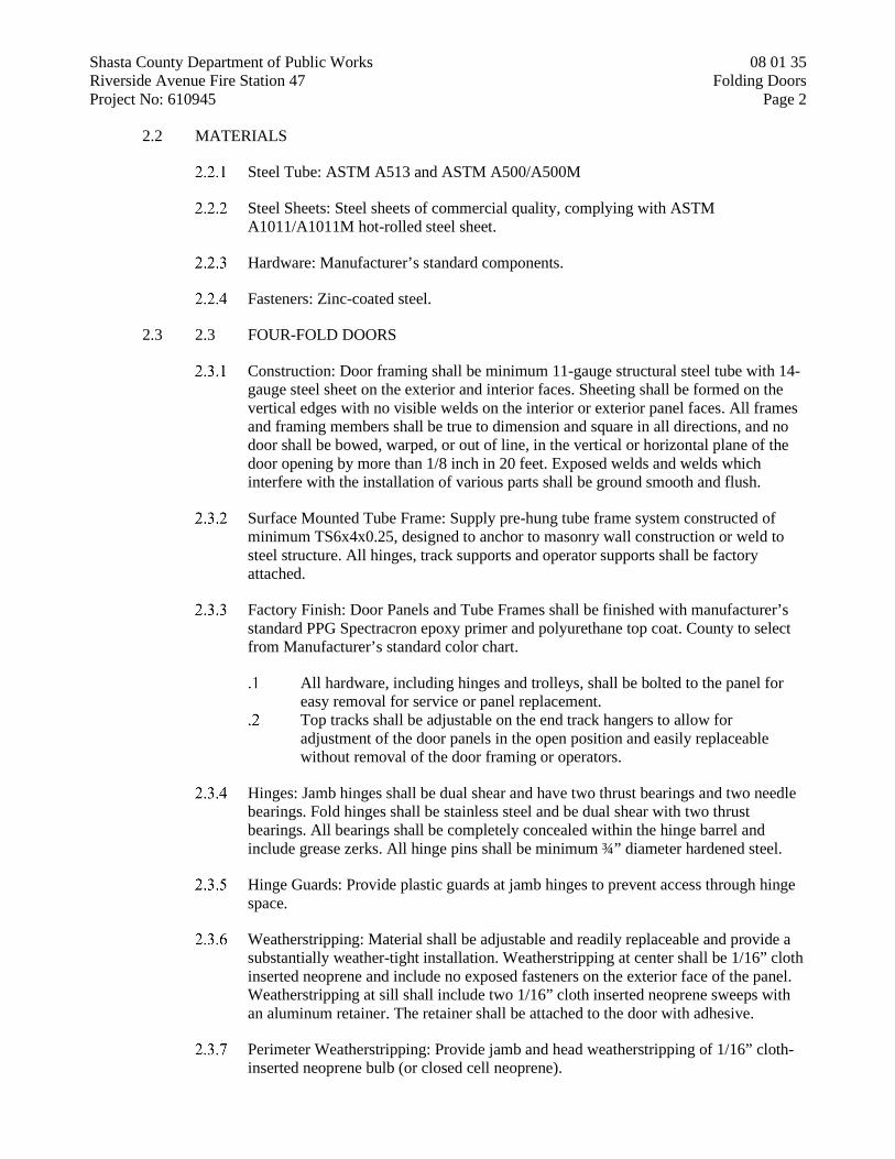
Shasta County Department of Public Works 08 01 35 Riverside Avenue Fire Station 47 Folding Doors Project No: 610945 Page 2
2.2 MATERIALS
Steel Tube: ASTM A513 and ASTM A500/A500M
Steel Sheets: Steel sheets of commercial quality, complying with ASTM A1011/A1011M hot-rolled steel sheet.
Hardware: Manufacturer’s standard components.
Fasteners: Zinc-coated steel.
2.3 2.3 FOUR-FOLD DOORS
Construction: Door framing shall be minimum 11-gauge structural steel tube with 14-gauge steel sheet on the exterior and interior faces. Sheeting shall be formed on the vertical edges with no visible welds on the interior or exterior panel faces. All frames and framing members shall be true to dimension and square in all directions, and no door shall be bowed, warped, or out of line, in the vertical or horizontal plane of the door opening by more than 1/8 inch in 20 feet. Exposed welds and welds which interfere with the installation of various parts shall be ground smooth and flush.
Surface Mounted Tube Frame: Supply pre-hung tube frame system constructed of minimum TS6x4x0.25, designed to anchor to masonry wall construction or weld to steel structure. All hinges, track supports and operator supports shall be factory attached.
Factory Finish: Door Panels and Tube Frames shall be finished with manufacturer’s standard PPG Spectracron epoxy primer and polyurethane top coat. County to select from Manufacturer’s standard color chart.
All hardware, including hinges and trolleys, shall be bolted to the panel for easy removal for service or panel replacement.
Top tracks shall be adjustable on the end track hangers to allow for adjustment of the door panels in the open position and easily replaceable without removal of the door framing or operators.
Hinges: Jamb hinges shall be dual shear and have two thrust bearings and two needle bearings. Fold hinges shall be stainless steel and be dual shear with two thrust bearings. All bearings shall be completely concealed within the hinge barrel and include grease zerks. All hinge pins shall be minimum ¾” diameter hardened steel.
Hinge Guards: Provide plastic guards at jamb hinges to prevent access through hinge space.
Weatherstripping: Material shall be adjustable and readily replaceable and provide a substantially weather-tight installation. Weatherstripping at center shall be 1/16” cloth inserted neoprene and include no exposed fasteners on the exterior face of the panel. Weatherstripping at sill shall include two 1/16” cloth inserted neoprene sweeps with an aluminum retainer. The retainer shall be attached to the door with adhesive.
Perimeter Weatherstripping: Provide jamb and head weatherstripping of 1/16” cloth-inserted neoprene bulb (or closed cell neoprene).

Shasta County Department of Public Works 08 01 35 Riverside Avenue Fire Station 47 Folding Doors Project No: 610945 Page 3
Vision Panels: Provide 1” insulated, tempered, vision panels of the size, shape and location as noted on the drawings.
2.4 OPERATOR
Each Four-Fold door shall be operated by an overhead mounted electro-mechanical drive unit designed for high cycle operation. Operator consists of an electric motor, gear reducer, and rotating drive arm. The door shall be operated with connecting rods attached to the rotating drive arm on the operator and to control arms attached to the jamb door section and to the door lintel. The connecting rods shall be positive drive, keeping the door under firm control at all times. The connecting rods shall be fitted with spherical bearings and control arms shall be equipped with oil impregnated bronze bearings on polished shafts.
Operator shall be instantly reversible, open and close rapidly and start and stop gradually. Operator shall be adjustable to allow door to fully clear the opening. Operator shall automatically lock the door in the closed position. Operator shall be equipped with disengaging mechanism to convert to manual operation.
Electric motor shall be of sufficient size to operate doors under normal operating conditions at no more than 75 percent of rated capacity. The motor shall be wound for three phase 208/230/480 VAC, 60 Hertz operation.
Electric Controls: Controls shall be furnished by the door manufacturer and shall be complete for each door, and built in accordance with the latest NEMA standards. Incoming electrical shall be 208/230VAC 3-phase.
Control panel assemblies shall be UL listed as per NFPA 70. Controls shall include a programmable logic controller with digital message
display or LED indicators. Controller shall include programmable close timers and programmable inputs/outputs.
Controls shall include a variable frequency drive with independent adjustment of the opening and closing speeds.
Enclosures shall be NEMA 4 with disconnect switch. Push buttons (interior) for each door shall have on (2) momentary pressure
three-button push-button station marked “OPEN”, “CLOSE” and “STOP”. Push button enclosure shall be NEMA 4. One control station at each door and one door control station at hallway to station office.
Limit switches shall be provided to stop the travel of the door in its fully open or fully closed position.
Safety edges: Provide 4-wire fall-safe electric safety edges on leading edge of all doors to reverse door upon contact with obstruction.
Photo eyes: Provide exterior, jamb mounted, light Curtain type photo eyes, NEMA 4 rated. Photo eye shall cover from floor level to 72” above floor.
Presence Sensor: Provide interior, overhead mounted, presence sensor with pre-open and pre-close safety fields. Sensor shall be LZR-Widescan or equal.
Radio Controls: Provide radio receiver and 6 single button remotes per door. Remotes to open and close doors with single button.

Shasta County Department of Public Works 08 01 35 Riverside Avenue Fire Station 47 Folding Doors Project No: 610945 Page 4
PART 3 - PART 3 - EXECUTION
3.1 INSTALLATION
Install Four-Fold metal doors in strict accordance with the approved drawings by qualified door erection crews. All door openings shall be completely prepared by the general contractor prior to the installation of the doors. Permanent or temporary electric wiring shall be brought to the door opening before installation is started and shall be completed so as not to delay the inspection test.
Doors shall be set plumb, level, and square, and with all parts properly fastened and mounted. All moving parts shall be tested and adjusted and left in good operating condition.
3.2 ADJUSTING AND CLEANING
Inspection of the doors and a complete operating test will be made by the installer in the presence of the general contractor or architect as soon as the erection is complete. Any defects noted shall be corrected. After door approval in the above test, the general contractor must assume the responsibility for any damage or rough handling of the doors during construction until the building is turned over to the County and final inspection is made.
Clean surfaces and repaint abraded or damaged finished surfaces to match factory-applied finish.
END OF SECTION 08 11 00

Shasta County Department of Public Works 08 11 00 Riverside Avenue Fire Station 47 Hollow Metal Frames Project No: 610945 Page 1
HOLLOW METAL FRAMES
SECTION 08 11 00
PART 1 - GENERAL
1.1 SUMMARY
Section Includes: Provide hollow metal doors and pressed steel door and window frames, anchors and silencers.
1.2 REFERENCES
Steel Door Institute (SDI): SDI-100 (ANSI/SDI A250.8) - Recommended Specifications - Standard Steel Doors and Frames.
National Association of Architectural Metal Manuf. (NAAMM): Hollow Metal Manual.
ASTM E152: Methods of Fire Test of Door Assemblies.
NFPA 105: Smoke Control Guide
ANSI 117.1: Handicap Code
Underwriters Laboratories: Standards as applicable to fire rated doors and frames.
Materials tested, labeled and inspected by Warnock Hersey International are acceptable upon approval of authorities.
All fire rated doors, frames, and windows shall conform to and be in compliance with the California Building Code as adopted. They shall bear an appropriate UL or WH label.
1.3 SUBMITTALS
Shop Drawings
Submit complete shop drawings listing openings numerically by architect’s opening numbers showing product construction, sizes, anchors, reinforcing, cutouts, elevations, and finish.
Submit notes with shop drawings indicating items that vary from plans and specifications, have conflicts for label compliance, are not in compliance with standards referenced above, have door, frame, hardware or function conflicts, or require review and clarification by architect.
Installation Instructions
Submit installation instructions or field delivery receipt.

Shasta County Department of Public Works 08 11 00 Riverside Avenue Fire Station 47 Hollow Metal Frames Project No: 610945 Page 2
Instructions for installation, maintenance, and preparation for field painting supplied with delivery of material to jobsite.
Schedule: Prepared by supplier, using same reference numbers for details and openings as those on Drawings.
1.4 DELIVERY, STORAGE AND PRODUCT PROTECTION
Doors and Frames will be delivered to the job site undamaged with the doors properly protected by cardboard and plastic covering and shall be stored in upright positions, 4 inches off the floor or ground with proper separation for air circulation and shall be stored inside or under complete weather protection. Damage not acknowledged at delivery shall be considered job site damage and the responsibility of the contractor.
PART 2 - PRODUCTS
2.1 MANUFACTURERS
Acceptable Steel Door Products:
Curries 707 Series. Steelcraft L-Series The Ceco Corporation high frequency, steel stiffened. Or accepted equal.
Acceptable Steel Frame Products:
Curries Steelcraft The Ceco Corporation Or accepted equal
2.2 MATERIALS
Doors:
Doors: Hollow metal flush steel door, 1-3/4” thick.
Interior Doors: Minimum 18 gauge. Exterior Doors: Minimum 16 gauge galvanized. Glazed and Louver Doors: Provide systems as indicated on Drawings. Fabricate doors from cold rolled, stretcher leveled, prime quality steel
to sizes and designs as noted in the plans. Door shall have full flush faces that will show no weld or fabrication
marks when painted and viewed from an oblique angle. Stile and rail doors may have face seams at joints.
Doors shall be sound deadened, and insulated by the following method providing the manufacturer furnishes a certification of tested compliance by a recognized testing laboratory to the minimum requirements noted below:
1 pound per cubic ft. density slab of polystyrene foam permanently and fully bonded to the entire surface of face skins.

Shasta County Department of Public Works 08 11 00 Riverside Avenue Fire Station 47 Hollow Metal Frames Project No: 610945 Page 3
Minimum performance requirements:
1. U Factor: Minimum .41 2. STC Factor: Minimum 34 3. Swing Test: ANSI A151.1 Level “A” 1,000,000 cycle test
with twist test. 4. Corrosion: Pass ANSI A224.1
Reinforcement:
1. Hinges: Minimum 8 gauge. 2. Locks: Minimum 16 gauge. 3. Surface Hardware: Minimum 12 gauge. 4. Panics fully reinforced – thru bolting not acceptable.
Construction: All out swinging exterior doors shall have top caps. Doors will be fully reinforced for all hardware to be surface applied and no hardware will be screwed to the surface skin of the door except kickplates, edging, push plates or name plates.
Full glass doors (40% or more door face in glass) shall be constructed of 16 gauge steel closed tube type construction. Cutout in standard slab doors are not acceptable.
Door Design, Clearances, and Locations: Doors shall be beveled 1/8” in 2” at both edges. Square edge doors and doors with loose hinge fillers will not be acceptable.
1. Hinge and strike clearance: 3/32” 2. Head: 1/8” 3. Floor: (unless otherwise noted) ¾” 4. Meeting Stiles: 3/32” 5. Hardware locations: Comply with ADA and CBC
requirements; refer to drawings. 6. Glazed Openings: Unless otherwise noted use bevel
aluminum glass stop with removable snap-in stops on the non-security side. Provide steel glass stop per UL requirements on all label doors with screw-attached stops. Provide special steel glass stop for insulated glass designed to adequately secure glass. Glass stop shall fully surround door faces and seal inner core of door. The flanges shall not extend more than 1/16” from the face of the door. The hollow metal supplier shall reinforce any glass cutout adequately to insure that the door will have the same structural integrity as a flush door and that it will provide heavy-duty service considering the location, frequency of use and hardware to be installed. The hollow metal supplier shall assume responsibility for insuring that glazing stops to not conflict with flat bar panics.
Frames:
Welded (pre-assembled) type; minimum 16 gage.

Shasta County Department of Public Works 08 11 00 Riverside Avenue Fire Station 47 Hollow Metal Frames Project No: 610945 Page 4
Frames shall be full face welded, square, accurately sized and have a welded spreader bar at the base for field removal. Acceptable tolerances per SDI 117.
Exterior frames shall be galvanized.
Door Silencers: Manufacturer's standard resilient type; removable for replacement.
Glazing Stops: Full flush type with glass centered in opening, unsecured side integral with unit, secured side fastened with flush, countersunk Allen type fasteners; minimum 16 gage.
Jamb Anchors:
Stud-Wall Type: Designed to engage stud, welded to back of frames; not less than 0.042 inch thick.
Locate anchors not more than 18 inches from top and bottom of frame. Space anchors not more than 32 inches o.c. and as follows:
1. Three anchors per jamb up to 60 inches high 2. Four anchors per jamb from 60 to 90 inches high 3. Five anchors per jamb from 90 to 96 inches hgh 4. Five anchors per jamb plus 1 additional anchor per jamb for
each 24 inches or fraction thereof above 96 inches high 5. Two anchors per head for frames more than 42 inches wide
and mounted in metal-stud partitions.
Floor Anchors: Formed from same material as frames, not less than 0.042 inch thick, and as follows:
Monolithic Concrete Slabs: Clip-type anchors, with two holes to receive fasteners.
Separate Topping Concrete Slabs: Adjustable-type anchors with extension clips, allowing not less than 2-inch height adjustment. Terminate bottom of frames at finish floor surface.
2.3 FABRICATION
Conform to requirements of SDI (ANSI A250 Series) or NAAMM.
Reinforce and prepare doors and frames to receive hardware.
. Locate hardware as indicated, or if not indicated, according to ANSI/SDI A250.8.
Reinforce doors and frames to receive nontemplated, mortised and surface-mounted door hardware.
Comply with applicable requirements in ANSI/SDI A250.6 and ANSI/DHI A115 Series specifications for preparation of hollow metal work for hardware.
Coordinate locations of conduit and wiring boxes for electrical connections.
Frames:

Shasta County Department of Public Works 08 11 00 Riverside Avenue Fire Station 47 Hollow Metal Frames Project No: 610945 Page 5
Welded Frames: Accurately form and cut mitered corners of welded type frames; weld on inside surfaces; grind welded joints to smooth uniform finish.
Head Reinforcement: Reinforce frames wider than 4'-0" with minimum 12 gage formed steel channels welded in place, flush with top of frames.
Doors at Glazed Panels: Reinforce jambs and heads of frames for doors which occur adjacent to glazed sidelights and partitions.
Door Silencers:
Place minimum three single bumpers on single door frames; space equally along strike jambs.
Place minimum of two single bumpers on double door frames; place on frame heads.
Provide jamb anchors per SDI-100 (ANSI/SDI 250.8) and NAAMM; weld floor jamb anchors in place.
Finish:
Interior Units: Prime Paint. Exterior Units: Apply minimum A60 non-spangles galvanized coating, ASTM
A924 and A653. Surface treatment after galvanizing to remove oils and prepare for painting. Apply one coat of primer.
PART 3 - EXECUTION
3.1 INSTALLATION
Install frames in accordance with SDI-100 (ANSI/SDI A250.8) and ANSI/SDI A250.11 or NAAMM "Hollow Metal Manual" and with manufacturer's recommendations and installation instructions.
Install frames plumb and square, and with maximum diagonal distortion of 1/16".
Coordinate hardware installation.
Remove and replace frames damaged during delivery, storage, installation and construction.
Paste filler repair shall not be permitted.
After installation, touch-up scratched paint surfaces.
END OF SECTION 08 11 00

Shasta County Department of Public Works 08 14 23 Riverside Avenue Fire Station 47 Plastic-Laminate-Faced Wood Doors Project No: 610945 Page 1
PLASTIC-LAMINATE-FACED WOOD DOORS
SECTION 08 14 23
PART 1 - PART 1 - GENERAL
1.1 SUMMARY
Section Includes:
Plastic-Laminate-Faced Doors.
1.2 1.2 REFERENCES
AWI Quality Standards of Architectural Woodwork Institute.
NWMA Standard Procedures and Recommendations for Factory Machining Architectural and Plastic Faced Flush Doors for Hardware.
Underwriters Laboratories Inc. (UL): Building Materials Directory.
Materials tested, labeled and inspected by Warnock Hersey International are acceptable upon approval of authorities.
1.2.4 Factory Mutual Engineering Corporation (FM), as applicable to fire rated wood doors.
1.2.5 DHI - Door Hardware Institute: “Installation Guide for Doors and Hardware”.
1.2.6 NFPA 80 – National Fire Protection Association.
1.3 REGULATORY REQUIREMENTS
Architectural wood doors furnished for this project shall be in full compliance with the CBC, NFPA 80, NFPA 101, NFPA 105 and ADA.
1.4 SUBMITTALS
Product Data: Furnish manufacturer's literature.
Shop Drawings: Indicate general construction, jointing methods, hardware locations, and locations of cut-outs.
For doors with glazed lites, indicate clearly the typed, materials, and fire ratings of glass stops proposed.
Samples:
Furnish sample of door corner indicating panel configuration.

Shasta County Department of Public Works 08 14 23 Riverside Avenue Fire Station 47 Plastic-Laminate-Faced Wood Doors Project No: 610945 Page 2
Submit two door corner samples in specified plastic laminate finish, including edge laminate, for each type of door construction required (i.e. fire-rated).
1.5 PROJECT CONDITIONS
Do not deliver or install doors until conditions for temperature and relative humidity have been stabilized in accordance with referenced standards requirements applicable to Project location.
1.6 WARRANTY
Special Warranty: Provide for replacing, rehanging and refinishing wood doors exhibiting defects in materials or workmanship including warp and delamination.
Special Warranty Period: Five years.
PART 2 - PART 2 - PRODUCTS
2.1 MANUFACTURERS
Weyerhaeuser Company.
Eggers Industries.
Algoma Hardwoods, Inc.
Or accepted equal.
2.2 MATERIALS
Construction:
5 ply hot press construction or 7 ply cold press construction Core glue bonded to stiles and rails then thickness sanded prior to door lay-up.
No mechanical fasteners may be used. Institutional solid particle board core. SLM edges with veneer covering and SLM blocking for hardware. Provide doors made with adhesives and composite wood products that do not
contain urea-formaldehyde resins.
Plastic Laminate Faces:
Decorative 3-ply laminate face from the following manufacturers: Formica, Nevamar, Wilsonart or equal.
High pressure decorative laminate general purpose grade 50 (GP50 - .050“ thick). complying with NEMA standard LD-3.
Apply faces prior to edges, ease all corners.
2.3 ACCESSORIES:
Metal glazing stops.

Shasta County Department of Public Works 08 14 23 Riverside Avenue Fire Station 47 Plastic-Laminate-Faced Wood Doors Project No: 610945 Page 3
Glazed Openings: Glaze doors at factory with glass of type and thickness indicated.
2.4 FABRICATION
Fabricate doors in accordance with requirements of specified standards.
Prefit wood doors. Prepare doors to receive hardware. Factory machine doors for mortise hardware.
Bevel strike edge of single-acting doors, 1/8" in 2".
PART 3 - PART 3 - EXECUTION
3.1 INSTALLATION
Install wood doors in accordance with manufacturer's recommendations and installation instructions, and reference standards, plumb and square, and with maximum diagonal distortion of 1/16".
Coordinate hardware installation with manufacturer’s requirements.
END OF SECTION 08 14 23

Shasta County Department of Public Works 08 31 13 Riverside Avenue Fire Station 47 Access Doors Project No: 610945 Page 1
ACCESS DOORS
08 31 13
PART 1 - PART 1 - GENERAL
1.1 SUMMARY
Section Includes: Provide access doors set in finished surfaces.
Provide access doors and panels as required for access to controls and valves behind finished surfaces.
Provide access doors to concealed attic spaces where noted on Drawings. Coordinate with various trades for controls and valves that may be concealed.
1.2 SYSTEM DESCRIPTION
Fire-Resistance Ratings: Where required provide access door assembly from manufacturer listed in Underwriter's Laboratories, Inc. "Classified Building Materials Index" for rating shown.
Provide UL label on each rated access door. Materials tested, labeled and inspected by Warnock Hersey International are
acceptable upon approval of authorities.
1.3 SUBMITTALS
Product Data: Furnish manufacturer's literature.
Shop Drawings: Indicate locations of access doors required but not indicated on Architectural Drawings.
PART 2 - PART 2 - PRODUCTS
2.1 MANUFACTURERS
Nystrom Building Products.
Milcor, Inc.
J.L. Industries.
Karp Associates, Inc.
Or accepted equal.
2.2 MATERIALS
General: Provide access door assemblies consisting of an integral unit, complete and ready for installation.

Shasta County Department of Public Works 08 31 13 Riverside Avenue Fire Station 47 Access Doors Project No: 610945 Page 2
Non-Fire Rated Units: Flush panel access doors; provide type with frame flange concealed in finished construction.
Provide insulated doors where indicated on drawings.
Fire Rated Units: Manufacturer's standard UL rated insulated flush doors with 1" flanged frame and self-closing mechanism.
Frames: Fabricate from minimum 16 gage steel.
Doors: Flush panel type, fabricate from minimum 14 gage steel.
Provide continuous piano type hinge. Finish with manufacturer's factory-applied enamel prime coat applied over
phosphate coating on steel.
Locking Devices: Provide flush, key-operated cylinder lock for each access door; provide two keys per lock and key locks alike, unless otherwise scheduled.
2.3 FABRICATION
Size Variations: Obtain Architect's acceptance of manufacturer's standard size units that may vary slightly from sizes shown or scheduled.
Fabricate units of continuous welded steel construction; grind welds smooth and flush with adjacent surfaces.
Provide attachment devices and fasteners of type required for specific job conditions.
PART 3 - PART 3 - EXECUTION
3.1 EXAMINATION
Examine areas and conditions under which access doors are to be installed.
Do not proceed with work until unsatisfactory conditions are corrected; installation signifies acceptance of conditions.
3.1.2 Obtain specific locations and sizes for required access doors from trades requiring access to concealed equipment; coordinate installation with work of other trades.
3.2 INSTALLATION
Comply with manufacturer's installation instructions for access doors.
Install fire rated access doors in accordance with NFPA 80.
Set frames accurately in position and securely attach to supports with face panels plumb or level in relation to adjacent finish surfaces.
Adjust hardware and doors after installation for proper operation.

Shasta County Department of Public Works 08 31 13 Riverside Avenue Fire Station 47 Access Doors Project No: 610945 Page 3
3.3 PROTECTION
Remove and replace doors and frames that are warped, bowed, or otherwise damaged.
END OF SECTION 08 31 13

Shasta County Department of Public Works 08 33 23 Riverside Avenue Fire Station 47 Overhead Coiling Doors Project No: 610945 Page 1
OVERHEAD COILING DOORS
08 33 23
PART 1 - GENERAL
1.1 SUMMARY
This Section includes the following types of electric-motor-operated overhead coiling doors:
Insulated coiling service doors.
1.2 PERFORMANCE REQUIREMENTS
Structural Performance: Provide overhead coiling doors capable of withstanding the effects of gravity loads and the following loads and stresses without evidencing permanent deformation of door components:
Wind Load: Uniform pressure (velocity pressure) of 25lbf/sq. ft., acting inward and outward
Impact Test for Flying Debris: Comply with ASTM E 1996, tested according to ASTM E 1886.
Level of Protection: Basic Protection. Wind Zone One: 110 mph, pressure test to ½ and 1-1/2 x design
pressure (positive and negative)
Operation-Cycle Requirements: Provide overhead coiling door components and operators suitable for high-cycle use and capable of operating for not less than 20,000 cycles and for 30 cycles per hour.
Door Operators: Comply with UL 325
1.3 SUBMITTALS
Product Data: For each type and size of overhead coiling door and accessory.
Shop Drawings: Include plans, elevations, sections, details, and attachment to other work.
Samples: For each exposed finish.
1.4 QUALITY ASSURANCE
Installer Qualifications: Manufacturer’s authorized representative who is trained and approved for both installation and maintenance of units required for this Project.

Shasta County Department of Public Works 08 33 23 Riverside Avenue Fire Station 47 Overhead Coiling Doors Project No: 610945 Page 2
Electrical Components, Devices and Accessories: Listed and labeled as defined in CEC, Article 100.
PART 2 - PRODUCTS
2.1 MANUFACTURERS
Available Manufacturers: Subject to compliance with requirements, manufacturers offering products that may be incorporated into the Work include, but are not limited to, the following:
Manufacturers: Subject to compliance with requirements, provide products by one of the following:
Overhead Door Corp. Cookson Company Raynor
2.2 DOOR CURTAIN MATERIALS AND CONSTRUCTION
Door Curtains: Interlocking slats in a continuous length for width of door of thickness and mechanical properties recommended by door manufacturer for performance, size, and type of door.
Steel Door Curtain Slats: Zinc-coated (galvanized), cold-rolled structural steel sheet; complying with ASTM A 653/A 653M, G90 (Z275) coating designation.
Slat Type: Flat profile. Slat cavity filled with CFC-free foamed-in-place, polyurethane insulation.
R-Value: 6.24, U-Value: 0.160
Endlocks and Windlocks: Malleable-iron casings, secured to curtain slats to comply with wind load.
Bottom Bar: Manufacturer’s standard to suit type of curtain slats.
Curtain Jamb Guides: Steel angles or stainless steel angels, with sufficient depth and strength to retain curtain, to allow curtain to operate smoothly, and to withstand loading. Slot bolt holes for guide adjustment. Provide removable stops on guides to prevent overtravel of curtain, and a continuous bar for holding windlocks.
Jamb Guide Weatherstripping: Manufacturer’s standard vinyl material and finish to match curtain slats, with sufficient depth and closure material from guide to slats. Exterior doors only.
Hood: Form to act as weatherseal and entirely enclose coiled curtain and operating mechanism at opening head. Contour to fit end brackets. Roll and reinforce top and bottom edges for stiffness. Provide closed ends for surface-mounted hoods, and provide fascia for any portion of between-jamb mounting projecting beyond wall face. Provide intermediate support brackets as required to prevent sagging.

Shasta County Department of Public Works 08 33 23 Riverside Avenue Fire Station 47 Overhead Coiling Doors Project No: 610945 Page 3
Steel Door Hoods: Minimum 0.028-inch thick, hot-dip galvanized steel sheet that matches slat steel.
Shape: Square.
Integral Sills: Integral part of frame assembly; fabricate of same sheet metal.
2.3 COILING DOOR TYPES
Coiling Service Door: Insulated overhead coiling door, 20 gauge galvanized steel slats with flat slat profile. Include full perimeter weather seals, steel angle guides, high-cycle torsion spring, 24 gauge galvanized painted steel hood, electric motor operation with interior switch. 20psf wind load. Basis of Design: Raynor DuraCoil Optima.
2.4 COILING DOOR OPERATORS
Provide UL listed electric operator, size as recommended by manufacturer to move door in either direction at not less than 2/3 foot nor more than 1 foot per second. Basis of Design: Raynor Control Hoist 2.0 Optima.
Sensing Edge Protection
Electric sensing edge reversing mechanism.
Operator Controls
Push-button and key operated control stations with open, close, and stop buttons
Controls for both interior and exterior location. Controls surface mounted.
Motor Voltage: 120volt. Solid State motor controller Fire Station Timer: Push button activates the open cycle and timer to close
feature.
Drive Orientation
For electric motor operated doors, coordinate the drive orientation with building structure and finishes to maintain required clearances for unit.
Remote Control
Provide surface-mounted control station to operate doors remotely from control panel across the apparatus bay.
Controls to allow for open-close-stop. Controls to be labeled to clearly identify which door is controlled
from each button.
Provide a minimum of six transmitters for remote activation from vehicles.

Shasta County Department of Public Works 08 33 23 Riverside Avenue Fire Station 47 Overhead Coiling Doors Project No: 610945 Page 4
2.5 FINISHES
Glavanized Steel Finish: Manufacturer’s standard powder coated finish.
Color and Gloss: As selected by Architect from manufacturer’s full range.
PART 3 - PART 3 - EXECUTION
3.1 INSTALLATION
General: Install coiling doors and operating equipment complete with necessary hardware, jamb and head molding strips, anchors, inserts, hangers, and equipment supports.
Install fire-rated doors to comply with NFPA 80.
Lubricate bearings and sliding parts; adjust doors to operate easily, free of warp, twist, or distortion, and with weathertight fit around entire perimeter.
3.2 DEMONSTRATION
Engage a factory-authorized service representative to train County’s maintenance personnel to adjust, operate, and maintain doors.
END OF SECTION 08 33 23
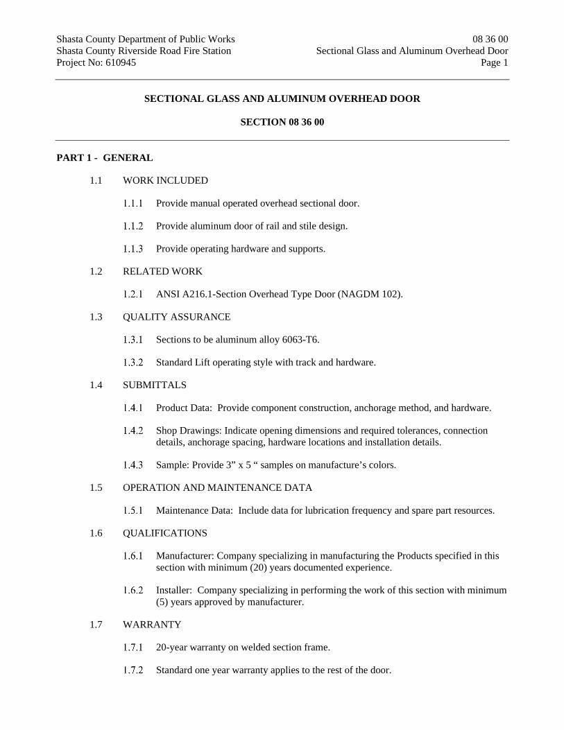
Shasta County Department of Public Works 08 36 00 Shasta County Riverside Road Fire Station Sectional Glass and Aluminum Overhead Door Project No: 610945 Page 1
SECTIONAL GLASS AND ALUMINUM OVERHEAD DOOR
SECTION 08 36 00
PART 1 - GENERAL
1.1 WORK INCLUDED
Provide manual operated overhead sectional door.
Provide aluminum door of rail and stile design.
Provide operating hardware and supports.
1.2 RELATED WORK
ANSI A216.1-Section Overhead Type Door (NAGDM 102).
1.3 QUALITY ASSURANCE
Sections to be aluminum alloy 6063-T6.
Standard Lift operating style with track and hardware.
1.4 SUBMITTALS
Product Data: Provide component construction, anchorage method, and hardware.
Shop Drawings: Indicate opening dimensions and required tolerances, connection details, anchorage spacing, hardware locations and installation details.
Sample: Provide 3” x 5 “ samples on manufacture’s colors.
1.5 OPERATION AND MAINTENANCE DATA
Maintenance Data: Include data for lubrication frequency and spare part resources.
1.6 QUALIFICATIONS
Manufacturer: Company specializing in manufacturing the Products specified in this section with minimum (20) years documented experience.
Installer: Company specializing in performing the work of this section with minimum (5) years approved by manufacturer.
1.7 WARRANTY
20-year warranty on welded section frame.
Standard one year warranty applies to the rest of the door.

Shasta County Department of Public Works 08 36 00 Shasta County Riverside Road Fire Station Sectional Glass and Aluminum Overhead Door Project No: 610945 Page 2
20-year warranty on finish.
PART 2 - PRODUCTS
2.1 MANUFACTURERS
ARM-R-LITE DOOR MANUFACTURING CO. or equal.
Door Type: TITAN MODEL.
Or accepted equal.
2.2 MATERIALS
Rails and stiles of aluminum alloy 6063-T6.
Finish at all aluminum surfaces: Kynar Finish.
2.3 PANEL CONSTRUCTION
Tubular hollow aluminum shapes to be heli-arc welded in concealed locations. Fill shapes with expanding foam insulation.
Rails and Stiles: .70 Extruded 6063-T6 Alloy 1-3/4” thick Bottom Rail…………..4 1/2” Top Rail………………4 1/2” Meeting Rails……….. 3 3/8” Wide per pair End Stiles…………….3 3/8” Wide per pair Center Stiles …………3 3/8” Wide per pair
Exterior Door Sections to contain 7/16” insulated, tempered, low “E” glazing.
2.4 DOOR COMPONENTS
Hardware: All hinges and fixtures made of 14 gauge galvanized steel. Full floating, ball bearing rollers have hardened steel races, and roller sizes will be adequate for design requirements and limitations.
Heavy-duty, fully adjustable roller brackets are attached to each end cap to provide an easy adjustment of the door to the job for proper seal. All hardware is heavy-duty and rust-resistant with galvanized fasteners. Heavy-duty rollers contain steel ball bearings in case-hardened steel races.
Weather-strip: aluminum door stops.
Track is 2”.
Sectional Door Assembly: Aluminum door assembly with ship-lap construction to form weather tight joints and provide full-width interlocking structural rigidity.
Wind load Design: ANSI/AGDM 102 standards are as required by local codes.

Shasta County Department of Public Works 08 36 00 Shasta County Riverside Road Fire Station Sectional Glass and Aluminum Overhead Door Project No: 610945 Page 3
Lock: keyed cylinder lock.
PART 3 - PART 3 - EXECUTION
3.1 PREPARATION
Verify that wall openings are ready to receive work and opening dimensions and tolerances are within specified limits.
Beginning of installation means acceptance of existing surfaces.
Prepare opening to permit correct installation of door unit.
3.2 INSTALLATION
Install door unit assembly in accordance with manufacturer’s instructions.
Anchor assembly to wall construction and building framing without distortion or stress.
Secure tracks to structural members only.
Fit and align door assembly including hardware, level and plumb, to provide smooth operation.
Coordinate installation of sealant and backing materials at frame perimeter.
Install perimeter trim and closures.
3.3 TOLERANCES
Maintain dimensional tolerances and alignment with adjacent work.
Maximum variation from Plumb: 1/8 inch.
Maximum variation from Level: 1/8 inch.
Longitudinal or Diagonal Warp: Plus or minus 1/8 inch from 10 ft. straight edge.
3.4 ADJUSTING
Adjust door assembly to smooth operation.
3.5 CLEANING
Clean doors, frames and glass.
Remove labels and visible markings.
END OF SECTION 08 36 00

Shasta County Department of Public Works 08 56 00 Shasta County Riverside Road Fire Station Vinyl Windows Project No: 610945 Page 1
VINYL WINDOWS
SECTION 08 56 00
PART 1 - GENERAL
1.1 SUMMARY
Section includes: Tubular extruded poly vinyl chloride (PVC) windows.
1.2 SUBMITTALS
Product Data
Shop Drawings: Include window schedule, window elevations, sections and details, and multiple window assembly details.
Samples:
Color samples: Minimum 1x4 inch (25x100mm) samples of PVC with integral color.
Glass, showing specified tint color.
Quality Assurance/Control Submittals:
Qualifications: Proof of manufacturer’s qualifications. U-Factor and structural rating charts required for AAMA and NFRC labeling
requirements. Installation Instructions- AAMA 2400 (“Mounting Flange Installation”) or
AAMA 2410 (“Flush Fin Installation”).
Closeout Submittals: submit the following items:
Temporary window labels marked to identify windows that labels were applied to.
Maintenance instructions. Special warranties.
1.3 QUALITY ASSURANCE
Overall Standards: Comply with ANSI/AAMA 101.I.S.2, except as otherwise noted herein.
Qualifications:
Manufacturer Qualifications:
Minimum five years experience in producing vinyl windows of the type(s) specified.
Member AAMA, NFRC

Shasta County Department of Public Works 08 56 00 Shasta County Riverside Road Fire Station Vinyl Windows Project No: 610945 Page 2
Regulatory Requirements:
Certifications for insulated glass windows:
AAMA: Windows shall be Gold Label certified with label attached to frame per AAMA requirements.
NFRC: Windows shall be NFRC certified with temporary U-factor label applied to glass and an NFRC tab added to permanent AAMA frame label.
1.4 DELIVERY, STORAGE, AND HANDLING
Follow manufacturer’s instructions on label applied to windows.
1.5 WARRANTY
10-year Warranty.
Warranty windows against defects in materials and workmanship including costs for parts and labor.
PART 2 - PRODUCTS
2.1 MANUFACTURERS
Products supplied by the following manufacturer:
Milgard Manufacturing, Inc.
Or accepted equal.
2.2 MATERIALS
Vinyl: Integral color PVC compound containing impact-resistant solid plasticizer, titanium dioxide UV inhibitor and surface and color stabilizers.
Comply with ASTM D 4216 and ANSI/AAMA 101/I.S.2.
2.3 GENERAL PERFORMANCE REQUIREMENTS
Thermal Performance: Comply with NFRC 100.
Air Leakage, Water Resistance, Structural Test: Comply with ANSI/AAMA 101/I.S.2.
Forced-Entry Resistance: Comply with ASTM E 588
2.4 WINDOW TYPES
Casement
Frame; 3-1/4” minimum depth. Sash: 2-5/8” minimum depth.

Shasta County Department of Public Works 08 56 00 Shasta County Riverside Road Fire Station Vinyl Windows Project No: 610945 Page 3
Hardware
Stainless steel rotary scissor operator with standard fold-down nesting handle, ADA compliant.
Dual level locking mechanism. Two bar stainless steel hinge.
Exterior Trim: 1-3/8” nail fin setback, 2” nail fin. Weatherstripping
Foam filled bulb (interior and exterior); flexible leaf (middle)
Picture Window
Frame: 3-1/4” minimum depth Sightlines: Equal to Horizontal Slider and Casement. Exterior Trim: 1-3/8” nail fin setback, 2” nail fin.
Horizontal Slider
Frame: 3-1/4” minimum depth Sash: 1-1/4” minimum depth. Slightlines: Equal for operating and fixed sash. Hardware:
Nylon rollers with stainless steel axles, extruded vinyl snap-on monorail roller track.
SmartTouch direct action locking mechanism. Dual pull rails.
Exterior Trim: 1-3/8” nail fine setback, 2” nail fin. Weatherstripping
Fin seal polypropylene pile
2.5 GLAZING
Insulated Glass Units: ASTM E 774, Class A, 7/8 inch (22 mm) thick overall.
Glazing Type: Dual
SunCoatMAX Low-E/Clear/SunCoatMAX
2.6 FABRICATION
Fabricate frames and sash with mitered and fusion welded corners and joints. Trim and finish corners and welds to match adjacent surfaces.
Provide concealed metal reinforcements in sash frame for attaching lock mechanism.

Shasta County Department of Public Works 08 56 00 Shasta County Riverside Road Fire Station Vinyl Windows Project No: 610945 Page 4
Factory inside glaze with snap-on PVC mitred glazing stops matching bevels on the sash and frame. Insulating glass units shall be reglazable without dismantling sash framing.
2.7 FINISHES
Frame and Sash Color: Tan.
2.8 SOURCE QUALITY CONTROL
Windows inspected in accordance with manufacturer’s Quality Control Program as required by AAMA Gold Label certification.
PART 3 - EXECUTION
3.1 EXAMINATION
Examine openings in which windows will be installed.
Verify that framing complies with AAMA 2400 (“Mounting Flange Installation”).
Verify that fasteners in framed walls are fully driven and will not interfere with window installation
Coordinate with responsible entity to correct unsatisfactory conditions.3.1.3 Commencement of work by installer is acceptance of substrate conditions.
3.2 INSTALLATION
Install windows in framed walls in accordance with AAMA 2400 (“Mounting Flange Installation”) or AAMA 2410 (“Flush Fin Installation”).
Do not remove temporary labels.
3.3 CLEANING
Remove temporary labels and retain for Closeout Submittals.
Clean soiled surfaces and glass using a mild detergent and warm water solution with soft, clean cloths.
END OF SECTION 08 56 00

Shasta County Department of Public Works 08 56 59 Riverside Avenue Fire Station 47 Aluminum Transaction Window Project No: 610945 Page 1
ALUMINUM TRANSACTION WINDOW
SECTION 08 56 59
PART 1 - GENERAL
1.1 SUMMARY
This section includes:
Aluminum, medium-duty commercial sliding service windows as indicated in drawings and in sections.
1.2 REFERENCES
Standards, manuals, and codes refer to the latest edition of such standards, manuals, and codes in effect as of the date of issue of this Project Manual, unless indicated otherwise in CBC Chapter 35 and CFC Chapter 80.
Referenced Standards:
AAMA 800: Voluntary Specifications and Test Methods for Sealants. ASTM F1915: Standard Test Methods for Glazing for Detention Facilities. ASTM C920: Standard Specification for Elastomeric Joint Sealants. ASTM C1036: Standard Specification for Flat Glass. ASTM C1048: Standard Specification for Heat-Treated Flat Glass – Kind HS,
Kind FT Coated and Uncoated Glass. ASTM C1349: Standard Specification for Architectural Flat Glass Clad
Polycarbonate. ASTM D256: Standard Test Methods for Determining the Izod Pendulum
Impact Resistance of Plastics. ASTM D790: Standard Test Methods for Flexural Properties of Unreinforced
and Reinforced Plastics and Electrical Insulating Materials. ASTM D1003: Standard Test Method for Haze and Luminous Transmittance
of Transparent Plastics. Glass Association of North America (GANA): Glazing Manual, latest edition.
1.3 SUBMITTALS
Product Data: Submit Manufacturer’s technical product data substantiating that products comply on glazing types specified. Provide structural, physical and environmental test characteristics, size limitations, and special handling or installation requirements.
Product Data: Submit Manufacturer’s technical product data substantiating that products comply on glazing sealants, glazing tapes, and setting blocks: Provide functional and environmental characteristics, limitations, and special application requirements. Identify available colors.
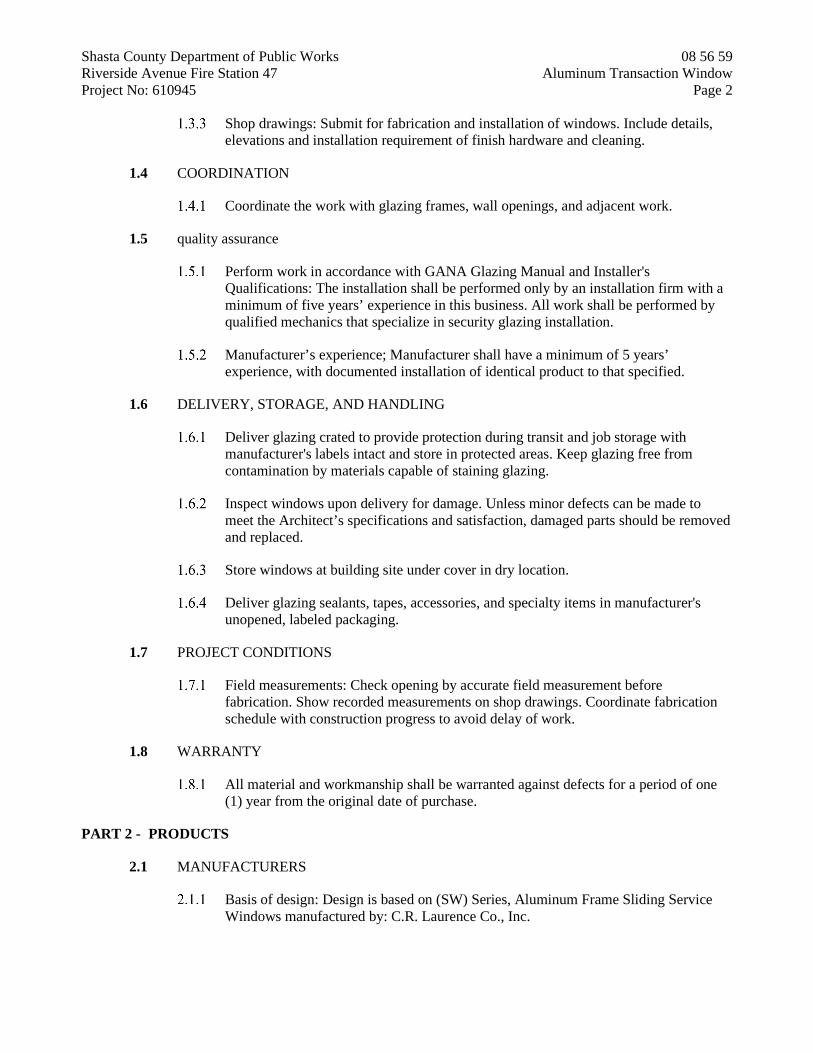
Shasta County Department of Public Works 08 56 59 Riverside Avenue Fire Station 47 Aluminum Transaction Window Project No: 610945 Page 2
Shop drawings: Submit for fabrication and installation of windows. Include details, elevations and installation requirement of finish hardware and cleaning.
1.4 COORDINATION
Coordinate the work with glazing frames, wall openings, and adjacent work.
1.5 quality assurance
Perform work in accordance with GANA Glazing Manual and Installer's Qualifications: The installation shall be performed only by an installation firm with a minimum of five years’ experience in this business. All work shall be performed by qualified mechanics that specialize in security glazing installation.
Manufacturer’s experience; Manufacturer shall have a minimum of 5 years’ experience, with documented installation of identical product to that specified.
1.6 DELIVERY, STORAGE, AND HANDLING
Deliver glazing crated to provide protection during transit and job storage with manufacturer's labels intact and store in protected areas. Keep glazing free from contamination by materials capable of staining glazing.
Inspect windows upon delivery for damage. Unless minor defects can be made to meet the Architect’s specifications and satisfaction, damaged parts should be removed and replaced.
Store windows at building site under cover in dry location.
Deliver glazing sealants, tapes, accessories, and specialty items in manufacturer's unopened, labeled packaging.
1.7 PROJECT CONDITIONS
Field measurements: Check opening by accurate field measurement before fabrication. Show recorded measurements on shop drawings. Coordinate fabrication schedule with construction progress to avoid delay of work.
1.8 WARRANTY
All material and workmanship shall be warranted against defects for a period of one (1) year from the original date of purchase.
PART 2 - PRODUCTS
2.1 MANUFACTURERS
Basis of design: Design is based on (SW) Series, Aluminum Frame Sliding Service Windows manufactured by: C.R. Laurence Co., Inc.

Shasta County Department of Public Works 08 56 59 Riverside Avenue Fire Station 47 Aluminum Transaction Window Project No: 610945 Page 3
2.2 MATERIALS
Frames: Aluminum frame modules shall be constructed of 6063-T5 extruded aluminum. Window glides on top-hung nylon slides. Poly-pile weather stripping and slide locks. Overall frame sizes are to be in accordance with the contract drawings.
Finish: All aluminum to be clear anodized (or as specified by Architect).
Glazing: The glazing is 1/4” in thickness and shall be tempered.
PART 3 - EXECUTION
3.1 EXAMINATION
Verify prepared openings for adequacy to receive glazing.
Verify openings for glazing are correctly sized and within tolerance.
Verify that surfaces of glazing channels or recesses are clean, free of obstructions, and ready to receive glazing.
3.2 INSTALLATION
Clean contact surfaces with solvent and wipe dry.
Apply primer or sealer to joint surfaces wherever recommended by sealant manufacturer.
Check that glazing is free of edge damage and surface defects.
Install window in accordance with manufacturer’s printed instructions and recommendations. Replace damaged units with new units.
Protect glazing from edge damage at all times during handling, installation, and subsequent operation of the glazed components of the work.
Glazing channel dimensions are intended to provide for necessary bite on the glazing, minimum edge clearance and adequate sealant thicknesses, with reasonable tolerances. The glazier is responsible for correct glazing size for each opening, within the tolerances and necessary dimensions established and for verifying the dimensions of the glazing stops.
Sealant shall be installed in a neat, flush, professional manner. Sealant not in compliance shall be completely removed and replaced at no cost to County.
Leave entire work in neat, orderly, clean condition at time of Project Completion.
3.3 CLEANING
Clean frame and glazing surfaces after installation, complying with requirements contained in the manufacturer’s instructions. Remove excess glazing sealant compounds, dirt or other substances.

Shasta County Department of Public Works 08 56 59 Riverside Avenue Fire Station 47 Aluminum Transaction Window Project No: 610945 Page 4
3.4 PROTECTION
Institute protective measures required throughout the remainder of the construction period to ensure that all the windows do not incur any damage or deterioration, other than normal weathering, at the time of acceptance.
END OF SECTION 08 56 59

Shasta County Department of Public Works 08 71 00 Riverside Avenue Fire Station 47 Door Hardware Project No: 610945 Page 1
DOOR HARDWARE
SECTION 08 71 00
PART 1 - GENERAL
1.1 SUMMARY
Section Includes: Provide hardware for hollow metal, aluminum and wood doors.
Provide cylinders for doors fabricated with hardware.
1.2 QUALITY ASSURANCE
Fire Rated Doors: Comply with requirements of NFPA 80 and applicable codes for fire rated door hardware; provide hardware bearing Underwriters Laboratory (UL) labels.
Doors indicated in fire rated partitions and walls shall be positive latching and self-closing, with smoke gaskets.
Access for Persons with Disabilities: Comply with California Code of Regulations, Title 24, and Americans with Disabilities Act Accessibility Guidelines (ADAAG).
Supplier: Recognized builders hardware supplier with minimum five years successful experience in scheduling and furnishing hardware; factory-authorized to distribute specified hardware.
Provide services of architectural hardware consultant to supervise hardware supply and consult with CSFM, as directed.
Coordinate work of this Section with others directly affected. Send templates within 10 days of hardware schedule approval.
Products: Provide each type of hardware (hinges, pivots, locksets, latchsets, closers, trim) from single manufacturer unless otherwise indicated in Hardware Schedule.
Existing hardware that is to be removed and re-used is to be maintained in the current condition. Any existing hardware that is damaged during construction is to be replaced.
1.3 REFERENCES
ANSI A115 and A115W Series: Door and Frame Preparation Standards.
ANSI A156.1 through A156.20: Standards for various hardware items.
National Fire Protection Association: NFPA 80, 101,105.
California Code of Regulations: Title 24, Part 2, California Building Code.

Shasta County Department of Public Works 08 71 00 Riverside Avenue Fire Station 47 Door Hardware Project No: 610945 Page 2
Americans with Disabilities Act Accessibility Guidelines (ADAAG).
1.4 SUBMITTALS
Hardware Schedule: Prepare a vertical schedule of hardware:
Door numbers must be in numerical sequence. List each opening, door size, door hand, door and frame material, description
of to and from, manufacturer’s numbers and finish. Hardware supplier shall retype schedule when changes occur during the
project and supply new schedules, at no additional expense.
Shop Drawings: Indicate locations and mounting heights of hardware.
Supply templates to door and frame manufacturers for proper and accurate sizing and locations of cut-outs for hardware.
1.4.3 Product Data: Submit catalog cuts for each type of hardware.
Keying Schedule: Coordinate with Engineer.
1.5 KEYING CONFERENCE
Upon receipt of approved Hardware Schedule, architectural hardware consultant shall attend keying conference with Engineer, and Architect.
1.6 OPERATION AND MAINTENANCE DATA
Provide manufacturer's parts list and maintenance instructions for each type of hardware supplied and necessary wrenches and tools required for proper maintenance of hardware.
1.7 DELIVERY, STORAGE AND HANDLING
Deliver hardware in manufacturer's original packages, marked for intended opening and use.
Pack complete with necessary screws, bolts, keys, instructions, and installation template, if necessary, for spotting mortising tools.
Upon delivery, furnish complete list of hardware for checking, clearly marked to correspond with marking on each package.
Review list for completeness and accuracy.
1.8 WARRANTY
Provide 1-year warranty covering products and workmanship. Warranty period for closers shall be 10 years.

Shasta County Department of Public Works 08 71 00 Riverside Avenue Fire Station 47 Door Hardware Project No: 610945 Page 3
1.9 MAINTENANCE MATERIALS
Contractor will provide County with all wrenches and tools which were included with hardware including extra screws.
PART 2 - PRODUCTS
2.1 MATERIALS
General: Provide complete hardware with accessories as required for doors and applications indicated.
Acceptable Manufacturers: Provide manufacturers specified and manufacturers listed in Hardware Schedule, with references to catalog numbers and designations.
Templates: Furnish templates or physical hardware items to manufacturers concerned sufficiently in advance to avoid delay in Work.
Reinforcing Units: Furnished by door manufacturer, coordinated by hardware manufacturer.
Fasteners: Furnish as recommended by manufacturer and as required to install secure hardware.
Finish: Match hardware. Furnish screws for items applied on gypsum board sufficiently long to provide
solid connection to framing or backing
Electrical and Mechanical: Make provisions and coordinate requirements for mechanical and electrical devices in connection with hardware.
2.2 HARDWARE ITEMS
Review Drawings for hardware group locations and door types; where not fully covered in Hardware Schedule, comply with following general requirements; inform Engineer where conflicts occur.
Provide hardware items with accessories complete to function as intended.
Hinges and Butts: ANSI A156.1; comply with following unless otherwise indicated.
Acceptable Manufacturers:
IVES (Allegion) Stanley Hardware Division of Stanley Works. (Hardware Schedule
symbol: “ST”). McKenny (Assa-Abloy)
Provide minimum 3 hinges to 90" high, 4 hinges to 120" high for each door leaf, unless otherwise indicated.

Shasta County Department of Public Works 08 71 00 Riverside Avenue Fire Station 47 Door Hardware Project No: 610945 Page 4
Provide nonferrous butts with non-removable pins at exterior and locked outswinging doors, non-rising at interior doors; stainless steel where labeled; steel butts at labeled interior doors.
Provide ball bearing or oilite bearing hinges at doors with closers. Tips: Flat button tips with matching plug.
Locking Devices: Provide of metal matching specified finish; interior parts of steel and zinc-dichromate plating, to resist rusting and corrosion; do not supply plastic, die-cast or aluminum mechanisms.
Acceptable Manufacturers:
Schlage Lock Co. Sargent Best Or accepted equal
Type:
Mortise Locksets: ANSI A156.13, Series 1000, Grade 1, Mortise Type with 6 pin tumbler cylinders, except where otherwise indicated in Hardware Schedule.
Cylindrical Locksets: ANSI A156.2, Series 4000, Grade 1, Bored Type (cylindrical) with 6 pin tumbler cylinders, except where otherwise indicated in Hardware Schedule.
Lockset and Latchset Design: Solid lever with escutcheon, as selected by Architect.
Backset: 2-3/4". Strikes: Furnish standard strikes with extended lips where required to protect trim
from being marred by latch bolt; verify type of cutouts provided in metal frames.
Cylinders, Keys, and Keying:
Permanent cylinders and cores by County. Construction cylinders to be provided by hardware supplier during
construction. Provide 10 keys. Key Control System: Provide complete key control system with identification
and storage capacity suitable for Project.
Other Hardware: Provide as indicated, as specified, as included in Hardware Schedule, and as required for complete installation.
Acceptable Manufacturers: PRODUCT MANUFACTURER APPROVE SUBSTITUTIONS HINGES HAGER STANLEY, IVES CONTINUOUS HINGES HAGER IVES, ABH LOCKS HAGER SCHLAGE “L” CYLINDERS BEST NONE PANICS HAGER VON DUPRIN 98

Shasta County Department of Public Works 08 71 00 Riverside Avenue Fire Station 47 Door Hardware Project No: 610945 Page 5
CLOSERS HAGER LCN 4040XP OVERHEAD STOPS HAGER GJ, RIXSON FLUSHBOLTS IVES HAGER, TRIMCO DUSTPROOF STRIKES IVES HAGER, TRIMCO FLOORSTOPS HAGER IVES, TRIMCO WALLSTOPS IVES HAGER, TRIMCO KICKPLATES IVES HAGER, TRIMCO SILENCERS IVES HAGER, TRIMCO THRESHOLDS PEMKO ZERO, NGP DOOR SWEEPS PEMKO ZERO, NGP DOOR BOTTOMS PEMKO ZERO, NGP SEALS PEMKO ZERO, NGP ASTRAGALS PEMKO ZERO, NGP
Weatherstripping: Provide continuous weatherstripping at top and sides of exterior doors.
Sound Gasketting: Continuous at top and sides of doors, where indicated.
2.3 FINISHES
Finishes are identified in the Hardware Schedule included in this Section, but generally brushed chrome unless otherwise noted.
PART 3 - EXECUTION
3.1 INSTALLATION
Install finish hardware specified under this Section; coordinate with manufacture and installation of doors and frames.
Fit hardware prior to painting, then remove for painting of doors and frames before final installation of hardware.
Install hardware in accordance with manufacturer's instructions and DHI installation guide for doors and hardware.
Fasteners: Use only manufacturers supplied fasteners. Drill and tap at metal and pilot holes at wood. No tek type screws are acceptable.
Installers qualifications
Approved by supplier.
Install finish hardware before painting for accurate fit and then remove for painting and reinstall after final painting.
Adjust closers to conform to ADA and California Title 24. Closing speed to comply with CBC 11B-404.2.8.1.
Hardware supplier shall visit jobsite prior to ordering hardware to verify compatibility of new hardware specified on existing doors and frames.

Shasta County Department of Public Works 08 71 00 Riverside Avenue Fire Station 47 Door Hardware Project No: 610945 Page 6
No extra cost will be allowed because of changes or corrections necessary to facilitate installation of hardware.
3.2 MOUNTING POSITIONS
Heights given are center line heights from finished floor.
Locks and Latches: 38" to center of lever. Door Pulls: 42" to center of grip. Push Plate: 42"; coordinate with pull location. Push-Pull Bar: 42" to center of bar. Top Hinge: To jamb manufacturer's standard, but not greater than 10" from
head of frame to center line of hinge. Bottom Hinge: To jamb manufacturer's standard, but not greater than 12-1/2"
from floor to center line of hinge. Intermediate Hinges: Equally spaced between top and bottom hinges and
from each other. Hinge Mortise on Door Leaf: 1/4" to 5/16" from stop side of door.
Comply with recommendations of Builders Hardware Manufacturers Association, subject to approval, for heights of items not indicated.
3.3 ADJUSTMENT
After air supply is turned on, qualified hardware supplier's or manufacturer's representatives shall inspect installation and make adjustments.
Adjust closers, locks, and critical operational hardware. Maximum door opening force shall comply with CBC 11B-404.2.9.
Deliver instructions for maintenance and future adjustments to County's representative.
3.4 CERTIFICATION
At the completion of the Project and prior to final closeout, the hardware consultant shall visit the project and inspect all hardware installed. Consultant shall advise the Engineer by letter that all hardware is per specification, properly installed and correctly adjusted, or note matters that require correction. Failure to perform these obligations after notification shall result in the hiring of an outside consultant, at Contractor’s expense.
3.5 HARDWARE SCHEDULE
The Hardware Schedule establishes a type and standard of quality.
Examine Drawings and Specifications and furnish proper hardware for door openings, whether listed or not.
Bring omissions to attention of Engineer prior to bid opening for instructions; otherwise, list will be considered complete; no extras will be allowed.
Hardware Schedule by Groups:

Shasta County Department of Public Works 08 71 00 Riverside Avenue Fire Station 47 Door Hardware Project No: 610945 Page 7
GROUP 1 DOOR 10A, 22A 1 EA CONTINUOUS HINGE 780-112HD 628 1 EA PANIC 4601 0 RIM 36” 1-3/4” 626 1 EA PANIC TRIM/KEYPAD CO-200-993-70-KP-SPA 626 1 EA MORTISE CYLINDER 1E74 C4 RP3 626 1 EA CLOSER 5100 PAR HD FC ALM 1 EA DROP PLATE 5923 ALM 1 EA FLOORSTOP 259H 626 1 EA THRESHOLD 276A ALUM 1 EA DOOR SWEEP 18100CNB ALUM 1 EA WEATHERSTRIP BY STOREFRONT SUPPLIER
GROUP 2 DOOR 10B, 26B
3 EA HINGES BB1168 4.5X4.5 NRP 652 1 EA PANIC TRIM 45 CE WTN 626 1 EA MORTISE CYLINDER 1E74 C265 RP3 626 1 EA CLOSER 5100 PAR HD FC ALM 1 EA WALLSTOP WS407CVX 630 1 EA KICKPLATE 8400 10X2LDW B-CS 630 1 EA SEALS S88D DUR
GROUP 3 DOOR 11A 3 EA HINGES BB1168 4.5X4.5 652 1 EA LOCKSET 3850 SECT WTN L/C0 3985 0 626 1 EA MORTISE CYLINDER 1E74 C265 RP3 626 1 EA WALLSTOP WS407CVX 630 1 EA KICKPLATE 8400 10X2LDW B-CS 630 3 EA SILENCERS SR64 GRAY
GROUP 4 DOOR 12A
3 EA HINGES BB1168 4.5X4.5 652 1 EA LOCKSET 3880 SECT WTN L/C 0 3985 0 626 1 EA MORTISE CYLINDER 1E74 C265 RP3 626 1 EA WALLSTOP WS407CVX 630 1 EA KICKPLATE 8400 10X2LDW B-CS 630 3 EA SILENCERS SR64 GRAY
GROUP 5 DOOR 13A
3 EA HINGES BB1168 4.5X4.5 652 1 EA LOCKSET 3856 SECT WTN L/C 0 3985 0 626 1 EA MORTISE CYLINDER 1E74 C265 RP3 626 1 EA CLOSER 5100 MLT FC ALM 1 EA WALLSTOP WS407CVX 630 1 EA KICKPLATE 8400 10X2LDW B-CS 630 1 EA SEALS S88D DUR

Shasta County Department of Public Works 08 71 00 Riverside Avenue Fire Station 47 Door Hardware Project No: 610945 Page 8
GROUP 6 DOOR 25A, 32A, 33A
3 EA HINGES BB1168 4.5X4.5 652 1 EA PRIVACY W/IND. 3896 SECT WTN 0 3985 0 626 1 EA WALLSTOP WS407CVX 630 1 EA KICKPLATE 8400 10X2LDW B-CS 630 1 EA SEALS S88D DUR
GROUP 7 DOOR 26A
6 EA HINGES FBB168 4.5X4.5 NRP 652 1 EA LOCKSET 3880 SECT WTN L/C 0 3985 0 626 1 EA MORTISE CYLINDER 1E74 C265 RP3 626 2 EA OVERHEAD STOP & HOLD 7017 SRF SZ2@ 90DEG 630 2 EA FLUSHBOLTS FB358 626 1 EA DUSTPROOF STRIKE DP2 626 2 EA KICKPLATES 8400 10X1LDW B-CS 630 2 EA SILENCERS SR64 GRAY 1 EA ASTRAGAL 355CS ALUM
GROUP 8 DOOR 26C
3 EA HINGES BB1168 4.5X4.5 NRP 652 1 EA LOCKSET 3880 SECT WTN L/C 0 3985 0 626 1 EA MORTISE CYLINDER 1E74 C265 RP3 626 1 EA OVERHEAD STOP & HOLD 7017 SRF SZ2 @ 90DEG 630 1 EA KICKPLATE 8400 10X2LDW B-CS 630 3 EA SILENCERS SR64 GRAY
GROUP 9 DOOR 26D
3 EA HINGES BB1168 4.5X4.5 652 1 EA PASSAGE 3810 SECT WTN 0 3985 0 626 1 EA OVERHEAD STOP & HOLD 7017 SRF SZ2 @ 90DEG 630 1 EA KICKPLATE 8400 10X2LDW B-CS 630 3 EA SILENCERS SR64 GRAY
GROUP 10 DOOR 30A, 35A, 36A, 37A, 38A, 40B
3 EA HINGES BB1168 4.5X4.5 652 1 EA PASSAGE 3810 SECT WTN 0 3985 0 626 1 EA WALLSTOP WS407CVX 630 1 EA KICKPLATE 8400 10X2LDW B-CS 630 3 EA SILENCERS SR64 GRAY
GROUP 11 DOOR 34A
3 EA HINGES BB1168 4.5X4.5 NRP 652 1 EA LOCKSET 3880 SECT WTN L/C 0 3985 0 626 1 EA MORTISE CYLINDER 1E74 C265 RP3 630
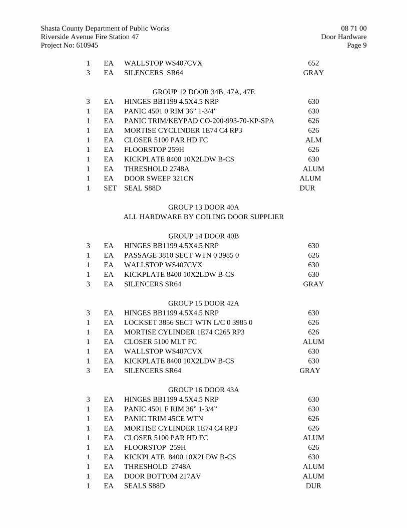
Shasta County Department of Public Works 08 71 00 Riverside Avenue Fire Station 47 Door Hardware Project No: 610945 Page 9
1 EA WALLSTOP WS407CVX 652 3 EA SILENCERS SR64 GRAY
GROUP 12 DOOR 34B, 47A, 47E
3 EA HINGES BB1199 4.5X4.5 NRP 630 1 EA PANIC 4501 0 RIM 36” 1-3/4” 630 1 EA PANIC TRIM/KEYPAD CO-200-993-70-KP-SPA 626 1 EA MORTISE CYCLINDER 1E74 C4 RP3 626 1 EA CLOSER 5100 PAR HD FC ALM 1 EA FLOORSTOP 259H 626 1 EA KICKPLATE 8400 10X2LDW B-CS 630 1 EA THRESHOLD 2748A ALUM 1 EA DOOR SWEEP 321CN ALUM 1 SET SEAL S88D DUR
GROUP 13 DOOR 40A
ALL HARDWARE BY COILING DOOR SUPPLIER
GROUP 14 DOOR 40B 3 EA HINGES BB1199 4.5X4.5 NRP 630 1 EA PASSAGE 3810 SECT WTN 0 3985 0 626 1 EA WALLSTOP WS407CVX 630 1 EA KICKPLATE 8400 10X2LDW B-CS 630 3 EA SILENCERS SR64 GRAY
GROUP 15 DOOR 42A
3 EA HINGES BB1199 4.5X4.5 NRP 630 1 EA LOCKSET 3856 SECT WTN L/C 0 3985 0 626 1 EA MORTISE CYLINDER 1E74 C265 RP3 626 1 EA CLOSER 5100 MLT FC ALUM 1 EA WALLSTOP WS407CVX 630 1 EA KICKPLATE 8400 10X2LDW B-CS 630 3 EA SILENCERS SR64 GRAY
GROUP 16 DOOR 43A
3 EA HINGES BB1199 4.5X4.5 NRP 630 1 EA PANIC 4501 F RIM 36” 1-3/4” 630 1 EA PANIC TRIM 45CE WTN 626 1 EA MORTISE CYLINDER 1E74 C4 RP3 626 1 EA CLOSER 5100 PAR HD FC ALUM 1 EA FLOORSTOP 259H 626 1 EA KICKPLATE 8400 10X2LDW B-CS 630 1 EA THRESHOLD 2748A ALUM 1 EA DOOR BOTTOM 217AV ALUM 1 EA SEALS S88D DUR

Shasta County Department of Public Works 08 71 00 Riverside Avenue Fire Station 47 Door Hardware Project No: 610945 Page 10
GROUP 17 DOOR 44A
3 EA HINGES BB1199 4.5X4.5 NRP 630 1 EA LOCKSET 3880 SECT WTN L/C 0 3985 0 626 1 EA MORTISE CYLINDER 1E74 C265 RP3 626 1 EA OVERHEAD STOP & HOLD 7017 SRF SZ2 @ 90DEG 630 1 EA KICKPLATE 8400 10 X 2LDW B-CS 630 3 EA SILENCERS SR64 GRAY
GROUP 18 DOOR 47B, 47C, 47D, 47F, 47G, 47H
ALL HARDWARE BY FOLDING DOOR SUPPLIER
GROUP 19 DOOR 471 3 EA HINGES BB1199 4.5X4.5 NRP 630 1 EA PANIC 4501 0 RIM 36” 1-3/4” 630 1 EA PANIC TRIM/KEYPAD CO-200-993-70-KP-SPA 626 1 EA MORTISE CYLINDER 1E74 C4 RP3 626 1 EA CLOSER 5100 PAR HD FC ALUM 1 EA FLOORSTOP 259H 626 1 EA KICKPLATE 8400 10 X 2LDW B-CS 1 EA THRESHOLD 2748A ALUM 1 EA DOOR SWEEP 321CN ALUM 1 EA SEALS S88D DUR
GROUP 20 DOOR 48A
3 EA HINGES BB1199 4.5X4.5 NRP 630 1 EA LOCKSET 3880 SECT WTN L/C 0 3985 0 626 1 EA MORTISE CYLINDER 1E74 C265 RP3 626 1 EA CLOSER 5100 PAR HD FC ALUM 1 EA FLOORSTOP 259H 626 1 EA THRESHOLD 2748A ALUM 1 EA DOOR SWEEP 321 CN ALUM 1 EA SEALS S88D DUR
END OF SECTION 08 71 00

Shasta County Department of Public Works 08 73 00 Riverside Avenue Fire Station 47 Automatic Door Operators Project No: 610945 Page 1
AUTOMATIC DOOR OPERATORS
SECTION 08 73 00
PART 1 - GENERAL
1.1 DESCRIPTION
Furnish and install exterior barrier free automatic door operators.
1.2 1.2 SUBMITTALS
Product Data: Furnish manufacturer's product data and standard details including fab-rication, finishing, hardware, operators, accessories, and other components of the work. Include rough-in diagrams, wiring diagrams, parts lists, and maintenance in-structions.
Shop Drawings: Furnish shop drawings for fabrication and installation. Show an-chors, joint system, expansion provisions, hardware, and other components not shown in manufacturer's product data.
Templates and Diagrams: Furnish templates, diagrams, and other data to fabricators and installers of related work for coordination of operators with doors, frames, hard-ware, electrical, and other work.
1.3 QUALITY ASSURANCE
Manufacturer's Qualifications: Provide operators produced by a firm with not less than 5-years experience in the fabrication of automatic door operation equipment.
Installer's Qualifications: An authorized representative of the door manufacturer.
Automatic door operators shall comply with ANSI A156.10 and UL 325.
Barrier free door operators shall comply with ANSI A156.19, Low-Energy Automatic Door Standard.
PART 2 - PRODUCTS
2.1 APPROVED MANUFACTURERS
Besam, Inc.
Republic Industries, Inc.
Horton Automatics
Gyro Tech, Inc.
Stanley Magic-Door Div. of Stanley Works

Shasta County Department of Public Works 08 73 00 Riverside Avenue Fire Station 47 Automatic Door Operators Project No: 610945 Page 2
Or approved equal.
2.2 AUTOMATIC DOOR OPERATOR FOR BARRIER FREE DOORS
Operator: Low-energy, self-contained, electromechanical design. The operator shall be powered open with a DC motor with closing by spring force. The motor shall be off when the door is in the closing mode. The door shall be manually operated with power on or off without damage to the operator.
Operator shall permit manual opening of door and automatic operation when ac-tuated with pushbutton switch.
The operator shall include the following variable adjustments in compliance with ANSI A156.19:
Opening Speed: 3- to 5-seconds. Closing Speed: 3- to 5-seconds. Time Delay Before Closing: 2- to 30-seconds.
Opening and closing force, measured 2-inches out from the lock stile of the door, shall not exceed 15-pounds of force to stop the door when operating in either direction.
Operator shall be mounted and concealed in an extruded aluminum cover running full width of door. Finish aluminum with a clear anodized finish.
Control Switches: Round stainless steel engraved handicap design, marked "Push to Open", one for each side of opening. Locate where indicated. Refer to door hardware schedule and drawings.
Electrical Requirements: 120-VAC, 1-phase, 60-Hz to operator; low voltage wires from push-plate switches to operator.
Low-voltage wiring connecting the door operator to the building security electronics system.
Door operator adjustment shall not require a computer to re-program a computer chip.
PART 3 - EXECUTION
3.1 INSTALLATION
Install automatic door operating equipment by factory-trained installers in accordance with manufacturer's instructions and reviewed shop drawings.
Adjust operators to achieve smooth and quiet operation.
3.2 CLEANING AND PROTECTION
Clean exposed operating components as recommended by manufacturer.
Protect automatic door operating equipment from damage and deterioration during construction.

Shasta County Department of Public Works 08 73 00 Riverside Avenue Fire Station 47 Automatic Door Operators Project No: 610945 Page 3
END OF SECTION 08 73 00

Shasta County Department of Public Works 08 80 00 Riverside Avenue Fire Station 47 Glazing Contract No: 610945 Page 4
GLAZING
SECTION 08 80 00
PART 1 - GENERAL
1.1 SUMMARY
Section Includes:
Provide miscellaneous glass and glazing for hollow metal work, windows and doors not provided elsewhere including accessories as required for complete installation.
1.2 REFERENCES
Glass Association of North America (GANA): Glazing Manual and Sealant Manual.
1.3 SYSTEM DESCRIPTION
Safety Glass Standard: CPSC 16 CFR 1201, ANSI Z97.1, and California Building Code Chapter 24.
1.4 SUBMITTALS
All submittals shall be submitted under the provisions of Section 01 33 00, “Submittal Procedures”.
Product Data: Furnish for each type of glass, and each type of exposed glazing material.
1.5 WARRANTY
Special Warranties
Special Warranty Period: Two years.
PART 2 - PRODUCTS
2.1 GLAZING MATERIALS
Tempered Safety Glass: Select glazing quality, clear float glass, fully tempered, ASTM C1048, Kind FT; nominal thickness 1/4"; safety glass.
Manufacturers:
Ford Glass Division. PPG Industries, Inc. Or approved equal.

Shasta County Department of Public Works 08 80 00 Riverside Avenue Fire Station 47 Glazing Contract No: 610945 Page 4
Locations: Provide at doors and at window openings where indicated on drawings and required by applicable codes and federal requirements.
Insulated Glazing System: Outside lite: clear w/low E & reflective coatings, ¼” Solarban r100, ½” air space, ¼” clear inside lite.
Manufacturers:
Ford Glass Division. PPG Industries, Inc. Or accepted equal.
Clear Float Glass: FS DD-G-451; Type 1, Class 1, glazing select quality; 1/4 inch thick.
Manufacturers:
Nippon Sheet Glass. Pilkington Glass, Ltd. Ashai Glass Co. Or accepted equal
Frameless Mirrors: ASTM C1036, Mirror quality q1 or q2, clear float glass; 1/4" thick; full silver coating, copper coating and organic coating; arrised edges; factory treated and sealed after cutting and finishing.
Manufacturers:
Binswanger Mirror Products, Memphis, TN. Downey Glass Co., Los Angeles, CA. General manufacturers listed. Or accepted equal.
Mirror Attachment:
Bottom Supports: Stainless steel angles, minimum 0.05" thickness; provide felt pads for setting mirrors on angles; provide concealed fasteners.
Adhesive: Nontoxic type as recommended by mirror manufacturer.
Glazing Sealant: ASTM C920, Type S, Grade NS, elastomeric one-component silicone glazing sealants as recommended by sealant manufacturer for application involved.
Manufacturers:
a. Dow Corning Corp. b. General Electric Co. c. Pecora Corp. d. Or accepted equal.

Shasta County Department of Public Works 08 80 00 Riverside Avenue Fire Station 47 Glazing Contract No: 610945 Page 4
Setting Blocks: 70-90 durometer hardness; 4" long by 3/8" thick by 1/4" high standard setting blocks.
Spacer Shims: Silicone compatible, 50 durometer hardness; 3" long by 3/32" thick by 1/4" high.
PART 3 - EXECUTION
3.1 PREPARATION
Clean glazing channels and framing members to receive glass immediately before glazing; remove coatings not firmly bonded to substrate.
Apply primer to joint surfaces where recommended by sealant manufacturer.
3.2 INSTALLATION
Comply with GANA Glazing Manual and Sealant Manual and glazing manufacturer instructions.
Do not allow glass to touch metal surfaces. Comply with NFPA 80 for glass in fire rated openings.
Place setting blocks at quarter points in thin course of sealant.
Install removable stops with glass centered in space with spacer shims at 2'-0" intervals on both sides of glass, 1/4" below sightline.
Sealant at Glazing: Fill gap between glass and stops with sealant to depth equal to bite of frame on glass but not more than 3/8" below sightline.
Apply sealant to uniform and level line, flush with sightline; tool or wipe sealant surface for smooth appearance; at exterior locations tool sealant so water is carried away from glass.
3.3 CLEANING
Mark glass after installation by crossed streamers attached to framing and held away from glass; do not apply markers to surface of glass.
Remove nonpermanent labels immediately after sealant cures; cure sealants for high early strength and durability.
Remove and replace glass that is broken, chipped, cracked, abraded or damaged during construction period, including natural causes, accidents and vandalism.
END OF SECTION 08 80 00

Shasta County Department of Public Works 08 91 00 Riverside Avenue Fire Station 47 Metal Louvers Project No: 610945 Page 1
METAL LOUVERS
SECTION 08 91 00
PART 1 - GENERAL
1.1 WORK INCLUDED
Louvers and frames.
Bird screening.
1.2 REFERENCES
AMCA 500 - (Air Movement Council Association) Test Method for Louvers, Dampers, and Shutters.
ANSI/ASTM B221 - Aluminum-Alloy Extruded Bars, Rods, Wire, Shapes, and Tubes.
ASTM B209 - Aluminum-Alloy Sheet and Plate.
1.3 SYSTEM PERFORMANCE
Fabricate louver to permit 50 percent free area.
1.4 QUALITY ASSURANCE
Manufacturer: Company specializing in manufacture of AMCA certified louvers with three years’ experience.
1.5 SUBMITTALS
Indicate on shop drawings, layout, elevations, dimensions, and tolerances; head, jamb, and sill details; blade configuration; screening; and frames.
Provide product data on preassembled louvers describing design characteristics, maximum recommended air velocity, free area, materials, and finishes.
Submit manufacturer's installation instructions.
1.6 COORDINATION
Coordinate work of this Section with installation of metal building system.
Coordinate work of this Section with mechanical ductwork.

Shasta County Department of Public Works 08 91 00 Riverside Avenue Fire Station 47 Metal Louvers Project No: 610945 Page 2
1.7 WARRANTY
Provide special warranty that louvers will be free of defects in material and workmanship for a period of Five (5) years.
PART 2 - PRODUCTS
2.1 ACCEPTABLE MANUFACTURERS
Wonder Metals Corp.
Or accepted equal.
2.2 MATERIALS
Louver blades and frame head, jamb and sill: 16 ga. galvanized steel
Fasteners and Anchors: Stainless steel type as recommended by manufacturer.
2.3 ACCESSORIES
Bird Screen: Interwoven wire mesh of galvanized steel, 19 gauge wire, 1/2 inch open weave, square design.
Exterior Door louver screen: Interwoven wire mesh of galvanized steel, 19 gauge wire, 1/16” minimum – 1/8” maximum opening size, open weave, square design
Flashings: Of same material as louver frame.
Sealants.
2.4 FABRICATION
Louver Size: Depth as indicated on the drawings. Verify opening size prior to fabrication.
Louver Blade: Sloped at 45 degree; "Z" shape as indicated; reinforced with 16 gauge; minimum material thickness of 16 gauge; integral waterstops on blade.
Louver Frame: Channel shape, welded corner joints, material thickness of 16 gauge.
Mullions: Concealed of steel, profiled to suit louver frame.
Head, Jamb, and Sill Flashings: Roll formed to required shape, one piece per location.
Screens: Permanently install screen mesh in shaped frame with reinforced corner construction; screw to louver frame.
Sizes and shapes as shown on Drawings.

Shasta County Department of Public Works 08 91 00 Riverside Avenue Fire Station 47 Metal Louvers Project No: 610945 Page 3
2.5 FINISHES
All steel surfaces to be first galvanized, then primed, then field paint finish coats.
PART 3 - EXECUTION
3.1 INSPECTION
Verify that prepared openings and flashings are ready to receive work and opening dimensions are as indicated on shop drawings.
Beginning of installation means acceptance of existing conditions.
3.2 INSTALLATION
Install louver assembly in accordance with manufacturer's instructions.
Install louvers level and plumb.
Secure louvers in opening framing as shown on drawings.
Install flashings and align louver assembly to ensure moisture shed from flashings and diversion of moisture to exterior.
Install bird screening to interior of louver.
Install perimeter sealant and backing rod in accordance with Section 07 90 00.
3.3 ADJUSTING AND CLEANING
Clean surfaces and components.
END OF SECTION 08 91 00

Shasta County Department of Public Works 09 21 16 Riverside Avenue Fire Station 47 Gypsum Board Assemblies Contract No: 610945 Page 1
GYPSUM BOARD ASSEMBLIES
SECTION 09 21 16
PART 1 - GENERAL
1.1 SUMMARY
Section Includes: Provide gypsum board systems including gypsum board, joint treatment, acoustical accessories, and general accessories for complete installation.
1.2 REFERENCES
ASTM C754: Installation of Steel Framing Members to Receive Screw-Attached Gypsum Wallboard.
ASTM C840: Application and Finishing of Gypsum Board.
1.3 SYSTEM DESCRIPTION
Performance Requirements: Perform gypsum board systems work in accordance with recommendations of ASTM C754 and ASTM C840 unless otherwise specified.
Loads: Comply with California Building Code requirements for design of metal framing for gypsum board systems.
Deflection: Maximum L/240 typical, L/360 where plaster or tile is indicated.
Seismic Requirements: Comply with code requirements for seismic bracing.
Systems Responsibility: Provide products manufactured by or recommended by manufacturer of gypsum board to maintain single-source responsibility for system.
Openings: Obtain dimensions and locations from other trades and provide openings and enclosures for accessories, specialties, equipment, and ductwork.
1.4 SUBMITTALS
Product Data: Provide product data on metal framing, gypsum board, joint tape, and decorative finish.
1.5 PROJECT CONDITIONS
Do not begin installation of interior gypsum board until space is enclosed, space is not exposed to other sources of water, and space is free of standing water.
Maintain areas to receive gypsum board at minimum 50 degree F for 48 hours prior to application and continuously after application until drying of joint compound is complete; comply with ASTM C840.

Shasta County Department of Public Works 09 21 16 Riverside Avenue Fire Station 47 Gypsum Board Assemblies Contract No: 610945 Page 2
Immediately remove from site gypsum board for interior use exposed to water, including gypsum board with water stains, with signs of mold, and gypsum board with mildew.
PART 2 - PRODUCTS
2.1 MANUFACTURERS
United States Gypsum Co., USG Corp.
Georgia-Pacific Corp.
National Gypsum Co.
Or accepted equal.
2.2 MATERIALS
Gypsum Board - Standard
ASTM C1396, TYPE X, FIRE RATED, 5/8” thick paper faced gypsum panels with tapered edges.
Moisture Resistant Gypsum Board
Equal to Georgia Pacific Corp. “Dens-Armor Plus High Performance” 5/8” thick fiberglass faced, treated gypsum panels with tapered edges. Fire rated Type X.
Gypsum Board Accessories: Comply with ASTM C840.
Gypsum board sealer: Provide one Coat "Hamilton Prep Coat Plus" prior to application of gypsum board texture.
Provide protective coated steel corner beads and edge trim; type designed to be concealed in finished construction by tape and joint compound.
Corner Beads: Manufacturer's standard metal beads. Edge Trim: “J”, "L", "LK", or "LC" casing beads – manufacturer’s standard. Reinforcing Tape, Joint Compound, Adhesive, Water, Fasteners: Types
recommended by system manufacturer and conforming to ASTM C475.
Typical Joint Compound: Chemical hardening type for bedding and filling, ready-mixed or powder vinyl type for topping.
Control Joints: Back to back casing beads.
Back control joints with 4 mil thick polyethylene air seal.
Reveals: Extruded aluminum special trim pieces in manufacturer's standard or custom shapes to conform to configurations and dimensions indicated.
Manufactures:
1. Fry Reglet Corp./Drywall Moldings.

Shasta County Department of Public Works 09 21 16 Riverside Avenue Fire Station 47 Gypsum Board Assemblies Contract No: 610945 Page 3
2. MM Systems Corp./Drywall Moldings. 3. Gordon Inc./Final Forms I Drywall Trims. 4. Substitutions: Refer to Section 01 62 00.
Gypsum Board Texture: Equal to USG “Sheetrock Brand” ready mixed wall and ceiling spray texture.
Acoustic Sealant: Serious Energy “Quiet Seal Pro”, non-hardening, gun grade sealant per STM C834.
Electrical Box Pads: Provide at outlet, switch and telephone boxes in walls with acoustical insulation.
Non-Fire Rated Partitions: Match Harry A. Lowry & Associates, CA/Lowry’s electrical box pads.
PART 3 - EXECUTION
3.1 Installation:
Gypsum Board Installation: Install in accordance with ASTM C840 and manufacturer's recommendations.
Use screws when fastening gypsum board to furring and to framing. Erect gypsum board with ends and edges occurring over firm bearing.
Ensure joints of second layer do not occur over joints of first layer in double layer applications.
Place control joints to be consistent with lines of building spaces and as directed by Architect.
Provide where system abuts structural elements. Provide at dissimilar materials. Lengths exceeding 30'-0" in partitions. Ceiling areas exceeding 50'-0" or 2500 square feet. Wings of "L", "U" and "T" shaped ceilings.
Place corner beads at external corners; use longest practical lengths. Place edge trim where gypsum board abuts dissimilar materials. Tape, fill, and sand exposed joints, edges, corners and openings to produce
surface ready to receive finishes; feather coats onto adjoining surfaces. Finishing: Comply with Gypsum Association (GA) “Levels of Gypsum Board
Finish”.
GA Level 4 (Typical): Provide three coat finishing and sanding is required for surfaces indicated to be painted; provide flush, smooth joints and surfaces ready for applied paint finishes.
Texture: Light orange peel.
Remove and replace defective work.

Shasta County Department of Public Works 09 21 16 Riverside Avenue Fire Station 47 Gypsum Board Assemblies Contract No: 610945 Page 4
END OF SECTION 09 21 16

Shasta County Department of Public Works 09 22 16 Riverside Avenue Fire Station 47 Non-Structural Metal Framing Contract No: 610945 Page 3
METAL FRAMING
SECTION 09 22 16
PART 1 - GENERAL
1.1 SECTION INCLUDES
Section includes metal stud framing and accessories.
1.2 REFERENCES
The publications listed below form a part of this Section to the extent referenced. The publications are referred to in the text by the basic designation only.
Unless otherwise noted, standards, manuals, and codes refer to the latest edition of such standards, manuals, and codes as of the date of issue of this Project Manual.
Referenced Standards:
ASTM A653/A653M–Standard Specification for Steel Sheet, Zinc-Coated (Galvanized) or Zinc-Iron Alloy-Coated (Galvannealed) by the Hot-Dip Process.
ASTM A924/A924M– tandard Specification for General Requirements for Steel Sheet, Metallic-Coated by the Hot-Dip Process.
ASTM C645–Standard Specification for Nonstructural Steel Framing Members.
ASTM C754–Standard Specification for Installation of Steel Framing Members to Receive Screw-Attached Gypsum Panel Products.
ASTM C1513–Standard Specification for Steel Tapping Screws for Cold-Formed Steel Framing Connections.
SSPC Paint 20–Zinc Rich Primers.
1.3 SYSTEM DESCRIPTION
Interior Walls: Metal stud framing system with batt type acoustic insulation and interior gypsum board
Maximum Allowable Deflection:
1:120 span at gypsum board finish. 1:240 span ceramic tile finishes.
Wall and Ceiling Systems:
Design to provide for movement of components without damage, failure of joint seals, undue stress on fasteners, or other detrimental effects when subject to seasonal or cyclic day/night temperature ranges.

Shasta County Department of Public Works 09 22 16 Riverside Avenue Fire Station 47 Non-Structural Metal Framing Contract No: 610945 Page 4
1.4 SUBMITTALS
Shop Drawings:
Indicate component details, stud layout, framed openings, anchorage to structure, type and location of fasteners and accessories or items required of other related work.
Describe method for securing studs to tracks, splicing and for blocking and reinforcement to framing connections.
Product Data: Submit data describing standard framing member materials and finish, product criteria, load charts and limitations.
Manufacturer's Installation Instructions: Submit special procedures, perimeter conditions requiring special attention.
1.5 QUALITY ASSURANCE
Perform Work in accordance with ASTM C754.
Comply with 2010 CBC, Chapter 22A, Section 2210A.
Form, fabricate, install, and connect components in accordance with ML/SFA 540.
1.6 QUALIFICATIONS
Manufacturer: Company specializing in manufacturing products specified in this Section.
Installer: Company specializing in performing Work of this Section.
PART 2 - PRODUCTS
2.1 METAL FRAMING SYSTEM
Manufacturers:
Clark/Western Building Systems Dietrich Industries, Inc. Marino/Ware CEMCO Or accepted equal.
2.2 COMPONENTS
Framing System Components: ASTM C645.
16 Gauge and heavier, Fy = 50 ksi 18 Gauge and lighter, Fy = 33 ksi Minimum.

Shasta County Department of Public Works 09 22 16 Riverside Avenue Fire Station 47 Non-Structural Metal Framing Contract No: 610945 Page 5
Studs and Joists: ASTM A653/A653M non-load bearing rolled steel, channel shaped, punched for utility access, depths and gauges and spacing as indicated on the drawings.
Tracks and Headers: Same material and thickness as studs, bent leg retainer notched to receive studs. Ceiling Runners: With extended leg retainer.
Slotted Track: Slotted track system for positive attachment of metal studs to track, for Head of Wall expansion joint movement (cyclic) and static Joint System in fire-rated construction, as detailed and required on Drawings, in compliance with UL 2079 cyclical movement ± ½ inch overall 1” movement: Slp-Trk as manufactured by Dietrich Industries, Inc.
Forming Steel shall conform to ASTM A653, Grade 33 with a minimum yield point of 33,000 psi.
Formed Steel shall be galvanized in accordance with ASTM A924 for a Class G60 by the hot dip process.
Slotted track shall be provided in standard widths and gauges, as required and indicated on Drawings. Down standing legs shall be nominally 2-1/2” and shall be provided with 1-1/2” slots at 1” on center.
Fasteners:
For attachment of studs to slotted track, minimum No. 8 corrosion resistant by 1/2 inch waferhead screws.
For attachment of Slotted Track to overhead structural element, as provided for the structural details affecting the work.
Furring and Bracing Members: Minimum 18 gauge steel in sizes and shapes as indicated on Drawings and to suit application..
Fasteners: ASTM C1513, self-drilling, self-tapping corrosion resistant screws.
Sheet Metal Backing: 16 gauge.
Anchorage Devices: As indicated on the drawings.
Touch-Up Primer for Galvanized Surfaces: SSPC-Paint 20 Type II Organic zinc rich.
PART 3 - EXECUTION
3.1 EXAMINATION
Coordination and project conditions.
Verify rough-in utilities are in proper location.
3.2 INSTALLATION
Align and secure top and bottom runners as indicated on Drawings.
Place two beads of acoustic sealant between runners and substrate, studs and adjacent construction, to achieve acoustic seal.

Shasta County Department of Public Works 09 22 16 Riverside Avenue Fire Station 47 Non-Structural Metal Framing Contract No: 610945 Page 6
Place two beads of acoustic sealant between studs and adjacent vertical surfaces to achieve acoustic seal.
Framing at openings shall be as shown on Drawings. Install intermediate studs at same spacing as wall studs.
Install studs vertically at 16” unless otherwise noted on drawings.
Install joists horizontally at 16” unless otherwise noted on drawings.
Align stud web openings horizontally.
Secure studs to tracks as indicated on Drawings.
Stud splicing not permissible.
Fabricate corners using minimum of three studs.
Double stud at wall openings and door and window jambs, not more than 2” from each side of openings.
Brace stud framing system rigid.
Coordinate erection of studs with requirements of door frames and window frames; install supports and attachments.
Backing/Blocking: Shall be provided for all wall and ceiling finishes and for the supporting and anchorage of products, fixtures and equipment for all trades, including, but not limited to, toilet partitions, toilet room accessories, casework, mirrors, trim, applied wall finishes, artwork, wall bumpers, downspout straps, plumbing and electrical fixtures, etc. Coordinate size, type and location of backing and supports with manufacturer or supplier of items requiring backing/blocking.
Refer to Drawings for indication of partitions extending stud framing through ceiling to structure above. Maintain clearance under structural building members to avoid deflection transfer to studs. Install extended leg ceiling runners.
Coordinate placement of insulation in stud spaces after stud frame erection.
3.3 ERECTION TOLERANCES
Maximum Variation From Indicated Position: 1/8” in 10’ (non-cumulative).
Maximum Variation From Plumb: 1/8” in 10’ (non-cumulative).
END OF SECTION 09 22 16

Shasta County Department of Public Works 09 51 13 Riverside Avenue Fire Station 47 Acoustic Ceilings Contract No: 610945 Page 5
ACOUSTIC CEILINGS
SECTION 09 51 13
PART 1 - GENERAL
1.1 SUMMARY
Section Includes: Provide acoustical ceiling systems with exposed suspended metal grid system, trim, and accessories as required for complete finished installation.
1.2 SYSTEM DESCRIPTION
Seismic Design Requirements: Comply with California Building Code requirements for seismic bracing of ceiling suspension system, and with ASTM E580.
Ceiling Struts: Provide struts as detailed on Drawings and as required by code, placed maximum 12'-0" on center in both directions and within 6'-0" of each wall.
Slack Wires: Provide safety slack wires, two per light fixture on diagonally opposite corners and a single wire for each recessed down light.
Fire Performance Characteristics: Provide products listed by Underwriters Laboratories (UL) or other independent testing laboratory acceptable to applicable authorities.
Flame Spread/Smoke Density: Provide products meeting code requirements for maximum 25 flame spread and maximum 25 smoke density.
1.3 REFERENCES
ASTM C635: Metal Suspension Systems for Acoustical Tile and Lay-in Panel Ceilings.
ASTM C636: Installation of Metal Ceiling Suspension Systems for Acoustical Tile and Lay-in Panel Ceilings.
ASTM E580: Application of Ceiling Suspension Systems for Acoustical Tile and Lay-In Panels in Areas Requiring Seismic Restraint.
1.4 SUBMITTALS
All submittals shall be submitted under the provisions of Section 01 33 00, “Submittal Procedures”.
Product Data: Furnish manufacturers' literature.
Shop Drawings: Clearly indicate grid layout and related dimensioning, junctions with other work and ceiling finishes, and inter-relation of mechanical and electrical items related to system.

Shasta County Department of Public Works 09 51 13 Riverside Avenue Fire Station 47 Acoustic Ceilings Contract No: 610945 Page 5
Samples: Furnish samples of exposed grid finish and each type of ceiling unit.
1.5 QUALITY ASSURANCE
Installer Qualifications: Firm with minimum three years successful experience in projects of similar type and scope; acceptable to manufacturer of acoustical units.
1.6 SITE CONDITIONS
Do not install ceilings until building is enclosed, sufficient heat is provided, dust-generating activities have terminated and overhead mechanical work is completed, tested and approved.
Do not allow acoustical ceiling units to be exposed to moisture; immediately remove acoustical ceiling units with stains, units with signs of mold, and units with mildew.
Allow wet work to dry prior to commencement of installation.
Maintain uniform temperatures of minimum 60 degrees F and humidity of 20% to 40% prior to, during and after installation.
1.7 EXTRA STOCK
Provide 3% cartons of extra tile of each type used for the County’s maintenance use at no additional cost
PART 2 - PRODUCTS
2.1 MATERIALS
Suspension System: Comply with ASTM C635, as applicable to type of suspension system required for type of ceiling units indicated.
Manufacturers:
Armstrong World Industries, Inc. Chicago Metallic Corp. USG, Interiors, Inc. / Donn. Or accepted equal.
Exposed Grid System: Narrow, 9/16” nominal face width, direct hung aluminum or steel ‘T’ exposed grid system.
Attachment Devices: Size for 5 times design load indicated in ASTM C635, Table 1, Direct Hung.
Hanger Wires: 12 gauge. Straps, Tubes and Angles: Provide galvanized steel as required to meet state
and local requirements for seismic design loads. Structural Class: intermediate-duty system, minimum. Edge Molding: Manufacturer's standard angle molding for edges and
penetrations of ceiling, with single flange of molding exposed. Finish of Exposed Items: Manufacturer's standard white baked enamel.

Shasta County Department of Public Works 09 51 13 Riverside Avenue Fire Station 47 Acoustic Ceilings Contract No: 610945 Page 5
Maximum Allowable Deflection: L/360.
Lay-In Panels: ASTM E1264 type and form as indicated on Drawings.
Manufacturers:
Armstrong World Industries, Inc. USG Interiors, Inc. Or accepted equal.
Typical Throughout Building where shown on drawings.
Panels: Mineral composition lay-in Tegular ceiling panels with square edge designed to be compatible with specified suspension system.
Style: Armstrong “Cortega, Fine Fissured” unless otherwise indicated.
Size: 2’-0” x 2’-0 x 5/3”
PART 3 - EXECUTION
3.1 PREPARATION
Furnish layouts for inserts, clips and other supports required to be installed by other trades for support of acoustical ceilings.
Install inserts, clips, and supports where not previously installed and where additional supports are required for complete installation.
Measure ceiling area and establish layout of acoustical units to balance border widths at opposite edges of each ceiling; do not use less than half width units at borders.
Coordinate with other work supported by or penetrating through ceilings, including light fixtures, HVAC equipment and partition systems.
3.2 INSTALLATION
Installation of all suspended acoustical ceilings shall comply with installation requirements outlined in CBC (Title 24 Part 2), Chapter 25A.
Install acoustical ceiling systems in accordance with manufacturer's recommendations and ASTM C636.
Finished Ceilings: True to lines and levels and free from warped, soiled or damaged grid or acoustical units.
Install ceiling systems in a manner capable of supporting superimposed loads, with maximum permissible deflection of 1/8" in 10'-0".
Install after major above-ceiling work is complete; coordinate location of hangers with other work.

Shasta County Department of Public Works 09 51 13 Riverside Avenue Fire Station 47 Acoustic Ceilings Contract No: 610945 Page 5
Ensure suspension system is located to accommodate fittings and units of equipment that is to be placed after installation of ceiling grid.
Where ducts or other equipment prevent regular spacing of hangers, reinforce nearest adjacent hangers and related carrying channels as required to span required distance.
Install ceiling suspension system to resist seismic loads as required by state and local codes, including extra hanger wires and compression supports for ceilings and light fixtures.
Hang system independently of walls, columns, ducts, pipes and conduit. Where suspension system members are spliced, avoid visible displacement of the longitudinal axis or face plane of adjacent members.
Do not support lighting fixtures from or on main runners or cross runners if weight of fixture causes total dead load to exceed deflection capability.
Support fixture loads independently or provide supplementary hangers located within 6" of each corner.
Do not install fixtures so main runners and cross runners are eccentrically loaded; where fixture installation would produce rotation of runners, provide stabilizer bars.
Install edge moldings at intersection of ceiling and vertical surfaces, using maximum lengths, straight, true to line and level; miter corners.
Provide edge moldings at junctions with other ceiling finishes.
Where required form expansion joints to accommodate movement and maintain visual closure without distorting system.
Fit acoustic units in place, free from damaged edges or defects detrimental to appearance and function.
Lay directionally patterned units one way with pattern as directed. Fit border units neatly against abutting surfaces.
Install system level, in uniform plane and free from twist, warp and dents.
Install hold-down clips where required by applicable codes and where ceiling is within 20'-0" of an exterior door.
Adjustment: Adjust sags or twists that develop in ceiling system and replace any part that is damaged or faulty.
END OF SECTION 09 51 13

Shasta County Department of Public Works 09 65 13 Riverside Avenue Fire Station 47 Resilient Base Contract No: 610945 Page 1
RESILIENT BASE
09 65 13
PART 1 - PART 1 - GENERAL
1.1 SUMMARY
Section Includes: Provide resilient base, and accessories as required for complete installation.
1.2 SYSTEM DESCRIPTION
Performance Requirements: Provide materials tested under ASTM E648, Flooring Radiant Panel Test, with results of 0.45 watts/cm2 or higher.
1.3 SUBMITTALS
Product Data: Furnish manufacturer's product literature.
Samples: Furnish samples of each base color and type.
1.4 PROJECT CONDITIONS
Maintain minimum 70 degree F air temperature at installation area for 3 days prior to, during, and for 24 hours after installation.
Store materials in area of application; allow three days for material to reach same temperature as area.
PART 2 - PRODUCTS
2.1 MATERIALS
Resilient Base: Conform to FS SS-W-40, with premolded end stops and external corners; 1/8" gage; provide base at floor surfaces unless otherwise indicated.
Type: Extruded rubber. Manufacturers:
Johnsonite, Inc. Burke Or accepted equal.
Base:
Johnsonite coved toe, 4". Provide base in 120’ coils. 4’ pieces are not acceptable.

Shasta County Department of Public Works 09 65 13 Riverside Avenue Fire Station 47 Resilient Base Contract No: 610945 Page 2
Colors: As selected by Architect from manufacturer's full range of available colors.
Primers and Adhesives: Water-resistant nontoxic types recommended by base manufacturer for specified material and application.
PART 3 - EXECUTION
3.1 INSTALLATION
3.1.1 Apply to walls, columns, pilasters, casework, and other permanent fixtures in rooms and areas where base is required.
Fit joints tight and vertical; maintain minimum measurement of 18" between joints.
Miter internal corners; use molded sections for external corners and exposed ends.
Install base on solid backing, adhere tightly to wall and floor surfaces; fill voids along top edge of base with manufacturer's recommended adhesive filler.
Scribe and fit to door frames and other obstructions.
Install straight and level to variation of plus or minus 1/8" over 10'-0".
3.2 CLEAN-UP
Remove excess adhesive from floor, base and wall surfaces without causing damage.
Clean surfaces in accordance with manufacturer's recommendations.
END OF SECTION 09 65 13

Shasta County Department of Public Works 09 65 16 Riverside Avenue Fire Station 47 Sheet Vinyl Flooring Contract No: 610945 Page 1
SHEET VINYL FLOORING
SECTION 09 65 16
PART 1 - GENERAL
1.1 DESCRIPTION OF WORK
Resilient Sheet Vinyl Flooring and accessories.
Concrete sealer.
1.2 REGULATORY REQUIREMENTS
Class 1 Fire Rating in conformance with NFPA 101 for Interior Floor Finish, minimum 0.45 watts per square centimeter.
Heat resistant to air temperature between +140º F (60º C) and -5º F (-20º C).
250 PSI Static Load limit and 1,500 PSI rolling load limit in accordance with LF-475a.
Flexibility must conform to LF-475a paragraph 4.6.5.
Wear resistance index in excess of 400 in accordance with test ASTM C-501.
Impregnated with Bacteriostat to retard the growth of bacteria.
Minimum 0.6 coeffiction of friction per ASTM D2047.
1.3 SUBMITTALS
Product Information and Installation Instructions.
Shop Drawings indicating seaming, edge conditions and transitions.
Certification in writing by the manufacturer that the Flooring Contractor is approved for the installation of the Resilient Sheet Vinyl, accessories and heat welding of all seams.
Seven year wear warranty.
Manufacturer's written recommendations for maintenance of the Sheet Vinyl Flooring.
1.4 ENVIRONMENTAL REQUIREMENTS
Store materials in warm, clean, dry enclosed space, protected from weather, maintained at a minimum temperature of 65º F (18º C) and a maximum temperature of 80º F (26º C) for 48 hours prior to installation.
Shasta County Department of Public Works 09 65 16 Riverside Avenue Fire Station 47 Sheet Vinyl Flooring Contract No: 610945 Page 2
Maintain a minimum 65º F (18º C) and maximum 75º F (24º C) during installation of flooring and accessories, and for 48 hours after completion of the installation.
PART 2 - PRODUCTS
2.1 MANUFACTURERS - RESILIENT SHEET VINYL FLOORING
Manufacturers
Mohawk Group Or accepted equal.
Accessories:
Vinyl heat welding thread in matching colors. Subfloor filler and patching compound must be Portland based resin cement
as recommended by the Flooring Manufacturer; with a minimum compressive strength of 4,000 psi in accordance with ASTM 349/157. Gypsum based fillers will not be allowed.
Stainless Steel Drain Rings. Vinyl Reducing Strip equal to Mercer #700 or #705.
Color as selected by Architect.
PART 3 - EXECUTION
3.1 EXAMINATION
Verify that surfaces are smooth and flat and are ready to receive the sheet vinyl floor covering.
Verify concrete substrate is dry in accordance with the Resilient Flooring Industry Standard ASTM E-96-80 Test Method for water Vapor Transmission: Maximum allowable 3 lbs/water/24 hours/1,000 sq. ft. by conducting moisture tests.
Beginning of installation means acceptance of existing substrate and site conditions.
3.2 PREPARATION
Remove sub-floor ridges and bumps. Remove paint, grease, oil, plaster dropping and other foreign materials. Fill low spots, cracks, joints, holes and other defects with specified sub-floor filler as recommended by the manufacturer.
Prohibit traffic on area prepared until filler is cured.
Sweep or vacuum substrate to remove all dust and dirt.
Mechanically fasten Stainless Steel drain rings over all round drain outlets over the sheet vinyl. Drill into concrete to accommodate Red Head mollies manufacturer by HILTI Inc. Screw stainless steel rings tightly utilizing Red Head mollies. Stainless steel rings to be of a size to allow removal of clean-out grate.

Shasta County Department of Public Works 09 65 16 Riverside Avenue Fire Station 47 Sheet Vinyl Flooring Contract No: 610945 Page 3
Install vinyl reducer as specified where required.
3.3 INSTALLATION OF SHEET VINYL FLOORING
Install in accordance with manufacturer's instructions.
Mix and spread adhesive according to manufacturer's instructions.
After setting flooring in place, roll with minimum 150 lb. roller to attain full adhesion.
Terminate flooring at centerline of door at door openings where adjacent floor finish is dissimilar.
Groove seams using manufacturer's approved grooving tool, to accommodate vinyl welding thread.
Heat weld all seams with vinyl welding thread and trim flush to surface when rod has cooled. Do not attempt to heat weld any seams until after adhesive has completely dried.
Flash cove all walls to 6”.
3.4 INSTALLATION OF ACCESSORIES
Install C9 cap strip to accommodate sheet vinyl to a height of 6" as indicated on the drawings using contact adhesive.
Seal all other crevices around pipes, drains, etc. with sealant in a matching color to the vinyl flooring.
3.5 3.5 CLEANING AND PROTECTION
Perform initial maintenance immediately upon completion of floor installation, removing any adhesive residue from the surface of the flooring.
Sweep or vacuum floor thoroughly.
Damp mop with warm water to remove soil. Green nylon pad with detergent is to be used to remove any marks.
Protect floor against damage from rolling loads for 48 hours after the installation has been completed by covering with plywood or hardboard where rolling traffic will occur prior to the 48 hour period.
Protect installed flooring with undyed, untreated building paper until floor has been inspected and accepted by County or Architect.
END OF SECTION 09 65 16

Shasta County Department of Public Works 09 65 66 Riverside Avenue Fire Station 47 Resilient Athletic Flooring Contract No: 610945 Page 1
RESILIENT ATHLETIC FLOORING
09 65 66
PART 1 - GENERAL
1.1 SUMMARY
This Section includes the following:
Interlocking, solid, rubber floor tile.
1.2 SUBMITTALS
Product Data: For each type of product indicated.
Shop Drawings: Show installation details and tile layout.
Maintenance Data.
1.3 PROJECT CONDITIONS
Adhesively Applied Products:
Maintain temperatures within range recommended in writing by manufacturer, but not less than 70 deg F or more than 95 deg F, in spaces to receive floor coverings during the following time periods:
48 hours before installation, unless longer period is recommended in writing by manufacturer.
During installation. 48 hours after installation, unless longer period is recommended in
writing by manufacturer.
After post installation period, maintain temperatures within range recommended in writing by manufacturer, but not less than 55 deg F or more than 95 deg F.
Close spaces to traffic during floor covering installation. Close spaces to traffic for 48 hours after floor covering installation, unless
manufacturer recommends longer period in writing.
PART 2 - PRODUCTS
2.1 INTERLOCKING, SOLID, RUBBER FLOOR TILE
Available Products: Subject to compliance with requirements, products that may be incorporated into the Work include, but not limited to, the following:
Products: Subject to compliance with requirements, provide one of the following:

Shasta County Department of Public Works 09 65 66 Riverside Avenue Fire Station 47 Resilient Athletic Flooring Contract No: 610945 Page 2
Johnsonite, Commotion Sports Flooring Flexco Rubber Or accepted equal
Material: Rubber – 85% recycled content.
Installation Methd: Free Lay.
Tile Interlock: Visible.
Traffic-Surface Texture: Smooth
Size: 24” square, minimum
Thickness: 3/8 inch.
Color and Pattern: As selected by Architect from manufacturer’s full range.
Accessories:
Border Tiles: Interlocking, beveled-edge tiles, of same material as floor tile, with bevels that transition from thickness of floor tile to surface below it, with straight outside edges, and for use where floor covering corners and edges do not abut vertical surfaces.
PART 3 - EXECUTION
3.1 PREPARATION
Concrete Substrates: Prepare according to ASTM F 710.
Verify that substrates are dry and free of curing compounds, sealers, and hardeners.
Alkalinity and Adhesion Testing: Perform tests recommended in writing by manufacturer. Proceed with installation only after substrates pass testing.
Moisture Testing: Install Vapor Emissions Control System.
Remove substrate coatings and other substances that are incompatible with adhesives and that contain soap, wax, oil or silicone, using mechanical methods recommended in writing by manufacturer. Do not use solvents.
Use trowelable leveling and patching compound to fill cracks, holes, and depressions in substrates.
Move floor coverings and installation materials into spaces where they will be installed at least 48 hours in advance of installation, unless manufacturer recommends a longer period in writing.
Do not install floor coverings until they are same temperature as space where they are to be installed.

Shasta County Department of Public Works 09 65 66 Riverside Avenue Fire Station 47 Resilient Athletic Flooring Contract No: 610945 Page 3
Sweep and vacuum clean substrates to be covered by floor coverings immediately before installation. After cleaning, examine substrates for moisture, alkaline salts, carbonation, and dust. Proceed with installation only after unsatisfactory conditions have been corrected.
3.2 FLOOR TILE INSTALLATION
Lay out tiles from center marks established with principal walls, discounting minor offsets, so tiles at opposite edges of room are of equal width. Adjust as necessary to avoid using cut widths that equal less than one-half tile at perimeter.
Lay tiles with grain direction alternating in adjacent tiles (basket-weave pattern) in pattern of colors and sizes indicated.
3.3 CLEANING AND PROTECTING
Perform the following operations immediately after completing floor covering installation:
Remove adhesive and other blemishes from floor covering surfaces. Sweep and vacuum floor coverings thoroughly. Damp-mop floor coverings to remove marks and soil.
Do not wash floor coverings until after time period recommended in writing by manufacturer.
Protect floor coverings from mars, marks, indentations, and other damage from construction operations and placement of equipment and fixtures during remainder of construction period. Use protection methods recommended in writing by manufacturer.
END OF SECTION 09 65 66

Shasta County Department of Public Works 09 68 13 Riverside Avenue Fire Station 47 Carpet Tile Contract No: 610945 Page 1
CARPET TILE
SECTION 09 68 13
PART 1 - GENERAL
1.1 SUMMARY
Section Includes: Provide carpet tile including edge strips where carpeting terminates at other floor finishes and accessories as required for complete finished installation.
1.2 SYSTEM DESCRIPTION
Performance Requirements:
Fire and Smoke: Carpet tiles shall have passed following fire and smoke tests.
DOC-FF-1-70: Pass NFPA 258 (Smoke Density): 450 or less. ASTM E648 (Flooring Radiant Panel Test): 0.45 or higher.
Static: Carpet tile shall develop less than 3.0 kilovolts of static at 70 degrees F and 20 percent relative humidity.
1.3 REFERENCES
The publications listed below form a part of this Section to the extent referenced. The publications are referred to in the text by the basic designation only. Refer to Section 01 42 00 “References” for definitions, acronyms, and abbreviations.
Unless otherwise noted, standards, manuals, and codes refer to the latest edition of such standards, manuals, and codes as of the date of issue of this Project Manual.
Referenced Standards:
AATCC-134 – Electrostatic Propensity of Carpets. ASTM D1667 – Standard Specification for Flexible Cellular
Materials-Vinyl Chloride Polymers and Copolymers (Closed-Cell Foam). ASTM E648 – Standard Test Method for Critical Radiant Flux of
Floor-Covering Systems Using a Radiant Heat Energy Source. ASTM E662 – Standard Test Method for Specific Optical Density of
Smoke Generated by Solid Materials. ASTM F710 – Standard Practice for Preparing Concrete Floors to
Receive Resilient Flooring. Carpet & Rug Institute Publication, CRI 104, Standard for Installation
Specifications of Commercial Carpet. Carpet & Rug Institute Publication, CRI TM-102 – Fluorochemical Finishes.

Shasta County Department of Public Works 09 68 13 Riverside Avenue Fire Station 47 Carpet Tile Contract No: 610945 Page 2
1.4 SUBMITTALS
Product Data: Provide product data on specified products, describing physical and performance characteristics; sizes, patterns, colors available, and method of installation, as well as manufacturer’s installation instructions.
Shop Drawings: Clearly indicate carpet tile layout, direction of carpet tiles, adhesive to be used, method of integrating edge strips with carpet tile, and installation procedures.
Samples: Submit samples of each carpet tile type and color, and of each color of edge strip.
Certificate of Compliance: Furnish manufacturer's certificate of compliance stating each material delivered conforms to Specifications.
Maintenance Recommendations: Prior to final acceptance of carpet tile installation, furnish carpet manufacturer's detailed maintenance recommendations for care, cleaning and repair of carpets installed.
1.5 QUALITY ASSURANCE
Installer Qualifications: Firm with minimum five years successful experience in carpet tile installation and approved by carpet tile manufacturer.
Mock-Up: Provide minimum 12' by 12' mock-up of carpet tile for approval prior to beginning installation; approved mock-up may be incorporated into finished installation.
1.6 PROJECT CONDITIONS
Do not commence carpet tile installation until painting and finishing work is complete and ceiling and other overhead work has been tested, approved and completed, unless specifically approved.
Store materials for three days prior to installation in area of installation to achieve temperature stability.
Maintain room temperature at minimum 60 degrees F for at least 24 hours prior to installation; relative humidity shall be approximately that at which area is to be maintained.
Schedule, receive and place carpet tile on floors indicated; protect from soiling and damage during transit, storage, and installation.
1.7 WARRANTY
Special Warranty for Carpet Tiles: Manufacturer's standard form in which manufacturer agrees to repair or replace components of carpet tile installation that fail in materials or workmanship within specified warranty period.
Shasta County Department of Public Works 09 68 13 Riverside Avenue Fire Station 47 Carpet Tile Contract No: 610945 Page 3
Warranty does not include deterioration or failure of carpet tile due to unusual traffic, failure of substrate, vandalism, or abuse.
Failures include, but are not limited to, more than 10 percent loss of face fiber, edge raveling, snags, runs, and delamination.
Warranty Period: Two years from date of Substantial Completion.
1.8 MAINTENANCE
Submit three copies of manufacturer's operation and maintenance data for commercial installation to County in an 8-1/2 by 11 inch hard cover binder.
Include maintenance procedures, recommended maintenance materials, and suggested schedule for cleaning, vacuum cleaning, shampooing and recommended type of furniture casters and glides for use with specified carpet tile products.
1.9 EXTRA MATERIALS
Furnish extra materials described below, before installation begins, that match products installed and that are packaged with protective covering for storage and identified with labels describing contents.
Provide full size units equal to 5 percent of the total area of carpeting, but not less than 10 sq. yards, of each type and color specified. Extra materials shall be packaged, identified, and delivered to County under provisions of Section 01 70 00 “Execution and Closeout Requirements”.
PART 2 - PRODUCTS
2.1 MANUFACTURERS
Basis-of-Design Product: Mannington. Style: Span. Provide the specified product or accepted equal.
2.2 MATERIALS
Carpet Tile:
Carpet type Modular Tile
Size 18” x 36”
Construction Type Patterned Loop
Fiber System Econyl 100% Regenerated, Type 6 Nylon
Backing Type Infinity 2
Colors: As selected by Architect from manufacturer’s full range of colors, not limited to one type.

Shasta County Department of Public Works 09 68 13 Riverside Avenue Fire Station 47 Carpet Tile Contract No: 610945 Page 4
Adhesive: Nontoxic type recommended by carpet tile manufacturer to suit application and expected service.
Edge Strips: Rubber; manufacturer's standard colors as selected.
Leveling Material: Latex-cement material designed for providing thin solid surface for leveling and minor ramping of subsurface to adjacent floor finishes.
Use material capable of being applied and feathered out to adjacent floor without spalling.
2.3 ACCESSORIES
Trowelable Leveling and Patching Compounds: Latex-modified, hydraulic-cement-based formulation provided or recommended by carpet tile manufacturer.
Primers and Adhesives:
Primers: As recommended by carpet tile and adhesive manufacturer. Adhesives: Water-resistant, mildew-resistant, nonstaining, pressure-sensitive
type to suit products and subfloor conditions indicated, that complies with flammability requirements for installed carpet tile and is recommended by carpet tile manufacturer for releasable installation.
Adhesives shall be compatible for use over the vapor retarder installed under Section 07 26 50 “Vapor Emission Control System”.
PART 3 - EXECUTION
3.1 EXAMINATION
Verify that substrate surfaces are smooth and flat with maximum variation of 1/8 inch in 10 feet and are ready to receive work.
Examine substrates, areas, and conditions, with Installer present, for compliance with requirements for maximum moisture content, alkalinity range, installation tolerances, and other conditions affecting carpet tile performance. Examine carpet tile for type, color, pattern, and potential defects.
Contractor shall verify that concrete floors are dry and exhibit negative alkalinity, carbonization or dusting. Contractor shall be responsible for performing the tests required below. Concrete floor surfaces shall be tested for moisture content and alkalinity at least two weeks prior to carpet installation with the building acclimated to working environment of the tenant. Prior to installation, Contractor shall provide documentation in writing of the test results to Engineer.
Moisture emission rates shall not exceed 5.0 lbs. /1000 sq. ft. / 24 hours. Moisture emission and pH test to be performed three for the first 1,000 sq. ft.
and one for each 1,000 sq. ft. thereafter. Slab pH range from 8-9, not to exceed 9 pH. Verify flooring and adhesive
manufacturer requirements before installation.

Shasta County Department of Public Works 09 68 13 Riverside Avenue Fire Station 47 Carpet Tile Contract No: 610945 Page 5
Carpet tile shall not be installed when the relative humidity exceeds 60 percent. Contractor shall provide dehumidifiers as required to maintain 60 percent maximum relative humidity for the duration of the carpet tile installation.
Beginning of installation means acceptance of existing substrate and site conditions.
3.2 PREPARATION
General: Comply with ASTM F710, CRI 104, Section 7.3, "Site Conditions; Floor Preparation," and with carpet manufacturer's written installation instructions for preparing substrates.
Remove sub-floor ridges and bumps. Fill low spots, cracks, joints, holes and other defects with sub-floor filler.
Apply, trowel and float filler to leave smooth, flat, hard surface. Repair all floor irregularities.
Prohibit traffic until filler is cured.
Vacuum floor surface.
3.3 INSTALLATION
General: Comply with CRI 104, Section 14, "Carpet Modules," and with carpet tile manufacturer's written installation instructions.
Installation Pattern: Install modular tile using quarter-turn technique; unless otherwise indicated on Drawings or recommended by tile manufacturer.
Installation Method: As recommended in writing by carpet tile manufacturer.
Maintain dye lot integrity. Do not mix dye lots in the same area.
Cut and fit carpet tile to butt tightly to vertical surfaces, permanent fixtures, and built-in furniture including cabinets, pipes, outlets, edgings, thresholds, and nosings. Bind or seal cut edges as recommended by carpet tile manufacturer.
Extend carpet tile into toe spaces, door reveals, closets, open-bottomed obstructions, removable flanges, alcoves, and similar openings.
Maintain reference markers, holes, and openings that are in place or marked for future cutting by repeating on finish flooring as marked on subfloor. Use nonpermanent, nonstaining marking device.
Install pattern parallel to walls and borders, unless otherwise indicated on Drawings.
Install edge strips at unprotected or exposed edges of carpet tile including terminations at thresholds and where carpet tile abuts a dissimilar finished floor material. Carpet tile edges shall comply with CBC Section 1124B.2 requirements.

Shasta County Department of Public Works 09 68 13 Riverside Avenue Fire Station 47 Carpet Tile Contract No: 610945 Page 6
3.4 CLEANING
Remove excess adhesive from floor, base and wall surfaces without damage. Remove and dispose of all scraps, cartons and rubbish upon completion of the work. Remove all loose yarn with sharp scissors.
Clean carpet tiles of all spots with proper spot remover and vacuum clean carpet tile surfaces.
3.5 PROTECTION
Protect installed carpet tile to comply with CRI 104, Section 16, "Protection of Indoor Installations."
Prohibit traffic from carpet tile areas for 24 hours after installation. Installer shall take necessary steps to protect carpet tile work and the work of other trades during carpet tile installation, and shall be responsible for restoration of work or property damaged by carpet tile Installer.
END OF SECTION 09 68 13

Shasta County Department of Public Works 09 77 30 Riverside Avenue Fire Station 47 Fiberglass Wall Panels Contract No: 610945 Page 1
FIBERGLASS WALL PANELS
SECTION 09 77 30
PART 1 - GENERAL
1.1 SUMMARY
Section Includes: Fiberglass reinforced laminate wall panels (FRL), with trim pieces and accessories as required for complete installation.
1.2 SUBMITTALS
Product Data: Furnish manufacturer's literature indicating design parameters, thickness, fabrication details, tolerances, colors, finishes, methods of support and anchorages.
Maintenance Instructions: Include manufacturer's recommended cleaning materials and application methods, including precautions in use of cleaning materials that may be detrimental to surfaces.
Samples: Furnish fiberglass wall panels and exposed trim.
1.3 DELIVERY, STORAGE, AND HANDLING
Store panels in clean and dry area where temperatures are maintained at minimum 40 degrees F with normal humidity.
Do not store in upright position.
Take precautionary measures with adhesives and solvents to prevent fire hazards.
1.4 PROJECT CONDITIONS
Maintain surfaces and materials at minimum 60 degrees F three days before and during application period.
Provide continuous ventilation during work and after installation of wall covering.
1.5 SCHEDULING
Schedule installation of wall paneling as late in construction schedule as possible to prevent damage during construction.
PART 2 - PRODUCTS
2.1 MANUFACTURERS
Fiber Reinforced Laminate (FRL) Panel System:

Shasta County Department of Public Works 09 77 30 Riverside Avenue Fire Station 47 Fiberglass Wall Panels Contract No: 610945 Page 2
Panolam Industries/Panolam FRL Laminate, Class A.
Vinyl Moldings:
Nudo Products
Caulking for FRL:
Color Rite, Inc.
Or accepted equal.
2.2 MATERIALS
Panels:
Fiberglass Reinforced Laminate (FRL) panel system:
Thickness: 0.088” Size: 48” wide by up to 144” long Fire-Rating: Rating of 25 or less per ASTM E84 Smoke Developed: 55, tested to ASTM E84 Colors & Patterns: As selected by Architect
Primer: Provide non-staining nontoxic release coat primer as recommended by wall panel manufacturer where panels are applied to gypsum board.
Primer: Type designed to allow removal of wall paneling from gypsum board without damaging paper facing of board, and without premature separation of wall paneling from wall.
Adhesive: Panel manufacturer's standard nontoxic, waterproof adhesive suitable for substrates indicated and for application indicated.
Trim Pieces: Manufacturer's standard matching moldings and trim pieces as required for complete, finished installation, and as required for joints, corners and panel edges.
Seam Treatment: Colored acrylic/silicone caulk. Color to match laminate.
Mechanical Fasteners: Not permitted unless concealed.
PART 3 - EXECUTION
3.1 INSPECTION
Ensure surfaces to receive wall paneling are clean, true and free of irregularities, do not commence with work until surfaces are satisfactory.
Ensure wall surface flatness tolerance does not vary more than 1/8" in 10'-0", nor vary at a rate greater than 1/16" per running foot.

Shasta County Department of Public Works 09 77 30 Riverside Avenue Fire Station 47 Fiberglass Wall Panels Contract No: 610945 Page 3
Schedule installation of wall paneling as late in construction schedule as possible to prevent damage during construction.
3.2 INSTALLATION
Handle and install wall panels in accordance with manufacturer's recommendations and installation instructions.
Cope and miter trim pieces.
Securely adhere panels to wall surfaces; use blind nailing methods as required to support panels until adhesive dries; exposed mechanical fasteners shall not be acceptable.
Install panels in maximum size increments available.
Install FRL panels applying adhesive with notched trowel to entire backside of panels.
Using ‘J’ type roller, remove trapped air and ensure proper adhesion.
Remove excess adhesive from edges; wipe seam clean with dry cloth towel.
Install wall paneling before installation of plumbing, bases, hardware, and similar accessories.
Trim: Utilize edge and corner trim. Vertical panel joints shall be butt joints with no trim.
3.3 CLEANING
Clean panel system in accordance with manufacturer's instructions.
Remove debris and leave areas neat and clean.
Replace accessories.
END OF SECTION 09 77 30

Shasta County Department of Public Works 09 91 00 Riverside Avenue Fire Station 47 Painting and Coating Contract No: 610945 Page 1
PAINTING AND COATING
SECTION 09 91 00
PART 1 - GENERAL
1.1 WORK INCLUDED
Provide painting and finishing of exposed items and surfaces.
Specified surface preparation, priming and coats of paint are in addition to shop-priming and surface treatment specified under other sections of work.
Painting and finishing includes field finishing of all exterior and interior items not listed as "Surfaces not to be Painted" unless clearly indicated otherwise.
Painting and finishing includes field finishing of select shop finished items where indicated as required to match adjacent surfaces, such as mechanical grilles and registers.
.4 Field paint exposed bare and covered pipes, ducts, and hangers, exposed steel and iron work, and primed metal surfaces of equipment installed under mechanical and electrical work in occupied spaces.
1.2 SURFACES NOT TO BE PAINTED
Gaskets and Hardware at doors. Prefinished items including finished metal surfaces, unless noted otherwise. Walls and ceiling in concealed areas and generally inaccessible areas. Moving parts of operating mechanical and electrical units Code-required Labels: Keep equipment identification and fire rating labels
free of paint. Plastic smoke stops and weather stripping at doors.
1.3 SUBMITTALS
Product Data: Submit product data on all finishing products.
Samples for Verification:
Submit two samples 8-1/2 x 11 inch in size illustrating range of colors, textures and level of gloss finish for each surface-finishing product scheduled.
Submit manufacturer's application instructions. Submit color charts in duplicate for all paints, stains and special coatings.
1.4 QUALITY ASSURANCE
Regulatory Requirements: Furnish materials approved for use by applicable air quality management district for limitations of volatile organic compounds for architectural or special coatings as applicable.
Products shall meet or exceed the following Federal Specifications:

Shasta County Department of Public Works 09 91 00 Riverside Avenue Fire Station 47 Painting and Coating Contract No: 610945 Page 2
Alkyd Enamel – TT-E-489 QPL Zinc Oxide Primer – TT-P-641
Provide manufacturers 5 year written performance guarantee for elastomeric paint and application error (materials and labor).
1.5 REGULATORY REQUIREMENTS
Conform to code for flame/fuel/smoke rating requirements for finishes.
Conform to requirements of the Environmental Protection Agency.
1.6 DELIVERY, STORAGE, AND HANDLING
Deliver materials to job site in original, new and unopened packages and containers bearing manufacturer's name and label, with:
Name of material, color and sheen. Manufacturer's name, stock number and date of manufacture. Contents by volume, for major pigment and vehicle constituents. Thinning and application instructions.
1.7 SITE CONDITIONS
Apply water-base paints when temperature of surfaces and surrounding air are between 50 and 90 degrees F.
Apply solvent-thinned paints when temperature of surfaces and surrounding air are between 45 and 95 degrees F.
Do not apply paint in rain, fog or mist; or when relative humidity exceeds 85 percent; or to damp or wet surfaces.
Painting may be continued during inclement weather if areas to be painted are enclosed and heated within temperature limits specified.
Provide additional temporary ventilation during interior application of paints to eliminate volatile organic compound (VOC) emissions from interior spaces as quickly as possible.
1.8 EXTRA STOCK
Provide a one gallon container of each color and surface texture to the County.
Label each container with color, texture, and room locations, in addition to the manufacturer's label.
PART 2 - PRODUCTS
2.1 ACCEPTABLE MANUFACTURERS
Kelly-Moore.

Shasta County Department of Public Works 09 91 00 Riverside Avenue Fire Station 47 Painting and Coating Contract No: 610945 Page 3
Fuller-O'Brien Corp.
Sherwin-Williams Co.
Dunn-Edwards Corp.
Or approved Equal
2.2 MATERIALS
Definition: "Paint" as used herein means coating systems including primers, emulsions, enamels, stains, sealers and fillers, whether used as prime, intermediate or finish coats.
Provide top line quality commercial grade paints.
Colors and Finishes:
Prior to commencement of painting work, Project Engineer will furnish color numbers or chips for surfaces to be painted.
Multiple brush-out samples will be required for each paint finish.
Final acceptance of colors will be from samples applied on site. Color pigments: Pure, non-fading, applicable types to suit substrates and
service indicated; no lead content permitted. Finish Coat Coordination: Provide finish coats which are compatible with
prime paints used.
Review other Specification sections in which prime paints are provided; ensure compatibility of total coatings systems.
Upon request from other trades furnish information on characteristics of finish materials proposed for use.
Provide barrier coats over incompatible primers or remove and re-prime as required.
Notify Project Engineer in writing of any anticipated problems in use of specified coating systems with substrates primed by others.
Material Quality: Materials not bearing manufacturer's identification as a best-grade product shall not be acceptable.
Use of proprietary names in color selection is not intended to imply exclusion of equivalent products of other manufacturers.
Provide undercoat paints produced by same manufacturer as finish coats; use only thinners approved by paint manufacturer, and use only within recommended limits.
Provide finish coats capable of being washed with mild detergent without loss of color, sheen, or pigments.
Volatile Organic Compound (VOC) Emissions: Select materials that generate least amount of pollution; consider pollution and volatile organic compound (VOC) emissions generated during manufacturing, transport, installation, use, and disposal.

Shasta County Department of Public Works 09 91 00 Riverside Avenue Fire Station 47 Painting and Coating Contract No: 610945 Page 4
Avoid materials that contain ozone depleting chemicals and that emit potentially harmful volatile organic compound (VOC) emissions.
Avoid materials that can leach harmful chemicals into ground water; do not allow potentially harmful chemicals to enter sewers nor storm drains.
Select materials that can be reused or recycled and materials with significant percentage of recycled content; set specific recycled content percentages for individual materials; avoid materials difficult to recycle.
PART 3 - EXECUTION
3.1 PREPARATION
Inspection: Examine areas and conditions under which painting work is to be applied.
Start of painting work indicates acceptance of surfaces and conditions of surfaces and conditions within any particular area.
Where exposed items or surfaces are not specifically mentioned in Schedules, paint same as adjacent similar materials or areas.
Do not paint over dirt, rust, scale, grease, moisture, scuffed surfaces, or conditions detrimental to a durable paint film.
Perform preparation and cleaning procedures in accordance with paint manufacturer's instructions and as specified for substrate condition.
Correct minor defects and clean surfaces which affect work of this Section.
Remove hardware, accessories, and items in place and not to be painted, or provide protection prior to surface preparation and painting; after painting reinstall removed items.
Clean surfaces before applying paint; remove oil and grease prior to mechanical cleaning; program cleaning so contaminants from cleaning process do not fall onto wet, newly painted surfaces.
Gypsum Board Surfaces: Latex fill minor defects. Spot prime defects after repair.
Cementitious Materials: Prepare by removing efflorescence, chalk, dirt, grease, oils, and by roughening as required to remove glaze.
Determine alkalinity and moisture content of surfaces to be painted. If surfaces are found to be sufficiently alkaline to cause blistering and burning
of finish paint, neutralize before application of paint. Do not paint over surfaces where moisture content exceeds manufacturer's
printed directions.
Wood: Clean wood surfaces of dirt, oil, and other foreign substances; sandpaper smooth surfaces exposed to view, and dust off.
Scrape and clean seasoned knots and apply thin coat of recommended knot sealer, before application of priming coat.
Prime, stain, or seal wood required to be job-painted immediately upon delivery to job; prime edges, ends, faces, undersides, and backsides of wood.

Shasta County Department of Public Works 09 91 00 Riverside Avenue Fire Station 47 Painting and Coating Contract No: 610945 Page 5
After priming, fill holes and imperfections in finish surfaces with putty or plastic wood-filler; sandpaper smooth when dry.
Ferrous Metals: Touch up shop-applied prime coats wherever damaged using same type of primer as applied in shop or barrier coat compatible with finish paint.
Bare Surfaces: Clean surfaces that are not galvanized or shop-coated, of oil, dirt, loose mill scale and other foreign substances by solvent or mechanical cleaning.
Galvanized Surfaces: Clean free of oil and surface contaminants, using non-petroleum based solvent; primer and touch-up primer to be zinc-rich primer.
Mix painting materials in accordance with manufacturer's directions.
Store materials in tightly covered containers; maintain containers used in storage, mixing and application of paint in a clean condition, free of foreign materials and residue.
Stir materials before application to produce mixture of uniform density, and stir as required during application; do not stir surface film into material, if necessary, strain material before using.
3.2 PROTECTION
Protect elements surrounding the work of this Section from damage or disfiguration.
Repair damage to other surfaces caused by work of this Section.
Furnish drop cloths, shields, and protective methods to prevent spray or droppings from disfiguring other surfaces.
3.3 APPLICATION
Apply paint in accordance with manufacturer's directions; use applicators and techniques best suited for substrate and type of material being applied.
Apply additional coats when stains or blemishes show through final coat, until paint is a uniform finish, color and appearance.
Provide extra attention to assure dry film thickness at corners and crevices is equivalent to that of flat surfaces.
Paint surfaces behind movable equipment and furniture same as similar exposed surfaces; paint surfaces behind permanently-fixed equipment and furniture with prime coat only.
Paint interior surfaces of ducts, where visible through registers or grilles, with a flat, non-specular black paint.
Paint back sides of access panels and removable or hinged covers to match exposed surfaces.
Finish doors on tops, bottoms and side edges same as faces. Sand lightly between each succeeding enamel coat and each varnish coat.
Scheduling Painting: Apply first coat to surfaces that have been cleaned, pretreated or prepared for painting as soon as practicable after preparation.

Shasta County Department of Public Works 09 91 00 Riverside Avenue Fire Station 47 Painting and Coating Contract No: 610945 Page 6
Allow time between successive coatings to permit proper drying. Do not recoat until paint feels firm and does not deform or feel sticky under
moderate thumb pressure. Coordinate with County phasing and scheduling of areas to be painted.
Minimum Coating Thickness: Apply materials at not less than manufacturer's recommended spreading rate, to establish a total dry film thickness as recommended by coating manufacturer.
Prime Coats: Apply to items not previously primed; recoat primed and sealed surfaces where there is evidence of suction spots or unsealed areas in first coat.
Finish Coats: Provide even texture; leave no laps, irregularity in texture, skid marks, or other surface imperfections.
Completed Work: Match approved samples for color, texture and coverage; remove, refinish or repaint work not accepted.
3.4 PAINTING SYSTEMS
Interior Work: Provide the following paint systems:
Typical Rooms – Satin.
One Coat “Hamilton Prep-Coat Plus" prior to application of gypsum board texture (masking by others) at exposed gypsum board only.
One coat PVA primer at exposed gypsum board only. Two coats acrylic latex.
Bathrooms – Semi Gloss
One Coat “Hamilton Prep-Coat Plus" prior to application of gypsum board texture (masking by others) at exposed gypsum board only.
One coat PVA primer at exposed gypsum board only. Two coats acrylic latex.
Steel - Unprimed: Semigloss sheen.
One coat rust inhibitive primer. Two coats acrylic latex enamel, semi-gloss.
Steel - Primed: Semigloss sheen.
One additional coat of rust inhibitive primer. Two coats acrylic latex enamel, semi-gloss.
Steel - Galvanized: Semigloss sheen.
One coat galvanized metal primer. Two coats acrylic latex enamel, semi-gloss.
Sheens: Comply with ASTM D523, reflectance of paint.

Shasta County Department of Public Works 09 91 00 Riverside Avenue Fire Station 47 Painting and Coating Contract No: 610945 Page 7
Flat: 1-10. Satin: 15-30. Eggshell: 30-45. Semigloss: 45-75. Gloss: 75-100.
APPLICATION TYPE MPI Gloss Level
Dunn Edwards
Glidden Profession al/Devoe
Sherwin Williams
Kelly Moore
PRIMERS Exterior Ferrous Metal Alkyd G1 BRPR00 4160 B50WZ 1710 Exterior Ferrous Metal (Industrial) Epoxy G1 5300
Rustoleum 4030 B58
Series 646
7125
Exterior Galvanized Metal and Aluminum Acrylic G1 W8 or Metal Wax
4020 B66W1 1722
Concrete and Masonry Epoxy/Acrylic G1 ESPR00-1 Interior Gypsum Board PVA G1 W101 1030 B28W400 971 Interior Ferrous Metal Alkyd G1 BRPR00 4160 B66-310 1711 Interior Galvanized Metal Acrylic G1 UGPR00
or W8 4020 B66W1 1722
FINISHES Exterior Ferrous & Galvanized Metal, and Aluminum
100 percent Acrylic
G5 EVSH50 2406 A8 1250
Exterior Ferrous Metal (Industrial) Aliphatic Urethane Enamel
G6 Carbothane 134MC
379 B65 Series
-
Interior Gypsum Board, Ferrous Metal, and Galvanized Metal
Latex Enamel G5 SPMA50 1406 B31W251 1650
Interior Gypsum Board Latex Enamel G3 SPMA30 1402 B20W251 1686 Concrete or Masonry 100 percent
Acrylic G1 EVSH10-2
MISCELLANEOUS
Exterior Heavy Duty Cleaner Water-Based N/A 88 Jasco Prep & Prime
Exterior & Interior Galvanized Metal Etch Prep.
N/A N/A
3.5 CLEAN-UP, PROTECTION AND REPAIR
Clean-Up: During progress of work, remove discarded paint materials, rubbish, cans and rags from site at end of each work day.
Clean glass and paint-spattered surfaces immediately by proper methods of washing and scraping, using care not to scratch or damage finished surfaces.

Shasta County Department of Public Works 09 91 00 Riverside Avenue Fire Station 47 Painting and Coating Contract No: 610945 Page 8
Protection: Protect work of other trades, whether to be painted or not; correct damage by cleaning, repairing or replacing, and repainting, as acceptable to the County.
Provide "Wet Paint" signs to protect newly-painted finishes. Remove temporary protective wrappings provided by others for protection of
their work, after completion of painting operations.
Repair: At completion of work of other trades, touch-up and restore damaged surfaces or defaced painted surfaces.
3.6 FIELD QUALITY CONTROL
County reserves right to invoke material testing procedure at any time during field painting.
If test results show material being used does not comply with specified requirement, Contractor may be directed to remove non-complying work, pay for testing, and repaint surfaces.
END SECTION 09 91 00

Shasta County Department of Public Works 10 14 00 Riverside Avenue Fire Station 47 Signage Contract No: 610945 Page 1
SIGNAGE
SECTION 10 14 00
PART 1 - GENERAL
1.1 SUMMARY
Section Includes: Provide general signage as indicated complete with attachment devices and accessories as required for complete installation.
Provide signage for all concealed items requiring maintenance or operation.
1.2 QUALITY ASSURANCE
Access for Persons with Disabilities: Provide signs for assuring access for persons with disabilities in accordance with state and federal regulations.
California Regulations: Comply with California Code of Regulations, Title 24, Part 2.
Federal Regulations: Comply with Americans with Disabilities Act Accessibility Guidelines (ADAAG).
1.3 SUBMITTALS
Shop Drawings: Furnish listing of sign types, lettering and locations, along with overall dimension of each sign.
Product Data: Furnish manufacturer's literature, indicate each sign type, style, available colors and method of attachment.
Samples: Provide one typical room sign in style, type, and finishes selected.
1.4 DELIVERY, STORAGE AND HANDLING
Package separately or in like groups of names, labeled as to names enclosed; include installation template, attachment system and installation instructions.
PART 2 - PRODUCTS
2.1 MANUFACTURERS
ASI Sign Systems Inc.
Mohawk Engraving Company, Incorporated
Best Sign Systems Inc.
Cameo, California Metal Enameling Co.

Shasta County Department of Public Works 10 14 00 Riverside Avenue Fire Station 47 Signage Contract No: 610945 Page 2
Vomar Products, Inc.
Impact Architectural Signs, Inc. (Exterior Building Identification).
Or accepted equal.
2.2 MATERIALS
Sign Type: Sub-surface process with dimensional letters.
1/8” non-glare acrylic with custom image/color printed on the second surface.
1/32” thick dimensional characters and symbols chemically welded to acrylic signage.
Character Type: Characters on signs shall be raised 1/32 inch minimum and shall be sans serif uppercase characters accompanied by California Grade 2 Braille. See Note 5 below.
Character Size: Raised characters shall be a minimum of 5/8 inch and a maximum of 2 inches high.
Finish and Contrast: Contrast between characters, symbols and their background must be 70% minimum and have a non-glare finish. 1117B.5.2.
Proportions: Characters on signs shall have a width-to-height ratio of between 3:5 and 1:1, and a stroke width-to-height ratio of between 1:5 and 1:10. 1117B.5.3.
Braille: California Grade 2 Braille shall be used wherever Braille is required in other portions of these standards. Dots shall be 1/10 inch on center in each cell with 2/10 Inch space between cells, measured from the last column of dots in the first cell to the first column of dots in the second cell. Dots shall be rounded and raised a minimum of 1/40 inch above the background. 1117B.5.6.
2.2.4 Cast aluminum at exterior building signage.
2.3 SIGNAGE TYPES
California Toilet Room Signs: Signs, conforming to California requirements for signs for toilet rooms, with inset symbols and characters; concealed mounting system.
Provide signs required by California Code of Regulations Title 24.
Men's Room: 12" equilateral triangle, vertex pointing up. Ladies' Room: 12" diameter circle Unisex Toilet: 12" diameter circle with equilateral triangle, vertex
pointing up, inscribed in circle; circle and triangle each 0.25" thick.
Colors: As selected by Project Engineer. Symbols: As selected from manufacturer's standard symbols. Adhesive: Type as recommended by sign manufacturer for type of substrate
involved.

Shasta County Department of Public Works 10 14 00 Riverside Avenue Fire Station 47 Signage Contract No: 610945 Page 3
ADAAG Toilet Room Signs: Conforming with ADAAG requirements for signs for permanent rooms, with inset symbols and with raised and Braille characters; concealed mounting system.
Comply with ADAAG requirements for raised and Braille characters, pictorial symbols, finish, and contrasts requirements.
Entry Decals: Provide minimum 6" square decals with international symbol of accessibility white on blue background with white border, applied to glass at accessible entry doors.
Room Signs:
Size and Style: Typical room sign 6” x 5”. Colors: As selected by Project Engineer.
Braille Exit Door Signs: Conforming to ADAAG requirements for signs for permanent rooms, with raised and Braille characters; concealed mounting system.
Colors: As selected by Project Engineer. Size and Style: As indicated on Drawings.
Emergency Evacuation Signs: Silk-screened polycarbonate with screening on back and with Braille information conforming to ADAAG and California requirements.
Information: Provide sign system with information as required by applicable authorities for emergency egress.
Silk-Screen Colors: As selected by Project Engineer.
Silk-screen Lacquer: Similar to Advanced Screen Products/Industrial Gloss Lacquer Silk-screen Ink; colors as selected by Project Engineer.
Size and Style: As indicated on Drawings and acceptable to applicable authorities.
Attachment: Method subject to Project Engineer approval.
Concealed item signs: Laminated colored plastic core color contrasting to exterior face color; total thickness 0.125”
Lettering: Engraved through face material to expose core. Colors: As selected by Project Engineer. Size and Style: Typical room sign 1/2”x1 1/2”. Location: Provide one sign for item conceal within walls, floors, or ceilings
that will require maintenance.
Exterior Building Signage: 4” thick cast aluminum numbers with integral black lighting held of building 3”.
Building Address Signage: Building address numbers, 12” tall, 2” deep last aluminum, locate per Architect’s direction.

Shasta County Department of Public Works 10 14 00 Riverside Avenue Fire Station 47 Signage Contract No: 610945 Page 4
PART 3 - EXECUTION
3.1 INSTALLATION
General: Install signs in accordance with manufacturer recommendations and installation instructions, free from distortions and defects.
Entry Signs: Install per Drawings.
END OF SECTION 10 14 00

Shasta County Department of Public Works 10 26 16 Riverside Avenue Fire Station 47 Corner Guards Contract No: 610945 Page 1
CORNER GUARDS
SECTION 10 26 13
PART 1 - GENERAL
1.1 SUMMARY
Section Includes:
Stainless steel corner guards. Mounting adhesive and accessories as required for complete finished
installation.
1.2 SUBMITTALS
Product Data: Furnish manufacturer's product literature.
Samples: Furnish 12” long samples of corner guards.
Test Reports: Submit manufacturer’s test reports and certification indicating compliance with applicable building code requirements.
1.3 PROJECT CONDITIONS
Maintain minimum 70 degree F air temperature at installation area for three days before, during, and for 24 hours after installation.
1.4 QUALITY ASSURANCE
Comply with specified project requirements regarding fit and finish.
1.5 DELIVERY, STORAGE, AND HANDLING
Delivery: Deliver materials to site in manufacturer’s original, unopened containers and packaging with labels clearly identifying product name and manufacturer.
Storage: Store materials in a clean, dry location protected against damage of any kind.
PART 2 - PRODUCTS
2.1 STAINLESS STEEL CORNER GUARDS
Manufacturers:
Koroseal “Bellagard” Series VS34-S6 Or accepted equal.
Materials:

Shasta County Department of Public Works 10 26 16 Riverside Avenue Fire Station 47 Corner Guards Contract No: 610945 Page 2
Corner Guard: ASTM A666, Type 304 stainless steel with #4 satin finish; minimum 16 gauge.
Finish: textured finish equal to Bellagard S6 finish Size: 3-1/2" by 3-1/2" by 4’. Angle: 90° and 135°, see plan for locations Attachment: Manufacturer's recommended adhesive for type of wall.
PART 3 - EXECUTION
3.1 EXAMINATION
Verify by examination that wall surfaces are acceptable to receive the specified guard systems. Notify the Architect in writing if wall surfaces are not acceptable. Do not begin installation until unacceptable conditions have been corrected.
3.2 INSTALLATION
Install guards in accordance with manufacturer's recommendations and installation instructions.
Install corner guards accurately in location, alignment, and elevation.
Install corner guards from floor to ceiling.
END OF SECTION 10 26 13

Shasta County Department of Public Works 10 28 13 Riverside Avenue Fire Station 47 Toilet Accessories Contract No: 610945 Page 1
TOILET ACCESSORIES
SECTION 10 28 13
PART 1 - GENERAL
1.1 SUMMARY
Section Includes:
Provide toilet accessories with attachment hardware and rough-in frames as required for complete, operational installation.
Provide accessories in toilet rooms and other rooms as noted on the drawings.
1.2 SUBMITTALS
Product Data: Provide product data on accessories describing size, finish, details of function, attachment methods and blocking requirements and locations prior to wall framing.
Installation Instructions: Submit manufacturer’s installation instructions for all specified products.
1.3 QUALITY ASSURANCE
Access for Persons with Disabilities: Comply with California Building Code and Americans with Disabilities Act Accessibility Guidelines (ADAAG).
1.4 DELIVERY, STORAGE AND HANDLING
Deliver inserts and rough-in frames to jobsite at appropriate time for building in.
Do not deliver accessories to site until rooms in which they are to be installed are ready to receive them.
Pack accessories individually, protect each item and its finish.
1.5 PROJECT CONDITIONS
Protect adjacent or adjoining finished surfaces from damage during installation of work of this section.
Before starting work notify the County in writing of conditions detrimental to installation or operation of units.
Verify with the County exact location of accessories.
Coordinate the work of this Section with the placement of internal wall reinforcement and reinforcement to receive anchor attachments.

Shasta County Department of Public Works 10 28 13 Riverside Avenue Fire Station 47 Toilet Accessories Contract No: 610945 Page 2
1.6 WARRANTY
Special Warranty: Replace mirrors that exhibit signs of desilvering or distortion.
Special Warranty Period: Two years.
PART 2 - PART 2 - PRODUCTS
2.1 MANUFACTURERS
Bobrick Washroom Equipment, Inc.
Bradley Corporation.
American Specialties, Inc.
NuTone
Or Accepted Equal.
2.2 MATERIALS
Stainless Steel Sheet: ASTM A666, commercial grade, Type 302/304, gages as standard with manufacturer of specified items.
Stainless Steel Tubing: ASTM A269, commercial grade, seamless welded.
Sheet Steel: ASTM A1008, cold rolled stretcher leveled; minimum G90 galvanized coating, ASTM A924 and A653.
Adhesive: Epoxy type contact cement as recommended by accessory manufacturer.
Fasteners, Screws, and Bolts: Hot dip galvanized; as recommended by accessory manufacturer for component and substrate.
Keys: Provide universal keys for access to toilet accessory units requiring internal access for servicing and supply.
Provide minimum six keys to County representative. Coin Operated Units: Provide locked coin box keyed separately from standard
units, coin operated units keyed alike.
2.3 FABRICATION
Weld and grind smooth joints of fabricated components.
Form exposed surfaces from one sheet of stock, free of joints.
Fabricate units with tight seams and joints, exposed edges rolled; hang doors and access panels with continuous piano hinges; provide concealed anchorage where possible.

Shasta County Department of Public Works 10 28 13 Riverside Avenue Fire Station 47 Toilet Accessories Contract No: 610945 Page 3
Provide steel anchor plates and anchor components for installation on building finishes.
Form surfaces flat without distortion; maintain flat surfaces without scratches and without dents; finish exposed edges eased, free of sharp edges where potential exists for physical contact.
Back paint components where contact is made with building finishes, to prevent electrolysis.
Hot dip galvanize ferrous metal anchors and fastening devices.
Assemble components in shop; package complete with anchors and fittings.
2.4 FINISHES
Exposed Finishes: Stainless steel, number 4, satin finish; satin chrome finish acceptable where stainless steel not available for accessory item listed or scheduled.
Concealed Surfaces: Treat and clean, spray-apply one coat primer and baked enamel finish.
PART 3 - PART 3 - EXECUTION
3.1 PREPARATION
Provide templates and rough-in measurements.
3.2 INSTALLATION
Install accessories in accordance with manufacturer's printed instructions using fasteners appropriate to substrate.
Install true, plumb and level, securely and rigidly anchored to substrate.
Use tamper-proof, security type fasteners.
Adjust accessories for proper operation and verify mechanisms function smoothly.
Replace damaged and defective items.
Clean and polish exposed surfaces after removing temporary labels.
END OF SECTION 10 28 13

Shasta County Department of Public Works 10 44 16 Shasta County Riverside Road Fire Station Fire Extinguishers & Cabinets Contract No: 610945 Page 1
FIRE EXTINGUISHERS & CABINETS
SECTION 10 44 16
PART 1 - GENERAL
1.1 SUMMARY
Section Includes: Provide portable fire extinguishers and cabinets for portable fire extinguishers with accessories as required for complete installation.
1.2 SUBMITTALS
Product Data: Furnish manufacturer's literature.
1.3 QUALITY ASSURANCE
NFPA Compliance: Fabricate and label fire extinguishers to comply with NFPA 10, "Portable Fire Extinguishers."
PART 2 - PRODUCTS
2.1 MATERIALS
Fire Extinguishers:
Typical: Provide 2A-10BC multi-purpose dry chemical type fire extinguisher. Fire Extinguisher Cabinets: Provide fully recessed mounting unless otherwise
indicated, where semi-recessed is indicated or required, provide trim suitable for installation indicated.
Manufacturers:
J.L. Industries/Ambassador Series. Larsen's Mfg. Co./Architectural Series. Potter-Roemer/Alta Series. Or Accepted Equal.
Cabinet Depth: Provide cabinets designed for space available in walls with fire extinguisher cabinets, and of sufficient depth to house 2A-10BC multi-purpose dry chemical type fire extinguisher.
Trim: Manufacturer's standard edge trim for specified models. .6 Metal Gages: Provide manufacturer's standard gages for cabinets
specified. Construction: Mitered and welded one-piece tubular door frames; weld joints
and grind smooth; manufacturer's standard steel box with white baked enamel interior finish and primed exterior finish.
Steel Doors and Trim: Vertical Duo style. Door Hardware: Manufacturer’s standard; door to open 180 degrees.

Shasta County Department of Public Works 10 44 16 Shasta County Riverside Road Fire Station Fire Extinguishers & Cabinets Contract No: 610945 Page 2
PART 3 - PART 3 - EXECUTION
3.1 PREPARATION
Examine substrates and conditions under which fire extinguisher cabinets are to be installed.
Do not proceed with work until unsatisfactory conditions have been corrected.
3.2 INSTALLATION
Install cabinets in locations and at mounting height to comply with requirements of governing authorities; prepare recesses in walls as required.
Securely fasten to structure, square and plumb, in accordance with manufacturer's instructions.
Wherever exact location of units is not shown, locate as directed by the County.
Install appropriate fire extinguisher in each cabinet.
END OF SECTION 10 44 16

Shasta County Department of Public Works 10 51 00 Riverside Avenue Fire Station 47 Turnout Gear Lockers Wall Mounted Contract No: 610945 Page 1
TURNOUT GEAR LOCKERS WALL MOUNTED
SECTION 10 51 00
PART 1 - GENERAL
1.1 SECTION INCLUDES
Design, fabrication and installation of wall mounted turnout gear lockers as specified herein.
1.2 SUBMITTALS
Product Data: Submit manufacturer’s product data and installation instructions.
Shop Drawings: Submit manufacturer’s shop drawings for each individual run of lockers.
Samples: Submit manufacturer’s standard color samples.
Owner’s Manual: Provide maintenance manual at closeout.
Warranty: Submit manufacturer’s standard warranty.
1.3 QUALITY ASSURANCE
Manufacturer shall have a minimum of five years’ experience in the direct manufacture of lockers.
Installer shall have experience in locker installation.
1.4 DELIVERY, STORAGE AND HANDLING
Delivery: Deliver materials to site in manufacturer’s original, unopened containers with labels identifying product and manufacturer’s name.
Storage: Store materials in a clean dry area.
Handling: Protect materials and finish during installation and handling to prevent damage.
PART 2 - PRODUCTS
2.1 MANUFACTURERS
Mid-Minnesota Wire (GearGrid Product Line)
Or accepted equal.

Shasta County Department of Public Works 10 51 00 Riverside Avenue Fire Station 47 Turnout Gear Lockers Wall Mounted Contract No: 610945 Page 2
2.2 TURNOUT GEAR LOCKERS
Model: GEARGRID Wall Mounted Storage System.
Locker sizes:
Standard 20” Opening: Overall dimension-79” high x 21.25” wide x 20” deep.
Clear Opening Width: 18.75”
Construction: Units shall be welded at all applicable joints. Forming of metal shall be completed by standard cold-forming operations. Use of fasteners will only be required to allow for knock-down shipping, securing units to mounting surface and on applicable accessories.
Vertical Dividers:
Outer Frames: 1.25” O.D. x 16 gauge wall thickness ASTM A513 steel tubing.
Inner Grid: .25” diameter ASTM 510 cold drawn steel wire resistance welded to a 3” square pattern.
Back Panel:
Grid: .25” diameter ASTM 510 cold drawn steel wire resistance welded to a 3” square pattern.
Shelves: (1) Top, (1) Bottom. .25” diameter ASTM 510 cold drawn steel wire resistance welded and cold formed. Top shelf includes a 20 gauge steel bracket to accept a 2” x 16” name placard.
Apparel Hooks: (3) per opening. .25” diameter ASTM 510 cold drawn steel wire resistance welded and cold formed.
2.3 ACCESSORIES
Door
Frame: 1.25” O.D. x 16 gauge wall thickness ASTM A513 steel tubing. Inner Grid: .25” diameter ASTM 510 cold drawn steel wire resistance welded
to a 3” square pattern. Top Cover: .25” diameter ASTM 510 cold drawn steel wire resistance welded
to a 3” square pattern. Hinge: Single pin welded style with brass pivot bushing. Placard Channel: 20 gauge steel to accept a 2” x 12” name placard. Latch/Hasp: Self-latching with padlock hasp. Lock by County.
Horizontal Hang Bar
Tube: 1.25” O.D. x 16 gauge 304 stainless steel tubing. Brackets: Attach to side mesh, powder coated.

Shasta County Department of Public Works 10 51 00 Riverside Avenue Fire Station 47 Turnout Gear Lockers Wall Mounted Contract No: 610945 Page 3
Coat Drying Hanger
.25” diameter 304 stainless steel wire cold formed and resistance welded. Black vinyl coating on hook end.
Glove Drying Hanger
.25” diameter 304 stainless steel wire cold formed and resistance welded. Black vinyl coating on hook end.
2.4 FINISH
General: All system components excluding assembly and mounting hardware and stainless steel components are to receive the standard finish.
Standard Finish: Components to be cleaned using a phosphatized bath, clear water rinse and electro-statically coated with a durable TGIC powder coating.
Color: To be selected from manufacturer’s full range of standard colors.
PART 3 - EXECUTION
3.1 EXAMINATION
Examine areas to receive lockers. Notify architect if areas are not acceptable. Do not begin installation until unacceptable conditions have been corrected.
3.2 INSTALLATION
Install in accordance with manufacturer's instructions.
Use manufacturer’s hardware for assembly.
Anchor to mounting surface with proper hardware.
END OF SECTION 10 51 00

Shasta County Department of Public Works 10 56 13 Riverside Avenue Fire Station 47 Metal Storage Shelving & Cabinets Contract No: 610945 Page 1
METAL STORAGE SHELVING & CABINETS
SECTION 10 56 13
PART 1 - GENERAL
1.1 SECTION INCLUDES
Metal storage shelving
1.2 SUBMITTALS
Submit product data for sizes, types, method of attachment and methods of construction.
1.3 DELIVERY, STORAGE AND HANDLING
Protect metal shelving from damage by other trades. Store in dry protected areas. Replace any damaged items at no cost to County.
PART 2 - PRODUCTS
2.1 JANITOR ROOM
Janitor Shelving Units: Antimicrobial wire shelves; stainless steel posts with shelf adjustability in 1” increments.
Manufacturers
Metro Or Accepted Equal
Shelf Size: 18” deep,, typical. Posts: Stainless steel posts with floor plates, 62-9/16 inches total height.
PART 3 - EXECUTION
3.1 INSTALLATION
Install shelving per manufacturer’s recommendations.
Fasten shelving to wall and floor per manufacturer’s recommendations to meet CBC seismic requirements.
Install metal shelving units in locations as designated on the Drawings. Units shall be set plumb and level.
END OF SECTION 10 56 13

Shasta County Department of Public Works 10 75 00 Riverside Avenue Fire Station 47 Flag Poles Contract No: 610945 Page 1
FLAG POLES
SECTION 10 75 00
PART 1 - GENERAL
1.1 SUMMARY
Section Includes: Provide embedded ground set cone tapered aluminum flagpole with concealed halyard system, revolving truck, pulleys and fittings, and accessories as required for complete finished installation.
1.2 REFERENCES
National Association of Architectural Metal Manufacturers (NAAMM): Metal Flag Pole Manual.
1.3 SYSTEM DESCRIPTION
Performance Requirements: Design pole and anchorage system to resist, without permanent deformation, and non-resonant, 90 miles/hour wind velocity.
1.4 SUBMITTALS
Product Data: Submit manufacturer's literature.
Shop Drawings: Indicate dimensions of pole, anchor requirements, all components, and sizes.
Samples: Submit pole finish, indicating polish, texture and color.
1.5 DELIVERY, STORAGE, AND HANDLING
Spiral wrap flagpole with protective covering and pack in shipping tubes.
PART 2 - PRODUCTS
2.1 MANUFACTURERS
American Flagpole, Division of Kearney-National Inc.
Concord Industries, Inc.
John Ewing & Co. Inc.
Or accepted equal.

Shasta County Department of Public Works 10 75 00 Riverside Avenue Fire Station 47 Flag Poles Contract No: 610945 Page 2
2.2 MATERIALS
Flagpoles: One piece, cone tapered aluminum poles; conforming to NAAMM Metal Flagpole Manual.
Type: Embedded ground mounted type (minimum 4'-0" setting depth). Nominal Height: 35'-0". Outside Diameter: 7" at butt, nominal 3" at top. Wall Thickness: Minimum 0.188".
Aluminum: ASTM B221.
Finish: Clear anodized aluminum as approved by Architect.
Foundation Base: Embedded type concrete construction.
Flash Collar/Base: As indicated; where not specifically indicated, as selected by Architect from manufacturer's standard flash collars and ornamental bases.
Internal Halyard System: Manufacturer's standard stainless steel aircraft cable system, revolving truck with stainless steel ball-bearings, non-fouling, heavy duty winch with locked flush access door.
Provide bronze snap hooks. Provide rubber covered counterweight. Provide braided sling. Provide two removable crank handles.
Lightning Ground Rod: Minimum 10" long copper rod, 3/4" diameter.
Lightning Ground Cable: Copper No. 6 AWG stranded, soft drawn.
Asphaltic Paint: Bituminous coating, black color.
PART 3 - PART 3 - EXECUTION
3.1 PREPARATION
Install concrete foundations for flagpoles correctly sized and positioned.
Coat portions of flagpole below grade and in contact with dissimilar materials with asphaltic paint.
3.2 INSTALLATION
Install flagpole, base assembly and fittings in accordance with manufacturer's recommendations and installation instructions and as indicated on drawings.
Ground flagpole installations.
Check and adjust installed fittings for smooth operation.

Shasta County Department of Public Works 10 75 00 Riverside Avenue Fire Station 47 Flag Poles Contract No: 610945 Page 3
Instruct County's representative in maintenance and operation.
END OF SECTION 10 75 00
Shasta County Department of Public Works 10 90 00 Riverside Avenue Fire Station 47 Miscellaneous Specialties Contract No: 610945 Page 1
MISCELLANEOUS SPECIALTIES
SECTION 10 90 00
PART 1 - GENERAL
1.1 SUMMARY
Interior Miscellaneous specialties:
Appliances
Outdoor miscellaneous specialties:
Emergency Key Access Box
1.2 SUBMITTALS
Product Data: Provide product data on specified products, describing physical and performance characteristics; sizes, patterns, colors available, and method of installation, as well as manufacturers installation instructions.
Installation Instructions.
PART 2 - PRODUCTS
2.1 INTERIOR SPECIALTIES
Appliances: Furnished by County
2.2 OUTDOOR SPECIALTIES
Recessed Mounted Emergency Key Access Box: 5” H x 4” W x 3” D #3200 RMK recess mounted vault by Knox Company, Irvine CA.
PART 3 - EXECUTION
3.1 INSPECTION
Verify existing substrate is complete and acceptable.
Beginning of installation means acceptance of existing conditions.
3.2 INSTALLATION
Install equipment plumb and level.
Position to provide convenient access to concealed work requiring access.
Secure rigidly in place in accordance with manufacturer's instructions.

Shasta County Department of Public Works 10 90 00 Riverside Avenue Fire Station 47 Miscellaneous Specialties Contract No: 610945 Page 2
END OF SECTION 10 90 00

Shasta County Department of Public Works 12 20 00 Riverside Avenue Fire Station 47 Window Treatments Contract No: 610945 Page 1
WINDOW TREATMENTS
SECTION 12 20 00
PART 1 - GENERAL
1.1 SECTION INCLUDES
Horizontal slat louver blinds with valance.
Operating hardware
1.2 SYSTEM DESCRIPTION
Horizontal metal slat louver blinds installed at window openings, manual control of raising and lowering by cord; blade angle adjustable by control wand.
1.3 SUBMITTALS
Product Data: Manufacturer’s data sheets on each product to be used, including:
Preparation instructions and recommendations Styles, material descriptions, dimensions of individual components, profiles,
features, finishes and operating instructions. Storage and handling requirements and recommendations. Mounting details and installation methods.
Window Treatment Schedule: Use same room designations as indicated on the Drawings and include opening sizes and key to typical mounting details.
Selection Samples:
Horizontal Louver Blinds: Submit two samples 6” long illustrating slat materials and finish and color.
Maintenance Data: Methods for maintaining blinds, precautions regarding cleaning materials and methods, instructions for operating hardware and controls.
1.4 QUALITY ASSURANCE
Manufacturer Qualifications: Obtain horizontal louver blinds from a company specializing in manufacturing the products specified in this section.
Installer Qualifications: Installer trained and certified by the manufacturer with a minimum of ten years’ experience in installing products comparable to those specified in this section.
Fire-Test Response Characteristics: Passes NFPA 701-99 and T-19 CCR Division 1, Chapter 8 small and large-scale vertical burn. Materials tested shall be identical to products proposed for use.

Shasta County Department of Public Works 12 20 00 Riverside Avenue Fire Station 47 Window Treatments Contract No: 610945 Page 2
Anti-Microbial Characteristics: ‘No Growth’ per ASTM G 21 results in fungi ATCC9642, ATCC 9644, ATCC 9645.
1.5 DELIVERY, STORAGE, AND HANDLING
Deliver shades in factory-labeled packages, marked with manufacturer and product name, fire-test response characteristics, and location of installation using same room designations indicated on Drawings and in the Window Treatment Schedule.
Deliver blinds wrapped and crated in a manner to prevent damage to components or marring of surfaces.
Store and protect products under provisions of Section 01 60 00 “Product Requirements.”
Store in a clean, dry area, laid flat and blocked off ground to prevent sagging, twisting or warping.
Furnish ten additional slats under provisions of Section 01 70 00 “Execution and Closeout Requirements.”
1.6 PROJECT CONDITIONS
Environmental Limitations: Install blinds after finish work including painting is complete and ambient temperature and humidity conditions are maintained at the levels indicated for Project when occupied for its intended use.
PART 2 - PRODUCTS
2.1 HORIZONAL LOUVER BLINDS AT ALL WINDOWS
Manufacturers: Spring Window Fashions, Product: Bali® Classics™ 1” Mini Bind.
Hunter-Douglas Contract. Levolor Contract Or accepted equal.
Horizontal metal slat louver blinds installed at all interior and exterior window openings, manual control of raising and lowering by cord; blade angle adjustable by control wand.
Louver Slats: Slats shall be aluminum alloyed for maximum strength, flexibility and resistance to corrosion. Slats shall be nominally 1-inch wide and 8 gage minimum thickness. Slats shall have a pre-coating treatment to bond the polyester baked enamel finish coat that features Advanced Finishing Technology (AFT) which provides a smoother, harder, less porous surface that provides anti-static performance to help repel dust and anti-microbial qualities to help resist fungal and bacterial growth.
Steel Channel Headrail: “U” shaped 1-inch by 1-1/2” deep channel shall measure 0.025” thick and be fabricated from phosphate treated steel with rolled edges at top and with prime coat of vinyl primer and finished coat of

Shasta County Department of Public Works 12 20 00 Riverside Avenue Fire Station 47 Window Treatments Contract No: 610945 Page 3
polyester baked enamel to match bottomrail and end support brackets and to coordinate with slats. Headrail shall be roll-formed.
Head Channel Hardware: Hardware shall be acetal low friction thermoplastic and guide lift cords and ladders in the head channel preventing wear and discoloration. Operating hardware shall be mechanically locked into head channel, by means of snap-in fittings with no mechanical cleats visible from underside of headrail.
Enclosed Metal Bottomrail: Completely enclosed tubular shape, phosphate treated steel with prime coat of vinyl primer and finished coat of polyester baked enamel matching headrail and coordinating with slat color. Bottomrail shall be roll-formed with locking groove to receive dust cover. Thermoplastic protective caps in bottom of rail shall be used to secure ladder ends and assure window sill protection. Hold-down bracket pins shall be available. Bottomrail shall measure 0.025” thick.
Tilt Rod Support: Tilt rod support shall be acetal low friction thermoplastic and shall support tilt rod. It shall provide a smooth bearing and center the ladder drum over ladder hole. Incorporated with tilt rod support shall be a grommet guide to guide lift cord and braided ladder through bottom of headrail. Acetal grommet shall have beveled edges to prevent cord and braided ladder wear and discoloration.
Ladder Drum: Shall be injection molded thermoplastic with smooth hole edges to position ladder. Ladders shall be securely attached by means of a snap down top, eliminating the need for braided ladder clips.
Cord Lock: Cord lock shall be of a snap-in design and incorporate a stainless steel wear guard over which cords pass and a floating shaft-type locking pin. Locking pin shall be free of abrasive teeth and offer minimum wear to cord. Cord lock shall incorporate a “crash-proof” safety feature that shall lock blind automatically upon release of cord. End of lift cords shall be treated with plastic tassels.
Cord Guide: Cord guide shall be nickel plated steel and will guide and center lift cords into cord lock opening.
Ring Pull: When supplied with a standard nominal 4” cord length, a single ring will be attached to 2 and 4 cord blinds. Non-standard lengths of 8” or greater will have a joiner ball located nominally 4” from the headrail and will have two separate cords coming down from the joiner ball. Each with a separate ring, to the specified non-standard length.
Shaft Type Tilter: The tilter shall be of a worm and gear arrangement in a totally enclosed gear case (housing). The worm shall be of clear polycarbonate, the gear of nylon and the gear housing of acetal thermoplastic. The tilter shall be designed for smooth low friction operation and shall incorporate a clutch mechanism to eliminate damage due to over tilting. Tilter shall be a snap-in component allowing for field removal if required.
Tilt Wand: The tilt wand shall be a clear polycarbonate hollow rod, with a hexagonal shape measuring approximately 1/4” across the points, providing a positive, comfortable grip. The want shall hang vertically by its own weight and should be of sufficient length for easy access and operation. Wand shall be attached to the tilter shaft

Shasta County Department of Public Works 12 20 00 Riverside Avenue Fire Station 47 Window Treatments Contract No: 610945 Page 4
by means of a spring clip and shall be easily detached and reattached in the field.
Hexagonal Tilt Rod: Tilt rod shall be electro-zinc coated solid steel. Tilt rod shall be hexagonal in cross-section measuring ¼” at its widest points. Tilt rod shall limit torsional deflection to 6 degrees in a 30” test length with a torque application of one-foot pound.
Braided Ladders: Slat supports shall have braided ladder which will assure proper control with adequate overlap of slats in the closed position. Distance between end ladder and end of slats will not exceed 6-1/2”; distance between braided ladders shall not exceed 24”.
Braided Ladder Material: Material shall be 100% high tenacity polyester yarn. Vertical component shall be not less than 0.045” diameter nor greater than 0.066” diameter, and shall provide maximum strength and flexibility with minimum stretch. Horizontal component, or rungs, shall be not less than two threads and shall be approximately 31.0mm long. Ladders shall be of sufficient length for bottom of blind to hang with a tolerance of plus one half/minus zero inches of the specified length. Standard ladder shall provide 20mm minimum distance between the slats. Ladders shall be dyed to manufacturers color standard.
Lift Cords: Lift cords shall be braided with polyester jacket and center core. Size of cord shall be 1.4mm. Cords shall be detachable, if required, and shall be of sufficient length to properly control the raising or lowering of the blind. Lift cords shall be equipped with plastic tassels. Cord shall be securely anchored to the bottomrail and it shall be possible to detach and attach cords. Cording arrangements shall comply with assembly standards set for the size and weight of the blind. Cords shall be dyed to manufacturers color standard.
Cord Lock and Tilter Operation Locations: Blinds shall be made with the following cord lock and tilter location options when viewed from within the room:
Tilter at left, cord lock at right.
End Support Brackets: Standard hinged cover end support brackets of phosphate treated steel with prime coat of vinyl primer and finished coat of polyester baked enamel in color to match headrail. Brackets shall be marked left and right to facilitate installation and shall have 1-1/4” extra wide top to accommodate power screwdriver. Brackets shall facilitate easy removal of head channel. Each bracket shall be installed with a minimum of two installation screws. Optional turn clip pivot brackets shall be provided for mounting headrail of blind within extruded aluminum blind pockets.
Intermediate Support Brackets: Brackets shall be furnished for blinds over 48” wide. Maximum spacing for intermediate support brackets shall be 48” wide.
End Stiffeners:
To add rigidity to the headrail, electroplated steel and stiffeners shall be inserted at each end of the headrail.

Shasta County Department of Public Works 12 20 00 Riverside Avenue Fire Station 47 Window Treatments Contract No: 610945 Page 5
To eliminate lateral movement and to center the blind in the window, each end stiffener shall have a lateral adjustment tab.
General: Blinds shall be free of sharp edges, burrs or other defects. Accessory Hardware: Type recommended by blind manufacturer. Fabrication: Fabricate blinds to fill openings from head to sill and jamb to
jamb. Locate blind divisions at mullions.
Blind Slat and Head Rail Housing: Color as selected by Architect.
Cord and ladder color to match slats and rail color.
2.2 BLACK-OUT SHADES AT ALL BEDROOMS
Basis of Design: Motorized FlexShade as manufactured by Draper, Inc. Type: manual vertical roll-up, fabric, window shade with mounting brackets, and other components necessary for complete installation.
.1 Mounting brackets
.2 Endcaps and fascia
.3 Endcaps and headbox
Roller: Fabricated from extruded aluminum or steel. Diameter, wall thickness, and material selected by manufacturer to accommodate shade size. Provide with roller idler assembly of molded nylon and zinc-plated steel pin. Sliding pin to allow easy installation and removal of roller. Fabric connected to the roller tube with LSE (low surface energy) double sided adhesive specifically developed to attach coated textiles to metal. Adhesive attachment to eliminate horizontal impressions in fabric.
Brackets: 1/8 inch thick stamped steel, black powder coat, idler height adjuster, field adjustable to wall or ceiling mount.
.1 Mounted to wall.
Shade Slat: Slat encased in heat-seamed hem.
Headbox, Pocket Style: Aluminum fabrication with removable closure, endcaps, and U-shaped pocket:
.1 Finish: Custom powder coat as selected by the Architect.
Light Gap Reduction Channels
2.3 FABRIC
Room Darkening Fabrics
Color and Pattern: As selected by Architect from manufacturer’s standard range.

Shasta County Department of Public Works 12 20 00 Riverside Avenue Fire Station 47 Window Treatments Contract No: 610945 Page 6
PART 3 - EXECUTION
3.1 EXAMINATION
Verify that openings are ready to receive the work.
Do not commence fabrication until field measurements are confirmed.
Ensure structural supports are correctly placed.
Beginning of installation means installer accepts existing surfaces.
3.2 PREPARATION
Clean surfaces thoroughly prior to installation.
Prepare surfaces using the methods recommended by the manufacturer for achieving the best results for the substrate under the project conditions.
3.3 3.3 INSTALLATION
Horizontal Louver Blinds:
Install blinds in accordance with manufacturer’s instruction Place controls for most accessible locations. All life cords and tilt wands shall be of sufficient length to be accessible from
a maximum of 48” above the finish floor.
3.4 TOLERANCES – Horizontal Louver Blinds
Maximum Variation of Gap at Window Opening Perimeter: ¼”.
Maximum Offset from Level: 1/8”.
3.5 ADJUSTING – Horizontal Louver Blinds
Adjust blinds for smooth operation.
3.6 PROTECTION
Protect installed products until completion of project.
Touch-up, repair or replace damaged products before Substantial Completion.
END OF SECTION 12 20 00

Shasta County Department of Public Works 12 48 13 Riverside Avenue Fire Station 47 Entrance Mats and Frames Contract No: 610945 Page 1
ENTRANCE MATS AND FRAMES
SECTION 12 48 13
PART 1 - GENERAL
1.1 SUMMARY
This section includes the following types of Flooring Systems:
Exterior: Provide nylon/rubber surface (recycled tires) entry floor mats with recessed metal frames and accessories as required for complete finished installation.
1.2 SUBMITTALS
Product Data: Furnish product data for each type of floor mat and frame specified, including manufacturer's specifications and installation instructions, details of construction relative to materials, dimensions of individual components, profiles, and finishes.
Shop Drawings: Furnish large scale drawing of total assembly, showing anchorage.
Provide templates or units to job site in time for installation in concrete subflooring.
Samples: Furnish sample of grille, color and style specified. Submit sample mat of pattern, color and style specified.
Maintenance Data: Manufacturer's printed instructions for cleaning and maintaining floor mats.
1.3 PROJECT CONDITIONS
Field Measurements: Check actual framed openings for mats by accurate field measurements before fabrication; show recorded measurements on final shop drawings. Coordinate fabrication schedule with construction progress to avoid delay of work.
1.4 SEQUENCING AND SCHEDULING
Install frames integrally with principal placing of concrete floor system. Locate, align, and level frame members accurately.
PART 2 - PRODUCTS
2.1 MANUFACTURERS
Exterior

Shasta County Department of Public Works 12 48 13 Riverside Avenue Fire Station 47 Entrance Mats and Frames Contract No: 610945 Page 2
Pawling Rubber Co. The R.C. Musson Rubber Co. American Floor Products Co. (AFCO) Marley Flexco and Etex Group Company. Or accepted equal.
2.2 MATERIALS
Exterior
Nylon/Rubber Mat: chenilled tire cord; 3/8" thick; 12" by 12" tiles; ribbed surface texture; manufacturer's standard color as selected by Architect.
Type: Standard parquet pattern unless otherwise indicated.
Primer: Manufacturer's standard zinc chromate primer or similar protective coating for surfaces in contact with concrete or dissimilar materials.
Adhesive: Nontoxic type as recommended by manufacturer. Accessories: As required for complete, secure installation.
PART 3 - EXECUTION
3.1 INSTALLATION
Install units in accordance with manufacturer's recommendations and installation instructions and approved shop drawings.
Set to allow entry foot grilles to be flush with adjacent finish floor.
Install entry foot grilles level and true to line, flush with adjacent floor finishes.
Anchor grilles to frame with devices spaced as recommended by manufacturer and as required to comply with requirements for access for persons with disabilities.
END OF SECTION 12 48 13

Shasta County Department of Public Works 12 92 00 Riverside Avenue Fire Station 47 Site Furnishings and Equipment Contract No: 610945 Page 1
SITE FURNISHINGS AND EQUIPMENT
SECTION 12 92 00
PART 1 - GENERAL
1.1 CONDITIONS
The general provisions of the Contract, including General and Supplementary Conditions and General Requirements apply to the work specified in this Section.
1.2 DESCRIPTION
Work includes but is not limited to the following:
Furnish all labor, materials, tools, equipment, operation or methods listed, mentioned or scheduled on the Drawings and/or herein specified in this Section.
Although such Work is not specifically indicated, furnish and install all supplementary or miscellaneous items, appurtenances and devices incidental to or necessary for a sound, secure and complete installation.
Completely coordinate with Work of all other trades.
1.3 QUALITY ASSURANCE
All products or items described herein shall be new, unless otherwise specified, and shall be from the specified manufacturer or approved equal. Products shall be complete in all respects, properly installed, and in perfect working order.
1.4 QUALIFICATION OF INSTALLER
Installer shall be thoroughly trained and experienced in the skills required, and shall be completely familiar with the products and their installation as specified on the Drawings and in this Section. Installer shall be present at all times during progress of Work of this Section and shall direct all Work performed.
1.5 COORDINATION
Contractor shall be charged with the responsibility of making arrangements for the coordination of his construction operations with those of all others on the job, and he shall permit other forces so engaged to accomplish their portion of the Work without undue interference or delay.
Contractor shall place order for all site furnishings and equipment immediately after award of bid to ensure adequate time for manufacturing, shipping and installation. If any materials or equipment are not ordered in time, additional costs made by equipment manufacturer's to their equipment in time to meet construction schedule together with any special handling costs, shall be borne by the Contractor. NO project extension shall be granted due to improper lead time in ordering.

Shasta County Department of Public Works 12 92 00 Riverside Avenue Fire Station 47 Site Furnishings and Equipment Contract No: 610945 Page 2
1.6 SUBMITTALS
Submit one (1) digital copy of manufacturer's catalog cuts off all products for Landscape Architects approval. Catalog cuts shall clearly identify product, finishes, color, schedule and installation.
All approvals must be granted prior to ordering product.
PART 2 - PRODUCTS
2.1 PICNIC TABLE
Picnic table Model SG206 8’ table, multi-pedestal in-ground mount, perforated pattern, color: Black.
Picnic table Model SG207 8’ ADA table, multi-pedestal in-ground mount, perforated pattern, color: Black; manufactured by: Wabash Valley P.O. Box 5 – 505 East Main Street Silver Lake, Indiana 46982 and distributed by: David O'Keefe Company P.O. Box 457 Alamo, California 94507 (415) 837-4440
PART 3 - EXECUTION
3.1 INSTALLATION OF PICNIC TABLES AND BENCHES
Install items level and plumb.
Directly embed supports into concrete footing as detailed in conformance with manufacturer's specifications.
3.2 PROTECTION
Adequately protect all work form damage by subsequent construction operations. Damaged work shall be replaced by Contractor and at Contractor's expense.
END OF SECTION 12 92 00

Shasta County Department of Public Works 13 34 19 Riverside Avenue Fire Station 47 Metal Building Systems Contract No: 610945 Page 1
METAL BUILDING SYSTEMS
SECTION 13 34 19
PART 1 - GENERAL
1.1 SECTION INCLUDES
Metal Framing Components
Metal Wall Panels and Trim
Metal Roof Panels and Trim
Metal Building Accessories
1.2 REFERENCE STANDARDS
American Institute of Steel Construction (AISC):
AISC Specification for Structural Steel Buildings. AISC Serviceability Design Considerations for Low-Rise Buildings.
American Iron and Steel Institute (AISI):
AISI North American Specification for the Design of Cold-Formed Steel Structural Memebers.
American Welding Society (AWS):
AWS D1.1 / D1.1M – Structural Welding Code – Steel. AWA D1.3 / D1.3M – Structural Welding Code – Sheet Steel.
Association for Iron & Steel Technology (AISE):
AISE 13 – Specifications for Design and Construction of Mill Buildings.
ASTM International (ASTM):
ASTM A 36 – Standard Specification for Carbon Structural Steel. ASTM A 48 – Specification for Gray Iron Castings. ASTM A 123 – Specification for Zinc (Hot-Dip Galvanized) Coatings on Iron
and Steel Products. ASTM A 194 – Specification for Carbon Steel, Alloy, Steel, and Stainless
Steel Nuts. ASTM A 307 – Specification for Carbon Steel Bolts and Studs, 60,000 psi
Tensile Strength. ASTM A 354 – Standard Specification for Quenched and Tempered Alloy
Steel Bolts, Studs, and other Externally Threaded Fasteners.

Shasta County Department of Public Works 13 34 19 Riverside Avenue Fire Station 47 Metal Building Systems Contract No: 610945 Page 2
ASTM A 449 – Standard Specification for Hex Cap Screws, Bolts and Studs, Steel, Heat Treated, 120/105/90 ksi Minimum Tensile Strength, General Use.
ASTM A 475 – Specification for Zinc-Coated Steel Wire Strand. ASTM A 500 – Specification for Cold-Formed Welded and Seamless Carbon
Steel Structural Tubing in Rounds and Shapes. ASTM A 529 – Standard Specification for High-Strength Carbon-Manganese
Steel of Structural Quality. ASTM A 536 – Standard Specification for Ductile Iron Castings. ASTM A 563 – Specification for Carbon and Alloy Steel Nuts. ASTM A 568 – Standard Specification for Steel, Sheet Carbon, Structural,
and High-Strength, Low-Alloy, Hot-Rolled and Cold-Rolled, General Requirements for
ASTM A 572 – Standard Specification for High-Strength Low-Alloy Columbium-Vanadium Structural Steel.
ASTM A 635 – Standard Specification for Steel, Sheet and Strip, Heavy- Thickness Coils, Hot-Rolled, Alloy, Carbon, Structural, High-Strength Low-Alloy, and High-Strength Low-Alloy with Improved Formability, General Requirements for
ASTM A 653 / A 653M – Standard Specification for Steel Sheet, Zinc-Coated (Galvanized) or Zinc-Iron Alloy-Coated (Galvannealed) by the Hot-Dip Process.
ASTM A 673 – Standard Specification for Sampling Procedure for Impact Testing of Structural Steel.
ASTM A 755 – Standard Specification for Steel Sheet, Metallic Coated by the Hot-Dip Process and Prepainted by the Coil-Coating Process for Exterior Exposed Building Products.
ASTM A 792 / A 792M – Standard Specification for Steel Sheet, 55% Aluminum-Zinc Alloy-Coated by the Hot-Dip Process.
ASTM A 924 – Standard Specification for General Requirements for Steel Sheet, Metallic-Coated by the Hot-Dip Process.
ASTM A 992 – Standard Specification for Structural Steel Shapes. ASTM A 1011 – Standard Specification for Steel, Sheet and Strip, Hot-
Rolled, Carbon, Structural, High-Strength Low-Alloy, High-Strength Low-Alloy with Improved Formability, and Ultra-High Strength.
ASTM A 1018 – Standard Specification for Steel, Sheet and Strip, Heavy-Thickness Coils, Hot-Rolled, Carbon, Commercial, Drawing, Structural, High-Strength Low-Alloy, High-Strength Low-Alloy with Improved Formability, and Ultra-High Strength.
ASTM A 1039 – Specification for Steel, Sheet, Hot Rolled, Carbon, Commercial, Structural, and High-Strength Low-Alloy, Produced by Twin-Roll Casting Process.
ASTM A 1063 – Standard Specification for Steel Sheet, Twin-Roll Cast, Zinc-Coated (Galvanized) by the Hot-Dip Process
ASTM B 633 – Standard Specification for Electrodeposited Coatings of Zinc on Iron and Steel.
ASTM E 96 / E96M – Standard Test Methods for Water Vapor Transmission of Materials.
ASTM E 108 – Spread-of Flame Testing: Class 1A Rating. ASTM E 283 – Standard Test Method for Determining the Rate of Air
Leakage Through Exterior Windows, Curtain Walls, and Doors Under Specified Pressure Differences Across the Specimen.
Shasta County Department of Public Works 13 34 19 Riverside Avenue Fire Station 47 Metal Building Systems Contract No: 610945 Page 3
ASTM E 331 – Standard Test Method for Water Penetration of Exterior Windows, Skylights, Doors and Curtain Walls by Uniform Static Air Pressure Difference.
ASTM E 1592 – Test Method for Structural Performance of Sheet Metal Roof and Siding Systems by Uniform Static Air Pressure Difference
ASTM E 1646 – Test Method for Water Penetration of Exterior Metal Roof Panel Systems by Uniform Static Air Pressure Difference.
ASTM E 1680 – Test Method for Rate of Air Leakage through Exterior Metal Roof Panel Systems.
ASTM E 2140 – Test Method for Water Penetration of Metal Roof Panel Systems by Static Water Pressure Head.
ASTM F 436 – Specification for Hardened Steel Washers. ASTM F 844 – Standard Specification for Washers, Steel, Plain (Flat),
Unhardened for General Use. ASTM F 1145 – Standard Specification for Turnbuckles, Swaged, Welded,
Forged. ASTM F 1554 – Specification for Anchor Bolts, Steel, 36, 55, and 105-ksi
Yield Strength. ASTM F 3125 – Standard Specification for High Strength Structural Bolts,
Steel and Allow Steel, Heat Treated, 120 ksi and 150 ksi Minimum Tensile Strength (replaces A325 & A490).
IAS – International Accreditation Service
LGSI – Light Gauge Steel Institute
SJI – Steel Joist Institute
FM Global:
FMRC Standard 4471 – Approval Standard for Class 1 Roofs for Hail Damage Resistance, Combustibility, and Wind Uplift Resistance.
Metal Building Manufacturers Association (MBMA):
MBMA Metal Building Systems Manual
Underwriters Laboratories (UL):
UL 580 – Standard for Tests for Uplift Resistance of Roof Assemblies.
1.3 DEFINITIONS
Metal Building System: A building system that will employ:
Either continuous or simple-span ‘Z’ or ‘C’-shaped cold-formed purlins or open-web steel joists for support of the roof cladding.
Simple-Span ‘Z’ or ‘C’-shaped cold-formed purlins or open-web steel joists for support of the steel wall cladding.
Three-plate, built-up rigid space frames and/or cold-formed ‘C’ or hot-rolled I-shaped post-and-beam framing to support the roof and wall secondary members.

Shasta County Department of Public Works 13 34 19 Riverside Avenue Fire Station 47 Metal Building Systems Contract No: 610945 Page 4
All systems (cladding, roof and wall secondary, lateral primary framing, and longitudinal bracing) work together to provide resistance to vertical and lateral loading demands.
Gable Symmetrical: A continuous frame building with the ridge in the center of the building, consisting of tapered or straight columns and tapered or straight rafters. The sidewall girts may be continuous (by-passing the columns) or simple span (inset in the column line). The rafters may or may not have interior columns.
Gable Asymmetrical: A continuous frame building with an off-center ridge, consisting of tapered or straight columns and tapered or straight rafters. The eave height and roof slope may differ on each side of the ridge. The sidewall girts may be continuous (by-passing the columns) or simple span (flush in the column line). The rafters may or may not have interior columns.
Single-Slope: A continuous frame building which does not contain a ridge, but consists of one continuous slope from side to side. The building consists of straight or tapered columns and tapered or straight rafters. The sidewall girts may be continuous (by-passing the columns) or simple span (flush in the column line). The rafters may or may not have interior columns.
Roof Slope: Pitch expressed as inches of rise for each 12” of horizontal run.
Building Width: Measured from outside to outside of sidewall secondary structural member (girt) except Shadow Panel which is outside to outside of panel.
Building Eave Height: A nominal dimension measured from the finished floor to top flange of eave strut.
Building Length: Measured from outside to outside of endwall secondary structural member except Shadow Panel which is outside to outside of panels.
Auxiliary Loads: Dynamic loads induced by cranes, conveyors, or other material handling systems.
Collateral Loads: The weight of any non-moving equipment or material, such as ceilings, electrical or mechanical equipment, sprinkler systems, plumbing, or ceilings.
Dead Load: The actual weight of the building system (as provided by the metal building supplier) supported by a given member.
Floor Live Loads: Loads induced on a floor system by occupants of a building and their furniture, equipment, etc.
Roof Live Loads: Loads produced by maintenance activities, rain, erection activities, and other movable or moving loads but not including wind, snow, seismic, crane, or dead loads.
Roof Snow Loads: Gravity load induced by the weight of snow or ice on the roof, assumed to act on the horizontal projection of the roof.

Shasta County Department of Public Works 13 34 19 Riverside Avenue Fire Station 47 Metal Building Systems Contract No: 610945 Page 5
Seismic Loads: Loads acting in any direction on a structural system due to the action of an earthquake.
Wind Loads: The loads on a structure induced by the forces of wind blowing from an horizontal direction.
1.4 DESIGN REQUIREMENTS
General
The building manufacturer will use standards, specifications, recommendations, findings and/or interpretations of professionally-recognized groups such as AISC, AISI, AWS, ASTM, CSA, CWB, MBMA, Federal Specifications, and unpublished research by MBMA as the basis for establishing design, drafting, fabrication, and quality criteria, practices, and tolerances. The Manufacturer’s design, drafting, fabrication and quality criteria, practices, and tolerances shall govern, unless specifically countermanded by the contract documents.
Design structural mill sections and built-up plate sections in accordance with:
Code-appropraite edition of AISC’s “Specification for the Design, Fabrication and Erection of Structural Steel for Buildings”, ANSI/AISC 360 ASD method.
Cold-Formed stell structural members and panels will generally be designed in accordance with applicable version of “Specifications for the Design of Cold-Formed Steel Structural Members”, ANSI/AISI S-100 or CAN CSA S136.
Design weldments per the following:
Structural Welding
1. Design per AWS D1.1, “Structural Welding Code – Steel”, Latest Edition.
Cold-Formed Welding
1. Design per AWS D1.3, “Structural Welding Code – Sheet Steel”, Latest Edition.
Design Code:
Structural design for the building structural system shall be provided by the metal building system manufacturer. Refer to the Drawings for design loads.
1.5 DESIGN SEQUENCE
BID PACKAGE: Provide pricing for the project per this section, the accompanying drawings and project manual.
SUCCESSFUL BIDDER: Once the project has been awarded then proceed with the submittal package:

Shasta County Department of Public Works 13 34 19 Riverside Avenue Fire Station 47 Metal Building Systems Contract No: 610945 Page 6
Within 20 calendar days of the signing of the contract, the contractor shall provide to County a full set of plans, details and structural calculations for the building.
Provide three (3) copies of all documents and plans. All plans and calculations shall bear an original stamp by an architect or structural engineer licensed in California.
Provide wet signed drawings, details and calculations.
After review by the County and Architect. Submit an updated building department submittal set to the County for review by the Shasta County Building Department.
1.6 SUBMITTALS
Product Data: Manufacturer’s data sheets on each product to be used, including:
Preparation instructions and recommendations. Storage and handling requirements and recommendations. Installation Methods.
Drawings: Furnish complete erection drawings for the proper identification and assembly of all building components. These drawings will show anchor bolt settings, transverse cross sections, sidewall, endwall and roof framing, flashing, and sheeting and accessory installation details.
Certificates: Standard drawings and design analysis shall bear the seal of a registered professional engineer upon request.
Preventive Maintenance Manual.
Welder’s Certifications: Certification of welder qualifications shall be furnished as specified by the Project Engineer.
Submit certification verifying that the metal roof system has been tested and approved by Underwriter’s Laboratory as Class 90.
Submit certification verifying that the metal standing seam roof system has been tested in accordance with ASTM E 1592 test protocols.
1.7 QUALITY ASSURANCE
Manufacturer / Fabricator Qualifications:
All primary products specified in this section will be supplied by a IAS AC 472 Accredited Manufacturer / Fabricator with a minimum of five (5) years’ experience.
Weldments / Welder/ Weld Inspection Qualifications:
Welding Inspection and welding inspector qualification for structural ssteel shall be in accordance with AWS D1.1, “Structural Welding Code – Steel”, latest edition. Welding inspection and welding inspector qualification for

Shasta County Department of Public Works 13 34 19 Riverside Avenue Fire Station 47 Metal Building Systems Contract No: 610945 Page 7
cold-formed steel shall be in accordance with AWS D1.3, “Structural Welding Code – Sheet Steel”, latest edition.
Erector Qualifications: All products listed in this section are to be installed by a single installer with a minimum of five (5) years demonstrated experience in installing products of the same type and scope as specified.
Design: Standard drawings and design analysis must bear the seal of a registered professional engineer. Design analysis must be on file and furnished by manufacturer upon request.
1.8 DELIVERY, STORAGE, AND HANDLING
Delivery and Acceptance Requirements: Deliver materials to site in manufacturer’s original, unopened containers and packaging, with labels clearly identifying product name and manufacturer.
Storage and Handling Requirements:
Store and handle materials in accordance with manufacturer’s instructions. Keep materials in manufacturer’s original, unopened containers and
packaging until installation. Do not store materials directly on ground. Store materials on flat, level surface, raised above ground, with adequate
support to prevent sagging. Protect materials and finish during storage, handling, and installation to
prevent damage.
Maintain environmental conditions (temperature, humidity, and ventilation) within limits recommended by manufacturer for optimum results. Do not install products under environmental conditions outside manufacturer’s absolute limits.
1.9 WARRANTY
American Buildings Company offers a variety of competitive warranties for panel coatings, roof systems weathertightness, purchased products, and manufacturer materials. For specific warranty details and costs contact American Buildings Company at 334-687-2032.
Type Requirements Liability / Sq. Ft. Exterior Material and Finish
25 year roof and wall materials
Full repair, repaint or replacement cost
Insulated Panel Exterior Finish
25 year roof finish Full repair, repaint, or replacement cost
PART 2 - PRODUCTS
2.1 MANUFACTURERS
Acceptable Manufacturer: American Buildings Company

Shasta County Department of Public Works 13 34 19 Riverside Avenue Fire Station 47 Metal Building Systems Contract No: 610945 Page 8
Butler
Metal Sales
NVCOR
CBC Steel Buildings
Empire Steel Buildings
Borga Steel Buildings
Or Accepted Equal.
2.2 MATERIALS
Primary Framing Steel:
Steel for mill-rolled structural sections shall conform to the requirements of ASTM specification A 36 or ASTM A 572 Grade 50 or 55 as applicable.
Steel for all built-up sections shall meet as applicable the physical and chemical properties of:
ASTM A 1011, Grade 55 ASTM A 572, Grade 55 ASTM A 529, Grade 55
Steel used for endwall “C” sections shall meet the physical and chemical properties of ASTM A 1011, Grade 55. Steel for Cold-Formed Endwall “C” sections must conform to the requirments of ASTM A-1011 or A-1039 Grade 55, or ASTM A-653 Grade 55 with minimum yield strength of 55 ksi.
Secondary Framing Steel:
Steel used to form purlins, girts, eave struts and “C” sections shall meet the physical and chemical properties of ASTM A 1011, Grade 55.
Steel used to form zinc-coated (galvanized) purlins and girts shall meet the physical and chemical properties of ASTM A 653, Grade 50, 55 ksi minimum yield and G90 Coating designation as described in ASTM A 924.
Roof Panels: Basis of Design – Metal Sales Manufacturing Corporation Impower Series Insulated Metal Panels SR2 Standing Seam Roof Panel.
24 gage Concealed fastener Panel width: 40” Rib height: 2” Panel thickness: 6” Insulating value: R-49
Wall Panels: Basis of Design – Metal Sales Manufacturing Corporation Empire Series EM15-168 CF

Shasta County Department of Public Works 13 34 19 Riverside Avenue Fire Station 47 Metal Building Systems Contract No: 610945 Page 9
22 gage Finish: Acrylic Coated Galvalume 16” panel coverage 1 ½” panel height 8” rib spacing, 4” wide ribs Concealed fastening. Orientation: Horizontal and vertical, see drawings.
2Gutter, Flashing and Downspout:
Gutters and Flashings: 24 gage, AZ50 aluminum-zinc alloy-coated steel with a pre-painted finish.
Downspouts: 24 gage aluminum-zinc alloy-coated steel with color coordinated, pre-painted finish, rectangular in shape.
Panel Clips:
. All clips must have factory-applied mastic and designed so that movement between the panel and the clip does not occur.
Sealant and Closures:
Sidelaps: Factory applied non-skinning Butyl mastic. Enlaps, Eave, Ridge Assembly, and Gable Flashings: Field applied 100%
solids butyl-based elastomeric tape sealant, furnished in pre-cut lengths. Outside Closures: Closed-cell, plastic or metal Inside Closures: Closed-cell, plastic or metal.
2.3 PRIMARY FRAMING
Typical Rigid Frame: Typical rigid frames shall be welded, built-up “I” sections or mill-rolled structural sections. The columns and the rafters may be either uniform depth or tapered.
Endwall Frames: All endwall roof beams and endwall columns shall be cold-formed “C” sections, mill-rolled structural sections, or built-up “I” sections as required by design.
Plates, Stiffeners, etc: All base plates, splice plates, cap plates, and stiffeners shall be factory welded into place on the structural members.
Bolt Holes, etc.: All base plates and flanges shall be shop fabricated to include bold connections holes. Webs shall be shop fabricated to include cable brace or rod brace holes and flange brace holes.
Shop Applied Primers – All uncoated structural steel members shall be cleaned of all foreign matter and loose mill scale as per requirements of the Structural Steel Painting Council cleaning specification SSPC-SP2 and SSPC-SP1 as required. Structural steel members will then receive a one mil coat of red oxide primer. Primer meets or exceeds the performance requirements of the specification SSPC-15, for Type 1 Red Oxide Paint. Primer is not intended as a finish coat and is compatible only for top coating with aliphatic solvent based alkyd enamels.

Shasta County Department of Public Works 13 34 19 Riverside Avenue Fire Station 47 Metal Building Systems Contract No: 610945 Page 10
2.4 SECONDARY FRAMING
Purlins and Girts: Purlins and girts shall be cold-formed “Z” or “C” sections with stiffened flanges. They shall be pre-punched at the factory to provide for field bolting to the primary framing. They shall be simple or continuous span as required by design.
Purlins Horizontal Structural members which support roof coverings.
Depth: To be determined by design. Maximum Length: To be determined by design. Finish: Gray Primer.
2.4.3 Girts: Horizontal structural members that support vertical panels.
Depth: To be determined by design. Maximum Length: To be determined by design. Finish: Gray Primer
2.4.4 Eave Structs: Eave struts shall be unequal flange, cold-formed “C” sections.
Depth: To be determined by design. Maximum Length: To be determined by design. Finish: Gray Primer
2.4.5 Base Framing: Base members to which the base of the wall covering may be attached to the perimeter of the slab. Secured to the concrete slab with mechanical anchors.
Formed base sill. Base channel
With flashing
Finish: Gray Primer.
2.5 ACCESSORIES
Canopies: Overhanging or projecting roof structures off the sidewall or endwall.
Roof Line Trim: See drawings.
Purlin Extensions.
Framed Openings.
Overhead door support framing shall be designed to resist applicable horizontal wind loads and shall consist of channel jambs with a channel header at the top of the opening. 20 gage steel, color coordinated flashing shall be provided to conceal panel edges at the opening unless otherwise specified.
Walk Doors:

Shasta County Department of Public Works 13 34 19 Riverside Avenue Fire Station 47 Metal Building Systems Contract No: 610945 Page 11
Size: As noted on the Contract Drawings.
Windows: Self-flashing, self-framing horizontal slide or fixed narrow-lite windows.
Type/Size: As noted on the Contract Drawings.
Soffit Panels: Basis of Design
American Buildings Company’s Soffit Liner (SLP). The interlocking ribs are designed to conceal the panel fasteners. The Soffit Liner Panel shall provide a net coverage of 12” in width.
24 gage. Dimensions: 12 inches wide by 1 inch high. Finish: Acrylic coated galvalume.
Facades: Decorative structural and panel system projecting from the face of a wall panel.
Valley Gutter: Gutter used to carry off water from attached buildings or multi-gabled buildings. 14 gauge pre-galvanized, field welded in place.
Pipe Flashings: Pipe flashing shall be of a one piece construction and fabricated from an EPDM membrane and shall have an aluminum base that can field conformed to any panel configuration.
Louvers: Louvers shall be manufactured from 20 gage acrylic coated galvalume and shall be self-framing and self-flashing. They shall be equipped with adjustable dampers unless otherwise specified.
2.6 FABRICATION
General:
Framing members shall be shop fabricated for field bolted assembly. The surfaces of the bolted connections shall be smooth and free from burrs or distortions.
All shop connections shall be in accordance with the American Welding Society (AWS) Code for Building Construction or the Canadian Welding Bureau (CWB), as applicable. Certification of welder qualification shall be furnished when required and specified on the Contract Documents.
Visual inspection methods will be used for verification of weld quality as outlined by the AWS Structural Steel Welding Code, Visual Inspection Acceptance Criteria, D1.1, Table 6.1.
All framing members where necessary shall carry an easily visible identifying mark.
Primary Framing:
Plates, Stiffeners and Related Members: Shop fabricated base plates splice plates, cap plates, and stiffeners welded into place onto the structural members.

Shasta County Department of Public Works 13 34 19 Riverside Avenue Fire Station 47 Metal Building Systems Contract No: 610945 Page 12
Bolt Holes and Related Machining: Shop fabricated base plates, splices and flanges to include bolt connection holes. Shop fabricated webs to include bracing holes.
Secondary structural (purlins and girts) connection onto frames to be ordinary bolted connections, which may include welded clips.
Manufacturer is responsible for all welding inspection in accordance with the manufacturer’s IAS Accreditation or CAN/CSA A660 Certification. Special inspections by the buyer or County may be done in the manufacturer’s facility and must be noted on the Contract Documents.
Non-Destructive Testing (NDT) – NDT shall be performed and documented as required by the governing building code for this project. Any special NDT requirements must be noted on the Contract Documents.
Zee Purlins:
Fabricate purlins from cold-formed “Z” sections with stiffened flanges. Flange stiffeners shall be designed to comply with the requirements of the latest edition of AISI. Connection bolts will install through the webs, the flanges, or both.
Girts
Girts must be simple or continuous span as required by design. Connection bolts will install through the webs, the flanges, or both.
Bracing:
Diagonal Bracing: Diagonal bracing in the roof and sidewall shall be used to remove longitudinal loads (wind, crane, etc.) from the structure. This bracing shall be furnished to length and equipped with hillside washers, cut washers and nuts at each end. It may consist of rods threaded at each end or galvanized cable with suitable end anchors.
Special Bracing: When diagonal bracing is not permitted in the sidewall, a rigid frame type portal, fixed base columns, or wall diaphragm must be used. Wind bracing in the roof and/or walls need not be furnished where it can be shown that the diaphragm strength of the roof and/or wall covering is adequate to resist the applied wind forces.
Flange Braces: The inside compression flange of all primary framing shall be braced laterally with angles connecting to the webs or purlins or girts so that the flange compressive stress is within allowable limits for any relevant combination of loadings.
Bridging: Top and bottom chords of open-web bar joists shall be bridged as required by design and as indicated on the building erection drawings.
Standing Seam Panels – General:
One side of the panel is configured as female, having factory applied butyl mastic inside the female seam. The female side will hook over the male side and when seamed, create a continuous lock forming a weathertight seam.
Panels are factory notched at both ends so that field installation can commence from either end of the building per slope/plane and proceed in one

Shasta County Department of Public Works 13 34 19 Riverside Avenue Fire Station 47 Metal Building Systems Contract No: 610945 Page 13
direction only. Panels cannot start at both ends of the building slope/plane and work towards each other.
Maximum panel length is 50 feet unless otherwise noted on the Contract Documents.
Endlaps:
Endlaps must have a 16 quage backup plate and have the endlap joint fasteners installed in four factory applied dimples.
Apply mastic between the panels and secure with #14-14x1 inch self-drilling fasteners through the panels, and backup plate to form a compression joint.
“Through-the-Roof” fasteners may only be used at endlaps and eaves.
PART 3 - PART 3 - EXECUTION
3.1 EXAMINATION
Examine substrates, areas, and conditions, with erector present, for compliance with requirements for installation tolerances and other conditions affecting performance of work.
Before erection proceeds, survey elevations and locations of concrete and masonry bearing surfaces with locations of anchor rods, bearing plates and other embedment’s to receive structural framing, with Erector present, for compliance with requirements and metal building system manufacturer’s tolerances.
Proceed with erection only after unsatisfactory conditions have been corrected.
3.2 PREPARATION
Clean surfaces thoroughly prior to installation.
Provide temporary shores, guys, braces, and other supports during erection to keep structural framing secure, plumb, and in alignment against temporary construction loads equal in intensity to design loads. Remove temporary supports when permanent structural framing connections and bracing are in place, unless otherwise indicated.
3.3 INSTALLATION
The erection of the metal building and the installation of accessories shall be performed in accordance with the manufacturer’s erection manuals and the building erection drawings. The erection shall be performed by a qualified erector using proper tools and equipment. In addition, erection practices shall conform to Section 4, Common Industry Practices found in the most current version of the Metal Building Systems Manual. There shall be no field modifications to primary structural members except as authorized and specified by the building manufacturer.
3.4 PROTECTION
Protect installation products until completion of project.
Touch-up, repair or replace damaged products before Substantial Completion.

Shasta County Department of Public Works 13 34 19 Riverside Avenue Fire Station 47 Metal Building Systems Contract No: 610945 Page 14
END OF SECTION 13 34 19

Shasta County Department of Public Works 22 00 00 Riverside Avenue Fire Station 47 Plumbing Project No: 610945 Page 1
PLUMBING
22 00 00
PART 1 - GENERAL
1.1 INCLUDED
This Specification establishes the required standards for all labor, materials, equipment, and workmanship in connection with the furnishing, fabrication, and installation of “Plumbing.” Plumbing work includes, but is not limited to, the following items of work:
A complete system of soil, waste, vent, and sanitary sewer piping and structures, including provisions for mechanical equipment drainage; and connection of same to public sanitary sewers, located as indicated on the Drawings.
Cold water distribution system, complete, from points of contact with site domestic water systems (located approximately as indicated on the Drawings) to all plumbing fixtures, mechanical equipment, building specialties, and County supplied equipment scheduled for service on the Drawings.
Hot water distribution system, complete, from serving water heaters and/or points of contact with site domestic hot water, to all plumbing fixtures, mechanical equipment, building specialties, and County supplied equipment schedule for service on the Drawings.
All plumbing fixtures and trim as scheduled on the Drawings, inclusive of setting of Fixtures and connections to drainage and water supply systems.
Flashing of all plumbing pipe penetrations through exterior walls, roofs, and foundations. Sheet metal and lead flashings for pipe penetrations through roofs shall be furnished by the Plumbing Contractor and installed by the appropriate Roofing Contractor.
Excavation and backfill as required for the work of this Section in conformity with Earthwork Section of the Specifications.
Rough in and connection of all fixtures and equipment furnished by the County and/or Tenant.
Final connection of water and natural gas to equipment furnished under other Sections.
Protection of all piping specified herein and/or shown on the Drawings, from freezing. Buried piping shall be a minimum 12” below the local front line. Piping above grade in unconditioned areas shall be insulated.
Testing and adjusting of all piping systems and equipment herein specified. Sterilization of domestic water systems. Pipe wrapping and insulation.
The bidding requirements and contract forms, including General Conditions and Supplemental General Conditions, all Division 01 Sections apply to all work herein.
Should any work or material not be included in the Drawings or Specifications but it nevertheless necessary for the proper execution of the stated scope therefore for full

Shasta County Department of Public Works 22 00 00 Riverside Avenue Fire Station 47 Plumbing Project No: 610945 Page 2
compliance with codes, laws, rules, and regulations, the Contractor shall understand such work and material is required, and shall perform all such work.
1.2 LICENSES, PERMITS, AND FEES
The Contractor shall provide, procure, and pay for all licenses, permits, fees, etc. as required to carry on and complete their work.
1.3 CODES AND STANDARDS
All work shall be done in code with all applicable local, state, and federal building safety codes, ordinances, and regulations. Additionally, all work shall conform to the latest editions of the following standards:
National Fire Protection Association. California Mechanical Code. California Plumbing Code. Underwriters Laboratories. Titles 8, 17, 19, 21, 24 of the California Code of Regulations. California Electric Code.
When the Contract Documents call for materials or construction of a higher standard than is required by the above, the Contract Document requirements shall take precedence over the requirements of the applicable laws, ordinances, rules, or regulations. Nothing in the Contract Documents shall be interpreted as permitting work in violation of said laws, rules, and/or regulations.
The Contractor for this work shall furnish, without extra charge, any additional materials and/or labor as may be required for compliance with these laws, rules, and/or regulations though such materials and/or labor are not specially set forth in the Contract Documents.
1.4 LICENSING REQUIREMENTS
All plumbing systems shall be installed by a C-36 Plumbing Contractor. Plumbing systems include: waste removal and connection of on-site waste disposal systems; piping, storage tanks, and venting for supply of gases and liquids for any purpose; all gas appliances, flues, and gas connections; water and gas piping from the County’s side of utility meter to the structure or fixed works, installation of any type of equipment to heat water or fluids to a suitable temperature; and maintenance and replacement of the items described above, including health and safety devices.
All plumbing and hydronic piping insulation shall be performed by a C-2 – Insulation and Acoustical Contractor.
1.5 SUBMITTALS
All fixtures, materials, and equipment equal in quality and utility to these herein mentioned will be accepted. When specific names are used in describing fixtures, materials, and equipment they are mentioned as standards only, but this implies no right on the part of the Contractor to use other fixtures, material, and equipment or methods, unless approved as equal in quality and utility by the Architect.

Shasta County Department of Public Works 22 00 00 Riverside Avenue Fire Station 47 Plumbing Project No: 610945 Page 3
Before any fixtures, materials, or equipment are purchased, the Contractor shall
submit to the Architect for approval, a complete list of materials, fixtures, and equipment, giving the manufacturer’s names, model numbers, and catalog sheets.
The Contractor shall submit for the approval of the Architect, shop drawings of proposed material and equipment that differ from the specified materials and equipment, and of any specified materials and equipment with special conditions and/or arrangements. These drawings shall show necessary modifications of County, plumbing, electrical, and mechanical work required by the proposed materials and equipment.
Submittal lists and drawings shall include identifying marks assigned by the Drawings and Specifications.
Review of drawings and other material submitted shall not be construed as complete check or constitute a waiver of the requirements of the Drawings and Specifications, but will indicate that the material submitted is acceptable in quality and utility. This review shall not relieve the Contractor of the responsibility to fit the proposed materials to the spaces provided, and to effect necessary rearrangements or construction of other work.
1.6 COOPERATION WITH OTHER TRADES
Cooperate fully with other trades doing work on the project as may be necessary for the proper completion of the project. Refer to the Structural, Mechanical, and Electrical Drawings for details of the building structure and equipment installation that will tend to overlap, conflict with or require coordination with the work of this Section, and schedule this work accordingly.
Any work done without regard for other trades shall be moved, replaced, or redone as required, without extra charges to County.
1.7 AS-BUILT DRAWINGS
A complete set of Contract Drawings shall be maintained at the work site, and all changes in the work shall be recorded on this set, on a daily basis. The final as-built drawings shall be submitted to the County’s Representative for approval.
1.8 DRAWINGS
The drawings indicate diagrammatically the general layout of the plumbing systems and other related work. Field verification of scaled dimensions taken from the Drawings is required.
The Contractor shall review and compare the Architectural, Structural, Plumbing, Mechanical, and Electrical Drawings and all County supplied equipment Drawings, and adjust their work to be in conformity with the conditions indicated thereon. Discrepancies between drawings, between drawings and actual field conditions, or between Drawings and Specifications, shall promptly be brought to the attention of the Architect for a determination of the modifications to be effected. In the event that a major modification is required, a Change Order will be prepared.

Shasta County Department of Public Works 22 00 00 Riverside Avenue Fire Station 47 Plumbing Project No: 610945 Page 4
1.9 VERIFICATION OF EXISTING CONDITIONS AND DEMOLITION
Before installation of any new work, verify the location, size, and other conditions at all points of connection to services or other existing piping, and at all locations where new work will cross or pass near existing piping, electrical, or other facilities.
Patch, cap, or repair existing works affected by this demolition in concealed spaces within six (6) inches of a live main or branch.
Deliver removed material to the County as directed by the Architect. Dispose of all other removed material offsite.
Information shown relative to existing services is based upon available records and data during preparation of the Drawings, but shall be verified. Make reasonable deviations found necessary to conform to actual locations and conditions, without extra charge.
The data given herein and on the Drawings are as exact as could be reasonably secured, but absolute accuracy is not guaranteed. Exact locations, distances, elevations, etc. will be governed by shop drawings, the building itself, and actual field conditions.
1.10 DAMAGE BY LEAKS
Contractor shall be responsible for any damage to work of other Contractors that is caused by leaks in any temporary or permanent piping systems due to pipe rupture, disconnected pipes or fittings, or by overflow of equipment.
1.11 SEISMIC FORCE RESISTANCE: MECHANICAL, PLUMBING, FIRE PROTECTION SYSTEMS
All mechanical systems and plumbing piping systems shall adhere to the SMACNA “Seismic Restraint Manual: Guidelines for Mechanical Systems,” Third Edition, dated March 2008.
Equipment:
Each piece of equipment installed shall be constructed and anchored to structural supports to resist a seismic force of 150% of the equipment’s operating weight in any direction. Supports, anchors, and braces shown shall be minimum.
Equipment manufacturer shall design, construct, and certify that his equipment satisfies the special minimum seismic resistance requirements and shall submit calculations or test results supporting his certification.
1.12 DELIVERY, STORAGE, AND HANDLING
Contractor shall be responsible for delivery, storage, protection, and placing of all equipment and materials.
Contractor shall protect the work and materials from damage during construction. Equipment stored at the job site shall be protected from dust,

Shasta County Department of Public Works 22 00 00 Riverside Avenue Fire Station 47 Plumbing Project No: 610945 Page 5
water, or other damage, and be covered if equipment is exposed to weather. Protect interiors of new equipment and piping systems against entry of foreign matter. Clean both inside and outside before painting or placing equipment in operation.
Any items damaged shall be repaired or replaced, at no additional cost to the County.
Cleanliness of Piping and Equipment Systems
Exercise care in storage and handling of equipment and piping material to be incorporated in the work. Remove debris arising from cutting, threading, and welding of piping.
Piping systems shall be flushed, blown, or pigged as necessary to deliver clean systems.
Contractor shall be fully responsible for all costs, damage, and delay arising from failure to provide clean systems.
1.13 1.13 WARRANTIES
Equipment warranties shall be provided for all equipment, with all necessary information filled in, except purchase date, in favor of the County.
The contractor shall guarantee that all work under this Section is free from defects in material and workmanship for a period of one year from the date of filing the Notice of Completion. Replacement of defective work and damage caused to work of other trades as a result of such defective work shall be the responsibility of the Contractor, and shall be made at no cost to the County.
1.14 ALTERNATIVE MATERIALS AND METHODS
These plans and specifications describe the general scope of the mechanical systems. These plans and specifications do not preclude the submittal of alternative methods or materials. Manufacturer’s names and catalog numbers are stated to identify the type and quality of the equipment or materials required for the project.
The contractor may submit shop drawings and/or technical information on alternative equipment, materials or installation details to accomplish the intent of the plans and specifications. Approval of the alternative equipment, materials or installation details shall not relieve the contractor of any responsibility for complying with the intent of the plans and specifications. Submit the manufacturers' technical information, shop drawings, and/or written description of alternative methods for each item described by manufacturer's name and catalog number and for each component, equipment, material, or installation detail required.
1.15 SITE EXAMINATION
Thoroughly examine the site and verify the actual work conditions. No extra compensation will be allowed for expenses due to failure to discover site conditions which affect the work.

Shasta County Department of Public Works 22 00 00 Riverside Avenue Fire Station 47 Plumbing Project No: 610945 Page 6
PART 2 - PRODUCTS
2.1 GENERAL
Only specified material shall be utilized in the work of this Section unless substitutions have been approved in accordance with the General Conditions and Division 1 Sections of the Specifications.
All materials shall be new and unused, of the best quality for the intended use, and shall be listed by the ASA, AGA, and UL as meeting their requirements and bearing their label wherever standards have been established and label services are regularly furnished by them.
2.2 PIPE AND FITTINGS
Gas Piping
Above Ground - Schedule 40 Black Steel
All concealed pipe and all pipe 2-1/2” and larger shall be welded. Fittings for welded pipe shall be seamless steel with welded neck.
All accessible pipe 2” and smaller shall be threaded. Fittings for threaded pipe shall be 150-lb. malleable iron, screwed and banded.
Below Grade (Exterior) – Schedule 40 Black Steel
Schedule 40 black steel pipe conforming to ASTM A-120 with extruded plastic coating, threaded malleable iron fittings, wrapped with UPC-approved 20 mil PVC pipe wrap.
Below Grade (Exterior) – Polyethylene Yellow Gas Piping
Polyethylene PE2406 yellow gas piping with fuse-sealed connections and IAPMO listed anodless steel risers may be substituted for buried steel pipe if installed by contractors with qualification certificates.
Underground lines shall be Performance Pipe, “DriscoPlex 6500” PE2406 polyethylene pipe and fittings for underground gas distribution. The polyethylene plastic pipe and heat fusion fittings shall meet the requirements of ASTM D 2513.
The pipe and fitting manufacturer shall be ISO Certified in accordance with the current edition of ISO 9001 and a documented quality management system that defines product specifications and manufacturing and quality assurance procedures that assure conformance with customer and applicable regulatory requirements.
A licensed and bonded Contractor shall perform all underground gas distribution piping construction work. The Contractor shall secure all necessary permits before commencing construction.
Materials used for the manufacture of polyethylene pipe and fittings shall be PE 2708 (PE2406) medium density polyethylene meeting cell classification 234373E per ASTM D 3350; and shall be Listed in Plastic Pipe Institute TR-r with standard grade HDB ratings of 1250 psi at 73°F, and 1000 psi at 140°F. All pipe and fittings materials

Shasta County Department of Public Works 22 00 00 Riverside Avenue Fire Station 47 Plumbing Project No: 610945 Page 7
shall be opaque yellow in color. Materials shall be stabilized against ultraviolet deterioration and suitable for outdoor storage for at least 4 years.
Underground Beneath Building (Interior) – Schedule 40 Black Steel
Piping shall be installed in a gastight conduit. The conduit shall be made of PVC not less than Schedule 40. The interior diameter of the conduit shall not be less than 1/2 inch larger than the outside diameter of the gas piping.
Conduit with one end terminating outdoors: the conduit shall extend to the outside wall of a building, and the outer end shall not be sealed. The outside end of the conduit must be screened with a minimum 1/4 inch mesh screen. The termination point must be a minimum 6 inches above grade. The inside end of the conduit must be sealed to prevent the possible entrance of a gas leakage.
Conduit with both ends terminating indoors: where the conduit originates and terminates within the same building, the conduit shall originate and terminate in an accessible portion of the building and shall not be sealed. Provide access panels as required.
Sanitary Soil, Waste, and Vent Piping:
Below Ground
Lines 2” and larger shall be service weight, hub-less cast iron soil pipe and fittings, and shall conform to the requirements of ASTM A 888 and CISPI Standard 301. Approved manufacturers: Charlotte, Tyler, or AB&I.
Joints: Couplings shall conform to the requirements of ASTM C1540 and shall be heavy duty type 304 stainless steel shielded, having 4 sealing clamps for pipe sizes 1 ½” thru 4”, and 6 sealing clamps for pipe sizes 5” thru 10”. Gaskets shall comply with ASTM C-564. Anaco, Tyler, or equal.
Above Ground
Lines 2” and larger shall be standard weight, hub-less cast iron soil pipe and fittings, and shall conform to the requirements of ASTM A 888 and CISPI Standard 301. Approved manufacturers: Charlotte, Tyler, or AB&I.
Joints: Couplings shall conform to the requirements of ASTM C1540 and shall be heavy duty type 304 stainless steel shielded, having 4 sealing clamps for pipe sizes 1 ½” thru 4:, and 6 sealing clamps for pipe sizes 5” thru 10”. Gaskets shall comply with ASTM C-564. Anaco, Tyler, or equal.
Condensate Piping
Type M, hard temper, copper with wrought copper or cast brass fittings. Joints shall be made up with “Stay-Safe 50” lead free solder.

Shasta County Department of Public Works 22 00 00 Riverside Avenue Fire Station 47 Plumbing Project No: 610945 Page 8
For gas-fired condensing appliances, use Schedule 40 PVC-DWV condensate
drain piping, installed in compliance with ASTM F1866 with PVC socket fittings and solvent joints.
Cold and Hot Water Piping
All domestic cold water piping 3” and smaller shall be Type L, hard temper, copper pipe with wrought copper or cast brass solder joint fittings. All joints shall be made up with “Stay-Safe 50” lead free solder. A suitable non-corrosive flux shall be used at all joints.
Pipes below grade inside buildings shall be soft drawn, Type L or K copper with no joints below slabs. Pipes shall be installed in a PVC conduit not less than Schedule 40. The interior diameter of the conduit shall not be less than 1/2 inch larger than the outside diameter of the water piping.
2.3 UNIONS
Steel pipe unions shall be malleable iron, 150lb., ground joint, Grinnell Fig. 463.
Copper pipe unions shall be soldered joint, Nibco series 633 or 733, Mueller, or equal.
Dielectric unions shall be EPCO or equal.
2.4 VALVES, SPECIALTIES
Ball Valves, Nonpotable Water: Nibco T-580, bronze body, “Ring Ball,” conventional port, two piece, lever handle, 125 lb.
Ball Valves, Potable Water up to 2”: Nibco T-585-80-LF, lead-free silicon bronze body, “Ring Ball,” full port, two piece, lever handle, 125 lb.
Ball Valves, Potable Water over 2”: Nibco T-580-80-LF, lead-free silicon bronze body, “Ring Ball,” conventional port, two piece, lever handle, 125 lb.
Check Valves, Nonpotable Water:
Nibco T-480, bronze body, inline lift type, Teflon seat, and discs, spring actuated, 125 lb.
Nibco T-413, Stockham B-345, bronze body, Y-pattern lift type, Class 200.
Check Valves, Potable Water:
Nibco T-480-LF, lead-free silicon bronze body, inline lift type, Teflon seat, and discs, spring actuated, 125 lb.
Nibco T-413-Y-LF, lead-free silicon bronze body, Y-pattern lift type, Class 200.
Gate Valves: 3” and smaller shall be NIBCO T134 or Stockham B-120 or B-124, bronze body, union bonnet, rising stem, solid wedge, 150 lb. with wheel handle.
Gas Shut-off Valves:

Shasta County Department of Public Works 22 00 00 Riverside Avenue Fire Station 47 Plumbing Project No: 610945 Page 9
At Building Service: Homestead Fig. 601, semi-steel, lubricated plug, lever
handle, 200. Lb. Install CALIFORNIA Series 300 seismic actuated shut off valve at entrance to building. Brace per manufacturer’s instructions.
At Connection to Equipment: Jomar T-203 gas ball valves, ¼-turn, hot forged brass, 2-piece design, standard port, appliance type with side tap/drain. Provide with ADA certified stainless steel flex connection 12” max.
Relief Valves: Water heater temperature/pressure relief valve, Watts, M&M, or equal with ASME rating, and AGA certified design. Set at 125 psi and 210°F.
Backflow Preventers (where shown on the Drawings or required by local code):
Atmospheric type; Wilkins #35 series. Pressure type: Wilkins #720A series. Reduced pressure type:
¼” to 2” – Wilkins #975-XLMS series. 2 ½” to 10” – Wilkins #375 series.
Water Pressure Regulating Valves: Wilkins 500 YSBR series. Install where pressure to building exceeds 70 psi.
Gas Pressure Regulators: American Regulator, Series 1813C. Regulators shall be sized for full gas capacity of equipment as scheduled on the Drawings. Inlet pressure shall be 5 psig. Outlet pressure shall be 7” water column. Regulators installed indoors shall have relief opening piped to outdoors. Size relief pipe in accordance with ANSI Z223.1 “National Fuel Gas Code.”
2.5 HANGERS, SUPPORTS
Installation of piping shall be such that damage cannot result through loading, expansion, or contraction of piping. Anchors shall be installed to obtain uniformity of pipe movement.
Pipe supports shall be spaced sufficiently close to support pipes properly without formation of pockets. Hangers shall be installed at ends of mains and branches and maximum intermediate spacing shall be as follows:
MAXIMUM SPACING, (FT.) MINIMUM ROD DIAMETER Pipe Diameter, Inches Pipe Dia. Rod Dia. 1” &Less 1-1/4”& More Inches Inches
Steel 8 10 2 & Less 3/8 Copper 6 8 2-1/2 to 3 ½ Cast Iron 5 (One min. per length & fitting) 4 & Larger 5/8
Pipe hangers shall be Superstrut, B-Line, or equivalent Grinnell. All hangers shall be electro-chromate finished. Hanger rods shall have electro-galvanized finish.
Steel pipe, cast iron soil pipe: C-711 pipe hangers.
Copper tubing: C-711 pipe hanger complete with C-716 isolator.

Shasta County Department of Public Works 22 00 00 Riverside Avenue Fire Station 47 Plumbing Project No: 610945 Page 10
Insulated pipe: C-711 pipe hanger fitted to outside of insulation with C-790
galvanized shields.
Trapeze Hangers
Grouped pipes may be supported by A-1200 channel bolted to rods. Copper and steel pipe shall be attached to channels with A-716 “Cush-A-
Clamp.”
Cast iron soil pipe shall be supported with C-711 pipe hangers with rods attached to the bottom of channels.
Point of Support Connectors
Wood Construction
540 side beam hanger for stationary pipes. S-541 for pipes subject to movement.
Vertical Pipe Risers: Vertical pipes risers shall be securely supported with C-720 pipe clamps (C-720P for bare cold water pipe) anchored to construction.
Provide resilient mounting for domestic water piping. Thermal insulation may serve as resilient mounting for insulated piping.
Suspended water piping shall be anchored with steel struts installed at midpoint of each run.
No valve or piece of equipment shall be used to support piping.
2.6 CLEANOUTS
Cleanouts in membrane damp-proofed floors shall have flashing flange and membrane clamps. Plugs shall be bronze, with cast iron body ferrule for cast iron pipe.
Floor Cleanouts (FCO): Zurn ZN 1400-HD, “Level-trol” adjustable cleanouts, dura-coated cast iron with gas and water-tight ABS tapered thread plug, and round scoriated top, adjustable to finished floor .
Grade Cleanouts (GCO): Zurn Z-1474-IN or equal JR Smith. Housing to be dura-coated cast iron body with integral anchor flange and scoriated cover with lifting device. Cleanouts in un-paved areas shall be set in 18” x 18” x 4” concrete pads.
Wall Cleanouts (WCO):
Copper tubing: Nibco Figure 816 or 817, with Zurn Z-1462, 6” x 6” polished chrome-plated bronze wall plate and frame.
Cast iron pipe: Zurn Z-1441, dura-coated with gas and water-tight bronze, taper thread plug and round smooth stainless steel access cover with securing screw.
Steel pipe: Zurn Z-1468, round stainless steel wall access cover, complete with securing screw and bronze raised hex head plug for steel pipe.

Shasta County Department of Public Works 22 00 00 Riverside Avenue Fire Station 47 Plumbing Project No: 610945 Page 11
2.7 SLEEVES, WALL PLATES
Service pipe through exterior wall, roofs: Crane Style BC wall and ceiling plates; chrome plated at finished rooms.
Pipes through, under footings: 18 gauge iron sleeves two diameters larger than pipe, cast in concrete, annular space filled with mastic or plastic bituminous cement.
Pipes through fire rated walls shall be protected with fire retardant mastic as detailed on the Drawings. Installation shall be in full accordance with the requirements of the UL system number. Hilti or approved equal.
Wall and ceiling plates: Crane Style BC or equal; chrome plated at finished rooms.
Pipes through floors, interior concrete walls, and through fire rated wall and smoke stop partitions: 18 gauge iron sleeves, two diameters large than pipe, annular space filled with 3M Brand Fire Barrier CP-25 caulk.
Pipes through 1-hour walls shall be protected with fire retardant mastic as detailed on the Drawings. Installation shall be in full accordance with the requirements of the UL system number. Hilti or approved equal.
2.8 ACCESS DOORS
Where construction is not inherently accessible, provide adequately sized and conveniently located access doors in ceiling, walls, and furring for servicing vales, equipment, etc.
Access doors shall be Karp, Milcor, or equal, prime coated steel for all surfaces except ceramic tile, 12” x12” minimum size as required. Locks shall be flush, screwdriver operated.
Style KDW for gypsum board surfaces. Style PL for plaster surfaces. Style 210 for acoustic tile surfaces. Style DSC 214-M satin finish stainless steel at ceramic tile surfaces. Style “Fire Rated” at rated ceilings and walls.
2.9 PIPE INSULATION
Insulate all hot water supply piping, all hot water return piping, all cold water supply piping in exterior walls or unconditioned spaces, and all primary roof drain piping in conditioned spaces with John Manville “Micro-Lok” 650, Fiberglass, Certainteed, or equal, rigid fiberglass one-piece pipe insulation with and all purpose jacket. Jackets shall be constructed of high density, white kraft bonded to aluminum foil with fiberglass yarn, with a pressure sensitive closure system.
All insulation shall have composite (insulation, jacket, and adhesive used to adhere the jacket to the insulation) Fire and Smoke Hazard ratings as tested under procedure ASTM E-84, NFPA 255 or UL 723, not exceeding: Flame Spread – 25, Smoke Developed – 50.
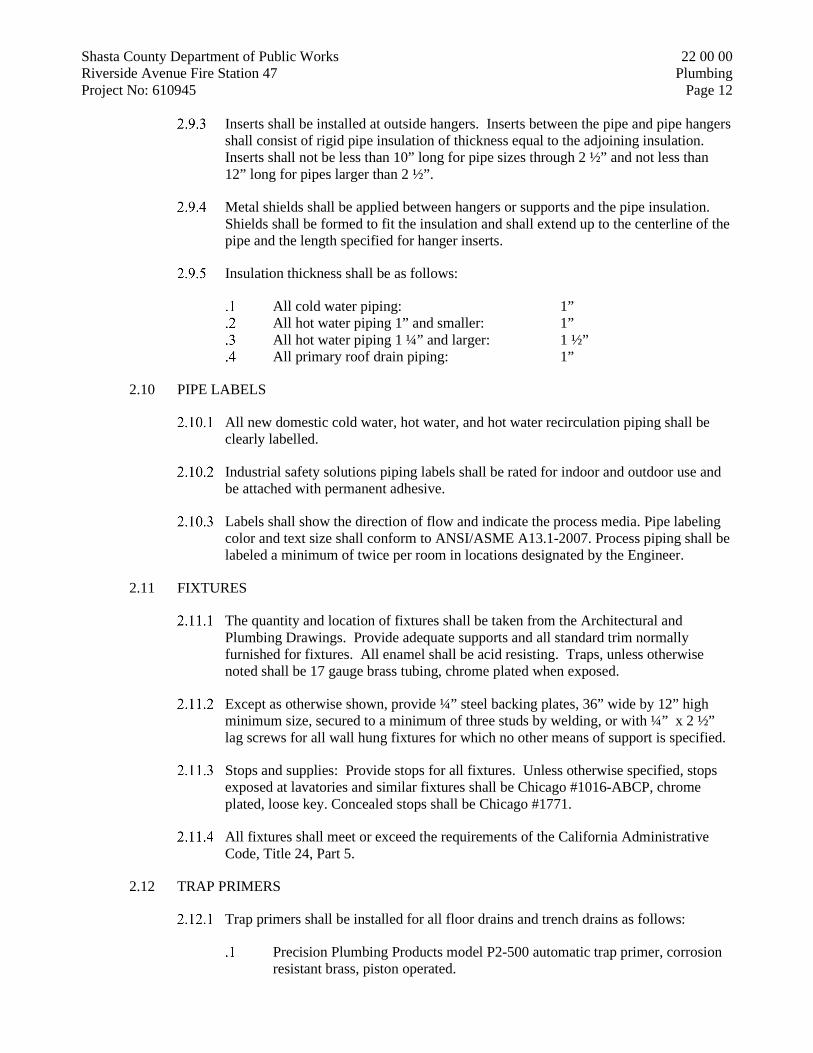
Shasta County Department of Public Works 22 00 00 Riverside Avenue Fire Station 47 Plumbing Project No: 610945 Page 12
Inserts shall be installed at outside hangers. Inserts between the pipe and pipe hangers
shall consist of rigid pipe insulation of thickness equal to the adjoining insulation. Inserts shall not be less than 10” long for pipe sizes through 2 ½” and not less than 12” long for pipes larger than 2 ½”.
Metal shields shall be applied between hangers or supports and the pipe insulation. Shields shall be formed to fit the insulation and shall extend up to the centerline of the pipe and the length specified for hanger inserts.
Insulation thickness shall be as follows:
All cold water piping: 1” All hot water piping 1” and smaller: 1” All hot water piping 1 ¼” and larger: 1 ½” All primary roof drain piping: 1”
2.10 PIPE LABELS
All new domestic cold water, hot water, and hot water recirculation piping shall be clearly labelled.
Industrial safety solutions piping labels shall be rated for indoor and outdoor use and be attached with permanent adhesive.
Labels shall show the direction of flow and indicate the process media. Pipe labeling color and text size shall conform to ANSI/ASME A13.1-2007. Process piping shall be labeled a minimum of twice per room in locations designated by the Engineer.
2.11 FIXTURES
The quantity and location of fixtures shall be taken from the Architectural and Plumbing Drawings. Provide adequate supports and all standard trim normally furnished for fixtures. All enamel shall be acid resisting. Traps, unless otherwise noted shall be 17 gauge brass tubing, chrome plated when exposed.
Except as otherwise shown, provide ¼” steel backing plates, 36” wide by 12” high minimum size, secured to a minimum of three studs by welding, or with ¼” x 2 ½” lag screws for all wall hung fixtures for which no other means of support is specified.
Stops and supplies: Provide stops for all fixtures. Unless otherwise specified, stops exposed at lavatories and similar fixtures shall be Chicago #1016-ABCP, chrome plated, loose key. Concealed stops shall be Chicago #1771.
All fixtures shall meet or exceed the requirements of the California Administrative Code, Title 24, Part 5.
2.12 TRAP PRIMERS
Trap primers shall be installed for all floor drains and trench drains as follows:
Precision Plumbing Products model P2-500 automatic trap primer, corrosion resistant brass, piston operated.

Shasta County Department of Public Works 22 00 00 Riverside Avenue Fire Station 47 Plumbing Project No: 610945 Page 13
2.13 SHOCK ABSORBERS
Zurn, “Shoktrol,” or equal JR Smith, stainless steel bellows. Install with gate valve shut-off and access door at all flush valves or other automatic valves. A single unit sized in accordance with the manufacturer’s recommendations may serve batteries of valves.
2.14 VALVE BOXES
Christy #F-08, complete with concrete cover and required extensions. Index all covers “GAS” or “WATER” as required for service use.
2.15 STRAINERS
For pipes 1 ½” – 2”: NIBCO T/S 221/222-A, or Wilkins S or YB series strainer, 20 mesh type 304 stainless steel screen, bronze construction 200 psi CWP or approved equal. Provide with hose bib drain.
For pipes 2 ½” & larger: NIBCO F-721A, or Wilkins F series, flanged, 125 lb., tapped bolted bonnet with plug and stainless steel screen.
PART 3 - EXECUTION
3.1 SURFACE CONDITIONS
This Contractor shall be held to have examined the site and compared it with the Contract Documents, and to adequately understand the conditions under which the work is to be performed. In the event of discrepancy, this Contractor shall notify the Architect and proceed as directed. This Contractor shall be held responsible for all existing conditions, whether or not accurately described, and no allowance shall subsequently be made on his behalf for any error, omission, or extra expense due to failure or neglect to make such examination and notification.
Prior to commencing the work of this Section, this Contractor shall inspect the installed work of other trades and verify that their work is sufficiently complete to permit the start of work under this Section and that the completed work will be in complete accordance with the original design. In the event of discrepancy immediately notify the Architect and proceed as directed.
3.2 ACCESSIBILITY
Equipment shall be placed and piping connections made in such a manner that all routine adjustments and maintenance operations may be carried out without inconvenience and so that all code requirements for clearances are maintained.
3.3 VIBRATION AND SOUND CONTROL
Make all necessary provisions to prevent the transmission of vibration to the building structure, including flexible pipe connections to motor driven equipment, resilient mounting for piping, and sealing off pipe and duct penetrations of walls and roof.

Shasta County Department of Public Works 22 00 00 Riverside Avenue Fire Station 47 Plumbing Project No: 610945 Page 14
3.4 INSULATION
Insulation shall be applied in complete accordance with the manufacturer’s published installation instructions. All insulation shall be applied on clean, dry surfaces and shall be continuous through wall and ceiling opening and sleeves. All joints shall be firmly butted together and longitudinal jacket laps and butt strips shall be smoothly secured. Specified adhesives, mastics, and coatings shall be applied at the manufacturer’s recommended minimum coverage per gallon.
3.5 PIPING INSTALLATION – GENERAL
Rough in shall proceed as rapidly as general construction will permit. All rough-in shall be complete, at locations verified by Architect and County, and tested and inspected prior to installation of concrete, lath, plaster, gypsum wallboard, or other finishes.
All piping shall be concealed in finished rooms, installed in furred walls and partitions. Where furred or suspended ceilings occur, piping shall be installed in the concealed space at points adjacent to beams and/or other structural members, and coordinated with ductwork and equipment. Where exposed piping occurs, it shall be installed parallel to or at right angles to building walls, unless specifically shown otherwise on the Drawings.
Installation of piping shall be such that damage cannot result, through thermal expansion or contraction, to piping, building, or pipe hangers and supports. Anchors shall be installed at midpoints of all runs in main piping for the purpose of localizing pipe expansion or prevention of creepage.
All pipe lines shall be installed free from traps and air pockets, true to line and grade, with suitable supports properly space. All piping shall be installed without undue stresses and with provision for expansion and contraction.
All piping shall be new and free from foreign substances. American standard pipe threads shall be used for IPS threaded work. Joints in threaded piping shall be made up with Teflon tape applied to the male threads only. No screwed pipe joints shall be caulked or packed with rope or other packing materials. Pipe shall be free from tool marks, threads cut accurately with not more than two (2) threads showing beyond fitting. Friction wrenches shall not be used with plated, polished, or soft metal piping. All changes in pipe size shall be made with reducing fitting. Bushings will not be permitted.
Protect unattended openings in piping during construction.
Weld all pipe 2.5 inches and larger. Use the following procedure. All welders must be AWS certified. AWS B2.1 SMAW 6G Pipe Welding Procedure Specifications. Welding process: SMAW Grove Angle: 60 degrees Position: 6G Fixed position Material/Spec: A 106 Weld Progression: Up Thickness (pipe/tube): Groove (in.) .280 Backing: No Notes: Sch. 40 Pipe Current/Polarity: DCEP Filler Metal Class: E6010Rt/E7018F1

Shasta County Department of Public Works 22 00 00 Riverside Avenue Fire Station 47 Plumbing Project No: 610945 Page 15
Root Opening: 1/16 to 1/8 Other Filler Metal Class: Rt. 1/8, 3/32 filler
Welded joints shall be beveled and butt-welded. Reductions of pipe shall be made with forged steel welding fittings. Branch reductions of two or more pipe sizes smaller than the main, may be Bonney “Weld-O-Let” fittings, or equal. Job fabricated reductions and branches shall not be used. All pipe burrs shall be reamed out. Welding rods shall be as follows, or approved equal: Pipe Size Arc Welding Gas Welding 2” and larger Fleetweld #5 Oxweld #1 or Page Hi-Test M 1 ½” and larger None Oxweld #1 or Page Hi-Test M
No water or drainage piping shall pass over electrical equipment unless adequate protection is provided to prevent damage by leaks or condensation.
All copper tubing shall be formed in a workmanlike manner, in accordance with the Pipe and Tube Bending Handbook of the Copper and Brass Research Association. A tube bender giving support to the periphery of the tube shall be used. The tubing shall be protected against flatting or other injury.
All copper connections and joints shall be made in accordance with the Copper Tube Handbook, Copper and Brass Research Association. No swaged connections will be permitted. All valves, pumps, and similar equipment shall be connected to copper piping through union or flange adapter fittings.
Valves, cocks, etc., shall be installed to allow convenient accessibility and operation.
Unions and flanges shall be installed to allow convenient replacement of all equipment and clearing tubes.
A union connection shall be installed downstream from all valves, at equipment connections and at other locations as required or directed.
Shut off valves shall be provided in all main services, and where required to permit proper servicing of equipment. Valves of one type shall be of one manufacturer.
All valves shall be of the same size as the pipelines in which they are installed, unless specifically sized on the Drawings. All hand controlled line valves shall be ball valves, except where throttling control or frequent operation is required, in which case globe or angle valves shall be used. Globe valves in horizontal lines shall be installed with stem in horizontal to permit line draining. All globe and angle valves shall be installed to close against pressure. Disc valves shall have discs suitable for the services for which they are to be used.
All valves shall be accessible and shall not be installed with the stems below the horizontal plane. Provide access panels at walls, ceilings, or floors.
Provide prime coated escutcheon plates at all points where exposed ping penetrates finished wall ceilings or floors.

Shasta County Department of Public Works 22 00 00 Riverside Avenue Fire Station 47 Plumbing Project No: 610945 Page 16
Cutting or boring of joists or other structural members shall be done only when
alternative routing is impossible and only upon written approval of the Architect or County.
3.6 INSTALLATION, PIPING
Natural Gas Piping
Natural gas piping shall slope back to meter, where possible. Bottom of vertical natural gas lines shall be fitted with 6” long capped drip
legs. In addition to the main shut-off valve, a natural gas stopcock shall be installed
at each piece of gas-fired equipment.
Condensate Piping
Indirect waste piping shall be installed to a uniform minimum grade of ¼” per foot unless otherwise noted.
Changes in direction of indirect waste piping shall be accomplished by the use of appropriate drainage fittings.
Drilling and tapping of indirect waste pipes and the use of saddle hubs and bands are prohibited.
Flashing
All roof and wall penetrations shall be flashed and counterflashed water tight with 26 gauge sheet metal, except as noted.
Vents through roof shall be flashed with Semco #1100-4 lead flashing assemblies. Flashing shall extend over top of pipe and shall be turned down inside top of pipe.
Soil, Waste, Vent, Drain Piping
Soil, waste, and vent piping occurring within the building shall be installed to a uniform minimum grade of ¼” per foot unless otherwise noted. Vent piping shall be graded so that all condensation shall flow directly to a soil or waste line.
Changes in direction of drainage piping shall be accomplished by the use of appropriate drainage and sanitary fittings.
Protection against breakage of piping passing under or through walls shall be provided using specified sleeves and caulking.
Adapters shall be installed between threaded iron and soil pipe. Test tees shall be installed at the foot of all soil, waste, and storm water
stacks. Cleanouts shall be located where indicated on the Drawings; at all horizontal
offsets; at ends of waste or sewer branches more the 5’ in length; at intervals of 100’ in straight runs of piping, or at closer intervals if directed or required by local code. Location of cleanouts in finished spaces shall be approved by the Architect prior to installation.
Hot and Cold Water Systems

Shasta County Department of Public Works 22 00 00 Riverside Avenue Fire Station 47 Plumbing Project No: 610945 Page 17
Di-electric unions shall be installed where copper pipe is connected to
galvanized steel piping or stub outs. Connections from copper pipe to fixture supply fittings shall be made with
copper or brass nipples. All domestic water piping shall be kept clear of the building structure. Where
it is within 1” of the building structure, it shall be wrapped with felt (3/16” minimum thickness).
To the greatest extent possible, domestic cold water piping shall be kept separated from hot piping and where there is a choice shall be run in the coolest portion of the available space.
Plumbing Fixtures
Space between wall mounted fixtures and wall surface shall be neatly pointed up with silicone rubber compound of color matching fixture.
All exposed bolt heads and nuts used to secure fixtures shall be concealed with vitreous china caps.
Excavation and Backfill
Provide all excavation, trenching, and backfill in connection with the work of this Section.
Excavation shall be carried to 4” below the bottom of pipes. Provide a sand bedding for all sloped drainage piping, and provide smooth uniformly graded bedding of firm but yielding material for all other piping, catch basins, and similar structures.
Backfill material shall be non-corrosive and free from all foreign material that could damage pipes. Backfill shall be placed in 6” layers, each layer tamped, and compacted to 95% of maximum dry density (ASTM D-1557-64T (c) compaction test procedure).
Storm Drainage Piping
Roof drains shall be installed where indicated on the Drawings, in conjunction with work specified in “Membrane Waterproofing” Section. This Contractor shall be responsible for a watertight installation.
Rain water leaders connected to roof drains and gutter systems shall be standard weight galvanized steel pipe and fittings, except where otherwise noted, and shall be continuous from drain to connection with underground storm water drainage facilities. Provide a cleanout at the base of all vertical to horizontal transitions.
Sheet metal downspouts are furnished and installed by others. Downspouts inside building, if shown, shall be continuous from drain to curb
or connection with underground storm water drainage facilities. Provide a cleanout at the base of all vertical to horizontal transitions.
Insulate storm drain piping where it is located above a ceiling or within a concealed space. Overflow piping is not required to be insulated.

Shasta County Department of Public Works 22 00 00 Riverside Avenue Fire Station 47 Plumbing Project No: 610945 Page 18
3.7 INSTALLATION, HANGERS & SUPPORTS
Installation of piping shall be such that damage cannot result through loading, expansion, or contraction of piping. Anchors shall be installed to obtain uniformity of pipe movement.
Hanger rod sizes shall be no smaller than 3/8-inch for pipe and tube sizes ½ to 4 inches and ½ inch for sizes 5-8 inches.
Pipe supports shall be spaced sufficiently close to support pipes properly without formation of pockets. Hangers shall be installed at ends of mains and branches. Maximum horizontal support spacing shall be as follows:
Steel Pipe for Water or DWV: 10 feet for pipe sizes ¾ inch and smaller and 12 feet for sizes 1 inch and larger.
Steel and Tinned Copper Pipe for Gas: 6 feet for ½ inch pipe; 8 feet for sizes ¾ to 1 inch, and 10 feet for sizes 1 ¼ inch and larger.
Copper Tube and Pipe, soldered or brazed: 6 feet for pipe sizes 1 ½ inches and smaller and 10 feet for sizes 2 inches and larger.
Hubless Cast-Iron shall be supported at every other joint, unless over 4 feet, then support each joint. Support adjacent to joint, not to exceed 18 inches, brace at not more than 40 foot intervals to prevent horizontal movement. Support at each horizontal branch connection. Hangers shall not be placed on the coupling.
Provide resilient mounting for domestic water piping. Thermal insulation may serve as resilient mounting for insulated piping.
Suspended water piping shall be anchored with steel struts installed at midpoint of each run.
No valve or piece of equipment shall be used to support piping.
Pipes through studs or joists shall be isolated from structure with properly sized Hubbard “Hole-Rite” suspension clamps.
3.8 TESTING, INSPECTIONS
General
This Contractor shall not allow or cause any work of this Section to be covered or enclosed until it has been inspected, tested, and approved by the Architect and the authorities having jurisdictions over the work. Should any of this work by enclosed or covered up before such inspection, testing, and approval, this Contractor shall uncover the work, have the necessary inspections, tests, and approvals made and, at no expense to the County, make all repairs necessary to restore both his work and that of other contractors that may have been damaged, to be in conformity with the Contract Documents.
Tests

Shasta County Department of Public Works 22 00 00 Riverside Avenue Fire Station 47 Plumbing Project No: 610945 Page 19
This Contractor shall make all tests required by all local, state, and federal
laws, codes, ordinances, and regulations having jurisdiction over this work. Furnish all necessary labor, materials, and equipment for conducting tests, and
pay all expenses in connection therewith. Should leaks develop while testing, repairs shall be made, and tests shall be repeated until a satisfactory test is obtained.
Water Piping shall by hydrostatically tested for 6 hours at 150 psi. All equipment shall be tested water tight at utility pressure.
Drainage and Vent Piping shall be tested for 1 hour by plugging all outlets and filling the pipes with water to the top of vertical sections of pipes. No loss of water shall be permitted.
3.9 DOMESTIC WATER SYSTEM STERILIZATION
Upon completion of this work, the domestic water system shall be thoroughly flushed, sterilized, and reflushed. Sterilization and reflushing shall be performed using the following procedure.
All work shall be performed in the presence of the inspector. Introduce chlorine or a solution of sodium hypochlorite, filling the lines
slowly and supplying the sterilization agent at a rate of 50 parts of chlorine per million, as determined by residual chlorine tests at the ends of all branches. Open and close all valves while the system is being chlorinated to insure uniform distribution.
After the sterilizing agent has been applied for 24 hours, test for residual chlorine at the ends of the branches. If less than 5 ppm is indicated, repeat the sterilization procedure.
When tests show at least 5 ppm of residual chlorine, flush out the system until all traces of the chemical are removed.
After a period of 48 hours minimum, bacteriological tests, using samples from at least 3 representative points shall be made by recognized testing agency, who shall certify to the Architect that the system is bacteriologically safe and at least equal in safety to that of the principal water supply. The laboratory report and certification shall be transmitted to the Architect and County.
3.10 ADJUSTING
Properly adjust all stops, and controls, and demonstrate safe and satisfactory operation of all equipment.
3.11 CLEANING
.Flush all water piping systems. Remove, clean, and replace all strainer baskets prior to final inspection.
.Blow out all compressible fluid piping with compressed air before connecting with regulators or equipment.

Shasta County Department of Public Works 22 00 00 Riverside Avenue Fire Station 47 Plumbing Project No: 610945 Page 20
3.12 CLEANUP
Upon completion of the work of this Section, remove all surplus material, debris, and equipment associated with or used in the performance of this work.
END OF SECTION 22 00 00

Shasta County Department of Public Works 23 00 00 Riverside Avenue Fire Station 47 HVAC Project No: 610945 Page 1
HVAC
23 00 00
PART 1 - GENERAL
1.1 INCLUDED
This section covers mechanical work, complete. Work includes furnishing, installing, calibrating, adjusting, testing, documenting, and starting up equipment in accordance with these Specifications, the accompanying Plans, and the directions of the Engineer.
1.2 LICENSES, PERMITS, AND FEES
The Contractor shall provide, procure, and pay for all licenses, permits, fees, etc. as required to carry on and complete their work.
1.3 CODES AND STANDARDS
All work shall be done in code with all applicable local, state, and federal building safety codes, ordinances, and regulations. Additionally, all work shall conform to the latest editions of the following standards:
National Fire Protection Association. California Mechanical Code. California Plumbing Code. Underwriters Laboratories. Titles 8, 17, 19, 21, 24 of the California Code of Regulations. California Electric Code. SMACNA Standards. ASHRAE Standards 55 and 62.1.
When the Contract Documents call for materials or construction of a higher standard than is required by the above, the Contract Document requirements shall take precedence over the requirements of the applicable laws, ordinances, rules, or regulations. Nothing in the Contract Documents shall be interpreted as permitting work in violation of said laws, rules, and/or regulations.
The Contractor for this work shall furnish, without extra charge, any additional materials and/or labor as may be required for compliance with these laws, rules, and/or regulations though such materials and/or labor are not specially set forth in the Contract Documents.
1.4 LICENSING REQUIREMENTS
All work of Division 22 and 23 shall be performed by an appropriately licensed contractor. The licenses shall be current, valid through the term of the contract and in the name of the contractor.

Shasta County Department of Public Works 23 00 00 Riverside Avenue Fire Station 47 HVAC Project No: 610945 Page 2
All HVAC work, which includes warm air heating systems and water heating pumps, ventilating systems, air conditioning systems, and ductwork, registers, flues, humidity, and thermostatic controls in connection with these systems, shall be performed by a C-20 – Warm-Air Heating, Ventilating and Air-Conditioning Contractor.
All ducting and piping insulation shall be performed by a C-2 – Insulation and Acoustical Contractor.
1.5 SUBMITTALS
General Requirements
Submittal lists and drawings shall include identifying marks assigned by the Drawings and Specifications.
Review of drawings and other material submitted shall not be construed as complete check or constitute a waiver of the requirements of the Drawings and Specifications, but will indicate that the material submitted is acceptable in quality and utility. This review shall not relieve the Contractor of the responsibility to fit the proposed materials to the spaces provided, and to effect necessary rearrangements or construction of other work.
All fixtures, materials, and equipment equal in quality and utility to these herein mentioned will be accepted. When specific names are used in describing fixtures, materials, and equipment they are mentioned as standards only, but this implies no right on the part of the Contractor to use other fixtures, material, and equipment or methods, unless approved as equal in quality and utility by the Architect.
Before any fixtures, materials, or equipment are purchased, the Contractor shall submit to the Architect for approval, a complete list of materials, fixtures, and equipment, giving the manufacturer’s names, catalog number, capacity, size, power requirements, etc.
The Contractor shall submit for the approval of the Architect, shop drawings of proposed material and equipment that differ from the specified materials and equipment, and of any specified materials and equipment with special conditions and/or arrangements. These drawings shall show necessary modifications of County, plumbing, electrical, and mechanical work required by the proposed materials and equipment.
Submittal – Product Data
Submit manufacturer’s product data for all HVAC equipment, in compliance with
1.6 COOPERATION WITH OTHER TRADES
Cooperate fully with other trades doing work on the project as may be necessary for the proper completion of the project. Refer to the Structural, Plumbing, and Electrical Drawings for details of the building structure and equipment installation that will tend to overlap, conflict with or require coordination with the work of this Section, and schedule this work accordingly.
Any work done without regard for other trades shall be moved, replaced, or redone as required, without extra charges to County.

Shasta County Department of Public Works 23 00 00 Riverside Avenue Fire Station 47 HVAC Project No: 610945 Page 3
1.7 DIVISION OF WORK BETWEEN DIVISIONS 23 AND 26
Close coordination between the electrical and mechanical trades is a part of the work that is required by this contract. No allowance will be made for omissions based on incorrectly assuming another trade will be performing your work. Confirm your scope of work with the general contractor.
The division of responsibilities between trades supplying equipment in other Divisions may be different. For instance, Division 26 contractor may be required to supply disconnect switches and starters for non-HVAC mechanical equipment supplied under other Divisions.
Division 23 Responsibilities
Assume responsibility for the proper functioning of the HVAC systems in their entirety.
Furnish and install all conductors and conduit required for control of HVAC equipment.
Make all terminations with the exception of power conductors. Furnish and install all control panels and devices to provide a complete and
functional controls system, including all controls transformers. Furnish and install motor starters for all equipment specified in Division 23. Install duct smoke detectors furnished by fire alarm contractor in buildings
with fire alarm systems. Furnish and install duct smoke detectors in buildings without fire alarm
systems. Furnish and install all control conductors and conduit connecting duct smoke
detectors to smoke dampers and fan start controls. All electrical work performed under Division 23 shall conform to the
requirements of Division 26.
Division 26 Responsibilities
Furnish and install all raceways, conduit, disconnect switches, and conductors necessary for electrical power supply.
Make all power supply terminations to motors, starters, disconnect switches, control transformers, and other mechanical devices.
Fire alarm contractor to furnish duct smoke detectors in buildings with fire alarm systems.
Provide power to all duct smoke detectors and smoke dampers. Coordinate all work with mechanical contractors.
1.8 AS-BUILT DRAWINGS
A complete set of Contract Drawings shall be maintained at the work site, and all changes in the work shall be recorded on this set, on a daily basis. The final as-built drawings shall be submitted to the Architect for approval.

Shasta County Department of Public Works 23 00 00 Riverside Avenue Fire Station 47 HVAC Project No: 610945 Page 4
1.9 DESIGN DRAWINGS
The drawings indicate diagrammatically the general layout of the mechanical systems and other related work. Field verification of scaled dimensions taken from the Drawings is required.
The Contractor shall review and compare the Architectural, Structural, Plumbing, Mechanical, and Electrical Drawings and all County supplied equipment Drawings, and adjust their work to be in conformity with the conditions indicated thereon. Discrepancies between drawings, between drawings and actual field conditions, or between Drawings and Specifications, shall promptly be brought to the attention of the Architect for a determination of the modifications to be effected. In the event that a major modification is required, a Change Order will be prepared.
1.10 VERIFICATION OF EXISTING CONDITIONS AND DEMOLITION
Before installation of any new work, verify the location, size, and other conditions at all points of connection to services or other existing piping, and at all locations where new work will cross or pass near existing piping, electrical, or other facilities.
Remove ductwork, piping, controls, fixtures, and equipment that is not to remain in service as shown on the Drawings or as required. This included the removal of associated appurtenances and supports.
Patch, cap, or repair existing works affected by this demolition in concealed spaces within six (6) inches of a live main or branch.
Deliver removed material to the County as directed by the Architect. Dispose of all other removed material offsite.
Information shown relative to existing services is based upon available records and data during preparation of the Drawings, but shall be verified. Make reasonable deviations found necessary to conform to actual locations and conditions, without extra charge.
1.11 OPERATING AND MAINTENANCE INSTRUCTIONS
Furnish three sets of typewritten instructions covering maintenance, adjustment, and operation of each piece of apparatus, bound in a hard cover loose-leaf binder. Neatly obscure or cross out inapplicable data from manufacturer’s literature. Submit data to the Architect.
Operating instructions shall show sequence of operations, lubrication, care, and maintenance requirements of all equipment. Final acceptance of the work will not be made until a satisfactory submission of this material is received and approved by the rchitect.
The County’s authorized representative shall be instructed in the operation and servicing of all HVAC & plumbing systems.

Shasta County Department of Public Works 23 00 00 Riverside Avenue Fire Station 47 HVAC Project No: 610945 Page 5
1.12 ACCURACY OF DATA
The data given herein and on the Drawings are as exact as could be reasonably secured, but absolute accuracy is not guaranteed. Exact locations, distances, elevations, etc. will be governed by shop drawings, the building itself, and actual field conditions.
1.13 DAMAGE BY LEAKS
Contractor shall be responsible for any damage to work of other Contractors that is caused by leaks in any temporary or permanent piping systems due to pipe rupture, disconnected pipes or fittings, or by overflow of equipment.
1.14 SEISMIC FORCE RESISTANCE: MECHANICAL, PLUMBING, FIRE PROTECTION SYSTEMS
All mechanical systems and plumbing piping systems shall adhere to the SMACNA “Seismic Restraint Manual: Guidelines for Mechanical Systems,” Third Edition dated March 2008.
1.15 DELIVERY, STORAGE, AND HANDLING
Contractor shall be responsible for delivery, storage, protection, and placing of all equipment and materials.
Contractor shall protect the work and materials from damage during construction. Equipment stored at the job site shall be protected from dust, water, or other damage, and be covered if equipment is exposed to weather. Protect interiors of new equipment and piping systems against entry of foreign matter. Clean both inside and outside before painting or placing equipment in operation.
Any items damaged shall be repaired or replaced, at no additional cost to the County.
Cleanliness of Piping and Equipment Systems
Exercise care in storage and handling of equipment and piping material to be incorporated in the work. Remove debris arising from cutting, threading, and welding of piping.
Piping systems shall be flushed, blown, or pigged as necessary to deliver clean systems.
Contractor shall be fully responsible for all costs, damage, and delay arising from failure to provide clean systems.
1.16 WARRANTIES
Equipment warranties shall be provided for all equipment, with all necessary information filled in, except purchase date, in favor of the County.
The contractor shall guarantee that all work under this Section is free from defects in material and workmanship for a period of one year from the date of filing the Notice of Completion. Replacement of defective work and damage caused to work of other

Shasta County Department of Public Works 23 00 00 Riverside Avenue Fire Station 47 HVAC Project No: 610945 Page 6
trades as a result of such defective work shall be the responsibility of the Contractor, and shall be made at no cost to the County.
1.17 ALTERNATIVE MATERIALS AND METHODS
These plans and specifications describe the general scope of the mechanical systems. These plans and specifications do not preclude the submittal of alternative methods or materials. Manufacturer’s names and catalog numbers are stated to identify the type and quality of the equipment or materials required for the project.
The contractor may submit shop drawings and/or technical information on alternative equipment, materials or installation details to accomplish the intent of the plans and specifications. Approval of the alternative equipment, materials or installation details shall not relieve the contractor of any responsibility for complying with the intent of the plans and specifications. Submit the manufacturers' technical information, shop drawings, and/or written description of alternative methods for each item described by manufacturer's name and catalog number and for each component, equipment, material, or installation detail required.
1.18 SITE EXAMINATION
Thoroughly examine the site and verify the actual work conditions. No extra compensation will be allowed for expenses due to failure to discover site conditions which affect the work.
PART 2 - PRODUCTS
2.1 GENERAL
All materials, appliances, and equipment shall be new and best of their respective kinds, free from defects, and of the make, brand, or quality specified or as accepted by the Architect.
When two or more units of materials or equipment of the same type or class are required, these units shall be products of one manufacturer.
Apply and install all items in accordance with manufacturer’s written instructions. Refer conflicts between manufacturer’s instructions and the contract drawings and specifications to the Architect for resolution.
2.2 VRF OUTDOOR UNITS
Heat Recovery Air Cooled Outdoor Units
The outdoor unit modules shall be air-cooled, direct expansion (DX), multi-zone units used specifically with VRF components described in this section and Part 5 (Controls). The outdoor unit modules shall be equipped with a single compressor which is inverter-driven and multiple circuit boards – all of which must be manufactured by the branded VRF manufacturer. Each outdoor unit module shall be completely factory assembled, piped and wired and run tested at the factory.

Shasta County Department of Public Works 23 00 00 Riverside Avenue Fire Station 47 HVAC Project No: 610945 Page 7
Outdoor unit systems may be comprised of multiple modules with differing capacity if a brand other than basis of design is proposed. All units requiring a factory supplied twinning kits shall be piped together in the field, without the need for equalizing line(s). If an alternate manufacturer is selected, any additional material, cost, and labor to install additional lines shall be incurred by the contractor. Contractor responsible for ensuring alternative brand compatibility in terms of availability, physical dimensions, weight, electrical requirements, etc.
Outdoor unit shall have a sound rating no higher than 68 dB(A) individually or 70 dB(A) twinned. Units shall have a sound rating no higher than 52 dB(A) individually or 55 dB(A) twinned while in night mode operation. Units shall have 5 levels sound adjustment via dip switch selectable fan speed settings. If an alternate manufacturer is selected, any additional material, cost, and labor to meet published sound levels shall be incurred by the contractor.
Refrigerant lines from the outdoor unit to the indoor units shall be insulated in accordance with the installation manual.
The outdoor unit shall have the capability of installing the main refrigerant piping through the bottom of the unit.
The outdoor unit shall have an accumulator with refrigerant level sensors and controls. Units shall actively control liquid level in the accumulator via Linear Expansion Valves (LEV) from the heat exchanger.
The outdoor unit shall have a high pressure safety switch, over-current protection, crankcase heater and DC bus protection.
VRF system shall meet performance requirements per schedule and be within piping limitations & acceptable ambient temperature ranges as described in respective manufacturers’ published product catalogs. Non-published product capabilities or performance data are not acceptable.
The outdoor unit shall be capable of operating in heating mode down to -25F ambient temperatures or cooling mode down to 23F ambient temperatures, without additional low ambient controls. If an alternate manufacturer is selected, any additional material, cost, and labor to meet low ambient operating condition and performance shall be incurred by the contractor.
Unit must defrost all circuits simultaneously in order to resume full heating more quickly during extreme low ambient temperatures (below 23F). Partial defrost, also known as hot gas defrost which allows reduced heating output during defrost, is permissible only when ambient temperature is above 23F.
The outdoor unit shall have a high efficiency oil separator plus additional logic controls to ensure adequate oil volume in the compressor is maintained. Oil return sequences must be enabled only during extended periods of reduced refrigerant flow to ensure no disruption to correct refrigerant flow to individual zones during peak loads. Systems which might engage oil return sequence based on hours of operation risk oil return during inopportune periods are not allowed. Systems which rely on sensors (which may fail) to engage oil return sequence are not allowed.
While in hot gas defrost the system shall slow the indoor unit fan speed down to maintain a high discharge air temperature, systems that keep fan running in same state shall not be allowed as they provide an uncomfortable draft to the indoor zone due to lower discharge air temperatures.
In reverse defrost all refrigerant shall be bypassed in the main branch controller and shall not be sent out to the indoor units, systems that flow refrigerant through indoor units during reverse defrost shall not be allowed.

Shasta County Department of Public Works 23 00 00 Riverside Avenue Fire Station 47 HVAC Project No: 610945 Page 8
The outdoor unit shall be capable of operating in cooling mode down to -10°F with optional manufacturer supplied low ambient kit.
Low ambient kit shall be provided with predesigned control box rated for outdoor installation and capable of controlling kit operation automatically in all outdoor unit operation modes.
a. Low ambient kit shall be listed by Electrical Laboratories (ETL) and bear the ETL label.
b. Low ambient kit shall be factory tested in low ambient temperature chamber to ensure operation. Factory performance testing data shall be available when requested.
The outdoor unit shall be provided with a manufacturer supplied 20 gauge hot dipped galvanized snow/hail guard. The snow/hail guard protects the outdoor coil surfaces from hail damage and snow build-up in severe climates.
Unit Cabinet
The casing(s) shall be fabricated of galvanized steel, bonderized and finished. The outdoor unit shall be tested in compliance with ISO9277 such that no
unusual rust shall develop after 960 hours of salt spray testing. Panels on the outdoor unit shall be scratch free at system startup. If a scratch
occurs the salt spray protection is compromised and the panel should be replaced immediately.
Fan
Each outdoor unit module shall be furnished with direct drive, variable speed propeller type fan(s) only. Fans shall be factory set for operation at 0 in. WG. external static pressure, but capable of normal operation with a maximum of 0.32 in WG. external static pressure via dipswitch.
All fan motors shall have inherent protection, have permanently lubricated bearings, and be completely variable speed.
All fans shall be provided with a raised guard to prevent contact with moving parts.
Refrigerant and Refrigerant Piping
R410A refrigerant shall be required for systems. Polyolester (POE) oil—widely available and used in conventional domestic
systems—shall be required. Prior to bidding, manufacturers using alternate oil types shall submit material safety data sheets (MSDS) and comparison of hygroscopic properties for alternate oil with list of local suppliers stocking alternate oil for approval at least two weeks prior to bidding.
Refrigerant piping shall be phosphorus deoxidized copper (copper and copper alloy seamless pipes) of sufficient radial thickness as defined by the VRF equipment manufacturer and installed in accordance with manufacturer recommendations.
All refrigerant piping must be insulated with ½” closed cell, CFC-free foam insulation with flame-Spread Index of less than 25 and a smoke-development Index of less than 50 as tested by ASTM E 84 and CAN / ULC S-102. R value of insulation must be at least 3.

Shasta County Department of Public Works 23 00 00 Riverside Avenue Fire Station 47 HVAC Project No: 610945 Page 9
Refrigerant line sizing shall be in accordance with manufacturer specifications. Future changes to indoor unit styles or sizes must be possible without resizing/replacing refrigerant piping to any other branch devices or indoor units.
Coil
Outdoor Coil shall be constructed to provide equal airflow to all coil face surface are by means of a 4-sided coil
Outdoor Coil shall be elevated at least 12” from the base on the unit to protect coil from freezing and snow build up in cold climates. Manufacturer’s in which their coil extends to within a few inches from the bottom of their cabinet frame shall provide an additional 12” of height to their stand or support structure to provide equal protection from elements as Mitsubishi Electric basis of design. Any additional support costs, equipment fencing, and tie downs required to meet this additional height shall be responsibility of Mechanical Contractor to provide.
The outdoor heat exchanger shall be of zinc coated aluminum construction with turbulating flat tube construction. The coil fins shall have a factory applied corrosion resistant finish. Uncoated aluminum coils/fins are not allowed.
The coil shall be protected with an integral metal guard. Refrigerant flow from the outdoor unit shall be controlled by means of an
inverter driven compressor. Unit shall have prewired plugs for optional panel heaters in order to prevent
any residual ice buildup from defrost. Panel heaters are recommended for operating environments where the ambient temperature is expected to stay below -1F for 72 hours.
Condenser coil shall have active hot gas circuit direct from compressor discharge on lowest coil face area to shed defrost condensate away from coil and protect from Ice formation after returning to standard heat pump operation. While in Heat Pump operation this lower section of the Outdoor Evaporator coil shall continually run hot gas from the compressor discharge to protect the coil from ice buildup and coil rupture. Manufacturers who do not have an active hot gas circuit in the lower section of the Outdoor coil to protect coil from freezing shall not be allowed to bid on project in markets where the outdoor unit will see temperatures below freezing.
Compressor
Each outdoor unit module shall be equipped with only inverter driven scroll hermetic compressors. Non inverter-driven compressors, which may cause inrush current (demand charges) and require larger generators for temporary power shall not be allowed.
Each compressor shall be equipped with a multi-port discharge mechanism to eliminate over compression at part load. Manufacturer’s that rely on a single compressor discharge port and provide no means of eliminating over compression and energy waste at part load shall not be allowed.
Crankcase heat shall be provided via induction-type heater utilizing eddy currents from motor windings. Energy-wasting “belly-band” type crankcase heaters are not allowed. Manufacturers that utilize belly-band crankcase heaters will be considered as alternate only.
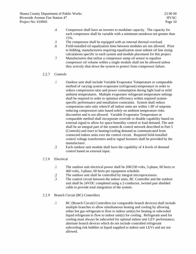
Shasta County Department of Public Works 23 00 00 Riverside Avenue Fire Station 47 HVAC Project No: 610945 Page 10
Compressor shall have an inverter to modulate capacity. The capacity for each compressor shall be variable with a minimum turndown not greater than 15%.
The compressor shall be equipped with an internal thermal overload. Field-installed oil equalization lines between modules are not allowed. Prior
to bidding, manufacturers requiring equalization must submit oil line sizing calculations specific to each system and module placement for this project.
Manufacturers that utilize a compressor sump oil sensor to equalize compressor oil volume within a single module shall not be allowed unless they actively shut down the system to protect from compressor failure.
Controls
Outdoor unit shall include Variable Evaporator Temperature or comparable method of varying system evaporator (refrigerant) temperature in order to reduce compression ratio and power consumption during light load or mild ambient temperatures. Multiple evaporator refrigerant temperature settings shall be required in order to optimize efficiency within required system-specific performance and installation constraints. System shall reduce compression ratio only when/if all indoor units are within 1.8F of setpoint; reducing compression ratio based solely on ambient temperature risks discomfort and is not allowed. Variable Evaporator Temperature or comparable method shall incorporate override or disable capability based on external signal to allow for space humidity control or load demand. The unit shall be an integral part of the system & control network described in Part 5 (Controls) and react to heating/cooling demand as communicated from connected indoor units over the control circuit. Required field-installed control voltage transformers and/or signal boosters shall be provided by the manufacturer.
Each outdoor unit module shall have the capability of 4 levels of demand control based on external input.
Electrical
The outdoor unit electrical power shall be 208/230 volts, 3-phase, 60 hertz or 460 volts, 3-phase, 60 hertz per equipment schedule.
The outdoor unit shall be controlled by integral microprocessors. The control circuit between the indoor units, BC Controller and the outdoor
unit shall be 24VDC completed using a 2-conductor, twisted pair shielded cable to provide total integration of the system.
Branch Circuit (BC) Controllers
BC (Branch Circuit) Controllers (or comparable branch devices) shall include multiple branches to allow simultaneous heating and cooling by allowing either hot gas refrigerant to flow to indoor unit(s) for heating or subcooled liquid refrigerant to flow to indoor unit(s) for cooling. Refrigerant used for cooling must always be subcooled for optimal indoor unit LEV performance; alternate branch devices which do not include controlled refrigerant subcooling risk bubbles in liquid supplied to indoor unit LEVs and are not allowed.

Shasta County Department of Public Works 23 00 00 Riverside Avenue Fire Station 47 HVAC Project No: 610945 Page 11
BC Controllers (or comparable branch devices) shall be equipped with a circuit board that interfaces to the controls system and shall perform all functions necessary for operation. The unit shall have a galvanized steel finish and be completely factory assembled, piped and wired. Each unit shall be run tested at the factory. This unit shall be mounted indoors, with access and service clearance provided for each controller. BC Controllers (or comparable branch devices) shall be suitable for use in plenums in accordance with UL1995 ed 4.
BC Unit Cabinet
The casing shall be fabricated of galvanized steel. Each cabinet shall house a liquid-gas separator and multiple refrigeration
control valves. The unit shall house two tube-in-tube heat exchangers.
Refrigerant Piping
All refrigerant pipe connections shall be brazed. Future changes to indoor unit quantities or sizes served by BC Controller or
comparable branch device must be possible with no piping changes except between the branch device and indoor unit(s) changing. Systems which might require future piping changes between branch device and outdoor unit—if changes to indoor unit quantities or sizes are made—are not considered equal and are not allowed.
Refrigerant Valves
Service shut-off valves shall be field-provided/installed for each branch to allow service to any indoor unit without field interruption to overall system operation.
Condensate Management
BC Controller (or comparable branch device) must have integral resin drain pan or insulate refrigeration components with removable insulation that allows easy access for future service needs. Cabinets filled with solid foam insulation do not allow for future service and are not allowed.
Electrical
The unit electrical power shall be 208/230 volts, 1 phase, 60 Hertz. The unit shall be capable of satisfactory operation within voltage limits of 187-228 (208V/60Hz) or 207-253 (230/60Hz).
The BC Controller shall be controlled by integral microprocessors. The control circuit between the indoor units and outdoor units shall be
24VDC completed using a 2-conductor, twisted pair shielded cable to provide total integration of the system.
2.3 CEILING CASSETTE VRF INDOOR UNITS
4-Way Ceiling-Recessed Cassette with Grille For 2x2 Grid Indoor Unit
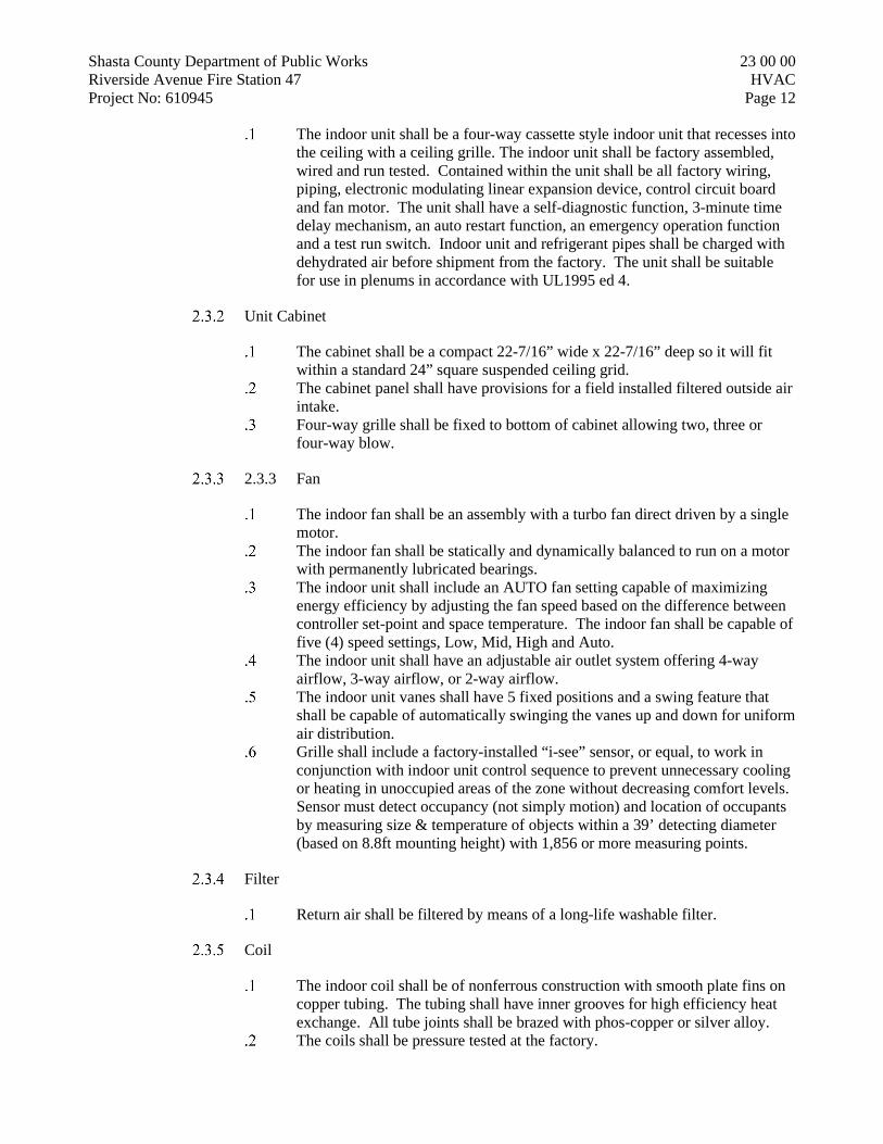
Shasta County Department of Public Works 23 00 00 Riverside Avenue Fire Station 47 HVAC Project No: 610945 Page 12
The indoor unit shall be a four-way cassette style indoor unit that recesses into the ceiling with a ceiling grille. The indoor unit shall be factory assembled, wired and run tested. Contained within the unit shall be all factory wiring, piping, electronic modulating linear expansion device, control circuit board and fan motor. The unit shall have a self-diagnostic function, 3-minute time delay mechanism, an auto restart function, an emergency operation function and a test run switch. Indoor unit and refrigerant pipes shall be charged with dehydrated air before shipment from the factory. The unit shall be suitable for use in plenums in accordance with UL1995 ed 4.
Unit Cabinet
The cabinet shall be a compact 22-7/16” wide x 22-7/16” deep so it will fit within a standard 24” square suspended ceiling grid.
The cabinet panel shall have provisions for a field installed filtered outside air intake.
Four-way grille shall be fixed to bottom of cabinet allowing two, three or four-way blow.
2.3.3 Fan
The indoor fan shall be an assembly with a turbo fan direct driven by a single motor.
The indoor fan shall be statically and dynamically balanced to run on a motor with permanently lubricated bearings.
The indoor unit shall include an AUTO fan setting capable of maximizing energy efficiency by adjusting the fan speed based on the difference between controller set-point and space temperature. The indoor fan shall be capable of five (4) speed settings, Low, Mid, High and Auto.
The indoor unit shall have an adjustable air outlet system offering 4-way airflow, 3-way airflow, or 2-way airflow.
The indoor unit vanes shall have 5 fixed positions and a swing feature that shall be capable of automatically swinging the vanes up and down for uniform air distribution.
Grille shall include a factory-installed “i-see” sensor, or equal, to work in conjunction with indoor unit control sequence to prevent unnecessary cooling or heating in unoccupied areas of the zone without decreasing comfort levels. Sensor must detect occupancy (not simply motion) and location of occupants by measuring size & temperature of objects within a 39’ detecting diameter (based on 8.8ft mounting height) with 1,856 or more measuring points.
Filter
Return air shall be filtered by means of a long-life washable filter.
Coil
The indoor coil shall be of nonferrous construction with smooth plate fins on copper tubing. The tubing shall have inner grooves for high efficiency heat exchange. All tube joints shall be brazed with phos-copper or silver alloy.
The coils shall be pressure tested at the factory.

Shasta County Department of Public Works 23 00 00 Riverside Avenue Fire Station 47 HVAC Project No: 610945 Page 13
The unit shall be provided with an integral condensate lift mechanism that will be able to raise drain water 19-3/4” inches above the condensate pan.
Electrical
The unit electrical power shall be 208/230 volts, 1-phase, 60 hertz. The system shall be capable of satisfactory operation within voltage limits of
187-228 volts (208V/60Hz) or 207-253 volts (230V/60Hz).
Controls
Indoor unit shall compensate for the higher temperature sensed by the return air sensor compared to the temperature at level of the occupant when in HEAT mode. Disabling of compensation shall be possible for individual units to accommodate instances when compensation is not required.
Control board shall include contacts for control of external heat source. External heat may be energized as second stage with 1.8°F – 9.0°F adjustable deadband from set point.
Indoor unit shall include no less than four (4) digital inputs capable of being used for customizable control strategies.
Indoor unit shall include no less than three (3) digital outputs capable of being used for customizable control strategies.
A factory-installed drain pan sensor shall provide protection against drain pan overflow by sensing a high condensate level in the drain pan. Should this occur, the control shuts down the indoor unit before an overflow can occur. A thermistor error code will be produced should the sensor activate indicating a fault which must be resolved before the unit re-starts.
2.4 HORIZONTAL DUCTED VRF INDOOR UNITS
General
The multi-position indoor unit shall be factory assembled, wired and run tested. Contained within the unit shall be all factory wiring, piping, electronic modulating linear expansion device, control circuit board and fan motor. The unit shall have a self-diagnostic function, 3-minute time delay mechanism, and an auto restart function. Indoor unit and refrigerant pipes shall be charged with dehydrated air before shipment from the factory. The unit shall be suitable for use in air handling spaces in accordance with Section 18.2 of UL 1995 4th Edition, be tested in accordance with ANSI/ASHRAE 193 and have less than 2% air leakage at maximum airflow setting.
Unit Cabinet
The cabinet shall include a fixed bottom return, a fixed vertical discharge supply and be pre-painted, pre-insulated, 22 gauge galvanized steel.
Fan
The indoor unit fan shall be an assembly with a single, statically and dynamically balanced direct drive fan with a high efficiency DC motor with permanently lubricated bearings.

Shasta County Department of Public Works 23 00 00 Riverside Avenue Fire Station 47 HVAC Project No: 610945 Page 14
The fan shall have 3-speeds with the capability to operate between 0.3-0.8 In.WG selectable.
Filter
The unit shall have a 1” filter rack with a reusable filter.
Coil
The indoor coil shall be of nonferrous construction with smooth plate fins on copper tubing. The tubing shall have inner grooves for high efficiency heat exchange. All tube joints shall be brazed with phos-copper or silver alloy.
The coils shall be pressure tested at the factory.
Electrica
The unit electrical power shall be 208/230 volts, 1-phase, 60 hertz. The system shall be capable of satisfactory operation within voltage limits of
187-228 volts (208V/60Hz) or 207-253 volts (230V/60Hz).
Control
Control board shall include contacts for control of external heat source. External heat may be energized as second stage with 1.8 degree F deadband from set point.
2.5 ENERGY RECOVERY VENTILATORS
General
The ERV unit shall be factory assembled, wired and run tested. Contained within the unit shall be all factory wiring, control circuit board and blowers with motors, filters, and insulated foam air guides. The unit shall have factory installed inlet air thermistors, control board with functions for local, remote, and optional control modes.
Unit Cabinet
The cabinet shall be fabricated of galvanized steel, and covered with polyurethane foam insulation as necessary with steel mounting points securely attached
Blowers
The unit shall be furnished with direct drive centrifugal blowers running simultaneously supplying and extracting air at the same rate for balanced ventilation air flow.
The blower motors shall be a directly connected to the blower wheels and have permanently lubricated bearings.
Heat Exchanger

Shasta County Department of Public Works 23 00 00 Riverside Avenue Fire Station 47 HVAC Project No: 610945 Page 15
The enthalpic heat exchanger element shall be constructed of specially treated cellulous fiber membrane separated by corrugated layers to allow total heat (sensible and latent) energy recovery from the exhaust air to the supply air or from the supply air to the exhaust air as determined by design conditions.
Basis of design heat exchanger does not require condensate drain. Contractor responsible for all additional costs relating to alternate brands which may require condensate drain connection.
Bypass Damper
The ERV shall have an automatic supply side by-pass damper to allow inbound ventilation air to by-pass the heat exchanger element when factory-installed thermistors measure outside ambient temperature being at least 7 degrees cooler than air returned from interlocked indoor units running in cooling mode.
The mechanism for opening and closing the bypass damper shall be a 208V-230V synchronous electric motor through an actuator. The motor will drive a steel cable connected to a mechanical damper flap to allow fresh air to bypass the element.
Filter
The ERV shall be equipped with factory installed, washable air filters located at each intake face (both supply and exhaust sides) of the heat exchanger element to clean the air and prevent clogging.
Electrical
The units will require a 208-230Volt, 1 Phase, 60Hz power supply.
Control
ERV shall be capable of interlocked control with other systems by manufacturer. Communication must include MODE of interlocked indoor unit to allow benefit of proper operation of bypass damper
ERV control board shall allow independent control by contact closure from third-party sensor-driven controllers, switches, or timers.
Performance
The ERV units shall have the following nominal capacities:
Model Size (CFM) Nominal Airflow External Static Capacity (In. WG)
at Nominal Airflow
300 300 CFM 0.46
470 470 CFM 0.60
600 600 CFM 0.66

Shasta County Department of Public Works 23 00 00 Riverside Avenue Fire Station 47 HVAC Project No: 610945 Page 16
1200 1200 CFM 0.59
The temperature recovery efficiency at extra low fan speed will be as follows:
Model Size (CFM) Temperature Recovery Enthalpic Recovery
Heating Cooling
300 83% 81.5% 65%
470 84.5% 83% 72%
600 81% 80% 71%
1200 81% 80% 71%
2.6 VEHICLE EXHAUST SYSTEM (EF-1)
Air Moving Devices:
Centrifugal Fans: The fan shall be a direct drive centrifugal type, high pressure, single width, single inlet as required or indicated. Impeller wheels shall be of a radial design for high static pressure performance. Impeller wheels shall be spark resistance and made of aluminum material to prevent static electricity build up. The impeller shall be dynamically and static balanced, and of the non-overloading type to provide maximum efficiency while achieving quiet, vibration-free operation. The fan motor and assembly shall be mounted on a steel frame for durability in any type of weather conditions. The base shall have four (4) pre punched openings at bottom of fan base for field attachment to either an exterior wall or roof structure.
Fan motor and bearing: All 1 to 10 horsepower motors shall be totally enclosed fan cooled (TEFC). The bearings shall be self-aligned; ball bearing type permanently sealed and lubricated. Fan shafts shall be steel and rotate in a non-sparking TEFLON seal to prevent hot gases coming in contact with the motor bearings. The exhaust discharge outlet shall be in compliance with ACGIH recommendations and EPA requirements (min. of 40 ” above roofline). Air intakes, windows, cascade systems, prevailing currents, communication equipment and building aesthetics shall be considered in the final location of the fan. Silencers shall be provided when fan sound decibels exceed 64 Dba.
Performance: The Fan Capacity shall be sized as such as to deliver the required CFM at each hose drop the vehicle engine exhaust (based on an airtight connection at tailpipe), lengths of ductworks, elbows, branches, shut down. wyes, etc. which accumulate the static pressure at the field inlet. The manufacturer’s provided fan(s) shall be performance guaranteed.
Location: The fan shall be located on the outside of the fire station as far away from any living quarters as possible so that firefighters would not be disturbed by the system activation.
Electrical Controllers

Shasta County Department of Public Works 23 00 00 Riverside Avenue Fire Station 47 HVAC Project No: 610945 Page 17
Controller type: The controller shall be manufactured and delivered as an Operating System with one series controller manufactured by the bidder or An equal to the specifications to follow.
Electrical controllers: The electrical controller offered shall be approved by Underwriters Laboratories (UL) as a complete electrical system for enclosed industrial control panels. No exceptions.
Electrical controllers shall be UL listed/approved and manufactured in accordance with Underwriters Laboratories standard UL-508 enclosed industrial control panels. Enclosures shall be NEMA 12 rated and UL listed as Type 12. The electrical enclosure shall be provided and mounted in an electrical enclosure to restrict access to internal components of controller by only authorized entry.
Electrical Contactors: Contactors shall be Allen Bradley Industrial Electrical Contactors, provided with the appropriate adjustable overload relays to meet the proper full load amperage of motor that is outlined in these specifications. The contactor shall conform to the following standards: BS-5424, VDE0660, and be approved by UL Certification as an approved component.
Control Transformer: Shall be UL listed industrial control circuit transformer with primary and secondary fuse blocks. Transformer shall be provided with multi-tap primary 208V through 480V, AC, and 24V through 120V secondary.
Electrical Timer: Shall be solid state five- (5) minute adjustable timer. The operating logic shall complete this cycle. Input voltage shall be applied to the timer at all times. Upon closure of a normally open isolated start switch, the load energizes and remains energized as long as the switch is closed. When the start switch opens, the timing cycle shall start. At the end of the preset time delay, the load de-energizes and the timer is ready for a new timing cycle. Timer shall be a UL recognized component under file number E65038.
Engine Start Switch: Shall be of an engine pressure sensing type, capable of recognizing the output pressure of any type of motor vehicle exhaust. The electrical contact shall be dry type or not to exceed 24V.
Electrical Wiring: Shall be run in wire channel to allow for easier identification of wiring circuit and appearance. All wiring circuitry shall meet UL listed for proper bending radiuses and terminations.
Electrical Terminal Block: Shall be 600 V, UL rated and recognized. It shall provide individual connection points for remote controls, power and motor connections.
Electrical Wiring Schematic: Shall be provided with each electrical control box supplied. Wiring schematic shall show internal circuitry as well as all primary and secondary connections to
2.7 UNIT HEATERS (UH-1 – UH-6)
General
Provide 82% high-efficiency, power vented, gas-fired unit heaters manufactured by Reznor, Modine or equal.
Fuel

Shasta County Department of Public Works 23 00 00 Riverside Avenue Fire Station 47 HVAC Project No: 610945 Page 18
The Model UDAP series shall be equipped for use with natural gas. Gas connection shall be external to the cabinet.
Heat Exchanger
The heater shall be equipped with a multi-cell, 4 pass serpentine style steel heat exchanger.
Heat exchanger tubes shall be press fabricated of titanium stabilized, corrosion resistant aluminized steel.
All heat exchangers shall be fabricated with no welding or brazing, only tool pressed mechanical joints.
All heat exchanger cells shall be designed with an aerodynamic cross section to provide maximum airflow.
Burner
The units shall incorporate a single, one piece burner assembly with a single orifice.
The burner shall have a continuous wound close pressed stainless steel ribbon separating the flame from the burner interior.
All units shall have venture tube and orifice supplying fuel to a one-piece burner housing.
Each heat exchanger cell shall use balanced induction to maintain optimum flame control.
2.7.5 Controls
Controls shall include a two-stage gas valve; direct spark multi-try ignition with electronic flame supervision with timed lockout integrally controlled via a printed circuit board.
The control board shall also incorporate diagnostic lights, DIP switches for fan overrun settings, and a relay for fan only operation.
All units shall be equipped with a safety limit switch. All controls shall be enclosed in the unit housing to protect them from
accidental damage that could be caused by factors in the building that would adversely affect external controls.
Combustion Air and Venting
The unit shall have a factory-installed power venter device to draw combustion air through an inlet in the rear of the cabinet.
The combustion air/venting system shall include a vibration isolated power venter motor and wheel assembly and a combustion air pressure switch.
Unit sizes 30-100 shall include a flame rollout switch. The unit shall be equipped with an approved common vent option to allow
venting with another gravity vented Category I gas appliance. A vent cap shall be available.
Electrical
Operation shall be controlled by an integrated circuit board that includes LED diagnostic indicator lights.

Shasta County Department of Public Works 23 00 00 Riverside Avenue Fire Station 47 HVAC Project No: 610945 Page 19
Supply voltage connections are made at the circuit board. 24-volt control connections shall be made on an externally mounted terminal
strip with connections (W1, W2, R, and G). All internal wiring, both line and control voltages, shall be terminated by
insulated terminal connectors to minimize shock hazard during service. Each unit shall be equipped for use with 115/1 volt power supply.
Cabinet
The cabinet shall be low profile with a pre-oat or powder coat RAL 1001 white paint finish.
Finish shall be a minimum 80 gloss on G30 galvanized steel. The cabinet shall be constructed so that screws are not visible from the
bottom, front, or sides, except for service panel and accessories. Unit construction shall incorporate a beveled front corner on control side for
additional cabinet rigidity. All units shall be manufactured with a tooled drawn supply air orifice on the
rear panel to reduce fan inlet noise. The unit shall be designed for ceiling suspension featuring 3/8”-16 female
threads (hanger kits for 1” pipe) at both 2-point and 4-point locations with no additional adapter kits. (Hanger kit for ceiling mounting shall be available for sizes 30-125).
The cabinet shall be equipped with RAL 3005 burgundy painted, roll-formed horizontal louvers.
Louvers shall be spring held and adjustable for directing airflow. Vertical louvers shall be available.
The cabinet shall be equipped with a full safety fan guard with no more than ½ inch grill spacing on sizes 30-125 or no more than 1 inch on sizes 150-400.
The motor and fan assembly shall be resiliently mounted to the cabinet to reduce vibration and noise.
The unit shall be designed with a full opening service access panel complete with screw closure attachment and lifting handle for removal.
All components in the gas train, all standard electrical controls, and the power venter shall be within the service compartment.
Minimum top clearance from combustibles shall be 1” for sizes 30-125 and 4” for sizes 150-400.
Minimum bottom clearance from combustibles shall be 1” for all sizes. Minimum clearance from combustibles on non-service side shall be 1” for
sizes 30-125 and 2” for sizes 150-400.
Certifications
Unit(s) shall be design certified by the Canadian Standards Association to ANSI Z83.8B and CSA 2.6B for commercial/industrial installation.
Manufacturer must have a minimum of 50 years experience in the manufacture of gas fired unit heaters.
2.8 DIRECT DRIVE BACKWARD INCLINED CENTRIFUGAL INLINE EXHAUST FAN (EF-2)
Greenheck SQ, or approved equal, as scheduled on drawings

Shasta County Department of Public Works 23 00 00 Riverside Avenue Fire Station 47 HVAC Project No: 610945 Page 20
Housing/Cabinet Construction
Construction material: Aluminum Square design constructed of heavy gauge galvanized steel and shall include
square duct mounting collars Housing and bearing supports shall be constructed of heavy gauge bolted and
welded steel construction to prevent vibration and to rigidly support the shaft and bearing assembly.
Wheel
Non-overloading, backward inclined centrifugal wheel. Constructed of aluminum. Statically and dynamically balanced in accordance to AMCA Standard 204-
05. The wheel cone and fan inlet will be matched and shall have precise running
tolerances for maximum performance and operating efficiency. Single thickness blades are securely riveted or welded to a heavy gauge back
plate and wheel cone.
Electronically Commutated Motor
Motor enclosures: Open type. Motor to be a DC electronic commutation type motor (ECM) specifically
designed fFOR fan applications. AC induction type motors are not acceptable. Examples of unacceptable motors are: Shaded Pole, Permanent Split Capacitor (PSC), Split Phase, Capacitor Start and 3 phase induction type motors.
Motors are permanently lubricated, heavy duty ball bearing type to match with the fan load and pre-wired to the specific voltage and phase.
Internal motor circuitry to convert AC power supplied to the fan to DC power to operate the motor.
Motor shall be speed controllable down to 20% of full speed (80% turndown). Speed shall be controlled by either a potentiometer dial mounted at the motor or by a 0-10 VDC signal.
Motor shall be a minimum of 85% efficient at all speeds.
2.9 DUCTWORK
Sheet Metal Ductwork - Rectangular
Ducts and plenums shall be fabricated and installed in conformance with the latest editions of: NFPA Pamphlet No. 90A; California Building Code; California Mechanical Code and the SMACNA HVAC Duct Construction Standards (Metal and Flexible). Ducts and plenums shall be constructed of hot dipped galvanized mild steel and shall have airtight Class “B” seals at all transverse joints and longitudinal seams. Tables and figures hereinafter referenced are from the 2005 edition of the SMACNA HVAC Duct Construction Standards (Metal and Flexible).
Rectangular duct construction shall conform to Table 2-3. All transverse joints shall be flanged per Table 2-32, with corner closures or “Duct Mate” flanged connections with corner closures per Figure 2-17. Elbows shall be

Shasta County Department of Public Works 23 00 00 Riverside Avenue Fire Station 47 HVAC Project No: 610945 Page 21
standard radius (Type RE 1) or square throat with vanes (Type RE 2) per Figure 4-2, with double thickness turning vanes per Figures 4-3 and 4-4. Offsets and transitions shall be per Figure 4-7. Supply, return, and exhaust branch connections shall be per Figure 4-5 or 4-6. Splitters shall not be used.
Lined ducts shall be fabricated such that the net inside dimensions equals the duct sizes shown on the Drawings.
Sheet Metal Ductwork - Spiral
Round ducts shall be spiral, United McGill or equal. All transverse joints and longitudinal seams shall have Class “B” seals. All branches in round duct systems shall be made with factory fabricated reducing wye branches. Duct turns shall be made with standard, factory fabricated, three-piece elbows.
Flexible Ductwork
Flexible ducts shall be Flexmaster “8M” or approved equal. Flexible ducts shall be used only where shown on the Drawings, and maximum length of any given flexible duct shall not exceed 5 ft. Galvanized sheet metal elbows shall be used for turns greater the 45° on flexible ducts 10” and larger. Connections to rectangular ducts shall be made with “spin-in” fittings with air scoops. The installation of flexible ducts shall conform to Figure 3-10, with the exceptions noted herein.
Supports
Supports for horizontal ducts and plenums shall be fabricated per Figures 5-5 and 5-6 and Tables 5-1, 5-2, and 5-3. The maximum distance between hangers shall be eight feet for rectangular ducts and twelve feet for round ducts. Attachments to the structure shall be made with adequately sized lag bolts for straphangers and adequately sized machine bolts and side beam brackets for rod hangers. Supports for vertical ducts shall be band iron strap or angle bracket type per Figure 5-8 and 5-9.
Specialties:
Duct Access Doors: Including those for removing filters, duct access doors shall be as detailed in Figure 7-2 with sash locks, piano hinges, and gaskets. Access doors shall have an unobstructed full swing.
2.10 DUCTWORK ACCESSORIES
Flexible Duct Connections
Duro-Dyne “Metal-Fab” with Duroion, Ventfabrics “Ventglass,” or approved equal.
Install at each point where a blower unit is connected to a duct. A minimum clearance of three inches between the duct and the source of vibration shall be maintained. Install per Figure 2-17.
Screens

Shasta County Department of Public Works 23 00 00 Riverside Avenue Fire Station 47 HVAC Project No: 610945 Page 22
Install removable bird screens at all outside intakes and exhaust air discharges. Screens shall be fabricated from ½” x 14 gauge mesh secured in full frames. Screens and frames shall be constructed of the same material as the duct, hood, or equipment to which attached.
Joints
Tape all joints airtight using Hardcast type “DT” pressureless tape and “HD-20” adhesive, per manufacturer’s directions.
Dampers
Provide butterfly or multi-blade dampers where indicated on the Drawings or as required for balancing air quantities to values shown without generating excessive noise. Provide Duro-Dyne “KS-385,” or approved equal, locking quadrants on each manual damper. Locate dampers in furred ceilings near access panels where possible.
Butterfly dampers shall be constructed as per Figure 7-4, Figure A, B, and C in the duct manual.
Multi-blade dampers shall conform to Figure 7-5. Back-draft dampers shall be Air Balance “Air Dynamic” model DY-
1002-V, or equal.
2.11 INSULATION
Exterior of Ductwork:
Unless specified to be lined, all sheet metal supply and return ducts in indirectly conditioned spaces shall be insulated on the outside with Johns Manville “Microlite XG” flexible fiberglass blanket-type duct wrap, with factory applied FSK aluminum foil facing, with a composite UL rating of 25/50, minimum R-6 installed.
Unless specified to be lined, all sheet metal supply and return ducts in unconditioned spaces shall be insulated on the outside with Johns Manville “Microlite XG” flexible fiberglass blanket-type duct wrap, with factory applied FSK aluminum foil facing, with a composite UL rating of 25/50, minimum R-8 installed.
All outside air ductwork between building outside air inlet and HVAC unit or heat/energy recovery ventilator shall be insulated on the outside with Johns Manville “Microlite XG” flexible fiberglass blanket-type duct wrap, with factory applied FSK aluminum foil facing, with a composite UL rating of 25/50, minimum R-4 installed.
Exhaust ductwork within 10 feet of termination point and between any heat/energy recovery ventilator and exhaust termination shall be insulated on the outside with Johns Manville “Microlite XG” flexible fiberglass blanket-type duct wrap, with factory applied FSK aluminum foil facing, with a composite UL rating of 25/50, minimum R-4 installed.
Interior of Ductwork:

Shasta County Department of Public Works 23 00 00 Riverside Avenue Fire Station 47 HVAC Project No: 610945 Page 23
Duct lining shall be installed in supply and return ducts and plenums where noted on the Drawings. Lining shall be Johns Manville “PermacoteLinacoustic R” rigid fiberglass board for plenums and “PermacoteLinacoustic HP” fiberglass duct liner for ducts, 1” thick, unless otherwise noted, with fire resistant coating. Duct liner shall meet ASTM C 1071, with air surface coated with acrylic coating treated with EPA registered anti-microbial agent prove to resist microbial growth as determined by ASTM G 21 and G 22. Insulation with torn or broken coating shall be removed and replaced. Loose corners, edges, and butt joints will not be accepted.
All exposed exterior supply and return ductwork shall have minimum 2” interior insulation, as specified in this section.
Maximum velocity: 5,000 ft/min. Fasteners: duct liner galvanized steel pins, welded or mechanically fastened. Developed smoke density shall not exceed 50. Flame spread rating shall not
exceed 25.
2.12 REFRIGERATION PIPING AND APPURTENANCES
Refrigerant piping shall be Type “ACR” de-oxidized hard temper copper tube, ASTM B280.
Mechanical joints on refrigerant piping systems are prohibited. All refrigerant piping joints shall be brazed. Use lead-free, silver solder, minimum 15% silver content.
Pipe fittings shall be wrought-copper with soldered joints, ASME B16.22.
Flexible connections shall be bronze, double braided, sweat solder ends.
Moisture/liquid indicators (sight glasses) shall be color change moisture indication type, replaceable element, filter screen and pad, sweat solder ends; Sporlan “See-All”, Henry, or equal.
Charging and purge valves shall be forged brass, diaphragm packless, globe type, angle or straight through, one end solder, one end flare; Henry 623 and 643 series, Sporlan or equal.
Solenoid valves shall be forged brass, extended end connections, solder ends, molded coil; Sporlan “E” series or equal. Comply with ARI 760 & UL 429.
Filter driers shall be replaceable media, angle type; Henry “Dri-Cor” or equal; ARI 730.
Thermsotatic expansion valves shall have forged brass body, stainless steel seats and pins, ODF solder connections, external equalizer,; ARI 750.
Outdoor condensing units shall have a flexible piping section at the outdoor unit.
Refrigerant piping between the indoor branch boxes and the individual fan coil units may be pre-insulated line sets, IsoClima or equal. Pre-insulated with expanded polyethylene sheath, closed cell with external LDPE foil. Piping shall be crimped closed for safety. Tested in accordance with UL94 for Surface Burning

Shasta County Department of Public Works 23 00 00 Riverside Avenue Fire Station 47 HVAC Project No: 610945 Page 24
Characteristics, UL723A for Flame/Smoke Index and UL746A for Ignition Resistance. Copper shall be ASTM B280 approved.
2.13 REGISTERS, GRILLES, AND DIFFUSERS
Air terminals shall be Titus, equivalent Nailor, or approved equal, as scheduled on the Drawings.
All terminals shall be steel and shall be factory painted “off-white,” unless otherwise noted. Air terminals for installation in gypsum board shall have a 1” border for surface mounting.
2.14 ACCESS PANELS
Where construction is not inherently accessible, provide adequately sized and conveniently located access doors in ceilings, walls, and furring for servicing valves, equipment, etc. Doors shall be delivered to the General Contractor for installation.
Fire Rated: Inryco/Milcor, U.L. listed, “B” label, 1 ½ hour rating. Minimum size shall be 12” x 12”. Provide larger sizes where required. Locks shall be flush screwdriver operated.
Drywalled Surfaces: Inryco/Milcor, Style DW, prime coated steel. Minimum size shall be 12” x 12”. Provide larger sizes where required. Locks shall be flush screwdriver operated.
Concrete and Tiled Surfaces: Inryco/Milcor, Style M, prime coated steel, except access panels installed in tiled surfaces shall be stain finish stainless steel. Minimum size shall be 12” x 12”. Provide larger sizes where required. Locks shall be flush screwdriver operated.
Plastered Surfaces: Inryco/Milcor, Style K, prime coated steel. Minimum size shall be 12” x 12”. Provide larger sizes where required. Locks shall be flush screwdriver operated.
2.15 FIRE/SMOKE DAMPERS
All fire/smoke dampers shall be Ruskin FSD60 series combination fire smoke dampers or approved equal. Rated for 1-1/2 hour fire resistance in accordance with UL555, Leakage Class I Smoke Damper in accordance with UL555S.
Frame: 5 inches x minimum 16 gage (127 x minimum 1.6 mm) roll formed, galvanized steel hat-shaped channel, reinforced at corners.
2.15.3 Blades: True airfoil-shaped, single piece, double skin. Material: Minimum 14 gage (2.0 mm) equivalent thickness, galvanized steel.
Blade Seals: Inflatable silicone fiberglass material to maintain smoke leakage rating to a minimum of 450°F (232°C) and galvanized steel for flame seal to 1,900°F (1,038°C). Mechanically attached to blade edge (glue-on or grip type seals are not acceptable).

Shasta County Department of Public Works 23 00 00 Riverside Avenue Fire Station 47 HVAC Project No: 610945 Page 25
Jamb Seals: Stainless steel, flexible metal compression type.
Axles: Minimum ½ inch (13) diameter plated steel, hex-shaped, mechanically attached to blade.
Provide TS 150EZ Fire Stat, UL classified dual temperature device that allows the damper to be re-opened after initial closure from heat.
Where a total coverage fire alarm system is not provided in the building, provide factory duct smoke detector kit, Ruskin DSDF, with “single-point” electrical connections.
Minimum 20 gauge factory sleeve.
Factory mounting angles with pre-punched screw holes.
PART 3 - EXECUTION
3.1 INSTALLATION, GENERAL
Provide all necessary cutting in connection with the work of the Section. No cutting shall be done without the approval of the Architect. Comply with requirements specified in Cutting and Patching Section.
No structural members shall be drilled, bored, or notched in a manner that will impair their structural capacity.
All penetrations of concrete or masonry shall be made with core drills.
3.2 EQUIPMENT STARTUP
Notify the County’s representative a minimum of two weeks prior to equipment startup date to allow for County’s personnel to be present during startup.
Manufacturer must provide a service technician to supervise rigging of the units to ensure proper fit.
Unit must be checked out, tested and placed into operation by the installing contractor under the supervision of an authorized representative of the factory.
Controls contractor must be present during startup to ensure that factory-installed controls have been adequately installed, wired, and integrated into the building managements system.
Provide minimum eight (8) hours of training time with County’s maintenance personnel to thoroughly review new equipment, maintenance requirements, and equipment controls.
During startup, the full functionality of the equipment shall be demonstrated to the satisfaction of the County’s representative, including heating, mechanical cooling, economizer cooling, zone modulation, and all emergency shutdown features.

Shasta County Department of Public Works 23 00 00 Riverside Avenue Fire Station 47 HVAC Project No: 610945 Page 26
3.3 EQUIPMENT, GENERAL REQUIREMENTS
Equipment shall operate quietly and without objectionable vibration. Such problems, other than from equipment operating at optimum conditions, shall be the Contractor’s responsibility and shall be eliminated at the direction of the Architect.
Install equipment to provide good appearance, easy access, and adequate space to allow replacement and maintenance. Provide bases, supports, anchor bolts, and other items required to achieve this. Installation shall be level, above moisture level, and adequately braced.
Thoroughly lubricate equipment before operating. Repair of damage resulting from failure to comply with this requirement shall be the Contractor’s responsibility.
Connections to piping shall be secured and properly aligned and all utility and control connections shall be properly isolated from the building structure by means of vibration isolators and flexible connections. Any equipment not meeting this requirement will be modified and reinstalled at no expense to the County.
Move equipment into building through available openings. Dismantle equipment where necessary to accomplish this. After reassembly, test equipment to verify its satisfactory operating condition.
3.4 DUCTWORK
All ductwork shall be installed within spaces provided where possible. Ducts shall be installed true to line and grade, fully secured to structural faming with specified hangers and supports, insulated, and vibration isolated, where required.
Each section of supply air ductwork shall be cleaned at the shop, dust and oil free, using a degreasing agent and detergent and sealed airtight at both ends with visqueen and tape. Supply ducts shall be additionally cleaned with a disinfecting solution. Ends of all supply and internally insulated exhaust dusts shall be kept sealed until the time they are jointed. When duct sections are joined, wipe down all interior surfaces with a clean tack cloth. If tack cloth shows any dust, then re-clean duct as described above. The intent is that no foreign matter be allowed to enter the ductwork at any time after factory cleaning and during construction.
3.5 CONTROLS
This Contractor shall provide all required control components, including but not limited to thermostats, temperature sensors, static pressure sensors, humidity sensors, damper actuators, valve actuators, unitary controllers, relays, and low-voltage wiring, such that the County is provided with a fully functional control system.
Where work is performed in an existing building, this Contractor shall integrate all control modifications into the existing building control system, if applicable. Specific requirements shall be coordinated with County and approved by Architect prior to installation.
Installation of the system shall be made under the supervision of the manufacturer of the equipment, or his factory authorized representative.

Shasta County Department of Public Works 23 00 00 Riverside Avenue Fire Station 47 HVAC Project No: 610945 Page 27
In addition to the submittals required above, and those set forth in “Submittals,” the following items shall be furnished.
In an existing building, this Contractor shall furnish a document that describes the proposed materials methods for integration into the existing building management system, if applicable.
Prior to final inspection, the system contractor shall furnish a letter stating that the entire control system and all interlock wiring is installed and operating in a satisfactory manner.
3.6 THERMOSTAT
Room thermostats shall be installed in the locations indicated on the Contract Drawings. Final locations shall be coordinated with County’s maintenance personnel and shall be installed in locations which shall provide representative temperatures for the adjacent areas.
Low voltage control wiring and conduit shall be installed in accordance with requirements of Division 26.
3.7 INSULATION
Exterior Ductwork:
The insulation shall be cut longer than the perimeter of the duct to provide 2” staple lap and minimum compression at the corners. All joints shall be lapped 2’ and stapled with outward clinching staples 2” on center. The insulation shall be mechanically fastened to the underside of all ducts 24” wide or more using cup-head pins, weld pins, or stick pins with speed clips 18” on center. All joints and penetrations of the vapor barrier jacket shall be sealed with a minimum 3” wide matching pressure sensitive tape. Pressure-sensitive tape shall be firmly rubbed in place immediately after application using a “squeegee” type tool.
When a vapor seal is required, two coats of vapor retarder mastic reinforced with one layer of 4” wide, open weave glass fabric may be used in lieu of pressure-sensitive tape. Mastic shall be brushed onto joint and glass fabric until the fabric is filled. Mastics shall be applied in accordance with application instructions on the container.
Interior Duct Liner
Apply to the inside face of ducts, coated side facing air stream, fasten using fire retardant adhesive meeting ASTM C 9169, and secure with mechanical liner fasteners at 24” maximum o.c., both directions. Pin length should be such as to limit compression of liner.
Exposed edges must be factory or field coated. For systems operating at 4000 fpm or higher, a metal nosing must be installed on all liner leading edges. Insulation with torn or broken coatings shall be removed or replaced. Loose corners, edges, and butt joints will not be accepted.
Refrigerant Piping

Shasta County Department of Public Works 23 00 00 Riverside Avenue Fire Station 47 HVAC Project No: 610945 Page 28
The insulation shall be installed in accordance with the manufacturer’s instructions. All joints and seams shall be sealed with waterproof vapor retardant adhesive. All pipes exposed to the weather shall be coated with aluminum jacketing to protect the insulation from ultra-violet radiation in accordance with the manufacturer’s published instructions.
3.8 REFRIGERANT PIPING
Piping shall be continuously purged with dry nitrogen while soldering. Care shall be taken when soldering near valves or other equipment that may be damaged by extreme heat.
Refrigerant piping shall be tested for leaks under 500 psig pressure using an inert gas such as dry nitrogen. Joints shall be tested for leaks using soapsuds. (WARNING! OXYGEN OR ACETYLENE SHALL NOT BE USED IN PLACE OF DRY NITROGEN. A VIOLENT EXPLOSION MAY RESULT!). Be sure that all controls, relief valves, or rupture discs that could be damaged by test pressure are removed before beginning pressure test.
Pressure and leak tests on refrigerant piping and equipment shall be done in accordance with local code requirements and the American Standard Safety Code for Mechanical Refrigeration (ASA B9.1).
Pressure Testing Requirements:
.1 A three-step pressure test shall be performed per the following:
Step 1 – Leak check at 149 psi for a minimum of 3 minutes. Step 2- Leak check at 312 psi for a minimum of 5 minutes. Step 3 – Leak check at 550 psi for a minimum of 24 hours.
Evacuation Requirements:
The contractor shall notify the Architect 48 hours prior to the time and date of the evacuation.
A vacuum pump specifically designed for use with R-410A shall be used to triple-evacuate the system per the following procedure:
Step 1 – Evacuate the system to 29” mercury and maintain for 20 minutes.
Step 2 – Break vacuum with dry nitrogen to a pressure of 2-3 psi and maintain for 15 minutes.
Step 3 – Evacuate the system to 29” mercury and maintain for 20 minutes.
Step 4 – Break vacuum with dry nitrogen to a pressure of 2-3 psi and maintain for 15 minutes.
Step 5 - Evacuate the system to 29” mercury and maintain for 20 minutes.
The refrigerant charge shall be calculated and weighed into the system.

Shasta County Department of Public Works 23 00 00 Riverside Avenue Fire Station 47 HVAC Project No: 610945 Page 29
After charging with refrigerant, all joints shall be tested with an electric halide leak detector. Precautions should be taken to keep moisture out of the system, and a drier shall be used.
Service technicians shall be certified in the use of CFC and HCFC refrigerant recovery and recycling equipment and he/she shall use UL listed and labeled recovery equipment when discharging refrigerant.
3.9 FIRE / SMOKE DAMPERS
Inspect areas to receive dampers. Notify the Engineer of conditions that would adversely affect the installation or subsequent utilization of the dampers. Do not proceed with installation until unsatisfactory conditions are corrected.
Install dampers at locations indicated on the drawings and in accordance with the manufacturer’s UL approved installation instructions. Install dampers square and free from racking with blades running horizontally. Do not compress or stretch damper frame into duct or opening. Handle damper using sleeve or frame. Do not lift damper using blades, actuator, or jackshaft.
Install bracing for multiple section assemblies to support assembly weight and to hold against system pressure. Install bracing as needed.
3.10 SUPPORTS AND HANGERS
All hangers, supports, and attachments to the structure must be capable of withstanding three times the anticipated load.
3.11 TEST, INSPECTIONS
Make all necessary control adjustments and balancing of air and water flows. Operate the entire system for a period of time not less than three (3) working days for the purpose of proving satisfactory performance. During this period, instruct such persons as the County and/or Architect may designate in the proper operation of the systems. Should further adjustment prove necessary, operating tests shall be repeated until a satisfactory test is obtained.
This Contractor shall not allow or cause any work of this Section to be covered or enclosed until it has been inspected, tested, and approved by the Architect and the authorities having jurisdiction over the work. Should any of this work be enclosed or covered up before such inspection, testing, and approval, this Contractor shall uncover the work, have the necessary inspections, tests, and approvals made and, at no expense to the County, make all repairs necessary to restore both his work and that of other contractors which may have been damaged to be in conformity with the Contract Documents.
3.12 CLEANUP
Upon completion of the work of this Section, remove all material, debris, and equipment associated with or used in the performance of this work.

Shasta County Department of Public Works 23 00 00 Riverside Avenue Fire Station 47 HVAC Project No: 610945 Page 30
END OF SECTION 23 00 00

Shasta County Department of Public Works 23 05 93 Riverside Avenue Fire Station 47 Testing Adjusting Balancing Project No: 610945 Page 1
TESTING ADJUSTING BALANCING
23 05 93
PART 1 - GENERAL
1.1 SCOPE
Provide all supervision, personnel, instruments, calibration, equipment, and all other materials necessary to perform balancing and testing, and compile test data including calculations and services necessary for the heating, ventilating, and air conditioning systems for this project, all in accordance with the project Drawings and Specifications and as specified herein.
1.2 GENERAL
Mechanical Contractor will employ a Testing, Adjusting, and Balancing (TAB) Agency that is certified by Associated Air Balancing Council (AABC), National Environmental Balancing Bureau (NEBB), or Testing, Adjusting, and Balancing Bureau (TABB).
The TAB Agency shall be responsible for inspecting, balancing, adjusting, testing, and logging the data of the performance of fans, all dampers in the duct systems, all air distribution devices, and the flows of water through all coils.
Existing equipment, unless specifically mentioned otherwise, shall not in the scope of the TAB work.
A completely operable system shall be placed into operation each day during testing and balancing.
The TAB Agency shall utilize instrumentation which meets the requirements of ASHRAE 111, Section 5, “Instrumentation”.
The Mechanical Contractor shall be responsible for certifying in writing that the system, as scheduled for balancing, is operational and complete. Completeness shall include not only the physical installation, but the Mechanical Contractor’s certification that the prime movers are installed in good working order, and that full load performance has been preliminary tested under the certification of the Mechanical Contractor. Before any testing and balancing is started, a complete report shall be sent to the TAB Agency by the Mechanical Contractor.
The Mechanical Contractor shall be responsible for making all modifications to recertify discrepancies reported by the TAB Contractor as indicating non-compliance with the Contract Documents. By completing the work on time, the Mechanical Contractor shall provide sufficient time before the completion date so that balancing can be accomplished.
If construction deficiencies are encountered which preclude obtaining optimum conditions, the deficiencies will be recorded and given to the County’s representative.

Shasta County Department of Public Works 23 05 93 Riverside Avenue Fire Station 47 Testing Adjusting Balancing Project No: 610945 Page 2
The TAB Agency is advised that deficiencies in the HVAC construction are often encountered during final TAB services, and should include in the bid an amount deemed advisable to compensate for time in identifying the deficiencies.
1.3 SERVICES
The TAB Agency will balance, test, and adjust the systemic components to obtain optimum conditions in each conditioned space in the building. If construction deficiencies are encountered which preclude obtaining optimum conditions, the deficiencies will be recorded and given to the County’s representative. The TAB Agency is advised that deficiencies in the HVAC construction are often encountered during final TAB services, and should include in the bid an amount deemed advisable to compensate for time in identifying the deficiencies.
The report shall be complete with logs, data, and records as required herein and all logs, data, and records shall be typed, produced, on white bond paper, and bound. Transmit four copies directly to the County’s Representative to be distributed to the Mechanical Contractor, Controls Contractor, Engineer, and record file.
The report shall contain the following general data in a format selected by the TAB Agency for clarity and ease of reference.
Project Title. Project Location. Project Architect (Firm name and address). Project Mechanical Engineer (Name). TAB Field Test Engineer (Name). TAB Agency (Firm name and address). Inclusive dates tests were performed and date of report. Calibration Certificates of each instrument used along with specific ID
numbers (i.e., serial numbers).
1.4 SUBMITTALS
Submittal No. 15950 (1) – TAB Agenda
The TAB Contractor shall submit a complete agenda, which shall outline in full the testing methods and locations for each HVAC system and/or device that is within the scope of the TAB work. The agenda shall represent the total system balance report, less field test data. Areas of intended field test inputs shall be represented by fully labeled blank spaces.
The TAB Agenda shall also indicate the proposed test methods, instrumentation devices and all applicable calibration certificates.
Submittal No 15950 (2) – TAB Report
Provide Test and Balance Report as indicated herein.
1.5 AIR SYSTEMS REQUIREMENTS
In addition to the above data in its appropriate format, the Test and Balance Report shall include the following data:

Shasta County Department of Public Works 23 05 93 Riverside Avenue Fire Station 47 Testing Adjusting Balancing Project No: 610945 Page 3
VRF Fan Coils
Manufacturer and model. Size. Motor hp, voltage, phase, cycles, full load amps. Location and local identification data. Identification tag listed in schedules on drawings and specifications. Supply airflow (cfm) and exhaust airflow (cfm), where applicable. Fan RPM. Motor current readings at each fan. Inlet and outlet static pressure from supply fan and exhaust fan (if
applicable). These readings shall be related to the fan curve. Static pressure differential across each coil and filter section. Entering air and leaving air temperatures (DB/WB) in 100% cooling
mode. Entering air and leaving air temperatures (DB) in 100% heating
mode. Outdoor air percentage setting. Outdoor airflow in economizer mode (if applicable). Outdoor airflow in demand control ventilation mode (if applicable).
Exhaust Fans
Manufacturer and model. Size. Motor hp, voltage, phase, cycles, full load amps. Location and local identification data. Identification tag listed in schedules on drawings and specifications. Exhaust airflow (cfm). Fan RPM. Motor current readings at each fan.
PART 2 - PRODUCTS (NOT USED)
PART 3 - EXECUTION
3.1 GENERAL PROCEDURES
During the balancing, the temperature regulation shall be adjusted for proper relationship between controlling instruments and calibrated. The correctness of the final setting shall be proved by taking hourly readings for a period of one successive 8-hour day, in a typical room on each separately controlled zone, after tenant moves in. The total variation shall not exceed 2 degrees from the preset medium temperature during the temperature survey period. (This will be done only on systems that are totally operational).
3.2 AIR SYSTEMS PROCEDURES
The TAB Agency shall perform the following tests and balance the air systems in accordance with the following requirements:

Shasta County Department of Public Works 23 05 93 Riverside Avenue Fire Station 47 Testing Adjusting Balancing Project No: 610945 Page 4
Test and adjust blower and motor rpm to design requirements. Test and record motor full load amperes and corresponding voltage. Make pitot tube traverse of main supply ducts and obtain design cfm at fans. Test and record system static pressures, suction and discharge. Test and adjust system for design cfm of outside air. Test and record entering and leaving air dry bulb temperatures of all heating
and cooling coils. Test and record entering and leaving wet bulb temperatures of all cooling
coils. Adjust all main supply and return air ducts to proper design cfm. System
supply airflow, system return airflow, and system outdoor airflow shall be balanced to within 5% of the design requirement.
Adjust all zones to proper design cfm, supply and return. Test and adjust each diffuser, grille, and register to within 10% of design
requirement. Each grille, diffuser, and register shall be identified as to location and area. Size, type, and manufacturer of diffusers, grilles, registers, and all tested
equipment shall be identified and listed. Manufacturer’s ratings on all equipment shall be used to make required calculations.
Readings and test of diffusers, grilles, and registers shall include required fpm velocity and test resultant velocity, required cfm and test resultant cfm after adjustments.
TAB Agency shall check all controls to ensure they are operating as specified. Provide the control contractor with specific set points.
3.3 TEMPERATURE CONTROL SYSTEM
In the progress of performing the TAB work, the TAB Agency shall:
Work with the Controls Contractor to ensure the most effective total system operation within the design limitations, and to obtain mutual understanding of intended control performance.
Verify that all control devices are properly connected. Verify that all dampers, valves, and other controlled devices are operated by
the intended controller. Verify that all dampers and valves are in the position indicated by the
controller (open, closed, or modulating). Verify that the integrity of valves and dampers in terms of tightness of close-
off and full-open position. This includes dampers in multi-zone units. Check that all valves are properly installed in the piping system in relation to
direction of flow and location. Verify the calibration of all controllers. Verify the proper application of all normally open and normally closed
valves. Check the locations of all thermostats and humidistats for potential erratic
operation from outside influences such as sunlight, drafts, or cold walls. Check the locations of all sensors to determine whether their position will
allow them to sense only the intended temperatures or pressures of the media. Controls Contractor will relocate as deemed necessary by the TAB Agency.
Check the sequence of operation for any control mode is in accordance with approved shop drawings. Verify that only minimum simultaneous heating

Shasta County Department of Public Works 23 05 93 Riverside Avenue Fire Station 47 Testing Adjusting Balancing Project No: 610945 Page 5
and cooling occurs. Observe that heating cannot take place until the cooling zone of valve is completely closed.
Verify that all controller set points meet the design intent. Check all dampers for free travel. Verify the operation of all interlock systems. Perform all system verification to assure the safety of the system and its
components.
A systematic check of the above requirements shall be included in the final TAB report.
3.4 TEST AND BALANCE REPORT
The report shall contain the following data:
.1 A listing of the measured air quantities at each outlet corresponding to the temperature tabulation specified above.
Air quantities at each return and exhaust air handling device (only if ducted return systems).
Static pressure readings entering and leaving each supply, return and exhaust fan, filter, and coil of the system. These readings shall be related to fan curves in terms of cfm handled.
Water pressure readings at gauge connections. Pressure readings at coils and pumps shall be related to coils and pump curves in terms of gpm handled.
Motor current readings at each fan and pump. The voltages at the time of the readings shall be listed.
3.5 FINAL ACCEPTANCE
At the time of final inspection, the Balancing Agency shall recheck, in the presence of the County’s Representative, specific and random selections of data, i.e., water and air quantities, recorded in the Certified Report.
Points and areas for recheck shall be selected by the County’s Representative.
Measurement and test procedures shall be the same as approved for work forming basis of Certified Report.
Selections for recheck, specific plus random, will not normally exceed 25% of the total number tabulated in the report, except that special air systems may require a complete recheck for safety reasons.
If random tests elicit a measured flow deviation of 10% or more from that recorded in the Certified Report on 10% or more of the selected recheck stations, the report shall be automatically rejected. In the event the report is rejected, all systems shall be readjusted and tested, new data recorded, new Certified Report submitted, and new inspection tests made, all at no additional cost to the County.
Following final acceptance of the Certified Report by the County’s Representative, the settings of all valves, splitter, dampers, and other adjustment devices shall be permanently marked by the TAB Agency, so that adjustment can be restored if disturbed at any time. Devices shall not be marked until after final acceptance.

Shasta County Department of Public Works 23 05 93 Riverside Avenue Fire Station 47 Testing Adjusting Balancing Project No: 610945 Page 6
END OF SECTION 23 05 93

Shasta County Department of Public Works 23 09 00 Riverside Avenue Fire Station 47 Controls Project No: 610945 Page 1
CONTROLS
23 09 00
PART 1 - GENERAL
1.1 WORK INCLUDED
1.1.1 Furnish all labor, materials, equipment, and service necessary to modify the existing energy management system (EMS) for a complete and operative new EMS system, utilizing Direct Digital electronic controls as shown on the Drawings and as specified herein.
All labor, material, equipment, and software necessary to meet the listed functions of the EMS as specified herein and as shown on the Drawings shall be included.
Refer to Section 26 for power wiring to line voltage devices.
Control wiring, except for power wiring, necessary for temperature control systems is covered in this Section.
1.2 RELATED WORK SPECIFIED ELSEWHERE
Section 26 – Electrical
1.3 SUBMITTALS REQUIRED FOR THIS SECTION
Submittal requirements are set forth in Section 26, ELECTRICAL.
The requirements covered in this Section are in addition to requirements of Section 26.
Submittals shall be configured to meet or exceed the requirements of both sections.
Submittal packages shall be assembled as listed below:
Initial submittal. Testing submittals. Operation and maintenance manuals.
Initial Submittal:
Prior to fabricating or shipping any material, submit the following information and documentation. This package shall be stand-alone and shall be suitable for forwarding by the Contractor to the Fire Marshal following approval by the Engineer. Include the following:
Table of contents.

Shasta County Department of Public Works 23 09 00 Riverside Avenue Fire Station 47 Controls Project No: 610945 Page 2
Description of project. Include location/address; County’s name and telephone number; and contractor’s name, address, and telephone number.
Complete components list showing quantities, descriptions, manufacturers, model numbers, and chose options.
Manufacturer’s specification sheets on all equipment. Building floor plan(s) showing all devices, zoning, and room
identification. Interconnection diagram which shows all components and
interconnecting wire and conduit, including links to Local Area etworks and telephone connections. If the submitted configuration departs from the conduit and wire layout on the Plans, review of the configuration shall not obligate the County to additional costs.
Point-to-point wiring diagram for all items within panel(s). Panel layout drawings. Symbol legend for devices shown on submitted Drawings. Identification of type of wiring used. Details on support and anchorage of equipment. Details on installation of temperature control devices. Detailed Drawing(s) showing conduit penetrations of fire walls, if
any. Manufacturer’s installation instructions.
Testing Submittals:
Testing submittals are required, as specified later in this Section.
Operation and Maintenance Manuals
Operation and Maintenance Manual submittals are required, as specified later in this Section.
Should any item be included which deviates from these Specifications, the deviation shall be clearly indicated and explained at the time of submittal.
Submittals shall be complete, neat, orderly, and indexed. The Contractor shall check submittals for number of copies, adequate identification, correctness, and compliance with the Drawings and Specifications, and shall initial all copies.
Revise and resubmit all submittal information until acceptable to the Engineer.
1.4 STARTUP, OPERATING, AND MAINTENANCE SERVICE
The manufacturer’s field services representative shall furnish technical direction as required to ensure proper startup, operation, and maintenance of the equipment.
Operation and maintenance training of the County’s staff shall be provided. Not less than 4 hours of training shall be provided at times convenient to the County.
1.5 SPARE PARTS
Provide the following spare equipment:

Shasta County Department of Public Works 23 09 00 Riverside Avenue Fire Station 47 Controls Project No: 610945 Page 3
Ten fuses of each type used.
1.6 OPERATION AND MAINTENANCE MANUALS
Operation and maintenance manuals shall meet the requirements of Section 26, in addition to the requirements below:
Provide five copies of operation and maintenance manuals. Including the following:
Corrected submittals as required herein. Record (as-built) wiring diagrams and equipment drawings. For all equipment suppliers, list of current names, addresses,
telephone numbers of those who should be contacted for service, information, and assistance.
Record (as-built) Contract Drawings marked with red pencil to show work revisions and also raceway and cable where different from the original Drawings. Prepare by obtaining new, clean sets of Contract Drawings from the Engineer, and pay all costs for same. Each manual set shall have original red pencil marks (not copies).
Test reports.
Material shall be clean and filed under dividers with headings in accordance with the specification item title.
1.7 WARRANTY
The work and materials covered in this Section shall be guaranteed for a period of 1 year from the date of acceptance thereof against defective material, design, and workmanship.
PART 2 - PRODUCTS
2.1 SYSTEM, GENERAL
All components used shall be serviceable, repairable, and replaceable by qualified temperature control technicians using nonproprietary parts, tools, and instruments.
2.2 TEMPERATURE CONTROL MATERIAL
Electric Damper Actuators
Electric damper actuators shall be gear or hydraulic type as scheduled. Actuators shall be properly sized to provide sufficient torque to position the
damper throughout its operating range. Spring return actuators shall be used with outside air and relief air dampers.
Motorized Control Dampers
Motorized control dampers shall be parallel blade for two-position control and opposed blade for proportional control applications.
Dampers shall be black enamel finish, galvanized, with nylon bearings.

Shasta County Department of Public Works 23 09 00 Riverside Avenue Fire Station 47 Controls Project No: 610945 Page 4
Blade edge and tip seals shall be included for all dampers. Blades shall be 16 gauge, minimum, and 10 inches wide, maximum the frame
shall be welded channel iron. Dampers with both dimensions under 18 inches may have strap iron frames.
Control Valves
Shall be two-way or three-way pattern as shown. Constructed for tight shutoff. Shall operate satisfactorily against system pressures and differentials. Valves with sizes up to and including 2 inches shall be screwed. 2 ½ inch, and larger valves shall be flanged configuration. Control valves shall be sized for a maximum pressure drop of 4.0 psig at rated
flow (except as noted).
Temperature Control Panels (TCP)
Furnish NEMA 1 (interior) or NEMA 4 (exterior) temperature control panel of code gauge steel, with locking doors, for mounting and devices as shown.
They shall meet all applicable requirements of Title 24, California Administrative Code.
All controllers, relays, switches, etc., for equipment located in mechanical equipment rooms shall be mounted in a TCP, as shown on the Drawings.
Temperature settings, adjustments, and calibration shall be done at the TCP. All electric devices within a control panel shall be factory wired. Provide engraved, laminated plastic nameplates identifying all devices
mounted on the face of the control panel. A complete set of related “as-built” control drawings shall be furnished in
each control panel.
Electronic Thermometers
Shall have 2 percent accuracy and 1 ½ degrees repeatability. Shall be mounted on the temperature control panels as shown on the
temperature control diagrams.
2.3 GENERAL PRODUCT DESCRIPTION
The energy management system shall be capable of integrating multiple building functions, including equipment supervision and control, alarm management, energy management, and historical data collection and archiving.
The energy management system shall consist of the following:
Stand-along DDC panels. Stand-alone application-specific controllers (ASCs). Portable operator’s terminals.
The system shall be modular in nature and shall permit expansion of both capacity and functionality through the addition of sensors, actuators, stand-along DDC panels, and operator devices.

Shasta County Department of Public Works 23 09 00 Riverside Avenue Fire Station 47 Controls Project No: 610945 Page 5
System architectural design eliminates dependence upon any single device for alarm reporting and control execution.
Each DDC panel shall operate independently by performing its own specified control, alarm management, operator I/O, and historical data collection.
The failure of any single component or network connection shall not interrupt the execution of control strategies at other operational devices.
Stand-alone DDC panels shall be able to access any data from or send control commands and alarm reports directly to any other DDC panel or combination of panels on the network without dependence upon a central processing device.
Stand-alone DDC panels shall also be able to send alarm reports to multiple-operator workstations without dependence upon a central processing device.
2.4 NETWORKING/COMMUNICATIONS
The design of the EMS network operator workstations and stand-alone DDC panels, as shown on the Drawings.
Inherent in the system’s design shall be the ability to expand or modify the network.
Local Area Network:
Workstation.DDC Panel Support
DDC panels shall directly reside on a local area network such that communications may be executed directly between controllers, directly between workstations, and between controllers and workstations on a peer-to-peer basis.
Dynamic Data Access
All operator devices, either network resident or connected via dial-up modems, shall have the ability to access all point status and application report data or execute control functions for any and all other devices via the local area network.
Access to data shall be based upon logical identification of building equipment.
Access to system data shall not be restricted by the hardware configuration of the energy management system.
The hardware configuration of the EMS network shall be totally transparent to the user when accessing data or developing control programs.
General network design shall include the following provisions:
High-speed data transfer rates for alarm reporting, quick report generation from multiple controllers, and upload/download efficiency between network devices. The minimum baud rate shall be 2.5 megabaud.

Shasta County Department of Public Works 23 09 00 Riverside Avenue Fire Station 47 Controls Project No: 610945 Page 6
Support of any combination of controllers and operator workstations directly connected to the local area network. A minimum of 50 devices shall be supported on a single local area network.
Detection and accommodation of single or multiple failures of either workstations, DDC panels, or the network media. The network shall include provisions for automatically reconfiguring itself to allow all operational equipment to perform their designated functions as effectively as possible in the event of single or multiple failures.
Message and alarm buffering to prevent information from being lost. Error detection, correction, and retransmission to guarantee data
integrity. Default device definition to prevent loss of alarms or data, and ensure
alarms are reported as quickly as possible in the event an operator device does not respond.
Commonly available, multiple-sourced networking components and protocols shall be used to allow the EMS to coexist with other networking applications, such as office automation. MAP, ETHERNET, IBM Token Ring, and ARCNET are acceptable technologies.
Use of an industry standard IEEE 802.x protocol. Communications must be of a deterministic nature to ensure calculable performance under worst-case network loading.
Synchronization of the real-time clocks in all DDC panels shall be provided.
Dial-up Communications
Auto-dial/Auto-answer communications shall be provided to allow stand-alone DDC panels to communicate with remote operator stations on an intermittent basis via telephone lines.
Dial-up Stand-alone DDC Panels
1. Auto-dial panels shall automatically place calls to workstations to report critical alarms or to upload trend and historical information for archiving.
2. Stand-alone DDC panels shall analyze and prioritize all alarms to minimize the initiation of calls. Noncritical alarms shall be buffered in memory and reported as a group of alarms or until an operator manually requests an upload of all alarms.
3. The auto-dial program shall include provisions for handling busy signals, “no answers,” and incomplete data transfers. Default devices shall be called when communications cannot be established with primary devices.
Dial-up Workstations
1. Operators at dail-up workstations shall be able to perform all control functions, all report functions, and all database generation and modification functions as described for workstations connected via the local area network.

Shasta County Department of Public Works 23 09 00 Riverside Avenue Fire Station 47 Controls Project No: 610945 Page 7
2. Routines shall be provided to automatically answer calls and either file or display information sent from remote DDC panels.
3. The fact that communications is taking place with remote control system over telephone lines shall be completely transparent to an operator.
Modem Characteristics
1. Dial-up communications shall make use of Hayes compatible 9,600-baud modems and voice-grade telephone lines.
2. Each stand-alone DDC panel may have its own modem, or a group of stand-alone DDC panels may share a modem.
2.5 STAND-ALONE DDC PANELS
General
Stand-alone DDC panels shall be microprocessor-based, multitasking, multiuser, real-time, digital control processors.
Each stand-alone DDC panel shall consist of modular hardware, with plug0in enclosed processors, communication controllers, power supplies, and input/output modules.
A sufficient number of controllers shall be supplied to fully meet the requirements of this specification and the attached point list.
Memory
Each DDC panel shall have sufficient memory to support its own operating system and databases, including the following:
Control processes Energy management applications Alarm management Historical/trend data for all points Maintenance support applications Custom processes Operator I/O Dial-up communications Manual override monitoring
Point Types
Each DDC panel shall support the following types of point inputs and outputs: a. Digital inputs for status/alarm contacts.
Digital outputs for on/off equipment control. Analog inputs for temperature, pressure, humidity, flow, and position
measurements. Analog outputs for valve and damper position control, and capacity
control of primary equipment. Pulse inputs for pulsed contact monitoring.

Shasta County Department of Public Works 23 09 00 Riverside Avenue Fire Station 47 Controls Project No: 610945 Page 8
Expandability
The system shall be modular in nature and shall permit easy expansion through the addition of software applications, workstation hardware, field controllers sensors, and actuators.
The system architecture shall support 25 percent expansion capacity of all types of DDC panels and all point types included in the initial installation.
Serial Communication Ports
Stand –alone DDC panels shall provide at least two RS-232C serial data communication ports for simultaneous operation of multiple-operator I/O devices, such as industry standard printers, laptop workstations, PC workstations, and panel-mounted or portable DDC panel operator’s terminals.
Stand-alone DDC panels shall allow temporary use of portable devices without interrupting the normal operation of permanently connected modems, printers, or networks terminals.
Hardware Override Switches
As indicated in the point schedule, the operator shall have the ability to manually override automatic or centrally executed commands at the DDC panel via local, point discrete, onboard hard/off/auto operator override switches for binary control points and gradual switches for analog control-type points.
These override switches shall be operable whether the panel is powered or not.
Hardware Override Monitoring
DDC panels shall monitor the status of position of all overrides. This information shall be included in logs and summaries to inform the
operator that automatic control has been inhibited. DDC panels shall also collect override activity information for daily and
monthly reports.
Local Status Indicator Lamps
The DDC panel shall provide status indication for each binary input and output for constant, up-to-date verification of all point conditions, without the need for an operator I/O device.
Integrated Online Diagnostics
Each DDC panel shall continuously perform self-diagnostics, communication diagnosis, and diagnosis of all subsidiary equipment.
The DDC panel shall provide both local and remote annunciation of any detected component failures or repeated failure to establish communication.
Indication of the diagnostic results shall be provided at each DDC panel and shall not require the connection of an operator I/O device.
Surge and Transient Protection

Shasta County Department of Public Works 23 09 00 Riverside Avenue Fire Station 47 Controls Project No: 610945 Page 9
Isolation shall be provided at all network terminations, as well as all field point terminations to suppress induced-voltage transients consistent with IEEE Standard 587-1980.
Isolation levels shall be sufficiently high as to allow all signal wiring to be run in the same conduit as high-voltage wiring where acceptable by electrical code.
Power Fail Restart
In the event of the loss of normal power, there shall be an orderly shutdown of all stand-alone DDC panels to prevent the loss of database or operating system software.
Nonvolatile memory shall be incorporated for all critical controller configuration data, and battery backup shall be provided to support the real-time clock and all volatile memory for a minimum of 72 hours.
Upon restoration of normal power, the DDC panel shall automatically resume full operation without manual intervention.
Should DDC panel memory be lost for any reason, the user shall have the capability of reloading the DDC panel via the local area network via the local RD-232C port or via telephone line dial-in.
2.6 SYSTEM SOFTWARE FEATURES
General
All necessary software to form a complete operating system as described in this specification shall be provided.
The software programs specified in this Section shall be provided as an integral part of the DDC panel and shall not be dependent upon any higher-level computer for execution.
Control Software Description
The DDC panels shall have the ability to perform the following pretested control algorithms:
Two-position control Proportional control Proportional, plus integral control Proportional, integral, plus derivative control Automatic control loop tuning
Equipment Cycling Protection
Control software shall include a provision for limiting the number of times each piece of equipment may by cycled within any 1-hour period.
Heavy Equipment Delays

Shasta County Department of Public Works 23 09 00 Riverside Avenue Fire Station 47 Controls Project No: 610945 Page 10
The system shall provide protection against excessive demand situations during startup periods by automatically introducing time delays between successive start commands to heavy electrical loads.
Power Fail Motor Restart
Upon the resumption of normal power, the DDC panel shall analyze the status of all controlled equipment, compare it with normal occupancy scheduling, and turn equipment on or off as necessary to resume normal operation.
Energy Management Applications
DDC panels shall have the ability to perform any or all of the following energy management routines:
Time-of-day scheduling a. Calendar-based scheduling b. Holiday scheduling c. Temporary schedule overrides d. Optimal start e. Optimal stop f. Night setback control g. Enthalpy switchover (economizer) h. Peak-demand limiting i. Temperature-compensated load rolling j. Fan speed/CFM control k. Heating/cooling interlock l. Cold deck reset m. Hot deck reset n. Hot water reset o. Chilled water reset p. Condenser water reset q. Chiller sequencing r. All programs shall be executed automatically without the need for
operator intervention and shall be flexible enough to allow user customization
s. Programs shall be applied to building equipment as described in the Execution portion of this Specification.
Custom Process Programming Capability
DDC panels shall be able to execute custom, job-specific processes defined by the user, to automatically perform calculations and special control routines.
Process inputs and variables
It shall be possible to use any of the following in a custom process:
1. Any system-measured point data or status 2. Any calculated data 3. Any results from other processes 4. User-defined constants
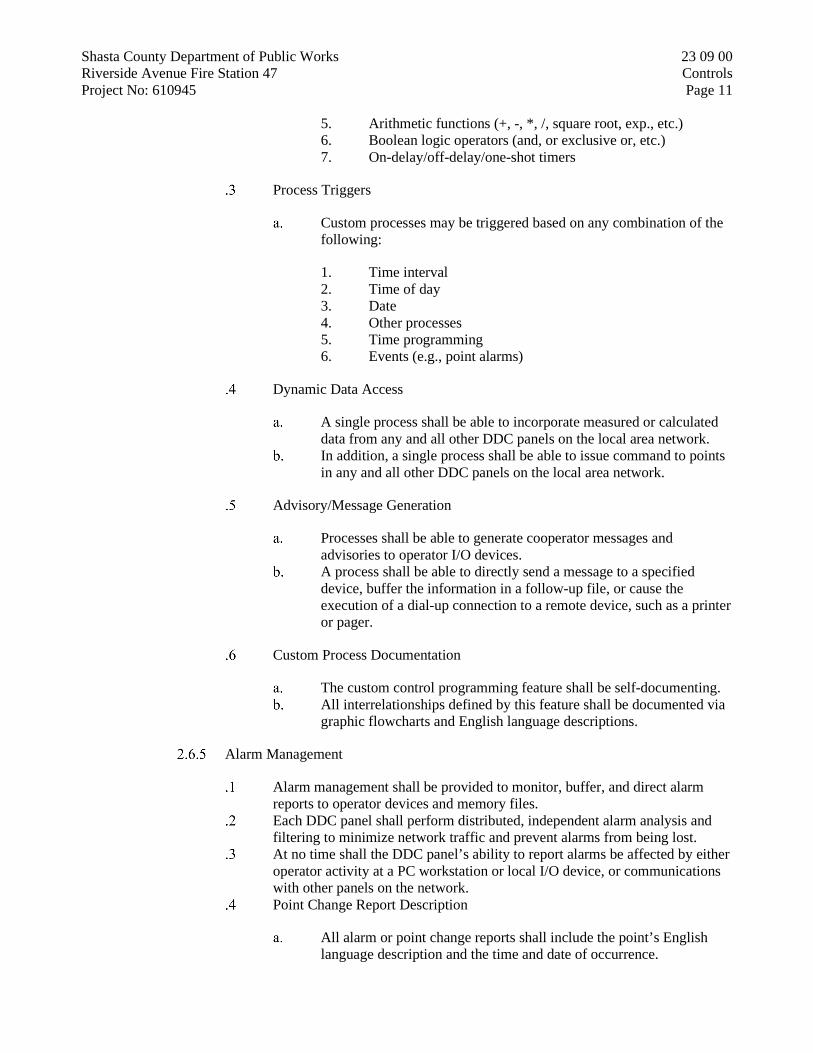
Shasta County Department of Public Works 23 09 00 Riverside Avenue Fire Station 47 Controls Project No: 610945 Page 11
5. Arithmetic functions (+, -, *, /, square root, exp., etc.) 6. Boolean logic operators (and, or exclusive or, etc.) 7. On-delay/off-delay/one-shot timers
Process Triggers
Custom processes may be triggered based on any combination of the following:
1. Time interval 2. Time of day 3. Date 4. Other processes 5. Time programming 6. Events (e.g., point alarms)
Dynamic Data Access
A single process shall be able to incorporate measured or calculated data from any and all other DDC panels on the local area network.
In addition, a single process shall be able to issue command to points in any and all other DDC panels on the local area network.
Advisory/Message Generation
Processes shall be able to generate cooperator messages and advisories to operator I/O devices.
A process shall be able to directly send a message to a specified device, buffer the information in a follow-up file, or cause the execution of a dial-up connection to a remote device, such as a printer or pager.
Custom Process Documentation
The custom control programming feature shall be self-documenting. All interrelationships defined by this feature shall be documented via
graphic flowcharts and English language descriptions.
Alarm Management
Alarm management shall be provided to monitor, buffer, and direct alarm reports to operator devices and memory files.
Each DDC panel shall perform distributed, independent alarm analysis and filtering to minimize network traffic and prevent alarms from being lost.
At no time shall the DDC panel’s ability to report alarms be affected by either operator activity at a PC workstation or local I/O device, or communications with other panels on the network.
Point Change Report Description
All alarm or point change reports shall include the point’s English language description and the time and date of occurrence.

Shasta County Department of Public Works 23 09 00 Riverside Avenue Fire Station 47 Controls Project No: 610945 Page 12
Prioritization
The user shall be able to define the specific system reaction for each point.
Alarms shall be prioritized to minimize nuisance reporting and to speed operator response to critical alarms.
A minimum of three priority levels shall be provided. Each DDC panel shall automatically inhibit the reporting of selected
alarms during system shutdown and startup. Users shall have the ability to manually inhibit alarm reporting for
each point. The user shall also be able to define under which conditions point
changes need to be acknowledged by an operator and/or sent to follow-up files for retrieval and analysis at a later date.
Report Routing
Alarm reports, messages, and files will be directed to a user-defined list of operator devices or PCs used for archiving alarm information.
Alarms shall also be automatically directed to a default device in the event a primary device is found to be offline.
Alarm Messages
In addition to the point’s descriptor and the time and date, the user shall be able to print, display, or store a 65-character alarm message to fully describe the alarm condition or to direct operator response.
Each stand-alone DDC panel shall be capable of storing a library of at least 250 alarm messages.
Each message may be assignable to any number of points in the panel.
Auto-Dial Alarm Management
In dial-up applications, only critical alarms shall initiate a call to a remote operator device.
In all other cases, call activity shall be minimized by time stamping and saving reports until an operator-scheduled time, a manual request, or until the buffer space is full.
The alarm buffer must store a minimum of 50 alarms.
Historical Data and Trend Analysis
A variety of historical data collection utilities shall be provided to automatically sample, store, and display system data in all of the following ways:
Continuous Point Histories
1. Stand-alone DDC panels shall store point history files for all analog and binary inputs and outputs.

Shasta County Department of Public Works 23 09 00 Riverside Avenue Fire Station 47 Controls Project No: 610945 Page 13
2. The point history routine shall continuously and automatically sample the value of all analog inputs at half-hour intervals.
3. Samples for all points shall be stored for the past 24 hours to allow the user to immediately analyze equipment performance and all problem-related events for the past day.
4. Point history files for binary input or output points and analog output points shall include a continuous record of the last 10 status changes or commands for each point.
Control Loop Performance Trends
1. Stand-alone DDC panels shall also provide high-resolution sampling capability with an operator-adjustable resolution of 10 to 300 seconds in 1-second increments for verification of control loop performance.
Extended Samper Period Trends
1. Measured and calculated analog and binary data shall also be assignable to user-definable trends for the purpose of collecting operator-specific performance data over extended periods of time.
2. Samper intervals of 1 minute to 2 hours, in 1-minute intervals, shall be provided. Each stand-alone DDC panel shall have a dedicated buffer for trend data and shall be capable of storing a minimum of 5,000 data samples.
Data Storage and Archiving
1. Trend data shall be stored at the stand-alone DDC panels and uploaded to hard disk storage when archiving is desired.
2. Uploads shall occur based upon either user-defined intervals, manual command, or when the trend buffers become full.
3. All trend data shall be available in disk file form for use in third-party personal computer applications.
Runtime Totalization
Stand-alone DDC panels shall automatically accumulate and store runtime hours for binary input and output points, as specified in the Execution portion of this Specification.
The totalization routine shall have a sampling resolution of 1 minute or less. The user shall have the ability to define a warning limit for runtime
totalization. Unique, user-specified messages shall be generated when the limit is reached.
Analog/Pulse Totalization
Stand-alone DDC panels shall automatically sample, calculate, and store consumption totals on a daily, weekly, or monthly basis for user-selected analog and binary pulse input-type points.

Shasta County Department of Public Works 23 09 00 Riverside Avenue Fire Station 47 Controls Project No: 610945 Page 14
Totalization shall provide calculation and storage of accumulations of up to 99,999.9 units (e.g., KWH, gallons, KBTU, tons, etc).
The totalization routine shall have a sampling resolution of 1 minute or less. The user shall have the ability to define a warning limit. Unique, user-specified messages shall be generated when the limit is reached.
Event Totalization
Stand-alone DDC panels shall have the ability to count events, such as the number of times a pump or fan system is cycled on and off.
Event totalization shall be performed on a daily, weekly, or monthly basis. The event totalization feature shall be able to store the records associated with
a minimum of 9,999.9 events, before reset. The user shall have the ability to define a warning limit. Unique, user-specified messages shall be generated when the limit is reached.
2.7 APPLICATIONS-SPECIFIC CONTROLLERS, HVAC APPLCIATIONS
Each stand-alone DDC controller shall be able to extend its performance and capacity through the use of remote application-specific controllers (ASCs).
Each ASC shall operate as a stand-alone controller, capable of performing its specified control responsibilities independently of other controllers in the network.
Each ASC shall be a microprocessor-based, multitasking, real-time digital control processor.
Each ASC shall have sufficient memory to support its own operating system and database, including the following:
Control processes. Energy management applications Operator I/O (portable service terminal)
The operator interface to any ASC point data or programs shall be through any network-resident PC workstation or any PC or portable operator’s terminal that is connected to any DDC panel in the network.
Application-specific controllers shall directly support the temporary use of a portable service terminal.
The capabilities of the portable service terminal shall include, but not be limited to, the following:
Display temperatures. Display status. Display set points. Display control parameters. Override binary output control. Override analog set points. Modification of gain and offset constants.

Shasta County Department of Public Works 23 09 00 Riverside Avenue Fire Station 47 Controls Project No: 610945 Page 15
Power Fail Protection
All system set points, proportional bands, control algorithms, and any other programmable parameters shall be stored such that a power failure of any duration does not necessitate reprogramming the controller.
Application Description
VAV Terminal Unit Controllers
VAV terminal unit controller shall support, but not be limited to, the control of the following configurations of VAV boxes to address current requirements, as described in the Execution portion of this Specification, and for future expansion:
1. Single duct only (cooling only or cooling with reheat) 2. Fan powered (parallel/side pocket, series/on-off logic) 3. Dual duct (constant volume, variable volume) 4. Supply/exhaust
VAV terminal unit controllers shall support the following types of point inputs and outputs:
1. Proportional cooling outputs 2. Box and baseboard heating outputs (proportional, or one to
three stages) 3. Fan control output (on/off logic, or proportional series fan
logic)
The modes of operation supported by the VAV terminal unit controllers shall minimally include, but not be limited to, the following:
1. Day/week schedule 2. Comfort/occupancy mode 3. Economy mode (standby mode, unoccupied, etc.) 4. Temporary override mode
Occupancy-Based Standby/Comfort Mode Control
1. Each VAV terminal unit controller shall have a provision for occupancy-sensing overrides.
2. Based upon the contact status of either a manual wall switch or an occupancy-sensing device, the VAV terminal unit controller shall automatically select either standby or comfort mode to minimize the heating and cooling requirements, while satisfying comfort conditions.
Continuous Zone Temperature Histories
1. Each VAV terminal unit controller shall automatically and continuously maintain a history of the associated zone

Shasta County Department of Public Works 23 09 00 Riverside Avenue Fire Station 47 Controls Project No: 610945 Page 16
temperature to allow users to quickly analyze space comfort and equipment performance for the past 24 hours.
2. A minimum of two samples per hour shall be stored.
Alarm Management
1. Each VAV terminal unit controller shall perform its own limit and status monitoring and analysis to maximize network performance by reducing unnecessary communications.
Unitary Controllers
Unitary controllers shall support, but not be limited to, the following types of systems to address specific applications described in the Execution portion of this Specification, and for future expansion:
1. Unit vents (ASHRAE cycle I, II, III, or W) 2. Heat pumps (air-to-air, water-to-air) 3. Package rooftops 4. Fan coils (two-pipe, four-pipe)
Unitary controllers shall support the following types of point inputs and outputs:
1. Economizer switchover inputs
Dry bulb Outdoor air enthalpy Differential temperature Binary input from a separate controller
2. Economizer outputs
Integrated analog, with minimum position Binary output to enable self-contained economizer
actuator Heating and cooling outputs One to three stages Analog output, with two-pipe logic Reversing valve logic for heat pumps
3. Fan Output
On/off logic control
Unitary controllers shall support the following library of control strategies to address the requirements of the sequences described in the Execution portion of this Specification, and for future expansion:
1. Daily/weekly schedules 2. Comfort/occupancy mode 3. Economy mode

Shasta County Department of Public Works 23 09 00 Riverside Avenue Fire Station 47 Controls Project No: 610945 Page 17
Standby mode/economizer available Unoccupied/economizer not available Shutdown Lighting logic interlock to economy mode
4. Temporary override mode
Temporary comfort mode (occupancy-based control) Boost (occupant warmer/cooler control)
Occupancy-Base Standby/Comfort Mode Control
1. Each unitary controller shall have a provision for occupancy-sensing overrides.
2. Based upon the contact status of either a manual wall switch or an occupancy-sensing device, the unitary controller shall automatically select either standby or comfort mode to minimize the heating and cooling requirements, while satisfying comfort conditions.
Continuous Zone Temperature Histories
1. Each unitary controller shall automatically and continuously maintain a history of the associated zone temperature to allow users to quickly analyze space comfort and equipment performance for the past 24 hours. A minimum of two samples per hour shall be stored.
Alarm Management
1. Each unitary controller shall perform its own limit and status monitoring and analysis to maximize network performance by reducing unnecessary communications.
AHU Controllers
AHU controllers shall support, but not be limited to, the following configurations of systems to address current requirements, as described in the Execution portion of this Specification, and for future expansion:
1. Large air handling units
Mixed air – single path Mixed air – dual path 100-percent single path 100-percent dual path
AHU controllers shall support all of the necessary point inputs and outputs to perform the specified control sequences in a totally stand-alone fashion.

Shasta County Department of Public Works 23 09 00 Riverside Avenue Fire Station 47 Controls Project No: 610945 Page 18
AHU controllers shall have a library of control routines and program logic to perform the sequences of operation, as specified in the Execution portion of this Specification.
Occupancy-Based Standby/Comfort Mode Control
1. Each AHU controller shall have a provision for occupancy-sensing overrides.
2. Based upon the contact status of either a manual wall switch or an occupancy-sensing device, the AHU controller shall automatically select either standby or comfort mode to minimize the heating and cooling requirements, while satisfying comfort conditions.
Continuous Zone Temperature Histories
1. Each AHU controller shall automatically and continuously maintain a history of the associated zone temperature to allow users to quickly analyze space comfort and equipment performance for the past 24 hours.
2. A minimum of two samples per hour shall be store.
Alarm Management
1. Each AHU controller shall perform its own limit and status monitoring and analysis to maximize network performance by reducing unnecessary communications.
PART 3 - EXECUTION
3.1 GENERAL
Electrical work shall be executed in accordance with section 16000, ELECTRICAL.
Work shall be performed in a workmanlike manner by craftsman skilled in the particular trade. Work shall be performed in accordance with the Plans, Specifications, manufacturer’s recommendations, and the best practice in the trade. Completed work shall present a neat and finished appearance.
Coordinate work with the County and the work of other trades to avoid conflicts, errors, delays, and unnecessary interference during construction.
All thermostats or temperature sensors in the conditioned space shall have blank locking covers. Furnish cast aluminum guards where shown on the Plans.
Identify each item mounted on the face of a control panel with an engraved, phenolic label (1/4 –inch high engraved letters, minimum). Identify each item of control equipment (except room sensors and thermostats) with stamped tape firmly attached to equipment.
All control adjustments shall be accessible without use of a ladder.

Shasta County Department of Public Works 23 09 00 Riverside Avenue Fire Station 47 Controls Project No: 610945 Page 19
Thermostats or sensors mounted on outside walls shall be mounted on 1-inch minimum thickness rigid fiberglass insulating base (or equal).
All thermal sensors in water lines hall be the direct-immersion type, installed through a “direct-immersion fitting” consisting of an isolation valve and Teflon packing.
3.2 PROTECTION DURING CONSTRUCTION
Throughout the Contract, provide protection for materials and equipment against loss or damage and from the effects of weather.
Prior to installation, store items to be installed in indoor locations.
Items subject to corrosion under damp conditions and items containing insulation, such as transformers, motors, and controls, shall be stored in indoor, heated, dry locations.
Following installation, protect materials, equipment, and insulation from corrosion, physical damage, and moisture.
Cap conduit runs during construction with manufactured seals.
Keep openings in boxes or equipment closed during construction.
Provide temporary heating source for electrical equipment in damp locations or locations subject to condensation, including transformers, motors, and controls, until construction is complete and equipment is energized.
3.3 3.3 MATERIAL AND EQUIPMENT INSTALLATION
Follow the manufacturer’s installation recommendations unless otherwise indicated.
Follow the Engineer’s decision, at no additional cost to the County, wherever any conflict arises between the manufacturer’s instruction, State, or other codes and regulations, and these Contract Documents.
Keep copy of the manufacturer’s installation instructions available on the jobsite for review at all times.
Install freestanding equipment in accordance with the manufacturer’s recommendations. Unless noted otherwise, mount freestanding equipment on a 3 ½ inch concrete pad.
Secure motor control centers (MCCs) and other freestanding equipment rigidly to floors to mounting pads with anchor bolts, expansion shields, or other approved means.
Grout mounting channels provided with MCCs into the floor or mounting pads, unless the MCCs are firmly anchored with the specified concrete anchors, in which case the channels are not required.

Shasta County Department of Public Works 23 09 00 Riverside Avenue Fire Station 47 Controls Project No: 610945 Page 20
3.4 CUTTING AND PATCHING
Do not cut or notch any structural member or building surface without specific approval of the Engineer.
Where possible, avoid any cutting, channeling, chasing, or drilling of floors, walls, partitions, ceilings, paving, or other surfaces.
Use clamps and channel where required for the installation, support, or anchorage of conduit, raceways, or other electrical materials and equipment.
Following such work, restore surfaces neatly to new condition using skilled craftsmen of the trades involved, at no additional cost to the County.
3.5 CLEANING AND TOUCHUP PAINTING
Keep the premises free from accumulation of waste material or rubbish.
Upon completion of work, remove materials, scraps, and debris from the premises and from the interior and exterior of all devices and equipment.
Refinish damaged surfaces to new condition using skilled craftsmen of the trades involved, at no additional cost to the County.
3.6 INSTALLATION
Electrical work
All temperature control and interlock wiring shall be plenum-rated cable. Power or interlock wiring shall be run in separate conduit form sensor wiring. Wiring shall conform to the National Electrical Code. All wiring of any nature in connection with temperature control system,
regardless of voltage, including temperature control wiring, interlocking, and the like, shall be included in the air conditioning work.
END OF SECTION 23 09 00

Shasta County Department of Public Works 26 05 19 Riverside Avenue Fire Station 47 Low -Voltage Electrical Power Conductors and Cables Project No: 610945 Page 1
LOW-VOLTAGE ELECTRICAL POWER CONDUCTORS AND CABLES
26 05 19
PART 1 - GENERAL
1.1 SUMMARY
Section Includes:
Copper building wire rated 600 V or less. Metal-clad cable, Type MC, rated 600 V or less. Landscape lighting cable, 150V or less. Connectors, splices, and terminations rated 600 V and less.
1.2 DEFINITIONS
MOCP: Maximum overcurrent protection.
MCA: Minimum circuit ampacity.
Exposed: On or attached to the surface or behind panels designed to allow access. Raceways and cables in unfinished basements in accessible underfloor areas or attics; or behind, above, or below panels designed to allow access; and that may be removed without damage to the building structure or finish are considered exposed.
Concealed: Rendered inaccessible by the structure of finish of the building. Raceways and cables supported or located within hollow frames or permanently enclosed by the finish of buildings are considered concealed.
PART 2 - PRODUCTS
2.1 COPPER BUILDING WIRE
Description: Flexible, insulated and uninsulated, drawn copper current-carrying conductor with an overall insulation layer or jacket, or both, rated 600 V or less.
Manufacturers: Subject to compliance with requirements, available manufacturers offering products that may be incorporated into the Work include, but are not limited to the following:
Southwire Company. Okonite.
Standards:
Listed and labeled as defined in CEC, by a qualified testing agency, and marked for intended location and use.
Conductor and Cable Marking: Comply with wire and cable marking according to UL's "Wire and Cable Marking and Application Guide."

Shasta County Department of Public Works 26 05 19 Riverside Avenue Fire Station 47 Low -Voltage Electrical Power Conductors and Cables Project No: 610945 Page 2
Conductors: Copper, complying with ASTM B3 for bare annealed copper and with ASTM B8 or ASTM B496 for stranded conductors.
Conductor Insulation:
Type THHN and Type THWN-2: Comply with UL 83. Type XHHW-2: Comply with UL 44.
2.2 METAL-CLAD CABLE, TYPE MC (non-Hospital Grade)
Description: A factory assembly of one or more current-carrying insulated conductors in an overall metallic sheath.
Manufacturers: Subject to compliance with requirements, available manufacturers offering products that may be incorporated into the Work include, but are not limited to the following:
General Cable Technologies Corporation. Southwire Company.
Standards:
Listed and labeled as defined in CEC, by a qualified testing agency, and marked for intended location and use.
Comply with UL 1569. RoHS compliant. Conductor and Cable Marking: Comply with wire and cable marking
according to UL's "Wire and Cable Marking and Application Guide."
Ground Conductor: Insulated.
Conductor Insulation:
Type TFN/THHN/THWN-2: Comply with UL 83. Type XHHW-2: Comply with UL 44.
Armor: Steel, interlocked.
Jacket:
PVC applied over armor when used in crawl spaces. Suitable for wet or damp locations per CEC 330.10(11).
Non-damp or wet locations may use dry location rated MC.
2.3 LANDSCAPE LIGHTING CABLE
Description: Low voltage (low energy) underground landscape lighting cable is suitable for outdoor accent lighting, landscape lighting and security lighting applications not exceeding 50 VDC. The product can be installed outdoors exposed to sunlight. Low voltage underground landscape lighting cable is suitable for use at temperatures not exceeding -20C or maximum 60C.

Shasta County Department of Public Works 26 05 19 Riverside Avenue Fire Station 47 Low -Voltage Electrical Power Conductors and Cables Project No: 610945 Page 3
Standards:
Comply with UL1493. CSA Requirements of the NEC. RoHS compliant.
Conductor properties:
14/2 AWG
1. 45 mil insulation thickness. 2. 41/30 AWG conductor stranding.
2.4 CONNECTORS AND SPLICES
Description: Factory-fabricated connectors, splices, and lugs of size, ampacity rating, material, type, and class for application and service indicated; listed and labeled as defined in CEC, by a qualified testing agency, and marked for intended location and use.
Manufacturers: Subject to compliance with requirements, available manufacturers offering products that may be incorporated into the Work include, but are not limited to the following:
3M Electrical Products. Greaves. Hubbell Power Systems, Inc. Ideal Industries, Inc. ILSCO. NSi Industries LLC. Thomas & Betts Corporation; A Member of the ABB Group.
Jacketed Cable Connectors: For steel and aluminum jacketed cables, zinc die-cast with set screws, designed to connect conductors specified in this Section.
Lugs: One piece, seamless, designed to terminate conductors specified in this Section.
Material: Copper. Type: One or two-hole with standard or long barrels. Termination: Compression.
Splices shall be in accordance with the CEC and UL Listing.
Above Ground Splices for No. 10 AWG and Smaller:
Solderless, screw on, reusable pressure cable type, with integral insulation, approved for copper and aluminum conductors.
The integral insulator shall have a skirt to completely cover the stripped conductors.
The number, size, and combination of conductors used with the connector, as listed on the manufacturer's packaging, shall be strictly followed.

Shasta County Department of Public Works 26 05 19 Riverside Avenue Fire Station 47 Low -Voltage Electrical Power Conductors and Cables Project No: 610945 Page 4
Above Ground Splices for No. 8 AWG to No. 4/0 AWG:
Compression, hex screw, or bolt clamp type of high conductivity and corrosion resistant material, listed for use with copper and aluminum conductors.
Insulate with materials approved for the particular use, location, voltage, and temperature. Insulation level shall be not less than the insulation level of the conductors being joined.
Splice and insulation shall be product of the same manufacturer.
PART 3 - EXECUTION
3.1 INSTALLATION
Comply with:
CEC Chapter 2 for Wiring and Protection. CEC Chapter 3 for Wiring Methods and Materials. NECA 1: Standard Practices for Good Workmanship in Electrical
Construction. NECA 101 Standard for Installing Steel Conduits (RMC, IMC, EMT).
The contractor shall verify MOCP and MCA requirements with the listing and labeling of each piece of equipment or device delivered to the field and determine if the feeder or branch circuit is compliant with the listing and labeling. Comply with CEC 110.3 and 422.60. The contractor shall inform the EEOR of any discrepancies.
It is assumed that all terminations in the field shall have minimum rated 75°C rated terminals. The contractor shall field verify all terminals for connection in compliance with CEC 110.14. The contractor shall inform the Engineer of Record of any terminals deviating from 75°C. All conductors are rated for 75°C on plans unless otherwise noted.
3.2 CONDUCTOR MATERIAL APPLICATIONS
Branch Circuits and Feeders: THHN/THWN-2 Copper; solid for No. 12 AWG and smaller; stranded for No. 10 AWG and larger.
3.3 CONDUCTOR INSULATION AND MULTICONDUCTOR CABLE APPLICATIONS AND WIRING METHODS
Feeders: Concealed or exposed: Type THHN/THWN-2, single conductors in raceway.
Branch Circuits:
General:
Branch circuits shall be routed as single conductors in raceway from the panelboard until reaching the room, space, device, or equipment served.
The use of flexible raceway to equipment, appliances, surface and lay-in luminaires and devices shall be limited to 6’-0”.

Shasta County Department of Public Works 26 05 19 Riverside Avenue Fire Station 47 Low -Voltage Electrical Power Conductors and Cables Project No: 610945 Page 5
The use of metal-clad cable to equipment and appliances is prohibited.
Metal-clad cable may be used to serve surface and lay-in luminaires and devices where lengths do not exceed 20’-0” from the junction box served by the raceway.
Exposed Branch Circuits not readily visible (typ. above ceiling or other similar spaces) without removal of an access panel: Type THHN/THWN-2 or XHHW-2, single conductors in raceway Metal-clad cable, Type MC.
Exposed Branch Circuits readily visible: Type THHN/THWN-2 or XHHW-2, single conductors in raceway.
Branch Circuits Concealed in Ceilings, Walls, and Partitions: Type THHN/THWN-2 or XHHW-2, single conductors in raceway Metal-clad cable, Type MC.
Branch Circuits Concealed in Concrete, below Slabs-on-Grade, and Underground: Type THHN/THWN-2 or XHHW-2, single conductors in raceway.
Cord Drops and Portable Appliance Connections: Type SO, hard service cord with stainless-steel, wire-mesh, strain relief device at terminations to suit application. Comply with CEC Article 400.
3.4 INSTALLATION OF CONDUCTORS AND CABLES
Conceal cables in finished walls, ceilings, and floors unless otherwise indicated.
Use manufacturer-approved pulling compound or lubricant where necessary; compound used must not deteriorate conductor or insulation. Do not exceed manufacturer's recommended maximum pulling tensions and sidewall pressure values.
Use pulling means, including fish tape, cable, rope, and basket-weave wire/cable grips, that will not damage cables or raceway.
Install exposed cables parallel and perpendicular to surfaces of exposed structural members and follow surface contours where possible.
Wiring within Enclosures: Separate power-limited and non-power-limited conductors as recommended by manufacturer with a minimum separation of 0’-6”. Install conductors parallel with or at right angles to sides and back of the enclosure. Bundle, lace, and train conductors to terminal points with no excess. Connect conductors that are terminated, spliced, or interrupted in any enclosure associated with fire-alarm system to terminal blocks. Mark each terminal according to system's wiring diagrams. Make all connections with approved crimp-on terminal spade lugs, pressure-type terminal blocks, or plug connectors.
Cable Taps: Use numbered terminal strips in junction, pull, and outlet boxes; cabinets; or equipment enclosures where circuit connections are made.
Color-Coding: Color-code Division 27 and Division 28 conductors differently from normal building power wiring.

Shasta County Department of Public Works 26 05 19 Riverside Avenue Fire Station 47 Low -Voltage Electrical Power Conductors and Cables Project No: 610945 Page 6
3.5 CONNECTIONS
Tighten electrical connectors and terminals according to manufacturer's published torque-tightening values. If manufacturer's torque values are not indicated, use those specified in UL 486A-486B.
Wiring at Outlets: Install conductor at each outlet, with at least 6 inches of slack.
3.6 IDENTIFICATION
Identify and color-code conductors and cables according to Section 260553 "Identification for Electrical Systems."
3.7 FIELD QUALITY CONTROL
Testing Agency: Engage a qualified professional to perform tests and inspections.
Perform tests and inspections:
After installing conductors and cables and before electrical circuitry has been energized, test service entrance and feeder conductors for compliance with requirements.
After installing conductors and cables and before electrical circuitry has been energized, test service entrance and feeder conductors and all conductors #6 AWG and larger.
The cabling system shall be certified (inspected, tested, and documented) that it is ready for operation.
1. Insulation resistance test:
i. Perform insulation resistance test on each conductor #6 AWG and larger with respect to ground. Applied potential to be 1,000 VDC for one minute.
ii. Record test values and submit to the Engineer. Insulation resistance to be 50 megohm, minimum.
iii. Measure insulation resistance of complete circuits with the breakers open.
Forms: Example ORT forms are provided in the supplement at the end of this section.
END OF SECTION 260519

Shasta County Department of Public Works 26 05 19 Riverside Avenue Fire Station 47 Low -Voltage Electrical Power Conductors and Cables Project No: 610945 Page 7
SUPPLEMENT NO. 1
EXAMPLE ORT FORMS
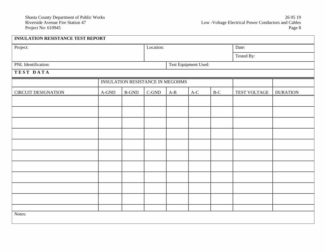
Shasta County Department of Public Works 26 05 19 Riverside Avenue Fire Station 47 Low -Voltage Electrical Power Conductors and Cables Project No: 610945 Page 8
INSULATION RESISTANCE TEST REPORT
Project: Location: Date:
Tested By:
PNL Identification: Test Equipment Used:
T E S T D A T A
INSULATION RESISTANCE IN MEGOHMS
CIRCUIT DESIGNATION A-GND B-GND C-GND A-B A-C B-C TEST VOLTAGE DURATION
Notes:

Shasta County Department of Public Works 26 05 26 Riverside Avenue Fire Station 47 Grounding and Bonding for Electrical Systems Project No: 610945 Page 1
GROUNDING AND BONDING FOR ELECTRICAL SYSTEMS
26 05 26
PART 1 - GENERAL
1.1 DEFINITIONS
Structure: That which is built or constructed, other than equipment (CEC Article 100).
EGC: Equipment ground conductor.
PART 2 - PRODUCTS
2.1 CONDUCTORS
Insulated Conductors: Copper wire or cable insulated for 600 V unless otherwise re-quired by applicable Code or authorities having jurisdiction.
Bare Copper Conductors:
Solid Conductors: ASTM B3. Stranded Conductors: ASTM B8. Bonding Conductor: No. 4 or No. 6 AWG, stranded conductor. Tinned Bonding Jumper: Tinned-copper tape, braided conductors terminated
with copper ferrules; 1-5/8 inches wide and 1/16 inch thick.
2.2 CONNECTORS
Listed and labeled by an NRTL acceptable to authorities having jurisdiction for appli-cations in which used and for specific types, sizes, and combinations of conductors and other items connected.
Welded Connectors: Exothermic-welding kits of types recommended by kit manufac-turer for materials being joined and installation conditions.
Bus-Bar Connectors: Mechanical type, cast silicon bronze, solderless compression-type wire terminals, and long-barrel, two-bolt connection to ground bus bar.
Conduit Grounding Hubs: Mechanical type, terminal with threaded hub.
Beam Clamps: Mechanical type, terminal, ground wire access from four directions, with dual, tin-plated or silicon bronze bolts.
Cable Tray Ground Clamp: Mechanical type, zinc-plated malleable iron.
U-Bolt Clamps: Mechanical type, copper or copper alloy, terminal listed for direct burial.
Water Pipe Clamps:

Shasta County Department of Public Works 26 05 26 Riverside Avenue Fire Station 47 Grounding and Bonding for Electrical Systems Project No: 610945 Page 2
Mechanical type, two pieces with stainless-steel bolts.
Material: Tin-plated aluminum. Listed for direct burial.
U-bolt type with malleable-iron clamp and copper ground connector rated for direct burial.
2.3 GROUNDING ELECTRODES
Ground Rods: Copper-clad steel; 3/4 inch by 10 feet.
UFER ground: See construction drawing electrical details.
PART 3 - EXECUTION
3.1 Comply with CEC Article 250.
3.2 APPLICATIONS
Conductors: Install solid conductor for No. 8 AWG and smaller, and stranded conduc-tors for No. 6 AWG and larger unless otherwise indicated.
Conductor Terminations and Connections:
Pipe and Equipment Grounding Conductor Terminations: Bolted connectors. Underground Connections: Welded connectors. Connections to Structural Steel: Bolted Connectors.
Grounding Conductors: Green insulation.
3.3 EQUIPMENT GROUNDING
Install insulated equipment grounding conductors with all feeders and branch circuits.
Air-Duct Equipment Circuits: Install insulated equipment grounding conductor to duct-mounted electrical devices operating at 120 V and more, including air cleaners, heaters, dampers, humidifiers, and other duct electrical equipment. Bond conductor to each unit and to air duct and connected metallic piping.
Water Heater, Heat-Tracing, and Antifrost Heating Cables: Install a separate insulated equipment grounding conductor to each electric water heater and heat-tracing cable. Bond conductor to heater units, piping, connected equipment, and components.
Isolated Grounding Conductors: Green-colored insulation with more than one contin-uous yellow stripe. On feeders with isolated ground, identify grounding conductor where visible to normal inspection, with alternating bands of green and yellow tape, with at least three bands of green and two bands of yellow.
3.4 GROUNDING UNDERGROUND DISTRIBUTION SYSTEM COMPONENTS
Comply with IEEE C2 grounding requirements.
Shasta County Department of Public Works 26 05 26 Riverside Avenue Fire Station 47 Grounding and Bonding for Electrical Systems Project No: 610945 Page 3
Pad-Mounted Transformers and Switches: Install one ground rod. Ground pad-mounted equipment and noncurrent-carrying metal items associated. Supply bonding jumper for client-owned transformers shall be installed at the transformer.
3.5 INSTALLATION
Grounding Conductors: Route along shortest and straightest paths possible unless oth-erwise indicated or required by Code. Avoid obstructing access or placing conductors where they may be subjected to strain, impact, or damage.
Ground Rods: Drive rods until tops are 2 inches below finished floor or final grade unless otherwise indicated.
Interconnect ground rods with grounding electrode conductor below grade and as otherwise indicated. Make connections without exposing steel or dam-aging coating if any.
Use exothermic welds for all below-grade connections.
Bonding Straps and Jumpers: Install in locations accessible for inspection and mainte-nance except where routed through short lengths of conduit.
Bonding to Structure: Bond straps directly to basic structure, taking care not to penetrate any adjacent parts.
Bonding to Equipment Mounted on Vibration Isolation Hangers and Supports: Install bonding so vibration is not transmitted to rigidly mounted equipment.
Use exothermic-welded connectors for outdoor locations.
Grounding and Bonding for Piping:
Metal Water Service Pipe: Install insulated copper grounding conductors, in conduit, from building's main service equipment, or grounding bus, to main metal water service entrances to building. Connect grounding conductors to main metal water service pipes; use a bolted clamp connector or bolt a lug-type connector to a pipe flange by using one of the lug bolts of the flange. Where a dielectric main water fitting is installed, connect grounding conduc-tor on street side of fitting. Bond metal grounding conductor conduit or sleeve to conductor at each end.
Water Meter Piping: Use braided-type bonding jumpers to electrically bypass water meters. Connect to pipe with a bolted connector.
Bond each aboveground portion of gas piping system downstream from equipment shutoff valve.
Bonding Interior Metal Ducts: Bond metal air ducts to equipment grounding conduc-tors of associated fans, blowers, electric heaters, and air cleaners. Install bonding jumper to bond across flexible duct connections to achieve continuity.
Concrete-Encased Grounding Electrode (Ufer Ground): Fabricate according to CEC; use a minimum of 20 feet of bare copper conductor (size as indicated on plans).
If concrete foundation is less than 20 feet long, coil excess conductor within base of foundation.

Shasta County Department of Public Works 26 05 26 Riverside Avenue Fire Station 47 Grounding and Bonding for Electrical Systems Project No: 610945 Page 4
Connections: Make connections so possibility of galvanic action or electrolysis is minimized. Select connectors, connection hardware, conductors, and connection methods so metals in direct contact are galvanically compatible.
3.6 FIELD QUALITY CONTROL
Perform tests and inspections.
Tests and Inspections:
After installing grounding system but before permanent electrical circuits have been energized, test for compliance with requirements.
Inspect physical and mechanical condition. Verify tightness of accessible, bolted, electrical connections with a calibrated torque wrench according to manufacturer's written instructions.
Test completed grounding system at each location where a maximum ground-resistance level is specified, at service disconnect enclosure grounding termi-nal, at ground test wells, and at individual ground rods. Make tests at ground rods before any conductors are connected.
Measure ground resistance no fewer than two full days after last trace of precipitation and without soil being moistened by any means other than natural drainage or seepage and without chemical treatment or other artificial means of reducing natural ground resistance.
Perform tests by fall-of-potential method according to IEEE 81.
Grounding system will be considered defective if it does not pass tests and inspec-tions.
Report measured ground resistances that exceed the following values:
Power and Lighting Equipment or System with Capacity of 500 kVA and Less: 10 ohms.
Power and Lighting Equipment or System with Capacity of 500 to 1000 kVA: 5 ohms.
Power and Lighting Equipment or System with Capacity More Than 1000 kVA: 3 ohms.
Power Distribution Units or Panelboards Serving Electronic Equipment: 3 ohm(s).
Excessive Ground Resistance: If resistance to ground exceeds specified values, notify Architect promptly and include recommendations to reduce ground resistance.
END OF SECTION 26 05 26

Shasta County Department of Public Works 26 05 29 Riverside Avenue Fire Station 47 Hangers and Supports for Electrical Systems Project No: 610945 Page 1
HANGERS AND SUPPORTS FOR ELECTRICAL SYSTEMS
26 05 29
PART 1 - GENERAL
1.1 SUMMARY
Section Includes:
Steel slotted support systems. Conduit and cable support devices. Mounting, anchoring, and attachment components, including powder-actuated
fasteners, mechanical expansion anchors, concrete inserts, clamps, through bolts, toggle bolts, and hanger rods.
PART 2 - PRODUCTS
2.1 SUPPORT, ANCHORAGE, AND ATTACHMENT COMPONENTS
Steel Slotted Support Systems: Preformed steel channels and angles with minimum 13/32-inch-diameter holes at a maximum of 8 inches o.c. in at least one surface.
Standard: Comply with MFMA-4 factory-fabricated components for field as-sembly.
Material for Channel, Fittings, and Accessories: Stainless steel, Type 304 Stainless steel.
Channel Width: Selected for applicable load criteria. Metallic Coatings: Hot-dip galvanized after fabrication and applied according
to MFMA-4. Painted Coatings: Manufacturer's standard painted coating applied according
to MFMA-4. Protect finishes on exposed surfaces from damage by applying a strippable,
temporary protective covering before shipping.
Conduit and Cable Support Devices: Galvanized Steel hangers, clamps, and associat-ed fittings, designed for types and sizes of raceway or cable to be supported.
Mounting, Anchoring, and Attachment Components: Items for fastening electrical items or their supports to building surfaces include the following:
Mechanical-Expansion Anchors: Insert-wedge-type, stainless steel, for use in hardened Portland cement concrete, with tension, shear, and pullout capacities appropriate for supported loads and building materials where used.
Clamps for Attachment to Steel Structural Elements: MSS SP-58 units are suitable for attached structural element.
Through Bolts: Structural type, hex head, and high strength. Comply with ASTM F3125/F3125M, Grade A325.
Hanger Rods: Threaded galvanized steel. Raceway spring steel clamps listed and suitable for the use.

Shasta County Department of Public Works 26 05 29 Riverside Avenue Fire Station 47 Hangers and Supports for Electrical Systems Project No: 610945 Page 2
PART 3 - EXECUTION
3.1 APPLICATION
Comply with the following standards for application and installation requirements of hangers and supports, except where requirements on Drawings or in this Section are stricter:
NECA 1 (Good Workmanship Standards). NECA 101 (Metallic Raceway Standards). NECA 111 (Nonmetallic Raceway Standards). California Electric Code 300.19 and Table 300.19 (A) for vertical cable sup-
ports.
Maximum Support Spacing and Minimum Hanger Rod Size for Raceways: Space supports for EMT, and RMC as required by CEC. Minimum rod size shall be 1/4 inch in diameter.
Multiple Raceways or Cables: Install trapeze-type supports fabricated with steel slot-ted or other support system, sized so capacity can be increased by at least 25 percent in future without exceeding specified design load limits.
Secure raceways and cables to these supports with two-bolt conduit clamps.
Spring-steel clamps designed for supporting single conduits without bolts may be used for 1-1/2-inch and smaller raceways serving branch circuits and communication sys-tems above suspended ceilings, and for fastening raceways to trapeze supports.
3.2 SUPPORT INSTALLATION
Comply with NECA 1 and NECA 101 for installation requirements except as speci-fied in this article.
Raceway Support Methods: In addition to methods described in NECA 1, EMT IMC and RMC may be supported by openings through structure members, according to CEC.
Strength of Support Assemblies: Where indicated, select sizes of components so strength will be adequate to carry present and future static loads within specified load-ing limits. Minimum static design load used for strength determination shall be weight of supported components plus 200 lb.
Mounting and Anchorage of Surface-Mounted Equipment and Components: Anchor and fasten electrical items and their supports to building structural elements by the fol-lowing methods unless otherwise indicated by code:
To Wood: Fasten with lag screws or through bolts. To New Concrete: Bolt to concrete inserts. To Masonry: Approved toggle-type bolts on hollow masonry units and expan-
sion anchor fasteners on solid masonry units. To Steel: Beam clamps (MSS SP-58, Type 19, 21, 23, 25, or 27), complying
with MSS SP-69.

Shasta County Department of Public Works 26 05 29 Riverside Avenue Fire Station 47 Hangers and Supports for Electrical Systems Project No: 610945 Page 3
To Light Steel: Sheet metal screws. Items Mounted on Hollow Walls and Nonstructural Building Surfaces: Mount
cabinets, panelboards, disconnect switches, control enclosures, pull and junc-tion boxes, transformers, and other devices on slotted-channel racks attached to substrate by means that comply with seismic-restraint strength and anchor-age requirements.
Drill holes for expansion anchors in concrete at locations and to depths that avoid the need for reinforcing bars.
3.3 INSTALLATION OF FABRICATED METAL SUPPORTS
Cut, fit, and place miscellaneous metal supports accurately in location, alignment, and elevation to support and anchor electrical materials and equipment.
3.4 CONCRETE BASES
Construct concrete bases of dimensions indicated, but not less than 4 inches larger in both directions than supported unit, and so anchors will be a minimum of 10 bolt di-ameters from edge of the base.
Use 3000-psi, 28-day compressive-strength concrete. Concrete materials, reinforce-ment, and placement requirements are specified in specification Division 3. Reference Electrical, Structural and Architectural plan sheets.
Anchor equipment to concrete base as follows:
Place and secure anchorage devices. Use supported equipment manufacturer's setting drawings, templates, diagrams, instructions, and directions furnished with items to be embedded.
Install anchor bolts to elevations required for proper attachment to supported equipment.
Install anchor bolts according to anchor-bolt manufacturer's written instruc-tions.
3.5 PAINTING
Touchup: Clean field welds and abraded areas of shop paint. Paint exposed areas im-mediately after erecting hangers and supports. Use same materials as used for shop painting. Comply with SSPC-PA 1 requirements for touching up field-painted surfac-es.
Apply paint by brush or spray to provide minimum dry film thickness of 2.0 mils.
Touchup: Comply with requirements in Specification Division 09 and Architectural plan sheets for cleaning and touchup painting of field welds, bolted connections, and abraded areas of shop paint on miscellaneous metal.
Galvanized Surfaces: Clean welds, bolted connections, and abraded areas and apply galvanizing-repair paint to comply with ASTM A780.

Shasta County Department of Public Works 26 05 29 Riverside Avenue Fire Station 47 Hangers and Supports for Electrical Systems Project No: 610945 Page 4
END OF SECTION 26 05 29

Shasta County Department of Public Works 26 05 33 Riverside Avenue Fire Station 47 Raceways and Boxes for Electrical Systems Project No: 610945 Page 1
RACEWAYS AND BOXES FOR ELECTRICAL SYSTEMS
26 05 33
PART 1 - GENERAL
1.1 REFERENCES
See Specification Section 260519, “LOW VOLTAGE ELECTRICAL POWER CONDUCTORS AND CABLES”.
1.2 SUMMARY
Section Includes:
Metal conduits and fittings. Nonmetallic conduits and fittings. Metal wireways and auxiliary gutters. Boxes, enclosures, and cabinets. Pull boxes for exterior underground cabling.
1.3 DEFINITIONS
EMT: Electrical Metallic Tubing.
RMC: Rigid Metallic Conduit.
PVC: Rigid Polyvinyl Chloride Conduit.
FMC: Flexible Metal Conduit.
LFMC: Liquid-tight Flexible Metal Conduit.
Concealed: Rendered inaccessible by the structure of finish of the building. Raceways and cables supported or located within hollow frames or permanently enclosed by the finish of buildings are considered concealed.
Exposed: On or attached to the surface or behind panels designed to allow access. Race-ways and cables in unfinished basements in accessible underfloor areas or attics; or be-hind, above, or below
Auxiliary Gutter: A sheet metal enclosure used to supplement wiring spaces at meter centers, distribution centers, switchgear, switchboards, and similar points of wiring sys-tems. The enclosure has hinged or removable covers for housing and protecting electri-cal wires, cables and busbars. The enclosure is designed for conductors to be laid or set in place after the enclosures have been installed as a complete system (CEC 366.2).
Gutter: A sheet metal enclosure used for wiring spaces at meter centers, distribution cen-ters, switchgear, switchboards, and similar points of wiring systems.

Shasta County Department of Public Works 26 05 33 Riverside Avenue Fire Station 47 Raceways and Boxes for Electrical Systems Project No: 610945 Page 2
Enclosure: a space within an above ground box to which raceways terminate and wire space is given to redirect, splice, or terminate to power distribution blocks (CEC 314.28). Cabinets and enclosures are typically equipped with hinged doors that may be lockable, or gasketed.
Pull Box: Underground box to which raceways terminate and wire space is given to redi-rect or splice conductors.
Wireway: Sheet metal troughs with hinged or removable covers for housing and protect-ing electrical wires and cable and in which conductors are laid in place after the raceway has been installed as a complete system (CEC 376.2).
1.4 ACTION SUBMITTALS
Product Data: For all products.
PART 2 - PRODUCTS
2.1 METAL CONDUITS AND FITTINGS
Metal Conduit:
Listing and Labeling: Listed and labeled as defined in CEC, by a qualified test-ing agency, and marked for intended location and application.
RMC: Comply with ANSI C80.1 and UL 6. EMT: Comply with ANSI C80.3 and UL 797. FMC: Comply with UL 1; zinc-coated steel. LFMC: Flexible steel conduit with PVC jacket and complying with UL 360.
Metal Fittings:
Comply with NEMA FB 1 and UL 514B. Listing and Labeling: Listed and labeled as defined in CEC, by a qualified test-
ing agency, and marked for intended location and application. Fittings, General: Listed and labeled for type of conduit, location, and use. Conduit Fittings for Hazardous (Classified) Locations: Comply with UL 1203
and CEC. Fittings for EMT:
Material: Steel. Type Indoor:
1. EMT: Setscrew or Compression. 2. RMC: Rigid galvanized threaded. 3. FMC: Steel screw-in.
Type Outdoor:
1. EMT: Compression raintight. 2. RMC: Rigid galvanized threaded.

Shasta County Department of Public Works 26 05 33 Riverside Avenue Fire Station 47 Raceways and Boxes for Electrical Systems Project No: 610945 Page 3
3. RNC: Rigid Non-metallic push-in couplings and connectors for joining PVC lengths and push in threaded couplings and con-nectors for transitions from PVC to RMC, or EMT.
4. LFMC: Liquid tight steel or iron.
Joint Compound for RMC: Approved, as defined in CEC, by authorities having jurisdic-tion for use in conduit assemblies, and compounded for use to lubricate and protect threaded conduit joints from corrosion and to enhance their conductivity.
2.2 NONMETALLIC CONDUITS AND FITTINGS
Nonmetallic Conduit:
Listing and Labeling: Nonmetallic conduit shall be listed and labeled as defined in CEC, by a qualified testing agency, and marked for intended location and ap-plication.
Fiberglass:
Comply with NEMA TC 14. Comply with UL 2515 for aboveground raceways. Comply with UL 2420 for belowground raceways.
PVC: Type EPC-40-PVC, complying with NEMA TC 2 and UL 651 unless oth-erwise indicated.
Nonmetallic Fittings:
Fittings, General: Listed and labeled for type of conduit, location, and use. Fittings for PVC: Comply with NEMA TC 3; match to conduit or tubing type
and material.
Fittings for LFNC: Comply with UL 514B.
Solvents and Adhesives: As recommended by conduit manufacturer.
2.3 BOXES, ENCLOSURES, AND CABINETS
General Requirements for Boxes, Enclosures, and Cabinets:
Boxes, enclosures, and cabinets installed in wet locations shall be listed for use in wet locations.
Sheet Metal Outlet and Device Boxes: Comply with NEMA OS 1 and UL 514A.
Small Sheet Metal Pull and Junction Boxes: NEMA OS 1.
Box extensions used to accommodate new building finishes shall be of same material as recessed box.
Device Box Dimensions:

Shasta County Department of Public Works 26 05 33 Riverside Avenue Fire Station 47 Raceways and Boxes for Electrical Systems Project No: 610945 Page 4
General: 4 inches square by 2-1/8 inches deep. For fire alarm speaker backboxes: 5-Square boxes unless manufacturer recom-
mends otherwise. For Cat6A cable installation: 5-Square box.
Paddle Fan Outlet Boxes: Nonadjustable, designed for attachment of paddle fan weigh-ing 70 lb.
Listing and Labeling: Paddle fan outlet boxes shall be listed and labeled as de-fined in CEC, by a qualified testing agency, and marked for intended location and application.
2.4 PULL BOXES FOR EXTERIOR UNDERGROUND WIRING
General Requirements for Underground Pull Boxes:
Pull Boxes for use in underground systems shall be designed and identified as defined in CEC, for intended location and application.
Boxes installed in wet areas shall be listed and labeled as defined in CEC, by a qualified testing agency, and marked for intended location and application.
Underground Polymer-Concrete Pull Boxes:
Steel Cover: H20 AASHTO M309, skid resistant and marked. Frame to be rein-forced concrete with steel frame.
Configuration: Designed for flush burial with open bottom unless otherwise in-dicated.
Cover: Weatherproof, secured by tamper-resistant locking devices and having structural load rating consistent with enclosure and handhole location.
Cover Finish: Nonskid finish shall have a minimum coefficient of friction of 0.50.
Cover Legend: Molded lettering, "ELECTRIC”, or “FIRE ALARM” or “COMMUNICATION” as shown on Drawings.
Conduit Entrance Provisions: Conduit-terminating fittings shall mate with enter-ing ducts for secure, fixed installation in enclosure wall.
Precast concrete structures shall be designed and constructed in accordance with ASTM C857 and ASTM c858. Concrete compressive strength at 28 days shall not be less than 3,000 PSI.
Extension rings: as required.
PART 3 - EXECUTION
3.1 RACEWAY APPLICATION
Outdoors: Apply raceway products as specified below unless otherwise indicated:
Exposed Conduit not Subject to damage: EMT. Exposed Conduit Subject to damage: RMC. Concealed Conduit, Aboveground: EMT. Underground Conduit: PVC Type 40.

Shasta County Department of Public Works 26 05 33 Riverside Avenue Fire Station 47 Raceways and Boxes for Electrical Systems Project No: 610945 Page 5
Connection to Vibrating Equipment (Including Transformers and Hydraulic, Pneumatic, Electric Solenoid, or Motor-Driven Equipment): LFMC.
Boxes, Wireways and Enclosures, Aboveground: NEMA 250, Type 3R.
Indoors: Apply raceway products as specified below unless otherwise indicated:
Exposed Conduit not Subject to damage: EMT. Exposed Conduit Subject to damage: RMC. Concealed in Ceilings and Interior Walls and Partitions: EMT. Connection to Vibrating Equipment (Including Transformers and Hydraulic,
Pneumatic, Electric Solenoid, or Motor-Driven Equipment): FMC, except use LFMC in damp or wet locations.
Boxes and Enclosures: NEMA 250, Type 1, except use NEMA 250, Type 4 stainless steel in institutional and commercial kitchens and damp or wet loca-tions.
Raceway Fittings: Compatible with raceways and suitable for use and location.
Rigid Steel Conduit: Comply with NEMA FB 2.10. EMT: Comply with NEMA FB 2.10. Flexible Conduit: Comply with NEMA FB 2.20.
3.2 INSTALLATION
Comply with NECA 1 and NECA 101 for installation requirements except where re-quirements on Drawings or in this article are stricter. Comply with CEC limitations for types of raceways allowed in specific occupancies and number of floors.
Wireways shall be installed per CEC Article 376.
Raceways shall be installed in compliance with the the manufacturer installation instruc-tions, this Specification Section and relevant CEC Articles listed below:
EMT: CEC Article 358. RMC: CEC Article 344. FMC: CEC Article 348 LFMC: CEC Article 350 PVC: CEC Article 352.
Do not fasten conduits onto the bottom side of a metal deck roof.
Keep raceways at least 6 inches away from parallel runs of flues and steam or hot-water pipes. Install horizontal raceway runs above water and steam piping.
Complete raceway installation before starting conductor installation.
Arrange stub-ups so curved portions of bends are not visible above finished slab.
Install no more than the equivalent of three 90-degree bends in any conduit run except for control wiring conduits, for which fewer bends are allowed. Support within 12 inches of changes in direction.

Shasta County Department of Public Works 26 05 33 Riverside Avenue Fire Station 47 Raceways and Boxes for Electrical Systems Project No: 610945 Page 6
Make bends in raceway using large-radius preformed ells. Field bending shall be accord-ing to CEC minimum radii requirements. Use only equipment specifically designed for material and size involved.
Conceal conduit within finished walls, ceilings, and floors unless otherwise indicated. Install conduits parallel or perpendicular to building lines.
Support conduit within 36” inches of boxes, cabinets and enclosures to which attached.
Raceways Embedded in Slabs:
Run conduit larger than 1-inch trade size, parallel or at right angles to main rein-forcement. Where at right angles to reinforcement, place conduit close to slab support. Secure raceways to reinforcement at maximum 10-foot intervals.
Arrange raceways to cross building expansion joints at right angles with expan-sion fittings.
Arrange raceways to keep a minimum of 2 inches of concrete cover in all direc-tions.
Do not embed threadless fittings in concrete unless specifically approved by Ar-chitect for each specific location.
Stub-Ups to Above Recessed Ceilings:
Use 1” EMT for raceway. Use a conduit bushing or insulated fitting to terminate stub-ups not terminated in
hubs or in an enclosure. Stub ups shall be installed for every data box location shown in Drawings.
Threaded Conduit Joints, Exposed to Wet, Damp, Corrosive, or Outdoor Conditions: Apply listed compound to threads of raceway and fittings before making up joints. Fol-low compound manufacturer's written instructions.
Raceway Terminations at Locations Subject to Moisture or Vibration: Use insulating bushings to protect conductors including conductors smaller than No. 4 AWG.
Terminate threaded conduits into threaded hubs or with locknuts on inside and outside of boxes or cabinets. Install insulated throat metal grounding bushings on service conduits.
Install raceways square to the enclosure and terminate at enclosures with locknuts. In-stall locknuts hand tight plus 1/4 turn more.
Do not rely on locknuts to penetrate nonconductive coatings on enclosures. Remove coatings in the locknut area prior to assembling conduit to enclosure to assure a continu-ous ground path.
Cut conduit perpendicular to the length. For conduits 2-inch trade size and larger, use roll cutter or a guide to make cut straight and perpendicular to the length.
Install pull wires in empty raceways. Use polypropylene or monofilament plastic line with not less than 200-lb tensile strength. Leave at least 12 inches of slack at each end of

Shasta County Department of Public Works 26 05 33 Riverside Avenue Fire Station 47 Raceways and Boxes for Electrical Systems Project No: 610945 Page 7
pull wire. Cap underground raceways designated as spare above grade alongside race-ways in use.
Mount boxes at heights indicated on Drawings. If mounting heights of boxes are not in-dividually indicated, give priority to ADA requirements. Install boxes with height meas-ured to center of box unless otherwise indicated.
Recessed Boxes in Masonry Walls: Saw-cut opening for box in center of cell of masonry block and install box flush with surface of wall. Prepare block surfaces to provide a flat surface for a raintight connection between box and cover plate or supported equipment and box.
Horizontally separate boxes mounted on opposite sides of walls, so they are not in the same vertical channel.
Locate boxes so that cover or plate will not span different building finishes.
Support boxes of three gangs or more from more than one side by spanning two framing members or mounting on brackets specifically designed for the purpose.
Fasten junction and pull boxes to or support from building structure. Do not support boxes by conduits.
3.3 INSTALLATION OF UNDERGROUND CONDUIT
Direct-Buried Conduit:
All work performed in the field shall comply with CEC Article 300.5(A) through 300.5(F).
Comply with minimum coverage in accordance with CEC Table 300.5. After installing conduit, backfill and compact. Start at tie-in point, and work to-
ward end of conduit run, leaving conduit at end of run free to move with expan-sion and contraction as temperature changes during this process. Firmly hand tamp backfill around conduit to provide maximum supporting strength. After placing controlled backfill to within 12 inches of finished grade, make final con-duit connection at end of run and complete backfilling with normal compaction as specified in contract documents.
Install manufactured duct elbows for stub-ups at poles and equipment and at building entrances through floor unless otherwise indicated. Encase elbows for stub-up ducts throughout length of elbow.
Install manufactured rigid steel conduit elbows for stub-ups at poles and equip-ment and at building entrances through floor.
Couple steel conduits to ducts with adapters designed for this purpose and encase coupling with 3 inches of concrete for a minimum of 12 inches on each side of the coupling.
For stub-ups at equipment mounted on outdoor concrete bases and where conduits penetrate building foundations, extend steel conduit hor-izontally a minimum of 60 inches from edge of foundation or equipment base. Install insulated grounding bushings on terminations at equipment.

Shasta County Department of Public Works 26 05 33 Riverside Avenue Fire Station 47 Raceways and Boxes for Electrical Systems Project No: 610945 Page 8
3.4 INSTALLATION OF UNDERGROUND PULL BOXES
Install pull boxes level and plumb and with orientation and depth coordinated with con-necting conduits to minimize bends and deflections required for proper entrances.
Unless otherwise indicated, support units on a level bed of crushed stone or gravel, graded from 1/2-inch sieve to No. 4 sieve and compacted to same density as adjacent undisturbed earth.
Elevation: In paved areas, set so cover surface will be flush with finished grade. Set co-vers of other enclosures 1 inch above finished grade.
Install removable hardware, including pulling eyes, cable stanchions, cable arms, and insulators, as required for installation and support of cables and conductors and as indi-cated.
Field-cut openings for conduits according to enclosure manufacturer's written instruc-tions. Cut wall of enclosure with a tool designed for material to be cut. Size holes for terminating fittings to be used, and seal around penetrations after fittings are installed.
END OF SECTION 26 05 33

Shasta County Department of Public Works 26 05 53 Riverside Avenue Fire Station 47 Identification for Electrical Systems Project No: 610945 Page 1
IDENTIFICATION FOR ELECTRICAL SYSTEMS
26 05 53
PART 1 - GENERAL
1.1 REFERENCES
See Specification Section 260513 - Medium Voltage Cables for items relating to me-dium voltage applications. Only the tagging of electrical gear in this Specification Section shall apply to medium voltage materials.
1.2 SUMMARY
Section Includes:
Labels. Tape. Cable ties.
PART 2 - PRODUCTS
2.1 COLOR AND LEGEND REQUIREMENTS
Color-Coding for Phase- Identification, 600 V or Less: Use colors listed below for ungrounded feeder and branch-circuit conductors.
Color shall be factory applied or field applied for sizes larger than No. 8 AWG if authorities having jurisdiction permit.
Colors for 240VAC or 208VAC, 3Ø Systems and Circuits:
Phase A: Black. Phase B: Red. Phase C: Blue. Neutral: White. Ground: Green.
2.2 LABELS
Single-sided plastic equipment label:
Thickness: 1/16” or greater. Font: Times New Roman, 3/16” H. Mounting: Permanent double sided outdoor mounting tape covering the entire
back of label. Placement: Centered at top of equipment. White letters on a black field. Size as required, but minimum shall be 1”H x 3”W.

Shasta County Department of Public Works 26 05 53 Riverside Avenue Fire Station 47 Identification for Electrical Systems Project No: 610945 Page 2
2.3 TAPE
Underground-Line Warning Tape:
Tape:
Recommended by manufacturer for the method of installation and suitable to identify and locate underground electrical and communica-tions utility lines.
Printing on tape shall be permanent and shall not be damaged by bur-ial operations.
Tape material and ink shall be chemically inert and not subject to degradation when exposed to acids, alkalis, and other destructive sub-stances commonly found in soils.
2.4 CABLE TIES
General-Purpose Cable Ties: Fungus inert, self-extinguishing, one piece, self-locking, and Type 6/6 nylon.
Minimum Width: 3/16 inch. Tensile Strength at 73 Deg F according to ASTM D638: 12,000 psi. Temperature Range: Minus 40 to plus 185 deg F. Color: Black, except where used for color-coding.
UV-Stabilized Cable Ties: Fungus inert, designed for continuous exposure to exterior sunlight, self-extinguishing, one piece, self-locking, and Type 6/6 nylon.
Minimum Width: 3/16 inch. Tensile Strength at 73 Deg F according to ASTM D638: 12,000 psi. Temperature Range: Minus 40 to plus 185 deg F. Color: Black.
PART 3 - EXECUTION
3.1 PREPARATION
Self-Adhesive Identification Products: Before applying electrical identification prod-ucts, clean substrates of substances that could impair bond, using materials and meth-ods recommended by manufacturer of identification product.
3.2 PANELBOARD AND SWITCHBOARD CIRCUIT DIRECTORIES
Circuit directories shall be typed or computer-generated using Times New Romans font.
Circuit directories shall meet minimum CEC 408.4 requirements. The contractor shall identify each circuit with room number, room name and equipment served. Standard abbreviations from the CEC and Webster’s dictionary are allowed. (E.g., “207 Janitor WH” or “102,103 RR RCPT”).

Shasta County Department of Public Works 26 05 53 Riverside Avenue Fire Station 47 Identification for Electrical Systems Project No: 610945 Page 3
3.3 INSTALLATION
Coordinate identification with Project Drawings.
Elevated Components: Increase sizes of labels, signs, and letters to those appropriate for viewing from the floor.
Service equipment at other than dwelling units shall be legibly marked in the field with the maximum available fault current. The field marking(s) shall include the date of the fault-current calculation was performed and be of sufficient durability to with-stand the environment involved. The calculation shall be documented and made avail-able to those authorized to design, install, inspect, maintain, or operate the system (CEC 110.24[A]).
Electrical equipment, such as switchboards, switchgear, panelboards, industrial con-trol panels, meter socket enclosures, and motor control centers, that is in other than dwelling units, and is likely to require examination, adjustment, servicing, or mainte-nance while energized, shall be field or factory marked to warn qualified persons of electric arc flash hazards. The marking shall meet the requirements in CEC 110.21(B) and shall be located so as to be clearly visible to qualified persons before examination, adjustment, servicing, or maintenance of the equipment (CEC 110.16 [A]).
Each service disconnect shall be permanently marked to identify it as a service discon-nect (CEC 230.70[B]).
Underground Line Warning Tape:
During backfilling of trenches, install continuous underground-line warning tape directly above cable or raceway at 6 to 8 inches below finished grade. Use multiple tapes where width of multiple lines installed in a common trench or concrete envelope exceeds 16 inches overall.
Install underground-line warning tape for direct-buried cables and cables in raceways.
Fire alarm circuits shall have a red marking at the breaker per NFPA 72, 10.6.5.2. The fire alarm circuit breaker location shall be identified at each fire alarm control panel, remote power supply and any other piece of equipment using single sided equipment labels.
Single-sided equipment labels:
Adhere labels to equipment using an optically clear two-part epoxy mix. Do not screw or use rivets fasten labels to equipment.
All existing and new panelboards, switchgear, and disconnect nameplates shall follow the examples below:
PANEL A
FED FROM MSB 400A, 277/480, 3Ø, 22kAIC
Shasta County Department of Public Works 26 05 53 Riverside Avenue Fire Station 47 Identification for Electrical Systems Project No: 610945 Page 4
XFMR B FED FROM PANEL A
480:120/208V, 3Ø, 75Kva
FIRE ALARM CONTROL PANEL FED FROM PANEL A, CKT 22
END OF SECTION 26 05 53

Shasta County Department of Public Works 26 24 16 Riverside Avenue Fire Station 47 Panelboards Project No: 610945 Page 1
PANELBOARDS
26 24 16
PART 1 - GENERAL
1.1 SUMMARY
Section Includes:
Distribution panelboards. Lighting and appliance branch-circuit panelboards. Disconnecting and overcurrent protection devices.
1.2 DEFINITIONS
ATS: Acceptance testing specification.
GFCI: Ground-fault circuit interrupter.
MCCB: Molded-case circuit breaker.
SPD: Surge protective device.
1.3 ACTION SUBMITTALS
Product Data: For each type of panelboard.
Include materials, switching and overcurrent protective devices, SPDs, acces-sories, and components indicated.
Include dimensions and manufacturers' technical data on features, perfor-mance, electrical characteristics, ratings, and finishes.
Product Selection for Restricted Space: Drawings indicate maximum dimen-sions for panelboards including clearances between panelboards and adjacent surfaces and other items. Comply with indicated maximum dimensions.
Shop Drawings: For each panelboard and related equipment.
Include dimensioned plans, elevations, sections, and details. Show tabulations of installed devices with nameplates, conductor termination
sizes, equipment features, and ratings. Detail enclosure types including mounting and anchorage, environmental pro-
tection, knockouts, corner treatments, covers and doors, gaskets, hinges, and locks.
Detail bus configuration, current, and voltage ratings. Short-circuit current rating of panelboards and overcurrent protective devices. Detail features, characteristics, ratings, and factory settings of individual
overcurrent protective devices and auxiliary components.

Shasta County Department of Public Works 26 24 16 Riverside Avenue Fire Station 47 Panelboards Project No: 610945 Page 2
1.4 QUALITY ASSURANCE
Manufacturer Qualifications: ISO 9001 or 9002 certified.
1.5 FIELD CONDITIONS
Environmental Limitations:
Do not deliver or install panelboards until spaces are enclosed and weather-tight, wet work in spaces is complete and dry, work above panelboards is complete, and temporary HVAC system is operating and maintaining ambient temperature and humidity conditions at occupancy levels during the remain-der of the construction period.
PART 2 - PRODUCTS
2.1 PANELBOARDS AND LOAD CENTERS COMMON REQUIREMENTS
Electrical Components, Devices, and Accessories: Listed and labeled as defined in CEC, by a qualified testing agency, and marked for intended location and application.
Comply with NEMA PB 1.
Comply with CEC.
Enclosures: As indicated on plans.
Rated for environmental conditions at installed location.
Indoor Dry and Clean Locations: NEMA 250, Type 1. Outdoor Locations: NEMA 250, Type 3R. Kitchen or Wash down areas: NEMA 250, Type 4X.
Front: Secured to box with concealed trim clamps. For surface-mounted fronts, match box dimensions; for flush-mounted fronts, overlap box. Trims shall cover all live parts and shall have no exposed hardware.
Hinged Front Cover: Door-in-door hinged trim. Trims shall cover all live parts and shall have no exposed hardware.
Gutter Extension and Barrier: Same gage and finish as panelboard enclosure; integral with enclosure body. Arrange to isolate individual panel sections.
Finishes:
a. Panels and Trim: Steel, factory finished immediately after cleaning and pretreating with manufacturer's standard two-coat, baked-on fin-ish consisting of prime coat and thermosetting topcoat.
Back Boxes: Galvanized steel.
Phase, Neutral, and Ground Buses:
Interiors shall be factory assembled into a unit. Replacing switching and pro-tective devices shall not disturb adjacent units or require removing the main bus connectors.

Shasta County Department of Public Works 26 24 16 Riverside Avenue Fire Station 47 Panelboards Project No: 610945 Page 3
Equipment Ground Bus: Adequate for feeder and branch-circuit equipment grounding conductors; bonded to box.
Isolated Ground Bus: Adequate for branch-circuit isolated ground conductors; insulated from box.
Full-Sized Neutral: Equipped with full-capacity bonding strap for service en-trance applications. Mount electrically isolated from enclosure. Do not mount neutral bus in gutter.
Conductor Connectors: Suitable for use with conductor material and sizes.
Material: Tin-plated aluminum. Terminations shall allow use of 75 deg C rated conductors without derating. Size: Lugs suitable for indicated conductor sizes, with additional gutter space,
if required, for larger conductors. Main and Neutral Lugs: Mechanical type, with a lug on the neutral bar for
each pole in the panelboard. Ground Lugs and Bus-Configured Terminators: Mechanical type, with a lug
on the bar for each pole in the panelboard.
NRTL Label: Panelboards or load centers shall be labeled by an NRTL acceptable to authority having jurisdiction for use as service equipment with one or more main ser-vice disconnecting and overcurrent protective devices. Panelboards or load centers shall have meter enclosures, wiring, connections, and other provisions for utility me-tering. Coordinate with utility company for exact requirements.
Panelboard Short-Circuit Current Rating: Fully rated to interrupt symmetrical short-circuit current available at terminals. Assembly listed by an NRTL for 100 percent in-terrupting capacity.
Panelboards and overcurrent protective devices rated 240 V or less shall have short-circuit ratings as shown on Drawings, but not less than 10,000 A rms symmetrical.
Panelboards and overcurrent protective devices rated above 240 V and less than 600 V shall have short-circuit ratings as shown on Drawings, but not less than 14,000 A rms symmetrical.
2.2 PERFORMANCE REQUIREMENTS
Seismic Performance: Panelboards shall withstand the effects of earthquake motions determined according to ASCE/SEI 7.
The term "withstand" means "the unit will remain in place without separation of any parts from the device when subjected to the seismic forces specified."
2.3 SURGE PROTECTIVE DEVICE
See specification section 264313 “Surge Protection for Low-voltage Electrical Power Circuits.”

Shasta County Department of Public Works 26 24 16 Riverside Avenue Fire Station 47 Panelboards Project No: 610945 Page 4
2.4 POWER PANELBOARDS
Manufacturers: Subject to compliance with requirements, available manufacturers of-fering products that may be incorporated into the Work include, but are not limited to the following:
Eaton. Siemens Industry, Inc., Energy Management Division. Square D.
Panelboards: NEMA PB 1, distribution type.
Doors: Hinged door-in-door, secured with vault-type latch with tumbler lock; keyed alike.
Mains: as indicated on plans.
Branch Overcurrent Protective Devices: Bolt-on circuit breakers.
Branch Overcurrent Protective Devices for Circuit-Breaker Frame Sizes Larger Than 125 A: Bolt-on circuit breakers.
2.5 DISCONNECTING AND OVERCURRENT PROTECTIVE DEVICES
MCCB: Comply with UL 489, with interrupting capacity to meet available fault cur-rents.
Thermal-Magnetic Circuit Breakers:
a. Inverse time-current element for low-level overloads. Instantaneous magnetic trip element for short circuits. Adjustable magnetic trip setting for circuit-breaker frame sizes 250 A
and larger.
Handle Clamp: Loose attachment, for holding circuit-breaker handle in on po-sition.
Circuit breaker lockouts allowing for lock-out-tag-out. GFCI Circuit Breakers: Single- and double-pole configurations with Class A
ground-fault protection (6-mA trip). Arc-Fault Circuit Interrupter Circuit Breakers: Comply with UL 1699;
120/240-V, single-pole configuration. Top or sub-feed Circuit Breakers: Vertically mounted. MCCB Features and Accessories:
a. Standard frame sizes, trip ratings, and number of poles. Breaker handle indicates tripped status. UL listed for reverse connection without restrictive line or load rat-
ings. Lugs: Mechanical style, suitable for number, size, trip ratings, and
conductor materials.

Shasta County Department of Public Works 26 24 16 Riverside Avenue Fire Station 47 Panelboards Project No: 610945 Page 5
PART 3 - EXECUTION
3.1 EXAMINATION
Verify actual conditions with field measurements prior to ordering panelboards to ver-ify that equipment fits in allocated space in, and comply with, minimum required clearances specified in CEC.
Examine panelboards before installation. Reject panelboards that are damaged, rusted, or have been subjected to water saturation.
Examine elements and surfaces to receive panelboards for compliance with installa-tion tolerances and other conditions affecting performance of the Work.
Proceed with installation only after unsatisfactory conditions have been corrected.
3.2 INSTALLATION
Coordinate layout and installation of panelboards and components with other con-struction that penetrates walls or is supported by them, including electrical and other types of equipment, raceways, piping, encumbrances to workspace clearance require-ments, and adjacent surfaces. Maintain required workspace clearances and required clearances for equipment access doors and panels.
Comply with NECA 1.
Temporary Lifting Provisions: Remove temporary lifting eyes, channels, and brackets and temporary blocking of moving parts from panelboards.
The center of the operating handle of switches or circuit breakers used as switches shall not be mounted higher than 79” above the floor or working platform per CEC 404.8.
Mount panelboard cabinet plumb and rigid without distortion of box.
Mount recessed panelboards with fronts uniformly flush with wall finish and mating with back box.
Make grounding connections and bond neutral for services and separately derived sys-tems to ground. Make connections to grounding electrodes, separate grounds for iso-lated ground bars, and connections to separate ground bars.
Install filler plates in unused spaces.
Stub four 1-inch empty conduits from each panelboard into accessible ceiling space or space designated to be ceiling space in the future. Stub four 1-inch empty conduits in-to raised floor space or below slab not on grade.
Arrange conductors in gutters into groups and bundle and wrap with wire ties.
Mount spare fuse cabinet in accessible location.

Shasta County Department of Public Works 26 24 16 Riverside Avenue Fire Station 47 Panelboards Project No: 610945 Page 6
Examine the area where panelboard(s) and/or loadcenter(s) shall be installed. Ensure compliance with CEC 110.26 for “Spaces About Electrical Equipment”.
Handle clamps preventing the circuit from being shut off accidentally shall be pro-vided for all:
Fire alarm circuits. Handle shall have red marking per NFPA 72 10.6.5.2. Multi-distribution frames, intermediate distribution frames. Handle shall be
blue in color.
Comply with CEC 110.25. Circuit breaker lockouts allowing for lock-out-tag-out shall be provided for all:
Transformers. Mechanical loads. Water heaters. Motors.
3.3 IDENTIFICATION
Create a directory to indicate installed circuit loads; incorporate Owner's final room designations. Handwritten directories are not acceptable. Install directory inside pan-elboard door. All directories shall be typed or computer printed.
3.4 FIELD QUALITY CONTROL
Acceptance Testing Preparation:
Test insulation resistance for each panelboard bus, component, connecting supply, feeder, and control circuit.
Test continuity of each circuit.
3.5 ADJUSTING
Adjust moving parts and operable components to function smoothly and lubricate as recommended by manufacturer.
END OF SECTION 26 24 16

Shasta County Department of Public Works 26 27 26 Riverside Avenue Fire Station 47 Wiring Devices Project No: 610945 Page 1
WIRING DEVICES
26 27 26
PART 1 - GENERAL
1.1 DEFINITIONS
AFCI: Arc-fault circuit interrupter.
GFCI: Ground-fault circuit interrupter.
Pigtail: Short lead used to connect a device to a branch-circuit conductor.
1.2 ACTION SUBMITTALS
Product Data: For each type of product.
Products: As indicated on plans and in specifications. Equals are allowed based on shop drawings below.
Shop Drawings:
For lighting control systems shown on plans: Plans indicate placement, con-trol desired, and basis of design by manufacturer listed (typically Acuity Con-trols nLight, nLight AIR and/or Sensorswitch). The contractor shall submit the plans to a manufacturer’s representative who will produce a shop draw-ings, product bill of material and submittal sheets. These submittals shall in-clude:
Interconnection diagrams showing field-installed wiring. Include diagrams for power, signal, and control wiring. Submittal data sheets for each product.
For standard wiring devices:
Submittal data sheets for each product.
1.3 CLOSEOUT SUBMITTALS
Operation and Maintenance Data: For wiring devices to include in all manufacturers' packing-label warnings and instruction manuals that include labeling conditions.
PART 2 - PRODUCTS
2.1 GENERAL WIRING-DEVICE REQUIREMENTS
Wiring Devices, Components, and Accessories: Listed and labeled as defined in CEC, by a qualified testing agency, and marked for intended location and use.

Shasta County Department of Public Works 26 27 26 Riverside Avenue Fire Station 47 Wiring Devices Project No: 610945 Page 2
Comply with CEC.
RoHS compliant.
Comply with NEMA WD 1.
Devices that are manufactured for use with modular plug-in connectors may be substi-tuted under the following conditions:
Connectors shall comply with UL 2459 and shall be made with stranding building wire.
Devices shall comply with requirements in this Section.
Devices for Owner-Furnished Equipment:
Receptacles: Match plug configurations. Cord and Plug Sets:
Match equipment requirements. Comply with CEC Article 400 and Table 400.4.
Device Color:
Wiring Devices Connected to Normal Power System: White unless otherwise indicated or required by CEC or device listing.
Wall Plate Color: For plastic covers, match device color.
Source Limitations: Obtain each type of wiring device and associated wall plate from single source from single manufacturer.
2.2 APPLIANCE RECEPTACLES, 250V
Range Receptacle, 250 V, 50 A:
Description: Three pole, four wire, and self-grounding. Configuration: NEMA 14-50R. Standards: Comply with UL listing. Mounting: Flush.
Dryer Receptacle, 250V, 30A:
Description: Three pole, four wire, and self-grounding. Configuration: NEMA 14-30R. Standards: Comply with UL listing. Mounting: Flush.
2.3 SPECIFICATION GRADE RECEPTACLES, 125 V, 20 A
Tamper-Resistant Controlled Duplex Receptacles, 125 V, 20A:
Description: Two pole, three wire, and self-grounding.

Shasta County Department of Public Works 26 27 26 Riverside Avenue Fire Station 47 Wiring Devices Project No: 610945 Page 3
Configuration: NEMA WD 6, Configuration 5-20R. Standards: Comply with UL 498 and FS W-C-596. Poles: 2. Wire: 3. Circuit: Split-circuit, one outlet marked controlled.
Tamper-Resistant Duplex Receptacles, 125 V, 20 A:
Description: Two pole, three wire, and self-grounding. Integral shutters that operate only when a plug is inserted in the receptacle.
Configuration: NEMA WD 6, Configuration 5-20R. Standards: Comply with UL 498 and FS W-C-596. Marking: Listed and labeled as complying with CEC, "Tamper-Resistant Re-
ceptacles" Article.
2.4 SPECIFICATION GRADE GFCI RECEPTACLES, 125 V, 20 A
Tamper-Resistant Duplex GFCI Receptacles, 125 V, 20 A:
Description: Integral GFCI with "Test" and "Reset" buttons and LED indica-tor light. Two pole, three wire, and self-grounding. Integral shutters that oper-ate only when a plug is inserted in the receptacle.
Configuration: NEMA WD 6, Configuration 5-20R. Standards: Comply with UL 498, UL 943 Class A, and FS W-C-596. Marking: Listed and labeled as complying with CEC, "Tamper-Resistant Re-
ceptacles" Article.
Tamper- and Weather-Resistant, GFCI Duplex Receptacles, 125 V, 20 A:
Description: Integral GFCI with "Test" and "Reset" buttons and LED indica-tor light. Two pole, three wire, and self-grounding. Integral shutters that oper-ate only when a plug is inserted in the receptacle. Square face.
Configuration: NEMA WD 6, Configuration 5-15R. Standards: Comply with UL 498 and UL 943 Class A. Marking: Listed and labeled as complying with CEC, "Tamper-Resistant Re-
ceptacles" and "Receptacles in Damp or Wet Locations" articles.
2.5 CORD AND PLUG SETS
Match voltage and receptacle configuration, current ratings and number of conductors to requirements of equipment being connected.
Cord: Rubber-insulated, stranded-copper conductors, with Type SOW-A jacket; with green-insulated grounding conductor and ampacity of at least 130 percent of the equipment rating.
Plug: Industrial grade, nylon body and integral cable-clamping jaws. Match cord and receptacle type for connection.
Type: W.
Compliances:

Shasta County Department of Public Works 26 27 26 Riverside Avenue Fire Station 47 Wiring Devices Project No: 610945 Page 4
Type W insulation, thermoset. UL Listed. ASTM and B-172. ICEA S-75-381. RoHS Compliant.
2.6 SPECIFICATION GRADE TOGGLE SWITCHES, 120/277 V, 20 A
Single-Pole Switches, 120/277 V, 15 A:
Standards: Comply with UL 20 and FS W-S-896.
Three-Way Switches, 120/277 V, 20 A:
Comply with UL 20 and FS W-S-896.
2.7 WALL PLATES
Single Source: Obtain wall plates from same manufacturer of wiring devices.
Single and combination types shall match corresponding wiring devices.
Plate-Securing Screws: Metal with head color to match plate finish. Material for Finished Spaces: Smooth, high-impact thermoplastic. Material for Finished Spaces subject to high impact: 0.035 inch-thick, satin
finished Type 302 stainless steel. Material for Damp Locations: Cast aluminum with spring-loaded lift cover
and listed and labeled for use in wet and damp locations.
Wet-Location, Weatherproof Cover Plates: NEMA 250, complying with Type 3R, weather-resistant, die-cast aluminum with while-in-use lockable cover.
Recessed wall plates.
Manufacturers: Subject to compliance with requirements, available manufac-turers offering products that may be incorporated into the Work include, but are not limited to the following:
Arlington. Legrand Pass & Seymour.
3-Gang Recessed TV Box Kit. Up to 12 multimedia connections.
Left side: 120V SPD receptacle. Center: Blank cover. Right Side: Cat6 RJ-45 Jack.
Include all applicable cover plates and accessories. Contractor shall provide cabling in between recessed wall plates where shown
on plans.

Shasta County Department of Public Works 26 27 26 Riverside Avenue Fire Station 47 Wiring Devices Project No: 610945 Page 5
2.8 RETRACTABLE CORD REELS
Manufacturers: Subject to compliance with requirements, available manufacturers of-fering products that may be incorporated into the Work include, but are not limited to the following:
Coxreel. Reelworks.
Description: Retractable cord reel with self-contained rewind power and non-sparking ratchet assembly, 4-way roller with adjustable cable stop and safety chain secured to structure. Reel shall lock when desired cable has laid out and unlock/retract when ca-ble is pulled to release lock. Cord shall be provided by the manufacturer. Plug and Cord grip manufacturer shall be Molex or equal.
Wiring: #10 AWG.
Cord length: 40’-0”
Molex Plug set: 125 V, 20 A, specification grade receptacle within a Woodhead Neo-tex Paracril OZO 1-gang rubber box and plate. Box shall be rated for abrasion, chemi-cal exposure and temperature extremes.
Molex Cord grip: Woodhead rubber connector with MAX-LOC Grip and non-metallic strain relief mesh.
PART 3 - EXECUTION
3.1 INSTALLATION
Comply with NECA 1, including mounting heights listed in that standard, unless oth-erwise indicated.
Comply with CEC 404.7. Switches shall be installed so the closed position is up.
Coordination with Other Trades:
Protect installed devices and their boxes. Do not place wall finish materials over device boxes, and do not cut holes for boxes with routers that are guided by riding against outside of boxes.
Keep outlet boxes free of plaster, drywall joint compound, mortar, cement, concrete, dust, paint, and other material that may contaminate the raceway system, conductors, and cables.
Install device boxes in brick or block walls so that the cover plate does not cross a joint unless the joint is troweled flush with the face of the wall.
Install wiring devices after all wall preparation, including painting, is com-plete.
Conductors:
Do not strip insulation from conductors until right before they are spliced or terminated on devices.

Shasta County Department of Public Works 26 27 26 Riverside Avenue Fire Station 47 Wiring Devices Project No: 610945 Page 6
Strip insulation evenly around the conductor using tools designed for the pur-pose. Avoid scoring or nicking of solid wire or cutting strands from stranded wire.
The length of free conductors at outlets for devices shall comply with CEC, Article 300, without pigtails.
Existing Conductors:
Cut back and pigtail or replace all damaged conductors. Straighten conductors that remain and remove corrosion and foreign
matter. Pigtailing existing conductors is permitted, provided the outlet box is
large enough.
Device Installation:
Replace devices that have been in temporary use during construction and that were installed before building finishing operations were complete.
Keep each wiring device in its package or otherwise protected until it is time to connect conductors.
Do not remove surface protection, such as plastic film and smudge covers, until the last possible moment.
Connect devices to branch circuits using pigtails that are not less than 6 inches in length.
When there is a choice, use side wiring with binding-head screw terminals. Wrap solid conductor tightly clockwise, two-thirds to three-fourths of the way around terminal screw.
Use a torque screwdriver when a torque is recommended or required by man-ufacturer.
When conductors larger than No. 12 AWG are installed on 15- or 20-A cir-cuits, splice No. 12 AWG pigtails for device connections.
Tighten unused terminal screws on the device. When mounting into metal boxes, remove the fiber or plastic washers used to
hold device-mounting screws in yokes, allowing metal-to-metal contact. Where data and power devices are paired together on plans, power devices
shall be consistently installed to the left of a data device.
Receptacle Orientation:
Install ground pin of vertically mounted receptacles down, and on horizontally mounted receptacles to the left.
Device Plates: Do not use oversized or extra-deep plates. Repair wall finishes and re-mount outlet boxes when standard device plates do not fit flush or do not cover rough wall opening.
Arrangement of Devices: Unless otherwise indicated, mount flush, with long dimen-sion vertical and with grounding terminal of receptacles on top. Group adjacent switches under single, multigang wall plates.

Shasta County Department of Public Works 26 27 26 Riverside Avenue Fire Station 47 Wiring Devices Project No: 610945 Page 7
3.2 GFCI RECEPTACLES
Feed through GFCI receptacles are not allowed unless specifically keynoted on plans. Downstream receptacles shall not be protected by an upstream device.
3.3 IDENTIFICATION
Comply with Section 260553 "Identification for Electrical Systems."
3.4 FIELD QUALITY CONTROL
Test Instruments: Use instruments that comply with UL 1436.
Test Instrument for Receptacles: Digital wiring analyzer with digital readout or illumi-nated digital-display indicators of measurement.
Tests for Receptacles:
Line Voltage: Acceptable range is 105 to 132 V. GFCI Trip: Test for tripping values specified in UL 1436 and UL 943. Using the test plug, verify that the device and its outlet box are securely
mounted.
Test straight-blade convenience outlets in patient-care areas for the retention force of the grounding blade according to NFPA 99. Retention force shall be not less than 4 oz.
Wiring device will be considered defective if it does not pass tests and inspections.
Prepare test and inspection reports.
END OF SECTION 26 27 26

Shasta County Department of Public Works 26 28 16 Riverside Avenue Fire Station 47 Enclosed Switches and Circuit Breakers Project No: 610945 Page 1
ENCLOSED SWITCHES AND CIRCUIT BREAKERS
26 28 16
PART 1 - GENERAL
1.1 SUMMARY
Section Includes:
Nonfusible switches. Motor-rated toggle switch, 2 or 3 pole 30A.
1.2 DEFINITIONS
NC: Normally closed.
NO: Normally open.
SPDT: Single pole, double throw.
1.3 ACTION SUBMITTALS
Product Data: For each type of product.
PART 2 - PRODUCTS
2.1 MANUFACTURERS
Manufacturers: Subject to compliance with requirements, available manufacturers of-fering products that may be incorporated into the Work include, but are not limited to the following:
Square D. Eaton. General Electric. Siements.
2.2 GENERAL REQUIREMENTS
Source Limitations: Obtain enclosed switches and circuit breakers, overcurrent protec-tive devices, components, and accessories, within same product category, from single manufacturer.
Product Selection for Restricted Space: Drawings indicate maximum dimensions for enclosed switches and circuit breakers, including clearances between enclosures, and adjacent surfaces and other items. Comply with indicated maximum dimensions.
Electrical Components, Devices, and Accessories: Listed and labeled as defined in CEC, by an NRTL, and marked for intended location and application.

Shasta County Department of Public Works 26 28 16 Riverside Avenue Fire Station 47 Enclosed Switches and Circuit Breakers Project No: 610945 Page 2
Comply with CEC.
2.3 NONFUSIBLE SWITCHES
Type HD, Heavy Duty, Three Pole, Double Throw, 600-V ac, 1200 A and Smaller: UL 98 and NEMA KS 1, horsepower rated, lockable handle with capability to accept three padlocks, and interlocked with cover in closed position.
Accessories:
Lugs: Mechanical type, suitable for number, size, and conductor material. Service-Rated Switches: Labeled for use as service equipment.
Nonfusible switches shall comply with CEC 110.25.
2.4 MOTOR-RATED TOGGLE SWITCH
Toggle Disconnect Switch with thermal overload unit, 2 or 3 pole, 16A (Typically GE Model CR101) :
Description: 16A rated two or three pole switch as (poles number per applica-tion).
Lockable: Switch/Disconnect shall be provided with a raised switch cover that can lock the switch out in the “off” position.
Mounting holes shall align with standard device holes. Set to either on or off position. Lock can be inserted to hold in off po-
sition. Thermal overload unit shall be rated for the unit served, not more than
125% of the current and shall be sized in accordance with the manu-facturer’s recommendations (if indicated).
Motor-rated toggle switches shall comply with CEC 110.25.
Industrial-rated Toggle Disconnect Switch, 2 or 3 pole, 30A:
Description: 30A rated two or three pole switch as (poles number per applica-tion).
Lockable: Switch/Disconnect shall be provided with a raised switch cover that can lock the switch out in the “off” position.
Mounting holes shall align with standard device holes. Set to either on or off position. Lock can be inserted to hold in off po-
sition.
Motor rated toggle switches shall comply with CEC 110.25.
Industrial rated Toggle Disconnect Switch, 2 or 3 pole, 60A:
Description: 60A rated two or three pole switch as (poles number per applica-tion).

Shasta County Department of Public Works 26 28 16 Riverside Avenue Fire Station 47 Enclosed Switches and Circuit Breakers Project No: 610945 Page 3
Lockable: Switch/Disconnect shall be provided with a NEMA 1 cover that can lock the switch out in the “off” position.
Mounting holes shall align with standard device holes. Set to either on or off position. Lock can be inserted to hold in off po-
sition.
Motor-rated toggle switches shall comply with CEC 110.25.
PART 3 - EXECUTION
3.1 EXAMINATION
Examine elements and surfaces to receive enclosed switches and circuit breakers for compliance with installation tolerances and other conditions affecting performance of the Work.
Proceed with installation only after unsatisfactory conditions have been corrected.
Commencement of work shall indicate Installer's acceptance of the areas and conditions as satisfactory.
3.2 ENCLOSURE ENVIRONMENTAL RATING APPLICATIONS
Enclosed Switches and Circuit Breakers: Provide enclosures at installed locations with the following environmental ratings.
Indoor, Dry and Clean Locations: NEMA 250, Type 1. Outdoor Locations: NEMA 250, Type 3R.
3.3 INSTALLATION
Coordinate layout and installation of switches, circuit breakers, and components with equipment served and adjacent surfaces. Maintain required workspace clearances and required clearances for equipment access doors and panels.
Install individual wall-mounted switches and circuit breakers with tops at uniform height unless otherwise indicated.
Install fuses in fusible devices.
Comply with NECA 1.
Comply with CEC Article 430, Part IX.
Examine the area of installation and comply with work and equipment space require-ments per CEC 110.26.
3.4 IDENTIFICATION
Comply with requirements in Section 260553 "Identification for Electrical Systems."

Shasta County Department of Public Works 26 28 16 Riverside Avenue Fire Station 47 Enclosed Switches and Circuit Breakers Project No: 610945 Page 4
Identify field-installed conductors, interconnecting wiring, and components; provide warning signs.
Label each enclosure with laminated-plastic nameplate.
3.5 FIELD QUALITY CONTROL
Perform tests and inspections.
Tests and Inspections for Switches:
Visual and Mechanical Inspection:
Inspect physical and mechanical condition. Inspect anchorage, alignment, grounding, and clearances. Verify that the unit is clean. Verify blade alignment, blade penetration, travel stops, and mechani-
cal operation. Verify that fuse sizes and types match the Specifications and Draw-
ings. Verify that each fuse has adequate mechanical support and contact in-
tegrity. Inspect bolted electrical connections for high resistance using one of
the two following methods: Verify lubrication of moving current-carrying parts and moving and
sliding surfaces.
Enclosed switches and circuit breakers will be considered defective if they do not pass tests and inspections.
END OF SECTION 26 28 16

Shasta County Department of Public Works 26 32 13 Shasta County Riverside Road Fire Station Diesel Engine Generators Project No: 610945 Page 1
DIESEL ENGINE GENERATORS
26 32 13
PART 1 - GENERAL
1.1 RELATED DOCUMENTS
A. Drawings and general provisions of the Contract, including General and Supplementary Conditions and Division 01 Specification Sections, apply to this Section.
1.2 SUMMARY
A. Section includes packaged engine generators used to supply non-emergency power, with the following features:
1. Diesel engine. 2. Diesel fuel-oil system. 3. Control and monitoring. 4. Generator overcurrent and fault protection. 5. Generator, exciter, and voltage regulator. 6. Outdoor engine generator enclosure. 7. Vibration isolation devices. 8. Finishes.
1.3 DEFINITIONS
A. Operational Bandwidth: The total variation from the lowest to highest value of a parameter over the range of conditions indicated, expressed as a percentage of the nominal value of the parameter.
1.4 ACTION SUBMITTALS
A. Product Data: For each type of product.
1. Include rated capacities, operating characteristics, electrical characteristics, and furnished specialties and accessories.
2. Include thermal damage curve for generator. 3. Include time-current characteristic curves for generator protective device. 4. Include fuel consumption in gallons per hour at 0.8 power factor at 0.5, 0.75, and 1.0 times
generator capacity. 5. Include generator efficiency at 0.8 power factor at 0.5, 0.75, and 1.0 times generator capacity.

Shasta County Department of Public Works 26 32 13 Shasta County Riverside Road Fire Station Diesel Engine Generators Project No: 610945 Page 2
6. Include airflow requirements for cooling and combustion air in cubic feet per minute at 0.8 power factor, with air-supply temperature of 95, 80, 70, and 50 deg F. Provide Drawings indicating requirements and limitations for location of air intake and exhausts.
7. Include generator characteristics, including, but not limited to, kilowatt rating, efficiency, reactances, and short-circuit current capability.
B. Shop Drawings:
1. Include plans and elevations for engine generator and other components specified. Indicate access requirements affected by height of subbase fuel tank.
2. Include details of equipment assemblies. Indicate dimensions, weights, loads, required clearances, method of field assembly, components, and location and size of each field connection.
3. Identify fluid drain ports and clearance requirements for proper fluid drain. 4. Design calculations for selecting vibration isolators and seismic restraints and for designing
vibration isolation bases. 5. Vibration Isolation Base Details: Detail fabrication including anchorages and attachments to
structure and to supported equipment. Include base weights. 6. Include diagrams for power, signal, and control wiring. Complete schematic, wiring, and
interconnection diagrams showing terminal markings for engine generators and functional relationship between all electrical components.
1.5 INFORMATIONAL SUBMITTALS
A. Source Quality-Control Reports: Including, but not limited to, the following:
1. Certified summary of prototype-unit test report. 2. Certified Test Reports: For components and accessories that are equivalent, but not identical, to
those tested on prototype unit. 3. Certified Summary of Performance Tests: Certify compliance with specified requirement to meet
performance criteria for sensitive loads. 4. Report of factory test on units to be shipped for this Project, showing evidence of compliance
with specified requirements. 5. Report of sound generation. 6. Report of exhaust emissions showing compliance with applicable regulations.
B. Field quality-control reports.
1.6 CLOSEOUT SUBMITTALS
A. Operation and Maintenance Data: For packaged engine generators to include in emergency, operation, and maintenance manuals.
1. List of tools and replacement items recommended to be stored at Project for ready access. Include part and drawing numbers, current unit prices, and source of supply.
2. Operating instructions laminated and mounted adjacent to generator location. 3. Training plan.

Shasta County Department of Public Works 26 32 13 Shasta County Riverside Road Fire Station Diesel Engine Generators Project No: 610945 Page 3
1.7 MAINTENANCE MATERIAL SUBMITTALS
A. Furnish extra materials that match products installed and that are packaged with protective covering for storage and identified with labels describing contents.
1. Fuses: One for every 10 of each type and rating, but no fewer than one of each. 2. Indicator Lamps: Two for every six of each type used, but no fewer than two of each. 3. Filters: One set each of lubricating oil, fuel, and combustion-air filters. 4. Tools: Each tool listed by part number in operations and maintenance manual.
1.8 QUALITY ASSURANCE
A. Installer Qualifications: An authorized representative who is trained and approved by manufacturer.
B. Testing Agency Qualifications: Accredited by NETA.
1. Testing Agency's Field Supervisor: Certified by NETA to supervise on-site testing.
1.9 WARRANTY
A. Manufacturer's Warranty: Manufacturer agrees to repair or replace components of packaged engine generators and associated auxiliary components that fail in materials or workmanship within specified warranty period.
1. Warranty Period: 10 years from date of Substantial Completion.
PART 2 - PRODUCTS
2.1 MANUFACTURERS
A. Kohler. B. Cummins. C. Generac. D. Source Limitations: Obtain packaged engine generators and auxiliary components from single source
from single manufacturer.
2.2 ENGINE GENERATOR ASSEMBLY DESCRIPTION
A. Factory-assembled and -tested, water-cooled engine, with brushless generator and accessories.
B. Electrical Components, Devices, and Accessories: Listed and labeled as defined in CEC, by a qualified testing agency, and marked for intended location and use.
C. Power Rating: Standby.
D. Frequency: 60 Hz.

Shasta County Department of Public Works 26 32 13 Shasta County Riverside Road Fire Station Diesel Engine Generators Project No: 610945 Page 4
E. Governor: Adjustable isochronous, with speed sensing.
F. Mounting Frame: Structural steel framework to maintain alignment of mounted components without depending on concrete foundation. Provide lifting attachments sized and spaced to prevent deflection of base during lifting and moving.
1. Rigging Diagram: Inscribed on metal plate permanently attached to mounting frame to indicate location and lifting capacity of each lifting attachment and engine generator center of gravity.
G. Capacities and Characteristics:
1. Power Output Ratings: Nominal ratings as indicated excluding power required for the continued and repeated operation of the unit and auxiliaries.
2. Nameplates: For each major system component to identify manufacturer's name and address, and model and serial number of component.
H. Engine Generator Performance:
1. Steady-State Voltage Operational Bandwidth: 3 percent of rated output voltage from no load to full load.
2. Transient Voltage Performance: Not more than 20 percent variation for 50 percent step-load increase or decrease. Voltage shall recover and remain within the steady-state operating band within three seconds.
3. Steady-State Frequency Operational Bandwidth: 0.5 percent of rated frequency from no load to full load.
4. Steady-State Frequency Stability: When system is operating at any constant load within the rated load, there shall be no random speed variations outside the steady-state operational band and no hunting or surging of speed.
5. Transient Frequency Performance: Less than 5 percent variation for 50 percent step-load increase or decrease. Frequency shall recover and remain within the steady-state operating band within five seconds.
6. Output Waveform: At no load, harmonic content measured line to line or line to neutral shall not exceed 5 percent total and 3 percent for single harmonics. Telephone influence factor, determined according to NEMA MG 1, shall not exceed 50 percent.
7. Sustained Short-Circuit Current: For a three-phase, bolted short circuit at system output terminals, system shall supply a minimum of 250 percent of rated full-load current for not less than 10 seconds and then clear the fault automatically, without damage to generator system components.
8. Start Time: 10 seconds.
I. Engine Generator Performance for Sensitive Loads:
1. Oversizing generator compared with the rated power output of the engine is permissible to meet specified performance.
1. Nameplate Data for Oversized Generator: Show ratings required by the Contract Documents rather than ratings that would normally be applied to generator size installed.
2. Steady-State Voltage Operational Bandwidth: 1 percent of rated output voltage from no load to full load.

Shasta County Department of Public Works 26 32 13 Shasta County Riverside Road Fire Station Diesel Engine Generators Project No: 610945 Page 5
3. Transient Voltage Performance: Not more than 10 percent variation for 50 percent step-load increase or decrease. Voltage shall recover and remain within the steady-state operating band within 0.5 second.
4. Steady-State Frequency Operational Bandwidth: Plus or minus 0.25 percent of rated frequency from no load to full load.
5. Steady-State Frequency Stability: When system is operating at any constant load within the rated load, there shall be no random speed variations outside the steady-state operational band and no hunting or surging of speed.
6. Transient Frequency Performance: Less than 2-Hz variation for 50 percent step-load increase or decrease. Frequency shall recover and remain within the steady-state operating band within three seconds.
7. Output Waveform: At no load, harmonic content measured line to neutral shall not exceed 2 percent total with no slot ripple. Telephone influence factor, determined according to NEMA MG 1, shall not exceed 50 percent.
8. Sustained Short-Circuit Current: For a three-phase, bolted short circuit at system output terminals, system shall supply a minimum of 300 percent of rated full-load current for not less than 10 seconds and then clear the fault automatically, without damage to winding insulation or other generator system components.
9. Excitation System: Performance shall be unaffected by voltage distortion caused by nonlinear load.
1. Provide permanent magnet excitation for power source to voltage regulator.
2.3 DIESEL ENGINE
A. Fuel: ASTM D975, diesel fuel oil, Grade 2-D S15.
B. Rated Engine Speed: 1800 rpm.
C. Lubrication System: Engine or skid-mounted.
1. Filter and Strainer: Rated to remove 90 percent of particles 5 micrometers and smaller while passing full flow.
2. Thermostatic Control Valve: Control flow in system to maintain optimum oil temperature. Unit shall be capable of full flow and is designed to be fail-safe.
3. Crankcase Drain: Arranged for complete gravity drainage to an easily removable container with no disassembly and without use of pumps, siphons, special tools, or appliances.
D. Jacket Coolant Heater: Factory installed in coolant system. Comply with UL 499.
E. Cooling System: Closed loop, liquid cooled, with radiator factory mounted on engine generator set mounting frame and integral engine-driven coolant pump.
1. Coolant: Solution of 50 percent ethylene-glycol-based antifreeze and 50 percent water, with anticorrosion additives as recommended by engine manufacturer.
2. Size of Radiator: Adequate to contain expansion of total system coolant from cold start to 110 percent load condition.
3. Expansion Tank: Constructed of welded steel plate and rated to withstand maximum closed-loop coolant system pressure for engine used. Equip with gage glass and petcock.

Shasta County Department of Public Works 26 32 13 Shasta County Riverside Road Fire Station Diesel Engine Generators Project No: 610945 Page 6
4. Temperature Control: Self-contained, thermostatic-control valve modulates coolant flow automatically to maintain optimum constant coolant temperature as recommended by engine manufacturer.
5. Coolant Hose: Flexible assembly with inside surface of nonporous rubber and outer covering of aging-, UV-, and abrasion-resistant fabric.
1. Rating: 50-psig maximum working pressure with coolant at 180 deg F, and noncollapsible under vacuum.
2. End Fittings: Flanges or steel pipe nipples with clamps to suit piping and equipment connections.
2.4 DIESEL FUEL-OIL SYSTEM
A. Comply with NFPA 30.
B. Piping: Fuel-oil piping shall be Schedule 40 black steel, complying with requirements in Section 231113 "Facility Fuel-Oil Piping." Cast iron, aluminum, copper, and galvanized steel shall not be used in the fuel-oil system.
C. Main Fuel Pump: Mounted on engine to provide primary fuel flow under starting and load conditions.
D. Relief-Bypass Valve: Automatically regulates pressure in fuel line and returns excess fuel to source.
E. Day Tank: Comply with UL 142, freestanding, factory-fabricated fuel tank assembly, with integral, float-controlled transfer pump and the following features:
1. Containment: Integral rupture basin with a capacity of 110 percent of nominal capacity of day tank.
1. Leak Detector: Locate in rupture basin and connect to provide audible and visual alarm in the event of day-tank leak.
2. Tank Capacity: As recommended by engine manufacturer for an uninterrupted period of 48 hours' operation at 100 percent of rated power output of engine generator system without being refilled.
3. Pump Capacity: Exceeds maximum flow of fuel drawn by engine-mounted fuel supply pump at 110 percent of rated capacity, including fuel returned from engine.
4. Low-Level Alarm Sensor: Liquid-level device operates alarm contacts at 25 percent of normal fuel level.
5. High-Level Alarm Sensor: Liquid-level device operates alarm and redundant fuel shutoff contacts at midpoint between overflow level and 100 percent of normal fuel level.
6. Piping Connections: Factory-installed fuel supply and return lines from tank to engine; local fuel fill, vent line, overflow line; and tank drain line with shutoff valve.
7. Redundant High-Level Fuel Shutoff: Actuated by high-level alarm sensor in day tank to operate a separate motor-control device that disconnects day-tank pump motor. Sensor shall signal solenoid valve, located in fuel suction line between fuel storage tank and day tank, to close. Both actions shall remain in shutoff state until manually reset. Shutoff action shall initiate an alarm signal to control panel but shall not shut down engine generator.

Shasta County Department of Public Works 26 32 13 Shasta County Riverside Road Fire Station Diesel Engine Generators Project No: 610945 Page 7
F. Subbase-Mounted, Double-Wall, Fuel-Oil Tank: Factory installed and piped, complying with UL 142 fuel-oil tank. Features include the following:
1. Tank level indicator. 2. Fuel-Tank Capacity: Minimum 133 percent of total fuel required for planned operation plus fuel
for periodic maintenance operations between fuel refills. 3. Leak detection in interstitial space. 4. Vandal-resistant fill cap. 5. Containment Provisions: Comply with requirements of authorities having jurisdiction.
2.5 CONTROL AND MONITORING
A. Automatic Starting System Sequence of Operation: When mode-selector switch on the control and monitoring panel is in the automatic position, remote-control contacts in one or more separate automatic transfer switches initiate starting and stopping of engine generator. When mode-selector switch is switched to the on position, engine generator starts. The off position of same switch initiates engine generator shutdown. When engine generator is running, specified system or equipment failures or derangements automatically shut down engine generator and initiate alarms.
B. Manual Starting System Sequence of Operation: Switching on-off switch on the generator control panel to the on position starts engine generator. The off position of same switch initiates engine generator shutdown. When engine generator is running, specified system or equipment failures or derangements automatically shut down engine generator and initiate alarms.
C. Comply with UL 508A.
D. Configuration: Operating and safety indications, protective devices, basic system controls, and engine gages shall be grouped in a common control and monitoring panel mounted on the engine generator. Mounting method shall isolate the control panel from engine generator vibration. Panel shall be powered from the engine generator battery.
E. Configuration: Operating and safety indications, protective devices, basic system controls, and engine gages shall be grouped in a common wall-mounted control and monitoring panel. Panel shall be powered from the engine generator battery.
F. Configuration: Operating and safety indications, protective devices, basic system controls, engine gages, instrument transformers, generator disconnect switch or circuit breaker, and other indicated components shall be grouped in a combination control and power panel. Control and monitoring section of panel shall be isolated from power sections by steel barriers. Panel shall be powered from the engine generator battery. Panel features shall include the following:
1. Wall-Mounting Cabinet Construction: Rigid, self-supporting steel unit complying with NEMA ICS 6.
2. Switchboard Construction: Freestanding unit complying with Section 262413 "Switchboards." Power bus shall be copper. Bus, bus supports, control wiring, and temperature rise shall comply with UL 891.
3. Switchgear Construction: Freestanding unit complying with Section 262300 "Low-Voltage Switchgear."

Shasta County Department of Public Works 26 32 13 Shasta County Riverside Road Fire Station Diesel Engine Generators Project No: 610945 Page 8
G. Control and Monitoring Panel:
1. Digital engine generator controller with integrated LCD display, controls, and microprocessor, capable of local and remote control, monitoring, and programming, with battery backup.
2. Analog control panel with dedicated gages and indicator lights for the instruments and alarms indicated below.
3. Instruments: Located on the control and monitoring panel and viewable during operation.
1. Engine lubricating-oil pressure gage. 2. Engine-coolant temperature gage. 3. DC voltmeter (alternator battery charging). 4. Running-time meter. 5. AC voltmeter, for each phase. 6. AC ammeter, for each phase. 7. AC frequency meter. 8. Generator-voltage adjusting rheostat.
4. Controls and Protective Devices: Controls, shutdown devices, and common alarm indication, including the following:
1. Cranking control equipment. 2. Run-Off-Auto switch. 3. Control switch not in automatic position alarm. 4. Overcrank alarm. 5. Overcrank shutdown device. 6. Low-water temperature alarm. 7. High engine temperature pre-alarm. 8. High engine temperature. 9. High engine temperature shutdown device. 10. Overspeed alarm. 11. Overspeed shutdown device. 12. Low fuel main tank.
1) Low-fuel-level alarm shall be initiated when the level falls below that required for operation for duration required in "Fuel Tank Capacity" Subparagraph in "Diesel Fuel-Oil System" Article.
13. Coolant low-level alarm. 14. Coolant low-level shutdown device. 15. Coolant high-temperature prealarm. 16. Coolant high-temperature alarm. 17. Coolant low-temperature alarm. 18. Coolant high-temperature shutdown device. 19. Battery high-voltage alarm. 20. Low cranking voltage alarm. 21. Battery-charger malfunction alarm. 22. Battery low-voltage alarm. 23. Lamp test. 24. Contacts for local and remote common alarm. 25. Remote manual stop shutdown device.

Shasta County Department of Public Works 26 32 13 Shasta County Riverside Road Fire Station Diesel Engine Generators Project No: 610945 Page 9
26. Generator overcurrent-protective-device not-closed alarm. 27. Hours of operation. 28. Engine generator metering, including voltage, current, hertz, kilowatt, kilovolt ampere, and
power factor.
H. Supporting Items: Include sensors, transducers, terminals, relays, and other devices and include wiring required to support specified items. Locate sensors and other supporting items on engine or generator unless otherwise indicated.
2.6 GENERATOR OVERCURRENT AND FAULT PROTECTION
A. Overcurrent protective devices shall be coordinated to optimize selective tripping when a short circuit occurs.
B. Generator Circuit Breaker: Molded-case, thermal-magnetic type; 100 percent rated; complying with UL 489.
1. Tripping Characteristic: Designed specifically for generator protection. 2. Trip Rating: Matched to generator output rating. 3. Shunt Trip: Connected to trip breaker when engine generator is shut down by other protective
devices. 4. Mounting: Adjacent to, or integrated with, control and monitoring panel.
C. Generator Circuit Breaker: Molded-case, electronic-trip type; 100 percent rated; complying with UL 489.
1. Tripping Characteristics: Adjustable long-time and short-time delay and instantaneous. 2. Trip Settings: Selected to coordinate with generator thermal damage curve. 3. Shunt Trip: Connected to trip breaker when engine generator is shut down by other protective
devices. 4. Mounting: Adjacent to, or integrated with, control and monitoring panel.
D. Generator Circuit Breaker: Insulated-case, electronic-trip type; 100 percent rated; complying with UL 489.
1. Tripping Characteristics: Adjustable long-time and short-time delay and instantaneous. 2. Trip Settings: Selected to coordinate with generator thermal damage curve. 3. Shunt Trip: Connected to trip breaker when engine generator is shut down by other protective
devices. 4. Mounting: Adjacent to, or integrated with, control and monitoring panel.
E. Generator Disconnect Switch: Molded-case type; 100 percent rated.
1. Trip Rating: Matched to generator output rating. 2. Shunt Trip: Connected to trip switch when signaled by generator protector or by other protective
devices.
F. Generator Protector: Microprocessor-based unit shall continuously monitor current level in each phase of generator output, integrate generator heating effect over time, and predict when thermal damage of

Shasta County Department of Public Works 26 32 13 Shasta County Riverside Road Fire Station Diesel Engine Generators Project No: 610945 Page 10
alternator will occur. When signaled by generator protector or other engine generator protective devices, a shunt-trip device in the generator disconnect switch shall open the switch to disconnect the generator from load circuits. Protector performs the following functions:
1. Initiates a generator overload alarm when generator has operated at an overload equivalent to 110 percent of full-rated load for 60 seconds. Indication for this alarm is integrated with other engine generator malfunction alarms. Contacts shall be available for load shed functions.
2. Under single- or three-phase fault conditions, regulates generator to 300 percent of rated full-load current for up to 10 seconds.
3. As overcurrent heating effect on the generator approaches the thermal damage point of the unit, protector switches the excitation system off, opens the generator disconnect device, and shuts down the engine generator.
4. Senses clearing of a fault by other overcurrent devices and controls recovery of rated voltage to avoid overshoot.
2.7 GENERATOR, EXCITER, AND VOLTAGE REGULATOR
A. Comply with NEMA MG 1.
B. Drive: Generator shaft shall be directly connected to engine shaft. Exciter shall be rotated integrally with generator rotor.
C. Stator-Winding Leads: Brought out to terminal box to permit future reconnection for other voltages if required. Provide [six] [12]-lead alternator.
D. Construction shall prevent mechanical, electrical, and thermal damage due to vibration, overspeed up to 125 percent of rating, and heat during operation at 110 percent of rated capacity.
E. Enclosure: Dripproof.
F. Instrument Transformers: Mounted within generator enclosure.
G. Strip Heater: Thermostatically controlled unit arranged to maintain stator windings above dew point.
H. Windings: Two-thirds pitch stator winding and fully linked amortisseur winding.
2.8 OUTDOOR ENGINE GENERATOR ENCLOSURE
A. Description: Vandal-resistant, sound-attenuating, weatherproof steel housing; wind resistant up to 100 mph. Multiple panels shall be lockable and provide adequate access to components requiring maintenance. Panels shall be removable by one person without tools. Instruments and control shall be mounted within enclosure.
1. Sound Attenuation Level: 75dBA at 23 feet.
B. Description: Prefabricated or pre-engineered, galvanized-steel-clad, integral structural-steel-framed, walk-in enclosure; erected on concrete foundation.

Shasta County Department of Public Works 26 32 13 Shasta County Riverside Road Fire Station Diesel Engine Generators Project No: 610945 Page 11
C. Structural Design and Anchorage: Comply with ASCE/SEI 7 for wind loads up to 100 mph.
D. Seismic Design: Comply with seismic requirements in Section 260548.16 "Seismic Controls for Electrical Systems."
E. Hinged Doors: With padlocking provisions.
F. Thermal Insulation: Manufacturer's standard materials and thickness selected in coordination with space heater to maintain winter interior temperature within operating limits required by engine generator components.
G. Muffler Location: Within enclosure.
H. Engine-Cooling Airflow through Enclosure: Maintain temperature rise of system components within required limits when unit operates at 110 percent of rated load for two hours with ambient temperature at top of range specified in system service conditions.
1. Louvers: Fixed-engine, cooling-air inlet and discharge. Stormproof and drainable louvers prevent entry of rain and snow.
2. Automatic Dampers: At engine cooling-air inlet and discharge. Dampers shall be closed to reduce enclosure heat loss in cold weather when unit is not operating.
3. Ventilation: Provide temperature-controlled exhaust fan interlocked to prevent operation when engine is running.
I. Interior Lights with Switch: Factory-wired, vaporproof luminaires within housing; arranged to illuminate controls and accessible interior. Arrange for external electrical connection.
1. AC lighting system and connection point for operation when remote source is available. 2. DC lighting system for operation when remote source and generator are both unavailable.
J. Convenience Outlets: Factory-wired, GFCI. Arrange for external electrical connection.
2.9 REMOTE RADIATOR MOTORS
A. Description: NEMA MG 1, Design B, medium-induction, random-wound, squirrel-cage motor.
B. Efficiency: Energy efficient, as defined in NEMA MG 1.
C. Service Factor: 1.15.
D. Bearings: Regreasable, shielded, antifriction ball bearings suitable for radial and thrust loading.
E. Motor Sizes: Minimum size as indicated. If not indicated, large enough so driven load will not require motor to operate in service factor range above 1.0.
F. Temperature Rise: Match insulation rating.
G. Enclosure Material: Cast iron for motor frame sizes 324T and larger; rolled steel for motor frame sizes smaller than 324T.

Shasta County Department of Public Works 26 32 13 Shasta County Riverside Road Fire Station Diesel Engine Generators Project No: 610945 Page 12
H. Controllers, Electrical Devices, and Wiring: Electrical devices and connections are specified in electrical Sections.
2.10 VIBRATION ISOLATION DEVICES
A. Elastomeric Isolator Pads: Oil- and water-resistant elastomer or natural rubber, arranged in single or multiple layers, molded with a nonslip pattern and galvanized-steel baseplates of sufficient stiffness for uniform loading over pad area, and factory cut to sizes that match requirements of supported equipment.
1. Material: Standard neoprene separated by steel shims. 2. Shore A Scale Durometer Rating: 60. 3. Number of Layers: One. 4. Minimum Deflection: ½”.
B. Restrained Spring Isolators: Freestanding, steel, open-spring isolators with seismic restraint.
1. Housing: Steel with resilient vertical-limit stops to prevent spring extension due to wind loads or if weight is removed; factory-drilled baseplate bonded to 1/4-inch-thick, elastomeric isolator pad attached to baseplate underside; and adjustable equipment-mounting and -leveling bolt that acts as blocking during installation.
2. Outside Spring Diameter: Not less than 80 percent of compressed height of the spring at rated load.
3. Minimum Additional Travel: 50 percent of required deflection at rated load. 4. Lateral Stiffness: More than 80 percent of rated vertical stiffness. 5. Overload Capacity: Support 200 percent of rated load, fully compressed, without deformation or
failure.
C. Comply with requirements in Section 232116 "Hydronic Piping Specialties" for vibration isolation and flexible connector materials for steel piping.
D. Comply with requirements in Section 233113 "Metal Ducts" for vibration isolation and flexible connector materials for exhaust shroud and ductwork.
E. Vibration isolation devices shall not be used to accommodate misalignments or to make bends.
2.11 FINISHES
A. Indoor and Outdoor Enclosures and Components: Manufacturer's standard finish over corrosion-resistant pretreatment and compatible primer.
2.12 SOURCE QUALITY CONTROL
A. Prototype Testing: Factory test engine generator using same engine model, constructed of identical or equivalent components and equipped with identical or equivalent accessories.
1. Tests: Comply with IEEE 115.

Shasta County Department of Public Works 26 32 13 Shasta County Riverside Road Fire Station Diesel Engine Generators Project No: 610945 Page 13
B. Project-Specific Equipment Tests: Before shipment, factory test engine generator and other system components and accessories manufactured specifically for this Project. Perform tests at rated load and power factor. Include the following tests:
1. Test components and accessories furnished with installed unit that are not identical to those on tested prototype to demonstrate compatibility and reliability.
2. Test generator, exciter, and voltage regulator as a unit. 3. Full load run. 4. Maximum power. 5. Voltage regulation. 6. Transient and steady-state governing. 7. Single-step load pickup. 8. Safety shutdown. 9. Provide 14 days' advance notice of tests and opportunity for observation of tests by Owner's
representative. 10. Report factory test results within 10 days of completion of test.
PART 3 - EXECUTION
3.1 EXAMINATION
A. Examine areas, equipment bases, and conditions, with Installer present, for compliance with requirements for installation and other conditions affecting packaged engine generator performance.
B. Examine roughing-in for piping systems and electrical connections. Verify actual locations of connections before packaged engine generator installation.
C. Proceed with installation only after unsatisfactory conditions have been corrected.
3.2 INSTALLATION
A. Comply with NECA 1 and NECA 404.
B. Comply with packaged engine generator manufacturers' written installation and alignment instructions.
C. Install packaged engine generator to provide access, without removing connections or accessories, for periodic maintenance.
D. Install electrical devices furnished by equipment manufacturers but not specified to be factory mounted.
3.3 CONNECTIONS
A. Piping installation requirements are specified in other Sections. Drawings indicate general arrangement of piping and specialties.

Shasta County Department of Public Works 26 32 13 Shasta County Riverside Road Fire Station Diesel Engine Generators Project No: 610945 Page 14
B. Connect fuel, cooling-system, and exhaust-system piping adjacent to packaged engine generator to allow space for service and maintenance.
C. Connect engine exhaust pipe to engine with flexible connector.
D. Connect fuel piping to engines with a gate valve and union and flexible connector.
E. Ground equipment according to Section 260526 "Grounding and Bonding for Electrical Systems."
F. Connect wiring according to Section 260519 "Low-Voltage Electrical Power Conductors and Cables." Provide a minimum of one 90-degree bend in flexible conduit routed to the engine generator from a stationary element.
G. Balance single-phase loads to obtain a maximum of 10 percent unbalance between any two phases.
3.4 FIELD QUALITY CONTROL
A. Testing Agency: Owner will engage a qualified testing agency to perform tests and inspections.
B. Testing Agency: Engage a qualified testing agency to perform tests and inspections.
C. Manufacturer's Field Service: Engage a factory-authorized service representative to test and inspect components, assemblies, and equipment installations, including connections.
D. Perform tests and inspections.
E. Tests and Inspections:
1. Perform tests recommended by manufacturer and each visual and mechanical inspection and electrical and mechanical test listed in first two subparagraphs below, as specified in NETA ATS. Certify compliance with test parameters.
1. Visual and Mechanical Inspection:
1) Compare equipment nameplate data with Drawings and the Specifications. 2) Inspect physical and mechanical condition. 3) Inspect anchorage, alignment, and grounding. 4) Verify that the unit is clean.
2. Electrical and Mechanical Tests:
1) Perform insulation-resistance tests according to IEEE 43.
a) Machines Larger Than 200 hp Test duration shall be 10 minutes. Calculate polarization index.
b) Machines 200 hp or Less: Test duration shall be one minute. Calculate the dielectric-absorption ratio.
2) Test protective relay devices.

Shasta County Department of Public Works 26 32 13 Shasta County Riverside Road Fire Station Diesel Engine Generators Project No: 610945 Page 15
3) Verify phase rotation, phasing, and synchronized operation as required by the application.
4) Functionally test engine shutdown for low oil pressure, overtemperature, overspeed, and other protection features as applicable.
5) Perform vibration test for each main bearing cap. 6) Verify correct functioning of the governor and regulator.
2. Battery Tests: Equalize charging of battery cells according to manufacturer's written instructions. Record individual cell voltages.
1. Measure charging voltage and voltages between available battery terminals for full-charging and float-charging conditions. Check electrolyte level and specific gravity under both conditions.
2. Test for contact integrity of all connectors. Perform an integrity load test and a capacity load test for the battery.
3. Verify acceptance of charge for each element of the battery after discharge. 4. Verify that measurements are within manufacturer's specifications.
3. Battery-Charger Tests: Verify specified rates of charge for both equalizing and float-charging conditions.
4. System Integrity Tests: Methodically verify proper installation, connection, and integrity of each element of engine generator system before and during system operation. Check for air, exhaust, and fluid leaks.
5. Exhaust-System Back-Pressure Test: Use a manometer with a scale exceeding 40-inch wg. Connect to exhaust line close to engine exhaust manifold. Verify that back pressure at full-rated load is within manufacturer's written allowable limits for the engine.
6. Exhaust Emissions Test: Comply with applicable government test criteria. 7. Voltage and Frequency Transient Stability Tests: Use recording oscilloscope to measure voltage
and frequency transients for 50 and 100 percent step-load increases and decreases, and verify that performance is as specified.
8. Harmonic-Content Tests: Measure harmonic content of output voltage at 25 and 100 percent of rated linear load. Verify that harmonic content is within specified limits.
F. Coordinate tests with tests for transfer switches and run them concurrently.
G. Test instruments shall have been calibrated within the past 12 months, traceable to NIST Calibration Services, and adequate for making positive observation of test results. Make calibration records available for examination on request.
H. Leak Test: After installation, charge exhaust, coolant, and fuel systems and test for leaks. Repair leaks and retest until no leaks exist.
I. Operational Test: After electrical circuitry has been energized, start units to confirm proper motor rotation and unit operation for generator and associated equipment.
J. Test and adjust controls and safeties. Replace damaged and malfunctioning controls and equipment.
K. Remove and replace malfunctioning units and retest as specified above.

Shasta County Department of Public Works 26 32 13 Shasta County Riverside Road Fire Station Diesel Engine Generators Project No: 610945 Page 16
L. Retest: Correct deficiencies identified by tests and observations, and retest until specified requirements are met.
M. Report results of tests and inspections in writing. Record adjustable relay settings and measured insulation resistances, time delays, and other values and observations. Attach a label or tag to each tested component indicating satisfactory completion of tests.
N. Infrared Scanning: After Substantial Completion, but not more than 60 days after final acceptance, perform an infrared scan of each power wiring termination and each bus connection while running with maximum load. Remove all access panels so terminations and connections are accessible to portable scanner.
1. Follow-up Infrared Scanning: Perform an additional follow-up infrared scan 11 months after date of Substantial Completion.
2. Instrument: Use an infrared scanning device designed to measure temperature or to detect significant deviations from normal values. Provide calibration record for device.
3. Record of Infrared Scanning: Prepare a certified report that identifies terminations and connections checked and that describes scanning results. Include notation of deficiencies detected, remedial action taken, and observations after remedial action.
3.5 DEMONSTRATION
A. Engage a factory-authorized service representative to train Owner's maintenance personnel to adjust, operate, and maintain packaged engine generators.
END OF SECTION 26 32 13
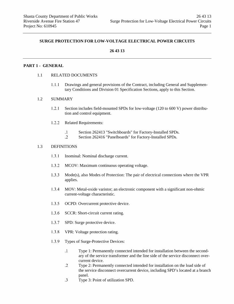
Shasta County Department of Public Works 26 43 13 Riverside Avenue Fire Station 47 Surge Protection for Low-Voltage Electrical Power Circuits Project No: 610945 Page 1
SURGE PROTECTION FOR LOW-VOLTAGE ELECTRICAL POWER CIRCUITS
26 43 13
PART 1 - GENERAL
1.1 RELATED DOCUMENTS
Drawings and general provisions of the Contract, including General and Supplemen-tary Conditions and Division 01 Specification Sections, apply to this Section.
1.2 SUMMARY
Section includes field-mounted SPDs for low-voltage (120 to 600 V) power distribu-tion and control equipment.
Related Requirements:
Section 262413 "Switchboards" for Factory-Installed SPDs. Section 262416 "Panelboards" for Factory-Installed SPDs.
1.3 DEFINITIONS
Inominal: Nominal discharge current.
MCOV: Maximum continuous operating voltage.
Mode(s), also Modes of Protection: The pair of electrical connections where the VPR applies.
MOV: Metal-oxide varistor; an electronic component with a significant non-ohmic current-voltage characteristic.
OCPD: Overcurrent protective device.
SCCR: Short-circuit current rating.
SPD: Surge protective device.
VPR: Voltage protection rating.
Types of Surge-Protective Devices:
Type 1: Permanently connected intended for installation between the second-ary of the service transformer and the line side of the service disconnect over-current device.
Type 2: Permanently connected intended for installation on the load side of the service disconnect overcurrent device, including SPD’s located at a branch panel.
Type 3: Point of utilization SPD.

Shasta County Department of Public Works 26 43 13 Riverside Avenue Fire Station 47 Surge Protection for Low-Voltage Electrical Power Circuits Project No: 610945 Page 2
1.4 ACTION SUBMITTALS
Product Data: For each type of product.
Include rated capacities, operating characteristics, electrical characteristics, and furnished specialties and accessories.
1.5 CLOSEOUT SUBMITTALS
Maintenance Data: For SPDs to include in maintenance manuals.
PART 2 - PRODUCTS
2.1 GENERAL SPD REQUIREMENTS
SPD with Accessories: Listed and marked as defined in CEC Article 285.
Comply with CEC.
Comply with UL 1449.
MCOV of the SPD shall be the nominal system voltage.
2.2 SERVICE ENTRANCE SUPPRESSOR
SPDs: Comply with UL 1449, Type 2.
SPDs with the following features and accessories:
Integral disconnect switch. Internal thermal protection that disconnects the SPD before damaging
internal suppressor components. Indicator light display for protection status. Surge counter.
Comply with UL 1283.
Peak Surge Current Rating: The minimum single-pulse surge current withstand rating per phase shall not be less than 200 kA. The peak surge current rating shall be the arithmetic sum of the ratings of the individual MOVs in a given mode.
Protection modes and UL 1449 VPR for grounded wye circuits with 208Y/120 V, three-phase, four-wire circuits shall not exceed the following:
Line to Neutral: 700 V for 208Y/120 V. Line to Ground: 1200 V for 208Y/120 V. Line to Line: 1000 V for 208Y/120 V.
SCCR: Equal or exceed 100 kA.
Inominal Rating: 20 kA.

Shasta County Department of Public Works 26 43 13 Riverside Avenue Fire Station 47 Surge Protection for Low-Voltage Electrical Power Circuits Project No: 610945 Page 3
2.3 PANEL SUPPRESSORS
SPDs: Comply with UL 1449, Type 2.
Include LED indicator lights for power and protection status. Internal thermal protection that disconnects the SPD before damaging internal
suppressor components.
Peak Surge Current Rating: The minimum single-pulse surge current withstand rating per phase shall not be less than 100 kA. The peak surge current rating shall be the arithmetic sum of the ratings of the individual MOVs in a given mode.
Comply with UL 1283.
Protection modes and UL 1449 VPR for grounded wye circuits with 208Y/120 V, three-phase, four-wire circuits shall not exceed the following:
Line to Neutral: 700 V for 208Y/120 V. Line to Ground: 700 V for 208Y/120 V. Neutral to Ground: 700 V for 208Y/120 V. Line to Line: 1200 V for 208Y/120 V
SCCR: Equal or exceed 100 kA.
Inominal Rating: 10 kA.
PART 3 - EXECUTION
3.1 INSTALLATION
Comply with NECA 1.
Install in accordance with CEC Article 285 and manufacturer’s instructions.
Install an OCPD or disconnect as required to comply with the UL listing of the SPD.
END OF SECTION 26 43 13

Shasta County Department of Public Works 26 51 00 Riverside Avenue Fire Station 47 Interior Lighting Project No: 610945 Page 1
INTERIOR LIGHTING
26 51 00
PART 1 - GENERAL
1.1 SUMMARY
Section Includes:
Emergency lighting units. Exit signs. Lighting fixture supports.
1.2 DEFINITIONS
CCT: Correlated color temperature.
CRI: Color-rendering index.
Lumen: Measured output of lamp and luminaire, or both.
Luminaire: Complete lighting fixture, including ballast housing if provided.
1.3 ACTION SUBMITTALS
Product Data: For each type of product.
1.4 CLOSEOUT SUBMITTALS
Operation and Maintenance Data: For lighting equipment and fixtures to include in emergency, operation, and maintenance manuals.
1.5 COORDINATION
Coordinate layout and installation of lighting fixtures and suspension system with oth-er construction that penetrates ceilings or is supported by them, including HVAC equipment, fire-suppression system, and partition assemblies.
PART 2 - PRODUCTS
2.1 MANUFACTURERS
Products: Subject to compliance with requirements, available products that may be in-corporated into the Work include, but are not limited to, product(s) indicated on Drawings.

Shasta County Department of Public Works 26 51 00 Riverside Avenue Fire Station 47 Interior Lighting Project No: 610945 Page 2
2.2 GENERAL REQUIREMENTS FOR LIGHTING FIXTURES AND COMPONENTS
Recessed Fixtures: Comply with NEMA LE 4 for ceiling compatibility for recessed fixtures.
Metal Parts: Free of burrs and sharp corners and edges.
Sheet Metal Components: Steel unless otherwise indicated. Form and support to pre-vent warping and sagging.
Factory-Applied Labels: Comply with UL 1598. Include recommended lamps and bal-lasts. Labels shall be located where they will be readily visible to service personnel, but not seen from normal viewing angles when lamps are in place.
Fixtures containing integral emergency battery backup components.
Compliances:
NFPA 101 (Life Safety Code). CEC ( National Electrical Code) CEC-400-2014-009-CMF (CEC Bat-
tery Charger Efficiency Standard). The emergency power system shall provide power for a duration of
not less than 90 minutes and shall consist of storage batteries, unit equipment or an on-site generator (CBC 1008.3.4).
2.3 EMERGENCY LIGHTING UNITS
General Requirements for Emergency Lighting Units: Self-contained units complying with UL 924.
Battery: Sealed, maintenance-free, lead-acid type. Charger: Fully automatic, solid-state type with sealed transfer relay. Operation: Relay automatically turns lamp on when power-supply circuit
voltage drops to 80 percent of nominal voltage or below. Lamp automatically disconnects from battery when voltage approaches deep-discharge level. When normal voltage is restored, relay disconnects lamps from battery, and battery is automatically recharged and floated on charger.
Test Push Button: Push-to-test type, in unit housing, simulates loss of normal power and demonstrates unit operability.
LED Indicator Light: Indicates normal power on. Normal glow indicates trickle charge; bright glow indicates charging at end of discharge cycle.
Wire Guard: Heavy-chrome-plated wire guard protects lamp heads or fixtures. Remote Test: Switch in hand-held remote device aimed in direction of tested
unit initiates coded infrared signal. Signal reception by factory-installed infra-red receiver in tested unit triggers simulation of loss of its normal power sup-ply, providing visual confirmation of either proper or failed emergency re-sponse.
Integral Self-Test: Factory-installed electronic device automatically initiates code-required test of unit emergency operation at required intervals. Test fail-ure is annunciated by an integral audible alarm and a flashing red LED.
CEC Title 20 Compliant.

Shasta County Department of Public Works 26 51 00 Riverside Avenue Fire Station 47 Interior Lighting Project No: 610945 Page 3
2.4 LIGHTING FIXTURE SUPPORT COMPONENTS
Single-Stem Hangers: 1/2-inch steel tubing with swivel ball fittings and ceiling cano-py. Finish same as fixture.
Twin-Stem Hangers: Two, 1/2-inch steel tubes with single canopy designed to mount a single fixture. Finish same as fixture.
Wires: ASTM A 641/A 641M, Class 3, soft temper, zinc-coated steel, 12 gauge.
Wires for Humid Spaces: ASTM A 580/A 580M, Composition 302 or 304, annealed stainless steel, 12 gauge.
Rod Hangers: 3/16-inch minimum diameter, cadmium-plated, threaded steel rod.
Hook Hangers: Integrated assembly matched to fixture and line voltage and equipped with threaded attachment, cord, and locking-type plug.
PART 3 - EXECUTION
3.1 INSTALLATION
Comply with CEC Article 402.
Lighting fixtures:
Set level, plumb, and square with ceilings and walls unless otherwise indicat-ed.
Lighting for closet storage spaces shall comply with CEC 410.2 and 410.16. For luminaires installed in or under roof decking, comply with CEC
410.10(F). Luminaires installed in suspended ceilings shall comply with CEC 410.36. Ceiling mounted luminaires installed flush or recessed shall comply with CEC
Article 410, Part X.
Temporary Lighting: If it is necessary, and approved by Architect, to use permanent luminaires for temporary lighting, install and energize the minimum number of lumi-naires necessary. When construction is sufficiently complete, remove the temporary luminaires, disassemble, clean thoroughly, install new lamps, and reinstall.
Remote Mounting of Ballasts or Drivers: Distance between the ballast/driver and fix-ture shall not exceed that recommended by ballast/driver manufacturer. Verify, with ballast/driver manufacturers, maximum distance between ballast/driver and luminaire.
Lay-in Ceiling Lighting Fixtures Supports: Do not use grid as a support element.
Install ceiling support system rods or wires, independent of the ceiling sus-pension devices, for each fixture. Locate not more than 6 inches from lighting fixture corners.
Support Clips: Fasten to lighting fixtures and to ceiling grid members at or near each fixture corner with clips that are UL listed for the application.

Shasta County Department of Public Works 26 51 00 Riverside Avenue Fire Station 47 Interior Lighting Project No: 610945 Page 4
Fixtures of Sizes Less Than Ceiling Grid: Install as indicated on reflected ceiling plans or center in acoustical panel, and support fixtures independently with at least two 3/4-inch metal channels spanning and secured to ceiling tees.
Install at least one independent support rod or wire from structure to a tab on lighting fixture. Wire or rod shall have breaking strength of the weight of fix-ture at a Safety Factor of 3.
Suspended Lighting Fixture Support:
Pendants and Rods: Where longer than 48 inches, brace to limit swinging. Stem-Mounted, Single-Unit Fixtures: Suspend with twin-stem hangers. Continuous Rows: Use tubing or stem for wiring at one point and tubing or
rod for suspension for each unit length of fixture chassis, including one at each end.
Do not use grid as support for pendant luminaires. Connect support wires or rods to building structure.
END OF SECTION 26 51 00

Shasta County Department of Public Works 26 56 00 Riverside Avenue Fire Station 47 Exterior Lighting Project No: 610945 Page 1
EXTERIOR LIGHTING
26 56 00
PART 1 - GENERAL
1.1 RELATED DOCUMENTS
Drawings and general provisions of the Contract, including General and Supplementary Conditions and Division 01 Specification Sections, apply to this Section.
1.2 SUMMARY
Section Includes:
Exterior luminaires. Luminaire-mounted photoelectric relays. Poles and accessories.
1.3 DEFINITIONS
CCT: Correlated color temperature.
CRI: Color-rendering index.
Luminaire: Complete lighting fixture, including ballast housing if provided.
Pole: Luminaire support structure, including tower used for large area illumination.
Standard: Same definition as "Pole" above.
1.4 ACTION SUBMITTALS
Product Data: For each type of product.
1.5 CLOSEOUT SUBMITTALS
Operation and Maintenance Data: For luminaires to include in emergency, operation, and maintenance manuals.
PART 2 - PRODUCTS
2.1 MANUFACTURERS
Products: Subject to compliance with requirements, available products that may be in-corporated into the Work include, but are not limited to, product(s) indicated on Draw-ings.

Shasta County Department of Public Works 26 56 00 Riverside Avenue Fire Station 47 Exterior Lighting Project No: 610945 Page 2
2.2 GENERAL REQUIREMENTS FOR LUMINAIRES
Luminaires shall comply with UL 1598 and be listed and labeled for installation in wet locations by an NRTL acceptable to authorities having jurisdiction.
Metal Parts: Free of burrs and sharp corners and edges.
Sheet Metal Components: Corrosion-resistant aluminum unless otherwise indicated. Form and support to prevent warping and sagging.
Housings: Rigidly formed, weather- and light-tight enclosures that will not warp, sag, or deform in use. Provide filter/breather for enclosed luminaires.
Luminaire Finish: Manufacturer's standard paint applied to factory-assembled and -tested luminaire before shipping. Where indicated, match finish process and color of pole or support materials.
2.3 STEEL POLES
Shape: Square, straight.
Intermediate Handhole and Cable Support: Weathertight, 3x5 inch handhole located at midpoint of pole with cover for access to internal welded attachment lug for electric ca-ble support grip.
Grounding and Bonding Lugs: Welded 1/2" inch threaded lug, and accessible through handhole.
Prime-Coat Finish: Manufacturer's standard prime-coat finish ready for field painting.
PART 3 - EXECUTION
3.1 LUMINAIRE INSTALLATION
Comply with CEC Article 402.
Fasten luminaire to indicated structural supports.
Use fastening methods and materials selected to resist seismic forces defined for the application and approved by manufacturer.
3.2 POLE INSTALLATION
Clearances: Maintain the following minimum horizontal distances of poles from surface and underground features unless otherwise indicated on Drawings:
Fire Hydrants and Storm Drainage Piping: 60 inches. Water, Gas, Electric, Communication, and Sewer Lines: 10 feet.
Concrete Pole Foundations: Set anchor bolts according to anchor-bolt templates fur-nished by pole manufacturer.

Shasta County Department of Public Works 26 56 00 Riverside Avenue Fire Station 47 Exterior Lighting Project No: 610945 Page 3
In areas where pole are subject to severe damage, pole foundation shall be set at 3 feet above finished grade.
1.1 FIELD QUALITY CONTROL
Inspect each installed fixture for damage. Replace damaged fixtures and components.
Illumination Observations: Verify normal operation of lighting units after installing lu-minaires and energizing circuits with normal power source.
Verify operation of photoelectric controls.
PART 1 - END OF SECTION 26 56 00

Shasta County Department of Public Works 28 46 21.11 Riverside Avenue Fire Station 47 Addressable Fire Alarm Systems Project No: 610945 Page 1
ADDRESSABLE FIRE ALARM SYSTEMS
28 46 21.11
PART 1 - GENERAL
1.1 RELATED DOCUMENTS
Penetrations by free air cabling shall employ a smoke and acoustical pathway or a fire rated pathway. Reference Specification Section 078413.28, “PENETRATION FIRESTOPPING (FIRE ALARM).
1.2 SUMMARY
Section Includes:
Fire alarm control unit. Manual fire alarm boxes. System smoke detectors. Carbon monoxide detectors. Notification appliances. Device guards. Magnetic door holders. Remote annunciator. Graphic annunciator. Addressable interface device. Digital alarm communicator transmitter.
1.3 DEFINITIONS
EMT: Electrical Metallic Tubing.
FACP: Fire Alarm Control Panel.
HLI: High Level Interface.
NICET: National Institute for Certification in Engineering Technologies.
1.4 ACTION SUBMITTALS
The fire alarm system shall be function in full compliance with 2019 California Fire Code for Group V-B, R-1 AND S-1 occupancies. All components shall be furnished for the fire alarm system which enables system-wide intercommunication between fire alarm equipment, voice annunciation selectable by zones, and selectable zones/digital microphone capability which shall be installed at the Fire Alarm Annunciator. The con-tractor shall provide and install all components recommended by the manufacturer not shown on the drawings for complete system installation (digital voice cards, cabinet brackets, etc.). No allowances shall be made for missed components that would normally be required by the manufacturer to produce a fully functional system.

Shasta County Department of Public Works 28 46 21.11 Riverside Avenue Fire Station 47 Addressable Fire Alarm Systems Project No: 610945 Page 2
Product Data: For each type of product, include furnished options and accesso-ries.
Include construction details, material descriptions, dimensions, profiles, and finishes.
Include rated capacities, operating characteristics, and electrical charac-teristics.
General Submittal Requirements:
Submittals shall be approved by authorities having jurisdiction prior to submit-ting them to Architect.
Shop Drawings shall be prepared by persons with the following qualifications:
Trained and certified by manufacturer in fire alarm system design. Licensed or certified by authorities having jurisdiction.
1.5 CLOSEOUT SUBMITTALS
Operation and Maintenance Data: For fire alarm systems and components to include in emergency, operation, and maintenance manuals.
Comply with the "Records" section of the "Inspection, Testing and Maintenance" chapter in NFPA 72.
Provide "Fire Alarm and Emergency Communications System Record of Completion Documents" according to the "Completion Documents" Article in the "Documentation" section of the "Fundamentals" chapter in NFPA 72.
Complete wiring diagrams showing connections between all devices and equipment. Each conductor shall be numbered at every junction point with indication of origination and termination points.
Riser diagram. Device addresses. Air-sampling system sample port locations and modeling program re-
port showing layout meets performance criteria. Record copy of site-specific software. Provide "Inspection and Testing Form" according to the "Inspection,
Testing and Maintenance" chapter in NFPA 72, and include the follow-ing:
1. Equipment tested. 2. Frequency of testing of installed components. 3. Frequency of inspection of installed components. 4. Requirements and recommendations related to results of
maintenance. 5. Manufacturer's user training manuals.
Manufacturer's required maintenance related to system warranty re-quirements.
Abbreviated operating instructions for mounting at fire alarm control unit and each annunciator unit.

Shasta County Department of Public Works 28 46 21.11 Riverside Avenue Fire Station 47 Addressable Fire Alarm Systems Project No: 610945 Page 3
Software and Firmware Operational Documentation:
Software operating and upgrade manuals. Program Software Backup: On magnetic media or compact disk, complete with
data files. Device address list. Printout of software application and graphic screens.
PART 2 - PRODUCTS
2.1 SYSTEM DESCRIPTION
Source Limitations for Fire Alarm System and Components: Components shall be com-patible with, and operate as an extension of, existing system.
Noncoded, UL-certified addressable system, with multiplexed signal transmission andhorn/strobe evacuation.
All components provided shall be listed for use with the selected system.
Electrical Components, Devices, and Accessories: Listed and labeled as defined in NFPA 70, by a qualified testing agency, and marked for intended location and applica-tion.
2.2 SYSTEMS OPERATIONAL DESCRIPTION
Fire alarm signal initiation shall be by one or more of the following devices and systems:
Manual stations. Heat detectors. Smoke detectors. Duct smoke detectors. Carbon monoxide detectors. Automatic sprinkler system water flow.
2.3 DIGITAL ALARM COMMUNICATOR TRANSMITTER
Digital alarm communicator transmitter shall be acceptable to the remote central station and shall comply with UL 632.
Local functions and display at the digital alarm communicator transmitter shall include the following:
Programming device. LED display. Manual test report function and manual transmission clear indication. Communications failure with the central station or fire alarm control unit.
Digital data transmission shall include the following:
Address of the alarm-initiating device.

Shasta County Department of Public Works 28 46 21.11 Riverside Avenue Fire Station 47 Addressable Fire Alarm Systems Project No: 610945 Page 4
Address of the supervisory signal. Address of the trouble-initiating device. Loss of ac supply. Loss of power. Low battery. Abnormal test signal. Communication bus failure.
Secondary Power: Integral rechargeable battery and automatic charger.
Self-Test: Conducted automatically every 24 hours with report transmitted to central sta-tion.
PART 3 - EXECUTION
3.1 EXAMINATION
Examine areas and conditions for compliance with requirements for ventilation, temper-ature, humidity, and other conditions affecting performance of the Work.
Verify that manufacturer's written instructions for environmental conditions have been permanently established in spaces where equipment and wiring are installed, before installation begins.
Examine roughing-in for electrical connections to verify actual locations of connections before installation.
Proceed with installation only after unsatisfactory conditions have been corrected.
3.2 EQUIPMENT INSTALLATION
Comply with NFPA 72, NFPA 101, and requirements of authorities having jurisdiction for installation and testing of fire alarm equipment. Install all electrical wiring to comply with requirements in NFPA 70 including, but not limited to, Article 760, "Fire Alarm Systems."
Devices placed in service before all other trades have completed cleanup shall be replaced.
Devices installed but not yet placed in service shall be protected from construc-tion dust, debris, dirt, moisture, and damage according to manufacturer's written storage instructions.
Install a cover on each smoke detector that is not placed in service during construction. Cover shall remain in place except during system testing. Remove cover prior to system turnover.
Duct Smoke Detectors: Comply with NFPA 72 and NFPA 90A. Install sampling tubes so they extend the full width of duct. Tubes more than 36 inches (9100 mm) long shall be supported at both ends.

Shasta County Department of Public Works 28 46 21.11 Riverside Avenue Fire Station 47 Addressable Fire Alarm Systems Project No: 610945 Page 5
Do not install smoke detector in duct smoke-detector housing during construc-tion. Install detector only during system testing and prior to system turnover.
Air-Sampling Smoke Detectors: If using multiple pipe runs, the runs shall be pneumati-cally balanced.
Branch and Fire Alarm Circuits:
General:
Specification Section 284621.11, “Addressable Fire Alarm Systems” supersedes Specification Section 260519, “Low Voltage Electrical Pow-er and Conductors and Cables” for Branch Circuits only. Comply with all other applicable standards listed in Division 26 specifications.
The use of metal-clad cable is prohibited.
Branch Circuits:
Exposed Branch Circuits not readily visible without removal of an ac-cess panel: Type THHN/THWN-2, single conductors in raceway.
Exposed Branch Circuits readily visible: Type THHN/THWN-2, single conductors in raceway.
Branch Circuits Concealed in Ceilings, Walls, and Partitions: Type THHN/THWN-2, single conductors in raceway.
Branch Circuits Concealed in Concrete, below Slabs-on-Grade, and Un-derground: Type THHN/THWN-2, single conductors in raceway.
Fire Alarm Circuits:
Exposed Fire Alarm Circuits not readily visible without removal of an access panel: fire alarm conductors without raceway.
Exposed Fire Alarm Circuits readily visible: Fire Alarm conductors in raceway.
Fire Alarm Circuits Concealed in Ceilings, Walls, and Partitions: Fire Alarm conductors in raceway
Fire Alarm Circuits Concealed in Concrete, below Slabs-on-Grade, and Underground: Type THHN/THWN-2, single conductors in raceway.
3.3 IDENTIFICATION
Install framed instructions in a location visible from fire alarm control unit.
3.4 GROUNDING
Ground fire alarm control unit and associated circuits; comply with IEEE 1100. Install a ground wire from main service ground to fire alarm control unit.
Ground shielded cables at the control panel location only. Insulate shield at device loca-tion.

Shasta County Department of Public Works 28 46 21.11 Riverside Avenue Fire Station 47 Addressable Fire Alarm Systems Project No: 610945 Page 6
3.5 FIELD QUALITY CONTROL
Field tests shall be witnessed by authorities having jurisdiction.
Manufacturer's Field Service: Engage a factory-authorized service representative to test and inspect components, assemblies, and equipment installations, including connections.
Perform tests and inspections in accordance with this specification section and NFPA 72 Chapters 7 & 14.
Visual Inspection: Conduct visual inspection prior to testing.
Inspection shall be based on completed record Drawings and system documentation that is required by the "Completion Documents, Prepara-tion" table in the "Documentation" section of the "Fundamentals" chap-ter in NFPA 72.
Comply with the "Visual Inspection Frequencies" table in the "Inspec-tion" section of the "Inspection, Testing and Maintenance" chapter in NFPA 72; retain the "Initial/Reacceptance" column and list only the in-stalled components.
System Testing: Comply with the "Test Methods" table in the "Testing" section of the "Inspection, Testing and Maintenance" chapter in NFPA 72.
Test audible appliances for the public operating mode according to manufactur-er's written instructions. Perform the test using a portable sound-level meter complying with Type 2 requirements in ANSI S1.4.
Test audible appliances for the private operating mode according to manufactur-er's written instructions.
Test visible appliances for the public operating mode according to manufactur-er's written instructions.
Factory-authorized service representative shall prepare the "Fire Alarm System Record of Completion" in the "Documentation" section of the "Fundamentals" chapter in NFPA 72 and the "Inspection and Testing Form" in the "Records" section of the "Inspection, Testing and Maintenance" chapter in NFPA 72.
Reacceptance Testing: Perform reacceptance testing to verify the proper operation of added or replaced devices and appliances.
Fire alarm system will be considered defective if it does not pass tests and inspections.
Prepare test and inspection reports.
3.6 DEMONSTRATION
Train Owner's maintenance personnel to adjust, operate, and maintain fire alarm system.
END OF SECTION 28 46 21.11

Shasta County Department of Public Works 31 11 00 Riverside Avenue Fire Station 47 Clearing and Grubbing Project No: 610945 Page 1
CLEARING AND GRUBBING
SECTION 31 11 00
PART 1 - GENERAL
1.1 DESCRIPTION
This work shall consist of removing objectionable material from within the right of way, construction areas, road approaches, material sites within the right of way, areas through which ditches and channels are to be excavated, and other areas as may be shown on the plans and specified in these special provisions. Clearing and grubbing shall be performed in advance of grading operations and in accordance with the requirements specified in these specifications.
1.2 PROTECTION OF PROPERTY
Trees and plants which are not to be removed shall be protected from injury or damage. Only trees and plants that are designated or marked for removal by the Engineer shall be removed.
PART 2 - PRODUCTS
2.1 NOT USED
PART 3 - EXECUTION
3.1 CLEARING AND GRUBBING
Vegetation shall be cleared and grubbed only within the excavation and embankment slope lines. No payment will be made to the Contractor for clearing and grubbing outside these limits, unless the work is authorized by the Engineer.
The area above the natural ground surfaces shall be cleared of all vegetation, such as trees, logs, upturned stumps, roots of down trees, brush, grass, weeds and other objectionable material including concrete or masonry, within the excavation and embankment limits.
Within the limits of clearing, the areas below the natural ground surface, except in embankment areas where the grading plane is 2 feet or more above the natural ground, shall be grubbed to a depth necessary to remove all stumps, roots, buried logs, and all other objectionable material. Objectionable material shall not be left in or under embankments or dikes.
All trees, existing stumps and roots within embankment areas where the grading plane is 2 feet or more above the natural ground shall be cut off not more than one foot above the natural ground at any point, or completely removed where a structure is to be constructed, trenches are to be excavated, unsuitable material is to be removed, or where the slopes of original hillsides, old or new fill, are cut into.

Shasta County Department of Public Works 31 11 00 Riverside Avenue Fire Station 47 Clearing and Grubbing Project No: 610945 Page 2
If shown on the plans or directed by the Engineer that certain shade and ornamental trees and plants shall be preserved, those trees and plants shall be fully protected from injury by the Contractor at the Contractor's expense. Trees shall be felled in such a manner as not to injure standing trees, plants, and improvements which are to be preserved.
Tree branches extending over the roadway and which hang within 20 feet of finished grade shall be cut off close to the trunks in accordance with recognized standards of good arboricultural practices. In connection with the removal of tree branches that extend over the new or widened roadway, the Contractor shall remove other tree branches under the direction of the Engineer, in such a manner that the tree will present a balanced appearance.
3.2 REMOVAL AND DISPOSAL OF MATERIAL
Cleared vegetation and brush shall not be burned onsite and shall be disposed of at an offsite location.
The job site, roadway, and adjacent areas shall be left with a neat and finished appearance. No accumulation of flammable material shall remain on or adjacent to the work areas.
END OF SECTION 31 11 00

Shasta County Department of Public Works 31 20 01 Riverside Avenue Fire Station 47 General Earthwork Project No: 610945 Page 1
GENERAL EARTHWORK
SECTION 31 20 01
PART 1 - PART 1 - GENERAL
1.1 DESCRIPTION
This Section covers construction of excavations, embankments, shoring, dewatering, subgrade preparation, grading and compaction of backfill materials, and all other associated work involved in excavations, embankments, and engineered earthwork.
Refer to Section 32 12 16, “Hot Mixed Asphalt Pavement and Overlays” for specifications and additional requirements for hot mix asphalt material. Note: Trench excavation, backfill, compaction, and all other associated work involved in trench excavations is not covered in this section. Refer to Section 31 23 33, “Trench Excavation and Backfill” for information and additional requirements for this type of work.
1.2 QUALITY ASSURANCE
All earthwork must be performed in accordance with these special provisions and the requirements of the project Geotechnical Report and to the satisfaction of the Engineer and his consultant Geotechnical Engineer. In case of discrepancy between the Geotechnical Report and these special provisions, the Geotechnical Report shall take precedence unless otherwise approved by the Engineer and his Geotechnical Engineer.
1.3 SUBMITTALS
Submittals shall include, but not be limited to, the following items:
Gradation results for all aggregate material being used on the project. Load slips for all material delivery trucks shall be delivered to the job site
with the truck. The Contractor shall retain all load slips, and shall make them available to the Engineer upon request.
Excavation shoring and bracing plan.
1.4 UNDERGROUND UTILITY MARKINGS
Utilities on the Plans may be shown incorrectly or not at all. The Contractor shall contact Underground Service Alert (USA) at 811 at least forty-eight (48) hours, but not less than two (2) working days, prior to any demolition or excavation and request field markings of all underground utilities.

Shasta County Department of Public Works 31 20 01 Riverside Avenue Fire Station 47 General Earthwork Project No: 610945 Page 2
PART 2 - PRODUCTS
2.1 GENERAL
Material specifications listed on the Plans, where applicable, shall supercede those listed in this Section.
2.2 NATIVE BACKFILL
Native backfill shall consist of material excavated (native subsoil) during the course of the project, and shall be free of organics, debris, oversized particles (>3”), and other deleterious material. If highly plastic clayey materials (PI>30 and LL>50) are encountered, those materials should be excluded from embankment construction. Excavated gravel and aggregate base materials free of debris, organics, and deleterious materials are also acceptable for use as native backfill.
2.3 NATIVE TOPSOIL
Native topsoil shall consist of material excavated from the upper soil layer (from the surface to a depth of approximately six inches) during the course of the project. Native topsoil shall be stockpiled separately from native subsoil.
2.4 NATIVE SUBSOIL
Native subsoil shall consist of material excavated below the native topsoil (below a depth of approximately six inches). Native subsoil shall be stockpiled separately from native topsoil.
2.5 IMPORTED BACKFILL
Imported backfill shall closely match the composition of the material that was removed from the excavation, shall be free of organic and other deleterious material, shall be less than three inches (3”) in maximum dimension, and must comply with the recommendations included in the Geotechnical Report.
2.6 IMPORTED TOPSOIL
Imported topsoil shall be sandy loam, shall be friable, shall have a high degree of fertility, and shall be free of weeds, clods, roots, rocks, gravel, sticks, brush, and other deleterious material. An imported topsoil analysis shall be submitted to the Engineer for approval prior to delivery of any imported topsoil to the project site. Should the Engineer reject any portion of the delivered soil for any reason, it shall be removed immediately at no cost to the County. The Contractor shall be responsible for maintaining all placed topsoil until the project has been accepted.
2.7 STRUCTURE BACKFILL
Structure backfill shall conform to Section 19-3.02C of the 2015 Caltrans Standard Specifications (CSS).

Shasta County Department of Public Works 31 20 01 Riverside Avenue Fire Station 47 General Earthwork Project No: 610945 Page 3
2.8 SLURRY CEMENT BACKFILL
Slurry cement backfill shall conform to Section 19-3.02E of the 2015 Caltrans Standard Specifications (CSS).
2.9 PERVIOUS BACKFILL MATERIAL
Pervious backfill material shall conform to Section 19-3.02, “Pervious Backfill Material” of the 2015 Caltrans Standard Specifications (CSS).
2.10 ENGINEERING FABRICS
Fabrics used for filtering and rock slope protection applications shall conform to Section 96, “Geosynthetics” of the 2015 Caltrans Standard Specifications (CSS).
PART 3 - EXECUTION
3.1 STORAGE OF MATERIALS
It shall be the sole responsibility of the Contractor to store all earthwork material in a safe location out of the traveled way.
3.2 SHORING, SHEETING AND BRACING
All excavations requiring shoring, sheeting, or bracing shall conform to the requirements of the California Occupational Safety and Health Act (CAL-OSHA). The Contractor shall furnish and install all shoring and bracing required to support the excavation walls for the protection of all personnel working in the excavation. Shoring and bracing shall be removed in a manner that protects the workers, prevents sloughing of the excavation walls, and prevents damage to aboveground property and underground utilities.
3.3 PAVEMENT REMOVAL
3Before removing existing pavement, make a vertical saw cut to full depth along the limits of the removal area.
3.4 TOPSOIL REMOVAL, STOCKPILING, AND STORAGE
Prior to beginning any excavation or embankment, the Contractor shall remove the topsoil and stockpile it for future use (if applicable). Stockpiled topsoil shall be stored clear of the construction area. The Contractor shall take reasonable care to prevent the topsoil from becoming mixed with subsoil.
3.5 GENERAL EXCAVATION
The Contractor shall perform all excavation work required to accomplish the construction, regardless of the type, nature, or condition of material encountered. The method of excavation used is optional; however, no equipment shall be operated near existing structures or newly completed construction if such operation will endanger these structures. Excavation that cannot be accomplished using power equipment

Shasta County Department of Public Works 31 20 01 Riverside Avenue Fire Station 47 General Earthwork Project No: 610945 Page 4
without endangering these structures, or those within 24” of marked underground utilities, shall be dug with hand tools.
The Contractor shall complete all excavations to the elevations, lines, and grades shown on the Plans. Allowances shall be made within the excavation for shoring, forms, working space, bedding, and backfill. Overexcavation beyond the grade lines shown on the Plans shall be backfilled and compacted at the Contractor’s sole expense with embankment, unless otherwise directed by the Engineer (including overexcavation required to remove existing utilities shown on the Plans as to be removed). Overexcavation required due to unsuitable subgrade soils shall be covered under Section 3.08 below.
The Contractor shall control excavations through careful backfill and shoring placement that prevents excavation wall sloughing, and shall remove all material that sloughs into the excavation. In addition, all voids or cavities that result from sloughing excavation walls shall be backfilled and compacted with the same material at the same compaction/vibration requirements as shown on the excavation detail for that excavation. If, in the opinion of the Engineer, additional asphalt, concrete, or other surface material must be removed to adequately compact or vibrate the backfill placed in these voids or cavities, the Contractor shall sawcut and remove the surface material to the limits of the voids or cavities as directed by the Engineer. All costs associated with the removal of material that has sloughed into the trench, placement and compaction of the additional backfill material, and the sawcutting, removal, and patching of additional surface material shall be the sole responsibility of the Contractor, and no additional payment will be made to the Contractor for this work.
3.6 EXCAVATION DEWATERING
The Contractor shall provide and install sufficient means and facilities to divert, remove, and properly dispose of all water in the area of the excavation from any source, and shall maintain all work areas and excavations in a clean, dry, and safe condition.
The Contractor shall dewater all excavations to keep groundwater out of the excavation. Water shall not be allowed in excavations during concrete pours, or during placement and compaction of embankment and structure backfill. Dewatering shall be accomplished by methods that will ensure a water-free excavation, that will preserve the design lines and grades of the bottom of the excavations,that will maintain the groundwater level at least one (1) foot below the excavation design grade, that will prevent the loss of fines from the bottom of the excavation. Dewatering shall be a continuous 24-hours-a-day, 7-days-a-week operation until the excavation is completely backfilled.
The Contractor shall have pumps on hand of sufficient capacity and horsepower to pump all ground water and residual drainage or sewage from excavations to a downstream bypass point. Refer to the approved SWPPP for treatment of discharge from dewatering pumps.

Shasta County Department of Public Works 31 20 01 Riverside Avenue Fire Station 47 General Earthwork Project No: 610945 Page 5
3.7 OVEREXCAVATION
Prior to construction of embankments, roadway structural sections, and structure foundations, overexcavate portions of the site down to competent natural soils as specified in the Geotechnical Report and as directed by the Engineer.
Backfill resultant holes with embankment and compact the embankment as specified in Section 3.12.
3.8 UNSUITABLE SUBGRADE EXCAVATION AND BACKFILL
Unsuitable subgrade is native material at subgrade that, in the opinion of the Engineer, is unsuitable to use as a subgrade layer and must be removed to provide a solid construction surface. Examples of this type of subgrade are plant material, logs, trash, wood chips and debris, mud, soft or spongy soil, and the like. It DOES NOT refer to material that sloughs into the excavation from the sidewalls due to insufficient shoring and must be dug out and it DOES NOT refer to native material encountered over optimum moisture content. If the Engineer determines that unsuitable material is encountered at the bottom of the excavation, the Engineer shall direct the Contractor as to the total volume of unsuitable material to be removed from the excavation.
Once the unsuitable material has been excavated to the satisfaction of the Engineer, the Contractor shall backfill the overexcavation to the elevations, lines, and grades shown with embankment and compact the embankment as specified in Section 3.12. The Engineer may direct the Contractor to furnish and place geotextile fabric below the embankment materials in accordance with the 2015 Caltrans Standard Specifications (CSS) Section 96-1.02O. Furnishing and placing geotextile fabric is considered extra work.
3.9 SEDIMENT CONTROL
All earthwork activities and construction of drainage facilities involving water diversions and excavation dewatering shall comply with Section 01 57 23, “Temporary Storm Water Pollution Control” of these specifications.
3.10 SUBGRADE PREPARATION
Prior to placement and compaction of embankment and road structural sections, the upper 8 inches of native soils beneath embankments and road structural sections shall be scarified, moisture conditioned to near optimum moisture content and compacted to a minimum of 90% relative compaction determined from ASTM D1557. If the subgrade is within 2.5 feet below finished grade of a roadway, parking lot, or building pad, compact the subgrade to a minimum of 95% relative compaction.
3.11 TRENCH EXCAVATION AND BACKFILL
Trench excavation and backfill must comply with Section 31 23 33, “Trench Excavation and Backfill”.
3.12 EMBANKMENT CONSTRUCTION
Embankment shall consist of native backfill or imported backfill.

Shasta County Department of Public Works 31 20 01 Riverside Avenue Fire Station 47 General Earthwork Project No: 610945 Page 6
Prior to placement and compaction of embankment and roadway/parking lot structural sections, prepare subgrade as specified in Section 3.10 above.
Unless otherwise directed, all embankments shall be placed and compacted before any required excavation for installation of structures is performed in embankment areas. For pipelines to be installed in embankments, embankment shall be placed and compacted to a minimum of two feet above the top of the pipe before the pipe trench excavation will be allowed.
Rocks, broken concrete, or other solid materials, which are larger than three inches (3”) in greatest dimension, shall not be placed in embankment.
When embankment is to be made and compacted on hillsides, or where new embankment is to be compacted against existing embankments or where embankment is built one-half width at a time, the slopes of the original hillsides and old or new embankments shall be cut into a minimum of eight feet (8’) horizontally as the work is brought up in layers. Material thus cut out shall be recompacted along with the new embankment material at the Contractor’s expense.
Where embankment is to be made and compacted on original hillsides, old or new embankments, and end dumping is permitted, the slopes of the original ground or embankment shall be benched or cut into before starting end dumping.
When embankment is to be placed on an existing roadway, the existing roadbed shall be scarified, watered, graded and rolled in advance of placing new material thereon.
Clods or hard lumps of earth over six inches (6”) in greatest dimensions shall be broken up before compacting the material in embankment.
Embankments shall be constructed in layers of uniform thickness. The loose thickness of each layer of embankment material before compaction shall not exceed eight inches (8”).
Fill materials shall be mechanically compacted. Jetting is not allowed. Care shall be taken not to damage pipe, conduit, or other facilities with compacting equipment.
The Engineer shall perform compaction testing to determine whether or not the compaction efforts meet the minimum compaction requirements. Embankment that fails compaction tests shall be re-compacted as necessary to meet the minimum compaction requirements at the sole expense of the Contractor. Costs for retesting areas which fail to meet the required compaction will be borne by the Contractor.
Relative Compaction (95 Percent) - Relative compaction of not less than ninety-five percent (95%) shall be obtained for a minimum depth of eight inches (8”) below subgrade (bottom of roadway and parking lot structural section) for the width between the outer edges of shoulders, whether in excavation or embankment.
In addition, relative compaction of not less than ninety-five percent (95%) shall be obtained for a minimum depth of thirty inches (30”) below finished grade for roadways and parking lots (including shoulders), and building pads. Compaction of building pads must be approved by the Engineer prior to excavation of footings.
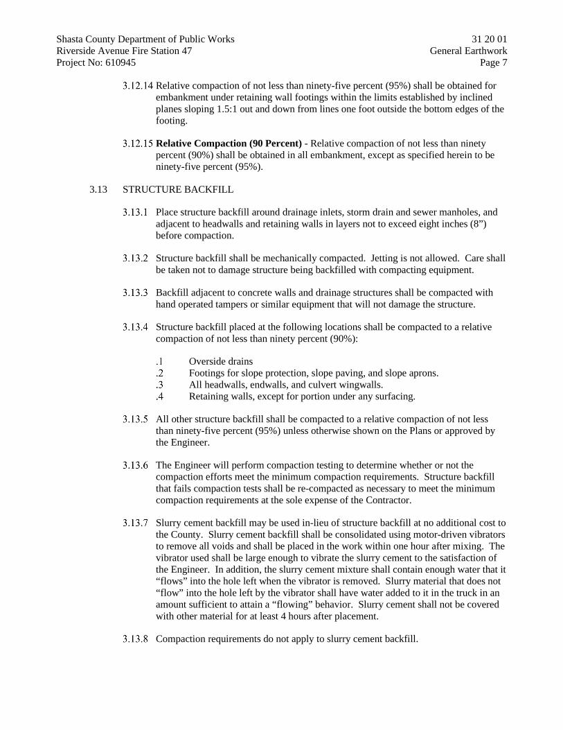
Shasta County Department of Public Works 31 20 01 Riverside Avenue Fire Station 47 General Earthwork Project No: 610945 Page 7
Relative compaction of not less than ninety-five percent (95%) shall be obtained for embankment under retaining wall footings within the limits established by inclined planes sloping 1.5:1 out and down from lines one foot outside the bottom edges of the footing.
Relative Compaction (90 Percent) - Relative compaction of not less than ninety percent (90%) shall be obtained in all embankment, except as specified herein to be ninety-five percent (95%).
3.13 STRUCTURE BACKFILL
Place structure backfill around drainage inlets, storm drain and sewer manholes, and adjacent to headwalls and retaining walls in layers not to exceed eight inches (8”) before compaction.
Structure backfill shall be mechanically compacted. Jetting is not allowed. Care shall be taken not to damage structure being backfilled with compacting equipment.
Backfill adjacent to concrete walls and drainage structures shall be compacted with hand operated tampers or similar equipment that will not damage the structure.
Structure backfill placed at the following locations shall be compacted to a relative compaction of not less than ninety percent (90%):
Overside drains Footings for slope protection, slope paving, and slope aprons. All headwalls, endwalls, and culvert wingwalls. Retaining walls, except for portion under any surfacing.
All other structure backfill shall be compacted to a relative compaction of not less than ninety-five percent (95%) unless otherwise shown on the Plans or approved by the Engineer.
The Engineer will perform compaction testing to determine whether or not the compaction efforts meet the minimum compaction requirements. Structure backfill that fails compaction tests shall be re-compacted as necessary to meet the minimum compaction requirements at the sole expense of the Contractor.
Slurry cement backfill may be used in-lieu of structure backfill at no additional cost to the County. Slurry cement backfill shall be consolidated using motor-driven vibrators to remove all voids and shall be placed in the work within one hour after mixing. The vibrator used shall be large enough to vibrate the slurry cement to the satisfaction of the Engineer. In addition, the slurry cement mixture shall contain enough water that it “flows” into the hole left when the vibrator is removed. Slurry material that does not “flow” into the hole left by the vibrator shall have water added to it in the truck in an amount sufficient to attain a “flowing” behavior. Slurry cement shall not be covered with other material for at least 4 hours after placement.
Compaction requirements do not apply to slurry cement backfill.

Shasta County Department of Public Works 31 20 01 Riverside Avenue Fire Station 47 General Earthwork Project No: 610945 Page 8
3.14 WORKMANSHIP GUARANTY
The Contractor shall guarantee his excavation work against settlement for a period of one year after the Notice of Completion has been filed. During this time, the Contractor shall repair, at his own expense and to the satisfaction of the Engineer, all failed excavation backfill and resurfacing. For the purpose of this contract, failure shall be deemed to have occurred if any of the following conditions exists:
On paved streets, a depression in a pavement patch of 1/8" (0.01') below the sides of the uncut portion of pavement.
Along shoulder areas, behind sidewalks, and in other unpaved portions of the right-of-way, a depression of 3/4" (0.06') below the average of the sides of the uncut portion.
Across all fields, pastures, or areas untraveled by automotive equipment, a depression causing the ponding of water between the sides of the uncut portion.
Any other settlement that causes drainage problems or concentrations of water to run along the excavation line.
If any of these conditions exist, the Contractor shall correct the failure within a time frame acceptable to the County.
END OF SECTION 31 20 01

Shasta County Department of Public Works 31 23 33 Riverside Avenue Fire Station 47 Trench Excavation and Backfill Project No: 610945 Page 1
TRENCH EXCAVATION AND BACKFILL
SECTION 31 23 33
PART 1 - GENERAL
1.1 DESCRIPTION
This Section covers trench excavation, shoring, dewatering, unsuitable subgrade removal and replacement, trench backfill and compaction, and all other associated work involved cut or as approved by the Engineer. Excavations, embankments, and other related engineered earthwork are not covered in this section. Refer to Section 31 20 01, “General Earthwork” for information and additional requirements for this type of work.
1.2 QUALITY ASSURANCE
Quality assurance testing shall be performed in accordance with Shasta County Quality Assurance Program (QAP) and these specifications.
1.3 SUBMITTALS
Submittals shall include, but not be limited to, the following items:
Laboratory test results of the aggregate gradation for all aggregate material being used on this project.
Mix design for all types of slurry cement being used on the project. Trench shoring and bracing plan. Load slips for all material delivery trucks shall be delivered to the job site
with the truck. The Contractor shall retain all load slips, and shall make copies and submit them to the Engineer at the end of each day.
1.4 UNDERGROUND UTILITY MARKINGS
Utilities on the Plans may be shown incorrectly or not at all. The Contractor shall contact Underground Service Alert (USA) at 1-800-227-2600 at least forty-eight (48) hours, but not less than two (2) working days, prior to any demolition or excavation and request field markings of all underground utilities.
PART 2 - PRODUCTS
2.1 BEDDING AND INITIAL BACKFILL MATERIAL
WATER PIPES: Bedding and initial backfill for water pipes shall be utility sand, free from organics, clay, and other deleterious material, and shall have a sand equivalent equal to or greater than 20. Furnish locally sourced material that meets either the PG&E or the County gradation specification.

Shasta County Department of Public Works 31 23 33 Riverside Avenue Fire Station 47 Trench Excavation and Backfill Project No: 610945 Page 2
STORM DRAIN PIPES: Bedding and initial backfill for storm drain pipes shall be Class 2 Aggregate Base (3/4-inch maximum) complying with Section 26-1.02 of the 2015 Caltrans Standard Specifications (CSS).
SANITARY SEWER PIPES: Bedding and initial backfill for sanitary sewer pipes shall be Class 2 Aggregate Base (3/4-inch maximum) complying with Section 26-1.02 of the 2015 Caltrans Standard Specifications (CSS).
2.2 SLURRY CEMENT BACKFILL
Slurry cement backfill shall conform to Section 19-3.02E of the 2015 Caltrans Standard Specifications (CSS).
2.3 TRENCH BACKFILL
PAVED AREAS: Trench backfill shall be Class 2 Aggregate Base (3/4-inch maximum) complying with Section 26-1.02 of the 2015 Caltrans Standard Specifications (CSS).
UNPAVED AREAS: Trench backfill shall be native backfill or imported backfill as specified in Section 00 73 01, “General Earthwork”.
2.4 OTHER MATERIALS
Other trench backfill material not specifically described above shall be selected by the Contractor and approved by the Engineer.
PART 3 - EXECUTION
3.1 STORAGE OF MATERIALS
It shall be the sole responsibility of the Contractor to store all trench excavation and backfill material in a safe location out of the traveled way.
3.2 NOTIFICATION OF SERVICE INTERRUPTION
If continuous water or sewer service to the work area will be interrupted during portions of the work, the Contractor shall notify all affected residents and businesses at least 2 (two) full working days in advance of anticipated water or sewer shutdowns. Unless otherwise noted on the Plans, the maximum duration for water shutdown is 8 hours.
3.3 PAVEMENT REMOVAL
When the trench is in an existing paved area, the pavement shall be saw cut on neat lines parallel and equidistant from the trench centerline. The width of the saw cut shall be at least six inches (6”) wider than the trench excavation and the sawcut lines shall be straight with little or no jogs. Pavement between the sawcut lines shall be broken and removed ahead of the trenching operations. Prior to re-paving over trenches, all damaged or disturbed pavement edges shall be sawcut again to provide a clean, solid, vertical face free from loose or cracked material.

Shasta County Department of Public Works 31 23 33 Riverside Avenue Fire Station 47 Trench Excavation and Backfill Project No: 610945 Page 3
Pavement shall not be cut until the respective utility companies have marked the location of their underground facilities and the Engineer has given final approval of the trench alignment.
3.4 TRENCH EXCAVATION
The Contractor shall perform all excavation required to accomplish the construction, regardless of the type, nature, or condition of material encountered. Excavations within 24" of marked underground utilities shall be dug with hand tools. The Contractor shall excavate the trench to the elevations, lines, and grades shown on the Plans. Allowance shall be made within the excavation for shoring, forms, working space, bedding, and backfill. Overexcavation below the grade lines shown on the Plans shall be backfilled at the Contractor’s sole expense with trench backfill material approved by the Engineer and compacted to specified densities (including overexcavation required to remove existing utilities shown on the Plans as to be removed). Overexcavation required due to unsuitable subgrade soils shall be covered under Section 3.07 below. The Contractor shall control excavations through careful backfill and shoring placement that prevents trench wall sloughing, and shall remove all material that sloughs into the trench. In addition, all voids or cavities that result from sloughing trench walls shall be backfilled and compacted with the same material at the same compaction/vibration requirements as shown on the trench detail for that section of trench. If, in the opinion of the Engineer, additional asphalt, concrete, or other surface material must be removed to adequately compact or vibrate the backfill placed in these voids or cavities, the Contractor shall sawcut and remove the surface material to the limits of the voids or cavities as directed by the Engineer. All costs associated with the removal of material that has sloughed into the trench, placement and compaction of the additional backfill material, and the sawcutting, removal, and patching of additional surface material shall be the sole responsibility of the Contractor, and no additional payment will be made to the Contractor for this work. At the end of each working day, trenches shall be completely backfilled and compacted, and when in streets, opened to traffic as soon as possible. No trench will be allowed to be left open.
3.5 TRENCH SHORING AND SAFETY
All trench excavations requiring shoring shall conform to the requirements of the California Occupational Safety and Health Act (CAL-OSHA). The Contractor shall furnish and install all shoring and bracing required to support the trench walls for the protection of all personnel working in the excavation. Shoring and bracing shall be removed in a manner that protects workers and prevents sloughing of trench walls. Unless otherwise specified, all sheeting, timbering, lagging, and bracing shall be removed during backfilling, and in such a manner to prevent any movement of the ground or damage to the pipe or to other structures. When using movable trench supports, care shall be exercised to prevent disturbing the pipe location, jointing, or embedment. Any voids left in the trench wall or embedment materials by support removal shall be carefully filled with bedding material and compacted. Removal of bracing between sheeting shall only be done

Shasta County Department of Public Works 31 23 33 Riverside Avenue Fire Station 47 Trench Excavation and Backfill Project No: 610945 Page 4
where backfilling proceeds and bracing is removed in a manner that does not relax trench support.
3.6 TRENCH DEWATERING
The Contractor shall dewater all trench excavations to keep groundwater out of the excavation. Ground water and residual drainage or sewage will not be allowed in excavations during bedding, concrete pours, or backfill and compaction. The Contractor shall have pumps on hand of sufficient capacity and horsepower to pump all ground water and residual drainage or sewage from excavations to a downstream bypass point. Refer to the approved SWPPP for treatment of discharge from dewatering pumps.
3.7 UNSUITABLE SUBGRADE EXCAVATION AND BACKFILL
Unsuitable subgrade is native trench material at subgrade that, in the opinion of the Engineer, is unsuitable to use as a pipe bed and must be removed to provide a solid construction surface. Examples of this type of subgrade are plant material, logs, trash, wood chips and debris, mud, soft or spongy soil, and the like. It DOES NOT refer to material that sloughs into the excavation from the sidewalls due to insufficient shoring and must be dug out and it DOES NOT refer to native material encountered over optimum moisture content. If the Engineer determines that unsuitable material is encountered at the bottom of the trench, the unsuitable material shall be removed to a minimum depth of six inches (6”), or to a depth designated by the Engineer, and replaced with bedding material. The Engineer may direct the Contractor to furnish and place geotextile fabric below the bedding materials. The geotextile fabric shall be a Class A1 subgrade enhancement geotextile in accordance with the 2015 Caltrans Standard Specifications (CSS) Section 96-1.02O. Furnishing and placing geotextile fabric will be paid for as extra work. If material more than twelve inches (12”) below the typical trench bottom is ordered removed by the Engineer, the excavation below that point and the imported bedding material required to backfill the trench to that elevation will be paid for as extra work.
3.8 UNCOMPACTABLE AREAS
When pipelines cross through areas where compaction cannot occur (underneath large conduit banks or other obstacles), the Contractor shall bed and backfill the pipe (up to 12" above the top of the pipe or to the bottom of the obstacle, whichever is less) with Class 2 Permeable Material complying with Section 68-2.02F of the 2015 C altrans Standard Specifications (CSS). If the length of the Permeable Material placement exceeds 10 feet measured along the trench, the Contractor shall construct slurry cement waterstops that extend from 12" above the top of the pipe to the bottom of the bedding material every 10 feet. Slurry cement waterstops placed under these conditions shall be considered as trench backfill, and no additional payment shall be made to the Contractor for their inclusion in the trench backfill.
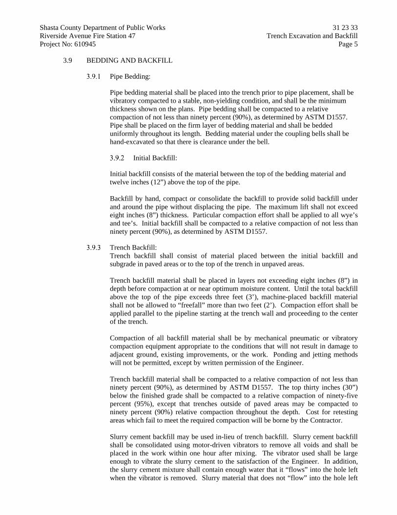
Shasta County Department of Public Works 31 23 33 Riverside Avenue Fire Station 47 Trench Excavation and Backfill Project No: 610945 Page 5
3.9 BEDDING AND BACKFILL
Pipe Bedding:
Pipe bedding material shall be placed into the trench prior to pipe placement, shall be vibratory compacted to a stable, non-yielding condition, and shall be the minimum thickness shown on the plans. Pipe bedding shall be compacted to a relative compaction of not less than ninety percent (90%), as determined by ASTM D1557. Pipe shall be placed on the firm layer of bedding material and shall be bedded uniformly throughout its length. Bedding material under the coupling bells shall be hand-excavated so that there is clearance under the bell.
Initial Backfill:
Initial backfill consists of the material between the top of the bedding material and twelve inches (12”) above the top of the pipe. Backfill by hand, compact or consolidate the backfill to provide solid backfill under and around the pipe without displacing the pipe. The maximum lift shall not exceed eight inches (8”) thickness. Particular compaction effort shall be applied to all wye’s and tee’s. Initial backfill shall be compacted to a relative compaction of not less than ninety percent (90%), as determined by ASTM D1557.
Trench Backfill: Trench backfill shall consist of material placed between the initial backfill and subgrade in paved areas or to the top of the trench in unpaved areas. Trench backfill material shall be placed in layers not exceeding eight inches (8”) in depth before compaction at or near optimum moisture content. Until the total backfill above the top of the pipe exceeds three feet (3’), machine-placed backfill material shall not be allowed to “freefall” more than two feet (2’). Compaction effort shall be applied parallel to the pipeline starting at the trench wall and proceeding to the center of the trench. Compaction of all backfill material shall be by mechanical pneumatic or vibratory compaction equipment appropriate to the conditions that will not result in damage to adjacent ground, existing improvements, or the work. Ponding and jetting methods will not be permitted, except by written permission of the Engineer. Trench backfill material shall be compacted to a relative compaction of not less than ninety percent (90%), as determined by ASTM D1557. The top thirty inches (30”) below the finished grade shall be compacted to a relative compaction of ninety-five percent (95%), except that trenches outside of paved areas may be compacted to ninety percent (90%) relative compaction throughout the depth. Cost for retesting areas which fail to meet the required compaction will be borne by the Contractor. Slurry cement backfill may be used in-lieu of trench backfill. Slurry cement backfill shall be consolidated using motor-driven vibrators to remove all voids and shall be placed in the work within one hour after mixing. The vibrator used shall be large enough to vibrate the slurry cement to the satisfaction of the Engineer. In addition, the slurry cement mixture shall contain enough water that it “flows” into the hole left when the vibrator is removed. Slurry material that does not “flow” into the hole left

Shasta County Department of Public Works 31 23 33 Riverside Avenue Fire Station 47 Trench Excavation and Backfill Project No: 610945 Page 6
by the vibrator shall have water added to it in the truck in an amount sufficient to attain a “flowing” behavior. Slurry cement shall not be covered with other material for at least 4 hours after placement. Compaction requirements do not apply to slurry cement backfill.
3.10 WORKMANSHIP GUARANTY
The Contractor shall guarantee his trench work against settlement for a period of one year after the Notice of Completion has been filed. During this time, the Contractor shall repair, at his own expense and to the satisfaction of the Engineer, all failed trench backfill and resurfacing. For the purpose of this contract, failure shall be deemed to have occurred if any of the following conditions exists: On paved streets, a depression in a pavement patch of 1/8" (0.01') below the sides of the uncut portion of pavement (includes trench lines and pavement widening).
Along shoulder areas, behind sidewalks, and in other unpaved portions of the right-of-way, a depression of 3/4" (0.06') below the average of the sides of the uncut portion.
Across all fields, pastures, or areas untraveled by automotive equipment, a depression causing the ponding of water between the sides of the uncut portion.
Any other settlement that causes drainage problems or concentrations of water to run along the excavation line.
If any of these conditions exist, the Contractor shall correct the trench failure within a time frame acceptable to the County.
END OF SECTION 31 23 33

Shasta County Department of Public Works 32 11 23 Riverside Avenue Fire Station 47 Aggregate Base Courses Project No: 610945 Page 1
AGGREGATE BASE COURSES
SECTION 32 11 23
PART 1 - GENERAL
1.1 DESCRIPTION
This work includes furnishing and placing aggregate base courses.
1.2 QUALITY ASSURANCE
Aggregate base course materials shall conform to Section 26 of the 2015 Caltrans Standard Specifications (CSS) unless otherwise specified in these Specifications or on the Plans.
Acceptance of aggregate base course materials will be based on aggregate gradation, R-value, and sand equivalent requirements specified.
Acceptance of placement of aggregate base course will be based on percent relative compaction specified, as tested under California Test 231.
If the aggregate gradation test results, sand equivalent test results, or both do not comply with the operating range requirements, do not place additional aggregate base course materials until you demonstrate to the Engineer the material to be placed complies with the operating range requirements.
If aggregate gradation test results, sand equivalent test results, or both do not comply with the Contract Compliance requirements, remove the aggregate base course materials or request a payment deduction. The Engineer determines the amount of payment deduction.
Each aggregate gradation and sand equivalent test represents no more than 500 cubic yards of aggregate base course material or 1 day’s production, whichever is smaller.
1.3 SUBMITTALS
Submittals shall include, but not be limited to, the following items:
Laboratory test results of the aggregate gradation, sand equivalent, and R-value for the aggregate base course materials proposed for use on the project.
PART 2 - PRODUCTS
2.1 CLASS 2 AGGREGATE BASE
Class 2 aggregate base shall conform to Section 26-1.02 of the CSS.

Shasta County Department of Public Works 32 11 23 Riverside Avenue Fire Station 47 Aggregate Base Courses Project No: 610945 Page 2
PART 3 - EXECUTION
3.1 GENERAL
Place, spread, and compact aggregate base course materials according to the requirements of Section 26-1.03 of the CSS.
END OF SECTION 32 11 23

Shasta County Department of Public Works 32 12 16 Riverside Avenue Fire Station 47 Hot Mix Asphalt Project No: 610945 Page 1
HOT MIX ASPHALT
SECTION 32 12 16
PART 1 - GENERAL
1.1 1.1 DESCRIPTION
This work shall cover the composition, mixing, construction upon the prepared subgrade, and the protection of hot mixed asphalt (HMA) pavement, including, but not limited to, placement of HMA, tack coat, and temporary pavement. Aggregate base is not covered in this section. Refer to Section 32 11 23, “Aggregate Base Courses” for aggregate base specifications and requirements.
1.2 QUALITY ASSURANCE
Work and materials shall comply with the applicable sections of the 2015 Caltrans Standard Specifications (CSS) unless otherwise specified in these Specifications or on the Plans. In addition, quality assurance testing of materials shall be performed in accordance with Shasta County Quality Assurance Program (QAP) and these specifications.
1.3 INSPECTION OF PLANT AND EQUIPMENT
The Engineer shall have access at all times to all parts of the material producing plants for checking the mixing operations and materials and the adequacy of the equipment in use.
1.4 SUBMITTALS
Submittals shall include, but not be limited to, the following items:
Submit a verified Job Mix Formula (JMF) dated within 12 months before HMA production for each HMA type and aggregate size specified. JMF must be verified by a firm qualified under the Caltrans Independent Assurance Program. If a verified JMF is not available, the Contractor shall perform JMF verification testing using a laboratory meeting the qualifications above. Submit the verified JMF to the Engineer for review and acceptance. The submitted JMF shall conform to all requirements of Section 39 of the CSS and these specifications, and shall be appropriate for the construction application. The Engineer will not perform JMF verification tests. The Engineer reviews the JMF submittal within 5 days from the complete JMF submittal.
Load slips for all material delivery trucks shall be delivered to the job site with the truck. The Contractor shall retain all load slips, and submit them to the Engineer at the end of each day of paving.

Shasta County Department of Public Works 32 12 16 Riverside Avenue Fire Station 47 Hot Mix Asphalt Project No: 610945 Page 2
PART 2 - PRODUCTS
2.1 TEMPORARY PAVEMENT
Temporary pavement shall be Type A, 3/4-inch grading conforming to Section 39, “Hot Mix Asphalt” of the CSS. A "cold mix" asphalt concrete containing SC-800 liquid asphalt may be used for temporary pavement if approved by the Engineer.
2.2 HMA (TYPE A)
HMA (Type A) shall conform to Section 39, “Hot Mix Asphalt” of the CSS and shall consist of the following materials:
Asphalt Binder: Asphalt binder for HMA (Type A) shall be PG Grade 64-10 complying with Section 92 of the CSS.
Aggregate: Aggregate for HMA (Type A) shall conform to 3/4-inch grading.
2.3 PRIME COAT
NOT USED
2.4 TACK COAT
Tack coat (paint binder) shall conform to Section 94, “Asphaltic Emulsions” of the CSS and shall be type CRS2, CQS1, PMCRS2 asphaltic emulsion, or asphalt binder.
2.5 SEAL COAT
NOT USED
2.6 CRACK SEALANT
NOT USED
2.7 GEOSYNTHETIC PAVEMENT INTERLAYER (PAVING FABRIC)
NOT USED
PART 3 - EXECUTION
3.1 TEMPORARY PAVEMENT CONSTRUCTION
In all paved areas disturbed by underground work, the Contractor shall install a minimum of two (2) inches of temporary pavement before traffic is allowed back onto the area. The temporary surface shall be maintained by the Contractor at all hours of the day including non-working hours. The grade of temporary pavement shall be maintained to within one-half (0.5) inch of the grade of adjacent roadway pavement until final pavement is installed, and shall be compacted such that the surface of the temporary pavement is flat. Temporary pavement shall be provided even if the existing pavement is to be removed later in street reconstruction.

Shasta County Department of Public Works 32 12 16 Riverside Avenue Fire Station 47 Hot Mix Asphalt Project No: 610945 Page 3
Installation of temporary pavement by the Contractor prior to the obtaining of final compaction tests by the Engineer will in no way relieve the Contractor of obtaining final compaction before the final paving is placed. Temporary paving shall be removed in its entirety prior to placement of final pavement.
3.2 PERMANENT PAVEMENT CONSTRUCTION
General
Place HMA (Type A) using method compaction according the requirements of Section 39-2 of the CSS and these specifications. The requirement for a pneumatic-tired roller may be omitted if the Contractor demonstrates to the Engineer that intermediate compaction of HMA can be achieved with a steel-tired roller to the satisfaction of the Engineer.
Subgrade Preparation:
Prior to paving, subgrade shall be prepared and accepted by the Engineer in accordance with Section 32 11 23, “Aggregate Base Courses”.
Tack Coat:
Apply tack coat in accordance with Section 39-2 of the CSS.
3Acceptance Testing
Do not take data cores. Requirements for testing in-place density using cores and nuclear gauge do not apply. The Engineer will not perform the production start-up evaluation. The Engineer’s laboratory will perform acceptance testing for each day of hot mix asphalt production and placement. Split samples will be furnished to the Contractor. Acceptance testing to be performed is limited to the following tests and frequencies:
HMA Acceptance
Quality Characteristic Test Method Minimum Testing Frequency
Aggregate Gradation AASHTO T 27 1 per paving day Sand Equivalent (min.) AASHTO T 176 1 per paving day Asphalt Binder Content (%) AASHTO T 308 Method A 1 per paving day Hamburg wheel track AASHTO T 324
(Modified) 1 per project
Acceptance test results will be furnished to the Contractor within 24 hours after tests are concluded.

Shasta County Department of Public Works 32 12 16 Riverside Avenue Fire Station 47 Hot Mix Asphalt Project No: 610945 Page 4
Pavement smoothness requirements do not apply except that the completed surface shall be thoroughly compacted, smooth, and free from ruts, humps, depressions, or irregularities. Any ridges, indentations or other objectionable marks left in the surface of the HMA by rollers, rakes, or other equipment shall be eliminated.
Miscellaneous HMA:
Miscellaneous HMA is limited to the areas shown on the plans or as directed by the Engineer.
END OF SECTION 32 12 16
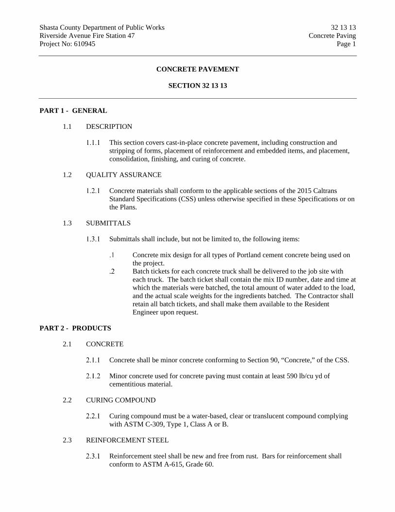
Shasta County Department of Public Works 32 13 13 Riverside Avenue Fire Station 47 Concrete Paving Project No: 610945 Page 1
CONCRETE PAVEMENT
SECTION 32 13 13
PART 1 - GENERAL
1.1 DESCRIPTION
This section covers cast-in-place concrete pavement, including construction and stripping of forms, placement of reinforcement and embedded items, and placement, consolidation, finishing, and curing of concrete.
1.2 QUALITY ASSURANCE
Concrete materials shall conform to the applicable sections of the 2015 Caltrans Standard Specifications (CSS) unless otherwise specified in these Specifications or on the Plans.
1.3 SUBMITTALS
Submittals shall include, but not be limited to, the following items:
Concrete mix design for all types of Portland cement concrete being used on the project.
Batch tickets for each concrete truck shall be delivered to the job site with each truck. The batch ticket shall contain the mix ID number, date and time at which the materials were batched, the total amount of water added to the load, and the actual scale weights for the ingredients batched. The Contractor shall retain all batch tickets, and shall make them available to the Resident Engineer upon request.
PART 2 - PRODUCTS
2.1 CONCRETE
Concrete shall be minor concrete conforming to Section 90, “Concrete,” of the CSS.
Minor concrete used for concrete paving must contain at least 590 lb/cu yd of cementitious material.
2.2 CURING COMPOUND
Curing compound must be a water-based, clear or translucent compound complying with ASTM C-309, Type 1, Class A or B.
2.3 REINFORCEMENT STEEL
Reinforcement steel shall be new and free from rust. Bars for reinforcement shall conform to ASTM A-615, Grade 60.

Shasta County Department of Public Works 32 13 13 Riverside Avenue Fire Station 47 Concrete Paving Project No: 610945 Page 2
2.4 WELDED WIRE MESH
Welded wire mesh shall conform to ASTM A-185.
2.5 EXPANSION JOINT MATERIAL
Pre-molded expansion joint fillers shall conform to ASTM D-1751.
2.6 OTHER MATERIALS
Other materials not specifically described above or on the Plans shall be as selected by the Contractor and approved by the Engineer.
PART 3 - EXECUTION
3.1 GENERAL
All concrete paving work shall conform to the details shown on the plans.
All exposed corners shall have a 1/2-inch radius unless noted otherwise.
3.2 FORMS
Forms must be rigid enough to withstand the pressure of fresh concrete without distortion.
Forms must be smooth on the side placed against concrete.
3.3 CONCRETE PLACEMENT
Concrete shall be placed and consolidated by methods that will not cause segregation of the aggregates and that will result in a dense homogeneous concrete that fills the forms and is free of voids and rock pockets. Unless otherwise shown, reinforcement must have 2-inch clear cover measured from the surface of the concrete to the outside of the reinforcement.
3.4 CONCRETE FINISHES
Concrete pavement shall be float finished and medium broomed to provide a non-slip surface.
3.5 JOINTS AND SCORELINES
The location of all joints and scorelines shall be approved by the Engineer prior to construction.
3.6 CONCRETE CURING
Apply curing compound to concrete after finishing the surface, immediately before the moisture sheen disappears from the concrete surface, but before drying shrinkage or craze cracks start to appear. Apply the curing compound at a rate of 150 sq ft/gal.

Shasta County Department of Public Works 32 13 13 Riverside Avenue Fire Station 47 Concrete Paving Project No: 610945 Page 3
If the film of the curing compound is damaged before the expiration of 7 days after the concrete is placed, immediately repair it with additional curing compound.
3.7 DEFECTIVE CONCRETE
The Contractor shall allow the Engineer to inspect concrete surfaces immediately upon removal of the forms. The Engineer shall have sole discretion over what defects are classified as “minor defects” and what defects are classified as “major defects,” as listed below, and over what methods the Contractor may use to correct the defects.
Minor defects may, at the sole discretion of the Engineer, be repaired by the Contractor at his sole expense with cement mortar. Patching material shall be thoroughly compacted into place, shall be flush with the surrounding surface, and shall be kept damp for at least forty-eight (48) hours.
Major defects may include (but are not limited to) voids, rock pockets, honeycombing, surface defects, poor finish work, poor lines and grades, and embedded debris. Major defects are not acceptable, and are grounds for rejection of the work by the Engineer.
END OF SECTION 32 13 13

Shasta County Department of Public Works 32 16 21 Riverside Avenue Fire Station 47 Curbs, Gutters, Sidewalks and Curb Ramps Project No: 610945 Page 1
CURBS, GUTTERS, SIDEWALKS, AND CURB RAMPS
SECTION 32 16 21
PART 1 - GENERAL
1.1 DESCRIPTION
This section covers cast-in-place concrete curbs, gutters, sidewalks, and curb ramps, including construction and stripping of forms, placement of reinforcement and embedded items, and placement, consolidation, finishing, and curing of concrete.
1.2 QUALITY ASSURANCE
Concrete materials shall conform to the applicable sections of the 2015 Caltrans Standard Specifications (CSS) unless otherwise specified in the specifications or on the plans.
1.3 SUBMITTALS
Submittals shall include, but not be limited to, the following items:
Concrete mix design for all types of Portland cement concrete being used on the project.
Batch tickets for each concrete truck shall be delivered to the job site with each truck. The batch ticket shall contain the mix ID number, date and time at which the materials were batched, the total amount of water added to the load, and the actual scale weights for the ingredients batched. The Contractor shall retain all batch tickets, and shall submit them to the Engineer at the end of each day.
PART 2 - PRODUCTS
2.1 CONCRETE
Concrete shall be minor concrete conforming to Section 90, “Concrete” of the CSS. Minor concrete used for curbs, gutters, sidewalks, and curb ramps must contain at least 463 lb/cu yd of cementitious material. For extruded or slip-form construction, the aggregate size may range from 3/8 to 1 inch. If you use 3/8 inch maximum size aggregate, cementitious material content must be at least 505 lb/cu yd.
2.2 CURING COMPOUND
Curing compound shall be a water based, clear or translucent compound, conforming to ASTM C-309, Type 1, Class A or B.

Shasta County Department of Public Works 32 16 21 Riverside Avenue Fire Station 47 Curbs, Gutters, Sidewalks and Curb Ramps Project No: 610945 Page 2
2.3 REINFORCEMENT STEEL
Reinforcement steel shall be new and free from rust. Bars for reinforcement shall conform to ASTM A-615, Grade 60.
2.4 WELDED WIRE MESH
Welded wire mesh shall conform to ASTM A-185.
2.5 EXPANSION JOINT MATERIAL
Pre-molded expansion joint fillers shall conform to ASTM D-1751.
2.6 DETECTABLE WARNING SURFACE
The detectable warning surface must be prefabricated and then cast-in-place into the sidewalks and curb ramps. The detectable warning surface shall be manufactured from glass and carbon reinforced polyester based Sheet Molding Compound (SMC) composite material. The truncated domes must contain fiberglass reinforcement within the truncated dome. The truncated dome pattern must comply with section 705 of the 2010 ADA Standards and section 11B-705 of the 2016 California Building Code. The color of the detectable warning surface must be yellow no. 33538 of FED-STD-595. The detectable warning surface shall be guaranteed in writing for a period of five (5) years from the date of final contract completion.
2.7 OTHER MATERIALS
Other materials not specifically described above or on the Plans shall be selected by the Contractor and approved by the Engineer.
PART 3 - EXECUTION
3.1 CONCRETE CURBS, SIDEWALKS, AND CURB RAMPS
All curb, gutter, sidewalk, and curb ramp work shall conform to the details shown on the plans. Where curbs, gutters, sidewalks, and curb ramps were removed and must be replaced, the replacement work shall exactly match the dimensions of the concrete removed. All exposed corners shall have a ½-inch radius unless noted otherwise.
3.2 SAWCUTTING
All sections of concrete sidewalks and curbs being demolished and removed shall be sawcut full depth at the nearest sidewalk scoreline or joint. Any sections of existing sidewalk or curb not being demolished that are damaged by the Contractor during the

Shasta County Department of Public Works 32 16 21 Riverside Avenue Fire Station 47 Curbs, Gutters, Sidewalks and Curb Ramps Project No: 610945 Page 3
course of construction shall be repaired or replaced to the satisfaction of the Engineer at the sole expense of the Contractor.
3.3 FORMS
Forms must be rigid enough to withstand the pressure of fresh concrete without distortion. Forms must be smooth on the side placed against concrete.
3.4 CONCRETE PLACEMENT
Concrete shall be placed and consolidated by methods that will not cause segregation of the aggregates and that will result in a dense homogeneous concrete that fills the forms and is free of voids and rock pockets. Unless otherwise shown, reinforcement must have 2-inch clear cover measured from the surface of the concrete to the outside of the reinforcement.
3.5 CONCRETE FINISHES
Concrete curbs, gutters, sidewalks, and curb ramps, shall be float finished and light broomed to provide a non-slip surface.
3.6 JOINTS AND SCORELINES
The location of all joints and scorelines shall be approved by the Engineer prior to construction.
3.7 CONCRETE CURING
Apply curing compound to concrete after finishing the surface, immediately before the moisture sheen disappears from the concrete surface, but before drying shrinkage or craze cracks start to appear. Apply the curing compound at a rate of 150 sq ft/gal. If the film of the curing compound is damaged before the expiration of 7 days after the concrete is placed, immediately repair it with additional curing compound.
3.8 DEFECTIVE CONCRETE
The Contractor shall allow the Engineer to inspect concrete surfaces immediately upon removal of the forms. The Engineer shall have sole discretion over what defects are classified as “minor defects” and what defects are classified as “major defects,” as listed below, and over what methods the Contractor may use to correct the defects. Minor defects may, at the sole discretion of the Engineer, be repaired by the Contractor at his sole expense with cement mortar. Patching material shall be thoroughly compacted into place, shall be flush with the surrounding surface, and shall be kept damp for at least forty-eight (48) hours. Major defects may include (but are not limited to) voids, rock pockets, honeycombing, surface defects, poor finish work, poor lines and grades, and embedded debris. Major defects are not acceptable, and are grounds for rejection of the work by the Engineer.

Shasta County Department of Public Works 32 16 21 Riverside Avenue Fire Station 47 Curbs, Gutters, Sidewalks and Curb Ramps Project No: 610945 Page 4
END OF SECTION 32 16 21

Shasta County Department of Public Works 32 17 23 Riverside Avenue Fire Station 47 Pavement Striping and Marking Project No: 610945 Page 1
PAVEMENT STRIPING AND MARKING
SECTION 32 17 23
PART 1 - GENERAL
1.1 DESCRIPTION
This Section covers all pavement striping and pavement marking placement, including pavement markers.
1.2 QUALITY ASSURANCE
Pavement striping and marking materials shall conform to the applicable sections of the 2015 Caltrans Standard Specifications (CSS) unless otherwise specified in these Specifications or on the Plans. In addition, quality assurance testing of materials shall be performed in accordance with the City of Shasta Lake Quality Assurance Program (QAP) and these specifications.
1.3 SUBMITTALS
Informational Submittals: Informational submittals shall include, but not be limited to, the following items:
Certificates of Compliance for all paint and thermoplastic marking materials certifying that all materials used on the project comply with applicable sections of the CSS.
Certificates of Compliance for all types of pavement markers certifying that the pavement markers used on the project comply with CSS.
1.4 REGULATORY AGENCIES
Prior to beginning work that is covered in this Section, the Contractor shall contact the Shasta County Air Quality Management District at (530) 225-5674 to determine what, if any, local air pollution control regulations apply to this work, and to obtain any required permits, provide any required notices, or comply with any other requirement prior to starting the work.
PART 2 - PRODUCTS
2.1 THERMOPLASTIC TRAFFIC STRIPES AND MARKINGS
Thermoplastic material used for traffic stripes and pavement markings shall conform to the CSS, Section 84-2.02B.
2.2 PAINTED TRAFFIC STRIPES AND MARKINGS
Paint used for traffic stripes, parking stripes, and pavement markings shall conform to the CSS, Section 84-2.02C.

Shasta County Department of Public Works 32 17 23 Riverside Avenue Fire Station 47 Pavement Striping and Marking Project No: 610945 Page 2
2.3 PAVEMENT MARKERS
Pavement markers and adhesive shall conform to Section 81-3.02 of the CSS. Pavement markers must be the type shown on the plans.
2.4 GLASS BEADS
Glass beads applied to thermoplastic material must be Type 2, complying with AASHTO M247. Glass beads applied to paint shall conform to State Specification 8010-004.
2.5 MARKING TEMPLATES
Marking templates shall be constructed of either metal or plywood, shall fit closely to the surface being sprayed, and shall be dimensioned and lettered as shown on the Plans.
PART 3 - EXECUTION
3.1 SURFACE PREPARATION
The portion of the roadway surface to receive striping, markings, or pavement markers shall be free of dirt, curing compound, grease, oil, moisture, loose or unsound layers, paint and any other material which would adversely affect the bond of the paint, thermoplastic, or adhesive material. Use abrasive blast cleaning to remove curing compound from the surface of new concrete pavement that is to receive traffic stripes or pavement markings.
3.2 CONTROL OF ALIGNMENT AND LAYOUT
The Contractor shall establish alignments for striping and shall perform all layout work required for all pavement markings using methods that will not damage the pavement, conflict with traffic control devices, or impede the normal flow of traffic during striping, pavement marking, and pavement marker installations. The Engineer must approve all layout work prior to applying permanent stripes, markings, and markers.
3.3 STRIPING JOINTS
Where new striping meets existing striping, the Contractor shall begin or end the transition from existing striping to new striping a sufficient distance into the existing striping to ensure continuity of the striping pattern.
3.4 THERMOPLASTIC TRAFFIC STRIPES AND MARKINGS
Thermoplastic traffic stripes and markings shall be applied by the spray or extrusion methods in accordance with Section 84-2.03 of the CSS.
Apply glass beads at a rate of at least 8 pounds per 100 square feet of stripe or marking.

Shasta County Department of Public Works 32 17 23 Riverside Avenue Fire Station 47 Pavement Striping and Marking Project No: 610945 Page 3
3.5 PAINTED TRAFFIC STRIPES AND MARKINGS
Painted traffic stripes, parking stripes, and markings shall be applied in accordance with Section 84-2.03 of the CSS.
Apply 2 coats of paint. Glass beads shall be applied at an approximate rate of 5 pounds per gallon of
paint.
3.6 PAVEMENT MARKERS
Install the type of markers shown on the plans in accordance with Section 81-3.03 of the CSS.
END OF SECTION 32 17 23

Shasta County Department of Public Works 32 17 24 Riverside Avenue Fire Station 47 Signs Project No: 610945 Page 1
SIGNS
SECTION 32 17 24
PART 1 - GENERAL
1.1 DESCRIPTION
Sign panels shall be furnished and installed on new posts at the locations shown on the plans or where designated by the Engineer and in conformance with these special provisions.
PART 2 - PRODUCTS
2.1 FURNISHING SIGN PANELS
Sign panels shall be fabricated and furnished in accordance with details shown on the plans, the Traffic Sign Specifications, and these special provisions.
Traffic Sign Specifications for California sign codes are available for review at: http://www.dot.ca.gov/hq/traffops/signtech/signdel/specs.htm
Traffic Sign Specifications for signs referenced with Federal MUTCD sign codes can be found in Standard Highway Signs Book, administered by the Federal Highway Administration, which is available for review at: http://mutcd.fhwa.dot.gov/ser-shs_millennium.htm
Information on cross-referencing California sign codes with the Federal MUTCD sign codes is available at: http://www.dot.ca.gov/hq/traffops/signtech/signdel/specs.htm
Temporary or permanent signs shall be free from blemishes that may affect the serviceability and detract from the general sign color and appearance when viewing during daytime and nighttime from a distance of 25 feet. The face of each finished sign shall be uniform, flat, smooth, and free of defects, scratches, wrinkles, gel, hard spots, streaks, extrusion marks, and air bubbles. The front, back, and edges of the sign panels shall be free of router chatter marks, burns, sharp edges, loose rivets, delaminated skins, excessive adhesive over spray and aluminum marks.
2.2 QUALITY CONTROL FOR SIGNS
No legend shall be installed at the project site. Legend shall include letters, numerals, tildes, bars, arrows, route shields, symbols, logos, borders, artwork, and miscellaneous characters. The style, font, size, and spacing of the legend shall conform to the Standard Alphabets published in the FHWA Standard Highway Signs Book. The legend shall be oriented in the same direction in accordance with the manufacturer's orientation marks found on the retroreflective sheeting. On multiple panel signs, legend shall be placed across joints without affecting the size, shape, spacing, and appearance of the legend. Background and legend shall be wrapped around interior edges of formed panel signs as shown on plans to prevent delamination.

Shasta County Department of Public Works 32 17 24 Riverside Avenue Fire Station 47 Signs Project No: 610945 Page 2
For sign panels within City right of way, the following notation shall be placed on the lower right side of the back of each sign where the notation will not be blocked by the sign post or frame: .1 PROPERTY OF CITY OF ANDERSON, .2 Name of the sign manufacturer, .3 Month and year of fabrication, .4 Type of retroreflective sheeting, and .5 Manufacturer's identification and lot number of retroreflective sheeting. The above notation shall be applied directly to the aluminum sign panels in 1/4-inch upper case letters and numerals by die-stamp and applied by similar method to the fiberglass reinforced plastic signs. Painting, screening, or engraving the notation will not be allowed. The notation shall be applied without damaging the finish of the sign. For sign panels that have a minor dimension of 48 inches or less, no splice will be allowed in the retroreflective sheet except for the splice produced during the manufacturing of the retroreflective sheeting. For sign panels that have a minor dimension greater than 48 inches, only one horizontal splice will be allowed in the retroreflective sheeting. Signs exhibiting a significant color difference between daytime and nighttime shall be replaced immediately at the Contractor's expenses. Repairing sign panels will not be allowed except when approved by the Engineer. The Engineer will inspect signs at the delivery location, and in accordance with Section 6, “Control of Materials,” of the Standard Specifications. The Engineer will inspect signs for damage and defects before and after installation. The Contractor shall assume the costs and responsibilities resulting from the use of patented materials, equipment, devices, and processes for the Contractor's work.
2.3 SHEET ALUMINUM
2.3.1 Alloy and temper designations for sheet aluminum shall be in accordance with ASTM Designation: B 209. The Contractor shall furnish the Engineer a Certificate of Compliance for the sheet aluminum. Sheet aluminum shall be pretreated in accordance to ASTM Designation: B 449. Surface of the sheet aluminum shall be cleaned, deoxidized, and coated with a light and tightly adherent chromate conversion coating free of powdery residue. Following the cleaning and coating process, the sheet aluminum shall be protected from exposure to grease, oils, dust, and contaminants. Sheet aluminum shall be free of buckles, warps, dents, cockles, burrs, and defects resulting from fabrication.

Shasta County Department of Public Works 32 17 24 Riverside Avenue Fire Station 47 Signs Project No: 610945 Page 3
2.4 RETROREFLECTIVE SHEETING
The Contractor shall furnish retroreflective sheeting for sign background and legend in conformance with ASTM Designation: D 4956 and "Prequalified and Tested Signing and Delineation Materials" of these special provisions. The Contractor shall furnish the Engineer a Certificate of Compliance for the retroreflective sheeting. Retroreflective sheeting shall be applied to sign panels as recommended by the retroreflective sheeting manufacturer without stretching, tearing, and damage. Class 1, 3, or 4 adhesive backing shall be used for Type II, III, IV, VII, VIII, and IX retroreflective sheeting. Class 2 adhesive backing may also be used for Type II retroreflective sheeting. The adhesive backing shall be pressure sensitive and fungus resistant. When the color of the retroreflective sheeting determined from instrumental testing is in dispute, the Engineer's visual test will govern.
2.5 PROCESS COLOR AND FILM
The Contractor shall furnish and apply screened process color, non-reflective opaque black film, and protective overlay film of the type, kind, and product that are approved by the manufacturer of the retroreflective sheeting. The Contractor shall furnish the Engineer a Certificate of Compliance for the screened process color, non-reflective opaque black film, and protective overlay film. The surface of the screened process color shall be flat and smooth. When the screened process colors determined from the instrumental testing in accordance to ASTM Designation: D 4956 are in dispute, the Engineer's visual test will govern. The Contractor shall provide patterns, layouts, and set-ups necessary for the screened process. The Contractor may use green, red, blue, and brown reverse-screened process colors for background and non-reflective opaque black film or black screened process color for legend. The coefficient of retroreflection for reverse-screened process colors on white retroreflective sheeting shall not be less than 70 percent of the coefficient of retroreflection specified in ASTM Designation: D 4956. The screened process colors and non-reflective opaque black film shall have the same outdoor weatherability as that of the retroreflective sheeting. After curing, screened process colors shall withstand removal when tested by applying 3M Company Scotch Brand Cellophane Tape No. 600 or equivalent tape over the color and removing with one quick motion at 90° angle.

Shasta County Department of Public Works 32 17 24 Riverside Avenue Fire Station 47 Signs Project No: 610945 Page 4
PART 3 - EXECUTION
3.1 GENERAL
Sign installation shall conform to the details shown on the plans, City of Redding Construction Standard 152.20, and as directed by the Engineer.
END OF SECTION 32 17 24

Shasta County Department of Public Works 32 17 26 Riverside Avenue Fire Station 47 Tactile Warning Surfacing Contract No: 610945 Page 1
TACTILE WARNING SURFACING
SECTION 32 17 26
PART 1 - GENERAL
1.1 SECTION INCLUDES
Embedded tactile warning surface tile, with an inline dome pattern, for application on ramps and level walking surfaces.
Tactile Tile Installation Method: As indicated on Drawings, and as follows:
New Concrete: Installation in cast-in-place uncured (wet) concrete.
1.2 REFERENCES
Referenced Standards:
AASHTO HB-17 – Standard Specifications for Highway Bridges. ASTM B117 – Standard Practice for Operating Salt Spray (Fog)
Apparatus. ASTM C293 – Standard Test Method for Flexural Strength of Concrete
(Using Simple Beam With Center-Point Loading). ASTM C1028 – Standard Test Method for Determining the Static
Coefficient of Friction of Ceramic Tile and Other Like Surfaces by the Horizontal Dynamometer Pull-Meter Method.
ASTM D543 – Standard Practices for Evaluating the Resistance of Plastics to Chemical Reagents.
ASTM D570 – Standard Test Method for Water Absorption of Plastics. ASTM D638 – Standard Test Method for Tensile Properties of Plastics. ASTM D695 – Standard Test Method for Compressive Properties of Rigid
Plastics. ASTM D1037 – Standard Test Methods for Evaluating Properties of Wood-
Base Fiber and Particle Panel Materials. ASTM D2486 – Standard Test Methods for Scrub Resistance of Wall Paints. ASTM D5420 – Standard Test Method for Impact Resistance of Flat, Rigid
Plastic Specimen by Means of a Striker Impacted by a Falling Weight (Gardner Impact).
ASTM E84 – Standard Test Method for Surface Burning Characteristics of Building Materials.
ASTM G155 – Standard Practice for Operating Xenon Arc Light Apparatus for Exposure of Non-Metallic Materials.
1.3 SUBMITTALS
Shop Drawings: Show detailed plans of tile profile, fastener locations, and installation methods.

Shasta County Department of Public Works 32 17 26 Riverside Avenue Fire Station 47 Tactile Warning Surfacing Contract No: 610945 Page 2
1.4 QUALITY ASSURANCE
Manufacturer Qualifications: Firm specializing in manufacturing products specified in this Section with a minimum 5 years’ experience.
1.5 REGULATORY REQUIREMENTS
General: Provide detectable (tactile) warning products in accordance with CCR. Title 24, Part 1, 2013 California Administrative Code, Chapter 5 “Access to Public Buildings by Persons with Disabilities.”
Article 3 “Acceptance of Detectable Warning and Directional Surface Products for Manufacturers and Design Professionals.”
Article 4 “Application for Independent Entity Evaluation Approval (IEEA).”
Definition of Detectable Warning: Conform to 2013 California Building Code, Chapter 2 “Definitions,” Section 202 “Definitions.”
Chapter 11B “Accessibility to Public Buildings, Public Accommodations, Commercial Buildings and Publicly Funded Housing,” Section 11B-247.1 scope for detectable warnings.
Detectable Warnings for Site Accessibility: Provide detectable warning system in accordance with 2013 California Building Code, Chapter 11B, “Accessibility to Public Buildings, Public Accommodations, Commercial Buildings and Publicly Funded Housing,” and ADAAG as applicable.
Detectable Warning locations: Chapter 11B, Section 11B-705.1.2
1.6 DELIVERY, STORAGE AND HANDLING
Deliver, store and handle packaged products in original containers with seals unbroken and labels intact until the time of installation.
Store delivered products in a clean, safe, dry area.
PART 2 - PRODUCTS
2.1 MANUFACTURERS
Basis-of Design Product: Armor-tile by Engineered Plastics Inc.
Provide Cast-In-Place Type Armor-Tile for embedding in cast-in-place uncured (wet) concrete.
ADA Solutions, Inc., Cast-in-Place type. Or accepted equal
Or accepted equal.

Shasta County Department of Public Works 32 17 26 Riverside Avenue Fire Station 47 Tactile Warning Surfacing Contract No: 610945 Page 3
2.2 MATERIALS
Tactile Warning Tiles: An epoxy polymer composite with an ultraviolet stabilized coating containing aluminum oxide particles in the truncated domes.
Cast-In-Place Type Tile for Embedding in Cast-In-Place Uncured (Wet) Concrete:
Tile thickness to be 0.3875 inch at domes and 0.1875 inch in flat areas between domes. Total thickness at perimeter to be 1.375 inches; dome height to be 0.20 inch.
Tile underside to have embedment flanges with 0.625-inch diameter holes; long sides to have 0.1875-inch diameter vent holes.
Tile to have sound amplifying plastic plates attached between flanges, with an air space between tile bottom surface and sound amplifying plastic plates.
Tile face to have non-slip texture.
Color and Size:
Safety Yellow, (Federal Color #33538) colorfast, UV stabilized coating. Color shall be uniform throughout the tile.
Sizes: As indicated on Drawings.
Performance Requirements: Tactile warning tiles shall meet or exceed the following criteria:
Water Absorption: 0.05 percent, maximum, when tested in accordance with ASTM D570.
Slip Resistance: 0.80, minimum combined wet/dry static coefficient of friction on top of domes and field area, when tested in accordance with ASTM C1028.
Compressive Strength: 28,000 psi, minimum, when tested in accordance with ASTM D695.
Tensile Strength: 19,000 psi, minimum, when tested in accordance with ASTM D638.
Flexural Strength: 25,000 psi, minimum, when tested in accordance with ASTM C293.
Gardner Impact: 550 inch-pounds per inch minimum, when tested in accordance with ASTM D5420.
Chemical Stain Resistance: No discoloration or staining when exposed to 10 percent hydrochloric acid, urine, saturated calcium chloride, black stamp pad ink, chewing gum, red aerosol paint, 10 percent ammonium hydroxide, 1 percent soap solution, turpentine, 5 percent Urea, diesel fuel, motor oil, and tested in accordance with ASTM D543.
Wear Depth: 0.06 inch, maximum, after 1000 abrasion cycles of 40 grit Norton Metallite sandpaper, tested in accordance with ASTM D2486.
Flame Spread: 15 maximum, when tested in accordance with ASTM E84. Accelerated Weathering: No deterioration, fading or chalking, when tested for
3,000 hours in accordance with ASTM G155. Accelerated Aging and Freeze Thaw Test of Tile and Adhesive System: No
cracking, delamination, warping, checking, blistering, color change, loosening

Shasta County Department of Public Works 32 17 26 Riverside Avenue Fire Station 47 Tactile Warning Surfacing Contract No: 610945 Page 4
of tiles, or other detrimental defects, when tested in accordance with ASTM D1037.
Salt and Spray Performance: No evidence of deterioration or defects after 200 hours of exposure, when tested in accordance with ASTM B117.
AASHTO HB-17 Single Wheel HS20-44 Loading Test for Cast-In-Place Type Tile: Mounted on concrete platform with 1/2 inch air space at the underside of tile and subjected to a maximum load of 10,400 pounds, corresponding to 8000 pound individual wheel load and 30 percent impact factor; no visible damage at maximum loading.
PART 3 - EXECUTION
3.1 INSTALLATION
Install tactile warning surface tiles in accordance with manufacturer’s printed instructions.
Install Cast-In-Place Type tiles over cast-in-place, uncured (wet) concrete.
Ensure that the surfaces being prepared and fabricated to receive the tiles are constructed correctly and adequately for tile installation.
Installation in Cast-In-Place Uncured (Wet) Concrete: Maintain concrete in 4 inch to 7 inch slump range. Lay tactile warning surface tiles (without removing protective plastic wrap) in uncured (wet) concrete and tamp each tile in place. Place weights over tiles to prevent floating, as recommended by the manufacturer. After curing, remove protective plastic wrap, and clean tile surfaces.
END OF SECTION 32 17 26

Shasta County Department of Public Works 32 31 00 Riverside Avenue Fire Station 47 Sliding Gate Operator Contract No: 610945 Page 1
SLIDING GATE OPERATOR
SECTION 32 31 00
PART 1 - GENERAL
1.1 SUMMARY
Pre-wired, self-contained, slide gate operator for horizontal sliding gates, including all selected attachments and accessory equipment.
1.2 SUBMITTALS
Shop drawings: Showing connections to adjacent construction, range of travel, and all electrical and mechanical connections to the operator. All underground runs of electrical and hydraulic lines shall be indicated. Drawings shall also show the size had location of the concrete mounting pad. Underground electrical runs shall be shown on shop drawings.
Installation instructions: Submit two copies of manufacturer’s installation instructions for this specific project.
Test reports:
Submit affidavits from the manufacturer demonstrating that the gate operator has been tested to 200,000 cycles without breakdown.
Each operator shall bear a label indicating that the operator mechanism has been tested for full power and pressure of all hydraulic components, full stress tests of all mechanical components and electrical tests of all overload devices.
1.3 QUALITY ASSURANCE
Manufacturer: A company specializing in the manufacture of hydraulic gate operators of the type specified, with a minimum of ten tears experience.
Installer: A minimum of three years experience installing similar equipment.
Operator – Factory Testing:
Fully assemble and test, at the factory, each gate operator to assure smooth operation, sequencing and electrical connection integrity. Apply physical loads to the operator to simulate field conditions. Tests shall simulate physical and electrical loads equal to the fully rated capacity of the operator components.
Check all mechanical connections for tightness and alignment. Check all welds for completeness and continuity. Check welded corners and edges to assure they are square and straight.
Inspect zinc finish for completeness. Touch up any imperfections prior to shipment.

Shasta County Department of Public Works 32 31 00 Riverside Avenue Fire Station 47 Sliding Gate Operator Contract No: 610945 Page 2
Check all hydraulic hoses and electrical wires to assure that chafing cannot occur during shipping or operation.
1.4 REGULATORY REQUIREMENTS
Operators shall be built to UL325 standards and be listed by a NRTL testing laboratory. Complete all electrical work according to local codes and National Electrical code. All fieldwork shall be performed in a neat and professional manner, completed to journeyman standards.
Current safety standards require the use of multiple external sensors to be capable of reversing the gate in either direction upon sensing an obstruction. Also see Subsection 2.2D.
Current safety standards require gate operators to be designed, labeled and compliant with usage Classes I-IV.
1.5 DELIVERY, STORAGE AND HANDLING
Store products upright in the original shipping containers, covered, ventilated and protected from weather conditions.
1.6 WARRANTY
Provide a five-year manufacturer’s limited warranty against all defects in materials or workmanship. Defective materials shall be replaced with comparable materials furnished by the manufacturer.
PART 2 - PRODUCTS
2.1 MANUFACTURERS
HySecurity / SlideDriver 30F UPS
Crown Industrial Operators.
Or accepted equal.
2.2 OPERATION
Operation shall be by means of a metal rail passing between a pair of solid metal wheels with polyurethane treads. Operator motors shall be hydraulic, gearoller type, and system shall not include belts, gears, pulleys, roller chains or sprockets to transfer power from operator to gate panel. The operator shall generate a minimum horizontal pull of 300 pounds (136 kg) without the drive wheels slipping and without distortion of supporting arms. Operator shall be capable of handling gates weighing up to 3000 pounds (1,361 kg). Gate panel velocity shall not be less than 1.7 feet (.52 m) per second and shall be stopped gradually to prevent shock loads to the gate and operator assembly. The “soft stop” feature of the gate operator shall be controlled by two adjustable hydraulic brake valves (one for each direction). The “soft start” feature shall allow the pump to start at zero pressure, then progressively increase the pressure, over a period not less than two seconds, to 1,000 PSI (6.89 MPa).

Shasta County Department of Public Works 32 31 00 Riverside Avenue Fire Station 47 Sliding Gate Operator Contract No: 610945 Page 3
Standard mechanical components shall include as a minimum:
Supporting arms: Cast aluminum channel. Arms shall incorporate a fully bushed, 1-1/2" (38 mm) bronze bearing surface, acting on arm pivot pins. (item 2 below)
Arm pivot pins: 3/4" (19 mm) diameter, stainless steel, with integral tabs for ease of removal.
Tension spring: 2-1/2" (63.5 mm) heavy duty, 800 pound (363 kg) capacity. Tension adjustment: Finger tightened nut, not requiring the use of tools. Drive release: Must instantly release tension on both drive wheels, and
disengage them from contact with drive rail in a single motion, for manual operation.
Limit switches: Fully adjustable, toggle types, with plug connection to control panel.
Electrical enclosure: Oversized, metal, with hinged lid gasketed for protection from intrusion of foreign objects, and providing ample space for the addition of accessories.
Chassis: 1/4" (6.35 mm) steel base plate, and 12 Ga. (2.66 mm) sides and back welded and ground smooth.
Cover: 16 Ga. (1.52 mm) zinc plated steel with a textured TGIC polyester powder coat finish. All joints welded.
Finish: Zinc plated steel with textured TGIC polyester powder coat finish, proven to withstand 1000-hour salt spray test.
Drive wheels: Two 6" (152 mm) Dia. metal hub with polyurethane tread. Drive rail: Shall be extruded 6061 T6, not less than 1/8” (3.175 mm) thick.
Drive rail shall incorporate alignment pins for ease of replacement or splicing. Pins shall enable a perfect butt splice.
Hydraulic hose: Shall be 1/4" (6.35 mm) synthetic, rated to 2750 PSI (19 MPa).
Hydraulic valves: Shall be individually replaceable cartridge type, in an integrated hydraulic manifold.
Hose fittings: At manifold shall be quick-disconnect type, others shall be swivel type.
Hydraulic fluid: High performance type with a viscosity index greater than 375 and temperature range -40F to 167F degrees (-40C to 75C).
A zero to 2000 PSI (13.79 MPa) pressure gauge, mounted on the manifold for diagnostics, shall be a standard component.
The hydraulic fluid reservoir shall be formed from a single piece of metal, non-welded, and shall be powder painted on the inside and the outside, to prevent fluid contamination.
Minimum standard electrical components:
Pump motor: Shall be minimum 2 HP, 56C, 24 V DC motor. All components shall have overload protection. Controls: Smart Touch Controller Board with 256K of program memory
containing:
inherent entrapment sensor; built in “warn before operate” system; built in timer to close; liquid crystal display for reporting of functions;

Shasta County Department of Public Works 32 31 00 Riverside Avenue Fire Station 47 Sliding Gate Operator Contract No: 610945 Page 4
26 programmable output relay options; anti-tailgate mode; built-in power surge/lightning strike protection; menu configuration, event logging and system diagnostics easily
accessible with a PC and HySecurity’s free START software; RS232 port for connection to laptop or other computer peripheral and
RS485 connection of Master/Slave systems or network interface.
Low voltage sensor to protect batteries from over discharge. Last operation can be programmed for fail secure or fail open
AC power loss operation: the operation can be programmed to open immediately or stay open after next normal operation, or remain in normal operation until batteries are low.
Control circuit: 24VDC. Permanently sealed, maintenance free, lead acid batteries in separate insulated
and ventilated enclosure. Battery enclosure is NEMA 3R 30”x30”x12” (.76m x.76m x .30m), pre-
galvanized and painted dark gray enamel. 20 amp, fully automatic, regulated battery charger,
Security lock / Emergency operation / Manual operation:
Operator shall have automatic electronic locking to prevent unauthorized entry which shall function after the loss of AC power.
Operator shall unlock with a switch input so that the gate can be manually pushed.
Operator shall have inputs for Emergency open and Emergency close. Operator shall have outputs to indicate forced entry, full open and full closed
gate position.
Controls: Smart Touch Controller Board containing:
Built-in power surge/lightening strike protection on all inputs. Double sided control board with all sensitive electronic components on the
protected bottom side, conformal coated for environmental protection. 256k flash memory allows updates to program software without removal of
parts. Non-volatile memory to support system configuration and event logs without
power. Clock chip to support time date recording of event logging system. Liquid crystal display for reporting of functions and setup menu
programming. Membrane switch interface allowing full system control with only five
buttons. Automatically self-adaptive inherent entrapment sensor. Integrated “warn before operate” system. Integrated timer to close and maximum run timer. Two spare RS-485 ports for external communication and support of
expansion controls. RS-232 port for external serial communication, reading of event log and
programming.

Shasta County Department of Public Works 32 31 00 Riverside Avenue Fire Station 47 Sliding Gate Operator Contract No: 610945 Page 5
Two spare output relays, 40 Amp rated with at least 19 programmable function options.
Spare solid state output with, 4 Amp rated with at least 19 programmable function options.
Programmable anti-tailgate mode for faster gate closure and to deter following vehicles.
Required external sensors: See 1.5,2. Photo eyes or gate edges or a combination thereof to be installed such that the gate is capable of reversing in either direction upon sensing an obstruction.
Additional control devices:
.1 Entry: Key Pad or Radio Signal Remote Release.
.2 Exit: Vehicle Detector Loops
Other options:
Smart Vehicle Detector, model HY-5A Matching 12 inch (.30 m) Base Riser Cover lock kit 110AH, sealed - no maintenance batteries (to increase UPS capacity to 30,000
feet (9.14 km) gate travel). Factory drive rail
Vehicle Detector Loops: Saratec Model 5153 or accepted equal:
.1 Tuning: Automatic – Less than 1 second Output: Prescence Relay. 2 amps. N.O.
Lightning Protection: Accepts 10 Microfarads @ 2000 volts between loop and
ground. 10 Microfarads @ 1000 volts across open loop terminals.
Frequency
Three position switch on front panel. Holding Time: 30-60 minutes, depending on vehicle and loop configuration. Maximum Lead-In: 1,000 ft. Loop Inductance: 30 – 1000 Microphenries (1-1/2’ x 6’ x 10’ x 100’ loops fall
within this range). Similar loops may be used in series or Loop Isolation: Total – will operate and “Self-Tune” with low quality loops.
Operating
-40°F to +185°F. Indicator: Front panel solid-state light. Connector: 11-pin amphenol type, front mounted.
The Digital Vehicle Detector shall be completely “self-tuning” the moment power is applied. The detector shall tune itself to a pre-determined sensitivity level. The only field adjustment required shall be the setting of the three-position switch which sets to loop frequency. When two or more loop detectors are used in close proximity, this “Low/Medium/High” adjustment switch shall be set so that each detector is operating on a different frequency.

Shasta County Department of Public Works 32 31 00 Riverside Avenue Fire Station 47 Sliding Gate Operator Contract No: 610945 Page 6
The detector shall constantly monitor the frequency of the loop several times per second, and compare and adjust for changes such as loop aging, moisture, mechanical deterioration, foreign bodies in the loop, etc.
Detector Loop Placement:
Entrance Gates: Install a shadow loop on the secure side of the gate. Exit Gates: Install a free exit loop on the secure side of the gate, and a shadow
loop on the non-secure side of the gate.
Remote gate release devices: Places operator in “manual mode” from remote location.
2.3 FACTORY TESTING
Fully assemble and test, at the factory, each gate operator to assure smooth operation, sequencing and electrical connection integrity. Tests shall simulate physical and electrical loads equal to the fully rated capacity of the operator components.
Assure reliability of control boards by testing 100% of production for 19 hours in an environmental chamber that cycles between 0F – 160F while a computer monitors and records board functions.
Check all mechanical connections for tightness and alignment. Check all welds for completeness and continuity. Check welded corners and edges to assure they are square and straight.
Inspect painted finish for completeness and gloss. Touch up imperfections prior to shipment.
Check all mechanical parts, hydraulic hoses and electrical wires to assure that chafing cannot occur during shipping or operation.
PART 3 - EXECUTION
3.1 SITE EXAMINATION
Locate concrete operator mounting pad in accordance with approved shop drawings.
Make sure that gate is operating smoothly under manual conditions before installation of gate operators. Do not proceed until gate panel is aligned and operates without binding.
3.2 INSTALLATION
Install gate operator in accordance with the manufacturer’s printed instructions, current at the time of installation. Coordinate locations of operators with Contract Documents and other trades.
Installer shall insure that the electric service to the operator is at least 20 AMPS. Operator wattage is 1000.

Shasta County Department of Public Works 32 31 00 Riverside Avenue Fire Station 47 Sliding Gate Operator Contract No: 610945 Page 7
Coordinate installation and controls with Division 28 – Security Electronics for fully operational system.
3.3 FIELD QUALITY CONTROL
Test gate operator through ten full cycles and adjust for operation without binding, scraping or uneven motion. Test limit switches for proper “at rest” gate position.
All anchor bolts shall be fully concealed in the finished installation.
3.4 ADJUST AND CLEAN
Test gate operators through ten full cycles and adjust for operation without binding, scraping or uneven motion.
Cleaning and Finishing: Upon completion of the work clean all exposed surfaces, removing any discoloration of foreign matter. Touch up all abraded or scrapped areas with touch-up paint to match gate color. Touch-up shall not be obvious.
Protect all installed work against damage for other construction work.
Clean Up: Upon completion of the work of this section, remove all surplus materials, rubbish and debris for the gate installation area.
3.5 CONTINUED SERVICE AND DOCUMENTATION
Train County’s personnel in the general maintenance of the gate operator and accessories and provide one copy of operations and maintenance manual. Manuals shall identify parts of the equipment for future procurement.
END OF SECTION 32 31 00
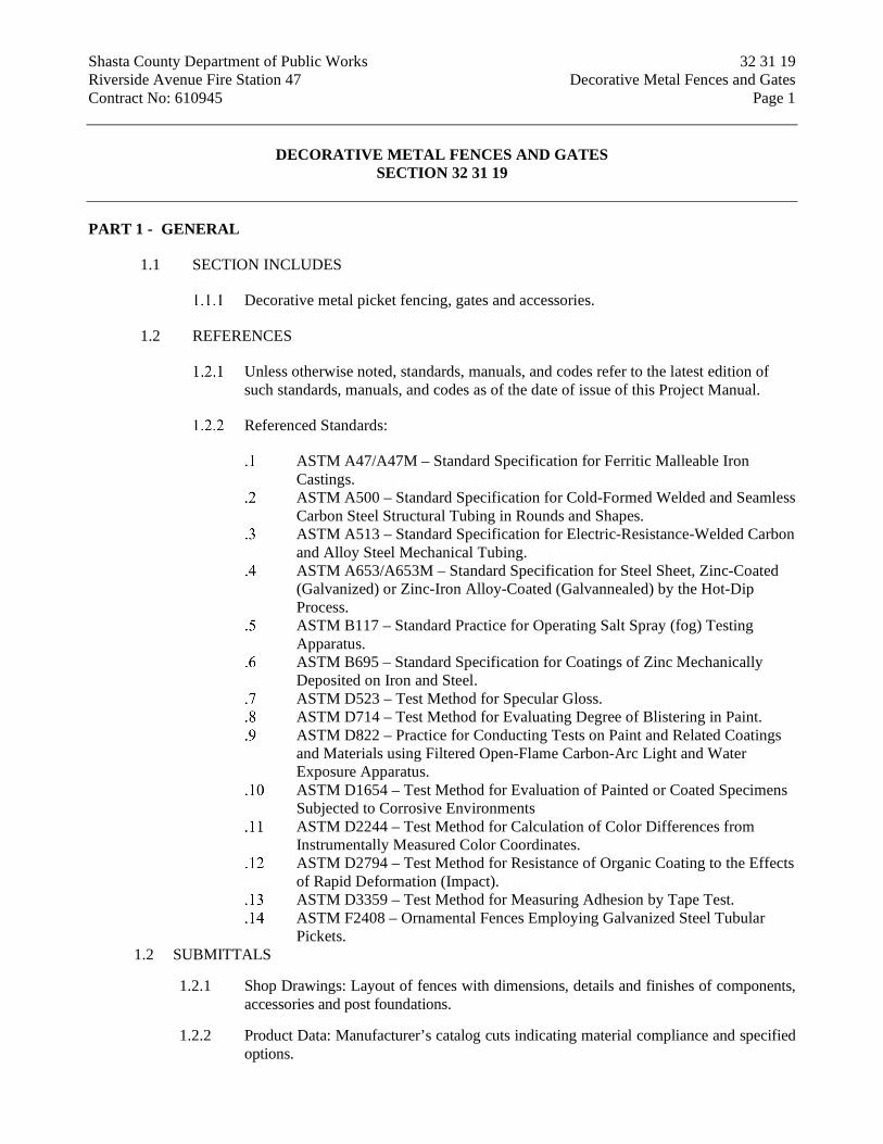
Shasta County Department of Public Works 32 31 19 Riverside Avenue Fire Station 47 Decorative Metal Fences and Gates Contract No: 610945 Page 1
DECORATIVE METAL FENCES AND GATES
SECTION 32 31 19
PART 1 - GENERAL
1.1 SECTION INCLUDES
Decorative metal picket fencing, gates and accessories.
1.2 REFERENCES
Unless otherwise noted, standards, manuals, and codes refer to the latest edition of such standards, manuals, and codes as of the date of issue of this Project Manual.
Referenced Standards:
ASTM A47/A47M – Standard Specification for Ferritic Malleable Iron Castings.
ASTM A500 – Standard Specification for Cold-Formed Welded and Seamless Carbon Steel Structural Tubing in Rounds and Shapes.
ASTM A513 – Standard Specification for Electric-Resistance-Welded Carbon and Alloy Steel Mechanical Tubing.
ASTM A653/A653M – Standard Specification for Steel Sheet, Zinc-Coated (Galvanized) or Zinc-Iron Alloy-Coated (Galvannealed) by the Hot-Dip Process.
ASTM B117 – Standard Practice for Operating Salt Spray (fog) Testing Apparatus.
ASTM B695 – Standard Specification for Coatings of Zinc Mechanically Deposited on Iron and Steel.
ASTM D523 – Test Method for Specular Gloss. ASTM D714 – Test Method for Evaluating Degree of Blistering in Paint. ASTM D822 – Practice for Conducting Tests on Paint and Related Coatings
and Materials using Filtered Open-Flame Carbon-Arc Light and Water Exposure Apparatus.
ASTM D1654 – Test Method for Evaluation of Painted or Coated Specimens Subjected to Corrosive Environments
ASTM D2244 – Test Method for Calculation of Color Differences from Instrumentally Measured Color Coordinates.
ASTM D2794 – Test Method for Resistance of Organic Coating to the Effects of Rapid Deformation (Impact).
ASTM D3359 – Test Method for Measuring Adhesion by Tape Test. ASTM F2408 – Ornamental Fences Employing Galvanized Steel Tubular
Pickets. 1.2 SUBMITTALS
1.2.1 Shop Drawings: Layout of fences with dimensions, details and finishes of components, accessories and post foundations.
1.2.2 Product Data: Manufacturer’s catalog cuts indicating material compliance and specified options.

Shasta County Department of Public Works 32 31 19 Riverside Avenue Fire Station 47 Decorative Metal Fences and Gates Contract No: 610945 Page 2
1.2.3 Samples: Color selections for finishes and samples of materials (e.g., caps and accessories).
1.3 QUALITY ASSURANCE
1.3.1 Manufacturer’s Qualifications: Sufficient experience manufacturing similar products.
1.3.2 Erector’s Qualifications: Sufficient experience installing similar products; approved by fence manufacturer.
1.4 PROTECTION
1.4.1 Damage to Adjoining Property and Existing Surfaces: Contractor shall assume all responsibility for damage to building surfaces and materials and shall restore them to their original condition should damage occur.
1.5 DELIVERY, STORAGE AND HANDLING
1.5.1 Deliver, store and handle materials so as to avoid damage.
1.6 WARRANTY
1.6.1 All structural fence components (i.e. rails, pickets, and posts) shall be warranted by the manufacturer for a period of 20 years from date of substantial completion. Warranty shall cover any defects in material finish, including cracking, peeling, chipping, blistering or corroding.
PART 2 - PRODUCTS
2.1 MANUFACTURER
Ameristar, Product: Ornamental Picket Fence: Montage II Industrial Weight, Invincible Style, 3 rail.
Monumental Iron Works.
Or Accepted Equal.
2.2 ORNAMENTAL PICKET FENCE
Materials for fence framework (i.e., pickets, rails and posts) shall be manufactured from coil steel having a minimum yield strength of 45,000 psi. All steel shall be galvanized to meet the requirements of ASTM A653/A653M with a minimum zinc coating weight of 0.90 ounces per square foot (coating designation G-90), hot dip process.
Pickets: Material for fence pickets shall be 1” square x 14 gauge galvanized steel tubing with curved ends above top rail and spear-pointed tops.
Rails: The cross-sectional shape of the rails shall conform to the manufacturer’s standard design, with outside cross section dimensions of 1.75” square and a minimum thickness of 14 gauge. Picket holes in the rail shall be spaced 4.715” o.c. Pickets shall be inserted into the pre-punched holes in the rails. Picket-to-rail intersection to be welded.

Shasta County Department of Public Works 32 31 19 Riverside Avenue Fire Station 47 Decorative Metal Fences and Gates Contract No: 610945 Page 3
Posts: Posts at fence shall be 3” square tube x 12 gauge, posts at gate shall be 3” square tube x 12 gauge.
The manufactured fence system shall be capable of meeting the vertical load, horizontal load, and infill performance requirements for Industrial weight fences under ASTM F2408.
Finish: The manufactured panels and posts shall be subjected to an inline electrodeposition coating (E-Coat) process consisting of a multi-stage pretreatment/wash (with zinc phosphate), followed by a duplex application of an epoxy primer and an acrylic topcoat. The minimum cumulative coating thickness of epoxy and acrylic shall be 2 mils (0.058 mm). The color shall be as selected by architect. The coated panels and posts shall be capable of meeting the performance requirements for each quality characteristic shown in ASTM F2408.
Swing gates shall be fabricated using 1.75” x 14ga rail, 2” sq. x 11ga. gate ends, and 1” sq. x 14ga. pickets. Gates that exceed 6’ in width will have a 1.75” sq. x 14ga. intermediate upright. All rail and upright intersections shall be joined by welding. All picket and rail intersections shall also be joined by welding. Gusset plates will be welded at each upright to rail intersection. Cable kits will be provided for additional trussing for all gates leaves over 6’.
2.3 DECORATIVE METAL GATE
Materials for gate framework (i.e., pickets, rails and posts) shall be manufactured from coil steel having a minimum yield strength of 45,000 psi. All steel shall be galvanized to meet the requirements of ASTM A653/A653M with a minimum zinc coating weight of 0.90 ounces per square foot (coating designation G-90), hot dip process.
Pickets: Material for gate pickets shall be 1” square x 14 gauge galvanized steel tubing with curved ends above top rail and spear-pointed tops. Picket spacing shall be 4-3/4”.
Rails: The cross-sectional shape of the rails shall conform to the manufacturer’s standard design. Material for top rails, uprights and diagonal rails shall be 2” square x 11 gauge. Material for the bottom rail shall be 2” x 4” x 11 gauge.
Gate Posts: Posts at gates shall be 4 inch square x 11 gauge, ASTM A513 hot-rolled structural quality steel, 50,000 psi tensile strength, with ASTM A653 hot-dipped galvanized G90 coating. Provide top cap at each post.
Privacy panels, 20 ga. sheets attached to inside of pickets.
Track: Galvanized steel angles sized to accommodate trucks.
Trucks: Two swivel type zinc die cast trucks having four sealed lubricant ball bearing wheels, 4 inches in diameter by 1 inch in width, with two side rolling wheels to insure alignment of truck in track shall be provided for each gate leaf. Trucks shall be held to post brackets by 7/8 inch diameter ball bolts with 1/2 inch shank. Truck assembly shall be designed to take the same reaction load as the track.

Shasta County Department of Public Works 32 31 19 Riverside Avenue Fire Station 47 Decorative Metal Fences and Gates Contract No: 610945 Page 4
Guide Roller Assembly: Provide for each supporting post 4 inch rubber guide rollers. Each assembly shall consist of rubber wheels 4 inches in diameter with oil impregnated bearings and shall be attached to post so that the bottom horizontal member will roll between the wheels which can be adjusted to maintain plumb gate frames and proper alignment.
Accessories: All gate hangers, latches, brackets, guide assemblies and stops shall be malleable iron or steel, galvanized after fabrication.
Finish: The manufactured roll gates and bolt-on panels (if applicable) shall be subjected to a thermal stratification coating process (high temperature, in-line, multi-stage, multi-layer) including, as a minimum, a six-stage pre-treatment/wash (with zinc phosphate), an electrostatic spray application of an epoxy base, and a separate electrostatic spray application of a polyester finish. The base coat shall be a thermosetting epoxy powder coating (gray in color) with a minimum thickness of of 2 mils (0.0508mm). The topcoat shall be a “no-mar” TGIC polyester powder coat finish with a minimum thickness of 2 mils (0.0508mm). The color shall be as selected by architect.
Completed gates shall be capable of supporting a 200 lb. load applied at midspan without permanent deformation.
See Section 32 31 00 for gate operator, provide all required hardware for functioning gate system.
Concrete: Minimum 28 day compressive strength of 3,000 psi for setting gate posts.
Fabrication:
Use materials of size and thickness indicated or, if not indicated, as required to produce strength and durability in finished product for use intended. Work to dimensions shown or accepted on shop drawings, using proven details of fabrication and support. Use type of materials shown or specified for various components of work.
Form exposed work true to line and level with accurate angles and surfaces and straight sharp edges. Ease exposed edges to a radius of approximately 1/32 inch unless otherwise indicated.
Form exposed connections with hairline joints, flush and smooth, using concealed fasteners.
Fabricate to design, dimensions and details indicated. Provide members formed of galvanized steel tube of sizes indicated.
Fabricate and furnish gates complete with all hardware. Sliding gate shall be constructed as specified above and indicated on
Drawings.
2.4 ACCESSORIES
Ornamental Picket Fence Accessories: Provide indicated items required to complete fence system. Galvanize each ferrous metal item in accordance with ASTM B695 and finished to match framing.

Shasta County Department of Public Works 32 31 19 Riverside Avenue Fire Station 47 Decorative Metal Fences and Gates Contract No: 610945 Page 5
Privacy picket panels by Hurricane, manufacturing or accepted equal at all gates and as indicated on drawings.
Rail Attachment Brackets: Pressed steel or cast malleable iron.
Post Caps: Formed steel, cast or malleable iron, weathertight closure cap. Provide one standard post cap at each post.
2.5 POST SETTING MATERIALS
Concrete: Minimum 28 day compressive strength of 3,000 psi.
PART 3 - EXECUTION
3.1 EXAMINATION
Verify areas to receive fencing are completed to final guides and evaluations.
Ensure property lines and legal boundaries of work are clearly established.
3.2 ORNAMENTAL PICKET FENCE INSTALLATION
Install fence in accordance with manufacturer’s instructions.
Space posts uniformly per manufacturer’s standard, unless otherwise noted.
Concrete Footings: Drill holes in firm, undisturbed or compacted soil. Holes shall have diameter four times greater than outside dimension of posts and depths approximately 6” deeper than post bottom. Excavate deeper as required for adequate support in soft and loose soils and for posts with heavy lateral loads. Set post bottom below surface when in firm, undisturbed soil. Place concrete around posts in a continuous pour. Trowel finish around post and slope to direct water away from posts. Refer to Drawings for footing size.
Check each post for vertical and top alignment and maintain in position during placement and finishing operations.
Align fence panel posts. Panels shall be attached to posts using mechanically fastened panel brackets supplied by the manufacturer.
Install post caps and other accessories to complete fence.
Connect fence panels to concrete masonry unit columns w/ cement plaster finish where occurs using mechanically fastened panel brackets supplied by the manufacturer with sufficient embed into concrete masonry unit.
3.3 ORNAMENTAL GATE INSTALLATION
Install gate in accordance with manufacturer’s instructions.
Space posts uniformly per manufacturer’s standard, unless otherwise noted.

Shasta County Department of Public Works 32 31 19 Riverside Avenue Fire Station 47 Decorative Metal Fences and Gates Contract No: 610945 Page 6
Concrete Footings: Drill holes in firm, undisturbed or compacted soil. Holes shall have diameter four times greater than outside dimension of posts and depths approximately 6” deeper than post bottom. Excavate deeper as required for adequate support in soft and loose soils and for posts with heavy lateral loads. Set post bottom below surface when in firm, undisturbed soil. Place concrete around posts in a continuous pour. Trowel finish around post and slope to direct water away from posts. Refer to Drawings for footing size.
Check each post for vertical and top alignment and maintain in position during placement and finishing operations.
Gate hardware shall be provided by the manufacturer of the gate and shall be installed per manufacturer’s recommendations.
Gate Lockset Hardware supplied by section 08 71 00.
3.4 SLIDING GATE INSTALLATION
Install gate in accordance with manufacturer’s instructions.
Workmanship: All work shall be installed level and plumb and securely anchored to the fence structure.
Gate: Install gate plumb, level and secure for a full opening without interference. Gate shall operate freely and without bind.
Cutting, Fitting and Placement: Perform cutting, drilling and fitting required for installation of gates. Set work accurately in location, alignment and elevation, plumb, level, true and free of rack, measured from established lines and levels. Install in concrete foundations as indicated.
Fit exposed connections accurately together to form tight hairline joints.
Gate posts shall be set in accordance with the spacing shown in the construction plans. 6” wheels shall be bolted to the gate between the wheel plates welded near the ends of the gate bottom rail. The gate shall be set upright with the V-grooved wheels positioned over the pre-installed steel V-track that traverses the gate opening. Roller guides shall be affixed to the gate posts at a height even with the gate top rail to hold the gate in a vertical position. Gate stops shall be welded to the end of the gate or track so gate cannot pass rollers in either direction.
Coordinate installation of gate with installation of fencing, gate operator and controls.
3.5 CLEANING
Clean up debris and unused material and remove from the site.
When cutting/drilling rails or posts adhere to the following steps to seal the exposed steel surfaces;
Remove all metal shavings from cut area.

Shasta County Department of Public Works 32 31 19 Riverside Avenue Fire Station 47 Decorative Metal Fences and Gates Contract No: 610945 Page 7
Apply zinc-rich primer to thoroughly cover cut edge and/or drilled hole; let dry.
Apply 2 coats of custom finish paint matching fence color.
END OF SECTION

Shasta County Department of Public Works 32 31 23 Riverside Avenue Fire Station 47 Chain Link Fences and Gates Project No: 610945 Page 1
CHAIN LINK FENCES AND GATES
SECTION 32 31 23
PART 1 - PART 1 - GENERAL
1.1 1.1 WORK INCLUDED
Fence framework, fabric with vinyl privacy slats, and accessories.
Excavation for post bases.
Concrete anchorage for posts.
Manual gates and related hardware.
1.2 REFERENCES
ASTM A90/A90M – Zinc alloy coating test methods.
Product Manual CLF – 2445 – Chain Link Fence Manufacturers Institute.
ASTM A123 – Pipe, Steel, Black and Hot-dipped Zinc-coated (Galvanized) Welded and Seamless, for Ordinary Uses.
ASTM A392 – Zinc coated steel chain link fence fabric.
ASTM A121 – Zinc coated steel barbed wire.
ASTM F567 – Installation of chain link fencing.
1.3 QUALITY ASSURANCE
Manufacturer: Company specializing in commercial quality chain link fencing with five years’ experience.
Installation: ANSI/ASTM F567.
1.4 SUBMITTALS
Shop Drawings:
Submit Shop Drawings for all specified products. Include plan layout, grid, spacing of components, accessories, fittings,
hardware, anchorages, and schedule of components.
Product Data: Submit Product Data for all specified products.
Installation Instructions: Submit Installation Instructions for all specified products.

Shasta County Department of Public Works 32 31 23 Riverside Avenue Fire Station 47 Chain Link Fences and Gates Project No: 610945 Page 2
PART 2 - PART 2 – PRODUCTS
2.1 ACCEPTABLE MANUFACTURERS
Anchor Fence Co.
Builders Fence Co.
Or accepted equal.
2.2 MATERIALS
Framework: ASTM A120; galvanized Schedule 40 steel pipe, standard weight, one piece without joints.
Fabric: 2” mesh, 3.5 diamonds per foot of height, 9 gage, zinc coated steel wire fabric – ASTM A392. Knuckled top and bottom selvage.
Steel Pipe: Type 1: ASTM F-1083, Galvanized Schedule 40 steel pipe, standard weight, Framework and fittings.
2.3 CONCRETE MIX
Concrete: 2500 PSI, min.
2.4 COMPONENTS
Line Posts: 1.90” O.D. galvanized steel pipe.
Pull, Corner and Terminal Posts: 2.375” galvanized steel pipe.
Top and Brace Rail: 1.66 inch diameter, plain end, sleeve coupled steel pipe – lengths not less than 18’-0”.
Gate Frame: 2.375” O.D.
Caps: steel or malleable iron, galvanized coated. Sized to post dimension, set screw retained.
Fittings: Sleeves, bands, clips, rail ends, tension bars, fasteners and fittings; galvanized steel.
Tension Wire: 7 gage thick steel, single strand.
Swinging Gate Hardware: Fork type latch with gravity drop; center gate stop and drop rod; Mechanical keepers; two 180 degree gate hinges per leaf and hardware for padlock.
2.5 FABRICATION
Gates: Construct gates with interior bracing and truss-rods to span opening without deflection.

Shasta County Department of Public Works 32 31 23 Riverside Avenue Fire Station 47 Chain Link Fences and Gates Project No: 610945 Page 3
Accessories: Same finish as framing.
2.6 FINISHES
Galvanized Coating.
Accessories: Same finish as framing.
PART 3 - EXECUTION
3.1 INSTALLATION
Install framework, fabric, accessories and gates in accordance with ANSI/ASTM F567.
Provide fence at heights noted on drawings.
Space line posts at intervals not exceeding 10 feet. Set all posts as detailed in plans.
Set terminal gate and posts plumb, in concrete footings with top of footing 2 inches below finish grade.
Provide top rail through line post tops and splice with 7 inch long rail sleeves.
Brace each gate and corner post back to adjacent line post with horizontal center brace rail and diagonal truss rods. Install brace rail, one bay from end and gate posts.
Install center and bottom brace rail on all corner leaves, gate leaves, and at all 10 foot high fences.
Stretch fabric between terminal posts or at intervals of 100 feet maximum, whichever is less.
Position bottom of fabric 2 inches above finished grade.
Fasten fabric to top rail, line posts, braces, bottom rail and bottom tension wire with wire ties maximum 15 inches on centers.
Attach fabric to end, corner, and gate posts with tension bars and tension bar clips.
Install bottom tension wire stretched taut between terminal posts – typical at all 6 foot high fences. Install bottom rail 1-5/8” diameter typical at all fences greater than 8 feet high.
Install gates with fabric to match fence. Install three hinges per leaf, latch, catches, drop bolt and sockets retainer and locking clamp.
Provide concrete center drop to foundation depth and drop rod retainers at center of double gate openings.
END OF SECTION 32 31 23

Shasta County Department of Public Works 32 80 00 Riverside Avenue Fire Station 47 Irrigation Project No: 610945 Page 1
IRRIGATION
SECTION 32 80 00
PART 1 - GENERAL
1.1 DESCRIPTION
Scope of Work: The Contractor shall furnish all labor, materials, tools, equipment, and transportation required to perform and complete the installation of an automatic sprinkler irrigation system, including all piping, sprinkler heads, controls, connections, testing, etc. as shown on the Drawings and as specified herein.
Related work in other sections: The following items of associated work are included in other sections of these specifications:
Section 32 90 00, Planting.
1.2 QUALITY CONTROL
Reviews: Contractor shall specifically request the following reviews prior to with the work. Requests for reviews must be received in writing at least 48 hours in advance.
Pressure testing and trench depths Final inspection (End of maintenance).
Regulatory Requirements: Work and materials shall be in accordance with latest rules, regulations, and other applicable State and local laws. Nothing in Construction Documents is to be construed to permit work not conforming to these codes.
1.3 PROTECTION
Contractor shall be responsible for protection of existing irrigation and utilities within and immediately adjacent to the construction area; and repair, to the satisfaction of the County, any damages to irrigation and utility lines that occur as result of operations of this work.
Provide water and controls to existing adjacent irrigation system continuously through project as shown on the Drawings.
Provide and install adequate warnings and barriers to prevent damage or injuries from irrigation operations and equipment.
1.4 SUBMITTALS
Contractor shall submit manufacturer’s cut sheets for each element of irrigation system before beginning work.
On request, Contractor shall provide County with particle size sieve analysis of bedding sand and aggregate base showing compliance with specifications.

Shasta County Department of Public Works 32 80 00 Riverside Avenue Fire Station 47 Irrigation Project No: 610945 Page 2
PART 2 - PRODUCTS
2.1 MATERIALS
Rock-free Soil: Native or import soil free of rocks, roots, sticks, clods, debris, and other foreign matter over 1 inch in longest dimension.
Bedding Sand: Course, clean sand meeting the following specifications. Sieve Size Percent Passing #4 75-100 #50 0-70 #100 0-30 #200 0-15
Pea Gravel: Clean, washed, natural stone with maximum particle size of ½ inch.
Aggregate Base: Caltrans Standard Specifications, Section 26, Class 2 Aggregate Base
2.2 COMPONENTS
The components will be as specified: All materials shall be new. Any deviation from the specifications must first be approved by the County in writing. All materials shall be clearly marked by manufacturer on all material containers or certificates of contents for inspection.
Automatic Controller, Accessories, and Wire:
Controller: As indicated on the Drawings. Direct Burial Wire:
Wire: Type UF, 14g insulated single strand copper, copper to meet ASTM B-3 requirements, common to be white.
Waterproof wire connectors: (3M DBY or DBR or approved equal).
Flow Sensor: As indicated on the Drawings. Includes receiver, sensor, and interface equipment. Verify compatibility between sensor and controller.
Pipe and Fittings:
PVC pipe: Schedule 40 PVC with solvent weld joints, Type 1, Grade 1 PVC compound (ASTM D1784, ASTM D1785, ASTM D2672).
PVC fittings: High impact, standard weight, Schedule 40, molded PVC (ASTM D2466), as manufactured by Spears, Lasco, or approved equal.
Copper pipe and fittings shall be Type K per ASTM B-88. Brass pipe and nipples shall be red brass per ASTM B-687-88. Bronze fittings per ASTM B-62-93 and ASTM B-584.
Electric Valves: 200 PSI rating, as indicated on the Drawings.

Shasta County Department of Public Works 32 80 00 Riverside Avenue Fire Station 47 Irrigation Project No: 610945 Page 3
Quick Coupler Valves and Keys: brass, 125 psi, as indicated on the Drawings; provide 2 keys with matching hose swivels.
Sleeves: SCH 40 PVC pipe, solvent weld joint.
Ball Valves: SCH 80 PVC with unions (150 PSI), SCH 40 PVC (150 psi).
Valve Boxes: HDPE body with matching bolt-down cover; size box to facilitate equipment; minimum inside dimension-14”x19”; manufacturer: NDS, Brooks-Carson, or equal.
Backflow Device and Enclosure: as indicated on the Drawings.
Drip Irrigation:
Drip tubing
One-half inch (½”) low-density linear polyethylene tubing with pressure compensating, self-flushing, integral emitters with internal check valve at a specified spacing or blank tubing without emitters as specified on the Drawings. Individual emitters shall be welded to the inside wall of the tubing as an integral part of the tubing assembly and contain a copper insert or infusion to prevent root intrusion.
Fittings: plastic, same manufacturer as drip tubing. Manufacturers:
1. Netafim “Techline HCVXR” 2. Rainbird “XFS-CV”
Pressure regulating filter: 150 psi rating; 200 mesh; 30 or 40 psi outlet pressure; as indicated on the Drawings.
Line flushing valve: as indicated on the Drawings. Staples: 6” long, 11g galvanized steel wire formed into “U” shape. Operation indicator: as indicated on the Drawings.
PART 3 - EXECUTION
3.1 EXISTING SITE CONDITIONS
Locations of existing utilities and other improvements shown on the Drawings are approximate. Existing conditions shall be verified. Should any utilities be encountered that are not indicated on the plans, the County shall be notified immediately. The Contractor shall be held responsible for any damages caused to existing services.
3.2 GRADING
Contractor shall be responsible for installing all irrigation features to their finished grade and at depths indicated. All rough grading and/or finish grading shall be completed and/or accommodated before trenching commences.

Shasta County Department of Public Works 32 80 00 Riverside Avenue Fire Station 47 Irrigation Project No: 610945 Page 4
3.3 LAYOUT
Contractor shall not make any changes from the original Drawings without receiving written permission from the County’s Representative. All changes must be recorded on the record "As-built" drawings prepared by the Contractor.
Location of pipe and valves on the Drawings is diagrammatic. Locate pipe and components in landscaped areas and valves near edge of turf, walks, or curbs as much as possible.
3.4 TRENCHING
All trenches shall be open vertical construction, sufficiently wide to provide ample working space and depths as specified. PVC pipe may be made up on the surface and then placed in the trench. Do not cut existing tree roots measuring over 2 inches in diameter in order to install sprinkler lines. Where small roots must be cut, excavate around by hand and make clean cuts using a saw or ax.
Minimum depth of cover:
Mainlines: 18” Laterals: 12” Sleeves: 24” (18” if located above other utilities)
3.5 BACKFILLING
All work must be inspected and approved by the County prior to covering. Give County a minimum of 48 hours written notice prior to filling trenches. All debris and rocks shall be removed from the trenches. Pipe shall have a firm uniform bearing for the entire length of each pipe line to prevent uneven settlement. Wedging or blocking of pipe will not be permitted.
Backfill Material:
Mainline: bedding sand around pipe (minimum 2” below, 4” above); remainder to be rock free soil.
Laterals: Rock-free soil. Conduit and sleeves under paved areas: minimum 3” of bedding sand around
pipe remainder to be aggregate base.
Backfill shall be brought to uniform and optimum moisture content and mechanically compacted in 6" layers, to the following densities per ASTM D1557.
Within landscape areas: 85% - 90%. Under pavement: 95%.
3.6 INSTALLATION
Piping System:
Handling of PVC pipe and fittings: The Contractor is cautioned to exercise care in handling, loading, unloading, and storing PVC pipe; beds on which

Shasta County Department of Public Works 32 80 00 Riverside Avenue Fire Station 47 Irrigation Project No: 610945 Page 5
materials are stored must be full length of pipe to avoid damage. PVC pipe and fittings shall be especially protected from direct sunlight. Any section of pipe that has been dented or damaged shall not be used in the work.
Laying of PVC pipe:
Install PVC pipe per manufacturers’ recommendations and ASTM F1668 and as detailed on the Drawings. Handling and assembly of pipe, fittings, and equipment shall be accomplished by skilled tradesmen. Bending of pipe will not be permitted.
Trenches shall be padded with bedding sand or rock-free soil as noted above. Pipe shall have a minimum cover of bedding sand or rock-free soil as noted above.
PVC pipe should never be laid when there is water in the trench; or when the temperature is 32 degrees F or below.
Snake pipe from side to side of trench bottom to allow for expansion and contraction.
All foreign matter or dirt shall be removed from inside the pipe before joining and piping shall be kept clean by approved means during and after laying of pipe.
Flushing: Remove end heads and operate system at full pressure until all debris, dirt, and sand is removed. Divert water to prevent ponding or damage to finished work.
Thread Connections: A non-hardening pipe sealant (Weld-On “All Seal”, Spears Blue 75, or approved equivalent) or Teflon tape shall be used on all threaded joints except at sprinklers.
Provide PVC sleeves for water lines and wires under walks and paving. Backfill per Section 3.05. Cap or plug ends to prevent intrusion of backfill and debris.
Solvent Weld Joints: Solvent weld joints shall be made with manufacturer's recommended solvent, applied in accordance with manufacturer's recommendations. Pipe and fitting shall be thoroughly cleaned of dirt, dust and moisture before applying solvent with a non-synthetic brush. Use primer, on pressure pipe only, prior to applying solvent.
Sprinklers and Valves:
Sprinkler heads, shut off valves, electric valves, and quick coupler valves shall be located as shown on the Drawings except where existing conditions prohibit, or slight changes are approved to achieve as good or better coverage under the same conditions.
Valves shall be located in planter areas and adjacent to walks, curbs, or turf areas. Install one valve per valve box.
Install valves as detailed on the Drawings.
Shasta County Department of Public Works 32 80 00 Riverside Avenue Fire Station 47 Irrigation Project No: 610945 Page 6
Controls
Install control wires along-side the mainline wherever possible. Maintain a 3” separation. Install a loop every 100’. Install extra wires as indicated on the Drawings.
Run one extra common wire through all valve locations as backup; color to be different than other wires.
Make all wire splices in valve boxes using specified connectors. Install controller as indicated on the Drawings. Provide control modules as
needed. Install all sensors per Drawings and manufacturer’s instructions. Make all
interface connections. Program devices and controller for proper operation.
Drip Tubing:
Trench and install drip tubing as shown on the Drawings after planting and finish grading have been completed. Secure with staples installed at 3’ on center.
Backfill drip tubing with rock free soil after complete installation and testing.
3.7 FIELD QUALITY CONTROL
Visual Inspection: Pipe shall be homogenous throughout and free from visual cracks, holes, or foreign materials. Inspection shall be made on each length of pipe. All materials are subject to impact test at the discretion of the County’s Representative.
Hydrostatic Tests - Open Trench:
Hydrostatic testing shall be conducted in accordance with the pipe manufacturer’s recommended testing procedures.
Request the presence of the County’s Representative in writing at least 48 hours in advance of testing.
Testing to be accomplished at the expense of the Contractor and in the presence of the County’s Representative.
Apply continuous static water pressure of 100 psi when welded plastic joints have cured at least 24 hours. Pipe shall be free of air at time of testing. With the risers and openings capped:
Main lines and submains to be tested for four hours. Lateral lines to be tested for one hour.
Drip tubing shall be brought to full working pressure and tested for 10 minutes.
Repair leaks resulting from tests and repeat tests. Center load piping with a small amount of backfill to prevent arching or
slipping under pressure.
Backflow Testing: All new backflow devices shall be tested immediately after installation by a Certified Backflow Assembly Tester. A written copy of the test results shall be provided to the County.

Shasta County Department of Public Works 32 80 00 Riverside Avenue Fire Station 47 Irrigation Project No: 610945 Page 7
Test to determine that irrigation system functions according to manufacturer's data and gives full coverage according to intent of the Drawings. If not functioning as specified, correct system to provide satisfactory performance.
3.8 CLEAN UP
Immediately clean up any soil, sand, or debris spilled onto streets, parking areas, and sidewalks and properly dispose legally off site. Sweep and/or wash all dirt and mud off paved areas.
During all phases of the construction work, the Contractor shall take precautions to abate dust nuisance by cleanup, sweeping, sprinkling with water, or other means as necessary.
3.9 GUARANTEE
All workmanship and materials hereunder shall be guaranteed for one year, from date of final acceptance, against defective workmanship and materials. This includes filling and repairing depressions and replacing plantings due to settlement of irrigation trenches. The Contractor is not responsible for vandalism or theft after date of final acceptance.
3.10 RECORD DRAWINGS
Contractor shall regularly update plans of the systems and any changes made to the system throughout the project. Underground installations shall be indicated with at least two measurements from surface features such as walks sand buildings. All changes shall be recorded on this plan before trenches are backfilled. The record drawing shall be made by the Contractor, completed and submitted to the County before payment shall be made for work installed.
3.11 CLOSE OUT
One complete set of manufacturer's warranties, guarantees, instruction sheets, parts lists and operational manuals shall be delivered to the County before acceptance of the project. Final inspection shall not be made until the sets are approved.
Contractor shall program the irrigation controller and accessories and instruct the County’s maintenance personnel in its operation.
Contractor shall meet with the County’s maintenance personnel to review the irrigation system and operation. Contractor shall provide the County with any equipment needed to adjust or operate the irrigation system.
Contractor shall provide Shasta County with a Landscape Certificate of Completion which includes:
Certification Form Certification of Installation Irrigation Scheduling Schedule of Landscape and Irrigation Maintenance Landscape Irrigation Audit Report

Shasta County Department of Public Works 32 80 00 Riverside Avenue Fire Station 47 Irrigation Project No: 610945 Page 8
Soil Management Report (not needed if provided at building permit application)
END OF SECTION 32 80 00

Shasta County Department of Public Works 32 90 00 Riverside Avenue Fire Station 47 Planting Project No: 610945 Page 1
PLANTING
SECTION 32 90 00
PART 1 - GENERAL
1.1 DESCRIPTION
Scope of Work: The Contractor shall furnish all labor, materials, tools, equipment, and transportation required to perform and complete the following work as specified herein:
Soil Placement, Preparation, and Fertilization Finish Grading Planting Weed Control and Top Dressing Maintenance and Guarantee Periods
Related work in other Sections: The following items of associated work are included in other sections of these specifications:
Section 32 80 00, Irrigation Systems.
1.2 QUALITY CONTROL
Reviews: Contractor shall specifically request the following reviews in writing prior to progressing with the work. Contractor shall give the County 48 hour notice prior to review.
Soil placement, cultivation, and amending. Substantial completion. Acceptance of Completion (Begin Maintenance Period). Final Acceptance (End of Maintenance Period).
Testing: As requested by County, import fill shall be tested by a licensed laboratory for soil fertility. Test shall include pH, organic matter, soil texture, salinity, infiltration rate, Nitrate, Phosphorus, Potassium, Calcium, Magnesium, Boron, Sodium, Sulfate, Iron, Sodium Absorption Ratio, and Cation Exchange Capacity. Test report shall include recommendations to address soil deficiencies. A copy of the soil fertility report shall be provided to the County and Architect. Contractor shall be responsible for cost of testing.
1.3 PROTECTION
Contractor shall be responsible for the protection of all existing utilities within the construction area and shall repair any damage to these utility lines that might occur as a result of his operations to the satisfaction of the County’s Representative.
Provide adequate means for protection from damage through excessive erosion, flooding, and heavy rains. Repair or replace damaged areas.

Shasta County Department of Public Works 32 90 00 Riverside Avenue Fire Station 47 Planting Project No: 610945 Page 2
Protect trunks and roots of existing plants on site. Do not use heavy equipment within branch spread. Do not rip or rototill in areas with heavy root system.
Keep all chemical amendments dry until after application.
Provide and install adequate warnings and barriers to prevent damage or injuries from planting operations and equipment.
Protect mycorrhizal inoculum from moisture, direct sunlight, and temperatures over 90°.
1.4 SUBMITTALS
Samples of soil amendment, imported planter fill, and gravel top dressings.
Delivery slips indicating amount of soil amendment and fertilizer delivered to project site.
Certificate of compliance for filter fabric.
Soil fertility report (if requested by County).
PART 2 - PRODUCTS
2.1 MATERIALS
Materials to be used shall be in new and perfect condition. Materials shall be as specified; any deviation or substitution from the Drawings must first be approved by the County’s Representative in writing.
All chemicals shall conform to the requirements of the California Food and Agricultural Code and the County Agricultural Commissioner.
Fertilizer/Soil Conditioner: 5-3-1 with 15% humic acid and soil penetrant (GroPower Plus or equal)
Pre-plant Fertilizer: 6-24-24 with 5% sulfur, .75% zinc, and 1.5% iron (Best or equal)
21-0-0 with 24% Sulfur (Simplot Ammonium Sulfate or equal).
Fertilizer Packs for Trees and Shrubs: Biodegradable fertilizer packets, 20-10-5 (Best, GroPower, RTI, or equal).
Soil amendment: bark product, 90% bark base, 1/8” – 1/4” particle size, free of weeds, soil, toxic chemicals, and other debris.
Mycorrhizal Inoculum
120 propagules of arbuscular mycorrhizae fungi per cubic centimeter in a solid carrier suitable for hydro-seeding or dry seeding equipment.
RTI “AM 120” or approved equal.

Shasta County Department of Public Works 32 90 00 Riverside Avenue Fire Station 47 Planting Project No: 610945 Page 3
Plant Materials: Shall consist of all trees and shrubs listed on the Drawings. All plants shall conform to the requirements of the American Standard for Nursery Stock (ANSI Z60.1-2014). Plants shall be healthy, shapely, well rooted, not pot bound, free from insect pests or plant diseases, and properly hardened off before planting. Plants not alive and in satisfactory growing condition, as determined by County’s Representative, shall be replaced without cost to County. All plants shall be true to name. The County’s Representative may reject plants before or after planting. All plants of named variety shall be delivered with a nursery name tag attached. Minimum plant sizes:
Large tree - 15 gallon: 7’ high. Small tree – 15 gallon: 5’ high. Shrub – 5 gallon: 12” high x 12” wide. Shrub – 1 gallon: 6” high or 6” wide.
Import planter fill: fertile, loose, friable sandy loam, capable of sustaining vigorous plant growth. Fill shall be clean and free from toxic minerals and chemicals, noxious weeds, rocks larger than 1” in any dimension, and other objectionable materials. Acidity/alkalinity range: 5.5 to 7.0. Site soil may be used if it meets specifications.
Tree Support and Protection
Lodgepole pine stakes, 2” diameter, 8’ long Flexible vinyl tie with UV inhibitors (VIT “Cinch Tie” or approved equal). Trunk Paint: interior latex paint; color-grey.
Gravel: 3/8” crushed river stone or granite, free of soil, clay, and organic matter. Limestone is not acceptable.
Large gravel: 1-1/2” crushed river stone or granite, free of soil, clay, and organic matter. Limestone is not acceptable.
Filter Fabric: Geotextile filter fabric: Caltrans Standard Specifications, Section 88-1.03.
PART 3 - EXECUTION
3.1 PREPARATION
Planting areas:
Remove all aggregate base and debris from planters. Remove all debris and weeds and properly dispose.
Inspect soil and weather conditions prior to planting or laying sod. Planting and sod installation over excessively wet, muddy or frozen soil or during freezing temperatures is not acceptable.
Verify completion of soil preparation, irrigation system, and finish grading prior to planting.

Shasta County Department of Public Works 32 90 00 Riverside Avenue Fire Station 47 Planting Project No: 610945 Page 4
3.2 SOIL PREPARATION
Soil in all planting areas shall be loosened to a depth of 12" below finish grade. The top 3" of soil prior to the placing of any fertilizers or conditioners. Soil preparation is for all shrub planting beds and lawn areas.
Place import planter fill or site soil in planters at depths as shown on Drawings or to meet required finish grades. Loosen subsoil to a 4” depth prior to placing fill.
Apply per 1,000 square feet in all planting areas as shown on Drawings. Incorporate to a depth of 6” within 4 hours of applying mycorrhizal inoculum.
4 cubic yards: soil amendment 15 pounds: fertilizer/soil conditioner 15 pounds: pre-plant fertilizer 5 pounds: 21-0-0 1.5 pounds: mycorrhizal inoculum
Water areas to settle fill. Add additional fill to achieve correct finish grade.
Upon completion of soil preparation, inspection and approval of County’s Representative shall be obtained prior to commencement of planting.
3.3 FINISH GRADING
Grade all finish surfaces smooth and even.
Eliminate any existing erosion or construction scars.
Slope drainage patterns away from buildings as per intention of grading plan.
3.4 PLANTING
Under the direction of the County’s Representative, Contractor may make slight adjustments to plant material location if it reflects the original intention of the Drawings. Major relocation of plant material needs County’s approval before planting. Do not plant trees or shrubs in drainage swales.
Trees and shrubs shall be planted in holes twice the diameter and 4” deeper than the depth of their containers. Install trees so that the crown of the trunk is 1" higher than the immediate soil level. Install shrubs so that the crown of the trunk is 1/2" higher than the immediate soil level. Backfill around roots shall be firmed to prevent settling. Provide a berm or watering basin for each tree.
Install fertilizer packets in plant holes per manufacturer instructions at the following rate:
1 Gallon: 1 packet 5 Gallon: 3 packets 15 Gallon: 6 packets
Tree Support and Protection
Shasta County Department of Public Works 32 90 00 Riverside Avenue Fire Station 47 Planting Project No: 610945 Page 5
Staking:
Support shall consist of two tree stakes driven on each side of the rootball and perpendicular to the prevailing winds. Install stakes plumb. Remove existing nursery stake if present.
Install two pairs of tree ties per tree in a figure eight configuration. Secure to stake with galvanized roofing nails.
Protection: Paint trunks of trees branching 3’ or more above ground with trunk paint. Apply paint from ground level to first set of main limbs.
Remove watering basins after initial watering.
3.5 TOP DRESSING
Gravels: Place 3” deep over filter fabric. Lap fabric joints 8 inches. Cut out 12” diameter circle from fabric at each plant. Finish grade of gravel to be flush with finish grade of adjacent paving.
3.6 CLEAN-UP
During construction, the Contractor shall keep the site free of rubbish and debris, and shall clean up the site promptly when notified to do so. Care should be taken to prevent spillage on streets from hauling; and any such spillage and debris deposited on streets due to the Contractor's operations, shall be immediately cleaned up.
During all phases of the construction work, the Contractor shall take all precautions to abate dust nuisance by cleanup, sweeping, sprinkling with water, or other means as necessary.
3.7 MAINTENANCE
General
Protect all landscape areas. Damaged material and components shall be repaired or replaced at Contractor’s expense.
Keep trash removed from all landscape areas. Maintain all landscaped areas during the course of construction. Improper maintenance or poor condition of the plant material at the
termination of the scheduled maintenance period may cause postponement of the final completion date of the project. Maintenance shall be continued until all work for the total project is acceptable.
Trees, plants, and groundcovers
Maintain all plant material in a healthy, growing condition. Maintain tree stakes and ties. Tighten and re-stake as needed. Provide control of pests, animals, and diseases as needed. Provide weed control as needed in landscape and mulch areas. Use of pre-
emergent and other herbicides is permitted if compatible with type of plant material. Apply per manufacturer recommendations.

Shasta County Department of Public Works 32 90 00 Riverside Avenue Fire Station 47 Planting Project No: 610945 Page 6
Prune only to remove dead or diseased branches and promote proper growth. Irrigate as needed.
Irrigation System
Maintain irrigation system in a properly functioning condition. Adjust watering schedule to provide the correct amount of water based on site
and weather conditions. Repair all damage to irrigation system within 24 hours. Drip System
Periodically inspect and clean filters per manufacturer’s recommendations.
Periodically inspect the operation indicators while in operation to determine if service or repairs are required.
Periodically inspect each drip zone while in operation. Inspections should occur at the beginning of the irrigation season, after planting, and after any digging has occurred in the zone area. Look for excessively dry or wet areas.
3.8 GUARANTEE
County’s Representative may reject any plant material which is damaged, diseased, in a state of decline, or dead. The Contractor shall immediately replace any rejected material at his expense. All replacement materials or installations shall conform to the Construction Documents. Replaced plant materials shall be guaranteed for one-half of the initial guarantee period.
3.9 MAINTENANCE AND GUARANTEE PERIODS
Maintenance period shall be for ninety (90) calendar days. Maintenance period begins when all elements of construction, planting, and irrigation for the entire project are completed in accordance with the Construction Documents and accepted by the County or Representative.
The Contractor shall guarantee all plant materials and other materials for 90 days minimum from date landscape installation is accepted as complete.
If the 90 day maintenance and guarantee period begins between December 15 and March 15, the 90 day period shall begin after March 15. If the 90 day maintenance and guarantee period ends between December 15 and March 15, the 90 day period shall be extended after March 15 the number of days falling within the period. In both cases, the Contractor is responsible for maintenance and guarantee between December 15 and March 15.
3.10 FINAL ACCEPTANCE
Upon completion of all project work, including the maintenance period, the Contractor shall submit a written request to the County to conduct an observation and determine the acceptability of the project.

Shasta County Department of Public Works 32 90 00 Riverside Avenue Fire Station 47 Planting Project No: 610945 Page 7
When observed work does not comply with the Construction Documents, replace rejected work and continue maintenance period until County re-inspects and accepts the project.
Prior to the date of final observation, the Contractor shall provide the County with all record drawings, written instructions, components, and close out submittals as described in the Construction Documents.
Prior to final acceptance, Contractor shall submit a Certification of Installation and required documentation to the County of Shasta.
END SECTION 32 90 00
Shasta County Department of Public Works 33 11 01 Riverside Avenue Fire Station 47 Water Piping and Appurtenances Project No: 610945 Page 1
WATER PIPING AND APPURTENANCES
SECTION 33 11 01
PART 1 - GENERAL
1.1 DESCRIPTION
This Section covers the installation of new water mains, gate valves and other appurtenances, water services, connections of new water mains to existing water mains, and all other associated work involving water system improvements. All AWWA references are to the latest revision of the specification.
1.2 QUALITY ASSURANCE
All materials shall be new, of current factory manufacture (unless otherwise shown on the Plans), shall be the product of a supplier regularly engaged in the manufacturing of pipe and water products, and shall be guaranteed against defects or workmanship in accordance with the General Provisions, unless more stringently specified herein. The materials and work performed in this Section shall conform to the following standards:
The American National Standards Institute (ANSI) The American Society for Testing and Materials (ASTM) American Water Works Association, Inc. (AWWA) The American Society of Mechanical Engineers, Boiler and Pressure Vessel
Code (ASME) Plumbing and Drainage Institute (PDI) Underwriters Laboratories, Inc. (UL) Uniform Plumbing Code (UPC) Occupational Safety and Health Administration (OSHA) California Department of Industrial Relations (CAL OSHA) The American Association of State Highway Officials (AASHTO)
Quality assurance testing will be performed in accordance with the City of Anderson Quality Assurance Program (QAP).
1.3 SUBMITTALS
The Contractor shall supply the Engineer with manufacturer's certification that piping materials and appurtenances meet all specification requirements as stated in this Section. Submittals shall include, but not be limited to, the following items:
Manufacturer’s product information cut sheets for all manufactured items proposed for use indicating dimensions. This information shall include specific manufacturer's certification that piping materials and appurtenances meet all specification requirements as stated in this Section.
Temporary water service connection plan (if applicable).

Shasta County Department of Public Works 33 11 01 Riverside Avenue Fire Station 47 Water Piping and Appurtenances Project No: 610945 Page 2
1.4 EXISTING CITY OF ANDERSON WATER SYSTEM
Water from the City water distribution system shall only be introduced to an untested or unapproved water main through a backflow prevention device. Unless otherwise directed by the Engineer, the Contractor shall not turn any gate valve not installed by him during the course of the current project. Existing gate valves shall be turned only by City personnel. Unless otherwise approved by the Engineer, the Contractor shall not hot-tap existing water mains to install new water mains or services. Where hot-taps are approved, the work shall be performed either by City personnel, or by other personnel pre-qualified by the Engineer for the tapping work.
1.5 LINES AND GRADES
The Contractor shall construct all water system improvements to the lines and grades shown on the Plans, unless otherwise directed by the Engineer.
1.6 DISTRIBUTION OPERATOR CERTIFICATION
All Contractors bidding on or performing work within the City of Anderson involving connections to, or modifications of, the City’s potable water distribution system shall employ a staff member that carries a valid a Water Distribution Operator, Grade 2 certification. The certified Operator shall maintain active certification throughout the entire duration of the project. All work on new or existing potable systems shall be performed under the DIRECT SUPERVISION of the certified Operator employed by the Contractor. Failure of the Contractor to provide the certification information of the Distribution Operator with his bid shall be grounds for finding the bid non-responsive. Failure of the Contractor to engage a certified Operator to supervise work related to the City’s water distribution system shall be grounds for the Engineer to stop construction work on the project. If work is stopped for this reason, the Contractor shall not be entitled to any extention of time or monetary claims related to the stoppage.
PART 2 - CONSTRUCTION MATERIALS
2.1 GENERAL
All materials shall be from new stock, delivered in new condition. Where no method of tests for materials is specified, the latest applicable test specified by ASTM shall be followed. Material specifications listed on the Plans, where applicable, shall supersede those listed in this Section.
2.2 TEMPORARY WATER SERVICES
All temporary service pipe material shall be Schedule 80 PVC or steel pipe. Schedule 40 PVC pipe is not acceptable.

Shasta County Department of Public Works 33 11 01 Riverside Avenue Fire Station 47 Water Piping and Appurtenances Project No: 610945 Page 3
2.3 WATER MAIN PIPE
Water main pipe shall conform to CORS, Page 400.00.
2.4 WATER SERVICE PIPING
Water service piping and fittings shall conform to CORS, Page 400.00.
2.5 JOINT RESTRAINTS
Joint restraints shall conform to CORS, Page 400.00. Pre-approved mechanical joint restraint fittings include EBAA Iron “Megalug” Series, Romac ”RomaGrip”, Sigma “One-Lok”, or approved equal. Pre-approved restraint harnesses for bell and spigot connections include EBAA Iron Series 1700, Romac Model 611, Sigma “PVP”, or approved equal.
2.6 FLEXIBLE PLAIN-END PIPE JOINT FITTINGS
Flexible plain-end pipe joint fittings shall consist of one center ring, two end rings, two wedge pipe gaskets, and nuts and trackhead bolts as needed. The center and end rings shall be steel or ductile iron, and shall be coated with shopcoat or epoxy finish. All components (notably gaskets) shall be sized for the specific location where they are being installed. Pre-approved plain-end fittings shall include Romac Style 501, Dresser Style 153, or approved equal.
2.7 WATER SERVICE SADDLES
Water service saddles shall conform to CORS, Page 400.00.
2.8 BALL CORPORATION STOP and ANGLE BALL METER VALVE
Corporation stops and angle valves shall conform to CORS, Page 400.00. Connections between fittings and water service piping shall be made with pack joints (Ford, A.Y. McDonald, or approved equal), and stainless steel insert stiffeners shall be used as needed when connecting water service piping to pack joints.
2.9 WATER METERS and RADIO TRANSMITTERS
Water meters and radio transmitters shall be supplied by the Engineer.
2.10 FITTINGS
Fittings shall conform to CORS, Page 400.00.
2.11 GATE VALVES
Gate valves shall conform to CORS, Page 400.00.

Shasta County Department of Public Works 33 11 01 Riverside Avenue Fire Station 47 Water Piping and Appurtenances Project No: 610945 Page 4
2.12 GATE VALVE EXTENSION STEMS
Extension stems shall be by Mueller, Kennedy, or approved equal for use with valve boxes as listed below in Section 2.13. Stem diameters shall be 1-1/4" unless otherwise shown. Stem guides shall be Mueller A26448, Kennedy, or approved equal. Guides shall be spaced such that the slenderness ratio of the stem body does not exceed 200.
2.13 WATER VALVE BOXES
Valve boxes and covers shall conform to City of Anderson. The word “WATER” shall be cast into each lid.
2.14 WATER METER BOXES
Water meter boxes shall conform to City of Anderson.
2.15 THRUST BLOCKS
Thrust blocking shall conform to City of Anderson and the details on the plans. Materials used for thrust blocks shall be sized and located as indicated on the Plans. All thrust block concrete shall be 2500 psi and have a slump of not more than three (3) inches. Thrust blocks shall be installed ONLY where specifically shown on the Plans. All other restraint requirements shall be met with restraint fittings (see Section 2.05 above), as directed by the Engineer.
2.16 FIRE HYDRANT ASSEMBLIES
Fire hydrant assemblies shall conform to CORS, Page 421.00.
2.17 BEDDING AND BACKFILL MATERIALS
Bedding, backfill, and compaction requirements for water pipes shall conform to Section 31 23 33, “Trench Excavation and Backfill”.
2.18 NUTS AND BOLTS
Nuts and bolts shall be as supplied with fittings and appurtenances as listed elsewhere in this section. All nuts and bolts shall have rubberized undercoating applied to the threads on the bolt and nut prior to backfill.
2.19 BRASS AND BRONZE COMPONENTS
Brass and bronze components of gates, valves, meters, and appurtenances which have surfaces in contact with the water shall be alloys containing less than 16 percent zinc and 2 percent aluminum. Approved alloys are ASTM B 61- B 62 - B 98 alloy A, B, or D - B 139, alloy A - B 143,

Shasta County Department of Public Works 33 11 01 Riverside Avenue Fire Station 47 Water Piping and Appurtenances Project No: 610945 Page 5
alloy 1 - B - B, 164 - B 194 - B 292 - alloy A - B 127. Stainless steel alloy 18-8 may be substituted for bronze at the option of the manufacturer and with the approval of the Engineer.
2.20 RUBBERIZED UNDERCOATING AND POLYETHYLENE WRAP
Rubberized undercoating and polyethylene wrap shall conform to CORS, Page 400.00.
2.21 TRACE WIRE and WARNING TAPE
Trace wire and warning tape shall conform to CORS, Page 400.00.
2.22 OTHER MATERIALS
Other water-related materials not specifically described above or shown on the Plans shall be as selected by the Contractor and approved by the Engineer.
PART 3 - CONSTRUCTION METHODS
3.1 VERIFICATION OF EXISTING PIPE SIZES AND DIAMETERS
It shall be the sole responsibility of the Contractor to verify pipe sizes and to check the outside diameter (O.D.) of all pipes at connection points to ensure that commonly available coupling hardware and gaskets will accommodate the existing pipes PRIOR to cutting into any pipe.
3.2 STORAGE OF MATERIALS
It shall be the sole responsibility of the Contractor to store pipe, gate valves, fittings, and other materials in a safe location out of the traveled way.
3.3 NOTIFICATION OF SERVICE INTERRUPTION
If continuous water service to the work area will be interrupted during portions of the work, the Contractor shall notify all affected residents at least 2 (two) full working days in advance of anticipated water shutdowns. Unless otherwise noted on the Plans, the maximum duration for water shutdown is 8 hours.
3.4 BACKFLOW PREVENTION
All connections to the City of Anderson water distribution system shall require a double check valve at the point of connection. The double check valve shall be tested and certified by the City of Anderson Water Utility and approved by the Engineer prior to use. The Contractor shall be responsible for the maintenance and protection of the double check valves.

Shasta County Department of Public Works 33 11 01 Riverside Avenue Fire Station 47 Water Piping and Appurtenances Project No: 610945 Page 6
3.5 USE OF FIRE HYDRANTS
If the Contractor wishes to use fire hydrants in the area for any purpose, he shall install a hydrant meter and control valve on the fire hydrant designated as the water source. The Contractor shall obtain the hydrant meter and control valve from the City of Anderson Water Utility. Only special hydrant operating wrenches shall be used to open hydrants. Hydrants shall only be operated with the hydrant valve in the “full open” position. If any hydrants are damaged as a result of the Contractor’s operation, the Contractor shall notify the Engineer immediately to allow for rapid damage repair. The Contractor shall pay all costs associated with said repair. Fire hydrants used for temporary water service shall be maintained by the Contractor in a completely accessible condition available to the Fire Department at all times.
3.6 TEMPORARY WATER SERVICES
Temporary water service to residents, when required, shall be installed as outlined on the Plans and as directed by the Engineer. Unless otherwise shown on the Plans, the exact method of temporary service connection is left up to the Contractor, subject to the following general guidelines:
At locations where the temporary service pipe crosses driveways, the Contractor shall protect the temporary service pipe in a manner approved by the Engineer and in a way that will allow residents access to have vehicular access to their property.
Pressure and bacteria testing and disinfection of temporary water service piping shall be successfully performed in accordance with AWWA C600 and C651 and accepted by the Engineer prior to placing the temporary water service piping into service (see Sections 3.15 and 3.16 below, and refer to AWWA C651).
All water meters shall be removed prior to connection to the temporary service pipe, placed in a waterproof bag, and left in the meter box.
Connections between temporary service pipe and residents’ existing water service shall not cross the sidewalk or otherwise create a tripping hazard.
The Contractor shall adequately protect the temporary service pipes at all times.
All fittings required to supply the temporary service with water from an adjacent valve assembly are the responsibility of the Contractor.
3.7 TRENCH DEWATERING
Trench dewatering shall comply with Section 31 23 33, “Trench Excavation and Backfill”. Where existing water mains are being cut open for any reason, the Contractor shall have pumps on hand of sufficient capacity and horsepower to handle the volume of water that may be anticipated entering the trench from the existing water main and services as they drain.

Shasta County Department of Public Works 33 11 01 Riverside Avenue Fire Station 47 Water Piping and Appurtenances Project No: 610945 Page 7
3.8 WATER MAIN INSTALLATION
Water main pipe shall be installed in conformance with AWWA C600 or C900 (as applicable) and the pipe manufacturer’s recommendations. All pipe shall be centered in the trench. All pipe shall be laid on compacted bedding material as outlined in Section 3.09 below. Trench excavation and backfill shall comply with Section 31 23 33, “Trench Excavation and Backfill”. All pipe shall be carefully lowered into the trench to prevent damage. Under no circumstances shall pipe be dropped, rolled, or dumped into trenches. Pipe ends shall be throughly cleaned before the pipe is joined. Whenever work ceases for any reason, the end of the pipe shall be closed with a watertight fitting, plug or cover. The interior of the pipe shall be kept free from dirt and debris as the work progresses. All pipe field cuts shall be made in accordance with the manufacturer’s recommendations. Field cut pipe ends shall be made at right angles to the axis of the pipe. All joints shall be made in accordance with the manufacturer’s recommendations. Pipe lubricant shall be applied to all pipe gaskets prior to joint assembly. Lubricant shall be of a type specifically for the type of pipe being jointed. The Contractor shall provide all tools, equipment, and devices, such as special jacks, chains, chokers, and similar items, to make all joint connections. Where plain-end pipe connections are made, the Contractor shall cut his pipe to length such that the installed gap between the two plain pipe ends does not exceed 0.10'. If the gap exceeds 0.10', the Contractor shall remove one length of pipe, cut another section of pipe to length, and reinstall the joint such that the gap does not exceed 0.10'. Pressure and bacteria testing and disinfection of new water mains shall be successfully performed in accordance with AWWA C600 and C651 and accepted by the Engineer prior to placing the new pipeline and services into service (see Sections 3.15 and 3.16 below, and refer to AWWA C651). If the Contractor is planning on chlorinating the new water main by inserting calcium hypochlorate tablets, he shall make certain that he attaches the tablets to the top of the pipe with food-grade adhesive at every joint in sufficient numbers to ensure that adequate chlorination of the new main is achieved. All fittings required to conduct pressure and bacteria testing (for instance, additional taps or flushing ports) are the responsibility of the Contractor. 10 gauge copper trace wire shall be taped to the pipe along the full length of all new mains and services. The wire shall be looped around each main line fitting, and shall be extended to the top of each traffic box and meter box.

Shasta County Department of Public Works 33 11 01 Riverside Avenue Fire Station 47 Water Piping and Appurtenances Project No: 610945 Page 8
3.9 BEDDING AND BACKFILL
Place bedding and backfill as specified in Section 31 23 33, “Trench Excavation and Backfill”, and in conformance with the details shown.
3.10 GATE VALVE AND FITTING INSTALLATION
All gate valves and fittings shall be thoroughly cleaned before installation. The interior of valves and fittings shall be kept free from dirt and debris as the work progresses. Gate valves shall be inspected in both the open and closed position by the Contractor prior to installation to ensure that the valves operate correctly. All valves and fittings shall be carefully lowered into the trench to prevent damage. Under no circumstances shall valves or fittings be dropped, rolled, or dumped into trenches. All joints shall be made in accordance with the manufacturer’s recommendations. Pipe lubricant shall be applied to all pipe gaskets prior to joint assembly. Lubricant shall be of a type specifically made for the type of pipe being jointed. The Contractor shall provide all tools, equipment, and devices, such as special jacks, chains, chokers, and similar items, to make all joint connections. Where plain-end pipe connections are made with plain-end couplers, the Contractor shall cut his pipe to length such that the installed gap between the two plain pipe ends does not exceed 0.10'. If the gap exceeds 0.10', the Contractor shall remove one length of pipe, cut another section of pipe to length, and reinstall the joint such that the gap does not exceed 0.10'. Prior to connection, all joints, machined faces, and gaskets shall be thoroughly cleaned The interior faces of gate valves and fittings shall be kept free from dirt and debris as the work progresses. Where valve operating nuts are buried 4 feet or more below finish grade, extension stems shall be installed to bring the operating nut within 6 inches of the traffic box lid. Prior to trench backfill, all nuts and bolts on all gate valves and fittings shall be sprayed with rubberized undercoating. In addition, all buried gate valves and fittings shall be wrapped with 6-mil polyethylene plastic and securely taped closed. Where gate valves or other fittings are installed, and bacteria testing is not practical (ie water valve projects where no new sections of water main are installed), the interior faces of all gate valves and other fittings shall be thoroughly washed with a chlorine/water or chlorine bleach solution immediately prior to installation. Thrust blocks shall be installed ONLY where specifically shown on the Plans. Where thrust blocking is specifically shown on the Plans, the Contractor shall have the fittings or assemblies in place with all connections made PRIOR to pouring the thrust block. Under no circumstances shall the thrust block be poured prior to fitting or assembly installation.
Shasta County Department of Public Works 33 11 01 Riverside Avenue Fire Station 47 Water Piping and Appurtenances Project No: 610945 Page 9
3.11 WATER SERVICE INSTALLATION
Water service pipe shall be installed in conformance with the manufacturer’s recommendations. All pipe shall be centered in the trench. Trench excavation and backfill for water services shall be the same as the requirements for water mains. See Section 31 23 33, “Trench Excavation and Backfill” for excavation and backfill requirements. All water service hardware shall be carefully assembled to prevent damage to the threads of the hardware. Water service piping and hardware shall be throughly cleaned before the pipe is joined. Whenever work ceases for any reason, the exposed ends of the water service shall be closed with a watertight fitting, plug or cover. The interior of the pipe shall be kept free from dirt and debris as the work progresses. All pipe field cuts shall be made in accordance with the manufacturer’s recommendations. Field cut pipe ends shall be made at right angles to the axis of the pipe. All joints shall be made in accordance with the manufacturer’s recommendations. Pipe lubricant shall be applied to all pipe gaskets prior to joint assembly. Lubricant shall be of a type specifically for the type of pipe being jointed. Prior to trench backfill, all nuts and bolts on all service saddles shall be sprayed with rubberized undercoating. Pressure and bacteria testing and disinfection of new water services shall be successfully performed in accordance with AWWA C600 and C651 and accepted by the Engineer prior to placing the new pipeline and services into service (see Sections 3.15 and 3.16 below, and refer to AWWA C651). 10 gauge copper trace wire shall be taped to the water service pipe along the full length of all new services. The wire shall be connected to the main line trace wire at the service saddle, and shall be extended to the top of each meter box.
3.12 JOINT RESTRAINTS
Restrained joints shall be installed in accordance with the manufacturer’s recommendations. Prior to trench backfill, all nuts and bolts shall be sprayed with rubberized undercoating. In addition, all buried restraint glands and harnesses shall be wrapped with 6-mil polyethylene plastic and securely taped closed.
3.13 CONNECTIONS TO EXISTING PIPES
Connections to existing pipes shall be made with plain-end couplers unless otherwise shown on the Plans. The Contractor shall measure the exact outside diameter of the pipes being connected to verify that all coupler hardware and gaskets will fit correctly PRIOR to cutting into any pipe (see Section 3.01 above).

Shasta County Department of Public Works 33 11 01 Riverside Avenue Fire Station 47 Water Piping and Appurtenances Project No: 610945 Page 10
When connecting new piping to existing asbestos cement (A.C.) pipe, the Contractor shall determine (by probing, digging, or other means) whether a joint exists in the A.C. pipe within 3' of his excavation. If a joint is present within this distance, he shall, at the direction of the Engineer, extend his excavation, remove the existing A.C. coupler, and make the connection between the two pipes at the existing A.C. pipe joint. Where plain-end pipe connections are made, the Contractor shall cut his pipe to length such that the installed gap between the two plain pipe ends does not exceed 0.10'. If the gap exceeds 0.10', the Contractor shall remove one length of pipe, cut another section of pipe to length, and reinstall the joint such that the gap does not exceed 0.10'. Prior to trench backfill, all nuts and bolts on all couplers shall be sprayed with rubberized undercoating. In addition, all couplings shall be wrapped with 6-mil polyethylene plastic and securely taped closed. The Contractor may encounter existing asbestos cement pipe during this work. The Contractor is warned that asbestos is a known human carcinogen that poses serious health risks, and he is hereby notified that any and all work on this project involving asbestos cement water mains shall be performed in accordance with current Cal/OSHA regulations (note that special exemptions exist when the asbestos work is limited to A.C. pipe). Links to current regulations may be found at: http://www.dir.ca.gov/dosh/Asbestos.html All cutting and handling of asbestos cement pipe shall be done in accordance with all applicable Cal/OSHA, E.P.A., and governing health agency requirements. Disposal of non-friable asbestos-containing materials shall be in an approved landfill in accordance with local, County, and State guidelines.
3.14 ABANDONING EXISTING WATER MAINS IN PLACE
Generally, existing water main piping (including services) being taken out of service shall be removed and disposed of. Existing water mains shall only be abandoned in place if specifically shown on the Plans or approved by the Engineer. The ends of pipelines being abandoned in place shall be securely closed by a tight fitting mechanical plug, or a plug poured out of either structural concrete or slurry cement. Abandoned pipe which may be subjected to surge pressure shall be blind flanged instead of plugged. Pipelines shall not be abandoned until their use is no longer required. The Contractor shall notify the Engineer in advance of any intended pipe abandonment. All existing gate valves on the pipeline being abandoned shall be closed AFTER the existing main is abandoned.
3.15 PRESSURE TESTING
Pressure and bacteria testing of new water mains shall be successfully performed prior to placing the new pipeline into service.

Shasta County Department of Public Works 33 11 01 Riverside Avenue Fire Station 47 Water Piping and Appurtenances Project No: 610945 Page 11
Refer to Section 3.04 for backflow prevention information and requirements. The Contractor shall conduct combination hydrostatic pressure and leakage tests in accordance with AWWA C600 or C605 (as applicable) as specified in COSLCS 400.50 on all new water mains, new water services, and temporary water service piping, and shall furnish all necessary equipment and material to complete the work, including a hydraulic force pump with a calibrated test gauge. The Engineer shall monitor the test, and shall witness all gauge calibrations. On buried pipelines, the Contractor may, if field conditions permit, partially backfill the trench and leave the joints open for inspection and conduct an initial pressure test to satisfy himself that the pipeline will pass. The acceptance test on buried water mains, however, shall only be conducted once all backfilling has been completed. On exposed water mains, the acceptance test shall be conducted after the piping has been completely installed, including all supports and hangers. The testing location and the test pressure used for the combination hydrostatic pressure and leakage tests shall be as directed by the Engineer.
3.16 DISINFECTING WATER MAINS
Bacteria testing will be required for all new water mains and new water services that can be isolated from the existing water system, and for all temporary water service piping. Bacteria testing of other portions of the construction may be required, and shall be performed as directed by the Engineer. All disinfection procedures shall be accomplished by methods approved by the Engineer in accordance with AWWA C651.
The pressure test shall be successfully completed before bacteria testing may begin (See Section 3.15 above).
After successful pressure testing of the new main, the system shall be chlorinated. (Chlorine tablet installation may have already taken place per Section 3.08 above - if this is the case, please skip to Step 3 below). This chlorination shall be accomplished by a method approved by the Engineer in accordance with AWWA C651.
No matter which chlorine introduction method is used, the Contractor shall achieve a free chlorine residual of not less than 10 parts per million for a 24-hour period. During the chlorination process, all valves within the area being tested shall be operated, unless they are attached to the City water system.
After successful chlorination, the chlorinated water shall be flushed from the lines at the extremities until the residual chlorine level in the new water main is equal, chemically and bacteriologically, to that of the permanent water supply in the surrounding area. Refer to Section 3.04 for backflow prevention information and requirements. Chlorinated water shall be disposed of into the City wastewater system as directed by the Engineer.
When disinfection and flushing are complete, the Contractor shall arrange for bacteriological sampling testing of the pipeline by a qualified laboratory at the

Shasta County Department of Public Works 33 11 01 Riverside Avenue Fire Station 47 Water Piping and Appurtenances Project No: 610945 Page 12
intervals prescribed in AWWA C651 (two sets of samples taken from the same locations 24 hours apart). If any bacteria test is failed, the main shall be chlorinated and flushed again, and the bacteria test repeated. This process shall be repeated as necessary at the sole expense of the Contractor until the new water main passes the bacteria test.
END OF SECTION 33 11 01

Shasta County Department of Public Works 33 30 00 Riverside Avenue Fire Station 47 Sanitary Sewage Systems Project No: 610945 Page 1
SANITARY SEWAGE SYSTEMS
SECTION 33 30 00
PART 1 - GENERAL
1.1 SUMMARY
Contractor shall furnish and install gravity-flow, non-pressure sanitary sewer outside the building, with the following components, including all accessories for a complete installation:
Sanitary sewer piping, fittings, and accessories.
Precast concrete septic and grease interceptor tanks.
Gravity sewer line.
Continuous sleeve at storm drain crossings as shown on plans
Dispersal trenches
Cleanouts.
1.2 RELATED DOCUMENTS
Drawings and general provisions of the Contract, including General and Supplemen-tary Conditions and Specification Sections, apply to this Section.
1.3 DEFINITIONS
PVC: Polyvinyl chloride plastic.
ABS: Acrylonitrile-Butadiene-Styrene
1.4 SUBMITTALS
Product Data: For each type of pipe to be utilized
Shop Drawings: For the following:
For Cleanouts: Include plans, elevations, sections, details, including frames and co-vers.
For Septic and Grease Tanks: Include plans, elevations, sections, details, including framesand covers.
1.5 DELIVERY, STORAGE, AND HANDLING
Do not store plastic pipe and fittings in direct sunlight.

Shasta County Department of Public Works 33 30 00 Riverside Avenue Fire Station 47 Sanitary Sewage Systems Project No: 610945 Page 2
Protect pipe, pipe fittings, and seals from dirt and damage.
Handle tanks according to manufacturer's written rigging instructions.
1.6 PROJECT CONDITIONS
Interruption of Existing Sanitary Sewer Service: It is not anticipated that an interrup-tion of existing sewer service will be necessary for the installation of the proposed system.
Site Information: Verify that sanitary sewerage system piping may be installed in compliance with original design and referenced standards.
PART 2 - PRODUCTS
2.1 MANUFACTURERS
In other Part 2 articles where titles below introduce lists, the following requirements apply to product selection:
Available Manufacturers: Subject to compliance with requirements, manufacturers offering products that may be incorporated into the Work include, but are not limited to:
Jensen Precast Cooks Concrete Products, Inc. North Valley Precast
2.2 SEPTIC AND GREASE TANKS
The manufacturer shall provide the structural design and certification to the engineer for review. The design shall be in accordance with accepted engineering practice. Precast concrete shall have been designed by a registered engineer and approved by state or local regulatory agencies, or authorities.
Loading Criteria:
There shall be 140 pcf for minimum weight of saturated backfill, or 127 pcf for unsaturated backfill (500 psf minimum).
Design loading shall be H-20 traffic rated The tank shall also support a concentrated wheel load of 2500 lbs.
Tanks requiring deep burial (>48") or subject to truck or heavy traffic loading require special consideration. (A minimum soil cover of 12 inches shall be used, unless specified otherwise by manufacturer.)
All tanks shall be structurally sound and watertight and shall be guaranteed in writing by the tank manufacturer for a period of three years from the date of final acceptance. Manufacturer’s signed guarantee shall accompany bids. The tank guarantee/warranty shall be furnished at the time of submittal. The tank shall be capable of withstanding long-term hydrostatic loading, in addi-tion to the soil loading, due to a water table maintained at ground surface.

Shasta County Department of Public Works 33 30 00 Riverside Avenue Fire Station 47 Sanitary Sewage Systems Project No: 610945 Page 3
Tanks shall be manufactured and furnished with a minimum access opening of 24 inches in diameter and of the configuration shown on the manufactur-er’s drawings. Modification of completed tanks will not be permitted.
Inlet plumbing shall include an inlet tee which penetrates 18 inches into the liquid from the inlet flow line. (The depth may vary depending on the tank’s height; in all cases, though, the inlet should extend to a level below the bot-tom of the maximum scum depth.) The inlet plumbing shall allow for natural ventilation back through the building sewer and vent stack.
Tanks shall be capable of successfully withstanding an above ground static hydraulic test and shall be individually tested.
Tanks shall be installed in strict accordance with the manufacturer’s recom-mended installation instructions.
Concrete Tanks:
Concrete Septic Tank shall conform to the following requirements:
Walls, bottom and top of reinforced concrete tanks shall be designed across the shortest dimension using one-way slab analysis. Stresses in each face of monolithically constructed tanks may be determined by analyzing the tank cross-section as a continuous fixed frame.
The walls and bottom slab shall be poured monolithically Reinforcing steel shall be ASTM A-615 Grade 60, FY = 60,000 psi.
Details and placement shall be in accordance with ACI 315 and ACI 318.
Concrete shall be ready-mix with cement conforming to ASTM CI50, Type II. It shall have a cement content of not less than six (6) sacks per cubic yard and maximum aggregate size of 3/4-inch. Wa-ter/cement ratio shall be kept low (0.35±), and concrete shall achieve a minimum compressive strength of 4000 psi in 28 days. The con-tractor shall submit a concrete mix design to the engineer for review and approval. Three (3) concrete sample cylinders shall be taken and tested until the manufacturer and engineer are satisfied that the mini-mum compression strength is being obtained. To ensure compliance, the manufacturer shall then make and set three (3) sample cylinders for a minimum of 20% of the remaining tanks at the discretion of the engineer. If the minimum compressive strength is not being obtained, the manufacturer shall be required to make the test sample cylinders for each tank manufactured.
Calcium chloride will not be allowed in the mix design. The cost of testing cylinders shall be the tank manufacturer’s responsibility. The tank manufacturer may supply a Swiss hammer for compressive test-ing in the field in lieu of sample cylinders.
Form release used on tank molds shall be Nox Crete™ or equal. Die-sel or other petroleum products are not acceptable.
Tanks shall not be moved from the manufacturing site to the job site until the tank has cured for seven (7) days or has reached two-thirds of the design strength.
The tank and the top slab shall be sealed with a preformed flexible plastic gasket. The flexible plastic gasket shall be equal to the flexi-ble butyl resin sealant ConSeal™ CS-102 or CS-202 as manufactured

Shasta County Department of Public Works 33 30 00 Riverside Avenue Fire Station 47 Sanitary Sewage Systems Project No: 610945 Page 4
by Concrete Sealants, Inc. of New Carlisle, Ohio, and shall conform to federal specification SS-S-00210(2iOA) and AASHTO M-198.
In order to demonstrate water tightness, tanks shall be tested at the site prior to acceptance. Inlets to the septic tank will be watertight pipe seal Cast-A-Seal™ (manufactured by Press-Seal Gasket Corpo-ration) or approved equal. After installation is completed and before backfilling, each tank shall be filled with water to a point 2" above the top of the tank and the water loss measured after a 24-hour period. After it has been determined that there is no leakage, test the access riser seam. Backfill to a minimum depth of 2" above the riser seam to prevent damage from hydrostatic uplift. Fill the tank to a point 2" above the riser seam (the field test period may be reduced to not less than two (2) hours). No tank will be accepted if there is any leakage over the two (2) hour period.
Tanks shall be protected by applying a heavy cement-base waterproof coating (Thoroseal® or equal), on the inside, in compliance with Council of American Building Officials (CABO) report #NRB-168; 6181. However, the tank should be watertight without the addition of seal coatings.
Risers shall be required for access to internal vaults and access into the septic tanks for septage pumping. All risers shall be constructed watertight. The risers shall be attached to the tanks such that a water-tight seal is provided. Risers shall be Model RR3036. Adhesive re-quired to adhere the PVC or fiberglass risers to either fiberglass or ABS tank adapter shall be a two-part adhesive, Model MA320 or ap-proved equal. To ensure product compatibility, a single manufacturer shall supply risers, lids, and attachment components.
Frames and Covers: ASTM A 536, Grade 60-40-18, heavy-duty, ductile iron, 30 or 36-inch inside diameter (as shown on plans) with 4-inch minimum width flange, indented top design, with lettering "SANITARY SEWER" cast into cover.
2.3 WASTEWATER DISPERSAL TRENCHES
Absorption Line Pipe: Polyvinyl chloride (PVC) standard weight pipe and fittings, Schedule 40, complying with ASTM F 441-M. Pipe must meet or exceed require-ments of NSF Standard No. 61. Pipe must have plain end pipe with solvent welded fit-tings complying with ASTM F-1970. Perforations must be 1/2 inch or 5/8 inch in di-ameter, located in 2 rows 120 degrees apart and spaced at intervals of every 3 to 5 inches. Piping which is manufactured without the required drain holes must have the holes drilled using approved drilling equipment and jigs. Burrs on the pipe surfaces resulting from the drilling operation must be removed.
Absorption Rock: Absorption rock must be uniformly graded 1/2 inch to 3/4 inch clean, washed and dry density of not less than 95 pounds per cubic foot.
Filter Fabric: Filter fabric shall be 8oz nonwoven geotextile fabric or Engineer ap-proved equal

Shasta County Department of Public Works 33 30 00 Riverside Avenue Fire Station 47 Sanitary Sewage Systems Project No: 610945 Page 5
2.4 SANITARY SEWER PIPE MATERIALS
4” Plastic Pipe: ANSI/ASTM D3034, SDR35 Type PSM, polyvinyl chloride (PVC) material; inside nominal diameter of 4 inches bell and spigot style solvent sealed end joints.
2” and smaller Plastic Pipe: ASTM D 3034, SCH 40, polyvinyl chloride (PVC) material; for solvent cement or elastomeric gasket joints
ABS (Acrylonitrile Butadienne Styrene) Sewer Pipe and Fittings: ASTM D 2661, for solvent cement or elastomeric gasket joints.
2.5 EFFLUENT FILTER
Effluent Filter: The tank shall have an Orenco model ft1254-36 effluent filter or ap-proved equivalent. The filter must have 1/8” mesh with a flow area through the mesh opening of 4.4 sq.ft. The minimum filter surface area of 14.6 sq.ft. The filter shall be install per manufactures recommendations.
2.6 DISTRIBUTION BOX
Distribution Box: A precast concrete distribution box shall be installed with a mini-mum width of 12 inches. The pre-cast concrete shall achieve a minimum compressive strength of 3000 psi in 28 days. Boxes shall be installed in conformance with the manufacturer's instructions.
The distribution box shall be fitted with a water tight, removable lid for access.
All outlets from the distribution box shall be at the same level to insure the even dis-tribution of flow.
The drop between inlet and outlet inverts shall be at least two inches.
2.7 TRENCH PIEZOMETER
Piezometers: Piezometers must be sewer pipe, SDR 35, conforming to ASTM D 3034; or plastic drain, waste, and vent pipe, conforming to ASTM D 2665, perforated as shown, and terminating with an appropriately sized flexible PVC access cap with an inside nominal diameter of 4 inches bell and spigot style solvent sealed end joints
2.8 CLEANOUTS
Cleanouts: Install cleanouts and extension from sewer pipe to cleanout at grade as in-dicated. Set cleanout frame and cover in concrete block 18 by 18 by 12 inches deep, except where location is in concrete paving. Set top of cleanout 1 inch above sur-rounding earth grade or flush with grade when installed in paving.

Shasta County Department of Public Works 33 30 00 Riverside Avenue Fire Station 47 Sanitary Sewage Systems Project No: 610945 Page 6
PART 3 - EXECUTION
3.1 EARTHWORK
Excavation, trenching, and backfilling are specified in Division 31 Section "Earth Moving."
3.2 PIPING INSTALLATION
General Locations and Arrangements: Drawing plans and details indicate general lo-cation and arrangement of underground sanitary sewer piping. Location and arrange-ment of piping layout take design considerations into account. Install piping as indi-cated, to extent practical. Where specific installation is not indicated, follow piping manufacturer's written instructions.
Install piping beginning at low point, true to grades and alignment indicated with unbroken continuity of invert. Place bell ends of piping facing upstream. Install gaskets, seals, sleeves, and couplings according to manufacturer's written instructions for use of lubricants, cements, and other installation requirements.
Install manholes or cleanouts for changes in direction.
Install proper size increasers, reducers, and couplings where different sizes or materials of pipes and fittings are connected.
Install gravity-flow, nonpressure sewer piping according to the following:
Install piping pitched down in direction of flow, at minimum slope of 2 percent, unless otherwise indicated.
Install PVC sewer piping according to ASTM D 2321 and ASTM F 1668.
Installed gravity sewer pipe shall not deviate from the required line or grade more than 2 inches for line and 1/4” for grade. No variation is acceptable where it would result in a level or reverse sloping invert. Grade shall be measured at the pipe invert and the sewer shall have a smooth and uniform invert.
Installed sewer pipe, after completion of backfill, shall not deviate from the vertical grade by more than 1 inch (plus or minus) and additionally, no sag in the piping shall be allowed which causes stagnant water to pond.
3.3 ABSORBTION FIELD INSTALLATION
Install absorption trench lines in dry weather. The excavation must not commence un-til the soil moisture condition is dry. The trenches must be prepared by carefully rak-ing sidewalls and the bottom to remove any smeared or glazed soil surfaces. Loose material must be removed from the trench. Sharp objects which may damage the filter fabric must be removed during backfilling operations.
Absorption trenches must not remain exposed to the elements for more than one day after excavation. Open trenches must not be exposed to rainfall and other external sources of moisture.

Shasta County Department of Public Works 33 30 00 Riverside Avenue Fire Station 47 Sanitary Sewage Systems Project No: 610945 Page 7
The backfill material must be mounded 6 inches above the trench. Backfill must not be compacted or driven over. Absorption backfill must be native material free of rocks greater than 2" in greatest dimension, vegetable matter, trash or other deleterious ma-terial.
3.4 SEPTIC AND GREASE TANK INSTALLATION
General: Install septic tanks in an 8” bed of pea gravel complete with accessories as indicated. Set tops of frames and covers flush with finish surface where they occur in pavements. Elsewhere, set tops 3 inches above finish surface, unless otherwise indi-cated.
In order to demonstrate water tightness, tanks shall be tested at the site prior to ac-ceptance. Inlets to the septic tank will be watertight pipe seal Cast-A-Seal™ (manu-factured by Press-Seal Gasket Corporation) or approved equal. After installation is completed and before backfilling, each tank shall be filled with water to a point 2" above the top of the tank and the water loss measured after a 24-hour period. After it has been determined that there is no leakage, test the access riser seam. Backfill to a minimum depth of 2" above the riser seam to prevent damage from hydrostatic uplift. Fill the tank to a point 2" above the riser seam (the field test period may be reduced to not less than two (2) hours). No tank will be accepted if there is any leakage over the two (2) hour period.
Tanks shall be protected by applying a heavy cement-base waterproof coating (Thoroseal® or equal), on the inside, in compliance with Council of American Build-ing Officials (CABO) report #NRB-168; 6181. However, the tank should be water-tight without the addition of seal coatings.
3.5 CLEANOUT INSTALLATION
Install cleanouts and riser extension from sanitary sewer pipe to cleanout at grade.
Set cleanout frames and covers in concrete pavement with tops flush with pavement surface.
3.6 CLEANING
Clean ends and interior of piping of dirt and debris.
3.7 FIELD QUALITY CONTROL
Failure to install joints properly shall be cause for rejection and replacement of piping system.
All portions of the pipeline shall be tested for straightness, roundness and leakage by the Contractor in accordance with the following specified procedures.
All sewer pipelines shall be tested for roundness and straightness by drawing a mandrel through the pipeline. All PVC sewers, except laterals, shall have a mandrel test in accordance with SS 306-1.2.12, except that mandrels may be sized for the listed deflections based on base diameter rather than average in-

Shasta County Department of Public Works 33 30 00 Riverside Avenue Fire Station 47 Sanitary Sewage Systems Project No: 610945 Page 8
side diameter. Each mandrel shall be provided with a gauging ring to verify its diameter.
All PVC sewers shall have leakage test in accordance with SS 306-1.4.1. The Contractor shall have leakage measured in excess of the amounts speci-
fied herein, by locating the leaks, making permanent corrections by repairs or replacements to reduce the leakage to within allowable amounts, and retesting affected portions.
END OF SECTION 33 30 00

Shasta County Department of Public Works 33 41 01 Riverside Avenue Fire Station 47 Storm Drain Piping and Appurtenances Project No: 610945 Page 1
STORM DRAIN PIPING AND APPURTENANCES
SECTION 33 41 01
PART 1 - GENERAL
1.1 DESCRIPTION
This section covers the installation of new storm drain piping, drain inlets, manholes, headwalls, and all other associated work involving storm drain improvements.
1.2 QUALITY ASSURANCE
All materials shall be new, of current factory manufacture, shall be the product of a supplier regularly engaged in the manufacturing of pipe and storm drain products, and shall be guaranteed against defects or workmanship in accordance with the General Provisions, unless more stringently specified herein. The materials and work performed in this Section shall conform to the following standards (as applicable):
The American National Standards Institute (ANSI) American Society For Testing and Materials (ASTM) Plumbing and Drainage Institute (PDI) Underwriters' Laboratories Inc. (UL) Uniform Plumbing Code (UPC) Occupational Safety and Health Administration (OSHA) California Department of Industrial Relations (CAL OSHA) The American Association of State Highway Officials (AASHTO)
1.3 SUBMITTALS
The Contractor shall supply the Engineer with manufacturer's certification that piping materials and appurtenances meet all specification requirements as stated in this Section. Submittals shall include, but not be limited to, the following items:
Manufacturer’s product information cut sheets for all manufactured and precast items proposed for use. Product information shall include dimensions.
Storm drain bypass plan for active storm drains.
PART 2 - PRODUCTS
2.1 GENERAL
All materials shall be from new stock, delivered in new condition. Where no method of tests for materials is specified, the latest applicable test specified by ASTM shall be followed. Material specifications listed on the Plans, where applicable, shall supersede those listed in this Section.

Shasta County Department of Public Works 33 41 01 Riverside Avenue Fire Station 47 Storm Drain Piping and Appurtenances Project No: 610945 Page 2
2.2 HDPE STORM DRAIN PIPE
High Density PolyEthylene (HDPE) pipe shall meet the requirements of AASHTO M294, Type S or MP6-95, Type S (as applicable), shall have integral bell joints, and shall utilize a rubber gasket to form a silt-tight connection. HDPE pipe shall be Hancor Sure-Lok ST, ADS N–12 ST IB, or approved equal. HDPE pipe shall have a smooth interior wall surface and a Manning’s “n” design value of 0.012 or less. Gaskets shall be installed by the pipe manufacturer. Joints shall remain silt-tight when subjected to 1.5 degree axial misalignment.
2.3 PVC STORM DRAIN PIPE
4” through 15” PVC storm drain pipe must be solid wall pipe, manufactured from a Type I, Grade I Polyvinyl Chloride compound with a cell classification of 12454 per ASTM D 1784. The SDR of the pipe shall be 26 meeting the requirements of ASTM D 2241 unless otherwise shown on the Plans. PVC pipes shall have integral bell and spigot push-on elastomeric gasketed joints meeting the requirements of ASTM D 3212. PVC storm drain pipe shall be used ONLY where specifically shown on the Plans.
2.4 REINFORCED CONCRETE STORM DRAIN PIPE (RCP)
Reinforced Concrete Pipe (RCP) shall be the class designated on the plans, shall meet the requirements of ASTM C76, and shall have elastomeric gasketed joints meeting the requirements of ASTM C443. RCP storm drain pipe shall be used ONLY where specifically shown on the Plans.
2.5 CORRUGATED STEEL STORM DRAIN PIPE (CSP)
Corrugated steel pipe (CSP) shall be fabricated from zinc-coated steel sheet complying with the requirements of AASHTO M 36. Zinc-coated steel sheet must comply with AASHTO M 218, except the coating weight is determined under ASTM A123 and A153. Corrugations must be either 2-2/3-by-1/2-inch or 3-by-1-inch. Coupling bands for joining CSP must comply with AASHTO M 36. CMP storm drain pipe shall be used ONLY where specifically shown on the Plans.
2.6 DRAINAGE INLETS AND MANHOLES
Drainage inlets and storm drain manholes shall be constructed in conformance with the details shown on the plans. The concrete mix used for concrete drainage inlets and storm drain manholes shall be minor concrete conforming to Section 90, “Concrete,” of the CSS. Minor concrete must contain at least 505 lb/ cu yd of cementitious material.

Shasta County Department of Public Works 33 41 01 Riverside Avenue Fire Station 47 Storm Drain Piping and Appurtenances Project No: 610945 Page 3
Rubber gasket waterstops shall be installed on all storm drain pipes with smooth outside walls where they penetrate the inlet or manhole wall.
2.7 STORM DRAIN HEADWALLS
The concrete mix used for storm drain headwalls shall be minor concrete conforming to Section 90, “Concrete,” of the CSS. Minor concrete must contain at least 505 lb/ cu yd of cementitious material.
2.8 BEDDING AND BACKFILL MATERIALS
Bedding and backfill material for storm drain pipelines shall be as shown on the Plans and in conformance with Section 31 23 33, ”Trench Excavation and Backfill”. Backfill materials for drainage inlets and headwalls shall be Structure Backfill as shown on the plans and as specified in Section 31 20 01, “General Earthwork”.
2.9 OTHER MATERIALS
Other storm drain-related materials not specifically described above shall be as selected by the Contractor and approved by the Engineer.
PART 3 - EXECUTION
3.1 MAINTENANCE OF STORM DRAIN FLOWS
All new storm drain lines, drainage inlets, and manholes shall be installed in such a manner as to not interrupt the normal flow of storm water or cause surcharging of upstream lines. Where existing storm drain structures on active storm drains are being modified or relocated, the Contractor shall submit a storm drain bypass plan to the Engineer prior to commencement of storm drain work. The bypass plan shall be subject to approval by the Engineer. The installation of storm drain lines in flowing water is not allowed.
3.2 STORAGE OF MATERIALS
Pipe, fittings, and other related materials shall be stored in a safe location out of the Caltrans right-of-way.
3.3 TRENCH DEWATERING
Dewatering of excavations for trenches, manholes, or drainage inlets may be required to keep the groundwater out of the excavation. Comply with Section 31 23 33, ”Trench Excavation and Backfill”.
3.4 STORM DRAIN PIPE INSTALLATION
All pipe shall be installed in conformance with the manufacturer’s recommendations and the trench details shown on the Plans. All pipe shall be centered in the trench. All pipe shall be carefully lowered into the trench to prevent damage. Under no circumstances shall pipe be dropped, rolled, or dumped into trenches.

Shasta County Department of Public Works 33 41 01 Riverside Avenue Fire Station 47 Storm Drain Piping and Appurtenances Project No: 610945 Page 4
Pipe ends shall be carefully cleaned before the pipe is joined. Whenever work ceases for any reason, the end of the pipe shall be closed with a watertight fitting, plug or cover. The interior of the pipe shall be kept free from dirt and debris as the work progresses. All pipe field cuts shall be made in accordance with the manufacturer’s recommendations. Field cut pipe ends shall be made at right angles to the axis of the pipe except where pipes terminate in manholes or at a skewed angle in a drainage inlet. All joints shall be made in accordance with the manufacturer’s recommendations. Pipe lubricant shall be applied to all pipe gaskets prior to joint assembly. Lubricant shall be of a type specifically made for the type of pipe being jointed. The Contractor shall provide all tools, equipment, and devices, such as special jacks, chains, chokers, and similar items, to make all joint connections.
3.5 BEDDING AND BACKFILL
Pipe shall be laid on an unyielding bed true to line and grade with compacted bedding material under the full length of the pipe. Bedding material under the coupling bells shall be hand-excavated so that there is clearance under the bell. Place and compact bedding and backfill material as specified in Section 31 23 33, ”Trench Excavation and Backfill”.
3.6 STORM DRAIN HEADWALLS
Storm drain headwalls shall be cast-in-place or pre-cast. Pipes connecting to headwalls shall terminate flush with the outside face of the headwall. If pipes are not installed monolithically with the headwall, they shall be neatly and smoothly grouted into the headwall to the satisfaction of the Engineer. All voids between the pipe and the headwall wall shall be filled with grout. Backfill headwalls as shown on the Plans and as specified in Section 31 20 01, “General Earthwork”.
3.7 DRAINAGE INLETS AND STORM DRAIN MANHOLES
Pipes connecting to new drainage inlets and storm drain manholes shall terminate flush with the inside face of the structure wall. If pipes are not installed monolithically with the inlet or manhole walls , they shall be neatly and smoothly grouted into the wall to the satisfaction of the Engineer. All voids between the pipe and the structure wall shall be filled with grout. All plastic pipes with smooth exterior walls shall have water-tight water stops approved by the Engineer installed in the structure wall. Water stop gaskets shall have a minimum thickness of one-half inch centered in the structure wall and shall fit tightly around the pipe so as to form a water-tight seal after the pipe is grouted into the wall.

Shasta County Department of Public Works 33 41 01 Riverside Avenue Fire Station 47 Storm Drain Piping and Appurtenances Project No: 610945 Page 5
Drainage inlet and storm drain manhole excavations shall be backfilled as shown on the Plans and as specified in Section 31 20 01, “General Earthwork”.
3.8 STORM DRAIN MAIN ACCEPTANCE
The Engineer may make a television inspection of any new pipeline after backfilling and resurfacing is completed or at any time during the contract guaranty period. Where infiltration, excessive deflection, or any structural failure of the pipe is observed during said inspection, the Contractor shall be responsible for repairing or replacing the failed section of pipe at the Contractors own expense, including removal and replacement of all affected improvements and any and all other costs incurred in order to repair the pipe.
END OF SECTION 33 41 00

Shasta County Department of Public Works Public Contract Code Section 9204 Shasta County Jail Door Replacement Project Appendix A Project No: 610534 Page 1

Shasta County Department of Public Works Public Contract Code Section 9204 Shasta County Jail Door Replacement Project Appendix A Project No: 610534 Page 2
Shasta County Department of Public Works Public Contract Code Section 9204 Shasta County Jail Door Replacement Project Appendix A Project No: 610534 Page 3

Shasta County Department of Public Works Public Contract Code Section 9204 Shasta County Jail Door Replacement Project Appendix A Project No: 610534 Page 4