DESIGN-BID-BUILD CONSTRUCTION CONTRACT - BidNet
307
DBB CONSTRUCTION CONTRACT VERSION 07/06/16 DESIGN-BID-BUILD CONSTRUCTION CONTRACT BETWEEN CONTRACTOR AND OWNER TO BE USED WITH BOARD OF REGENTS OF THE UNIVERSITY SYSTEM OF GEORGIA’S DESIGN PROFESSIONAL (ARCHITECTURAL) CONTRACT BETWEEN LEGAL GC FIRM NAME (CONTRACTOR) AND BOARD OF REGENTS OF THE UNIVERSITY SYSTEM OF GEORGIA (OWNER) For the Use and Benefit of: THE UNIVERSITY OF GEORGIA USING AGENCY (INSTITUTION) PROJECT NO. 101850118, OUA-18-022, ROCK EAGLE 4-H BANKERS BUILDING RENOVATION INCLUDES: Executive Summary of Contents Preface Form of Contract Contract 1 to Contract 4 Bid Requirements pp 1 - 12 Table of Contents pp i to iv General Conditions pp 1 to 73 Forms Forms 1 to Forms 29 Supplementary General Conditions pp 1 UGA Special Conditions pp 1 – 2 Technical Specifications 60 Sections Technical Drawings 13 Sheets
-
Upload
khangminh22 -
Category
Documents
-
view
0 -
download
0
Transcript of DESIGN-BID-BUILD CONSTRUCTION CONTRACT - BidNet

DBB CONSTRUCTION CONTRACT VERSION 07/06/16
DESIGN-BID-BUILD CONSTRUCTION CONTRACT
BETWEEN CONTRACTOR AND OWNER
TO BE USED WITH
BOARD OF REGENTS OF THE UNIVERSITY SYSTEM OF GEORGIA’S DESIGN PROFESSIONAL (ARCHITECTURAL) CONTRACT
BETWEEN
LEGAL GC FIRM NAME (CONTRACTOR)
AND
BOARD OF REGENTS OF THE UNIVERSITY SYSTEM OF GEORGIA (OWNER)
For the Use and Benefit of:
THE UNIVERSITY OF GEORGIA USING AGENCY (INSTITUTION)
PROJECT NO. 101850118, OUA-18-022, ROCK EAGLE 4-H BANKERS BUILDING RENOVATION
INCLUDES: Executive Summary of Contents Preface Form of Contract Contract 1 to Contract 4 Bid Requirements pp 1 - 12 Table of Contents pp i to iv General Conditions pp 1 to 73 Forms Forms 1 to Forms 29 Supplementary General Conditions pp 1
UGA Special Conditions pp 1 – 2 Technical Specifications 60 Sections Technical Drawings 13 Sheets

EXECUTIVE SUMMARY OF CONTENTS
BOARD OF REGENTS DESIGN-BID-BUILD CONTRACT GENERAL CONDITIONS VERSION 07/06/2016
EXECUTIVE SUMMARY OF CONTENTS FORM OF CONTRACT BID REQUIREMENTS GENERAL CONDITIONS SECTION 1 – GENERAL Part 1 - General Part 2 - Contractor’s General Responsibilities and Duties. Part 3 - Owner’s General Responsibilities and Rights. Part 4 - Protection of Persons and Property Part 5 - Bonds, Indemnity, and Insurance Part 6 - Hazardous Conditions and Materials Part 7 - Miscellaneous Provisions. SECTION 2 – PRE-COMMENCEMENT PHASE Part 1 - Pre-commencement Phase Services Part 2 - Construction Documents and Site Plan SECTION 3 – CONSTRUCTION PHASE Part 1 - Construction Phase Services Part 2 - Changes to the Work Part 3 - Time. Part 4 - Correcting the Work, Inspections, Covering and Uncovering Work Part 5 - Subcontractors, Trade Contractors, and Suppliers SECTION 4 – COMPENSATION Part 1 - General. Part 2 - Payments Withheld Part 3 - Liens SECTION 5 - CONTRACT ADJUSTMENTS, DISPUTES, AND TERMINATION Part 1 - Owner’s Right to Suspend Work Part 2 - Contract Adjustments and Disputes Part 3 - Termination SECTION 6 – PROJECT COMPLETION Part 1 - Material Completion Part 2 - Final Completion Part 3 - Inspections for Completion of the Work Part 4 - Final Documents Part 5 – Payment for Material Completion and Final Payment Part 6 - Correction of the Work after Final Completion SECTION 7 – FORMS
Performance Bond Payment Bond Georgia Security and Immigration Compliance Act Affidavit(s) Non-Influence Affidavit Statutory Affidavit Five Year Bond on Roofs and Walls Specimen Certificate of Manufacturer Certificate of Insurance Bond to Discharge Claim Change Order Forms Application for Payment Form Subcontractor Retainage Release Certificate Final Certification of Costs
SUPPLEMENTARY GENERAL CONDITIONS

CONSTRUCTION CONTRACT
CONTRACT 1 DBB FORM OF CONTRACT OUA-18-022 (BANKERS RENOVATION) VERSION 07/06/16 04/06/2018
CONSTRUCTION CONTRACT BETWEEN CONTRACTOR AND OWNER
THIS CONSTRUCTION CONTRACT (hereinafter the “Contract”) made this Date day of Month, Year (hereinafter
the “Effective Date”), by and between the BOARD OF REGENTS OF THE UNIVERSITY SYSTEM OF GEORGIA (hereinafter the
“Owner”), for the use and benefit of THE UNIVERSITY OF GEORGIA (hereinafter the “Using Agency” or “Institution”) LEGAL
GC Firm Name , (hereinafter the “General Contractor” / “Contractor”), whose address is MUST be a physical address.
NO P.O. Boxes.; Phone: XXX-XXX-XXXX; Fax XXX-XXX-XXXX
(a) Contractor’s FEIN or Tax Identification Number:
(b) Contractor’s Georgia License Type and Number:
(c) Contractor’s Federal Employment Verification Certification: The Contractor is registered with, authorized to use, is using and will continue to use, the federal work authorization program throughout the term of the contract, and holds the following authorization: User Identification Number: Date of Authorization: Date
WITNESSETH, that the Contractor and the Owner, for the consideration set forth herein, the adequacy and
sufficiency of which is hereby acknowledged by each party, agree as follows:
Project No. 101850118 Project Name and Description: ROCK EAGLE 4-H BANKERS BUILDING RENOVATION (hereinafter the “Project.”) 1. Existing Documents. The Contractor has reviewed and taken into consideration the Bidding Documents in preparing his bid. 2. The Contract Sum: The Owner shall pay the Contractor for the performance of the contract, subject to additions and deductions provided by approved change orders, in current funds, the Contract Sum as follows, base bid less Deductive Alternate 1: AND /100 DOLLARS ($ ) 3. The Material Completion and Occupancy Date shall be achieved within 90 consecutive calendar days beginning the date specified in the Proceed Order. 4. The agreed daily amount for Liquidated Damages is: $ 400.00 per day. 5. The agreed daily amount for Time Dependent Overhead Costs is: $ 0.00 per day.

CONSTRUCTION CONTRACT
CONTRACT 2 DBB FORM OF CONTRACT OUA-18-022 (BANKERS RENOVATION) VERSION 07/06/16 04/06/2018
6. Notice. All notices in accordance with Section 1.1.5 shall be given to the following addresses: CONTRACTOR: LEGAL GC Firm Name Physical Address, NO P.O. Boxes City, State Zip Attention: CM-POC, Title Phone Number: CM-POC Phone Facsimile Number: CM-POC Fax Email: CM-POC Email address
OWNER: Board of Regents of the University System of Georgia
270 Washington Street, SW, 6th Floor Atlanta, Georgia 30334 Attention: Jim James, Vice Chancellor for Facilities Phone Number: 404-962-3155 Facsimile Number: 404-962-3188
OWNER’S REPRESENTATIVE: Board of Regents of the University System of Georgia By and on behalf of The University of Georgia Procurement Office
424 East Broad Street, Room 301 Athens, Georgia 30602 Attention: Jessica Beri Phone Number: (706) 542-0876 Email: [email protected] USING AGENCY (Institution): The University of Georgia Office of University Architects 382 East Broad Street Athens, Georgia 30602 Attention: Chuck Cartwright Phone Number: (706) 542-3605 Email: [email protected] DESIGN PROFESSIONAL: Menefee Architecture, LLC 1075 Brady Avenue NW Atlanta, Georgia 30318 Attention: Tony Menefee Phone Number: (404) 876-1011 Email: [email protected] 7. Scope Of The Work: The Contractor shall furnish all the materials, perform all of the Work, and do all things required by the Contract Documents.
8. Schedule and Completion: The Pre-commencement Phase Services to be performed under this Contract shall commence upon the Effective Date of the Contract and be completed within 60 days thereafter. Activities on the Site shall commence on the date specified in the Proceed Order and shall be materially complete in accordance with established Milestones, and not later than the Material Completion and Occupancy Date. 9. Periodic Progress Payments: The Owner shall make progress payments, less retainage, as set forth in Section 4 of the General Conditions. 10. Payment for Material Completion: The Contractor may request payment of the remaining contract balance, including retainage, less amounts credited the Owner or incurred as liquidated damages, and less amounts withheld for the Punchlist

CONSTRUCTION CONTRACT
CONTRACT 3 DBB FORM OF CONTRACT OUA-18-022 (BANKERS RENOVATION) VERSION 07/06/16 04/06/2018
by reason of Minor Items or Permitted Incomplete Work (See Paragraph 6.5.3.2). Payment for Material Completion shall be made by a check payable jointly to the Contractor and Surety and shall be mailed to the Surety. 11. Final Payment: Final Payment shall be made within ten days of receipt of the final payment application as set forth in Section 6, Part 2 of the General Conditions, provided that all other requirements of the Contract shall have been met in full. 12. The Contract Documents: This Contract, together with the Bidding Documents and the Bid, shall constitute the Contract Documents for the Project. 13. Bonds: The Contractor shall furnish both a performance bond and a payment bond and shall pay the premiums thereon as a Cost of the Work. The Performance Bond shall guarantee the full performance of the Contract. 14. Full Performance: The Owner and the Contractor hereby agree to the full performance of the Contract Documents. 15. Applicable Law: This Contract and all rights, privileges and responsibilities shall be interpreted and construed according to the laws of the State of Georgia. 16. No Conflict Of Interest: The Contractor covenants that it presently has no interest and shall not acquire any interest, direct or indirect, that would conflict in any manner or degree with the performance required under this Contract. The Contractor further covenants that, in the performance of this Contract, it shall neither contract with nor employ any person having any such interest. 17. Transactions With State Officials, Ethics: The parties hereto certify that the provisions of law contained in the Act prohibiting full-time appointive officials and employees of the State from engaging in certain transactions affecting the State as defined in O.C.G.A. §§45-10-20–26 and the Governor’s Executive Orders governing ethics, have not and will not be violated in any respect in regard to this contract and further certifies that registration and all disclosures required thereby have been complied with. 18. No Assignment: This Contract and the proceeds of this Contract may not be assigned or sublet as a whole, nor may the performance thereunder be assigned, without the prior written consent of the Owner. 19. No Waiver: The failure of the Owner at any time to require performance by the Contractor of any provision hereof, shall in no way affect the right of the Owner thereafter to enforce any provision or any part of the Contract, nor shall the failure of the Owner to enforce any breach of any provision hereof to be taken or held to be a waiver of such provision, or as a waiver, modification or rescission of the Contract itself. 20. Boycott of Israel. The Contractor certifies that it is not currently, nor will it engage in during the duration of this contract, a boycott of Israel as defined in the Official Code of Georgia (O.C.G.A. 50-5-85). 21. Full Agreement. The Contract Documents supersede all prior negotiations, discussion, statements, and agreements between Owner and Contractor and constitute the full, complete, and entire agreement between Owner and Contractor. There can be no changes to this Contract by oral means, nor by course of conduct of the parties, nor by custom of the trade. No changes to this Contract will be binding on either party hereto unless such change is properly authorized, in writing, in accordance with Section 3, Part 2 of the General Conditions.
[Remainder of Page Intentionally Left Blank]
[Signatures Begin on Next Page]

CONSTRUCTION CONTRACT
CONTRACT 4 DBB FORM OF CONTRACT OUA-18-022 (BANKERS RENOVATION) VERSION 07/06/16 04/06/2018
IN WITNESS WHEREOF the parties hereto have executed this Contract the day and year first written above. LEGAL GC FIRM NAME Contractor ATTEST: _ (L.S.) BY: ______________________________ (L.S.) , SECRETARY , PRESIDENT
(SEAL, OVER SIGNATURE) (If not a corporation, signature must be notarized.) APPROVED: USING AGENCY BY: GWYNNE M. DARDEN – ASSOCIATE VICE PRESIDENT FOR FACILITIES PLANNING THE UNIVERSITY OF GEORGIA WITNESS: (PRINT NAME / TITLE) BOARD OF REGENTS OF THE UNIVERSITY SYSTEM OF GEORGIA, OWNER BY: (L.S.) JAMES SHORE SENIOR ASSOCIATE VICE PRESIDENT FOR FINANCE AND ADMINISTRATION & BUDGET DIRECTOR WITNESS: CLAYTON WILCOX DIRECTOR OF CAPITAL BUDGETS Attachments:
1. General Conditions and Forms 2. Supplementary General Conditions

BID REQUIREMENTS INVITATION TO BID
BID REQUIREMENTS–1
DBB CONSTRUCTION CONTRACT BID REQUIREMENTS VERSION 07/06/2016
BID REQUIREMENTS
INVITATION TO BID The Owner will receive sealed bids from Contractors in Room #301, University of Georgia, Procurement Office, Business Services Building, 424 East Broad Street, Athens, Georgia 30602. Bids must be physically on the table in the Bid Room by 2:00 o’clock pm, at the time legally prevailing in Athens, Georgia on 05/17/2018, for the construction of OUA-18-022, ROCK EAGLE 4-H BANKERS BUILDING RENOVATION - BID NO. 101850118, located at the University of Georgia Rock Eagle 4-H Center in Eatonton, Georgia. At the time and place noted above, the bids will be publicly opened and announced. Bidding Documents may be obtained through the University of Georgia, Procurement Office at the Business Services Building, 424 East Broad Street, Room 301, Athens, Georgia 30602. Contact Jessica Beri, Assistant Procurement Officer, with the Procurement Office at [email protected]. Bidding documents may also be obtained, free of charge, at the Georgia Procurement Registry website: http://ssl.doas.state.ga.us/PRSapp/PR_index.jsp. Bidders are cautioned that acquisition of Bidding Documents through any source other than the Georgia Procurement Registry website is not advisable. Acquisition of Bidding Documents from unauthorized sources places the bidder at risk of receiving incomplete or inaccurate information upon which to base a bid. There will be a pre-bid conference held on May 1, 2018 at 10:00 am in the Bankers Building at the Rock Eagle 4-H Center located at 350 Rock Eagle Road, Eatonton, Georgia 31024. Attendance at this conference is MANDATORY for any Contractor intending to bid on this project. Others may attend if they so desire. Bidders' attention is called to the Statement of Bidder’s Qualifications, which establishes minimum qualifications for Contractors bidding this project. The Statement of Qualifications specified shall be submitted in writing to the Owner as required in the Statement of Bidder’s Qualifications. Bids will not be considered from Contractors failing to meet the qualifications established or from Contractors failing to submit the required documentation of qualifications. Contract, if awarded, will be on a lump sum basis. No bid may be withdrawn for a period of thirty-five days after time has been called on the date of opening except in accordance with the provisions of Georgia law. Bids must be accompanied by a Bid Bond made payable to the Owner in an amount equal to not less than five percent of the Bid. Both a performance bond and a payment bond will be required, each in an amount equal to 100 percent of the Contract Sum prior to execution of contract. The Owner reserves the right in its sole and complete discretion to waive technicalities and informalities. The Owner further reserves the rights in its sole and complete discretion to reject all bids and any bid that is not responsive or that is over the budget. The Owner anticipates that the contract will be awarded to the responsive and responsible bidder who provides the lowest bid within the budget. In judging whether the bidder is responsible, the Owner will consider, but is not limited to, the following:
Whether the bidder has certified that it meets the minimum qualifications detailed in the Statement of Bidder’s Qualifications.
Whether the bidder attended the mandatory pre-bid conference in its entirety. Whether the bidder or its principals are currently ineligible, debarred, suspended, or otherwise excluded from
bidding or contracting by any state or federal agency, department, or authority; Whether the bidder or its principals have been terminated for cause or are currently in default on a public works
contract; Whether the bidder can demonstrate sufficient cash flow to undertake the project as evidenced by a Current Ratio
of 1.0 or higher; Whether the bidder can demonstrate a commitment to safety with regard to Workers' Compensation by having an
Experience Modification Rate (EMR) over the past three years not having exceeded an average of 1.2; and Whether the bidder’s past work provides evidence of an ability to successfully complete public works projects within
the established time, quality, or cost, or to comply with the bidder’s contract obligations. In the event all responsive and responsible bids are in excess of the budget, the Owner, in its sole and absolute discretion and in addition to rejecting all bids, reserves the right either to supplement the budget or to negotiate with the lowest responsive and responsible bidder (after all deductive alternates are taken) but only for the purpose of making changes to the project that will result in a cost to the Owner that is within the budget, as it may be supplemented.

BID REQUIREMENTS INVITATION TO BID
BID REQUIREMENTS–2
DBB CONSTRUCTION CONTRACT BID REQUIREMENTS VERSION 07/06/2016
BOARD OF REGENTS OF THE UNIVERSITY SYSTEM OF GEORGIA BY: Jessica Beri, Assistant Procurement Officer

INSTRUCTIONS TO BIDDERS
BID REQUIREMENTS–3
DBB CONSTRUCTION CONTRACT BID REQUIREMENTS VERSION 07/06/2016
BID REQUIREMENTS
INSTRUCTIONS TO BIDDERS
1. Basis of Contract. Contract, if awarded, will be on a lump sum basis and will be substantially in accordance with the Contract shown on pages Contract – 1 to Contract – 4. 2. Examination of Site. In undertaking the work under this Contract, the Contractor acknowledges that he has visited the Project Site and has taken into consideration all observed conditions that might affect his work. 3. Surety and Insurance Companies. The Contract provides that the surety and insurance companies must be acceptable to the Owner. Only those sureties listed in the Department of Treasury’s Listing of Approved Sureties (Department Circular 570) are acceptable to the Owner. At the time of issuance, all insurance and bonds must be issued by a company licensed by the Georgia Insurance Commissioner to transact the business of insurance in the State of Georgia for the applicable line of insurance. Such company shall be an insurer (or, for qualified self insurers or group self insureds, a specific excess insurer providing statutory limits) with an A.M. Best Financial Strength Rating of "A-" or better and with an A.M. Best Financial Size Category of Class V or larger. 4. Bidding Documents. The Bidding Documents comprise the Construction Documents, the Invitation to Bid, the Instructions to Bidders, the Bid Form, and all Addenda, upon which the bidder submits a bid. 5. Addenda. All Addenda issued prior to bid date adjust, modify, or change the drawings and specifications as set forth in the Addenda. No Addenda will be issued within five days of the date set for opening bids without an extension of the bid date. All such Addenda are part of the contract. 6. Interpretations. No oral interpretation will be made to bidders as to the meaning of the drawings and specifications. Requests for interpretation of drawings and specifications must be made in writing to the Design Professional not later than six days prior to the date set for receipt of the bids. Failure on the part of the successful bidder to request clarification shall not relieve him as Contractor of the obligation to execute such work in accordance with a later interpretation by the Design Professional. All interpretations made to bidders will be issued in the form of Addenda to the plans and specifications and will be sent to all plan holders of record. Acknowledgement of receipt of such Addenda shall be listed in the Bid Form by the Contractor. 7. Alternates. Unless otherwise stipulated, all alternate bids are deductive. It is in the best interest of the public, and the intent of the Owner is, that the entire Project be constructed within the funds allocated in the Project budget. The acceptance of any deductive alternate will be utilized as a last resort to accomplish the Project without requiring a redesign and rebidding of the Project. Any alternate, or alternates, if taken, will be taken in numerical sequence to the extent necessary. 8. Sales Tax. Unless otherwise provided for in the Contract Documents, the Contractor shall include in his bid all sales taxes, consumer taxes, use taxes, and all other applicable taxes that are legally in effect at the time bids are received. 9. Trade Names, Specifications.
(a) No Restriction of Competition. When reference is made in the Contract Documents to trade names, brand names, or to the names of manufacturers, such references are made solely to indicate that products of that description may be furnished and are not intended to restrict competitive bidding. If it is desired to use products of trade or brand names or of manufacturers’ names that are different from those mentioned in the Bidding Documents, application for the approval of the use of such products must reach the hands of the Design Professional at least ten days prior to the date set for the opening of bids (see 9(b) below). This provision applies only to the party making a submittal prior to bid. If approved by Design Professional, the Design Professional will issue an addendum to all bidders. This provision does not prevent the Owner from initiating the addition of trade names, brand names, or names of manufacturers by addendum prior to bid. (b) Request for Approval of Substitute Product. All requests for approval of substitution of a product that is not listed in the Bidding Documents must be made to the Design Professional in writing. For the Design Professional to prepare an addendum properly, an application for approval of a substitute product must be accompanied by a copy of the published recommendations of the manufacturer for the installation of the product together with a complete schedule of changes in the drawings and specifications, if any, that must be made in other work in order to permit the use and installation of the proposed product in accordance with the recommendations of the manufacturer of the product. The application to the Design Professional for approval of a proposed substitute product must be accompanied by a

INSTRUCTIONS TO BIDDERS
BID REQUIREMENTS–4
DBB CONSTRUCTION CONTRACT BID REQUIREMENTS VERSION 07/06/2016
schedule setting forth in which respects the materials or equipment submitted for consideration differ from the materials or equipment designated in the Bidding Documents. (c) Burden of Proof. The burden of proving acceptability of a proposed product rests on the party making the submission. Therefore, the application for approval must be accompanied by technical data that the party requesting approval desires to submit in support of its application. The Design Professional will consider reports from reputable independent testing laboratories, verified experience records showing the reputation of the proposed product with previous users, evidence of reputation of the manufacturer for prompt delivery, evidence of reputation of the manufacturer for efficiency in servicing its products, or any other written information that is helpful in the circumstances. The degree of proof required for approval of a proposed product as acceptable for use in place of a named product or named products is that amount of proof necessary to convince a reasonable person beyond all doubt. To be approved, a proposed product must also meet or exceed all express requirements of the Contract Documents. (d) Issuance of Addenda. If the Design Professional approves the submittal, an addendum will be issued to all prospective bidders indicating the approval of the additional product(s). Issuance of an addendum is a representation to all bidders that the Design Professional in the exercise of his professional discretion established that the product submitted for approval is acceptable and meets or exceeds all express requirements. If a submittal is initially rejected by the Design Professional, but determined to be acceptable to Design Professional after a conference with the Owner, an addendum covering the said submittal will be issued prior to the opening of bids. The successful bidder may furnish no products of any trade names, brand names, or manufacturers' names except those designated in the Contract Documents unless approvals have been published by addendum in accordance with the above procedure. Oral approvals of products are not valid. (e) Conference with the Owner. Any party who alleges that rejection of a submittal is the result of bias, prejudice, caprice, or error on the part of the Design Professional may request a conference with a representative of the Owner, provided: that the request for said conference, submitted in writing, shall have reached the Owner at least six days prior to the date set for the opening of bids, time being of the essence.
10. Employment of Georgia Citizens and Use of Georgia Products. The work provided for in this Contract is to be performed in Georgia. It is the desire of the Owner that materials and equipment manufactured or produced in Georgia shall be used in the work and that Georgia citizens shall be employed in the work at wages consistent with those being paid in the general area in which the work is to be performed. This desire on the part of the Owner is not intended to restrict or limit competitive bidding or to increase the cost of the work; nor shall the fulfillment of this desire be asserted by the Contractor as an excuse for any noncompliance or omission to fulfill any obligation under the contract. 11. Trading with the State Statutes, Ethics. By submitting a bid, the bidder certifies that the provisions of law contained in O.C.G.A. Sections 45-10-20 to 45-10-71, which prohibit officials and employees of the state from engaging in certain transactions with the state and state agencies, and the Governor’s Executive Orders governing ethics, have not and will not be violated in any respect in regard to this contract and further certifies that registration and all disclosures required thereby have been complied with. 12. Georgia Security and Immigration Compliance Act Requirements. No bid will be considered unless the Contractor certifies its compliance with the Immigration reform and Control Act of 1986 (IRCA), D.L. 99-603 and the Georgia Security Immigration Compliance Act OCGA 13-10-91 et seq. The Contractor shall execute the Georgia Security and Immigration Compliance Act Affidavit, as found in Section 7 of the Construction Contract. Contractor also agrees that it will execute any affidavits required by the rules and regulations issued by the Georgia Department of Audits and Accounts. If the Contractor is the successful bidder, contractor warrants that it will include a similar provision in all written agreements with any subcontractors engaged to perform services under the Contract. 13. Owner’s Policy Statement. The policy of the Owner is that minority business enterprises shall have the maximum opportunity to participate in the Owner’s purchasing process. The Owner encourages all minority business enterprises to compete for, win, and receive contracts for goods, services, and construction. In addition, Georgia law provides a state income tax credit available to any business that subcontracts with a minority-owned business. [See O.C.G.A. §48-7-38 and O.C.G.A. §50-5-130. See also Executive Order of the Governor No. A-11-0002-1992.] For more information, please contact the Board of Regents’ Office of Business Development by e-mail at [email protected]. Any questions regarding statements contained hereunder should be directed to Annette Evans, UGA Procurement Officer by email at [email protected].
INSTRUCTIONS TO BIDDERS
BID REQUIREMENTS–5
DBB CONSTRUCTION CONTRACT BID REQUIREMENTS VERSION 07/06/2016
14. Bids. (a) Bid Opening. Bids will be opened and announced as stated in the Invitation to Bid. (b) Bid Submission. All bids must be submitted on the Bid Form as attached hereto and must be signed, notarized, and sealed by a notary public. All blanks for information entry in bid forms submitted to Owner should be filled. Blanks left unfilled constitute irregularities in the bid and place the bidder at risk of having the bid rejected unless the Owner rules the irregularity to be an informality or technicality that the director can waive, as is made clear in Paragraph 16 of these “Instructions to Bidders” and on the Bid Form. Numbers shall be written in English words and in Arabic numerals. The inclusion of any condition, alternate, qualification, limitation, or provision not called for shall render the bid nonresponsive and shall be sufficient cause for rejection of a bid. (c) Bid Security. Bids must be accompanied by a Bid Bond made payable to the Owner in an amount not less than five percent of the Bid. Bid Bonds should be furnished on forms accepted as standard by the insurance industry, but shall be substantially in accordance with the Bid Security Form attached hereto. (d) Delivery of Bids. Bids are to be addressed to the Owner, at the address and room number shown in the Invitation to Bid. Bids must be enclosed in an opaque, sealed envelope; marked with the Bid Date, Bid Time, Bid Number, Name of Project; and identified with the words "Bid for Construction.” Bids must be placed in the hands of the Owner at the specified location by not later than the hour and date named in the Invitation to Bid. After that time, no bids may be received. It is the sole responsibility of the bidder to ensure the delivery of the bids to the required address. (e) Alternates. A bid must be submitted for all alternates. Failure to so may render the bid nonresponsive and be sufficient cause for rejection of a bid. (f) Withdrawal of Bids. Bids may be withdrawn by bidders prior to the time set for official opening. After time has been called, no bid may be withdrawn for a period of thirty-five days after the time and date of opening except as provided in O.C.G.A Section 13-10-22 (appreciable error in calculation of bid). Negligence or error on the part of any bidder in preparing his bid confers no right of withdrawal or modification of his bid after time has been called except as provided by Georgia law.
15. Contract Award. Award shall be made on a lump sum basis to the lowest responsive and responsible bidder. The lowest bid will be the bid whose price, after incorporating all accepted alternates, is the lowest responsive bid that was received from a responsible bidder. No bid may be withdrawn for a period of thirty-five days after time has been called on the date of opening except in accordance with the provisions of law. 16. Owner’s Rights Concerning Award. The Owner reserves the right in its sole and complete discretion to waive technicalities and informalities. The Owner further reserves the right in its sole and complete discretion to reject all bids and any bid that is not responsive or that is over the budget, as amended. In judging whether the bidder is responsible, the Owner will consider, but is not limited to consideration of, the following:
(a) Whether the bidder or its principals are currently ineligible, debarred, suspended, or otherwise excluded from bidding or contracting by any state or federal agency, department, or authority; (b) Whether the bidder or its principals have been terminated for cause or are currently in default on a public works contract; (c) Whether the bidder can demonstrate sufficient cash flow to undertake the project as evidenced by a Current Ratio of 1.0 or higher; (d) Whether the bidder can demonstrate a commitment to safety with regard to Workers' Compensation by having an Experience Modification Rate (EMR) over the past three years not having exceeded an average of 1.2; and (e) Whether the bidder’s past work provides evidence of an ability to successfully complete public works projects within the established time, quality, or cost, or to comply with the bidder’s contract obligations.
17. Owner’s Right to Negotiate with the Lowest Bidder. In the event all responsive and responsible bids are in excess of the budget, the Owner, in its sole and absolute discretion and in addition to the rights set forth above, reserves the right either to (i) supplement the budget with additional funds to permit award to the lowest responsive and responsible bid, or (ii) to negotiate with the lowest responsive and responsible bidder (after taking all deductive alternates) only for the purpose of making changes to the Project that will result in a cost to the Owner that is within the budget, as it may be amended.

INSTRUCTIONS TO BIDDERS
BID REQUIREMENTS–6
DBB CONSTRUCTION CONTRACT BID REQUIREMENTS VERSION 07/06/2016
18. Contract Forms. The contract forms, including the payment and performance bonds, shall be as set forth in the General Conditions, Section 7 – Forms.
[Remainder of Page Intentionally Left Blank]

BID FORM
BID REQUIREMENTS–7
DBB CONSTRUCTION CONTRACT BID REQUIREMENTS VERSION 07/06/2016
BID REQUIREMENTS
BID FORM To: OWNER BOARD OF REGENTS OF THE UNIVERSITY SYSTEM OF GEORGIA
University of Georgia, Office of Procurement _______________________________ _______________________________
Re: Project Name and No.: Bid 101850118, OUA-18-022, ROCK EAGLE 4-H BANKERS BUILDING RENOVATION Bid Date: May 17, 2018 at 2:00 p.m. THE BID: Bid. Having carefully examined the Specifications entitled Bid 101850118, OUA-18-022, Rock Eagle 4-H Bankers Building Renovation, and the Bidding Documents, and Addendum No.(s): ___________ as well as the Site and conditions affecting the Work, bidder hereby proposes to furnish all services, labor, materials, and equipment called for by them for the entire Work, in accordance with the aforesaid documents, for the sum of:
______________________________________________________________ Dollars ($ ___________________________) which sum is hereinafter called the Bid. The Bid shall be the amount of the Contract Sum executed between the Owner and the Contractor unless Alternates are accepted. Alternates. We further propose that, should any of the following alternates be accepted and be incorporated in the Contract, the Bid will be altered in each case as follows:
NO ALTERNATES Errors or Revisions. Prior to the bid opening date and hour, errors may be stricken or revisions may be made and corrections entered on this proposal form or on the bid envelope with sufficient clarity to be easily understood. All such annotations shall be binding on the bidder. No Withdrawal. For and in consideration of the sum of $10.00, the receipt of which is hereby acknowledged, bidder and Owner agree that this bid may not be revoked or withdrawn after the time set for the opening of bids, except as provided in Georgia law, but is an irrevocable offer that shall remain open for acceptance for a period of thirty-five days following the time set for the opening of bids. Execution of the Contract. If bidder is notified in writing by statutory mail of the acceptance of this bid within thirty-five days after time set for the opening of bids, bidder agrees to execute within ten days the Contract for the Work for the above stated Bid, as adjusted by the accepted Alternates, and at the same time to furnish and deliver to the Owner a Performance Bond and a Payment Bond on forms shown in Section 7 of the General Conditions of the Contract, both in an amount of equal to 100 percent of the Contract Sum. Commencement and Completion of Work. Upon the Effective Date of the Contract, bidder agrees to commence all Preconstruction Activities. Upon issuance of a Proceed Order, bidder agrees to commence physical activities on the Site with adequate forces and equipment and to complete to Material Completion all work in 90 consecutive calendar days beginning the day after the date of the Proceed Order. Bid Bond. Enclosed herewith is a Bid Bond (NO OTHER FORM ACCEPTABLE) in the amount of _________________________________________ Dollars ($ _____________________ ) (being not less than five percent of the Bid). Bidder agrees that the above stated amount is the proper measure of liquidated damages that the Owner will sustain by bidder’s failure to execute the Contract or to furnish the Performance and Payment Bonds should bidder’s bid be accepted. Obligation of Bid Bond. If this bid is accepted within thirty-five days after the date set for the opening of bids and bidder fails to execute the Contract within ten days after Notice of Successful Bid, or if bidder fails to furnish both Performance and Payment Bonds, the obligation of the Bid Bond will remain in full force and effect and the money payable thereon shall be paid into the funds of the Owner as liquidated damages for such failure; otherwise, the obligations of the Bid Bond will be null and void.

BID FORM
BID REQUIREMENTS–8
DBB CONSTRUCTION CONTRACT BID REQUIREMENTS VERSION 07/06/2016
Bidder Certification Certification under Oath. Under oath I certify that I am a principal or other representative of the bidder, and that I am authorized by it to execute the foregoing bid on its behalf; and further, that I am a principal person of the bidder with management responsibility for the construction for the bidder, and as such I am personally knowledgeable of all its pertinent matters. I further certify that this bid is made without prior understanding, agreement, or connection with any corporation, firm, or person submitting a bid for the same services, materials, labor, supplies, or equipment and is in all respects fair and without collusion or fraud. Bidder and its principals understand that collusive bidding is a violation of state and federal law and can result in fines, prison sentences, and civil damage awards. Bidder agrees to abide by all conditions of this bid.
BY: __________________________________________ Authorized Signature (BLUE INK)
___________________________________________ Printed Name Title
Sworn to and subscribed before me this Day of , 20 . ________________________________________ Notary Public My commission expires: ______________ (SEAL) NOTE: THE NOTARY SEAL MUST BE APPLIED UNDER GEORGIA LAW, WHETHER OR
NOT THE LAW OF THE STATE WHERE EXECUTED PERMITS OTHERWISE.

STATEMENT OF BIDDER'S QUALIFICATIONS
BID REQUIREMENTS–9
DBB CONSTRUCTION CONTRACT BID REQUIREMENTS VERSION 07/06/2016
STATEMENT OF BIDDER'S QUALIFICATIONS: (To be subscribed and sworn to before a notary public.)
The bidder submits the following statement of bidder’s qualifications for consideration by the Owner. Bidder’s Name: _________________________________________________________ LEGAL NAME OF BUSINESS Bidder’s Address: __________________________________________________________
LEGAL BUSINESS ADDRESS (NO P.O. BOX, MUST BE PHYSICAL ADDRESS)
__________________________________________________________ CITY STATE ZIP
__________________________________________________________
MAILING ADDRESS IF DIFFERENT FROM ABOVE Telephone Number: ___________ ______________________
AREA CODE NUMBER The full names of persons and firms interested in the foregoing bid as principals are as follows:
(1)____________________________________________________________________ Circle One: President Partner Owner Other
(2)____________________________________________________________________ Circle One: Vice President Secretary Partner Other
(3)____________________________________________________________________ Circle One: Vice President Secretary Partner Other
Note: If incorporated: The names of both the President and Corporate Secretary must be indicated. If a partnership, all partners must be indicated.
Social Security Number or FEIN: _____________________________________ Contractor’s Georgia License Type and Number: Contractor’s Federal Employment Verification Certification: (Must include completed Contractor Affidavit as found in Section 7 of the Contract)
The Contractor is registered with, authorized to use, is using and will continue to use, the federal work authorization program throughout the term of the contract, and holds the following authorization: User Identification Number: Date of Authorization:
State Where Organized or Incorporated: ______________________________ Plan of Organization: (Circle One) Proprietorship Corporation Partnership Joint Venture Other (Describe) Years Engaged in Construction Contracting in Present Firm Organization: ____________ years.

STATEMENT OF BIDDER'S QUALIFICATIONS
BID REQUIREMENTS–10
DBB CONSTRUCTION CONTRACT BID REQUIREMENTS VERSION 07/06/2016
Bidder Hereby Certifies that bidder: a. Has never refused to sign a contract at the original bid on a public works contract except as allowed under Georgia law. b. Has never been terminated for cause on a public works contract. c. Has had no (criminal or felony) convictions, suspensions, or debarments of the bidder, its officers, or its principals for building code violations, bid rigging, or bribery in the last ten years. d. Is not and its organization or its principals are not debarred, suspended, declared ineligible, or otherwise excluded by any Federal or State department or agency from doing business with the Federal Government or a State. e. Has insurance required by the Contract Documents in place or has arranged to obtain it from an insurer authorized to do business in the State of Georgia. f. Has sufficient bonding capacity to obtain a payment and performance bond from a surety meeting the requirements of the Contract Documents and authorized to do business in the State of Georgia. g. Has sufficient cash flow to perform this Project. h. Has a current and valid Georgia General Contractor’s license (residential and light commercial licenses shall not qualify) i. Has been in business under the present company name for a minimum of 5 years and has not been judged in default or been provided a notice of breach of contract on any construction contract within that time. j. Bidder’s surety firm has not completed any contract on the bidder’s behalf, or paid for completion because the bidder was default terminated by a project owner, within the last 5 years. k. Bidder’s Superintendent will be dedicated full-time to this project. l. Has successfully completed 2 or more projects with similar or comparable scopes, as described at the beginning of this document, within the last 5 years. m. Bidder’s Superintendent has successfully completed 2 or more projects with similar or comparable scopes, as described at the beginning of this document, within the last 5 years. n. Has a Corporate Safety Officer with at least 2 years of experience in this position. o. OSHA has not cited and assessed penalties against the bidder for any “serious”, “willful”, or “repeat” violations of its safety or health regulations within the last 3 years. p. The EPA, Georgia EPD, or another delegated agency has not cited and assessed penalties against the bidder or the project on which the bidder was the contractor within the last 3 years. Remarks or explanations of the above paragraphs a through p: ______________________________________________________________________________________________________
______________________________________________________________________________________________________
______________________________________________________________________________________________________
______________________________________________________________________________________________________
______________________________________________________________________________________________________
______________________________________________________________________________________________________

STATEMENT OF BIDDER'S QUALIFICATIONS
BID REQUIREMENTS–11
DBB CONSTRUCTION CONTRACT BID REQUIREMENTS VERSION 07/06/2016
Bidder Certification Certification under Oath. Under oath I certify that I am a principal or other representative of the bidder, and that I am authorized by it to execute the foregoing Statement of Bidder’s Qualifications is true and correct, including any explanation above and submitted under oath.
BY: __________________________________________ Authorized Signature (BLUE INK PLEASE)
___________________________________________ Printed Name Title
Sworn to and subscribed before me this Day of , 20 . ________________________________________ Notary Public My commission expires: ______________ (SEAL) NOTE: THE NOTARY SEAL MUST BE APPLIED UNDER GEORGIA LAW, WHETHER OR
NOT THE LAW OF THE STATE WHERE EXECUTED PERMITS OTHERWISE. Statistical Information. This request is made for statistical purposes only. PLEASE INDICATE BELOW WHICH OF THE FOLLOWING DESCRIPTIONS APPLY TO YOUR COMPANY: ____ MINORITY BUSINESS ENTERPRISE (MBE) – One of the following statements describes this business: a) Owned by a member of a minority race; or b) a partnership of which a majority of interest is owned by one or more members of a minority race; or c) a public corporation of which a majority of the common stock is owned by one or more members of a minority race. A member of a minority race is defined as a person who is a member of a race that comprises less than fifty percent of the total population of the State of Georgia. For recordkeeping purposes, this includes, but is not limited to, persons who are Black, Hispanic, Asian-Pacific American, Native American, or Asian-Indian American. ____ GEORGIA MINORITY BUSINESS ENTERPRISE (GMBE) – Business meets the definition of a minority-owned business and, in addition, meets the following criteria: a) was organized in the State of Georgia; or b) reports income from the business for Georgia Income Tax purposes; or c) minority stockholders report earnings for Georgia Minority Business Enterprise. For more information, please contact the Board of Regents’ Office of Business Development by e-mail at [email protected]. ____ NEITHER DESCRIPTION APPLIES TO YOUR COMPANY.

BID REQUIREMENTS–12
DBB CONSTRUCTION CONTRACT BID REQUIREMENTS VERSION 07/06/2016
BID REQUIREMENTS BID SECURITY FORM
KNOW ALL BY THESE PRESENTS, That we, {Insert Contractor’s Legal Name and Address} as Principal, hereinafter called the Principal, and {Insert Legal Name and Address of Surety}, a corporation duly organized under the laws of the State of {Insert State of Corporate Organization}, as Surety, hereinafter called the Surety, are held and firmly bound unto:
OWNER:
Attention:
Phone Number:
Facsimile Number: as Obligee, hereinafter called the Obligee in the sum of ______________________________________________ (Not less than five percent of the Bid) Dollars ($ _______________________ ), for the payment of which sum well and truly to be made, the said Principal and the said Surety, bind ourselves, our heirs, executors, administrators, successors and assigns, jointly and severally, firmly by these presents. WHEREAS, the Principal has submitted a Bid for ________________________________________________________;
{Insert Owner’s Project Number and Project Description} NOW, THEREFORE, if the Obligee shall accept the Bid of the Principal and (1) the Principal shall enter into a Contract with the Obligee in accordance with the terms of such Bid, and the Principal shall execute the Contract and give such bond or bonds as may be specified in the Bidding or Contract Documents with good and sufficient surety for the faithful performance of such Contract and for the prompt payment of labor and material furnished in the prosecution thereof; or (2) in the event of the failure of the Principal to enter such Contract and give such bond or bonds, and the Principal shall pay to the Obligee the difference not to exceed the difference hereof between the amount specified in said Bid and such larger amount for which the Obligee may in good faith contract with another party to perform the Work covered by said Bid; then this obligation shall be null and void, otherwise to remain in full force and effect. Signed and sealed this _______ Day of _______________, 20___
Name of Contractor: Principal ____________________________________ Witness
By: (Seal)
Title
Name of Surety: Surety ____________________________________ Witness
By: (Seal) (*) (*) Attach Power of Attorney
NOTE TO CONTRACTOR: Use of Surety’s standard Bid Bond form is acceptable as long as it substantially complies with the following:

GENERAL CONDITIONS TABLE OF CONTENTS
DBB CONSTRUCTION CONTRACT VERSION 07/01/2011
I
GENERAL CONDITIONS TABLE OF CONTENTS
SECTION 1 – GENERAL Part 1 – General Provisions
1.1.1 – General Matters 1.1.2 – Project Team, Cooperation, Partnering 1.1.3 – Constitutional Principles Applicable to State Public Works Projects. 1.1.4 – Third Party Beneficiary 1.1.5 – Notice 1.1.6 – Liquidated Damages 1.1.7 – Documents 1.1.8 – Defined Terms 1.1.9 – Basic Definitions
Part 2 – Contractor’s General Responsibilities and Duties. 1.2.1 – Contractor’s General Responsibilities 1.2.2 – Contractor’s General Duties 1.2.3 – Audit 1.2.4 - Employment of Georgia Citizens and Use of Georgia Products and Georgia Forest Products
Part 3 – Owner’s General Responsibilities and Rights. 1.3.1 – Owner’s Representative 1.3.2 – Design Professional 1.3.3 – Permits, Licenses, and Inspections 1.3.4 – Testing 1.3.5 – No Partial Occupancy 1.3.6 – Disqualification of Potential “Pre-Qualified” Subcontractors 1.3.7 – Owner’s Right to Perform Work
Part 4 – Protection of Persons and Property 1.4.1 – Reasonable Precautions 1.4.2 – Duty to Protect Property 1.4.3 – Safety Precautions 1.4.4 – Emergencies 1.4.5 – Fire Protection 1.4.6 – Remedy Damages 1.4.7 – Written Program
Part 5 – Bonds, Indemnity, and Insurance 1.5.1 – Bonds 1.5.2 – Liability and Indemnification 1.5.3 – Insurance Requirements
Part 6 – Hazardous Conditions and Materials
1.6.1 – Hazardous Materials 1.6.2 – Responsibility and Warranty of Subcontractors, Trade Contractors, and Suppliers 1.6.3 – Hazardous Materials and Substances Used on the Job Site 1.6.4 – Hazardous Conditions
Part 7 – Miscellaneous Provisions 1.7.1 – Legal Compliance 1.7.2 – Surveys, Permits and Regulations 1.7.3 – Open Records Act 1.7.4 – Use of Project Site 1.7.5 – Office for Contract Compliance Specialist (CCS) 1.7.6 – Utilities 1.7.7 – Royalties and Patents 1.7.8 – Separate Contracts 1.7.9 – Minority, Women and Disadvantaged Business Participation 1.7.10 – Assignment 1.7.11 – Interpretation of Contract Documents. 1.7.12 – Counterparts 1.7.13 – Forms and Specimens 1.7.14 – Entire Agreement
SECTION 2 – PRE-COMMENCEMENT PHASE Part 1 – Pre-commencement Phase Services
2.1.1 – Pre-commencement Coordination

GENERAL CONDITIONS TABLE OF CONTENTS
DBB CONSTRUCTION CONTRACT VERSION 07/01/2011
II
2.1.2 – Construction Preparation Period 2.1.3 – Construction Management Plan 2.1.4 – Quality Control Program 2.1.5 – Construction Progress Schedule, Overall Project Schedule 2.1.6 – Progress Reports and Information 2.1.7 – Rental Rates and Wage Rates for Change Orders 2.1.8 – Unit Prices 2.1.9 – Building Commissioning Services
Part 2 – Construction Documents and Site Plan 2.2.1 – Contract Documents 2.2.2 – Documents at the Project Site 2.2.3 – Submittals 2.2.4 – Manufacturer’s Recommendations 2.2.5 – Site Plan 2.2.6 – Geological and Archaeological Specimens
SECTION 3 – CONSTRUCTION PHASE Part 1 – Construction Phase Services
3.1.1 – Basic Construction Services 3.1.2 – Measurements and Dimensions 3.1.3 – Rain Water, Surface Water, and Back-up 3.1.4 – Dust Control 3.1.5 – Cutting, Patching and Fitting 3.1.6 – Space Conditions 3.1.7 – Cleaning Up 3.1.8 – Duty of Contractor to Report Defects 3.1.9 – Duty of Contractor to Report Conflicts
Part 2 – Changes to the Work 3.2.1 – Acknowledgement of Existing physical Conditions 3.2.2 – Owner’s Right to Make Changes 3.2.3 – Changes Forbidden without Consent of Owner 3.2.4 – Form and Execution of Change Orders 3.2.5 – All Cost and Time Impacts to be Included 3.2.6 – Changes in Contract Time 3.2.7 – Determining the Cost to Owner for Changes 3.2.8 – Cost Allowable for Changes to the Work, Allowances for Contractor, and Permissible Expenditures 3.2.9 – Allowable Costs for Changes to the Work 3.2.10 – Costs Not Allowable for Changes in the Work 3.2.11 – Change Order Formats (Lump Sum, Force Accounts, Indeterminate Unit Pricing) 3.2.12 – Changes Due to Subsurface or Other Unforeseen Conditions 3.2.13 – Compensable Rock 3.2.14 – Claims for Extended General Conditions Costs 3.2.15 – Release of Claims 3.2.16 – Sole Source Designation
Part 3 – Time. 3.3.1 – Time is of the Essence 3.3.2 – Competent Management of Time 3.3.3 – Contract Time 3.3.4 – Commencement, Prosecution, and Completion 3.3.5 – Construction Progress Schedule (Overall Project Schedule) 3.3.6 – Completion Date 3.3.7 – General Rule – No Damages for Delay 3.3.8 – Exception to General Rule – Compensable Delay 3.3.9 – Non Compensable Delay 3.3.10 – Submission of Claims for Compensable Delay and to Extend the Material Completion and Occupancy Date 3.3.11 – Recovery of Schedule Delays
Part 4 – Correcting the Work, Inspections, Covering and Uncovering Work
3.4.1 – Correcting the Work 3.4.2 – Inspections 3.4.3 – Covering and Uncovering Work

GENERAL CONDITIONS TABLE OF CONTENTS
DBB CONSTRUCTION CONTRACT VERSION 07/01/2011
III
3.4.4 – Inspection Does Not Relieve Contractor Part 5 – Subcontractors, Trade Contractors, and Suppliers
3.5.1 – Subcontractors, Trade Contractors, and Suppliers 3.5.2 – Representation of Contractor 3.5.3 – Contractor Responsible for Acts and Omissions 3.5.4 – No Contract between Owner and Subcontractors, Trade Contractors, and Suppliers. 3.5.5 – Relationship of Contractor and Subcontractors, Trade Contractors, and Suppliers
SECTION 4 - COMPENSATION Part 1 – General.
4.1.1 – Payments 4.1.2 – Application for Payments 4.1.3 – Processing of Application for Payment (Periodical Estimates) 4.1.4 – Effect of Design Professional’s Certificate an Application for Payment. 4.1.5 – Payment Due 4.1.6 – Payment Due Dates and Interest 4.1.7 – Payments for Change Order Work
Part 2 – Payments Withheld 4.2.1 – Payments Withheld
Part 3 – Liens 4.3.1 – Public Property Not Subject to Lien 4.3.2 – Notice of Commencement 4.3.3 – Release of Liens
SECTION 5 – CONTRACT ADJUSTMENTS, DISPUTES, AND TERMINATION Part 1 - Owner’s Right to Suspend or Stop Work
5.1.1 – Owner’s Right to Suspend Work 5.1.2 – Owner’s Right to Stop Work 5.1.3 – Owner’s Rights Independent from Rights and Duty of the Design Professional
Part 2 – Contract Adjustments and Disputes 5.2.1 – General Provisions 5.2.2 – General Claims for Contract Adjustments and Disputes 5.2.3 – Dispute Resolution 5.2.4 – Certain Claims Excluded From General Claims
Part 3 – Termination 5.3.1 – Owner’s Right to Terminate Contract for Convenience 5.3.2 – Owner’s Right to Declare Default and/or Terminate Contract for Cause 5.3.3 – Contractor’s Right to Terminate 5.3.4 – Limitation of Payments 5.3.5 – Termination by Owner for Abandonment by Contractor 5.3.6 – Notices of Termination
SECTION 6 – PROJECT COMPLETION Part 1 – Material Completion
6.1.1 – Material Completion 6.1.2 – Effect of Achieving Material Completion 6.1.3 – Effect of Failure to Achieve Material Completion
Part 2 – Final Completion 6.2.1 – Final Completion 6.2.2 – Effect of Achieving Final Completion 6.2.3 – Effect of Failure to Achieve Final Completion
Part 3 – Inspections for Completion of the Work 6.3.1 – General Responsibility of the Contractor for Inspection 6.3.2 – Notice of Readiness for Inspection for Material Completion 6.3.3 – Conducting the Inspection for Material Completion 6.3.4 – Notification of Using Agency of Site Visits by the Contractor or Subcontractors 6.3.5 – Notification of Readiness for Interim Inspection for Punchlist Completion 6.3.6 – Conducting the Interim Inspection for Punchlist Completion 6.3.7 – Conducting the Inspection for Final Completion
Part 4 – Final Documents 6.4.1 – Final Documents 6.4.2 – Presentation of Final Documents

GENERAL CONDITIONS TABLE OF CONTENTS
DBB CONSTRUCTION CONTRACT VERSION 07/01/2011
IV
6.4.3 – Keys Part 5 – Payment for Material Completion and for Final Payment
6.5.1 – Payment for Material Completion 6.5.2 – Application for Payment for Material Completion 6.5.3 – Release of Contractor’s Retainage 6.5.4 – Effect of Payment for Material Completion and Release of Claims 6.5.5 – Final Payment 6.5.6 – Effect of Final Payment and Release of Claims
Part 6 – Correction of the Work after Final Payment 6.6.1 – Non-Compliant or Defective Work 6.6.2 – Warranty and Guaranty 6.6.3 – Warranty Complaint Item Procedure
SECTION 7 – FORMS
Performance Bond Payment Bond Georgia Security and Immigration Compliance Act Affidavit(s) Sub-Subcontractor Affidavit Non-Influence Affidavit Statutory Affidavit Five Year Bond on Roofs and Walls Specimen Certificate of Manufacturer Certificate of Insurance Bond to Discharge Claim Change Order Forms Application for Payment Form Subcontractor Retainage Release Certificate Final Certification of Costs
SUPPLEMENTARY GENERAL CONDITIONS

SECTION 1 – GENERAL PART 1 – GENERAL PROVISIONS
DBB CONSTRUCTION CONTRACT GENERAL CONDITIONS VERSION 07/01/2011
1
GENERAL CONDITIONS OF THE CONSTRUCTION CONTRACT
SECTION 1 – GENERAL
PART 1 – GENERAL PROVISIONS 1.1.1 General Matters.
1.1.1.1 This Contract and Affiliated Agreements – Requirement for Written Agreements. This Contract and all Affiliated Agreements, including any subsequent modifications, must be in writing, dated, and executed by the parties. Affiliated Agreements, including financial arrangements with respect to this Project, must be promptly and fully disclosed to the Owner upon their execution or modification.
1.1.1.2 Basic Statement of Owner Objectives. The Owner’s basic objectives are the construction of the Project within the limits of the funds available to Owner for construction of the Project, and in accordance with the approved Construction Documents.
1.1.1.3 Project Team. To accomplish Owner’s objectives, Owner intends to employ a team concept in connection with the construction of the Project. The basic roles and general responsibilities of team members are set forth in general terms below but are more fully set forth in the Design Professional Contract with respect to the Design Professional, in the Program Management Agreement with any Program Manager, and in this Contract with respect to the Contractor.
1.1.1.3.1 Relationship of Parties. The Owner and the Contractor agree to proceed with the Project on the basis of trust, good faith, and fair dealing and to cooperate fully with each other. The Owner and the Contractor shall do all things reasonably necessary to perform this Contract in an economical and timely manner, including without limitation, consideration of design modifications to enhance constructability and alternative materials or equipment, if considered necessary or convenient by the Owner. The Contractor agrees to procure or furnish, as permitted by the laws of Georgia, all Pre-Commencement phase services and construction phase services as set forth herein. The Owner shall endeavor to promote harmony and cooperation among the Owner, Program Manager, Design Professional, the Using Agency, Contractor and other persons or entities employed by the Owner for the Project.
1.1.1.3.2 Design Professional. The Design Professional is retained in accordance with the Design Professional Contract (i) for the design and preparation of Construction Documents that are necessary to implement the Program governing the construction of the Project or Components thereof, and the design and preparation of any necessary documents antecedent to preparation of such Construction Documents, or (ii) for construction contract administration of the Work under Contract Documents, or (iii) for both. The Contractor acknowledges and agrees that the Contract Documents are addressed to skilled tradesmen in the construction profession who shall be required to use their special skills and experience, through submittals and shop drawings, to translate the Design Professional’s design intent as expressed in the Contract Documents into a completed structure. The Contract Documents shall specify when shop drawings or submittals require the seal of a specialty consultant.
1.1.1.3.2.1 The basis of the Owner's engagement of the Design Professional is the "Design
Professional Contract.” The Contractor is advised that both the Owner and the Design Professional have on file, at their respective places of business, copies of that executed agreement. The Design Professional is not the agent of the Owner, except to the extent so specified in writing, but is employed as a consultant to the Owner to assist the Owner in determining if the conditions of the contract have been met. All decisions of the Design Professional on matters of aesthetics are final, conclusive, and binding on all parties if consistent with the requirements of the Contract Documents.
1.1.1.3.2.2 The Contractor promptly shall request and review a copy of the Design Professional
Contract during the Pre-commencement Phase and shall become familiar with the respective services, authorities, obligations, and responsibilities of the parties therein. Contractor agrees to develop a working relationship with the Design Professional to effectuate the purposes of the Project in accordance with the terms of this Contract and with consideration of the Design Professional’s responsibilities under the Design Professional Contract.

SECTION 1 – GENERAL PART 1 – GENERAL PROVISIONS
DBB CONSTRUCTION CONTRACT GENERAL CONDITIONS VERSION 07/01/2011
2
1.1.1.3.2.3 The Contractor acknowledges that the respective contracts require the Owner and the Design Professional to proceed with the Project on the basis of trust, good faith, and fair dealing, and they will take all actions reasonably necessary to ensure the Project proceeds to completion within the Owner's time and budgeting constraints. The Contractor also acknowledges that the Design Professional is to perform all tasks and services required of it under the Design Professional Contract. The Contractor further acknowledges that, in order for the Design Professional to perform its obligations, the Design Professional requires certain materials, information, or other submissions pursuant to the Contract Documents from the Contractor. The Contractor agrees to provide the Design Professional with the submittals required by the Contract Documents. The Contractor further agrees to cooperate with the Design Professional to ensure timely completion of all obligations under this Contract to complete the entire Project.
1.1.1.3.2.4 Contractor agrees that the services provided by the Design Professional under the
Design Professional Contract are intended to coordinate and complement, but not to diminish, alter or substitute for, any of the services, authority, obligations, or responsibilities of the Contractor under this Contract. Contractor further agrees that the performance of services by the Design Professional in connection with the Project shall in no way relieve Contractor from any of its services, authority, obligations, or responsibilities under this Contract, and shall not alter or diminish those services, authority, obligations, or responsibilities in any way whatsoever.
1.1.1.3.3 Program Manager. Owner may designate a Program Manager to administer the Project and this Contract. In lieu of a Program Manager, Design Professional may be designated to perform the role of Program Manager. The Program Manager may also be designated as the Owner’s Representative, and if no Owner’s Representative is designated, the Program Manager shall be the Owner’s Representative.
1.1.1.3.4 Owner's Representative. Owner shall from time to time in writing designate one person as Owner's Representative under this Contract. Owner may designate the Program Manager, if any, as the Owner’s Representative. Owner's Representative so designated in writing shall serve as Owner's Representative under this Contract unless or until Owner gives notice in writing of the appointment of his successor. Owner or Owner's Representative may designate in writing assistants to serve as Owner's Representative with respect to the Project governed by this Contract or in different phases or in specific areas of responsibility with respect to the Project. All requests for consents and approvals required of Owner in connection with the Project, whether by Program Manager, Design Professional, or Contractor, shall be submitted to Owner's Representative, or if the matter is within the written designation of authority of his assistant, to his designated assistant. Design Professional and Contractor may rely upon written consents and approvals signed by the Owner's Representative, or his designated assistant acting within the scope of his written designation, as the consent and approval of Owner.
1.1.1.3.5 Using Agency, Using Agency’s Representative. The Project is intended for the benefit of the Using Agency. A copy of all matters submitted to Owner shall also be submitted to Using Agency for Using Agency’s information. The Using Agency may designate one or more representatives to participate with Owner in Owner’s activities under this Contract. Neither the Using Agency nor any representative of Using Agency shall have any authority to act for or in the name of the Owner. Participation in the Project by Using Agency or its representative(s) shall be solely advisory to the Owner. The Program Manager, Design Professional, Contractor, or any Separate Contractor must not act or rely solely upon any directive, interpretation, decision, act, or omission of Using Agency or the Using Agency’s Representative.
1.1.1.3.6 Owner’s Construction Inspector. Owner may from time to time in writing designate a person or firm as Owner's Construction Inspector under this Contract. The Owner’s Construction Inspector may be hired by Owner or hired under the Program Manager’s Contract or the Design Professional’s Contract and shall provide inspection services of the Work on behalf of the Owner. The presence of an Owner’s Construction Inspector does not relieve the Contractor of any of its responsibilities for quality control and independent testing set forth in the General Requirements. The Owner’s Construction Inspector has the authority to report any deviations from the Contract Documents directly to the Contractor’s superintendent at the job site for immediate action, and also to report same to the Program Manager or Design Professional, and Owner.

SECTION 1 – GENERAL PART 1 – GENERAL PROVISIONS
DBB CONSTRUCTION CONTRACT GENERAL CONDITIONS VERSION 07/01/2011
3
1.1.1.3.7 Representatives. The designated representatives of the Contractor and the Owner shall have full authority to act (other than for the receipt of notices that must be given as specified in Paragraph 1.1.5) in matters relating to this Contract until notice is given that such authority has been revoked. Contractor and the Owner may each rely upon the written certification of the other as to the appointment of a designated representative or the revocation of his authority. The Contractor shall designate, in writing, a representative authorized to act on the Contractor's behalf with respect to the Project. The Contractor's initial authorized representative shall be the Project Superintendent of the Contractor as identified by the Contractor. Contractor shall employ the Project Superintendent and necessary assistants who shall be in attendance at the Site during the progress of the Work. The Contractor’s designee shall represent Contractor: All written communications given to the Contractor’s designee shall be binding upon Contractor.
1.1.1.3.8 Separate Contractor. Owner may select one or more Separate Contractors to perform work with respect to the Project or Components thereof. The Contractor shall afford the Owner's Separate Contractors reasonable opportunity for introduction and storage of their materials and equipment and performance of their activities and shall coordinate the Separate Contractors’ schedules with those of the Contractor. The Owner's Separate Contractors shall adhere to the Contractor's work rules, schedule, laydown areas, and safety requirements. 1.1.1.3.9 Commissioning Authority. Owner may select and employ a Commissioning Authority to perform building commissioning activities and monitor testing activities. The Commissioning Authority shall perform and coordinate and accomplish its work as set forth in Articles 1.3.4 and 2.1.9.
1.1.2 Project Team, Cooperation, Partnering.
1.1.2.1 Concept. It is the Owner's expectation that the Program Manager, Design Professional, Owner, Using Agency, Contractor, and any Separate Contractor, shall work as a Project Team to effect the commencement of and completion of construction in accordance with the Project Schedule, and to achieve Final Completion of the Project. Each team member shall communicate with all other team members to assure overall coordination, cooperation, and efficiency. Each team member shall cooperate fully with and coordinate fully with each other team member in order to achieve Project completion in an expeditious and economical manner. The Contractor shall schedule regular meetings of the key principals of the Project Team in an effort to solve problems in a partnering atmosphere to facilitate the ability of each team member to meet its business objectives, so long as its business objectives are consistent with the successful completion of the Project. It is the Owner’s intent that all consensus decisions of the Project Team, where differing from the Contract Documents, be reduced to writing in an appropriate Change Order.
1.1.2.2 Conference. Promptly after the execution of this Contract, Contractor shall confer with the Program Manager, Design Professional, Owner, and Using Agency to identify personnel and relevant organizational charts of each team member, and to establish working relationships with each team member.
1.1.2.3 Authority of Contractor. Contractor is, and at all times during the term of this Contract shall be, an independent contractor in the performance of its duties and obligations under this Contract. Contractor shall have no authority to bind or otherwise obligate Owner, orally, in writing or by any acts, unless specifically authorized by Owner in writing. Nothing contained in this Contract shall constitute or be deemed or construed to create a partnership or joint venture, or any agency relationship, between Owner and Contractor.
1.1.2.4 Team Evaluation Process, Covenant not to Sue. If Team Evaluation is elected as part of this Contract, all team members agree to participate in good faith in the State of Georgia’s formal Team Evaluation Process [copies of which will be made available to any bidder on request]. By executing this agreement for construction services with the Owner, the Contractor waives any and all legal rights for defamation, libel or slander and covenants not to sue the Board of Regents, the Owner, the Design Professional, the Using Agency, other team members, and their respective representatives and agents for comments, rankings, and results related to the Contractor's performance posted in good faith as a part of, and in accordance with, said Team Evaluation Process. The Design Professional and other team members, in their agreements with the Owner, have executed, or will execute, a similar agreement.
1.1.3 Constitutional Principles Applicable to State Public Works Projects.
1.1.3.1 Title to Project Site. Title to the Site is vested in the Board of Regents of the University System of Georgia as public property of the State of Georgia, and is not subject to levy or lien. 1.1.3.2 Title to Improvements and Delivered Materials. Title to all improvements constructed at the Site vests instanter in the Board of Regents. Title to all materials vests in the Board of Regents upon their delivery without rejection by the

SECTION 1 – GENERAL PART 1 – GENERAL PROVISIONS
DBB CONSTRUCTION CONTRACT GENERAL CONDITIONS VERSION 07/01/2011
4
Contractor at the Site, regardless of the status of payment or nonpayment of the costs thereto. Protection of laborers and Suppliers (regarding payment for services and materials) is effected through the provision of payment and performance bonds by the State. 1.1.3.3 Limited Waiver of Sovereign Immunity Ex Contractu. Contractor acknowledges and agrees that Owner is an agency or instrumentality of the State of Georgia, and as such is entitled to the protection of sovereign immunity. As set forth in Article I, Section II, Paragraph IX of the 1983 Georgia Constitution, sovereign immunity is waived “as to any action ex contractu for the breach of any written contract.” Contractor specifically acknowledges the constitutional and contractual requirements that written changes, modifications, and waivers to this Contract must be specifically executed by the Owner as set forth in the Contract Documents. Accordingly, Contractor specifically acknowledges the constitutional prohibitions against claims against Owner based solely upon oral statement, course of conduct, customs of the trade, quasi-contract, quantum meruit, or O.C.G.A § 13-4-4 (mutual departure from contract terms). 1.1.3.4 Limitations upon Authority of Agents. Contractor further acknowledges that Owner is an agency or instrumentality of the State of Georgia, and as such acts through specific public officials. The legal concepts of agency applicable to the Owner are solely as set forth in O.C.G.A. §45-6-5 and as further specified in the Contract Documents. Contractor specifically acknowledges the statutory and contractual requirements that written changes, modifications, and waivers to this contract must be executed only by the identified representatives of Owner as set forth in the Contract Documents. Accordingly, Contractor specifically acknowledges that any claims against Owner based upon the act of any non-authorized employee or official are invalid. 1.1.3.5 U.C.C. Not Generally Applicable. Contractor further acknowledges and agrees that Owner, as set forth in subsection (3) above, has granted only a limited waiver of sovereign immunity, such that the provisions of the Uniform Commercial Code (O.C.G.A §11-1-101 through §11-2-725) governing sales of goods do not apply to this Contract. Contractor specifically acknowledges the contractual requirements that written changes, modifications, and waivers to this contract must be specifically executed by the Owner as set forth in the Contract Documents. Accordingly, Contractor specifically waives and covenants not to make against Owner any claims based upon the Uniform Commercial Code. Contractor understands, however, that Contractor’s subcontracts with Suppliers and Subcontractors may in fact include sales of goods and therefore be properly governed by the Uniform Commercial Code; nonetheless Contractor covenants that any such application shall in no way be construed to have any legal effect upon this contract between Owner and Contractor.
1.1.4 Third Party Beneficiary. Contractor acknowledges, stipulates, and agrees that the Owner is a public department, agency, or commission of the executive branch of government of the State of Georgia performing an essential public and governmental function by means of the Contract. Contractor acknowledges, stipulates, and agrees that the Using Agency is an express third party beneficiary of this Contract. There are no individual or personal third party beneficiaries of this Contract. 1.1.5 Notice.
1.1.5.1 General Requirement. Any notice, election, demand, request, consent, approval, or other communication required or permitted to be given under this Contract shall be in writing signed by an officer or duly authorized representative of the party making same and shall be delivered personally or shall be sent by certified or statutory mail, postage prepaid, return receipt requested, shall be effective as of the date on which it is received or would have been received but for the refusal of the addressee to accept delivery, and shall be addressed as shown in the Contract. The persons and addresses to which notices should be given may be changed by notice given in accordance with this Article.
1.1.5.2 Copies of Notices to Owner. Wherever the Contract Documents provide that a copy of any notice, request, or demand filed with the Design Professional by the Contractor shall be furnished to the Owner, such notice, request, or demand shall not become effective until the Owner has received his copy. No notice in writing or given orally to the Design Professional or to the Contract Compliance Specialist is notice to the Owner unless copy of the aforesaid notice in writing shall have been properly served upon the Owner at the address shown in the Contract.
1.1.6 Liquidated Damages.
1.1.6.1 Time of the Essence. Time being of the essence of this Contract, and a material consideration thereof, it is mutually agreed by the parties hereto in case of the Contractor’s failure to complete the construction within the time specified, the Owner will be damaged thereby. The Contractor shall commence performance of the Work on the Site under this Contract as of the Proceed Order Date. The Contractor shall complete construction, except for Minor Items and Permitted Incomplete Work (see Article 6.1.1), not later than the Material Completion and Occupancy Date, as adjusted by Change Order.
1.1.6.2 Liquidated Damages. Because it is difficult to definitely ascertain and prove the amount of said damages, inclusive of, but not limited to, expenses for inspection, superintendence, loss of use, and necessary traveling expenses, the Owner, Contractor, and Using Agency hereby agree that the amount of such damages shall be the daily

DBB CGENER
VERSIO
1.1.7
1.1.8indicaspeciparag
CONSTRUCTION CRAL CONDITIONS ON 07/01/2011
rate specifending on Damages amount reor interrup
1.LiM
1.acbaCfoO
1.1.6.3 LiOwner and1.1.6 shalreasons ot
Documen
1.1.7.1 PSupplemechange toimprimatu
The Desigimplication
1.1.7.2 Cshall furnreproduciread-only ContractoProfessio
1.1.7.3 MMarked-UDocumentinstructionand other
1.1.7.4 Crelated co
. Defined Tated that are ifically definedgraphs, and th
1.1.8.1 Mthe contraand commsubject butechnical o
CONTRACT
fied in the Conthe date that are not estab
easonably estimption in view of
.1.6.2.1 Coniquidated Dam
Material Compl
.1.6.2.2 Dedccrue and sucalance of any
Contractor or itsor Liquidated D
Owner's deman
imitation on Od Using Agencl be construether than dela
nts.
recedence of ntary Conditio
o the Contracr of the Owner
“By orde
gn Professionan.
Copies of Connish to the Cble and electelectronic fo
or deems necnal.
Marked-Up (“Asp Documentsts annotated a
ns, answers tohidden eleme
Copies to the Orrespondence
Terms. Whereapplicable to
d, terms with ihe titles of othe
Meaning of Woary, words usemon meaningsusiness, tradeor trade mean
ntract, beginnthe Certificate
blished as a pmated in advaf the uncertain
ntractor Agreemages set foretion and Occ
ducted as Thech deduction sy Liquidated Ds Surety. If thDamages as hnd, the amoun
Owner’s Damacy for delay shd to limit Owny.
Documents aons, and the ct Documentsr as follows:
er of the Board
al has no auth
tract DocumeContractor uptronic backgroormat. The cessary and
s-Built”) Docus to the Desand changed o RFI’s, clarificnts.
Owner. Upon, letters of tran
ever used in thboth the singnitial capital leer documents
ords and Phraed in the Contrs; words havie, or professioing shall be he
ing upon the ce of Material Cpenalty but a
ance to cover nty and imposs
es to Pay. Therth in the Cocupancy Date
ey Accrue. Liqshall be in adDamages sha
he unpaid balaherein above
nt by which suc
ages. Except hall be limited ner’s right to
and ChangesSupplementa
is effective
d of Regents o
hority to amen
ents to Contrap to five setound floor anContractor mshall pay th
ments. Prior tsign Professio
to reflect the cations, sketc
n Owner’s reqnsmittal, etc.
he Contract Dular and pluraetters in the Cor forms.
ses. Unless tract Documenng technical on. Materialseld to refer to
5
contractually rCompletion is re calculated losses to be insibility of asce
e Contractor aontract by theand the date t
quidated Damaddition to the rall be deducteance of the Co
provided, the ch sum excee
as otherwise to the Liquidapursue dama
. In the evenary Conditionsunless notice
of the Universi
d the Contrac
actor. Withous of comple
nd reflected cmay obtain suhe cost of re
to Final Componal. The M
as-built condches, delegate
quest, the Con
Documents, theal, and to the
Contract Docum
the context ornts that have uor trade mea
s or work dessuch recogniz
required Mateissued. The pand agreed u
ncurred by theertaining actua
agrees to pay e number of dthat the Certifi
ages shall be retainage proved from the
ontract Sum is Contractor sh
ds the unpaid
set forth in tated Damagesages or remed
nt of conflict,s take precede shall have
ity System of
ct Documents,
ut charge to tted Contract
ceiling plan duch additionaeproduction o
pletion, the CoMarked-Up Dodition of the Ped contractor
ntractor shall
e terms definemasculine an
ments may in
r the Contractusual and comanings shall bscribed in wozed meaning.
erial Completioparties agree tupon in advae Owner and Ual damages tha
the amount, days betweenicate of Mater
deducted fromvided for in thPayment for less than the
hall promptly balance of th
he Contract Ds as defined hdies for claims
the Contract dence over thbeen issued
Georgia, Own
orally or in w
the Contractot Documentsdrawings and,al sets of Coof such addi
ontractor shall ocuments sha
Project, includidesign drawin
furnish the O
ed in this Connd feminine thclude referenc
t Documents tmmon meaningbe given their rds that, so a
SECT
PART 1 – GEN
on and Occupathat the specifnce as a fair Using Agency at would be inc
computed by n the contractial Completion
m periodic payhe Contract. Material Comtotal amount tpay to the Owe Contract Su
Documents, daerein. Nothings against the
takes precedhe General Co
by the Owne
ner.”
writing, either e
or the Design in hardcopy, if requested
ontract Documitional sets t
provide one call consist ofing all Changengs and locat
Owner with cop
tract will havehereof. In adces to identifie
taken as a whgs shall be givcustomary m
applied, have
TION 1 – GENERA
NERAL PROVISION
ancy Date andfied Liquidatedand equitablefor such dela
curred.
multiplying thetually required
n is issued.
yments as theThe remaining
mpletion to theto be deductedwner, upon theum.
amages of theg in this ArticleContractor fo
dence over theonditions. Noer bearing the
expressly or b
n Professionay, one set od, one copy inments, as theto the Design
complete set of the Contrace Orders, fieldions of utilitie
pies of Projec
e the meaningdition to termed articles and
hole indicate toven their usua
meaning in the a well-know
AL S
d d e y
e d
y g e d e
e e
or
e o e
y
al of n e n
of ct d s
ct
s s d
o al e n

SECTION 1 – GENERAL PART 1 – GENERAL PROVISIONS
DBB CONSTRUCTION CONTRACT GENERAL CONDITIONS VERSION 07/01/2011
6
1.1.8.2 Cross-References, Headings, and Citations to the Contract. Cross-references, headings, and citations to the Contract, if any, are for the convenience of the Contractor and the Owner and are not intended to be plenary or exhaustive nor are they to be considered in interpreting the Contract Documents or any part of the Contract Documents.
1.1.8.3 Install, Deliver, Furnish, Supply, Provide and Other Such Words. Install, deliver, furnish, supply, provide, and other such words mean that the Work in question shall be put in place by the Contractor ready for use unless expressly provided to the contrary.
1.1.8.4 Articles Not Plenary. This Article and Article 1.1.9 are not entire, plenary, or exhaustive of all terms used in the Contract and General Conditions that require definition. There may be definitions of other terms under articles to which the terms are related.
1.1.9 Basic Definitions.
1.1.9.1 Addenda. Written or graphic instruments issued prior to the opening of bids that clarify, correct, or change any of the component parts of the Bidding documents.
1.1.9.2 Affiliate. With respect to Contractor, any firm, partnership, corporation or other legal entity that is owned by, under common ownership or control with, or having a common principal or shareholder with, the Contractor, whether such relationship is direct or indirect. In addition, unless the consequences of such relationship for the purposes of this Contract are expressly waived in writing by the Owner after full disclosure by the Contractor, the term “Affiliate” also includes any entity currently affiliated with Contractor as a partner or joint venturer with respect to any commercial
venture, whether or not such venture includes the Project. See O.C.G.A. §13-10-23. 1.1.9.3 Affiliated Agreement. Any agreement concerning the Project between the Contractor and an Affiliate, including all modifications and amendments thereto. 1.1.9.4 Application for Payment. The form acceptable to Owner that is to be used by the Contractor during the course of the Work in requesting payment from the Owner and that is to be accompanied by such supporting documentation as is required by the Contract Documents. 1.1.9.5 Asbestos. Any material that contains more than one percent asbestos and is friable or is releasing asbestos fibers into the air above current action levels established by the United States Occupational Safety and Health Administration. 1.1.9.6 Authorization for Using Agency to Enter. The Notice from Owner to the Contractor and the Using Agency, upon issuance of a Certificate of Material Completion, that the Using Agency is authorized to take possession of the Project. 1.1.9.7 Bid. The offer of a Bidder submitted on the prescribed form setting forth the Contract Sum for all activities required by the Bidding Documents.
1.1.9.8 Bid Bond. A bond, required by law, with a surety in accordance with the Instructions to Bidders, substantially in the form and substance specified in the Bidding Documents, with the Owner as obligee, and intended to secure the execution of the Contract by the Bidder.
1.1.9.9 Bidding Documents. The Construction Documents, the Invitation to Bid, the Instructions to Bidders, the Bid Form, and all Addenda, upon which the Bidder submits a Bid. 1.1.9.10 Bulletin Written or graphic material issued after the award of the contract that clarifies, corrects, or proposes a change in any of the component parts of the Contract Documents. 1.1.9.11 Business Day. A business day is each calendar day other than Saturday, Sunday, and any holiday observed by Owner. 1.1.9.12 Change Order. A document issued on or after the Effective Date of the Contract, signed by the Contractor and the Owner and ordinarily certified by the Design Professional, which may authorize a change or changes, including but not limited to a change to the Contract Sum, the Contract Time, or the Contract Documents 1.1.9.13 Claim. A demand or assertion by the Owner or the Contractor seeking an adjustment of the Contract Sum or Contract Time, or both, or other relief with respect to the terms of the Contract. The term "Claim" also includes other disputes and matters in question between the Owner and the Contractor arising out of or relating to the Contract. The

SECTION 1 – GENERAL PART 1 – GENERAL PROVISIONS
DBB CONSTRUCTION CONTRACT GENERAL CONDITIONS VERSION 07/01/2011
7
responsibility to substantiate a Claim shall rest with the party making the Claim. A demand for money or services by a third party, including a Trade Contractor, Supplier, or subcontractor to the Contractor, is ipso facto not a Claim against the Owner. 1.1.9.14 Construction Documents. The architectural and engineering documents setting forth the design for the Project prepared by the Design Professional. Construction Documents include, but are not limited to, the Specifications, the Drawings, the Supplementary Conditions, the General Conditions, and all Addenda. 1.1.9.15 Construction Progress Schedule. A schedule indicating proposed activity sequences and durations, milestone dates for receipt and approval of pertinent information, preparation, submittal, and processing of Shop Drawings and Samples, delivery of materials or equipment requiring long-lead time procurement, and proposed date(s) of Material Completion and Occupancy and Final Completion. The schedule will be developed to represent the sixteen or seventeen CSI Specification Divisions. It shall have a minimum number of activities as required to adequately represent to Owner the complete scope of work and define the Project’s critical path and associated activities. If the Project is to be phased, then each individual Phase should be identified from start through completion of the overall Project and should be individually scheduled and described, including any Owner’s occupancy requirements and showing portions of the Project having occupancy priority. The format of the schedule will have dependencies indicated on a monthly grid identifying milestone dates such as construction start, phase construction, structural top out, dry-in, rough-in completion, metal stud and drywall completion, equipment installation, systems operational, Material Completion and Occupancy Date, final inspection dates, Punchlist, and Final Completion date. 1.1.9.16 Contract. The written document that is the evidence of the Contract between the Owner and the Contractor. 1.1.9.17 Contract Compliance Specialist. A person, if so designated by the Owner, to record daily events at the Site, including deliveries of equipment and supplies, and the progress of the Work. The Contract Compliance Specialist is not an inspector, and has no authority or power to act as agent for the Owner or to approve or disapprove any action of the Contractor. The Contract Compliance Specialist has no authority to and shall not be requested to sign or initial documents such as delivery receipts, drayage or hauling receipts, or time and materials tickets, or other similar documents evidencing transactions among the Contractor and Subcontractors. 1.1.9.18 Contract Documents. The Contract Documents include the executed Contract, the Bid, the Bidding Documents, and all Change Orders.
1.1.9.19 Contract Sum. The amount of money payable by the Owner to the Contractor for completion of the Pre-Commencement Services and the Work in accordance with the Contract Documents. 1.1.9.20 Contract Time. The period of time established for completion of the Project by the Contract Documents. Contract Time commences upon the date specified in the Proceed Order and ends upon the Material Completion and Occupancy Date, as it may be amended. 1.1.9.21 Contractor. The person or entity responsible for the proper completion of the activities described in the Contract Documents and who executes the Contract. 1.1.9.22 Cost of the Work. The sum of all allowable costs necessarily incurred and paid by Contractor in the proper performance of the Work. 1.1.9.23 Day. Unless otherwise stated, reference to the terms "day," "days," "month," or "months" mean calendar day, calendar days, calendar month, and calendar months, respectively. 1.1.9.24 Defective Work. Work that, for any reason, is not in compliance with the Contract Documents. Defective Work is usually identified in a Notice of Non-Compliant Work. 1.1.9.25 Design Professional Contract. The Contract between the Owner and the Design Professional for the design of the Project. 1.1.9.26 Design Professional. The architect or engineer or architectural or engineering firm selected by Owner (i) for the design and preparation of Contract Documents governing the construction of a Project, or (ii) for construction contract administration under the Contract Documents, or (iii) for both, all such services and the scope thereof to be set forth in the Design Professional Contract. The Design Professional is not an employee of the Owner but is engaged or retained by it for the purpose of performing design and construction administration services for the project. The term “Design Professional” includes architects, engineers, surveyors, designers, and other consultants retained by the Design Professional.

SECTION 1 – GENERAL PART 1 – GENERAL PROVISIONS
DBB CONSTRUCTION CONTRACT GENERAL CONDITIONS VERSION 07/01/2011
8
1.1.9.27 Drawings. That part of the Contract Documents prepared or approved by the Design Professional that graphically show the scope, extent, and character of the Work to be performed by Contractor. Shop Drawings and other Contractor submittals are not Drawings as so defined.
1.1.9.28 Effective Date of the Contract. The date indicated on the Contract or as otherwise specified therein. 1.1.9.29 Final Certificate, Design Professional’s Certificate of Final Completion. The Certificate issued by the Design Professional stating that all work has been completed in accordance with the terms of the Contract Documents. See Section 6, Project Completion. 1.1.9.30 Final Completion. The full and final completion of all Work in accordance with the Contract Documents. 1.1.9.31 Final Notice of Non-Compliant Work. The Final Notice of Non-Compliant Work issued as a result of the Inspection for Material Completion, also known as the Final Punch List. Upon the completion or correction of this Non-Compliant Work (“punch list” work) the Design Professional will issue the Final Certificate. 1.1.9.32 Hazardous Substances. See Section 1 Part 6. 1.1.9.33 Material Completion and “Material Completion and Occupancy Date”. See Section 6 Part 1. 1.1.9.34 Milestone. A principal event specified in the Contract Documents including the Material Completion and Occupancy Date and other events relating to an intermediate completion date or time. 1.1.9.35 Notice. Written notice. See Article 1.1.5. 1.1.9.36 Notice of Apparent Successful Bid. The written notice by the Owner to the Successful Bidder stating that upon timely compliance by the Successful Bidder with the conditions precedent listed therein, the Owner will sign and deliver the Contract. The Construction Preparation Period begins on the Effective Date of the Contract. (See Section 2, Part 1.) 1.1.9.37 Notice of Non-Compliant Work. A Notice of Non-Compliant Work shall be in writing, shall be dated, shall be signed by the Design Professional, and shall be addressed to the Contractor with a copy to the Owner, as set forth in Section 3, Part 4 (Correcting the Work) and Section 6, Part 6 (Correcting the Work after Final Payment). 1.1.9.38 Owner. The Board of Regents, by and through a State Agency, identified as such in this Contract with whom Contractor has entered into the Contract and for whom the Work is to be completed. 1.1.9.39 Overall Project Schedule. The Construction Progress Schedule that is approved by the Owner. 1.1.9.40 Pre-Commencement Phase Services. The services required to be provided by the Contractor for the Pre-Commencement Phase of the Project in accordance with the Contract Documents. 1.1.9.41 Proceed Order. The Proceed Order is a written notice from the Owner that includes a specified date (i.e. the Proceed Order Date) upon which the Contractor is authorized to commence physical work on the Site. Unless the Proceed Order states otherwise, the Proceed Order Date shall be the date upon which the Proceed Order is actually signed and dated by the Owner’s authorized representative. A Proceed Order is a condition precedent to the execution of any Work on the site by the Contractor. The Proceed Order was formerly referred to as the “Notice to Proceed.” 1.1.9.42 Project. The total and complete undertaking for the public works facility to be constructed under this Contract. 1.1.9.43 Project Manual. A bound manual prepared by the Design Professional. It includes the Invitation to Bid, Instructions to Bidders, the Bid Form, the Specifications, the General Conditions and Supplementary General Conditions. 1.1.9.44 Resident Engineer Inspector. Synonymous with Contract Compliance Specialist. See Paragraph 1.1.9.16. 1.1.9.45 Samples. Physical examples of materials, equipment, or workmanship that are representative of some portion of the Work and that establish the standards by which such portion of the Work will be judged. The Contractor shall furnish for approval all samples required by the Contract Documents. The Work shall be in accordance with approved samples.

SECTION 1 – GENERAL PART 1 – GENERAL PROVISIONS
DBB CONSTRUCTION CONTRACT GENERAL CONDITIONS VERSION 07/01/2011
9
1.1.9.46 Separate Contractor. Any person or entity other than Contractor that enters into an agreement with Owner to perform the construction of all or any portion of the construction on a Project. 1.1.9.47 Site. Lands or areas indicated in the Contract Documents as being furnished by the Owner upon which the Work is to be performed, including rights-of-way and easements for access thereto, and such other lands furnished by the Owner that are designated for the use of the Contractor. Also referred to as Project Site, Job Site and Premises. 1.1.9.48 Specifications. That part of the Contract Documents consisting of written requirements for materials, equipment, systems, standards, and workmanship as applied to the Work, and certain administrative requirements and procedural matters applicable thereto. The term "Specifications" shall also include all written matter in the Project Manual or on the drawings and any Addenda or Change Orders thereto. 1.1.9.49 Subcontractor. The generic term subcontractor as employed herein includes only those having a direct contract with the Contractor. 1.1.9.50 Submittals. Shop Drawings, schedules, data, catalogue cuts, manufacturers' published recommendations, charts, bulletins, brochures, illustrations, circulars, roughing drawings or formulae, etc., that are specifically prepared, distributed, or assembled by or for Contractor or by Subcontractors, manufacturers, or Suppliers and submitted by Contractor to illustrate some portion of the Work or for use in installing the Work. The Contract Documents shall specify when shop drawings or submittals require the seal of a specialty consultant. 1.1.9.51 Successful Bidder. The responsible Bidder submitting the lowest responsive Bid. 1.1.9.52 Supplier. A manufacturer, fabricator, distributor, supplier, or vendor of goods or equipment in connection with the Work, or any other party having a Contract or Purchase Order with the Contractor or with a Subcontractor to furnish materials or equipment to be incorporated in the Work by the Contractor or a Subcontractor. 1.1.9.53 Trade Contractor. A Subcontractor who furnishes and installs materials according to the plans and specifications of this Project but does not include one who merely furnishes materials. See 1.1.9.49. 1.1.9.54 Underground Facilities. All underground pipelines, conduits, ducts, cables, wires, manholes, vaults, tanks, tunnels, or other such facilities or attachments, and any encasements containing such facilities, including without limitation those that convey electricity, gases, steam, liquid petroleum products, telephone or other communications, cable television, water, wastewater, storm water, other liquids or chemicals, or traffic or other control systems. 1.1.9.55 Unit Price Work. Work to be paid for on the basis of unit prices as defined and described in the Contract Documents. A percentage markup for overhead or profit shall be included in all unit prices. 1.1.9.56 Using Agency. The State entity for which the Project is being constructed. The term may include an institution (e.g., University of Georgia) that is a part of the Board of Regents of the University System of Georgia. 1.1.9.57 Using Agency’s Representative. The Using Agency may designate from time to time a Using Agency’s Representative, who shall work with the Design Professional and the Owner’s Representative as a liaison with the Using Agency. 1.1.9.58 Work. All labor, materials, and services necessary to produce the construction of the Project in accordance with the Contract Documents, including the entire construction or the various separately identifiable parts thereof. Work includes and is the result of performing or providing all labor, services, and documentation necessary to produce such construction, and furnishing, installing, and incorporating all equipment, fixtures, and supplies into such construction, all as required by the Contract Documents.

SECTION 1 – GENERAL PART 2 – CONTRACTOR’S GENERAL RESPONSIBILITIES AND DUTIES
DBB CONSTRUCTION CONTRACT GENERAL CONDITIONS VERSION 07/01/2011
10
PART 2 – CONTRACTOR’S GENERAL RESPONSIBILITIES AND DUTIES
1.2.1 Contractor’s General Responsibilities.
1.2.1.1 Representations of Contractor.
1.2.1.1.1 Independent Contractor. The Contractor represents that it is an independent contractor, competent, knowledgeable, and familiar with the type of work contemplated by this Contract. The Contractor agrees and understands that neither it nor any of its agents or employees may act in the name of the Owner except and unless specifically authorized in writing by the Owner to do so. The Contractor shall furnish construction administration and management services and use the Contractor's best efforts to perform the Project in an expeditious and economical manner consistent with the interests of the Owner.
1.2.1.1.2 Familiarity with Project. Contractor represents that it has: (a) visited and examined the Site(s), (b)
taken into account local conditions and observed conditions that affect the Project, the Work, or the cost thereof, (c) investigated the labor situation related to the Project, (d) examined the superintendence of the Project, the Work, the time of completion, and other relevant matters, and (e) has taken these into consideration in submitting his bid.
1.2.1.2 Responsibility to Coordinate. Contractor acknowledges its responsibility to coordinate the Work with that of Separate Contractors to be selected for the installation of other work within the Project, or in the proximity of the Project. Contractor expressly agrees to schedule and, with the assistance of Owner, coordinate the Work with such Separate Contractors and to permit each phase of the Project to be completed on schedule.
1.2.1.3 Project Delivery. Contractor shall construct the Project in accordance with the Contract Documents, and Contractor shall deliver the Project completed in accordance with the Contract Documents, substantially free from defects, and within the Contract Time.
1.2.1.4 Contractor's Warranty as to Performance. The Contractor warrants that he is familiar with the codes applicable to the Work and that he has the skill, knowledge, competence, organization, and plant to execute the Work promptly and efficiently in compliance with the requirements of the Contract Documents. The Contractor has the obligation to keep a competent superintendent on the Work during its progress, to employ only skilled workers, and to enforce strict discipline and good order among his employees. The Contractor is responsible for seeing that the Work is installed in accordance with the Contract Documents. Failure or omission on the part of the Owner, representatives of the Owner, agents of the Owner, the Contract Compliance Specialist, engineers employed by the Design Professional, representatives of the Design Professional, or the Design Professional either to discover or to bring to the attention of the Contractor any deviation from, omission from, or noncompliance with the Contract Documents shall not be used by the Contractor or its surety as a defense for failure on his part to install the Work in accordance with the Contract Documents or for any other neglect to fulfill requirements of the Contract; neither shall the presence of any one, or all, or any of the foregoing at the Site or the fact that any one, or all, or any of the foregoing may have examined the Work or any part of the Work be used as a defense by the Contractor against a claim for failure on his part to install the Work in accordance with the Contact Documents or for any neglect to fulfill requirements of the Contract. No requirement of this Contract may be altered or waived except by Change Order.
1.2.2 Contractor’s General Duties.
1.2.2.1 Construction Staging and Construction Services. The Contractor shall provide and pay for all labor, materials, equipment, transportation, construction, resources, work, and services necessary or incidental to completing the Work for each phase of the Project in a proper and timely manner in accordance with the Contract Documents and applicable laws.
1.2.2.2 Supervision and Direction. Contractor shall supervise and direct the Work using diligent skill and attention. Contractor shall be responsible for and shall coordinate all construction means, methods, techniques, sequences, and procedures. (See Article 3.1.1 et seq.)
1.2.2.3 Enforce Discipline. Contractor shall at all times enforce strict discipline and good order among its employees, Subcontractors, and others performing the Work, and shall not employ or permit the employment of unfit persons or persons not skilled in the task assigned to them.

SECTION 1 – GENERAL PART 2 – CONTRACTOR’S GENERAL RESPONSIBILITIES AND DUTIES
DBB CONSTRUCTION CONTRACT GENERAL CONDITIONS VERSION 07/01/2011
11
1.2.2.4 Security Clearances. Where work is required within a specially secured controlled access environment, work shall be performed by personnel who have passed a security screening.
1.2.2.5 Maintain Records. Contractor shall keep Owner informed of the progress of the Work. Contractor shall maintain records of the cost for the Work pursuant to and in compliance with GASB 34 accounting requirements and such other methods as Owner may require, including complete backup documentation for all pay applications.
1.2.2.6 Answer Questions. Contractor, with reasonable promptness and in accordance with time limits set by Owner, shall answer Owner's questions and provide Owner with requested Project information.
1.2.2.7 Acts and Omissions. Employees of or Subcontractors to the Contractor shall perform the Work required by this Contract. The Contractor is responsible to the Owner for acts and omissions of the Contractor's employees, Subcontractors and their agents and employees, and other persons.
1.2.2.8 Contractor. Contractor shall, in coordination with the Design Professional, accomplish the construction of the Project, including all required submittals, and such Change Orders as may be issued.
1.2.2.9 Meetings with the Owner. Contractor shall schedule and conduct meetings with the Owner, Design Professional, Separate Contractors, and appropriate Subcontractors, not less than biweekly, for the purpose of discussing the status and progress of the Work. Such meetings shall be held as often as Owner determines. 1.2.2.10 Schedule and Coordination Meetings. Contractor shall schedule and conduct meetings as necessary with Subcontractors, Suppliers, and other appropriate Project Team Members to coordinate and schedule the Work.
1.2.3 Audit. At the request of the Owner, the Contractor shall allow the Owner the opportunity to select an auditor to examine and inspect the Project and the Contractor's books, records, and any and all accounts and similar data related to the Project. The Owner shall bear the cost of such audit. The auditor may sign a confidentiality agreement before conducting any such audit. Notwithstanding such agreement, Contractor understands and agrees that all project records are subject to the Georgia Open Records Act. 1.2.4 Employment of Georgia Citizens and Use of Georgia Products and Georgia Forest Products. Given that the Work provided for in this Contract is to be performed in Georgia, it is the wish of the Owner that materials and equipment manufactured or produced in Georgia shall be used in the Work and that Georgia citizens shall be employed in the Work at wages consistent with those being paid in the general area in which the Work is to be performed. This desire on the part of the Owner is not intended to restrict or limit competitive bidding nor to increase the cost of the Work; nor shall the fulfillment of this desire be asserted by the Contractor as an excuse for any noncompliance or omission to fulfill any obligation under the Contract. O.C.G.A. §§50-5-60 to 63 are further incorporated into the General Conditions of the Contract as expressed below:
(a) No contract for the construction of, addition to, or repair of any facility, the cost of which is borne by the State, or any department, agency, commission, authority, or political subdivision thereof shall be let, unless said contract contains a stipulation therein providing that the Contractor, Construction Manager or Subcontractor shall use exclusively Georgia forest products in construction thereof, when forest products are to be used in such construction, addition or repair, and if Georgia forest products are available.
(b) These provisions shall not apply when in conflict with Federal law, rules, and regulations concerning interstate commerce or construction.

SECTION 1 – GENERAL PART 3 – OWNER’S GENERAL RESPONSIBILITIES AND RIGHTS
DBB CONSTRUCTION CONTRACT GENERAL CONDITIONS VERSION 07/01/2011
12
PART 3 – OWNER’S GENERAL RESPONSIBILITIES AND RIGHTS 1.3.1 Owner’s Representative.
1.3.1.1 Written Designation. The Owner shall designate, in writing, a representative authorized to act on the Owner's behalf with respect to the Project. The Owner hereby designates the party identified in the Contract as its initial authorized representative and reserves the right to designate additional or replacement representatives by written notice to the Contractor.
1.3.1.2 Accessibility. The Owner's Representative shall be readily accessible (either on site or by computer, phone, fax or otherwise), shall be well acquainted with the Project, and shall have authority promptly to render decisions and to furnish information required of, or to be provided by, the Owner hereunder.
1.3.1.3 Independent Review and Inspection. The Owner may undertake independent inspection of the installation of the Work. Such independent inspector shall operate on behalf of the Owner and shall act to protect the best interests of the Owner.
1.3.2 Design Professional.
1.3.2.1 Design Professional to Design Work. The Design Professional Contract requires the Design Professional to design and to prepare the Contract Documents, a copy of which shall be furnished to the Contractor upon request. The Design Professional Contract requires the Design Professional to designate a readily accessible representative (either on Site or by computer, phone or fax or otherwise) who shall have authority promptly to render decisions and to furnish information required of the Design Professional.
1.3.2.2 Copies of Contract Documents to Contractor. The Design Professional Contract requires that the Contractor be furnished, free of charge, up to ten sets of completed Contract Documents in hard copy, one full set of reproducible drawings and electronic background floor and reflected ceiling plan drawings and, if requested, one complete copy in read-only electronic format. The Contractor may obtain such additional sets of Contract Documents as the Contractor deems necessary and shall pay the cost of reproduction of such additional sets to the Design Professional.
1.3.2.3 Contract Administration. The Design Professional shall provide periodic review of the Work to assess compliance with the Contract Documents. The Design Professional shall not review any Work in respect to safety. The Design Professional is not the agent of the Owner, but is engaged as a consultant to the Owner to assist the Owner in determining if the conditions of the contract have been met. He is the agent of the Owner only when in special instances he is authorized in writing by the Owner so to act, and in such instances he shall, upon request, show the Contractor written authority. He has authority to stop the Work whenever such stoppage may be necessary to enforce the proper execution of the Contract.
1.3.2.4 Impartial Decisions. The Design Professional is the interpreter of the conditions of the Construction Contract and the judge of its performance, in the first instance. The Design Professional shall side neither with the Owner nor with the Contractor, but shall use its powers to enforce performance by both.
1.3.2.5 Design Professional Decisions. Design Professional’s decisions must be in writing and signed by the Design Professional of Record.
1.3.2.5.1 Promptness. The Design Professional shall make decisions within fourteen calendar days after proper presentation of evidence on (1) any issue, claim, or dispute of the Owner or Contractor, or (2) a demand of the Owner or Contractor for a decision on any matter relating to the execution or progress of the Work.
1.3.2.5.2 Additional Time. If because of events beyond the Design Professional’s reasonable control, it is not able to meet the specified time period, then it should be entitled to ask the Owner for additional time, which request shall not be unreasonably denied.
1.3.2.5.3 Protests of Design Professional’s Decisions. All decisions of the Design Professional on any claim, dispute, or demand shall be final and binding on the Contractor in the absence of written notice of protest from the Contractor received by the Owner within fourteen calendar days of the date of the decision of the Design Professional is received by the contractor. See Section 5 Part 2.

SECTION 1 – GENERAL PART 3 – OWNER’S GENERAL RESPONSIBILITIES AND RIGHTS
DBB CONSTRUCTION CONTRACT GENERAL CONDITIONS VERSION 07/01/2011
13
1.3.2.6 Aesthetics. All decisions of the Design Professional on matters of aesthetics are final, conclusive, and binding on all parties if consistent with the requirements of the Contract Documents. 1.3.2.7 Succession. In case of the termination of the employment of the Design Professional, the Owner shall appoint a capable and reputable Design Professional against whom the Contractor makes no reasonable objection and whose status under the Contract shall be that of the former Design Professional.
1.3.3 Permits, Licenses, and Inspections. The Owner shall cooperate with the Contractor in obtaining building and other permits, licenses, and inspections. See also Subparagraph 2.1.2.2.3 and Article 2.1.5. 1.3.4 Testing. The Owner shall provide and pay for initial and subsequent independent construction testing as required by the Contract Documents. Laboratories for testing services shall be selected by, engaged by, and responsible to the Design Professional. In the case of tests (a) prescribed in the Contract Documents or any part thereof, or (b) requested by the Design Professional, the Contractor must give notice to the selected testing agency stating the date and the hour when he will be ready for the test to be made. In the event the test fails or the Contractor is not ready for the test, the expense of the services of the testing laboratory shall be deducted from the Contract Sum, upon notice to the Contractor by the Owner accompanied by a copy of the invoice for the testing services for the test that failed or for which the Contractor was not ready. The notice and readiness provisions of this article do not apply to verification of design mix on concrete. 1.3.5 No Partial Occupancy. There shall be no partial occupancy by the Using Agency of the Project prior to the achievement of Material Completion. This provision may be modified in the Supplementary General Conditions only for phased construction projects with stand-alone components, or may be modified by Change Order. 1.3.6 Disqualification of Potential “Pre-Qualified” Subcontractors. The Owner may disqualify for just cause any pre-qualified potential subcontractors identified in the Bidding Documents. Owner shall pay any difference in the cost of the Work resulting from such disqualification. 1.3.7 Owner’s Right to Perform Work. The Owner reserves the right to perform construction or operations related to the Project with Separate Contractors on the Site. If the Contractor claims that delay or additional cost is because of such action by the Owner, the Contractor shall assert such claims as provided in Section 5, Part 2 of the General Conditions.
SECTION 1 – GENERAL PART 4 – PROTECTION OF PERSONS AND PROPERTY
DBB CONSTRUCTION CONTRACT GENERAL CONDITIONS VERSION 07/01/2011
14
PART 4 – PROTECTION OF PERSONS AND PROPERTY 1.4.1 Reasonable Precautions. The Contractor shall take reasonable precautions for the safety of, and shall provide reasonable protection to prevent damage, injury or loss to: (a) employees performing the Work and other persons, including without limitation the General Public, who may be affected thereby; (b) the Work and materials and equipment to be incorporated therein, whether in storage on or off the Site, under care, custody, or control of the Contractor or the Contractor's Subcontractors; or (c) other property at or adjacent thereto, such as trees, shrubs, lawns, walks, pavements, roadways, structures and utilities not designated for removal, relocation, replacement or other rearrangement in the course of construction. 1.4.2 Duty to Protect Property. The Contractor shall continuously maintain adequate protection of the Work from damage and shall protect all other property on the Site from damage, injury, or loss regardless of who may be the owner of said property. He shall make good any such damage, injury, or loss. 1.4.3 Safety Precautions. The Contractor shall comply with the rules and regulations of OSHA and the Department of Labor (O.C.G.A. Section §34-2-6), and, where not inconsistent with the foregoing, the "Manual of Accident Prevention in Construction" issued by the Associated General Contractors of America, Inc., for safety and prevention of accidents, and shall maintain an accurate record of all cases of death, occupational disease, and injury requiring medical attention or causing loss of time from work arising out of and in the course of employment on work under the Contract. The Contractor alone shall be responsible for the safety, efficiency, and adequacy of his plant, appliances, and methods, and for any damage that may result from their improper construction, maintenance, or operations. He shall erect and properly maintain at all times, as required by the conditions and progress of the Work, proper safeguards for the protection of workers and the public and shall post danger warnings against any hazards created by the construction operations. The Contractor shall designate a responsible member of his organization, normally the superintendent, whose duty shall be the prevention of accidents. 1.4.4 Emergencies. In an emergency affecting the safety of persons or property or the Work or of adjoining property, the Contractor shall take reasonable precautions to prevent imminent damage, injury, or loss. 1.4.5 Fire Protection. Contractor shall take adequate and reasonable precautions to protect the Work against damage by fire and smoke. For example, without limitation, Contractor shall do the following:
(a) Provide fire extinguishers or fire hoses in readily accessible locations; (b) Periodically inspect fire extinguishers, remove discharged extinguishers immediately, and replace with new or recharged extinguishers; (c) Keep fire extinguishers or fire hoses within five (5) feet of any welding or open flame operations; (d) Remove oil-soaked and paint-soaked materials, including paper and rags, from the Site daily, and more frequently as necessary, to eliminate danger of fire. (e) Prohibit workers from smoking during operations involving combustible adhesives, solvents, mastics, or other fire hazard materials.
1.4.6 Remedy Damages. The Contractor shall promptly remedy damages and loss to property at the Site caused by the Contractor, by any Subcontractor, by anyone directly or indirectly employed by the Contractor or any such Subcontractor, or by anyone for whose acts the Contractor or any such Subcontractor may be liable. Should the Contractor cause damage to any Separate Contractor‘s work, the Contractor agrees, upon due notice, to settle with the Separate Contractor. 1.4.7 Written Programs. Contractor shall have written environmental, quality control, crisis/emergency management, health and safety programs in place with a designated (qualified) coordinator as the point of contact during the project. Such plans shall be on the Site and the superintendent and the project management team shall be familiar with and utilize such programs.

SECTION 1 – GENERAL PART 5 – BONDS, INDEMNITY, AND INSURANCE
DBB CONSTRUCTION CONTRACT GENERAL CONDITIONS VERSION 07/01/2011
15
PART 5 – BONDS, INDEMNITY, AND INSURANCE 1.5.1 Bonds
1.5.1.1 Performance Bond and Payment Bond. The Contractor shall furnish both a performance bond and a payment bond in the exact form set forth in Section 7, (Forms) of these General Conditions. 1.5.1.2 Required Qualifications for Surety. The Contract provides that the surety and insurance companies must be acceptable to the Owner. Only those sureties listed in the Department of Treasury’s Listing of Approved Sureties (Department Circular 570) are acceptable to the Owner. All bonds at the time of issuance must be issued by a company authorized by the Insurance Commissioner to transact the business of suretyship in the State of Georgia, and shall have a Best Policyholders Rating of "A-" or better and with a financial size rating of Class V or larger.
1.5.1.3 Penal Amount of Bonds, State Law. The Contractor acknowledges and agrees that, pursuant to O.C.G.A. §§13-10-2, 13-10-20, 13-10-40 and 13-10-60, the performance bond and the payment bond must be in a penal amount equal to at least 100% of the Contract Sum. Accordingly, the Contractor warrants and agrees that, for any Change Order increasing the Contract Sum by five percent or more or when the total cost of the work has increased by five percent or more, it shall obtain a written amendment to the payment bond and the performance bond increasing the penal amounts of both bonds to 100% of the Contract Sum, effective as of the date of the Change Order. The premium increase, if any, may be properly included in the cost of the Change Order. The Design Professional shall approve no payment for the work provided by the Change Order until the Contractor has provided the written amendment to the Owner.
1.5.2 Liability and Indemnification.
1.5.2.1 General Liability. The Contractor shall be responsible to the Owner from the time of the signing of the agreement or the beginning of the first work, whichever shall be earlier, for all injury or damage of any kind resulting from any negligent act or omission or breach, failure or other default regarding the Work by the Contractor, or any of its Subcontractors, its agents, employees or others working at the direction of the Contractor or on its behalf, regardless of who may be the owner of the property.
1.5.2.2 Indemnification Agreement. Contractor hereby agrees to indemnify and hold harmless the Owner, the State of Georgia and its departments, agencies and instrumentalities and all of their respective officers, members, employees and directors (hereinafter collectively referred to as the "Indemnitees") from and against any and all claims, demands, liabilities, losses, costs or expenses, including attorneys' fees, due to liability to a third party or parties, for any loss due to bodily injury (including death), personal injury, and property damage arising out of or resulting from the performance of this Contract or any act or omission on the part of the Contractor, its agents, employees or others working at the direction of Contractor or on its behalf., or due to any breach of this Contract by the Contractor, or due to the application or violation of any pertinent Federal, State or local law, rule or regulation. This indemnification extends to the successors and assigns of the Contractor. This indemnification obligation survives the termination of the Contract and the dissolution or, to the extent allowed by law, the bankruptcy of the Contractor. If and to the extent such damage or loss (including costs and expenses) as covered by this indemnification is paid by the State Tort Claims Trust Fund, the State Authority Liability Trust Fund, the State Employee Broad Form Liability Fund, the State Insurance and Hazard Reserve Fund, and other self-insured funds (all such funds hereinafter collectively referred to as the "Funds") established and maintained by the State of Georgia Department of Administrative Services Risk Management Division (hereinafter "DOAS") the Contractor agrees to reimburse the Funds for such monies paid out by the Funds.
1.5.2.2.1 This indemnification does not extend beyond the scope of this Contract and the work undertaken thereunder. Nor does this indemnification extend to claims for loses or injuries or damages incurred directly by the Indemnitees due to breach, negligence or default by the Indemnitor under the terms and conditions of this Contract. 1.5.2.2.2 This indemnification does not extend to claims for loses or injuries or damages incurred by the Indemnitees due to any negligent act, error, or omission of a design professional in the performance of professional services that fails to meet the applicable professional standard of care, skill and ability as employed by others in their profession.
1.5.2.3. DOAS. Risk Management will endeavor to notify affected insurers of claims made against the State that fall within this indemnity. In the event of litigation, the Attorney General will endeavor to keep the Contractor and its general liability insurer as named on the insurance certificate informed regarding the claims and settlement.
1.5.3 Insurance Requirements.
SECTION 1 – GENERAL PART 5 – BONDS, INDEMNITY, AND INSURANCE
DBB CONSTRUCTION CONTRACT GENERAL CONDITIONS VERSION 07/01/2011
16
1.5.3.1 Insurance Certificates. The Contractor shall, in accordance with 2.1.2.2, procure the insurance coverages identified below at the Contractor’s expense (e.g. within the bid price and Contract Sum) and shall furnish the Owner an insurance certificate listing the Owner as the certificate holder and as an additional insured. Evidence of insurance coverages shall be provided on the form shown in Section 7 or on a form acceptable to the Owner. The insurance certificate must provide the following:
(a) Name and address of authorized agent (b) Name and address of insured (c) Name of insurance company(ies) (d) Description of policies (e) Policy Number(s) (f) Policy Period(s) (g) Limits of liability (h) Name and address of Owner as certificate holder (i) Project Name and Number (j) Signature of authorized agent (k) Telephone number of authorized agent (l) Mandatory thirty day notice of cancellation or non-renewal (except ten days for non payment).
1.5.3.2 Insurer Qualifications, Insurance Requirements. Each of the insurance coverages required below (i) shall be issued by a company licensed by the Insurance Commissioner to transact the business of insurance in the State of Georgia for the applicable line of insurance, and (ii) shall be an insurer (or, for qualified self-insureds or group self insureds, a specific excess insurer providing statutory limits) with a Best Policyholders Rating of "A-" or better and with a financial size rating of Class V or larger. Each such policy shall contain the following provisions:
1.5.3.2.1 The insurance company agrees that the policy shall not be canceled, changed, allowed to lapse or allowed to expire until thirty days after the Owner has received written notice thereof, as evidenced by return receipt of certified mail or statutory mail, or until such time as other insurance coverage providing protection equal to protection called for in this Contract shall have been received, accepted and acknowledged by the Owner. Such notice shall be valid only as to the Project as shall have been designated by Project Number and Name in said notice.
1.5.3.2.2 The policy shall not be subject to invalidation as to any insured by reason of any act or omission of another insured or any of its officers, employees, agents or other representatives ("Separation of Insureds").
1.5.3.2.3 Each Insurer is hereby notified that the statutory requirement that the Attorney General of Georgia shall represent and defend the Indemnities remains in full force and effect and is not waived by issuance of any policy of insurance. In the event of litigation, any settlement on behalf of the indemnities must be expressly approved by the Attorney General. The Contractor and its insurance carrier may retain, but are not obligated to retain, counsel to assist with the defense of the Indemnities, in which case there will be mutual cooperation between the Attorney General and such counsel. See O.C.G.A. § 45-15-12.
1.5.3.2.4 All deductibles shall be paid for by the Contractor.
1.5.3.2.5 Self-insured retention, except for qualified self-insurers or group self-insurers, in any policy shall not exceed $100,000.00.
1.5.3.3 Required Insurance Coverages. The Contractor also agrees to purchase insurance and have the authorized agent state on the insurance certificate that the Contractor has purchased the following types of insurance coverages, consistent with the policies and requirements of O.C.G.A. §50-21-37. The minimum required coverages and liability limits are as follows:
1.5.3.3.1 Workers' Compensation Insurance. The Contractor agrees to provide at a minimum Workers' Compensation coverage in accordance with the statutory limits as established by the General Assembly of the State of Georgia. A group insurer must submit a certificate of authority from the Insurance Commissioner approving the group insurance plan. A self-insurer must submit a certificate from the Georgia Board of Workers’ Compensation stating the Contractor qualifies to pay its own workers’ compensation claims. The Contractor shall require all Subcontractors performing work under this Contract to obtain an insurance certificate showing proof of Workers' Compensation Coverage and shall submit a certificate on the letterhead of the Contractor in the following language:

SECTION 1 – GENERAL PART 5 – BONDS, INDEMNITY, AND INSURANCE
DBB CONSTRUCTION CONTRACT GENERAL CONDITIONS VERSION 07/01/2011
17
This is to certify that all subcontractors performing work on this Project are covered by their own workers' compensation insurance or are covered by the Contractor’s workers’ compensation insurance.
1.5.3.3.2 Employers' Liability Insurance. The Contractor shall also maintain Employer's Liability Insurance Coverage with limits of at least:
(i) Bodily Injury by Accident $1,000,000 each accident; (ii) Bodily Injury by Disease $1,000,000 each employee; and (iii) Bodily Injury/Disease Aggregate $1,000,000 each accident.
The Contractor shall require all Subcontractors performing work under this Contract to obtain an insurance certificate showing proof of Employers Liability Insurance Coverage and shall submit a certificate on the letterhead of the Contractor in the following language:
This is to certify that all subcontractors performing work on this Project are covered by their own Employers Liability Insurance Coverage or are covered by the Contractor’s Employers Liability Insurance Coverage.
1.5.3.3.3 Commercial General Liability Insurance. The Contractor shall provide Commercial General Liability Insurance (2001 ISO Occurrence Form or equivalent) that shall include, but need not be limited to, coverage for bodily injury and property damage arising from premises and operations liability, products and completed operations liability, blasting and explosion, collapse of structures, underground damage, personal injury liability and contractual liability. The CGL policy must include separate aggregate limits per Project and shall provide at a minimum the following limits:
Coverage Limit 1. Premises and Operations $ 1,000,000.00 per Occurrence 2. Products and Completed Operations $ 1,000,000.00 per Occurrence 3. Personal Injury $ 1,000,000.00 per Occurrence 4. Contractual $ 1,000,000.00 per Occurrence 5. General Aggregate $ 2,000,000.00 per Project
Additional Requirements for Commercial General Liability Insurance are shown below at Paragraph 1.5.3.3.6.
1.5.3.3.4 Commercial Business Automobile Liability Insurance. The Contractor shall provide Commercial Business Automobile Liability Insurance that shall include coverage for bodily injury and property damage arising from the operation of any owned, non-owned, or hired automobile. The Commercial Business Automobile Liability Insurance Policy shall provide not less than $1,000,000 Combined Single Limits for each accident. Additional Requirements for Commercial Business Automobile Liability Insurance are shown below at Paragraph 1.5.3.3.6.
1.5.3.3.5 Commercial Umbrella Liability Insurance. The Contractor shall provide a Commercial Umbrella Liability Insurance to provide excess coverage above the Commercial General Liability, Commercial Business Automobile Liability and the Workers' Compensation and Employers' Liability to satisfy the minimum limits set forth herein. The umbrella coverage shall follow form with the Umbrella limits required as follows:
For Contract Amounts Less For Contract Amounts Equal to or Than $5,000,000.00: Greater than $5,000,000:
$ 2,000,000 per Occurrence $2,000,000 per Occurrence $ 4,000,000 Aggregate $10,000,000 Aggregate
Additional Requirements for Commercial Umbrella Liability Insurance are shown below at Paragraph 1.5.3.3.6.
1.5.3.3.6 Additional Requirements for Commercial Policies in Paragraphs 1.5.3.3.3 through 1.5.3.3.5
(a) The policy shall name as additional Insureds the officers, members, and employees of the Owner and the Using Agency. (b) The policy must be on an "occurrence” basis.
1.5.3.3.7 Builders Risk Insurance. Contractor shall provide a Builder’s Risk Policy to be made payable to the Owner and Contractor, as their interests may appear. The policy amount should be equal to 100% of the Contract Sum, written on a Builder’s Risk “All Risk”, or its equivalent. The policy shall be endorsed as follows:

SECTION 1 – GENERAL PART 5 – BONDS, INDEMNITY, AND INSURANCE
DBB CONSTRUCTION CONTRACT GENERAL CONDITIONS VERSION 07/01/2011
18
The following may occur without diminishing, changing, altering or otherwise affecting the coverage and protection afforded the insured under this policy:
(i) Furniture and equipment may be delivered to the insured premises and installed in place ready for use; and (ii) Partial or complete occupancy by Owner; and (iii) Performance of work in connection with construction operations insured by the Owner, by agents or lessees or other Contractors of the Owner or Using Agency
In the event that the Contract is for renovation, addition or modification of an existing structure and Builders Risk Insurance is not available, the Owner will accept an Installation Floater Insurance Policy with the above endorsements in lieu of the Builders' Risk Insurance Policy. Such floater must insure loss to materials and equipment prior to acceptance by Owner and must be on an ALL RISK BASIS with the policy written on a specific job site.
1.5.3.3.8 Disposition of Insurance Documents. One original certificate of insurance with all endorsements
attached must be deposited with Owner for each insurance policy required.
1.5.3.4 Termination of Obligation to Insure. Unless otherwise expressly provided to the contrary, the obligation to insure as provided herein shall not terminate until the Design Professional shall have executed the Certificate of Material Completion. 1.5.3.5 Failure of Insurers. The Contractor is responsible for any delay resulting from the failure of his insurance carriers to furnish proof of proper coverage in the prescribed form.

SECTION 1 – GENERAL PART 6 – HAZARDOUS CONDITIONS AND MATERIALS
DBB CONSTRUCTION CONTRACT GENERAL CONDITIONS VERSION 07/01/2011
19
PART 6 – HAZARDOUS CONDITIONS AND MATERIALS 1.6.1 Hazardous Materials.
1.6.1.1 Definition.
1.6.1.1.1 The term "Hazardous Materials shall mean any material or substance within the meaning and definition for “Hazardous Substance” and/or “Hazardous Waste” as those terms are employed and set forth in the Georgia Hazardous Site Response Act and the Comprehensive Environmental Response Compensation and Liability Act as amended, 42 USC § 6901 et seq., and regulations promulgated thereunder (collectively "CERCLA") and any corresponding state or local law or regulation, and shall also include: (a) any Pollutant or Contaminant as those terms are defined in CERCLA; (b) any Solid Waste or Hazardous Constituent as those terms are defined by, or are otherwise identified by, the Resource Conservation and Recovery Act as amended, 42 USC § 6901 et seq., and regulations promulgated thereunder (collectively "RCRA") and any corresponding state or local law or regulation; (c) crude oil, petroleum and fractions of distillates thereof and petroleum releases ; (d) any other material, substance or chemical defined, characterized or regulated as toxic or hazardous under any applicable law, regulation, ordinance, directive or ruling, including, but not limited to, Asbestos or polychlorinated biphenyl (PCB),and, (e) any infectious or medical waste or environmental contamination as defined by any applicable federal or state laws or regulations. 1.6.1.1.2 The term “Hazardous” Materials does not include those materials that are expressly and specifically required to be installed under the Contract Documents. 1.6.1.1.3 The term “Hazardous” Materials does not include products or materials that are commonly used in construction or industrial practice so long as they are used in accordance with the manufacturer’s instructions or Material Safety Data Sheets issued for the product or materials. (See Article 1.6.3 below.)
1.6.1.2 Obligation to Notify Owner of Existing Hazardous Materials. The Contractor shall immediately notify the Owner and the Design Professional, both orally and in writing, of the presence and location of any physical evidence of, or information regarding the presence of Hazardous Materials at the Site of which it becomes aware. If the Contractor encounters Hazardous Materials on the Site the Contractor shall (i) immediately stop performance of Work or that portion of the Work affected by or affecting such Hazardous Materials; (ii) secure the contaminated area against intrusion; (iii) not disturb or remove the Hazardous Materials; (iv) not proceed, or allow any subcontractor or supplier to proceed, with any Work or other activities in the area affected by such Hazardous Materials until such materials have been properly remediated and until directed in writing to do so by the Owner; and, (v) take any other steps necessary to protect life and health and the surrounding environment. The Contractor shall be entitled to adjustment of the Contract Time and the Contract Sum pursuant to Section 5, Part 2 of these General Conditions in order to compensate for the impact of any required demolition, re-work, shutdown, delay, protection of work, disruption, and start-up resulting from the encountering of such Hazardous Materials on the Site for which the Contractor is not responsible.
1.6.1.3 Prohibition Against Selecting and Installing Products Containing Hazardous Materials. The Contractor shall not select, install or otherwise incorporate any products or materials containing Hazardous Materials within the boundaries of the Site. Should the Contractor or any Subcontractors have knowledge that, or believe that, an item, component, material, substance, or accessory within a product or assembly selected by the Contractor or any Subcontractor may contain Hazardous Materials it is the Contractor’s responsibility to secure a written certification from the manufacturer of any suspected material which identifies the specific Hazardous Material(s) contained, together with the Material Safety Data Sheets (MSDS) for such materials which shall be submitted to the Owner and Design Professional. 1.6.1.4 Fill, Backfill and Landscaping. No soil found on Site, or transported to the Site from remote locations, which contains debris or waste or Hazardous Materials shall be used for fill, backfill or landscaping topsoil.
1.6.2 Responsibility and Warranty of Subcontractors, Trade Contractors and Suppliers. Products that are specified by reference standards or in descriptive manner without a manufacturer’s name, model number or trade name, to be selected by the Contractor, shall not contain Hazardous Materials in any form, except as and to the extent permitted in 1.6.1, above, and 1.6.3, below. The Contractor shall require that each of its Subcontractors and Suppliers warrant to the Owner and Design Professional that all materials, products and assemblies, other than those which specifically and expressly required by the Contract Documents, incorporated, or submitted for incorporation into this Project, are free of Hazardous Materials. This warranty shall also include all materials, components, and accessories not specifically enumerated or detailed in the Contract Documents but which are required by performance specifications or recommended by manufacturers for complete installation of materials, products and assemblies.
SECTION 1 – GENERAL PART 6 – HAZARDOUS CONDITIONS AND MATERIALS
DBB CONSTRUCTION CONTRACT GENERAL CONDITIONS VERSION 07/01/2011
20
1.6.3 Hazardous Materials and Substances Used On the Job Site. Products containing Hazardous Materials may be employed in the performance of work by the Contractor and its Subcontractors, as allowed by subparagraph 1.6.1.1.2 and 1.6.1.1.3 above, as a means and methods application or as part of its performance of the Work, such as chemicals used on the Site, but only provided that: (i) such products are used In accordance with the manufacturer’s instructions and Material Safety Data Sheets; (ii) such products are rendered harmless upon completion of the affected Work; (iii) reasonable precautions can be and are taken to prevent foreseeable bodily injury or death to persons involved in the Work or in its proximity, including the ultimate users of the completed Work; (iv) the Contractor shall make available to the Owner and the Design Professional copies of Material Safety Data Sheets (MSDS) for any such products used on the Site, and (v), the Contractor shall immediately notify Owner, Design Professional and appropriate regulatory agencies if there is a spill or release or misuse of any such product used on the Site that exceeds State or Federal reportable limits. 1.6.4 Hazardous Conditions. The Contractor and Owner acknowledge that previously unknown hazardous conditions may be uncovered at any job site, and in particular where existing structures are being demolished and/or remodeled to accommodate new construction or to reutilize existing facilities. Should a hazardous condition not involving Hazardous Materials as set forth above be encountered on the Site, and should reasonable safety precautions be deemed by the Contractor in good faith to be inadequate to prevent foreseeable personal injury to persons encountering the hazardous condition, the Contractor shall, upon recognizing the hazardous condition, stop work in the affected area and immediately report the hazardous condition to the Design Professional and Owner in writing. The Owner shall undertake, or shall contract (by Change Order) with the Contractor or contract with a Separate Contractor, to resolve the condition. So long as the hazardous condition did not result from activities or substances brought on the Site by the Contractor, the Contractor is entitled to adjustments in the Contract Time and the Contract Sum as set forth in Paragraph 1.6.1.2 above.
SECTION 1 – GENERAL PART 7 – MISCELLANEOUS PROVISIONS
DBB CONSTRUCTION CONTRACT GENERAL CONDITIONS VERSION 07/01/2011
21
PART 7 – MISCELLANEOUS PROVISIONS 1.7.1 Legal Compliance.
1.7.1.1 General. This Contract shall be governed by the law of Georgia. The Contractor shall comply with all laws, rules, regulations, ordinances, and orders of any government agency having jurisdiction in the performance of the Work and shall ensure the compliance of its Subcontractors.
1.7.1.2 Specific Laws. Without limiting the generality of the foregoing Paragraph, the following laws are specifically referenced:
1.7.1.2.1 The Drug-Free Workplace Act, O.C.G.A. § 50-24-1, et seq. 1.7.1.2.2 Preference for Georgia Supplies, materials, equipment, and agricultural products, O.C.G.A. §§50-5-60 through 61. 1.7.1.2.3 Preference for Georgia forest products, O.C.G.A. § 50-5-63. 1.7.1.2.4 Preference for local sellers of Georgia products, O.C.G.A. § 50-5-62. 1.7.1.2.5 Standards and Requirements for Construction, Alterations, etc., O.C.G.A. § 8-2-1 et seq. 1.7.1.2.6 Control of Soil Erosion and Sedimentation, O.C.G.A. § 12-7.1, et seq. 1.7.1.2.7 Regulation of Fire and other Hazards, O.C.G.A. § 25-2-1 et seq. 1.7.1.2.8 Regulation of Blasting Operations, O.C.G.A. § 25-2-1 et seq. and 25-9-1 et seq. 1.7.1.2.9 Providing safe workplace, O.C.G.A. §s 34-2-10 and 34-7-20 1.7.1.2.10 Georgia Facility Protection Act, O.C.G.A. § 25-9-1 et seq. (See Article E-12(f)) 1.7.1.2.11 High Voltage Safety Act, O.C.G.A. § 46-3-30 et seq. 1.7.1.2.12 Access and Use by Physically Handicapped Persons, O.C.G.A. § 30-3-1 et seq. 1.7.1.2.13 Small and Minority Business Enterprises, O.C.G.A. §s 50-5-120 et seq. and 50-5-130 et seq. 1.7.1.2.14 Trading with the State or State Officials, O.C.G.A. §s 45-10-20 to 45-10-71. 1.7.1.2.15 Title VII of the Civil Rights Act, 42 U.S.C. § 2000a through 2000h-6 1.7.1.2.16 Age Discrimination in Employment Act, 29 U.S.C. § 621 et seq.; 42 U.S.C. § 6101 et seq. 1.7.1.2.17 Americans with Disabilities Act, 42 U.S.C. § 12101 et seq. 1.7.1.2.18 Federal Occupational Safety and Health Act, 29 U. S. C. § 651 et seq. 1.7.1.2.19 Federal Emergency Planning and Community Right-to-Know Act, 42 U. S. C. § 11001 et seq. 1.7.1.2.20 Georgia Open Records Act, O.C.G.A. §50-18-70 et seq.
1.7.1.2.21 Georgia Blasting Standards Act, O.C.G.A. § 25-8-1 et seq. and Blasting, Excavating Nearby
Underground Gas Pipes and Utilities, 25-9-1 et. seq. 1.7.1.2.22 Scaffolding and Staging Statute, O.C.G.A. §34-1-1 et seq. 1.7.1.2.23 Department of Labor Rules and Regulations, O.C.G.A. § 34-2-6 et seq. 1.7.1.2.24 Hazardous Chemical Protection and Right to Know Act, O.C.G.A. § 45-22-2 et seq.,

SECTION 1 – GENERAL PART 7 – MISCELLANEOUS PROVISIONS
DBB CONSTRUCTION CONTRACT GENERAL CONDITIONS VERSION 07/01/2011
22
1.7.1.2.25 Retainage on Public Works Contracts, 0.C.G.A. §13-10-80 et seq. 1.7.1.2.26 Compliance with “federal work authorization programs” and federal Immigration Reform and
Control Act of 1986 by Georgia Public Employers, contractors and subcontractors, O.C.G.A. §13-10-90 et seq. 1.7.1.3 Building Codes. The following Building Codes, in the latest editions approved by the Georgia Department of Community Affairs, shall be used. (See O.C.G.A. §8-2-20.) The Design Professional will designate any additional codes or special modifications in the Supplementary General Conditions. As of the year 2000, these codes are published jointly by the Southern Building Code Congress International, the International Code Council, the Building Officials and Code Administrators, International, and the International Conference of Building Officials, and are commonly referred to as the International Building Codes.
1.7.1.3.1 Georgia State Minimum Standard Building Code (International Building Code, 2000 Edition) with
Georgia Amendments. 1.7.1.3.2 Georgia State Minimum Standard Mechanical Code (International Mechanical Code, 2000 Edition),
with Georgia Amendments. 1.7.1.3.3 Georgia State Minimum Standard Gas Code (International Fuel Gas Code, 2000 Edition), with
Georgia Amendments. 1.7.1.3.4 Georgia State Minimum Standard Plumbing Code (International Plumbing Code, 2000 Edition), with
Georgia Amendments. 1.7.1.3.5 Georgia State Minimum Standard Electric Code (National Electrical Code, 2002 Edition), with
Georgia Amendments. 1.7.1.3.6 Georgia State Minimum Standard Energy Code (International Energy Conservation Code, 2000
Edition), with Georgia Amendments. 1.7.1.3.7 Georgia State Minimum Standard Fire Prevention Code (International Fire Code, 2003 Edition),
with Georgia Amendments.
1.7.1.4 Fire, Life Safety, and Accessibility Codes. The following codes, in the versions approved by the Georgia State Fire Marshal/Fire Safety Commissioner and Department of Human Resources, shall be used. The Design Professional will designate any additional codes or special modifications in the Supplementary General Conditions.
1.7.1.4.1 Georgia State Life Safety Code (NFPA 101) 1.7.1.4.2 State Accessibility Codes (See O.C.G.A. §30-3-3) 1.7.1.4.3 Rules and Regulations of the Georgia Safety Fire Commissioner (See O.C.G.A. §§25-2-4,12.) 1.7.1.4.4 Swimming Pool Permits and Regulations (See O.C.G.A. §31-45-3, Rules and Regulations Chapter
290-5-57)
1.7.1.5 Latest Edition. The latest edition approved by the implementing agency of the regulations, rules, and codes listed in Paragraphs 1.7.1.3 and 1.7.1.4 above, with all amendments as of the date of the opening of bids, shall govern the installation of all Work and is adopted and incorporated into the Contract Documents and made a part thereof by reference, Provided, however that the drawings and specifications shall be adhered to in all cases where they call for quality of materials, quality of workmanship, or quality of construction which is equal to or in excess of the quality required by the above stated codes and Provided also: That there may be no variances from the drawings and specifications except to the extent that the said variances shall be necessary in order to comply with the above stated codes. It shall be the responsibility of the Contractor to familiarize himself with the requirements of the above stated codes. If there are any express requirements in the drawings or specifications that are at variance to the above stated codes, all changes in the Work necessary to eliminate or add to the said requirements and make the Work conform to the above stated codes shall be adjusted as provided in the Contract for changes in the Work.

SECTION 1 – GENERAL PART 7 – MISCELLANEOUS PROVISIONS
DBB CONSTRUCTION CONTRACT GENERAL CONDITIONS VERSION 07/01/2011
23
1.7.1.6 Compliance with Executive Orders Concerning Ethics. The Contractor warrants that he and his firm have complied in all respects with the Governor’s Executive Orders concerning ethics matters, including, but not limited to, Executive Order dated January 13, 2003 (establishing Code of Ethics for Executive Branch Officers and Employees, including provisions governing former officers and employees); Executive Order dated October 1, 2003 (governing vendors to state agencies and disclosure and registration of lobbyists); and O.C.G.A. Sections 21-5-70(5), 21-5-71 and 21-5-73, all as amended effective January 9, 2006 (requiring registration and disclosure filings by state agency vendor lobbyists). In this regard, the Contractor certifies that any lobbyist employed or retained by the Contractor or his firm has both registered and made the required disclosures required by the Executive Orders, as amended. 1.7.1.7 Compliance with Federal and State Work Authorization and Immigration Laws. The Contractor and all subcontractors, suppliers and consultants must comply with all federal and state work authorization and immigration laws, and must certify compliance using the form set forth in Section 7 (“Georgia Security and Immigration Compliance Act Affidavits”). The required certificates must be filed with the Owner and copied maintained by the Contractor as of the beginning date of this contract and each subcontract, supplier contract, or consultant contract, and upon final payment to the subcontractor or consultant. State officials, including officials of the Georgia Department of Audits and Accounts, officials of the Owner, retain the right to inspect and audit the Project Site and employment records of the Contractor, subcontractors and consultants without notice during normal working hours until Final Completion, and as otherwise specified by law and by Rules and Regulations of the Georgia Department of Audits and Accounts.
1.7.2 Surveys, Permits, and Regulations. The Owner shall furnish all surveys unless otherwise specified. Permits and licenses of a temporary nature necessary for the prosecution of the Work shall be obtained and paid for by the Contractor. Permits, licenses, and easements for permanent structures or permanent changes in existing facilities shall be obtained and paid for by the Owner unless otherwise specified. The Contractor and its Subcontractors must pay any municipal or county occupational licenses, taxes, or fees, if any. The Contractor shall give all notices and comply with all laws, ordinances, rules, and regulations bearing on the conduct of the Work. If the Contractor observes that the drawings or specifications are at variance with any such laws, ordinances, rules or regulations, he shall promptly notify the Owner in writing, and any necessary changes shall be adjusted as provided in the Contract for changes in the Work. If the Contractor performs any Work knowing it to be contrary to such laws, ordinances, rules or regulations without such notice to the Owner, he shall bear all costs arising therefrom. Nothing in this paragraph shall be construed to impose design responsibility on the Contractor except as noted in the Contract Documents. 1.7.3 Open Records Act. Owner and Design Professional and Contractor acknowledge and agree that all records of the project and the Work, including records of Subcontractors, are subject to the Georgia Open Records Act, O.C.G.A. §50-18-70 et seq., with particular attention being called to O.C.G.A. §50-18-70(a) regarding the records of private persons, firms, corporations, or other private entity engaged in performance of services or functions on behalf of a state agency, public agency or public office. 1.7.4 Use of Site. The Contractor has a revocable license to come on, use, and perform Work upon the Premises, shall confine thereto his plant, his apparatus, the staging and storage of materials, the operations of his forces and the Work to limits indicated by law, ordinances, permits, or the Contract Documents, and shall not unreasonably encumber the Premises with his materials. The Contractor shall not load or permit any part of the Work to be loaded with weight that will endanger its safety. The Contractor shall enforce Contract requirements regarding signs, advertisements, fires, and smoking and shall remove from the Premises and properly dispose all trash and debris. 1.7.5 Office for Contract Compliance Specialist (CCS). The Contractor shall provide at his expense a temporary office,
services, utilities, equipment, and supplies at the Site for the use of the CCS. The office shall be a minimum of 100 square feet in size; weather-tight; and shall be provided with heat, ventilation, cooling, electric lights, adequate windows, and securable access. The following services shall be provided: at least four dual-plug 110 v. electrical outlets, two private telephone connections and local telephone service. The following equipment for the CCS’s exclusive use shall be provided: a desk with drawers, two chairs, a four drawer metal file cabinet, a plan table and rack, a telephone with messaging capability, and connection, cables/electrical surge protection for the electronic equipment and for the CCS’s computer. The following items, which may be used in common with the Contractor’s facilities, shall be provided: wet (flush) toilet, potable water and soap for hand washing, potable water suitable for drinking, access to fax machine and copier, and use of a room with table and chairs to accommodate meetings of a minimum of eight (8) people. The use of a temporary portable wet toilet with a holding tank is acceptable only when a sanitary sewer is not available on the Site. Toilet tissue and paper hand towels shall be provided at all times. At the completion of the project, all of the equipment provided will be returned to the Contractor. The Contractor is not responsible for providing the following items for the CCS: computer equipment, internet access, long distance, stationery supplies, and personal safety equipment. 1.7.6 Utilities. Pending the extension and connection of permanent water, permanent gas, permanent sewer taps, and permanent electric power, the Contractor shall obtain temporary water, temporary gas, temporary electric power, and provide
SECTION 1 – GENERAL PART 7 – MISCELLANEOUS PROVISIONS
DBB CONSTRUCTION CONTRACT GENERAL CONDITIONS VERSION 07/01/2011
24
sewage disposal at his own expense. In the absence of provisions to the contrary, the Contractor shall pay for all utilities services until Material Completion has been achieved. 1.7.7 Royalties and Patents. The Contractor shall pay all royalties and license fees. He shall defend all suits or claims for infringement of any patent rights and shall save the Owner harmless from loss on account thereof. The Owner shall defend and be responsible for all such loss when a particular process or the product of a particular manufacturer or manufacturers is specified. 1.7.8 Separate Contracts. The Owner reserves the right at any time and from time to time upon notice to Contractor to perform, or cause to be performed by other Contractors, other work at the Site in connection with the development of the Project that is not contemplated hereby or that is contemplated hereby if the Contractor and the Owner shall be unable to agree upon a Change Order incorporating such work as Work of the Contractor under this Contract. In either case, the Owner shall assure that such personnel or Contractors do not cause any conflict with the Work of Contractor. Contractor shall afford the Owner and other Contractors reasonable opportunity for the introduction, protection, and storage of material and equipment at the Site and the execution of work, and shall properly connect, if required by Contract Documents, and coordinate its work with theirs. If any work by the Owner or its other Contractors increases Contractor's costs or extends the time of performance, Contractor shall be entitled upon timely claim to a Change Order for payment by Owner of any reasonable costs actually incurred by Contractor as a result thereof and to an extension of time for performance for such reasonable time as the Design Professional shall determine. Contractor has no responsibility hereunder to certify the suitability or correctness of any work performed by Owner's own personnel or other Contractors under direct contract with the Owner. This Article also applies to installation of loose equipment and fixtures by the Owner, Using Agency, or a Separate Contractor. 1.7.9 Women, and Disadvantaged Business Participation.
1.7.9.1 Good Faith Efforts. Contractor shall, to the extent consistent with quality, price, risk and other lawful and relevant considerations, use its good faith efforts to achieve participation by minority, women, and disadvantaged business enterprise participation in Work and services contracted to Contractor under this Contract.
1.7.9.2 Policy of the State of Georgia. It is the policy of the State of Georgia that minority business enterprises shall have the maximum opportunity to participate in the State purchasing process. Therefore, the State of Georgia encourages all minority business enterprises to compete for, win, and receive Contracts for goods, services, and construction. In addition, the State encourages all companies to sub-contract portions of any State Contract to minority business enterprises. It is the wish of the Owner that minority businesses be given the opportunity to propose on the various parts of the Work. This desire on the part of the Owner is not intended to restrict or limit competitive selection or to increase the cost of the Work. The Owner supports a healthy free market system that seeks to include responsible businesses and provides ample opportunity for business growth and development.
1.7.9.3 Minority Vendor Designee. The minority vendor designee of the Owner shall be specified in the Supplementary General Conditions or the Instructions to Bidders. For more information, please contact the Board of Regents’ Office of Business Development by e-mail at [email protected].
1.7.10 Assignment. The Contractor shall not assign the Contract or sublet it as a whole nor shall the Contractor assign any moneys due or to become due to him hereunder. Contractors may subcontract portions of the Work, normally performed by Subcontractors. 1.7.11 Interpretation of Contract Documents. The Contract Documents shall be construed neither against nor in favor of either party, but shall be construed in a neutral manner. 1.7.12 Counterparts. This Contract may be executed in multiple counterparts. All counterparts shall constitute one and the same instrument. One (1) counterpart of this Contract shall be delivered to the Owner and one (1) counterpart to the Contractor. 1.7.13 Forms and Specimens. The forms and specimens In Section 7 are incorporated by reference herein and shall be executed in substantial conformance as required or convenient in describing obligations under the Contract Documents. 1.7.14 Entire Agreement. The Contract Documents referenced herein constitute the entire Contract between the Owner and the Contractor with respect to the Project and supersedes all prior negotiations, representations, and agreements. Except as set forth herein, there are no other promises, understandings, agreements, representations or warranties, oral or written, expressed or implied between the parties. This Contract may not be changed, modified, or terminated, in whole or in part, nor any provision waived except by Change Order.

SECTION 2 – PRE-COMMENCEMENT PHASE PART 1 – PRE-COMMENCEMENT PHASE SERVICES
DBB CONSTRUCTION CONTRACT GENERAL CONDITIONS VERSION 07/01/2011
25
SECTION 2 – PRE-COMMENCEMENT PHASE
PART 1 – PRE-COMMENCEMENT PHASE SERVICES 2.1.1 Pre-commencement Coordination. As early as practicable and reasonably in advance of the commencement of Work on the Project, the Contractor shall schedule and conduct an initial construction coordination meeting for the purpose of determining and developing the appropriate and necessary processes and procedures for proper planning and coordination for the installation of all the Work. The meeting shall include all of the Subcontractors, Trade Contractors, , and Suppliers materially involved in such installation of the Work. The Contractor shall assure that each necessary Subcontractor involved in performance of the Work shall be present and represented by a knowledgeable person with authority to reach agreement on the coordination procedures and processes involving its portion of the Work. The Owner shall be represented at this initial meeting by the Owner’s Representative, and shall require that authorized and knowledgeable representatives of each of the separate disciplines in the design team, comprising the Design Professional and all Consultants contributing to the design preparation, shall also be present at the initial meeting. If necessary, additional meetings shall be scheduled by the Contractor with all of the affected parties to continue review and resolution of any real or apparent conflicts or interferences. 2.1.2 Construction Preparation Period.
2.1.2.1 Requirement for Project Planning. No physical work will begin on the construction site until the receipt of a Proceed Order issued by the Owner. The Contract assumes that a Proceed Order will be issued in not more than sixty days from the Effective Date of the Contract. Failure of the Contractor to provide the necessary documentation for the issuance of a Proceed Order shall not entitle the Contractor to any extension of time. If a Proceed Order is not issued within sixty days from the award of the Contract and non-issuance is due to nonperformance by the Contractor, the Contractor may be in default.
2.1.2.2 Timing of Submission of Documents. No Proceed Order shall be issued until the Owner has received, in good and proper order, the following documents. The documents shall be submitted in accordance with the following schedule:
2.1.2.2.1 Within ten days of the Notice of Apparent Successful Bid:
(a) Contract executed by Contractor (b) Payment and Performance Bonds in accordance with Article 1.5.1
2.1.2.2.2 Within fourteen days of the Effective Date of the Contract: (a) Proof of Insurance as required in Paragraph 1.5.3.1 (b) List of intended Subcontractors
2.1.2.2.3 Prior to the issuance of the Proceed Order, but in any event, within sixty days of the Effective Date of the Contract:
(a) Submittal and Shop Drawing Schedule as required in Article 2.2.3 (b) Construction Progress Schedule as required in Article 2.1.5 (c) Documents Review Report as required in paragraph 2.1.2.3 (d) Construction Management Plan as required in Article 2.1.3 (e) Documentation necessary for receiving land disturbance permits, See Article 2.2.5 (f) Contractor’s Quality Control Program as required in Article 2.1.4 (g) Written Safety Program as required in Article 1.4.7 (h) Contractor’s Schedule of Rental Rates and Wage Rates

SECTION 2 – PRE-COMMENCEMENT PHASE PART 1 – PRE-COMMENCEMENT PHASE SERVICES
DBB CONSTRUCTION CONTRACT GENERAL CONDITIONS VERSION 07/01/2011
26
2.1.2.3 Document Review and Verification. Within one business day of receipt of the Effective Date of the Contract Contractor shall commence a review of the plans and Specifications, to identify conflicts, omissions, or constructability issues in the documents. Contractor shall prepare a report containing a list of issues and suggested modifications identified. He shall provide a copy of the report to the Design Professional and the Owner prior to the end of the Construction Preparation Period. If a fire protection sprinkler system is required, the Contractor shall submit to the Design Professional the certificate of competency of the fire protection sprinkler system Trade Contractor as required by State of Georgia Fire Protection and Safety Code. The certificate of competency shall be provided to the Design Professional prior to any work being performed on the fire protection sprinkler system. Nothing in this paragraph shall be construed to impose design responsibility on the Contractor except as noted in the Contract Documents.
2.1.3 Construction Management Plan. Contractor shall prepare and furnish to the Owner a thorough and complete plan for the management of the Project from issuance of the Proceed Order through the issuance of the Design Professional's Certificate of Material Completion. Such plan shall include, without limitation, an estimate of the manpower requirements for each trade and the anticipated availability of such manpower, a schedule prepared using the critical path method that will amplify and support the schedule required in Article 2.1.5 below, and the Submittal Schedule as required in Article 2.2.3. The Contractor shall include in his plan the names and resumés of the Project Superintendent, Project Manager and the person in charge of Safety. 2.1.4 Quality Control Program.
2.1.4.1 Responsibility for Quality of Materials and Installation. Contractor acknowledges that he has full, total, and complete responsibility for providing materials, labor, and all other items necessary for providing the level of quality specified in the Contract Documents. He agrees that this responsibility is indivisible, non-delegable, non-transferable, and not diminished by any inspections provided by the Design Professional or his consulting engineers, nor by any inspections provided by the Owner. In recognition of this, Contractor will prepare for submission and review by the Design Professional, a written program describing the efforts that will be taken to insure the proper quality level is achieved. The program shall be submitted prior to the issuance of a Proceed Order.
2.1.4.2 Written Program. Contractor’s written Quality Control Program shall describe in detail the steps the Contractor will take to ensure quality and will include, without limitation, those personnel, in addition to the Superintendent, who will provide review and verification of the proper installation of the Work. Each Subcontractor having responsibility for more than $100,000 of the contract cost shall be addressed in the plan. The written program shall include affidavits from each of the involved Subcontractors acknowledging their responsibilities under the Contract in general and the Quality Control Program specifically.
2.1.5 Construction Progress Schedule; Overall Project Schedule. The Contractor shall submit for review by the Design Professional and approval by the Owner a Construction Progress Schedule based upon the Design Professional’s Preliminary Design and Construction Schedule and prepared using a CPM (Critical Path Method) process within sixty days after the Effective Date of the Contract, utilizing a full-featured software package in a form satisfactory to the Design Professional and Owner, showing the dates for commencement and completion of the Work required by the Contract Documents, including coordination of mechanical, plumbing, and electrical disciplines, as well as coordination of the various subdivisions of the Work within the Contract. Milestones must be clearly indicated and sequentially organized to identify the critical path of the Project. The Construction Schedule will be developed to represent the CSI specification divisions. It shall have the minimum number of activities required to adequately represent to the Owner the complete scope of Work and define the Project’s (and each Phase’s if phased) critical path and associated activities. The format of the Construction Progress Schedule will have dependencies indicated on a monthly grid identifying milestone dates such as construction start, phase construction, structural top out, dry-in, rough-in completion, metal stud and drywall completion, equipment installation, systems operational, inspections for Material Completion and Occupancy Date, and Final Completion Date. The Contractor shall submit, along with the Construction Progress Schedule, the Submittal Schedule for approval by the Design Professional, correlating the associated approval dates for the documents with the Construction Progress Schedule. Upon recommendation by the Design Professional and approval by the Owner, the Construction Progress Schedule shall become the Overall Project Schedule, which shall be utilized by the Design Professional, Owner and Contractor. The Contractor must provide the Design Professional and the Owner with monthly updates of the Overall Project Schedule indicating completed activities and any changes in sequencing or activity durations, including approved change orders. See also Article 3.3.5.

SECTION 2 – PRE-COMMENCEMENT PHASE PART 1 – PRE-COMMENCEMENT PHASE SERVICES
DBB CONSTRUCTION CONTRACT GENERAL CONDITIONS VERSION 07/01/2011
27
2.1.6 Progress Reports and Information. When required, the Contractor shall submit to the Owner such schedule of quantities and costs, payrolls, bills, vouchers, correct copies of all subcontracts, statements, reports, correct copies of all agreements, correspondence, and written transactions with the surety on the performance bond that have any relevance to the Work, estimates, records, and other data as the Owner may request that concerns the Work performed or to be performed under this Contract. When requested by the Owner, the Contractor shall give the Owner access to its records relating to the foregoing. (See also Article 1.2.3, Audits.) The above reports shall include, but are not limited to, (a) written notice of dates by which specified Work will have been completed, (b) written notice of dates by which Non-Compliant Work will be made good, (c) written notice that Non-Compliant Work has been made good, (d) written notice as to the date or dates by which Work that has not been performed with equal steps and at the same rate required by the Overall Project Schedule shall have been brought into conformity with the Overall Project Schedule, (e) date by which any undisputed claim of a Subcontractor supplier, or laborer shall have been paid, (f) written advice regarding the nature and amount of any disputed claim of a Subcontractor, supplier, or laborer, and (g) information regarding Work performed under Change Orders. 2.1.7 Rental Rates and Wage Rates for Change Orders. As soon as is practical, but prior to the completion of the
Construction Preparation Period and in any event prior to the commencement of any Work on the Site, the Contractor shall submit in accordance with the style and format of a specimen to be furnished by the Owner for consideration of the Owner the following: (1) a proposal for rental rates on heavy construction equipment that shall apply in the event Change Order Work is performed, and (2) a proposal for wage rates for the types of project labor that shall apply in the event of the execution of any Change Order Work. Under penalty of false swearing, a principal of the contracting firm shall certify that the proposal for rental rates and proposal for wage rates do not exceed current costs for like services. The Owner will in no event consider a rental rate in excess of eighty percent of the rate set forth in the latest edition of the "Compilation of Nationally Averaged Rental Rates for Construction Equipment" of the Associated Equipment Distributors unless the rates proposed in excess of eighty percent are supported by proof satisfactory to the Owner that the excess rates are reasonable. If the equipment is owned by the Contractor the costs shall be charged at a maximum of eighty percent of market monthly rental rates for the amount of time used. If applicable, transportation costs may be included. The decision of the Owner shall be final, binding and conclusive on all parties. Rental rates shall be payable only for the actual time the equipment is required on the Site. 2.1.8 Unit Prices.
2.1.8.1 During Construction Preparation Period. Prior to the completion of the Construction Preparation Period, the Contractor shall establish with the Owner Unit Prices not already bid. Examples include additional installation of stormwater management BMPs, any other anticipated Change Order Work that can utilize Unit Prices, or for any items of Work considered necessary by the Design Professional and not established in the Contract Documents.
2.1.8.2 During Construction. Upon request of the Owner the Contractor shall submit written proposals for unit prices to be applied in the event Change Order Work is authorized by the Owner to be performed under Case (b). 2.1.8.3 Calculation of Unit Prices. Unit Prices include all sums for payment, repayment, reimbursement, remittance, remuneration, compensation, profit, cost, overhead, expense, loss, expenditure, allowance, charge, demand, hire, wages, salary, tax, cash, assessment, price, money, bill, statement, dues, recovery, restitution, benefit, recoupment, exaction, or injury. Unit prices to cover the addition or reinstallation of stormwater management BMPs shall be calculated by type and linear foot. Unit Prices shall not include any Time Dependent Overhead Costs, as such costs will be added as appropriate pursuant to Section 3, Part 3. The Contractor shall certify that the Unit Prices submitted do not exceed current costs in the industry or trade for like services or materials.
2.1.9 Building Commissioning Services. The Owner may provide as a part of its testing services the Building Commissioning services involving the project’s HVAC and exhaust systems, temperature control systems, fire detection and alarm systems, emergency power and lighting system, fire suppression system, security locks and security locking control systems, food service equipment (if applicable), and laundry equipment (if applicable). In the event the Using Agency’s Program specifies additional commissioning services, the Owner shall procure such services as well. The Owner, through its Executive Administrator, may engage an independent Commissioning Authority. It is the intent of this Article that the Commissioning Authority enforce the requirements mentioned herein and certify that the systems and equipment listed all function properly prior to the initiation of each final inspection. 2.1.9.1 Initial Building Commissioning Plan. The Owner may develop with its Commissioning Authority, the Contractor and the Design Professional, an initial Building Commissioning plan to consist of the following:

SECTION 2 – PRE-COMMENCEMENT PHASE PART 1 – PRE-COMMENCEMENT PHASE SERVICES
DBB CONSTRUCTION CONTRACT GENERAL CONDITIONS VERSION 07/01/2011
28
2.1.9.1.1 The Building Commissioning Plan shall include a summary of understanding of the design intent for each of the relevant building systems and equipment. Each design intent summary shall establish critical performance criteria that indicates whether a system is properly functioning. 2.1.9.1.2 The Building Commissioning Plan shall include a commissioning schedule listing the duration of each commissioning activity such as system and equipment manual submittal and approval, equipment start-up, and system and equipment training, and combining all such activities in a manner reflecting the inherent subsidiary relationships between activities. This schedule shall be used as a basis for accomplishing the commissioning portion of the Overall Progress Schedule.
2.1.9.2 Define Duties. The Contractor, in coordination with the Commissioning Authority and the Design Professional, shall during preparation of the Contract Documents clearly define all duties and activities required of the various Trade Contractors relating to Building Commissioning, any necessary order in which these activities and duties must take place, and define all critical performance criteria to be achieved. 2.1.9.3 Inspect, Review and Monitor. The Commissioning Authority shall inspect, review and monitor all Building Commissioning related construction activities for timeliness, completeness and conformance with the criteria established by the contract documents, and report same to the Contractor, Owner and the Design Professional. The Contractor and Commissioning Authority shall coordinate and supervise the training activities of each system.

SECTION 2 – PRE-COMMENCEMENT PHASE PART 2 – CONTRACT DOCUMENTS AND SITE PLAN
DBB CONSTRUCTION CONTRACT GENERAL CONDITIONS VERSION 07/01/2011
29
PART 2 – CONTRACT DOCUMENTS AND SITE PLAN 2.2.1 Contract Documents.
2.2.1.1 Familiarity with Contract Documents. Contractor represents that it has reviewed or will review and become familiar with the Contract Documents, not later than the commencement of the construction phase.
2.2.1.2 Identification of Construction Documents. The Design Professional shall identify the Construction Documents, which shall include, but are not limited to, the Specifications, the Drawings, and all Addenda. The Construction Documents are included within the Contract Documents. 2.2.1.3 Correlation and Intent. It is the intention of the Owner, Design Professional, and Contractor that the Construction Documents include all items necessary for proper execution and full and final completion of the Work. The Contract and Construction Documents (the Contract Documents) are complementary, and what is required by one is as binding as if required by all. Performance by the Contractor is required to the extent consistent with and reasonably inferable from the Contract Documents as being necessary to produce the design intent as expressed in the Contract Documents. The intention of the Owner and the Design Professional is that the Contract and Construction Documents include all labor and materials, equipment, and transportation necessary for the proper execution of the work. It is not intended, however, that materials or work not covered by or properly inferable from any heading, branch, class, or trade of the specifications shall be supplied unless noted on the drawings.
2.2.1.4 Arrangement. of Specifications. The Specifications are separated into numbered and titled divisions for convenience of reference. Neither the Owner nor the Design Professional shall assume any responsibility for defining the limits of any subcontracts on account of the arrangement of the Specifications. Notwithstanding the appearance of such language in the various divisions of the Specifications as, "The Plumbing Contractor,” "The Electrical Contractor," "The Roofing Contractor," etc., the Contractor is responsible to the Owner for the entire Contract and the execution of all of the Work referred to in the Contract Documents. No partial sets of Bidding Documents shall be issued by the Design Professional. Any partial documents issued by the Contractor shall be the responsibility of the Contractor.
2.2.1.5 Conflicts. The following general principles shall govern the settlement of disputes that may arise over conflicts in the Contract Documents: (a) as between figures given on drawings and the scaled measurements, the figures shall govern; (b) as between large-scale drawings and small-scale drawings, the larger scale shall govern; (c) as between the Contract and the Specifications, the requirements of the Contract, as executed, shall govern. Conflicts noted shall be reported to the Design Professional. The principles set forth herein shall not alter the provisions of Paragraph 1.1.7.1. Schedules, lists, indexes, tables, inventories, written instructions, written descriptions, summaries, statements, classifications, Specifications, written selections, or written designations, although appearing on the drawings, are deemed to be and are Specifications.
2.2.1.6 Requests for Information (RFI). In the event the Contract Documents are not complete, definite, and clear, the Contractor shall request the Design Professional in writing for additional instructions and shall furnish the Owner a copy of the RFI. With reasonable promptness but not more than five days thereafter, the Design Professional shall furnish complete, definite, and clear instructions in writing, or by means of drawings, or both. In the event such additional instructions are given orally for expediency, they shall be confirmed in writing or by drawings or both within five days following the oral instructions. Any such additional instructions shall be consistent with the Contract Documents and reasonably inferable therefrom. The Work shall be executed in conformity with the aforesaid instructions. The Design Professional shall furnish the Owner a copy of all additional instructions issued to the Contractor. If, because of events beyond its reasonable control, the Design Professional is not able to meet the specified time period, then it is entitled to ask for additional time from the Owner.
2.2.1.7 Effect of Addenda, Bulletins, and Change Orders. No special implication, interpretation, construction, connotation, denotation, import, or meaning shall be assigned to any provision of the Contract Documents because of changes created by the issuance of any (1) Addendum, (2) Bulletin, or (3) Change Order other than the precise meaning that the Contract Documents would have had if the provision thus created had read originally as it reads subsequent to the (1) Addendum, (2) Bulletin, or (3) Change Order by which it was created.

SECTION 2 – PRE-COMMENCEMENT PHASE PART 2 – CONTRACT DOCUMENTS AND SITE PLAN
DBB CONSTRUCTION CONTRACT GENERAL CONDITIONS VERSION 07/01/2011
30
2.2.1.8 Intellectual Property Rights in Construction Documents, Drawings, and Models. The drawings, Specifications and other documents prepared by the Design Professional pursuant to this Contract (including, without limitation, the Construction Documents), are the property of the Owner, whether or not the Project for which they are made commences or completes construction. Neither the Contractor nor any Subcontractor or material or equipment supplier shall own or claim a copyright in such drawings, Specifications, and other similar or related documents; Owner shall retain all common law, statutory, and other intellectual property rights with respect thereto. The Contractor must deliver remaining copies of such documents to the Owner upon request or upon completion of the Work, except that the Contractor may keep one copy of such documents for its files. The Contractor shall only use such drawings, Specifications and other documents for this Project. Neither the Contractor nor any Subcontractor or material or equipment supplier may use such drawings, Specifications, and other documents on other projects without the specific written consent of the Owner. All models are the property of the Owner.
2.2.2 Documents at the Project Site.
2.2.2.1 Drawings and Specifications at the Project Site. The Contractor shall keep at the Site at least one copy of the Contract Documents and Change Orders, all in good order and available to the Design Professional and to his representatives.
2.2.2.2 Recording Changes. The Contractor shall record all changes and shall annotate a copy of the drawings to reflect the as-built condition as required in Paragraph 1.1.7.3 above.
2.2.3 Submittals. Submittals required by the Contract Documents shall be prepared specifically for the Work by the Contractor to illustrate some portion of the Work. Submittals are not Contract Documents.
2.2.3.1 Submittal Schedule. Within sixty days after the Effective Date of the Contract, the Contractor shall prepare and submit a Submittal Schedule for review and approval of the Design Professional. In establishing the Submittal Schedule the Contractor shall take into account large submittal documents that will require longer review times, e.g., submittals with over fifty sheets of drawings. The Design Professional’s approval shall be based on conformance of the Submittal Schedule with the Overall Project Schedule, subject to change from time to time in accordance with the progress of the Work.
2.2.3.2 Submission and Approval. The Contractor’s Submittals must comply with the Contract Documents. The Contractor shall review and approve all Submittals prior to submission. The Contract Documents shall specify when shop drawings or submittals require the seal of a specialty consultant. The Contractor shall submit copies of Submittals as required by the Contract Documents for the Work of the various trades. The Design Professional shall review, approve, or take other appropriate action with respect to shop drawings, samples, or other submissions of the Contractor, including, but not limited to, confirming conformance with the design concept of the Project and with the Contract Documents. The Design Professional shall respond to and return said items to the Contractor within fourteen calendar days from receipt provided that the Submittals are submitted by the Contractor in accordance with the required Submittal schedule. The Design Professional shall review and give comment or approval to Submittal schedule within fourteen calendar days from receipt. Large submittal documents may require longer review times, e.g., submittals with over fifty sheets of drawings. If, because of events beyond its reasonable control, the Design Professional is not able to meet the specified time period, then it is entitled to ask for additional time from the Owner. The Contractor shall make all corrections required by the Design Professional and furnish such corrected copies as may be needed. If the Contractor believes that any corrections required by the Design Professional constitute a change to the contract, the Contractor shall immediately notify the Design Professional and Owner and request instructions. By forwarding the approved Submittals to the Design Professional, the Contractor represents that the Contractor has determined and verified materials, field measurements, and field construction criteria related thereto, or will do so, and has checked and coordinated the information contained within such Submittals with the requirements of the Work and of the Contract Documents. The Design Professional’s approval of Submittals shall not relieve the Contractor from the responsibility for errors of any sort in Submittals or schedules. The Contractor shall perform no portion of the Work for which the Contract Documents require Submittals until the Design Professional has approved the respective Submittal. The Contractor shall maintain at the Site one copy of all approved Submittals.
2.2.3.3 Cost of Additional Review. The Design Professional shall be responsible for an initial and one subsequent review of the Submittal. Where the subsequent Submittal is not accepted due to noncompliance with the Contract Documents, the Contractor shall be responsible for payment for the additional time required by the Design Professional to complete the Submittal review.

SECTION 2 – PRE-COMMENCEMENT PHASE PART 2 – CONTRACT DOCUMENTS AND SITE PLAN
DBB CONSTRUCTION CONTRACT GENERAL CONDITIONS VERSION 07/01/2011
31
2.2.4 Manufacturer's Recommendations. All work or materials shall be installed in accordance with the manufacturer's recommendations and requirements. The Contractor shall obtain the manufacturer’s recommendations and requirements, for its use at the Site in executing the Work, copies of bulletins, circulars, catalogues, or other publications bearing the manufacturer’s titles, numbers, editions, dates, etc. If the manufacturer’s recommendations and requirements are not available, the Contractor shall request installation instructions from the Design Professional. 2.2.5 Site Plan.
2.2.5.1 General. The Design Professional is responsible for providing the initial sealed Site Plan as a part of the Bidding Documents. During the Pre-Commencement phase, the Contractor shall review the initial Site Plan and make and submit recommendations for any changes to the initial Site Plan. The Contractor is required to obtain the land disturbance permit(s) applicable to the Owner that implement the National Pollution Discharge Elimination System (NPDES) requirements for stormwater management for construction activities from the appropriate issuing authority. Compliance requires that there be properly designed Best Management Practices (BMPs), properly installed BMPs, and inspection and maintenance of the installed BMPs.
2.2.5.2 Implementation. The Design Professional will depict upon the Site Plan its initial recommendations as to elements of the erosion, sedimentation, and pollution control plan, specifying his recommended design of BMPs for the Project, including stormwater management facilities, and other like matters. It is the Contractor’s responsibility to review the design of the BMPs and submit any changes to the plan, including the Contractor’s desired use of entrances to the Site, Contractor’s trailer(s) location, laydown areas and other similar matters affecting the design and implementation of the BMPs. The Design Professional and Contractor shall arrive at a final sealed Site Plan for submission to the permitting officials that enables the land disturbance permitting of the Project. The Design Professional and Contractor shall resolve with the local permitting official any deficiencies by the end of the Pre-commencement period.
2.2.5.3 Installation, Inspection, and Maintenance. The Contractor is responsible for installation and maintenance of the BMPs as a part of its Bid. The Design Professional shall obtain the services of a qualified testing laboratory to inspect the BMPs in accordance with the permits, the costs of such inspections to be borne by the Owner. In the event of Abnormal Weather Conditions or force majeure, the Contractor shall be compensated for re-installation of BMPs at established Unit Prices.
2.2.6 Geological and Archeological Specimens. If, during the execution of the Work, the Contractor, any Subcontractor, or any servant, employee, or agent of either should uncover any valuable material or materials, such as, but not limited to, treasure trove, geological specimens, archival material, archeological specimens, or ore, the Contractor acknowledges that title to the foregoing is vested in the Owner. The Contractor shall notify the Owner upon the discovery of any of the foregoing, shall take reasonable steps to safeguard it, and seek further instruction from the Design Professional. Any additional cost incurred by the Contractor shall be addressed under the provision for changed conditions. The Contractor agrees that the Geological and Water Resources Division and the Historic Preservation Division of the Georgia Department of Natural Resources may inspect the Work at reasonable times.

SECTION 3 – CONSTRUCTION PHASE PART 1 – CONSTRUCTION PHASE SERVICES
DBB CONSTRUCTION CONTRACT GENERAL CONDITIONS VERSION 07/01/2011
32
SECTION 3 – CONSTRUCTION PHASE
PART 1 – CONSTRUCTION PHASE SERVICES 3.1.1 Basic Construction Services.
3.1.1.1 Requirement to Commence Work. The Contractor shall under all circumstances commence work under this Contract no later than ten days after the Proceed Order Date of the Proceed Order.
3.1.1.2 Payment for Services and Work. Unless otherwise stipulated, the Contractor shall provide and pay for all materials, supplies, labor, services, water, tools, equipment, light, power, transportation, and other utilities and facilities necessary for the proper execution and completion of the Work.
3.1.1.3 Quality of Materials and Workmanship. Unless otherwise specified, all materials shall be new, and both workmanship and materials shall be of good quality. The Contractor shall, if required, furnish satisfactory evidence as to the kind and quality of materials and work. The burden of proof is on the Contractor.
3.1.1.4 Quality and Discipline of Employees. The Contractor shall at all times enforce strict discipline and good order among his employees and shall not employ on the work any unfit person or anyone not skilled in the work assigned to him.
3.1.1.5 Failure of the Contractor to Supply Workmen. A Notice of Non-Compliant Work may be issued for failure of the Contractor to supply enough workers or enough materials or proper materials.
3.1.1.6 Superintendence and Supervision by Contractor.
3.1.1.6.1 Supervision by Contractor. The Contractor shall give efficient supervision to the work, using his best skill and attention. He shall carefully study and compare all drawings, specifications, and instructions and shall at once report to the Design Professional any error, inconsistency, or omission that he may discover, but he shall not be held responsible for their existence or discovery.
3.1.1.6.2 Superintendent of Contractor. The Contractor shall keep on this work during its progress and until the Final Certificate has been executed by the Design Professional a competent Project Superintendent and any necessary assistants, all satisfactory to the Design Professional and Owner. The Project Superintendent shall not be changed except with the consent of the Owner and the Design Professional unless the superintendent proves to be unsatisfactory to the Contractor and ceases to be in his employ. The superintendent represents the Contractor and all directions given to the superintendent shall be as binding as if given to the Contractor.
3.1.1.6.3 Replacement Project Superintendent. If the Contractor terminates the Project Superintendent or, if the Contractor, for any reason, engages a Project Superintendent different from the one originally assigned to the Project, Contractor must ensure that the replacement Project Superintendent has similar qualifications and experience as the originally identified Project Superintendent. Furthermore, the Contractor must obtain the Owner's prior written approval before engaging a permanent replacement Project Superintendent.
3.1.2 Measurements and Dimensions. Before ordering material or doing work that is dependent upon coordination with building conditions, the Contractor shall verify all dimensions, elevations, grades, and pitch by taking measurements at the building and shall be responsible for the correctness of same. Any discrepancies between the drawings and/or specifications and the existing conditions shall be referred to the Design Professional for additional instructions before any work affected thereby is begun. 3.1.3 Rain Water, Surface Water, and Back-up. The Contractor shall protect all Work, including but not limited to, excavations and trenches, from rainwater, surface water, and back up of drains and sewers. The Contractor shall furnish all labor, pumps, shoring, enclosures, and equipment necessary to protect and to keep the Work free of water. 3.1.4 Dust Control. Dust-proof enclosures or partitions for protection wherever dusty or dirty work is performed and dampening of debris to avoid dusting when removed shall be provided and included as a cost of the work. 3.1.5 Cutting, Patching, and Fitting. The Contractor shall do all cutting, patching, and fitting of the Work that may be required to make its several parts come together properly and fit.
SECTION 3 – CONSTRUCTION PHASE PART 1 – CONSTRUCTION PHASE SERVICES
DBB CONSTRUCTION CONTRACT GENERAL CONDITIONS VERSION 07/01/2011
33
3.1.6 Space Conditions. All pipes passing through floors, walls, and ceilings shall be installed with sufficient space between them to permit installation of pipe insulation and floor, wall, and ceiling plates without cutting of insulation or plates. Roughed-in dimensions shall be prepared by the Contractor to accomplish this requirement. The Contractor shall locate all equipment that must be serviced, operated, or maintained in fully accessible positions. This provision includes but is not limited to valves, traps, cleanouts, motors, controllers, switchgear, drain points, filter, access doors, and fire dampers. If spaces, dimensions, or other design conditions do not permit compliance with the present article, the Contractor shall file a request in writing with the Design Professional for additional instructions, furnishing a copy to the Owner. 3.1.7 Cleaning Up. 3.1.13.1 During Construction. At all times, the Contractor shall keep the premises free from accumulations of waste material or rubbish caused by his employees, Trade Contractors, or work. Periodically during the course of the Work he shall remove all his rubbish from and about the building and all his tools, scaffolding, and surplus materials and shall leave his work "broom-clean" or its equivalent, unless more exactly specified. Prior to Final Completion by a Trade Contractor of any Trade Contract, Contractor shall require the Trade Contractor to remove from the Work and Site all temporary systems, tools, equipment, machinery, and surplus materials not required for the continued performance of any Work under the Trade Contract or this Contract. In case of dispute, after 48 hours written notice the Owner may remove the rubbish and charge the cost to the Contractor. 3.1.13.2 Prior to Material Completion. Prior to the inspection for Material Completion of the Project Contractor shall remove from the Site all wastes and rubbish, clean all tile and glass surfaces, replace broken glass, remove stains, paint spots, and clean and polish all plumbing fixtures and equipment, leave the Work “vacuum clean” or its substantial equivalent, all hard surface floors swept and mopped, all carpeted floors vacuumed, all surfaces other than floors dusted, blower dusted, or wiped (depending on type of surface) and surface blemishes cleaned, all glazing washed [both sides], and all electrical and mechanical equipment and fixtures cleaned, with all ductwork cleaned and filters replaced, if such are dirty, before other cleaning is started, and re-cleaned if any dust or dirt has gotten into the ductwork during the cleaning process. The Contractor shall restore existing facilities such as roads, other paved surfaces, fencing, curbing and the like at the Site to at least their preconstruction conditions; provided, however, the Contractor may, in an orderly fashion, leave such equipment and supplies at the Site as necessary to achieve Final Completion of the Project. This cleaning must be completed before the Contractor can expect the Design Professional to commence the inspection for Material Completion. To achieve Material Completion, the Contractor shall have fully cleaned the Site – all debris must have been removed from the site and all paved surfaces must have been broom swept and thoroughly hosed down. 3.1.8 Duty of Contractor to Report Defects. If any part of the Contractor’s work depends for proper execution or results upon the work of any Separate Contractor to the Owner, the Contractor shall inspect and promptly report to the Design Professional any apparent defects in such work that render it unsuitable for such proper execution and results. 3.1.9 Duty of Contractor to Report Conflicts. To ensure the proper execution of his subsequent work, the Contractor shall measure work already in place and shall at once report to the Design Professional any discrepancy between the executed Work and the drawings or specifications.
SECTION 3 – CONSTRUCTION PHASE PART 2 – CHANGES TO THE WORK
DBB CONSTRUCTION CONTRACT GENERAL CONDITIONS VERSION 07/01/2011
34
PART 2 – CHANGES TO THE WORK 3.2.1 Acknowledgement of Existing Physical Conditions. In undertaking the work under this Contract, the Contractor acknowledges that he has visited the premises and has taken into consideration all open and apparent conditions that might affect his work. No claim based on lack of knowledge of existing conditions shall be allowed unless the existing physical conditions cannot be discovered by a reasonably observant person. Any claims relating to conditions that are materially different from the Contract Documents that were not open and apparent may be adjusted as provided in this Part. 3.2.2 Owner’s Right to Make Changes. Without invalidating the Contract, the Owner, by Change Order and without notice to the sureties, may authorize or order extra work or changes by altering, adding to, or deducting from the Work or the Contract Time, the Contract Sum being adjusted accordingly. All Change Orders shall be performed under the conditions of the original Contract except that any claim for extension of time caused thereby shall be adjusted at the time of signing of the Change Order. (See Change Order formats in Section 7.) Prior to the issuance of the Proceed Order, the Contractor and the Owner shall advise each other in writing of their designees authorized to accept and approve changes to the Contract Sum and the limits to each designee's authority. Should any designee or limits of authority change during the time this Contract is in effect, the Contractor or Owner shall give written notice to the other as provided in Article 1.1.5. There is no legal limitation on the Owner’s right to make changes such as may be, in the Owner’s sole discretion, useful or desirable to the Project. 3.2.3 Changes Forbidden without Consent of Owner. Neither the Design Professional nor the Contractor shall
make any change whatsoever in the work without an approved Change Order. In the absence of an approved Change Order, the Contractor shall have no claim for payment, repayment, reimbursement, remittance, remuneration, compensation, profit, cost, overhead, expense, loss, expenditure, allowance, charge, demand, hire, wages, salary, tax, cash, assessment, price, money, bill, statement, dues, recovery, restitution, benefit, recoupment, exaction, injury, damages, or time based upon or resulting from any change. The provisions of this Article do not apply to emergencies as described in Article 1.4.4. 3.2.4 Form and Execution of Change Orders.
3.2.4.1 The Change Order. The Change Order is the instrument by which adjustments in the Contract Sum and the Contract Time are effected. The Change Order shall be accompanied by a breakdown as set forth in Paragraph 3.2.7.4. The breakdown is for the purpose of enabling the Design Professional and the Owner to make a judgment on the dollar amount of the adjustment in the Contract Sum and is not a part of the Change Order. No condition, term, qualification, limitation, exception, exemption, modification, or proviso, except as set forth in this Part, shall appear in the breakdown. Only such conditions, terms, qualifications, limitations, exceptions, exemptions, modifications, and provisos as are permitted under this Part are valid. The Design Professional shall certify to the dollar amount and description of the adjustments permitted by the Change Order.
3.2.4.2 Execution of Change Orders. Change Orders shall be signed by the Contractor, ordinarily certified by the Design Professional, and approved by the Owner in accordance with the form of Change Order prescribed by the Owner. No request for payment by the Contractor for a Change Order shall be due, nor shall any such request appear on an Application for Payment, until the Change Order is executed by the Owner. In the event of emergency (see Article 1.4.4) or significant impact to the Overall Project Schedule, the Owner shall direct the Change Order to proceed upon a Force Account until the cost and time is resolved in the manner set forth in Paragraph 3.2.7.3 below.
3.2.4.3 Disagreement between Design Professional and Contractor.
3.2.4.3.1 As to Contract Sum. Should the Design Professional disagree with the Contractor as to the amount of the adjustment to the Contract Sum and such disagreement is not resolved between them within seven days, the Owner, if it desires the Change Order work to proceed, may direct a Change Order for Force Account or Indeterminate Units.

SECTION 3 – CONSTRUCTION PHASE PART 2 – CHANGES TO THE WORK
DBB CONSTRUCTION CONTRACT GENERAL CONDITIONS VERSION 07/01/2011
35
3.2.4.3.2 As to Contract Time. Should the Design Professional disagree with the Contractor as to the amount of the adjustment to the Contract Time and such disagreement not be resolved between them within seven days, the decision of the Design Professional as to any adjustment in the Contract Time, including any designation by the Design Professional of such time as is eligible for Time Dependent Overhead Costs, shall be final, subject to protest to the Owner of the Design Professional’s decision as set forth in Section 5 Part 2. 3.2.4.3.3 As to Other Disagreements. Should the Design Professional disagree with the Contractor as to matters other than Contract Sum or Contract Time, the dispute shall be resolved by the Owner as set forth in Section 5, Part 2.
3.2.4.4 Change Order Conditions. All Change Orders are issued under the following conditions and shall contain the following language as appropriate:
3.2.4.4.1 For Lump Sum Change Order: The payment and extension of time (if any) provided by this Change Order constitutes compensation in full to the Contractor and its Subcontractors and Suppliers for all costs and markups directly and indirectly attributable to the Change Order herein, for all delays related thereto and for performance of changes within the time stated.
3.2.4.4.2 For Force Account or Indefinite Amount Change Order: The payment and extension of time (if any) provided by this Change Order constitutes interim compensation to the Contractor and its Subcontractors and Suppliers for actual costs and markups directly and indirectly attributable to the Change Order herein, for all delays related thereto and for performance of changes within the time stated. 3.2.4.4.3 For All Change Orders: Any changes or reservations by the Contractor to the representations and releases in the Change Order, or refusal of the Contractor to execute the Change Order, shall be a material breach of this Contract that may be sufficient cause to issue a declaration of default.
3.2.5 All Cost and Time Impacts to be Included. Each Change Order shall include all time and monetary impacts of the change. Failure to include a change in Contract Time or in Contract Sum in Change Orders shall be considered a zero price/zero time Change Order and shall waive any change in Contract Time and Contract Sum. Commencement of Work upon a Change Order is conclusive proof that the Contractor accepts the Change Order. 3.2.6 Changes in Contract Time. All Change Orders must state that the Contract Time and the Material Completion and Occupancy Date either are not changed or are increased or decreased by a specific number of Days. The CONTRACTOR must provide written justification for the extension to the Design Professional and to the Owner. The written justification must demonstrate an anticipated actual increase in the time required to complete the Work beyond that allowed by the Contract as adjusted by prior Change Orders to the Contract. No extension to the Contract Time shall be allowed unless the additional or changed Work increases the length of the critical path beyond the Material Completion and Occupancy Date. If approved, the increase in time required to complete the Work shall be added to the Contract Time. The Owner may decrease, by Change Order, the Contract Time when an Owner-requested deletion from the Work results in a decrease in the actual time required to complete the Work as demonstrable on the critical path of the Construction Progress Schedule. Eligibility and processing requirements for Time Dependent Overhead Costs for compensable delay is addressed in Article 3.3.8 and 3.3.10. 3.2.7 Determining the Cost to Owner for Changes. The cost to the Owner of any change shall be determined in one or more of the following ways:
3.2.7.1 Lump Sum. The Change Order cost is determined by mutual agreement as a lump sum amount changing the Contract Sum allowed for completion of the Work. The Change Order shall be substantiated by documentation itemizing the estimated quantities and costs of all labor, materials and equipment required as well as any mark-up used. The price change shall include the cost percent allowed for the Contractor's overhead and profit and, if eligible, Time Dependent Overhead Costs.
3.2.7.2 Unit Price Work. The Change Order cost is calculated by using unit prices and calculating the number of net units of Work in each part of the Work that is changed, either as the Work progresses or before Work on the change commences, and by then multiplying the calculated number of units by the applicable unit price set forth in the Contract or multiplying by a mutually agreed unit price if none was provided in the Contract. No

SECTION 3 – CONSTRUCTION PHASE PART 2 – CHANGES TO THE WORK
DBB CONSTRUCTION CONTRACT GENERAL CONDITIONS VERSION 07/01/2011
36
additional percentage markup for overhead or profit shall be added to the unit prices as this markup is included within the unit prices. Time Dependent Overhead Costs will be added if eligible. 3.2.7.3 Force Account. The Change Order cost is accomplished by Force Account in the event the Contractor and Design Professional cannot agree on the cost of the Change Order or the cost cannot be reasonably determined prior to beginning the Work.
3.2.7.3.1 A Force Account is the establishment by the Owner’s Incumbrance Record of a maximum dollar amount (Stipulated Maximum Sum) beyond which no changed work may be undertaken, subject to amendment, for funding all costs of a Change Order. As the Work authorized by the Change Order progresses, the Contractor must provide an accounting of actual costs incurred in accomplishing the Work. The accounting must include an annotated copy of the Overall Project Schedule to accurately show the status of the Work at the time the Change Order utilizing a Force Account is issued, to show the start and finish of the changed Work, and to show the status of the Work when the changed Work is completed.
3.2.7.3.2 Actual costs, except as otherwise agreed to in writing by the Owner, shall not exceed those prevailing for the trades or crafts, materials, and equipment in the locality of the Project, may include only those items listed as allowable in Article 3.2.9, and shall not include any of the costs listed as not allowable in Article 3.2.10. The Owner shall be permitted, on a daily basis, to verify such records and may require such additional records as are necessary to determine the cost of the change to the Work.
3.2.7.3.3 The Owner shall prescribe the dollar limit for a Force Account in writing by authorizing a Stipulated Maximum Sum of money to be committed toward execution of the said change, and the Contractor shall have no authority to perform any change that will cost the Owner in excess of the Stipulated Maximum Sum. The Stipulated Maximum Sum shall be based on the estimated cost of the Work and the Contractor's allowance for overhead and profit as set forth in 3.2.8 below, including any time extension, Time Dependent Overhead Costs (if eligible), and a reasonable contingency. It shall be the sole responsibility of the Contractor to apply in writing to the Owner, NOT to the Design Professional, for an increase in the Stipulated Maximum Sum if the total value of the Work is approaching and might exceed the Stipulated Maximum Sum.
3.2.7.3.4 Within fourteen days of the conclusion of such Work ordered by Force Account, the Contractor and the Owner shall arrive at the total lump sum cost for the Change Order. Such lump sum cost shall be incorporated into and finalize the Change Order, and shall reference and close the Incumbrance Record establishing the Force Account.
3.2.7.4 Breakdown of Expenditures. The Contractor shall review any Owner requested or directed change and shall respond in writing within fourteen calendar days after receipt of the proposed change (or such other reasonable time as the Owner may direct), stating the effect of the proposed change upon his Work, including any increase or decrease in the Contract Time and Sum. The Contractor shall furnish to the Owner and the Design Professional an itemized breakdown of the quantities and prices and expenditures for labor and materials used in computing the proposed change in Contract Sum, in the form prescribed by the Owner, and the breakdown shall be accompanied by the following declaration:
I do solemnly swear to the best of my knowledge, information, and belief, that the costs shown hereinabove do not exceed current costs for like services or materials in the locality of the Project and, in the case of a Force Account, the costs represented do not exceed the actual costs to the Contractor; and that the quantities shown do not exceed actual requirements.
The Contractor shall obtain and furnish as back up to the Contractor’s breakdown a separate breakdown for each subcontractor's charges prepared by each subcontractor on the letterhead of the subcontractor and properly signed by the subcontractor. The Owner shall review the Contractor’s proposal and respond to the Contractor within fourteen days of receipt.

SECTION 3 – CONSTRUCTION PHASE PART 2 – CHANGES TO THE WORK
DBB CONSTRUCTION CONTRACT GENERAL CONDITIONS VERSION 07/01/2011
37
3.2.8 Cost Allowable for Changes to the Work, Allowances for Contractor, and Permissible Expenditures.
3.2.8.1 Overhead and Profit. The percentage for overhead and profit to be used in calculating additive changes in the Work (not including changes covered by unit prices) shall not exceed the percentages for each category listed below. Said percentages for overhead and profit shall be applied only on the net cost of the changed Work, (i.e., the difference in cost between original and revised Work).
3.2.8.1.1 Contractor. If the Contractor does all or part of the changed Work with employees that
work directly for the Contractor, its markup for overhead and profit on the changed Work the Contractor performs with its employees shall be twenty-five percent of the first $50,000 of the net Allowable Costs, and twenty percent of the remaining net Allowable Costs, if any.
3.2.8.1.2 Subcontractor. If a Subcontractor does all or part of the changed Work with employees
that work directly for the Subcontractor, the Subcontractor's markup for overhead and profit on the Work the Subcontractor performs with its employees shall be twenty-five percent of the first $50,000 of the net Allowable Costs, and twenty percent of the remaining net Allowable Costs, if any. Determination of a Subcontractor’s extended overhead costs, if any, is the responsibility of the Contractor.
3.2.8.1.3 Contractor’s Markup on Subcontractor’ Work. The Contractor's management markup on
the subcontractor's net additional allowable expenditures shall be seven and one half percent. The Contractor shall not be permitted the overhead and profit markup on Time Dependent Overhead Costs, but shall be permitted a management markup of five percent on Time Dependent Overhead Costs.
3.2.8.1.4 Second and Lower Tier Subcontractor. If a Subcontractor at any tier does all or part of the
changed Work with its employees, the Subcontractor's markup on the Subcontractor’s work with its employees shall be twenty-five percent of the first $50,000 of the cost, and twenty percent of the remaining cost, if any. The management markup of a Subcontractor's work by the Contractor and all intervening tiers of Subcontractors shall not exceed seven and one half percent for the Contractor and any Subcontractor, or a total of fifteen percent for the changes to the Work.
3.2.8.2 The above percentages shall be applied to the net Allowable Costs, if any, as limited and defined in this Part. If the net difference between Allowable Costs and credits to the Owner results in a decrease in the Owner’s cost, the amount of credit allowed the Owner shall be the net decrease without any allowance for profit and overhead. Other than any eligible Time Dependent Overhead Costs, all costs that are not Allowable Costs in Article 3.2.9 or are disallowed in Article 3.2.10 shall be considered as overhead and shall be exclusively compensated in the allowances provided for in paragraph 3.2.8.1 above.
3.2.9 Allowable Costs for Changes in the Work. Allowable cost for changes to the Work are limited to the following:
3.2.9.1 Labor costs for employees directly employed in the change in the Work, including salaries and wages plus the cost of payroll charges and fringe benefits and overtime premiums, if such premiums are explicitly authorized by the Owner, set at rates established in the manner set forth in Article 2.1.7.
3.2.9.2 Materials incorporated into the change to the Work, including costs of transportation, handling, fuel, and on-site storage, if applicable.
3.2.9.3 Equipment incorporated in the changed Work or equipment used directly in accomplishing the Work. If the equipment is rented expressly for accomplishing the change in the Work, that cost shall be the rental rate according to the terms of the rental agreement, which the Owner shall have the right to approve, or shall be set at rates established in the manner set forth in Article 2.1.7. The decision of the Owner shall be final, binding, and conclusive on all parties.
3.2.9.4 Costs of increases in premiums for the Contractor’s Payment Bond and Performance Bond or for bond premiums for its Subcontractors, to the extent that such increased costs are a result of coverage adjustments for changes in Work approved by the Owner. Prior to requesting payment for the Change Order work, the Contractor shall provide proof of its notification to the Surety of the change in the Work and of the Surety's agreement to include such change in its coverage. The cost of the increase in premium shall be an allowable cost but shall not be marked up. In no event shall a cost in excess of two percent of the cost of the change be allowable.

SECTION 3 – CONSTRUCTION PHASE PART 2 – CHANGES TO THE WORK
DBB CONSTRUCTION CONTRACT GENERAL CONDITIONS VERSION 07/01/2011
38
3.2.9.5 Sales, consumer, use, and other applicable taxes that are legally in effect at the time the change order is approved.
3.2.9.6 Any other costs directly attributable to the change in the Work, such as professional engineering costs, except those set forth in Articles 3.2.8 and 3.2.10.
3.2.9.7 For Change Order Work directed by the Owner, where the headquarters of the Subcontractor actually performing the work is more than 100 miles from the Project Site, the Subcontractor may include in the cost of the Change Order a stipend of fifty dollars per day for each worker performing work at the Site if that worker is receiving a per diem under present company policy, not to exceed the number of workers and number of days determined by Design Professional’s decision to be attributable to the new work so ordered, so long as the number of workers and number of days attributable to any deleted work is deducted there from. No allowance for overhead or profit as set forth in Article 3.2.8 may be added to the Change Order cost on account of the stipend amount, and the full amount of the stipend must be actually paid to the eligible worker or it shall be forfeited by the Contractor and Subcontractor(s). 3.2.9.8 The Owner may require any or all of the following documentation to be provided by the Contractor to support the Allowable Costs:
(a) certified payroll records showing the name, classification, date, daily hours, total hours,
rate, and extension for each laborer, foreman, supervisor or other worker; (b) equipment type & model, dates, daily hours, total hours, rental rate or other specified
rate, and extension for each unit of equipment; (c) invoices for materials showing quantities, prices, and extensions; (d) daily records of waste materials removed from the Site and/or fill materials imported to
the Site; (e) certified measurements of over excavations, piling installed and similar work; and/or (f) transportation records for materials, including prices, loads, and extensions.
3.2.10 Costs Not Allowable for Changes in the Work. Costs not allowable under any circumstances are as follows: 3.2.10.1 Costs due to the negligence of the Contractor, Subcontractors, or other persons for whom the Contractor is responsible, including but not limited to costs of delay, costs for the correction of Non-Compliant Work, costs for improper disposal of material, costs for equipment wrongly supplied, costs for the Contractor’s delay in performing the Work, or costs for delay in ordering and obtaining normally available materials or equipment.
3.2.10.2 Home office expenses, including payroll costs for the Contractor's or any Subcontractors’ officers, executives, administrators, accountants, counsel, engineers, timekeepers, estimators, clerks, and other similar administrative personnel employed by the Contractor, whether at the Site or in the Contractor's or a Subcontractor’s principal or branch office for general administration of the Work (including those referred to as “Eichlay costs”). These costs are deemed overhead included in the percentage markups allowable in Article 3.2.8 above.
3.2.10.3 Home and branch office expenses that include, but are not limited to, expenses of Contractor's home and branch offices, Contractor's capital expenses, interest on Contractor's capital used for the Work, charges for delinquent payments, small tools, incidental costs, rent, utilities, telephone and office equipment, and other general overhead expenses of the home and branch office (including those referred to as “Eichlay costs”).
3.2.10.4 Where Work is deleted from the Contract (by Bulletin, Change Order, or otherwise) prior to commencement of that Work without substitution of other similar Work, one hundred percent of the Contract Sum attributable to that Work shall be deducted from the Contract Sum. However, in the event that material submittals have been approved and orders placed for said materials, a lesser amount as justified by proper documentation shall be deducted from the Contract Sum. The credit if any to the Owner for reduced premiums on payment bonds and performance bonds shall be in all cases one hundred percent of the credit. If the deductive Change Order affects the critical path or the schedule and it causes an overall reduction in the Contract Time, jobsite time dependent expenses shall be included in the deduction at the rate established in the Contract for Time Dependent Overhead Costs. 3.2.10.5 Wages of a foreman, if the foreman is concurrently supervising other Work at the Site. 3.2.10.6 Premiums for bonds required of Subcontractors by the Contractor.

SECTION 3 – CONSTRUCTION PHASE PART 2 – CHANGES TO THE WORK
DBB CONSTRUCTION CONTRACT GENERAL CONDITIONS VERSION 07/01/2011
39
3.2.11 Change Order Formats. Formats for Lump Sum Change Orders and for Change Orders based upon either a force account or upon unit pricing with an indeterminate number of units are in Section 7, Forms. 3.2.12 Changes due to Subsurface or Other Unforeseen Conditions.
3.2.12.1 Subsurface Conditions. Unless the Contract Documents stipulate specific quantities and units of rock or unsuitable soils, the Contractor shall assume material below the surface of the Earth to be earth and other material that can be removed by power shovel or similar equipment. Should conditions encountered below the surface of the ground be at variance to the number of unit requirements as indicated by drawings or specifications, and absent an agreed-upon unit price established prior to the bid by Addendum, or after contract execution by Change Order, the Contract Sum and/or time shall be adjusted as provided in the Contract Documents for changes in the work. 3.2.12.2 Other Unforeseen Conditions. If unknown physical conditions are encountered at the Site that differ materially from those indicated in the Contract Documents, then the Contractor shall give notice to the Design Professional promptly before conditions are further disturbed, but in no event later than two business days after the first observance of the conditions. The Design Professional shall promptly investigate such conditions and, if they differ materially and cause an increase or decrease in the Contractor's cost or time required for performance of any part of the Work, the Design Professional may recommend an adjustment by Change Order to the Contract Sum or Contract Time, or both. If the Design Professional determines that the conditions at the Site are not materially different from those indicated in the Contract Documents and that no change in the terms of the Contract is justified, the Design Professional shall so notify the Owner and the Contractor in writing, stating the reasons. Protest by either party of the Design Professional’s decision shall be in accordance with Section 5, Part 2.
3.2.13 Compensable Rock. CAUTION: No rock for which extra compensation is expected to be received shall be removed except pursuant to and in conformity with a written authorization or order of the Owner. Unless otherwise provided in the Bid Documents, no removal of rock as defined herein shall be included in the Bid. Shale, rottenstone, or stratified rock that can be loosened with a pick or removed by a hydraulic excavator equivalent to a Caterpillar Model 215, a single engine pan (Caterpillar 621 or equivalent) that is pushed by a crawler tractor (Caterpillar D-8K or equivalent), or similar equipment shall not be classified as rock.
3.2.13.1 Definitions of Compensable Rock. Rock, for the purposes of pricing its removal, is defined as follows:
3.2.13.1.1 Rippable Rock. Rippable rock is defined as any material that can be ripped with a single-tooth hydraulic ripper drawn by a crawler tractor having a minimum draw bar pull rated at not less than 56,000 pounds (Caterpillar D-8K or equivalent) and occupies an original volume of at least one cubic yard.
3.2.13.1.2 Mass Rock. Mass rock is defined as any material that cannot be ripped with a single-
tooth hydraulic ripper drawn by a crawler tractor having a minimum draw bar pull rated at not less than 56,000 pounds (Caterpillar D-8K or equivalent) and occupies an original volume of at least one cubic yard.
3.2.13.1.3 Trench Rock. Trench rock is defined as any material that must be removed from a
trench that cannot be excavated with a hydraulic excavator having a bucket curling force rated at not less than 18,300 pounds (Caterpillar Model 215 or equivalent) and occupies an original volume of at least one-half cubic yard.
3.2.13.1.4 Caisson Rock. Caisson Rock is defined as material that must be removed from a shaft
which cannot be penetrated faster than two feet per hour (fifteen minute minimum) using a rock auger with bullet-shaped hardened steel teeth (Kennametal bits or equivalent), and the drilling equipment should have the capacity to produce a continuous torque of at least 1,000,000 inch pounds and a downward force of at least 50,000 pounds (a Hughes LLDH in good working condition) for piers up to seventy two inches in diameter. Use of equipment with greater torque or downward force modifies the definition of refusal to be the point at which the equipment cannot penetrate faster than two feet per hour (fifteen minute minimum). In rare cases, refusal may occur on a rock seam or boulder above the general massive rock surface. The compensation for Caisson Rock should include only material that cannot be penetrated by the rock auger at the specified rate.

SECTION 3 – CONSTRUCTION PHASE PART 2 – CHANGES TO THE WORK
DBB CONSTRUCTION CONTRACT GENERAL CONDITIONS VERSION 07/01/2011
40
3.2.13.2 Pricing for Compensable Rock. All compensable rock shall be priced by unit prices upon volume prior to removal and shall be calculated by survey and engineering calculations. No rock shall be priced by truckload, bucket load, or other similar pricing methods. Unit prices shall be determined prior to removal, either in the Contract Documents or by Change Order. Unit prices shall be inclusive of all profit and overhead, except for Time Dependent Overhead Costs. Unit prices shall include the following:
(a) Excavation and removal of all rubble; (b) Addition and removal of overburden for blasting; (c) Excavation of all blast rubble; (d) Replacement of suitable soils in areas of overblasting or over removal; and (e) All costs of labor, equipment, supplies, blasting materials, safety requirements, drayage, haulage, and disposal, including offsite disposal costs.
The Contractor expressly agrees that the Contractor’s sole monetary remedy for extensions of Contract Time due to removal of rock that materially affects the completion of the Work by lengthening the critical path of the Overall Project Schedule shall be the daily rate established in the Time Dependent Overhead Costs in the Contract. Extensions of Time and compensation for Time Dependent Overhead Costs for compensable rock are to be processed as a Change Order pursuant to Article 3.2.6.
3.2.14 Subcontractor Claims for Extended General Conditions Costs. The daily rate for Time Dependent Overhead Costs established in the Contract is intended to compensate the Contractor for the additional jobsite overhead costs resulting from any compensable time extension. The Contractor, in its sole discretion, shall be responsible for allocating the Time Dependent Overhead Costs among its affected subcontractors and itself. Owner’s payment of the Time Dependent Overhead Costs to the Contractor, and Contractor’s allocation thereof, shall constitute the only monetary compensation the Contractor and subcontractors shall be entitled to receive as reimbursement for Time Dependent Overhead Costs incurred as a result of any compensable delay to the Project. 3.2.15 Release of Claims. The execution by the Contractor of a Change Order shall be and operate as a release to the Owner of all claims by the Contractor and of all liability owing to the Contractor for all things done or furnished in connection with the Work described in the Change Order. The execution of any Change Order by the Owner shall not be an acceptance of any Work or materials not in accordance with the Contract Documents, nor shall it relieve the Contractor of responsibility for faulty materials or workmanship or operate to release the Contractor or his surety from any obligation arising under the Contract or the Performance Bond or Payment Bond. 3.2.16 Sole Source Designation for Change Order Work.
3.2.16.1 Definition of Sole Source. As used in this Article 3.2.16, “Sole Source” means a Trade Contractor or Supplier or Subcontractor specified by name in a Bulletin as the exclusive source from which conforming goods or services may be obtained. Designation of goods or services by reference to a named source accompanied by the qualification “or equal” or similar language is not a designation of a Sole Source as that term is defined herein. 3.2.16.2 Limitations. This Article 3.2.16 applies only to Bulletins referenced in a proposed Change Order that designates a Sole Source that was not designated in the Bidding Documents. Except as stated in this Article, the Contractor’s inability to obtain payment and performance bonds from Sole Source Subcontractors or warranties from Subcontractors, as required under the Bidding Documents for this Contract, shall not otherwise excuse the Contractor from its bonding and warranty obligations under this Contract.
3.2.16.3 Sole Source as Grounds for Rejection of a Change Order. If a Change Order is submitted to Contractor for the purposes of adding a Bulletin to this Contract and said Bulletin designates a Sole Source from which Contractor is required to procure goods or services necessary to perform the Work, which Sole Source has not been designated previously, Contractor shall be entitled to reject the proposed Change Order if the designated Sole Source refuses to provide to Contractor the warranties, bonds, terms or schedule required under the Contract Documents, including any warranty or terms or schedule required by Bulletins referenced in the proposed Change Order. In such event, Contractor shall give written notice to the Owner rejecting the proposed Change Order and, if possible, shall accompany said written notice with a proposal from Contractor for changes or modifications to the Bulletin so as to eliminate the Sole Source designation but to achieve goods or services equal in quality or function. The Owner may then require the Design Professional to revise the subject Bulletin so as to eliminate the designation of the Sole Source by incorporation of Contractor's proposal or otherwise. Upon revision of the Bulletin by the Design Professional and approval thereof by the Owner, the Owner shall again submit to the Contractor a proposed Change Order for the purpose of adding the revised Bulletin to this Contract. If the Owner decides to retain the Sole Source in the Change Order and Contractor

SECTION 3 – CONSTRUCTION PHASE PART 2 – CHANGES TO THE WORK
DBB CONSTRUCTION CONTRACT GENERAL CONDITIONS VERSION 07/01/2011
41
cannot acquire the full contractually required warranties from the Sole Source, Contractor shall be held only to the warranty terms and schedule obtainable from the Sole Source. 3.2.16.4 No Excuse Without Notice. If Contractor accepts a proposed Change Order adding a Bulletin to this Contract that designates a Sole Source without invoking this Article and putting the Owner on notice, Contractor shall not be excused from its obligations with respect to the described Work by reason of the refusal of a designated Sole Source to provide warranties as required under this Contract.

SECTION 3 – CONSTRUCTION PHASE PART 3 – TIME
DBB CONSTRUCTION CONTRACT GENERAL CONDITIONS VERSION 07/01/2011
42
PART 3 – TIME 3.3.1 Time is of the Essence. Time is of the essence of this Contract and all obligations hereunder. 3.3.2 Competent Management of Time. The Contractor has represented to the Owner, in order to be awarded this contract, that the Contractor is experienced in managing construction in accordance with contract requirements and in a timely manner and that the Contractor has included in his proposal sufficient sums to carefully and competently manage this project for completion within the stipulated Contract Time. 3.3.3 Contract Time.
3.3.3.1 Fair and Reasonable. The Contractor has carefully examined and analyzed the Site, the Contract Documents, and all known factors related to his ability to complete this project within the Contract Time stipulated. By submitting his bid for this project, the Contractor agrees that the stipulated Contract Time is fair and reasonable.
3.3.3.2 Delays. The parties recognize there may be delays to perform Change Order work in the event that conditions encountered at the Site are different from those indicated in the Contract Documents, or to perform Change Order work to correct errors in the plans and specifications. Execution of any change must be authorized. In such event, there shall be an adjustment in the Contract Sum as provided in the Contract Documents for changes in the Work, The parties agree that such delays are not a ground for claiming extraordinary remunerations except as set forth in this Contract in Article 3.3.8 below.
3.3.4 Commencement, Prosecution, and Completion.
3.3.4.1 Commencement, Prosecution, and Completion of Work. The Contractor will be required (a) to commence the Work under this Contract on the applicable Proceed Order Date, (b) to prosecute the Work with faithfulness and energy (c) to install the various parts of the work with equal steps shown on the Overall Project Schedule and at the same rate (or better) shown on the Overall Project Schedule and (d) to complete the Work within the Contract Time, as adjusted. Commencement of the Work shall mean actual physical work on the Site. Unless otherwise agreed, and subject to Change Orders, Material Completion of the Project must be achieved on or before the date established as the Material Completion and Occupancy Date under the Schedule.
3.3.4.2 Contractor’s Acceleration for failure to meet Schedule Requirements. In the event the Contractor shall be delinquent in respect to achieving the Milestone dates established in the Overall Project Schedule, Contractor shall, within seven days after receipt of written demand of the Owner, cause its employees and Subcontractors to perform work at an accelerated pace with hours and days in addition to the normal working hours and working days, as necessary to promptly bring the Work into compliance with the Overall Project Schedule. Fulfillment of this requirement as to overtime work shall not relieve the Contractor from liability for breach of the covenant as to time. For account of recovery of lost time required of the Contractor for its breach of covenant as to time, the Contractor shall be entitled to no claim against the Owner for any payment, repayment, reimbursement, remittance, remuneration, compensation, profit, cost, overhead, expense, loss expenditure, allowance, charge, demand, hire, wages, salary, tax, cash, assessment, price, money, bill, statement, dues, recovery, restitution, benefit, recoupment, exaction, injury or damages.
3.3.5 Construction Progress Schedule (Overall Project Schedule).
3.3.5.1 Submittal, Approval, and Updates. Not later than sixty days after the Effective Date of the Contract, but prior to the Proceed Order, the Contractor must submit a Construction Progress Schedule in accordance with Section 2.1.5.
3.3.5.2 Approval of Overall Project Schedule. . Upon recommendation by the Design Professional and approval by the Owner, the Construction Progress Schedule shall become the Overall Project Schedule, and becomes a part of this Contract. The Overall Project Schedule shall govern the schedule of activities of the Contractor under this Contract
3.3.5.3 Monthly Updates. The Contractor must provide the Design Professional and the Owner with monthly updates of the Overall Project Schedule indicating completed activities and any changes in sequencing or activity durations. (See also Articles 2.1.2 and 2.1.5).
3.3.6 Completion Date. The Work under this Contract shall be completed by midnight of the date required in the Contract as the Material Completion and Occupancy Date unless extended by approved requests for extension of time.

SECTION 3 – CONSTRUCTION PHASE PART 3 – TIME
DBB CONSTRUCTION CONTRACT GENERAL CONDITIONS VERSION 07/01/2011
43
3.3.7 General Rule – No Damages for Delay, Extension of Time Sole Remedy. Contractor shall not be entitled to any damages for delay or to any other reimbursement as a Cost of the Work, or to an increase in the contract amount, or to payment, damages, monies, or compensation of any kind from Owner for direct, indirect, impact, or disruption damages (including but not limited to costs of acceleration of Work or any Phase thereof) arising because of delay or other hindrance of any kind whatsoever; except as specifically permitted by Article 3.3.8. Extension of the time is the Contractor's sole remedy for any delays not the fault of the Contractor. 3.3.8 Exception to General Rule – Compensable Delay. The extension of the Contract Time and the adjustment to the Contract Sum specifically provided for in this Article shall be Contractor’s sole and exclusive remedy for delays, hindrances, interferences or resulting inefficiencies and re-sequencing.
3.3.8.1 Compensable Delay – Unavoidable Delay.
3.3.8.1.1 Delay by Owner or Design Professional. If the Contractor is delayed in the progress of the Work between the Proceed Order Date and the Material Completion and Occupancy Date, as amended, by an act or neglect of the Owner, Owner's employees, Design Professional or Separate Contractors employed by the Owner, or by other causes beyond the Contractor’s control which the Design Professional determines are the fault of the Owner or the Design Professional and may justify delay, then the Contract Time will be extended by Change Order for such reasonable time as the Design Professional and the Owner may determine; provided, however, that (i) such delays extend the Overall Project Schedule’s critical path; (ii) the Contractor has taken all reasonable actions to mitigate the effects of the delay on the Work; (iii) the fault or negligence of the Contractor, the Contractor's agents or employees did not materially contribute to such causes; and (iv) the Contractor shall have notified Owner of the cause or causes of such delay within fourteen days from the date on which the Contractor first becomes aware of such delay.
3.3.8.1.2 Delay in Responses to Submittals. Any claim by Contractor for a change in the Material
Completion and Occupancy Date due to delay of responses to submittals may be made during the time
while the failure of the Design Professional to act or perform continues, or within seven days after such
failure to act or perform has been cured. If no Submittal Schedule or agreement as required in Paragraph 2.2.3.1 is agreed upon, then a claim for delay will be allowed only after the Design Professional has been allowed fourteen days to take action. Any claim for extension of time must be reasonable and take into consideration the nature of the submittal.
3.3.8.1.3 To be Processed as a Part of the Change Order Process. Extensions of Time and compensation for Time Dependent Overhead Costs for Unavoidable Delay are to be processed as a Change Order pursuant to Article 3.2.6.
3.3.8.2 Compensable Delay – Certain Change Orders.
3.3.8.2.1 Owner-Requested Changes. If the Owner requests changes in the Contract Documents that would materially affect the completion of the Work by lengthening the critical path of the Overall Project Schedule, the Design Professional shall determine the appropriate number of days and thereby extend the Material Completion and Occupancy Date. The Contractor expressly agrees that the Contractor’s sole monetary remedy for such extensions of Contract Time shall be calculated at the daily rate established for Time Dependent Overhead Costs in the Contract. 3.3.8.2.2 Other Change Orders. For Change Orders involving the following situations that would materially affect the completion of the Work by lengthening the critical path of the Construction Progress Schedule, the Design Professional shall determine the appropriate number of days and thereby extend the Material Completion and Occupancy Date. The Contractor expressly agrees that the Contractor’s sole monetary remedy for such extensions of Contract Time shall be calculated at the daily rate established for Time Dependent Overhead Costs in the Contract. (a) Changes due to Subsurface or Other Unforeseen Conditions, Article 3.2.12. (b) Changes for Compensable Rock, Article 3.2.13. (c) Changes deleting work, Paragraph 3.2.10.4 3.3.8.2.3 To be Processed as a Part of the Change Order Process. Extensions of Time and compensation for Time Dependent Overhead Costs for all Change Orders are to be processed as a part of each Change Order pursuant to Article 3.2.6.
SECTION 3 – CONSTRUCTION PHASE PART 3 – TIME
DBB CONSTRUCTION CONTRACT GENERAL CONDITIONS VERSION 07/01/2011
44
3.3.8.3 Compensable Delay – Force Majeure. If, between the Proceed Order Date and the Material Completion and Occupancy Date, as amended, the CM/GC is unable to perform or is delayed in the performance of any of the terms and provisions of this Contract, that materially affects the completion of the Work by lengthening the critical path of the Construction Progress Schedule, as a result of (i) governmental preemption of materials in connection with a national emergency declared by the President of the United States; (ii) riot, insurrection, acts of terror or terrorism or other civil disorder affecting performance of the Work; (iii) labor strikes that could not be reasonably anticipated, or (iv) earthquakes, or unusual and extreme weather conditions constituting Acts of God, then, and in any such event, such inability or delay shall be excused, and the time for completing the affected portions of the Project (and the entire Project, if applicable) shall be extended for such reasonable period of time as the delay has affected the critical path of the performance of the Work hereunder.
3.3.8.3.1 Mitigation of Delay. Contractor shall take all reasonable actions to minimize the delay caused by any of the above factors, and shall notify Owner in writing with a copy to the Design Professional of any event allowing for excuse or delay not later than seven days after the Contractor first becomes aware of the event, or should have become aware, of the event; otherwise Contractor will be deemed to have waived the excuse or delay. 3.3.8.3.2 To be Processed as a Part of the Change Order Process. Extensions of Time and compensation for Time Dependent Overhead Costs for Force Majeure are to be processed as a Change Order pursuant to Article 3.2.6.
3.3.8.4 Compensable Delay – Abnormal Weather. Extensions of time will be granted for abnormal inclement weather conditions that delay the critical path of the progress of the work.
3.3.8.4.1 Abnormal weather delay is defined as days lost to weather conditions either (i) in excess of days specified in the Supplementary General Conditions, or (ii) if not defined in the Supplementary General Conditions, as days in excess of a local historic average prevailing at the Site recorded by the National Oceanic and Atmospheric Administration (NOAA) for the 120 months immediately preceding the Proceed Order Date. 3.3.8.4.2 Not later than ten days after of the first occurrence of the event giving rise to the claim or with respect to claims for extension of time as a result of abnormal weather, and not later than ten days after the end of each calendar month thereafter, the Contractor shall file a claim with the Design Professional with a copy to the Owner. By not later than fifteen days from the receipt of the claim, the Design Professional shall render a decision concerning the allowance of an extension of time and shall report his decision to both the Contractor and the Owner. 3.3.8.4.3 Extensions of Time and compensation for Time Dependent Overhead Costs for Abnormal Weather are to be processed as a Change Order pursuant to Article 3.2.6.
3.5.8.5 Protest. The Design Professional’s decision as to abnormal weather delay shall be subject to protest by either the Contractor or the Owner as set forth in Section 5, Part 2.
3.3.9 Non-Compensable Delay. Contractor understands, acknowledges and agrees that delays occasioned by the events and occurrences set forth below are not compensable delays and do not constitute reason for extending the Date for Material Completion and Occupancy. It is Contractor's responsibility to make adequate provision for the following in scheduling the Work:
3.3.9.1 Normal Weather Conditions. Weather conditions other than those that substantially vary from the normal climatology conditions that prevailed at the Site for the preceding 120 months, as evidenced by data published by the National Oceanic and Atmospheric Administration.
3.3.9.2 Delay in Delivery of Materials or Equipment. Delay in delivery of materials or equipment for any cause other than those specified in Paragraph 3.3.8.3. No claim will be approved if materials or equipment are delayed due to Contractor's tardy procurement or expediting. 3.3.9.3 All Other Delay. All delay not covered in Article 3.3.8.
3.3.10 Submission of Claims for Compensable Delay and to Extend the Material Completion and Occupancy Date.

SECTION 3 – CONSTRUCTION PHASE PART 3 – TIME
DBB CONSTRUCTION CONTRACT GENERAL CONDITIONS VERSION 07/01/2011
45
3.3.10.1 Time for Submission. Except as specified below, any claim by Contractor for a change in the Contract Time or the Material Completion and Occupancy Date shall be made within fourteen days of the day on which the Contractor becomes aware of the event on which the claim is based or, if the Contract Documents specify a shorter or longer period with respect to such event, within the period specified by the Contract Documents. 3.3.10.2 Delay Claim Must Be In Writing. Any claim to extend the Contract Time and Material Completion and Occupancy Date must be in writing, must set forth in detail the basis for the claim and the number of days of delay claimed, must be correlated with the approved Overall Project Schedule, must be executed by the Contractor and delivered to the Design Professional and the Owner, and must be reviewed and an appropriate time assessed by the Design Professional. 3.3.10.3 When Delay Claim Deemed Waived. Any claim to extend the Contract Time and Material Completion and Occupancy Date not made in writing to Owner within the above time periods shall be deemed waived and shall not thereafter be valid. In the case of a continuing delay as a result of a single event, only one claim submission is necessary. 3.3.10.4 Design Professional to Decide. The Contract Time and the Material Completion and Occupancy Date may be extended for such reasonable time as the Design Professional may decide, and the Overall Project Schedule shall then be updated. 3.3.10.5 Payment for Extensions of Contract Time. The Contractor expressly agrees that the Contractor’s sole monetary remedy for Compensable Delay shall be calculated at the daily rate established for the Time Dependent Overhead Costs in the Contract. 3.3.10.6 Claims Related to Extraordinary Time Dependent Overhead Cost. In situations where Time Dependent Overhead Costs are authorized, and the cost incurred exceeds 170% of the established Time Dependent Overhead Cost daily rate, then the Contractor may submit a claim under this article for consideration of such extraordinary additional cost.
3.3.11 Recovery of Schedule Delays.
3.3.11.1 Recovery of Schedule Delays. If the Design Professional determines that the Project is one week or more behind schedule, per the approved Overall Project Schedule, the Design Professional shall so notify the Contractor in writing. Within seven days of the date of the Design Professional's notice, the Contractor shall deliver to the Design Professional and Owner a written plan explaining how the Contractor intends to bring the Project back on schedule. The Contractor's plan must provide sufficient detail to allow the Design Professional and Owner to determine the proposal's feasibility. 3.3.11.2 Recovery of Schedule Delays During Last Sixty Days of Contract Time. At any time during the last sixty days of the Contract Time that the Design Professional finds that the Contractor is behind schedule per the Contract Time, as amended, the Design Professional shall notify the Contractor in writing. Within seven days of the date of the Design Professional's notice, the Contractor shall prepare and deliver to the Design Professional and Owner a written plan explaining how the Contractor intends to bring the Project back on schedule. The Contractor's plan must provide sufficient detail to allow the Design Professional and Owner to determine the proposal's feasibility.
SECTION 3 – CORRECTING THE WORK INSPECTIONS PART 4 – COVERING AND UNCOVERING WORK
DBB CONSTRUCTION CONTRACT GENERAL CONDITIONS VERSION 07/01/2011
46
PART 4 – CORRECTING THE WORK, INSPECTIONS, COVERING AND UNCOVERING WORK
3.4.1 Correcting the Work.
3.4.1.1 Notice of Non-Compliant Work. A Notice of Non-Compliant Work shall be in writing, shall be dated, shall be signed by the Design Professional, shall be addressed to the Contractor with a copy to the Owner, and shall contain three elements as follows:
3.4.1.1.1 Description of Work.
(a) that has been omitted or (b) that is unexecuted as of the date of the Notice of Non-Compliant Work, the time for its
incorporation into the work as planned in the Overall Project Schedule having expired, or (c) that has not been executed in accordance with the methods and materials designated
in the Contract Documents.
3.4.1.1.2 Contract References: Citation of the provision or provisions of the Contract Documents which specify the Work to be executed.
3.4.1.1.3 Time for Compliance. Fixing of a reasonable space of time within which the Contractor shall have made good the deficiency (which said space of time shall not be deemed to be an extension of Contract Time) for filing the Notice of Readiness for Inspection for Material Completion pursuant to Article 6.3.2 nor shall it be deemed to be authorization for amendment to the Overall Project Schedule.
3.4.1.2 Failure to Supply Workmen or Materials or to Prosecute the Work. A Notice of Non-Compliant Work may be issued for failure of the Contractor to supply enough workers or enough materials or proper materials to prosecute the Work. A Notice of Non-Compliant Work in such event may be based on Article 3.3.2 (Competent Management of Time), and upon the definition of Work as set forth under Paragraph 1.1.9.58.
3.4.1.3 Removal and Making Good of Non-Compliant Work. The Contractor shall remove from the Site within the space of time designated in Notice of Non-Compliant Work all work determined by the Design Professional as failing to conform to the contract, whether incorporated in the work or not, and the Contractor shall promptly replace and re-execute the work in accordance with the Contract and without expense to the Owner and shall bear the expense of making good all work of other contractors destroyed by such removal or replacement. The Contractor shall supply any omitted work and perform all unexecuted work within the space of time fixed by the Design Professional in Notices of Non-Compliant Work.
3.4.1.4 Remedy of the Owner for Breach of Notice of Non-Compliant Work.
3.4.1.4.1 Failure to Make Good a Deficiency. If the Contractor does not make good a deficiency within a reasonable space of time fixed in a Notice of Non-Compliant Work, the Owner may do any of the following:
(a) Remove the Non-Compliant Work and store it at the expense of the Contractor. If the Contractor does not pay the expenses of such removal and storing within ten days after receipt of written demand of the Owner, the Owner may upon three days' notice in writing to the Contractor sell such materials at private sale or at auction and shall account for the net proceeds thereof after deducting all proper costs incurred by the Owner. (b) Supply omitted work, perform unexecuted work, or replace and re-execute work not done in accordance with the methods and materials designated in the Contract Documents, and deduct the cost thereof from any payment then or thereafter due the Contractor. The Design Professional shall approve the amount charged to the Contractor.

SECTION 3 – CORRECTING THE WORK INSPECTIONS PART 4 – COVERING AND UNCOVERING WORK
DBB CONSTRUCTION CONTRACT GENERAL CONDITIONS VERSION 07/01/2011
47
3.4.1.4.2 Other Remedies. The remedies stated in this article are in addition to the remedies otherwise available to the Owner, do not exclude such other remedies, and are without prejudice to any other remedies. Time limits stated in Notices of Non-Compliant Work are of the essence of the contract. Unless otherwise agreed to by the Owner in writing, the making good of Non-Compliant work shall physically commence at the Site in not more than seven days after receipt of the Notice of Non-Compliant Work, except that in case of emergency correction shall physically commence at the Site at once, and except that the Contractor shall in any event physically commence the correction at the Site early enough to complete within the space of time allowed in the Notice of Non-Compliant Work. The Owner shall give prompt consideration to reasonable requests for delay in commencement of the making good of Notices of Non-Compliant Work. The making good of Non-Compliant work shall be completed within the space of time allowed in the Notice of Non-Compliant Work unless the Contractor shall have requested from the Design Professional an increase in the amount of time allowed and the Design Professional shall have given notice to the Contractor in writing, with copy to the Owner, stating the additional amount of time, if any, allowed.
3.4.1.5 Notice of Correction from Contractor. The Contractor shall give prompt notice in writing to the Design Professional, with copy to the Owner, upon completion of the correction of the Non-Compliant work. In the absence of such notice, it shall be and is presumed under this Contract that there has been no correction, supplying remedy, or performance of unexecuted work.
3.4.1.6 The Owner's Right to Correct Work. If the Contractor should neglect to prosecute the Work properly or fail to correct Non-Compliant Work or fail to perform any provision of this Contract, the Owner, after three days' written notice to the Contractor, may without prejudice to any other remedy he may have (including without limitation remedies against the Contractor’s surety), make good the deficiencies and may deduct the cost thereof from the payment then or thereafter due the Contractor.
3.4.2 Inspections.
3.4.2.1 Access to Work. The Design Professional, the Owner, and their representatives shall have access at all times to the work wherever it is in preparation or progress, and the Contractor shall provide proper facilities for such access and for inspection.
3.4.2.2 Notice of Readiness for Inspection to Design Professional from Contractor Prior to Covering Work. If the specifications, the Design Professional's instructions (either in the specifications or issued later in writing), laws, ordinances or any public authority require any work to be specially tested or approved, the Contractor shall give the Design Professional timely notice in writing of its readiness for inspection. If the inspection is by any authority other than the Design Professional, the Contractor shall give timely notice of the date fixed for such inspection. Inspections by the Design Professional shall be made promptly and, where practicable, at the source of supply.
3.4.2.3 Fire Marshal Inspections.
3.4.2.3.1 General. The State Fire Marshal may make inspections at any time. It shall be the responsibility of the Contractor to request an inspection at eighty percent completion and at 100% completion and to give notice when all items on the 100% inspection report have been completed. Requests shall be in writing with a copy to the Owner and Design Professional.
3.4.2.3.2 Inspections Defined. The basic definitions for eighty percent and 100% inspections are as follows:
(a) Eighty Percent Inspection: The structural components are in place and open for review of the fire safety components. NOTE: Structural components include the following: fire walls, vertical shafts, stairways, smoke stops, hazardous area separation, roof and ceiling assemblies, corridor and door width, and HVAC system. (b) 100% Inspection: The Contractor has completed all of the items on the eighty percent inspection report and has the certificate of occupancy in hand.

SECTION 3 – CORRECTING THE WORK INSPECTIONS PART 4 – COVERING AND UNCOVERING WORK
DBB CONSTRUCTION CONTRACT GENERAL CONDITIONS VERSION 07/01/2011
48
3.4.2.4 False Start. In the event the Contractor shall have issued notice of readiness prematurely, his action shall be deemed to be a "false start.” The Contractor shall be liable for the damage resulting from the aforesaid false start, including, but not limited to, the salary, professional fees, and travel and living expenses of the person or parties inconvenienced by the aforesaid false start.
3.4.2.5 Certificate of Occupancy. The Contractor’s obligation under the Contract is to install the Work in accordance with the Contract Documents, obtain the Certificate of Occupancy from the State Fire Marshal or his deputy, and forward it to the Design Professional as a part of the final close out procedures. The Design Professional’s obligation is to design the Work to comply with the applicable codes and to qualify for a Certificate of Occupancy.
3.4.3 Covering and Uncovering Work.
3.4.3.1 Re-examination or Re-testing of Work Covered Pursuant to Consent of Design Professional. Re-examination or re-testing of questioned Work previously covered pursuant to consent of the Design Professional may be ordered by the Design Professional. If so ordered the Work must be uncovered by the Contractor. The Owner shall pay the cost of re-examination and replacement or of re-testing if such Work is found in accordance with the Contract Documents. The Contractor shall pay such cost if such Work is found not in accordance with the Contract Documents unless the Contractor can show that a Separate Contractor caused the defect in the Work. In that event, the Owner shall pay such cost. Re-examination or re-testing under the terms of this Paragraph applies only to Work that has been covered with consent of the Design Professional. Work covered without consent of the Design Professional must be uncovered for examination as provided below.
3.4.3.2 Re-examination or Re-testing of Work Covered Without Consent of Design Professional. If any Work should be covered without approval or consent of the Design Professional or contrary to any provision of the Contract Documents, such Work must be uncovered for examination by the Design Professional at the Contractor’s expense. The Contractor shall be liable for the costs resulting from the aforesaid uncovering, including, but not limited to, the salary, professional fees, and travel and living expenses of the person or parties inconvenienced thereby.
3.4.4 Inspection Does Not Relieve Contractor. Under the Contract Documents, the Contractor acknowledges that it has the responsibility for furnishing all services, labor, supplies, and materials for the entire Work in accordance with such documents. No provisions of this article nor any inspection of the Work by the Owner, representatives of the Owner, the Using Agency, Contract Compliance Specialist, clerk-of-the-works, engineers employed by the Design Professional, representatives of the Design Professional, or the Design Professional shall in any way diminish, relieve, or alter said responsibility and undertaking of the Contractor. Neither shall the omission of any of the foregoing to discover or to bring to the attention of the Contractor the existence of any Work or materials injured or done not in accordance with said Contract Documents in any way diminish, relieve, or alter such obligation of the Contractor nor shall the aforesaid omission diminish or alter the rights or remedies of the Owner as set forth in the Contract Documents. The Contract Compliance Specialist has no power to make decisions, to accept or reject work, or to consent to the covering of Work. The Contract Compliance Specialist owes no duty to the Contractor.

SECTION 3 – CONSTRUCTION PHASE PART 5 - SUBCONTRACTORS, TRADE CONTRACTORS, AND SUPPLIERS
DBB CONSTRUCTION CONTRACT GENERAL CONDITIONS VERSION 07/01/2011
49
PART 5 – SUBCONTRACTORS, TRADE CONTRACTORS, AND SUPPLIERS,
3.5.1 Subcontractors, Trade Contractors, and Suppliers.
3.5.1.1 Submission of List. Within fourteen days of the Effective Date of the Contract, the Contractor shall submit in writing to the Design Professional a list of the names of Subcontractors that the Contractor intends to employ on the Work. The list of Subcontractors is not submitted for approval but is for the purpose of establishing the following:
3.5.1.1.1 What trades and portions of the work are to be performed under subcontract, and. 3.5.1.1.2 The names of the parties selected by the Contractor to perform work by subcontract, the
aforesaid selection being a matter lying solely within the discretion of the Contractor. 3.5.1.1.3 The Contractor shall identify each minority owned and each female owned Trade
Contractor and Subcontractor or Supplier performing work on or supplying material to the project. 3.5.1.1.4 By not later than the tenth day of the month following the end of each quarter the
Contractor shall submit to the owner a list of all minority and female owned Subcontractors, Trade Contractors, or Supplier performing work on or supplying material to the Project and the amount paid to each for that quarter.
3.5.1.2 No Approval of Subcontractors, Trade Contractors, and Suppliers. Neither the Owner nor the Design Professional undertakes to pass upon or approve any Subcontractor, Trade Contractor, or supplier.
3.5.2 Representation of Contractor. The Contractor represents that the Subcontractors, Suppliers, and Trade Contractors selected by it are reputable, skilled, reliable, competent, qualified in the trade or field in which they are to perform on the Project, and thoroughly familiar with the codes and laws applicable to their work. 3.5.3 Contractor Responsible for Acts and Omissions. The Contractor agrees that he is as fully responsible for the acts and omissions of his Subcontractors, Trade Contractors, Suppliers, and employees, and further of all persons directly or indirectly employed by them, as the Contractor is for the acts and omissions of employees and persons directly employed by the Contractor. The failure of a Subcontractor, Trade Contractor, supplier, or employee to perform shall not be asserted by the Contractor as an excuse for any omission from or noncompliance with requirements of the Contract Documents; nor shall the Contractor be entitled to an extension of time solely because of failure of a Subcontractor, Trade Contractor, supplier, or employee to perform. The subcontracting of work does not relieve the Contractor of the responsibility for the execution of the work and for compliance with all requirements of the Contract Documents. The Contractor shall not assert negligence, inefficiency, insolvency, bankruptcy, or incompetence of any Subcontractor, Trade Contractor, supplier, or employee as excuse for the existence of any noncompliance with or omission to fulfill any obligation under the Contract either as to timely performance or as to compliance with methods and materials designated in the Contract Documents; nor shall the Contractor assert nonperformance of a Subcontractor, Trade Contractor, supplier, or employee as excuse for the existence of any noncompliance with or omission to fulfill any obligation under the Contract. As to Subcontractor, Trade Contractor, supplier, and employees of the Contractor, the doctrine that a principal is liable for the acts and omissions of his agent shall be binding on the Contractor in his relationship to the Owner, and the Contractor may not reverse the aforesaid doctrine by contract or legal mechanism. 3.5.4 No Contract between Owner and Any Subcontractor, Trade Contractor, Supplier, or Employee. Nothing
contained in the Contract Documents shall create any contractual relation between the Owner and any Subcontractor, Trade Contractor, Supplier, or employee of the Contractor or its Subcontractors.. 3.5.5 Relationship of Contractor With Subcontractors, Trade Contractors, and Suppliers.
3.5.5.1 Obligations of Each. The Contractor agrees to bind every Subcontractor, Trade Contractor, Supplier (hereinafter collectively referred to as “Subordinate Contractor”) to the terms of the Contract Documents insofar as they are applicable to its work, including the following provisions of this Article:

SECTION 3 – CONSTRUCTION PHASE PART 5 - SUBCONTRACTORS, TRADE CONTRACTORS, AND SUPPLIERS
DBB CONSTRUCTION CONTRACT GENERAL CONDITIONS VERSION 07/01/2011
50
3.5.5.1.1 The Contractor Agrees:
(a) To be bound to the Subordinate Contractor by all the obligations that the Owner owes to the Contractor under the Contract Documents. (b) To pay the Subordinate Contractor upon the payment of certificates issued under the schedule of values described in the General Conditions the amount allowed to the Contractor on account of the Subordinate Contractor's work to the extent of the Subordinate Contractor's interest therein within seven days of receipt of payment from the Owner; provided, however, that retainage shall be released to the Subordinate Contractor as provided by law and in accordance with the statutory affidavit set forth in Section 7, Forms. (c) To pay the Subordinate Contractor upon the payment of certificates issued otherwise than the schedule of values such manner that at all times the Subordinate Contractor's total payments shall be as large in proportion to the value of the work done by the Subordinate Contractor as the total amount certified and paid to the Contractor is to the value of the work done by the Subordinate Contractor. (d) To pay the Subordinate Contractor a just share of any property insurance money received by the Contractor and due to Subordinate Contractor for work performed by Subordinate and paid for by insurance. (e) That no claim for services rendered or materials supplied or other matters by the Contractor against the Subordinate Contractor shall be valid unless written notice thereof is given by the Contractor to the Subordinate Contractor prior to or during the first ten days of the calendar month following that in which the Contractor determines that the claim is chargeable against that Subordinate Contractor. (f) To give the Subordinate Contractor, upon its request, an opportunity to be present with Contractor and to submit evidence in any dispute involving rights of the Subordinate Contractor.
3.5.5.1.2 The Contractor Agrees to require its Subcontractors to do the following:
(a) To be bound to the Contractor by the terms of the Contract Documents and to assume toward the Contractor all the obligations and responsibilities that the Contractor by the aforesaid documents assumes toward the Owner. (b) To submit to the Contractor applications for payment in such reasonable time as to enable the Contractor to apply for payment under these General Conditions. (c) To make all claims for extras, for extensions of time or for damages to the Contractor in the manner provided in the General Conditions for like claims by the Contractor upon the Owner, except that the time for making such claims to the Contractor is within ten days after the initial event leading to the claim. (d) To pay their Subordinate Contractors upon the payment of certificates issued under the schedule of values described in the General Conditions the amount allowed on account of such Subordinate Contractor's work to the extent of such Subordinate Contractor's interest therein within seven days of its receipt of payment; provided, however, that retainage shall be released as provided by law and in accordance with the statutory affidavit set forth in Section 7, Forms. (e) To pay their Subordinate Contractors upon Subcontractor’s receipt of payment such that at all times their Subordinate Contractors’ aggregate payments shall be in proportion to the Work performed by each of the Subordinate Contractors.
3.5.5.2 Owner Not Obligated to Any Subcontractor, Subordinate Contractor, Trade Contractor, or Supplier. There is no obligation on the part of the Owner to pay to or to see to the payment of any sums to any

SECTION 3 – CONSTRUCTION PHASE PART 5 - SUBCONTRACTORS, TRADE CONTRACTORS, AND SUPPLIERS
DBB CONSTRUCTION CONTRACT GENERAL CONDITIONS VERSION 07/01/2011
51
Subcontractor, Subordinate Contractor, Trade Contractor, Supplier, laborer, employee, or person supplying labor, materials, machinery or equipment to the Project.
3.5.5.3 Term “Substantial Completion” Deleted. The term “substantial completion,” if found, is hereby deleted and is of no force in all Subcontracts, Trade Contracts, and in the Trade Sections of the Contract Documents. In certain contexts, the term may be superseded by the term “Material Completion” as defined in this Contract.
3.5.5.4 Failure to Incorporate Terms in Subcontracts. The Contractor agrees that failure on his part to incorporate this Article 3.5.5 in all Subcontracts, Trade Contracts, or Supplier contracts, is a material breach of an essential covenant of this Contract, and further agrees that in the event of such breach the Contractor shall, within five days after demand of the Owner, furnish proof in writing that the deficiency has been remedied to the end that (1) the Contractor may not maintain that it is beyond his competence to require performance of terms of the contract by a subcontractor and (2) no subcontractor may maintain that he has not assumed toward the Contractor all the obligations and responsibilities that the Contractor has assumed toward the Owner. Failure on the part of the Contractor to effect remedy as above within five days after receipt of written demand of the Owner shall be grounds for issuance of a declaration of default by the Owner.
SECTION 4 – COMPENSATION PART 1 – GENERAL
DBB CONSTRUCTION CONTRACT GENERAL CONDITIONS VERSION 07/01/2011
52
SECTION 4 – COMPENSATION
PART 1 - GENERAL 4.1.1 Payments. The Owner will make progress payments to the Contractor in accordance with Section 4 of the General Conditions. Final Payment will be made in accordance with Section 6 of the General Conditions. The date and amount of payment are subject to Section 4, Part 2. Sums retained by the Owner remain the property of the Owner until such time as the Contractor shall have become entitled to receive such payment pursuant to Section 6 of the General Conditions by furnishing the remainder of the Work and services required by the Contract Documents. 4.1.2 Application for Payments.
4.1.2.1 Form of Application. The Contractor shall periodically submit to the Design Professional an Application for Payment on the form set forth in Section 7 (sometimes called a "Periodical Estimate") for each payment requested, and, if requested by the Owner or Design Professional, shall attach backup materials including, but not limited to, receipts or other vouchers, showing his payments for materials and labor, including payments previously made to Subcontractors.
4.1.2.2 Initial Breakdown and Periodical Payments. Each Application for Payment shall be submitted at least ten days before each payment falls due, and the Contractor shall, before the first application, shall submit to the Design Professional a Schedule of Values of the various parts of the work, including quantities, aggregating the total sum of the Contract, divided in the same manner set forth in the Application for Payment Form set forth in Section 7 showing the Contractor’s right to the payment claimed and so arranged and so itemized as to meet the approval of the Design Professional and, further, if requested, supported by such evidence as to its correctness as the Design Professional may direct.
4.1.2.3 Materials Stored. If the Application for Payment includes materials delivered and suitably stored at the Site but not incorporated in the work, they shall, if required by the Owner or the Design Professional, be conditional upon submission by the Contractor of bills of sale or such other procedure as will establish the Owner's title to such material or otherwise adequately protect the Owner's interest. The Contractor is responsible for the existence, protection, and, if necessary, replacement of materials until execution of the Final Certificate of the Design Professional. The Owner shall not pay for any materials stored off-site.
4.1.2.4 Retainage.
4.1.2.4.1 Withholding of Retainage; Conversion to Lump Sum. Retainage shall be withheld from each periodic payment to the Contractor in the amount of ten percent of the sum of the total amount earned for work–in-place (original Contract), total amount earned for work-in-place (Change Orders), and Value of Materials stored at the Site. After one-half of the Contract Sum, including Change Orders, becomes due and the Work meets all of the following conditions:
(a) On or ahead of the Overall Project Schedule; and (b) There are no breaches of Notices of Non-Compliant Work; and (c) There is no delinquency in the completion of work and filing of the final breakdown and
accounting pursuant to any Change Orders utilizing a Force Account;
then, if the Contractor requests and the Design Professional approves in writing, the sum being withheld as retainage will be converted to a lump sum and held by the Owner until Material Completion.
4.1.2.4.2 Reinstatement of Retainage. The Owner will withhold no further retainage from payments to the Contractor unless one or more of the following events occur:
(a) The percentage of work complete falls behind the percentage required by the Overall Project
Schedule by as much as five percent; or (b) The Contractor breaches a Notice of Non-Compliant Work; or (c) The Contractor becomes delinquent in regard to the filing of the final breakdown and
accounting pursuant to any Change Orders utilizing a Force Account;
in which event or events the Owner shall reinstate the ten percent retainage on all Applications for Payment due to be paid while one or more of the events continues to exist. The Contractor will be given written notice of the reinstatement of the retainage.

SECTION 4 – COMPENSATION PART 1 – GENERAL
DBB CONSTRUCTION CONTRACT GENERAL CONDITIONS VERSION 07/01/2011
53
4.1.2.4.3 Reconversion to Lump Sum. If the Contractor subsequently:
(a) Recovers all lost time and puts the work back on schedule; and (b) Remedies all breaches of Notices of Non-Compliant Work; and (c) Supplies a proper breakdown and accounting pursuant to any Change Orders utilizing a Force
Account;
then the sums withheld while either or all of the events existed will be again converted to a lump sum.
4.1.2.5 Subcontractor’s Retainage Release. At the discretion of the Owner and request by Contractor, an amount equal to the subcontract retainage of a Subcontractor may be separately released from the retainage held by the Owner as he completes his work. An application in accordance with the Owner’s specimen (See Section 7, Forms) for release of a Subcontractor's retainage shall contain a release of all claims by the Subcontractor and shall bear the original certificates of the Subcontractor, the Contractor, and the Design Professional that the Subcontractor's work has been fully performed and that the sum for which payment is requested is due by the Contractor to the Subcontractor. Checks releasing a Subcontractor's retainage shall be made payable to the Contractor, the Contractor’s surety, and the Subcontractor and shall be mailed to the Contractor’s surety. This article does not create any contractual relationship between the Owner and the Subcontractor or any duty of the Owner to any Subcontractor.
4,1.2.6 Accounting Format. Applications for Payment shall be broken down by CSI Category and, in certain situations, by CSI Description and capital asset category, as set forth in the form for Application for Payment. The purpose is to provide appropriate backup documents for the Contractor’s Final Certification of Costs in conformance with GASB 34 accounting standards. See Section 7 – Forms, “Application for Payment” and Final Certification of Costs.
4.1.3 Processing of Application for Payment (Periodical Estimates). The Contract Compliance Specialist (CCS) will review the Application for Payment prepared and executed by the Contractor and, if he concurs, execute a certificate on the face of the Application for Payment as to its accuracy. The Design Professional shall visit the Site after the Contractor and CCS have agreed on the Application for Payment and conduct such inspections and reviews as are necessary to make a decision as to the accuracy of the Application for Payment. If the CCS and the Contractor cannot agree on the appropriateness of the Application for Payment in question, the Design Professional shall make a decision. Upon determining the appropriateness of the Application, the Design Professional shall execute the certificate on the Application for Payment and forward it to the Owner for payment. Not later than seven days after receipt of the Application for Payment, the Design Professional shall issue its certificate for such amount as it decides to be properly due or state in writing its reasons for withholding any sums in its certificate. 4.1.4 Effect of Design Professional’s Certificate on an Application for Payment. No certificate issued by the Design Professional, nor payment made to the Contractor by the Owner, or partial or entire use or occupancy of the Work by the Owner shall be an acceptance of any work or materials not in accordance with the Contract Documents.
4.1.5 Payment Due. Payment of an Application for Payment shall be due ten days after receipt by the Owner of the certification of the Application for Payment by the Design Professional. 4.1.6 Payment Due Dates and Interest. Should the Owner fail to pay a proper invoice within thirty calendar days of receipt, the Contractor shall notify the Owner in writing by certified or statutory mail. If the Owner fails to pay within five business days of receipt of the notice, the Contractor shall receive, in addition the sum named in the proper invoice, interest thereon at the rate of one half percent per month on the unpaid balance as may be due. 4.1.7 Payments for Change Order Work. Payments will not be made for any changes in the Work until a Change Order has been executed.

SECTION 4 – COMPENSATION PART 2 – PAYMENTS WITHHELD
DBB CONSTRUCTION CONTRACT GENERAL CONDITIONS VERSION 07/01/2011
54
PART 2 – PAYMENTS WITHHELD 4.2.1 Payments Withheld.
4.2.1.1 Payments Withheld or Nullified. The Design Professional or the Owner may withhold or, on account of subsequently discovered evidence, nullify the whole or a part of any certificate to such extent as may be necessary to protect the Owner from loss because of the following conditions:
(a) Defective work not remedied. (b) Claims or liens filed (c) Failure of the Contractor to make payments properly to Subcontractor or Supplier for materials or labor. (d) A reasonable doubt that the Contract can be completed for the balance then unpaid. (e) Damage to a Separate Contractor or to the Owner or a third party. (f) Failure to maintain a rate of progress consistent with the Milestones. (g) Failure to supply enough skilled workers or proper materials. (h) Court-ordered retention. (i) State Tax Forms not on file. (j) Breach of this Contract
4.2.1.2 Withheld Payments Restored. When the conditions above are remedied, payment shall be made for amounts withheld because of them.

SECTION 4 – COMPENSATION PART 3 - LIENS
DBB CONSTRUCTION CONTRACT GENERAL CONDITIONS VERSION 07/01/2011
55
PART 3 - LIENS 4.3.1 Public Property Not Subject to Lien. The Contractor acknowledges that, pursuant to law, the Site is public property of the State of Georgia and is not subject to lien or levy. The Contractor will notify the Owner of any liens or levies against the Site of which it becomes aware. The Contractor shall cooperate with the Owner and shall use its best efforts to assist in securing the release of any liens or levies of which it becomes aware. 4.3.2 Notice of Commencement. A Notice of Commencement shall be filed by the Contractor with the Clerk of the Superior Court in the county in which the Project is located, pursuant to O.C.G.A. §13-10-62.
4.3.3 Release of Liens. Neither any part of the retainage nor the Final Payment shall become due until the Contractor, if required, shall deliver to the Owner a complete release of all liens or conditional release of lien upon payment or claims arising out of this contract in accordance with the Owner’s specimen form (a copy of which will be provided to any bidder on request), or receipts in full in place thereof and, if required in either case, an affidavit that so far as he has knowledge or information the releases and receipts include all labor and materials for which a lien or claim could be filed; but the Contractor may, if any Subcontractor or claimant refuses to provide a release, furnish a bond satisfactory to the Owner to indemnify the Owner against any lien or claim. If any lien or claim remains unsatisfied after all payments are made, the Contractor shall refund to the Owner all monies that the latter may be compelled to pay in discharging such lien or claim, including all costs and reasonable attorney's fees.

SECTION 5 – CONTRACT ADJUSTMENTS, DISPUTES AND TERMINATION PART 1 – OWNER’S RIGHT TO SUSPEND OR STOP WORK
DBB CONSTRUCTION CONTRACT GENERAL CONDITIONS VERSION 07/01/2011
56
SECTION 5 – CONTRACT ADJUSTMENTS, DISPUTES, AND TERMINATION
PART 1 – OWNER’S RIGHT TO SUSPEND OR STOP WORK
5.1.1 Owner’s Right to Suspend Work. The Owner reserves the right, with or without the concurrence of the Design Professional, to suspend the Work at any time or from time to time at the Owner's sole discretion, upon giving Contractor five days advanced written notice thereof. If the Owner exercises this right and then resumes the Work covered hereby, Contractor shall be entitled upon timely claim to a Change Order for payment by Owner of any reasonable Actual Costs actually incurred by Contractor in connection with the suspension and resumption of the Work, as well as an extension in the time for performance of the Work to the extent Contractor is delayed by Owner's suspension, to include compensation based upon the rate for Time Dependent Overhead Costs. The Design Professional shall determine the time, which shall be binding upon both Owner and Contractor, as set forth in Section 3, Part 3. 5.1.2 Owner’s Right to Stop Work. The Owner reserves the right, for itself and for any designated Construction Inspector retained by Owner, upon observation of apparent nonconforming Work, to immediately stop the affected Work. If the Work is later determined by the Design Professional to be in fact conforming Work, then Contractor shall be entitled upon timely claim to a Change Order for payment by Owner of any reasonable Actual Costs actually incurred by Contractor in connection with the stop Work order and resumption of the Work, as well as an extension in the time for performance of the Work to the extent Contractor is delayed by Owner's stop Work order. The Design Professional shall determine the time, which shall be binding upon both Owner and Contractor, as set forth in Section 3, Part 3. 5.1.3 Owner’s Rights Independent from Rights and Duty of the Design Professional. The rights granted to Owner under this Article are independent of the duty and obligation of the Design Professional to stop the Work for non-compliant work or to issue Notices of Non-Compliant Work.
SECTION 5 – CONTRACT ADJUSTMENTS, DISPUTES AND TERMINATION PART 2 – CONTRACT ADJUSTMENTS AND DISPUTES
DBB CONSTRUCTION CONTRACT GENERAL CONDITIONS VERSION 07/01/2011
57
PART 2 – CONTRACT ADJUSTMENTS AND DISPUTES 5.2.1 General Provisions.
5.2.1.1 No Arbitration. There is no agreement to arbitrate any dispute arising under the Contract Documents. Any and all references to arbitration in any of the Contract Documents, including without limitation any exhibits, attachments or references, are hereby deleted and rendered null and void.
5.2.1.2 Continuation of the Work. Unless otherwise agreed in writing, and notwithstanding any other rights or obligations of either of the parties under any Contract Documents or Contracts, the Contractor must carry on with the performance of its contract services and the Work, including all duties and obligations hereunder, during the pendency of any Claim, dispute, and other matter in question or during any alternative dispute resolution proceeding, court proceeding, or other proceeding to resolve any Claim, dispute, and other matter in question, and the Owner will continue to make payments in accordance with the Contract Documents. The Owner, however, is under no obligation to make payments on or against such Claims, disputes, and other matters in question during the time required to resolve such Claims, disputes, and other matters in question.
5.2.2 General Claims for Contract Adjustments and Disputes.
5.2.2.1 General Claims of the Contractor. Should the Contractor suffer any injury or damage to person or property that Contractor reasonably believes a legal basis exists for liability on the part of the Owner, Program manager, or Design Professional, and that should result in an adjustment in the Cost of the Work or the Contract Time, such claim shall be made in writing in the form of a Request for Change Order to the Design Professional and copy the owner within fourteen days after such injury or damage is or has been observed. Any and all claims not made within said fourteen days are barred, waived, released, and discharged. The decision of the Design Professional is final and binding on the Contractor unless the Contractor protests the decision of the Design Professional and files a Statement of General Claim as set forth below.
5.2.2.2 Processing of General Claims. All claims must be filed and processed as a request for Change Order and subject to the processes and limitations set forth in Section 3 Part 2. If the requested Change Order is rejected, a protest may be made as set forth in Paragraph 5.2.2.3 below.
5.2.2.3 Protest; Statement of General Claim; Time of Submission. No protest of a claim decision of the Design Professional by the Contractor, whether said claim shall be accrued or prospective, shall be valid unless a "Statement of Claim" in writing and accompanied by vouchers and other supporting data shall have been filed with the Owner’s Representative, or if there is no Owner’s Representative, with the Owner by the Contractor not later than thirty days after the Design Professional’s decision to reject the claim, time being of the essence. The "Statement of Claim" shall contain a concise and clear recital of the grounds and the legal basis upon which the claim is asserted, including a designation of the applicable provisions of the Contract Documents. The Statement of Claim shall indicate the dollar amount of the claim and the number of days of adjustment of the Contract Time. The Owner and Contractor shall endeavor to resolve the dispute in accordance with Article 5.2.3 below. 5.2.2.4 Claims by Subcontractors. No claim or protest shall be made by the Contractor solely on the ground that a Subcontractor, Supplier, or Trade Contractor has made a claim or protest against the Contractor. The Contractor must maintain its claim or protest against the Owner based upon the provisions of the Contract Documents and independent of any right the Subcontractor, Supplier, or Trade Contractor has against the Contractor. The Contractor shall defend the Owner from any claims or protests submitted by a Subcontractor, Supplier, or Trade Contractor asserted in violation of, or contrary to any provision of the Contract Documents.
5.2.3 Dispute Resolution.
5.2.3.1 Initial Dispute Resolution. If a dispute arises out of or relates to this Contract or its breach, the parties shall endeavor to settle the dispute first through direct discussions between the parties’ representatives who have the authority to settle the dispute. If the parties’ representatives are not able to promptly settle the dispute, they shall refer the dispute to the senior administrators of the parties who have the authority to settle the dispute, who shall meet within fourteen days thereafter. If the dispute is not settled by the senior administrators, the parties may submit the dispute to mediation in accordance with Paragraph 5.2.3.2.
5.2.3.2 Mediation. If the dispute cannot be settled pursuant to Paragraph 5.2.3.1, the parties may elect to submit the dispute to mediation. The parties agree to conclude such mediation within sixty days of electing

SECTION 5 – CONTRACT ADJUSTMENTS, DISPUTES AND TERMINATION PART 2 – CONTRACT ADJUSTMENTS AND DISPUTES
DBB CONSTRUCTION CONTRACT GENERAL CONDITIONS VERSION 07/01/2011
58
mediation. The parties shall select a mutually agreeable mediator and shall share the cost of the mediator equally. Either party may terminate the mediation at any time after the first session, but the decision to terminate shall be communicated directly by the party’s representative to the other party’s representative and the mediator.
5.2.3.3 Multiparty Proceeding. All parties necessary to resolve a claim shall be parties to the same dispute resolution proceeding and shall share the costs equally. Appropriate provisions shall be included in all other contracts relating to the Work to provide for the consolidation of such dispute resolution procedures.
5.2.3.4 No Litigation. No litigation may be commenced without first following the process in this Article. Action may be filed in the Superior Court in Fulton County, Georgia, pursuant to OCGA §50-21-1, after the filing party
provides thirty days written notice to the opposing party. 5.2.4 Certain Claims Excluded from General Claims. 5.2.4.1 All claims for Compensable Delay under Article 3.3.8.
5.2.4.2 All claims for changes to the Work under Article 3.2.12, Article 3.2.13, Article 3.2.14, and Article 3.2.16.
SECTION 5 – CONTRACT ADJUSTMENTS, DISPUTES AND TERMINATION PART 3 - TERMINATION
DBB CONSTRUCTION CONTRACT GENERAL CONDITIONS VERSION 07/01/2011
59
PART 3 - TERMINATION 5.3.1 Owner’s Right to Terminate Contract for Convenience.
5.3.1.1 Termination for Convenience. The Owner may at any time, and for any reason or without any reason or cause, terminate this Contract by written notice to the Contractor specifying the termination date, without cause and irrespective of whether or not Contractor is in default of any of its obligations hereunder. The effective date of termination shall not be earlier than seven days from the date of confirmed receipt of the written notice.
5.3.1.1.1 The Contractor shall: (i) stop the Services or the Work (as applicable); (ii) place no further
orders or Subcontracts for materials, labor, services or equipment; and (iii) terminate all material and equipment orders and Subcontracts to the extent terminable (unless otherwise directed by Owner in writing) and advise Owner of all materials, equipment and other items which cannot be canceled or which are already delivered and allow Owner to participate in the salvage or disposition thereof.
5.3.1.1.2 If Owner terminates this Contract pursuant to this Section prior to the commencement of the Construction Stage, Contractor shall, as soon as practical after receiving notice of termination under Section 5.3.1.1, submit to Owner an Application for Payment for all services performed through the date of receipt of the notice of termination, for which payment has not been previously made pursuant to the terms of this Contract.
5.3.1.1.3 If Owner terminates this Contract pursuant to this Section after commencement of the Construction Stage, Contractor shall, as soon as practical after receiving notice of termination under Section 5.3.1.1, submit to Owner an Application for Payment showing all of the costs incurred by Contractor in the performance of the Work terminated through the date of receipt of the notice of termination. The phrase “costs incurred by Contractor in the performance of the Work terminated” as used herein shall be deemed to include:
(i) Subcontract costs of Work completed; (ii) Cancellation fees in regard to equipment and materials ordered; (iii) Cost of all materials and equipment ordered which cannot be cancelled; less actual proceeds received upon the disposition thereof; (iv) Field Work accomplished; (v) Permit, engineering, bond and inspection fees;
(vi) All other direct costs actually incurred by Contractor that can be demonstrated by invoice, canceled check, or other appropriate documentation; (vii) General Conditions costs and profit incurred through the date of termination. (viii) Job Site and termination costs for ten business days after the date of termination to be paid at the daily rate Time Dependent Overhead Costs.
5.3.1.2, Acceptance of payment by the Contractor shall constitute a waiver of all further claims by Contractor against Owner under the Contract, and shall be Contractor’s exclusive remedy for termination of the Contract.. Notwithstanding anything to the contrary contained in the Contract Documents, in no event shall Contractor be entitled to any payment on account of accident or lost profits or consequential damages in connection with any termination of the Contract, or otherwise in connection with the Contract.
5.3.1.3 Condition Precedent to Payment. As a condition precedent to receiving the payment set forth in this
Article 5.3.1, Contractor shall deliver to the Owner all papers, documents, assignments and agreements relating to the Project, in particular the Contract Documents (including ownership and copyright thereof) as set forth in Article 1.1.7, Paragraphs 1.1.9.17 and 2.2.1.8.

SECTION 5 – CONTRACT ADJUSTMENTS, DISPUTES AND TERMINATION PART 3 - TERMINATION
DBB CONSTRUCTION CONTRACT GENERAL CONDITIONS VERSION 07/01/2011
60
5.3.1.4 Assignment of Rights, Trade, and Subcontracts. 5.3.1.4.1 Assignment. If requested, Contractor shall assign to the Owner or to an entity of Owner's
choice any or all of Contractor's contractual rights in respect thereof, so that the assignee shall be fully vested with all rights and benefits of Contractor under such papers, documents and agreements, together with releases and waivers of lien in the same manner as would be required upon Final Completion. The Owner may also request the assignment from Contractor to Owner or to the entity of Owner's choice of any or all Subcontractors and supplier agreements entered into by Contractor and in that event the assignee shall be solely obligated to the Subcontractors and Suppliers under such contracts or agreements for all sums payable thereunder and not previously paid by the Owner to Contractor.
5.3.1.4.2 Cessation of Entitlement. Upon the Contractor's assignment of agreements, contracts, Trade Contracts and/or Owner's payment of monies due Contractor as provided in Subparagraph 5.3.1.4.1 above, Contractor shall be entitled to no further compensation of any kind from Owner and shall have no further obligation with regard to the assigned agreements, contracts, Subcontractors or Supplier.
5.3.2 Owner’s Right to Declare Default and/or Terminate Contract for Cause.
5.3.2.1 Termination for Cause. In the event that any provisions of this Contract are violated by the Contractor, through its own forces or by any of its subcontractors, the Owner may serve written notice upon the Contractor and the surety of the Owner's intention to declare default and terminate the Contractor. Unless within ten days after the serving of such notice upon the Contractor, such violation or delay shall cease and satisfactory arrangement of correction be made, the Contractor shall, upon the expiration of said ten days, be in default. Such notices shall outline the reasons for such intention to terminate the contract. In the event of any such default, the Owner shall immediately serve notice thereof upon the surety and the Contractor, and the Owner shall demand that the surety perform in accordance with its bond. If the surety fails to exercise its election under the bond or does not commence performance thereof within the time required by the bond, the Owner may take over the Work and prosecute the same to completion for the account of and at the expense of the Contractor. The Contractor and its surety shall be liable to the Owner for any excess cost to the Owner. The Owner may take possession of and utilize in completing the Work such materials, appliances, and plant as may be on the Site and necessary thereto.
5.3.2.2 Grounds for Issuance of Notice of Declaration of Default. It shall be a sufficient ground for the issuance of a notice of declaration of default that the Contractor has been unfaithful or delinquent in the performance of the Contract or any part of it in any respect. The Design Professional does not have authority to declare the Contractor in default.
5.3.2.2.1 Non-Compliant Work. Without limitation of the foregoing and without subtracting from any right or defense of the Owner under other provisions of the Contract Documents, the Contractor acknowledges and agrees that it is grounds for issuance of a notice of declaration of default under the performance bond if the Contractor shall have neglected or failed for any reason to remedy a breach of a Notice of Non-Compliant Work within thirty days after the Owner shall have given written notice of said breach to the Contractor.
5.3.2.2.2 Failure to Prosecute the Work. If the Contractor refuses or fails, except in cases for which extensions of time are provided, to supply enough properly skilled workmen or proper materials, or if it fails to make proper payment to Subcontractors for materials or labor, or if it fails to diligently prosecute the Work in accordance with the Contract Documents, then the Owner may, without prejudice to any right or remedy and after giving the Contractor and its Surety, after ten days' written notice of the Owner’s Intent to Declare Default, during which period the Contractor fails to cure or fails to commence and thereafter diligently prosecute Work necessary to cure the violation, declare the Contractor to be in default.
SECTION 5 – CONTRACT ADJUSTMENTS, DISPUTES AND TERMINATION PART 3 - TERMINATION
DBB CONSTRUCTION CONTRACT GENERAL CONDITIONS VERSION 07/01/2011
61
5.3.2.2.3 Other Failures of the Contractor. If Contractor, without limitation, makes a general assignment for the benefit of its creditors, or if a receiver is appointed on account of its insolvency, or if it persistently disregards laws, ordinances, rules, regulations or orders of any public authority having jurisdiction over the Project, or if it otherwise is guilty of a violation of any provision of this Contract, then the Owner may, without prejudice to any right or remedy and after giving the Contractor and its Surety, if any, ten days written notice of the Owner’s Intent to Declare Default, during which period the Contractor fails to cure or fails to commence and thereafter diligently prosecute Work necessary to cure the violation, declare the Contractor to be in default.
5.3.2.3 Owner’s Right to Prosecute the Work. Time being of the essence, if the Contractor shall be declared in default, both the Contractor and the Surety agree that the Owner may, after giving the Contractor and Surety the required notice and time under the bond if any is required, without prejudice to any other remedy and without invalidating the performance bond, make good such deficiencies and may deduct the cost thereof from payment due the Contractor or, at the Owner's option and without prejudice to the Owner’s rights against the Contractor and Surety, the Owner may terminate the Contractor and take possession of the Site and of all materials, equipment, tools and construction equipment and machinery thereon owned by the Contractor and finish the Work by whatever method the Owner shall deem expedient.
5.3.2.4 Effect of Later Determination. In the event the parties agree or a court of competent jurisdiction determines (or the parties agree to settle with a consent determination) that a default is wrongful or not the fault of the Contractor, the termination shall be considered to be a Termination for Convenience and the sole remedy available to the Contractor shall be the contractual treatment of the termination pursuant to Article 5.3.1 above and without any other damages or relief.
5.3.3 Contractor’s Right to Terminate.
5.3.3.1 Contractor's Right to Stop Work. The Contractor may, upon seven days written notice to the Owner and the Design Professional, stop Work without penalty for the following reasons:
5.3.3.1.1 Order of Court or Superior Public Authority. If any court or other superior public authority issues an order that affects the Work and the order results from no act or fault of the Contractor, the Contractor may stop the affected Work. In addition, the Contractor may stop Work as a result of an act of government, such as a declaration of a national emergency, making critical materials unavailable.
5.3.3.1.2 Failure to issue Certificate of Payment. Work may be stopped if the Design Professional should fail to certify any Application for Payment within fourteen days after said certification is due from the Design Professional. This ground terminates upon any payment of the Application for Payment by the Owner.
5.3.3.2 Contractor's Right to Terminate Contract.
5.3.3.2.1 Contractor’s Right to Terminate for Nonpayment. If the Owner fails to pay the Contractor when payment is due, the Contractor must give written notice of the Contractor's intention to terminate this Contract. If the Owner fails to provide the Contractor payment or written notice of a dispute as to the amount sought by the Contractor within thirty days after receipt of the Contractor's written notice, the Contractor may terminate this Contract. Upon such termination the Owner will pay the Contractor for the Work properly executed to date, and, upon timely claim therefore, for any proven loss sustained or cost incurred upon any materials, equipment, tools, construction equipment and machinery, and cancellation charges on existing obligations of the Contractor.
5.3.3.2.2 Contractor’s Right to Terminate after Stopping Work. After stopping its Work in accordance with Paragraph 5.3.3.1 above, the Contractor may, upon thirty days written notice to the Owner and the Design Professional, terminate this Contract and recover from the Owner payment for all Work executed and any proven loss sustained or incurred upon any plant or any materials, equipment, tools, construction equipment and machinery, and cancellation charges on existing obligations of the Contractor, if the grounds for stopping the Work are not removed.
5.3.4 Limitation on Payments. For terminations pursuant to Article 5.3.2 and 5.3.3, the Contract Sum shall be deemed earned only to the extent of an amount that bears to the total Contract Sum the same ratio that the Work in place

SECTION 5 – CONTRACT ADJUSTMENTS, DISPUTES AND TERMINATION PART 3 - TERMINATION
DBB CONSTRUCTION CONTRACT GENERAL CONDITIONS VERSION 07/01/2011
62
at the time of termination bears to the total Work, as reasonably determined by the Design Professional, and approved by the Owner. 5.3.5 Termination by Owner for Abandonment by Contractor. Both the Contractor and the Surety agree that, after fourteen calendar days’ written notice to the Contractor, the Owner may terminate the Contractor if the Contractor abandons the Project. If such termination occurs, the Owner shall credit the Contractor for Work satisfactorily completed, less any costs and liquidated damages the Owner suffers in correcting the Work, re-contracting and starting-up a replacement contractor, and completing the Project, including all warranties. 5.3.6 Notices of Termination. Notwithstanding any other provision of this Contract, no party may terminate this Contract, regardless of reason, unless the terminating party shall first issue a written Notice of Termination or of Default to the terminated or defaulted party by Statutory Mail or Certified Mail, Return Receipt Requested.

SECTION 6 – PROJECT COMPLETION PART 1 – MATERIAL COMPLETION
DBB CONSTRUCTION CONTRACT GENERAL CONDITIONS VERSION 07/01/2011
63
SECTION 6 - PROJECT COMPLETION
PART 1 – MATERIAL COMPLETION
6.1.1 Material Completion.
6.1.1.1 Material Completion Defined. Material Completion is when the Work or designated portion thereof is complete in accordance with the Contract Documents so that the Owner and its Using Agency can occupy and utilize the Work for its intended use. Material Completion shall include issuance of any required Health Department inspections and any necessary certificates to operate, certificate of occupancy, as well as complete operation of all applicable building systems including, but not limited to, mechanical, electrical, plumbing, fire protection, fire alarm, security, elevators, life safety, and accessibility. Material Completion occurs when the Work is complete, except for Minor Items or Permitted Incomplete Work or Warranty Complaint Items (see Article 6.6.3), and a Certificate of Material Completion is obtained.
6.1.1.1.1 Material Completion and Occupancy Date. The date designated in the Contract for Material
Completion to be achieved. 6.1.1.1.2 Minor Item Defined. A Minor Item is a portion or element of the Work—
(a) that can be totally complete within thirty days; and (b) that can be completed while the Using Agency occupies the Work without impeding or interfering with either the Using Agency’s use and occupation of the Work or the Contractor’s ability to complete the Minor Item; and (c) that will not interfere with the complete use and enjoyment of the project by the Using Agency.
6.1.1.1.3 Permitted Incomplete Work Defined. Permitted Incomplete Work is work that is incomplete through no fault of the Contractor, as determined by the Owner, including, but not limited to, seasonal test and balance, seasonal landscaping, scheduled elevator inspection or maintenance, incomplete work due to failure of Separate Contractors to complete work, and the like.
6.1.1.2 When Material Completion Required. Material Completion shall be achieved within the Contract Time and by the Material Completion and Occupancy Date, as amended. Failure by the Contractor to achieve Material Completion by not later than the Material Completion and Occupancy Date, as amended, shall be sufficient cause for the assessment of Liquidated Damages.
6.1.2 Effect of Achieving Material Completion. Upon the date when Material Completion is actually achieved, the following matters are conclusively determined:
6.1.2.1 Occupancy of the Work. The Using Agency may immediately occupy the Work without restriction.
6.1.2.2 Warranty Periods. All warranties begin to run from the date Material Completion is achieved.
6.1.2.3 Utilities. All utilities become the responsibility of the Using Agency.
6.1.2.4 Insurance. The Using Agency is responsible for all insurance for the Project.
6.1.2.5 Liquidated Damages. The Liquidated Damages daily rate is reduced to zero.
6.1.2.6 Payment for Material Completion. The Contractor may request payment of the remaining contract balance, including retainage, less the amounts credited the Owner or incurred as Liquidated Damages, and less the amounts withheld for the punchlist by reason of Minor Items or Permitted Incomplete Work. See Paragraph 6.5.3.2.
6.1.3 Effect of Failure to Achieve Material Completion. Should Material Completion not be achieved by the Material Completion and Occupancy Date, as amended, the following matters are conclusively determined:
6.1.3.1 Breach of Contract. As time is of the essence in the completion of the Work, the Contractor is in breach of the Contract and is subject to default.
6.1.3.2 Liquidated Damages. Liquidated Damages at the specified daily rate in the Contract begin to accrue and are payable on the day immediately following the Material Completion and Occupancy Date.
SECTION 6 – PROJECT COMPLETION PART 2 – FINAL COMPLETION
DBB CONSTRUCTION CONTRACT GENERAL CONDITIONS VERSION 07/01/2011
64
PART 2 – FINAL COMPLETION 6.2.1 Final Completion.
6.2.1.1 Final Completion Final Completion shall be evidenced by the Design Professional’s Certificate of Final Completion. Final Completion should include completion of Permitted Incomplete Work, as defined in Section 6, Part 1.
6.2.1.2 When Final Completion Required. Minor Items shall be completed as expeditiously as possible, but not later than thirty days after Material Completion of the Work. Permitted Incomplete Work shall be completed as expeditiously as possible, but not later than a date established by the Design Professional. The Design Professional’s Certificate of Final Completion shall not be issued until all Minor Items and Permitted Incomplete Work are completed. 6.2.1.3 Deductions for Uncorrected Work. If the Design Professional and Owner deem it inexpedient to correct work not done in accordance with Contract Documents, a deduction from the Contract Sum may be made; but there is no duty on the part of the Owner to accept any work not done in accordance with the Contract Documents.
6.2.2 Effect of Achieving Final Completion. Upon the date when Final Completion is achieved and the Design Professional’s Certificate of Final Completion is issued, the following matters are conclusively determined:
6.2.2.1 Project Completion. The Project and the Work are complete.
6.2.2.2 Payment for Final Completion. All amounts withheld from Payment for Material Completion and not previously paid to the Contractor or credited to the Owner, as set forth in Section 6, Part 4, are payable upon receipt of a final pay request from the Contractor.
6.2.3 Effect of Failure to Achieve Final Completion. Should Final Completion not be achieved within the time specified, as amended, the Owner may issue to the Contractor a fourteen-day notice as a final warning to complete the Work. If Final Completion is not achieved by the end of the fourteenth day from the date of the Notice, the following matters are conclusively determined, subject to any request for extension of time as set forth in paragraph 6.2.3.3 below:
6.2.3.1 Breach of Contract. As time is of the essence in the completion of the Work, the Contractor is in breach of the Contract and is subject to default. 6.2.3.2 Ineligibility to Bid Upon State Contracts. The Contractor is ineligible to bid or propose on any contract of the Owner, the Georgia State Financing and Investment Commission, the Board of Regents of the University System of Georgia or any unit of the University System of Georgia, or the Georgia Department of Administrative Services. In the event a bid has been submitted but the bid award has not been made, the Contractor’s ineligibility requires that its bid be rejected.
6.2.3.2.1 Automatic Restoration of Eligibility to Bid. The Contractor’s eligibility to bid upon state contracts shall be restored automatically as of the date of achievement of Final Completion as evidenced by the Certificate of Final Completion.
6.2.3.2.2 Application to Reinstate Eligibility to Bid. If the Contractor never achieves Final Completion, the Contractor’s eligibility to bid or propose on state contracts may be reinstated upon the following:
(a) Not earlier than eighteen months after the date of failure to achieve Final Completion, a written application requesting reinstatement of eligibility to one of the following: the Director, Construction Division, GSFIC; the Vice Chancellor for Facilities, Board of Regents; or the Commissioner, Department of Administrative Services; and (b) The showing of good and just cause to believe that the actual achievement of Final Completion was impossible, or the showing of other good and just cause that the Contractor’s eligibility should be reinstated. (c) The Contractor may request a personal presentation in the application.
6.2.3.3 Extension of Time for Final Completion. The Contractor may file a request for an additional extension of time in the manner prescribed in Section 3, Part 3, and the effects of Failure to Achieve Final Completion shall be suspended until the Design Professional’s decision. Should the Design Professional grant the application for extension of time generally, the time for achieving Final Completion shall be adjusted accordingly. Should the

SECTION 6 – PROJECT COMPLETION PART 2 – FINAL COMPLETION
DBB CONSTRUCTION CONTRACT GENERAL CONDITIONS VERSION 07/01/2011
65
Design Professional grant the application for extension of time for a specific item of Work, that item of Work shall be deemed Permitted Incomplete Work with a specific individual final completion date.

SECTION 6 – PROJECT COMPLETION PART 3 – INSPECTIONS FOR COMPLETION OF THE WORK
DBB CONSTRUCTION CONTRACT GENERAL CONDITIONS VERSION 07/01/2011
66
PART 3 – INSPECTIONS FOR COMPLETION OF THE WORK 6.3.1 General Responsibility of the Contractor for Inspection. The Contractor acknowledges and agrees that it has an indivisible, non-delegable, and nontransferable contractual obligation to the Owner to make its own inspections of the Work at all stages of construction; and it shall supervise and superintend performance of the Contract in such manner as to enable it to confirm and corroborate at all times that all work has been executed strictly in accordance with the methods and materials designated in the Contract Documents. The Contractor’s inspections are also for the purpose of permitting the Contractor to accurately represent that (a) its certifications on Applications for Payment are true and correct and (b) its notices of readiness for inspections are true and correct. Accordingly, the Contractor acknowledges and agrees that it may not defend or excuse any deviation from the Contract Documents on the ground (a) that another person or party failed to bring the deviation to its attention, or (b) that any Subcontractor is at fault. 6.3.2 Notice of Readiness for Inspection for Material Completion.
6.3.2.1 Preparation of Initial Punchlist. Prior to the Material Completion and Occupancy Date, as amended, the Contractor shall correct all non-compliant or incomplete work. The Contractor shall then prepare an initial punchlist itemizing to the best of the Contractor’s knowledge all Minor Items and Permitted Incomplete Work (as defined in Section 6, Part 1) and provide a copy of the initial punchlist to the Design Professional and Owner. The Contractor is encouraged to consult with the Design Professional prior to finalizing the initial punchlist, in particular in arriving at consensus for Minor Items and Permitted Incomplete Work.
6.3.2.2 Contractor’s Notice of Readiness for Inspection for Material Completion. After or simultaneously with the provision of the initial punchlist, the Contractor shall give the Design Professional and Owner written Notice of Readiness for Inspection for Material Completion in the following words:
The work on the Contract for the [show name of Project as it appears in the Contract] having been materially completed, I request that the Design Professional perform an Inspection for Material Completion promptly in accordance with Section 6 of the General Conditions. I have attached the initial punchlist.
6.3.2.3 No Inspection without Notice. No Inspection for Material Completion shall be made until such time as the Design Professional and Owner have received notice in the form indicated above. In the event the Contractor shall have issued the Contractor’s Notice of Readiness for Inspection for Material Completion prematurely, the Contractor shall be liable for the damage resulting therefrom, including but not limited to the salaries, professional fees, travel expenses, and living expenses of the persons or parties inconvenienced thereby.
6.3.2.4 Additional Requirements for Inspection for Material Completion. The Contractor shall not request any Inspection for Material Completion before the Contractor has provided to the Design Professional the following:
6.3.2.4.1 a copy of the initial test and balance report on the heating, ventilating, and air conditioning system;
6.3.2.4.2 a copy of the facility operation and maintenance instructions, and any other documents specified by the Design Professional in Division 1 of the Specifications; and
6.3.2.4.3 A certification from the Contractor that all building systems specified in Paragraph 6.1.1.1 above are operational. The Contractor expressly agrees that obtaining the manufacturer’s warranties are solely the responsibility of the Contractor. In fulfilling this responsibility, the Contractor shall obtain the manufacturer’s certificates in the format specified in Section 7 below, and shall coordinate the initial start-up and testing of building systems. In all cases where the equipment of two or more manufacturers ties in and functions together, the Contractor shall require the manufacturers’ field representatives to perform simultaneously the initial start-up, the testing, and the placing of their equipment into operation. "Start-up" is defined as putting the equipment into action. "Testing" is defined as performing such testing as is stipulated in the Contract Documents to be performed. "Placing into operation" is defined as operating the equipment for a sufficient period of time to determine that it is performing properly.

SECTION 6 – PROJECT COMPLETION PART 3 – INSPECTIONS FOR COMPLETION OF THE WORK
DBB CONSTRUCTION CONTRACT GENERAL CONDITIONS VERSION 07/01/2011
67
6.3.3 Conducting the Inspection for Material Completion. The Design Professional shall conduct the Inspection for Material Completion within seven days of receipt of the notice specified in Paragraph 6.3.3.2. The Design Professional shall confirm the initial punchlist, shall add or delete Minor Items or Permitted Incomplete Work as appropriate, shall assign values to each item on the punchlist, and shall assign completion dates for the items of Permitted Incomplete Work. At the completion of the Inspection for Material Completion, the resulting punchlist shall be finalized by the Design Professional and provided to the Contractor within five days and shall become the final punchlist. Upon determination of conformity with the definition of Material Completion as specified in Section 6.1.1.1 above, the Design Professional shall issue a Certificate of Material Completion. 6.3.4 Notification of Using Agency of Site Visits by the Contractor or Subcontractors. Following the issuance of a Certificate of Material Completion, the Contractor or its Subcontractors shall not visit the Site without first giving notice to the Using Agency and the Owner. 6.3.5 Contractor’s Notice of Readiness for Interim Inspection for Punchlist Completion. Not more than thirty days after Material Completion, and upon completion of the Final Punchlist (including all Minor Items and such Permitted Incomplete Items as are due to be completed), the Contractor shall give the Design Professional and Owner written notice requesting Inspection for Final Completion in the following words:
The work on the Contract for the [show name of Project as it appears in the Contract] having been 100% completed, except for Permitted Incomplete Work not yet due to be completed, I request that the Design Professional perform an Inspection for Final Completion promptly in accordance with Section 6 of the General Conditions.
No inspection for Interim Inspection for Punchlist Completion shall be made until the Design Professional and the Owner have received notice in the form indicated above. In the event the Contractor shall have issued the Contractor’s Notice of Readiness for Interim Inspection for Punchlist Completion prematurely, the Contractor shall be liable for the damages resulting therefrom, including but not limited to the salaries, professional fees, travel expenses, and living expenses of the persons or parties inconvenienced thereby. 6.3.6 Conducting the Interim Inspection for Punchlist Completion. The Design Professional will conduct the Inspection for Final Completion. The Design Professional will confirm the final punchlist has been completed including all Minor Items. Upon completion of the inspection, the Design Professional will issue a Report of Interim Inspection, noting any Permitted Incomplete Work that remains to be accomplished and the date by which it is to be completed. In the event all Permitted Incomplete Work has been completed at the time of this Interim Inspection, and the Design Professional so certifies, then this inspection shall be deemed an Inspection for Final Completion. In the event any Minor Item is determined to be incomplete, the Owner may give the fourteen-day notice of failure to complete the Work, as set forth in Article 6.2.3. 6.3.7 Conducting the Inspection for Final Completion. When all Permitted Incomplete Work has been completed or scheduled for completion, the Owner shall call for and the Design Professional shall schedule the Final Inspection with the Owner and Contractor. The Design Professional shall conduct the Inspection for Final Completion and shall confirm that all Permitted Incomplete Work has been completed. Then the Design Professional shall issue the Certificate of Final Completion and Final Payment and any remaining funds may, upon an Application for Payment, be paid to the Contractor. Any Final Documents not yet submitted must be submitted with the Application for Final Payment. In the event any item of Permitted Incomplete Work is determined to be incomplete and the date for its completion has passed, the Owner may give the fourteen-day notice of failure to complete the Work, as set forth in Article 6.2.3.
SECTION 6 – PROJECT COMPLETION PART 4 – FINAL DOCUMENTS
DBB CONSTRUCTION CONTRACT GENERAL CONDITIONS VERSION 07/01/2011
68
PART 4 – FINAL DOCUMENTS 6.4.1 Final Documents.
6.4.1.1 Final Documents Defined. Final Documents consist of all documents set forth in Division 1 of the specifications, as well as all warranties and guarantees required by the Contract Documents.
6.4.1.2 Minimum Specific Final Documents Required. Prior to submission of the Application for Payment for Material Completion, all Final Documents, including but not limited to the following, must be submitted to the Owner and Using Agency:
6.4.1.2.1 Affidavits.
(a) A Non-Influence Affidavit in the exact form as shown in Section 7, Forms. (b) A Statutory Affidavit in the exact form as shown in Section 7, Forms. Any exceptions to the Statutory Affidavit are subject to the approval of the Owner.
6.4.1.2.2 Bonds.
(a) A Five-Year Bond for Roofs and Walls as shown in Section 7, Forms, written by a surety authorized to do business in the State of Georgia and in the penal sum of the actual cost of the exterior walls, wall cladding, wall components, wall insulation, roof insulation, roof deck and roof but not less than the amount shown as in the approved initial breakdown for these roof systems and wall systems. (b) Any Bonds to Discharge Claim issued to Subcontractors and Suppliers as shown in Section 7, Forms.
6.4.1.2.3 Marked-up Construction Documents. The Contractor shall provide a complete set of Marked-up Contract Documents to the Design Professional, which set shall reflect all changes caused by RFIs, field changes, Change Orders, or observed changes by the Contractor or subcontractor(s) for the purpose of the Design Professional’s issuance of Record Documents to the Owner.
6.4.1.2.4 Operation and Maintenance Data and Instructions and Training. The Contractor shall furnish proper written instructions to the Owner and Using Agency on operation and maintenance of all mechanical and electrical equipment. The Contractor shall provide training to the Using Agency in the operation and maintenance of all mechanical and electrical systems in the presence of the Design Professional and Owner and shall give notice in writing to the Design Professional, Owner and Using Agency at least fifteen days prior to the date it is proposes for the training. For all items of mechanical or electrical equipment or apparatus installed that require operation or maintenance after occupancy, the Contractor shall furnish and deliver to the Owner and Using Agency complete brochures and data as prepared and published by the manufacturers covering details of operation and maintenance.
6.4.1.2.5 Certificates of Manufacturers for Major Components. Certificates of Manufacturers shall be provided for elevators, moving walks, dumbwaiters, escalators, lifts, major components of HVAC and plumbing systems, e.g., cooling towers, compressors, condensers, absorption units, chiller units, fan coil units, air handling units, boilers, base mounted pumps, temperature controls, chemical feed systems; sewage pumps and water treatment systems, and incinerator systems; and major components of electrical systems. Start-up, testing, and placing into operation shall be performed by the field representative(s) of the manufacturer(s), and certificate(s) of the manufacturer(s) shall be filed with the Owner on the letterhead(s) of the manufacturer(s) in which the manufacturer(s) certifies or certify that "the equipment has been installed in strict compliance with the recommendations of the manufacturer(s) and is operating properly,” in the format shown in Section 7, Forms. The manufacturer shall list in the certificate the item or items furnished to the job and the date, name, or other positive means of identifying any supplementary documents containing the recommendations of the manufacturer, with a copy of each of the supplementary documents attached to the certificate.
6.4.1.2.6 Final Certification of Costs. For proper capital asset reporting of the Project, the Contractor shall submit its Final Certification of Costs in the format set forth in Section 7, Forms.
6.4.1.2.7 Keys. Unless an alternative locking or keying system is specified, a minimum of two sets of keys, with tags indicating room number or room description or door each key is intended to fit attached
SECTION 6 – PROJECT COMPLETION PART 4 – FINAL DOCUMENTS
DBB CONSTRUCTION CONTRACT GENERAL CONDITIONS VERSION 07/01/2011
69
to each key, shall be delivered to the Owner and Using Agency. Contractor shall prepare and furnish with the keys an itemized key schedule listing the room number or room description or door, serial number of key, and number of keys being delivered for each door or lock.
6.4.2 Presentation of Final Documents. At the time of the Inspection for Material Completion, but in any event prior to the application for Final Payment, the Contractor will provide the Owner and Using Agency with a three ring binder containing all of the Final Documents, warranties, and guarantees required by the Contract Documents. Included in the binder shall be the documents indicating the brand names actually used in the installation of the work. 6.4.3 Keys. Keys with tags indicating number and/or description of door or room each key is intended to fit attached to each key shall be delivered to the Owner and Using Agency. The Contractor shall prepare and furnish with the keys an itemized key schedule in quintuplicate listing the door or room number and/or description, serial number of key, and number of keys being delivered for each door or lock.
SECTION 6 – PROJECT COMPLETION PART 5 – PAYMENT FOR MATERIAL COMPLETION AND FINAL PAYMENT
DBB CONSTRUCTION CONTRACT GENERAL CONDITIONS VERSION 07/01/2011
70
PART 5 – PAYMENT FOR MATERIAL COMPLETION AND FINAL PAYMENT
6.5.1 Payment for Material Completion. Payment for Material Completion shall be due 10 days after receipt by the Owner of the application for payment upon achievement and certification of Material Completion, provided that Final Documents shall have been submitted. Payment shall be made by a check payable jointly to the Contractor and surety and shall be mailed to the surety. 6.5.2 Application for Payment for Material Completion. 6.5.2.1 Certification of Contractor. The Contractor shall certify, over his own signature, that the Work provided for by the Contract Documents has been completed under the terms and conditions thereof, and that the entire balance of the contract, including retainage, is due and payable, except for those amounts determined by the Design Professional to be withheld due to credits due to the Owner and Minor Items or Permitted Incomplete Work pursuant to Article 6.6.3 below. 6.5.2.2 Supporting Documentation.
6.5.2.2.1 Financial Data. The Contractor shall submit evidence satisfactory to the Design Professional that all payrolls, material bills, and other indebtedness connected with the work have been paid. 6.5.2.2.2 Affidavits and Bonds. The Contractor shall attach copies of the affidavits and bonds set forth in subparagraphs 6.4.2.2.1 and 2 above, execute the payment certification and forward it directly to the Design Professional.
6.5.3 Release of Contractor’s Retainage. 6.5.3.1 Establishment of List. At the completion of the Inspection for Material Completion, the Design Professional and Contractor, with the consent of the Owner, shall develop the Final Punchlist. The Design Professional will assign a value for each the Minor Items and Permitted Incomplete Work. 6.5.3.2 Establishment of Amount of to be Withheld for Punchlist Items. In general, the amount to be withheld from the Payment for Material Completion and to be paid upon Final Completion shall be equal to 200% of the Design Professional’s value of completing the Work for each Minor Item or Permitted Incomplete Work. The following additional amounts to be withheld shall be applied where applicable.
6.5.3.2.1 Mechanical and HVAC Systems. Until such time as the Design Professional shall have certified that the heating system has been balanced under seasonable weather conditions, the amount withheld shall in no event be less than $1,000.00. 6.5.3.2.2 Certificates. For each certificate required for major components a sum of $500.00 shall be withheld until such certificate shall have been filed with the Owner and Institution.
6.5.4 Effect of Payment for Material Completion and Release of Claims. Owner shall process the Payment for Material Completion as expeditiously as possible in accordance with the certification of the Design Professional, but interest shall not accrue until thirty (30) days have elapsed from receipt, unless error is found in the application or supporting documents. Acceptance of Payment for Material Completion by the Contractor shall operate as settlement, waiver, release, discharge and payment in full of all claims against Owner of any nature arising out of the Project except for the work associated with the Minor Items and the Permitted Incomplete Work. 6.5.5 Final Payment. Final Payment shall be due 10 days after receipt by the Owner of the application for payment upon achievement and certification of Final Completion, provided that Final Documents shall have been submitted. Payment shall be made by a check payable jointly to the Contractor and surety and shall be mailed to the surety. Owner shall process the Final Payment expeditiously as possible in accordance with the certification of the Design Professional, but interest shall not accrue until thirty (30) days have elapsed from receipt, unless error is found in the application or supporting documents. 6.5.5.1 Certification of Contractor. The Contractor shall certify, over his own signature, that the Work provided for by the Contract Documents has been completed under the terms and conditions thereof, and that the entire balance of the contract is due and payable.

SECTION 6 – PROJECT COMPLETION PART 5 – PAYMENT FOR MATERIAL COMPLETION AND FINAL PAYMENT
DBB CONSTRUCTION CONTRACT GENERAL CONDITIONS VERSION 07/01/2011
71
6.5.5.2 Supporting Documentation.
6.5.5.2.1 Financial Data. The Contractor shall submit evidence satisfactory to the Design Professional that all payrolls, material bills, and other indebtedness connected with the work have been paid. 6.5.5.2.2 Affidavits and Bonds. The Contractor shall attach copies of the affidavits and bonds set forth in subparagraphs 6.4.2.2.1 and 2 above, execute the payment certification, and forward it directly to the Design Professional.
6.5.6 Effect of Final Payment and Release of Claims. Acceptance of Final Payment for Material Completion by the Contractor shall operate as settlement, waiver, release, discharge and payment in full of all claims against Owner of any nature arising out of the Project.
SECTION 6 – PROJECT COMPLETION PART 6 – CORRECTION OF WORK AFTER FINAL PAYMENT
DBB CONSTRUCTION CONTRACT GENERAL CONDITIONS VERSION 07/01/2011
72
PART 6 – CORRECTION OF WORK AFTER FINAL PAYMENT 6.6.1 Non-Compliant or Defective Work. Neither the Design Professional's Certificate of Final Completion, nor any decision of the Design Professional, nor payment, nor any provision in the Contract shall relieve the Contractor of responsibility for faulty materials, faulty workmanship, or omission of contract work, and it shall remedy any defects or supply any omissions resulting therefrom and pay for any damage to other work resulting therefrom.
6.6.1.2 Notice of Non-Compliant or Defective Work. The Owner shall give notice of observed defects or omissions with reasonable promptness. Attached to or included within the notice shall be a Notice of Non-Compliant Work.
6.6.1.3 Correction of the Work. Within the space of time designated in Notices of Non-Compliant Work and without expense to the Owner, the Contractor shall correct, remedy, replace, re-execute, supply omitted work, or remove from the premises all work designated as non-compliant by the Design Professional. The Contractor shall give prompt notice in writing to the Design Professional, with copy to the Owner, upon completion of the supplying of any omitted work or the correction of any work designated as non-compliant by the Design Professional. In the absence of said notice, it shall be and is presumed under this Contract that there has been no correction of the non-compliant work or supplying of omitted work. If the Contractor does not remove, make good the deficiency, correct, or remedy faulty work, or supply any omitted work within the space of time designated in Notices of Non-Compliant Work, then the Owner, after ten days' notice in writing to the Contractor, may remove the work, correct the work, remedy the work or supply omitted work at the expense of the Contractor. In case of emergency involving health, safety of property, or safety of life the Owner may proceed at once with correction of the Work without waiving any rights of the Owner. Correction of defective work executed under the plans and specifications or supplying of omitted work whether or not covered by warranty of a subcontractor or supplier, remains the primary, direct responsibility of the Contractor. The foregoing obligation of the Contractor shall remain in effect until the expiration of the statute of limitations covering the Work.
6.6.2 Warranty and Guaranty. The Contractor warrants and guarantees that all work executed under the Contract Documents shall be free from defects of materials or workmanship for a period of one year from the date of Material Completion. Whenever a manufacturer’s warranty or the Contract Documents call for written guaranties or warranties in excess of one year, the Contractor shall furnish them in such form as to permit direct enforcement by the Owner against any Subcontractor, Supplier, or manufacturer whose guaranty or warranty is called for. The Contractor further agrees to all of the following:
6.6.2.1 Jointly and Severally Liable. The Contractor is jointly and severally liable with such Subcontractors, Trade Contractors, Suppliers, or manufacturers;
6.6.2.2 Ratification of Warranties by the Contractor. The warranties and guaranties of the Subcontractors, Trade Contractors, Suppliers, and manufacturers are provided by the Contractor for purposes of performance under this article, and the Contractor, ratifies them by its warranty and guaranty;
6.6.2.3 Service of notice. Service of notice on the Contractor that there has been breach of any warranty or guaranty will be sufficient to invoke the terms of this article;
6.6.2.4 Bind Subcontractors, etc. The Contractor shall bind its Subcontractors, Trade Contractors, Suppliers, and manufacturers to the terms of this article; and
6.6.2.5 Warranties no Limitation. The calling for or the furnishing of written warranties shall in no way limit the contractual obligation of the Contractor to correct the work as set forth in this Part. The remedies stated in this article are in addition to the remedies otherwise available to the Owner, do not exclude such other remedies, and are without prejudice to any other remedies.

SECTION 6 – PROJECT COMPLETION PART 6 – CORRECTION OF WORK AFTER FINAL PAYMENT
DBB CONSTRUCTION CONTRACT GENERAL CONDITIONS VERSION 07/01/2011
73
6.6.3 Warranty Complaint Item Procedure.
6.6.3.1 Notice of Warranty/Guaranty Complaint Items. The Owner and Using Agency may provide notice of warranty work by a warranty complaint letter, sent by statutory mail or facsimile to the Contractor. The letter should outline the complaint item in non-technical language. In emergency situations, the initial notification may be oral to a person or office designated by the Contractor. The Contractor shall respond promptly to all such notices.
6.6.3.2 Duty to Correct. During the one year period of the warranty and guaranty, any defects of material or workmanship that become apparent shall be the responsibility of the Contractor until and unless the Contractor can show abuse or design defect. The Contractor shall immediately correct all defects that become known during the one year period at no cost to the Owner unless notice is given to the Design Professional, Owner and Using Agency, prior to correcting the defect that the cause of the defect is the result of abuse or design deficiency.
6.6.3.2.1 Initial Response. When the Using Agency, the Owner, or the Design Professional notifies the Contractor of a defect, the Contractor will visit the site to review the complaint within five days and shall promptly correct the Work. If the Contractor fails to respond within this time limit, the Owner may correct the defect or malfunction and charge the Contractor for the Work. The Contractor shall give notice in writing to the Owner when corrections have been completed. 6.6.3.2.2 Design Defect or User Abuse. If the Contractor believes that a design defect or user abuse has caused the malfunction or defect, he will notify the Design Professional and the Design Professional will issue a formal decision in his capacity as Design Professional and initial interpreter of the conditions of the contract. If the Contractor disagrees with the Design Professional’s response, he shall protest to the Owner in accordance with Section Five Part two. If it is determined the complaint is not the responsibility of the Contractor, the Contractor shall be promptly paid for the cost of the corrective work. 6.6.3.2.3 Emergency Situations. If the condition is an emergency, this will be communicated to the Contractor with the request that corrections are to be accomplished immediately. The Contractor shall respond to the notice in emergency situations within twenty-four hours. If the Contractor fails to respond within this time limit, the Owner may correct the defect and charge the Contractor for the Work. If it is determined the complaint is not the responsibility of the Contractor, the Contractor shall be promptly paid for the cost of the corrective work. The Contractor shall give notice in writing to the Owner when corrections have been completed.

SECTION 7 – FORMS
DBB CONSTRUCTION CONTRACT SECTION 7, FORMS
1
SECTION 7 – FORMS FORMS INDEX:
Performance Bond Payment Bond Georgia Security and Immigration Compliance Act Affidavit(s) Non-Influence Affidavit Statutory Affidavit Five Year Bond on Roofs and Walls Specimen Certificate of Manufacturer Certificate of Insurance Bond to Discharge Claim Change Order Forms Application for Payment Form Subcontractor Retainage Release Certificate Final Certification of Costs

SECTION 7 – FORMS PERFORMANCE BOND
DBB CONSTRUCTION CONTRACT SECTION 7, FORMS
2
PERFORMANCE BOND
Bond No. Project No. Project Number
KNOW ALL MEN BY THESE PRESENTS: That ___________________________________________________________ as principal (hereinafter referred to (Legal Name and Address of the Contractor) as "Contractor"), and ________________________________________________ as surety (hereinafter referred to
(Legal Title and Address of Surety) as "Surety"), are held and firmly bound unto the Board of Regents of the University System of Georgia as Obligee (hereinafter referred to as "Owner") in the amount of and No/100 Dollars ($ .00), to which payment Contractor and Surety bind Themselves, their heirs, executors, administrators, successors and assigns, jointly and severally, firmly by these presents. WHEREAS, the above bounden Principal has entered into a contract with the Owner bearing date of Month, Day, Year for: Project Number and Description, Institution Name, City, State in accordance with drawings and specifications prepared by: LEGAL DP Firm Name which said contract is incorporated herein by reference and made a part hereof, and is hereinafter referred to as the Contract. NOW THEREFORE, THE CONDITION OF THIS OBLIGATION is such that, if the Contractor shall promptly and faithfully perform and comply with the terms and conditions of said contract; and shall indemnify and save harmless the Owner against and from all cost, expenses, damages, injury or loss to which said Owner may be subjected by reason of any wrongdoing, including patent infringement, misconduct, want of care or skill, default or failure of performance on the part of said Principal, his agents, subcontractors or employees, in the execution or performance of said contract, then this obligation shall be null and void; otherwise it shall remain in full force and effect.
(1) The said Surety to this bond, for value received, hereby stipulates and agrees that no change or changes, extension of time or extensions of time, alteration or alterations or addition or additions to the terms of the contract, or to the work to be performed thereunder, or the specifications or drawings accompanying same, or the exercise of the Owner’s right to do work pursuant to Articles 1.3.7, 1.7.8, or 5.3.5, or Paragraphs 3.4.1.4 or 5.3.2.3, shall in any way affect its obligation on this bond, and it does hereby waive notice of any such change or changes, extension of time or extensions of time, alteration or alterations or addition or additions to the terms of the contract or to the Work or to the specifications or drawings. In addition, the Surety to this bond, for value received, hereby agrees to the provisions of Article 1.5.1, including Paragraph 1.5.1.3 for increases in the penal amount of this bond, and waives notice from the Owner of any such changes. (2) If pursuant to the Contract Documents the Contractor shall be declared in default by the Owner under the aforesaid Contract and the Owner has terminated the Contractor’s right to complete the Contract, the Surety shall promptly perform this bond agreement in accordance with its terms and conditions. If Surety chooses to investigate, Owner shall cooperate with the Surety in its investigation and shall make all public project records available for inspection by Surety at no cost to Owner. It shall be the duty of the Surety to give an unequivocal notice in writing to the Owner, within twenty-five (25) days after receipt of such a declaration of default, of the Surety's election to either remedy the default or defaults promptly or to perform the Contract promptly, time being of the essence. In said notice of election, the Surety shall indicate the date on which the remedy or performance will commence, and it shall then be the duty of the Surety to give prompt notice in writing to the Owner immediately upon completion of (a) the remedy and/or correction of each default, (b) the remedy and/or correction or each item of condemned work, (c) the furnishing of each omitted item of work, and (d) the performance of the contract. The Surety shall not assert its Principal as justification for its failure to give notice of election or for its failure to promptly remedy the default or defaults or perform the Contract. (3) It is expressly agreed by the Principal and the Surety that the Owner, if he desires to do so, is at liberty to make inquiries at any time of subcontractors, laborers, materialmen, or other parties concerning the status of payments for labor, materials, or services furnished in the prosecution of the work. (4) No right of action shall accrue on this bond to or for the use of any person or corporation other than the Owner named herein or the legal successors of the Owner.
SECTION 7 – FORMS PERFORMANCE BOND
DBB CONSTRUCTION CONTRACT SECTION 7, FORMS
3
(5) For the purposes of this bond, the name and address of the responsible official of the Surety’s claims department, to whom correspondence and telecommunications may be addressed and/or with whom business concerning this bond may be conducted will be as follows: NAME TITLE __________________________________________________________________ ADDRESS CITY STATE ZIP CODE TELEPHONE (6) Further, this bond shall be the Performance Bond furnished under O.C.G.A. §§ 13-10-2, 13-10-20 and shall be subject to increase in the penal amount of the bond pursuant to such statutes and Article 1.5.1 of the Contract. (7) No action can be instituted on this bond after one year from the date of Final Completion as determined pursuant to Article 6.2.2. SIGNED AND SEALED THIS ___________ DAY OF __________________________, 20_____. ATTEST: (NAME OF Contractor) By Secretary(*) President (SURETY) (*)(*) (TITLE) (*) Please apply seal of Corporation over Secretary’s Signature. (*)(*) Please apply seal of Surety and arrange for countersignature by a “Georgia Licensed Agent” of Surety pursuant to O.C.G.A. §33-23-5. Kindly show title of the aforesaid agent as “Georgia Licensed Agent.” (*) Attach Power of Attorney

SECTION 7 – FORMS PAYMENT BOND
DBB CONSTRUCTION CONTRACT SECTION 7, FORMS
4
PAYMENT BOND Bond No. Project No. Project Number
KNOW ALL MEN BY THESE PRESENTS: That____________________________________________________________ as Principal (hereinafter referred to as the (Legal Title and Address of the Contractor)
"Principal") and ____________________________________________________________ as Surety (hereinafter referred ( Legal Name and Address of the Surety)
to as "Surety"), are held and firmly bound unto the BOARD OF REGENTS OF THE UNIVERSITY SYSTEM OF GEORGIA as Obligee (hereinafter referred to as "Owner") for the use and benefit of claimants defined, hereinafter in the amount of Dollars ($ )to which payment Principal and Surety bind themselves, their heirs, executors, administrators, successors and assigns jointly and severally, firmly by these presents. WHEREAS, the above bounden Principal has entered into a contract with Owner dated Month, Day, Yearfor Project Number and Description, Institution Name, City, State in accordance with the drawings and specifications prepared by: LEGAL DP Firm Name which contract is incorporated herein by reference and made a part hereof, and is hereinafter referred to as the Contract. NOW, THEREFORE, THE CONDITION OF THIS OBLIGATION is such that if the Principal shall promptly make payment to all claimants as hereinafter defined, for all labor and materials supplied in the prosecution of the work provided for in said Contract, then this obligation shall be void, otherwise it shall remain in full force and effect subject, however, to the following conditions: (1) The said Surety to this bond, for value received, hereby stipulates and agrees that no change or changes, extension of time or
extensions of time, alteration or alterations or addition or additions to the terms of the contract or to the work to be performed thereunder, or the specifications or drawings accompanying same, or the exercise of the Owner’s right to do work pursuant to Articles 1.3.7,1.7.8 or 5.3.5 or Paragraphs 3.4.1.4 or 5.3.2.3, shall in any way affect its obligation on this bond, and it does hereby waive notice of any such change or changes, extension of time or extensions of time, alteration or alterations or addition or additions to the terms of the contract or to the Work or to the specifications or drawings. In addition, the Surety to this bond, for value received, hereby agrees to the provisions of Article 1.5.1, including Paragraph 1.5.1.3, for increases in the penal amount of this bond and waives notice from the Owner of any such changes.
(2) A claimant is defined as any subcontractor and any person supplying labor, materials, machinery, or equipment in the prosecution of
the work provided for in said contract. (3) Every person entitled to the protection hereunder and who has not been paid in full for labor or materials furnished in the prosecution
of the work referred to in said bond before the expiration of a period of ninety (90) days after the day on which the last of the labor was done or performed by him, or materials or equipment or machinery was furnished or supplied by him for which claim is made, shall have the right to sue on such payment bond for the amount, or the balance thereof, unpaid at the time of the commencement of such action and to prosecute such action to final execution and judgment for the sum or sums due him, provided, however, that any person having direct contractual relationship with a subcontractor, but no contractual relationship express or implied with the Contractor furnishing said payment bond shall have (a) given written notice to said Contractor within ninety (90) days from the day on which such person did or performed the last of the labor, or furnished the last of the materials or machinery or equipment for which such claim is made stating with substantial accuracy the amount claimed and the name of the party to whom the materials were furnished or supplied or for whom the labor was performed or done; and (b) if the Contractor has filed a Notice of Commencement in accordance with the requirements of O.C.G.A. §13-10-62 and Articles 4.3.2 of the contract, given to said contractor a written Notice to Contractor within 30 days from the filing of the Notice of Commencement or 30 days following the first delivery of labor, materials, machinery or equipment, whichever is later, setting forth:
A) The name, address, and telephone number of the person providing labor, material, machinery, or equipment;
B) The name and address of each person at whose instance the labor, material, machinery or equipment is being furnished;
C) The name and the location of the public work; and
D) A description of the labor, material, machinery, or equipment being provided and, if known, the contract price or anticipated
value of the labor, material, machinery, or equipment to be provided or the amount claimed to be due, if any. It is provided further that nothing contained herein shall limit the right of action to said 90-day period. Notice may be served by the
depositing of a notice, certified mail, postage paid, duly addressed to the Contractor at any place he maintains an office or conducts his business, or his residence, in any post office or branch post office or any letter box under the control of the Post Office Department or notice may be served by statutory mail pursuant to O.C.G.A. §9-10-12 or in any manner in which the sheriffs of Georgia are authorized by law to serve summons or process. Every suit instituted under this section shall be brought in the name of the claimant without Owner being made a party thereof. The official who has custody of said bond is authorized and directed to furnish, to any person making application thereof who submits an affidavit that he has supplied labor or materials for such work and payment therefore has not been made, or that he is being sued on any such bond, a copy of such bond and the contract for which it was given, certified, by the official who has custody of said bond and contract shall be admitted in evidence without further proof. Applicants

SECTION 7 – FORMS PAYMENT BOND
DBB CONSTRUCTION CONTRACT SECTION 7, FORMS
5
shall pay for such certified statements and such fees as the official fixes to cover the cost of preparation thereof, but in no case shall the fixed fee exceed the fees that the clerks of the superior courts are permitted to charge for similar copies.
(4) It is expressly agreed by the Principal and the Surety that the Owner, if he desires to do so, is at liberty to make inquiries at any
time of subcontractors, laborers, materialmen, or other parties concerning the status of payments for labor, materials, or services furnished in the prosecution of the work.
(5) For the purposes of this bond, the name and address of the responsible official of the Surety’s claims department, to whom
correspondence and telecommunications may be addressed and/or with whom business concerning this bond may be conducted will be as follows:
NAME TITLE __________________________________________________________________ ADDRESS CITY STATE ZIP CODE TELEPHONE (6) Further, this bond shall be the Payment Bond furnished under O.C.G.A. §§ 13-10-1, 13-10-60 et seq. and shall be subject to
increase in the penal amount of the bond pursuant to such statutes and Article 1.5.1 of the Contract. (7) No action can be instituted on this bond after one year from the date of Final Completion as determined pursuant to Article 6.2.2. SIGNED AND SEALED THIS ___________ DAY OF __________________________, 20_____. ATTEST: (NAME OF Contractor) By Secretary(*) President (SURETY) (*)(*) (TITLE) (*) Please apply seal of Corporation over Secretary’s Signature. (*)(*) Please apply seal of Surety and arrange for countersignature by a “Georgia Licensed Agent” of Surety pursuant to O.C.G.A.
§33-23-5. Kindly show title of the aforesaid agent as “Georgia Licensed Agent.” (*) Attach Power of Attorney

SECTION 7 – FORMS GEORGIA SECURITY AND IMMIGRATION COMPLIANCE ACT AFFIDAVIT(S)
DBB CONSTRUCTION CONTRACT SECTION 7, FORMS
6
GEORGIA SECURITY AND IMMIGRATION COMPLIANCE ACT AFFIDAVIT(S)
“Contractor” in the following Affidavits shall mean “General Contractor”/”Contractor” for the purpose of compliance with O.C.G.A. § 13-10-91, (b). For the purpose of completing the attached Affidavits, please insert the following:
“Name of Public Employer” shall mean “Board of Regents of the University System of Georgia, Owner, for the use and benefit of University of Georgia, Using Agency”
“Name of Project” shall mean “Project No. Bid 101850118, OUA-18-022, ROCK EAGLE 4-H BANKERS
BUILDING RENOVATION”

SECTION 7 – FORMS GEORGIA SECURITY AND IMMIGRATION COMPLIANCE ACT AFFIDAVIT(S)
DBB CONSTRUCTION CONTRACT SECTION 7, FORMS
7
Contractor Affidavit under O.C.G.A. § 13-10-91(b)(1) By executing this affidavit, the undersigned contractor verifies its compliance with O.C.G.A. § 13-10-91, stating affirmatively that the individual, firm or corporation which is engaged in the physical performance of services on behalf of Board of Regents of the University System of Georgia for the use and benefit of University of Georgia, Using Agency (public employer) has registered with, is authorized to use and uses the federal work authorization program commonly known as E-Verify, or any subsequent replacement program, in accordance with the applicable provisions and deadlines established in O.C.G.A. § 13-10-91. Furthermore, the undersigned contractor will continue to use the federal work authorization program throughout the contract period and the undersigned contractor will contract for the physical performance of services in satisfaction of such contract only with subcontractors who present an affidavit to the contractor with the information required by O.C.G.A. § 13-10-91(b). Contractor hereby attests that its federal work authorization user identification number and date of authorization are as follows: _________________________________ Federal Work Authorization User Identification Number _________________________________ Date of Authorization _________________________________ Name of Contractor Bid 101850118, OUA-18-022, ROCK EAGLE 4-H BANKERS BUILDING RENOVATION Name of Project Board of Regents of the University System of Georgia For the use and benefit of University of Georgia Name of Public Employer
I hereby declare under penalty of perjury that the foregoing is true and correct.
Executed on ______, ___, 20__ in _____(city), ______(state).
_________________________________ Signature of Authorized Officer or Agent _______________________________ Printed Name and Title of Authorized Officer or Agent
SUBSCRIBED AND SWORN BEFORE ME ON THIS THE ______ DAY OF ______________,20__. _________________________________ NOTARY PUBLIC My Commission Expires: _________________________________

SECTION 7 – FORMS GEORGIA SECURITY AND IMMIGRATION COMPLIANCE ACT AFFIDAVIT(S)
DBB CONSTRUCTION CONTRACT SECTION 7, FORMS
8
Subcontractor Affidavit under O.C.G.A. § 13-10-91(b)(3)
By executing this affidavit, the undersigned subcontractor verifies its compliance with O.C.G.A. § 13-10-91, stating affirmatively that the individual, firm or corporation which is engaged in the physical performance of services under a contract with (name of contractor) on behalf of Board of Regents of the University System of Georgia for the use and benefit of University of Georgia, Using Agency (public employer) has registered with, is authorized to use and uses the federal work authorization program commonly known as E-Verify, or any subsequent replacement program, in accordance with the applicable provisions and deadlines established in O.C.G.A. § 13-10-91. Furthermore, the undersigned subcontractor will continue to use the federal work authorization program throughout the contract period and the undersigned subcontractor will contract for the physical performance of services in satisfaction of such contract only with sub-subcontractors who present an affidavit to the subcontractor with the information required by O.C.G.A. § 13-10-91(b). Additionally, the undersigned subcontractor will forward notice of the receipt of an affidavit from a sub-subcontractor to the contractor within five business days of receipt. If the undersigned subcontractor receives notice that a sub-subcontractor has received an affidavit from any other contracted sub-subcontractor, the undersigned subcontractor must forward, within five business days of receipt, a copy of the notice to the contractor. Subcontractor hereby attests that its federal work authorization user identification number and date of authorization are as follows: _________________________________ Federal Work Authorization User Identification Number _________________________________ Date of Authorization _________________________________ Name of Subcontractor Bid 101850118, OUA-18-022, ROCK EAGLE 4-H BANKERS BUILDING RENOVATION Name of Project Board of Regents of the University System of Georgia For the use and benefit of University of Georgia Name of Public Employer I hereby declare under penalty of perjury that the foregoing is true and correct. Executed on ______, ___, 20__ in _____(city), ______(state). _________________________________ Signature of Authorized Officer or Agent _______________________________ Printed Name and Title of Authorized Officer or Agent SUBSCRIBED AND SWORN BEFORE ME ON THIS THE ______ DAY OF ______________,20__. _________________________________ NOTARY PUBLIC My Commission Expires: _________________________________

SECTION 7 – FORMS GEORGIA SECURITY AND IMMIGRATION COMPLIANCE ACT AFFIDAVIT(S)
DBB CONSTRUCTION CONTRACT SECTION 7, FORMS
9
Sub-subcontractor Affidavit under O.C.G.A. § 13-10-91(b)(4)
By executing this affidavit, the undersigned sub-subcontractor verifies its compliance with O.C.G.A. § 13-10-91, stating affirmatively that the individual, firm or corporation which is engaged in the physical performance of services under a contract for (name of subcontractor or sub-subcontractor with whom such sub-subcontractor has privity of contract) and (name of contractor) on behalf of Board of Regents of the University System of Georgia for the use and benefit of University of Georgia, Using Agency (public employer) has registered with, is authorized to use and uses the federal work authorization program commonly known as E-Verify, or any subsequent replacement program, in accordance with the applicable provisions and deadlines established in O.C.G.A. § 13-10-91. Furthermore, the undersigned sub-subcontractor will continue to use the federal work authorization program throughout the contract period and the undersigned sub-subcontractor will contract for the physical performance of services in satisfaction of such contract only with sub-subcontractors who present an affidavit to the sub-subcontractor with the information required by O.C.G.A. § 13-10-91(b). The undersigned sub-subcontractor shall submit, at the time of such contract, this affidavit to (name of subcontractor or sub-subcontractor with whom such sub-subcontractor has privity of contract). Additionally, the undersigned sub-subcontractor will forward notice of the receipt of any affidavit from a sub-subcontractor to (name of subcontractor or sub-subcontractor with whom such sub-subcontractor has privity of contract). Sub-subcontractor hereby attests that its federal work authorization user identification number and date of authorization are as follows: _________________________________ Federal Work Authorization User Identification Number _________________________________ Date of Authorization _________________________________ Name of Sub-subcontractor Bid 101850118, OUA-18-022, ROCK EAGLE 4-H BANKERS BUILDING RENOVATION Name of Project Board of Regents of the University System of Georgia For the use and benefit of University of Georgia Name of Public Employer I hereby declare under penalty of perjury that the foregoing is true and correct. Executed on ______, ___, 20__ in _____(city), ______(state). _________________________________ Signature of Authorized Officer or Agent _______________________________ Printed Name and Title of Authorized Officer or Agent SUBSCRIBED AND SWORN BEFORE ME ON THIS THE ______ DAY OF ______________,20__. _________________________________ NOTARY PUBLIC My Commission Expires: _________________________________

SECTION 7 – FORMS NON-INFLUENCE AFFIDAVIT
DBB CONSTRUCTION CONTRACT SECTION 7, FORMS
10
NON-INFLUENCE AFFIDAVIT
COUNTY OF ________________________________ STATE OF ________________________________ I do solemnly swear on my oath that as to the Contract dated_________________________, 20_____________, between _______________________________________________________________________________
(NAME OF CONTRACTOR)
and the Owner, I have no knowledge of the exertion of any influence or the attempted exertion of any influence on the firm on behalf of which this affidavit is made in any way, manner, or form in the purchase of materials, equipment, or other items involved in construction, manufacture, or employment of labor under the aforesaid Contract by any employee, officer, or agent of the Owner, or any person connected with the State Government of Georgia in any way whatsoever. This ________ day of __________________________, 20_______. ______________________________________________(L.S.) Signature ______________________________________________ Title ______________________________________________ Firm COUNTY OF __________________________________ STATE OF ____________________________________ Personally before me, the undersigned authority, appeared____________________________________________
(NAME OF PERSON SIGNING THE AFFIDAVIT) who is known to me to be an official of the firm of ___________________________________________________, (NAME OF CONTRACTOR) and who, after being duly sworn, stated on his oath that he had read the above statement and that the same is true and correct. ________________________________________________ Notary Public My Commission expires _____________________________ This______ day of __________________________, 20____.
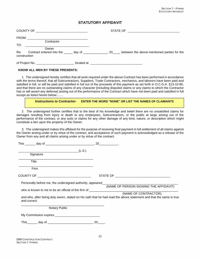
SECTION 7 – FORMS STATUTORY AFFIDAVIT
DBB CONSTRUCTION CONTRACT SECTION 7, FORMS
11
STATUTORY AFFIDAVIT COUNTY OF ______________________________ STATE OF ______________________________ FROM: ___________________________________ Contractor TO: _____________________________________
Owner Re: Contract entered into the _____ day of ______________, 20____, between the above-mentioned parties for the construction of Project No. ______________________ located at ______________________________
KNOW ALL MEN BY THESE PRESENTS:
1. The undersigned hereby certifies that all work required under the above Contract has been performed in accordance with the terms thereof, that all Subcontractors, Suppliers, Trade Contractors, mechanics, and laborers have been paid and satisfied in full, or will be paid and satisfied in full out of the proceeds of this payment as set forth in O.C.G.A. §13-10-80, and that there are no outstanding claims of any character [including disputed claims or any claims to which the Contractor has or will assert any defense] arising out of the performance of the Contract which have not been paid and satisfied in full except as listed herein below:.......
2. The undersigned further certifies that to the best of his knowledge and belief there are no unsatisfied claims for damages resulting from injury or death to any employees, Subcontractors, or the public at large arising out of the performance of the contract, or any suits or claims for any other damage of any kind, nature, or description which might constitute a lien upon the property of the Owner.
3. The undersigned makes this affidavit for the purpose of receiving final payment in full settlement of all claims against the Owner arising under or by virtue of the contract, and acceptance of such payment is acknowledged as a release of the Owner from any and all claims arising under or by virtue of the contract.
This ______ day of ____________________________, 20___________.
___________________________________(L.S.)
Signature ___________________________________________ Title ___________________________________________ Firm
COUNTY OF _______________________________ STATE OF ________________________________
Personally before me, the undersigned authority, appeared____________________________________________ (NAME OF PERSON SIGNING THE AFFIDAVIT)
who is known to me to be an official of the firm of ___________________________________________________, (NAME OF CONTRACTOR) and who, after being duly sworn, stated on his oath that he had read the above statement and that the same is true and correct. ________________________________________________ Notary Public My Commission expires __________________________ This______ day of __________________________, 20____.
Instructions to Contractor- ENTER THE WORD "NONE" OR LIST THE NAMES OF CLAIMANTS

SECTION 7 – FORMS FIVE-YEAR ROOF AND WALL BOND
DBB CONSTRUCTION CONTRACT SECTION 7, FORMS
12
FIVE YEAR BOND ON ROOFS AND WALLS
STATE OF GEORGIA COUNTY OF ______________________________
Firmly Bound. Know all men by these presents, that we, ________________ (“Contractor”) as Principal, and (Name of Surety), as Surety, are held and firmly bound unto ______________________________________________________________________________,
(Insert Name of Owner) Owner, in the sum of____________ Dollars ($______________) for the payment of which well and truly to be made and done, we bind ourselves, our executors and administrators, our successors and assigns, jointly and severally, by these presents.
Condition of Obligation. The condition of the above obligation is such that WHEREAS Contractor has entered into a Contract with Owner dated_________________ (enter date of contract), for construction of Project No.________________.
Warranty. WHEREAS, the said Contractor warrants with respect to the said work that for a period of five years from the date of the execution of the final certificate of the Design Professional, the roofs of the building (or buildings) and roofs of passages, including but not limited to the roof envelope, including but not limited to the roof decking; deck sheathing; material used as a roof base or insulation over which roof is applied; roofing materials; promenade decks or any other work on the surface of the roof; flashing; base flashing; counter flashing; metal work, gravel stops; or roof expansion joints shall be absolutely watertight and free from all leaks. At no expense to the Owner, the Contractor will make repairs to any defects that may develop in the work including but not limited to: blisters, exposed felts, ridges, wrinkles, splits, warped insulation, and loose flashing, in a manner compatible to the system and acceptable under industry standards and in accordance with the construction specifications. The Contractor also warrants that for the same five-year period the walls of the building (or buildings) and building envelope, including but not limited to: vertical and/or horizontal expansion joints, below and/or above grade waterproofing, below and/or above grade damp-proofing, thru-wall flashing, damp course flashing and waterproofing of joints at openings in walls including but not limited to door perimeters, window perimeters, vents and pipe openings shall be absolutely watertight and free from all leaks, seepage or dampness, and that he shall, at no expense to the Owner, make repairs to any defects that may develop in the work in a manner compatible to the system and acceptable under industry standards and in accordance with the construction specifications, Provided, however: That the following are excluded from the warranty:
(a) Defects or failures resulting from abuse by the Owner, upon presentation of competent evidence of same by the Contractor.
(b) Defects in design that the said Contractor shall produce competent evidence of having had provided clear written notice in writing to the Owner prior to commencing installation of the Work, except, however, that the Contractor shall not be responsible, insofar as liability under this bond is concerned, for bringing to the attention of the Owner defects in design involving failure of only the following three structural elements:
(1) Structural Frame (2) Load bearing walls (3) Foundations
nor shall the Contractor be responsible for correction of leaks resulting from said failure.
(c) Damage caused by fire, tornado, hail, hurricane, acts of God, wars, riots, or civil commotion upon presentation of competent evidence of same by the Contractor..
(d) The Contractor is not an insurer nor is he a guarantor of the design. Any other provisions of this bond to the contrary notwithstanding, the Contractor shall not be required to remedy any errors or omissions of design.
Leaks or Defects. WHEREAS the said Contractor agrees that should any leaks or defects occur in the roof envelope or wall envelope of the said (Name and Number of Project) the said Contractor will promptly remedy the said leaks or defects and pay for any damage to other work of said Project resulting therefrom, except, however, that when this instrument is executed by a Trade Contractor this Contract, shall, insofar as the Trade Contractor is concerned, extend only to the work executed by said Trade Contractor.
Notice to Surety. If the Contractor shall have been given notice to remedy leaks or defects pursuant to the Contract Documents and has been declared in default by the Owner and the Owner has terminated the Contractor’s right to complete the remedy, the Surety shall be notified in writing and shall promptly perform this bond agreement in accordance with its terms and conditions. If Surety chooses to investigate, Owner shall cooperate with the Surety in its investigation and shall make all public project records available for inspection by Surety at no cost to Owner. It shall be the duty of the Surety to give an unequivocal notice in writing to the Owner, within twenty-five
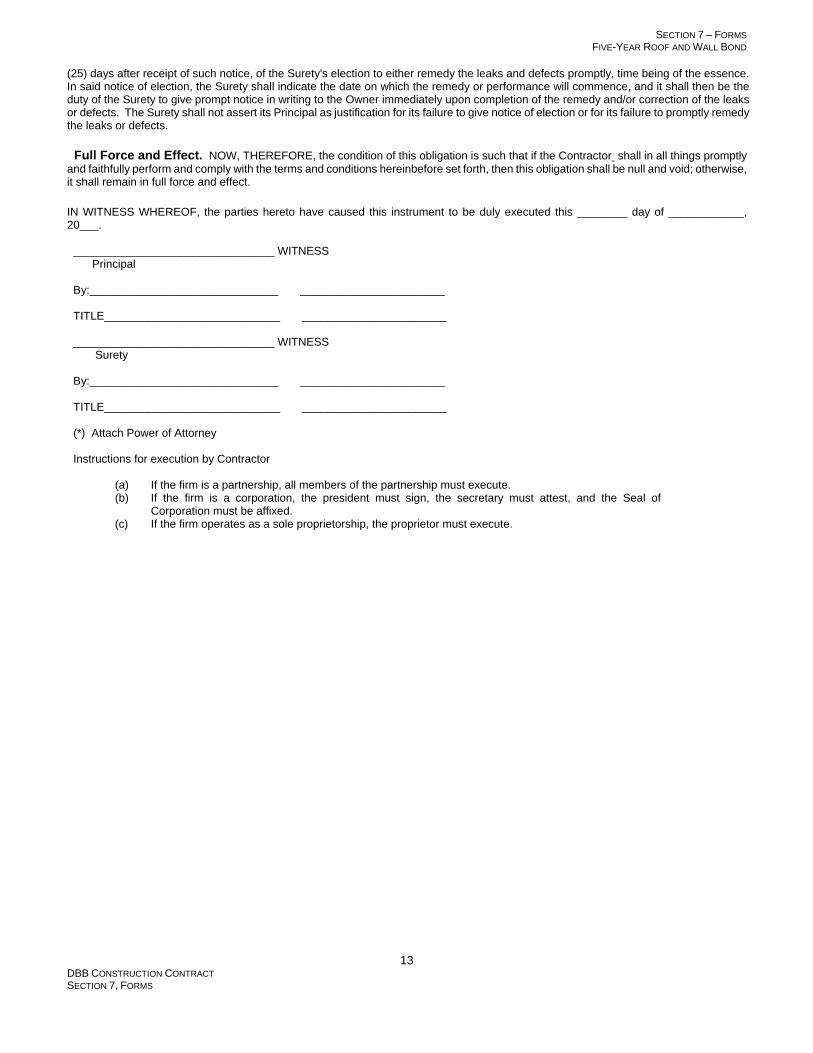
SECTION 7 – FORMS FIVE-YEAR ROOF AND WALL BOND
DBB CONSTRUCTION CONTRACT SECTION 7, FORMS
13
(25) days after receipt of such notice, of the Surety's election to either remedy the leaks and defects promptly, time being of the essence. In said notice of election, the Surety shall indicate the date on which the remedy or performance will commence, and it shall then be the duty of the Surety to give prompt notice in writing to the Owner immediately upon completion of the remedy and/or correction of the leaks or defects. The Surety shall not assert its Principal as justification for its failure to give notice of election or for its failure to promptly remedy the leaks or defects.
Full Force and Effect. NOW, THEREFORE, the condition of this obligation is such that if the Contractor shall in all things promptly and faithfully perform and comply with the terms and conditions hereinbefore set forth, then this obligation shall be null and void; otherwise, it shall remain in full force and effect.
IN WITNESS WHEREOF, the parties hereto have caused this instrument to be duly executed this ________ day of ____________, 20___. ________________________________ WITNESS Principal By:______________________________ _______________________ TITLE____________________________ _______________________ ________________________________ WITNESS Surety By:______________________________ _______________________ TITLE____________________________ _______________________ (*) Attach Power of Attorney Instructions for execution by Contractor
(a) If the firm is a partnership, all members of the partnership must execute. (b) If the firm is a corporation, the president must sign, the secretary must attest, and the Seal of
Corporation must be affixed. (c) If the firm operates as a sole proprietorship, the proprietor must execute.

SECTION 7 – FORMS BOND TO DISCHARGE CLAIM
DBB CONSTRUCTION CONTRACT SECTION 7, FORMS
14
SPECIMEN CERTIFICATE OF MANUFACTURER INSTRUCTIONS FOR PREPARATION OF CERTIFICATE: To be acceptable, the certificate must be prepared in the form indicated by this specimen on the official letterhead of the manufacturer. No portions of the certificate may be omitted. Attached is a copy of the Contract provision under which the certificate is required. The Authority needs only one copy of the certificate. If equipment of a manufacturer is not installed in strict compliance with the recommendations of the manufacturer or if in the design of the work the equipment is not applied in strict compliance with the recommendations of the manufacturer, a letter from the manufacturer should be forwarded to the Contractor [with copies to the Design Professional and the Owner] setting forth a list of the deviations from the recommendations of the manufacturer and stating what remains to be done in order to bring the work into strict compliance with the recommendations of the manufacturer. Prior to calling upon the representative of the manufacturer for performance of the services necessary to enable him to execute a certificate in accordance with this specimen, it is the obligation of the Contractor to have installed the work in strict compliance with the recommendations of the manufacturer [See Article 2.2.4 of the Contract], and it is likewise the obligation of the Contractor to have put the equipment in good operating condition in absolute and final readiness for the "start-up,” "testing,” and "placing into operation" as defined herein below by the representative of the manufacturer.
Date:_______________________________
Re: Certificate of [JOHN DOE CORPORATION] that equipment or components furnished by it has [or have, as the case may be] been installed in strict compliance with its recommendations and is [or are, as the case may be] operating properly at PROJECT NO._________________
Gentlemen:
1. We certify through our duly authorized and acting agent that the following item [or items, as the case may be] furnished by us to the Project named in the caption was [or were, as the case may be] started up, tested, and placed in operation by our authorized field representative on [enter the date on which the field representative performed the start-up, test, and placing into operation] and is [or are, as the case may be] operating properly:
[List the item or items furnished to the job. Show catalogue number or numbers.]
2. We certify further that the aforesaid equipment was installed in strict compliance with our recommendations as published by us in the following document [or documents, as the case may be]:
[Insert the date, name, or other positive means of identifying the exact document or documents in which the recommendations for installation and use of the item or items are published.] (*)
3. A copy of the aforesaid document(s) is (are) attached hereto.
This __________________ day of________________, 20____
JOHN DOE CORPORATION
By:_________________________________ Authorized Representative
(*) The date must be shown [See Article 6.4.1.2.5 DEFINITIONS: l. "Start-up" is defined as putting the equipment into action. 2. "Testing" is defined as performing such testing as is stipulated in the Contract Documents to be performed. 3. "Placing into operation" is defined as operating the equipment for a sufficient period of time for the determination to be made that it is performing properly.
Insert name and address of Owner

SECTION 7 – FORMS BOND TO DISCHARGE CLAIM
DBB CONSTRUCTION CONTRACT SECTION 7, FORMS
15

SECTION 7 – FORMS BOND TO DISCHARGE CLAIM
DBB CONSTRUCTION CONTRACT SECTION 7, FORMS
16
THIS FORM IS FOR OPTIONAL USE TO RELEASE TO THE CONTRACTOR FUNDS WITHHELD FROM A PAY APPLICATION IN THE EVENT A
SUBCONTRACTOR FILES A CLAIM AGAINST THE CONTRACT BALANCE HELD BY THE OWNER THAT REMAINS UNRESOLVED. THIS IS A
SUBORDINATE DOCUMENT TO THE PAYMENT BOND FOR THE PROJECT, AND IS CALCULATED AGAINST THE PENAL AMOUNT OF THAT
PAYMENT BOND. THERE ARE OTHER METHODS THAT MAY BE USED TO REMEDY SUCH SITUATIONS, HOWEVER, THIS FORM IS
EFFECTIVE WHEN NONE OF THE PARTIES ARE ABLE TO REACH AGREEMENT UPON THE CLAIM.
BOND TO DISCHARGE CLAIM WHEREAS, _______________________________________________________ (hereinafter referred to as “Claimant” has filed a claim against ______________________________________________________________ (the “Contractor”, hereinafter referred to as “Principal”) on the following contract: WHEREAS, the undersigned Principal and Surety have issued Payment Bond No. _____________________ (the “Primary Bond”) to the Owner, as Obligee, on the Contract dated ___________ for Project ______ _________________________________ ; WHEREAS, the undersigned Principal and Surety dispute the Claimant’s entitlement to all or part of the claim and expressly reserve all rights and defenses available at law in connection therewith; WHEREAS, ___________________________________________________________ as Principal and __________________________________________________ as Surety, desire to continue to receiving payments from the Owner for work done on the above referenced project, NOW THEREFORE, in consideration of these premises, the undersigned Principal and Surety do hold themselves firmly bond unto __________________________________________________ as Claimant, in the total amount of _______________________________________ dollars ($_____________), representing double the amount of the claim. The condition of this Bond to Discharge Claim is such that should the undersigned Principal or Surety pay to the Claimant the sum that may be found to be due to the Claimant upon the trial of any action that may be filed by said Claimant, or if Principal or Surety pay to the Claimant a sum agreeable to Claimant and Claimant accepts such payment, then this Bond shall be void; otherwise to remain in full force and effect. The penal amount of the Primary Bond is conditionally reduced by the amount of this Bond to Discharge Claim, and upon payment of any sums to the Obligee under this Bond to Discharge Claim, the penal amount of the Primary Bond is reduced instanter by the amount of such payment. No action can be instituted on this bond after one year from the date of Final Completion as determined pursuant to Article 6.2.2 of the Contract. IN WITNESS WHEREOF, the said Principal and Surety have set their hands and seals this _____ day of ____________, 20___.
_________________________________ Principal by:_______________________________ _________________________________ Surety by:_______________________________ Attorney-in-Fact _________________________________ Type Name Above
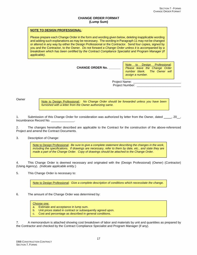
SECTION 7 - FORMS CHANGE ORDER FORMAT
DBB CONSTRUCTION CONTRACT SECTION 7, FORMS
17
CHANGE ORDER FORMAT (Lump Sum)
CHANGE ORDER No. _______
Project Name: ____________________________ Project Number: __________________________
Owner 1. Submission of this Change Order for consideration was authorized by letter from the Owner, dated , 20__, Incumbrance Record No. . 2. The changes hereinafter described are applicable to the Contract for the construction of the above-referenced Project and amend the Contract Documents. 3. Description of Change: 4. This Change Order is deemed necessary and originated with the (Design Professional) (Owner) (Contractor) (Using Agency). (Indicate applicable entity.) 5. This Change Order is necessary to: 6. The amount of the Change Order was determined by: 7. A memorandum is attached showing cost breakdown of labor and materials by unit and quantities as prepared by the Contractor and checked by the Contract Compliance Specialist and Program Manager (if any).
NOTE TO DESIGN PROFESSIONAL: Please prepare each Change Order in the form and wording given below, deleting inapplicable wording and adding such explanations as may be necessary. The wording in Paragraph 11 may not be changed or altered in any way by either the Design Professional or the Contractor. Send four copies, signed by you and the Contractor, to the Owner. Do not forward a Change Order unless it is accompanied by a breakdown which has been certified by the Contract Compliance Specialist and Program Manager (if applicable).
Note to Design Professional: Please leave the Change Order number blank. The Owner will assign a number.
Choose one: a. Estimate and acceptance in lump sum. b. Unit prices stated in contract or subsequently agreed upon. c. Cost and percentage as described in general conditions.
Note to Design Professional:: No Change Order should be forwarded unless you have been furnished with a letter from the Owner authorizing same.
Note to Design Professional: Be sure to give a complete statement describing the changes in the work, including the specifications. If drawings are necessary, refer to them by date, etc., and state they are made a part of the Change Order. Copy of drawings should be attached to the Change Order.
Note to Design Professional: Give a complete description of conditions which necessitate the change.

SECTION 7 - FORMS CHANGE ORDER FORMAT
DBB CONSTRUCTION CONTRACT SECTION 7, FORMS
18
8. We have verified the quantity and quality of all materials shown on the memorandum. We have verified that all prices are reasonable and do not exceed current costs for like services or materials, and we have verified that the quality of the materials meets the requirements of the Contract Documents. 9. The contractor shall be allowed additional calendar days for completion. The Material Completion and Occupancy Date is: __________________ . 10. The Contract Sum shall be (increased) (decreased) by $ _________________ on account of this change. 11. The payment and extension of time, if any, provided by this Change Order constitutes compensation in full to the Contractor and its Subcontractors, Suppliers, and Trade Contractors for all costs and markups, directly and indirectly attributable to the changes ordered herein, and for all delays or time related costs thereto and for any acceleration costs for performance of changes within the time stated and to be completed by the Material Completion and Occupancy Date and for any claims related thereto against the Owner and the Design Professional, and design consultants. APPROVED AND AGREED BY CONTRACTOR: RECOMMENDED FOR OWNER'S ACCEPTANCE LEGAL GC Firm Name DESIGN PROFESSIONAL: LEGAL DP Firm Name By: By: (Print Name/Title) (Print Name/Title) Date approved by Contractor: Date approved by Design Professional: APPROVED AND AGREED BY USING AGENCY: APPROVED AND AGREED BY OWNER: INSTITUTION NAME BOARD OF REGENTS OF THE UNIVERSITY By: By: (Print Name/Title) (Print Name/Title) Date approved by Using Agency: Date approved by Owner:
Note to Design Professional: Please insert the number of additional Days allowed and the new Material Completion and Occupancy Date, or, if no additional time is allowed, insert “0” for the Days and “No Change” for the date.
Note to Design Professional: Please observe that verification of quantities and prices means the Design Professional who signs the Change Order has personal knowledge that the quantities shown in the memorandum referred to under paragraph 7 above are correct, that he has personally satisfied himself that full credit has been extended for any work or materials deleted or omitted, and that he has conclusively established by such checking or inquire as may be necessary that the prices and allowances shown in the memorandum comparable with current costs for like services and materials.
Note to Design Professional: Please delete inapplicable language in parentheses and enter the dollar amount for this change. Insure that cost of the Work, percentage markup for profit, and the daily rate of general conditions costs is accurate and included in the amount of an additive change. If a deductive change, the amount is generally cost of the work only; however, consult with the owner in significant deductive Change Orders to determine if time or profit should be included in the deducted amount.

SECTION 7 - FORMS CHANGE ORDER FORMAT
DBB CONSTRUCTION CONTRACT SECTION 7, FORMS
19
CHANGE ORDER FORMAT (Force Account or Indeterminate Units)
CHANGE ORDER No. _______
Project Name: ____________________________ Project Number: __________________________
Owner 1. Submission of this Change Order for consideration was authorized by letter from the Owner, dated , 20__, Incumbrance Record No. . 2. The changes hereinafter described are applicable to the Contract for the construction of the above-referenced Project and amend the Contract Documents.. 3. Description of Change: 4. This Change Order is deemed necessary and originated with the (Design Professional) (Owner) (Contractor) (Using Agency). (Indicate applicable entity.) 5. This Change Order is necessary to: 6. The Maximum Allowable Cost of the Change Order was estimated by:
NOTE TO DESIGN PROFESSIONAL: Please prepare each Change Order in the form and wording given below, deleting inapplicable wording and adding such explanations as may be necessary. The wording in Paragraph 8 may not be changed or altered in any way by either the Design Professional or the Contractor. The wording in Paragraph 5 of the Final Cost Amendment may not be changed or altered in any way by either the Design Professional or the Contractor. Send four copies, signed by you and the Contractor, to the Owner. Do not forward a Change Order unless it is accompanied by a breakdown which has been checked by the Contract Compliance Specialist and Program Manager (if applicable).
Note to Design Professional: Please leave the Change Order number blank. The Owner will assign a number.
Choose one: a. Estimate in lump sum. b. Unit prices stated in contract or subsequently agreed upon, and an estimated number of units. c. Cost and percentage as described in general conditions.
Note to Design Professional:: No Change Order should be forwarded unless you have been furnished with a letter from the Owner authorizing same.
Note to Design Professional: Be sure to give a complete statement describing the changes in the work, including the specifications. If drawings are necessary, refer to them by date, etc., and state they are made a part of the Change Order. Copy of drawings should be attached to the Change Order.
Note to Design Professional: Give a complete description of conditions which necessitate the change.

SECTION 7 - FORMS CHANGE ORDER FORMAT
DBB CONSTRUCTION CONTRACT SECTION 7, FORMS
20
7. A memorandum is attached showing the estimated cost breakdown of labor and materials by unit and quantities as prepared by the Contractor and checked by the Contract Compliance Specialist and Program Manager (if any). 8. The Maximum Allowed Cost for this Change Order is $ __________________________, and is established as Incumbrance Record No. _______________ . This Maximum Allowed Cost may be amended by the Owner in the event the actual costs are expected to exceed the Maximum Allowed Cost, provided that Contractor shall give written notice of such fact prior to incurring actual costs in excess of ninety percent of the Maximum Allowable Cost. In no event shall actual costs be incurred in excess of the Maximum Allowed Cost, as it may be amended. APPROVED AND AGREED BY CONTRACTOR: RECOMMENDED FOR OWNER'S ACCEPTANCE LEGAL GC Firm Name DESIGN PROFESSIONAL: LEGAL DP Firm Name
By: By: (Print Name/Title) (Print Name/Title) Date approved by Contractor: Date approved by Design Professional: APPROVED AND AGREED BY USING AGENCY: APPROVED AND AGREED BY OWNER: INSTITUTION NAME BOARD OF REGENTS OF THE UNIVERSITY By: By: (Print Name/Title) (Print Name/Title) Date approved by Using Agency: Date approved by Owner:

SECTION 7 - FORMS CHANGE ORDER FORMAT
DBB CONSTRUCTION CONTRACT SECTION 7, FORMS
21
FINAL COST AMENDMENT TO
CHANGE ORDER NO. ___________ 1. A memorandum is attached showing cost breakdown of labor and materials by unit and quantities as prepared by the Contractor and checked by the Contract Compliance Specialist and Program Manager (if any). 2. We have verified the quantity and quality of all materials shown on the memorandum. We have verified that all prices are reasonable and do not exceed current costs for like services or materials, and we have verified that the quality of the materials meets the requirements of the Contract Documents. 3. The contractor shall be allowed additional calendar days for completion. The Material Completion and Occupancy date is: __________________ . 4. The Contract Sum shall be (increased) (decreased) by $ _________________ on account of this change. 5. The payment and extension of time, if any, provided by this Change Order constitutes compensation in full to the Contractor and its Subcontractors, Suppliers, and Trade Contractors for all costs and markups, directly and indirectly attributable to the changes ordered herein, and for all delays or time related costs thereto and for any acceleration costs for performance of changes within the time stated and to be completed by the Material Completion and Occupancy Date and for any Claims related thereto against the Owner and the Design Professional, and design consultants. APPROVED AND AGREED BY CONTRACTOR: RECOMMENDED FOR OWNER'S ACCEPTANCE LEGAL GC Firm Name DESIGN PROFESSIONAL: LEGAL DP Firm Name By: By: (Print Name/Title) (Print Name/Title) Date approved by Contractor: Date approved by Design Professional: APPROVED AND AGREED BY USING AGENCY: APPROVED AND AGREED BY OWNER: INSTITUTION NAME BOARD OF REGENTS OF THE UNIVERSITY By: By: (Print Name/Title) (Print Name/Title) Date approved by Using Agency: Date approved by Owner:
Note to Design Professional: Please insert the number of additional Days allowed and the new Material Completion and Occupancy Date, or, if no additional time is allowed, insert “0” for Days and “No Change” for the date.
Note to Design Professional: Please observe the fact that verification of quantities and prices means the Design Professional who signs the Change Order has personal knowledge that the quantities shown in the memorandum referred to under paragraph 7 above are correct, that he has personally satisfied himself that full credit has been extended for any work or materials deleted or omitted, and that he has conclusively established by such checking or inquire as may be necessary that the prices and allowances shown in the memorandum comparable with current costs for like services and materials.
Note to Design Professional: Please delete inapplicable language in parentheses and enter the dollar amount for this change. Insure that cost of the Work, percentage markup for profit, and the daily rate of general conditions costs is accurate and included in the amount of an additive change. If a deductive change, the amount is generally cost of the work only; however, consult with the owner in significant deductive Change Orders to determine if time or profit should be included in the deducted amount.

SECTION 7 - FORMS APPLICATION FOR PAYMENT FORM
DBB CONSTRUCTION CONTRACT SECTION 7, FORMS
22
APPLICATION FOR PAYMENT
APPLICATION FOR PAYMENT NO. PROJECT NO. CERTIFICATE OF THE CONTRACTOR OR HIS DULY AUTHORIZED REPRESENTATIVE
To the best of my knowledge and belief, I certify that all items, units, quantities, and prices of work and material shown on this Application for Payment No. are correct; that all work has been performed and materials supplied in full accordance with the terms and conditions of the Contract Documents between
(Owner) and dated (Contractor)
and all authorized changes thereto; and that the following is a true and correct statement of the contract account up to and including the
last day of the period covered by this Application and that no part of the "amount due this Application" has been received.
(a) Total amount earned for work in place (original contract) $
(b) Total amount earned for work in place (Change Orders) $
(c) Value of materials stored at site $
(d) Total amount earned ( (a) plus (b) plus (c) ) $
(e) Amount retained (10%) $
(f) Total earned less retained percentage ( (d) minus (e) ) $
(g) Total previously approved $
(h) Amount due THIS ESTIMATE ( (f) minus (g) ) $
(i) Retainage payment to Subcontractors per Paragraph 4 .1.2.5 of the General Conditions. $
(j) AMOUNT DUE Contractor ( (h) minus (i) ) $
I further certify that all claims outstanding against the undersigned Contractor for labor, materials, and expendable equipment employed in the performance of said contract have been paid in full in accordance with the requirements of said contract, except such outstanding claims as are listed below or on the attached sheet, which statement contains all claims against the Contractor which are not yet paid, including all disputed claims and any claims to which the Contractor has or will assert any defense.
I further certify that all of the materials indicated on this Application for Payment as being stored on the Site, but not yet incorporated into the building, have been purchased, delivered, and are now stored on the Site for future incorporation into the building and until so incorporated the title to same is, upon payment of this statement, vested in the Owner. Furthermore, the undersigned Contractor assumes full responsibility for the existence, protection, and, if necessary, replacement of the above-mentioned materials until the completion of this contract. Contractor By Date Title STATEMENT OF THE CONTRACT COMPLIANCE SPECIALIST
I have checked this Application for Payment and, to the best of my knowledge and belief, the statement of work performed and statement of materials stored on site by the Contractor are supported by my observations Name Contract Compliance Specialist. Date: CERTIFICATE OF THE DESIGN PROFESSIONAL
I certify that I have verified this Application for Payment and, to the best of my knowledge and belief, it is a true and correct statement of work performed and statement of materials stored on site by the Contractor and that the Contractor's certified statement of his account and the amount due him is correct and just. I further certify that all work has been performed and materials have been supplied in full accordance with the terms and conditions of the Contract Documents and authorized changes thereto. Name Design Professional. Date:

SECTION 7 - FORMS APPLICATION FOR PAYMENT FORM
DBB CONSTRUCTION CONTRACT SECTION 7, FORMS
23
SCHEDULE OF CHANGE ORDERS In support of Application for Payment No. Project No. Period Ending: Contractor:
CHANGE ORDERS
ADDITIONS
DEDUCTIONS
Number (1)
Date (2)
Authorized Amount (3)
Amount this Period (4)
Completed Previous
Periods (5)
Authorized Deductions
(6)

SECTION 7 – FORMS APPLICATION FOR PAYMENT FORM
DBB CONSTRUCTION CONTRACT SECTION 7, FORMS
24
WORK PERFORMED TO DATE In support of Application for Payment No. For the period from , through inclusive. Project No. Name and location of Project Contractor's Name and Address
WORK INCLUDED IN ORIGINAL CONTRACT
DETAILED ESTIMATE
WORK PERFORMED TO DATE
CSI Category and Description
Item No. and Designation (1)
Number & Kind of Units
(2)
Unit Price (3)
Estimated Cost (4)
No. of Units (5)
Amount Earned
to Date (6)
Value of
Incomplete Work
(7)
Percent
Complete (8)
A. Contracting Requirements: * a. b. c, 1. Division 1 – General Requirements: * a. b. c. 2. Division 2 – Site Construction: ** (i) Building a. b. c. (ii) Infrastructure a. b. c. 3. Division 3 – Concrete: * a. b. c. 4. Division 4 – Masonry: ** (i) Building a. b. c. (ii) Infrastructure a. b. c. 5. Division 5 – Metals: * a. b. c.

SECTION 7 – FORMS APPLICATION FOR PAYMENT FORM
DBB CONSTRUCTION CONTRACT SECTION 7, FORMS
25
6. Division 6 – Wood and Plastics: * a. b. c. 7. Division 7 – Thermal & Moisture: ***** a. b. c. Roof: 8. Division 8 – Doors & Windows: * a. b. c. 9. Division 9 – Finishes: * a. b. c. 10. Division 10 – Specialties: * a. b. c. 11. Division 11 – Equipment: *** (i) Fixed or Built-in: a. b. c. (ii) Moveable: a. b. c. 12. Division 12 – Furnishings: *** (i) Fixed or Built-in: a. b. c. (ii) Moveable: a. b. c. 13. Division 13 – Special Construction: * a. b. c. 14. Division 14 – Conveying Systems: * a. b. c. 15. Division 15 – Mechanical: **** (i) Building a. b. c. (ii) Infrastructure a. b. c. 16. Division 16 – Electrical: ** (i) Building a. b. c.

SECTION 7 – FORMS APPLICATION FOR PAYMENT FORM
DBB CONSTRUCTION CONTRACT SECTION 7, FORMS
26
(ii) Infrastructure a. b. c. 17. Division 17 – Special Inspections: ** (i) Building a. b. c. (ii) Infrastructure a. b. c. (iii) Documents
A. Total Amount of original contract
B. Plus or minus total previously approved C. O.'s Nos.-----------incl.
C. Plus or minus C. O.'s Nos.-----------incl. approved during period covered by this est.-----------
D. Total Net Adjusted Amt.
NOTES: The following breakdowns must be accomplished in order to comply with Government Accounting requirements. Upon completion of the Project, the final Application for Payment must show all divisions and sections, and a Final Certification of Costs for Capital Asset Accounting completed and submitted with the Application for Final Payment. * Report Items in each division, by CSI division and such other breakdown as is useful to the Contractor or Contract Compliance
Specialist. ** These items must be broken down into 2 categories, (i) Building and (ii) Infrastructure, reported by specification section.
Infrastructure for these purposes is defined as everything outside a line five feet from the building footprint. *** These items must be broken down into 2 categories; (i) fixed equipment & furnishings and (ii) Moveable equipment & furnishings and
reported by specification section. **** Division 15 – Mechanical. This item must be broken down into 2 categories, (i) Building and (ii) Infrastructure, reported by specification
section. Chillers and HVAC units that serve the facility are to be included as a part of the Building, even if they are outside the 5-foot limit. Chillers and HVAC units that are outside the 5 foot limit and serve more than one facility, such as equipment used in a central plant, are to be included in Infrastructure.
***** Division 7 – Thermal & Moisture Components of the Roof system should be reported as a separate line item. Generally, this includes
components of Sections 7500 and 7600.

SECTION 7 – FORMS APPLICATION FOR PAYMENT FORM
DBB CONSTRUCTION CONTRACT SECTION 7, FORMS
27
SUMMARY OF MATERIALS STORED
In support Application for Payment No. Project No. Period Ending: Contractor:
ITEM NO.
NAME
(Contractor or Subcontractor)
TYPE OF MATERIAL
QUANTITY
AMOUNT (Dollars)
TOTALS
Prepared by for (Contractor) Date , and certified by him to be a true and accurate statement.
Checked:
By: Contract Compliance Specialist
Date:

SECTION 7 – FORMS SUBCONTRACTOR RETAINAGE RELEASE CERTIFICATE
DBB CONSTRUCTION CONTRACT SECTION 7, FORMS
28
SUBCONTRACTOR RETAINAGE RELEASE CERTIFICATE (To be Originated by Subcontractor)
TO: Board of Regents of the University System of Georgia, Owner Institution Name, Using Agency RE: Project Name and Number: Project Number and Description, Institution Name, City, State: Certificate Regarding Subcontractor's Completed Work and Retainage Release 1. This is to certify that our work is one hundred percent complete for our subcontract number . Our retainage is due in accordance with the contract documents. Our scope of work included the . The total amount of retainage now due is $ . 2. The Subcontractor hereby certifies that all work required under the above contract has been performed in accordance with the terms thereof, that all materialmen, subcontractors, mechanics, and laborers have been paid and satisfied in full, and that there are no outstanding claims of any character (including disputed claims or any claims to which the subcontractor has or will assert any defense) arising out of the performance of the contract which have not been paid and satisfied in full except as listed hereinbelow, which exceptions apply only to the release in Paragraph 5, below:
[Enter: "None" or List or Make Reference & Attach Exhibit A.] 3. The Subcontractor further certifies that to the best of his knowledge and belief there are no unsatisfied claims for damages resulting from injury or death to any employees, subcontractors, or the public at large arising out of the performance of the contract, or any suits or claims for any other damage of any kind, nature, or description which might constitute a claim or lien upon the property of the Owner. 4. The Subcontractor has received final payment in full settlement of all claims against the Owner arising under or by virtue the contract, and acceptance of such payment is acknowledged as a release of the Owner from any and all claims arising under or by virtue of the contract. This release includes any claims set forth or excepted in Paragraph 2 above. 5. [Strike out if not applicable] The Subcontractor has received final payment in full settlement of all claims against the Contractor arising under or by virtue the contract, and acceptance of such payment is acknowledged as a release of the Contractor from any and all claims arising under or by virtue of the contract except as set forth in Paragraph 2 above. 6. Payments pursuant to this certificate shall in no way diminish, change, alter or affect the rights of the Owner under the contract documents. SUBCONTRACTOR: By: Date: CONTRACTOR: By: Date: DESIGN PROFESSIONAL: By: Date: NOTICE: OWNER MUST RECEIVE A COPY WITH ALL ORIGINAL SIGNATURES.

SUPPLEMENTARY GENERAL CONDITIONS
DBB CONSTRUCTION CONTRACT 29 SECTION 7, FORMS
FINAL CERTIFICATION OF COSTS FOR CAPITAL ASSET ACCOUNTING
Date: ____________________________________ To: _______________________________________ (Owner) The following accounting of costs for Project No. ______________________________ , Project Name: ____________ _______________________________________ at ______________________________________________________ is submitted as follows, with the breakdown of costs as specified in the Final Pay Request attached hereto and incorporated herein, for the purposes of capital asset accounting pursuant to GASB 34 Accounting Statements: 1. BUILDING AND BUILDING IMPROVEMENTS: * $ _____________________________________ 2. INFRASTRUCTURE: ** $ _____________________________________ 3. FURNISHINGS AND EQUIPMENT: *** $ _____________________________________ ====================================== TOTAL: $ _____________________________________ Notes: (Contractor must insure costs from all Change Orders are apportioned and included in each line item above) * Building: Include totals from Items A, 1, 3, 5, 6, 7, 8, 9, 10, 13, 14, 15 and “Building” portions of Items 2, 4, and 16.
** Infrastructure: Include totals from the “Infrastructure” portions of Items 2, 4 and 16. *** Furnishing and Equipment : Include totals from only the “moveable” portions of Items 11 and 12.
I certify to the best of my knowledge and belief that all of the amounts set forth on this Certificate are true and correct and
are supported by the financial records for this project on file with the Contractor. Contractor By: ___________________________________ Date Title: __________________________________
CERTIFICATE OF THE DESIGN PROFESSIONAL
I certify to the best of my knowledge, information and belief that the amounts certified by the Contractor are consistent with
the estimates provided in my final Statement of Probable Cost for the Project; that the Building Improvement contains a footprint based upon a line 5 feet outside the building structure) of _________ square feet, a total of __________ gross square feet, and contains ______ floors (including basements). The building fire protection system is _________________ (include type of system). The Certificate of Occupancy was issued on _________________________. I further certify that the design intent for this project is that the Building and Building Improvements are of Building Construction Class _________ and ISO Occupancy Type(s) _______ and have an expected useful life of _____________ years from the date of this Certificate, and that my observations of the construction confirm these expectations. (See Exhibit J of Design Professional Contract.) Name Design Professional. Date: ______________________
CERTIFICATE OF THE USING AGENCY OR OWNER
I certify that to the best of my knowledge, information, and belief that the cost of the real property covered by this project, to the boundaries on the final Site Plan, was $ and the cost of additional government-supplied furnishings and equipment acquired for this Project was $ _____________________________________ .
Name Title: ____________________. Date: ________________

SUPPLEMENTARY GENERAL CONDITIONS
1
SUPPLEMENTARY GENERAL CONDITIONS 1. Minority Vendor Designee. The minority vendor designee of the Board of Regents of the University System of Georgia to act as liaison with minority vendors is Ms. Christina Hobbs . For more information, please contact the Board of Regents’ Office of Business Development by e-mail at [email protected]. 2. The use of all forms of tobacco products on property owned, leased, rented, in the possession of, or in any way used by the USG or its affiliates is expressly prohibited. “Tobacco Products” is defined as cigarettes, cigars, pipes, all forms of smokeless tobacco, clove cigarettes and any other smoking devices that use tobacco such as hookahs or simulate the use of tobacco such as electronic cigarettes. (Board of Regents Policy Manual, 9.1.7 Tobacco and Smoke-Free Campus Policy. http://www.usg.edu/policymanual/section9/policy/C503/#p9.1.7_tobacco_and_smoke_free_campus_policy) 3. General Contractor may be required to use e-Builder, the BOR’s Capital Program Management Software.

UGA DESIGN & CONSTRUCTION SPECIAL CONDITIONS (For Design‐Bid‐Build) OUA‐18‐022 (Rock Eagle 4‐H: Bankers Building Renovation) AUGUST 1, 2016 PAGE‐1
UGA DESIGN & CONSTRUCTION SPECIAL CONDTIONS (For Design‐Bid‐Build)
Project Name: Rock Eagle 4‐H: Bankers Building Renovation Design
Project Number: OUA‐18‐022
1. The term Contractor means General Contractor. 2. UGA Design & Construction Supplemental General Requirements and Standards: The Design
Professional shall comply with the requirements set forth in the “UGA DESIGN & CONSTRUCTION SUPPLEMENTAL GENERAL REQUIREMENTS & STANDARDS” dated August 1, 2016 and available at www.architects.uga.edu/standards. The Contractor shall comply with the section “Supplemental General Requirements” of the “UGA DESIGN & CONSTRUCTION SUPPLEMENTAL GENERAL REQUIREMENTS & STANDARDS” dated August 1, 2016 and available at www.architects.uga.edu/standards.
3. Normal Working Times: It is customary that all work under this contract be performed on normal working days. Normal working days are defined as Monday through Friday from 8 am until 5 pm excluding Georgia State holidays. Work during other than normal times to include weekends, holidays and after‐hours shall be coordinated with and subject to approval by the Owner. A minimum of 72‐hour notice is required for the Owner to make all necessary arrangements and such work shall be scheduled at the convenience of the Owner.
4. Construction Restrictions:
A. Existing Facilities: The work to be performed under this contract is located within the University of Georgia’s (UGA) main campus area. Existing UGA facilities to include, but not limited to Rock Eagle 4‐H cabins will be occupied during the life of this contract. The Contractor shall schedule his work and coordinate his labor and equipment in such a manner as to NOT interfere with access to and operation of these facilities.
B. Pedestrian Walkway: The Contractor is advised and cautioned that all roads and walkways around the jobsite are major pedestrian corridors. The Contractor shall schedule his work and coordinate his labor and equipment in such a manner as to NOT interfere with access to and movement along these pedestrian corridors. The Contractor shall clearly designate walkways and provide protective measures to ensure the safe movement of pedestrians around the construction site.
C. Other projects under construction in this area include, but are not limited to, Rock Eagle Cabin Replacement projects. Contractor shall coordinate and schedule his work NOT to interfere with these projects.
5. Hazardous Materials: A. General: Any statement contained herein regarding the presence of hazardous materials (such
as asbestos, lead based paint, Polychlorinated Biphenyls (PCBs) etc.) or absence of hazardous containing materials is based on the best current information in the Owner's possession. Since asbestos and lead based paint were commonly used in construction materials, asbestos‐containing, lead based paint containing materials or other hazardous materials may be encountered during the execution of work under this contract. The Contractor shall exercise extreme care when demolishing, repairing or otherwise disturbing existing work. The Contractor shall cease work immediately if suspected hazardous containing materials are encountered in the work, and notify the Owner in writing of each incident. The Owner shall cooperate with the Contractor, and shall perform all requisite testing to confirm the presence or absence of hazardous containing materials for each reported incident. However, the Owner

UGA DESIGN & CONSTRUCTION SPECIAL CONDITIONS (For Design‐Bid‐Build) OUA‐18‐022 (Rock Eagle 4‐H: Bankers Building Renovation) AUGUST 1, 2016 PAGE‐2
cannot guarantee that the site of the work included under this contract is completely free from hazardous materials. (See General Requirements 1.6.1).
B. Survey: A pre‐construction hazardous materials survey was not conducted. Hazardous materials are not expected as the existing building was abated in the past.
6. Work on Public Streets & Roads: Any work or activity on streets that interferes with traffic movement to include, but not limited to, borings, pavement cuts, open trenches, pavement patches, re‐surfacing, street closings, detours and one‐way traffic shall be coordinated with the local Public Works Department and the Owner at least five working days hours in advance. The Contractor shall be solely responsible for obtaining necessary permits from the local Public Works Department to include completing forms and paying all fees.
7. Job Site Office: For the purposes of this contract, the Superintendent’s vehicle and a mobile phone will be sufficient as the ‘Job Site Office’. At least one copy of the following documents shall be kept in the job site office: Original Contract Specifications; Drawings; and Addenda Approved Change Orders; Component Change Orders (if applicable); Guaranteed Maximum Price Change Order (if applicable) Approved Shop Drawings and Submittals The above documents shall be maintained in a legible condition and stored in a systematic fashion. Notation shall be made in red ink on one set of drawings and specifications calling attention to alterations made by addenda and change orders.
8. No hot work permit is required to complete the Work.


ROCK EAGLE BANKER'S BLDG. RENOVATION TABLE OF CONTENTSMENEFEE ARCHITECTURE 00 01 10 - 1
201712 00 01 10 - 1 16 April 2018
SECTION 00 01 10
TABLE OF CONTENTS
PROCUREMENT AND CONTRACTING REQUIREMENTS
1.01 DIVISION 00 -- PROCUREMENT AND CONTRACTING REQUIREMENTS
A. 00 01 10 - Table of Contents
SPECIFICATIONS
2.01 DIVISION 01 -- GENERAL REQUIREMENTS
A. 01 10 00 - Summary
B. 01 20 00 - Price and Payment Procedures
C. 01 30 00 - Administrative Requirements
D. 01 40 00 - Quality Requirements
E. 01 50 00 - Temporary Facilities and Controls
F. 01 60 00 - Product Requirements
G. 01 70 00 - Execution and Closeout Requirements
H. 01 78 00 - Closeout Submittals
2.02 DIVISION 02 -- EXISTING CONDITIONS
A. 02 41 00 - Demolition
2.03 DIVISION 03 -- CONCRETE
A. 03 10 00 - Concrete Forming and Accessories
B. 03 20 00 - Concrete Reinforcing
C. 03 30 00 - Cast-in-Place Concrete
2.04 DIVISION 04 -- MASONRY
A. 04 20 00 - Unit Masonry
2.05 DIVISION 05 -- METALS (NOT USED)
2.06 DIVISION 06 -- WOOD, PLASTICS, AND COMPOSITES
A. 06 10 00 - Rough Carpentry
2.07 DIVISION 07 -- THERMAL AND MOISTURE PROTECTION
A. 07 31 13 - Asphalt Shingles
B. 07 84 00 - Firestopping
C. 07 90 05 - Joint Sealers
2.08 DIVISION 08 -- OPENINGS
A. 08 12 13 - Hollow Metal Frames
B. 08 14 16 - Flush Wood Doors
C. 08 43 13 - Aluminum-Framed Storefronts
D. 08 71 00 - Finish Hardware
E. 08 80 00 - Glazing
2.09 DIVISION 09 -- FINISHES
A. 09 21 16 - Gypsum Board Assemblies
B. 09 24 00 - Cement Plastering
C. 09 51 00 - Acoustical Ceilings
D. 09 65 00 - Resilient Flooring

ROCK EAGLE BANKER'S BLDG. RENOVATION TABLE OF CONTENTSMENEFEE ARCHITECTURE 00 01 10 - 2
201712 00 01 10 - 2 16 April 2018
E. 09 68 16 - Sheet Carpeting
F. 09 90 01 - Painting and Coatings
2.10 DIVISION 10 -- SPECIALTIES
A. 10 44 00 - Fire Protection Specialties
2.11 DIVISION 11 -- EQUIPMENT
A. 11 33 00 - Retractable Stairs
2.12 DIVISION 12 -- FURNISHINGS (NOT USED)
A. 12 24 14 - Room Darkening Roller Shades
2.13 DIVISION 13 -- SPECIAL CONSTRUCTION (NOT USED)
2.14 DIVISION 14 -- CONVEYING EQUIPMENT (NOT USED)
2.15 DIVISION 21 -- FIRE SUPPRESSION
A. 21 00 00 - Fire Supression
2.16 DIVISION 22 -- PLUMBING
A. 22 00 10 - General Provisions - Plumbing
B. 22 01 00 - Operation and Maintenance of Plumbing
C. 22 05 00 - Common Work Results for Plumbing
D. 22 05 23 - Plumbing Valves and Strainers
E. 22 05 53 - Identification for Plumbing Piping and Equipment
F. 22 07 00 - Plumbing Insulation
G. 22 10 00 - Pipe, Fittings, and Accessories - Plumbing
H. 22 10 05 - Plumbing Piping and Drainage Accessories
I. 22 34 00 - Domestic Water Heating Equipment
J. 22 40 00 - Plumbing Fixtures and Trim
2.17 DIVISION 23 -- HEATING, VENTILATING, AND AIR-CONDITIONING (HVAC)
A. 23 00 10 - General Provision - HVAC
B. 23 05 00 - Common Work Results for HVAC
C. 23 05 93 - Testing Balancing and Adjusting
D. 23 31 00 - Ductwork
E. 23 37 13 - Grilles, Registers, and Diffusers
F. 23 41 00 - Air Filters
2.18 DIVISION 26 -- ELECTRICAL
A. 26 0500 - Common Work Results
B. 26 0519 - Low Voltage Conductors
C. 26 0526 - Grounding
D. 26 0533 - Raceway and Boxes
E. 26 0553 - Identification
F. 26 2400 - Panelboards
G. 26 2726 - Wiring Devices
H. 26 2813 - Fuses
I. 26 2816 - Disconnect Switches
J. 26 5120 - Interior Lighting

ROCK EAGLE BANKER'S BLDG. RENOVATION TABLE OF CONTENTSMENEFEE ARCHITECTURE 00 01 10 - 3
201712 00 01 10 - 3 16 April 2018
END OF TABLE OF CONTENTS

ROCK EAGLE BANKER'S BLDG. RENOVATION SUMMARYMENEFEE ARCHITECTURE 01 10 00 - 1
201712 01 10 00 - 1 16 April 2018
SECTION 01 10 00
SUMMARY
PART 1 GENERAL
1.01 PROJECT
A. Project Name: Rock Eagle Banker's Building Renovation.
B. Owner's Name: University of Georgia.
C. Architect's Name: Menefee Architecture, LLC.
D. The Project consists of the renovation of an existing camp building including siteimprovements.
1.02 CONTRACT DESCRIPTION
A. Contract Type: A single prime contract based on the Cost of the Work plus a fee as describedin Owner Generated Contract.
1.03 DESCRIPTION OF ALTERATIONS WORK
A. Scope of demolition and removal work is shown on drawings and specified in Section 02 41 00.
B. Scope of alterations work is shown on drawings.
1.04 WORK BY OWNER
A. Items noted NIC (Not in Contract) will be supplied and installed by Owner before SubstantialCompletion. Some items include:
B. Owner will supply and install the following:1. Low Voltage Wiring and equipment.2. Audio Visual Equipment.3. Other as required to accomodate a fully functioning space.
1.05 OWNER OCCUPANCY
A. Owner intends to continue to occupy adjacent portions of the existing building during the entireconstruction period.
B. Owner intends to occupy the Project upon Substantial Completion.
C. Cooperate with Owner to minimize conflict and to facilitate Owner's operations.
D. Schedule the Work to accommodate Owner occupancy.
1.06 CONTRACTOR USE OF SITE AND PREMISES
A. Construction Operations: Limited to areas noted on Drawings. See also Civil Drawings.
B. Arrange use of site and premises to allow:1. Owner occupancy.2. Work by Others.3. Use of site and premises by the public.
C. Provide access to and from site as required by law and by Owner:1. Emergency Building Exits During Construction: Keep all exits required by code open
during construction period; provide temporary exit signs if exit routes are temporarilyaltered.
2. Do not obstruct roadways, sidewalks, or other public ways without permit.
D. Existing building spaces may not be used for storage.
E. Time Restrictions:1. Refer to UGA Front End Documents.
F. Utility Outages and Shutdown:1. Consult UGA Front End Documents.2. Prevent accidental disruption of utility services to other facilities.
ROCK EAGLE BANKER'S BLDG. RENOVATION SUMMARYMENEFEE ARCHITECTURE 01 10 00 - 2
201712 01 10 00 - 2 16 April 2018
PART 2 PRODUCTS - NOT USED
PART 3 EXECUTION - NOT USED
END OF SECTION
ROCK EAGLE BANKER'S BLDG. RENOVATION PRICE AND PAYMENT PROCEDURESMENEFEE ARCHITECTURE 01 20 00 - 1
201712 01 20 00 - 1 16 April 2018
SECTION 01 20 00
PRICE AND PAYMENT PROCEDURES
PART 1 GENERAL
1.01 SECTION INCLUDES
A. Procedures for preparation and submittal of applications for progress payments.
B. Documentation of changes in Contract Sum and Contract Time.
C. Change procedures.
D. Correlation of Contractor submittals based on changes.
E. Procedures for preparation and submittal of application for final payment.
1.02 SCHEDULE OF VALUES
A. Form to be used: Owner Provided form. AIA G704 is acceptable as back-up to owner forms forline item breakdown.
B. Forms filled out by hand will not be accepted.
C. Submit Schedule of Values in duplicate within 15 days after date of Owner-ContractorAgreement.
D. Revise schedule to list approved Change Orders, with each Application For Payment.
1.03 APPLICATIONS FOR PROGRESS PAYMENTS
A. Payment Period: Submit at intervals stipulated in the Agreement.
B. Electronic media printout including equivalent information will be considered in lieu of standardform specified; submit sample to Architect for approval.
C. Forms filled out by hand will not be accepted.
D. Execute certification by signature of authorized officer.
E. Use data from approved Schedule of Values. Provide dollar value in each column for each lineitem for portion of work performed and for stored products.
F. Submit three copies of each Application for Payment.
G. Include the following with the application:1. Transmittal letter as specified for Submittals in Section 01 30 00.2. Affidavits attesting to off-site stored products.
H. When Architect requires substantiating information, submit data justifying dollar amounts inquestion. Provide one copy of data with cover letter for each copy of submittal. Showapplication number and date, and line item by number and description.
1.04 MODIFICATION PROCEDURES
A. For minor changes not involving an adjustment to the Contract Sum or Contract Time, Architectwill issue instructions directly to Contractor and copy the owner.
B. For other required changes, Architect will issue a document signed by Owner instructingContractor to proceed with the change, for subsequent inclusion in a Change Order.1. The document will describe the required changes and will designate method of
determining any change in Contract Sum or Contract Time.2. Promptly execute the change.
C. For changes for which advance pricing is desired, Architect will issue a document that includesa detailed description of a proposed change with supplementary or revised drawings andspecifications, a change in Contract Time for executing the change with a stipulation of anyovertime work required and the period of time during which the requested price will beconsidered valid. Contractor shall prepare and submit a fixed price quotation within 5 businessdays days.
ROCK EAGLE BANKER'S BLDG. RENOVATION PRICE AND PAYMENT PROCEDURESMENEFEE ARCHITECTURE 01 20 00 - 2
201712 01 20 00 - 2 16 April 2018
D. Contractor may propose a change by submitting a request for change to Architect, describingthe proposed change and its full effect on the Work, with a statement describing the reason forthe change, and the effect on the Contract Sum and Contract Time with full documentation anda statement describing the effect on Work by separate or other contractors. Document anyrequested substitutions in accordance with Section 01 60 00.
E. Computation of Change in Contract Amount: As specified in the Agreement and Conditions ofthe Contract.1. For change requested by Architect for work falling under a fixed price contract, the amount
will be based on Contractor's price quotation.2. For change requested by Contractor, the amount will be based on the Contractor's request
for a Change Order as approved by Architect.3. For pre-determined unit prices and quantities, the amount will based on the fixed unit
prices.4. For change ordered by Architect without a quotation from Contractor, the amount will be
determined by Architect based on the Contractor's substantiation of costs as specified forTime and Material work.
F. Substantiation of Costs: Provide full information required for evaluation.1. On request, provide following data:
a. Quantities of products, labor, and equipment.b. Taxes, insurance, and bonds.c. Overhead and profit.d. Justification for any change in Contract Time.e. Credit for deletions from Contract, similarly documented.
2. Support each claim for additional costs with additional information:a. Origin and date of claim.b. Dates and times work was performed, and by whom.c. Time records and wage rates paid.d. Invoices and receipts for products, equipment, and subcontracts, similarly
documented.3. For Time and Material work, submit itemized account and supporting data after completion
of change, within time limits indicated in the Conditions of the Contract.
G. After execution of Change Order, promptly revise Schedule of Values and Application forPayment forms to record each authorized Change Order as a separate line item and adjust theContract Sum.
1.05 APPLICATION FOR FINAL PAYMENT
A. Prepare Application for Final Payment as specified for progress payments, identifying totaladjusted Contract Sum, previous payments, and sum remaining due.
END OF SECTION
ROCK EAGLE BANKER'S BLDG. RENOVATION ADMINISTRATIVE REQUIREMENTSMENEFEE ARCHITECTURE 01 30 00 - 1
201712 01 30 00 - 1 16 April 2018
SECTION 01 30 00
ADMINISTRATIVE REQUIREMENTS
PART 1 GENERAL
1.01 SECTION INCLUDES
A. Preconstruction meeting.
B. Progress meetings.
C. Construction progress schedule.
D. Submittals for review, information, and project closeout.
E. Submittal procedures.
1.02 RELATED REQUIREMENTS
A. Section 01 70 00 - Execution and Closeout Requirements: Additional coordinationrequirements.
B. Section 01 78 00 - Closeout Submittals: Project record documents.
PART 2 PRODUCTS - NOT USED
PART 3 EXECUTION
3.01 PRECONSTRUCTION MEETING
A. Owner will schedule a meeting after resolution of GMP.
B. Attendance Required:1. Owner.2. Architect.3. Contractor.4. relevant subcontractors.
C. Agenda:1. Execution of Owner-Contractor Agreement.2. Submission of executed bonds and insurance certificates.3. Distribution of Contract Documents.4. Submission of list of Subcontractors, list of Products, schedule of values, and progress
schedule.5. Designation of personnel representing the parties to Contract, ________ and Architect.6. Procedures and processing of field decisions, submittals, substitutions, applications for
payments, proposal request, Change Orders, and Contract closeout procedures.7. Scheduling.
D. Record minutes and distribute copies within two days after meeting to participants, with twocopies to Architect, Owner, participants, and those affected by decisions made.
3.02 PROGRESS MEETINGS
A. Schedule and administer meetings throughout progress of the Work at maximum bi-monthlyintervals.
B. Make arrangements for meetings, prepare agenda with copies for participants, preside atmeetings.
C. Attendance Required: Job superintendent, major Subcontractors and suppliers, Owner,Architect, as appropriate to agenda topics for each meeting.
D. Agenda:1. Review minutes of previous meetings.2. Review of Work progress.3. Field observations, problems, and decisions.4. Identification of problems that impede, or will impede, planned progress.5. Review of submittals schedule and status of submittals.

ROCK EAGLE BANKER'S BLDG. RENOVATION ADMINISTRATIVE REQUIREMENTSMENEFEE ARCHITECTURE 01 30 00 - 2
201712 01 30 00 - 2 16 April 2018
6. Maintenance of progress schedule.7. Corrective measures to regain projected schedules.8. Planned progress during succeeding work period.9. Maintenance of quality and work standards.10. Effect of proposed changes on progress schedule and coordination.11. Other business relating to Work.
E. Record minutes and distribute copies within two days after meeting to participants, with twocopies to Architect, Owner, participants, and those affected by decisions made.
3.03 CONSTRUCTION PROGRESS SCHEDULE
A. Within 10 days after date of the Agreement, submit preliminary schedule defining plannedoperations for the first 60 days of Work, with a general outline for remainder of Work.
B. If preliminary schedule requires revision after review, submit revised schedule within 10 days.
C. Within 10 days after joint review, submit complete schedule.
D. Submit updated schedule with each Application for Payment.
3.04 SUBMITTALS FOR REVIEW
A. When the following are specified in individual sections, submit them for review:1. Product data.2. Shop drawings.3. Samples for selection.4. Samples for verification.
B. Submit to Architect for review for the limited purpose of checking for conformance withinformation given and the design concept expressed in the contract documents.
C. Samples will be reviewed only for aesthetic, color, or finish selection.
D. After review, provide copies and distribute in accordance with SUBMITTAL PROCEDURESarticle below and for record documents purposes described in Section 01 78 00 - CloseoutSubmittals.
3.05 SUBMITTALS FOR INFORMATION
A. When the following are specified in individual sections, submit them for information:1. Design data.2. Certificates.3. Test reports.4. Inspection reports.5. Manufacturer's instructions.6. Manufacturer's field reports.7. Other types indicated.
B. Submit for Architect's knowledge as contract administrator or for Owner. No action will betaken.
3.06 SUBMITTALS FOR PROJECT CLOSEOUT
A. When the following are specified in individual sections, submit them at project closeout:1. Project record documents.2. Operation and maintenance data.3. Warranties.4. Bonds.5. Other as indicated in Owner's front end documents.6. Other types as indicated.
B. Submit for Owner's benefit during and after project completion.
3.07 SUBMITTAL PROCEDURES
A. Transmit each submittal with a copy of approved submittal form.

ROCK EAGLE BANKER'S BLDG. RENOVATION ADMINISTRATIVE REQUIREMENTSMENEFEE ARCHITECTURE 01 30 00 - 3
201712 01 30 00 - 3 16 April 2018
B. Sequentially number the transmittal form. Revise submittals with original number and asequential alphabetic suffix.
C. Identify Project, Contractor, Subcontractor or supplier; pertinent drawing and detail number, andspecification section number, as appropriate on each copy.
D. Apply Contractor's stamp, signed or initialed certifying that review, approval, verification ofProducts required, field dimensions, adjacent construction Work, and coordination ofinformation is in accordance with the requirements of the Work and Contract Documents.
E. Deliver submittals to Architect at business address.
F. Schedule submittals to expedite the Project, and coordinate submission of related items.
G. For each submittal for review, allow 15 days excluding delivery time to and from the Contractor.
H. Identify variations from Contract Documents and Product or system limitations that may bedetrimental to successful performance of the completed Work.
I. Provide space for Contractor and Architect review stamps.
J. When revised for resubmission, identify all changes made since previous submission.
K. Distribute reviewed submittals as appropriate. Instruct parties to promptly report any inability tocomply with requirements.
L. Submittals not requested will not be recognized or processed.
END OF SECTION

ROCK EAGLE BANKER'S BLDG. RENOVATION QUALITY REQUIREMENTSMENEFEE ARCHITECTURE 01 40 00 - 1
201712 01 40 00 - 1 16 April 2018
SECTION 01 40 00
QUALITY REQUIREMENTS
PART 1 GENERAL
1.01 SECTION INCLUDES
A. References and standards.
B. Quality assurance submittals.
C. Mock-ups.
D. Tolerances.
E. Testing and inspection services.
1.02 RELATED REQUIREMENTS
A. Section 01 30 00 - Administrative Requirements: Submittal procedures.
B. Section 01 60 00 - Product Requirements: Requirements for material and product quality.
1.03 REFERENCE STANDARDS
A. ASTM C1077 - Standard Practice for Laboratories Testing Concrete and Concrete Aggregatesfor Use in Construction and Criteria for Laboratory Evaluation; 2014.
1.04 REFERENCES AND STANDARDS
A. For products and workmanship specified by reference to a document or documents not includedin the Project Manual, also referred to as reference standards, comply with requirements of thestandard, except when more rigid requirements are specified or are required by applicablecodes.
B. Conform to reference standard of date of issue current on date of Contract Documents, exceptwhere a specific date is established by applicable code.
C. Obtain copies of standards where required by product specification sections.
D. Maintain copy at project site during submittals, planning, and progress of the specific work, untilSubstantial Completion.
E. Should specified reference standards conflict with Contract Documents, request clarificationfrom Architect before proceeding.
F. Neither the contractual relationships, duties, or responsibilities of the parties in Contract northose of Architect shall be altered from the Contract Documents by mention or inferenceotherwise in any reference document.
1.05 TESTING AND INSPECTION AGENCIES
A. Owner will employ and pay for services of an independent testing agency to perform specifiedtesting and inspection.
B. Employment of agency in no way relieves Contractor of obligation to perform Work inaccordance with requirements of Contract Documents.
PART 3 EXECUTION
2.01 CONTROL OF INSTALLATION
A. Monitor quality control over suppliers, manufacturers, products, services, site conditions, andworkmanship, to produce Work of specified quality.
B. Comply with manufacturers' instructions, including each step in sequence.
C. Should manufacturers' instructions conflict with Contract Documents, request clarification fromArchitect before proceeding.
D. Comply with specified standards as minimum quality for the Work except where more stringenttolerances, codes, or specified requirements indicate higher standards or more preciseworkmanship.
ROCK EAGLE BANKER'S BLDG. RENOVATION QUALITY REQUIREMENTSMENEFEE ARCHITECTURE 01 40 00 - 2
201712 01 40 00 - 2 16 April 2018
E. Have Work performed by persons qualified to produce required and specified quality.
F. Verify that field measurements are as indicated on shop drawings or as instructed by themanufacturer.
G. Secure products in place with positive anchorage devices designed and sized to withstandstresses, vibration, physical distortion, and disfigurement.
2.02 MOCK-UPS
A. Tests will be performed under provisions identified in this section and identified in the respectiveproduct specification sections.
B. Assemble and erect specified items with specified attachment and anchorage devices,flashings, seals, and finishes.
C. Accepted mock-ups shall be a comparison standard for the remaining Work.
D. Where mock-up has been accepted by Architect and is specified in product specificationsections to be removed, remove mock-up and clear area when directed to do so.
2.03 TOLERANCES
A. Monitor fabrication and installation tolerance control of products to produce acceptable Work. Do not permit tolerances to accumulate.
B. Comply with manufacturers' tolerances. Should manufacturers' tolerances conflict with ContractDocuments, request clarification from Architect before proceeding.
C. Adjust products to appropriate dimensions; position before securing products in place.
2.04 TESTING AND INSPECTION
A. Testing Agency Duties:1. Provide qualified personnel at site. Cooperate with Architect and Contractor in
performance of services.2. Perform specified sampling and testing of products in accordance with specified
standards.3. Ascertain compliance of materials and mixes with requirements of Contract Documents.4. Promptly notify Architect and Contractor of observed irregularities or non-conformance of
Work or products.5. Perform additional tests and inspections required by Architect.6. Submit reports of all tests/inspections specified.
B. Limits on Testing/Inspection Agency Authority:1. Agency may not release, revoke, alter, or enlarge on requirements of Contract Documents.2. Agency may not approve or accept any portion of the Work.3. Agency may not assume any duties of Contractor.4. Agency has no authority to stop the Work.
C. Contractor Responsibilities:1. Deliver to agency at designated location, adequate samples of materials proposed to be
used that require testing, along with proposed mix designs.2. Cooperate with laboratory personnel, and provide access to the Work and to
manufacturers' facilities.3. Provide incidental labor and facilities:
a. To provide access to Work to be tested/inspected.b. To obtain and handle samples at the site or at source of Products to be
tested/inspected.c. To facilitate tests/inspections.d. To provide storage and curing of test samples.
4. Notify Architect and laboratory 24 hours prior to expected time for operations requiringtesting/inspection services.

ROCK EAGLE BANKER'S BLDG. RENOVATION QUALITY REQUIREMENTSMENEFEE ARCHITECTURE 01 40 00 - 3
201712 01 40 00 - 3 16 April 2018
D. Re-testing required because of non-conformance to specified requirements shall be performedby the same agency on instructions by Architect.
E. Re-testing required because of non-conformance to specified requirements shall be paid for byContractor.
2.05 DEFECT ASSESSMENT
A. Replace Work or portions of the Work not conforming to specified requirements.
END OF SECTION

ROCK EAGLE BANKER'S BLDG. RENOVATION TEMPORARY FACILITIES AND CONTROLSMENEFEE ARCHITECTURE 01 50 00 - 1
201712 01 50 00 - 1 16 April 2018
SECTION 01 50 00
TEMPORARY FACILITIES AND CONTROLS
PART 1 GENERAL
1.01 SECTION INCLUDES
A. Temporary utilities.
B. Temporary telecommunications services.
C. Temporary sanitary facilities.
D. Temporary Controls: Barriers, enclosures, and fencing.
E. Security requirements.
F. Vehicular access and parking.
G. Waste removal facilities and services.
H. Field offices.
1.02 TEMPORARY UTILITIES
A. Owner will provide the following:1. Electrical power , consisting of connection to existing facilities.2. Water supply, consisting of connection to existing facilities.
B. New permanent facilities may be used.
1.03 TELECOMMUNICATIONS SERVICES
A. Superintendant shall maintain cell phone for access at jobsite.
1.04 TEMPORARY SANITARY FACILITIES
A. Provide and maintain required facilities and enclosures. Provide at time of project mobilization.
B. Maintain daily in clean and sanitary condition.
1.05 BARRIERS
A. Provide barriers to prevent unauthorized entry to construction areas, to prevent access to areasthat could be hazardous to workers or the public and to protect existing facilities and adjacentproperties from damage from construction operations and demolition.
B. Provide protection for plants designated to remain. Replace damaged plants.
C. Protect non-owned vehicular traffic, stored materials, site, and structures from damage.
1.06 FENCING
A. See Civil Drawings.
B. Provide 6 foot high fence around construction site; equip with vehicular and pedestrian gateswith locks.
1.07 EXTERIOR ENCLOSURES
A. Provide temporary weather tight closure of exterior openings to accommodate acceptableworking conditions and protection for Products, to allow for temporary heating and maintenanceof required ambient temperatures identified in individual specification sections, and to prevententry of unauthorized persons. Provide access doors with self-closing hardware and locks.
1.08 INTERIOR ENCLOSURES
A. Provide temporary partitions as required to separate work areas from Owner-occupied areas,to prevent penetration of dust and moisture into Owner-occupied areas, and to prevent damageto existing materials and equipment.
1.09 SECURITY
A. Provide security and facilities to protect Work, existing facilities, and Owner's operations fromunauthorized entry, vandalism, or theft.

ROCK EAGLE BANKER'S BLDG. RENOVATION TEMPORARY FACILITIES AND CONTROLSMENEFEE ARCHITECTURE 01 50 00 - 2
201712 01 50 00 - 2 16 April 2018
1.10 VEHICULAR ACCESS AND PARKING
A. Comply with Rock Eagle Camp requirements and obtain necessary permits.
B. Provide temporary parking areas to accommodate construction personnel. When site space isnot adequate, provide additional off-site parking.
1.11 WASTE REMOVAL
A. Provide waste removal facilities and services as required to maintain the site in clean andorderly condition.
B. Provide containers with lids. Remove trash from site per owner's requirements.
C. If materials to be recycled or re-used on the project must be stored on-site, provide suitablenon-combustible containers; locate containers holding flammable material outside the structureunless otherwise approved by the authorities having jurisdiction.
D. Open free-fall chutes are not permitted. Terminate closed chutes into appropriate containerswith lids.
1.12 FIELD OFFICES
A. Office: Weathertight, with lighting, electrical outlets, heating, cooling equipment, and equippedwith sturdy furniture, drawing rack, and drawing display table.
B. Provide space for Project meetings, with table and chairs to accommodate 6 persons.
C. Locate offices a minimum distance of 30 feet from existing and new structures.
PART 2 PRODUCTS - NOT USED
PART 3 EXECUTION - NOT USED
END OF SECTION
ROCK EAGLE BANKER'S BLDG. RENOVATION PRODUCT REQUIREMENTSMENEFEE ARCHITECTURE 01 60 00 - 1
201712 01 60 00 - 1 16 April 2018
SECTION 01 60 00
PRODUCT REQUIREMENTS
PART 1 GENERAL
1.01 SECTION INCLUDES
A. General product requirements.
B. Transportation, handling, storage and protection.
C. Product option requirements.
D. Substitution limitations and procedures.
E. Procedures for Owner-supplied products.
F. Maintenance materials, including extra materials, spare parts, tools, and software.
1.02 RELATED REQUIREMENTS
A. Section 01 10 00 - Summary - : Lists of products to be removed from existing building.
B. Section 01 40 00 - Quality Requirements: Product quality monitoring.
C. Section 01 61 16 - Volatile Organic Compound (VOC) Content Restrictions: Requirements forVOC-restricted product categories.
1.03 REFERENCE STANDARDS
A. NEMA MG 1 - Motors and Generators; 2014.
B. NFPA 70 - National Electrical Code; Most Recent Edition Adopted by Authority HavingJurisdiction, Including All Applicable Amendments and Supplements.
1.04 SUBMITTALS
A. Proposed Products List: Submit list of major products proposed for use, with name ofmanufacturer, trade name, and model number of each product.1. Submit within 15 days after date of receipt of Bid Documents.2. For products specified only by reference standards, list applicable reference standards.
B. Product Data Submittals: Submit manufacturer's standard published data. Mark each copy toidentify applicable products, models, options, and other data. Supplement manufacturers'standard data to provide information specific to this Project.
C. Shop Drawing Submittals: Prepared specifically for this Project; indicate utility and electricalcharacteristics, utility connection requirements, and location of utility outlets for service forfunctional equipment and appliances.
D. Sample Submittals: Illustrate functional and aesthetic characteristics of the product, withintegral parts and attachment devices. Coordinate sample submittals for interfacing work.1. For selection from standard finishes, submit samples of the full range of the
manufacturer's standard colors, textures, and patterns.
PART 2 PRODUCTS
2.01 NEW PRODUCTS
A. Provide new products unless specifically required or permitted by the Contract Documents.
B. DO NOT USE products having any of the following characteristics:1. Made outside the United States, its territories, Canada, or Mexico.2. Made using or containing CFC's or HCFC's.3. Made of wood from newly cut old growth timber.
C. Where all other criteria are met, Contractor shall give preference to products that:1. If used on interior, have lower emissions, as defined in Section 01 61 16.2. If wet-applied, have lower VOC content, as defined in Section 01 61 16.3. Are extracted, harvested, and/or manufactured closer to the location of the project.4. Have longer documented life span under normal use.

ROCK EAGLE BANKER'S BLDG. RENOVATION PRODUCT REQUIREMENTSMENEFEE ARCHITECTURE 01 60 00 - 2
201712 01 60 00 - 2 16 April 2018
5. Result in less construction waste.6. Are made of vegetable materials that are rapidly renewable.7. Have a published GreenScreen Chemical Hazard Analysis.
2.02 PRODUCT OPTIONS
A. Products Specified by Reference Standards or by Description Only: Use any product meetingthose standards or description.
B. Products Specified by Naming One or More Manufacturers: Use a product of one of themanufacturers named and meeting specifications, no options or substitutions allowed.
C. Products Specified by Naming One or More Manufacturers with a Provision for Substitutions: Submit a request for substitution for any manufacturer not named.
2.03 MAINTENANCE MATERIALS
A. Furnish extra materials, spare parts, tools, and software of types and in quantities specified inindividual specification sections.
B. Deliver to owner as directed; obtain receipt prior to final payment.
PART 3 EXECUTION
3.01 SUBSTITUTION PROCEDURES
A. Instructions to Bidders specify time restrictions for submitting requests for substitutions duringthe bidding period. Comply with requirements specified in this section.
B. Architect will consider requests for substitutions only within 15 days after date Bid Documents.
C. Substitutions may be considered when a product becomes unavailable through no fault of theContractor.
D. Document each request with complete data substantiating compliance of proposed substitutionwith Contract Documents.
E. A request for substitution constitutes a representation that the submitter:1. Has investigated proposed product and determined that it meets or exceeds the quality
level of the specified product.2. Will provide the same warranty for the substitution as for the specified product.3. Will coordinate installation and make changes to other Work that may be required for the
Work to be complete with no additional cost to Owner.4. Waives claims for additional costs or time extension that may subsequently become
apparent.5. Will reimburse Owner and Architect for review or redesign services associated with
re-approval by authorities.
F. Substitutions will not be considered when they are indicated or implied on shop drawing orproduct data submittals, without separate written request, or when acceptance will requirerevision to the Contract Documents.
G. Substitution Submittal Procedure:1. Submit digital copies of request for substitution for consideration. Limit each request to
one proposed substitution.2. Submit shop drawings, product data, and certified test results attesting to the proposed
product equivalence. Burden of proof is on proposer.3. The Architect will notify Contractor in writing of decision to accept or reject request.
3.02 OWNER-SUPPLIED PRODUCTS
A. See Section 01 10 00 - Summary for identification of Owner-supplied products.
B. Owner's Responsibilities:1. Arrange for and deliver Owner reviewed shop drawings, product data, and samples, to
Contractor.2. Arrange and pay for product delivery to site.3. On delivery, inspect products jointly with Contractor.

ROCK EAGLE BANKER'S BLDG. RENOVATION PRODUCT REQUIREMENTSMENEFEE ARCHITECTURE 01 60 00 - 3
201712 01 60 00 - 3 16 April 2018
4. Submit claims for transportation damage and replace damaged, defective, or deficientitems.
5. Arrange for manufacturers' warranties, inspections, and service.
C. Contractor's Responsibilities:1. Review Owner reviewed shop drawings, product data, and samples.2. Receive and unload products at site; inspect for completeness or damage jointly with
Owner.3. Handle, store, install and finish products.4. Repair or replace items damaged after receipt.
3.03 TRANSPORTATION AND HANDLING
A. Coordinate schedule of product delivery to designated prepared areas in order to minimize sitestorage time and potential damage to stored materials.
B. Transport and handle products in accordance with manufacturer's instructions.
C. Transport materials in covered trucks to prevent contamination of product and littering ofsurrounding areas.
D. Promptly inspect shipments to ensure that products comply with requirements, quantities arecorrect, and products are undamaged.
E. Provide equipment and personnel to handle products by methods to prevent soiling,disfigurement, or damage.
F. Arrange for the return of packing materials, such as wood pallets, where economically feasible.
3.04 STORAGE AND PROTECTION
A. Designate receiving/storage areas for incoming products so that they are delivered according toinstallation schedule and placed convenient to work area in order to minimize waste due toexcessive materials handling and misapplication.
B. Store and protect products in accordance with manufacturers' instructions.
C. Store with seals and labels intact and legible.
D. Store sensitive products in weather tight, climate controlled, enclosures in an environmentfavorable to product.
E. For exterior storage of fabricated products, place on sloped supports above ground.
F. Cover products subject to deterioration with impervious sheet covering. Provide ventilation toprevent condensation and degradation of products.
G. Prevent contact with material that may cause corrosion, discoloration, or staining.
H. Provide equipment and personnel to store products by methods to prevent soiling,disfigurement, or damage.
I. Arrange storage of products to permit access for inspection. Periodically inspect to verifyproducts are undamaged and are maintained in acceptable condition.
END OF SECTION

ROCK EAGLE BANKER'S BLDG. RENOVATION EXECUTION AND CLOSEOUT REQUIREMENTSMENEFEE ARCHITECTURE 01 70 00 - 1
201712 01 70 00 - 1 16 April 2018
SECTION 01 70 00
EXECUTION AND CLOSEOUT REQUIREMENTS
PART 1 GENERAL
1.01 SECTION INCLUDES
A. Examination, preparation, and general installation procedures.
B. Requirements for alterations work, including selective demolition, except removal, disposal,and/or remediation of hazardous materials and toxic substances.
C. Pre-installation meetings.
D. Cutting and patching.
E. Surveying for laying out the work.
F. Cleaning and protection.
G. Starting of systems and equipment.
H. Demonstration and instruction of Owner personnel.
I. Closeout procedures, except payment procedures.
1.02 RELATED REQUIREMENTS
A. Section 01 10 00 - Summary: Limitations on working in existing building; continued occupancy;work sequence; identification of salvaged and relocated materials.
B. Section 01 30 00 - Administrative Requirements: Submittals procedures.
C. Section 01 40 00 - Quality Requirements: Testing and inspection procedures.
D. Section 01 50 00 - Temporary Facilities and Controls: Temporary interior partitions.
E. Section 01 78 00 - Closeout Submittals: Project record documents, operation and maintenancedata, warranties and bonds.
1.03 REFERENCE STANDARDS
A. NFPA 241 - Standard for Safeguarding Construction, Alteration, and Demolition Operations;2013.
1.04 SUBMITTALS
A. See Section 01 30 00 - Administrative Requirements, for submittal procedures.
B. Survey work: Submit name, address, and telephone number of Surveyor before starting surveywork.1. On request, submit documentation verifying accuracy of survey work.2. Submit a copy of site drawing signed by the Land Surveyor, that the elevations and
locations of the work are in conformance with Contract Documents.3. Submit surveys and survey logs for the project record.
C. Cutting and Patching: Submit written request in advance of cutting or alteration that affects:1. Structural integrity of any element of Project.2. Integrity of weather exposed or moisture resistant element.3. Efficiency, maintenance, or safety of any operational element.4. Visual qualities of sight exposed elements.5. Work of Owner or separate Contractor.
D. Project Record Documents: Accurately record actual locations of capped and active utilities.
1.05 QUALIFICATIONS
A. For survey work, employ a land surveyor registered in the State in which the Project is locatedand acceptable to Architect. Submit evidence of Surveyor's Errors and Omissions insurancecoverage in the form of an Insurance Certificate.
B. For design of temporary shoring and bracing, employ a Professional Engineer experienced indesign of this type of work and licensed in the State in which the Project is located.

ROCK EAGLE BANKER'S BLDG. RENOVATION EXECUTION AND CLOSEOUT REQUIREMENTSMENEFEE ARCHITECTURE 01 70 00 - 2
201712 01 70 00 - 2 16 April 2018
1.06 PROJECT CONDITIONS
A. Use of explosives is not permitted.
B. Ventilate enclosed areas to assist cure of materials, to dissipate humidity, and to preventaccumulation of dust, fumes, vapors, or gases.
C. Dust Control: Execute work by methods to minimize raising dust from construction operations. Provide positive means to prevent air-borne dust from dispersing into atmosphere and overadjacent property.1. Provide dust-proof barriers between construction areas and areas continuing to be
occupied by Owner.
D. Noise Control: Provide methods, means, and facilities to minimize noise produced byconstruction operations.1. At All Times: Excessively noisy tools and operations will not be tolerated inside the
building at any time of day; excessively noisy includes jackhammers.
1.07 COORDINATION
A. See Section 01 10 00 for occupancy-related requirements.
B. Coordinate scheduling, submittals, and work of the various sections of the Project Manual toensure efficient and orderly sequence of installation of interdependent construction elements,with provisions for accommodating items installed later.
C. Notify affected utility companies and comply with their requirements.
D. Verify that utility requirements and characteristics of new operating equipment are compatiblewith building utilities. Coordinate work of various sections having interdependent responsibilitiesfor installing, connecting to, and placing in service, such equipment.
E. Coordinate space requirements, supports, and installation of mechanical and electrical workthat are indicated diagrammatically on Drawings. Follow routing shown for pipes, ducts, andconduit, as closely as practicable; place runs parallel with lines of building. Utilize spacesefficiently to maximize accessibility for other installations, for maintenance, and for repairs.
F. In finished areas except as otherwise indicated, conceal pipes, ducts, and wiring within theconstruction. Coordinate locations of fixtures and outlets with finish elements.
G. Coordinate completion and clean-up of work of separate sections.
H. After Owner occupancy of premises, coordinate access to site for correction of defective workand work not in accordance with Contract Documents, to minimize disruption of Owner'sactivities.
PART 2 PRODUCTS
2.01 PATCHING MATERIALS
A. New Materials: As specified in product sections; match existing products and work for patchingand extending work.
B. Type and Quality of Existing Products: Determine by inspecting and testing products wherenecessary, referring to existing work as a standard.
C. Product Substitution: For any proposed change in materials, submit request for substitutiondescribed in Section 01 60 00.
PART 3 EXECUTION
3.01 EXAMINATION
A. Verify that existing site conditions and substrate surfaces are acceptable for subsequent work. Start of work means acceptance of existing conditions.
B. Verify that existing substrate is capable of structural support or attachment of new work beingapplied or attached.
C. Examine and verify specific conditions described in individual specification sections.

ROCK EAGLE BANKER'S BLDG. RENOVATION EXECUTION AND CLOSEOUT REQUIREMENTSMENEFEE ARCHITECTURE 01 70 00 - 3
201712 01 70 00 - 3 16 April 2018
D. Take field measurements before confirming product orders or beginning fabrication, to minimizewaste due to over-ordering or misfabrication.
E. Verify that utility services are available, of the correct characteristics, and in the correctlocations.
F. Prior to Cutting: Examine existing conditions prior to commencing work, including elementssubject to damage or movement during cutting and patching. After uncovering existing work,assess conditions affecting performance of work. Beginning of cutting or patching meansacceptance of existing conditions.
3.02 PREPARATION
A. Clean substrate surfaces prior to applying next material or substance.
B. Seal cracks or openings of substrate prior to applying next material or substance.
C. Apply manufacturer required or recommended substrate primer, sealer, or conditioner prior toapplying any new material or substance in contact or bond.
3.03 PREINSTALLATION MEETINGS
A. When required in individual specification sections, convene a preinstallation meeting at the siteprior to commencing work of the section.
B. Require attendance of parties directly affecting, or affected by, work of the specific section.
C. Notify Architect 5 business days in advance days in advance of meeting date.
D. Prepare agenda and preside at meeting:1. Review conditions of examination, preparation and installation procedures.2. Review coordination with related work.
E. Record minutes and distribute copies within two days after meeting to participants, with twocopies to Architect, Owner, participants, and those affected by decisions made.
3.04 LAYING OUT THE WORK
A. Promptly notify Architect of any discrepancies discovered.
B. Establish elevations, lines and levels. Locate and lay out by instrumentation and similarappropriate means:1. Grid or axis for structures.2. Building foundation, column locations, ground floor elevations, and ________.
C. Periodically verify layouts by same means.
3.05 GENERAL INSTALLATION REQUIREMENTS
A. Install products as specified in individual sections, in accordance with manufacturer'sinstructions and recommendations, and so as to avoid waste due to necessity for replacement.
B. Make vertical elements plumb and horizontal elements level, unless otherwise indicated.
C. Install equipment and fittings plumb and level, neatly aligned with adjacent vertical andhorizontal lines, unless otherwise indicated.
D. Make consistent texture on surfaces, with seamless transitions, unless otherwise indicated.
E. Make neat transitions between different surfaces, maintaining texture and appearance.
3.06 ALTERATIONS
A. Drawings showing existing construction and utilities are based on casual field observation only.1. Verify that construction and utility arrangements are as shown.2. Report discrepancies to Architect before disturbing existing installation.3. Beginning of alterations work constitutes acceptance of existing conditions.
B. Keep areas in which alterations are being conducted separated from other areas that are stilloccupied.1. Provide, erect, and maintain temporary dustproof partitions of construction specified in
Section 01 50 00 in locations indicated on drawings.
ROCK EAGLE BANKER'S BLDG. RENOVATION EXECUTION AND CLOSEOUT REQUIREMENTSMENEFEE ARCHITECTURE 01 70 00 - 4
201712 01 70 00 - 4 16 April 2018
C. Remove existing work as indicated and as required to accomplish new work.1. Remove items indicated on drawings.2. Relocate items indicated on drawings.3. Where new surface finishes are to be applied to existing work, perform removals, patch,
and prepare existing surfaces as required to receive new finish; remove existing finish ifnecessary for successful application of new finish.
4. Where new surface finishes are not specified or indicated, patch holes and damagedsurfaces to match adjacent finished surfaces as closely as possible.
D. Services (Including but not limited to HVAC, Plumbing, Fire Protection, Electrical, andTelecommunications): Remove, relocate, and extend existing systems to accommodate newconstruction.1. Maintain existing active systems that are to remain in operation; maintain access to
equipment and operational components; if necessary, modify installation to allow access orprovide access panel.
2. Where existing systems or equipment are not active and Contract Documents requirereactivation, put back into operational condition; repair supply, distribution, and equipmentas required.
3. Where existing active systems serve occupied facilities but are to be replaced with newservices, maintain existing systems in service until new systems are complete and readyfor service.a. Disable existing systems only to make switchovers and connections; minimize
duration of outages.b. Provide temporary connections as required to maintain existing systems in service.
4. Verify that abandoned services serve only abandoned facilities.5. Remove abandoned pipe, ducts, conduits, and equipment, including those above
accessible ceilings; remove back to source of supply where possible, otherwise cap stuband tag with identification; patch holes left by removal using materials specified for newconstruction.
E. Protect existing work to remain.1. Prevent movement of structure; provide shoring and bracing if necessary.2. Perform cutting to accomplish removals neatly and as specified for cutting new work.3. Repair adjacent construction and finishes damaged during removal work.
F. Adapt existing work to fit new work: Make as neat and smooth transition as possible.
G. Patching: Where the existing surface is not indicated to be refinished, patch to match thesurface finish that existed prior to cutting. Where the surface is indicated to be refinished, patchso that the substrate is ready for the new finish.
H. Refinish existing surfaces as indicated:1. Where rooms or spaces are indicated to be refinished, refinish all visible existing surfaces
to remain to the specified condition for each material, with a neat transition to adjacentfinishes.
2. If mechanical or electrical work is exposed accidentally during the work, re-cover andrefinish to match.
I. Clean existing systems and equipment.
J. Remove demolition debris and abandoned items from alterations areas and dispose of off-site;do not burn or bury.
K. Do not begin new construction in alterations areas before demolition is complete.
L. Comply with all other applicable requirements of this section.
3.07 CUTTING AND PATCHING
A. Whenever possible, execute the work by methods that avoid cutting or patching.
B. See Alterations article above for additional requirements.
C. Perform whatever cutting and patching is necessary to:
ROCK EAGLE BANKER'S BLDG. RENOVATION EXECUTION AND CLOSEOUT REQUIREMENTSMENEFEE ARCHITECTURE 01 70 00 - 5
201712 01 70 00 - 5 16 April 2018
1. Complete the work.2. Fit products together to integrate with other work.3. Provide openings for penetration of mechanical, electrical, and other services.4. Match work that has been cut to adjacent work.5. Repair areas adjacent to cuts to required condition.6. Repair new work damaged by subsequent work.7. Remove samples of installed work for testing when requested.8. Remove and replace defective and non-conforming work.
D. Execute work by methods that avoid damage to other work and that will provide appropriatesurfaces to receive patching and finishing. In existing work, minimize damage and restore tooriginal condition.
E. Employ original installer to perform cutting for weather exposed and moisture resistantelements, and sight exposed surfaces.
F. Cut rigid materials using masonry saw or core drill. Pneumatic tools not allowed without priorapproval.
G. Restore work with new products in accordance with requirements of Contract Documents.
H. Fit work air tight to pipes, sleeves, ducts, conduit, and other penetrations through surfaces.
I. At penetrations of fire rated walls, partitions, ceiling, or floor construction, completely seal voidswith fire rated material in accordance with Section 07 84 00, to full thickness of the penetratedelement.
J. Patching:1. Finish patched surfaces to match finish that existed prior to patching. On continuous
surfaces, refinish to nearest intersection or natural break. For an assembly, refinish entireunit.
2. Match color, texture, and appearance.3. Repair patched surfaces that are damaged, lifted, discolored, or showing other
imperfections due to patching work. If defects are due to condition of substrate, repairsubstrate prior to repairing finish.
3.08 PROGRESS CLEANING
A. Maintain areas free of waste materials, debris, and rubbish. Maintain site in a clean and orderlycondition.
B. Remove debris and rubbish from pipe chases, plenums, attics, crawl spaces, and other closedor remote spaces, prior to enclosing the space.
C. Broom and vacuum clean interior areas prior to start of surface finishing, and continue cleaningto eliminate dust.
D. Collect and remove waste materials, debris, and trash/rubbish from site periodically and disposeoff-site; do not burn or bury.
3.09 PROTECTION OF INSTALLED WORK
A. Protect installed work from damage by construction operations.
B. Provide special protection where specified in individual specification sections.
C. Provide temporary and removable protection for installed products. Control activity in immediatework area to prevent damage.
D. Provide protective coverings at walls, projections, jambs, sills, and soffits of openings.
E. Protect finished floors, stairs, and other surfaces from traffic, dirt, wear, damage, or movementof heavy objects, by protecting with durable sheet materials.
F. Prohibit traffic or storage upon waterproofed or roofed surfaces. If traffic or activity isnecessary, obtain recommendations for protection from waterproofing or roofing materialmanufacturer.

ROCK EAGLE BANKER'S BLDG. RENOVATION EXECUTION AND CLOSEOUT REQUIREMENTSMENEFEE ARCHITECTURE 01 70 00 - 6
201712 01 70 00 - 6 16 April 2018
G. Remove protective coverings when no longer needed; reuse or recycle plastic coverings ifpossible.
3.10 SYSTEM STARTUP
A. Coordinate schedule for start-up of various equipment and systems.
B. Verify that each piece of equipment or system has been checked for proper lubrication, driverotation, belt tension, control sequence, and for conditions that may cause damage.
C. Verify tests, meter readings, and specified electrical characteristics agree with those required bythe equipment or system manufacturer.
D. Verify that wiring and support components for equipment are complete and tested.
E. Execute start-up under supervision of applicable Contractor personnel and manufacturer'srepresentative in accordance with manufacturers' instructions.
F. Submit a written report that equipment or system has been properly installed and is functioningcorrectly.
3.11 DEMONSTRATION AND INSTRUCTION
A. Demonstrate start-up, operation, control, adjustment, trouble-shooting, servicing, maintenance,and shutdown of each item of equipment at agreed time, at equipment location.
B. For equipment or systems requiring seasonal operation, perform demonstration for otherseason within six months.
C. Provide a qualified person who is knowledgeable about the Project to perform demonstrationand instruction of owner personnel.
3.12 ADJUSTING
A. Adjust operating products and equipment to ensure smooth and unhindered operation.
3.13 FINAL CLEANING
A. Execute final cleaning prior to design team punchlist site visit.1. Clean areas to be occupied by Owner prior to final completion before Owner occupancy.
B. Use cleaning materials that are nonhazardous.
C. Clean interior and exterior glass, surfaces exposed to view; remove temporary labels, stainsand foreign substances, polish transparent and glossy surfaces, vacuum carpeted and softsurfaces.
D. Remove all labels that are not permanent. Do not paint or otherwise cover fire test labels ornameplates on mechanical and electrical equipment.
E. Clean equipment and fixtures to a sanitary condition with cleaning materials appropriate to thesurface and material being cleaned.
F. Clean filters of operating equipment.
G. Clean debris from roofs, gutters, downspouts, and drainage systems.
H. Clean site; sweep paved areas, rake clean landscaped surfaces.
I. Remove waste, surplus materials, trash/rubbish, and construction facilities from the site;dispose of in legal manner; do not burn or bury.
3.14 CLOSEOUT PROCEDURES
A. Make submittals that are required by governing or other authorities.
B. Notify Architect when work is considered ready for Substantial Completion.
C. Submit written certification that Contract Documents have been reviewed, work has beeninspected, and that work is complete in accordance with Contract Documents and ready forArchitect's review.
D. Correct items of work listed in executed Certificates of Substantial Completion and comply withrequirements for access to Owner-occupied areas.

ROCK EAGLE BANKER'S BLDG. RENOVATION EXECUTION AND CLOSEOUT REQUIREMENTSMENEFEE ARCHITECTURE 01 70 00 - 7
201712 01 70 00 - 7 16 April 2018
E. Notify Architect when work is considered finally complete.
F. Complete items of work determined by Architect's final inspection.
END OF SECTION

ROCK EAGLE BANKER'S BLDG. RENOVATION CLOSEOUT SUBMITTALSMENEFEE ARCHITECTURE 01 78 00 - 1
201712 01 78 00 - 1 16 April 2018
SECTION 01 78 00
CLOSEOUT SUBMITTALS
PART 1 GENERAL
1.01 SECTION INCLUDES
A. Project Record Documents.
B. Operation and Maintenance Data.
C. Warranties and bonds.
D. Other documents as required by Owner's Front End Documents.
1.02 RELATED REQUIREMENTS
A. Section 01 30 00 - Administrative Requirements: Submittals procedures, shop drawings,product data, and samples.
B. Section 01 70 00 - Execution and Closeout Requirements: Contract closeout procedures.
C. Individual Product Sections: Specific requirements for operation and maintenance data.
D. Individual Product Sections: Warranties required for specific products or Work.
1.03 SUBMITTALS
A. Project Record Documents: Submit documents to Architect with claim for final Application forPayment.
B. Operation and Maintenance Data:1. Submit two copies of preliminary draft or proposed formats and outlines of contents before
start of Work. Architect will review draft and return one copy with comments.2. For equipment, or component parts of equipment put into service during construction and
operated by Owner, submit completed documents within ten days after acceptance.3. Submit one copy of completed documents 15 days prior to final inspection. This copy will
be reviewed and returned after final inspection, with Architect comments. Revise contentof all document sets as required prior to final submission.
4. Submit two sets of revised final documents in final form within 10 days after finalinspection.
5. Conform to Owner's close out document requirements.
C. Warranties and Bonds:1. For equipment or component parts of equipment put into service during construction with
Owner's permission, submit documents within 10 days after acceptance.2. Make other submittals within 10 days after Date of Substantial Completion, prior to final
Application for Payment.3. For items of Work for which acceptance is delayed beyond Date of Substantial
Completion, submit within 10 days after acceptance, listing the date of acceptance as thebeginning of the warranty period.
4. Confirm to Owner's Warranty and Bond requirements.
PART 2 PRODUCTS - NOT USED
PART 3 EXECUTION
3.01 PROJECT RECORD DOCUMENTS
A. Maintain on site one set of the following record documents; record actual revisions to the Work:1. Drawings.2. Specifications.3. Addenda.4. Change Orders and other modifications to the Contract.5. Reviewed shop drawings, product data, and samples.6. Manufacturer's instruction for assembly, installation, and adjusting.
B. Ensure entries are complete and accurate, enabling future reference by Owner.
ROCK EAGLE BANKER'S BLDG. RENOVATION CLOSEOUT SUBMITTALSMENEFEE ARCHITECTURE 01 78 00 - 2
201712 01 78 00 - 2 16 April 2018
C. Store record documents separate from documents used for construction.
D. Record information concurrent with construction progress.
E. Specifications: Legibly mark and record at each product section description of actual productsinstalled, including the following:1. Manufacturer's name and product model and number.2. Product substitutions or alternates utilized.3. Changes made by Addenda and modifications.
F. Record Drawings and Shop Drawings: Legibly mark each item to record actual constructionincluding:1. Field changes of dimension and detail.2. Details not on original Contract drawings.
3.02 OPERATION AND MAINTENANCE DATA
A. Source Data: For each product or system, list names, addresses and telephone numbers ofSubcontractors and suppliers, including local source of supplies and replacement parts.
B. Product Data: Mark each sheet to clearly identify specific products and component parts, anddata applicable to installation. Delete inapplicable information.
C. Drawings: Supplement product data to illustrate relations of component parts of equipment andsystems, to show control and flow diagrams. Do not use Project Record Documents asmaintenance drawings.
D. Typed Text: As required to supplement product data. Provide logical sequence of instructionsfor each procedure, incorporating manufacturer's instructions.
3.03 OPERATION AND MAINTENANCE DATA FOR MATERIALS AND FINISHES
A. For Each Product, Applied Material, and Finish:1. Product data, with catalog number, size, composition, and color and texture designations.2. Information for re-ordering custom manufactured products.
B. Instructions for Care and Maintenance: Manufacturer's recommendations for cleaning agentsand methods, precautions against detrimental cleaning agents and methods, andrecommended schedule for cleaning and maintenance.
C. Additional information as specified in individual product specification sections.
D. Where additional instructions are required, beyond the manufacturer's standard printedinstructions, have instructions prepared by personnel experienced in the operation andmaintenance of the specific products.
3.04 OPERATION AND MAINTENANCE DATA FOR EQUIPMENT AND SYSTEMS
A. For Each Item of Equipment and Each System:1. Description of unit or system, and component parts.2. Identify function, normal operating characteristics, and limiting conditions.3. Include performance curves, with engineering data and tests.4. Complete nomenclature and model number of replaceable parts.
B. Where additional instructions are required, beyond the manufacturer's standard printedinstructions, have instructions prepared by personnel experienced in the operation andmaintenance of the specific products.
C. Operating Procedures: Include start-up, break-in, and routine normal operating instructions andsequences. Include regulation, control, stopping, shut-down, and emergency instructions. Include summer, winter, and any special operating instructions.
D. Maintenance Requirements: Include routine procedures and guide for preventativemaintenance and trouble shooting; disassembly, repair, and reassembly instructions; andalignment, adjusting, balancing, and checking instructions.
E. Provide servicing and lubrication schedule, and list of lubricants required.

ROCK EAGLE BANKER'S BLDG. RENOVATION CLOSEOUT SUBMITTALSMENEFEE ARCHITECTURE 01 78 00 - 3
201712 01 78 00 - 3 16 April 2018
F. Include manufacturer's printed operation and maintenance instructions.
G. Include sequence of operation by controls manufacturer.
H. Provide original manufacturer's parts list, illustrations, assembly drawings, and diagramsrequired for maintenance.
I. Additional Requirements: As specified in individual product specification sections.
3.05 ASSEMBLY OF OPERATION AND MAINTENANCE MANUALS
A. Assemble operation and maintenance data into durable manuals for Owner's personnel use,with data arranged in the same sequence as, and identified by, the specification sections.
B. Where systems involve more than one specification section, provide separate tabbed divider foreach system.
C. Binders: Commercial quality, 8-1/2 by 11 inch three D side ring binders with durable plasticcovers; 2 inch maximum ring size. When multiple binders are used, correlate data into relatedconsistent groupings.
D. Cover: Identify each binder with typed or printed title OPERATION AND MAINTENANCEINSTRUCTIONS; identify title of Project; identify subject matter of contents.
E. Project Directory: Title and address of Project; names, addresses, and telephone numbers ofArchitect, Consultants,Contractorand subcontractors, with names of responsible parties.
F. Tables of Contents: List every item separated by a divider, using the same identification as onthe divider tab; where multiple volumes are required, include all volumes Tables of Contents ineach volume, with the current volume clearly identified.
G. Dividers: Provide tabbed dividers for each separate product and system; identify the contentson the divider tab; immediately following the divider tab include a description of product andmajor component parts of equipment.
H. Text: Manufacturer's printed data, or typewritten data on 20 pound paper.
I. Drawings: Provide with reinforced punched binder tab. Bind in with text; fold larger drawings tosize of text pages.
J. Arrangement of Contents: Organize each volume in parts as follows:1. Project Directory.2. Table of Contents, of all volumes, and of this volume.3. Operation and Maintenance Data: Arranged by system, then by product category.
a. Source data.b. Operation and maintenance data.c. Field quality control data.d. Photocopies of warranties and bonds.
3.06 WARRANTIES AND BONDS
A. Obtain warranties and bonds, executed in duplicate by responsible Subcontractors, suppliers,and manufacturers, within 10 days after completion of the applicable item of work. Except foritems put into use with Owner's permission, leave date of beginning of time of warranty until theDate of Substantial completion is determined.
B. Verify that documents are in proper form, contain full information, and are notarized.
C. Co-execute submittals when required.
D. Retain warranties and bonds until time specified for submittal.
END OF SECTION

ROCK EAGLE BANKER'S BLDG. RENOVATION DEMOLITIONMENEFEE ARCHITECTURE 02 41 00 - 1
201712 02 41 00 - 1 16 April 2018
SECTION 02 41 00
DEMOLITION
PART 1 GENERAL
1.01 SECTION INCLUDES
A. Selective demolition of building elements for alteration purposes.
1.02 RELATED REQUIREMENTS
A. Section 01 10 00 - Summary: Limitations on Contractor's use of site and premises.
B. Section 01 50 00 - Temporary Facilities and Controls: Site fences, security, protective barriers,and waste removal.
C. Section 01 60 00 - Product Requirements: Handling and storage of items removed for salvageand relocation.
D. Section 01 70 00 - Execution and Closeout Requirements: Project conditions; protection ofbench marks, survey control points, and existing construction to remain; reinstallation ofremoved products; temporary bracing and shoring.
1.03 REFERENCE STANDARDS
A. 29 CFR 1926 - U.S. Occupational Safety and Health Standards; current edition.
B. NFPA 241 - Standard for Safeguarding Construction, Alteration, and Demolition Operations;2013.
1.04 QUALITY ASSURANCE
A. Demolition Firm Qualifications: Company specializing in the type of work required.1. Minimum of Five years of documented experience.
PART 2 PRODUCTS -- NOT USED
PART 3 EXECUTION
3.01 GENERAL PROCEDURES AND PROJECT CONDITIONS
A. Comply with other requirements specified in Section 01 70 00.
B. Comply with applicable codes and regulations for demolition operations and safety of adjacentstructures and the public.1. Obtain required permits.2. Comply with applicable requirements of NFPA 241.3. Use of explosives is not permitted.4. Take precautions to prevent catastrophic or uncontrolled collapse of structures to be
removed; do not allow worker or public access within range of potential collapse ofunstable structures.
5. Provide, erect, and maintain temporary barriers and security devices.6. Use physical barriers to prevent access to areas that could be hazardous to workers or the
public.7. Conduct operations to minimize effects on and interference with adjacent structures and
occupants.8. Do not close or obstruct roadways or sidewalks without permit.9. Conduct operations to minimize obstruction of public and private entrances and exits; do
not obstruct required exits at any time; protect persons using entrances and exits fromremoval operations.
10. Obtain written permission from owners of adjacent properties when demolition equipmentwill traverse, infringe upon or limit access to their property.
C. Do not begin removal until receipt of notification to proceed from Owner.
D. Do not begin removal until built elements to be salvaged or relocated have been removed.
E. Protect existing structures and other elements that are not to be removed.1. Provide bracing and shoring.

ROCK EAGLE BANKER'S BLDG. RENOVATION DEMOLITIONMENEFEE ARCHITECTURE 02 41 00 - 2
201712 02 41 00 - 2 16 April 2018
2. Prevent movement or settlement of adjacent structures.3. Stop work immediately if adjacent structures appear to be in danger.
F. Minimize production of dust due to demolition operations; do not use water if that will result inice, flooding, sedimentation of public waterways or storm sewers, or other pollution.
G. If hazardous materials are discovered during removal operations, stop work and notify Architectand Owner; hazardous materials include regulated asbestos containing materials, lead, PCB's,and mercury.
H. Perform demolition in a manner that maximizes salvage and recycling of materials.1. Dismantle existing construction and separate materials.2. Set aside reusable, recyclable, and salvageable materials; store and deliver to collection
point or point of reuse.
3.02 SELECTIVE DEMOLITION FOR ALTERATIONS
A. Drawings showing existing construction and utilities are based on casual field observation andexisting record documents only.1. Verify that construction and utility arrangements are as shown.2. Report discrepancies to Architect before disturbing existing installation.3. Beginning of demolition work constitutes acceptance of existing conditions that would be
apparent upon examination prior to starting demolition.
B. Separate areas in which demolition is being conducted from other areas that are still occupied.1. Provide, erect, and maintain temporary dustproof partitions of construction specified in
Section 01 50 00 in locations indicated on drawings.
C. Remove existing work as indicated and as required to accomplish new work.1. Remove rotted wood, corroded metals, and deteriorated masonry and concrete; replace
with new construction specified.2. Remove items indicated on drawings.
D. Services (Including but not limited to HVAC, Plumbing, Fire Protection, Electrical,Telecommunications, and ______): Remove existing systems and equipment as indicated.1. Maintain existing active systems that are to remain in operation; maintain access to
equipment and operational components.2. Where existing active systems serve occupied facilities but are to be replaced with new
services, maintain existing systems in service until new systems are complete and readyfor service.
3. Verify that abandoned services serve only abandoned facilities before removal.4. Remove abandoned pipe, ducts, conduits, and equipment, including those above
accessible ceilings; remove back to source of supply where possible, otherwise cap stuband tag with identification.
E. Protect existing work to remain.1. Prevent movement of structure; provide shoring and bracing if necessary.2. Perform cutting to accomplish removals neatly and as specified for cutting new work.3. Repair adjacent construction and finishes damaged during removal work.4. Patch as specified for patching new work.
3.03 DEBRIS AND WASTE REMOVAL
A. Remove debris, junk, and trash from site.
B. Leave site in clean condition, ready for subsequent work.
C. Clean up spillage and wind-blown debris from public and private lands.
END OF SECTION

ROCK EAGLE BANKER'S BLDG. RENOVATION CONCRETE FORMING AND ACCESSORIESMENEFEE ARCHITECTURE 03 10 00 - 1
201712 03 10 00 - 1 16 April 2018
SECTION 03 10 00
CONCRETE FORMING AND ACCESSORIES
PART 1 GENERAL
1.01 SECTION INCLUDES
A. Formwork for cast-in place site concrete, with shoring, bracing and anchorage.
B. Form accessories.
C. Form stripping.
1.02 RELATED REQUIREMENTS
A. Section 03 20 00 - Concrete Reinforcing.
B. Section 03 30 00 - Cast-in-Place Concrete.
1.03 REFERENCE STANDARDS
A. ACI 117 - Standard Specifications for Tolerances for Concrete Construction and Materials;2010.
B. ACI 301 - Specifications for Structural Concrete; 2010 (Errata 2012).
C. ACI 318 - Building Code Requirements for Structural Concrete and Commentary; 2011.
D. ACI 347R - Guide to Formwork for Concrete; 2014.
E. PS 1 - Structural Plywood; 2009.
PART 2 PRODUCTS
2.01 FORMWORK - GENERAL
A. Provide concrete forms, accessories, shoring, and bracing as required to accomplishcast-in-place concrete work.
B. Design and construct to provide resultant concrete that conforms to design with respect toshape, lines, and dimensions.
C. Comply with applicable state and local codes with respect to design, fabrication, erection, andremoval of formwork.
D. Comply with relevant portions of ACI 347, ACI 301, and ACI 318.
2.02 WOOD FORM MATERIALS
A. Softwood Plywood: PS 1, C Grade, Group 2.
PART 3 EXECUTION
3.01 EXAMINATION
A. Verify lines, levels and centers before proceeding with formwork. Ensure that dimensions agreewith drawings.
3.02 EARTH FORMS
A. Hand trim sides and bottom of earth forms. Remove loose soil prior to placing concrete.
3.03 ERECTION - FORMWORK
A. Erect formwork, shoring and bracing to achieve design requirements, in accordance withrequirements of ACI 301.
B. Provide bracing to ensure stability of formwork. Shore or strengthen formwork subject tooverstressing by construction loads.
C. Align joints and make watertight. Keep form joints to a minimum.
3.04 FORMWORK TOLERANCES
A. Construct formwork to maintain tolerances required by ACI 117, unless otherwise indicated.

ROCK EAGLE BANKER'S BLDG. RENOVATION CONCRETE FORMING AND ACCESSORIESMENEFEE ARCHITECTURE 03 10 00 - 2
201712 03 10 00 - 2 16 April 2018
3.05 FIELD QUALITY CONTROL
A. An independent testing agency will perform field quality control tests, as specified in Section 0140 00.
B. Inspect erected formwork, shoring, and bracing to ensure that work is in accordance withformwork design, and to verify that supports, fastenings, wedges, ties, and items are secure.
3.06 FORM REMOVAL
A. Do not remove forms or bracing until concrete has gained sufficient strength to carry its ownweight and imposed loads.
B. Loosen forms carefully. Do not wedge pry bars, hammers, or tools against finish concretesurfaces scheduled for exposure to view.
END OF SECTION

ROCK EAGLE BANKER'S BLDG. RENOVATION CONCRETE REINFORCINGMENEFEE ARCHITECTURE 03 20 00 - 1
201712 03 20 00 - 1 16 April 2018
SECTION 03 20 00
CONCRETE REINFORCING
PART 1 GENERAL
1.01 SECTION INCLUDES
A. Reinforcing steel for cast-in-place site concrete.
B. Supports and accessories for steel reinforcement.
1.02 RELATED REQUIREMENTS
A. Section 03 10 00 - Concrete Forming and Accessories.
B. Section 03 30 00 - Cast-in-Place Concrete.
1.03 REFERENCE STANDARDS
A. ACI 301 - Specifications for Structural Concrete; 2010 (Errata 2012).
B. ACI 318 - Building Code Requirements for Structural Concrete and Commentary; 2011.
C. ACI SP-66 - ACI Detailing Manual; 2004.
D. ASTM A184/A184M - Standard Specification for Welded Deformed Steel Bar Mats for ConcreteReinforcement; 2006 (Reapproved 2011).
E. ASTM A615/A615M - Standard Specification for Deformed and Plain Carbon Steel Bars forConcrete Reinforcement; 2015.
F. ASTM A704/A704M - Standard Specification for Welded Steel Plain Bar or Rod Mats forConcrete Reinforcement; 2006 (Reapproved 2011).
G. ASTM A1064/A1064M - Standard Specification for Carbon-Steel Wire and Welded WireReinforcement, Plain and Deformed, for Concrete; 2015.
H. CRSI (P1) - Placing Reinforcing Bars; 2011.
1.04 SUBMITTALS
A. See Section 01 30 00 - Administrative Requirements, for submittal procedures.
B. Shop Drawings: Comply with requirements of ACI SP-66. Include bar schedules, shapes ofbent bars, spacing of bars, and location of splices.1. Prepare shop drawings under seal of a Professional Structural Engineer experienced in
design of work of this type and licensed in the State in which the Project is located.
C. Reports: Submit certified copies of mill test report of reinforcement materials analysis.
1.05 QUALITY ASSURANCE
A. Perform work of this section in accordance with ACI 301.
PART 2 PRODUCTS
2.01 REINFORCEMENT
A. Reinforcing Steel: ASTM A615/A615M Grade 60 - 60,000 psi.1. Deformed billet-steel bars.2. Unfinished.
B. Steel Welded Wire Reinforcement (WWR): Plain type; ASTM A1064/A1064M.
C. Reinforcement Accessories:1. Tie Wire: Annealed, minimum 16 gage, 0.0508 inch.2. Chairs, Bolsters, Bar Supports, Spacers: Sized and shaped for adequate support of
reinforcement during concrete placement.
PART 3 EXECUTION
3.01 PLACEMENT
A. Place, support and secure reinforcement against displacement. Do not deviate from requiredposition.
ROCK EAGLE BANKER'S BLDG. RENOVATION CONCRETE REINFORCINGMENEFEE ARCHITECTURE 03 20 00 - 2
201712 03 20 00 - 2 16 April 2018
B. Do not displace or damage vapor barrier.
C. Accommodate placement of formed openings.
D. Conform to applicable code for concrete cover over reinforcement.
3.02 FIELD QUALITY CONTROL
A. An independent testing agency, as specified in Section 01 40 00, will inspect installedreinforcement for conformance to contract documents before concrete placement.
END OF SECTION

ROCK EAGLE BANKER'S BLDG. RENOVATION CAST-IN-PLACE CONCRETEMENEFEE ARCHITECTURE 03 30 00 - 1
201712 03 30 00 - 1 16 April 2018
SECTION 03 30 00
CAST-IN-PLACE CONCRETE
PART 1 GENERAL
1.01 SECTION INCLUDES
A. Site Concrete for new door landing.
B. Concrete curing.
1.02 RELATED REQUIREMENTS
A. Section 03 10 00 - Concrete Forming and Accessories: Forms and accessories for formwork.
B. Section 03 20 00 - Concrete Reinforcing.
1.03 REFERENCE STANDARDS
A. ACI 117 - Standard Specifications for Tolerances for Concrete Construction and Materials;2010.
B. ACI 211.1 - Standard Practice for Selecting Proportions for Normal, Heavyweight, and MassConcrete; 1991 (Reapproved 2009).
C. ACI 301 - Specifications for Structural Concrete; 2010 (Errata 2012).
D. ACI 302.1R - Guide for Concrete Floor and Slab Construction; 2004 (Errata 2007).
E. ACI 304R - Guide for Measuring, Mixing, Transporting, and Placing Concrete; 2000.
F. ACI 305R - Hot Weather Concreting; 2010.
G. ACI 306R - Cold Weather Concreting; 2010.
H. ACI 308R - Guide to Curing Concrete; 2001 (Reapproved 2008).
I. ACI 318 - Building Code Requirements for Structural Concrete and Commentary; 2011.
J. ASTM C39/C39M - Standard Test Method for Compressive Strength of Cylindrical ConcreteSpecimens; 2015a.
K. ASTM C94/C94M - Standard Specification for Ready-Mixed Concrete; 2015.
L. ASTM C143/C143M - Standard Test Method for Slump of Hydraulic-Cement Concrete; 2012.
M. ASTM C150/C150M - Standard Specification for Portland Cement; 2015.
N. ASTM C173/C173M - Standard Test Method for Air Content of Freshly Mixed Concrete by theVolumetric Method; 2014.
O. ASTM C260/C260M - Standard Specification for Air-Entraining Admixtures for Concrete; 2010a.
P. ASTM C494/C494M - Standard Specification for Chemical Admixtures for Concrete; 2013.
Q. ASTM C618 - Standard Specification for Coal Fly Ash and Raw or Calcined Natural Pozzolanfor Use in Concrete; 2015.
1.04 SUBMITTALS
A. See Section 01 30 00 - Administrative Requirements, for submittal procedures.
B. Product Data: Submit manufacturers' data on manufactured products showing compliance withspecified requirements and installation instructions.
C. Mix Design: Submit proposed concrete mix design.1. Indicate proposed mix design complies with requirements of ACI 301, Section 4 - Concrete
Mixtures.2. Indicate proposed mix design complies with requirements of ACI 318, Chapter 5 -
Concrete Quality, Mixing and Placing.
1.05 QUALITY ASSURANCE
A. Perform work of this section in accordance with ACI 301 and ACI 318.
B. Follow recommendations of ACI 305R when concreting during hot weather.

ROCK EAGLE BANKER'S BLDG. RENOVATION CAST-IN-PLACE CONCRETEMENEFEE ARCHITECTURE 03 30 00 - 2
201712 03 30 00 - 2 16 April 2018
C. Follow recommendations of ACI 306R when concreting during cold weather.
1.06 WARRANTY
A. See Section 01 78 00 - Closeout Submittals, for additional warranty requirements.
PART 2 PRODUCTS
2.01 CONCRETE MATERIALS
A. Cement: ASTM C150, Type I - Normal Portland type. 1. Acquire all cement for entire project from same source.
B. Fine and Coarse Aggregates: ASTM C 33.1. Acquire all aggregates for entire project from same source.
C. Fly Ash: ASTM C618, Class F.
D. Water: Clean and not detrimental to concrete.
2.02 ADMIXTURES
A. Do not use chemicals that will result in soluble chloride ions in excess of 0.1 percent by weightof cement.
B. Air Entrainment Admixture: ASTM C260/C260M.
C. High Range Water Reducing and Retarding Admixture: ASTM C494/C494M Type G.
D. High Range Water Reducing Admixture: ASTM C494/C494M Type F.
E. Water Reducing and Accelerating Admixture: ASTM C494/C494M Type E.
F. Water Reducing and Retarding Admixture: ASTM C494/C494M Type D.
G. Accelerating Admixture: ASTM C494/C494M Type C.
H. Retarding Admixture: ASTM C494/C494M Type B.
I. Water Reducing Admixture: ASTM C494/C494M Type A.
2.03 CURING MATERIALS
A. Evaporation Reducer: Liquid thin-film-forming compound that reduces rapid moisture losscaused by high temperature, low humidity, and high winds; intended for application immediatelyafter concrete placement.
B. Curing Compound, Naturally Dissipating: Clear, water-based, liquid membrane-formingcompound; complying with ASTM C309.
2.04 CONCRETE MIX DESIGN
A. Proportioning Normal Weight Concrete: Comply with ACI 211.1 recommendations.
B. Admixtures: Add acceptable admixtures as recommended in ACI 211.1 and at ratesrecommended or required by manufacturer.
C. Normal Weight Concrete:1. Compressive Strength, when tested in accordance with ASTM C39/C39M at 28 days:
3,000 pounds per square inch.2. Fly Ash Content: Maximum 15 percent of cementitious materials by weight.
2.05 MIXING
A. Transit Mixers: Comply with ASTM C94/C94M.
PART 3 EXECUTION
3.01 EXAMINATION
A. Verify lines, levels, and dimensions before proceeding with work of this section.
3.02 PREPARATION
A. In locations where new concrete is doweled to existing work, drill holes in existing concrete,insert steel dowels and pack solid with non-shrink grout.

ROCK EAGLE BANKER'S BLDG. RENOVATION CAST-IN-PLACE CONCRETEMENEFEE ARCHITECTURE 03 30 00 - 3
201712 03 30 00 - 3 16 April 2018
3.03 PLACING CONCRETE
A. Place concrete in accordance with ACI 304R.
B. Notify Architect and Special Inspections Firm not less than 24 hours prior to commencement ofplacement operations.
C. Maintain records of concrete placement. Record date, location, quantity, air temperature, andtest samples taken.
D. Ensure reinforcement, inserts, waterstops, embedded parts, and formed construction jointdevices will not be disturbed during concrete placement.
E. Place concrete continuously without construction (cold) joints wherever possible; whereconstruction joints are necessary, before next placement prepare joint surface by removinglaitance and exposing the sand and sound surface mortar, by sandblasting or high-pressurewater jetting.
3.04 CONCRETE FINISHING
A. Provide Broom Finish to match site concrete in separate project.
3.05 CURING AND PROTECTION
A. Comply with requirements of ACI 308R. Immediately after placement, protect concrete frompremature drying, excessively hot or cold temperatures, and mechanical injury.
B. Maintain concrete with minimal moisture loss at relatively constant temperature for periodnecessary for hydration of cement and hardening of concrete.
3.06 FIELD QUALITY CONTROL
A. An independent testing agency will perform field quality control tests, as specified in Section 0140 00.
B. Provide free access to concrete operations at project site and cooperate with appointed firm.
C. Submit proposed mix design of each class of concrete to inspection and testing firm for reviewprior to commencement of concrete operations.
D. Tests of concrete and concrete materials may be performed at any time to ensure conformancewith specified requirements.
E. Compressive Strength Tests: ASTM C39/C39M. For each test, mold and cure three concretetest cylinders. Obtain test samples for every 100 cu yd or less of each class of concrete placed.
F. Take one additional test cylinder during cold weather concreting, cured on job site under sameconditions as concrete it represents.
G. Perform one slump test for each set of test cylinders taken, following procedures of ASTMC143/C143M.
3.07 DEFECTIVE CONCRETE
A. Test Results: The testing agency shall report test results in writing to Architect and Contractor within 24 hours of test.
B. Defective Concrete: Concrete not conforming to required lines, details, dimensions, tolerancesor specified requirements.
C. Repair or replacement of defective concrete will be determined by the Architect. The cost ofadditional testing shall be borne by Contractor when defective concrete is identified.
D. Do not patch, fill, touch-up, repair, or replace exposed concrete except upon express directionof Architect for each individual area.
3.08 PROTECTION
A. Do not permit traffic over unprotected concrete floor surface until fully cured.
END OF SECTION

ROCK EAGLE BANKER'S BLDG. RENOVATION UNIT MASONRYMENEFEE ARCHITECTURE 04 20 00 - 1
201712 04 20 00 - 1 16 April 2018
SECTION 04 20 00
UNIT MASONRY
PART 1 GENERAL
1.01 SECTION INCLUDES
A. Concrete Block.
B. Mortar.
C. Reinforcement and Anchorage.
1.02 RELATED REQUIREMENTS
A. Section 03 20 00 - Concrete Reinforcing: Reinforcing steel for grouted masonry.
1.03 REFERENCE STANDARDS
A. ACI 530/530.1/ERTA - Building Code Requirements and Specification for Masonry Structuresand Related Commentaries; 2011.
B. ASTM A641/A641M - Standard Specification for Zinc-Coated (Galvanized) Carbon Steel Wire;2009a (Reapproved 2014).
C. ASTM A1064/A1064M - Standard Specification for Carbon-Steel Wire and Welded WireReinforcement, Plain and Deformed, for Concrete; 2015.
D. ASTM C90 - Standard Specification for Loadbearing Concrete Masonry Units; 2014.
E. ASTM C91/C91M - Standard Specification for Masonry Cement; 2012.
F. ASTM C270 - Standard Specification for Mortar for Unit Masonry; 2014a.
1.04 SUBMITTALS
A. See Section 01 30 00 - Administrative Requirements, for submittal procedures.
B. Product Data: Provide data for masonry units, fabricated wire reinforcement, mortar, andmasonry accessories.
C. Manufacturer's Certificate: Certify that masonry units meet or exceed specified requirements.
1.05 QUALITY ASSURANCE
A. Installer Qualifications: Company specializing in performing work of the type specified and withat least three years of documented experience.
PART 2 PRODUCTS
2.01 CONCRETE MASONRY UNITS
A. Concrete Block: Comply with referenced standards and as follows:1. Size: Standard units with nominal face dimensions of 16 by 8 inches and nominal depth of
8 inches.
2.02 MORTAR MATERIALS
A. Masonry Cement: ASTM C91/C91M, Type S.
2.03 REINFORCEMENT AND ANCHORAGE
A. Reinforcing Steel: Type ________, as specified in Section 03 20 00; size as indicated ondrawings; galvanized finish.
B. Single Wythe Joint Reinforcement: Truss or ladder type; ASTM A1064/A1064M steel wire, millgalvanized to ASTM A641/A641M, Class 3; 0.1483 inch side rods with 0.1483 inch cross rods; width as required to provide not more than 1 inch and not less than 1/2 inch of mortar coverageon each exposure.
2.04 MORTAR MIXES
A. Mortar for Unit Masonry: ASTM C270, using the Proportion Specification.1. Masonry below grade and in contact with earth: Type S.2. Exterior, loadbearing masonry: Type S.

ROCK EAGLE BANKER'S BLDG. RENOVATION UNIT MASONRYMENEFEE ARCHITECTURE 04 20 00 - 2
201712 04 20 00 - 2 16 April 2018
PART 3 EXECUTION
3.01 EXAMINATION
A. Verify that field conditions are acceptable and are ready to receive masonry.
B. Verify that related items provided under other sections are properly sized and located.
3.02 PREPARATION
A. Provide temporary bracing during installation of masonry work. Maintain in place until buildingstructure provides permanent bracing.
3.03 COLD AND HOT WEATHER REQUIREMENTS
A. Comply with requirements of ACI 530/530.1/ERTA or applicable building code, whichever ismore stringent.
3.04 COURSING
A. Establish lines, levels, and coursing indicated. Protect from displacement.
B. Maintain masonry courses to uniform dimension. Form vertical and horizontal joints of uniformthickness.
C. Concrete Masonry Units:1. Bond: Running.2. Coursing: One unit and one mortar joint to equal 8 inches.
3.05 PLACING AND BONDING
A. Lay hollow masonry units with face shell bedding on head and bed joints.
B. Remove excess mortar and mortar smears as work progresses.
C. Do not shift or tap masonry units after mortar has achieved initial set. Where adjustment mustbe made, remove mortar and replace.
D. Perform job site cutting of masonry units with proper tools to provide straight, clean, unchippededges. Prevent broken masonry unit corners or edges.
3.06 REINFORCEMENT AND ANCHORAGE - GENERAL
A. Unless otherwise indicated on drawings or specified under specific wall type, install horizontaljoint reinforcement 16 inches on center.
B. Place continuous joint reinforcement in first and second joint below top of walls.
C. Lap joint reinforcement ends minimum 6 inches.
3.07 TOLERANCES
A. Maximum Variation From Unit to Adjacent Unit: 1/16 inch.
B. Maximum Variation from Plane of Wall: 1/4 inch in 10 ft and 1/2 inch in 20 ft or more.
C. Maximum Variation from Plumb: 1/4 inch per story non-cumulative; 1/2 inch in two stories ormore.
3.08 CLEANING
A. Remove excess mortar and mortar droppings.
B. Replace defective mortar. Match adjacent work.
C. Clean soiled surfaces with cleaning solution.
END OF SECTION

ROCK EAGLE BANKER'S BLDG. RENOVATION ROUGH CARPENTRYMENEFEE ARCHITECTURE 06 10 00 - 1
201712 06 10 00 - 1 16 April 2018
SECTION 06 10 00
ROUGH CARPENTRY
PART 1 GENERAL
1.01 SECTION INCLUDES
A. Structural dimension lumber framing.
B. Sheathing.
C. Communications and electrical room mounting boards.
D. Concealed wood blocking, nailers, and supports.
E. Miscellaneous wood nailers, furring, and grounds.
1.02 RELATED REQUIREMENTS
A. Section 07 31 13 - Asphalt Shingles.
1.03 REFERENCE STANDARDS
A. AWC (WFCM) - Wood Frame Construction Manual for One- and Two-Family Dwellings; 2015.
B. ASTM A153/A153M - Standard Specification for Zinc Coating (Hot-Dip) on Iron and SteelHardware; 2009.
C. ASTM E84 - Standard Test Method for Surface Burning Characteristics of Building Materials;2015a.
D. AWPA U1 - Use Category System: User Specification for Treated Wood; 2012.
E. PS 2 - Performance Standard for Wood-Based Structural-Use Panels; 2010.
F. PS 20 - American Softwood Lumber Standard; 2010.
G. SPIB (GR) - Grading Rules; 2014.
1.04 DELIVERY, STORAGE, AND HANDLING
A. General: Cover wood products to protect against moisture. Support stacked products to preventdeformation and to allow air circulation.
B. Fire Retardant Treated Wood: Prevent exposure to precipitation during shipping, storage, orinstallation.
PART 2 PRODUCTS
2.01 GENERAL REQUIREMENTS
A. Dimension Lumber: Comply with PS 20 and requirements of specified grading agencies.1. Species: Southern Pine, unless otherwise indicated.
B. Lumber fabricated from old growth timber is not permitted.
2.02 DIMENSION LUMBER FOR CONCEALED APPLICATIONS
A. Grading Agency: Southern Pine Inspection Bureau, Inc. (SPIB).
B. Sizes: Nominal sizes as indicated on drawings, S4S.
C. Moisture Content: S-dry or MC19.
D. Stud Framing (2 by 2 through 2 by 6 ):1. Species: Any allowed under referenced grading rules.2. Grade: No. 2.
E. Joist, Rafter, and Small Beam Framing (2 by 6 through 4 by 16 ):
F. Miscellaneous Framing, Blocking, Nailers, Grounds, and Furring:1. Lumber: S4S, No. 2 or Standard Grade.
2.03 CONSTRUCTION PANELS
A. Roof Sheathing: Any PS 2 type, rated Structural I Sheathing.1. Bond Classification: Exterior.

ROCK EAGLE BANKER'S BLDG. RENOVATION ROUGH CARPENTRYMENEFEE ARCHITECTURE 06 10 00 - 2
201712 06 10 00 - 2 16 April 2018
2. Span Rating: 60.3. Performance Category: 3/4 PERF CAT.
B. Wall Sheathing: Any PS 2 type.1. Bond Classification: Exterior.2. Grade: Structural I Sheathing.3. Span Rating: 24.4. Performance Category: 5/16 PERF CAT.5. Edge Profile: Square edge.
C. Communications and Electrical Room Mounting Boards: PS 1 A-D plywood, or medium densityfiberboard; 3/4 inch thick; flame spread index of 25 or less, smoke developed index of 450 orless, when tested in accordance with ASTM E84.
2.04 ACCESSORIES
A. Fasteners and Anchors:1. Metal and Finish: Hot-dipped galvanized steel per ASTM A 153/A 153M for high humidity
and preservative-treated wood locations, unfinished steel elsewhere.2. Drywall Screws: Bugle head, hardened steel, power driven type, length three times
thickness of sheathing.3. Anchors: Expansion shield and lag bolt type for anchorage to solid masonry or concrete.
B. Die-Stamped Connectors: Hot dipped galvanized steel, sized to suit framing conditions.
2.05 FACTORY WOOD TREATMENT
A. Treated Lumber and Plywood: Comply with requirements of AWPA U1 - Use Category Systemfor wood treatments determined by use categories, expected service conditions, and specificapplications.
PART 3 EXECUTION
3.01 PREPARATION
A. Coordinate installation of rough carpentry members specified in other sections.
3.02 INSTALLATION - GENERAL
A. Select material sizes to minimize waste.
B. Reuse scrap to the greatest extent possible; clearly separate scrap for use on site as accessorycomponents, including: shims, bracing, and blocking.
C. Where treated wood is used on interior, provide temporary ventilation during and immediatelyafter installation sufficient to remove indoor air contaminants.
3.03 FRAMING INSTALLATION
A. Set structural members level, plumb, and true to line. Discard pieces with defects that wouldlower required strength or result in unacceptable appearance of exposed members.
B. Make provisions for temporary construction loads, and provide temporary bracing sufficient tomaintain structure in true alignment and safe condition until completion of erection andinstallation of permanent bracing.
C. Install structural members full length without splices unless otherwise specifically detailed.
D. Comply with member sizes, spacing, and configurations indicated, and fastener size andspacing indicated, but not less than required by applicable codes and AWC (WFCM) WoodFrame Construction Manual.
E. Construct double joist headers at floor and ceiling openings and under wall stud partitions thatare parallel to floor joists; use metal joist hangers unless otherwise detailed.
F. Frame wall openings with two or more studs at each jamb; support headers on cripple studs.
3.04 BLOCKING, NAILERS, AND SUPPORTS
A. Provide framing and blocking members as indicated or as required to support finishes, fixtures,specialty items, and trim.

ROCK EAGLE BANKER'S BLDG. RENOVATION ROUGH CARPENTRYMENEFEE ARCHITECTURE 06 10 00 - 3
201712 06 10 00 - 3 16 April 2018
B. In framed assemblies that have concealed spaces, provide solid wood fireblocking as requiredby applicable local code, to close concealed draft openings between floors and between topstory and roof/attic space; other material acceptable to code authorities may be used in lieu ofsolid wood blocking.
C. In metal stud walls, provide continuous blocking around door and window openings foranchorage of frames, securely attached to stud framing.
D. In walls, provide blocking attached to studs as backing and support for wall-mounted items,unless item can be securely fastened to two or more studs or other method of support isexplicitly indicated.
E. Where ceiling-mounting is indicated, provide blocking and supplementary supports aboveceiling, unless other method of support is explicitly indicated.
F. Provide the following specific non-structural framing and blocking:1. Storefront window framing.
3.05 ROOF-RELATED CARPENTRY
A. Coordinate installation of roofing carpentry with deck construction, framing of roof openings, androofing assembly installation.
3.06 INSTALLATION OF CONSTRUCTION PANELS
A. Roof Sheathing: Secure panels with long dimension perpendicular to framing members, withends staggered and over firm bearing.1. Nail panels to framing; staples are not permitted.
B. Wall Sheathing: Secure with long dimension perpendicular to wall studs, with ends over firmbearing and staggered, using nails, screws, or staples.
C. Communications and Electrical Room Mounting Boards: Secure with screws to studs withedges over firm bearing; space fasteners at maximum 24 inches on center on all edges and intostuds in field of board.1. At fire-rated walls, install board over wall board indicated as part of the fire-rated assembly.2. Where boards are indicated as full floor-to-ceiling height, install with long edge of board
parallel to studs.3. Install adjacent boards without gaps.4. Size: 48 by 96 inches, installed horizontally at ceiling height.
3.07 TOLERANCES
A. Framing Members: 1/4 inch from true position, maximum.
B. Variation from Plane (Other than Floors): 1/4 inch in 10 feet maximum, and 1/4 inch in 30 feetmaximum.
3.08 CLEANING
A. Waste Disposal: Comply with the requirements of Section 01 74 19.1. Comply with applicable regulations.2. Do not burn scrap on project site.3. Do not burn scraps that have been pressure treated.4. Do not send materials treated with pentachlorophenol, CCA, or ACA to co-generation
facilities or “waste-to-energy” facilities.
B. Do not leave any wood, shavings, sawdust, etc. on the ground or buried in fill.
C. Prevent sawdust and wood shavings from entering the storm drainage system.
END OF SECTION

ROCK EAGLE BANKER'S BLDG. RENOVATION FINISH CARPENTRYMENEFEE ARCHITECTURE 06 20 00 - 1
201712 06 20 00 - 1 16 April 2018
SECTION 06 20 00
FINISH CARPENTRY
PART 1 GENERAL
1.01 SECTION INCLUDES
A. Finish carpentry items.
B. Interior Standing and Running Trim, and glazed wood frames.
C. Exterior Cementitious panels and trim.
D. Hardware and attachment accessories.
1.02 RELATED REQUIREMENTS
A. Section 06 10 00 - Rough Carpentry: Support framing, grounds, and concealed blocking.
B. Section 09 90 00 - Painting and Coating: Painting and finishing of finish carpentry items.
1.03 REFERENCE STANDARDS
A. ANSI A135.4 - American National Standard for Basic Hardboard; 2012.
B. AWI (QCP) - Quality Certification Program; current edition at www.awiqcp.org.
C. PS 20 - American Softwood Lumber Standard; 2010.
1.04 ADMINISTRATIVE REQUIREMENTS
1.05 DELIVERY, STORAGE, AND HANDLING
A. Protect work from moisture damage.
PART 2 PRODUCTS
2.01 FINISH CARPENTRY ITEMS
A. Quality Grade: Unless otherwise indicated provide products of quality specified byAWI/AWMAC/WI (AWS) for Premium Grade.
B. Exterior Woodwork Items:1. Cementitious Trim: Hardie 3/4" trim or approved equal.2. Cementitious Panels: Hardie 5/16" x 4'-0" x 8'-0" panels or approved equal.
C. Interior Woodwork Items:1. Standing and Running Trim: Plain Sliced S4S Poplar suitable for opaque finish..
2.02 FASTENINGS
A. Fasteners: Of size and type to suit application; galvanized finish in concealed locations andgalvanized finish in exposed locations.
2.03 ACCESSORIES
A. Lumber for Shimming, Blocking, and other applications indicated on drawings: Softwoodlumber of Pine or Fir species.
B. Glass: Type ____ as specified in Section 08 80 00.
C. Wood Filler: Solvent base, tinted to match surface finish color.
PART 3 EXECUTION
3.01 EXAMINATION
A. Verify adequacy of backing and support framing.
B. Verify mechanical, electrical, and building items affecting work of this section are placed andready to receive this work.
3.02 INSTALLATION
A. Set and secure materials and components in place, plumb and level.

ROCK EAGLE BANKER'S BLDG. RENOVATION FINISH CARPENTRYMENEFEE ARCHITECTURE 06 20 00 - 2
201712 06 20 00 - 2 16 April 2018
B. Carefully scribe work abutting other components, with maximum gaps of 1/32 inch. Do not useadditional overlay trim to conceal larger gaps.
C. Install in longest practical lengths.
3.03 PREPARATION FOR SITE FINISHING
A. Set exposed fasteners. Apply wood filler in exposed fastener indentations. Sand work smooth.
B. Site Finishing: See Section 09 90 00.
C. Before installation, prime paint surfaces of items or assemblies to be in contact withcementitious materials.
3.04 TOLERANCES
A. Maximum Variation from True Position: 1/16 inch.
B. Maximum Offset from True Alignment with Abutting Materials: 1/32 inch.
END OF SECTION

ROCK EAGLE BANKER'S BLDG. RENOVATION ASPHALT SHINGLESMENEFEE ARCHITECTURE 07 31 13 - 1
201712 07 31 13 - 1 16 April 2018
SECTION 07 31 13
ASPHALT SHINGLES
PART 1 GENERAL
1.01 SECTION INCLUDES
A. Asphalt shingle roofing.
B. Flexible sheet membranes for eave protection, underlayment, and valley protection.
C. Associated metal flashings and accessories.
1.02 RELATED REQUIREMENTS
A. Section 06 10 00 - Rough Carpentry: Roof sheathing.
1.03 REFERENCE STANDARDS
A. ASTM D225 - Standard Specification for Asphalt Shingles (Organic Felt) Surfaced with MineralGranules; 2007.
B. ASTM D226/D226M - Standard Specification for Asphalt-Saturated Organic Felt Used inRoofing and Waterproofing; 2009.
C. ASTM D1970/D1970M - Standard Specification for Self-Adhering Polymer Modified BituminousSheet Materials Used as Steep Roofing Underlayment for Ice Dam Protection; 2017.
D. ASTM D3161/D3161M - Standard Test Method for Wind-Resistance of Steep Slope RoofingProducts (Fan-Induced Method); 2016a.
E. ASTM D3462/D3462M - Standard Specification for Asphalt Shingles Made From Glass Felt andSurfaced with Mineral Granules; 2016.
F. NRCA (RM) - The NRCA Roofing Manual; 2017.
1.04 SUBMITTALS
A. See Section 01 30 00 - Administrative Requirements, for submittal procedures.
B. Product Data: Provide data indicating material characteristics.
C. Samples: Submit two samples of each shingle color indicating color range and finishtexture/pattern; for color selection.
D. Manufacturer's Installation Instructions: Indicate installation criteria and procedures.
E. Manufacturer's Certificate: Certify that products meet or exceed specified requirements.
1.05 FIELD CONDITIONS
PART 2 PRODUCTS
2.01 MANUFACTURERS
A. Asphalt Shingles:1. Match existing shingles.
2.02 ASPHALT SHINGLES
A. Asphalt Shingles: Asphalt-coated glass felt, mineral granule surfaced, complying with ASTMD3462/D3462M.1. Fire Resistance: Class A.2. Wind Resistance: Class F, when tested in accordance with ASTM D3161/D3161M.
2.03 SHEET MATERIALS
A. Underlayment: Asphalt-saturated organic roofing felt, unperforated, complying with ASTMD226/D226M, Type I ("No.15").
B. Flexible Flashing: Self-adhering polymer-modified asphalt sheet complying with ASTMD1970/D1970M; 40 mil total thickness; with strippable treated release paper and polyethylenesheet top surface.

ROCK EAGLE BANKER'S BLDG. RENOVATION ASPHALT SHINGLESMENEFEE ARCHITECTURE 07 31 13 - 2
201712 07 31 13 - 2 16 April 2018
2.04 ACCESSORIES
A. Nails for shingles: Standard round wire shingle type, of hot-dipped zinc coated steel, 10 wiregage, 0.1019 inch shank diameter, 3/8 inch head diameter, of sufficient length to penetratethrough roof sheathing or 3/4 inch into roof sheathing or decking.
B. Nails for aluminum flashings: Aluminum or stainless steel of size to suit application.
2.05 METAL FLASHINGS
A. Metal Flashings: Provide sheet metal eave edge and other flashing indicated.1. Form flashings to profiles indicated on Drawings.
B. Aluminum Sheet Metal: Prefinished aluminum, 26 gage, 0.017 inch minimum thickness; stuccoembossed, PVC coating, match existing color.
PART 3 EXECUTION
3.01 EXAMINATION
A. Verify existing conditions prior to beginning work.
B. Verify that deck is of sufficient thickness to accept fasteners.
C. Verify that roof penetrations and plumbing stacks are in place and flashed to deck surface.
D. Verify roof openings are correctly framed.
E. Verify deck surfaces are dry, free of ridges, warps, or voids.
3.02 PREPARATION
A. Seal roof deck joints wider than 1/16 inch as recommended by shingle manufacturer.
B. At areas where eave protection membrane is to be adhered to substrate, fill knot holes andsurface cracks with latex filler.
C. Broom clean deck surfaces before installing underlayment or eave protection.
D. Install eave edge flashings tight with fascia boards. Weather lap joints 2 inches and seal withplastic cement. Secure flange with nails spaced 12 inches on center.
3.03 INSTALLATION - EAVE PROTECTION MEMBRANE
A. Install eave protection membrane from eave edge to minimum 4 ft up-slope beyond interior faceof exterior wall.
B. Install eave protection membrane in accordance with manufacturer's instructions and NRCA(RM) applicable requirements.
3.04 INSTALLATION - UNDERLAYMENT
A. Underlayment At Roof Slopes Up to 4:12: Install two layers of underlayment over area notprotected by eave protection, with ends and edges weather lapped minimum 4 inches. Staggerend laps of each consecutive layer. Nail in place.
B. Underlayment At Roof Slopes Greater Than 4:12: Install underlayment perpendicular to slopeof roof, with ends and edges weather lapped minimum 4 inches. Stagger end laps of eachconsecutive layer. Nail in place. Weather lap minimum 4 inches over eave protection.
C. Items projecting through or mounted on roof: Weather lap and seal watertight with plasticcement.
3.05 INSTALLATION - METAL FLASHING AND ACCESSORIES
A. Weather lap joints minimum 2 inches and seal weather tight with plastic cement.
B. Secure in place with nails at ____ inches on center. Conceal fastenings.
3.06 INSTALLATION - SHINGLES
A. Install shingles in accordance with manufacturer's instructions manufacturer's instructions andNRCA (RM) applicable requirements.

ROCK EAGLE BANKER'S BLDG. RENOVATION ASPHALT SHINGLESMENEFEE ARCHITECTURE 07 31 13 - 3
201712 07 31 13 - 3 16 April 2018
1. Fasten individual shingles using 2 nails per shingle, or as required by code, whichever isgreater.
2. Fasten strip shingles using 4 nails per strip, or as required by code, whichever is greater.
B. Place shingles in straight coursing pattern with 5 inch weather exposure to produce doublethickness over full roof area. Provide double course of shingles at eaves.
C. Project first course of shingles 3/4 inch beyond fascia boards.
D. Extend shingles 1/2 inch beyond face of gable edge fascia boards.
E. Extend shingles on one slope across valley and fasten. Trim shingles from other slope 2 inchesfrom valley center line to achieve closed cut valley, concealing the valley protection.
F. Complete installation to provide weather tight service.
3.07 PROTECTION
A. Do not permit traffic over finished roof surface.
END OF SECTION

ROCK EAGLE BANKER'S BLDG. RENOVATION FIRESTOPPINGMENEFEE ARCHITECTURE 07 84 00 - 1
201712 07 84 00 - 1 16 April 2018
SECTION 07 84 00
FIRESTOPPING
PART 1 GENERAL
1.01 SECTION INCLUDES
A. Firestopping systems.
B. Firestopping of all joints and penetrations in fire-resistance rated and smoke-resistantassemblies, whether indicated on drawings or not, and other openings indicated.
1.02 RELATED REQUIREMENTS
A. Section 01 70 00 - Execution and Closeout Requirements: Cutting and patching.
B. Section 09 21 16 - Gypsum Board Assemblies: Gypsum wallboard fireproofing.
1.03 REFERENCE STANDARDS
A. ASTM E119 - Standard Test Methods for Fire Tests of Building Construction and Materials;2015.
B. ASTM E814 - Standard Test Method for Fire Tests of Through-Penetration Fire Stops; 2013a.
C. ASTM E2837 - Standard Test Method for Determining the Fire Resistance of ContinuityHead-of-Wall Joint Systems Installed Between Rated Wall Assemblies and Nonrated HorizontalAssemblies; 2013.
D. ASTM G21 - Standard Practice for Determining Resistance of Synthetic Polymeric Materials toFungi; 2015.
E. UL (FRD) - Fire Resistance Directory; current edition.
1.04 SUBMITTALS
A. See Section 01 30 00 - Administrative Requirements, for submittal procedures.
B. Schedule of Firestopping: List fire rating of the penetrated assembly and firestopping test ordesign number.
C. Product Data: Provide data on product characteristics, performance ratings, and limitations.
D. Manufacturer's Installation Instructions: Indicate preparation and installation instructions.
E. Manufacturer's Certificate: Certify that products meet or exceed specified requirements.
F. Installer Qualification: Submit qualification statements for installing mechanics.
1.05 QUALITY ASSURANCE
A. Manufacturer Qualifications: Company specializing in manufacturing the products specified inthis section with minimum three years documented experience.
B. Installer Qualifications: Company specializing in performing the work of this section and:1. Trained by the manufacturer.
1.06 FIELD CONDITIONS
A. Comply with firestopping manufacturer's recommendations for temperature and conditionsduring and after installation. Maintain minimum temperature before, during, and for 3 days afterinstallation of materials.
PART 2 PRODUCTS
2.01 FIRESTOPPING - GENERAL REQUIREMENTS
A. Manufacturers:1. 3M Fire Protection Products: www.3m.com/firestop.2. Hilti, Inc: www.us.hilti.com.3. Nelson FireStop Products: www.nelsonfirestop.com.
B. Firestopping: Any material meeting requirements.

ROCK EAGLE BANKER'S BLDG. RENOVATION FIRESTOPPINGMENEFEE ARCHITECTURE 07 84 00 - 2
201712 07 84 00 - 2 16 April 2018
C. Mold Resistance: Provide firestoppping materials with mold and mildew resistance rating of 0 asdetermined by ASTM G21.
D. Primers, Sleeves, Forms, Insulation, Packing, Stuffing, and Accessories: Type required fortested assembly design.
2.02 FIRESTOPPING PENETRATIONS THROUGH GYPSUM BOARD WALLS OR HORIZONTALSHAFT WALL CEILINGS
A. Blank Openings:1. 2 Hour Construction: UL System W-L-3334; Hilti CP 653 Speed Sleeve.2. 1 Hour Construction: UL System W-L-3334; Hilti CP 653 Speed Sleeve.
B. Penetrations By:1. Multiple Penetrations in Large Openings:
a. 2 Hour Construction: UL System W-L-1389; Hilti FS-ONE Intumescent FirestopSealant.
b. 1 Hour Construction: UL System W-L-1389; Hilti FS-ONE Intumescent FirestopSealant.
2. Uninsulated Metallic Pipe, Conduit, and Tubing:a. 1 Hour Construction: UL System W-L-1054; Hilti FS-ONE Intumescent Firestop
Sealant.3. Electrical Cables Not In Conduit:
a. 1 Hour Construction: UL System W-L-3065; Hilti FS-ONE MAX Intumescent FirestopSealant, CP 606 Flexible Firestop Sealant, CD 601S Elastomeric Firestop Sealant, orCP 618 Firestop Putty Stick.
4. Insulated Pipes:a. 1 Hour Construction: UL System W-L-5029; Hilti FS-ONE Intumescent Firestop
Sealant.5. HVAC Ducts, Insulated:
a. 1 Hour Construction: UL System W-L-7156; Hilti FS-ONE Intumescent FirestopSealant.
PART 3 EXECUTION
3.01 EXAMINATION
A. Verify openings are ready to receive the work of this section.
3.02 PREPARATION
A. Clean substrate surfaces of dirt, dust, grease, oil, loose material, or other matter that couldadversely affect bond of firestopping material.
B. Remove incompatible materials that could adversely affect bond.
3.03 INSTALLATION
A. Install materials in manner described in fire test report and in accordance with manufacturer'sinstructions, completely closing openings.
B. Do not cover installed firestopping until inspected by authority having jurisdiction.
C. Install labeling required by code.
3.04 FIELD QUALITY CONTROL
A. Repair or replace penetration firestopping and joints at locations where inspection resultsindicate firestopping or joints do not meet specified requirements.
3.05 CLEANING
A. Clean adjacent surfaces of firestopping materials.
3.06 PROTECTION
A. Protect adjacent surfaces from damage by material installation.
END OF SECTION

ROCK EAGLE BANKER'S BLDG. RENOVATION FIRESTOPPINGMENEFEE ARCHITECTURE 07 84 00 - 3
201712 07 84 00 - 3 16 April 2018
ROCK EAGLE BANKER'S BLDG. RENOVATION JOINT SEALERSMENEFEE ARCHITECTURE 07 90 05 - 1
201712 07 90 05 - 1 16 April 2018
SECTION 07 90 05
JOINT SEALERS
PART 1 GENERAL
1.01 SECTION INCLUDES
A. Sealants and joint backing.
1.02 RELATED REQUIREMENTS
A. Section 08 43 13 - Aluminum-Framed Storefronts.
1.03 REFERENCE STANDARDS
A. ASTM C834 - Standard Specification for Latex Sealants; 2014.
B. ASTM C920 - Standard Specification for Elastomeric Joint Sealants; 2014.
C. ASTM C1193 - Standard Guide for Use of Joint Sealants; 2013.
1.04 ADMINISTRATIVE REQUIREMENTS
A. Coordinate the work with other sections referencing this section.
1.05 SUBMITTALS
A. See Section 01 30 00 - Administrative Requirements, for submittal procedures.
B. Product Data: Provide data indicating sealant chemical characteristics.
C. Manufacturer's Installation Instructions: Indicate special procedures.
1.06 QUALITY ASSURANCE
A. Applicator Qualifications: Company specializing in performing the work of this section withminimum three years documented experience and approved by manufacturer.
1.07 FIELD CONDITIONS
A. Maintain temperature and humidity recommended by the sealant manufacturer during and afterinstallation.
1.08 WARRANTY
A. See Section 01 78 00 - Closeout Submittals, for additional warranty requirements.
B. Correct defective work within a five year period after Date of Substantial Completion.
C. Warranty: Include coverage for installed sealants and accessories which fail to achieve airtightseal, exhibit loss of adhesion or cohesion, or do not cure.
PART 2 PRODUCTS
2.01 MANUFACTURERS
A. Gunnable and Pourable Sealants:1. Dow Corning Corporation: www.dowcorning.com.2. Tremco Global Sealants: www.tremcosealants.com.
2.02 SEALANTS
A. General Purpose Interior Sealant: Acrylic emulsion latex; ASTM C834, Type OP, Grade NFsingle component, paintable.1. Applications: Use for:
a. Interior wall and ceiling joints where drywall abuts a disimilar material.b. Joints between door frames and wall surfaces.c. Other interior joints for which no other type of sealant is indicated.
2. Products:a. Tremco Global Sealants; ____: www.tremcosealants.com.
B. Silicone Sealant: ASTM C920, Grade NS, Class 25, Uses NT, A, G, M, O; single component,solvent curing, non-sagging, non-staining, fungus resistant, non-bleeding.1. Color: To be selected by Architect from manufacturer's full range.

ROCK EAGLE BANKER'S BLDG. RENOVATION JOINT SEALERSMENEFEE ARCHITECTURE 07 90 05 - 2
201712 07 90 05 - 2 16 April 2018
2. Movement Capability: Plus and minus 25 percent.3. Service Temperature Range: -65 to 180 degrees F.4. Shore A Hardness Range: 15 to 35.5. Applications:
a. Aluminum Storefront.6. Products:
a. Dow Corning Corporation; 795 Medium Modulus Silicone: www.dowcorning.com.
2.03 ACCESSORIES
A. Primer: Non-staining type, recommended by sealant manufacturer to suit application.
B. Joint Backing: Round foam rod compatible with sealant; ASTM D 1667, closed cell PVC;oversized 30 to 50 percent larger than joint width.
C. Bond Breaker: Pressure sensitive tape recommended by sealant manufacturer to suitapplication.
PART 3 EXECUTION
3.01 EXAMINATION
A. Verify that substrate surfaces are ready to receive work.
B. Verify that joint backing and release tapes are compatible with sealant.
3.02 PREPARATION
A. Remove loose materials and foreign matter that could impair adhesion of sealant.
B. Clean and prime joints in accordance with manufacturer's instructions.
C. Perform preparation in accordance with manufacturer's instructions and ASTM C1193.
D. Protect elements surrounding the work of this section from damage or disfigurement.
3.03 INSTALLATION
A. Perform work in accordance with sealant manufacturer's requirements for preparation ofsurfaces and material installation instructions.
B. Perform installation in accordance with ASTM C1193.
C. Install end dams at sill condition and seal continuously to adjacent construction for watertightinstallation.
D. Measure joint dimensions and size joint backers to achieve the following, unless otherwiseindicated:1. Width/depth ratio of 2:1.2. Neck dimension no greater than 1/3 of the joint width.3. Surface bond area on each side not less than 75 percent of joint width.
E. Install bond breaker where joint backing is not used.
F. Install sealant free of air pockets, foreign embedded matter, ridges, and sags.
G. Apply sealant within recommended application temperature ranges. Consult manufacturerwhen sealant cannot be applied within these temperature ranges.
H. Tool joints concave.
3.04 CLEANING
A. Clean adjacent soiled surfaces.
3.05 PROTECTION
A. Protect sealants until cured.
END OF SECTION

ROCK EAGLE BANKER'S BLDG. RENOVATION HOLLOW METAL FRAMESMENEFEE ARCHITECTURE 08 12 13 - 1
201712 08 12 13 - 1 16 April 2018
SECTION 08 12 13
HOLLOW METAL FRAMES
PART 1 GENERAL
1.01 SECTION INCLUDES
A. Non-fire-rated steel frames for non-steel doors.
1.02 RELATED REQUIREMENTS
A. Section 08 71 00 - Door Hardware: Hardware, silencers, and weatherstripping.
B. Section 09 90 00 - Painting and Coating: Field painting of frames.
1.03 REFERENCE STANDARDS
A. ANSI/ICC A117.1 - American National Standard for Accessible and Usable Buildings andFacilities; International Code Council; 2009.
B. ANSI/SDI A250.8 - Specifications for Standard Steel Doors and Frames (SDI-100); 2014.
C. ANSI/SDI A250.10 - Test Procedure and Acceptance Criteria for Prime Painted Steel Surfacesfor Steel Doors and Frames; 2011.
D. BHMA A156.115 - American National Standard for Hardware Preparation in Steel Doors andSteel Frames; 2014.
E. UL (BMD) - Building Materials Directory; Underwriters Laboratories Inc.; current edition.
1.04 SUBMITTALS
A. See Section 01 30 00 - Administrative Requirements for submittal procedures.
B. Product Data: Materials and details of design and construction, hardware locations,reinforcement type and locations, anchorage and fastening methods, and finishes; and onecopy of referenced grade standard.
C. Shop Drawings: Details of each opening, showing elevations, glazing, frame profiles, andidentifying location of different finishes, if any.
D. Installation Instructions: Manufacturer's published instructions, including any special installationinstructions relating to this project.
E. Manufacturer's Certificate: Certification that products meet or exceed specified requirements.
1.05 QUALITY ASSURANCE
A. Manufacturer Qualifications: Company specializing in manufacturing the products specified inthis section with minimum three years of documented experience.
1.06 DELIVERY, STORAGE, AND HANDLING
A. Protect with resilient packaging; avoid humidity build-up under coverings; prevent corrosion.
PART 2 PRODUCTS
2.01 MANUFACTURERS
A. Steel Frames with Integral Casings:1. Assa Abloy Ceco, Curries, or Fleming: www.assaabloydss.com.2. Steelcraft, an Allegion brand: www.allegion.com/us.
2.02 STEEL DOOR FRAMES - GENERAL REQUIREMENTS
A. Refer to Door and Frame Schedule on the drawings for frame sizes, fire ratings, sound ratings,finishing, door hardware to be installed, and other variations, if any.
B. Door Frame Type: Provide steel door frames with integral casings, for field finishing.
C. Accessibility: Comply with ANSI/ICC A117.1.
D. Combined Requirements: If a particular door and frame unit is indicated to comply with morethan one type of requirement, comply with all the specified requirements for each type; forinstance, an exterior door that is also indicated as being sound-rated must comply with the

ROCK EAGLE BANKER'S BLDG. RENOVATION HOLLOW METAL FRAMESMENEFEE ARCHITECTURE 08 12 13 - 2
201712 08 12 13 - 2 16 April 2018
requirements specified for exterior doors and for sound-rated doors; where two requirementsconflict, comply with the most stringent.
E. Hardware Preparation: In accordance with BHMA A156.115, with reinforcement welded inplace, in addition to other requirements specified.
2.03 STEEL DOOR FRAMES WITH INTEGRAL CASINGS
A. Interior Door Frames, Non-Fire-Rated: Fully welded type.1. Grade: Comply with frame requirements in ANSI A250.8 - SDI-100; Level 1 -
Standard-Duty, 18 gage, 0.042 inch, minimum frame steel thickness.2. Finish: Factory primed, for field finishing.
2.04 ACCESSORY MATERIALS
A. Silencers: Resilient rubber, fitted into drilled hole; 3 on strike side of single door, 3 on centermullion of pairs, and 2 on head of pairs without center mullions.
B. Temporary Frame Spreaders: Provide for all factory- or shop-assembled frames.
2.05 FINISH MATERIALS
A. Primer: Rust-inhibiting, complying with ANSI A250.10, door manufacturer's standard.
PART 3 EXECUTION
3.01 EXAMINATION
A. Verify existing conditions before starting work.
B. Verify that opening sizes and tolerances are acceptable.
C. Verify that finished walls are in plane to ensure proper door alignment.
3.02 INSTALLATION
A. Install frames in accordance with manufacturer's instructions and recommendations and asfollows.
B. Coordinate frame anchor placement with wall construction.
C. Coordinate installation of hardware.
3.03 TOLERANCES
A. Maximum Diagonal Distortion: 1/16 inch measured with straight edges, crossed corner tocorner.
END OF SECTION
ROCK EAGLE BANKER'S BLDG. RENOVATION FLUSH WOOD DOORSMENEFEE ARCHITECTURE 08 14 16 - 1
201712 08 14 16 - 1 16 April 2018
SECTION 08 14 16
FLUSH WOOD DOORS
PART 1 GENERAL
1.01 SECTION INCLUDES
A. Flush wood doors; flush configuration; non-rated.
1.02 RELATED REQUIREMENTS
A. Section 08 12 13 - Hollow Metal Frames.
B. Section 08 71 00 - Door Hardware.
C. Section 08 80 00 - Glazing.
1.03 REFERENCE STANDARDS
A. ANSI A135.4 - American National Standard for Basic Hardboard; 2012.
B. ASTM C1048 - Standard Specification for Heat-Strengthened and Fully Tempered Flat Glass;2012.
C. AWI (QCP) - Quality Certification Program; current edition at www.awiqcp.org.
D. AWI/AWMAC/WI (AWS) - Architectural Woodwork Standards; 2014.
E. ICC (IBC) - International Building Code; 2012.
F. NFPA 80 - Standard for Fire Doors and Other Opening Protectives; 2016.
G. UL (BMD) - Building Materials Directory; Underwriters Laboratories Inc.; current edition.
H. UL 10B - Standard for Fire Tests of Door Assemblies; Current Edition, Including All Revisions.
I. UL 10C - Standard for Positive Pressure Fire Tests of Door Assemblies; Current Edition,Including All Revisions.
J. WDMA I.S. 1A - Interior Architectural Wood Flush Doors; 2013.
1.04 SUBMITTALS
A. See Section 01 30 00 - Administrative Requirements, for submittal procedures.
B. Product Data: Indicate door core materials and construction; veneer species, type andcharacteristics.
C. Shop Drawings: Show doors and frames, elevations, sizes, types, swings, undercuts, beveling,blocking for hardware, factory machining, factory finishing, cutouts for glazing and other details.
D. Specimen warranty.
E. Samples: Submit two samples of door veneer, ___6_ by 6____ inch in size illustrating woodgrain, stain color, and sheen.
F. Manufacturer's Installation Instructions: Indicate special installation instructions.
G. Warranty, executed in Owner's name.
1.05 QUALITY ASSURANCE
A. Manufacturer Qualifications: Company specializing in manufacturing the products specified inthis section with minimum three years of documented experience.1. Company with at least one project in the past 5 years with value of woodwork within 20
percent of cost of woodwork for this Project.2. Accredited participant in the specified certification program prior to the commencement of
fabrication and throughout the duration of the project.
B. Installed Fire Rated Door Assembly: Conform to NFPA 80 for fire rated class as indicated.
1.06 DELIVERY, STORAGE, AND HANDLING
A. Package, deliver and store doors in accordance with specified quality standard.
B. Accept doors on site in manufacturer's packaging. Inspect for damage.

ROCK EAGLE BANKER'S BLDG. RENOVATION FLUSH WOOD DOORSMENEFEE ARCHITECTURE 08 14 16 - 2
201712 08 14 16 - 2 16 April 2018
C. Protect doors with resilient packaging sealed with heat shrunk plastic. Do not store in damp orwet areas; or in areas where sunlight might bleach veneer. Seal top and bottom edges withtinted sealer if stored more than one week. Break seal on site to permit ventilation.
1.07 WARRANTY
A. See Section 01 78 00 - Closeout Submittals, for additional warranty requirements.
B. Interior Doors: Provide manufacturer's warranty for the life of the installation.
C. Include coverage for delamination of veneer, warping beyond specified installation tolerances,defective materials, and telegraphing core construction.
PART 2 PRODUCTS
2.01 DOORS
A. All Doors: See drawings for locations and additional requirements.1. Quality Level: Custom Grade, Standard Duty performance, in accordance with
AWI/AWMAC/WI (AWS).2. Wood Veneer Faced Doors: 5-ply unless otherwise indicated.
B. Interior Doors: 1-3/4 inches thick unless otherwise indicated; flush construction.1. Provide solid core doors at all locations except provide hollow core doors at _____.2. Wood veneer facing with factory transparent finish .
2.02 DOOR AND PANEL CORES
A. Non-Rated Solid Core and 20 Minute Rated Doors: Type particleboard core (PC), plies andfaces as indicated.
B. Hollow Core Doors: Type - Standard (FSHC); plies and faces as indicated.
2.03 DOOR FACINGS
A. Veneer Facing for Transparent Finish: match existing species, veneer grade in accordance withquality standard indicated, plain sliced (flat cut), with book match between leaves of veneer,running match of spliced veneer leaves assembled on door or panel face.1. Vertical Edges: Same species as face veneer.
2.04 ACCESSORIES
A. Glazed Openings:1. Heat-Strengthened and Fully Tempered Glass: ASTM C1048.
B. Glazing Stops: Wood, of same species as door facing, mitered corners; prepared forcountersink style concealed screws.
2.05 DOOR CONSTRUCTION
A. Fabricate doors in accordance with door quality standard specified.
B. Cores Constructed with stiles and rails:
C. Factory machine doors for hardware other than surface-mounted hardware, in accordance withhardware requirements and dimensions.
D. Factory fit doors for frame opening dimensions identified on shop drawings, with edgeclearances in accordance with specified quality standard.1. Exception: Doors to be field finished.
E. Provide edge clearances in accordance with the quality standard specified.
2.06 FACTORY FINISHING - WOOD VENEER DOORS
A. Finish work in accordance with WDMA I.S.1-A for Grade specified and as follows:1. Transparent:
a. System - TR-2, Catalyzed Lacquer.b. Sheen: Satin.
B. Factory finish doors in accordance with approved sample.

ROCK EAGLE BANKER'S BLDG. RENOVATION FLUSH WOOD DOORSMENEFEE ARCHITECTURE 08 14 16 - 3
201712 08 14 16 - 3 16 April 2018
C. Seal door top edge with color sealer to match door facing.
PART 3 EXECUTION
3.01 EXAMINATION
A. Verify existing conditions before starting work.
B. Verify that opening sizes and tolerances are acceptable.
C. Do not install doors in frame openings that are not plumb or are out-of-tolerance for size oralignment.
3.02 INSTALLATION
A. Install doors in accordance with manufacturer's instructions and specified quality standard.
B. Factory-Finished Doors: Do not field cut or trim; if fit or clearance is not correct, replace door.
C. Use machine tools to cut or drill for hardware.
D. Coordinate installation of doors with installation of frames and hardware.
E. Coordinate installation of glazing.
3.03 TOLERANCES
A. Conform to specified quality standard for fit and clearance tolerances.
B. Conform to specified quality standard for telegraphing, warp, and squareness.
3.04 ADJUSTING
A. Adjust doors for smooth and balanced door movement.
B. Adjust closers for full closure.
END OF SECTION

ROCK EAGLE BANKER'S BLDG. RENOVATION ALUMINUM-FRAMED STOREFRONTSMENEFEE ARCHITECTURE 08 43 13 - 1
201712 08 43 13 - 1 16 April 2018
SECTION 08 43 13
ALUMINUM-FRAMED STOREFRONTS
PART 1 GENERAL
1.01 SECTION INCLUDES
A. Aluminum-framed storefront, with vision glass.
1.02 RELATED REQUIREMENTS
A. Section 07 90 05 - Joint Sealers: Perimeter sealant and back-up materials.
B. Section 08 71 00 - Door Hardware: Hardware items other than specified in this section.
C. Section 08 80 00 - Glazing: Glass and glazing accessories.
1.03 REFERENCE STANDARDS
A. AAMA CW-10 - Care and Handling of Architectural Aluminum From Shop to Site; 2015.
B. AAMA 611 - Voluntary Specification for Anodized Architectural Aluminum; 2012.
C. ASCE 7 - Minimum Design Loads for Buildings and Other Structures; 2010, with 2013Supplements and Errata.
D. ASTM A36/A36M - Standard Specification for Carbon Structural Steel; 2014.
E. ASTM B221 - Standard Specification for Aluminum and Aluminum-Alloy Extruded Bars, Rods,Wire, Profiles, and Tubes; 2014.
F. ASTM B221M - Standard Specification for Aluminum and Aluminum-Alloy Extruded Bars, Rods,Wire, Profiles, and Tubes [Metric]; 2013.
G. ASTM E547 - Standard Test Method for Water Penetration of Exterior Windows, Skylights,Doors, and Curtain Walls by Cyclic Static Air Pressure Differential; 2000 (Reapproved 2009).
H. ASTM E1105 - Standard Test Method for Field Determination of Water Penetration of InstalledExterior Windows, Skylights, Doors, and Curtain Walls, by Uniform or Cyclic Static Air PressureDifference; 2015.
1.04 ADMINISTRATIVE REQUIREMENTS
A. Coordinate with installation of other components that comprise the exterior enclosure.
1.05 SUBMITTALS
A. See Section 01 30 00 - Administrative Requirements, for submittal procedures.
B. Product Data: Provide component dimensions, describe components within assembly,anchorage and fasteners, glass and infill, door hardware, internal drainage details .
C. Shop Drawings: Indicate system dimensions, framed opening requirements and tolerances,affected related Work, expansion and contraction joint location and details, and field weldingrequired.
D. Design Data: Provide framing member structural and physical characteristics, engineeringcalculations, dimensional limitations.
E. Hardware Schedule: Complete itemization of each item of hardware to be provided for eachdoor, cross-referenced to door identification numbers in Contract Documents.
F. Warranty: Submit manufacturer warranty and ensure forms have been completed in Owner'sname and registered with manufacturer.
1.06 QUALITY ASSURANCE
A. Designer Qualifications: Design structural support framing components under directsupervision of a Professional Structural Engineer experienced in design of this Work andlicensed at the State in which the Project is located.
B. Manufacturer and Installer Qualifications: Company specializing in manufacturing aluminumglazing systems with minimum three years of documented experience.

ROCK EAGLE BANKER'S BLDG. RENOVATION ALUMINUM-FRAMED STOREFRONTSMENEFEE ARCHITECTURE 08 43 13 - 2
201712 08 43 13 - 2 16 April 2018
1.07 DELIVERY, STORAGE, AND HANDLING
A. Handle products of this section in accordance with AAMA CW-10.
B. Protect finished aluminum surfaces with wrapping. Do not use adhesive papers or sprayedcoatings that bond to aluminum when exposed to sunlight or weather.
1.08 FIELD CONDITIONS
A. Do not install sealants when ambient temperature is less than 40 degrees F. Maintain thisminimum temperature during and 48 hours after installation.
1.09 WARRANTY
A. See Section 01 78 00 - Closeout Submittals, for additional warranty requirements.
B. Correct defective Work within a five year period after Date of Substantial Completion.
C. Provide five year manufacturer warranty against failure of glass seal on insulating glass units,including interpane dusting or misting. Include provision for replacement of failed units.
D. Provide five year manufacturer warranty against excessive degradation of exterior finish. Include provision for replacement of units with excessive fading, chalking, or flaking.
PART 2 PRODUCTS
2.01 MANUFACTURERS
A. Aluminum-Framed Storefront:1. Kawneer North America; ____: www.kawneer.com.
a. TRIFAB 451T.2. Substitutions: See Section 01 60 00 - Product Requirements.
2.02 STOREFRONT
A. Aluminum-Framed Storefront: Factory fabricated, factory finished aluminum framing memberswith infill, and related flashings, anchorage and attachment devices.1. Vertical and horizontal Mullion Dimensions: _______.
a. 2" x 4 1/2".2. Glazing:
a. 1" insulated.3. Glazing Position:
a. centereed in mullion.4. Fabrication: Joints and corners flush, hairline, and weatherproof, accurately fitted and
secured; prepared to receive anchors and hardware; fasteners and attachments concealedfrom view; reinforced as required for imposed loads.
5. Expansion/Contraction: Provide for expansion and contraction within system componentscaused by cycling temperature range of 170 degrees F over a 12 hour period withoutcausing detrimental effect to system components, anchorages, and other buildingelements.
6. Movement: Allow for movement between storefront and adjacent construction, withoutdamage to components or deterioration of seals.
7. Air and Vapor Seal: Maintain continuous air barrier and vapor retarder throughoutassembly, primarily in line with inside pane of glazing and inner sheet of infill panel andheel bead of glazing compound.
B. Doors:1. Kawneer Medium Stile Door Model 350.2. Glazing: 1" clear insulated glass.3. Finish: match storefront.4. Thickness: 1 3/4".
2.03 MATERIALS
A. Extruded Aluminum: ASTM B221 (ASTM B221M).
B. Structural Steel Sections: ASTM A36/A36M; shop primed.
ROCK EAGLE BANKER'S BLDG. RENOVATION ALUMINUM-FRAMED STOREFRONTSMENEFEE ARCHITECTURE 08 43 13 - 3
201712 08 43 13 - 3 16 April 2018
C. Fasteners: Stainless steel.
D. Exposed Flashings: Aluminum sheet, 20 gage, 0.032 inch minimum thickness; finish to matchframing members.
E. Concealed Flashings: Sheet aluminum, 26 gage, 0.017 inch minimum thickness.
F. Glazing Accessories: As specified in Section 08 80 00.
2.04 FINISHES
A. Class II Anodized Finish: AAMA 611 AA-M12C22A31 anodic coating not less than 0.4 milsthick.1. Match existing bronze finish.
PART 3 EXECUTION
3.01 EXAMINATION
A. Verify dimensions, tolerances, and method of attachment with other work.
B. Verify that wall openings and adjoining air and vapor seal materials are ready to receive work ofthis section.
3.02 INSTALLATION
A. Install wall system in accordance with manufacturer's instructions.
B. Attach to structure to permit sufficient adjustment to accommodate construction tolerances andother irregularities.
C. Provide alignment attachments and shims to permanently fasten system to building structure.
D. Align assembly plumb and level, free of warp or twist. Maintain assembly dimensionaltolerances, aligning with adjacent work.
E. Touch-up minor damage to factory applied finish; replace components that cannot besatisfactorily repaired.
3.03 TOLERANCES
A. Maximum Variation from Plumb: 0.06 inches every 3 ft non-cumulative or 1/16 inches per 10 ft,whichever is less.
B. Maximum Misalignment of Two Adjoining Members Abutting in Plane: 1/32 inch.
3.04 FIELD QUALITY CONTROL
A. See Section 01 40 00 - Quality Requirements, for independent testing and inspectionrequirements. Inspection will monitor quality of installation and glazing.
3.05 CLEANING
A. Remove protective material from pre-finished aluminum surfaces.
B. Wash down surfaces with a solution of mild detergent in warm water, applied with soft, cleanwiping cloths. Take care to remove dirt from corners. Wipe surfaces clean.
C. Remove excess sealant by method acceptable to sealant manufacturer.
3.06 PROTECTION
A. Protect installed products from damage during subsequent construction.
END OF SECTION

ROCK EAGLE BANKER’S BLDG. RENOVATION FINISH HARDWARE MENEFEE ARCHITECTURE 08 71 00 - 1
201712 08 71 00 - 1 16 APRIL 2018
SECTION 08 71 00
FINISH HARDWARE
PART 1 GENERAL
1.01 DESCRIPTION OF WORK
A. Work under this section comprises of providing hardware specified in this Section and noted on the drawings for a complete and operational system. For any door or opening not mentioned in the following, furnish hardware of the same type as a similar opening.
B. Including but not limited to: 1. Hinges-Pivots 2. Flush bolts 3. Locksets and Cylinders 4. Exit Devices and Mullions 5. Push/Pull Plates 6. Closers 7. Kick/Mop and Protection Plates 8. Stops, Wall Bumpers, O.H. Controls and Silencers 9. Thresholds, Sweeps and Weatherstrips 10. Miscellaneous Trim and Accessories
1.02 RELATED DOCUMENTS
A. Related documents, Drawings and General Provisions of Contract including General Provisions and Supplementary Conditions and Division 1 Specification Sections apply to this Section.
1.03 RELATED WORK, SPECIFIED ELSEWHERE THAT SHOULD BE EXAMINED FOR ITS EFFECT UPON THIS SECTION
A. Section 08 11 13 – Hollow Metal Doors and Frames
B. Section 08 43 13 – Aluminum-Framed Entrances and Storefront
C. Section 08 14 16 – Wood Doors
D. Division 16 - Electrical
1.04 REFERENCES
A. Applicable publications: The publications listed below form a part of this specification to the extent referenced. The publications are referred to in the text by the basic designation only.
B. State and Local Codes, including the Authority Having Jurisdiction (AHJ).
C. American National Standards Institute (ANSI) 1. ANSI A117.1, Providing Accessibility and Usability for Physically Handicapped
People 2. ANSI/BHMA A156 (current document)

ROCK EAGLE BANKER’S BLDG. RENOVATION FINISH HARDWARE MENEFEE ARCHITECTURE 08 71 00 - 2
201712 08 71 00 - 2 16 APRIL 2018
D. National Fire Protection Association (NFPA) 1. NFPA 105 Recommended Practice for the Installation of Smoke-Control Door
Assemblies, 1999 edition. 2. NFPA 252 Standard Methods of Fire Tests of Door Assemblies.
E. Underwriter's Laboratories, Inc. (UL) - UL Standards for Safety: 1. UL 10C Fire Tests of Door Assemblies 2. UL 228 Door Closer-Holders, With or Without Integral Smoke Detectors 3. UL 305 Panic Hardware 4. UL 1784-90 Air Leakage Tests of Door Assemblies
F. Refer to current edition for references above.
1.02 SUBMITTALS
A. Submit in accordance with Division 1. Provide items, articles, materials, operations and methods listed, mentioned or specified in this Section (including extra material) or on drawings, in quantities as required to complete project. Provide hardware that functions properly. Prior to furnishing hardware, advise Architect of items that will not operate properly, are improper for conditions, or will not remain permanently anchored. Submit Certificates of Compliance for fire rated openings under product data sheets. Include manufacturers installation instructions for hardware.
B. Hardware Schedules: Submit six [6] copies of the finish hardware schedule and three [3] copies of catalog cuts for each item to the Architect for approval. Mark scheduled hardware items with highlighter. Approval will in no way relieve the Contractor of his obligations supply hardware required for openings whether specified or not. Use door references same as contract documents. Hardware schedule to include a door index and approved keying schedule. Schedule to be in the DHI vertical format listing each door opening, handing, door sizes, rating, materials of door and frame. Hardware scheduled or required for the opening and the finish of the hardware. Include special mounting instructions for each item with the hardware schedule. Use specification Heading numbers with any variations suffixed #.A, #.B, #.C, etc. Headings with electrified hardware furnish Riser , Elevation and Point to Point Wiring Diagrams for each variation. Include narrative that clearly explains the operation of the opening and sequence of events at the end of each hardware set with electrified hardware. Supply the Contractor with schedules within [2] weeks from the date the purchase order is executed. Furnish the services of an Architectural Hardware Consultant (AHC) responsible for producing the hardware schedule, keying and coordination with other trades. The AHC to be available to meet with the Owner and Architect during normal business hours. Produce a separate hardware schedule aside from the complete hardware schedule that contains headings with electrified hardware. Use same heading numbers as used in overall hardware schedule. After each heading include Wiring Schematic for each hardware item in the hardware set and wiring diagrams (riser, elevation and point to point). Provide copies of electric hardware schedule to each installer, security contractor and Division 16 contractor whose scope of work is impacted by electrified hardware.
C. Certification of Compliance: Submit information necessary to indicate compliance with these specifications as required.
D. Templates: Send templates for finish hardware items the door and frame supplier within three [3] working days after receipt of approved schedule.

ROCK EAGLE BANKER’S BLDG. RENOVATION FINISH HARDWARE MENEFEE ARCHITECTURE 08 71 00 - 3
201712 08 71 00 - 3 16 APRIL 2018
1.03 QUALITY ASSURANCE
A. Manufacturers Requirements: Repair or replace damaged or defective materials prior to shipment. Repaired products to meet OEM (Original Manufacturers Equipment) standards.
B. Supplier Qualifications: A recognized architectural door hardware supplier, with office and warehousing facilities that has a record of successful in-service performance for supplying door hardware similar in quantity, type, and quality to that indicated for this project. Supplier to be a factory direct authorized distributor for hardware products supplied under this section.
C. Field Verification:Field verify existing doors and frames receiving hardware. Verify hardware is compatible with the existing door/frame preparation, reinforcements and existing conditions. Advise Architect in writing of any incompatibility issues, including but not limited to, items that will not operate properly, are improper for conditions, or will not remain permanently anchored. Resolve these issues not less than ten days prior to bid.
D. Regulatory Requirements: Comply with requirements of ADA, State Codes, Local Codes, NFPA 80, NFPA101 and NFPA 252 in providing hardware for fire rated openings.
E. Product Standards: BHMA/ANSI A156. 1. Hinges, Mortise Locks and Latches, Closers, Thresholds, Trim, Finishes and
other miscellaneous hardware: Complying with requirements of ANSI A156 standards for quality, construction, performance and operation applicable for specified hardware. Current edition of each ANSI Standard is considered the standard for reference based on project bid date.
2. After market modifications to products for electrification are not acceptable. Electrified hardware items to be electrified by the original manufacturer in order to preserve manufacturers warranty.
F. Pre-Installation Conference: Require attendance for the GC project manager & superintendent, material supplier and installer.
G. Keying Meeting: Schedule key meeting within two weeks of awarding purchase order for finish hardware to establish keying requirements. Contractor, Architect, Owner and Material Supplier to attend this meeting. Notify participants of time and place of meeting at least seven days in advance. Incorporate and coordinate hardware in the Project to provide a complete unified system of keying. Including cabinets, freezers, bleachers, etc. Key individual cylinders as directed by the Architect and Owner. A complete keying schedule to be submitted to the Architect and Owner for review after meeting.
1.01 DELIVERY AND STORAGE
A. Tag each item or package according to the approved finish hardware schedule, and include manufacturer’s instructions with each item or package.
B. Deliver hardware in manufacturers original packaging.
C. Inventory door hardware jointly with representatives of hardware supplier and hardware installer until each is satisfied that count is correct.

ROCK EAGLE BANKER’S BLDG. RENOVATION FINISH HARDWARE MENEFEE ARCHITECTURE 08 71 00 - 4
201712 08 71 00 - 4 16 APRIL 2018
D. Provide secure lock-up for door hardware delivered to the Project, but not yet installed.
E. Store Finish Hardware per manufacturers recommendations.
1.04 WARRANTY
A. Heavy duty bored lever locks: Seven [7] year warranty.
B. Standard duty bored lever locks: Three [3] year warranty.
C. Mortise locksets: Limited Lifetime warranty.
D. Exit devices: Five [5] year warranty.
E. Door closer bodies: Ten [10] year warranty.
PART 2 PRODUCTS
2.01 GENERAL
A. Provide ADA compliant hardware in fully functional hardware sets and systems that operate and function to meet code, manufacturer, system and hardware set requirements. Including but not limited to drop plates, glass bead shim kits, vertical rod extensions, mounting brackets, wall magnet extension sets, anchors, fasteners, cylinders, cores, trim rings, collars, cams, tail pieces, wiring diagrams (elevation/riser/point to point), power supplies, product variants, fasteners and options as required for proper installation and operation of hardware. Provide fire rated hardware at rated openings.
2.02 FASTENERS
A. Furnish with hardware with appropriate necessary screws, bolts and other fasteners of suitable size and type to anchor hardware in position for a long life under hard use. Install hardware with fasteners furnished by the hardware manufacturer. USE ONLY MANUFACTURER FURNISHED FASTENERS. USE OF ANY OTHER FASTENERS WILL VOID LABEL AND WARRANTY. TEK SCREWS ARE NOT ACCEPTABLE.
B. Furnish fasteners where necessary with expansion shields, toggle bolts and other anchors according to the material to which the hardware is to be applied and the recommendation of the hardware manufacturer. MOUNT EXIT DEVICES, DOOR CLOSERS AND O.H. CONTROLS WITH THRU BOLTS (TB or SNB) TO WOOD AND HOLLOW METAL DOORS. Provide template machine screws for installation of exit devices, closers and overhead controls on plastic laminate, FRP and aluminum doors. Cast thresholds to have cast on anchors. Provide extruded thresholds with stainless steel screws and lead expansion shields.
C. Design of anchors to harmonize with the hardware as to material and finish.

ROCK EAGLE BANKER’S BLDG. RENOVATION FINISH HARDWARE MENEFEE ARCHITECTURE 08 71 00 - 5
201712 08 71 00 - 5 16 APRIL 2018
2.03 HINGES
A. Butt Hinges: Hinges to conform to ANSI/BHMA A156.1-2000 Buts and Hinges. Provide five-knuckle, button tip, template butts with non-rising loose pins. Provide non-removable (NRP) and Safety Studs (SSF) for exterior out-swing doors as shown. Exterior out-swing doors to have hinges of stainless steel or non-ferrous brass or bronze, as shown. Hinge pin and fasteners to be of same material and finish as hinge leafs. Where stainless steel or brass or bronze hinges are specified provide resistant bearings. Interior doors to have wrought steel hinges, polished and plated to match the specified finish. Provide wide throw hinges where required to clear casing and/or trim and to allow doors with magnetic hold opens to hold open a 900 or 1800 parallel to wall as detailed on drawings. Provide three [3] hinges for doors up to 90 inches in height and one [1] additional hinge for every 30 inches or fraction there of above 90 inches. Provide hinges 4 ½” in height for doors up to 36” in width and 5” in height for doors over 36” in width.
B. Geared Aluminum Continuous Hinges: Continuous gear hinges to conform to requirements of ANSI/BHMA A156.26-2000 Continuous Hinges. Provide heavy duty geared hinges with fire pins at fire rated openings where required. Gear hinges to be appropriate length for each door.
C. Acceptable manufacturers and products: Butt Hinges Stanley Hager BommerF179 1279 5000 FBB179 BB1279 BB5000 F191 1191 5002 FBB191 BB1191 BB5002 FBB168 BB1168 BB5004 FBB199 BB1199 BB5006 Aluminum Continuous Hinges Select Hager Bommer SL24SD/HD 780-224/HD FM##-/HD SL11/18HD 780-111/112HD FMSLF/SLIHD
2.04 LOCKSETS
A. Locksets, latchsets and trim to be of one of the manufacturers listed and subject to compliance with the specification.
B. Coordinate with door supplier and installer: 1. Doors with lock rails: Hardware to be mounted at centerline of lock rail. 2. Reverse hand pairs of doors with overlapping astragal on active leaf provide 7/8”
LTC flat strike.
C. Provide mortise locks with 1” throw stainless steel deadbolts with hardened steel rollers and ¾” stainless steel latchbolts. Locksets to be reversible without taking the lock case apart. Lock case to be 12ga. Lock front to be 1/8” thick. Locks to meet or exceed the requirements of ANSI A156.13, 1000 Series, Operational Grade 1.
D. Bored Lever Locks specified as such to meet or exceed the requirements of ANSI A156.2, Series, 4000, Grade 1 as shown.
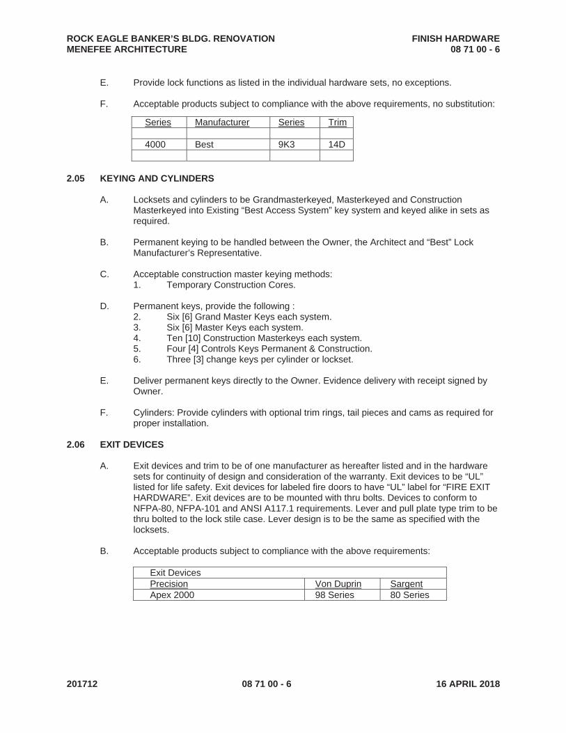
ROCK EAGLE BANKER’S BLDG. RENOVATION FINISH HARDWARE MENEFEE ARCHITECTURE 08 71 00 - 6
201712 08 71 00 - 6 16 APRIL 2018
E. Provide lock functions as listed in the individual hardware sets, no exceptions.
F. Acceptable products subject to compliance with the above requirements, no substitution:
2.05 KEYING AND CYLINDERS
A. Locksets and cylinders to be Grandmasterkeyed, Masterkeyed and Construction Masterkeyed into Existing “Best Access System” key system and keyed alike in sets as required.
B. Permanent keying to be handled between the Owner, the Architect and “Best” Lock Manufacturer’s Representative.
C. Acceptable construction master keying methods: 1. Temporary Construction Cores.
D. Permanent keys, provide the following : 2. Six [6] Grand Master Keys each system. 3. Six [6] Master Keys each system. 4. Ten [10] Construction Masterkeys each system. 5. Four [4] Controls Keys Permanent & Construction. 6. Three [3] change keys per cylinder or lockset.
E. Deliver permanent keys directly to the Owner. Evidence delivery with receipt signed by Owner.
F. Cylinders: Provide cylinders with optional trim rings, tail pieces and cams as required for proper installation.
2.06 EXIT DEVICES
A. Exit devices and trim to be of one manufacturer as hereafter listed and in the hardware sets for continuity of design and consideration of the warranty. Exit devices to be “UL” listed for life safety. Exit devices for labeled fire doors to have “UL” label for “FIRE EXIT HARDWARE”. Exit devices are to be mounted with thru bolts. Devices to conform to NFPA-80, NFPA-101 and ANSI A117.1 requirements. Lever and pull plate type trim to be thru bolted to the lock stile case. Lever design is to be the same as specified with the locksets.
B. Acceptable products subject to compliance with the above requirements:
Exit Devices Precision Von Duprin SargentApex 2000 98 Series 80 Series
Series Manufacturer Series Trim 4000 Best 9K3 14D

ROCK EAGLE BANKER’S BLDG. RENOVATION FINISH HARDWARE MENEFEE ARCHITECTURE 08 71 00 - 7
201712 08 71 00 - 7 16 APRIL 2018
2.07 CLOSERS
A. Provide heavy duty, surface mounted, hydraulic type with full rack and pinion construction. Size closers at the time of installation in accordance with the manufacturers’ recommendations at the building site. Closers to be the product of a single manufacturer and to have a full cover. Provide closers with adjustable spring power, which allows for closer sizing. Provide closers with separate tamper resistant, non-critical regulating screw valves for closing speed, latching speed and backcheck control as a standard feature. Provide spacers, mounting brackets and plates as required for application.
B. Acceptable products subject to compliance with the above requirements, no substitution:
Closers Stanley LCN SargentD4550 4041 351 D3550 FC 1461 FC 1431
2.08 MISCELLANEOUS HARDWARE
A. Push Plates, Pull Plates, Kick Plates, Flush bolts, Stops, O.H. Stops and Holders, Lock Guards.
B. Acceptable products subject to compliance: 1. Protection Plates, Push Plates and Pull Plates: Plates that are 16” or more aff to
be beveled four sides. Acceptable manufacturers: Don-Jo, Hiawatha, Rockwood, Trimco.
2. Kick Plates: .050” thick, 6” high x 2” LDW (Less than Door Width). Adjust width as required where used with edge guards and edge guard continuous hinges. Adjust height as required to accommodate bottom rail dimensions.
3. Mop Plates: .050” thick, 4” high x 1” LDW (Less than Door Width). Adjust width as required where used with edge guards and edge guard continuous hinges.
4. Armor Plates: .050” thick, 32” high x 2” LDW (Less than Door Width). Adjust width as required where used with edge guards and edge guard continuous hinges.
5. Push Plates: .050” thick, 4” wide x 16” high. Adjust width and height as required where narrow stile doors are used.
6. Pull Plates: Plate .050” thick, 4” wide x 16” high. Pull: 8” C to C. Pull to be solid stock. Hollow or wrought pulls are not acceptable. Provide concealed mounting.
7. Wall Stops/Floor Stops: Provide stops with appropriate anchors. Acceptable manufacturers: Don-JO, Rockwood, Trimco, Hiawatha.
8. O.H. Stops & Holders: Provide thru bolt fasteners for surface mounted stops and holders. Acceptable manufacturers: Rixson. Glynn Johnson, ABH.

ROCK EAGLE BANKER’S BLDG. RENOVATION FINISH HARDWARE MENEFEE ARCHITECTURE 08 71 00 - 8
201712 08 71 00 - 8 16 APRIL 2018
2.09 THRESHOLDS, SWEEPS AND WEATHERSTRIP
A. Provide hardware that complies with ANSI A156.22.2003 Door Gasketing and Edge Seal Systems subject to compliance. Hardware to be of same profile, fastening method and seal type material as specified. 1. Extruded Thresholds: Fastener holes to be maximum of 24” o.c. and symmetrical
with center of door opening.
B. Acceptable manufacturers: 1. Hager 2. Reese 3. Pemko 4. National Guard
2.10 FIRE AND SMOKE SEALS
A. Seals for fire and smoke doors provided under section 08110 and 08210.
2.11 SILENCERS
A. Provide punch in silencers of pneumatic design for mounting to metal door frames. Silencers to meet the requirements of ANSI A156.16. Provide 3 each silencers for single doors and 2 each silencers for pairs of doors. Do not provide silencers for doors with weather seals or fire/smoke seals that mount on the stop face where silencers are mounted.
2.12 FINISHES
A. Hardware finish in general to be US10B oiled rubbed bronze or as noted in Hardware Schedule 3.05.
B. Finishes: 1. Exterior Continuous Hinges: Dark Bronze Anodized 2. Interior Hinges: US10B/641 3. Interior Locks 690 Powder Coat Bronze 4. Exit Devices: 313AN 5. Mullions SP313 6. Overhead Stops SP313 7. Closers: Dark Bronze 695 8. Flat Goods: US10B/613 9. Protection Plates: US10B/613 10. Push Plates and Pulls: US10B/613 11. Weather Stripping and Thresholds Dark Bronze Anodized
PART 3 EXECUTION
3.01 DELIVERY, STORAGE AND HANDLING
A. Check hardware against the approved Finish Hardware schedule upon delivery.

ROCK EAGLE BANKER’S BLDG. RENOVATION FINISH HARDWARE MENEFEE ARCHITECTURE 08 71 00 - 9
201712 08 71 00 - 9 16 APRIL 2018
B. Store hardware per manufacturers’ printed instructions. Store hardware in a dry, secure location to protect against loss and damage.
3.02 INSTALLATION
A. Hardware to be installed by experienced finish hardware installers only.
B. Install hardware in accordance with the approved Finish Hardware schedule and per the manufacturers’ printed instructions. Pre-fit hardware before the door finish is applied; remove hardware prior to field finish (includes painting) and reinstall after the finish is completely dry.
C. Locks and Exit Devices: Where used in conjunction with doors with lock rails mount locks and exit devices on center line of lock rail.
D. Closers: Avoid installing closers on exterior side of doors and on corridor/common side of interior doors where possible.
E. Install hardware with manufacturer furnished fasteners. Use of fasteners not furnished by hardware manufacturer will void fire labels and warranty. TEK screws are not acceptable.
F. Install and adjust hardware so that the parts operate smoothly without bind or drag and so that doors latch, close tightly and do not rattle.
G. Install hardware to comply with federal, state and local code and legal requirements.
3.03 INSPECTION
A. Furnish services of an independent AHC (Architectural Hardware Consultant) or manufacturers’ representative for respective products to ensure proper installation and operation of hardware.

ROCK EAGLE BANKER’S BLDG. RENOVATION FINISH HARDWARE MENEFEE ARCHITECTURE 08 71 00 - 10
201712 08 71 00 - 10 16 APRIL 2018
3.04 HARDWARE SETS
HARDWARE SET AL-1
Door: 100, Each to have:
2 each Continuous Hinge SL11HD/SL18HD Select 1 each Exit Device CD35EO Von Duprin 1 each Exit Device CD35NL-OP Von Duprin 1 each Rim Cylinder 1E72 Best 3 each Mortise Cylinder 1E74 Best 4 each Perm Cores Best 2 each Pulls 1191-3 x N Mount Trimco 1 each Key Removable Mullion KR4954 Von Duprin 2 each Closers 4041XP-4040-18G LCN 2 each OH Stops 100H series Glynn Johnson 1 set Weatherstripping By Door/Frame Mfg. 2 each Door Bottoms By Door/Frame Mfg.
1 each Threshold By Door/Frame Mfg.
HARDWARE SET 1 Door: 101A Each to have:
1 each Continuous Hinge SL24HD Select 1 each Exit Device CD98L-17 Von Duprin 1 each Rim Cylinder 1E72 Best 1 each Mortise Cylinder 1E74 Best 1 each Closer 1461 FC SHCUSH LCN 1 each Kick Plate 6 x 2 LDW .050 B4E Trimco 1 set Seals 5050 NGP

ROCK EAGLE BANKER’S BLDG. RENOVATION FINISH HARDWARE MENEFEE ARCHITECTURE 08 71 00 - 11
201712 08 71 00 - 11 16 APRIL 2018
HARDWARE SET 2
Door: 101B Each to have:
1 each Continuous Hinge SL24HD Select 1 each Exit Device CD98NL Von Duprin 1 each Rim Cylinder 1E72 Best 1 each Mortise Cylinder 1E74 Best 1 each Closer 4041XP SHCUSH LCN 1 each Kick Plate 6 x 2 LDW .050 B4E Trimco 1 set Weatherseal 700S DKB NGP 1 each Door Bottom 319V DKB NGP 1 each Threshold 425 DKB NGP 1 each Drip Cap 16 DKB NGP
HARDWARE SET 3
Door: 104A Each to have:
1 each Continuous Hinge SL24HD Select 1 each Push Plate 1001-3 Trimco 1 each Pull Plate 1014-3B Trimco 1 each Closer 1461 FC SHCUSH LCN 1 each Kick Plate 6 x 2 LDW .050 B4E Trimco 1 set Seals 5050B NGP
NOTE: PROVIDE HINGE FILLERS IF NECESSARY – DON JO - FF45/FF50
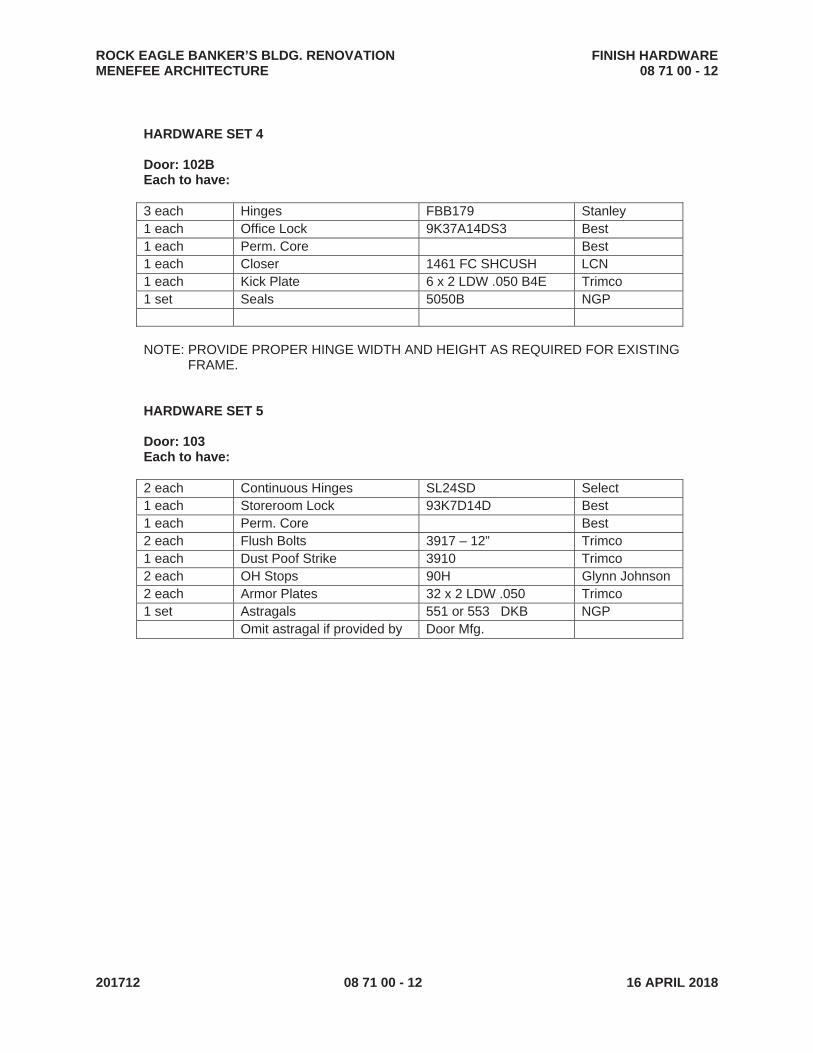
ROCK EAGLE BANKER’S BLDG. RENOVATION FINISH HARDWARE MENEFEE ARCHITECTURE 08 71 00 - 12
201712 08 71 00 - 12 16 APRIL 2018
HARDWARE SET 4
Door: 102B Each to have:
3 each Hinges FBB179 Stanley 1 each Office Lock 9K37A14DS3 Best 1 each Perm. Core Best 1 each Closer 1461 FC SHCUSH LCN 1 each Kick Plate 6 x 2 LDW .050 B4E Trimco 1 set Seals 5050B NGP
NOTE: PROVIDE PROPER HINGE WIDTH AND HEIGHT AS REQUIRED FOR EXISTING FRAME.
HARDWARE SET 5
Door: 103 Each to have:
2 each Continuous Hinges SL24SD Select 1 each Storeroom Lock 93K7D14D Best 1 each Perm. Core Best 2 each Flush Bolts 3917 – 12” Trimco 1 each Dust Poof Strike 3910 Trimco 2 each OH Stops 90H Glynn Johnson 2 each Armor Plates 32 x 2 LDW .050 Trimco 1 set Astragals 551 or 553 DKB NGP Omit astragal if provided by Door Mfg.

ROCK EAGLE BANKER’S BLDG. RENOVATION FINISH HARDWARE MENEFEE ARCHITECTURE 08 71 00 - 13
201712 08 71 00 - 13 16 APRIL 2018
HARDWARE SET 6
Door: 105, 106 Each to have:
1 each Continuous Hinges SL24SD Select 1 each Push Plate 1001-3 Trimco 1 each Pull Plate 1014-3B Trimco 1 each Closer 1461 FC Reg Arm LCN 1 each Kick Plate 6 x 2 LDW .050 B4E Trimco 1 each Mop Plate 4 x 1 LDW .050 B4E Trimco 1 each Floor Stop 1231 Trimco 1 set Seals 5050B NGP
NOTE: PROVIDE HINGE FILLERS IF NECESSARY – DON JO - FF45/FF50
END OF SECTION

ROCK EAGLE BANKER'S BLDG. RENOVATION GLAZINGMENEFEE ARCHITECTURE 08 80 00 - 1
201712 08 80 00 - 1 16 April 2018
SECTION 08 80 00
GLAZING
PART 1 GENERAL
1.01 SECTION INCLUDES
A. Glass.
1.02 RELATED REQUIREMENTS
A. Section 08 13 14 - Aluminum-Framed Storefronts.
1.03 REFERENCE STANDARDS
A. 16 CFR 1201 - Safety Standard for Architectural Glazing Materials; current edition.
B. ASTM C864 - Standard Specification for Dense Elastomeric Compression Seal Gaskets,Setting Blocks, and Spacers; 2005 (Reapproved 2011).
C. ASTM C1036 - Standard Specification for Flat Glass; 2011.
D. ASTM C1048 - Standard Specification for Heat-Strengthened and Fully Tempered Flat Glass;2012.
E. ASTM C1172 - Standard Specification for Laminated Architectural Flat Glass; 2014.
F. ASTM C1193 - Standard Guide for Use of Joint Sealants; 2013.
G. ASTM E84 - Standard Test Method for Surface Burning Characteristics of Building Materials;2015a.
H. GANA (GM) - GANA Glazing Manual; 2009.
I. GANA (SM) - GANA Sealant Manual; 2008.
J. GANA (LGRM) - Laminated Glazing Reference Manual; 2009.
K. ICC (IBC) - International Building Code; 2015.
1.04 SUBMITTALS
A. See Section 01 30 00 - Administrative Requirements, for submittal procedures.
B. Product Data on Glass Types: Provide structural, physical and environmental characteristics,size limitations, special handling or installation requirements.
C. Manufacturer's Certificate: Certify that each specified type glass meets or exceeds specifiedrequirements.
1.05 QUALITY ASSURANCE
A. Perform Work in accordance with GANA Glazing Manual and GANA Sealant Manual for glazinginstallation methods.
B. Installer Qualifications: Company specializing in performing the work of this section withminimum three years documented experience.
1.06 FIELD CONDITIONS
A. Do not install glazing when ambient temperature is less than 50 degrees F.
B. Maintain minimum ambient temperature before, during and 24 hours after installation of glazingcompounds.
1.07 WARRANTY
A. See Section 01 78 00 - Closeout Submittals, for additional warranty requirements.
B. Sealed Insulating Glass Units: Provide a five (5) year warranty to include coverage for sealfailure, interpane dusting or misting, including replacement of failed units.
PART 2 PRODUCTS
2.01 GLAZING TYPES
A. Type IG-1 - Sealed Insulating Glass Units: Vision glass, double glazed.
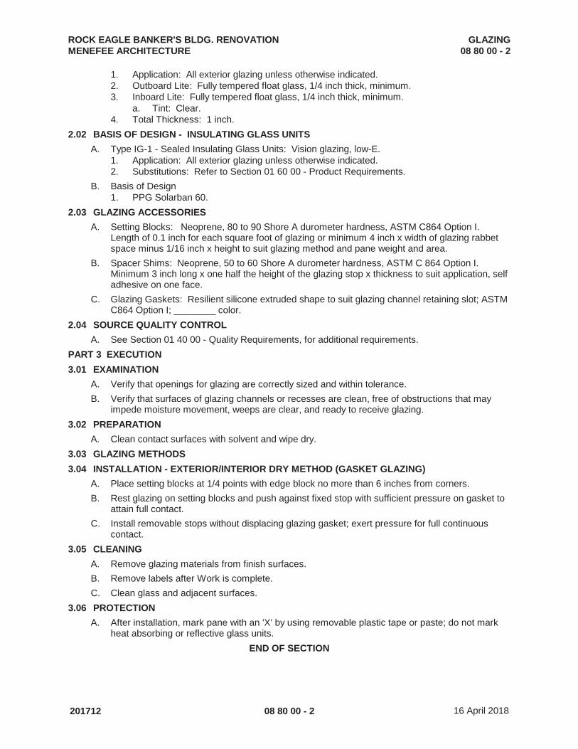
ROCK EAGLE BANKER'S BLDG. RENOVATION GLAZINGMENEFEE ARCHITECTURE 08 80 00 - 2
201712 08 80 00 - 2 16 April 2018
1. Application: All exterior glazing unless otherwise indicated.2. Outboard Lite: Fully tempered float glass, 1/4 inch thick, minimum.3. Inboard Lite: Fully tempered float glass, 1/4 inch thick, minimum.
a. Tint: Clear.4. Total Thickness: 1 inch.
2.02 BASIS OF DESIGN - INSULATING GLASS UNITS
A. Type IG-1 - Sealed Insulating Glass Units: Vision glazing, low-E.1. Application: All exterior glazing unless otherwise indicated.2. Substitutions: Refer to Section 01 60 00 - Product Requirements.
B. Basis of Design1. PPG Solarban 60.
2.03 GLAZING ACCESSORIES
A. Setting Blocks: Neoprene, 80 to 90 Shore A durometer hardness, ASTM C864 Option I. Length of 0.1 inch for each square foot of glazing or minimum 4 inch x width of glazing rabbetspace minus 1/16 inch x height to suit glazing method and pane weight and area.
B. Spacer Shims: Neoprene, 50 to 60 Shore A durometer hardness, ASTM C 864 Option I. Minimum 3 inch long x one half the height of the glazing stop x thickness to suit application, selfadhesive on one face.
C. Glazing Gaskets: Resilient silicone extruded shape to suit glazing channel retaining slot; ASTMC864 Option I; ________ color.
2.04 SOURCE QUALITY CONTROL
A. See Section 01 40 00 - Quality Requirements, for additional requirements.
PART 3 EXECUTION
3.01 EXAMINATION
A. Verify that openings for glazing are correctly sized and within tolerance.
B. Verify that surfaces of glazing channels or recesses are clean, free of obstructions that mayimpede moisture movement, weeps are clear, and ready to receive glazing.
3.02 PREPARATION
A. Clean contact surfaces with solvent and wipe dry.
3.03 GLAZING METHODS
3.04 INSTALLATION - EXTERIOR/INTERIOR DRY METHOD (GASKET GLAZING)
A. Place setting blocks at 1/4 points with edge block no more than 6 inches from corners.
B. Rest glazing on setting blocks and push against fixed stop with sufficient pressure on gasket toattain full contact.
C. Install removable stops without displacing glazing gasket; exert pressure for full continuouscontact.
3.05 CLEANING
A. Remove glazing materials from finish surfaces.
B. Remove labels after Work is complete.
C. Clean glass and adjacent surfaces.
3.06 PROTECTION
A. After installation, mark pane with an 'X' by using removable plastic tape or paste; do not markheat absorbing or reflective glass units.
END OF SECTION

ROCK EAGLE BANKER'S BLDG. RENOVATION GYPSUM BOARD ASSEMBLIESMENEFEE ARCHITECTURE 09 21 16 - 1
201712 09 21 16 - 1 16 April 2018
SECTION 09 21 16
GYPSUM BOARD ASSEMBLIES
PART 1 GENERAL
1.01 SECTION INCLUDES
A. Metal stud wall framing.
B. Acoustic insulation.
C. Gypsum wallboard.
D. Joint treatment and accessories.
1.02 RELATED REQUIREMENTS
A. Section 06 10 00 - Rough Carpentry: Wood blocking product and execution requirements.
B. Section 09 51 00 - Acoustical Ceilings: in conjunction with GWB assemblies
1.03 REFERENCE STANDARDS
A. ASTM C475/C475M - Standard Specification for Joint Compound and Joint Tape for FinishingGypsum Board; 2015.
B. ASTM C645 - Standard Specification for Nonstructural Steel Framing Members; 2014.
C. ASTM C754 - Standard Specification for Installation of Steel Framing Members to ReceiveScrew-Attached Gypsum Panel Products; 2015.
D. ASTM C840 - Standard Specification for Application and Finishing of Gypsum Board; 2013.
E. ASTM C954 - Standard Specification for Steel Drill Screws for the Application of Gypsum PanelProducts or Metal Plaster Bases to Steel Studs From 0.033 in. (0.84 mm) to 0.112 in. (2.84 mm)in Thickness; 2015.
F. ASTM C1002 - Standard Specification for Steel Self-Piercing Tapping Screws for Application ofGypsum Panel Products or Metal Plaster Bases to Wood Studs or Steel Studs; 2014.
G. ASTM C1047 - Standard Specification for Accessories For Gypsum Wallboard and GypsumVeneer Base; 2014a.
H. ASTM C1396/C1396M - Standard Specification for Gypsum Board; 2014.
1.04 SUBMITTALS
A. See Section 01 30 00 - Administrative Requirements, for submittal procedures.
B. Shop Drawings: Indicate special details associated with fireproofing and acoustic seals.
C. Product Data: Provide data on metal framing, gypsum board, and accessories.
1.05 QUALITY ASSURANCE
A. Installer Qualifications: Company specializing in performing gypsum board application andfinishing, with minimum five years of documented experience.
PART 2 PRODUCTS
2.01 METAL FRAMING MATERIALS
A. Manufacturers - Metal Framing, Connectors, and Accessories:1. Clarkwestern Dietrich Building Systems LLC; ____: www.clarkdietrich.com.2. Marino; ____: www.marinoware.com.3. Phillips Manufacturing Co; ____: www.phillipsmfg.com/#sle.4. Substitutions: See Section 01 60 00 - Product Requirements.
B. Non-Loadbearing Framing System Components: ASTM C645; galvanized sheet steel, of sizeand properties necessary to comply with ASTM C754 for the spacing indicated, with maximumdeflection of wall framing of L/360 at 5 psf.1. Studs: "C" shaped with flat or formed webs with knurled faces. Minimum 20 gauge except
where used for wall furring supported by existing substrate.
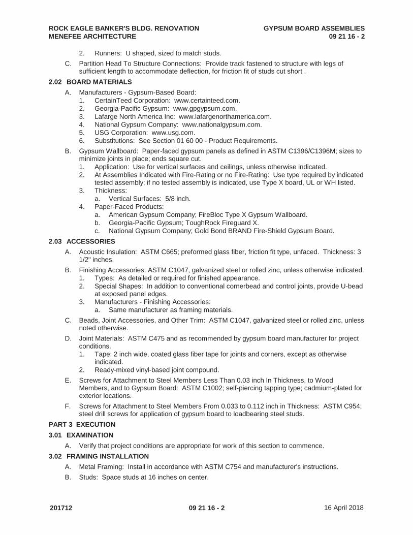
ROCK EAGLE BANKER'S BLDG. RENOVATION GYPSUM BOARD ASSEMBLIESMENEFEE ARCHITECTURE 09 21 16 - 2
201712 09 21 16 - 2 16 April 2018
2. Runners: U shaped, sized to match studs.
C. Partition Head To Structure Connections: Provide track fastened to structure with legs ofsufficient length to accommodate deflection, for friction fit of studs cut short .
2.02 BOARD MATERIALS
A. Manufacturers - Gypsum-Based Board:1. CertainTeed Corporation: www.certainteed.com.2. Georgia-Pacific Gypsum: www.gpgypsum.com.3. Lafarge North America Inc: www.lafargenorthamerica.com.4. National Gypsum Company: www.nationalgypsum.com.5. USG Corporation: www.usg.com.6. Substitutions: See Section 01 60 00 - Product Requirements.
B. Gypsum Wallboard: Paper-faced gypsum panels as defined in ASTM C1396/C1396M; sizes tominimize joints in place; ends square cut.1. Application: Use for vertical surfaces and ceilings, unless otherwise indicated.2. At Assemblies Indicated with Fire-Rating or no Fire-Rating: Use type required by indicated
tested assembly; if no tested assembly is indicated, use Type X board, UL or WH listed.3. Thickness:
a. Vertical Surfaces: 5/8 inch.4. Paper-Faced Products:
a. American Gypsum Company; FireBloc Type X Gypsum Wallboard.b. Georgia-Pacific Gypsum; ToughRock Fireguard X.c. National Gypsum Company; Gold Bond BRAND Fire-Shield Gypsum Board.
2.03 ACCESSORIES
A. Acoustic Insulation: ASTM C665; preformed glass fiber, friction fit type, unfaced. Thickness: 31/2" inches.
B. Finishing Accessories: ASTM C1047, galvanized steel or rolled zinc, unless otherwise indicated.1. Types: As detailed or required for finished appearance.2. Special Shapes: In addition to conventional cornerbead and control joints, provide U-bead
at exposed panel edges.3. Manufacturers - Finishing Accessories:
a. Same manufacturer as framing materials.
C. Beads, Joint Accessories, and Other Trim: ASTM C1047, galvanized steel or rolled zinc, unlessnoted otherwise.
D. Joint Materials: ASTM C475 and as recommended by gypsum board manufacturer for projectconditions.1. Tape: 2 inch wide, coated glass fiber tape for joints and corners, except as otherwise
indicated.2. Ready-mixed vinyl-based joint compound.
E. Screws for Attachment to Steel Members Less Than 0.03 inch In Thickness, to WoodMembers, and to Gypsum Board: ASTM C1002; self-piercing tapping type; cadmium-plated forexterior locations.
F. Screws for Attachment to Steel Members From 0.033 to 0.112 inch in Thickness: ASTM C954;steel drill screws for application of gypsum board to loadbearing steel studs.
PART 3 EXECUTION
3.01 EXAMINATION
A. Verify that project conditions are appropriate for work of this section to commence.
3.02 FRAMING INSTALLATION
A. Metal Framing: Install in accordance with ASTM C754 and manufacturer's instructions.
B. Studs: Space studs at 16 inches on center.

ROCK EAGLE BANKER'S BLDG. RENOVATION GYPSUM BOARD ASSEMBLIESMENEFEE ARCHITECTURE 09 21 16 - 3
201712 09 21 16 - 3 16 April 2018
1. Extend partition framing to structure where indicated and to ceiling in other locations.2. Partitions Terminating at Ceiling: Attach ceiling runner securely to ceiling track in
accordance with manufacturer's instructions.3. Partitions Terminating at Structure: Attach extended leg top runner to structure, maintain
clearance between top of studs and structure, and brace both flanges of studs withcontinuous bridging.
C. Openings: Reinforce openings as required for weight of doors or operable panels, using notless than double studs at jambs.
D. Standard Metal Stud Wall Furring: Install at concrete and masonry walls or columns scheduledto receive gypsum board, not more than 4 inches from floor and ceiling lines and abutting walls. Secure in place on alternate channel flanges at maximum 16 inches on center.1. Orientation: Vertical.
E. Blocking: Install wood blocking for support of:1. Framed openings.2. Wall mounted cabinets.3. Toilet accessories.4. Owner provided A/V equipment
3.03 ACOUSTIC ACCESSORIES INSTALLATION
A. Acoustic Insulation: Place tightly within spaces, around cut openings, behind and aroundelectrical and mechanical items within partitions, and tight to items passing through partitions.
B. Acoustic Sealant: Install in accordance with manufacturer's instructions.1. Place one bead continuously on substrate before installation of perimeter framing
members.2. Place continuous bead at perimeter of each layer of gypsum board.3. In non-fire-rated construction, seal around all penetrations by conduit, pipe, ducts, and
rough-in boxes.
3.04 BOARD INSTALLATION
A. Comply with ASTM C 840, GA-216, and manufacturer's instructions. Install to minimize butt endjoints, especially in highly visible locations.
B. Single-Layer Non-Rated: Install gypsum board in most economical direction, with ends andedges occurring over firm bearing.1. Exception: Tapered edges to receive joint treatment at right angles to framing.
3.05 INSTALLATION OF TRIM AND ACCESSORIES
A. Control Joints: Place control joints consistent with lines of building spaces and as indicated.
B. Corner Beads: Install at external corners, using longest practical lengths.
C. Edge Trim: Install at locations where gypsum board abuts dissimilar materials and as indicated.
3.06 JOINT TREATMENT
A. Paper Faced Gypsum Board: Use fiberglass joint tape, bedded with ready-mixed vinyl-basedjoint compound and finished with ready-mixed vinyl-based joint compound.
B. Finish gypsum board in accordance with levels defined in ASTM C840, as follows:1. Level 4: Walls and ceilings to receive paint finish or wall coverings, unless otherwise
indicated.2. Level 2: In utility areas, behind cabinetry, and on backing board to receive tile finish.3. Level 1: Fire rated wall areas above finished ceilings, whether or not accessible in the
completed construction.
C. Tape, fill, and sand exposed joints, edges, and corners to produce smooth surface ready toreceive finishes.1. Feather coats of joint compound so that camber is maximum 1/32 inch.

ROCK EAGLE BANKER'S BLDG. RENOVATION GYPSUM BOARD ASSEMBLIESMENEFEE ARCHITECTURE 09 21 16 - 4
201712 09 21 16 - 4 16 April 2018
3.07 TOLERANCES
A. Maximum Variation of Finished Gypsum Board Surface from True Flatness: 1/8 inch in 10 feetin any direction.
END OF SECTION

ROCK EAGLE BANKER'S BLDG. RENOVATION CEMENT PLASTERINGMENEFEE ARCHITECTURE 09 24 00 - 1
201712 09 24 00 - 1 16 April 2018
SECTION 09 24 00
CEMENT PLASTERING
PART 1 GENERAL
1.01 SECTION INCLUDES
A. Cement plastering for minor patching and repairs.
1.02 RELATED REQUIREMENTS
A. Section 09 22 36 - Lath: Lath, furring, beads, screeds, and joint accessories for plaster base.
B. Section 09 91 13 - Exterior Painting.
1.03 REFERENCE STANDARDS
A. ASTM C150/C150M - Standard Specification for Portland Cement; 2015.
B. ASTM C206 - Standard Specification for Finishing Hydrated Lime; 2014.
C. ASTM C926 - Standard Specification for Application of Portland Cement-Based Plaster; 2016b.
D. ASTM C932 - Standard Specification for Surface-Applied Bonding Compounds for ExteriorPlastering; 2006 (Reapproved 2013).
1.04 SUBMITTALS
A. See Section 01 30 00 - Administrative Requirements, for submittals procedures.
B. Product Data: Provide data on plaster materials and trim accessories.
1.05 QUALITY ASSURANCE
A. Installer Qualifications: Company specializing in performing the work of this section withminimum three years documented experience.
1.06 FIELD CONDITIONS
A. Exterior Plaster Work: Do not apply plaster when substrate or ambient air temperature is 40degrees F or lower, or when temperature is expected to drop below 40 degrees F within 48hours of application.
PART 2 PRODUCTS
2.01 CEMENT PLASTER APPLICATIONS
A. Lath Plaster Base: Metal lath.1. Plaster Type: Factory prepared plaster mix.2. First Coat: Apply to a nominal thickness of 3/8 inch.3. Second Coat: Apply to a nominal thickness of 3/8 inch.4. Leveling Coat: Apply to a nominal thickness of 1/32 to 1/16 inch.5. Finish Coat: Apply to a nominal thickness of 1/8 inch.
a. Texture: match existing.
B. Solid Plaster Base: Concrete masonry.1. Plaster Type: Jobsite mixed plaster.2. First Coat: Apply to a nominal thickness of 1/4 inch.3. Second Coat: Apply to a nominal thickness of 1/4 inch.4. Leveling Coat: Apply to a nominal thickness of 1/32 to 1/16 inch.5. Finish Coat: Apply to a nominal thickness of 1/8 inch.
2.02 FACTORY PREPARED CEMENT PLASTER
A. Premixed Base Coats: Mixture of cement, aggregate, fibers, and proprietary admixtures forscratch and brown coats; install in accordance with ASTM C926.1. Manufacturers:
a. Amerimix, an Oldcastle brand; AMX 700 SBF: www.amerimix.com.b. The QUIKRETE Companies; QUIKRETE® Base Coat Stucco Pump Grade:
www.quikrete.com.

ROCK EAGLE BANKER'S BLDG. RENOVATION CEMENT PLASTERINGMENEFEE ARCHITECTURE 09 24 00 - 2
201712 09 24 00 - 2 16 April 2018
c. Substitutions: See Section 01 60 00 - Product Requirements.
B. Premixed Leveling Coat: Acrylic polymer-based blend approved for use with plastermanufacturer's base coat and finish materials.1. Manufacturers: same as base coat.
a. Substitutions: See Section 01 60 00 - Product Requirements.
C. Premixed Finish Coating: Same product as base coat.
2.03 ACCESSORIES
A. Beads, Screeds, and Joint Accessories: As specified in Section 09 22 36.
B. Bonding Compound: Provide type recommended for bonding plaster to solid surfaces,complying with ASTM C932.
C. Reinforcing Mesh: 4.5 oz/sq yd alkali-resistant mesh.
PART 3 EXECUTION
3.01 EXAMINATION
A. Verify existing conditions are acceptable prior to starting this work.
B. Verify masonry joints are flush and surfaces are ready to receive work of this section, and thatthere are no existing bituminous or water repellent coatings on masonry surfaces.
C. Verify concrete surfaces are flat, honeycombs are filled flush, and surfaces are ready to receivework of this section, and that there are no existing bituminous, water repellent, or form releaseagent coatings on concrete surfaces that may be detrimental to plaster bond.
D. Verify lath is flat, secured to substrate, and joint and surface perimeter accessories are properlyin place.
3.02 PREPARATION
A. Dampen masonry surfaces to reduce excessive suction.
B. Clean concrete surfaces of foreign matter using approved acid solutions, solvents, ordetergents, and then rinse surfaces thoroughly with clean water.
C. Roughen smooth concrete surfaces and apply bonding compound in accordance withmanufacturer's written installation instructions.
3.03 MIXING
A. Mix only as much plaster as can be used prior to initial set.
B. Mix materials dry, to uniform color and consistency, before adding water.
C. Do not retemper mixes after initial set has occurred.
D. Protect mixtures from frost or freezing temperatures, contamination, and excessive evaporation.
3.04 APPLICATION
A. Apply plaster in accordance with manufacturer's written instructions and comply with ASTMC926.
B. Base Coats:1. Apply base coat(s) to fully embed lath and to specified thickness.2. Follow guidelines in ASTM C926 and manufacturer's written installation instructions for
moist curing base coats and application of subsequent coats.
C. Leveling Coat:1. Apply leveling coat to specified thickness.2. Fully embed reinforcing mesh in leveling coat.
D. Finish Coats:1. Cement Plaster:
a. Apply with sufficient material and pressure to ensure complete coverage of base tospecified thickness.

ROCK EAGLE BANKER'S BLDG. RENOVATION CEMENT PLASTERINGMENEFEE ARCHITECTURE 09 24 00 - 3
201712 09 24 00 - 3 16 April 2018
b. Apply desired surface texture while mix is still workable.
3.05 TOLERANCES
A. Maximum Variation from True Flatness: 1/8 inch in 10 feet.
3.06 REPAIR
A. Patching: Remove loose, damaged or defective plaster and replace with plaster of samecomposition; finish to match surrounding area.
END OF SECTION

ROCK EAGLE BANKER'S BLDG. RENOVATION ACOUSTICAL CEILINGSMENEFEE ARCHITECTURE 09 51 00 - 1
201712 09 51 00 - 1 16 April 2018
SECTION 09 51 00
ACOUSTICAL CEILINGS
PART 1 GENERAL
1.01 SECTION INCLUDES
A. Suspended metal grid ceiling system.
B. Acoustical units.
1.02 RELATED REQUIREMENTS
A. 09 21 16 - Gypsum Board Assemblies.
1.03 REFERENCE STANDARDS
A. ASTM C635/C635M - Standard Specification for the Manufacture, Performance, and Testing ofMetal Suspension Systems for Acoustical Tile and Lay-in Panel Ceilings; 2013a.
B. ASTM C636/C636M - Standard Practice for Installation of Metal Ceiling Suspension Systems forAcoustical Tile and Lay-In Panels; 2013.
C. ASTM E580/E580M - Standard Practice for Installation of Ceiling Suspension Systems forAcoustical Tile and Lay-in Panels in Areas Subject to Earthquake Ground Motions; 2014.
D. ASTM E1264 - Standard Classification for Acoustical Ceiling Products; 2014.
1.04 ADMINISTRATIVE REQUIREMENTS
A. Sequence work to ensure acoustical ceilings are not installed until building is enclosed,sufficient heat is provided, dust generating activities have terminated, and overhead work iscompleted, tested, and approved.
B. Do not install acoustical units until after interior wet work is dry.
1.05 SUBMITTALS
A. See Section 01 30 00 - Administrative Requirements, for submittal procedures.
B. Product Data: Provide data on suspension system components.
C. Samples: Submit two samples 6x6 inch in size illustrating material and finish of acoustical units.
D. Manufacturer's Installation Instructions: Indicate special procedures.
1.06 QUALITY ASSURANCE
A. Suspension System Manufacturer Qualifications: Company specializing in manufacturing theproducts specified in this section with minimum three years documented experience.
B. Acoustical Unit Manufacturer Qualifications: Company specializing in manufacturing theproducts specified in this section with minimum three years documented experience.
1.07 FIELD CONDITIONS
A. Maintain uniform temperature of minimum 60 degrees F, and maximum humidity of 40 percentprior to, during, and after acoustical unit installation.
PART 2 PRODUCTS
2.01 MANUFACTURERS
A. Acoustic Panels: See Finish drawings
B. Suspension Systems:1. Armstrong World Industries, Inc; ____: www.armstrong.com.2. CertainTeed Corporation; ____: www.certainteed.com.3. Chicago Metallic Corporation; ____: www.chicagometallic.com.4. Hunter Douglas Contract; ____: www.hunterdouglascontract.com.
2.02 ACOUSTICAL UNITS
A. Acoustical Units - General: ASTM E1264, Class A.

ROCK EAGLE BANKER'S BLDG. RENOVATION ACOUSTICAL CEILINGSMENEFEE ARCHITECTURE 09 51 00 - 2
201712 09 51 00 - 2 16 April 2018
2.03 SUSPENSION SYSTEM(S)
A. Suspension Systems - General: Complying with ASTM C635/C635M; die cut and interlockingcomponents, with stabilizer bars, clips, splices, perimeter moldings, and hold down clips asrequired.
B. Steel Suspension System: Formed steel, commercial quality cold rolled; heavy-duty.1. Profile: Tee; 15/16 inch wide face at 6' plank tile and 3/4' at 2x2 tiles.2. Construction: Double web.3. Finish: White painted.
2.04 ACCESSORIES
A. Support Channels and Hangers: Galvanized steel; size and type to suit application, seismicrequirements, and ceiling system flatness requirement specified.
B. Perimeter Moldings: Same material and finish as grid.1. At Exposed Grid: Provide L-shaped molding for mounting at same elevation as face of
grid.2. At Concealed Grid: Provide matching edge molding to suit application molding.
PART 3 EXECUTION
3.01 EXAMINATION
A. Verify existing conditions before starting work.
B. Verify that layout of hangers will not interfere with other work.
3.02 INSTALLATION - SUSPENSION SYSTEM
A. Install suspension system in accordance with ASTM C636/C636M, ASTM E580/E580M, andmanufacturer's instructions and as supplemented in this section.
B. Rigidly secure system, including integral mechanical and electrical components, for maximumdeflection of 1:360.
C. Install after major above-ceiling work is complete. Coordinate the location of hangers with otherwork.
D. Hang suspension system independent of walls, columns, ducts, pipes and conduit. Wherecarrying members are spliced, avoid visible displacement of face plane of adjacent members.
E. Where ducts or other equipment prevent the regular spacing of hangers, reinforce the nearestaffected hangers and related carrying channels to span the extra distance.
F. Do not support components on main runners or cross runners if weight causes total dead loadto exceed deflection capability.
G. Support fixture loads using supplementary hangers located within 6 inches of each corner, orsupport components independently.
H. Do not eccentrically load system or induce rotation of runners.
I. Perimeter Molding: Install at intersection of ceiling and vertical surfaces and at junctions withother interruptions.1. Use longest practical lengths.2. Overlap and rivet corners.
J. Install compression struts of size and spacing to resist uplift from exterior exposure whenBi-Fold doors is in open position.
3.03 INSTALLATION - ACOUSTICAL UNITS
A. Install acoustical units in accordance with manufacturer's instructions.
B. Fit acoustical units in place, free from damaged edges or other defects detrimental toappearance and function.
C. Fit border trim neatly against abutting surfaces.
D. Install units after above-ceiling work is complete.

ROCK EAGLE BANKER'S BLDG. RENOVATION ACOUSTICAL CEILINGSMENEFEE ARCHITECTURE 09 51 00 - 3
201712 09 51 00 - 3 16 April 2018
E. Install acoustical units level, in uniform plane, and free from twist, warp, and dents.
F. Cutting Acoustical Units:1. Make field cut edges of same profile as factory edges.
G. Install hold-down clips on panels within 40 ft of an exterior Bi-Fold door.
3.04 TOLERANCES
A. Maximum Variation from Flat and Level Surface: 1/8 inch in 10 feet.
B. Maximum Variation from Plumb of Grid Members Caused by Eccentric Loads: 2 degrees.
END OF SECTION

ROCK EAGLE BANKER'S BLDG. RENOVATION RESILIENT FLOORINGMENEFEE ARCHITECTURE 09 65 00 - 1
201712 09 65 00 - 1 16 April 2018
SECTION 09 65 00
RESILIENT FLOORING
PART 1 GENERAL
1.01 SECTION INCLUDES
A. Resilient tile flooring.
B. Resilient base.
C. Installation accessories.
1.02 RELATED REQUIREMENTS
A. Section 03 30 00 - Cast-in-Place Concrete: Restrictions on curing compounds for concreteslabs and floors.
1.03 REFERENCE STANDARDS
A. ASTM F1066 - Standard Specification for Vinyl Composition Floor Tile; 2004 (Reapproved2014).
B. ASTM F1861 - Standard Specification for Resilient Wall Base; 2008 (Reapproved 2012).
1.04 SUBMITTALS
A. See Section 01 30 00 - Administrative Requirements, for submittal procedures.
B. Product Data: Provide data on specified products, describing physical and performancecharacteristics; including sizes, patterns and colors available; and installation instructions.
C. Verification Samples: Submit two samples, 2x2 inch in size illustrating color and pattern foreach resilient flooring product specified.
D. Maintenance Data: Include maintenance procedures, recommended maintenance materials,and suggested schedule for cleaning, stripping, and re-waxing.
1.05 FIELD CONDITIONS
A. Maintain temperature in storage area between 55 degrees F and 90 degrees F.
B. Store materials for not less than 48 hours prior to installation in area of installation at atemperature of 70 degrees F to achieve temperature stability. Thereafter, maintain conditionsabove 55 degrees F.
PART 2 PRODUCTS
2.01 TILE FLOORING
A. Luxury Vinyl Tile: Homogeneous, with color extending throughout thickness, and:1. Minimum Requirements: Comply with ASTM F1066, of Class corresponding to type
specified.2. Size: see drawings.3. Thickness: 0.125 inch.4. Pattern: Solid color.5. Manufacturers: see Drawings for products.
a. Substitutions: See Section 01 60 00 - Product Requirements.
2.02 RESILIENT BASE
A. Resilient Base: ASTM F1861, Type TS rubber, vulcanized thermoset; top set Style B, Cove,and as follows:1. Height: 4 inch.2. Thickness: 0.125 inch thick.3. Finish: Satin.4. Color: see drawings.5. Manufacturers: See drawings.
a. Substitutions: See Section 01 60 00 - Product Requirements.

ROCK EAGLE BANKER'S BLDG. RENOVATION RESILIENT FLOORINGMENEFEE ARCHITECTURE 09 65 00 - 2
201712 09 65 00 - 2 16 April 2018
2.03 ACCESSORIES
A. Subfloor Filler: White premix latex; type recommended by adhesive material manufacturer.
B. Primers, Adhesives, and Seaming Materials: Waterproof; types recommended by flooringmanufacturer.
C. Sealer and Wax: Types recommended by flooring manufacturer.
PART 3 EXECUTION
3.01 EXAMINATION
A. Verify that surfaces are flat to tolerances acceptable to flooring manufacturer, free of cracks thatmight telegraph through flooring, clean, dry, and free of curing compounds, surface hardeners,and other chemicals that might interfere with bonding of flooring to substrate.
B. Verify that wall surfaces are smooth and flat within the tolerances specified for that type of work,are dust-free, and are ready to receive resilient base.
C. Cementitious Sub-floor Surfaces: Verify that substrates are dry enough and ready for resilientflooring installation by testing for moisture and pH.1. Obtain instructions if test results are not within limits recommended by resilient flooring
manufacturer and adhesive materials manufacturer.
3.02 PREPARATION
A. Prepare floor substrates as recommended by flooring and adhesive manufacturers.
B. Remove sub-floor ridges and bumps. Fill minor low spots, cracks, joints, holes, and otherdefects with sub-floor filler to achieve smooth, flat, hard surface.
C. Prohibit traffic until filler is cured.
D. Clean substrate.
3.03 INSTALLATION
A. Starting installation constitutes acceptance of sub-floor conditions.
B. Install in accordance with manufacturer's instructions.
C. Spread only enough adhesive to permit installation of materials before initial set.
D. Fit joints tightly.
E. Set flooring in place, press with heavy roller to attain full adhesion.
F. Where type of floor finish, pattern, or color are different on opposite sides of door, terminateflooring under centerline of door.
G. Install edge strips at unprotected or exposed edges, where flooring terminates, and whereindicated.
H. Scribe flooring to walls, columns, cabinets, floor outlets, and other appurtenances to producetight joints.
3.04 TILE FLOORING
A. Mix tile from container to ensure shade variations are consistent when tile is placed, unlessmanufacturer's instructions say otherwise.
B. Lay flooring with joints and seams parallel to building lines to produce symmetrical tile pattern.
C. Install tile to basket weave pattern. Allow minimum 1/2 full size tile width at room or areaperimeter.
3.05 RESILIENT BASE
A. Fit joints tightly and make vertical. Maintain minimum dimension of 18 inches between joints.
B. Miter internal corners. At external corners, use premolded units. At exposed ends, usepremolded units.
C. Install base on solid backing. Bond tightly to wall and floor surfaces.

ROCK EAGLE BANKER'S BLDG. RENOVATION RESILIENT FLOORINGMENEFEE ARCHITECTURE 09 65 00 - 3
201712 09 65 00 - 3 16 April 2018
3.06 CLEANING
A. Remove excess adhesive from floor, base, and wall surfaces without damage.
B. Clean in accordance with manufacturer's instructions.
3.07 PROTECTION
A. Prohibit traffic on resilient flooring for 48 hours after installation.
END OF SECTION

ROCK EAGLE BANKER'S BLDG. RENOVATION SHEET CARPETINGMENEFEE ARCHITECTURE 09 68 16 - 1
201712 09 68 16 - 1 16 April 2018
SECTION 09 68 16
SHEET CARPETING
PART 1 GENERAL
1.01 SECTION INCLUDES
A. Carpet, direct-glued.
B. Removal of existing carpet.
C. Accessories.
1.02 REFERENCE STANDARDS
A. ASTM F710 - Standard Practice for Preparing Concrete Floors to Receive Resilient Flooring;2011.
B. CRI 104 - Standard for Installation of Commercial Carpet; 2015.
1.03 SUBMITTALS
A. See Section 01 30 00 - Administrative Requirements, for submittal procedures.
B. Shop Drawings: Indicate seaming plan, method of joining seams, direction of carpet pile andpattern, location of edge moldings and edge bindings.
C. Samples: Submit two samples 12 inch in size illustrating color and pattern for each carpet andcushion material specified.
D. Manufacturer's Installation Instructions: Indicate special procedures.
E. Maintenance Data: Include maintenance procedures, recommended maintenance materials,and suggested schedule for cleaning.
1.04 QUALITY ASSURANCE
A. Manufacturer Qualifications: Company specializing in manufacturing specified carpet withminimum three years documented experience.
B. Installer Qualifications: Company specializing in installing carpet with minimum three yearsdocumented experience.
1.05 FIELD CONDITIONS
A. Store materials in area of installation for minimum period of 24 hours prior to installation.
B. Maintain minimum 70 degrees F ambient temperature 24 hours prior to, during and 24 hoursafter installation.
PART 2 PRODUCTS
2.01 MANUFACTURERS AND PRODUCT
A. Carpet: See Finish Schedule
2.02 ACCESSORIES
A. Sub-Floor Filler: Type recommended by carpet manufacturer.
B. Carpet Adhesive: Recommended by carpet manufacturer; releasable type.
PART 3 EXECUTION
3.01 EXAMINATION
A. Verify that sub-floor surfaces are smooth and flat within the tolerances specified for that type ofwork and are ready to receive carpet.
B. Verify that wall surfaces are smooth and flat within the tolerances specified for that type of work,are dust-free, and are ready to receive carpet.
3.02 PREPARATION
A. Remove existing carpet and carpet cushion.
B. Prepare floor substrates as recommended by flooring and adhesive manufacturers.
ROCK EAGLE BANKER'S BLDG. RENOVATION SHEET CARPETINGMENEFEE ARCHITECTURE 09 68 16 - 2
201712 09 68 16 - 2 16 April 2018
C. Clean substrate.
3.03 INSTALLATION - GENERAL
A. Starting installation constitutes acceptance of sub-floor conditions.
B. Install carpet and cushion in accordance with manufacturer's instructions and CRI 104(Commercial).
C. Verify carpet match before cutting to ensure minimal variation between dye lots.
D. Lay out carpet and locate seams in accordance with shop drawings.1. Locate seams in area of least traffic, out of areas of pivoting traffic, and parallel to main
traffic.2. Do not locate seams perpendicular through door openings.3. Align run of pile in same direction as anticipated traffic and in same direction on adjacent
pieces.4. Locate change of color or pattern between rooms under door centerline.5. Provide monolithic color, pattern, and texture match within any one area.
E. Install carpet tight and flat on subfloor, well fastened at edges, with a uniform appearance.
3.04 DIRECT-GLUED CARPET
A. Double cut carpet seams, with accurate pattern match. Make cuts straight, true, and unfrayed. Apply seam adhesive to cut edges of woven carpet immediately.
B. Apply contact adhesive to floor uniformly at rate recommended by manufacturer. After sufficientopen time, press carpet into adhesive.
C. Apply seam adhesive to the base of the edge glued down. Lay adjoining piece with seamstraight, not overlapped or peaked, and free of gaps.
D. Roll with appropriate roller for complete contact of adhesive to carpet backing.
E. Trim carpet neatly at walls and around interruptions.
3.05 CLEANING
A. Remove excess adhesive from floor and wall surfaces without damage.
B. Clean and vacuum carpet surfaces.
END OF SECTION

ROCK EAGLE BANKER'S BLDG. RENOVATION PAINTING & COATINGSMENEFEE ARCHITECTURE 09 90 01 - 1
201712 09 90 01 - 1 16 April 2018
SECTION 09 90 01
PAINTING & COATINGS
PART 1 – GENERAL
1.01 SUMMARY OF WORK
A. Project Overview1. The Work in this Section requires the surface preparation and field application of primers,
paints, stains and coatings to surfaces appearing in this Schedule.
1.02 RELATED SECTIONS:
A. SECTION 09 20 00 Plaster and Gypsum Board
1.03 REFERENCES
A. Occupational Safety & Health Act (OSHA) Safety Standards
B. American National Standards Institute (ANSI) Performance Standards
C. National Paint and Coatings Association (NPCA) Gloss Standard
D. American Society for Testing Materials (ASTM) Testing Methods
E. Master Paint Institute (MPI) established paint categories and standards
F. Ozone Transmission Commission (OTC) established levels of Volatile Organic Compounds.
1.04 DEFINITIONS
A. Commercial as used in this Section refers to a painter grade product.
B. DFT as used in this Section refers to the Dry Film Thickness of the coating.
C. DTM as used in this Section refers to a product that can be applied Direct To Metal.
D. Enamel refers to any acrylic or alkyd (oil) base paint which dries leaving an eggshell, pearl,satin, semi-gloss or high gloss enamel finish.
E. Gloss levels as established by the National Paint & Coating Association (NPCA) using ASTMtest method1. #D-523 are as follows:
a. Flat 0 – 5 60 degree meterb. Eggshell 5 - 20 60 degree meterc. Satin 20 - 35 60 degree meterd. Semi-Gloss 30 – 65 60 degree metere. Gloss over - 65 60 degree meter
F. Premium as used in this Section refers to the best quality “top of the line” products.
G. VOC as used in this Section refers to Volatile Organic Compounds found in primers, paints,sealers and stains.1. The level of VOCs appears after each product listed in the Interior Schedule in grams per
liter (g/L).
1.05 SUBMITTALS
A. Submit a product data sheets and material safety data sheets for all primers, paints, stains andcoatings used.
B. Submit 8-1/2” X 11” draw downs of each color in the products and sheen to be used forapproval by the Owner/Architect.
1.06 QUALITY ASSURANCE
A. Qualifications1. Work is to be done by qualified painters with a minimum of three years experience in
surface preparation and paint application.
B. Field Samples1. Apply a sample of the coating system in an area designated by the Owner/Architect.

ROCK EAGLE BANKER'S BLDG. RENOVATION PAINTING & COATINGSMENEFEE ARCHITECTURE 09 90 01 - 2
201712 09 90 01 - 2 16 April 2018
C. Manufacturer’s Warranty1. Inspection of all surfaces to be coated must be done by the manufacturer’s representative
to insure proper preparation prior to application.2. All thinners, fillers, primers and finish coatings must be from the same manufacturer to
support a product warranty. Products other than those submitted must be accompanied bya letter stating its fitness for use and compatibility.
1.07 DELIVERY AND HANDLING
A. Product1. Primers, sealers, stains and coatings must be delivered to the site in original, containers
with manufacturers label intact.2. Labels must remain on all containers used to hold primers, paints or stains while on site.
Containers without labels are to be disposed of.3. Product name, number, health and safety information, and precautions must be legible at
all times during storage and use.
B. Storage1. Coatings material and thinners stored on site must be kept in a clean, secure and climate
controlled area designated by the Owner.
C. Waste Management & Disposal1. Disposal containers for recycled materials must be established on site.2. Dispose of rags containing solvent, daily.3. Dispose of hazardous coatings in accordance with state, county and local regulations for
hazardous waste disposal.
1.08 SITE CONDITIONS
A. Site Inspection:1. The Contractor will inspect surfaces to be painted for signs or defects, physical damage,
excessive moisture or contamination that would prevent proper adhesion. Notify theArchitect and Owner of any damages or conditions.
2. The Contractor will test existing coatings for lead prior to bid submittal.
1.09 SCHEDULING
A. The Contractor will schedule the work in a manner to avoid delay or contamination to preparedsurfaces or surfaces already completed.
1.10 MAINTENANCE
A. Extra Materials:1. Provide one gallon of each type and color in full unused cans.2. At all times, cans will be clearly labeled and marked with color name, number and the
room to be painted.
PART 2 – PRODUCT
2.01 MANUFACTURER’S
A. The products of Benjamin Moore & Company (Moore) are approved and appear as the standardof quality in the Schedule appearing in this Section. Contact Randall Smith, CSI, CDT [email protected] <mailto:[email protected]> for additionalinformation.
B. Approved Manufacturers:1. Benjamin Moore & Company (Basis of Design)2. Coronado Paints and Coatings (Basis of Design)3. Sherwin Williams & Company.4. KEM.

ROCK EAGLE BANKER'S BLDG. RENOVATION PAINTING & COATINGSMENEFEE ARCHITECTURE 09 90 01 - 3
201712 09 90 01 - 3 16 April 2018
2.02 PRECAUTIONS
A. The Contractor is to review the product manufacturers special instructions for surfacepreparation, application, temperature, re-coat times, and product limitations.
B. The Contractor is to review product health and safety precautions listed by the manufacturer.
C. The Contractor is responsible for enforcing on site health and safety requirements associatedwith the Work.
2.03 EXTERIOR PAINT SCHEDULE:
A. Stucco1. Premium Waterbase System: (one prime coat and two finish coats)
a. Primer:1) 068 High Build Acrylic Masonry Primer
b. Finish:1) W096 Regal Select Acrylic Alkyd Soft Gloss House Paint
2. Commercial Waterbase System: (one prime coat and two finish coats)a. Primer:
1) 169 Super Spec Acrylic Latex Primerb. Finish:
1) 183 Super Spec 100% Acrylic Flat House Paint2) 185 Super Spec 100% Acrylic Low Lustre House Paint3) 184 Super Spec 100% Acrylic Satin House Paint4) 170 Super Spec 100% Acrylic Semi-Gloss House & Trim Paint
3. 4. Waterproof Elastomeric System: (one prime coat and two finish coats)a. Primer:
1) 068 High Build Acrylic Masonry Primerb. Finish:
1) 056 Moorlastic 100% Acrylic Flat Waterproof Coating2) 055 Moorlastic 100% Acrylic Low Lustre Waterproof Coating
B. Masonry - Existing or new CMU1. 1. Premium Waterbase System: (one filler coat and two finish coats)
a. Filler:1) 206 Super Spec Acrylic Latex Block Filler
b. Finish:1) W103 Regal Select Acrylic Alkyd Low Lustre House Paint2) N403 Regal Select High Build Acrylic Semi-Gloss House Paint
2. 3. Textured Coating System: (one filler coat and two finish coats)a. Filler:
1) 206 Super Spec Acrylic Latex Block Fillerb. Finish:
1) 3192 Coronado Texcrete Acrylic Latex Sand Texture Coating2) 3194 Coronado Texcrete Acrylic Latex Smooth Waterproof Coating3) 3196 Coronado Texcrete Acrylic Latex Medium Texture Coating
3. 4. Waterproof Elastomeric System: (one prime coat and two finish coats)a. Filler:
1) 206 Super Spec Acrylic Latex Block Fillerb. Finish:
1) 056 Moorlastic 100% Acrylic Flat Waterproof Coating2) 055 Moorlastic 100% Acrylic Low Lustre Waterproof Coating
C. Ferrous Metal : Exterior Doors and Frames1. Premium Waterbase System: (one prime coat and two finish coats)
a. Primer:1) P06 Super Spec HP Alkyd Metal Primer
b. Finish:

ROCK EAGLE BANKER'S BLDG. RENOVATION PAINTING & COATINGSMENEFEE ARCHITECTURE 09 90 01 - 4
201712 09 90 01 - 4 16 April 2018
1) N403 Regal Select High Build Acrylic Semi-Gloss House Pa
D. Non Ferrous / Galvanized Metal - Bi-Fold Door System
E. Wood: Existing Wood Window (Painted) Acrylic / Alkyd Finish1. Premium Waterbase System: (two finish coats)
a. Finish:1) W096 Regal Select Acrylic Alkyd Soft Gloss House Paint
2.04 INTERIOR PAINT SCHEDULE
A. CMU - Existing1. Premium Waterbase System: (one filler coat and two finish coats)
a. Filler:1) 206 Super Spec Acrylic Latex Block Filler (45 g/L)
b. Finish:1) 551 Regal Select Acrylic Semi-Gloss Enamel (38 g/L)
B. Ferrous Metal – Steel, Iron - Doors, Frames, Handrails1. Premium Waterbase System: (shop primed with two finish coats)
a. Primer:1) P06 Super Spec HP Alkyd Metal Primer (323 g/L)
b. Finish:1) 793 Advance Waterborne Alkyd Semi-Gloss Enamel(48 g/L; LEED compliant
C. Gypsum Board / Drywall1. Premium Waterbase System: (one prime coat and two finish coats)
a. Primer:1) 023 Fresh Start 100% Acrylic Primer Sealer (50 g/L)
b. Finish:1) 548 Regal Select Matte Flat Acrylic Wall Paint (42 g/L) - Ceilings and Soffits2) 549 Regal Select Acrylic Eggshell Enamel (38 g/L) - Partitions
D. Wood: New and Existing Wood Trim (Painted)1. Premium Waterbase System: (one prime coat and two finish coats)
a. Primer:1) 023 Fresh Start 100% Acrylic Primer Sealer (50 g/L)
b. Finish:1) 793 Advance Waterborne Alkyd Semi-Gloss Enamel(48 g/L); LEED compliant
E. Wood: Existing Doors (Stained):1. Alkyd Polyurethane System: (one stain coat, one intermediate coat and one finish clear
coat)a. Stain:
1) 234 Benwood Alkyd Wood Stain (540 g/L)b. Intermediate Coat:
1) 413 Benwood Quick Dry Alkyd Sanding Sealer (494 g/L)c. Finish:
1) N435 Benwood Clear Polyurethane Low Lustre Finish (349 g/L)2) N428 Benwood Clear Polyurethane High Gloss Finish (348 g/L)
2. Acrylic Waterborne Polyurethane System: (one stain coat, one sealer coat, two clearcoats)a. Stain:
1) 205 Benwood Waterborne Acrylic Wood Stain ( g/L)b. Sealer:
1) 423 Benwood Stays Clear Acrylic Low Lustre Polyurethane (270 g/L)c. 2 clear coats:
1) 423 Benwood Stays Clear Acrylic Low Lustre Polyurethane (270 g/L)2) 422 Benwood Stays Clear Acrylic High Gloss Polyurethane (270 g/L)

ROCK EAGLE BANKER'S BLDG. RENOVATION PAINTING & COATINGSMENEFEE ARCHITECTURE 09 90 01 - 5
201712 09 90 01 - 5 16 April 2018
PART 3 - EXECUTION
3.01 SURFACE PREPARATION
A. Surface condition:1. The Contractor shall inform the owner of any surfaces that are not suitable for application.2. The Contractor is responsible for protecting sidewalls, shrubbery, cars, fences or adjacent
surfaces not to receive paint.3. Additional cost in time and money to replace or repair surfaces not adequately protected
will be paid by the Contractor.4. Upon completion, the condition of the unpainted surfaces shall be as originally found prior
to the Work.5. Do not tint primers the same color as the finish coat.
B. Stucco:1. Remove all mildew, dirt, dust, form release agents or other contaminates that would
prevent proper adhesion to the surface.2. Remove all peeling paint and marginally loose paint down to a sound surface.3. New concrete must cure 30 days before application of primers and finish coats.4. Degloss all glossy surfaces before application of new paint.5. Surface must be completely dry. If wet, do not paint until the cause of the moisture has
been corrected.
C. Ferrous Metal: (Steel, Iron)1. Remove all mildew, dirt, dust, loose rust or other contaminates that would prevent proper
adhesion to the surface.2. Remove all peeling paint and marginally loose paint down to a sound surface.3. Sand rusty or bare metal surfaces and apply rust inhibitive metal primer.4. Repair or replace damaged metal surfaces before priming or painting..5. Remove old brittle or cracked caulking and re-caulk to properly seal windows and doors.
D. Gypsum Board (Drywall)1. Use appropriate gypsum board finishing level that matches the finish paint sheen.2. Surfaces must be free of drywall dust and loose joint compound.3. Use primer on all bare drywall areas.4. Tint primers one half (1/2) the color of the finish coats5. Sand primer coat before application of the finish coats.
E. Wood (Painted)1. Remove all mildew, dirt, loose dust or other contaminates that would prevent proper
adhesion to the surface.2. Remove mill marks and wood grade stamp completely.3. Repair or replace damaged wood surfaces.4. Prime all bare wood surfaces before application of the finish coat.5. Remove old brittle or cracked caulking and re-caulk to properly seal windows, doors and
trim.
3.02 APPLICATION
A. Application of any primers, paints, stains or coatings will serve as acceptance by the contractorthat surfaces were properly prepared in accordance to manufacturers label directions andwritten specifications.
B. Apply paint only when surface and air temperature meet the manufacturer’s recommendations.
C. Apply evenly and spread smoothly with manufacturers recommended type of brush, roller orspray equipment.
D. Apply the number of coats specified to achieve the recommended dry film thickness andcoverage.
E. Apply material within the recoat time recommended by the manufacturer for each product used.

ROCK EAGLE BANKER'S BLDG. RENOVATION PAINTING & COATINGSMENEFEE ARCHITECTURE 09 90 01 - 6
201712 09 90 01 - 6 16 April 2018
F. Allow each coat to dry before application of additional coats.
G. Paint all exposed mechanical and electrical components components exposed to view includingsurfaces inside ductwork.
3.03 3.03 COLOR
A. Refer to the Finish Schedule in the Drawings for color location.
B. Colors shall leave a uniform sheen and appearance
END OF SECTION
ROCK EAGLE BANKER'S BLDG. RENOVATION FIRE PROTECTION SPECIALTIESMENEFEE ARCHITECTURE 10 44 00 - 1
201712 10 44 00 - 1 16 April 2018
SECTION 10 44 00
FIRE PROTECTION SPECIALTIES
PART 1 GENERAL
1.01 SECTION INCLUDES
A. Fire extinguishers.
B. Fire extinguisher cabinets.
C. Accessories.
1.02 RELATED REQUIREMENTS
A. Section 09 21 16 - Gypsum Board Assemblies.
1.03 REFERENCE STANDARDS
A. NFPA 10 - Standard for Portable Fire Extinguishers; 2013.
1.04 SUBMITTALS
A. See Section 01 30 00 - Administrative Requirements, for submittal procedures.
B. Product Data: Provide extinguisher operational features.
C. Shop Drawings: Indicate locations of cabinets and cabinet physical dimensions.
D. Manufacturer's Installation Instructions: Indicate special criteria and wall opening coordinationrequirements.
E. Manufacturer's Certificate: Certify that products meet or exceed specified requirements.
F. Maintenance Data: Include test, refill or recharge schedules and re-certification requirements.
1.05 FIELD CONDITIONS
A. Do not install extinguishers when ambient temperature may cause freezing of extinguisheringredients.
PART 2 PRODUCTS
2.01 MANUFACTURERS
A. Fire Extinguishers:1. Larsons Manufacturing Company.2. Kidde, a unit of United Technologies Corp; ______: www.kidde.com.3. Substitutions: See Section 01 60 00 - Product Requirements.
B. Fire Extinguisher Cabinets and Accessories:1. Same as Fire Extinguisher.
2.02 FIRE EXTINGUISHERS
A. Fire Extinguishers - General: Comply with product requirements of NFPA 10 and applicablecodes, whichever is more stringent.
B. Multipurpose Dry Chemical Type Fire Extinguishers: Carbon steel tank, with pressure gage.1. Cartridge Operated: Spun shell.2. Class: A:B:C type.3. Size: 10 pound.4. Temperature range: Minus 65 degrees F to ___ degrees F.
2.03 FIRE EXTINGUISHER CABINETS
A. Cabinet Construction: Non-fire rated.1. Formed primed steel sheet; 0.036 inch thick base metal.
B. Cabinet Configuration: Semi-recessed type.
C. Door: 0.036 inch metal thickness, reinforced for flatness and rigidity with nylon catch. Hingedoors for 180 degree opening with two butt hinge.
D. Finish of Cabinet Exterior Trim and Door: Baked enamel, color as selected.

ROCK EAGLE BANKER'S BLDG. RENOVATION FIRE PROTECTION SPECIALTIESMENEFEE ARCHITECTURE 10 44 00 - 2
201712 10 44 00 - 2 16 April 2018
E. Finish of Cabinet Interior: White colored enamel.
2.04 ACCESSORIES
A. Cabinet Signage: UGA Standard.
PART 3 EXECUTION
3.01 EXAMINATION
A. Verify existing conditions before starting work.
B. Verify rough openings for cabinet are correctly sized and located.
3.02 INSTALLATION
A. Install in accordance with manufacturer's instructions.
B. Secure rigidly in place.
C. Place extinguishers in cabinets.
END OF SECTION

ROCK EAGLE BANKER'S BLDG. RENOVATION RETRACTABLE STAIRSMENEFEE ARCHITECTURE 11 33 00 - 1
201712 11 33 00 - 1 16 April 2018
SECTION 11 33 00
RETRACTABLE STAIRS
PART ONE GENERAL
1.01 SECTION INCLUDES
A. Manual disappearing stairways.
1.02 REFERENCES
A. ANSI A14.9: Safety Requirements for Ceiling Mounted Disappearing Climbing Systems.
1.03 SUBMITTALS
A. Submit under provisions of Section 01300.
B. Manufacturer's data sheets on each product to be used, including:1. 1. Preparation instructions and recommendations.2. 2. Storage and handling requirements and recommendations.3. 3. Installation methods.
C. Shop Drawings for Stairs:1. 1. Plan and section of stair installation.2. 2. Indicate rough opening dimensions for ceiling and/or roof openings.
1.04 DELIVERY, STORAGE, AND HANDLING
A. Store stairway until installation inside under cover in manufacturer's unopened packaging. Ifstored outside, under a tarp or suitable cover.
1.05 WARRANTY
A. Limited Warranty: One year against defective material and workmanship, covering parts only.Defective parts, as deemed by the manufacturer, will be replaced at no charge, freightexcluded, upon inspection at manufacturer's plant.
PART TWO PRODUCTS
2.01 MANUFACTURERS
A. Basis of Design: Precision Ladders, LLC, P. O. Box 2279; Morristown, TN 37816-2279; Tel:423-586-2265; Fax: 423-586-2091; www.PrecisionLadders.com
B. Requests for substitutions will be considered in accordance with provisions of Section 01600.
2.02 MANUAL DISAPPEARING STAIRWAY.
A. Manual Disappearing Stairway.1. Standard Model: Super Simplex Disappearing Stairway as manufactured by Precision
Ladders LLC. Stairs for ceiling heights 7’-0” - 12’-0”: Model 1000 (ceiling height in inches).Stairs for ceiling heights 12’-1” - 13’-6”: Model 2000 (ceiling height in inches).
B. Performance Standard: Unit shall comply with ANSI A14.9, Commercial Type, for roughopenings between 27 inches to 39 inches. Residential Type for rough openings between 22-1/2” and 27”. Stairway capacity shall be rated at 500 lbs.
C. Accessories:1. 1. Steel pole to aid opening and closing stairways.2. 2. Stairs for ceiling heights 9’ -10” - 12’ -0” shall be equipped with a patented Precision
Fold Assist to aid in folding and unfolding of sections. Stairs for ceiling heights 12’ 1” -13’6” shall be equipped with 2 Fold Assists. Precision Fold-Assist is optional on stairwaysfor ceiling heights of 9’ 9” and below.
3. 3. Keyed lock for door (standard on fire-rated models, optional on non-fire-rated models).
D. Components:1. Ceiling Opening
a. Ceiling height of 9’ 9” or less requires an opening of 30” x 54”

ROCK EAGLE BANKER'S BLDG. RENOVATION RETRACTABLE STAIRSMENEFEE ARCHITECTURE 11 33 00 - 2
201712 11 33 00 - 2 16 April 2018
2. Stairway Stringer: 6005-T5 Extruded aluminum channel 5” x 1” x 1/8”; tri-fold design; steelblade type hinges; adjustable feet with plastic Mar-guard. Pitch shall be 63°.
3. Stairway Tread: 6005-T5 extruded aluminum channel 5 3/16 inches by 1 1/4 inches by 1/8inch. Depth is 5 3/16 inches. Deeply serrated top surface. Riser Height: 9-1/2 inches. ClearTread Width for Standard Width: 18 inches.
4. Railing: Aluminum bar handrail riveted to stringers, upper section only.5. 5. Frame:
a. If ceiling to floor (or roof deck) above is under 12”, frame shall be 1/8” steel formedchannel, box.
b. When ceiling to floor (or roof deck) above is 12” or greater, the frame shall be 1/8”steel, 63° (with built-in steps) on the hinge end, 90° on the other end, custom depth tofill distance from ceiling to floor above. This custom frame will require a longeropening in the floor above than is required at the ceiling level.
6. 6. Door Panela. On fire-rated models, the door panel shall be constructed of 20 gauge steel and have
a 2 hour fire rating for use in fire-rated ceiling assemblies as issued byWarnock-Hersey or other appropriate independent testing/licensing agency.
7. 7. Hardware:a. Steel blade type hinge connecting stringer sections. Zinc plated and chromate sealed.b. Steel operating arms, both sides. Zinc coat with clear trivalent chromate.c. Double acting steel springs and cable, both sides.d. Rivets rated at 1100 lb (499 kg) shear strength each.e. Steel section alignment clips at stringer section joints.f. Molded rubber guards at corners of aluminum door panel.
8. Finishes: Mill finish on aluminum stairway components. Prime coat on frame.
2.03 FABRICATION
A. Completely fabricate ladder ready for installation before shipment to the site.
EXECUTION
3.01 EXAMINATION
A. Do not begin installation until rough opening and structural support have been properlyprepared.
B. If substrate preparation is the responsibility of another installer, notify Architect of unsatisfactorypreparation before proceeding.
C. Examine materials upon arrival at site. Notify the carrier and manufacturer of any damage.
3.02 INSTALLATION
A. Install in accordance with manufacturer's instructions.
3.03 PROTECTION
A. Protect installed products until completion of project.
B. Touch-up, repair or replace damaged products before Substantial Completion.
END OF SECTION
ROCK EAGLE BANKER'S BLDG. RENOVATION ROOM DARKENING ROLLER SHADESMENEFEE ARCHITECTURE 12 24 14 - 1
201712 12 24 14 - 1 16 April 2018
SECTION 12 24 14
ROOM DARKENING ROLLER SHADES
PART 1 GENERAL
1.01 SECTION INCLUDES
A. Room darkening roller shades.
1.02 RELATED SECTIONS
A. Section 08 43 13 - Aluminum-Framed Storefronts.
B. Section 09 21 16 - Gypsum Board Assemblies: Coordination with gypsum board assemblies forinstallation of shade pockets, closures and related accessories.
1.03 REFERENCES
A. ASTM G 21 - Standard Practice for Determining Resistance of Synthetic Polymeric Materials toFungi.
B. NFPA 70 - National Electrical Code.
C. NFPA 701 - Fire Tests for Flame-Resistant Textiles and Films.
1.04 SUBMITTALS
A. Submit under provisions of Section 01300.
B. [Product Data <http://www.arcat.com/arcatcos/cos34/arc34104.cfm>]: Manufacturer's datasheets on each product to be used, including:1. Preparation instructions and recommendations.2. Styles, material descriptions, dimensions of individual components, profiles, features,
finishes and operating instructions.3. Storage and handling requirements and recommendations.4. Mounting details and installation methods.5. Typical wiring diagrams including integration of motor controllers with building
management system, audiovisual and lighting control systems as applicable..
C. Shop Drawings: Plans, elevations, sections, product details, installation details, operationalclearances, wiring diagrams and relationship to adjacent work.1. Prepare shop drawings in REVIT format using base sheets provided electronically by the
Architect.2. Indicate field verified dimensions for all shades. If construction progress at time of shop
drawing submission is not sufficient for field verification of dimension, CM and installerremain responsible for this information prior to fabrication.
D. Window Treatment Schedule: For all roller shades. Use same room designations as indicatedon the Drawings and include opening sizes and key to typical mounting details.
E. Selection Samples: For each finish product specified, one set of shade cloth options andaluminum finish color samples representing manufacturer's full range of available colors andpatterns.
F. Verification Samples: For each finish product specified, one complete set of shadecomponents, unassembled, demonstrating compliance with specified requirements. Shadeclothsample and aluminum finish sample as selected. Mark face of material to indicate interiorfaces.
G. Maintenance Data: Methods for maintaining roller shades, precautions regarding cleaningmaterials and methods, instructions for operating hardware and controls.
1.05 QUALITY ASSURANCE
A. Manufacturer Qualifications: Obtain roller shades through one source from a singlemanufacturer with a minimum of twenty years experience in manufacturing productscomparable to those specified in this section.

ROCK EAGLE BANKER'S BLDG. RENOVATION ROOM DARKENING ROLLER SHADESMENEFEE ARCHITECTURE 12 24 14 - 2
201712 12 24 14 - 2 16 April 2018
B. Installer Qualifications: Installer trained and certified by the manufacturer with a minimum of tenyears experience in installing products comparable to those specified in this section.
C. Fire-Test-Response Characteristics: Passes NFPA 701 small and large-scale vertical burn. Materials tested shall be identical to products proposed for use.
D. Electrical Components: NFPA Article 100 listed and labeled by either UL or ETL or other testingagency acceptable to authorities having jurisdiction, marked for intended use, and tested as asystem. Individual testing of components will not be acceptable in lieu of system testing.
E. Anti-Microbial Characteristics: 'No Growth' per ASTM G 21 results for fungi ATCC9642, ATCC9644, ATCC9645.
F. Mock-Up: Provide a mock-up (manual shades only) of one roller shade assembly for evaluationof mounting, appearance and accessories.1. Locate mock-up in window designated by Architect.2. Do not proceed with remaining work until, mock-up is accepted by Architect.
1.06 DELIVERY, STORAGE, AND HANDLING
A. Deliver shades in factory-labeled packages, marked with manufacturer and product name,fire-test-response characteristics, and location of installation using same room designationsindicated on Drawings and in the Window Treatment Schedule.
1.07 PROJECT CONDITIONS
A. Environmental Limitations: Install roller shades after finish work including painting is completeand ambient temperature and humidity conditions are maintained at the levels indicated forProject when occupied for its intended use.
1.08 WARRANTY
A. Roller Shade Hardware and Chain Warranty: Manufacturer's standard non-depreciatingtwenty-five year limited warranty.
B. Standard Shadecloth: Manufacturer's standard twenty-five year warranty.
C. Roller Shade Motors and Motor Control Systems: Manufacturer's standard non-depreciatingfive year warranty.
D. Roller Shade Installation: One year from date of Substantial Completion, not includingscaffolding, lifts or other means to reach inaccessible areas.
PART 2 PRODUCTS
2.01 MANUFACTURERS
A. Basis of Design: MechoShade Systems, Inc.
B. Draper Shades, Inc.
C. Requests for substitutions will be considered in accordance with:1. Provisions in Division One.2. Board of Regents of the University System of Georgia Bidding and Contract requirements.
2.02 ROLLER SHADE TYPES
A. Motorized Shades:1. Mounting: Surface mounting:
a. As shown on drawings.b. With ceiling closure by manufacturer.c. With fascia by manufacturer.
2. Configuration: Single blackout shadecloth.3. Controls: Electrically operated, standard line voltage switches.
2.03 SHADE CLOTH
A. EcoVeil Screens 0950 Series (1% open)1. 100% thermoplastic olefin (TPO)

ROCK EAGLE BANKER'S BLDG. RENOVATION ROOM DARKENING ROLLER SHADESMENEFEE ARCHITECTURE 12 24 14 - 3
201712 12 24 14 - 3 16 April 2018
2. NFPA 701-2004: pass
2.04 SHADE BAND
A. Shade Bands: Construction of shade band includes the fabric, the hem weight, hem-pocket,shade roller tube, and the attachment of the shade band to the roller tube. Sewn hems andopen hem pockets are not acceptable.1. Hem Pockets and Hem Weights: Fabric hem pocket with RF-welded seams (including
welded ends) and concealed hem weights. Hem weights shall be of appropriate size andweight for shade band. Hem weight shall be continuous inside a sealed hem pocket. Hempocket construction and hem weights shall be similar, for all shades within one room.
2. Shade Band and Shade Roller Attachment:a. Use extruded aluminum shade roller tube of a diameter and wall thickness required to
support shade fabric without excessive deflection. Roller tubes less than 1.55 inch(39.37 mm) in diameter for manual shades, and less than 2.55 inches (64.77 mm) formotorize shades are not acceptable.
b. Provide for positive mechanical engagement with drive / brake mechanism.c. Provide for positive mechanical attachment of shade band to roller tube; shade band
shall be made removable / replaceable with a "snap-on" snap-off" spline mounting,without having to remove shade roller from shade brackets.
d. Mounting spline shall not require use of adhesives, adhesive tapes, staples, and/orrivets.
e. Any method of attaching shade band to roller tube that requires the use of: adhesive,adhesive tapes, staples, and/or rivets are not acceptable.
2.05 SHADE FABRLCATLON
A. Fabricate units to completely fill existing openings from head to sill and jamb-to-jamb, unlessspecifically indicated otherwise.
B. Provide battens in standard shades as required to assure proper tracking and uniform rolling ofthe shadebands. Contractor shall be responsible for assuring the width-to-height (W:H) ratiosshall not exceed manufacturer's standards or, in absence of such standards, shall beresponsible for establishing appropriate standards to assure proper tracking and rolling of theshadecloth within specified standards. Battens shall be roll-formed stainless steel or temperedsteel, as required.
C. For railroaded shadebands, provide seams in railroaded multi-width shadebands as required tomeet size requirements and in accordance with seam alignment as acceptable to Architect. Seams shall be properly located. Furnish battens in place of plain seams when the width,height, or weight of the shade exceeds manufacturer's standards. In absence of suchstandards, assure proper use of seams or battens as required to, and assure the propertracking of the railroaded multi-width shadebands.
D. Provide battens for railroaded shades when width-to-height (W:H) ratios meet or exceedmanufacturer's standards. In absence of manufacturer's standards, be responsible for properuse and placement of battens to assure proper tracking and roll of shadebands.
E. Blackout shadebands, when used in side channels, shall have horizontally mounted, roll-formedstainless steel or tempered-steel battens not more than 3 feet (115 mm) on center extendingfully into the side channels. Battens shall be concealed in a integrally-colored fabric to match theinside and outside colors of the shadeband, in accordance with manufacturer's publishedstandards for spacing and requirements.1. Battens shall be roll formed of stainless steel or tempered steel and concave to match the
contour of the roller tube.2. Batten pockets shall be self-colored fabric front and back RF welded into the shadecloth. A
self-color opaque liner shall be provided front and back to eliminate any see through of thebatten pocket that shall not exceed 1-1/2 inches (38.1 mm) high and be totally opaque. Asee-through moire effect, which occurs with multiple layers of transparent fabrics, shall notbe acceptable.

ROCK EAGLE BANKER'S BLDG. RENOVATION ROOM DARKENING ROLLER SHADESMENEFEE ARCHITECTURE 12 24 14 - 4
201712 12 24 14 - 4 16 April 2018
2.06 COMPONENTS
A. Access and Material Requirements:1. Provide shade hardware allowing for the removal of shade roller tube from brackets
without removing hardware from opening and without requiring end or center supports tobe removed.
2. Provide shade hardware that allows for removal and re-mounting of the shade bandswithout having to remove the shade tube, drive or operating support brackets.
3. Use only Delrin engineered plastics by DuPont for all plastic components of shadehardware. Styrene based plastics, and /or polyester, or reinforced polyester will not beacceptable.
B. Motorized Shade Hardware and Shade Brackets:1. Provide shade hardware constructed of minimum 1/8-inch (3.18 mm) thick plated steel, or
heavier, thicker, as required to support 150 percent of the full weight of each shade.2. Provide shade hardware system that allows for field adjustment of motor or replacement of
any operable hardware component without requiring removal of brackets, regardless ofmounting position (inside, or outside mount).
3. Provide shade hardware system that allows for operation of multiple shade bands offset bya maximum of 8-45 degrees from the motor axis between shade bands (4-22.5 degrees)on each side of the radial line, by a single shade motor (multi-banded shade, subject tomanufacturer's design criteria).
2.07 SHADE MOTOR DRIVE SYSTEM
A. Shade Motors:1. Tubular, asynchronous (non-synchronous) motors, with built-in reversible capacitor
operating at 110v AC (60hz), single phase, temperature Class A, thermally protected,totally enclosed, maintenance free with line voltage power supply equipped with lockingdisconnect plug assembly furnished with each motor.
2. Conceal motors inside shade roller tube.3. Maximum current draw for each shade motor of 2.3 amps.4. Use motors rated at the same nominal speed for all shades in the same room.
B. Total hanging weight of shade band shall not exceed 80 percent of the rated lifting capacity ofthe shade motor and tube assembly.
2.08 ACCESSORLES
A. Roller Shade Pocket: as indicated on the Drawings.1. Provide either extruded aluminum and or formed steel shade pocket, sized to
accommodate roller shades, with exposed extruded aluminum closure mount, tile supportand removable closure panel to provide access to shades.
B. Pocket Accessories: As indicated on the Drawings.
PART 3 EXECUTION
3.01 EXAMINATION
A. Do not begin installation until substrates have been properly prepared.
B. If substrate preparation is the responsibility of another installer, notify Architect of unsatisfactorypreparation before proceeding.
3.02 PREPARATION
A. Clean surfaces thoroughly prior to installation.
B. Prepare surfaces using the methods recommended by the manufacturer for achieving the bestresult for the substrate under the project conditions.

ROCK EAGLE BANKER'S BLDG. RENOVATION ROOM DARKENING ROLLER SHADESMENEFEE ARCHITECTURE 12 24 14 - 5
201712 12 24 14 - 5 16 April 2018
3.03 INSTALLATION
A. Install roller shades level, plumb, square, and true according to manufacturer's writteninstructions, and located so shade band is not closer than 2 inches (50 mm) to interior face ofglass. Allow proper clearances for window operation hardware.
B. Turn-Key Single-Source Responsibility for Motorized Interior Roller Shades: To control theresponsibility for performance of motorized roller shade systems, assign the design,engineering, and installation of motorized roller shade systems, motors, controls, and lowvoltage electrical control wiring specified in this Section to a single manufacturer and theirauthorized installer/dealer. The Architect will not produce a set of electrical drawings for theinstallation of control wiring for the motors, or motor controllers of the motorized roller shades.Power wiring (line voltage), shall be provided by the roller shade installer/dealer, in accordancewith the requirements provided by the manufacturer. Coordinate the following with the rollershade installer/dealer:1. Contractor shall provide power panels and circuits of sufficient size to accommodate roller
shade manufacturer's requirements, as indicated on the mechanical and electricaldrawings.
2. Contractor shall coordinate with requirements of roller shade installer/dealer, beforeinaccessible areas are constructed.
3. Roller shade installer/dealer shall run line voltage as dedicated home runs (of sufficientquantity, in sufficient capacity as required) terminating in junction boxes in locationsdesignated by roller shade dealer.
4. Roller shade installer/dealer shall provide and run all line voltage (from the terminatingpoints) to the motor controllers, wire all roller shade motors to the motor controllers, andprovide and run low voltage control wiring from motor controllers to switch/ controllocations designated by the Architect. All above-ceiling and concealed wiring shall beplenum-rated, or installed in conduit, as required by the electrical code having jurisdiction.
5. Contractor shall provide conduit with pull wire in all areas, which might not be accessible toroller shade contractor due to building design, equipment location or schedule.
C. Adjust and balance roller shades to operate smoothly, easily, safely, and free from binding ormalfunction throughout entire operational range.
D. Clean roller shade surfaces after installation, according to manufacturer's written instructions.
E. Engage Installer to train Owner's maintenance personnel to adjust, operate and maintain rollershade systems.
3.04 PROTECTION
A. Protect installed products until completion of project.
B. Touch-up, repair or replace damaged products before Substantial Completion.
END OF SECTION
ROCK EAGLE BANKER'S BLDG. RENOVATION FIRE SUPPRESSIONMENEFEE ARCHITECTURE 21 00 00 - 1
201712 21 00 00 - 1 16 April 2018
SECTION 21 00 00
FIRE SUPPRESSION
PART 1 GENERAL
1.01 DESCRIPTION: This Section specifies requirements for the fire protection sprinkler system within the building.
1.02 SUBMITTALS
A. All submittals of catalog materials shall be complete and bound in a folder with the job name and the name of the installing contractor on the cover. Piecemeal and incomplete submittals are not acceptable.
B. Catalog material shall be clearly and neatly marked to show applicable model numbers and options. Any deviations or substitutions from specified material requirements shall be specifically identified in a summary sheet at the front of the submittal. Materials not relevant to the job shall be deleted or clearly marked. 1. Submit catalog data on the following: 2. Piping and fittings 3. Pipe hangers 4. Sprinklers
C. Submit sprinkler working plans drawn to a minimum scale of 1/8" = 1'0". Drawings and calculations shall meet the requirements outlined in NFPA 13 Chapter 23 Plans and Calculations and include the following information: 1. Reflected ceiling plans shall be included indicating coordination of all sprinklers with
lighting, diffusers, and ceiling types. 2. Type, temperature ratings, and locations of all sprinklers 3. Location of mechanical equipment with defined service access areas. 4. The location and size of the remote area of coverage including number of sprinklers
calculated, hazard classification, flow and pressure requirements as determined by hydraulic calculations.
5. Show pipe lengths, hanger locations, and pipe distances from column centerlines, in addition to all data required by NFPA 13.
D. After installation, inspection, and tests are complete, submit to the Engineer the Material and Test Certificates as required by NFPA 13, with all data typed in and bearing the required signatures. A copy of these approved certificates shall be turned over to the Owner with other maintenance data.
1.03 QUALITY ASSURANCE
A. All work shall be in strict accordance with Putnam County requirements, and the following, including the latest Georgia State Fire Commissioner's Rules and Regulations: 1. NFPA 13 - 2013 Standard for the Installation of Sprinkler Systems. 2. Chapter 120-3-3 Rules and Regulations for the State Minimum Fire Safety Standards
B. The system shall be installed by an experienced firm regularly engaged in the installation of sprinkler systems. The installing firm shall have a current Certificate of Competency from the Georgia State Fire Marshall's office.
C. All shop drawings to be submitted to the local and/or state authority Georgia State Financing and Investment Commission (GSFIC) for review prior to submittal to the Architect.
D. All products and components installed in the system shall be Factory Mutual approved and listed by Underwriters Laboratories.
E. To assure uniformity and compatibility of piping components in grooved piping systems, all grooved products utilized shall be supplied by a single manufacturer. Grooving tools shall be supplied from the same manufacturer as the grooved components.
1.04 SPACE CONDITIONS: Provide additional fittings and offsets as required to coordinate the work with other trades.

ROCK EAGLE BANKER'S BLDG. RENOVATION FIRE SUPPRESSIONMENEFEE ARCHITECTURE 21 00 00 - 2
201712 21 00 00 - 2 16 April 2018
1.05 SCOPE OF WORK: Modify existing sprinkler system as necessary to conform to new architectural ceiling and floor plans.
PART 2 PRODUCTS
2.01 MATERIALS
A. Unless noted otherwise, all materials shall be new and free from defects.
B. Materials and equipment used for similar application shall be the products of one manufacturer unless noted otherwise.
2.02 PIPE AND FITTINGS
A. Pipe shall be black steel: 1. For wet pipe systems piping shall be black steel to meet ANSI/UL 852 Metallic Sprinkler
Pipe for Fire Protection Service, FM-1630, ASTM A-135 or ASTM A-53. 2. All pipe less than Schedule 40 shall meet ASTM A-135. All pipe 1-1/4" and smaller shall
be Schedule 40. All pipe lighter than Schedule 30 shall be all be UL listed and FM approved and shall be joined by welding or Victaulic roll grooved couplings only (no threaded joints). Acceptable manufacturers are: Youngstown Tube, Allied Tube and Conduit, Wheatland Tube Co., and Bull Moose.
3. Piping submittals shall indicate the material qualities and wall thickness schedules to be used.
B. No malleable iron fittings shall be used in pneumatic (dry) piping systems
C. Ductile iron threaded fittings: castings shall conform to ASTM A536, dimensions shall conform to ASME B16.3, NPT threads shall conform to ASME B1.20.1 and rated to 300# WSP. Acceptable manufacturers are Smith-Cooper ("SCI"), AnvilStar ("SPF"), Argco, Sigma, or approved equivalent.
D. Cast iron threaded fittings: shall be UL Listed and FM approved for 300 psi service. Gray iron per ASTM A126 class B. Dimensions conform to ANSI B16.4 class 125 (plugs and bushings conform to ASME B16.14) and rated to 125# WSP. NPT threads per ANSI/ASME B1.20.1. Acceptable manufacturers are Smith-Cooper, Star, AnvilStar, Sigma, or approved equivalent.
E. Grooved joints and fittings: 1. Grooved mechanical fittings and couplings shall use an elastomeric gasket (EPDM or
nitrile) enclosed by a split ductile iron housing. All wet pipe systems shall be roll-grooved type. All dry systems shall be cut groove type.
2. Self-grooving couplings and fittings employing set screws or plain end pipe shall not be used.
3. Ductile iron grooved fittings: coatings shall be non-lead orange paint. Acceptable manufacturers are Allied Rubber & Gasket Co. (ARGCO), AnvilStar ("SPF"), API International (KLAMPz), Munro, Reliable, Shurjoint, Sigma, Smith-Cooper ("SCI"), The Viking Corp (VGS), Tyco, or Victaulic.
4. Rigid type couplings: Housings shall be ductile iron ASTM A-536, cast with offsetting, angle-pattern bolt pads to provide system rigidity and support and hanging in accordance with NFPA 13. 1-1/4” through 8” shall be “Installation Ready” stab-on design, for direct ‘stab’ installation onto grooved end pipe without prior field disassembly and no loose parts. Acceptable manufacturers: Anvil Gruvlok 7400 S or Rigidlite 7400, Allied Rubber & Gasket Company (ARGO) Model 001, API International Model K05 KLAMPz, Dixon Valve & Coupling Co 402R, GemLock - Style 5, Reliable Automatic Sprinkler Company (RASCO) Model RRC, Shurjoint Model 7771, Smith-Cooper International (SCI) Model 65LR, Viking V-Z05, Tyco Figure 577, Victaulic FireLock® EZ Style 009H (1-1/4” – 4”) and QuickVic™ Style 005 (2” – 8”). 10” and larger shall be Victaulic Style 07 standard rigid coupling.

ROCK EAGLE BANKER'S BLDG. RENOVATION FIRE SUPPRESSIONMENEFEE ARCHITECTURE 21 00 00 - 3
201712 21 00 00 - 3 16 April 2018
5. Reducing couplings: Shall be allowed only where one pipe size change occurs. Use reduction pipe fittings where change of more than one pipe size occurs. Acceptable reducing coupling manufacturers are: Allied Rubber & Gasket Company (ARGO) Model 020, Anvil International SPF RC2 or Figure 7010, Reliable Automatic Sprinkler Company (RASCO) Model RRDC, Shurjoint Model 7706, Smith-Cooper International (SCI) Model 65RC, Viking V-7706, Tyco Figure 716, and Victaulic Model 750.
6. Galvanized fittings shall be installed in all corrosive areas (i.e. areas exposed to the elements, pools, pool chemical storage, chemical storage, etc.)
F. Mechanical tees: shall provide a mid-point branch outlet (either threaded or grooved) without the use of multiple fittings or the welding method. A hole shall be cut or drilled – torch cutting is prohibited – before the mechanical tee is installed in accordance with the manufacturer’s installation instructions. Mechanical tees shall be supplied with a Grade “E” EPDM gasket a pair of bolts and nuts. Removed pipe section shall be tethered to mechanical tee.
2.03 SPRINKLERS
A. All sprinklers up to K-Factor 5.8 shall have 1/2" NPT threaded connections unless otherwise noted. All sprinklers with K-Factor 8.0 or greater shall have 3/4" NPT threaded connection, unless otherwise noted.
B. New sprinklers shall match existing sprinklers' manufacturer and type. If matching sprinkler is unavailable, then the following sprinklers may be installed:
Pendent Sprinklers
Nominal K-Factor
Globe Fire Sprinkler Co.
Reliable Automatic Sprinkler Co.
The Viking Corp. Tyco Fire Products Victaulic Co.
Standard QR Standard QR Standard QR Standard QR Standard QR
K5.6 GL5651 GL5601 R1314 R1414 VK102 VK302 TY325* TY323* V2707 V2708
K5.6EC VK600 TY3232
K8.0 GL8156 GL8106 R1712 R3612 VK202 VK352 TY4251 TY4231 V3405 V3406
K8.0EC R4842 VK602 TY4232
K11.2 R2916 R3216 VK536 VK377 TY5251 TY5231 V3407 V3408
K11.2EC VK608 TY5237 V3411 V3412
K14.0 R4613 RA1812 VK500 TY6236 V4402
K14.0EC VK572 TY6237 V3414
K25.2 RA0912 VK510 TY9226 V4601
K25.2EC RA0842
*Tyco TY-B and TY-FRB old serial # TY3231 & TY3251
Recessed Pendent Sprinklers
Nominal K-Factor
Globe Fire Sprinkler Co.
Reliable Automatic Sprinkler Co.
The Viking Corp. Tyco Fire Products Victaulic Co.
Standard QR Standard QR Standard QR Standard QR Standard QR
K5.6 GL5651 GL5601 R1314 R1414 VK102 VK302 TY325* TY323* V2707 V2708
K5.6EC
K8.0 GL8151 GL8101 R1712 R3612 VK202 VK352 TY4251 TY4231 V3405 V3406
K8.0EC R4842 VK602 TY4232
K11.2
K11.2EC VK608 TY5237 V3411 V3412
K14.0
K14.0EC TY6237 V3414
*Tyco TY-B and TY-FRB old serial # TY3231 & TY3251

ROCK EAGLE BANKER'S BLDG. RENOVATION FIRE SUPPRESSIONMENEFEE ARCHITECTURE 21 00 00 - 4
201712 21 00 00 - 4 16 April 2018
Upright Sprinklers
Nominal K-Factor
Globe Fire Sprinkler Co.
Reliable Automatic Sprinkler Co.
The Viking Corp. Tyco Fire Products Victaulic Co.
Standard QR Standard QR Standard QR Standard QR Standard QR
K5.6 GL5661 GL5615 RA1325 RA1425 VK100 VK300 TY315* TY313* V2703 V2704
K5.6EC
K8.0 GL8164 GL8118 R1722 R3622 VK200 VK350 TY4151 TY4131 V3401 V3402
K8.0EC
K11.2 R2921 R3226 VK530 VK531 TY5151 TY5131 V3403 V3404
K11.2EC VK532 TY5137
K14.0 VK520
K14.0EC TY6137
K25.2 VK598 V4603
K25.2EC VK595 TY9128
*Tyco TY-B and TY-FRB old serial # TY3131 & TY3151
Dry Pendent Sprinklers*
Nominal K-Factor
Globe Fire Sprinkler Co.
Reliable Automatic Sprinkler Co.
The Viking Corp. Tyco Fire Products Victaulic Co.
Standard QR Standard QR Standard QR Standard QR Standard QR
K5.6 GL5679 GL5635 RA5314 RA5714 VK150 VK172 TY3255 TY3235 V3605 V3606
K8.0 V3607 V3608
K11.2 VK544 VK547
K14.0 VK502
*Provide dry pendent sprinklers in areas with finished/drop ceilings, to minimize volume of trapped water in dry pipe systems.
Dry Adjustable Pendent Sprinklers*
Nominal K-Factor
Globe Fire Sprinkler Co.
Reliable Automatic Sprinkler Co.
The Viking Corp. Tyco Fire Products Victaulic Co.
Standard QR Standard QR Standard QR Standard QR Standard QR
K5.6 VK154 VK176
K11.2 VK546 VK549
*Provide dry pendent sprinklers in areas with finished/drop ceilings, to minimize volume of trapped water in dry pipe systems.
Dry Recessed Pendent Sprinklers*
Nominal K-Factor
Globe Fire Sprinkler Co.
Reliable Automatic Sprinkler Co.
The Viking Corp. Tyco Fire Products Victaulic Co.
Standard QR Standard QR Standard QR Standard QR Standard QR
K5.6 GL5679 GL5635 R5314 R5714 VK158 VK180 TY3255 TY3235 V3605 V3606
K8.0 V3607 V3608
K11.2 VK545 VK548
*Provide dry pendent sprinklers in areas with finished/drop ceilings, to minimize volume of trapped water in dry pipe systems.

ROCK EAGLE BANKER'S BLDG. RENOVATION FIRE SUPPRESSIONMENEFEE ARCHITECTURE 21 00 00 - 5
201712 21 00 00 - 5 16 April 2018
C. Recessed sprinklers: 1. In all lay-in ceilings, unless otherwise noted. Finish shall be white painted/polyester with
matching escutcheons/cover plates, unless otherwise noted. 2. All escutcheons installed with recessed sprinklers shall be two-piece semi-recessed
mounted.
D. Upright sprinklers: 1. Install upright sprinklers in all areas exposed to structure. 2. All upright sprinklers shall be cast brass finish, unless otherwise noted.
E. Temperature ratings shall be as recommended by NFPA 13 unless shown otherwise.
F. Install sprinkler guards on all sprinklers located within 7'-0" of finished floor. Acceptable manufacturers are: Globe Model JG, Reliable Model C-1, Tyco Model G1or Model G4, Viking Model A-1 or Model D-1, or Victaulic Model V27 or Model V34.
G. Sprinkler escutcheons and guards shall be listed, supplied, and approved for use with the sprinkler, by the sprinkler manufacturer.
2.04 HANGERS AND SUPPORTS
A. The installation and spacing of hangers for sprinklers shall conform to NFPA 13.
B. Hangers and supports shall be UL listed and FM approved and suitable for the structural system as recommended by the manufacturer.
C. Piping smaller than 8" shall be supported by galvanized steel, adjustable, flat band hangers. Acceptable manufacturers are AFCON model 300, Anvil, Globe Pipe Hanger 300 Series, PHD Manufacturing, Inc., ERICO Caddy, B-Line, Inc. (TOLCO), or approved equivalent.
D. Sprinkler piping below ductwork shall not be supported directly from the ductwork, but by trapeze hangers or angles conforming to NFPA 13.
PART 3 EXECUTION
3.01 PIPING AND EQUIPMENT
A. Route sprinkler piping to provide a finished system located above finished ceilings, where ceilings are installed.
B. DO NOT route new sprinkler piping under HVAC units or within HVAC unit service access, coordinate with mechanical contractor for unit locations prior to beginning work.
C. Run pipe parallel to column centerlines. Pipe shall generally be installed as high as possible to maintain maximum headroom. Provide auxiliary drains as needed to drain all portions of the piping systems.
D. Piping arrangements shall be made as compact as possible. Spool pieces and pipe nipples shall be as short as installation will allow.
E. Use galvanized piping for ball drip discharges, drains subject to alternate wetting and drying, and water motor piping. Use galvanized fittings for all piping systems where galvanized piping is required.
F. Threads on fittings and bolts shall be fully engaged. At least two threads shall be visible through the nuts of all bolted connections. Threads shall be made up using approved joint compound or tape.
G. No sprinkler shall be located closer than 6" from an adjacent wall.
H. Sprinklers shall be visibly aligned on the ceiling and centered in the tiles. Head cover plates shall be set tight against the ceiling.
I. The sprinkler bulb protector must remain in place until the sprinkler is completely installed and before the system is placed in service. Remove bulb protectors carefully by hand after installation. Do not use any tools to remove bulb protectors.
J. Torch cutting is not permitted as a means of modifying sprinkler or standpipe systems.
K. Install grooved joint fittings per manufacturer's recommendations.

ROCK EAGLE BANKER'S BLDG. RENOVATION FIRE SUPPRESSIONMENEFEE ARCHITECTURE 21 00 00 - 6
201712 21 00 00 - 6 16 April 2018
3.02 INTERRUPTIONS OF EXISTING SPRINKLER SYSTEMS: Sprinkler work shall be scheduled to provide for minimum downtime on the existing system. At the end of each day the existing system shall be placed back in service for the night. If special conditions prohibit the reactivation of certain sections of the system, the Owner shall be notified in writing at least three days in advance.
3.03 TESTS AND INSPECTIONS
A. All tests and inspections of the system and its components shall be conducted as per NFPA 13 and witnessed by representatives of the engineer, the installer, the local fire department (at their discretion), and the Insurance and Regulatory Agencies at a time coordinated between all parties. A minimum of five days notice shall be given than the system is ready for tests.
B. Each portion of the interior piping shall be hydrostatically tested for two (2) hours at 200 psig measured at the bottom of the system. All leaks shall be repaired until the system is tight for two (2) hours.
C. Final inspection shall include operation of all water flow detection devices, alarm valves, and drains.
D. The Contractor shall submit a report recording test results, switch settings, and witnesses. Material and Test Certificates, as indicated in NFPA 13, shall be completed and submitted for all piping systems.
3.04 IDENTIFICATION SIGNS AND RECORD PLANS:
A. Valve Tags: All sprinkler valves shall be tagged with a numbered metal tag as specified in Section 21 05 53. In addition, all auxiliary drain and inspectors test valves shall have a 2"H x 6"W red sign with white letters "AUXILIARY DRAIN" or "INSPECTORS TEST". Acceptable manufacturers: ARGO, Seton Identification Products, Emedco, Tyco Type B, Brooks Equipment, or approved equal.
B. On-site Record Plans: One clean copy of all sprinkler working plans shall be sealed in a plastic envelope and attached to the wall near sprinkler riser.
C. Installer shall permanently mount signage indicating system hydraulic design and water supply demands.
1. Hydraulic Data Nameplate: Attach engraved aluminum placard/nameplate, or plastic placard, or vinyl with adhesive back (inked with permanent marker) to the base of each sprinkler riser with design flow and pressure for the system. Acceptable manufacturers: ARGO Item #50-10-240 or Item #50-20-240, Seton Identification Products Style No. 91246 or Style No. 98139, Emedco Part No. SHS300, Brooks Equipment Part No. A232, Tyco Type E, or approved equal.
END OF SECTION

ROCK EAGLE BANKER'S BLDG. RENOVATION GENERAL PROVISIONS - PLUMBINGMENEFEE ARCHITECTURE 22 00 10 - 1
201712 22 00 10 - 1 16 April 2018
SECTION 22 00 10
GENERAL PROVISIONS – PLUMBING
PART 1 GENERAL
1.01 DESCRIPTION: These Plumbing General provisions specified herein apply to all Sections of Division 22.
1.02 WORK INCLUDED: Provide all materials, labor and services as specified in Division 22 and shown on the accompanying drawings.
1.03 DEFINITIONS:
A. Terms: The following definitions of terms supplement those of the General Conditions, and are applicable to all Plumbing Sections.1. Provide: Furnish, install and connect completely.2. Piping: Pipe installed with all required fittings, valves and accessories, and forming a
complete system.3. Wiring: Wire or cable installed in raceway with all required boxes, fittings, connectors, and
accessories completely installed.4. Power Wiring: Wiring which supplies the electrical current which flows through a
connected motor or heater.5. Exposed: Revealed to view or subject to weather.6. Control, interlock and starting circuit wiring: All wiring required by all Plumbing Sections
which is not power wiring.7. Fittings: All connecting pieces of a system.
B. Drawings: The Mechanical Drawings are diagrammatic except where specifically indicated otherwise. Refer to Architectural and Structural Drawings for building dimensions.
C. Materials: Refer to the General Conditions. All material shall be suitable for the service and operating conditions of this Specification.
1.04 ABBREVIATIONS: The following abbreviations are used in this Division of the Specifications:
AGA - American Gas AssociationANSI - American National Standards InstituteASME - American Society of Mechanical EngineersASPE - American Society of Plumbing EngineersASSE - American Society of Sanitation EngineersASTM - American Society for Testing and MaterialsAWWA - American Water Works AssociationCDA - Copper Development AssociationCISPI - Cast Iron Soil Pipe InstituteFM - Factory MutualMSS - Manufacturers Standardization Society of the Valve and Fittings Industry Inc.NEMA - National Electrical Manufacturers AssociationNFPA - National Fire Protection AssociationNSF - National Sanitation FoundationPDI - Plumbing and Drainage InstituteSCS - Soil Conservation ServiceUL - Underwriters Laboratories, Inc.
1.05 APPLICABLE CODES:
A. The latest amended editions of the codes applicable to the work of the municipality having jurisdiction.
B. In the absence of any municipal adopted codes, the following shall apply:1. International Building Code, 2012 Edition, with Georgia Amendments (2014) (2015)
(2017) (2018)2. International Fire Code, 2012 Edition, with Georgia Amendments (2014)3. International Plumbing Code, 2012 Edition, with Georgia Amendments (2014, 2015)

ROCK EAGLE BANKER'S BLDG. RENOVATION GENERAL PROVISIONS - PLUMBINGMENEFEE ARCHITECTURE 22 00 10 - 2
201712 22 00 10 - 2 16 April 2018
4. International Mechanical Code, 2012 Edition, with Georgia Amendments (2014, 2015)5. International Fuel Gas Code, 2012 Edition, with Georgia Amendments (2014, 2015)6. National Electrical Code, 2017 Edition (No Georgia Amendments)7. International Energy Conservation Code, 2009 Edition, with Georgia Supplements and
Amendments (2011, 2012)1. Chapter 120-3-20: Georgia Accessibility Code for Buildings and Facilities.2. Chapter 120-3-3: Georgia Rules and Regulations for the State Minimum Fire Safety
Standards.
1.06 QUALITY ASSURANCE:
A. This work requires special construction expertise that must be verified through documented experience. Therefore, any major Sub-Contractor submitting a bid for this scope of work must confirm that he has completed similar work. The following requirements for Work Experience and Contracting Experience and Licensing shall be documented and submitted with other required forms.1. Demonstrated experience in completing installations of at least three (3) similar projects
and a minimum of five (5) years experience involving renovation, additions and new work of domestic water, sanitary, waste and vent piping systems and natural gas piping systems.
2. Contracting Experience and Licensing:a. The Contractor shall have been in business under the present company name for a
minimum of five (5) years, shall have a State of Georgia, Master Plumber Class II license. An officer, partner or principal of the Contractor shall be the holder of the License.
b. The Contractor shall not have been declared in default on any construction contract within that time.
B. Experience outlined in paragraphs above must be demonstrated by projects which are complete prior to the bid date for this work.
C. Bids will not be accepted from Contractors failing to meet the qualifications established or from Contractors failing to submit the required documentation of qualifications.
1.07 SPACE CONDITIONS:
A. All work shall fit the spaces available. Verify all dimensions of the work before commencing fabrication and/or installation.
B. Minor deviations from the drawings required to conform to space conditions and to provide the required operation, service, or maintenance accessibility shall be made at no additional cost, and subject to approval.
C. Piping and equipment shall not be installed in electrical equipment rooms. Outside of electrical equipment rooms, do not run piping or locate equipment, with respect to switchboards, panel boards, power panels, motor control centers or dry type transformers:1. Within 42" in front (and rear if free standing) of equipment; or2. Within 36" of sides of equipment3. Clearances apply vertically from floor to ceiling structures.
D. Hydronic piping shall not be installed above any electrical or control panels.
1.08 RECORD DRAWINGS:
A. Upon completion of the Project, the Contractor shall submit one set of contract prints with red marks indicating As-built conditions of all piping and equipment, and incorporating changes made during construction. A record of as-built conditions shall be kept throughout the Project and shall be used in the preparation of the final record drawings.
ROCK EAGLE BANKER'S BLDG. RENOVATION GENERAL PROVISIONS - PLUMBINGMENEFEE ARCHITECTURE 22 00 10 - 3
201712 22 00 10 - 3 16 April 2018
1.09 WARRANTIES AND GUARANTEES:
A. The materials of the plumbing systems shall have the Manufacturer’s and/or supplier’s Guarantee or Warranty put into effect by execution and filing of any and all related papers.Minimum warranty shall be for one (1) year from date of substantial completion. Date of substantial completion shall be determined by the Owner. If the manufacturer’s standard warranty is for a longer period, it shall apply. Obtain service or repair under the terms of andsaid Guarantee or Warranty in behalf of the Owner.
B. The installed plumbing systems shall be delivered to the Owner in proper working order.Contractor shall warranty the plumbing system for a period of one (1) year, replace any work or material, which develops defects, excluding normal wear and tear, from the date of substantial completion.
C. Warranties and Guarantees shall be furnished in exact conformity with the requirements of the General Conditions.
1.10 CONTINUITY OF SERVICE:
A. All work shall be scheduled with that of other trades. The following conditions shall apply to all affected work.
B. Before disconnecting any existing systems for changes, the Contractor shall:1. Have all needed materials stored at the job site.2. Have assurance that all labor and skilled mechanics needed will be available at the proper
time.3. Estimate the time the system will be out of service and inform the Owner in writing.4. Secure approval of the shutdown dates from the Owner in writing before disconnecting the
system.
C. Work shall be so conducted that the water and gas supply and drainage of existing services will not be interrupted when such services are required for normal usage of the occupied portions of the existing building.
D. Work shall be done at such time and in such manner as to cause minimum inconvenience to the Owner and as approved by him or his representative. No allowance will be made for lack of knowledge of existing conditions.
1.11 EXISTING CONDITIONS:
A. Existing systems and equipment shall remain unchanged except where otherwise specified or shown on the drawings.
B. Where pipes or accessories that are to remain in service are disconnected for removal of equipment or because of building alterations, they shall be reconnected to match the existing installation.
C. The remodeling work to be done in the existing building shall be coordinated with work of other trades. New piping shall be run to point of connection to existing piping and tie-ins shall be made in such a manner as to afford minimum inconvenience to building occupants and operation.
D. All pipe, valves, fittings, etc., which are removed from the existing building shall become the property of the Contractor and shall be removed from the premises. Due allowances shall be made for this material in the bid.
E. Existing work shall be relocated as shown on the drawings.
F. Existing work shall be removed as shown on the drawings.
G. Work shall include the removal or extension of and connection to parts of the existing work, and all changes in the existing system to make it conform to changes in the building.
H. Piping rendered useless by the removal of walls, partitions, fixtures, etc., shall be removed and the outlets at the main capped behind the finish surfaces.

ROCK EAGLE BANKER'S BLDG. RENOVATION GENERAL PROVISIONS - PLUMBINGMENEFEE ARCHITECTURE 22 00 10 - 4
201712 22 00 10 - 4 16 April 2018
1.12 OPERATING INSTRUCTIONS:
A. Instructions: Instruct the Owner's representative in operation of the installed systems. The basis of these instructions shall be those written for inclusion in the maintenance and operating instruction data specified herein. Obtain certificates, signed by the Owner's representative, that these instructions have been received.
B. Notification: Notify the Owner at least five days before commencing operating period for domestic heating equipment, as specified herein, in order that the Owner's representative may be present during that period.
1.13 DOCUMENTATION:
A. Documents to be submitted prior to request for final inspection:1. Maintenance Manuals per Section 22 01 00.2. Three copies of multi-year warranties and guarantees bound in a brochure with index
listing equipment.
B. Data to be Delivered at Final Inspection:1. Record Drawings.2. Certificate by Owner's representative confirming that operating instructions have been
received.
1.14 SUBMITTALS:
A. Procedure: Refer to the GENERAL CONDITIONS and SUPPLEMENTS thereto for submittal procedure of items called for in the Contract Documents.
B. Submittal data covering the work of this Division will be reviewed only after such items have been reviewed in detail and approved by the Contractor, such approval being indicated by suitable notations or stamp on the data.
C. Each submittal shall be clearly marked indicating Specification Section and paragraph for which it is intended. Any deviations, exclusions or substitutions from specified material requirements shall be specifically identified in a summary sheet at the front of the submittal.
D. Where submittal sheets contain multiple products or selections, the specific item being submitted for review shall be clearly indicated with a red arrow (stamped or hand written). “Catalog” submittals (multiple items contained in the submittal, specific items not identified) will be rejected and not reviewed.
E. Submit the requested submittals in sufficient quantity to provide two copies in addition to those required by Contractor.
F. All pump submittals shall include performance curves indicating flow, pressure, efficiency, and power requirements. For pumps, adjacent impeller selections shall be included.
G. Motor Tabulation on all motors furnished listing the following nameplate data: Horsepower, voltage, phase and full load amps.
H. Submittal List: See the individual Plumbing Specification Sections for specific submittal requirements.
END OF SECTION

ROCK EAGLE BANKER'S BLDG. RENOVATION OPERATION & MAINTENANCE OF PLUMBINGMENEFEE ARCHITECTURE 22 01 00 - 1
201712 22 01 00 - 1 16 April 2018
SECTION 22 01 00
OPERATION AND MAINTENANCE OF PLUMBING
PART 1 GENERAL
1.01 Provide manual in number of copies indicated under Section 22 00 10 – General Provisions -Plumbing.
1.02 Material submitted in the manuals shall represent the equipment manufacturer, model, and type installed on the project.
PART 2 PRODUCTS
2.01 Maintenance and Operating Manuals shall consist of the following as a minimum:
A. Hardback three ring binders with job name and Owner's name on cover.
B. Typed index listing name, address, and phone number of the General Contractor, Plumbing Subcontractor, Insulation Subcontractor, and all major equipment suppliers.
C. Typed table of contents, listing each section, title, and number.
D. All Sections shall be tabbed with plastic tabs listing Section numbers.
E. Each item of equipment requiring maintenance and operation data as noted in each specification section shall be provided with an index listing the types of equipment installed.Submittal data shall be included to the extent necessary to identify equipment, including summary sheet, such as model, size, water flow, pressure developed, speed, and motor size.Instructions shall include type and suggested frequency of maintenance, oiling, cleaning, disassembly, and reassembly directions, and wiring diagrams.
F. One section shall include a complete set of record control drawings, bound in a plastic insert, full size, complete with a written sequence of operation for all control systems.
G. Letters, where factory startup or checking has been required, certifying completion of performance.
PART 3 EXECUTION
3.01 All maintenance and operating manuals shall be complete and ready to turn over to Owner's representative at final inspection.
3.02 Incomplete manuals will be returned to the Contractor for complete resubmission. Loose leafsubmittal of material at various stages of completion will not be acceptable.
END OF SECTION

ROCK EAGLE BANKER'S BLDG. RENOVATION COMMON WORK RESULTS FOR PLUMBINGMENEFEE ARCHITECTURE 22 05 00 - 1
201712 22 05 00 - 1 16 April 2018
SECTION 22 05 00
COMMON WORK RESULTS FOR PLUMBING
PART 1 GENERAL
1.01 DESCRIPTION: This Section of specifications deals with materials and methods pertaining to all work specified under Division 22.
1.02 RELATED SECTIONS:
A. Section 22 00 10 General Provisions Plumbing
B. Section 22 05 23 Plumbing Valves and Strainers
1.03 SUBMITTALS:
A. See General Conditions for submittal procedure.
B. Provide submittal data showing starter dimensions, weight, electrical requirements, and service access requirements.
C. Provide submittal data showing motor horsepower, electrical requirements, and efficiency.
D. Provide submittal data showing firestop systems, including details for penetrations and instructions for installation
E. Provide manufacturer’s instructions, indicate installation and support requirements.
1.04 JOB CONDITIONS:
A. Install all apparatus so as to maintain maximum headroom and clearances consistent with requirements of the drawings and specifications.
B. All equipment requiring service shall be installed to permit access for servicing without damage to building structure or finishes.
PART 2 PRODUCTS
2.01 SUPPORTS AND HANGERS:
A. Individual horizontal piping shall be supported as follows:1. Steel and cast iron piping with painted clevis hangers.2. Hangers in contact with copper piping shall be copper plated swivel ring type. 3. Hangers around insulated copper piping shall be painted clevis or galvanized steel swivel
ring type.4. Copper piping exposed adjacent to structure shall be secured with copper plated pipe
clamp.5. All attachments in contact with copper piping shall be copper, copper plated or plastic
coated.6. Horizontal, parallel and adjacent piping shall be supported by gang hangers utilizing PVC
coated channel and PVC coated standard pipe clamps or approved equal.
B. Exposed Vertical Piping shall be supported by attachment to wall at midpoint with offset pipe clamps. Clamp for uninsulated copper piping shall be copper plated or plastic coated.
C. Pipe in Chases:1. Piping in pipe chases shall be secured to building structure using attachments
hereinbefore specified. Hangers for water piping within plumbing chases shall be supported with rods bolted to pipe clamps which shall be affixed to cast iron pipe. Piping may be supported from the more rigid cast iron pipe with the use of plastic brackets designed for that purpose.
2. Rough-in stubs through partitions to fixtures shall be securely anchored by means of an attachment secured to wall.
D. Hangers and pipe attachments, except where otherwise specified shall be Elcen, Hilti, Michigan Hanger Company, B-Line, or Grinnell.
2.02 STRUCTURAL ATTACHMENTS:
A. INSERTS:

ROCK EAGLE BANKER'S BLDG. RENOVATION COMMON WORK RESULTS FOR PLUMBINGMENEFEE ARCHITECTURE 22 05 00 - 2
201712 22 05 00 - 2 16 April 2018
1. Individual inserts shall be malleable iron type selected for the type and thickness of the slab and the load to be carried.
2. Continuous inserts shall be formed galvanized steel type selected for the type and thickness of the slab and the load to be carried. Inserts shall be furnished with end caps, closure strips and shall be anchored at 6" O.C.
3. Inserts shall be used in poured in place concrete slabs.4. Inserts shall be Elcen, Michigan Hanger, Grinnell, or B-Line.
B. Concrete Fasteners:1. Fasteners shall be self-drilling type, Locke Mfg. Co. "Bull Dog", Phillips "Red Head", or
Diamond "Blue-Cut".2. Fasteners shall be used in solid masonry walls and shall be used in solid concrete walls.
C. Toggle Bolts with not less than 1/4" diameter bolts shall be used in hollow type wall construction.
D. Clamps of configuration compatible with beams and steel members shall be used in steel construction. Clamps shall be Grinnell, Michigan Hanger Company, Elcen, or B-Line.
E. Hanger rods shall be selected to safely carry the load to be supported and shall not be less than the diameter listed by the hanger manufacturers for the specific size hanger used.
2.03 PAINTING:
A. Primers shall be acrylic, corrosion resistant type, selected for the metal or other surface to be painted, with a maximum VOC emission of 150 grams per liter. Sherwin-Williams Pro-Cryl Universal Primer or equal.
B. Topcoats shall be acrylic latex base, selected for the material, surface and operating temperature of the equipment or apparatus to be painted, with a maximum VOC emission of 150 grams per liter for non-flat finishes and 50 grams per liter for flat finishes. Sherwin-Williams Pro-Mar 200 (interior metal, black-out), Sherwin-Williams SuperPaint (exterior metal), or equal.
2.04 FIRESTOP SEALANT:
A. Firestop sealant shall be a synthetic elastomer caulk, strip, or sheet designed for use as a one part fire, smoke, and gas sealant. Material shall be intumescent and capable of being installed with caulk gun, shears, and putty knife. Material shall be UL classified and Factory Mutual approved for sealing in floors, walls, or partitions to 3 hour rating per ASTM E-814.
B. Fire barrier material shall be 3M Fire Barrier Sheet, Strip, and Caulk.
2.05 ASBESTOS: All materials used in this work shall be asbestos free.
PART 3 EXECUTION
3.01 INSTALLATION:
A. All work shall be installed plumb and square unless clearly indicated otherwise. Installation shall be performed by competent persons, trained in their respective skills.
B. Furnish and install equipment complete, including connections, services and adjustments for systems to operate safely and in compliance with requirements of the contract.
C. Install each item in full compliance with current recommendations of the manufacturer.Equipment manufacturer or his authorized representative shall furnish services and/or supervision necessary to ensure compliance with this provision. Conflict between manufacturer's recommendation and other contract requirements shall be resolved before installation.
D. Requirements of the several acceptable manufacturers for each specified item of equipment may vary as to installation details, location and number of connections, dimensions and weight.Provide all drawings, services, material, and labor necessary for the installation and proper functioning of the equipment furnished.

ROCK EAGLE BANKER'S BLDG. RENOVATION COMMON WORK RESULTS FOR PLUMBINGMENEFEE ARCHITECTURE 22 05 00 - 3
201712 22 05 00 - 3 16 April 2018
3.02 PROTECTION OF MATERIALS AND EQUIPMENT:
A. Take precautions to protect all materials and equipment from damage during the construction process.
B. Do not store materials and equipment outdoors subject to weather without complete weather protection.
C. Do not install materials or equipment in a partially constructed structure exposed to weather, unless all material and equipment is continuously protected from damage by weather or the construction process.
D. Material and equipment damaged by improper protection during construction is subject to replacement based on the judgment of the Engineer at no cost to the Owner.
3.03 CUTTING AND REPAIRING:
A. Cut and repair all walls, floors, and ceilings necessary for the installation of the mechanical work, but no cutting of work of other trades will be permitted without the consent of the Architect or his representative.
B. All cutting and repairing of walls, floors, and ceilings shall be subject to the supervision and approval of the Contractor.
3.04 CLEANING AND FINAL CLEAN-UP:
A. Keep the premises free of waste, debris and surplus materials.
B. After equipment has been installed, remove all extraneous materials, rust and stains; blow,vacuum or flush all foreign matter from all equipment.
C. Identification plates on equipment shall be free of paint and shall be polished.
3.05 EXCAVATION AND BACKFILL:
A. Do all trenching, excavating and backfilling required for the Mechanical Sections. Include all necessary repairing, shoring, bracing, pumping and protection for safety of persons and property. Repairing shall be comparable to work cut and shall be approved by the proper authorities.
B. Slope sides of excavations to comply with OSHA regulations and local ordinances having jurisdiction. Shore and brace where sloping is not possible either because space restrictions or stability of materials excavated. Maintain sides and slopes of excavations in a safe condition until completion of backfilling.
C. Care shall be taken to avoid existing facilities in excavating. Contractor shall be responsible for all damage to existing facilities in executing this work.
D. Excavate rock to depth of 6" below bottom of pipe. Space between rock and pipe shall be filled with sand.
E. Bottom of trenches shall be graded to secure the required fall. Size of bell holes for soil and sewer pipe shall be held to a minimum so that the entire pipe length rests on compacted fill or undisturbed earth.
F. Backfill shall be placed completely under pipe haunches and in bell holes and uniformly tamped in 6" layers. Backfill over top of pipe with select materials free of clods, stones, boulders, and foreign materials. Backfill shall not be installed until pipe is tested and field inspected by inspector.
G. Backfill shall be compacted to 95% of maximum dry density as determined by a Standard Proctor Test, ASTM-D698, except where under areas to be paved, top 12 to 24 inches of fill shall be compacted to 97% dry density by above standard.
3.06 MOTOR VOLTAGES: All motor voltages shall be checked with the electrical drawings prior to preparation of submittals or ordering of equipment.

ROCK EAGLE BANKER'S BLDG. RENOVATION COMMON WORK RESULTS FOR PLUMBINGMENEFEE ARCHITECTURE 22 05 00 - 4
201712 22 05 00 - 4 16 April 2018
3.07 PIPING SUPPORTS AND ANCHORS:
A. Waste, drain and relief valve discharge piping shall be securely anchored to structure, equipment or concrete base. Piping shall be located with two inches clear above the floor.
B. Combination riser clamps may be used where more than one pipe passes through floors.
C. Riser clamps for support of risers shall span penetration of slot or sleeve in floor. In exposed location, use short span clamps.
D. Hang all piping so that equipment flanges and connections bear none of weight of piping. At pump suction and discharges, piping shall be supported free of pump casing through the use of base elbows.
E. Horizontal supports shall be spaced as follows:1. Steel piping at not more than 10' intervals.2. Cast iron piping at 5' intervals, except supports shall be placed at intervals equal to the
pipe length but not to exceed 10'. Also, no hub pipe over 3" size shall be supported at each change from horizontal to vertical or vertical to horizontal direction.
3. Copper piping 1-inch and smaller at 8' intervals; larger than 1-inch at 10' intervals.
3.08 HANGER SIZES:
A. Hangers shall be sized to fit the pipe except for the insulated piping, in which case hangers shall be of size for pipe and insulation to pass through.
B. See Insulation for Pipe Saddles.
3.09 STRUCTURAL ATTACHMENTS:
A. Inserts shall be used for individual loads exceeding 150 lbs. Concrete fasteners may be used where approved in writing by Architect for individual loads of 150 lbs. or less.
B. Inserts shall be secured to the forms before the pouring of concrete. In all spaces with exposed concrete ceilings, the openings not filled with rods and nut shall be filled with cement grout flush with the ceiling.
C. Shooting of fasteners into the slab shall be allowed only in approved locations.
D. Devices for connection to the structure shall not be loaded more than 75% of the manufacturer's rated load.
3.10 PAINTING:
A. Except where otherwise specified, painting shall be done under another Division. Surfaces shall be left clean and free from oil.
B. Finishes of factory painted apparatus shall be touched up where finish is marred in installation.
C. Where galvanizing is broken during fabrication or installation, recoat exposed areas with cold galvanizing compound.
D. Interior ferrous pipe and supports exposed to view without removing ceilings or access panels shall be primed and top coated with two coats of semi-gloss paint, color selected by Architect.
E. Exterior ferrous piping and supports shall be primed and top coated with two coats exterior satin finish paint, color selected by Architect.
3.11 FIRESTOP SEALING FLOOR AND WALL PENETRATIONS:
A. Where piping, control tubing, and conduit penetrate fire or smoke rated walls and floors, the penetration shall be sealed with fire barrier herein specified.
B. Fire barrier shall be installed in strict accordance with manufacturer's printed instructions.Material shall be installed with sufficient depth to maintain a fire endurance rating equivalent to that of the adjacent wall or floor.
3.12 LUBRICATION: All equipment installed under this division shall be properly lubricated in accordance with the manufacturer’s instructions and recommendations before it is operated during the installation period and shall be checked again before final acceptance.
END OF SECTION

ROCK EAGLE BANKER'S BLDG. RENOVATION PLUMBING VALVES AND STRAINERSMENEFEE ARCHITECTURE 22 05 23 - 1
201712 22 05 23 - 1 16 April 2018
SECTION 22 05 23
PLUMBING VALVES AND STRAINERS
PART 1 GENERAL
1.01 DESCRIPTION: This section specifies the valves and strainers common to the plumbing piping systems of Division 22. HVAC, fire protection, and other specialty valves and accessories are specified in other Sections of Division 22.
1.02 RELATED SECTIONS:
A. Section 22 05 00 Common Work Results for Plumbing
B. Section 22 10 00 Pipe, Fittings and Accessories – Plumbing
C. Section 22 10 05 Plumbing, Piping and Drainage Accessories
1.03 QUALITY ASSURANCE:
A. All valves provided under Plumbing Sections shall be of the same manufacturer, except as otherwise specified.
B. All valves shall have asbestos-free packing and gaskets.
C. All valves and fittings shall be of Lead Free construction. Lead Free refers to less than 0.25% weighted average lead content in relation to wetted surface of pipe, fittings and fixtures in systems delivering water for human consumption. Any product designed for dispensing potable water shall meet both the NSF/ANSI 61 and NSF/ANSI 372 test standards via third party testing and certification.
1.04 SUBMITTALS:
A. See General Conditions for submittal procedure.
B. Provide Individual data sheets with complete system information including mechanical components.
C. Provide manufacturer’s instructions, indicate any installation and support requirements.
D. Provide operation and maintenance procedures; assembly drawings and parts list.
PART 2 PRODUCTS
2.01 BALL VALVES:
A. Valves 2" and under shall be full port, lead free bronze ball valve rated for 150 psi saturated steam and 600 psi non-shock cold working pressure conforming to MSS SP-110 and NSF/ANSI 61 with bronze body, chrome plated vented ball, reinforced PTFE seat ring, stainless steel stem, and coated steel handle with vinyl handle hand grip, and soldered connections.
B. Ball valves shall be Apollo, Hammond, Milwaukee, Nibco, Powell or Stockham/Crane.
2.02 BACKFLOW PREVENTERS:
A. Back-Siphonage, Backflow Preventer: Provide on each hose bibb a bronze body non-removable backflow preventer. Preventer shall be Watts No. 8A.
B. Backflow preventers shall be manufactured by Ames, Febco, Hersey, Watts or Zurn Wilkins.
2.03 GAS VALVES:
A. Gas valves interior to the building at equipment shall include brass body, chrome plated brass ball, brass stem, glass reinforced PTFE seat with aluminum handle and threaded connections. Valves shall be CSA certified to ½ PSI for indoor appliance connections per ANSI Z21.15/CSA 9. Valves shall meet CGA CR91-002 and ASME B16.44 for 5 PSI indoor shutoff and rated for 600 PSI CWP. Gas valves shall be manufactured by Apollo, Hammond, Milwaukee or Nibco.
B. Gas valves exterior to the building shall be lubricated plug type meeting requirements of ANSI/ASME B16.33 with semi steel body and removable handle rated for 125 PSIG. Valves shall be threaded in size 2" and under and flanged over 2" size. Gas valves shall be manufactured by Crane, Flowserve Corporation, Homestead, or Resun.

ROCK EAGLE BANKER'S BLDG. RENOVATION PLUMBING VALVES AND STRAINERSMENEFEE ARCHITECTURE 22 05 23 - 2
201712 22 05 23 - 2 16 April 2018
2.04 GAS (PROPANE) PRESSURE REGULATORS: Pressure regulators shall be spring loaded adjustable regulator with cast iron body, brass orifice, Buna-N or silicone valve seat, steel valve stem with inlet and outlet rated for pressure and capacity noted on the plans. Regulators shall maintain a reduced outlet pressure under lockup (no-flow) conditions. Regulators installed on the exterior of the building shall be approved for outdoor installation.
PART 3 EXECUTION
3.01 VALVE INSTALLATION:
A. Install valves in accessible locations with stems located in horizontal or vertical positions.
B. Install a gas valve and union at each piece of equipment.
C. Gas pressure regulators shall comply with the following:1. Pressure regulators shall be provided with access and protected from physical damage.2. Where located indoors, the regulator shall be vented to the outdoors or shall be equipped
with a leak limiting device. Pressure regulators that require a vent shall have an independent vent to the outside of the building. The vent shall be designed to prevent the entry of water or foreign objects.
3. A tee fitting with one opening capped or plugged shall be installed between the regulator and its upstream shutoff valve. The tee fitting shall be positioned to allow connection of a pressure measuring instrument and to serve as a sediment trap.
4. A tee fitting with one opening capped or plugged shall be installed not less than 10 pipe diameters downstream of the pressure regulator outlet. The tee fitting shall be positioned to allow connection of a pressure measuring instrument.
END OF SECTION

ROCK EAGLE BANKER'S BLDG. RENOVATIONIDENTIFICATION FOR PLUMBING PIPING
AND EQUIPMENTMENEFEE ARCHITECTURE 22 05 53 - 1
201712 22 05 53 - 1 16 April 2018
SECTION 22 05 53
IDENTIFICATION FOR PLUMBING PIPING AND EQUIPMENT
PART 1 GENERAL
1.01 DESCRIPTION: This section specifies the identification requirements for the plumbing systems.
1.02 RELATED SECTIONS:
A. Section 22 00 10 General Provisions Plumbing
B. Section 22 05 00 Common Work Results for Plumbing
C. Section 22 10 05 Plumbing Piping and Drainage Accessories
1.03 SUBMITTALS:
A. See General Conditions for submittal procedure.
B. Product Data: Submit manufacturer’s technical product data and installation instructions for each identification material and device required.
1.04 SUMMARY:
A. Section includes:1. Pressure Sensitive Adhesive Pipe Markers.2. Engraved Equipment Markers.
1.05 REFERENCES:
A. American National Standards Institute (ANSI): ANSI A13.1-1985 –Scheme for the Identification of Piping Systems.
B. Department of Labor 29 CFR 1910.1200.
1.06 QUALITY ASSURANCE:
A. Manufacturer’s Qualifications: Firms regularly engaged in manufacture of identification products of types and sizes required, whose products have been in satisfactory use for a period of five (5) years.
B. Codes and Standards: Comply with ANSI A13.1 for lettering size, length of color field, colors, and viewing angles of identification products.
PART 2 PRODUCTS
2.01 MECHANICAL IDENTIFICATION MATERIALS: Provide manufacturer’s standard products for each application as referenced in this section.
2.02 PIPE MARKERS:
A. Pressure-Sensitive Type: Provide manufacturer’s standard preprinted, permanent adhesive, color-coded pressure sensitive vinyl labels complying with ANSI A13.1. Color-coded plastic adhesive flow directional arrow tape, full circle at both ends of the pipe marker, tape overlapped 1-1/2”. Use 1” tape for piping less than 2-1/2”, 2” tape for 2-1/2” thru 8” piping; and 4” tape for larger piping.
B. Lettering: Comply with ANSI A 13.1 for piping system nomenclature. Abbreviate only as necessary to accommodate marker length.
2.03 ENGRAVED PLASTIC EQUIPMENT MARKERS: Provide manufacture’s standard 1/16” engraved equipment tags matching the terminology on schedules as closely as possible. Use black with white letters, 1” x 3” or 1 ½” x 4” for control devices, and valves and 4” x 6” for equipment. Use green with white letters, 3” long x the ceiling grid width for equipment above lay-in ceilings.
PART 3 EXECUTION
3.01 GENERAL INSTALLATION REQUIREMENTS: Where identification is to be applied to surfaces requiring painting, insulation, or other covering or finish, including valve tags in finished mechanical spaces, install identification after completion of covering and painting. Install identification prior to installation of acoustical ceilings and similar removable concealment.
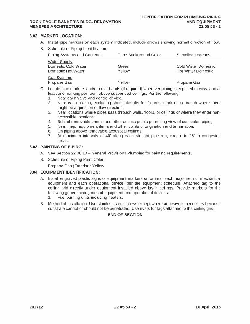
ROCK EAGLE BANKER'S BLDG. RENOVATIONIDENTIFICATION FOR PLUMBING PIPING
AND EQUIPMENTMENEFEE ARCHITECTURE 22 05 53 - 2
201712 22 05 53 - 2 16 April 2018
3.02 MARKER LOCATION:
A. Install pipe markers on each system indicated, include arrows showing normal direction of flow.
B. Schedule of Piping Identification:
Piping Systems and Contents Tape Background Color Stenciled Legends
Water SupplyDomestic Cold Water Green Cold Water DomesticDomestic Hot Water Yellow Hot Water Domestic
Gas SystemsPropane Gas Yellow Propane Gas
C. Locate pipe markers and/or color bands (if required) wherever piping is exposed to view, and at least one marking per room above suspended ceilings. Per the following:1. Near each valve and control device.2. Near each branch, excluding short take-offs for fixtures, mark each branch where there
might be a question of flow direction.3. Near locations where pipes pass through walls, floors, or ceilings or where they enter non-
accessible locations.4. Behind removable panels and other access points permitting view of concealed piping.5. Near major equipment items and other points of origination and termination.6. On piping above removable acoustical ceilings.7. At maximum intervals of 40’ along each straight pipe run, except to 25’ in congested
areas.
3.03 PAINTING OF PIPING:
A. See Section 22 00 10 – General Provisions Plumbing for painting requirements.
B. Schedule of Piping Paint Color:
Propane Gas (Exterior): Yellow
3.04 EQUIPMENT IDENTIFICATION:
A. Install engraved plastic signs or equipment markers on or near each major item of mechanical equipment and each operational device, per the equipment schedule. Attached tag to the ceiling grid directly under equipment installed above lay-in ceilings. Provide markers for the following general categories of equipment and operational devices.1. Fuel burning units including heaters.
B. Method of Installation: Use stainless steel screws except where adhesive is necessary because substrate cannot or should not be penetrated. Use rivets for tags attached to the ceiling grid.
END OF SECTION
ROCK EAGLE BANKER'S BLDG. RENOVATION PLUMBING SYSTEMS INSULATIONMENEFEE ARCHITECTURE 22 07 00 - 1
201712 22 07 00 - 1 16 April 2018
SECTION 22 07 00
PLUMBING SYSTEMS INSULATION
PART 1 GENERAL
1.01 DESCRIPTION: Insulation specified in this Section is for insulation used in Division 22 work.
1.02 RELATED SECTIONS:
A. Section 22 10 05 Plumbing Piping and Drainage Accessories.
B. Section 22 00 10 General Provisions Plumbing
1.03 DEFINITIONS:
A. Exposed piping is work that can be seen when the building is complete without opening or removing access doors or panels.
B. Other piping is considered to be concealed.
1.04 INSPECTION:
A. Surfaces to be insulated shall be clean, dry, and free of foreign material, such as rust, scale and dirt when insulation is applied. Perform pressure tests required by other Sections before applying insulation.
B. Where existing insulation is damaged due to the new work, repair damage to match existing work or replace damaged portion with insulation specified for new work.
1.05 QUALITY ASSURANCE:
A. Products of the manufacturers listed will be acceptable for use for the specific functions noted.All materials shall be compatible with the materials to which they are applied, and shall not corrode, soften or otherwise attack such material in either the wet or dry state.
B. Materials shall be applied subject to their temperature limits. Any methods of application of insulating materials or finishes not specified in detail herein shall be in accordance with the particular manufacturer's published recommendations.
C. Insulation shall be applied by experienced workers regularly employed for this type work.
1.06 RATING:
A. Insulation and accessories, unless specifically exempted, shall have a composite flame-spread rating of not more than 25 and a smoke developed rating of not more than 50. Materials that are factory applied shall be tested as assembled. Materials that are field applied may be tested individually. No fugitive or corrosive treatments shall be employed to impart flame resistance.
B. Flame Spread and Smoke Developed Ratings shall be determined by Method of Test of Surface Burning Characteristics of Building Materials, ASTM E-84 1997 or UL 723.
C. Products or their shipping cartons shall bear a label indicating flame spread and smoke developed ratings.
D. Treatment of pipe jackets to impart flame and smoke safety shall be permanent.
1.07 ASBESTOS: All materials used in this work shall be asbestos free.
PART 2 PRODUCTS
2.01 INSULATION APPLICATIONS:
A. Pipe Insulation – Denoted by Type P:1. Interior concealed Domestic Cold water:
a. Type P3 Glass fiber, 1/2” thick.2. Domestic Hot water, interior installations:
a. Type P3 Glass fiber, 1” thick for piping up to 2” diameter
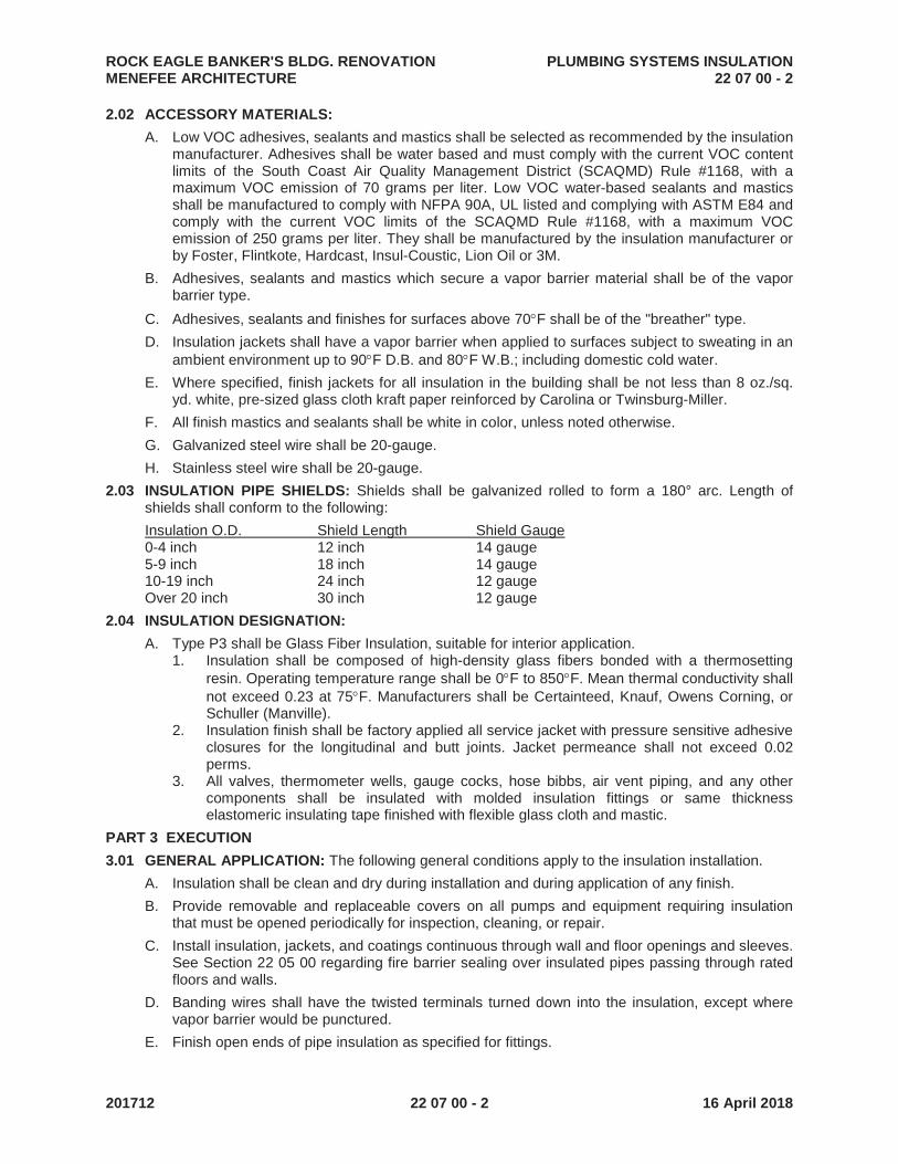
ROCK EAGLE BANKER'S BLDG. RENOVATION PLUMBING SYSTEMS INSULATIONMENEFEE ARCHITECTURE 22 07 00 - 2
201712 22 07 00 - 2 16 April 2018
2.02 ACCESSORY MATERIALS:
A. Low VOC adhesives, sealants and mastics shall be selected as recommended by the insulation manufacturer. Adhesives shall be water based and must comply with the current VOC content limits of the South Coast Air Quality Management District (SCAQMD) Rule #1168, with amaximum VOC emission of 70 grams per liter. Low VOC water-based sealants and mastics shall be manufactured to comply with NFPA 90A, UL listed and complying with ASTM E84 and comply with the current VOC limits of the SCAQMD Rule #1168, with a maximum VOCemission of 250 grams per liter. They shall be manufactured by the insulation manufacturer or by Foster, Flintkote, Hardcast, Insul-Coustic, Lion Oil or 3M.
B. Adhesives, sealants and mastics which secure a vapor barrier material shall be of the vapor barrier type.
C. Adhesives, sealants and finishes for surfaces above 70 F shall be of the "breather" type.
D. Insulation jackets shall have a vapor barrier when applied to surfaces subject to sweating in an ambient environment up to 90 F D.B. and 80 F W.B.; including domestic cold water.
E. Where specified, finish jackets for all insulation in the building shall be not less than 8 oz./sq. yd. white, pre-sized glass cloth kraft paper reinforced by Carolina or Twinsburg-Miller.
F. All finish mastics and sealants shall be white in color, unless noted otherwise.
G. Galvanized steel wire shall be 20-gauge.
H. Stainless steel wire shall be 20-gauge.
2.03 INSULATION PIPE SHIELDS: Shields shall be galvanized rolled to form a 180° arc. Length of shields shall conform to the following:
Insulation O.D. Shield Length Shield Gauge0-4 inch 12 inch 14 gauge5-9 inch 18 inch 14 gauge10-19 inch 24 inch 12 gaugeOver 20 inch 30 inch 12 gauge
2.04 INSULATION DESIGNATION:
A. Type P3 shall be Glass Fiber Insulation, suitable for interior application.1. Insulation shall be composed of high-density glass fibers bonded with a thermosetting
resin. Operating temperature range shall be 0 F to 850 F. Mean thermal conductivity shall not exceed 0.23 at 75 F. Manufacturers shall be Certainteed, Knauf, Owens Corning, or Schuller (Manville).
2. Insulation finish shall be factory applied all service jacket with pressure sensitive adhesive closures for the longitudinal and butt joints. Jacket permeance shall not exceed 0.02 perms.
3. All valves, thermometer wells, gauge cocks, hose bibbs, air vent piping, and any other components shall be insulated with molded insulation fittings or same thickness elastomeric insulating tape finished with flexible glass cloth and mastic.
PART 3 EXECUTION
3.01 GENERAL APPLICATION: The following general conditions apply to the insulation installation.
A. Insulation shall be clean and dry during installation and during application of any finish.
B. Provide removable and replaceable covers on all pumps and equipment requiring insulation that must be opened periodically for inspection, cleaning, or repair.
C. Install insulation, jackets, and coatings continuous through wall and floor openings and sleeves.See Section 22 05 00 regarding fire barrier sealing over insulated pipes passing through rated floors and walls.
D. Banding wires shall have the twisted terminals turned down into the insulation, except where vapor barrier would be punctured.
E. Finish open ends of pipe insulation as specified for fittings.

ROCK EAGLE BANKER'S BLDG. RENOVATION PLUMBING SYSTEMS INSULATIONMENEFEE ARCHITECTURE 22 07 00 - 3
201712 22 07 00 - 3 16 April 2018
F. All piping and equipment that are scheduled to be insulated shall have a finished jacket, either factory or field applied.
G. Staples shall be installed only on insulation that does not contain a vapor barrier.
H. For all cold piping systems (waste piping receiving condensate discharge and domestic cold water), all components of the piping system shall be insulated and provided with a continuous vapor barrier. Vapor barriers shall be continuous for entire piping system and shall not be pierced except as specified otherwise.
I. Factory applied jacket shall be the finish jacket unless otherwise noted.
J. Maintain vapor barrier where dissimilar insulation products abut.
3.02 PIPE SHIELDS: For all piping, insulation shall be continuous on pipe at pipe hangers with protection shields bearing on the outside of the insulation.
3.03 INSULATION APPLICATION:
A. Type P3 – Glass Fiber Insulation:1. Cover pipe with insulation with each section tightly abutted one to another. Jacket shall be
lapped and secured with self-adhesive strip.2. Abutting ends of insulation shall be covered with 4" wide butt strips smoothly secured with
adhesive.3. Fittings and valves shall be covered with mitered or molded insulation sections secured
with galvanized steel wire and finished with smooth coat of white glass fabric and mastic.
3.04 FINISH JACKETS:
A. Pre-sized glass cloth jackets shall be secured by a continuous coating of adhesive applied to a uniform thickness. Jacket shall be smooth without wrinkles. Jacket shall be applied to straight lengths of covering only.
B. Flexible glass cloth shall be applied to equipment, valves, fittings, and curved surfaces. Cloth tape shall be smoothly applied and secured with a continuous coat of adhesive. White fabric and mastic to be used on exposed pipe fittings. Tape shall overlap itself and adjacent jackets not less than two inches (2").
END OF SECTION

ROCK EAGLE BANKER'S BLDG. RENOVATION PIPE FITTINGS & ACCESSORIES - PLUMBINGMENEFEE ARCHITECTURE 22 10 00 - 1
201712 22 10 00 - 1 16 April 2018
SECTION 22 10 00
PIPE, FITTINGS AND ACCESSORIES – PLUMBING
PART 1 GENERAL
1.01 DESCRIPTION: Piping specified in this Section is for types of pipe and accessories used in Division 22.
1.02 RELATED SECTIONS:
A. Section 22 05 00 Common Work Results for Plumbing
B. Section 22 10 05 Plumbing Piping and Drainage Accessories
1.03 SUBMITTALS:
A. See General Conditions for submittal procedure.
B. Provide product data for pipe and fitting materials, indicating conformance with specified standards.
1.04 QUALITY ASSURANCE:
A. Codes and regulations referred to are minimum standards. Where the requirements of these specifications or drawings exceed those of the codes and regulations, the drawings and specifications govern.
B. Pressure/temperature ratings of all components and accessories shall meet or exceed design conditions for the system in which they are installed.
C. Welding shall be in accordance with procedures of the National Certified Pipe Welding Bureau and shall comply with the requirements of the ANSI Code for Pressure Piping. Welders shall be qualified under the above procedures and certified by the National Certified Pipe Welding Bureau.
PART 2 PRODUCTS
2.01 PIPE AND FITTINGS:
A. Steel Pipe and Fittings:1. Pipe (up to 12” diameter):
Material SpecificationSchedule 40 Black steel ASTM A53, latest edition, Grade B
2. Fittings:a. 150 lb. SWP malleable iron screwed fittings conforming to ANSI B16.3.b. 125 lb. SWP cast iron flange fittings conforming to ANSI B16.1.c. Cast iron drainage pattern fittings conforming to ANSI B16.12.d. Dielectric couplings and/or flange kits shall be provided at connections between
ferrous and non-ferrous pipe. Provide with high temperature gaskets rated for 300 F steam service.
e. Unions:(1) Except where otherwise specified, unions in welded piping shall be flanges.(2) Unions in piping 2-inch and smaller shall be 150 lb. malleable iron, ground joint,
bronze to iron, screw type.(3) Unions in screwed piping 2½" and larger shall be 125 lb. cast iron flanges.
f. Fittings, flanges, and unions in galvanized steel pipe shall be galvanized.3. Joints, unless specified otherwise:
a. Screwed Joints: Joint compound shall be "Titeseal" or Teflon Tape, except where otherwise specified.
4. Pipe and fittings shall be made in America unless otherwise approved.
B. Copper Pipe and Fittings (Soldered):1. Pipe:
Material SpecificationType L tube ASTM B88, latest edition

ROCK EAGLE BANKER'S BLDG. RENOVATION PIPE FITTINGS & ACCESSORIES - PLUMBINGMENEFEE ARCHITECTURE 22 10 00 - 2
201712 22 10 00 - 2 16 April 2018
2. Fittings:a. Wrought copper solder joint type conforming to ANSI B16.22. Cast fittings
conforming to ANSI B16.18, except where otherwise specified, may be used only in patterns not available in wrought fittings, and where desired changes in direction and/or reduction in size cannot be accomplished with two wrought fittings.
b. Adapter fittings shall be provided at all copper to brass pipe connections. Adapters 2" and smaller shall be cast bronze or wrought copper. Adapters larger than 2" shall be 150 lb. cast bronze flanges. Adapters between the meter and the pressure reducing valve shall be 250 lb cast bronze flanges.
c. 150 lb. cast bronze flange fittings conforming to ANSI B16.24 downstream of the pressure reducing valves.
d. Dielectric couplings and/or flanged kits shall be provided at all copper to steel pipe connections.
e. Cast DWV fittings shall conform to ANSI B16.23; wrought DWV fittings to ANSI B16.29.
f. Unions:(1) Except where otherwise specified, unions shall be wrought copper or cast
bronze.(2) Unions in piping 2½" and larger shall be 150 lb. cast bronze flanges,
downstream of the pressure reducing valve and 250 lb between the meter and the PRV.
(3) Insulating unions shall be provided at all equipment having ferrous connections.3. Copper pipe shall be manufactured by Mueller Industries, Cerro Flow Industries, or
Cambridge-Lee Industries.4. Fittings shall be manufactured by Mueller Industries, Cello Products, Nibco, or Elkhart
Products.5. Joints, unless specified otherwise:
a. Solder Joints: Solder shall be 95/5 (95% tin, 5% antimony) except where otherwise specified. Where specified or noted on the drawings, solder shall have a silver alloy solder having a melting point of not less than 1100 F. NO LEAD SOLDER SHALL BE PERMITTED.
b. Solder flux shall be the type recommended by the manufacturer of the 95/5 solder used, meeting ANSI/NSF Standard 61. Silver brazing flux shall be used for solder of 1100 F. or higher melting point.
C. Cast Iron Soil Pipe and Fittings:1. Pipe and Fittings:
a. Coated hub and spigot cast iron soil pipe and fittings conforming to ASTM A74, latest edition with preformed rubber gasket joints conforming to ASTM C564-97.
b. Coated "no hub" cast iron soil pipe and fittings, 10" size and under, conforming to Cast Iron Soil Pipe Institute Standard 301 and ASTM A 888, latest edition.
c. Cast iron pipe and fittings shall be by one manufacturer; Charlotte Pipe and Foundry Company, Tyler Pipe, or AB&I Foundry.
d. Cast iron P-traps exposed shall have brass cleanout plugs.2. Joints:
a. Compression joints shall consist of a one-piece elastomer gasket conforming to ASTM C564 and ASTM C1563.
b. “No hub” vent piping and waste piping 2” and smaller shall be joined with standard stainless steel threaded no-hub couplings conforming to the Cast Iron Soil Pipe Institute (CISPI) Standard 310 and shall be listed by NSF International and manufactured by MG Coupling Company or equivalent.
c. Heavy duty no-hub couplings shall be used as follows:(1) All soil and waste piping larger than 2”.
d. Heavy duty no-hub couplings shall conform to ASTM C1540 and shall be made with Anaheim Foundry Company’s Husky SD4000, Mission HW, or Clamp All 125.

ROCK EAGLE BANKER'S BLDG. RENOVATION PIPE FITTINGS & ACCESSORIES - PLUMBINGMENEFEE ARCHITECTURE 22 10 00 - 3
201712 22 10 00 - 3 16 April 2018
e. All couplings shall consist of housing, band, screws, stainless steel shield, and neoprene gasket. Couplings shall conform to ASTM C564 and ASTMC1563.
D. Plastic DWV Pipe and Fittings:1. Pipe: Schedule 40 PVC and ABS conforming to ASTM D2665 and D2661 respectively.2. Fittings: Drainage, waste, and vent PVC and ABS fittings conforming to ASTM D2665 and
ASTM D2661 respectively.3. Plastic DMW pipe and fittings shall be by one manufacturer: Charlotte Pipe and Foundry
Company, Harvel, or US Plastic.4. Solvent Weld Joints: Primer shall be low VOC (less than 450 PPM) type, tinted purple,
and conforming to ASTM F-656. Cement shall be industrial grade low VOC type, compatible with the piping material being joined and suitable for temperatures up to 140 F.
2.02 SLEEVES:
A. Provide standard weight steel pipe sleeves at all points where piping passes through walls, floors, and ceilings, except where otherwise specified.
B. #20 U.S. gauge galvanized steel sleeves may be used through all walls and through floors in concealed pipe chases where concrete thickness is 4" or less.
PART 3 EXECUTION
3.01 PIPING - GENERAL:
A. All piping shall be run straight and parallel to building construction. All changes in directions shall be made with fittings as specified herein and shown on the drawings.
B. All piping shall be installed with allowance for expansion and contraction.
C. Pipe connections to equipment that is supported independent of the pipe, including pumps, shall be aligned with the equipment.
D. Install piping so as to preserve access to all valves, air vents, and other equipment and to provide the maximum headroom possible.
E. All piping, except cast iron, which runs through concrete slabs or walls shall be insulated or caulked in sleeves as hereinafter specified so that the pipe metal does not come in contact with the concrete masonry.
F. Equipment Drains, Drips, Etc.:1. All devices and equipment having drain, drip or blowdown connection shall be piped to
nearest floor drain terminating with an elbow over grate, except where otherwise specified.
2. Piping shall be run parallel and plumb to walls and shall be braced to walls, floor, other piping, or equipment.
3. Piping shall be full size of device or equipment connection. Except for relief valve discharges, horizontal drains may be combined into one pipe that is one pipe larger than largest connecting pipe.
4. Condensate drains shall be trapped and provided with unions and cleanouts.
G. Unions shall be provided at all connections to flow control valves, equipment, and apparatus.
3.02 PROCEDURES FOR JOINTS IN STEEL PIPING:
A. Screwed Joints:1. All threads shall be standard, clean cut and tapered. All burrs shall be reamed from inside
of the pipe, and pipe shall be turned on end and all loose dirt and scale knocked out.2. Pipes with threads stripped, chipped or damaged, or split pipe or defective fittings shall
not be used.3. Joint compound shall be applied to the male threads only.
3.03 PROCEDURES FOR JOINTS IN COPPER PIPING:
A. Solder Joints:

ROCK EAGLE BANKER'S BLDG. RENOVATION PIPE FITTINGS & ACCESSORIES - PLUMBINGMENEFEE ARCHITECTURE 22 10 00 - 4
201712 22 10 00 - 4 16 April 2018
1. Ends of pipe shall be cut square and cleaned with sand cloth so as to remove all oxides before soldering. Fittings shall be similarly cleaned with sand cloth or wire brush.
2. Flux shall be evenly applied to both pipe end and fittings.3. Solder shall completely fill all parts of joint. Clean excess flux from pipe after joint
completed.
3.04 PROCEDURES FOR JOINTS IN CAST IRON SOIL AND WASTE PIPING:
A. Compression joints shall consist of one piece elastomer gasket conforming to ASTM C-564.
B. Hubless and Gasketed Joints shall be made up in strict accordance with manufacturer's recommendations.
3.05 PROCEDURES FOR JOINTS IN PLASTIC PIPE:
A. Ends of pipe shall be cut square, cleaned, and deburred prior to threading or applying primer.
B. Pipe threading shall be performed per manufacturer’s recommendations.
C. Chemical welded joints shall be primed, cemented, and assembled per manufacturer'srequirements.
3.06 SLEEVES: Provide all sleeves in floors, beams, walls, roof, etc., as required for installing work of this Division unless otherwise specified hereinafter.
A. Sleeves shall be of sufficient size for pipe and full-size insulation to pass through.
B. Sleeves through outside walls above grade shall be caulked watertight between pipe or pipe insulation and sleeve with non-shrink grout.
C. Pipes penetrating walls below grade shall be sealed with a waterproof, modular, mechanical expansion seal consisting of interlocking synthetic rubber links shaped to continuously fill the annular space between the pipe and wall opening. Sizing of links and wall sleeve shall be determined by manufacturer. Thunderline "Link Seal" or Metraflex “Metraseal”.
D. Sleeves shall be spaced sufficient distance from adjacent walls and other sleeves so that insulation and/or finish plates may be installed without cutting insulation or plates.
E. Sleeves shall be placed on the piping as it is installed to permit installation of sleeves in walls, partitions, and slabs in one piece.
F. Omit sleeves where cast iron pipes pass through masonry partitions, slabs on grade, and where all pipes pass through gypsum board partitions.
G. See Section 22 05 00 Common Work Results for Plumbing regarding firestop requirements.
3.07 PRESSURE TESTING: See particular piping section for pressure testing requirements.
END OF SECTION
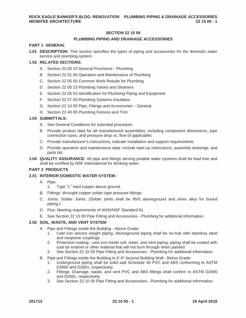
ROCK EAGLE BANKER'S BLDG. RENOVATION PLUMBING PIPING & DRAINAGE ACCESSORIESMENEFEE ARCHITECTURE 22 10 05 - 1
201712 22 10 05 - 1 16 April 2018
SECTION 22 10 05
PLUMBING PIPING AND DRAINAGE ACCESSORIES
PART 1 GENERAL
1.01 DESCRIPTION: This section specifies the types of piping and accessories for the domestic water service and plumbing system.
1.02 RELATED SECTIONS:
A. Section 22 00 10 General Provisions - Plumbing
B. Section 22 01 00 Operation and Maintenance of Plumbing
C. Section 22 05 00 Common Work Results for Plumbing
D. Section 22 05 23 Plumbing Valves and Strainers
E. Section 22 05 53 Identification for Plumbing Piping and Equipment
F. Section 22 07 00 Plumbing Systems Insulation
G. Section 22 10 00 Pipe, Fittings and Accessories – General
H. Section 22 40 00 Plumbing Fixtures and Trim
1.03 SUBMITTALS:
A. See General Conditions for submittal procedure.
B. Provide product data for all manufactured assemblies; including component dimensions, pipe connection sizes, and pressure drop vs. flow (if applicable).
C. Provide manufacturer’s instructions, indicate installation and support requirements.
D. Provide operation and maintenance data; include start-up instructions, assembly drawings, and parts list.
1.04 QUALITY ASSURANCE: All pipe and fittings serving potable water systems shall be lead free and shall be certified by NSF International for drinking water.
PART 2 PRODUCTS
2.01 INTERIOR DOMESTIC WATER SYSTEM:
A. Pipe:1. Type "L" hard copper above ground.
B. Fittings: Wrought copper solder type pressure fittings.
C. Joints: Solder Joints. (Solder joints shall be 95/5 aboveground and silver alloy for buried piping.)
D. Flux: Meeting requirements of ANSI/NSF Standard 61.
E. See Section 22 10 00 Pipe Fitting and Accessories - Plumbing for additional information.
2.02 SOIL, WASTE, AND VENT SYSTEM
A. Pipe and Fittings inside the Building - Above Grade: 1. Cast iron service weight piping. Aboveground piping shall be no-hub with stainless steel
and neoprene couplings.2. Protective coating - cast iron inside soil, water, and vent piping: piping shall be coated with
coal tar enamel or other material that will not burn through when painted.3. See Section 22 10 00 Pipe Fitting and Accessories - Plumbing for additional information.
B. Pipe and Fittings inside the Building to 5'-0" beyond Building Wall - Below Grade:1. Underground piping shall be solid wall Schedule 40 PVC and ABS conforming to ASTM
D2665 and D2661, respectively.2. Fittings: Drainage, waste, and vent PVC and ABS fittings shall confirm to ASTM D2665
and D2661, respectively.3. See Section 22 10 00 Pipe Fitting and Accessories - Plumbing for additional information.

ROCK EAGLE BANKER'S BLDG. RENOVATION PLUMBING PIPING & DRAINAGE ACCESSORIESMENEFEE ARCHITECTURE 22 10 05 - 2
201712 22 10 05 - 2 16 April 2018
2.03 GAS (PROPANE) PIPING SYSTEM (ABOVE GRADE):
A. Propane Gas piping shall be schedule 40 black steel pipe.
B. Fittings shall be threaded malleable iron in sizes 2" and under.
C. See Section 22 10 00 Pipe Fitting and Accessories - Plumbing for additional information.
2.04 CLEANOUTS:
A. Cleanouts for concealed piping in floor or ceiling construction shall extend through the finished floor above. Medium duty cleanouts shall be cast iron body, adjustable housing, round top, bronze plug, nickel bronze secured top; Smith 4026. Cleanouts in carpeted areas shall have carpet markers.
B. Cleanouts for piping concealed in wall construction shall be tapped for machine screws and provided with access cover plates, Smith 4472T stainless steel.
C. Equal products by Josam or Zurn are acceptable.
2.05 HYDRANTS: HB: Hose Bibbs shall be furnished with integral vacuum breaker, 3/4" hose thread, removable handle, polished chrome finish; Chicago 952 or equal by Prier, Watts, Woodford, or Zurn.
PART 3 EXECUTION
3.01 PIPING GENERAL: Temporary Closures: During construction period, all rough-in plumbing shall be sealed off with test plugs and caps until fixtures are ready to be installed.
3.02 DOMESTIC WATER: Drains from backflow preventers, air gap devices, and strainers shall be piped to floor drains.
3.03 SOIL, WASTE, AND VENT:
A. Grading: Horizontal drainage piping 2½" and smaller shall be graded not less than ¼" per foot, piping 3" and larger shall be graded not less than 1/8" per foot. Vents shall be graded so as to drain back to the soil or waste pipe. Sewer piping shall be graded in accordance with inverts established on the drawings. For all drainage piping, the slope shall be uniform for the entire length.
B. Hub drains at slab level shall be continuation of hub and spigot piping system. No-hub piping shall be used above slab level with exception of hub drains at slab.
3.04 CLEANOUTS:
A. Provide cleanouts where shown on drawings.
B. Size of cleanouts shall be of the same nominal size as the pipe served for pipe sizes four inches and smaller; for larger pipe sizes, cleanouts shall be not less than 4" nominal pipe size.
3.05 DRAIN AND CLEANOUT JOINTS:
A. Joints between pipe and inside caulk bodies may be made with Jiffee-Joint Gaskets conforming to ASTM C-564.
B. Gaskets shall be selected for the specific pipe specified.
C. Gaskets shall be of the same manufacturer as the drains or cleanouts.
3.06 TRAPS: Provide traps for all fixtures. Set traps true and level. Provide exposed traps with brass cleaning screws.
3.07 PRESSURE TESTS:
A. All piping shall be pressure tested before insulation and concealment.
B. The following piping shall be tested to the pressure and for the period of time listed, and shall hold the specified pressure at the low point of the system for the specified length of time, without perceptible loss of pressure or leakage.
C. At the completion of the tests, the Contractor shall submit a letter on his letterhead certifying that the tests have been performed and listing the date of the tests.1. Domestic Water Piping:
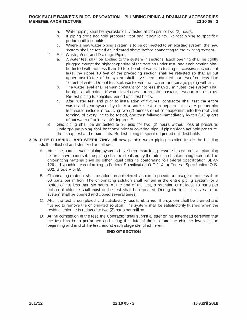
ROCK EAGLE BANKER'S BLDG. RENOVATION PLUMBING PIPING & DRAINAGE ACCESSORIESMENEFEE ARCHITECTURE 22 10 05 - 3
201712 22 10 05 - 3 16 April 2018
a. Water piping shall be hydrostatically tested at 125 psi for two (2) hours.b. If piping does not hold pressure, test and repair joints. Re-test piping to specified
period until test holds.c. Where a new water piping system is to be connected to an existing system, the new
system shall be tested as indicated above before connecting to the existing system.2. Soil, Waste, Vent, and Drainage Piping:
a. A water test shall be applied to the system in sections. Each opening shall be tightly plugged except the highest opening of the section under test, and each section shall be tested with not less than 10 feet head of water. In testing successive sections, at least the upper 10 feet of the preceding section shall be retested so that all but uppermost 10 feet of the system shall have been submitted to a test of not less than 10 feet of water. Do not test soil, waste, vent, rainwater, or drainage piping with air.
b. The water level shall remain constant for not less than 15 minutes; the system shall be tight at all points. If water level does not remain constant, test and repair joints.Re-test piping to specified period until test holds.
c. After water test and prior to installation of fixtures, contractor shall test the entire waste and vent system by either a smoke test or a peppermint test. A peppermint test would include introducing two (2) ounces of oil of peppermint into the roof vent terminal of every line to be tested, and then followed immediately by ten (10) quarts of hot water of at least 140 degrees F.
3. Gas piping shall be air tested to 30 psig for two (2) hours without loss of pressure.Underground piping shall be tested prior to covering pipe. If piping does not hold pressure, then soap test and repair joints. Re-test piping to specified period until test holds.
3.08 PIPE FLUSHING AND STERILIZING: All new potable water piping installed inside the building shall be flushed and sterilized as follows:
A. After the potable water piping systems have been installed, pressure tested, and all plumbingfixtures have been set, the piping shall be sterilized by the addition of chlorinating material. The chlorinating material shall be either liquid chlorine conforming to Federal Specification BB-C-120 or hypochlorite conforming to Federal Specification O-C-114, or Federal Specification O-S-602, Grade A or B.
B. Chlorinating material shall be added in a metered fashion to provide a dosage of not less than 50 parts per million. The chlorinating solution shall remain in the entire piping system for a period of not less than six hours. At the end of the test, a retention of at least 10 parts per million of chlorine shall exist or the test shall be repeated. During the test, all valves in the system shall be opened and closed several times.
C. After the test is completed and satisfactory results obtained, the system shall be drained and flushed to remove the chlorinated solution. The system shall be satisfactorily flushed when the residual chlorine is reduced to two (2) parts per million.
D. At the completion of the test, the Contractor shall submit a letter on his letterhead certifying that the test has been performed and listing the date of the test and the chlorine levels at the beginning and end of the test, and at each stage identified herein.
END OF SECTION

ROCK EAGLE BANKER'S BLDG. RENOVATION DOMESTIC WATER HEATING EQUIPMENTMENEFEE ARCHITECTURE 22 34 00 - 1
201712 22 34 00 - 1 16 April 2018
SECTION 22 34 00
DOMESTIC WATER HEATING EQUIPMENT
PART 1 GENERAL
1.01 DESCRIPTION: This section specifies the domestic water heating equipment.
1.02 RELATED SECTIONS:
A. Section 22 00 10 General Provisions - Plumbing
B. Section 22 01 00 Operation and Maintenance of Plumbing
C. Section 22 05 00 Common Work Results for Plumbing
D. Section 22 05 23 Plumbing Valves and Strainers
E. Section 22 05 53 Identification for Plumbing Piping and Equipment
F. Section 22 07 00 Plumbing Systems Insulation
G. Section 22 10 00 Pipe, Fittings and Accessories – Plumbing
1.03 SUBMITTALS:
A. See General Conditions for submittal procedure.
B. Provide shop drawing showing water heater dimensions, capacities, weight, pressure rating, electrical requirements and pipe connection sizes and locations.
C. Provide shop drawings for control panel showing the proposed wiring diagram with accompanying complete typewritten sequence of operations (if applicable). A symbols list defining all abbreviated components shall be included. A cut sheet on each component used in the system shall be included. The diagram shall delineate between power and control wiring and shall indicate all contactors, relays, and other components of the system. Normally open positions for the relays shall be indicated.
D. Provide manufacturers recommendations for flue vent configuration and flue material.
E. Provide manufacturer’s instructions, indicate installation and support requirements.
F. Provide operation and maintenance data; include start-up instructions, assembly drawings and parts list.
PART 2 PRODUCTS
2.01 TANKLESS GAS WATER HEATER:
A. Tankless Heater(s) shall be internally mounted, instantaneous, multiple point-of-use, propanefired, direct vent, water heater(s) design certified to the ANSI Z21.10.3 standard for gas fired water heaters.
B. Each Tankless Heater shall produce no more than 55 ppm NOx emissions when tested in accordance with the Rules and Regulations of the South Coast Air Quality Management District (SCAQMD).
C. Tankless Heater(s) shall be configured to operate with propane gas and a 120 volt/60 Hz AC power source.
D. Tankless Heater(s) shall have a BTU input range as scheduled on the drawings, a minimum thermal efficiency rating of 84%, and a minimum hot water outlet capacity as scheduled on the drawings.
E. Tankless Heater(s) shall be microprocessor controlled and utilize a direct electronic ignition system (with no standing pilot), fully modulating gas control valve, turbine flow meter, automatic electro-mechanical water flow control valve, and water temperature thermistors to maintain outlet water temperature between ± 2 °F of set point temperature.
F. Tankless Heater(s) shall incorporate the following internal safety devices: flame failure lockout, boiling protection lockout, thermal overheat protection, internal freeze protection for ambient temperatures as low as –30 °F, and lockout protection in the event of a blocked flue.

ROCK EAGLE BANKER'S BLDG. RENOVATION DOMESTIC WATER HEATING EQUIPMENTMENEFEE ARCHITECTURE 22 34 00 - 2
201712 22 34 00 - 2 16 April 2018
G. Tankless Heater(s) shall be provided with a temperature thermostat with an adjustable set point range of 98°F to 140°F.
H. Tankless Heater(s) shall also be capable of storing and displaying a history of up to 9diagnostic maintenance codes, via the display on the temperature thermostat controller.
I. Heaters shall activate on minimum flow of 0.4 gallons per minute.
J. Tankless Heater(s) shall have stainless steel burners, solid brass water flow control valve, and solid brass inlet and outlet water connections.
K. Tankless Heater(s) shall have a copper heat exchanger warranted against material defects or workmanship for a period of 5 years from date of purchase. All other parts shall be warranted against material defects or workmanship for a period of 5 years from the date of purchase.
L. Tankless heater(s) shall be manufactured by Rinnai
PART 3 EXECUTION
3.01 INSTALLATION:
A. Pipe relief valve discharge the full size of relief valve discharge opening in Type "L" copper pipe to over nearest drain as noted on the drawings. Terminate discharge over drain with indirect connection.
B. Set water heater thermostat controls for 120 F water.
3.02 STARTUP:
A. The initial start-up of all water heater(s) shall be performed by a qualified factory representative of the heater manufacturer. The factory representative shall supervise the start-up and instruct owner’s personnel in the proper operation and maintenance of the heaters.
B. Start-up report shall be submitted in triplicate indicating all operational controls tested and performance documented.
END OF SECTION

ROCK EAGLE BANKER'S BLDG. RENOVATION PLUMBING FIXTURES AND TRIMMENEFEE ARCHITECTURE 22 40 00 - 1
201712 22 40 00 - 1 16 April 2018
SECTION 22 40 00
PLUMBING FIXTURES AND TRIM
PART 1 GENERAL
1.01 DESCRIPTION: This section specifies the fixtures and trim requirements.
1.02 RELATED SECTIONS:
A. Section 22 00 10 General Provisions - Plumbing
B. Section 22 01 00 Operation and Maintenance of Plumbing
C. Section 22 05 00 Common Work Results for Plumbing
D. Section 22 05 23 Plumbing Valves and Strainers
E. Section 22 07 00 Plumbing Systems Insulation
F. Section 22 10 00 Pipe, Fittings and Accessories - Plumbing
G. Section 22 10 05 Plumbing Piping and Drainage Accessories
1.03 SUBMITTALS:
A. See General Conditions for submittal procedure.
B. Provide product data for all fixtures; including catalog illustrations, dimensions, pipe connection sizes, and associated trim.
C. Provide manufacturer’s instructions, indicate installation and support requirements.
D. Provide operation and maintenance data; include start-up instructions, assembly drawings and parts list.
1.04 QUALITY ASSURANCE:
A. All fixtures shall have the manufacturer's guarantee; label or trademark indicating specified quality. All Acid Resisting enamel shall bear the manufacturer's symbol signifying Acid Resisting material.
B. All vitreous china fixtures shall be by the same manufacturer. All sinks shall be by the same manufacturer.
C. All fixtures construction components, tanks, and joints shall be of lead free material and construction. All drinking fountains and all faucets shall meet NSF Standard 61 and shall be certified to meet the standard requirements by NSF or UL.
D. Fixtures shall be white in color and all spaces between the fixture and the wall or floor shall be filled with white, mildew resistant, non-hardening silicone caulking.
E. All valves and fittings serving potable water fixtures shall be of Lead Free construction. Lead Free refers to less than 0.25% weighted average lead content in relation to wetted surface of pipe, fittings and fixtures in systems delivering water for human consumption. Any product designed for dispensing potable water shall meet both the NSF/ANSI 61 and NSF/ANSI 372 test standards via third party testing and certification
PART 2 PRODUCTS
2.01 FIXTURES shall be complete with all equipment, fittings, and trim. Fittings and trim shall be chrome plated brass unless specified otherwise, including P-traps, supplies and stops.
2.02 FIXTURE SCHEDULE:
A. Fixture Manufacturers shall be as follows:1. Enameled cast iron Service Sinks shall be provided by American Standard, Kohler or
Zurn.2. Stops, shall be by one manufacturer BrassCraft, Engineered Brass, McGuire or Zurn.
B. Fixtures:1. SS (Wall Hung Service Sink):
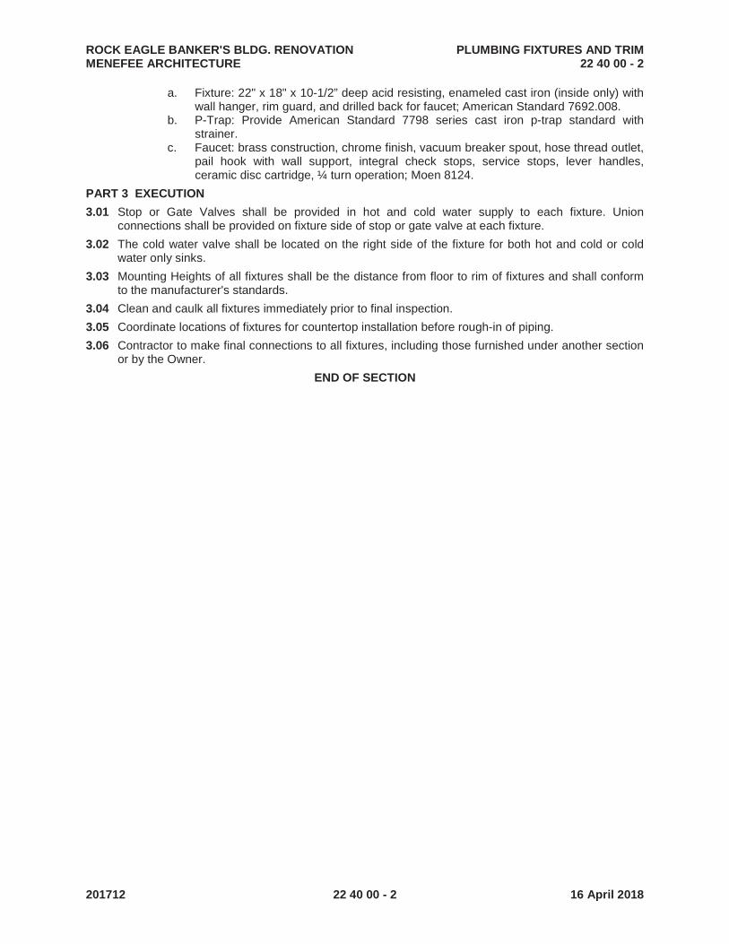
ROCK EAGLE BANKER'S BLDG. RENOVATION PLUMBING FIXTURES AND TRIMMENEFEE ARCHITECTURE 22 40 00 - 2
201712 22 40 00 - 2 16 April 2018
a. Fixture: 22" x 18" x 10-1/2” deep acid resisting, enameled cast iron (inside only) with wall hanger, rim guard, and drilled back for faucet; American Standard 7692.008.
b. P-Trap: Provide American Standard 7798 series cast iron p-trap standard with strainer.
c. Faucet: brass construction, chrome finish, vacuum breaker spout, hose thread outlet, pail hook with wall support, integral check stops, service stops, lever handles,ceramic disc cartridge, ¼ turn operation; Moen 8124.
PART 3 EXECUTION
3.01 Stop or Gate Valves shall be provided in hot and cold water supply to each fixture. Union connections shall be provided on fixture side of stop or gate valve at each fixture.
3.02 The cold water valve shall be located on the right side of the fixture for both hot and cold or cold water only sinks.
3.03 Mounting Heights of all fixtures shall be the distance from floor to rim of fixtures and shall conform to the manufacturer's standards.
3.04 Clean and caulk all fixtures immediately prior to final inspection.
3.05 Coordinate locations of fixtures for countertop installation before rough-in of piping.
3.06 Contractor to make final connections to all fixtures, including those furnished under another section or by the Owner.
END OF SECTION

ROCK EAGLE BANKER'S BLDG. RENOVATION GENERAL PROVISIONS - HVAC MENEFEE ARCHITECTURE 23 00 10 - 1
201712 23 00 10 - 1 16 April 2018
SECTION 23 00 10
GENERAL PROVISIONS – HVAC
PART 1 GENERAL
1.01 DESCRIPTION: These Mechanical General provisions specified herein apply to all Sections of Division 23.
1.02 WORK INCLUDED: Provide all materials, labor and services as specified in Division 23 and shown on the accompanying drawings.
1.03 DEFINITIONS:
A. Terms: The following definitions of terms supplement those of the GENERAL PROVISIONS - HVAC, and are applicable to all MECHANICAL SECTIONS. 1. Provide: Furnish, install and connect completely. 2. Piping: Pipe installed with all required fittings, valves and accessories, and forming a
complete system. 3. Wiring: Wire or cable installed in raceway with all required boxes, fittings, connectors, and
accessories completely installed. 4. Power Wiring: Wiring which supplies the electrical current which flows through a
connected motor or heater. 5. Exposed: Revealed to view or subject to weather. 6. Control, interlock and starting circuit wiring: All wiring required by all Mechanical Sections
that is not power wiring. 7. Fittings: All connecting pieces of a system.
B. Drawings: The Mechanical Drawings are diagrammatic except where specifically indicated otherwise. Refer to Architectural and Structural Drawings for building dimensions.
C. Materials: Refer to the GENERAL CONDITIONS. All material shall be suitable for the service and operating conditions of this Specification.
1.04 ABBREVIATIONS: The following abbreviations are used in this Division of the Specifications:
ASTM - American Society for Testing Materials. AABC - Associated Air Balance Council. ASME - American Society of Mechanical Engineers. ARI - Air Conditioning and Refrigeration Institute. SMACNA - Sheet Metal and Air Conditioning Contractors National Association. ANSI - American National Standards Institute. NEMA - National Electrical Manufacturers Association UL - Underwriters Laboratories, Inc. AWWA - American Water Works Association. SCS - Soil Conservation Service.
1.05 APPLICABLE CODES:
A. The latest amended editions of the codes applicable to the work of the municipality having jurisdiction.
B. In the absence of any municipal adopted codes, the following shall apply: 1. International Building Code, 2006 Edition, with Georgia Amendments (2007, 2009 and
2010). 2. International Mechanical Code, 2006 Edition, with Georgia Amendments (2007, Errata to
2007 amendments, 2008, 2010 and 2011). 3. ASHRAE Standard 90.1 Energy Standard for Buildings Except Low-Rise Residential
Buildings 4. All City, County, State, Regional, and other ordinances applicable to the work shall apply.
1.06 RELATED WORK: The following work is generally specified in other Divisions of the Specifications, except as specifically otherwise stated in this Division.
1. Electric power wiring. 2. Painting.

ROCK EAGLE BANKER'S BLDG. RENOVATION GENERAL PROVISIONS - HVAC MENEFEE ARCHITECTURE 23 00 10 - 2
201712 23 00 10 - 2 16 April 2018
3. Installation of access panels in walls and ceiling construction. 4. Installation of starters, contactors, thermal overload switches, and remote push buttons. 5. Curbs, other than pre-fabricated. 6. Flashing and pitch pockets around equipment on roof.
1.07 SPACE CONDITIONS:
A. All work shall fit the spaces available in an approved manner. Verify all dimensions of the work before commencing fabrication and/or installation. Advise engineer of record if a problem exist before proceeding with any work.
B. Minor deviations from the drawings required to conform to space conditions and to provide the required operation, service, or maintenance accessibility shall be made at no additional cost, and subject to approval.
C. Piping, equipment, or ductwork shall not be installed in electrical equipment rooms. Outside of electrical equipment rooms, do not run piping or ductwork, or locate equipment, with respect to switchboards, panel boards, power panels, motor control centers, or dry type transformers:
Within 42" in front (and rear if free standing) of equipment; or Within 36" of sides of equipment Clearances apply vertically from floor to ceiling structures.
D. Hydronic piping shall not be installed above any electrical or control panels.
1.08 RECORD DRAWINGS:
A. Upon completion of the Project, the Contractor shall submit one set of contract prints with red marks indicating As-built conditions of all piping, ductwork, and equipment, and incorporating changes made during construction. A record of as-built conditions shall be kept throughout the Project and shall be used in the preparation of the final record drawings.
B. The Contractor shall provide digital images (minimum resolution of 1152 x 864 pixels in JPEG standard image file format) delivered via email or on CD, of any utilities/piping that are installed underground with a reference drawing indicating which direction each picture is taken. The reference drawing shall dimension the utility/piping from a prominent fixed object.
1.09 GUARANTEES:
A. Furnish a written guarantee covering each category of work..
B. Guarantee shall be furnished in exact conformity with the requirements of the General Conditions.
1.10 CONTINUITY OF SERVICE:
A. All work shall be scheduled with that of other trades. The following conditions shall apply to all affected work.
B. Before disconnecting any existing systems for changes, the Contractor shall: 1. Have all materials needed stored at the job site. 2. Have assurance that all labor and skilled mechanics needed will be available at the proper
time. 3. Estimate the time the system will be out of service and inform the Owner in writing. 4. Secure approval of the shutdown dates from the Owner in writing before disconnecting the
system.
C. See General Conditions for correct procedures involving shut-downs of any utilities.
D. Work shall be done at such time and in such manner as to cause minimum inconvenience to the Owner and as approved by him or his representative. No allowance will be made for lack of knowledge of existing conditions.

ROCK EAGLE BANKER'S BLDG. RENOVATION GENERAL PROVISIONS - HVAC MENEFEE ARCHITECTURE 23 00 10 - 3
201712 23 00 10 - 3 16 April 2018
1.11 OPERATING INSTRUCTIONS:
A. Instructions: Instruct the Owner's representative in operation of the installed systems. The basis of these instructions shall be those written for inclusion in the maintenance and operating instruction data specified herein. Obtain certificates, signed by the Owner's representative, that these instructions have been received.
B. Notification: Notify the Owner at least five days before commencing operating period for refrigeration and heating equipment, as specified herein, in order that the Owner's representative may be present during that period.
1.12 DOCUMENTATION:
A. Documents to be submitted prior to request for final inspection: 1. Maintenance Manuals per Section 23 01 00. 2. Test and Balance Report. 3. Three copies of multi-year warranties bound in a brochure with index listing equipment.
B. Data to be Delivered at Final Inspection: 1. Record Drawings. 2. Certificate by Owner's representative confirming that operating instructions have been
received.
1.13 SUBMITTALS:
A. Procedure: Refer to the GENERAL CONDITIONS and SUPPLEMENTS thereto for submittal procedure of items called for in the Contract Documents.
B. Submittal data covering the work of this Division will be reviewed only after such items have been reviewed in detail and approved by the Contractor, such approval being indicated by suitable notations or stamp on the data.
C. Each submittal shall be clearly marked indicating Section and paragraph for which it is intended. Any deviations, exclusions or substitutions from specified material requirements shall be specifically identified in a summary sheet at the front of the submittal.
D. Where submittal sheets contain multiple products or selections, the specific item being submitted for review shall be clearly indicated with a red arrow (stamped or hand written). “Catalog” submittals (multiple items contained in the submittal, specific items not identified) will be rejected and not reviewed.
E. Submit the requested submittals in sufficient quantity to provide two copies in addition to those required by Contractor.
F. Submittal List: See the individual Mechanical Specification Sections for specific submittal requirements.
END OF SECTION

ROCK EAGLE BANKER'S BLDG. RENOVATION COMMON WORK RESULTS FOR HVAC MENEFEE ARCHITECTURE 23 05 00 - 1
201712 23 05 00 - 1 16 April 2018
SECTION 23 05 00
COMMON WORK RESULTS FOR HVAC
PART 1 GENERAL
1.01 DESCRIPTION: This Section of specifications deals with materials and methods pertaining to all work specified under Division 23.
1.02 RELATED SECTION: Section 23 00 10 General Provisions Mechanical
1.03 SUBMITTALS:
A. See General Conditions for submittal procedure.
B. Provide manufacturer’s instructions, indicate installation and support requirements.
1.04 JOB CONDITIONS:
A. Install all apparatus so as to maintain maximum headroom and clearances consistent with requirements of the drawings and specifications.
B. All equipment requiring service shall be installed to permit access for servicing without damage to building structure or finishes.
PART 2 PRODUCTS
PART 3 EXECUTION
3.01 INSTALLATION:
A. All work shall be installed plumb and square unless clearly indicated otherwise. Installation shall be performed by competent persons, trained in their respective skills.
B. Furnish and install equipment complete, including connections, services and adjustments for systems to operate safely and in compliance with requirements of the contract.
C. Install each item in full compliance with current recommendations of the manufacturer. Equipment manufacturer or his authorized representative shall furnish services and/or supervision necessary to ensure compliance with this provision. Conflict between manufacturer's recommendation and other contract requirements shall be resolved before installation.
D. Requirements of the several acceptable manufacturers for each specified item of equipment may vary as to installation details, location and number of connections, dimensions and weight. Provide all drawings, services, material, and labor necessary for the installation and proper functioning of the equipment furnished.
3.02 PROTECTION OF MATERIALS AND EQUIPMENT:
A. Take precautions to protect all materials and equipment from damage during the construction process.
B. Do not store materials and equipment outdoors subject to weather without complete weather protection.
C. Do not install materials or equipment in a partially constructed structure exposed to weather, unless all material and equipment is continuously protected from damage by weather or the construction process.
D. Material and equipment damaged by improper protection during construction is subject to replacement based on the judgment of the Engineer at no cost to the Owner.
3.03 CUTTING AND REPAIRING:
A. Cut and repair all walls, floors, and ceilings necessary for the installation of the mechanical work, but no cutting of work of other trades will be permitted without the consent of the Architect or his representative.
B. All cutting and repairing of walls, floors, and ceilings shall be subject to the supervision and approval of the Contractor.
ROCK EAGLE BANKER'S BLDG. RENOVATION COMMON WORK RESULTS FOR HVAC MENEFEE ARCHITECTURE 23 05 00 - 2
201712 23 05 00 - 2 16 April 2018
3.04 CLEANING AND FINAL CLEAN-UP:
A. Keep the premises free of waste, debris and surplus materials.
B. After equipment has been installed, remove all extraneous materials, rust and stains; blow, vacuum or flush all foreign matter from all equipment.
C. Identification plates on equipment shall be free of paint and shall be polished.
END OF SECTION

ROCK EAGLE BANKER'S BLDG. RENOVATION TESTING, BALANCING, AND ADJUSTING MENEFEE ARCHITECTURE 23 05 93 - 1
201712 23 05 93 - 1 16 April 2018
SECTION 23 05 93
TESTING, BALANCING, AND ADJUSTING
PART 1 GENERAL
1.01 DESCRIPTION: This section specifies the requirements for testing and balancing the Heating, Ventilating, and Air Conditioning Systems.
1.02 RELATED SECTION: Section 23 00 10 General Provisions HVAC
1.03 QUALIFICATIONS: The test and balance work shall be performed by an independent firm certified by the Associated Air Balance Council (AABC), or National Environmental Balancing Bureau (NEBB). Acceptable Test and Balancing agencies shall be Air Analysis of Atlanta, Thomas Balancing of Macon, Test and Balance Corporation and Research Air Flo.
1.04 PROCEDURES:
A. All air distribution systems and hydronic systems shall be tested, adjusted, and balanced to the conditions specified and/or shown on the drawings.
B. Performance of systems and components at specified conditions shall be verified by testing.
C. Before request for final inspection, calibrate, adjust, set, test and check all valves, dampers, temperatures, pressures, and flow rates of systems for operation and performance.
D. All test and balance work shall be performed in accordance with AABC or NEBB procedures.
E. Review the proposed systems installation drawings and determine if all measuring and balancing devices required for proper test and balance of the systems are specified and sized correctly.
F. Check that proposed ductwork layouts allows duct pitot traverses to be performed correctly to allow overall air flows.
G. The Test and Balance contractor shall read and implement the Test and Balance Plan of Action shown below.
1.05 REPORTS: Submit completed and certified report to Architect in triplicate or in printable electronic format.
PART 2 PRODUCTS
2.01 Provide all instruments, charts, materials, and equipment required to develop a complete test and balance report.
PART 3 EXECUTION
3.01 Test and balance report shall be a complete document and shall state specified design and actual measured/balanced levels. Report shall include at a minimum but not limited to, at least the following:
A. Air side of systems: 1. Coil entering and leaving temperatures. 2. All air unit component pressure drops. 3. Fan RPM and entering and leaving static pressure. 4. Air flow readings for all diffuser outlets and exhaust grilles. 5. Air flow and pressure drops for all terminals. Where heating coils are included, data shall
be same as under Coils and Heat Exchangers. 6. Space temperatures at thermostats. 7. Outlet temperatures of selected diffusers. 8. Manufacturer’s performance curves, tables and graphs.
B. Electric Motors: 1. Full load amperes, voltage, and horsepower. 2. Installed starter heater size.
C. Controls: 1. Calibrate all control elements and check operation including all interlocks. 2. Aide in adjusting all control systems to optimize energy use for all associated equipment.

ROCK EAGLE BANKER'S BLDG. RENOVATION TESTING, BALANCING, AND ADJUSTING MENEFEE ARCHITECTURE 23 05 93 - 2
201712 23 05 93 - 2 16 April 2018
3. Coordinate, aide and verify in located of sensors and to help ensure that sensor locations shall be free from drafts, heat sources or other factors that may affect the accuracy of the control system. Coordinate any change in sensor location with engineer prior to commencing work.
D. Total Systems: Contractor shall check all systems operating together, in all modes of operation, to ensure that the air conditioned spaces are in an overall positive pressurization state.
E. Building: Overall building and individual spaces air balance and pressurization levels.
F. General: Report shall include a list of all deficiencies found during the preliminary testing and a contractor response indicating remedial action taken for each item. The TAB work shall not be deemed finished without this report.
3.02 BALANCING AND ADJUSTMENT AFTER FINAL INSPECTION:
A. After building is accepted and occupied, and after testing and preliminary balancing are completed, send qualified personnel to building for not less than one period during summer and one period during winter, observe temperatures throughout conditioned spaces, consult with Owner's representative as to need for additional balancing or adjustment, then perform such work as is indicated.
B. Schedule these visits, at a time agreeable to Owner, during December through February for heating, and July through August for cooling.
3.03 TEST AND BALANCE PLAN OF ACTION:
A. The general contractor shall incorporate the TAB into the overall construction project to ensure that enough time is allowed for the testing and balancing contractor to complete the total system balancing according to a balancing plan prior to the completion date defined by the construction schedule.
B. A balancing plan prepared by the balancing contractor shall cover balancing techniques and testing procedures for all individual systems and equipment as well as for the overall system. 1. The plan shall include:
a. A list of the test instruments that are planned to be used in the testing and balancing process.
b. A description of the testing procedure for each HVAC system to be tested. List all of the equipment to be tested for each system and the techniques to be used for the testing procedure. Standard forms used by the TAB agency association shall be completed to reflect all equipment and systems identified by system and/or model number specific to the project. Blank, “sample” forms are unacceptable.
c. A list of the all contractors that are required to assist with the testing and balancing process along with the expectations of each of the contractors to successfully complete a total system balance. Most importantly, the expectations of the BAS contractor shall be listed. This shall include provision of automation software for balancing, timely automation system access, and the development of global overrides for system maximum performance testing.
d. An outline of the required construction completeness prior to starting the testing and balancing process
e. A realistic estimate of the time required to complete the testing and balancing process; the plan shall describe in detail the required time to complete balance of sub-systems and total system balance. The general contractor shall recognize that the balancing process sequential and not a process that can be shortened by simply putting more technicians on the project to complete the process faster. Buildings with direct digital control systems require a great deal of the testing and balancing process to be performed through adjustments to the HVAC systems via the automation/control system. Network access limitations and/or control software may prevent more than one operator from communicating with the automation/control system at a time. This makes it inefficient to have too many balancing technicians on a single project if the majority of the adjustments can only be made through one computer terminal.

ROCK EAGLE BANKER'S BLDG. RENOVATION TESTING, BALANCING, AND ADJUSTING MENEFEE ARCHITECTURE 23 05 93 - 3
201712 23 05 93 - 3 16 April 2018
f. A listing of the necessary uninterrupted accessibility to the building to completely test HVAC equipment and sub systems.
g. The general contractor shall allow time in the balancing plan schedule to allow the balancing contractor to address any issues in the design or installation, which prevents a system from operating at design performance. The general contractor shall take the time for resolution of these issues by the responsible party into account in the balancing schedule. A ‘contingency’ of an additional week or two should be incorporated into the balancing plan schedule to accommodate additional time required for the responsible party to correct any minor issues preventing design performance of the building.
h. Building accessibility during balancing (1) The balancing contractor shall be provided uninterrupted access to all areas of
the building. Large HVAC systems may require the access to the same area several times throughout the balancing process. Finishing processes of the building construction such as laying carpet and tile flooring, waxing floors, construction cleaning, and fire alarm testing that require the HVAC systems to be shut down shall be identified in the balancing plan to inform the construction manager of possible conflicts who shall attempt to schedule the testing and balancing process around them. Some building accessibility issues to address in the balancing plan include the following: i. Flooring work, such as carpet laying and tiling, must be performed either
before or after the testing and balancing process for a particular system serving the area in which the flooring work is to be done. If the completed flooring will restrict the use of boom lifts, the testing and balancing of the system serving that area shall be completed before the floor work if the HVAC system components are inaccessible by ladder.
ii. Final building cleaning that would prevent further access of contractors shall be delayed until the testing and balancing is completed.
iii. If fire alarm testing will affect the HVAC system, the balancing contractor should be notified in advance when fire alarm testing is scheduled. For example, closing fire dampers or shutting down air handling units can disrupt total system balancing.
C. A detailed balancing plan shall be submitted for all projects at the same time as mechanical submittal data. The balancing contractor shall follow up with the general contractor to ensure that the balancing plan has been properly reviewed and incorporated within the construction schedule.
END OF SECTION

ROCK EAGLE BANKER'S BLDG. RENOVATION DUCTWORK MENEFEE ARCHITECTURE 23 31 00 - 1
201712 23 31 00 - 1 16 April 2018
SECTION 23 31 00
DUCTWORK
PART 1 GENERAL
1.01 DESCRIPTION: This section specifies the sheetmetal requirements for Division 23 ductwork.
1.02 RELATED SECTIONS:
A. Section 23 05 00 Common Work Results for HVAC
B. Section 23 05 93 Testing, Balancing and Adjusting
C. Section 23 37 13 Grilles, Registers, and Diffusers
1.03 SUBMITTALS:
A. See General Conditions for submittal procedure.
B. Provide data on damper performance including, but not limited to, total static pressure drop verses airflow shown for all multi-blade dampers, size and quantity of dampers required.
C. Provide shop drawing showing multi-blade damper dimensions, construction, duct connection sizes and electrical requirements.
D. Provide manufacturer’s instructions, indicate installation and support requirements.
1.04 STANDARDS:
A. Refer to the SMACNA "HVAC Duct Construction Standards, Metal and Flexible ", Third Edition, 2005 , latest printing published by SMACNA.
B. Refer to the SMACNA “Duct Cleanliness for New Construction Guidelines”, latest printing published by SMACNA.
C. Unless noted otherwise herein, all ductwork shall be constructed, sealed, and supported in strict compliance with the SMACNA standards referenced above.
D. Refer to the SMACNA “IAQ Guidelines for Occupied Buildings Under Construction”, First Edition, 1995, for both new construction and renovation work.
1.05 PRESSURE AND VELOCITY RATINGS: All supply air ductwork, return ductwork, and exhaust ductwork, unless otherwise noted, shall be constructed and reinforced for 2000 FPM velocity and 2" static positive or negative, unless otherwise noted. This construction shall be referred to as "low pressure".
1.06 DUCT DIMENSIONS: Dimensions shown on the drawings are metal-to-metal size, unless noted otherwise.
PART 2 PRODUCTS
2.01 METAL MATERIALS:
A. Sheetmetal shall be hot dipped galvanized steel of lock forming quality with minimum zinc coating of 1.25 ounces per square foot each side (SMACNA G-90) per ASTM A 525. Exposed duct to be painted shall be “paint-grip” type or treated to accept paint.
B. Formed reinforcing drives, slips, pocket locks, and standing seams shall be constructed from sheet metal stock of the same material as the associated ductwork. Intermediate reinforcing angles may be uncoated steel painted with two coats of primer.
C. Round and flat oval ductwork shall be factory fabricated low-pressure spiral lock seam type constructed in accordance with the above referenced SMACNA manual. All fittings shall be factory fabricated by same manufacturer as ductwork. Manufacturers shall be Semco, Monroe Metals, or United Sheet Metal.

ROCK EAGLE BANKER'S BLDG. RENOVATION DUCTWORK MENEFEE ARCHITECTURE 23 31 00 - 2
201712 23 31 00 - 2 16 April 2018
2.02 ACCESSORIES:
A. Flexible ductwork in low-pressure systems shall be factory fabricated Class 1 type rated for a minimum of 4" positive or ¾ " negative static pressure. In medium pressure systems, flexible ductwork shall be rated for 10" positive and 1" negative static pressure. All flex ductwork shall be insulated type, tested in accordance with UL 181, with a minimum R-value of 6. Construction shall be metalized polyester or black polyethylene over galvanized steel wire or vinyl impregnated fiberglass on tedlar covered steel helix or spiral. Insulation shall be 1" thick fiberglass with vapor barrier jacket. Exterior skin of metalized polyester or black polyethylene is as shown on drawings. Manufacturers shall be Atco, Cleveaflex, Flexmaster, or Thermaflex. Black polyethylene type shall be installed above any ceiling types that will allow the ductwork to be visible.
B. Refer to the SMACNA “IAQ Guidelines for Occupied Buildings Under Construction”, First Edition, 1995, for both new construction and renovation work.
C. Flexible duct connectors shall be non-combustible glass fabric of 30 oz. per square yard minimum weight fabric, coated on each side with fire-retardant Neoprene for indoor applications and Hypalon on exterior applications. Fabric shall be 3" wide and attached at each edge with a strip of 24 gauge galvanized steel. Material shall be tested in accordance with UL 181 and shall be suitable for contained exposure 200 F continuously.
D. Low VOC water based duct sealing compounds shall be manufactured to comply with NFPA 90A, U.L. listed and complying with ASTM E84. The sealants must be rated for high pressure applications, both indoor and outdoor, and also comply with the current VOC limits of the Bay Area Air Quality Management District Regulation 8, Rule 51, with a maximum VOC emission of 250 grams per liter. Sealants shall be by Ductmate, Foster, Hardcast or United Sheet Metal. Pressure sensitive tape is not acceptable.
PART 3 EXECUTION
3.01 GENERAL DUCTWORK INSTALLATION:
A. All ductwork shall be fabricated, stored and installed per the SMACNA Duct Cleanliness Guidelines for Intermediate Level Cleanliness. This guide includes the requirement for ducts to be stored in a clean, dry area, the installation area shall be protected from the elements, and temporary closure of open ends on completed ducts, and other measures intended to minimize contamination of the circulating air.
B. All (existing or new) ductwork that is open-ended (temporarily or permanently) shall be covered, sealed and protected to eliminate the entry of foreign debris into the ductwork system. All existing Return air ductwork that is to be open-ended during construction shall be covered with MERV 8 filter media.
C. Provide offsets, elbows, and transformations to coordinate with other work. Changes in shape or dimension shall be made with a maximum slope as noted in SMACNA Duct Construction Standard.
D. Leave system clean from dust, trash and foreign matter.
E. Installation shall be air tight and free from rattles, vibration and movement.
F. Provide access doors for access to fire dampers, controls, coils, duct smoke detectors, humidifiers, and where required for cleaning, oiling, inspection and maintenance.
G. Paint interior ductwork visible behind ceilings, grilles or registers flat black. Coordinate with architect and engineer locations to paint ductwork.
3.02 DUCTWORK SUPPORT:
A. Ductwork shall be supported per SMACNA standard except hanger spacing shall not exceed 8' for rectangular duct and 10' for round rigid ductwork. See further sections outlining where hangers are permitted.
B. Ductwork penetrating floors in equipment rooms shall be provided with a 4" high concrete curb around the duct.

ROCK EAGLE BANKER'S BLDG. RENOVATION DUCTWORK MENEFEE ARCHITECTURE 23 31 00 - 3
201712 23 31 00 - 3 16 April 2018
C. All rectangular ductwork shall be supported by use of SMACNA approved trapeze hangers. The use of screws or rivets and hanger straps shall not be permitted.
D. All round or oval ductwork shall be supported by use of SMACNA approved trapeze hangers or the use of hanger straps that do not involve the use of screws securing the strap to the duct. Screws or rivets shall not be installed in any portion of the ductwork that is used for air movement.
3.03 LOW PRESSURE DUCTWORK:
A. Squared and radiused elbows shall be constructed as per figure 2-2, except no mitered elbows or square elbows without vanes are allowed. Turning vanes shall be constructed as per figures 2-3 and 2-4.
B. Divided flow branches shall be constructed as per figure 2-5, always with splitter damper.
C. All rectangular low pressure ductwork that does not contain terminal units (constant volume units) shall use TDF duct joint systems, regardless of size.
3.04 DUCT SEALING:
A. Seal joints per SMACNA procedures with duct sealer as duct is erected. Sealing ductwork after erection is complete will not be accepted. Cover all joints to be sealed with sealer and assemble in normal fashion. Duct Seal Levels are as follows: 1. Seal Level A – Seal all transverse joints, longitudinal seams, and all duct wall
penetrations.
B. Where ductwork is bolted together, provide 1/8" thick gaskets at each bolted joint.
C. All supply air ductwork and exhaust/relief ductwork on the discharge outlet side of the exhaust/relief fan shall be Seal Level A.
D. All other low pressure ductwork not addressed above shall be sealed as follows: 1. Exterior – Seal Level A 2. Unconditioned Interior Space – Seal Level B. 3. Plenums or Conditioned Space – Seal Level C.
3.05 FLEXIBLE DUCTWORK INSTALLATION:
A. Flex duct shall be installed full size of diffuser unless otherwise shown. Maximum length of flexible duct shall not exceed 5 feet at diffusers and 2 feet at terminal inlets.
B. Where length of diffusers runout exceeds 5 feet, use low-pressure duct for extension. Secure flexible ductwork at all connections to diffusers, terminals, and round ductwork with Flexmaster “Quick Release – LS Series” stainless steel clamps.
C. Flexible ductwork to be supported per SMACNA, figures 3-9 or 3-10.
D. Flex ductwork shall not be used in exhaust or return duct systems.
3.06 DUCTS THROUGH FIRE RATED walls and floors shall have areas around exterior of duct or insulation sealed with fire barrier material. See Section 23 05 00.
END OF SECTION

ROCK EAGLE BANKER'S BLDG. RENOVATION GRILLES, REGISTERS, AND DIFFUSERS MENEFEE ARCHITECTURE 23 37 13 - 1
201712 23 37 13 - 1 16 April 2018
SECTION 23 37 13
GRILLES, REGISTERS, AND DIFFUSERS
PART 1 GENERAL
1.01 DESCRIPTION: This section specifies grilles, registers, and diffusers furnished and installed under Division 23.
1.02 RELATED SECTION: Section 23 31 00 Ductwork
1.03 SUBMITTALS:
A. See General Conditions for submittal procedure.
B. Provide data on air distribution performance including, but not limited to, total static pressure drop and sound generation (NC) verses airflow shown for each supply and return grille, size and quantity of grilles required.
C. Provide shop drawing showing catalog illustrations, dimensions, duct connection sizes and accessories.
D. Provide manufacturer’s instructions, indicate installation and support requirements.
E. Provide color chart for all grille, registers and diffusers.
1.04 QUALITY ASSURANCE:
A. Performance of grilles, registers, and diffusers shall be tested in accordance with ANSI/ASHRAE Standard 70 -1991.
B. All grilles, registers, and diffusers shall be selected and furnished by one manufacturer.
PART 2 PRODUCTS
2.01 Grilles, registers, and diffusers have been selected from one manufacturer's catalog. Manufacturers shall be Titus, Metalaire, Trox, or Price,. All Manufacture’s shall be capable of coordinating with architectural ceiling requirements.
2.02 All grilles and registers with borders shall be furnished with gasketed seals around the perimeter. All grilles, registers, and diffusers shall be aluminum or steel as scheduled.
2.03 Register dampers shall be gang operated opposed blade type operable through the face of the diffuser.
2.04 Extractors shall be gang operated with galvanized steel construction, 2” blade spacing, fully adjustable blades, with thru key operated screw at different face, Titus AG-225 with operator #3.
PART 3 EXECUTION
3.01 TEMPORARY DUST PROTECTION:
A. In order to prevent the circulation of construction dust in the building, protect all air outlets being with one layer of Dyn-O-Wrap.
B. Apply dust protection to each register, grille or diffuser before any duct construction work is started. Maintain dust protection as directed by Owner.
3.02 Attach ceiling diffusers to flex duct connection in a secure fashion with Flexmaster “Quick Release – LS Series” stainless steel clamps.
3.03 Install offset return grilles so that blade offset is angled down towards the floor.
3.04 Coordinate exact location of ceiling diffusers and grilles with reflected ceiling plan.
END OF SECTION
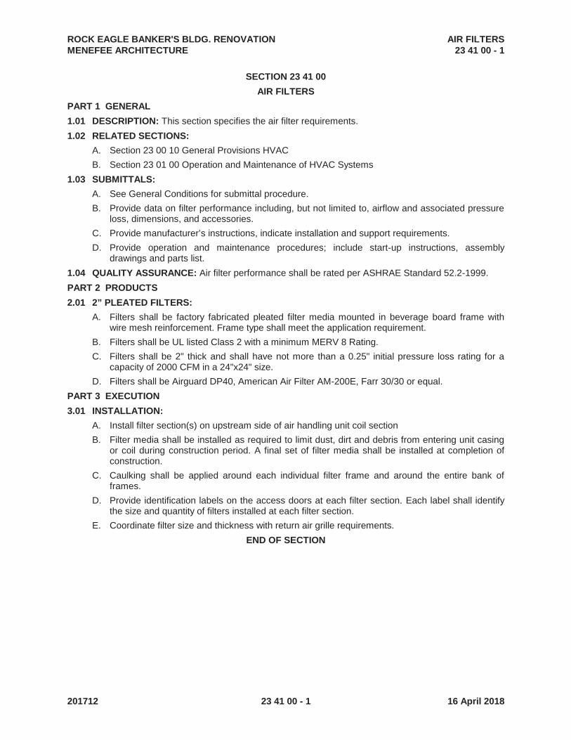
ROCK EAGLE BANKER'S BLDG. RENOVATION AIR FILTERS MENEFEE ARCHITECTURE 23 41 00 - 1
201712 23 41 00 - 1 16 April 2018
SECTION 23 41 00
AIR FILTERS
PART 1 GENERAL
1.01 DESCRIPTION: This section specifies the air filter requirements.
1.02 RELATED SECTIONS:
A. Section 23 00 10 General Provisions HVAC
B. Section 23 01 00 Operation and Maintenance of HVAC Systems
1.03 SUBMITTALS:
A. See General Conditions for submittal procedure.
B. Provide data on filter performance including, but not limited to, airflow and associated pressure loss, dimensions, and accessories.
C. Provide manufacturer’s instructions, indicate installation and support requirements.
D. Provide operation and maintenance procedures; include start-up instructions, assembly drawings and parts list.
1.04 QUALITY ASSURANCE: Air filter performance shall be rated per ASHRAE Standard 52.2-1999.
PART 2 PRODUCTS
2.01 2” PLEATED FILTERS:
A. Filters shall be factory fabricated pleated filter media mounted in beverage board frame with wire mesh reinforcement. Frame type shall meet the application requirement.
B. Filters shall be UL listed Class 2 with a minimum MERV 8 Rating.
C. Filters shall be 2" thick and shall have not more than a 0.25" initial pressure loss rating for a capacity of 2000 CFM in a 24"x24" size.
D. Filters shall be Airguard DP40, American Air Filter AM-200E, Farr 30/30 or equal.
PART 3 EXECUTION
3.01 INSTALLATION:
A. Install filter section(s) on upstream side of air handling unit coil section
B. Filter media shall be installed as required to limit dust, dirt and debris from entering unit casing or coil during construction period. A final set of filter media shall be installed at completion of construction.
C. Caulking shall be applied around each individual filter frame and around the entire bank of frames.
D. Provide identification labels on the access doors at each filter section. Each label shall identify the size and quantity of filters installed at each filter section.
E. Coordinate filter size and thickness with return air grille requirements.
END OF SECTION

ROCK EAGLE BANKER’S BLDG. RENOVATION COMMON WORK RESULTS MENEFEE ARCHITECTURE 26 05 00- 1 -
RCE#2018030 26 05 00- 1 - 16 April 2018
SECTION 26 05 00
COMMON WORK RESULTS
1.0 GENERAL
1.1 RELATED DOCUMENTS:
A. The General and Supplementary Conditions, and General Requirements (Division 1), apply to the work specified in this Section.
2.0PRODUCTS
2.1 MATERIALS AND WORKMANSHIP:
A. All materials and equipment shall be:
1. New and of best grade of standard manufacture. 2. Approved by U.L. and be so labeled. 3. For wire and cable, marked as required by Article 310-11 N.E.C. 4. Installed by mechanics skilled in their trades, working under the direct
supervision of competent experienced foremen and/or superintendents. 5. Installed in a thorough workmanlike manner, presenting a neat, clean cut
appearance when completed. Any part or parts not meeting this requirement shall be replaced or rebuilt without extra expense to the Owner.
2.2 TIMELY PLACING OF MATERIALS AND EQUIPMENT:
A. Panelboard cans, raceways, conduit, pull and junction boxes, etc., shall be installed
at the proper time during progress of construction. Coordinate work sequence and interface with other trades.
2.3 SPACE REQUIREMENTS: A. Contractor for work under this Division shall be fully responsible for determining in
advance of purchase that equipment and materials proposed for installation shall fit into the confines indicated and allow sufficient clearance for maintenance and service of all equipment including that of other trades.
2.4 MANUFACTURERS’ LITERATURE: A. Deliver all printed tags, instructions, certified drawings, parts lists, certificates etc.,
supplied with equipment items, to the Architect at completion of project. B. Assemble all such printed materials into a stiffback binder identified on face.
2.5 PROTECTION OF APPARATUS: A. All conduit and other openings shall be kept protected to prevent entry of foreign
matter. Fixtures, equipment, and apparatus shall be covered for protection against dirt, water, chemical, or mechanical damage before and during construction. The

ROCK EAGLE BANKER’S BLDG. RENOVATION COMMON WORK RESULTS MENEFEE ARCHITECTURE 26 05 00- 2 -
RCE#2018030 26 05 00- 2 - 16 April 2018
original finish, including shop coat of paint of fixtures, apparatus, or equipment that has been damaged shall be restored prior to final acceptance.
2.6 SHOP DRAWINGS:
A. The Contractor shall furnish complete submittals for each of the following listed items of electrical equipment in accordance with Division 1. For convenience, the Contractor may submit shop drawings in groups. The groups are listed below:
GROUP I GROUP IV 1. PANELBOARDS 1. LIGHTING FIXTURES 2. TRANSFORMERS 2. LAMPS 3. DISCONNECT SWITCHES 3. CONTACTORS & RELAYS 4. CIRCUIT BREAKERS 4. REMOTE CONTROL 5. FUSES SWITCHES 5. TIME CLOCKS GROUP II 6. PHOTO-ELECTRIC CELLS 1. COMBINATION STARTERS 2. MOTOR SWITCHES
GROUP III 1. DEVICES & COVERPLATES 2. CONDUIT, BOXES & FITTINGS
3. WIRE 4. NAMEPLATE SAMPLES & SCHEDULE 5. PADLOCKS
2.7 PAINTING:
A. Light fixtures shall be factory finish painted. Priming coat for other equipment shall be provided under this Division; Finish painting under Division, “PAINTING”
2.8 DRAYAGE, HOISITNG, AND SCAFFOLDING:
A. Contractor for this Division shall:
1. Be fully responsible for drayage, hoisting, warehousing, and demurrage, for all equipment and materials to be furnished and installed under this Division.
2. Provide all scaffolding required for erection of materials and equipment included under this Division.
3. Be fully responsible for the safety of his employees using such scaffolding.
2.9 CUTTING AND PATCHING: A. Contractor for this Division shall provide openings required for work under this
DIVISION.
1. Contractor for this Division shall layout, to dimension and location, all openings on surfaces to be formed, framed, or cut.
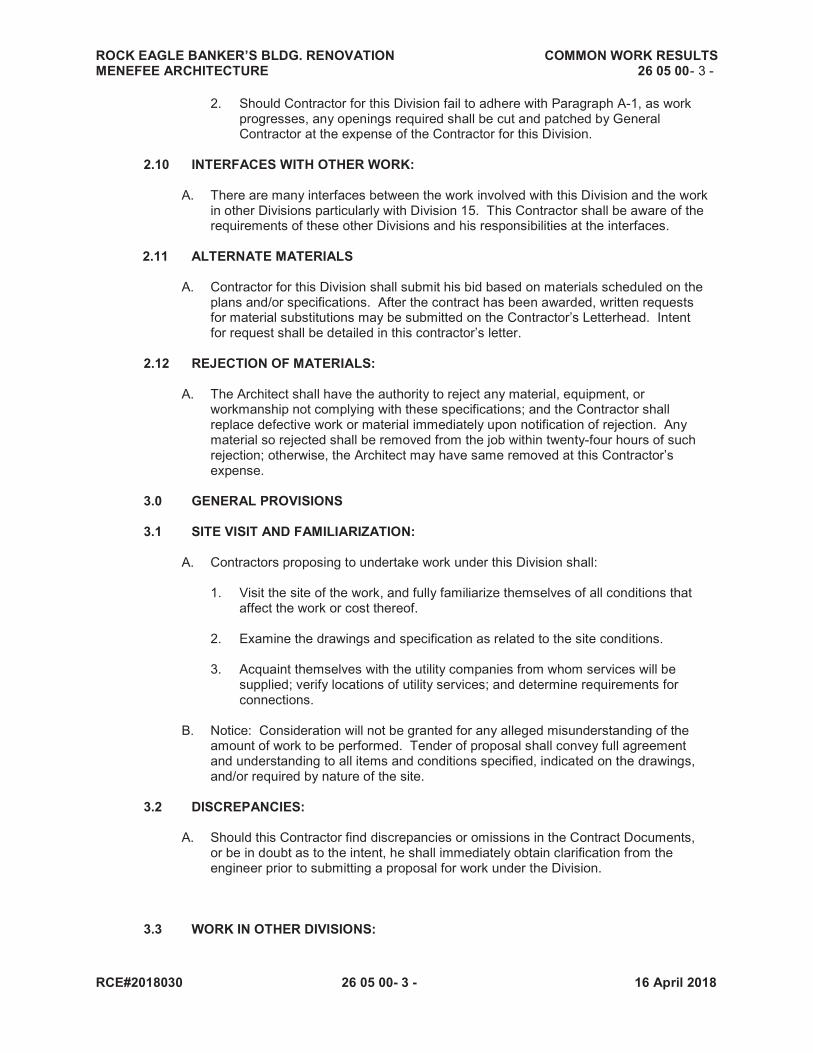
ROCK EAGLE BANKER’S BLDG. RENOVATION COMMON WORK RESULTS MENEFEE ARCHITECTURE 26 05 00- 3 -
RCE#2018030 26 05 00- 3 - 16 April 2018
2. Should Contractor for this Division fail to adhere with Paragraph A-1, as work progresses, any openings required shall be cut and patched by General Contractor at the expense of the Contractor for this Division.
2.10 INTERFACES WITH OTHER WORK:
A. There are many interfaces between the work involved with this Division and the work in other Divisions particularly with Division 15. This Contractor shall be aware of the requirements of these other Divisions and his responsibilities at the interfaces.
2.11 ALTERNATE MATERIALS
A. Contractor for this Division shall submit his bid based on materials scheduled on the plans and/or specifications. After the contract has been awarded, written requests for material substitutions may be submitted on the Contractor’s Letterhead. Intent for request shall be detailed in this contractor’s letter.
2.12 REJECTION OF MATERIALS:
A. The Architect shall have the authority to reject any material, equipment, or workmanship not complying with these specifications; and the Contractor shall replace defective work or material immediately upon notification of rejection. Any material so rejected shall be removed from the job within twenty-four hours of such rejection; otherwise, the Architect may have same removed at this Contractor’s expense.
3.0 GENERAL PROVISIONS
3.1 SITE VISIT AND FAMILIARIZATION:
A. Contractors proposing to undertake work under this Division shall:
1. Visit the site of the work, and fully familiarize themselves of all conditions that affect the work or cost thereof.
2. Examine the drawings and specification as related to the site conditions.
3. Acquaint themselves with the utility companies from whom services will be
supplied; verify locations of utility services; and determine requirements for connections.
B. Notice: Consideration will not be granted for any alleged misunderstanding of the
amount of work to be performed. Tender of proposal shall convey full agreement and understanding to all items and conditions specified, indicated on the drawings, and/or required by nature of the site.
3.2 DISCREPANCIES:
A. Should this Contractor find discrepancies or omissions in the Contract Documents,
or be in doubt as to the intent, he shall immediately obtain clarification from the engineer prior to submitting a proposal for work under the Division.
3.3 WORK IN OTHER DIVISIONS:
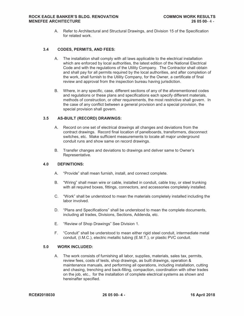
ROCK EAGLE BANKER’S BLDG. RENOVATION COMMON WORK RESULTS MENEFEE ARCHITECTURE 26 05 00- 4 -
RCE#2018030 26 05 00- 4 - 16 April 2018
A. Refer to Architectural and Structural Drawings, and Division 15 of the Specification for related work.
3.4 CODES, PERMITS, AND FEES:
A. The installation shall comply with all laws applicable to the electrical installation which are enforced by local authorities, the latest edition of the National Electrical Code and with the regulations of the Utility Company. The Contractor shall obtain and shall pay for all permits required by the local authorities, and after completion of the work, shall furnish to the Utility Company, for the Owner, a certificate of final review and approval from the inspection bureau having jurisdiction.
B. Where, in any specific, case, different sections of any of the aforementioned codes
and regulations or these plans and specifications each specify different materials, methods of construction, or other requirements, the most restrictive shall govern. In the case of any conflict between a general provision and a special provision, the special provision shall govern.
3.5 AS-BUILT (RECORD) DRAWINGS:
A. Record on one set of electrical drawings all changes and deviations from the
contract drawings. Record final location of panelboards, transformers, disconnect switches, etc. Make sufficient measurements to locate all major underground conduit runs and show same on record drawings.
B. Transfer changes and deviations to drawings and deliver same to Owner’s
Representative. 4.0 DEFINITIONS:
A. “Provide” shall mean furnish, install, and connect complete.
B. “Wiring” shall mean wire or cable, installed in conduit, cable tray, or steel trunking with all required boxes, fittings, connectors, and accessories completely installed.
C. “Work” shall be understood to mean the materials completely installed including the
labor involved.
D. “Plans and Specifications” shall be understood to mean the complete documents, including all trades, Divisions, Sections, Addenda, etc.
E. “Review of Shop Drawings” See Division 1.
F. “Conduit” shall be understood to mean either rigid steel conduit, intermediate metal
conduit, (I.M.C.), electric metallic tubing (E.M.T.), or plastic PVC conduit.
5.0 WORK INCLUDED:
A. The work consists of furnishing all labor, supplies, materials, sales tax, permits, review fees, costs of tests, shop drawings, as built drawings, operation & maintenance manuals, and performing all operations, including installation, cutting and chasing, trenching and back-filling, compaction, coordination with other trades on the job, etc., for the installation of complete electrical systems as shown and hereinafter specified.

ROCK EAGLE BANKER’S BLDG. RENOVATION COMMON WORK RESULTS MENEFEE ARCHITECTURE 26 05 00- 5 -
RCE#2018030 26 05 00- 5 - 16 April 2018
B. No materials shall be installed until shop drawings have been reviewed.
C. The electrical drawings are schematic, and are not intended to show the exact location of conduit, outlets, etc. The Contractor shall refer to the architectural, structural, and shall fit his work to conform to the details of building construction. The right is reserved to shift any switch, receptacle, ceiling outlet, or other outlet a maximum of ten feet (10’) from its location as shown before it is permanently installed, without incurring additional expense.
D. Should conflicts exist between the plans and specifications, the specifications, shall
govern. E. The drawings and specifications shall both be considered as part of the contract.
Any work and material shown in the one and omitted in the other, or which may fairly be implied by both or either, shall be furnished and performed.
F. No deviations from the drawings and specifications shall be made without the full
knowledge and consent of the Architect. Should the Contractor find, at any time during the progress of the work, that, in his judgment, existing conditions make desirable a modification in requirements covering any particular item or items, he shall report such items promptly to the Architect for his decision and instructions.
6.0 WORK NOT INCLUDED:
A. The installation and connection of the following items is not included in this section
of the specifications:
1. All motors for mechanical equipment together with the associated motor controllers, starters, unless provided in motor control center and remote control devices, electrical heating equipment with contactor, individual element protection, etc., will be furnished under HVAC section of the specifications.
2. Control and Interlock Wiring: Provisions for the installation of all control and
interlock wiring is provided under Section 15 of the specifications.
7.0 ARC FLASH 1.01 SCOPE:
A. Description: 1. Provide an arc flash hazard analysis of each panelboard and disconnect switch.
Determine in the analysis the personal hazard category and the associated flash protection boundary.
2. Submit all calculations to the Architect for review and comment prior to ordering
affected equipment. 3. Provide an Arc Flash and Shock Hazard label on each switchboard, panelboard,
transformer and disconnect switch disconnect switch based upon the arc flash hazard analysis with all appropriate information required by NFPA 70E reported on the label.
B. Codes: 1. NFPA 70 2. NFPA 70E

ROCK EAGLE BANKER’S BLDG. RENOVATION COMMON WORK RESULTS MENEFEE ARCHITECTURE 26 05 00- 6 -
RCE#2018030 26 05 00- 6 - 16 April 2018
PART 2 - PRODUCTS 2.01 LABELS:
A. Provided non-paper labels with adhesive both which will resist degradation due to sunlight and moisture.
PART 3 - EXECUTION
3.01 ANALYSIS:
A. The arc flash hazard analysis shall be performed by a registered professional engineer registered in the state where the project is located. The submittal to the Architect shall include the seal and signature of the professional engineer who performed the analysis.
B. The analysis shall include selection and coordination of all overcurrent devices
as to operation to minimize both the arc fault level and nuisance tripping.
C. Include in the submittal all time-current curves of breakers and fuses, tabulation of adjustable trip settings and tabulation of current limiting fuses selected.
3.02 INSTALLATION:
A. Install each label on the front of the equipment, in a prominent visible location and
where possible, centered. END OF SECTION
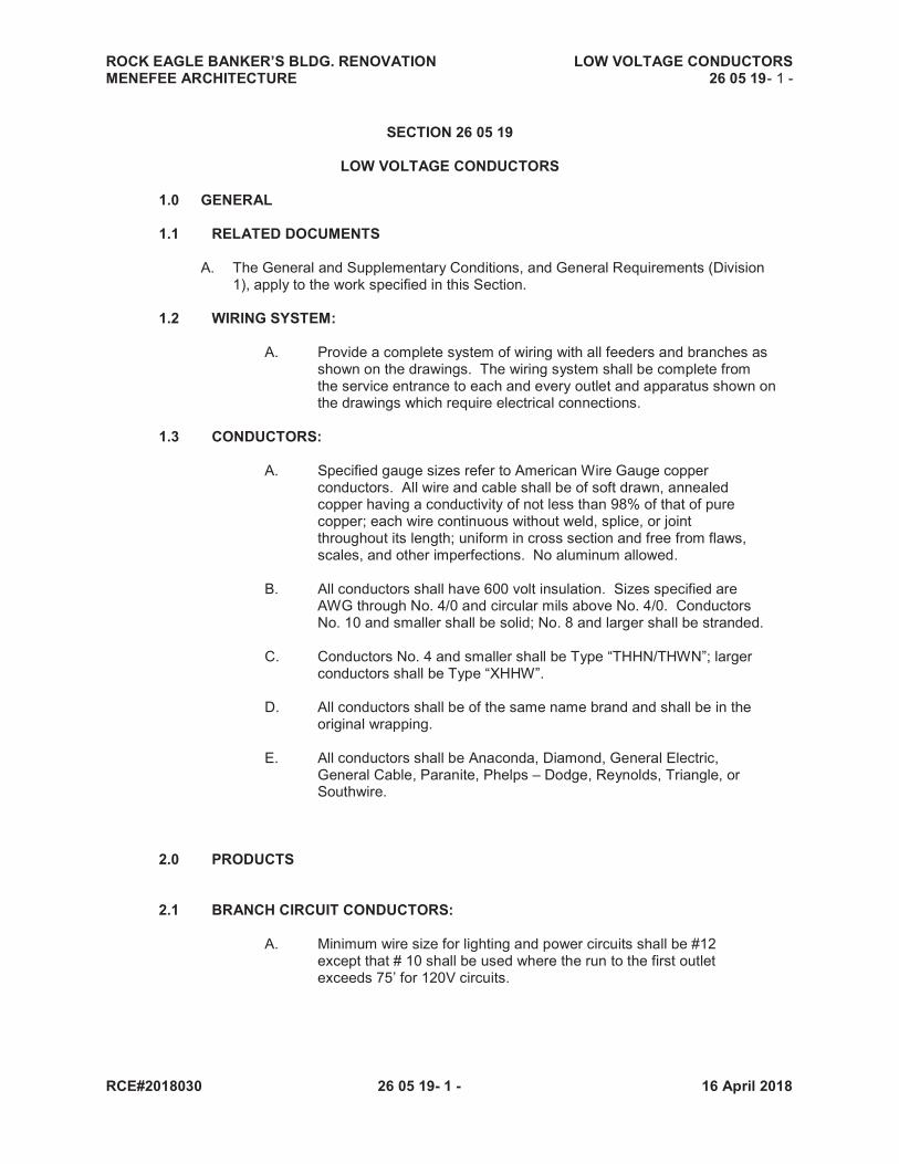
ROCK EAGLE BANKER’S BLDG. RENOVATION LOW VOLTAGE CONDUCTORS MENEFEE ARCHITECTURE 26 05 19- 1 -
RCE#2018030 26 05 19- 1 - 16 April 2018
SECTION 26 05 19
LOW VOLTAGE CONDUCTORS
1.0 GENERAL
1.1 RELATED DOCUMENTS
A. The General and Supplementary Conditions, and General Requirements (Division 1), apply to the work specified in this Section.
1.2 WIRING SYSTEM: A. Provide a complete system of wiring with all feeders and branches as shown on the drawings. The wiring system shall be complete from the service entrance to each and every outlet and apparatus shown on the drawings which require electrical connections. 1.3 CONDUCTORS: A. Specified gauge sizes refer to American Wire Gauge copper conductors. All wire and cable shall be of soft drawn, annealed copper having a conductivity of not less than 98% of that of pure copper; each wire continuous without weld, splice, or joint throughout its length; uniform in cross section and free from flaws, scales, and other imperfections. No aluminum allowed. B. All conductors shall have 600 volt insulation. Sizes specified are AWG through No. 4/0 and circular mils above No. 4/0. Conductors No. 10 and smaller shall be solid; No. 8 and larger shall be stranded. C. Conductors No. 4 and smaller shall be Type “THHN/THWN”; larger conductors shall be Type “XHHW”. D. All conductors shall be of the same name brand and shall be in the original wrapping. E. All conductors shall be Anaconda, Diamond, General Electric, General Cable, Paranite, Phelps – Dodge, Reynolds, Triangle, or Southwire. 2.0 PRODUCTS 2.1 BRANCH CIRCUIT CONDUCTORS: A. Minimum wire size for lighting and power circuits shall be #12 except that # 10 shall be used where the run to the first outlet exceeds 75’ for 120V circuits.

ROCK EAGLE BANKER’S BLDG. RENOVATION LOW VOLTAGE CONDUCTORS MENEFEE ARCHITECTURE 26 05 19- 2 -
RCE#2018030 26 05 19- 2 - 16 April 2018
B. Branch circuit conductors shall be color – coded as follows:
C. The feeder and service entrance conductors shall be color coded by the use of colored plastic tape applied within 6” of each conductor end. Color coding conductor markers shall be Brady or approved equal. D. Provide a #16 AWG iron pull wire or plastic pull line (rated at 500 lbs. test) in all conduits for future use or for telephone use. The ends of such conduit shall be corked or capped. E. Branch circuit wiring which supplies more than one fluorescent Fixture through the wireway other fixtures shall be rated for use at 150 degrees C. 3.0 EXECUTION 3.1 WIRE AND CABLE: A. Wire shall not be drawn into a conduit until all work of a nature
which may cause injury is complete. Ideal, Wire – Ease, or approved equal may be used as a lubricant. Where two or more circuits run to a single outlet box, tag each circuit with linen tags as a guide to the fixture hanger in making fixture connections. B. All stranded conductors shall be furnished with copper connecting lugs drilled or reamed the full diameter of the bare conductors. Mains and feeders shall be run their entire length in continuous pieces without joints or splices. C. Conductors shall be continuous from outlet to outlet and from outlet to junction box or pull box. All splices and joints shall be carefully and securely made to be mechanically and electrically solid with pressure type connectors, “SCOTCHLOK” or approved equal. Tape shall be “Scotch” No. 33 for indoor and No. 88 for outdoor or approved equal. Where connection is made to any material, copper
terminal lugs shall be bolted or compression fitted to the conductors. Where multiple connections are made to the same terminal, individual lugs for each conductor shall be used.
D. At each fixture outlet a loop or end of wire not less than 8” long shall be left for connection to fixtures.
Voltage 208Y/120 480Y/277 240D/120 Phase A Black Brown Black Phase B Red Orange Blue Phase C Blue Yellow Orange (208V) Neutral White Gray White Ground Green
Isolated Ground Green w/ White Stripe
ROCK EAGLE BANKER’S BLDG. RENOVATION LOW VOLTAGE CONDUCTORS MENEFEE ARCHITECTURE 26 05 19- 3 -
RCE#2018030 26 05 19- 3 - 16 April 2018
E. No conductors shall be pulled until the raceway system is complete. F. The number of cross hatches, where indicated, designates the number of conductors to be installed when the number exceeds a minimum two (2). Where cross hatches are not indicated, the number of conductors shall be as determined by switching, homeruns, etc.. This does not apply to conduit provided for telephone or other special systems. G. Branch circuits shall contain the necessary number of conductors to afford the switch control indicated.
ROCK EAGLE CABIN GROUNDING MENEFEE ARCHITECTURE 26 05 26- 1 -
RCE#2018030 26 05 26- 1 - 16 April 2018
SECTION 26 05 26
GROUNDING
1.0 GENERAL
1.1 RELATED DOCUMENTS:
A. The General and Supplementary Conditions, and General Requirements (Division 1), apply to the work specified in this Section.
1.2 APPARATUS:
A. All apparatus and equipment specified hereinafter in this Section Fully conform to current standards of NEMA to the extent applicable to each type and class of equipment and apparatus described; and individually bear the seal of the Underwriter’s Laboratories.
PRODUCTS 2.1 GROUND CONNECTIONS:
A. Provide a grounding electrode system consisting of a minimum of three (3) ¾” x 10’-0”
copperweld rods driven 24” below grade, a minimum of 6’-0” apart in the form of an equilateral triangle, bonded together with No. 2 copper conductors, installed a minimum of 3’-0” clear of foundations walls. Contractor shall extend from electrodes to service with No. 2 copper, green insulated ground conductor in a 1” conduit, and connect to ground bus bar therein, to housing, and to frame. Provide a bonding jumper and connect to all grounding electrodes.
B. Provide a No. 2 green insulated, XHHW, copper conductor bond across the water
meter, same to be attached to ground clamps on water line on each side of meter. The pipes shall be thoroughly cleaned before installing clamps. Make sure arrangements as are necessary to permit doing this work at the time the water meter is installed.
C. Provide a No. 2 green insulated XHHW copper ground conductor in 1” conduit from
cold water entrance pipe, ahead of first valve, to main service entrance and bond ground to ground bar therein, to housing, and to frame with lugs. All ground clamps shall be equipped with compression type cable lugs independent of the compression device clamping the pipe rod, and shall be O.Z/Gedney Type “CG”.
D. Where non-metallic insulating couplings are used in metallic water piping systems, the Contractor shall provide a No. 2 green insulated XHHW copper conductor bond across the couplings, same to be attached to ground clamps on water line on each side of the couplings. The pipes shall be thoroughly cleaned before installing the clamps. Make such arrangements as are necessary to permit doing this work at the time the water piping is installed.
E. Provide an 8” long green grounding wire from grounding lug of all wall switches and
receptacles to a suitable bonding device on the conduit or to the outlet box. The outlet box bond shall be a green grounding terminal screw. Ground wire installed behind the device mounting screws will not be acceptable.
ROCK EAGLE CABIN GROUNDING MENEFEE ARCHITECTURE 26 05 26- 2 -
RCE#2018030 26 05 26- 2 - 16 April 2018
3.0 EXECUTION
3.1 INSTALLATION: A. Shop drawings shall indicate that all of the function requirements of the specifications have been met. In addition, the UL approved RMS symmetrical
interrupting capacity shall be indicated for each circuit breaker, and a certification that these are UL ratings shall be attached.

ROCK EAGLE CABIN RACEWAY AND BOXES MENEFEE ARCHITECTURE 26 05 33- 1 -
RCE#2018030 26 05 26- 1 - 16 April 2018
SECTION 26 05 33
RACEWAY AND BOXES
1.0 RACEWAY
1.1 RELATED DOCUMENTS:
A. The General and Supplementary Conditions, and General Requirements (Division 1), apply to the work specified in this Section.
PRODUCTS
2.1 SECONDARY SERVICE CONDUIT:
A. Secondary electrical service duct banks shall be concrete encased galvanized rigid steel conduit, IMC, or Schedule 40 PVC. Duct bank located below floor slab is not required to be concrete encased but is required to be 30” below floor slab to top of duct bank.
2.3 FEEDERS & BRANCH CIRCUITS:
A. Rigid conduit or IMC shall be used for all feeders, branch circuits, and sub-feeders
where exposed to possible physical damage. EMT shall be permitted for feeders and branch circuits in protected areas.
B. MC cable is allowed for branch circuits in protected areas. MC cable shall not be exposed to view.
C. PVC conduit is allowed below grade only.
2.4 RACEWAYS: A. Except as otherwise noted, specified, or required, provide all conductors in rigid
conduit, IMC, EMT, or Schedule 40 PVC as hereinafter specified. Rigid conduit, or EMT shall be of the best quality hot-dipped galvanized or sheradized steel tubing, and of standard trade dimensions, smooth inside and out. Each length of conduit shall bear the maker’s trademark or stamp.
B. Connections to panelboard cabinets and/or pull boxes shall have grounding wedge
lugs, Thomas & Betts, or approved equal, between the bushing and the box, or locknuts so designed to bite into the metal.
C. Rigid conduit or IMC fittings shall be of steel or malleable iron, as manufactured by
Thomas & Betts or approved equal. ZINC DIE CAST FITTINGS ARE NOT PERMITTED.
D. Fittings for electrical metallic tubing shall be compression type, made of steel, with
case hardened locknuts and nylon insulated throats, Thomas & Betts Series 5120, 5123; or steel set screw fittings with nylon insulated throat, case hardened locknut, and zinc chromate finish, Thomas & Betts 5030 or 5031. ZINC DIE CAST FITTINGS ARE NOT ACCEPTABE. Fittings equal to those specified above as manufactured by Midwest, Raco, or Appleton are acceptable.
E. All PVC rigid conduit, fittings, and cement shall be produced by the same
manufacturer. All joints shall be solvent welded in accordance with manufacturers’ recommendations. All PVC conduit shall be schedule 40.

ROCK EAGLE CABIN RACEWAY AND BOXES MENEFEE ARCHITECTURE 26 05 33- 2 -
RCE#2018030 26 05 26- 2 - 16 April 2018
F. Strain relief cord grip connectors shall be oil and water resistant, with a neoprene
bushing, Thomas & Betts Series 2631, or approved equal.
G. To insure continuity of ground and improved conductivity, use Kopr-Sheild compound, Series CP-8 as manufactured by Thomas & Betts, or approved equal, on all threaded joints.
H. Provide junction boxes or pull boxes where shown and where necessary to avoid
excessive runs or too many bends between outlets.
I. Approved Appleton, Crouse-Hinds, or O.Z. Manufacturing Company Type “AX” expansion fittings shall be installed in all rigid conduit, and E.M.T. which passes through an expansion joint.
J. Approved conduit manufacturers are:
RIGID, IMC OR FLEXIBLE CONDUIT Allied, Sheraduct, Republic, Triangle, Wheatland, Youngstown FLEXIBLE CONDUIT (PVC COVER) Anaconda “Sealite”, Robroy ELECTRICAL METALLIC TUBING Steeltubes, National, X-duct, Jr., Weatland, Allied, Triangle, Youngstown PLASTIC PVC Carlon Schedule 40
2.5 FLEXIBLE CONDUIT: A. FLEXIBLE STEEL CONDUIT (NO COVER): Flexible steel conduit shall be used in
making short flexible connections from outlet boxes to recessed lighting fixtures. Flexible steel conduit serving lighting fixtures shall be 72” in length. Flexible steel conduit serving other equipment (this does not include switches or receptacles) shall be as short as possible, but shall have a minimum length of 12”.
B. PVC EXTRUDED COVER FLEXIBLE CONDUIT: Only PVC extruded cover
flexible conduit will be permitted for use in making up short flexible connections to dry-type transformers, rotating or vibrating machinery, kitchen equipment, or equipment where exposed to moisture. The flexible conduit at these locations shall be as short as possible, but shall have a minimum length or 12”.
C. A green stranded bonding jumper shall be installed inside all flexible conduits.
Provide a junction box at the transition from rigid to flexible. 2.6 INSULATING BUSHINGS: A. All rigid conduit 1” and larger terminating in cabinets, panel boxes, pull boxes, and similar boxes shall have insulating bushings or grounding bushings.

ROCK EAGLE CABIN RACEWAY AND BOXES MENEFEE ARCHITECTURE 26 05 33- 3 -
RCE#2018030 26 05 26- 3 - 16 April 2018
2.7 CONDUIT PROTECTION: A. Conduits, for electrical service entrance conductors or feeders, installed in the ground, either outside or beneath the building, shall be spaced a minimum of 7.5” on center with a minimum depth to the top of electrical duct banks shall be 30”. All threaded joints in conduit that is encased in concrete shall have U.L. listed joint compound applied to be watertight.
B. Conduits for branch circuits outside the building not beneath driveways or parking areas may be direct buried without concrete encasement. The maximum depth to the top of direct buried conduits shall be 36”.
C. Conduit run in any slab shall be above the bottom steel and below the top steel.
No conduit runs shall be spaced less than 3” apart.
D. For all conduits and conduit duct banks installed in the ground outside the building, provide identifying marker tape the entire length of each conduit or duct bank. The tape shall be constructed of inert polyethylene, resistant to acids, alkalis, etc., in the soil, and shall be a minimum 4 mil thickness. The tape shall be yellow, 6” wide, and shall have the words “CAUTION ELECTRIC LINE BURIED BELOW,” imprinted with contrasting permanent ink. The imprint shall repeat itself for the entire length of the tape. The tape shall be buried at a maximum of 18” below finished grade, above a portion of the earth fill above the conduit or concrete encasement. The tape shall be “Terra Tape” as manufactured by Reef Industries Inc., P.O. Box 33248, Houston Texas 77003 (1-800-231-6074).
E. Conduit shall be secured in place and protected to prevent damage to work during construction. The ends of all conduit and conduit fittings shall be plugged to avoid filling with plaster, etc., with Thomas & Betts “Push-Penney Plugs,” Series 1470. All conduit shall be blown out and swabbed clear of water and trash prior to pulling wire.
2.8 CONCRETE:
A. Concrete for underground conduit protection and conduit duct banks shall be a minimum of 3000 P.S.I. mix.
2.9 CUTTING AND PATCHING:
A. Provide sleeves for conduit, cables, and busways accurately before concrete floors are poured, or set boxes on the forms so as to leave openings in the floors in which the required sleeves can be subsequently located; in which case fill in the concrete voids around the sleeves.
B. Should the contractor neglect to perform this preliminary work and should cutting be
required in order to install conduit, cables, busway, or equipment, then the expense of the cutting and restoring of surfaces to their original condition shall be borne by this Contractor.
2.10 PENETRATIONS:
A. Where any electrical item such as conduit, cable, telephone cable, etc., penetrates a wall, floor, or ceiling, the original integrity of the respective wall, floor, or ceiling

ROCK EAGLE CABIN RACEWAY AND BOXES MENEFEE ARCHITECTURE 26 05 33- 4 -
RCE#2018030 26 05 26- 4 - 16 April 2018
shall be restored. The fireproof rating of the sealant used shall have an equal or better rating than the original fire separation material.
B. All openings provided for future conduit or future cable shall be sealed.
C. The penetrations shall be sealed with the original material or a U.L. listed fitting designed for that purpose.
2.11 BELOW GRADE CONDUIT AND CABLE SEAL
A. The seal for either conduit or cable below grade shall form a reliable, lasting seal between building outside and shall be able to withstand pressures to a minimum of 50 feet head of water. The below grade seals shall be as manufactured by O.Z./Gedney and sized for the particular application. 2.12 THREADED JOINT COMPOUND: A. Threaded joint compound shall be corrosion inhibiting compound that is electrically conductive under pipe joint pressure. The compound shall be Thomas & Betts “KOPR-SHIELD”, or approval equal. 2.13 SMOKE AND FIRE STOP FITTINGS: A. Smoke and Fire Stop Fittings shall be U.L. listed for that purpose. The fittings used to seal conduit either on the outside of the conduit or cable or internally shall have heat activated intumescent material which expands to fill all voids with an hourly fire-rating equal to or higher than the rating of the floor or wall through which the cable or conduit passes. The seals for conduit shall be of the flanged type. 3.0 EXECTION: 3.1 INSTALLATION: A. Conduit shall be continuous from outlet to outlet, from outlet to panelboard cabinet, junction box, and/or pull box. Conduit shall enter and be secured to all boxes, etc., in such a manner that each system will be electrically continuous from service to all outlets. All conduit from panelboard cabinets and junction boxes shall terminate in approved outlet boxes or conduit fittings. Conduit connection to any box which has no threaded hub for its reception shall be double locknutted.
B. In general, the conduit installation shall follow the layout shown. However, this
layout is diagrammatic only; where changes are necessary due to structural conditions, other apparatus, or other causes, such changes shall be made without any additional cost to the Owner. Offsets in conduit are not indicated, and must be provided as required.
C. At couplings, conduit ends shall be threaded so they meet in the coupling. Right
and left couplings shall not be used; conduit couplings of the Erickson type or approved equal shall be used at locations requiring such joints.
D. Where conduit is installed in outdoor or indoor locations where exposed to
continuous or intermittent moisture, connections at enclosures shall provide a liquid-tight seal. The sealing hub fittings shall be of steel or malleable iron, with a
ROCK EAGLE CABIN RACEWAY AND BOXES MENEFEE ARCHITECTURE 26 05 33- 5 -
RCE#2018030 26 05 26- 5 - 16 April 2018
recessed sealing “O” ring and a nylon insulated throat, Thomas & Betts Series 370. All conduit and cable, telephone or otherwise, which extend from the interior to the exterior below grade shall be sealed with a fitting designed for that particular use so as to be watertight.
E. Minimum size conduit for branch circuits shall be ½”. Home run conduits for lighting
branch circuits and receptacle branch circuits shall be ¾” minimum size. Home runs shall extend from outlets shown to panel designated.
F. No bends will be permitted with a radius less than six (6) times the diameter or the
conduit, and not more than 90 degrees. G. All conduit shall be concealed in wall, in or below floors, or above ceiling unless
otherwise directed or indicated. Concealed conduit shall be supported from the building construction at intervals not exceeding 8’-0”. Concealed conduit above the ceiling shall be supported independent of ceiling construction. Where ceiling of the lay-in type are used, conduit must be installed high enough to permit removal of ceiling panels and lighting fixtures.
H. Where conduit is expressly shown to be run exposed, the conduit shall be supported
at intervals not exceeding 8’-0” with straps and wood screws for wood construction, machine screws for metal construction, and expansion bolts for masonry construction. Exposed conduit in finished spaces that pass through walls or ceilings shall be provided with chrome plated escutcheons. Run exposed conduit, where permitted by this specification, parallel or at right angles to building walls and ceiling and support from walls or ceiling with approved galvanized iron clamps or hangers. Devices attached to masonry or slabs shall be secured with inserts and bolts or lead expansion sleeves. Provide a support at each outlet box, at each conduit elbow, and at each junction box.
I. The conduit sizes shown may be increased if desired to facilitate the pulling of
cables. J. Where devices are supplied from conduit in or below floor slabs, the conduit shall be
stubbed up the specified height at the location shown and the masonry wall built-up around the conduit by cutting the webs of the concrete blocks.
K. Where two (2) or more conduits are run parallel and adjacent, they shall be installed
on gang hangers. L. Conduit embedded in concrete which is in contact with the earth, and conduit
installed outside the building below grade shall be rigid steel conduit, IMC, or Schedule 40 PVC. Conduit elsewhere shall be EMT unless specified or noted otherwise. Schedule 40 PVC is not allowed in walls, above ceiling, or exposed.
4.0 OUTLET BOX AND JUNCTION BOXES
4.1 RELATED DOCUMENTS:
A. The General and Supplementary Conditions, and General Requirements (Division 1), apply to the work specified in this Section.
4.2 LOCATION OF OUTLETS:
A. Unless specifically indicated, all outlets are located diagrammatically

ROCK EAGLE CABIN RACEWAY AND BOXES MENEFEE ARCHITECTURE 26 05 33- 6 -
RCE#2018030 26 05 26- 6 - 16 April 2018
on the drawings. Reference shall be made to architectural and mechanical plans for the exact location of all outlets. Outlets shall be located so that they will be symmetrical with architectural details and power outlets shall be so located as the properly serve the equipment.
4.3 OUTLET BOXES: A. Provide all outlet boxes for lighting fixtures, wall switches, wall Receptacles, telephone, etc., galvanized steel for concealed work, or cast type
boxes, as specified. Provide cast ferrous alloy outlet boxes for all surface mounted wall switches and receptacles. Utility boxes are not acceptable.
4.4 JUNCTION BOXES AND PULL BOXES:
A. Furnish and install junction boxes as required to facilitate installationof the various conduit systems and as required by the N.E.C.
5.0 OUTLET BOXES:
A. Outlet boxes used in rigid conduit work exposed to weather shall be cast ferrous alloy type. Outlet boxes for vapor-tight lighting fixtures shall be cast corrosion resistant type.
B. Outlet boxes in ceiling, and in plastered or gypsum stud walls, shall be 4”
octagonal, 4” square, or 4-11/16” square boxes. Plaster covers ½” in height shall be installed on boxes and walls, columns and in acoustical tile ceilings. Boxes in concrete slab ceiling shall be concrete type.
B. Outlets at origins of “home runs” to panelboards shall be 4-11/16” square outlet
boxes. D. Outlet boxes recessed in unplastered concrete block walls and partitions shall be
designed especially for installation in block and tile walls and partitions. Single-gang or multi-gang square cornered masonry boxes shall be used for one or more devices at the termination of a conduit run. Conventional 4” octagonal or 4-11/16” square boxes fitted with square tile covers of proper depth for concrete block shall be used where two or more conduits enter a box.
E. Wall and column telephone outlets shall be 4” square, with ½” hole single device
plaster cover. F. Flush mounted outlet boxes in all exposed masonry walls shall be RACO or Steel
City masonry or thru – the – wall boxes or shall be 4” square boxes with series 52 – C –49 –N. The boxes and box covers shall have square edges, and shall have the device mounting holes inside the box.
G. Stamped steel outlet boxes shall be manufactured by Appleton Electric Company,
RACO Manufacturing Company, or Steel City Electric Company. 5.1 DEVICE BOXES:
A. Devices boxes shall be minimum 3”H x 2”W x 2-3/4”D per gang, Same manufacture as outlet boxes.
5.2 JUNCTION BOXES AND PULL BOXES:

ROCK EAGLE CABIN RACEWAY AND BOXES MENEFEE ARCHITECTURE 26 05 33- 7 -
RCE#2018030 26 05 26- 7 - 16 April 2018
A. Furnish and install all junction boxes required to facilitate the installation of the
various conduit systems. Furnish and install all support boxes required for vertical riser, each shall have Red Seal type VCC or approved equal cable supports as required by Article 300-19, N.E.C.
B. All junction and pull boxes shall be accessible with covers designed for quick
removal. Where boxes are required to occur above a nonaccessible furred ceiling in a finished area, the removable cover shall be flush with the finished ceiling. The exact location shall be approved by the Architect.
5.3 INSULATED BUSHING:
A. Insulating bushings shall be used in all pull boxes, tap boxes, and switches where conductors are larger than No. 6 AWG.
5.4 OUTLET LOCATIONS:
A. The location of any outlet may be moved ten feet with the prior approval of the Architect and before it is installed, without any additional expense to the Owner.
B. This contractor shall check the location of all wall outlets including light fixtures,
receptacles, and switches, to verify that the outlets will clear any wall fixture, shelving, work tables, sinks, or similar equipment that will be installed.
C. Outlets occurring in architectural features shall be accurately centered in same.
Install wall switch outlets on the STRIKE SIDE of doors with coverplates clearing door trim.
D. Outlet boxes in partitions shall NOT be set back to back. Boxes set side by side
facing separate rooms or spaces, shall be nippled together by offset nipples. After conductors are pulled, the nipples shall be tightly packed with insulation to prevent sound transmission.
E.The drawings are intended to show the locations of outlets, devices, fixtures and
arrangement and control of circuits only. Exact locations shall be determined by actual measurement at the building and/or by reference to the architectural drawings.
F. Outlet boxes shall be provided with 3/8” fixture stud to support light fixtures. Outlet
boxes shall be firmly anchored to structural members of the building, using wood screws for wood construction, bolts for steel construction, and expansion bolts secured in place with cement mortar for masonry construction. Ceiling outlets flush in furred acoustical tile ceiling construction for surface or pendent mounted lighting fixtures shall be 4” square or octagonal pressed steel boxes supported from the building structure independent of the ceiling construction. For outlet boxes location between steel studs, provide Caddy No. BHA; and adjacent to studs, provide Caddy No.MSC.
G. Provide plaster rings for all boxes set in plaster ceilings or walls. H. Junction boxes shall be provided with blank covers. Covers on ceiling outlets shall
be round, and shall be painted to match ceilings. Covers on wall junction boxes shall be of size and finish as used on switch and receptacle outlets.

ROCK EAGLE CABIN RACEWAY AND BOXES MENEFEE ARCHITECTURE 26 05 33- 8 -
RCE#2018030 26 05 26- 8 - 16 April 2018
I. All outlet boxes shall be flush mounted within the wall regardless of wall construction, unless they are specifically shown as being used with exposed conduit. Cuts for outlet boxes in masonry walls shall be made so that the coverplate will completely cover the cut. The edge of all outlet boxes shall be flush with the surface in which they are recessed. The devices that fit into the outlet boxes shall be screwed tight before the coverplate is installed, and the coverplate shall NOT be used as a means of tightening the devices in place.
J.Where outlets are shown as being adjacent and different mounting heights are
specified for each they shall be mounted ONE DIRECTLY over the other, on the center line of the group or on the center line or the room or wall.
K. The mounting height of all wall outlets is indicated on the architectural or electrical
plans. The mounting height is from finished floor to the centerline of the device or outlet. The contractor may, with the Architect’s approval on the job, slightly vary the mounting height of wall outlet so that the outlet box, top or bottom occur at a masonry joint.
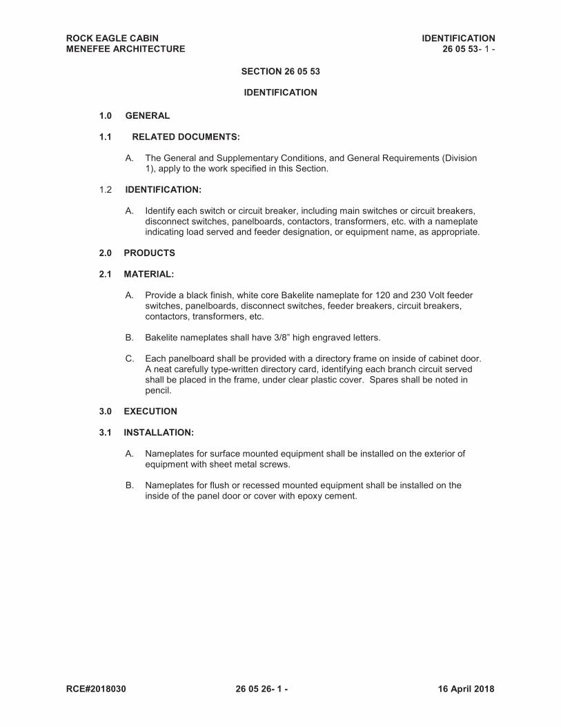
ROCK EAGLE CABIN IDENTIFICATION MENEFEE ARCHITECTURE 26 05 53- 1 -
RCE#2018030 26 05 26- 1 - 16 April 2018
SECTION 26 05 53
IDENTIFICATION
1.0 GENERAL
1.1 RELATED DOCUMENTS:
A. The General and Supplementary Conditions, and General Requirements (Division 1), apply to the work specified in this Section.
1.2 IDENTIFICATION:
A. Identify each switch or circuit breaker, including main switches or circuit breakers,
disconnect switches, panelboards, contactors, transformers, etc. with a nameplate indicating load served and feeder designation, or equipment name, as appropriate.
2.0 PRODUCTS
2.1 MATERIAL:
A. Provide a black finish, white core Bakelite nameplate for 120 and 230 Volt feeder
switches, panelboards, disconnect switches, feeder breakers, circuit breakers, contactors, transformers, etc.
B. Bakelite nameplates shall have 3/8” high engraved letters.
C. Each panelboard shall be provided with a directory frame on inside of cabinet door.
A neat carefully type-written directory card, identifying each branch circuit served shall be placed in the frame, under clear plastic cover. Spares shall be noted in pencil.
3.0 EXECUTION
3.1 INSTALLATION:
A. Nameplates for surface mounted equipment shall be installed on the exterior of equipment with sheet metal screws.
B. Nameplates for flush or recessed mounted equipment shall be installed on the
inside of the panel door or cover with epoxy cement.

ROCK EAGLE CABIN PANELBOARDS MENEFEE ARCHITECTURE 26 24 00- 1 -
RCE#2018030 26 05 26- 1 - 16 April 2018
SECTION 26 24 00
PANELBOARDS
1.0 GENERAL
1.1 RELATED DOCUMENTS:
A. The General and Supplementary Conditions, and General Requirements (Division 1), apply to the work specified in this Section.
1.2 APPARATUS:
A. All apparatus and equipment specified hereinafter in this Section Fully conform to current standards of NEMA to the extent applicable to each type and class of equipment and apparatus described; and individually bear the seal of the Underwriter’s Laboratories.
B. To the maximum extent feasible, all such apparatus and material shall be of one and the same manufacturer.
C. The type, classes, and catalog numbers hereinafter stated, and employed are to establish the class and quality of apparatus and equipment required for this work. In general, all catalog numbers given are Square “D” Company; however, apparatus and equipment effectively equal in all respects to that described as manufactured by General Electric, Westinghouse, Siemens/ITE, or Cutler Hammer shall be acceptable.
2.0PRODUCTS
2.1PANELBOARDS:
A. Panelboards shall be of the automatic circuit breaker type, factory assembled by the manufacturer of the circuit breakers. Panelboards shall be new and the manufacturer’s latest standard catalogued design. Panelboards shall be the product of the same manufacturer as the cabinets and shall bear UL labels.
B. Panelboards shall be for service voltage with number of branch circuits of capacity
scheduled. Unless otherwise indicated, panels and sections thereof shall have main lugs only of capacity equal to or greater than the rating or setting of the over current protective device next back on line.
C. Panelboard Boxes shall be constructed of code gauge steel, 20” minimum width by 5-3/4” deep. Panels having through feed shall have 8” bottom and side gutters.
D. Panelboard trims shall be flush or surface type as scheduled on the plans,
constructed of code gauge steel, finished with rust inhibiting prime coat and baked enamel finish. Trims to be complete with indicating adjustable trim clamps, door with chromium plated combination cylinder lock and catch, and directory of glass or clear plastic. All locks shall be keyed alike. Directory to be type-written with spares indicated in pencil. All panel trims shall have an angle bracket welded to the back near bottom to support the weight of the trim. Trims exceeding 48” in height shall vault handle and three point latch system. The trims on all flush mounted 20” wide panels shall have trim clamps and hinges concealed when the door is closed. Trims shall not be removable with the door in the locked position.

ROCK EAGLE CABIN PANELBOARDS MENEFEE ARCHITECTURE 26 24 00- 2 -
RCE#2018030 26 05 26- 2 - 16 April 2018
E. Circuit breakers shall be thermal and magnetic molded case type quick-make and
quick-break bolt on manual and on automatic operation. Breakers shall be of the over-the-center toggle operating type, with the handle going to a position between “ON” and “OFF” to indicate automatic tripping. All multi-pole breakers shall have internal common trip, and have all load side connectors of the same gutter.
F. Load Centers 208/120 Volt, 3 phase, 4 wire. Circuit breakers in panelboards shall
have interrupting capacity as scheduled. Breakers intended to interrupt more than 5,000 amperes shall be labeled to conform to N.E.C. Article 240-83( c ). Circuit breakers used as switches for lighting circuits shall be approved for such switching duty. Low voltage panels shall have main breakers as scheduled on the drawings. Panelboard bussing shall be silver-plated copper or ALCAN 70 tin-plated aluminum.

ROCK EAGLE CABIN WIRING DEVICES MENEFEE ARCHITECTURE 26 27 26- 1 -
RCE#2018030 26 05 26- 1 - 16 April 2018
SECTION 26 27 26
WIRING DEVICES
1.0 GENERAL
1.1 RELATED DOCUMENTS:
A. The General and Supplementary Conditions, and General Requirements (Division 1), apply to the work specified in this Section.
1.2 SWITCHES, RECEPTACLES & COVERPLATES:
A. Provide switches, receptacles, and coverplates as indicated on the plans and as specified herein.
B. Color of devices shall be gray with semi-jumbo stainless steel coverplates. Asterisk
(*) in catalog number indicates color selection required. 2.0 PRODUCTS 2.1 SWITCHES:
A. Single pole toggle – Hubbell No. 1201*. B. Three – way toggle – Hubbell No. 1203*. B. Surface or flush mounted manual starters (with Overload protection) for fractional
horsepower motors shall be square “D” Type FSJ-1P (flush) or Type FG-1P(surface).
D. “Remote Start – Stop” push button stations shall be mounted in NEMA 1 enclosures
and shall be Square “D” Heavy – Duty Class 9001. Push button stations to be grouped or ganged shall be mounted in a NEMA 1 sheet steel enclosure.
E. Wiring devices equal to those described above as manufactured by Arrow Hart,
Slater, Levition, or Pass & Seymour are acceptable.
2.2 RECEPTACLES: A. Duplex receptacles shall be 20 Amp., 125V, Tamper-Resistant Hubbell (See Floor
Plans) B. Dedicated circuit receptacles shall be 20 Amp., 125V, Hubbell No. (See Floor
Plans). B.Special receptacles as noted on drawings.
E. Ground fault circuit interrupter receptacles shall be duplex, provide Class A (5 ma sensitivity) GFIC protection and shall be the feed – through type, (See Floor Plans)
F. Wiring devices equal to those described above as manufactured by Arrow Hart,
Slater, Leviton, or Pass & Seymour are acceptable.

ROCK EAGLE CABIN WIRING DEVICES MENEFEE ARCHITECTURE 26 27 26- 2 -
RCE#2018030 26 05 26- 2 - 16 April 2018
2.3 COVERPLATES:
A. Color of coverplate shall be stainless steel. B. Coverplates for surface mounted devices shall be formed steel with cadmium
plating, Sierra “H” Series, or approved equal. C. Coverplates shall be manufactured by Hubbell, Levition, Pass & Seymour, Sierra.
3.0 EXECUTION 3.1 INSTALLATION:
A. Where more than one device is indicated at a location, the devices shall be mounted in combined sectional gang boxes and covered jointly by a common plate.
B. Light switches shall be installed on the strike side of doors as actually installed;
advise Architect where drawings contradict. C. The Architect reserves the right to relocate any wiring device up to a distance of ten
feet from the location shown, before rough – in, without additional cost. D. All junction boxes, outlet boxes, sectional switch boxes, utility boxes, etc., shall be
covered with a finished coverplate unless specifically noted otherwise. E. Contractor shall not install coverplates until after the first job visit by the Architect or
Electrical Engineer. F. Manual will dimmers shall be installed with heat sink fins oriented vertically and the
back surface of the heat sink flush on the wall surface, not recessed into the wall. Dimmers mounted one above another shall be separated by a minimum of four inches clear wall surface between adjacent units.
END OF SECTION

ROCK EAGLE CABIN FUSES MENEFEE ARCHITECTURE 26 28 13- 1 -
RCE#2018030 26 05 26- 1 - 16 April 2018
SECTION 26 28 13
FUSES
1.0 GENERAL
1.1 RELATED DOCUMENTS:
A. The General and Supplementary Conditions, and General Requirements (Division 1), apply to the work specified in this Section.
1.2 APPARATUS:
A. All apparatus and equipment specified hereinafter in this Section. Fully conform to current standards of NEMA to the extent applicable to each type and class of equipment and apparatus described; and individually bear the seal of the Underwriter’s Laboratories.
B. To the maximum extent feasible, all such apparatus and material shall be of one and the same manufacturer.
C. The type, classes, and catalog numbers hereinafter stated, and employed are to establish the class and quality of apparatus and equipment required for this work. In general, all catalog numbers given are Square “D” Company; however, apparatus and equipment effectively equal in all respects to that described as manufactured by General Electric, Westinghouse, Siemens/ITE, or Cutler Hammer shall be acceptable.
2.0PRODUCTS 2.1 FUSES:
A. Provide all fuses. All fuses shall be of the same manufacturer. All fuses shall be of the high interrupting rating, current limiting type and manufactured by Bussman or Gould-Shawmut. Fuses shall be provided for each fuse cutout and the specified quantity of fuses shall be furnished for spares.
B. Circuits 0 to 600 ampere shall be protected by rejection type, current limiting
BUSSMAN LOWPEAK Dual Element Fuses LPN-RK (250 volts) or LPS-RK (600 volts). All dual-element fuses will have separate over-load and short –circuit elements. Fuse shall incorporate element having a 284 degree F. melting point alloy and shall be independent of the short-circuit clearing chamber. The fuse must hold 500% of rated current for a minimum of 10 seconds and be listed by Underwriters Laboratories Inc., with an interrupting rating of 100,000 amperes RMS symmetrical. The fuses shall be UL Class RK-1.
C. Spare fuses: Provide and turn over to the Owner or Owner’s representative a
minimum of one (1) set of spare fuses (set consisting of three fuses) for each type and rating of fuses installed. When the number installed exceeds five (5) sets, provide an additional spare set of fuses for each five (5) or fraction thereof.
D. Provide a cabinet in which to store all spare fuses. Bussman Catalog No. SFC.

ROCK EAGLE CABIN DISCONNECT SWITCHES MENEFEE ARCHITECTURE 26 28 16- 1 -
RCE#2018030 26 05 26- 1 - 16 April 2018
SECTION 26 28 16
DISCONNECT SWITCHES
1.0 GENERAL
1.1 RELATED DOCUMENTS:
A. The General and Supplementary Conditions, and General Requirements (Division 1), apply to the work specified in this Section.
1.2 APPARATUS:
A. All apparatus and equipment specified hereinafter in this Section. Fully conform to current standards of NEMA to the extent applicable to each type and class of equipment and apparatus described; and individually bear the seal of the Underwriter’s Laboratories.
B. To the maximum extent feasible, all such apparatus and material shall be of one and the same manufacturer.
C. The type, classes, and catalog numbers hereinafter stated, and employed are to establish the class and quality of apparatus and equipment required for this work. In general, all catalog numbers given are Square “D” Company; however, apparatus and equipment effectively equal in all respects to that described as manufactured by General Electric, Westinghouse, Siemens/ITE, or Cutler Hammer shall be acceptable.
2.0 PRODUCTS 2.1 DISCONNECT SWITCHES:
A. Sub-feeder switches and disconnect switches in damp locations or exposed to the
weather shall be NEMA 3R (Raintight). Disconnect switches shall be horsepower rated for the motor or load actually installed.
B. All disconnect switches shall have factory installed provisions for padlocking in
either the “ON” or “OFF” position. C. Unless otherwise noted, disconnect switches shall be of the same manufacturer as
the panelboards. D. All switches shall have nameplates as specified in another Section of this specification.
2.2 PADLOCKS:
A. Provide two (2) forged brass padlocks on all fused and non-fused disconnect
switches located outside of the building. One lock shall be used to lock the switch door to prevent unauthorized opening, and the other shall be used to lock switch in the “OFF” or “ON” position.
B. Padlocks shall be pull-on operation, five-pin tumblers, similar and Equal to Yale and
Towne Manufacturing Company No. 830. All locks shall be keyed alike. Furnish two (2) keys for each lock.

ROCK EAGLE CABIN INTERIOR LIGHTING MENEFEE ARCHITECTURE 26 51 20- 1 -
RCE#2018030 26 05 26- 1 - 16 April 2018
SECTION 26 51 20
INTERIOR LIGHTING
1.0 GENERAL 1.1 RELATED DOCUMENTS
A. The General and Supplementary Conditions, and General Requirements (Division 1), apply to the work specified in this Section.
1.2 GENERAL:
A. All lighting fixtures, together with required mounting hardware, shall be provided under this Section. Ceiling grids which are used for support shall be certified for support of the respective type fixture to be installed. Any additional supports or rods required to support fixtures on ceiling from building structure shall be furnished.
2.0 PRODUCTS 2.1 MATERIALS: A. Furnish and install all lighting fixtures shown and scheduled on the drawings.
Fixtures shall: 1. Be complete with lamps of the type noted in schedule. 2. Have metal parts, glassware plastic diffusers, etc., free from scratches, cracks,
and other defects; any items damaged during shipment, handling, or installation shall be replaced without expense to the Owner.
B. Each lighting fixture shall have been tested and certified for proper operation by the
fixture manufacturer for the type ceiling and mounting on/in which it is installed. C. Unless otherwise specified, all diffusers for L.E.D. lighting fixtures shall be
prismatic acrylic.
3.0 EXECUTION
A. Each recessed lighting fixture shall have a trim to match the type of ceiling (plaster, exposed grid, concealed spline, etc.) in which it is being installed, regardless of catalog number specified or scheduled on the plans.
B. Each lighting fixture recessed in a plaster ceiling of any type shall have a plaster
frame. C. Each lighting fixture recessed in a concrete slab shall have a wiring junction box
mounted in the housing. D. The Contractor shall be responsible for confirming all ceiling types before ordering
lighting fixtures shipped to job.

ROCK EAGLE CABIN INTERIOR LIGHTING MENEFEE ARCHITECTURE 26 51 20- 2 -
RCE#2018030 26 05 26- 2 - 16 April 2018
E. The contractor shall be responsible for confirming exact locations of all lighting fixtures by coordination with the Architect’s Reflected Ceiling Plans and mechanical equipment above or on the ceiling.
F. All lighting fixtures shall be supported from the building structure. The fixtures shall
be supported in a manner that will insure the fixture weight being equally distributed from each support and the fixture remaining in a level position.
G. L.E.D. fixtures installed recessed in a suspended ceiling system shall be supported
from the building structure with two (2) 12 gauge wires on diagonal corners of the fixture. In addition, the fixture shall be clipped to the members of the ceiling suspension system.
H. L.E.D. fixtures installed in or on any ceiling other than a suspended ceiling system
specifically mentioned above shall be supported with concealed steel rods. Rods shall be ¼” diameter minimum and shall be located where recommended by the fixture manufacturer. Provide a minimum of two (2) supports for each 4’ or 8’ fixture chassis. Supports shall be a maximum of 48” on center. For incandescent fixtures, steel hanging wire may be used by attaching the wire to the fixture mounting frame.
I. All fixtures with lamp position, tilt, shutters, rotation, or other types of adjustment
shall be rough adjusted by the Contractor at the time of installation. The Architect will determine the final aiming and/or adjustments during the final review. Fixtures serving areas where daylighting is predominant will be adjusted after sunset.
J. Pendant mounted incandescent fixtures shall be steel supported by a fixture stud
mounted in the outlet box. Suspended L.E.D. fixtures shall have mounting stems located as per the manufacturer’s recommendations, by in no case shall have less than two (2) stems per chassis.
K. Where a continuous row of L.E.D. fixtures is shown, the letter shall indicate the
type. Provide the number of fixtures or total length shown in each row. All L.E.D. light fixtures unless otherwise indicated.
L. Provide the type and number of L.E.D. lamps specified at each lighting fixture. All
lamps shall be operating at the time of the Final Review.