BID SUMMARY - Michigan Bid System
342
Bidding and Contract Document (R 2/13) Project Name: Energy Center – Thermal Ice Storage File No. 071/11205.DCS DMB-401D (R 2/13) BID SUMMARY DEPARTMENT OF TECHNOLOGY, MANAGEMENT AND BUDGET SUBMIT BID TO : OVERNIGHT MAIL TO : FACILITIES AND BUSINESS SERVICES ADMINISTRATION FACILITIES AND BUSINESS SERVICES ADMINISTRATION DESIGN AND CONSTRUCTION DIVISION DESIGN AND CONSTRUCTION DIVISION First Floor, Stevens T. Mason Building 530 West Allegan Street P.O. Box 30026, Lansing, Michigan 48909 Lansing, Michigan 48933 FILE NUMBER 071/11205.DCS INDEX NUMBER 43204 AGENCY CODE 071 COMPTROLLER CODE COMMODITY CODE AGENCY NUMBER DEPARTMENT/AGENCY Department of Technology, Management and Budget PROJECT SCOPE OF WORK DESCRIPTION/LOCATION Energy Center – Thermal Ice Storage BID OPENING DATE 2:00 PM, Wednesday, May 8, 2013 FOR AN EXAMINATION OF THE SITE CONTACT: Scott Davis, 517-636-0520 NOTE: SEE SECTION 00100 INSTRUCTIONS TO BIDDERS AND SECTION 00700 GENERAL CONDITIONS PROVIDED WITH THE BIDDING DOCUMENTS. BID: WE PROPOSE TO FURNISH, PERFORM AND COMPLETE THE ENTIRE WORK IN ACCORDANCE WITH THE CONTRACT DOCUMENTS IN CONSIDERATION OF THE BID PRICE (S) STATED BELOW. FIRM NAME AND COMPLETE ADDRESS TELEPHONE NUMBER □ Qualified Disabled Veteran FEDERAL I.D. NUMBER (IF NONE, SOCIAL SECURITY NUMBER)* BIDDER'S SIGNATURE AND TITLE DATE WITNESS' SIGNATURE DATE *Protected information required for processing payments. Base Bid (from Bid Schedule) ................................................................................................……….Dollars $______________________ BID GUARANTEE REQUIRED: A FIVE (5) PERCENT BID SECURITY IS REQUIRED FOR ALL BIDS. A PERFORMANCE BOND AND A PAYMENT BOND ARE REQUIRED FOR ALL BIDS OVER $50,000.00. PERFORMANCE AND PAYMENT BONDS ARE REQUIRED BY SOME STATE AGENCIES ON PROJECTS WITH AN ESTIMATED PROJECT COST OF LESS THAN $50,000.00. NOTE: EACH BID SUBMITTED FOR THIS WORK MUST BE ACCOMPANIED BY A BID GUARANTEE AS SPECIFIED IN THE SECTION 100 INSTRUCTIONS TO BIDDERS. BIDDERS ARE ALSO CAUTIONED TO FAMILIARIZE THEMSELVES WITH ALL OF THE OTHER CONDITIONS OF THE CONTRACT AS SET FORTH THROUGHOUT THE GENERAL CONDITIONS PREFACE TEXT. Project Scope of Work : Provide new Thermal Ice Storage system at the Energy Center including new chiller, piping, pumps, ice storage tanks, insulation, pipe support systems, etc. Provide new chiller and pump pads and repair existing floor in main Operating Area. Remove floor slab in Ice Tank Area and provide new foundations. Rework below slab plumbing as shown. Provide new equipment platform, steel columns, grating, stairs, railings, etc. Provide painting. Engage the services of Trane to rework and expand the existing Trane Summit temperature control system. Provide new VFD’s, motor control centers, electrical wiring and conduit including both 8,320 volt and 480 volt electrical work. Commission the Thermal Ice Storage system as described in the specifications. Provide a temporary 350 ton self-contained chiller system and all required temporary piping, supervision, etc. to serve the Operations Building during main system shutdown and tie-in new valved takeoffs in existing chilled water and condenser water system mains, all on some weekend to be named in October, 2013. All work to be performed at the State Governmental Secondary Complex, Dimondale, Michigan. Builders Risk Insurance is provided if marked. The Bidder must figure its Base Bid on the specified, or Addendum-approved, materials and equipment only . No “or equal” or substitution proposals will be permitted after Bid opening, except as provided in the General Conditions. Contract Time : Upon acceptance by the State of the Proposal and Contract, the Contractor agrees to be substantially complete with all Work no later than 180 calendar days after the Pre-Construction Meeting and finally complete with all Work no later than 60 days thereafter. Addenda : Bidder acknowledges receipt of Addenda: No. ___ dated: ________, No. ___ dated: ________ No. ___ dated: ________ This Bid Summary is intended to serve as a summary page. Failure to complete this Bid Summary may be cause for the Bid to be rejected.
-
Upload
khangminh22 -
Category
Documents
-
view
1 -
download
0
Transcript of BID SUMMARY - Michigan Bid System

Bidding and Contract Document (R 2/13) Project Name: Energy Center – Thermal Ice Storage File No. 071/11205.DCS
DMB-401D (R 2/13)
BID SUMMARY DEPARTMENT OF TECHNOLOGY, MANAGEMENT AND BUDGET
SUBMIT BID TO: OVERNIGHT MAIL TO: FACILITIES AND BUSINESS SERVICES ADMINISTRATION FACILITIES AND BUSINESS SERVICES ADMINISTRATION DESIGN AND CONSTRUCTION DIVISION DESIGN AND CONSTRUCTION DIVISION First Floor, Stevens T. Mason Building 530 West Allegan Street P.O. Box 30026, Lansing, Michigan 48909 Lansing, Michigan 48933
FILE NUMBER 071/11205.DCS
INDEX NUMBER 43204
AGENCY CODE 071
COMPTROLLER CODE
COMMODITY CODE
AGENCY NUMBER
DEPARTMENT/AGENCY Department of Technology, Management and Budget
PROJECT SCOPE OF WORK DESCRIPTION/LOCATION Energy Center – Thermal Ice Storage
BID OPENING DATE 2:00 PM, Wednesday, May 8, 2013
FOR AN EXAMINATION OF THE SITE CONTACT: Scott Davis, 517-636-0520
NOTE: SEE SECTION 00100 INSTRUCTIONS TO BIDDERS AND SECTION 00700 GENERAL CONDITIONS PROVIDED WITH THE BIDDING DOCUMENTS.BID: WE PROPOSE TO FURNISH, PERFORM AND COMPLETE THE ENTIRE WORK IN ACCORDANCE WITH THE CONTRACT DOCUMENTS IN CONSIDERATION OF THE BID PRICE (S) STATED BELOW.
FIRM NAME AND COMPLETE ADDRESS TELEPHONE NUMBER
□ Qualified Disabled Veteran
FEDERAL I.D. NUMBER (IF NONE, SOCIAL SECURITY NUMBER)*
BIDDER'S SIGNATURE AND TITLE DATE
WITNESS' SIGNATURE DATE
*Protected information required for processing payments.
Base Bid (from Bid Schedule)................................................................................................……….Dollars $______________________ BID GUARANTEE REQUIRED: A FIVE (5) PERCENT BID SECURITY IS REQUIRED FOR ALL BIDS. A PERFORMANCE BOND AND A PAYMENT BOND ARE REQUIRED FOR ALL BIDS OVER $50,000.00. PERFORMANCE AND PAYMENT BONDS ARE REQUIRED BY SOME STATE AGENCIES ON PROJECTS WITH AN ESTIMATED PROJECT COST OF LESS THAN $50,000.00.
NOTE: EACH BID SUBMITTED FOR THIS WORK MUST BE ACCOMPANIED BY A BID GUARANTEE AS SPECIFIED IN THE SECTION 100 INSTRUCTIONS TO BIDDERS. BIDDERS ARE ALSO CAUTIONED TO FAMILIARIZE THEMSELVES WITH ALL OF THE OTHER CONDITIONS OF THE CONTRACT AS SET FORTH THROUGHOUT THE GENERAL CONDITIONS PREFACE TEXT.
Project Scope of Work: Provide new Thermal Ice Storage system at the Energy Center including new chiller, piping, pumps, ice storage tanks, insulation, pipe support systems, etc. Provide new chiller and pump pads and repair existing floor in main Operating Area. Remove floor slab in Ice Tank Area and provide new foundations. Rework below slab plumbing as shown. Provide new equipment platform, steel columns, grating, stairs, railings, etc. Provide painting. Engage the services of Trane to rework and expand the existing Trane Summit temperature control system. Provide new VFD’s, motor control centers, electrical wiring and conduit including both 8,320 volt and 480 volt electrical work. Commission the Thermal Ice Storage system as described in the specifications. Provide a temporary 350 ton self-contained chiller system and all required temporary piping, supervision, etc. to serve the Operations Building during main system shutdown and tie-in new valved takeoffs in existing chilled water and condenser water system mains, all on some weekend to be named in October, 2013. All work to be performed at the State Governmental Secondary Complex, Dimondale, Michigan.
Builders Risk Insurance is provided if marked.
The Bidder must figure its Base Bid on the specified, or Addendum-approved, materials and equipment only. No “or equal” or substitution proposals will be permitted after Bid opening, except as provided in the General Conditions.
Contract Time: Upon acceptance by the State of the Proposal and Contract, the Contractor agrees to be substantially complete with all Work no later than 180 calendar days after the Pre-Construction Meeting and finally complete with all Work no later than 60 days thereafter.
Addenda: Bidder acknowledges receipt of Addenda: No. ___ dated: ________, No. ___ dated: ________ No. ___ dated: ________
This Bid Summary is intended to serve as a summary page. Failure to complete this Bid Summary may be cause for the Bid to be rejected.

Blank Page
jmuizelaar
Rectangle

State of Michigan
Department of Technology, Management, and Budget Facilities Administration
Project Manual For
Department of Technology, Management, and Budget State Governmental Secondary Complex
Energy Center Dimondale, Michigan
Thermal Ice Storage
File No. 071/11205.DCS
Index No. 43204
Issued for Bids
Prepared By:
Century A&E 277 Crahen Ave
Grand Rapids, MI 49525
April 4, 2013

Blank Page
jmuizelaar
Rectangle

Bidding and Contract Document (R 2/3) Project Name: Energy Center – Thermal Ice Storage File No. 071/11205.DCS
i
TABLE OF CONTENTS CONTRACT DIVISION 00 BIDDING REQUIREMENTS, CONTRACT FORMS, AND CONTRACT CONDITIONS 00001 TITLE PAGE 00003 TABLE OF CONTENTS i-ii 00004 LIST OF DRAWINGS iii 00010 PRE-BID INFORMATION 00-1 to 00-2 00020 GLOSSARY 00-2 TO 00-6 00100 INSTRUCTION TO BIDDERS 00-6 TO 00-10 00120 SUPPLEMENTARY INSTRUCTIONS 00-10 00200 INFORMATION TO BIDDERS 00-11 00700 GENERAL CONDITIONS 00-11 TO 00-22 00750 SPECIAL WORKING CONDITIONS 00-23 00800 SUPPLEMENTARY CONDITIONS 00-23 00850 WAGE DETERMINATION SCHEDULE 00-23 00900 ADDENDA 00-23 DIVISION 01 - GENERAL REQUIREMENTS 01010 SUMMARY OF WORK 01-1 TO 01-4 01025 MEASUREMENT AND PAYMENT 01-4 TO 01-5 01040 COORDINATION 01-5 01050 FIELD ENGINEERING 01-5 01060 REGULATORY REQUIREMENTS 01-5 TO 01-7 01090 REFERENCES 01-7 TO 01-8 01100 SPECIAL PROJECT PROCEDURES 01-8 01200 PROJECT MEETINGS 01-9 01300 SUBMITTALS 01-9 TO 01-10 01400 QUALITY CONTROL 01-11 01500 CONSTRUCTION FACILITIES AND TEMPORARY CONTROLS 01-11 01600 MATERIAL AND EQUIPMENT 01-11 01650 FACILITY START-UP 01-2 01700 CONTRACT CLOSE-OUT 01-12 TO 01-13 01710 PROJECT RECORD DOCUMENTS 01-13 TO 01-14 01720 DEMONSTRATION TO OWNER AND ENGINEER 01-14 TO 01-15 01730 OWNER TRAINING 01-15 01800 MAINTENANCE 01-16 APPENDIX I – FORMS FOR BIDDING APPENDIX II – FORMS FOR CONTRACT AWARD APPENDIX III – SPECIAL WORKING CONDITIONS APPENDIX IV – SPECIAL PROJECT PROCEDURES APPENDIX V – PREVAILING WAGE RATES DIVISION 3 - CONCRETE 03 30 00 CAST-IN-PLACE CONCRETE 03 60 00 GROUT DIVISION 4 - MASONRY 04 20 00 UNIT MASONRY

Bidding and Contract Document (R 2/3) Project Name: Energy Center – Thermal Ice Storage File No. 071/11205.DCS
ii
DIVISION 5 - METALS 05 12 00 STRUCTURAL STEEL 05 50 20 CONCRETE EXPANSION ANCHORS 05 51 00 METAL STAIRS 05 52 13 STEEL PIPE OR TUBE RAILINGS 05 59 00 MISCELLANEOUS METAL WORK DIVISION 7 – THERMAL AND MOISTURE PROTECTION 07 84 10 FIRE STOPPING DIVISION 9 - FINISHES 09 30 00 TILE 09 67 00 FLUID APPLIED FLOORING 09 90 00 PAINTING DIVISION 21 – FIRE SUPPRESSION 21 10 00 FIRE ALARM SYSTEMS 21 20 00 FIRE SUPPRESSION SYSTEMS DIVISION 23 –MECHANICAL 23 00 00 MECHANICAL GENERAL REQUIREMENTS 23 01 00 BASIC MECHANICAL MATERIALS AND METHODS 23 05 93 TESTING, ADJUSTING AND BALANCING 23 07 00 MECHANICAL INSULATION 23 08 00 MECHANICAL SYSTEMS COMMISSIONING 23 09 20 TEMPERATURE CONTROLS 23 09 30 SEQUENCES OF OPERATION, GRAPHICS, AND POINTS LST 23 21 20 PUMPS 23 57 00 HEAT EXCHANGERS 23 60 00 CENTRIFUGAL ICE CHILLER 23 65 00 ICE STORAGE TANKS AND ACCESSORIES DIVISION 26 –ELECTRICAL 26 05 00 COMMON WORK RESULTS FOR ELECTRICAL 26 05 19 ELECTRICAL CONDUCTORS 26 05 26 GROUNDING 26 05 33 RACEWAYS 26 05 34 JUNCTION, PULL AND OUTLET BOXES 26 05 53 IDENTIFICATION 26 13 11 MEDIUM VOLTAGE LOAD INTERRUPTER SWITCHGEAR 26 22 13 TRANSFORMERS 26 24 13 MAIN SWITCHBOARD AND PANELBOARDS 26 24 13 SWITCHBOARDS 26 27 13 METERING 26 27 26 WIRING DEVICES 26 28 13 FUSES 26 28 16 MOTOR AND CIRCUIT DISCONNECTS 26 28 17 CIRCUIT BREAKERS 26 29 13 MOTOR STARTERS 26 29 23 ADJUSTABLE SPEED CONTROLLER 26 43 13 SURGE PROTECTIVE DEVICES 26 51 00 INTERIOR LIGHTING

Bidding and Contract Document (R 2/3) Project Name: Energy Center – Thermal Ice Storage File No. 071/11205.DCS
iii
SECTION 00004 LIST OF DRAWINGS DRAWINGS - BOUND SEPARATELY COVER SHEET CS-1 SITE PLAN A1.1 OPERATING LOWER LEVEL – ARCHITECTURAL PLAN A1.2 OPERAING MAIN LEVEL – ARCH DEMO AND NEW PLANS A1.3 ICE TANK AREA – ARCH DEMO AND MISC. REWORK PLANS A1.4 ICE TANK AREA – ARCHITECTURAL EXITING PLANS S0.1 STRUCTURAL NOTES S1.1 OPERATING AREA – SHORING PLANS S1.2 ICE TANK AREA – FOUNDATION PLANS S1.3 ICE TANK AREA – EQUIPMENT PLATFORM FRAMING PLAN S2.1 EXISTING ROF FRAMING & PIPE SUPPORT LAYOUT S2.2 ENLARGED FRAMING PLAN & PIPE SUPPORT LAYOUT S3.1 STRUCTURAL SECTIONS AND DETAILS S3.2 STRUCTURAL SECTIONS AND DETAILS FP1.1 ICE TANK AREA – FIRE PROTECTION PLANS MD1.1 OPERATING LOWER LEVEL – MECHANICAL DEMOLITION PLAN MD1.2 OPERATING MAIN LEVEL – MECHANICAL DEMOLITION PLAN MD1.3 ICE TANK AREA – MECHANICAL DEMOLITION PLANS M1.1 OPERATING LOWER LEVEL – MECHANICAL PLAN M1.2 OPERATING MAIN LEVEL – MECHANICAL PLAN M1.3 ICE TANK AREA – MECHANICAL PLANS M1.4 ICE TANK AREA – PLUMBING PLANS M5.1 OPERATING LOWER LEVEL –ENLARGED MECHANICAL PLAN M5.2 OPERATING MAIN LEVEL –ENLARGED MECHANICAL PLAN M7.1 OPERATING LOWER LEVEL –MECHANICAL SECTIONS M7.2 OPERATING MAIN LEVEL – MECHANICAL SECTIONS M7.3 ICE TANK AREA – MECHANICAL SECTIONS M8.1 MECHANICAL DETAILS M9.1 CHILLED WATER AND CHILLED GLYCOL PIPING SCHEMATIC M9.2 CONDENSER WATER PIPING SCHEMATIC M9.3 CHILLER OPERATING MODE DIAGRAMS M10.1 MECHANICAL LEGEND AND SCHEDULES
E1.1 OPERATING LOWER LEVEL – ELECTRICAL PLAN E1.2 PARTIAL SITE AND OPERATING MAIN LEVEL ELECTRICAL PLAN E1.3 ICE TANK AREA – ELECT DEMO, LIGHTING AND POWER PLANS E9.1 ELECTRICAL 8320 VOLT ONE-LINE DIAGRAM E9.2 ELECTRICAL 480 VOLT ONE-LINE DIAGRAM

Blank Page
jmuizelaar
Rectangle

Bidding and Contract Document (R 2/13) Project Name: Energy Center – Thermal Ice Storage File No. 071/11205.DCS
DIVISION 00
BIDDING REQUIREMENTS, CONTRACT FORMS, AND CONTRACT CONDITIONS

Blank Page
jmuizelaar
Rectangle

Bidding and Contract Document (R 2/13) Project Name: Energy Center – Thermal Ice Storage File No. 071/11205.DCS
00-1
SECTION 00010 PRE-BID INFORMATION 1. Invitation to Bid (ITB) Your firm is invited to submit a Bid. The State of Michigan as the Owner will receive sealed Bids, delivered to
the Department of Technology, Management and Budget, Facilities and Business Services Administration (DTMB-FBSA), First Floor, Stevens T. Mason Building, PO Box 30026, 530 West Allegan Street, Lansing, Michigan 48909, for Energy Center – Thermal Ice Storage until 2:00 P.M., local time, on Wednesday, May 8, 2013, when all Bids duly received will be opened publicly and read aloud. The State reserves the right to cancel this Invitation to Bid (ITB) or change the date and time for submitting Bids by announcing same at any time before the established date and time for Bid opening. Bids must remain open for acceptance by the Owner for no less than the Bid hold period. Contractor may agree to extend the Bid hold period. However, any such extension must be based upon no increase in the Bid Price and/or Contract Time.
2. Work Description
Notice is given hereby that the Department of Technology, Management, and Budget, Facilities Administration, Design and Construction Division, will accept bids for: File No. 071/11205.DCS Index No. 43204 Department of Technology, Management and Budget Energy Center – Thermal Ice Storage
According to contract documents prepared by Century A&E and described in general as:
Project Scope of Work: Provide new Thermal Ice Storage system at the Energy Center including new chiller, piping, pumps, ice storage tanks, insulation, pipe support systems, etc. Provide new chiller and pump pads and repair existing floor in main Operating Area. Remove floor slab in Ice Tank Area and provide new foundations. Rework below slab plumbing as shown. Provide new equipment platform, steel columns, grating, stairs, railings, etc. Provide painting. Engage the services of Trane to rework and expand the existing Trane Summit temperature control system. Provide new VFD’s, motor control centers, electrical wiring and conduit including both 8,320 volt and 480 volt electrical work. Commission the Thermal Ice Storage system as described in the specifications. Provide a temporary 350 ton self-contained chiller system and all required temporary piping, supervision, etc. to serve the Operations Building during main system shutdown and tie-in new valved takeoffs in existing chilled water and condenser water system mains, all on some weekend to be named in October, 2013. All work to be performed at the State Governmental Secondary Complex, Dimondale, Michigan.
The Bidder must figure its Base Bid on the specified, or Addendum-approved, materials and equipment only. No “or equal” or substitution proposals will be permitted after Bid opening, except as provided in the General Conditions and the individual technical sections.
The site is located at
State Secondary Complex Energy Center 7432 Parsons Drive Dimondale, Michigan 48821
3. Bidding Documents Sets of Bidding Documents may be obtained from www.bid4michigan.com. Additionally, hard copies of Bidding Documents may be obtained from the Professional at Century A&E, 277 Crahen Avenue, NE, Grand Rapids, Michigan 49525-3459. Ph 616-456-5227. Bidders can receive bidding documents for a non-refundable amount of $100.00 to be payable to the State of Michigan by a certified or cashier’s check or money order drawn upon a bank insured by an agency of the Federal Government, submitted to the Professional for each full set of Bidding Documents requested by any Bidder or any other party).
4. Bid Security Each Bid must enclose Bid Security, in the amount of five percent (5%) of the Bidder's Base Bid, paid to the “State of
Michigan” in the form of a certified or cashier’s check or money order drawn upon a bank insured by an agency of the Federal Government or a bid bond with an authorized surety company.
5. Pre-Bid Conference A MANDATORY pre-bid conference will be held at Energy Center, 7432 Parsons Drive, Dimondale,
Michigan 48821, on Monday, April 22, 2013, at 1:30 PM Local Time (sixteen calendar days before due date for Bids). A tour of the work area will immediately follow after an initial review of the bid requirements and plans and specifications. All prospective Bidders are required to attend the meeting and tour. Other parties interested in the Work are encouraged to attend the tour. Addenda may be issued, in response to issues raised at the pre-bid conference and tour, or as the Owner and/or Professional may otherwise consider necessary.
6. Equal Employment Opportunity Covenants to not discriminate in employment by Contractors, Subcontractors and Suppliers required
by Law are contained in Instructions to Bidders and General Conditions and are applicable to the Work and any Sub-agreement under the Contract.

Bidding and Contract Document (R 2/13) Project Name: Energy Center – Thermal Ice Storage File No. 071/11205.DCS
00-2
7. Contract Times The Contract Times and the associated liquidated damages are specified in the Contract in Section 00100 -
Instructions to Bidders, Item 22. 8. Contact Person All requests or inquiries concerning the Bidding Documents or the Work must be addressed to:
William T. Rose, P.E.; Century A&E ; 277 Crahen Avenue ; Grand Rapids, MI 49525; Phone: (616) 456-5227; Fax: (616) 456-5228; Email: [email protected]
9. Award Subject to any agreed extension of the period for holding Bids, Bids must remain valid for acceptance by the Owner for 60
Calendar Days after the date of Bid opening. In addition, the Owner expressly reserves the right, within the Owner's sole discretion, to reject any or all Bids, to waive any irregularities, to issue post-Bid Addenda and re-bid the Work without re-advertising, to re-advertise for Bids, to withhold the award for any reason the Owner determines and/or to take any other appropriate action.
END OF SECTION 00010
SECTION 00020 GLOSSARY ActivityAn element in the Progress Schedule establishing a requisite step, or the time and resources required, for completing the part of the Work associated with that Activity. AddendaWritten instruments that are used by the Owner and/or Professional to incorporate interpretations or clarifications, modifications and other information into the Bidding Documents. An Addendum issued after Bid opening to those Bidders who actually submitted a Bid, for the purpose of re-bidding the Work without re-advertising, is referred to as a post-Bid Addendum. Agency- Any unit, section, division, department or other instrumentality of the State that benefits from the Work. AlternateRefers to work specified in the Bidding Documents for which the Bidder must bid an Bid Price. Apparent Low BidderThat Bidder who’s Base Bid, when added to those specific Alternates the Owner intends to accept, yields the lowest sum of Base Bid and Alternates pending Best Value Selection. Archaeological FeatureAny prehistoric or historic deposit of archaeological value, as determined by a representative of a State agency that is duly authorized to evaluate such findings and render such judgments. An Archaeological Feature deposit may include, but is not limited to Indian habitations, ceremonial sites, abandoned settlements, treasure trove, artifacts or other objects with intrinsic archaeological value and that relate to the history and culture of the State of Michigan. The Archaeological Features are listed under Section 00800 Supplementary Conditions. Authorized Technical DataInformation and data contained in a report of exploration and tests of subsurface conditions. Also, any physical data (dimension, location, conditions, etc.) contained in those Drawings of physical conditions of existing surface and subsurface facilities. Best ValueThe bids will be evaluated for best value based on price and qualitative components that may include but are not limited to technical design, technical approach, quality of proposed personnel, and management plans, per PA 430 of 212. BidWritten offer by a Bidder for the Work, as specified, which designates the Bidder’s Base Bid and Bid Prices for all Alternates. The term Bid includes a re-bid. BidderThe Person acting directly, or through an authorized representative, who submits a Bid directly to the Owner. Bidding DocumentsThe proposed Contract Documents as advertised, and all Addenda issued before execution of the Contract. Bid Price The Bidder’s price for a lump sum item of work, or the product of the Bidder’s unit price for an item of Unit Price Work times the quantity given on the Bid Form for that item. Bid SecuritySecurity serving as a guarantee that the Bidder will conform to all conditions. Bidding RequirementsThe Advertisement, Instructions to Bidders, Supplementary Instructions, Information for Bidders, Bid Form, Bid Form Attachments and qualification submittals, as advertised and as modified by Addenda, and any other Section included within Division 0 of the Bidding Documents for the purpose of governing bidding and award of the Contract. BoardThe Administrative Board of the State of Michigan. Bond Security furnished by the Contractor, as required by the Contract Documents.

Bidding and Contract Document (R 2/13) Project Name: Energy Center – Thermal Ice Storage File No. 071/11205.DCS
00-3
Business DayAny Day except Saturdays, Sundays and holidays observed by the Owner. BulletinA request used by the Owner to describe a change in the Work under consideration by the Owner and to request the Contractor to submit a proposal for the corresponding adjustment in Contract Price and/or Contract Time, if any. Calendar DayEvery day shown on the calendar, Saturdays, Sundays and holidays included. Cash AllowanceAn Owner-specified sum included within the Contract Price to reimburse the Contractor for the actual purchase/furnished cost of materials and/or equipment or other designated items, as specifically provided in the Contract Documents. Although the scope (e.g., the required quantity) of any Work covered by a Cash Allowance is sufficiently detailed in the Contract Documents for the purposes of bidding the required labor costs, Subcontract costs, construction equipment costs and general conditions costs and Fee, it is understood that the required materials, equipment or other designated items are of uncertain purchase cost at the time of Bid or are yet to be specified in more detail by the Professional as to quality, appearance, durability, finish and such other necessary features affecting purchase price. Change OrderA written order issued and signed by the Owner, which amends the Contract Documents for changes in the Work or an adjustment in Contract Price and/or Contract Time, or both. Contract AwardThe official action of the Board or the Director-FBSA awarding the Contract to the Contractor. Contract DocumentsWritten and graphic documents that form the legal agreement between the Owner and the Contractor, consisting of this document, completed Bid and Contract forms, terms and conditions of the contract, specifications, drawings, addenda, Notice of Award, Notice-to-Proceed and contract change orders. Contract PriceThe total compensation, including authorized adjustments, payable by the Owner to the Contractor (subject to provisions for Unit Price Work). Contract TimesThe Contract Times for the entire Work are the periods allowed, including authorized adjustments, for Substantial Completion and final completion of the Work. The Contract Times for a designated portion of the Work are the periods allowed for Substantial Completion and final completion of any such portion of the Work, as specified in the Contract Documents. ContractorBusiness enterprise with which the Owner has entered into the Contract. Correction PeriodPeriod during which the Contractor must, in accordance with the Contract Documents, (a) correct or, if rejected, remove and replace Defective Work, and (b) maintain warranties for materials and equipment in full force and effect. Cost of the Work InvolvedThe sum of all costs that would be, or actually were, necessarily incurred by the Contractor in providing any Work Involved with the related change, less the costs that would be, or would have been, incurred by the Contractor to provide such Work without the related change. DefectiveAs determined by the Professional, an adjective which when referring to or when applied to the term “Work” refers to (a) Work not conforming to the Contract Documents or not meeting the requirements of an inspection, test or approval, or (b) Work itemized in a Punch List which the Contractor fails to complete or correct within a reasonable time after issuance of the Punch List by the Professional. DelayAny act or omission or other event that in any manner adversely affects or alters the schedule, progress or completion of all or any part of the Work. Delay is a generic term intended to include deferral, stoppage, slow down, interruption and extended performance, and all related hindrance, rescheduling, disruption, interference, inefficiency and productivity and production losses. Department (DTMB)Department of Technology, Management and Budget of the State of Michigan. Director is the Director of the Department. Director-FBSA is the Director of DTMB Facilities and Business Services Administration. DivisionEach of the numbered, distinct parts (starting with Division 0) into which the Specifications are divided. DrawingsPart of the Contract Documents showing the Work. Drawings must neither serve nor be used as Shop Drawings. EmergencyA condition affecting the safety or protection of persons, or the Work, or property at or adjacent to the site. Facilities and Business Services Administration (FBSA)-Entity in the Department responsible for design, construction, and operations and maintenance of facilities. Fee for the Work Involved (Fee)An established, percentage mark-up on the Cost of the Work Involved which is allowed to the Contractor for (a) reasonable administrative costs, and (b) negotiated, reasonable profit on the Cost of the Work Involved.
Bidding and Contract Document (R 2/13) Project Name: Energy Center – Thermal Ice Storage File No. 071/11205.DCS
00-4
Hazardous MaterialAsbestos containing materials (ACMs), Polychlorinated biphenyls (PCBs), petroleum products, such construction materials as paint thinners, solvents, gasoline, oil, etc., and any other like material the manufacture, use, treatment, storage, transportation or disposal of which is regulated by federal, State or local Laws governing the protection of public health, natural resources or the environment. Invitation To Bid (ITB) -The solicitation document presenting the terms and conditions that will become part of the Contract when the Bid is accepted. Law(s)Means federal, State and local statutes, ordinances, orders, rules and/or regulations. MCLThe Michigan Compiled Laws of the State of Michigan. Means and MethodsIncludes means, methods, techniques, sequences and/or procedures applicable to the Work. Notice of AwardWritten notice accepting the Bid to the lowest responsive, responsible Bidder and designating the Contract Price (and establishing the Alternates accepted by the Owner). Notice-to-ProceedWritten notice issued by the Project Director directing the Contractor to commence the construction activities and establishing the start date of the Contract Time. On-Site Inspection–The Professional’s on-site examination of the Contractor’s completed or in progress Work to determine and verify to the Project Director that the quantity and quality of all Work complies with the requirements of the Contract Documents. OwnerThe State of Michigan, with whom the Contractor has entered into the Contract and for whom the Work is to be provided. Owner Field RepresentativeA State employee or consultant, acting under the direction of the Project Director, providing on-site, periodic observation and documentation of the Work for compliance with the Contract Documents. Partial UseUse by the Owner of a designated portion of the Work before accomplishing Substantial Completion of the entire Work. Partial Use does not mean Substantial Completion of the portion of the Work placed in use by the Owner. PersonIndividuals, partnerships, corporations, receivers, trustees, joint ventures or any other legal entity and any combinations of any of them. Political SubdivisionAny county, city, village or other local unit of the State, including any agency, department or instrumentality of any such county, city, village or other local unit. PreAward ScheduleA Qualification Submittal required of the Apparent Low Bidder before Contract Award, and which is used by the Owner in the evaluation of the Apparent Low Bidder’s Bid. Professional Services Contractor (PSC or Professional)The individual or business entity who has the authority to practice the disciplines required by the Contract Documents. An Agency with appropriate licensing may replace the PSC in their role if a consultant is not used. ProjectThe total construction, which includes the Work and possibly other work completed by others, as indicated in the Contract Documents. Project Director-Designated State employee(s) (a) Responsible for directing and supervising the Professional’s services during the period allowed for completion of the Work; and/or (b) Acting as representative for the Owner and for the enforcement of the Contract Documents, approving payment to the Contractor and coordinating the activities of the State, Owner, Professional and Contractor. Project ScheduleWork Schedule that shows the Contractor's approach to planning, scheduling and execution of the Work and that accurately portrays completed Work as to sequencing and timing, as provided in the Contract Documents. Project SpecificationsThe Contract Documents organized into Divisions, “Technical Specifications means Divisions of the Specifications consisting of technical descriptions of materials, equipment, construction systems, standards and workmanship. Project Manual–The Book of Specifications, containing Division 0 of the Specifications and the technical Specifications. Provisionary AllowanceAn amount included within the Contract Price to reimburse the Contractor for the cost to furnish and perform Work that is uncertain because, for example, it is indeterminate in scope and may not be shown or detailed in the Contract Documents. Punch ListA list of minor items to be completed or corrected by the Contractor, any one of which do not materially impair the use of the Work for its intended purpose.
Bidding and Contract Document (R 2/13) Project Name: Energy Center – Thermal Ice Storage File No. 071/11205.DCS
00-5
Qualified Disabled Veteran (QDV)QDV as defined by Public Act 22 of 2010, MCL. 18.1241.3 and supported by a DD214 Proof of Service and Discharge, a Veterans Administration rating decision letter, proof of disability (if the disability is not indicated on the DD214), and appropriate legal documents setting forth the 51% natural persons QDV ownership. Record DocumentsDrawings, Specifications, Addenda, Change Orders, Change Authorizations, Bulletins, inspection, test and approval reports, photographs, written clarifications and interpretations and all other documents recording, or annotated to show, all revisions and deviations between the as-built installation and the Contract Documents, all approved Submittals and all clarifications and interpretations. RecordsBooks, reports, documents, electronic data, and other evidence relating to the bidding, award and furnishing and performance of the Work. Recycled MaterialRecycled paper products, structural materials made from recycled plastics, re-refined lubricating oils, reclaimed solvents, recycled asphalt and concrete, recycled glass products, re-treaded tires, ferrous metals containing recycled scrap metals and all other materials that contain (a) waste materials generated by a business or consumer, (b) materials that have served their intended purpose, and/or (c) materials that have been separated from solid waste for collection, recycling and disposition in the percentage determined by the State as provided by Law. Request for PaymentThe form provided by the Owner (Payment Request DMB-440) to be used by the Contractor in requesting payment for Work completed, which must enclose all supporting information required by the Contract Documents. Schedule of ValuesA schedule of pay items, which subdivides the Work into its various parts and which details, for each itemized part, cost and pricing information required for making payments for Work performed. The sum of all pay item costs in the Schedule of Values must equal the Contract Price for the Work. Shop DrawingsIncludes drawings, diagrams, illustrations, standard schedules, performance charts, instructions and other data prepared by or for the Contractor to illustrate some part of the Work, or by a Supplier and submitted by the Contractor to illustrate items of material or equipment. Soil Erosion and Sedimentation Control–The planning, design and installation of appropriate Best Management Practices designed and engineered specifically to reduce or eliminate the off-site migration of soils via water runoff, wind, vehicle tracking, etc. Soil erosion and sedimentation control in the State of Michigan is regulated under The Natural Resources Environmental Protection Act; Soil Erosion and Sedimentation Control, 1994 PA 451, Part 91, as amended, MCL 324.9101 et seq. Soil erosion and sedimentation control associated with this Contract is monitored and enforced by the DTMB-FBSA. StateThe State of Michigan in its governmental capacity, including its departments, divisions, agencies, boards, offices, commissions, officers, employees and agents. Non-capitalized references to a state refer to a state other than the State of Michigan. State Construction CodeThe Michigan State Construction Code Act, 1972 PA 230, as amended, MCL 125.1501 et seq. SubcontractorA Person having an agreement with the Contractor to provide labor at the site and furnishing materials and/or equipment for incorporation into the Work. SubmittalsIncludes technical Submittals, Progress Schedules and those other documents required for submission by the Contract Documents. The term "technical Submittal" includes Shop Drawings, brochures, samples, Operation and Maintenance (O&M) Manuals, test procedures and any other Submittal the Contract Documents require the Contractor to submit to demonstrate how the items covered, after installation or incorporation into the Work, will conform to the information given in the Contract Documents and be compatible with the design of the completed Work as a functioning whole as indicated in the Contract Documents. Substantial CompletionThe Work, or a portion of the Work designated in the Contract Documents as eligible for separate Substantial Completion, has been completed in accordance with the Contract Documents as determined by the PSC, to the extent that the Owner can use or occupy the entire Work, or the designated portion of the Work, for the use intended without any outstanding, concurrent Work at the site, except as may be required to complete or correct Punch List items. SupplierA manufacturer or fabricator, or a distributor, material man or vendor representing a manufacturer or fabricator, who has an agreement with the Contractor to furnish materials and/or equipment. Underground UtilitiesPipelines, piping, conduit, duct, cables, wells, tanks, tunnels and appurtenances, or other similar facilities, installed underground to convey or support conveyance of potable water, sprinkler or irrigation water, fire protection systems, electricity, gases, steam, petroleum products, sewerage and drainage removal, telephone, communications, cable TV, traffic or control systems. Unit Price WorkWork involving specified quantities (i.e., related Work quantities) which when performed is measured by the Professional and paid using the measured quantities and unit prices contained in the Contract Documents. Performance of Unit Price Work for undefined quantities is contingent upon conditions encountered at the site, as determined and authorized by the Professional.

Bidding and Contract Document (R 2/13) Project Name: Energy Center – Thermal Ice Storage File No. 071/11205.DCS
00-6
Unit Price Work, SpecifiedWork of specified and defined quantities (i.e., quantities are detailed in, and can be taken-off from, the Contract Documents) that when performed is measured by the Professional and paid based on the measured quantities and unit prices contained in the Contract Documents. Work (as in “the Work,” "the entire Work”)The entire completed Construction required by the Contract Documents. The Work results from furnishing and performing all services, obligations, responsibilities, management, supervision, labor, materials, equipment, construction equipment, general conditions, permits, taxes, patent fees and royalties, testing, inspection and approval responsibilities, warranties, temporary facilities, small tools, field supplies, Bonds, insurance, mobilization, close-out, overhead and all connections, devices and incidental items of any kind or nature required and/or made necessary by the Contract Documents. Work Involved, any Work InvolvedExisting or prospective Work (a) reflected in any notice, proposal or claim, or (b) reflected in changes ordered or in process, or (c) affected by Delay.
END OF SECTION 00020 SECTION 00100 INSTRUCTION TO BIDDERS 1. PREPARATION OF BID: Execute Bid fully and properly. Submit a completed Bid Summary Form (DMB-401) with original signature in
a sealed envelope to the Department of Technology, Management and Budget, Facilities and Business Services Administration, Design and Construction Division before the opening time when Bids will be publicly opened and read aloud. On the outside of the envelope, identify: i) the Project by name, file number, index number and location; ii) Bidder’s name, complete address and phone number; and “Sealed Bid Enclosed” written on the envelope.
2. BID CONTENTS: Bid Form and Bid Form Attachments must be used and completely filled out to be a valid Bid. All Bid prices must be
printed or typed in both words and figures. The Bid will consist of the following forms: (Also see Appendix I) Bids Forms to be submitted
1. Bid Summary Form (DMB-401);
2. Filled out Bid Breakdown Form totaling to the Base Bid Amount
3. Signed Qualified Disabled Veteran (QDV) Business Representation Form
4. Signed Certification of a Michigan Based Business Form
5. Signed Responsibility Certification Form
6. Signature Authorization or copy of the partnership agreement if signed by all partners (Standard form to be furnished by bidder; form not included in Appendix I).
7. Filled out Bid Bond Form
8. Bid Security in the amount of 5% of Base Bid Price;
9. Filled out Questionnaire / Qualification Submittal Form including filled out References Attachment Forms containing a minimum of three trade references.
10. A resume of the proposed project superintendent along with a list of similar projects handled by that individual.
11. Payment and Performance Bonds (upon issuing the Notice of Award – See Appendix II).
12. Copy of valid Certificate of Awardability (See Item 3. CERTIFICATE OF AWARDABILITY: this Section);
3. CERTIFICATE OF AWARDABILITY: The Contractor must not discriminate on the basis of religion, race, color, national origin,
age, sex, marital status, height, weight, arrest record or disability. Prior to the award of any Contract of $100,000.00 or more, the Michigan Department of Technology, Management and Budget (DTMB) Contract Compliance Representative will notify the Michigan Department of Civil Rights (DCR) Contract Compliance Representative, providing a bid tabulation and providing a description of the recommended awardee(s) including business(es)’ name, business(es)’ designated contact person, last four digits of company(ies)’ tax identification number, business(es)’ address, and business(es)’ contact person telephone number. In the event a contractor doesn’t possess a valid Certificate of Awardability and is the most qualified low bidder, the contractor must immediately submit, upon notification by DTMB, their application to DCR. DO NOT SUBMIT APPLICATION TO DCR UNLESS YOU ARE THE LOW BIDDER.
The time required by DCR to process and render a decision on such application is nine (9) calendar days from the date of transmission of bid tab information by DTMB to DCR. Communications concerning Certificates of Awardability should be directed to:

Bidding and Contract Document (R 2/13) Project Name: Energy Center – Thermal Ice Storage File No. 071/11205.DCS
00-7
Michigan Department of Civil Rights Business and Community Affairs Cadillac Place 3054 West Grand Boulevard, Suite 3-600 Detroit, Michigan 48202 Telephone: (313) 456-3822 Fax: (313) 456-3826
4. MICHIGAN PREFERENCE CERTIFICATION: All Bidders submitting Bids in excess of $100,000.00 must complete the Preference
Certification Form in Appendix I - Forms. This information will determine if a Bidder qualifies as a "Michigan" business for purposes of application of in-State preference considerations where applicable.
5. QUALIFICATIONS OF BIDDERS/ABILITY TO PERFORM: The apparent Low Bidder must submit to the Professional, within three
Business Days after receipt of the Professional’s request, a list of the Subcontractors, Project Schedule, and other information requested. The schedule must show sequence of the Work Activities with percentages of completion. Failure to provide the submittals may disqualify the Bid.
6. SIGNATURES: All Bids, notifications, claims, and statements must be signed as follows:
(a) Corporations: Signature of official must be accompanied by a certified copy of the Resolution of the Board of Directors authorizing the individual signing to bind the corporation.
(b) Partnerships: Signature of one partner must be accompanied by a signed copy of the legal document (e.g. Power of Attorney or partnering agreement) authorizing the individual signing to bind all partners. If Bid is signed by all partners, no authorization is required.
(c) Individual: No authorization is needed. Each signature must be witnessed. 7. BID PRICES: The Bidder’s Base Bid and Alternate Bid prices must include, and payment for completed Work will compensate
in full for: all services, obligations, responsibilities, management, supervision, labor, materials, devices, equipment, construction equipment, general conditions, permits, patent fees and royalties, testing, inspection and approval responsibilities, warranties, temporary facilities, small tools, supplies, Bonds, insurance, taxes, mobilization, close-out, overhead and profit and all connections, appurtenances and any other incidental items of any kind or nature, as are necessary to complete the Work, in a neat, first quality, workmanlike and satisfactory manner in accordance with the Drawings and Specifications and as otherwise required to fulfill the requirements of the Bidding Documents. For each Cash Allowance item, the Bidder must include, within the Bid, all labor costs, construction equipment costs, insurance and Bond premiums and other general conditions costs and Fees (Bidder’s and Subcontractors’) to complete Work associated with the material, equipment or other designated item to be furnished under the Cash Allowance. For each Provisionary Allowance, the Bidder must include, within the Bid, insurance, premiums (not recoverable as labor burden) and Bond premiums required to complete Work that may be ordered under Provisionary Allowance.
8. INSPECTION OF BIDDING DOCUMENTS AND SITE CONDITIONS: The Bidder must carefully review and inspect all
documents referenced and made part of this ITB, site conditions, all applicable statutes, regulations, ordinances and resolutions addressing or relating to the goods and services under this contract. Failure to do so or failure to acquire clarifications and answers to any discovered conflicts, ambiguities, errors or omissions in the Bidding Documents will be at the Bidder’s sole risk.
9. SAFETY REQUIREMENTS AND LAWS: The Bidder awarded the Contract must comply with all applicable federal, state and local
Laws including health and safety regulations, environmental protection, permits and licensing. 10. INTERPRETATIONS AND ALTERATIONS TO THE BID AND BIDDING DOCUMENTS: All requests for clarification or interpretation
of the Bidding Documents, all proposals for any modifications to the Bidding Documents, all requests for information and all other questions or inquiries about the Bidding Documents and/or the Work shall be submitted in writing to the Contact Person identified in the Bid Documents. All requests must be received by the Contact Person no later than 5:00 PM, Wednesday, May 1, 2013 (seven calendar days before the date of Bid opening). All requests received after 5:00 PM, Wednesday, May 1, 2013 will be answered at the discretion of the Contact Person and only if (a) the response can easily be given through Addenda made available at least seventy-two hours before Bid opening (counting Business Days only), and / or (b) the Bid opening is postponed by Addendum, and / or (c) the Work is rebid without readvertising following the issuance of post-Bid Addenda. Bidders must not rely upon any oral statements or conversations regarding interpretations, clarifications, corrections, additions, deletions or other revisions or information to the Bidding Documents. Any addition, limitation or provision made with or attached to the Bid may render it non-responsive and/or irregular and be a cause for rejection. The Owner reserves the right to issue a post-Bid Addenda after opening the Bids and set a new date for the receipt and opening of sealed Bids. The Bidder acknowledges that any quantities of Unit Price Work given in this ITB are approximate only and payments will be made only for actual quantities of Unit Price Work completed in accordance with the Contract Documents.
11. MODIFICATION OF RECEIVED BID: A modification of a Bid already received will be considered only if the modification shows
increase or decrease to the original bid and is submitted in writing in the Bid form(s) and received before the Bid opening time and date. Modifications may be submitted by a fax to (517) 373-3562.

Bidding and Contract Document (R 2/13) Project Name: Energy Center – Thermal Ice Storage File No. 071/11205.DCS
00-8
12. BID WITHDRAWAL: Except for timely filed claims of mathematical or clerical errors granted by the State, no Bid may be withdrawn
within sixty Calendar Days after the Bid Opening time and date or before the Bid expiration date without forfeiting Bid security. The request to withdraw a Bid due to error must be submitted in writing along with the supporting documents within two Business Days after the date of Bid Opening. The claim must describe in detail the error(s), include a signed affidavit stating the facts of the alleged error(s) and request that the Bidder be released from its Bid. The review of the claim and its supporting documents by the State is only for the purpose of evaluating the Bidder’s request and must not create duty or liability on the State to discover any other Bid error or mistake. The sole liability of any Bid error or mistake rests with Bidder.
13. BID OPENING; OBJECTION TO THE AWARD: Bids will be opened and publicly read at the opening time and date. A Bidder may file
a written protest with the Director-FBSA to object to the Apparent Low Bidder. This objection must be filed within seven Calendar Days after the date of Bid opening and must describe in detail the basis for the protest and request a determination. The Director-FBSA will either dismiss or uphold the protest and notify the protestor within ten Calendar Days after receipt of the written protest.
14. BID IRREGULARITIES: The following irregularities on any Bid Form or Bid Form Attachment must be resolved as follows:
(a) between words and figures, the words must be used; (b) between any sum, computed by the Bidder, and the correct sum, the sum computed by the Bidder must be used; (c) between the product, computed by the Bidder, of any quantity and Bid Unit Price and the correct product of the Unit Price and the
quantity of Unit Price Work, the product extended by the Bidder must be used; (d) between a stipulated Allowance and the amount entered, the Allowance must be used; (e) any mobilization pay item exceeding the maximum specified must be ignored and the Bid must remain unchanged; (f) if any Bidder fails or neglects to bid a Unit Price for an item of Unit Price Work but shows an "Bid Price" for that item, the missing unit
price must be computed from the respective quantity and the Item Bid Price shown; (g) if any Bidder fails or neglects to show a "Bid Price" for an item of Unit Price Work but bids a unit price, the missing Bid Price must
remain as “zero”; and (h) if any Bidder fails or neglects to enter a Bid Price in both words and figures, the Bid Price printed or typed, whether in words or
figures, must be used. 15. BID GUARANTEE: Each proposal must be accompanied by either a bank certified or cashier's check on an open, solvent bank or a bid
bond with an authorized surety company (the surety must be listed on the current U.S. Department of the Treasury Circular 570) in the amount of five percent of the base bid payable to the State of Michigan, as a guarantee of good faith. If the successful Bidder fails to furnish satisfactory bonds and insurance within fifteen Calendar Days after Notice of Award, such guarantee must be forfeited to the State as liquidated damages. The bid security, exclusive of bid bonds, of all unsuccessful Bidders will be returned when an award is made or upon substitution of a bid bond. The bid security of the successful Bidder will be returned when the performance bond and labor and material bond are approved.
16. REJECTION OF BID: The Bidder acknowledges the right of the Owner to reject any Bids and to waive any informality, defects or
irregularity in any Bid received. In addition, the Bidder recognizes the right of the Owner to reject a Bid if: (a) the Bid is in any way incomplete or irregular; (b) the Bidder, Subcontractor or Supplier is not responsible as determined by the Owner; (c) the Bidder’s performance as a Contractor was unsatisfactory under a prior Contract with the Owner for the construction, repair,
modification or demolition of a facility with the Owner, or under any other Contract, which was funded, directly or indirectly, by the Owner;
(d) there are reasonable grounds for believing that collusion or unlawful agreements exists between any Bidders, that a Bidder is interested in more than one Bid, or that the Bid is not genuine;
(e) the Bid exceeds the funds available; or (f) the Bidder does not have a valid Certificate of Awardability or does not qualify for consideration given to bids received while final
certification is still pending. 17. FEDERAL IDENTIFICATION NUMBER: If you are bidding a State job for the first time, you should verify that your federal
identification number or social security number is in the State's master system. Failure to verify that this information exists will delay any payments to you. This number is required before any payments can be processed. You can verify your number or be put into the system by contacting the following:
State of Michigan Office of Financial Management Payee Registration P.O. Box 30026 Lansing, Michigan 48909 Telephone (888) 734-9749 Local (517) 373-4111 Fax (517) 373-6458 www.michigan.gov/dmb/0,4568,7-150-9141_60101-271185--,00.html (Selling to the State) & (How to Register as a Vendor)
18. MATERIALS AND EQUIPMENT: Any Bidder wishing to use manufacturers or materials other than those specified must submit a written
request to the Professional not later than seven days before due date for Bids. Request must be accompanied by product data to

Bidding and Contract Document (R 2/13) Project Name: Energy Center – Thermal Ice Storage File No. 071/11205.DCS
00-9
permit evaluation and comparison with specified products or materials. The Person submitting the request will be responsible for its prompt delivery. The Professional and the Owner will examine and evaluate the product data and if found acceptable, an Addendum will be issued and mailed or delivered to each Person who has received a set of Drawings and Specifications. All Addenda issued must be made a part of the Contract requirements. Contractor will be responsible for any extra work and expense incurred to satisfactorily and completely incorporating each substitute product into the Project.
19. MICHIGAN PRODUCTS AND RECYCLED PRODUCTS: All Contractors and Suppliers are encouraged to provide Michigan-made
products and/or recycled products and/or green products and/or environmentally-friendly products whenever possible where price, quality, and performance are equal to, or superior to, non-Michigan products and the requirements of the Contract Documents. The Contractor will be required to use alternatives to landfills for waste disposal such as reuse or recycle of asphalt, bricks, concrete, masonry, plastics, paint, glass, carpet, metals, wood, drywall, insulation and any other waste materials to the extent practical.
20. PRE-AWARD SUBMITTALS: Various pre-award (post bid) submittals will be required as requested by the Project Director and
Engineer. Required submittals may include, but not be limited to, additional information regarding proposed Project Supervisor, contractor experience, a copy of the Contractor EMR rating as issued from their insurance carrier, etc. Failure to submit or document requested information may result in disqualification of the bidder.
21. CONTRACT AND CONTRACT AWARD: The Owner intends to award a Contract to the responsive and responsible best value
bidder, except as provided below relative to veteran’s preference. The Apparent Low Bidders will be evaluated for responsiveness and responsibility based on the following:
Compliance with the bid specifications and requirements. The Bidder’s financial resources. The Bidder’s technical capabilities. The Bidder’s technical experience. The Bidder’s proposed project superintendent The Bidder’s past performance. The Bidder’s insurance and bonding capacity. The Bidder’s business integrity.
If a qualified disabled veteran meets all requirements of the contract solicitation and with the veteran’s preference is the lowest
Bidder, the Owner will award the contract to the qualified disabled veteran bidder. A determination as to whether all requirements of the bid solicitation have been met will be based solely on the Owner’s and Professional’s evaluation of the Bid Summary, Bid Attachments, Bidder-provided documents (including description of Bidder’s experience with similar projects and identification and experience of proposed project superintendent), and post-bid interview.
Each bid requesting the Qualified Disabled Veterans (QDV) preference, in accordance with Public Act 22 of 2010, MCL
18.1241.3 shall include a DD214 Proof of Service and Discharge, a Veterans Administration rating decision letter, proof of disability (if the disability is not indicated on the DD214), and appropriate legal documents setting forth the 51% natural persons QDV ownership. For the purpose of evaluating and determining the low responsive bid, 10% of the lowest responsive bid (the bid that would otherwise receive the contract award if the preference were not being considered) will be deducted from all QDV bids. If the low responsive QDV bid, less the 10% preference, is less than the lowest responsive bid, then the QDV bid will be declared the official low responsive bid. The original QDV bid amount will be the basis of the contract award.
Example: Lowest Responsive Bid $100,000 Lowest Responsive QDV Bid $109,000 Preference (10% of the Lowest Responsive Bid) $ 10,000 Lowest Responsive QDV Bid Less Preference $ 99,000 ($109,000 - $10,000) Official Low Responsive Bid $109,000 The bids will be evaluated for best value based on price and qualitative components by comparing the qualitative components of
the three lowest responsive and responsible Bidders. The comparison may also include other Bidders whose bids are within 10% of the lowest responsive and responsible Bidder. Determination of the lowest three Bidders shall be on the basis of the sum of the Base Bid and any additive and deductive Alternates the Owner accepts, in the order in which they are listed only. The Owner will accept an Alternate only if all other previously listed Alternates are also accepted, unless acceptance by the Owner of Alternates in a different order does not affect determination of the lowest three bidders in any way.
Some qualitative components that may be evaluated are:
Technical approach. Quality of proposed personnel. Management plans.

Bidding and Contract Document (R 2/13) Project Name: Energy Center – Thermal Ice Storage File No. 071/11205.DCS
00-10
Experience with similar projectsIdentification and experience of proposed project superintendent. For contracts under $250,000, best value may be primarily based on the lowest responsive and responsible bid. Determination of the lowest three Bidders shall be on the basis of the sum of the Base Bid and any additive and deductive
Alternates the Owner accepts as listed in the Bid Summary Form. Alternates shall be accepted in the order listed. The Owner will accept an Alternate only if all other previously listed Alternates are also accepted, unless acceptance by the Owner of Alternates in a different order does not affect determination of the lowest three bidders in any way.
The Contractor will be required to submit applicable bonds and insurance. Upon acceptance by the State, this document will
constitute the Contract and the executed duplicate will be returned to the Contractor. The Contract, however, is not in force until the Contractor has complied with all of the requirements of insurance and bonds.
22. CONTRACT TIME; LIQUIDATED DAMAGES:
1. Work of all trades as specified in the Contract Documents must be Substantially Complete no later than 180 calendar days after the date of the Pre-Construction Meeting. The Contract Time is of the essence and liquidated damages for each Calendar Day that expires after this Substantial Completion of the entire Work will be in the amount of $500.00 /day. Additionally, all work as specified in the Contract Documents must be Finally Complete no later than 60 calendar days after the date of the Substantial completion. This Contract Time is of the essence and liquidated damages for each Calendar Day that expires after this Final Completion will be in the amount of $200.00 /day.
2. The Contractor agrees that the completion times and dates, specified above are an essential condition of the Proposal and Contract. Should the contractor fail to complete the work by the listed times and dates, it is agreed that liquidated damages will be deducted from the Base Proposal Sum for each and every calendar day the work is incomplete as described above and below. It is understood and agreed that these deductions are not a penalty, but represent liquidated damages suffered by the State Unit, and is so fixed on a per diem basis because of the extreme difficulty of ascertaining the time and full amount of damage the State Unit will sustain if the work is not completed by the above date. Refer to the General Conditions of the Proposal and Contract for additional terms and conditions.
3. See Section 00700 – General Conditions, Paragraphs 4.1, 4.2, 4.3 and 4.4 and Section 01700 – Project Closeout for more detailed definitions of “Substantial Completion” and “Final Completion”.
4. Should any bidder determine, during the bidding period, that the specified Time Of Completion would be impossible to meet by reason of material delivery dates or other logical reason, he should so advise the Director at least seven days prior to due date for the receipt of bids. If any change in the Time of Completion is determined to be necessary, it will be issued by addendum.
23. MOBILIZATION: If used in the Specifications/Bid schedule, all the up-front costs incurred by the Contractor must be covered by the
mobilization. The costs to establish temporary site offices, to obtain required permits for commencing the Work and for bonds and insurance premiums are examples of costs to the Contractor that are covered by mobilization pay item. This cost must not exceed four percent (4%) of the Base Bid, unless otherwise expressly provided in the Bidding Documents.
24. SOIL EROSION AND SEDIMENTATION CONTROL: All Work under this Contract must meet the storm water management
requirements of the Project and comply with the applicable Soil Erosion and Sedimentation Control (SESC) rules and regulations and specific provisions for same within the Contract Documents. SESC measures will be monitored and enforced by the Facilities and Business Services Administration, or another authorized enforcing agency if so delegated, through the review of the Contractor’s implementation plans and site inspections. Facilities and Business Services Administration or the Professional will notify the Contractor in writing of any violation(s) of the applicable SESC statutes and/or the corrective action(s) undertaken by the Owner and may issue stop work orders. Facilities and Business Services Administration has the right to assess a fine to the Contractor for noncompliance with the provisions of the Contract Documents and/or SESC regulations applicable to this Work and fines must be in addition to any other remediation costs or liquidated damages applicable to the Project and may exceed the value of the Contract.
25. EXPERIENCE MODIFICATION RATING (EMR) : As part of the Bid Submittals, all Bidders shall submit their EMR numbers. If selected
for a post bid interview, the Engineer will require a copy of the Contractor EMR rating as issued from the Contractor’s insurance carrier.
END OF SECTION 00100 SECTION 00120 SUPPLEMENTARY INSTRUCTIONS The provisions of this Section amend or supplement Section 00100 Instructions to Bidders and those other provisions of the Bidding Requirements that are indicated below. All other Bidding Requirements that are not so amended or supplemented remain in full force and effect.
END OF SECTION 00120

Bidding and Contract Document (R 2/13) Project Name: Energy Center – Thermal Ice Storage File No. 071/11205.DCS
00-11
SECTION 00200 INFORMATION TO BIDDERS Your proposal must be received on or before the Bid opening date and the time stated in the Bidding Documents. NOTE: Some express mail services guarantee delivery by 3:00 p.m. However, your Bid WILL NOT BE ACCEPTED IF NOT received at Facilities and Business Services Administration by the 2:00 p.m. time required. Carefully review the list of required submittals as Listed in Section 00100. Before sealing the envelope, check to be sure that:
1. The Bid Summaries and the proposal forms are signed with original signature.(See Appendix I) 2. The Bid Breakdown Form is filled in (See Appendix I) 3. Bid security is signed by the Bidder and the surety company and included. (See Appendix I) 4. All Addenda received are acknowledged. 5. Signature authorization is included. 6. A description of the Bidder’s experience with similar project. 7. Identification of the proposed project superintendent is included with a resume and list of similar projects handled by that
individual. 8. A list is included of at least three (3) projects completed within the last three (3) years of similar size and complexity, with
contact information for references for each. The purpose of the pre-bid conference and inspection is to answer questions and provide an inspection tour of the Project site at the scheduled time on the day of the meeting. A representative will be available to assist the Contractors. Other inspection visits may be allowed if needed. Individuals needing special services to fully participate in the meeting due to a disability may contact Scott Davis at (517) 636-0520. 1. UNDERGROUND UTILITIES Information or data about physical conditions of existing Underground Utilities, which have been used by the Professional in preparing the Bidding Documents, is shown or indicated in the Drawings and technical Specifications and those Underground Utility drawings itemized immediately below. 2. PERMITS, APPROVALS, LICENSES AND FEES The Contractor shall be responsible for all permits, approvals, licenses and fees. 3. SEQUENCING REQUIREMENTS Refer to Section 01010 – Summary of Work and other technical specifications, including, but not limited to the General Requirements, for information, data and criteria on sequences of Work restraints, construction and maintenance of service to existing facilities, which, if provided, must govern the selection of Work sequences. Each Bidder must be responsible for any conclusions or interpretations the Bidder makes related to the selection of sequences and Means and Methods, based on the technical data made available, and/or those additional investigations or studies made or obtained by that Bidder. 4. SUBSURFACE CONDITIONS
N/A 5. OTHER PHYSICAL CONDITIONS
N/A
END OF SECTION 00200
SECTION 00700 GENERAL CONDITIONS 1. Interpretations: Any requests for clarifications or interpretations of the Contract Documents must be in writing to the
Professional, who will issue written clarifications or interpretations as appropriate. If the Contractor believes that such clarification or interpretation justifies an adjustment to the Contract Price/Time, the Contractor must promptly notify the Professional in writing before proceeding with the Work Involved.
1.1 Standards: The Contract Documents describe the entire Work. The provisions of the Contract Documents must govern over
any standard specifications, manual or code of any technical society, organization or association but, if lower than the standards set by any Law applicable to the Work or the Project, the higher standards must govern. The Contractor’s responsibilities extend to cover Subcontractors and Suppliers if liable as a result of their actions or obligations.
1.2 Contract Time Computation: The time to complete the Work must be made in Calendar Days and must include both the first
and last day. The first day is established by the Notice-to-Proceed.

Bidding and Contract Document (R 2/13) Project Name: Energy Center – Thermal Ice Storage File No. 071/11205.DCS
00-12
1.3 Technical Specifications and Priority: The following applies whenever priority is called for in Contract Documents:
specifications must govern Drawings; figured dimensions must govern scaled dimensions; detail drawings must govern general drawings; Drawings must govern Submittals.
1.4 Indemnification: The Contractor is required to defend, indemnify and hold harmless the Owner and the Professional, their
employees, agents, servants, and representatives from and against all claims, suits, demands, actions of whatever type and nature and all judgments, costs, losses and damages, whether direct, indirect or consequential including, but not limited to, charges of architects, engineers, attorneys and others and all court, hearing and any other dispute resolution costs arising from: (a) any patent or copyright infringement by the Contractor; (b) any damage to the premises or adjacent lands, areas, properties, facilities, rights-of-way and easements, including loss of
use to the business and property of others as a result of Contractor’s operations; (c) any bodily injury, sickness, disease or death, or injury to or destruction of property, including loss of use due to or related to
the Work and caused in whole or in part by the Contractor or Subcontractor or Supplier’s negligence, omissions or failure to maintain the required insurance and coverage and;
(d) a failure by the Contractor to appropriately handle Hazardous Materials for the Work or the Contractor’s operations in compliance with the Owner requirements and/or applicable Laws and regulations.
The indemnification obligations are not affected by the limitation on the amount and types of damages, compensation or benefits payable by or for the Contractor or Subcontractor or Supplier under worker’s or workman’s compensation acts, disability benefit acts or other employee benefit acts.
1.5 Contract Documents Ownership: The State is the owner of the Contract Documents. The Contractor, Subcontractor or
Supplier must not reuse any of the documents on any other Project without prior consent of the State and Professional. The Professional will furnish on behalf of the Owner at no cost to the Contractor, up to ten copies of Drawings and Project Specifications.
2. General Provisions 2.1 Owner: the Project Director and/or Owner Field Representative will represent the Owner. Neither the Project Director nor the
Owner Field Representative has the authority to interpret the requirements of the Contract Documents or to authorize any changes in the Work or any adjustment in Contract Price/Time. The State will provide the necessary easements for permanent structure and permanent changes in existing lands, areas, properties and facilities. However, the Contractor must obtain, at no increase in Contract Price/Time, permits for any other lands, areas, properties, facilities, rights-of-way and easements required by the Contractor for temporary facilities, storage, disposal of soil or waste material or any other purpose. The Contractor must submit copies of the permits and written agreements to the Owner. The Contractor must engage a registered land surveyor to establish the necessary reference points and/or base lines for construction and must be responsible for protecting them including benchmarks and Project elevations.
2.2 Professional: Acting as the Owner’s representative during the Contract Time period, the Professional will endeavor to guard
the Owner from Defective work and to keep the Owner informed of the progress of the Work. Unless delegated by specific written notice from the Owner, the Professional and the Professional’s representatives do not have the authority to authorize any changes in the Work or any adjustment in Contract Price/Time. The On-site Inspections by the Owner Field Representative and/or the Professional do not relieve the Contractor from its obligation to provide the Work in accordance with the Contract Documents or represent acceptance of Defective Work.
2.3 Contractor: The Contractor must manage, supervise, and direct the Work competently, applying the management, supervision,
skills, expertise, scheduling, coordination and attention necessary to provide the Work in accordance with the Contract Documents with a minimum disturbance to or interference to the business operations on site or adjacent properties. The Contractor must assign and maintain a competent full-time superintendent on the Work, as its representative, at all times while Work is being done on site and must not be replaced without the Owner’s consent. The Contractor shall enforce good order among its employees and shall not employ on the work any disorderly, intemperate, or unfit persons, or not skilled in the work assigned to them. The Contractor is solely responsible for his Means and Methods, safety precautions and programs related to safety, the Contractor’s failure to execute the Work in accordance with the Contract Documents and any act of omissions by the Contractor, Subcontractor or Supplier. The Contractor must compare Contract Documents for conflicts, unworkable or unsafe specified Means and Methods and verify against manufacturer’s recommendations for installations and handling and must notify the Professional in writing of the discovery of any such conflicts or errors. The Contractor is required to furnish certifications that lines and grades for all concrete work were checked before and after placing concrete, and that final grades are as required by the Contractor Documents. Wherever required, the Contractor must be responsible for all cutting, fitting, drilling, fixing-up, and patching of concrete, masonry, gypsum board, piping and other materials that may be necessary to make in-place Work and dependent Work fit together properly. The Contractor must restore to pre-existing conditions all walks, roadways, paved or landscaped areas and other real and personal property not designated for alteration by the Contract Documents. The Contractor must maintain at the site one copy of material safety data sheets (MSDS) and one copy of all as-built/Record Documents in good order and annotated in a neat and legible manner to show: (a) all revisions made, (b) dimensions noted during the furnishing and performance of the Work, and

Bidding and Contract Document (R 2/13) Project Name: Energy Center – Thermal Ice Storage File No. 071/11205.DCS
00-13
(c) all deviations between the as-built installation and the Contract Documents, all approved Submittals and all clarifications and interpretations.
The Contractor must maintain and furnish promptly to the Owner and the Professional upon their request daily field reports recording the on-site labor force and equipment (Contractor and Subcontractors); materials/equipment received; visits by Suppliers; significant in-progress and completed trade Work within major areas; and other pertinent information. The Contractor is obligated to act to prevent threatened damage, death, injury or loss without any special instruction in emergencies and must give the Owner prompt written notice of any changes in Work resulting from the action taken for review and approval.
2.4 Subcontractors and Suppliers: The Owner assumes no contractual obligations to anyone other than the Contractor. All trade
construction Drawings must be field coordinated before fabrication and/or installation. The Owner reserves the right to reject or revoke, for its convenience, any approved Subcontractor/Supplier. Work performed by any Subcontractor or Supplier must be through an appropriate written agreement that: (a) expressly binds the Subcontractor/Supplier to the requirements of the Contract Documents, (b) requires such Subcontractor or Supplier to assume toward the Contractor all the obligations that the Contractor assumes
toward the Owner and the Professional, and (c) contains the waiver of rights and dispute resolution provisions.
3. Bonds and Insurance: 3.1 Both the Performance Bond and Payment Bond must remain in effect from the date of Contract Award until final completion of
the Work or the end of Correction Period, whichever comes later. Insurance must be provided by insurers authorized to do business as insurer in the State. The surety bonds required for a Construction Contract will not be accepted by Facilities and Business Services Administration unless the surety bonding company is listed in the current United States Government, Department of Treasury’s, Listing of approved sureties (bonding/insurance companies), Department Circular 570. This circular is published annually every July 1, in the Federal Register solely for providing a listing of companies holding certificates of authority as acceptable sureties on Federal bonds and as acceptable reinsuring companies required to provide bonds to the United States Government. Copies of the current Circular listing may be obtained through the internet web site at http://www.fms.treas.gov/c570/c570.html. Also, insurers must have an “A-“ A.M. Best Company Rating and a Class VII or better financial size category as shown in the most current A.M. Best Company ratings. The insurance company must attach evidence that it is authorized by the Department of Licensing and Regulatory Affairs, Office of Financial and Insurance Regulation (OFIR) to do business as an insurer in Michigan. The State must be named as an additional insured on the General Liability Insurance policy. These certificates must specify the Project Index No., Project Title, and a description of the Project scope of work. The Contractor agrees that insurance coverage afforded under the policies as such coverage relate to the State under this Contract as determined by the Contractor will not be modified or canceled without at least thirty calendar days prior written notice to the State. To view the latest A.M. Best’s Key Ratings Guide and the A.M. Best’s Company Reports (which include the A.M. Best’s Ratings) visit the A.M. Best internet web site at http://www.ambest.com. The Contractor must not perform any part of the Work unless the Contractor has in full force and effect all the required insurance.
3.2 The Apparent Low Bidder is required to provide proof of the minimum levels of insurance coverage as indicated below. The
purpose of this coverage must be to protect the State from claims which may arise out of or result from the Contractor’s performance of services under the terms of this Contract, whether such services are performed by the Contractor, or by any subcontractor, or by anyone directly or indirectly employed by any of them, or by anyone for whose acts they may be liable.
The Contractor waives all rights against the State for recovery of damages to the extent these damages are covered by the insurance policies the Contractor is required to maintain pursuant to this Contract. The Contractor also agrees to provide evidence that all applicable insurance policies contain a waiver of subrogation by the insurance company.
All insurance coverages provided relative to this Contract/Purchase Order is PRIMARY and NON-CONTRIBUTING to any comparable liability insurance (including self-insurances) carried by the State. The Insurance must be written for not less than any minimum coverage herein specified or required by law, whichever is greater. All deductible amounts for any of the required policies are subject to approval by the State. The State reserves the right to reject insurance written by an insurer the State deems unacceptable. BEFORE THE CONTRACT IS SIGNED BY BOTH PARTIES OR BEFORE THE PURCHASE ORDER IS ISSUED BY THE STATE, THE CONTRACTOR MUST FURNISH TO THE DIRECTOR OF THE FACILITIES AND BUSINESS SERVICES ADMINISTRATION, DESIGN AND CONSTRUCTION DIVISION CERTIFICATE(S) OF INSURANCE VERIFYING INSURANCE COVERAGE. THE CERTIFICATE MUST BE ON THE STANDARD “ACCORD” FORM. THE CONTRACT OR PURCHASE ORDER NUMBER MUST BE SHOWN ON THE CERTIFICATE OF INSURANCE TO ASSURE CORRECT FILING. All such Certificate(s) are to be prepared by the Insurance Provider and not by the Contractor. All such Certificate(s) must contain a provision indicating that coverages afforded under the policies WILL NOT BE CANCELLED, MATERIALLY CHANGED, OR NOT RENEWED without SIXTY days prior written notice, except for 10 days for non-payment of premium, having been given to the Director of Design and Construction Division, DTMB-FBSA. Such NOTICE must include the CONTRACT NUMBER affected and be mailed to the Project Director.

Bidding and Contract Document (R 2/13) Project Name: Energy Center – Thermal Ice Storage File No. 071/11205.DCS
00-14
The Contractor is required to provide the type and amount of insurance below:
A. Commercial General Liability Insurance with a limit of not less than $1,000,000each occurrence. If such CGL insurance contains
a general aggregate limit, it must apply separately to this project.
The Contractor must list the State, its departments, divisions, agencies, offices, commissions, officers, employees and agents as ADDITIONAL INSUREDS on the Commercial General Liability policy.
B. Contractor must have vehicle liability insurance for bodily injury and property damage as required by law on any auto including
owned, hired and non-owed vehicles used in the Contractor’s business.
The Contractor must list the State, its departments, divisions, agencies, offices, commissions, officers, employers and agents as ADDITIONAL INSUREDS on the vehicle liability policy.
C. Worker’s disability compensation, disability benefit or other similar employee benefit act with minimum statutory limits. NOTE:
(1) If coverage is provided by a State fund or if Contractor has qualified as a self-insurer, separate certification must be furnished that coverage is in the state fund or that Contractor has approval to be a self-insurer;
(2) Any citing of a policy of insurance must include a listing of the States where that policy’s coverage is applicable; and (3) This provision must not be applicable where prohibited or limited by Michigan law.
D. Employer’s Liability Insurance with the following minimum limits:
$1,000,000 each accident $1,000,000 each employee by disease $1,000,000 aggregate disease
Liability Insurance must be endorsed to list as additional insureds the Professional’s consultants and agents. Worker’s Compensation, Employer’s Liability Insurance and all other liability insurance policies must be endorsed to include a waiver of rights to recover from the Owner, Professional and the other additional insureds. The Contractor’s liability insurance must remain in effect through the Correction Period and through any special correction periods. For any employee of the Contractor who is resident of and hired in Michigan, the Contractor must have insurance for benefits payable under Michigan’s Worker’s Compensation Law. For any other employee protected by Worker’s Compensation Laws of any other state, the Contractor must have insurance or participate in a mandatory state fund, where applicable, to cover the benefits payable to any such employee. These requirements must not be construed to limit the liability of the Contractor or its insurers. The Owner does not represent that the specified coverage or limits of insurance are sufficient to protect the Contractor’s interests or liabilities.
3.3 Builder’s Risk Insurance: If indicated on the Bid Summary, the Owner will purchase and maintain property insurance for 100%
of actual cash replacement value of the insurable Work while in the course of construction, including foundations, additions, attachments, and all fixtures, machinery and equipment belonging to and constituting a permanent part of the building structures. The property insurance also will cover temporary structures, materials and supplies to be used in completing the Work, only while on the building site premises or within five hundred feet of the site. The property insurance insures the interests of the Owner, Contractor and all Subcontractors and Suppliers at any tier as their interest may appear. The property insurance insures against “all risk” of physical loss or damage to the extent usually provided in policy forms of insurers authorized to transact this insurance in Michigan, but will be subject to a deductible of $10,000 for each loss occurrence. A copy of the master insurance policy will be kept at Facilities and Business Services Administration, for review by the Contractor and Subcontractors. The Contractor must cooperate with the Owner in determining the actual cash replacement value of any insured loss. Any deductible amount must be paid by the Contractor. The Owner may purchase and maintain for its benefit boiler and machinery insurance.
3.4 The Owner and Contractor intend that the required policies of property insurance must protect all the parties insured and provide
primary coverage for all losses and damages caused by the perils covered. Accordingly, to the extent that the insurance company pays claims, the Owner and the Contractor and its Subcontractors/Suppliers waive all rights against each other for any such losses and damages and also waive all such rights against the Professional and all other persons named as insureds or additional insureds.
4. Prosecutions; Substantial Completion: 4.1 The Contractor must not start the Work at the site before the first day established by the Notice to Proceed. A pre-construction
conference will be held with the Contractor to review its Progress Schedule, qualifications of its key personnel, its proposed access to the site, traffic and parking, procedures for submittal, change orders, etc., and to exchange emergency telephone numbers. The Contractor must use its accepted Progress Schedule when making proposals or claims for adjustment in Contract Time/Price.
4.2 Except in an Emergency, all Work at the site must take place during normal working hours; 7:00 AM to 5:00 PM, during Business
Days and in accordance with the special working conditions for the Agency. If the Contract Documents allow work outside the normal hours, the Contractor must provide a written notice to the Owner twenty-four hours before performing such Work and

Bidding and Contract Document (R 2/13) Project Name: Energy Center – Thermal Ice Storage File No. 071/11205.DCS
00-15
must reimburse the Owner any related increase in the costs incurred by the Owner such as overtime charges of the Professional and payments for custodial and security personnel.
4.3 If, upon inspection and completing all pre-requisite testing of the Work, the Contractor considers that a portion of the work or all
of the Work is substantially completed, it must provide a list of items to be corrected or completed to the Owner and the Professional for joint inspection. Within ten Calendar Days of this joint inspection, the Professional will deliver to the Owner and Contractor a list of incomplete/Defective work or a Certificate of Substantial Completion with a Punch List. The certificate must: (a) fix a reasonable date of Substantial Completion, (b) fix a date for completion of the Punch List, and (c) recommend the division of responsibilities between the Owner and Contractor for utilities, security, safety, insurance,
maintenance, etc. Upon issuing the certificate, the Owner will pay for the completed Work subject to (a) withholding of two hundred percent of the value of any uncompleted Work, as determined by the Professional, and (b) any other deductions as the Professional may recommend or may withhold to cover Defective work, liquidated damages and the fair value of any other items entitling the Owner to a withholding. Prerequisites for Substantial Completion, over and above the extent of Work completion required, include (a) receipt by the Owner of operating and maintenance documentation, (b) all systems have been successfully tested and demonstrated by the Contractor for their intended use, and (c) the Owner having received all required certifications and/or occupancy approvals from the State and those Political Subdivisions having jurisdiction over the Work. Receipt of all certifications and/or occupancy approvals from those Political Subdivisions with jurisdiction in and of itself does not necessarily connote Substantial Completion. The Contractor must provide all related operating and maintenance (O&M) documentation to the Owner before training if training is required and not later than Substantial Completion otherwise. The Contractor must give the Owner the final O&M documentation (with revisions made after Substantial Completion) before the request for final payment.
4.4 The Owner may decide to use, at its sole option, any functioning portion of the Work and will inform the Contractor in writing of
the decision. The portion of Work to be used must be jointly inspected to determine the extent of completion if it has not undergone the inspection for Substantial Completion. The Professional must prepare a list of items to be corrected/completed and the Owner will allow the Contractor reasonable access to correct/complete the listed items and finish other work.
5. Warranty; Tests, Inspections and Approvals; Corrections of Work: 5.1 Warranty: The Contractor must furnish the State with a written guarantee to remedy any defects due to faulty materials or labor
which appear in the Work within one year from the date of final acceptance by the State. This warranty excludes defect or damage caused by (a) abuse, modification by others, insufficient or improper operation or maintenance, or (b) normal wear and tear under normal usage. Manufacturer warranties for materials and equipment received by the Contractor must be assigned and promptly delivered to the Owner at Substantial Completion. The warranties period starts from the date of the substantial completion and must be in full force and effect for the entire duration of the Correction Period.
5.2 Tests, Inspections and Approvals: The Owner will perform or retain a professional/agency to perform inspections, tests or
approvals for those materials required to meet quality control standards specified in the Contract Documents. However, the Contractor must assume full responsibility for any testing, inspection or approval (a) required to meet code requirements, as promulgated by code inspecting authorities; (b) required by Law; (c) indicated or required by the Contract Documents; (d) required for the Professional’s acceptance of a Supplier, materials or equipment or mix designs submitted for prior approval
by the Contractor; or (e) Defective work, including an appropriate portion of the Delay and costs occasioned by discovery of Defective work. The Contractor must (a) pay all related costs; (b) schedule related activities; and (c) secure and furnish to the Professional the required certificates of inspection, testing or approval. The Contractor must provide proper and safe access to the site for inspection, testing or approval. The Contractor must provide the Professional a timely notice whenever any Work is ready for inspection, testing or approval. If the Contractor covers any Work without proper approval by the Professional as required by the Contract Documents, the Contractor must, at its own expense, uncover, expose or otherwise make available, when requested by the Professional or Owner, for testing, inspection or approval of the covered Work.
5.3 Correction of Work: If any testing, inspection or approval reveals Defective Work and the Work is rejected by the Professional,
the Contractor, at its sole expense, must promptly, as directed, correct or remove the Defective Work from the site and replace it with non-Defective Work within the Correction Period. The Contractor must bear responsibility for its proportionate share of the Delay and costs resulting from the correction and/or removal and replacement of Defective Work. If the Contractor, within reasonable and agreed upon time after receipt of written notice, (a) fails to correct Defective Work or remove and replace rejected Work, or (b) fails to correct or complete items on any Punch List, or (c) fails to perform Work in accordance with the Contract Documents, or (d) fails to comply with any other provision of the Contract Documents, the Owner, directly or through others, after seven Calendar Days from the date of the written notice to the Contractor, may correct and remedy the Defective Work. To the extent necessary to correct and remedy such Defective Work, the Owner must be allowed to exclude the Contractor from all or part of the site; take possession of all or part of the Work and stop related operations of the Contractor; take possession of the Contractor’s tools, plant and office and construction equipment at the site; and incorporate into the Work materials and equipment for which the Owner has paid the Contractor. The Contractor must allow the Owner and the Professional easy access to the site to correct such Defective Work. The Owner must be entitled to an appropriate decrease in

Bidding and Contract Document (R 2/13) Project Name: Energy Center – Thermal Ice Storage File No. 071/11205.DCS
00-16
Contract Price for all claims, costs, losses, damages and Delay incurred or sustained by the Owner which are attributable to the Contractor. Such costs may include, but not limited to, costs of correction or removal and replacement of Defective Work, costs of repair and replacement of other work destroyed or damaged by the action and related charges of the Professional. If the discovery of the Defective Work takes place after final payment and the Contractor fails to correct and pay the Owner any of these costs, the Owner must demand due performance under the Performance Bond. Until the period of limitation provided by Michigan Law, the Contractor must promptly, and upon receipt of written notice from the Owner, correct Defective Work. In the event of an Emergency or unacceptable risk of loss or damage or if appropriate under the circumstances, the Owner, directly or through others under contract with the Owner, may correct or remove and replace the Defective Work. The specified correction of Work requirements have no limitation on the rights of the Owner to have Defective Work corrected or removed and replaced, if rejected, except as otherwise provided by the Michigan Law.
5.4 Special Correction Period Requirements: Whenever the Owner undertakes any portion of the Work because the Contractor’s
act or omission Delays completion of the Work or it is eligible for Partial Use, the warranties for all materials and equipment incorporated into that portion of the Work must remain in full force and effect between the start of such Partial Use and the date when the Correction Period starts. The Correction Period for any Defective Work that is corrected or rejected and replaced within the last three months of the Correction Period must be extended by an additional six months, starting on the date such Work was made non-Defective.
5.5 Special Maintenance Requirements: If the Contract Documents specify that the entire Work, or a portion of the Work, upon
reaching Substantial Completion, must not be placed in use by the Owner, the Contractor must maintain the Work, or specified part of the Work, in good order and proper working condition and must take all other actions necessary for its protection between the certified date of Substantial Completion and the date when the Work, or designated part of the Work, is placed in use. If no separate price for such special maintenance period was requested and made part of the Contract Documents, the Owner will amend the Contract Documents to appropriately increase the Contract Price.
6. Changes: 6.1 Changes in the Work: The Owner may, at any time, without notice to sureties, make any changes bilaterally or unilaterally, by
a written Change Order, in the Work within the general scope of the Contract, including but not limited to changes in the Specifications, materials, or Contract Time. In a bilateral change order, the Owner may direct the Professional to prepare a Bulletin describing the change being considered. Upon receiving the Bulletin, the Contractor establishes the cost and returns it to the Professional for review within 15 calendar days. The Contractor’s proposal must be irrevocable for 60 Calendar Days after it is submitted to the Professional. If the Professional recommends acceptance of the Bulletin and the Owner agrees with the changes, the Owner issues a written bilateral Contract Change Order to amend the Contract Documents. However, the Owner may issue a unilateral Change Order if the Owner and Contractor are unable to agree on the adjustment in Contract Price or Time. If the Contractor disagrees with such unilateral Contract Change Order, the Contractor must complete the Work and may deliver notice of a claim in accordance with the claim submittal process.
6.2 Differing Site Condition: The Owner does not warrant that any technical data, including the Project reference points, provided
by the Owner is necessarily sufficient and complete for the purpose of selecting Means and Methods, initiating, maintaining and supervising safety precautions and programs or discharging any other obligation assumed by the Contractor under the Contract Documents. If different or unknown site conditions are discovered, the Contractor must notify the Owner in writing before the conditions are disturbed or before proceeding with the affected Work. Upon review, if the Owner decides to agree with the differing site conditions, with the Professional’s advice, the Owner may issue a written Contract Change Order to amend the Contract Price or Time through the Bulletin authorization process. If the Owner decides to disagree with the Contractor and the Contractor disagrees with the Owner’s decision, the Contractor must complete the Work and may deliver notice of a claim in accordance with the claim submittal process. No proposal or claim by the Contractor due to differing site conditions will be allowed (a) if the Contractor knew of their existence before submitting its Bid or if those conditions could have been discovered by any reasonable examinations for which the Contractor, as Bidder, was made responsible under the Bidding Requirements and/or (b) unless the Contractor’s notice is provided on a timely basis and gives the Owner adequate opportunity to investigate the asserted differing site conditions.
6.3 Responsibilities for Underground Utilities: The Contractor must comply with the 1974 PA 53, as amended, MCL 460.701 et
seg., and all other Laws concerning Underground Utilities. Before performing site Work, all Underground Utilities, lines and cables (public and private) must be located and marked. The Contractor must notify MISS DIG to locate and mark utilities on properties that are not State properties. In addition, the Contractor must be responsible for immediately notifying the Owner of any contact with or damage to Underground Utilities, and for the safety, protection of and repairing any damage done to any Work, surface and subsurface facilities. If the Contractor encounters Underground Utilities that inaccurately located by the Contract Documents or not previously located/marked, which could not be reasonably have been seen, the Owner may issue a written Contract Change Order to amend the Contract Price or Time through the Bulletin authorization process.
6.4 Hazardous Material Conditions: If the Contractor encounters material reasonably believed to be Hazardous Material, which
was not described in the Drawings and/or Specifications and was not generated or brought to the site by the Contractor, the Contractor shall immediately stop all affected work, give written notice to the Owner of the conditions encountered, and take appropriate health and safety precautions in accordance with all federal, State and local laws. Upon receipt of the notice, the Owner will investigate the conditions and (a) may stop the Work and terminate the affected Work or the Contract for
Bidding and Contract Document (R 2/13) Project Name: Energy Center – Thermal Ice Storage File No. 071/11205.DCS
00-17
convenience; (b) may contract others to have the Hazardous Material removed or rendered harmless or; (c) issue a written Contract Change Order to amend the Contract Price/Time through the Bulletin authorization process. If the Hazardous Material is brought to site by the Contractor or as a result in whole or in part from any of its violation of any Law covering the use, handling, storage, disposal of, processing, transport and transfer or from any other act or omission within its control, the Contractor is responsible for the Delay and costs to cleanup the site, remove and render harmless the Hazardous Material to the satisfaction of the Owner, State and all Political Subdivisions with jurisdiction.
6.5 Incidents with Archaeological Features: The Contractor must immediately notify the Owner in writing of any Archeological
Feature deposits encountered at the site and must protect the deposits in a satisfactory manner. If the Contractor encounters such features, which result in an anticipated change to the Contract Price/Time, the Owner may issue a written Contract Change Order through the Bulletin authorization process.
6.6 Unit Price Work: Quantities as listed have been carefully estimated but are not guaranteed. The State reserves the right to
increase or decrease the quantities of the Work to be performed at the Unit Price by amounts up to 20 percent of the listed estimated quantities. For Unit Price Work, the Contractor must promptly inform the Professional in writing if actual quantities differ from the estimated quantities for any item. For quantities over 120% or below 80% of the estimated quantity, the Owner may negotiate a Unit Price with the Contractor, or direct a unilateral change, or bid that Work under separate contract. Any adjusted Unit Price agreed upon by the Owner will only apply to the actual quantities above 120% or below 80% of the estimated quantity. No adjustment due to quantity variations must be allowed (a) unless the Contractor met the notice requirements, or (b) if any Unit Price increase results in whole or in part from any act or omission within the control of the Contractor (errors in the Contractor's Bid, unbalanced Unit Prices, etc.). If a dispute arise between the Owner and the Contractor on the adjusted Unit Price, the Contractor must carry on the Work with due diligence during the disputes/disagreements.
6.7 Cash Allowances; Provisionary Allowances: The Contractor must obtain the Professional’s written acceptance before
providing materials, equipment, or other items covered by Cash Allowance. Payments under a Cash Allowance must be on actual cost and exclude cost for supervision, handling, unloading, storage, installation, testing, fee, premiums for bond and insurance, etc. Work authorized under any Provisionary Allowance may consist of (a) changes required by actual conditions, as determined by the Professional, and (b) any other Work authorized and completed under the pertinent provisions of the Contract Documents. Unlike a Cash Allowance, payments under a Provisionary Allowance will include not only the purchase/furnished cost of the materials and equipment involved, but also all related labor costs, subcontract costs, construction equipment costs, general conditions costs and Fee, provided they are calculated in accordance with the requirements of the contract documents.
6.8 Changes in Contract Price: 6.8.1 The Contractor’s proposals or claims for Work Involved must detail all affected items of Work, whether increased, revised,
added or deleted, and must be fully documented and itemized as to (a) individual adds and deducts in Work quantities and labor man-hours; (b) corresponding itemized cost of Work Involved; (c) materials and equipment cost including transportation, storage and suppliers’ field services; and (d) Fee.
6.8.2 For Contractor’s proposals or claims for adjustments in Contract Price arising from Delays, the Contractor’s estimates must
be as comprehensive and detailed as may be appropriate to support the proposal or claim. Examples of related information include labor manpower levels, production data and Progress Schedule revision.
6.8.3 If the Contract Documents use lump sum or Unit Prices for the Work Involved, those prices must be used in estimating the
price change. Otherwise, the Owner may direct the Contractor to proceed (a) on a negotiated lump sum; or (b) on an actual cost basis with or without a guaranteed maximum; or (c) through a unilateral Change Order on a lump sump basis or a not-to-exceed basis, based on the Professional’s estimate of the anticipated Cost of the Work Involved and a fee. Items making-up the Cost of the Work Involved must be allowable to the extent (a) consistent with those prevailing in the Project locality, (b) necessary, reasonable and clearly allocable to the Work Involved, and (c) limited to labor costs, subcontract costs, material and equipment costs, construction equipment costs and general conditions costs.
6.8.4 In estimating any additional cost by the Contractor or its Subcontractor, the rates for the craft labor man-hour used in
estimating changes in Contract Price must not exceed the rates in Means Cost Data (Means) or other cost guide acceptable to the Owner. If the rates exceed the acceptable cost guides, the Contractor must provide proper justifications acceptable to the Professional and the Owner. The payroll costs may be used to quote a Bulletin. However, the payroll costs must include wages, labor burdens and a factor for field supplies and purchase costs (less market values if not consumed) of tools not owned by the workers. Labor burdens must be certified by an authorized financial representative of the Contractor and may include social security, unemployment, taxes, workers’ compensation, health and retirement benefits, vacation and holiday pay. The factor for field supplies and tools (individually valued at less than $1,000.00) must not exceed 4% of the wages without burdens, unless detailed data, which supports higher costs, is provided. Rates for owned, rented or leased construction equipment must be in accordance with the contract price rates. Otherwise, the appropriate hourly, daily, weekly or monthly rates listed in Means must be used. However, if the total rental or lease cost of an item to the Project exceeds the reasonable purchase price of the rented or leased item, the Owner reserves the right to pay only the purchase price of the item and take title to the item. Operating cost must not exceed the hourly operating rate in Means and for multiple shifts, rates must not exceed the shift work adjustments recommended in the cost guide.

Bidding and Contract Document (R 2/13) Project Name: Energy Center – Thermal Ice Storage File No. 071/11205.DCS
00-18
6.8.5 The cost of any Work Involved may include necessary general conditions costs to the extent those costs increase or decrease
on account of, or are directly attributable to, the performance of the furnishing and/or performance of the additional Work Involved, or are required due to an extension in Contract Times or Delays. Such costs may include payroll costs of personnel, temporary facilities at the site, liability insurance and bond premiums, Subcontractors, royalty payments and fees for permits and licenses and taxes on the Work Involved.
6.8.6 A contractor or subcontractor who performs the Work may charge a fee of up to 15% of the cost of Work involved for
overhead and profit. Contractor may charge a mark-up fee of up to 5% of its Subcontractor’s cost excluding fees if the Work is performed by the Subcontractor. If Work is to be performed by lower tier subcontractor(s), intermediate subcontractors must share a fee of up to 5% of the lowest tier subcontractor’s cost excluding fees. The total mark-up fees for the Work must not exceed 25% of the lowest tier subcontractor’s cost excluding fees. If the adjustment to the Contract Price incorporates a contractor reservation of rights to claim additional adjustments, the fees must be reduced by one-third. Contractor’s administrative costs and home office overhead must be non-reimbursable expenses covered by the Fee for the Work.
6.9 Changes in Contract Time: 6.9.1 If a justified extension beyond the Contract Time is not reasonably anticipatable under the circumstances, the Owner may
approve an extension to the Contract Time through the Bulletin authorization process at no additional cost to the Owner. Examples of events that may justify an extension in the Contract Time include acts of God; acts of the public enemy; fires; floods; and strikes.
6.9.2 If, at any time during the life of this Contract, the Contractor finds that for reasons beyond its control, it will be impossible to
complete the Work on or before the Contract completion date, a written request for a change to the Contract extending the time of completion must be submitted. Such a request must set forth in precise detail the reasons believed to justify an extension and must be in such format as the State may require.
6.9.3 When submitting a quotation for a Contract change authorization for extra work or change in plans, the Contractor must include
as part of the quotation, a statement requesting any extra time necessary to complete the related Work. Lack of such a statement will serve as notification that the extra time will not be required to complete the Contract work and will waive the right to a later claim. The Owner will not pay additional compensation to the Contractor for performing Contract Work during any extension period granted.
6.9.4 If the Progress Schedule and the funding allow for an early completion date, the Contractor may submit to the Owner for
approval, a request to shorten the Contract Time. If approved by the Owner, the new Contract Time applies to the Project and liquidated damages, if any, will be assessed for any delays after the new completion date.
6.10 Access to Records: The Contractor and its Subcontractors must comply with the Prevailing Wage Rates for the county where
the Project is located, and must maintain and keep, in accordance with generally accepted accounting principles, records pertaining to the bidding, award and performance of the Work, including, but not limited to certified payroll, employment records and all data used in estimating the Contractor’s prices for the Bid, Change Order, proposal or claim. The Owner or its representative must have access to those records, must have the right to interview the Contractor’s employees and must be provided with appropriate facilities for the purpose of inspection, audit/review and copying for five years after final payment, termination or date of final resolution of any dispute, litigation, audit exception or appeal. The payroll and other employment records of workers assigned to the site must contain the name and address of each worker, correct wage classification, rate of pay, daily and weekly number of hours worked, deduction made and actual wages paid. The Contractor must maintain records that show: (a) the anticipated costs or actual costs incurred in providing such benefits, (b) that commitment to provide such benefits is enforceable, and (c) that the plan or program is financially responsible and has been communicated in writing to the workers affected.
6.11 Price Reduction for Defective Cost or Pricing Data: Whenever the Contractor signs a proposal for a change in the Contract
or claim settlement, the Contractor will be deemed to have certified on behalf of itself, Subcontractors and Suppliers, to its best knowledge and belief that the proposal and its contents (a) were made in good faith and are consistent with the facts and the provisions of the Contract; and (b) are current, complete and accurate. If the Contract Price/Time is increased by any Change Order, claim or dispute settlement because the Contractor, Subcontractor or Supplier, at any tier, represented or furnished cost or pricing data of any kind that were false, contained math errors or were incomplete, the Contract Price must be correspondingly reduced by Change Order. If there is a good cause to doubt the Contractor’s compliance with the Defective cost and pricing data requirements, the Owner must be entitled to make an appropriate withholding from any payment otherwise owed to the Contractor.
Bidding and Contract Document (R 2/13) Project Name: Energy Center – Thermal Ice Storage File No. 071/11205.DCS
00-19
7. Payments 7.1 Schedule of Values: The Schedule of Values must be approved by the Professional and accepted by the Owner and must divide the
Work into pay items for significant Sections and areas, facilities or structures, with subtotals for first tier Subcontractors. If required in Division 1, the accepted Schedule of Values must be supported by a more detailed breakdown allocating the pay items to the Progress Schedule Activities. It must tabulate labor costs, Subcontract costs and material and equipment costs. Labor costs must include appropriate sums for construction equipment costs, general conditions costs, administrative costs and profit, unless separate pay items are itemized for those costs. The Schedule of Values must include two percent of the Contract Price for each of the following close-out pay items: (a) fire safety inspection, certificate of occupancy and other code approvals, as specified in the Contract Documents, (b) manufacturer warranties, finalized operating and maintenance documentation, Owner training documentation, and test and balance reports, and (c) finalized as-built/Record Documents.
7.2 Requests for Payment: Not more than once every thirty Calendar Days, the Contractor may submit to the Professional a
Request for Payment on the Owner’s form signed by the Contractor certifying Work completed and enclosing all supporting documentation. A draft copy of the payment request may be submitted to the Owner Field Representative for review and comments. For projects under $50,000, the Contractor may not submit more than two requests in addition to the final payment request. Each Request for Payment must certify that all monies owed by the Contractor to Subcontractors and Suppliers for which payment previously has been sought has been paid from payments received. No Request for Payment must include amounts for a Subcontractor or Supplier if the Contractor does not intend to use the payments requested, when received, to reduce the Contractor’s outstanding obligations on the Work. The Owner will pay the Contractor within thirty Calendar Days after the Owner receives and approves a certified Request for Payment from the Professional. The Contractor will provide a certification in writing that the payment request submittal is true and accurate. If payment is requested based on materials and equipment stored at the site or at another location agreed to in writing, the Request for Payment also must be accompanied by (a) consent of surety, (b) a bill of sale, invoice or other documentation warranting that the Owner has received the materials and equipment free and clear of all liens, and (c) evidence that the materials and equipment are covered by appropriate property insurance and other arrangements to protect them and the Owner's interests. The Contractor warrants and guarantees that title to all Work, materials and equipment covered by any Request for Payment, whether incorporated in the Work or not, will pass to the Owner free and clear of all liens no later than at the time of payment by the Owner to the Contractor.
7.3 Review of Request for Payment; Intent of Review: Within ten Calendar Days after receipt of a Request for Payment, the
Professional must certify to the Owner the amount the Professional determines to be due, or must return the Request for Payment to the Contractor indicating the reasons for withholding certification. The Professional's certification of any Request for Payment constitutes a representation to the Owner that the Work has progressed to the point indicated; that to the best of the Professional's knowledge, information and belief, the quality of the Work is in accordance with the Contract Documents; and that the Contractor is entitled to payment in the amount certified. In the case of final payment, the Professional's certification of final payment and recommendation that the Work is acceptable must be a further representation that conditions governing final payment to the Contractor have been met.
7.4 Refusal to Make or to Recommend Payment: The Owner may withhold from any payment an amount based on the (a)
Professional's refusal to recommend payment or (b) Owner's estimate of the fair value of items included in the payment request. The Owner will give the Contractor reasonably prompt written notice supporting such action. The Professional may refuse to recommend any part of any payment, or because of subsequently discovered evidence, inspections or tests or the value of the Punch List, nullify all or any portion of any payment previously recommended, as the Professional may consider necessary to protect the Owner from loss because:
(a) the Work is Defective or completed Work has been damaged requiring correction or replacement, (b) the Contract Price has been reduced by Change Order, (c) it has been necessary that the Owner correct Defective Work or complete Work, (d) reasonable evidence exists that all or a part of the Work will not be completed within the corresponding Contract Time, (e) the Contractor failed to comply with any material requirements of the Contract, including, but not limited to the failure to
submit Progress Schedule Submittals or as-built/Record Documents when due, (f) stored materials for which payment has been made or is sought has been determined by the Professional or the Owner
Field Representative to be damaged or missing, or (g) the Professional reasonably believes or knows of the occurrence of an event justifying termination for cause.
7.5 Request for Final Inspection: The Contractor must complete the Substantial Completion Punch List within the Contract Time
and date. The Contractor must assemble all required documentation before requesting final inspection in writing. The Contractor may request final inspection of the entire Work, or the part of the Work for which final payment is specified in the Contract Documents. Upon this written notice, and if deemed appropriate by the professional, the Professional will make a final completion inspection with the Owner and Contractor and notify the Contractor of all incomplete or Defective Work revealed by the Final Inspection. The Contractor must immediately correct and complete the Work.
7.6 Close-out Documents: The Contractor must prepare and submit the following documentation before requesting final
inspection or final payment: final operating and maintenance documentation (with revisions made after Substantial Completion), warranties, inspection certificates, as-built/Record Documents, release of payment claim forms, and all other required documents.

Bidding and Contract Document (R 2/13) Project Name: Energy Center – Thermal Ice Storage File No. 071/11205.DCS
00-20
7.7 Request for Final Payment: The Contractor may request final payment after correcting or completing the Work to the
satisfaction of the Professional and delivering close-out documentation (7.6). The Contractor’s request for final payment must also enclose:
(a) evidence of completed operations insurance and an affidavit certifying that the insurance coverage will not be canceled,
materially changed, or renewal refused, (b) an affidavit certifying that the surety agrees that final payment does not relieve the surety of any of its obligations under the
Performance Bond and Payment Bond, (c) a completed DMB-460 Form close out checklist, (d) a list of all pending insurance claims rising out of or resulting from the Work being handled by the Contractor and/or its
insurer (e) Contractor’s ‘Guarantee and Statement’ (DMB-437) containing a statement of guaranteed indebtedness acceptable to the
Owner in the full amount of the Contract Price, or a release of payment claims in the form of a release of liens, or a Bond or other security acceptable to the Owner to indemnify the Owner against any payment claim.
7.8 Final Payment and Acceptance: If the Professional is satisfied that the entire Work, or the part of the Work for which final
payment is specified in the Contract Documents, is complete and the Contractor’s other obligations under the Contract Documents has been fulfilled, the Professional will furnish to the Owner and Contractor the Professional’s certification of final payment and acceptance within thirty Calendar Days after receipt of the final payment request. If the Professional is not satisfied, the Professional will return the request to the Contractor indicating in writing the reasons for not certifying final payment. If the final payment request is returned, the Contractor must correct the deficiencies and re-request final payment. If the Owner concurs with the Professional’s certification of final payment the Owner will, within thirty Calendar Days after receipt of the Professional’s certification of final payment, pay the balance of the Contract Price subject to those provisions governing final payment specified in the Contract Documents. If the Owner does not concur with the Professional’s determination, the Owner will return the request for final payment to the Contractor with written reasons for refusing final payment and acceptance.
7.9 Contractor's Continuing Obligation: The following does not constitute acceptance of the Work in the event the Work or any
Work is not in accordance with the Contract Documents, and therefore does not release the Contractor from its obligation to perform and furnish the Work in accordance with the Contract Documents: (a) a certification by the Professional of any Request for Payment or final payment; (b) the issuance of a Substantial Completion certificate; (c) any payment by the Owner to the Contractor; (d) any Partial Use; (e) any act of acceptance by the Owner or any failure to do so; (f) any review and approval of a Shop Drawing, sample, test procedure or other Submittal; (g) any review of a Progress Schedule; (h) any On-Site Inspection; (i) any inspection, test or approval; (j) any issuance of a notice of acceptability by the Professional; or (k) any correction of Defective Work or any completion of Work by the Owner.
7.10 Waiver of Claims: The making of final payment does not constitute a waiver by the Owner of any rights as to the Contractor's
continuing obligations under the Contract Documents, nor will it constitute a waiver of any claims by the Owner against the Contractor still unsettled, or arising from unsettled payment claims, Defective Work appearing after final inspection or failure by the Contractor to comply with the Contract Documents or the terms of any special warranties provided by the Contract Documents or by Law. The acceptance of final payment will constitute a waiver of all claims by the Contractor against the Owner, other than those claims previously made in writing, on a timely basis.
8. Other Work: During the Contract Time, the Owner may self perform or Contract for other work at the site. By doing so, the
Owner or its representative will coordinate the operations of the Contractor and the other work. Whenever the other work interfaces with the Contractor’s Work on site, the Contractor must coordinate its activities with the interfacing work, inspect the other work and promptly report to the Professional in writing if the other work is unavailable or unsuitable. The Contractor’s failure to do so will constitute an acceptance of such other work as fit and proper for integration with the Work except for latent or non-apparent defects and deficiencies in the other work. The Contractor must provide proper and safe access to the site for handling, unloading and storage of their materials and equipment and for the execution of the other work. The Contractor must do all cutting, fitting, patching and interfacing of the Work that may be required to make any part of the Work come together properly and integrate with other work. If the Contractor becomes party to a dispute or claim due to damages caused to its Work/property or other work/their property, the Contractor must promptly attempt, without involving the Owner or the Professional or their agents, to settle with the other party by agreement or otherwise resolve the claim. If the Owner determines that the other work resulted in a delay to the Work to be performed by the Contractor and such delay justifies a Change Order, the Owner will authorize the necessary adjustment in Contract Price and/or Time.
9. Stop Work Orders and Suspension of Work: The Owner may order the Contractor in writing to defer, stop, suspend or
interrupt all or part of the Work, in the event any of the following situations:

Bidding and Contract Document (R 2/13) Project Name: Energy Center – Thermal Ice Storage File No. 071/11205.DCS
00-21
(a) any Work is Defective, (b) any Work, when completed, will not conform to the Contract Documents, (c) any materials or equipment are unsuitable, (d) any workers are insufficiently skilled, (e) failure of the Contractor to implement appropriate measures for the SESC, or (f) as the Owner may determine appropriate for its convenience. The Contractor is responsible for the Delays and any additional costs if at fault. Any justified increase in Contract Price/Time due to suspension of Work must be submitted within thirty Calendar Days of knowing the extent of Delays and before submitting the final payment.
10. Termination: 10.1 Termination for Breach: The Owner may elect to terminate all or any part of the Work if:
(a) the Contractor fails to complete the Work, or a specified part of the Work, within the corresponding Contract Time; fails or refuses to supply sufficient management, supervision, workers, materials or equipment; or otherwise fails to prosecute the Work, or any specified part of the Work, with the diligence required to comply with the Contract Time(s);
(b) the Contractor persistently disregards the authority of the Professional or violates or disregards a provision of the Contract Documents or the Laws of any Political Subdivision with jurisdiction;
(c) the Contractor admits in writing, or the Owner otherwise establishes, the Contractor's inability or refusal to pay the Contractor's debts generally as they become due;
(d) in response to the Owner's demand, the Contractor fails to provide adequate, written assurance that the Contractor has the financial resources necessary to complete the Work within the Contract Time;
(e) the Contractor fails to comply with the Michigan Residency requirements (1984 PA 431, as amended, MCL 18.1241a); or is found to be in violation of Section 4 of 1980 PA 278 concerning unfair labor practices, or any nondiscrimination requirements imposed by Law;
(f) at any time, the Contractor, Subcontractor or Supplier is in violation of unfair labor practices prohibited by Section 8 of Chapter 327 of the National Labor Relations Act, 29 U.S.C. 158; or
(g) the Contractor violates or breaches any material provision of the Contract Documents, which provides contractually for cause termination or rescission of the Contract or of the Contractor’s right to complete the Work.
Within seven Calendar Days after the Contractor receives a notice requiring assurance of due performance for any of the above occurring non-conformances, the Contractor must meet with the Owner and present the Contractor’s plan to correct the problems. If the Owner determines that the Contractor’s plan provides adequate assurance of correction, that determination does not waive the Owner's right to subsequently default the Contractor or affect any rights or remedies of the Owner against the Contractor and/or surety then existing or that may accrue in the future. The Owner, after giving the Contractor and surety seven Calendar Days’ written notice of intent to default, may declare the Contractor in default and terminate the services of the Contractor for cause. Unless otherwise agreed between the Owner and Contractor, at the expiration of the Seven-Calendar Day (intent to default) period, the Contractor must immediately stop all Work and proceed in accordance with the Owner’s instructions. Following the expiration of the Seven-Calendar Day (intent to default) notice, the Contractor will be sent a default letter – notice of termination for cause. The Owner will issue a Contract Change Order to revise the name of the contract party to the name of the surety company. The surety company must undertake to perform and complete the Work, in accordance with the Contract Documents, in place of the Contractor, either through the surety's agents or by executing agreements with qualified contractors (excluding the Contractor and any of the Contractor's affiliates), or both.
The Owner may issue a fifteen-Calendar Day notice of intent to default the surety company if they fail to execute in a timely manner the completion of the Contract Work. Without an adequate plan of correction, the Owner may issue a notice of termination for cause letter to the surety. If a termination of the contract with the surety occurs, the Owner reserves the right to complete the Work.
If the Owner has terminated the Contractor, any such termination will not affect any rights or remedies of the Owner against the Contractor or surety, or both, then existing or that may accrue after termination. All provisions of the Contract Documents that, by their nature, survive final acceptance of the Work must remain in full force and effect after a termination for cause of the Contractor or default of the surety, or both. The Owner may, in its sole discretion, permit the Contractor to continue to perform Work when the Contractor is in default or has been defaulted. Such decision by the Owner in no way operates as a waiver of any of the Owner's rights under the Contract Documents or Performance Bond, nor in the event of a subsequent default, entitle the Contractor or surety to continue to perform or prosecute the Work to completion.
10.2 For none bonded projects, the Owner will follow the termination protocol in Paragraph 10.1 without involving a surety. 10.3 Termination for Convenience of the Owner: Upon fifteen Calendar Days' written notice to the Contractor and surety, or sooner if
reasonable under the circumstances, the Owner may, without cause and without prejudice to any other right or remedy it may have, elect to terminate any part of the Work, or the Contract in whole or in part, as the Owner may deem appropriate for its convenience. Upon receipt of any such termination notice, the Contractor must immediately proceed in accordance with any specific instructions, protect and maintain the Work, and make reasonable and diligent efforts to mitigate costs associated with the termination. In such termination, the Contractor must be paid in accordance with the terms of this Contract for only services rendered before the effective date of termination. Upon termination for convenience, the Contractor must be released from any obligation to provide further services

Bidding and Contract Document (R 2/13) Project Name: Energy Center – Thermal Ice Storage File No. 071/11205.DCS
00-22
and the Owner must have full power and authority to take possession of the Work, assume any agreements with Subcontractors and Suppliers that the Owner selects, and prosecute the Work to completion by Contract or as the Owner may deem expedient.
10.4 Termination for Lack of Funding: If expected or actual funding is withdrawn, reduced or limited in any way before the completion
date set forth in this Contract or in any amendment, the State may, upon written notice to the Contractor, terminate this Contract in whole or in part in accordance with Paragraph 10.3.
11. Disputes: All claims, counterclaims, disputes and other matters in question between the Owner and Contractor arising out of
or relating to the Contract Documents must be submitted in writing to the Professional and otherwise processed and resolved as provided in this Article. The Contractor must carry on the Work with due diligence during all disputes or disagreements. Work must not be delayed or postponed pending resolution of any disputes or disagreements. The Contractor must exercise reasonable precautions, efforts and measures to avoid situations that would cause delay.
11.1 Notice of Claim: Except for Owner claims for liquidated damages, no claim is valid unless it is based upon written notice
delivered by the claimant to the other party promptly, but in no event later than thirty Calendar Days after the Professional's or Project Director’s determination giving rise to the claim. The notice must state the nature of the dispute, the amount involved, if any, and the remedy sought. The claim submittal with all supporting data must be delivered within sixty Calendar Days after the determination giving rise to the claim (unless the Professional allows an extension). The responsibility to substantiate claims rests with the claimant. A claim by the Contractor must be submitted to the Professional and Project Director for a recommendation or decision from the Professional. A claim by the Owner must be submitted to the Contractor and the Professional for a written recommendation or decision by the Professional. The Owner reserves the right to audit any Contractor claim (or claim package) that the Contractor values at more than $50,000.00. Pending final resolution of any claim under this Article, the Contractor must proceed diligently with the Work and comply with any decision of the Owner and/or Professional. For all Contractor claims seeking an increase in Contract Price or Contract Time, the Contractor must submit an affidavit, certifying that the amount claimed accurately reflects any Delay and all costs that the Contractor is entitled from the occurrence of the claimed event and that supporting cost and pricing data are current, accurate, complete and represent the Contractor's best knowledge and belief. The affidavit must be signed in the same manner as required in Item 6 of Section 00100.
11.2 Recommendations or Decisions from the Professional: For claims under $100,000.00, if requested in writing by the
Contractor, the Professional will render a recommendation or decision within thirty Calendar Days after the request and the Owner will issue, if necessary, a determination within thirty Calendar Days after the Professional's recommendation or decision. For claims exceeding $100,000.00, the Professional will issue its recommendation or decision and the Owner, if necessary, will issue its determination, within sixty Calendar Days.
If the Professional denies a Contractor claim or agrees with an Owner claim, that decision must be final and binding on the Contractor, without any determination by the Owner, unless the Contractor files a request for a presentation with the Director-FBSA within thirty Calendar Days. To the extent that any recommendation from the Professional is partly or wholly adverse to a claim from the Owner, that determination must be final and binding on both the Owner and Contractor unless either party files a request for a presentation with the Director-FBSA within thirty Calendar Days. If the Professional recommends payment of any Contractor claim which increases the Contract Price, that recommendation is subject to the Owner’s written approval. In the event any such determination from the Owner is partly or wholly adverse to the preceding recommendation from the Professional, that determination must be final and binding on the Contractor unless the Contractor files suit in the Michigan Court of Claims within thirty Calendar Days after receipt of such determination. The claim is waived if not made in accordance with these requirements.
If either the Contractor or Owner is not satisfied with any decision of the Professional on a claim, that party must, within thirty Calendar Days of receiving that decision, file a written appeal with complete supporting documentation with the Director-FBSA.. The Director-FBSA has discretion concerning the allowability of evidence submitted, and is not bound to any rules of evidence. If the right to a presentation is waived or if a presentation is conducted and the dispute remains unresolved, the Director-FBSA, at the Director-FBSA’s sole option, must specify in which forum the dispute must be conducted by issuing a written determination to the Contractor that the dispute if the Contractor so elects, be submitted in writing to the Michigan Court of Claims. The Director-FBSA’s determination on the dispute is final and binding on the Contractor unless the Contractor files a lawful action in the Michigan Court of Claims within thirty Calendar Days after receiving the Director-FBSA’s determination. After settlement or final adjudication of any claim, if payment by the Contractor is not made to the Owner, the Owner may offset the appropriate amounts against (a) payments due to the Contractor under any other Contract between the Owner and the Contractor, or (b) any amounts for which the Owner may be obligated to the Contractor in any capacity. The Director-FBSA may designate someone to fulfill the Director-FBSA’s duties under these terms and conditions.
END OF SECTION 00700

Bidding and Contract Document (R 2/13) Project Name: Energy Center – Thermal Ice Storage File No. 071/11205.DCS
00-23
SECTION 00750 SPECIAL WORKING CONDITIONS The Work is for the Department of Technology, Management and Budget and its special working conditions are included in Appendix IV – Special Working Conditions. Contractor must comply with all security regulations. Access to and egress from the buildings and State Agency grounds must be via routes specifically designated by the State Agency and these documents. Whenever the Contractor has caused an operating security system to go out of service, or left unsecured openings in existing facilities or security fences, the Contractor must furnish a security guard acceptable to the OWNER to maintain security of the facility outside of normal working hours and will be held responsible for any losses from the facility. The Contractor must maintain at all times dust control measures to the satisfaction of the Owner. See Section 01010 – Summary of Work and Appendix III for additional information and requirements.
END OF SECTION 00750 SECTION 00800 SUPPLEMENTARY CONDITIONS – Not applicable
END OF SECTION 00800
SECTION 00850 WAGE DETERMINATION SCHEDULE The Contractor and all Subcontractors must comply with all Laws pertaining to occupational classifications and to the following requirements: 1. The rates of wages and fringe benefits to be paid to each class of construction mechanics must not be less than the wage and
fringe benefit rates issued by the Michigan Department of Licensing and Regulatory Affairs (DLARA), Wage and Hour Division in its schedule of occupational classification and wage and fringe benefit for the locality in which the Work is to be performed. These prevailing wage rates are included in Appendix V.
2. The Contractor must keep posted on the construction site, in a conspicuous place, a copy of all prevailing wage and fringe benefit
rates as prescribed in the Contract and the address and telephone number of the DLARA’s, Wage and Hour Division office responsible for enforcing these provisions, and must keep an accurate record showing the name and classification of each Person performing Work on the site, the dates on which Work was performed, the hours each Person worked on the site and the actual hourly wage and benefits paid to each Person. This record must be notarized by a Notary Public and must be available to DTMB-FBSA and DLARA for an audit or inspection, at any time, upon their request. In addition, as per section 6.10 of this Document, the Contractor must have available to DTMB and DLARA, certified payroll of those working on the project.
3. If any trade is omitted from the schedule of wages and fringe benefit rates included in Appendix IV, the trades omitted must also be
paid not less than the wage and fringe benefit rates prevailing in the locality in which the Work is to be performed. 4. The Contractor must keep posted on the construction site, in a conspicuous place, notice that construction mechanics, as the
intended beneficiaries of 1965 PA 166, as amended, who have not been paid in accordance with the Act may file a claim with the DLARA.
A finding by the DLARA that the Contractor or any Subcontractor is in violation of these requirements is final.
END OF SECTION 00850 SECTION 00900 ADDENDA Each Bid submittal must include acknowledgement of receipt and review of all Addenda issued during the Bidding period.
END OF SECTION 00900

Blank Page
jmuizelaar
Rectangle

Bidding and Contract Document (R 2/13) Project Name: Energy Center – Thermal Ice Storage File No. 071/11205.DCS
DIVISION 01
GENERAL REQUIREMENTS

Blank Page
jmuizelaar
Rectangle
Bidding and Contract Document (R 2/13) Project Name: Energy Center – Thermal Ice Storage File No. 071/11205.DCS
01-1
SECTION 01010 SUMMARY OF WORK I. GENERAL
A. General information covering the "Scope of Work" is described on the Invitation to Bid Form. Additional information is as follows. Also, see drawings and all other specification sections.
B. The project is to be completed for the State of Michigan, herein referred to as the Owner, and is described as the Energy Center – Thermal Ice Storage project.
C. The work consists of a single prime contract between the Contractor and the State. The Contractor shall divide the work and employ separate Sub-Contractors as they desire but the single prime Contractor shall be responsible that all work is completed as described in the drawings and specifications.
D. "Provide" means "furnish and install". E. See Section 00100 – Instructions to Bidders, Paragraph 22 for additional information regarding project completion times and
liquidated damages.
F. Contractor Work Hours
1. Typical Contractor Work Hours shall be 7:00 AM – 5:00 PM, Monday – Friday, five days a week.
2. Working at times other than as described above may be arranged in advance if mutually agreeable with both the Contractor and the Owner.
G. Provide temporary protective measures, construction walls, construction signs and barriers, as required to protect building staff
and equipment and so that building staff may continue to perform their normal work functions throughout demolition and repair work.
H. Provide closeout documents, including certificates, warranties, project manuals, as-built drawings, and Owner training for all new equipment and systems as specified in Sections 01700, 01720, and 01730.
I. Arrange and pay for all permits and inspection fees and carefully coordinate with State Building, Mechanical, and Electrical inspectors so that required occupancy permits can be obtained within the required substantial completion date.
J. Asbestos is not expected to be present for this project. Lead paint may be present but not materials have been tested. See Special Project Procedures in Appendix IV for additional information including asbestos and lead paint abatement procedures.
II. TEMPORARY CHILLER AND NEW VALVED CONNECTIONS AT CHILLED AND CONDENSER WATER MAINS.
A. The new ice chiller system in the Energy Center requires new tie-ins to the chilled water and condenser water piping mains. To do so, the main chiller system must be shut down and drained, the new tie-in work must be performed, and the main chiller system must be refilled and put back into operation.
B. The existing Operations Building requires chilled water cooling at all times. Accordingly, the Contractor shall provide and maintain a temporary chiller to be located at and to serve the neighboring Operations Center as described herein. The Contractor shall provide all necessary labor, equipment, and materials to install and maintain the chiller during the Energy Center chilled water outage. The Work includes fuel supply and continuous on-site supervision of the temporary chiller system during operation. Services shall include:
1. One 200-Ton trailer-mounted chiller system. Chiller shall be self-contained with no external electrical power supply required.
2. One trailer-mounted oil fired electrical generator as required to power the temporary chiller system.
3. Provide temporary six inch hoses and connect to existing 6-inch diameter Victaulic chilled water supply/return connections located immediately inside the northeast entry to the Operations Center. The Owner will provide a temporary exterior door leaf for Contractor’s modification to allow routing of chilled water piping through the building northeast entry, while maintaining building security.
C. Within the Energy Center, the Contractor shall provide and cut in two new 16 inch valved takeoffs on the chilled water supply and return mains as shown on drawing MD1.1. The Contractor shall also demolish the existing new 24 inch end caps and 4 inch bypass shut-off valves for the tower water piping and provide new as shown on drawing MD1.2.
D. The work must wait until a weekend in October as coordinated with and approved by the Owner. The required work sequencing is as follows:
1. The Contractor shall give a minimum of two weeks notice of intent to perform the tie-in work and must receive approval from the Owner.

Bidding and Contract Document (R 2/13) Project Name: Energy Center – Thermal Ice Storage File No. 071/11205.DCS
01-2
2. The Contractor shall deliver the temporary chiller on a Wednesday (in October as approved by the Owner) and set into place, hook up, fill, and otherwise make operational, all prior to 5:00 PM on that Wednesday. Then beginning at 5:00 PM on that Wednesday, the Contractor shall start up and test the temporary chiller and then run for a minimum of two (2) hours or otherwise as requested by the Owner to demonstrate to the satisfaction of the Owner that the temporary system is fully functional and operating as required.
3. Assuming the Owner approves the temporary installation on Wednesday, the temporary chiller must be left in place but then restarted again sometime Friday afternoon as coordinated with the Owner to re-verify proper operation.
4. Assuming the temporary chiller is again proven to be operating properly and is providing required cooling to the Operations Building, State maintenance staff will shut down and begin draining the main chiller system starting Friday at 5:00 PM.
5. It is anticipated that the Contractor may begin tie-in work at 7:00 AM on Saturday (although possibly earlier or later depending on possible issues with draining the main system).
6. The Contractor must be complete with all tie-in work by no later than 12:00 noon Sunday.
7. State maintenance staff will begin re-filling the main chiller system starting at 12:00 noon on Sunday and will thereafter fill and put the system back on line.
8. It is anticipated that the main chiller system will be back on line sometime later Sunday afternoon. However, the temporary chiller system must continue to operate until approximately 12:00 noon on Monday or otherwise as coordinated with the Owner, at which time the Owner will give notice to the Contractor that the Operations Building can be switched back over to the main chiller system.
9. Once the Operations Building is again being cooled by the main chiller system, the Contractor shall remove the temporary chiller system and perform any final cleaning or restoration as required.
10. Whenever the temporary chiller is operational, the Contractor must provide 24 hour on-site supervision and must have standby fuel tanks as required for continuous and reliable operation.
III. DEMOLITION
A. See Appendix IV – Demolition / Remodeling Project Procedures for additional requirements.
B. Coordinate with the Owner’s personnel to shutdown, lock-out and tag out all systems related to this work prior to starting any demolition.
C. In the Ice Tank area, demolish existing small office construction, walls, doors, carpet, etc. Remove existing garage door on east side of area, including support rails, frame, etc. Remove existing man-door and frame for relocation as shown. Add shoring as required to maintain stability of the structure.
D. In the Main Level Operating Area, remove, grind down, and make smooth the area where existing pads, supports, piers, etc. remain under the old Boiler No. 3 area. Remove broken tiles, and prepare floor for new pads and tile replacement.
E. In the Ice Tank Area, cut and remove the existing floor slab, stairs, railings, miscellaneous concrete, etc as shown on the plans. Coordinate removal of plumbing items with the Mechanical Contractor.
F. Temporarily rework or relocate existing fire protection piping if required for installation of new equipment platform and tanks.
G. Remove existing above and below slab plumbing devices, floor drains, cleanouts, storm and sanitary piping, etc. as shown on the drawings and as required for installation of new floor slab and foundations.
H. Engage the services of the Fire Alarm System manufacturer to relocate and rework fire alarm devices as shown on the plans. Fire Alarm System shall remain active as required during construction.
I. Provide miscellaneous electrical demolition as shown and described on the plans. This includes removal of conduit and wiring for existing lighting and removal/relocation of conduit and wiring for receptacles and other devices. Any circuits no longer used shall be removed back to the source panel.
J. Coordinate with the Owner prior to the shut down of any utilities, control systems, fire alarm systems or fire protection system.
IV. NEW WORK
A. Coordinate with the Owner’s personnel to shutdown, lock-out and tag out all systems related to this work prior to starting any demolition.
B. In the Operating Area, provide new concrete chiller and pump pads, fill openings in the concrete floor as indicated, repair tile floor, core drill floor and provide new pipe sleeve assemblies, etc. as shown and specified. Also provide two new exterior concrete pads for new electrical pad mount equipment. See electrical drawings.

Bidding and Contract Document (R 2/13) Project Name: Energy Center – Thermal Ice Storage File No. 071/11205.DCS
01-3
C. Provide wood sheathing and metal plates to protect the floor tile, provide new structural steel beams, and shore the main level floor as described in the drawings, all as required to protect existing building components and as necessary to bring in and install the new chiller. Remove temporary shoring columns after chiller has been installed. New support steel below concrete floor shall remain.
D. The equipment that the Contractor uses to roll the chiller into place shall distribute the load of the chiller evenly across multiple supports at each end of the chiller. A minimum of (6) rollers, or several continuous timbers, are required to distribute the load across each end. Contractor shall submit their proposed plan to the Engineer for review and approval prior to proceeding.
E. Provide new miscellaneous steel for new pipe hanger supports as shown.
F. Provide floor tile work and repair as specified and as shown on the drawings.
G. Paint all new equipment pads with epoxy paint.
H. Paint the refrigerant relief vent and paint all new steel for pipe supports and floor shoring.
I. In the Ice Tank Area, provide new concrete foundations and concrete slab as shown and specified. Provide concrete sealer. Coordinate with independent concrete testing and soil compaction testing service whose services will be engaged under separate contract.
J. Provide new CMU and face brick to fill in garage door void and for relocation of existing man door. Brick to match existing.
K. Relocate existing man-door and frame as shown on the drawings. Provide new lintel and rework and provide new CMU and face brick as required and as shown for relocated door.
L. Provide new structural steel, grating, etc. and construct new equipment platform. Provide new stairs, railings, etc. as shown on the drawings.
M. Paint structural steel, guardrails, stairs, new exposed CMU, relocated door and frame, new pipe support steel (in all areas), etc. as described on the drawings and as specified in Section 09900 – Painting. Painting of interior existing and new CMU walls shall be performed by the Owner.
N. In all areas, provide miscellaneous steel members as shown on the drawings and as required for pipe support and pipe support hangers.
O. In the Ice Tank Area, rework existing fire protection system and extend to below new equipment platform as shown and specified.
P. In the Operating Area, provide new ice chiller CH-5 as shown and specified. See Note IV-D above regarding bringing chiller into building and across floor.
Q. Provide refrigerant relief vent piping and run over to west wall near other chiller vent termination. Provide all required miscellaneous small piping and valves and described in the chiller installation manuals and as required for a complete installation.
R. Provide new pumps, air separator, expansion tank, temperature and pressure sensing wells and connections, heat exchangers etc. including all required hangers and supports shown and specified.
S. Install new control valves and sensor wells furnished by the Temperature Control Contractor.
T. Provide a new glycol feed unit as shown and specified. Provide all required water treatment chemicals and glycol solution such that the glycol system is 30% Ethylene Glycol
U. In the Ice Tank Area, provide new below slab sanitary and storm drain piping and provide new floor drains, cleanouts, etc as shown on the drawings and as required for construction of new concrete foundations.
V. Provide new ice tanks and connect as shown and specified. Furnish new ice build sensor and control panel.
W. In all areas, provide new stainless steel piping, valves, fittings, drains, air vent assemblies, connections, etc. including all required hangers and supports shown and specified.
X. In all areas, provide new piping insulation and aluminum jackets for chilled water, condenser water, and chilled glycol as specified.
Y. Engage the services of Trane to provide temperature control work as the temperature control contractor (TCC). The TCC shall rework and expand the existing Trane Tracer Summit temperature control system as described in the specifications and as required to implement the new control schemes. The TCC shall furnish all control valves and shall provide all control devices, sensors, flow meters, etc. as well as all required 24 volt transformers and all required conduit and wire associated with control functions. The TCC shall install the ice build sensor system furnished by others. See Section 23 0920 – Temperature Controls and Section 23 0930 – Sequences of Operation for additional requirements.
Z. Engage the services of an independent Test and Balance Contractor to provide test and balance services as specified in Section 23 0530 – Testing, Adjusting, and Balancing..

Bidding and Contract Document (R 2/13) Project Name: Energy Center – Thermal Ice Storage File No. 071/11205.DCS
01-4
AA. In the exterior electrical room, the Electrical Contractor shall remove the existing feeder to the south transformer from the existing standby switchgear and use this breaker to feed a new outdoor metal-enclosed switchgear.
BB. The Electrical contractor shall provide new pad mounted switchgear and transformers as shown. Provide factory startup and special testing and reporting as specified.
CC. In the Operating Area, the Electrical Contractor shall provide a new switchboard and distribution panel to feed the new chiller and pumps.
DD. In the Ice Tank Area, the Electrical Contractor shall remove, relocate and provide new lighting and devices as indicated on the plan. A new platform area will be created, with lighting and receptacles required above and below.
EE. Fire alarm devices shall be relocated as shown on the drawings. The Electrical Contractor shall engage the services of a factory representative in this work.
FF. Existing door access control system devices shall be relocated as shown on the drawings. The Electrical Contractor shall engage the services of a factory representative in this work as required.
GG. Variable frequency drives (VFD’s) shall be provided, installed, and wired by the Electrical Contractor. The Electrical Contractor shall engage the services of the manufacturer to perform startup, adjust, perform startup tests, adjust, etc. as necessary in support of the Temperature Control Contractor’s efforts.
HH. Fully startup and commission all equipment and submit all startup reports and documentation as required to verify the proper operation of all equipment and control systems and as specified in Section 23 0530 – Commissioning. Attend separate and special commissioning meetings as required for coordination and also as required by the Engineer.
II. .Once all equipment if fully functional and commissioned, the Temperature Control Contractor and the Mechanical Contractor shall perform Demonstration to Owner and Engineer activities to demonstrate proper operation of all equipment. See Section 01720 – Demonstration to Owner and Engineer for additional Requirements.
JJ. Provide Owner Training both prior to Substantial Completion and prior to Final Completion as specified in Section 01730 – Owner raining.
KK. Provide closeout documents, including certificates, warranties, project manuals, as-built drawings, etc. as specified in Section 01710 – Project Record Documents.
V WORK BY OTHERS:
A. The State Unit will perform the following Work: 1. The State will assist with the drain down and refilling of the chilled water and condenser water systems and will provide a
temporary security door as described in Paragraph II above. 2. The State will paint new and existing interior CMU walls in the Ice Tank Area. 3. The State will provide all required water treatment for the additional water in the new chilled water piping and shall assist
with chilled water system fill. (All required glycol fluids, system fill, etc for the new chilled glycol piping shall be the responsibility of the Contractor).
4. The State will relocate a grinder and drill press currently located in the Operating Area lower level.
B. State Salvage: The State reserves the right to salvage certain items and equipment prior to construction.
1. The State will mark all items to be salvaged prior to the start of construction and includes but is not limited to the following: a. State Salvage: The State reserves the right to salvage certain items and equipment and those salvaged items will be identified to the Bidder at the time of their inspection of the proposed Work. The State will remove salvaged items before commencement of the Work. b. Moving Furnishings and Equipment: The Contractor must give timely notice to the State Agency representative
identified in the pre-construction meeting of all movable equipment that will interfere with the Work or which the Contractor cannot protect with coverings of paper, plastic, drop cloths or clean tarpaulin. The Contractor must furnish, install, maintain and remove all coverings used to protect furnishings, window coverings and movable equipment.
2. Other items may be identified to the Contractor prior to the start of the Work.
END OF SECTION 01010
SECTION 01025 MEASUREMENT AND PAYMENT I. GENERAL:
A. Schedule of Values: Before the start of on-site construction or demolition work, the Contractor must submit a Schedule of Values to the Professional for review and approval, of the various tasks that must be performed to complete all the Work. The schedule

Bidding and Contract Document (R 2/13) Project Name: Energy Center – Thermal Ice Storage File No. 071/11205.DCS
01-5
must show each task and the corresponding value of the task, including separate monies allocated for General Condition items and Project close-out. The aggregate total value for all tasks must be equal to the total Contract sum.
B. The Contractor shall assign a minimum of 6% of the total contract to project closeout activities.
C. See Section 00700 – General Conditions, Paragraph 7.1 for additional requirements.
END OF SECTION 01025 SECTION 01040 COORDINATION I. GENERAL: A. Project Coordination: 1. Before beginning Work the Contractor must coordinate with the State Agency representative to implement the schedule for
the Project. Once the Project is started, it must be carried to completion without delay. 2. Any building utility service interruptions or outages including security required by the Contractor in performing the Work must
be prearranged with the staff of the State Agency and must occur only during those scheduled times. 3. The Contractor is not responsible for removing room furnishings unless is required by the Contract Documents. B. Cutting and Patching: 1. The Contractor must do all cutting, fitting or patching of the Work that may be required to make its several parts fit together
properly or make new Work join with the existing structure. The Contractor must take proper precautions so as not to endanger any existing Work. The Contractor must not cut or alter existing structural members or foundations unless specifically required by the Contract Documents or approved by the Engineer.
2. Holes or openings cut in exterior walls and roofs for installation of materials or equipment must be waterproofed by appropriate, approved materials and methods.
3. All adjacent finished surfaces that are damaged by the new Work must be patched with materials matching existing surfaces. Joints between patched and existing material must be straight, smooth and flush. Workers skilled in its installation must apply all patching material.
END OF SECTION 01040
SECTION 01050 FIELD ENGINEERING I. GENERAL: A. When applicable, the Contractor must employ a surveyor who must establish and maintain all lines and levels required for laying
out and constructing the Work. The Contractor agrees to assume all responsibility due to inaccuracy of any Work of the surveyor, and including incorrect bench marks, their loss or disturbance. Upon completion of the Project, the Contractor must submit two copies of site layout Drawings prepared for the Project and certified by the surveyor.
END OF SECTION 01050
SECTION 01060 REGULATORY REQUIREMENTS I. GENERAL: A. Regulations:
1. Laws: The Contractor and its Subcontractors/Suppliers must comply with all Federal, State and local Laws applicable to the Work and site.
2. Codes: All Works must be provided in accordance with the State Construction Code Act, 1972 PA 230, as amended,
MCL 125.1501 et seg,, International Building and Residential Codes and all applicable Michigan construction codes and fire safety including but not limited to: Michigan Building Code, Michigan Residential Code, Michigan Uniform Energy Code, Michigan Electrical Code, Michigan Rehabilitation Code for Existing Buildings, Michigan Mechanical Code, Michigan Elevator Code and Michigan Plumbing Code. If the Contractor observes that any Contract Document conflicts with any Laws or the State Construction Code or any permits in any respect, the Contractor must promptly notify the

Bidding and Contract Document (R 2/13) Project Name: Energy Center – Thermal Ice Storage File No. 071/11205.DCS
01-6
Professional in writing. If the Contractor provides any Work knowing or having to reason to know of such conflict, the Contractor must be responsible for that performance.
3. Permits: All required construction permits must be secured and their fees including inspection costs must be paid by the
Contractor. The time incurred by the Contractor in obtaining construction permits must constitute time required to complete the Work and does not justify any increases to the Contract Time or Price, except when revisions to the Drawings and/or Specifications required by the permitting authority cause the Delays. The Contractor must pay all charges of Public Utilities for connections to the Work, unless otherwise provided by Cash Allowances specific to those connections.
4. Taxes: The Contractor must pay all Michigan sales and use taxes and any other similar taxes covering the Work that are
currently imposed by legislative enactment and as administered by the Michigan Department of Treasury, Revenue Division. If the Contractor is not required to pay or bear the burden or obtains a refund of any taxes deemed to have been included in the Bid and Contract Price, the Contract Price must be reduced by a like amount and that amount, whether as a refund or otherwise, must ensure solely to the benefit of the State of Michigan.
5. Safety and Protection: The Contractor and its Subcontractors/Suppliers must comply with all applicable Federal, State
and local Laws governing the safety and protection of persons or property, including, but not limited to the Michigan Occupational Safety and Health Act (MIOSHA), 1974 PA 154, as amended, MCL 408.1001 et seg., and all rules promulgated under the Act. The Contractor is responsible for all damages, injury or loss to the Work, materials, equipment, fines, penalties as a result of any violation of such Laws, except when it’s due to the fault of the Drawings or Specifications or to the Act, error or omission of the Owner or Professional. The Contractor is solely responsible for initiating, maintaining and supervising all safety precautions and programs and such responsibility must continue until such time as the Professional is satisfied that the Work, or Work inspected, is completed and ready for final payment. In doing the Work and/or in the event of using explosives, the Contractor must take all necessary precautions for the safety of, and must erect and maintain all necessary safeguards and provide the necessary protection to prevent damage, injury or loss to: (a) all employees on the Work and other persons who may be affected by the Work, (b) all the Work and materials and equipment to be incorporated into the Work, whether stored on or off the site, and (c) other property at or adjacent to the site, including trees, shrubs, lawns, walks, pavements, roadways, structures, utilities and Underground Utilities not designated for removal, relocation or replacement. In the event of severe weather, the Contractor must inspect the Work and the site and take all reasonably necessary actions and precautions to protect the Work and ensure that public access and safety are maintained.
6. Fire Hazard Conditions:
1. The fire hazard classification of finish materials where used in the specification must be in accordance with the current
Michigan Building Code.
2. Classification must be determined by tunnel test in accordance with National Fire Protection Association (NFPA-255), American Society for Testing Materials (ASTM E-84) or Underwriters' Laboratories, Inc. (UL-723).
7. Flame/Smoke Resistance Standards: The Contractor must provide carpeting complying with "Class B" requirements as
set forth in Michigan Department of State Police State Fire Safety Board "Health Care Facilities Fire Safety Rules' R29.1243, Rule 243, when tested in accordance with the following procedures:
1. Tunnel Test: Test for surface burning characteristics, with ratings for flame spread, fuel contribution, and/or smoke
density; ASTM E 84, UL 723, or NFPA No. 255. 2. Pill Test: Test for flammability; ASTM D 2859, or DOC FF-1-70.
3. Floor Radiant Panel Test: Test for burning under varying radiant energy levels; ASTM E 648, with minimum average radiant flux ratings not less than 0.45 watts/sq. cm.
4. Smoke Density Test: Test in radiant heat chamber, with and without flame, for density of smoke generated; ASTM E 662, or NFPA No. 258, also known as NBS Smoke Density Chamber Test
8. Michigan Right-To-Know Law: The Contractor and its Subcontractors/Suppliers must comply with MIOSHA, Michigan
Right-to-Know Law, Public Act 80 of 1986 (Act) and the rules promulgated under it. The Act places certain requirements on employers to develop a communication program designed to safeguard the handling of hazardous chemicals through labeling of chemical containers and development and availability of Material Safety Data Sheets (MSDS), and to provide training for employees who work with these chemicals and develop a written hazard communications program. The Act also provides for specific employee rights, including the right to be notified of the location of MSDS and to be notified at the site of new or revised MSDS within five Business Days after receipt and to request MSDS copies from their employers. The Contractor, employer or Subcontractor must post and update these notices at the site.
9. Environmental Requirements: The Contractor and its Subcontractors/Suppliers must comply with all applicable
Federal, State and local environmental Laws, standards, orders or requirements including but not limited to the National Environmental Policy Act of 1969, as amended, Michigan Natural Resources and Environmental Protection Act, P.A. 451 of 1994, as amended, the Clean Air Act, as amended, the Clean Water Act, as amended, the Safe Drinking Water Act, as

Bidding and Contract Document (R 2/13) Project Name: Energy Center – Thermal Ice Storage File No. 071/11205.DCS
01-7
amended, Pollution Prevention Act, as amended, Resource Conservation and Recovery Act, as amended, National Historic Preservation Act, as amended and Energy Policy and Conservation Act and Energy Standards for Buildings Except Low-Rise Residential Buildings, ANSI/ASHRAE/IESNA Standard 90.1-1999.
10. Nondiscrimination: For all State Contracts for goods or services in amount of $5,000 or more, or for Contracts entered into
with parties employing three or more employees; in connection with the performance of Work under this Contract, the Contractor and its Subcontractors and Suppliers must comply with the following requirements:
10.1 Not to discriminate against any employee or applicant for employment because of race, color, religion, national origin,
age, sex, height, weight or marital status and take affirmative action to ensure that applicants are employed and the employees are not subject to such discrimination. Such action must include, but is not be limited to, the following: employment, upgrading, demotion or transfer; recruitment advertising; layoff or termination; rates of pay or other forms of compensation; and selection for training.
10.2 To state in all solicitations or advertisements for employees that all qualified applicants will receive consideration for
employment without regard to race, color, religion, national origin, age, sex, height, weight or marital status. 10.3 To send, or have its collective bargaining representative send, each labor union or representative of workers with
which there is a collective bargaining agreement or other contract or understanding, a notice advising the labor unions or workers' representative of the commitments under this provision.
10.4 To comply with the Elliot-Larsen Civil Rights Act, 1976 PA 453, as amended , MCL 37.2201 et seq.; the Michigan
Persons With Disability Civil Rights Act, 1976 PA 220, as amended, MCL 37.1101 et Seq.; and all published rules, regulations, directives, and orders of the Michigan Civil Rights Commission (MCRC) which may be in effect on or before the date of Bid opening.
10.5 The Contractor must furnish and file compliance reports within the times, and using the forms prescribed by the MCRC.
Compliance report forms may also elicit information as to the practices, policies, programs, and employment statistics of the Contractor and Subcontractors. The Contractor must permit access to Records by the MCRC and its agent for purposes of ascertaining compliance with the Contract and with rules, regulations, and orders of the MCRC.
10.6 If, after a hearing held under its rules, the MCRC finds that the Contractor has not complied with the nondiscrimination
requirements of the Contract Documents, MCRC may, as part of its order, certify its findings to the Administrative Board of the State of Michigan, which may order the cancellation of the Contract and/or declare the Contractor ineligible for future contracts with the State until the Contractor complies with the MCRC’s order.
11. Michigan Residency for Employees: Fifty percent of the persons employed on the Work by the Contractor must have
been residents of the State of Michigan for not less than one year before beginning employment on the Work. This residency requirement may be reduced or waived to the extent that Michigan residents are not available or to the extent necessary to comply with the federal funds used for the Project. This requirement does not apply to employers who are signatories to collective bargaining agreements that allow for the portability of employees on an interstate basis.
END OF SECTION 01060
SECTION 01090 REFERENCES I. GENERAL: A. References will be made in an abbreviated alpha numeric form to specific standard specifications, reference publications and
building codes of federal or state agencies, manufacturers, associations or trade organizations. Such references will be identified by the alphabetic abbreviation which identifies the government agency, the association or organization followed by the rule, section or detail number that are to form a part of these specifications, the same as if fully set forth herein, and must be of latest issued date in effect three months before the Bid opening date shown on the Proposal and Contract. The abbreviations used are referred to as follows:
Abbreviation Agency, Association or Organization ACI American Concrete Institute AISC American Institute of Steel Construction, Inc. AMCA Air Moving and Conditioning Association ANSI American National Standards Institute, Inc. ASHRAE American Society of Heating, Refrigerating and Air Conditioning Engineers ASME American Society of Mechanical Engineers ASSE American Society of Sanitary Engineering ASTM American Society of Testing and Materials AWS American Welding Society

Bidding and Contract Document (R 2/13) Project Name: Energy Center – Thermal Ice Storage File No. 071/11205.DCS
01-8
AWWA American Water Works Association BOCA Building Officials and Code CDA Copper Development Assn., Inc. CLFMI Chain Link Fence Manufacturer's Institute CISPI Cast Iron Soil Pipe Institute CRSI Concrete Reinforcing Steel Institute CS Commercial Standard F/M Factory Mutual Research Corporation FS Federal Specifications HEW United States Department of Health Education and Welfare MDOT Michigan Department of Transportation NFPA National Fire Protection Association NSF National Sanitation Foundation Testing Laboratory, Inc NSWMA National Solid Waste Management Association PCA Portland Cement Association PDI Plumbing and Drainage Institute SMACNA Sheet Metal & Air Conditioning Contractors UL Underwriters Laboratories, Inc. USBM United States Bureau of Mines USDC United States Department of Commerce
END OF SECTION 01090 SECTION 01100 SPECIAL PROJECT PROCEDURES I. GENERAL:
A. Signage: The Contractor must post appropriate construction signs to advise the occupants and visitors of occupied facilities of the limits of construction work areas, hardhat areas, excavations, construction parking and staging areas, etc. The Contractor must maintain safe and adequate pedestrian and vehicular access to fire hydrants, commercial and industrial establishments, churches, schools, parking lots, hospitals, fire and police stations and like establishments. The Contractor must obtain written approval from the Owner ten Calendar Days before connecting to existing facilities or interrupting the services on site.
B. Barrier and Enclosures:
1. The Contractor must furnish, install and maintain as long as necessary and remove when no longer required adequate
barriers, warning signs or lights at all dangerous points throughout the Work for protection of property, workers and the public. The Contractor must hold the State of Michigan harmless from damage or claims arising out of any injury or damage that may be sustained by any person or persons as a result of the Work under the Contract.
2. Temporary Fence: The Contractor must entirely enclose the Contract area by means of woven wire or snow fence having
minimum height of four feet. Gates must be provided at all points of access. Gates must be closed and secured in place at all times when Work under the Contract is not in progress. The fence must be removed and grounds restored to original condition upon completion of the Work.
3. Street Barricades: The Contractor must erect and maintain all street barricades, signal lights and lane change markers
during the periods that a traffic lane is closed for their operations. There must be full compliance with rules and ordinances respecting such street barricading and devices must be removed when hazard is no longer present.
C. Construction Aid:
1. The Contractor must furnish, install, and maintain as long as necessary and remove when no longer required, safe and
adequate scaffolding, ladders, staging, platforms, chutes, railings, hoisting equipment, etc., as required for proper execution of the Work. All construction aids must conform to Federal, State, and local codes or Laws for protection of workers and the public.
D. Hazardous Materials
1. See Appendix IV – Special Project Procedures for information relating to the possible presence of hazardous materials.
END OF SECTION 01100

Bidding and Contract Document (R 2/13) Project Name: Energy Center – Thermal Ice Storage File No. 071/11205.DCS
01-9
SECTION 01200 PROJECT MEETINGS I. GENERAL:
A. Pre-Construction Conferences: The Project Director will schedule a pre-construction conference to be attended by the Professional, State Agency staff, and the Contractors. A project procedure as outlined in DMB-460 Form, will be established for the Work during the pre-construction meeting. When no organizational meeting is called, the Contractor, before beginning any Work, must meet with the staff of the Agency and arrange a Work schedule for the Project. Once the Project has been started, the Contractor must carry it to completion without delay.
B. Progress Meetings: The Engineer will schedule progress meetings to be held on the job site whenever needed to supply
information necessary to prevent job interruptions, to observe the Work or to inspect completed Work. The Contractor must be represented at each progress meeting by persons with full authority to act for the Contractor in regard to all portions of the Work. Additionally, and at the discretion of the Engineer, the Contractor job superintendent responsible for day-to-day site work activities, as well as selected Sub-Contractor representatives may be required to attend progress meetings as benefits job coordination and work progress.
END OF SECTION 01200 SECTION 01300 SUBMITTALS I. General:
A. The Contractor must deliver all required submittals to the Engineer.
B. Shop drawings will be examined by the Engineer for conformance with the design concept of the Project and for compliance with the information given in the Contract Documents. The Contractor must furnish all Work in accordance with approved shop drawings.
C. The contractor shall check and verify all field measurements, and review and approve all shop drawings prior to submittal to Architect/Engineer. Thereafter the contractor shall submit to the Architect/Engineer with such promptness as to cause no delay in the work, a minimum of five copies of shop drawings, product data catalogs, material schedules, safety data sheets, etc.
D. Following examination by the Architect/Engineer, three copies will be retained and the remaining copies will be returned to the contractor with indication of approval or with notations for correction. The following materials, building systems and equipment require submission of shop drawings, material lists, products data catalogs, etc. Submission of information on other material or equipment may be requested by the Architect/Engineer at any time:
E. Contractor must submit to the Professional (a) Submit the following information printed on each and every sheet of shop drawings and on the cover page of each and every specification, catalog or pamphlet:
Name and location of the project. Project Name: Energy Center – Thermal Ice Storage DTMB File No.: 071/11205.DCS Index Numbers: 43204 Contract Number: Drawing No.: Date of Drawing:
F. Each submittal must be stamped/certified to indicate that the Contractor has satisfied the requirement of the Contract Documents and all trade construction Submittals must be coordinated, reviewed and stamped/approved by the Contractor before submission to the Professional.
G. Before each submission, the Contractor must (a) determine and verify all field measurements, quantities, dimensions, instructions for installation and handling of equipment and systems, installation requirements (including location, dimensions, access, fit, completeness, etc.), materials, color, catalog numbers and other similar data as to correctness and completeness, and (b) have reviewed and coordinated that technical Submittal with other technical submittals and the requirements of the Contract Documents. The Contractor must give the Professional specific written notice of any variation from the requirements of the Contract Documents.
H. Neither the Owner’s authority to review any of the Submittals by the Contractor, nor the Owner’s decision to raise or not to raise any objections about the Submittals, creates or imposes any duty or responsibility on the Owner to exercise any such authority or decision for the benefit of the Contractor/Subcontractor/Supplier, any surety to any of them or any other third party. The Contractor is not relieved of responsibility for errors or omissions in shop drawings, product data, samples, or similar submittals just because the Professional approved them.
I. The finalized As-Built/Record Documents and approved Submittals must be required for processing final payment to the Contractor.

Bidding and Contract Document (R 2/13) Project Name: Energy Center – Thermal Ice Storage File No. 071/11205.DCS
01-10
II. Submittals:
ITEM OF WORK TYPE OF INFORMATION SECTION NO. Cast-in-Place Concrete Shop Drawings, Mix Design, Certifications 03 3000 Grout Shop Drawings 03 6000 Structural Steel Shop Drawings, Reports, Certifications 05 1200 Unit Masonry Shop Drawings, Samples, Certificates, Reports 04 2000 Concrete Expansion Anchors Cut Sheets 05 5020 Railings Shop Drawings 05 5213 Metal Stairs Shop Drawings 05 5100 Miscellaneous Metal Work Shop Drawings 05 5900 Fire Stopping Cut Sheets, Manf. Identification No. 07 8410 Tile Shop Drawings, Samples 09 3000 Fluid Applied Flooring Cut Sheets, Color Charts 09 7000 Painting Cut Sheets, Application Schedule, Color Charts 09 9000 Fire Protection Systems Cut Sheets, Contractors Material and Test Certificate, 21 2000 Hydraulic Calculations, Working Plans Basic Mechanical Materials Shop Drawings, Testing Procedures, Valve Schedules 23 0100 Testing, Adjusting and Balancing Balance Reports 23 0593 Mechanical Systems Commissioning Commissioning Reports, Startup Reports 23 0800 Mechanical Insulation Cut Sheets, Application Schedule, List of Removable Items 23 0700 Temperature Controls Shop Drawings, Cut Sheets, Wiring Diagrams, Sequences 23 0920 of Operation, Commissioning Documents Mechanical Insulation Cut Sheets, Application Schedule, List of Removable Items 23 0700 Pumps Shop Drawings, Factory Startup and Alignment Reports 23 2120 Heat Exchangers Shop Drawings 23 5700 Centrifugal Ice Chillers Shop Drawings, Installation and O&M Manuals 23 6000 Ice Storage Tanks and Ice Probe Shop Drawings, Installation and O&M Manuals 23 6500 Grounding Reports 26 0526 Junction Pull and Outlet Boxes Catalog Cuts 26 0534 Electrical Identification Catalog Cuts and Schedule 26 0553 Medium Voltage Load Interrupter Switchgear Shop Drawings, Factory Startup Reports 26 1311 Transformers Shop Drawings, Factory Startup Reports, Commissioning 26 2213 Reports, Test Reports Switchboards Shop Drawings, Factory Startup Reports, Commissioning 26 2413 Reports, Test Reports Power Metering Shop Drawings, Test Reports 26 2713 Wiring Devices Cut Sheets 26 2726 Fuses Cut Sheets 26 2813 Motor and Circuit Disconnects Shop Drawings 26 2816 Circuit Breakers Shop Drawings, Performance Curves 26 2817 Motor Starters Shop Drawings, O&M Manuals 26 2913 Adjustable Speed Controller Shop Drawings, Factory Startup Reports 26 2923 Surge Suppression Shop Drawings 26 4313 Interior Lighting Shop Drawings 25 5100
III. Progress Schedule:
A. Periodically and as requested by the Engineer, the Contractor must submit an updated Progress Schedule for the Professional and Owner review. The Progress Schedule Submittals are intended to show: (a) the priority and sequencing by which the Contractor intends to execute the Work (or Work remaining) to comply with Contract Times, those sequences of Work indicated in or required by the Contract Documents; (b) how the Contractor anticipates foreseeable events, site conditions and all other general, local and prevailing conditions that may in any manner affect cost, progress, schedule, performance and furnishing of the Work; and (c) how the Means and Methods chosen by the Contractor translate into activities and sequencing; and (d) the actual timing and sequencing of completed Work.
B. Contractor must resolve the issues arising from the review by the Professional and/or the Owner and submit Progress Schedule Revision.
C. The review of the Progress Schedule by the Professional or the Owner does not create or impose on the Owner or the Professional any responsibility for the timing, planning, scheduling or execution of the Work or the correctness of any such Progress Schedule detail. The Contractor must update the schedule monthly.
D. The correctness of Progress Schedule remains the sole responsibility of the Contractor.
E. The Contractor is responsible for any time Delay and any cost incurred by the Professional, Contractor or Subcontractors/Suppliers as a result of resubmissions and re-reviews of a particular Submittal.
END OF SECTION 01300

Bidding and Contract Document (R 2/13) Project Name: Energy Center – Thermal Ice Storage File No. 071/11205.DCS
01-11
SECTION 01400 QUALITY CONTROL I. GENERAL:
A. Testing Services: Concrete and soil compaction tests will be provided by an independent testing agency under separate contract. The Contractor shall work with the testing agency as required for them to easily perform their work.
END OF SECTION 01400
SECTION 01500 CONSTRUCTION FACILITIES AND TEMPORARY CONTROLS I. GENERAL:
A. The Contractor must furnish and install all temporary facilities and controls required by the Work, must remove them from State property upon completion of the Work, and the grounds and existing facilities must be restored to their original condition.
B. If water or electricity is available in the area where Work will be performed, the Contractor will not be charged for reasonable use
of these services for construction operation. The Contractor must pay costs for installation and removal of any temporary connections including necessary safety devices and controls. Use of services must not disrupt or interfere with operations of the State Agency.
C. Temporary Sanitary Facilities:
1. State Toilets: The State Agency will designate a permanent toilet facility on the premises for use by personnel employed in the Work. The Contractor must repair any damage to the toilet facility caused by their employees and maintain it in a clean and sanitary condition.
D. Field Office:
1. On Site Trailer: At the beginning of the Work, the Contractor may provide a field office and storage building at the site in a location acceptable to the Owner. The building may be a trailer. The Contractor may provide such other temporary buildings as he may require for the use of workers and safe storage for tools and materials. Job signs with the Contractor’s name, logos, specialty, … etc., are not allowed.
END OF SECTION 01500
SECTION 01600 MATERIAL AND EQUIPMENT I. GENERAL:
A. The Contractor must furnish and be responsible for all materials, equipment, facilities, tools, supplies and utilities necessary for completing the Work. All materials and equipment must be provided as described in the Contract Documents and of good quality, free of defect and new and must be applied, installed, connected, erected, used, cleaned and conditioned following the manufacturer’s and Suppliers’ instructions.
B. Delivery, Storage, and Handling: All materials and equipment delivered to and used in the Work must be suitably stored and
protected from the elements. The areas used for storage must only be those approved by the State Agency. The Owner assumes no responsibility for stored material. The ownership and title to materials will not be vested in the Owner before materials are incorporated in the Work, unless payment is made by the Owner for stored materials and equipment. After delivery, before and after installation, the Contractor must protect materials and equipment against theft, injury or damage from all causes. For all materials and equipment, the Contractor must provide complete information on installation, operation and preventive maintenance. 1. The Contractor must cover and protect bulk materials while in storage which are subject to deterioration because of
dampness, the weather or contamination. The Contractor must keep materials in their original sealed containers, unopened, with labels plainly indicating manufacturer's name, brand, type and grade of material and must immediately remove from the Work site containers which are broken, opened, watermarked and/or contain caked, lumpy or otherwise damaged materials.
2. The Contractor must keep equipment stored outdoors from contact with the ground, away from areas subject to flooding and covered with weatherproof plastic sheeting or tarpaulins.
3. The Contractor must certify that any materials stored off-site are: a) Stored on property owned or leased by the Contractor or owned by the agency. b) Insured against loss by fire, theft, flood or other hazards. c) Properly stored and protected against loss or damage. d) In compliance with the plans and specifications. e) Specifically allotted, identified, and reserved for the project. f) Itemized for tracking and payment. g) Subject to these conditions until the items are delivered to the project site.
END OF SECTION 01600

Bidding and Contract Document (R 2/13) Project Name: Energy Center – Thermal Ice Storage File No. 071/11205.DCS
01-12
SECTION 01650 FACILITY START-UP I. GENERAL:
A. See Section 23 0800 – Mechanical Systems Commissioning for additional requirements.
B. Work with State Staff to make sure that all remaining equipment is unaffected by the demolition work and that there are no leaks or problems associated with or caused by the demolition work.
C. Tests: The complete installation consisting of the several parts of equipment and systems installed according to the requirements of the Contract Documents must be ready in all respects for use by the State Agency and must be subjected to a test at full operating conditions and pressures for normal conditions of use.
D. Adjustments: Contractor must adjust and replace the Work which is necessary to fulfill the requirements of the Contract
Documents and to comply with the directions and recommendations of the manufacturer of the several parts of equipment, and to comply with all provisions of architectural and/or engineering drawings/specifications and all codes and regulations which may apply to the entire installation.
END OF SECTION 01650
SECTION 01700 CONTRACT CLOSE-OUT I. GENERAL:
A. Substantial Completion: 1. “Substantial Completion” shall be defined as follows: The work has been completed in accordance with the Contract
Documents to the extent that the Owner can use or occupy the entire work for the intended use without any outstanding work except as may be required to complete or correct minor Punch List items. Substantial completion includes: (a) the Owner having received all required permits and/or occupancy approvals from the State Unit having jurisdiction over the work, (b) all systems have been successfully tested and demonstrated by the Contractor for the intended use, (c) all existing hoods re-certified for use, (d) ) all system commissioning activities and test and balance work have been successfully completed except for issuance of final reports, (e) receipt by the Owner of Volume 1: Operating and Maintenance Manual (see Section 01720 for further information), and (f), the Owner has been given preliminary training (see Section 01730). Further, the definition of punch list shall include a list of minor items to be completed by the Contractor, any one of which do not materially impair the use of the work for its intended purpose.
2. The Contractor must notify the Professional, the Project Director and the Agency when the Work will be substantially complete. If the Professional, Owner, and Agency agree that the project is Substantially Complete, the Professional and Project Director will inspect the Work. The Professional, upon determining that the Work, or a portion of the Work inspected, is substantially complete, will prepare a Punch List and will attach it to the respective Certificate of Substantial Completion. The Contractor must be represented on the job site at the time this inspection is made and thereafter must complete all Work by the date set for final acceptance by the Owner.
3. Also see Section 00700 – General Conditions, Paragraphs 4.1, 4.2, 4.3 and 4.4 for additional requirements regarding
Substantial Completion.
B. Final Completion:
1. “Final Completion” shall be defined as follows: All work has been completed in accordance with the Contract Documents including all punch list items. Final Completion includes (a) receipt by the Owner of Volume 2: Record Drawings, Tests, and Certifications (see Section 01710 for further information), (b) all system commissioning activities and test and balance work final report complete and submitted and approved (c) all Demonstration to Owner and Engineer activities completed and approved, (d) all required Owner training has been completed (see Section 01730), (e) all required final cleaning is completed, and (f) the Owner having received all warrantees, reports, certificates, and record drawings.
2. For the work to be considered Finally Complete, all equipment and systems must be operating and performing as described in the contract documents, all demonstration to Owner and Engineer activities must be completed, and the Contractor must be in receipt of a of a Letter of Acceptance from the Engineer. See Section 01720 for additional information.
3. The Contractor shall notify the Project Manager of the Design and Construction Division, Facilities Management and the
State Unit when the Work will be finally complete and ready for final inspection and submittals of final closeout documents. The Contractor shall be represented on the job site at the time this final completion meeting.
C. Cleaning:

Bidding and Contract Document (R 2/13) Project Name: Energy Center – Thermal Ice Storage File No. 071/11205.DCS
01-13
1. Regular Cleaning: The Contractor must remove all scrap or removed material, debris or rubbish from the Project work site
at the end of each working day and more frequently whenever the Owner Field Representative deems such material to be a hazard. The Contractor cannot discard materials on the grounds of the State Agency without the express permission of the Project Director. No salvage or surplus material may be sold on the premises of the State Agency. No burning of debris or rubbish is allowed. Any recycled materials must be recycled and the Contractor will be required to provide recycling plan.
2. Final Cleaning: Before final acceptance by the State, the Contractor must clean all of the Work and existing surfaces,
building elements and contents that were soiled by their operations and make repairs for any damage or blemish that was caused by the Work.
END OF SECTION 01700
SECTION 01710 PROJECT RECORD DOCUMENTS I. PROJECT MANUALS
A. Provide six (6) complete sets of project manuals, in a minimum of two separate volumes each, in three ring binders which include the following information: 1. Volume 1: Operation and Maintenance Manuals
2. Volume 2: Record Drawings, Tests, and Certifications
B. The manuals shall be assembled as follows:
1. Manuals shall be bound in durable 8 ½ x 11 three D size ring plastic cover binders.
2. Each manual shall have durable permanent internal page dividers, logically organized as described in this section with tab
titles clearly printed under reinforced laminated plastic tabs. 3. Each binder shall have the following inserted into both the binder front cover and the binder spine:
Energy Center – Thermal Ice Storage File No. 071/11205.DCS Index No. 43204
Volume 1: Operation and Maintenance Manuals (or Volume 2: Record Drawings, Tests, and Certifications as appropriate)
Date
4. Individual binders shall be no more than three inches thick. If additional binders are therefore required, list them as Volume
1A, Volume 1B, etc. or Volume 2A, Volume 2B, etc. as appropriate. 5. Each binder shall have a complete table of contents, for all binder volumes. Provide revised Volume 1 table of contents as
required when Volume 2 is submitted. 6. Provide a tab in Volume 2 for record drawings (As built drawings will be inserted by the engineer).
II. VOLUME 1: OPERATION AND MAINTENANCE MANUALS
A. A directory of names, addresses, and telephone numbers of the following:
1. Engineer
2. Contractor
3. All subcontractors 4. Major equipment suppliers
B. Shop Drawings
1. Provide copies of all shop drawings previously submitted in the project including architectural trades.

Bidding and Contract Document (R 2/13) Project Name: Energy Center – Thermal Ice Storage File No. 071/11205.DCS
01-14
2. See Section 01300 for a list of shop drawings that are also to be included in the Volume 1 Operation and Maintenance
Manual submittal.
C. For each item of equipment and each system
1. Description of unit or system, and component parts
2. Identify function, normal operating characteristics, and limiting conditions. 3. Include performance curves, with engineering data and tests. 4. Complete nomenclature and model number of replaceable parts. 5. Shop drawings and product data
D. Installation Instructions: Include complete installation instructions including all requirements per listing agencies E. Operating Procedures: Include start-up, break-in, and routine normal operating instructions and sequences. Include regulation,
control, stopping, shut-down, and emergency instructions, Include summer, winter, and any special operating instructions. F. Maintenance Requirements: Included routine procedures and guide for preventative maintenance and trouble shooting,
disassembly, repair, and reassembly instructions, and alignment, adjusting, balancing, and checking instructions. G. Provide servicing and lubrication schedule, and list of lubricants required. H. Include manufacturers’ printed operating and maintenance instructions. I. Include control diagrams and sequence of operation of all equipment. J. Provide original manufacturer’s parts list, illustrations, assembly drawings, and diagrams required for maintenance. K. Provide list of original manufacturer’s spare parts, current prices, and recommended quantities to be maintained in storage.
III. VOLUME 2: RECORD DRAWINGS, TESTS, AND CERTIFICATIONS
A. Record Drawings
1. The Contractor shall furnish to the Design and Construction Division, Project Manager with his/her request for final payment, reproducible Drawings of plans, and any sections or details necessary, clearly showing the actual path and location of material and equipment installed in this project. Plans shall be drawn at the scale as the design documents
2. Record drawings consist of either marked up construction documents, with markups neatly printed in red ink, or shall be CAD
drawings, altering the AutoCAD drawings which will be furnished by the Engineer.
B. Test and Balance Reports : Include Test and Balance Reports per Section 23 0590.
C. Warrantees and Bonds: Include Warrantees and Bonds including required DMB forms.
D. Certificates and permits: Include all certificates, permits, etc.
END OF SECTION 01710
SECTION 01720 DEMONSTRATION TO OWNER AND ENGINEER I. GENERAL
A. The Contractor, in conjunction their sub-contractors, shall demonstrate to the Owner and Engineer that the systems are working properly and as intended. The demonstration work may also include fine tuning and adjusting operating sequences so as to improve system performance.
B. The demonstration activities will consist of a series of meetings, demonstrations, etc. as required to demonstrate and verify proper operation of the entire system.

Bidding and Contract Document (R 2/13) Project Name: Energy Center – Thermal Ice Storage File No. 071/11205.DCS
01-15
C. The demonstration activities are above and beyond commissioning activities and typically begin after all commissioning documents have been submitted.
D. Generally, the demonstration activities will be provided by the Temperature Control Contractor and demonstration activities will be based performance review based on control system computerized graphical interface. However, other sub-contractors (typically electrical and mechanical) maybe called in as required.
E. See Section 23 0800 – Commissioning and Section 23 0920 – Temperature Controls for additional requirements.
II SUBSTANTIAL COMPLETION
A. At the discretion of the Engineer, the Contractor may be required to provide initial demonstration activities as part of Substantial Completion. The intent is to provide some initial demonstration activities if necessary to verify that all systems are operating as intended.
III FINAL COMPLETION
A. In general, final system demonstration activities will occur after Substantial Completion but prior to Final Completion.
B. For the work to be considered Finally Complete, the proper operation of all equipment and systems must be successfully demonstrated to the Owner and Engineer.
C. When the Owner and Engineer agree that the Contractor has demonstrated proper operation, the Engineer will issue a written Letter of Acceptance.
D. Until the Contractor receives the written Letter of Acceptance from the Engineer, the work will not be considered as Finally Complete
E. See Section 00100 – Instructions to Bidders, Paragraph 22- Contract Time; Liquidated Damages for information relating to the possible assessment of Liquidated Damages related to Final Completion.
END OF SECTION 01720
SECTION 01730 OWNER TRAINING I. GENERAL
A. The Contractor, in conjunction with selected equipment vendors, shall provide Owner training regarding all work, especially regarding the operation and maintenance of all mechanical and electrical equipment.
B. Provide Owner Training in two distinct phases: one at Substantial Completion and one at Final Completion as detailed in this
section.
C. Prior to each training session, provide a detailed training agenda for approval by the Owner and Engineer. D. Provide forms for the Owner to sign to acknowledge receipt of all training
II SUBSTANTIAL COMPLETION
A. The intent is to provide sufficient initial operator training and equipment demonstrations so that the Owner may operate the systems until final training is received prior to final closeout
B. Provide copies of Volume 1 O&M Manuals and review the manuals as part of the training
C. Provide time as needed and as requested by the Owner as required to train Owner’s staff.
III FINAL COMPLETION
A. The intent is to provide additional operator training and equipment demonstrations on a separate and later date after the boiler has been in operation for a short period of time and prior to final closeout.
B. Provide time as needed and as requested by the Owner as required to train Owner’s staff.
C. Training shall again include final review of Volume 1 O&M Manuals
END OF SECTION 01730

Bidding and Contract Document (R 2/13) Project Name: Energy Center – Thermal Ice Storage File No. 071/11205.DCS
01-16
SECTION 01800 MAINTENANCE I. GENERAL:
The Contractor is responsible for maintaining the Work in good order and proper working conditions and must take all necessary actions for their protection until they are placed for use by the Owner
END OF SECTION 01800

Bidding and Contract Document (R 2/13) Project Name: Energy Center – Thermal Ice Storage File No. 071/11205.DCS
APPENDIX I
FORMS FOR BIDDING

Blank Page
jmuizelaar
Rectangle

Bidding and Contract Document (R 2/13) Project Name: Energy Center – Thermal Ice Storage File No. 071/11205.DCS
DMB-401D (R 2/13)
BID SUMMARY DEPARTMENT OF TECHNOLOGY, MANAGEMENT AND BUDGET
SUBMIT BID TO: OVERNIGHT MAIL TO: FACILITIES AND BUSINESS SERVICES ADMINISTRATION FACILITIES AND BUSINESS SERVICES ADMINISTRATION DESIGN AND CONSTRUCTION DIVISION DESIGN AND CONSTRUCTION DIVISION First Floor, Stevens T. Mason Building 530 West Allegan Street P.O. Box 30026, Lansing, Michigan 48909 Lansing, Michigan 48933
FILE NUMBER 071/11205.DCS
INDEX NUMBER 43204
AGENCY CODE 071
COMPTROLLER CODE
COMMODITY CODE
AGENCY NUMBER
DEPARTMENT/AGENCY Department of Technology, Management and Budget
PROJECT SCOPE OF WORK DESCRIPTION/LOCATION Energy Center – Thermal Ice Storage
BID OPENING DATE 2:00 PM, Wednesday, May 8, 2013
FOR AN EXAMINATION OF THE SITE CONTACT: Scott Davis, 517-636-0520
NOTE: SEE SECTION 00100 INSTRUCTIONS TO BIDDERS AND SECTION 00700 GENERAL CONDITIONS PROVIDED WITH THE BIDDING DOCUMENTS.BID: WE PROPOSE TO FURNISH, PERFORM AND COMPLETE THE ENTIRE WORK IN ACCORDANCE WITH THE CONTRACT DOCUMENTS IN CONSIDERATION OF THE BID PRICE (S) STATED BELOW.
FIRM NAME AND COMPLETE ADDRESS TELEPHONE NUMBER
□ Qualified Disabled Veteran
FEDERAL I.D. NUMBER (IF NONE, SOCIAL SECURITY NUMBER)*
BIDDER'S SIGNATURE AND TITLE DATE
WITNESS' SIGNATURE DATE
*Protected information required for processing payments.
Base Bid (from Bid Schedule)................................................................................................……….Dollars $______________________ BID GUARANTEE REQUIRED: A FIVE (5) PERCENT BID SECURITY IS REQUIRED FOR ALL BIDS. A PERFORMANCE BOND AND A PAYMENT BOND ARE REQUIRED FOR ALL BIDS OVER $50,000.00. PERFORMANCE AND PAYMENT BONDS ARE REQUIRED BY SOME STATE AGENCIES ON PROJECTS WITH AN ESTIMATED PROJECT COST OF LESS THAN $50,000.00.
NOTE: EACH BID SUBMITTED FOR THIS WORK MUST BE ACCOMPANIED BY A BID GUARANTEE AS SPECIFIED IN THE SECTION 100 INSTRUCTIONS TO BIDDERS. BIDDERS ARE ALSO CAUTIONED TO FAMILIARIZE THEMSELVES WITH ALL OF THE OTHER CONDITIONS OF THE CONTRACT AS SET FORTH THROUGHOUT THE GENERAL CONDITIONS PREFACE TEXT.
Project Scope of Work: Provide new Thermal Ice Storage system at the Energy Center including new chiller, piping, pumps, ice storage tanks, insulation, pipe support systems, etc. Provide new chiller and pump pads and repair existing floor in main Operating Area. Remove floor slab in Ice Tank Area and provide new foundations. Rework below slab plumbing as shown. Provide new equipment platform, steel columns, grating, stairs, railings, etc. Provide painting. Engage the services of Trane to rework and expand the existing Trane Summit temperature control system. Provide new VFD’s, motor control centers, electrical wiring and conduit including both 8,320 volt and 480 volt electrical work. Commission the Thermal Ice Storage system as described in the specifications. Provide a temporary 350 ton self-contained chiller system and all required temporary piping, supervision, etc. to serve the Operations Building during main system shutdown and tie-in new valved takeoffs in existing chilled water and condenser water system mains, all on some weekend to be named in October, 2013. All work to be performed at the State Governmental Secondary Complex, Dimondale, Michigan.
Builders Risk Insurance is provided if marked.
The Bidder must figure its Base Bid on the specified, or Addendum-approved, materials and equipment only. No “or equal” or substitution proposals will be permitted after Bid opening, except as provided in the General Conditions.
Contract Time: Upon acceptance by the State of the Proposal and Contract, the Contractor agrees to be substantially complete with all Work no later than 180 calendar days after the Pre-Construction Meeting and finally complete with all Work no later than 60 days thereafter.
Addenda: Bidder acknowledges receipt of Addenda: No. ___ dated: ________, No. ___ dated: ________ No. ___ dated: ________
TThhiiss BBiidd SSuummmmaarryy iiss iinntteennddeedd ttoo sseerrvvee aass aa ssuummmmaarryy ppaaggee.. FFaaiilluurree ttoo ccoommpplleettee tthhiiss BBiidd SSuummmmaarryy mmaayy bbee ccaauussee ffoorr tthhee BBiidd ttoo bbee rreejjeecctteedd..

Blank Page
jmuizelaar
Rectangle

Bidding and Contract Document (R 2/13) Project Name: Energy Center – Thermal Ice Storage File No. 071/11205.DCS
BID BREAKDOWN FORM All bidders are required to provide a bid breakdown, to be included with the bid submittal, by filling in the dollar values for the various work categories as indicated below. Include all required material and installation labor for each category. The total of all categories shall be equal to the Base Bid Sum. 1. General Conditions $
2. Demolition $
3. Temporary Chiller Rental, Installation and Supervision $
4. Weekend Tie-ins to Chilled Water and Condenser Water Mains $
5. Floor Shoring and Floor Protection in Operating Area $
6. Concrete Work Including New Slab, Foundations and Pads $
7. Masonry Work $
8. Structural Steel Including Equipment Platform, Stairs, Railings, $
Misc Steel for Pipe Hangers, etc
9. Painting $
10. Chiller (Equipment Only) $
11. Pumps (Equipment Only) $
12. Ice Storage Tanks and Ice Measuring Probe (Equipment Only) $
13. Insulation Work $
14. Remaining Mechanical Work (Including All Labor) $
15. Water Treatment Chemicals (Material Only) $
16. Temperature Control Work (Trane) $
17. Fire Protection Work $
18. Fire Alarm Work $
19. Electrical Work $
20. Miscellaneous $ Grand Total Base Bid $

Blank Page
jmuizelaar
Rectangle

Bidding and Contract Document (R 2/13) Project Name: Energy Center – Thermal Ice Storage File No. 071/11205.DCS
R 2/13
DEPARTMENT OF TECHNOLOGY, MANAGEMENT AND BUDGET Facilities and Business Services Administration
Design & Construction Division
Qualified Disabled Veteran (QDV)
Business Representation
‘Qualified Disabled Veteran,’ means a business entity that is 51% or more owned by one or more veterans with a service-connected disability. ‘Qualified Disabled,’ means a business entity that is 51% or more owned by one or more with a service-connected disability. The vendor represents that it IS _____, IS NOT _____ a qualified disabled veteran. The contractor represents and warrants that the company meets the above (when checked) and has attached supporting documentation per the following: Each bid requesting the Qualified Disabled Veterans (QDV) preference, in accordance with Public Act 22 of 2010, MCL 18.1241.3 shall include a DD214 Proof of Service and Discharge, a Veterans Administration rating decision letter, proof of disability (if the disability is not indicated on the DD214), and appropriate legal documents setting forth the 51% natural persons QDV ownership.
Bidder: ________________________________________
________________________________________ Authorized Agent Name (print or type)
________________________________________
Authorized Agent Signature & Date
Fraudulent Certification as a Qualified Disabled Veteran is subject to debarment under MCL 18.264 .

Blank Page
jmuizelaar
Rectangle
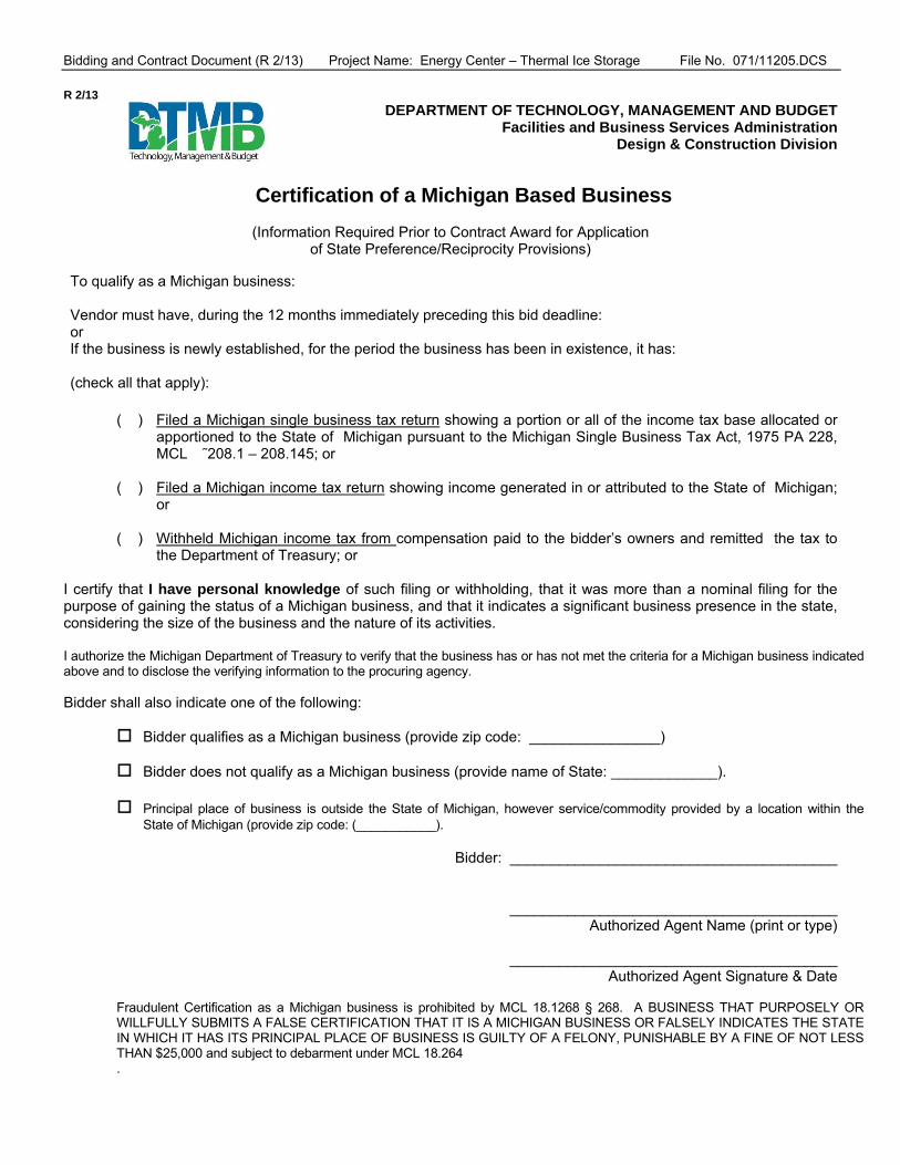
Bidding and Contract Document (R 2/13) Project Name: Energy Center – Thermal Ice Storage File No. 071/11205.DCS
R 2/13 DEPARTMENT OF TECHNOLOGY, MANAGEMENT AND BUDGET
Facilities and Business Services Administration Design & Construction Division
Certification of a Michigan Based Business
(Information Required Prior to Contract Award for Application of State Preference/Reciprocity Provisions)
To qualify as a Michigan business: Vendor must have, during the 12 months immediately preceding this bid deadline: or If the business is newly established, for the period the business has been in existence, it has: (check all that apply):
( ) Filed a Michigan single business tax return showing a portion or all of the income tax base allocated or
apportioned to the State of Michigan pursuant to the Michigan Single Business Tax Act, 1975 PA 228, MCL �˜208.1 – 208.145; or
( ) Filed a Michigan income tax return showing income generated in or attributed to the State of Michigan;
or ( ) Withheld Michigan income tax from compensation paid to the bidder’s owners and remitted the tax to
the Department of Treasury; or
I certify that I have personal knowledge of such filing or withholding, that it was more than a nominal filing for the purpose of gaining the status of a Michigan business, and that it indicates a significant business presence in the state, considering the size of the business and the nature of its activities.
I authorize the Michigan Department of Treasury to verify that the business has or has not met the criteria for a Michigan business indicated above and to disclose the verifying information to the procuring agency.
Bidder shall also indicate one of the following:
Bidder qualifies as a Michigan business (provide zip code: ________________)
Bidder does not qualify as a Michigan business (provide name of State: _____________). Principal place of business is outside the State of Michigan, however service/commodity provided by a location within the
State of Michigan (provide zip code: (___________).
Bidder: ________________________________________
________________________________________ Authorized Agent Name (print or type)
________________________________________
Authorized Agent Signature & Date Fraudulent Certification as a Michigan business is prohibited by MCL 18.1268 § 268. A BUSINESS THAT PURPOSELY OR WILLFULLY SUBMITS A FALSE CERTIFICATION THAT IT IS A MICHIGAN BUSINESS OR FALSELY INDICATES THE STATE IN WHICH IT HAS ITS PRINCIPAL PLACE OF BUSINESS IS GUILTY OF A FELONY, PUNISHABLE BY A FINE OF NOT LESS THAN $25,000 and subject to debarment under MCL 18.264 .

Blank Page
jmuizelaar
Rectangle

Bidding and Contract Document (R 2/13) Project Name: Energy Center – Thermal Ice Storage File No. 071/11205.DCS
R 2/13 DEPARTMENT OF TECHNOLOGY, MANAGEMENT AND BUDGET
Facilities and Business Services Administration Design & Construction Division
Responsibility Certification The bidder certifies to the best of its knowledge and belief that, within the past three (3) years, the bidder, an officer of the bidder, or an owner of a 25% or greater interest in the bidder: (a) Has not been convicted of a criminal offense incident to the application for or performance of a contract or subcontract with the
State of Michigan or any of its agencies, authorities, boards, commissions, or departments. (b) Has not had a felony conviction in any state (including the State of Michigan). (c) Has not been convicted of a criminal offense which negatively reflects on the bidder’s business integrity, including but not
limited to, embezzlement, theft, forgery, bribery, falsification or destruction of records, receiving stolen property, negligent misrepresentation, price-fixing, bid-rigging, or a violation of state or federal anti-trust statutes.
(d) Has not had a loss or suspension of a license or the right to do business or practice a profession, the loss or suspension of
which indicates dishonesty, a lack of integrity, or a failure or refusal to perform in accordance with the ethical standards of the business or profession in question.
(e) Has not been terminated for cause by the Owner. (f) Has not failed to pay any federal, state, or local taxes. (g) Has not failed to comply with all requirements for foreign corporations. (h) Has not been debarred from participation in the bid process pursuant to Section 264 of 1984 PA 431, as amended, MCL
18.1264, or debarred or suspended from consideration for award of contracts by any other State or any federal Agency. (i) Has not been convicted of a criminal offense or other violation of other state or federal law, as determined by a court of
competent jurisdiction or an administrative proceeding, which in the opinion of DTMB indicates that the bidder is unable to perform responsibly or which reflects a lack of integrity that could negatively impact or reflect upon the State of Michigan, including but not limited to, any of the following offenses under or violations of:
i. The Natural Resources and Environmental Protection Act, 1994 PA 451, MCL 324.101 to 324.90106. ii. A persistent and knowing violation of the Michigan Consumer Protection Act, 1976 PA 331, MCL 445.901 to 445.922. iii. 1965 PA 166, MCL 408.551 to 408.558 (law relating to prevailing wages on state projects) and a finding that the bidder
failed to pay the wages and/or fringe benefits due within the time period required. iv. Repeated or flagrant violations of 1978 PA 390 MCL 408.471 to 408.490 (law relating to payment of wages and fringe
benefits). v. A willful or persistent violation of the Michigan Occupational Health and Safety Act, 1974, PA 154, MCL 408.10001 to
408.1094, including: a criminal conviction, repeated willful violations that are final orders, repeated violations that are final orders, and failure to abate notices that are final orders.
vi. A violation of federal or state civil rights, equal rights, or non-discrimination laws, rules, or regulations. vii. Been found in contempt of court by a Federal Court of Appeals for failure to correct an unfair labor practice as prohibited
by Section 8 of Chapter 372 of the National Labor Relations Act, 29 U. s. C. 158 (1980 PA 278, as amended, MCL 423.321 et seq).
I understand that a false statement, misrepresentation or concealment of material facts on this certification may be grounds for rejection of this proposal or termination of the award and may be grounds for debarment. Bidder: _______________________________________ _______________________________________
Authorized Agent Name (print or type)
_______________________________________ Authorized Agent Signature & Date
I am unable to certify to the above statements. My explanation is attached.

Blank Page
jmuizelaar
Rectangle

Bidding and Contract Document (R 2/13) Project Name: Energy Center – Thermal Ice Storage File No. 071/11205.DCS
BID BOND BID SUBMITTED ON the _______ day of ________________, 20____.
Bid Security is in the form of: a Bid Bond _______ Bid Bond form has been duly executed _______; or A Bank Certified or Cashier's check ___ or Money Order ___ is attached to this page ____ Bidder’s Certificate of Awardability is attached to the last page of this Bid Form ____
If the Bidder is an Individual:
Name of Individual: _________________________________________________________ Name & Title of Person Authorized to sign: ___________________________________________ Signature: _________________________________________________________ (If not the Individual, Attach Power of Attorney) Date Doing Business as: _________________________________________________________ Business Address: _________________________________________________________
Federal Identification (I.D.) No. or Social Security No. ________________________________________
County of registration _________________________
Telephone: _________________________ FAX: ______________________
If the Bidder is a Partnership:
By: _________________________________________________________ (True Name of the Partnership) _________________________________________________________ Partner Authorized to Sign Date Signature: _________________________________________________________ (Attach evidence of Authority to sign) Date Business Address: _________________________________________________________
Federal Identification (I.D.) No. or Social Security No. ________________________________________
County of registration _________________________
Telephone: _________________________ FAX _______________________
If the Bidder is a Corporation:
By: _________________________________________________________ (Legal Corporation Name)
Name & Title of Authorized Officer: __________________________________________________ Signature: _________________________________________________________ (Attach evidence of Authority to sign) Date Name & Title of Officer Attesting: __________________________________________________ Signature: _________________________________________________________ Date Business Address: _________________________________________________________ Federal Identification (I.D.) No. or Social Security No. ________________________________________
Telephone: _________________________ FAX _______________________
(State of Incorporation): _________________________________________________________
If The Bidder is A Joint Venture: JOINT VENTURE SIGNATURES MUST BE AS PROVIDED IN INSTRUCTIONS TO BIDDERS. EACH JOINT VENTURER SIGNING THE BID MUST SIGN IN THE MANNER INDICATED FOR AN INDIVIDUAL, A PARTNERSHIP OR A CORPORATION. IF MORE THAN TWO JOINT VENTURERS OF THE SAME TYPE ARE INCLUDED, USE ADDITIONAL PAGES. JOINT VENTURE STATE OF INCORPORATION ___________________ OR COUNTY OF REGISTRATION _____________________

Blank Page
jmuizelaar
Rectangle

Bidding and Contract Document (R 2/13) Project Name: Energy Center – Thermal Ice Storage File No. 071/11205.DCS
QUESTIONNAIRE/QUALIFICATION SUBMITTAL
PROFESSIONAL
WORK
AGENCY No. _______________ INDEX No. _______________ FILE No. _______________
ARTICLE 1 ORGANIZATION
1.1. Date of organization (or incorporation) ____________ State of incorporation ______________ (IRS) EIN _______________
1.2. Title and name of Principals (President, Vice-Presidents, Secretary and Treasurer, if a corporation; partners, if a partnership)
_________________________________________________________________________________________________________
_________________________________________________________________________________________________________
1.3. Is your organization's principal place of business maintained in the State of Michigan? ___ If your organization maintains its principal place of business outside the State, attach a copy of the Certificate of Authority which your organization procured in accordance with MCL 450.2011.
1.4. If your organization, any business entity related to or affiliated with your organization, or any present or former executive employee, officer, director, shareholder (owning twenty percent (20%) or more of the outstanding shares), partner, or owner of your organization or of any such related or affiliated entity has ever been convicted of a felony, or has felony charges pending, in any state within the last three (3) years from the date of Bid opening, furnish with this Bidder's Questionnaire all material facts relating to any such felony conviction or such pending felony charges.
1.5 Experience Modification Rating (EMR): ___________________________________________________________________
ARTICLE 2 SPECIALTY CONTRACTOR LICENSES
2.1. Does your organization hold valid licenses covering specialty classifications of Work that your organization itself intends to perform and for which a specific specialty license is required by any Political Subdivision with jurisdiction over the Work ______? If so, attach a list with all licenses by number and classification; state the name of the organization holding the license, the renewal date of each license, whether each license is active, and attach a copy of each license.
ARTICLE 3 EXPERIENCE
3.1. What is the general character of the work performed by your organization? _____________________________________ How many years of experience in construction work similar in character and scope to the Work under the Bidding Documents has your organization had: (a) as a General Contractor? ________; (b) as a Subcontractor? ________.
3.2. Attach a list of all public contracts or subcontracts under public contracts that your organization has performed within the last five (5) years which are similar in character and scope to the Work under the Bidding Documents (using the forms in the "References Attachment" provided with this Questionnaire). If the contract or subcontract referenced is not substantially completed, furnish the percent complete for that contract or subcontract.
3.3. Within the last five (5) years, has your organization failed to complete a contract or subcontract awarded to it? _____ If so, attach a list for each contract or subcontract, state when, where and why.
3.4. Within the last five (5) years, has any officer or partner of your organization been an officer or partner of another organization that failed to complete a contract or subcontract? __________. If so, for each contract or subcontract, state the name of each officer or partner and the name of the organization and owner(s), and the reasons why the contract or subcontract was not completed.

Bidding and Contract Document (R 2/13) Project Name: Energy Center – Thermal Ice Storage File No. 071/11205.DCS
ARTICLE 4 ADDITIONAL QUALIFICATIONS
4.1. (Nominated Subcontractor only) Will you subcontract any part of the Work covered by the intended Subagreement? ___. If so, which parts of the Work covered by the intended Subagreement do you intend to subcontract to a lower tier Subcontractor? _____________________________________________________________________________________________________________
4.2. State the name, address and telephone number of a representative of your organization who personally visited and inspected the site: ______________________________________________________________________________________________.
Also, describe, in an attachment to this Questionnaire, subsurface and physical conditions at or contiguous to the site that your representative investigated and how they were accounted for in the preparation of your organization's Bid.
4.3. Attach a list of construction equipment and machinery your organization intends to use in the execution of the Work, as estimated in the preparation of your organization's Bid.
4.4. Does your organization rent or lease equipment or facilities from other affiliate organizations? ______. If so, state the name of the affiliate organization(s) ____________________________________________________________________________
ARTICLE 5 REFERENCES
5.1. Trade references (Minimum of three (3)): 5.2. Bank references: 5.3. Insurance: The undersigned Apparent Low Bidder ____ or nominated Subcontractor _____ ____________________________________ certifies that all statements and answers made to the interrogatories in this Questionnaire are current, accurate and complete as of the date stated below. (Note: Attachments shall be fastened at the end of this Section).
Signed by: ____________________________ Name _______________________________ Title ________________________ on this __________ day of ____________________, 20_______.
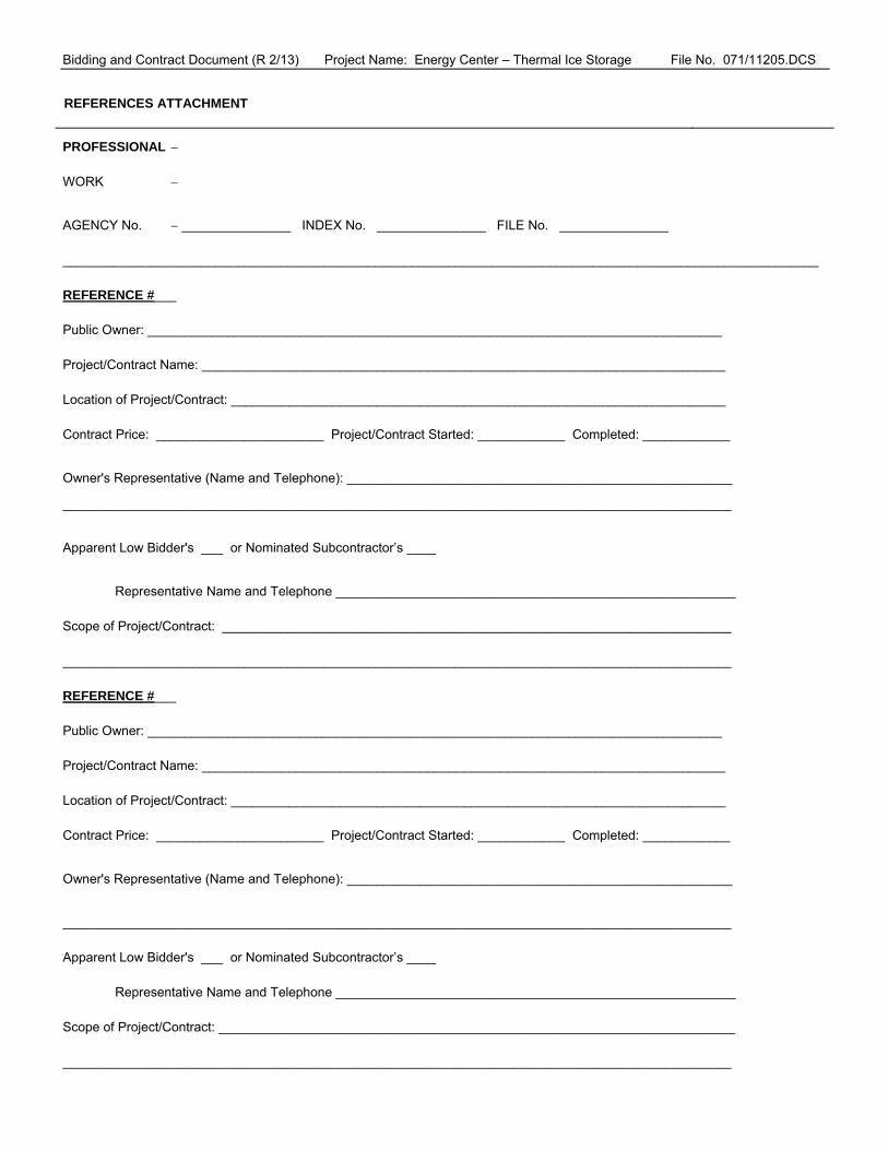
Bidding and Contract Document (R 2/13) Project Name: Energy Center – Thermal Ice Storage File No. 071/11205.DCS
REFERENCES ATTACHMENT
PROFESSIONAL WORK
AGENCY No. _______________ INDEX No. _______________ FILE No. _______________ ________________________________________________________________________________________________________ REFERENCE #___ Public Owner: _______________________________________________________________________________ Project/Contract Name: ________________________________________________________________________ Location of Project/Contract: ____________________________________________________________________ Contract Price: _______________________ Project/Contract Started: ____________ Completed: ____________
Owner's Representative (Name and Telephone): _____________________________________________________
____________________________________________________________________________________________
Apparent Low Bidder's ___ or Nominated Subcontractor’s ____
Representative Name and Telephone _______________________________________________________ Scope of Project/Contract: ______________________________________________________________________ ____________________________________________________________________________________________ REFERENCE #___ Public Owner: _______________________________________________________________________________ Project/Contract Name: ________________________________________________________________________ Location of Project/Contract: ____________________________________________________________________ Contract Price: _______________________ Project/Contract Started: ____________ Completed: ____________
Owner's Representative (Name and Telephone): _____________________________________________________
____________________________________________________________________________________________ Apparent Low Bidder's ___ or Nominated Subcontractor’s ____ Representative Name and Telephone _______________________________________________________ Scope of Project/Contract: _______________________________________________________________________ ____________________________________________________________________________________________

Bidding and Contract Document (R 2/13) Project Name: Energy Center – Thermal Ice Storage File No. 071/11205.DCS
REFERENCES ATTACHMENT
PROFESSIONAL WORK
AGENCY No. _______________ INDEX No. _______________ FILE No. _______________
________________________________________________________________________________________________________ REFERENCE #___ Public Owner: _______________________________________________________________________________ Project/Contract Name: ________________________________________________________________________ Location of Project/Contract: ____________________________________________________________________ Contract Price: _______________________ Project/Contract Started: ____________ Completed: ____________
Owner's Representative (Name and Telephone): _____________________________________________________
____________________________________________________________________________________________
Apparent Low Bidder's ___ or Nominated Subcontractor’s ____
Representative Name and Telephone _______________________________________________________ Scope of Project/Contract: ______________________________________________________________________ ____________________________________________________________________________________________ REFERENCE #___ Public Owner: _______________________________________________________________________________ Project/Contract Name: ________________________________________________________________________ Location of Project/Contract: ____________________________________________________________________ Contract Price: _______________________ Project/Contract Started: ____________ Completed: ____________
Owner's Representative (Name and Telephone): _____________________________________________________
____________________________________________________________________________________________
Apparent Low Bidder's ___ or Nominated Subcontractor’s ____
Representative Name and Telephone _______________________________________________________ Scope of Project/Contract: _______________________________________________________________________ ____________________________________________________________________________________________

Bidding and Contract Document (R 2/13) Project Name: Energy Center – Thermal Ice Storage File No. 071/11205.DCS
APPENDIX II
FORMS FOR CONTRACT AWARD

Blank Page
jmuizelaar
Rectangle

Bidding and Contract Document (R 2/13) Project Name: Energy Center – Thermal Ice Storage File No. 071/11205.DCS
PERFORMANCE BOND
AGENCY No. _________ INDEX No. ________ SURETY COMPANY REFERENCE No. ____________
That "the Contractor," ___________________________________________________, a corporation ___, individual ___, partnership ___, joint venture ___ of the State of __________________, qualified to do business in the State of Michigan, as Principal, and "the Surety," ____________________________________________________________________, of the State of _________________, as surety, are held and bound unto the State of Michigan, "the Owner," as Obligee, in the amount of __________________________________________________________________________ Dollars ($_________________), for the payment of which the Contractor and Surety bind themselves, their respective heirs, successors, legal representatives and assigns, jointly and severally, in compliance with 1963 PA 213, as amended, MCL 129.201 et seq.
The Contractor has entered into "the Contract" with the Owner for _______________________________________________ _______________, "the Work," covered by the Contract Documents, which are incorporated into this Performance Bond by this reference;
If the Contractor faithfully performs and fulfills all the undertakings, covenants, terms, conditions, warranties, indemnifications and agreements of the Contract Documents within the Contract Time (including any authorized changes, with or without notice to the Surety) and during the Correction Period, and if the Contractor also performs and fulfills all the undertakings, covenants, terms, conditions, warranties, indemnifications and agreements of any and all duly authorized modifications of the Contract Documents, then THIS OBLIGATION IS VOID, OTHERWISE TO REMAIN IN FULL FORCE AND EFFECT.
A. No change in Contract Price or Contract Time, "or equal" or substitution or modification of the Contract Documents (including addition, deletion or other revision) releases the Surety of its obligations under this Section 00610 Performance Bond. The Surety expressly waives notice of any such change in Contract Price or Contract Time, "or equal" or substitution or modification of
the Contract Documents (including addition, deletion or other revision).
B. This Performance Bond must be solely for the protection of the Owner and its successors, legal representatives or assigns.
C. It is the intention of the Contractor and Surety that they must be bound by all terms and conditions of the Contract Documents (including, but not limited to General Conditions and this Performance Bond). However, this Performance Bond is executed pursuant to 1963 PA 213, as amended, MCL 129.201 et seq., and if any provision(s) of this Performance Bond is/are illegal, invalid or unenforceable, all other provisions of this Performance Bond must nevertheless remain in full force and effect, and the Owner must be protected to the full extent provided by 1963 PA 213, as amended, MCL 129.201 et seq.
IMPORTANT: The Surety must be authorized to do business in the State of Michigan by the Department of Licensing and Regulatory Affairs Insurance Bureau, must be listed on the current U.S. Department of the Treasury Circular 570, and, unless otherwise authorized by the Owner in writing, must have at least an A Best's rating and a Class VII or better financial size category per current A. M. Best Company ratings.
Name, Address and Telephone of the Surety:
Address and Telephone of Agent, who is either a resident of, or whose principal office is maintained in, the State of Michigan
Signed and sealed this __________ day of _______________________, 20_____.
THE CONTRACTOR: (Print Full Name and Sign) By:___________________________________________________________
WITNESS ______________________________ Name & Title: __________________________________________________
Telephone No. _________________________________________________
THE SURETY: (Print Full Name and Sign) Agent: ________________________________________________________
WITNESS ______________________________ Attorney-in-Fact: ________________________________________________
Telephone No. ____________________________________________________

Blank Page
jmuizelaar
Rectangle

Bidding and Contract Document (R 2/13) Project Name: Energy Center – Boiler No. 3 Demolition File No. 071/11205/DCS
PAYMENT BOND
AGENCY No. _________ INDEX No. ________ SURETY COMPANY REFERENCE No._____________
"the Contractor," ___________________________________________________, a corporation ___, individual ___, partnership ___, joint venture ___ of the State of __________________, qualified to do business in the State of Michigan, as Principal, and "the Surety," ____________________________________________________________________, of the State of _________________, as surety, are held and bound unto the State of Michigan, "the Owner," as Obligee, in the amount of __________________________________________________________________________ Dollars ($_________________), for the payment of which the Contractor and Surety bind themselves, their respective heirs, successors, legal representatives and assigns, jointly and severally, in compliance with 1963 PA 213, as amended, MCL 129.201 et seq.
The Contractor has entered into "the Contract" with the Owner for _____________________________________________ __________________, "the Work," covered by the Contract Documents, which are incorporated into this Payment Bond by this reference;
If the Contractor promptly pays all claimants supplying labor or materials to the Contractor or to the Contractor's Subcontractors in the prosecution of the Work, then THIS OBLIGATION IS VOID, OTHERWISE TO REMAIN IN FULL FORCE AND EFFECT.
A. All rights and remedies on this Payment Bond are solely for the protection of all claimants supplying labor and materials to the Contractor or the Contractor's Subcontractors in the prosecution of the Work, and must be determined in accordance with Michigan Law.
B. No change in Contract Price or Contract Time, "or equal" or substitution or modification of the Contract Documents (including addition, deletion or other revision) must release the Surety of its
obligations under this Payment Bond. The Surety hereby expressly waives notice of any such change in Contract Price or Contract Time, "or equal" or substitution or modification of the Contract Documents (including addition, deletion or other revision).
C. It is the intention of the Contractor and Surety that they must be bound by all terms and conditions of the Contract Documents (including, but not limited to this Payment Bond). However, this Payment Bond is executed pursuant to 1963 PA 213, as amended, MCL 129.201 et seq., and if any provision(s) of this Payment Bond is/are illegal, invalid or unenforceable, all other provisions of this Payment Bond must nevertheless remain in full force and effect, and the Owner must be protected to the full extent provided by 1963 PA 213, as amended, MCL 129.201 et seq.
IMPORTANT: The Surety must be authorized to do business in the State of Michigan by the Department of Licensing and Regulatory Affairs Insurance Bureau, must be listed on the current U.S. Department of the Treasury Circular 570, and, unless otherwise authorized by the Owner in writing, must have at least an A Best's rating and a Class VII or better financial size category per current A. M. Best Company ratings.
Name, Address and Telephone of the Surety:
Address and Telephone of Agent, who is either a resident of, or whose principal office is maintained in, the State of Michigan
Signed and sealed this __________ day of _______________________, 20_____.
THE CONTRACTOR: (Print Full Name and Sign) By:___________________________________________________________
WITNESS ______________________________ Name & Title: __________________________________________________
Telephone No. _________________________________________________
THE SURETY: (Print Full Name and Sign) Agent: ________________________________________________________
WITNESS ______________________________ Attorney-in-Fact: ________________________________________________
Telephone No. ____________________________________________________

Blank Page
jmuizelaar
Rectangle

Bidding and Contract Document (R 2/13) Project Name: Energy Center – Thermal Ice Storage File No. 071/11205.DCS
APPENDIX III
SPECIAL WORKING CONDITIONS

Blank Page
jmuizelaar
Rectangle

Bidding and Contract Document (R 2/13) Project Name: Energy Center – Thermal Ice Storage File No. 071/11205.DCS
DTMB Facilities Security Clearance Request
Contractor Instructions
The purpose of this document is to establish security and supervision requirements for contract personnel requiring access to Department of Technology, Management and Budget (DTMB) facilities. A DTMB Security Clearance form must be completed before an individual is granted access to a facility. Access approval will be in effect for one year from date of DTMB Facility Services approval or until estimated project completion date (whichever occurs first). Contract personnel agree to adhere to all DTMB rules and regulations which in DTMB facilities. Access will only be granted for normal business hours. (Monday-Friday, 8:00 a.m.-5:00 p.m. except State holidays). DTMB Facilities and Business Services Administration, Facility Services section must clear any exception in advance. Contract personnel will be required to submit the following to DTMB Facility Services Manager or Regional Manager before entering a DTMB facility: Procedure for submitting form electronically (preferred and recommended) 4. Complete a DTMB Security Clearance form (using Microsoft Excel) and include the following:
Company name Company Contact name and phone number Complete name (last name first) and date of birth for all employees requiring access.
5. Email completed form to DTMB Facility Manager for an individual building or DTMB Regional Facility
Manager for multiple building requests. Procedure for submitted in person or mail delivery 1. Complete a DTMB Security Clearance form (using Microsoft Excel) and include the following:
Company name Company Contact name and phone number Complete name (last name first) and date of birth for all employees requiring access.
2. Return completed form to DTMB Facility Manager for an individual building or DTMB Regional Facility
Manager for multiple building requests. Note: This request must be received a minimum of 48 hours before enter a DTMB Facility. DTMB Facility Access Criteria: 1. Present pictured ID. 2. Name must appear on the clearance list. 3. Sign-in and wear a dated visitor’s pass (must be visibly displayed at all times). 4. Return visitor pass to security desk at days end. Note: Individuals whose name does not appear on the clearance list are required to be signed in by a member of the DTMB Facility Services staff. Failure to comply with the above procedure will result in the individual(s) being delayed and may be cause for denying access to DTMB facilities.

Blank Page
jmuizelaar
Rectangle

Bidding and Contract Document (R 2/13) Project Name: Energy Center – Thermal Ice Storage File No. 071/11205.DCS
APPENDIX IV
SPECIAL PROJECT PROCEDURES

Blank Page
jmuizelaar
Rectangle

Bidding and Contract Document (R 2/13) Project Name: Energy Center – Thermal Ice Storage File No. 071/11205.DCS
DEMOLITION/REMODELING PROJECT PROCEDURES Furnish all equipment, materials, labor and services necessary to complete all building demolition required in connection with the existing building, in order to permit the installation of new Work. The goal of the Owner is to generate the least amount of waste or debris possible. However, inevitable waste and debris that are generated shall be reused, salvaged, or recycled, and disposal in landfills shall be minimized to the extent economically feasible. The Contractor will be required to prepare waste management plan for the collection, handling, storage, transportation and disposal of the waste generated at the construction site for the Owner’s review and approval. The Contractor will be required to produce waste management progress reports. 1. Locations: Notations are made in various places on the Drawings to call attention to building demolition which is required;
however, these Drawings are not intended to show each and every item to be removed. The Contractor and the Subcontractors for the various trades must remove the materials related to their respective trades as required to permit the construction of the new Work as shown.
2. Permits: The Contractor must secure from the appropriate agencies all required permits necessary for proper execution of the
work before starting work on the project site. All fees for securing the permits must be paid by the Contractor, including all inspection costs which may be legally assessed by the Bureau of Construction Codes in accordance with the authority granted under the Public Act 1980 PA 371, as amended.
3. Enclosures: Where it is necessary to make alterations to walls, floors or roof of the existing building, the Contractor must provide
and maintain dustproof partitions to separate the parts where Work is being done from the adjoining parts occupied by the State Agency. Where any parts are opened and exposed to the elements, the Contractor must provide weather tight enclosures to fully protect the structure and its contents.
4. Waste Management Plan: The management plan must address waste source identification and separation, returns, reuse and
salvage, recycling, landfill options, alternatives to landfilling, materials handling procedures and transportation. 5. Preparation: Protect all existing Work that is to remain and restore in an approved manner any such Work that becomes
damaged.
5.1 Rubbish and debris resulting from the Work must be removed immediately from the site by the Contractor. However, any recyclable materials must be recycled; the Contractor will be required to use alternatives to landfills for waste disposal such as reuse or recycle of asphalt, bricks, concrete, masonry, plastics, paint, glass, carpet, metals, wood, drywall, insulation and any other waste materials to the extent practical.
5.2 Unless otherwise specified, the Agency will remove existing furniture, drapery tracks, draperies, window blinds, and other
equipment items, which might interfere with the new construction. 6. Coordination: Demolition work, in connection with any new unit of Work, must not be commenced until all new materials
required for completion of that new item of Work are at hand. 7. Waste Management Plan Progress Reports: Submit an updated report with the payment requests. The progress reports shall
include: a. The amount of waste sent to a landfill, tipping fees paid and the total disposal cost. Include supporting documents such as
manifests, weight tickets, receipts and/or invoices. b. Records for each material recycled/reused/salvaged from the project including the amount, date removed from the job site,
final destination, transportation cost, recycled materials and the net cost/ savings. c. Breakdown of waste by type generated to date. d. Recycling/salvage/landfill rates. e. Percent of waste recycled/salvaged to date.

Bidding and Contract Document (R 2/13) Project Name: Energy Center – Thermal Ice Storage File No. 071/11205.DCS
HAZARDOUS MATERIALS PROJECT PROCEDURES
1. The Contractor must use, handle, store, dispose of, process, transport and transfer any material considered a Hazardous Material in accordance with all Federal, State and local Laws. If the Contractor encounters material reasonably believed to be a Hazardous Material and which may present a substantial danger, the Contractor must immediately stop all affected work, give written notice to the Owner of the conditions encountered, and take appropriate health and safety precautions.
2. Environmental Hazards (air, water, land and liquid industrial) are handled by the Waste and Hazardous Materials Division,
Michigan Department of Environmental Quality (MDEQ) in carrying out the requirements of the Federal Environmental Protection Agency (EPA). For general information and/or a copy of the latest regulations and publications call (517) 335-2690.
3. The Michigan Occupational Safety and Health Administration (MIOSHA) provides protection and regulations for the safety and
health of workers. The Department of Licensing and Regulatory Affairs provides for the safety of workers. The Department of Community Health provides for the health of workers (517/373-3740) (TDD 517/373-3573).
3.1 Contractor must post any applicable State and/or Federal government regulations at the job site in a prominent location. 3.2 Contractor must be responsible for training their workers in safe work practices and in proper removal methods when
coming in contact with hazardous chemicals. 4. Applicable Regulations:
4.1 Natural Resources and Environmental Protection Act – PA 451 of 1994, as amended, including Part 111 – Hazardous Waste Management, Part 121 – Liquid Industrial Waste and Part 147 – PCB compounds.
4.2 RCRA, 1976 - Resource Conservation and Recovery Act: This federal statute regulates generation, transportation,
treatment, storage or disposal of hazardous wastes nationally. 4.3 TSCA, 1979 – Toxic Substances Control Act: This statute regulates the generation, transportation, storage and disposal of
industrial chemicals such as PCBs. 5. Definitions: Hazardous substances are ignitable, corrosive, reactive, and/or toxic, based on their chemical characteristics.
5.1 Under Federal and Michigan Law, a Small Quantity Generator of hazardous waste provides from 220 to less than 2,000 lbs./month or never accumulates 2,200 lbs. or more.
5.2 A Generator size provider of hazardous waste provides 2,200 lbs. or more/month or accumulates above 2,200 lbs.
6. Disposals: To use an off-site hazardous waste disposal facility, the Contractor must use the Uniform Hazardous Waste Manifest
(shipping paper). Small quantities of hazardous waste may not be disposed of in sanitary landfills used for solid waste. 7. Federal, State and local Laws and regulations may apply to the storage, handling and disposal of Hazardous Materials and
wastes at each State Agency. Contact the Environmental Assistance Center of the Michigan Department of Environmental Quality (MDEQ) at 1-800-662-9278, Fax to: 517-241-0673 or e-mail to: [email protected] for general MDEQ information including direct and referral assistance on air, water and wetlands permits; contaminated site clean-ups; underground storage tank removals and remediation; hazardous and solid waste disposal; pollution prevention and recycling; and compliance-related assistance. The Center provides businesses, municipalities, and the general public with a single point of access to DEQ's environmental programs.

Bidding and Contract Document (R 2/13) Project Name: Energy Center – Thermal Ice Storage File No. 071/11205.DCS
ASBESTOS ABATEMENT PROJECT PROCEDURES
It is not anticipated that asbestos containing materials will be encountered in this project. However, if the Contractor encounters a suspected ACM that was not previously identified, the Contractor must immediately stop all affected work, give written notice to the Owner of the conditions encountered, and take appropriate health and safety precautions. If, after providing Owner notification, the Contractor is directed to sample and/or remove the suspected ACM in question, a Contract Change Order will be written to modify the existing Contract to pay for the additional cost. Any abatement shall be completed in accordance with the requirements of this Section. If removal of ACM is required, removal must be completed by a contractor currently licensed to remove asbestos by the State of Michigan, Department of Licensing and Regulatory Affairs (DLARA) Asbestos Program and abatement must be performed in accordance with all Federal, State and local Laws and Regulations. Prior to commencing any asbestos abatement activities, the licensed abatement contractor must submit, as required by Federal, State and Local Laws and Regulations, a “Notification of Intent to Renovate/Demolish” to both the State of Michigan, Department of Environmental Quality (MDEQ), Air Quality Division and to the DLARA, Asbestos Program, to comply with National Emission Standards for Hazardous Air Pollutants (NESHAP), and the Clean Air Act (CAA). All regulated ACM must be disposed of at an approved Type II (general refuse) landfill and must be in leak-tight wrapping or containers. ACM that is non friable and is not in poor condition or will not become regulated ACM at any time can be disposed of in a Type III (construction debris) landfill. At the completion of each abatement activity, the Contractor must perform clearance testing in accordance with National Institute for Occupational Safety and Health (NIOSH) 582 “Sampling and Evaluating Airborne Asbestos Dust”. All air samples shall indicate concentrations of less than 0.01 fibers/cc for clearance to be met. Clearance testing shall be performed by a third party Asbestos Consultant. The Asbestos Consultant selected by the Contractor shall be experienced and knowledgeable about the methods for asbestos air sampling and be able to select representative numbers and locations of samples. It is mandatory that the Asbestos Consultant’s on-site hygienist performing sampling and analysis have certification that he/she has passed a NIOSH 582 or equivalent course. The NESHAP asbestos regulations, notification form, guidelines and fact sheets are available on DEQ’s web site www.michigan.gov/deq under heading Air; then click on Asbestos NESHAP Program. For guidelines on submitting notifications pursuant to the Asbestos Contractors Licensing Act, contact the DLARA, Occupational Health Division, Asbestos Program at (517) 322-1320 or visit DLARA’s web site www.michigan.gov/asbestos.

Bidding and Contract Document (R 2/13) Project Name: Energy Center – Thermal Ice Storage File No. 071/11205.DCS
LEAD ABATEMENT PROJECT PROCEDURES
As part of the demolition work, the workers are assumed to be exposed to lead or materials containing lead above acceptable levels until proven otherwise through personal air sampling and analysis. The Contractor shall take all steps necessary to assure that his/her employees are not exposed to lead at concentrations greater than the Permissible Exposure Limit as per the State of Michigan Department of Licensing and Regulatory Affairs Occupational Health Standards Part 603 “Lead Exposure in Construction”. In addition, the Contractor shall convey this same requirement to all subcontractors that may be under his/her control. The employer shall comply with the Michigan Lead Abatement Act, as amended, and the Lead Hazard Control rules and must communicate information concerning lead hazards according to the requirements of Michigan Occupational Safety and Health Administration (MIOSHA) Part 603 and the Occupational Safety and Health Administration’s (OSHA's) Hazard Communication Standard for the construction industry, 29 CFR 1926.59, including but not limited to safety equipment (e.g. personal fit-tested and approved respirators and protective clothing), worker rotation (on a short-cycle and regular basis), working practices (e.g. sanding, cutting, grinding, abraded, burning and heat-gun stripping of lead based paint are not allowed), the requirements concerning warning signs and labels, material safety data sheets (MSDS), and employee information and training. Employers shall comply with the requirements of 29 CFR 1926.62(l) - Employee Information and Training. If lead or materials containing lead will be disturbed as a part of the work to be performed, the Contractor must remove, transport and dispose of these materials at no additional cost to the Owner and prior to any other work taking place within the immediate vicinity of said material. The Contractor must provide the Owner a minimum 10 working day notification prior to the start of any lead abatement activities with abatement in occupied buildings being completed even if they will be conducted during off hours (nights, weekends and state holidays). Abatement is defined as an activity specifically designed to permanently remove lead paint, lead-contaminated dust or other lead containing materials, the installation of a permanent enclosure or encapsulation of lead paint or other lead containing materials, the replacement of lead-painted surfaces or fixtures, the removal or covering of lead-contaminated soil, and any preparation, cleanup, disposal and post-abatement clearance testing associated with these activities. Renovation, remodeling, landscaping, or other activity, that is not designed to permanently eliminate lead paint hazards, but is instead designed to repair, restore, or remodel a structure, or housing unit even though the activity may incidentally result in a reduction or elimination of a lead paint hazard is not considered abatement. If abatement of lead or materials containing lead is required, abatement must be completed by a currently certified Lead Abatement Contractor as certified by the State of Michigan, Department of Community Health. In addition, the Lead Abatement Contractor’s workers and supervisors must also be currently certified by the State of Michigan, Department of Community Health. Lead abatement including clearance testing shall be performed in accordance with the State of Michigan, Lead Abatement Act, Part 54A Lead Abatement and with all other Federal, State and local Laws and Regulations that may apply. Prior to commencing any lead abatement activities, the abatement must be designed by a currently certified Lead Professional Project Designer. At the completion of abatement, the abated area shall meet clearance requirements with clearance testing to be performed by a Clearance Technicians currently certified by the State of Michigan Department of Community Health. For additional information about certifications, guidance and regulations for lead hazard control activities, visit www.michigan.gov/leadsafe.
Bidding and Contract Document (R 2/13) Project Name: Energy Center – Thermal Ice Storage File No. 071/11205.DCS
APPENDIX V
PREVAILING WAGE RATES

Blank Page
jmuizelaar
Rectangle

RICK. SNYDER STATE OF MICHIGAN
GOVERNOR Prevailing Wages PO Box 30476
Lansing, MI 48909 517-322-1825
Informational Sheet: Prevailing Wages on State Projects
(06/11) Page 1 of 1
REQUIREMENTS OF THE PREVAILING WAGES ON STATE PROJECTS ACT, PUBLIC ACT 166 OF 1965
The State of Michigan determines prevailing rates pursuant to the Prevailing Wages on State Projects Act, Public Act 166 of 1965, as amended. The purpose of establishing prevailing rates is to provide minimum rates of pay that must be paid to workers on construction projects for which the state or a school district is the contracting agent and which is financed or financially supported by the state. By law, prevailing rates are compiled from the rates contained in collectively bargained agreements which cover the locations of the state projects. The official prevailing rate schedule provides an hourly rate which includes wage and fringe benefit totals for designated construction mechanic classifications. The overtime rates also include wage and fringe benefit totals. Please pay special attention to the overtime and premium pay requirements. Prevailing wage is satisfied when wages plus fringe benefits paid to a worker are equal to or greater than the required rate. State of Michigan responsibilities under the law:
• The department establishes the prevailing rate for each classification of construction mechanic requested by a contracting agent prior to contracts being let out for bid on a state project.
Contracting agent responsibilities under the law:
• If a contract is not awarded or construction does not start within 90 days of the date of the issuance of rates, a re-determination of rates must be requested by the contracting agent.
• Rates for classifications needed but not provided on the Prevailing Rate Schedule, must be obtained prior to contracts being let out for bid on a state project.
• The contracting agent, by written notice to the contractor and the sureties of the contractor known to the contracting agent, may terminate the contractor's right to proceed with that part of the contract, for which less than the prevailing rates have been or will be paid, and may proceed to complete the contract by separate agreement with another contractor or otherwise, and the original contractor and his sureties shall be liable to the contracting agent for any excess costs occasioned thereby.
Contractor responsibilities under the law:
• Every contractor and subcontractor shall keep posted on the construction site, in a conspicuous place, a copy of all prevailing rates prescribed in a contract.
• Every contractor and subcontractor shall keep an accurate record showing the name and occupation of and the actual wages and benefits paid to each construction mechanic employed by him in connection including certified payroll, as used in the industry, with said contract. This record shall be available for reasonable inspection by the contracting agent or the department.
• Each contractor or subcontractor is separately liable for the payment of the prevailing rate to its employees. • The prime contractor is responsible for advising all subcontractors of the requirement to pay the prevailing rate prior to
commencement of work. • The prime contractor is secondarily liable for payment of prevailing rates that are not paid by a subcontractor. • A construction mechanic shall only be paid the apprentice rate if registered with the United States Department of
Labor, Bureau of Apprenticeship and Training and the rate is included in the contract. Enforcement:
A person who has information of an alleged prevailing wage violation on a state project may file a complaint with the State of Michigan. The department will investigate and attempt to resolve the complaint informally. During the course of an investigation, if the requested records and posting certification are not made available in compliance with Section 5 of Act 166, the investigation will be concluded and a referral to the Office of Attorney General for civil action will be made. The Office of Attorney General will pursue costs and fees associated with a lawsuit if filing is necessary to obtain records.

Blank Page
jmuizelaar
Rectangle

RICK. SNYDER STATE OF MICHIGAN
GOVERNOR Prevailing Wages PO Box 30476
Lansing, MI 48909 517-322-1825
Informational Sheet: Prevailing Wages on State Projects
(06/11) Page 1 of 1
General Information Regarding Fringe Benefits
Certain fringe benefits may be credited toward the payment of the Prevailing Wage Rate: o If a fringe benefit is paid directly to a construction mechanic o If a fringe benefit contribution or payment is made on behalf of a construction mechanic o If a fringe benefit, which may be provided to a construction mechanic, is pursuant to a written contract
or policy o If a fringe benefit is paid into a fund, for a construction mechanic
When a fringe benefit is not paid by an hourly rate, the hourly credit will be calculated based on the annual value of the fringe benefit divided by 2080 hours per year (52 weeks @ 40 hours per week). The following is an example of the types of fringe benefits allowed and how an hourly credit is calculated: Vacation Dental insurance Vision insurance Health insurance Life insurance Tuition Bonus 401k Employer Contribution Total Hourly Credit
40 hours X $14.00 per hour = $560/2080 = $31.07 monthly premium X 12 mos. = $372.84 /2080 = $5.38 monthly premium X 12 mos. = $64.56/2080 = $230.00 monthly premium X 12 mos. = $2,760.00/2080 = $27.04 monthly premium X 12 mos. = $324.48/2080 = $500.00 annual cost/2080 = 4 quarterly bonus/year x $250 = $1000.00/2080 = $2000.00 total annual contribution/2080 =
$.27$.18$.03
$1.33$.16$.24$.48$.96
$3.65
Other examples of the types of fringe benefits allowed: Sick pay Holiday pay Accidental Death & Dismemberment insurance premiums
The following are examples of items that will not be credited toward the payment of the Prevailing Wage Rate:o Legally required payments, such as:
Unemployment Insurance payments Workers’ Compensation Insurance payments FICA (Social Security contributions, Medicare contributions)
o Reimbursable expenses, such as: Clothing allowance or reimbursement Uniform allowance or reimbursement Gas allowance or reimbursement Travel time or payment Meals or lodging allowance or reimbursement Per diem allowance or payment
o Other payments to or on behalf of a construction mechanic that are not wages or fringe benefits, such as: Industry advancement funds Financial or material loans

Blank Page
jmuizelaar
Rectangle
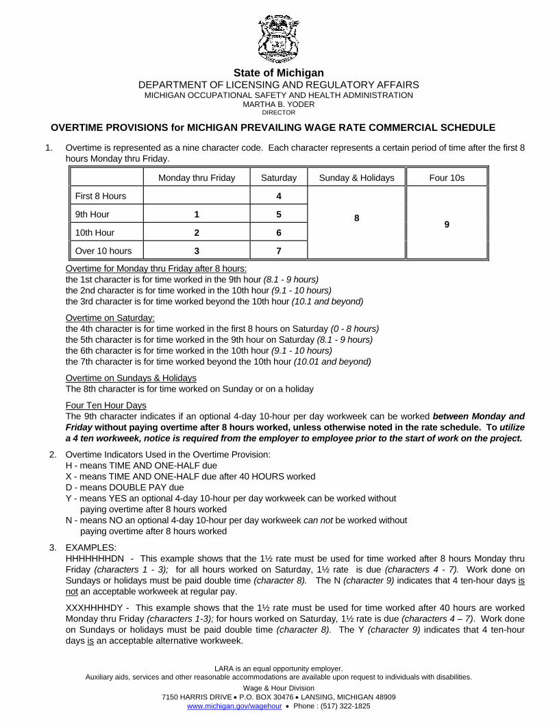
State of Michigan
DEPARTMENT OF LICENSING AND REGULATORY AFFAIRS MICHIGAN OCCUPATIONAL SAFETY AND HEALTH ADMINISTRATION
MARTHA B. YODER DIRECTOR
OVERTIME PROVISIONS for MICHIGAN PREVAILING WAGE RATE COMMERCIAL SCHEDULE
LARA is an equal opportunity employer. Auxiliary aids, services and other reasonable accommodations are available upon request to individuals with disabilities.
Wage & Hour Division 7150 HARRIS DRIVE P.O. BOX 30476 LANSING, MICHIGAN 48909
www.michigan.gov/wagehour Phone : (517) 322-1825
1. Overtime is represented as a nine character code. Each character represents a certain period of time after the first 8 hours Monday thru Friday.
Monday thru Friday Saturday Sunday & Holidays Four 10s
First 8 Hours 4
9th Hour 1 5
10th Hour 2 6
Over 10 hours 3 7
8
9
Overtime for Monday thru Friday after 8 hours: the 1st character is for time worked in the 9th hour (8.1 - 9 hours) the 2nd character is for time worked in the 10th hour (9.1 - 10 hours) the 3rd character is for time worked beyond the 10th hour (10.1 and beyond)
Overtime on Saturday: the 4th character is for time worked in the first 8 hours on Saturday (0 - 8 hours) the 5th character is for time worked in the 9th hour on Saturday (8.1 - 9 hours) the 6th character is for time worked in the 10th hour (9.1 - 10 hours) the 7th character is for time worked beyond the 10th hour (10.01 and beyond)
Overtime on Sundays & Holidays The 8th character is for time worked on Sunday or on a holiday
Four Ten Hour Days The 9th character indicates if an optional 4-day 10-hour per day workweek can be worked between Monday and Friday without paying overtime after 8 hours worked, unless otherwise noted in the rate schedule. To utilize a 4 ten workweek, notice is required from the employer to employee prior to the start of work on the project.
2. Overtime Indicators Used in the Overtime Provision: H - means TIME AND ONE-HALF due X - means TIME AND ONE-HALF due after 40 HOURS worked D - means DOUBLE PAY due Y - means YES an optional 4-day 10-hour per day workweek can be worked without paying overtime after 8 hours worked N - means NO an optional 4-day 10-hour per day workweek can not be worked without paying overtime after 8 hours worked
3. EXAMPLES: HHHHHHHDN - This example shows that the 1½ rate must be used for time worked after 8 hours Monday thru Friday (characters 1 - 3); for all hours worked on Saturday, 1½ rate is due (characters 4 - 7). Work done on Sundays or holidays must be paid double time (character 8). The N (character 9) indicates that 4 ten-hour days is not an acceptable workweek at regular pay.
XXXHHHHDY - This example shows that the 1½ rate must be used for time worked after 40 hours are worked Monday thru Friday (characters 1-3); for hours worked on Saturday, 1½ rate is due (characters 4 – 7). Work done on Sundays or holidays must be paid double time (character 8). The Y (character 9) indicates that 4 ten-hour days is an acceptable alternative workweek.

Blank Page
jmuizelaar
Rectangle

ENGINEERS - CLASSES OF EQUIPMENT LIST
UNDERGROUND ENGINEERS HAZARDOUS WASTE ABATEMENT ENGINEERS CLASS I Backfiller Tamper, Backhoe, Batch Plant Operator, Clam-Shell, Concrete Paver (2 drums or larger), Conveyor Loader (Euclid type), Crane (crawler, truck type or pile driving), Dozer, Dragline, Elevating Grader, End Loader, Gradall (and similar type machine), Grader, Power Shovel, Roller (asphalt), Scraper (self propelled or tractor drawn), Side Broom Tractor (type D-4 or larger), Slope Paver, Trencher (over 8’ digging capacity), Well Drilling Rig, Mechanic, Slip Form Paver, Hydro Excavator. CLASS II Boom Truck (power swing type boom), Crusher, Hoist, Pump (1 or more 6" discharge or larger gas or diesel powered by generator of 300 amps or more, inclusive of generator), Side Boom Tractor (smaller than type D-4 or equivalent), Tractor (pneu-tired, other than backhoe or front end loader), Trencher (8’ digging capacity and smaller), Vac Truck. CLASS III Air Compressors (600 cfm or larger), Air Compressors (2 or more less than 600 cfm), Boom Truck (non-swinging, non-powered type boom), Concrete Breaker (self-propelled or truck mounted, includes compressor), Concrete Paver (1 drum, ½ yard or larger), Elevator (other than passenger), Maintenance Man, Mechanic Helper, Pump (2 or more 4" up to 6" discharge, gas or diesel powered, excluding submersible pump), Pumpcrete Machine (and similar equipment), Wagon Drill Machine, Welding Machine or Generator (2 or more 300 amp or larger, gas or diesel powered). CLASS IV Boiler, Concrete Saw (40HP or over), Curing Machine (self-propelled), Farm Tractor (w/attachment), Finishing Machine (concrete), Firemen, Hydraulic Pipe Pushing Machine, Mulching Equipment, Oiler (2 or more up to 4", exclude submersible), Pumps (2 or more up to 4" discharge if used 3 hrs or more a day-gas or diesel powered, excluding submersible pumps), Roller (other than asphalt), Stump Remover, Vibrating Compaction Equipment (6’ wide or over), Trencher (service) Sweeper (Wayne type and similar equipment), Water Wagon, Extend-a-Boom Forklift.
CLASS I Backhoe, Batch Plant Operator, Clamshell, Concrete Breaker when attached to hoe, Concrete Cleaning Decontamination Machine Operator, Concrete Pump, Concrete Paver, Crusher, Dozer, Elevating Grader, Endloader, Farm Tractor (90 h.p. and higher), Gradall, Grader, Heavy Equipment Robotics Operator, Hydro Excavator, Loader, Pug Mill, Pumpcrete Machines, Pump Trucks, Roller, Scraper (self-propelled or tractor drawn), Side Boom Tractor, Slip Form Paver, Slope Paver, Trencher, Ultra High Pressure Waterjet Cutting Tool System Operator, Vactors, Vacuum Blasting Machine Operator, Vertical Lifting Hoist, Vibrating Compaction Equipment (self-propelled), and Well Drilling Rig. CLASS II Air Compressor, Concrete Breaker when not attached to hoe, Elevator, End Dumps, Equipment Decontamination Operator, Farm Tractor (less than 90 h.p.), Forklift, Generator, Heater, Mulcher, Pigs (Portable Reagent Storage Tanks), Power Screens, Pumps (water), Stationary Compressed Air Plant, Sweeper, Water Wagon and Welding Machine.

Blank P
age
jmuizelaar
Rectangle

Bidding and Contract Document (R 2/13) Project Name: Energy Center – Thermal Ice Storage File No. 071/11205.DCS
State of Michigan [email protected] Official Request #: 355 Requestor: DTMB Project Description: State Secondary Complex Energy Center - Thermal Ice Storage Project Number: File# 071/11205.DCS - Index# 43204
Eaton County Official 2013 Prevailing Wage Rates for State Funded Projects Issue Date: 3/28/2013 Contract must be awarded by: 6/26/2013 Page 1 of 26 Classification Last Straight Time and Double Overtime Name Description Updated Hourly a Half Time Provision ==============================================================================================================
Asbestos & Lead Abatement Laborer Asbestos & Lead Abatement Laborer MLDC $38.85 $51.87 $64.89 H H H X X X X D Y 4 ten hour days @ straight time allowed Monday-Saturday, 10/23/2012 must be consecutive calendar days
Asbestos & Lead Abatement, Hazardous Material Handler Asbestos and Lead Abatement, Hazardous Material Handler AS207 $38.85 $52.00 $65.15 H H H X X X X D Y 10/23/2012 4 ten hour days @ straight time allowed Monday-Saturday,
Boilermaker Boilermaker BO169 $54.70 $81.08 $107.45 H H H H H H H D Y 8/14/2009 Apprentice Rates: 1st 6 months $40.31 $59.49 $78.67 2nd 6 months $41.45 $61.21 $80.95 3rd 6 months $42.57 $62.88 $83.19 4th 6 months $43.69 $64.57 $85.43 5th 6 months $44.81 $66.24 $87.67 6th 6 months $49.53 $73.40 $97.26 7th 6 months $49.32 $73.01 $96.69 8th 6 months $51.58 $76.40 $101.21
Official Request #: 355 Official Rate Schedule Requestor: DTMB Every contractor and subcontractor shall keep posted Project Description: State Secondary Complex Energy Center - Thermal Ice on the construction site, in a conspicuous place, a copy of all prevailing wage and fringe benefit rates Project Number: File# 071/11205.DCS - Index# 43204 prescribed in a contract. County: Eaton Page 1 of 26
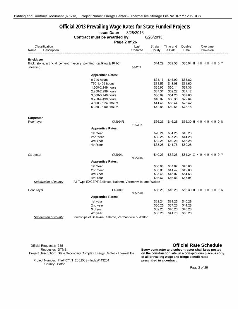
Bidding and Contract Document (R 2/13) Project Name: Energy Center – Thermal Ice Storage File No. 071/11205.DCS
Official 2013 Prevailing Wage Rates for State Funded Projects Issue Date: 3/28/2013 Contract must be awarded by: 6/26/2013 Page 2 of 26 Classification Last Straight Time and Double Overtime Name Description Updated Hourly a Half Time Provision ==============================================================================================================
Bricklayer Brick, stone, artificial, cement masonry, pointing, caulking & BR9-31 $44.22 $62.58 $80.94 H H H H H H H D Y cleaning 3/8/2013
Apprentice Rates: 0-749 hours $33.16 $45.99 $58.82 750-1,499 hours $34.55 $48.08 $61.60 1,500-2,249 hours $35.93 $50.14 $64.36 2,250-2,999 hours $37.31 $52.22 $67.12 3,000-3,749 hours $38.69 $54.28 $69.88 3,750-4,499 hours $40.07 $56.36 $72.64 4,500 - 5,249 hours $41.46 $58.44 $75.42 5,250 - 6,000 hours $42.84 $60.51 $78.18
Carpenter Floor layer CA1004FL $36.26 $46.28 $56.30 H H H H H H H D N 11/1/2012 Apprentice Rates: 1st Year $28.24 $34.25 $40.26 2nd Year $30.25 $37.26 $44.28 3rd Year $32.25 $40.26 $48.28 4th Year $33.25 $41.76 $50.28
Carpenter CA1004L $40.27 $52.26 $64.24 X X H H H H H D Y 10/25/2012 Apprentice Rates: 1st Year $30.68 $37.87 $45.06 2nd Year $33.08 $41.47 $49.86 3rd Year $35.48 $45.07 $54.66 4th Year $36.67 $46.86 $57.04 Subdivision of county All Twps EXCEPT Bellevue, Kalamo, Vermontville, and Walton
Floor Layer CA-100FL $36.26 $46.28 $56.30 H H H H H H H D N 10/24/2012 Apprentice Rates: 1st year $28.24 $34.25 $40.26 2nd year $30.25 $37.26 $44.28 3rd year $32.25 $40.26 $48.28 4th year $33.25 $41.76 $50.28 Subdivision of county townships of Bellevue, Kalamo, Vermontville & Walton
Official Request #: 355 Official Rate Schedule Requestor: DTMB Every contractor and subcontractor shall keep posted Project Description: State Secondary Complex Energy Center - Thermal Ice on the construction site, in a conspicuous place, a copy of all prevailing wage and fringe benefit rates Project Number: File# 071/11205.DCS - Index# 43204 prescribed in a contract. County: Eaton Page 2 of 26

Bidding and Contract Document (R 2/13) Project Name: Energy Center – Thermal Ice Storage File No. 071/11205.DCS
Official 2013 Prevailing Wage Rates for State Funded Projects Issue Date: 3/28/2013 Contract must be awarded by: 6/26/2013 Page 3 of 26 Classification Last Straight Time and Double Overtime Name Description Updated Hourly a Half Time Provision ============================================================================================================== Carpenter CA-525 $36.65 $46.60 $56.54 H H H H H H H D N 10/24/2012 Apprentice Rates: 1st year $28.69 $34.66 $40.62 2nd year $30.68 $37.64 $44.60 3rd year $32.67 $40.62 $48.58 4th year $33.67 $42.12 $50.58 Subdivision of county the townships of Bellevue, Kalamo, Vermontvile & Walton only
Cement Mason Cement Mason PL16-7 $37.52 $49.84 $62.16 H H H H H H H D Y 10/23/2012 Four 10s allowed Monday-Thursday with Friday or Saturday inclement weather make up days. Saturday hours for inclement weather make up shall be paid straight rate unless over 40 hours worked.
Apprentice Rates: 1st year $28.90 $36.91 $44.92 2nd year $31.36 $40.60 $49.84 3rd year $33.82 $44.29 $54.76
Drywall Drywall Taper and Finisher PT-845-DF $35.42 $47.42 $59.42 H H H H H H H D N 10/6/2009 Apprentice Rates: 0 - 1,000 hours $24.62 $31.22 $37.82 1,001 - 2,000 hours $25.82 $33.02 $40.22 2,001 to 3,000 hours $27.74 $35.90 $44.06 3,001 to 4,000 hours $29.42 $38.42 $47.42 4,001 to 5,000 hours $31.82 $42.02 $52.22 5,001 to 6,000 hours $34.22 $45.62 $57.02
Electrician Road Way Electrical Work EC-17 $49.55 $71.93 $94.30 H H H H H H H D Y Double time due after 16 hours on any calendar day and all 5/31/2012 hours Sunday.
Apprentice Rates: 1st 6 months $31.65 $45.07 $58.49 2nd 6 months $33.88 $48.42 $62.96 3rd 6 months $36.13 $51.79 $67.46 4th 6 months $38.35 $55.13 $71.90 5th 6 months $40.58 $58.47 $76.36 6th 6 months $45.06 $65.19 $85.32
Official Request #: 355 Official Rate Schedule Requestor: DTMB Every contractor and subcontractor shall keep posted Project Description: State Secondary Complex Energy Center - Thermal Ice on the construction site, in a conspicuous place, a copy of all prevailing wage and fringe benefit rates Project Number: File# 071/11205.DCS - Index# 43204 prescribed in a contract. County: Eaton Page 3 of 26

Bidding and Contract Document (R 2/13) Project Name: Energy Center – Thermal Ice Storage File No. 071/11205.DCS
Official 2013 Prevailing Wage Rates for State Funded Projects Issue Date: 3/28/2013 Contract must be awarded by: 6/26/2013 Page 4 of 26 Classification Last Straight Time and Double Overtime Name Description Updated Hourly a Half Time Provision ==============================================================================================================
Journeyman Wireman EC-445-IW $41.98 $56.87 $71.75 H H H H H H H D N 4/30/2008 Apprentice Rates: 0-1,000 hours $18.80 $25.37 $31.94 1,001-2,000 hours $20.27 $27.58 $34.88 2,001-2,750 hours $26.68 $34.86 $43.05 2,751-3,500 hours $28.16 $37.09 $46.01 3,501-4,250 hours $29.66 $39.33 $49.01 4,251-5,000 hours $31.15 $41.57 $51.99 5,001-5,750 hours $32.64 $43.81 $54.97 5,751-6,500 hours $34.12 $46.03 $57.93 6,501-7,250 hours $35.61 $48.26 $60.91 7,251-8,000 hours $37.11 $50.51 $63.91 Subdivision of county Townships of Sunfield, Vermontville, Kalamo, Bellevue, Walton, and Brookfield ONLY.
Sound & Communication Technician EC-445-SC $22.66 $30.76 $38.86 H H H H H H H D N 3/6/2007 Apprentice Rates: 1st 6 months $10.16 $14.42 $18.66 2nd 6 months $10.93 $15.57 $20.20 3rd 6 months $11.70 $16.72 $21.74 4th 6 months $12.48 $17.89 $23.30 5th 6 months $13.25 $19.05 $24.84 6th 6 months $14.02 $20.20 $26.38 Subdivision of county Townships of Sunfield, Vermontville, Kalamo, Bellevue, Walton and Brookfield ONLY.
Inside Wireman EC-665-IW $49.29 $65.30 $81.30 H H D H H H D D Y 11/3/2011 A four day schedule of ten hours a day is allowed Monday thru Friday.
Apprentice Rates: 0-1000 hours $28.28 $36.29 $44.28 1000-2000 hours $29.88 $38.67 $47.48 2000-3500 hours $31.49 $41.09 $50.69 3500-5000 hours $34.74 $45.14 $55.54 5000-6500 hours $36.35 $47.55 $58.75 6500-8000 hours $37.95 $49.95 $61.94 Subdivision of county Roxand, Oneida, Delta, Chester, Benton, Windsor, Carmel, Eaton, Eaton Rapids & Hamlin townships
Official Request #: 355 Official Rate Schedule Requestor: DTMB Every contractor and subcontractor shall keep posted Project Description: State Secondary Complex Energy Center - Thermal Ice on the construction site, in a conspicuous place, a copy of all prevailing wage and fringe benefit rates Project Number: File# 071/11205.DCS - Index# 43204 prescribed in a contract. County: Eaton Page 4 of 26

Bidding and Contract Document (R 2/13) Project Name: Energy Center – Thermal Ice Storage File No. 071/11205.DCS
Official 2013 Prevailing Wage Rates for State Funded Projects Issue Date: 3/28/2013 Contract must be awarded by: 6/26/2013 Page 5 of 26 Classification Last Straight Time and Double Overtime Name Description Updated Hourly a Half Time Provision ============================================================================================================== Sound and Communication Journeyman EC-665-SD $38.01 $49.97 $61.93 H H D H H H D D Y A four day schedule of ten hours a day is allowed Monday 11/3/2011 thru Friday.
Apprentice Rates: 1st period $22.25 $28.44 $34.66 2nd period $23.83 $30.66 $37.48 3rd period $25.40 $32.85 $40.30 4th period $26.97 $35.05 $43.11 5th period $28.56 $37.25 $45.95 6th period $30.12 $39.44 $48.75 Subdivision of county Roxand, Oneida, Delta, Chester, Benton, Windsor, Carmel, Eaton, Eaton Rapids and Hamlin townships
Lineman/Technician outside utility and commercial power EC-876 $47.05 $68.11 $89.17 H H H H H H H D Y and high voltage pipe type cable work and electrical 11/18/2009 underground. Four 10s allowed Monday-Thursday with Friday makeup or Tuesday-Friday with Monday makeup.
Apprentice Rates: 1st period $30.20 $42.69 $55.26 2nd period $32.32 $46.02 $59.70 3rd period $34.42 $49.16 $63.90 4th period $36.53 $52.33 $68.12 5th period $38.63 $55.47 $72.32 6th period $40.74 $58.64 $76.54 7th period $42.84 $61.79 $80.74
Elevator Constructor Elevator Constructor Mechanic EL-85 $65.80 $109.78 D D D D D D D D Y 1/12/2011 Apprentice Rates: 1st year $46.01 $70.20 2nd year $50.41 $79.00 3rd year $52.61 $83.40 4th year $57.00 $92.18
Official Request #: 355 Official Rate Schedule Requestor: DTMB Every contractor and subcontractor shall keep posted Project Description: State Secondary Complex Energy Center - Thermal Ice on the construction site, in a conspicuous place, a copy of all prevailing wage and fringe benefit rates Project Number: File# 071/11205.DCS - Index# 43204 prescribed in a contract. County: Eaton Page 5 of 26

Bidding and Contract Document (R 2/13) Project Name: Energy Center – Thermal Ice Storage File No. 071/11205.DCS
Official 2013 Prevailing Wage Rates for State Funded Projects Issue Date: 3/28/2013 Contract must be awarded by: 6/26/2013 Page 6 of 26 Classification Last Straight Time and Double Overtime Name Description Updated Hourly a Half Time Provision ==============================================================================================================
Glazier Glazier GL-826 $41.62 $55.84 $70.05 H H H H D D D D Y 2/18/2011 Apprentice Rates: 1st 6 months $30.25 $38.78 $47.31 2nd 6 months $31.67 $40.91 $50.15 3rd 6 months $33.09 $43.04 $52.99 4th 6 months $34.51 $45.17 $55.83 5th 6 months $35.93 $47.30 $58.67 6th 6 months $37.36 $49.45 $61.53 7th 6 months $38.78 $51.57 $64.37 8th 6 months $40.20 $53.71 $67.21
Heat and Frost Insulator Spray Insulation AS25S $20.14 $29.14 H H H H H H H H N 3/5/2007
Heat and Frost Insulator and Asbestos Worker Heat and Frost Insulator and Asbestos Worker AS47 $44.40 $58.76 $73.12 H H H H H H H D Y 4 ten hour work days shall be either Monday thru Thursday 3/11/2013 or Tuesday thru Friday
Apprentice Rates: 1st year $25.78 $32.96 $40.14 2nd year $29.50 $38.11 $46.73 3rd year $33.22 $43.27 $53.32 4th year $36.95 $48.44 $59.93 5th year $40.68 $53.61 $66.53
Ironworker Pre-engineered Metal Work IR-25-PE-Z2 $42.37 $51.88 $61.39 X X H X X X X D Y 5/9/2012 Apprentice Rates: 1st Year $24.56 $30.05 $35.53 3rd 6 month period $26.68 $32.91 $39.15 4th 6 month period $28.81 $35.80 $42.80 5th 6 month period $30.93 $38.68 $46.42 6th 6 month period $33.06 $41.56 $50.06
Official Request #: 355 Official Rate Schedule Requestor: DTMB Every contractor and subcontractor shall keep posted Project Description: State Secondary Complex Energy Center - Thermal Ice on the construction site, in a conspicuous place, a copy of all prevailing wage and fringe benefit rates Project Number: File# 071/11205.DCS - Index# 43204 prescribed in a contract. County: Eaton Page 6 of 26
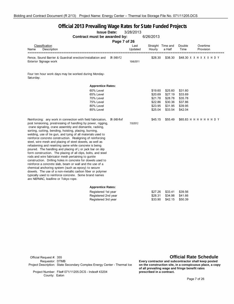
Bidding and Contract Document (R 2/13) Project Name: Energy Center – Thermal Ice Storage File No. 071/11205.DCS
Official 2013 Prevailing Wage Rates for State Funded Projects Issue Date: 3/28/2013 Contract must be awarded by: 6/26/2013 Page 7 of 26 Classification Last Straight Time and Double Overtime Name Description Updated Hourly a Half Time Provision ============================================================================================================== Fence, Sound Barrier & Guardrail erection/installation and IR-340-F2 $28.30 $38.30 $48.30 X X H X X X H D Y Exterior Signage work 10/6/2011 Four ten hour work days may be worked during Monday- Saturday.
Apprentice Rates: 60% Level $19.60 $25.60 $31.60 65% Level $20.69 $27.19 $33.69 70% Level $21.78 $28.78 $35.78 75% Level $22.86 $30.36 $37.86 80% Level $23.95 $31.95 $39.95 85% Level $25.04 $33.54 $42.04
Reinforcing: any work in connection with field fabrication, IR-340-Ref $45.15 $55.49 $65.83 H H H H H H H D Y post tensioning, prestressing of handling by power, rigging, 7/3/2012 crane signaling, crane assembly and dismantle, racking, sorting, cutting, bending, hoisting, placing, burning, welding, use of tie gun, and tying of all materials used to reinforce concrete construction. Realigning of reinforcing steel, wire mesh and placing of steel dowels, as well as refastening and resetting same while concrete is being poured. The handling and placing of j or jack bar on slip form construction. The placing of all clips, bolts, and steel rods and wire fabricator mesh pertaining to gunite construction. Drilling holes in concrete for dowels used to reinforce a concrete slab, beam or wall and the use of a chemical anchoring system (such as epoxy) to secure dowels. The use of a non-metallic carbon fiber or polymer typically used to reinforce concrete. Some brand names are NEFMAC, leadline or Tokyo rope.
Apprentice Rates: Registered 1st year $27.26 $33.41 $39.56 Registered 2nd year $28.31 $34.98 $41.66 Registered 3rd year $33.90 $42.15 $50.39
Official Request #: 355 Official Rate Schedule Requestor: DTMB Every contractor and subcontractor shall keep posted Project Description: State Secondary Complex Energy Center - Thermal Ice on the construction site, in a conspicuous place, a copy of all prevailing wage and fringe benefit rates Project Number: File# 071/11205.DCS - Index# 43204 prescribed in a contract. County: Eaton Page 7 of 26
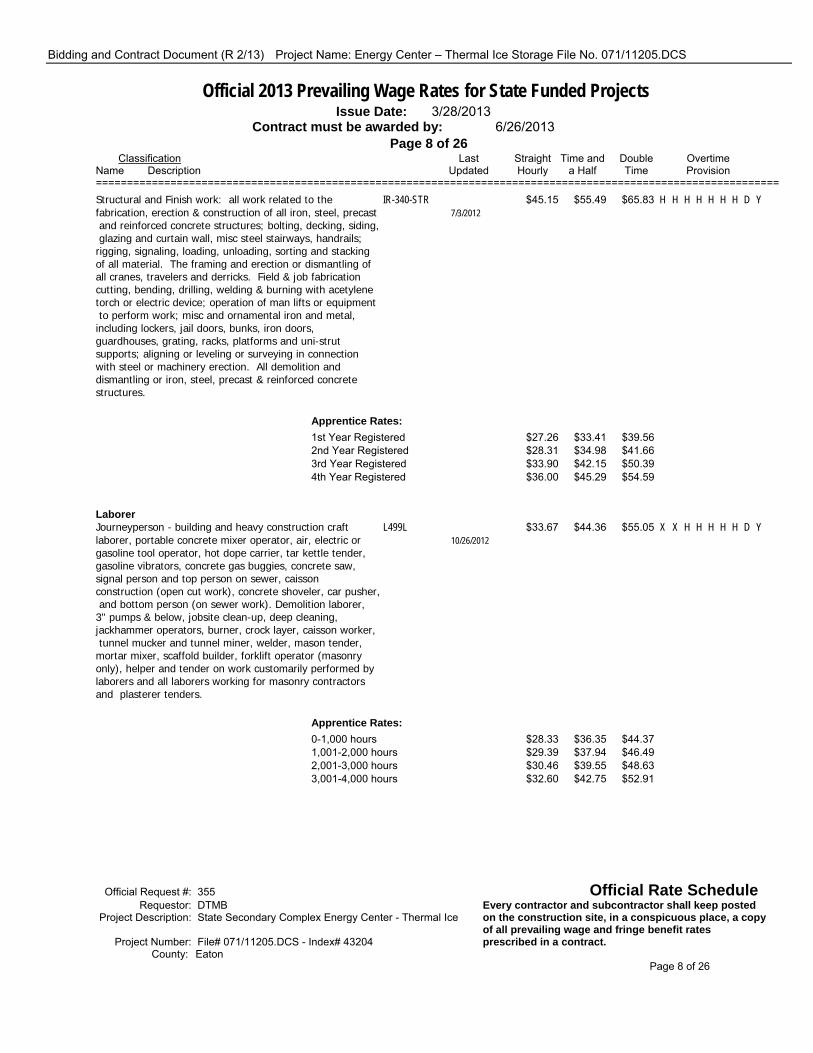
Bidding and Contract Document (R 2/13) Project Name: Energy Center – Thermal Ice Storage File No. 071/11205.DCS
Official 2013 Prevailing Wage Rates for State Funded Projects Issue Date: 3/28/2013 Contract must be awarded by: 6/26/2013 Page 8 of 26 Classification Last Straight Time and Double Overtime Name Description Updated Hourly a Half Time Provision ============================================================================================================== Structural and Finish work: all work related to the IR-340-STR $45.15 $55.49 $65.83 H H H H H H H D Y fabrication, erection & construction of all iron, steel, precast 7/3/2012 and reinforced concrete structures; bolting, decking, siding, glazing and curtain wall, misc steel stairways, handrails; rigging, signaling, loading, unloading, sorting and stacking of all material. The framing and erection or dismantling of all cranes, travelers and derricks. Field & job fabrication cutting, bending, drilling, welding & burning with acetylene torch or electric device; operation of man lifts or equipment to perform work; misc and ornamental iron and metal, including lockers, jail doors, bunks, iron doors, guardhouses, grating, racks, platforms and uni-strut supports; aligning or leveling or surveying in connection with steel or machinery erection. All demolition and dismantling or iron, steel, precast & reinforced concrete structures.
Apprentice Rates: 1st Year Registered $27.26 $33.41 $39.56 2nd Year Registered $28.31 $34.98 $41.66 3rd Year Registered $33.90 $42.15 $50.39 4th Year Registered $36.00 $45.29 $54.59
Laborer Journeyperson - building and heavy construction craft L499L $33.67 $44.36 $55.05 X X H H H H H D Y laborer, portable concrete mixer operator, air, electric or 10/26/2012 gasoline tool operator, hot dope carrier, tar kettle tender, gasoline vibrators, concrete gas buggies, concrete saw, signal person and top person on sewer, caisson construction (open cut work), concrete shoveler, car pusher, and bottom person (on sewer work). Demolition laborer, 3" pumps & below, jobsite clean-up, deep cleaning, jackhammer operators, burner, crock layer, caisson worker, tunnel mucker and tunnel miner, welder, mason tender, mortar mixer, scaffold builder, forklift operator (masonry only), helper and tender on work customarily performed by laborers and all laborers working for masonry contractors and plasterer tenders.
Apprentice Rates: 0-1,000 hours $28.33 $36.35 $44.37 1,001-2,000 hours $29.39 $37.94 $46.49 2,001-3,000 hours $30.46 $39.55 $48.63 3,001-4,000 hours $32.60 $42.75 $52.91
Official Request #: 355 Official Rate Schedule Requestor: DTMB Every contractor and subcontractor shall keep posted Project Description: State Secondary Complex Energy Center - Thermal Ice on the construction site, in a conspicuous place, a copy of all prevailing wage and fringe benefit rates Project Number: File# 071/11205.DCS - Index# 43204 prescribed in a contract. County: Eaton Page 8 of 26

Bidding and Contract Document (R 2/13) Project Name: Energy Center – Thermal Ice Storage File No. 071/11205.DCS
Official 2013 Prevailing Wage Rates for State Funded Projects Issue Date: 3/28/2013 Contract must be awarded by: 6/26/2013 Page 9 of 26 Classification Last Straight Time and Double Overtime Name Description Updated Hourly a Half Time Provision ==============================================================================================================
Laborer - Hazardous Class A Laborer - performing work in conjunction with site LHAZ-Z6-A $33.50 $47.32 $61.13 H H H H H H H D Y preparation and other preliminary work prior to actual 3/6/2013 removal, handling, or containment of hazardous waste substances not requiring use of personal protective equipment required by state or federal regulations; or a laborer performing work in conjunction with the removal, handling, or containment of hazardous waste substances when use of personal protective equipment level "D" is required.
Apprentice Rates: 0-1,000 work hours $28.66 $40.06 $51.45 1,001-2,000 work hours $29.62 $41.50 $53.37 2,001-3,000 work hours $30.59 $42.95 $55.31 3,001-4,000 work hours $32.53 $45.87 $59.19
Class B Laborer - performing work in conjunction with the LHAZ-Z6-B $34.50 $48.82 $63.13 H H H H H H H D Y removal, handling, or containment of hazardous waste 3/6/2013 substances when the use of personal protective equipment levels "A", "B" or "C" is required.
Apprentice Rates: 0-1,000 work hours $29.40 $41.17 $52.93 1,001-2,000 work hours $30.42 $42.70 $54.97 2,001-3,000 work hours $31.44 $44.23 $57.01 3,001-4,000 work hours $33.48 $47.29 $61.09
Laborer Underground - Tunnel, Shaft & Caisson Class I - Tunnel, shaft and caisson laborer, dump man, LAUCT-Z2-1 $34.72 $45.94 $57.15 H H H H H H H D Y shanty man, hog house tender, testing man (on gas), and 1/16/2013 watchman.
Apprentice Rates: 0-1,000 work hours $29.61 $38.27 $46.93 1,001-2,000 work hours $30.63 $39.80 $48.97 2,001-3,000 work hours $31.66 $41.35 $51.03 3,001-4,000 work hours $33.70 $44.41 $55.11
Official Request #: 355 Official Rate Schedule Requestor: DTMB Every contractor and subcontractor shall keep posted Project Description: State Secondary Complex Energy Center - Thermal Ice on the construction site, in a conspicuous place, a copy of all prevailing wage and fringe benefit rates Project Number: File# 071/11205.DCS - Index# 43204 prescribed in a contract. County: Eaton Page 9 of 26

Bidding and Contract Document (R 2/13) Project Name: Energy Center – Thermal Ice Storage File No. 071/11205.DCS
Official 2013 Prevailing Wage Rates for State Funded Projects Issue Date: 3/28/2013 Contract must be awarded by: 6/26/2013 Page 10 of 26 Classification Last Straight Time and Double Overtime Name Description Updated Hourly a Half Time Provision ============================================================================================================== Class II - Manhole, headwall, catch basin builder, bricklayer LAUCT-Z2-2 $34.81 $46.07 $57.33 H H H H H H H D Y tender, mortar man, material mixer, fence erector, and 1/16/2013 guard rail builder
Apprentice Rates: 0-1,000 work hours $29.68 $38.37 $47.07 1,001-2,000 work hours $30.71 $39.92 $49.13 2,001-3,000 work hours $31.73 $41.45 $51.17 3,001-4,000 work hours $33.78 $44.53 $55.27
Class III - Air tool operator (jack hammer man, bush LAUCT-Z2-3 $34.91 $46.22 $57.53 H H H H H H H D Y hammer man and grinding man), first bottom man, second 1/16/2013 bottom man, cage tender, car pusher, carrier man, concrete man, concrete form man, concrete repair man, cement invert laborer, cement finisher, concrete shoveler, conveyor man, floor man, gasoline and electric tool operator, gunnite man, grout operator, welder, heading dinky man, inside lock tender, pea gravel operator, pump man, outside lock tender, scaffold man, top signal man, switch man, track man, tugger man, utility man, vibrator man, winch operator, pipe jacking man, wagon drill and air track operator and concrete saw operator (under 40 h.p.).
Apprentice Rates: 0-1,000 work hours $29.75 $38.48 $47.21 1,001-2,000 work hours $30.79 $40.04 $49.29 2,001-3,000 work hours $31.82 $41.59 $51.35 3,001-4,000 work hours $33.88 $44.67 $55.47
Class IV - Tunnel, shaft and caisson mucker, bracer man, LAUCT-Z2-4 $35.07 $46.46 $57.85 H H H H H H H D Y liner plate man, long haul dinky driver and well point man. 1/16/2013
Apprentice Rates: 0-1,000 work hours $29.87 $38.66 $47.45 1,001-2,000 work hours $30.91 $40.22 $49.53 2,001-3,000 work hours $31.95 $41.78 $51.61 3,001-4,000 work hours $34.03 $44.90 $55.77
Class V - Tunnel, shaft and caisson miner, drill runner, LAUCT-Z2-5 $35.33 $46.85 $58.37 H H H H H H H D Y keyboard operator, power knife operator, reinforced steel 1/16/2013 or mesh man (e.g. wire mesh, steel mats, dowel bars)
Apprentice Rates: 0-1,000 work hours $30.07 $38.96 $47.85 1,001-2,000 work hours $31.12 $40.53 $49.95 2,001-3,000 work hours $32.17 $42.11 $52.05 3,001-4,000 work hours $34.28 $45.27 $56.27 Official Request #: 355 Official Rate Schedule Requestor: DTMB Every contractor and subcontractor shall keep posted Project Description: State Secondary Complex Energy Center - Thermal Ice on the construction site, in a conspicuous place, a copy of all prevailing wage and fringe benefit rates Project Number: File# 071/11205.DCS - Index# 43204 prescribed in a contract. County: Eaton Page 10 of 26
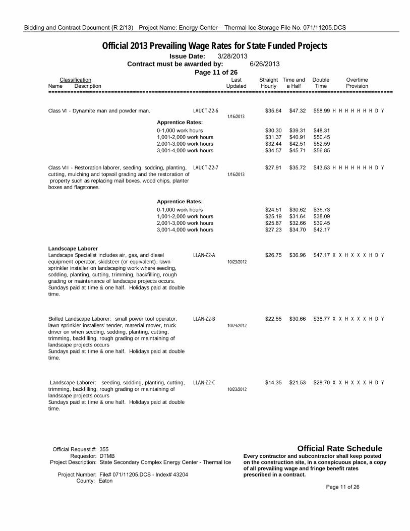
Bidding and Contract Document (R 2/13) Project Name: Energy Center – Thermal Ice Storage File No. 071/11205.DCS
Official 2013 Prevailing Wage Rates for State Funded Projects Issue Date: 3/28/2013 Contract must be awarded by: 6/26/2013 Page 11 of 26 Classification Last Straight Time and Double Overtime Name Description Updated Hourly a Half Time Provision ==============================================================================================================
Class VI - Dynamite man and powder man. LAUCT-Z2-6 $35.64 $47.32 $58.99 H H H H H H H D Y 1/16/2013 Apprentice Rates: 0-1,000 work hours $30.30 $39.31 $48.31 1,001-2,000 work hours $31.37 $40.91 $50.45 2,001-3,000 work hours $32.44 $42.51 $52.59 3,001-4,000 work hours $34.57 $45.71 $56.85
Class VII - Restoration laborer, seeding, sodding, planting, LAUCT-Z2-7 $27.91 $35.72 $43.53 H H H H H H H D Y cutting, mulching and topsoil grading and the restoration of 1/16/2013 property such as replacing mail boxes, wood chips, planter boxes and flagstones.
Apprentice Rates: 0-1,000 work hours $24.51 $30.62 $36.73 1,001-2,000 work hours $25.19 $31.64 $38.09 2,001-3,000 work hours $25.87 $32.66 $39.45 3,001-4,000 work hours $27.23 $34.70 $42.17
Landscape Laborer Landscape Specialist includes air, gas, and diesel LLAN-Z2-A $26.75 $36.96 $47.17 X X H X X X H D Y equipment operator, skidsteer (or equivalent), lawn 10/23/2012 sprinkler installer on landscaping work where seeding, sodding, planting, cutting, trimming, backfilling, rough grading or maintenance of landscape projects occurs. Sundays paid at time & one half. Holidays paid at double time.
Skilled Landscape Laborer: small power tool operator, LLAN-Z2-B $22.55 $30.66 $38.77 X X H X X X H D Y lawn sprinkler installers' tender, material mover, truck 10/23/2012 driver on when seeding, sodding, planting, cutting, trimming, backfilling, rough grading or maintaining of landscape projects occurs Sundays paid at time & one half. Holidays paid at double time.
Landscape Laborer: seeding, sodding, planting, cutting, LLAN-Z2-C $14.35 $21.53 $28.70 X X H X X X H D Y trimming, backfilling, rough grading or maintaining of 10/23/2012 landscape projects occurs Sundays paid at time & one half. Holidays paid at double time.
Official Request #: 355 Official Rate Schedule Requestor: DTMB Every contractor and subcontractor shall keep posted Project Description: State Secondary Complex Energy Center - Thermal Ice on the construction site, in a conspicuous place, a copy of all prevailing wage and fringe benefit rates Project Number: File# 071/11205.DCS - Index# 43204 prescribed in a contract. County: Eaton Page 11 of 26

Bidding and Contract Document (R 2/13) Project Name: Energy Center – Thermal Ice Storage File No. 071/11205.DCS
Official 2013 Prevailing Wage Rates for State Funded Projects Issue Date: 3/28/2013 Contract must be awarded by: 6/26/2013 Page 12 of 26 Classification Last Straight Time and Double Overtime Name Description Updated Hourly a Half Time Provision ==============================================================================================================
Operating Engineer Class C- Regular equipment operator, crane, stiff leg EN-324-BH2C $47.95 $61.77 $75.59 H H H H H H H D Y derrick, scraper dozer, grader, front end loader, hoist, job 10/23/2012 mechanic, head grease man, concrete pump truck and hydro excavators Four 10 hour days may be scheduled Monday-Thursday or Tuesday-Friday. Work not performed due to weather, Monday-Thursday may be scheduled on Friday.
Apprentice Rates: 0 - 999 hours $39.06 $48.73 $58.41 1,000 - 1,999 hours $40.44 $50.81 $61.17 2,000 - 2,999 hours $41.82 $52.87 $63.93 3,000 - 3,999 hours $43.20 $54.95 $66.69 4,000 - 4,999 hours $44.59 $57.03 $69.47 5,000 - 5,999 hours $45.97 $59.10 $72.23
Class D- Air tugger (single drum), material hoist, boiler EN-324-BH2D $43.15 $54.57 $65.99 H H H H H H H D Y operator, sweeping machine, winch truck, Bob Cat and 10/23/2012 similar equipment, elevators (when operated by an operating engineer), and fork truck over 20' lift Four 10 hour days may be scheduled Monday-Thursday or Tuesday-Friday. Work not performed due to weather, Monday-Thursday may be scheduled on Friday.
Class E- Pump 6" or over, well points, freeze systems, boom EN-324-BH2E $42.55 $53.67 $64.79 H H H H H H H D Y truck (non-swinging), end dumps and laser/power screed, 10/23/2012 concrete wire saw 20 h.p. and over and brokk concrete breaker Four 10 hour days may be scheduled Monday-Thursday or Tuesday-Friday. Work not performed due to weather, Monday-Thursday may be scheduled on Friday.
Class F- Air compressor, welder, generators, conveyors, EN-324-BH2F $40.10 $50.00 $59.89 H H H H H H H D Y pumps under 6", Grease man, and fork truck 20' or less lift 10/23/2012 Four 10 hour days may be scheduled Monday-Thursday or Tuesday-Friday. Work not performed due to weather,
Official Request #: 355 Official Rate Schedule Requestor: DTMB Every contractor and subcontractor shall keep posted Project Description: State Secondary Complex Energy Center - Thermal Ice on the construction site, in a conspicuous place, a copy of all prevailing wage and fringe benefit rates Project Number: File# 071/11205.DCS - Index# 43204 prescribed in a contract. County: Eaton Page 12 of 26

Bidding and Contract Document (R 2/13) Project Name: Energy Center – Thermal Ice Storage File No. 071/11205.DCS
Official 2013 Prevailing Wage Rates for State Funded Projects Issue Date: 3/28/2013 Contract must be awarded by: 6/26/2013 Page 13 of 26 Classification Last Straight Time and Double Overtime Name Description Updated Hourly a Half Time Provision ============================================================================================================== Class G- Oiler, fireman and heater operator EN-324-BH2G $38.40 $47.45 $56.49 H H H H H H H D Y 10/23/2012 Four 10 hour days may be scheduled Monday-Thursday or Tuesday-Friday. Work not performed due to weather, Monday-Thursday may be scheduled on Friday.
Class A- Crane w/ main Boom & Jib 220' or longer EN-OSA $49.30 $63.80 $78.29 H H H H H H H D Y 10/23/2012 Four 10 hour days may be scheduled Monday-Thursday or Tuesday-Friday. Work unabled to be performed due to weather, Monday-Thursday may be scheduled on Friday.
Class A- Crane w/ main Boom & Jib 300' or longer EN-OSA3 $50.80 $66.05 $81.29 H H H H H H H D Y 10/23/2012 Four 10 hour days may be scheduled Monday-Thursday or Tuesday-Friday. Work unabled to be performed due to weather, Monday-Thursday may be scheduled on Friday.
Class A- Crane w/ main Boom & Jib 400' or longer EN-OSA4 $52.30 $68.30 $84.29 H H H H H H H D Y 10/23/2012 Four 10 hour days may be scheduled Monday-Thursday or Tuesday-Friday. Work not performed due to weather, Monday-Thursday may be scheduled on Friday.
Class B- Crane Operator with main boom and jib 140' or EN-OSB $49.05 $63.42 $77.79 H H H H H H H D Y longer, tower cranes, gantry crane, whirley derrick 10/23/2012 Four 10 hour days may be scheduled Monday-Thursday or Tuesday-Friday. Work unabled to be performed due to weather, Monday-Thursday may be scheduled on Friday.
Operating Engineer - Marine Construction Diver/Wet Tender, Engineer (hydraulic dredge) GLF-1 $63.00 $82.35 $101.70 X X H H H H H D Y 3/1/2013 Holiday pay= $121.05 per hour, wages & fringes
Subdivision of county all Great Lakes, islands therein, & connecting & tributary waters
Crane/Backhoe Operator, 70 ton or over Tug Operator, GLF-2 $61.50 $80.10 $98.70 X X H H H H H D Y Mechanic/Welder, Assistant Engineer (hydraulic dredge), 3/1/2013 Leverman (hydraulic dredge), Diver Tender Holiday pay = $117.30 per hour, wages & fringes Official Request #: 355 Official Rate Schedule Requestor: DTMB Every contractor and subcontractor shall keep posted Project Description: State Secondary Complex Energy Center - Thermal Ice on the construction site, in a conspicuous place, a copy of all prevailing wage and fringe benefit rates Project Number: File# 071/11205.DCS - Index# 43204 prescribed in a contract. County: Statewide Page 13 of 26

Bidding and Contract Document (R 2/13) Project Name: Energy Center – Thermal Ice Storage File No. 071/11205.DCS
Official 2013 Prevailing Wage Rates for State Funded Projects Issue Date: 3/28/2013 Contract must be awarded by: 6/26/2013 Page 14 of 26 Classification Last Straight Time and Double Overtime Name Description Updated Hourly a Half Time Provision ============================================================================================================== Subdivision of county All Great Lakes, islands therein, & connecting & tributary waters
Friction, Lattice Boom or Crane License Certification GLF-2B $62.50 $81.60 $100.70 X X H H H H H D Y 3/1/2013 Holiday pay = $119.80
Subdivision of county All Great Lakes, islands, therein, & connecting & tributary waters
Deck Equipment Operator, Machineryman, Maintenance of GLF-3 $57.40 $73.95 $90.50 X X H H H H H D Y Crane (over 50 ton capacity) or Backhoe (115,000 lbs or 3/1/2013 more), Tug/Launch Operator, Loader, Dozer on Barge, Deck Machinery Holiday pay = $107.05 per hour, wages & fringes
Subdivision of county All Great Lakes, islands therein, & connecting & tributary waters
Deck Equipment Operator, (Machineryman/Fireman), (4 GLF-4 $51.85 $65.63 $79.40 X X H H H H H D Y equipment units or more), Off Road Trucks, Deck Hand, Tug 3/1/2013 Engineer, & Crane Maintenance 50 ton capacity and under or Backhoe 115,000 lbs or less, Assistant Tug Operator Holiday pay = $93.17 per hour, wages & fringes
Subdivision of county All Great Lakes, islands therein, & connecting & tributary waters
Operating Engineer Hazardous Waste Class I Level A - Fully encapsulating chemical resistant suit w/ EN-324-HWCI-Z2A $50.13 $65.29 $80.45 H H H H H H H D Y pressure demand, full face piece SCBA or pressure demand 1/20/2012 supplied air respirator w/ escape SCBA. The highest available level of respiratory, skin and eye protection. Four 10 hour days may be worked Monday-Thursday with Friday as a straight-time make up day.
Apprentice Rates: 1st 6 months $40.44 $51.06 $61.67 2nd 6 months $41.96 $53.34 $64.71 3rd 6 months $43.48 $55.62 $67.75 4th 6 months $44.98 $57.87 $70.75 5th 6 months $46.50 $60.15 $73.79 6th 6 months $48.02 $62.43 $76.83
Official Request #: 355 Official Rate Schedule Requestor: DTMB Every contractor and subcontractor shall keep posted Project Description: State Secondary Complex Energy Center - Thermal Ice on the construction site, in a conspicuous place, a copy of all prevailing wage and fringe benefit rates Project Number: File# 071/11205.DCS - Index# 43204 prescribed in a contract. County: Eaton Page 14 of 26
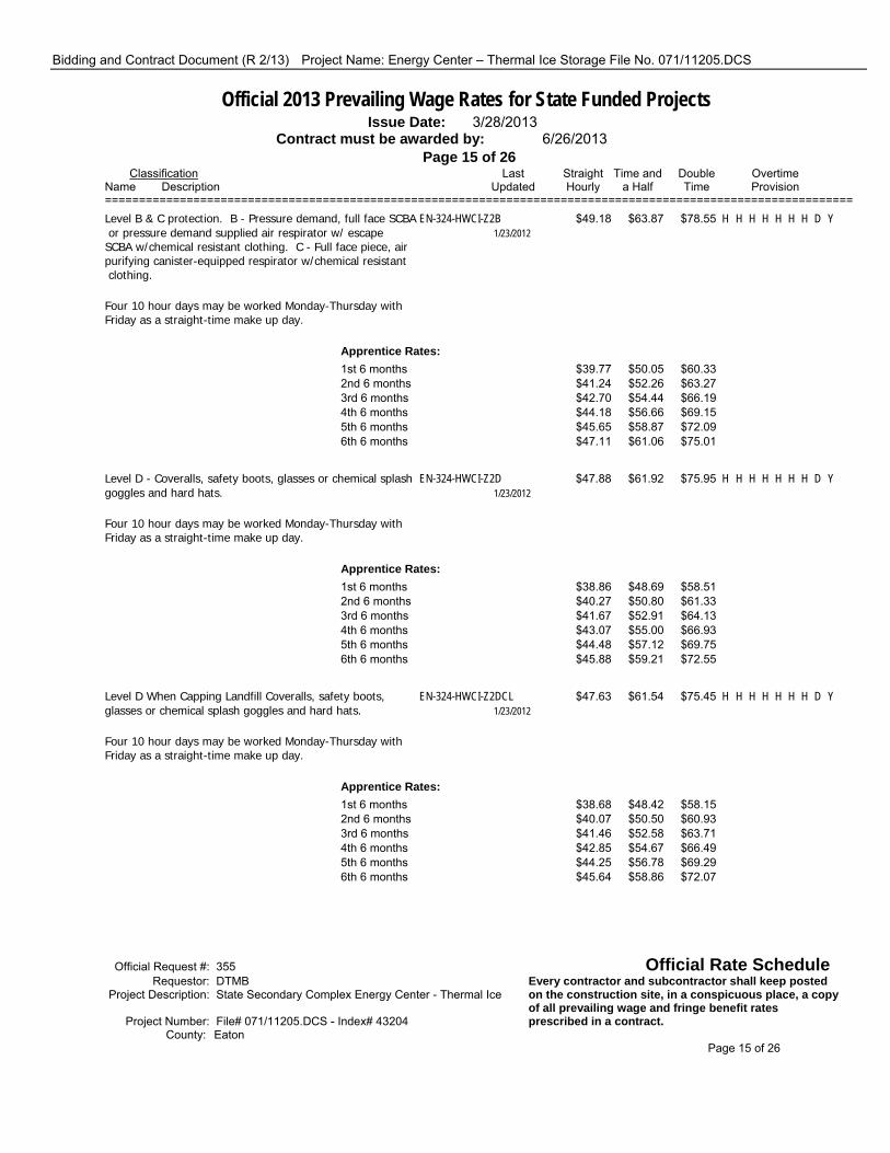
Bidding and Contract Document (R 2/13) Project Name: Energy Center – Thermal Ice Storage File No. 071/11205.DCS
Official 2013 Prevailing Wage Rates for State Funded Projects Issue Date: 3/28/2013 Contract must be awarded by: 6/26/2013 Page 15 of 26 Classification Last Straight Time and Double Overtime Name Description Updated Hourly a Half Time Provision ============================================================================================================== Level B & C protection. B - Pressure demand, full face SCBA EN-324-HWCI-Z2B $49.18 $63.87 $78.55 H H H H H H H D Y or pressure demand supplied air respirator w/ escape 1/23/2012 SCBA w/chemical resistant clothing. C - Full face piece, air purifying canister-equipped respirator w/chemical resistant clothing. Four 10 hour days may be worked Monday-Thursday with Friday as a straight-time make up day.
Apprentice Rates: 1st 6 months $39.77 $50.05 $60.33 2nd 6 months $41.24 $52.26 $63.27 3rd 6 months $42.70 $54.44 $66.19 4th 6 months $44.18 $56.66 $69.15 5th 6 months $45.65 $58.87 $72.09 6th 6 months $47.11 $61.06 $75.01
Level D - Coveralls, safety boots, glasses or chemical splash EN-324-HWCI-Z2D $47.88 $61.92 $75.95 H H H H H H H D Y goggles and hard hats. 1/23/2012 Four 10 hour days may be worked Monday-Thursday with Friday as a straight-time make up day.
Apprentice Rates: 1st 6 months $38.86 $48.69 $58.51 2nd 6 months $40.27 $50.80 $61.33 3rd 6 months $41.67 $52.91 $64.13 4th 6 months $43.07 $55.00 $66.93 5th 6 months $44.48 $57.12 $69.75 6th 6 months $45.88 $59.21 $72.55
Level D When Capping Landfill Coveralls, safety boots, EN-324-HWCI-Z2DCL $47.63 $61.54 $75.45 H H H H H H H D Y glasses or chemical splash goggles and hard hats. 1/23/2012 Four 10 hour days may be worked Monday-Thursday with Friday as a straight-time make up day.
Apprentice Rates: 1st 6 months $38.68 $48.42 $58.15 2nd 6 months $40.07 $50.50 $60.93 3rd 6 months $41.46 $52.58 $63.71 4th 6 months $42.85 $54.67 $66.49 5th 6 months $44.25 $56.78 $69.29 6th 6 months $45.64 $58.86 $72.07
Official Request #: 355 Official Rate Schedule Requestor: DTMB Every contractor and subcontractor shall keep posted Project Description: State Secondary Complex Energy Center - Thermal Ice on the construction site, in a conspicuous place, a copy of all prevailing wage and fringe benefit rates Project Number: File# 071/11205.DCS - Index# 43204 prescribed in a contract. County: Eaton Page 15 of 26

Bidding and Contract Document (R 2/13) Project Name: Energy Center – Thermal Ice Storage File No. 071/11205.DCS
Official 2013 Prevailing Wage Rates for State Funded Projects Issue Date: 3/28/2013 Contract must be awarded by: 6/26/2013 Page 16 of 26 Classification Last Straight Time and Double Overtime Name Description Updated Hourly a Half Time Provision ==============================================================================================================
Operating Engineer Hazardous Waste Class II Level A - Fully encapsulating chemical resistant suit w/ EN-324-HWCII-Z2A $45.73 $58.69 $71.65 H H H H H H H D Y pressure demand, full face piece SCBA or pressure demand 1/20/2012 supplied air respirator w/ escape SCBA. The highest available level of respiratory, skin and eye protection. Four 10 hour days may be worked Monday-Thursday with Friday as a straight-time make up day.
Level B & C protection. B - Pressure demand, full face SCBA EN-324-HWCII-Z2B $44.79 $57.28 $69.77 H H H H H H H D Y or pressure demand supplied air respirator w/ escape 1/23/2012 SCBA w/chemical resistant clothing. C - Full face piece, air purifying canister-equipped respirator w/chemical resistant clothing. Four 10 hour days may be worked Monday-Thursday with Friday as a straight-time make up day.
Level D - Coveralls, safety boots, glasses or chemical splash EN-324-HWCII-Z2D $43.49 $55.33 $67.17 H H H H H H H D Y goggles and hard hats. 1/23/2012 Four 10 hour days may be worked Monday-Thursday with Friday as a straight-time make up day.
Level D When Capping Landfill Coveralls, safety boots, EN-324-HWCII-Z2DCL $43.24 $54.96 $66.67 H H H H H H H D Y glasses or chemical splash goggles and hard hats. 1/23/2012 Four 10 hour days may be worked Monday-Thursday with Friday as a straight-time make up day.
Operating Engineer Hazardous Waste Crane w/ Boom & Jib leads 140' or longer Level A - Fully encapsulating chemical resistant suit w/ EN-324-HW140-Z2A $52.78 $69.27 $85.75 H H H H H H H D Y pressure demand, full face piece SCBA or pressure demand 1/20/2012 supplied air respirator w/ escape SCBA. The highest available level of respiratory, skin and eye protection. Four 10 hour days may be worked Monday-Thursday with Friday as a straight-time make up day.
Official Request #: 355 Official Rate Schedule Requestor: DTMB Every contractor and subcontractor shall keep posted Project Description: State Secondary Complex Energy Center - Thermal Ice on the construction site, in a conspicuous place, a copy of all prevailing wage and fringe benefit rates Project Number: File# 071/11205.DCS - Index# 43204 prescribed in a contract. County: Eaton Page 16 of 26

Bidding and Contract Document (R 2/13) Project Name: Energy Center – Thermal Ice Storage File No. 071/11205.DCS
Official 2013 Prevailing Wage Rates for State Funded Projects Issue Date: 3/28/2013 Contract must be awarded by: 6/26/2013 Page 17 of 26 Classification Last Straight Time and Double Overtime Name Description Updated Hourly a Half Time Provision ============================================================================================================== Level B & C protection. B - Pressure demand, full face SCBA EN-324-HW140-Z2B $51.72 $67.68 $83.63 H H H H H H H D Y or pressure demand supplied air respirator w/ escape 1/23/2012 SCBA w/chemical resistant clothing. C - Full face piece, air purifying canister-equipped respirator w/chemical resistant clothing. Four 10 hour days may be worked Monday-Thursday with Friday as a straight-time make up day.
Level D - Coveralls, safety boots, glasses or chemical splash EN-324-HW140-Z2D $50.53 $65.89 $81.25 H H H H H H H D Y goggles and hard hats. 1/23/2012 Four 10 hour days may be worked Monday-Thursday with Friday as a straight-time make up day.
Level D When Capping Landfill Coveralls, safety boots, EN-324-HW140-Z2DCL $50.28 $65.52 $80.75 H H H H H H H D Y glasses or chemical splash goggles and hard hats. 1/23/2012 Four 10 hour days may be worked Monday-Thursday with Friday as a straight-time make up day.
Operating Engineer Hazardous Waste Crane w/ Boom & Jib leads 220' or longer Level A - Fully encapsulating chemical resistant suit w/ EN-324-HW220-Z2A $53.08 $69.72 $86.35 H H H H H H H D Y pressure demand, full face piece SCBA or pressure demand 1/20/2012 supplied air respirator w/ escape SCBA. The highest available level of respiratory, skin and eye protection. Four 10 hour days may be worked Monday-Thursday with Friday as a straight-time make up day.
Level B & C protection. B - Pressure demand, full face SCBA EN-324-HW220-Z2B $52.04 $68.16 $84.27 H H H H H H H D Y or pressure demand supplied air respirator w/ escape 1/23/2012 SCBA w/chemical resistant clothing. C - Full face piece, air purifying canister-equipped respirator w/chemical resistant clothing. Four 10 hour days may be worked Monday-Thursday with Friday as a straight-time make up day.
Level D - Coveralls, safety boots, glasses or chemical splash EN-324-HW220-Z2D $50.83 $66.34 $81.85 H H H H H H H D Y goggles and hard hats. 1/23/2012 Four 10 hour days may be worked Monday-Thursday with Friday as a straight-time make up day.
Official Request #: 355 Official Rate Schedule Requestor: DTMB Every contractor and subcontractor shall keep posted Project Description: State Secondary Complex Energy Center - Thermal Ice on the construction site, in a conspicuous place, a copy of all prevailing wage and fringe benefit rates Project Number: File# 071/11205.DCS - Index# 43204 prescribed in a contract. County: Eaton Page 17 of 26

Bidding and Contract Document (R 2/13) Project Name: Energy Center – Thermal Ice Storage File No. 071/11205.DCS
Official 2013 Prevailing Wage Rates for State Funded Projects Issue Date: 3/28/2013 Contract must be awarded by: 6/26/2013 Page 18 of 26 Classification Last Straight Time and Double Overtime Name Description Updated Hourly a Half Time Provision ==============================================================================================================
Level D When Capping Landfill Coveralls, safety boots, EN-324-HW220-Z2DCL $50.58 $65.97 $81.35 H H H H H H H D Y glasses or chemical splash goggles and hard hats. 1/23/2012 Four 10 hour days may be worked Monday-Thursday with Friday as a straight-time make up day.
Operating Engineer Hazardous Waste Regular Crane, Job Mechanic, Dragline Operator, Boom Truck Operator, Power Shovel Operator and Concrete Pump with boom Level A - Fully encapsulating chemical resistant suit w/ EN-324-HWRC-Z2A $51.10 $66.75 $82.39 H H H H H H H D Y pressure demand, full face piece SCBA or pressure demand 1/20/2012 supplied air respirator w/ escape SCBA. The highest available level of respiratory, skin and eye protection. Four 10 hour days may be worked Monday-Thursday with Friday as a straight-time make up day.
Operating Engineer Hazardous Waste Regular Crane, Job Mechanic, Dragline Operator, Boom Truck Operator, Power Shovel Operator and Concrete Pump with Boom Operator Level B & C protection. B - Pressure demand, full face SCBA EN-324-HWRC-Z2B $50.15 $65.32 $80.49 H H H H H H H D Y or pressure demand supplied air respirator w/ escape 1/23/2012 SCBA w/chemical resistant clothing. C - Full face piece, air purifying canister-equipped respirator w/chemical resistant clothing. Four 10 hour days may be worked Monday-Thursday with Friday as a straight-time make up day.
Level D - Coveralls, safety boots, glasses or chemical splash EN-324-HWRC-Z2D $48.85 $63.37 $77.89 H H H H H H H D Y goggles and hard hats. 1/23/2012 Four 10 hour days may be worked Monday-Thursday with Friday as a straight-time make up day.
Level D When Capping Landfill Coveralls, safety boots, EN-324-HWRC-Z2DCL $48.60 $63.00 $77.39 H H H H H H H D Y glasses or chemical splash goggles and hard hats. 1/23/2012 Four 10 hour days may be worked Monday-Thursday with Friday as a straight-time make up day.
Official Request #: 355 Official Rate Schedule Requestor: DTMB Every contractor and subcontractor shall keep posted Project Description: State Secondary Complex Energy Center - Thermal Ice on the construction site, in a conspicuous place, a copy of all prevailing wage and fringe benefit rates Project Number: File# 071/11205.DCS - Index# 43204 prescribed in a contract. County: Eaton Page 18 of 26

Bidding and Contract Document (R 2/13) Project Name: Energy Center – Thermal Ice Storage File No. 071/11205.DCS
Official 2013 Prevailing Wage Rates for State Funded Projects Issue Date: 3/28/2013 Contract must be awarded by: 6/26/2013 Page 19 of 26 Classification Last Straight Time and Double Overtime Name Description Updated Hourly a Half Time Provision ==============================================================================================================
Operating Engineer Steel Work Class A- Crane w/ main Boom & Jib 220' or longerFour 10 EN-324-SWW1220 $49.65 $64.32 $78.99 H H H H H H H D Y hour days may be scheduled Monday-Thursday or Tuesday- 10/23/2012 Friday. Work not performed due to weather, Monday- Thursday may be scheduled on Friday.
Class A- Crane w/ main Boom & Jib 300' or longer EN-324-SWW1300 $51.15 $66.57 $81.99 H H H H H H H D Y 10/23/2012 Four 10 hour days may be scheduled Monday-Thursday or Tuesday-Friday. Work not performed due to weather, Monday-Thursday may be scheduled on Friday.
Class A- Crane w/ main Boom & Jib 400' or longer EN-324-SWW1400 $52.65 $68.82 $84.99 H H H H H H H D Y 10/23/2012 Four 10 hour days may be scheduled Monday-Thursday or Tuesday-Friday. Work not performed due to weather, Monday-Thursday may be scheduled on Friday.
Class B- Crane Operator with main boom and jib 140' or EN-324-SWW1B $49.40 $63.95 $78.49 H H H H H H H D Y longer, tower cranes, gantry crane, whirley derrick 10/23/2012 Four 10 hour days may be scheduled Monday-Thursday or Tuesday-Friday. Work not performed due to weather, Monday-Thursday may be scheduled on Friday.
Class C- Regular equipment operator, crane, dozer, grader, EN-324-SWW1C $48.90 $63.20 $77.49 H H H H H H H D Y loader, hoist, straddle wagon, job mechanic & hydro 10/23/2012 excavator Four 10 hour days may be scheduled Monday-Thursday or Tuesday-Friday. Work not performed due to weather, Monday-Thursday may be scheduled on Friday.
Apprentice Rates: 0 - 999 hours $39.72 $49.73 $59.73 1,000 - 1,999 hours $41.15 $51.87 $62.59 2,000 - 2,999 hours $42.58 $54.01 $65.45 3,000 - 3,999 hours $44.01 $56.16 $68.31 4,000 - 4,999 hours $45.44 $58.31 $71.17 5,000 - 5,999 hours $46.87 $60.45 $74.03
Official Request #: 355 Official Rate Schedule Requestor: DTMB Every contractor and subcontractor shall keep posted Project Description: State Secondary Complex Energy Center - Thermal Ice on the construction site, in a conspicuous place, a copy of all prevailing wage and fringe benefit rates Project Number: File# 071/11205.DCS - Index# 43204 prescribed in a contract. County: Eaton Page 19 of 26

Bidding and Contract Document (R 2/13) Project Name: Energy Center – Thermal Ice Storage File No. 071/11205.DCS
Official 2013 Prevailing Wage Rates for State Funded Projects Issue Date: 3/28/2013 Contract must be awarded by: 6/26/2013 Page 20 of 26 Classification Last Straight Time and Double Overtime Name Description Updated Hourly a Half Time Provision ============================================================================================================== Class D- Air tugger (single drum), material hoist, pump 6" EN-324-SWW1D $43.80 $55.55 $67.29 H H H H H H H D Y or over, elevators (when operated by an operating 10/23/2012 engineer) and brokk concrete breaker Four 10 hour days may be scheduled Monday-Thursday or Tuesday-Friday. Work not performed due to weather, Monday-Thursday may be scheduled on Friday.
Class E- Air compressor, welder, generators and conveyors. EN-324-SWW1E $42.15 $53.07 $63.99 H H H H H H H D Y 10/23/2012
Class F- Oiler and Fireman EN-324-SWW1F $39.55 $49.17 $58.79 H H H H H H H D Y 10/23/2012 Four 10 hour days may be scheduled Monday-Thursday or Tuesday-Friday. Work not performed due to weather, Monday-Thursday may be scheduled on Friday.
Operating Engineer Underground Class I Equipment - Backfiller Tamper, Backhoe, Batch Plant EN-324A2-UC1 $48.63 $62.77 $76.90 H H H H H H H D Y Operator, Clamshell, Concrete Paver 2 drums or larger, 1/16/2013 Conveyor Loader Euclid type, Crane (crawler, truck type or pile driving), Dozer, Dragline, Elevating Grader, endloader, gradall, grader, hydro excavator, power shovel, roller asphalt, scraper self-propelled or tractor drawn, side boom tractor, slip form paver, slope paver, trencher over 8 ft. digging capacity, well drilling rig, concrete pump with boom operator
Apprentice Rates: 0-999 hours $38.70 $48.42 $58.14 1,000-1,999 hours $40.09 $50.50 $60.92 2,000-2,999 hours $41.48 $52.59 $63.70 3,000-3,999 hours $42.87 $54.68 $66.48 4,000-4,999 hours $44.26 $56.76 $69.26 5,000-5,999 hours $45.64 $58.83 $72.02
Class II Equipment - Boom Truck, Crusher, Hoist, Pump 6 EN-324A2-UC2 $43.74 $55.43 $67.12 H H H H H H H D Y inch discharge or larger, side boom tractor, Tractor (pneu- 1/16/2013 tired other than backhoe or front end loader), Trencher 8 ft. digging capcity and smaller, Vac Truck
Official Request #: 355 Official Rate Schedule Requestor: DTMB Every contractor and subcontractor shall keep posted Project Description: State Secondary Complex Energy Center - Thermal Ice on the construction site, in a conspicuous place, a copy of all prevailing wage and fringe benefit rates Project Number: File# 071/11205.DCS - Index# 43204 prescribed in a contract. County: Eaton Page 20 of 26

Bidding and Contract Document (R 2/13) Project Name: Energy Center – Thermal Ice Storage File No. 071/11205.DCS
Official 2013 Prevailing Wage Rates for State Funded Projects Issue Date: 3/28/2013 Contract must be awarded by: 6/26/2013 Page 21 of 26 Classification Last Straight Time and Double Overtime Name Description Updated Hourly a Half Time Provision ============================================================================================================== Class III Equipment - Air Compressors 600 cfm or larger, EN-324A2-UC3 $43.24 $54.68 $66.12 H H H H H H H D Y Air Compressors 2 or more less than 600 dfm, Boom Truck 1/16/2013 non-swinging non-powered type boom, Concrete Breaker self-propelled or truck mounted, Concrete paver 1 drum 1/2 yd. or larger, Elevator other than passenger, Pump 4 inch to 6 inch discharge, pumpcrete machine, wagon drill, welding machine or generator 2 or more 300 amp or larger
Class IV Equipment - Boiler, Concrete Saw 40 hp or over, EN-324A2-UC4 $42.96 $54.26 $65.56 H H H H H H H D Y curing machine self propelled, end dumps, extend a boom 1/16/2013 forklift, farm tractor with attachment, finishing machine concrete, firemen, hydraulic pipe pushing machine, mulching equipment, oiler, pumps up to 4 inch discharge, roller other than asphalt, stump remover, sweeper wayne type, trencher, vibrating compaction equipment self propelled 6 ft. wide or over, water wagon.
Painter Painter PT-845-BR $31.74 $42.36 $52.98 H H H H H H H D Y 10/6/2009 A 4-10s workweek allowed Monday-Thursday. Friday may be a make-up day if less than 40 were worked Mon-Thurs.
Apprentice Rates: 0-1000 hours $22.18 $28.02 $33.86 1001-2000 hours $23.24 $29.61 $35.98 2001-3000 hours $24.94 $32.16 $39.38 3001-4000 hours $26.43 $34.40 $42.36 4001-5000 hours $28.55 $37.58 $46.60 5001-6000 hours $30.68 $40.77 $50.86
Pipe and Manhole Rehab General Laborer for rehab work or normal cleaning and TM247 $27.20 $36.70 H H H H H H H H N cctv work-top man, scaffold man, CCTV assistant, jetter-vac 10/15/2012 assistant
Tap cutter/CCTV Tech/Grout Equipment Operator: unit TM247-2 $31.70 $43.45 H H H H H H H H N driver and operator of CCTV; grouting equipment and tap 10/15/2012 cutting equipment
CCTV Technician/Combo Unit Operator: unit driver and TM247-3 $30.45 $41.57 H H H H H H H H N operator of cctv unit or combo unit in connection with 10/15/2012 normal cleaning and televising work
Official Request #: 355 Official Rate Schedule Requestor: DTMB Every contractor and subcontractor shall keep posted Project Description: State Secondary Complex Energy Center - Thermal Ice on the construction site, in a conspicuous place, a copy of all prevailing wage and fringe benefit rates Project Number: File# 071/11205.DCS - Index# 43204 prescribed in a contract. County: Statewide Page 21 of 26
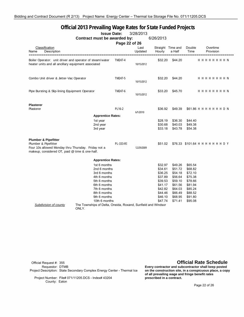
Bidding and Contract Document (R 2/13) Project Name: Energy Center – Thermal Ice Storage File No. 071/11205.DCS
Official 2013 Prevailing Wage Rates for State Funded Projects Issue Date: 3/28/2013 Contract must be awarded by: 6/26/2013 Page 22 of 26 Classification Last Straight Time and Double Overtime Name Description Updated Hourly a Half Time Provision ============================================================================================================== Boiler Operator: unit driver and operator of steam/water TM247-4 $32.20 $44.20 H H H H H H H H N heater units and all ancillary equipment associated 10/15/2012
Combo Unit driver & Jetter-Vac Operator TM247-5 $32.20 $44.20 H H H H H H H H N 10/15/2012
Pipe Bursting & Slip-lining Equipment Operator TM247-6 $33.20 $45.70 H H H H H H H H N 10/15/2012
Plasterer Plasterer PL16-2 $36.92 $49.39 $61.86 H H H H H H H D N 6/1/2010 Apprentice Rates: 1st year $28.19 $36.30 $44.40 2nd year $30.68 $40.03 $49.38 3rd year $33.18 $43.78 $54.38
Plumber & Pipefitter Plumber & Pipefitter PL-333-RI $51.02 $76.33 $101.64 H H H H H H H D Y Four 10s allowed Monday thru Thursday. Friday not a 12/29/2009 makeup, considered OT, paid @ time & one-half.
Apprentice Rates: 1st 6 months $32.97 $49.26 $65.54 2nd 6 months $34.61 $51.72 $68.82 3rd 6 months $36.25 $54.18 $72.10 4th 6 months $37.89 $56.64 $75.38 5th 6 months $39.53 $59.10 $78.66 6th 6 months $41.17 $61.56 $81.94 7th 6 months $42.82 $64.03 $85.24 8th 6 months $44.46 $66.49 $88.52 9th 6 months $46.10 $68.95 $91.80 10th 6 months $47.74 $71.41 $95.08 Subdivision of county The Townships of Delta, Oneida, Roxand, Sunfield and Windsor ONLY.
Official Request #: 355 Official Rate Schedule Requestor: DTMB Every contractor and subcontractor shall keep posted Project Description: State Secondary Complex Energy Center - Thermal Ice on the construction site, in a conspicuous place, a copy of all prevailing wage and fringe benefit rates Project Number: File# 071/11205.DCS - Index# 43204 prescribed in a contract. County: Eaton Page 22 of 26
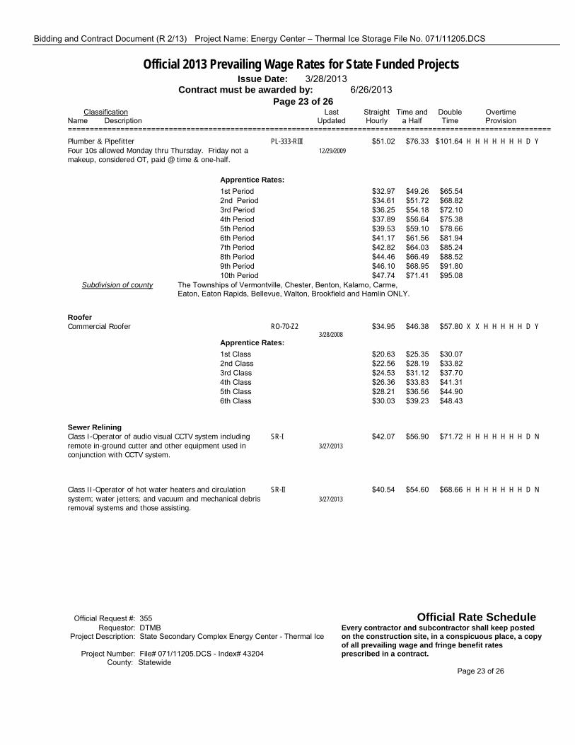
Bidding and Contract Document (R 2/13) Project Name: Energy Center – Thermal Ice Storage File No. 071/11205.DCS
Official 2013 Prevailing Wage Rates for State Funded Projects Issue Date: 3/28/2013 Contract must be awarded by: 6/26/2013 Page 23 of 26 Classification Last Straight Time and Double Overtime Name Description Updated Hourly a Half Time Provision ============================================================================================================== Plumber & Pipefitter PL-333-RIII $51.02 $76.33 $101.64 H H H H H H H D Y Four 10s allowed Monday thru Thursday. Friday not a 12/29/2009 makeup, considered OT, paid @ time & one-half.
Apprentice Rates: 1st Period $32.97 $49.26 $65.54 2nd Period $34.61 $51.72 $68.82 3rd Period $36.25 $54.18 $72.10 4th Period $37.89 $56.64 $75.38 5th Period $39.53 $59.10 $78.66 6th Period $41.17 $61.56 $81.94 7th Period $42.82 $64.03 $85.24 8th Period $44.46 $66.49 $88.52 9th Period $46.10 $68.95 $91.80 10th Period $47.74 $71.41 $95.08 Subdivision of county The Townships of Vermontville, Chester, Benton, Kalamo, Carme, Eaton, Eaton Rapids, Bellevue, Walton, Brookfield and Hamlin ONLY.
Roofer Commercial Roofer RO-70-Z2 $34.95 $46.38 $57.80 X X H H H H H D Y 3/28/2008 Apprentice Rates: 1st Class $20.63 $25.35 $30.07 2nd Class $22.56 $28.19 $33.82 3rd Class $24.53 $31.12 $37.70 4th Class $26.36 $33.83 $41.31 5th Class $28.21 $36.56 $44.90 6th Class $30.03 $39.23 $48.43
Sewer Relining Class I-Operator of audio visual CCTV system including SR-I $42.07 $56.90 $71.72 H H H H H H H D N remote in-ground cutter and other equipment used in 3/27/2013 conjunction with CCTV system.
Class II-Operator of hot water heaters and circulation SR-II $40.54 $54.60 $68.66 H H H H H H H D N system; water jetters; and vacuum and mechanical debris 3/27/2013 removal systems and those assisting.
Official Request #: 355 Official Rate Schedule Requestor: DTMB Every contractor and subcontractor shall keep posted Project Description: State Secondary Complex Energy Center - Thermal Ice on the construction site, in a conspicuous place, a copy of all prevailing wage and fringe benefit rates Project Number: File# 071/11205.DCS - Index# 43204 prescribed in a contract. County: Statewide Page 23 of 26

Bidding and Contract Document (R 2/13) Project Name: Energy Center – Thermal Ice Storage File No. 071/11205.DCS
Official 2013 Prevailing Wage Rates for State Funded Projects Issue Date: 3/28/2013 Contract must be awarded by: 6/26/2013 Page 24 of 26 Classification Last Straight Time and Double Overtime Name Description Updated Hourly a Half Time Provision ==============================================================================================================
Sheet Metal Worker Sheet Metal Worker SHM-7-1 $45.92 $59.47 $73.02 H H H H D D D D Y 4 10s allowed as consecutive days, M-Th or T-F 10/22/2012
Apprentice Rates: First Year $24.69 $31.46 $38.24 Second Year $29.86 $37.99 $46.12 Third Year $37.79 $47.28 $56.76 Fourth Year $40.50 $51.34 $62.18
Sprinkler Fitter Sprinkler Fitter SP 669 $46.51 $61.99 $77.47 H H H H H H H D Y 9/17/2009 Apprentice Rates: Class 1 & 2 $23.44 $31.31 $39.17 Class 3 $29.35 $37.75 $46.15 Class 4 $30.93 $40.12 $49.31 Class 5 $35.50 $45.47 $55.45 Class 6 $37.07 $47.83 $58.59 Class 7 $38.65 $50.20 $61.75 Class 8 $40.22 $52.55 $64.89 Class 9 $41.79 $54.91 $68.03 Class 10 $43.36 $57.27 $71.17
Tile, Terrazzo and Mosiac Finisher BR9-31-TF $30.57 $39.66 $48.75 H H H H H H H D Y 3/7/2013 Apprentice Rates: 0-749 hours $24.21 $30.12 $36.03 750-1,499 hours $25.12 $31.49 $37.85 1,500-2,249 hours $26.03 $32.85 $39.67 2,250-2,999 hours $26.93 $34.20 $41.47 3,000-3,749 hours $27.84 $35.57 $43.29 3,750-4,499 hours $28.75 $36.93 $45.11
Setter BR9-31-TS $35.94 $46.71 $57.47 H H H H H H H D Y 3/7/2013 Apprentice Rates: 0-749 hours $28.40 $35.39 $42.39 750-1499 hours $29.48 $37.01 $44.55 1500-2249 hours $30.56 $38.63 $46.71 2250-2999 hours $31.63 $40.24 $48.85 3000-3749 hours $32.71 $41.86 $51.01 3750-4499 hours $33.79 $43.48 $53.17
Official Request #: 355 Official Rate Schedule Requestor: DTMB Every contractor and subcontractor shall keep posted Project Description: State Secondary Complex Energy Center - Thermal Ice on the construction site, in a conspicuous place, a copy of all prevailing wage and fringe benefit rates Project Number: File# 071/11205.DCS - Index# 43204 prescribed in a contract. County: Eaton Page 24 of 26

Bidding and Contract Document (R 2/13) Project Name: Energy Center – Thermal Ice Storage File No. 071/11205.DCS
Official 2013 Prevailing Wage Rates for State Funded Projects Issue Date: 3/28/2013 Contract must be awarded by: 6/26/2013 Page 25 of 26 Classification Last Straight Time and Double Overtime Name Description Updated Hourly a Half Time Provision ==============================================================================================================
Truck Driver of all trucks of 8 cubic yd capacity or over TM-RB2 $40.40 $37.84 H H H H H H H H Y 10/9/2012
of all trucks of 8 cubic yard capacity or less TM-RB2A $40.30 $37.69 H H H H H H H H Y 10/9/2012
on euclid type equipment TM-RB2B $40.55 $38.06 H H H H H H H H Y 10/9/2012
Underground Laborer Open Cut, Class I Construction Laborer LAUC-Z3-1 $32.66 $42.80 $52.93 H H H H H H H D Y 1/16/2013 Apprentice Rates: 0-1,000 work hours $28.17 $36.06 $43.95 1,001-2,000 work hours $29.07 $37.41 $45.75 2,001-3,000 work hours $29.97 $38.76 $47.55 3,001-4,000 work hours $31.76 $41.45 $51.13
Underground Laborer Open Cut, Class II Mortar and material mixer, concrete form man, signal man, LAUC-Z3-2 $32.80 $43.01 $53.21 H H H H H H H D Y well point man, manhole, headwall and catch basin 1/16/2013 builder, guard rail builders, headwall, seawall, breakwall, dock builder and fence erector.
Apprentice Rates: 0-1,000 work hours $28.28 $36.23 $44.17 1,001-2,000 work hours $29.18 $37.57 $45.97 2,001-3,000 work hours $30.09 $38.94 $47.79 3,001-4,000 work hours $31.90 $41.65 $51.41
Underground Laborer Open Cut, Class III Air, gasoline and electric tool operator, vibrator operator, LAUC-Z3-3 $32.92 $43.19 $53.45 H H H H H H H D Y drillers, pump man, tar kettle operator, bracers, rodder, 1/16/2013 reinforced steel or mesh man (e.g. wire mesh, steel mats, dowel bars, etc.), cement finisher, welder, pipe jacking and boring man, wagon drill and air track operator and concrete saw operator (under 40 h.p.), windlass and tugger man, and directional boring man.
Apprentice Rates: 0-1,000 work hours $28.37 $36.36 $44.35 1,001-2,000 work hous $29.28 $37.73 $46.17 2,001-3,000 work hours $30.19 $39.09 $47.99 3,001-4,000 work hours $32.01 $41.82 $51.63 Official Request #: 355 Official Rate Schedule Requestor: DTMB Every contractor and subcontractor shall keep posted Project Description: State Secondary Complex Energy Center - Thermal Ice on the construction site, in a conspicuous place, a copy of all prevailing wage and fringe benefit rates Project Number: File# 071/11205.DCS - Index# 43204 prescribed in a contract. County: Eaton Page 25 of 26

Bidding and Contract Document (R 2/13) Project Name: Energy Center – Thermal Ice Storage File No. 071/11205.DCS
Official 2013 Prevailing Wage Rates for State Funded Projects Issue Date: 3/28/2013 Contract must be awarded by: 6/26/2013 Page 26 of 26 Classification Last Straight Time and Double Overtime Name Description Updated Hourly a Half Time Provision ==============================================================================================================
Underground Laborer Open Cut, Class IV Trench or excavating grade man. LAUC-Z3-4 $32.97 $43.26 $53.55 H H H H H H H D Y 1/16/2013 Apprentice Rates: 0-1,000 work hours $28.41 $36.42 $44.43 1,001-2,000 work hours $29.32 $37.79 $46.25 2,001-3,000 work hours $30.23 $39.15 $48.07 3,001-4,000 work hours $32.06 $41.89 $51.73
Underground Laborer Open Cut, Class V Pipe Layer LAUC-Z3-5 $33.11 $43.47 $53.83 H H H H H H H D Y 1/16/2013 Apprentice Rates: 0-1,000 work hours $28.51 $36.57 $44.63 1,001-2,000 work hours $29.43 $37.95 $46.47 2,001-3,000 work hours $30.35 $39.33 $48.31 3,001-4,000 work hours $32.19 $42.09 $51.99
Underground Laborer Open Cut, Class VI Grouting man, top man assistant, audio visual television LAUC-Z3-6 $30.41 $39.42 $48.43 H H H H H H H D Y operations and all other operations in connection with 1/16/2013 closed circuit television inspection, pipe cleaning and pipe relining work and the installation & repair of water service pipe & appurtenances
Apprentice Rates: 0-1,000 work hours $26.49 $33.54 $40.59 1,001-2,000 work hours $27.27 $34.71 $42.15 2,001-3,000 work hours $28.05 $35.88 $43.71 3,001-4,000 work hours $29.63 $38.25 $46.87
Underground Laborer Open Cut, Class VII Restoration laborer, seeding, sodding, planting, cutting, LAUC-Z3-7 $27.56 $35.15 $42.73 H H H H H H H D Y mulching and topsoil grading and the restoration of 1/16/2013 property such as replacing mail boxes, wood chips, planter boxes, flagstones etc.
Apprentice Rates: 0-1,000 work hours $24.35 $30.33 $36.31 1,001-2,000 work hours $24.99 $31.29 $37.59 2,001-3,000 work hours $25.63 $32.25 $38.87 3,001-4,000 work hours $26.92 $34.19 $41.45
Official Request #: 355 Official Rate Schedule Requestor: DTMB Every contractor and subcontractor shall keep posted Project Description: State Secondary Complex Energy Center - Thermal Ice on the construction site, in a conspicuous place, a copy of all prevailing wage and fringe benefit rates Project Number: File# 071/11205.DCS - Index# 43204 prescribed in a contract. County: Eaton Page 26 of 26

Project Name: Energy Center – Thermal Ice Storage Project Number: MIS 016
SECTION 03 3000 CAST-IN-PLACE CONCRETE
-f:\projects\mis016\projmgmt\specs\ice storage\arch and structural\03 3000 cast in place concrete.doc-4/3/2013 Page 1 CENTURY A&E
PART 1 - GENERAL 1.01 DESCRIPTION:
A. The work includes all cast-in-place concrete for new chiller and pum p pads, new exterior electrical pads, repair of existing floor penetrations, new floors, and new footings.
B. The work includes cast-in-place concrete for composite floor construction.
1. Related Sections: The fol lowing Sections contain requirements related to the work of this Section:
2. Section 05 50 20 – Concrete Expansion Anchors. 3. Section 05 12 00 – Structural Steel 4. Section 09 67 00 – Fluid Applied Flooring
1.02 REFERENCES:
A. ACI 211.1, "R ecommended Practice for Sel ecting Proportions for Normal, Heavyweight, and Mass Concrete".
B. ACI 212.3R, "Chemical Admixtures for Concrete". C. ACI 301, "Specifications for Structural Concrete for Buildings".
D. ACI 302.1R, "Recommended Practice for Floor and Slab Construction". E. ACI 304R, "Recommended Practice for Measuring, Mixing and Placing Concrete".
F. ACI 304.2R "Placing Concrete by Pumping Methods". G. ACI 305R, "Hot-Weather Concreting". H. ACI 306R, "Cold-Weather Concreting". I. ACI 308, "Standard Practice for Curing Concrete". J. ACI 309R, "Guide for Consolidation of Concrete". K. ACI 315, "Details and Detailing of Concrete Reinforcement". L. ACI 318, "Building Code Requirements for Reinforced Concrete". M. ACI 347R, "Recommended Practice for Concrete Formwork". N. ACI 544R, “Report on Fiber Reinforced Concrete.” O. Concrete Reinforcing Steel Institute (CRSI). P. American Society for Testing and Materials (ASTM).
1.03 SUBMITTALS:
A. Submit under provisions of SECTION 01300, "Submittals".

Project Name: Energy Center – Thermal Ice Storage Project Number: MIS 016
SECTION 03 3000 CAST-IN-PLACE CONCRETE
-f:\projects\mis016\projmgmt\specs\ice storage\arch and structural\03 3000 cast in place concrete.doc-4/3/2013 Page 2 CENTURY A&E
B. Submit proposed mix design prepared by an approve d independent testing fi rm for each class of concrete. Proportions shall be se lected according to ACI 301, Secti on 3.9. No concrete shall be placed until approval is obtained from the ENGINEER.
C. Submit shop drawings showing all fabrication dimensions and l ocations for pl acing the
reinforcing steel and accessories . Approval from the ENGINEER shall be obtained before fabrication. Details of reinforcem ent and accessories not covered herein shall be in accordance with ACI 315.
D. Submit certifications for the following:
1. Cement. 2. Aggregates. 3. Admixtures. 4. Reinforcement: Mill test report.
1.04 JOB CONDITIONS:
A. Construction loads shall not exceed the superim posed load which any member, with necessary supplemental support, is capable of carrying safely and without damage.
PART 2 - PRODUCTS 2.01 MATERIALS:
A. Formwork: 1. Forms for Exposed Finish Concrete: Plyw ood, metal, metal-framed plywood faced, or
other acceptable panel-type m aterials, to provide continuous, straight, smooth, exposed surfaces. Furnish in largest practicable si zes to m inimize number of joints and to conform to joint spacing shown on Drawings. a. Use overlaid plywood complying with US Product Standard PS-1, A-C or B-B
High Density Overlay (HDO) Concrete Forms, Class I. 2. Forms for Unexposed Finish Concrete: Plywood, lumber, metal, or other acceptable
material. Provide lumber dressed on at least two edges and one side for tight fit. 3. Form Coatings: Provi de commercial formulation form-coating compounds with
maximum VOC of 350 m g/L that will not bond with , stain, or adversely affect concrete surfaces and will not impair subsequent treatments of concrete surfaces.
4. Form Ties: Factory fabricated, adjustable length, removable or snap-off metal form ties designed to prevent form deflection and to prevent spalling of concrete upon removal. Provide units that will leave no m etal closer than 1-1/2inches (38.1 m m) to exposed surface. a. Provide ties that, when removed, will leave holes not larger than 1-inch
(25.4 mm) diameter in concrete surface. B. Concrete:
1. Cement shall conform to ASTM C150 or ASTM C595 (maximum fly ash content shall be 20% by weight). Al l cement used in exposed concrete shall be of t he same brand from the same mill. a. Aetna Cement Company. b. Holnam Corporation. c. LaFarge Corporation. d. Medusa Cement Company. e. St. Mary's Blue Circle Cement Co.
2. Coarse aggregate shall conform to MDOT 6A or 6AA or ASTM C33, Size 57. 3. Fine aggregate shall conform to MDOT 2NS or ASTM C33, fines.

Project Name: Energy Center – Thermal Ice Storage Project Number: MIS 016
SECTION 03 3000 CAST-IN-PLACE CONCRETE
-f:\projects\mis016\projmgmt\specs\ice storage\arch and structural\03 3000 cast in place concrete.doc-4/3/2013 Page 3 CENTURY A&E
4. Mixing water shall be clean, fresh, and potable.
5. Admixtures, if used, shall conform to the appropriate specifications listed below: a. Air-Entraining Admixtures: Neut ralized vinsol resin conforming to ASTM
C260 or any other ASTM C260 air entraining admixture that the manufacturer will certify as compatible with the use of superplasticizers.
b. Pozzolanic Admixtures: ASTM C618, Type C or Type F, except that loss on ignition shall not exceed 4%.
c. Use Type F pozzolith admixture for concrete which is exposed to raw sewage or aggressive solutions.
d. Water Reducing Admixture: "Eucon W R-75" by the Euclid Chemical Co., "Pozzolith 200N" by Master Builders or "Plastocrete 160" by Sika Chem ical Corp. or W.R. Grace "WRDA Series". The admixture shall conform to ASTM C494, Type A and not contain more chloride ions than are present in municipal drinking water.
e. High Range Water Reducing Admixture (Superplasticizer Type F or G): "Eucon 37" by Euclid Chemical Co., "Rheobuild" by Master Builders, or "Sikament" by Sika Chemical Corp. or W.R. Grace "Daracem 100", W.R. Grace "ADVA Series". The adm ixture shall conform to ASTM C494, Type F or G, and not contain more chloride ions than are present in municipal drinking water.
f. Water Reducing, Retarding Admixture: "Eucon 75" by Euclid Chemical Co., "Pozzolith R" by Master Builders, or "Plastiment" by Sika Chemical Corp., or W.R. Grace "Daratard Series". The ad mixture shall conform to ASTM C494, Type D and not contain more chloride ions than are present in municipal drinking water.
g. Non-Corrosive, Non-Chloride Accelerator : "Accelguard 80", Euclid Chem ical Co., "Palarset", W.R. Grace & Co., or "Pozzutec 20", Master Builders, Inc. The admixture shall conform to ASTM C494, Type C or E, and not contain more chloride ions than are present in municipal drinking water.
6. Prohibited Admixtures: Calcium chloride, thiocyanates or admixtures containing more than 0.05% chloride ions are not permitted. a. All materials used in the work shall be of the same composition as used in
establishing the mix design.
C. Reinforcing Materials:
1. Reinforcing bars shall be deformed bars conforming to ASTM A615 or A616, Grade 60. 2. Welded wire fabric shall conform to ASTM A185. 3. White Nylon or Polypropylene Fibers: Fiberm esh, W.R. Grace, or Nycon, 3/4 inch
length, 80-110 ksi tensile strength, recommended 1-1/2 lb/cyd., minimum dosage. D. Accessories:
1. Tie Wire: Minimum 16 gage annealed type. 2. Chairs, Bar Supports, Bolsters, Spacers: Per CRSI Manual of Standard Practice, plastic
protected (Class 1) for structural slabs, bright basic (Class 3), for slabs-on-grade. a. For slab on grade, use support s with sand pl ates or hori zontal runners where
base material will not support chair legs. b. For exposed to view concrete surfaces, where legs of supports are in contact
with forms, provide supports with legs that are plastic protected per CRSI Class 1 or stainless steel protected per CRSI Class 2.
3. Form Ties: W ater seal snap form ties with minimum 1-inch diameter steel or neoprene collar at mid-point required for walls subject to hydrostatic pressure.

Project Name: Energy Center – Thermal Ice Storage Project Number: MIS 016
SECTION 03 3000 CAST-IN-PLACE CONCRETE
-f:\projects\mis016\projmgmt\specs\ice storage\arch and structural\03 3000 cast in place concrete.doc-4/3/2013 Page 4 CENTURY A&E
4. Control Joint Inserts: Prefo rmed plastic control joint inserts with pull-off tops and locking flanges on vertical legs. Subject to compliance with requirements, provide one of the following: a. “Pull-Top Quickjoint” by Quickjoint, Inc. b. “Stress Lock” by H. Compton Company, Inc. c. “Sure-Joint” by Safe-T-Grip Industries. d. “Zip-Cap Control Joint” by Greenstreak.
E. Premolded Joint Filler:
1. Shall conform to ASTM D1752 (non-ext ruding, non-bituminous type) for i nterior applications.
F. Joint Sealant:
1. Horizontal Joints: Two part, self-leveling, polyurethane sealant. a. Sonolastic SL2, by Sonneborn Corporation. b. Sikaflex 2C SL, by Sika Corporation. c. Dualthane, by W.R. Meadows.
2. Vertical Joints: Two part, non-sag, polyurethane sealant. a. Sonolastic NP2, by Sonneborn Corporation. b. Sikaflex 2C NS, by Sika Corporation. c. Dualthane, by W.R. Meadows.
G. Vapor Retarder: 6 mil minimum thickness clear polyethylene film, for below grade application,
per ASTM D4397. Maximum water vapor transmission rate shall be 0.23 g/24 hr/100 sq. in. and maximum perm rating shall be 0.13 perms.
H. Bonding and Repair Materials:
1. Bonding Adhesive: The com pound shall be a polyvinyl acetate or acrylic base, rewettable type, "Euco Weld" by Euclid Chemical Co., or "Sonocret e" by Sonneborn-Contech, or "Weldcrete" by Larsen Co. Use only in areas not subject to moisture.
2. Epoxy Bonding Adhesive: The com pound shall be a t wo (2) component, 100% solids, 100% reactive compound suitable for use on dry or dam p surfaces, "Euco Epoxy #452MV or #620 by Euclid Chemical Co., or "Sonobond" by Sonneborn-Contech, or "Sikadur 32 Hi-Mod" by Sika Corporation.
3. Bonding Admixture: The compound shall be a latex, non-rewettable type, "SBR Latex" or "Flex-con" by Euclid Chemical Co., "Intralok" by W.R. Meadows, "Daraweld C" by W.R. Grace, or "Sika Bond" by Sika Corporation.
4. Underlayment Compound: Fr ee-flowing, self-leveling, pumpable cementitious base compound.
I. Curing Compounds: Sodium silicate compounds are prohibited.
1. Curing Compound for Exposed Interior Floors: ASTM C1315, Type I, Class A, clear, non-yellowing, VOC compliant, minimum 30 percent solids. Subject to compliance with requirements, provide one of the following: a. "Safe Cure and Seal J-18," Dayton Superior Corp. b. "Super Aqua Cure Vox," Euclid Chemical Co. c. "Dress & Seal #30WB," L&M Construction Chemicals, Inc. d. "Horn Clear Seal EM-180," A. C. Horn, Inc. e. "Kure and Seal WB-30," Sonneborn-ChemRex, Inc. f. "Vocomp No. 20/25 - Clear", W.R. Meadows Co.
2. CONTRACTOR shall confirm compatibility of any curing com pound or sealer with adhesives for any flooring to be placed on the slab.

Project Name: Energy Center – Thermal Ice Storage Project Number: MIS 016
SECTION 03 3000 CAST-IN-PLACE CONCRETE
-f:\projects\mis016\projmgmt\specs\ice storage\arch and structural\03 3000 cast in place concrete.doc-4/3/2013 Page 5 CENTURY A&E
J. Non-Slip Finish: Alu minum oxide or granitic type, "Non-Slip Aggregate" by Euclid Chemical Co., "Grip It AO" by L&M Construction Chemicals, "Toxgrip" by Toch, or "Fri ctex" by Sonneborn-Contech. The aggregate shall be graded in standard No. 8 - No. 30 size.
K. Underlayment Compound: Free-fl owing, self-leveling, pumpable, cement-based compound for applications from feathered edges to 1-inch (25.4mm) thick. 1. Products: Subject to compliance with requirements, provide one of the following:
a. “K-15,” Ardex, Inc. b. “Conflow,” Conspec Marketing and Mfg. Co. c. “LevelLayer II,” Dayton Superior Corp. d. “Flo-Top,” Euclid Chemical Co. e. “Levelex,” L&M Construction Chemicals, Inc. f. “Pourcrete,” Master Builders, Inc. g. “Stoncrete UL1,” Stonhard, Inc. h. “Thoro Underlayment Self-Leveling,” Thoro System Products.
2. Surface preparation and cleaning shall be performed in strict com pliance of manufacturers’ recommendation to ensure a sound bonding to the base concrete.
2.02 PROPORTIONING CONCRETE:
A. Proportions shall be selected using ACI 301, Section 3.9. B. Proportions and materials shall conform to Schedule A, Specification Requirements for Concrete,
at end of this Section.
C. Plain concrete for curb and gutter, interior and exterior slabs and equipment pads, and concrete fill below existing footings and utilities. 1. Proportions and Materials:
a. Permissible Cement Types: I, IP, I-A, IP-A. b. Minimum Cement Content: 6.0 sacks/cu.yd. c. Coarse Aggregate: MDOT 6A. d. Sand: MDOT-2NS. e. Maximum Water-Cement Ratio: 5.0 gal./sack. f. Entrained Air content: 5-8%. g. Maximum Slump: 4”. h. Minimum Compressive Strength, fc’ (28 day) 4000 psi.
D. Flowable Fly Ash Fill:
1. All flowable fly ash fill (also know as contro lled low strength material – CLSM) shall be proportioned, batched, transported, placed, and tested in accordance with the recommendations in ACI report 229R-94.
2. CONTRACTOR shall submit the proposed CLSM mix design and test strength data to the ENGINEER for approval prior to use on the project.
3. The CLSM shall consist of a m ixture of port land cement, fly ash, fi ne aggregate, and water.
4. Portland cement shall be ASTM C150, Type 1. 5. Fly ash shall be ASTM C618, Class C, Loss on ignition less than 4%. 6. Fine aggregate shall be ASTM C33, MDOT 8.02 2NS sand or equal. 7. Mixing water shall be clean, fresh, and potable. 8. The proposed mix design shall have at least one sack of cement (94 lbs) per cubic yard in
the mix. 9. The 28 day strength of the CLSM shall be a minimum of 200 PSI.

Project Name: Energy Center – Thermal Ice Storage Project Number: MIS 016
SECTION 03 3000 CAST-IN-PLACE CONCRETE
-f:\projects\mis016\projmgmt\specs\ice storage\arch and structural\03 3000 cast in place concrete.doc-4/3/2013 Page 6 CENTURY A&E
10. The CLSM shall be placed at locations as i ndicated on the plans in separate lifts if necessary to prevent damage to forms, walls, or other structures that the fluid CLSM may be cast against.
11. Vibrators shall not be used to consolidate the CLSM.
E. Use of all admixtures must be approved by the ENGINEER. Al l admixtures shall be used i n accordance with the manufacturers' instructions except as otherwise directed by the ENGINEER.
F. If the CONTRACTOR intends to place concrete by pumping, the mix design shall be prepared in
accordance with these specifications and the recommendations of ACI 304.2R.
G. Superplasticizer may be included as needed for workability and slump. 2.03 FABRICATING REINFORCEMENT:
A. Fabricate in accordance with approved shop drawings and ACI 315. B. Locate reinforcing splices not indicated on Drawi ngs. Locat ion and cl ass of spl ices is to be
approved by the ENGINEER. PART 3 - EXECUTION 3.01 ERECTION OF FORMWORK:
A. Forms shall be used, wherever necessary, to c onfine the concrete and shape i t to the required dimensions. Form s shall have sufficient strength to withstand the pressure resul ting from placement and vibration of the concrete, and shall have sufficient rigidity to maintain specified tolerances.
B. Earth cuts shall not be used as form s for vertical surfaces unless shown on the plans or approved
by ENGINEER. C. The design and engineering of the formwork, as well as its construction, shall be the responsibility
of the CONTRACTOR. D. The formwork shall be designed for the loads, lateral pressure, and allowable stresses outlined in
"Guide to Formwork for C oncrete" (ACI 347R) "Formwork for Concrete" (ACI SP-4) and for design considerations, wind loads, allowable stresses, and ot her applicable requirements of t he controlling local building code.
E. Forms shall be sufficiently tight to prevent loss of mortar from the concrete. Chamfer strips shall
be placed in the corners of form s to produce beveled edges on perm anently exposed surfaces. Interior corners on such surfaces and the edges of formed joints will not require beveling unless specifically called for on the plans.
F. At construction joints, contact surface of the fo rm sheathing for flush surfaces exposed to view
shall overlap the hardened concre te in the previous placem ent by not more than one inch. The forms shall be held against the hardened concrete to prevent offsets or loss of m ortar at the construction joint and to maintain a true surface.
G. Formwork shall be so anchored to shores or other supporting surfaces or m embers to prevent
upward or lateral movement of any part of the formwork system during concrete placement.
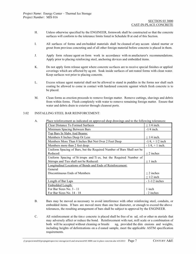
Project Name: Energy Center – Thermal Ice Storage Project Number: MIS 016
SECTION 03 3000 CAST-IN-PLACE CONCRETE
-f:\projects\mis016\projmgmt\specs\ice storage\arch and structural\03 3000 cast in place concrete.doc-4/3/2013 Page 7 CENTURY A&E
H. Unless otherwise specified by the ENGINEER, formwork shall be constructed so that the concrete surfaces will conform to the tolerance limits listed in Schedule B at end of this Section.
I. All surfaces of forms and em bedded materials shall be cleaned of any accum ulated mortar or
grout from previous concreting and of all other foreign material before concrete is placed in them. J. Apply form release agent on form work in accordance with m anufacturer's recommendations.
Apply prior to placing reinforcing steel, anchoring devices and embedded items. K. Do not apply form release agent where concrete su rfaces are to receive special finishes or applied
coverings which are affected by ag ent. Soak inside surfaces of unt reated forms with clean water. Keep surfaces wet prior to placing concrete.
L. Excess release agent material shall not be allowed to stand in puddles in the forms nor shall such
coating be allowed to come in contact with hardened concrete against which fresh concrete is to be placed.
M. Clean forms as erection proceeds to remove foreign matter. Remove cuttings, shavings and debris
from within forms. Flush completely with water to remove remaining foreign matter. Ensure that water and debris drain to exterior through cleanout ports.
3.02 INSTALLING STEEL BAR REINFORCEMENT:
A. Place reinforcement as indicated on approved shop drawings and to the following tolerances: Clear Distance To Formed Surfaces + 1/4 inch. Minimum Spacing Between Bars -1/4 inch. Top Bars In Slabs And Beams: Members 8 Inches Deep Or Less
+ 1/4 inch.
Members More Than 8 Inches But Not Over 2 Feet Deep -1/4, + 1/2 inch Members more than 2 feet deep: - 1/4, + 1 inch. Uniform Spacing of Bars, but the Required Number of Bars Shall not be Reduced:
+ 2 inches
Uniform Spacing of St irrups and Ti es, but the Required Number of Stirrups and Ties shall not be Reduced:
+ 1 inch
Longitudinal Locations of Bends and Ends of Reinforcement: General Discontinuous Ends of Members
+ 2 inches + 1/2 inch
Length of Bar Laps - 1-1/2 inches Embedded Length: For Bar Sizes No. 3 - 11 For Bar Sizes No. 14 - 18
1 inch - 2 inches
B. Bars may be moved as necessary to avoid interference with other reinforcing steel, conduits, or
embedded items. If bars are moved more than one bar diameter, or enough to exceed the above tolerances, the resulting arrangement of bars shall be subject to approval by the ENGINEER.
C. All reinforcement at the tim e concrete is placed shall be free of m ud, oil or other m aterials that
may adversely affect or reduce the bond. Reinforcement with rust, mill scale or a combination of both will be accepted without cleaning or brushi ng, provided the dim ensions and weights, including heights of deformations on a cl eaned sample, meet the applicable ASTM specification requirements.
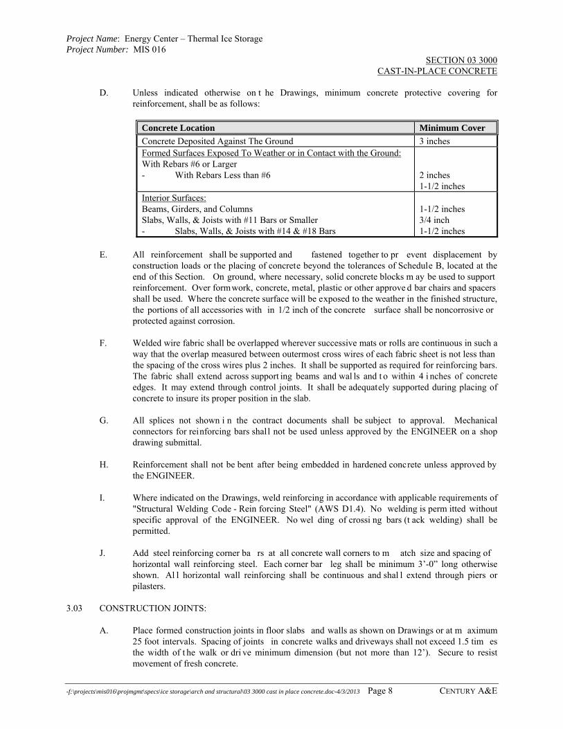
Project Name: Energy Center – Thermal Ice Storage Project Number: MIS 016
SECTION 03 3000 CAST-IN-PLACE CONCRETE
-f:\projects\mis016\projmgmt\specs\ice storage\arch and structural\03 3000 cast in place concrete.doc-4/3/2013 Page 8 CENTURY A&E
D. Unless indicated otherwise on t he Drawings, minimum concrete protective covering for reinforcement, shall be as follows:
Concrete Location Minimum Cover
Concrete Deposited Against The Ground 3 inches Formed Surfaces Exposed To Weather or in Contact with the Ground: With Rebars #6 or Larger - With Rebars Less than #6
2 inches 1-1/2 inches
Interior Surfaces: Beams, Girders, and Columns Slabs, Walls, & Joists with #11 Bars or Smaller - Slabs, Walls, & Joists with #14 & #18 Bars
1-1/2 inches 3/4 inch 1-1/2 inches
E. All reinforcement shall be supported and fastened together to pr event displacement by
construction loads or the placing of concrete beyond the tolerances of Schedule B, located at the end of this Section. On ground, where necessary, solid concrete blocks m ay be used to support reinforcement. Over formwork, concrete, metal, plastic or other approve d bar chairs and spacers shall be used. Where the concrete surface will be exposed to the weather in the finished structure, the portions of all accessories with in 1/2 inch of the concrete surface shall be noncorrosive or protected against corrosion.
F. Welded wire fabric shall be overlapped wherever successive mats or rolls are continuous in such a
way that the overlap measured between outermost cross wires of each fabric sheet is not less than the spacing of the cross wires plus 2 inches. It shall be supported as required for reinforcing bars. The fabric shall extend across support ing beams and wal ls and t o within 4 i nches of concrete edges. It may extend through control joints. It shall be adequately supported during placing of concrete to insure its proper position in the slab.
G. All splices not shown i n the contract documents shall be subject to approval. Mechanical
connectors for reinforcing bars shall not be used unless approved by the ENGINEER on a shop drawing submittal.
H. Reinforcement shall not be bent after being embedded in hardened concrete unless approved by
the ENGINEER. I. Where indicated on the Drawings, weld reinforcing in accordance with applicable requirements of
"Structural Welding Code - Rein forcing Steel" (AWS D1.4). No welding is perm itted without specific approval of the ENGINEER. No wel ding of crossi ng bars (t ack welding) shall be permitted.
J. Add steel reinforcing corner ba rs at all concrete wall corners to m atch size and spacing of
horizontal wall reinforcing steel. Each corner bar leg shall be minimum 3’-0” long otherwise shown. Al l horizontal wall reinforcing shall be continuous and shal l extend through piers or pilasters.
3.03 CONSTRUCTION JOINTS:
A. Place formed construction joints in floor slabs and walls as shown on Drawings or at m aximum 25 foot intervals. Spacing of joints in concrete walks and driveways shall not exceed 1.5 tim es the width of t he walk or dri ve minimum dimension (but not more than 12’). Secure to resist movement of fresh concrete.

Project Name: Energy Center – Thermal Ice Storage Project Number: MIS 016
SECTION 03 3000 CAST-IN-PLACE CONCRETE
-f:\projects\mis016\projmgmt\specs\ice storage\arch and structural\03 3000 cast in place concrete.doc-4/3/2013 Page 9 CENTURY A&E
B. All reinforcement shall be continued across joints unless noted otherwise. Key s and i nclined dowels shall be provided as directed by the ENGINEER. Longitudinal keys at least 1-1/2 inches deep shall be provided in all joints in walls and between walls and slabs or footings.
C. The surface of the concrete at a ll joints shall be thoroughly cleaned and all laitance removed prior
to placing adjoining concrete. D. When joining new concrete to existing concrete, bond shall be obtained by one of the following
methods: 1. The use of an approved bondi ng agent. Use epoxy bonding agent in joints exposed to
moisture or below grade. Use latex bonding agent in other applications. 2. Roughening the surface of the concrete in an approved manner, which will expose the
aggregate and will n ot leave laitance, loosened particles of aggregate or damaged concrete at the surface.
3. Provide epoxy grouted dowels as shown on the plans. 3.04 EXPANSION/ISOLATION JOINTS:
A. Reinforcement or ot her embedded metal items bonded t o the concrete (except dowels in floors bonded on only one side of joints) shall not be permitted to extend continuously through any expansion joint.
B. Premolded expansion joint filler shall be of the type required by the contract documents.
3.05 EMBEDDED ITEMS:
A. Provide formed openings where requi red for pi pes, conduits, sleeves and ot her work t o be embedded in and passing through concrete members.
B. Accurately locate and set in place items which are to be cast directly into concrete.
C. Coordinate work of other secti ons and cooperate with trade involved in forming and/or setting
openings, slots, recesses, chases, sleeves, bolts, anchors and other inserts. D. Install all concrete accessories in accord ance with Drawings and m anufacturer's
recommendations; straight, level, and pl umb. Ensure items are not disturbed during concrete placement.
E. Voids in sleeves, inserts, and anchor slots shall be filled temporarily with a read ily removable
material to prevent entry of concrete into the voids. F. No aluminum items shall be embedded in concrete. G. Placement Tolerances - Anchor Bolts:
1. Locate accurately, + 1/8 inch horizontal tolerance, +1/4 inch vertical tolerance. Positioning templates shall be used to set all anchor bolts.
2. Secure to prevent displacem ent during c oncrete pours. Recheck positions as pour progresses and correct any deviations while concrete is still in plastic state.
3. Replace all bolts not placed to the above to lerance, by chippi ng out, resetting, and grouting with non-shrink grout as directed by the ENGINEER.

Project Name: Energy Center – Thermal Ice Storage Project Number: MIS 016
SECTION 03 3000 CAST-IN-PLACE CONCRETE
-f:\projects\mis016\projmgmt\specs\ice storage\arch and structural\03 3000 cast in place concrete.doc-4/3/2013 Page 10 CENTURY A&E
3.06 CONCRETE PRODUCTION: A. General:
1. All concrete shall be ready -mixed and sha ll be batched, mixed and t ransported in accordance with ASTM C94, "Standard Speci fications for Ready-Mixed Concrete", Option C. Plant equipment and facilities sh all conform to the "Check List fo r Certification of Ready Mixed Concrete Production Facilities" of the National Ready Mixed Concrete Association. a. Provide batch ticket for each batch disc harged and used in work, indicating
project identification name and num ber, date, mix type, mix time, batch quantities and load quantity.
2. Concrete shall be mixed only in quantities for immediate use. Batch-to-discharge time shall not exceed the following time limits or 300 revolutions of mixing drum, whichever comes first. Concrete which has begun initial set shall not be retempered, but shall be discarded. a. When air temperature is less than 85 deg. F (29.4 deg. C), mix and delivery time
shall not exceed 90 m inutes. When air temperature is between 85 deg. F (29.4 deg. C) and 90 deg. F (32 deg. C), reduce mixing and del ivery time from 90 minutes to 75 minutes, and when ai r temperature is above 90 deg. F (32. deg. C), reduce mixing and delivery time to 60 minutes.
3. When concrete arrives at the project with slump below that suitable for placing, as
indicated by the specifications, water may be added onl y if neither the maximum permissible water-cement ratio nor the maximum slump is exceeded. a. The water shall be incorporated by additional mixing equal to at least half of the
total mixing required. b. An addition of water above that pe rmitted by the limitation on water-cem ent
ratio shall be accom panied by a quantity of cement sufficient to maintain the proper water-cement ratio.
c. Such addition shall be accom plished only upon authorization of the ENGINEER.
3. Addition of water on-site to im prove workability of mix is not acceptable.
Superplasticizers may be added per manufacturer's directions to improve workability, but the admixture must be i ncluded on t he approved concret e mix design. Addi tion of superplasticizers at the site shall be as directed by the concrete producer and approved by the ENGINEER, and shall be dispensed through a truck-mounted admixture dispensing system or a job-site portable admix dispenser. Type "G" superplasticizers may be added at batching plant.
B. Hot Weather:
1. The ingredients shall be cooled before mixing, or flake ice or well-crushed ice of a si ze that will melt completely during mixing may be substituted for all or part of the mixing water if, due to high temperature, low slump, flash set or cold joints are encountered.
2. Hot weather concreting shall follow the recommendations of AC I 305, except as otherwise directed by the ENGINEER.
3. Concrete with a temperature in excess of 90 deg. F shall be rejected. 3.07 PLACING CONCRETE - GENERAL:
A. Preparation: 1. Hardened concrete and foreign materials shall be removed from the inner surfaces of the
conveying equipment.

Project Name: Energy Center – Thermal Ice Storage Project Number: MIS 016
SECTION 03 3000 CAST-IN-PLACE CONCRETE
-f:\projects\mis016\projmgmt\specs\ice storage\arch and structural\03 3000 cast in place concrete.doc-4/3/2013 Page 11 CENTURY A&E
2. Formwork shall have been com pleted; snow, ice and wat er shall have been removed; reinforcement shall have been secured in place; expansion joint material, anchors, and other embedded items shall have been posi tioned; and the entire preparation shall have been approved prior to placing concrete.
B. Conveying:
1. Concrete shall be handled from the m ixer to the place of final deposit as rapidly as practicable by m ethods which will prevent se gregation or loss of ingredients and in a manner which will assure that the required quality of the concrete is maintained.
2. Conveying equipment shall be approved and shall be of a si ze and desi gn such t hat detectable setting of concrete shall not o ccur before adjacent concrete is placed. Conveying equipment shall be cleaned at th e end of each operation or work day. Conveying equipment and operation shall conform to the following additional requirements: a. Truck mixers, agitators, and nonagi tating units and t heir manner of operat ion
shall conform to the applicable requirements of "Speci fications for R eady-Mixed Concrete" (ASTM C94).
b. Belt conveyors shall be horizontal or at a slope which will not cause excessive segregation or l oss of i ngredients. C oncrete shall be protected against undue drying or rise in temperature. An approved arrangem ent shall be used at the discharge end to prevent apparent segregation. Mortar shall not be allowed to adhere to the return length of t he belt. Long runs shal l be di scharged into a hopper or through a baffle.
c. Chutes shall be metal or metal-lined (aluminum is not permitted) and shall have a slope not exceeding 1 vertical to 2 horiz ontal and not less than l vertical to 3 horizontal. C hutes more than 20 feet long and chut es not meeting the slope requirements may be used provi ded they discharge into a hopper before distribution.
d. Pumping or pneum atic conveying equipment shall be of suitable kind with adequate pumping capacity. Pneum atic placement shall be controlled so that segregation is not apparent in the discharged concrete. The l oss of sl ump in pumping or pneum atic conveying equipment shall not exceed 2 inches. Concrete shall not be conveyed through pipe made of aluminum or aluminum alloy.
C. Depositing:
1. General: C oncrete shall be deposited continuously or i n layers of such t hickness (maximum 2 feet) that no concrete will b e deposited on concrete which has hardened sufficiently to cause the formation of seams or planes of weakness within the section. No interruption shall exceed 45 m inutes. If a section cannot be placed continuously, construction joints shall be located as shown in the contract documents or as approved. Placing shall be carried on at such a rate that the concrete which is being integrated with fresh concrete is still p lastic. Co ncrete which has partially hardened or has been contaminated by foreign materials shall not be deposited. Temporary spreaders in forms shall be rem oved when the concrete placing has reached an elev ation rendering their service unnecessary. They may remain embedded in the concrete only if made of metal or concrete and if prior approval has been obtained.
2. Placing: Placing of concrete in supported elements shall not be started until the concrete previously placed in columns and walls is no longer plastic and has been in place at least two hours.
3. Segregation: Concrete shall be deposited as nearly as practicable in its final position to avoid segregation due to rehandling or flowing. Concrete shall not be subjected to any procedure which will cause segregation. Maximum vertical drop shall be 5 feet unless a minimum 6" dia. tremie drop chute is used.

Project Name: Energy Center – Thermal Ice Storage Project Number: MIS 016
SECTION 03 3000 CAST-IN-PLACE CONCRETE
-f:\projects\mis016\projmgmt\specs\ice storage\arch and structural\03 3000 cast in place concrete.doc-4/3/2013 Page 12 CENTURY A&E
4. Consolidation: All concrete shall be cons olidated by vibration, spading, rodding or forking so that the concrete is thoroughly worked around t he reinforcement around embedded items, and into corners of form s, eliminating all air or st one pockets which may cause honey-combing, pitting, or planes of weakness. Consolidation shall begin within 10 minutes of placement. Internal vibrators shall have a m inimum frequency of 8000 vibrations per m inute and sufficient am plitude to consolidate the concrete effectively. They shall be operated by competent workmen. Use of vibrators to transport concrete within forms shall not be allowed. Vibrators shall be inserted and withdrawn at points approximately 18 inches apart. At each insertion, the duration shall be sufficient to consolidate the concrete but not sufficient to cause segregation, generally from 5 to 15 seconds. A spare vi brator shall be kept on the job si te during all concrete placing operations. Where the concrete is to have an as-cast finish, a full surface of mortar shall be brought against the form by the vibrati on process, supplem ented if necessary by spading to work the coarse aggregate back from the formed surface.
D. Protection:
1. Unless adequate protection is provided and approval is obtained, concrete shall not be placed during rain, sleet, or snow.
2. Rainwater shall not be allowed to increase the mixing water nor to dam age the surface finish.
3. Placing temperature: W hen the temperature of t he surrounding air is expected to be below 40 degrees F duri ng placing or within 24 hours t hereafter, the temperature of the plastic concrete, as placed, shall be no lower than 55 degrees F for sections less than 12 inches in any dimension nor 50 degrees F for any other sections. The temperature of the concrete as placed shall not be so high as to cause difficulty from loss of slump, flash set, or cold joints and should not exceed 90 degrees F. When the temperature of the concrete exceeds 90 degrees F, precautionary m easures approved by the ENGINEER shall be put into effect. When the temperature of the steel is greater than 120 degrees F, steel forms and reinforcement shall be sprayed with water just prior to placing the concrete.
E. Bonding:
1. When joining new concrete to existing concrete, the surface of joints shall be prepared in accordance with one of the methods specified in Article 3.04.
2. The hardened concrete of construction joints and of joints between footings and walls or columns, between walls or col umns and beam s or fl oors they support, joints in unexposed walls and al l others not mentioned below shall be dam pened (but not saturated) immediately prior to placing of fresh concrete.
3. The hardened concrete of joints in exposed work; joints in the middle of beams, girders, joists, and slabs; and joints in work designed to contain liquids shall be dampened (but not saturated) and then thoroughly covered wi th a coat of cem ent grout of si milar proportions to the mortar in the concrete. The grout shall be as t hick as possible on vertical surfaces and at least 1/2 inch thic k on horizontal surfaces. The fresh concrete shall be placed before the grout has attained its initial set.
4. Joints receiving a bonding agent shall have been prepared and agent applied in accordance with the manufacturer's recommendations prior to placing of fresh concrete.
3.08 REMOVAL OF FORMWORK:
A. Do not remove forms, shores and bracing until concrete has gained sufficient strength to carry its own weight, and const ruction and desi gn load which are l iable to be i mposed upon it. The minimum concrete strength for supported slabs or members shall be 75% of t he specified design strength prior to removal of forming, shoring, or bracing, unless otherwise recommended by the

Project Name: Energy Center – Thermal Ice Storage Project Number: MIS 016
SECTION 03 3000 CAST-IN-PLACE CONCRETE
-f:\projects\mis016\projmgmt\specs\ice storage\arch and structural\03 3000 cast in place concrete.doc-4/3/2013 Page 13 CENTURY A&E
CONTRACTORS' Registered Professional Engineer in writing to the ENGINEER. Veri fy strength of concrete by compressive test results.
B. Loosen forms carefully. Do not wedge pry bars, hammers or tools against concrete surfaces. C. Remove forms not directly supporting weight of concrete as s oon as stripping operations will not
damage concrete. 3.09 REPAIR OF SURFACE DEFECTS:
A. Surface defects, including tie holes, unless otherwise specified by the contract documents, shall be repaired immediately after form removal.
B. Repair of Defective Areas:
1. All honeycombed and other defective concrete shall be removed down to sound concrete. If chipping is necessary the edges shall be perpendicular to the surface or slightly undercut. No featheredges will be permitted. The area to be patched and an area at least 6 inches wide surrounding it shall be dampened to prevent absorption of water from the patching mortar. A bonding grout shall be prepared using a mix of approximately l part cement to one part fine sand passing a No. 30 m esh sieve, mixed to the consistency of thick cream, and then well brushed into the surface.
2. The patching mixture shall be made of the same materials and of approximately the same proportions as used for the concrete, except that the coarse aggregate shall be om itted and the mortar shall consist of not more than l part cement to 2-1/2 parts sand and by damp loose volume. White portland cement shall be substituted for a part of the gray portland cement on exposed concret e in order to produce a col or matching the color of the surrounding concrete, as determ ined by a trial patch. The quantity of m ixing water shall be no more than necessary for handling and placing. The patching mortar shall be mixed in advance and allowed to stand with frequent manipulation with a trowel, without addition of water, until it has reached the stiffest consistency that will permit placing.
3. After surface water has evaporated from the area to be patched, the bond coat shall be well brushed into the surface. W hen the bond coat begins to lose the watersheen, the premixed patching mortar shall be applied. The mortar shall be thoroughly consolidated into place and struck off so as to leave the patch slightly higher than the surrounding surface. To perm it initial shrinkage, it shall be left undisturbed fo r at least one hour before being finally finished. The patched area shall be kept damp for 7 day s. Metal tools shall not be used in finishing a patch in a formed wall which will be exposed.
C. Tie Holes: After being cleaned and thoroughly dampened, the tie holes shall be filled solid with
patching mortar. D. All structural repairs shall be m ade with prior approval of t he ENGINEER as t o method and
procedure. E. If permitted or required, proprieta ry compounds for adhesion or as patching ingredients may be
used in lieu of or i n addition to the foregoing patching procedures. Such compounds shall be submitted to the ENGINEER for approval and used in accordance with the m anufacturer's recommendations.
3.10 FINISHING OF FORMED SURFACES:
A. For all unexposed concrete, provide a rough form finish: No selected form facing materials shall be specified for rough form finish surfaces. Ti e holes and defects shall be patched. Fins

Project Name: Energy Center – Thermal Ice Storage Project Number: MIS 016
SECTION 03 3000 CAST-IN-PLACE CONCRETE
-f:\projects\mis016\projmgmt\specs\ice storage\arch and structural\03 3000 cast in place concrete.doc-4/3/2013 Page 14 CENTURY A&E
exceeding 1/4 inch in height shall be chipped off or rubbed off. Ot herwise, surfaces shall be left with the texture imparted by the forms.
B. For all exposed concrete, provide a smooth form finish: The form facing material shall produce a
smooth, hard, uniform texture on the concrete. It may be plywood, tempered concrete-form-grade hardboard, metal, plastic, paper, or ot her approved material capable of produci ng the desired finish. The arrangement of the facing material shall be orderly and symmetrical, with the number of seams kept to the practical minimum. It shall be supported by studs or other backing capable of preventing excessive deflection. Ma terial with raised grain, torn surfaces, worn edges, patches, dents, or other defects which will impair the texture of the concrete surface shall not be used. Tie holes and defects shall be patched. All fins shall be completely removed.
C. For all concrete which is to be coated or painted, provide a grout cleaned finish on a smooth form
finish: No cleaning operations shall be undertaken until all conti guous surfaces to be cleaned are completed and accessible, however cleaning as the work progresses shall not be perm itted. Mix one part Portland cement and one and one-hal f parts fine sand with sufficient water to produce a grout having the consistency of thick paint. White Portland cement shall be substituted for a part of the gray Portland cement in order t o produce a color matching the color of the surrounding concrete, as determined by a trial patch. W et the surface of the concrete sufficiently to prevent absorption of water from the grout and apply the grout uniformly with brushes or a spray gun. Immediately after applying the gr out, scrub the surface vigorously w ith a cork float or stone to coat the surface and fill all air bubbles and holes. While the grout is still plastic, rem ove all excess grout by working the surface with a rubber fl oat, sack, or other m eans. After the surface whitens from drying (about thirty minutes at normal temperatures), rub vi gorously with clean burlap. The finish shall be kept damp for at least 36 hours after final rubbing.
3.11 PLACING AND FINISHING CONCRETE-SLABS:
A. Preparation of Subgrade for Slabs on Ground: 1. The subgrade shal l be wel l drained and of ad equate and uniform load bearing nature.
The in-place density of the s ubgrade soils shall be at least the m inimum required in the specifications. The bottom of an undrained granular base course shall not be lower than the adjacent finished grade.
2. The subgrade shal l be free of frost before concret e placing begins. If the temperature inside a building where concrete is to be placed is below freezing it shall be raised and maintained above 50 degrees F long enough to remove all frost from the subgrade.
3. The subgrade shall be moist at the time of concreting. If necessary, it shall be dampened with water in advance of concret ing but there shall be no free wat er standing on the subgrade nor any muddy or soft spots when the concrete is placed.
B. Edge Forms and Screeds:
1. Edge forms and interm ediate screed stri ps shall be set accurately to produce the designated elevations and cont ours of the finished surface, and shall be sufficiently strong to support vibrating screeds or rol lerpipe screeds i f the nature of t he finish specified requires the use of such equipment. The concrete surface shall be aligned to the contours of screedstrips by the use of st rike-off templates or approved com pacting type screeds.
2. When formwork is cambered, screeds shall be set to a like camber to maintain the proper concrete thicknesses.
C. Placement:
1. Mixing and placing shall be carefully coordinated with finishing. Concrete shall not be placed on the subgrade or form s more rapidly than it can be spread, straight edged, and

Project Name: Energy Center – Thermal Ice Storage Project Number: MIS 016
SECTION 03 3000 CAST-IN-PLACE CONCRETE
-f:\projects\mis016\projmgmt\specs\ice storage\arch and structural\03 3000 cast in place concrete.doc-4/3/2013 Page 15 CENTURY A&E
darbied or bull floated. These operat ions must be performed before bleeding water has an opportunity to collect on the surface.
2. To obtain good surfaces and avoid cold joints , the size of finishing crews shall be planned with due regard for t he effects of concrete temperature and atmospheric conditions on the rate of hardening of the concrete.
D. Jointing: Jo ints in slabs on grade shall be located and det ailed as i ndicated in the contract
documents. If saw-cut joints are required or permitted, cutting shall be timed properly with the set of the concrete. Cutting shall be st arted as soon as the concrete has hardened sufficiently to prevent aggregates being dislodged by the saw, and shall be completed before shrinkage stresses become sufficient to produce cracking but not longer than 24 hours after finishing is complete.
E. Consolidation: C oncrete in slabs shall be t horoughly consolidated. Int ernal vibration shall be
used in beams and gi rders of fram ed slabs and al ong the bulkheads of sl abs on grade. Consolidation of slabs shall be obt ained with vibrating screeds, rol ler pipe screeds, i nternal vibrators, or other approved means.
3.12 MONOLITHIC SLAB FINISHES:
A. Float Finish: Apply float finish to m onolithic slab surfaces to receive tr owel finish and other finishes as hereinafter specifi ed; slab surfaces to be covered with m embrane or elastic waterproofing, membrane or elastic roofing, or sand-bed terrazzo; and as otherwise indicated. 1. After screeding, consolidating, and leveling concrete slabs, do not work surface until
ready for floating. Begin floa ting, using float blades or float shoes only, when surface water has di sappeared, when concret e has s tiffened sufficiently to permit operation of power-driven floats, or both. Consolidate surface with powe r-driven floats or by hand-floating if area is small or inaccessible to power units. Cut down high spots and fill low spots. Uniformly slope surfaces to drains. Immediately after leveling, refloat surface to uniform, smooth, granular texture.
B. Trowel Finish: Apply trowel finish to interior monolithic slab surfaces to be exposed to view and
slab surfaces to be covered with resilient floori ng, carpet, ceramic or quarry tile, paint, or other thin film finish coating system. 1. After floating, begin first trowel finish operation using power-driven trowel. Begin final
troweling when surface produces ringing s ound as trowel is m oved over surface. Consolidate concrete surface by final hand-tr oweling operation, free of trowel m arks, uniform in texture and appearance. Grind smooth surface defects that would telegraph through applied floor covering system.
C. Trowel and Fine Broom Finish: W here ceramic or quarry tile is to be installed with thin-set
mortar, apply trowel finish as specified, then immediately follow with slightly scarifying surface by fine brooming.
D. Nonslip Broom Finish: Apply nonslip broom finish to exterior concrete slabs, walks, platforms,
steps, and ramps, and elsewhere as indicated. 1. Immediately after float finishing, slightly roughen concrete surface by broom ing with
fiber-bristle broom perpendicular to main traffic route. Coordinate required final finish with ENGINEER before application.
E. Nonslip Aggregate Finish: Appl y nonslip aggregate finish to concrete stair treads, platforms, ramps, sloped walks, and elsewhere as indicated.
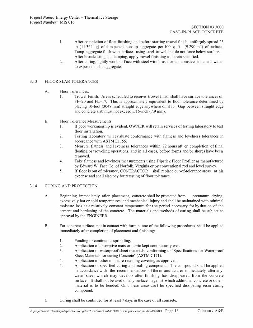
Project Name: Energy Center – Thermal Ice Storage Project Number: MIS 016
SECTION 03 3000 CAST-IN-PLACE CONCRETE
-f:\projects\mis016\projmgmt\specs\ice storage\arch and structural\03 3000 cast in place concrete.doc-4/3/2013 Page 16 CENTURY A&E
1. After completion of float finishing and before starting trowel finish, uniformly spread 25 lb (11.364 kg) of dam pened nonslip aggregate per 100 sq. ft (9.290 m2) of surface. Tamp aggregate flush with surface using steel trowel, but do not force below surface. After broadcasting and tamping, apply trowel finishing as herein specified.
2. After curing, lightly work surf ace with steel wire brush, or an abrasive stone, and water to expose nonslip aggregate.
3.13 FLOOR SLAB TOLERANCES
A. Floor Tolerances: 1. Trowel Finish: Areas scheduled to receive trowel finish shall have surface tolerances of
FF=20 and FL=17. This is approximately equivalent to floor tolerance determined by placing 10-foot (3048 mm) straight edge anywhere on slab. Gap between straight edge and concrete slab must not exceed 5/16-inch (7.9 mm).
B. Floor Tolerance Measurements:
1. If poor workmanship is evident, OWNER will retain services of testing laboratory to test floor installation.
2. Testing laboratory will ev aluate conformance with flatness and levelness tolerances in accordance with ASTM E1155.
3. Measure flatness and l evelness tolerances within 72 hours aft er completion of fi nal floating or troweling operations, and in all cases, before forms and/or shores have been removed.
4. Take flatness and levelness measurements using Dipstick Floor Profiler as manufactured by Edward W. Face Co. of Norfolk, Virginia or by conventional rod and level survey.
5. If floor is out of tolerance, CONTRACTOR shall replace out-of-tolerance areas at his expense and shall also pay for retesting of floor tolerance.
3.14 CURING AND PROTECTION:
A. Beginning immediately after placement, concrete shall be protected from premature drying, excessively hot or cold temperatures, and mechanical injury and shall be maintained with minimal moisture loss at a rel atively constant temperature for t he period necessary for hy dration of the cement and hardening of the concrete. The materials and methods of curing shall be subject to approval by the ENGINEER.
B. For concrete surfaces not in contact with form s, one of the following procedures shall be applied
immediately after completion of placement and finishing:
1. Ponding or continuous sprinkling. 2. Application of absorptive mats or fabric kept continuously wet. 3. Application of waterproof sheet materials, conforming to "Specifications for Waterproof
Sheet Materials for curing Concrete" (ASTM C171). 4. Application of other moisture-retaining covering as approved. 5. Application of specified curing and sealing compound. The com pound shall be applied
in accordance with the recommendations of the m anufacturer immediately after any water sheen whi ch may develop after finishing has disappeared from the concrete surface. It shall not be used on any surface against which additional concrete or other material is to be bonded. On t hese areas use t he specified dissipating resin curing compound.
C. Curing shall be continued for at least 7 days in the case of all concrete.

Project Name: Energy Center – Thermal Ice Storage Project Number: MIS 016
SECTION 03 3000 CAST-IN-PLACE CONCRETE
-f:\projects\mis016\projmgmt\specs\ice storage\arch and structural\03 3000 cast in place concrete.doc-4/3/2013 Page 17 CENTURY A&E
D. Hot Weather: W hen necessary, provision for windbreaks, shading, fog spraying, sprinkling, ponding or wet covering with a light colored material shall be made in advance of placement, and such protective measures shall be taken as quickly as concrete hardening and finishing operations will allow.
E. Rate of Tem perature Change: Changes in tem perature of the air immediately adjacent to the
concrete during and immediately following the curing period shall be kept as uniform as possible and shall not exceed 5 degrees F in any one hour or 50 degrees F in any 24-hour period.
F. During the curing period, the concrete shall be protected from damaging mechanical disturbances,
such as load stresses, heavy shock, and excessive vibration. All finished concrete surfaces shall be protected from damage by construction equipment, materials, or m ethods, by application of curing procedures, and by rain or running water. Self-supporting structures shall not be loaded in such a way as to over stress the concrete.
3.15 FIELD QUALITY CONTROL:
A. Field inspection and t esting is to be perform ed by a fi rm appointed and pai d for by the ENGINEER. W hen additional testing of materials or concrete is necessary because of their failure by test or inspection to meet specification requirements, the cost of the additional testing shall be paid for by the CONTRACTOR.
B. Provide access to all portions of the work and an y necessary assistance in obtaining and handling
samples at the project or other material sources. C. Sampling Fresh Concrete: ASTM C172, except modified for slump to comply with ASTM C94.
1. Compression Strength Specimen: ASTM C31; one set of 4 cylinders for each 50 cu yd (35 m3), or fraction thereof, of each m ixture design of concrete placed in any one day. Provide 2 addi tional sets of cylinders and store on si te to be used l ater if required for verification of in-place concrete strength.
2. Slump: ASTM C143; one test at point of discharge for each com pressive strength specimen or whenever consistency of concrete appears to vary.
3. Air Content: ASTM C173, volumetric method for lightweight or normal weight concrete; ASTM C231 pressure method for normal weight concrete; one test at point of discharge for each com pressive strength specim en and for each batch whenever consistency of concrete appears to vary.
4. Concrete Temperature: One test at point of discharge for each compressive strength specimen and whenever consistency of concrete appears to vary.
5. Compressive Strength Tests: ASTM C39; one specimen tested at 7 days, 2 specimens tested at 28 days, and one specimen retained in reserve for later testing if required.
6. When frequency of testing will p rovide fewer th an 5 strength tests fo r given class o f concrete, conduct testing from at least 5 randomly selected batches or from each batch if fewer than 5 are used.
7. When total quantity of given class o f concrete is less th an 50 cu yds (35 m3), ENGINEER may waive strength test if adequate evidence of sat isfactory strength is provided.
8. When strength of field-cured cylinders is less than 85 percent of companion laboratory-cured cylinders, evaluate current operations and provi de corrective procedures for protecting and curing the in-place concrete.
9. Strength level of concrete will b e considered satisfactory if averages of sets of 3 consecutive strength test results equal or ex ceed specified compressive strength, and no individual strength test result falls below specified compressive strength by more than 500 psi (3.447 MPa).

Project Name: Energy Center – Thermal Ice Storage Project Number: MIS 016
SECTION 03 3000 CAST-IN-PLACE CONCRETE
-f:\projects\mis016\projmgmt\specs\ice storage\arch and structural\03 3000 cast in place concrete.doc-4/3/2013 Page 18 CENTURY A&E
D. Test results will b e reported in writing to Project Manager, Structural Engineer, Ready-Mix Producer, and CONTRACTOR within 24 hours after tests. Reports of compressive strength tests shall contain the project identification nam e and number, date of concrete placem ent, name of concrete testing service, concrete type and cl ass, location of concrete batch in structure, design compressive strength at 28 days, concrete mix proportions and materials, compressive breaking strength, and type of break for both 7-day tests and 28-day tests.
E. Nondestructive Testing: Im pact hammer, sonoscope, or ot her nondestructive device may be
permitted but shall not be used as the sole basis for acceptance or rejection. F. Additional Tests: The testing service will make additional tests of in-place concrete when test
results indicate specified concrete strengths and other characteristics have not been attained in the structure, as directed by ENGINEER. Testing service may conduct tests to determine adequacy of concrete by cored cy linders complying with ASTM C42, or by other methods as directed. CONTRACTOR shall pay for such tests when unacceptable concrete is verified.
END OF SECTION

Project Name: Energy Center – Thermal Ice Storage Project Number: MIS 016
SECTION 03 3000 CAST-IN-PLACE CONCRETE
-f:\projects\mis016\projmgmt\specs\ice storage\arch and structural\03 3000 cast in place concrete.doc-4/3/2013 Page 19 CENTURY A&E
ASTM C150 - Portland Cement Types Type
Mortar Cube. Compressive Strength/Days
Usage
I 2800 @ 7 For use when the special properties specified for any other type are not required. IA ** 2250 @ 7 Same uses as Type I except where air entraining is desired. II 2500 @ 7 For general use, more especially when moderate sulfate resistance or moderate heat of
hydration is desired. IIA ** 2000 @ 7 Same uses as Type II except where air entraining is desired. III 3500 @ 3 For use when high early strength is desired. IIIA ** 2800 @ 3 Same uses as Type III except where air entraining is desired. IV 2500 @ 28 For use when a low heat of hydration is desired. V 3000 @ 28 For use when high sulfate resistance is desired. ASTM C595 - Blended Hydraulic Cement Types Type
Mortar Cube Compressive Strength **
Suffixes *
Usage
Type IS - Portland Blast Furnace Cement
3500 MS - A - MH For use in general concrete construction.
Type IP - Portland Pozzolan Cement
3500 MS - A - MH For use in general concrete construction.
Type P - Portland Pozzolan Cement
3000 MS - A - LH For use in concrete construction where high strength at early ages are not required.
Type S - Slag Cement 1500 A For use in combination with portland cement in making concrete or i n combination with hydrated lime in making masonry mortar.
Type I(PM) - Pozzolan Modified Portland Cement
3500 MS - A - MH For use in general concrete construction.
Type I(SM) - Slag Modified Portland Cement
3500 MS - A - MH For use in general concrete construction.
* These admixtures and suffixes may be speci fied for desi gnated cement types singularly or i n any
combination thereof: MS - Moderate Sulfate Resistance; A - Air Entraining; MH - Moderate Heat of Hydration; LH- Low Heat of Hydration.
** NOTE: Air Entraining reduces compressive strength by approximately 17 - 20%.

Blank Page
jmuizelaar
Rectangle

Project Name: Energy Center – Thermal Ice Storage Project Number: MIS 016
SECTION 03 3000 CAST-IN-PLACE CONCRETE
f:\projects\mis016\projmgmt\specs\ice storage\arch and structural\03 3000 cast in place concrete.doc-4/3/2013Page 20 CENTURY A&E
SCHEDULE A SPECIFICATION REQUIREMENTS FOR CONCRETE USE CATEGORY
PERMISSIBLE CEMENT TYPE
MINIMUMCEMENT CONTENT/CY
COARSE AGGREGATE
MAXIMUM WATER/CEMENT RATIO*
ENTRAINED AIR CONTENT
MAXIMUM SLUMP
MINIMUMCOMPRESSIVESTRENGTH Fc'
Interior Floors: a. Residential I, IP 5-1/2 sacks MDOT-6A 5.5 gal/sack --- 4" 3500 psi b. Industrial
(garage) I, IP, IA, IP-A 5-1/2 sacks MDOT-6A 5.5 gal/sack 5-7% 3" 4000 psi
c. Industrial and Commercial
I, IP, IA, IP-A 5-1/2 sacks MDOT-6A 5.5 gal/sack 2-3% 3" 4000 psi
d. Lightweight/Com- posite (110 pcf)
I, IA 5-1/2 sacks 3/4" max. **** 5.5 gal/sack 5-7% 4" 3500 psi
Interior: a. Liquid Containing
Structures I, IP, IA, IP-A 6 sacks MDOT-6AA 5.5 gal/sack 5-7% 4" 3500 psi
b. Conc. exposed to raw sewage or aggressive solutions
IP, II, V, IP-A IIA, VA
6 sacks MDOT-6AA 5.0 gal/sack 5-7% 4" 3500 psi
c. Beams, Columns, Walls, etc.
I, IP 5-1/2 sacks MDOT-6A 6.0 gal/sack --- 4" 4000 psi
Exterior: ** a. Liquid Containing
Structures I, IP, IA, IP-A 6 sacks MDOT-6AA 5.5 gal/sack 5-7% 4" 4000 psi
b. Conc. exposed to raw sewage or aggressive solutions
IP, II, V, IP-A IIA, VA
6 sacks MDOT-6AA 5.0 gal/sack 5-7% 4" 4000 psi
c. Beams, Columns, Walls, etc.
I, IP, IA, IP-A 5-1/2 sacks MDOT-6A 5.5 gal/sack 5-7% 4" 4000 psi
d. Architectural Conc.
I, IP, IA, IP-A 5-1/2 sacks *** 5.5 gal/sack 5-7% 4" 3500 psi
e. Footings I, IP 5-1/2 sacks MDOT-6A 6.0 gal/sack --- 3" 4000 psi f. Sidewalks, Conc.
Paving, etc. I, IP, IA, IP-A 5-1/2 sacks MDOT-6AA 5.0 gal/sack 5-7% 3" 3500 psi
* Water Cement Ratio: 5.0 gal/sack = 0.44 lbs/lbs., 5.5 gal/sack = 0.48 lbs/lbs., 6.0 gal/sack = 0.53 lbs/lbs. ** Exterior Means: Exterior exposure on any side. *** Maximum Coarse Aggregate size shall be compatible with the form liner and placing methods to be used by the CONTRACTOR. **** Lightweight Aggregate shall be predampened and allowed to remain stockpiled for minimum of 12 hours before use.

Blank P
age
jmuizelaar
Rectangle

Project Name: Energy Center – Thermal Ice Storage Project Number: MIS 016
SECTION 03 3000 CAST-IN-PLACE CONCRETE
f:\projects\mis016\projmgmt\specs\ice storage\arch and structural\03 3000 cast in place concrete.doc-4/3/2013 Page 21 CENTURY A&E
SCHEDULE B TOLERANCES FOR FORMED SURFACES (ACI 301, 4.3.1) 1. Variation from plumb:
A. In the lines and surfaces of columns, piers, walls, and in arrises: In any 10 foot of length .......................................................................................................... 1/4 inch Maximum for the entire length ................................................................................................. 1 inch
B. For exposed corner columns, control joint grooves, and other conspicuous lines: In any 20 foot length .............................................................................................................. 1/4 inch Maximum for the entire length .............................................................................................. 1/2 inch
2. Variation from the level or from the grades specified in the contract documents: A. In slab soffits, ceilings, beam soffits and in arrises,
measured before removal of supporting shores In any 10 foot of length .......................................................................................................... 1/4 inch In any bay or in any 20 foot length ........................................................................................ 3/8 inch Maximum for the entire length .............................................................................................. 3/4 inch
B. In exposed lintels, sills, parapets, horizontal grooves, and other conspicuous lines: In any bay or in any 20 foot length ........................................................................................ 1/4 inch Maximum for the entire length .............................................................................................. 1/2 inch
3. Variation of the linear building lines from established position in plan and related position of columns, walls, and partitions:
In any bay ............................................................................................................................... 1/2 inch In any 20 foot of length .......................................................................................................... 1/2 inch Maximum for the entire length ................................................................................................. 1 inch
4. Variation in the sizes and location of sleeves, floor openings, and wall openings .................................................................................................... + 1/4 inch
5. Variation in cross sectional dimensions of columns and beams and in the thickness of slabs and walls:
Minus ..................................................................................................................................... 1/4 inch Plus......................................................................................................................................... 1/2 inch
6. Footings* A. Variations in dimensions in plan:
Minus ..................................................................................................................................... 1/2 inch Plus......................................................................................................................................... 2 inches
B. Misplacement or eccentricity: 2 percent of the footing width in the direction of misplacement but not more than ........................................................................................ 2 inches
C. Thickness: Decrease in specified thickness ............................................................................................ 5 percent Increase in specified thickness .............................................................................................. No limit
7. Variation in steps: A. In a flight of stairs:
Rise ..................................................................................................................................... + 1/8 inch Tread ................................................................................................................................... + 1/4 inch
B. In consecutive steps: Rise ................................................................................................................................... + 1/16 inch Tread ................................................................................................................................... + 1/8 inch
* Tolerances apply to concrete dimensions only, not to positions of vert ical reinforcing steel, dowels, or
embedded items.

Blank Page
jmuizelaar
Rectangle

Project Name: Energy Center – Thermal Ice Storage Project Number: MIS 016
SECTION 03 6000 GROUT
f:\projects\mis016\projmgmt\specs\ice storage\arch and structural\03 6000 grout.doc-4/3/2013 Page 1 CENTURY A&E
PART 1 - GENERAL 1.01 DESCRIPTION:
A. This Section includes installation of cementitious grout for structural steel column base plates, bearing plates, drilled-in anchor bolts, drilled-in reinforcing dowels, etc. as shown on Drawings. This Section also includes the use of non-shrink grout for structural concrete repairs.
B. Related Sections: Section 05 1200 Structural Steel
1.02 SUBMITTALS:
A. Submit under provisions of Section 01300, “Submittals.”
B. Submit product data or manufacturer's specifications and installation instructions for following products. Include laboratory test reports and other data to show compliance with specifications (including specified standards). 1. Shrinkage-resistant grout.
C. Submit shop drawings, including setting drawings, templates, and directions for installation of
anchor bolts and other anchorages to be installed as work of other Sections. PART 2 - PRODUCTS 2.01 MATERIALS:
A. Shrinkage-Resistant Grout: Premixed, non-metallic, non-corrosive, non-staining product containing selected silica sands, portland cement, shrinkage compensating agents, plasticizing and water-reducing agents with minimum compressive strength of 6,000 psi at 28 days, complying with ASTM C1107. Subject to compliance with requirements, provide one of the following: 1. "Euco Hi Flow."; Euclid Chemical Co. 2. "Crystex"; L & M Construction Chemicals, Inc. 3. "Masterflow 928"; Master Builders. 4. "Upcon Superflow"; Bostick Upco Division. 5. "Five Star Grout"; U.S. Grout Corp. 6. ENGINEER approved equal.
PART 3 - EXECUTION 3.01 PLACEMENT OF SETTING BASES AND BEARING PLATES:
A. Clean concrete and masonry bearing surfaces of bond-reducing materials and roughen to improve bond to surfaces. Clean thoroughly with liberal quantities of water, leaving concrete saturated but free of standing water.
B. Clean Bottom surface of base and bearing plates. Set loose and attached base plates and bearing
plates for structural steel members on steel wedges or other steel adjusting devices.
C. Tighten anchor bolts after supported members have been positioned and plumbed. Do not remove wedges or shims, but if protruding, cut off flush with edge of base or bearing plate prior to packing with grout.
D. Pack grout solidly between bearing surfaces and bases or plates to ensure that no voids remain.
Finish exposed surfaces, protect installed materials, and allow to cure.
E. For proprietary grout materials, comply with manufacturer's instructions.
END OF SECTION

Blank Page
jmuizelaar
Rectangle

Project Name: Energy Center – Thermal Ice Storage Project Number: MIS 016
SECTION 04 2000 UNIT MASONRY
f:\projects\mis016\projmgmt\specs\ice storage\arch and structural\04 2000 unit masonry.doc4/3/13 Page 1 CENTURY A&E
PART 1 - GENERAL 1.01 SECTION INCLUDES:
A. This work is required only if the door to the roof must be enlarged to remove the existing chiller / boiler. See Section 01010 for additional information.
B. This Section includes the following:
1. Concrete unit masonry. 2. Clay unit masonry. 3. Masonry reinforcing and anchors. 4. Masonry accessories. 5. Masonry wall insulation.
1.02 SUBMITTALS:
A. Submit under provision of SECTION 01300. B. Submittal Requirements:
Specified Items
Product Data
Shop Dwgs.
Samples
Mfg. Matl. Certif.
Matl.Test Reports
Concrete Masonry Units Mortar & grout materials
X X X
Face Brick X X XMortar & grout mixes X X Accessories * Exp Jt/C.J./ Bond Breaker/Weeps/ Vents
X
Cleaners * X 1. Submittals for Items Identified by Asterisk (*): If products will be supplied to the project
exactly as specified, supplier may at his option submit a letter of certification listing products being used and identifying manufacturer and model number. Provided information is adequate to verify conformance with specifications, no other submittals will be required for those items.
1.03 QUALITY ASSURANCE:
A. Unit Masonry Standard: The design and construction of concrete masonry shall conform to National Concrete Masonry Association (NCMA) and comply with ACI 530.1/ASCE 6 "Specifications for Masonry Structures". 1. Revise ACI 530.1/ASCE 6 to exclude Sections 1.4 and 1.7; Parts 2.12, 3.1.2, and 4.1.2;
and Articles 1.5.1.2, 1.5.1.3, 2.1.1.1, 2.1.1.2, and 2.3.3.9 and to modify Article 2.1.1.4 by deleting requirement for installing vent pipes and conduits built into masonry.
B. Single-Source Responsibility for Mortar Materials: Obtain mortar ingredients of uniform quality,
and color for exposed masonry, from one manufacturer for each cementitious component and from one source and producer for each aggregate.
1.04 DELIVERY, STORAGE, AND HANDLING:
A. Deliver masonry materials to project in undamaged condition.

Project Name: Energy Center – Thermal Ice Storage Project Number: MIS 016
SECTION 04 2000 UNIT MASONRY
f:\projects\mis016\projmgmt\specs\ice storage\arch and structural\04 2000 unit masonry.doc4/3/13 Page 2 CENTURY A&E
B. Store cementitious materials off the ground, under cover, and in dry location. C. Store aggregates where grading and other required characteristics can be maintained and
contamination avoided. D. Store masonry accessories including metal items to prevent corrosion and accumulation of dirt
and oil. 1.05 PROJECT CONDITIONS:
A. Stain Prevention: Prevent grout, mortar, and soil from staining the face of masonry to be left exposed or painted. Remove immediately any grout, mortar, and soil that come in contact with such masonry. 1. Protect base of walls from rain-splashed mud and mortar splatter by means of coverings
spread on ground and over wall surface. 2. Protect sills, ledges, and projections from mortar droppings. 3. Protect surfaces of window and door frames, and similar products from mortar
droppings. B. Cold-Weather Construction: Comply with referenced unit masonry standard for cold-weather
construction. Do not lay masonry units that are wet or frozen. Remove masonry damaged by freezing conditions.
C. Hot-Weather Construction: Comply with referenced unit masonry standard.
PART 2 - PRODUCTS 2.01 MATERIALS, GENERAL:
A. Comply with referenced unit masonry standard and other requirements specified in this Section applicable to each material indicated.
2.02 CLAY MASONRY UNIT – BRICK:
A. Provide special molded shapes where indicated on the drawings and at locations where
configuration of construction cannot be produced by sawing standard brick or where special brick is required to produce finished surfaces on all exposed edges.
B. Face Brick: ASTM C216, Grade SW, Type FBS standard modular size, 7-5/8” x 3-5/8” x 2-1/4”.
Match existing brick veneer in size and color.
2.03 CONCRETE MASONRY UNITS: A. General: Provide special shapes where indicated on the Drawings and at lintels, corners, jambs,
sash, control joints, headers, for bonding other special conditions. Provide square edge units for outside corners unless indicated otherwise.
B. Standard Concrete masonry Units:
1. Size: Standard modular units – 7 5/8” x 7 5/8” x 15 5/8”. Other sizes where indicated on the Drawings.
2. Exposed surfaces: Manufacturer’s standard color and texture. 3. Classification:
a. Below Grade Units: ASTM C90, Grade N, Type I, normal weight, 125pcf. b. Exterior Envelope Units: ASTM C90, Grade N, Type I, medium weight, 105pcf
to less than 125 pcf.
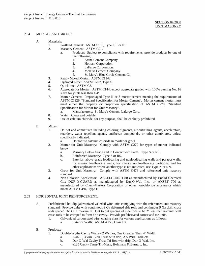
Project Name: Energy Center – Thermal Ice Storage Project Number: MIS 016
SECTION 04 2000 UNIT MASONRY
f:\projects\mis016\projmgmt\specs\ice storage\arch and structural\04 2000 unit masonry.doc4/3/13 Page 3 CENTURY A&E
2.04 MORTAR AND GROUT:
A. Materials: 1. Portland Cement: ASTM C150, Type I, II or III. 2. Masonry Cement: ASTM C91.
a. Products: Subject to compliance with requirements, provide products by one of the following: 1. Aetna Cement Company. 2. Holnam Corporation. 3. LaFarge Corporation. 4. Medusa Cement Company. 5. St. Mary's Blue Circle Cement Co.
3. Ready Mixed Mortar: ASTM C1142. 4. Hydrated Lime: ASTM C207, Type S. 5. Quicklime: ASTM C5. 6. Aggregate for Mortar: ASTM C144, except aggregate graded with 100% passing No. 16
sieve for joints less than 1/4". 7. Mortar Cement: Prepackaged Type N or S mortar cement meeting the requirements of
ASTM C1329, "Standard Specification for Mortar Cement". Mortar cement mortar must meet either the property or proportion specification of ASTM C270, "Standard Specification for Mortar for Unit Masonry". a. Manufacturers: St. Mary's Cement, Lafarge Corp.
8. Water: Clean and potable. 9. Use of calcium chloride, for any purpose, shall be explicity prohibited.
B. Mixes:
1. Do not add admixtures including coloring pigments, air-entraining agents, accelerators, retarders, water repellent agents, antifreeze compounds, or other admixtures, unless specifically indicated. a. Do not use calcium chloride in mortar or grout.
2. Mortar for Unit Masonry: Comply with ASTM C270 for types of mortar indicated below: a. Masonry Below Grade and in Contact with Earth: Type S or RS. b. Reinforced Masonry: Type S or RS. c. Exterior, above-grade loadbearing and nonloadbearing walls and parapet walls;
for interior loadbearing walls; for interior nonloadbearing partitions, and for other applications where another type is not indicated, use Type N or RN.
3. Grout for Unit Masonry: Comply with ASTM C476 and referenced unit masonry standard.
4. Non-Chloride Accelerator: ACCELGUARD 80 as manufactured by Euclid Chemical Co.; DUR-O-GUARD as manufactured by Dur-O-Wal, Inc., or AKSET 700 as manufactured by Chem-Masters Corporation or other non-chloride accelerator which meets ASTM C494, Type E.
2.05 HORIZONTAL JOINT REINFORCEMENT:
A. Prefabricated hot dip galavanized weleded wire units complying with the referenced unit masonry
standard. Provide units with continuous 9 Ga deformed side rods and continuous 9 Ga plain cross rods spaced 16” O.C. maximum. Out to out spacing of side rods to be 2” less than nominal wall cross rods to be crimped to form drip cavity. Provide prefabricated corner and tee units. 1. Galvanized carbon steel wire, coating class for various applications as follows:
a. Exterior Walls: ASTM A153, Class B2.
B. Products: 1. Double-Wythe Cavity Walls – 2 Wythes, One Greatrer Than 4” Width:
a. AA610, 3 wire Blok Truss with drip, AA Wire Products. b. Dur-O-Wal Cavity Truss Tri Rod with drip, Dur-O-Wal, Inc. c. #135 Cavity Truss-Tri-Mesh, Hohmann & Barnard, Inc.

Project Name: Energy Center – Thermal Ice Storage Project Number: MIS 016
SECTION 04 2000 UNIT MASONRY
f:\projects\mis016\projmgmt\specs\ice storage\arch and structural\04 2000 unit masonry.doc4/3/13 Page 4 CENTURY A&E
2.06 ADJUSTABLE MASONRY VENEER ANCHOR:
A. Rib stiffened 14 Ga hot dipped galvanized brick tie. 1. #315 Flexible Dovetail Brick Tie, Hohmann & Barnard, Inc.
2.07 MISCELLANEOUS MASONRY ACCESSORIES:
A. Weep Holes and Vents: Provide the following: 1. Weeps: #343 Wilko Weep Hole by Hohmann & Barnard Inc., spaced no greater than
16" o.c. Located at base of cavity wall, shelf angles, door and window heads. 2. Weeps: 3/8-inch tube spaced 16” o.c., but no less than three per window. Located above
window sill thru-wall flashing. 3. Vents: #343 Wilko Weep Hole by Hohmann & Barnard Inc., spaced no greater than 24”
o.c. Locate at top of cavity wall and top of all other portions of cavity wall that are not continous.
B. Mortar Dropping Collection Device:
1. Provide product manufactured from polyester/polyethylene mesh and using recycled polyster.
2. Acceptable product: Mortar Net htt://www.mortarnet.com/ 3. Shape to be trapezoidal (dovetail) to enhance drsainage. 4. Material will no oxidize, rot, promote mold or fungus, or react with other common
building materials such as mortar, cememt, asphalt, modified bitumen, PVC, copper, or galvanized metal, thereby ensuring long-term performance for all materials.
2.08 EMBEDDED THROUGH WALL FLASHING MATERIALS:
A. Flexible Sheet Flashing: 1. Uncured EDPM self-adhering membrane, 24-inches wide, 60 mil thick, installed in
accordance with manufacturer’s instructions.
B. Drip Edge Flashing: 1. Use 0.018-inch thick stainless steel.
2.09 INSULATION:
A. Loose Granular perlite Insulation:
1. ASTM C549, Type II surface-treated for water repellency and limited moisture absorption.
2.10 MASONRY CLEANERS:
A. Cleaner: No acid based cleaners shall be used. The masonry contractor shall use only cleaning products approved by the concrete masonry manufacturer and/or supplier. Such approval shall be obtained in writing and a copy, along with the approved cleaning products provided as part of the masonry contractor’s shop drawing submittal.
PART 3 - EXECUTION 3.01 EXAMINATION:
A. Examine conditions, with Installer present, for compliance with requirements for installation tolerances and other specific conditions, and other conditions affecting performance of unit masonry.
B. Examine rough-in and built-in construction to verify actual locations of piping connections prior to installation.

Project Name: Energy Center – Thermal Ice Storage Project Number: MIS 016
SECTION 04 2000 UNIT MASONRY
f:\projects\mis016\projmgmt\specs\ice storage\arch and structural\04 2000 unit masonry.doc4/3/13 Page 5 CENTURY A&E
C. Report unsatisfactory conditions to the ENGINEER. Do not proceed until unsatisfactory
conditions have been corrected. 3.02 INSTALLATION, GENERAL:
A. Comply with referenced unit masonry standard and other requirements indicated applicable to each type of installation included in Project.
B. Thickness: Build cavity walls to the full thickness shown. C. Cut masonry units with motor-driven saws to provide clean, sharp, unchipped edges. Cut units as
required to provide continuous pattern and to fit adjoining construction. Use full-size units without cutting where possible.
D. Matching Existing Masonry: Match coursing, bonding, color, and texture of new masonry with
existing masonry. 3.03 CONSTRUCTION TOLERANCES:
A. Comply with construction tolerances of referenced unit masonry standard. 3.04 LAYING MASONRY WALLS:
A. Lay out walls in advance for accurate spacing of surface bond patterns with uniform joint widths.
Advoid the use of less-than-half-size units at corners, jambs and where possible at other locations.
B. Bond Pattern for Exposed Masonry: Lay exposed masonry in the following bond pattern; do not use units less than nominal 4-inch horizontal face dimensions at corners or jambs. 1. One-half running bond with vertical joint in each course centered on units in courses
above and below, except where indicated otyherwise on the Drawings.
3.05 MORTAR BEDDING AND JOINTING:
A. Lay hollow concrete masonry units as follows: 1. With full mortar coverage on horizontal and vertical face shells. 2. Bed webs in mortar in starting course on footings and in all courses of piers, columns,
and pilasters, and where adjacent to cells or cavities to be filled with grout. 3. For starting course on footings where cells are not grouted, spread out full mortar bed
including areas under cells. B. Lay brick masonry units as follows:
1. Lay brick dry, plumb, level, and true to line in full beds of mrtar and with full head joints.
2. After mortar has stiffened somewhat, firmly compact joint with concave jointing tool.
C. Cut joints flush for masonry walls to be concealed or to be covered by other materials. All exposed joints to be tooled with a round jointer. Compact mortar into joints before tooling or striking flush.
3.06 CAVITIES/AIR SPACE:
A. Keep cavities/air spaces clean of mortar droppings and other materials during construction. Strike
joints facing cavities/air spaces flush.

Project Name: Energy Center – Thermal Ice Storage Project Number: MIS 016
SECTION 04 2000 UNIT MASONRY
f:\projects\mis016\projmgmt\specs\ice storage\arch and structural\04 2000 unit masonry.doc4/3/13 Page 6 CENTURY A&E
3.07 MASONRY CELL INSULATION:
A. Pour granular insulation into cavities as shown to fill void spaces completely. Maintain inspection ports to show presence of insulation at extremeties of each pour area. Close ports after complete coverage has been confirmed. Limit fall of insulation to 4’-0” height.
3.08 LINTELS:
A. Install steel lintels where indicated. B. Provide masonry lintels where shown and wherever openings of more than 1'-0" for brick size
units and 2'-0" for block size units are shown without structural steel or other supporting lintels. Provide precast or formed-in-place masonry lintels. Cure precast lintels before handling and installation. Temporarily support formed-in-place lintels. 1. For hollow concrete masonry unit walls, use specially formed bond beam units with
reinforcement bars placed as indicated and filled with coarse grout. C. Provide minimum bearing of 8 inches at each jamb, unless otherwise indicated.
3.09 FLASHING/WEEP HOLES:
A. General: Install embedded flashing and weep holes in masonry at base of cavity walls, window sills, door and window heads, horizontal relief angles and other locations used for cavity wall drainage shall be a two part system.
B. Prepare masonry surfaces so that they are smooth and free from projections that could puncture
flashing. Place through-wall flashing on sloping bed of mortar and cover with mortar. Seal penetrations in flashing with adhesive/sealant/tape as recommended by flashing manufacturer before covering with mortar.
C. Install flexible sheet flashing as follows:
1. Extend flexible sheet flashing to within no more than 1-inch of exterior face of brick veneer, overlapping and adhering to the stainless steel drip edge flashing.
2. Flexible flashing to extend up vertical face of backup substrate, using full width of sheet and terminate at the top of the flexible flashing sheet with a termination bar.
3. Caulk top edge of termination bar.
D. Install drip edge flashing as follows: 1. Horizontal leg (in joint) shall run back to within ½-inch in interior face of brick wythe
(cavity side). 2. Exposed drip leg shall be 3/8” to ½” in length and bent downward at a minimum of 15
degrees, but no greater than 45 degrees. 3. All joints shall be soldered over entire length of joint.
E. Install weep holes and vents as follows:
1. Weeps #343 spaced no greater than 16” o.c.. Locate at base of cavity walls, shelf angles, door and window heads.
2. Weeps 3/8-inch tubes spaced at 16” o.c., but no less than three per window. Locate above windo sill thru-wall flashing.
3. Vents #343 spaced no greater than 24” o.c. Locate at top of cavity walls, and top of all other portions of cavity walls that are not continous.
4. Mortar dropping collection devise shall be located inside cavity walls above weep holes.
3.10 REPAIRING, POINTING, AND CLEANING:
A. Remove and replace masonry units that are loose, chipped, broken, stained, or otherwise damaged or if units do not match adjoining units. Install new units to match adjoining units and in fresh mortar or grout, pointed to eliminate evidence of replacement.

Project Name: Energy Center – Thermal Ice Storage Project Number: MIS 016
SECTION 04 2000 UNIT MASONRY
f:\projects\mis016\projmgmt\specs\ice storage\arch and structural\04 2000 unit masonry.doc4/3/13 Page 7 CENTURY A&E
B. Pointing: During the tooling of joints, enlarge any voids or holes, except weep holes, and
completely fill with mortar. Point-up all joints including corners, openings, and adjacent construction to provide a neat, uniform appearance, prepared for application of sealants.
C. Final Cleaning: After mortar is thoroughly set and cured, clean exposed masonry as follows:
1. Remove large mortar particles by hand with wooden paddles and nonmetallic scrape hoes or chisels.
2. Test Cleaning Methods on Sample Wall Panel: Leave 1/2 panel uncleaned for comparison purposes. Obtain ENGINEER's approval of sample cleaning before proceeding with cleaning of masonry.
3. Wet wall surfaces with water prior to application of cleaners; remove cleaners promptly by rinsing thoroughly with clear water.
D. Clean brick by means of bucket and brush hand-cleaning method described in BIA “Technical Note No. 20 Revised” using the following masonry cleaner: 1. Job-mixed detergent solution.
E. Clean concrete masonry by means of cleaning method indicated in NCMA TEK 45 applicable to
type of stain present on exposed surfaces. F. Protection: Provide final protection and maintain conditions, in a manner acceptable to Installer,
that ensure unit masonry is without damage and deterioration at time of Substantial Completion.
END OF SECTION

Blank Page
jmuizelaar
Rectangle
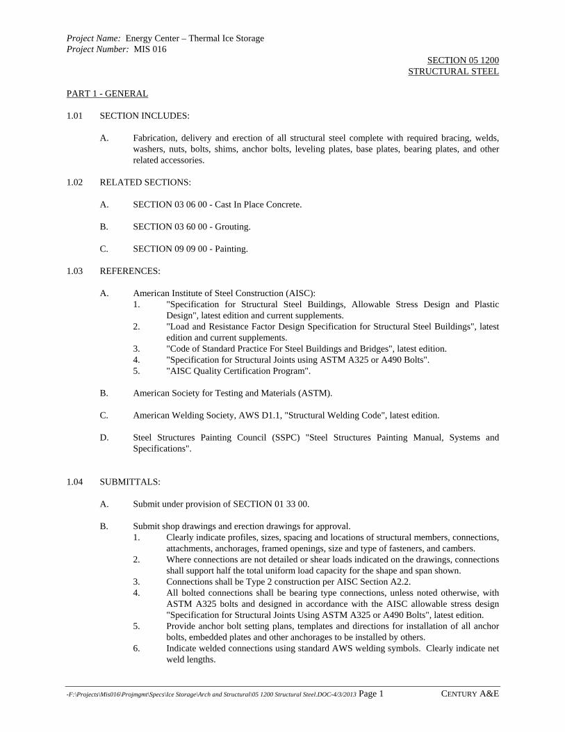
Project Name: Energy Center – Thermal Ice Storage Project Number: MIS 016
SECTION 05 1200 STRUCTURAL STEEL
-F:\Projects\Mis016\Projmgmt\Specs\Ice Storage\Arch and Structural\05 1200 Structural Steel.DOC-4/3/2013 Page 1 CENTURY A&E
PART 1 - GENERAL 1.01 SECTION INCLUDES:
A. Fabrication, delivery and erection of all structural steel complete with required bracing, welds, washers, nuts, bolts, shims, anchor bolts, leveling plates, base plates, bearing plates, and other related accessories.
1.02 RELATED SECTIONS:
A. SECTION 03 06 00 - Cast In Place Concrete. B. SECTION 03 60 00 - Grouting.
C. SECTION 09 09 00 - Painting.
1.03 REFERENCES:
A. American Institute of Steel Construction (AISC): 1. "Specification for Structural Steel Buildings, Allowable Stress Design and Plastic
Design", latest edition and current supplements. 2. "Load and Resistance Factor Design Specification for Structural Steel Buildings", latest
edition and current supplements. 3. "Code of Standard Practice For Steel Buildings and Bridges", latest edition. 4. "Specification for Structural Joints using ASTM A325 or A490 Bolts". 5. "AISC Quality Certification Program".
B. American Society for Testing and Materials (ASTM). C. American Welding Society, AWS D1.1, "Structural Welding Code", latest edition. D. Steel Structures Painting Council (SSPC) "Steel Structures Painting Manual, Systems and
Specifications". 1.04 SUBMITTALS:
A. Submit under provision of SECTION 01 33 00. B. Submit shop drawings and erection drawings for approval.
1. Clearly indicate profiles, sizes, spacing and locations of structural members, connections, attachments, anchorages, framed openings, size and type of fasteners, and cambers.
2. Where connections are not detailed or shear loads indicated on the drawings, connections shall support half the total uniform load capacity for the shape and span shown.
3. Connections shall be Type 2 construction per AISC Section A2.2. 4. All bolted connections shall be bearing type connections, unless noted otherwise, with
ASTM A325 bolts and designed in accordance with the AISC allowable stress design "Specification for Structural Joints Using ASTM A325 or A490 Bolts", latest edition.
5. Provide anchor bolt setting plans, templates and directions for installation of all anchor bolts, embedded plates and other anchorages to be installed by others.
6. Indicate welded connections using standard AWS welding symbols. Clearly indicate net weld lengths.

Project Name: Energy Center – Thermal Ice Storage Project Number: MIS 016
SECTION 05 1200 STRUCTURAL STEEL
-F:\Projects\Mis016\Projmgmt\Specs\Ice Storage\Arch and Structural\05 1200 Structural Steel.DOC-4/3/2013 Page 2 CENTURY A&E
C. Submit 2 copies of mill test reports. D. Submit welder certifications in accordance with AWS "Qualification" requirements. E. Detailed delivery and erection schedule listing shipment numbers, members and day of delivery.
1.05 DELIVERY, STORAGE AND HANDLING:
A. Deliver materials to site to ensure uninterrupted progress of work and in accordance with approved delivery schedule submitted.
B. Coordinate delivery of anchor bolts and other items which are to be embedded in cast-in-place
concrete or masonry with ENGINEER and installer in ample time to not delay work. C. Store materials to permit easy access for inspection and identification. Keep materials off ground
using pallets, timbers or other supports. Protect steel and packaged materials from corrosion and deterioration.
D. Repair or replace all damaged materials. E. Structural steel shall be handled with nylon slings or other means after painting to prevent damage
of the paint system. PART 2 - PRODUCTS 2.01 MATERIALS:
A. Structural Steel Wide Flange Shapes: Shall conform to ASTM A992 (Fy=50 ksi).
B. Bars and Plates: Shall conform to ASTM A36 (Fy=36 ksi) C. Steel Tubing or Pipe:
1. General Usage: Shall conform to ASTM A501, ASTM A500 Grade B,
D. High Strength Threaded Fasteners: Heavy hexagon high strength bolts, heavy hexagon nuts, and hardened steel washers under each turned element. 1. Quenched and tempered medium carbon steel conforming to requirements of ASTM
A325, Type 1. E. Anchor Bolts: Shall Conform to the requirements of ASTM F1554 Grade 36. F. Welding Materials: Type required for materials being welded and conforming to applicable AWS
specification. G. Grout: Shall be in accordance with SECTION 03 06 00, Grouting. H. Galvanizing: Structural steel shall be galvanized in accordance with ASTM B633, Service Class
C3 - severe. I. Paint: Shop Primer shall be Carboline, Carbocoat 115 VOC; International, 260FD Primer or
approved equal.

Project Name: Energy Center – Thermal Ice Storage Project Number: MIS 016
SECTION 05 1200 STRUCTURAL STEEL
-F:\Projects\Mis016\Projmgmt\Specs\Ice Storage\Arch and Structural\05 1200 Structural Steel.DOC-4/3/2013 Page 3 CENTURY A&E
2.02 FABRICATION:
A. All structural steel shall be fabricated and erected in accordance with the AISC "Specification for Structural Steel for Buildings, Allowable Stress Design, and Plastic Design," latest edition, as amended to-date. Verify all dimensions prior to fabrication.
B. Shop fabricate and shop assemble structural steel in largest practical sections and to greatest
extent possible to minimize field welding and erection. C. Field connections are to be bearing type bolted connections unless welding is specifically called
for on the plans. D. Accurately cut and mill column ends and bearing plates to assure full contact of bearing surfaces
prior to welding. Provide leveling nuts to position plate to a true plane and precise elevation. E. Surface preparation before prime painting shall be in accordance with SSPC-SP-3 "Power Tool
Cleaning." Do not prime surfaces to be field welded. F. Apply primer in accordance with manufacturer's requirements with a minimum dry-film thickness
of 2 mils.
G. Surface preparation and shop prime painting of all structural steel shall be in accordance with SECTION 09 09 00, Painting. Primer shall be considered as first coat.
PART 3 - EXECUTION 3.01 ERECTION:
A. Erect structural steel in accordance with approved erection drawings. B. Make adequate provision for all erection loads, and for sufficient temporary bracing to maintain
structure safe, plumb and in true alignment until completion of erection and installation of necessary permanent bracing.
C. All field welding is to be done by welders certified in accordance with AWS specifications. D. Do not enlarge holes in members by burning or drift pins, except in secondary members and with
written approval of the ENGINEER. E. Do not field cut or alter structural members without the written approval of the ENGINEER. F. Field drill all bolt holes required for new connections; no torch cutting of holes will be permitted.
G. Immediately after erection, clean and prime paint all welds, abrasions and surfaces not shop
primed, except surfaces to be in contact with concrete. Paint shall be the same as used for shop priming.
H. Immediately after erection, clean and paint all surfaces not shop painted, welds, and all damage to
the paint system in accordance with SECTION 09 09 00, Painting.
END OF SECTION

Blank Page
jmuizelaar
Rectangle
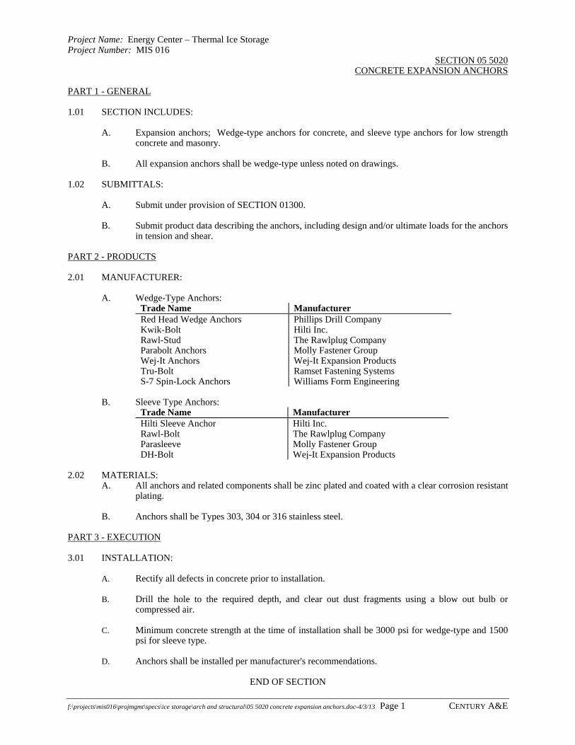
Project Name: Energy Center – Thermal Ice Storage Project Number: MIS 016
SECTION 05 5020 CONCRETE EXPANSION ANCHORS
f:\projects\mis016\projmgmt\specs\ice storage\arch and structural\05 5020 concrete expansion anchors.doc-4/3/13 Page 1 CENTURY A&E
PART 1 - GENERAL 1.01 SECTION INCLUDES:
A. Expansion anchors; Wedge-type anchors for concrete, and sleeve type anchors for low strength concrete and masonry.
B. All expansion anchors shall be wedge-type unless noted on drawings.
1.02 SUBMITTALS:
A. Submit under provision of SECTION 01300. B. Submit product data describing the anchors, including design and/or ultimate loads for the anchors
in tension and shear. PART 2 - PRODUCTS 2.01 MANUFACTURER:
A. Wedge-Type Anchors: Trade Name ManufacturerRed Head Wedge Anchors Phillips Drill CompanyKwik-Bolt Hilti Inc.Rawl-Stud The Rawlplug CompanyParabolt Anchors Molly Fastener GroupWej-It Anchors Wej-It Expansion ProductsTru-Bolt Ramset Fastening SystemsS-7 Spin-Lock Anchors Williams Form Engineering
B. Sleeve Type Anchors:
Trade Name ManufacturerHilti Sleeve Anchor Hilti Inc.Rawl-Bolt The Rawlplug CompanyParasleeve Molly Fastener GroupDH-Bolt Wej-It Expansion Products
2.02 MATERIALS:
A. All anchors and related components shall be zinc plated and coated with a clear corrosion resistant plating.
B. Anchors shall be Types 303, 304 or 316 stainless steel.
PART 3 - EXECUTION 3.01 INSTALLATION:
A. Rectify all defects in concrete prior to installation. B. Drill the hole to the required depth, and clear out dust fragments using a blow out bulb or
compressed air. C. Minimum concrete strength at the time of installation shall be 3000 psi for wedge-type and 1500
psi for sleeve type. D. Anchors shall be installed per manufacturer's recommendations.
END OF SECTION

Blank Page
jmuizelaar
Rectangle

Project Name: Energy Center – Thermal Ice Storage Project Number: MIS 016
SECTION 05 5100 METAL STAIRS
f:\projects\mis016\projmgmt\specs\ice storage\arch and structural\05 5100 metal stairs.doc-4/3/13 Page 1 CENTURY A&E
PART 1 - GENERAL 1.01 DESCRIPTION:
A. The work includes the steel stairs. 1.02 REFERENCES:
A. AISC "Specifications for the Design and Erection of Structural Steel for Buildings". B. AWS "Structural Welding Code" D1.1. C. ASTM, American Society for Testing and Materials.
1.03 SUBMITTALS:
A. Submit under provisions of Section 01 33 00, “Submittals.”
B. Shop drawings are required for the steel stairs. Indicate profiles, sizes, connections, reinforcing, anchorage, elevations, size and type of fasteners and welds.
PART 2 - PRODUCTS 2.01 MANUFACTURERS:
A. Provide prefabricated stair assemblies as manufactured by American Stair Corp. or by Sharon Industries.
2.02 MATERIALS:
A. Structural steel, ASTM A36. B. Steel pipe, ASTM A501. C. Steel plates, ASTM A283, Grade D. D. Steel sheets and strips, ASTM A570, Grade C. E. Structural bolts, ASTM A325. Anchor bolts, ASTM A307. F. Shop prime coat, zinc chromate alkyd, Federal Specifications TT-P-645.
2.03 FABRICATION:
A. Fabricate metal stairs in shop and fit and assemble in largest practical sections. Field verify dimensions affecting work prior to fabrication. Exposed joints shall be butt type, flush, and hair line where mechanically fastened. Grind exposed welds smooth and flush. Anchorage of same material and finish as metal fabrications. Thoroughly clean surfaces to be prime painted; do not shop prime surfaces to be field welded.
B. Steel stairs at location shown with stringers of A36 steel.
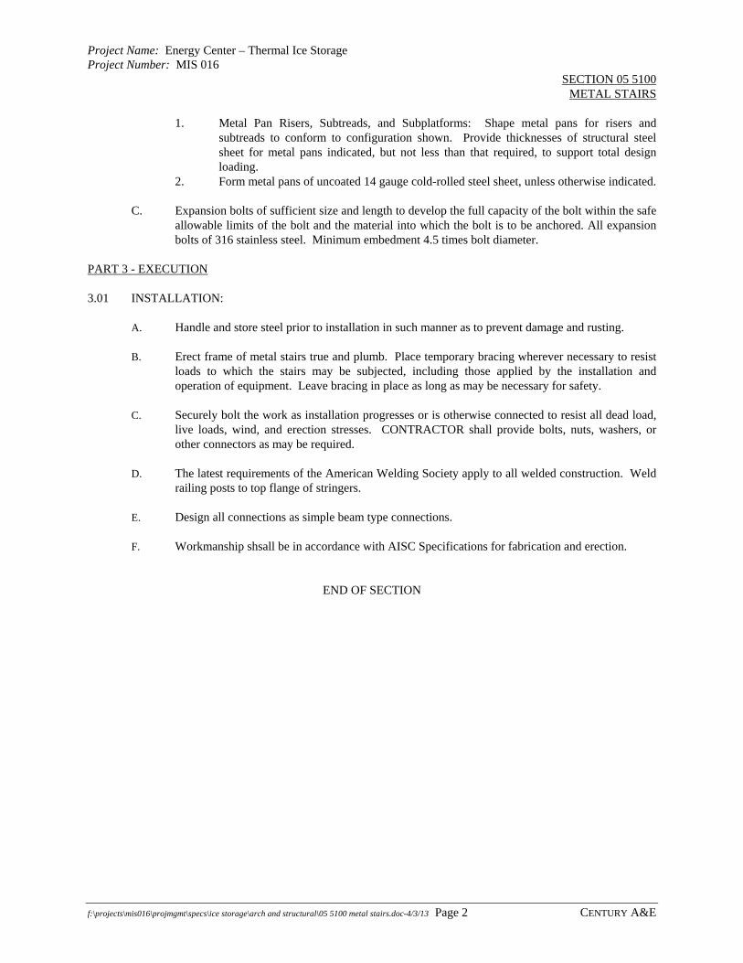
Project Name: Energy Center – Thermal Ice Storage Project Number: MIS 016
SECTION 05 5100 METAL STAIRS
f:\projects\mis016\projmgmt\specs\ice storage\arch and structural\05 5100 metal stairs.doc-4/3/13 Page 2 CENTURY A&E
1. Metal Pan Risers, Subtreads, and Subplatforms: Shape metal pans for risers and subtreads to conform to configuration shown. Provide thicknesses of structural steel sheet for metal pans indicated, but not less than that required, to support total design loading.
2. Form metal pans of uncoated 14 gauge cold-rolled steel sheet, unless otherwise indicated.
C. Expansion bolts of sufficient size and length to develop the full capacity of the bolt within the safe allowable limits of the bolt and the material into which the bolt is to be anchored. All expansion bolts of 316 stainless steel. Minimum embedment 4.5 times bolt diameter.
PART 3 - EXECUTION 3.01 INSTALLATION:
A. Handle and store steel prior to installation in such manner as to prevent damage and rusting. B. Erect frame of metal stairs true and plumb. Place temporary bracing wherever necessary to resist
loads to which the stairs may be subjected, including those applied by the installation and operation of equipment. Leave bracing in place as long as may be necessary for safety.
C. Securely bolt the work as installation progresses or is otherwise connected to resist all dead load,
live loads, wind, and erection stresses. CONTRACTOR shall provide bolts, nuts, washers, or other connectors as may be required.
D. The latest requirements of the American Welding Society apply to all welded construction. Weld
railing posts to top flange of stringers. E. Design all connections as simple beam type connections. F. Workmanship shsall be in accordance with AISC Specifications for fabrication and erection.
END OF SECTION

Project Name: Energy Center – Thermal Ice Storage Project Number: MIS 016
SECTION 05 5213 STEEL PIPE OR TUBE RAILINGS
-f:\projects\mis016\projmgmt\specs\ice storage\arch and structural\05 5213 steel pipe or tube railings.doc-4/3/13 Page 1 CENTURY A&E
PART 1 - GENERAL 1.01 DESCRIPTION:
A. The work includes all steel pipe or tube railings and handrails, fittings, attachments, and accessories.
1.02 REFERENCES:
A. Michigan Department of Labor General Industry Safety Standards Commission Safety Standards, Part 2, "Floor and Wall Openings, Stairways, and Skylights".
B. American Society for Testing and Materials.
1.03 SUBMITTALS:
A. Submit under provisions of Section 01 33 00, “Submittals.” B. Submit shop drawings for all railings, including materials, finishes, and splice and attachment
details. Identify locations and the relationship to adjoining work. Indicate all required field measurements.
C. Submit manufacturer's assembly and installation instructions.
PART 2 - PRODUCTS 2.01 MATERIALS:
A. Guardrails shall be 1-1/2 inch I.D., Schedule 40, steel pipe or tube conforming to ASTM A501; ASTM A500; or ASTM A53, Grade B, except hydrostatic test is not required.
B. Vertical posts for guardrails shall conform to ASTM A500, Grade B. C. Fittings, attachments, and accessories shall conform to ASTM A36; ASTM A48, Class 30 (grey
cast iron); or ASTM A47 (malleable iron). 2.02 FABRICATION:
A. General: Railings and vertical posts shall be of standard weight 1-1/2 inch I.D. steel pipe. 1. Joints between posts and rails shall be welded and ground smooth. 2. Spacing of vertical posts shall not exceed 5 feet on centers unless otherwise shown on
Drawings. 3. Railings shall be fabricated in as long of sections as practicable with no joints between
posts. Posts shall be a single, unspliced pipe length. Lower rails shall be a single, unspliced length between posts. Top rails shall be continuous. Two intermediate equally spaced rails are required for assembly, business, educational, and institutional facilities.
4. Distance from upper surface of top rail to top of mounting surface shall be 42 inches. Stair railings shall have a distance of not less than 34 inches nor more than 38 inches from the upper surface of the top rail to the top of the tread nosing or landing.
5. Provide stair railings complete with return ends and wall brackets. On stairways, at least one handrail shall extend in the direction of the stair run not less than 12 inches beyond the top riser nor less than 12 inches beyond the bottom riser.
6. Vertical posts shall be set into steel pipe sleeves cast in concrete, anchored by floor mounted flanged, or side mounted brackets as detailed. Minimum flange or bracket thickness shall be ¼-inch.
7. Handrail assemblies and guardrail systems shall be designed to resist a simultaneous vertical and horizontal load of 50 lb. per lineal foot applied at the top rail. The horizontal load is to be applied perpendicular to the plane of the handrail or guardrail. In addition,

Project Name: Energy Center – Thermal Ice Storage Project Number: MIS 016
SECTION 05 5213 STEEL PIPE OR TUBE RAILINGS
-f:\projects\mis016\projmgmt\specs\ice storage\arch and structural\05 5213 steel pipe or tube railings.doc-4/3/13 Page 2 CENTURY A&E
handrail assemblies and guardrail systems shall be able to withstand a single concentrated load of 200 lb. applied in any direction at any point along the top rail. This point load need not be assumed to act concurrently with the 50 lb./ft uniform load specified previously.
8. For service or access openings in railings, provide safety chains of twisted links, welded steel, galvanized, 12 links per foot, 78 pounds per 100 feet, 8000 pounds tensile strength, one end fixed, other end with safety snap hook.
9. Prime paint railings after fabrication with coating compatible with finish paint coatings specified in SECTION 09 90 00.
B. Verify field dimensions prior to fabrication. C. Railing shall be formed by welded construction conforming to AWS D1.1. All welds shall be
ground smooth. D. Rail-to-end post connections and all changes in rail direction shall be formed by radius bends. E. Two intermediate equally spaced rails required for commercial and industrial applications. Four
intermediate rails equally spaced required for assembly, business, educational and institutional facilities.
F. Close exposed ends of pipe with 3/16 inch plate or prefabricated fittings. G. Provide weep hole where moisture may accumulate. H. Toe plates 4 inches high by 1/4 inch thick steel plate 1/4 inch above walking surface. I. Slip-fit sleeves shall be provided for removable railings. J. Where shown, provide chain with eye, snap hook, and staple. K. Supply components required for proper anchorage of railings and handrails. L. Shop prime all sections with primer compatible with finish coat(s). See SECTION 09 90 00.
PART 3 - EXECUTION 3.01 INSTALLATION:
A. Erect work square, level, and free from distortion or defects detrimental to appearance and performance.
B. Tolerances:
1. Spacing: + 3/8 inch. 2. Alignment: + 1/4 inch. 3. Plumbness: + 1/8 inch.
C. Set posts in concrete with molten lead or non-shrink grout SECTION 03 60 00. D. Grind smooth all field welds. E. Touch up all field welds or damaged surface areas with primer. F. Rectify all defective work.
END OF SECTION

Project Name: Energy Center – Thermal Ice Storage Project Number: MIS 016
SECTION 05 5900 MISCELLANEOUS METAL WORK
f:\projects\mis016\projmgmt\specs\ice storage\arch and structural\05 5900 miscellaneous metal work.doc-4/3/13 Page 1 Century A&E
PART 1 - GENERAL 1.01 DESCRIPTION:
A. The work includes the custom fabrication of ferrous metal items. B. Provide new steel support systems for the new piping and equipment.
1.02 SUBMITTALS:
A. Submit under provisions of Section 01300. 1.03 REFERENCES:
A. AISC "Specifications for the Design and Erection of Structural Steel for Buildings". B. AWS "Structural Welding Code" D1.1. C. ASTM, American Society for Testing and Materials.
PART 2 - PRODUCTS 2.01 MATERIALS:
A. Structural Steel: ASTM A572 wide flange shapes, ASTM A36 for all other shapes. B. Steel Plates: ASTM A283, Grade D. C. Structural Bolts: ASTM A325. Anchor bolts, ASTM A307. D. Shop Prime Coat: Zinc chromate alkyd, Federal Specifications TT-P-645.
2.02 FABRICATION:
A. Miscellaneous metal work shop fabricated, fitted, and assembled in largest practical sections. Verify dimensions affecting work prior to fabrication. Exposed joints butt type, flush, and hairline where mechanically fastened. Grind exposed welds smooth and flush. Anchorage of same material and finish as metal fabrications. Thoroughly clean surfaces to be galvanized or prime painted; do not shop prime surfaces to be field welded.
B. Provide steel lintels as indicated. End bearings minimum of 8 inches. Weld plates continuous to
structural members. PART 3 - EXECUTION 3.01 FABRICATION:
A. Miscellaneous metal is to be shop fabricated, insofar as practical. Field cutting, drilling, and welding are prohibited except as allowed by ENGINEER.

Project Name: Energy Center – Thermal Ice Storage Project Number: MIS 016
SECTION 05 5900 MISCELLANEOUS METAL WORK
f:\projects\mis016\projmgmt\specs\ice storage\arch and structural\05 5900 miscellaneous metal work.doc-4/3/13 Page 2 Century A&E
3.02 ERECTION:
A. Prior to erection, steel handled and stored in such manner as to prevent damage and rusting. B. The frame of metal structures erected true and plumb. Temporary bracing placed wherever
necessary to resist all loads to which the structure may be subjected, including those applied by the installation and operation of equipment. Such bracing left in place as long as may be necessary for safety.
C. As erection progresses the work shall be securely bolted or otherwise connected to resist all dead
load, live loads, wind and erection stresses. The CONTRACTOR to provide bolts, nuts, and washers or other connectors as may be required.
D. Do not cut, weld or drill galvanized items after the zinc coating is applied. E. The latest requirements of the American Welding Society apply to all welded construction. F. All connections designed as simple beam type connections. G. Workmanship in accordance with AISC Specifications for fabrication and erection.
END OF SECTION

Project Name: Energy Center – Thermal Ice Storage Project Number: MIS 016
SECTION 07 8410 FIRESTOPPING
f:\projects\mis016\projmgmt\specs\ice storage\arch and structural\07 8410 firestopping.doc-4/3/2013 Page 1 CENTURY A&E
PART 1 - GENERAL 1.01 DESCRIPTION:
A. Firestop all penetrations of floors and walls in fire-rated assemblies as indicated on Drawings. Only tested firestop systems shall be used in specific locations as follows: 1. Penetrations for the passage of duct, cable, cable tray, conduit, piping, electrical busways and
raceways through fire-rated vertical barriers (walls and partitions), horizontal barriers (floor/ceiling assemblies), and vertical service shaft walls and partitions.
2. Safing slot gaps between edge of floor slabs and curtain walls. 3. Openings between structurally separated sections of walls or floors. 4. Gaps between the top of walls and ceilings or roof assemblies. 5. Expansion joints in walls and floors. 6. Openings and penetrations in fire-rated partitions or walls containing fire doors. 7. Openings around structural members that penetrate floors or walls.
1.02 REFERENCES:
A. ASTM E814, "Standard Method of Fire Tests of Through Penetration Fire Stops."
B. ASTM E84, "Standard Test Method for Surface Burning Characteristics of Building Materials."
C. Underwriters Laboratories (UL) of Northbrook, IL also performs ASTM E814 tests under their designation of UL 1479, and publishes the results in their "Fire Resistance Directory" that is updated annually with a mid year Supplement. 1. UL Fire Resistance Directory:
a. Through-Penetration Firestop Devices (XHCR). b. Fire-Resistance Ratings (BXUV). c. Through-Penetration Firestop Systems (XHEZ). d. Fill, Voids, or Cavity Material (XHHW). e. Forming Materials (XHKU).
D. UL 2079, "Tests for Resistance of Building Joint Systems." E. Building Codes: BOCA, ICBO, and SBCCI.
F. NFPA 101, "Life Safety Code."
G. NFPA 70, "National Electrical Code."
1.04 DEFINITIONS:
A. Firestopping: Material or combination of materials used to retain integrity of fire-rated construction by maintaining an effective barrier against the spread of flame, smoke, water, and hot gases through penetrations in fire-rated wall and floor assemblies.
B. F-Rating (Flame Rating): The length of time the firestop system will resist passage of gases and flame
on the unexposed surface (opposite side of furnace) including penetrating elements. This rating assures the slow spread of the fire by preventing the passage of flame and gases within the project’s fire resistance requirements.
C. T-Rating (Temperature Rating): The length of time the sample (including the penetrating element)
does not exceed 325 degrees F temperature rise above its initial temperature (approximately 400

Project Name: Energy Center – Thermal Ice Storage Project Number: MIS 016
SECTION 07 8410 FIRESTOPPING
f:\projects\mis016\projmgmt\specs\ice storage\arch and structural\07 8410 firestopping.doc-4/3/2013 Page 2 CENTURY A&E
degrees F actual) as measured on the unexposed surface. This rating assures that the fire will not spread further by minimizing the temperature conductivity through the assembly, thus, preventing the ignition of combustible materials near or in contact with the assembly on the unexposed side of the fire within the project’s fire resistance requirements. What good is a 2-hour rated floor (F-Rating) if the furnishings above the floor ignite (short circuit) within 1-hour; or if the unburned gases (smoke) above flash over (explode) within 1-hour?
1.05 SUBMITTALS:
A. Submit under provisions of Section 01300, "Submittals."
B. Product Data: Manufacturer's specifications and technical data for each material including the composition and limitations, documentation of UL firestop systems to be used, and manufacturer's installation instructions to comply with Section 01300.
C. Manufacturer's Engineering Judgment Identification Number and drawing details when no UL system
is available for an application. Manufacturer's Engineering Judgment must include both project name and CONTRACTOR'S name who will install firestop system as described on drawing.
D. Submit Material Safety Data Sheets (MSDS) provided with each product delivered to the job-site.
1.06 QUALITY ASSURANCE:
A. Furnish a manufacturer's direct representative (not distributor or agent) on the job-site during initial installation of firestop systems to train appropriate installing personnel in proper selection and installation procedures. Installation shall be done per manufacturer's written recommendations published in their literature and drawing details.
B. Firestop system installation must meet requirements of ASTM E814, UL 1479, or UL 2079 tested
assemblies that provide a fire rating equal to that of the construction assembly being penetrated.
C. Proposed firestop materials and methods shall conform to applicable governing codes having jurisdiction.
D. Firestop systems do not re-establish the structural integrity of load bearing partitions or assemblies, nor
support live loads and traffic. Installer shall consult the Structural Engineer prior to penetrating any load bearing assembly.
E. For those firestop applications that exist for which no UL tested system is available through any
manufacturer, a Manufacturer's Engineering Judgment derived from similar UL system designs or other tests must be submitted to local authorities having jurisdiction for review and approval prior to installation. Manufacturer's Engineering Judgment drawings must follow requirements set forth by the International Firestop Council (September 7, 1994).
F. Installer Qualifications: Engage an experienced installer who is certified, licensed, or otherwise
qualified by the firestopping manufacturer as having the necessary experience, staff, and training to install manufacturer's products per specified requirements. A manufacturer's willingness to sell its firestopping products to the CONTRACTOR or to an installer engaged by the CONTRACTOR does not in itself confer qualification on the buyer.
1.07 DELIVERY, STORAGE, AND HANDLING:
A. Delivery firestopping materials undamaged in manufacturer's clearly labeled, unopened containers,

Project Name: Energy Center – Thermal Ice Storage Project Number: MIS 016
SECTION 07 8410 FIRESTOPPING
f:\projects\mis016\projmgmt\specs\ice storage\arch and structural\07 8410 firestopping.doc-4/3/2013 Page 3 CENTURY A&E
identified with brand type, and UL label where applicable.
B. Coordinate delivery of materials with scheduled installation date to allow minimum storage time a job-site.
C. Store materials under cover and protect from weather and other damage in compliance with
manufacturer's requirements.
D. Comply with recommended procedures, precautions, or remedies described in Material Safety Data Sheets (MSDS) as applicable.
E. Do not use damaged or expired materials.
1.08 PROJECT CONDITIONS;
A. Do not use materials that contain flammable solvents.
B. Schedule installation of firestopping after completion of penetrating item installation but prior to covering or concealing of openings.
C. Verify existing conditions and substrates before starting work. Correct unsatisfactory conditions
before proceeding.
D. Weather Conditions: Do not proceed with installation of firestop materials when temperature exceeds the manufacturer's recommended limitations for installing materials printed on product label and product data information sheet.
E. During installation, provide masking and drop cloths to prevent firestopping from contaminating any
adjacent surfaces not scheduled to be covered. PART 2 - PRODUCTS 2.01 GENERAL:
A. Provide firestopping composed of components that are compatible with each other, with the substrates forming openings, and with the items, if any, penetrating the firestopping under conditions of service and application, as demonstrated by the firestopping manufacturer based on testing and field experience.
B. Provide components for each firestopping system that are needed to install fill material. Use only
components specified by the manufacturer and approved by the qualified testing agency for the designated fire-resistance rated systems.
2.02 ACCEPTABLE MANUFACTURERS:
A. Subject to compliance with requirements of through penetration firestop systems listed in Volume II (XHEZ) of the UL Fire Resistance Directory, provide products of the following manufacturers as identified below: 1. 3M Fire Protection Products, St. Paul, MN 55144-1000; telephone 800/328-1687. 2. Hilti Construction Chemicals, Inc., Tulsa, OK 74121; telephone 800/879-8000. 3. International Protective Coatings (IPC), Oakhurst, NJ 07712; telephone 800/334-8796. 4. Johns Manville, Denver, CO 80217-5108; telephone 888/322-1129. 5. Nelson Electric Co., Inc., Tulsa, OK 74101; telephone 800/331-7325.

Project Name: Energy Center – Thermal Ice Storage Project Number: MIS 016
SECTION 07 8410 FIRESTOPPING
f:\projects\mis016\projmgmt\specs\ice storage\arch and structural\07 8410 firestopping.doc-4/3/2013 Page 4 CENTURY A&E
6. Specified Technologies, Inc., Somerville, NJ 08876; telephone 908/526-8000. 7. Tremco Sealants & Coatings, Beachwood, OH 44122; telephone 216/292-5000.
2.03 MATERIALS:
A. Use only firestop products that have been tested under ASTM E814, UL 1479, or UL 2079 for specific fire-rated construction conditions conforming to construction assembly type, penetrating item type, annular space requirements, and fire-rating involved for each separate instance.
B. For penetrations by non-combustible items, including steel pipe, copper pipe, rigid steel conduit, and
electrical metallic tubing (EMT), the following materials are acceptable: 1. Hilti FS 601 Elastomeric Firestop Sealant. 2. Hilti FS-ONE High Performance Intumescent Firestop Sealant. 3. 3M Firestop Sealant 2000. 4. 3M Fire Barrier Caulk CP25. 5. Tremco Tremstop Fyre-Sil Sealant.
C. For fire-rated construction joints and other gaps, the following materials are acceptable:
1. Hilti FS 601 Elastomeric Firestop Sealant. 2. Hilti FS 604 Self-Leveling Elastomeric Firestop Sealant. 3. 3M Firestop Sealant 2000. 4. Tremco Tremstop Fyre-Sil Sealant.
D. For penetrations by combustible items (penetrants consumed by high heat and flame) including
insulated metal pipe, PVC jacketed, flexible cable or cable bundles, and plastic pipe (closed piping systems), the following materials are acceptable: 1. Hilti FS-ONE High Performance Firestop Sealant. 2. Hilti CP 642 Firestop Jacket. 3. 3M Fire Barrier Caulk CP25. 4. 3M Fire Barrier FS-195 Wrap/Strip. 5. Tremco Tremstop WBM Intumescent Firestop Sealant.
E. For penetrations by plastic pipe (open piping systems), the following materials are acceptable:
1. Hilti CP 642 Firestop Jacket. 2. Hilti FS-ONE High Performance Firestop Sealant. 3. 3M Fire Barrier PPD Plastic Pipe Device.
F. For large size or complex penetrations made to accommodate cable trays, multiple steel and copper
pipes, electrical busways in raceways, the following materials are acceptable: 1. Hilti FS 635 Trowelable Firestop Compound. 2. Hilti FIREBLOCK. 3. 3M Firestop Foam 2001. 4. 3M Fire Barrier CS-195 Composite Sheet. 5. Tremco PS Pillow System.
G. For openings between structurally separate sections of wall and floors, and at top of walls, the
following materials are acceptable: 1. Hilti FS 601 Elastomeric Firestop Sealant. 2. Hilti FS-ONE High Performance Firestop Sealant. 3. 3M Fire Barrier Caulk CP25.
H. Provide a firestop system with an "F" Rating as determined by UL 1479 or ASTM E814 which is
equal to the time rating of construction being penetrated.
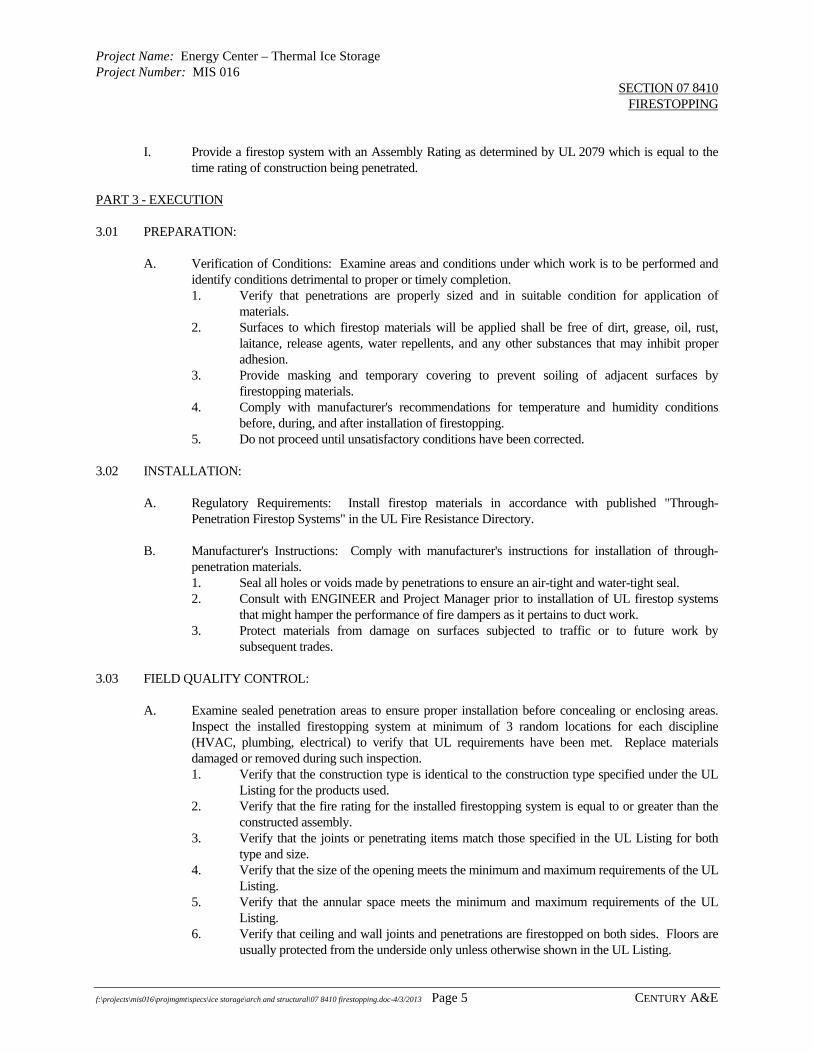
Project Name: Energy Center – Thermal Ice Storage Project Number: MIS 016
SECTION 07 8410 FIRESTOPPING
f:\projects\mis016\projmgmt\specs\ice storage\arch and structural\07 8410 firestopping.doc-4/3/2013 Page 5 CENTURY A&E
I. Provide a firestop system with an Assembly Rating as determined by UL 2079 which is equal to the
time rating of construction being penetrated. PART 3 - EXECUTION 3.01 PREPARATION:
A. Verification of Conditions: Examine areas and conditions under which work is to be performed and identify conditions detrimental to proper or timely completion. 1. Verify that penetrations are properly sized and in suitable condition for application of
materials. 2. Surfaces to which firestop materials will be applied shall be free of dirt, grease, oil, rust,
laitance, release agents, water repellents, and any other substances that may inhibit proper adhesion.
3. Provide masking and temporary covering to prevent soiling of adjacent surfaces by firestopping materials.
4. Comply with manufacturer's recommendations for temperature and humidity conditions before, during, and after installation of firestopping.
5. Do not proceed until unsatisfactory conditions have been corrected. 3.02 INSTALLATION:
A. Regulatory Requirements: Install firestop materials in accordance with published "Through-Penetration Firestop Systems" in the UL Fire Resistance Directory.
B. Manufacturer's Instructions: Comply with manufacturer's instructions for installation of through-
penetration materials. 1. Seal all holes or voids made by penetrations to ensure an air-tight and water-tight seal. 2. Consult with ENGINEER and Project Manager prior to installation of UL firestop systems
that might hamper the performance of fire dampers as it pertains to duct work. 3. Protect materials from damage on surfaces subjected to traffic or to future work by
subsequent trades. 3.03 FIELD QUALITY CONTROL:
A. Examine sealed penetration areas to ensure proper installation before concealing or enclosing areas. Inspect the installed firestopping system at minimum of 3 random locations for each discipline (HVAC, plumbing, electrical) to verify that UL requirements have been met. Replace materials damaged or removed during such inspection. 1. Verify that the construction type is identical to the construction type specified under the UL
Listing for the products used. 2. Verify that the fire rating for the installed firestopping system is equal to or greater than the
constructed assembly. 3. Verify that the joints or penetrating items match those specified in the UL Listing for both
type and size. 4. Verify that the size of the opening meets the minimum and maximum requirements of the UL
Listing. 5. Verify that the annular space meets the minimum and maximum requirements of the UL
Listing. 6. Verify that ceiling and wall joints and penetrations are firestopped on both sides. Floors are
usually protected from the underside only unless otherwise shown in the UL Listing.

Project Name: Energy Center – Thermal Ice Storage Project Number: MIS 016
SECTION 07 8410 FIRESTOPPING
f:\projects\mis016\projmgmt\specs\ice storage\arch and structural\07 8410 firestopping.doc-4/3/2013 Page 6 CENTURY A&E
B. Keep areas of work accessible until inspection by applicable code enforcement authorities.
C. Perform patching and repairing of firestopping caused by cutting or penetrating of existing firestop systems already installed by other trades.
3.04 ADJUSTING AND CLEANING:
A. Remove equipment, materials, and debris after completion of work and leave area in undamaged, clean condition.
B. Clean all surfaces adjacent to sealed holes and joints of excess firestop materials and soiling as work
progresses.
END OF SECTION

Project Name: Energy Center – Thermal Ice Storage Project Number: MIS 016
SECTION 09 3000 TILE
f:\projects\mis016\projmgmt\specs\ice storage\arch and structural\09 3000 tile.doc-4/3/13 Page 1 CENTURY A&E
PART 1 - GENERAL 1.01 DESCRIPTION:
A. The work includes quarry tile, mortar and grout, and related accessories. 1.02 REFERENCES:
A. Tile Council of America (TCA) Handbook for Ceramic Tile Installation. B. TCA 137.1 Recommended Specifications for Ceramic Tile. C. ANSI Standard Specifications for Ceramic Tile. D. ASTM - American Society for Testing and Materials.
1.03 SUBMITTALS:
A. Submit under provisions of Section 01300, “Submittals.”
B. Submit copies of manufacturer's product data and installation recommendations for the quarry tile. 1. Submit completed Master Grade certificates indicating that materials and installation
comply with this Specification. C. Submit set of samples of quarry tile indicating full range of colors and patterns available
1.04 DELIVERY, STORAGE, HANDLING:
A. Deliver tile materials in manufacturer's original packing with labels and seals intact. Store materials in compliance with manufacturer's instructions.
PART 2 - PRODUCTS 2.01 MANUFACTURERS:
A. Quarry Tile: American Olean, Summitwille, Hanley, Structural Stoneware, or equal. B. Mortar and Grout: L&M-Surco, The Upco Co., Mapei, Atlas Mineral, or equal.
2.02 TILE GRADE REQUIREMENTS:
A. Tile to comply with TCA Standard and grade requirements. Provide tile materials for setting and grouting from one manufacturer.
2.02 QUARRY TILE:
A. Quarry tile, extruded and ground to size after firing (with slip-resistant surface using rustproof aggregate), square edge, 6 inch x 6 inch x 1/2 inch thick, 6 inch x 6 inch x 3/4 inch step nosing.
2.03 MORTAR:
A. Portland cement mortar, ANSI A108.1 consisting of gray cement, sand, hydrated lime ASTM C207, water.
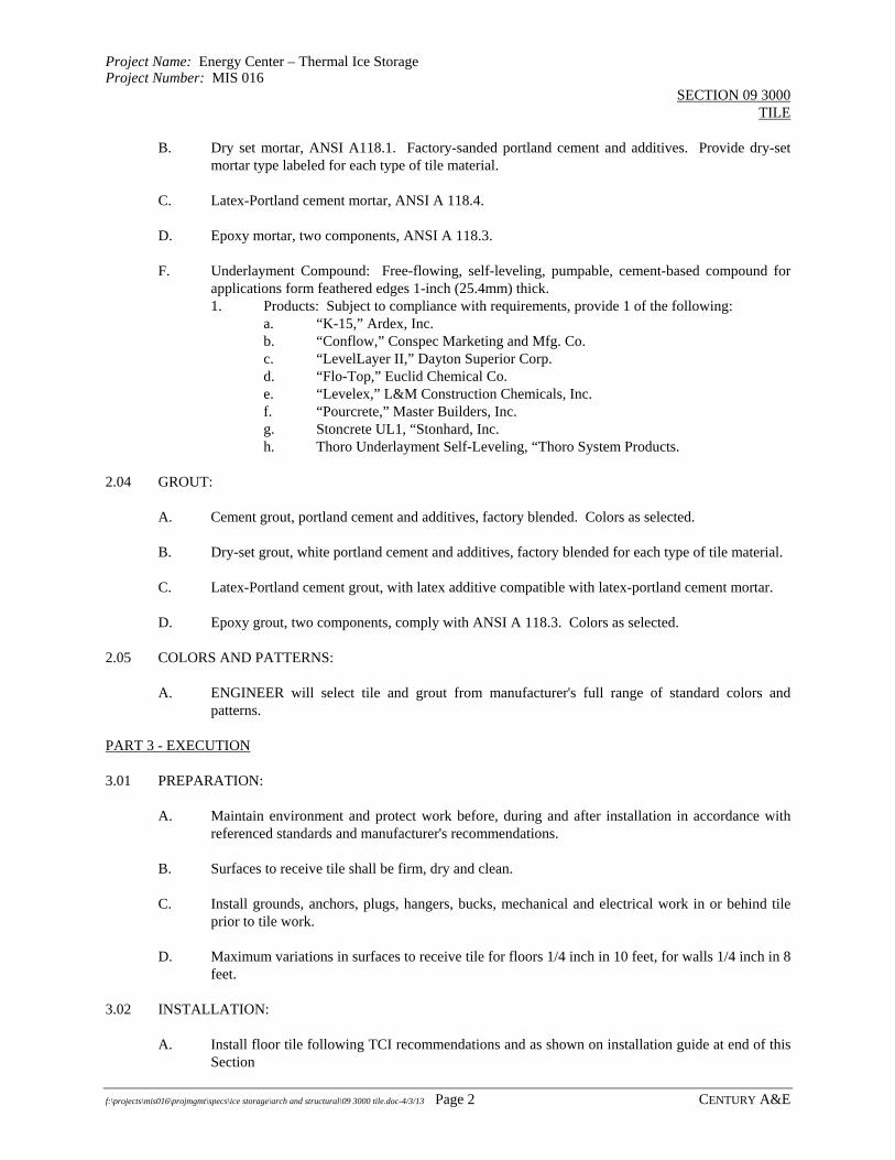
Project Name: Energy Center – Thermal Ice Storage Project Number: MIS 016
SECTION 09 3000 TILE
f:\projects\mis016\projmgmt\specs\ice storage\arch and structural\09 3000 tile.doc-4/3/13 Page 2 CENTURY A&E
B. Dry set mortar, ANSI A118.1. Factory-sanded portland cement and additives. Provide dry-set mortar type labeled for each type of tile material.
C. Latex-Portland cement mortar, ANSI A 118.4. D. Epoxy mortar, two components, ANSI A 118.3. F. Underlayment Compound: Free-flowing, self-leveling, pumpable, cement-based compound for
applications form feathered edges 1-inch (25.4mm) thick. 1. Products: Subject to compliance with requirements, provide 1 of the following:
a. “K-15,” Ardex, Inc. b. “Conflow,” Conspec Marketing and Mfg. Co. c. “LevelLayer II,” Dayton Superior Corp. d. “Flo-Top,” Euclid Chemical Co. e. “Levelex,” L&M Construction Chemicals, Inc. f. “Pourcrete,” Master Builders, Inc. g. Stoncrete UL1, “Stonhard, Inc. h. Thoro Underlayment Self-Leveling, “Thoro System Products.
2.04 GROUT:
A. Cement grout, portland cement and additives, factory blended. Colors as selected. B. Dry-set grout, white portland cement and additives, factory blended for each type of tile material. C. Latex-Portland cement grout, with latex additive compatible with latex-portland cement mortar. D. Epoxy grout, two components, comply with ANSI A 118.3. Colors as selected.
2.05 COLORS AND PATTERNS:
A. ENGINEER will select tile and grout from manufacturer's full range of standard colors and patterns.
PART 3 - EXECUTION 3.01 PREPARATION:
A. Maintain environment and protect work before, during and after installation in accordance with referenced standards and manufacturer's recommendations.
B. Surfaces to receive tile shall be firm, dry and clean. C. Install grounds, anchors, plugs, hangers, bucks, mechanical and electrical work in or behind tile
prior to tile work. D. Maximum variations in surfaces to receive tile for floors 1/4 inch in 10 feet, for walls 1/4 inch in 8
feet. 3.02 INSTALLATION:
A. Install floor tile following TCI recommendations and as shown on installation guide at end of this Section

Project Name: Energy Center – Thermal Ice Storage Project Number: MIS 016
SECTION 09 3000 TILE
f:\projects\mis016\projmgmt\specs\ice storage\arch and structural\09 3000 tile.doc-4/3/13 Page 3 CENTURY A&E
B. Extend tile work into recesses and under or behind equipment and fixtures, to form a complete covering without interruptions, except as otherwise shown. Terminate work neatly at obstructions, edges and corners without disrupting pattern or joint alignments.
C. Accurately form intersections and returns. Perform cutting and drilling of tile without marring
visible surfaces. Carefully grind cut edges of tile abutting trim, finish or built-in items for straight aligned joints. Fit tile closely to electrical outlets, piping, fixtures and other penetrations.
D. Jointing pattern, unless otherwise shown, shall lay tile in grid pattern. Align joints when
adjoining tiles on floor, base, walls and trim are same size. Layout tile work and center tile fields in both directions in each space or on each wall area. Provide uniform joint widths.
E. Tile installation work for setting bed mortar and grouting to comply with the following ANSI
Standard requirements. Portland cement mortar and grout: ANSI A 108.1. Dry-set portland cement or latex-portland cement mortar and grout: ANSI A 108.5. Epoxy mortar and grout: ANSI A 108.6 and ASTM C399. Organic adhesive: ANSI A 108.4.
F. Expansion and Control Joints: Provide openings for joints (shown and detailed), (to comply with
recommendations in TCA "Handbook for Ceramic Tile Installation"). Joint filler elastomeric sealant.
3.03 CLEANING:
A. Clean and polish tile surfaces upon completion of grouting. B. Unglazed tile may be cleaned with acid solutions when permitted by tile and grout manufacturer's
instructions, but not sooner than 14 days after installation. Protect metal surfaces, cast iron and vitreous plumbing fixtures from acid cleaning. Flush surface with clean water before and after cleaning.
C. Leave finished installation clean and free of defective work. D. For tile areas grouted with furan resin, remove protective wax surfacing in accordance with tile
manufacturer's instructions. 3.04 PROTECTION:
A. Protect installed tile work with kraft paper or other heavy covering during construction period. Apply a protective coat of neutral protective cleaner to completed tile walls and floors.
B. Prohibit foot and wheel traffic on tiled floors for 7 days after grouting is completed. C. Before final inspection, remove protective coverings and rinse neutral cleaner from tile surfaces.

Blank Page
jmuizelaar
Rectangle
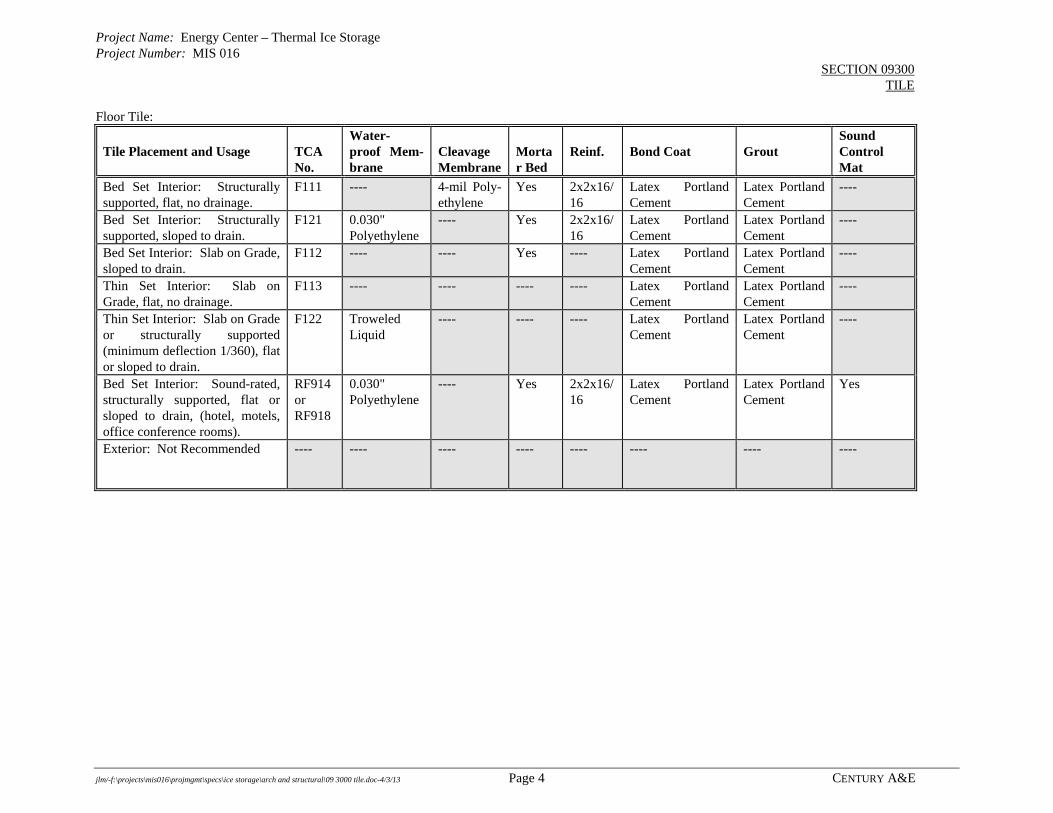
Project Name: Energy Center – Thermal Ice Storage Project Number: MIS 016
SECTION 09300 TILE
jlm/-f:\projects\mis016\projmgmt\specs\ice storage\arch and structural\09 3000 tile.doc-4/3/13 Page 4 CENTURY A&E
Floor Tile:
Tile Placement and Usage
TCA No.
Water- proof Mem-brane
Cleavage Membrane
Mortar Bed
Reinf.
Bond Coat
Grout
Sound Control Mat
Bed Set Interior: Structurally supported, flat, no drainage.
F111 ---- 4-mil Poly-ethylene
Yes 2x2x16/16
Latex Portland Cement
Latex Portland Cement
----
Bed Set Interior: Structurally supported, sloped to drain.
F121 0.030" Polyethylene
---- Yes 2x2x16/16
Latex Portland Cement
Latex Portland Cement
----
Bed Set Interior: Slab on Grade, sloped to drain.
F112 ---- ---- Yes ---- Latex Portland Cement
Latex Portland Cement
----
Thin Set Interior: Slab on Grade, flat, no drainage.
F113 ---- ---- ---- ---- Latex Portland Cement
Latex Portland Cement
----
Thin Set Interior: Slab on Grade or structurally supported (minimum deflection 1/360), flat or sloped to drain.
F122 Troweled Liquid
---- ---- ---- Latex Portland Cement
Latex Portland Cement
----
Bed Set Interior: Sound-rated, structurally supported, flat or sloped to drain, (hotel, motels, office conference rooms).
RF914 or RF918
0.030" Polyethylene
---- Yes 2x2x16/16
Latex Portland Cement
Latex Portland Cement
Yes
Exterior: Not Recommended
---- ---- ---- ---- ---- ---- ---- ----

Project Name: Energy Center – Thermal Ice Storage Project Number: MIS 016
SECTION 09300 TILE
jlm/-f:\projects\mis016\projmgmt\specs\ice storage\arch and structural\09 3000 tile.doc-4/3/13 Page 5 CENTURY A&E
Wall Tile:
Tile Placement and Usage
TCA No.
Water- proof Mem-brane
Metal Lath
Mortar Bed
Backer Board
Bond Coat
Organic Adhesive
Grout
Exterior Masonry or Concrete: Use with discretion, if at all.
W201 Yes Yes Yes ---- Latex Portland Cement
---- Latex Portland Cement
Exterior Masonry or Concrete: Dry areas.
W202 ---- ---- ---- ---- Latex Portland Cement
---- Latex Portland Cement
Interior Masonry or Concrete: Wet areas.
W222 Yes Yes Yes ---- Latex Portland Cement
---- Latex Portland Cement
Interior Wood or Metal Studs: Damp areas, lavatory backs.
W223 ---- ---- ---- Moisture Resistant Gyp. Bd.
---- Yes Latex Portland Cement
Interior Wood or Metal Studs: Dry areas.
W242 ---- ---- ---- Standard Gyp. Bd.
---- Yes Latex Portland Cement
Interior Wood or Metal Studs: Wet areas, showers.
B412 ---- ---- ---- Cementi-tious Backer Units
Latex Portland Cement
---- Latex Portland Cement
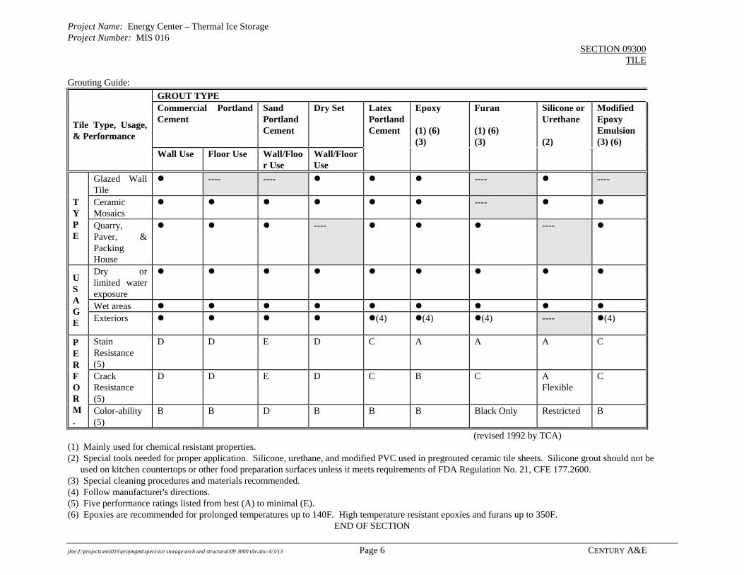
Project Name: Energy Center – Thermal Ice Storage Project Number: MIS 016
SECTION 09300 TILE
jlm/-f:\projects\mis016\projmgmt\specs\ice storage\arch and structural\09 3000 tile.doc-4/3/13 Page 6 CENTURY A&E
Grouting Guide:
Tile Type, Usage, & Performance
GROUT TYPE Commercial Portland Cement
Sand Portland Cement
Dry Set Latex Portland Cement
Epoxy (1) (6) (3)
Furan (1) (6) (3)
Silicone or Urethane (2)
Modified Epoxy Emulsion (3) (6)
Wall Use Floor Use Wall/Floor Use
Wall/Floor Use
T Y P E
Glazed Wall Tile
---- ---- ---- ----
Ceramic Mosaics
----
Quarry, Paver, & Packing House
---- ----
U S A G E
Dry or limited water exposure
Wet areas Exteriors
(4) (4) (4) ---- (4)
P E R F O R M.
Stain Resistance (5)
D D E D C A A A C
Crack Resistance (5)
D D E D C B C A Flexible
C
Color-ability (5)
B B D B B B Black Only Restricted B
(revised 1992 by TCA) (1) Mainly used for chemical resistant properties. (2) Special tools needed for proper application. Silicone, urethane, and modified PVC used in pregrouted ceramic tile sheets. Silicone grout should not be used on kitchen countertops or other food preparation surfaces unless it meets requirements of FDA Regulation No. 21, CFE 177.2600. (3) Special cleaning procedures and materials recommended. (4) Follow manufacturer's directions. (5) Five performance ratings listed from best (A) to minimal (E). (6) Epoxies are recommended for prolonged temperatures up to 140F. High temperature resistant epoxies and furans up to 350F.
END OF SECTION

Blank P
age
jmuizelaar
Rectangle
Project Name: Energy Center – Thermal Ice Storage Project Number: MIS 016
SECTION 09 6700 FLUID-APPLIED FLOORING
f:\projects\mis016\projmgmt\specs\ice storage\arch and structural\09 6700 flluid applied flooring.doc-4/3/13 Page 1 Century A&E
PART 1 GENERAL
1.01 SECTION INCLUDES
A. Fluid-applied flooring and base for one new chiller equipment pad and six new pump equipment pads.
B. Colors shall match existing.
1.03 REFERENCE STANDARDS
A. ASTM D 638 - Standard Test Method for Tensile Properties of Plastics; 2008.
B. ASTM D 695 - Standard Test Method for Compressive Properties of Rigid Plastics; 2002a.
C. ASTM D 905 - Standard Test Method for Strength Properties of Adhesive Bonds in Shear by Compression Loading; 2003.
D. ASTM D 4060 - Standard Test Method for Abrasion Resistance of Organic Coatings by the Taber Abraser; 2007.
E. ASTM E 84 - Standard Test Method for Surface Burning Characteristics of Building Materials; 2008.
F. ASTM E 96/E 96M - Standard Test Methods for Water Vapor Transmission of Materials; 2005.
G. ASTM E 648 - Standard Test Method for Critical Radiant Flux of Floor-Covering Systems Using a Radiant Heat Energy Source; 2008.
1.04 SUBMITTALS
A. See Section 01300 - Submittals, for submittal procedures.
B. Product Data: Provide data on specified products, describing physical and performance characteristics; sizes, patterns and colors available.
C. Maintenance Data: Include maintenance procedures, recommended maintenance materials, procedures for stain removal, repairing surface, and suggested schedule for cleaning.
1.05 QUALITY ASSURANCE
A. Manufacturer Qualifications: Company specializing in manufacturing products specified in this section with minimum three years documented experience.
B. Applicator Qualifications: Company specializing in performing work of this section with minimum 3 years experience.
1.06 DELIVERY, STORAGE, AND HANDLING
A. Store resin materials in a dry, secure area.
B. Store materials for three days prior to installation in area of installation to achieve temperature stability.

Project Name: Energy Center – Thermal Ice Storage Project Number: MIS 016
SECTION 09 6700 FLUID-APPLIED FLOORING
f:\projects\mis016\projmgmt\specs\ice storage\arch and structural\09 6700 flluid applied flooring.doc-4/3/13 Page 2 Century A&E
1.07 FIELD CONDITIONS
A. Maintain minimum temperature in storage area of 55 degrees F (13 degrees C).
B. Store materials in area of installation for minimum period of 24 hours prior to installation.
C. Maintain ambient temperature required by manufacturer 72 hours prior to, during, and 24 hours after installation of materials.
PART 2 PRODUCTS
2.01 MANUFACTURERS
A. Fluid-Applied Flooring: 1. Crossfiled Products Corp; Product "Dex-O-Tex": www.crossfieldproducts.com. 2. General Polymers; Product "Deco-Rez #115": www.generalpolymers.com. 3. BASF Construction Chemicals-Building Systems: www.chemrex.com. 4. H.G. Fuller; Product "Tufflite". 5. Substitutions: See Section 01 6000 - Product Requirements.
2.02 MATERIALS
A. Fluid-Applied Flooring: Epoxy, two component industrial type floor surfacing system consisting of primer, topping including epoxy resin, hardener, coloring agent and selected fine aggregates, and finish coat. 1. Top Coat: Epoxy, two-component, thermosetting; 1/8 inch (3 mm) thick; color as
selected. 2. Non-slip Surfacing: Mineral, color as selected. 3. Critical Radiant Flux: Minimum of 0.22 watts/sq cm, when tested in accordance with
ASTM E 648. 4. Tensile Strength: 1,750 psi, when tested in accordance with ASTM D 638. 5. Compressive Strength: 7,500 psi, when tested in accordance with ASTM D 695. 6. Abrasion Resistance: Maximum weight loss of 1,00 g/1000 cycles, when tested in
accordance with ASTM D 4060. 7. Impact Resistance: MIL-D-3134, Para. 4.7.3 except topping. 8. Mildew Resistance: No growth.
2.03 ACCESSORIES
A. Divider Strips: Extruded rigid PVC, 1/8 inch (33 mm) thick, height to match flooring thickness, with anchoring features; color as selected.
B. Control Joint Strips: Match divider strips; nominal width, 1/8 inch (3 mm) wide neoprene filler strip between side strips, with anchoring features, strip height to suit flooring thickness.
C. Primers and Adhesives: Waterproof; types recommended by flooring manufacturer.
PART 3 - EXECUTION
3.01 EXAMINATION
A. Verify that sub-floor surfaces are smooth and flat within the tolerances specified for that type of work and are ready to receive flooring.
B. Verify that wall surfaces are smooth and flat within the tolerances specified for that type of work, are dust-free, and are ready to receive flooring.

Project Name: Energy Center – Thermal Ice Storage Project Number: MIS 016
SECTION 09 6700 FLUID-APPLIED FLOORING
f:\projects\mis016\projmgmt\specs\ice storage\arch and structural\09 6700 flluid applied flooring.doc-4/3/13 Page 3 Century A&E
C. Verify that sub-floor surfaces are dust-free and free of substances that could impair bonding of materials to sub-floor surfaces.
D. Verify that wood sub-floors have 12 percent maximum moisture content.
E. Verify that concrete sub-floor surfaces are ready for flooring installation by testing for moisture emission rate and alkalinity; obtain instructions if test results are not within limits recommended by flooring materials manufacturer.
F. Verify that required floor-mounted utilities are in correct location.
3.02 PREPARATION
A. Remove sub-floor ridges and bumps. Fill low spots, cracks, joints, holes, and other defects with sub-floor filler.
B. Apply, trowel, and float filler to achieve smooth, flat, hard surface. Grind irregularities above the surface level. Prohibit traffic until filler is cured.
C. Vacuum clean substrate.
D. Apply primer to surfaces required by flooring manufacturer.
3.03 INSTALLATION-STRIPS
A. Accurately saw cut substrate to install divider strips.
B. Install strips straight and level to locations indicated.
C. Install base divider strips to match floor pattern. Install terminating cap strip at top of base; attach securely to wall substrate.
3.04 INSTALLATION-FLOORING
A. Apply in accordance with manufacturer's instructions.
B. Apply each coat to minimum thickness indicated.
C. Finish to smooth level surface.
3.05 PROTECTION
A. Prohibit traffic on floor finish for 48 hours after installation.
B. Barricade area to protect flooring until cured.
END OF SECTION

Blank Page
jmuizelaar
Rectangle
Project Name: Energy Center – Thermal Ice Storage Project Number: MIS 016
SECTION 09 9000 PAINTING
f:\projects\mis016\projmgmt\specs\ice storage\arch and structural\09 9000 painting.doc-4/3/13 Page 1 Century A&E
PART 1 - GENERAL 1.01 SUMMARY:
A. This Section includes surface preparation, painting, and finishing of exposed interior items and
surfaces. 1. Surface preparation, priming, and finish coats specified in this Section are in addition to
shop priming and surface treatment specified under other Sections. B. Work Includes Painting of:
1. Metal railings and stairs, new and existing in Ice Storage Tank Area 2. Structural steel columns 3. Structural steel mezzanine support 4. Steel for equipment and pipe supports including pipe hangers and rods. 5. Chiller refrigeration relief vent piping 6. All new and existing hollow metal man doors and frames within the Ice Storage Area.. 7. Owner responsible for repainting existing roof structure and CMU walls in Ice Storage
Area.
C. Related Work 1. New chiller equipment pads and new pump equipment pads (six)) to be covered with
epoxy paint system under Section 09 6700 – Fluid Applied Flooring. 2. Paint colors shall match existing.
D. Paint exposed surfaces whether or not colors are designated in "schedules," except where a surface or material is specifically indicated not to be painted or is to remain natural. Where an item or surface is not specifically mentioned, paint the same as similar adjacent materials or surfaces. If color or finish is not designated, the ENGINEER will select from standard colors or finishes available.
E. Painting is not required on prefinished items, finished metal surfaces, concealed surfaces,
operating parts, and labels. 1. Prefinished items not to be painted include the following factory-finished components,
but not limited to: a. Finished mechanical and electrical equipment. b. Light fixtures. c. Distribution cabinets.
2. Concealed surfaces not to be painted include wall or ceiling surfaces in the following generally inaccessible areas: a. Furred areas. b. Utility tunnels. c. Pipe spaces. d. Duct shafts.
3. Finished metal surfaces not to be painted include: a. Anodized aluminum. b. Stainless steel. c. Chromium plate. d. Copper. e. Bronze. f. Brass.
4. Operating parts not to be painted include moving parts of operating equipment such as the following:

Project Name: Energy Center – Thermal Ice Storage Project Number: MIS 016
SECTION 09 9000 PAINTING
f:\projects\mis016\projmgmt\specs\ice storage\arch and structural\09 9000 painting.doc-4/3/13 Page 2 Century A&E
a. Valve and damper operators. b. Linkages. c. Sensing devices. d. Motor and fan shafts.
5. Labels: Do not paint over Underwriter's Laboratories, Factory Mutual or other code-required labels or equipment name, identification, performance rating, or nomenclature plates.
F. Related Sections: The following Sections contain references pertaining to this Section:
1. SECTION 05590, Metal Fabrications. 2. SECTION 08105, Hollow Metal Doors and Frames.
1.02 REFERENCES:
A. Reference Documents: 1. Steel Structures Painting Council (SSPC), Volume 1 and 2. 2. Steel Structures Painting Council (SSPC), Visual Standard (VIS 1-89). 3. American Society for Testing and Materials (ASTM). 4. American National Standards Institute (ANSI), Standard A-13.1, "Scheme for
Identification of Piping Systems". 1.03 DEFINITIONS:
A. "Paint" as used herein means all coating systems materials, primers, emulsions, enamels, stains, sealers and fillers, and other applied materials whether used as prime, intermediate, or finish coats.
1.04 SUBMITTALS:
A. Submit under provisions of SECTION 01300. B. Product Data: for each paint system specified, including block fillers and primers.
1. Provide the manufacturer's technical information including label analysis and instructions for handling, storage, and application of each material proposed for use.
2. List each material and cross-reference the specific coating, finish system, and application. Identify each material by the manufacturer's catalog number and general classification.
3. Product data sheets shall indicate the mixing and thinning directions, and recommended spray nozzles and pressures.
C. Samples for Verification Purposes: Provide samples of each color and material to be applied, with texture to simulate actual conditions, on representative samples of the actual substrate. Define each separate coat, including block fillers and primers. Use representative colors when preparing samples for review. Resubmit until required sheen, color, and texture are achieved. 1. Provide a list of material and application for each coat of each sample. Label each
sample as to location and application. 2. Submit samples on the following substrates for the ENGINEER'S review of color and
texture only: a. Concrete: Provide two 4-inch-square samples for each color and finish. b. Concrete Masonry: Provide two 4- by 8-inch samples of masonry, with mortar
joint in the center, for each finish and color. c. Painted Wood: Provide two 12- by 12-inch samples of each color and material
on hardboard. d. Stained or Natural Wood: Provide two 4- by 8-inch samples of natural and
stained wood finish on actual wood surfaces.

Project Name: Energy Center – Thermal Ice Storage Project Number: MIS 016
SECTION 09 9000 PAINTING
f:\projects\mis016\projmgmt\specs\ice storage\arch and structural\09 9000 painting.doc-4/3/13 Page 3 Century A&E
e. Ferrous Metal: Provide two 4-inch-square samples of flat metal and two 8-inch-long samples of solid metal for each color and finish.
D. Provide material safety data sheets.
1.05 QUALITY ASSURANCE:
A. Engage an experienced applicator who has completed painting system applications similar in material and extent to those indicated for the project that have resulted in a construction record of successful in-service performance.
B. Single-Source Responsibility: Provide primers and undercoat paint produced by the same
manufacturer as the finish coats. C. Material Quality: Provide the manufacturer's paint material of the various coatings as specified.
Paint material containers not displaying manufacturer's product identification will not be acceptable. 1. Federal Specifications establish a minimum quality level for paint materials, except
where other product identification is used. Provide written certification from the manufacturer that materials provided meet or exceed these criteria.
D. On wall surfaces and other exterior and interior components, duplicate finishes of prepared
samples. Provide full-coat finish samples on at least 100 sq. ft. of surface until required sheen, color and texture are obtained; simulate finished lighting conditions for review of in-place work. 1. Final acceptance of colors will be from job-applied samples.
1.06 DELIVERY, STORAGE, AND HANDLING:
A. Deliver materials to the job site in the manufacturer's original, unopened packages and containers bearing manufacturer's name and label and the following information: 1. Product name or title of material. 2. Product description (generic classification or binder type). 3. Manufacturer's lot number. 4. Manufacturer's stock number and date of manufacture. 5. Contents by volume, for pigment and vehicle constituents. 6. Thinning instructions. 7. Application instructions. 8. Color name and number. 9. Handling instructions and precautions.
B. Store materials not in use in tightly covered containers in a well-ventilated area at a minimum
ambient temperature of 45 deg F (7 deg C). Maintain containers used in storage in a clean condition, free of foreign materials and residue.
1.07 PROJECT/SITE CONDITIONS:
A. Apply water-based paints only when the temperature of surfaces to be painted and surrounding air temperatures are between 50 deg F (10 deg C) and 90 deg F (32 deg C). Maintain these temperatures throughout the minimum cure time recommended by the manufacturer.
B. Apply solvent-thinned paints only when the temperature of surfaces to be painted and surrounding
air temperatures are between 45 deg F (7 deg C) and 95 deg F (35 deg C). Maintain these temperatures throughout the minimum cure time recommended by the manufacturer.
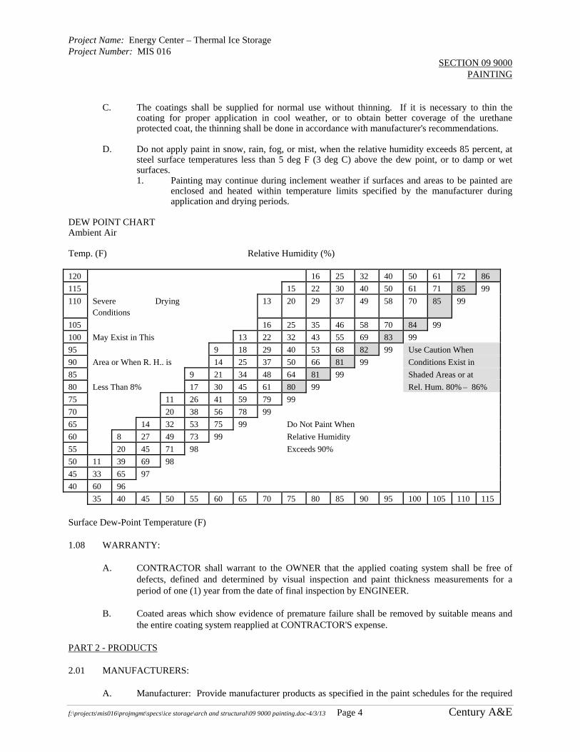
Project Name: Energy Center – Thermal Ice Storage Project Number: MIS 016
SECTION 09 9000 PAINTING
f:\projects\mis016\projmgmt\specs\ice storage\arch and structural\09 9000 painting.doc-4/3/13 Page 4 Century A&E
C. The coatings shall be supplied for normal use without thinning. If it is necessary to thin the
coating for proper application in cool weather, or to obtain better coverage of the urethane protected coat, the thinning shall be done in accordance with manufacturer's recommendations.
D. Do not apply paint in snow, rain, fog, or mist, when the relative humidity exceeds 85 percent, at
steel surface temperatures less than 5 deg F (3 deg C) above the dew point, or to damp or wet surfaces. 1. Painting may continue during inclement weather if surfaces and areas to be painted are
enclosed and heated within temperature limits specified by the manufacturer during application and drying periods.
DEW POINT CHART Ambient Air Temp. (F) Relative Humidity (%) 120 16 25 32 40 50 61 72 86
115 15 22 30 40 50 61 71 85 99
110 Severe Drying Conditions
13 20 29 37 49 58 70 85 99
105 16 25 35 46 58 70 84 99
100 May Exist in This 13 22 32 43 55 69 83 99
95 9 18 29 40 53 68 82 99 Use Caution When
90 Area or When R. H.. is 14 25 37 50 66 81 99 Conditions Exist in
85 9 21 34 48 64 81 99 Shaded Areas or at
80 Less Than 8% 17 30 45 61 80 99 Rel. Hum. 80% – 86%
75 11 26 41 59 79 99
70 20 38 56 78 99
65 14 32 53 75 99 Do Not Paint When
60 8 27 49 73 99 Relative Humidity
55 20 45 71 98 Exceeds 90%
50 11 39 69 98
45 33 65 97
40 60 96
35 40 45 50 55 60 65 70 75 80 85 90 95 100 105 110 115
Surface Dew-Point Temperature (F) 1.08 WARRANTY:
A. CONTRACTOR shall warrant to the OWNER that the applied coating system shall be free of defects, defined and determined by visual inspection and paint thickness measurements for a period of one (1) year from the date of final inspection by ENGINEER.
B. Coated areas which show evidence of premature failure shall be removed by suitable means and
the entire coating system reapplied at CONTRACTOR'S expense. PART 2 - PRODUCTS 2.01 MANUFACTURERS:
A. Manufacturer: Provide manufacturer products as specified in the paint schedules for the required

Project Name: Energy Center – Thermal Ice Storage Project Number: MIS 016
SECTION 09 9000 PAINTING
f:\projects\mis016\projmgmt\specs\ice storage\arch and structural\09 9000 painting.doc-4/3/13 Page 5 Century A&E
applications in Part 3 of this Section. 2.02 PAINT MATERIALS:
A. Material Compatibility: Provide block fillers, finish coat materials, and related materials that are compatible with one another and the substrates indicated under conditions of service and application, as demonstrated by the manufacturer based on testing and field experience.
B. Colors: Provide color selections made by the OWNER from the manufacturer's full range of
standard colors. C. Interior paints are to be specified for inclusion of an anti-fungal additive. D. Alykd or oil base paints are preferred as a primer on metal for filed applications as long as the
LEED VOC budget can be obtained.
2.03 GLOSS LEVELS:
A. Gloss Levels: Provide paint with gloss levels as follows, and in accordance with the National Paint and Coatings Association (NPCA):
Sheen Level
Test Method
General Gloss Range
Ceilings and Fog Sprays
Flat 85 Degree Meter Below 15 Below 5 Low Sheen 85 Degree Meter -- 3 to 18 Eggshell 60 Degree Meter 5 to 20 8 to 20 Satin 60 Degree Meter 15 to 35 15 to 30 Semi-Gloss 60 Degree Meter 30 to 65 25 to 50 Gloss 60 Degree Meter Over 65 Over 50
PART 3 - EXECUTION 3.01 EXAMINATION:
A. Examine substrates and conditions under which painting will be performed for compliance with requirements for application of paint. Do not begin paint application until unsatisfactory conditions have been corrected. 1. Start of painting will be construed as the applicator's acceptance of surfaces and
conditions within a particular area. B. Coordination of Work: Review other Sections in which primers are provided to ensure
compatibility of the total system for various substrates on request. Furnish information on characteristics of finish materials to ensure use of compatible primers. 1. Notify the ENGINEER about anticipated problems using the materials specified over
substrates primed by others. 3.02 PREPARATION:
A. General Procedures: Remove hardware and hardware accessories, plates, machined surfaces, lighting fixtures, and similar items in place that are not to be painted, or provide surface-applied protection prior to surface preparation and painting. Remove these items if necessary for complete painting of the items and adjacent surfaces. Following completion of painting

Project Name: Energy Center – Thermal Ice Storage Project Number: MIS 016
SECTION 09 9000 PAINTING
f:\projects\mis016\projmgmt\specs\ice storage\arch and structural\09 9000 painting.doc-4/3/13 Page 6 Century A&E
operations in each space or area, have items reinstalled by workers skilled in the trades involved. 1. Clean surfaces before applying paint or surface treatments. Remove oil and grease prior
to cleaning. Schedule cleaning and painting so that dust and other contaminants from the cleaning process will not fall on wet, newly painted surfaces.
B. Surface Preparation: Clean and prepare surfaces to be painted in accordance with the
manufacturer's instructions and SSPC for each particular substrate condition and as specified. 1. Provide barrier coats over incompatible primers or remove and reprime. Notify
ENGINEER in writing of problems anticipated with using the specified finish-coat material with substrates primed by others.
2. Cementitious Materials: Prepare concrete, concrete masonry block, cement plaster, and mineral-fiber-reinforced cement panel surfaces to be painted. Remove efflorescence, chalk, dust, dirt, grease, oils, laitance and release agents. Roughen as required to remove glaze. If hardeners or sealers have been used to improve curing, use mechanical methods of surface preparation. a. Use abrasive blast-cleaning methods if recommended by the paint manufacturer. b. Determine alkalinity and moisture content of surfaces by performing appropriate
tests. If surfaces are sufficiently alkaline to cause blistering and burning of finish paint, correct this condition before application. Do not paint surfaces where moisture content exceeds that permitted in manufacturer's printed directions.
c. Clean concrete floors to be painted with a 5 percent solution of muriatic acid or other etching cleaner. Flush the floor with clean water to remove acid, neutralize with ammonia, and rinse; allow to dry and vacuum before painting.
d. Thin first coat of coal tar to allow penetration into concrete, per manufacturer's recommendations.
3. Ferrous Metals: Clean non-galvanized ferrous-metal surfaces that have not been shop coated; remove oil, grease, dirt, loose mill scale, and other foreign substances. a. All the surfaces to be coated shall be blast cleaned. b. The abrasive used for blast cleaning shall be an approved low dusting abrasive
and shall have a gradation such that the abrasive will produce a uniform profile of 1 to 2.5 mils, as measured with extra coarse Testex Replica Tape.
c. All abrasive and coating residue shall be removed from steel surfaces with a commercial grade vacuum cleaner equipped with a brush-type cleaning tool, or by double blowing. If the double blowing method is used, the exposed top surfaces of all structural steel, including flanges, longitudinal stiffeners splice plates, hangers, etc., shall be vacuumed after the double blowing operations are completed. The air line used for blowing the steel clean shall have an in-line water trap and the air shall be free of oil and water as it leaves the air line. The steel shall then be kept dust free and primed within eight (8) hours after blast cleaning.
d. For interior steel not exposed to harsh conditions or chemical exposure, prep in accordance with SSPC-SP3, "Power Tool Cleaning." Removal of loose rust, loose mill scale, and loose paint to degree specified by power tool chipping, descaling, sanding, wire brushing, and grinding.
e. For exterior steel (or interior steel exposed to harsh conditions or chemical exposure) prep in accordance with SSPC-SP6, "Commercial Blast Cleaning." Blast until at least two-thirds of the surface area is free of all visible residue.
f. Touch up bare areas and shop-applied prime coats that have been damaged. Wire-brush, clean with solvents recommended by the paint manufacturer, and touch up with the same primer as the shop coat.
4. Existing Painted Surfaces: Remove existing loose or flaked coatings down to sound surface or to bare substrate. Regardless of the method used for cleaning, feather edges of

Project Name: Energy Center – Thermal Ice Storage Project Number: MIS 016
SECTION 09 9000 PAINTING
f:\projects\mis016\projmgmt\specs\ice storage\arch and structural\09 9000 painting.doc-4/3/13 Page 7 Century A&E
remaining old paint so that the repainted surface can have a reasonably smooth appearance. Re-prime bare substrates with appropriate primer.
C. After proper preparation and cleaning, and immediately before painting, remove dirt, dust, and
other contaminants from the surface by brushing, blowing with clean, dry air, or by vacuum cleaning.
D. Materials Preparation: Carefully mix and prepare paint materials in accordance with
manufacturer's directions. 1. Maintain containers used in mixing and application of paint in a clean condition, free of
foreign materials and residue. 2. Stir material before application to produce a mixture of uniform density; stir as required
during application. Do not stir surface film into material. Remove film and, if necessary, strain material before using.
3. Use only thinners approved by the paint manufacturer, and only within recommended limits.
4. For Epoxy, Coal Tar Epoxy and Urethane Coatings: Mix coatings with a high shear mixer (such as Jiffy Mixer) in accordance with the manufacturer's directions, to a smooth, lump-free consistency. Paddle mixers or paint shakers are not permitted. Mix in the original containers as far as possible, and continue mixing until all of the metallic powder or pigment is in suspension. Exercise care to ensure that all of the coating solids that may have settled to the bottom of the container are thoroughly dispersed. Strain the coating through a screen having openings no larger than those specified for a No. 50 sieve per ASTM E11. After straining, the mixed primer shall be kept under continuous agitation up to and during the time of application.
3.03 APPLICATION:
A. Apply paint in accordance with manufacturer's directions. Use applicators and techniques best suited for substrate and type of material being applied.
B. Do not paint over dirt, rust, scale, grease, moisture, scuffed surfaces, faying surfaces or conditions
detrimental to formation of a durable paint film. 1. Paint colors, surface treatments, and finishes are indicated in "schedules." 2. Provide finish coats that are compatible with primers used. 3. All finish coats are to be rolled. 4. Finish coats shall not be applied prior to construction operations nearing substantial
completion and when all dust generating work and risk of wall damage is minimal. 5. Where epoxy coatings will be used, test existing coatings and substrates for lifting. If
they lift, remove them. 6. The number of coats and film thickness required is the same regardless of the application
method. Do not apply succeeding coats until the previous coat has cured as recommended by the manufacturer. Sand between applications where sanding is required to produce an even smooth surface in accordance with the manufacturer's directions.
7. Apply additional coats when undercoats, stains, or other conditions show through final coat of paint until paint film is of uniform finish, color, and appearance. Give special attention to ensure that surfaces, including edges, corners, crevices, welds, and exposed fasteners, receive a dry film thickness equivalent to that of flat surfaces.
8. The term "exposed surfaces" includes areas visible when permanent or built-in fixtures, convector covers, covers for finned tube radiation, grilles, and similar components are in place. Extend coatings in these areas as required to maintain the system integrity and provide desired protection.

Project Name: Energy Center – Thermal Ice Storage Project Number: MIS 016
SECTION 09 9000 PAINTING
f:\projects\mis016\projmgmt\specs\ice storage\arch and structural\09 9000 painting.doc-4/3/13 Page 8 Century A&E
9. Paint surfaces behind movable equipment and furniture same as similar exposed surfaces. Paint surfaces behind permanently fixed equipment or furniture with prime coat only before final installation of equipment.
10. Paint interior surfaces of ducts, where visible through registers or grilles, with a flat, non-specular black paint.
11. Paint back sides of access panels and removable or hinged covers to match exposed surfaces.
12. Finish interior of wall and base cabinets and similar field-finished casework to match exterior.
13. Finish exterior doors on tops, bottoms, and side edges same as exterior faces. 14. Sand lightly between each succeeding enamel or varnish coat. 15. Omit primer on metal surfaces that have been shop-primed and touch up painted. 16. Final coat shall be free of defects such as scratches, scuffs, sheen variations, touch-ups
and non-uniform in appearance. 17. Failure of time application of final finish coat at the proper stage of the project’s
construction, such that the finish product is free of the defects described above, will require the contractor to repaint all affected wall surfaces judged to be, as the sole discretion of the University, in an unacceptable finish state.
18. Repainting shall be performed to the satisfaction of, and at no additional cost to, the University.
C. Proper curing conditions for ferrous metals will be required between the applications of all coats.
The minimum curing time between coats and the maximum time between coats shall be in accordance with the manufacturer's recommendation except that no more than sixty (60) calendar days will be permitted between coats. If the maximum time between coats is exceeded, all newly coated surfaces shall be completely blast cleaned again to a near-white finish (SSPC-SP10) and recoated and shall be at the CONTRACTOR's expense. After the steel is primed, it shall be vacuumed again before subsequent coating. If for any reason this vacuuming does not remove all the accumulated dust and/or dirt, or if more than three (3) weeks has elapsed since the steel was primed, or if in the opinion of the ENGINEER the surface is unfit for top-coating, the surface shall be scrubbed with a mild detergent solution (any commercial laundry detergent) and thoroughly rinsed with water and allowed to dry for twenty-four (24) hours before the surface is coated.
D. Minimum Coating Thickness: Apply materials at not less than the manufacturer's recommended
spreading rate. Provide a total dry film thickness of the entire system as recommended by the manufacturer and as stated in paint schedules. If the application of coating at the required thickness in one (1) pass produces runs, bubbles, or sags, the coating shall be applied in multiple passes, the passes separated by several minutes. Where excessive coating thickness produces mud-cracking, such coating shall be scraped back to soundly bonded coating and the area recoated to the required thickness. All dry spray shall be removed, by sanding if necessary. In areas of deficient primer thickness, the areas shall be thoroughly cleaned with power washing equipment, as necessary to remove all dirt; the areas shall then be wire brushed, vacuumed, and recoated. Tint each undercoat a lighter shade to facilitate identification of each coat where multiple coats are applied.
E. Mechanical and Electrical Work: Painting mechanical and electrical work is limited to items
exposed in mechanical equipment rooms and in occupied spaces. F. Block Fillers: Apply block fillers to concrete masonry block at a rate to ensure complete coverage
with pores filled. G. Pigmented (Opaque) Finishes: Completely cover to provide an opaque, smooth surface of
Project Name: Energy Center – Thermal Ice Storage Project Number: MIS 016
SECTION 09 9000 PAINTING
f:\projects\mis016\projmgmt\specs\ice storage\arch and structural\09 9000 painting.doc-4/3/13 Page 9 Century A&E
uniform finish, color, appearance, and coverage. Cloudiness, spotting, holidays, laps, brush marks, runs, sags, ropiness, or other surface imperfections will not be acceptable.
H. Completed Work: Match approved samples for color, texture, and coverage. Remove, refinish, or
repaint work not in compliance with specified requirements. I. All metal coated with impure unsatisfactory or unauthorized coating material or coated in an
unworkmanlike or objectionable manner, shall be thoroughly cleaned and recoated or otherwise corrected as directed by the ENGINEER.
3.04 FIELD QUALITY AND CONTROL:
A. The CONTRACTOR shall provide access to the job site and areas of work at all times during normal working hours for the OWNER. This requirement includes both shop and field work.
B. The field inspection shall be performed by the Construction Manager according to the following
outline. 1. Surface Preparation:
a. Surface appearance per SSPC checked with visual standards. b. Anchor profile checked with replica tape.
2. Coating Conditions: a. Temperature of steel using a surface thermometer. b. Determination of relative humidity and dew point and air temperature using a
sling psychrometer. 3. Verify Coating Thickness:
a. Dry film thickness will be determined by use of a magnetic film thickness gauge.
b. Pin holes will be checked using a holiday detector. C. Surfaces other than steel shall be visually inspected by the ENGINEER or OWNER'S
REPRESENTATIVE. D. Failure to comply with these specifications in any manner shall be sufficient cause for rejection of
work. 3.05 CLEAN-UP AND PROTECTION:
A. Cleanup: At the end of each work day, remove empty cans, rags, rubbish, and other discarded paint materials from the site.
B. Upon completion of painting, clean glass and paint-spattered surfaces. Remove spattered paint by
washing and scraping, using care not to scratch or damage adjacent finished surfaces. C. Protect work of other trades, whether to be painted or not, against damage by painting. Correct
damage by cleaning, repairing or replacing, and repainting, as acceptable to ENGINEER. D. Provide "wet paint" signs to protect newly painted finishes. Remove temporary protective
wrappings provided by others for protection of their work after completion of painting operations. 1. At completion of construction activities of other trades, touch up and restore damaged or
defaced painted surfaces.
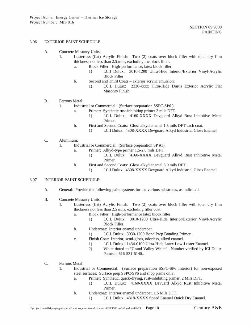
Project Name: Energy Center – Thermal Ice Storage Project Number: MIS 016
SECTION 09 9000 PAINTING
f:\projects\mis016\projmgmt\specs\ice storage\arch and structural\09 9000 painting.doc-4/3/13 Page 10 Century A&E
3.06 EXTERIOR PAINT SCHEDULE:
A. Concrete Masonry Units: 1. Lusterless (flat) Acrylic Finish: Two (2) coats over block filler with total dry film
thickness not less than 2.5 mils, excluding the block filler. a. Block Filler: High-performance, latex block filler:
1) I.C.I Dulux: 3010-1200 Ultra-Hide Interior/Exterior Vinyl-Acrylic Block Filler
b. Second and Third Coats – exterior acrylic emulsion: 1) I.C.I. Dulux: 2220-xxxx Ultra-Hide Durus Exterior Acrylic Flat
Masonry Finish. B. Ferrous Metal:
1. Industrial or Commercial: (Surface preparation SSPC-SP6 ). a. Primer: Synthetic rust-inhibiting primer 2 mils DFT.
1) I.C.I. Dulux: 4160-XXXX Devguard Alkyd Rust Inhibitive Metal Primer.
b. First and Second Coats: Gloss alkyd enamel 1.5 mils DFT each coat. 1) I.C.I Dulux: 4308-XXXX Devguard Alkyd Industrial Gloss Enamel.
C. Aluminum:
1. Industrial or Commercial. (Surface preparation SP #1). a. Primer: Alkyd-type primer 1.5-2.0 mils DFT.
1) I.C.I. Dulux: 4160-XXXX Devguard Alkyd Rust Inhibitive Metal Primer.
b. First and Second Coats: Gloss alkyd enamel 3.0 mils DFT. 1) I.C.I Dulux: 4308-XXXX Devguard Alkyd Industrial Gloss Enamel.
3.07 INTERIOR PAINT SCHEDULE:
A. General: Provide the following paint systems for the various substrates, as indicated. B. Concrete Masonry Units:
1. Lusterless (flat) Acrylic Finish: Two (2) coats over block filler with total dry film thickness not less than 2.5 mils, excluding filler coat. a. Block Filler: High-performance latex block filler.
1) I.C.I. Dulux: 3010-1200 Ultra-Hide Interior/Exterior Vinyl-Acrylic Block Filler.
b. Undercoat: Interior enamel undercoat. 1) I.C.I. Dulux: 3030-1200 Bond Prep Bonding Primer.
c. Finish Coat: Interior, semi-gloss, odorless, alkyd enamel. 1) I.C.I. Dulux: 1434-0100 Ultra-Hide Latex Low-Luster Enamel. 2) White tinted to “Grand Valley White”. Number verified by ICI Dulux
Paints at 616-531-6140.. C. Ferrous Metal:
1. Industrial or Commercial. (Surface preparation SSPC-SP6 Interior) for non-exposed steel surfaces: Surface prep SSPC-SP6 and shop prime only. a. Primer: Synthetic, quick-drying, rust-inhibiting primer, 2 Mils DFT.
1) I.C.I. Dulux: 4160-XXXX Devuard Alkyd Rust Inhibitive Metal Primer.
b. Undercoat: Interior enamel undercoat, 1.5 Mils DFT. 1) I.C.I. Dulux: 4318-XXXX Speed Enamel Quick Dry Enamel.
Project Name: Energy Center – Thermal Ice Storage Project Number: MIS 016
SECTION 09 9000 PAINTING
f:\projects\mis016\projmgmt\specs\ice storage\arch and structural\09 9000 painting.doc-4/3/13 Page 11 Century A&E
c. Finish Coat: Exterior, gloss, alkyd enamel. 1) I.C.I. Dulux: 4318-XXXX Speed Enamel Quick Dry Enamel.
END OF SECTION

Blank Page
jmuizelaar
Rectangle

Project Name: Energy Center – Thermal Ice Storage Project Number: MIS 016
SECTION 21 1000 FIRE ALARM SYSTEM
f:\projects\mis016\projmgmt\specs\ice storage\fire sprinker and alarm\21 1000 fire alarm.doc Page 1 CENTURY A&E
PART 1 - GENERAL 1.01 WORK SUMMARY
A. General: 1. The existing Fire Alarm System is to remain in place and in operation throughout
construction. 2. Relocate various Fire Alarm System devices as indicated on the drawings.
B. Allowable Contractors 1. The Contractor shall engage the services of system manufacturer, as part of the contract, to
provide work related to the fire alarm system as specified and shown.
1.02 SUBMITTALS
A. N/A
1.03 RELATED SECTIONS
A. See Section 01010 – Summary of Work for additional discussion.
PART 2 – PRODUCTS – NOT APPLICABLE PART 3 - EXECUTION 3.01 GENERAL
A. Coordinate Work with all trades, relocating existing devices and wiring as indicated on the drawings.
B. Disable the system only momentarily in the areas outside of the construction work and only as necessary to perform the work. Coordinate all outages with the Owner prior to disabling the system in any way.
C. Test and put system into operation. Verify that all existing and relocated devices are operational and the system contains no faults.
D. Submit reports to State of Michigan and code authorities as required.
END OF SECTION

Blank Page
jmuizelaar
Rectangle

Project Name: Energy Center – Thermal Ice Storage Project Number: MIS 016
SECTION 21 2000 FIRE SUPPRESION SYSTEMS
f:\projects\mis016\projmgmt\specs\ice storage\fire sprinker and alarm\21 2000 fire suppression.doc-4/3/13 Page 1 CENTURY A&E
PART 1 GENERAL 1.01 DESCRIPTION:
A. Fire protection sprinkler system design, installation and testing per NFPA 13.
B. Rework of existing wet fire protection system in the Ice Tank Area (old Wood Shop / Incinerator area) to accommodate new ice tank equipment and equipment platform, including installation of new fire protection piping to protect the space under the new equipment platform.
1.02 SUBMITTALS:
A. Submit under provisions of Division 1.
B. Submit product data for the following: 1. Combination of fittings, gaskets and grooves. 2. Sprinkler heads. 3. Hangers.
C. Submit Contractor's Material and Test Certificate.
D. Submit complete working plans for review as required by NFPA 13 to Engineer for review.
E. Submit approved working plans to Owner and local fire department for review.
F. Properly field test and startup and check all systems and components as specified, as required by NFPA, and local fire department requirements.
1.03 QUALIFICATIONS:
A. The fire protection sprinkler system shall comply with the latest addition of NFPA 13 - Standard for the Installation of Sprinkler Systems.
B. Design shall comply with Factory Mutual and NFPA Standards, and local code requirements.
C. Items shall bear the Underwriter’s Label (UL) or Factory Mutual (FM) approval stamps to indicate acceptance by major fire service product rating organizations.
1.04 DESIGN CONDITIONS:
A. Wet sprinkler system for the building shall be designed conforming to NFPA 13 fior Ordinary Hazard I, 0.15 gpm/sf for most remote 1500 sf.
PART 2 PRODUCTS 2.01 PIPING:
A. Pipe and Fittings Up to Two Inch (2"): Carbon steel, Schedule 40, ASTM A795, A53 or A135 Factory Mutual approved, with standard cast iron, one hundred seventy-five (175) psi water working pressure fittings ANSI B16.3 Factory Mutual approved.
2.02 SPRINKLER HEADS
A. Sprinklers shall be quick response, upright pendant or sidewall style, of rough brass.

Project Name: Energy Center – Thermal Ice Storage Project Number: MIS 016
SECTION 21 2000 FIRE SUPPRESION SYSTEMS
f:\projects\mis016\projmgmt\specs\ice storage\fire sprinker and alarm\21 2000 fire suppression.doc-4/3/13 Page 2 CENTURY A&E
PART 3 EXECUTION 3.01 GENERAL:
A. The Fire Protection Contractor shall prepare working plan of the proposed fire protection system, including all applicable dimensions, walls, steel layout, lines and main location, sizing, hangers, etc. as required by NFPA 13.
B. Installation of the fire protection system shall begin only after approved drawings have been received by the Fire Protection Contractor. Should approved drawings not be available and installation begun, it is the Fire Protection Contractor's responsibility to ensure that the fire protection system meets with any requirements noted on the approved drawings, once received.
C. Fire Protection Contractor shall provide head protectors where necessary to prevent damage during the final stages of building construction.
3.02 TESTING AND CERTIFICATION:
A. Upon completion of the fire protection system, the Fire Protection Contractor shall perform all required acceptance tests and complete the Contractor's Material and Test Certificate(s) per NFPA 13 requirements.
B. Submit three (3) copies of the certificate to the Engineer.
A. The Fire Protection Contractor shall correct any deficiencies found and noted by the Engineer prior to final payment at no additional cost to owner.
3.03 INSTALLATION OF PIPING
A. Complete pipe installation shall be in accordance with the latest requirements of NFPA Pamphlet No. 13.
B. Sprinkler heads and piping shall clear lights, piping, beams and all other obstructions that prevent effective sprinkling. Installation (shop) drawings shall indicate where potential interferences are located. Sprinklers with water shields shall be installed under obstructions over 4' wide, in ordinary hazard areas.
C. Sprinkler head spacing shall be based on the following requirements set forth by NFPA 13:
1. Piping shall be sized accordingly. Subcontractor shall use hydraulic calculation method in accordance with NFPA #13 and submit calculations on FM or NFPA approved work sheets. In either case, obtain written approval of proposed installation from the Authority having jurisdiction and other governing authorities by furnishing plans to Owner for approval. Velocities shall not exceed 20 FPS in gridded systems; 26 FPS for standard systems and 15 fps at flow switch.
D. Install pipes so that system may be completely drained. Run drain lines from drains and test connections to outside or to nearest standpipe drain, or as shown on plans. Provide drain valves at all low points. Flush entire system prior to installing terminal valves and sprinkler heads at flow rates recommended by FM. Drain down test at 200 GPM without overflow is required. Arrange for FM inspector or Owner's Representative to witness test.

Project Name: Energy Center – Thermal Ice Storage Project Number: MIS 016
SECTION 21 2000 FIRE SUPPRESION SYSTEMS
f:\projects\mis016\projmgmt\specs\ice storage\fire sprinker and alarm\21 2000 fire suppression.doc-4/3/13 Page 3 CENTURY A&E
E. Label main, valves, etc. per FM and NFPA requirements.
F. Hangers and Supports: Comply with the requirements of NFPA 13, and FM DS, 2-8N and 4-1N. Hangers and support spacing and locations for piping joined with grooved mechanical couplings shall be in accordance with the grooved mechanical coupling manufacturer's written instructions, and Factory Mutual requirements (2-8N 3-15.1.11.1), which require two (2) hangers per pipe section, joined by grooved couplings. Provide adequate anchorage and/or concealment for piping service exposed in explosion hazard areas.
G. Install 1 inch test connection at the most remote point from the riser of each system. Coordinate exact location and height above the floor with the Engineer prior to installation.
3.04 TESTS
A. Perform hydrostatic test at two hundred (200) psig for two (2) hours. For interior piping, there shall be no visible leakage. Allow at least 8 hours at reduced 50 psi pressure to absorb any air in the system prior to 2 hour acceptance test. All control valves shall be fully closed and opened under water pressure to insure proper operation.
B. Repair or replace piping system components, which do not pass the test procedures, specified and retest.
C. Repair damage caused by leaks, flooding or draining during flushing and testing.
D. Flushing Tests 1. All lead-in connections to sprinkler system risers shall be flushed thoroughly
until water is clear before connections are made to sprinkler system.
END OF SECTION

Blank Page
jmuizelaar
Rectangle

Project Name: Energy Center – Thermal Ice Storage Project Number: MIS016
SECTION 23 0000 MECHANICAL GENERAL REQUIREMENTS
f:\projects\mis016\projmgmt\specs\ice storage\mech\23 0000 mech general.doc-4/3/13 Page 1 CENTURY A&E
PART 1 - GENERAL 1.01 GENERAL PROVISIONS
A. General: 1. “Provide” means furnish, install, commission and make fully operational. 2. Submit equipment and product submittals to the Engineer/Engineer for approval prior to
construction per provision of Section 01300. 3. Provide manufacturer’s startup services including report submittals as described in
individual specification sections.
1.02 CONSTRUCTION REQUIREMENTS
A. Contractors shall commission all equipment as specified in the various technical specification sections and as specified in Section Division 1. The Contractors shall attend commissioning meetings and conduct field tests and submit reports, startup and check equipment and submit reports, shall assist with test and balance activities, as specified in these specifications and as directed by the Owner and Engineer.
B. Coordinate the fabrication, construction, and installation of all mechanical work with all other
trades prior to construction. 1.03 HVAC WORK SCOPE SUMMARY
A. See Section 01010 – Summary of Work for requirements. 1.04 PLUMBING WORK SCOPE SUMMARY
A. See Section 01010 – Summary of Work for requirements. 1.05 INTENT
A. The intent of this Division is to call for finished work, tested and ready for operation.
B. Furnish all materials, supplies, equipment, tools, transportation and facilities, and perform all labor and services necessary for the complete installation of the mechanical systems as shown on the Drawings, as herein specified, and as required to make complete and operating systems.
C. The work shall also include the completion of such details of mechanical work not mentioned or
specifically shown, but which are necessary for the successful operation of all mechanical systems.
1.06 CODES
A. Where Standards or Codes are mentioned, the latest edition or revision in force shall be followed.
B. Contract Documents shall take precedence when they are more stringent than codes, ordinances, standards, and statutes. Codes, ordinances, standards and statutes shall take precedence when they are more stringent or conflict with the Drawings and Specifications.
C. Should any change be required to conform to the codes, ordinances and rules, the Contractor shall
notify the Engineer and shall include the costs involved in this work. Contractor shall be held to complete all work necessary to meet these local code requirements without additional compensation after award of the Contract.
1.07 PERMITS AND INSPECTIONS
A. Secure and pay for all permits, inspections, tests and fees required for the work to be performed.

Project Name: Energy Center – Thermal Ice Storage Project Number: MIS 016
SECTION 23 0000 MECHANICAL GENERAL REQUIREMENTS
f:\projects\mis016\projmgmt\specs\ice storage\mech\23 0000 mech general.doc-4/3/13 Page 2 CENTURY A&E
B. Upon completion of the work, furnish Inspection Certificates as normally issued in connection
with the work.
1.08 DRAWINGS AND SPECIFICATIONS
A. Schedules shown on Drawings are for convenience and not intended to be a count of equipment, fixtures, etc. Each supplier shall make a separate count of these items and shall be required to furnish the equipment, fixture and materials wherever shown on the Drawings but not included in the Schedule.
B. Drawings show arrangement, general design and extent to the systems and are diagrammatic
except where in certain cases they are detailed giving exact locations and arrangement. C. Drawings are not intended to be scaled for rough-in dimensions. Where shop drawings are
required for this purpose or field measurements are needed for the installation, they shall be prepared by the installing Contractor.
1.09 SUBMITTALS
A. Prepare all required submittals in accordance with applicable provisions of Section 01340.
B. Shop Drawings: Prior to delivery of any material to the job site, the Contractor shall submit shop drawings for review by the Engineer.
C. See individual technical specification sections for additional requirements.
1.10 O&M MANUALS AND RECORD DRAWINGS
A. See Section 01720 for requirements.
1.11 DEMONSTRATION TO ENGINEER AND OWNER
A. See Section 01730 for requirements.
1.12 OWNER TRAINING
A. See Section 01730 for requirements.
1.13 CONTRACTOR RESPONSIBILITY
A. Each Contractor shall be responsible for the safety and good condition of all work and materials in Contract until its completion.
B. Assume entire responsibility for all the materials, workmanship and satisfactory performance of
the systems installed. It is not intended to limit or restrict the Contractor to the use of materials and manner of shop fabrication or erection that is not in accord with best standard practice.
C. It is also not intended that the drawings or this Specification indicate or specify each item or
material, which is required to complete a satisfactory installation. Where such items are required and they are considered to be the accepted trade practice to provide same, they shall be considered to be both specified and indicated.
D. The design and construction of all equipment and materials specified herein shall conform in all details with the latest revised codes of the American Society of Mechanical Engineers, the American Standards Association, American Society of Heating, Refrigeration, and Air Conditioning Engineers, and all existing laws, ordinances and requirements of the State.

Project Name: Energy Center – Thermal Ice Storage Project Number: MIS 016
SECTION 23 0000 MECHANICAL GENERAL REQUIREMENTS
f:\projects\mis016\projmgmt\specs\ice storage\mech\23 0000 mech general.doc-4/3/13 Page 3 CENTURY A&E
1.14 STORAGE, AND HANDLING
A. Protect all materials and equipment during delivery and during storage on site. Store materials and equipment on suitable blocking to maintain parts clear of the ground and to insure drainage of all rainwater.
1.15 COORDINATION AND COOPERATION
A. Submit to and obtain from trades concerned, copies of shop drawings and catalog data of work which connects with or affects their work.
B. Make arrangements with other trades as required to properly correlate installation into the overall
project.
C. Each Contractor shall be responsible for establishing elevations and routing of ductwork and piping and to correlate the work with other trades.
D. Coordinate location and arrangement of equipment, piping, ductwork, etc. In case of interferences
between various items, or if simplified construction procedures are possible by relocation or changes in arrangement, change may be made if approved by Engineer in writing.
1.16 WARRANTY:
A. Warranty all labor, materials, and workmanship for a period of one (1) year from date of final acceptance. Also see Division 1.
B. Alterations, repairs, or replacement of defects in materials, equipment, and labor shall be borne by
the Contractor at Contractor’s expense.
1.17 MAINTENANCE AND SERVICE ACCESSIBILITY
A. Install equipment, ductwork and piping to permit service and maintenance to all parts of the systems installed. Minor deviations from the drawings may be made to provide proper accessibility, but any major change will require written approval.
B. The Contractor shall be responsible to maintain all required maintenance and service access based on the approve shop drawings and manufacturer’s installation instructions. If the drawings conflict with the manufacturer’s installation instructions, the Contractor shall stop work and request clarification from the Engineer. Any equipment that is installed by the Contractor that is not serviceable or accessible, even if shown that way on the drawings, shall be removed and reinstalled by the Contractor at their own cost.
PART 2 – PRODUCTS 2.01 GENERAL:
A. Reference applicable technical sections in this Division for specific systems.
2.02 MATERIALS, EQUIPMENT AND WORKMANSHIP:
A. All materials shall be new and shall be prepared, fabricated and installed with skill and workmanship as is commonly considered to be the best in the trade involved. Work shall be performed at such times as will be best for the proper conduct of the entire project.
B. The ENGINEER shall notify the Contractor of rejected or faulty work upon discovery, but this
failure to detect omissions or violations of the Contract will not act as a waiver of the right to demand correction of defects in materials or workmanship.

Project Name: Energy Center – Thermal Ice Storage Project Number: MIS 016
SECTION 23 0000 MECHANICAL GENERAL REQUIREMENTS
f:\projects\mis016\projmgmt\specs\ice storage\mech\23 0000 mech general.doc-4/3/13 Page 4 CENTURY A&E
C. Certain materials and equipment are specified by manufacturer or trade name and catalog or model number to establish standards of quality, performance, design and suitability for intended use. The products of other manufacturers may be authorized by the OWNER and Engineer/Engineer if they are so approved in writing by the Engineer / Engineer prior to Bid.
D. If the Contractor obtains approval from the Engineer prior to bid and provides approved
equipment or materials other than that upon which the design is based, it shall be Contractor’s responsibility to coordinate its installation with the work of all other trades and with the space available. Contractor shall also pay for any changes caused to other trades as a result of the substitution.
2.03 EQUIPMENT SUPPORTS:
A. Provide the supports and hangers for equipment installed under this work. Where equipment is to be suspended from the roof steel, provide intermediate support members such that the load is carried at the panel points of the joists or trusses.
2.04 COMPONENTS AND REVISIONS:
A. Components normally furnished with equipment shall be considered as part of the specification whether specifically mentioned or not. Any revision necessary due to substitution shall be the responsibility of the Contractor without extra cost to the project.
PART 3 – EXECUTION 3.01 COMMISSIONING
A. See Sections 01010, 01650, and 23 0800 for requirements.
3.02 EXAMINATION OF PREMISES:
A. Verify site conditions under which this work must be conducted prior to commencing. Contractor shall be held to have examined the premises and shall be satisfied and fully conversant with all conditions. No claim for additional compensation due to Contractor’s failure to make this evaluation is allowed.
B. Examine all spaces, surfaces, and areas to receive the work. Do not proceed until corrections, if
any required, have been made.
C. Verify dimensions, elevations, grades and obtain all measurements required for proper execution of the work.
D. Verify points of connections to utilities prior to start of construction and report any inconsistency
before commencing work.
3.03 INSTALLATION REQUIREMENTS:
A. Each sub-Contractor shall have in charge of work a competent, experienced superintendent who shall be qualified for the work to be performed.
B. Coordinate and schedule the work with other trades to properly expedite the completion of the
project. Consult with other trades so that they are informed for coordination of all services. C. Equipment shall be set in place when necessary prior to enclosing the spaces. Any equipment
which will not enter the normal openings provided or which will not fit into the designated areas will not be acceptable.

Project Name: Energy Center – Thermal Ice Storage Project Number: MIS 016
SECTION 23 0000 MECHANICAL GENERAL REQUIREMENTS
f:\projects\mis016\projmgmt\specs\ice storage\mech\23 0000 mech general.doc-4/3/13 Page 5 CENTURY A&E
D. Equipment shall be cleaned, aligned to tolerances specified by equipment manufacturer, and lubricated prior to start-up. Flush piping, valves, strainers, and similar devices. Adjust systems for proper operation.
E. Perform system adjustments and place all equipment in operating condition. Obtain the services
of approved factory trained technicians where specified in this Division to start the equipment in accordance with factory recommendations.
3.04 CLEARANCES:
A. Mechanical equipment shall be installed so that maintenance and replacement can be performed without the removal of other equipment.
B. Clearance around pumps, coils, fans, air conditioners, etc. shall be provided for operation,
maintenance, replacement, repair and removal. C. Piping connections to equipment shall be made with valves, unions, or flange fittings to permit
their repair or removal without causing damage to piping or equipment. D. Install all ducts, piping, conduit, wiring, switches, panels, fixtures, etc. to accommodate any
obstacles anticipated or encountered during construction. Determine exact route and location of ductwork, piping or raceway prior to fabrication.
E. Prior to shop fabrication of ductwork, piping, conduit, etc., make field measurements and make
shop drawings to check for clearances and interferences. F. Due to the scale of drawings, all required fittings, offsets, elevation changes, and routing are not
shown. The intent of these drawings and specifications is that these shall be installed without additional cost.
G. Maintain proper headroom and pitch of lines. H. Install equipment, ductwork and piping to permit service and maintenance to all parts of the
systems installed. Minor deviations from the drawings may be made to provide proper accessibility, but any major change will require written approval.
I. The Contractor shall be responsible to maintain all required maintenance and service access based
on the approve shop drawings and manufacturer’s installation instructions. If the drawings conflict with the manufacturer’s installation instructions, the Contractor shall stop work and request clarification from the Engineer. Any equipment that is installed by the Contractor that is not serviceable or accessible, even if shown that way on the drawings, shall be removed and reinstalled by the Contractor at their own cost
3.05 OPENINGS:
A. Provide openings in walls, ceilings, floors or roofing which are part of the existing construction as required for the installation of the work.
B. The location and size of all openings shall be the responsibility of each sub-Contractor for the
trade involved. C. Install and provide sleeves, inserts, panels, raceways, boxes, curbs, etc. ahead of the work to be
performed. D. Openings shall be neatly patched after installation of the work. E. Flash and counterflash where mechanical equipment passes through waterproofed walls, floors,
and roofs.

Project Name: Energy Center – Thermal Ice Storage Project Number: MIS 016
SECTION 23 0000 MECHANICAL GENERAL REQUIREMENTS
f:\projects\mis016\projmgmt\specs\ice storage\mech\23 0000 mech general.doc-4/3/13 Page 6 CENTURY A&E
F. Provide Link-Seal pipe sleeves for pipe, conduit, etc. that passes through foundation walls below grade.
3.06 CUTTING AND PATCHING:
A. Cutting shall be avoided whenever possible. Any cutting required in the new construction shall be performed by the Contractor under the direction of the Engineer.
B. Where piping, ductwork, conduit, etc. must pass through walls, floors or other building
components, the Contractor shall provide reinforcement or support adjacent to the opening to compensate for the removal of any support material.
3.07 GENERAL CLEANING:
A. Upon completion of the work, leave all surfaces broom clean and vacuum all ductwork, piping, conduit external surfaces.
B. The entire installation shall be thoroughly free from oil and grease, dust and dirt, and any other
foreign matter. C. Special cleaning methods shall be described in individual sections of this specification.
3.08 REMOVAL OF RUBBISH:
A. Remove on a daily basis all rubbish, debris, dirt, cartons, materials, etc. resulting from the work. Remove during construction to keep dirt accumulation to a minimum.
3.09 PROTECTION:
A. Protect all work from damage and protect the Owner’s property from injury or loss during the performance of the work.
B. Properly protect adjacent property as provided by law and the contract documents. Provide and
maintain all passageways, fences, lights and other facilities for protection required by local conditions.
C. Any damage shall be repaired to original condition and acceptable to the Owner. D. Seal all equipment openings, air handling units, etc., from dirt and debris during construction. E. Seal all ductwork and piping that is incomplete from dirt and debris during construction.
3.10 LEAK DAMAGE:
A. Damage caused by leaks in any of the equipment or piping installed by the Contractor to the building or to the work of other Contractors, or to the contents, etc. shall be repaired by the Contractor who caused such damage at Contractor’s expense.
END OF SECTION
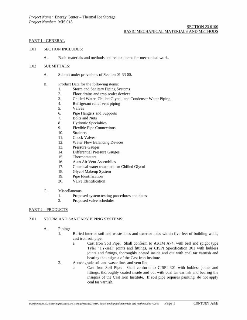
Project Name: Energy Center – Thermal Ice Storage Project Number: MIS 018
SECTION 23 0100 BASIC MECHANICAL MATERIALS AND METHODS
f:\projects\mis016\projmgmt\specs\ice storage\mech\23 0100 basic mechanical materials and methods.doc-4/3/13 Page 1 CENTURY A&E
PART 1 - GENERAL
1.01 SECTION INCLUDES:
A. Basic materials and methods and related items for mechanical work.
1.02 SUBMITTALS:
A. Submit under provisions of Section 01 33 00.
B. Product Data for the following items: 1. Storm and Sanitary Piping Systems 2. Floor drains and trap sealer devices 3. Chilled Water, Chilled Glycol, and Condenser Water Piping 4. Refrigerant relief vent piping 5. Valves 6. Pipe Hangers and Supports 7. Bolts and Nuts 8. Hydronic Specialties 9. Flexible Pipe Connections 10. Strainers 11. Check Valves 12. Water Flow Balancing Devices 13. Pressure Gauges 14. Differential Pressure Gauges 15. Thermometers 16. Auto Air Vent Assemblies 17. Chemical water treatment for Chilled Glycol 18. Glycol Makeup System 19. Pipe Identification 20. Valve Identification
C. Miscellaneous: 1. Proposed system testing procedures and dates 2. Proposed valve schedules
PART 2 – PRODUCTS 2.01 STORM AND SANITARY PIPING SYSTEMS:
A. Piping: 1. Buried interior soil and waste lines and exterior lines within five feet of building walls,
cast iron soil pipe. a. Cast Iron Soil Pipe: Shall conform to ASTM A74, with bell and spigot type
Tyler "TY-seal" joints and fittings, or CISPI Specification 301 with hubless joints and fittings, thoroughly coated inside and out with coal tar varnish and bearing the insignia of the Cast Iron Institute.
2. Above grade soil and waste lines and vent line a. Cast Iron Soil Pipe: Shall conform to CISPI 301 with hubless joints and
fittings, thoroughly coated inside and out with coal tar varnish and bearing the insignia of the Cast Iron Institute. If soil pipe requires painting, do not apply coal tar varnish.

Project Name: Energy Center – Thermal Ice Storage Project Number: MIS 018
SECTION 23 0100 BASIC MECHANICAL MATERIALS AND METHODS
f:\projects\mis016\projmgmt\specs\ice storage\mech\23 0100 basic mechanical materials and methods.doc-4/3/13 Page 2 CENTURY A&E
B. Floor Drains: 1. Cast iron body, with double drainage flange, weepholes, bottom outlet, anti-tilting grate,
flashing clamp, deep seal P-trap. 2. Provide trap sealing devices as indicated on drawings. 3. Covers:
a. Unfinished Areas: Non-clog 11-1/2 inch round, deep sediment bucket and satin bronze finish strainer.
C. Acceptable Manufacturers: Smith, Josam, Zurn, Wade, or equal. D. Cleanouts:
1. Locations: At each 90 degree bend in suspended and underground waste and drain pipes, at 50 foot intervals in straight runs, at base of each downspout and riser, above P-traps and elsewhere as shown.
2. Exposed Concrete Floor Areas: Sectional cast iron with serrated cut-off section, brass head plug with cover.
3. Acceptable Manufacturers: Smith, Josam, Zurn, Wade or equal.
2.02 CHILLED WATER, CHILLED GLYCOL, AND CONDENSER WATER PIPING SYSTEMS
A. Pipe: 1. Austenitic stainless steel straight welded pipe per ASTM A778 Grade TP 304L, Schedule
10. The pipe shall also conform to ANSI B36.19, ANSI B31.1 and ANSI B31.3. The design temperature range -425oF through 800oF.
B. Fittings: 1. Wrought austenitic stainless steel per ASTM A774 Grade WP304L, Schedule 10, ANSI
B16.9 and ANSI B16.25. Class 150, butt weld, long radius, temperature -425oF through 800oF.
C. Flanges: 1. Forged carbon steel per ASTM A36 and ANSI B16.1, Class 125, lap joint flange, inside
diameter of flange has a radius to relieve pressure on the flared pipe. Flange must be prime painted to prevent rust during shipment and storage.
D. Stub Ends:
1. Wrought austenitic stainless steel per ASTM A774 Grade WP304L, Schedule 10, butt weld.
E. Gaskets:
1. Garlock Off-White Gylon 3510
2.03 CHILLER REFRIGERANT RELIEF VENT:
A. Steel Pipe: Conforming to ASTM A53, Type E, Grade B (ERW). Where used for steam service or hot water service in excess of 50# or where forming or bending of piping is required. 1. Black Steel Pipe: Schedule 40, unless otherwise specified. Sizes 2 inches and smaller
have screwed joints and 125# fittings. Sizes 2-1/2 inches and larger have welded joints and fittings, except that connections to valves and equipment are made with welding neck flanges, or as detailed.
B. Welding Fittings for Black Steel Pipe: Midwest, Tube Turn, Ladish or B&W, of domestic
manufacture, 150# steel beveled welding fittings conforming to ASTM A234 WPB and all applicable provisions of ANSI B16.9.
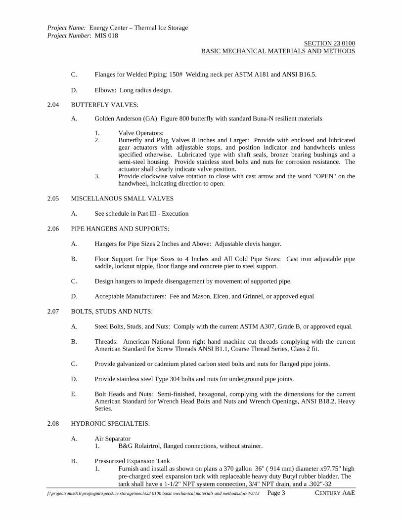
Project Name: Energy Center – Thermal Ice Storage Project Number: MIS 018
SECTION 23 0100 BASIC MECHANICAL MATERIALS AND METHODS
f:\projects\mis016\projmgmt\specs\ice storage\mech\23 0100 basic mechanical materials and methods.doc-4/3/13 Page 3 CENTURY A&E
C. Flanges for Welded Piping: 150# Welding neck per ASTM A181 and ANSI B16.5. D. Elbows: Long radius design.
2.04 BUTTERFLY VALVES:
A. Golden Anderson (GA) Figure 800 butterfly with standard Buna-N resilient materials 1. Valve Operators: 2. Butterfly and Plug Valves 8 Inches and Larger: Provide with enclosed and lubricated
gear actuators with adjustable stops, and position indicator and handwheels unless specified otherwise. Lubricated type with shaft seals, bronze bearing bushings and a semi-steel housing. Provide stainless steel bolts and nuts for corrosion resistance. The actuator shall clearly indicate valve position.
3. Provide clockwise valve rotation to close with cast arrow and the word "OPEN" on the handwheel, indicating direction to open.
2.05 MISCELLANOUS SMALL VALVES
A. See schedule in Part III - Execution
2.06 PIPE HANGERS AND SUPPORTS:
A. Hangers for Pipe Sizes 2 Inches and Above: Adjustable clevis hanger.
B. Floor Support for Pipe Sizes to 4 Inches and All Cold Pipe Sizes: Cast iron adjustable pipe saddle, locknut nipple, floor flange and concrete pier to steel support.
C. Design hangers to impede disengagement by movement of supported pipe.
D. Acceptable Manufacturers: Fee and Mason, Elcen, and Grinnel, or approved equal
2.07 BOLTS, STUDS AND NUTS:
A. Steel Bolts, Studs, and Nuts: Comply with the current ASTM A307, Grade B, or approved equal.
B. Threads: American National form right hand machine cut threads complying with the current American Standard for Screw Threads ANSI B1.1, Coarse Thread Series, Class 2 fit.
C. Provide galvanized or cadmium plated carbon steel bolts and nuts for flanged pipe joints.
D. Provide stainless steel Type 304 bolts and nuts for underground pipe joints.
E. Bolt Heads and Nuts: Semi-finished, hexagonal, complying with the dimensions for the current American Standard for Wrench Head Bolts and Nuts and Wrench Openings, ANSI B18.2, Heavy Series.
2.08 HYDRONIC SPECIALTEIS:
A. Air Separator 1. B&G Rolairtrol, flanged connections, without strainer.
B. Pressurized Expansion Tank 1. Furnish and install as shown on plans a 370 gallon 36" ( 914 mm) diameter x97.75" high
pre-charged steel expansion tank with replaceable heavy duty Butyl rubber bladder. The tank shall have a 1-1/2" NPT system connection, 3/4" NPT drain, and a .302"-32

Project Name: Energy Center – Thermal Ice Storage Project Number: MIS 018
SECTION 23 0100 BASIC MECHANICAL MATERIALS AND METHODS
f:\projects\mis016\projmgmt\specs\ice storage\mech\23 0100 basic mechanical materials and methods.doc-4/3/13 Page 4 CENTURY A&E
charging valve connection (standard tire valve) to facilitate the on-site charging of the tank to meet system requirements.
2. The tank shall be fitted for horizontal hung installation. 3. The tank must be constructed in accordance with Section VIII of the ASME Boiler and
Pressure Vessel Code and stamped 125 PSI working pressure. 4. Each tank shall be ITT Industries - Bell & Gossett Model No. B-1400
C. Misc. fittings 1. See schematic on drawing M8.1
2.09 FLEXIBLE PIPE CONNECTIONS:
A. Steel Piping: Construct with stainless steel inner hose and braided exterior sleeve.
B. Use connectors suitable for minimum 125 psi and 450 degrees F and 200 psi WOG and 250 degrees F.
C. Manufacturers: Universal, Flexonics and Metraflex or equal.
2.10 STRAINERS:
A. Size 5 Inch and Larger: Flanged iron body, basket pattern with 3/16 inch stainless steel perforated screen.
B. Screen Free Area: Minimum 3 times the area of the inlet pipe. Provide valved drain and hose connection off strainer bottom.
C. Provide differential pressure gauges across all strainers. See drawings for piping details and this Section for gauges.
2.11 PIPE SLEEVES:
A. See drawings details.
2.12 SILENT CHECK VALVES:
A. Type: Non-slam or silent, suitable for use in either the horizontal or vertical position, semi-steel body, bronze plug and seat and guide bushing ASTM B143, and stainless steel helical spring ASTM A276.
B. Metraflex Style 900 or equal as approved by the Engineer.
2.13 WATER FLOW BALANCING DEVICES
A. P-103: 10 inch Triple Duty Valve as manufactured by B&G.
B. All other pumps: no balancing devices
2.14 FLEXIBLE PIPE CONNECTIONS:
A. Steel Piping: Construct with stainless steel inner hose and braided exterior sleeve. B. Use connectors suitable for minimum 125 psi and 450 degrees F and 200 psi WOG and 250
degrees F. C. Manufacturers: Universal, Flexonics and Metraflex or equal.
Project Name: Energy Center – Thermal Ice Storage Project Number: MIS 018
SECTION 23 0100 BASIC MECHANICAL MATERIALS AND METHODS
f:\projects\mis016\projmgmt\specs\ice storage\mech\23 0100 basic mechanical materials and methods.doc-4/3/13 Page 5 CENTURY A&E
2.15 STANDARD PRESSURE GAUGES:
A. General: Install all pressure gauges readable from the floor complete with name plates. .
B. Ranges: 2 times the indicated operating pressure or 5 PSIG above the relief valve setting.
C. Pressure Gauges: 1. Equivalent to Trerice 600CB 2. Size: 4-1/2 inch dial gauges encased in an aluminum diecast housing with a threaded
access cover and glass crystal. 3. Gauge Body: Water and dust tight with back flange and 1/2 inch NPT connection. 4. Movements: Rotary geared stainless steel with Grade "A" phosphor bronze Bourdon
tube rated from 30 inch vacuum to 1000 PSIG maximum. Accuracy within 1/2% of the scale range.
5. Dial: White laminated phenol with black graduations and a micrometer recalibration type pointer.
6. Filling: Glycerin. 7. Conduit: 1/2 inch capillary tube runs of 7 feet and longer, or over aisles. 8. Range: 0 – 100 psig
D. Always provide gage isolators and pulsation dampeners on gauges
2.16 DIFFERENTIAL PRESSURE GAUGES:
A. General: Install differential pressure gauges and piping assemblies across all pipe strainers. See detail on drawings.
B. Pressure Gauges: 1. Equivalent to Ashcroft 1127/1128 differential pressure gauge. 2. Size: 6 inch dial 3. Range 0 – 10 psig
2.17 THERMOMETERS: A. General: Install thermometers in piping system and duct systems as shown to be readily readable
from the floor or access panels in the ceiling. Provide separable brass sockets for all thermometers in piping systems or special duct flange for all thermometers in duct systems.
B. Ranges:
1. Chilled water and chilled glycol: 0 to 100 degrees F. 2. Condenser water : 20 to 120 degrees F
C. Industrial Type Thermometers:
1. Provide adjustable angle type with 9 inch case and a minimum stem length of 6 inches in piping.
2. Casing: Cast aluminum with double strength glass, white face with dark graduations. 3. Stem: 304 stainless 4. Element: A red reading mercury tube. 5. Manufacturers: Trerice
2.18 AUTO AIR RELIEF VALVE ASSEMBLIES A. General clarification: Auto Air Relief valves shall have integral check valves to keep air from
entering back into the valve during low pressure conditions.
Project Name: Energy Center – Thermal Ice Storage Project Number: MIS 018
SECTION 23 0100 BASIC MECHANICAL MATERIALS AND METHODS
f:\projects\mis016\projmgmt\specs\ice storage\mech\23 0100 basic mechanical materials and methods.doc-4/3/13 Page 6 CENTURY A&E
2.19 CHEMICALS WATER TREATMENT FOR CHILLED GLYCOL SYSTEM
1. The system shall be filled with a pre-mixed ethylene glycol solution resulting in a minimum seven parts de-ionized water to three parts inhibited ethylene glycol (30% mixture). Ethylene glycol shall be a premixed product equivalent to Wintrex as furnished by Houghton Chemical.
B. The solution shall be thoroughly mixed by the chemical supplier. Field mixed glycol, automotive
glycol, and field inhibited glycol is not acceptable. See Section 23 0100 for requirements C. The chilled water cooling system shall first be flushed and recirculated with corrosion inhibitor
cleaning and passivating agent and then filled with tap water. Verify all flushing and filling means and methods with Calmac representative prior to performing work.
2.20 GLYCOL MAKEUP SYSTEM (GMS-1)
A. Manufacturer: 1. CALMAC or approved equal as determined by Engineer based on full shop drawing
submittal prior to bid
B. General 1. The liquid pressurization system shall be factory engineered and tested as a complete
unit. The unit shall be approved for outdoor use using TEFC pump motor and hot-dipped galvanized frame. A minimum 60 gallon covered, vented, reservoir with 1 0 gallon graduations is required. It shall include an adjustable pressure relief valve which protects against accidental over-pressurization by the management system. Isolation valves, between building and filling system, and service valves, between reservoir and pump, are required. Alarms with both visual indicating lights and remote contact points are required for the following conditions: low system pressure, low liquid level in reservoir, high liquid level, loss of power, and low solution level. The minimum pumping capacity shall be 3 gallons per minute at 80 psig
C. Features
1. Unit is able to be located outdoors with TEFC pump motor, hot dipped galvanized frame and a NEMA 3R control box.
2. A 65 gallon vented reservoir, with 10 gallon graduations which can be used for mixing glycol/water solution.
3. Alarms to indicate various conditions, which are detailed below. 4. Pressure relief valve which protects against over-pressurization by the GMS.
Not to be used in place of a properly sized system pressure relief valve. 5. Isolation valve between building system and GMS. 6. Service valve between the reservoir and the pump. 7. Drain valve located after pump to allow removing most of solution from the
GMS reservoir.
D. Alarms - Standard on the GMS liquid pressurization system are visible warning lights and electrical contacts (rated 4 amp at 230 Volts) for remote monitoring of alarms for the following conditions: 1. Add Solution warning - Solution needs to be added to the reservoir, however
GMS pump will continue to run until level reaches the Low Liquid Level alarm.
2. Low Liquid Level -GMS pump is automatically turned off 3. Low System Pressure - Possible leak in building system 4. High Liquid Level 5. Loss of Power – Low Liquid Level alarm contacts also close on loss of power

Project Name: Energy Center – Thermal Ice Storage Project Number: MIS 018
SECTION 23 0100 BASIC MECHANICAL MATERIALS AND METHODS
f:\projects\mis016\projmgmt\specs\ice storage\mech\23 0100 basic mechanical materials and methods.doc-4/3/13 Page 7 CENTURY A&E
2.21 PIPE AND VALVE IDENTIFICATION
A. See Part III – Execution of this Section for requirements
PART 3 - EXECUTION
3.01 INSTALLATION:
A. Contractor shall provide survey to locate pipes, elevations, ducts, conduits, etc. and to prepare shop drawings. Variations to suit existing conditions, structural features or mechanical equipment shall be Contractor’s responsibility.
B. Run piping parallel with building lines and as direct as possible. Piping shall be concealed as far as possible in the finished portions of the building.
C. Install all piping so as to be completely drainable with stop and drain valves installed accessibly at the low points of the system.
D. Provide air relief valves in all high points of piping.
E. Provide two 1 ¼” male cam-lok fittings per supply and return and to be installed across pumps and in mechanical room so that cleaning and passivating chemicals can be circulated in all new hydronic piping systems.
F. Downfeed runouts for water piping shall be taken at 45 degrees or from bottom of main and upfeed runouts from the top of the main.
G. Cut pipe accurately and install without springing or forcing. All burrs shall be removed after cutting.
H. Lubricate cleanout plugs with mixture of graphite and linseed oil.
I. Install shut-off valves for all fixtures and equipment.
J. Sanitary and storm lines graded 1/8 inch per foot unless otherwise indicated.
3.02 PIPE AND FITTINGS
A. Preparation: Ream pipes and tubes, clean off scale and dirt, inside and outside, before assembly. Remove welding slag or other foreign material from piping.
B. Connection: Screw joint steel piping up to and including 2 inches. Weld piping 2-1/2 inches and larger, including branch connections.
C. Make screwed joints with full cut standard taper pipe threads with red lead and linseed oil or other approved non-toxic joint compound applied to make threads only.
D. Use main sized saddle type branch connections or directly connecting branch lines to mains in steel piping if main is at least one pipe size larger than the branch for up to 6 inch mains and if main is at least two pipe sizes larger than branch for 8 inches and larger mains. Do not project branch pipes inside the main pipe.
3.03 VALVES:
A. General: 1. Provide valves of same manufacturer throughout where possible.

Project Name: Energy Center – Thermal Ice Storage Project Number: MIS 018
SECTION 23 0100 BASIC MECHANICAL MATERIALS AND METHODS
f:\projects\mis016\projmgmt\specs\ice storage\mech\23 0100 basic mechanical materials and methods.doc-4/3/13 Page 8 CENTURY A&E
2. Provide valves with manufacturer's name and pressure rating clearly marked on outside of body.
B. Installation: 1. Install valves with stems upright or horizontal, not inverted. 2. Install ball valves for shut-off and isolating service, to isolate equipment, part of systems
or vertical risers. 4. Install globe or angle valves for throttling service and control device or meter by-pass. 5. Provide spring loaded check valves on discharge of condensate pumps, condenser water
and water booster pumps.
C. Miscellaneous Valve Schedule:
Type
Size
LunkCat. #
Hmstd.Cat. #
CraneCat. #
Nibco Cat. #
JenksCat. #
Check Valves
2" and smaller. All bronze with sweat ends
2145 IB647 1342 S113 1222
2" and smaller All bronze with screwed ends
2144 IB940 37 T-413BWY 92A
Ball Valves
2" and smaller 708HST BV711-T 2330TF T590Y 32A
3.04 PIPE HANGERS AND SUPPORTS:
A. Support horizontal steel and copper piping as follows:
Nominal Pipe Size (in.)
Max. Distance BetweenSupport (ft.)
1/2 to 1-1/2 62 & 2-1/2 103 and above 10
B. Install hangers to provide minimum 1/2 inch clear space between finished covering and adjacent work.
C. Place a hanger within one foot of each horizontal elbow.
D. Use hangers which are vertically adjustable 1-1/2 inch minimum after piping is erected.
E. Do not support pipe from other pipe.
3.05 AUTO AIR VENT ASSEMBLIES:
A. Air vent assembly to be as detailed on drawings. No modifications.
B. Install in all high places and at ends of runs before elbowing down and otherwise as shown on the drawings.
3.06 CHEMICAL TREATMENT FOR GLYCOL SYSTEM:
A. Verify requirements with Trane and Calmac.
B. Coordinate fill with Owner.
Project Name: Energy Center – Thermal Ice Storage Project Number: MIS 018
SECTION 23 0100 BASIC MECHANICAL MATERIALS AND METHODS
f:\projects\mis016\projmgmt\specs\ice storage\mech\23 0100 basic mechanical materials and methods.doc-4/3/13 Page 9 CENTURY A&E
C. Provide temporary pumps and fill hose as required.
3.07 GLYCOL FEED PUMP SYSTEM:
A. Install per manufacturer’s instructions.
B. Test and verify proper pressure settings. Verify alarm shows up at temperature control panel.
3.08 PIPE AND EQUIPMENT IDENTIFICATION:
A. Match existing identification and marking scheme using identical materials. Verify based on field inspection.
B. Coiled Plastic Pipe Markers 1. Pre-coiled semi-rigid plastic formed to cover full circumference of pipe and to attach to
pipe without adhesive. 2. Marking Services MS-970, pre-printed, color-coded, with lettering indicating service,
and showing direction of flow. a. Style H with minimum of 3 attaching nylon straps b. Colors: Comply with ASME A13.1, unless otherwise indicated. c. Lettering: Use piping system terms indicated and abbreviate only as
necessary for each application length. 3.5 inches tall d. Arrows: Integral with piping system service lettering to accommodate both
directions; or as separate unit on each pipe marker to indicate direction of flow.
C. Stencils: Prepared with letter sizes according to ASME A13.1 for piping.
1. Stencil Material: Aluminum or fiberboard. 2. Stencil Paint: Exterior, gloss, enamel, black, unless otherwise indicated. Paint may be in
pressurized spray-can form. 3. Identification Paint: Exterior, enamel in colors according to ASME A13.1, unless
otherwise indicated.
3.09 VALVE IDENTIFICATION:
A. Match existing identification and marking scheme using identical materials. Verify based on field inspection.
B. Brass Tags: 2 inch diameter, secured to each valve with brass S-hook and stamped with system designation and assigned number.
C. Obtain existing valve schedule from Owner and review existing valve naming sequence. Submit proposed schedule showing proposed continuation of sequence to Architect / Engineer for approval. Provide a printed schedule, in duplicate, describing each valve by number, giving location and service for which used as part of the project closeout documentation
3.10 TESTING AND CLEANING OF HYDRONIC WATER SYSTEMS:
A. General: 1. Submit a notice of intention to test to the Architect / Engineer, Construction Manager,
and Owner at least seven (7) days prior to the test. 2. All hydronic piping to be pressure tested with Owner present and if desired by any of
Architect / Engineer, Construction Manager to witness the test. Coordinate the tests to accommodate the appropriate schedules.
3. Provide pumps, gauges, instruments, test equipment personnel and clean auxiliary water. 4. Operate pumps which have mechanical seal only with water in the system.

Project Name: Energy Center – Thermal Ice Storage Project Number: MIS 018
SECTION 23 0100 BASIC MECHANICAL MATERIALS AND METHODS
f:\projects\mis016\projmgmt\specs\ice storage\mech\23 0100 basic mechanical materials and methods.doc-4/3/13 Page 10 CENTURY A&E
5. Test prior to painting, installation of insulation, or concealment. 6. Tests may be made on sections of piping as installed. 7. Re-test repaired or revised piping.
B. Pressure Testing: 1. Testing with compressed air or gas is prohibited. 2. Test pressure: 150 percent of the operating pressure or pump shut-off head pressure
whichever is greater. a. Minimum pressure: 50 psi. b. Test period: 2 hours minimum.
C. Cleaning: 1. Fill system with fresh water and add Mitco BL-5
2. Circulate the solution through the system for a period of 8 hours, allowing temperature to
reach design temperature. 3. Drain, clean strainers and refill with fresh water. Operate system at design temperature
for 4 hours. Test with hydrionpaper. Accept a pH of 7 or higher.
3.11 LUBRICATION:
A. Ensure that all motors and equipment, as required, are properly lubricated before such items are accepted by the OWNER.
END OF SECTION

Project Name: Energy Center – Thermal Ice Storage Project Number: MIS 016
SECTION 23 0593 TESTING, ADJUSTING AND BALANCING
f:\projects\mis016\projmgmt\specs\ice storage\mech\23 0593 testing adjusting balancing.doc-4/3/13 Page 1 CENTURY A&E
PART 1 - GENERAL
1.01 SUMMARY:
A. This Section specifies the requirements and procedures for total mechanical systems testing, adjusting, and balancing. Requirements include measurement and establishment of mechanical systems fluid flow rates as required to meet design specifications; and recording and reporting the results of these measurements.
B. Systems testing, adjusting, and balancing (T/A/B) consists of checking and adjusting all building environmental systems to produce design objectives. It includes, but is not necessarily limited to, the following: 1. Balancing of water distribution. 2. Calibration and verification of flow meters and chilled glycol and condenser flow
through chiller 3. Adjustment of total system to provide design flow rates. 4. Electrical measurements. 5. Verification of performance of all equipment and automatic controls. 6. Assistance with commissioning activities.
C. Test, adjust, and balance the following mechanical systems: Also, see the schedules on the drawings for required hydronic system balancing for existing and new systems and Section 23 0993 – Sequences of Operation and Graphics. Provide test and balance services for the following systems (which include remeasuring and rebalancing existing systems to verify proper system performance at all operational modes). 1. Ice Chiller including chilled glycol and condenser water flow. 2. Ice Tank System 3. Pump P-101 4. Pump P-102 5. Pump P-103 6. Pump P-104 7. Pump P-105 8. Pump P-106 9. Assist with calibration of flow meters and calibration of flow through chiller evaporator
and condenser barrels. 10. Assist with verification of temperature control system operation. 11. Assist with commissioning activities per Section 23 0800 – Commissioning.
D. Attend project meetings and commissioning meetings as directed by the Engineer who will required meeting attendance as benefits the progress of the project. 1. Requirements and procedures for piping systems leakage tests.
1.02 SYSTEM PERFORMANCE REQUIREMENTS AND OBSERVED FIELD PROBLEMS
A. Required systems performance: Balance all systems to within 10% of the stated performance values.
B. System Balancing Problems: If it becomes apparent that the various systems cannot be balanced to within 10% of the stated performance values due to some system installation or performance problem, stop work as soon as possible and immediately contact the Architect / Engineer. DO NOT proceed with system balancing and submit a complete report if the there are system design problems.

Project Name: Energy Center – Thermal Ice Storage Project Number: MIS 016
SECTION 23 0593 TESTING, ADJUSTING AND BALANCING
f:\projects\mis016\projmgmt\specs\ice storage\mech\23 0593 testing adjusting balancing.doc-4/3/13 Page 2 CENTURY A&E
1.03 DEFINITIONS:
A. Test: To determine quantitative performance of equipment.
B. Adjust: To regulate the specified fluid flow rate at the terminal equipment.
C. Balance: To proportion flows within the distribution system (submains, branches, and terminals) according to specified design quantities.
D. Procedure: Standardized approach and execution of sequence of work operations to yield reproducible results.
E. Report Forms: Test data sheets arranged for collecting test data in logical order for submission and review. These data should also form the permanent record to be used as the basis for required future testing, adjusting, and balancing.
F. Terminal: The point where the controlled fluid enters or leaves the distribution system. These are supply inlets on water terminals and return outlets on water terminals
G. Main: Pipe containing the system's major or entire fluid flow.
H. Submain: Pipe containing part of the system's capacity and serving 2 or more branch mains.
I. Branch Main: Pipe serving 2 or more terminals.
J. Branch: Pipe serving single terminal.
1.04 SUBMITTALS:
A. Submit under provisions of Section 01300 - Submittals.
B. Qualifications: Submit proof that the proposed T/A/B agency, the Test and Balance Engineer assigned to supervise the procedures, and the technicians proposed to perform the procedures meet the qualifications specified below.
C. Sample Forms: Submit sample forms, if other than those standard forms prepared by the AABC are proposed.
D. Certified Reports: Submit T/A/B reports bearing the seal and signature of the Test and Balance Engineer. The reports shall be certified proof that the systems have been tested, adjusted, and balanced in accordance with the referenced standards; are an accurate representation of how the systems have been installed; are true representation of how the systems are operating at the completion of the T/A/B procedures; and are an accurate record of all final quantities measured, to establish normal operating values of the systems. Follow the procedures and format specified below: 1. Draft Reports: Upon completion of T/A/B procedures, prepare draft reports on the
approved forms. Draft reports may be hand written, but must be complete, factual, accurate, and legible. Organize and format draft reports in the same manner specified for the final reports. Submit 2 complete sets of draft reports. Only one complete set of draft reports will be returned.
2. Final Report: Upon verification and approval of draft reports, prepare final reports, type written, and organized and formatted as specified below. Submit 2 complete sets of final reports.

Project Name: Energy Center – Thermal Ice Storage Project Number: MIS 016
SECTION 23 0593 TESTING, ADJUSTING AND BALANCING
f:\projects\mis016\projmgmt\specs\ice storage\mech\23 0593 testing adjusting balancing.doc-4/3/13 Page 3 CENTURY A&E
3. Report Format: Report forms shall be those standard forms prepared by the referenced standard for each respective item and system to be tested, adjusted, and balanced. Bind report forms complete with schematic systems diagrams and other data in reinforced, vinyl, 3-ring binders. Provide binding edge labels with the project identification and title descriptive of the contents. Divide the contents of the binder into the below listed divisions, separated by divider tabs: a. General Information and Summary. b. Hydronic Systems. c. Temperature Control Systems.
4. Report Contents: Provide the following minimum information, forms and data: a. General Information and Summary: Inside cover sheet to identify T/A/B
agency, CONTRACTOR, OWNER, ENGINEER, and Project. Include addresses, and contact names and telephone numbers. Also include certification sheet containing the seal and name address, telephone number, and signature of the Certified Test and Balance Engineer. Include in this division listing of the instrumentation's used for the procedures along with the proof of calibration.
b. Remainder of Report: Include appropriate forms containing as minimum, the information indicated on the standard report forms prepared by the AABC, for each respective item and system. Prepare schematic diagram for each item of equipment and system to accompany each respective report form.
E. Calibration Reports: Submit proof that all required instrumentation has been calibrated to tolerances specified in the referenced standards, within period of 6 months prior to starting the project.
1.05 QUALITY ASSURANCE:
A. Acceptable Test and Balance Sub-Contractors (No other contractors allowed) 1. Midwest 2. Synergy 3. Great Lakes Balancing
B. Codes and Standards: Perform T/A/B work in accordance with applicable provisions of the following: 1. AABC: "National Standards For Total System Balance". 2. ASHRAE: ASHRAE Handbook, 1995 Applications Volume, Chapter 34, Testing,
Adjusting, and Balancing. 3. International Performance Measurement and Verification Protocol (IPMVP)
C. Pre-Balancing Conference: Prior to commencing T/A/B procedures, schedule and conduct conference with the ENGINEER and representatives of installers of the mechanical systems. The objective of the conference is final coordination and verification of system operation and readiness for commencement of T/A/B work.
D. Develop and implement a Measurement and Verification (M&V) Plan consistent with IPMVP for a period of no less than one year of post construction occupancy.
1.06 PROJECT CONDITIONS:
A. Systems Operation: Systems shall be fully operational prior to beginning procedures.
B. Pre-Balancing Checklist: Prior to beginning T/A/B procedures, survey all systems scheduled to be tested, adjusted, and balanced. Identify all incomplete work, non-functioning systems or missing devices which will prevent effective performance of T/A/B work. Present this

Project Name: Energy Center – Thermal Ice Storage Project Number: MIS 016
SECTION 23 0593 TESTING, ADJUSTING AND BALANCING
f:\projects\mis016\projmgmt\specs\ice storage\mech\23 0593 testing adjusting balancing.doc-4/3/13 Page 4 CENTURY A&E
information to appropriate mechanical systems installers in checklist form. Do not begin T/A/B work until all checklist items have been satisfactorily addressed.
1.07 SEQUENCING AND SCHEDULING:
A. All hydronic piping to be pressure tested with GVSU representative present (provide one week notice of testing)
B. The T&B contractor shall complete work prior to final commissioning. or system verification by the Commissioning Authority. The TAB contractor is to coordinate the TAB plan with the Prime Contractor and schedule time frames for TAB at the pre-construction meeting to be cincorporated in the overall project schedule.
C. Test, adjust and balance air conditioning systems during summer season and heating systems during winter season, including at least period of operation at outside conditions within 5 deg. F wet bulb temperature of maximum summer design condition, and within 10 deg. F dry bulb temperature of minimum winter design condition. Take final temperature readings during seasonal operation.
PART 2 - PRODUCTS
NOT USED PART 3 - EXECUTION
3.01 PRELIMINARY PROCEDURES FOR HYDRONIC SYSTEM BALANCING:
A. Before operating the system perform these steps: 1. Open valves to full open position. 2. Remove and clean all strainers. 3. Examine hydronic systems and determine if water has been treated and cleaned. 4. Check pump rotation. 5. Clean and set automatic fill valves for required system pressure. 6. Check expansion tanks to determine that they are not air bound and that the system is
completely full of water. 7. Check air vents at high points of systems and determine if all are installed and operating
freely (automatic type) or to bleed air completely (manual type). 8. Check operation of automatic bypass valves. 9. Check and set operating temperatures of chillers to design requirements. 10. Lubricate all motors and bearings.
3.02 MEASUREMENTS:
A. Provide all required instrumentation to obtain proper measurements, calibrated to the tolerances specified in the referenced standards. Instruments shall be properly maintained and protected against damage.
B. Provide instruments meeting the specifications of the referenced standards.
C. Use only those instruments which have the maximum field measuring accuracy and are best suited to the function being measured.
D. Apply instrument as recommended by the manufacturer.

Project Name: Energy Center – Thermal Ice Storage Project Number: MIS 016
SECTION 23 0593 TESTING, ADJUSTING AND BALANCING
f:\projects\mis016\projmgmt\specs\ice storage\mech\23 0593 testing adjusting balancing.doc-4/3/13 Page 5 CENTURY A&E
E. Use instruments with minimum scale and maximum subdivisions and with scale ranges proper for the value being measured.
F. When averaging values, take sufficient quantity of readings which will result in repeatability error of less than 5 percent. When measuring single point, repeat readings until 2 consecutive identical values are obtained.
G. Take all reading with the eye at the level of the indicated value to prevent parallax.
H. Use pulsation dampeners where necessary to eliminate error involved in estimating average of rapidly fluctuation readings.
I. Take measurements in the system where best suited to the task.
3.04 PERFORMING TESTING, ADJUSTING, AND BALANCING:
A. Perform testing and balancing procedures on each system identified, in accordance with the detailed procedures outlined in the referenced standards.
B. Cut insulation and piping for installation of test probes to the minimum extent necessary to allow adequate performance of procedures.
C. Patch insulation and housings, using materials identical to those removed.
D. Seal piping, and test for and repair leaks.
E. Seal insulation to reestablish integrity of the vapor barrier.
F. Mark equipment settings, including valve indicators and similar controls and devices, to show final settings. Mark with paint or other suitable, permanent identification materials.
G. Retest, adjust, and balance systems subsequent to significant system modifications, and resubmit test results.
3.05 SYSTEM PERFORMANCE REQUIREMENTS AND OBSERVED FIELD PROBLEMS
A. Required systems performance: Balance all systems to within 10% of the stated performance values.
B. System Balancing Problems: If it becomes apparent that the various systems cannot be balanced to within 10% of the stated performance values due to some system installation or performance or design problem , stop work and immediately contact the Contractor and the Engineer. DO NOT proceed with system balancing and submit a complete report if the there are system performance prolems. If test and balance work does proceed despite performance issues that are subsequently addressed, the Test and Balance Contractor shall rebalance and test all systems at no additional cost to the Owner.
3.06 RECORD AND REPORT DATA:
A. Record all data obtained during testing, adjusting, and balancing in accordance with, and on the forms recommended by the referenced standards, and as approved on the sample report forms.

Project Name: Energy Center – Thermal Ice Storage Project Number: MIS 016
SECTION 23 0593 TESTING, ADJUSTING AND BALANCING
f:\projects\mis016\projmgmt\specs\ice storage\mech\23 0593 testing adjusting balancing.doc-4/3/13 Page 6 CENTURY A&E
B. Prepare report of recommendations for correcting unsatisfactory mechanical performances when system cannot be successfully balanced.
3.07 SYSTEMS COMMISSIONING:
A. See Section 23 0800 –Commissioning for additional information.
B. Coordinate all activities with the Temperature Control Contractor and Prime Contractor.
END OF SECTION
Project Name: Energy Center – Thermal Ice Storage Project Number: MIS 016
SECTION 23 0700 MECHANICAL INSULATION
f:\projects\mis016\projmgmt\specs\ice storage\mech\23 0700 insulation.doc-4/3/13 Page 1 CENTURY A&E
PART 1 - GENERAL
1.01 SUMMARY:
A. This Section includes the furnishing and installation of thermal insulation for mechanical piping and equipment as indicated on the Drawings, as specified herein, and as required for the proper and complete performance of the Work.
B. Types of mechanical insulation specified in this Section include the following:
1. Chilled Water and Condenser Water Piping Systems Insulation: a. Glass Fiberwith factory vapor barrier and aluminum jacket.
2. Chilled Glycol Piping Systems Insulation: a. Rigid thermoplastic (polystyrene) foam (two layers 1.0 inch think) with field
applied outer film jacket and final aluminum jacket.
3. Service part removeable insulation – Strainer ends, Autoair Valve Assemblies Manual Air Outlet, a. Closed Cell Flexible Elastomeric with Velcro Closures for strainers ends
4. Equipment Insulation – For any and all cold surfaces that could possibly sweat: Chilled Water and Chilled Glycol Pumps, Chilled Water and Chilled Glycol Strainer Blowdown Piping, Chilled Water and Chilled Glycol Autoair Valve Assemblies, Chilled Glycol Air Removal, Pipe Drains, Pressure Gauge Piping, etc. a. Closed Cell Flexible Elastomeric
5. Equipment Insulation – Miscellaneous Repair of Factory Installed Chiller Insulation a. Closed Cell Flexible Elastomeric
C. Intent: 1. All cold surfaces that might sweat during normal operation must be insulated. This
includes drain ends, auto air valve assemblies, pressure gauge manifolds, valve shafts, etc. and any other items as found.
2. Once in operation, the Engineer will inspect all piping systems and components for the presence of condensation. The Engineer will note any items that require additional insulation and the Contractor shall provide those additional insulation materials at no additional cost to the Owner.
D. Related Sections: The following Section contains requirements that relate to this Section: 1. Section 23 0000, "Mechanical General Provisions". 2. Section 23 1000, “Basic Materials and Methods”.
E. For miscellaneous insulation of Trane chiller, contact Kurt Trierweiler of Trane (ph 517-xxx-xxxx) to verify insulation instructions and requirements prior to bid
1.02 SUBMITTALS:
A. Submit under provisions of Section 01300 - Submittals
B. Product Data: Submit manufacturer's technical product data and installation instructions for each type of mechanical insulation. Submit application schedule listing manufacturer's product number, k-value, thickness, r-factor, and furnished accessories for each mechanical system receivng insulation.
C. Provide a list of all miscellaneous equipment and piping items to be insulated.

Project Name: Energy Center – Thermal Ice Storage Project Number: MIS 016
SECTION 23 0700 MECHANICAL INSULATION
f:\projects\mis016\projmgmt\specs\ice storage\mech\23 0700 insulation.doc-4/3/13 Page 2 CENTURY A&E
D. Provide a list of all items or devices where a removable insulation cover is required.
1.03 QUALITY ASSURANCE:
A. Installer's Qualifications: Firm with at least 5 years successful installation experience on projects with mechanical insulation's similar to that required for this project.
B. Flame/Smoke Ratings: Provide composite mechanical insulation (insulation, jackets, coverings, sealers, mastics and adhesives) with flame-spread index of 25 or less, and smoke-developed index of 450 or less, as tested by ASTM E84 (NFPA 255) method and U.L. 723. Shipping containers for insulating materials shall bear the U. L. label.
1.04 DELIVERY, STORAGE, AND HANDLING:
A. Deliver insulation, coverings, cements, adhesives, and coatings to site in containers with manufacturer's stamp or label, affixed showing fire hazard indexes of products.
B. Protect insulation against dirt, water, and chemical and mechanical damage. Do not install damaged or wet insulation; remove from project site.
1.05 WARRANTY:
A. Warrant replacement insulation installation for 1 year from date of final acceptance at no additional cost to OWNER.
PART 2 - PRODUCTS
2.01 CHILLED WATER AND CONDENSER WATER PIPING INSULATION MATERIALS
A. Fiberglass: Provide 1-piece, preformed, rigid molded fibrous glass, 4-lb density, with k-factor of 0.24 at 75 deg F complying with ASTM C547, rated for use to 850 degrees F; with factory-applied vapor barrier of white craft paper with glass fiber yarn, bonded to aluminized film, moisture vapor transmission when tested in accordance ASTM E 96/E of 0.02 perm-inches.. 1. Subject to compliance with requirements, provide products of one of the following:
a. Knauf. b. Mansville. c. Owens-Corning Fiberglas d. Keene Corp
B. Application 1. Chilled Water: 1.5 inches 2. Condenser Water: 1.0 inch
C. Aluminum Jacket: Provide 0.016-inch thich aluminum ASTM B209, 3003 Alloy, H-14 temper jacketing and matching pre-formed 45-degree and 90-degree, long radius elbows, same matieral, finsh and thickness as jacket.
D. Pipe Supports at Hangers: Provide section of preformed calcium silicate equal to IIG Thermo-12 Gold on bottom half of pipe where pipe and support come in contact. Section to be a minimum of 12” long and span 6” to either side of support to allow for expansion and contraction of pipe. A 3/16” thick, 304 stainless steel plate rolled to be used as a cradle to match the span of the calcium silicate block.
2.02 CHILLED GLYCOL PIPING INSULATION MATERIALS
A. Provide two (2) layors of 1-inch thick rigid thermoplastic foam with closed cell structure, K value at 75º F, 0.259 equal to ITW Insulation Systems XPS PIB Extruded Polystyrene Pipe Insulation Billet with ITW Insulation Systems 540 vapor retarder film and tape. 1. Other manufacturer’s may be approved as determined by the Engineer based on full shop
drawing submittals prior to bid.

Project Name: Energy Center – Thermal Ice Storage Project Number: MIS 016
SECTION 23 0700 MECHANICAL INSULATION
f:\projects\mis016\projmgmt\specs\ice storage\mech\23 0700 insulation.doc-4/3/13 Page 3 CENTURY A&E
B. Aluminum Jacket: Provide 0.016-inch thich aluminum ASTM B209, 3003 Alloy, H-14 temper jacketing and matching pre-formed 45-degree and 90-degree, long radius elbows, same matieral, finsh and thickness as jacket.
C. Pipe Supports at Hangers: Provide section of preformed calcium silicate equal to IIG Thermo-12 Gold on bottom half of pipe where pipe and support come in contact. Section to be a minimum of 12” long and span 6” to either side of support to allow for expansion and contraction of pipe. A 3/16” thick, 304 stainless steel plate rolled to be used as a cradle to match the span of the calcium silicate block.
2.03 EQUIPMENT/ PUMPS / HYDRONIC ACCESSORIES
A. Closed Cell Flexible Elastomeric, 1-inch thick: Provide preformed or sheet material as required complying with ASTM C534; equal to Armstrong AP ARMAFLEX or SELF-SEAL. Aluminum Jacket NOT required.
B. Equipment Insulation Compounds: Provide adhesives, cements, sealers, mastics and protective
finishes as recommended by insulation manufacturer for applications indicated. C. Equipment Insulation Accessories: Provide staples, bands, wire, wire netting, tape, corner angles,
anchors and stud pins as recommended by insulation manufacturer for applications indicated. D. For any and all items requiring maintenance access including strainer end caps, miscellaneous
small valves, drain connections, provide removable insulation pieces, caps etc. If necessary to keep removable insulation components in place during normal operation, provide velcro closure materials.
PART 3 EXECUTION
3.01 EXAMINATION:
A. Examine areas and conditions under which mechanical insulation is to be installed. Do not proceed with work until unsatisfactory conditions have been corrected in manner acceptable to Installer.
3.02 INSTALLATION OF PIPING INSULATION:
A. Install insulation products as specified herein; and in accordance with manufacturer's written instructions, and recognized industry practices to ensure that insulation serves its intended purpose.
B. Install insulation on pipe systems subsequent to installation of testing, and acceptance of tests.
C. Install insulation materials with smooth and even surfaces. Insulate each continuous run of piping with full-length units of insulation, with single cut piece to complete run. Do not use cut pieces or scraps abutting each other.
D. Surfaces to receive insulation shall in all cases be free of rust, scale or dust, clean and dry. If surface is specified to be painted prior to insulating, others shall complete the painting prior to commencement of insulation work.
E. Insulation shall be applied with tightly butted joints, free of voids and gaps. All fasteners and bands shall be neatly aligned and overall appearance of work shall be subject to Engineer's approval. All insulation must be sealed to the pipe lines of a minimum of six (6") inches from any termination of such insulation. The pipe insulation vapor barrier jacket must also be positively sealed to the pipe at the points of termination.

Project Name: Energy Center – Thermal Ice Storage Project Number: MIS 016
SECTION 23 0700 MECHANICAL INSULATION
f:\projects\mis016\projmgmt\specs\ice storage\mech\23 0700 insulation.doc-4/3/13 Page 4 CENTURY A&E
F. When using pressure sensitive tapes for joint closures, surfaces shall be wiped clean with particular attention paid to dust and grease.
G. Pipe insulation shall be placed on the pipe with all joints tightly butted. At all insulation joints, surfaces of insulation shall be sealed with a continuous bead of specified joint sealant. The vapor barrier jacket shall be sealed using the specified adhesive to provide a perfect vapor seal. End butt joints shall be similarly sealed using factory finished butt strips and the specified adhesive.
H. On chilled glycol piping, the insulation system shall be completely vapor sealed before the aluminum jacket is applied. The aluminum jacket shall not compromise the vapor barrier by penetration of fasteners, etc. Vapor stops at butt joints shall be applied at every fourth pipe section joint and at each fitting to provide isolation of water incursion.
I. All piping shall be supported in such a manner that neither the insulation nor the vapor/weather barrier is compromised by the hanger or the effects of the hanger. In all cases, hanger spacing shall be such that the circumferential joint may be made outside the hanger. On cold systems, vapor barrier shall be continuous, including material covered by the hanger saddle.
J. Taper covering terminated at equipment, specialties, access doors, etc, or where jackets are pierced by metal parts such as hangers, thermometers, etc. and securely seal jacket to pipe or other metal parts.
K. Provide insulation for all cold items or surfaces that may possibly sweat during normal operation.
L. Provide removable caps or covers for all cold items or surfaces that need to be inspected, or viewed, or operated or otherwise where access is required.
3.03 INSTALLATION OF EQUIPMENT INSULATION AND MISCELLANEOUS PIPING AND HYDRONIC SPECIALTIES:
A. Install equipment thermal insulation products in accordance with manufacturer's written
instructions, and in compliance with recognized industry practices to ensure that insulation serves intended purpose.
B. Insulate the following equipment items using closed cell flexible elastomeric specified in Part 2
above: 1. Pumps 2. Air Removal 3. Valves 4. Auto Air Assemblies 5. Sections of gauges and sensors or piping near cold piping that might possibly sweat. 6. Fittings 7. Drains 8. Flow Meters 9. Strainers 10. Check Valves 11. Triple Duty Valves
C. Install insulation materials with smooth and even surfaces and on clean and dry surfaces. Redo
poorly fitted joints. Do not use mastic or joint sealer as filler for gapping joints and excessive voids resulting from poor workmanship.
D. Maintain integrity of vapor-barrier on equipment insulation and protect it to prevent puncture and
other damage. Seal all jacket seams, exposed edges, and penetrations with UL listed tapes or vapor retardant adhesives comparable to insulation jacketing material.
Project Name: Energy Center – Thermal Ice Storage Project Number: MIS 016
SECTION 23 0700 MECHANICAL INSULATION
f:\projects\mis016\projmgmt\specs\ice storage\mech\23 0700 insulation.doc-4/3/13 Page 5 CENTURY A&E
E. Apply insulation using the staggered joint method for both single and double layer construction, where feasible. Apply each layer of insulation separately.
F. Provide insulation for all cold items or surfaces that may possibly sweat during normal operation.
G. Provide removable caps or covers for all cold items or surfaces that need to be inspected, or viewed, or operated or otherwise where access is required.
3.04 EXISTING INSULATION REPAIR:
A. Remove and replace damaged sections of existing mechanical insulation that was damaged or altered as part of the Work. Install new insulation of same thickness as existing. Install new jacket lapping and sealed over existing.
3.05 PROTECTION AND REPLACEMENT:
A. Insulation Installer shall advise CONTRACTOR of required protection for insulation work during remainder of construction period, to avoid damage and deterioration.
B. Replace damaged insulation which cannot be repaired satisfactorily, including units with vapor barrier damage and moisture saturated units.
C. Remove and replace all insulating materials on which mold or mildew has occurred, or which have been discolored or stained due to mold, mildew or condensation within 1 year of Substantial Completion.
END OF SECTION

Blank Page
jmuizelaar
Rectangle

Project Name: Energy Center – Thermal Ice Storage Project Number: MIS 016
SECTION 23 0800 MECHANICAL SYSTEMS COMMISSIONING
f:\projects\mis016\projmgmt\specs\ice storage\mech\23 0800 commissioning.doc-4/3/13 Page 1 CENTURY A&E
PART 1 - GENERAL
1.01 SUMMARY:
A. This Section includes information relating to systems commissioning.
B. All commissioning activities shall be the responsibility of and directed by the Prime Contractor. An independent Commissioning Agent is not required.
C. In this Specification, mechanical systems commissioning includes all activities relating to the demonstration and documentation of the mechanical system installation and performance per the design intent and Owner’s requirements
D. The commissioning process includes the following activities: 1. Definition of Overall Design Intent and Sequences of Operation 2. List of Equipment Requiring Commissioning 3. Systems requiring written startup reports 4. Commissioning Process Scheduling and Communication including attendance at
Commissioning Meetings 5. Submittal of Test and Balance Reports 6. Submittal of Sequence of Operations Functional Check Lists by Temperature Control
Contactor 7. Demonstration to Owner and Engineer 8. Owner Training 9. Submittal of Project Record and Closeout Documents
1.02 DEFINITION OF OVERALL DESIGN INTENT AND SEQUENCES OF OPERATION:
A. See Section 01010 – Summary of Work for the mechanical work scope
B. See Section 23 0000 – Mechanical General Provisions for a general requirements.
C. See Section 23 0993 – Sequences of Operation and Graphics for a general description of the required performance and a detailed description of the required sequences of operation
1.03 LIST OF EQUIPMENT REQUIRING COMMISSIONING:
A. The following items are to be commissioned:
1. New chillers CH-5
2. New pumps P-101, P-102, P-103, P-104, P-105, P-106
3. Heat Exchangers HX-3, HX-4
4. Ice Tanks
5. Temperature Control System in including alls sensors, control valves, ice build sensors, etc. including verification of proper system operation in each mode.
6. Verfication of proper flow through condenser barrel when tower pump system is both in high pressure and low pressure modes.
7. Glycol feed unit
1.04 LIST OF EQUIPMENT REQUIRING FACTORY AUTHORIZED STARTUP REPORTS:
A. The following items require factory inspection, startup assistance, and submittal of written startup report.
1. New chiller CH-5
2. New pumps P-101, P-102, P-103, P-104, P-105, P-106
3. Ice Storage Tank installation and operation

Project Name: Energy Center – Thermal Ice Storage Project Number: MIS 016
SECTION 23 0800 MECHANICAL SYSTEMS COMMISSIONING
f:\projects\mis016\projmgmt\specs\ice storage\mech\23 0800 commissioning.doc-4/3/13 Page 2 CENTURY A&E
4. Ice build sensor
1.05 COMMISSIONING PROCESS SCHEDULING AND COMMUNICATION:
A. The Prime Contractor shall coordinate all commissioning activities, including the development of a commissioning schedule that indicates the time and sequencing of all activities.
B. It is anticipated that there will be a minimum of four special meetings between the Owner, Engineer / Architect, Prime Contractor, Equipment Vendors, Electrical Sub-Contracotr,, Temperature Control Contractor, and the Test and Balance Sub Contractor to review commissioning procedures, plan the schedules, coordinate, and review progress. 1. Pre-commissioning Planning Meeting 2. Commissioning Progress Meetings 1 3. Commissioning Progress Meeting 2 4. Final Commissioning Review and Approval Meeting
1.06 TEST AND BALANCE REPORTS:
A. The Test and Balance Contractor shall work closely with the Mechanical Contractor and Temperature Control Contractor and help coordinate all activities.
B. See Section 23 0593 for a description of required Test and Balance work
1.07 SEQUENCE OF OPERATIONS FUNCTIONAL CHECK LISTS BY TEMPERATURE CONTROL CONTRACTOR:
A. The Temperature Control Contractor shall develop and submit to the Engineer for approval a complete functional checklist for each piece of equipment.
B. The Functional Check list is intended to represent a step-by-step process whereby each required control sequence, safety, operational parameter, etc. is verified and documented.
C. The Temperature Control Contractor shall work with the Engineer and Owner to modify the proposed list as required.
D. Once the Functional Checklist has been accepted, then the Temperature Control Contractor shall coordinate with the Mechanical Contractor and Test and Balance Contractor to help schedule all activities.
1.08 DEMONSTRATION TO OWNER ENGINEER:
A. Once all systems are fully functional and all commissioning activities are complete, the Temperature Control Contractor (and Mechanical Contractor as necessary) will meet with the Owner and Engineer to demonstrate graphics and proper operation in each mode and to possibly alter miscellaneous sequences for improved system operation.
B. See Section 01720 – Demonstration to Owner and Engineer for additional requirements.
1.09 OWNER TRAINING:
A. Once the Engineer and Owner confirm that all systems are operating as intended, the Contractor shall provide Owner Training
B. See Section 01730 – Owner Training for additional requirements.
Project Name: Energy Center – Thermal Ice Storage Project Number: MIS 016
SECTION 23 0800 MECHANICAL SYSTEMS COMMISSIONING
f:\projects\mis016\projmgmt\specs\ice storage\mech\23 0800 commissioning.doc-4/3/13 Page 3 CENTURY A&E
1.10 PROJECT RECORD DOCUMENTS:
A. The Contractor must submit six sets of complete O&M Manuals in multiple volumes.
B. The Contractor must submit O&M Volumes 1A, 1B, 1C, etc. prior to Substantial Completion
C. The Contractor must submit O&M Volumes 2 prior to Final Completion
D. See Section 01710 – Project Record Documents for additional requirements. PART 2 - PRODUCTS
Not Used
PART 3 - EXECUTION
Not Used
END OF SECTION

Blank Page
jmuizelaar
Rectangle
Project Name: Energy Center – Thermal Ice Storage Project Number: MIS 016
SECTION 23 0920 TEMPERATURE CONTROLS
f:\projects\mis016\projmgmt\specs\ice storage\mech\23 0920 temperature controls.doc-4/4/13 Page 1 CENTURY A&E
PART 1 -GENERAL 1.01 DESCRIPTION OF WORK
A. The Bidding Contractor shall directly contract the services of Trane to provide the equipment and services listed and described in this specification, also known as the Temperature Control work. Also, see Section 01010 – Summary of Work for additional requirements and explanations regarding the required work.
B. Contact Trane to obtain a bid price and to coordinate the temperature and controls work provided by Trane. Bidding Contractor shall include Trane’s associated cost in their bid and shall list the cost in the Bid Form in Appendix I.
C. Trane shall be responsible for all BMS and Temperature Control wiring and conduit for a complete and operable system, including control wiring and installation of control panels associated with the ice monitor probe. All wiring shall be done in accordance with all local and national codes.
D. See Section 23 0930 - Sequences of Operations and Graphics for a list of control points (graphics points list) that helps define the required control points, sensors, transmitters, etc.
E. The Temperature Control Contractor (TCC) shall perform the following: 1. Work as selectively described in the following specifications
a. Section 23 0800 – Commissioning of Mechanical Systems b. Section 23 0920 – Temperature Controls c. Section 23 0930 – Sequences of Operation, Points Lists, and Required Graphics
2. Provide all required transformers and 24 volt control wiring as required for all control devices.
3. Provide new temperature sensors, controllers, actuators, panels, control wiring and conduit, etc.
4. Furnish control valves, flow meters, and sensor wells for installation by mechanical contractor.
5. Provide engineering. 6. Develop new and revise existing graphics. 7. Assist with startup and commissioning and test and balance as required and as specified.
Provide Owner training. Demonstrate proper operation of all equipment to Engineer. Provide closeout documentation.
F. All materials and equipment used shall be standard components, regularly manufactured for this and/or other systems and not custom designed especially for this project. All systems and components shall have been thoroughly tested and proven in actual use for at least two years
1.02 WORK BY OTHERS
A. Electrical Contractor provides: 1. 120V power to all BMS and/or Temperature control panels and transformers 2. Wiring of all power feeds through all disconnect starters to electrical motors. 3. Variable Frequency Drives (VFD’s)
B. Products furnished but not installed under this section 1. Temperature sensor wells 2. Flow meter 3. 3-way control valves. 4. Condenser control valve

Project Name: Energy Center – Thermal Ice Storage Project Number: MIS 016
SECTION 23 0920 TEMPERATURE CONTROLS
f:\projects\mis016\projmgmt\specs\ice storage\mech\23 0920 temperature controls.doc-4/4/13 Page 2 CENTURY A&E
C. Products installed but not furnished under this section 1. Section 23 6500 – Ice Storage Tanks and Accessories
a. Ice Measuring Probe
D. Control devices furnished and installed by others (but wired and controlled by TCC). 1. Section 23 6000– Centrifugal Chillers
a. Chiller flow switches
1.03 SUBMITTALS
A. Submit under provisions of Section 01300 - Submittals.
B. Submit complete documentation in the following phased delivery schedule: 1. Submittals prior to construction 2. Submittals for system commissioning for Substantial Completion 3. Submittals for project closeout for Final Completion
C. Submittals prior to construction: 1. Valve schedules 2. Data cut sheets for all controllers, components, actuators, flow meters, panels, pressure
switches, temperature sensors, etc. 3. System schematics, including:
a. Piping schematic diagrams b. sequence of operations c. point names d. point addresses e. interface wiring diagrams f. panel layouts. g. system riser diagrams
4. Proposed point-to-point commissioning checklists (see Part 3 - Execution for additional requirements)
5. Proposed functional test forms used to indicate all required steps to verify correct sequences of operation (see Part 3 - Execution for additional requirements.
D. Submittals for system commissioning for Substantial Completion 1. See Section 01710 for additional requirements. 2. Complete Volume 1 O&M manuals using 3-ring binder format with each separate section
having its own tab. 3. Index sheets listing contents in alphabetical order 4. Contact information 5. Manufacturer's equipment parts list of all functional components of the system, 6. Sequence of operations 7. As-Built interconnection wiring diagrams 8. Trunk cable schematic showing remote electronic panel locations and all trunk data 9. List of connected data points, including panels to which they are connected and input
device (sensors, etc.) 10. Completed point-to-point commissioning checklists 11. Completed functional test forms
E. Submittals for project closeout for Final Completion 1. See Section 01710 for additional requirements. 2. Auto-CAD disk of as-built system schematics, including wiring diagrams and as-built
sensor locations

Project Name: Energy Center – Thermal Ice Storage Project Number: MIS 016
SECTION 23 0920 TEMPERATURE CONTROLS
f:\projects\mis016\projmgmt\specs\ice storage\mech\23 0920 temperature controls.doc-4/4/13 Page 3 CENTURY A&E
3. Completed warrantee forms
1.04 WARRANTY
A. Provide all labor, services, materials, parts, and equipment necessary for the successful operation of the new control system for a period of one (1) year after substantial completion.
1.05 RELATED SECTIONS
A. See Section 01010 - Summary of Work, for additional work scope requirements.
B. See Section 23 0800 – Mechanical Systems Commissioning for additional requirements.
C. See Section 23 0993 - Sequences of Operations and Graphics for required sequences of operation and a detailed description of required graphics.
1.06 REFERENCES
A. American National Standards Institute, Inc. (ANSI) 1. X3.64 - Additional Controls for Use with the American National Standard Code for
Information Interchange. 2. X3.4 Character Set.
B. American Society of Heating, Refrigerating, and Air Conditioning Engineers (ASHRAE) 1. Handbook, 1997 Fundamentals. 2. BACnet Standard 1995-135.
C . American Society of Mechanical Engineers (ASME). 1. B16.22 - Wrought Copper and Copper Alloy Solder-Joint Pressure Fittings.
D . National Electrical Manufacturers Association (NEMA) 1. 250 - Enclosures for Electrical Equipment (1000 volt maximum).
E. National Fire Protection Association (NFPA) 1. 70 - National Electrical Code. 2. 90A - Installation of Air Conditioning and Ventilating Systems.
F. Underwriters Laboratory Inc. (U LI) 1. 555 - Fire Dampers. 2. 555S - Leakage Rated Dampers for Use in Some Control Systems. 3. 864 - Process Management Equipment. 4. 916 - Equipment, Energy Management.
G. International Standards Organization (ISO). 1. 9001- Quality Standard.
H. Software Engineering Institute (SEI). 1. Certification Level 3.
1.07 CODES AND APPROVALS
A. The complete HVAC Instrumentation and Control installation shall be in strict compliance to the national, state and local mechanical and electrical codes as applicable and all referenced sections

Project Name: Energy Center – Thermal Ice Storage Project Number: MIS 016
SECTION 23 0920 TEMPERATURE CONTROLS
f:\projects\mis016\projmgmt\specs\ice storage\mech\23 0920 temperature controls.doc-4/4/13 Page 4 CENTURY A&E
of these specifications. All devices shall be ULI or FM listed and labeled for the specific use, application and environment to which they are applied.
B. The system shall comply with the standards referenced in Part 1.
C. The system shall be designed and manufactured to the ISO 9001 quality standard for quality assurance and SEI Certification Level 3 or higher for software development.
D. All electronic equipment shall conform to the requirements of FCC regulation Part 15, and be so labeled. Spread spectrum components shall comply with FCC regulation part 15. 247 regarding low power unlicensed transmitters, and be so labeled.
E. Ensure that all safety switches, such as high pressure switches, remain active under all operating conditions.
F. Ensure that all wiring, conduit, starters, push buttons, control devices and other electrical devices provided for any areas which are indicated as hazardous or in areas classified as hazardous by the National Electrical Code, the American Insurance Association, or the National Fire Protection Association meet all requirements for these classifications. Refer to the Electrical Drawings for area classifications.
G. The final checkout and verification (commissioning) of the complete and proper system operation shall be performed by technicians certified by the TCC to be fully trained in the systems operation, installation, checkout, and maintenance. See Part 3 - Execution of this section for further requirements.
PART 2 - PRODUCTS
2.01 GENERAL
A. Provide standard products that are compatible with and are a part of the existing system as manufactured by Trane. 1. Provide sensors, actuators, transmitters, control wiring, controllers, panels, etc. as
required to perform the sequences of operation and report, monitor, and control the mechanical systems as described in Section 23 0993 - Sequences of Operation and Graphics.
2. Extend and apply existing energy management software 3. Extend existing and provide new graphics as described in Section 23 0930.
2.02 PRODUCTS
A. Control Valve Actuators 1. All new actuators shall be 24 V. 2. See points lists for requirements
B. Control Valves 1. Modulating 3-way control valves shall have two independent actuators. 2. Two position 3-way valves shall have a single actuator with a linkage between the valves. 3. Valves shall be line size
C. Flow Meters 1. F-3100 In-Line Electromagnetic Flow Meter as manufactured by Onicon. 2. Carbon Steel Body with PTFE Liner.
Project Name: Energy Center – Thermal Ice Storage Project Number: MIS 016
SECTION 23 0920 TEMPERATURE CONTROLS
f:\projects\mis016\projmgmt\specs\ice storage\mech\23 0920 temperature controls.doc-4/4/13 Page 5 CENTURY A&E
3. ANSI 150 psig flange 4. Remote mount electronics enclosure.
D. Pipe Temperature Sensors 1. Standard Trane system component.
E. Pipe High Pressure Switch 1. Standard Trane system component.
F. Pipe Differential Pressure Sensor 1. Standard Trane system component.
G. Condenser Water Flow Control Valve 1. GA Figure 5737 Throttling Solenoid Valve including valves, control piping, pressure
gauges, check valves, 24 volt modulating open and closed solenoids, 24 volt valve position transmitter, speed controllers, , etc as detailed on GA Industries Data Sheet 5737.01 and as required for a complete functioning valve system.
2. Use 12 inch globe valve. Cv = 1836 full open 3. Contact Matthew Hurst, MBA Distributers, (517) 787-9016, [email protected]
PART 3 – EXECUTION
3.01 INSTALLATION
A. Electrical Components: 1. For installation standards and procedures for electrical components, refer to Division 26
specifications.
B. Control Wiring (24 volts or less): 1. All control wiring shall be run in conduit. 3. See Division 26 for additional requirements.
C. Control Power Wiring: 1. Whenever control power wiring is taken from a receptacle panel, provide a breaker
handle locking device to lock the breaker in the “ON” position. Label the circuit as “Control System Power, Do Not De-Activate”.
3.02 COMMISSIONING
A. See Section 23 0800 – Mechanical Systems Commissioning for additional requirements.
B. Point to Point Tests: 1. Use the point to point checklist to verify that all control devices, sensors, actuators, etc
are properly wired and properly functioning. 2. Test, adjust, and calibrate all control equipment including sensors in terms of design,
function, and performance to prepare for the functional tests. 3. Verify that all control devices and operators operate smoothly and freely without
excessive hunting or cycling. 4. Submit the completed point to point checklists with initials by each control point
indicating that the point is properly wired, functioning, calibrated, and properly communicating.
5. Remedy any defects or malfunctions that are determined by these tests and repeat tests until defects have been corrected to the complete satisfaction of the OWNER.

Project Name: Energy Center – Thermal Ice Storage Project Number: MIS 016
SECTION 23 0920 TEMPERATURE CONTROLS
f:\projects\mis016\projmgmt\specs\ice storage\mech\23 0920 temperature controls.doc-4/4/13 Page 6 CENTURY A&E
C. Functional Test: 1. Upon completion of the point to point checklists, begin verification of all required control
sequences using the functional test forms previously submitted. 2. Include items that require interfacing with the test and balance contractor, such as
calibration of the flow meter. 3. For each required sequence or control function, the functional test forms shall indicate a
proposed action that would verify the associated sequence and then the expected result. 4. Test and verify the operation of all control system functions including all sequences of
operations, safeties, alarms, etc. 5. Submit the completed functional test forms with initials by each activity indicating what
action was performed and what result was achieved. 6. Remedy any defects or malfunctions that are determined by these tests and repeat tests
until defects have been corrected to the complete satisfaction of the OWNER.
D. Adjusting and Balancing: 1. Cooperate with and assist the adjusting and balancing personnel in their adjustments and
balancing of the air and hydronic systems.
3.03 CLOSEOUT REQUIREMENTS
A. See the following Sections for Additional Requirements 1. Section 01700 – Contract Closeout 2. Section 01710 – Project Record Documents 3. Section 01720 –Demonstration to Owner and Engineer 4. Section 01730 – Owner Training 5. Section 23 0800 – Mechanical Systems Commissioning
B. Demonstration to Owner and Engineer 1. The Temperature Control Contractor shall allow a minimum of twenty four (24) hours
to work with the Engineer to demonstrate proper operation of all systems and to adjust and fine tune operating sequences as required to improve performance.
C. Owner Training 1. The Temperature Control Contractor shall furnish a minimum of sixteen (16) hours of
Owner training by factory trained and certified personnel. The training will provide an overview of the job specific control components, sequences of operation, network capability and structure, etc.
2. Training will be provided at two milestones: Training at Substantial Completion and Training at Final Completion
3. Operation and maintenance manuals, including as-built wiring diagrams and component lists, shall be provided for each training attendee.
END OF SECTION

Project Name: Energy Center – Thermal Ice Storage Project Number: MIS 016
SECTION 23 0930 SEQUENCES OF OPERATION, GRAPHICS, AND POINTS LIST
f:\projects\mis016\projmgmt\specs\ice storage\mech\23 0930 sequences of operations.doc-4/4/13 Page 1 CENTURY A&E
PART 1 - GENERAL
1.01 SECTION INCLUDES:
A. Sequences of Operation
B. Required Graphics
C. Control Points List
1.02 GENERAL
A. The Temperature Control Contractor shall supply all sensors, controllers, meters, programming, graphics development, etc. as required to perform the sequences of operation as described herein.
B. The Temperature Control work shall be provided by Trane. See Section 23 0920 – Temperature Controls for additional information. The Contractor shall engage the services of Trane as part of the contractor work.
C. The terms “Temperature Control Contractor”, “TCC”, “Control Contractor” and “Trane” may be used interchangeably and shall all refer to the Trane controls group that must be engaged to provide the temperature control work for this project.
1.03 RELATED SECTIONS:
A. Section 23 0000 – Mechanical General Provisions
B. Section 23 0100 – Basic Mechanical Materials and Methods
C. Section 23 0800 – Mechanical Systems Commissioning
D. Section 23 0593 - Testing, Adjusting, and Balancing
E. Section 23 0920 – Temperature Controls
F. Division 26
1.04 SUBMITTALS:
A. Submit under provisions of Section 01300 – Submittals and Section 23 0920 – Temperature Controls.
PART 2 PRODUCTS
2.01 GENERAL
A. See Section 23 0900 and Division 26 for products and installation methods.
B. The requirements of this Section shall serve as part of the work scope and contract obligations of the Temperature Control Contractor (TCC). Except as specifically noted, the TCC shall provide all products required to perform the specified sequences of operations and as necessary to report data points as described by the required graphics, whether or not the products are shown on the drawings or described in Section 23 0920. The required graphics shall be considered as a points list that helps define the sensors, valves, etc. that are required for individual pieces of equipment, both for control (per the sequences below) and for performance monitoring (which may not be mentioned in the sequences).

Project Name: Energy Center – Thermal Ice Storage Project Number: MIS 016
SECTION 23 0930 SEQUENCES OF OPERATION, GRAPHICS, AND POINTS LIST
f:\projects\mis016\projmgmt\specs\ice storage\mech\23 0930 sequences of operations.doc-4/4/13 Page 2 CENTURY A&E
PART 3 EXECUTION
3.01 GENERAL
A. See Section 23 0920 –Temperature Controls and Instrumentation and Division 216 for additional requirements.
B. The Building Management System (BMS) shall be provided by the Temperature Control Contractor (TCC) and shall be an expansion and extension of the existing Trane Tracer Summit system.
C. The required graphics data points listed in this section shall serve as a required points list.
D. All listed setpoint values shall be adjustable from the operator interface of the BMS.
E. The Electrical Sub-Contractor shall provide all control wiring and conduit.
3.02 THERMAL ICE STORAGE SYSTEM
A. Operation Mode Summary 1. See Drawing M9.3 for a summary and simplified schematic of all the operational modes.
B. System Description 1. The Energy Center – Thermal Ice Storage system consists of one new dual mode ice chiller,
54 new thermal ice storage tanks, two new heat exchangers, four new chilled glycol pumps and two new chilled water pumps.
2. The chiller and ice storage tanks will use 30% ethylene glycol for low ice making temperatures and are separated from the main chilled water system via heat exchangers.
3. The new equipment has the following nominal capacities: a. Ice Chiller (CH-5)
1) Ice Build Mode (22 F supply temperature): 690 tons 2) Ice Chiller Day Mode (37 F supply temperature): 910 tons
b. Thermal Ice Storage Tanks: 6,400 ton hours 1) Ice Melt Mode: 800 tons at 37 R discharge for 8 hours. 2) Ice Build Mode: 690 tons at 22 F inlet for 9.3 hours
c. Heat Exchangers (typical of two: HX-3 & HX-4): 833 tons (uses 37 F glycol to cool chilled water to 42 F.
4. In general, the intent is to save electrical operating costs by using the new ice chiller to make ice during off-peak electrical billing hours (7:00 PM to 11:00 AM) and when electrical rates are lower and then turn off the chiller and use the stored ice to provide cooling during on-peak electrical billing hours (11:00 AM to 7:00 PM) when electrical rates are higher.
5. However, plant operators can select a variety of other operational modes. The Thermal Ice Storage system is also designed to allow operation of both the ice chiller and the ice storage tanks at the same time during the day. Accordingly, the new system has two different chilled glycol-to-chilled water heat exchangers (HX-3 and HX-4).
6. In addition, the system is capable of extending wintertime “free” tower cooling during slightly warmer weather by directing the discharge chilled water from the free cooling heat exchanger to either the ice storage tanks or the ice chiller.
7. The various Thermal Ice Storage System modes of operation are as follows: a. Ice Build Mode (690 tons to ice tanks) b. Ice Melt Mode – HX-3 (800 tons) c. Ice Melt Mode – HX-4 (800 tons) d. Chiller Day Mode – HX-3 (910 tons) e. Chiller Day Mode – HX-4 (910 tons) f. Parallel Chiller Day and Ice Melt Mode – HX-3 & HX-4 (1,400 tons)
8. Each of the above modes can cool chilled water directly from the chilled water return mains (normal) or can pull from the discharge of the “free cooling” HX-1 (supplement free cooling).
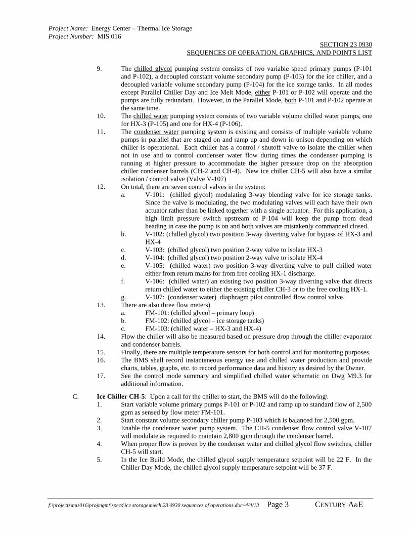
Project Name: Energy Center – Thermal Ice Storage Project Number: MIS 016
SECTION 23 0930 SEQUENCES OF OPERATION, GRAPHICS, AND POINTS LIST
f:\projects\mis016\projmgmt\specs\ice storage\mech\23 0930 sequences of operations.doc-4/4/13 Page 3 CENTURY A&E
9. The chilled glycol pumping system consists of two variable speed primary pumps (P-101 and P-102), a decoupled constant volume secondary pump (P-103) for the ice chiller, and a decoupled variable volume secondary pump (P-104) for the ice storage tanks. In all modes except Parallel Chiller Day and Ice Melt Mode, either P-101 or P-102 will operate and the pumps are fully redundant. However, in the Parallel Mode, both P-101 and P-102 operate at the same time.
10. The chilled water pumping system consists of two variable volume chilled water pumps, one for HX-3 (P-105) and one for HX-4 (P-106).
11. The condenser water pumping system is existing and consists of multiple variable volume pumps in parallel that are staged on and ramp up and down in unison depending on which chiller is operational. Each chiller has a control / shutoff valve to isolate the chiller when not in use and to control condenser water flow during times the condenser pumping is running at higher pressure to accommodate the higher pressure drop on the absorption chiller condenser barrels (CH-2 and CH-4). New ice chiller CH-5 will also have a similar isolation / control valve (Valve V-107)
12. On total, there are seven control valves in the system: a. V-101: (chilled glycol) modulating 3-way blending valve for ice storage tanks.
Since the valve is modulating, the two modulating valves will each have their own actuator rather than be linked together with a single actuator. For this application, a high limit pressure switch upstream of P-104 will keep the pump from dead heading in case the pump is on and both valves are mistakenly commanded closed.
b. V-102: (chilled glycol) two position 3-way diverting valve for bypass of HX-3 and HX-4
c. V-103: (chilled glycol) two position 2-way valve to isolate HX-3 d. V-104: (chilled glycol) two position 2-way valve to isolate HX-4 e. V-105: (chilled water) two position 3-way diverting valve to pull chilled water
either from return mains for from free cooling HX-1 discharge. f. V-106: (chilled water) an existing two position 3-way diverting valve that directs
return chilled water to either the existing chiller CH-3 or to the free cooling HX-1. g. V-107: (condenser water) diaphragm pilot controlled flow control valve.
13. There are also three flow meters) a. FM-101: (chilled glycol – primary loop) b. FM-102: (chilled glycol – ice storage tanks) c. FM-103: (chilled water – HX-3 and HX-4)
14. Flow the chiller will also be measured based on pressure drop through the chiller evaporator and condenser barrels.
15. Finally, there are multiple temperature sensors for both control and for monitoring purposes. 16. The BMS shall record instantaneous energy use and chilled water production and provide
charts, tables, graphs, etc. to record performance data and history as desired by the Owner. 17. See the control mode summary and simplified chilled water schematic on Dwg M9.3 for
additional information.
C. Ice Chiller CH-5: Upon a call for the chiller to start, the BMS will do the following\ 1. Start variable volume primary pumps P-101 or P-102 and ramp up to standard flow of 2,500
gpm as sensed by flow meter FM-101. 2. Start constant volume secondary chiller pump P-103 which is balanced for 2,500 gpm. 3. Enable the condenser water pump system. The CH-5 condenser flow control valve V-107
will modulate as required to maintain 2,800 gpm through the condenser barrel. 4. When proper flow is proven by the condenser water and chilled glycol flow switches, chiller
CH-5 will start. 5. In the Ice Build Mode, the chilled glycol supply temperature setpoint will be 22 F. In the
Chiller Day Mode, the chilled glycol supply temperature setpoint will be 37 F.

Project Name: Energy Center – Thermal Ice Storage Project Number: MIS 016
SECTION 23 0930 SEQUENCES OF OPERATION, GRAPHICS, AND POINTS LIST
f:\projects\mis016\projmgmt\specs\ice storage\mech\23 0930 sequences of operations.doc-4/4/13 Page 4 CENTURY A&E
D. Ice Build Mode 1. In general, the Ice Build Mode should not begin unless at least 25% (adjustable) of the ice
has been used (75% or lower as indicated by the Ice Measuring Probe). 2. Pumps P-101 or P-102 will start and ramp up to 2,500 gpm as sensed by flow meter FM-1,
chilled glycol pump P-103 will start, and condenser water control valve V-107 will modulate open. Once the chiller flow switches prove flow, Chiller CH-5 will be enabled to produce chilled glycol at 22 F.
3. Valve V-102 will be commanded to bypass heat exchangers HX-3 and HX-4. 4. Isolation valves for heat exchangers HX-3 and HX-4 will both be closed. 5. Variable volume pump P-104 will ramp up to 2,500 gpm as measured by flow meter FM-2. 6. The Ice Build Mode will continue until the chilled glycol return temperature falls to 28 F
(adjustable). However, the Ice Build Mode should not terminate unless the Ice Measuring Probe indicates that the ice inventory is above 50%.
7. The various temperature sensors may also be used to confirm there is no flow in bypass loops.
8. Additionally and as a safety to prevent potential HX freeze-up, the Ice Build Mode will stop if the chilled glycol temperature falls below 33 F as measured by temperature sensors TE-12 (HX-3 chilled glycol inlet) or TE-14 (HX-4 chilled glycol inlet).[ [This shouldn’t happen. Valve V-102 should be positioned such that chilled glycol bypasses the HX and the two closed isolation valves V-103 and V-104 should stop any very low temperature glycol flowing to the HX.]
E. Ice Melt Mode HX-3 1. Pumps P-101 or P-102 will start and ramp up to 2,500 gpm and chilled glycol pump P-104
serving the ice tanks will start and ramp up to 2,500 gpm. 2. Valve V-101 will modulate as required to maintain a chilled glycol supply temperature of 37
F as measured at temperature sensor TE-9 (ice tank discharge after blending valve). 3. Valve V-102 will be commanded to direct chilled glycol to heat exchangers HX-3 and HX-
4. 4. Isolation valve V-103 associated with HX-3 will open. Isolation valve V-104 associated
with HX-3 will remain closed. 5. Variable volume chilled water pump P-105 will ramp up to approximately 2,500 gpm as
sensed by flow meter FM-3 and thereafter will ramp up and down as required to maintain a chilled water supply temperature of 42 F (adjustable) as sensed by temperature sensor TE-22.
6. Once valve V-101 is fully open to the ice tanks and the ice tank can no longer supply 37 F glycol at full flow (2,500 gpm), the system may continue to operate at the discretion of the operator. Pump P-104 will ramp down such that the ice tank discharge at reduced flow and as sensed by temperature sensor TE-9 remains at 37 F. Accordingly, chilled water pump P-105 will ramp down as required to maintain 42 F chilled water supply temperature. Once pump P-104 ramps down to its minimum valve (VFD at 20 Hz) and the chilled glycol supply eventually rises above 37 F, the Ice Melt Mode shall stop. Additionally, the Ice Melt Mode shall be terminated whenever the Ice Measuring Probe indicates that the ice inventory is below 10%.
F. Ice Melt Mode HX-4 1. Everything shall operate the same as for Ice Melt Mode HX-3 except HX-3 will not be
isolated, HX-4 isolation valve will be open, chilled water pump P-106 will start, etc. 2. See the Operation Mode Summary Table on Dwg. M9.3
G. Chiller Day Mode HX-3 1. Pumps P-101 or P-102 will start and ramp up to 2,500 gpm as sensed by flow meter FM-1,
chilled glycol pump P-103 will start, and condenser water control valve V-107 will modulate open. Once the chiller flow switches prove flow, Chiller CH-5 will be enabled to produce chilled glycol at 37 F.

Project Name: Energy Center – Thermal Ice Storage Project Number: MIS 016
SECTION 23 0930 SEQUENCES OF OPERATION, GRAPHICS, AND POINTS LIST
f:\projects\mis016\projmgmt\specs\ice storage\mech\23 0930 sequences of operations.doc-4/4/13 Page 5 CENTURY A&E
2. Valve V-102 will be commanded to direct chilled glycol to heat exchangers HX-3 and HX-4.
3. Isolation valve V-103 associated with HX-3 will open. Isolation valve V-104 associated with HX-3 will remain closed.
4. Variable volume chilled water pump P-105 will ramp up to approximately 2,500 gpm as sensed by flow meter FM-3 and thereafter will ramp up and down as required to maintain a chilled water supply temperature of 42 F (adjustable) as sensed by temperature sensor TE-22.
H. Chiller Day Mode HX-4 1. Everything shall operate the same as for Ice Melt Mode HX-3 except HX-3 will not be
isolated, HX-4 isolation valve will be open, chilled water pump P-106 will start, etc. 2. See the Operation Mode Summary Table on Dwg. M9.3
I. Parallel Ice and Chiller Operation 1. In the Parallel Ice and Chiller Operation Mode, the total system pressure drop would be
exceedingly large if total flow was 5,000 gpm or fully twice the flow of the standard modes. Accordingly, and to keep pump HP requirements reasonable, the parallel flow total flow rate will drop to 4,000 gpm.
2. Pumps P-101 and P-102 will start and ramp up to 2,000 gpm each (4,000 gpm total) as sensed by flow meter FM-1, chilled glycol pump P-103 will start, and condenser water control valve V-107 will modulate open. Once the chiller flow switches prove flow, Chiller CH-5 will be enabled to produce chilled glycol at 37 F at 2,500 gpm.
3. Additionally pump P-104 serving the ice tanks will start and ramp up to 1,500 gpm. 4. Valve V-101 will modulate as required to maintain a chilled glycol supply temperature of 37
F as measured at temperature sensor TE-9 (ice tank discharge after blending valve). 5. Valve V-102 will be commanded to direct chilled glycol to heat exchangers HX-3 and HX-
4. 6. Isolation valve V-103 associated with HX-3 and isolation valve V-104 associated with HX-
3 will both be open. 7. Variable volume chilled water pumps P-105 and P-106 will initially ramp up and down in
parallel to approximately 2,000 gpm each (5,000 gpm total) as sensed by flow meter FM-3 and thereafter will ramp up and down as required to maintain a chilled water supply temperature of 42 F (adjustable) as sensed by temperature sensor TE-22.
J. Supplement Free Cooling Modes 1. In all modes above that cool chilled water, the Thermal Ice Storage system typically pulls
chilled water return from the return main as commanded by two position blending valve V-105.
2. However, the system is also capable of supplementing the “free cooling” by cooling the chilled water that discharges from the free cooling heat exchanger HX-1
3. The supplement free cooling mode would only be used when free cooling was active and when ambient temperatures are not quite cold enough for full free cooling.
4. In the Supplement Free Cooling Mode, valve V-105 would be commanded to pull water from the free cooling HX-1 discharge rather than from the chilled water return main.
5. All other pumps, valves, etc. will operate as previously described.
K. Electrical and Chilled Water Measurements 1. Chilled water production shall be measured at all times based on the chilled water inlet and
outlet temperatures of HX-3 and HX-4 and on the chilled water flow as measured by FM-3. 2. Electrical kW use shall be measured instantaneously from the chiller, all VFD, and from a
current sensor on pump P-103. 3. The BMS shall show instantaneous electrical use and chilled water production and shall
record electrical energy, chilled water use, create graphs of hourly, daily, weekly, monthly, etc. system energy and chilled water data as desired by the Owner.

Project Name: Energy Center – Thermal Ice Storage Project Number: MIS 016
SECTION 23 0930 SEQUENCES OF OPERATION, GRAPHICS, AND POINTS LIST
f:\projects\mis016\projmgmt\specs\ice storage\mech\23 0930 sequences of operations.doc-4/4/13 Page 6 CENTURY A&E
3.03 GRAPHICS GENERAL REQUIREMENTS
A. Adjust, modify, and enhance existing graphics displays and create new graphics displays as required and as typically developed for this Owner. Provide additional programming time as required to work with Owner to provide desired graphics nesting. Obtain schematic diagrams and floor plan AutoCAD drawings from the Engineer as appropriate.
B. Setpoint values shall always be displayed in addition to actual sensor values. For example, the space temperature setpoint shall be displayed along with the actual space temperature value
C. As defined by this Section, if the following graphics data points list asks for a point “status”, it only requires the system command and there are no secondary hardwired position or run verification or current sensors.
D. As defined by this Section, if the following graphics data points list asks for “run verification”, then there is a hard wired current sensor to verify system operation.
3.04 REQUIRED EQUIPMENT / SCHEMATIC GRAPHICS
A. Compare existing graphics and schematics with the following list. Revise the graphics and provide additional sensors, control points, etc. as required.
B. Required Graphics 1. Thermal Ice Storage System Chilled Water / Chilled Glycol System (see Dwg M9.1) with all
points, temperatures, valve commands, etc. 2. Thermal Ice Storage System Condenser Water System (see Dwg M9.1) with all points,
temperature, valve commands, etc. 3. Separate sections or portions of schematics as appropriate for easy reading and interface on
computer screen. 4. Use hyper link buttons to navigate within schematic. 5. Indicate operation mode and have operation mode selection buttons 6. Indicate current chilled water output. 7. Indicate current Thermal Ice Storage total power input, listing each individual item
separately. 8. Create electrical rate structure graphic indicating on-peak and off-peak times. Graphic shall
indicate time left until next change in rate time. 9. Graphic shall indicate total Ton-Hours of Ice storage remaining and shall calculate
remaining hours of cooling based on current consumption.
C. Required Points 1. Chiller CH-5 Enable 2. Chiller CH-5 Chilled Glycol Temperature Setpoint (BacNet) 3. Chilled Glycol Temperature setpoint (BacNet) 4. Chilled kW Input (BacNet) 5. Other miscellaneous chiller information and alarms (BacNet) 6. Pump P-101 – Variable Speed Chilled Glycol Primary Pump – VFD Start (DI) 7. Pump P-101 – Variable Speed Chilled Glycol Primary Pump – VFD Speed (AO) 8. Pump P-101 – Variable Speed Chilled Glycol Primary Pump – VFD Status (DI) 9. Pump P-101 – Variable Speed Chilled Glycol Primary Pump – VFD Alarm (DI) 10. Pump P-101 – Variable Speed Chilled Glycol Primary Pump – kW Input (AI) 11. Pump P-101 – Variable Speed Chilled Glycol Primary Pump – VFD BacNet Connection 12. Pump P-102 – Variable Speed Chilled Glycol Primary Pump – VFD Start (DI) 13. Pump P-102 – Variable Speed Chilled Glycol Primary Pump – VFD Speed (AO) 14. Pump P-102 – Variable Speed Chilled Glycol Primary Pump – VFD VFD Status (DI) 15. Pump P-102 – Variable Speed Chilled Glycol Primary Pump – VFD VFD Alarm (DI) 16. Pump P-102 – Variable Speed Chilled Glycol Primary Pump – VFD BacNet Connection 17. Pump P-102 – Variable Speed Chilled Glycol Primary Pump – kW Input (AI) 18. Pump P-103 – Constant Volume Chilled Glycol Chiller Pump – Stop / Start (DO)

Project Name: Energy Center – Thermal Ice Storage Project Number: MIS 016
SECTION 23 0930 SEQUENCES OF OPERATION, GRAPHICS, AND POINTS LIST
f:\projects\mis016\projmgmt\specs\ice storage\mech\23 0930 sequences of operations.doc-4/4/13 Page 7 CENTURY A&E
19. Pump P-103 – Constant Volume Chilled Glycol Chiller Pump – kW Input (AI) 20. Pump P-104 – Variable Speed Chilled Glycol Ice Tank Pump – VFD Start (DI) 21. Pump P-104 – Variable Speed Chilled Glycol Ice Tank Pump – VFD Speed (AO) 22. Pump P-104 – Variable Speed Chilled Glycol Ice Tank Pump – VFD Status (DI) 23. Pump P-104 – Variable Speed Chilled Glycol Ice Tank Pump – VFD Alarm (DI) 24. Pump P-104 – Variable Speed Chilled Glycol Ice Tank Pump – VFD BacNet Connection 25. Pump P-104 – Variable Speed Chilled Glycol Ice Tank Pump – kW Input (AI) 26. Pump P-105 – Variable Speed Chilled Water Pump – VFD Start (DI) 27. Pump P-105 – Variable Speed Chilled Water Pump – VFD Speed (AO) 28. Pump P-105 – Variable Speed Chilled Water Pump – VFD Status (DI) 29. Pump P-105 – Variable Speed Chilled Water Pump – VFD Alarm (DI) 30. Pump P-105 – Variable Speed Chilled Water Pump – VFD BacNet Connection 31. Pump P-105 – Variable Speed Chilled Water Pump – kW Input (AI) 32. Pump P-106 – Variable Speed Chilled Water Pump – VFD Start (DI) 33. Pump P-106 – Variable Speed Chilled Water Pump – VFD Speed (AO) 34. Pump P-106 – Variable Speed Chilled Water Pump – VFD Status (DI) 35. Pump P-106 – Variable Speed Chilled Water Pump – VFD Alarm (DI) 36. Pump P-106 – Variable Speed Chilled Water Pump – VFD BacNet Connection 37. Pump P-106 – Variable Speed Chilled Water Pump – kW Input (AI) 38. Valve V-101A – Chilled Glycol 3-way Ice Tank Diverting – Open / Close (AO) 39. Valve V-101B – Chilled Glycol 3-way Ice Tank Diverting – Open / Close (AO) 40. Valve V-102 – Chilled Glycol 3-way HX Bypass – Open / Close (DI) 41. Valve V-103 – Chilled Glycol 2-way HX-3 Isolation – Open / Close (DI) 42. Valve V-104 – Chilled Glycol 2-way HX-4 Isolation – Open / Close (DI) 43. Valve V-105 – Chilled Water 3-way CHWR or HX-1 – Open / Close (DI) 44. Valve V-106 – Chilled Water 3-way CH-3 or HX-1 – Open / Close (DI) [existing] 45. Valve V-107 – Condenser Water Flow Control Valve Open (AO) 46. Valve V-107 – Condenser Water Flow Control Valve Close (AO) 47. Valve V-107 – Condenser Water Flow Control Valve Position (AI) 48. Flow Meter FM-1 – Chilled Glycol Ice Storage Tank Loop – GPM (AI) 49. Flow Meter FM-2 – Chilled Glycol Primary Loop – GPM (AI) 50. Flow Meter FM-3 – Chilled Water Production – GPM (AI) 51. Temp Element TE-1 – Chilled Glycol Primary Loop, Upstream Chiller (AI) 52. Temp Element TE-2 – Chilled Glycol Chiller CHGR (AI) [factory mounted] 53. Temp Element TE-3 – Chilled Glycol Chiller CHGS (AI) [factory mounted] 54. Temp Element TE-4 – Chilled Glycol Primary Loop, Chiller Bypass (AI) 55. Temp Element TE-5 – Chilled Glycol Primary Loop, Downstream Chiller (AI) 56. Temp Element TE-6 – Chilled Glycol Ice Tank Return, Upstream V-101 (AI) 57. Temp Element TE-7 – Chilled Glycol Ice Tank Return, Upstream V-101 (AI) 58. Temp Element TE-8 – Chilled Glycol Ice Tank Supply, Upstream V-101 (AI) 59. Temp Element TE-9 – Chilled Glycol Ice Tank Supply, Downstream V-101 (AI) 60. Temp Element TE-10 – Chilled Glycol Primary Loop, Ice Tank Bypass (AI) 61. Temp Element TE-11 – Chilled Glycol Primary Loop, Downstream Ice Tanks (AI) 62. Temp Element TE-12 – Chilled Glycol, HX-3 Inlet (AI) 63. Temp Element TE-13 – Chilled Glycol, HX-3 Outlet (AI) 64. Temp Element TE-14 – Chilled Glycol, HX-4 Inlet (AI) 65. Temp Element TE-15 – Chilled Glycol, HX-4 Outlet (AI) 66. Temp Element TE-16 – Chilled Water, HX-1 Outlet (AI) 67. Temp Element TE-17 – Chilled Water Return Main (AI) 68. Temp Element TE-18 – Chilled Water, HX-3 Inlet (AI) 69. Temp Element TE-19 – Chilled Water, HX-3 Outlet (AI) 70. Temp Element TE-20 – Chilled Water, HX-4 Inlet (AI) 71. Temp Element TE-21 – Chilled Water, HX-4 Outlet (AI) 72. Temp Element TE-22 – Chilled Water Combined HX-3 & HX-4 Outlet (AI) 73. Temp Element TE-23 – Condenser Water to Chiller (AI) [factory mounted]
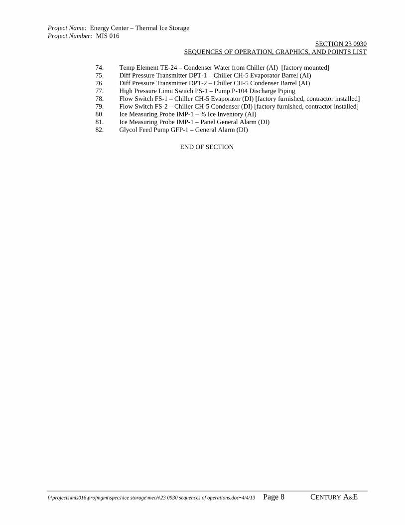
Project Name: Energy Center – Thermal Ice Storage Project Number: MIS 016
SECTION 23 0930 SEQUENCES OF OPERATION, GRAPHICS, AND POINTS LIST
f:\projects\mis016\projmgmt\specs\ice storage\mech\23 0930 sequences of operations.doc-4/4/13 Page 8 CENTURY A&E
74. Temp Element TE-24 – Condenser Water from Chiller (AI) [factory mounted] 75. Diff Pressure Transmitter DPT-1 – Chiller CH-5 Evaporator Barrel (AI) 76. Diff Pressure Transmitter DPT-2 – Chiller CH-5 Condenser Barrel (AI) 77. High Pressure Limit Switch PS-1 – Pump P-104 Discharge Piping 78. Flow Switch FS-1 – Chiller CH-5 Evaporator (DI) [factory furnished, contractor installed] 79. Flow Switch FS-2 – Chiller CH-5 Condenser (DI) [factory furnished, contractor installed] 80. Ice Measuring Probe IMP-1 – % Ice Inventory (AI) 81. Ice Measuring Probe IMP-1 – Panel General Alarm (DI) 82. Glycol Feed Pump GFP-1 – General Alarm (DI)
END OF SECTION

Project Name: Energy Center - Thermal Ice Storage Project Number: MIS016
SECTION 23 2120 PUMPS
f:\projects\mis016\projmgmt\specs\ice storage\mech\23 2120 pumps.docx-4/3/2013 Page 1 CENTURY A&E
PART 1 – GENERAL
1.01 SUMMARY
A. This section includes the following types of pumps: 1. Base-mounted, vertically split case, double suction pumps. 2. Coordination regarding concrete pad. 3. Engaging the pump vendor for factory services to align pumps and submit written startup
reports.
1.02 RELATED SECTIONS:
A. Section 23 0010 – Mechanical General Provisions
B. Section 23 0100 – Basic Mechanical Materials and Methods
C. Section 23 0930 – Sequences of Operation an Graphics
D. Section 23 0593 – Testing, Adjusting, and Balancing
E. Division 26 – Variable Speed Drives 1.03 REFERENCED STANDARDS
A. National Electrical Code Compliance: Components shall comply with NFPA 70 "National Electrical Code."
B. UL Compliance: Pu mps shall be listed and labeled by UL, and comply with UL Standard 778 "Motor Operated Water Pumps."
C. NEMA Compliance: Electric motors and components shall be listed and labeled NEMA.
D. ANSI/HI 1.1-1.4, 1.6 – 2000
E. ANSI/HI 9.6.1-1998
F. ANSI/HI 9.6.3-1997
G. ASTM A159-83(2006) Standard Specification for Automotive Gray Iron Castings 1.04 SUBMITTALS
A. General: In addition to procedures specified in Division 1, comply with the following. 1. Tag submitted data with the corresponding designation of that item as scheduled in the
construction documents. All in formation submitted shall be individually "tagged" to easily identify it with the corresponding material or equipment. Failure to comply with this requirement will resu lt in that item or, at th e discretion of the Engineer, all ite ms submitted, being rejected without being reviewed.
B. Product data: Furnish catalog information, certified pumps curves, rated capacities, final impeller dimensions, and accessories provided for the product indicated. 1. Indicate operating point of each pump on curves. 2. Furnish pump curves for each pump and combination of pumps designed to operate in
parallel. The pump curve shall show as a minimum; bhp, flow, total dynamic head, impeller diameter and syste m curve (i ndividually and in combination for each pump operating in a p arallel application). Pumps operating in p arallel operation shall be selected to cross the system curve when operating individually.
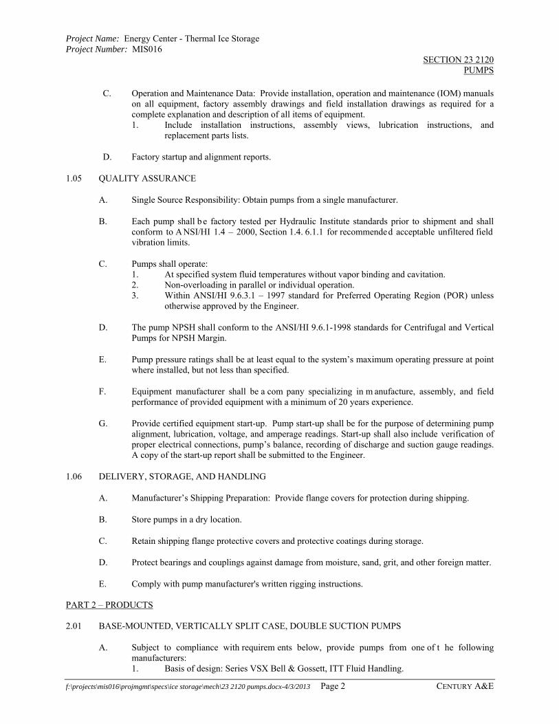
Project Name: Energy Center - Thermal Ice Storage Project Number: MIS016
SECTION 23 2120 PUMPS
f:\projects\mis016\projmgmt\specs\ice storage\mech\23 2120 pumps.docx-4/3/2013 Page 2 CENTURY A&E
C. Operation and Maintenance Data: Provide installation, operation and maintenance (IOM) manuals on all equipment, factory assembly drawings and field installation drawings as required for a complete explanation and description of all items of equipment. 1. Include installation instructions, assembly views, lubrication instructions, and
replacement parts lists.
D. Factory startup and alignment reports.
1.05 QUALITY ASSURANCE
A. Single Source Responsibility: Obtain pumps from a single manufacturer.
B. Each pump shall b e factory tested per Hydraulic Institute standards prior to shipment and shall conform to A NSI/HI 1.4 – 2000, Section 1.4. 6.1.1 for recommended acceptable unfiltered field vibration limits.
C. Pumps shall operate: 1. At specified system fluid temperatures without vapor binding and cavitation. 2. Non-overloading in parallel or individual operation. 3. Within ANSI/HI 9.6.3.1 – 1997 standard for Preferred Operating Region (POR) unless
otherwise approved by the Engineer.
D. The pump NPSH shall conform to the ANSI/HI 9.6.1-1998 standards for Centrifugal and Vertical Pumps for NPSH Margin.
E. Pump pressure ratings shall be at least equal to the system’s maximum operating pressure at point where installed, but not less than specified.
F. Equipment manufacturer shall be a com pany specializing in m anufacture, assembly, and field performance of provided equipment with a minimum of 20 years experience.
G. Provide certified equipment start-up. Pump start-up shall be for the purpose of determining pump alignment, lubrication, voltage, and amperage readings. Start-up shall also include verification of proper electrical connections, pump’s balance, recording of discharge and suction gauge readings. A copy of the start-up report shall be submitted to the Engineer.
1.06 DELIVERY, STORAGE, AND HANDLING
A. Manufacturer’s Shipping Preparation: Provide flange covers for protection during shipping.
B. Store pumps in a dry location.
C. Retain shipping flange protective covers and protective coatings during storage.
D. Protect bearings and couplings against damage from moisture, sand, grit, and other foreign matter.
E. Comply with pump manufacturer's written rigging instructions. PART 2 – PRODUCTS 2.01 BASE-MOUNTED, VERTICALLY SPLIT CASE, DOUBLE SUCTION PUMPS
A. Subject to compliance with requirem ents below, provide pumps from one of t he following manufacturers: 1. Basis of design: Series VSX Bell & Gossett, ITT Fluid Handling.
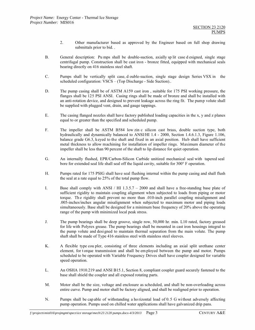
Project Name: Energy Center - Thermal Ice Storage Project Number: MIS016
SECTION 23 2120 PUMPS
f:\projects\mis016\projmgmt\specs\ice storage\mech\23 2120 pumps.docx-4/3/2013 Page 3 CENTURY A&E
2. Other manufacturer based as approved by the Engineer based on full shop drawing submittals prior to bid. .
B. General description: Pu mps shall be double-suction, axially sp lit case d esigned, single stage centrifugal pump. Construction shall be cast iron - bronze fitted, equipped with mechanical seals bearing directly on 416 stainless steel shaft.
C. Pumps shall be vertically split case, d ouble-suction, single stage design Series VSX in the scheduled configuration: VSCS – (Top Discharge - Side Suction)..
D. The pump casing shall be of ASTM A159 cast iron , suitable for 175 PSI working pressure, the flanges shall be 125 PSI ANSI. Casing rings shall be made of bronze and shall be installed with an anti-rotation device, and designed to prevent leakage across the ring fit. The pump volute shall be supplied with plugged vent, drain, and gauge tappings.
E. The casing flanged nozzles shall have factory published loading capacities in the x, y and z planes equal to or greater than the specified and scheduled pump.
F. The impeller shall be ASTM B584 low zin c silicon cast brass, double suction type, both hydraulically and dynamically balanced to ANSI/HI 1.4 - 2000, Section 1.4.6.1.3, Figure 1.106, balance grade G6.3, keyed to the shaft and fixed in an axial position. Hub shall have sufficient metal thickness to allow machining for installation of impeller rings. Maximum diameter of the impeller shall be less than 90 percent of the shaft to lip distance for quiet operation.
G. An internally flushed, EPR/Carbon-Silicon Carbide unitized mechanical seal with tapered seal bore for extended seal life shall seal off the liquid cavity, suitable for 300° F operation.
H. Pumps rated for 175 PSIG shall have seal flushing internal within the pump casing and shall flush the seal at a rate equal to 25% of the total pump flow.
I. Base shall comply with ANSI / HI 1.3.5.7 – 2000 and shall have a free-standing base plate of sufficient rigidity to maintain coupling alignment when subjected to loads from piping or motor torque. Th e rigidity shall prevent no more than .010-inch parallel coupling misalignment and .005-inches/inches angular misalignment when subjected to maximum motor and piping loads simultaneously. Base shall be designed for a minimum base frequency of 20% above the operating range of the pump with minimized local peak stress.
J. The pump bearings shall be deep groove, single row, 50,000 hr. min. L10 rated, factory greased for life with Polyrex grease. The pump bearings shall be mounted in cast iron housings integral to the pump volute and desi gned to maintain thermal separation from the main volute. The pump shaft shall be made of Type 416 stainless steel with stainless steel sleeves.
K. A flexible type cou pler, consisting of three elements including an axial split urethane center element, for t orque transmission and shall be em ployed between the pump and motor. Pumps scheduled to be operated with Variable Frequency Drives shall have coupler designed for variable speed operation.
L. An OSHA 1910.219 and ANSI B15.1, Section 8, compliant coupler guard securely fastened to the base shall shield the coupler and all exposed rotating parts.
M. Motor shall be the size, voltage and enclosure as scheduled, and shall be non-overloading across entire curve. Pump and motor shall be factory aligned, and shall be realigned prior to operation.
N. Pumps shall be cap able of withstanding a ho rizontal load of 0. 5 G wi thout adversely affecting pump operation. Pumps used on chilled water applications shall have galvanized drip pans.
Project Name: Energy Center - Thermal Ice Storage Project Number: MIS016
SECTION 23 2120 PUMPS
f:\projects\mis016\projmgmt\specs\ice storage\mech\23 2120 pumps.docx-4/3/2013 Page 4 CENTURY A&E
PART 3 – EXECUTION 3.01 GENERAL
A. Provide certified equipment start-up. Pump start-up shall be for the purpose of determining pump alignment, lubrication, voltage, and amperage readings. Start-up shall also include verification of proper electrical connections, pump’s balance, recording of discharge and suction gauge readings. A copy of the start-up report shall be submitted to the Engineer.
3.02 EXAMINATION
A. Examine areas, equipm ent foundations, and conditions, for compliance with requirements for installation tolerances and other conditions affecting performance of HVAC pumps.
B. Examine rough-in for piping systems to verify actual locations of piping connections prior to installation.
C. Examine equipment foundations and/or inertia bases for suitable conditions where pumps are to be installed.
D. Correct unsatisfactory conditions prior to installation of pumps.
3.03 INSTALLATION
A. General: Co mply with the ANSI/HI 1 .4-2000 and manufacturer's written installation and alignment instructions.
B. Install pumps in locations and arranged to provide access for p eriodic maintenance, including removal of motors, impellers, couplings, and accessories.
C. Support pumps and piping separately so that the weight of the piping system does not rest on the pump.
D. Refer to the drawings for details of pump installation and accessories.
E. Each unit shall be l eveled and grouted according to the manufacturer's instructions before alignment and start-up.
F. Recheck and verify proper pump alignment prior to start-up.
G. Engage services of factory to align pumps, assist with startup, and to submit written reports.
END OF SECTION

Project Name: Energy Center - Thermal Ice Storage Project Number: MIS016
SECTION 23 5700 HEAT EXCHANGERS
f:\projects\mis016\projmgmt\specs\ice storage\mech\23 5700 heat exchangers.doc Page 1 Century A&E
PART 1 - GENERAL 1.01 SUMMARY
A. Section includes 1. Chilled glycol to chilled water plate and frame heat exchangers.
1.02 SUBMITTALS:
A. Shop Drawings: Submit complete shop drawings including dimensional data, installation instructions, performance and capacity data, pressure drops, design flows, maintenance manuals, and recommended spare parts list.
PART 2 – PRODUCTS 2.01 GENERAL
A. Provide as shown on the plans two plate and frame heat exchanger as shown and specified. Heat Exchanger shall be counter flow arrangement with capacities as noted on the drawings and meeting the following construction requirements
2.02 ACCEPTABLE MANUFACTURERS
A The heat exchanger shall be as manufactured by Calmac. Products as manufactured by Mueller may be acceptable as determined by the Engineer based on full shop drawing submittal prior to bid.
2.03 MANUFACTURING STANDARDS
A. The plate heat exchanger shall be manufactured in accordance with the applicable sections of the ASME code of Unfired Pressure Vessels, Section VIII, Div 1, latest edition. Whether the unit is stamped or unstamped, the factory must hold a valid "U"- stamp certification and QC manual for ASME plate heat exchangers.
2.04 PRODUCT PERFORMANCE
A. See schedule on drawings. 2.05 FRAME
A. Frame shall be carbon steel of at least grade SA 516/70 or 60. Frame shall be sandblasted, coated with a zinc-rich primer, and finished with two coats of epoxy enamel. The movable cover shall be supported from the upper carry bar by means of a roller for units 6" port and larger. Frame covers shall be of sufficient thickness so as not to require the use of horizontal reinforcing bars. Connections equal to or less than 2" shall be stainless steel 316 L male NPT. Connections equal or larger than 3" shall be 150 psig ANSI studded port design. Carrying and guiding bars design shall permit the removal or access to any plate in the plate pack without the need to remove any other plates. Compression bolts shall be provided in material SA 193 B7 and coated with zinc plate or Teflon. The open bolt ends shall be covered with a plastic mash to protect from the environment and prevent bodily injury. The bolting system shall be designed so that only four compression bolts are required for opening and closing of the unit.
Project Name: Energy Center - Thermal Ice Storage Project Number: MIS016
SECTION 23 5700 HEAT EXCHANGERS
f:\projects\mis016\projmgmt\specs\ice storage\mech\23 5700 heat exchangers.doc Page 2 Century A&E
2.06 PLATES A. Plates shall be embossed with a horizontal herringbone pattern in high or low thermal length
design as required. Plates shall be 304 AISI and 0.0197 inches (5 mm) thick. B. The inlet port area shall be designed with sloping lead-in grooves so as to minimize pressure drop
in that area. The plate shall be designed with an integral plate hanging system. The hanger area shall feature a locking lip, which engages the adjacent plate in order to ensure proper alignment. Absolutely no reinforcement shall be welded to the plates. All plates shall be pressed in a single-stage operation.
2.07 GASKETS
A. Gaskets shall be a molded one-piece design with venting holes in the port areas to avoid cross contamination. One piece molded glued gaskets are required. The adhesive used shall be of quality 3M 1099 or 847. The gasket material shall be NBR HT CLIP-TITE
PART 3 - PRODUCTS 3.01 GENERAL
A. Install per manufacturers installation instructions.
3.02 INSPECTION AND TESTING
A. After completion of assembly and before shipment, the heat exchanger shall be hydrostatically tested in accordance with the requirements of ASME Section VIII, Division 1. The test shall be single-side, with the other side at atmospheric pressure.
1. A name plate shall be securely attached to the exchanger in a location that is easily accessible and visible after installation. The name plate must include model and serial number, plate/gasket material, test/design pressure, design temperature, and tightening dimension.
2. The plate heat exchanger shall be flushed clean at factory prior to shipment. Proper lifting instructions for plate heat exchangers shall be included with each shipment.
END OF SECTION 23 5700

Project Name: Energy Center - Thermal Ice Storage Project Number: MIS016
SECTION 23 6000 CENTRIFUGAL ICE CHILLER
f:\projects\mis016\projmgmt\specs\ice storage\mech\23 6000 centrifugal chiller.doc Page 1 Century A&E
PART 1 - GENERAL
1.01 SECTION INCLUDES
A. Chiller package.
B. Charge of refrigerant and oil.
C. Controls and control connections.
D. Chilled water connections.
E. Condenser water connections.
F. Auxiliary water connections.
G. Shipped loose flow proving switches.
H. Starters.
I. Electrical power connections.
1.02 REFERENCES
A. ANSI/ASHRAE STANDARD 15-2007 - Safety Code for Mechanical Refrigeration.
B. ASHRAE 90.1 - Energy Conservation in New Building Design.
C. ASME SEC VIII - Boiler and Pressure Vessel Code.
D. ANSI/UL 465 - Central Cooling Air Conditioners.
E. AHRI STANDARD 550/590-2003 - Ce ntrifugal, Helical rotary, scroll, and reciprocating water chillers.
F. AHRI Standard 575-2008 Sound
G. AFBMA 9 - Load Ratings and Fatigue Life of Roller Bearings.
H. ASHRAE STANDARD 34 - Number Designation and Safety Classification of Refrigerants
I. ANSI/ASHRAE Standard 147-2002 - R educing the Release of Halogenated Refrigerants from Refrigerating and Air-Conditioning Equipment and Systems
1.03 SUBMITTALS
A. Submit according to Section 01300 - Submittals
B. All proposals for chiller performance must include an AHRI approved selection method for the specified refrigerants.
C. Submit drawings indicating assembled dimensions, operating weight, load distribution, and required service and access clearances.

Project Name: Energy Center - Thermal Ice Storage Project Number: MIS016
SECTION 23 6000 CENTRIFUGAL ICE CHILLER
f:\projects\mis016\projmgmt\specs\ice storage\mech\23 6000 centrifugal chiller.doc Page 2 Century A&E
D. Submit product data indicating options and specialties, electrical req uirements, and wiring diagrams and connections. Indicate accessories, valves, strainers, and thermostatic valves required for the complete system.
E. Submit rigging, installation, and startup procedures. Include operations and maintenance data for both the chiller and starter or variable-speed drive. Include location, size, and type of field piping connections.
F. Submit performance data indicating energy input versus cooling load output from 100 to 25 percent of full load with constant entering condenser water temperature.
G. Submit compressor and product data in table form indicating impeller speed (RPM), number of bearings, type of bearings, high speed impeller shaft RPM, sound pressure level per AHRI 575-1994 (dB), number of stages, number of sets of inlet guide vanes, amount of refrigerant charge (lb), and amount of oil required (gal).
1.04 REGULATORY REQUIREMENTS
A. Conform to AHRI Standard 550/590-2003 code for rating and testing of water chillers.
B. Conform to UL 1995 for Safety for Heating and Cooling Equipment and provide UL label.
C. Conform to ANSI/ASME SECTION VIII Boiler and Pressure Vessel Code for construction and testing of centrifugal chillers as applicable.
D. Conform to ANSI/ASHRAE STANDARD 15-2007 code for construction and operation of centrifugal chillers.
E. Unit shall bear the AHRI Certification Label for the specific type of water chiller as applicable.
F. Refrigeration Transfer: Provide service val ves and other factory-installed accessories required to facilitate transfer of refrigerant from the chiller to remote systems.
G. Refrigerant Isolation for chillers Using 134a. Factory install check or manual isolation valves in the compressor discharge line to the condenser and the refri gerant liquid line leaving the condenser to allows for isolation and storage of the full refrigerant charge in the chiller condenser shell. In addition, provide isolation valve on the suction side of compressor from evaporator to allow for isolation and storage of full refrigerant charge in the chiller evaporator shell.
H. Low pressure chillers: Chiller that operate and low pressure must have a h igh efficiency purge system to ensure that the any potential possible non-condensable leakage into the vessel is immediately eliminated. The purge run time shall be monitored by the main unit controller as to act as a leak detector if required.
1.05 DELIVERY, STORAGE, HANDLING AND EQUIPMENT ROOM REQUIREMENTS
A. Comply with manufacturer's installation instructions for rigging, chiller loading, local transportation requirements, unloading, storage, and final setting.
B. Protect chiller and controls from physical da mage. Leave factory shipping covers in place until installation. The entire unit must me shrink wrapped with an environmentally recyclable material standard. The material shall include an im bedded desiccant to minimize/eliminate internal moisture.

Project Name: Energy Center - Thermal Ice Storage Project Number: MIS016
SECTION 23 6000 CENTRIFUGAL ICE CHILLER
f:\projects\mis016\projmgmt\specs\ice storage\mech\23 6000 centrifugal chiller.doc Page 3 Century A&E
C. The chiller shall ship with a dry nitrogen charge to eliminate potential charge loss during delivery and construction. The refrigerant monitoring system shall be active at th e job site prior to the charging of the chiller.
D. The chiller should ship with a full charge of oil.
1.06 WARRANTY
A. Provide a complete unit parts and labor warranty (including refrigerant) for one year from startup or 18 months from shipment, whichever occurs first. Warranty shall cover any loss of refrigerant.
B. The labor warranty will cover the expense of labor to replace a part that is found to be defective in material or workmanship. The cost of reasonable technician travel and diagnostic time is included with standard hour allowances applying. Only the manufacturer's commercial warranty agent may perform warranted repairs under the labor warranty. E xcess hours (overtime, nuisance calls, inefficiency or access proble ms) are not c overed. Provide Whole Unit La bor Warranty for the duration of 1st year.
C. A 2nd-5th year motor/transmission/compressor parts warranty shall also be provided.
PART 2 - PRODUCTS
2.01 SUMMARY
A. Description: Factory-assembled and tested water chiller complete with compressor, evaporator, condenser, controls, starter or variable speed drive, interconnecting unit piping and wiring, indicating accessories, and mounting frame. Perf ormance shall be per specification section 3 schedule.
B. The contractor shall furnish and install centrifugal water chillers as shown and sch eduled in the plans and specifications. The units shall produce the specified tonnage per the scheduled data in accordance with AHRI 550/590-2003. The un it shall bear the AHRI certification label as applicable.
C. Approved Manufacturers: 1. Trane
D. Unit shall be painted in accordance with the manufacturer’s standard procedures and practices.
2.02 COMPRESSOR AND MOTOR
A. The compressor shall be centrifugal.
B. Low pressure refrigerant machines shall be provided when available.
C. Chiller should be able to unload to 20 percent of design to nnage with co nstant entering water temperature. The minimum unloading point shall be demonstrated at the time of t he factory performance test. The m achine shall be modified to include hot gas bypass if the minimum load cannot be met.
D. Compressor assembly shall be v ibration tested at the factory. Vibration shall not exceed 0.15 inches per second. The test data shall be recorded and provided to the customer for approval.
E. The motor shall be hermetic and either suction or liquid refrigerant cooled. Hot gas motor cooling

Project Name: Energy Center - Thermal Ice Storage Project Number: MIS016
SECTION 23 6000 CENTRIFUGAL ICE CHILLER
f:\projects\mis016\projmgmt\specs\ice storage\mech\23 6000 centrifugal chiller.doc Page 4 Century A&E
is not accepta ble. Open drives are not acceptable due t o the pote ntial for refrigerant and oil leakage associated with the mechanical shaft seal and the coupling between an open motor and the compressor.
F. Manufacturers with spee d increasing transmissions shall not exceed 10,000 RPM compressor speeds and shall annually inspect the gears and al l bearings. A report shall be forwarded to the owner each year over the first five years to confirm completion.
G. The impellers shall be fully shrouded and made of a high strength aluminum alloy. Impellers shall be dynamically balanced and over-speed tested at 1.25 times impeller shaft speed.
2.03 EVAPORATOR (CHILLER BARREL)
A. The evaporator and condenser shall be bui lt in accordance with ANSI/ASHRAE 15-2001 Safety Code for Mechanical Refrigeration.
B. Evaporator tubes shall be internally enhanced. The minimum tube wall th ickness shall be 0.025 inch.
C. The evaporator water piping connections shall be flanged.
D. The evaporator waterboxes shall be standard non-marine type with connections per schedule.
E. Supply and return head waterboxes shall be designed for a working pressure of 150 psig and shall be factory hydrostatic pressure tested at 150 percent of the design pressure. Provide drain and vent connections in water boxes.
F. Insulation will be 3/4" insulation and cover all low-temperature surfaces to include the evaporator, waterboxes, and suction elbow. Economizer, if applicable, is insulated with 3/8" insulation.
G. Units with multi-stage compressors shall incorporate an interstage flash vessel "economizer". All units with single stage compressors shall have the condensers circuited for liquid subcooling and be provided with a thermometer well to monitor the amount of subcooling.
H. Adjustable or float type refrigerant metering devices and thermal expansion valves shall be inspected and adjusted by t he manufacturer at th e end of each year for the first five years of operation to assure equivalent reliability and maintenance to a fi xed orifice system. A written report shall be forwarded to the owner each year to confirm completion.
2.04 CONDENSER
A. The condenser shall be bui lt in accorda nce with ANSI/ASHRAE 15-2001 Sa fety Code for Mechanical Refrigeration.
B. Condenser tubes shall be internally enhanced. The minimum tube wall thickness shall be 0.028 inch.
C. The condenser water piping connections shall be flanged.
D. The condenser waterboxes shall be marine box type with hinged cover.
E. Supply and return head waterboxes shall be designed for a working pressure of 150 psig and shall be factory hydrostatic pressure tested at 150 percent of the design pressure. Provide drain and vent connections in water boxes.

Project Name: Energy Center - Thermal Ice Storage Project Number: MIS016
SECTION 23 6000 CENTRIFUGAL ICE CHILLER
f:\projects\mis016\projmgmt\specs\ice storage\mech\23 6000 centrifugal chiller.doc Page 5 Century A&E
2.05 PURGE SYSTEM
A. The manufacturers of low pressure machines, must provide a purge system. Acceptable purges are the Trane EarthWise Purge. The Turboguard Purge is not acceptable.
B. The purge efficiency must meet ASHRAE Standard 147-2002 paragraph 4.7.
C. The purge shall be capable of operating when the chiller is id le in accordance with ASHRAE Standard 147-2002, paragraph 4.7.2 (a).
2.06 CONTROLS
A. The chiller shall be controlled by a unit mounted, stand-alone Direct Digital Control (DDC ) system. A dedicated chiller microprocessor control panel is to be supplied with each chiller by the chiller manufacturer.
B. Enclosure shall be unit mounted NEMA 250 Type 1.
C. A color, touch sensitive liquid crystal display (LCD) shall be unit mounted and a minimum of 12.1" diagonal. The di splay shall be f ully adjustable in height and viewing angle. Animated graphical representations of ch iller subsystem operation shall be used to enh ance the user interface.
D. Display shall consist of a menu driven interface with easy touch screen navigation to organized subsystem reports for compressor, evaporator, condenser, purge and motor information as well as associated diagnostics. The controller shall display all active diagnostics and a minimum of 20 historical diagnostics.
E. The controller shall have the ability to display all primary sub-system operational parameters on dedicated trending graphs. The operator must be able to create up to 6 additional c ustom trend graphs, choosing up to 10 uni que parameters for each gra ph to tre nd log data parameters simultaneously over an adjustable period and frequency polling.
F. The chiller control panel shall p rovide control of chiller operation and monitoring of chiller modules, sensors, actuators, relays and switches. The chiller control panel shall include controls to safely and efficiently operate the chiller.
G. Safeties - the chiller control panel shall provide the following safeties: 1. Low chilled water temperature 2. Low evaporator refrigerant temperature or pressure 3. High condenser refrigerant pressure 4. Evaporator and condenser water flow status 5. Low oil pressure 6. Low oil temperature 7. High oil temperature 8. High motor winding temperatures 9. High motor current 10. Starter/AFD function faults 11. Sensor faults 12. Unit controls operation 13. The chiller control panel or starter shall incorporate advanced motor protection to
safeguard the motor throughout the starting and running cycles from the adverse effects of: a. Current phase loss

Project Name: Energy Center - Thermal Ice Storage Project Number: MIS016
SECTION 23 6000 CENTRIFUGAL ICE CHILLER
f:\projects\mis016\projmgmt\specs\ice storage\mech\23 6000 centrifugal chiller.doc Page 6 Century A&E
b. Current phase unbalance c. Current phase reversal d. Under/Over voltage e. Motor current overload f. Distribution fault protection with auto restart consisting of three-phase current
sensing devices that monitor the status of the current g. Starter contactor fault protection h. Starter transition failure
H. The chiller control panel shall be capable of displaying system data in I-P or SI units.
I. The front of the chiller control panel shall display the following in clear language, without the use of codes, look-up tables, or gauges: 1. Run time 2. Number of starts 3. Current chiller operating mode 4. Chilled water set point and set point source 5. Electrical current limit set point and set point source 6. Entering and leaving evaporator water temperatures 7. Entering and leaving condenser water temperatures 8. Saturated evaporator and condenser refrigerant temperatures 9. Evaporator and condenser refrigerant pressure 10. Oil tank temperature 11. Oil tank pressure 12. Oil pump discharge pressure 13. Differential oil pressure 14. Compressor motor current per phase 15. Compressor motor percent RLA 16. Compressor motor voltage per phase 17. kW energy consumption and power factor 18. Compressor motor winding temperatures per phase 19. Purge operating mode 20. Purge operating status 21. Time until next purge run 22. Daily pumpout - 24 hours 23. Avg daily pumpout - 7 Days 24. Purge refrigerant compressor suction temp 25. Purge liquid temp (chiller condenser saturated refrigerant temperature) 26. Daily pumpout limit/alarm
J. The chiller control panel shall provide password protection of all setpoints.
K. Control authority must be capable of handling at least four conditions: Off, local manual at the chiller, local automatic at the chiller and automatic control through a remote source.
L. The chiller control panel shall provide evaporator freeze protection and low limit control to avoid low evaporator refrigerant temperature trip-outs during critical p eriods of chiller operation. Whenever this control is in effect, the controller shall indicate that the chiller is in adaptive mode. If the condition exists for more than 30 seconds, a limit warning alarm relay shall energize.
M. The chiller control panel shall p rovide individual relay ou tputs to start/stop the evaporator and condenser water pumps. The condenser water pump relay output can be used to enable the cooling tower temperature controls.

Project Name: Energy Center - Thermal Ice Storage Project Number: MIS016
SECTION 23 6000 CENTRIFUGAL ICE CHILLER
f:\projects\mis016\projmgmt\specs\ice storage\mech\23 6000 centrifugal chiller.doc Page 7 Century A&E
N. The chiller control panel shall provide leaving chilled water temperature reset based upon return water temperature.
O. The chiller control panel shall be capable of providing short cycling protection.
P. The chiller control panel shall provide condenser limit control including a pressure transducer and interconnecting piping and wiring. This control shall be used to avoid high condenser refrigerant pressure tripouts. The control shall take action in response to the condenser refrigerant pressure. Whenever this control is in effect, the panel will automatically indicate that the chiller is in adaptive mode and if the condition exists for more than 30 seconds, a limit warn ing alarm shall energize.
Q. The chiller controller shall communicate directly to existing State of Mich igan Trane Tracer Summit control panel.
2.07 STARTERS
A. LOW VOLTAGE, UNIT MOUNTED, STAR DELTA STARTER 1. Motor starter sh all be a Star-Delta Clo sed Transition and shall have a NEM A 1A
gasketed enclosure. 2. The starter enclosure shall have a starter short circuit rating (SCR) of [_______]. If the
starter enclosure does not have this SCR rating, then a device shall be provided upstream of the starter to limit the fault current at the starter to be equal or less than the starter short circuit rating of the starter.
3. Motor starters shall include incoming line provisions for t he number and size cables shown on the drawings. Incoming line lugs shall be copper mechanical type.
4. Contactors shall be sized properly to the chiller full load currents. 5. Each motor starter shall include a 4 KVA control power transformer with fused primary
and secondary. Control relays shall be provided within the motor starter to interface with the control panel.
6. If the chiller main processor does not include an advanced motor protection system, the starter shall include an advanced motor protection system incorporating electronic three phase current overloads and current transformers. This electronic motor protection system shall monitor and protect against the following conditions: a. Current phase loss b. Current phase unbalance c. Current phase reversal d. Under/Over line voltage e. Motor current overload during startup and running f. Momentary power l oss protection with auto restart consisting of three-phase
current sensing devices that monitor the status of the current. Restart inhibit is active and looks at motor RTDs to maximize starts/hour.
g. Starter contactor fault protection h. Starter transition failure i. Distribution fault protection.
7. The starter shall be able to operate in temperatures up to 104 degrees F. 8. All field supplied wires, bus bars, and fittings shall be copper only. 9. The following optional starter features shall be provided:
a. Circuit Breaker - Starter shall contain a circuit brea ker capable of bre aking currents up to its interruption capacity of [______] amperes. Operating handle and trip indicator shall be located on the door. This handle shall be capable of being padlocked.

Project Name: Energy Center - Thermal Ice Storage Project Number: MIS016
SECTION 23 6000 CENTRIFUGAL ICE CHILLER
f:\projects\mis016\projmgmt\specs\ice storage\mech\23 6000 centrifugal chiller.doc Page 8 Century A&E
PART 3 - EXECUTION
3.01 INSTALLATION
A. Install in accordance with manufacturer's instructions.
B. Provide for connection to electrical service. Include for connection of oil pump if required.
C. Provide for connection of electrical wiring between starter and chiller control panel, oil pump, and purge unit.
D. Furnish and install necessary auxiliary water piping for oil cooling units if required.
E. Arrange piping for easy dismantling to permit tube cleaning.
F. Provide piping from chiller relief device to outdoors. Size as recommended by manufacturer.
3.02 MANUFACTURER'S FIELD SERVICES
A. All Startup, maintenance and monitoring functions shall be perf ormed by a manufacturer’s commercial agent to confirm, (in writing), that equipment has been correctly installed and passes specification checklist prior to equipment becoming operational and covered under OEM warranty.
B. Applied chiller manufacturers shall maintain service capabilities no more than 100 miles from the job site.
C. The manufacturer shall furnish complete submittal wiring diagrams of the chiller(s) starter(s) and associated components like cooling towers, pumps, interlocks, etc. as a pplicable for field maintenance and service.
END OF SECTION
Project Name: Energy Center Ice Storage Project Number: MIS016
SECTION 23 6500 ICE STORAGE TANKS AND ACCESSORIES
f:\projects\mis016\projmgmt\specs\ice storage\mech\23 6500 ice tanks & accessories.docx Page 1 Century A&E
PART 1 – GENERAL 1.01 SECTION INCLUDES
A. Ice Storage Tanks
B. Ice Measuring Probe C. Biocide Chemicals for Phase Change Water D. Factory inspection and startup including submittal of written reports. E. Engaging factory representative to attend pre-installation meeting at project site, perform periodic
installation inspections, to assist with startup, and to submit written inspection and startup reports. 1.02 ACCEPTABLE MANUFACTURERS
A. CALMAC or approved equal as determined by the Engineer based on full shop drawing
submittals prior to bid. 1.03 ICE TANK VESSEL WARRANTY
A. "Manufacturers of ice tanks shall provide a parts and labor warranty for air compressor (if required) and bubbler system (if required), float switches, heat tracing tape, tank pressure relief valves if required, sight glass, insulation, corrosion, phase change fluid containment, and structure of tank for TEN YEARS from date of shipment to jobsite. A warranty certificate of authenticity must be provided from the manufacturer at time of submittal specifically mentioning the tank and required ancillary equipment parts warranty of 10 years, including all parts required for complete repair, and or redeployment which is to remain in force through freeze solid events that could occur by any means. If the company manufacturing the ice storage tanks is younger in age than the length of the warranty period, a Warranty Certificate from a third party warranty program that has been in the product warranty business for over 20 years, including the scope, length of the specified warranty and freeze solid event(s) and redeployment coverage, must be purchased and included with the submittals. If the warranty length and scope specified in these documents is beyond the manufacturer’s standard warranty, the local representative of the ice tanks must provide a third party Warranty Certificate demonstrating the scope and length and freeze solid event(s) and redeployment coverage of warranty specified.”
1.04 ICE TANK HEAT EXCHANGER WARRANTY
A. Manufacturer of ice tanks must provide complete parts and labor warranty for ice tank heat exchanger integrity and ice inventory meter and/or ice thickness meter for FIVE YEARS from date of shipment to job site. A warranty certificate of authenticity must be provided from the manufacturer at time of submittal specifically mentioning the ice tank heat exchanger parts warranty of 5 years including all parts required for complete repair, and or redeployment which is to remain in force through freeze solid events that could occur by any means. If the company manufacturing the ice storage tanks is younger in age than the length of the warranty period, a Warranty Certificate from a third party warranty program that has been in the product warranty business for over 20 years, including the scope, length of the specified warranty and freeze solid event(s) and redeployment coverage, must be purchased and included with the submittals. If the warranty length and scope specified in these documents is beyond the manufacturer’s standard warranty, the local representative of the ice tanks must provide a third party Warranty Certificate demonstrating the scope and length and freeze solid event(s) and redeployment coverage of warranty specified.”

Project Name: Energy Center Ice Storage Project Number: MIS016
SECTION 23 6500 ICE STORAGE TANKS AND ACCESSORIES
f:\projects\mis016\projmgmt\specs\ice storage\mech\23 6500 ice tanks & accessories.docx Page 2 Century A&E
PART 2 – PRODUCTS 2.01 ICE STORAGE VESSELS
A. The modular ice storage tank design shall incorporate structure and storage fluid containment in a one-piece (sides and bottom) seamless tank designed for a minimum 25-year service life and shall be constructed solely of corrosion-resistant materials.
B. The ice tanks and tank covers shall be suitable for installation above or below ground with a
maximum 12 inch deep covering, and shall produce a floor loading of no more that 391 pounds per square foot.
C. The ice tank farm shall be modular and have a maximum single tank capacity of no more than 400
net usable ton-hours each, capable of being individually isolated so that each 400 ton-hour tank may be serviced without interrupting the operation of the total system for system reliability. The tanks shall have opposite or same end connections as shown on plans. Isolation valves for tanks shall be supplied, installed and insulated as shown on the plans.
D. The ice tank shall consist of a seamless one-piece design manufactured with high-density
rotationally molded corrosion resistant polyethylene with an average thickness of 3/8 inch. Buried tanks shall be one-third thicker and installed in accordance with manufacturers recommended procedures. The tank shall include a factory assembled thermally isolated expansion chamber to help prevent expansion water from forming capacity reducing ice caps. If the non basis of design ice tank does not contain phase change expansion chamber, manufacturer must provide and guarantee insulated expansion tank with quote.
E. Galvanized steel vessels will also be considered provided all galvanized steel parts (heat
exchanger, all sides of tanks and all supports) are coated with a cross linked epoxy-phenolic cured coating with an alkaline curing agent such as Plasite 7122HAR to eliminate long term corrosion due to sweating and/or outdoor weather. Galvanized surfaces shall be cleaned and properly etched with a standard solution such as Galvaprep® or a phosphating solution. After the surface is etched it shall be thoroughly rinsed with water and dried prior to applying protective coating. Coated galvanized steel tanks shall be reinforced with full width structural angles underneath on all FOUR sides, and all seams are welded to ensure watertight construction.
F. Manufacturer of metal tanks must also provide an extra containment pool liner for installation
after 10 years of operation.
G. Partially buried or totally buried galvanized steel tanks shall be field surface coated with Ameron D9, 2-4 mils, and an intermediate coat 6-8 mils of Ameron 385 epoxy, and to coated with Ameron 450HS Urethane, 2-4 mils to minimize corrosion.
H. The fluid containment barriers shall each have a minimum tear resistance of graves 12,000
lbs./inch minimum in BOTH directions according to ASTM-1004A zinc rich compound shall be applied to all exposed edges and welds. Ice tank and fluid containment shall be warranted as designated under warranty section.
I. The phase change water containment integrity shall be totally repairable without removing the
internal ice tank heat exchanger. If removal of tank heat exchanger is required, tank manufacturer shall provide to owner at their option money or labor for heat exchanger removal, repair, and replacement during containment warranty period. Indoor installations shall require no more than three foot of overhead clearance for heat exchanger repair. Galvanized steel tanks shall include enough room for rigging apparatus for a side or overhead removal of heat exchanger for tube
Project Name: Energy Center Ice Storage Project Number: MIS016
SECTION 23 6500 ICE STORAGE TANKS AND ACCESSORIES
f:\projects\mis016\projmgmt\specs\ice storage\mech\23 6500 ice tanks & accessories.docx Page 3 Century A&E
repair. J. If required by installation manual, manufacturers of thermal storage tank vessels shall provide,
install, and warrant tank safety switches and temperature thermisters. Manufacturer shall notify control contractor of the quantity of safety BAS points required for the tank farm. Float switches and thermisters shall be included in the ice tank warranty.
K. All thermal storage tanks must be designed and able to withstand, without damage or distortion,
repeated cycles of total freezing of ALL water within it due to control malfunctions or ambient temperatures. Damages caused by a total freeze shall be covered under ice tank vessel warranty defined in this specification.
L. All thermal storage vessels must be capable of being re-deployed for use at other sites with
remaining specified original warranty in force. If redeployment is not possible without a redeployment kid, provide add price for one complete redeployment kit installed.
M. Manufacturers of thermal storage tank vessels shall provide, install and warrant all heat tracing
tape if required for inventory meters, site glasses, and connections. 2.02 ICE TANK HEAT EXCHANGER
A. The ice tank shall contain a spiral-wound, mat type heat exchanger, constructed entirely of polyethylene headers and 5/8 inch O.D. polyethylene tubing arranged in multiple parallel circuits with OPPOSITE direction of flow in adjoining tubes for even ice making and melting. Every connection in the heat exchanger shall be fusion welded.
B. Manufacturers of thermal energy storage heat exchangers using tubes less than 5/8 inch inside
diameter must provide tubes connected to internal headers with all fusion welded construction. If all fusion welded construction is not provided, the manufacturer must provide annual inspections of mechanical connections for seven years.
C. Additionally, manufacturers using tubes less than 5/8 inch O.D. must install and warrant a self
cleaning 5 micron glycol fluid filter and strainer system to filter glycol entering tank farm to eliminate tube blockages at in heat exchanger tubes.
D. Steel heat exchanger tubes (1.05" O.D.) may be used provided steel framework is hot dip
galvanized after fabrication and coated as directed above in tank specification with PLASITE 7122 HAR. All ice tank heat exchangers shall be warranted as specified elsewhere.
E. The heat exchanger shall be capable of operating up to a 90 psi (620 kPa) maximum pressure and
shall have a minimum burst pressure rated for 4 times the maximum operating pressure. F. Each ice tank heat exchanger and its associated piping shall be factory hydrostatically-pressure
tested to a minimum of 250 psi (1724 kPa) after tank insertion, not prior. G. To avoid capacity reducing ice caps, heat exchanger tubes shall be totally submerged in the
freezing liquid, and shall be kept evenly spaced by plastic spacer strips. H. Heat transfer fluid temperature drops across the heat exchanger in the charging mode must be
large enough to permit full fluid flow through the ice making ethylene glycol chiller. Bypass of fluid around the ice making ethylene glycol chiller in the charging mode is not acceptable.
I. Multiple modular thermal storage tank systems shall be piped parallel in reverse return for self-

Project Name: Energy Center Ice Storage Project Number: MIS016
SECTION 23 6500 ICE STORAGE TANKS AND ACCESSORIES
f:\projects\mis016\projmgmt\specs\ice storage\mech\23 6500 ice tanks & accessories.docx Page 4 Century A&E
balancing. At design conditions the ice tank flow shall not change greater than 3% by varying the pressure across the tank farm by one foot (.043psi). Manufacturers unable to meet this criterion must provide install and warrant circuit setters for each tank in the farm. Manufacturer must provide pressure drop curves of ice tank with submittal package.
J. The heat exchanger must be repairable without removal from tank. K. Pressure relief valves between the tank and system must be provided and warranted by non basis
of design ice tank manufacturer’s if required by ice tank manufacturer. 2.03 ICE TANK COVERS
A. Covers shall be provided for all ice modules and/or tanks. Covers for buried vessels shall be designed to support architectural landscaping wood chips, or other similar material, having a maximum depth of twelve inches. Covers shall also support the weight of an average adult person (200 pounds) at any point on the tank farm.
B. Covers shall be in modular sections that can be readily lifted, removed, and replaced by two men.
Each section shall weigh no more than 250 pounds, and shall have smoothed edges or handles for easy and safe gripping.
C. Each vessel shall have at least one inspection port in the cover, which can be used for visual
inspection, determining liquid level, and for filling the vessel with water, without removing the cover(s). Each buried tank's inspection port shall have a Schedule 80 PVC pipe extending to six inches above grade, with a gasketed and easily removable cap.
D. Covers for steel vessels shall be a minimum of 16 gauge stainless or 14 gauge for hot dipped
galvanized steel tanks of same type used on sides and bottom.
2.04 ICE TANK INSULATION
A. The bottom, sides and cover(s) of each vessel shall be factory insulated. Insulation on the interior of the structural containment vessel is unacceptable.
B. Manufacturer must provide adequate insulation to limit standby losses not to exceed ONE
PERCENT of the total stored capacity when in an 85 degree F. environment for a period of twenty-four hours.
C. For plastic vessels that freeze solid the bottom and the sides of the tank shall be insulated
externally with a minimum of two inches of extruded polystyrene or polyurethane applied in overlapping layers having a minimum R- factor of nine (9). Insulation of sides shall be covered with a .032-inch thick aluminum jacket for protection and reflectance.
D. The tops of all vessel types shall have a minimum of three inches of insulation applied to the
interior cavity of the cover and have an R- factor of 24. Insulation with direct access or contact with the storage fluid or ambient air is not acceptable.
E. For stainless steel or galvanized steel vessels that do not freeze solid, insulation meeting the
standby loss criteria shall be applied between the exterior of the containment wall or pool type liner and the interior of the structural support system. Insulation of sides and bottom of vessel shall be covered with a minimum 30 mil thick PVC or EPDM impermeable liner, with all seams and joints double lapped and solvent welded. All fastening materials used to hold the liner in place shall be non-corrosive plastic, or stainless steel.

Project Name: Energy Center Ice Storage Project Number: MIS016
SECTION 23 6500 ICE STORAGE TANKS AND ACCESSORIES
f:\projects\mis016\projmgmt\specs\ice storage\mech\23 6500 ice tanks & accessories.docx Page 5 Century A&E
2.05 WATER TREATMENT
A. See Section 23 0100 – Basic Mechanical Materials and Methods for additional information.
B. Hydrostatically flush clean and field pressure test all piping EXTERNAL to thermal storage tanks as specified elsewhere to remove welding slag, flux, and dirt. If hydrostatic test is with water the ice tanks must not be a part of this test and shall be valved off to eliminate filling the ice tanks with water, which cannot be easily replaced with the pre-mixed ethylene glycol. After successful completion of the test, drain the system and add premixed ethylene glycol to the system as described in another part of the specification. Upon completion of the filling and removal of air, pressure test the ice tanks in accordance with manufacturers recommendations.
C. A lug type, full flow shut off valve shall be included for field installation and insulation in the
supply and return lines of each tank on the system side of the removable flexible connector (if required).
D. Liquid level and/or pressure switches in the expansion tank shall provide glycol system leak
protection. E. Tank bottoms shall be level and supported over the entire area and insulated from their supporting
surface with insulation supplied by the tank manufacturer. Non-plastic tanks must be set on pressure treated Douglas Fir sleepers. Follow manufacturer’s installation recommendations for partially buried or totally buried tanks. Metal tank manufacturers must provide a factory applied mastic coating for corrosion protection and a field installed cathodic corrosion protection system for each tank.
2.06 ICE MEASURING PROBE
A. The thermal storage farm system shall be provided with one ice inventory-measuring device,
which will indicate the amount of ice available at any time within an accuracy of +/- 5 percent. This inventory-measuring device shall also be equipped with an electric transducer capable of producing a 4 - 20 ma. signal which can interface with the building automation system. This device is for indication only, NOT FOR CONTROL OF ICE SYSTEM.
B. The CALMAC Ice Inventory Meter LL-102 measures the quantity of ice in the IceBank Thermal
Storage Tank and provides both a visual indication and an electronic signal (4-20mA) suitable for remote monitoring. The inventory meter consists of a weather resistant control box, tank probe and twin tubing. Power (11 5V or 230V) needs to be supplied to the control box, but there is no electric connection to the tanks. Both the 11 5V and 230V models draw less than one amp.
C. The 4” analog type visual indicator is factory calibrated at 0 to 100% and the 4-20mA signal is
also factory adjusted to this same range. No field adjustment of the analog meter or electronic transducer should be necessary. However, it is required that the measurement probe (air supply tube) be properly mounted and positioned in a tank cover. A hole needs to be drilled in a tank’s cover into which the suppliedadjustable compression fitting is threaded. Typically, only one tank in an installation is monitored. Special adapters are supplied for meters installed on buried tanks.
D. The inventory meter is supplied with fifteen feet of special twin tubing to connect it to the tank
probe. Longer lengths are available by special order. E. The instrument is accurate to within +/-5% and is useful for executing more sophisticated control
strategies that require knowledge of remaining ice inventory. The instrument is not intended to be

Project Name: Energy Center Ice Storage Project Number: MIS016
SECTION 23 6500 ICE STORAGE TANKS AND ACCESSORIES
f:\projects\mis016\projmgmt\specs\ice storage\mech\23 6500 ice tanks & accessories.docx Page 6 Century A&E
used as an indicator of full charge for the purpose of terminating the ice building process. Please refer to the Performance Data section of the CALMAC catalog for a description of the procedure for controlling the ice-making mode.
F. The ice tank manufacturer shall supply a one year supply of water treatment chemicals required
for treatment of the phase change water against biological growth and tank corrosion. 1. The treatment must eliminate algae, bacteria, and metal corrosion (if metal tanks
supplied). The submittal documents must contain the name(s), and quantities required for the ten-year chemical treatment. Rules for handling, storing, amount of room required for storing, rules for handling, and rules for application must also be provided. Manufacturer of ice tank must provide factory-trained personnel annual inspection for heat exchanger and tank corrosion during warranty period shown below.
PART 3 –EXECUTION 3.01 GENERAL
A. Assist with system startup and commissioning.
B. Engage factory representative to attend pre-installation meeting at project site, perform periodic
installation inspections, to assist with startup, and to submit written inspection and startup reports.
3.02 INSTALLATION A. Obtain complete installation instructions from manufacturer and attend pre-installation meeting
with manufacturer’s representative.
B. Install according to manufacturer’s instructions. C. Move tanks and set in place on Ice Tank Area floor and equipment platform as shown on the
drawings. Do not deviate from the layout shown.
D. Coordinate installation of Ice Measuring Probe with Temperature Control Contractor. E. Fill each tank with regular tap water per manufacturer’s instructions. F. Introduce biocide chemicals per manufacturer’s instructions.
END OF SECTION

Project Name: Energy Center – Thermal Ice Storage Project Number: MIS016
SECTION 26 0500 ELECTRICAL GENERAL PROVISIONS
f:\projects\mis016\projmgmt\specs\ice storage\electrical\26 0500 electrical general provision.doc Page 1 Century A&E
PART 1 - GENERAL 1.01 SECTION INCLUDES:
A. General provisions for electrical work.
B. For the following scopes of work, the definition of “Provide” means to furnish and install a
complete system as defined in the scope.
C. ‘Construction Documents’ are defined as the construction drawings, technical specifications, addenda, and bulletins issued for this project.
1.02 SCOPE OF ELECTRICAL WORK:
A. Power Distribution System:
1. Modify the existing 8320V distribution system fed from the existing emergency switchgear as indicated on the one-line diagrams. This will involve the interruption of power to the facility and therefore will require prior OWNER approval. Complete as much work as possible prior to the shut-down to minimize outage duration.
2. Provide new medium voltage transformer as described and shown on the drawings and specifications. Provide all testing, terminations and grounding as required per the construction documents.
3. Provide a new building electrical distribution system as required per the construction documents. Provide all switchboards, panels, motor control centers, variable frequency drives, surge suppression equipment, power metering equipment, circuit breakers, fuses, disconnects, receptacles, conduit, wire, terminations and all supporting material.
4. Provide power to all the components of the HVAC system and mechanical systems (chiller, pumps, energy management system (EMS), etc.) for the new construction. Provide all power wiring, safety disconnects, motor control starters, breakers and fuses.
5. Provide and install all variable frequency drives (VFDs) as required for the new HVAC equipment. Provide all power wiring and conduit for the VFDs.
6. Support the commissioning efforts of the mechanical trades by providing factory-trained personnel to program and troubleshoot the VFDs.
7. Modify the existing branch circuits and devices in the existing carpenter shop as required to accommodate its new use as a tank room. Provide new or relocate as indicated on the drawings.
B. Lighting: 1. Provide new lighting for the existing carpenter shop as required to accommodate its new
function as the tank room. Provide fixtures, ballasts, control devices, control wiring, power circuits, mounting devices, supports, etc. as required for a complete lighting system.
C. Communication Systems: 1. All data network and telephone equipment racks, cabling, terminations, data jacks, outlet
cover plates, and testing will be provided by the OWNER or others. All supports hooks for telephone and data branch wiring is provided under separate contract.
2. Provide all cable tray, conduits, junction boxes and outlet boxes for supporting the data network and telephone system as described in the construction documents. Provide all supports for the raceway system.
D. Special Systems: 1. Relocate existing fire alarm devices as required to accommodate the new construction. 2. Relocate existing door access control system components and devices as required to
accommodate the new construction.
E. EMS Controls: 1. Control wiring directly interfaced with the EMS control panels and the motor control
equipment will be provided by the Temperature Control Contractor (TCC) as required

Project Name: Energy Center – Thermal Ice Storage Project Number: MIS016
SECTION 26 0500 ELECTRICAL GENERAL PROVISIONS
f:\projects\mis016\projmgmt\specs\ice storage\electrical\26 0500 electrical general provision.doc Page 2 Century A&E
per the construction documents. The TCC will provide all monitoring current sensors and other devices as described in the contract documents. Coordinate terminations with the Temperature Control Contractor. Provide all other control wiring and control devices as described in the construction documents.
2. Provide mechanical interlock control wiring to from VFDs to their respective mechanical equipment. All other low voltage control wiring interfaced with the VFD will be provided by the Temperature Control Contractor.
1.03 COORDINATION OF ELECTRICAL WORK
A. Site and Project Documentation Examination:
1. Submission of proposal is considered evidence the CONTRACTOR has visited site, examined Drawings and Specifications, as provided by OWNER, and fully informed himself with all Project site conditions, and is proficient and experienced and knowledgeable of all standards, codes, ordinances, permits and regulations which affect his respective trade’s completion cost and time required and that all costs are included in his proposal.
2. Each Electrical CONTRACTOR and Sub-Contractor shall examine all Drawings and Specifications, as provided by OWNER, of his trade and work shown on Drawings.
3. All schedules on Drawings and Specifications, as provided by OWNER, are only for convenience of CONTRACTOR. Each CONTRACTOR shall make his own count and, where fixtures or equipment are shown on Drawings but not on Schedule, he shall provide like equipment or fixtures for like rooms or use.
B. Equipment Clearance: 1. Electrical CONTRACTOR to coordinate with Mechanical CONTRACTOR’s equipment
location, to insure adequate clearance is maintained, as required by National Electrical Code and applicable state, federal, and local codes, as well as accessibility for future maintenance operation.
2. Electrical work shall be arranged with building construction to provide minimum 6’-8” overhead clearance where possible. Contractor shall notify Construction Manager in writing upon any instance this condition cannot be achieved.
C. Demolition: 1. The CONTRACTOR shall be responsible to remove and/or relocate any electrical
equipment in conflict of new construction. 2. Determination by OWNER shall be made concerning all items to be removed from
Project as to if OWNER shall keep or if CONTRACTOR is to remove from site. 3. Contractor shall document and record all material demolished and removed from the site.
Contractor shall issue a copy of noted items to OWNER’S commissioning agent.
1.04 QUALITY ASSURANCE, STANDARDS, AND SYMBOLS: A. Applicable Standards and Codes:
1. NEC, (NFPA 70) National Electrical Code. 2. IEEE, Institute of Electrical and Electronic Engineers 3. AWS, American Welding Society Standards for Welding 4. ANSI C2, American National Standards Institute National Electrical Safety Code 5. ANSI-C73, American National Standards Institute Dimensions of Attachment Plugs &
Receptacles 6. NECA National Electrical Contractors Association Standards for Installation 7. NEMA National Electrical Manufacturers Association Standards for Materials and
Products 8. ASTM American Society for Testing and Materials 9. ASA American Standards Association
10. NFPA, National Fire Protection Association 11. NBFU, National Board of Fire Underwriters 12. UL, Underwriters’ Laboratories, Inc. 13. OSHA, Occupational Safety and Health Act

Project Name: Energy Center – Thermal Ice Storage Project Number: MIS016
SECTION 26 0500 ELECTRICAL GENERAL PROVISIONS
f:\projects\mis016\projmgmt\specs\ice storage\electrical\26 0500 electrical general provision.doc Page 3 Century A&E
14. ADA, Americans with Disabilities Act 15. JIC, Joint Industrial Council 16. CFR, Code of Federal Regulations Title 29 Labor, Subpart S-Electrical
B. All work to be provided and tested in accordance with all applicable local, county, and state laws,
ordinances, codes, rules, and regulations.
C. Where quantities, sizes, or other requirements on Drawings or Specifications are in excess of code requirements, Drawings or Specifications govern.
D. When conflict exists between referenced Specifications or standards, more stringent requirements govern. No extra compensation for such compliance requirements shall be allowed.
E. No work shall be covered or enclosed until tested in accordance with applicable codes and regulations, and successful tests witnessed and approved by authorized inspection authority and OWNER.
1.05 SUBMITTALS: A. Compliance: The CONTRACTOR shall provide submittals on all materials and equipment and/or
installation to OWNER.
B. CONTRACTOR to submit in sufficient quantities so that 2 copies are provided to the OWNER.
C. Each submittal must include: 1. Transmittal letter listing all items being submitted. 2. Each item labeled for project name, technical specification number, function, and
CONTRACTOR’s name. Signatures of ELECTRICAL CONTRACTOR and GENERAL CONTRACTOR (if applicable) are required certifying they have inspected submittal as to substantial compliance with project Contract Documents, space allowance for installation, and adequate services and work by other necessary trades.
3. Submittals which are received from sources other than through CONTRACTOR’s office will return “without action.”
D. Submittal Definition: 1. Submittals to the Engineer during construction for review prior to purchase may be
presented in electronic format (PDF). Final submittals to the Owner at project closeout must also conform to the following.
2. Maintenance/Operating Manuals: For switchgear, transformers, VFD’s, motor controls, fire alarm systems, provide simplified typewritten operating and maintenance instructions including the following: a. Operational procedures (power failure, fire alarm reset, etc.) b. Periodic maintenance items c. Seasonal maintenance items d. Preventative maintenance items e. List of service agents and suppliers for all electrical equipment f. Complete parts list and wiring diagrams for all equipment g. Submit to ENGINEER all available service contracts for equipment for
submittal and review with OWNER 3. Bind in 2”, 3-ring, vinyl covered binder with pockets to contain folded sheets, properly
labeled on spine and face of binder. 4. Provide the at least 4 copies of each submittal and enough copies for the general
contractor or as required. 5. The following is a comprehensive list of specifications sections that will require
submittals for approval: 26 2213 – Transformers 26 2419 – Motor Control Centers 26 2713 - Power Metering 26 2726 - Wiring Devices

Project Name: Energy Center – Thermal Ice Storage Project Number: MIS016
SECTION 26 0500 ELECTRICAL GENERAL PROVISIONS
f:\projects\mis016\projmgmt\specs\ice storage\electrical\26 0500 electrical general provision.doc Page 4 Century A&E
26 2813 - Fuses 26 2816 - Motor and Circuit Disconnects 26 2817 - Circuit Breakers 26 2913 - Motor Starters 26 4313 – Transient Voltage Surge Supression 26 5100 – Lighting
1.06 TEMPORARY FACILITIES: A. The CONTRACTOR shall furnish and install all temporary facilities and controls required by the
work and shall remove them from State property upon completion of the work. All such construction aids shall conform to applicable codes and laws for protection of works and the public. The grounds and existing facilities shall be left clean and restored to their original condition.
B. The CONTRACTOR shall provide environmentally proper removal, handling, and disposal of waste materials resulting from his work. The work site will be maintained in a clean orderly fashion with waste materials removed on a regular basis.
C. Water and electricity will be available in the areas where work will be performed. The CONTRACTOR will not be charged for reasonable use of these services for the construction operation. The CONTRACTOR shall pay costs for installation and removal of any temporary connections including necessary safety devices and controls. The use of these services shall in no way disrupt or interfere with operations of the State.
1.07 PERMITS, INSPECTIONS AND UTILITY CONNECTIONS:
A. Obtain all necessary permits and pay all fees in connection with all permits, inspections, and
approval by the proper authorities in local jurisdiction of such work.
1.08 DRAWINGS: A. Drawings and Specifications are provided for assistance to the CONTRACTOR and are
diagrammatic only to indicate the general arrangement and location of circuits, outlets, etc. Exact locations will be determined by field conditions. Deviations from the arrangement indicated to meet actual conditions shall be made with no expense to the OWNER. Throughout the progress of construction, the CONTRACTOR shall keep a set of detailed field record drawings, including the exact location of concealed work and underground utilities. This requirement does not authorize any deviations from the Contract Drawings without prior approval from the OWNER. The field record information shall be marked in a legible manner on prints of the Drawings. At the completion of work, all field record information shall be delivered by the CONTRACTOR to the OWNER.
PART 2 - PRODUCTS 2.01 MATERIALS:
A. All electrical equipment and material shall be furnished new and shall be accepted, or certified, or
listed or labeled or otherwise determined to be safe by a nationally recognized testing laboratory (NRTL). 1. Commonly accepted NRTL's: Underwriters Laboratory, Inc. (UL) Factory Mutual, Inc.
(FM). 2. Equipment or material accepted certified, listed or labeled by an accepted NRTL shall be
used in preference to equipment or material that does not have that acceptance.
B. Substitutions for materials and equipment listed herein must be of equal standards, quality and desired operation, or superior. There will be no approval or consideration for approval of equipment or material submittals for substitution prior to Award of the Contract.
Project Name: Energy Center – Thermal Ice Storage Project Number: MIS016
SECTION 26 0500 ELECTRICAL GENERAL PROVISIONS
f:\projects\mis016\projmgmt\specs\ice storage\electrical\26 0500 electrical general provision.doc Page 5 Century A&E
PART 3 - EXECUTION 3.01 ELECTRICAL INSTALLATION:
A. General: Sequence, coordinate, and integrate the various elements of electrical systems, materials,
and equipment. Comply with the following requirements: 1. Coordinate electrical systems, equipment, and materials installation with other building
components. 2. Verify all dimensions with field measurements. 3. Arrange for chases, slots, and openings in other building components during progress of
construction, to allow for electrical installations. 4. Coordinate installation of electrical panelboard tubs, back-boxes, and concealed conduit
and tubing with masonry/concrete work. 5. Coordinate the installation of required supporting devices and sleeves to be set in poured-
in-place concrete and other structural components, as they are constructed. 6. Cooperation with other trades shall be implemented by the CONTRACTOR by his
reference to the Site Utilities Drawings and Specifications for work by other trades and to be carried on simultaneously or sequentially with the electrical work. This requirement is to facilitate construction to proceed with no harm to the OWNER due to the absence of cooperation. All other Drawings and Specifications shall become part of the Electrical Specifications as they relate to electrical work.
7. Sequence, coordinate, and integrate installations of electrical materials and equipment for efficient flow of the work. Give particular attention to large equipment requiring positioning prior to closing in the building.
8. Where mounting heights are not detailed or dimensioned, install systems, materials, and equipment to provide the maximum headroom possible.
9. Coordinate connection of electrical systems with exterior underground and overhead utilities and services. Comply with requirements of governing regulations, franchised service companies, and controlling agencies. Provide required connection for each service.
10. All excavation, backfilling, and concrete work shall conform to the applicable Sections of these Specifications.
11. Install systems, materials, and equipment to conform with approved submittal data, including coordination drawings, to greatest extent possible. Conform to arrangements indicated by the Contract Documents, recognizing that portions of the work are shown only in diagrammatic form. Where coordination requirements conflict with individual system requirements, refer conflict to the Architect.
12. Install systems, materials, and equipment level and plumb, parallel and perpendicular to other building systems and components, where installed exposed in finished spaces.
13. Install electrical equipment to facilitate servicing, maintenance, and repair or replacement of equipment components. As much as practical, connect equipment for ease of disconnecting, with minimum of interference with other installations.
14. Install access panel or doors whether units are concealed behind finished surfaces. 15. Install systems, materials, and equipment giving right-of-way priority to systems required
to be installed at a specified slope. 16. All work must comply with OSHA lockout/tagout procedures.
a. CONTRACTOR will be responsible for lockout/tagout of the nearest source of power supplying equipment to be repaired, replaced, or removed.
b. CONTRACTOR will be responsible for the training of their employees in lockout procedures. They will also be responsible to supply their employees with lockout equipment.
c. Prior to shutdown of any equipment and/or power, CONTRACTOR will notify the OWNER with a minimum of seven business days notice.
d. Any breaker, breaker panel, disconnect, switch, contactor, starter, control, and/or other electrical device not locked out or tagged out will be deemed in-use.
e. All personnel involved in the repair, replacement, installation, or removal of equipment will use the lockout/tagout procedure. This includes, but is not

Project Name: Energy Center – Thermal Ice Storage Project Number: MIS016
SECTION 26 0500 ELECTRICAL GENERAL PROVISIONS
f:\projects\mis016\projmgmt\specs\ice storage\electrical\26 0500 electrical general provision.doc Page 6 Century A&E
limited to, the lockout of electrical, steam, gas, hydraulic, pneumatic, and stored energy.
B. CUTTING & PATCHING 1. Cut, remove, and legally dispose of selected electrical equipment, components, and
materials as indicated, including but not limited to removal of electrical items indicated to be removed and items made obsolete by the new work.
2. Patch existing finished surfaces and building components using new materials matching existing materials and experienced installers. Installers’ qualifications refer to the materials and methods required for the surface and building components being patched.
3. Where underground conduit penetrates walls or foundations install a “Link-Seal”.
C. CERTIFICATE OF INSPECTION 1. Provide OWNER evidence that installation has been inspected and approved by authority
with jurisdiction over electrical work involved.
D. RECORD DRAWINGS 1. OWNER and CONTRACTOR to coordinate record documentation
E. PLACING SYSTEMS INTO OPERATION
1. General a. Electrical CONTRACTOR shall be responsible for all start-up procedures,
system checks and phase balancing, coordinating work of other contractors and sub-contractors.
b. All equipment shall be installed, tested and operated in accordance with manufacturer’s recommendations at normal operating conditions
c. Place all systems into operation when weather or other considerations require their use. Perform repair adjustment and balancing operations as often as required to assure satisfactory operation before final acceptance.
F. ADJUSTMENTS AND BALANCING 1. Subsequent to the installation of the electrical power and distribution system and upon
the beginning of operation, CONTRACTOR shall make all necessary adjustments to equipment installed or connect by him under this contract so as to insure proper operation of the same. CONTRACTOR shall measure phase balance and make necessary adjustments to any portion of the electrical system that is substantially out of balance.
G. GUARANTEE AND WARRANTIES 1. Provide written guarantee for all work performed under this contract for a period of not
less than one year from the date of project completion 2. Provide manufacturer’s warranty on all products provided.
H. WARRANTIES AND BONDS
1. The CONTRACTOR shall obtain and forward to the State any statements concerning Guarantee and Indebtedness, and any other special warranties or requirements of the Contract Documents. All required material shall accompany CONTRACTOR’s request for final payment, including all operation and maintenance data required by the Contract Documents.
END OF SECTION

Project Name: Energy Center – Thermal Ice Storage Project Number: MIS016
SECTION 26 0519 ELECTRICAL CONDUCTORS
f:\projects\mis016\projmgmt\specs\ice storage\electrical\26 0519 electrical conductors.doc Page 1 Century A&E
PART 1 - GENERAL 1.01 DESCRIPTION:
A. Work of this section includes wire and cable for all types of applications.
1.02 RELATED SECTIONS: A. Section 260533 – Raceways
1.03 DELIVERY, STORAGE, AND HANDLINE: A. Cable shall be on original reels or in boxes and shall be new and unused.
B. Store cables in dry protected area and protect cable ends in accordance with manufacturer’s
recommendations.
1.04 COORDINATION: A. Coordinate layout and installation of cable with other installations.
B. Revise location and elevations from those indicated as required to suit field conditions and as
approved by the Architect/Engineer.
1.05 MANUFACTURERS: A. Company specializing in manufacturing products specified in this Section with minimum five
years documented experience. PART 2 PRODUCTS 2.01 LOW VOLTAGE, LIGHTING AND POWER CONDUCTORS:
A. Conductors provided on 120/240, 277/480, and 120/208 volt power and lighting systems to be
stranded per ASTM B-8 soft drawn copper.
B. Insulation system shall be type THWN rated 600V as defined and listed in Article 310 of NEC.
C. Minimum size conductor utilized shall be #12 AWG for power and lighting circuits.
D. Color code conductor insulation as follows: 1. Line Voltage 480Y/277V - Brown, Orange, Yellow 2. Line Voltage 208Y/120V - Black, Red, Blue 3. Grounding Conductor - Green 4. Neutral - White 5. Control - Red 6. DC Circuits - Blue 7. Voltage from External Source - Yellow 8. Color shall be integral with the insulation compound applied by cable manufacturer.
E. Control wiring
Project Name: Energy Center – Thermal Ice Storage Project Number: MIS016
SECTION 26 0519 ELECTRICAL CONDUCTORS
f:\projects\mis016\projmgmt\specs\ice storage\electrical\26 0519 electrical conductors.doc Page 2 Century A&E
2.02 MEDIUM VOLTAGE POWER CABLES: A. Cables shall be single conductor EPR (Ethylene Propylene Rubber), insulated, thermoplastic
jacketed power cable suitable for use in aerial, direct burial, conduit, and underground duct installations. The cable shall be capable of operating continuously at a conductor temperature not in excess of 105°C for normal operation, 140°C for emergency overload conditions, and 250°C for short circuit conditions, and is rated 15,000 volt, 133%. Cable and materials shall meet all applicable requirements of the following standards: 1. ASTM B3 2. AEIC CS-6 3. ASTM B8 4. UL 1072 MV105 5. ICEA S-93-639 6. NEMA WC-74
B. Finished cable shall be UL listed as Type MV-105.
C. The conductor shall be 15kV shielded single conductor with an extruded semi-conducting, strand
and insulating screens, copper tape type metallic shield over insulation screen. The layer shall be applied in tandem with and firmly bonded to the insulation. The shield shall be fully compatible with the insulation.
D. The insulation shall be EPR meeting the requirements of the referenced standards. The average thickness shall be 0.220 inches and the minimum spot shall not be less than 90% of the average thickness. The color of the insulation shall be contrast to the color of the semi-conducting shields.
E. The insulation shall be covered with an extruded layer of semiconducting thermosetting material applied in tandem with the insulation. The shield shall be fully compatible with the insulation. The outer surface shall be printed "Semi-Conducting - Remove When Terminating or Splicing". The shield shall be free stripping in accordance with AEIC CS-6.
F. The semi-conducting shield shall be covered with helically applied bare copper tape 0.005 inches thick. The copper tape shall have an average overlap of 12.5% with a minimum overlap of 10%. The cable shall be provided with a jacket of black PVC conforming to the requirements ICEA S-68-516 paragraph 4.4.5. The average thickness shall be in accordance Table 4-3 of ICEA S-68-516. The minimum spot thickness shall not be less than 80% of the average thickness.
G. The surface of the cable shall be identified by a durable marking at intervals not exceeding 24 inches. The marking shall include manufacturer's name, year manufactured, UL Listing, insulating material, conductor size, conductor material, voltage rating, and insulation thickness.
H. Physical and electrical tests shall be conducted in accordance with the requirements of ICEA S-93-639, UL 1072 MV105, NEMA WC74 and AEIC CS-6.
I. Acceptable Manufacturers: Okonite, Kerite, Southwire, Pirelli, BICC General Cable.
2.03 INSTRUMENTATION CABLES: A. Instrumentation conductors shall be stranded copper conductors minimum size #22 AWG.
B. Instrumentation conductors shall be paired and each pair twisted, and 100% shielded where noted
on the drawings.
C. Instrumentation cables to have minimum 300 volt insulation on each conductor and have a jacket overall.

Project Name: Energy Center – Thermal Ice Storage Project Number: MIS016
SECTION 26 0519 ELECTRICAL CONDUCTORS
f:\projects\mis016\projmgmt\specs\ice storage\electrical\26 0519 electrical conductors.doc Page 3 Century A&E
PART 3 – EXECUTION 3.01 APPLICATIONS:
A. Service Entrance: Type USE, copper conductor.
B. Feeders: Type XHHW or Type THHN, copper conductor.
C. Branch Circuits: Type THWN-2 or Type THHN, copper conductor.
3.02 LOW VOLTAGE LIGHTING AND POWER CABLES:
A. Install only after completion of work, which might cause damage to wires or conduit.
B. Clean out or replace conduit in which dirt, water, concrete, or other foreign matter has been allowed to accumulate, before installing wiring.
C. Identify each end of each conductor by wire marking tape or sleeve. Mark on outer cover giving voltage, type, size and circuit number.
D. Splices: 1. No wire splices allowed in entire length of conduit or raceway. 2. Make splices in electrical enclosures. 3. Install splices and tapes that possess equivalent or better mechanical strength and
insulation ratings than conductors being spliced. 4. Use splice and tap connectors that are compatible with conductor material. 5. Splice Insulation: Equal to original factory insulation.
E. Termination of Conductors:
1. Insulated type compression lugs. 2. At distribution equipment containing aluminum bus bars; use aluminum copper lugs
rated and approved for the application.
F. Conductors terminating at outlets shall be left not less than 8 inches long within outlet box.
G. MC cable is permitted only under the following conditions and requirements: 1. Used for branch circuitry, but once exposed must terminate to junction box to EMT
conduit within 6-feet unless otherwise approved by the ENGINEER. 2. May be used for light fixture connections not exceeding 6-feet in length. 3. May not be terminated into panels without prior approval.
H. Use of AC cable is prohibited.
I. Where 120 volt, 20 Amp branch circuit wiring from panelboard to first outlet exceeds 100 feet in
length, increase the wire size to 10AWG.
J. Tag and Labeling conductors is as follows: 1. Future Connections: Shall be identified by describing the power source and circuit
number. 2. Multiple conductors located in the same raceway: Where multi-branch circuits and/or
control wiring occupy the same junction box and raceway shall be label to identify the circuit number and source or the equipment it interfaces.

Project Name: Energy Center – Thermal Ice Storage Project Number: MIS016
SECTION 26 0519 ELECTRICAL CONDUCTORS
f:\projects\mis016\projmgmt\specs\ice storage\electrical\26 0519 electrical conductors.doc Page 4 Century A&E
3.03 MEDIUM VOLTAGE POWER CABLES:
A. Install only after completion of work, which might cause damage to wires or conduit.
B. Clean out or replace conduit in which dirt, water, concrete, or other foreign matter has been allowed to accumulate, before installing cables.
C. Cable Splices: 1. Only as required. 2. No wire splices allowed in entire length of conduit or raceway. 3. Make splices in electrical enclosures. 4. Cable Splices and Underground Cable Terminations: Industry standards, Edison
Electrical Institute Underground Reference book ICEA & IEEE Standards, and manufacturer's recommendations.
5. Splice Insulation: Equal to original factory insulation. 6. Splices in Underground Locations: molded rubber type.
D. Provide separate conduit for each circuit.
E. Terminate with terminations as specified.
F. At Termination Points:
1. Mark on outer cover given voltage, type, and size. 2. Identify each end of each conductor by wire marking tape or sleeve. 3. Use compression type lugs.
G. The feeders shall be connected for correct phase rotation. Where possible, buses shall be
connected to result in the "X" phase being in the north, east, or top positions, with the other phases following in sequence. The terminals H1, H2, and H3 of transformers shall be connected to X1, X2, and X3, respectively, of incoming feeders
. 3.04 INSTRUMENTATION CABLE:
A. Install only after completion of work which might cause damage to wires or conduit.
B. Clean out or replace conduit in which dirt, water, concrete, or other foreign matter has been
allowed to accumulate, before installing wiring.
C. Splices: No wire splices allowed in entire length of conduit or raceway.
D. Provide separate conduit for instrumentation circuits.
E. Mark on outer cover the control loop number at each end and each conductor the wire number by wire marking tape or sleeve.
3.05 FIREPROOFING OF CABLES:
A. Fireproofing of wires and cables shall be accomplished by half lapped taping using electrical arc
and fireproofing tape made of heat resistant organic coated on one side with a flame retardant elastomer. The fireproofing tape shall be held in place by spiral wrapping at 18 inch intervals using pressure sensitive glass cloth tape 2 inches in width.
B. All wire and cable 4000 volts and higher installed exposed in cable vaults or manholes shall be fireproofed.

Project Name: Energy Center – Thermal Ice Storage Project Number: MIS016
SECTION 26 0519 ELECTRICAL CONDUCTORS
f:\projects\mis016\projmgmt\specs\ice storage\electrical\26 0519 electrical conductors.doc Page 5 Century A&E
3.06 WIRE PULLING: A. Use wire pulling lubricant for pulling (No. 4 AWG) and larger wire. Do not pull cables through
conduit with more than allowable bends specified in NEC 345-11. Only approved pulling compound that is suitable for the type wire insulation is allowed.
PART 4 - COMMISSIONING 4.01 MEDIUM VOLTAGE CABLES – ELECTRICAL TESTING:
A. Perform DC high potential test and provide results in table form to ENGINEER with actual results
noted. 1. DC voltage as specified by IEEE, Standard 400-1980. 2. Test voltage to be applied slowly as specified by IEEE, Standard 400-1980. 3. The maximum test voltage applied shall be maintained for 15 minutes. 4. Leakage current shall be read and recorded each minute until maximum test voltage is
reached. At maximum test voltage the leakage current shall be read and recorded each minute until the current stabilizes at which time the current shall be read and recorded each 5 minutes until the end of the test.
END OF SECTION

Blank Page
jmuizelaar
Rectangle

Project Name: Energy Center – Thermal Ice Storage Project Number: MIS016
SECTION 26 0526 GROUNDING
f:\projects\mis016\projmgmt\specs\ice storage\electrical\26 0526 grounding.doc Page 1 Century A&E
PART 1 - GENERAL 1.01 DESCRIPTION:
A. The Work of this section includes equipment for an effective grounding system.
1.02 SUBMITTALS:
A. Submit under provisions of Section 26 0500 and Division 1.
B. Certified ground resistance tests on each ground rod and the complete electrode system consisting
of multiple rods and grounding conductor.
1.03 STANDARDS: A. IEEE Standard 142.
B. NEC Article 250.
PART 2 - PRODUCTS 2.01 GROUNDING ELECTRODE:
A. Grounding electrode to be triad configuration of ground rods space at distances greater than the
length of each rod and connected by a bare copper ground conductor.
B. Ground rods shall be bonded steel core with thick copper covering inseparable bonded together 5/8" diameter X 10’-0” in length. Ground rod couplings are to be used if rod length of greater than 10 feet is required.
2.02 GROUNDING CONNECTIONS:
A. To be thermoweld when concealed or below grade.
B. To be mechanical where exposed to view.
C. Where the grounding conductor penetrates a concrete surface use a 5/8-inch solid copperweld rod
or a thermoweld antisyphon water stop.
2.03 GROUNDING ELECTRODE CONDUCTOR: A. Grounding electrode conductor is to be copper sized in accordance with Table 250-66 of NEC.
2.04 EQUIPMENT GROUNDING CONDUCTORS: A. Equipment grounding conductors shall be copper sized in accordance with Table 250-122 of
NEC.
PART 3 - EXECUTION 3.01 INSTALLATION:
A. Unless otherwise indicated, the ground connections for non-current carrying parts and enclosures
shall not be less than # 4/0 AWG for equipment rated above 600 volts.
Project Name: Energy Center – Thermal Ice Storage Project Number: MIS016
SECTION 26 0526 GROUNDING
f:\projects\mis016\projmgmt\specs\ice storage\electrical\26 0526 grounding.doc Page 2 Century A&E
B. Bond the non-current carrying parts of all electrical equipment installed under this contract including metallic raceways, raceway supports, motors, equipment enclosures, and metallic cable sheaths by means of bare copper cable or copper strap to the station grounding system or as shown.
C. All power, lighting, and receptacle circuit conduits shall include a ground conductor sized per the NEC. Attach grounding conductors to equipment by means of approved copper alloy solderless grounding lugs or clamps which shall be secured to the equipment and the grounding point by means of hexhead cap screws or machine bolts after the contact surfaces have been cleaned to bright metal.
D. Ground conductors run in conduit with circuit conductors are to be securely connected inside the junction boxes or enclosures. Ground conductors terminating at the motor control centers, switchgear, to be terminated at the ground bus. Splices in ground conductors shall be made by the "Cadweld" process by Erico products, Inc., Continental Industries "Thermoweld", or equal.
E. Support ground straps at intervals not exceeding two (2) feet by means of round head bronze machine screws and approved type anchors.
F. All circuits in non-metallic raceways shall include a ground conductor sized per the NEC or as shown. Attach grounding conductors to equipment by means of hexhead cap screws or machine bolts after the contact surfaces have been cleaned to bright metal. Ground conductors terminating at the motor control centers, switchgear, to be terminated at the ground bus.
G. Bond grounding conductor from lightning arrester to ground bus in transformer pad.
H. Bond grounding conductor to water pipe main.
I. Ground bus to be as specified on the drawings.
J. Underground Conductors shall be bare, stranded copper except as otherwise indicated.
K. Ground Rods: Locate a minimum of one-rod length from each other and at least the same distance from any other grounding electrode. Interconnect ground rods with bare conductors buried at least 24 inches below grade. Connect bare-cable ground conductors to ground rods by means of exothermic welds except as otherwise indicated. Make these connections without damaging the copper coating or exposing the steel. Use 3/4-inch by 10-ft. ground rods except as otherwise indicated. Drive rods until tops are 6 inches below finished floor or final grade except as otherwise indicated.
L. Bond interior metal piping systems and metal air ducts to equipment ground conductors of pumps, fans, and electric heaters.
M. Exothermic Welded Connections: Use for connections to structural steel and for underground connections. Install at connections to ground rods and plate electrodes. Comply with manufacturer's written recommendations. Welds that are puffed up or that show convex surfaces indicating improper cleaning are not acceptable.
PART 4 - COMMISSIONING 4.01 Visual and Mechanical Inspection
A. Verify that the ground system is in compliance with drawings and specifications.
B. Verify all connections to ground busses and equipment are properly installed.

Project Name: Energy Center – Thermal Ice Storage Project Number: MIS016
SECTION 26 0526 GROUNDING
f:\projects\mis016\projmgmt\specs\ice storage\electrical\26 0526 grounding.doc Page 3 Century A&E
4.02 Electrical Tests
A. NOTE: When performing dielectric tests, you must disconnect all Instrument and Control Transformers, Arresters, TVSS units, and other sensitive electronic equipment that may cause erroneous results or cause damage to equipment that is not rated in accordance industry standards.
B. Verify the proper selection and operation of the electrical test equipment. Record the date of the
last calibration date and the date re-calibration is due.
C. Perform a fall-of-potential (3-point) test or alternative in accordance with IEEE Standard 81-1991 on the main grounding electrode or system.
D. Ground resistance tests of each ground electrode system shall be made and results signed as
correct by the CONTRACTOR.
E. Ground/resistance maximum values shall be as follows: 1. Equipment rated 500 kVA and less: 10 Ohms 2. Equipment rated 500 kVA to 1000 kVA: 5 Ohms 3. Equipment rated over 1000 kVA: 3 Ohms 4. Unfenced substations and pad-mounted equipment: 5 Ohms 5. Manhole grounds: 10 Ohms
END OF SECTION

Blank Page
jmuizelaar
Rectangle

Project Name: Energy Center – Thermal Ice Storage Project Number: MIS016
SECTION 26 0533 RACEWAYS
f:\projects\mis016\projmgmt\specs\ice storage\electrical\26 0533 raceways.doc Page 1 Century A&E
PART 1 - GENERAL 1.01 DESCRIPTION:
A. Work of this section includes electrical conduit systems.
1.02 RELATED SECTIONS:
A. Section 26 0516 – Electrical Conductors
B. Section 26 0534 - Junction, Pull, and Outlet Boxes
PART 2 - PRODUCTS 2.01 CONDUIT:
A. Provide rigid nonmetallic conduit, PVC schedule 40 heavy wall, rated for 90 degrees C conductors and for use in direct sunlight conforming to UL 651 and Federal Specification W-C-1094A.
B. Provide rigid galvanized steel, threaded, hot dipped galvanized inside and out conforming to U.L. Standard 6 and ANSI C80.1.
C. Provide intermediate metal conduit (IMC), galvanized, threaded, conforming to UL 1242 and ANSI C80.6.
D. Provide electrical metal tubing (EMT), galvanized, conforming to UL 797 and ANSI C80.3.
2.02 COUPLINGS AND CONNECTORS:
A. For rigid non-metallic PVC conduit, couplings to be PVC, liquid tight, suitable for the conduit with which the couplings are used and of the same manufacturer.
B. Provide rigid threaded, galvanized, compatible with galvanized rigid steel conduit.
C. For intermediate metal conduits, provide IMC couplings galvanized, threaded, and of the same manufacturer.
D. For electrical metal tubing, provide couplings and connectors to be compression gland type, and of the same manufacturer.
E. Connectors to non-metallic boxes: none required; provide boxes with hubs suitable for the application to insure a watertight connection.
F. Connectors to metallic boxes or conversion to metallic conduit: provide adapters as recommended by conduit manufacturer to provide a watertight threaded connection.
2.03 FITTINGS:
A. UL listed.
B. For nonmetallic conduit, liquid tight, utilizing the same non-metallic material as used in the conduit for body and the cover. Cover screws shall be stainless steel.

Project Name: Energy Center – Thermal Ice Storage Project Number: MIS016
SECTION 26 0533 RACEWAYS
f:\projects\mis016\projmgmt\specs\ice storage\electrical\26 0533 raceways.doc Page 2 Century A&E
C. For metallic conduit, liquid tight, malleable iron alloy body and cover, zinc coated and stainless steel screws.
2.04 CLAMPS & HANGERS:
A. Hot dipped galvanized malleable iron straps with back spacers, and hot dipped galvanized strap hangers with zinc plated threaded rods and hardware.
B. PVC or other nonmetallic straps as recommended by the conduit manufacturer for the non-metallic conduit. Any metallic screws, bolts, nuts or other attachment hardware to be stainless steel.
C. Trapeze type hangers to be: 1. For galvanized conduit-galvanized steel channel support system with stainless steel
hardware, as manufactured by Super-Strut or Unistrut.
2.05 UNDERGROUND LINE MARKING TAPE:
A. Provide permanent, yellow-colored, continuous-printed, plastic tape compounded for direct-burial service not less than 6 inches wide by 4 mils thick. Printed legend indicative of general type of underground line below.
PART 3 - EXECUTION 3.01 INSTALLATION:
A. Outdoors: 1. Exposed: Rigid or intermediate metal conduit. 2. Concealed: Rigid or intermediate metal conduit. 3. Underground: Rigid non-metallic conduit or schedule 80 PVC. 4. Vibrating Equipment Connections: Liquidtight flexible metal conduit
B. Indoors: 1. Main Service Feeders: Rigid steel conduit 2. Vibrating Equipment Connections: Liquidtight flexible metal conduit 3. Damp or Wet Locations: Rigid metal conduit. 4. Exposed: Electrical Metallic Tubing 5. Concealed: Electrical Metallic Tubing 6. Concealed in Floor: Rigid non-metallic conduit or non-metallic tubing
C. Install the conduit in accordance with the manufacturer's recommendations. All buried conduits outside of buildings shall have locations marked on drawings. Minimum conduit size shall be 1”. In no event shall the conduit size be less than required by National Electric Code for the wire size and number indicated.
D. Use Schedule 40 PVC conduit for underground installation. Encase in a minimum of 6” of concrete as required per the drawings or elsewhere in this specification.
E. During trench backfilling of underground conduits, install continuous underground plastic line marker located 12 inches directly above conduit. Where multiple lines installed in a common trench or concrete envelope do not exceed an overall width of 16 inches; install a single line marker.

Project Name: Energy Center – Thermal Ice Storage Project Number: MIS016
SECTION 26 0533 RACEWAYS
f:\projects\mis016\projmgmt\specs\ice storage\electrical\26 0533 raceways.doc Page 3 Century A&E
F. All conduit shall be concealed unless noted otherwise on the drawings or approved by the ARCHITECT. Conduit can be surface mounted in open ceiling areas and in mechanical rooms. Conduit and tubing running to surface mounted panelboards, automatic transfer switches, and transformers may be surface mounted.
G. Run conduit parallel to or at right angles to building lines, except when in concrete slab or run under base slab. Do not support conduit from roof deck. Support conduit per NEC requirements.
H. Conduit imbedded in concrete floor with at least 1-inch cover. Conduit shall be a minimum of 1” diameter, supported and space to prevent voids in the concrete.
I. Paint the ends of the conduit jointing couplings or threaded fittings with zinc rich coating of at least 90% purity zinc. Use cold galvanizing compounding ZRC Products Co. or Zinc-It or equal.
J. Fasten all conduits entering boxes with locknut and bushing in the inside and locknut on the outside. (Conduit should enter through only bottom of boxes unless otherwise specified).
K. Provide flexible conduit connections to all motors, solenoids and vibrating equipment. Flexible conduit shall be a minimum 18 inches in length and shall be sufficiently long (maximum of 6 feet) to enable motor to be moved to allow the disconnecting of the motor coupling without disconnecting the motor and shall be equipped with approved type grounding devices to ensure continuity between the conduit and the connection.
L. Provide conduit sealing fittings and seal conduit with duct seal where conduits leave heated area and enter unheated area.
M. Provide flashing and pitchpockets in making watertight joints where conduits pass through roof or waterproofing membranes. Coordinate with construction manager.
N. Install UL approved expansion fittings complete with grounding jumpers where conduits, metallic or non-metallic cross building expansion joints. Provide bends or offsets in conduit adjacent to building expansion joints where conduit is installed above suspended ceilings. In exposed PVC conduit runs longer than 50 feet, provide expansion couplings near boxes or devices. In exposed PVC conduit runs, which do not have devices or boxes, an expansion coupling shall be installed for every 100 lineal feet of conduit.
O. All conduit must have at least 6" clearance from steam and other hot lines, towers, vessels, and equipment; except where unavoidable at cross over points.
P. Conduit shall be securely attached to the building structure. Unless otherwise indicated, all electrical equipment shall be spaced at least 1/4-inch from the wall with hanger clamps to Unistrut, Super Strut, or equal.
Q. For single metallic conduit runs use galvanized conduit straps or ring bolt type hangers with specialty spring clips. Perforated strap is not allowed. Groups of conduits shall be supported on trapeze type hangers, Unistrut, or equal. Individual conduits not supported on conduit straps shall be provided with clevis type hangers. Hanger support shall be rod with threaded connections.
R. Anchor Methods: 1. Hollow Masonry: Toggle bolts or spider type expansion anchors. 2. Solid Masonry: Lead expansion anchors or preset inserts. 3. Metal Surfaces: Machine screws, bolts, or welded studs. 4. Wood Surfaces: Wood screws. 5. Concrete Surfaces: Self-drilling anchors or power-driven studs.
Project Name: Energy Center – Thermal Ice Storage Project Number: MIS016
SECTION 26 0533 RACEWAYS
f:\projects\mis016\projmgmt\specs\ice storage\electrical\26 0533 raceways.doc Page 4 Century A&E
S. All empty conduits installed for future use shall have #14 AWG zinc coated steel or monofilament plastic line not less than 200lb tensile strength. Conduit shall be capped or plugged and properly identified.
T. For power circuits, provide pull boxes at least every 200 feet in long conduit runs. Bends shall be large radius ells with a maximum equivalent of four quarter bends in any run between pulling joints
U. Telephone and signal system raceways 4-inch trade size and smaller: In addition to the other requirements of this section, install maximum lengths of 150 feet and with a maximum of two 90-degree bends or equivalent. Install pull or junction boxes where necessary to comply with these requirements.
V. Clean all conduit thoroughly inside and outside after installation and just before pulling cables. All metallic conduits not terminated in metal fittings or metal cabinets and secured with locknuts shall be terminated with grounding bushings.
W. Install only undamaged conduit. Plug ends to prevent entry of dirt and moisture.
X. Layout conduit routing to avoid structural obstructions and minimizing crossovers. Conduit runs must be installed in a neat and well-planned arrangement and in a manner that will not interfere with access to equipment or with the use of access ways.
Y. Conduit runs as indicated on drawings are schematic, exact routing of conduit to be approved by ENGINEER. Make field bends and offsets uniform and symmetrical, without flattening conduit or scarring conduit finish and of minimum radius for each size as given in NEC Article 346.
Z. Conduit shall be as shown on plans and/or as required for the installation of outlets and devices shown on drawings. All conduits shall be supported from the structure or provided rods independent of all other trades. Proper location of conduits shall be the responsibility of the Electrical Contractor who shall avoid interferences with other trades.
END OF SECTION
Project Name: Energy Center – Thermal Ice Storage Project Number: MIS016
SECTION 26 0534 JUNCTION, PULL AND OUTLET BOXES
f:\projects\mis016\projmgmt\specs\ice storage\electrical\26 0534 junction pull boxes.doc Page 1 Century A&E
PART 1 - GENERAL 1.01 DESCRIPTION:
A. Work of this section includes junction boxes, pull boxes, and outlet boxes for interior and exterior
locations.
1.02 RELATED SECTIONS: A. Section 26 0533 - Raceways
PART 2 - PRODUCTS 2.01 JUNCTION, PULL, AND OUTLET BOXES:
A. All boxes used outdoors with rigid steel galvanized conduits or intermediate metallic conduits
shall have malleable iron body and cover with stainless steel screws. The finish shall be zinc electroplate and aluminum polymer enamel. NEMA Type 3R or Type 4.
B. All boxes used indoors with rigid steel galvanized conduits or IMC shall be pressed steel hot dip galvanized as specified in Part C below.
C. All boxes used with EMT shall be pressed steel, hot dip galvanized suitable for flush or surface installation rated for NEMA OS 2.
D. Junction and pull boxes used with non-metallic conduits shall be PVC or molded fiberglass rated for NEMA OS 2.
E. All boxes shall be UL listed and conforming to area classification. Boxes shall be NEMA 1 for all indoor installations and NEMA 3R for outdoor installations.
PART 3 - EXECUTION 3.01 INSTALLATION:
A. Clean interior of boxes of moisture, dirt, metal filings or other foreign matter.
B. Assure that all conduit fittings that enter the box are tight and secure.
C. Locate boxes in walls, above removable ceilings, on walls, on columns as shown on the drawings.
D. Provide covers for all junction boxes and pullboxes.
END OF SECTION

Blank Page
jmuizelaar
Rectangle
Project Name: Energy Center – Thermal Ice Storage Project Number: MIS016
SECTION 26 0553 ELECTRICAL IDENTIFICATION
-f:\projects\mis016\projmgmt\specs\ice storage\electrical\26 0553 identification.doc-4/3/2013 Page 1 CENTURY A&E
PART 1 - GENERAL 1.01 SUMMARY
A. This Section includes electrical identification of electrical materials, equipment and installations.
It includes requirements for electrical identification components including but not limited to the following: 1. Buried electrical line warnings. 2. Identification labeling for raceways, cables and conductors. 3. Operational instruction signs. 4. Warning and caution signs. 5. Equipment labels and signs.
B. Refer to other Division 26 sections for additional specific electrical identification associated with
specific items.
1.02 SUBMITTALS A. Product Data: For each electrical identification product required on the project.
1.03 QUALITY ASSURANCE
A. Comply with ANSI C2.
B. Comply with NFPA 70.
C. Comply with ANSI A13.1 and NFPA 70 for color-coding.
PART 2 - PRODUCTS 2.01 CABLE LABELS
A. Comply with ANSI A13.1, Table 3, for minimum size of letters for legend and for minimum
length of color field for each raceway and cable size.
B. Vinyl or vinyl-cloth, self-adhesive, wraparound, cable/conductor markers with preprinted numbers and letters.
C. Color: Black letters on white field.
D. Label Information: Indicate voltage and if applicable service. 2.02 NAMEPLATES AND SIGNS
A. Safety Signs: Comply with 29 CFR, Chapter XVII, Part 1910.145.
B. Engraved Plastic Nameplates and Signs: Engraving stock, melamine plastic laminate, minimum
1/16 inch thick for signs up to 20 sq. in, or 8 inches in length; and 1/8 inch thick for larger sizes. C. Color: Black letters on white face except for emergency systems listed in NFPA 70, Article 700,
or as directed by the owner.
D. Nameplates shall be punched or drilled for mechanical fasteners.
E. Exterior, Metal-Backed, Butyrate Signs: Weather-resistant, non-fading, preprinted, cellulose-acetate butyrate signs with 0.0396-inch galvanized-steel backing; and with colors, legend, and size required for the application. 1/4-inch grommets in corners for mounting.
Project Name: Energy Center – Thermal Ice Storage Project Number: MIS016
SECTION 26 0553 ELECTRICAL IDENTIFICATION
-f:\projects\mis016\projmgmt\specs\ice storage\electrical\26 0553 identification.doc-4/3/2013 Page 2 CENTURY A&E
F. Fasteners for Nameplates and Signs: Self-tapping, stainless steel screws or No. 10/32 stainless-
steel machine screws with nuts and flat and lock washers. 2.03 UNDERGROUND LABELS
A. Underground line marking tape: permanent, bright-colored, continuous printed, plastic tape com-
pounded for direct-burial service not less than 6 inches wide by 4 mils thick. Printed legend indic-ative of general type of underground line below.
2.04 MISCELLANEOUS IDENTIFICATION PRODUCTS
A. Self-Adhesive Tape: Electronic Label Maker, imprinted, pressure-sensitive, abrasion-resistant
plastic tape. PART 3 - EXECUTION 3.01 INSTALLATION
A. Identification Materials and Devices: Install at locations for most convenient viewing without in-terference with operation and maintenance of equipment, in accordance with manufacturer’s writ-ten instructions and requirements of NEC.
B. Lettering, Colors, and Graphics: Coordinate names, abbreviations, colors, and other designations with corresponding specified or indicated.
C. Identify high-voltage feeder conduits (over 600V) by words “DANGER-HIGH VOLTAGE KEEP OUT” in black letters 2 inches tall, stenciled at 10-foot intervals over painted orange background.
D. Sequence of Work: If identification is applied to surfaces that require finish, install identification after completing finish work.
E. Self-Adhesive Identification Products: Clean surfaces before applying.
F. Install nameplates and labels parallel to equipment lines.
G. Identify junction, pull and connection boxes: Code-required caution sign for boxes shall be pres-sure-sensitive, self-adhesive label indicating system voltage in black, preprinted on orange back-ground. Install on outside of box cover. Also label box covers with identity of contained circuits. Use pressure-sensitive plastic labels at exposed locations and similar labels or plasticized card stock tags at concealed boxes.
H. All surface and flush mounted wiring devices (light switches, receptacles, etc.) shall have the power circuit identified, in permanent marker or pen, on the back (inside) of the device cover plate.
I. Underground electrical line identification: During trench backfilling, for exterior underground power, signal and communication lines, install continuous underground plastic line marker, locat-ed 12 inches directly above conduit. Where multiple lines installed in a common trench or con-crete envelope, do not exceed an overall width of 16 inches: install a single line marker.
J. Labeling Legend: List panel and circuit number or equivalent in a legible manner.
K. Color-Coding of Secondary Phase Conductors: Refer to section 26 0519.
L. Wiring for control systems shall be color-coded in accordance with wiring diagrams furnished with the equipment.
Project Name: Energy Center – Thermal Ice Storage Project Number: MIS016
SECTION 26 0553 ELECTRICAL IDENTIFICATION
-f:\projects\mis016\projmgmt\specs\ice storage\electrical\26 0553 identification.doc-4/3/2013 Page 3 CENTURY A&E
M. Tag or label conductors as follows:
1. Future connections: Conductors indicated to be for future connection or connection under another contract with identification indicating source and circuit numbers.
2. Multiple circuits: Where multiple branch circuits or control wiring or communica-tions/signal conductors are present in the same box or enclosure (except for three-circuit, four-wire home runs), label each conductor or cable. Provide legend indicating source, voltage, circuit number, and phase for branch circuit wiring. Phase and voltage of branch circuit wiring may be indicated by means of coded color of conductor insulation. For control and communication/signal wiring, use color coding or wire/cable marking tape at terminations and at intermediate locations where conductors appear in wiring boxes, troughs and control cabinets. Use consistent letter/number conductor designations throughout on wire/cable marking tapes.
N. Factory apply color the entire length of conductors, except the following field-applied, color-coding methods may be used instead of factory-coded wire for sizes larger than No. 10 AWG:
O. Colored, pressure-sensitive plastic tape in half-lapped turns for a distance of 6 inches from termi-nal points and in boxes where splices or taps are made. Apply last two turns of tape with no ten-sion to prevent possible unwinding. Use 1-inch wide tape in colors specified. Adjust tape bands to avoid obscuring cable identification markings.
P. Warnings, Cautions, and Instructions: Install to ensure safe operation and maintenance of electri-cal systems and of items to which they connect. Install engraved plastic-laminated instruction signs with approved legend where instructions are needed for system or equipment operation. In-stall metal-backed butyrate signs for outdoor items.
Q. Emergency Operation: Install engraved laminated signs with white legend on red background with minimum 3/8 inch high lettering for emergency instructions on power transfer, load shed-ding, and other emergency operations.
R. Switch Identification Labels: Self-Adhesive Tape. Install on each switch when there are more than two switches under one faceplate or if switches are used to control exhaust fans or other equipment. Unless otherwise indicated, provide a single line of text with 18-inch high black let-tering on clear background. Label shall indicate load controlled.
S. Apply circuit/control/item designation labels of engraved plastic laminate for disconnect switches, breakers, pushbuttons, pilot lights, motor control centers and similar items for power distribution and control components above, except panelboards and alarm/signal components, where labeling is specified elsewhere. For panelboards, provide framed, typed circuit schedules with explicit de-scription and identification of items controlled by each individual breaker.
T. Equipment Identification Labels: Engraved plastic laminate. Install on each unit of equipment, including central or master unit of each system. This includes power, lighting, communication, signal, and alarm systems, unless units are specified with their own self-explanatory identification. Unless otherwise indicated, provide a single line of text with 1/2 inch high lettering on 1-1/2 inch high label; where two lines of text are required, use labels 2 inches high. Use white lettering on black field. Apply labels for each unit of the following categories (not all categories may be re-quired on the project) of equipment using mechanical fasteners: 1. Panelboards, electrical cabinets, and enclosures. Include series rated labeling if required. 2. Access doors and panels for concealed electrical items. 3. Electrical switchgear and switchboards. Include series rated labeling if required. 4. Motor-control centers. 5. Disconnect switches. 6. Enclosed circuit breakers. 7. Motor starters.

Project Name: Energy Center – Thermal Ice Storage Project Number: MIS016
SECTION 26 0553 ELECTRICAL IDENTIFICATION
-f:\projects\mis016\projmgmt\specs\ice storage\electrical\26 0553 identification.doc-4/3/2013 Page 4 CENTURY A&E
8. Push-button stations. 9. Power transfer equipment. 10. Contactors. 11. Remote-controlled switches. 12. Control devices. 13. Transformers. 14. Variable frequency drives.
END OF SECTION

Project Name: Energy Center – Thermal Ice Storage Project Number: MIS016
SECTION 26 1311 MEDIUM VOLTAGE LOAD INTERRUPTER SWITCHGEAR
f:\projects\mis016\projmgmt\specs\ice storage\electrical\26 1311 metal enclosed mv gear.doc PAGE 1 CENTURY A&E
PART 1 - GENERAL
1.01 SCOPE
A. The Contractor shall furnish and install the medium voltage load interrupter switchgear as specified herein and as shown on the contract drawings.
1.02 RELATED SECTIONS
A. Section 26 0500 Common Work Results for Electrical
B. Section 26 0526 Grounding
1.03 REFERENCES
A. The medium voltage load interrupter switchgear and all components shall be designed, manufactured and tested in accordance with the latest applicable standards as follows:
1. ANSI/IEEE C37.20.3 2. ANSI/IEEE C37.20.4 3. ANSI C37.22 4. ANSI C37.57, C37.58 5. NEMA SG5 6. NEMA SG6 7. CSA 22.2 No.31-M89 (5/15 kV ratings only) 8. EEMAC G8-3.3
B. Listing by Underwriters Laboratories (UL) or Canadian Standards Association (CSA) shall be provided for 5 kV or 15 kV class medium voltage load interrupter switchgear.
1.04 SUBMITTALS – FOR REVIEW/APPROVAL
A. The following information shall be submitted to the Engineer: 1. Master drawing index 2. Front view elevation 3. Floor plan 4. Top view 5. Single line 6. Nameplate schedule 7. Component list 8. Conduit entry/exit locations 9. Assembly ratings including:
a. Short-circuit rating b. Voltage c. Continuous current d. Basic Impulse Level
10. Major component ratings including: a. Voltage b. Continuous current c. Interrupting ratings
11. Cable terminal sizes
Project Name: Energy Center – Thermal Ice Storage Project Number: MIS016
SECTION 26 1311 MEDIUM VOLTAGE LOAD INTERRUPTER SWITCHGEAR
f:\projects\mis016\projmgmt\specs\ice storage\electrical\26 1311 metal enclosed mv gear.doc PAGE 2 CENTURY A&E
B. Where applicable or required by the Engineer the following additional information shall be submitted to the Engineer:
1. Bus duct connection 2. Connection details between close-coupled assemblies 3. Composite floor plan of close-coupled assemblies 4. Electrical schematic diagram 5. Key interlock scheme drawing and sequence of operations 6. Descriptive bulletins 7. Product data sheets
1.05 SUBMITTALS – FOR CONSTRUCTION
A. The following information shall be submitted for record purposes: 1. Final as-built drawings and information for items listed in Paragraph 1.04, and shall
incorporate all changes made during the manufacturing process 2. Wiring diagrams 3. Certified production test reports 4. Installation information including equipment anchorage provisions
1.06 QUALIFICATIONS
A. The manufacturer of the assembly shall be the manufacturer of the major components within the assembly.
B. For the equipment specified herein, the manufacturer shall be ISO 9001 or 9002 certified.
C. The manufacturer of this equipment shall have produced similar electrical equipment for a minimum period of five (5) years. When requested by the Engineer, an acceptable list of installations with similar equipment shall be provided demonstrating compliance with this requirement.
1.07 DELIVERY, STORAGE AND HANDLING
A. Equipment shall be handled and stored in accordance with manufacturer’s instructions. One (1) copy of these instructions shall be included with the equipment at time of shipment.
B. Each switchgear assembly shall be split into shipping groups for handling as indicated on the drawings or per the manufacturer’s recommendations. Shipping groups shall be designed to be shipped by truck, rail or ship. Shipping groups shall be bolted to skids. Accessories shall be packaged and shipped separately. Each switchgear shipping group shall be equipped with lifting eyes for handling solely by crane.
1.08 OPERATION AND MAINTENANCE MANUALS
A. Equipment operation and maintenance manuals shall be provided with each assembly shipped, and shall include instruction leaflets and instruction bulletins for the complete assembly and each major component.

Project Name: Energy Center – Thermal Ice Storage Project Number: MIS016
SECTION 26 1311 MEDIUM VOLTAGE LOAD INTERRUPTER SWITCHGEAR
f:\projects\mis016\projmgmt\specs\ice storage\electrical\26 1311 metal enclosed mv gear.doc PAGE 3 CENTURY A&E
PART 2 - PRODUCTS
2.01 MANUFACTURERS
A. Eaton
B. Square D
C. GE
D. Siemens
E. The listing of specific manufacturers above does not imply acceptance of their products that do not meet the specified ratings, features and functions. Manufacturers listed above are not relieved from meeting these specifications in their entirety. Products in compliance with the specification and manufactured by others not named will be considered only if pre-approved by the Engineer ten (10) days prior to bid date.
2.02 RATINGS
A. Switchgear assembly ratings shall be as follows: 1. Nominal System Voltage 15kV three-phase
three wire
2. System Grounding solid
3. Main Cross Bus Continuous Current 1200 A
5. Maximum Design Voltage 15 kV
6. BIL 95 kV
7. Main Cross Bus Momentary Current (10 Cycle) 40 kA Asymmetrical RMS
8. Main Cross Bus 2-Second Short Circuit Current 25 kA Symmetrical RMS
9. Non-Fused Switch (Continuous and Load Break) 1200 Amperes
10. Non-Fused Momentary withstand 40 kA Asym RMS
11. Non-Fused Switch Fault close 40kA Asymmetrical
12. Non-Fused Switch 2-Second Short Circuit Current 25 kA Sym RMS
13. Fuse Rating 300 Ampere
14. Type of Fuse CLE
15. Fuse Interrupting Rating 63kA Sym RMS
16. Fused Switch Fault close 101kA Asym RMS
2.03 5 AND 15 KV CONSTRUCTION
A. The metal-enclosed load interrupter switchgear shall consist of deadfront, completely metal-enclosed vertical sections containing load interrupter switches and fuses (where shown) of the number, rating and type noted on the drawings or specified herein.
B. The following features shall be supplied on every vertical section containing a three-pole, two-position open-closed switch:

Project Name: Energy Center – Thermal Ice Storage Project Number: MIS016
SECTION 26 1311 MEDIUM VOLTAGE LOAD INTERRUPTER SWITCHGEAR
f:\projects\mis016\projmgmt\specs\ice storage\electrical\26 1311 metal enclosed mv gear.doc PAGE 4 CENTURY A&E
1. A minimum 8-inch x 16-inch high-impact viewing window that permits full view of the position of all three switch blades through the closed door. The window shall not be more than 58-inches above the switch pad level to allow ease of inspection
2. The door shall be interlocked with the switch so that: a. The switch must be opened before the door can be opened. b. The door must be closed before the switch can be closed.
3. A hinged grounded metal barrier that is bolted closed in front of every switch to prevent inadvertent contact with any live part, yet allows for a full-view inspection of the switch blade position
4. Provision for padlocking the switch in the open or closed position 5. Green OPEN, Red CLOSED switch position indicators with the words “Open” and
“Closed” in French, Spanish and English 6. A hinged cover with rustproof quarter turn nylon latches over the switch operating
mechanism to discourage casual tampering 7. The switch shall be removable from the structure as a complete operational component
C. Vertical section construction shall be of the universal frame type using die-formed and bolted parts. All enclosing covers and doors shall be fabricated from steel with thickness equal to or greater than that specified in ANSI/IEEE C37.20.3. No owner removable hardware for covers or doors shall be thread-forming type. To facilitate installation and maintenance of cables and bus in each vertical section, a split removable top cover and padlockable hinged rear door held closed by bolts shall be provided. A G90 grade galvanized base shall isolate equipment from contact with the concrete pad providing protection from rust. Heavy-duty hot dipped galvanized anchor clips shall be provided to anchor the switchgear to the concrete pad.
D. Each vertical section containing a switch shall have a single, full-length, flanged front door and shall be equipped with two (2) rotary latch-type padlockable handles. Provision shall be made for operating the switch and storing the removable handle without opening the full length door.
E. Each load interrupter switch shall have the following features: 1. Three-pole gang-operated mechanism 2. Manual quick-make, quick-break over-toggle-type mechanism that does not require the
use of a chain or a cable for operation, and utilizes a heavy-duty coil spring to provide opening and closing energy
3. The speed of opening and closing the switch shall be independent of the operator, and it shall be impossible to tease the switch into any intermediate position under normal operation
4. Separate main and break contacts to provide maximum endurance for fault close and load interrupting duty
5. Insulating barriers between each phase and between the outer phases and the enclosure 6. A maintenance provision for slow closing the switch to check switch blade engagement
and slow opening the switch to check operation of the arc interrupting contacts
2.04 BUS
A. All phase bus conductors shall be tin-plated copper.
B. Ground bus shall be silver-plated copper and be directly fastened to a galvanized metal surface of each vertical section, and be of a size sufficient to carry the rated (2-second) current of the switchgear assembly.

Project Name: Energy Center – Thermal Ice Storage Project Number: MIS016
SECTION 26 1311 MEDIUM VOLTAGE LOAD INTERRUPTER SWITCHGEAR
f:\projects\mis016\projmgmt\specs\ice storage\electrical\26 1311 metal enclosed mv gear.doc PAGE 5 CENTURY A&E
C. A neutral bus shall be provided only when indicated on the drawings. It shall be insulated for 1000 Vac to ground. The current rating of the neutral bus shall be 600 amperes.
2.05 BUS INSULATION SYSTEM
A. All bus shall be supported utilizing a high strength and high creep support providing 10.5-inch of creep distance between phases and ground. The molded fins shall be constructed of high track resistant cycloaliphatic epoxy.
B. All standoff insulators on switches and fuse mountings shall be cycloaliphatic epoxy.
2.06 WIRING/TERMINATIONS
A. One (1) terminal pad per phase shall be provided for attaching contractor-supplied cable terminal lugs for a maximum of two (2) conductors per phase of the sizes indicated on the drawings. Sufficient space shall be allowed for contractor supplied electrical stress relief termination devices.
B. Small wiring, fuse blocks and terminal blocks within the vertical section shall be furnished as indicated on the drawings. Each control wire shall be labeled with wire markers. Terminal blocks shall be provided for owner’s connections to other apparatus.
2.07 FUSES
A. Fault protection shall be provided by fuses with continuous ratings as shown in the contract documents. Any fuse/switch integrated momentary and fault close ratings specified shall have been verified by test and UL and CSA certified.
2.08 ENCLOSURES
A. Enclosures shall be constructed per IEEE/ANSI C37.20.3 Outdoor specifications. (Exceeds NEMA 3R.)
B. Each vertical section shall have a sloped weatherproof roof with labyrinth shaped joints. Use of gasket or caulking to make roof joints weatherproof shall not be permitted. All exterior openings shall be screened to prevent the entrance of small animals and barriered to inhibit the entrance of snow, sand, etc. A minimum of one (1) 250-watt, 120-volt space heater shall be provided in each vertical section. Power for the space heater(s) shall be furnished by a control power transformer mounted in the switchgear. The design shall be non-walk-in type.
C. Each vertical section shall be ventilated at the top and bottom, both front and rear, to allow airflow to provide cooling and help prevent buildup of moisture within the structure. The ventilated covers shall be externally removable to allow safe maintenance of the filter media without providing access to live parts.
D. Enclosure shall be Dust Resistant. All ventilated openings shall be filtered to inhibit the ingress of dust. The ventilated covers shall be externally removable to allow safe maintenance of the filter media without providing access to live parts. All external doors and covers shall be gasketed.

Project Name: Energy Center – Thermal Ice Storage Project Number: MIS016
SECTION 26 1311 MEDIUM VOLTAGE LOAD INTERRUPTER SWITCHGEAR
f:\projects\mis016\projmgmt\specs\ice storage\electrical\26 1311 metal enclosed mv gear.doc PAGE 6 CENTURY A&E
2.09 NAMEPLATES
A. A nameplate shall be mounted on the front door of each switch vertical section in accordance with the drawings.
2.10 FINISH
A. Prior to assembly, all enclosing steel shall be thoroughly cleaned and phosphatized. A powder coating shall be applied electrostatically, then fused-on by baking in an oven. The coating is to have a thickness of not less than 1.5 mils. The finish shall have the following properties:
Impact resistance (ASTM D-2794) 60 direct/60 indirect
Pencil hardness (ASTM D-3363) H
Flexibility (ASTM D-522) Pass 1/8-inch mandrel
Salt spray (ASTM B117-85 [20]) 600 hours
Color ANSI 61 gray
PART 3 - EXECUTION
3.01 FACTORY TESTING
A. Standard factory tests shall be performed on the equipment under this section. All tests shall be in accordance with the latest version of ANSI and NEMA standards.
B. The manufacturer shall provide three (3) certified copies of factory test reports.
3.02 FIELD QUALITY CONTROL
A. Provide the services of a qualified factory-trained manufacturer’s representative to assist the Contractor in installation and startup of the equipment specified under this section for a period of three (3) working days. The manufacturer’s representative shall provide technical direction and assistance to the Contractor in general assembly of the equipment, connections and adjustments, and testing of the assembly and components contained therein.
B. The Contractor shall provide three (3) copies of the manufacturer’s field startup report.
3.03 MANUFACTURER’S CERTIFICATION
A. The Contractor shall provide a qualified factory-trained manufacturer’s representative shall certify in writing that the equipment has been installed, adjusted and tested in accordance with the manufacturer’s recommendations.
B. The Contractor shall provide three (3) copies of the manufacturer’s representative’s certification.
3.04 TRAINING
A. The Contractor shall provide a training session for up to five (5) owner’s representatives for two (2) normal workdays at a job site location determined by the owner.
B. The training session shall be conducted by a manufacturer’s qualified representative and consist of instruction on the assembly, switches and major components.

Project Name: Energy Center – Thermal Ice Storage Project Number: MIS016
SECTION 26 1311 MEDIUM VOLTAGE LOAD INTERRUPTER SWITCHGEAR
f:\projects\mis016\projmgmt\specs\ice storage\electrical\26 1311 metal enclosed mv gear.doc PAGE 7 CENTURY A&E
3.05 INSTALLATION
A. The Contractors shall install all equipment per the manufacturer’s recommendations and the contract drawings.
B. All necessary hardware to secure the assembly in place shall be provided by the Contractor.
END OF SECTION

Blank Page
jmuizelaar
Rectangle

Project Name: Energy Center – Thermal Ice Storage Project Number: MIS016
SECTION 26 2213 TRANSFORMERS
f:\projects\mis016\projmgmt\specs\ice storage\electrical\26 2213 transformers.doc Page 1 Century A&E
PART 1 - GENERAL 1.01 DESCRIPTION:
A. Work of this section includes medium and low voltage transformers as provided in this project.
1.02 REFERENCES:
A. (UL) – Underwriters’ Laboratories.
B. (ANSI) – American National Standards Institute.
1.03 SUBMITTALS:
A. Submit under provisions of Section 26 0500 and Division 1. B. Shop drawings shall be submitted to the ENGINEER for his review prior to shipment of the unit.
C. Product Data shall be provided including the following information.
1. Transformer oil dielectric tests 2. Noise level tests 3. BIL impulse verification test 4. Percent impedance. 5. Percent regulation at unity power factor 6. Winding losses 7. Core losses 8. Percent excitation current 9. Resistance tests
10. Polarity and phase relation tests 11. Temperature rise tests 12. Corona tests
D. Include stated guaranteed efficiencies at full load, three quarter load, half-load, and one-quarter
load. In addition, indicate the regulation at unity and 0.8 power factor along with no load losses.
1.04 DELIVERY, STORAGE AND HANDLING: A. All shipping braces and supports shall be clearly identified for removal before energizing.
1.05 WARRANTY:
A. All transformers shall have a warranty for a minimum of one (1) year from the date the
transformer is first energized. PART 2 -PRODUCTS 2.01 ACCEPTABLE MANUFACTURERS:
A. General Electric
B. Square D Co.
C. ABB Power

Project Name: Energy Center – Thermal Ice Storage Project Number: MIS016
SECTION 26 2213 TRANSFORMERS
f:\projects\mis016\projmgmt\specs\ice storage\electrical\26 2213 transformers.doc Page 2 Century A&E
D. Cooper (medium voltage only)
E. ACME Electrical Corporation (low voltage only)
2.02 DRY TYPE TRANSFORMERS: A. Provide three phase and single phase transformers as specified with two 2-1/2% full capacity taps
above and four 2-1/2% full capacity taps below primary voltage (15kVA to 500kVA). Unless otherwise shown, and provide three phase transformer as follows: 1. 480 volt primary and, 2. 208Y/120 volt secondary or 120/240V secondary
B. Insulation System: Provide units insulated with a NEMA ST20 standard 185 degrees C
(transformers 15kVA and smaller) or 220 degrees C (transformers larger than 15kVA) UL component insulation system, not to exceed 80 degrees C rise above a 40 degrees C ambient temperature under above full load conditions.
C. Coils: 1. Coils shall be continuous wound without splices except for taps 2. Impregnated with a non-hydroscopic thermosetting varnish. 3. Windings: all copper. 4. Termination Plates: Tin-plated copper. 5. Internal coil connections: Brazed or pressure-type.
D. Cores:
1. Manufacturer cores from high-grade non-aging grain oriented silicon steel with high magnetic permeability's, low hysteresis and eddy current losses.
2. Magnetic flux densities kept well below saturation to allow for a minimum 10% over voltage excitation.
3. Clamp cores with structural angles and bolt to the enclosure to prevent damage during shipment and handling.
E. Enclosures: 1. The enclosure shall be made of heavy gauge steel and shall be degreased, cleaned,
primed, and finished with ANSI 61 color weather-resistant enamel. All transformers shall be equipped with a wiring compartment suitable for conduit entry and large enough to allow convenient wiring. The maximum temperature of the enclosure shall not exceed 90°C. The core of the transformer shall be visibly grounded to the enclosure.
2. On units rated below 30 KVA, the enclosure construction shall be totally enclosed, non-ventilated, NEMA 3R, with lifting eyes.
3. On units rated 30 KVA and above, the enclosure construction shall be ventilated, NEMA 2, drip-proof, with lifting holes. All ventilation openings shall be protected against falling dirt. On outdoor units, provide suitable weather shields over ventilation openings.
4. The maximum temperature of the top of the enclosure shall not exceed 35°C rise over a 40°C ambient.
F. Sound Levels: Minimum of 3 dBA less than NEMA ST20 standard sound levels when factory tested according to IEEE Standard C57.12.91, “Test Code for Dry-Type Distribution and Power Transformers.”
G. Construction: 1. Transformer shall be pad mounted. 2. Enclosure shall be constructed of minimum 14-gauge steel. 3. It shall have a solid drip proof top and be mounted on a sufficient strength to permit
jacking, rolling, and skidding.

Project Name: Energy Center – Thermal Ice Storage Project Number: MIS016
SECTION 26 2213 TRANSFORMERS
f:\projects\mis016\projmgmt\specs\ice storage\electrical\26 2213 transformers.doc Page 3 Century A&E
4. Bolted removable panels shall be provided for easy access to top connections, enclosed terminals, and accessory equipment.
H. The following factory tests shall be performed on all transformers: 1. Ratio tests on the rated voltage connection and on all tap connections. 2. Polarity and phase-relation tests on the rated voltage connection. 3. Applied potential tests. 4. Induced potential test.
2.03 OIL FILLED PAD MOUNTED TRANSFORMERS:
A. Shall comply with IEEE C57.12.26 and ANSI C57.12.28.
B. Provide 3 phase, oil cooled pad mounted transformer, 60 Hertz 55 degrees C. continuous basis, 65
degrees C. hot spot.
C. Transformer shall be filled with ‘Envirotemp’ FR3, or State approved equal, edible seed-oil. Product shall be UL listed as NFPA 70 requirements for fire point of not less than 300 degrees C when tested according to ASTM D92. Liquid shall be bio-degradable and non-toxic.
D. Primary Voltage: 8320 volts, delta configuration
E. Secondary Voltage: 480Y/277 volts, solid grounded, wye configuration
F. KVA rating as noted on the drawings
G. Surge Arresters: Distribution class, one for each primary phase. Comply with NEMA LA 1. Support from tank wall within high-voltage compartment. Location of arrestor is to be on outside wall.
H. High-Voltage Terminations and Equipment: Dead front with universal-type bushing wells for deadfront bushing-well inserts. Include the following: 1. Bushing-Well Inserts: One for each high-voltage bushing well. 2. Surge Arresters: Dead-front, elbow-type, metal-oxide-varistor units.
I. Include the following accessories:
1. Drain Valve: 1 inch (25 mm), with sampling device. 2. Dial-type thermometer. 3. Liquid-level gage. 4. Pressure-vacuum gage. 5. Pressure-Relief Device: Self-sealing with an indicator.
J. Factory Tests: Design and routine tests conform to the referenced standards.
K. Identify transformers and install warning signs according to 26 05 53 “Identification for Electrical
Systems."
L. Taps: Four 2-1/2 percent rated full load taps in the high voltage side two above and two below normal voltage.
M. Transformer Rating: 95 KV BIL, minimum 4.0% impedance.
N. Transformer Efficiency: Shall meet the energy efficiency requirements of NEMA TP1 2002 based on its kVA rating.

Project Name: Energy Center – Thermal Ice Storage Project Number: MIS016
SECTION 26 2213 TRANSFORMERS
f:\projects\mis016\projmgmt\specs\ice storage\electrical\26 2213 transformers.doc Page 4 Century A&E
O. Tamperproof Construction: 1. Transformer and associated terminal compartments tamperproof meeting the
requirements of the Western Underground Committee Guide No. 2-13 "Security for Pad Mounted Equipment Enclosures".
2. No screws, bolts, or other externally removable fastening devices. 3. Lifting lugs and jacking supports shall be provided. 4. Transformer painted color
P. Terminal Compartments:
1. Full-height, air-filled incoming and outgoing terminal compartments with hinged doors located side-by-side separated by a steel barrier, with the incoming compartment on the left.
2. Incoming compartments accessible only after the door to the outgoing compartment has been opened. Interlocked penta-head bold/padlocking handle that releases to allow cam assembly to operate a three-point door latching mechanism.
3. Removable doors and compartment hood: Removable doorsill on compartments provided to permit rolling or skidding of unit into place over conduit studs in foundation.
Q. Incoming Line Section: 1. Compartment encloses high-voltage bushings. 2. Incoming cable from below. 3. Compartment shall have a hinged door with a fastening device that is accessible only
through the low-voltage compartment. 4. Lockable with single padlock. 5. Incoming line equipment arranged for radial feed. 6. Equipment enclosed in the incoming compartment:
a. Three (3) primary universal bushing wells to accept and furnished with inserts and dead front 90 degree elbows and hold down hardware stranded copper cable.
b. Lightning Arresters: Three required, 9 KV distribution class, mounted and supported in high voltage compartment.
c. Tap changer handle for de-energized operation only. d. Ground pad.
R. Outgoing Compartment:
1. Compartment arranged for cabling from below. 2. Hinged compartment door suitable for padlocking and shall contain:
a. Four (4) low voltage spade lug bushings for 480/277 volt wye secondary connection.
b. Low voltage bushings: Molded epoxy with blade type spade terminals and NEMA standard hole spacing arranged for vertical take-off.
c. Low voltage neutral: Insulated bushing grounded to transformer tank by a removable grounding strap.
d. Wye-to-wye connected transformers shall have the high and low voltage neutrals internally tied with a removable link for testing.
S. Transformer Tank: 1. Sealed tank of sufficient strength to withstand a pressure of 7 psi without permanent
distortion.
T. Coil Construction: 1. Shall be copper windings. 2. Coil construction shall be continuous (no splices) and of such design that it will
withstand maximum short circuit forces within standards with no effort an impedance or thermal rating.

Project Name: Energy Center – Thermal Ice Storage Project Number: MIS016
SECTION 26 2213 TRANSFORMERS
f:\projects\mis016\projmgmt\specs\ice storage\electrical\26 2213 transformers.doc Page 5 Century A&E
U. Core Construction:
1. All cores are to be constructed of miter cut, high grade, grain oriented, non-aging silicon steel.
2. All core laminations shall be free of burrs and stacked without gaps in a step type, configuration.
3. It shall be grounded to the core clamps by a detachable strap.
V. Accessories: 1. Lighting arrester mounting provisions. 2. Nameplate in low voltage compartment. 3. One-inch drain valve with sampling device. 4. Drain Valve: 1 inch (25 mm), with sampling device. 5. Dial-type thermometer. 6. Liquid-level gage. 7. Pressure-vacuum gage. 8. Pressure-Relief Device: Self-sealing with an indicator.
PART 3 - EXECUTION 3.01 INSTALLATION:
A. Low-voltage dry-type transformers:
1. Provide concrete housekeeping pads for all floor mounted transformers. Coordinate with Division 03310, Concrete Work.
2. Provide manufacturer-standard wall brackets for transformers 75kVA and below where shown to be wall-mounted.
3. Connect transformers to the conduit system using liquid-tight flexible conduit. 4. Arrange equipment to provide adequate spacing for access and for cooling air circulation. 5. Adjust transformer taps to provide optimum voltage conditions at utilization equipment
throughout the normal operating cycle of the facility.
B. Pad mounted transformers shall be mounted to align with conduits stubbing up into its line compartments. 1. Transformer shall be properly grounded to ground grid with bare copper wire. 2. Shims shall be placed under all four sides of any pad-mounted transformer that does not
have legs. 3. Final cable terminations’ shall not be made until OWNER required testing is complete. 4. Terminations shall not be tightened to manufacturer’s specifications to avoid cracking
bushings.
3.02 FIELD TESTING AND QUALITY CONTROL: A. Provide for the services of a factory-authorized representative to supervise field assembly and
connection of components, adjustments and per-testing of transformer.
B. Insulation Resistance Tests: Perform a megohmmeter test on the primary and secondary winding –to-winding and winding-to-ground fro a minimum of ten minutes according to the following:
Winding Rating (Volts)
Minimum Test Volts (D.C.)
Minimum Insulation Resistance (Megaohms)
Dry Type Liquid-Filled 0 – 600 1,000 500 100 601 – 5,000 2,000 5,000 1,000 5,000 – 35,000 5,000 25,000 5,000

Project Name: Energy Center – Thermal Ice Storage Project Number: MIS016
SECTION 26 2213 TRANSFORMERS
f:\projects\mis016\projmgmt\specs\ice storage\electrical\26 2213 transformers.doc Page 6 Century A&E
C. Provide copy of test results to the engineer and in the O&M manuals submitted to the OWNER at project completion.
PART 4 - COMMISSIONING 4.01 LOW VOLTAGE TRANSFORMERS:
A. Visual and Mechanical Inspection
1. Document equipment nameplate data on the test report. Verify that transformer nameplate ratings are in accordance with drawings and specifications.
2. Inspect the physical and mechanical condition of the equipment. 3. Verify that resilient mounts are free and that any shipping brackets have been removed.
4.02 MEDIUM VOLTAGE TRANSFORMERS:
A. Visual and Mechanical Inspection
1. Document equipment nameplate data on the test report. Verify that transformer nameplate ratings are in accordance with drawings and specifications.
2. Inspect the physical and mechanical condition of the equipment. 3. Using the calibrated torque-wrench method, verify that the tightness of accessible bolted
electrical connections is in accordance with the manufacturer's published data. 4. Verify correct liquid level in all tanks and bushings. 5. Perform specific inspections and mechanical tests as recommended by the manufacturer. 6. Verify correct equipment grounding.
B. Electrical Tests
1. NOTE: When performing dielectric tests, you must disconnect all Instrument and Control Transformers, Arresters, TVSS units, and other sensitive electronic equipment that may cause erroneous results or cause damage to equipment that is not rated in accordance industry standards.
2. Verify the proper selection and operation of the electrical test equipment. Record the date of the last calibration date and the date re-calibration is due.
3. Perform insulation-resistance tests, winding-to-winding, and each winding-to-ground with the test voltage in accordance with manufacturer’s requirements. Test duration shall be for ten minutes with resistances tabulated at 30 seconds, one minute, and ten minutes.
4. Perform a transformer turns-ratio test on all no-load tap-changer positions and all load tap-changer positions. Verify that tap setting is as specified. Verify that winding polarities are in accordance with nameplate.
C. In addition to any manufacturers standard testing procedures, the following tests, at a minimum, shall be performed on all transformers: 1. Electrical tests, conducted in accordance with applicable ASTM standards, shall be
performed for the following: a. Megger b. Doble c. Power factor d. Excitation e. Impulse
2. Oil testing and analysis as follows: a. Shall be performed at the following intervals:
1) Prior to shipping; performed and paid for by manufacturer. 2) Within seven (7) calendar days upon receipt of delivery for the
transformer to the job site or contractor’s warehouse, whichever is the designated initial point of delivery. Performed and paid for by Contractor.
3) Thirty (30) calendar days after the transformer is energized and regardless of actual load placed upon transformer. Performed and paid for by Contractor.

Project Name: Energy Center – Thermal Ice Storage Project Number: MIS016
SECTION 26 2213 TRANSFORMERS
f:\projects\mis016\projmgmt\specs\ice storage\electrical\26 2213 transformers.doc Page 7 Century A&E
4) Six (6) months after transformer has been energized. Performed and paid for by Contractor.
3. Dissolved gas analysis (DGA) shall be performed in accordance with ASTM D3612. a. Shall not have any one of the following individual combustible gases, and the
total of all combustible gases that exceeds the following stated ASTM maximum levels, in parts per million (ppm):
b. Hydrogen – 150 ppm c. Methane – 150 ppm d. Ethane – 150 ppm e. Ethylene – 100 ppm f. Acetylen – 2 ppm g. Carbon Monoxide – 750 ppm h. Total of all Combustible Gases – 750 ppm
4. Liquid Power Factor shall be performed in accordance with ASTM D924. Provide the following test results: a. Tested at 25 deg C shall be greater than 2.99 ppm b. Tested at 100 deg C shall be greater than 2.99 ppm
5. Carl Fisher Moisture Test shall be performed in accordance with ASTM D1533 and provide the following test result: Less than 29 ppm
6. Liquid Screen Test shall be performed in accordance with ASTM requirements and provide the following test results: a. Acid; ASTM 974; Not greater than 7.05 ppm. b. Interfacial tension (IFT); ASTM 971; Not greater than 32 ppm. c. Dielectric; ASTM D877; Not greater than 30 ppm. d. Specific Gravity; ASTM 1298; Between 0.83 and 0.89. Acceptable test result
shall be within this range. e. Color; ASTM 1298; 3.0 or less.
7. Oil sampling, for the oil test described above, shall be obtained using the sampling method described in ASTM 3613. Retesting required as a result of the Contractor’s failure to comply with ASTM 3613 shall be paid for by the Contractor.
8. All required oil tests shall be performed by SD Meyers Transformer Consultants. Contact Glenn Abbott at 1-800-444-9580 extension 3226. Test from any other lab will not be considered valid and retest will be required.
9. If any DGA test, performed at the required interval fails, additional testing will be performed as recommended by SD Meyers Transformer Consultants and all costs associated with retesting shall be paid for by the Contractor. If the recommendation of SD Meyers Transformer Consultants is to repair the transformer, it is at the sole discretion of the State to choose to repair or replace. All costs associated with the repair or replacement shall be paid for by the Contractor.
10. If, at any of the above required test intervals, the test results indicate non-compliance with the stated requirements for the Liquid Power Factor test, the Carl Fisher Moisture test, the Liquid Screen test or the Color test the transformer shall be rejected and a new transformer provided. All costs associated with providing a new transformer shall be paid for by the Contractor.
11. The project shall not be delayed as a result of the transformer failing to comply with any of the above stated requirements. The Contractor shall provide, if necessary to maintain the project’s scheduled completion date, a temporary transformer(s) of KVA size and capacity that is not less than the KVA specified for the new transformer. All cost associated with furnishing, installing and removing the temporary transformer(s) and any other required appurtenance’s and accessories shall be paid for by the Contractor.
12. Adjust transformer taps to provide optimum voltage conditions at utilization equipment throughout the normal operating cycle of the facility. Record voltages and tap settings to submit with test results.
END OF SECTION

Blank Page
jmuizelaar
Rectangle

Project Name: Energy Center – Thermal Ice Storage Project Number: MIS 016
SECTION 26 2413 SWITCHBOARDS
-f:\projects\mis016\projmgmt\specs\ice storage\electrical\26 2413 switchboards.doc-4/3/13 Page 1 CENTURY A&E
PART 1 - GENERAL 1.01 DESCRIPTION:
A. Work of this Section includes main switchboard. 1.02 SUBMITTALS:
A. Submit under provision of SECTION 01 33 00.
B. Shop drawings.
C. Product Data: 1. Circuit breakers 2. Fusible switch disconnects 3. Ground fault sensor 4. Current and voltage transformers 5. Metering devices, relays, switches
1.03 REFERENCES A. NEMA PB-2 B. UL 891 (Switchboards) C. UL 489 (Molded Case Circuit Breakers) PART 2 - PRODUCTS 2.01 MAIN SWITCHBOARD:
A. General: 1. Main switchboard shall be UL listed as suitable for service entrance; 277/480 volt, 3-
Phase, 4-wire, 65,000 AIC in a NEMA 1 enclosure 2. Main switchboard shall be free standing floor mounted dead front, dead rear type. All
sections of the switchboard shall align so that the back of the complete structure may be flush against a wall, and aligned in front.
3. Switchboard shall be IBC/CBC seismic rated for Zone 4 application. 4. Construction shall allow maintenance of incoming line terminations, main device
connections and all main bus bolted connections to be performed from front without rear access.
5. The feeder or branch devices shall be removable from the front and be group mounted with the necessary device line and load connections front accessible.
6. The main horizontal bus bars shall be mounted on glass polyester insulators with all three phases arranged in the same vertical plane. The main bus shall be non-tapered and have a capacity of 3000 amperes and shall be silver-plated copper and rated and braced for short circuit current of 65,000 RMS symmetrical amperes. Provide full capacity neutral bus.
7. Furnish and install ground fault and short-time zone interlocking between the main circuit breaker and all feeders on the switchboard.
8. Vertical sections shall be completely factory assembled with silver-plated coper bus, wired and tested before delivery, and shall bear UL labels. Individual vertical sections shall be designed for bolting together at installation site.

Project Name: Energy Center – Thermal Ice Storage Project Number: MIS 016
SECTION 26 2413 SWITCHBOARDS
-f:\projects\mis016\projmgmt\specs\ice storage\electrical\26 2413 switchboards.doc-4/3/13 Page 2 CENTURY A&E
9. Main switchboard design and construction shall meet NEC, NEMA, OSHA standards and have padlock hasps on all circuit breakers.
10. Main switchboard shall consist of main service circuit breaker sectionand distribution sections as shown on the Drawings.
11. All exterior and interior steel surfaces at the main switchboard shall be properly cleaned and finished grey hard dried enamel over a rust inhibiting coating.
12. A ground bus shall be furnished firmly secured to each vertical section and shall extend the entire length of the switchboard.
13. The switchboard shall be provided with adequate lifting means. 14. A lamacoid mimic panel shall be installed on the switchboard front cover designating the
line source, main circuit breaker, feeder breakers and the loads each feeder breaker serves. Spare breakers shall be represented on the mimic panel and designated as spares.
B. Main Circuit Breaker and Metering Section:
1. Provide provision for one (1) three phase circuit monitor. Furnish and install ANSI accuracy class 0.3 current transformers CT shorting block and test switch. Circuit monitor shall be owner-supplied and installed by the contractor in the field.
2. Furnish and install main breaker with following specification: a. Main circuit breaker shall be 3000 amperes 3 pole with true RMS tripping
capability and LSG (Long, Short-time, and Ground fault) trip function. b. In addition to the LSG trip function, the main circuit breaker shall have an Arc
Flash Maintenance setting and associated switch (ARMS) on the main breaker section. The ARMS switch shall have a means of lockout/tagout to prevent tampering while engaged.
c. Ground fault protection shall be provided for main circuit breakers of 1000 amperes or higher. Ground fault relay to be zero sequence type and be an integral part of the circuit breaker. Ground fault relay to be adjustable with indication of ground fault interruption and test push button required.
d. Push to trip button shall be provided on the breaker. e. Main circuit breaker's interrupting capacity shall be 65,000 AIC
3. Furnish and install ground fault and short-time zone interlocking between the main and feeder breakers to insure selective coordination.
4. Furnish and install Infrared windows for thorough scanning of cable lugs and the main bus on the line and load side of the main circuit breaker.
5. Furnish and install an arc resistant barrier between the main breaker section and the feeder breaker section. In combination with the ARMS switch, the barrier shall allow for removal of front covers of the feeder sections for the purpose of infra-red scanning.
C. Distribution Section:
1. Provide distribution section with outgoing feeders as shown on the Drawings. 2. Circuit breakers shall be solid state, trip-free, quick-make, quick-break, molded case, bolt
on type, minimum interrupting capacity 65,000 amperes. Ampere rating of outgoing feeders are shown on the Drawing.
3. Provide space for future addition of at least two (2) additional 225A, 3 pole circuit breakers .
4. Furnish and install Arc Flash Maintenance Switches (ARMS) on all feeder breakers with frames 800A or greater. The ARMS switch shall have a means of lockout/tagout to prevent tampering while engaged.
5. Furnish and install ground fault and short-time zone interlocking between the main and feeder breakers to insure selective coordination.

Project Name: Energy Center – Thermal Ice Storage Project Number: MIS 016
SECTION 26 2413 SWITCHBOARDS
-f:\projects\mis016\projmgmt\specs\ice storage\electrical\26 2413 switchboards.doc-4/3/13 Page 3 CENTURY A&E
PART 3 - EXECUTION 3.01 INSTALLATION:
A. Main switchboard shall be set so as to align with conduits stubbing up into its pull section.
B. Furnish and install housekeeping pad. C. Furnish and install lamacoid name plates indicating the load being served. Obtain OWNER
approval of lamacoid name plates to insure the proper names are associated with each load served by feeder breakers.
D. Ground the switchboard to the main ground system as shown on the Drawings.
E. All wiring terminations to be marked as to wire number or circuit number. F. Prepare and affix typewritten directory to the cover of the switchboard indicating loads controlled
by each circuit.
3.02 TESTING AND START UP
A. Provide the services of the manufacturer’s field service technician to perform standard start-up
and commissioning tests. Three copies of the start-up tests shall be submitted to the OWNER. One copie of the start-up tests shall be submitted to the ENGINEER. Tests at minimum shall consist of: 1. Megger switchboard bus 2. Circuit Breaker Secondary Injection Testing
B. Infrared scanning
1. Furnish the services of a NETA testing agency to perform infrared scanning at the following times: a. Upon initial energized start-up b. After substantial completion but not more than 2 months after final acceptance c. 11 months after substantial completion but not more than 12 months after final
acceptance. 2. All infrared scanning shall be performed in the presence of a University representative. 3. See Grand Valley State University Planning & Design Standards (Latest Revision) for
additional information on infrared scanning requirements.
C. Test reports 1. Manufacturer’s start-up report shall be submitted within one month of substantial
completion of project. In addition to close-out documents required under section 01 77 00, one copy of the manufacturer’s start-up report shall be submitted to the ENGINEER in both print and electronic (PDF) form.
2. Certified infrared reports shall be submitted after each scan. In addition to reports submitted for close-out documents required under section 01 77 00 and University requirements, submit one copy of the certified infrared report to the ENGINEER in both print and electronic (PDF) form.
END OF SECTION

Project Name: Energy Center – Thermal Ice Storage Project Number: MIS016
SECTION 26 2713 POWER METERING
f:\projects\mis016\projmgmt\specs\ice storage\electrical\26 2713 metering.doc Page 1 Century A&E
PART 1 – GENERAL 1.01 DESCRIPTION:
A. The work of this section includes the selection and installation of metering devices for the new
motor control center.
1.02 SUBMITTALS: A. Submit under provisions of Section 26 0500.
B. Manufacturer’s product data for type of meter supplied and associated wiring diagrams.
C. Provide manufacturer’s test reports on meter.
PART 2 - PRODUCTS 2.01 MATERIALS:
A. Power Metering Unit shall be a Siemens Model 9600 Power Monitoring Unit as described and
specified on the drawings. No other acceptable manufacturers.
B. Meter shall be factory mounted in a separate Nema 1 enclosure with terminal blocks for all field wiring.
PART 3 – EXECUTION 3.01 INSTALLATION:
A. Wall mount enclosure as shown on the drawings.
PART 4 - COMMISSIONING 4.01 VISUAL AND MECHANICAL INSPECTION:
A. Verify all instrument and control wiring is properly terminated per the drawings and manufacturer’s requirements.
B. The certified manufacturer representative shall program, verify and document all adjustable settings within the power metering unit. Submit a written list of settings to the Owner.
4.02 ELECTRICAL TESTING:
A. Verify and adjust all potential transformer and current transformer ratio settings in the monitor to
match nominal voltage and current of switchboard.
B. Verify that the display voltage and current is measuring properly, within 0.5% of actual bus voltage measurement at the monitor’s instrument transformers connection point to the bus.
C. Communication connection between campus network and meter to verify data acquisition and recording are accurate and within the tolerable range required by the Owner.
D. Provide a field test report of measurements at the meter and submit to the Owner
END OF SECTION

Blank Page
jmuizelaar
Rectangle

Project Name: Energy Center – Thermal Ice Storage Project Number: MIS016
SECTION 26 2726 WIRING DEVICES
f:\projects\mis016\projmgmt\specs\ice storage\electrical\26 2726 wiring devices.doc Page 1 Century A&E
PART 1 - GENERAL 1.01 SECTION INCLUDES:
A. Wiring devices including but not limited to receptacles, power receptacles, light switches, wall
plates, cover plates, GFIC receptacles, pushbuttons, and selector switches.
1.02 RELATED SECTIONS: A. Section 26 0534 - Junction, Pull and Outlet Boxes.
1.03 SUBMITTALS: A. Submit under provision of Section 26 0500.
B. Product data of all types of items supplied.
PART 2 - PRODUCTS 2.01 ACCEPTABLE MANUFACTURERS:
A. Arrow Hart
B. GE
C. Hubbell
D. Leviton
2.02 WALL SWITCHES:
A. 120/277 Volt Switches: Premium Industrial Specification grade, toggle handle, with totally
enclosed case, rated 20 ampere, tungsten, 60 Hertz. Switches to be Hubbell # 1221 or equal by Leviton, Cooper Wiring, or GE. Provide matching 2 pole, 3 way and 4 way switches.
B. Switch and Pilot Light: Toggle action type with red handle, integral long-life neon pilot light, rated at 20 ampere, 120 volts.
C. Color: Provide white handle switches.
2.03 RECEPTACLES A. Standard duplex receptacles shall be heavy-duty grade of UL Standard 498, full gang size,
polarized, duplex, parallel blade, rated at 15 amperes, 120 volts, conform to NEMA 5-15R and Federal Specification WC596-G
B. Standard single receptacle shall be specification grade, full gang size polarized, parallel blades, grounding type, rated at 2-pole, 3 wire 20 ampere, 240V conforming to NEMA (6 - 20R). Receptacles shall be Hubbell 5461 or equal by Leviton, Cooper.
C. Twist-lock style single receptacle shall be specification grade, full gang size polarized, duplex, locking blades, isolated grounding type, rated at 2-pole, 3 wire, 30 ampere, 250V conforming to NEMA (L6-30R). Receptacles shall be Hubbell IG2620 or equal by Leviton, Cooper

Project Name: Energy Center – Thermal Ice Storage Project Number: MIS016
SECTION 26 2726 WIRING DEVICES
f:\projects\mis016\projmgmt\specs\ice storage\electrical\26 2726 wiring devices.doc Page 2 Century A&E
D. Ground fault receptacle shall be UL listed Class A with 5 milli ampere sensitivity 20 ampere, 120 VAC, grounded, NEMA 5-20R. Receptacle shall have test and reset buttons integral with receptacle. Design units for installation in a 2-3/4” deep outlet box without and adapter.
E. Weatherproof receptacles shall be ground fault type duplex receptacles with weatherproof covers, which allow for complete coverage of receptacle during use. Receptacles shall be Hubbell WP26MP or approved equal.
F. Color: Provide white receptacles.
2.04 COVER PLATES A. Provide for standard switches and receptacles. Cover plates to be steel.
2.05 FUSED SWITCHES: A. Fused switch unit shall be for 120VAC, single-phase fans associated with unit heaters, cabinet
heaters, etc.
B. Switch shall be integral with a standard two-gang stamp steel junction box cover with integral fuse holder and fuse cover. Switch shall be rated for 120VAC, 15A. Switch unit type shall be Busman type SSY or approved equal.
2.06 PUSHBUTTON AND SELECTOR SWITCHES:
A. General: Pushbutton stations to be heavy duty, oil tight type surface or flush mounted as shown
on drawings. 1. Enclosure for surface mounting: Die cast, arranged for threaded conduit entrance. 2. Enclosure for flush mounted pushbuttons may be sheet steel. 3. Provide a lock out attachment with provision for padlocking on the stop button to render
control inoperative with lockout in place.
B. Mount selector switches or pushbuttons on starter covers except where indicated otherwise.
C. Operator Buttons: All metal operators with polyethylene color inserts, designed to accept any combination of contact blocks. (Painted buttons are not acceptable). 1. Emergency stop buttons: Red in color, with mushroom head. 2. Provide a clearly legible nameplate for each button designating its function.
D. Contact Blocks: Molded high arc resistant material with a minimum of one "normally open" and
one "normally closed" contact, having a continuous current rating of 10 amperes. 1. All terminals shall be readily accessible. 2. Blocks shall easily be changed and arranged for easy addition of additional contacts.
E. Indicating Lights: Transformer type with 6 to 8 volt lamps.
PART 3 - EXECUTION 3.01 INSTALLATION:
A. Mount switches 42 inches above finished floor.
B. Mount receptacles 18 inches above finished floor.
C. Install coverplates on all wiring devices.

Project Name: Energy Center – Thermal Ice Storage Project Number: MIS016
SECTION 26 2726 WIRING DEVICES
f:\projects\mis016\projmgmt\specs\ice storage\electrical\26 2726 wiring devices.doc Page 3 Century A&E
D. The outdoor units to be enclosed in cast aluminum boxes with cast aluminum, weatherproof cover
plates. E. Install devices and assemblies plumb and secure with all four edges in continuous contact with the
finished wall surfaces. Provide caulking, as required, where edges are not making contact.
F. Arrangement of devices: except as otherwise indicated, mount flush, with long dimension vertical, and grounding terminal of receptacles on top.
G. Where more than one wall switch is installed in the same location, set under one cover plate. Provide permanent barriers for ganged switches on 480/277 volt lighting systems.
H. Provide permanent barriers between adjacent switches on 240-volt service.
I. Install in accordance with Drawings, submittals, and manufacturers recommendations.
END OF SECTION

Blank Page
jmuizelaar
Rectangle

Project Name: Energy Center – Thermal Ice Storage Project Number: MIS016
SECTION 26 2813 FUSES
f:\projects\mis016\projmgmt\specs\ice storage\electrical\26 2813 fuses.doc Page 1 Century A&E
PART 1 - GENERAL 1.01 DESCRIPTION:
A. Work of this section includes fuses and fuse holders.
1.02 SUBMITTALS:
A. Submit under provision of Section 26 0500 and Division 1
B. Product data.
C. Time current curves and current limitation curves for fuses protecting medium voltage switches
and medium voltage feeders. 1.03 RELATED SECTIONS:
A. Section 26 2913 – Motor Starters
B. Section 26 2816 – Motor and Circuit Disconnects
C. Section 26 2213 – Transformers
D. Section 26 2419 – Motor Control Centers
PART 2 - PRODUCTS 2.01 GENERAL:
A. All fuses shall be UL listed, current limiting type, with high interrupting capacity.
B. All fuse contact surfaces shall be plated.
C. Fuses shall be selected to provide a fully selective system.
2.02 MANUFACTURERS:
A. Mersen (Ferraz Shawmut, Gould Shawmut)
B. Bussman
C. Littlefuse, Inc.
2.03 TRANSFORMER PROTECTION FUSES:
A. Medium Voltage (5.5 kV to 15.5 kV): Provide E rated fuses for medium voltage transformer's
primary side protection.
B. Low Voltage (600 VAC or less): 1. Above 600A: Provide Class L fuses for low voltage transformers rated above 600A. 2. 600A or less: Provide Class RK5, time delay type fuses for low voltage transformers
rated 600A or less. 3. All fuses shall have 200,000 amperes RMS interrupting rating.
Project Name: Energy Center – Thermal Ice Storage Project Number: MIS016
SECTION 26 2813 FUSES
f:\projects\mis016\projmgmt\specs\ice storage\electrical\26 2813 fuses.doc Page 2 Century A&E
C. Control Circuit (600 VAC or less): Provide Class CC for control circuit transformers rated 600 VAC or less. Fuses shall have 200,000 amperes RMS interrupting rating.
2.04 MOTOR PROTECTION FUSES:
A. Low Voltage (600 VAC or less): Provide time delay type, Class RK-5 (if more current limitation
is required, provide Class RK-1 or Class J) fuses for short-circuit protection of low voltage motors and motor controllers. Fuses shall have 200,000 amperes RMS interrupting rating.
2.05 MAIN CIRCUIT PROTECTION FUSES:
A. Medium Voltage (5.5 kV to 15.5 kV): Provide E rated fuses for medium voltage feeders' circuit
protection. Fuses shall have 50,000 amperes RMS interrupting rating.
B. Above 600 A: Provide Class L fuses for service entrance and feeder circuits rated above 600 A.
C. 600 A or less: Provide Class J or Class RK1, time delay type fuses for service entrance and feeder circuit rated 600 A or less.
D. All fuses shall have 200,000 amperes RMS interrupting rating. 2.06 PLUG FUSES:
A. Type UL 198F, Type S, dual element, time delay.
2.07 FUSE HOLDERS:
A. Wire connectors shall be screw type - for copper wire with or without terminals.
B. Fuse block insulators shall be molded thermoplastic. All insulators shall meet voltage clearance
and creepage requirements of UL for general industrial control equipment.
C. Fuse clips shall be spring-reinforced clips - available in 30, 60, and100 ampere rating. Spring reinforced plated copper clips are available 30 - 100 amperes, for copper wire connection only.
PART 3 - EXECUTION 3.01 INSTALLATION:
A. Fuses to be properly mounted or bolted into their fuseholder so as to maintain proper continuity.
B. Fuses and fuseholders shall be sized according to the NEC.
C. Coordination with other protective devices shall be accomplished by using proper time-current
curves.
END OF SECTION
Project Name: Energy Center – Thermal Ice Storage Project Number: MIS016
SECTION 26 2816 MOTOR AND CIRCUIT DISCONNECTS
f:\projects\mis016\projmgmt\specs\ice storage\electrical\26 2816 motor & circuit disconnects.doc Page 1 Century A&E
PART 1 – GENERAL 1.01 DESCRIPTION:
A. Work of this section includes motor and general circuit disconnects including separately mounted
disconnects and those mounted in motor control centers, panelboards, and switchboards.
1.02 RELATED SECTIONS: A. Section 26 2813 - Fuses.
B. Section 26 2419 - Motor Control Center.
1.03 SUBMITTALS: A. Submit under provision of Section 26 0500.
B. Provide shop drawings and product data for disconnects including outline and mounting
dimensions, wiring schematic diagrams, short circuit current withstand ability ratings
C. Provide operational and maintenance data including renewal parts for all disconnects. PART 2 - PRODUCTS 2.01 DISCONNECT SWITCHES:
A. Acceptable Manufacturers: 1. Square D 2. Cutler-Hammer 3. GE 4. Siemens 5. Bussman
B. Provide disconnect switches with switch blades fully visible in “OFF” position, rated NEMA KS1
type HD, Underwriters Laboratory listed, with quick-make, quick-break operation handle, and mechanism forming an integral part of the box, not in the cover. All current carrying parts shall be plated to resist corrosion and have cool operation. The switches to have dual cover interlock to prevent unauthorized opening of door in the "ON" position or closing switch with door open. Provide padlocking provisions to allow at least three (3) padlocks to prevent switch operation in the “OFF” position. Provide safety switches, fused, non-fused to horsepower rated, as required.
C. Switches shall have NEMA 1 or NEMA 3R rainproof enclosure where shown. on NEMA 3R enclosure covers to be securable in open position. The disconnect switch type enclosures shall be made of the following steel: NEMA 1 - Code gauge (UL 90) sheet steel; NEMA 3R - Code gauge (UL 98) galvanized steel. All enclosures to be given a rust-inhibitive phosphate treatment and then a coat of baked-on-gray enamel.
D. Provide fusible disconnect switches with clips for fuses which have UL listed short circuit rating of 200,000 rms symmetrical amperes when Class R or Class J fuses are used.
E. Disconnect switches shall be provided with mechanical type lugs suitable for the conductors used.
F. Provide surface-mounted (flush mounted in finished rooms) fuse switch units to be used for 125-volt circuits to small boilers, furnaces, and similar equipment. Locate box cover unit adjacent to equipment controlled unless otherwise shown on the plans. Provide box cover units manufactured by Bussman Series SSU/SSW/SSV/SCY.

Project Name: Energy Center – Thermal Ice Storage Project Number: MIS016
SECTION 26 2816 MOTOR AND CIRCUIT DISCONNECTS
f:\projects\mis016\projmgmt\specs\ice storage\electrical\26 2816 motor & circuit disconnects.doc Page 2 Century A&E
PART 3 - EXECUTION 3.01 INSTALLATION:
A. Install motor and circuit disconnects in accordance with manufacturers recommendations and
applicable codes.
B. Provide fuses of required rating in each fused switch.
C. Inspect all disconnect devices for damage. Verify operation of the disconnect prior to energizing or adding load.
END OF SECTION
Project Name: Energy Center – Thermal Ice Storage Project Number: MIS016
SECTION 26 2817 CIRCUIT BREAKERS
f:\projects\mis016\projmgmt\specs\ice storage\electrical\26 2817 circuit breakers.doc Page 1 Century A&E
PART 1 - GENERAL 1.01 DESCRIPTION:
A. Work of this section includes circuit breakers and their related enclosures.
1.02 RELATED SECTIONS:
A. Section 26 2213 – Transformers
B. Section 26 0419 – Motor Control Centers
1.03 SUBMITTALS:
A. Submit under provision of Section 26 0500 and Division 1.
B. Product data including applicable shop drawings.
C. Coordination and characteristic curves for main circuit breakers in medium voltage transformers
and main distribution panelboards. PART 2 - PRODUCTS 2.01 MATERIALS:
A. Molded Case Circuit Breakers:
1. 120, 208, 480 volt. 2. 50, 100, 225, 400, 600 ampere frame. 3. 15 to 600 continuous ampere rating. 4. Thermal magnetic trip unit. 5. 1, 2, and 3 pole breaker units. 6. Interrupting current rating as noted on the drawings. 7. Adjustable magnetic delay. 8. Trip free mechanism. 9. Quick make, quick break mechanism. 10. Plug-in line bus connected.
B. Motor Circuit Protectors:
1. 600 volt rating. 2. 50, 100, 150 ampere frames. 3. 3, 7, 15, 30, 50, 100, 150 continuous ampere rating. 4. Non-interchangeable adjustable magnetic trip unit. 5. Adjustable trip range of with lockable positions. 6. 2 and 3 pole breaker units. 7. Starter NEMA size 0 to 4.
C. Low Voltage Air and Insulated Case Circuit Breakers.
1. 800 to 3000 ampere rating. 2. 600 volts. 3. Quick make, quick break mechanism. 4. Handle operated stored energy or spring charging mechanism. 5. Manual push to trip button. 6. Contact position indicator. 7. Arc quenchers. 8. Manual closing.

Project Name: Energy Center – Thermal Ice Storage Project Number: MIS016
SECTION 26 2817 CIRCUIT BREAKERS
f:\projects\mis016\projmgmt\specs\ice storage\electrical\26 2817 circuit breakers.doc Page 2 Century A&E
9. Trip Requirements: a. Magnetic, static solid state tripping device. b. Adjustable ampere setting of 800 to 3000 amperes. c. Adjustable long time trip range of .5 to 1.0 times the sensor rating d. Adjustable long time trip delay range of 1.0 to 30.0 seconds e. Adjustable short time trip of .5 to 1.0 times the sensor rating f. Adjustable short time trip delay range of 0.3 cycles to 20 cycles g. Adjustable instantaneous trip of 5 to 12 times the sensor rating
D. Options Available for Circuit Breakers:
1. Line and load lugs suitable for use with copper conductors with standard copper pressure, set screw fastening, aluminum alloy, and terminals.
2. Mechanical interlocking of walking beam or sliding bar type. PART 3 - EXECUTION 3.01 INSTALLATION:
A. Circuit breakers to be mounted in enclosures, panels, load centers, motor control centers,
padmount transformer, or switchgear.
B. Enclosure for circuit breaker shall be properly grounded.
C. Attach handles as to not interfere with cover plate or door.
D. Properly mount circuit breaker so that acceptable electrical connection is made to bus work.
E. Terminations to breaker terminals shall be to industry standards.
F. Verify proper trip settings prior to energizing adjustable type breakers. PART 4 - COMMISSIONING 4.01 VISUAL AND MECHANICAL INSPECTION:
A. Document equipment nameplate data on report. Verify equipment nameplate ratings are in accordance with the drawings and specifications.
B. Inspect circuit breaker for correct mounting
C. Verify all trip settings on adjustable trip type breakers match the breaker trip setting and delay
settings issued by the ENGINEER.
D. Inspect case for cracks or other defects.
E. Verify tightness of accessible bolted connections and/or cable connections by calibrated torque-wrench method in accordance with manufacturer’s published data
F. Verify that trip units, shunt trip coils, auxiliary contacts and all other accessories are in accordance with the job specifications.
G. Exercise the push to trip button to verify trip and reset.
END OF SECTION

Project Name: Energy Center – Thermal Ice Storage Project Number: MIS016
SECTION 26 2913 MOTOR STARTERS
f:\projects\mis016\projmgmt\specs\ice storage\23 6500 tanks & accessories.docx Page 1 Century A&E
PART 1 GENERAL 1.01 DESCRIPTION:
A. The work of t his section includes separately mounted motor starters, and starters integrally
mounted with equipment.
1.02 SUBMITTALS: A. Submit under provision of Section 26 0500.
B. Provide shop drawings for motor starters separately mounted including outline and wiring
diagrams.
C. Provide Product Data including: 1. Outline mounting dimensions and wiring diagrams. 2. Component layout. 3. Motor starter contactor. 4. NEMA starter size. 5. Control transformer. 6. Overload relay. 7. Overcurrent disconnect device data. 8. Push buttons, selector switches, pilot lights.
D. Provide operation and maintenance data including renewal parts for all starters. Include listing of
each application showing m otor nameplate details, starter size and type and overload heater sizing.
PART 2 PRODUCTS 2.01 ACCEPTABLE MANUFACTURERS:
A. Allen-Bradley
B. Eaton
C. GE
D. ITE/Siemens
E. Square D
2.02 MANUAL MOTOR STARTERS:
A. Manual starters shall be used only on single-phase fractional (1/2 or less) horsepower motors.
B. Toggle switch operated type equipped with (melting alloy) thermal overload relay, which shall be
one piece and allow use of interchangeable heater elements.
C. Reset device to be t rip free operat ion, and rende r the starter inoperative if the interchangeable heater is removed.
D. The "ON" position located up toward the top of the enclosure.

Project Name: Energy Center – Thermal Ice Storage Project Number: MIS016
SECTION 26 2913 MOTOR STARTERS
f:\projects\mis016\projmgmt\specs\ice storage\23 6500 tanks & accessories.docx Page 2 Century A&E
E. Provide NEMA 1 enclosure for surface mounting with standard stainless steel flushplate.
F. Enclosure to be equipped with handle guard and provision for padlocking in OFF position.
G. Equipped with pilot light indicating when starter is in "ON" position.
H. Starter shall have an operating contact pole for each ungrounded conductor.
2.03 COMBINATION MOTOR STARTERS: A. Starters sizes shall be NEMA type as shown on the drawings.
B. Provide with motor circuit protector with ratings as shown on the Drawing. Provide padlocking in
"OFF" position. Operating voltage shall be 480 V, 3 phase and 208 V, 2 pole.
C. Provide NEMA 1 General Purpose Enclosure or as noted on the drawings.
D. Starter shall have double break si lver alloy contacts through NEMA size 3 whi ch shall be replaceable without removing any power wiring or the starter.
E. Coils to be m olded construction through NEMA size 5 (and form wound t aped, varnished and baked on NEMA size 6 and larger) replaceable from the front without removing the starter.
F. Provide bi-metal type therm al overload relays with replaceable and interchangeable heater modules, which shall be removable from the front of the starter. Overload heater modules shall be included with each overload relay. Overload relays to be m anually reset from front of starter enclosure and shall be "Trip Free" not allowing the overload relay control contacts to reclose or render harm to the overload relay if m anual reset is attem pted before cooling of the thermal element has occurred. R emoval of t he heater module shall render the starter inoperable. (Overload relay shall have a separate auxiliary isolated normally open contact, which shall close on overload.)
G. Shall have suitable space for the addition of aux iliary contacts of any arrangem ent of normally open or normally closed. NEMA size 1 through 5 shall accept 4 contacts. These contacts shall be in addition to the normal "seal in" contact. Auxiliary contacts, which shall be provided, are as follows 2-NO and 2-N.C.
H. Provide a three position Hand-OFF-Auto selector switch and green LED t ransformer type push-to-test “run” pilot light on the front of the enclosure.
I. Provide a control circuit transformer of ample capacity (minimum 50VA) to operate the control circuit at 120 volt plus 100 percent spare capaci ty. C ontrol transformer shall include two (2) primary fuses and one (1) secondary fuse.
J. Control circuits and relays shall be provided as shown on Drawi ngs with contacts rated not less than 120 volts, 10 amperes.
K. Mechanical interlocks shall be provided to prevent access to in side of starter cabinet by unauthorized personnel when switch is in “ON” position.
L. Provide a phase-loss relay on all units, wire to shut down the starter in case of a loss of phase.

Project Name: Energy Center – Thermal Ice Storage Project Number: MIS016
SECTION 26 2913 MOTOR STARTERS
f:\projects\mis016\projmgmt\specs\ice storage\23 6500 tanks & accessories.docx Page 3 Century A&E
PART 3 EXECUTION 3.01 INSTALLATION:
A. Install in accordance with manufacturer recommendations and applicable codes.
B. Select overload relay heaters to provide proper motor overload protection in accordance with NEC
considering motor service factor, tem perature rise, ambient temperatures and other applicable factors.
C. Connect controls in accordance with wiring diagrams. PART 4 COMMISSIONING 4.01 VISUAL AND MECHANICAL INSPECTION:
A. Document equipment nameplate data on test report. Verify that equipment nameplate ratings are in accordance with drawings and specifications. This will include: contactor, fuses, overloads, circuit breakers, overload relay heaters, and the control power transformer.
B. Inspect the physical and mechanical condition of the equipment. Do not conduct any electrical
tests until operation
C. Schedule with Owner visual and mechanical inspections and electrical tests with at least one week’s advance notification.
4.02 ELECTRICAL TESTS:
A. NOTE: When performing dielectric tests, you must disconnect all Instrument and Control Transformers, Arresters, TVSS units, and other sensitive electronic equipment that may cause erroneous results or cause damage to equipment that is not rated in accordance with the equipment standards.
B. Electrical tests shall not be performed on single-phase manual motor starters.
C. Perform operational tests by initiating control devices.
D. Verify proper phase rotation of motor load and swap conductors on control contactor as required.
E. Test the motor overload relay elements by injecting primary current through the overload circuit, and monitoring the trip time of the overload element.
END OF SECTION

Blank Page
jmuizelaar
Rectangle

Project Name: Energy Center – Thermal Ice Storage Project Number: MIS016
SECTION 26 2923 ADJUSTABLE SPEED CONTROLLER
f:\projects\mis016\projmgmt\specs\ice storage\electrical\26 2923 adjustable speed controller.doc Page 1 Century A&E
PART 1 - GENERAL 1.01 DESCRIPTION:
A. The work of this section includes variable frequency drive (VFD) controller for the purpose of
controlling the motor speed of the HVAC equipment as noted on the electrical ingle line diagram.
B. The motor speed will be controlled through the VFD by the Energy Management System (EMS).
C. VFDs will be furnished and installed by the Electrical Contractor. All power related conduit, wiring and terminations shall be provided by the Electrical Contractor. All mechanical interlocks (Freeze Stats & Smoke Detectors) control wiring for the VFD shall be provided by the electrical contractor. All control wiring connected to the EMS shall be provided by the TCC.
1.02 REFERENCES:
A. Applicable Standards and Codes:
1. National Board of Fire Underwriters (NBFU). 2. National Electrical Contractors "Standard of Installation" (NECA). 3. Institute of Electrical & Electronic Engineers (IEEE). 4. National Electrical Code (NEC). 5. National Electrical Manufacturers Association (NEMA). 6. National Fire Protection Association (NFPA). 7. Underwriters' Laboratories, Inc. (UL).
1.03 SUBMITTALS: A. Submit under provisions of Section 26 0500.
B. Provide detailed product data on each type of drive controller proposed. Data to be included:
1. Design type with components used. 2. Performance details including allowable electrical input parameters, speed regulation,
power factor, harmonic output effect of harmonic to input line, operating temperature, required environment, minimum and maximum speed setting, linear acceleration and deceleration setting, other adjustments.
3. Physical details including dimension and weights. 4. Statement of warranty. 5. Location of nearest in-warranty and out-of-warranty trained service labor and details of
cost. Also include details on parts availability. 6. Complete circuit diagrams.
1.04 START-UP AND OPERATOR TRAINING: A. The services of a competent experienced factory representative shall be provided to supervise start
up and instruct the OWNER'S operating personnel. This service shall consist of a total of up to three (3) 2-hour work sessions on the job site. This does not include travel to and from job site.
PART 2 - PRODUCTS 2.01 VARIABLE FREQUENCY DRIVE CONTROLS:
A. Provide solid-state AC variable frequency controllers to provide stepless variable speed over a
30% to 100% of 60Hz.
B. VFD shall be rated for use with 460VAC HVAC fan and pump applications.

Project Name: Energy Center – Thermal Ice Storage Project Number: MIS016
SECTION 26 2923 ADJUSTABLE SPEED CONTROLLER
f:\projects\mis016\projmgmt\specs\ice storage\electrical\26 2923 adjustable speed controller.doc Page 2 Century A&E
C. Speed regulation with 100 percent load change shall be within 3 percent of maximum speed.
D. Power factor of motor and controller combined shall be a minimum of 0.90 lagging over entire
speed and load range.
E. Service factor of combination motor and controller shall be a minimum of 1.15.
F. Designed to operate on 480 volt AC, +/-10 percent, 3 phase, 60 Hertz input.
G. Input Protection: 1. Phase sequence protection. 2. Protection during single phasing or loss of input. 3. Undervoltage trip provides shutdown in event of power drop or interruption. Automatic
reset. (Auto restart in ON position). 4. Current limit, adjustable 100 percent - 50 percent of rated motor current. 5. Transient suppression protects components from line notching and spikes. 6. Input current shall not exceed 150 percent of motor full load current at start up.
H. Nominal Output Power:
1. The Variable Frequency Drive(s) shall be rated for the HP, full load amperes and rpm of the motors. The inverter(s) shall be microprocessor-based static adjustable frequency controller(s) designed to provide continuous speed adjustment of three-phase motors. In the event of motor and pump critical speeds the drive control shall have the capability of being programmed to quickly "drive through" or avoiding prolonged operation at the critical speed. The adjustable frequency output voltage shall provide constant volts-per- Hertz excitation to the motor terminals up to 60 Hertz. The AC current output when connected to its motor shall have a maximum harmonic content of 5% of base frequency.
2. The Variable Frequency Drive shall be capable of sustaining a 110% torque overload for one minute and 150% for 3 seconds.
I. The Variable Frequency Drive (VFD) shall be of modular construction and be Pulse Width Modulated (PWM) design and shall include the following basic capabilities. 1. Designed in protection against overloads, output short circuits, ground faults and ac line
disturbances. Any kind of fault in the driven motor or motor circuit conductors shall not cause damage to the drive control.
2. Diagnostic/troubleshooting capability. 3. The minimum VFD efficiency shall be 95% at 100% speed and 87% at 60% speed. 4. The inverter shall be rated for an ambient temperature of -10 degrees C to 40 degrees C,
an altitude of up to 3,300 feet above sea level and humidity of 0 to 95% non-condensing. All components shall have an anti-corrosion coating.
5. 20-60 Hertz continuous operating range with standard motor. 6. Harmonic content - 5 percent of fundamental maximum.
J. Output Power Control and Protection:
1. Instantaneous Overvoltage Trip and undervoltage trip: 2. VFD must be capable of withstanding ground faults and short circuit faults on the motor
load side without damage to the VFD. 3. Instantaneous static over-current trip. 4. Fault sensing and trip circuit with manual reset. 5. Over-speed trip. 6. Motor over-temperature trip.
K. Control Features:
1. Provide unidirectional operation, coast to rest upon stop.

Project Name: Energy Center – Thermal Ice Storage Project Number: MIS016
SECTION 26 2923 ADJUSTABLE SPEED CONTROLLER
f:\projects\mis016\projmgmt\specs\ice storage\electrical\26 2923 adjustable speed controller.doc Page 3 Century A&E
2. Provide linear independent timed acceleration and deceleration, adjustable. 3. Provide adjustable full time torque limit throughout the operating range. 4. Provide 20 to 60 Hertz constant torque operation. 5. Provide the following features:
a. Automatic restart upon return of power following an electric source outage. b. Electrical isolation between the power and logic circuit. c. Door mounted diagnostic display of over-frequency, instantaneous overcurrent,
DC overvoltage, AC undervoltage/ loss-of-phase, emergency stop, overload, overtemperature, and inverter trip.
d. Process instrument follower control for a 4-20 mA DC control signal. 6. Provide direct communications capability (without additional software or hardware) to
interface with the building EMS. Communication capabilities with the EMS shall include the following: a. Notification of all VFD faults and the type of faults. b. VFD shall receive run, stop and variable speed set points from the EMS. c. Run feedback information and all motor status information.
L. Cabinets: Nema 1 enclosures with dust cover.
M. Acceptable Manufacturers:
1. Allen Bradley 2. Eaton 3. GE 4. Siemens 5. Square D
PART 3 - EXECUTION 3.01 INSTALLATION:
A. Install all equipment in accordance with Drawings and Specifications, manufacturer's
recommendations, and applicable codes and regulations.
B. VFD shall be wall mounted with proper clearances from other fixed equipment per the requirements of the NEC Code.
3.02 START-UP AND COMMISSIONING:
A. Provide the services of an experienced competent service engineer for a minimum of 1
4-hour days not including travel time for start up assistance. Service engineer shall be responsible for: 1. Checking the installation including wiring and connections. 2. Setting the adjustments on the drive control. 3. Executing a complete drive start up demonstrating the operation of the equipment to the
OWNER.
B. It is the responsibility of the CONTRACTOR to be certain that the service engineering specified time is adequate. The cost for additional time if required shall be responsibility of the CONTRACTOR.
Project Name: Energy Center – Thermal Ice Storage Project Number: MIS016
SECTION 26 2923 ADJUSTABLE SPEED CONTROLLER
f:\projects\mis016\projmgmt\specs\ice storage\electrical\26 2923 adjustable speed controller.doc Page 4 Century A&E
PART 4 - COMMISSIONING 4.01 INSPECTION OF EQUIPMENT
A. Document equipment nameplate data on the test report. Verify equipment nameplate ratings are in
accordance with the final approved or record drawings and specifications
B. Check for proper wire sizing per the manufacturer’s recommendations. Check insulation integrity; tighten to the specified torque per the manufacturer’s instructions.
C. Verify that a properly sized grounding conductor is connected to the drive grounding lug and terminates on a ground lug in the power distribution panel.
D. Test all mechanical interlocking devices.
E. Verify the type of load: constant torque or variable torque (centrifugal pumps and fans). Note the machine’s functional name on the test report
4.02 ELECTRICAL TESTING
A. Measure the dc bus voltage and verify that it is equal to the measured RMS Line to Line input
voltage +/-5%.
B. Measure the RMS values of Line to Line voltages: L1 to L2, L1 to L3, and L2 to L3. Verify that they are 460 Vac rms +/-5%. Phase to Phase voltage imbalance must be less than +/-2%. Measure L1, L2, and L3 to ground. Phase to ground voltage imbalance should be less than +/-5%. Perform measurements in standby mode, medium motor load, and full motor load.
C. Verify that phase rotation in Bypass mode is per the manufacturer’s recommendations. If incorrect, swap any two line-side power wires at the disconnecting switch.
D. Verify that phase rotation in VFD mode at approximately 10 Hz is per the manufacturer’s recommendations. If incorrect, swap any two wires at the “T lead” connections on the drive.
E. Measure Output voltages at the “terminals of the drive with no motor connected (open circuit with output phase fail detection turned off) and the drive running at half speed and again at full speed. Verify that phase to phase output voltage imbalance is less than 2% at any output frequency. Repeat with the motor connected and running at medium motor load and again at full motor load.
F. Measure the motor current in each at medium motor load and again at full motor load. Output Phase Current imbalance must be less than 5% at any load. Compare readings taken to displayed value of output current on the Keypad. Note any discrepancies on the test report.
G. Verify that speed control signals vary within the voltage or current range of the input to which they are connected. Check for proper shielding on wires connected to speed control inputs. Verify that signals are isolated from power wires.
H. Verify remote control operation of VFD from the EMS.
END OF SECTION

Project Name: Energy Center – Thermal Ice Storage Project Number: MIS016
SECTION 26 4313 TRANSIENT VOLTAGE SURGE SUPPRESSION (TVSS)
f:\projects\mis016\projmgmt\specs\ice storage\electrical\26 4313 surge protective devices.doc Page 1 Century A&E
PART 1 - GENERAL 1.01 RELATED DOCUMENTS
A. Provide TVSS surge protection devices for the motor control center as depicted and described in
the contract documents. 1.02 DESCRIPTION
A. General: Transient voltage surge suppression (TVSS) or surge protection device (SPD) is the
description and equipment required for the protection of all AC electrical circuits and electronic equipment from the effects of lightning induced voltages, external switching transients and internally generated switching transients.
1.03 REFERENCE STANDARDS AND PUBLICATIONS
A. General: The latest edition of the following standards and publications shall comply to the work of
this section: 1. ANSI/IEEE C84.1-1989, American National Standard for Electric Power Systems and
Equipment - Voltage Ratings (60 Hertz) 2. ANSI/IEEE C62.41-1991, Recommended Practice on Surge Voltages in Low-Voltage
AC Power Circuits 3. ANSI/IEEE C62.45-1992, IEEE Guide on Surge Testing for Equipment Connected to
Low-Voltage AC Power Circuits 4. Underwriters Laboratories UL 1449 Second Edition, Standard for Safety - Transient
Voltage Surge Suppressors 5. Underwriters Laboratories, UL 1283, Standard for Safety - Electromagnetic Interference
Filters 6. National Fire Protection Association, NFPA 780 - National Electrical Code 7. IEEE Standard 142-1991, IEEE Recommended Practice for Grounding of Industrial and
Commercial Power Systems (IEEE Green Book) 8. ANSI/IEEE Standard 141-1999, IEEE Recommended Practice for Electric Power
Distribution for Industrial Plants (IEEE Red Book) 9. IEEE Standard 1100-1999, IEEE Recommended Practice for Powering and Grounding
Sensitive Electronic Equipment (IEEE Emerald Book) 10. FIPS Pub 94, Federal Information Processing Standards Publication - Guideline on
Electrical Power for ADP Installations 11. National Electrical Manufacturer’s Association LS-1, 1992 (NEMA LS-1) 12. MIL Standard 220A Method of Insertion-loss Measurement 13. ISO 9001:1994, Quality Systems - Model for Quality Assurance in Design, Development,
Production, Installation and Servicing 1.04 QUALITY ASSURANCE
A. The manufacturer shall submit a written statement indicating that a factory authorized
representative inspected the installation. The installing contractor shall submit a checkout memorandum to the manufacturer. The memorandum shall indicate the date the equipment is placed into service and the actual method of installation. Submit three copies to the specifying engineer.
B. The manufacturer must be regularly engaged in the manufacture of surge suppression products for the specified categories for no less than ten (10) years.
Project Name: Energy Center – Thermal Ice Storage Project Number: MIS016
SECTION 26 4313 TRANSIENT VOLTAGE SURGE SUPPRESSION (TVSS)
f:\projects\mis016\projmgmt\specs\ice storage\electrical\26 4313 surge protective devices.doc Page 2 Century A&E
1.05 WARRANTY A. The SPD and supporting components shall be guaranteed by the manufacturer to be free of defects
in material and workmanship for a period of twenty (20) years from the date of substantial completion of service and activation of the system to which the suppressor is attached. Any additional diagnostic circuits (LEDs, surge counter, etc.) must meet a warranty period of ten (10) years.
B. Warranty is to cover the effects of lightning, single phasing, and all other electrical anomalies. The warranty shall cover the entire device, not just various components, such as modules only.
C. The installation of SPDs in or on electrical distribution equipment shall in no way compromise the equipment listing, labeling, or warranty of the distribution equipment.
1.06 SUBMITTALS
A. Submit under the provisions of Section 26 0500 and Division 1.
B. The transient voltage surge suppression submittals shall include, but shall not be limited to, the
following information: 1. Data for each suppressor type indicating conductor sizes, conductor types, and
connection configuration and lead lengths. 2. Manufacturer’s certified test data indicating the ability of the product to meet or exceed
requirements of this specification. 3. Drawings, with dimensions, indicating SPD mounting arrangement and lead length
configuration, and mounting arrangement of any optional remote diagnostic equipment and assemblies.
4. List and detail all protection systems such as fuses, disconnecting means and protective materials.
5. SPD wiring, bonding, and grounding connections shall be indicated on the wiring diagrams for each system. Include installation details demonstrating mechanical and electrical connections to equipment to be protected.
PART 2 - PRODUCTS
2.01 ACCEPTABLE MANUFACTURERS:
A. APC
B. Eaton.
C. Liebert.
D. Siemens.
E. Square D.
2.02 GENERAL REQUIREMENTS:
A. SPDs shall be listed in accordance with UL 1449 Second Edition, Standard for Safety, Transient
Voltage Surge Suppressors and UL 1283, Standard for Safety, Electromagnetic Interference Filters.
B. The SPD shall protect all modes and there shall be seven discrete suppression circuits: 3 modes connected Line to Ground, 3 modes connected Line to Neutral, and 1 mode connected Neutral to Ground for a 3-phase, 4-wire, plus ground voltage system. Line to Neutral to Ground is not an

Project Name: Energy Center – Thermal Ice Storage Project Number: MIS016
SECTION 26 4313 TRANSIENT VOLTAGE SURGE SUPPRESSION (TVSS)
f:\projects\mis016\projmgmt\specs\ice storage\electrical\26 4313 surge protective devices.doc Page 2 Century A&E
acceptable substitute for Line to Ground. Line to Neutral to Line and Line to Ground to Line (in combination) will be acceptable for Line to Line protection.
C. All SPDs must have passed the UL 1449 Second Edition Fault Current Test with a Rating of 200,000 AIC. Documentation substantiating this claim must be provided.
D. SPDs shall use a separate path to building ground; the equipment safety ground is not to be used as a transient ground path.
E. All SPDs are to be MOV based and not included SAD technology as a means of suppression
F. The maximum continuous operating voltage (MCOV) of all components shall not be less than 125% for a 120V system and 115% for 220, 240, 277, and 480V systems.
G. Standard diagnostic features are to include green LEDs (one per phase - normally on) indicating power and suppression status and a form C dry relay contact.
H. Extended diagnostics must include an audible alarm and surge counter to be displayed on an LCD display on the front of the suppressor. The surge counter must include a reset option. The audible alarm must include a mute option. Products requiring diagnostic test kits will not be acceptable.
I. SPDs shall be of compact design. The mounting position of the SPD shall allow a straight and short lead-length connection between the SPD and the point of connection in the panelboard.
J. Visual indication of proper SPD connection and operation shall be easily viewed on the front panel of the enclosure. The indicator lights shall indicate suppression circuit status, phase status, phase loss, reduced protection level and suppression fault.
K. The SPD shall be equipped with an integral disconnect switch.
L. A set of normally open/normally closed Form “C” dry contacts shall be provided for remote monitoring.
M. The enclosure type shall have a minimum of a NEMA 12 rating N. SPDs shall have a diagnostics LCD panel display providing information on phase loss (specific to
each phase), surge/transient event count, stored cumulative surge/transient event history, and technical support information.
O. SPDs shall be equipped with an audible alarm with mute, reset and acknowledge features.
P. The device must be certified (report to be submitted) to withstand a minimum of 20,000 Category C3 (Combination wave - 20,000 Volts - 1.2x50 s OCV and 10,000 Amps - 8x20 s SCC as defined by ANSI/IEEE C62.41-1991) impulses with less than 10% change in the baseline to final let-through voltage. This data must be submitted as an independently verified and certified test report.
Q. The maximum value for the attenuation for the suppressor must exceed a minimum of 33 dB. All measurements for this requirement must be taken using the MIL STD 220A method and with only six (6) inches of lead length extending outside of the normal exit location of leads for the enclosure.
2.03 SERVICE ENTRANCE PROTECTION
A. The service entrance TVSS equipment shall meet or exceed the minimum performance criteria as
follows: 1. The single-impulse surge-current rating shall be a minimum of 300,000 Amperes per
phase (150,000 Amperes per mode)..

Project Name: Energy Center – Thermal Ice Storage Project Number: MIS016
SECTION 26 4313 TRANSIENT VOLTAGE SURGE SUPPRESSION (TVSS)
f:\projects\mis016\projmgmt\specs\ice storage\electrical\26 4313 surge protective devices.doc Page 3 Century A&E
2. The UL 1449 Second Edition Suppressed Voltage Rating for the following configurations shall not exceed the following:
Voltage Configuration L-G L-N N-G
277/480V 800V 800V 800V
PART 3 – EXECUTION 3.01 INSTALLATION
A. The installing contractor shall install the parallel SPD with short and straight conductors as
practically possible. B. The contractor shall follow the SPD manufacturer’s recommended installation practice as found in
the equipment installation instructions.
C. The installation shall meet the requirements of all applicable codes.
END OF SECTION

Project Name: Energy Center – Thermal Ice Storage Project Number: MIS016
SECTION 26 5100 INTERIOR LIGHTING
f:\projects\mis016\projmgmt\specs\ice storage\electrical\26 5100 interior lighting.doc Page 1 Century A&E
PART 1 - GENERAL 1.01 DESCRIPTION:
A. The work of this section includes interior, exterior, exit and emergency lighting units with
generator switching devices.
1.02 SUBMITTALS: A. Submit under provision of Section 26 0500 and Division 1.
B. Provide product data for lighting units including outline and mounting dimensions, ballast
performance data, lighting efficiency tables, and graphic representation of photometric light distribution for each fixture or lighting unit.
1.03 WARRANTY:
A. All light fixtures or lighting units shall be fully warranted against defective workmanship and
materials for a period of one year from date of substantial completion.
1.04 QUALITY ASSURANCE: A. Electrical Component Standard: Components and installation shall comply with NFPA 70 "National
Electrical Code."
B. UL Compliance: Emergency lighting fixtures shall be UL listed and labeled.
C. Local Code Compliance: Comply with applicable local codes and regulations for emergency lighting and exit signage including, but not limited to, colors and letter heights for exit signs.
PART 2 - PRODUCTS 2.01 ACCEPTABLE MANUFACTURERS:
A. Acceptable manufacturers are as specified in the fixture schedule.
2.02 INTERIOR BUILDING LIGHTING:
A. Interior and exterior building lighting units shall have UL approval and label.
B. Fluorescent interior building lighting units:
1. Electronic Ballasts: Solid-state, full-light-output, energy-saving type compatible with energy-saving lamps. Conform to FCC Regulations Part 15, Subpart J. for electromagnetic interference. Conform to IEEE C62.41, "Guide for Surge Voltages in Low-Voltage AC Power Circuits," Category A, for resistance to voltage surges for normal and common modes. It must have a 5-year warranty. a. Minimum power factor: 95 percent. b. Minimum Operating Frequency: 20,000 Hz c. Total Harmonic Distortion: less than 10 percent. d. Average input: The following is the average required wattage when tested
according to ANSI C82.2, “Fluorescent Lamp Ballasts, Methods of Measurement.” 1) 58 or less watts when operating two F32T8 lamps. 2) 29 or less watts when operating one F32T8 lamp.
e. Wiring configuration: parallel.
Project Name: Energy Center – Thermal Ice Storage Project Number: MIS016
SECTION 26 5100 INTERIOR LIGHTING
f:\projects\mis016\projmgmt\specs\ice storage\electrical\26 5100 interior lighting.doc Page 2 Century A&E
f. Manufacturers: Motorola, Universal, or Advance. 2. Provide fusing for all fluorescent ballasts. 3. Unless otherwise provided by the fixture manufacturer, provide ballast disconnect for all
fluorescent fixtures with tube (double ended) style bulbs. This disconnecting means has to break all supply conductors feeding the ballast including the neutral, but not the ground. Acceptable product is IDEAL PowerPlug or approved equal that meets NFPA NEC Code 410.73 (G).
C. Emergency fluorescent power supply: 1. Internal type: self-contained, modular, battery-inverter unit factory-mounted within the
fixture body. 2. Test switch and LED indicator light: visible and accessible without opening fixture or
entering ceiling space. 3. Battery: sealed, maintenance-free, nickel-cadmium type, with a minimum nominal 10-
year life. 4. Operation: relay automatically turns 2 lamps on when supply circuit voltage drops to 80
percent of nominal or below. Relay disconnects lamp and batter automatically recharges when normal voltage is restored.
D. Fluorescent Lamps: Conform to ANSI Standards, C78 series applicable to each type of lamp. Provide tri-phosphor fluorescent lamps. Phosphor coated and fluorescent lamps shall be the product of a single manufacturer to reduce color deviations. Lamps shall be manufactured by General Electric, Osram Sylvania or Philips Lighting.
E. Provide fixtures with lamps, as shown on the Drawings and listed in Fixture Schedule. The work shall include all labor, materials, canopies, suspension of proper length, sockets, holders, reflectors, ballasts, diffusing materials, louvers, plaster frames, recessing boxes, etc., for the proper installation of the fixture. Provide adequate supporting facilities for lighting system as specified or shown on Drawings.
F. Provide luminaires complete with lamps, fused ballast and necessary supports and hangers. Mercury lamps shall be color improved.
G. Provide ballasts Class "P" rated, low temperature operation, high power factor, CBM certified by ETL, and UL listed with a sound rating of “A”.
H. Ballasts for the metal halide luminaires shall be integral with luminaire and shall be constant wattage regulated and have high above 90 percent power factor.
I. Refer to the drawings for the fixture schedule, mounting type and heights, lamp type and quantities.
PART 3 - EXECUTION 3.01 INSTALLATION:
A. Install interior and exterior building lighting units in accordance with National Electrical Code,
manufacturer's recommendations, and other applicable standards and practices to provide a high quality installation.
B. Recessed and semi-recessed fixtures may be supported from the suspended ceiling support system. Install ceiling system support rods or wires at a minimum of four rods or wires per fixture located not more than 6 inches from fixture corners.

Project Name: Energy Center – Thermal Ice Storage Project Number: MIS016
SECTION 26 5100 INTERIOR LIGHTING
f:\projects\mis016\projmgmt\specs\ice storage\electrical\26 5100 interior lighting.doc Page 3 Century A&E
1. Fixtures smaller than the ceiling grid: install a minimum of four rods or wires for each fixture and locate at corner of the ceiling grid where the fixture is located. Do not support fixtures by ceiling acoustical panels.
2. Fixtures of sizes less than the ceiling grid should be centered in the acoustical panel. Support fixtures independently with manufacturer’s standard support rails and secure to the ceiling tees.
3. Install support clips for recessed fixtures, securely fastened to ceiling grid members at or near each fixture corner.
C. Connect recessed luminaire to boxes with flexible conduit and fixture wire.
D. In placing outlets, fixtures (surface mounted, recessed, and semi-recessed) maintain alignment, spacing, layout, and general arrangements as shown on the Drawings.
E. Inspect each installed fixture for damage. Replace damaged fixtures and components.
F. Minor variations from Drawing dimensions may be made to clear construction interferences or other mechanical obstructions. Final arrangements shall present a symmetrical appearance, as approved by the ENGINEER.
END OF SECTION