Subject: This addendum forms part of the bidding and contract ...
43
Date: To: Subject: July 27, 2017 Prospective Bidders Addendum No. 2 CITY OF GALVESTON - BID # 17-036 Project Title: Rehab of Tanks at 59th Street Pump Station ADDENDUM No. 2 This addendum forms part of the bidding and contract documents and modifies the original bidding documents dated 7/6/2017. Acknowledge receipt of this addendum in the space provided below. FAILURE TO DO SO MAY SUBJECT BIDDER TO DISQUALIFICATION. ATTACHED PLEASE FIND THE ATTACHED SPECIFICATION CHANGES, DRAWING CHANGES AND CLARIFICATIONS I hereby certify receipt of this addendum and have incorporated its information or changes in preparation of my submittal. Authorized Signature Date Printed Name Company Name A COPY OF THE ADDENDUM MUST BE RETURNED WITH YOUR BID! -J- G:\1110\4923-00 Galveston GLO 2.2 Projects\4923-02 Rehab of Tanks at 59th\Specifications\Addendum No . 2\ADDENDUM 2_Rehab of Tanks at 59th Street Pump Station.docx
-
Upload
khangminh22 -
Category
Documents
-
view
4 -
download
0
Transcript of Subject: This addendum forms part of the bidding and contract ...

Date:
To:
Subject:
July 27, 2017
Prospective Bidders
Addendum No. 2
CITY OF GALVESTON - BID # 17-036 Project Title: Rehab of Tanks at 59th Street Pump Station
ADDENDUM No. 2
This addendum forms part of the bidding and contract documents and modifies the original bidding documents dated 7/6/2017. Acknowledge receipt of this addendum in the space provided below. FAILURE TO DO SO MAY SUBJECT BIDDER TO DISQUALIFICATION.
ATTACHED PLEASE FIND THE ATTACHED SPECIFICATION CHANGES, DRAWING CHANGES AND CLARIFICATIONS
I hereby certify receipt of this addendum and have incorporated its information or changes in preparation of my submittal.
Authorized Signature Date
Printed Name Company Name
A COPY OF THE ADDENDUM MUST BE RETURNED WITH YOUR BID!
-J-G:\1110\4923-00 Galveston GLO 2.2 Projects\4923-02 Rehab of Tanks at 59th\Specifications\Addendum No. 2\ADDENDUM 2_Rehab of Tanks at 59th Street Pump Station.docx

SPECIFICATION REVISIONS
CITY OF GALVESTON - BID# 17-036
Project Title: Rehab of Tanks at 5gth Street Pump Station ADDENDUM No. 2
1) Specification Section 09901 - Coating and Painting Water Storage Tanks
1.06 CONTAINMENT
A. Paragraph A is deleted in its entirety.
2.01 ACCEPT ABLE MANUF ACTUCTURERS, Section A - please add the following: "For the purposes of this project, Sherwin Williams will be considered equivalent to TNEMEC".
2.04 COATING SYSTEM(S) FOR STEEL TANKS
A. Paragraph A is deleted in its entirety.
2) Specification Section 09906 - TNEMEC Interior Coating System for Concrete Ground Storage Tanks, PART 2-PRODUCTS -2.01 MATERIALS, Section F-Epoxy Lining, Glaze Protective Lining (finish coat), Item c. Minimum Dry Film Thickness (DFT) is changed from 16 mils to 35 mils.
3) Specification Section 13204 - Rehabilitation of Ground Storage Tank, Section 3.C.1.1., has been revised to say:
1. Design Criteria a. Minimum to Maximum Tank Inflow: 0 - 7 ,000 gpm b. Minimum to Maximum Tank Outflow: 0 - 20,000 gpm
DRAWING REVISIONS
Sheets E03, E05, E07, E09, ElO and E15 are replaced in their entirety and are attached.
Clarifying revisions have been made to Sheets E03, E05, E07, E09, ElO and E15. These revisions clarify necessary changes in field instrumentation, conduit designations, conduit wire fill, underground conduit duct bank details and control wiring diagrams.
-2-G:\1110\4923-00 Galveston GLO 2.2 Projects\4923-02 Rehab of Tanks at 59th\Specifications\Addendum No. 2\ADDENDUM 2_Rehab of Tanks at 59th Street Pump Station.docx
CLARIFICATION ITEMS
1) Question:
CITY OF GALVESTON - BID # 17-036
Project Title: Rehab of Tanks at 59th Street Pump Station ADDENDUM No. 2
Can you please confirm there is no internal coating or liner present on the interior wall and floor of the concrete tanks that would need to be removed?
Response: There have been some epoxy repairs done in the past but otherwise there is no interior liner or coating to our knowledge. We were not able to access the inside of the concrete tanks for inspection.
2) Question: Can you please provide the flow rates for the concrete tanks in order to evaluate the venting capacity in Specification 13204 Paragraph C?
Response: See Specification Revisions in Addendum 2 - Section 13204.
3) Question: Can you provide the finish floor elevation of the concrete GS T's?
Response: Spot elevations of the top of the concrete foundation are shown on the existing site plan. This is the best infmmation available.
4) Question: What is the size ofthe downspouts, and is there a drawing?
Response: The downspouts are approximately 12" in diameter. Photographs of the downspouts are shown on the Drawings.
5) Question: What is the size of the Connection piping from tank No. 1 to tank No. 2?
Response: There is no direct interconnect piping from Tank No. 1 to Tank No. 2.
6) Question: DIP class is is not given in Section 02610 nor shown on drawings, what class is required for this project?
-3-G:\1110\4923-00 Galveston GLO 2.2 Projects\4923-02 Rehab ofTanks at 59th\Specifications\Addendum No. 2\ADDENDUM 2_Rehab of Tanks at 59th Street Pump Station.docx

··m-~ f , ~: I
. CITY OF GALVESTON - BID # 17-036
Project Title: Rehab of Tanks at 5gth Street Pump Station ADDENDUM No. 2
Response: Class 150 minimum is required for this project.
7) Question: Is steel pipe allowed as an alternate for the buried water lines?
Response: Steel pipe will be allowed for buried water lines.
8) Question: Do either the DI or steel buried piping require the polyurethane coating per Section 02629?
Response: Yes. All piping must be coated per the specifications.
9) Question: Is there any "Buy American" or A.LS requirements for this project?
Response: This project is not Buy American nor are there A.LS. requirements.
10) Question: Not sure any "size on size" tapping sleeve made larger than 24". 30"x30" Tapping sleeve & valve is not available as called out on sheet C12 & Detail 6/C14. Can we use a 30"x24" TS&V w/ 30"x24" MJ LEB reducer?
Response: All 30"x30" TS&V's called out shall be replaced by a 30" tapping sleeve with 24" valve, followed immediately by a 30"x24" reducer in order to get back to the proposed line size.
11) Question: Is the tank floors to be coated?
Response: The entire interior of the tanks are to be coated including walls, floors, ceilings and all interior appmienances.
-4-G:\1110\4923-00 Galveston GLO 2.2 Projects\4923-02 Rehab of Tanks at 59th\Specifications\Addendum No. 2\ADDENDUM 2_Rehab ofTanks at 59th Street Pump Station.docx
12) Question:
CITY OF GALVESTON - BID# 17-036
Project Title: Rehab of Tanks at 59th Street Pump Station ADDENDUM No. 2
Bid Item No. · 22 indicated lighting, no lighting on Contract Drawing.
Response: Contract Drawings illustrate lighting pull boxes, which are required. There are no actual lights being installed as paii of this project.
13) Question:
The spec talks about repair of the concrete tanks if needed. There is no line item for concrete repairs. How would this be paid for ifneeded?
Response: Minor concrete repairs are included in the cost of surface preparation. No separate line item in the Bid Proposal is included.
Any major concrete repairs, if needed, would be handled by a Change Order to the Contract. The nature and extent of the concrete repairs would dictate the amount of the Change Order.
14) Question: Do we have to be registered on the Texas Centralized Master Bidders List registration prior to bidding?
Response: Being registered with the State is not a requirement for bidding out this project.
-5-G:\1110\4923-00 Galveston GLO 2.2 Projects\4923-02 Rehab of Tanks at 59th\Specifications\Addendum No. 2\ADDENDUM 2_Rehab of Tanks at 59th Street Pump Station.docx

CITY OF GALVESTON Rehabilitation of Ground Storage Tanks at 59th Street
Section 09901
COATING AND PAINTING WATER STORAGE TANKS
COATING AND PAINTING WATER STORAGE TANKS
PART 1 - GENERAL
1.01 SCOPE
A. The work of this section includes the coating of all ground storage tank interior surfaces, and the painting of all ground storage tank exterior surfaces.
1.02 RELATED WORK SPECIFIED ELSEWHERE
1.03 REFERENCE SPECIFICATIONS AND ST AND ARDS
A. Without limiting the general aspects of other requirements of these · specifications, all surface preparation, coating and painting of interior and exterior surfaces and inspection shall conform to the applicable requirements of the Steel Structures Painting Council (SSPC), National Association of Conosion Engineers (NACE) International, American Society for Testing and Materials (ASTM), American Water Works Association (AWWA) and the manufacturer's printed instructions. The most cmTent revision of the standard shall prevail.
B. The Engineer's decision shall be final as the interpretation and/or conflict between any of the referenced specifications and standards contained herein.
1.04 CONTRACTOR
A. The Contractor shall have three years' practical experience and successful history in the application of specified product to surfaces of concrete and steel water tanks. The Contractor shall substantiate this requirement by furnishing a list of references and job completions.
B. The Contractor shall submit with his bid a written statement by the coatings manufacturer stating that the Contractor is familiar with the materials specified and has workers capable of performing the work specified herein.
C. The personnel performing the work shall be knowledgeable and have the required experience and skill to adequately perform the work for this
09901-1 G:\1110\4923-00 Galveston GLO 2.2 Projects\4923-02 Rehab of Tanks at 59th\Specifications\09901 Coating and Painting Water Storage Tanks_ADD2.doc

CITY OF GALVESTON Rehabilitation of Ground Storage Tanks at 59111 Street
COATING AND PAINTING WATER STORAGE TANKS
project, in accordance with SSPC-PAl, "Shop, Field and Maintenance Painting".
1.05 QUALITY ASSURANCE
A. General: Quality assurance procedures and practices shall be utilized to monitor all phases of surface preparation, application and inspection throughout the duration of the project. Procedures or practices not specifically defined herein may be utilized provided they meet recognized and accepted professional standards and are approved by the Engineer.
B. Application: No coating or paint shall be applied when: 1) the smrnunding air temperature or the temperature of the smface to be coated or painted is below the minimum surface temperature for the products specified herein, 2) rain, snow, fog or mist is present, 3) the surface temperature is less than 5°F above the dew point, 4) the air temperature is expected to drop below the minimum temperature for the products specified within six hours after application of coating. Dew point shall be measured by use of an instrument such as a Sling Psychrometer in conjunction with U.S. Depaiiment of Commerce Weather Bureau Psychometric Tables. If any of the above conditions are prevalent, coating or painting shall be delayed or postponed until conditions are favorable. The day's coating or painting shall be completed in time to permit the film sufficient drying time prior to damage by atmospheric conditions.
C. Thickness and Holiday Checking: Thickness of coatings and paint shall be checked with a non-destructive, magnetic-type thickness gauge, as per SSPC-PA 2 "Measurement of Dry Film Thickness with Magnetic Gauges". References in PA 2 which allow 80% of the minimum thickness specified are not acceptable. Use an instrument such as a Tooke Gauge if the Engineer deems a destructive test necessary.
D. The integrity of interior coated surfaces shall be checked with a low voltage holiday detector in accordance with NACE Standard RP0188. Non-destructive holiday detector shall not exceed 67.5 volts, nor shall destructive holiday detector exceed the voltage recommended by the manufacturer of the coating system. A solution of 1-ounce non-sudsing type wetting agent, such as Kodak Photo-Flo, and 1 gallon of tap water shall be used to perform the holiday testing. All pinholes and/or holidays shall be marked and repaired in accordance with the manufacturer's printed recommendations and retested. No pinholes or other irregularities will be permitted in the final coating.
E. Inspection Devices: The Contractor shall furnish, until final acceptance of coating and painting is accepted, inspection devices in good working condition for detection of holidays and measurement of dry film thickness
09901-2 G:\1110\4923-00 Galveston GLO 2.2 Projects\4923-02 Rehab ofTanks at 59th\Specifications\09901 Coating and Painting Water Storage Tanks_ADD2.doc

CITY OF GALVESTON Rehabilitation of Ground Storage Tanks at 59th Street
COATING AND PAINTING WATER STORAGE TANKS
of coating and paint. The Contractor shall also furnish U.S. Depaiiment of · Commerce National Bureau of Standards ce1iified thickness calibration plates to test the accuracy of dry film thickness gauges and ce1iified instrumentation to test the accuracy of holiday detectors. Dry film gauges and holiday detectors shall be made available for the Engineer's use at all times until final acceptance of application. Holiday detection devices shall be operated in the presence of the Engineer.
F. Inspection: The Engineer will employ or retain a coating inspector. Inspection for this project shall consist of 'hold point' inspections. The Engineer, his representative or the Contractor's inspector shall inspect the surface prior to abrasive blasting, after abrasive blasting but prior to application of coating materials, and between subsequeilt coats of material. Final inspection shall take place after all coatings are applied, but prior to placing the tank in service. Contractor will insure that sufficient rigging is in place so that the Engineer, his representative and/or the Engineer's inspector shall be able to conduct the required inspections.
G. Wan-anty Inspection: WaITanty inspection shall be conducted during the eleventh month following acceptance of all coating and painting work. All defective work shall be repaired in accordance with this specification and to the satisfaction of the Engineer and/or Owner.
1.06 CONTAINMENT
A. When a tank is to be rehabilitated and/or the coatings to be removed contain lead, containment shall at a minimum, conf 01m to the requirements of TCEQ's Texas Air Control Board Regulation I, 31 TAC Chapter 111 Sections 131 through 139 and meet the performance requirements of Section II "Environmental Safety and Worker Protection" of this Specification.
B. Containment system proposed by the CONTRACTOR must assure the protection of the su1Tounding environment and must provide sufficient protection to meet: TCEQ Texas Air Control Board regulations for the Control of Air Pollution and Visible Emissions of Paiiiculate Matter; Texas Water Commission regulations applicable to protection of the soil and water, and Section III "Material Disposal" and Section IV "Disposal of Hazardous Materials" of this Specification.
C. Construct containment system with windscreens of a-minimal shade factor as required below, with no emission from edges, rips, or tears. The containment system must be designed for the purpose of containing and controlling emissions, debris and protecting the air, ground and soil from contaminants resulting from lead paint removal, surface preparation and painting operations.
09901-3 G:\1110\4923-00 Galveston GLO 2.2 Projects\4923-02 Rehab ofTanks at 59th\Specifications\09901 Coating and Painting Water Storage Tanks_ADD2.doc

CITY OF GALVESTON Rehabilitation of Ground Storage Tanks at 59rh Street
COATING AND PAINTING WATER STORAGE TANKS
1. The containment system shall provide a safe working environment and provide for control of emissions.
2. For rehabilitating an existing tank, a Containment System meeting the requirements of an SSPC Class 2 containment, per SSPC Guide 61 (CON), shall be employed when lead-containing paint is to be removed by cleaning methods.
3. The containment materials must provide for performance which will comply with the following:
a. Protection of the environment, including air, water and soil, from abrasive blast media, process water, dust particles and paint debris.
b. Air movement within containment.
c. Secure edges and seams.
d. Permeable to natural lighting, unless alternate lighting is to be provided. '
4. Tarp overlap to provide for maximum containment of spent debris through the course of the project. In the event that emissions or releases occur, work shall be stopped until all defects are repaired.
5. Prior to installation, the containment system design must be submitted and reviewed by the ENGINEER.
6. Membranes that are impervious to paint debris dusts and process water shall be placed on the ground around the tank to prevent contamination of the ground storm waters and surface waters due to run-off. The debris must be contained within 30 feet of the base of the tank.
7. Prior to any changes or modifications in the containment system during the course of the work, proposed changes and modifications must be submitted in writing and reviewed by the ENGINEER. The submittal shall address the operations and technical reasons for containment modifications.
D. The containment system shall be maintained free of debris and defects.
09901-4 G:\1110\4923-00 Galveston GLO 2.2 Projects\4923-02 Rehab ofTanks at 59th\Specifications\09901 Coating and Painting Water Storage Tanks_ADD2.doc

CITY OF GALVESTON Rehabilitation of Ground Storage Tanks at 59111 Street
1.07 SAFETY AND HEAL TH REQUIREMENTS
COATING AND PAINTING WATER STORAGE TANKS
A. General: In accordance with requirements set forth by regulatory agencies applicable to the construction industry and manufacturer's printed instructions and appropriate technical bulletins and manuals, the Contractor shall provide and require use of personal protective lifesaving equipment for persons working on or about the project site.
B. Head and Face Protection and Respiratory Devices: Equipment shall include protective helmets, which shall be worn by all persons while in the vicinity of the work. In addition, workers engaged in or near the work during abrasive blasting shall wear eye and face protection devices and air purifying half mask or mouthpiece respirators with appropriate filters. Barrier creams shall be used on any exposed areas of skin.
C. Ventilation: Where ventilation is used to control hazardous exposure, all equipment shall be explosion-proof. Ventilation shall reduce the concentration of air contaminants to a degree such that a hazard does not exist. Air circulation and exhausting of solvent vapors shall be continued until coatings have fully cured.
D. Sound Levels: Whenever the occupational noise exposure exceeds maximum allowable sound levels, the Contractor shall provide and require the use of approved ear protection devices.
E. Illumination: Adequate illumination shall be provided while work is in progress, including explosion-proof lights and electrical equipment. Whenever required by the Engineer, the Contractor shall provide additional illumination and necessary supports to cover all areas to be inspected. The Engineer or his representative shall determine the level of illumination for inspection purposes.
F. Temporary Ladders and Scaffolding: All temporary ladders and scaffolding shall conform to applicable safety requirements. They shall be erected where requested by the Engineer to facilitate inspection and be moved by the Contractor to locations requested by the Engineer.
1.08 PRODUCT DELIVERY, STORAGE & HANDLING
A. All materials shall be brought to the jobsite in original sealed containers. They shall not be used until the Engineer has inspected the contents and obtained data from information on containers or label. Materials exceeding storage life recommended by the manufacturer shall be rejected.
09901-5 G:\1110\4923-00 Galveston GLO 2.2 Projects\4923-02 Rehab ofTanks at 59th\Specifications\09901 Coating and Painting Water Storage Tanks_ADD2.doc

CITY OF GALVESTON Rehabilitation of Ground Storage Tanks at 59th Street
COATING AND PAINTING WATER STORAGE TANKS
B. All coatings and paints shall be stored in enclosed structures to protect . them from weather and excessive heat or cold. Flammable coatings and
paints must be stored to conform to City, County, State and Federal safety codes for flammable coating or paint materials. At all times coatings and paints shall be protected from freezing.
PART 2 - MATERIALS
2.01 ACCEPT ABLE MANUFACTURERS
I
A. Materials specified are those that have been evaluated for the specific service. Products of the Tnemec Company, Inc. are listed to establish a standard of quality for coating. Furthe1more, a separate list of products is provided to establish a standard of quality for lining. Equivalent materials of other manufacturer's may be substituted on written approval of the Engineer. As part of the proof of equality, the Engineer will require at the cost of the Contractor, certified test reports from a nationally known, reputable and independent testing laboratory conducting comparative tests between the product specified and the requested substitution.
For the purposes of this project Sherwin Williams will be considered equivalent to Tnemec.
B. Requests for substitution shall include manufacturer's literature for each product giving name, product number, generic type, descriptive information, solids by volume, recommended dry film thickness and certified lab test reports showing results to equal the perfmmance criteria of the products specified herein. In addition, a list of five projects shall be submitted in which each product has been used and rendered satisfactory service.
C. Any material savings shall be passed to the Owner in the form of a contract dollar reduction.
D. Manufacturer's color charts shall be submitted to the Engineer at least 60 days prior to coating and/or paint application.
2.02 GENERAL REQUIREMENTS
A. All materials shall be lead-free as defined by the Consumer Product Safety Act, Part 1303.
B. All zinc dust pigment contained in any zinc-rich material shall meet the requirements of ASTM D 520 Type III as regards zinc content and purity.
09901-6 G:\1110\4923-00 Galveston GLO 2.2 Projects\4923-02 Rehab ofTanks at 59th\Specifications\0990 I Coating and Painting Water Storage Tanks_ADD2.doc

CITY OF GALVESTON Rehabilitation of Ground Storage Tanks at 59111 Street
COATING AND PAINTING WATER STORAGE TANKS
C. All materials for the interior wetted p01iion of the tank shall meet the requirements of ANSI/NSF Standard 61 for potable water contact.
2.03 MATERIAL PREPARATION
A. Mix and thin materials according to manufacturer's latest printed instructions.
B. Do not use materials beyond manufacturer's recommended shelflife.
C. Do not use mixed materials beyond manufacturer's recommended pot life.
2.04 COATING SYSTEM(S) FOR STEEL TANKS
A. Surface Preparation: Pressure wash all surfaces to be coated using a minimum of 3500 psi and a minimum flow rate of 3.0 gallons per minute with a zero-degree rotating tip (not fan type) to remove all oil, grease, chalk, dust, dili and other contaminants. For mildewed surfaces, add chlorine bleach and allow to dry on the surface. Rinse all surfaces with clean water. Rinse on a daily basis all surfaces to be painted that day. Clean all failed and rusting areas as per SSPCSPll Power Tool Cleaning to Bare Metal, taking care to not burnish the surface. Feather all edges smooth.
B. STEEL TANK INTERIOR 90ATING SYSTEMS
High-Build, Zinc/Epoxy System:
1. Coating System:
First Coat: Tnemec Series 94-H20 Hydro-Zinc applied at 2.5 to 3.5 dry mils. Thin only with approved thinner, Tnemec 41-3 or 41-49 Thinner.
Stripe Coat: Tnemec Series 20HS-1255 Pota-Pox applied by brush to all weld seams edges, corners, bolts, nuts and other difficult to coat areas. Thin only with approved thinner, Tnemec 41-4 Thinner.
Second Coat: Tnemec Series 22-WH07 Off-White Epoxoline applied at 18.0 to 24.0 dry mils. Thin only with approved thinner, Tnemec 41-2 Thinner.
Total dry film thickness shall be a minimum of20.5 mils.
09901-7 G:\1110\4923-00 Galveston GLO 2.2 Projects\4923-02 Rehab of Tanks at 59th\Specifications\0990 I Coating and Painting Water Storage Tanks_ADD2.doc

CITY OF GALVESTON Rehabilitation of Ground Storage Tanks at 591
,, Street COATING AND PAINTING WATER STORAGE TANKS
Series 44-710 Accelerator must be used with Series 94 if the surface temperature is 35°F to 60°F and 20% to 40% relative humidity.
For cold weather applications, use Series FC20HS in lieu of Series 20HS.
C. STEEL TANK EXTERIOR COATING SYSTEMS
1. Exterior System Summary:
a. The exterior surfaces of the GST'S obtain lead based coating which is to be encapsulated. It is the Contractors responsibility to protect the grade perimeter with tarping during the daily washing process.
b. In coastal environments the surfaces are to be coated daily and will be washed each day prior to the daily coating field work. The Contractor may assist the drying time with blowing down of surfaces with compressed air. There are no exceptions to the daily washing technique listed in these specifications.
2. Coating System:
First Coat: Tnemec Series 118 Uni-Bond Mastic applied at 6.0 to 8.0 dry mils. Thin only with approved thinner.
Stripe Coat: Tnemec Series 118 Uni-Bond Mastic applied at 6.0 to 8.0 dry mils. Thin only with approved thinner. In addition to weld seams, all edges, comers, bolts, rivets, pits shall receive a stripe coat.
Finish Coat: Tnemec Series 700 HydroFlon applied at 2.0 to 3.0 dry mils. Thin only with approved thinner.
The Contractor shall submit three (3) ~ets of color chaiis to the Engineer for final coat color selection by the Owner.
Total dry film thickness shall be a minimum of 8.5 mils per SSPC-PA 2 dry film inspection standards, with exception as noted in this specification. The majority of the thickness shall be made up in the prime coat thickness range. The maximum thickness of intermediate and final layers shall be maintained.
2.05 COATING SYSTEM(S) FOR CONCRETE TANKS
A. Surface Preparation: Pressure wash all surfaces to be coated using a minimum of 3500 psi and a minimum flow rate of 3.0 gallons per minute
09901-8 G:\1110\4923-00 Galveston GLO 2.2 Projects\4923-02 Rehab ofTanks at 59th\Specifications\09901 Coating and Painting Water Storage Tanks_ADD2.doc

CITY OF GALVESTON .Rehabilitation of Ground Storage Tanks at 59rh Street
COATING AND PAINTING WATER STORAGE TANKS
with a zero-degree rotating tip (not fan type) to remove all oil, grease, chalk, dust, dirt and other contaminants. For mildewed surfaces, add chlorine bleach and allow to dry on the surface. Rinse all surfaces with clean ·water.
Determine condition of concrete and address any spalls and cracks. Concrete surface properly power washed should attain the look and feel of 80-100 grit sandpaper.
If the presence of a concrete sealer is suspected, consult the coating supplier. Rinse on a daily basis all surfaces to be painted that day.
B. CONCRETE TANK INTERIOR LINING SYSTEMS
1. Coating System:
See specification Sections:
09905 - Green Monster Interior Coating System for Concrete Ground Storage Tanks
09906 - Tnemec Interior Coating System for Concrete Ground Storage Tanks
09907 - CIM Industries Inc. Interior Concrete Tank Elastomeric Coating for Concrete Ground Storage Tanks
C. CONCRETE TANK EXTERIOR COATING SYSTEMS
1. Coating System:
Prime Coat: Tnemec Series 156 Enviro-Crete applied at 6.0 to 8.0 mils.
Stripe Coat: Tnemec Series 156 Enviro-Crete applied by brush and scrubbed into all weld seams. In addition to weld seams, all edges, comers, bolts, rivets, pits shall receive a stripe coat.
Finish Coat: Tnemec Series 156 U Enviro-Crete ap.plied at 6.0 to 8.0 mils.
The Contractor shall submit three (3) sets of color charts to the Engineer for final coat color selection by the Owner.
09901-9 G:\1110\4923-00 Galveston GLO 2.2 Projects\4923-02 Rehab ofTanks at 59th\Specifications\09901 Coating and Painting Water Storage Tanks_ADD2.doc

CITY OF GALVESTON Rehabilitation of Ground Storage Tanks at 59111 Street
COATING AND PAINTING WATER STORAGE TANKS
Total dry film thickness shall be a minimum of 14.0 mils per SSPC-PA 2 dry film inspection standards, with exception as noted in this specification. The majority of the thickness shall be made up in the prime coat thickness range. The maximum thickness of intermediate and final layers shall be maintained.
Note: Tnemec Series 156 U Enviro-Crete as the final coat is a special order product. Color of prime coat shall be different than that of the finish coat. Finish colors to be approved by Engineer and Owner.
PART 3-EXECUTION
3.01 GENERAL
A. All surface preparation, coating and painting shall conform to applicable standards of the Steel Structures Painting Council, NACE International and the manufacturer's printed instructions. Materials applied to the surface prior to the approval of the Engineer shall be removed and reapplied to the satisfaction of the Engineer at the expense of the Contractor.
B. All work shall be performed by skilled craftsmen qualified to perform the required work in a manner comparable with the best standards of practice. Continuity of personnel shall be coordinated with the Engineer.
C. The Contractor shall provide a supervisor at the work site at all times during cleaning and application operations. The supervisor shall have the authority to sign and change orders, coordinate work and make decisions pe1iaining to the fulfillment of the contract.
D. Dust, di1i, oil, grease or any foreign matter that will affect the adhesion or durability of the coating or paint must be removed by washing with clean rags dipped in an approved cleaning solvent and wiped dry with clean rags.
E. Coating and painting systems include surface preparation, prime coating and finish coatings. The prime coating shall be field applied unless preapproved in writing by the Engineer.
F. The Contractor's coating and painting equipment shall be designed for application of materials specified and shall be maintained in first class working condition. Compressors shall have ~uitable traps and filters to remove water and oils from the air. Contractor's equipment shall be subject to approval of the Engineer.
G. Application of the first coat shall follow immediately after surface preparation and cleaning, if applicable, before rust bloom occurs or the same day, whichever is less. Any cleaned areas not receiving first coat
09901-10 G:\1110\4923-00 Galveston GLO 2.2 Projects\4923-02 Rehab ofTanks at 59th\Specifications\09901 Coating and Painting Water Storage Tanks_ADD2.doc

CITY OF GALVESTON Rehabilitation of Ground Storage Tanks at 59th Street
COATING AND PAINTING WATER STORAGE TANKS
within this period shall be recleaned prior to application of first coat. Use of dehumidification equipment shall be first reviewed by the Engineer and coatings manufacturer prior to deviating from this provision. . Stripe coat shall not be applied until first coat has cured and passed all testing.
H. Prior to assembly, all surfaces made inaccessible after assembly shall be prepared as specified herein and shall receive the coating or paint system specified.
3.02 SURFACE PREPARATION
A. The latest revision of the following surface preparation specifications of the Steel Structures Painting Council (SSPC) shall form a part of this specification. The summaries listed below are for inf01mational purposes; consult the actual SSPC specification for full detail.
1. Solvent Cleaning (SSPC-SPl): Removal of oil, grease, soil and other contaminants by 1use of solvents, emulsions, cleaning compounds, steam cleaning or similar materials and methods which involve a solvent or cleaning action.
2. Hand Tool Cleaning (SSPC-SP2): Removal of loose rust, loose mil scale and other detrimental foreign matter to a degree specified by hand chipping, scraping, sanding and wirebrushing.
3. Power Tool Cleaning (SSPC-SP3): Removal of loose rust, loose mil scale and other detrimental foreign matter by power wirebrushing, power impact tools or power sanders.
4. White Metal Blast Cleaning (SSPC-SP5/NACE No. 1): Air blast cleaning to a gray-white uniform metallic color until each element of surface area is free of all visible residues.
5. Commercial Blast Cleaning (SSPC-SP6 NACE No. 3): Air blast cleaning until at least two-thirds of each element of surface area is free of all visible residues.
6. Brush-Off Blast Cleaning (SSPC-SP7 NACE No. 4): Air blast cleaning to remove loose rust, loose mil scale and other
\
detrimental foreign matter to a degree specified.
7. Near-White Metal Blast Cleaning (SSPC-SPlO NACE No. 2): Air blast cleaning until at least 95% of each element of surface area is . free of all visible residues.
09901-11 G:\1110\4923-00 Galveston GLO 2.2 Projects\4923-02 Rehab of Tanks at 59th\Specifications\09901 Coating and Painting Water Storage Tanks_ADD2.doc

CITY. OF GALVESTON Rehabilitation of Ground Storage Tanks at 59111 Street
COATING AND PAINTING WATER STORAGE TANKS
8. Power Tool Cleaning to Bare Metal (SSPC-SPl 1): Differs from SSPC-SP3 in that it requires more thorough cleaning and a surface profile not less than 1 mil.
B. During cleaning operations, caution shall be exercised to insure that existing coatings or paints are not exposed to abrasion from blast cleaning.
C. The Contractor shall keep the area of his work and the surrounding environment in a clean condition. He shall not pe1mit blasting materials to accumulate as to constitute a nuisance or hazard to the accomplishment of the work, the operation of the existing facilities or to the sunounding environment.
3.03 NON-VISIBLE CONTAMINANTS
A. Chloride, sulfate and fe1rnus ions (Fe2+) tests shall be perfo1med on the interior metal p01iions of the tank prior to the application of coatings. The maximum allowable limit of these non-visible contaminants is:
1. The maximum level of chlorides is 30 milligrams per square meter or 3 micrograms per square centimeter.
2. The maximum level of sulfates is 100 milligrams per square meter or 10 micrograms per square centimeter.
3. The maximum level offenous ions (Fe2+) is 50 milligrams per square meter or 5 micrograms per square centimeter.
B. If testing shows amounts present in the test solution to be greater than the limits listed herein, the Contractor shall clean the surface of the entire tank interior with a 5,000 psi water blast with fine entrained abrasive until the levels in the test solutions are below the maximum acceptable level. Alternate cleaning methods may be allowed with prior approval of the Engineer. Surface shall be reblasted as specified in 2.04, 2.05, 2.06 and 2.07 at no additional cost to the Owner.
C. Contractor shall provide a written statement from paint manufacturer stating that the maximum acceptable levels are not less than those listed herein. Results of the testing shall be provided to the Engineer before any coatings are applied.
D. When exterior coats are to be applied on subsequent days, or when the shroud is dropped between coats, the previously-applied coat of paint shall be thoroughly pressure-washed to remove any fallout and/or salt that may have settled on the surface.
09901-12 G:\1110\4923-00 Galveston GLO 2.2 Projects\4923-02 Rehab of Tanks at 59th\Specifications\0990 I Coating and Painting Water Storage Tanks_ADD2.doc

CITY OF GALVESTON Rehabilitation of Ground Storage Tanks at 59th Street
3.04 APPLICATION, GENERAL
COATING AND PAINTING WATER STORAGE TANKS
A. Coating and paint application shall conform to the requirements of the Steel Structure Painting Council Paint Application Specification SSPCp A 1, latest revision, for "Shop, Field and Maintenance Painting".
B. Thinning shall be permitted only as recommended by the manufacturer and approved by the Engineer, and utilizing the thinners stated in Sections 2.04, 2.05, 2.06 and 2.07.
C. Each application of coating or paint shall be applied evenly, free of brush marks, sags, runs, with no evidence of poor workmanship. Care shall be exercised to avoid lapping on glass or hardware. Coatings and paint shall be sharply cut to lines. Finished surfaces shall be free from defects or blemishes.
D. Protective coverings or drop cloths shall be used to protect floors, fixtures and equipment. Care shall be exercised to prevent coatings or paints from being spattered onto surfaces which are not to be coated or painted. Report to the Engineer surfaces from which materials cannot be satisfactorily removed.
E. When two coats of coating or paint are specified, where possible, the first coat shall contain sufficient approved color additive to act as an indicator of coverage or the two coats must be of contrasting color.
Film thickness per coat as specified in Sections 2.04, 2.05, 2.06 and 2.07 are the minimum required. If roller application is deemed necessary, the Contractor shall apply additional coats as to achieve the specified thickness.
F. All material shall be as specified.
3.05 COATING SYSTEM APPLICATION
A. After completion of surface preparation as specified for the specific system, materials shall be applied as noted in Sections 2.04, 2.05, 2.06 and 2.07.
B. Care shall be taken so as to eliminate over spray and dry spray on the tank interior. Where such conditions are encountered, the surface shall be cleaned of all over spray and dry spray prior to the application of the succeeding coat.
09901-13 G:\1110\4923-00 Galveston GLO 2.2 Projects\4923-02 Rehab of Tanks at 59th\Specifications\09901 Coating and Painting Water Storage Tanks_ADD2.doc
CITY OF GALVESTON Rehabilitation of Ground Storage Tanks at 59111 Street
3.06 DISINFECTION
COATING AND PAINTING WATER STORAGE TANKS
A. Disinfection of interior surfaces shall be performed in the presence of the Engineer in accordance with all the requirements of applicable A WW A Standards and regulatory agencies.
B. Disinfection shall be performed after protective coatings have been applied to the interior surfaces and allowed to thoroughly cure. The minimum period allowed for curing shall be the greater of seven (7) calendar days or the manufacturer's curing period recommendation.
C. Prior to disinfecting, the complete interior shall be washed down with clean water and thoroughly flushed out. ·
D. All interior surfaces shall be thoroughly washed with a solution having a minimum chlorine content of 50 PPM. Chlorine solution accumulated on the bottom shall be drained to waste. Rinsing with clean water is not required.
3.07 SOLVENTVAPORREMOVAL
A. All solvent vapors shall be completely removed by suction-type exhaust fans and blowers before placing tank in operating service.
B. All solvent vapors will be exhausted both during and after coating application at a minimum rate of one air change every four hours to allow the proper curing of the coating material. High rates of production may require an increase in ventilation.
C. Ventilation shall be continued until such time as the coating has reached "full cure" as specified by the coating manufacturer.
3.08 CLEAN UP
A. Upon completion of the work, all staging, scaffolding and containers shall be removed from the site or destroyed in a manner approved by the Engineer. Coating or paint spots or oil stains upon adjacent surfaces shall be removed and the jobsite cleaned. All damage to surfaces resulting from the work of this section shall be cleaned, repaired or refinished to the satisfaction of the Engineer at no cost to the Owner.
END OF SECTION
09901-14 G:\1110\4923-00 Galveston GLO 2.2 Projects\4923-02 Rehab of Tanks at 59th\Specifications\0990 I Coating and Painting Water Storage Tanks_ADD2.doc

CITY OF GALVESTON Rehabilitation of Ground Storage Tanks at 59'" Street
TNEMEC INTERIOR COATING SYSTEM FOR
CONCRETE GROUND STORAGE TANKS
·PART 1- GENERAL
1.01 DESCRIPTION
A. Scope:
Section 09906
TNEMEC INTERIOR COATING SYSTEM FOR
CONCRETE GROUND STORAGE TANKS
1. Contractor shall provide all labor, materials, equipment and incidentals as specified, shown, and required to furnish, install, and place into satisfactory service the protective liner for concrete Work.
2. Where not otherwise shown, extent of the protective lining shall be located I) interior walls of the structures to be protected and, 2) interior surface of lids and top slabs (soffits) of structures to be protected.
3. Types of protective lining for concrete Work required include, but are not necessarily limited to, the following:
a. Trowelable, rapid-setting, cementitious repair m01tar b. Trowelable, fast-setting, epoxy- modified resurfacer (thin overlay) c. Corrosion-resistant, spray-applied, epoxy primer d. Corrosion-resistant, high-build epoxy finish coat e. Miscellaneous materials.
4. Cleaning, surface preparation, lining application, and thicknesses shall be as specified . herein and shall meet or exceed the lining manufacturer's recommendations. When the
manufacturer's minimum recommendations exceed the specified requirements, Contractor shall comply with the Manufacturer's minimum recommendations.
B. Coordination:
1. Coordinate surface preparation of substrates to avoid later difficulty or delay in performing the Work of this Section.
2. Review installation procedures under other Sections and coordinate the installation of items that must be installed prior to application of the protective lining.
3. All substrate surface preparation and lining application, including concrete resmfacing, to be completed by manufacturer's approved Applicator.
4. The Contractor shall coordinate with Engineer regarding the availability of work areas, completion times, safety, access and other factors which can impact plant operations.
1.02 REFERENCES
A. This Section contains references to the governing standards and documents listed below. They are a pait of this Section as specified and modified; the current version shall apply unless otherwise noted. In case of conflict between the requirements of this section and those of the listed documents, the more stringent of the requirements shall prevail.
09906-1 G:\1110\4923-00 Galveston GLO 2.2 Projects\4923-02 Rehab of Tanks at 59th\Specifications\09906 Tnemec Interior Coating System for Concrete Ground Storage Tanks_ADD#2.docx

CITY OF GALVESTON Rehabilitation of Ground Storage Tanks at 59(" Street
1. American Concrete Institute, (ACI)
TNEMEC INTERIOR COATING SYSTEM FOR
CONCRETE GROUND STORAGE TANKS
a. ACI 224. lR- Causes, Evaluation and Repair of Cracks in Concrete Structures b. ACI 301 - Specifications for Structural Concrete c. ACI 308R- Guide to Curing Concrete d. ACI 350 - Code Requirements for Environmental Engineering Concrete Structures
and Commentary e. ACI 515 - A Guide to the use of Waterproofing, Dampproofing, Protective, and
Decorative Barrier Systems for Concrete f. ACI 546.R- Concrete Repair Guide g. ACI 546.3R- Guide for the Selection of Materials for the Repair of Concrete
2. ASTM International, (ASTM)
a. ASTM C 868 - Standard Test Method for Chemical Resistance of Protective Linings b. ASTM C 1583/1583M - Standard Test Method for Tensile Strength of Concrete
Surfaces and the Bond Strength or Tensile Strength of Concrete Repair and Overlay Materials by Direct Tension (Pull-off Method) ·
c. ASTM D 2794 - Standard Test Method for Resistance of Organic Linings to the Effects of Rapid Deformation (Impact)
d. ASTM D 4060- Standard Test Method for Abrasion Resistance of Organic Linings by the Taber Abraser
e. ASTM D 4285 - Standard Test Method forlndicating Water or Oil in Compressed Air
f. ASTM D 4263 - Standard Test Method for Indicating Moisture in Concrete by the Plastic Sheet Method
g. ASTM D 4414 - Standard Practice for Measurement of Wet Film Thickness by Notch Gages
h. ASTM D 6944 Standard Test Method for Measuring Humidity with a Physchrometer
1. ASTM D 7682 - Standard Test Method for Replication and Measurement of Concrete Surface Profiles Using Replica Putty
j. ASTM F 1869 - Standard Test Method for Measuring Moisture Vapor Emission Rate of Concrete Subfloor Using Anhydrous Calcium Chloride
k. ASTM F 2170 - Standard Test Method for Determining Relative Humidity in Concrete Floor Slabs Using in situ Probes
1. ASTM F 2414 - Standard Practice for Sealing Sewer Manholes Using Chemical Grouting
3. International Concrete Repair Institute, (ICRI)
a. Guideline No. 310.1 R- Guide for Surface Preparation for the Repair of Deteriorated Concrete Resulting from Reinforcing Steel Corrosion
b. Guideline No. 310.2 - Selecting and Specifying Concrete Surface Preparation for Sealer, Linings, and Polymer Overlays
4. NACE International, (NACE)
a. NACE Publication 6D-l 73 - A Manual for Painter Safety
09906-2 G:\1110\4923-00 Galveston GLO 2.2 Projects\4923-02 Rehab of Tanks at 59th\Specifications\09906 Tnemec Interior Coating System for Concrete Ground Storage Tanks_ADD#2.docx

TNEMEC CITY OF GALVESTON INTERIOR COATING SYSTEM FOR Rehabilitation of Ground Storage Tanks at 59t1, Street CONCRETE GROUND STORAGE TANKS
b. NACE SPO 188- Standard Practice for Discontinuity (Holiday) Testing of Protective Linings
c. NACE SP0892 - Standard Practice for Coatings and Linings over Concrete for Chemical Immersion and Containment Service
d. NACE No. 6/SSPC-SP13 - Surface Preparation of Concrete
5. Occupational Safety and health Administration, (OSHA)
a. Safety and health Standards (29 CFR 1910/1926)
6. SSPC: The Society for Protective Linings, (SSPC)
a. SSPC-SP13/NACE No. 6- Surface Preparation of Concrete b. SSPC-Guide 12 - Guide for Illumination of Industrial Painting Projects
7. NSF: National Sanitation Foundation
a. ANSI/NSF Standard 61 -Certified Drinking Water System Components
B. Unless otherwise specified, references to documents shall mean the documents in effect at the time of receipt of Bids. If referenced documents have been discontinued by the issuing organization, references to those documents shall mean the replacement documents, the last version of the document before it was discontinued.
1.03 QUALITY ASSURANCE
A. Applicator Qualifications:
1. Contractor shall be a qualified Applicator by the corrosion protection lining manufacturer prior to bid date. Submit proof of acceptability of Applicator by manufacturer to Engineer.
2. Installation equipment shall be acceptable to the protective lining manufacturer. · 3. Applicator to establish quality control procedures and practices to monitor phases of
surface preparation, storage, mixing, application, and inspection throughout the duration of the project. Contractor to provide a fulltime, on-site person whose dedicated responsibilities will include quality control of the corrosion protection linings.
4. Applicator's quality control procedures and practices must include the following items:
a. Training of personnel in the proper surface preparation requirements. b. Training of personnel in the proper storing, mixing, and application and quality
control testing of the linings.
B. Mock-Ups:
1. Prior to the installation of the corrosion protection lining and auxiliaty system components, but after Engineer's approval of the Samples and Shop Drawings, install 150 square foot (14 square meters) stepped-back mock-ups of the systems showing each system component in an area selected by Engineer to show representative installation of the Work.
2. Engineer shall approve the mock-up before the start of Work. 3. Retain and protect mock-ups during construction as one standard for judging completed
corrosion protection lining Work. Do not alter mock-ups after approval by Engineer.
09906-3 G:\1110\4923-00 Galveston GLO 2.2 Projects\4923-02 Rehab of Tanks at 59th\Specifications\09906 Tnemec Interior Coating System for Concrete Ground Storage Tanks_ADD#2.docx

TNEMEC CITY OF GALVESTON INTERIOR COATING SYSTEM FOR Rehabilitation a/Ground Storage Tanks at 59t1, Stre~t CONCRETE GROUND STORAGE TANKS
· a. Finished Work, in compliance with visual qualities of mock-ups, that fails other onSite quality control testing procedures shall be replaced by Contractor at no charge to the Owner.
4. Contractor shall build as many mock-ups as required to achieve Engineer's acceptance of the corrosion protection lining.
5. The approved mock-up shall be considered the acceptable minimum standard of quality. 6. Any corrosion protection lining Work that proceeds without approved mock-ups will not
be accepted by the Engineer and removed at no cost to the Owner.
C. Pre-Installation Conference:
1. Before erecting mock-ups Contractor, Installer and technical representative of the corrosion protection lining manufacturer shall meet on-site with Engineer to discuss approved products and workmanship to ensure proper application of the corrosion protection lining components and substrate preparation requirements.
2. Review foreseeable methods and procedures related to the corrosion protection lining of coating Work including but not necessarily limited to the following:
a. Review Project requirements and the Contract Documents. b. Review required submittals, both completed and yet to be completed. c. Review status of substrate Work, including approval of surface preparations and
similar considerations. d. Review requirements of on-Site quality control testing and requirements for
preparing Site Quality Control Repo1t as specified herein. e. Review availability of materials, tradesmen, equipment and facilities needed to
make progress and avoid delays. f. Review required inspection and testing. g. Review environmental conditions, other Project conditions, and procedures for
coping with unfavorable conditions. h. Review regulations concerning code compliance, environmental protection, health,
safety, fire and similar considerations. 1. Review procedures required for the protection of the corrosion protection lining
during the remainder of the construction period.
3. Record the discussions of the Pre-Installation Conference and the decisions and agreements or disagreements reached, and furnish a copy of the minutes to each patty attending. Record any revision, or changes agreed upon, reasons therefore, and patties agreeing or disagreeing with them.
4. Reconvene the conference at the earliest oppo1tunity if additional information must be developed in order to conclude the subjects under consideration.
D. Performance Criteria: The smfaces to receive the protective lining shall be capable of withstanding under constant exposure to finished potable water, which includes exposure to disinfection chemicals. Products must have sufficient field history and accelerated laboratory testing to substantiate product viability for these exposures.
E. Source Quality Control: Provide each component of protective lining produced by a single manufacturer, including recommended repair mo1tar, repair overlay (resurfacer), base coat and topcoat materials.
09906-4 G:\1110\4923-00 Galveston GLO 2.2 Projects\4923-02 Rehab of Tanks at 59th\Specifications\09906 Tnemec Interior Coating System for Concrete Ground Storage Tanks_ADD#2.docx

TNEMEC CITY OF GALVESTON INTERIOR COATING SYSTEM FOR Rehabilitation of Ground Storage Tanks at 59'" Street CONCRETE GROUND STORAGE TANKS
F. Reference Standards: Comply with applicable provisions and recommendations of all standards listed in Section 1.2 except as otherwise shown or specified.
G. Protective Linings system specified are as manufactured by Tnemec Company, Inc., Kansas City, MO (816) 483-3400. Specified system is the minimum standard of quality for this project. Request for material substitutions shall be in accordance with requirements of the project specifications.
1.04 SUBMlTTALS
A. In accordance with the procedures and requirements set fo1th in the General Conditions and Section 01330 entitled "Submittal Procedures", the Contractor shall submit all required information as specified herein.
B. Shop Drawings: Submit for approval prior to commencing any Work:
1. Product Data Sheets: Copies of current technical data for each component specified and applied as outlined in this Section.
2. Material Safety Data Sheets: Copies of current MSDS for any materials brought on-site including all clean-up solvents, repair or resurfacing mortars and lining materials.
3. Qualification Data: Approved Installer Training Ce1tificates from manufacturer. 4. Performance Testing Rep01ts: Copies of test data for the entire physical, chemical, and
permeation prope1ties listed herein and as outlined within this Section. 5. Installation Instructions: Manufacturer's written installation instructions for the materials
specified in this Section. 6. Construction Details: Copies of manufacturer's computer generated standard lining details
for specified materials, including: leading edge termination, metal embedment in concrete, joint detail, wall-to-slab detail, pipe termination detail, and any other detail at the request of the Engineer.
7. Maintenance Manual: Upon completion of the Work, submit five copies of corrosion protection lining manufacturer's written instructions for recommended maintenance practices. Include the following information:
a. Product name and number. b. Name, address, e-mail address and telephone number of manufacturer and local
representative. c. Detailed procedures for routine maintenance and cleaning. d. Detailed procedures for repairs.
8. Product Substitution: The specified corrosion protection lining is the minimum standard of quality for this project. Equivalent materials of other manufacturers may be substituted only by approval of Engineer. Requests for material substitutions shall be in accordance with requirements of the project specification.
a. Manufacturers of "or equal" products shall provide direct prope1ty comparison with the materials specified in addition to complying with all other requirements of these Specifications. "Or equal" products shall employ the same generic materials and system components as the corrosion protection lining specified. "Or equal" products shall provide equivalent performance as the specified corrosion protection lining.
09906-5 G:\1110\4923-00 Galveston GLO 2.2 Projects\4923-02 Rehab ofTanks at 59th\Specifications\09906 Tnemec Interior Coating System for Concrete Ground Storage Tanks_ADD#2.docx
TNEMEC CITY OF GALVESTON INTERIOR COATING SYSTEM FOR Rehabilitation of Ground Storage Tanks at 59°1 Street CONCRETE GROUND STORAGE TANKS
b. Bidders desiring to use corrosion protection lining other than those specified shall submit proposed system with their proposal at the time of bid, together with the information required herein, and indicate the sum which will be deducted from the base bid should alternate materials be accepted.
C. Jobsite Repotts: Submit at the completion of Work
1. Daily Repmts: Include surface preparation, substrate conditions, ambient conditions application procedures, lining materials applied, material quantities, material batch number(s), description of work completed and location thereof.
2. Quality Control Repotts: Include all quality control testing and physical specimens. 3. Contractor shall maintain a copy of records until the expiration of the specified warranty
period.
1.05 PRODUCT DELIVERY, STORAGE, AND HANDLING
A. Delivery of Materials:
1. Deliver material in manufacturer's original, unopened and undamaged packages. 2. Clearly identify manufacturer's, brand name, contents, color, batch number, and any
personal safety hazards associated with the use of or exposure to the materials on each package.
3. Packages showing indications of damage that may affect condition of contents are not acceptable.
B. Storage of Materials:
1. Materials shall be stored in accordance with manufacturer's recommendations in enclosed structures and shall be protected from weather and adverse temperature conditions. Flammable materials shall be stored in accordance with state and local codes. Materials exceeding storage life as defined by the manufacturer shall be removed promptly from the site. Store all materials. only in area or areas designated by the Engineer solely for this purpose.
2. Store in original packaging under protective cover and protect from damage. 3. Stack containers in accordance with manufacturer's recommendations.
C. Handling of Materials: Handle materials in such a manner as to prevent damage to products or finishes.
1.06 JOB CONDITIONS
A. Environmental Requirements:
1. Proceed with corrosion protection lining Work only when temperature and moisture conditions of substrates, air temperature, relative humidity, dew point and other conditions comply with the corrosion protection lining manufacturer's written recommendations and when no damaging environmental conditions are forecasted for the time when the material will be vulnerable to such environmental damage. Record all such conditions and include in final Site Quality Control Repot1.
09906-6 G:\1110\4923-00 Galveston GLO 2.2 Projects\4923-02 Rehab of Tanks at 59th\Specifications\09906 Tnemec Interior Coating System for Concrete Ground Storage Tanks_ADD#2.docx

TNEMEC CITY OF GALVESTON INTERIOR COATING SYSTEM FOR Rehabilitation a/Ground Storage Tanks at 59t1• Street CONCRETE GROUND STORAGE TANKS
2. Maintain substrate temperature and ambient temperature before, during and after instaliation above 50°F (10°C) and rising in accordance with protective lining material manufacturer's instructions.
3. Provide adequate ventilation during instillation and full curing periods of the protective lining.
4. Protective Lining shall not be applied when ambient air temperature is within 5°F (3°C) of the dew point and falling.
5. Protective Lining shall not be applied when relative humidity is outside of material manufacturer's recommendations. Do not prepare surfaces or apply materials in rain, snow, fog, mist, or othe1wise inclement weather as per material manufacturer's instructions.
B. Dust and Contaminants: Protect work and adjacent areas from excessive dust and airborne contaminates during protective lining application and curing. Schedule Work to avoid excessive dust and airborne contaminants.
1.07 WARRANTY
A. Protective Lining Manufacturer shall warranty its products as free from material defects for a minimum period of one (1°) year. Provide associated Warranty Ce11ificate.
B. Contractor shall warranty the installed protective lining system as free from workmanship defects for a minimum period of one (1) year.
PART 2-PRODUCTS
2.01 MATERIALS
A. Protective Lining shall be comprised of: 1) concrete repair m011ar or epoxy resmfacer, 2) sprayapplied, epoxy primer (basecoat), and 3) high build epoxy glaze (finish coat).
1. Cementitious Repair M011ar: Trowelable grade, rapid-setting, cementitious repair mo11ar when concrete is deteriorated greater than a depth of 1/4-inch (6.35 mm) and when recommended by the Manufacturer to rehabilitate and restore concrete and provide level substrate for application of the protective lining; or
2. Epoxy Resmfacer: Epoxy-polymer modified cementitious resurfacer (thin overlay) applied to new or existing concrete to a depth up to 1/2-inch (12.7 mm). Repair new or existing concrete to fill all bugholes, surface imperfections and provide a uniform, level substrate for application of the protective lining; and
3. Spray-applied, epoxy primer; and 4. Epoxy glaze coat (finish coat) to provide enhanced chemical, permeation, and abrasion
resistance. 5. All components must be NSF Standard 61 certified for use on potable water structures.
B. Contractor shall provide all accesso1y components such as polysulfide sealants, and curing compounds, as recommended by the manufacturer for maximum protective lining adhesion to substrate, and long-term service performance. All components shall be NSF Standard 61 ce11ified for potable water contact
09906-7 G:\1110\4923-00 Galveston GLO 2.2 Projects\4923-02 Rehab of Tanks at 59th\Specifications\09906 Tnemec Interior Coating System for Concrete Ground Storage Tanks_ADD#2.docx

CITY OF GALVESTON TNEMEC
INTERIOR COATING SYSTEM FOR CONCRETE GROUND STORAGE TANKS Rehabilitation of Ground Storage Tanks at 59t1, Street
C. Cementitious Repair Mo1tar:
1. Properties: Tnemec Series 21 7 M01tarCrete
a. b. c.
Minimum Thickness: Maximum Thickness: Application Time Initial set at 75°F:
1/4 inches 4.0 inches
60min Final set at 75°F: 90 min
d. Bond Strength (ASTM C 1583) Applied at W' to Concrete: Concrete Failure Applied at 2.0" to Concrete: Concrete Failure
e. Compressive Strength (ASTM C 579) 16 hours: 8,670 28 days: 10,650 psi
f. Curing Requirements (ACI 308R) Method: Wet- or Membrane-cure Duration: 1 hour
g. Hydration (TOR Testing): 6 hours h. D1ying Shrinkage (ASTM C 596): 0.0% 1. Linear Shrinkage (ASTM C 531 ): 0.022% J. Thermal Expansion (ASTM C 531 ): 7.46 x 1 o-6 in/in/°F
2. Cementitious repair m01tar shall be a rapid-setting, non-shrinking resurfacing material capable of spray-transfer. Material shall have similar CLTE prope1ties as concrete.
D. Epoxy Cementitious Resmfacer:
1. Prope1ties: Tnemec Series 218 Mo1tarClad
a. Minimum thickness: 1/16 inch b. Maximum thickness: 1/2 inch c. Application Working Time at 75°F: 60 min d. Maximum Recoat Window: Unlimited e. Minimum Substrate Temperature: 40°F f. Bond Strength (ASTM D 7234)
Applied at 1/16" to Concrete: Concrete Failure g. Compressive Strength (ASTM C 579): 7,100 psi h. Curing Requirements (ACI 308)
Method: Ambient Cure Duration: 15 hours
I. Flexural Strength (ASTM C580): 1,290 psi J. Slant Shear (ASTM C882): 1,040 psi k. Splitting Tensile (ASTM C496): 640 psi
2. Epoxy cementitious resurfacer shall be an epoxy-modified, aggregate reinforced material for surfacing, patching and filling voids and bugholes in concrete. The material shall be suitable for the application down to 1/16 inch ( 1.6 mm) thickness and be capable of spraytransfer.
09906-8 G:\1110\4923-00 Galveston GLO 2.2 Projects\4923-02 Rehab ofTanks at 59th\Specifications\09906 Tnemec Interior Coating System for Concrete Ground Storage Tanks_ADD#2.docx

CITY OF GALVESTON Rehabilitation of Ground Storage Tanks at 591
" Street
E. Epoxy Lining, (prime coat):
1. Prope1iies:
a. b.
Application Time at 75°F: Color:
TNEMEC INTERIOR COATING SYSTEM FOR
CONCRETE GROUND STORAGE TANKS
Tnemec Series 20 Pata-Pox
c. d.
Maximum Dry Film Thickness (DFT):
10 hours 1255-Beige 6mils
e. f. g.
h.
i.
Abrasion (ASTM D 4060): Adhesion (ASTM D 4541 Type V): Humidity (ASTM D 4585): Prohesion (ASTM G 85): at scribe after 5,000 hours exposure Salt Spray (ASTM B 117): at scribe after 8,000 hours exposure NSF Standard 61
115 mg maximum 1,930 psi minimum 2,000 hours 'no effect . No more than 1/8" rust creepage
No more than 1/8" rush creepage
Direct contact with potable water
2. Epoxy Lining shall be a 100% solids, internally reinforced, spray-applied epoxy polymer protective barrier material specifically designed to protect concrete and steel surfaces in potable water environments, including associated abrasive physical attack and chemical attack from disinfection chemicals.
3. Epoxy Lining shall be capable of achieving the specified thickness in a single coat application.
F. Epoxy Lining, Glaze Protective Lining (finish coat):
1. Prope1iies: Tnemec Series 22 Epoxoline
a. b. c. d. e. f. g. h. 1.
j.
k.
Application Time at 75°F: Color: Minimum Dry Film Thickness (DFT): Maximum Dry Film Thickness (DFT): Abrasion (ASTM D 4060 Adhesion (ASTM D 4541 Type V): Humidity (ASTM D 4585): Immersion (ASTM D 870): Salt Spray (ASTM B 117): AWWA C210-07: . fo1ih in A WW A C210-07 NSF Standard 61
G. Product and Manufacturer:
25 min WH-11 Off White 35 mils 40 mils 109 mg maximum 1,765 psi minimum 2,000 hours no effect 2,000 hours in DI water no effect 10,000 hours no effect Meets testing requirements set
Direct contact with potable water
1. Materials specified are those that have been evaluated for the specific service. Products of Tnemec Company, Inc. (816-483-3400) are listed to establish a standard of performance and quality. Equivalent materials of other manufacturers may be submitted on written approval of the Engineer. As paii of the proof of equality, the Engineer will require at the cost of the Contractor, comparative laboratory tests as directed by the Engineer between the product specified and the requested substitution.
09906-9 G:\1110\4923-00 Galveston GLO 2.2 Projects\4923-02 Rehab of Tanks at 59th\Specifications\09906 Tnemec Interior Coating System for Concrete Ground Storage Tanks_ADD#2.docx

TNEMEC CITY OF GALVESTON INTERIOR COATING SYSTEM FOR Rehabilitation of Ground Storage Tanks at 591
" Street CONCRETE GROUND STORAGE TANKS 2. Requests for substitution shall include manufacturer's literature for each product giving
name, product number, generic type, descriptive information, laboratory testing showing results to equal the performance criteria of the products specified herein. In addition, a list of ten projects shall be submitted in which each product has been used and rendered satisfactory service.
3. Requests for product substitution shall be made at least 14 days prior to the bid date. 4. Any material savings shall be passed to the owner in the form of a contract dollar reduction.
PART 3-EXECUTION
3.01 GENERAL
A. Contractor shall provide, erect, and maintain all required hoists, scaffolding, staging and planking, and perform all access related hoisting work required to complete the Work of this Section as specified.
B. Contractor shall cover or otherwise protect finish work or other surfaces not being coated within the scope of this Section. Contractor shall erect and maintain protective tarps, enclosures and/or masking to contain debris, including dust or other airborne paiticles from surface preparation or application activities. This may include the use of dust or debris collection apparatus as required at no additional cost to Owner.
3.02 INSPECTION
A. Contractor shall examine the areas and conditions under which the protective coating Work is to be performed in accordance with NACE SP0892, Table 1 and SSPC-SP13/NACE No. 6, and notify ENGINEER in writing of conditions detrimental to the proper and timely completion of the Work.
B. Contractor shall confirm the presence of a positive side waterproofing on the exterior of the concrete structure.
C. Commencement of the Work of this Section shall indicate that the substrate and other conditions of installation are acceptable to the Contractor and his Applicator, and will produce a finished product meeting the requirements of the Specifications. All defects resulting from accepted conditions shall be corrected by Contractor at his own expense.
D. Stopping Active Leaks: After suiface cleaning, any visible leaks or other water ingress shall be reported to the Engineer. Any water infiltration through minor leaks must be stopped using a polyurethane grout manufactured by Avanti International, Webster, TX (281-486-5600), or approved equal, or other approved method in accordance with ACI 221.1 R. Surface and grouting material may require additional surface preparation prior to application of protective coating.
3.03 PREPARATION
A. Concrete suifaces to receive protective coating shall be cast with a Smooth Form Finish in accordance with ACI 301. Surfaces shall not be rubbed, sacked, troweled or otherwise finished in any manner that will obscure or cover the parent concrete surface with materials other than materials as specified in this Section.
09906-10 G:\1110\4923-00 Galveston GLO 2.2 Projects\4923-02 Rehab ofTanks at 59th\Specifications\09906 Tnemec Interior Coating System for Concrete Ground Storage Tanks_ADD#2.docx
TNEMEC CITY OF GALVESTON INTERIOR COATING SYSTEM FOR RehabHitation of Ground Storage Tanks at 59111 Street CONCRETE GROUND STORAGE TANKS
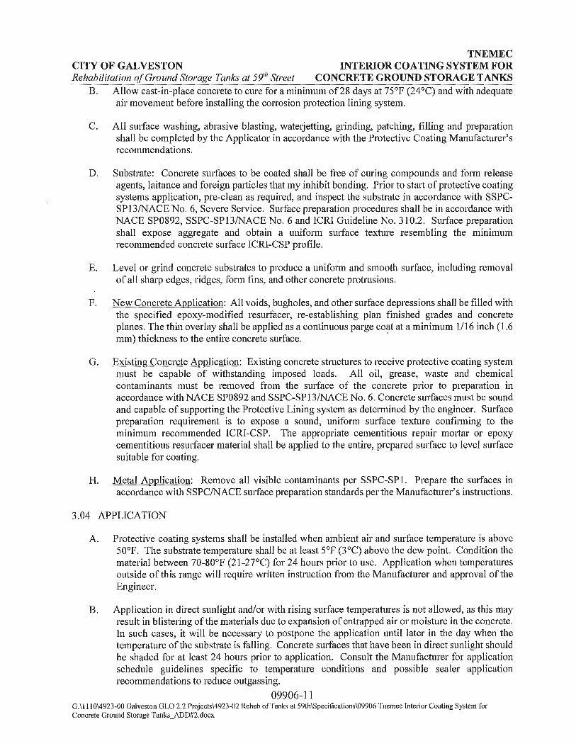
B. Allow cast-in-place concrete to cure for a minimum of28 days at 75°F (24°C) and with adequate air movement before installing the corrosion protection lining system.
C. All surface washing, abrasive blasting, wate1jetting, grinding, patching, filling and preparation shall be completed by the Applicator in accordance with the Protective Coating Manufacturer's recommendations.
D. Substrate: Concrete smfaces to be coated shall be free of curing compounds and form release agents, laitance and foreign particles that my inhibit bonding. Prior to start of protective coating systems application, pre-clean as required, and inspect the substrate in accordance with SSPCSP 13/NACE No. 6, Severe Service. Surface preparation procedures shall be in accordance with NACE SP0892, SSPC-SP13/NACE No. 6 and ICRI Guideline No. 310.2. Surface preparation shall expose aggregate and obtain a uniform smface texture resembling the minimum recommended concrete surface ICRI-CSP profile.
E. Level or grind concrete substrates to produce a uniform and smooth smface, including removal of all sharp edges, ridges, form fins, and other concrete protrusions.
F. New Concrete Application: All voids, bugholes, and other surface depressions shall be filled with the specified epoxy-modified resmfacer, re-establishing plan finished grades and concrete planes. The thin overlay shall be applied as a continuous parge coat at a minimum 1/16 inch (1.6 mm) thickness to the entire concrete surface. '
G. Existing Concrete Application: Existing concrete structures to receive protective coating system must be capable of withstanding imposed loads. All oil, grease, waste and chemical contaminants must be removed from the surface of the concrete prior to preparation in accordance with NACE SP0892 and SSPC-SP13/NACE No. 6. Concrete surfaces must be sound and capable of suppo1ting the Protective Lining system as determined by the engineer. Surface preparation requirement is to expose a sound, uniform surface texture confirming to the minimum recommended ICRI-CSP. The appropriate cementitious repair mo1tar or epoxy cementitious resurfacer material shall be applied to the entire, prepared smface to level smface suitable for coating.
H. Metal Application: Remove all visible contaminants per SSPC-SPl. Prepare the surfaces in accordance with SSPC/NACE surface preparation standards per the Manufacturer's instructions.
3.04 APPLICATION
A. Protective coating systems shall be installed when ambient air and surface temperature is above 50°F. The substrate temperature shall be at least 5°F (3°C) above the dew point. Condition the material between 70-80°F (21-27°C) for 24 hours prior to use. Application when temperatures outside of this range will require written instruction from the Manufacturer and approval of the Engineer.
B. Application in direct sunlight and/or with rising surface temperatures is not allowed, as this may result in blistering of the materials due to expansion of entrapped air or moisture in the concrete. In such cases, it will be necessary to postpone the application until later in the day when the temperature of the substrate is falling. Concrete surfaces that have been in direct sunlight should be shaded for at least 24 hours prior to application. Consult the Manufacturer for application schedule guidelines specific to temperature conditions and possible sealer application recommendations to reduce outgassing.
09906-11 G:\1110\4923-00 Galveston GLO 2.2 Projects\4923-02 Rehab ofTanks at 59th\Specifications\09906 Tnemec Interior Coating System for Concrete Ground Storage Tanks_ADD#2.docx

TNEMEC CITY OF GALVESTON INTERIOR COATING SYSTEM FOR Rehabilitation of Ground Storage Tanks at 59111 Street CONCRETE GROUND STORAGE TANKS
C. Cementitious Repair Mo1tar: Cementitious repair mo1tar shall be used for structural repairs or surface repairs exceeding a depth 1/4 inch (7 mm) in accordance with Manufacturer's written instructions as outlined in the product data sheet and application guide.
1. Thickness - Minimum 1/4 inch as required to re-establish original plane.
D. Epoxy Cementitious Resurfacer: Epoxy cementitious resurfacer shall be used for filling voids, bugholes, static cracks and joints, and for general concrete patching, and to provide a uniform, void free surface for Epoxy Lining application.
1. Thickness - Epoxy lining shall be applied to a minimum thickness of 1/16 inch (1.6 mm) to spalled areas or as shown on the plans.
E. Epoxy Lining (prime coat): Epoxy lining protective coating shall be spray applied, back rolled and cured in accordance with Manufacturer's written instructions as outlined in the product data sheet and application guide.
1. Thickness - Epoxy lining shall be applied to a thickness of 4 to 6 mils (150 to 225 SF/Gallon) dry film thickness to the entire surface.
F. Epoxy Glaze Coat (finish coat): Epoxy glaze finish coat shall be applied over the epoxy lining in accordance with Manufacturer's written instructions as outlined in the product data sheet and application guide.
1. Thickness - Epoxy glaze coat shall be applied to a thickness of 20 to 30 mils (53 to 80 SF/Gallon) dry film thickness over the entire epoxy lining prime coat surface.
3.05 FIELD QUALITY CONTROL, INSPECTION AND TESTING
A. Contractor to perform the quality control procedures listed below 111 conjunction with the requirements of this Section.
B. Inspect all materials upon receipt to ensure that all are supplied by the approved Manufacturer.
C. Surface pH Testing: The pH of cement particles collected from the concrete substrate will be measured using pH indicating paper or pH meter. The pH testing is to be pe1formed once every 50 square feet (5 square meters). Acceptable pH values shall be a minimum 9.0 as measured using color indicating pH paper with readable color calibrations and a scale at whole numbers or pH meter.
D. Surface Profile: Inspect and record substrate profile (anchor pattern). Smfaces shall be profiled, at a minimum, equal to the CSP roughness as recommended by the coating manufacturer in accordance with ICRI Guideline 310.2 and SSPC-SP13/NACE No. 6.
1. Perform replication of the concrete smface profile eve1y 500 square feet ( 46 square meters) using replica putty in accordance with ASTM 07682. Submit replications to the Engineer as part of the Jobsite Rep01ts.
E. Measure and record ambient air temperature once every two hours of each work shift using a thermometer and measure and record substrate temperature once eve1y two hours using an infrared or other smface thermometer.
09906-12 G:\1110\4923-00 Galveston GLO 2.2 Projects\4923-02 Rehab ofTanks at 59th\Specifications\09906 Tnemec Interior Coating System for Concrete Ground Storage Tanks_ADD#2.docx
TNEMEC CITY OF GALVESTON INTERIOR COATING SYSTEM FOR Rehabilitation of Ground Storage Tanks at 591
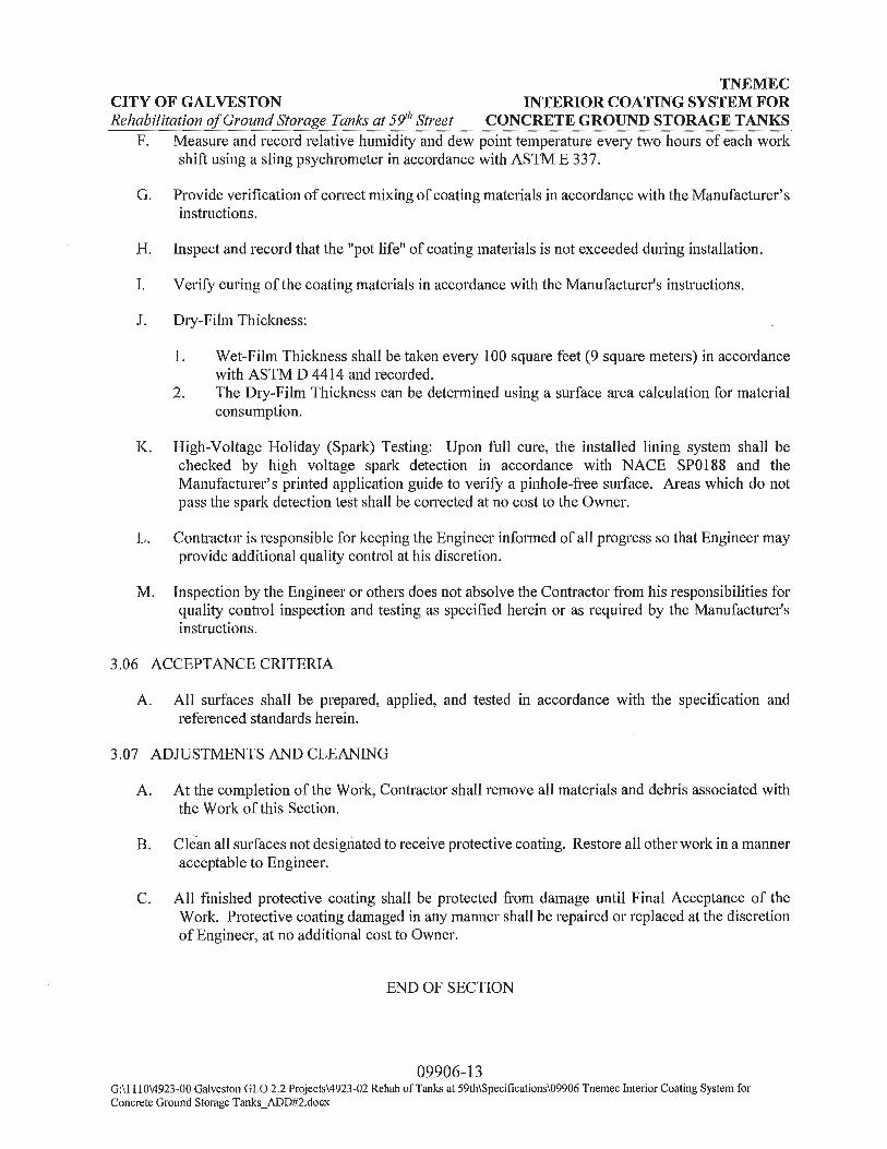
1, Street CONCRETE GROUND STORAGE TANKS F. Measure and record relative humidity and dew point temperature every two hours of each work
shift using a sling psychrometer in accordance with ASTM E 337.
G. Provide verification of correct mixing of coating materials in accordance with the Manufacturer's instructions.
H. Inspect and record that the "pot life" of coating materials is not exceeded during installation.
I. Verify curing of the coating materials in accordance with the Manufacturer's instructions.
J. Dry-Film Thickness:
1. Wet-Film Thickness shall be taken every 100 square feet (9 square meters) in accordance with ASTM D 4414 and recorded.
2. The Dry-Film Thickness can be determined using a surface area calculation for material consumption.
K. High-Voltage Holiday (Spark) Testing: Upon full cure, the installed lining system shall be checked by high voltage spark detection in accordance with NACE SP0188 and the Manufacturer's printed application guide to verify a pinhole-free surface. Areas which do not pass the spark detection test shall be corrected at no cost to the Owner.
L. Contractor is responsible for keeping the Engineer informed of all progress so that Engineer may provide additional quality control at his discretion.
M. Inspection by the Engineer or others does not absolve the Contractor from his responsibilities for quality control inspection and testing as specified herein or as required by the Manufacturer's instructions.
3.06 ACCEPTANCE CRITERIA
A. All surfaces shall be prepared, applied, and tested in accordance with the specification and referenced standards herein.
3.07 ADmSTMENTS AND CLEANING
A. At the completion of the Woi·k, Contractor shall remove all materials and debris associated with the Work of this Section.
B. Clean all surfaces not designated to receive protective coating. Restore all other work in a manner acceptable to Engineer.
C. All finished protective coating shall be protected from damage until Final Acceptance of the Work. Protective coating damaged in any manner shall be repaired or replaced at the discretion of Engineer, at no additional cost to Owner.
END OF SECTION
09906-13 G:\1110\4923-00 Galveston GLO 2.2 Projects\4923-02 Rehab of Tanks at 59th\Specifications\09906 Tnemec Interior Coating System for Concrete Ground Storage Tanks_ADD#2.docx

CITY OF GALVESTON
. SECTION 13204
REHABILITATION OF GROUND STORAGE TANK
REHABILITATION OF GROUND STORAGE TANK
PART 1 GENERAL
1.01 SUMMARY
A. · Item Includes
1. Provide all labor, equipment, personnel and incidentals to supply and install the following appurtenances.
a. Exterior Ladder
b. Interior Ladder
c. Roof Vent
d. Roof Handrail
e. Coating and Lining
f. Downspouts
g. Pipe Connections
B. Related Items:
1. Sections: 02221 Removing Existing Pavements, Structures, Wood,
1.02 REFERENCES
A. Not Applicable
1.03 SUBMITTALS
and Demolition Debris 02508 Pipe Penetration Through Wall 02509 Pipe Penetration Through Roof 09901 Coating and Painting Water Storage Tanks
A. Product Data: Submit manufacturer's product data, including surface preparation, application, and curing.
B. Wananty: Submit manufacturer's standard warranty.
13204-1

CITY OF GALVESTON Rehabilitation of Ground Storage Tanks at 59th Street
REHABILITATION OF GROUND STORAGE TANK
C. Shop drawings designed and stamped by a professional engineer in the State of Texas experienced in the design and rehabilitation of A WW A D-110 tanks.
1.04 DELIVERY, STORAGE AND HANDLING
A. Store all materials in cool, dry conditions and in strict accordance with manufacturer's directions.
1.05 QUALITY ASSURANCE
A. Qualifications:
1. All appurtenances to be anchored to the tank wall or roof must be designed and installed by the qualified tank contractor, DN Tanks of Wakefield, MA, or equal.
2. Installer: Use personnel experienced in the installation of the specified components for a minimum of2-years on projects of similar size and complexity. Provide a list of completed projects including project name and location and name of engineer.
PART 2 PRODUCTS
2.01 MATERIALS
A. Exterior Ladder
1. The ladder shall be aluminum 6061-T6 ladder extending from the tank dome to a point eight feet above finished grade at the tank exterior perimeter.
2. The ladder shall have a stainless steel fall prevention device attached consisting of a sliding, locking mechanism and safety belt and complying with applicable OSHA standards.
3. The base of the ladder to be equipped with a Ladder Gate door to prevent unauthorized access.
B. Interior Ladder
1. The ladder shall be NSF 61 approved fiberglass extending from the tank floor to the dome access hatch.
13204-2 G:\1110\4923-00 Galveston GLO 2.2 Projects\4923-02 Rehab ofTanks at 59th\Specifications\13204_ADD#2.doc

CITY OF GALVESTON Rehabilitation of Ground Storage Tanks at 59th Street
REHABILITATION OF GROUND STORAGE TANK
2. The ladder shall have a stainless steel fall prevention device attached consisting of a sliding, locking mechanism and safety belt and complying with applicable OSHA standards.
C. Dome Ventilator
1. · New vent shall be sized by the tank contractor based on the flow rates provided and mounted on a new reinforced concrete curb in accordance with the shop drawings. -
2. Caulking for the center dome vent shall be an NSF approved one part silicone sealant that meets or exceeds the requirements of the following specification standards: Federal Specifications TT-S-001543A Class A (COM-NBS) for silicone building sealants, and TT-S-00230C Class A (COM-NBS) for one-component sealants; ASTM 920.
D. Dome Handrail
1. Handrails of five feet in length shall be installed on either side of the exterior ground storage tank ladders as shown on contract plans. All posts and rails shall be 6061-T6 Schedule 40 anodized aluminum pipe. All fittings shall be Hollaender speed rail system or equal. Toeboard shall be attached using Hollaender clips or equal.
E. Coating and Lining
1. See specification section 09901- Coating and Painting Water Storage Tanks
F. Downspouts
1. See specification section 02221- Removing Existing Pavements, Structures, Wood, and Demolition Debris
G. Pipe Connections
1. See specification sections 02508 - Pipe Penetration Through Wall and 02509 - Pipe Penetration Through Roof
PART 3 EXECUTION
A. Exterior Ladder
1. Install and attach a new aluminum 606 l-T6 ladder onto the exterior tank wall in accordance with the approved shop drawings.
13204-3 G:\1110\4923-00 Galveston GLO 2.2 Projects\4923-02 Rehab ofTanks at 59th\Specifications\13204_ADD#2.doc

CITY OF GALVESTON Rehabilitation of Ground Storage Tanks at 59th Street
REHABILITATION OF GROUND STORAGE TANK
2. Install the ladder fall prevention device in accordance with the manufacturer's literature.
3. Present all harness and lanyards to the tank owner at the completion of the project.
B. Interior Ladder
1. Remove and dispose of existing interior ladder.
2. Install and attach a new fiberglass ladder onto the interior tank wall in accordance with the approved shop drawings.
3. Install the ladder fall prevention device in accordance with the manufacturer's literature
C. Roof Ventilator
1. Tank Contractor to submit vent design to Engineer for approval.
1. Design Criteria a. Minimum to Maximum Tank Inflow: 0-7,000 GPM b. Minimum to Maximum Tank Outflow: 0-20,000 GPM
2. Remove and dispose of existing dome ventilator in accordance with the contract drawings, manufacturer's literature, and approved shop drawings.
3. Pour new reinforced concrete curb as required to accept new roof vent as detailed in approved shop drawings.
4. Apply bead of silicone caulk to mating surfaces of the new fiberglass center dome vent and concrete vent curb.
5. Install new fiberglass center dome vent and anchor securely to vent curb with appropriate fasteners.
6. Apply bead of silicone caulk to vent flange, completely sealing flange to concrete vent curb to provide a water tight seal.
D. Roof Handrails
1. The dome handrail system shall be installed in accordance with the contract drawings, manufacturer's literature, and approved shop drawings.
13204-4 G:\ 1110\4923-00 Galveston GLO 2.2 Projects\4923-02 Rehab ofTanks at 59th\Specifications\13204_ADD#2.doc

CITY OF GALVESTON Rehabilitation of Ground Storage Tanks at 59111 Street
E. Coating and Lining
REHABILITATION OF GROUND STORAGE TANK
1. See specification section 09901- Coating and Painting Water Storage Tanks
F. Downspouts
1. See specification section 02221- Removing Existing Pavements, Structures, Wood, and Demolition Debris
G. Pipe Connections
1. See specification sections 02508 - Pipe Penetration Through Wall and 02509 - Pipe Penetration Through Roof
END OF SECTION
13204-5 G:\1110\4923-00 Galveston GLO 2.2 Projects\4923-02 Rehab ofTanks at 59th\Specifications\13204_ADD#2.doc
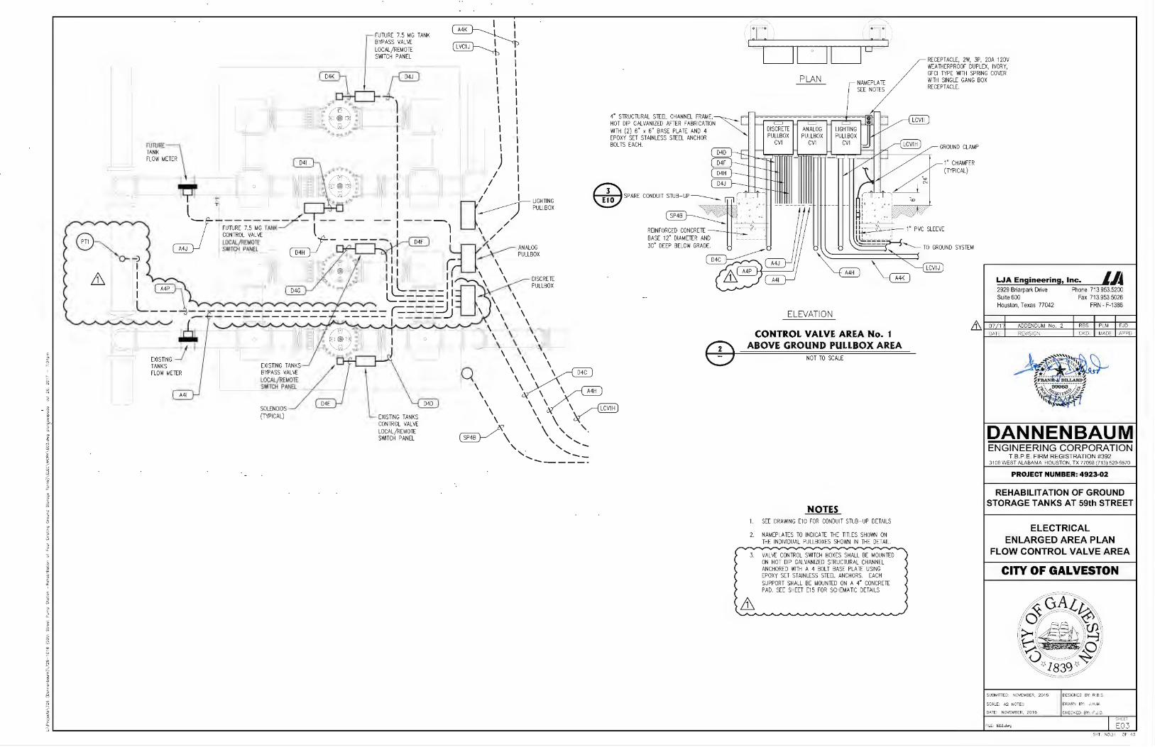
" 0
L_______JI L__I ___,I L__I ____,I
PLAN
ELEVATION
NAMEPLATE SEE NOTES
CONTROL VALVE AREA No. 1 ABOVE GROUND PULLBOX AREA
NOT TO SCALE
NOTES 1. SEE DRAl'l1NG E10 FOR CONDUIT STUB- UP DETAILS
NAMEPLATES TO INDICATE THE TITLES SHOWN ON 2' THE INDIVIDUAL PULLBOXES SHOWN IN THE DETAIL.
3 VAL VE CONTROL SWITCH BOXES SHALL BE MOUNTED · ON HOT DIP GALVANIZED STRUCTURAL CHANNEL
ANCHORED 1'11 TH A 4 BOLT BASE PLATE USING EPOXY SET STAINLESS STEEL ANCHORS. EACH SUPPORT SHALL BE MOUNTED ON A 4" CONCRETE PAD. SEE SHEET E15 FOR SCHEMA TIC DETAILS
RECEPTACLE, 2W, 3P, 20A 120V WEATHERPROOF DUPLEX, IVORY, GFCI TYPE l'llTH SPRING COVER 1'11TH SINGLE GANG BOX RECEPTACLE.
GROUND CLAMP
1" CHAMFER (TYPICAL)
LJA Engineering, Inc. LA 2929 Briarpark Drive Phone 713.953.5200 Suite 600 Fax 713.953.5026 Houston, Texas 77042 FRN • F-1386
DANNENBAUM ENGINEERING CORPORATION
T B p E FIRM REGISTRATION #392 3100 WEST ALABAMA HOUSTON, TX 77098 (71 3) 520-9570
PROJECT NUMBER: 4923·02
REHABILITATION OF GROUND STORAGE TANKS AT 59th STREET
ELECTRICAL ENLARGED AREA PLAN
FLOW CONTROL VALVE AREA
CITY OF GALVESTON

TAG DESCRIPTION SER VICE ROUTING SCHEDULE SIZE
VOLTAGE LOAD FROM TO VIA OR NOTE CONDUCTORS CONDUIT
FSL38 3RD FLOOR PENETRATION FOR CONDUIT LCV1 A -- -- 2ND FLOOR ELECTRICAL ROOM 3RD FLOOR LAS/ORTHO ROOM DEDICATED FOR TANK AREA -- 4"
FSL39 3RD FLOOR PENETRATION FOR CONDUIT D4A -- -- 2ND FLOOR ELECTRICAL ROOM 3RD FLOOR LAS/ORTHO ROOM DEDICATED FOR TANK AREA -- 4"
FSL40 3RD FLOOR PENETRATION FOR CONDUIT MA -- -- 2ND FLOOR ELECTRICAL ROOM 3RD FLOOR LAS/ORTHO ROOM DEDICATED FOR TANK AREA -- 4"
FSL41 3RD FLOOR PENETRATION FOR CONDUIT SP4 -- -- 2ND FLOOR ELECTRICAL ROOM 3RD FLOOR LAS/ORTHO ROOM DEDICATED FOR TANK AREA -- 4"
-- --WSL60 NORTH WALL PENETRATION FOR CONDUIT M -- -- 2ND FLOOR CONTROL ROOM 2ND FLOOR RESTROOM -- -- 6"
WSL61 EAST WALL PENETRATION FOR CONDUIT M -- -- 2ND FLOOR RESTROOM 2ND FLOOR HALLWAY NORTH -- -- 6"
WSL62 WEST WALL PENETRATION FOR CONDUIT M -- -- 2ND FLOOR HALLWAY NORTH 2ND FLOOR ELECTRICAL ROOM -- -- 6"
WSL63 NORTH WALL PENETRATION FOR CONDUIT 04 -- -- 2ND FLOOR CONTROL ROOM 2ND FLOOR RESTROOM -- -- 6"
WSL64 EAST WALL PENETRATION FOR CONDUIT 04 -- -- 2ND FLOOR RESTROOM 2ND FLOOR HALLWAY NORTH -- -- 6"
WSL65 WEST WALL PENETRATION FOR CONDUIT 04 -- -- 2ND FLOOR HALLWAY NORTH 2ND FLOOR ELECTRICAL ROOM -- -- 6"
-- --wsm NORTH WALL PENETRATION FOR CONDUIT LCV1 A -- -- 3RD FLOOR LAS/ORTHO ROOM 3RD FLOOR GENERA TOR AREA -- -- 4"
WSL74 WEST WALL PENETRATION FOR CONDUIT LCV1A -- -- 3RD FLOOR GENERATOR AREA FIELD -- -- 4"
WSL75 NORTH WALL PENETRATION FOR CONDUIT D4A -- -- 3RD FLOOR LAS/ORTHO ROOM 3RD FLOOR GENERA TOR AREA -- -- 4"
WSL76 WEST WALL PENETRATION FOR CONDUIT D4A -- -- 3RD FLOOR GENERA TOR AREA FIELD -- -- 4"
WSL77 NORTH WALL PENETRATION FOR CONDUIT MA -- -- 3RD FLOOR LAS/ORTHO ROOM 3RD FLOOR GENERA TOR AREA -- -- 4"
WSL78 WEST WALL PENETRATION FOR CONDUIT MA -- -- 3RD FLOOR GENERATOR AREA FIELD -- -- 4"
WSL79 NORTH WALL PENETRATION FOR CONDUIT SP4 -- -- 3RD FLOOR LAS/ORTHO ROOM 3RD FLOOR GENERA TOR AREA -- -- 4"
WSLBO WEST WALL PENETRATION FOR CONDUIT SP4 -- -- 3RD FLOOR GENERATOR AREA FIELD -- -- 4"
-- -- -- --A4 COMBINED WIRING CONDUIT ANALOG -- CONTROL ROOM MAIN SCADA PANEL 2ND FLOOR ELECTRICAL ROOM CABLE TRAY CONDUIT M, WSL60, CT, WSL61, CT, WSL62, CT 14- 2/ C #16 TSP TC 3"
M A USE DEDICATED CONDUIT SP3 FOR TANK AREA ANALOG -- 2ND FLOOR ELECTRICAL ROOM CABLE TRAY EXISTING UNDERGROUND PULLBOX No. 3 CT, CONDUIT MA, FSL40, CT, WSL77, WSL78 14-2/C #16 TSP TC 2·
MB ANALOG -- EXISTING UNDERGROUND PULLBOX No. 3 EXISTING GST No. 1 ABOVE GROUND ANALOG PULLBOX -- 14- 2/ C #16 TSP TC 3" LJA Engineering, Inc. LA MC ANALOG -- EXISTING GST No. 1 ABOVE GROUND ANALOG PULLBOX EXISTING GST No. 1 PRESSURE TRANSMITTER -- 1- 2/ C #16 TSP TC 3/ 4" 2929 Briarpark Drive Phone 713.953.5200 MD ANALOG -- EXISTING GST No. 1 ABOVE GROUND ANALOG PULLBOX EXISTING GST No. 2 ABOVE GROUND ANALOG PULLBOX -- 12- 2/ C #16 TSP TC 2" Sui1e 600 Fax 713.953.5026
A4E ANALOG -- EXISTING GST No. 2 ABOVE GROUND ANALOG PULLBOX EXISTING GST No. 2 PRESSURE TRANSMITTER -- 1- 2/ C #16 TSP TC 2" Houston, Texas 77042 FRN • F-1386
MF ANALOG -- EXISTING GST No. 2 ABOVE GROUND ANALOG PULLBOX EXISTING GST No. 3 ABOVE GROUND ANALOG PULLBOX -- 10-2/C #16 TSP TC 1 1/ 2''
~ I I I I
M G ANALOG -- EXISTING GST No. 3 ABOVE GROUND ANALOG PULLBOX EXISTING GST No. 3 PRESSURE TRANSMITTER -- 1-2/C #16 TSP TC 3/ 4" 07/ 171 ADDENDUM No. 2 I RBS I PLM I F JD DATE I REVISION I CKD. I MADE I APPD
_ A4_!:1 - -------------- ~N~!P~ -- EX§Tl~G iSI.. N.9.: ~ A§_OVf ~~ND_ A~ALQG .£Uh_LBQ_X __ - - - - ]!.N~ C..QNl:!Wh_ V~LV!_ ~E~ AJ!.Aic9G__PU.Y-B..QX - - - - -- ------------- 8~ / (2 #.!._6 .ISP_ T"-._ _ -------- - - - 1_1/2'' - - - - - -( A,jj ANALOG -- TANK CONTROL VALVE AREA ANALOG PULLBOX EXISTING TANKS FLOW METER -- 1- 2/ C #16 TSP TC /),_ ,· 1 ~ M~ FUTURE,. 2/..C f 16~TSf ~ ~ ~ ~ ~ ~ ~ f:J-} ~ ~ ,,~ A. .A. .A. .A .A.. .A. A. .A. .A. .A. .A. .A. .A..
A1iAL_QG -- NEW~TANK CO~TIJ.OL~VAJ.VE~A~A~AN}L9._G PULLBO_l( ~ ~ ~ ~ ~ FU1U1iE 'l_PS_lRE}M J'RESSURf Tf AN..5Ml}TEJ F;._OR PROPQ_SEQ 11(. --A.A..A..A.A.A..A.A.A.A.A ~ l}JT-,._ J s·N'' ~ ~ ~ ~
MK ANALOG -- TANK CONTROL VAL VE AREA ANALOG PULLBOX EXISTING GST No. 4 ABOVE GROUND ANALOG PULLBOX -- 4- 2/ C #16 TSP TC 2· * . ML ANALOG -- EXISTING GST No. 4 ABOVE GROUND ANALOG PULLBOX EXISTING GST No. 4 PRESSURE TRANSMITTER -- 1- 2/ C #16 TSP TC 3/ 4" ~F ii.LAiiD~
°I. " ·:··· ···············; ···~ A4M ANALOG -- EXISTING GST No. 4 ABOVE GROUND ANALOG PULLBOX PROPOSED 7.5 MG GST ANALOG PULLBOX - - FUTURE 1· ',1 ··. ,P.39983 .:~,1
1, 0,.-.. ~~ 3~4" 'Fit" .... =1 M N ANALOG -- NEW PROPOSED 7.5 MG GST ANALOG PULLBOX PROPOSED 7.5 MG GST PRESSURE TRANSMITTER -- FUTURE \ I A .
MP ANALOG -- TANK CONTROL VALVE AREA ANALOG PULLBOX PROPOSED INLET WATER PRESSURE TRANSMITTER PT-1 -- 1-2/C #16 TSP TC A 1" "\ \..... ~ .A. .A. .A.. .A. .A. A. .A. .A. .A.. .A. ~ ~ ~ ~ .A..A..A.A..A..A.A..A..A..A..A..A..A..A.A..A.A.A.A. .A. A. A. .A. .A. .A .A. A. .A A. ~ ~ ~ ~ ~ ~ ~ ~ ~ ~ ~ A. A. A. .A. .A .A. .A. .A .... ~ .A IA. .A. .A. A.
.)
LCV1 CONTROL VALVE AREA RECEPTACLES 120V -- 2ND FLOOR ELECTRICAL ROOM LIGHTING PANEL LA 2ND FLOOR ELECTRICAL ROOM CABLE TRAY CONDUIT LP1 A, CT 2- 3/ C #4 Vv1TH #8 GND. 2" DANNENBAUM LCV1A USE DEDICATED CONDUIT SP1 FOR TANK AREA 120V 2ND FLOOR ELECTRICAL ROOM CABLE TRAY EXISTING UNDERGROUND PULLBOX No. 3 CT, CONDUIT LCV1A, FSL38, CT, WSL73, WSL74 2- 3/ C #4 Vv1TH #8 GND. 2" --LCV1B RECEPTACLE POWER 120V -- EXISTING UNDERGROUND PULLBOX No. 3 EXISTING GST No. 2 ABOVE GROUND POWER PULLBOX -- 2- 3/ C #4 Vv1TH #8 GND. 2" ENGINEERING CORPORATION
T.B.P.E. FIRM REGISTRATION #392 LCV1 C RECEPTACLE POWER 120V -- LIGHTING PULLBOX GST1 RECEPTACLE -- 2 #12, 1 #12 GND 3/ 4" 3100 WEST ALABAMA HOUSTON, TX 77098 (71 3) 520-9570
LCV1D RECEPTACLE POWER 120V -- EXISTING TANK No. 1 ABOVE GROUND PULLBOX AREA EXISTING TANK No. 2 ABOVE GROUND PULLBOX AREA -- 2- 3/ C #4 Vv1TH #8 GND. 2· PROJECT NUMBER: 4923·02 LCV1E RECEPTACLE POWER 120V -- LIGHTING PULLBOX GST2 RECEPTACLE -- 2 #12, 1 #12 GND 3/ 4"
LCV1 F RECEPTACLE POWER 120V -- EXISTING TANK No. 2 ABOVE GROUND PULLBOX AREA EXISTING TANK No. 3 ABOVE GROUND PULLBOX AREA -- 2- 3/C #4 Vv1TH #8 GND. 2· REHABILITATION OF GROUND LCV1G RECEPTACLE POWER 120V -- LIGHTING PULLBOX GST3 RECEPTACLE 2 #12, 1 #12 GND 3/ 4" STORAGE TANKS AT 59th STREET LCV1H RECEPTACLE POWER 120V -- EXISTING TANK No. 3 ABOVE GROUND PULLBOX AREA CONTROL VALVE AREA No. 1 ABOVE GROUND PULLBOX AREA -- 2- 3/ C #4 Vv1 TH #8 GND. 2"
LCV11 RECEPTACLE POWER 120V -- LIGHTING PULLBOX CV1 RECEPTACLE 2 #12, 1 #12 GND 3/ 4" ELECTRICAL
LCV1J RECEPTACLE POWER 120V -- CONTROL VALVE AREA No. 1 ABOVE GROUND PULLBOX AREA EXISTING TANK No. 4 ABOVE GROUND PULLBOX AREA 3 #6, 1 #12 GND 2"
LCV1K RECEPTACLE POWER 120V -- EXISTING TANK No. 4 ABOVE GROUND PULLBOX AREA RECEPTACLE 2 #12, 1 #12 GND 3/ 4" CONDUIT & CABLE SCHEDULE LCV1L RECEPTACLE POWER 120V -- CONTROL VALVE AREA No. 1 ABOVE GROUND PULLBOX AREA NEW TANK ABOVE GROUND PULLBOX AREA 2 f/8 , 1 #8 GND 2" (SHEET 1 OF 2)
CITY OF GALVESTON
NOTES FOR SCHEDULE ABBREVIATIONS NOTES FOR SLEEVES
~~ 1. FOR ALLOWABLE CONDUIT AND CONDUCTOR INSULATION CSBE = CONDUIT SEALING BUSHING NEU. = NEUTRAL CQNDUIT SIZE SLEEVE SIZE
TYPES SEE RELATED SPECIFICATIONS. CT = CABLE TRAY PWR = POWER 3/ 4" & 1" = 2''
CNTRL = CONTROL RM = ROOM 1 1/2" & 2" = 4" ( ~ . ~ I 2. CONTRACTOR SHALL COIL AND TAPE SPARE CONDUCTORS.
DISC. SW. = DISCONNECT SVv1TCH TC = TRAY CABLE 3" & 4" = 6"
~ 0 3. CONDUITS ON PLANS ARE SHOWN DIAGRAMMATICALLY. EA. = EACH TSP = TVv1STED SHIELDED PAIR CONTRACTOR SHALL INSTALL SUPPORTS AND PULL
FSL = FLOOR SLEEVE FOR CONDUIT TST = TVv1STED SHIELDED TRIAD 0 v1s3gv~ FITTINGS AS REQUIRED Vv1TH A MAXIMUM OF THREE (3)
90' CONDUIT BENDS BETWEEN FITTINGS OR BOXES. FT. = FEET W/ = 'MTH FUT. = FUTURE WSL = WALL SLEEVE FOR CONDUIT ~
4. CONTRACTOR SHALL INSTALL AND CAP CONDUITS FOR GND. = GROUND FUTURE AS SHOWN ON PLANS.
TK. = TANK SUBMITTED: NOVEMBER, 20 16 DESIGNED BY: R.B.S.
SCALE: NONE DRAWN BY: J.H.M.
DATE: NOVEMBER, 2016 CHECKED BY: F.J.D.
I SHEET
FILE: E05.dwg E05 SHT. NO. 33 OF 43

,:::--, 11 ------------ rl ~Jl~~: ------------- ------
SECTIONE9
w1::~o~x~ J . -- ~~-:, ~
I j i~ EL. 30'·6" ! ! • 1'
Ll--1 ] 6()\j - i I • I
;:,+ f lk!; i - ~ i- , 1-.l
1,;cv--------1-:n,_l i i i
IJCC 'le. -· (
i ' FITTING AS \(_ REQUIRED •
·-·-·-·-·°R
t-----------
- J- -V\ l'.:R
DIESE
WIREWAY / I FJVr ~JJM ,47..=:...
12"W ~x12"D ! ~0~
[}-·· - 000- ··- ~
~PROPOSED UNDERGROUND PULLBOX NO. 3
(
ELEVATION NOT TO SCALE
LOOKING NORTH
_,re•-• 1,;;y: n.'-i:•••
·cu2 ·
HU C'.H ),J I
..!::_T_ ~ VJ)'.-£ . _ _) I
oo--oi,i J- r uJox I AT_ =:.! 1 JJ- . f:. _j
SEE NOTE No. 1 & 2
PULLBOX NOT TO SCALE
PULLBOX~ 36"W x36"H x1 2"0 BOTTON OF PANEL 0
BOTTOM OF CONDUIT EL. 33'·0"
AT ELEV. 32'- 6"
EB 0
0
0 0 0 0
0
- '..0 '1 )LI ( IV..ll(I I )
EL. 32'·5" .__ __ _. EL. 32'·6"
"'"") 36"W x18"H x12"D
SECTION NOT TO SCALE
EL. 30'·6"
C) I
"'
~------ c-rr- n-c---------
I I ~-r---------------- ·
I I I I I I I I I I
. :rtc3'iu 1· 1
NOTES
1. DURING THE PUMP BUILDING CONSTRUCTION CONDUIT LCV1A 2"C WAS LABELED SP1 CONDUIT 048 2"C WAS LABELED SP2 CONDUIT A4B 2"C WAS LABELED SP3 CONDUIT SP4A 2''C WAS LABELED SP4
2. CONTRACTOR IS TO ENSURE THE CONDUITS MENTIONED IN NOTE 1 ARE RELABELED AS PER THE PULLBOX DETAIL.
3. FROM PULL BOX No. 3 TO THE FLOW CONTROL VALVE STATION ROUTE THE SPARE CONDUIT WITH THE ANALOG ANO DISCRETE fil CONDUITS.
GRAPHIC SCALE 4 3 2 1 0 4 8 10
~
xxx I
LEGEND
PROPOSED UNDERGROUND CONDUITS
PROPOSED ABOVE GROUND CONDUITS
MODIFIED UNDERGROUN~
EXISTING UNDERGROUND CONDUITS
EXISTING ABOVE GROUND CONDUITS
PROPOSED OR MODIFIED CONDUIT NAME DESIGNATION
LJA Engineering, Inc. LA 2929 Briarpark Drive Phone 713.953.5200 Suite 600 Fax 713.953.5026 Houston, Texas 77042 FRN - F-1386
~ l-"-07~ 1~7--A=D~DE=N=D~UM~ N~o.~ 2 - t--RB_S--t-P-LM_ +-FJ_D--t
16
'
DATE REVISION CKD. MADE APPD
DANNENBAUM ENGINEERING CORPORATION
T.B.P.E. FIRM REGISTRATION #392 3100 WEST ALABAMA HOUSTON, TX 77098 (71 3) 520-9570
PROJECT NUMBER: 4923·02
REHABILITATION OF GROUND STORAGE TANKS AT 59th STREET
ELECTRICAL PUMP BUILDING
AREA PLAN AND SECTIONS
CITY OF GALVESTON
SUBMITTED: NOVEMBER, 201 6
SCALE: AS NOTED
DATE: NOVEMBER, 2016
FILE: E07.dwg
DESIGNED BY: RB.S.
DRAWN BY: J.H.M.
CHECKED BY: F.J.D. SHEET
E07 SHT. N0 35 OF 43

'W::: : , - , '. I I I I
1,1/'\,'' f- I I I ' ~ · 1: :: : - ' I : : : :
1< . ' 1 1 111 1 1 1 1 f 1 1 I i 1 1 11 1 1 ,-- :wrn:. 1 •
\ _ - i-- - - - - _ I ·,1 y
- \/~ RG- \JCV - , :; - ~~- 1AT8R - ~Cl OS.H-
>, I
, -----------------------'///- { _ ··~ ---------------
I I I I I I
' : I I I I I I I I I I
L _______________ :~~~)h I --_7---------------LAS b l • f J : _ _I~:
I
I
tl l WALL SLEEVE Mr>. No. 7
NS. 6'J 4" W':: / I - / '
NS.73- 4' (LCVIA) WS_75 4· (04A) w, H ' (A4A) ""-1 (SP4)
I TF AR C:A No.
'./:'SLSiJ- L''
WAil. SLEEVE Mr>. No. 9
\:\.'S_72-2"
WSI 'NSL 7:J L"
/ ii /; - /' WSL74-L' (LCVIA) W'V '! (D4A) \N (MA) W',U · (SP4)
- ··~~ T!F
WS ~C; - / " --Ns_~:s: 4"
---------{ 2,:,c )
::: 1_c r; t\AT8~ ~c
H -o~
::YI ~U-R
-aaaaaaaaaaaaaaaaaaaaa;rlaa~aaaaa~: 1 . I I - .· - -
1 1
",I L_J ~ -· I c_____-j _J
;: -j ;;R l1 f -;l ki\!; f I : I I ·. I I ~coc:, ;
l~:{~~~iC, ,[ :~ ~ "~~ IU~--d dl
·: v ii ' Ct\_)
/
',--' IU~--JJI
a: Q Q
4===========ll~ i]! ,,________,,, '.IHI f __ .,/ LJ~ Pie,-------lll----:_i\.i,,J_1; _,K~
- OR f- Of'H(bHI, I: - _.:.·.:·.:: __ _ ~o . •
- OR HJf HU :H 1-f,o.
FLOOR SlElVE AREA Ng. + SEE DWG. EllB
(: .Ajr x~: ~:~x~
_.t..S D.t•.Y -,;,w
PUMP BUILDING lrd FLOOR 480V
J3 _
LEGEND
PROPOSED UNDERGROtN> CONDURS
PROPOSED N!JNf. GROlN> CONDUTS
IIOOIAED UNDERGROINl~,,..,,........~~~,..,,......,.~~41
EXISTING UtllERGROUIC) COtl)URS
EXISTING N!JNf. GROIN) COtl)URS
~ -AED~~,...,......,,~.,......,...,~,,..,,........~.......--.~ [ ;<, f c· •, d U )AV[ .!_5 ~f cJ ul,
PROPOSED OR IIODfED CONDUIT NAME DESIGNATION
LJA Engineering, Inc. LA 2929 Briarpark Drive Phone 713.953.5200 Suite 600 Fax 713.953.5026 Houston, Texas 77042 FRN - F-1386
.&. 07 17 ADDENDUM No. 2 RBS PLM FJD
DATE REVISION CKD. MADE APPD
DANNENBAUM ENGINEERING CORPORATION
T.B.P.E. FIRM REGISTRATION #392 3100 WEST ALABAMA HOUSTON, TX 77098 (71 3) 520-9570
PROJECT NUMBER: 4923·02
REHABILITATION OF GROUND STORAGE TANKS AT 59th STREET
ELECTRICAL PUMP BLDG 3RD FLOOR
CABLE TRAY PLAN
CITY OF GALVESTON
SUBMITTED: NOVEMBER, 20 16 DESIGNED BY: R.8.S. ! POWER AND CONTROL PLAN GRAPHIC SCALE o s~~ c;~,,\Jf-1~: sci\~ 4 .3 z 1 o z 4 a 10 16 scALE: As sHowN
t ~lii~!iiii~~~ .... .J.1~ ~ ...... ~ 1 f._~~~~~~~~~~~~~~~~~~~~~~~~~~~~~~~~~~~~~~~~~~~~~~~~~~~~~~~~~~~~~~~~~~~~~~~~~~=--=·=~=·=~~:::::::=::::::::i:=::::::::::::::;...rD~AIT~•~N~DV~EM-BE-R,_2_01-6~~-CH-EC-K-ED-B-Y,_FJ-.D-. lJES1H0E~ITg~ DRAWN BY: J.H.M.
FILE: E09.dwg
SHT. NO. 37 OF 43

I FINISHED GRADE I FINISHED GRADE
,,. GROUNDING ,,. GROUNDING /«:(«:(~/ WARNING TAPE
; J a.em::t / ~ ~ ~ /; WARNING TAPE
;; 3 _,,- PVC COATED RIGID / GALVANIZED STEEL CONDUIT
FINISHED GRADE \ \ .,,.,...------- CONCRETE ENCASEMENT
··~~0%''"· ·'), 11 '··~~0_{//-'
#5 @ 8" oc ALL AROUND
#4 roJ @ 18" oc r ', PVC COATED RIGID
GALVANIZED STEEL CONDUIT /, . , , COUPLING ADAPTER. -__ , __ .-----:;-- - - - --=- /. i (AS REQUIRED) ---~ - ·- -r ............ ~
.,... - - .. - ....,_ - Jo-:;--- ' '
CONDUITS AS NOTED ON PLANS
ALL AROUND
CONDUITS AS NOTED ON PLANS
-~ t - _____::__ ~ _____!; PVC COATED RIGID GALVANIZED STEEL
PVC CONDUIT BEND (USE FOR ALL UNDERGROUND
TYPICAL MULTI-CONDUIT DUCTBANK SECTION
DETAIL NOT TO SCALE
TYPICAL SINGLE-CONDUIT DUCTBANK SECTION
07» /,'-::__ / 07 » 7 '"-.;'\, //// / / /// /
ANTI-TRIP EXPOSED CONDUIT PROTECTOR
AUL CONDUITS INSTALLED ACROSS THE TOP OF SLABS SHALL BE EQUIPPED WITH A FABRICATED (MIN. 10 GAUGE) HOT DIP GALVANIZED AFTER FABRICATION RIGID STEEL
ANTI-TRIP EXPOSED CONDUIT PROTECTOR.
DETAIL NOT TO SCALE
BENDS)
CONDUIT SlUB-UP
DETAIL NOT TO SCALE
4__;J--+-,L--:,r- USE CRIMPED ----+=:=:::J---,,j,.<:;.+-~ONNECTORS
TYPICAL GFCI RECEPTACLE HOOKUP
DETAIL
UNDERGROUND PULLBOX SCHEDULE - MINIMUM DIMENSIONS
@ PULlBOX No. A B c D E F G PLATE DOOR
~ Exi sn~NG ~3 1 44" 36" 36" 44" 16" 14" 35" 40"x 40" .&_ ..... .,,/
ALL UNDERGROUND PULLBOXES SHALL BE SIZE PER THE NEC REQUIREMENTS AND SUBMITIED FOR REVIEW
(TYPICAL)
UNDERGROUND J PULLBOX
--:} ---i
FROM PULL BOX No. 3 TO CONTROL VALVE AREA POWER/CONTROL CONDUITS SHALL BE IN A SEPARATE CONDUIT BANK FROM THE ANALOG/DISCRETE CONDUIT BANK. MINIMUM CONDUIT BANK SEPARATION OUT TO OUT SHALL BE 24 INCHES THROUGHOUT.
ELECTRICAL UNDERGROUND PULLBOX AREA
DETAIL
CAST IN ANGLIE FRAME WITH FLUSH STOP AND ANCHORS
PROVIDE SINGLE LEAF ALUMINUM CHECKER PLATE DOOR WITH AASHTO H- 20 RATING
A
PLAN
4" I I . ___ _J___~
0
TYPICAL ELECTRICAL UNDERGROUND PULLBOX
DETAIL
PVC COATED RIGID GALVANIZED STEEL CONDUIT COUPLING ADAPTER
CONCRETE 24" REINFORCE ~
""""".' . . . ,~ " ----, -1- - • -::1====::0 c = --t.._ J-...=:...,._ __
P~C CONDU:~ " ~ I i _/ GALVANIZED PIPE
PVC COATED RIGID CAP (PLASTl BOND)
SPARE CONDUIT SlUB- UP
DETAIL NOT TO SCALE
NOTE:
GALVANIZED CONDUITS. PROTECT CONDUIT BY DOUBLE LAP OF PVC TAPE.
UNDERGROUND CAPPED CONDUIT SlUB- OUT
DETAIL NOT TO SCALE
NOTE: ALL EXPOSED THREADS & GALVANIZED VOIDS TO BE COATED WITH ANTI RUST MATERIAL
PRECAST ELECTRICAL PULLBOXES (AS MANUFACTURED BY OLDCASTLE PRECAST, OR EQUAL) SHALL BE DESIGNED FOR H- 20 LOADING AND EQUIVALENT FLUID PRESSURE OF 70 PCF FOR SOIL.
4500 psi PRECAST CONCRETE
FINISH GRADE
LJA Engineering, Inc. LA 2929 Briarpark Drive Phone 713.953.5200 Suite 600 Fax 713.953.5026 Houston, Texas 77042 FRN - F-1386
'"'"~~ S ·N' * .
~F ii.LAiiD~ °1. " · :· ··· · · ·· ·· · ·· ·· · ··; · · ·J: ",1 ··. ,fl:39983 .:~,1 1,0,,-.~~ ·--f--~"~ ·~-.... ·'~ ·\~ . i
DANNENBAUM ENGINEERING CORPORATION
T.B.P.E. FIRM REGISTRATION #392 3100 WEST ALABAMA HOUSTON, TX 77098 (71 3) 520-9570
PROJECT NUMBER: 4923·02
REHABILITATION OF GROUND STORAGE TANKS AT 59th STREET
ELECTRICAL DETAILS
(SHEET 1 OF 4)
CITY OF GALVESTON
Cw SECTION NOT TO SCALE NOT TO SCALE ~ suBMITTEDc NOVEMBER, 2016
~ SCALE: AS SHOWN
DESIGNED BY: R.B.S.
DRAWN BY: J.H.M.
CHECKED BY: F.J.D. ,: FOR CONDUIT ENTIRY SEE ELECTRICAL SITE PLAN(S) DATE, NOVEMBER, 2016
} EsHlmO ..... FILE: E10 .dwg
~ L--------------------------------------------------------------------------------------------------.._-------------;:S~HT~.N~0~38:--;0~F-;,;'43
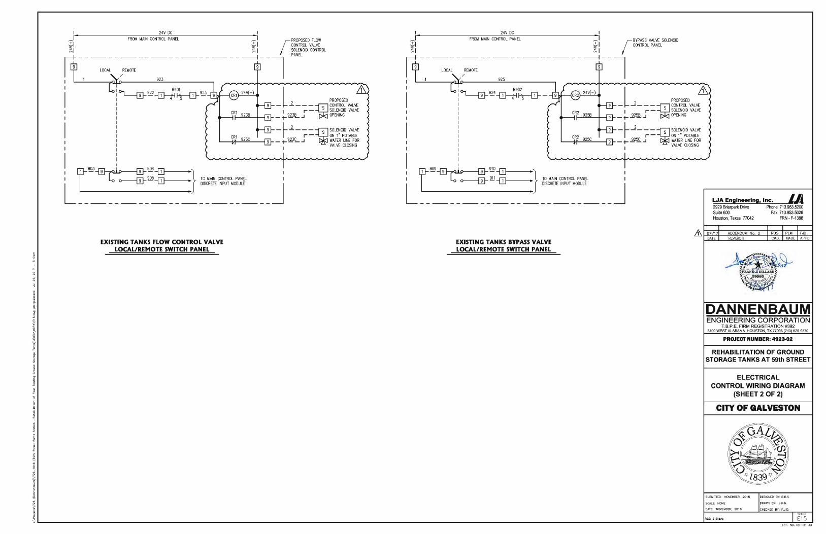
I 24V DC I ~ • FROM MAIN CONTROL PANEL ,: I PROPOSED FlOW
ti -}I (CONTROL VALVE ~ I ~ I SOLENOID CONTROL
~ - - '°'" - :"'°~ ---- ---- ---- -------:--1 "'" I 923
I
I l fil 2 PROPOSED
- - - - - ~ CONTROL VALVE I r - S SOLENOID VALVE
- +-WIL .J OPENING
_ L _l _ - -i SOLENOID VALVE I r - s ON 1" POTABLE _ t- !lb3c:_ .J WATER LINE FOR
I VALVE CLOSING
I f1 ~~~-OJ '} I I - Lo o--------fil--~ -OJ , TO MAIN CONTROL PANEL I L ~ DISCRETE INPUT MODULE J ----------- . --------
EXISTING TANKS FLOW CONTROL VALVE LOCAL/REMOTE SWITCH PANEL
I 24V DC I ~ • FROM MAIN CONTROL PANEL ,:1 (BYPASS VALVE SOLENOID t i j;' I CONTROL PANEL ~I ~ I
~-----=,~-:"'~ ------------------:--1 I 925
I
I R902
~~4~~- l ill 2 PROPOSED
- ----~ CONTROL VALVE I r - S SOLENOID VALVE
_ t- ..2f~ .J OPENING
_ L _j _ - -i SOLENOID VALVE I r - s ON 1" POTABLE _ t- -2.?~ .J WATER LINE FOR
I VALVE CLOSING
I f1 ~~~-OJ '} I I - Lo o--------fil--~ -OJ , TO MAIN CONTROL PANEL I L ~ DISCRETE INPUT MODULE J ----------- . --------
EXISTING TANKS BYPASS VALVE LOCAL/REMOTE SWITCH PANEL
LJA Engineering, Inc. LA 2929 Briarpark Drive Phone 713.953.5200 Suite 600 Fax 713.953.5026 Houston, Texas 77042 FRN - F-1386
''"~~ S ·N' * .
~F ii.LAiiD~ °1. " ·:··· ····· ····· ·····; ···J: ",1 ··. ,fl:39983 .:~,1 1,0,, .. ~~-._f..·~'<,~ ·~· .... ·'~ ·\~ . i
DANNENBAUM ENGINEERING CORPORATION
T.B.P.E. FIRM REGISTRATION #392 3100 WEST ALABAMA HOUSTON, TX 77098 (71 3) 520-9570
PROJECT NUMBER: 4923·02
REHABILITATION OF GROUND S TORAGE TANKS AT 59th STREET
ELECTRICAL CONTROL WIRING DIAGRAM
(SHEET 2 OF 2)
CITY OF GALVESTON
SUBMITTED: NOVEMBER, 201 6
SCALE: NONE
DATE: NOVEMBER, 2016
FILE: E15.dwg
DESIGNED BY: R.8.S.
DRAWN BY: J.H.M.
CHECKED BY: F.J.D. SHEET
E1 5 SHT. NO. 43 OF 43