ADDENDUM 2
13
1 Date of Issue: March 2012 Affected Publication: API Recommended Practice 934-A, Materials and Fabrication of 2 1/4Cr- 1Mo, 2 1 /4Cr-1Mo- 1 /4V, 3Cr-1Mo, and 3Cr-1Mo- 1 /4V Steel Heavy Wall Pressure Vessels for High- temperature, High-pressure Hydrogen Service, Second Edition, May 2008 ADDENDUM 2 Add the following Annex B to the document.
-
Upload
khangminh22 -
Category
Documents
-
view
3 -
download
0
Transcript of ADDENDUM 2

1
Date of Issue: March 2012 Affected Publication: API Recommended Practice 934-A, Materials and Fabrication of 2 1/4Cr-1Mo, 2 1/4Cr-1Mo-1/4V, 3Cr-1Mo, and 3Cr-1Mo-1/4V Steel Heavy Wall Pressure Vessels for High-temperature, High-pressure Hydrogen Service, Second Edition, May 2008
ADDENDUM 2 Add the following Annex B to the document.

31
Annex B(informative)
Weld Metal/Flux Screening Test for Reheat Cracking Susceptibility
B.1 Foreword
This annex is being issued in response to widespread fabrication problems with 2 1/4 Cr-1Mo-V reactors that occurred from January 2008 through at least August 2008 due to transverse reheat cracking (RHC). Additional background on the problem is given in Annex A of API 934-A. Annex A also gives guidance on inspection methods for detecting transverse reheat cracking, and suggests that the extent of inspection can vary based on “higher risk” versus “lower risk” welds. It further states that the risk can be determined by a screening test of the weld metal and flux heats. Initially, the screening test being used was the “Gleeble test” which is a high temperature tensile test done at a set strain rate using specialized testing equipment. Since these testers are generally used for research and are not standardized only a limited number of laboratories could conduct the tests, and although each tester distinguished between susceptible and non-susceptible materials, the threshold for acceptable material varied for each tester.
To develop an acceptable screening test which is repeatable between multiple laboratories, a Joint Industry Sponsored Research Program (JIP) was formed in Feb. 2010. The JIP sponsors included numerous oil companies, reactor fabricators, weld metal suppliers, steel suppliers, licensors and an engineering company. The program included developing the details of the test method, running sensitivity tests on numerous test variables and conducting round robin tests at multiple laboratories to ensure that the results were repeatable. At each stage, “good”, “bad”, and “borderline” materials were compared, to show that the test procedure could distinguish between these materials.
This procedure is applicable to 2 1/4 Cr-1Mo-V submerged arc welding (SAW) wire and flux combinations (by heat), and is solely for screening for fabrication reheat cracking susceptibility. The test criteria apply only to samples prepared and tested completely in accordance with this procedure and is not applicable to the previously-used Gleeble test methods. The screening test has the benefit of testing for almost all possible weld metal causes of fabrication reheat cracking. The Purchaser should decide on whether the screening test and/or other reheat cracking tests are required, and the Purchaser and reactor fabricator should decide which party will coordinate the testing and acceptable laboratories.
All other requirements from the material specifications for the weld wire and flux should still be met.
B.2 Scope
This testing procedure covers the assessment of the Reheat Cracking susceptibility of 2 1/4 Cr-1Mo-V SAW weld metal. This testing procedure should be used if specified by Purchaser as a screening test for each heat-of-wire/batch-of-flux combination.
The values stated in SI (metric) units are to be regarded as the standard.
NOTE This standard does not purport to address all of the safety concerns, if any, associated with its use. It is the responsibility of the User of this standard to establish appropriate safety and health practices and to determine the applicability of regulatory limitations prior to use. It is also the responsibility of the User to decide which party will coordinate the testing and to determine acceptable testing laboratories.
32 API RECOMMENDED PRACTICE 934-A
B.3 Referenced Industry Documents
B.3.1 American Society of Testing and Materials (ASTM)
ASTM B637, Standard Specification for Precipitation-Hardening Nickel Alloy Bars, Forgings, and Forging Stock for High-Temperature Service
ASTM E4, Standard Practices for Force Verification of Testing Machines
ASTM E83, Standard Practice for Verification and Classification of Extensometer Systems
ASTM E633, Standard Guide for Use of Thermocouples in Creep and Stress-Rupture Testing to 1800°F (1000°C) in Air
ASTM E1012, Standard Practice for Verification of Test Frame and Specimen Alignment under Tensile and Compressive Axial Force Application
B.3.2 International Standards Organization (ISO) and European Norms (EN)
ISO 376, Metallic materials—Calibration of force-proving instruments used for verification of uniaxial testing machines
ISO 9513, Metallic materials—Calibration of extensometers used in uniaxial testing
B.4 Terms and Definitions
RHC Reheat Cracking
RoA Reduction of Area (%)
SAW Submerged Arc Welding
YS Yield Strength (MPa)
UTS Ultimate Tensile Strength (Mpa)
El% or El Elongation (%)
B.5 Test Apparatus
B.5.1 Testing Machine
Machines used for tension testing shall conform to the requirements of ASTM E4 or ISO 376.
The forces used in determining tensile strength and yield strength shall be within the verified force application range of the testing machine as defined in ASTM E4 or ISO 376.
The testing machine shall be equipped with a means of measuring and controlling either the strain rate or the rate of crosshead motion or both to meet the requirements in B.8.5. It shall also be equipped with a means of heating and controlling the temperature to meet the requirements in B.8.3.

MATERIALS AND FABRICATIONS OF 2 1/4CR-1MO, 2 1/4CR-1MO-1/4V, 3CR-1MO, AND 3CR-1MO-1/4VSTEEL HEAVY WALL PRESSURE VESSELS FOR HIGH-TEMPERATURE, HIGH-PRESSURE HYDROGEN SERVICE 33
B.5.2 Gripping Devices
B.5.2.1 General
Various types of gripping devices may be used to transmit the measured force applied by the testing machine to the test specimens. To ensure axial tensile stress within the gage length, the axis of the test specimen should coincide with the center line of the heads of the testing machine. Any departure from this requirement may introduce bending stresses that are not included in the usual stress computation (force divided by cross-sectional area).
The gripping device should be attached to the heads of the testing machine through properly lubricated spherical-seated bearings or duly aligned following requirements of ASTM E1012.
A schematic diagram of a gripping device for threaded-end specimens using lubricated spherical-seated bearings is given in Figure B.1.
B.5.2.2 Effects of Testing Temperature on Gripping Device
Gripping devices and pull rods may oxidize, warp, and creep with repeated use at elevated temperatures. Increased bending stresses may result. Therefore, grips and pull rods should be periodically retested for axiality and reworked when necessary.
The use of high temperature resistant alloys for extension/gripping rods is mandatory to avoid yielding and to control the strain rate in the specimen. Yielding of the rods may have a strong effect on test results by transferring deformation from the specimen gauge length to the rods.
As examples, ASTM B637, UNS N07080 (formerly grade 80A), AISI 310S (EN 1.4845 / X8 Cr Ni 25 21) and AISI 314 (EN 1.4841 / X15 Cr Ni Si 25-21) have been successfully used. Other refractory or high temperature resistant alloys may also be used.
Figure B.1—Example of a Gripping Device Devoted to Threaded-end Specimens
SphericalBearing
Upper Headof TestingMachine
Specimenwith Threadedends

34 API RECOMMENDED PRACTICE 934-A
B.5.3 Dimension-Measuring Devices
Micrometers, calipers and other devices used for measuring linear dimensions shall be accurate and precise to at least one half the smallest unit to which the individual dimension is required to be measured. Since the measurements shall be to the nearest 0.02 mm (per B.8.7), the accuracy shall not be larger than 0.01 mm.
B.5.4 Extensometers
The use of extensometers is mandatory for verification of the strains. They shall record the actual deformation in the gage length and shall be used for determining the yield strength (YS). They should not be used for controlling the test strain rate.
Extensometers used in tension testing shall conform to the requirements of ASTM E83 or ISO 9513 for the testing conditions specified for this test method. ASTM E83 or ISO 9513 shall be used for selecting the required sensitivity and accuracy of extensometers. The extensometer shall also be tested to assure its accuracy when used in conjunction with a furnace at elevated temperature.
B.5.5 Heating Apparatus and Testing Atmosphere
The apparatus for and method of heating the specimens should provide the temperature control necessary to satisfy the requirements specified in B.8.4.
Heating shall be by an electric resistance, inductive or radiation furnace with the specimen in air at atmospheric pressure unless another test media is specifically agreed upon in advance.
The recommended media for testing is air (room atmosphere), but the following media can also be applied as alternatives without significant influence on the test results:
— vacuum,
— helium (standard industrial quality), or
— argon (standard industrial quality).
The test atmosphere shall be reported as required in B.10.
B.5.6 Temperature-Measuring Apparatus
The method of temperature measurement must be sufficiently sensitive and reliable to ensure that the temperature of the specimen is within the limits specified in B.8.4.
Temperature should be measured with thermocouples in conjunction with the appropriate thermometer device and settings. Thermocouples shall have a known calibration. When base-metal thermocouples are used, representative thermocouples should be calibrated for each lot of wires.
Temperature-measuring, controlling, and recording instruments shall be verified periodically against a secondary standard, such as a precision potentiometer and if necessary re-calibrated. Lead-wire error should be checked with the lead wires in place as they normally are used.

MATERIALS AND FABRICATIONS OF 2 1/4CR-1MO, 2 1/4CR-1MO-1/4V, 3CR-1MO, AND 3CR-1MO-1/4VSTEEL HEAVY WALL PRESSURE VESSELS FOR HIGH-TEMPERATURE, HIGH-PRESSURE HYDROGEN SERVICE 35
B.6 Welding of Screening Test Coupons
B.6.1 Weld Joint Details and Welding Parameters
Weld metal screening test coupons should be prepared with each heat/batch of wire and flux combination to be required for production welding. The base metal and backing plates can be made of:
— carbon steel—recommended regardless of reactor material,
— 2 1/4 Cr-1 Mo or 2 1/4 Cr-1 Mo-V, or
— CS with the bevel area buttered with 2 1/4 Cr-1 Mo or 2 1/4 Cr-1 Mo-V weld metal
Welding of the test coupon shall be as summarized in Table B.1 and Figures B.2 and B.3.
The weld coupon shall utilize a 30 mm thickness plate butt welding joint with a 10° bevel angle and 30 mm root opening, with a backing plate and filling with 4 beads per layer (see Figures B.2 and B.3).
This test is not a weld procedure qualification test nor is it relevant to production test plates, and the test coupon must be welded with these parameters to be indicative and valid. The welding parameters are not required to reflect production welding and thicker plates shall not be used.
Table B.1—Welding Parameters to be Used for Welding of Screening Test Coupons
Specified Welding Conditions
Wire Diameter (mm) a 3.2 4
Automatic vs Manual Welding b Machine / SAW Auto.
Heat Input (KJ/mm) 1.95 – 2.15
Voltage (V) 30 – 32
Amperage (A) 500 – 520 540 – 560
Travel Speed (cm/min) 50 +/– 2
Polarity (AC or DC+/-) AC
Joint Preparation See Figure B.2
Welding Position 1G
Stick-out (mm) 23 30
Use of Strongbacks to Minimize Distortion (Yes or No) Yes – See Figure B.4 for example
Preheating (°C) 200 Min.
Interpass Temperature Min./Max. (°C) 200 / 230
Post Heating or DHT (°C and hours) 350°C+/–10°C for 4 hours min.a Either 3.2 or 4 mm wire may be used from a given heat of wire (for a given flux batch), and should match production welding.b Single or tandem wire shall match what will be used for production welding

36 API RECOMMENDED PRACTICE 934-A
B.6.2 Heat Treatment of Test Coupons
Welding step shall be followed by Dehydrogenation Heat Treatment (DHT; also referred to as Post Heating) at 350 °C (+/– 10 °C) for 4 hours minimum.
The welded coupon must not be exposed to high temperature heat treatment such as Intermediate Stress Relieving heat treatment (ISR) or Postweld Heat Treatment (PWHT). Any deviation will lead to non-validity of the results.
B.7 Specimens and Sampling
B.7.1 Sampling
Two parallel RHC test specimens shall be longitudinally machined from the welded joint (see Figures B.5 and B.6). The gap between the two pre-forms shall be 2 mm. The length of the pre-form shall be 120 mm minimum and they
Figure B.2—Geometry of the Weld Joint to be Used for the Screening Test Coupon
Figure B.3—Welding Sequence to be Used for the Screening Test
Figure B.4—Example of Strongbacks Used to Minimize Coupon Distortion
30 mm
60 mm
10 mm
30 mm 200 mm 10°
1 2 3 4
NOTES:a) Four beads per layer.b) Welding direction reversed after each bead deposit. c) Coupon’s position fixed.

MATERIALS AND FABRICATIONS OF 2 1/4CR-1MO, 2 1/4CR-1MO-1/4V, 3CR-1MO, AND 3CR-1MO-1/4VSTEEL HEAVY WALL PRESSURE VESSELS FOR HIGH-TEMPERATURE, HIGH-PRESSURE HYDROGEN SERVICE 37
shall be extracted at least 50 mm from the ends of the test plates. These sample locations can be used for any of the plate and backing materials allowed in B.6.1.
50 mm of each ends of the welded joint must be removed in order to avoid sampling on non representative microstructures (due to non-stabilized welding parameters during depositing of beads).
B.7.2 Machining and Specimen Dimensions
RHC specimens are machined according to usual techniques (either classical lathe or numerically controlled lathe). Dimensions of the specimens are given by Figure B.7. Calibrated lengths of the specimen as per Figure B.7 are mandatory. Small deviations are acceptable only at the threaded ends as shown. If deviations are required, the axis of the specimen must be coincident with the axis of the 12x12x120 mm pre-form described in B.6.1.
Figure B.5—Position of Pre-forms Inside the Welded Zone—Macrographic View
Figure B.6—Position of Pre-forms Inside the Welded Zone—Schematic View
Pre-forms
7 mm ±0.5
12 mm ±0.5
12 mm ±0.5
2 mm +0 -0.5

38 API RECOMMENDED PRACTICE 934-A
B.8 Test Procedures
B.8.1 Cleaning Specimen
Carefully clean the specimen in fresh alcohol, acetone, or other suitable solvent that will not affect the metal being tested.
B.8.2 Connecting Specimen to the Machine
It is critical to not introduce nonaxial forces while installing the specimen. Specimens should not be turned to the end of the threads.
B.8.3 Testing Temperature
For the purpose of this RHC screening test procedure, testing temperature shall be equal to 650 °C +/– 3 °C.
B.8.4 Temperature Control and Heating of the Specimen
The thermocouple beads shall be formed in accordance with ASTM E633.
In attaching thermocouples to the specimen, the junction must be kept in intimate contact with the specimen and shielded from radiation. Ceramic insulators should be used on the thermocouples in the hot zone. Sheathed thermocouples can be used, keeping in mind the need of intimate contact with the specimen. The use of base-metal thermocouples welded directly on specimen is also acceptable.
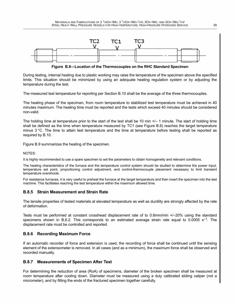
The use of three thermocouples is mandatory, one in the middle of the gauge length and one at each end of the reduced section (see Figure B.8).
The temperature difference between the three thermocouples should not exceed +/–3 °C.
For the whole duration of the test, (defined as the time from the application of force until fracture), the difference between the measured temperature given by TC1 and the nominal testing temperature (i.e. 650 °C) shall not exceed +/–3 °C.
(all units, unless specified otherwise, are in mm)
Figure B.7—Detailed Geometry of RHC Standard Specimen
Non-Mandatory Mandatory Non-Mandatory
MATERIALS AND FABRICATIONS OF 2 1/4CR-1MO, 2 1/4CR-1MO-1/4V, 3CR-1MO, AND 3CR-1MO-1/4VSTEEL HEAVY WALL PRESSURE VESSELS FOR HIGH-TEMPERATURE, HIGH-PRESSURE HYDROGEN SERVICE 39
During testing, internal heating due to plastic working may raise the temperature of the specimen above the specified limits. This situation should be minimized by using an adequate heating regulation system or by adjusting the temperature during the test.
The measured test temperature for reporting per Section B.10 shall be the average of the three thermocouples.
The heating phase of the specimen, from room temperature to stabilized test temperature must be achieved in 40 minutes maximum. The heating time must be reported and the tests which exceed 40 minutes should be considered non-valid.
The holding time at temperature prior to the start of the test shall be 10 min +/– 1 minute. The start of holding time shall be defined as the time when temperature measured by TC1 (see Figure B.8) reaches the target temperature minus 3 °C. The time to attain test temperature and the time at temperature before testing shall be reported as required by B.10.
Figure B.9 summarizes the heating of the specimen.
NOTES:
It is highly recommended to use a spare specimen to set the parameters to obtain homogeneity and relevant conditions.
The heating characteristics of the furnace and the temperature control system should be studied to determine the power input, temperature set point, proportioning control adjustment, and control-thermocouple placement necessary to limit transient temperature overshoots.
For resistance furnaces, it is very useful to preheat the furnace at the target temperature and then insert the specimen into the test machine. This facilitates reaching the test temperature within the maximum allowed time.
B.8.5 Strain Measurement and Strain Rate
The tensile properties of tested materials at elevated temperature as well as ductility are strongly affected by the rate of deformation.
Tests must be performed at constant crosshead displacement rate of to 0.8mm/min +/–20% using the standard specimens shown in B.6.2. This corresponds to an estimated average strain rate equal to 0.0005 s–1. The displacement rate must be controlled and reported.
B.8.6 Recording Maximum Force
If an automatic recorder of force and extension is used, the recording of force shall be continued until the sensing element of the extensometer is removed. In all cases (and as a minimum), the maximum force shall be observed and recorded manually.
B.8.7 Measurements of Specimen After Test
For determining the reduction of area (RoA) of specimens, diameter of the broken specimen shall be measured at room temperature after cooling down. Diameter must be measured using a duly calibrated sliding caliper (not a micrometer), and by fitting the ends of the fractured specimen together carefully.
Figure B.8—Location of the Thermocouples on the RHC Standard Specimen

40 API RECOMMENDED PRACTICE 934-A
The minimum diameter shall be measured to the nearest 0.02 mm with five (5) measurements minimum at different locations around the circumference. The average of the measurements shall be recorded.
If the fracture cross section is not circular, sufficient diameter measurements shall be made to establish the cross-sectional area at fracture. To account for cases with ovality, (variation between two or more measurements), calculation of cross-sectional area after breaking should be done with the elliptic area formula (Area = π.(a.b)/4 with a=grand axis of the ellipse and b=small axis of the ellipse) instead of the disc area formula (Area = π.D2/4 with D=average diameter).
If elongation is being reported (it is optional), the gauge length (Lo) should be taken equal to 26 mm, assuming the deformation is restricted to the reduced diameter length of the specimen.
Fracture should occur in the middle of the gauge length (in the central third of the specimen gauge length). If the fracture occurs at a fillet or gage mark the RoA may not be representative of the material, and the test should be declared not valid.
B.8.8 Precision and Bias
The results from each of the two specimens removed from a given weld sample and the average of the two results shall be reported as required in B.10.
Figure B.9—Illustration of Heating Requirements on Test Specimens
40 min max
Heating phase Time
Temperature
Test Temperature
(650°C)
Soaking (=holding) phase
10min ± 1min
Test Temperature ±3°C
Fracture of
specimen
Beginning of tensile
test
TC1
Adjustment of heater’s control parameters to mainta in TC1 in the
range (Test Temperature ±3°C)
Tensile phase

MATERIALS AND FABRICATIONS OF 2 1/4CR-1MO, 2 1/4CR-1MO-1/4V, 3CR-1MO, AND 3CR-1MO-1/4VSTEEL HEAVY WALL PRESSURE VESSELS FOR HIGH-TEMPERATURE, HIGH-PRESSURE HYDROGEN SERVICE 41
B.9 Test Criteria
For a wire-flux combination to be deemed acceptable for reheat cracking resistance:
— the average RoA of the two specimens shall be 32 % min, and
— the RoA of individual specimens shall be 29 % min.
B.10 Report
The report shall include the following (for each individual specimen).
— Description of material tested with all specified processing information.
— Identification of the specimen(s).
— As built specimen dimensions, including cross-sectional dimensions.
— Temperature of test.
— Test atmosphere.
— Time to attain test temperature and time at temperature before testing.
— Total duration of the tensile phase of the specimen.
— Other special conditions, such as nonstandard atmosphere and heating methods, exceptions to required dimensional accuracy and axiality of loading, amount and duration of temperature overshoot.
— Reduction of area for each individual sample and for each test average.
— Yield strength and Tensile strength
— When required, Elongation and Gage length. If elongation was measured from gage marks not on the reduced section of the specimen this fact should be included in the designation of the quantity, for example “elongation from shoulder measurements” or “elongation from over-all measurements.” If elongation was measured from the extensometer record at fracture instead of after fracture, this should be noted.
— Location and description of fracture. The description should include any defects, evidence of corrosion, and type of fracture (such as cup and cone, brittle, or shear).
— Identification of equipment used including make and capacity of testing machine, make and class of extensometer, make and size of furnace, type of temperature controller, and description of thermocouples.
— Name of test technician and date of test.
A test certificate shall be issued with this information. A sample certificate is shown in Table B.2. This certificate and these test results are not required to be included on—and generally will be separate from—the material mill certifications.
B.11 Acknowledgement and Future Publication
This test procedure was developed quickly and efficiently in response to a definite industry need. Appreciation is given to the JIP sponsors who agreed to promptly publish this procedure to help the industry. The JIP was completed within its one year goal, primarily thanks to the excellent test work done by ArcelorMittal Industeel and the JIP management by Wintech Global. The test data and round robin laboratory test results that went into the development of this procedure are published in an ASME PVP Conference 2012 paper by ArcelorMittal Industeel (PVP2012-78030). Additional background is given in ASME paper PVP2009-78144.

42 API RECOMMENDED PRACTICE 934-A
Table B.2—Sample Test Certificate
Weld Metal/Flux Screening Test Results for Reheat Cracking Susceptibility
Tested in accordance with API 934-A, Annex B
Test Sample Information
Specimen 1 Specimen 2
Identification of the specimen
Description of material tested with all specified processing information:Manufacturer Wire heat / Flux batch Filler Metal Classification / Diameter (mm)
As-built specimen dimensions Original Gauge Length, Gauge Diameter (mm)
Test Conditions
Temperature of test (°C)
Test atmosphere
Time at heating phase (minutes, seconds)
Time at soaking/holding phase (minutes, seconds)
Total duration of the tensile loading phase after soaking/holding phase (minutes, seconds)
Any special conditions a
Test Results
Diameter at Fracture—5 readings min. (mm)
Diameter—Average (mm)
Reduction of Area (%)
Yield Strength (MPa)
Tensile Strength (MPa)
When required, gauge length (mm) b
When required, elongation (%) b
Location and description of fracture c
Test Certification
Make and capacity of testing machine
Make and class of extensometer
Make and size of furnace
Type of temperature controller
Type of thermocouples
Name of test technician and date of test
Notes: a Examples: nonstandard atmosphere and heating methods, exceptions to required dimensional accuracy and axiality of
loading, or amount and duration of temperature overshoot. Some of these factors will result in the test results being rejected. b It should be note if elongation was measured from the extensometer record at fracture, or from gage marks not on the reduced
section of the specimen, for example “elongation from shoulder measurements” or “elongation from over-all measurements”. c The description should include any defects, evidence of corrosion, and type of fracture (such as cup and cone, brittle, or
shear).