ADDENDUM REQUIRED - Wisconsin Department of ...
566
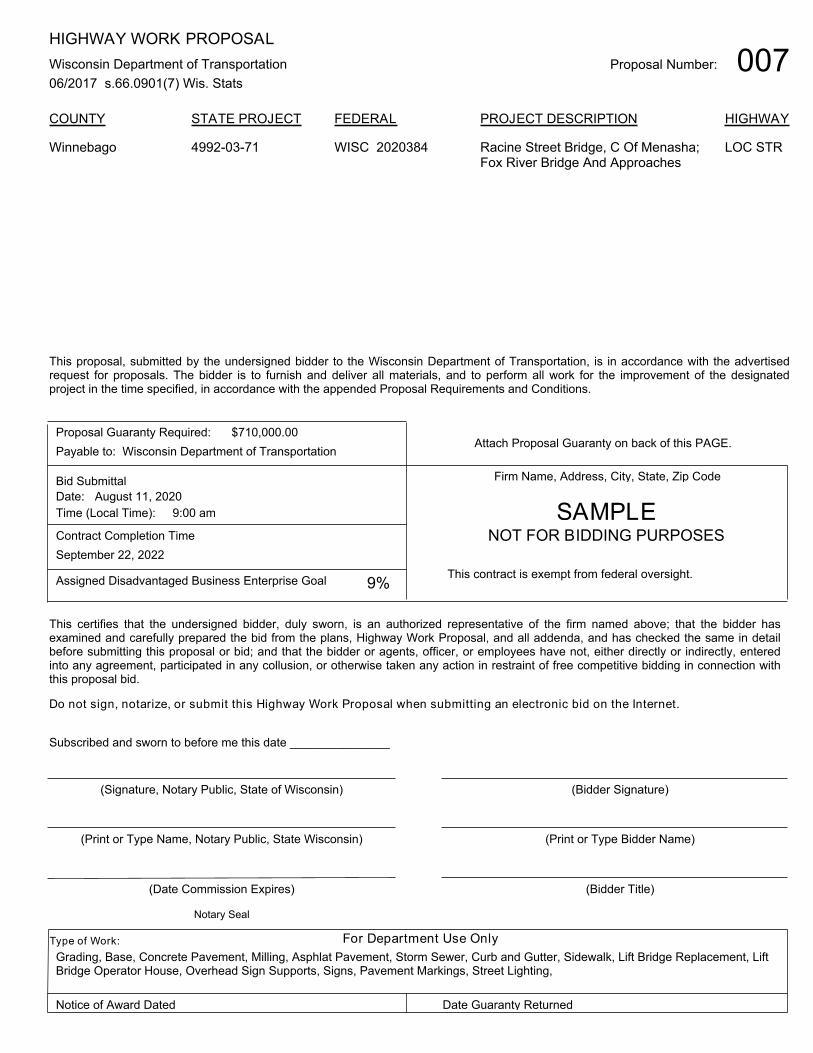
Proposal Number: 007 HIGHWAY WORK PROPOSAL Wisconsin Department of Transportation 06/2017 s.66.0901(7) Wis. Stats COUNTY STATE PROJECT FEDERAL PROJECT DESCRIPTION HIGHWAY 4992-03-71 WISC 2020384 Racine Street Bridge, C Of Menasha; Fox River Bridge And Approaches LOC STR Winnebago This proposal, submitted by the undersigned bidder to the Wisconsin Department of Transportation, is in accordance with the advertised request for proposals. The bidder is to furnish and deliver all materials, and to perform all work for the improvement of the designated project in the time specified, in accordance with the appended Proposal Requirements and Conditions. Proposal Guaranty Required: Payable to: Wisconsin Department of Transportation $710,000.00 Attach Proposal Guaranty on back of this PAGE. Bid Submittal Date: Time (Local Time): August 11, 2020 9:00 am Contract Completion Time September 22, 2022 Assigned Disadvantaged Business Enterprise Goal 9% Firm Name, Address, City, State, Zip Code This contract is exempt from federal oversight. This certifies that the undersigned bidder, duly sworn, is an authorized representative of the firm named above; that the bidder has examined and carefully prepared the bid from the plans, Highway Work Proposal, and all addenda, and has checked the same in detail before submitting this proposal or bid; and that the bidder or agents, officer, or employees have not, either directly or indirectly, entered into any agreement, participated in any collusion, or otherwise taken any action in restraint of free competitive bidding in connection with this proposal bid. Do not sign, notarize, or submit this Highway Work Proposal when submitting an electronic bid on the Internet. Subscribed and sworn to before me this date _______________ (Signature, Notary Public, State of Wisconsin) (Print or Type Name, Notary Public, State Wisconsin) (Date Commission Expires) (Bidder Signature) (Print or Type Bidder Name) (Bidder Title) For Department Use Only Type of Work: Notice of Award Dated Date Guaranty Returned Notary Seal SAMPLE NOT FOR BIDDING PURPOSES Grading, Base, Concrete Pavement, Milling, Asphlat Pavement, Storm Sewer, Curb and Gutter, Sidewalk, Lift Bridge Replacement, Lift Bridge Operator House, Overhead Sign Supports, Signs, Pavement Markings, Street Lighting,
-
Upload
khangminh22 -
Category
Documents
-
view
1 -
download
0
Transcript of ADDENDUM REQUIRED - Wisconsin Department of ...
Proposal Number: 007HIGHWAY WORK PROPOSAL
Wisconsin Department of Transportation
06/2017 s.66.0901(7) Wis. Stats
COUNTY STATE PROJECT FEDERAL PROJECT DESCRIPTION HIGHWAY
4992-03-71 WISC 2020384 Racine Street Bridge, C Of Menasha;Fox River Bridge And Approaches
LOC STRWinnebago
This proposal, submitted by the undersigned bidder to the Wisconsin Department of Transportation, is in accordance with the advertisedrequest for proposals. The bidder is to furnish and deliver all materials, and to perform all work for the improvement of the designatedproject in the time specified, in accordance with the appended Proposal Requirements and Conditions.
Proposal Guaranty Required:
Payable to: Wisconsin Department of Transportation
$710,000.00Attach Proposal Guaranty on back of this PAGE.
Bid Submittal
Date:
Time (Local Time):
August 11, 2020
9:00 am
Contract Completion Time
September 22, 2022
Assigned Disadvantaged Business Enterprise Goal 9%
Firm Name, Address, City, State, Zip Code
This contract is exempt from federal oversight.
This certifies that the undersigned bidder, duly sworn, is an authorized representative of the firm named above; that the bidder hasexamined and carefully prepared the bid from the plans, Highway Work Proposal, and all addenda, and has checked the same in detailbefore submitting this proposal or bid; and that the bidder or agents, officer, or employees have not, either directly or indirectly, enteredinto any agreement, participated in any collusion, or otherwise taken any action in restraint of free competitive bidding in connection withthis proposal bid.
Do not sign, notarize, or submit this Highway Work Proposal when submitting an electronic bid on the Internet.
Subscribed and sworn to before me this date _______________
(Signature, Notary Public, State of Wisconsin)
(Print or Type Name, Notary Public, State Wisconsin)
(Date Commission Expires)
(Bidder Signature)
(Print or Type Bidder Name)
(Bidder Title)
For Department Use OnlyType of Work:
Notice of Award Dated Date Guaranty Returned
Notary Seal
SAMPLENOT FOR BIDDING PURPOSES
Grading, Base, Concrete Pavement, Milling, Asphlat Pavement, Storm Sewer, Curb and Gutter, Sidewalk, Lift Bridge Replacement, LiftBridge Operator House, Overhead Sign Supports, Signs, Pavement Markings, Street Lighting,
DOTMPC
Addendum

PLEASE ATTACH PROPOSAL GUARANTY HERE

1 of 2
Effective with November 2007 Letting
PROPOSAL REQUIREMENTS AND CONDITIONS
The bidder, signing and submitting this proposal, agrees and declares as a condition thereof, to be bound by the following conditions and requirements.
If the bidder has a corporate relationship with the proposal design engineering company, the bidder declares that it did not obtain any facts, data, or other information related to this proposal from the design engineering company that was not available to all bidders.
The bidder declares that they have carefully examined the site of, and the proposal, plans, specifications and contract forms for the work contemplated, and it is assumed that the bidder has investigated and is satisfied as to the conditions to be encountered, as to the character, quality, and quantities of work to be performed and materials to be furnished, and as to the requirements of the specifications, special provisions and contract. It is mutually agreed that submission of a proposal shall be considered conclusive evidence that the bidder has made such examination.
The bidder submits herewith a proposal guaranty in proper form and amount payable to the party as designated in the advertisement inviting proposals, to be retained by and become the property of the owner of the work in the event the undersigned shall fail to execute the contract and contract bond and return the same to the office of the engineer within fourteen (14) days after having been notified in writing to do so; otherwise to be returned.
The bidder declares that they understand that the estimate of quantities in the attached schedule is approximate only and that the attached quantities may be greater or less in accordance with the specifications.
The bidder agrees to perform the said work, for and in consideration of the payment of the amount becoming due on account of work performed, according to the unit prices bid in the following schedule, and to accept such amounts in full payment of said work.
The bidder declares that all of the said work will be performed at their own proper cost and expense, that they will furnish all necessary materials, labor, tools, machinery, apparatus, and other means of construction in the manner provided in the applicable specifications and the approved plans for the work together with all standard and special designs that may be designed on such plans, and the special provisions in the contract of which this proposal will become a part, if and when accepted. The bidder further agrees that the applicable specifications and all plans and working drawings are made a part hereof, as fully and completely as if attached hereto.
The bidder, if awarded the contract, agrees to begin the work not later than ten (10) days after the date of written notification from the engineer to do so, unless otherwise stipulated in the special provisions.

2 of 2
The bidder declares that if they are awarded the contract, they will execute the contract agreement and begin and complete the work within the time named herein, and they will file a good and sufficient surety bond for the amount of the contract for performance and also for the full amount of the contract for payment. The bidder, if awarded the contract, shall pay all claims as required by Section 779.14, Statutes of Wisconsin, and shall be subject to and discharge all liabilities for injuries pursuant to Chapter 102 of the Statutes of Wisconsin, and all acts amendatory thereto. They shall further be responsible for any damages to property or injury to persons occurring through their own negligence or that of their employees or agents, incident to the performance of work under this contract, pursuant to the Standard Specifications for Road and Bridge Construction applicable to this contract. In connection with the performance of work under this contract, the contractor agrees to comply with all applicable state and federal statutes relating to non-discrimination in employment. No otherwise qualified person shall be excluded from employment or otherwise be subject to discrimination in employment in any manner on the basis of age, race, religion, color, gender, national origin or ancestry, disability, arrest or conviction record (in keeping with s.111.32), sexual orientation, marital status, membership in the military reserve, honesty testing, genetic testing, and outside use of lawful products. This provision shall include, but not be limited to the following: employment, upgrading, demotion or transfer; recruitment or recruitment advertising; layoff or termination; rates of pay or other forms of compensation, and selection for training, including apprenticeship. The contractor further agrees to ensure equal opportunity in employment to all applicants and employees and to take affirmative action to attain a representative workforce. The contractor agrees to post notices and posters setting forth the provisions of the nondiscrimination clause, in a conspicuous and easily accessible place, available for employees and applicants for employment. If a state public official (section 19.42, Stats.) or an organization in which a state public official holds at least a 10% interest is a party to this agreement, this contract is voidable by the state unless appropriate disclosure is made to the State of Wisconsin Ethics Board.
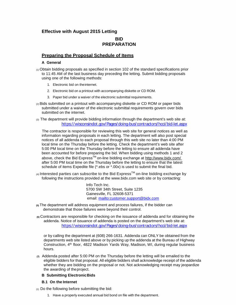
Effective with August 2015 Letting
BID PREPARATION
Preparing the Proposal Schedule of Items
A General
(1) Obtain bidding proposals as specified in section 102 of the standard specifications priorto 11:45 AM of the last business day preceding the letting. Submit bidding proposalsusing one of the following methods:
1. Electronic bid on the internet.
2. Electronic bid on a printout with accompanying diskette or CD ROM.
3. Paper bid under a waiver of the electronic submittal requirements.
(2) Bids submitted on a printout with accompanying diskette or CD ROM or paper bidssubmitted under a waiver of the electronic submittal requirements govern over bidssubmitted on the internet.
(3) The department will provide bidding information through the department’s web site at:https://wisconsindot.gov/Pages/doing-bus/contractors/hcci/bid-let.aspx
The contractor is responsible for reviewing this web site for general notices as well as information regarding proposals in each letting. The department will also post special notices of all addenda to each proposal through this web site no later than 4:00 PM local time on the Thursday before the letting. Check the department’s web site after 5:00 PM local time on the Thursday before the letting to ensure all addenda have been accounted for before preparing the bid. When bidding using methods 1 and 2 above, check the Bid ExpressTM on-line bidding exchange at http://www.bidx.com/ after 5:00 PM local time on the Thursday before the letting to ensure that the latest schedule of items Expedite file (*.ebs or *.00x) is used to submit the final bid.
(4) Interested parties can subscribe to the Bid ExpressTM on-line bidding exchange byfollowing the instructions provided at the www.bidx.com web site or by contacting:
Info Tech Inc. 5700 SW 34th Street, Suite 1235 Gainesville, FL 32608-5371 email: mailto:[email protected]
(5) The department will address equipment and process failures, if the bidder candemonstrate that those failures were beyond their control.
(6) Contractors are responsible for checking on the issuance of addenda and for obtaining theaddenda. Notice of issuance of addenda is posted on the department’s web site at:
https://wisconsindot.gov/Pages/doing-bus/contractors/hcci/bid-let.aspx
or by calling the department at (608) 266-1631. Addenda can ONLY be obtained from the departments web site listed above or by picking up the addenda at the Bureau of Highway Construction, 4th floor, 4822 Madison Yards Way, Madison, WI, during regular business hours.
(7) Addenda posted after 5:00 PM on the Thursday before the letting will be emailed to theeligible bidders for that proposal. All eligible bidders shall acknowledge receipt of the addendawhether they are bidding on the proposal or not. Not acknowledging receipt may jeopardizethe awarding of the project.
B Submitting Electronic Bids
B.1 On the Internet
(1) Do the following before submitting the bid:
1. Have a properly executed annual bid bond on file with the department.
2. Have a digital ID on file with and enabled by Info Tech Inc. Using this digital ID will constitute the bidder's signature for proper execution of the bidding proposal.
(2) In lieu of preparing, delivering, and submitting the proposal as specified in 102.6 and 102.9 of the standard specifications, submit the proposal on the internet as follows:
1. Download the latest schedule of items reflecting all addenda from the Bid ExpressTM web site.
2. Use ExpediteTM
software to enter a unit price for every item in the schedule of items.
3. Submit the bid according to the requirements of ExpediteTM
software and the Bid
ExpressTM
web site. Do not submit a bid on a printout with accompanying diskette or CD ROM or a paper bid. If the bidder does submit a bid on a printout with accompanying diskette or a paper bid in addition to the internet submittal, the department will disregard the internet bid.
4. Submit the bid before the hour and date the Notice to Contractors designates.
5. Do not sign, notarize, and return the bidding proposal described in 102.2 of the standard specifications.
(3) The department will not consider the bid accepted until the hour and date the Notice to Contractors designates.
B.2 On a Printout with Accompanying Diskette or CD ROM
(1) Download the latest schedule of items from the Wisconsin pages of the Bid ExpressTM web site reflecting the latest addenda posted on the department’s web site at:
https://wisconsindot.gov/Pages/doing-bus/contractors/hcci/bid-let.aspx
Use Expedite TM software to prepare and print the schedule of items. Provide a valid amount for all price fields. Follow instructions and review the help screens provided on the Bid ExpressTM web site to assure that the schedule of items is prepared properly.
(2) Staple an 8 1/2 by 11 inch printout of the ExpediteTM generated schedule of items to the other proposal documents submitted to the department as a part of the bidder's sealed bid. As a separate submittal, not in the sealed bid envelop but due at the same time and place as the sealed bid, also provide the ExpediteTM generated schedule of items on a 3 1/2 inch computer diskette or CD ROM. Label each diskette or CD ROM with the bidder's name, the 4 character department-assigned bidder identification code from the top of the bidding proposal, and a list of the proposal numbers included on that diskette or CD ROM as indicated in the following example:
Bidder Name
BN00
Proposals: 1, 12, 14, & 22
(3) If bidding on more than one proposal in the letting, the bidder may include all proposals for that letting on one diskette or CD ROM. Include only submitted proposals with no incomplete or other files on the diskette or CD ROM.
(4) The bidder-submitted printout of the ExpediteTM generated schedule of items is the governing contract document and must conform to the requirements of section 102 of the standard specifications. If a printout needs to be altered, cross out the printed information with ink or typewriter and enter the new information and initial it in ink. If there is a discrepancy between the printout and the diskette or CD ROM, the department will analyze the bid using the printout information.
(5) In addition to the reasons specified in section 102 of the standard specifications, proposals are irregular and the department may reject them for one or more of the following:
1. The check code printed on the bottom of the printout of the ExpediteTM
generated schedule of items is not the same on each page.
2. The check code printed on the printout of the ExpediteTM
generated schedule of items is not the same as the check code for that proposal provided on the diskette or CD ROM.

3. The diskette or CD ROM is not submitted at the time and place the department designates.
C Waiver of Electronic Submittal
(1) The bidder may request a waiver of the electronic submittal requirements. Submit a written request for a waiver in lieu of bids submitted on the internet or on a printout with accompanying diskette or CD ROM. Use the waiver that was included with the paper bid document sent to the bidder or type up a waiver on the bidder’s letterhead. The department will waive the electronic submittal requirements for a bidding entity (individual, partnership, joint venture, corporation, or limited liability company) for up to 4 individual proposals in a calendar year. The department may allow additional waivers for equipment malfunctions.
(2) Submit a schedule of items on paper conforming to section 102 of the standard specifications. The department charges the bidder a $75 administrative fee per proposal, payable at the time and place the department designates for receiving bids, to cover the costs of data entry. The department will accept a check or money order payable to: "Wisconsin, Dept. of Transportation."
(3) In addition to the reasons specified in section 102 of the standard specifications, proposals are irregular and the department may reject them for one or more of the following:
1. The bidder fails to provide the written request for waiver of the electronic submittal requirements.
2. The bidder fails to pay the $75 administrative fee before the time the department designates for the opening of bids unless the bidder requests on the waiver that they be billed for the $75.
3. The bidder exceeds 4 waivers of electronic submittal requirements within a calendar year.
(4) In addition to the reasons specified in section 102 of the standard specifications, the department may refuse to issue bidding proposals for future contracts to a bidding entity that owes the department administrative fees for a waiver of electronic submittal requirements.

PROPOSAL BID BOND Wisconsin Department of Transportation DT1303 1/2006
Proposal Number Project Number Letting Date
Name of Principal
Name of Surety State in Which Surety is Organized
We, the above-named Principal and the above-named Surety, are held and firmly bound unto the State of Wisconsin in the sum equal to the Proposal Guaranty for the total bid submitted for the payment to be made; we jointly and severally bind ourselves, our heirs, executors, administrators, successors and assigns. The condition of this obligation is that the Principal has submitted a bid proposal to the State of Wisconsin acting through the Department of Transportation for the improvement designated by the Proposal Number and Letting Date indicated above. If the Principal is awarded the contract and, within the time and manner required by law after the prescribed forms are presented for signature, enters into a written contract in accordance with the bid, and files the bond with the Department of Transportation to guarantee faithful performance and payment for labor and materials, as required by law, or if the Department of Transportation shall reject all bids for the work described, then this obligation shall be null and void; otherwise, it shall be and remain in full force and effect. In the event of failure of the Principal to enter into the contract or give the specified bond, the Principal shall pay to the Department of Transportation within 10 business days of demand a total equal to the Proposal Guaranty as liquidated damages; the liability of the Surety continues for the full amount of the obligation as stated until the obligation is paid in full. The Surety, for value received, agrees that the obligations of it and its bond shall not be impaired or affected by any extension of time within which the Department of Transportation may accept the bid; and the Surety does waive notice of any such extension. IN WITNESS, the Principal and Surety have agreed and have signed by their proper officers and have caused their corporate seals to be affixed this date: (DATE MUST BE ENTERED)
PRINCIPAL
(Company Name) (Affix Corporate Seal)
(Signature and Title)
(Company Name)
(Signature and Title)
(Company Name)
(Signature and Title)
(Company Name)
(Signature and Title)
NOTARY FOR PRINCIPAL
(Date)
State of Wisconsin )
) ss. County )
On the above date, this instrument was acknowledged before me by thenamed person(s).
(Signature, Notary Public, State of Wisconsin)
(Print or Type Name, Notary Public, State of Wisconsin)
(Date Commission Expires)
Notary Seal
(Name of Surety) (Affix Seal)
(Signature of Attorney-in-Fact)
NOTARY FOR SURETY
(Date)
State of Wisconsin )
) ss. County )
On the above date, this instrument was acknowledged before me by thenamed person(s).
(Signature, Notary Public, State of Wisconsin)
(Print or Type Name, Notary Public, State of Wisconsin)
(Date Commission Expires)
Notary Seal
IMPORTANT: A certified copy of Power of Attorney of the signatory agent must be attached to the bid bond.

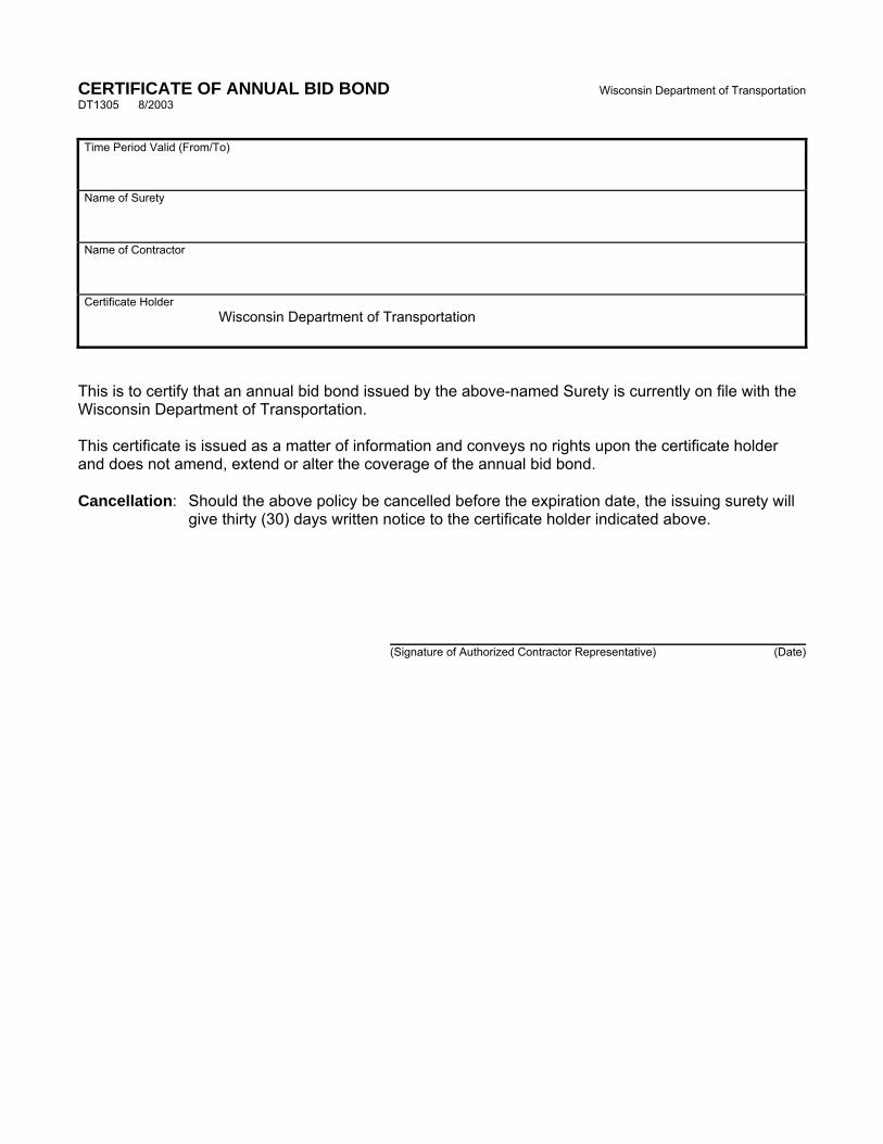
CERTIFICATE OF ANNUAL BID BOND Wisconsin Department of Transportation DT1305 8/2003
Time Period Valid (From/To)
Name of Surety
Name of Contractor
Certificate Holder
Wisconsin Department of Transportation
This is to certify that an annual bid bond issued by the above-named Surety is currently on file with the Wisconsin Department of Transportation.
This certificate is issued as a matter of information and conveys no rights upon the certificate holder and does not amend, extend or alter the coverage of the annual bid bond.
Cancellation: Should the above policy be cancelled before the expiration date, the issuing surety will give thirty (30) days written notice to the certificate holder indicated above.
(Signature of Authorized Contractor Representative) (Date)

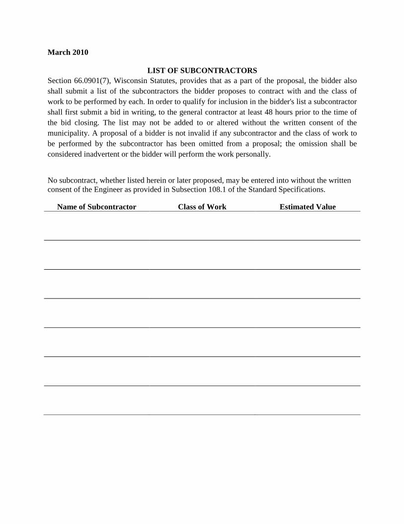
March 2010
LIST OF SUBCONTRACTORSSection 66.0901(7), Wisconsin Statutes, provides that as a part of the proposal, the bidder also shall submit a list of the subcontractors the bidder proposes to contract with and the class of work to be performed by each. In order to qualify for inclusion in the bidder's list a subcontractor shall first submit a bid in writing, to the general contractor at least 48 hours prior to the time of the bid closing. The list may not be added to or altered without the written consent of the municipality. A proposal of a bidder is not invalid if any subcontractor and the class of work to be performed by the subcontractor has been omitted from a proposal; the omission shall be considered inadvertent or the bidder will perform the work personally.
No subcontract, whether listed herein or later proposed, may be entered into without the written consent of the Engineer as provided in Subsection 108.1 of the Standard Specifications.
Name of Subcontractor Class of Work Estimated Value
Page 1 of 2
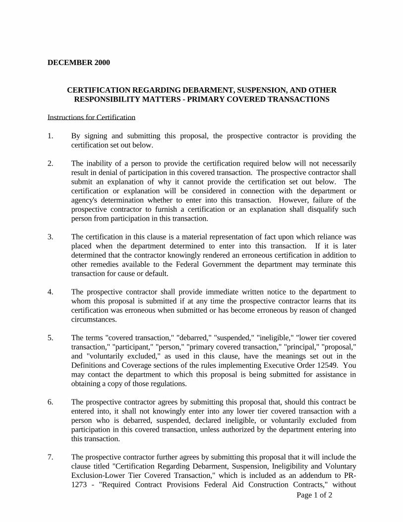
DECEMBER 2000
CERTIFICATION REGARDING DEBARMENT, SUSPENSION, AND OTHER RESPONSIBILITY MATTERS - PRIMARY COVERED TRANSACTIONS
Instructions for Certification
1. By signing and submitting this proposal, the prospective contractor is providing thecertification set out below.
2. The inability of a person to provide the certification required below will not necessarilyresult in denial of participation in this covered transaction. The prospective contractor shallsubmit an explanation of why it cannot provide the certification set out below. Thecertification or explanation will be considered in connection with the department oragency's determination whether to enter into this transaction. However, failure of theprospective contractor to furnish a certification or an explanation shall disqualify suchperson from participation in this transaction.
3. The certification in this clause is a material representation of fact upon which reliance wasplaced when the department determined to enter into this transaction. If it is laterdetermined that the contractor knowingly rendered an erroneous certification in addition toother remedies available to the Federal Government the department may terminate thistransaction for cause or default.
4. The prospective contractor shall provide immediate written notice to the department towhom this proposal is submitted if at any time the prospective contractor learns that itscertification was erroneous when submitted or has become erroneous by reason of changedcircumstances.
5. The terms "covered transaction," "debarred," "suspended," "ineligible," "lower tier coveredtransaction," "participant," "person," "primary covered transaction," "principal," "proposal,"and "voluntarily excluded," as used in this clause, have the meanings set out in theDefinitions and Coverage sections of the rules implementing Executive Order 12549. Youmay contact the department to which this proposal is being submitted for assistance inobtaining a copy of those regulations.
6. The prospective contractor agrees by submitting this proposal that, should this contract beentered into, it shall not knowingly enter into any lower tier covered transaction with aperson who is debarred, suspended, declared ineligible, or voluntarily excluded fromparticipation in this covered transaction, unless authorized by the department entering intothis transaction.
7. The prospective contractor further agrees by submitting this proposal that it will include theclause titled "Certification Regarding Debarment, Suspension, Ineligibility and VoluntaryExclusion-Lower Tier Covered Transaction," which is included as an addendum to PR-1273 - "Required Contract Provisions Federal Aid Construction Contracts," without
Page 2 of 2
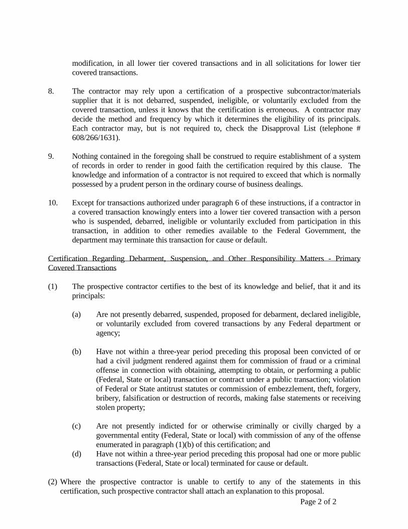
modification, in all lower tier covered transactions and in all solicitations for lower tier covered transactions.
8. The contractor may rely upon a certification of a prospective subcontractor/materials
supplier that it is not debarred, suspended, ineligible, or voluntarily excluded from the covered transaction, unless it knows that the certification is erroneous. A contractor may decide the method and frequency by which it determines the eligibility of its principals. Each contractor may, but is not required to, check the Disapproval List (telephone # 608/266/1631).
9. Nothing contained in the foregoing shall be construed to require establishment of a system
of records in order to render in good faith the certification required by this clause. The knowledge and information of a contractor is not required to exceed that which is normally possessed by a prudent person in the ordinary course of business dealings.
10. Except for transactions authorized under paragraph 6 of these instructions, if a contractor in
a covered transaction knowingly enters into a lower tier covered transaction with a person who is suspended, debarred, ineligible or voluntarily excluded from participation in this transaction, in addition to other remedies available to the Federal Government, the department may terminate this transaction for cause or default.
Certification Regarding Debarment, Suspension, and Other Responsibility Matters - Primary Covered Transactions (1) The prospective contractor certifies to the best of its knowledge and belief, that it and its
principals: (a) Are not presently debarred, suspended, proposed for debarment, declared ineligible,
or voluntarily excluded from covered transactions by any Federal department or agency;
(b) Have not within a three-year period preceding this proposal been convicted of or
had a civil judgment rendered against them for commission of fraud or a criminal offense in connection with obtaining, attempting to obtain, or performing a public (Federal, State or local) transaction or contract under a public transaction; violation of Federal or State antitrust statutes or commission of embezzlement, theft, forgery, bribery, falsification or destruction of records, making false statements or receiving stolen property;
(c) Are not presently indicted for or otherwise criminally or civilly charged by a
governmental entity (Federal, State or local) with commission of any of the offense enumerated in paragraph (1)(b) of this certification; and
(d) Have not within a three-year period preceding this proposal had one or more public transactions (Federal, State or local) terminated for cause or default.
(2) Where the prospective contractor is unable to certify to any of the statements in this
certification, such prospective contractor shall attach an explanation to this proposal.
4992-03-71 1 of 293
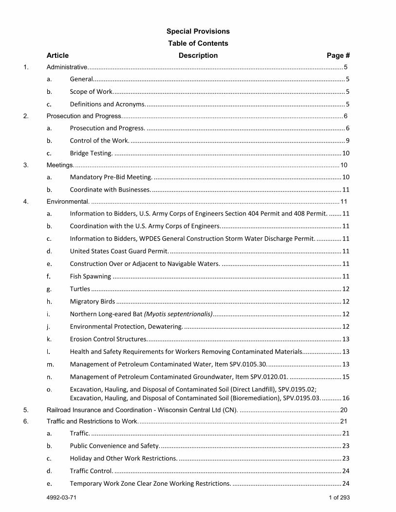
Special Provisions Table of Contents
Article Description Page # 1. Administrative. .............................................................................................................................................. 5
General. ............................................................................................................................................ 5
Scope of Work. ................................................................................................................................. 5
Definitions and Acronyms. ............................................................................................................... 5
2. Prosecution and Progress. ........................................................................................................................... 6
Prosecution and Progress. ............................................................................................................... 6
Control of the Work. ........................................................................................................................ 9
Bridge Testing. ............................................................................................................................... 10
3. Meetings. .................................................................................................................................................... 10
Mandatory Pre-Bid Meeting. ......................................................................................................... 10
Coordinate with Businesses. .......................................................................................................... 11
4. Environmental. ........................................................................................................................................... 11
Information to Bidders, U.S. Army Corps of Engineers Section 404 Permit and 408 Permit. ....... 11
Coordination with the U.S. Army Corps of Engineers. ................................................................... 11
Information to Bidders, WPDES General Construction Storm Water Discharge Permit. .............. 11
United States Coast Guard Permit. ................................................................................................ 11
Construction Over or Adjacent to Navigable Waters. ................................................................... 11
Fish Spawning ................................................................................................................................ 11
Turtles ............................................................................................................................................ 12
Migratory Birds .............................................................................................................................. 12
Northern Long-eared Bat (Myotis septentrionalis) ........................................................................ 12
Environmental Protection, Dewatering. ........................................................................................ 12
Erosion Control Structures. ............................................................................................................ 13
Health and Safety Requirements for Workers Removing Contaminated Materials...................... 13
Management of Petroleum Contaminated Water, Item SPV.0105.30. ......................................... 13
Management of Petroleum Contaminated Groundwater, Item SPV.0120.01. ............................. 15
Excavation, Hauling, and Disposal of Contaminated Soil (Direct Landfill), SPV.0195.02; Excavation, Hauling, and Disposal of Contaminated Soil (Bioremediation), SPV.0195.03. ........... 16
5. Railroad Insurance and Coordination - Wisconsin Central Ltd (CN). ........................................................ 20
6. Traffic and Restrictions to Work. ................................................................................................................ 21
Traffic. ............................................................................................................................................ 21
Public Convenience and Safety. ..................................................................................................... 23
Holiday and Other Work Restrictions. ........................................................................................... 23
Traffic Control. ............................................................................................................................... 24
Temporary Work Zone Clear Zone Working Restrictions. ............................................................. 24
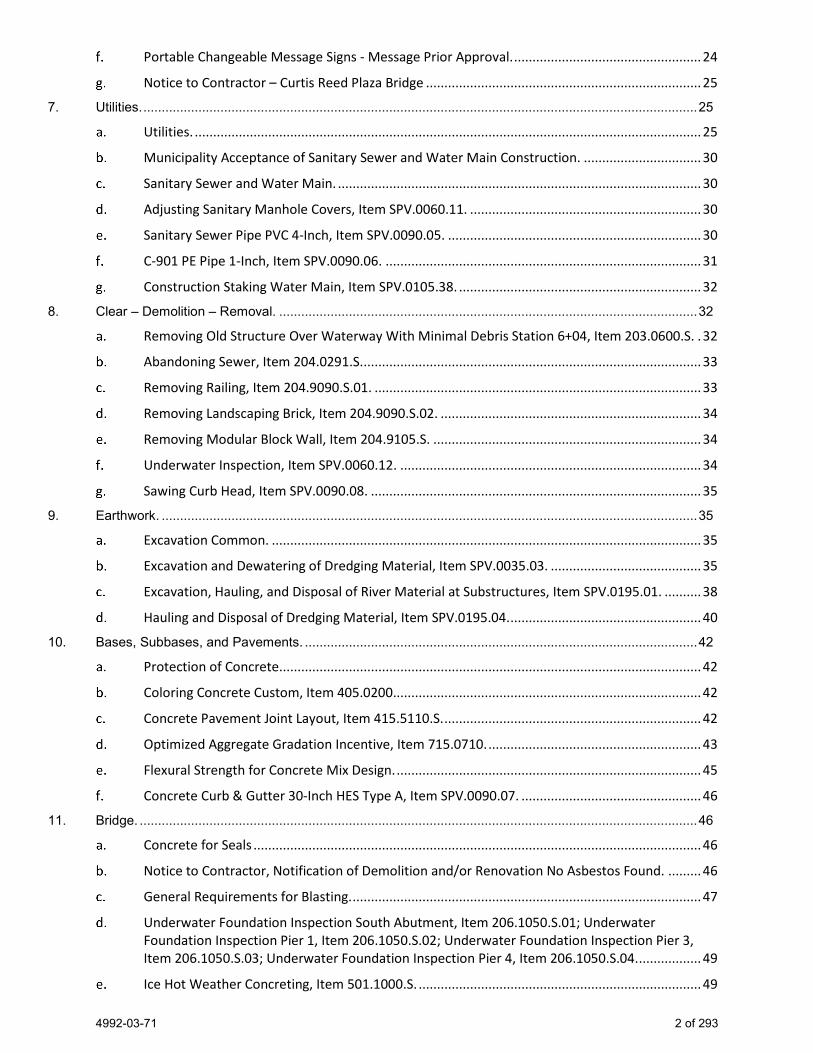
4992-03-71 2 of 293
Portable Changeable Message Signs - Message Prior Approval. ................................................... 24
Notice to Contractor – Curtis Reed Plaza Bridge ........................................................................... 25
7. Utilities. ....................................................................................................................................................... 25
Utilities. .......................................................................................................................................... 25
Municipality Acceptance of Sanitary Sewer and Water Main Construction. ................................ 30
Sanitary Sewer and Water Main. ................................................................................................... 30
Adjusting Sanitary Manhole Covers, Item SPV.0060.11. ............................................................... 30
Sanitary Sewer Pipe PVC 4-Inch, Item SPV.0090.05. ..................................................................... 30
C-901 PE Pipe 1-Inch, Item SPV.0090.06. ...................................................................................... 31
Construction Staking Water Main, Item SPV.0105.38. .................................................................. 32
8. Clear – Demolition – Removal. .................................................................................................................. 32
Removing Old Structure Over Waterway With Minimal Debris Station 6+04, Item 203.0600.S. . 32
Abandoning Sewer, Item 204.0291.S. ............................................................................................ 33
Removing Railing, Item 204.9090.S.01. ......................................................................................... 33
Removing Landscaping Brick, Item 204.9090.S.02. ....................................................................... 34
Removing Modular Block Wall, Item 204.9105.S. ......................................................................... 34
Underwater Inspection, Item SPV.0060.12. .................................................................................. 34
Sawing Curb Head, Item SPV.0090.08. .......................................................................................... 35
9. Earthwork. .................................................................................................................................................. 35
Excavation Common. ..................................................................................................................... 35
Excavation and Dewatering of Dredging Material, Item SPV.0035.03. ......................................... 35
Excavation, Hauling, and Disposal of River Material at Substructures, Item SPV.0195.01. .......... 38
Hauling and Disposal of Dredging Material, Item SPV.0195.04. .................................................... 40
10. Bases, Subbases, and Pavements. ........................................................................................................... 42
Protection of Concrete. .................................................................................................................. 42
Coloring Concrete Custom, Item 405.0200.................................................................................... 42
Concrete Pavement Joint Layout, Item 415.5110.S. ...................................................................... 42
Optimized Aggregate Gradation Incentive, Item 715.0710. .......................................................... 43
Flexural Strength for Concrete Mix Design. ................................................................................... 45
Concrete Curb & Gutter 30-Inch HES Type A, Item SPV.0090.07. ................................................. 46
11. Bridge. ........................................................................................................................................................ 46
Concrete for Seals .......................................................................................................................... 46
Notice to Contractor, Notification of Demolition and/or Renovation No Asbestos Found. ......... 46
General Requirements for Blasting. ............................................................................................... 47
Underwater Foundation Inspection South Abutment, Item 206.1050.S.01; Underwater Foundation Inspection Pier 1, Item 206.1050.S.02; Underwater Foundation Inspection Pier 3, Item 206.1050.S.03; Underwater Foundation Inspection Pier 4, Item 206.1050.S.04. ................. 49
Ice Hot Weather Concreting, Item 501.1000.S. ............................................................................. 49
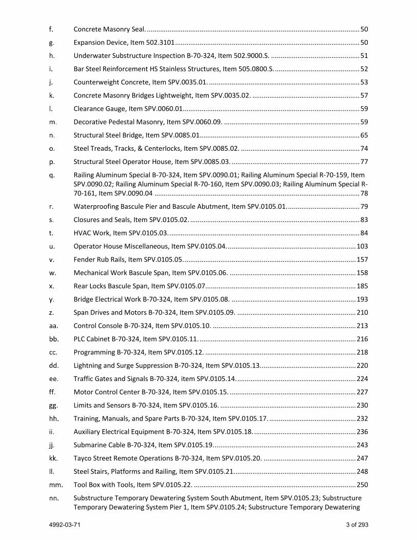
4992-03-71 3 of 293
Concrete Masonry Seal. ................................................................................................................. 50
Expansion Device, Item 502.3101 .................................................................................................. 50
Underwater Substructure Inspection B-70-324, Item 502.9000.S. ............................................... 51
Bar Steel Reinforcement HS Stainless Structures, Item 505.0800.S. ............................................. 52
Counterweight Concrete, Item SPV.0035.01. ................................................................................ 53
Concrete Masonry Bridges Lightweight, Item SPV.0035.02. ......................................................... 57
Clearance Gauge, Item SPV.0060.01.............................................................................................. 59
Decorative Pedestal Masonry, Item SPV.0060.09. ........................................................................ 59
Structural Steel Bridge, Item SPV.0085.01..................................................................................... 65
Steel Treads, Tracks, & Centerlocks, Item SPV.0085.02. ............................................................... 74
Structural Steel Operator House, Item SPV.0085.03. .................................................................... 77
Railing Aluminum Special B-70-324, Item SPV.0090.01; Railing Aluminum Special R-70-159, Item SPV.0090.02; Railing Aluminum Special R-70-160, Item SPV.0090.03; Railing Aluminum Special R-70-161, Item SPV.0090.04 ............................................................................................................. 78
Waterproofing Bascule Pier and Bascule Abutment, Item SPV.0105.01. ...................................... 79
Closures and Seals, Item SPV.0105.02. .......................................................................................... 83
HVAC Work, Item SPV.0105.03. ..................................................................................................... 84
Operator House Miscellaneous, Item SPV.0105.04. .................................................................... 103
Fender Rub Rails, Item SPV.0105.05. ........................................................................................... 157
Mechanical Work Bascule Span, Item SPV.0105.06. ................................................................... 158
Rear Locks Bascule Span, Item SPV.0105.07. ............................................................................... 185
Bridge Electrical Work B-70-324, Item SPV.0105.08. .................................................................. 193
Span Drives and Motors B-70-324, Item SPV.0105.09. ............................................................... 210
Control Console B-70-324, Item SPV.0105.10. ............................................................................ 213
PLC Cabinet B-70-324, Item SPV.0105.11. ................................................................................... 216
Programming B-70-324, Item SPV.0105.12. ................................................................................ 218
Lightning and Surge Suppression B-70-324, Item SPV.0105.13. .................................................. 220
Traffic Gates and Signals B-70-324, item SPV.0105.14. ............................................................... 224
Motor Control Center B-70-324, Item SPV.0105.15. ................................................................... 227
Limits and Sensors B-70-324, Item SPV.0105.16. ........................................................................ 230
Training, Manuals, and Spare Parts B-70-324, Item SPV.0105.17. .............................................. 232
Auxiliary Electrical Equipment B-70-324, Item SPV.0105.18. ...................................................... 236
Submarine Cable B-70-324, Item SPV.0105.19. ........................................................................... 243
Tayco Street Remote Operations B-70-324, Item SPV.0105.20. ................................................. 247
Steel Stairs, Platforms and Railing, Item SPV.0105.21. ................................................................ 248
Tool Box with Tools, Item SPV.0105.22. ...................................................................................... 250
Substructure Temporary Dewatering System South Abutment, Item SPV.0105.23; Substructure Temporary Dewatering System Pier 1, Item SPV.0105.24; Substructure Temporary Dewatering
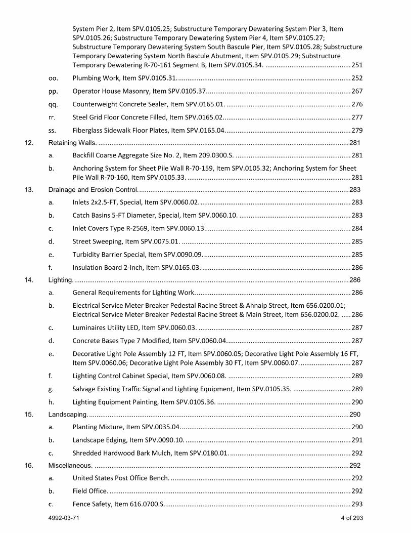
4992-03-71 4 of 293
System Pier 2, Item SPV.0105.25; Substructure Temporary Dewatering System Pier 3, Item SPV.0105.26; Substructure Temporary Dewatering System Pier 4, Item SPV.0105.27; Substructure Temporary Dewatering System South Bascule Pier, Item SPV.0105.28; Substructure Temporary Dewatering System North Bascule Abutment, Item SPV.0105.29; Substructure Temporary Dewatering R-70-161 Segment B, Item SPV.0105.34. .............................................. 251
Plumbing Work, Item SPV.0105.31. ............................................................................................. 252
Operator House Masonry, Item SPV.0105.37. ............................................................................. 267
Counterweight Concrete Sealer, Item SPV.0165.01. ................................................................... 276
Steel Grid Floor Concrete Filled, Item SPV.0165.02..................................................................... 277
Fiberglass Sidewalk Floor Plates, Item SPV.0165.04. ................................................................... 279
12. Retaining Walls. ....................................................................................................................................... 281
Backfill Coarse Aggregate Size No. 2, Item 209.0300.S. .............................................................. 281
Anchoring System for Sheet Pile Wall R-70-159, Item SPV.0105.32; Anchoring System for Sheet Pile Wall R-70-160, Item SPV.0105.33. ........................................................................................ 281
13. Drainage and Erosion Control. ................................................................................................................. 283
Inlets 2x2.5-FT, Special, Item SPV.0060.02. ................................................................................. 283
Catch Basins 5-FT Diameter, Special, Item SPV.0060.10. ............................................................ 283
Inlet Covers Type R-2569, Item SPV.0060.13............................................................................... 284
Street Sweeping, Item SPV.0075.01. ........................................................................................... 285
Turbidity Barrier Special, Item SPV.0090.09. ............................................................................... 285
Insulation Board 2-Inch, Item SPV.0165.03. ................................................................................ 286
14. Lighting. .................................................................................................................................................... 286
General Requirements for Lighting Work. ................................................................................... 286
Electrical Service Meter Breaker Pedestal Racine Street & Ahnaip Street, Item 656.0200.01; Electrical Service Meter Breaker Pedestal Racine Street & Main Street, Item 656.0200.02. ..... 286
Luminaires Utility LED, Item SPV.0060.03. .................................................................................. 287
Concrete Bases Type 7 Modified, Item SPV.0060.04. .................................................................. 287
Decorative Light Pole Assembly 12 FT, Item SPV.0060.05; Decorative Light Pole Assembly 16 FT, Item SPV.0060.06; Decorative Light Pole Assembly 30 FT, Item SPV.0060.07. ........................... 287
Lighting Control Cabinet Special, Item SPV.0060.08. .................................................................. 289
Salvage Existing Traffic Signal and Lighting Equipment, Item SPV.0105.35. ............................... 289
Lighting Equipment Painting, Item SPV.0105.36. ........................................................................ 290
15. Landscaping. ............................................................................................................................................ 290
Planting Mixture, Item SPV.0035.04. ........................................................................................... 290
Landscape Edging, Item SPV.0090.10. ......................................................................................... 291
Shredded Hardwood Bark Mulch, Item SPV.0180.01. ................................................................. 292
16. Miscellaneous. ......................................................................................................................................... 292
United States Post Office Bench. ................................................................................................. 292
Field Office. .................................................................................................................................. 292
Fence Safety, Item 616.0700.S..................................................................................................... 293
4992-03-71 5 of 293
STSP’S Revised November 21, 2019 SPECIAL PROVISIONS
1. Administrative.
General. Perform the work under this construction contract for Project 4992-03-71, Racine Street Bridge, C of Menasha, Fox River Bridge & Approaches, Local Street, Winnebago County, Wisconsin as the plans show and execute the work as specified in the State of Wisconsin, Department of Transportation, Standard Specifications for Highway and Structure Construction, 2020 Edition, as published by the department, and these special provisions.
If all or a portion of the plans and special provisions are developed in the SI metric system and the schedule of prices is developed in the US standard measure system, the department will pay for the work as bid in the US standard system. 100-005 (20191121)
Scope of Work. The work under this contract shall consist of grading, base aggregate dense, select crushed material, concrete pavement, curb and gutter, sidewalk, storm sewer, removal of structure B-70-001, construction of structures B-70-324, R-70-159, R-70-160, R-70-161, and S-70-383, pavement marking, permanent signing, traffic signals, traffic control, restoration and all incidental items necessary to complete the work as shown on the plans and included in the proposal and contract. 104-005 (20090901)
Definitions and Acronyms. A number of acronyms are used in the special provisions. The following list includes most acronyms used:
A Ampere ANSI American National Standards Institute
AMTFT Active Matrix Thin Film Transistor
ASTM American Society for Testing and Materials
AWG American Wire Gauge
BNC Bayonet Nut Coupling
CCTV Closed-circuit Television
CMU Concrete Masonry Unit Gb Gigabyte
GFCI Ground Fault Circuit Interface
dB Decibel dpi Dots Per Inch
DVI Digital Visual Interface
EMT Electrical Metallic Tubing HMI Human Machine Interface (Touchscreen)
HPU Hydraulic Power Unit Hz Hertz
I/O Input/Output
ICEA Insulated Cable Engineers Association
IEEE Institute of Electrical and Electronics Engineers
kip 1,000 pound (force)
4992-03-71 6 of 293
ksi Kips per Square Inch LCD Liquid Crystal Display
LED Light Emitting Diode
LS Limit Switch or Lump Sum (with regard to Payment)
kV Kilovolt kVA Kilovolt-ampere Mb Megabyte
MCC Motor Control Center
mil thousandth of an inch (length) NEC National Electric Code
NEMA National Electrical Manufacturers Association
NFPA National Fire Protection Association
MPH Miles per Hour MTS Manual Transfer Switch NTSC National Television System Committee
o.c. On Center pcf Pounds per Cubic Foot PLC Programmable Logic Controller
PVC Poly Vinyl Chloride
PA Public Address System
PRGS PVC Coated Rigid Galvanized Steel
psf Pounds per Square Foot psi Pounds per Square Inch rpm Revolutions per Minute SCADA Supervisory Control and Data Acquisition
SCTC Submarine Cable Termination Cabinets SXGA Super Extended Graphics Array
UL Underwriters Laboratory
UPS Uninterruptible Power Supply V Volt VAC Volts of Alternating Current
VDC Volts of Direct Current
VGA Video Graphics Array
VRMS Root Mean Squared Voltage
VSD Variable Speed Drive
Other acronyms can be found within the text of the special provisions and on the plans.
2. Prosecution and Progress.
Prosecution and Progress. Begin work within ten calendar days after the engineer issues a written notice to do so.

4992-03-71 7 of 293
Provide the start date to the engineer in writing within a month after executing the contract but at least 14 calendar days before the preconstruction conference. Upon approval, the engineer will issue the notice to proceed within ten calendar days before the approved start date.
To revise the start date, submit a written request to the engineer at least two weeks before the intended start date. The engineer will approve or deny that request based on the conditions cited in the request and its effect on the department’s scheduled resources
Following award of the contract and two weeks prior to the preconstruction conference, submit a detailed schedule of proposed operations for the completion of the work under this contract. Show controlling items in two-week increments from the start of the project to completion.
Manufacturers’ warranties or guarantees on equipment, materials, or products purchased for use on the contract are to be consistent with those provided as customary trade practice, obtained by the contractor, and submitted upon partial acceptance of the contract. The contractor will assign to the department all manufacturers’ warranties or guarantees on all such equipment, material, or products furnished for or installed as part of the work.
Staging Supplemental traffic control for the project consists of three stages described as follows: Items listed below are not limited to, but only highlight construction activities, that are subject to interim completion dates, liquidated damages, or penalties. Perform work as outlined in the following stages:
Stage 1 – Fall 2020 to Fall 2021
− Begin B-70-324 bascule pier, bascule abutment, and spans 5 and 6.
− Begin R-70-159 and R-70-160.
Stage 2 – Fall 2021 to Summer 2022
− Continue B-70-324 and begin spans 1 through 4.
− Continue R-70-159/160 and begin R-70-161.
− Do not start Stage 2 work prior to September 1, 2021 unless otherwise allowed by the engineer.
Stage 3 – Summer 2022
− Continue and complete B-70-324, R-70-159/160/161.
− Begin and complete all roadway reconstructions and open all roadways to traffic. This work includes all final pavement, sidewalk, curb and gutter, pavement marking, lighting, signing, landscaping, and all finishing items.
− Do not start Stage 3 work prior to June 6, 2022 unless otherwise allowed by the engineer.
Stage 4 - Fall 2022
− Allow 30-days for break-in period for work completed after Partial Acceptance, but before Substantially Complete.
− Work required includes any final adjustments to the bridge and its systems for proper operation.
Enhanced Liquidated Damages Replace standard spec 108.11 paragraph (3) as follows:
The department will assess $6000 in daily liquidated damages. These liquidated damages reflect the cost of engineering, supervision, and a portion of road user costs.
Interim Completion Date – August 24, 2022 Complete all work in Stage 3 within 80 consecutive calendar days and no later than August 24, 2022. This includes all road work from the closure of Racine Street/Main Street and Racine Street/Ahnaip Street intersections to opening the Racine Street roundabouts to traffic and obtaining partial acceptance of the Racine Street bridge.

4992-03-71 8 of 293
Supplement standard spec 108.11 as follows:
If all work required for partial acceptance as described in the article “Control of the Work” is not completed, the department will assess the contractor $6,000 in interim liquidated damages for each calendar day the contract work remains incomplete beyond 80 consecutive calendar days or August 24, 2022. An entire calendar day will be charged for any period of time within a calendar day that the requirements have not been met beyond 12:01 AM.
Replace standard spec 108.10.2.2(1) with the following:
(1) The engineer will award a time extension for severe weather on calendar day and completion date contracts. Submit a request for severe weather days if the number of adverse weather days, as defined in standard spec 101.3, exceeds the anticipated number of adverse weather days tabulated below.
Total Anticipated Adverse Weather Days for Each Calendar Month
Jan 7 July 5
Feb 7 Aug 5
Mar 7 Sept 5
April 6 Oct 6
May 5 Nov 7
June 5 Dec 7
United States Coast Guard Coordinate with the United States Coast Guard (USCG) Cleveland, Ohio Division 30 days prior to dates where the bascule span will remain inoperable. Coordination must include contingency days in the event of weather delays. An approval letter from USCG must be received before work commences.
USCG Contact: Blair Stanifer Bridge Management Specialist Bridge Administration Branch (Room 2047) US Coast Guard 1240 East 9th Street Cleveland, OH 44199
Additionally, the contractor will be responsible for any and all fines placed against the department by the United States Coast Guard for not meeting waterway navigation requirements as provided in the article “Construction Over or Adjacent to Navigable Waters.”
Winter Maintenance Snow may be plowed from the traveled roadway into the work site by the maintaining authority. The contractor is responsible for any snow removal from the work site that may be required to continue work operations.
The contractor is responsible for plowing any areas which may need to be cleared of snow or ice to accommodate changes in traffic control and to facilitate construction staging during winter months. Winnebago County or the local maintaining authority will not provide snow plowing operations in areas outside of the active traveled lanes.
Re-install or adjust any traffic control devices that may be damaged, removed, or shifted as part of normal winter maintenance operations. Clean and maintain traffic control devices as necessary or directed as a result of winter maintenance operations.
Anticipated locations of traffic control devices are shown in the plans. Review the work site with the engineer for locations where additional area may be available to maximize lane and shoulder widths over winter months to aid in winter maintenance operations and to maximize snow storage area. Adjust traffic control devices in these areas.
Snow plowing, ice removal including any road salt which may be required, maintenance and cleaning of traffic control devices, and other winter maintenance activities are incidental to other items of work under this contract.
4992-03-71 9 of 293
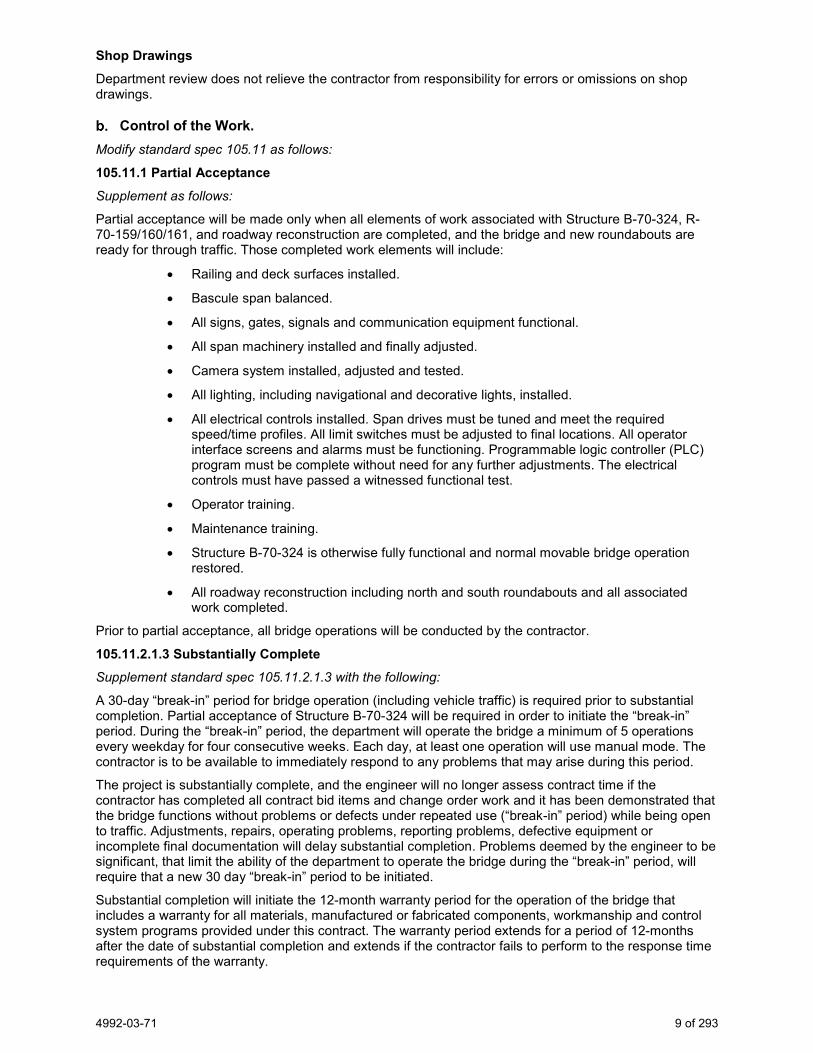
Shop Drawings Department review does not relieve the contractor from responsibility for errors or omissions on shop drawings.
Control of the Work. Modify standard spec 105.11 as follows:
105.11.1 Partial Acceptance Supplement as follows:
Partial acceptance will be made only when all elements of work associated with Structure B-70-324, R-70-159/160/161, and roadway reconstruction are completed, and the bridge and new roundabouts are ready for through traffic. Those completed work elements will include:
• Railing and deck surfaces installed.
• Bascule span balanced.
• All signs, gates, signals and communication equipment functional.
• All span machinery installed and finally adjusted.
• Camera system installed, adjusted and tested.
• All lighting, including navigational and decorative lights, installed.
• All electrical controls installed. Span drives must be tuned and meet the required speed/time profiles. All limit switches must be adjusted to final locations. All operator interface screens and alarms must be functioning. Programmable logic controller (PLC) program must be complete without need for any further adjustments. The electrical controls must have passed a witnessed functional test.
• Operator training.
• Maintenance training.
• Structure B-70-324 is otherwise fully functional and normal movable bridge operation restored.
• All roadway reconstruction including north and south roundabouts and all associated work completed.
Prior to partial acceptance, all bridge operations will be conducted by the contractor.
105.11.2.1.3 Substantially Complete Supplement standard spec 105.11.2.1.3 with the following:
A 30-day “break-in” period for bridge operation (including vehicle traffic) is required prior to substantial completion. Partial acceptance of Structure B-70-324 will be required in order to initiate the “break-in” period. During the “break-in” period, the department will operate the bridge a minimum of 5 operations every weekday for four consecutive weeks. Each day, at least one operation will use manual mode. The contractor is to be available to immediately respond to any problems that may arise during this period.
The project is substantially complete, and the engineer will no longer assess contract time if the contractor has completed all contract bid items and change order work and it has been demonstrated that the bridge functions without problems or defects under repeated use (“break-in” period) while being open to traffic. Adjustments, repairs, operating problems, reporting problems, defective equipment or incomplete final documentation will delay substantial completion. Problems deemed by the engineer to be significant, that limit the ability of the department to operate the bridge during the “break-in” period, will require that a new 30 day “break-in” period to be initiated.
Substantial completion will initiate the 12-month warranty period for the operation of the bridge that includes a warranty for all materials, manufactured or fabricated components, workmanship and control system programs provided under this contract. The warranty period extends for a period of 12-months after the date of substantial completion and extends if the contractor fails to perform to the response time requirements of the warranty.

4992-03-71 10 of 293
105.11.2.3 Final Acceptance Supplement as follows:
The project will not be accepted as final and progress payment retainage will not be reduced until successful completion of the 12-month warranty period.
Warranty If any of the bridge systems or components provided or modified as a part of the contract fall out of adjustment or fail to function satisfactorily during the warranty period, take prompt action to replace or repair the work. If normal manufacturer’s warranties have expired, it remains the contractor’s responsibility to repair or replace defective components. Provide the department with any guarantees greater than 12 months that were included with manufactured items procured for this contract.
Respond, and coordinate resolution, within four (4) hours of notification of an emergency and within 48 hours of non-emergency situations. An event will be considered an emergency if the bridge is inoperable or if a key safety feature has failed.
Modify standard spec 105.11.2.1.3 as follows:
The contractor will be liable for all cost incurred to the department if the bridge is non-operational during the 12-month warranty period. The contractor will be charged under administrative item 801.0104 Failure to Open Road to Traffic.
Modify standard spec 105.11.2.1.3 as follows:
During the warranty period subsequent to the 30-day break-in period and the contract deemed substantially complete, failure to respond and coordinate resolution within 48 hours after notification of an emergency or inadequate response or resolution to an emergency will permit the department the right to take corrective action
Bridge Testing. Prior to final acceptance, perform bridge testing in the presence of the engineer and any other invitees to demonstrate that all electrical and mechanical work has been properly completed to withstand repeated bridge openings. Invitees must include a representative from the city of Menasha responsible for handling movable bridge operations. If this individual declines or does not respond to the invitation, testing must still be conducted in the presence of the engineer.
Demonstrate all safety interlocks and their associated bypass a minimum of three times over the testing period.
Perform a minimum of 30 complete cycles of bridge opening and closing. Perform each cycle in the same manner, as the bridge will be normally operated by the city of Menasha after the project has been accepted. Utilize the complete safety interlocking system and operate all associated external electrical devices associated with it during each cycle.
Perform a minimum of six additional cycles of bridge opening and closing using the manual system.
Perform this testing over three workdays. Perform no more than 10 test cycles in normal operation mode and no more than two using the auxiliary drive system during each of the days that testing is being observed by the engineer.
Provide the department, the engineer, and the city of Menasha a minimum of 10 calendar days advance notice before commencing the first day of testing. Submit record of city invitations to the engineer.
3. Meetings.
Mandatory Pre-Bid Meeting. Add the following to standard spec 102.3.1:
Prospective bidders are required to attend a mandatory pre-bid meeting at 10:00 AM Thursday, July 23, 2020 at the Wisconsin Department of Transportation, Northeast Region, located at 944 Vanderperren Way, Green Bay, WI 54304-0080.

4992-03-71 11 of 293
Contractors will be able to obtain a bidding proposal form and submit a bid on this proposal only if they have been documented as attending the mandatory pre-bid meeting. ner-102-010 (20180212)
Coordinate with Businesses. The contractor will arrange and conduct a meeting between the contractor, the department, the city of Menasha (920) 967-3610, local officials and business people to discuss the project schedule of operations including vehicular and pedestrian access during construction operations. Hold the first meeting 14 days prior to the start of work under this contract and hold additional meetings prior to each of the other two major work stages. The contractor shall notify all parties in writing a minimum of 10 days before the meetings are held. ner-105-005 (20180212)
4. Environmental.
Information to Bidders, U.S. Army Corps of Engineers Section 404 Permit and 408 Permit. The department has obtained a U.S. Army Corps of Engineers Section 404 permit and Section 408 permit. Comply with the requirements of the permit in addition to requirements of the special provisions. A copy of the permit is available from the regional office by contacting Bill Bertrand at (920) 360-3124.
Coordination with the U.S. Army Corps of Engineers. The existing navigation cable shall remain in place at all times. Coordinate all work and schedule with the ACOE for structure B-70-324 and removal of B-70-001. Coordinate scheduling and construction of Pier 4 anchors for a new navigational cable system with the ACOE. Coordinate dredging with ACOE.
Information to Bidders, WPDES General Construction Storm Water Discharge Permit. The department has obtained coverage through the Wisconsin Department of Natural Resources to discharge storm water associated with land disturbing construction activities of this contract under the Wisconsin Pollutant Discharge Elimination System General Construction Storm Water Discharge Permit (WPDES Permit No. WI-S066796-1). A certificate of permit coverage is available from the regional office by contacting Bill Bertrand at (920) 360-3124. Post the permit in a conspicuous place at the construction site. stp-107-056 (20180628)
United States Coast Guard Permit. Contact the United States Coast Guard 30 days prior to when the bascule span will remain inoperable.
Construction Over or Adjacent to Navigable Waters. The Fox River is classified as a federal navigable waterway under standard spec 107.19.
stp-107-060 (20171130)
Fish Spawning There shall be no instream disturbance of Fox River as a result of construction activity under or for this contract, from ice out or March 1 (whichever occurs first) to June 15 both dates inclusive, in order to avoid adverse impacts upon the spawning of fish species.
Any change to this limitation will require submitting a written request by the contractor to the engineer, subsequent review and concurrence by the Department of Natural Resources in the request, and final approval by the engineer. The approval will include all conditions to the request as mutually agreed upon by WisDOT and DNR. 0036 (20090901)

4992-03-71 12 of 293
Turtles There is potential for impacts to the state special concern Blanding’s Turtle (Emydoidea blandingii). It is recommended that “j-hooks” or “small animal turn-arounds” are installed at the ends of any silt fence installed. Most importantly, any amphibians or reptiles that are found in the active work zone (which includes staging, storage, and parking areas within and adjacent to the project) shall be removed and relocated outside the active work zone. If there is an amphibian or reptile mortality, please contact Jay Schiefelbein at (920) 360-3784 or at [email protected] immediately.
Migratory Birds Swallow and other migratory birds’ nests have been observed on or under the existing bridge. All active nests (when eggs or young are present) of migratory birds are protected under the federal Migratory Bird Treaty Act.
The nesting season for swallows and other birds is usually between May 1 and August 30. Either prevent active nests from becoming established or apply for a depredation permit from the US Fish and Wildlife Service for work that may disturb or destroy active nests. The need for a permit may be avoided by removing the existing bridge structure prior to nest occupation by birds or clearing nests from all structures before the nests become active in early spring. As a last resort, prevent birds from nesting by installing a suitable netting device on the remaining structure prior to nesting activity. Include the cost for preventing nesting in the cost of Removing Old Structure Over Waterway with Minimal Debris. 0074 (20090901)
Northern Long-eared Bat (Myotis septentrionalis) Northern Long-eared Bats (NLEB) have the potential to inhabit the project limits because they roost in trees. Roosts may not have been observed on this project, but conditions to support the species exist. The species and all active roosts are protected by the Federal Endangered Species Act. If an individual bat or active roost is encountered during construction operations, stop work and notify the engineer and the WisDOT Regional Environmental Coordinator (REC).
According to the final 4(d) rule issued for the NLEB, the department has determined that the proposed activity may affect, but will not result in prohibited take of the NLEB. The activity involves tree removal but will not occur within 0.25 miles of a known hibernacula, nor will the activity remove a known maternity roost tree or any other tree within 150 feet of a known maternity roost tree.
If additional trees need to be removed, no Clearing shall occur without prior approval from the engineer, following coordination with the WisDOT REC. Additional tree removal beyond the area originally specified will require consultation with the United States Fish and Wildlife Service (USFWS) and may require a bat presence/absence survey. Notify the engineer if additional Clearing cannot be avoided to begin coordination with the WisDOT REC. The WisDOT REC will initiate consultation with the USFWS and determine if a survey is necessary.
Submit a schedule and description of Clearing operations with the ECIP 14 days prior to any Clearing operations. The department will determine, based on schedule and scope of work, what additional erosion control measures shall be implemented prior to the start of Clearing operations, and list those additional measures in the ECIP.
Environmental Protection, Dewatering. Add the following to standard spec 107.18:
If dewatering is required, treat the water to remove suspended sediments by filtration, settlement or other appropriate best management practice before discharge. The means and methods proposed to be used during construction shall be submitted for approval as part of the Erosion Control Implementation Plan for dewatering at each location it is required. The submittal shall also include the details of how the intake will be managed to not cause an increase in the background level turbidity before treatment and any additional erosion controls necessary to prevent sediments from reaching the project limits or wetlands and waterways. Guidance on dewatering can be found on the Wisconsin Department of Natural Resources website located in the Storm Water Construction Technical Standards, Dewatering Code #1061, “Dewatering”. This document can be found at the WisDNR website:
http://dnr.wi.gov/topic/stormwater/standards/const_standards.html
4992-03-71 13 of 293
The cost of all work and materials associated with water treatment and/or dewatering is incidental to the bid items the work is associated. ner-107-040 (20180212)
Erosion Control Structures. Within three calendar days after completing the excavation for a substructure unit, place riprap or other permanent erosion control items required by the contract or deemed necessary by the engineer around the unit at a minimum to a height equivalent to the calculated water elevation resulting from a storm that occurs on the average of once every two years (Q2) as shown on the plan, or as the engineer directs.
In the event that construction activity does not disturb the existing ground below the Q2 elevation, the above timing requirements for permanent erosion control shall be waived.
stp-107-070 (20191121
Health and Safety Requirements for Workers Removing Contaminated Materials. Add the following to standard spec 107.1:
Contaminated materials have been identified within the construction limits of this project. Based on sediment analytical data from investigations, contamination will be encountered during excavation, dredging, and dewatering activities.
Site workers, that have a probability of exposure to a hazardous material, will have completed Health and Safety training that meets Occupational Safety and Health Administration (OSHA) requirements. Prepare a site-specific Health and Safety Plan complying with the OSHA standard for Hazardous Waste Operation and Emergency Response (HAZWOPER), 29 CFR 1910.120. Submit the site-specific Health and Safety Plan and written documentation of up-to-date OSHA training to the engineer before the pre-construction meeting.
Develop, delineate, and enforce the health and safety procedures pursuant to 29 CFR 1910.120, 29 CFR 1926.1101, and other health and safety regulations. Restrict access to the Contaminated Material areas to only authorized, trained, and protected personnel until such time as excavation of contamination has been completed in the respective areas.
Specify the procedure for worker decontamination and for decontamination of equipment used in excavating, dewatering, and hauling of contaminated material in the site-specific Health and Safety Plan. ner-107-085 (20180212)
Management of Petroleum Contaminated Water, Item SPV.0105.30. A Description This special provision describes managing petroleum contaminated water.
Conform to standard spec 205, parts of the Wisconsin Administration Code (Department of Natural Resources Environmental Investigation and Remediation of Environmental Contamination, Chapters NR 700-736), as the plans show, and in this special provision.
This work consists of pumping petroleum contaminated water from open excavations into a temporary holding tank, as necessary to complete construction. Contaminated water encountered, but not requiring removal as a standard course of construction, shall remain in-place and not be managed under this special provision.
The cost for holding tank mobilization, transportation, and contaminated water disposal will be billed directly by the environmental consultant and/or disposal facility to the department.
A.1 Notice to the Contractor A Phase I Environmental Site Assessment (ESA) and Phase II Subsurface Investigation (SI), including testing for soil and groundwater contamination, were completed by the department for locations within this project where excavation is required. Information obtained by the department indicated that petroleum contaminated groundwater requiring special management is likely to be encountered at the following location:

4992-03-71 14 of 293
1. Station 628+20 to 629+20 from slope intercept to slope intercept at a depth of approximately 6 to 12 feet below existing grade. Groundwater contamination with gasoline or other petroleum related products at concentrations exceeding the Enforcement Standards identified in s. NR 140.10 Wisconsin Administrative Code are likely to be encountered during excavation activities.
If petroleum odors are observed during dewatering activities at other locations on the project, terminate dewatering activities and notify the engineer.
For further information regarding investigation activities at these locations, contact Kathie VanPrice, Wisconsin Department of Transportation, Environmental Coordinator, 944 Vanderperren Way, Green Bay, Wisconsin 54324, (920) 492-7175.
A.2 Coordination Coordinate work under this contract with the environmental consultant retained by the department:
Consultant: TRC Environmental Corporation Address: 708 Heartland Trail, Suite 3000, Madison, WI 53717 Fax: (608) 826-3941 Contact: Dan Haak Phone: (608) 826-3628 office, (608) 886-7423 mobile E-mail: [email protected]
The environmental consultant will determine the location and limits of contaminated groundwater to be managed and conveyed into a temporary holding tank based on groundwater analytical results from previous field investigations, visual observations or field screening of groundwater, surface water, and precipitation that collects within the excavations.
The environmental consultant will coordinate holding tank mobilization, waste characterization sampling of accumulated water, and transportation/disposal of contaminated water.
Provide a 14 calendar day advance notice of the pre-construction conference date to the environmental consultant. At the pre-construction conference, provide a proposed schedule for all excavation activities in the area of contamination. Three calendar days before commencement of excavation activities in the contaminated area, notify the engineer and environmental consultant. Coordinate with the environmental consultant to ensure that the consultant is present before and during excavation and dewatering activities in the area of contamination.
A.3 Health and Safety Requirements Prepare a site specific Health and Safety Plan complying with the Occupational Safety and Health Administration (OSHA) standard for Hazardous Waste Operation and Emergency Response (HAZWOPER), 29 CFR 1910.120.
All site workers taking part in remediation activities or who will have the reasonable probability of exposure of safety or health hazards associated with the hazardous material shall have completed Health and Safety training that meets OSHA requirements. A site specific Health and Safety Plan, and written verification by the contractor that workers will have completed up to date OSHA training will be submitted to the engineer before the start of remediation work.
Develop, delineate and enforce the health and safety exclusion zones for each contaminated site location pursuant to 29 CFR 1910.120.
B (Vacant) C Construction Add the following to standard spec 205.3:
Pump petroleum contaminated water from open excavations into a temporary holding tank as necessary to complete construction. Contaminated water encountered, but not requiring removal as a standard course of construction, shall remain in-place and not be managed under this special provision.
Take measures to limit groundwater, surface water, and precipitation from entering and exiting excavations in the area of contamination. Such measures, which may include berming, ditching, or other means, shall be maintained until subgrade construction in the area of contamination is complete.

4992-03-71 15 of 293
D Measurement The department will measure Management of Petroleum Contaminated Water as a single complete unit of work, acceptably performed.
E Payment The department will pay for measured quantities at the contract unit price under the following bid item: ITEM NUMBER DESCRIPTION UNIT SPV.0105.30 Management of Petroleum Contaminated Water LS
Payment is full compensation for controlling contaminated water and preventing non-contaminated surface water and precipitation from entering the areas of contamination; and for managing and pumping petroleum contaminated water from excavations in the area of contamination to the temporary holding tank. ner-107-100 (20180212)
Management of Petroleum Contaminated Groundwater, Item SPV.0120.01. A Description This special provision describes managing petroleum contaminated groundwater.
Groundwater pumped during dewatering operations between Stations 9RNB+50 to 10RNB+50 will likely contain contaminants that require discharged of the groundwater to the sanitary sewer system.
At no cost to the contractor, the City of Menasha has granted permission to discharge Petroleum-Contaminated Groundwater to the sanitary system, provided the requirements outlined herein are met.
The contractor shall notify the engineer immediately if strong petroleum odors are observed during dewatering activities. The engineer and the contractor shall discuss continued dewatering with the City of Menasha.
If petroleum odors are observed during dewatering activities at other locations on the project, terminate dewatering activities and notify the engineer.
B (Vacant) C Construction Add the following to standard spec 205.3:
Make every effort to minimize the amount of silt, sand, sediment, and other deleterious substances discharged during dewatering operations. Furnish, install and maintain a sediment box for the dewatering operation before discharging water to the sanitary system.
The Neenah-Menasha Sewerage Commission has granted preliminary permission to discharge to the sanitary system provided that the following requirements are met:
− Notify engineer, Mr. Adam Alix, Menasha DPW with the city of Menasha at (920) 967-3610, and Paul Much of Neenah-Menasha Regional WWTP at (920) 751-4760 before the discharge of contaminated groundwater to the sanitary system.
− If the pumping rate is equal to or less than 70 gallons per minute (70 gpm), then groundwater may be discharged into the sanitary system. Recovered groundwater shall be discharged to the nearest sanitary sewer manhole. All questions regarding discharge locations should be directed to:
Paul Much of Neenah-Menasha Regional WWTP at (920) 751-4760
− Permit has been submitted to the City of Menasha and Neenah-Menasha Sewerage Commission. Discharge and effluent limits are listed below.
Daily discharge limitation: Gasoline Range Organics (GRO) and Diesel Range Organics (DRO) combined shall not exceed 8mg/L and/or 6.67 lbs./day. Flow shall not exceed 100,000 gpd.
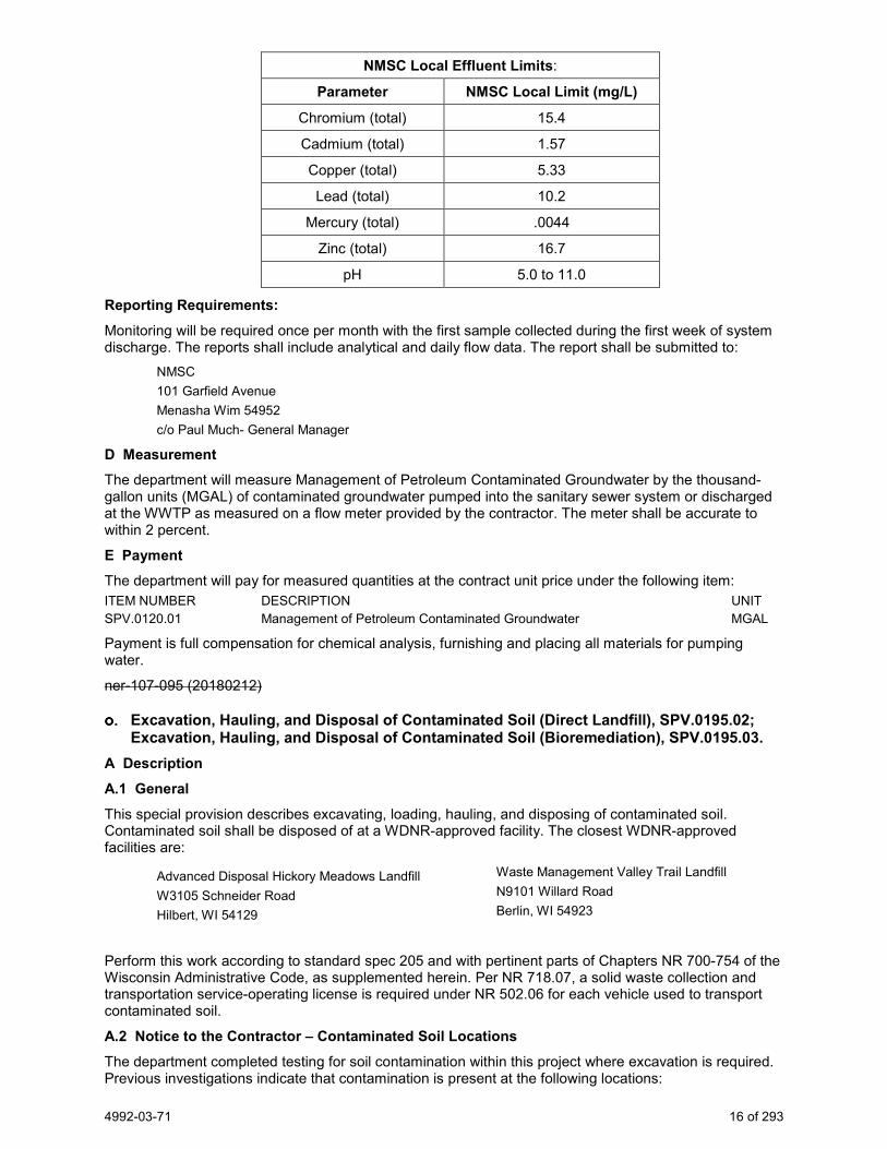
4992-03-71 16 of 293
NMSC Local Effluent Limits:
Parameter NMSC Local Limit (mg/L)
Chromium (total) 15.4
Cadmium (total) 1.57
Copper (total) 5.33
Lead (total) 10.2
Mercury (total) .0044
Zinc (total) 16.7
pH 5.0 to 11.0
Reporting Requirements: Monitoring will be required once per month with the first sample collected during the first week of system discharge. The reports shall include analytical and daily flow data. The report shall be submitted to:
NMSC 101 Garfield Avenue Menasha Wim 54952 c/o Paul Much- General Manager
D Measurement The department will measure Management of Petroleum Contaminated Groundwater by the thousand-gallon units (MGAL) of contaminated groundwater pumped into the sanitary sewer system or discharged at the WWTP as measured on a flow meter provided by the contractor. The meter shall be accurate to within 2 percent.
E Payment The department will pay for measured quantities at the contract unit price under the following item: ITEM NUMBER DESCRIPTION UNIT SPV.0120.01 Management of Petroleum Contaminated Groundwater MGAL
Payment is full compensation for chemical analysis, furnishing and placing all materials for pumping water.
ner-107-095 (20180212)
Excavation, Hauling, and Disposal of Contaminated Soil (Direct Landfill), SPV.0195.02; Excavation, Hauling, and Disposal of Contaminated Soil (Bioremediation), SPV.0195.03.
A Description A.1 General This special provision describes excavating, loading, hauling, and disposing of contaminated soil. Contaminated soil shall be disposed of at a WDNR-approved facility. The closest WDNR-approved facilities are:
Advanced Disposal Hickory Meadows Landfill W3105 Schneider Road Hilbert, WI 54129
Waste Management Valley Trail Landfill N9101 Willard Road Berlin, WI 54923
Perform this work according to standard spec 205 and with pertinent parts of Chapters NR 700-754 of the Wisconsin Administrative Code, as supplemented herein. Per NR 718.07, a solid waste collection and transportation service-operating license is required under NR 502.06 for each vehicle used to transport contaminated soil.
A.2 Notice to the Contractor – Contaminated Soil Locations
The department completed testing for soil contamination within this project where excavation is required. Previous investigations indicate that contamination is present at the following locations:

4992-03-71 17 of 293
Petroleum Contamination (Bioremediation)
− Station 1+47 NB to 2+50 NB, from reference line to limits on LT
− Station 20+37 NB to 21+05 NB, from reference line to limits on RT
− Station 18+35 NB to 19+35 NB, from reference line to limits on RT
− Station 1’B’+67 to 2’B’+15, from reference line to limits on RT
Polynuclear Aromatic Hydrocarbons and Metals Contamination (Direct Landfill) − Station 2+50 NB to 3+00 NB between 0 to 6 ft. bgs, from reference line to northwestern side
of former Banta Publishing Corporation building
− Station 8+00 NB to 8+50 NB, from limits on LT to limits on RT
Contaminated soil and/or underground storage tanks (USTs) may be encountered at other locations within the construction limits. If contaminated soil and/or USTs are encountered elsewhere on the project, terminate excavation activities in the area and notify the engineer. Contaminated soil at other locations shall be managed by the contractor under this contract. USTs will be removed by others. For further information regarding previous investigation and remediation activities at these sites contact:
Name: Kathie VanPrice Wisconsin DOT, Northeast Region Address: 944 Vanderperren Way Green Bay, WI 54304 Phone: (920) 492-7175 E-mail: [email protected] Name: Dan Haak TRC Environmental Corporation Address: 708 Heartland Trail, Suite 3000 Madison, WI 53717 Phone: (608) 826-3628 Fax: (608 -826-3941 E-mail: [email protected]
A.3 Coordination Coordinate work under this contract with the environment consultant:
Consultant: TRC Environmental Corporation Address: 708 Heartland Trail, Suite 3000, Madison, WI 53717 Fax: (608) 826-3941 Contact: Dan Haak Phone: (608) 826-3628 office; (608) 886-7423 mobile E-mail: [email protected]
The role of the environmental consultant will be limited to: 1. Determining the location and limits of contaminated soil to be excavated based on analytical results
from previous investigations, visual observations, and field screening of soil that is excavated; 2. Identifying contaminated soils to be hauled to the disposal facility; 3. Documenting that activities associated with management of contaminated soil are in conformance with
the contamination management methods for this project as specified herein; and 4. Obtaining the necessary approvals for disposal of contaminated soil from the disposal facility.
Provide at least a 14-calendar day notice of the preconstruction conference date to the environmental consultant. At the preconstruction conference, provide a schedule for all excavation activities in the areas of contamination to the environmental consultant. Also, notify the environmental consultant at least three calendar days prior to commencement of excavation activities in each of the contaminated areas.
Identify the WDNR-approved bioremediation and disposal facility that will be used for disposal of contaminated soils and provide this information to the environmental consultant no later than 30 calendar days prior to commencement of excavation activities in the contaminated areas or at the preconstruction
4992-03-71 18 of 293
conference, whichever comes first. The environmental consultant will be responsible for obtaining the necessary approvals for disposal of contaminated soils from the bioremediation and disposal facility.
Coordinate with the environmental consultant to ensure that the environmental consultant is present during excavation activities in the contaminated areas. Perform excavation work in each of the contaminated areas on a continuous basis until excavation work is completed. Do not pump or haul contaminated groundwater offsite without specific approval from the environmental consultant. Do not transport contaminated soil offsite without prior approval from the environmental consultant.
A.4 Protection of Groundwater Monitoring Wells Groundwater monitoring wells may be present within the construction limits. Protect all groundwater monitoring wells to maintain their integrity. Adjust wells that do not conflict with utilities, structures, curb and gutter, etc.to be flush with the final grade. For wells that conflict with the previously mentioned items, notify the environmental consultant, and coordinate with the environmental consultant for the abandonment or adjustment of the wells by others. The environmental consultant will provide maps indicating the locations of all known monitoring wells, if requested by the contractor.
A.5 Excavation Management Plan Approval The excavation management plan for this project has been designed to minimize the off-site disposal of contaminated material. The excavation management plan, including these special provisions, has been developed in cooperation with the WDNR. The WDNR’s concurrence letter is on file at the Wisconsin Department of Transportation. For further information regarding the investigations, including waste characterization within the project limits, contact Kathie VanPrice with the department, at (920) 492-7175.
B (Vacant) C Construction Supplement standard spec 205.3 with the following:
Control operations in the contaminated areas to minimize the quantity of contaminated soil excavated.
The environmental consultant will periodically evaluate soil excavated from the contaminated areas to determine if the soil will require offsite disposal. The environmental consultant will evaluate excavated soil based on field screening results, visual observations, and analytical results from previous environmental investigations. Assist the environmental consultant in collecting soil samples for evaluation using excavation equipment. The sampling frequency shall be a maximum of one sample for every 20 cubic yards excavated.
On the basis of the results of such field-screening, the material will be designated for disposal as follows:
− Excavation Common consisting of clean soil and/or clean construction and demolition fill (such as clean soil, boulders, concrete, reinforced concrete, bituminous pavement, bricks, building stone, and unpainted or untreated wood), which under NR 500.08 are exempt materials, or
− Low-level contaminated material (PID readings less than 10 ppm and no observation of staining or petroleum odor, or based on existing analytical data) for reuse as fill within the construction limits as allowed, or
− Petroleum contaminated soil (significant petroleum odor, staining, and/or PID readings greater than 10 ppm) for off-site treatment and disposal at the WDNR-licensed bioremediation facility, or
− Contaminated soil (based on the presence of industrial fill or existing analytical data) for off-site disposal at the WDNR-licensed disposal facility, or
− Potentially contaminated for temporary stockpiling and additional characterization prior to disposal.
Directly load and haul soil designated by the environmental consultant for offsite disposal to the WDNR-approved facility. Verify that vehicles used to transport contaminated material are licensed for such activity according to applicable state and federal regulations. Use loading and hauling practices that are appropriate to prevent any spills or releases of contaminated soils or residues. Prior to transport, sufficiently dewater soils so as not to contain free liquids.
4992-03-71 19 of 293
When material is encountered outside the above-identified limits of known contamination that appears to have been impacted with petroleum or chemical products, or when other obvious potentially contaminated materials are encountered or material exhibits characteristics of industrial-type wastes, such as fly ash, foundry sand, and cinders, or when underground storage tanks are encountered, suspend excavation in that area and notify the engineer.
Groundwater may be present within the construction limits. Water generated during dewatering operations (if necessary) is expected to be permitted to discharge to the surface except in the contaminated areas.
Contaminated groundwater generated from dewatering activities within the contaminated areas may exceed the surface water discharge limits for petroleum compounds specified in the DNR’s “General Permit to Discharge under the Wisconsin Pollutant Discharge Elimination System” for “Contaminated Groundwater from Remedial Action Operations” (WPDES Permit No. WI-0046566-5), Table 3.1.
Notify the environmental consultant prior to pumping contaminated groundwater.
The Neenah-Menasha Sewerage Commission has granted preliminary permission to discharge to the sanitary system provided that the following requirements are met:
− Notify engineer, Mr. Adam Alix, Menasha DPW with the city of Menasha at (920) 967-3610, and Paul Much of Neenah-Menasha Regional WWTP at (920) 751-4760 before the discharge of contaminated groundwater to the sanitary system.
− If the pumping rate is equal to or less than 70 gallons per minute (70 gpm), then groundwater may be discharged into the sanitary system. Recovered groundwater shall be discharged to the nearest sanitary sewer manhole. All questions regarding discharge locations should be directed to:
Paul Much of Neenah-Menasha Regional WWTP at (920) 751-4760
− Preliminary permit has been submitted to the City of Menasha and Neenah-Menasha Sewerage Commission. Final permit will need to be completed by the contractor.
In lieu of disposal of groundwater generated from the contaminated areas in the sanitary sewer to the City of Neenah-Menasha Wastewater Treatment Plant, pump contaminated water that exceeds surface water discharge limits, as determined by environmental consultant, into temporary holding tanks provided by others or an alternative discharge point as determined by the environmental consultant, as necessary to complete construction. Allow contaminated water encountered, but not requiring removal as a standard course of construction, to remain in-place and do not manage according to this special provision.
The environmental consultant will coordinate approval of contaminated water hauling and disposal. Only pump contaminated groundwater if the environmental consultant is on-site.
Discharging contaminated groundwater to any location other than that approved and provided by the environmental consultant, is at the contractor’s cost. If the contractor chooses alternate discharge, at the contractor’s cost, obtain DNR concurrence on any dewatering plans, and provide and operate any and all treatment and discharge equipment required.
Employ construction methods and techniques in a manner that will minimize the need for dewatering, and if dewatering is required, minimize the volume of water generated. Take measures to limit groundwater, surface water, and precipitation from entering and exiting excavations in the areas of contamination. Such measures, which may include berming, ditching, or other means, shall be maintained until construction of utilities in the areas of contamination are complete.
Ensure continuous dewatering and excavation safety at all times. Provide, operate, and maintain adequate pumping equipment and drainage and disposal facilities. Notify the engineer of any dewatering activities and obtain any permits necessary to discharge water. Provide copies of such permits to the engineer. Meet any requirements and pay any costs for obtaining and complying with such permit use. Follow all applicable legislative statues, judiciary decisions, and regulations of the State of Wisconsin.
Cost for contaminated groundwater collection and disposal is incidental to the project.
D Measurement The department will measure Excavation, Hauling, and Disposal of Contaminated Soil in tons of contaminated soil accepted by the disposal facility as documented by weight tickets generated by the facility. Load tickets must be delivered to the engineer within 10 business days of the date on which the soil was accepted by the facility.
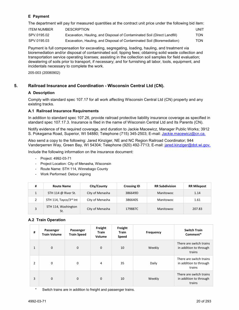
4992-03-71 20 of 293
E Payment The department will pay for measured quantities at the contract unit price under the following bid item: ITEM NUMBER DESCRIPTION UNIT SPV.0195.02 Excavation, Hauling, and Disposal of Contaminated Soil (Direct Landfill) TON SPV.0195.03 Excavation, Hauling, and Disposal of Contaminated Soil (Bioremediation) TON
Payment is full compensation for excavating, segregating, loading, hauling, and treatment via bioremediation and/or disposal of contaminated soil; tipping fees; obtaining solid waste collection and transportation service operating licenses; assisting in the collection soil samples for field evaluation; dewatering of soils prior to transport, if necessary; and for furnishing all labor, tools, equipment, and incidentals necessary to complete the work. 205-003 (20080902)
5. Railroad Insurance and Coordination - Wisconsin Central Ltd (CN).
A Description
Comply with standard spec 107.17 for all work affecting Wisconsin Central Ltd (CN) property and any existing tracks.
A.1 Railroad Insurance Requirements
In addition to standard spec 107.26, provide railroad protective liability insurance coverage as specified in standard spec 107.17.3. Insurance is filed in the name of Wisconsin Central Ltd and Its Parents (CN).
Notify evidence of the required coverage, and duration to Jackie Macewicz, Manager Public Works; 3912 S. Pokegama Road, Superior, WI 54880; Telephone (715) 345-2503; E-mail: [email protected].
Also send a copy to the following: Jared Kinziger, NE and NC Region Railroad Coordinator; 944 Vanderperren Way, Green Bay, WI 54304; Telephone (920) 492-7713; E-mail: [email protected].
Include the following information on the insurance document: - Project: 4992-03-71 - Project Location: City of Menasha, Wisconsin - Route Name: STH 114, Winnebago County - Work Performed: Detour signing
# Route Name City/County Crossing ID RR Subdivision RR Milepost
1 STH 114 @ River St. City of Menasha 386649D Manitowoc 1.14
2 STH 114, Tayco/3rd Int City of Menasha 386640S Manitowoc 1.61
3 STH 114, Washington St. City of Menasha 179887C Manitowoc 207.83
A.2 Train Operation
# Passenger Train Volume
Passenger Train Speed
Freight Train
Volume
Freight Train Speed
Frequency Switch Train Comment*
1 0 0 0 10 Weekly There are switch trains in addition to through
trains
2 0 0 4 35 Daily There are switch trains in addition to through
trains
3 0 0 0 10 Weekly There are switch trains in addition to through
trains
* Switch trains are in addition to freight and passenger trains.
4992-03-71 21 of 293
A.3 Names and Addresses of Railroad Representatives for Consultation and Coordination
Construction Contact Jackie Macewicz, Manager Public Works; 3192 S. Pokegama Road, Superior, WI 54880; Telephone (715) 345-2503; E-mail [email protected] for consultation on railroad requirements during construction.
Amend standard spec 108.4 to include the railroad in the distribution of the initial bar chart, and monthly schedule updates. The bar chart shall specifically show work involving coordination with the railroad.
Flagging Contact Submit by US Mail a "Request for Flagging Services and Cable Location" form with prepayment to: Flagging-US, 17641 South Ashland Avenue, Homewood, IL 60430; [email protected] . The form can be obtained at:
http://www.cn.ca/en/safety/employees/contractors-erailsafe/utility-installations
Requests for flagging and cable locates can take up to five business days after the railroad receives the paperwork. Reference the Wisconsin Milepost and Subdivision located in A.1. Advise Wisconsin Central Ltd (CN) that the flagging services are to be billed at the rate for a public highway project.
Cable Locate Contact In addition to contacting Diggers Hotline, follow the procedure listed under Flagging Contact.
Wisconsin Central Ltd (CN) will only locate railroad owned facilities buried in the railroad right-of-way. The railroad does not locate any other utilities.
A.4 Work by Railroad
The railroad will perform the work described in this section, except for work described in other special provisions, and will be accomplished without cost to the contractor. None
A.5 Temporary Grade Crossing
If a temporary grade crossing is desired, submit a written request to the railroad representative named in A.3 at least 40 days prior to the time needed. Approval is subject to the discretion of the railroad. The department has made no arrangements for a temporary grade crossing.
A.6 Rail Security Awareness and Contractor Orientation
All employees of contractors who work on CN properties are required to have minimum CN Safety and Security Awareness training. This training can be obtained by registering and following the CN link through www.contractororientation.com. This training is good for a period of one year.
a. Exception: CN has exempted from this training those it classifies as "Delivery Persons". Delivery Persons include contractors such as UPS, FedEx, trucking companies, etc. who merely access the property to supply materials or equipment.
The security awareness and contractor orientation certification must be renewed for projects that will carry over beyond the one-year period. Contractor and subcontractor employees shall wear the identification badge issued by www.contractororientation.com when on railroad right-of-way. Costs associated with training and registration are incidental to other items in the contract.
If employees of contractors have a current eRailSafe badge for CN then an additional badge is not required from www.contractororientation.com. stp-107-026 (20190717)
6. Traffic and Restrictions to Work.
Traffic. Maintain traffic as detailed in the Traffic Control plans, and as hereinafter described.
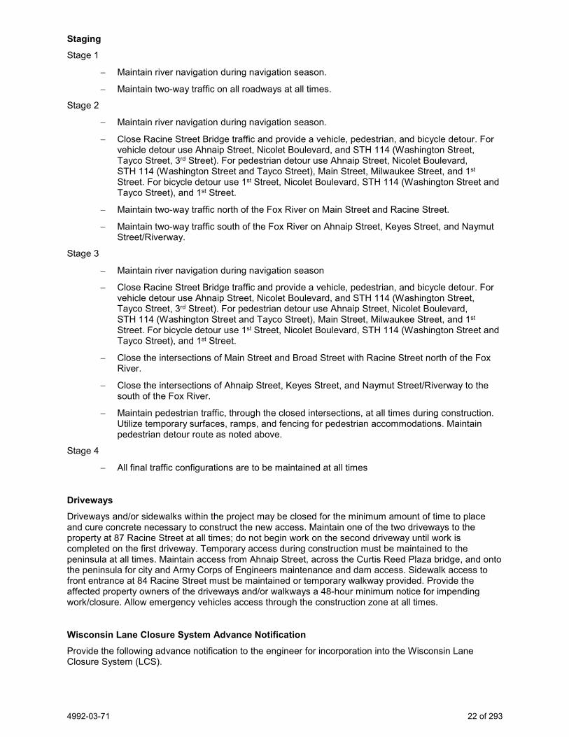
4992-03-71 22 of 293
Staging Stage 1
− Maintain river navigation during navigation season.
− Maintain two-way traffic on all roadways at all times.
Stage 2
− Maintain river navigation during navigation season.
− Close Racine Street Bridge traffic and provide a vehicle, pedestrian, and bicycle detour. For vehicle detour use Ahnaip Street, Nicolet Boulevard, and STH 114 (Washington Street, Tayco Street, 3rd Street). For pedestrian detour use Ahnaip Street, Nicolet Boulevard, STH 114 (Washington Street and Tayco Street), Main Street, Milwaukee Street, and 1st Street. For bicycle detour use 1st Street, Nicolet Boulevard, STH 114 (Washington Street and Tayco Street), and 1st Street.
− Maintain two-way traffic north of the Fox River on Main Street and Racine Street.
− Maintain two-way traffic south of the Fox River on Ahnaip Street, Keyes Street, and Naymut Street/Riverway.
Stage 3
− Maintain river navigation during navigation season
− Close Racine Street Bridge traffic and provide a vehicle, pedestrian, and bicycle detour. For vehicle detour use Ahnaip Street, Nicolet Boulevard, and STH 114 (Washington Street, Tayco Street, 3rd Street). For pedestrian detour use Ahnaip Street, Nicolet Boulevard, STH 114 (Washington Street and Tayco Street), Main Street, Milwaukee Street, and 1st Street. For bicycle detour use 1st Street, Nicolet Boulevard, STH 114 (Washington Street and Tayco Street), and 1st Street.
− Close the intersections of Main Street and Broad Street with Racine Street north of the Fox River.
− Close the intersections of Ahnaip Street, Keyes Street, and Naymut Street/Riverway to the south of the Fox River.
− Maintain pedestrian traffic, through the closed intersections, at all times during construction. Utilize temporary surfaces, ramps, and fencing for pedestrian accommodations. Maintain pedestrian detour route as noted above.
Stage 4
− All final traffic configurations are to be maintained at all times
Driveways Driveways and/or sidewalks within the project may be closed for the minimum amount of time to place and cure concrete necessary to construct the new access. Maintain one of the two driveways to the property at 87 Racine Street at all times; do not begin work on the second driveway until work is completed on the first driveway. Temporary access during construction must be maintained to the peninsula at all times. Maintain access from Ahnaip Street, across the Curtis Reed Plaza bridge, and onto the peninsula for city and Army Corps of Engineers maintenance and dam access. Sidewalk access to front entrance at 84 Racine Street must be maintained or temporary walkway provided. Provide the affected property owners of the driveways and/or walkways a 48-hour minimum notice for impending work/closure. Allow emergency vehicles access through the construction zone at all times.
Wisconsin Lane Closure System Advance Notification Provide the following advance notification to the engineer for incorporation into the Wisconsin Lane Closure System (LCS).
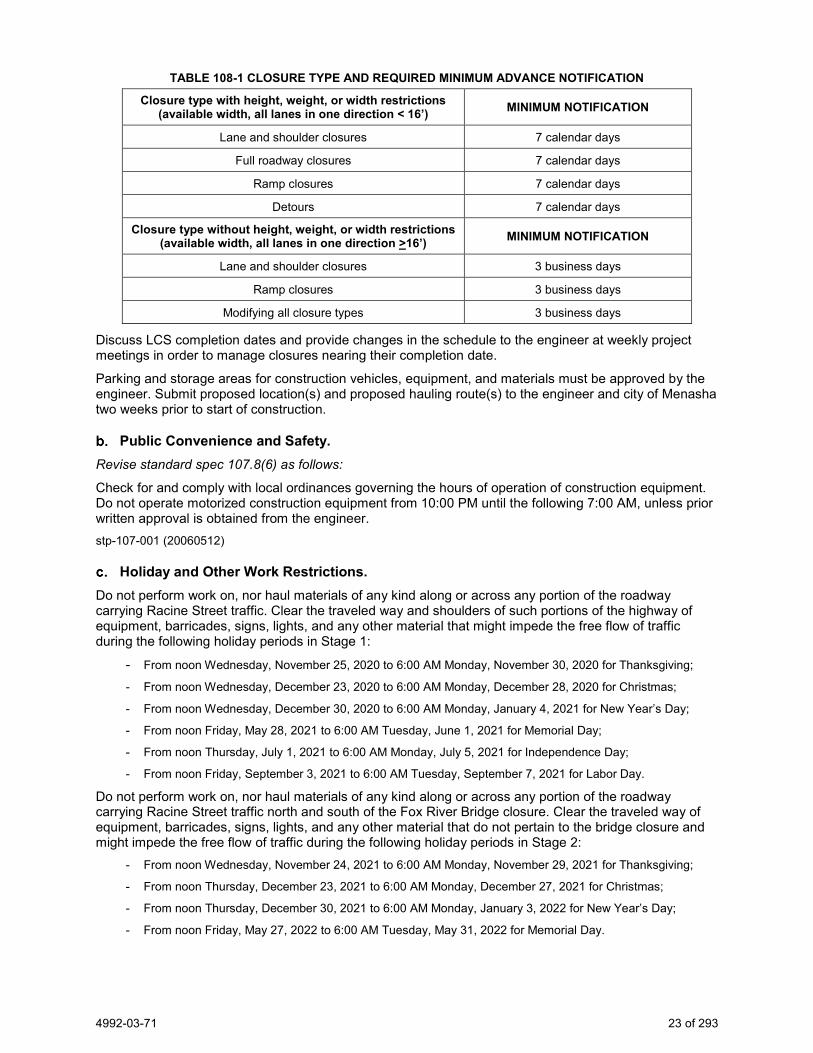
4992-03-71 23 of 293
TABLE 108-1 CLOSURE TYPE AND REQUIRED MINIMUM ADVANCE NOTIFICATION
Closure type with height, weight, or width restrictions (available width, all lanes in one direction < 16’) MINIMUM NOTIFICATION
Lane and shoulder closures 7 calendar days
Full roadway closures 7 calendar days
Ramp closures 7 calendar days
Detours 7 calendar days
Closure type without height, weight, or width restrictions (available width, all lanes in one direction >16’) MINIMUM NOTIFICATION
Lane and shoulder closures 3 business days
Ramp closures 3 business days
Modifying all closure types 3 business days
Discuss LCS completion dates and provide changes in the schedule to the engineer at weekly project meetings in order to manage closures nearing their completion date.
Parking and storage areas for construction vehicles, equipment, and materials must be approved by the engineer. Submit proposed location(s) and proposed hauling route(s) to the engineer and city of Menasha two weeks prior to start of construction.
Public Convenience and Safety. Revise standard spec 107.8(6) as follows:
Check for and comply with local ordinances governing the hours of operation of construction equipment. Do not operate motorized construction equipment from 10:00 PM until the following 7:00 AM, unless prior written approval is obtained from the engineer. stp-107-001 (20060512)
Holiday and Other Work Restrictions. Do not perform work on, nor haul materials of any kind along or across any portion of the roadway carrying Racine Street traffic. Clear the traveled way and shoulders of such portions of the highway of equipment, barricades, signs, lights, and any other material that might impede the free flow of traffic during the following holiday periods in Stage 1:
- From noon Wednesday, November 25, 2020 to 6:00 AM Monday, November 30, 2020 for Thanksgiving;
- From noon Wednesday, December 23, 2020 to 6:00 AM Monday, December 28, 2020 for Christmas;
- From noon Wednesday, December 30, 2020 to 6:00 AM Monday, January 4, 2021 for New Year’s Day;
- From noon Friday, May 28, 2021 to 6:00 AM Tuesday, June 1, 2021 for Memorial Day;
- From noon Thursday, July 1, 2021 to 6:00 AM Monday, July 5, 2021 for Independence Day;
- From noon Friday, September 3, 2021 to 6:00 AM Tuesday, September 7, 2021 for Labor Day.
Do not perform work on, nor haul materials of any kind along or across any portion of the roadway carrying Racine Street traffic north and south of the Fox River Bridge closure. Clear the traveled way of equipment, barricades, signs, lights, and any other material that do not pertain to the bridge closure and might impede the free flow of traffic during the following holiday periods in Stage 2:
- From noon Wednesday, November 24, 2021 to 6:00 AM Monday, November 29, 2021 for Thanksgiving;
- From noon Thursday, December 23, 2021 to 6:00 AM Monday, December 27, 2021 for Christmas;
- From noon Thursday, December 30, 2021 to 6:00 AM Monday, January 3, 2022 for New Year’s Day;
- From noon Friday, May 27, 2022 to 6:00 AM Tuesday, May 31, 2022 for Memorial Day.

4992-03-71 24 of 293
Do not perform work during following holiday periods during Stage 3: - From noon Friday, July 1, 2022 to 6:00 AM Tuesday, July 5, 2022 for Independence Day;
- From noon Friday, September 2, 2022 to 6:00 AM Tuesday, September 6, 2022 for Labor Day;
- From noon Wednesday, November 23, 2022 to 6:00 AM Monday November 28, 2022 for Thanksgiving.
stp-107-005 (20181119)
Traffic Control. Perform this work conforming to standard spec 643, and as the plans show, or as the engineer approves, except as follows.
Submit to engineer for approval a detailed traffic control plan for any changes to the proposed traffic control detail as the plans show. Submit this plan 10 days before the preconstruction conference.
The turning of traffic control devices when not in use to obscure the message will not be allowed under this contract.
Obtain prior approval from the engineer for the location of egress and ingress for construction vehicles to prosecute the work.
Conduct operations in such a manner that causes the least interference and inconvenience to the free flow of vehicles on the roadways. This includes the following:
Do not park or store any vehicle, piece of equipment, or construction materials on the right-of-way, unless otherwise specified in the traffic control article or without approval of the engineer.
All construction vehicles and equipment entering or leaving live traffic lanes shall yield to through traffic.
Equip all vehicles and equipment entering or leaving the live traffic lanes with a hazard identification beam (flashing yellow signal) capable of being visible on a sunny day when viewed without the sun directly on or behind the device from a distance of 1000 feet. Activate the beam when merging into or exiting a live traffic lane.
Do not disturb, remove or obliterate any traffic control signs, advisory signs, shoulder delineators or beam guard in place along the traveled roadways without the approval of the engineer. Immediately repair or replace any damage done to the above during the construction operations at contractor expense.
The traffic requirements are subject to change at the direction of the engineer in the event of an emergency.
Contact the City of Menasha 14 days prior to each stage for traffic signal timing adjustments at the Main Street and 1st Street intersections along Racine Street.
Contact: City of Menasha Engineering Department 100 Main Street, Suite 200 Menasha, WI 54952 Phone: (920) 967-3610
ner-643-065 (20190410)
Temporary Work Zone Clear Zone Working Restrictions. Park equipment and store materials, including stockpiles, a minimum of 8-feet from the edge of the traveled way unless protected by concrete barrier temporary precast.
If the contractor is unsure whether an individual work operation will meet the safety requirements for working within the clear zone, review the proposed work operation with the engineer before proceeding with the work. ner-104-005 (20181017)
Portable Changeable Message Signs - Message Prior Approval. After coordinating with department construction field staff, notify the Northeast Region Traffic Section at (920) 366-8033 (secondary contact number is (920) 360-3107) three business days before deploying or changing a message on a PCMS to obtain approval of the proposed message. The Northeast Region
4992-03-71 25 of 293
Traffic Unit will review the proposed message and either approve the message or make necessary changes.
PCMS boards must be deployed 7 days before the closure of Racine Street. ner-643-035 (20171213)
Notice to Contractor – Curtis Reed Plaza Bridge Hauling materials or driving contractor vehicles or equipment across the Curtis Reed Plaza bridge to access the peninsula is not permitted unless otherwise approved by the engineer. Access to the peninsula for materials and equipment must be accomplished by other means.
7. Utilities.
Utilities. This contract does not come under the provision of Administrative Rule Trans 220.
107-065 (20080501)
There are underground and overhead utility facilities located within the project limits. Coordinate construction activities with a call to Diggers Hotline or a direct call to the utilities that have facilities in the area located as required per statutes. Use caution to ensure the integrity of the underground facilities and shall maintain OSHA code clearances from overhead facilities at all times.
Additional detailed information regarding the location of vacated, relocated, and/or removed utility facilities is available in the work plan provided by each utility company or on the permits issued to them. View these documents at the region WisDOT office during normal working hours.
AT&T Wisconsin (Communication Line) has overhead and underground facilities throughout the project area that will be required to be adjusted, relocated or replaced to avoid conflicts with the proposed work. AT&T intends to start January 1, 2022 to be completed by April 8, 2022 with final manhole lid adjustments during final construction Stage 3.
AT&T will perform the following work starting January 1, 2022 to be completed by April 8, 2022, during Stage 2 work:
Along westbound Keyes Street from pole at Station 11+68’KWB’ 19 feet left, the existing aerial cable will be removed to pole at Station 11+10’KWB’ 18 feet left then to pole at Station 10+67’KWB’ 52 feet left. From the pole at Station 11+68’KWB’ 19 feet left, a new duct will be bored west along Keyes Street, north along River Way and across River Way at approximately Station 2+45’N’ to a new pole at Station 2+50’N’ 17 feet left.
Along northbound Naymut Street/River Way AT&T the aerial cable to remain from pole 45 feet south of 0+00’N’ 16 feet left going north, detaching from pole at Station 2+39’N’ 16 feet left and to be reattached to new poles at 0+10'N' and 2+50'N".
Along Broad Street at Station 1+72’B’ 24 feet right, an existing duct will be lowered and moved behind the curb excavation and a new duct will be placed from the existing manhole at this location northeast across Broad Street.
Along southbound Racine Street at Station 3+00’SB’ 62 feet right, the aerial cables are to be removed. At Station 3+03’SB’ 65 feet right, cable from existing handhole is to be removed. At Station 15+97’SB’ 32-ft left AT&T to adjust conduit 1-2-ft westerly to avoid conflicts with a proposed light base. At Station 16+65’SB’ 4-ft left AT&T to adjust conduit 2.5-ft westerly to avoid conflicts with proposed sanitary manhole. At Station 16+95’SB’ 32-ft left AT&T to adjust conduit 1-2-ft easterly to avoid conflicts with a proposed light base. At Station 17+46’SB’ 26 feet right, a new 12-ft by 6-ft by 7-ft manhole with 3-ft of cover will be placed with four new ducts running west. At Station 17+59’SB’ 14 feet right, four existing tile ducts will be exposed, replaced with a split duct, lowered approximately 3-ft and concrete encased. There are 2 transite ducts at this location that are discontinued.
Along eastbound Main Street at Station 2+32’MEB’ 14 feet right, the buried fiber optic cable will be adjusted. At Station 2+44’MEB’ 11 feet left, AT&T ducts conflict with the proposed storm pipe which planned to be lowered. At Station 2+63’MEB’ 0.5 feet right, the existing manhole will be removed and replaced with a new manhole and 2 vacant ducts to the north ending at approximately 15+40 ‘SB’ 47 feet
4992-03-71 26 of 293
left will be discontinued. A buried fiber optic cable and ducts also exist at this location currently. At Station 3+26’MEB’ 11 feet left, the ducts will be adjusted to avoid conflict with a proposed light pole.
During Stage 3, final road construction, AT&T will coordinate with contractor and perform the following adjustments:
Along Broad Street at Station 0+92’B’ 23-30 feet right, 4 existing ducts will need to be adjusted during the removal and installation of storm structures 14.0 and 15.0. AT&T will also be extending previously placed stubbed ducts at this location when they are adjusting the duct work. At Station 1+72’B’ 24 feet right, the existing 12-ft by 13-ft AT&T manhole will be rebuilt in place with the new roof being approximately 3-inchs below the proposed road cut. AT&T is to be notified a minimum of five working days notice in advance of excavation and construction in this area in order to be present and watch for damages and excavate approximately 2-ft around the perimeters as needed for placement of base materials.
Along Racine Street at Station 15+19.5’SB’ 7 feet left, ducts will need to be adjusted during the installation of the proposed 36-inch storm sewer. AT&T is to be notified a minimum of five days in advance of excavation and construction in this area in order to be present and make adjustments, which will require 1 day. At 17+01 ‘SB’, 26-ft left, 17+46 ‘SB’ 60-ft right, and 17+56 ‘SB’ 10-ft left AT&T has a conflict with the existing storm sewer. These adjustments will require coordination between the AT&T contractor and the storm contractor. AT&T is to be notified a minimum of five days in advance of the storm contractor’s removal of the existing 30-inch storm sewer prior to AT&T being able to adjust/lower existing and placement of new telephone ducts. AT&T to restore that portion of trench necessary for their placement.
AT&T to adjust their manhole frames and covers at time of road construction to match proposed finished grade during, summer of 2022, Stage 3, the manholes are located at 2+63’MEB’, 3+00’SB’, and 17+46’SB’. AT&T anticipates one working day for each adjustment. Contact AT&T a minimum of five working days before adjustments are needed.
The field contact is Joe Kassab, 205 S Jefferson St., Green Bay, WI 54301; Telephone: (920) 443-4200; Mobile: (920) 202-4002; Email [email protected].
CenturyLink/Level 3 (Communication Line) has underground facilities within the project limits.
Contact Century Link/Level 3 and provide a 10 day notice in advance of work for adjustments at the locations at/near Stations 17+79’SB’ 40 feet left, and 18+35’SB’ 34 feet left, as well as at catch basins 15.4 and 15.7, and manhole 18.0, where new storm sewer is being placed, Century Link/Level 3 which will require 3 days to make the adjustments. At Station 18+86’NB’ 18 feet right, the existing handhole will be relocated to approximately 24-ft right just before the new sidewalk being placed and will require 7 days to complete the relocation.
Contact CenturyLink/Level 3 when excavating within 10-feet of their facilities. CenturyLink/Level 3 plans to have an inspector during those work operations. A minimum of 10 working days will be needed for notification per location. Where proper vertical clearance of 24” cannot be maintained, CenturyLink/Level 3 will install temporary sandbags, or other suitable material to maintain proper clearance and protect their facility. The maximum unsupported exposed length of a CenturyLink facility is 5 feet. At no time should the facility be used as a brace to support equipment or sheeting/shoring materials.
Notify CenturyLink a minimum of 72 hours before backfill and compaction over CenturyLink facilities.
The field contact is Jason Busse, 3235 Intertech Drive, Suite 600, Brookfield, WI 53045; Telephone: (414) 224-6713; Email [email protected].
Charter Communications (Communication Line) has underground and overhead facilities within the project limits. Overhead relocations are to be completed jointly with Menasha Electric and Water Utilities pole relocations. The existing fiber under Main Street and Racine street from 15+00’SB’ to 18+00’SB’ will be discontinued and be incorporated into Menasha Electric and Water Utilities relocation that goes under Racine Street 15+50’SB’ and continues east to reconnect at Broad Street. Charter intends to complete this work starting on July 20, 2020 and completed by September 28, 2020.
The field contact is Vince Albin, 3520 E. Destination Dr, Appleton, WI 54915; Telephone: (920) 831-9249; Mobile: (920) 378-0444; Email: [email protected].

4992-03-71 27 of 293
City of Menasha (Sanitary Sewer) has underground facilities within the project limits. The City plans to remove and replace an existing sanitary manhole at Station 3+00’MEB’ along with approximately 30 feet of sanitary sewer pipe and a manhole at 16+60’SB’. The City intends to start work on April 1, 2022 with the work completed by April 15, 2022.
The field contact is Adam Alix, 100 Main Street, Menasha, WI 54592; Telephone: (920) 967-3611; Email: [email protected].
Menasha Electric and Water Utilities (Water) has has underground services within the project limits. Watermain, hydrants, valves and appurtenances will be adjusted at multiple locations. Menasha Utilities intends to start March of 2022 and be completed by April 15, 2022.
At the southern roundabout on Ahnaip St., two valves near Station 4+50’RNB’ and 4+75’RNB’ will be moved into the center of the roundabout circulatory roadway, and one will be removed at 5+20’RNB’.
Along Ahnaip Street from Station 0+00’RNB’ to Station 4+50’RNB’, the watermain will be replaced. At Station 1+20’RNB’ on Ahnaip Street, water service will be removed. At stations 1+60’RNB’ and 3+50’RNB’ and 3+12’RNB’ on Ahnaip Street, hydrants and a water valve will be moved respectively.
At Station 5+40’RNB’ on Racine Street, the valve will be removed and replaced. From Station 17+85’RNB’ to Station 21+80’RNB’ on Racine Street, the watermain will be relaid. The hydrant in the northwest corner of Broad Street and Racine Street will be moved.
At Station 2+30’N’ on Riverway, the valve will be moved. Between Storm Structures 6.0 and 8.0, the watermain will be lowered at two locations.
Near Station 2+40’MEB’ on Main Street, the valve will be replaced. At Station 2+85’MEB’ on Main Street, the watermain crossing will be discontinued.
Menasha Electric and Water Utility (MU) to adjust their valve covers at the time of road construction to match proposed finished grade during the summer of 2022, Stage 3. They request five working days before adjustments are needed and anticipate one working day for adjustments.
The field contact is Melanie Krause, 321 Milwaukee Street, Menasha, WI 54592; Telephone: (920) 967-3412; Email: [email protected].
Menasha Electric and Water Utilities (Electric) has underground and overhead services throughout the project limits.
There are several existing Menasha Electric and Water Utilities (MU) facilities along Ahnaip Street serving the Banta Building: at approximately 1+30’RNB’ the electrical service to the building will be removed and reconfigured after the demolition and will be placed underground. Existing streetlights on poles near the intersection of Ahnaip Street and Racine Street at 2+00’RNB’ LT, 3+00’RNB’ LT, 4+75’RNB’ LT and 6+25’RNB’ RT, and Broad Street and Racine Street at 1+00’B’ LT and 2+00’B‘ LT will be removed in the spring of 2022 and not reinstalled.
At Station 0+50’N’, on the west side of Naymut Street, the existing single-phase pole with streetlight attachment will be moved south to accommodate other changes, converted to a riser pole, and guyed to the north.
At Station 1+40’N’ on the east side of Naymut Street, the existing stub pole with streetlight attachment and will be moved south, to provide more separation to the proposed sidewalk. The light on this pole will remain but overhead guys to the north will be removed.
At Station 11+15’KWB’ on the north side of Keyes Street, the existing three-phase pole is close to the curb ramp and will be moved east, converted to a riser pole, and guyed to the west.
At Station 2+30’N’ on the west side of River Way, the existing three-phase pole will be moved north to accommodate other changes, converted to a riser pole, and guyed to the south.
At Station 10+20’KEB’ on the south side of Keyes Street, the existing light pole with service to the Doty Island sign is in conflict with the proposed sidewalk. This pole will be removed, and the service will be reconfigured. The light on this pole will be removed and not reinstalled.

4992-03-71 28 of 293
At Station 10+40’KWB’ on the north side of Keyes Street, the existing steel pole is within the extents of the cut/fill zone. This pole will be removed, and the attached facilities will be reconfigured. The foundation on this pole will be removed to approximately 2 feet below grade. The light on this pole will be removed and not reinstalled.
At Station 5+40’RSB’ on the west side of Racine Street, the existing three-phase transformer bank pole is in conflict with the proposed sidewalk. This pole will be removed, and the service will be fed from the river crossing facilities.
At Station 9+55’RNB’ on the east side of Racine Street, the existing underground vault is in conflict with the proposed bridge footing. This vault will be removed and any existing underground cable will be discontinued in place.
At Station 9+90’RNB’ on the east side of Racine Street, the existing steel pole is in conflict with the proposed bridge. This pole will be removed in October of 2020, and the attached facilities will be reconfigured. The foundation on this pole will be removed until the level of bedrock (approximately 17.5 feet below subgrade).
At Station 14+60’RSB’ on the east side of Racine Street, the existing steel pole is in conflict with the proposed sidewalk. This pole will be removed in August of 2020, and the attached facilities will be reconfigured. The foundation on this pole will be removed to approximately 2 feet below subgrade.
At Station 15+25’RSB’ on the east side of Racine Street, the existing underground vault is in conflict with the proposed roundabout. This vault will be removed but any existing underground cable will be discontinued in place.
At Station 18+60’RNB’ on the east side of Racine Street, the existing three-phase pole is in conflict with the proposed curb. This pole will be removed, and the attached facilities will be reconfigured. The light on this pole will be removed and not reinstalled.
At Station 20+10’RNB’ on the east side of Racine Street, the existing three-phase pole will be moved north to accommodate other changes.
At Station 0+05’B’ on the north side of Broad Street, the existing three-phase riser pole will be reconfigured in place.
At Station 1+00’B’ on the north side of Broad Street, the existing three-phase pole with switch attachment will be moved west to accommodate other changes. The light on this pole will be removed and not reinstalled.
At Station 2+75’B’ on the north side of Broad Street, the existing three-phase transformer bank pole will be moved east to accommodate other changes.
At Station 2+80’B’ on the south side of Broad Street, the existing three-phase riser will be removed to accommodate other changes.
At Station 2+80’B’ on the south side of Broad Street, the existing pad-mounted cabinets and an adjacent private enclosure will be removed to accommodate other changes.
For the river, the following is a description of the proposed plans for an underground crossing. New pad-mounted equipment will be installed east of the proposed bridge. Bores across the river will be made between this equipment and new equipment to be located within the parking lot of 59 Racine Street (described below) to accommodate both the 35kV and 15kV circuits; these bores will be outside the DOT project dredging extents. The bore will also be directly under retaining wall R-70-160 by approximately 25 feet to 28 feet. On the south side of the river, both circuits will be routed underground (in an existing trench where possible, and at an approximate depth of 48”) to the west to reach existing facilities. The 15kV circuit will be tapped to serve existing facilities near the steel pole location at Station 5+40’RSB’.
Following removal of the Banta building on Ahnaip Street at approximately Station 1+30’RNB’, new MU facilities will cross the Banta property underground at a depth of approximately 48” and tie into existing facilities on the south side of Ahnaip Street. Additional pad-mounted equipment will be installed near Station 3+00’RNB’ to accommodate changes to the overhead facilities near the south roundabout. Existing poles along Ahnaip Street will also be replaced between Oak Street and Nassau Street to accommodate the relocated 35kV circuit.
A new pad-mounted switch gear will be installed for the 15kV circuit to the west of the existing bridge and the circuit will exit through an underground bore at a depth such that it will not interfere with proposed storm sewer installations and crossing the new intersection. The circuit will turn north after passing through the roundabout construction area. The circuit will enter new pad-mounted equipment which will
4992-03-71 29 of 293
be located within the parking lot at 59 Racine Street. New pad-mounted transformers will also be installed in this area to provide service to the Headwaters Condos, the new bridge, and the street lighting.
One 15kV circuit will exit the pad-mounted equipment and cross Broad Street through an underground bore at a depth of approximately 48”. This circuit will riser on a new pole. A second 15kV circuit will exit the pad-mounted equipment and cross Broad Street and Racine Street through an underground bore; the crossing depths will be such that it will not interfere with proposed storm sewer installations. This circuit will riser on the relocated three-phase pole that currently exits at Station 1+00’B’. A third 15kV circuit and the 35kV circuit will exit the pad-mounted equipment and cross Broad Street through an underground bore at depths such that they will not interfere with proposed storm sewer installations. These circuits will riser on two new poles.
A new pad-mount cabinet will be installed at Broad Street and Racine Street, to provide access to a redundant electric circuit for the bridge.
Menasha Utilities (Electric) intends to start work in May 15, 2020. The proposed anticipated utility completion dates will be:
• River crossing bore starts June 8, 2020, and complete by July 17, 2020.
• North overhead and underground reconnections (near Broad Street) complete by August 21, 2020.
• South overhead and underground reconnections and final tie-in complete by October30, 2020.
• Site restoration complete by November 6, 2020.
The field contact is Melanie Krause, 321 Milwaukee Street, Menasha, WI 54592; Telephone: (920) 967-3412; Email: [email protected].
TDS Metrocom (Communication Line) has underground facilities that run along the east side of Racine Street from the north project limits south to Main Street, then along the south side of Main Street to the west project limits and will be discontinued. The new cable will be placed from Station 20+00’NB’ to the south along the east side of Racine Street to Station 18+70’NB’ where it will cross Racine Street to the west side right-of-way and then continue west along Broad Street out of the project limits, they will also remove an existing vault at 2+00 ‘B’. TDS intends to start May 18, 2020 with relocates completed by July 1. 2020.
The field contact is Tim Smith, 229 E. Green Bay St, Bonduel, WI 54107; Telephone: (715) 758-2193; Mobile: (715) 851-7588; Email: [email protected].
We Energies (Gas) has underground facilities that under Racine Street at Broad Street that will be relocated. We Energies intends to start July of 2020 and will require 20 working days.
The 2-inch PE main that is located on the south side of Broad Street and crosses Racine Street at Station 18+03 and will be removed and a new 4-inch PE main will be installed. The proposed 4-inch PE main is to cross under Broad Street at approximately Station 2+32 from RT 30-ft to 34-ft LT. The main will then turn west and cross Racine Street at approximately Station 18+26 from RT 81-ft to LT 7-ft’ to tie into the existing main in the area. The existing valve and valve box in the southeast corner of the intersection of Broad St and Racine St will be relocated to the northwest corner of the intersection of Broad St and Racine St.
The gas main in the south west corner of the intersection at Keys Street and Naymut Street is just off the right-of-way is clear of the proposed construction.
Contact We Energies before removing any gas facilities or electrical underground cables, to verify that they have been discontinued and carry no natural gas or electrical current. The contractor must not assume that unmarked facilities have been discontinued. At no time is it acceptable to push, pull, cut or drill an unmarked facility without explicit consent from We Energies. Contractor must call the We Energies 24 hour Dispatch lines to arrange for this verification.
We Energies Electric Dispatch, 1 (800) 662-4797
We Energies Gas Dispatch, 1 (800) 261-5325
4992-03-71 30 of 293
The field contact is Cody Beckman 800 S Lynndale Drive, Appleton, WI 54914; Telephone: (920) 380-3422; Mobile: (920) 428-1038; Email: [email protected].
Municipality Acceptance of Sanitary Sewer and Water Main Construction. Both the department, City of Menasha, and Menasha Utilities personnel will inspect construction of sanitary sewer and water main under this contract. Provide a minimum 72-hour notice prior to any work the city will be inspecting to ensure adequate coverage by staff. stp-105-001 (20140630)
Sanitary Sewer and Water Main. All sanitary sewer work shall be completed according to “Standard Specifications for Sewer and Water Construction in Wisconsin,” Sixth Edition, dated December 22, 2003, including all Addendum thereto.
Adjusting Sanitary Manhole Covers, Item SPV.0060.11. A Description This special provision describes adjusting sanitary manhole covers.
B Materials Use materials conforming to standard spec 611.2.
C Construction Use construction methods conforming to standard spec 611.3 and as follows:
Remove and reinstall existing chimney seals, as necessary to adjust manhole cover.
D Measurement The department will measure Adjusting Sanitary Manhole Covers as each individual unit, acceptably completed.
E Payment The department will pay for measured quantities at the contract unit price under the following bid item: ITEM NUMBER DESCRIPTION UNIT SPV.0060.11 Adjusting Sanitary Manhole Covers EACH
Payment is full compensation for providing all required materials, exclusive of frames, grates, or lids; and for removing, reinstalling and adjusting the covers, including removing and reinstalling the existing chimney seal. ner-900-005 (20190718)
Sanitary Sewer Pipe PVC 4-Inch, Item SPV.0090.05. A Description This special provision describes providing Sanitary Sewer Pipe PVC 4-Inch for sanitary sewer service laterals as the plans show including all appurtenances. Conform to Standard Specifications for Sewer and Water Construction in Wisconsin (newest edition including all addendums), hereon referred to below as the “Standard Specification,” except as modified below.
B Materials Sanitary Sewer Service Piping: Furnish ASTM D2665 Schedule 40 Pipe 4-Inch for sanitary sewer services. Sanitary sewer lateral fittings shall conform to ASTM F1866. Sanitary Sewer laterals shall have solvent weld joints conforming to ASTM D2672 and ASTM D2855. The solvent cement shall conform to ASM D2564.
Cleanout: Furnish 4” sanitary sewer service cleanout where called for in the plans. Furnish and install traffic rated cast iron cleanout box with cast iron lid marked “SEWER.” Set to final grade.
Tapping Saddle Tee: Furnish flexible tapping saddle tee conforming to Chapter 5.3.2 of the “Standard Specification” for cored tee connections.

4992-03-71 31 of 293
Tracer Wire: Comply with Section 2.11.0 of "Standard Specifications" except as amended below: Tracer wire shall be 10-gauge CCS with 30 mil HDPE insulation for direct burial. Place tracer wire at the springline of the lateral and tape to the pipe at 5-foot intervals. Connect lateral tracer wire to the sanitary main trace wire. Terminate the tracer wire at the building in a cast iron tracer wire box set to proposed grade.
C Construction Install according to chapter 5.3.0, 5.4.0 and Section 5.6.1 "Standard Specifications".
D Measurement The department will measure Sanitary Sewer Pipe PVC 4-Inch by the linear foot, acceptably completed.
E Payment The department will pay for measured quantities at the contract unit price under the following bid item: ITEM NUMBER DESCRIPTION UNIT SPV.0090.05 Sanitary Sewer Pipe PVC 4-Inch LF
Payment is full compensation for Sanitary Sewer Pipe PVC 4-Inch, tapping saddle, insulation, tracer wire, bends, fittings and cleanouts. Furnish necessary materials, labor, excavation, bedding, cover and backfill materials, sheathing, shoring, dewatering, testing, cleanup and all incidentals necessary to complete the work.
C-901 PE Pipe 1-Inch, Item SPV.0090.06. A Description This special provision describes providing C-901 PE Pipe 1-Inch for water service laterals as the plans show including all appurtenances. Conform to Standard Specifications for Sewer and Water Construction in Wisconsin (newest edition including all addendums), hereon referred to below as the “Standard Specification,” except as modified below.
B Materials Water Service tubing: Furnish C-901 PE Pipe 1-Inch for water services conforming to Chapter 8.24.0 of the “Standard Specifications.”
Corporation Stops: Furnish Corporation Stops according to AWWA C800 and ASTM B62 using compression fitting with 304 stainless steel, double stud tapping saddle according to Chapter 8.30.0 of the “Standard Specifications”
Curb Stops: Furnish Curb Stops according to AWWA C800 and ASTM B62 according to Chapter 8.30.0 of the “Standard Specifications”.
Curb Box: Furnish Curb Box (with tracer wire connector lid) according to Chapter 8.25.0 of the “Standard Specifications”.
Tracer Wire: Comply with Section 2.11.0 of "Standard Specifications" except as amended below: Tracer wire shall be 10-gauge CCS with 30 mil HDPE insulation for direct burial. Place tracer wire at the springline of the lateral and tape to the pipe at 5-foot intervals. Connect lateral tracer wire to the watermain tracer wire.
C Construction Install according to chapter 5.5.0 and Section 5.6.3 of "Standard Specifications", except as modified below.
Delete wood blocking in Section 5.5.12 and replace with solid concrete block or concrete.
Delete lead disc from Section 5.5.15.
D Measurement The department will measure C-901 PE Pipe 1-Inch by the linear foot, acceptably completed.
E Payment The department will pay for measured quantities at the contract unit price under the following bid item: ITEM NUMBER DESCRIPTION UNIT SPV.0090.06 C-901 PE Pipe 1-Inch LF
4992-03-71 32 of 293
Payment is full compensation for C-901 PE Pipe 1-Inch, including corporation stops, tapping saddles, curb stops, curb box, insulation and tracer wire. Furnish necessary materials, labor, excavation, bedding, cover and backfill materials, sheathing, shoring, dewatering, testing, disinfection, cleanup and all incidentals necessary to complete the work.
Construction Staking Water Main, Item SPV.0105.38. A Description This special provision describes the survey required to layout and construct all water main work included in this contract, including but not limited to water main, valves, water manholes, fittings, and hydrants.
B (Vacant) C Construction Perform the work conforming to 3.2.1 of the Standard Specifications for Sewer and Water Construction in Wisconsin, latest edition, and as specified below.
Set and maintain construction stakes or marks as necessary to achieve the required accuracy and to support the method of operations. Locate stakes to within 0.02 feet of the true horizontal position, and to establish the grade elevation to within 0.01 feet of the true vertical position.
D Measurement The department will measure Construction Staking Water Main as a single lump sum unit, acceptably completed.
E Payment The department will pay for measured quantities at the contract unit price under the following bid item: ITEM NUMBER DESCRIPTION UNIT SPV.0105.38 Construction Staking Water Main LS
Payment is full compensation for performing all survey work required to layout and construct all water main work under this contract; and for relocating and resetting damaged or missing construction stakes. ner-650-035 (20171213)
8. Clear – Demolition – Removal. Removing Concrete in the Canal Removing concrete in the canal along the peninsula under the existing bridge shall be removed by the contractor and included in the removing pavement item.
Removing Old Structure Over Waterway With Minimal Debris Station 6+04, Item 203.0600.S.
Conform to standard spec 203 as modified in this special provision.
Add the following to standard spec 203:
203.3.6 Removals Over Waterways and Wetlands
203.3.6.2 Removing Old Structure Over Waterway with Minimal Debris
(1) Remove the existing Structure B-70-001 over the Fox River in large sections and conforming to the contractor’s approved structure removal and clean-up plan. During superstructure removal, prevent all large pieces and minimize the number of small pieces from entering the waterway or wetland. Remove all reinforcing steel, all concrete, and all other debris that falls into the waterway or wetland. The contractor may leave limited amounts of small concrete pieces scattered over the waterway floor or wetland only if the engineer allows.
(2) Submit a structure removal and clean-up plan as part of the erosion control implementation plan required under standard spec 107.20. Do not start work under the structure removal and clean-up plan without the department’s written approval of the plan. Include the following information in the structure removal and clean-up plan:
4992-03-71 33 of 293
- Methods and schedule to remove the structure. - Methods to control potentially harmful environmental impacts. - Methods for superstructure removal that prevent all large pieces and minimize the number of small pieces
from entering the waterway or wetlands. - Methods to control dust and contain slurry. - Methods for removing piers and abutments. If blasting in water, include restrictions that regulatory agencies
and the contract require. - Methods for cleaning the waterway or wetlands.
(3) If stockpiling spoil material, place it on an upland site an adequate distance from the waterway, wetland, or any open water created by excavation. Install silt fence between the spoil pile and the waterway, wetland, or excavation site.
Add the following Removing Old Structure bid item to standard spec 203.5.1:
ITEM NUMBER DESCRIPTION UNIT 203.0600.S Removing Old Structure Over Waterway With Minimal Debris Station 6+04 LS stp-203-020 (20190618)
Abandoning Sewer, Item 204.0291.S. A Description
This special provision describes abandoning existing sewer by filling it with cellular concrete as the plans show and conforming to standard spec 204 and standard spec 501as modified in this special provision.
B Materials
Provide cellular concrete meeting the following specifications: 1 part cement, 1 part fly ash, 8 parts sand, or an approved equal, and water. Provide cement meeting the requirements of standard spec 501.2.1 for Type 1 Portland Cement. Provide sand meeting the requirements of standard spec 501.2.5.3 Provide water meeting the requirements of standard spec 501.2.4.
C Construction
Fill the abandoned sewer pipe with cellular concrete as the engineer directs. In the event that the sewer cannot be completely filled from existing manholes, tap the sewer where necessary and fill from these locations.
D Measurement The department will measure Abandoning Sewer in volume by the cubic yard as specified in standard spec 109.1.3.
E Payment The department will pay for measured quantities at the contract unit price under the following bid item: ITEM NUMBER DESCRIPTION UNIT 204.0291.S Abandoning Sewer CY
Payment is full compensation for furnishing all materials and excavating and backfilling where necessary. stp-204-050 (20080902)
Removing Railing, Item 204.9090.S.01. A Description
This special provision describes removing railing conforming to standard spec 204.
B (Vacant) C (Vacant) D Measurement The department will measure Removing Railing in linear feet, acceptably completed.
4992-03-71 34 of 293
E Payment Add the following to standard spec 204.5:
ITEM NUMBER DESCRIPTION UNIT 204.9090.S.01 Removing Railing LF stp-204-025 (20150630)
Removing Landscaping Brick, Item 204.9090.S.02. A Description
This special provision describes removing landscaping brick conforming to standard spec 204.
B (Vacant) C (Vacant) D Measurement The department will measure Removing Landscaping Brick in linear feet, acceptably completed.
E Payment Add the following to standard spec 204.5:
ITEM NUMBER DESCRIPTION UNIT 204.9090.S.02 Removing Landscaping Brick LF stp-204-025 (20150630)
Removing Modular Block Wall, Item 204.9105.S. A Description This special provision describes Removing Modular Block Wall conforming to standard spec 204.
B (Vacant) C (Vacant) D Measurement The department will measure Removing Modular Block Wall in lump sum, acceptably completed.
E Payment Add the following to standard spec 204.5
ITEM NUMBER DESCRIPTION UNIT
204-9105.S Removing Modular Block Wall LS
Underwater Inspection, Item SPV.0060.12. A Description This special provision describes furnishing labor, tools, equipment and materials necessary to inspect the river bottom after structure removal to confirm that all reinforcing steel has been removed.
B (Vacant) C Construction Provide audio/video equipment. Under the direction of the engineer, the diver will report characteristics of the debris remaining on the river bed. This report will consist of video documentation of the inspection.
Use a television monitor along with two-way audio communication with diver during the underwater inspection.
Record the video and audio in an engineer approved digital format for later review. Repeat inspection by the diver until all reinforcing steel is removed.
After the dive is completed, the digital recording of the inspection will become the property of the department.

4992-03-71 35 of 293
D Measurement The department will measure Underwater Foundation Inspection (Location) once for each individual unit, acceptably completed. The entire pier or abutment substructure location is considered a unit. Multiple underwater inspections at the same substructure location to correct foundation preparation deficiencies will not be measured.
E Payment The department will pay for measured quantities at the contract unit price under the following bid item: ITEM NUMBER DESCRIPTION UNIT
SPV.0060.12 Underwater Inspection EACH
Payment is full compensation for providing underwater inspections of the debris.
Sawing Curb Head, Item SPV.0090.08. A Description This special provision describes sawing curb head as shown on the plans and as hereinafter provided.
B (Vacant) C Construction Saw curb head according to the applicable portions of standard spec 690. Remove leftover concrete curb head material debris according to the applicable portions of standard spec 204.
D Measurement The department will measure Sawing Curb Head in length by the linear foot, acceptably completed.
E Payment The department will pay for measured quantities at the contract unit price under the following bid item: ITEM NUMBER DESCRIPTION UNIT
SPV.0090.08 Sawing Curb Head LF
Payment is full compensation for furnishing all sawing and sludge removal; and for disposal of leftover.
9. Earthwork.
Excavation Common. Supplement standard spec 205.4.1 (1) with the following:
The department will measure all excavation acceptably completed by computing volumes using alternate methods involving 3-dimensional measurements (surface to surface comparison).
Note that excavation for utility trenches and disposal of surplus and unsuitable material with the exception of rock is incidental to the other items of this project and will not be paid for separately.
Excavation and Dewatering of Dredging Material, Item SPV.0035.03. A Description A.1 General This special provision describes sediment dredging of the Fox River in a safe and environmentally-friendly manner. The dredging shall include all labor, materials, tools, equipment, and incidentals necessary to remove material by mechanical dredging from the bed of the Fox River to the proposed depths, elevations, and side slopes shown on the drawings, including material dewatering.
Perform this work according to standard spec 205 and with pertinent parts of Chapters NR 700-754 of the Wisconsin Administrative Code, as supplemented herein. Per NR 718.07, a solid waste collection and transportation service-operating license is required under NR 502.06 for each vehicle used to transport dredging material.
4992-03-71 36 of 293
A.2 Notice to the Contractor – Contaminated Sediment Locations The department and others have completed testing for sediment contamination at locations within this project where excavation is required. Testing indicated that low-level metals and polynuclear aromatic hydrocarbons (PAHs) contaminated sediment is potentially present.
For further information regarding previous investigation and remediation activities at these sites contact: Name: Kathie VanPrice
WisDOT Northeast Region Address: 944 Vanderperren Way
Green Bay, WI 54304 Phone: (920) 492-7175 E-mail: [email protected]
Name: Dan Haak
TRC Environmental Corporation Address: 708 Heartland Trail, Suite 3000
Madison, WI 53717 Phone: (608) 826-3628 Fax: (608) 826-3941 E-mail: [email protected]
A.3 Coordination Coordinate work under this contract with the environmental consultant retained by the department:
Consultant: TRC Environmental Corporation Address: 708 Heartland Trail, Suite 3000, Madison, WI 53717 Fax: (608) 826-3941 Contact: Dan Haak Phone: (608) 826-3628 office, (608) 886-7423 mobile E-mail: [email protected]
Under this special provision, the role of the environmental consultant will be limited to:
1. Documenting that activities associated with management of dredge material is in conformance with the dredge material management methods for this project as specified herein.
Provide at least a 14-calendar day notice of the preconstruction conference date to the environmental consultant. At the preconstruction conference, provide a schedule for all dredging activities to the environmental consultant. Also notify the environmental consultant at least three calendar days prior to commencement of dredging activities.
Coordinate with the environmental consultant to ensure that the environmental consultant can be present during dredging.
A.4 Excavation Management Plan Approval The excavation management plan for this project has been designed to minimize risk for all parties by disposing of all dredge material at a WDNR-licensed landfill under the bid item Hauling and Disposal of Dredging Material. The excavation management plan, as described in these special provisions, has been developed in cooperation with the WDNR. The WDNR’s concurrence letter is on file at the Wisconsin Department of Transportation. For further information regarding the investigations, including waste characterization within the project limits, contact Kathie VanPrice with WisDOT, at (920) 492-7175.
B (Vacant)
4992-03-71 37 of 293
C Construction Supplement standard spec 205.3 with the following:
Dewater dredge material on barge or in designated area according to WDNR-licensed landfill requirements. Dredge material may be temporarily stockpiled in the limited area designated by the environmental consultant at 59 Racine Street, Menasha, WI 54952. Provide temporary drainage and sediment control(s) such that no sediment or surface runoff (solids or liquids) can run onto neighboring properties.
Prior to transport for landfill disposal, sufficiently dewater dredge material so as not to contain free liquids, and to a level acceptable to receiving landfill. Decanted water from the river material need not be disposed of in any special way and may be deferred right back to the Fox River unless otherwise directed by the environmental consultant.
When material is encountered outside the above-identified limits of known contamination that appears to have been impacted with petroleum or chemical products, or when other obvious potentially contaminated materials are encountered or material exhibits characteristics of industrial-type wastes, such as fly ash, foundry sand, and cinders, or when underground storage tanks are encountered, suspend excavation in that area and notify the engineer.
D Measurement The department will measure Excavation and Dewatering of Dredging Material by the cubic yard, acceptably completed.
A pre-dredge terrain surface, and post-dredge terrain surface are established by AECOM and available in LandXML format. The bid quantity has been estimated by using AutoCAD Civil3d Version 2016 by surface to surface comparison, in which volume (differential) surface is generated. The 3d volume surface is the difference between the base (pre-dredge) surface and the comparison (post-dredge) surface.
The volume of in-situ material for payment will be determined in the following manner:
Prior to dredging, contractor shall perform a bathymetric survey of the work area, using transect spacing not greater than 20 feet. Individual soundings shall be spaced no greater than 10 feet apart along transects. This survey shall extend a minimum of 50 feet upstream and 50 feet downstream of the work area. This survey shall be referenced to NAVD88 and developed into a LandXML surface using AutoCAD Civil3d (Version 2016 or newer). Both the ascii-point survey file and LandXML surface file shall be provided to WisDOT for review and approval prior to dredging.
The required dredging is complete when 100% of the dredge area is at or below the specified dredge elevations. Maintaining control of dredge volume is paramount. No payment for over-dredging will be made. Volume of dredge material below finish grade will be at the contractor’s expense and will not be paid for.
Following completion of the dredging, contractor shall perform a post-dredge bathymetric survey of the same area covered in the pre-dredge survey, using the same transect/sounding spacing and vertical datum as the pre-dredge survey. Following this survey, the contractor shall use AutoCAD Civil3d (Version 2016 or newer) to prepare a post-dredge surface and a dredge volume surface representing the actual in-situ volume removed. The ascii survey point file, LandXML surface files, and a dredge report shall be provided to AECOM for review and approval. The dredge report shall identify the dates of pre-dredge and post-dredge surveys, the equipment used, a record of water level during each survey, and volume calculation results depicting for-pay in-situ dredge volume removed, and not-for-pay in-situ overdredge volume removed.
The approved volume for payment is based on in-situ sediment volume, not truckload volume.
E Payment The department will pay for measured quantities at the contract unit price under the following bid item:
ITEM NUMBER DESCRIPTION UNIT SPV.0035.03 Excavation and Dewatering of Dredging Material CY
Payment is full compensation for excavating, segregating, loading, temporary stockpiling, and dewatering of dredging material; obtaining solid waste collection and transportation service operating licenses; assisting in the collection of sediment samples for field evaluation; dewatering of sediment prior to transport, if necessary; and for furnishing all labor, tools, equipment, and incidentals necessary to complete the work.

4992-03-71 38 of 293
Excavation, Hauling, and Disposal of River Material at Substructures, Item SPV.0195.01. A Description A.1 General This special provision describes excavating, dewatering, hauling, and disposing of material from the Fox River at the bridge piers and north abutment at a WDNR approved landfill facility. The closest WDNR approved facility is:
Advanced Disposal Hickory Meadows Landfill W3105 Schneider Road Hilbert, WI 54129
Waste Management Valley Trail Landfill N9101 Willard Road Berlin, WI 54923
Perform this work according to standard spec 205 and with pertinent parts of Chapters NR 700-754 of the Wisconsin Administrative Code, as supplemented herein. Per NR 718.07, a solid waste collection and transportation service-operating license is required under NR 502.06 for each vehicle used to transport river material.
A.2 Notice to the Contractor – Contaminated River Material Locations The department and others have completed testing for river material contamination at locations within this project where excavation is required. Testing indicated that low-level metals and polynuclear aromatic hydrocarbons (PAHs) contaminated river material is potentially present.
For further information regarding previous investigation and remediation activities at these sites contact: Name: Kathie VanPrice
WisDOT Northeast Region Address: 944 Vanderperren Way
Green Bay, WI 54304 Phone: (920) 492-7175 E-mail: [email protected]
Name: Dan Haak
TRC Environmental Corporation Address: 708 Heartland Trail, Suite 3000
Madison, WI 53717 Phone: (608) 826-3628 Fax: (608) 826-3941 E-mail: [email protected]
A.3 Coordination Coordinate work under this contract with the environmental consultant retained by the department:
Consultant: TRC Environmental Corporation Address: 708 Heartland Trail, Suite 3000, Madison, WI 53717 Fax: (608) 826-3941 Contact: Dan Haak Phone: (608) 826-3628 (office), (608) 886-7423 (mobile) E-mail: [email protected]
The role of the environmental consultant will be limited to:
1. Documenting that activities associated with management of excavated river material are in conformance with the river material management methods for this project as specified herein; and
2. Obtaining the necessary approvals for disposal of river material from the landfill facility.
Provide at least a 14-calendar day notice of the preconstruction conference date to the environmental consultant. At the preconstruction conference, provide a schedule for all excavation activities in the areas of the Fox River to the environmental consultant. Also notify the environmental consultant at least three calendar days prior to commencement of excavation activities in the Fox River.

4992-03-71 39 of 293
Identify the WDNR approved landfill facility that will be used for disposal of excavated river material and provide this information to the environmental consultant no later than 30 calendar days prior to commencement of excavation activities in the Fox River or at the preconstruction conference, whichever comes first. The environmental consultant will be responsible for obtaining the necessary approvals for disposal of excavated river material at the landfill facility. The environmental consultant will be responsible for obtaining the necessary approvals for disposal of excavated river material from the landfill facility.
Coordinate with the environmental consultant to ensure that the environmental consultant has the opportunity to be present during excavation activities in the Fox River. Perform excavation work for each of the bridge pier and north abutment areas on a continuous basis until excavation work is completed. Do not transport excavated river material offsite without prior approval from the environmental consultant.
A.4 Excavation Management Plan Approval The excavation management plan for this project has been designed to minimize risk for all parties by disposing of all excavated river material at a WDNR-licensed landfill. The excavation management plan, as described in these special provisions, has been developed in cooperation with the WDNR. The WDNR’s concurrence letter is on file at the Wisconsin Department of Transportation. For further information regarding the investigations, including waste characterization within the project limits, contact Kathie VanPrice with WisDOT, at (920) 492-7175.
B (Vacant) C Construction Supplement standard spec 205.3 with the following:
Dewater excavated river material on barge or in designated area according to WDNR-licensed landfill requirements. Excavated river material may be temporarily stockpiled in the limited area designated by the environmental consultant at 59 Racine Street, Menasha, WI 54952. Provide temporary drainage and sediment control(s) such that no sediment or surface runoff (solids or liquids) can run onto neighboring properties.
Prior to transport for landfill disposal, sufficiently dewater excavated river material so as not to contain free liquids, and to a level acceptable to receiving landfill. Decanted water from the river material need not be disposed of in any special way and may be deferred right back to the Fox River unless otherwise directed by the environmental consultant.
Directly load and haul dewatered river material to the WDNR approved landfill facility. Verify that vehicles used to transport excavated river material are licensed for such activity according to applicable state and federal regulations. Use loading and hauling practices that are appropriate to prevent any spills or releases of river materials.
When material is encountered outside the above-identified limits of known contamination that appears to have been impacted with petroleum or chemical products, or when other obvious potentially contaminated materials are encountered or material exhibits characteristics of industrial-type wastes, such as fly ash, foundry sand, and cinders, or when underground storage tanks are encountered, suspend excavation in that area and notify the engineer.
D Measurement The department will measure Excavation, Hauling, and Disposal of River Material at Substructures in tons of excavated river material accepted by the landfill facility as documented by weight tickets generated by the landfill facility. Weight tickets must be delivered to the engineer within 10 business days of the date on which the river material was accepted by the landfill facility.
No payment will be made for tonnage pertaining to material removed beyond the required vertical and horizontal limits of excavation for the bridge piers and north abutment shown on the drawings. To impose this limitation of qualifying tonnage, the maximum amount of tons to be paid for Excavation, Hauling, and Disposal of River Material at Substructures is determined by the lesser of:
• Actual tonnage of excavated river material per plan limits, as determined by sum of engineer-validated landfill weight tickets, or
• The product of multiplying the Cubic Yards of excavated material per plan limits by a factor of 1.75 Tons per Cubic Yard.
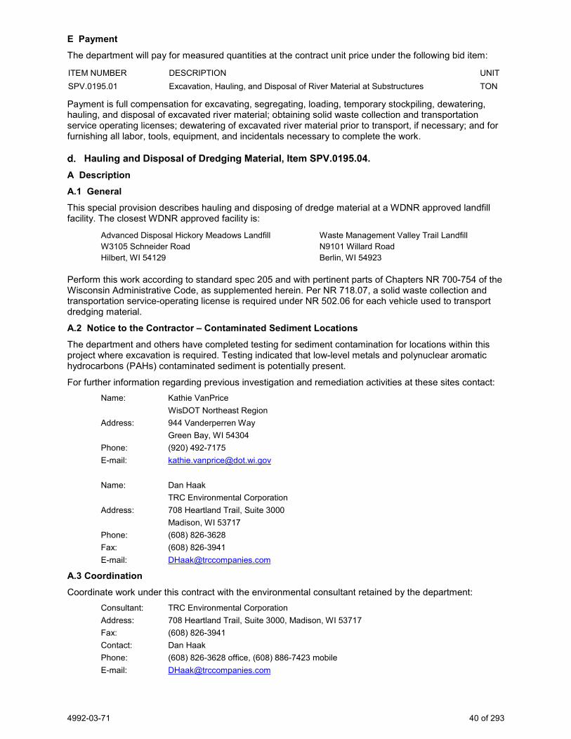
4992-03-71 40 of 293
E Payment The department will pay for measured quantities at the contract unit price under the following bid item:
ITEM NUMBER DESCRIPTION UNIT SPV.0195.01 Excavation, Hauling, and Disposal of River Material at Substructures TON
Payment is full compensation for excavating, segregating, loading, temporary stockpiling, dewatering, hauling, and disposal of excavated river material; obtaining solid waste collection and transportation service operating licenses; dewatering of excavated river material prior to transport, if necessary; and for furnishing all labor, tools, equipment, and incidentals necessary to complete the work.
Hauling and Disposal of Dredging Material, Item SPV.0195.04. A Description A.1 General This special provision describes hauling and disposing of dredge material at a WDNR approved landfill facility. The closest WDNR approved facility is:
Advanced Disposal Hickory Meadows Landfill W3105 Schneider Road Hilbert, WI 54129
Waste Management Valley Trail Landfill N9101 Willard Road Berlin, WI 54923
Perform this work according to standard spec 205 and with pertinent parts of Chapters NR 700-754 of the Wisconsin Administrative Code, as supplemented herein. Per NR 718.07, a solid waste collection and transportation service-operating license is required under NR 502.06 for each vehicle used to transport dredging material.
A.2 Notice to the Contractor – Contaminated Sediment Locations The department and others have completed testing for sediment contamination for locations within this project where excavation is required. Testing indicated that low-level metals and polynuclear aromatic hydrocarbons (PAHs) contaminated sediment is potentially present.
For further information regarding previous investigation and remediation activities at these sites contact: Name: Kathie VanPrice
WisDOT Northeast Region Address: 944 Vanderperren Way
Green Bay, WI 54304 Phone: (920) 492-7175 E-mail: [email protected]
Name: Dan Haak
TRC Environmental Corporation Address: 708 Heartland Trail, Suite 3000
Madison, WI 53717 Phone: (608) 826-3628 Fax: (608) 826-3941 E-mail: [email protected]
A.3 Coordination Coordinate work under this contract with the environmental consultant retained by the department:
Consultant: TRC Environmental Corporation Address: 708 Heartland Trail, Suite 3000, Madison, WI 53717 Fax: (608) 826-3941 Contact: Dan Haak Phone: (608) 826-3628 office, (608) 886-7423 mobile E-mail: [email protected]

4992-03-71 41 of 293
Under this special provision, the role of the environmental consultant will be limited to:
1. Documenting that activities associated with management of dredge material is in conformance with the dredge material management methods for this project as specified herein; and
2. Obtaining the necessary approvals for disposal of dredge material from the landfill facility.
Identify the WDNR approved landfill facility that will be used for disposal of dredge material and provide this information to the environmental consultant no later than 30 calendar days prior to commencement of dredging activities or at the preconstruction conference, whichever comes first. The environmental consultant will be responsible for obtaining the necessary approvals for disposal of dredge material at the landfill facility.
Do not transport dredge material offsite without prior approval from the environmental consultant.
A.4 Excavation Management Plan Approval The excavation management plan for this project has been designed to minimize risk for all parties by disposing of all dredge material at a WDNR-licensed landfill. The excavation management plan, as described in these special provisions, has been developed in cooperation with the WDNR. The WDNR’s concurrence letter is on file at the Wisconsin Department of Transportation. For further information regarding the investigations, including waste characterization within the project limits, contact Kathie VanPrice with WisDOT at (920) 492-7175.
B (Vacant) C Construction Supplement standard spec 205.3 with the following:
Directly load and haul dewatered dredge material to the WDNR approved landfill facility. Verify that vehicles used to transport dredge sediment are licensed for such activity according to applicable state and federal regulations. Use loading and hauling practices that are appropriate to prevent any spills or releases of dredge material.
D Measurement The department will measure Hauling and Disposal of Dredging Material in tons of dredging material accepted by the landfill facility as documented by weight tickets generated by the landfill facility. Weight tickets must be delivered to the engineer within 10 business days of the date on which the sediment was accepted by the landfill facility.
No payment will be made for tonnage pertaining to material removed beyond the required vertical and horizontal limits of dredging shown on the drawings. To impose this limitation of qualifying tonnage, the maximum amount of tons to be paid for Hauling and Disposal of Dredging Material is determined by the lesser of:
• Actual tonnage of dredging material per plan limits, as determined by sum of engineer-validated landfill weight tickets, or
• The product of multiplying the Cubic Yards of dredging material per plan limits by a factor of 1.75 Tons per Cubic Yard.
E Payment The department will pay for measured quantities at the contract unit price under the following bid item:
ITEM NUMBER DESCRIPTION UNIT SPV.0195.04 Hauling and Disposal of Dredging Material TON
Payment is full compensation for hauling and disposal of dredge material at WDNR licensed landfill including any tipping fees; obtaining solid waste collection and transportation service operating licenses; assisting in the collection of sediment samples for field evaluation, and for furnishing all labor, tools, equipment, and incidentals necessary to complete the work.
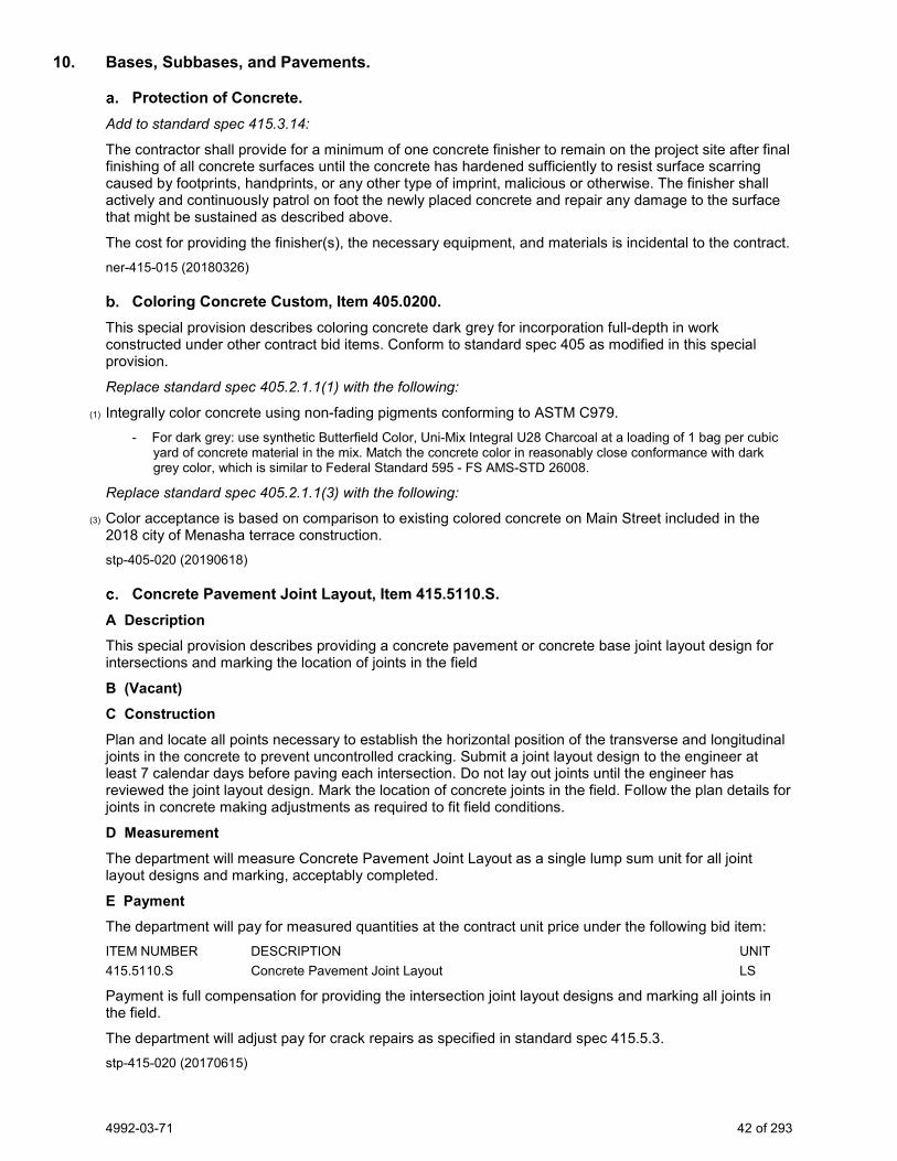
4992-03-71 42 of 293
10. Bases, Subbases, and Pavements.
Protection of Concrete. Add to standard spec 415.3.14:
The contractor shall provide for a minimum of one concrete finisher to remain on the project site after final finishing of all concrete surfaces until the concrete has hardened sufficiently to resist surface scarring caused by footprints, handprints, or any other type of imprint, malicious or otherwise. The finisher shall actively and continuously patrol on foot the newly placed concrete and repair any damage to the surface that might be sustained as described above.
The cost for providing the finisher(s), the necessary equipment, and materials is incidental to the contract. ner-415-015 (20180326)
Coloring Concrete Custom, Item 405.0200. This special provision describes coloring concrete dark grey for incorporation full-depth in work constructed under other contract bid items. Conform to standard spec 405 as modified in this special provision.
Replace standard spec 405.2.1.1(1) with the following:
(1) Integrally color concrete using non-fading pigments conforming to ASTM C979. - For dark grey: use synthetic Butterfield Color, Uni-Mix Integral U28 Charcoal at a loading of 1 bag per cubic
yard of concrete material in the mix. Match the concrete color in reasonably close conformance with dark grey color, which is similar to Federal Standard 595 - FS AMS-STD 26008.
Replace standard spec 405.2.1.1(3) with the following:
(3) Color acceptance is based on comparison to existing colored concrete on Main Street included in the 2018 city of Menasha terrace construction. stp-405-020 (20190618)
Concrete Pavement Joint Layout, Item 415.5110.S. A Description This special provision describes providing a concrete pavement or concrete base joint layout design for intersections and marking the location of joints in the field
B (Vacant) C Construction Plan and locate all points necessary to establish the horizontal position of the transverse and longitudinal joints in the concrete to prevent uncontrolled cracking. Submit a joint layout design to the engineer at least 7 calendar days before paving each intersection. Do not lay out joints until the engineer has reviewed the joint layout design. Mark the location of concrete joints in the field. Follow the plan details for joints in concrete making adjustments as required to fit field conditions.
D Measurement The department will measure Concrete Pavement Joint Layout as a single lump sum unit for all joint layout designs and marking, acceptably completed.
E Payment The department will pay for measured quantities at the contract unit price under the following bid item: ITEM NUMBER DESCRIPTION UNIT 415.5110.S Concrete Pavement Joint Layout LS
Payment is full compensation for providing the intersection joint layout designs and marking all joints in the field.
The department will adjust pay for crack repairs as specified in standard spec 415.5.3. stp-415-020 (20170615)
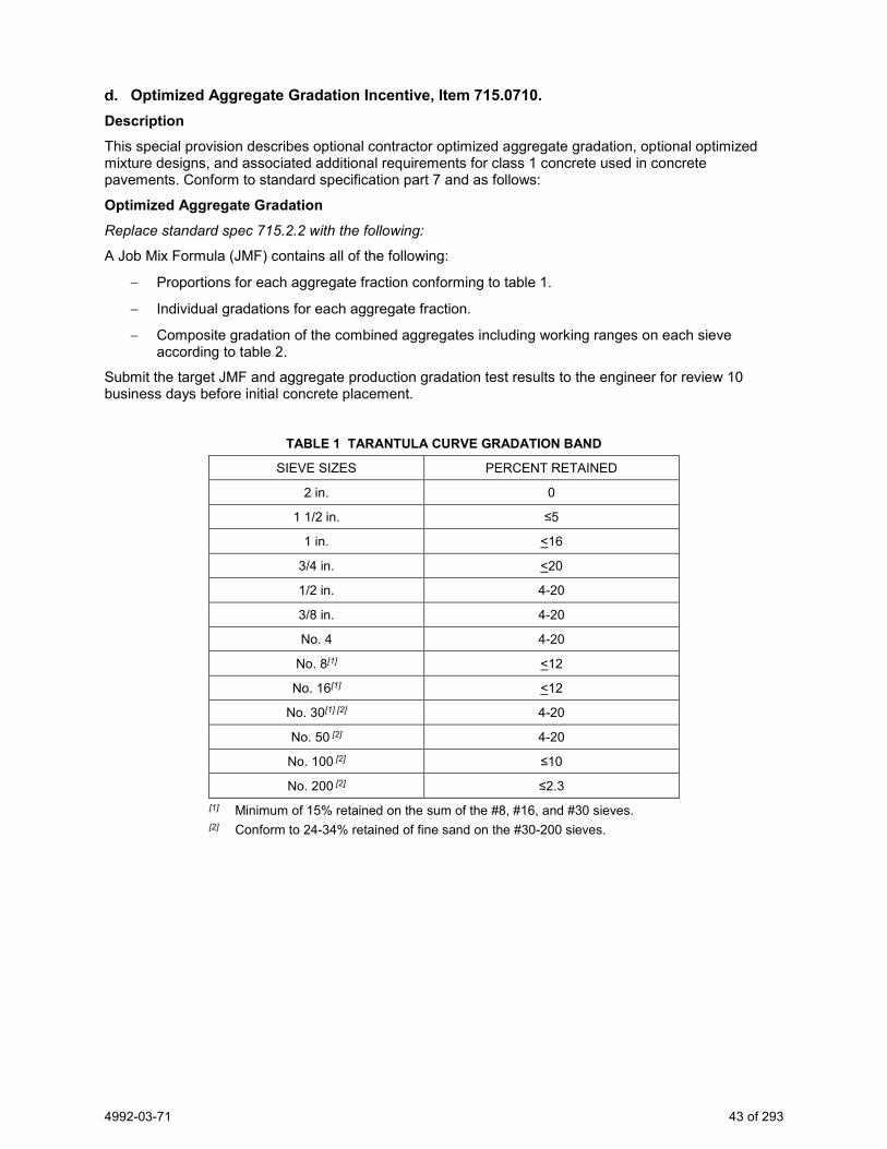
4992-03-71 43 of 293
Optimized Aggregate Gradation Incentive, Item 715.0710. Description This special provision describes optional contractor optimized aggregate gradation, optional optimized mixture designs, and associated additional requirements for class 1 concrete used in concrete pavements. Conform to standard specification part 7 and as follows:
Optimized Aggregate Gradation Replace standard spec 715.2.2 with the following:
A Job Mix Formula (JMF) contains all of the following:
− Proportions for each aggregate fraction conforming to table 1.
− Individual gradations for each aggregate fraction.
− Composite gradation of the combined aggregates including working ranges on each sieve according to table 2.
Submit the target JMF and aggregate production gradation test results to the engineer for review 10 business days before initial concrete placement.
TABLE 1 TARANTULA CURVE GRADATION BAND
SIEVE SIZES PERCENT RETAINED
2 in. 0
1 1/2 in. ≤5
1 in. <16
3/4 in. <20
1/2 in. 4-20
3/8 in. 4-20
No. 4 4-20
No. 8[1] <12
No. 16[1] <12
No. 30[1] [2] 4-20
No. 50 [2] 4-20
No. 100 [2] ≤10
No. 200 [2] ≤2.3 [1] Minimum of 15% retained on the sum of the #8, #16, and #30 sieves. [2] Conform to 24-34% retained of fine sand on the #30-200 sieves.

4992-03-71 44 of 293
TABLE 2 JMF WORKING RANGE
SIEVE SIZES WORKING RANGE[1] (PERCENT)
2 in. +/- 5 1 1/2 in. +/- 5
1 in. +/- 5 3/4 in. +/- 5 1/2 in. +/- 5 3/8 in. +/- 5 No. 4 +/- 5 No. 8 +/- 4
No. 16 +/- 4 No. 30 +/- 4 No. 50 +/- 3
No. 100 +/- 2 No. 200 ≤ 2.3
[1] Working range limits of composite gradation based on moving average of 4 tests.
Replace standard spec 710.5.6 with the following:
Determine the complete gradation, including P200, using a washed analysis for both fine and coarse aggregates. Test each stockpile for each component aggregate once per 1,500 cubic yards during concrete production.
Take samples by one of the following sampling methods: 1. At the belt leading to the weigh hopper. 2. Working face of the stock piles at the concrete plant if approved by the engineer.
The department will take independent QV samples using the same sampling method the contractor uses for QC sampling. QV samples may be taken by the contractor's QC personnel if witnessed by the department's QV personnel. The department will split each QV sample and retain half for all dispute resolutions. If QV test results conform to the specification, the department will take no further action. If QV test results are nonconforming, add the QV to the QC test results as if it were an additional QC test.
If, during concrete production, the moving average of four for any sieve fall outside the allowable JMF working range do the following:
1. Notify the engineer of the test results within 1 business day from the time of sampling. 2. Make immediate adjustments to the JMF, within the limits specified in Table 3; 3. Review JMF adjustments with the engineer. Both the contractor and engineer will sign the adjusted JMF if
the adjustments comply with Table 3. 4. If the moving average of four falls outside the adjusted allowable working range, stop production and provide
a new mix design including JMF to the engineer.
TABLE 3 ALLOWABLE JMF ADJUSTMENTS
SIEVE SIZES ALLOWABLE ADJUSTMENT
(PERCENT)
>= No. 4 +/- 5
No. 8 – No. 30 +/- 4
No. 50 +/- 3
No. 100 +/- 2

4992-03-71 45 of 293
Dispute Resolution The department will resolve disputes as specified in standard spec 106.3.4.3.5 using QV split samples.
Sublot and Lot Size A sublot consists of up to 1,500 cubic yards. A lot consists of two sublots.
Optimized Concrete Mixtures The contractor may use a reduced cementitious content for concrete pavement placed if the contractor does the following:
1. Use an optimized aggregate gradation as defined in this special provision. 2. Conform to the additional testing requirements for flexural strength as specified in the contract special
provisions. 3. Submit aggregate gradation result records no more than 2 years old when developing the mix design. 4. Determine the volume of voids in the optimized aggregates using ASTM C29. 5. Download and follow the instructions tab of the Optimized Gradation and Mix Design Spreadsheet located
at:
https://wisconsindot.gov/Pages/doing-bus/eng-consultants/cnslt-rsrces/qmp/default.aspx 6. Design an appropriate paste content based upon the Performance-based PCC Mix Design Guide located at:
https://wisconsindot.gov/Pages/doing-bus/eng-consultants/cnslt-rsrces/qmp/default.aspx 7. Provide a minimum Vpaste/Vvoids of 1.25. (Paste/Void ratio equals the volume of paste divided by the
volume of voids.). 8. Evaluate workability of trial batches by following section 6.8 of AASHTO Draft Performance Engineered
Concrete Pavement Mixtures Specifications located at:
https://wisconsindot.gov/Pages/doing-bus/eng-consultants/cnslt-rsrces/qmp/default.aspx 9. Submit trial batch workability results when submitting the mix design. 10. Submit the CP Tech center computer spreadsheet concrete mix design to the engineer for review at least 3
business days before producing concrete. 11. Provide a minimum cement content of 520 pounds per cubic yard, except if using type I, IL, or III cement in a
mix where the geologic composition of the coarse aggregate is primarily igneous or metamorphic materials, provide a minimum cement content of 660 pounds per cubic yard.
12. The contractor may use class C fly ash or grade 100 or 120 slag as a partial replacement for cement. For binary mixes use up to 30% fly ash or slag. For ternary mixes use up to 30% fly ash plus slag in combination. Replacement values are in percent by weight of the total cementitious material in the mix.
13. See CMM 8-70.2.2.3 for additional guidance.
Measurement The department will measure Optimized Aggregate Gradation Incentive by the dollar, for each combined averaged lot of QC test results meeting Table 1.
Payment The department will pay incentive of 3 percent of the contract unit price for concrete pavement under the following bid item: ITEM NUMBER DESCRIPTION UNIT 715.0710 Optimized Aggregate Gradation Incentive DOL
stp-715-005 (20191121)
Flexural Strength for Concrete Mix Design. This special provision describes optional testing requirements for flexural strength during the mix design process. Conform to standard spec part 7 as modified in this special provision.
Add the following to standard spec table 701-2:
TEST TEST STANDARD
Flexural Strength of Concrete AASHTO T97
4992-03-71 46 of 293
Replace standard spec 715.2.3.1(1) with the following:
(1) Provide both compressive and flexural strength information to demonstrate the strength of the proposed mix design. Use either laboratory strength data for new mixes or field strength data for established mixes as follows:
1. Use at least 5 pairs of cylinders for compressive strength. Demonstrate that the 28-day compressive strength will equal or exceed the 85 percent within limits criterion specified in standard spec 715.5.2.
2. Use at least 5 pairs of beams for flexural strength. Demonstrate that the 28-day flexural strength will equal or exceed 650 psi.
stp-715-010 (20170615)
Concrete Curb & Gutter 30-Inch HES Type A, Item SPV.0090.07. A Description This special provision describes providing concrete curb and gutter HES with reinforcement. Conform to standard spec 601 for concrete curb and gutter.
B Materials Furnish materials conforming to standard spec 601.2 except for concrete as specified in standard spec 416.2.
C Construction All construction methods shall conform to standard spec 601.3.
D Measurement The department will measure Concrete Curb and Gutter 30-Inch HES Type A by the linear foot, acceptably completed.
E Payment
The department will pay for measured quantities at the contract unit price under the following bid item: ITEM NUMBER DESCRIPTION UNIT SPV.0090.07 Concrete Curb and Gutter 30-Inch HES Type A LF
The department will pay for Concrete Curb and Gutter 30-Inch HES Type A as specified in standard spec 601.5. ner-601-005 (20190718)
11. Bridge.
Concrete for Seals Replace standard spec 502.4.3 (1)(2) with the following:
The department will measure Concrete Masonry Seal by cubic yard acceptably completed, measured as the volume of concrete placed up to a maximum of the volume the plans show, or the engineer directs.
The department will not measure the volume displaced by piles.
Notice to Contractor, Notification of Demolition and/or Renovation No Asbestos Found. John Roelke, License Number AII-119523, inspected Structure B-70-001 for asbestos on August 4, 2016. No regulated Asbestos Containing Material (RACM) was found on this structure. A copy of the inspection report is available from: Bill Bertrand at (920) 360-3124.
According to NR447 and DHS159, ensure that DNR or DHS receives a completed Notification of Demolition and/or Renovation (DNR Form 4500-113 (R 4/11), or subsequent revision) via U.S. mail, hand-delivery, or using the online notification system at least 10 working days before beginning any construction or demolition. Pay all associated fees. Provide a copy of the completed 4500-113 form to Bill Bertrand at (920) 360-3124, and DOT BTS-ESS attn: Hazardous Materials Specialist, PO Box 7965, Madison, WI 53707-7965. In addition, comply with all local or municipal asbestos requirements.
4992-03-71 47 of 293
Use the following information to complete WisDNR form 4500-113: - Site Name: Structure B-70-001, Racine Street over Fox River - Site Address: Fox River Bridge & Approaches - Ownership Information: WisDOT Northeast Region, 944 Vanderperren Way, Green Bay, WI 54304 - Contact: Bill Bertrand, WisDOT Northeast Region Project Manager - Phone: (920) 360-3124 - Age: 68 years old. This structure was constructed in 1952. - Area: 30,638 SF of deck
Insert the following paragraph in Section 6.g.: - If asbestos not previously identified is found or previously non-friable asbestos becomes crumbled,
pulverized, or reduced to a powder, stop work immediately, notify the engineer, and the engineer will notify the department’s Bureau of Technical Services at (608) 266-1476 for an emergency response as specified in standard spec 107.24. Keep material wet until it is abated or until it is determined to be non-asbestos containing material.
stp-107-125 (20120615)
General Requirements for Blasting. This special provision describes requirements for blasting for removal of existing substructures. Blasting methods will not be allowed for removal of material, including bedrock, under new substructure foundations.
Add the following to standard spec 205.3.7:
Perform all blasting in compliance with the Wisconsin Administrative Code Department of Safety and Professional Services SPS 307.43.
Blasting Plan Submittal Not less than two weeks before commencing blasting operations, or at any time when changes to the drilling and blasting methods are proposed, submit a Blasting Plan to the engineer for review. The blasting plan shall contain full details of the drilling and blasting patterns and controls proposed for both the controlled and production blasting. Include the following minimum information in the blasting plan:
1. Station limits of proposed shot. 2. Plan and section views of proposed drill pattern including free face, burden, blasthole spacing, blasthole
diameters, blasthole angles, lift height, and subdrill depth. 3. Loading diagram showing type and amount of explosives, primers, initiators, and location and depth of
stemming. 4. Initiation sequence of blastholes including delay times and delay system. 5. Manufacturer’s data sheets for all explosives, primers, and initiators to be employed.
The blasting plan submittal is for quality control and record keeping purposes. Review of the blasting plan by the engineer does not relieve the contractor of responsibility for the accuracy and adequacy of the plan when implemented in the field.
Safety
Immediately notify the engineer of any incidents of fly rock, damage to any personal property, or existing roadway that is open to traffic, and any violations of the Wisconsin Administrative Code Department of Safety and Professional Services SPS 307.43. Failure to do so shall be considered a safety violation under standard spec 107 and all work on the project may be stopped under standard spec 105.1(1).
Notify the engineer of the station, location, and ‘size’ of all blasts at least one hour before the blast.
Observe the entire blast area for a minimum of five minutes following a blast to guard against rock or debris fall before commencing work in the area.
The engineer has the authority to prohibit or halt the contractor’s blasting operations if it is apparent that through the methods being employed, the required slopes are not being obtained in a stable condition, the safety and convenience of the traveling public is being jeopardized, or vibration levels above the allowable levels occur.

4992-03-71 48 of 293
Condition Surveys
Conduct and document pre-blast and post-blast surveys of any nearby buildings or structures as required by the scaled-distance equation specified in the Wisconsin Administrative Code Department of Safety and Professional Services SPS 307.43. Make right of entry arrangements with the property owners for these condition surveys. Before any blasting, make the pre-blast survey records available to the engineer for review. After completion of blasting operations, perform a post-blast survey and make these records available to the engineer for review. The contractor shall be responsible for any damage resulting from blasting.
These condition surveys shall consist of visually inspecting and recording all existing defects in the structures before and after blasting operations. Photographs and/or videotape may be used to assist in documentation. Submit a written report to the department detailing the visual and photographic investigation of potentially affected structures. This report will include copies of the pre-blast and post-blast surveys and discuss any discrepancies and findings of these surveys.
If at any time during the progress of the work, the methods of drilling and blasting do not produce the desired result of a uniform slope and shear face, within the tolerances specified, drill, blast, and excavate in short sections, not exceeding 100 feet in length, until a technique is arrived at that will produce the desired results. Extra cost resulting from this requirement shall be borne by the contractor.
Vibration Control and Monitoring
All vibration control and monitoring shall comply with Wisconsin Administrative Code Department of Safety and Professional Services SPS 307.43, Instrumentation and SPS 307.44, Control of Adverse Effects.
Whenever there is a potential for vibration damage to adjacent buildings, structures, or utilities, monitor each blast with an approved seismograph located, as approved, between the blast area and the closest structure subject to blast damage, and as close as practical to the subject structure. Peak particle velocity shall not be allowed to exceed the safe limits of the nearest structure subject to vibration damage.
A vibration specialist, approved by the engineer, shall perform vibration monitoring. The vibration specialist shall monitor vibration levels according to the Wisconsin Administrative Code Department of Safety and Professional Services SPS 307.43 and interpret the seismograph records to ensure that the seismograph data shall be effectively utilized in the control of the blasting operations with respect to the existing structures and utilities.
According to the Wisconsin Administrative Code Department of Safety and Professional Services SPS 307.43 consult with the owner of any structure or utility not listed in SPS 307.43 to establish maximum allowable limits on ground vibrations. In no case shall these vibration limits exceed the following criteria:
Structure Type Maximum Peak Particle Velocity (inches/second)
Reinforced Concrete, Structures, Unoccupied 4.0
Steel Structures, Unoccupied 4.0
Buried Utilities 2.0
Wells and Aquifers 2.0
Green Concrete (Less than 7 days) 1.0
Furnish data recorded for each shot to the engineer before the next blast; the data shall include the following:
1. Identification of vibration monitoring instrument used. 2. Name of qualified observer and interpreter. 3. Distance and direction of recording station from blast area. 4. Type of ground at recording station and material on which the instrument is sitting. 5. Peak particle velocity and principal frequency in each component. 6. A dated and signed copy of records of seismograph readings. 7. A comparison of measured seismograph readings to maximum allowable readings identified in the
Wisconsin Administrative Code Department of Safety and Professional Services SPS 307.43 or as specified in this special provision.

4992-03-71 49 of 293
If the recorded vibration data exceeds the allowable levels established in the Wisconsin Administrative Code Department of Safety and Professional Services SPS 307.43 or as specified in this special provision, immediately halt blasting operations. Submit a revised blasting plan to the engineer and do not resume blasting operations until the engineer approves the revised plan.
All costs associated with the work described herein shall be considered included in the bid item Excavation Rock. stp-205-050 (20141107)
Underwater Foundation Inspection South Abutment, Item 206.1050.S.01; Underwater Foundation Inspection Pier 1, Item 206.1050.S.02; Underwater Foundation Inspection Pier 3, Item 206.1050.S.03; Underwater Foundation Inspection Pier 4, Item 206.1050.S.04.
A Description
This special provision describes providing underwater inspections of the substructure foundations conforming to standard spec 206.3.12.
B (Vacant) C Construction
Provide a diver who, under the direction of the engineer, will report the characteristics, cleanliness and quality of the excavated rock surface below the seal or footing to ensure that the foundation has been properly prepared as specified in standard spec 206.3.8.
Provide a video monitor and video camera, along with two-way audio communications with the diver during the inspection and record the video and audio.
Correct any deficiencies in the preparation of the seal or footing foundation and repeat the inspections until all deficiencies are corrected.
Place the seal or footing concrete within 24 hours after all deficiencies are corrected or as the engineer directs.
D Measurement The department will measure Underwater Substructure Inspection (Location) once for each individual unit, acceptably completed. The entire pier or abutment substructure location is considered a unit. Multiple underwater inspections at the same substructure location to correct concrete deficiencies will not be measured.
E Payment The department will pay for measured quantities at the contract unit price under the following bid item: ITEM NUMBER DESCRIPTION UNIT 206.1050.S.01 Underwater Foundation Inspection South Abutment EACH 206.1050.S.02 Underwater Foundation Inspection Pier 1 EACH 206.1050.S.03 Underwater Foundation Inspection Pier 3 EACH 206.1050.S.04 Underwater Foundation Inspection Pier 4 EACH
Payment is full compensation for all diving inspections and reporting; and for supplying video and two-way audio communications equipment and electronic video and audio files. stp-206-050 (20190618)
Ice Hot Weather Concreting, Item 501.1000.S. Conform to standard spec 501.3.8.2 except the department will pay for ice at the contract unit price under the Ice Hot Weather Concreting bid item. This special provision only applies to work done under the following contract bid items:
Concrete Masonry Bridges Concrete Masonry Retaining Walls Concrete Masonry Bridges HES Concrete Masonry Retaining Walls HES Concrete Masonry Culverts Concrete Masonry Endwalls Concrete Masonry Culverts HES Concrete Masonry Overlay Decks High Performance Concrete (HPC) Masonry Structures
4992-03-71 50 of 293
Replace standard spec 501.4 and 501.5 with the following:
501.4 Measurement (1) The department will measure Ice Hot Weather Concreting by the pound acceptably completed, measured
only if the conditions prescribed in standard spec 501.3.8.2 are met.
501.5 Payment (1) The department will pay for measured quantities at the contract unit price under the following bid item:
ITEM NUMBER DESCRIPTION UNIT 501.1000.S Ice Hot Weather Concreting LB
(2) Payment for Ice Hot Weather Concreting is full compensation for ice used to cool concrete placed in hot weather as specified in standard spec 501.3.8.2.
(3) The department will not pay directly for the concrete specified under this section. Concrete is incidental to the various bid items using it. Payment under those bid items includes providing all materials, including aggregates and associated aggregate source testing, cement, fly ash, slag, and admixtures; for preparing, transporting, storing, protecting and curing concrete; and for contractor requirements related to testing specified in standard spec 501.3.10.
(4) If required to remove and replace any concrete damaged by lack of proper protection. Perform this work at no expense to the department. stp-501-010 (20151210)
Concrete Masonry Seal. Replace standard spec 502.4.3 (1)(2) with the following:
The department will measure Concrete Masonry Seal by cubic yard acceptably completed, measured as the volume of concrete placed up to a maximum of the volume the plans show, or the engineer directs.
The department will not measure the volume displaced by piles.
Expansion Device, Item 502.3101 A Description
This special provision describes furnishing and installing an expansion device as the plans show conforming to standard spec 502 as modified in this special provision.
B Materials
The minimum thickness of the polychloroprene strip seal shall be 1/4 inch for non-reinforced elastomeric glands and 1/8 inch for reinforced glands. Furnish the strip seal gland in lengths suitable for a continuous one-piece installation at each individual expansion joint location. Provide preformed polychloroprene strip seals that conform to the requirements ASTM D3542, and have the following physical properties:
Property Requirements Value Test Method
Tensile Strength, min. 2000 psi ASTM D412
Elongation @ Break, min 250% ASTM D412
Hardness, Type A, Durometer 55 ± 5 pts. ASTM D2240
Compression Set, 70 hours @212˚F, max. 35% D395 Method B Modified
Ozone Resistance, after 70 hrs. at 100˚F under 20% Strain with 100 pphm ozone No Cracks ASTM D1149 Method A
Mass Change in Oil 3 after 70 hr. 212˚F Mass Change, max. 45% ASTM D471
Install the elastomeric strip seal gland with tools recommended by the manufacturer, and with a lubricant adhesive conforming to the requirements of ASTM D4070.

4992-03-71 51 of 293
The manufacturer and model number shall be one of the following approved strip seal expansion device products:
Model Number Strip Seal Gland Size[1]
Manufacturer 4-Inch 5-Inch 6-Inch
D.S. Brown SSA2-A2R-400 SSA2-A2R-XTRA SSA2-A2R-XTRA
R.J. Watson RJA-RJ400 RJA-RJ500 RJA-RJ600
Watson Bowman Acme A-SE400 A-SE500 A-SE800
Commercial Fabricators A-AS400 ----- ----- [1] Expansion device strip seal gland size requirement of 4", 5", and 6" shall be as the plans show.
Furnish manufacturer’s certification for production of polychloroprene represented showing test results for the cured material supplied and certifying that it meets all specified requirements.
The steel extrusion or retainer shall conform to ASTM designation A 709 grade 36 steel. After fabrication, steel shall be galvanized conforming to the requirements ASTM A123.
Manufacturer’s certifications for adhesive and steel shall attest that the materials meet the specification requirements. stp-502-020 (20200629)
Underwater Substructure Inspection B-70-324, Item 502.9000.S. A Description
This special provision describes providing underwater inspections of the substructure seal(s), footing(s) or shaft(s).
B (Vacant) C Construction
After placement of Concrete Masonry Bridges or Concrete Masonry Seal for the substructure and as soon as practicable after removal of the forms, provide a diver who, under the direction of the engineer, will report the characteristics and quality of the concrete placed below water level to ensure that the concrete masonry has been properly formed and placed.
Provide a video monitor and video camera, along with two-way audio communications with the diver during the inspection and record the video and audio.
Correct all deficiencies in the concrete and repeat the inspections until all deficiencies are corrected.
D Measurement The department will measure Underwater Inspection once for each individual unit, acceptably completed. The entire pier or abutment substructure location is considered a unit. Multiple underwater inspections at the same substructure location to correct deficiencies will not receive additional compensation beyond the bid price each per structure unit.
E Payment The department will pay for measured quantities at the contract unit price under the following bid item: ITEM NUMBER DESCRIPTION UNIT 502.9000.S Underwater Substructure Inspection B-70-324 EACH
Payment is full compensation for all diving inspections and reporting; and for supplying video and two-way audio communications equipment and recorded electronic video and audio files. Payment for correcting deficiencies in the placed concrete will be included at no extra cost to the project. stp-502-090 (20190618)

4992-03-71 52 of 293
Bar Steel Reinforcement HS Stainless Structures, Item 505.0800.S. A Description
This special provision describes furnishing and placing stainless steel reinforcing bars and associated stainless steel bar couplers.
Conform to standard spec 505 as modified in this special provision.
B Materials B.1 General Furnish stainless steel reinforcing bars conforming to ASTM A955 and to one of the following Unified Numbering System (UNS) designations: S31653, S31803, S32205, or S32304. Supply grade 60 bars, all of the same UNS designation. Conform to the chemical composition specified for the given UNS designation in ASTM A276 table 1.
Supply bars that are free of dirt, mill scale, oil, and debris by pickling to a bright or uniform light finish. The department may reject bars displaying rust/oxidation, questionable blemishes, or lack of a bright or uniform pickled surface.
Furnish chairs or continuous supports made of stainless steel or recycled plastic to support high-strength stainless bar steel reinforcement subject to the plastic chair restriction stated in standard spec 505.3.4(1).
Furnish couplers made from one of the UNS alloys allowed for bar steel.
Furnish tie wire made from one of the UNS alloys allowed for bar steel or from an engineer-approved plastic or nonmetallic material. Ensure that stainless steel tie wire is dead soft annealed.
B.2 Fabrication Before fabrication, supply test results from an independent testing agency certifying that the reinforcement meets the requirements of Annex A1 of ASTM A955.
Bend bars conforming to standard spec 505.3.2 and according to ASTM A955. Bend and cut bars using equipment thoroughly cleaned or otherwise modified to prevent contamination from carbon steel or other contaminants. Use tools dedicated solely to working with stainless steel.
B.3 Control of Material Identify reinforcement bars delivered to the project site with tags bearing the identification symbols used in the plans. Include the UNS designation, heat treat condition, heat number, grade corresponding to minimum yield strength level, and sufficient documentation to track each bar bundle to a mill test report.
Provide samples for department testing and acceptance according to CMM 8-50 Exhibit 1 requirements for concrete masonry reinforcement for uncoated bar steel.
Provide mill test reports for the project that do the following: 1. Verify that sampling and testing procedures and test results conform to ASTM A955, ASTM A276 table 1,
and these contract requirements. 2. Include a chemical analysis with the UNS designation, heat lot identification, and the source of the metal. 3. Include tensile strength, yield strength, and elongation tests results conforming to ASTM A955 for each size
furnished. 4. Certify that the bars have been pickled to a bright or uniform light finish.
C Construction
C.1 General Ship, handle, store, and place the stainless steel reinforcing as follows:
1. Separate from regular reinforcement during shipping. Pad points of contact with steel chains or banding, or secure with non-metallic straps.
2. Store on wooden cribbing separated from regular reinforcement. Cover with tarpaulins if stored outside. 3. Handle with non-metallic slings. 4. Do not flame cut or weld. Protect from contamination when cutting, grinding, or welding other steel products
above or near the stainless steel during construction. 5. Place on plastic or stainless steel bar chairs. If placing stainless steel chairs on steel beams, use chairs with
plastic-coated feet. 6. Tie with stainless steel wire or an engineer-approved plastic or nonmetallic material.

4992-03-71 53 of 293
Do not tie stainless steel reinforcing bars to, or allow contact with, uncoated reinforcing bars or galvanized steel. Maintain at least 1 inch clearance between stainless steel bars or dowels and uncoated or galvanized steel. Where 1 inch clearance is not possible, sleeve bars with a continuous polyethylene or nylon tube at least 1/8 inch thick extending at least 1 inch in each direction and bind with nylon or polypropylene cable ties. Sleeves are not required between stainless steel bars and shear studs. Stainless steel bars can be in direct contact with undamaged epoxy-coated bars.
Cut flush with the top flange or remove uncoated fasteners, anchors, lifting loops, or other protrusions into a bridge deck before casting the deck on prestressed concrete beams.
C.2 Splices
Splice as the plans show. Provide stainless steel couplers conforming to the minimum capacity, certification, proof testing, and written approval requirements of standard spec 550.3.3.4. The contractor may substitute stainless steel couplers for lap slices the plans show if the engineer approves in writing.
If increasing or altering the number or type of bar splices the plans show, provide revised plan sheets to the engineer showing the reinforcement layout, type, length, and location of revised bar splices and revised bar lengths. Obtain engineer approval for the location of new lap splices or substitution of mechanical bar couplers before fabrication. Ensure that new lap splices are at least as long as those the plans show.
D Measurement The department will measure Bar Steel Reinforcement HS Stainless Structures by the pound acceptably completed, computed from the nominal weights of corresponding sizes for carbon steel deformed bars in AASHTO M31 regardless of stainless steel alloy provided. The department will not measure extra material used if the contractor alters the reinforcement layout as allowed under C.2, extra material for splices or couplers the plans do not show, or the weight of devices used to support or fasten the steel in position.
The department will measure the Bar Couplers Stainless bid items as each individual coupler, acceptably completed.
E Payment The department will pay for measured quantities at the contract unit price under the following bid item: ITEM NUMBER DESCRIPTION UNIT 505.0800.S Bar Steel Reinforcement HS Stainless Structures LB
Payment for Bar Steel Reinforcement HS Stainless Structures is full compensation for furnishing and placing stainless steel reinforcing bars, including supports. Where the plans specify bar couplers, the department will pay for the length of bars as detailed with no deduction or increase for installation of the coupler. stp-505-005 (20190618)
Counterweight Concrete, Item SPV.0035.01. A Description This special provision describes performing all work related to the construction of the concrete counterweight for the bascule leaf.
B Materials B.1 Concrete Construct counterweight using Grade A concrete. Perform the work according to applicable provisions of standard spec 501, except air-entrainment will not be required for counterweight concrete.
For design purposes in developing the size of the counterweight shown on the plans, the unit weight of non-air-entrained counterweight concrete was assumed to be 149 pounds per cubic foot. Select appropriate materials for the concrete mix to achieve this unit weight. Modify the proposed size and/or configuration of the counterweight and counterweight pockets as necessary to account for any planned or unplanned deviations from that target unit weight.

4992-03-71 54 of 293
C Construction C.1 General Construct and configure the counterweight as shown on the plans except as specified below under “Balancing Calculations”.
Determine the final weight, outline and precise horizontal and vertical location of the center of gravity of counterweight. During final adjustment provide a “slight” over-balance on the channel side of the bascule leaf as specified below under “Balancing”.
Assume full responsibility for the correctness of final detailing and construction of the counterweight, so that when completed, the bridge will be in proper balance.
The counterweight framing is not designed to support the wet concrete. Construct the counterweight using proper forms and supports. Whenever there is a lapse of time between the placing of successive layers of concrete, provide 5/8-inch diameter dowels, not less than 3 feet long at 24-inch centers and embedded 18 inches into the fresh concrete for the purpose of tying the next succeeding layer to that just poured. In addition, roughen and clean the surface for the next pour and coat it with cement mortar immediately before placing additional concrete thereon.
Submit for review the method of supporting the counterweight forms. Such review does not, however, relieve the contractor of any responsibility in connection with the construction of the counterweight.
C.2 Test Blocks In order to make a close determination of the average unit weight of the concrete that will be used to construct the counterweight, make at least four sets of test blocks, with no less than six blocks in each set. Each block will measure at least 8 inches by 8 inches by 12 inches and all blocks will be the same size. The forms for the test blocks will be rigid and impervious. The concrete used for the test blocks will contain the same materials and air content as the concrete that will be used in the counterweight. After the concrete is poured into the forms, vibrate it to the same extent that the counterweight concrete will be vibrated. After vibrating, strike off the tops prior to initial set. Cure the test blocks in their forms for two days with the tops uncovered. During this time, store the blocks under shelter in the open air. Do not sprinkle water on them for purpose of curing. After two days, remove the forms and weigh the blocks. Use a scale having an accuracy of 0.01 pound to weigh the blocks. Accurately measure all three dimensions and record the weights of the individual blocks, the calculated unit weight of the individual blocks, and the calculated average unit weight of the set of blocks to the nearest 0.01 pcf. Recalibrate the scale by weighing a reference object prior to each time a set of blocks is weighed.
Make the first set of test blocks at least 75 days prior to final detailing of the proposed counterweight and completing the center of gravity calculations for the bascule leaf with counterweight.
Make the second set of test blocks approximately 15 days after the first set is made. If the average unit weight of the second set of blocks differs from the average unit weight of the first set by more than 1.0 pound per cubic foot, cast additional sets of test blocks until consistent unit weights are obtained.
Make an additional set of test blocks approximately seven days prior to pouring the counterweight. If the average unit weight of these test blocks differs from the average unit weight of the previous sets by more than 1.5 pcf, notify the engineer of the steps intended to be taken to ensure the proper balance of the completed bridge. The engineer's approval of these steps will be required prior to pouring the counterweight concrete.
Cast a set of test blocks with the concrete actually used in each pour of the counterweight. If the average unit weight of any of these sets differs from the average unit weight required by more than 1.5 pcf, notify the engineer of the steps intended to be taken to ensure the proper balance of the completed bridge. The engineer's approval of these steps will be required prior to pouring any additional portions of the counterweight concrete.
C.3 Balancing Calculations Prepare complete center of gravity calculations for the entire bascule leaf including its counterweight using weights and centers of gravity based on approved shop details for all components of the bascule leaf. Prepare these calculations by grouping material and computing subtotals only as directed by the engineer. Balance calculations not prepared by grouping material, as directed by the engineer, will be rejected. No construction will proceed on the counterweight until the contractor's balance calculations, and counterweight drawings with final dimensions and details have been reviewed by the engineer. This review will not relieve the contractor of the sole responsibility to provide acceptably balanced bascule leaf.
4992-03-71 55 of 293
Adjustments for balancing of the leaf can be accomplished by varying any combination of the following:
• The size and shape of the concrete counterweight. If the size of the counterweight is increased, it must be made in areas that will not critically reduce clearances to any adjacent fixed elements of the structure.
• The size, shape and location of voids in the counterweight for placement of adjustment blocks.
• The number of voids within the counterweight.
Prepare final balancing calculations based on the requirement that after completion of construction, the adjustment blocks installed in the adjustment pockets will constitute, at a minimum, 3.5 percent of the total weight of the counterweight. The number of adjustment blocks shown on the plans reflects a weight that is approximately 3.5 percent of the total design weight of the counterweight. Provide adjustment blocks distributed in the upper and lower pockets in proportion to what is shown on the plans and of approximately the total quantity shown on the plans.
C.4 Concrete Adjustment Blocks Make counterweight balancing adjustment blocks of the same size as shown in the plans.
Place the adjustment blocks in the pockets as shown on the final contractor prepared balancing drawings or as directed by the engineer. Provide the number of additional blocks shown on plans neatly stacked at the track level of the bascule pier and bascule abutment as directed by the engineer.
C.5 Balancing Check initial balance of the bascule leaf by opening and closing the leaf repeatedly under power while checking and recording the amperage. For initial balancing, adjustment blocks will be added, removed or rearranged until the amperage readings for opening and closing are approximately the same.
Place the first row of adjustment blocks in any pocket tight and neatly against the back of the pocket, and each subsequent row tight against the previous row.
Prior to placement of blocks into balance pockets for final balancing, remove any debris from the adjustment pockets; only adjustment blocks will be permitted in the pockets.
Measure the balance of each leaf of the movable span using the dynamic strain gauging technique. Furnish and install all equipment, materials, instruments, and labor necessary to determine the imbalance by dynamic strain gauging.
Employ the services of an established testing company experienced in dynamic strain gauge measurement of movable bridge balance, subject to approval of the engineer. To demonstrate such experience, identify a minimum of six movable bridges, including at least three bascule bridges, for which the company has provided complete and satisfactory dynamic strain gauge measurements and reporting. Make the measurements under the immediate direction of a professional engineer registered in the State of Wisconsin who has had hands-on-experience measuring movable span balance by the dynamic strain gauge procedure.
Furnish and install the required strain gauges, all cabling and transmission equipment, data acquisition equipment and strip chart recorders, and produce fully documented reports detailing the results of the measurements.
The following applies to the approved testing company: Submit the following items to the engineer for approval:
1. Description of experimental procedure including type and method of installation of strain gauge rosettes, method of transmission of low level signals, data acquisition equipment and/or strip chart recorders.
2. Layout of span drive machinery showing proposed location of strain gauges, amplifiers, cable or radio links, data acquisition equipment and all associated cabling.
3. Details of method of transmission of signals from shafting to data acquisition units.
4. Elementary wiring diagrams of interconnection of strain gauges, amplifiers, data acquisition equipment, and strip chart recorders.
5. Sample computations of shaft torque from measured strains, span imbalance, curve fitting and basis for friction correction.

4992-03-71 56 of 293
Affix two foil resistance strain gauge rosettes to each of the main pinion shafts, according to the strain gauge manufacturer’s installation instructions. Use 2-arm 90-degree rosettes mounted such that the grids are oriented at 45 degrees with the shaft axis and the two rosettes are affixed “back-to-back”, spaced 180 degrees apart circumferentially. Connect the gauges such that any bending strains in the shafts will be canceled and torsional shearing strains will be measured on each pinion shaft. Sufficiently clean the areas of the shafts where the gauges are to be mounted to remove all contaminants. On each shaft, mount two rosettes at 180 degrees from each other. Connect the two gauges such that any direct shear forces in the shafts are neglected and true torsional shear is measured.
Connect the strain gauge leads on each shaft to a four-arm amplifier. Transmit signals from the gauges to the data acquisition equipment either through cable links or amplified and then through wireless transmitters.
Connect output leads from each channel of the amplifiers to either a computer-based data logger provided with a two-channel strain gauge module streaming the amplified data to disk at a minimum1-kHz sample rate, or a five-channel minimum strip chart recorder with at least 250 mm wide chart paper. Provide an inclinometer to provide continuous leaf angle to either the data logging equipment or the strip chart recorder. Utilize step-wise adjustable chart speed and include a setting of at least 250 mm per minute. Use a recorder that is capable of recording data from at least 4 channels if it is equipped with a dedicated event marker or 5 channels if a channel is used to record events.
Record the strains in both shafts simultaneously versus span opening angle during opening and closing to a suitable scale. Record the readings for all shafts at the same strain scale and the chart speed, if a strip chart recorder is used. Make at least 3 opening/closing runs, when the wind speed is less than 5 miles/hour and the bridge deck is visibly dry. Release wind-up torque in the operating machinery prior to each run as verified by space between the faces of the engaged teeth of main pinion and gears.
Numerically convert the strains induced in the shafts to torque by applying fundamental stress-strain relationship calculations for each strain plot for both opening and closing. Use this data to give leaf imbalance versus opening angle, corrected for friction, at each pinion. Prepare plots of total span imbalance.
Submit a report documenting the results of the initial strain gauge measurements to the engineer. Separate reports are required for each leaf. Include the following in the reports:
1. Description of experimental procedure and equipment used.
2. Span drive diagram showing location at which strain gauges were attached and all applicable gear ratios.
3. Photocopies of a sample original strip chart for one complete run of each of the three sets in the case of strip chart recordings or data and chart files in Excel format if recorded by a data logger. Annotate with strain scales, angle of opening, significant ordinates, etc.
4. Description of relationships and sample calculations for obtaining shaft torque from strains, span imbalance from shaft torque, curve fitting and basis for friction correction.
5. Plots of the following parameters versus degree of opening during each opening/closing run and fitted balance curves corrected for friction:
− Total imbalance in foot-pounds for span.
− Frictional moment in foot-pounds for span.
6. Tabulation of imbalance moment at seated position for each leaf/run including the average value for each leaf.
7. The location of the leaf center of gravity.
After balance block adjustment, submit the final balance report, similar to the initial report, to the engineer. Include an introductory section giving the name of the bridge, the date of the measurements, weather conditions during measurements and any other information requested by the engineer.
Provide 5) working days of advance notice for final balance of the bascule leaf. For final balance of the bascule leaves, add, remove or rearrange adjustment blocks as necessary to make the leaves “slightly” leaf-heavy; that is, when no outside forces are acting on the leaf, it should tend to slowly drift to the closed position. The “slightly leaf heavy” condition is defined as:
4992-03-71 57 of 293
a. A downward reaction at the tip of each bascule girder when in the closed position of no less than 1,000 pounds and no greater than 2,000 pounds, and
b. The center of gravity with the span fully seated is located towards the channel at an angle no greater than 20 degrees above or below the horizontal line passing through the pinion.
The final balance will be checked in the nearly closed and nearly open positions as follows: With the leaf stationary, place the drive in a “freewheeling” mode with the brakes released. The leaf should begin to drift closed. Record the time that it takes from the moment that the brakes are released until the leaf has drifted 1.0 degree. If the leaf drifts more than 1.0 degree in 10 seconds, place additional adjustment blocks in the pockets as necessary. If the leaf drifts less than 1.0 degree in 60 seconds, remove adjustment blocks from the pockets as necessary.
Final balancing will be subject to the approval of the engineer and all necessary adjustment and materials which may be required will be considered as part of the work and expense of the contractor.
C.6 Acceptance The balance of the bascule leaf will be considered unacceptable if any of the following conditions occur:
• After final balancing, the total weight of adjustment blocks in the pockets constitutes less than 1 percent of the total weight of the counterweight.
• After final balancing, the total weight of adjustment blocks in the pockets constitutes more than 6 percent of the total weight of the counterweight.
• After final balancing, the bascule leaf is “slightly leaf heavy” as defined above.
D Measurement The department will measure Counterweight Concrete by the cubic yard of counterweight concrete, acceptably constructed, based on the proposed dimensions for the counterweight in the approved balancing calculations plus the volume of adjustment blocks approved and actually constructed.
E Payment The department will pay for measured quantities at the contract unit price under the following bid item: ITEM NUMBER DESCRIPTION UNIT SPV.0035.01 Counterweight Concrete CY
Payment is full compensation for performing all the work required to place the bascule leaf in a condition of balance that conforms to the above stated requirements. The cost of preparing approved balancing calculations is included in the bid item Structural Steel Bridge.
Concrete Masonry Bridges Lightweight, Item SPV.0035.02. A Description This special provision describes furnishing and placing lightweight concrete masonry for the movable bridge deck conforming to standard spec 502.
B Materials This work requires that the open-grid deck be filled with lightweight concrete masonry having a unit weight of 115 pounds per cubic foot. The lightweight concrete shall have a minimum compressive strength of 4,000 psi at 28 days. The contractor is responsible for the lightweight concrete mix design.
Submit the concrete mix design, including all required test data, to the engineer for approval.
B.1 Lightweight Coarse Aggregate Lightweight coarse aggregate shall conform to AASHTO M195. When tested according to AASHTO M104 using magnesium sulfate, the loss of lightweight aggregate in 5 cycles of the accelerated soundness test shall not exceed 8 percent. The drying shrinkage of concrete specimens prepared and tested conforming to section 8.4 of AASHTO M195, shall not exceed 0.07 percent. The resistance to degradation of the coarse aggregate, when tested conforming to AASHTO T96, shall not exceed a loss of 50% in 500 cycles.
The lightweight aggregate producer shall furnish test reports from an independent testing laboratory certifying that concrete made from the aggregate and containing approximately 6 percent air content shall have a minimum durability factor of 85 percent when tested conforming to AASHTO T161.
4992-03-71 58 of 293
B.2 Composition of Concrete Determine the proportions of cement, supplementary cementitious materials, fine aggregate, lightweight coarse aggregate and water and submit with the test result data to the engineer for approval. The unit weight of freshly mixed lightweight concrete measured conforming to AASHTO T121 shall not be greater than 116 and no less than 114 pounds per cubic foot. The water/cementitious materials ratio of the mix shall not exceed 0.40. Use a polycarboxylate high range water reducing admixture to achieve the workability required for placement of the concrete. The minimum cementitious materials content is 565 pounds per cubic yard. The mixture at the point of placement shall have a slump of 5” +/- 1” and air content of 7% +/-1%. The concrete shall have a minimum compressive strength of 4000 psi at an age of 28 days.
Use supplementary cementitious materials as needed to achieve low concrete permeability concrete that meets the testing requirements specified below. Fly ash, if used, shall conform to AASHTO M295, and may be used as a partial replacement for cement up to 30% on a 1:1 ratio by weight. Ground granulated blast furnace slag, if used, shall conform to AASHTO M302 and may be used as a partial replacement for cement up to 30% on a 1:1 ratio by weight. Silica Fume, if used, shall conform to AASHTO M 307 and may be used as a partial replacement for cement up to 10% on a 1:1 ratio by weight. The combined weight of all supplementary cementitious materials used in the mix shall be limited so that portland cement constitutes a minimum of 60% by weight of the total cementitious material.
Measure concrete permeability conforming to AASHTO T277 (Rapid Chloride Permeability Test). Permeability samples for T277 testing must be stripped of their molds and wet cured to an age of 7 days in a standard moist room or water tank. After 7 days, submerge the samples in water heated to 100°F until an age of 28 days. Upon completion of the curing process, obtain one sample from each cylinder and test conforming to AASHTO T277. The permeability test result shall not exceed 1500 coulombs.
C Construction In order to make a close determination of the average unit weight of the concrete that will be used in the deck, make at least four sets of test blocks, with no less than six blocks in each set. Each block will measure at least 8 inches by 8 inches by 12 inches and all blocks will be the same size. The forms for the test blocks will be rigid and impervious. The concrete used for the test blocks will contain the same materials and air content as the concrete that will be used in the deck. After the concrete is poured into the forms, vibrate it to the same extent that the deck concrete will be vibrated. After vibrating, strike off the tops prior to initial set. Cure the test blocks in their forms for two days with the tops uncovered. During this time, store the blocks under shelter in the open air. Do not sprinkle water on them for purpose of curing. After two days, remove the forms and weigh the blocks. Use a scale having an accuracy of 0.01 pound to weigh the blocks. Accurately measure all three dimensions and record the weights of the individual blocks, the calculated unit weight of the individual blocks, and the calculated average unit weight of the set of blocks to the nearest 0.01 pcf. Recalibrate the scale by weighing a reference object prior to each time a set of blocks is weighed.
To prove the design meets the given criteria, provide the engineer with the mix design and all required test results at least 4 days prior to making the first set of test blocks.
Make the first set of test blocks at least 75 days prior to final detailing of the proposed counterweight and completing the center of gravity calculations for the bascule leaf with deck and counterweight.
Make the second set of test blocks approximately 15 days after the first set is made. If the average unit weight of the second set of blocks differs from the average unit weight of the first set by more than 1.0 pound per cubic foot, cast additional sets of test blocks until consistent unit weights are obtained.
Make an additional set of test blocks approximately seven days prior to pouring the deck. If the average unit weight of these test blocks differs from the average unit weight of the previous sets by more than 1.5 pcf, notify the engineer of the steps intended to be taken to ensure the proper balance of the completed bridge. The engineer's approval of these steps will be required prior to pouring the counterweight concrete.
Cast a set of test blocks with the concrete actually used in each pour of the deck. If the average unit weight of any of these sets differs from the average unit weight required by more than 1.5 pcf, notify the engineer of the steps intended to be taken to ensure the proper balance of the completed bridge. The engineer's approval of these steps will be required prior to pouring any additional portions of the deck concrete.

4992-03-71 59 of 293
Stockpile all lightweight aggregate at the central batching plant for not less than 24 hours prior to use in the batches. Pre-wet the lightweight aggregate stockpiles using a sprinkler system as recommended by the lightweight aggregate manufacturer. At the end of the wetting period, allow the stockpiles to drain for a period of 12-15 hours immediately prior to use. Protect the stockpiles to prevent excessive evaporation of moisture after wetting.
Monitor air content using the volumetric method, conforming to AASHTO T196.
Delay the pour if the temperature within 48 hours following the proposed pour is predicted to fall below 40°F (5°C).
Give the concrete a continuous wet cure for a period of 7 days.
D Measurement The department will measure Concrete Masonry Bridges Lightweight by the cubic yard, acceptably completed, conforming to standard spec 502.4.2.
E Payment The department will pay for measured quantities at the contract unit price under the following bid item: ITEM NUMBER DESCRIPTION UNIT
SPV.0035.02 Concrete Masonry Bridges Lightweight CY
Payment for Concrete Masonry Bridges Lightweight is full compensation for furnishing test blocks, furnishing and placing concrete, monitoring, and curing.
Clearance Gauge, Item SPV.0060.01. A Description This special provision describes cleaning the end of the bascule pier and bascule abutment and painting a clearance gauge on each. This work shall be according to the plans, as directed by the engineer, and as hereinafter provided.
B Materials Use paint that is formulated to be used on concrete in exterior weather conditions. Provide product data to the engineer.
C Construction To clean the area to be painted, give it a light sand blast.
D Measurement The department will measure Clearance Gauge as each individual clearance gauge, acceptably completed.
E Payment The department will pay for measured quantities at the contract unit price under the following bid item: ITEM NUMBER DESCRIPTION UNIT SPV.0060.01 Clearance Gauge EACH
Payment is full compensation for cleaning the pier and abutment areas and painting the clearance gauge.
Decorative Pedestal Masonry, Item SPV.0060.09. A Description Furnish all labor, material and tools required for the satisfactory completion of the precast pedestal cap and thin brick facing at the Racine Street Bridge piers and retaining wall according to the drawings and as set forth in these specifications.
Included are the following:
1. Precast Stone pedestal caps.
2. Thin brick pier facing.
4992-03-71 60 of 293
B Materials B.1 Cast Stone Pier Caps B.1.1 Submittals Make all submittals according to standard spec 105 and 106.
For cast-stone units, submit manufacturer test reports for concrete mix based on testing according to ASTM C 1364 and including test for compressive strength, water-absorption and resistance to freezing and thawing.
Submit shop drawings showing fabrication and installation details for cast-stone units. Include dimensions, details of reinforcement and anchorages, and indication of finished faces.
Submit 12 by 12 inches by 2 inch samples for color and texture of cast stone required.
B.1.2 Quality Assurance Fabricator Qualifications: PCI-certified plant for Group A, Category AT that assumes responsibility for engineering precast stone units with a minimum of 5 years successful experience in manufacturing precast stone units similar to those required. Submit documentation stating that the fabricator meets these qualifications.
Quality-Control Standard: For manufacturing procedures and testing requirements, quality-control recommendations, and dimensional tolerances for types of units required, comply with PCI MNL 117, "Manual for Quality Control for Plants and Production of Architectural Precast Concrete Products."
B.1.3 Performance Requirements Delegated Design: Engage a qualified professional engineer to design precast stone units.
Design Standards: Comply with ACI 318 and design recommendations of PCI MNL 120, "PCI Design Handbook - Precast and Prestressed Concrete," applicable to types of architectural precast stone units indicated.
B.1.4 Materials Reinforcing Bars: ASTM A 615/A 615M, Grade 60, deformed, ASTM A 775/A 775M, epoxy-coated, with less than 2 percent damaged coating in each 12-inch bar length.
Epoxy Repair Coating: Liquid, two-part, epoxy repair coating; compatible with epoxy coating on reinforcement and complying with ASTM A 775/A 775M.
Deformed-Steel Welded Wire Reinforcement: ASTM A 497/A 497M, flat sheet epoxy coated or galvanized.
Portland Cement: ASTM C 150/C 150M; Type I, or III.
− For surfaces exposed to view in finished structure, use gray or white, as required for selected color, of same type, brand, and source throughout production.
Metakaolin: ASTM C 618, Class N.
Normal-Weight Aggregates: Except as modified by PCI MNL 117, ASTM C 33/C 33M, with coarse aggregates complying with Class 5S. Stockpile fine and coarse aggregates for each type of exposed finish from a single source (pit or quarry) for the project.
Face-Mixture-Coarse Aggregates: Selected, hard, and durable; free of material that reacts with cement or causes staining; to match selected finish sample.
− Gradation: To match approved sample.
− Face-Mixture-Fine Aggregates: Selected, natural or manufactured sand compatible with coarse aggregate; to match approved finish sample.
Coloring Admixture: ASTM C 979/C 979M, synthetic mineral-oxide pigments or colored water-reducing admixtures, temperature stable, nonfading, and alkali resistant.
Water: Potable; complying with chemical limits in PCI MNL 130.
Polymer-Curing Admixture: Acrylic thermoplastic copolymer dispersion complying with PCI MNL 130.
Air-Entraining Admixture: ASTM C 260/C 260M, containing not more than 0.1 percent chloride ions.
4992-03-71 61 of 293
Chemical Admixtures: ASTM C 494/C 494M, containing not more than 0.1 percent chloride ions.
Sealer: Colorless, pure acrylic water-repellent penetrating sealer which maintains natural look of concrete surface with no glaze or gloss, darkening or color change.
B.1.5 Concrete Mixes Proportion mixtures by either laboratory trial batch or field test data methods according to ACI 211.1, with materials to be used on Project, to provide normal-weight concrete with the following properties:
Compressive Strength (28 Days): 5000 psi minimum.
Water Absorption: 6 percent by weight or 14 percent by volume, tested according to ASTM C 642, except for boiling requirement.
Add air-entraining admixture at manufacturer's prescribed rate to result in concrete at point of placement having an air content complying with PCI MNL 117.
B.1.6 Fabrication General Cast-in recesses for stainless steel pins and other anchorage hardware: Fabricate anchorage hardware with sufficient anchorage and embedment to comply with design requirements. Accurately position recesses for attachment to pins where they do not affect position of main reinforcement or concrete placement.
Reinforcement: Comply with recommendations in PCI MNL 117 for fabricating, placing, and supporting reinforcement.
− Reinforce precast stone units to resist handling, transportation, and erection stresses and specified in-place loads.
− Repair cut and damaged epoxy coatings with epoxy repair coating according to ASTM D 3963/D 3963M. Use epoxy-coated steel wire ties to fasten epoxy-coated steel reinforcement.
Place face mixture to a minimum thickness after consolidation of the greater of 1 inch or 1.5 times the maximum aggregate size, but not less than the minimum reinforcing cover required.
Place concrete in a continuous operation to prevent cold joints or planes of weakness from forming in precast concrete units.
− Place backup concrete mixture to ensure bond with face-mixture concrete.
Thoroughly consolidate placed concrete by internal and external vibration without dislocating or damaging reinforcement and built-in items, and minimize pour lines, honeycombing, or entrapped air voids on surfaces. Use equipment and procedures complying with PCI MNL 117.
Comply with PCI MNL 117 for hot- and cold-weather concrete placement.
Identify pickup points of precast concrete units and orientation in structure with permanent markings.
Cure concrete, according to requirements in PCI MNL 117, by moisture retention without heat or by accelerated heat curing using low-pressure live steam or radiant heat and moisture. Cure units until compressive strength is high enough to ensure that stripping does not have an effect on performance or appearance of final product.
Discard and replace architectural precast concrete units that do not comply with requirements, including structural, manufacturing tolerance, and appearance, unless repairs meet requirements in PCI MNL 117 and engineer's approval.
Tolerances: Fabricate precast concrete units to shapes, lines, and dimensions indicated so each finished unit complies with PCI MNL 117 product tolerances as well as position tolerances for cast-in items.
B.1.7 Cast Stone Units Cast-Stone Units: Comply with ASTM C 1364. Units shall be manufactured using the vibrant dry tamp or wet-cast method. Units shall be resistant to freezing and thawing as determined by laboratory testing according to ASTM C 666/C 666M, Procedure A, as modified by ASTM C 1364.
Fabricate units with sharp edges and accurately reproduced details with indicated texture on all exposed surfaces unless otherwise indicated. Slope exposed horizontal surfaces 1:12 to drain unless otherwise indicated. Provide drips on projecting elements unless otherwise indicated.
4992-03-71 62 of 293
Cure Units as Follows:
− Cure units in enclosed, moist curing room at 95 to 100 percent relative humidity and temperature of 100 deg F (38 deg C) for 12 hours or 70 deg F (21 deg C) for 16 hours.
− Keep units damp and continue curing no fewer than seven days at mean daily temperature of 50 deg F (10 deg C) or above.
Acid etch units after curing to remove cement film from surfaces to be exposed to view.
B.1.8 Finishes Exposed faces shall be free of joint marks, grain, and other obvious defects. Corners, including false joints, shall be uniform, straight, and sharp. Finish exposed-face surfaces of architectural precast stone units to match approved sample and as follows:
Color: Limestone to match cast stone on bridge house.
Finish unexposed surfaces of architectural precast stone units with as cast finish.
Apply sealer to exposed surfaces.
B.1.9 Mortar Comply with requirements in Section B.1 "Masonry Veneer” for mortar mixes.
For setting mortar, use Type S unless otherwise recommended by manufacturer.
For pointing mortar, use Type N unless otherwise recommended by manufacturer.
B.1.10 Accessories Furnish loose hardware items including stainless steel pins and other hardware shapes for securing precast stone units to supporting construction.
Anchors: Type and size indicated, fabricated from Type 304 stainless steel complying with ASTM A 240/A 240M, ASTM A 276, or ASTM A 666.
Dowels: 1/2-inch diameter round bars, fabricated from Type 304 stainless steel complying with ASTM A 240/A 240M, ASTM A 276, or ASTM A 666.
B.2 Masonry Thin Brick B.2.1 Submittals Submit Thin Brick Product Data and Samples for Verification of color and size.
Masonry Standard: Comply with TMS 602/ACI 530.1/ASCE 6. Do not use units with defects. Provide shapes with exposed surfaces matching finish and color of bridge house masonry brick and exposed faces of adjacent units. Provide L configured finished corner units.
B.2.2 Clay Thin Brick: Facing brick complying with ASTM C 216.
Basis of Design: Bridge Pier brick – Interstate Brick Monterey L-4 Thin Brick & Corner − Grade Exterior
− Type SW-TBS
− Initial Rate of Absorption: Less than 30 g/30 sq. in. per minute when tested according to ASTM C 67.
− Efflorescence: Provide brick that has been tested according to ASTM C 67 and is rated "not effloresced."
− Size (Actual Dimensions): 9/16 inches wide by 2-1/4 inches high by 7-5/8 inches long.
B.2.3 Installation Materials Latex-Portland cement mortar – ANSI A118.4 Bonding Mortar: Type S
Grout Mortar – ANSI A118.6 or A118.7 Type N
4992-03-71 63 of 293
B.2.4 Masonry Cleaners Proprietary Acidic Cleaner: Manufacturer's standard-strength cleaner designed for removing mortar/grout stains, efflorescence, and other new construction stains from new masonry without discoloring or damaging masonry surfaces. Use product expressly approved for intended use by cleaner manufacturer and manufacturer of masonry units being cleaned.
B.2.5 Mortar Mixes General: Do not use admixtures, including pigments, air-entraining agents, accelerators, retarders, water-repellent agents, antifreeze compounds, or other admixtures unless otherwise indicated. Do not use calcium chloride in mortar or grout. Use portland cement-lime mortar unless manufacturer recommends otherwise.
Preblended, Dry Mortar Mix: Furnish dry mortar ingredients in form of a preblended mix. Measure quantities by weight to ensure accurate proportions, and thoroughly blend ingredients before delivering to project site.
Mortar for Thin Masonry: Comply with ASTM C 270, Proportion Specification. Use Type S for bonding mortar and Type N mortar grout unless another type is recommended for thin brick by the manufacturer.
B.3 Masonry Pier Accessories B.3.1 Submittals Product Data: For each type of product.
B.3.2 Materials Flashing: 18 gage stainless steel; ASTM A167, Type 304, soft temper; smooth finish. Provide a mill certification for this material.
Adhesives, Primers, and Seam Tapes for Flashings: Flashing manufacturer's standard products or products recommended by flashing manufacturer for bonding flashing sheets to each other and to substrates.
Sealant: Urethane, S, NS, 25, NT: Single-component, non-sag, nontraffic-use, plus 25 percent and minus 25 percent movement capability, urethane joint sealant; ASTM C 920, Type S, Grade NS, Class 25, Use NT.
Manufacturers: Tremco Dymonic or Vulkem 116.
C Construction C.1 Pedestal Cap and Thin Brick Facing C.1.1 Coordination Coordinate and prepare shop drawings with pier light pole mounting assembly requirements and bolt pattern accommodating sound structural attachment and smooth installation. C1.2 Field Conditions
Cold-Weather Requirements: Do not use frozen materials or materials mixed or coated with ice or frost. Do not install on frozen substrates. Remove and replace unit masonry damaged by frost or by freezing conditions. Comply with cold-weather construction requirements contained in TMS 602/ACI 530.1/ASCE 6.
Cold-Weather Cleaning: Use liquid cleaning methods only when air temperature is 40 deg F (4 deg C) and higher and will remain so until masonry has dried, but not less than seven days after completing cleaning.
Hot-Weather Requirements: Comply with hot-weather construction requirements contained in TMS 602/ACI 530.1/ASCE 6.
C.1.3 Installation, General Use full-size units without cutting if possible. If cutting is required to provide a continuous pattern or to fit adjoining construction, cut units with motor-driven saws; provide clean, sharp, unchipped edges. Allow units to dry before laying unless wetting of units is specified. Install cut units with cut surfaces and, where possible, cut edges concealed.
Select and arrange units for exposed unit masonry to produce a uniform blend of colors and textures. Mix units from several pallets or cubes as they are placed.
4992-03-71 64 of 293
Wetting of Brick: Wet brick before laying if initial rate of absorption exceeds 30 g/30 sq. in. (30 g/194 sq. cm) per minute when tested according to ASTM C 67. Allow units to absorb water so they are damp but not wet at time of laying.
Tolerances for Lines and Levels:
− For bed joints and top surfaces of bearing walls, do not vary from level by more than 1/4 inch in 10 feet, or 1/2 inch maximum.
− For conspicuous horizontal lines, such as lintels, sills, parapets, and reveals, do not vary from level by more than 1/8 inch in 10 feet or 1/2 inch maximum.
− For vertical lines and surfaces, do not vary from plumb by more than 1/4 inch in 10 feet or 1/2 inch maximum.
− For conspicuous vertical lines, such as external corners do not vary from plumb by more than 1/8 inch maximum.
− For lines and surfaces, do not vary from straight by more than 1/8 inch maximum.
Tolerances for Joints:
− For bed joints, do not vary from thickness indicated by more than plus or minus 1/8 inch maximum.
− For exposed head joints, do not vary from thickness indicated by more than plus or minus 1/8 inch maximum.
C.1.4 Preparation for Applying Pedestal Thin Brick Clean and remove all bond breaking materials, oil, wax, etc. from surface to receive thin brick. If the bond breakers are not completely removed from the concrete substrate, the thin brick will not properly adhere to the concrete walls.
Concrete should be bush-hammered or heavily sandblasted.
Lay out walls in advance for accurate spacing of surface bond patterns with uniform joint thicknesses and for accurate location of returns, and offsets. Use special L shaped units at outside corners and avoid using less-than-half-size units. Pattern: running bond.
C.1.5 Thin Brick Application Substrate may need to be moistened to prevent desiccation of the bonding mortar.
Apply thin brick to substrate using Type S bonding mortar using a ¼” notched trowel. Do not trowel an area larger than can be completed in 10 minutes.
Blend from multiple cartons to create a uniform distribution of color.
Back Butter (coat) the back side of the thin brick and press into place. Allow to dry a min of 24 hours.
Grout all joints to receive mortar with Type N Portland cement mortar.
Tool joint when mortar is thumb print hard.
C.1.6 Anchored Cast Stone Pier Caps Anchor cast stone pier caps to concrete piers with stainless steel pins to comply with the following requirements:
− Embed pins 4” into drilled or cast holes in concrete structural piers with mortar or epoxy as indicated. Use two pins per cap and locate with spacing as indicated.
− Set cast stone pier caps with 1.5” overhang all around onto fresh bed of mortar over flashing described below.
− Embed stainless steel pins 1.5” into ¾” drilled or cast holes at underside of cast stone as it is set.
C.1.7 Stainless Steel Flashing General: Install embedded flashing under precast stone cap as indicated.
Install flashing as follows unless otherwise indicated:
4992-03-71 65 of 293
Prepare substrate surfaces so they are smooth and free from projections that could puncture flashing. Place one-piece flashing on slightly sloping bed of mortar and cover with mortar.
Before covering with mortar, seal steel pin penetrations and where indicated light fixture mounting bolt penetrations in flashing with sealant.
Install flashing with drip edges beneath cast stone cap at exterior faces of pier.
C.1.8 Cleaning Clean brick using appropriate cleaning methods. Use low pressure cleaning method.
In-Progress Cleaning: Clean unit masonry as work progresses by dry brushing to remove mortar / grout fins and smears before tooling joints.
Final Cleaning: After mortar / grout is thoroughly set and cured, clean exposed masonry as follows:
− Test cleaning methods on sample lower wall section to ensure cleaner is not detrimental to finished product.
− Protect adjacent precast stone and non-masonry surfaces from contact with cleaner.
− Wet wall surfaces with water before applying cleaners; remove cleaners promptly by rinsing surfaces thoroughly with clear water.
− Clean brick by bucket-and-brush hand-cleaning method described in BIA Technical Notes 20.
− Clean masonry with a proprietary cleaner applied according to manufacturer's written instructions.
D Measurement The department will measure completed pedestal precast cap and thin brick finishes, constructed according to the contract and accepted, each as single complete units of work.
E Payment The department will pay for measured quantities at the contract price under the following bid item: ITEM NUMBER DESCRIPTION UNIT SPV.0060.09 Decorative Pedestal Masonry EACH
Payment is full compensation for all materials, labor and incidentals for decorative pedestal caps and brick facing, including precast concrete cap, foam thin brick applied with mortar according to the drawings and as set forth in these specifications.
Structural Steel Bridge, Item SPV.0085.01. A Description This special provision describes furnishing, fabricating, and erecting all structural steel associated with the bascule span of the bridge as shown on the plans and specified herein. Perform all work for this item according to all applicable requirements of the standard specifications except as modified herein or as shown on the plans.
This work includes, but is not limited to, the following items:
− All steel members of the movable leaf including but not limited to the bascule girders, floor beams, roadway stringers, lateral bracing, sidewalk stringers, sidewalk bracing and sidewalk supporting cantilevered brackets.
− Counterweight supporting trusses, cross framing system and end form plates.
− Machinery floor framing, machinery room floor plates, machinery room enclosure framing and bolts attaching machinery supports to machinery floor framing.
− Slip resistant steel plate for bascule sidewalks.
− Front and rear breaks in roadway including moving portions attached to the bascule leaf and non-moving portions attached to the adjacent fixed span and substructures.
− Front and rear breaks of sidewalks including moving portions attached to the bascule leaf and non-moving portions attached to the adjacent fixed span and substructures.

4992-03-71 66 of 293
− Longitudinal breaks in sidewalks including the portions attached to the bascule leaf and attached to the bascule pier and bascule abutment.
− Angles with anchors embedded in edges of bascule roadway slabs.
− Steel roadway barrier system and associated connections along inboard face of bascule girders
− Rack support frame systems.
− Track girder
− Grillages systems under rear locks.
− Anchor bolts for column bases of rack support frames.
− Anchor bolts for attachment of track girder to bascule pier and bascule abutment.
− Machinery room access ladders and hardware.
− All shop and field welded stud connectors attached to steel, unless otherwise noted.
− All shop installed and field installed fasteners for steel.
− Any other shop and field fasteners for connection of other items to the above structural steel except for the items furnished as a part of the bid item Mechanical Work Bascule Span and as otherwise shown or noted on the plans or in the special provisions.
− Furnishing, installing and final tensioning of bolts connecting tread forgings to bottom flanges of bascule girders, and those connecting track forgings to top flanges of track girders.
− Any other fabricated steel shown on the plans but not specifically listed above, except those specifically included with another bid item.
B Materials B.1 General Furnish steel conforming to AASHTO M 270 grade 50 unless otherwise noted on the plans.
Order all plate from the mill that is to be bent during fabrication such that the bend line will be oriented perpendicular to the direction of rolling.
B.1.1 Fracture Control Plan The AASHTO/AWS Fracture Control Plan (FCP) for Non-redundant Members, (Bridge Welding Code D1.5) shall be followed and shall constitute the Fracture Control Plan for this project, except as modified herein.
All non-redundant fracture critical material, noted (FCM) on the plans shall adhere to all requirements of the Fracture Control Plan.
The first sentence of the second paragraph of Subsection 8.2 of the Guide Specifications is amended as follows:
The Charpy test requirements for weld metal connecting AASHTO M270 (ASTM A709) Grades 36, and 50 steels to be 35 ft-lb (47.5 Nm) at -30 °F (-34.4 °C).
Base metal Charpy V-Notch requirements for fracture critical members are as follows:
MATERIAL: AASHTO M270 (ASTM A709)
GRADES THICKNESS, INCHES REQUIREMENTS
50*F Up to 4” Mechanically Fastened 25 ft-lb @ -30 °F
50*F Up to 2” Welded 25 ft-lb @ -30 °F
50*F Over 2” to 4” incl. Welded 30 ft-lb @ -30 °F
F- Designates “Fracture Critical” (Zone number is omitted because this specification exceeds Zone 3)
4992-03-71 67 of 293
Conduct the CVN-impact testing “P” plate frequency testing according to AASHTO T-243 (ASTM A673). Conduct Charpy impact tests on each plate at each end. Code the Charpy test pieces with respect to heat/plate number and record that code on the mill-test report of the steel supplier with the test result. If requested by the engineer, package and forward the broken pieces from each test (three specimens, six halves) to the Quality Assurance organization of the State.
* Reduce acceptability temperature for the CVN value by 15 °F for each increment of 10 ksi above 65 ksi, if the yield strength of the material exceeds 65 ksi. The yield strength is the value given in the certified “Mill Test Report”.
** Reduce acceptability temperature for the CVN value by 15 °F for each increment of 10 ksi above 85 ksi, if the yield strength of the material exceeds 85 ksi. The yield strength is the value given in the certified “Mill Test Report”.
B.1.2 Bolts and Anchors
Amend standard spec 506.2.5.1 as follows:
Where bolt diameters less than ½ inch or greater than 1½ inches are called for on the plans, use ASTM A449, Type I bolts except where another type of bolt is specifically called for.
Provide only high strength bolts that meet FHWA requirements for rotational tests.
B.1.3 Slip Resistant Steel Plate
Furnish slip resistant steel plate of the size, shape, and thickness shown on the plans for the sidewalk on bascule span conforming to ASTM A709 Grade 50. Provide a surface with a static coefficient of friction of 0.50 minimum in both dry and wet conditions. Do not provide additional joints or splices not shown on the plans without prior written approval of the engineer. Cover surface of the steel plate with a Martensitic alloy having a hardness of at least 55 on the Rockwell “C” scale. Use plasma stream deposition to assure maximum adhesion to the substrate. Provide surface bond strength for the coating no less than 4,000 psi. Hot-dip galvanize, the slip resistant steel plate after fabrication, drilling of all holes for bolted connections, and application of the slip resistant coating.
B.1.4 Submittals Prepare and submit complete steel shop detail drawings and steel erection drawings.
Prepare and submit span balancing calculations along with counterweight shop drawings as part of the shop drawings. See article “Counterweight Concrete” for the balancing calculation format and associated requirements. Prepared span balance calculations based on actual weights of all proposed elements to be furnished for the construction of the movable bascule leaf.
B.2 Galvanizing B.2.1 General Hot-dip galvanize the following items, including all appurtenant parts according to ASTM A123 or A153 as applicable.
− Longitudinal steel beams supporting the open steel roadway grid of the bascule span and their associated end connection angles and plates.
− Center break weldment and rear break weldment.
− Steel traffic barrier.
− Stringers along lines “a” and “g”.
− Fascia sidewalk stringer.
− Intermediate sidewalk bracket between exterior stringer and bascule girder.
− Ends of floor beams and ends of lateral bracing members within 5’-0” of the bascule girders and all associated end connection angles and plates.
− Slip resistant steel plate for the sidewalks.
− Front sidewalk breaks.
− Longitudinal sidewalk breaks.
− Angles embedded in the roadway slab on the bascule leaf.

4992-03-71 68 of 293
− Access ladders and all associated safety related components and attachment hardware.
− All bolts, unless noted otherwise on the plans.
− All anchor bolts — from the exposed end to a point 3 inches below the surface of the concrete, unless noted otherwise on the plans.
− Steel stairways located in bascule pier and bascule abutment.
− Any other items designated on the plans to be galvanized.
B.2.2 Bolts and Nuts Tap galvanized nuts oversize according to ASTM A563 and all other applicable ASTM standards. Supplementary Requirement S1, Lubricant and Test for Coated Nuts will apply.
Assemble and ship from a single manufacturer all bolts and nuts. The manufacturer is responsible for all mill tests and other reports and will perform the rotational tests and certification.
Perform rotational capacity tests according to FHWA requirements.
B.2.3 Repair of Damaged Galvanized Coating Repair any galvanized areas that are damaged by abrasion and other causes according to ASTM A780, using either the Zinc-Based Solders or the Zinc-Rich Paints type of materials. Follow the requirements of Annexes A1, Repair Using Zinc-Based Alloys, and/or A2, Repair Using Zinc-Rich Paints.
Alternatively, repair damaged areas as specified in standard spec 635.3.4.
B.3 Painting Clean and paint all structural steel, except as specified in section B.8.1 of this special provision, and miscellaneous metals according to standard spec 517 using the Epoxy System, unless otherwise noted.
Paint all metal elements of the bridge according to standard spec 506.3.32.
The color of the epoxy intermediate coat will be white.
Provide a urethane finish coat with gray color. Prepare test panels as described under the article “Painting Epoxy System B-70-324” and coordinate with the engineer for confirmation of the paint color from the engineer from the City of Menasha. Include color number for finish coat in shop drawings for structural steel.
Supply the engineer with the product data sheets before any coating is applied. The product data sheets will indicate the mixing and thinning directions, the recommended spray nozzles and pressures, the minimum drying time for shop applied coats, and the recommended procedures for coating galvanized bolts, nuts, and washers.
Blast clean and paint with a 1 mil (minimum dry film thickness) coating of zinc rich primer portions of structural steel which will be embedded in concrete, unless noted otherwise.
Do not perform abrasive blasting within the machinery rooms after the installation of any machinery.
Paint galvanized stringers, lateral bracing, and all associated gusset plates, connection angles, and connection plates. Provide a wash coat and a tie coat appropriate for painting of galvanized surfaces before painting these members with the same paint system as the rest of the bridge
B.4 Welding Perform welding in conformance to the requirements of standard spec 506.3 supplemented by the following:
Perform all welding and non-destructive testing for redundant and non-redundant main members and secondary members in conformance to the current edition of the AASHTO Bridge Welding Specifications, D1.5 and the details shown on the plans. Perform all welding by the electric arc process. Use full penetration welds for all butt and groove welds. The symbols on these plans indicate only the general type of weld required. Submit to the engineer for approval, the proposed weld geometry to be used in fabrication. Include machining or grinding required to maintain 2½ to 1 transitions. If a fillet weld size is not shown on the plans, size the weld according to WisDOT requirements for minimum weld size based on material thickness.
4992-03-71 69 of 293
B.5 Fabrication B.5.1 Rolling Portion of the Bascule Girders Bend flange plates of the heel portions of the bascule girders which support the tread forgings as shown on the plans. When plates are ordered from the mill, order widths and lengths of plates such that the bending is performed perpendicular to the direction that the plate was rolled. Prior to bending, heat the area of the plate that is to be bent to no less than 1,100 °F and no more than 1,250 °F. Notify the engineer so that he or she may be present during the bending of these plates.
Accurately weld the flange plates, at the heel portions of the bascule girders, which support the tread forgings, to the web plates so that not less than the designated thickness of metal will remain after machining the flange. Assure flange plates are square with the web plates. Order flange plates with extra thickness to allow for finishing and tolerances. The pay weight will be based on the thickness shown on the plans.
Weld the stiffener plates to the web and flange plates before the flange plates are machine finished. Finish the flange plates to provide a true and uniform bearing for the tread forgings.
Fabricate as a minimum, the heel portion of the bascule girder into a subassembly prior to boring the hole in the girder web for the pinion shaft bearing, prior to machining the curved surface of the bottom flange of the bascule girder to which the tread forging attaches, and prior to machining the curved rolling surface of the tread forging. Include in the heel subassembly the web plate, the curved bottom flange plate and all radial stiffeners attached to the web. After all welding of this subassembly is complete, precisely locate the center of roll and bore the hole for the bearing. Final-machine the curved rolling surface of the tread forgings after permanently attaching to the bascule girder bottom flange.
B.5.2 Rack Supports Machine the bottom flanges of the girders supporting the rack castings for the full length of the attached rack castings to provide a true plane for attaching the castings. Straighten the girders first, if necessary, so that machining of the bottom flange does not remove more than 1/8 inch of material
B.6 Shims Wherever shims are specified on the plans, the nominal, or theoretical, thickness "t" is indicated. Furnish shim pack thicknesses equal to 2 times the nominal thickness, of the following material thicknesses: t, t/2, t/4, t/8, t/16, etc., unless noted otherwise on the plans.
For machinery bases and structural parts that have machined surfaces, furnish the shim pack thicknesses in increments of 1/32 inch, unless otherwise noted on the plans. Use 1/16-inch increments for structural steel connections for parts not having machined surfaces.
B.7 Finishing Machine finish any welded assembly only after all welding is complete.
Anywhere the terms "Fin", "Finish", "Finished", or "Machined" or the finish symbol ( √ ) appear on the plans, it means that the surface must be machine finished; hand grinding will not be permitted.
B.8 Shop Assembly In addition to the shop assembly of components required by the standard specifications and as shown or noted on the plans, provide shop assembly as described below, including items furnished under other bid items where appropriate.
B.8.1 Assembly of the Tread Forgings to the Bascule Girders After final machining of the portion of bottom flanges of the bascule girders to which tread forgings are attached, blast clean the faying surface of the girder flanges and tread forgings. Perform blast cleaning of this surface according to SSPC-SP10/NACE No. 2, Near-White Blast Cleaning.
Provide a minimum blast profile to this surface of three (3) mils. Employ blasting equipment and necessary blasting materials that will ensure achieving this minimum blast profile. In the presence of a representative of the engineer or the representative he or she designates, measure and document this surface profile according to NACE standard RPO287 “Field Measurement of Surface Profile of Abrasive Blast Cleaned Steel Surfaces Using a Replica Tape” and provide documentation thereof. Provide the engineer a minimum of two weeks’ written notice prior to measuring the blasted surface profile.
4992-03-71 70 of 293
Do not prime paint the final blast cleaned faying surfaces of the tread forgings and mating surface of girder bottom flange. Immediately after completing of surface preparations and verification of achieving the 3 mil roughness, attach tread forgings to bascule girder flanges. Take all precautions necessary to assure that no corrosion develops on final blast cleaning faying surfaces before mounting and final bolting of tread forgings to girder flanges.
See Section C.4 “Attachment of Tread Forgings to Bascule Girder Flanges” of Article “Steel Treads and Tracks” regarding specific requirements for installation and final tensioning of bolts between tread forgings and bottom flanges of bascule girders.
Perform final finishing of the outside radius of the tread forgings after they are final-bolted to the bascule girders. Final finishing shall bring the tread surfaces to the specified radius, and within the tolerance shown on the plans.
B.8.2 Bascule Leaves Shop assemble the bascule leaves completely including the bascule girders with tread forgings permanently bolted, floor beams, vertical and horizontal truss members, counterweight end form plates, machinery room floor framing and machinery room floor plates.
Maintain a center to center distance between the bascule girders of the assembled bascule leaf as measured between longitudinal scribe lines on the attached tread forgings within 1/32 inch of the dimension shown on the plans for all locations along the length of roll. Provide the engineer a minimum of two weeks’ written notice to witness the verification of this dimension.
For each bascule girder, assure that the centerline of bore for the pinion shaft bearing is located within 0.010 inch of the theoretical center of roll shown on the plans. Assure that the radius of roll after final machining of the rolling surface of the tread forging is within 1/16 inch of the theoretical radius shown on the plans.
B.8.3 Rack Segments and Rack Support Frames Attach the rack segments to the rack support girders in the shop with turned bolts. Drill holes in the rack girders from the solid with rack segments attached.
Shop-assemble the rack support girder, columns, diagonal and horizontal strut as units. Sub-drill and ream all holes for field bolts to the sizes shown on the plans. Prior to reaming, hold the assembled pieces in their exact position by using temporary undersized bolts. Maintain all work points and work lines to within 1/32 inch of their absolute theoretical locations during this assembly.
Scribe the centerlines of the columns, in both directions, on the top and sides of the column cap plates. Scribe matching lines on the bottom flanges of the girders.
B.9 Numerical Roll Through Procedure Perform a numerical roll-through test for each of the fully assembled heel portions of the bascule girders with tread forgings permanently attached to assure acceptable mating of track forgings with corresponding tread forgings. Perform the procedure only in the presence of the engineer or designated representative. Provide the engineer a minimum of two weeks advanced notice of when this procedure will be performed for each of the four bascule girders to enable him to witness it.
The roll-through procedure shall provide proof and assurance of the following:
1. The longitudinal centerlines scribed on the final-machined tread forgings when attached to the bascule girders will precisely correspond to the longitudinal centerlines scribed on the final-machined track forgings when permanently erected in the field.
2. The transverse lines at the first and last positions of roll scribed on the final-machined tread forgings when attached to the bascule girders will precisely correspond to the transverse line scribed on the final-machined track forging when permanently set in the field.
3. All track forging pintles will precisely mate with corresponding tread forging receiving pockets without interference and without the space between any pintles and mating receiving pockets exceeding the maximum shown on the plans.
4992-03-71 71 of 293
Prepare and submit complete details of the proposed numerical roll-through procedure for review and approval by the engineer. Following is an outline of a recommended form for the procedure:
1. After final machining of the tread forging when permanently attached to the bascule girder, place a permanent longitudinal scribe line on the tread forging. Assure this scribe line corresponds to the precise centerline of the bascule girder web. Provide details on how this will be achieved.
2. For the first position of roll, project the center of bore in the bascule girder web for the pinion shaft bearing down to the attached tread forging. Place a permanent transverse scribe line for this position onto the rolling face of the tread forging. Extend this line onto the vertical surfaces of the edge of the plate for future use during field erection.
3. For each machined receiving pocket of the tread forgings, precisely measure and record the distance from the inside edge of the pocket to the scribed longitudinal centerline. Precisely measure and record the distance from the transversely scribed line for the first position to the front and back edges of each pocket.
4. For the mating track forging, make a temporary transverse reference line near the first position of roll. Also make a temporary longitudinal reference line near the centerline of the plate.
5. For each pintle of the track forging, precisely measure and record the distance from the inside edge of the pintle to the temporary longitudinal reference line. Similarly, precisely measure and record the distance from the front and back edges of each pintle to the temporary transverse reference line at the rolling surface.
6. Correlate the measurements from Step 3 for the inside edges of each tread forging pocket with the measurements from Step 5 for the inside edge of each track forging pintle to determine the optimum location to place a permanent longitudinal scribe line for the track forging. The optimum location will minimize the potential for interference between the inside edges of tread forging pockets and the inside edge of track forging pintles. Perform any supplemental machining of inside faces of track forging pintles required to assure a 0.02-inch minimum clearance is provided between inside edges of all tread forging pockets and inside edges of corresponding track forging pintles. Place permanent longitudinal scribe line on track forging. Extend scribe line onto vertical faces at front and back of tread forging.
7. Correlate the measurements from Step 3 for the front and back edges of each tread forging pocket with the measurements from Step 5 for the front and back edges of each track forging pintle to determine the optimum location to place a permanent transverse scribe line representing the first position of roll for the track forging. The optimum location will minimize the potential for interference between the front and back edges of the tread forging pockets and the front and back edges of track forging pintles. Provide any supplemental machining of front and back faces of track forging pintles required to assure a 0.02-inch minimum clearance is provided between front and back edges of all tread forging pockets with front and back edges of all track forging pintles. Place permanent transverse scribe lines for first and last position of roll on track forging. Extend scribe line onto vertical edge of tread forging.
C Construction
C.1 General Erect the bascule leaf in such a manner that navigation on the waterway is maintained as specified in the section “Construction Over or Adjacent to Navigable Waters”.
Coordinate with waterway users and secure permission from the U.S. Coast Guard to limit or obstruct to navigation for any periods of time that may be needed to accomplish items of work requiring a bascule leaf to be in the closed position—such as pouring of concrete for the roadway deck over the steel grid, machinery rooms and counterweight pits.
During periods when the bascule leaf is unbalanced, provide adequate supports, shoring, and/or falsework to support the unbalanced loads and maintain the leaf securely in its intended position. Secure the services of an engineer, registered in Wisconsin, to design these supports to carry the entire unbalanced loads plus all additional loads resulting from wind forces, temporary erection forces, accumulations of snow, ice, dirt, etc. Submit proposed methods, sealed by the contractor's engineer, to the engineer for review. Any review by the engineer will not relieve the contractor of full responsibility to ensure that the unbalanced bascule leaf is adequately maintained in a safe manner.

4992-03-71 72 of 293
Submit proposed construction methods and sequences required to move leaf while in an unbalanced condition for approval of the engineer. Submit full procedures that will be used to assure full control of the leaf is maintained.
C.2 Track Forgings
Carefully and accurately position the track forgings on track girder. Set the tops of the track forgings at the exact elevation shown on the plans and such that they will be perfectly level and all in the same horizontal plane. Provide competent personnel and all survey and other measuring equipment to assure accurate positioning of tread forgings.
C.2.1 Erection Tolerances for Track Forgings
Set track forgings within the following tolerance:
− The elevation of the rolling surface at each end of each track forging: within 1/32 inch of the elevation shown on the plans.
− The distance between the longitudinal centerline of each track forging at both the first and last position of roll: within 1/32 inch of the dimension measured in the shop between the longitudinal lines on the tread forgings after permanent attachment to the fully assembled heel portion of the bascule leaf.
− The location of the transverse scribe line for the first position of roll for each track forging: within 1/32 inch.
Provide all tools, equipment, and means necessary to assure track forgings do not shift after being positioned until encasing concrete around the track girder is poured and cured. Failure to permanently position and orient track forgings within these required tolerances will result in rejection of track forgings.
C.3 Rolling Portions of Bascule Girders The central planes of rotation of the rolling tread forgings must coincide with the vertical planes through the centerlines of their respective track forgings for all positions of the bascule leaf. Special care must be taken to maintain each rolling tread forging in the same vertical plane during the erection of the bridge and the construction of the counterweight.
See Section C.4 “Attachment of Tread Forgings to Bascule Girder Flanges” of Article “Steel Treads, Tracks & Centerlocks” for additional requirements for installation, snug tightening and final tensioning of bolts connecting tread forgings to bascule girder bottom flanges.
Assure the centers of roll for both bascule girders is maintained precisely in the same position relative to one another throughout erection of the bascule superstructure and during forming and pouring of the concrete counterweight so that no warp in the structure exists at completion.
During erection of the bascule leaf and immediately prior to pouring the concrete counterweight, ensure that the distance from centerline of each bascule girder to the centerline of roadway does not deviate by more than 1/16 inch from the theoretical value shown on the plans at reference line “B” nor more than 1/16 inch at reference line “6”.
C.4 Shoring Use adequate blocking, shoring, or struts to support the bascule girders and the counterweight during erection in order to accurately and satisfactorily erect the bridge. Assure each of the bascule girders cannot roll in either direction during forming, placement and curing of the concrete counterweight.
C.5 Rack Supports Accurately align the rack support frame members including the bottom strut and diagonal brace before embedding the lower portion in concrete. Locate the tops of the columns within 1/16 inch of their theoreti-cal locations in any direction. Erect the rack support girders with the pitch line of the attached rack castings at the proper elevation and horizontal alignment. Both ends of each rack must be within 1/32 inch of their theoretical locations in all directions. Assure the rack and pinion pitch lines are vertically aligned throughout the entire length of roll. Adjust and/or shim as required.
Assure the longitudinal centerline of the rack castings are aligned with the associated pinion centerline for all position of roll.
After final adjustment, fully tighten all bolts connecting the rack support girders to the columns.

4992-03-71 73 of 293
C.6 Clearances The first time the bascule leaf is slowly moved, check for minimal clearance or possible interference at all critical locations between the fixed and movable parts of the structure.
C.7 Vertical and Horizontal Alignment of Girders and Breaks Align the bascule girders and front and rear breaks in the roadway as follows, and in the order shown:
1. Lower both leaves to the nearly closed position to ascertain the relative alignment of the leaves.
2. Align the bascule girders laterally at the center of span so that the jaw portions of the centerlocks are precisely centered horizontally with respect to the mating diaphragm portions. Prior to final bolting the steel grid deck in place in panel 3-4, drill holes for lateral bracing in panel 3-4 as shown on the plans. Install bolts and fully tighten.
3. Adjust the shims at the centerlock jaw plates such that when lowering the leaves, both diaphragm castings strike their respective jaw plate at precisely the same position of the bascule leaf.
4. Adjust the shims at for the uplift supports so that when both leaves are in the fully closed position the strike plates at all four uplift supports rest fully and firmly on the uplift bearing plates.
5. Adjust the shims at the rear locks so that when the rear lock is driven, the "clearance" between each rear lock and associated bascule girder strike plate is +0.000" and -0.015".
6. After the above adjustments have been made, align the mating sections of roadway center and rear break plates so their teeth align properly.
C.8 Floor Beams on Bascule Span Assure the floor beams and stringers on the bascule span are fabricated and erected to be at the correct distance below the top of floor as shown on the plans. Assure the positions of these members will enable the roadway steel grid, which will be supported on them, to be at the proper elevation at all points.
C.9 Front and Rear Breaks in Roadway Ensure that the front and rear roadway break plates are adjusted to be parallel and at the same elevation as the surface of the concrete deck. Ensure the mating elements of the finger plate teeth of the roadway front and rear break are in proper alignment with respect to one another, as shown on the plans.
Do not connect the sections of the adjacent roadway floor grid at the center break to the stringers until the center break sections have been set to proper alignment and the centerlocks are precisely aligned both vertically and horizontally.
Do not connect the roadway floor grid sections at “Floor Beam Truss 1” to the stringers until after the grid sections have been set to their proper alignment.
Coordinate the work at the roadway rear break so that proper alignment, clearance and meshing of teeth will be maintained during construction of the adjacent concrete deck.
C.10 Metal Work Set in Concrete Place and maintain all metal work to be set or embedded in concrete with care to ensure exact alignment elevation. Where grout is shown on the plans, adjust and support the metal parts by means of leveling bolts. Provide an approved self-leveling, high strength non-shrink and non-staining grout. The furnishing and placing of grout will be considered incidental to the work of this bid item and others and no separate payment will be made for it.
D Measurement The department will measure Structural Steel Bridge by the pound, acceptably completed.
E Payment The department will pay for measured quantities at the contract unit price under the following bid item:
ITEM NUMBER DESCRIPTION UNIT SPV.0085.01 Structural Steel Bridge LB
4992-03-71 74 of 293
Payment is full compensation for furnishing, fabricating, transporting and delivering, erecting, and painting all structural steel.
The preparation of shop drawings, preparation of bascule leaf balancing calculations and associated drawings are included in this bid item.
Furnishing and installing shop welded shear connectors to structural steel is included in this bid item and no separate payment will be made for them. These connectors include, but are not limited to, angles, plates for roadway and sidewalk rear breaks, bascule girder web plates, counterweight end form plates, counterweight pocket cover connection angles, steel barrier end plate anchors.
Furnishing, installing and final tensioning of bolts connecting tread forgings to bascule girder flanges is included as part of this work.
7/8” diameter 4-inch long shear connectors field welded to the structural steel will be paid for separately. These connectors include those which are embedded in the roadway deck, including only those welded to the tops of the rack frames, floor beam truss 1, and roadway stringers.
The shop assembly and/or field erection of associated materials furnished under other bid items as specified herein is also included to this bid item and includes field setting of track forgings and attachment of tread forgings.
All costs for items associated with placing the bascule span in proper structural operating condition configuration, alignment, and balance is also considered included in this bid item.
Steel Treads, Tracks, & Centerlocks, Item SPV.0085.02. A Description This work consists of providing all labor, materials, tools and equipment necessary to detail, furnish, fabricate, machine, and deliver steel tread forgings that will be attached to the bottom flange of the bascule girders and mating steel track forgings that will be mounted on the bascule pier and bascule abutment as shown on the plans and specified herein.
This special provision also describes furnishing and machining of center lock diaphragm castings that will be attached to the tips of the south leaf bascule girders.
This work includes all transportation of parts that may be required between the forge, machine shop, steel fabricator and project site.
B Materials B.1 Forgings Provide steel forgings for treads and tracks with the yield and tensile strength and toughness shown on the plans. Provide steel forgings for treads and tracks conforming to ASTM A668 of the Class and strength specified on the plans and conforming to the general requirements of ASTM A788.
Perform each of the following for each forging:
− Magnetic Particle examination per ASTM A275 and ASTM E 709, or Liquid Penetrant examination per ASTM E 165. Acceptance criteria of ASTM A 788 Supplementary Requirements S18 and S19 shall apply.
− Ultrasonic examination per ASTM A 388 or ASTM E 2375. Acceptance criteria of ASTM A 788 Supplementary Requirement S20, Level BR and Level S shall apply.
B.2 Castings Provide material for all castings conforming to AASHTO M 192, Class 90, and ASTM A148M Grade 620-415. Supplementary requirements SI, Magnetic Particle Examination apply to this work.
Provide material meeting Charpy Impact requirements of 15 ft-lb at –50 degrees Fahrenheit.
C Construction Perform all work according to the details shown on the plans. Prepare and submit complete shop drawings for each tread forging, track forging, and diaphragm casting. Prepare and submit procedure for repairs to castings for minor defects in forgings or castings.
Provide ample thickness of material so that after finishing, the thickness of metal at every point will not be less than shown on the plans.

4992-03-71 75 of 293
Manufacture castings that provide neat finish patterns and appearance. Manufacture castings that will provide rounded edges and fillets to unfinished edges and inside corners. Construct the allowance for draft to be as small as is practicable.
C.1 Identification Marking
Construct a distinctive identification mark on each forging and casting that will permanently and clearly show on each part and ensure traceability to test report data after forgings have been final machined, painted, attached to bascule girders and erected on site. Locate these marks within 2 inches of the rolling surfaces of the track and tread forgings. Locate these marks for each forging on the outboard side of the tracks and treads at their ends that will be nearest the navigation channel. For each track and tread forging associated with the south bascule leaf, include the letter “S” in the mark. For each track and tread forging associated with the north bascule leaf, include the letter “N” in the mark. For each track forging, tread forging and centerlock diaphragm casting associated with a west bascule girder, also include the letter “W” in the mark. For each forging or casting associated with an east bascule girder, also include the letter “E” in the mark.
C.2 Machining, Scribing and Punch Marking Machine each track and tread forging to the dimensions shown on the plans. Perform machining such that surfaces do not deviate from theoretical plan dimensions by more than tolerances shown on the plans. Machine final rolling surface of treads after they are permanently attached to the bottom flange of the bascule girder. Scribe a longitudinal centerline on each track and tread forging. Provide punch marks of the first and last positions of roll on the track and tread. Provide scribe lines through the punch marks at right angles to the centerlines that extend fully to each face and that continue for a minimum of 1 inch onto the vertical side faces. Assure that all punch marks and scribe lines are clearly visible after the rolling surfaces of the tracks and treads are provided a clear coating, as described below, and delivered to the site.
See article “Structural Steel Bridge” for additional requirements for establishing precise location of centerlines and first and last positions of roll on tracks and treads through the mandatory numerical roll-through procedure.
Accurately finish the center lock castings as shown on the plans. Coordinate with fabricator of the centerlock jaw assemblies to assure that the vertical distance between each set of jaw wear plates is no less than 0.005 inches and no more than 0.050 inches greater than the associated dimension of each mating diaphragm casting.
C.3 Faying Surface Preparation of Tread and Track Forgings
After final machining of each tread and track forging, blast clean its faying surface which mates and is attached to the final machined surfaces the bascule girder or track girder. Perform blast cleaning of this bolted faying surface according to SSPC-SP10/NACE No. 2, Near White Blast Cleaning.
Provide a minimum blast profile to this surface of 3 mils. In the presence of a representative of the engineer, measure and document this surface profile according to NACE standard RPO287 “Field Measurement of Surface Profile of Abrasive Blast Cleaned Steel Surfaces Using a Replica Tape” and provide documentation thereof including the replica tapes used for verification of the minimum required profile for each tread and track forging. Provide the engineer a minimum of two weeks’ written notice prior to measuring the roughness of this blasted surface profile to allow witnessing of it.
Assure this same surface preparation and verification of achieving a three (3) mil blast profile is performed on the mating final machined faying surface of the bascule girder bottom flange and track girder top flange.
Do not prime paint the final blast cleaned faying surfaces of the tread forgings and mating surface of girder bottom flange or the track forging and mating surface of track girder top flange. Immediately after completion of surface preparations, attach the forgings to the flanges. Take all precautions necessary to assure that no corrosion develops on final blast cleaning faying surfaces before mounting and final bolting of the forgings to the flanges.
C.4 Attachment of Tread Forgings to Bascule Girder Flanges and Track Forgings to Track Girder Flanges
Install all bolts shown in the plans between each forging and flange and fully snug tighten all bolts before final tensioning. Only final tension bolts in the presence of the engineer. Provide a minimum of 2 weeks’ written notice to the engineer in advance of final tightening to allow witnessing of snug tight condition of all bolts and of final tensioning. Final tension bolts according to the requirements of standard spec 506.3,
4992-03-71 76 of 293
except provide 2/3 turn of nut rotation from the fully snug condition. Assure the minimum bolt tension of 104,000 pounds specified in Table 506-1 of the Wisconsin Department of Transportation Standard Specifications is achieved for all bolts after they have been final tensioned.
C.5 Cleaning and Painting
Paint the machined rolling surfaces of the treads and the mating surface of the tracks with clear lacquer after completion of all machining and placement of all alignment scribe lines and before placing outside or transporting. Assure that all scribe lines and punch marks remain visible for field erection after providing of the clear lacquer coating.
Except for the rolling surfaces of treads and tracks and the connection faying surfaces of treads, paint all remaining surfaces of treads and tracks’ plates according to standard spec 517 with a three coat paint system.
C.3 Erection See article “Structural Steel Bridge” for track erection requirements.
C.4 Quality of Forgings Provide adequate stock to allow removal of test coupons from each forging. Coupons shall be of sufficient size to allow for all necessary testing. Remove integral coupons only in the presence of the engineer or his or her representative. Remove integral coupons only after all heat treatment processes have been completed. Provide the engineer a minimum of two weeks’ written notice prior to removal of coupons.
Provide the engineer a minimum of two weeks’ written notice prior to performing testing to allow for the engineer or his or her representative to witness. Provide test reports within two weeks. Send test reports to the engineer within 10 days after testing is performed. Transport components from the forge only after testing has been completed, all test reports have been received by the engineer, and have been approved for shipping.
Where forgings are finished, assure the thickness of the metal remaining after finishing is not less than that shown on the plans.
C.5 Quality of Castings Neatly cast unfinished edges of bases, ribs and similar casting elements with rounded corners. Cast inside corners with a radius of one inch minimum. Clean castings and all fins or other irregularities removed so that they will have clean, smooth surfaces suitable for this class of work. Finish bosses to correct plane. Finish contact surfaces of castings which are to be attached to structural steel.
Cast one coupon integrally with each casting. Cast coupons of sufficient size to allow for all necessary testing. Castings with coupons insufficient in size, shape, or quality will be rejected. Castings with flame cut edge coupons will be rejected. Remove integral coupons only in the presence of the engineer or his representative. Remove integral coupons only after all heat treatment processes have been completed for the castings to which they are attached. Provide the engineer a minimum of two weeks’ notice prior removal of coupons. Castings with coupons removed without witness by the engineer or his representative will be rejected.
Provide the engineer opportunity to witness all material testing, including magnetic particle or Magnaflux examination of castings and tensile testing and Charpy impact testing of samples manufactured from integral coupons. Provide the engineer a minimum of two weeks’ notice prior to performing any testing to allow witnessing of all testing by him or his representative. Send elementary reports within two weeks. Send test reports to the engineer within 10 days after any test is performed. Transport castings from the foundry only after testing has been completed, all test reports have been received by the engineer, and he has approved them for shipping.
Castings having defects deemed significant by the engineer will be rejected. Recast any rejected casting. Any casting may be rejected either before or after finishing. Limited welding repairs of minor defects will be permitted. After submittal of details and procedures for making of repairs, allow two weeks for review by the engineer.
Where castings are finished, assure the thickness of the metal remaining after finishing is not less than that shown on the plans.
D Measurement The department will measure Steel Treads, Tracks, & Centerlocks by the pound based on the final-machined dimensions shown on the plans.

4992-03-71 77 of 293
E Payment The department will pay for measured quantities at the contract unit price under the following bid item: ITEM NUMBER DESCRIPTION UNIT SPV.0085.02 Steel Treads, Tracks, & Centerlocks LB
Payment is full compensation for furnishing all materials and providing all labor, tools, equipment, machining, transportation, and incidentals necessary to complete the contract work.
Structural Steel Operator House, Item SPV.0085.03. A Description This special provision describes furnishing, fabricating, and erecting all structural steel associated with the operator house of the bridge as shown on the plans and specified herein. Perform all work for this item according to all applicable requirements of the standard specifications except as modified herein or as shown on the plans.
This work includes, but is not limited to, the following items:
− All steel members for the bridge operator room framing system including columns, cross members, plates, and angles.
− Base plate grouting.
− All shop and field welded threaded stud connectors attached to steel.
− All shop and field welding required for the connection of steel framing members.
− Any other fabricated steel shown on the plans but not specifically listed above, except those specifically included with another bid item.
− Shop-applied 3-coat epoxy paint system and field touch up of paint.
B Materials B.1 General Furnish steel conforming to ASTM A500 Grade C unless otherwise noted on the plans.
Order all plate from the mill that is to be bent during fabrication such that the bend line will be oriented perpendicular to the direction of rolling.
B.2 Submittals Prepare and submit complete steel shop detail drawings and steel erection drawings.
B.3 Painting Clean and paint all structural steel according to standard spec 517 using the Epoxy System, unless otherwise noted.
Paint all metal elements of the bridge according to standard spec 506.3.32.
The color of the epoxy intermediate coat will be white.
Provide a urethane finish coat with black color. Include color number for finish coat in shop drawings for structural steel.
Supply the engineer with the product data sheets before any coating is applied. The product data sheets will indicate the mixing and thinning directions, the recommended spray nozzles and pressures, the minimum drying time for shop applied coats, and the recommended procedures for coating galvanized bolts, nuts, and washers.
Blast clean and paint with a 1 mil (minimum dry film thickness) coating of zinc rich primer portions of structural steel which will be embedded in concrete, unless noted otherwise.
B.4 Welding Perform welding in conformance to the requirements of standard spec 506.3 supplemented by the following:

4992-03-71 78 of 293
Perform all welding and non-destructive testing for redundant and non-redundant main members and secondary members in conformance to the current edition of the AASHTO Bridge Welding Specifications, D1.5 and the details shown on the plans. Perform all welding by the electric arc process. Use full penetration welds for all butt and groove welds. The symbols on these plans indicate only the general type of weld required. Submit to the engineer for approval, the proposed weld geometry to be used in fabrication. Include machining or grinding required to maintain 2½ to 1 transitions. If a fillet weld size is not shown on the plans, size the weld according to WisDOT requirements for minimum weld size based on material thickness.
C Construction
C.1 Metal Work Set in Concrete Place and maintain all metal work to be set or embedded in concrete with care to ensure exact alignment elevation. Where grout is shown on the plans, adjust and support the metal parts by means of leveling bolts. Provide an approved self-leveling, high strength non-shrink and non-staining grout. The furnishing and placing of grout will be considered incidental to the work of this bid item and others and no separate payment will be made for it.
D Measurement The department will measure Structural Steel Operator House by the pound, acceptably completed.
E Payment The department will pay for measured quantities at the contract unit price under the following bid item: ITEM NUMBER DESCRIPTION UNIT SPV.0085.03 Structural Steel Operator House LB
Payment is full compensation for furnishing, fabricating, transporting and delivering, erecting, and painting all operator house structural steel.
The preparation of shop drawings is included in this bid item.
Railing Aluminum Special B-70-324, Item SPV.0090.01; Railing Aluminum Special R-70-159, Item SPV.0090.02; Railing Aluminum Special R-70-160, Item SPV.0090.03; Railing Aluminum Special R-70-161, Item SPV.0090.04
A Description This special provision describes furnishing labor, tools, equipment and materials necessary to provide and mount Railing Aluminum Special on the Structures B-70-324, R-70-159, R-70-160 and R-70-161.
B Materials Furnish all material for extruded shapes conforming to the requirements of ASTM Designation: B 221, Alloy 6061-T6 and to the requirements of Section 513 of the Standard Specification.
Provide anchor bolts, nuts, and washers of the size called for on the plans. Provide bolts material that conform to the requirements of ASTM A276 and be of any type in the 300 series having a minimum yield strength of 40,000 pounds per square inch and a minimum elongation in two inches of 15 percent. Provide nuts that conform to the requirements of ASTM A194, Grade 8, 8C, 8T, or 8F and conform to ANS finished hexagon ANSI Specification B 18.2.2. Provide washers material that conform to the requirements of ASTM A240, Type 302, 304, 304L, 305, or 309S. Threads to conform to the Standards of Class 2A or 2B.
Provide all material sizes as shown on the plans.
B.1 General Submit complete shop detail drawings, anchor bolt setting plans, catalog data, and erection drawings as provided in standard spec 506.3.2, subsection "Submittals", and as specified herein.
C Construction Conform construction of the railing to the requirements of standard spec 513.3 and the plans.
Fabricate sections of railing to the sizes shown on the plans or required by the as-built anchor bolt setting plans; no field welding will be permitted.

4992-03-71 79 of 293
Provide an elastomeric bearing pad where aluminum would come in contact with concrete or steel. Provide 1/8” thick elastomeric pad.
After fabrication, anodized all posts, railings, and appurtenant parts with Statuary Bronze color (or other color if specified by the engineer).
Anchor bolts may be either embedded anchor bolts or concrete masonry anchors, conforming to the requirements of standard spec 502.2.12 and standard spec 502.3.14. Mechanical anchors will not be allowed.
If the contractor elects to use embedded anchor bolts, obtain from the fabricator of the aluminum railing anchor bolt setting plans. Set each group of anchor bolts (for a single post) together using a single template. Mark work lines on the templates to facilitate the accurate placement of the anchor bolt groups to the precise dimensions of the anchor bolt setting plans. Verify the exact location of each anchor bolt after the concrete is poured and cured. If necessary, revise the anchor bolt setting plans to show the as-built condition and take appropriate measures with the fabricator of the aluminum railing to assure that the railing and anchor bolts fit properly.
D Measurement The department will measure Railing Aluminum Special (Location) as a linear foot unit for work, acceptably completed.
E Payment The department will pay for measured quantities at the contract unit price under the following bid item: ITEM NUMBER DESCRIPTION UNIT SPV.0090.01 Railing Aluminum Special B-70-324 LF SPV.0090.02 Railing Aluminum Special R-70-159 LF SPV.0090.03 Railing Aluminum Special R-70-160 LF SPV.0090.04 Railing Aluminum Special R-70-161 LF
Payment is full compensation for furnishing and installing Railing Aluminum Special on Structures B-70-324, R-70-159, R-70-160 and R-70-161.
Waterproofing Bascule Pier and Bascule Abutment, Item SPV.0105.01. A Description This special provision describes furnishing and installing a commercial industrial membrane waterproofing system on the entire exterior surfaces of the bascule pier and bascule abutment from the top of footing to elevation 748.0.
B Materials B.1 General Furnish a liquid applied, two-component, high solids, elastomeric asphalt modified urethane coating that forms a seamless, abrasion resistant, and elastomeric waterproof membrane able to bridge cracks and joints. Provide a membrane that is impervious to water. Furnish a coating system that meets the following requirements:
− Elastomeric Waterproofing, ASTM C836 and C957: Exceeds all criteria − Solids by volume: 88 percent − Volatile Organic Compounds (VOC): 0.76 pounds per gallon (92 g/L) − Mullen Burst Strength, ASTM D751, 50 mils in CIM Scrim: 150 psi − Tear Strength, ASTM D624, Die C: 150 pounds per inch − Tensile Strength, ASTM D412, 100-mil sheet: 900 psi. − Extension to Break, ASTM D412: 400 percent − Recovery from 100 Percent Extension:
− After 5-minutes: 98 percent
− After 24-hours: 100 percent
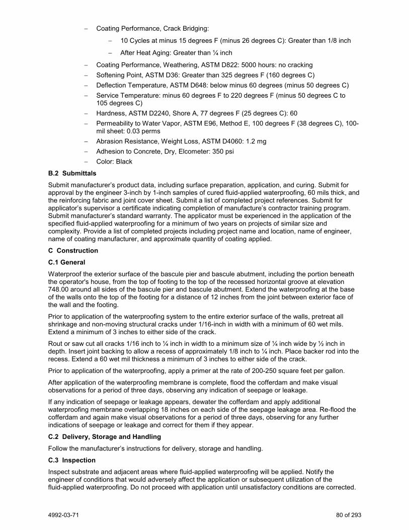
4992-03-71 80 of 293
− Coating Performance, Crack Bridging:
− 10 Cycles at minus 15 degrees F (minus 26 degrees C): Greater than 1/8 inch
− After Heat Aging: Greater than ¼ inch
− Coating Performance, Weathering, ASTM D822: 5000 hours: no cracking − Softening Point, ASTM D36: Greater than 325 degrees F (160 degrees C) − Deflection Temperature, ASTM D648: below minus 60 degrees (minus 50 degrees C) − Service Temperature: minus 60 degrees F to 220 degrees F (minus 50 degrees C to
105 degrees C) − Hardness, ASTM D2240, Shore A, 77 degrees F (25 degrees C): 60 − Permeability to Water Vapor, ASTM E96, Method E, 100 degrees F (38 degrees C), 100-
mil sheet: 0.03 perms − Abrasion Resistance, Weight Loss, ASTM D4060: 1.2 mg − Adhesion to Concrete, Dry, Elcometer: 350 psi − Color: Black
B.2 Submittals
Submit manufacturer’s product data, including surface preparation, application, and curing. Submit for approval by the engineer 3-inch by 1-inch samples of cured fluid-applied waterproofing, 60 mils thick, and the reinforcing fabric and joint cover sheet. Submit a list of completed project references. Submit for applicator’s supervisor a certificate indicating completion of manufacture’s contractor training program. Submit manufacturer’s standard warranty. The applicator must be experienced in the application of the specified fluid-applied waterproofing for a minimum of two years on projects of similar size and complexity. Provide a list of completed projects including project name and location, name of engineer, name of coating manufacturer, and approximate quantity of coating applied.
C Construction C.1 General Waterproof the exterior surface of the bascule pier and bascule abutment, including the portion beneath the operator's house, from the top of footing to the top of the recessed horizontal groove at elevation 748.00 around all sides of the bascule pier and bascule abutment. Extend the waterproofing at the base of the walls onto the top of the footing for a distance of 12 inches from the joint between exterior face of the wall and the footing.
Prior to application of the waterproofing system to the entire exterior surface of the walls, pretreat all shrinkage and non-moving structural cracks under 1/16-inch in width with a minimum of 60 wet mils. Extend a minimum of 3 inches to either side of the crack.
Rout or saw cut all cracks 1/16 inch to ¼ inch in width to a minimum size of ¼ inch wide by ½ inch in depth. Insert joint backing to allow a recess of approximately 1/8 inch to ¼ inch. Place backer rod into the recess. Extend a 60 wet mil thickness a minimum of 3 inches to either side of the crack.
Prior to application of the waterproofing, apply a primer at the rate of 200-250 square feet per gallon.
After application of the waterproofing membrane is complete, flood the cofferdam and make visual observations for a period of three days, observing any indication of seepage or leakage.
If any indication of seepage or leakage appears, dewater the cofferdam and apply additional waterproofing membrane overlapping 18 inches on each side of the seepage leakage area. Re-flood the cofferdam and again make visual observations for a period of three days, observing for any further indications of seepage or leakage and correct for them if they appear.
C.2 Delivery, Storage and Handling
Follow the manufacturer’s instructions for delivery, storage and handling.
C.3 Inspection Inspect substrate and adjacent areas where fluid-applied waterproofing will be applied. Notify the engineer of conditions that would adversely affect the application or subsequent utilization of the fluid-applied waterproofing. Do not proceed with application until unsatisfactory conditions are corrected.
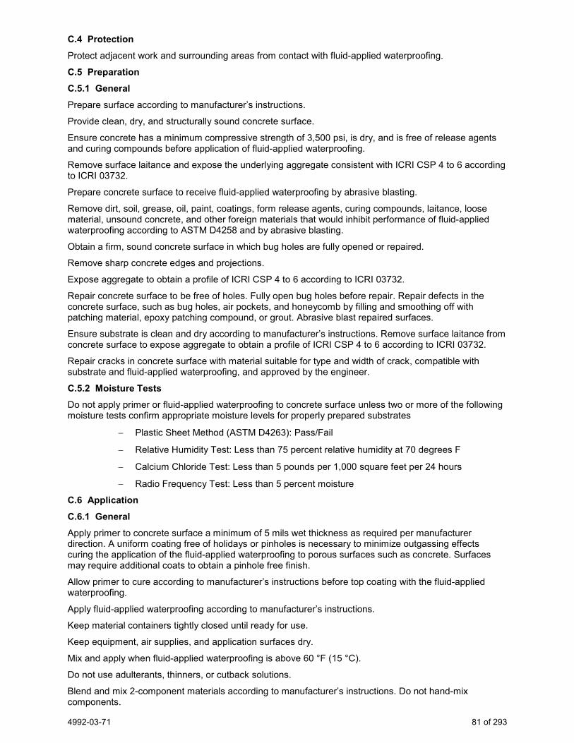
4992-03-71 81 of 293
C.4 Protection
Protect adjacent work and surrounding areas from contact with fluid-applied waterproofing.
C.5 Preparation
C.5.1 General Prepare surface according to manufacturer’s instructions.
Provide clean, dry, and structurally sound concrete surface.
Ensure concrete has a minimum compressive strength of 3,500 psi, is dry, and is free of release agents and curing compounds before application of fluid-applied waterproofing.
Remove surface laitance and expose the underlying aggregate consistent with ICRI CSP 4 to 6 according to ICRI 03732.
Prepare concrete surface to receive fluid-applied waterproofing by abrasive blasting.
Remove dirt, soil, grease, oil, paint, coatings, form release agents, curing compounds, laitance, loose material, unsound concrete, and other foreign materials that would inhibit performance of fluid-applied waterproofing according to ASTM D4258 and by abrasive blasting.
Obtain a firm, sound concrete surface in which bug holes are fully opened or repaired.
Remove sharp concrete edges and projections.
Expose aggregate to obtain a profile of ICRI CSP 4 to 6 according to ICRI 03732.
Repair concrete surface to be free of holes. Fully open bug holes before repair. Repair defects in the concrete surface, such as bug holes, air pockets, and honeycomb by filling and smoothing off with patching material, epoxy patching compound, or grout. Abrasive blast repaired surfaces.
Ensure substrate is clean and dry according to manufacturer’s instructions. Remove surface laitance from concrete surface to expose aggregate to obtain a profile of ICRI CSP 4 to 6 according to ICRI 03732.
Repair cracks in concrete surface with material suitable for type and width of crack, compatible with substrate and fluid-applied waterproofing, and approved by the engineer.
C.5.2 Moisture Tests Do not apply primer or fluid-applied waterproofing to concrete surface unless two or more of the following moisture tests confirm appropriate moisture levels for properly prepared substrates
− Plastic Sheet Method (ASTM D4263): Pass/Fail
− Relative Humidity Test: Less than 75 percent relative humidity at 70 degrees F
− Calcium Chloride Test: Less than 5 pounds per 1,000 square feet per 24 hours
− Radio Frequency Test: Less than 5 percent moisture
C.6 Application
C.6.1 General Apply primer to concrete surface a minimum of 5 mils wet thickness as required per manufacturer direction. A uniform coating free of holidays or pinholes is necessary to minimize outgassing effects curing the application of the fluid-applied waterproofing to porous surfaces such as concrete. Surfaces may require additional coats to obtain a pinhole free finish.
Allow primer to cure according to manufacturer’s instructions before top coating with the fluid-applied waterproofing.
Apply fluid-applied waterproofing according to manufacturer’s instructions.
Keep material containers tightly closed until ready for use.
Keep equipment, air supplies, and application surfaces dry.
Mix and apply when fluid-applied waterproofing is above 60 °F (15 °C).
Do not use adulterants, thinners, or cutback solutions.
Blend and mix 2-component materials according to manufacturer’s instructions. Do not hand-mix components.

4992-03-71 82 of 293
Maintain air supply for material spray application free of oil and water according to ASTM D4285.
Apply fluid-applied waterproofing directly to a clean and dry surface or to reinforcing fabric.
Apply a 6- to 12-inch wide strip of joint cover sheet over cracks larger than 1/8-inch wide, all joints, and edges. Adhere center joint cover sheet over all joints by applying a tack coat of the fluid-applied waterproofing.
Apply sufficient fluid-applied waterproofing to achieve 60-80 wet-mil film thickness.
C.6.2 Joint Lines Prepare for joint lines should rain or other conditions require work stoppage or extended delay.
Install joint lines clean and straight. Install overlap 6 inches minimum to ensure an impervious joint.
Severely abrade with wire brush or sandpaper and apply bonding agent to all areas where the fluid-applied waterproofing has cured beyond its recoat window.
C.6.3 Recoating Recoat the fluid-applied waterproofing system within the recoat window to obtain maximum interlayer adhesion to build specific thickness.
C.6.4 Immersion Service Minimize areas to be recoated outside the recoat window, except at joint lines.
C.6.5 Non-Immersion Service Severely abrade with wire brush or surface grinder, apply bonding agent, and recoat, if fluid-applied waterproofing has cured more than the recoat window. Acceptable adhesion can only be achieved through aggressive abrading.
C.7 Curing
Cure fluid-applied waterproofing according to manufacturer’s instructions.
Allow sufficient time for solvents to evaporate from the cured fluid-applied waterproofing before placing into service.
Allow minimum solvent release time of 24-hours to 48-hours at 60 °F (15 °C) for a 60 wet mil coating thickness.
Receive approval of cured coating by engineer.
C.8 Cleaning
Remove and dispose of all temporary materials used to protect adjacent work and surrounding areas.
Immediately remove and clean fluid-applied waterproofing materials from surfaces not intended to receive the materials.
D Measurement The department will measure Waterproofing Bascule Pier and Bascule Abutment as a single lump sum unit of work, acceptably completed. E Payment The department will pay for measured quantities at the contract unit price under the following bid item: ITEM NUMBER DESCRIPTION UNIT SPV.0105.01 Waterproofing Bascule Pier and Bascule Abutment LS
Payment is full compensation for furnishing and installing the waterproofing system on the bascule pier and bascule abutment including all labor, tools, materials, equipment and incidentals necessary to complete the contract work. Payment includes the cost to de-water for correcting any seepage or leakage after application of the waterproofing system.
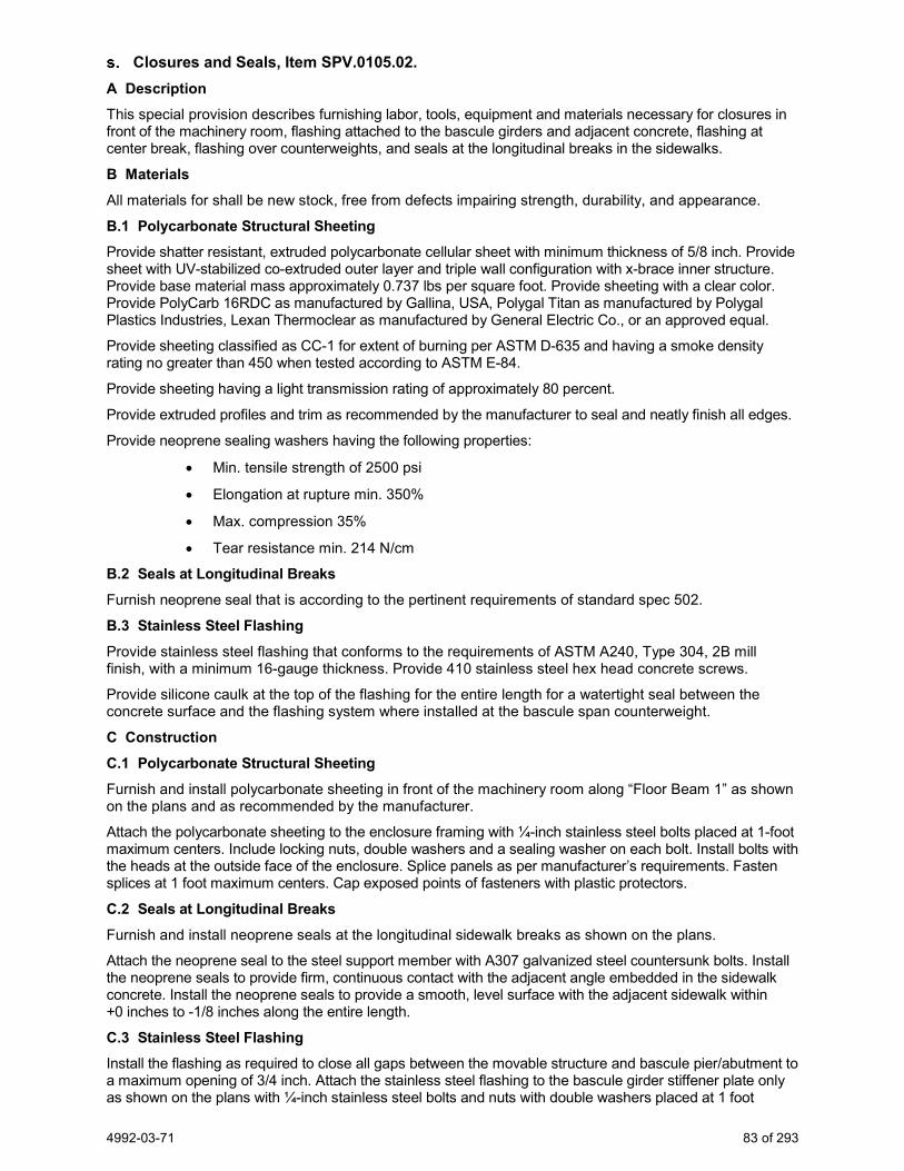
4992-03-71 83 of 293
Closures and Seals, Item SPV.0105.02. A Description This special provision describes furnishing labor, tools, equipment and materials necessary for closures in front of the machinery room, flashing attached to the bascule girders and adjacent concrete, flashing at center break, flashing over counterweights, and seals at the longitudinal breaks in the sidewalks.
B Materials All materials for shall be new stock, free from defects impairing strength, durability, and appearance.
B.1 Polycarbonate Structural Sheeting Provide shatter resistant, extruded polycarbonate cellular sheet with minimum thickness of 5/8 inch. Provide sheet with UV-stabilized co-extruded outer layer and triple wall configuration with x-brace inner structure. Provide base material mass approximately 0.737 lbs per square foot. Provide sheeting with a clear color. Provide PolyCarb 16RDC as manufactured by Gallina, USA, Polygal Titan as manufactured by Polygal Plastics Industries, Lexan Thermoclear as manufactured by General Electric Co., or an approved equal.
Provide sheeting classified as CC-1 for extent of burning per ASTM D-635 and having a smoke density rating no greater than 450 when tested according to ASTM E-84.
Provide sheeting having a light transmission rating of approximately 80 percent.
Provide extruded profiles and trim as recommended by the manufacturer to seal and neatly finish all edges.
Provide neoprene sealing washers having the following properties:
• Min. tensile strength of 2500 psi
• Elongation at rupture min. 350%
• Max. compression 35%
• Tear resistance min. 214 N/cm
B.2 Seals at Longitudinal Breaks Furnish neoprene seal that is according to the pertinent requirements of standard spec 502.
B.3 Stainless Steel Flashing Provide stainless steel flashing that conforms to the requirements of ASTM A240, Type 304, 2B mill finish, with a minimum 16-gauge thickness. Provide 410 stainless steel hex head concrete screws.
Provide silicone caulk at the top of the flashing for the entire length for a watertight seal between the concrete surface and the flashing system where installed at the bascule span counterweight.
C Construction C.1 Polycarbonate Structural Sheeting Furnish and install polycarbonate sheeting in front of the machinery room along “Floor Beam 1” as shown on the plans and as recommended by the manufacturer.
Attach the polycarbonate sheeting to the enclosure framing with ¼-inch stainless steel bolts placed at 1-foot maximum centers. Include locking nuts, double washers and a sealing washer on each bolt. Install bolts with the heads at the outside face of the enclosure. Splice panels as per manufacturer’s requirements. Fasten splices at 1 foot maximum centers. Cap exposed points of fasteners with plastic protectors.
C.2 Seals at Longitudinal Breaks Furnish and install neoprene seals at the longitudinal sidewalk breaks as shown on the plans.
Attach the neoprene seal to the steel support member with A307 galvanized steel countersunk bolts. Install the neoprene seals to provide firm, continuous contact with the adjacent angle embedded in the sidewalk concrete. Install the neoprene seals to provide a smooth, level surface with the adjacent sidewalk within +0 inches to -1/8 inches along the entire length.
C.3 Stainless Steel Flashing Install the flashing as required to close all gaps between the movable structure and bascule pier/abutment to a maximum opening of 3/4 inch. Attach the stainless steel flashing to the bascule girder stiffener plate only as shown on the plans with ¼-inch stainless steel bolts and nuts with double washers placed at 1 foot

4992-03-71 84 of 293
maximum centers. Attach the stainless steel flashing to the bascule pier/abutment concrete with ½-inch stainless steel masonry anchors placed at 6-inch maximum centers.
Install center break and counterweight flashing at the locations indicated on the plans, with minimum sheet lengths of 10 feet.
D Measurement The department will measure closures and seals as a single lump sum unit, acceptably completed. E Payment The department will pay for measured quantities at the contract unit price under the following bid item: ITEM NUMBER DESCRIPTION UNIT SPV.0105.02 Closures and Seals LS
Payment is full compensation for closures and seals; fabricating, furnishing and installing the flashing system; for furnishing and installing the caulk seal.
HVAC Work, Item SPV.0105.03. A Description A.1 Work Summary This special provision describes the installation of the heating and ventilating (HVAC) equipment and systems.
A.2 Regulatory Requirements 1. State and Local Codes
2. Conform to all state and local code requirements.
3. Permits and Inspections
4. Obtain permits and request inspections from authority having jurisdiction and pay for all Permit fees incidental thereto.
A.3 Equipment Accessibility Install equipment and materials to provide required access for servicing and maintenance. Coordinate the final location of concealed equipment and devices requiring access with final location of required access panels and doors. Allow ample space for removal of all parts that require replacement or servicing.
A.4 HVAC Installations Coordinate HVAC equipment and materials installation with other building components. Verify all dimensions by field measurements. Arrange for chases, slots and openings in other building components to allow for HVAC installations. Install HVAC equipment to facilitate maintenance and repair or replacement of equipment components. Connect equipment for ease of disconnecting, with minimum interference with other installation.
A.5 Quality Assurance Electrical characteristics for HVAC equipment: Equipment of higher electrical characteristics may be furnished provided such proposed equipment is approved in writing and connecting electrical services, circuit breakers, and conduit sizes are appropriately modified, and costs associated for modifications are included as part of the contractor’s work. If minimum energy ratings or efficiencies are specified, equipment shall comply with requirements.
A.6 Delivery, Storage and Handling Deliver HVAC materials with appropriate protective packaging with labels in place. Deliver pipes and tube with factory-applied end caps. Maintain end caps through shipping, storage and handling to prevent pipe end damage and to prevent entrance of dirt, debris and moisture.
A.7 References National Fire Protection Association (NFPA)
1. NFPA 54 (ANSI Z223.1) National Fuel Gas Code.
2. NFPA 255 Building Materials, Test of Surface Burning Characteristics.
4992-03-71 85 of 293
3. NFPA 90A Installation of Air Conditioning and Ventilating Systems.
4. NFPA 90B Installation of Warm Air Heating and Air Conditioning Systems.
American Society for Testing & Materials (ASTM)
1. ASTM C612 Specification for Mineral Fiber Block and Board Thermal Insulation.
2. ASTM B32 Specification for Solder Metal
3. ASTM B280 Specification for Seamless Copper Tube for Air Conditioning and Refrigeration Field Service.
4. ASTM A90 Test Method for Weight of Coating on Zinc-Coated (Galvanized Iron or Steel Articles.
5. ASTM A525 Specification for General Requirements for Steel Sheet, Zinc-Coated (Galvanized) by the Hot Dip Process.
6. ASTM A527 Specification for Steel Sheet, Zinc-Coated (Galvanized) by the Hot Dip Process, Lock Forming Quality.
7. ASTM C553 Specification for Mineral Fiber Blanket and Felt Insulation (Industrial Type).
Underwriters Laboratories (UL)
1. UL 723 Test for Surface Burning Characteristics of Building Materials.
2. UL 181 Factory-Made Air Ducts and Connectors
3. UL 441 Standard for Gas Vents
American National Standards Institute (ANSI)
1. ANSI/ASHRAE 34 Number Designation of Refrigerants.
2. ANSI/ASME B16.22 Wrought Copper and Copper Alloy Solder-Joint Pressure Fittings.
3. ANSI/ASME B31.5 Refrigeration Piping.
4. ANSI/ARI 710 Driers, Liquid-Line.
5. ANSI/ASHRAE 90A Energy Conservation in New Building Design.
6. ANSI/ASHRAE 103 Heating Seasonal Efficiency of Central Furnaces and Boilers, Methods of Testing.
Sheet Metal and Air Conditioning Contractors National Association (SMACNA)
1. SMACNA Low Pressure Duct Construction Standards.
Air Movement and Control Association (AMCA)
1. AMCA 99 Standards Handbook
− AMCA 210 Laboratory Methods of Testing Fans for Rating Purposes.
− AMCA 300 Test Code for Sound Rating Air Moving Devices.
− AMCA 301 Method of Calculating Fan Sound Ratings from Laboratory Test Data.
Air Conditioning and Refrigeration Institute (ARI)
1. ARI 201/240 Unitary Air Conditioning and Air Source Heat Pump Equipment
− ARI 530 Positive Displacement Refrigerant Compressors, Compressor Units and Condensing Units.
A.8 Submittals A.8.1 Equipment and Material Shop Drawings Submit shop drawings which include equipment information and product data for equipment listed below for review:
1. Furnace, DX Coil, Condensing unit and accessories.
− Exhaust Fan

4992-03-71 86 of 293
A.8.2 Report and Manuals Submittal Submit the Reports and Manuals requested for review:
− HVAC Testing, Adjusting and Balancing (TAB) Report.
− HVAC operating and maintenance manual including warranty documentation.
B Materials B.1 Basic HVAC System Materials and Methods. B.1.1 Pipe, Tube, and Fittings – General Pipe Threads: ASME B1.20.1 for factory-threaded pipe and pipe fittings.
B.1.2 Joining Materials – General Solder Filler Metals: ASTM B 32, lead-free alloys. Include water-flushable flux according to ASTM B 813.
Brazing Filler Metals: AWS A5.8, BCuP Series, copper-phosphorus alloys for general-duty brazing, unless otherwise indicated; and AWS A5.8, BAg1, silver alloy for refrigerant piping, unless otherwise indicated.
B.1.3 Pipe Penetrations – General Provide steel pipe sleeves with minimum wall thickness of 1/4 inch for pipes passing through beams and walls of concrete, brick, tile, or masonry, and 22 gage galvanized iron sleeves for pipes passing through other parts of construction. Provide steel pipe for all sleeves penetrating floors. Furnish each sleeve having inside diameter 1 inch larger than outside diameter of un-insulated and insulated pipe, unless wall or floor is a fire wall or barrier, in which case, only the pipe shall penetrate.
For pipes passing through floors, walls, and ceilings provide chrome-plated brass escutcheons having outside diameter to cover sleeved openings and inside diameter to fit pipe.
B.1.3.1 Non-rated surfaces Stamped steel, chrome plated, hinged, split ring escutcheons or floor-ceiling plates for covering openings in occupied spaces.
In exterior wall openings below grade, use a modular mechanical type seal consisting of interlocking synthetic rubber links shaped to continuously fill the annular space between the uninsulated pipe and the cored opening or a water stop type wall sleeve.
At interior partitions where pipe penetrations are sealed, use Tremco Dymonic, Sika Corp. Sikaflex 1a, Sonneborn Sonolastic NPI, or Mameco Vulken 116 urethane caulk to affect the seal. Use galvanized sheet metal sleeves in hollow wall penetrations.
B.1.4 Duct Penetrations - General Non-rated surfaces. Fiberglass insulation fill at voids with galvanized steel sheet metal bank-off on both sides of duct penetration through walls and ceiling structures. Use fire resistant sealant for sealing and soundproofing.
B.2 Identification and Painting for HVAC Systems B.2.1 Materials – Identification Systems Color: Unless specified otherwise, conform with ANSI/ASME A13.1.
Snap On Plastic Pipe Markers: Manufacturer's standard preprinted, semi rigid snap on, color coded pipe markers, conforming to ASME A13.1
Plastic Duct Markers: Manufacturer's standard laminated plastic, color coded duct markers. Conform to following color code:
1. Yellow/Green: Supply air.
2. Blue: Exhaust, outside, return, and mixed air.

4992-03-71 87 of 293
Plastic Equipment Markers: Laminated plastic, color coded equipment markers: Conform to following color code:
1. Green: Cooling equipment and components.
2. Yellow: Heating equipment and components.
3. Yellow/Green: Combination cooling and heating equipment and components.
Nomenclature: Include following, matching terminology on schedules as closely as possible:
1. Name and plan ID number.
2. Equipment service.
3. Size: Approximately 2½ by 4 inches (65 by 100 mm) for control devices, dampers, and valves; and 4½ by 6 inches (115 by 150 mm) for equipment.
Lettering and Graphics: Coordinate names, abbreviations, and other designations used in mechanical identification, with corresponding designations indicated. Use numbers, letter, and wording indicated for proper identification and operation/maintenance of mechanical systems and equipment.
B.2.2 Materials – Paint Systems Acceptable Manufacturers
1. Tnemec.
2. Carbolene.
3. Or approved equal.
Painting Systems
Application on metal piping and pipe and equipment supports: Non-submerged, normal conditions, indoors.
Generic Type: Polyamidoamine epoxy.
Finish Coat: Tnemec Series 69.
Interior: Two coats Series 69.
Exterior: One coat Series 69, one coat Series 74.
Primer Coat: Self priming.
Minimum Dry Mil Thickness: 5 to 8 mil.
Surface Preparation: Hand tool clean.
B.3 HVAC Ductwork Insulation B.3.1 Manufacturers Manufacturers: Subject to compliance with requirements, provide products by one of the following:
Glass Fiber:
1. Knauf Fiber Glass
2. Manville
3. Owens Corning Fiberglass Corporation
B.3.2 Materials Type A: Flexible Glass Fiber: ASTM C553 Type 1; "k" value of 0.29 at 75°F; foil scrim kraft facing with 0.02 perm rating.
Type B: Board: ASTM C 612, Class 2, semi-rigid jacketed board "k" value of 0.23 @ 75°F; FSK facing with 0.02 perm rating.
Adhesives: Waterproof fire-retardant type produced under the UL classification and follow-up service.
Lagging Adhesive: Fire resistive to NFPA 255 or UL 723.
4992-03-71 88 of 293
Impale Anchors: Galvanized steel, 12 gage, self-adhesive pad.
Joint Tape: Glass fiber cloth, FSK backing.
B.4 Refrigerant Piping and Specialties B.4.1 Piping Copper Tubing: ASTM B280, Type ACR hard drawn or annealed.
Fittings: ANSI/ASME B16.22 wrought copper.
Joints: ANSI/ASTM B32, solder Grade 95TA or ANSI/AWS A5.8 BCup silver braze.
Factory precharged linesets are acceptable.
B.4.2 Refrigerant Refrigerant: R-410A.
B.4.3 Moisture and Liquid Indicators Indicators: Single or Double port type, UL listed, with copper or brass body, flared or solder ends, sight glass, color coded paper moisture indicator with removable element cartridge and plastic cap; suitable for system working pressure and temperature.
B.4.4 Refrigerant Piping Insulation Flexible, close-cell elastomeric pipe insulation conforming to ASTM C534 Grade 1, Type I: AP Armaflex with appropriate adhesive; Armaflex 520.
B.5 Ductwork B.5.1 Materials Comply with SMACNA's "HVAC Duct Construction Standards--Metal and Flexible" for acceptable materials, material thicknesses, and duct construction methods, unless otherwise indicated. Sheet metal materials shall be free of pitting, seam marks, roller marks, stains, discolorations, and other imperfections.
Reinforcement Shapes and Plates: Galvanized-steel reinforcement where installed on galvanized sheet metal ducts, stainless steel where installed on stainless steel ducts.
General: Non-combustible or conforming to requirements for Class 1 air duct materials, or UL 181.
Steel Ducts: ASTM A525 or ASTM A527 galvanized steel sheet, lock-forming quality, having zinc coating of 1.25 oz per sq feet for each side in conformance with ASTM A90.
Flexible Ducts: Interlocking spiral of galvanized steel or aluminum construction or fabric supported by helically wound spring steel wire or flat steel bands; rated to 2 inches WG positive and 1.5 inches WG negative for low pressure ducts.
Fasteners: Rivets, bolts, or sheet metal screws. Use stainless steel fasteners on stainless steel ducts.
Sealant: Non-hardening, water resistant, fire resistive, compatible with mating materials; liquid used alone or with tape, or heavy mastic.
Tie Rods: Galvanized steel, 1/4-inch minimum diameter for lengths 36 inches or less; 3/8-inch minimum diameter for lengths longer than 36 inches.
Hanger Rod: Steel, galvanized; threaded both ends, threaded one end, or continuously threaded. B.5.2 Sealant Materials
Joint and Seam Sealants, General: The term "sealant" is not limited to materials of adhesive or mastic nature but includes tapes and combinations of open-weave fabric strips and mastics.
Joint and Seam Tape: 2 inches wide; glass-fiber-reinforced fabric.
Tape Sealing System: Woven-fiber tape impregnated with gypsum mineral compound and modified acrylic/silicone activator to react exothermically with tape to form hard, durable, airtight seal.
Water-Based Joint and Seam Sealant: Flexible, adhesive sealant, resistant to UV light when cured, UL 723 listed, and complying with NFPA requirements for Class 1 ducts.
Solvent-Based Joint and Seam Sealant: One-part, nonsag, solvent-release-curing, polymerized butyl sealant formulated with a minimum of 75 percent solids.

4992-03-71 89 of 293
Flanged Joint Mastic: One-part, acid-curing, silicone, elastomeric joint sealant complying with ASTM C 920, Type S, Grade NS, Class 25, Use O.
Flange Gaskets: Butyl rubber or EPDM polymer with polyisobutylene plasticizer.
B.5.3 Hangers and Supports
Building Attachments: Concrete inserts, powder-actuated fasteners, or structural-steel fasteners appropriate for construction materials to which hangers are being attached.
Use powder-actuated concrete fasteners for standard-weight aggregate concretes or for slabs more than 4 inches thick.
Exception: Do not use powder-actuated concrete fasteners for lightweight-aggregate concretes or for slabs less than 4 inches thick.
Hanger Materials: Galvanized sheet steel or threaded steel rod.
Hangers Installed in Corrosive Atmospheres: Electrogalvanized, all-thread rods or galvanized rods with threads painted with zinc-chromate primer after installation.
Strap and Rod Sizes: Comply with SMACNA's "HVAC Duct Construction Standards--Metal and Flexible" for steel sheet width and thickness and for steel rod diameters.
Galvanized-steel straps attached to aluminum ducts shall have contact surfaces painted with zinc-chromate primer.
Duct Attachments: Sheet metal screws, blind rivets, or self-tapping metal screws; compatible with duct materials.
Trapeze and Riser Supports: Steel shapes complying with ASTM A 36/A 36M.
Supports for Galvanized-Steel Ducts: Galvanized-steel shapes and plates.
B.5.4 Rectangular Duct Fabrication
Fabricate ducts, elbows, transitions, offsets, branch connections, and other construction according to SMACNA's "HVAC Duct Construction Standards--Metal and Flexible" and complying with requirements for metal thickness, reinforcing types and intervals, tie-rod applications, and joint types and intervals.
Lengths: Fabricate rectangular ducts in lengths appropriate to reinforcement and rigidity class required for pressure class.
Deflection: Duct systems shall not exceed deflection limits according to SMACNA's "HVAC Duct Construction Standards--Metal and Flexible."
Transverse Joints: Prefabricated slide-on joints and components constructed using manufacturer's guidelines for material thickness, reinforcement size and spacing, and joint reinforcement.
Manufacturers:
1. Ductmate Industries, Inc.
2. Nexus Inc.
3. Ward Industries, Inc.
Formed-On Flanges: Construct according to SMACNA's "HVAC Duct Construction Standards--Metal and Flexible," Figure 1-4, using corner, bolt, cleat, and gasket details.
Manufacturers:
1. Ductmate Industries, Inc.
2. Lockformer.
B.5.5 Round Duct and Fitting Fabrication Diameter as applied to flat-oval ducts in this Article is the diameter of a round duct with a circumference equal to the perimeter of a given size of flat-oval duct.
Round, Spiral Lock -Seam Ducts: Fabricate supply ducts of galvanized steel according to SMACNA's "HVAC Duct Construction Standards--Metal and Flexible."
Duct Joints: Ducts up to 48 Inches in Diameter: Interior, center-beaded slip coupling, sealed before and after fastening, attached with sheet metal screws.

4992-03-71 90 of 293
90-Degree Tees and Laterals and Conical Tees: Fabricate to comply with SMACNA's "HVAC Duct Construction Standards--Metal and Flexible," with metal thicknesses specified for longitudinal-seam straight ducts.
Diverging-Flow Fittings: Fabricate with reduced entrance to branch taps and with no excess material projecting from fitting onto branch tap entrance.
Fabricate elbows using die-formed, gored, pleated, or mitered construction. Unless elbow construction type is indicated, fabricate elbows as follows:
1. Mitered-Elbow Radius and Number of Pieces: Welded construction complying with SMACNA's "HVAC Duct Construction Standards--Metal and Flexible," unless otherwise indicated.
2. Round Mitered Elbows: Welded construction with the following metal thickness for pressure classes from minus 2- to plus 2-inch wg:
3. Ducts 3 to 36 Inches in Diameter: 0.034 inch.
4. 90-Degree, 2-Piece, Mitered Elbows: Use only for supply systems or for material-handling Class A or B exhaust systems and only where space restrictions do not permit using radius elbows. Fabricate with single-thickness turning vanes.
5. Round Elbows 8 Inches and Less in Diameter: Fabricate die-formed elbows for 45- and 90-degree elbows and pleated elbows for 30, 45, 60, and 90 degrees only. Fabricate nonstandard bend-angle configurations or nonstandard diameter elbows with gored construction.
6. Round Elbows 9 through 14 Inches in Diameter: Fabricate gored or pleated elbows for 30, 45, 60, and 90 degrees unless space restrictions require mitered elbows. Fabricate nonstandard bend-angle configurations or nonstandard diameter elbows with gored construction.
7. Round Elbows Larger Than 14 Inches in Diameter and All Flat-Oval Elbows: Fabricate gored elbows unless space restrictions require mitered elbows.
8. Die-Formed Elbows for Sizes through 8 Inches in Diameter and All Pressures 0.040-inch thick with 2-piece welded construction.
9. Round Gored-Elbow Metal Thickness: Same as non-elbow fittings specified above.
B.5.6 Ductwork General Construct Ts, bends, and elbows with radius of not less than 1-½ times width of duct on centerline. Where not possible and where rectangular elbows are used, provide turning vanes. Where acoustical lining is indicated, provide turning vanes of perforated metal with glass fiber insulation.
Increase duct sizes gradually, not exceeding 15 degrees divergence wherever possible. Divergence upstream of equipment shall not exceed 30 degrees; convergence downstream shall not exceed 45 degrees.
Elbows and transformation pieces, etc., shall be one to two gauges heavier, depending on size. Ratio of width individual air passages to total width of elbow shall be 1 to 5.
Longitudinal joints in horizontal runs or in risers shall be made with grooved seams. In elbows and transformation pieces, they shall be made with Pittsburgh corner seams or double corner seams.
Bracing shall be galvanized steel or stainless-steel angles as applicable and conform to SMACMA recommendations and standards.
All ductwork shall be constructed according to SMACNA and ASHRAE Specifications Standards and according to state and local code requirements. Ductwork to be sealed according to SMACNA seal Class B.
Provide fire resistant neoprene or other approved flexible connections on the entering and leaving side of all air handling units, etc., and at the collection boxes of all roof fans, etc., or as shown on plans, equal to Ventfabric "Ventglas". Attach with metal collar frames to prevent air leakage.
Provide flexible connection for ducts of dissimilar metals to prevent galvanic action.
Use double nuts and lock washers on threaded rod supports.
4992-03-71 91 of 293
B.6 Ductwork Accessories B.6.1 Sheet Metal Materials Comply with SMACNA's "HVAC Duct Construction Standards--Metal and Flexible" for acceptable materials, material thicknesses, and duct construction methods, unless otherwise indicated.
Galvanized Sheet Steel: Lock-forming quality; complying with ASTM A 653/A 653M and having G60 coating designation; ducts shall have mill-phosphatized finish for surfaces exposed to view.
Reinforcement Shapes and Plates: Galvanized-steel reinforcement where installed on galvanized sheet metal ducts; compatible materials for aluminum and stainless-steel ducts.
Tie Rods: Galvanized steel, 1/4-inch minimum diameter for lengths 36 inches or less; 3/8-inch minimum diameter for lengths longer than 36 inches.
B.6.2 Flexible Connectors Manufacturers:
1. Ductmate Industries, Inc.
2. Duro Dyne Corp.
3. Ventfabrics, Inc.
General Description: Flame-retardant or noncombustible fabrics, coatings, and adhesives complying with UL 181, Class 1.
Metal-Edged Connectors: Factory fabricated with a fabric strip 3-1/2 inches wide attached to two strips of 2-3/4-inch- wide, 0.028-inch- thick, galvanized sheet steel or 0.032-inch- thick aluminum sheets. Select metal compatible with ducts.
Indoor System, Flexible Connector Fabric: Glass fabric double coated with neoprene.
Minimum Weight: 26 oz./sq. yd.
Tensile Strength: 480 lbf/inch in the warp and 360 lbf/inch in the filling.
Service Temperature: Minus 40 to plus 200 deg F.
B.6.3 Duct Accessory Hardware Instrument Test Holes: Cast iron or cast aluminum to suit duct material, including screw cap and gasket. Size to allow insertion of pitot tube and other testing instruments and of length to suit duct insulation thickness.
Adhesives: High strength, quick setting, neoprene based, waterproof, and resistant to gasoline and grease.
B.7 Ceiling Exhaust Fans
Centrifugal Fan Unit: Direct driven, with steel housing, resilient mounted motor, gravity backdraft damper in discharge.
Disconnect Switch: Factory wired, non-fusible, in housing for thermal overload protected motor.
Grille: As required, molded aluminum with baked white enamel finish.
Accessories: Provide with Wall Cap and backdraft damper.
Provide cabinet and ceiling exhaust fans with capacities and accessories as indicated and scheduled on drawings.
Acceptable manufacturers to be: Greenheck, Cook or Penn.
B.8 Forced Air Furnaces and Evaporator Coils
Manufacturers: Subject to compliance with requirements, provide products by one of the following:
1. Carrier
2. Trane
4992-03-71 92 of 293
B.8.1 Manufactured Units Configuration: Upflow, type as shown on drawings with gas burner and direct expansion refrigeration. Single or two-stage as scheduled on drawings.
Units: Self-contained, packaged, factory assembled, pre-wired unit consisting of cabinet, supply fan, heat exchanger, burner or heater, controls, air filter, refrigerant cooling coil and outdoor package containing compressor, condenser coil and condenser fan
Refrigerant: Puron (R-410A).
Construction and Ratings: According to ARI 210/240. Testing: ASHRAE 14.
Performance Ratings: Energy Efficiency Rating (EER) not less than requirements of ANSI/ASHRAE 90A; seasonal efficiency to ANSI/ASHRAE 103. Provide units with meet or exceed the requirement of those scheduled on the drawings.
Heating Capacity and Staging: As scheduled on plans.
Air Handling: As scheduled on plans.
Cooling Capacity and Staging: As scheduled on plans.
B.8.2 Fabrication Cabinet: Galvanized steel with baked enamel finish, easily removed and secured access doors, glass fiber insulation and reflective liner.
Heat Exchanger:
Primary: 3-pass 20-gauge corrosion resistant aluminized steel of fold and crimp sectional design which operates under negative pressure
Secondary: Flow-through design having an interior laminate coating of polypropylene for corrosion resistance with fold and crip design which operates under negative pressure
Power vent fan, single or 2 speed as applicable.
Supply Fan: Centrifugal type rubber mounted with direct drive.
Motor: ANSI/NEMA MG 1; 1750 rpm rubber isolated hinge mounted, 4 speed.
Air Filters: Two-inch thick glass fiber – Merv 8, disposable type arranged for easy replacement.
B.8.3 Burner Gas Burner- Sealed combustion type with power vent fan, slow-opening dual rate gas valve, electric switch gas shut-off; flame proving sensor, hot surface igniter, pressure switch assembly; flame rollout switch, drain tubing and condensate trap, blower and inducer assembly, 40va transformer for thermostat power. Suitable for use with LP gas.
Burner Operating Controls:
High Limit Control: Fixed stop at maximum permissible setting, de energizes burner on excessive bonnet temperature and re-energizes when temperature drops to lower safe value.
Control Supply Fan: Bonnet temperatures and independent of burner controls, manual switch for continuous fan operation.
Single or two stage control as Scheduled
B.8.4 Evaporator Coil Coil and Coil Casing: Copper tube aluminum fin assembly, galvanized drain pan, drain connection, refrigerant piping connections and factory installed thermostatic expansion valve, fully insulated cabinet.
B.8.5 Electronic Programmable Room Heating/Cooling Thermostat Field-installed programmable, manual staged auto-changeover electronic digital thermostat. The thermostat shall offer three heating and two cooling stages with temperature control. An OFF-HEAT Auto-Cool Emerg system switch, OFF-AUTO fan switch and indicating LED’s shall be provided along with 7-day programming.
The thermostat must also be programmable for Occupied/Unoccupied status. During Occupied, the supply fan shall remain on and the unit to cycle heating cooling as required to maintain space setpoint.
4992-03-71 93 of 293
During Unoccupied cycle, the supply fan is to cycle on with heating/cooling operation in order to maintain setback temperature.
Thermostat is also to provide auxiliary contact to engage auxiliary fans (heat recovery) whenever the thermostat is in Occupied mode. During unoccupied mode, the auxiliary fan signal should be off.
Provide Honeywell T7351 Programmable thermostat or equivalent.
B.9 Air Cooled Condensing Units B.9.1 Manufacturers Manufacturers: Subject to compliance with requirements, provide products by one of the following:
• Carrier Corporation; Carrier Air Conditioning Div.
• Trane Co. (The); Worldwide Applied Systems Group
B.9.2 General - Split System Cooling Fully charged from the factory for matched indoor section and up to 15 feet of piping. Unit designed to operate at outdoor ambient temperatures as high as 115ºF.
• A.R.I certified.
• UL listed.
• Exterior must be designed for outdoor application.
Description: Factory assembled and tested; consisting of casing, conden-ser coils, condenser fans and motors, and unit controls.
• Refrigerant: R-410A
B.9.3 Split System Cooling Unit Casing Unit casing constructed of heavy gauge, galvanized steel and painted with a weather-resistant powder paint.
Corrosion and weatherproof CMBP-G30 Duratuff base.
B.9.4 Split System Cooling Compressor Compressor to have internal over temperature and pressure protector, total dipped hermetic motor and thermostatically controlled sump heater.
Also include roto-lock suction and discharge refrigeration connections, centrifugal oil pump, and low vibration and noise.
Compressor to have a 5-year limited warranty.
B.9.5 Split System Cooling Condenser Coil and Fans The Fin coil is continuously wrapped, corrosion resistant, all copper tubes and aluminum fins with minimum brazed joints. The coil is 3/8" O.D. seam-less copper or aluminum glued to a continuous fin.
Condensing Fans and Drives: Propeller fans with aluminum or galvanized-steel fan blades, for vertical air discharge; directly driven with permanently lubricated ball-bearing motors with integral current- and thermal-overload protection.
Coils are lab tested to withstand 2,000 pounds of pressure per square inch. Coil to be protected on all four sides by louvered panels.
Coil to have a 1-year warranty.
B.9.6 Split System Cooling Refrigerant Controls Operating and Safety Controls: Include condenser fan motor thermal and overload cutouts; 115-V control transformer, if required; magnetic contactors for condenser fan motors and a non-fused factory-mounted and -wired disconnect switch for single external electrical power connection.
High- and low-pressure protection to be inherent to the compressor.
Provide a factory installed liquid line drier.
4992-03-71 94 of 293
B.9.7 Cooling Low Ambient and Frost Control Provide unit with cooling capability to 55 deg. F, plus the addition of an evaporator defrost control to permit operation to 40 deg. F.
B.10 Natural Gas Systems B.10.1 Materials and Products General: Provide piping materials and factory fabricated piping products of sizes, types, pressure ratings, and capacities as indicated. Where not indicated, provide proper selection as determined by Installer to comply with installation requirements. Provide materials and products complying with NFPA 54 where applicable, base pressure rating on natural gas piping system maximum design pressures. Provide sizes and types matching piping and equipment connections; provide fittings of materials that match pipe materials used in natural gas systems.
B.10.2 Basic Pipes and Pipe Fittings Building Distribution Piping: Pipe Size 2 inches and Smaller:
− Black steel pipe; Schedule 40, malleable iron threaded fittings.
− 304 Stainless Steel Pipe; Schedule 40S, stainless steel threaded fittings.
− Pipe Size 2½ inches and Larger: Black steel pipe: Schedule 40; wrought steel butt-welding fittings.
Gas Piping (Underground) – Underground piping from utility main to the Gas Meter shall be by the local gas utility. Piping from the meter into the Structure shall be considered building distribution piping.
B.10.3 Special Valves General: Special valves required for natural gas systems include the following types:
Gas Cocks:
− Gas Cocks 2 inches and Smaller: 150 psi non-shock WOG, bronze straightway cock, flat or square head, threaded ends.
− Gas Cocks 2½ inches and Larger: 125 psi non-shock WOG, iron body bronze mounted, straightway cock, square head, flanged ends.
− Pressure Regulators: Step down pressure regulator, lock-up type staging type, reduction and capacity as required.
Manufacturer: Subject to compliance with requirements, provide gas cocks of one of the following:
• NIBCO, Inc.
• DeZurik Corporation
• Jenkins Bros.
• Lunkenheimer Company
• Rockwell International, Flow Control Division
• Stockham Valves and Fittings
• Walworth Company
C Construction C.1 Piping Systems – Common Requirements Install piping indicated to be exposed and piping in equipment rooms and service areas at right angles or parallel to building walls. Diagonal runs are prohibited unless specifically indicated otherwise.
Install piping free of sags and bends.
Install piping to allow application of insulation.
Select system components with pressure rating equal to or greater than system operating pressure.
Sleeves are required for core-drilled holes.
4992-03-71 95 of 293
Install sleeves for pipes passing through concrete and masonry walls, gypsum-board partitions, and concrete floor and roof slabs.
Cut sleeves to length for mounting flush with both surfaces.
Exception: Extend sleeves installed in floors of mechanical equipment areas or other wet areas 2 inches above finished floor level. Extend cast-iron sleeve fittings below floor slab as required to secure clamping ring if ring is specified.
Install sleeves in new walls and slabs as new walls and slabs are constructed.
Install sleeves that are large enough to provide 1/4-inch annular clear space between sleeve and pipe or pipe insulation. Use the following sleeve materials:
Steel Pipe Sleeves: For pipes smaller than NPS 6.
Verify final equipment locations for roughing-in.
C.1.1 Piping Joint Construction Join pipe and fittings according to the following requirements.
Ream ends of pipes and tubes and remove burrs. Bevel plain ends of steel pipe.
Remove scale, slag, dirt, and debris from inside and outside of pipe and fittings before assembly.
Soldered Joints: Apply ASTM B 813, water-flushable flux, unless otherwise indicated, to tube end. Construct joints according to ASTM B 828 or CDA's "Copper Tube Handbook," using lead-free solder alloy complying with ASTM B 32.
Brazed Joints: Construct joints according to AWS's "Brazing Handbook," "Pipe and Tube" Chapter, using copper-phosphorus brazing filler metal complying with AWS A5.8.
C.1.2 Equipment Installation – Common Requirements. Install equipment to allow maximum possible headroom unless specific mounting heights are indicated.
Install equipment level and plumb, parallel and perpendicular to other building systems and components in exposed interior spaces, unless otherwise indicated.
Install mechanical equipment to facilitate service, maintenance, and repair or replacement of components. Connect equipment for ease of disconnecting, with minimum interference to other installations. Extend grease fittings to accessible locations.
Install equipment to allow right-of-way for piping installed at required slope.
C.1.3 Painting Damage and Touchup: Repair marred and damaged factory-painted finishes with materials and procedures to match original factory finish.
C.2 Identification and Painting - General Where more than one type of mechanical identification is specified for listed application, selection is installer's option, but provide single selection for each product category.
Degrease and clean surfaces to receive adhesive for identification materials.
C.2.1 HVAC Systems - Labeling and Identifying Piping Systems: Install pipe markers on each system. Include arrows showing normal direction of flow.
Plastic markers: Install on pipe insulation segment where required for hot non-insulated pipes.
Locate pipe markers wherever piping is exposed in finished spaces, equipment rooms, accessible maintenance spaces (shafts, tunnels, plenums), and exposed exterior locations as follows:
1. Near each valve and control device.
2. Near each branch, excluding short take offs for fixtures and terminal units. Mark each pipe at branch, where flow pattern is not obvious.
3. Near locations where pipes pass through walls, floors, ceilings, or enter inaccessible enclosures.
4. At access doors, manholes, and similar access points that permit view of concealed piping.
5. Near major equipment items and other points of origination and termination.

4992-03-71 96 of 293
6. Spaced at a maximum of 50-foot (15 m) intervals along each run. Reduce intervals to 25 feet (7.5 m) in congested areas of piping and equipment.
7. On piping above removable acoustical ceilings, except omit intermediately spaced markers.
Equipment: Install engraved plastic laminate sign or equipment marker on or near each major item of mechanical equipment. Do not label equipment such as cabinet heaters and ceiling fans in occupied spaces.
Lettering Size: Minimum ¼ inch (6 mm) high lettering for name of unit where viewing distance is less than 2 feet (0.6 m), ½ inch (13 mm) high for distances up to 6 feet (1.8 m), and proportionately larger lettering for greater distances. Provide secondary lettering 1/2 to ¾ of size of principal lettering.
Text of Signs: Provide text to distinguish between multiple units, inform operator of operational requirements, indicate safety and emergency precautions, and warn of hazards and improper operations, in addition to name of identified unit.
Duct Systems: Identify air supply, return, exhaust, intake, and relief ducts with duct markers; or provide stenciled signs and arrows, showing duct system service and direction of flow.
Location: In each space where ducts are exposed or concealed by removable ceiling system, locate signs near points where ducts enter into space and at maximum intervals of 50 feet (15 m).
Adjusting: Relocate identifying devices, which become visually blocked by work of this Division or other Divisions.
C.2.2 Painting
Color Coding and Labeling of Piping and Equipment - The following color code shall be applied for all new piping installed as part of this project exposed to view:
1. Natural gas piping (interior) – yellow; (exterior) - grey
2. Exposed HVAC mechanical equipment hangers and supports: grey.
Protection of Finished Work and Equipment:
1. Protect with tarpaulin or drop cloth all floors, walls, glass, finished painted work, and equipment from paint spatter or other damage that might result from this Work.
2. Promptly remove all oil, paint, and solvent waste rags from the site and legally dispose of them. Do not burn waste materials.
3. Paint, varnish, and mixing cans shall not be placed on bare floors.
4. Dirty, oily, and dusty cover shall not be used.
5. No stains or spots shall remain after completion of painting. Remove hardware accessories, light fixtures, and similar items before painting.
6. Replace above items after finish coat is applied.
7. Masking may be utilized in lieu of removal of items.
Application:
1. Application may be by brushing or rolling. Method used shall be one as approved by material manufacturer for any one particular product.
2. Brushing: Brush in one direction then smooth at right angles to original brushing to produce a uniform thickness of coating.
3. Thickness of Coating: Where number of coats is indicated, it is intended to show the normal practice to obtain the proper dry mil thickness.
4. The dry mil film thickness must be provided in all cases even though it may require additional coatings to that specified. Contractor must provide adequate ventilation at all times.
Ventilation shall be adequate to remove fumes, preventing injury to workmen, or possibility of accumulating volatile gases.
4992-03-71 97 of 293
C.3 HVAC Ductwork Insulation C.3.1 Preparation Surface Preparation
Clean, dry, and remove foreign materials such as rust, scale, and dirt.
Mix insulating cements with clean potable water. Mix insulating cements contacting stainless steel surfaces with demineralized water.
C.3.2 Installation Refer to schedules at the end of this section for materials, forms, jackets, and thicknesses required for each ductwork system.
Select accessories compatible with materials suitable for the service. Select accessories that do not corrode, soften, or otherwise attack the insulation or jacket in either the wet or dry state.
Install vapor barriers on insulated ducts having surface operating temperatures below 60°F.
Install insulation, accessories and finishes according to the latest edition of MCIA National Commercial and Industrial Insulation Standards and manufacturer's installation instructions. Exceptions to these standards will be accepted where specifically modified in these specifications or where prior written approval has been obtained from the engineer.
Install insulation with smooth, straight, and even surfaces.
Seal joints and seams to maintain vapor barrier on insulation requiring a vapor barrier.
Seal penetrations for hangers, supports, anchors, and other projections in insulation requiring a vapor barrier.
Seal Ends
Except for flexible elastomeric insulation, taper ends at 45 deg angle and seal with lagging adhesive. Cut ends of flexible elastomeric cellular insulation square and seal with adhesive.
Apply adhesives and coatings at manufacturer's recommended coverage per gallon rate.
Keep insulation materials dry during application and finishing.
Items Not Insulated: Unless otherwise indicated do not apply insulation to the following systems, materials, and equipment:
− Factory insulated flexible ducts.
− Flexible connectors.
− Testing laboratory labels and stamps.
− Access panels and doors in air distribution systems.
Install block and board insulation as follows:
Speed Washers Attachment: Secure insulation tight and smooth with speed washers and welded pins. Space anchor pins 18 inches apart each way and 3 inches from insulation joints. Apply vapor barrier tape to seal insulation in contact, open joints, breaks, punctures, and voids in insulation.
Blanket Insulation: Install tight and smooth. Secure to ducts having long sides or diameters as follows:
1. Smaller than 24 Inches: Bonding adhesive applied in 6-inch wide transverse strips on 12-inch centers.
2. Overlap joints 3 inches.
3. Seal joints, breaks, and punctures with vapor barrier tape.
4. At test plugs, provide removable insulation plugs.
5. Insulate around damper operators so as to maintain full operating range of operator.

4992-03-71 98 of 293
C.3.3 Ductwork Insulation Schedule First 6’ of exhaust duct and outside air duct from building envelop Penetration.
1. Material: Glass fiber board round or rectangular as required.
2. Thickness 1/1/2”
3. Jacket: Provide with factory FSK jacket.
Supply air duct concealed above Toilet Room Ceiling:
1. Material: Glass fiber board round or rectangular as required.
2. Thickness: 1/1/2”
3. Jacket: Provide with factory FSK jacket.
C.4 Refrigeration Piping and Specialties Installation C.4.1 Preparation Ream pipe and tube ends. Remove burrs.
Remove scale and dirt on inside and outside before assembly.
Prepare piping connections to equipment with flanges or unions.
C.4.2 Installation Install refrigeration specialties according to manufacturer's instructions.
Route piping in orderly manner, with plumbing parallel to building structure, and maintain gradient.
Install piping to conserve building space and not interfere with use of space.
Group piping whenever practical at common elevations and locations. Slope piping one percent in direction of oil return.
Provide non-conducting dielectric connections when joining dissimilar metals.
Install piping to allow for expansion and contraction without stressing pipe, joints, or connected equipment.
Provide clearance for installation of insulation and access fittings.
Provide access to concealed fittings.
Where pipe support members are welded to structural building frame, brush clean and apply one coat of zinc rich primer to welding.
Prepare pipe, fittings, supports, and accessories not prefinished, ready for finish painting.
Insulate piping per insulation manufacturers recommendations. All insulation exposed to sunlight or installed outdoors shall be protected with two coats of WB Armaflex Finish or weather resistant coating.
Fully charge completed system with refrigerant after testing.
Provide refrigerant charging valve connections in liquid line between receiver shut off valve and expansion valve.
C.4.3 Field Quality Control Test refrigeration system according to ANSI/ASME B31.5.
Pressure test system with dry nitrogen to 200 psig. Perform final tests at 27 inches vacuum and 200 psig using halide torch electronic leak detector. Test to no leakage.
C.5 Ductwork Installation
Provide openings in ductwork where required to accommodate thermometers and controllers. Provide pilot tube openings where required for testing of systems, complete with metal can with spring device or screw to ensure against air leakage. Where openings are provided in insulated ductwork, install insulation material inside a metal ring.
Locate ducts with sufficient space around equipment to allow normal operating and maintenance activities.
4992-03-71 99 of 293
Suspended horizontal ductwork shall be securely and rigidly anchored and supported from the building structure by means of rod-angle iron or strap iron hangers. Rod hangers shall be threaded at both ends and equipped with nuts and washers. Angle and strap hangers shall be attached to ducts by means of welds or sheet metal screws or by rivets. They shall be attached to suitable roof or ceiling structures through formed angles, by anchor screws and heavy, wide washers. If attached to floor slab, the bearing quality of slab material shall be checked and found capable of supporting weight of duct.
Vertical dust risers shall be rigidly supported as they pass through floors, ceilings or roofs by angle iron spanning the opening and firmly and securely attached to the building walls or columns. All ductwork shall be so installed as to be free from vibration under all normal operating conditions. Where required, suitable sound attenuators shall be incorporated with the anchors and/or supports. Finish openings in floors, walls and ceilings with 22-gauge sheet metal closures to give a neat appearance.
Where ducts pass through walls or floors, provide a suitable sheet metal angle around the periphery of the duct. Where ducts pass through exterior building construction, provide a suitable flashing and counterflashing to make a weathertight installation.
Where external insulated ducts pass through walls, floors or ceilings, suitable size openings shall be made to allow for the insulation through the opening. The insulation shall not be stopped on each side of the opening.
Connect diffusers to low pressure ducts with 5 feet maximum length of flexible duct. Hold in place with strap or clamp.
C.5.1 Field Quality Control Perform the following field tests and inspections according to SMACNA's "HVAC Air Duct Leakage Test Manual". Provide evidence of compliance upon request.
Disassemble, reassemble, and seal segments of systems to accommodate leakage testing and for compliance with test requirements.
Conduct tests at static pressures equal to maximum design pressure of system or section being tested. If pressure classes are not indicated, test entire system at maximum system design pressure. Do not pressurize systems above maximum design operating pressure.
Maximum Allowable Leakage: Comply with requirements for Leakage Class 3 for round and flat-oval ducts, Leakage Class 12 for rectangular ducts in pressure classes lower than and equal to 2-inch wg (both positive and negative pressures), and Leakage Class 6 for pressure classes from 2- to 10-inch wg.
Remake leaking joints and retest until leakage is equal to or less than maximum allowable.
C.5.2 Adjusting and Cleaning Clean duct system and force air at high velocity through duct to remove accumulated dust. To obtain sufficient air, clean half the system at a time. Protect equipment, which may be harmed by excessive dirt with temporary filters, or bypass during cleaning.
C.6 Application and Installation of Ductwork Accessories Install duct accessories according to applicable details in SMACNA's "HVAC Duct Construction Standards--Metal and Flexible" for metal ducts
Provide duct accessories of materials suited to duct materials; use galvanized-steel accessories in galvanized ducts
Install flexible connectors immediately adjacent to equipment in ducts associated with fans and motorized equipment supported by vibration isolators.
Install duct test holes where indicated and required for testing and balancing purposes.
C.6.1 Adjusting Adjust duct accessories for proper settings.
Final positioning of manual-volume dampers is specified in “Testing, Adjusting, and Balancing” work description.
C.7 Ceiling Exhaust Fan Installation Install according to manufacturer's instructions.
Coordinate all wall openings required with general contractor.
4992-03-71 100 of 293
Support fan and fan housings utilizing neoprene isolators at all hanging points. Coordinate supports and support anchoring placement with general contractor.
Coordinate electrical requirements. Final electrical connections shall conform to Project Electrical requirements. Properly ground equipment. Coordinate the mounting and power wiring of fans with manufacturer’s recommendations.
C.8 Forced Air Furnace and Evaporator Coil Unit installation C.8.1 General Coordinate furnace, cased cooling coil with air cooled condensing unit. All equipment shall be matched to work together and be of the same manufacturer.
Verify pressure of natural gas to furnace. Install stepdown regulator if required.
C.8.2 Examination Verify that floors are ready for installation of units and openings are as indicated on shop drawings.
Verify that proper power supply is available for furnace and condenser package.
Verify that proper fuel supply is available for connection.
C.8.4 Installation Install according to manufacturer's instructions.
Install venting and combustion air per the furnace manufacturer’s instructions. Utilize listed Polypropylene piping material for furnace vent.
Install refrigerant lines from indoor equipment to outdoor condensing units. Insulate as required and recommended by manufacturer. Refrigerant lines are to be insulated.
Install condensate drain lines from Furnace and DX Coil to Condensate Pump. as shown on plans. Pipe condensate utilizing Schedule 40 PVC drain piping.
Install interconnecting control wiring between thermostat, furnace and air-cooled condensing unit.
Install to NFPA 90A and ANSI/NFPA 90B.
Install gas fired furnaces to ANSI Z223.1 (NFPA 54).
Provide vent connections to ANSI/NFPA 211.
C.9 Air-Cooled Condensing Unit installation C.9.1 Examination Examine substrates, areas, and conditions, with Installer present, for compliance with requirements for installation tolerances and other conditions affecting performance of air-cooled condensers.
Examine roughing-in for refrigerant piping systems to verify actual locations of piping connections before equipment installation.
Proceed with installation only after unsatisfactory conditions have been corrected.
C.9.2 Installation Install unit(s) level and plumb, firmly anchored in locations indicated; maintain manufacturer's recommended clearances.
Install air-cooled condensers on concrete base.
Maintain manufacturer's recommended clearances for service and maintenance.
Loose Components: Install electrical components, devices, and accessories that are not factory mounted.
C.9.3 Connections Piping installation requirements are specified herein. Drawings indicate general arrangement of piping, fittings, and specialties.
Install piping adjacent to machine to allow service and maintenance.

4992-03-71 101 of 293
Refrigerant Piping: Connect piping to unit with pressure relief, service valve, filter-dryer, and moisture indicator on each refrigerant-circuit liquid line.
Ground equipment according to electrical requirements of this project.
Connect wiring according to electrical requirements of this project.
C.9.4 Field Quality Control Perform the following field tests and inspections and prepare test reports:
− Perform electrical test and visual and mechanical inspection.
− Leak Test: After installation, charge system and test for leaks. Repair leaks and retest until no leaks exist.
− Operational Test: After electrical circuitry has been energized, start units to confirm proper motor rotation and unit operation. Complete manufacturer's starting checklist.
− Test and adjust controls and safeties. Replace damaged and malfunctioning controls and equipment.
− Verify proper airflow over coils.
Remove and replace malfunctioning air-cooled condensers and retest as specified above.
C.9.5 Startup Service Complete installation and startup checks according to manufacturer's written instructions and perform the following:
− Inspect for physical damage to unit casing.
− Verify that access doors move freely and are weathertight.
− Clean units and inspect for construction debris.
− Verify that all bolts and screws are tight.
− Verify that controls are connected and operational.
Lubricate bearings on fans.
Verify that fan wheel is rotating in the correct direction and is not vibrating or binding.
Start unit according to manufacturer's written instructions and complete manufacturer's startup checklist.
Verify proper operation of capacity control device.
After startup and performance test, lubricate bearings.
C.10 Natural Gas System Installation C.10.1 Summary Extent of work is limited to piping and accessories as required to extend natural gas line from meter to gas fired equipment as indicated on drawings and schedules as required by this section.
Contractor to verify gas pressure available with local natural gas utility and to provide piping system including gas pressure step down regulators as may be needed.
C10.2 Installation of Natural Gas Piping Use sealants on metal gas piping threads that are chemically resistant to natural gas. Use sealants sparingly and apply to only male threads of metal joints.
Remove cutting and threading burrs before assembling piping.
Do not install defective piping or fittings. Do not use pipe with threads that are chipped, stripped or damage.
Plug each gas outlet, including valves, with threaded plug or cap immediately after installation and retain until continuing piping, or equipment connections are completed.
Install drip legs in gas piping where indicated, and where required by code or regulation.
Install "tee" fittings with bottom outlet plugged or capped, at bottom of pipe risers.
4992-03-71 102 of 293
Install piping with 1/64 inch per foot downward slope in direction of flow.
Install piping parallel to other piping, but maintain minimum of 12-inch clearance between gas piping and steam or hydronic piping above 200 deg F.
Install gas pressure regulator at equipment. Size for pressure leaving meter, required pressure at equipment and required flow. Vent per code to atmosphere. NOTE: Coordinate gas pressures provided and placement of step-down regulators where they may be required.
All pipe supports to be spaced a maximum of 5 feet.
C.10.3 Natural Gas Service General: Coordinate with local gas utility company the connection of new loads to the existing natural gas service.
− Coordinate available gas pressure and gas load the new service.
− Coordinate with the utility the location of the new gas service.
− Consult with utility as to extent of its work, costs, and fees associated with any service
− size increases or modifications. Pay such costs and fees.
− Verify pressure leaving the meter. Gas piping distribution system was sized based on the indicated pressure leaving the meter or at the building structure as shown on the plans. If needed modify the gas pipe size based on actual pressures being provided.
Provide step down gas regulators as required at each structure and as may be needed at each natural gas burning device/equipment.
C.10.4 Installation of Natural Gas Piping Specialties Do not conceal any gas piping or specialties.
C.10.5 Installation of Valves Gas Cocks: Provide at connection to gas train for each gas fired equipment item and on risers and branches where indicated.
Locate gas cocks where easily accessible, and where they will be protected from possible injury.
C.10.6 Equipment Connections General: Connect gas piping to each gas fired equipment item with drip leg and shutoff gas cock.
Comply with equipment manufacturer's instructions.
Install any required step-down pressure regulators that may be required based on gas pressures supplied from gas meter to gas pressure requirements of equipment. Pipe any regulator vents to outside of building away from any O.A. intakes.
C.10.7 Field Quality Control Piping Tests: Inspect, test, and purge natural gas systems according to NFPA 54.
C.10.8 Adjusting, Cleaning and Painting Cleaning and Inspecting: Clean and inspect natural gas systems. Paint gas piping per this SPV, paragraph C.2.2.
C.11 HVAC Testing and Balancing This Section includes TAB to produce design objectives for the following:
1. Furnace and supply air and return air duct distribution system
2. Exhaust fans
3. HVAC equipment quantitative-performance settings.
4. Test and Verify that automatic control devices function properly and that interlocks work.
Reporting results of activities and procedures specified in this Section.
4992-03-71 103 of 293
C.11.1 TAB Submittals Certified TAB Reports: Submit two copies of reports prepared, as specified in this Section, on approved forms certified by TAB firm.
D Measurement The department will measure HVAC Work, completed according to the contract and accepted, as a single completed unit of work.
E Payment The department will pay for measured quantities at the contract unit price under the following bid item: ITEM NUMBER DESCRIPTION UNIT SPV.0105.03 HVAC Work LS
Payment is full compensation for HVAC Work; and for furnishing all labor, tools, equipment, materials, and incidentals necessary to complete the contract work.
Operator House Miscellaneous, Item SPV.0105.04. A Description Furnish all labor, material and tools required for the satisfactory construction completion of the Racine Street bridge operator house according to the plans and as described in these specifications.
This work includes but is not limited to the following:
1. Concrete Masonry Units
2. Metal Stair Nosing
3. Rough Carpentry
4. Shop-Fabricated Wood Trusses
5. Thermal Insulation
6. Fluid Applied Air Barrier
7. Standing Seam Metal Roof Panels
8. Joint Sealants
9. Aluminum Storefront
10. Aluminum Windows
11. Steel Doors and Frames
12. Door Hardware
13. Glazing
14. Non-Structural Metal Framing
15. Gypsum Board
16. Ceramic Tile
17. Acoustical Panel Ceiling
18. Resilient Base
19. Epoxy Flooring
20. Painting
21. Toilet Accessories
22. Fire Extinguishers
23. Roller Shades
24. Furniture

4992-03-71 104 of 293
Related Articles:
− “Cast-In-Place Concrete” for bridge operator house superstructure specified in Standard Specification Section 501 Concrete and Section 502 Concrete Bridges.
− “Structural Steel” for bridge operator house steel framing specified in Special Provision Section: Structural Steel Operator House.
− “Metal Fabrications” for galvanized steel lintels for brick and stone support specified in Special Provision Section: Operator House Masonry
− “Brick Masonry Veneer” for bridge operator house façade facing specified in Special Provision Section: Operator House Masonry.
− “Cast Stone Masonry Veneer” for bridge operator house façade facing specified in Special Provision Section: Operator House Masonry.
− “Painted Pipe and Tube Railings” for all bridge operator house handrails and guard rails specified in Special Provision Section: Steel Stairs, Platforms and Railings.
B Materials B.0 General Provide all products and workmanship of the highest commercial or industrial quality available. Lesser quality products, such as "economy" grade, will not be acceptable. The engineer will reject any product or work that is inferior in his judgment.
Interpret specific reference in these specifications to any article, device, product, material, fixture, form or type of construction, etc., by name, make or catalog number as establishing a standard of quality. Do not construe specific references as limiting competition. Use any article, device, product or material, fixtures, form, or type of construction, which in the judgment of the engineer is equal to that named in the special provisions or shown on the plans.
B.1 Concrete Masonry Units Provide concrete unit masonry as shown and as specified.
Comply with ACI 530.1/ASCE 6/TMS 602 unless modified by requirements in the contract documents.
B.1.1 Submittals Product Data: For each type of product indicated.
Mix Designs: For mortar and grout. Include description of type and proportions of ingredients.
B.1.2 Project Conditions Cold-Weather Requirements: Do not use frozen materials or materials mixed or coated with ice or frost. Do not build on frozen substrates. Remove and replace unit masonry damaged by frost or by freezing conditions. Comply with cold-weather construction requirements contained in ACI 530.1/ASCE 6/TMS 602.
Hot-Weather Requirements: Comply with hot-weather construction requirements contained in ACI 530.1/ASCE 6/TMS 602.
B.1.3 Materials Concrete Masonry Units (CMUs): ASTM C 90.
Density Classification: Normal weight.
Masonry Lintels: Built-in-place masonry lintels made from bond beam CMUs with reinforcing bars placed as indicated and filled with coarse grout. Temporarily support built-in-place lintels until cured.
Portland Cement: ASTM C 150, Type I or II, except Type III may be used for cold-weather construction.
Hydrated Lime: ASTM C 207, Type S.
Aggregate for Mortar: ASTM C 144.
Aggregate for Grout: ASTM C 404.
Steel Reinforcing Bars: ASTM A 615/A 615M or ASTM A 996/A 996M, Grade 60 deformed bars.

4992-03-71 105 of 293
Masonry Joint Reinforcement: ASTM A 951/A 951M, hot-dip galvanized, carbon steel, either ladder or truss type with single pair of side rods.
− Wire Size: 0.148-inch diameter.
− Spacing of Cross Rods, Tabs, and Cross Ties: Not more than 16 inches o.c.
Ties and Anchors Materials: Provide ties and anchors specified in this article that are made from materials that comply with the following unless otherwise indicated.
− Steel Sheet, Galvanized after Fabrication: ASTM A 1008/A 1008M, Commercial Steel, with ASTM A 153/A 153M, Class B coating.
Anchors for Connecting to Concrete: Corrugated Metal Ties consisting of metal strips not less than 1-1/4 inch wide with corrugations having a wavelength of 0.3 to 0.5 inch and an amplitude of 0.06 to 0.10 inch made from 0.075 inch thick, steel sheet, galvanized after fabrication with 1-1/2 inch 90 degree bend with 9/32 inch diameter hole for fastening to concrete and sized to extend to within 4 inches into masonry.
Partition Top Anchors: 0.105 inch thick metal plate with 3/8 inch diameter metal rod 6 inches long welded to plate and with closed-end plastic tube fitted over rod that allows rod to move in and out of tube. Fabricate from steel, hot-dip galvanized after fabrication.
Compressible Filler: Pre-molded filler strips complying with ASTM D 1056, Grade 2A1; compressible up to 35 percent; formulated from neoprene or urethane.
B.1.4 Mortar and Grout Mixes Mortar: Comply with ASTM C 270, Type N, Proportion Specification.
Grout: Comply with ASTM C 476.
B.2 Metal Stair Nosing B.2.1 Nosings for Concrete Stairs Furnish and install abrasive cast iron nosings at all concrete stair treads within the operator house, bascule abutment, and bascule pier. Provide nosings having a surface of silicon carbide abrasive, a minimum of 2-1/4 ounces per square foot to a minimum depth of 1/32 of an inch, and a cross-hatched pattern. Provide all nosings 5/16" thick, 3" wide, and full width of stair.
Provide all castings of uniform quality, free from blow holes, shrinkage defects, swells, cracks, or other defects. Nosings must be true to pattern. Casting material shall be of high quality iron. Castings must be free of fins, burrs and slag. Provide castings with one coat of black paint.
B.3 Rough Carpentry Provide rough carpentry work as shown and as specified. Rough carpentry includes:
− Roof framing with dimension lumber and plywood.
− Wood blocking
B.3.1 General Wood products shall be factory-marked to identify type, grade, inspection agency, producing mill and other qualities as specified.
Obtain measurements and verify dimensions shown before proceeding with carpentry work.
Keep carpentry materials dry during delivery. Store lumber and plywood in stacks with provisions for air circulation within stacks. Protect bottom of stacks against contact with damp or wet surfaces. Protect exposed materials against weather. Do not store dressed or treated lumber or plywood outdoors.
B.3.2 Lumber Lumber shall comply with U.S. Product Standard PS-20 for American Softwood Lumber, U.S. Dept of Commerce, and with rules of applicable manufacturer’s association or authorized inspection bureau under which each species of lumber is produced. Nominal sizes shown and specified refer to undressed lumber dimensions. Dress lumber four sides (S4S), unless otherwise shown or specified, and work to shapes and patterns shown. Detailed dimensions show actual sizes required.
Framing and miscellaneous lumber: Construction or No. 2 grade.
4992-03-71 106 of 293
Species:
Hem-fir (north); NLGA.
Southern pine; SPIB.
Douglas fir-larch; WCLIB or WWPA.
Maintain 19% maximum moisture content for all pieces of construction lumber. Mark Lumber “DRY.”
B.3.3 Plywood Plywood shall comply with U.S. Product Standard PS-1 for Construction and Industrial Plywood, U.S. Dept. of Commerce, except as otherwise specified.
Plywood shall be exterior-type plywood, APA Grade CDX, in thickness indicated.
B.3.4 Fasteners Provide fasteners, anchors, etc., for proper assembly and erection. Fasteners shall be of size to rigidly secure members in place.
B.3.5 Metal Framing Anchors Products: Subject to compliance with requirements, provide either the basis-of-design products indicated on drawings or comparable products by one of the following:
Alpine Engineered Products, Inc.
Cleveland Steel Specialty Co.
Harlen Metal Products, Inc.
KC Metals Products, Inc.
Simpson Strong-Tie Co., Inc.
Southeastern Metals Manufacturing Co., Inc.
USP Structural Connectors.
Allowable Design Loads: Provide products with allowable design loads, as published by manufacturer, that meet or exceed those of basis-of-design products. Manufacturer's published values shall be determined from empirical data or by rational engineering analysis and demonstrated by comprehensive testing performed by a qualified independent testing agency.
Galvanized Steel Sheet: Hot-dip, zinc-coated steel sheet complying with ASTM A 653/A 653M, G60 coating designation.
B.4 Shop-Fabricated Wood Trusses
B.4.1 Reference Standards TPI 1 – National Design Standard for Metal-Plate-Connected Wood Truss Construction; 2014.
TPI BCSI 1 – Building Component Safety Information Booklet: The Guide to Good Practice for Handling, Installing & Bracing of Metal Plate Connected Wood Trusses; 2015.
TPI DSB-89 – Recommended Design Specification for Temporary Bracing of Metal Plate connected wood trusses; 1989.
B.4.2 Submittals: Product Data: Manufacturer's data sheets on plate connectors, bearing plates, and metal bracing components.
Shop Drawings: Show truss configurations, sizes, spacing, size and type of plate connectors, cambers, framed openings, bearing and anchor details, and bridging and bracing.
− Include identification of engineering software used for design.
− Provide shop drawings stamped or sealed by design engineer.

4992-03-71 107 of 293
B.4.3 Quality Assurance Designer Qualifications: Perform design by or under direct supervision of a professional structural engineer experienced in design of this work and licensed in the State of Wisconsin.
Fabricator Qualifications: Company specializing in manufacturing the products specified in this section with minimum three years of metal plated connected wood truss fabrication experience.
B4.4 Delivery Storage and Handling Handle and erect trusses according to TPI BCSI 1.
Store trusses in vertical position resting on bearing ends.
B4.5 Trusses Wood Trusses: Designed and fabricated according to TPI 1 and TPI DSB-89 to achieve structural requirements indicated.
Structural Design: Comply with applicable code for structural loading criteria.
Roof Deflection: 1/240, maximum.
B4.6 Materials Lumber: Moisture Content: Between 7 and 9 percent.
Steel Connectors: Hot-dipped galvanized steel sheet, ASTM A653/A653M Structural Steel (SS) Grade 33/230, with G90/Z275 coating; die stamped with integral teeth.
Truss Bridging: Type, size and spacing recommended by truss manufacturer.
B.4.7 Accessories Wood Blocking, Bridging, Plates, and Miscellaneous Framing: Softwood lumber, any species, construction grade, 19 percent maximum and 7 percent minimum moisture content.
Fasteners: Electrogalvanized steel, type to suit application.
Bearing Plates: Electrogalvanized steel.
B.5 Thermal Insulation Provide either glass fiber blanket insulation or loose-fill insulation in framing of bridge operator house roof as shown and as specified.
Rigid and semi-rigid board insulation at cavity wall construction and perimeter foundation wall.
B.5.1 Submittals Manufacturer’s product data for each type of product indicated.
B.5.2 Materials Glass-Fiber Blanket Insulation: ASTM C 665, Type I; with maximum flame-spread and smoke-developed indexes of 25 and 50, respectively, per ASTM E 84; passing ASTM E 136 for combustion characteristics.
Glass-Fiber Loose-Fill Insulation: ASTM C 764, Type I for pneumatic application or Type II for poured application; with maximum flame-spread and smoke-developed indexes of 5, per ASTM E 84.
Extruded Polystyrene Insulation for furred interior walls: ASTM C578, Types IV and VI; cellular type, conforming to the following:
− Board Density: 1.6 lb/cu feet minimum.
− Board Size: 96 x 16 minimum.
− Board Thickness: 2 inches, unless otherwise indicated on Drawings.
− Thermal Resistance: R of 5.0 per inch.
− Water Absorption: According to ASTM D2842 0.3 percent by volume maximum.
− Compressive Strength: Below grade and foundation applications: Type VI; Minimum 40 psi.
− Board Edges: Square edges.
4992-03-71 108 of 293
− Flame/Smoke Properties: According to ASTM E84, labeled by agency acceptable to authorities having jurisdictions.
− Flame Spread: 5.
− Smoke Developed: 165.
Polyisocyanurate (ISO) Board Insulation for Masonry Cavity Wall: Rigid cellular foam, complying with ASTM C1289. Type II:
− Class 1 - Faced with glass fiber reinforced cellulosic felt facers on both major surfaces of core foam.
− Compressive Strength: Classes 1-2-3, Grade 1 - 16 psi (110 kPa), minimum.
− Thermal Resistance, R-value: At 1-1/2 inch thick; Class 1, Grades 1-2-3 - 8.4 (1.48) at 75 degrees F.
Eave Baffles: Flame-retardant PVC panels fastened to the wall top plate and underside of roof deck at eaves to prevent attic insulation from blocking air circulation channels between eave soffits and attic vents. Install between each truss/rafter.
Polyethylene Vapor Retarders: ASTM D 4397, 10 mils thick, with maximum permeance rating of 0.13 perm.
Vapor-Retarder Tape: Pressure-sensitive tape of type recommended by vapor-retarder manufacturer for sealing joints and penetrations in vapor retarder.
Adhesive: Gun grade, mastic type, compatible with insulation and substrate, and as recommended by manufacturer.
B.6 Fluid Applied Air Barrier B.6.1 Submittals Submit Product Data: For each type of product. Include manufacturer's written instructions for evaluating, preparing, and treating substrate; technical data; and tested physical and performance properties of products.
Submit Shop Drawings: For air-barrier assemblies. Show locations and extent of air barrier. Include details for substrate joints and cracks, counterflashing strips, penetrations, inside and outside corners, terminations, and tie-ins with adjoining construction. Include details of interfaces with other materials that form part of air barrier.
B.6.2 Quality Assurance
Installer Qualifications: An entity that employs installers and supervisors who are trained and approved by manufacturer.
Source Limitations: Obtain primary air-barrier materials and air-barrier accessories from single source from single manufacturer.
B.6.3 Field Conditions
Environmental Limitations: Apply air barrier within the range of ambient and substrate temperatures recommended by air-barrier manufacturer.
Protect substrates from environmental conditions that affect air-barrier performance.
Do not apply air barrier to a damp or wet substrate or during snow, sleet, hail, rain, fog, or mist.
B.6.4 Performance Requirements General: Air barrier shall be capable of performing as a continuous vapor-retarding air barrier and as a liquid-water drainage plane flashed to discharge to the exterior incidental condensation or water penetration. Air-barrier assemblies shall be capable of accommodating substrate movement and of sealing substrate expansion and control joints, construction material changes, penetrations, and transitions at perimeter conditions without deterioration and air leakage exceeding specified limits.
Air-Barrier Assembly Air Leakage: Maximum 0.04 cfm/sq. ft. of surface area at 1.57 lbf/sq. ft., when tested according to ASTM E 283, ASTM E 783 or ASTM E 2357.
4992-03-71 109 of 293
B.6.5 Materials Fluid-Applied, Synthetic Polymer, Vapor-Retarding Membrane Air Barrier.
Products: Subject to compliance with requirements, provide one of the following: − Grace Construction Products; W.R. Grace & Co. - Conn.; Perm-A-Barrier Liquid.
− Henry Company; Air-Bloc 32.
− Rubber Polymer Corporation, Inc.; Rub-R-Wall Airtight.
Physical and Performance Properties:
− Air Permeance: Maximum 0.004 cfm/sq. ft. of surface area at 1.57-lbf/sq. ft. pressure difference; ASTM E 2178.
− Vapor Permeance: Maximum 0.1 perm; ASTM E 96/E 96M.
− Ultimate Elongation: Minimum 500 percent; ASTM D 412, Die C.
B.6.6 Accessory Materials Accessory materials recommended by air-barrier manufacturer to produce a complete air-barrier assembly and compatible with primary air-barrier material:
Primer: Liquid waterborne primer recommended for substrate by air-barrier material manufacturer.
Butyl Strip: Vapor retarding, 30 to 40 mils thick, self-adhering; polyethylene-film-reinforced top surface laminated to layer of butyl adhesive with release liner backing.
Joint Reinforcing Strip: Air-barrier manufacturer's glass-fiber-mesh tape.
Substrate-Patching Membrane: Manufacturer's standard trowel-grade substrate filler.
Adhesive and Tape: Air-barrier manufacturer's standard adhesive and pressure-sensitive adhesive tape.
Stainless-Steel Sheet: ASTM A 240/A 240M, Type 304, 0.0187 inch thick, and Series 300 stainless-steel fasteners.
Sprayed Polyurethane Foam Sealant: One- or two-component, foamed-in-place, polyurethane foam sealant, 1.5- to 2.0-lb/cu. feet density; flame-spread index of 25 or less according to ASTM E 162; with primer and noncorrosive substrate cleaner recommended by foam sealant manufacturer.
Elastomeric Flashing Sheet: ASTM D 2000, minimum 50- to 65-mil-thick, cured sheet neoprene with manufacturer-recommended contact adhesives and lap sealant with stainless-steel termination bars and fasteners.
Joint Sealant: ASTM C 920, single-component, neutral-curing silicone; Class 100/50 (low modulus), Grade NS, Use NT related to exposure, and, as applicable to joint substrates indicated, Use O. Comply with Section 079200 "Joint Sealants."
Termination Mastic: Air-barrier manufacturer's standard cold fluid-applied elastomeric liquid; trowel grade.
B.7 Standing Seam Metal Panel Roof System B.7.1 Description System includes:
− Roof Panels
− Roof Louvers and Vents
− Gutters and Downspouts
− Soffit panels.
− Snow Guards
B.7.2 Submittals Submittals
Product Data: For each type of product indicated.

4992-03-71 110 of 293
Shop Drawings:
− Include plans, elevations, sections, and attachment details.
− Detail fabrication and installation layouts, expansion joint locations, fixed points, and keyed details. Distinguish between shop- and field-assembled work.
− Include details for forming, including seams and dimensions.
− Include details for joining and securing, including layout and spacing of fasteners, cleats, and other attachments.
− Include pattern of seams to match contract drawings.
− Include details of termination points and assemblies.
− Include details of expansion joints, including showing direction of expansion and contraction from fixed points.
− Include details of penetrations.
− Include details of edge conditions.
− Include details of special conditions.
− Include details of connections to adjoining work.
Samples: For each exposed product, minimum two 3 inches x 5 inches.
B.7.3 Quality Assurance. Sheet Metal Fabricator Qualifications: Fabricated a minimum of 250,000 square feet of metal roofing and wall panel systems of similar type to that specified that have a record of successful in-service performance.
Installer Qualification: An entity that employs installers and supervisors who are trained and approved by manufacturer.
Delivery Storage and Handling:
Deliver components, metal panels, and other manufactured items so as not to be damaged or deformed.
Do not store sheet metal materials in contact with other materials that might cause staining, denting, or other surface damage. Store sheet metal materials away from uncured concrete and masonry.
Retain and protect strippable protective covering on sheet metal from exposure to sunlight and high humidity, except to extent necessary for period of sheet metal installation.
B.7.4 Performance Requirements General Performance: Sheet metal roofing system including, but not limited to, metal panels, cleats, anchors and fasteners, sheet metal flashing integral with sheet metal panels, fascia panels, copings, trim, underlayment, and accessories, shall withstand wind loads, structural movement, thermally induced movement, and exposure to weather without failure due to defective manufacture, fabrication, or installation, or due to other defects in construction. Sheet metal roofing shall remain watertight.
Single Source Responsibility: Provide components and materials specified in this section from a single manufacturer.
Sheet Metal Roofing Standard: Comply with SMACNA's "Architectural Sheet Metal Manual" unless more stringent requirements are specified or indicated on drawings.
Conform to dimensions and profiles shown unless more stringent requirements are indicated.
Wind-Uplift Resistance: Provide metal roof panel assemblies that comply with UL 580 for wind-uplift-resistance rating: UL 90.
Thermal Movements: Allow for thermal movements from ambient and surface temperature changes to prevent buckling, opening of joints, overstressing of components, failure of joint sealants, failure of connections, and other detrimental effects.
Temperature Change: 130 deg F, ambient; 200 deg F, material surfaces.
4992-03-71 111 of 293
B.7.5 Standing-Seam Metal Roof Panels General: Provide factory-formed metal roof panels designed to be installed by lapping and interconnecting raised side edges of adjacent panels with joint type indicated and mechanically attaching panels to supports using concealed clips in side laps. Include clips, cleats, pressure plates, and accessories required for weathertight installation.
Steel Panel Systems: Unless more stringent requirements are indicated, comply with ASTM E 1514.
Vertical-Rib, Seamed-Joint, Standing-Seam Metal Roof Panels: Formed with vertical ribs at panel edges and a flat pan between ribs; designed for sequential installation by mechanically attaching panels to supports using concealed clips located under one side of panels, engaging opposite edge of adjacent panels, and mechanically seaming panels together.
Manufacturers: Subject to compliance with requirements, provide products by one of the following:
− Berridge Manufacturing Company
− CENTRIA Architectural Systems
− Firestone Metal Products, LLC
− Petersen Aluminum Corporation
Kynar Coated Steel Sheet: Zinc-coated (galvanized) steel sheet complying with ASTM A 653/A 653M, G90 coating designation, or aluminum-zinc alloy-coated steel sheet complying with ASTM A 792/A 792M, Class AZ50 coating designation; structural quality. Pre-painted by the coil-coating process to comply with ASTM A 755/A 755M.
Nominal Thickness: 0.028 inch (24 gage).
Exterior Finish: Series E: Standard Kynar 500
Color: Match Citadel Architectural Products “Statuary Bronze”
B.7.6 Underlayment Self-Adhering, Self-Healing, High-Temperature Sheet: Minimum 30 mils thick, consisting of a slip-resistant polyethylene- or polypropylene-film top surface laminated to a layer of butyl- or SBS-modified asphalt adhesive, with release-paper backing; specifically designed to withstand high metal temperatures beneath metal roofing. Provide primer according to written recommendations of underlayment manufacturer.
Products: Subject to compliance with requirements, available products that may be incorporated into the work include, but are not limited to, the following:
− Henry Company; Blueskin PE 200HT basis of design per manufacturer's written assembly recommendations.
− Carlisle Residential, a division of Carlisle Construction Materials; WIP 300HT.
− Grace Construction Products, a unit of W. R. Grace & Co.-Conn.; Ultra.
− Protecto Wrap Company; Protecto Jiffy Seal Ice & Water Guard HT.
− SDP Advanced Polymer Products Inc; Palisade SA-HT.
Thermal Stability: ASTM D 1970; stable after testing at 240 deg F or higher.
Low-Temperature Flexibility: ASTM D 1970; passes after testing at minus 20 deg F or lower.
Slip Sheet: Rosin-sized building paper, 3 lb/100 sq. ft. minimum.
B.7.7 Miscellaneous Materials Provide materials and types of fasteners, protective coatings, sealants, and other miscellaneous items as required for complete roofing system and as recommended by primary sheet metal manufacturer unless otherwise indicated.
Miscellaneous Metal Components: ASTM C 645; cold-formed, metallic-coated steel sheet, ASTM A 653/A 653M, G90 coating designation or ASTM A 792/A 792M, Class AZ50 coating designation unless otherwise indicated. Provide manufacturer's standard sections as required for support and alignment of metal panel system.

4992-03-71 112 of 293
B.7.7.1 Panel Accessories: Provide components required for a complete, weathertight panel system including trim, fasciae, soffits, corner units, clips, flashings, sealants, gaskets, fillers, closure strips, and similar items. Match material and finish of metal panels.
Closures: Provide closures at eaves and ridges, fabricated of same metal as metal panels.
Backing Plates: Provide metal backing plates at panel end splices, fabricated from material recommended by manufacturer.
Closure Strips: Closed-cell, expanded, cellular, rubber or crosslinked, polyolefin-foam or closed-cell laminated polyethylene; minimum 1-inch-thick, flexible closure strips; cut or premolded to match metal panel profile. Provide closure strips where indicated or necessary to ensure weathertight construction.
Flashing and Trim: Provide flashing and trim formed from same material as metal panels as required to seal against weather and to provide finished appearance. Locations include, but are not limited to, eaves, rakes, corners, bases, framed openings, ridges, valleys, fasciae, and fillers. Finish flashing and trim with same finish system as adjacent metal panels.
B.7.7.2 Panel Fasteners: Self-tapping screws designed to withstand design loads:
Wood screws, annular-threaded nails, self-tapping screws, self-locking rivets and bolts, and other suitable fasteners designed to withstand design loads.
Exposed Fasteners: Heads matching color of sheet metal roofing using plastic caps or factory-applied coating. Provide metal-backed EPDM or PVC sealing washers under heads of exposed fasteners bearing on weather side of panels.
Fasteners for Flashing and Trim: Blind fasteners or self-drilling screws, gasketed; with hex-washer head.
Blind Fasteners: High-strength aluminum or stainless-steel rivets suitable for metal being fastened.
Fasteners for Steel Sheet: passivated Series 300 stainless steel.
B.7.7.3 Sealant Tape: Pressure-sensitive, 100 percent solids, polyisobutylene compound sealant tape with release-paper backing. Provide permanently elastic, nonsag, nontoxic, nonstaining tape 1/2 inch wide and 1/8 inch thick.
B.7.7.4 Elastomeric Sealant: ASTM C 920, elastomeric polyurethane polymer sealant; of type, grade, class, and use classifications required to seal joints in sheet metal roofing and remain watertight.
B.7.7.5 Bituminous Coating: Cold-applied asphalt emulsion according to ASTM D 1187.
B.7.8 Roof Accessories B.7.8.1 Cleats: Provide intermittent and continuous attachment devices for mechanically seaming into joints and formed from same material as sheet, inter-lockable with sheet.
B.7.8.2 Gutters and Downspout Components: Gutters: Rectangular/Box "A" SMACNA style profile.
Downspouts: Rectangular profile, with seams facing away from building.
Components fabricated from pre-finished galvanized steel, ASTM A755; structural steel sheet, G90 zinc coating; 24 gage.
Finish: coating matching roof panels.
Anchorage Devices: per SMACNA requirements.
Supports: Bracket straps.
Accessories: Downspout outlets and headers profiled to suit gutters and downspouts.
B.7.8.3 Flashing and Trim: Formed from same material and with same finish as sheet metal roofing, minimum 0.018 inch thick.
B.7.8.4 Soffit Vents: Rectangular aluminum louvers with grilled faces and insect screening.
Size: See drawings.
Finish: Prepainted by the coil-coating process to comply with ASTM A 755/A 755M.

4992-03-71 113 of 293
Nominal Thickness: 0.028 inch (24 gage).
Exterior Finish: Series E: Standard Kynar 500
Color: Match Citadel Architectural Products “Statuary Bronze”
B.7.8.5 Roof Vent: Fixed, Extruded-Aluminum Louvers Submittals
Product Data: For each type of product.
Samples: For each type of metal finish required.
Louvers:
− Horizontal, Drainable-Blade Louver
− Louver Depth: 4 inches.
− Frame and Blade Nominal Thickness: Not less than 0.080 inch for blades and 0.080 inch for frames.
− Mullion Type: Exposed.
− Louver Performance Ratings:
− Free Area: Not less than 1.0 sq. ft. for pyramidal louver with sides matching angles of roof ridges from horizontal.
− Louver Screening for Aluminum Louvers:
− Bird Screening: Aluminum, 1/2-inch square mesh, 0.063-inch wire.
Materials
Aluminum Extrusions: ASTM B 221 (ASTM B 221M), Alloy 6063-T5, T-52, or T6.
Aluminum Sheet: ASTM B 209 (ASTM B 209M), Alloy 3003 or 5005 with temper as required for forming, or as otherwise recommended by metal producer for required finish.
Fasteners: Use types and sizes to suit unit installation conditions.
− Use Phillips flat-head tamper-resistant screws for exposed fasteners unless otherwise indicated.
− For color-finished louvers, use fasteners with heads that match color of louvers.
Fabrication
Fabricate frames, including integral sills, to fit in openings of sizes indicated, with allowances made for fabrication and installation tolerances, adjoining material tolerances, and perimeter sealant joints.
Join frame members to each other and to fixed louver blades with fillet welds concealed from view, threaded fasteners, or both, as standard with louver manufacturer unless otherwise indicated or size of louver assembly makes bolted connections between frame members necessary.
Aluminum Finishes:
− Prepainted by the coil-coating process to comply with ASTM A 755/A 755M.
− Nominal Thickness: 0.028 inch (24 gage).
− Exterior Finish: Series E: Standard Kynar 500
− Color: Match Citadel Architectural Products “Statuary Bronze”
B.7.8.6 Snow Guards: Rail-type, seam-mounted snow guards. Provide snow guards that withstand exposure to weather and resist thermally induced movement without failure, rattling, or fastener disengagement due to defective manufacture, fabrication, installation, or other defects in construction.
Description: Snow guard rails fabricated from metal pipes, bars, or extrusions, anchored to brackets and equipped with one rail with color-matching inserts of material and finish used for metal roofing.

4992-03-71 114 of 293
B.7.9 Fabrication
B.7.9.1 General: Fabricate and finish metal panels and accessories at the factory, by manufacturer's standard procedures and processes, as necessary to fulfill indicated performance requirements. Comply with indicated profiles and with dimensional and structural requirements.
Fabricate sheet metal roofing to comply with details shown and recommendations in SMACNA's "Architectural Sheet Metal Manual" that apply to design, dimensions (panel width and seam height), geometry, metal thickness, and other characteristics of installation. Fabricate sheet metal roofing and accessories in shop to greatest extent possible.
B.7.9.2 Double Lock Standing-Seam Roof: Form standing-seam panels with finished seam height of 1 inch.
Installation method: Solid deck with concealed clip fasteners and mechanically seamed panel joints.
B.7.9.3 Flat-Seam Soffit Panels: Form flat-seam panels from metal sheets with 1/2-inch notched and folded edges.
B.7.9.4 Fascia: Fabricate in minimum 96-inch long. Fabricate joint plates of same thickness as fascia, 24 oz./sq. ft.
Form exposed sheet metal work to fit substrates with little oil canning; free of buckling and tool marks; true to line, levels, and slopes; and with exposed edges folded back to form hems.
Form and fabricate sheets, seams, strips, cleats, edge treatments, integral flashings, and other components of metal panels to profiles, patterns, and drainage arrangements indicated on drawings and as required for leakproof construction.
B.7.10 Sheet Metal Accessories: Fabricate flashings and trim to comply with recommendations in SMACNA's "Architectural Sheet Metal Manual" that apply to design, dimensions, metal, and other characteristics of item required. Obtain field measurements for accurate fit before shop fabrication.
Seams: Fabricate nonmoving seams in accessories with flat-lock seams. Tin edges to be seamed, form seams, and solder. Following soldering, remove flux, wipe and wash solder joints clean.
Sealed Joints: Form non-expansion, but movable, joints in metal to accommodate sealant and to comply with SMACNA standards.
Conceal fasteners and expansion provisions where possible. Exposed fasteners are not allowed on faces of accessories exposed to view.
Fabricate cleats and attachment devices from same material as accessory being anchored or from compatible, noncorrosive metal recommended in writing by metal panel manufacturer.
Size: As recommended by SMACNA's "Architectural Sheet Metal Manual" or metal panel manufacturer for application, but not less than thickness of metal being secured.
B.7.10.1 Gutters: Fabricate to cross section required, with riveted and soldered joints, complete with end pieces, and other special accessories as required. Fabricate in minimum 96-inch-long sections. Fabricate expansion joints and accessories from same metal as gutters unless otherwise indicated.
B.7.10.2 Downspouts: Fabricate round downspouts to dimensions indicated, complete with mitered elbows and solder watertight. Furnish with metal hangers from same material as downspouts and anchors. Shop fabricate elbows. Solder all horizontal and vertical seams.
B.8 Joint Sealants Provide joint sealants as shown and as specified.
B.8.1 Submittals Product Data: For each joint-sealant product indicated.
Samples for Initial Selection: Manufacturer’s color charts consisting of strips of cured sealants showing the full range of colors available for each product exposed to view.
Samples for Verification: For each type and color of joint sealant required. Install joint sealants in 1/2-inch wide joints formed between two 6-inch long strips of material matching the appearance of exposed surfaces adjacent to joint sealants.
4992-03-71 115 of 293
B.8.2 Quality Assurance Obtain elastomeric materials from manufacturers who will, if requested, send a qualified technical representative to advise installer of proper procedures and precautions for use of materials. Employ only skilled, experienced tradesmen for sealant application.
B.8.3 Materials Compatibility: Provide joint sealants, joint fillers and other related materials that are compatible with one another and with joint substrates under conditions of service and application, as demonstrated by testing and field experience.
Colors: Provide colors of exposed joint sealants as selected by Architect from manufacturer's standard range.
Interior Sealants: One-part, siliconzied acrylic latex sealant, ASTM C 834, paintable.
Products:
− Pecora AC-20 Latex Sealant
− Tremco Tremflex #834 Siliconzied Acrylic Latex Sealant
Exterior Sealants: Medium Modulus (+/-50%) Structural Silicone Sealant: One-part, neutral cure; ASTM C 920, Type S, Grade NS, Class 50, Use NT, G, A, M, O. Products:
− Dow Corning 795 Silicone Building Sealant
− GE SilPruf SCS2000
− Pecora 895 Silicone Sealant
− Tremco Spectrem 2 or Spectrem 3
Backer Rod: ASTM C 1330 cylindrical sealant backings of size and density to control sealant depth and otherwise contribute to producing optimum sealant performance.
Bond-Breaker Tape: Polyethylene tape or other plastic tape recommended by sealant manufacturer for preventing sealant from adhering to rigid, inflexible joint-filler materials or joint surfaces at back of joint. Provide self-adhesive tape where applicable.
Cleaners and Primers: Provide joint cleaners and substrate primers recommended by sealant manufacturer for applications indicated.
B.9 Aluminum Storefront B.9.1 Submittals
Product Data: Provide component dimensions, describe components within assembly, anchorage and fasteners[<>], glass and infill, door hardware, and internal drainage details
Shop Drawings: Indicate system dimensions, framed opening requirements and tolerances, affected related work, expansion and contraction joint location and details, and field welding required. Include design engineer's stamp or seal on shop drawings for attachments and anchors.
Samples: Submit two samples 4" by 4" inches in size illustrating finished aluminum surface, glass, infill panels, glazing materials.
B.9.2 Delivery Storage and Handling Protect finished aluminum surfaces with wrapping. Do not use adhesive papers or sprayed coatings that bond to aluminum when exposed to sunlight or weather.
B.9.3 Field Conditions Do not install sealants when ambient temperature is less than 40 degrees F (5 degrees C). Maintain this minimum temperature during and 48 hours after installation.
B.9.4 Warranty Provide five-year manufacturer warranty against failure of glass seal on insulating glass units, including interpane dusting or misting. Include provision for replacement of failed units.

4992-03-71 116 of 293
Provide five-year manufacturer warranty against excessive degradation of exterior finish. Include provision for replacement of units with excessive fading, chalking, or flaking.
B.9.5 Products B.9.5.1 Basis of Design: EFCO Series 960 Wall, a Pella Company:
− www.efcocorp.com/#sle
− Framing for Insulating Glazing
− Front-Set Style, Thermally-Broken Storefront
Other Manufacturers: Provide either the product identified as "Basis of Design" or an equivalent product of one of the manufacturers listed below:
− Kawneer North America: www.kawneer.com
− YKK AP America Inc.: www.ykkap.com/#sle
B.9.5.2 Aluminum-Framed Storefront: Factory fabricated, factory finished aluminum framing members with infill, and related flashings, anchorage and attachment devices.
Glazing Rabbet: For 1 inch (25 mm) insulating glazing.
Finish: Class I color anodized. Factory finish all surfaces that will be exposed in completed assemblies.
Finish Color: Dark bronze.
Fabrication: Joints and corners flush, hairline, and weatherproof, accurately fitted and secured; prepared to receive anchors and hardware; fasteners and attachments concealed from view; reinforced as required for imposed loads.
Construction: Eliminate noises caused by wind and thermal movement, prevent vibration harmonics, and prevent "stack effect" in internal spaces.
System Internal Drainage: Drain to the exterior by means of a weep drainage network any water entering joints, condensation occurring in glazing channel, and migrating moisture occurring within system.
Expansion/Contraction: Provide for expansion and contraction within system components caused by cycling temperature range of 170 degrees F (95 degrees C) over a 12 hour period without causing detrimental effect to system components, anchorages, and other building elements.
Movement: Allow for movement between storefront and adjacent construction, without damage to components or deterioration of seals.
Perimeter Clearance: Minimize space between framing members and adjacent construction while allowing expected movement.
Air and Vapor Seal: Maintain continuous air barrier and vapor retarder throughout assembly, primarily in line with inside pane of glazing and inner sheet of infill panel and heel bead of glazing compound.
B.9.5.3 Performance Requirements Wind Loads: Design and size components to withstand the specified load requirements without damage or permanent set, when tested according to ASTM E330/E330M, using loads 1.5 times the design wind loads and 10 second duration of maximum load. Design Wind Loads: Comply with requirements of ASCE 7.
Member Deflection: Limit member deflection to flexure limit of glass in any direction, with full recovery of glazing materials.
Water Penetration Resistance on Manufactured Assembly: No uncontrolled water on interior face, when tested according to ASTM E331 at pressure differential of 8 psf (390 Pa).
Air Leakage Laboratory Test: Maximum of 0.06 cu ft/min sq feet (0.3 L/sec sq m) of wall area, when tested according to ASTM E283 at 6.27 psf (300 Pa) pressure differential across assembly.
Condensation Resistance Factor of Framing: 50, minimum, measured according to AAMA 1503.

4992-03-71 117 of 293
B.9.5.4 Components Aluminum Framing Members: Tubular aluminum sections, thermally broken with interior section insulated from exterior, drainage holes and internal weep drainage system.
Glazing Stops: Flush.
Cross-Section: As indicated on drawings.
Glazing: As specified in Section B.12
Operable Sash: Aluminum [projecting out awning]; finished to match storefront; turn handle latch with manufacturer's standard insect screen.
B.9.5.5 Materials Extruded Aluminum: ASTM B221 (ASTM B221M).
Sheet Aluminum: ASTM B209 (ASTM B209M).
Fasteners: Stainless steel.
Exposed Flashings: Aluminum sheet, 20 gage, 0.032 inch (0.81 mm) minimum thickness; finish to match framing members.
Glazing Gaskets: Type to suit application to achieve weather, moisture, and air infiltration requirements.
B.9.5.6 Finishes
Class I Color Anodized Finish: AAMA 611 AA-M12C22A42 Integrally colored anodic coating not less than 0.7 mils (0.018 mm) thick.
Color: Dark bronze.
B.10 Aluminum Windows Provide hollow aluminum windows as indicated on drawings and as specified herein
Related sections:
“Sealants” for sealants used during installation of aluminum windows.
“Glazing” for installation of glass in aluminum windows.
B.10.1 Submittals Product data: Include construction details, material descriptions, glazing and fabrication methods, dimensions of individual components and profiles, hardware, and finishes for aluminum windows.
Product Test Reports: For aluminum windows, for tests performed by a qualified testing agency, showing that window units comply with performance requirements indicated.
Shop Drawings: Include plans, elevations, sections, hardware, accessories, insect screens, operational clearances, and details of installation, including anchor, flashing, and sealant installation.
Samples: Exposed Finishes: 2 by 4 inches.
B.10.2 Quality Assurance Installer Qualifications: An installer acceptable to aluminum window manufacturer for installation of units required for this Project.
Field Conditions: Verify actual locations of structural supports and dimensions of openings for aluminum windows by field measurements before fabrication and indicate measurements on Shop Drawings.
B.10.3 Warranty Manufacturer's Warranty: Manufacturer agrees to repair or replace aluminum windows that fail in materials or workmanship within specified warranty period.
Failures include, but are not limited to, the following:
− Failure to meet performance requirements.
− Structural failures including excessive deflection, water leakage, condensation, and air infiltration.
− Faulty operation of movable sash and hardware.
4992-03-71 118 of 293
− Deterioration of materials and finishes beyond normal weathering.
− Failure of insulating glass.
− Warranty Period: 10 years from date of Substantial Completion.
B.10.4 Manufacturers Basis-of-Design Product: Subject to compliance with requirements, provide Series 670 Double Hung Windows by EFCO a Pella Company: www.efcocorp.com/#sle. or a comparable product by one of the following:
− TRACO
− Wausau Window and Wall Systems
− YKK AP America, Inc.
B.10.5 Performance Requirements Product Standard: Comply with AAMA/WDMA/CSA 101/I.S.2/A440 for definitions and minimum standards of performance, materials, components, accessories, and fabrication unless more stringent requirements are indicated.
Performance Class and Grade: AAMA/WDMA/CSA 101/I.S.2/A440 as follows:
− Minimum Performance Class: AW − Minimum Performance Grade: 60
Thermal Transmittance: NFRC 100 maximum whole-window U-factor of 0.42 Btu/sq. ft. x h x deg F.
Condensation-Resistance Factor (CRF): Provide aluminum windows tested for thermal performance according to AAMA 1503, showing a minimum CRF (frame) of 47.
Thermal Movements: Provide aluminum windows, including anchorage, that allow for thermal movements resulting from the following maximum change (range) in ambient and surface temperatures by preventing buckling, opening of joints, overstressing of components, failure of joint sealants, failure of connections, and other detrimental effects. Base engineering calculation on surface temperatures of materials due to both solar heat gain and nighttime-sky heat loss.
Temperature Change: 140 deg F, ambient; 210 deg F material surfaces.
B.10.6 Materials Aluminum Extrusions: Alloy and temper recommended by aluminum window manufacturer for strength, corrosion resistance, and application of required finish, but not less than 22,000-psi ultimate tensile strength, not less than 16,000-psi minimum yield strength, and not less than 0.125-inch thickness at any location for the main frame and sash members.
Fasteners: Aluminum, nonmagnetic stainless steel, epoxy adhesive, or other materials warranted by manufacturer to be non-corrosive and compatible with aluminum window members, trim, hardware, anchors, and other components. Cadmium-plated steel fasteners are not permitted.
− Reinforcement: Where fasteners screw-anchor into aluminum less than 0.125 inch thick, reinforce interior with aluminum or nonmagnetic stainless steel to receive screw threads, or provide standard, non-corrosive, pressed-in, splined grommet nuts.
− Exposed Fasteners: Unless unavoidable for applying hardware, do not use exposed fasteners. For application of hardware, use fasteners that match finish of member or hardware being fastened, as appropriate.
Anchors, Clips, and Accessories: Aluminum, Type 304 stainless steel, or zinc-coated steel or iron complying with ASTM B 633 for SC 3 severe service conditions, providing sufficient strength to withstand design pressure indicated. Cadmium-plated steel anchors, clips, and accessories are not permitted.
Reinforcing Members: Aluminum, Type 304 stainless steel, nickel/chrome-plated steel complying with ASTM B 456 for Type SC 3 severe service conditions, or zinc-coated steel or iron complying with ASTM B 633 for SC 3 severe service conditions, providing sufficient strength to withstand design pressure indicated. Cadmium-plated steel reinforcing members are not permitted.
4992-03-71 119 of 293
Compression-Type Weather Stripping: Provide compressible weather stripping designed for permanently resilient sealing under bumper or wiper action, and completely concealed when aluminum window is closed.
Weather-Stripping Material: Manufacturer's standard system and materials complying with AAMA/WDMA 101/I.S.2.
Sealants: For sealants required within fabricated windows, provide window manufacturer's standard, permanently elastic, non-shrinking, and non-migrating type recommended by sealant manufacturer for joint size and movement.
B.10.7 Hardware Provide manufacturer's standard hardware fabricated from aluminum or Type 304 stainless steel designed to smoothly operate, tightly close, and securely lock aluminum windows and sized to accommodate sash or ventilator weight and dimensions. Cadmium-plated hardware is not permitted. Do not use aluminum in frictional contact with other metals. Where exposed, provide extruded, cast, or wrought aluminum, die-cast zinc with special coating finish or nonmagnetic stainless steel.
Operation Function: Ventilators securely close at sash frames without using additional manually controlled locking devices.
Hung Window Hardware:
− Counterbalancing Mechanism: AAMA 902
− Locks and Latches: Operated from the inside only.
− Tilt Latch: Releasing latch allows sash to pivot about horizontal axis.
B.10.8 Insect Screens Design windows and hardware to accommodate screens in a tight-fitting, removable arrangement, with a minimum of exposed fasteners and latches. Provide for each operable exterior sash or ventilator.
Aluminum Insect Screen Frames: Manufacturer's standard aluminum alloy complying with SMA 1004. Fabricate frames with mitered or coped joints, concealed fasteners and removable PVC spline/anchor concealing edge of frame.
Finish: Match aluminum window members.
Aluminum Wire Fabric: 18-by-16 mesh of 0.011-inch-diameter, coated aluminum wire.
Wire-Fabric Finish: Charcoal gray.
B.10.9 Fabrication Fabricate aluminum windows, in sizes indicated, that comply with AAMA/WDMA 101/I.S.2 for performance class and performance grade indicated. Include a complete system for assembling components and anchoring windows.
− Fabricate aluminum windows that are re-glazable from inside of unit without dismantling sash or ventilator framing.
− Provide thermal-break construction that has been in use for not less than five years and has been tested to demonstrate resistance to thermal conductance and condensation and to show adequate strength and security of glass retention.
Weather Stripping: Provide full-perimeter weather stripping for each operable sash and ventilator.
Weep Holes: Provide weep holes and internal passages to conduct infiltrating water to exterior.
Mullions: Provide mullions and cover plates as shown, matching window units, complete with anchors for support to structure and installation of window units. Allow for erection tolerances and provide for movement of window units due to thermal expansion and building deflections, as indicated. Provide mullions and cover plates capable of withstanding design loads of window units.
Sub-frames: Provide sub-frames with anchors for window units as shown, of profile and dimensions indicated but not less than 0.062-inch-thick extruded aluminum. Miter or cope corners, and weld and dress smooth with concealed mechanical joint fasteners. Finish to match window units. Provide sub-frames capable of withstanding design loads of window units.
4992-03-71 120 of 293
B.10.10 Aluminum Finish Finish designations prefixed by AA comply with the system established by the Aluminum Association for designating aluminum finishes.
Class I, Color Anodic Finish: AA-M12C22A42/A44 (Mechanical Finish: nonspecular as fabricated; Chemical Finish: etched, medium matte; Anodic Coating: Architectural Class I, integrally colored or electrolytically deposited color coating 0.018 mm or thicker) complying with AAMA 611.
Color: Match storefront color.
Comply with NAAMM's "Metal Finishes Manual" for recommendations for applying and designating finishes.
Protect mechanical finishes on exposed surfaces from damage by applying a strippable, temporary protective covering before shipping.
Appearance of Finished Work: Variations in appearance of abutting or adjacent pieces are acceptable if they are within one-half of the range of approved samples. Noticeable variations in the same piece are not acceptable. Variations in appearance of other components are acceptable if they are within the range of approved samples and are assembled or installed to minimize contrast.
B.11 Steel Doors and Frames Provide hollow metal doors and frames as indicated on drawings and as specified herein related sections:
“Door Hardware” for installation accessories.
“Painting” for field finishing of steel doors and frames.
B.11.1 Definitions Minimum Thickness: Minimum thickness of base metal without coatings.
B.11.2 Submittals Product Data: Include construction details, material descriptions, core descriptions, and finishes.
Shop Drawings: Details of doors, including vertical and horizontal edge details and metal thicknesses.
Frame details, including dimensioned profiles and metal thicknesses.
Locations of reinforcement and preparations for hardware.
Details of anchorages.
B.11.3 Delivery, Storage, and Handling Deliver hollow metal work palletized, wrapped, or crated to provide protection during transit and project-site storage. Use vented plastic.
Deliver frame with two removable spreader bars across bottom of frames tack welded to jambs.
Store hollow metal work under cover at project site.
B.11.4 Field Measurements Verify actual dimensions of openings by field measurements before fabrication.
B.11.5 Manufacturers Subject to compliance with requirements, provide products by one of the following:
− Amweld Building Products, LLC
− Ceco Door Products; an Assa Abloy Group company
− Curries Company; an Assa Abloy Group company
− Kewanee Corporation (The)
− LaForce
− Steelcraft; an Ingersoll-Rand company

4992-03-71 121 of 293
B.11.6 Materials Cold-Rolled Steel Sheet: ASTM A 1008/A 1008M, Commercial Steel (CS), Type B; suitable for exposed applications.
Hot-Rolled Steel Sheet: ASTM A 1011/A 1011M, Commercial Steel (CS), Type B; free of scale, pitting, or surface defects; pickled and oiled.
Metallic-Coated Steel Sheet: ASTM A 653/A 653M, Commercial Steel (CS), Type B; with minimum A40 (ZF120) metallic coating.
Inserts, Bolts, and Fasteners: Hot-dip zinc-coated according to ASTM A 153/A 153M.
Galvanizing Repair Paint: High-zinc-dust-content paint for re-galvanizing welds in steel, complying with SSPC-Paint 20.
Shop Primer: Manufacturer's standard, fast-curing, lead-free and chromate-free primer complying with ANSI A250.10 acceptance criteria; recommended by primer manufacturer for substrate; compatible with substrate and field-applied finish paint system indicated; and providing a sound foundation for field-applied topcoats despite prolonged exposure.
B.11.7 Hollow Metal Doors Comply with ANSI A250.8, except as modified below.
Design: Flush panel.
Thickness: 1-3/4 inches
Face Sheets: Fabricated from metallic-coated steel sheet. Comply with requirements indicated below by reference to ANSI A250.8 for level and model and ANSI A250.4 for physical-performance level:
Level 3 and Physical Performance Level A (Extra Heavy Duty, 0.053 inch thick (16 gauge) face sheets), Model 1 (Full Flush).
Core: Polyurethane; provide doors fabricated with thermal-resistance value (R-value) of not less than 14.5 deg F x h x sq. ft./Btu when tested according to ASTM C 1363.
B.11.8 Hollow Metal Frames Comply with ANSI A250.8 and with details indicated for type and profile.
Fabricate from 0.067 inch thick (14 gauge) metallic-coated steel sheet, with mitered or coped and full profile welded corners with seamless face joints.
Form door stops integral with frames, minimum 5/8 inch high.
B.11.9 Hardware Reinforcement Fabricate according to ANSI/SDI A250.6 with reinforcing plates from same material as door face sheets and door frames.
− Hinges: Minimum 0.123 inch (10 gauge), thick by 1-1/2 inches wide by 6 inches longer than hinge, secured by not less than 6 spot welds.
− Lock Face, Closers and Other Surface-Mounted Hardware: Minimum 0.067 inch thick (14 gauge).
Fabricate concealed stiffeners and hardware reinforcement from either cold- or hot-rolled steel sheet.
B.11.10 Frame Anchors Jamb Anchors:
− For Masonry: Adjustable strap-and-stirrup or T-shaped anchors to suit frame size, not less than 0.042 inch thick, with corrugated or perforated straps not less than 2 inches wide by 10 inches long; or wire anchors not less than 0.177 inch thick.
− For In-Place Concrete: Minimum 3/8 inch diameter bolts with expansion shields or inserts. Provide pipe spacer from frame to wall, with throat reinforcement plate, welded to frame at each anchor location.
Floor Anchors: Clip-type anchors, with two holes to receive fasteners, formed from same material as frames, not less than 0.042 inch thick (18 gage).
4992-03-71 122 of 293
B.11.11 Fabrication Fabricate hollow metal work rigid and free of defects, warp, or buckle. Accurately form metal to required sizes and profiles, with minimum radius for thickness of metal.
Fabricate hollow metal work to tolerances indicated in SDI 117.
Doors: Provide weep-hole openings in bottom of doors to permit moisture to escape. Seal joints in top edges of doors against water penetration.
Frames: Weld flush face joints continuously; grind, fill, dress, and make smooth, flush, and invisible.
− Provide countersunk, flat-head or oval-head exposed screws and bolts for exposed fasteners unless otherwise indicated.
− Weld floor anchors to bottom of jambs with at least four spot welds per anchor.
− Locate jamb anchors not more than 6 inches from top and bottom of frame. Space anchors not more than 26 inches o.c.
Hardware Preparation: Factory prepare hollow metal work to receive templated mortised hardware; include cutouts, reinforcement, mortising, drilling, and tapping according to the templates furnished as specified in "Door Hardware" paragraph.
− Comply with applicable requirements in ANSI/SDI A250.6 and ANSI/DHI A115 Series specifications for preparation of hollow metal work for hardware. Locate hardware as indicated on Shop Drawings or, if not indicated, according to ANSI A250.8.
B.11.12 Finishes Surface Preparation: Comply with ASTM D6386 preparation for painting of galvanized steel. Clean surfaces with non-petroleum solvent so surfaces are free of oil and other contaminants. After cleaning, apply a conversion coating suited to the organic coating to be applied over it. Clean welds, mechanical connections, and abraded areas, and apply galvanizing repair paint specified below to comply with ASTM A 780.
Priming: Apply shop primer immediately after surface preparation and pretreatment. Apply a smooth coat of even consistency to provide a uniform dry film thickness of not less than 0.7 mils. Prime all surfaces of door and frame including inside of frame and bottom of door.
Steel doors and frames shall be finished with 2 coat paint system as specified in standard spec 517. Colors as selected by an architect and approved by the department.
B.12 Door Hardware Provide door hardware for new FRP doors and aluminum frames for the bridge operator house as specified herein.
Package and label each hardware item separately with all screws, bolts and accessories required for a complete installation.
B.12.1 Submittals Product Data: Catalog cuts and descriptive data of each product indicated.
Shop Drawings: Wiring diagrams for electrified door hardware.
Templates: Furnish hardware templates to doors and frames manufacturer as required for fabrication.
B.12.2 Quality Assurance Electrified Door Hardware: Listed and labeled as defined in NFPA 70, Article 100, by a testing agency acceptable to authorities having jurisdiction.
Review methods and procedures related to electrified door hardware including, but not limited to, the following:
− Inspect and discuss preparatory work performed by other trades.
− Inspect and discuss electrical roughing-in for electrified door hardware.

4992-03-71 123 of 293
Accessibility Requirements: Comply with the U.S. Architectural & Transportation Barriers Compliance Board's ADA-ABA Accessibility Guidelines.
− Provide operating devices that do not require tight grasping, pinching, or twisting of the wrist and that operate with a force of not more than 5 lbf.
− Bevel raised thresholds with a slope of not more than 1:2. Provide thresholds not more than 1/2 inch high.
− Adjust door closer sweep periods so that, from an open position of 70 degrees, the door will take at least 3 seconds to move to a point 3 inches from the latch, measured to the leading edge of the door.
B.12.3 Hinges Continuous Hinges: BHMA A156.26; extruded-aluminum, pinless, geared hinge leaves; joined by a continuous extruded-aluminum channel cap; with concealed, self-lubricating thrust bearings.
Minimum 0.120 inch thick hinge leaves with minimum overall width of 4 inches; fabricated 1 inch less in length than door height to accommodate full width surface sweeps, and to template screw locations; with components finished after milling and drilling are complete.
Manufacturers:
− Select Products Limited
− Bommer Industries, Inc.
− Hager Companies
− McKinney Products Company; an ASSA ABLOY Group company
B.12.4 Locksets Cylindical Locks: BHMA A156.2; Grade 1, Series 4000.
Manufacturers:
− Dorma, LR design
− Schlage, Longitude design
− Sargent, LL Design
Lock Throw: 3/4 inch.
Backset: 2-3/4 inches.
Function: Storeroom.
Lock Cylinders: Tumbler type, constructed from brass or bronze, stainless steel, or nickel silver.
Construction Cylinders: Standard Lock Cylinders, BHMA A156.5; Grade 1; with interchangeable cores; face finished to match lockset.
Number of Pins: 6.
Permanent Cores: Schlage Primus cylinders provided by owner and exchanged for construction cylinders following Substantial Completion.
B.12.5 Electric Strikes BHMA A156.31; Grade 1.
Provide power supply by same manufacturer as electric strike.
Manufacturers:
− Dorma Architectural Hardware; Member of The DORMA Group North America
− Adams Rite Manufacturing Co.; an Assa Abloy Group company
− Security Door Controls
− Von Duprin; an Ingersoll-Rand company

4992-03-71 124 of 293
B.12.6 Door Closers BHMA A156.4; rack-and-pinion hydraulic type with adjustable sweep and latch speeds controlled by key-operated valves and forged-steel main arm. Comply with manufacturer's written recommendations for size of door closers depending on size of door, exposure to weather, and anticipated frequency of use. Provide factory-sized closers, adjustable to meet field conditions and requirements for opening force.
Manufacturer: LCN Closers; an Ingersoll-Rand company.
B.12.7 Overhead Stops BHMA A156.8.
Manufacturers:
− Architectural Builders Hardware Mfg., Inc.
− Glynn-Johnson; an Ingersoll-Rand company
− Rockwood Manufacturing Company
B.12.8 Kick Plates Fabricate not more than 1-1/2 inches less than door width on stop side and 30” height.
Base metal: Stainless steel, 0.050" (U.S. 18 gauge).
Manufacturers:
− Trimco
− ABH (Architectural Builders Hardware Mfg., Inc.)
− CHMI (Custom Hardware Manufacturing, Inc.)
− Rockwood Manufacturing Co.
B.12.9 Weather-Stripping BHMA A156.22; air leakage not to exceed 0.50 cfm per foot of crack length for gasketing other than for smoke control, as tested according to ASTM E 283; with resilient or flexible seal strips that are easily replaceable and readily available from stocks maintained by manufacturer.
Manufacturers:
− National Guard Products
− Pemko Manufacturing Co.; an ASSA ABLOY Group company
− Reese Enterprises, Inc.
− Zero International
B.12.10 Thresholds BHMA A156.21; fabricated to full width of openings indicated.
Manufacturers:
− National Guard Products
− Pemko Manufacturing Co.; an ASSA ABLOY Group company
− Reese Enterprises, Inc.
− Zero International
B.12.11 Finishes Provide finishes complying with BHMA A156.18.
− Bronze or bronze anodized except as otherwise indicated.
− Interior Door closers: Bronze painted or powder-coated.
4992-03-71 125 of 293
B.13 Glazing Insulating laminated glass units for aluminum windows, as indicated on Drawings and as specified herein.
B.13.1 Submittals Product Data: For each glass product and glazing material indicated.’
Samples: For glass specified, 12 inches square.
B.13.2 Quality Assurance Glazing Publications: Comply with published recommendations of glass product manufacturers and organizations below, unless more stringent requirements are indicated. Refer to these publications for glazing terms not otherwise defined in this Section or in referenced standards.
− GANA Publications: GANA's "Laminated Glazing Reference Manual" and GANA's "Glazing Manual."
− IGMA Publication for Insulating Glass: SIGMA TM-3000, "North American Glazing Guidelines for Sealed Insulating Glass Units for Commercial and Residential Use."
B.13.3 Warranty Manufacturer's warranty, agreeing to repair or replace work which exhibits defects in materials or workmanship. “Defects" is defined to include, but not limited to, leakage of water, abnormal aging or deterioration, failure of hermetic seals, edge separation or delamination of laminated glass, and failure to perform as required. Include requirement for removal and replacement of covering and connected adjacent work.
Warranty Period: Ten years from date of Substantial Completion.
B.13.4 Manufacturers Subject to compliance with requirements, provide products of one of the following:
− Guardian Industries Corp.
− Oldcastle Glass, Inc.
− Pilkington North America
− PPG Industries, Inc.
− Viracon, Inc.
B.13.5 Glass Insulating-Glass Units: Factory-assembled units consisting of sealed lites of glass separated by a dehydrated interspace, qualified according to ASTM E 2190, and complying with other requirements specified.
Overall Unit Thickness: 1 inch.
Outdoor Lite: Laminated glass with two plies of 5 mm (3/16 inch) fully tempered float glass.
Indoor Lite: 6 mm (1/4 inch) thick fully tempered float glass
Sealing System: Dual seal.
Spacer: Thermally improved warm edge type, fabricated from aluminum or steel with a polymer bridge, or extruded polymer.
Thickness: 3/8 inch
Interspace Content: Air.
Low-E Coating: Pyrolytic or sputtered on fourth and fifth surfaces.
Visible Light Transmittance: 43 percent minimum.
Winter Nighttime U-Factor: 0.28 maximum.
Summer Daytime U-Factor: 0.26 maximum.
Solar Heat Gain Coefficient: 0.31 maximum.

4992-03-71 126 of 293
Fully Tempered Float Glass: ASTM C 1048; Type I; Quality-Q3; Class I (clear), kind Laminated Glass: ASTM C 1172, and complying with testing requirements in 16 CFR 1201 for Category II materials, and with other requirements specified. Use materials that have a proven record of no tendency to bubble, discolor, or lose physical and mechanical properties after fabrication and installation.
Construction: Laminate glass with polyvinyl butyral interlayer to comply with interlayer manufacturer's written recommendations.
Interlayer Thickness: 0.060 inch.
Interlayer Color: Clear.
B13.6 Installation Materials Compression Gaskets: Extruded or molded, closed-cell, integral-skinned EPDM gaskets complying with ASTM C 509, Type II, black; of profile and hardness required to maintain watertight seal.
Glazing Tapes: AAMA 806.3, preformed, butyl-based, 100 percent solids elastomeric tape; nonstaining and nonmigrating in contact with nonporous surfaces; with or without spacer rod as recommended in writing by tape and glass manufacturers for application indicated; and complying with ASTM C 1281 and AAMA 800.
B.13.7 Miscellaneous Materials Provide products of material, size, and shape complying with referenced glazing standard, requirements of manufacturers of glass and other glazing materials for application indicated, and with a proven record of compatibility with surfaces contacted in installation.
Cleaners, Primers, and Sealers: Types recommended by sealant or gasket manufacturer.
− Setting Blocks: Elastomeric material with a Shore, Type A durometer hardness of 85, plus or minus 5.
− Spacers: Elastomeric blocks or continuous extrusions with a Shore, Type A durometer hardness required by glass manufacturer to maintain glass lites in place for installation indicated.
− Edge Blocks: Elastomeric material of hardness needed to limit glass lateral movement (side walking).
B.14 Non-Structural Metal Framing B14.1 Submittals Product Data: For each type of product.
B14.2 Products Framing Members, General: Comply with ASTM C 754 for conditions indicated.
Steel Sheet Components: Comply with ASTM C 645 requirements for metal unless otherwise indicated.
Protective Coating: Coating with equivalent corrosion resistance of ASTM A 653/A 653M, G40, hot-dip galvanized unless otherwise indicated.
Studs and Tracks: ASTM C 645. Use either steel studs and runners or dimpled steel studs and runners.
Products: Subject to compliance with requirements, available products that may be incorporated into the Work include, but are not limited to, the following:
− MarinoWARE
− MBA Building Supplies
− MRI Steel Framing, LLC
− Telling Industries
− Minimum Base-Metal Thickness: 0.033 inch (20 gage).
− Depth: As indicated on Drawings.Slip-Type Head Joints: Provide the following:
Single Long-Leg Runner System: ASTM C 645 top runner with 2 inch deep flanges in thickness not less than indicated for studs, installed with studs friction fit into top runner and with continuous bridging located within 12 inches of the top of studs to provide lateral bracing.
4992-03-71 127 of 293
Deflection Track: Steel sheet top track manufactured to prevent cracking of finishes applied to interior partition framing resulting from deflection of structure above; in thickness not less than indicated for studs and in width to accommodate depth of studs.
Products: Subject to compliance with requirements, available products that may be incorporated into the Work include, but are not limited to, the following:
− ClarkDietrich Building Systems
− MBA Building Supplies
− Steel Network, Inc. (The)
− Telling Industries
Z-Shaped, Rigid Furring Channels: ASTM C 645.
− Minimum Base-Metal Thickness: 0.033 inch.
− Depth: As indicated on Drawings.
B14.3 Auxiliary Materials General: Provide auxiliary materials that comply with referenced installation standards.
Fasteners for Metal Framing: Of type, material, size, corrosion resistance, holding power, and other properties required to fasten steel members to substrates.
Isolation Strip at Exterior Walls: Provide the following:
Foam Gasket: Adhesive-backed, closed-cell vinyl foam strips that allow fastener penetration without foam displacement, 1/8 inch thick, in width to suit steel stud size.
B.15 Gypsum Board Submit Product Data or each type of product specified.
B15.1 General: Obtain gypsum wall board products, including joint reinforcing tape, and embedding material, from single manufacturer.
Provide maximum lengths and widths available that will minimize joints in each area and that correspond with support system indicated.
B15.2 Interior Gypsum Board Mold-Resistant Gypsum Board: ASTM C 1396/C 1396M. With moisture- and mold-resistant core and paper surfaces.
Core: 5/8 inch with long edges tapered.
Mold Resistance: ASTM D 3273, score of 10 as rated according to ASTM D 3274.
B15.3 Tile Backing Panels Glass-Mat, Water-Resistant Backing Board: ASTM C 1178/C 1178M, with manufacturer's standard edges.
Thickness: 5/8 inch
Mold Resistance: ASTM D 3273, score of 10 as rated according to ASTM D 3274.
B15.4 Trim Accessories Interior Trim: ASTM C 1047.in shapes, (cornerbead, L bead, U bead, etc.) as required.
Material: Galvanized or aluminum-coated steel sheet.
B15.5 Joint Treatment Materials General: Comply with ASTM C 475/C 475M.
Joint Tape:
− Interior Gypsum Board Joint Tape: Paper.
− Glass-Mat Gypsum Sheathing Board: 10-by-10 glass mesh.

4992-03-71 128 of 293
Joint Compound for Interior Gypsum Board: For each coat, use formulation that is compatible with other compounds applied on previous or for successive coats.
Prefilling: At open joints, rounded or beveled panel edges, and damaged surface areas, use setting-type taping compound.
Embedding and First Coat: For embedding tape and first coat on joints, fasteners, and trim flanges, use setting-type taping compound.
Fill Coat: For second coat, use setting-type, sandable topping compound.
Finish Coat: For third coat, use setting-type, sandable topping compound.
Joint Compound for Glass-Mat, Water-Resistant Backing Board: As recommended by backer unit manufacturer.
B15.6 Auxiliary Materials General: Provide auxiliary materials that comply with referenced installation standards and manufacturer's written instructions.
Steel Drill Screws: ASTM C 1002 unless otherwise indicated.
Use screws complying with ASTM C 954 for fastening panels to steel members from 0.033 to 0.112 inch (0.84 to 2.84 mm) thick.
For fastening cementitious backer units, use screws of type and size recommended by panel manufacturer.
Sound-Attenuation Blankets: ASTM C 665, Type I (blankets without membrane facing) produced by combining thermosetting resins with mineral fibers manufactured from glass, slag wool, or rock wool.
Acoustical Sealant: Manufacturer's standard nonsag, paintable, nonstaining latex sealant complying with ASTM C 834. Product effectively reduces airborne sound transmission through perimeter joints and openings in building construction as demonstrated by testing representative assemblies according to ASTM E 90.
B.16 Glazed Ceramic Tiles B.16.1 Submittals
Product Data: For each type of product.
Samples for Verification: Full-size units of each type and composition of tile and for each color and finish required.
Attic Stock: Furnish extra materials that match and are from same production runs as products installed and that are packaged with protective covering for storage and identified with labels describing contents:
Tile and Trim Units: Furnish quantity used to cover 5’x5’ area for each type, composition, color, pattern, and size indicated.
Grout: Furnish quantity of grout used to cover 5’x5’ area for each type, composition, and color indicated.
B.16.2 Delivery Storage and Handling
Deliver and store packaged materials in original containers with seals unbroken and labels intact until time of use. Comply with requirements in ANSI A137.1 for labeling tile packages.
Store liquid materials in unopened containers and protected from freezing.
Field Conditions
Environmental Limitations: Do not install tile until construction in spaces is complete and ambient temperature and humidity conditions are maintained at the levels indicated in referenced standards and manufacturer's written instructions.
B.16.3 Products
B.16.3.1 General: Source Limitations for Tile: Obtain tile of each type and color or finish from same production run and of consistent quality in appearance and physical properties for each contiguous area.
Source Limitations for Setting and Grouting Materials: Obtain setting and grouting materials, from single manufacturer.
4992-03-71 129 of 293
ANSI Ceramic Tile Standard: Provide tile that complies with ANSI A137.1 for types, compositions, and other characteristics indicated.
Provide tile complying with Standard grade requirements.
ANSI Standards for Tile Installation Materials: Provide materials complying with ANSI A108.02, ANSI standards referenced in other Part 2 articles, ANSI standards referenced by TCNA installation methods specified in tile installation schedules, and other requirements specified.
B.16.3.2 Tile: Basis of Design: Bridge House Wall Tile – Daltile: Annapolis
Type: Glazed Matte
Pattern: Subway
Color: Sail Matte AP10
Size (Actual Dimensions): 6 inches high by 16 inches long.
Basis of Design: Bridge House Floor Tile – Daltile: Chord
Type: Colorbody Porcelain
Pattern: Grid
Color: Canon Gray CH22
Size (Actual Dimensions): 24 inches wide by 48 inches long.
B.16.3.3 Setting Materials
Improved Modified Dry-Set Mortar (Thinset): ANSI A118.15.
For wall applications, provide mortar that complies with requirements for nonsagging mortar in addition to the other requirements in ANSI A118.15.
Grout Materials
High-Performance Tile Grout: ANSI A118.7, sanded.
B.16.3.4 Miscellaneous Materials
Corner Vertical Trim: 12” Jolly by Daltile to match tile color.
Window sill corner: Schluter-Rondec-Step in color coated aluminum to match tile or window color.
Tile Cleaner: A neutral cleaner capable of removing soil and residue without harming tile and grout surfaces, specifically approved for materials and installations indicated by tile and grout manufacturers.
B.16.4 Mixing Mortars and Grout Mix mortars and grouts to comply with referenced standards and mortar and grout manufacturers' written instructions.
Add materials, water, and additives in accurate proportions.
Obtain and use type of mixing equipment, mixer speeds, mixing containers, mixing time, and other procedures to produce mortars and grouts of uniform quality with optimum performance characteristics for installations indicated.
B.17 Acoustical Panel Ceiling B.17.1 Field Conditions
Deliver acoustical panels, suspension-system components, and accessories to project site and store them in a fully enclosed, conditioned space where they will be protected against damage from moisture, humidity, temperature extremes, direct sunlight, surface contamination, and other causes.
Before installing acoustical panels, permit them to reach room temperature and a stabilized moisture content.
Environmental Limitations: Do not install acoustical panel ceilings until spaces are enclosed and weathertight, wet-work in spaces is complete and dry, work above ceilings is complete, and ambient temperature and humidity conditions are maintained at the levels indicated for project when occupied for its intended use.
4992-03-71 130 of 293
B.17.2 Manufacturers Source Limitations: Obtain each type of acoustical ceiling panel and its supporting suspension system from a single source from a single manufacturer.
Subject to compliance with requirements, available manufacturers offering products that may be incorporated into the Work include, but are not limited to, the following:
− Armstrong World Industries, Inc.
− CertainTeed Corporation
− Chicago Metallic Corporation
− United States Gypsum Company
B.17.2 Performance Requirements Surface-Burning Characteristics: Comply with ASTM E 84; testing by a qualified testing agency. Identify products with appropriate markings of applicable testing agency.
Flame-Spread Index: Class A according to ASTM E 1264.
Smoke-Developed Index: 50 or less.
B.17.3 Acoustical Panels Acoustical Panel Standard: Provide manufacturer's standard panels according to ASTM E 1264. Color: White. Edge/Joint Detail: Reveal sized to fit flange of exposed suspension-system members. Thickness: 5/8 inch. Modular Size: 24 by 96 inches.
B.17.4 Metal Suspension System Metal Suspension-System Standard: Provide manufacturer's standard, direct-hung, metal suspension system and accessories according to ASTM C 635/C 635M and designated by type, structural classification, and finish indicated.
Narrow-Face, Capped, Double-Web, Steel Suspension System: Main and cross runners roll formed from cold-rolled steel sheet; prepainted, electrolytically zinc coated, or hot-dip galvanized, G30 coating designation; with prefinished 9/16-inch-wide metal caps on flanges.
− Structural Classification: Intermediate-duty system
− End Condition of Cross Runners: butt-edge type
− Face Design: Flat, flush
− Cap Material: Aluminum
− Cap Finish: Painted white
B.17.5 Accessories B.17.5.1 Attachment Devices: Size for five times the design load indicated in ASTM C 635/C 635M, Table 1, "Direct Hung," unless otherwise indicated. Comply with seismic design requirements.
Anchors: Anchors of type and material indicated below, with holes or loops for attaching hangers of type indicated and with capability to sustain, without failure, a load equal to five times that imposed by ceiling construction, as determined by testing according to ASTM E 488/E 488M or ASTM E 1512 as applicable, conducted by a qualified testing and inspecting agency.
Type: Post-installed bonded anchors.
Corrosion Protection: Carbon-steel components zinc plated according to ASTM B 633, Class SC 1 (mild) service condition.
Wire Hangers, Braces, and Ties: Provide wires as follows:
Zinc-Coated, Carbon-Steel Wire: ASTM A 641/A 641M, Class 1 zinc coating, soft temper.
B.17.5.2 Window Shade Pocket Provide window shade pockets consisting of roll-formed, aluminum with profile as shown on the plans. Match the finish on the aluminum window shade pocket to the ceiling color.
4992-03-71 131 of 293
B.17.5.3 Molding and Trim Roll-Formed, Sheet-Metal Edge Moldings and Trim: Type and profile indicated or, if not indicated, manufacturer's standard moldings for edges and penetrations formed from sheet metal of same material, finish, and color as that used for exposed flanges of suspension-system runners.
Edge moldings shall fit acoustical panel edge details and suspension systems indicated and match width and configuration of exposed runners.
Extruded-Aluminum Edge Moldings and Trim: Where indicated, provide manufacturer's extruded-aluminum edge moldings and trim of profile indicated or referenced by manufacturer's designations, including splice plates, corner pieces, and attachment and other clips, complying with seismic design requirements.
Baked-Enamel or Powder-Coat Finish: Minimum dry film thickness of 1.5 mils. Comply with ASTM C 635/C 635M and coating manufacturer's written instructions for cleaning, conversion coating, and applying and baking finish.
B.18 Resilient Base Rubber cove base as indicated on the drawings and as specified herein
B.18.1 Submittals Product Data: For each type of product indicated.
Samples: For each exposed product and for color and texture specified, not less than 12 inches long.
B.18.2 Materials Rubber Wall Base: ASTM F 1861, Type TP (rubber, thermoplastic).
− Group: I (solid, homogeneous).
− Style B, Cove.
Manufacturers: Subject to compliance with requirements, provide products by the following:
− Johnsonite; A Tarkett Company
− Mondo Rubber International, Inc.
− Nora Systems, Inc.
− Roppe Corporation, USA
Thickness: 0.125 inch.
Height: 4 inches.
Lengths: Coils in manufacturer's standard length.
Outside Corners: Preformed.
Inside Corners: Job formed.
Colors: As selected by Architect from full range of industry colors.
Adhesives: Water-resistant type recommended by resilient base manufacturer for resilient products and substrate conditions indicated.
Trowelable Leveling and Patching Compounds: Latex-modified, portland cement based or blended hydraulic-cement based formulation provided or approved by resilient product manufacture for applications indicated.
B.19 Epoxy Flooring Surface preparation and the application of epoxy flooring systems as shown and as specified.
Section includes installation of trowel or fluid applied epoxy flooring system with integral colored quartz chips and non-slip finish where indicated.
B.19.1 Definitions ASTM C579 - Standard Test Methods for Compressive Strength of Chemical-Resistant Mortars, Grouts, Monolithic Surfacings and Polymer Concretes.

4992-03-71 132 of 293
ASTM D695 – Standard Test Method for Compressive Properties of Rigid Plastics.
B.19.2 Submittals Product Data: Submit data on specified products, describing physical and performance characteristics; sizes, patterns and full range of colors available for selection.
Samples: Submit two samples 4 x 4 inch in size illustrating color, chip size and variation, matrix color, and texture.
Manufacturer’s Certificate: Certify products meet or exceed specified requirements.
Manufacturer's Installation Instructions: Submit special procedures, and perimeter conditions requiring special attention.
Closeout: Operation and Maintenance Data: Submit maintenance procedures, recommended maintenance materials, procedures for stain removal, repairing surface, and suggested schedule for cleaning.
B.19.3 Warranty Manufacturer’s Warranty: Include coverage for delamination of floor and base materials from substrate and degradation of surface finish for a period of five years.
B.19.4 Manufacturers
− Bond Blend Industrial Flooring; E300 Epoxy Slurry System; locally distributed by Creative Maintenance Solutions, Inc.
− BASF/Selby; Selbatwede 41 System; locally distributed by Masse’s Inc
− Dex-O-Tex; Decor-Flor; locally distributed by Masse’s Inc.
B.19.5 Components Epoxy Flooring: Thermosetting two-component epoxy resin binder, colored with select quartz aggregate for slip-resistant finish, complying with the following:
Total flooring thickness: 1/8 inch thick minimum.
Aggregate: Small quartz chips and ceramic granules, multiple colors as selected by owner from manufacturer’s standard colors.
Top Coat: Thermosetting single component epoxy or urethane, clear.
Compressive Strength:
System: ASTM C579; 10,000 psi.
Resin: ASTM D695; 12,000 psi.
Fire Resistance: Weight loss not to exceed limit for non-combustibility, according to ASTM D1360.
Color and Texture: To be selected by Architect from manufacturer’s standard colors and textures for non-slip finish.
B.19.6 Accessories Control Joints: Extruded mill finished aluminum; 1/8 inch wide neoprene filler strip between side strips, height to match flooring thickness, with anchoring features suitable for substrates.
Subfloor Filler: White premix latex; type recommended by flooring material manufacturer.
Primers and Adhesives: Waterproof; types recommended by flooring manufacturer.
B.20 Painting Prepare surfaces, paint bridge house interior concrete walls, unless tiled, and ceilings; also interior metal railings and steel door frame.
B.20.1 Definitions Gloss Level 3: 10 to 25 units at 60 degrees and 10 to 35 units at 85 degrees, according to ASTM D 523.
Gloss Level 5: 35 to 70 units at 60 degrees, according to ASTM D 523,

4992-03-71 133 of 293
B.20.2 Submittals Product Data: For each type of product. Include preparation requirements and application instructions.
Samples: For each type of paint system and each color and gloss of topcoat.
Product List: For each product indicated. Include printout of current "MPI Approved Products List" for each product category specified, with the proposed product highlighted.
B.20.3 Paint MPI Standards: Provide products that comply with MPI standards indicated and that are listed in its "MPI Approved Products List."
Material Compatibility: For each coat in a paint system, provide products recommended in writing by manufacturers of topcoat for use in paint system and on substrate indicated.
VOC Content: Provide materials that comply with VOC limits of authorities having jurisdiction.
Primers: As recommended in writing by topcoat manufacturer for each substrate encountered.
Paint for Walls and Ceiling: Latex, Interior, High Performance Architectural, (Gloss Level 3): MPI #139.
Paint for Interior Metal: MPI #163, Light Industrial Coating, exterior, water based, semi-gloss (Gloss Level 5).
Colors: As selected by Architect from manufacturer's full range.
Paint for Exterior Metal: Per bridge steel epoxy paint system.
Colors: As selected by Architect from manufacturer's full range.
B21 Toilet Accessories B21.1 Submittals Product Data: For each type of product indicated. Include the following:
Construction details and dimensions.
Anchoring and mounting requirements, including requirements for cutouts in other work and substrate preparation.
Material and finish descriptions.
Features that will be included for Project.
Manufacturer's warranty.
Maintenance Data: For toilet and bath accessories to include in maintenance manuals.
B21.2 Materials Stainless Steel: ASTM A 666, Type 304, 0.031-inch minimum nominal thickness unless otherwise indicated.
Brass: ASTM B 19, flat products; ASTM B 16/B 16M, rods, shapes, forgings, and flat products with finished edges; or ASTM B 30, castings.
Galvanized-Steel Sheet: ASTM A 653/A 653M, with G60hot-dip zinc coating.
Galvanized-Steel Mounting Devices: ASTM A 153/A 153M, hot-dip galvanized after fabrication.
Fasteners: Screws, bolts, and other devices of same material as accessory unit and tamper-and-theft resistant where exposed, and of galvanized steel where concealed.
Chrome Plating: ASTM B 456, Service Condition Number SC 2 (moderate service).
Mirrors: ASTM C 1503, Mirror Glazing Quality, clear-glass mirrors, nominal 6.0 mm thick.
ABS Plastic: Acrylonitrile-butadiene-styrene resin formulation.
B21.3 Manufacturers Subject to compliance with requirements, available manufacturers offering products that may be incorporated into the work include, but are not limited to, the following:

4992-03-71 134 of 293
− American Specialties, Inc.
− Bobrick Washroom Equipment, Inc.
− Bradley Corporation
B21.4 Washroom Accessories Toilet Tissue Dispenser: Combination unit with double-roll toilet tissue dispenser and removable sanitary-napkin waste receptacle with self-closing, disposal-opening cover.
− Basis-of-Design Product: Bradley Model 5942-10.
− Mounting: Semi-recessed. Designed for nominal 4 inch wall depth.
− Toilet Tissue Dispenser Capacity: 4 1/2 or 5 inch diameter tissue rolls.
− Toilet Tissue Dispenser Operation: Non-controlled delivery with theft-resistant spindles.
− Material and Finish: Stainless steel, No. 4 finish (satin).
− Lockset: Tumbler type.
Towel Dispenser/Waste Receptacle: Combination unit for dispensing C-fold or multifold towels, with removable waste receptacle.
− Basis-of-Design Product: Bradley Model 237-10.
− Mounting: Semi-recessed. Designed for nominal 4 inch wall depth.
− Minimum Towel-Dispenser Capacity: 600 C-fold or 800 multifold paper towels.
− Minimum Waste-Receptacle Capacity: 12 gal..
− Material and Finish: Stainless steel, No. 4 finish (satin).
− Liner: Reusable, vinyl waste-receptacle liner.
− Lockset: Tumbler type for towel-dispenser compartment.
Liquid-Soap Dispenser: Designed for dispensing soap in liquid or lotion form.
− Basis-of-Design Product: Bradley Model 646.
− Mounting: Vertically oriented, recessed.
− Capacity: 40 oz.
− Soap Vessel Liner: Low density polyethylene.
− Soap Valve: Chrome-plated brass with ABS mechanism. Requires less than 5 lbs. of force to dispense soap.
− Lockset: Tumbler type.
− Refill Indicator: Window type.
Grab Bar:
− Basis-of-Design Product: Bradley Model 837 Series.
− Mounting: Flanges with exposed fasteners.
− Material: Stainless steel, 0.05 inch thick.
− Finish: Smooth, No. 4 finish (satin).
− Outside Diameter: 1-1/4 inches.
− Configuration and Length: As indicated on Drawings.
Mirror Unit:
− Basis-of-Design Product: Bradley Model 7805 Series.
− Frame: Stainless-steel angle, 0.05 inch thick.
− Corners: Welded and ground smooth.
4992-03-71 135 of 293
− Integral Shelf: 5 inches deep.
− Hangers: Produce rigid, tamper- and theft-resistant installation, using method indicated below.
− One-piece, galvanized-steel, wall-hanger device with spring-action locking mechanism to hold mirror unit in position with no exposed screws or bolts.
− Size: As indicated on Drawings.
B.21.5 Custodial Accessories Mop and Broom Holder: Unit with shelf, hooks, holders, and rod suspended beneath shelf.
− Basis-of-Design Product: Bradley Model 9984.
− Length: 36 inches.
− Hooks: Three.
− Mop/Broom Holders: Four, spring-loaded, rubber hat, cam type.
− Material and Finish: Stainless steel, No.4 finish (satin).
− Shelf: Not less than nominal 0.05 inch thick stainless steel.
− Rod: Approximately 1/4 inch diameter stainless steel.
B.21.6 Fabrication General: Fabricate units with tight seams and joints, and exposed edges rolled. Hang doors and access panels with full-length, continuous hinges. Equip units for concealed anchorage and with corrosion-resistant backing plates.
Keys: Provide universal keys for internal access to accessories for servicing and resupplying. Provide minimum of three keys to owner's representative.
B.22 Fire Extinguishers Furnish and install six fire extinguishers in positions designated by the engineer.
Provide extinguishers with an all epoxy coated steel cylinder with an easy to operate, rugged metal trigger valve assembly, a highly visible recessed pressure indicating gauge, a siphon hose, and an appropriate mounting bracket. The extinguishers must be charged with Halon and have an Underwriters Laboratories (UL) rating of 4A-80 B:C. Provide extinguishers having a nominal capacity of 20 pounds of free flowing dry chemical, and a discharge time of approximately 20 seconds. The container of the extinguisher shall be manufactured according to I.C.C. specification 48A250. The instruction plate must clearly show the UL and FM approval and have a 60 B C minimum rating.
B.23 Roller Shades Equip the windows in the operator room with dual window shades. The outer shade (mounted nearest the glass) shall be a light filtering shade and the inner shade shall be a room darkening shade. Equip the windows at the entry level with room darkening shades only. Furnish seamless shades of a high quality commercial grade acceptable to the engineer.
Furnish bottom weights of aluminum, 1-inch x 1/8 inch x width of shade, enclosed in a fabric hem pocket. Furnish 1 3/8 inch OD steel roller tubes, lock-seamed and coated with a protective enamel finish.
Provide a clutch of high strength fiberglass reinforced polyester with high carbon steel springs to transmit motion from driving to driven members of the clutch mechanism. Provide a crash proof clutch mechanism that prevents slippage and raises and lowers smoothly to any desired height. Provide a clutch that operates bi-directionally with the use of an endless beaded chain and that never needs adjustment. Provide an idler made of high strength fiberglass reinforced polyester consisting of an outside sleeve and center shaft. The sleeve shall provide a bearing surface for the roller tube and must rotate freely on the center shaft, providing smooth, quiet, and long wearing operation. The control loop shall be an endless plated steel ball chain or plastic bead chain with a plastic connector.
Provide installation brackets of at least 1/16 inch thick steel with black baked enamel finish. Brackets must accommodate overhead, side, or face mounting with the clutch at either end of roller tube.
4992-03-71 136 of 293
B.23.1 Light Filtering Shades Furnish light filtering shades made of 3.5 mil minimum Mylar fabric with a sputtered metalized surface. The sputtered metalized surface shall be charcoal/silver-CS69 with the following characteristics:
Percent solar energy transmission: 15 ±
Percent solar energy absorption: 35 ±
Percent solar energy reflectance: 50 ±
Percent UV transmission: 2 ±
Percent visible light transmission: 12 ±
B.23.2 Room Darkening Shades Furnish room darkening shades made of fabric woven from extruded vinyl over a fiberglass or polyester core. Fabric must hang straight and flat, without buckling or distortion, and when trimmed, the fabric edge must remain straight and free of raveling. Fabric shall be closed weave to provide a room darkening capability. Fabric shall be flame retardant and shall be fade resistant to commercially accepted standards. Variations in fiber density and striations inherent in woven fabrics shall be within commercially accepted standards. Provide beige shades.
B.24 Furniture Provide furniture of highest quality with substantial commercial construction. Replace, at no additional cost to the state, any item not meeting the approval of the engineer with an item of higher quality that does meet the approval of the engineer.
B.24.1 Desk Provide one double pedestal style desk constructed of heavy duty steel with a total weight of approximately 250 pounds. Provide the desk with a 30" x 60" top made of plastic laminate and steel core, with stainless steel binding and enamel rim, and rounded corners. Provide the desk with height adjustable from 28-1/2"± to 30-1/2"± and leveling floor glides. Provide the desk with a back panel mounted between the two pedestals. All pedestal drawers shall be locked by the keyed center drawer. One pedestal shall contain 3-box drawers, the other pedestal one box drawer and one file drawer (file drawer to be approximately 12-1/4" wide x 11" high x 26-1/2" deep and have a compressor), both pedestals to contain a slide-out reference shelf. Provide the desk with stainless steel or chrome for all hardware and trim; and brushed chrome for drawer pulls.
B.24.2 Utility Table Provide one metal base utility table 36” deep x 72” wide x 29” high. Table must have adjustable, non-marring, leveling floor glides. Table must have a smooth top, chrome legs, and painted apron.
B.24.3 File Cabinets Provide one two-drawer file cabinet, 15" wide x 28" deep x 29" high. Provide a cabinet constructed of 20-gage steel for the body and 18-gage steel for the top and bottom. Each drawer shall be supported by full ball bearing plated cradle suspension with 3 cross straps, and equipped with a drawer catch, handle and opening latch. The cabinet shall have a baked enamel finish.
B.24.4 Chairs Provide one high-back executive chair with arms and one low-back operator chair without arms, both of heavy duty commercial quality. Provide easy-to-reach pneumatic seat height control and dual action posture control for adjusting both the seat tilt and the back tilt (control levers shall be behind the mid-point of the seat). Both seats and backs must be ergonomically shaped for comfort. Provide upholstering with a long wearing nylon over a dense foam padding (both upholstery and padding must conform to CA117 for flammability retardancy). Provide both chairs with five-pedestal bases with heavy duty casters suitable for use on ceramic flooring.
B.24.5 Coat Rack Furnish one 24" wide, free-standing metal coat rack made of heavy gage steel with a baked enamel finish with eight wooden hangers.
4992-03-71 137 of 293
B.24.6 Vertical Plan File Provide one heavy duty, single, mobile stand complete with 12 clamps, one data file extension with 12 data files. Provide a rolling stand made of steel tubing (square or round) with a baked enamel finish adjustable for both height and depth (for documents up to 36" x 48"). Provide the stand with two rear casters that roll freely and two front casters that are lockable. Provide heavy duty binder clamps with clips for pivot or drop lift filing. Provide clamps that hold documents without punching or stapling and are capable of holding from 1 to 100 sheets. Provide anodized aluminum clamps that have plastic end caps and snap-on, clear plastic windows for identification tags. Provide tee bolts and wing knobs fabricated of non-corrosive, non-seizing materials.
B.24.7 Waste Receptacle Provide one free standing waste paper receptacle having a capacity of 5 gallons and constructed of heavy-gage steel with a baked enamel finish.
B.24.8 Clock Provide one wall mounted office type analog clock in the operator’s room. Provide a battery powered clock. The clock must be minimum 12 inches in diameter and have black arabic numbers on a white background. The clock must have a second hand.
B.24.9 Locker Provide two, two compartment wide, double tier storage lockers, manufactured from 24-gage (minimum) steel and resting on 6-inch high legs. Compartments must be 12" wide x 18" (minimum) deep x 72" high and equipped with a shelf approximately 9" from the top, three double coat hooks or a coat rod, and three wooden hangers. Provide doors with rubber cushions and lockable tamper-proof chrome handles. A baked enamel finish is required on all surfaces.
B.24.10 Cabinet Provide three industrial quality steel storage cabinets manufactured from extra heavy duty, 16-gage steel frame with welded construction. Two cabinets must be 48" wide x 24" deep x 78" high. The third cabinet must be 36" wide x 24" deep x 72" high. All cabinets must have four 20-gage shelves, adjustable on 2" centers. The shelves must be double reinforced at the front and rear edges. Provide reinforced doors with three-point locking mechanisms and stainless steel or chrome plated door handles with a built-in key lock. Provide cabinets with leveling glides. A baked enamel finish is required on all surfaces, inside and out.
C Construction C.0 General C.0.1 Codes and Permits Install all equipment in strict compliance with applicable laws and the latest rules and regulations of all municipal and other public agencies having jurisdiction over this work.
If any items or requirements in this special provision conflict with any of the above-mentioned rules and regulations, then the minimum requirements shall be as shown on the plans and described in these special provisions and shall be altered, as approved in advance by the engineer, to meet any additional requirements. The engineer’s interpretation will govern.
Prepare and submit drawings and/or applications for approval of the state and agencies having jurisdic-tion to obtain any required permits and certificates and deliver a copy of the same to the engineer. The cost of any required permits is included in this bid item.
C.0.2 Submittals Submit to the engineer for review and approval complete construction drawings, shop details, installation drawings, catalog data, manufacturer’s literature, etc. Complete submittals required include, but are not limited to, all aluminum windows, mullions, architectural metals, CMU walls, hollow metal doors, door frames, door hardware, trim, concrete corbels, roofing, gutters, fiberglass grating and other pertinent items.
4992-03-71 138 of 293
C.0.3 Workmanship and Finish Secure all items to be set in concrete. Adjust these items to the satisfaction and approval of the engineer before placing concrete. Maintain position in correct alignment and at proper elevation during placing and curing of concrete. Neatly finish installation of metal work. Correct any defective work to the satisfaction of the engineer at no additional expense to the state.
C.0.4 Color Selection Before making the color selections, the engineer must have color samples for all items requiring a color selection. Submit samples of each manufacturer's entire color line to the engineer. For each item, the engineer will make a color selection from all the color samples submitted.
C.0.5 Guarantee For all items of work to be performed under this article, guarantee each item against defects in material and workmanship for a period equal to the standard warranty period of the manufacturer or the industry, whichever is longer. Commencement of the warranty period begins after final acceptance of the work. In the event of a legitimate claim, replace or repair the defective item, in whole or in part, as necessary, to restore the item to its original intended state.
C.1 Concrete Masonry Units C.1.1 Examination Examine conditions for compliance with requirements for installation tolerances and other conditions affecting performance of the Work.
Proceed with installation only after unsatisfactory conditions have been corrected.
C.1.2 Masonry Installation Use full-size units without cutting if possible. If cutting is required to provide a continuous pattern or to fit adjoining construction, cut units with motor-driven saws; provide clean, sharp, unchipped edges. Allow units to dry before laying unless wetting of units is specified. Install cut units with cut surfaces and, where possible, cut edges concealed.
Lay out walls in advance for accurate spacing of surface bond patterns with uniform 3/8 inch joint thicknesses and for accurate location of openings. Avoid using less-than-half-size units, particularly at corners, jambs, and, where possible, at other locations.
Bond Pattern: Lay masonry in running bond; do not use units with less than nominal 4 inch horizontal face dimensions at corners or jambs.
Fill space between steel frames and masonry solidly with mortar.
Where built-in items are to be embedded in cores of hollow masonry units, place a layer of metal lath, wire mesh, or plastic mesh in the joint below and rod mortar or grout into core.
Fill cores in hollow CMUs with grout 24 inches under lintels.
Install compressible filler in joint between top of walls and underside of structure above.
− Fasten partition top anchors to structure above and build into top of wall. Grout cells of CMUs solidly around plastic tubes of anchors and push tubes down into grout to provide 1/2 inch clearance between end of anchor rod and end of tube. Space anchors 48 inches o.c.
Mortar Bedding and Jointing:
Lay hollow CMUs as follows:
− With face shells fully bedded in mortar and with head joints of depth equal to bed joints.
− With webs fully bedded in mortar in grouted masonry, including starting course on footings.
− With entire units, including areas under cells, fully bedded in mortar at starting course on footings where cells are not grouted.
− Tool exposed joints slightly concave when thumbprint hard, using a jointer larger than joint thickness.

4992-03-71 139 of 293
Masonry Joint Reinforcement: Install entire length of longitudinal side rods in mortar with a minimum cover of 5/8 inch on side of walls. Lap reinforcement a minimum of 6 inches. Space reinforcement not more than 16 inches o.c.
Provide reinforcement not more than 8 inches above wall openings and extending 12 inches beyond openings in addition to continuous reinforcement.
Anchoring Masonry to Concrete: Anchor masonry to concrete where masonry abuts concrete to comply with the following:
− Anchor masonry with anchors embedded in masonry joints and attached to structure.
− Space anchors not more than 24 inches o.c. vertically.
Lintels: Provide masonry lintels where shown and where openings of more than 24 inches for block-size units are shown without structural steel or other supporting lintels.
− Provide minimum bearing of 8 inches at each jamb unless otherwise indicated.
C.1.3 Cleaning and Disposal In-Progress Cleaning: Clean unit masonry as work progresses by dry brushing to remove mortar fins and smears before tooling joints.
Final Cleaning: After mortar is thoroughly set and cured, clean exposed masonry as follows:
− Clean concrete masonry by cleaning method indicated in NCMA TEK 8-2A applicable to type of stain on exposed surfaces.
Excess masonry materials are contractor's property. At completion of unit masonry work, remove from Project site.
C.2 Metal Stair Nosing Place nosings for concrete stairs into fresh concrete at the time of casting stairs. Finish concrete flush with top of nosings for stairs between the entry level and MCC level. Finish concrete lower than top of nosings for stairs between the entry level and operator room to provide a flush surface with the ceramic tile. Paint nosings for concrete stairs between the entry level and operator’s room to match the floor tile.
C.3 Rough Carpentry C.3.1 General: Set rough carpentry to required levels and lines, with members plumb, true to line, cut, and fitted. Fit rough carpentry to other construction; scribe and cope as needed for accurate fit. Locate nailers, blocking, and similar supports to comply with requirements for attaching other construction.
Framing Standard: Comply with AF&PA's WCD 1, "Details for Conventional Wood Frame Construction," unless otherwise indicated.
Metal Framing Anchors: Install metal framing anchors to comply with manufacturer's written instructions. Install fasteners through each fastener hole.
Do not splice structural members between supports unless otherwise indicated.
Plywood: Do not use materials with defects that impair quality of sheathing or pieces that are too small to use with minimum number of joints or optimum joint arrangement. Arrange joints so that pieces do not span between fewer than three support members.
− Comply with applicable recommendations in APA Form No. E30, "Engineered Wood Construction Guide," for types of structural-use panels and applications indicated.
Securely attach rough carpentry work to substrate by anchoring and fastening as indicated, complying with the following:
− NES NER-272 for power-driven fasteners.
− Table 2304.9.1, "Fastening Schedule," in ICC's International Building Code.
C.4 Shop-Fabricated Wood Trusses C.4.1 Examination Verify that field measurements are as indicated.
Verify that supports and openings are ready to receive trusses.
4992-03-71 140 of 293
C.4.2 Erection Coordinate placement of bearing items.
Install trusses according to manufacturer's instructions and TPI DSB-89 and TPI BCSI 1; maintain a copy of each TPI document on site until installation is complete.
Set members level and plumb, in correct position.
Make provisions for erection loads, and for sufficient temporary bracing to maintain structure plumb, and in true alignment until completion of erection and installation of permanent bracing.
Do not field cut or alter structural members without approval of Truss Engineer of Record.
Install permanent bridging and bracing.
Install headers and supports to frame openings required with lumber according to Section C.3.
Coordinate placement of decking with work of this section.
C.6.4 Tolerances Framing Members: 1/2 inch maximum, from true position.
C.5 Thermal Insulation C.5.1 Concrete Foundation Perimeter: Adhere 6 inch wide strip of polyethylene sheet over construction joints with double beads of adhesive each side of joint.
Tape seal joints.
Extend sheet full height of joint.
Apply adhesive in three continuous beads per board length, minimum 1/8 inch thick.
Adhere boards to foundation wall perimeter, horizontally
Place boards in a method to maximize contact bedding
Stagger end joints
Butt edges and ends tight to adjacent board and to protrusions
Cut and fit insulation tight to protrusions or interruptions to insulation plane.
Do not permit work to be damaged prior to covering insulation.
C.5.2 Cavity walls: Place small dabs of adhesive, spaced approximately 12 inches o.c. both ways, on inside face of insulation boards, or attach with plastic fasteners designed for this purpose. Fit courses of insulation between wall ties and other confining obstructions in cavity, with edges butted tightly both ways. Press units firmly against inside wythe of masonry or other construction as shown.
Fill cracks and open gaps in insulation with crack sealer compatible with insulation and masonry.
Install boards horizontally between wall ties.
Place boards in a method to maximize contact bedding. Stagger end joints. Butt edges and ends tight to adjacent board and no protrusions.
Apply a single continuous bead of adhesive at all insulation board joints.
Do not permit work to be damaged prior to covering insulation.
C.5.3 Installation of Thermal Insulation Comply with insulation manufacturer's written instructions applicable to products and applications indicated.
Install insulation that is undamaged, dry, and unsoiled and that has not been left exposed to ice, rain, or snow at any time.
Extend insulation to envelop entire area to be insulated. Remove projections that interfere with placement.
4992-03-71 141 of 293
Glass-Fiber Blanket Insulation: Install in cavities formed by framing members according to the following requirements:
− Install blankets according to ASTM C 1320.
− Use insulation widths and lengths that fill the cavities formed by framing members. If more than one length is required to fill the cavities, provide lengths that will produce a snug fit between ends.
− Place insulation in cavities formed by framing members to produce a friction fit between edges of insulation and adjoining framing members.
− Maintain 3-inch clearance of insulation around recessed lighting fixtures not rated for or protected from contact with insulation.
Loose-Fill Insulation: Apply according to ASTM C 1015 and manufacturer's written instructions. Level horizontal applications to uniform thickness as indicated, lightly settle to uniform density, but do not compact excessively.
C.5.4 Installation of Vapor Retarders Extend vapor retarders to extremities of areas to protect from vapor transmission. Extend vapor retarders to cover miscellaneous voids in insulated substrates, including those filled with loose-fiber insulation.
Seal joints in vapor retarders over framing by lapping no fewer than two studs.
Fasten vapor retarders to wood framing at all edges; at perimeter of openings; and at lap joints. Space fasteners 16 inches o.c.
Seal joints caused by pipes, conduits, electrical boxes, and similar items penetrating vapor retarders with vapor-retarder tape to create an airtight seal between penetrating objects and vapor retarders.
Repair tears or punctures in vapor retarders immediately before concealment by other work. Cover with vapor-retarder tape or another layer of vapor retarders.
C.6 Fluid Applied Air Barrier C.7.1 Examination Examine substrates, areas, and conditions, for compliance with requirements and other conditions affecting performance of the Work.
Verify that substrates are sound and free of oil, grease, dirt, excess mortar, or other contaminants.
Verify that concrete has cured and aged for minimum time period recommended by air-barrier manufacturer.
Verify that concrete is visibly dry and free of moisture. Test for capillary moisture by plastic sheet method according to ASTM D 4263.
Proceed with installation only after unsatisfactory conditions have been corrected.
C.6.2 Surface Preparation Clean, prepare, treat, and seal substrate according to manufacturer's written instructions. Provide clean, dust-free, and dry substrate for air-barrier application.
Mask off adjoining surfaces not covered by air barrier to prevent spillage and overspray affecting other construction.
Remove grease, oil, bitumen, form-release agents, paints, curing compounds, and other penetrating contaminants or film-forming coatings from concrete.
Remove fins, ridges, mortar, and other projections and fill honeycomb, aggregate pockets, holes, and other voids in concrete with substrate-patching membrane.
At changes in substrate plane, apply sealant or termination mastic beads at sharp corners and edges to form a smooth transition from one plane to another.
Cover gaps in substrate plane and form a smooth transition from one substrate plane to another with stainless-steel sheet mechanically fastened to structural framing to provide continuous support for air barrier.
4992-03-71 142 of 293
C.6.3 Joint Treatment Prepare, treat, rout, and fill joints and cracks in substrate according to ASTM C 1193 and air-barrier manufacturer's written instructions. Remove dust and dirt from joints and cracks complying with ASTM D 4258 before coating surfaces.
Prime substrate and apply a single thickness of air-barrier manufacturer's recommended preparation coat extending a minimum of 3 inches along each side of joints and cracks. Apply a double thickness of fluid air-barrier material and embed a joint reinforcing strip in preparation coat.
C.6.4 Transition Strip Installation General: Install strips, transition strips, and accessory materials according to air-barrier manufacturer's written instructions to form a seal with adjacent construction and maintain a continuous air barrier.
Coordinate the installation of air barrier with installation of roofing membrane and base flashing to ensure continuity of air barrier with roofing membrane.
Install butyl strip on roofing membrane or base flashing so that a minimum of 3 inches of coverage is achieved over each substrate.
Apply primer to substrates at required rate and allow it to dry. Limit priming to areas that will be covered by fluid air-barrier material on same day. Reprime areas exposed for more than 24 hours.
Connect and seal exterior wall air-barrier material continuously to roofing-membrane air barrier, concrete below-grade structures, floor-to-floor construction, exterior glazing and window systems, glazed curtain-wall systems, storefront systems, exterior louvers, exterior door framing, and other construction used in exterior wall openings, using accessory materials.
At end of each working day, seal top edge of strips and transition strips to substrate with termination mastic.
Apply joint sealants forming part of air-barrier assembly within manufacturer's recommended application temperature ranges. Consult manufacturer when sealant cannot be applied within these temperature ranges.
Wall Openings: Prime concealed, perimeter frame surfaces of windows, curtain walls, storefronts, and doors. Apply elastomeric flashing sheet so that a minimum of 3 inches of coverage is achieved over each substrate. Maintain 3 inches of full contact over firm bearing to perimeter frames with not less than 1 inch of full contact.
Apply adhesive to wall, frame, and flashing sheet. Install flashing sheet and termination bars, fastened at 6 inches o.c. Apply lap sealant over exposed edges and on cavity side of flashing sheet.
Fill gaps in perimeter frame surfaces of windows, curtain walls, storefronts, and doors, and miscellaneous penetrations of air-barrier material with foam sealant.
Seal strips and transition strips around masonry reinforcing or ties and penetrations with termination mastic.
Seal top of through-wall flashings to air barrier with an additional 6-inch-wide, counterflashing strip.
Seal exposed edges of strips at seams, cuts, penetrations, and terminations not concealed by metal counterflashings or ending in reglets with termination mastic.
Repair punctures, voids, and deficient lapped seams in strips and transition strips. Slit and flatten fishmouths and blisters. Patch with transition strips extending 6 inches beyond repaired areas in strip direction.
C.6.5 Fluid Applied air Barrier Installation Apply fluid air-barrier material to form a seal with strips and transition strips and to achieve a continuous air barrier according to air-barrier manufacturer's written instructions. Apply fluid air-barrier material within manufacturer's recommended application temperature ranges.
Apply primer to substrates at required rate and allow it to dry.
Limit priming to areas that will be covered by fluid air-barrier material on same day. Reprime areas exposed for more than 24 hours.
Apply a continuous unbroken air-barrier membrane to substrates according to the following thickness. Apply air-barrier membrane in full contact around protrusions such as masonry ties.
Total dry film thickness as recommended in writing by manufacturer to meet performance requirements, but not less than 40-mil dry film thickness, applied in one or more equal coats.

4992-03-71 143 of 293
Apply strip and transition strip a minimum of 1 inch onto cured air-barrier material or strip and transition strip over cured air-barrier material overlapping 3 inches onto each surface according to air-barrier manufacturer's written instructions.
Do not cover air barrier until it has been tested and inspected by owner's testing agency.
Correct deficiencies in or remove air barrier that does not comply with requirements; repair substrates and reapply air-barrier components.
C.6.6 Field Quality Control Owner will perform inspections.
Air-barrier materials, accessories, and installation are subject to inspection for compliance with requirements. Inspections may include the following:
Continuity of air-barrier system has been achieved throughout the building envelope with no gaps or holes.
Continuous structural support of air-barrier system has been provided.
Concrete surfaces are smooth, clean, and free of cavities, protrusions, and mortar droppings.
Site conditions for application temperature and dryness of substrates have been maintained.
Maximum exposure time of materials to UV deterioration has not been exceeded.
Surfaces have been primed, if applicable.
Laps in strips and transition strips have complied with minimum requirements and have been shingled in the correct direction (or mastic has been applied on exposed edges), with no fishmouths.
Termination mastic has been applied on cut edges.
Strips and transition strips have been firmly adhered to substrate.
Compatible materials have been used.
Transitions at changes in direction and structural support at gaps have been provided.
Connections between assemblies (air-barrier and sealants) have complied with requirements for cleanliness, surface preparation and priming, structural support, integrity, and continuity of seal.
All penetrations have been sealed.
Air barriers will be considered defective if they do not pass inspections.
Apply additional air-barrier material, according to manufacturer's written instructions, where inspection results indicate insufficient thickness.
Remove and replace deficient air-barrier components for reapplication as specified above.
C.6.7 Cleaning and Protection Protect air-barrier system from damage during application and remainder of construction period, according to manufacturer's written instructions.
Protect air barrier from exposure to UV light and harmful weather exposure as required by manufacturer. If exposed to these conditions for more than 30 days, remove and replace air barrier or install additional, full-thickness, air-barrier application after repairing and preparing the overexposed membrane according to air-barrier manufacturer's written instructions.
Protect air barrier from contact with incompatible materials and sealants not approved by air-barrier manufacturer.
Clean spills, stains, and soiling from construction that would be exposed in the completed work using cleaning agents and procedures recommended by manufacturer of affected construction.
Remove masking materials after installation.
C.7 Standing Seam Metal Panel Roof System C.7.1 Examination Examine substrates, areas, and conditions, with Installer present, for compliance with requirements for installation tolerances, metal panel supports, and other conditions affecting performance of the work.

4992-03-71 144 of 293
Examine primary and secondary roof framing to verify that rafters, purlins, angles, channels, and other structural panel support members and anchorages have been installed within alignment tolerances required by metal roof panel manufacturer.
Examine solid roof sheathing to verify that sheathing joints are supported by framing or blocking and that installation is within flatness tolerances required by metal roof panel manufacturer.
Verify that air- or water-resistive barriers have been installed over sheathing or backing substrate to prevent air infiltration or water penetration.
Examine roughing-in for components and systems penetrating metal panels to verify actual locations of penetrations relative to seam locations of metal panels before installation.
Proceed with installation only after unsatisfactory conditions have been corrected.
C.7.2 Coordination Coordinate metal panel installation with rain drainage work, flashing, trim, construction of soffits, and other adjoining work to provide a leakproof, secure, and noncorrosive installation.
C.7.3 Metal Roof System Installation General: Install metal panels according to manufacturer's written instructions in orientation, sizes, and locations indicated. Anchor metal panels and other components of the Work securely in place, with provisions for thermal and structural movement.
Shim or otherwise plumb substrates receiving metal panels.
Flash and seal metal panels at perimeter of all openings. Fasten with self-tapping screws. Do not begin installation until air- or water-resistive barriers, gutter supports, valleys and flashings that will be concealed by metal panels are installed.
Install screw fasteners in predrilled holes.
Locate and space fastenings in uniform vertical and horizontal alignment.
Install flashing and trim as metal panel work proceeds.
Locate panel splices over, but not attached to, structural supports. Stagger panel splices and end laps to avoid a four-panel lap splice condition.
Align bottoms of metal panels and fasten with blind rivets, bolts, or self-tapping screws. Fasten flashings and trim around openings and similar elements with self-tapping screws.
Provide weathertight escutcheons for pipe and conduit-penetrating panels.
Fasteners: Use stainless-steel fasteners for surfaces exposed to the exterior.
Anchor Clips: Anchor metal roof panels and other components of the Work securely in place, using manufacturer's approved fasteners according to manufacturers' written instructions.
Metal Protection: Where dissimilar metals contact each other or corrosive substrates, protect against galvanic action as recommended in writing by metal panel manufacturer.
Standing-Seam Metal Roof Panel Installation: Fasten metal roof panels to supports with concealed clips at each standing-seam joint at location, spacing, and with fasteners recommended in writing by manufacturer.
Valleys: Overlap metal valley flashing 3 inches and seal to metal roof panel.
Install clips to supports with self-tapping fasteners.
Install pressure plates at locations indicated in manufacturer's written installation instructions.
Crimp standing seams with manufacturer-approved, motorized seamer tool so clip, metal roof panel, and factory-applied sealant are completely engaged.
C.7.4 Accessory Installation Install accessories with positive anchorage to building and weathertight mounting, and provide for thermal expansion. Coordinate installation with flashings and other components.
4992-03-71 145 of 293
Install components required for a complete metal panel roofing system including trim, corners, seam covers, flashings, gutters, downspouts sealants, gaskets, fillers, closure strips, and similar items. Provide types indicated by metal roof panel manufacturers; or, if not indicated, types recommended by metal roof panel manufacturer.
C.7.4.1 Gutters and Downspouts Join lengths with seams sealed and soldered waterproof. Tin edges of sheets to be soldered with solder on both sides for width not less than 1-1/2". inches. Slope gutters to downspouts. Face all downspout vertical seams away from building. Flash and seal gutters to downspouts and accessories.
C.7.4.2 Flashing and Trim Comply with performance requirements, manufacturer's written installation instructions, and SMACNA's "Architectural Sheet Metal Manual." Provide concealed fasteners where possible and set units true to line and level as indicated. Install work with laps, joints, and seams that will be permanently watertight and weather resistant.
Install exposed flashing and trim that is without buckling and tool marks, and that is true to line and levels indicated, with exposed edges folded back to form hems. Install sheet metal flashing and trim to fit substrates and achieve waterproof and weather-resistant performance.
Expansion Provisions: Provide for thermal expansion of exposed flashing and trim. Space movement joints at a maximum of 10 feet with no joints allowed within 24 inches of corner or intersection. Where lapped expansion provisions cannot be used or would not be sufficiently weather resistant and waterproof, form expansion joints of intermeshing hooked flanges, not less than 1 inch deep, filled with mastic sealant (concealed within joints).
Pipe Flashing: Form flashing around pipe penetration and metal roof panels. Fasten and seal to metal roof panels as recommended by manufacturer.
C.7.4.3 Roof Vent Installation Locate and place louvers level, plumb, and at indicated alignment with adjacent work. Use concealed anchorages where possible. Provide brass or lead washers fitted to screws where required to protect metal surfaces and to make a weathertight connection. Provide perimeter reveals and openings of uniform width for sealants and joint fillers. Seal units in place with sealant of color to match vents.
C.7.5 Cleaning and Protection Remove temporary protective coverings and strippable films, if any, as metal roof and soffit panels are installed, unless otherwise indicated in manufacturer's written installation instructions. On completion of metal panel installation, clean finished surfaces as recommended by metal panel manufacturer. Maintain in a clean condition during construction.
Replace metal panels that have been damaged or have deteriorated beyond successful repair by finish touchup or similar minor repair procedures.
C.7.6 Snow Guards Install snow guards according to manufacturer's written instructions.
Attachment for Standing-Seam Metal Roofing:
Seam-Mounted, Rail-Type Snow Guards: Stainless-steel clamps attached to vertical ribs of standing-seam metal roof panels.
C.8 Joint Sealants C.8.1 Project Conditions Environmental Conditions: Do not proceed with installation of joint sealants under the following conditions:
− When adverse or inclement weather conditions are impending or when ambient and substrate temperature conditions are outside the limits permitted by joint sealant manufacturers.
− When joint substrates are wet due to rain, frost, condensation or other causes.
Joint Width Conditions: Do not proceed with installation of joint sealants when joint widths are less than recommended by joint sealant manufacturer for application indicated.
4992-03-71 146 of 293
Inspection: Inspect joints indicated to receive joint sealants for compliance with requirements for joint configurations, installation tolerances and other conditions affecting joint sealant performance. Submit written report listing any conditions detrimental to performance of joint sealant work. Do not allow joint sealant work to proceed until unsatisfactory conditions have been corrected. Start of installation is evidence of acceptance of substrate.
C.8.2 Preparation Surface Cleaning of Joints: Clean out joints immediately before installing joint sealants to comply with joint-sealant manufacturer's written instructions.
Clean nonporous joint substrate surfaces with chemical cleaners or other means that do not stain, harm substrates, or leave residues capable of interfering with adhesion of joint sealants.
Joint Priming: Prime joint substrates where recommended by joint-sealant manufacturer or as indicated by preconstruction joint-sealant-substrate tests or prior experience. Apply primer to comply with joint-sealant manufacturer's written instructions. Confine primers to areas of joint-sealant bond; do not allow spillage or migration onto adjoining surfaces.
Masking Tape: Use masking tape where required to prevent contact of sealant or primer with adjoining surfaces that otherwise would be permanently stained or damaged by such contact or by cleaning methods required to remove sealant smears. Remove tape immediately after tooling without disturbing joint seal.
C.8.3 Installation Sealant Installation Standard: Comply with recommendations in ASTM C 1193 for use of joint sealants as applicable to materials, applications, and conditions indicated.
Install sealant backings of kind indicated to support sealants during application and at position required to produce cross-sectional shapes and depths of installed sealants relative to joint widths that allow optimum sealant movement capability.
Do not leave gaps between ends of sealant backings.
Do not stretch, twist, puncture, or tear sealant backings.
Remove absorbent sealant backings that have become wet before sealant application and replace them with dry materials.
Install bond-breaker tape behind sealants where sealant backings are not used between sealants and backs of joints.
Install sealants using proven techniques that comply with the following and at the same time backings are installed:
− Place sealants so they directly contact and fully wet joint substrates.
− Completely fill recesses in each joint configuration.
− Produce uniform, cross-sectional shapes and depths relative to joint widths that allow optimum sealant movement capability.
Tooling of Nonsag Sealants: Immediately after sealant application and before skinning or curing begins, tool sealants according to requirements specified in subparagraphs below to form smooth, uniform beads of configuration indicated; to eliminate air pockets; and to ensure contact and adhesion of sealant with sides of joint.
Remove excess sealant from surfaces adjacent to joints.
Use tooling agents that are approved in writing by sealant manufacturer and that do not discolor sealants or adjacent surfaces.
Provide concave joint profile per Figure 8A in ASTM C 1193, unless otherwise indicated.
Clean off excess sealant or sealant smears adjacent to joints as the work progresses by methods and with cleaning materials approved in writing by manufacturers of joint sealants and of products in which joints occur.

4992-03-71 147 of 293
C.9 Aluminum Storefront and Windows C.10.1 Examination Verify dimensions, tolerances, and method of attachment with other work.
Verify that wall openings and adjoining air and vapor seal materials are ready to receive work of this section.
C.9.2 Installation Install wall system according to manufacturer's instructions.
Attach to structure to permit sufficient adjustment to accommodate construction tolerances and other irregularities.
Provide alignment attachments and shims to permanently fasten system to building structure.
Align assembly plumb and level, free of warp or twist. Maintain assembly dimensional tolerances, aligning with adjacent work.
Provide thermal isolation where components penetrate or disrupt building insulation.
Install sill flashings. Turn up ends and edges; seal to adjacent work to form water tight dam.
Where fasteners penetrate sill flashings, make watertight by seating and sealing fastener heads to sill flashing.
Pack fibrous insulation in shim spaces at perimeter of assembly to maintain continuity of thermal barrier.
Install operating sash.
Touch-up minor damage to factory applied finish; replace components that cannot be satisfactorily repaired.
C.9.3 Tolerances Maximum Variation from Plumb: 0.06 inch per 3 feet non-cumulative or 0.06 inch per 10 feet, whichever is less.
Maximum Misalignment of Two Adjoining Members Abutting in Plane: 1/32 inch.
Adjusting
Adjust operating hardware and sash for smooth operation.
C.9.4 Cleaning Remove protective material from pre-finished aluminum surfaces.
Wash down surfaces with a solution of mild detergent in warm water, applied with soft, clean wiping cloths, and take care to remove dirt from corners and to wipe surfaces clean.
Upon completion of installation, thoroughly clean aluminum surfaces according to AAMA 609 and 610.
Protecting
Protect installed products from damage until Date of Substantial Completion.
C.10 Aluminum Windows C.10.1 Examination Examine openings, substrates, structural support, anchorage, and conditions, with Installer present, for compliance with requirements for installation tolerances and other conditions affecting performance of the Work.
Verify rough opening dimensions, levelness of sill plate, and operational clearances.
Proceed with installation only after unsatisfactory conditions have been corrected.
4992-03-71 148 of 293
C.10.2 Installation Comply with manufacturer's written instructions for installing windows, hardware, accessories, and other components. For installation procedures and requirements not addressed in manufacturer's written instructions, comply with installation requirements in ASTM E 2112.
Install windows level, plumb, square, true to line, without distortion or impeding thermal movement, anchored securely in place to structural support, and in proper relation to wall flashing and other adjacent construction to produce weathertight construction.
Install windows and components to drain condensation, water penetrating joints, and moisture migrating within windows to the exterior.
Separate aluminum and other corrodible surfaces from sources of corrosion or electrolytic action at points of contact with other materials.
C.10.3 Field Quality Control Testing Agency: City will engage a qualified testing agency to perform tests and inspections.
− Testing and inspecting agency will interpret tests and state in each report whether tested work complies with or deviates from requirements.
Testing Services: Testing and inspecting of installed windows shall take place as follows:
− Testing Methodology: Testing of windows for air infiltration and water resistance shall be performed according to AAMA 502.
Air-Infiltration Testing:
− Test Pressure: That required to determine compliance with AAMA/WDMA/CSA 101/I.S.2/A440 performance class indicated.
− Allowable Air-Leakage Rate: 1.5 times the applicable AAMA/WDMA/CSA 101/I.S.2/A440 rate for product type and performance class rounded down to one decimal place.
Water-Resistance Testing:
− Test Pressure: Two-thirds times test pressure required to determine compliance with AAMA/WDMA/CSA 101/I.S.2/A440 performance grade indicated.
− Allowable Water Infiltration: No water penetration.
− Testing Extent: Three windows of each type as selected by Architect and a qualified independent testing and inspecting agency. Windows shall be tested after perimeter sealants have cured.
− Test Reports: Prepared according to AAMA 502.
Remove and replace noncomplying windows and retest as specified above.
Additional testing and inspecting, at contractor's expense, will be performed to determine compliance of replaced or additional work with specified requirements.
Prepare test and inspection reports.
C.10.4 Adjusting, Cleaning and Protection Adjust operating sashes and hardware for a tight fit at contact points and weather stripping for smooth operation and weathertight closure.
Clean exposed surfaces immediately after installing windows. Avoid damaging protective coatings and finishes. Remove excess sealants, glazing materials, dirt, and other substances.
Keep protective films and coverings in place until final cleaning.
Remove and replace glass that has been broken, chipped, cracked, abraded, or damaged during construction period.
Protect window surfaces from contact with contaminating substances resulting from construction operations. If contaminating substances do contact window surfaces, remove contaminants immediately according to manufacturer's written instructions.
4992-03-71 149 of 293
C.11 Steel Doors And Frames C.11.1 Examination Examine substrates and conditions for compliance with requirements for installation tolerances and other conditions affecting performance of the work.
Proceed with installation only after unsatisfactory conditions have been corrected.
C.11.2 Installation Install hollow metal work plumb, rigid, properly aligned, and securely fastened in place; comply with Drawings and manufacturer's written instructions.
Install hollow metal frames in compliance with ANSI/SDI A250.11.
Set frames accurately in position; plumbed, aligned, and braced securely.
− Floor Anchors: Provide floor anchors for each jamb and mullion that extends to floor, and secure with postinstalled expansion anchors.
− Masonry Walls: Coordinate installation of frames to allow for solidly filling space between frames and masonry with grout.
− In-Place Concrete: Secure frames in place with post-installed expansion anchors. Countersink anchors, and fill and make smooth, flush, and invisible on exposed faces.
Remove welded-in shipping spreaders.
Fit hollow metal doors accurately in frames, within clearances specified below. Shim as necessary.
Jambs and Head: 1/8 inch plus or minus 1/16 inch.
Between Bottom of Door and Top of Threshold: Maximum 3/8 inch.
Immediately after erection, sand smooth rusted or damaged areas of prime coat and apply touchup of galvanizing repair paint and compatible air-drying, rust-inhibitive primer.
C.12 Door Hardware C.12.1 Preparation For surface applied door hardware, drill and tap doors and frames according to ANSI/SDI A250.6.
Review methods and procedures related to electrified door hardware including, but not limited to, the following:
Inspect and discuss preparatory work performed by other trades.
Inspect and discuss electrical roughing-in for electrified door hardware.
C.12.2 Installation Mounting Heights: Mount door hardware units at heights to comply ANSI/SDI A250.8. unless otherwise required to comply with governing regulations.
Install each door hardware item to comply with manufacturer's written instructions. Where cutting and fitting are required to install door hardware onto or into surfaces that are later to be painted or finished in another way, coordinate removal, storage, and reinstallation of surface protective trim units with finishing. Do not install surface-mounted items until finishes have been completed on substrates involved.
Set units level, plumb, and true to line and location. Adjust and reinforce attachment substrates as necessary for proper installation and operation.
Drill and countersink units that are not factory prepared for anchorage fasteners. Space fasteners and anchors according to industry standards.
Set thresholds for exterior doors in full bed of butyl-rubber or polyisobutylene sealant.
C.12.3 Adjusting Adjust and check each operating item of door hardware and each door to ensure proper operation or function of every unit. Replace units that cannot be adjusted to operate as intended. Adjust door control devices to compensate for final operation of heating and ventilating equipment and to comply with referenced accessibility requirements.
4992-03-71 150 of 293
Electric Strikes: Adjust horizontal and vertical alignment of keeper to properly engage lock bolt.
Door Closers: Adjust sweep period to comply with accessibility requirements and requirements of authorities having jurisdiction.
C.13 Glazing C.13.1 Installation Comply with combined written instructions of manufacturers of glass, gaskets, and other glazing materials, unless more stringent requirements are indicated, including those in referenced glazing publications.
Adjust glazing channel dimensions as required by Project conditions during installation to provide necessary bite on glass, minimum edge and face clearances, and adequate sealant thicknesses, with reasonable tolerances.
Glaze aluminum windows in the factory. Protect glass edges from damage during handling and installation. Remove damaged glass from Project site and legally dispose of off Project site. Damaged glass is glass with edge damage or other imperfections that, when installed, could weaken glass and impair performance and appearance.
Install setting blocks in sill rabbets, sized and located to comply with referenced glazing publications, unless otherwise required by glass manufacturer.
Do not exceed edge pressures stipulated by glass manufacturers for installing glass lites.
Provide spacers for glass lites where length plus width is larger than 50 inches.
Provide edge blocking where needed to prevent glass lites from moving sideways in glazing channel, as recommended in writing by glass manufacturer and according to requirements in referenced glazing publications.
C.13.2 Glazing Tape: Position tapes on fixed stops so that, when compressed by glass, their exposed edges are flush with or protrude slightly above sightline of stops.
Install tapes continuously, but not necessarily in one continuous length. Do not stretch tapes to make them fit opening.
Cover vertical framing joints by applying tapes to heads and sills first and then to jambs. Cover horizontal framing joints by applying tapes to jambs and then to heads and sills.
Place joints in tapes at corners of opening with adjoining lengths butted together, not lapped. Seal joints in tapes with compatible sealant approved by tape manufacturer.
Center glass lites in openings on setting blocks and press firmly against tape.
C.13.3 Gaskets: Cut compression gaskets to lengths recommended by gasket manufacturer to fit openings exactly, with allowance for stretch during installation.
Insert compression gasket between glass and pressure-glazing stop so it is securely in place with joints miter cut and bonded together at corners.
Install pressure-glazing stops, applying pressure uniformly to compression gaskets. Compress gaskets to produce a weathertight seal without developing bending stresses in glass.
Install gaskets so they protrude past face of glazing stops.
C.13.4 Cleaning and Protection Protect exterior glass from damage immediately after installation by attaching crossed streamers to framing held away from glass. Do not apply markers to glass surface. Remove nonpermanent labels and clean surfaces.
Protect glass from contact with contaminating substances resulting from construction operations. If, despite such protection, contaminating substances do come into contact with glass, remove substances immediately as recommended in writing by glass manufacturer.
4992-03-71 151 of 293
Examine glass surfaces adjacent to exterior concrete and other masonry surfaces at frequent intervals during construction, but not less than once a month, for buildup of dirt, scum, alkaline deposits, or stains; remove as recommended in writing by glass manufacturer.
Remove and replace glass that is broken, chipped, cracked, or abraded or that is damaged from natural causes, accidents, and vandalism, during construction period.
C.14 Non-Structural Metal Framing C.14.1 Examination Examine areas and substrates, with Installer present, and including welded hollow-metal frames, cast-in anchors, and structural framing, for compliance with requirements and other conditions affecting performance of the Work.
C.14.2 Installation Installation Standard: ASTM C 754.
Gypsum Board Assemblies: Also comply with requirements in ASTM C 840 that apply to framing installation.
Install supplementary framing, and blocking to support fixtures, grab bars, toilet accessories, or similar construction.
Install bracing at terminations in assemblies.
Do not bridge building control and expansion joints with non-load-bearing steel framing members. Frame both sides of joints independently.
Install framing system components according to spacing indicated, but not greater than spacing required by referenced installation standards for assembly types:
16 inches o.c. unless otherwise indicated.
Where studs are installed directly against exterior masonry walls at exterior walls, install isolation strip between studs and exterior wall.
Install studs so flanges within framing system point in same direction.
Install tracks (runners) at floors and overhead supports. Extend framing full height to structural supports or substrates above suspended ceilings.
Slip-Type Head Joints: Where framing extends to overhead structural supports, install to produce joints at tops of framing systems that prevent axial loading of finished assemblies.
Door Openings: Screw vertical studs at jambs to jamb anchor clips on door frames; install runner track section (for cripple studs) at head and secure to jamb studs.
Install two studs at each jamb unless otherwise indicated.
Install cripple studs at head adjacent to each jamb stud, with a minimum 1/2-inch clearance from jamb stud to allow for installation of control joint in finished assembly.
Furring: Attach to concrete with stub nails, screws designed for masonry attachment, or powder-driven fasteners spaced 24 inches o.c.
Installation Tolerance: Install each framing member so fastening surfaces vary not more than 1/8 inch from the plane formed by faces of adjacent framing.
C.15 Gypsum Board C.15.1 Installation Comply with ASTM C 840.
Isolate perimeter of gypsum board applied to non-load-bearing partitions at structural abutments. Provide 1/4- to 1/2-inch- (6.4- to 12.7-mm-) wide spaces at these locations and trim edges with edge trim where edges of panels are exposed. Seal joints between edges and abutting structural surfaces with acoustical sealant.
For trim with back flanges intended for fasteners, attach to framing with same fasteners used for panels. Otherwise, attach trim according to manufacturer's written instructions.
Prefill open joints, rounded or beveled edges, and damaged surface areas.
4992-03-71 152 of 293
Apply joint tape over gypsum board joints, except for trim products specifically indicated as not intended to receive tape.
Gypsum Board Finish Levels: Finish panels to levels indicated below and according to ASTM C 840:
Level 2: Panels that are substrate for tile.
Level 4: At surfaces that will be exposed to view unless otherwise indicated.
C.15.2 Protection Protect installed products from damage from weather, condensation, direct sunlight, construction, and other causes during remainder of the construction period.
Remove and replace panels that are wet, moisture damaged, and mold damaged.
C.16 Glazed Ceramic Tiles C16.1 Examination Verify that sub-floor surfaces are smooth and flat within the tolerances specified for that type of work and are ready to receive tile.
Verify that wall surfaces are smooth and flat within the tolerances specified for that type of work, are dust-free, and are ready to receive tile.
Verify that concrete sub-floor surfaces are ready for tile installation by testing for moisture emission rate and alkalinity; obtain instructions if test results are not within the following limits:
Moisture Emission Rate: Not greater than 3 lb per 1000 sq feet (7.1 kg per 100 sq m) per 24 hours, test according to ASTM F1869.
Alkalinity (pH): Verify pH range of 5 to 9, test according to ASTM F710.
C16.2 Preparation Protect surrounding work from damage.
Vacuum clean surfaces and damp clean.
Seal substrate surface cracks with filler.
Level existing substrate surfaces to acceptable flatness tolerances.
C16.3 Installation General:
− Install tile and grout according to applicable requirements of ANSI A108.1a through ANSI A108.13, manufacturer's instructions, and TCNA (HB) recommendations.
− Lay tile to pattern indicated. Do not interrupt tile pattern through openings.
− Cut and fit tile to penetrations through tile, leaving sealant joint space. Form corners and bases neatly. Align floor joints. Offset wall tile to running bond pattern to floor.
− Place tile joints uniform in width, subject to variance in tolerance allowed in tile size. Make grout joints without voids, cracks, excess mortar or excess grout, or too little grout.
− Form internal angles square and external angles square.
− Sound tile after setting. Replace hollow sounding units.
− Keep control and expansion joints free of mortar, grout, and adhesive.
− Prior to grouting, allow installation to completely cure; minimum of 48 hours.
− Grout tile joints unless otherwise indicated. Use standard grout unless otherwise indicated.
− At changes in plane and tile-to-tile control joints, use tile sealant instead of grout, with either bond breaker tape or backer rod as appropriate to prevent three-sided bonding.
16.4 Floor Installation Over interior concrete substrates, install according to TCNA (HB) Method F113, dry-set or latex-Portland cement bond coat, with standard grout.

4992-03-71 153 of 293
16.5 Wall Tile Installation Over coated glass mat backer board on studs, install according to TCNA (HB) Method W245.
Over interior concrete install according to TCNA (HB) Method W202, thin-set with dry-set or latex-Portland cement bond coat.
16.6 Cleaning Clean tile and grout surfaces.
16.7 Protecting Do not permit traffic over finished floor surface for 4 days after installation.
C.17 Acoustical Panel Ceilings C.17.1 Examination Examine substrates, areas, and conditions, including structural framing to which acoustical panel ceilings attach or abut, with Installer present, for compliance with requirements specified in this and other Sections that affect ceiling installation and anchorage and with requirements for installation tolerances and other conditions affecting performance of acoustical panel ceilings.
Examine acoustical panels before installation. Reject acoustical panels that are wet, moisture damaged, or mold damaged.
Proceed with installation only after unsatisfactory conditions have been corrected.
C.17.2 Preparation Measure ceiling area and establish layout of acoustical panels to balance border widths at opposite edges of each ceiling. Avoid using less-than-half-width panels at borders unless otherwise indicated and comply with layout shown on reflected ceiling plans.
Layout openings for penetrations centered on the penetrating items.
C.17.3 Installation Install acoustical panel ceilings according to ASTM C 636/C 636M and manufacturer's written instructions.
Suspend ceiling hangers from building's structural members and as follows:
− Install hangers plumb and free from contact with insulation or other objects within ceiling plenum that are not part of supporting structure or of ceiling suspension system.
− Splay hangers only where required to miss obstructions; offset resulting horizontal forces by bracing, countersplaying, or other equally effective means.
− Where width of ducts and other construction within ceiling plenum produces hanger spacings that interfere with location of hangers at spacings required to support standard suspension-system members, install supplemental suspension members and hangers in form of trapezes or equivalent devices.
− Secure wire hangers to ceiling-suspension members and to supports above with a minimum of three tight turns. Connect hangers directly to structure or to inserts, eye screws, or other devices that are secure and appropriate for substrate and that will not deteriorate or otherwise fail due to age, corrosion, or elevated temperatures.
− Space hangers not more than 48 inches o.c. along each member supported directly from hangers unless otherwise indicated; provide hangers not more than 8 inches from ends of each member.
− Size supplemental suspension members and hangers to support ceiling loads within performance limits established by referenced standards.
− Install edge moldings and trim of type indicated at perimeter of acoustical ceiling area and where necessary to conceal edges of acoustical panels.
− Screw attach moldings to substrate at intervals not more than 16 inches o.c. and not more than 3 inches from ends. Miter corners accurately and connect securely.
− Do not use exposed fasteners, including pop rivets, on moldings and trim.

4992-03-71 154 of 293
− Install suspension-system runners so they are square and securely interlocked with one another. Remove and replace dented, bent, or kinked members.
− Install acoustical panels with undamaged edges and fit accurately into suspension-system runners and edge moldings. Scribe and cut panels at borders and penetrations to provide precise fit.
− For square-edged panels, install panels with edges fully hidden from view by flanges of suspension-system runners and moldings.
C.17.4 Tolerances Suspended Ceilings: Install main and cross runners level to a tolerance of 1/8 inch in 12 feet, non-cumulative.
Moldings and Trim: Install moldings and trim to substrate and level with ceiling suspension system to a tolerance of 1/8 inch in 12 feet, non-cumulative.
C.17.5 Cleaning Clean exposed surfaces of acoustical panel ceilings, including trim, edge moldings, and suspension-system members. Comply with manufacturer's written instructions for cleaning and touchup of minor finish damage.
Remove and replace ceiling components that cannot be successfully cleaned and repaired to permanently eliminate evidence of damage.
C.18 Resilient Base C.18.1 Preparation Prepare substrates according to manufacturer's written instructions to ensure adhesion of resilient products.
Fill cracks, holes, and depressions in substrates with trowelable leveling and patching compound; remove bumps and ridges to produce a uniform and smooth substrate.
Do not install resilient products until they are the same temperature as the space where they are to be installed.
Immediately before installation, sweep and vacuum clean substrates to be covered by resilient products.
C.18.2 Installation Comply with manufacturer's written instructions for installing resilient base.
Apply resilient base to walls, pilasters, and other permanent fixtures in rooms and areas where base is required.
Install resilient base in lengths as long as practical without gaps at seams and with tops of adjacent pieces aligned.
Tightly adhere resilient base to substrate throughout length of each piece, with base in continuous contact with horizontal and vertical substrates.
Do not stretch resilient base during installation.
Preformed Outside Corners: Install preformed corners before installing straight pieces.
Job-Formed Inside Corners: Use straight pieces of maximum lengths possible and form with returns not less than 3 inches in length.
Miter or cope corners to minimize open joints.
Comply with manufacturer's written instructions for cleaning and protecting resilient products.
C.19 Epoxy Flooring C.19.1 Environmental Requirements Material shall be delivered to the project site in manufacturer’s original unopened containers bearing manufacturers name, product and color.
Store materials in dry, secure area, for three days prior to installation in area of installation to achieve temperature stability.
4992-03-71 155 of 293
Maintain minimum temperature in storage area of 50 degrees F.
Maintain ambient temperature required by manufacturer 72 hours prior to, during, and 24 hours after installation of materials.
C.19.2 Examination Verify that substrate is ready to receive work, and that subfloor surface is clean, dry, and free of substances which could affect bond.
Do not begin work until concrete substrate has cured 28 days minimum, and measured moisture content is not greater than 16 percent.
C.19.3 Preparation Mask/cover existing adjacent surfaces or areas that require protection from flooring installation operations.
Prepare surfaces as required by manufacturer for shot blast or grind existing substrate.
Remove sub-floor ridges and bumps. Fill low spots, cracks, joints, holes, and other defects with filler as recommended by manufacturer.
Apply, trowel, and float filler to achieve smooth, flat, hard surface. Grind remaining irregularities above surface level. Prohibit traffic until filler is cured.
Clean and vacuum substrate.
C.19.4 Joint Installation Install strips straight and level at existing substrate control joint locations.
Clean and vacuum entire surfaces.
C.19.5 Flooring Installation Mix all materials in strict accordance with manufacturers’ instructions.
Apply primer/body coat within thickness range required by manufacturer.
Broadcast selected color quartz into wet epoxy to provide non-slip finish and cure as required.
Apply clear chemical resistant epoxy top coat to achieve final finish and texture selected.
Finish to smooth level surface, following original flatness and slope.
C.19.6 Protection Prohibit traffic on floor finish until cured; minimum 48 hours after installation.
Barricade area to protect flooring until cured.
Remove all materials from site.
C.20 Painting C.20.1 Examination Examine substrates and conditions for compliance with requirements affecting performance of the Work.
Maximum Moisture Content of Substrates: When measured with an electronic moisture meter as follows:
Concrete: 12 percent.
Verify suitability of substrates, including surface conditions and compatibility with existing finishes and primers.
Proceed with coating application only after unsatisfactory conditions have been corrected.
Application of coating indicates acceptance of surfaces and conditions.
C.20.2 Preparation Comply with manufacturer's written instructions and recommendations in "MPI Manual" applicable to substrates and paint systems indicated.

4992-03-71 156 of 293
Remove hardware, covers, plates, and similar items already in place that are removable and are not to be painted. If removal is impractical or impossible because of size or weight of item, provide surface-applied protection before surface preparation and painting.
After completing painting operations, use workers skilled in the trades involved to reinstall items that were removed. Remove surface-applied protection if any.
Clean substrates of substances that could impair bond of paints, including dust, dirt, oil, grease, and incompatible paints and encapsulants.
Shop-Primed Steel Substrates:
− Clean field welds, bolted connections, and abraded areas of shop paint, and paint exposed areas with the same material as used for shop priming to comply with SSPC-PA 1 for touching up shop-primed surfaces.
Remove incompatible primers and reprime substrates with compatible primers or apply tie coat as required to produce paint systems indicated.
C.20.3 Application Apply paints according to manufacturer's written instructions and recommendations in "MPI Manual."
Apply 1 coat primer and 2 coats finish. Apply additional coats when undercoats, stains or other conditions show through final coat of paint; paint film shall be of uniform finish, color and appearance.
Omit primer on metal surfaces which have been shop-primed and touch-up painted, unless otherwise directed by the Architect.
Paint both sides and edges of interior doors and entire exposed surface of door frames.
Apply paints to produce surface films without cloudiness, spotting, holidays, laps, brush marks, roller tracking, runs, sags, ropiness, or other surface imperfections. Cut in sharp lines and color breaks.
C.20.4 Cleaning and Protection After completing paint application, clean spattered surfaces. Remove spattered paints by washing, scraping, or other methods. Do not scratch or damage adjacent finished surfaces.
Protect work of other trades against damage from paint application. Correct damage to work of other trades by cleaning, repairing, replacing, and refinishing, as approved by engineer, and leave in an undamaged condition.
At completion of construction activities of other trades, touch up and restore damaged or defaced painted surfaces.
C.21 Toilet Accessories C.21.1 Installation Install accessories according to manufacturers' written instructions, using fasteners appropriate to substrate indicated and recommended by unit manufacturer. Install units level, plumb, and firmly anchored in locations and at heights indicated.
Grab Bars: Install to withstand a downward load of at least 250 lbf, when tested according to ASTM F 446.
C.21.2 Adjusting and Cleaning Adjust accessories for unencumbered, smooth operation. Replace damaged or defective items.
Remove temporary labels and protective coatings.
Clean and polish exposed surfaces.
C.22 Fire Extinguishers Install one fire extinguisher at each level within the operator’s house, at the MCC level within the machinery access house, and in each machinery room of the bascule superstructure. Install fire extinguishers in positions designated by the engineer.
Securely fasten to structure, square and plumb, according to manufacturer’s instructions.
4992-03-71 157 of 293
C.23 Roller Shades Furnish and install dual window shades at all windows at the operator's house. Coordinate the window shade work with the suspended ceiling system and with the windows and window shade pockets. Furnish and install room darkening shades at all windows in the entry level. Install and finish all items according to good practice.
C.24 Furniture C.24.1 Delivery, Unpacking and Assembly Deliver furniture to job site only after all construction activities have been completed and State is ready to occupancy the bridge house.
Delivery each piece of furniture to the proper floor as directed by owner’s onsite engineer. Unwrap and remove all packaging from the site.
Taking care not to damage any existing finished surfaces of the building assemble furniture per manufacture’s written instructions.
Repair and or touch up and scrapes caused by furniture delivery, unpacking and assembly.
D Measurement The department will measure Operator House Miscellaneous as a single lump sum unit of work acceptably completed.
E Payment The department will pay for measured quantities at the contract unit price under the following bid item: ITEM NUMBER DESCRIPTION UNIT SPV.0105.04 Operator House Miscellaneous LS
Payment is full compensation for furnishing and installation of the miscellaneous items of work within the operator’s house; painting bascule pier/abutment interior.
Fender Rub Rails, Item SPV.0105.05. A Description This special provision describes furnishing labor, tools, equipment and materials necessary to provide and mount Fender Rub Rails to the channel face and around the upstream and downstream corners of the bascule pier and bascule abutment.
B Materials Provide material for fender rub rails conforming to requirements of ASTM D-2000 of the designation code recommended by the manufacturer for location and usage. Provide fender rub rail manufactured by Uniroyal, Inc., Goodyear Tire, Lord Corp. or an approved equal.
Provide fender rub rail 6-inch diameter half round as shown on the plans.
Submit complete shop detail drawings and erection drawings as provided in standard spec 506.3.2, in the Article "Contractor Responsibility", Subsection "Submittals", and as specified herein.
Furnish 12 additional sections of fender rub rails measuring 5 feet – 0 inches each and stored in operator house for future maintenance.
Furnish galvanized masonry anchors conforming to the requirements of standard spec 502.2.12.2 and as shown on the plans.
C Construction Attach fender rub rails to the channel face of the bascule pier and bascule abutment with galvanized connection hardware as shown on the plans.
Install galvanized masonry anchors conforming to the requirements of standard spec 502.3.14.2 and as shown on the plans.
Anchor bolts may be either embedded anchor bolts or concrete masonry anchors. If the contractor elects to use embedded anchor bolts, obtain from the manufacturer of the Fender Rub Rails anchor bolt setting plans. Set each group of anchor bolts (for a single piece of rub rail) together using a single template. Mark worklines on the templates to facilitate the accurate placement of the anchor bolt groups to the precise

4992-03-71 158 of 293
dimensions of the anchor bolt setting plans. Verify the exact location of each anchor bolt after the concrete is poured and cured. If necessary, revise the anchor bolt setting plans to show the as-built condition and take appropriate measures with the manufacturer of the Fender Rub Rails to assure that the rub rails and anchor bolts fit properly.
D Measurement The department will measure Fender Rub Rails as a single lump sum unit, acceptably completed.
E Payment The department will pay for measured quantities at the contract unit price under the following bid item: ITEM NUMBER DESCRIPTION UNIT SPV.0105.05 Fender Rub Rails LS
Payment is full compensation for furnishing and installing the Fender Rub Rails on the bascule pier and bascule abutment.
Mechanical Work Bascule Span, Item SPV.0105.06. A Description A.1 General This section describes the general requirements for the detailed work to be completed for bridge machinery components and systems. Provide bridge machinery that meets the requirements of AASHTO LRFD Movable Highway Bridge Design Specifications, 2nd Edition with Interim Revisions through 2018, hereafter referred to as AASHTO Movable, and these contract documents. Each lift span shall be powered by an electro-mechanical span drive system driven by a single 50 hp electric motor and equipped with a separate redundant 50 hp motor.
The Bridge Machinery consists of the following machinery:
− Prime Mover – 50 hp electric motor
− Redundant Prime Mover – Backup 50 hp electric motor
− Primary Speed Reducer – 24:1 with parallel dual input shafts and differential
− Primary Speed Reducer Support Weldment
− Secondary Speed Reducer – 50.6:1 triple reduction
− Secondary Speed Reducer Support Weldment
− Motor Brake – 10” drum type rated for 130 ft*lbf
− Machinery Brake – 16” drum type rated for 1,325 ft*lbf
− Couplings and Floating Shafts
− Pinion Shaft Bearing ‘B’ and support weldment
− Pinion Shaft
− Pinion Bearing and Hub
− Rack and Pinion
The cost of work in Bridge Machinery- General is included in the Bridge Machinery bid items.
A.2 Manufacturer’s Product Data Submit manufacturer’s data and/or shop drawings for all manufactured and purchased products.
Include in the submittal, as applicable: the manufacturer’s name and trade name; descriptive literature, catalog cuts, drawings, diagrams and certified prints and lay out dimensions; catalog model number, nameplate data, size and capacity, plus commercial, federal and military specification references; and any other relevant data required to establish contract compliance.
4992-03-71 159 of 293
A.3 Shop Drawings Detail and accurately dimension all parts on the shop drawings. Show limits of accuracy and tolerance required for machining, surface finishes and allowances for fits. Provide fits and finishes as specified according to ANSI B46.1 and ANSI B4.1.
Show proprietary parts in outline on the drawings. Furnish complete dimensions and data to enable a determination of the adequacy of the unit. Furnish certified dimensional prints stating the name, part and job number. Give pertinent load and speed ratings; provisions for lubricating, the method of lubrication, location and type of all lubrication, and vent fittings. If a product is modified in any way from the description submitted by its original manufacturer, provide a drawing that details the modifications and assigns a special part number to that part to avoid supply of replacement parts not similarly modified.
Provide a diagram or assembly drawing sufficient to enable disassembly and reassembly of the component. Identify and describe on the assembly drawing, or diagram, each internal part and show dimensions of principal parts; certified external dimensions; gross weight and normal operating ratings.
Provide shop bills of material, listing all parts by number and quantity. Provide the materials and specifications for each part. Where standard specifications are used, give the designating numbers.
The following abbreviations may be used:
AASHTO American Association of State Highway Transportation Officials
ABMA American Bearing Manufacturers Association
AGMA American Gear Manufacturers Association
AISI American Iron and Steel Institute
ANSI American National Standard Institute
ASME American Society of Mechanical Engineers
ASTM ASTM International
AWS American Welding Society
NEMA National Electrical Manufacturers Association
NLGI National Lubricating Grease Institute
OSHA Occupational Safety and Health Act
SAE Society of Automotive Engineers Standard
Specifications State of Wisconsin Standard Specifications for Highway and Structure Construction, 2020 edition
SSPC Steel Structures Painting Council
Furnish assembly and erection drawings with identifying marks and essential dimensions for locating parts and assemblies. The use of opposite hand or mirror image assembly drawings is not acceptable. It is the contractor’s responsibility to achieve satisfactory construction and operation of the machinery; approval of shop drawings by the engineer does not constitute relief from this provision.
Show subtitles describing the parts and the inspection agency on each shop drawing.
Submit shop drawings to the engineer for review. Resubmit drawings rejected or requiring correction until they are approved. Any damages or costs that result from ordering materials or performance of any work before receiving shop drawing approval shall be the responsibility of the contractor.
A.4 Operation and Maintenance Manuals A.4.1 General Requirements Furnish manuals containing complete descriptive literature, catalog cuts, reduced size shop drawings and other information required for successful operation and maintenance
for the machinery systems of the bridge. Provide revisions, if required, after the start-up period by means of addenda to the manuals.
Clearly print all materials so that the submittals, drawings, catalog cuts and all other information is legible, accurate and distinct. Reduced size drawings and illustrations must be legible so that dimensions and lettering are readable. Fold all large format pages to the page size necessary for inclusion in the manuals.
4992-03-71 160 of 293
Print the material on durable mediums. Use water resistant inks. Use printing methods that offer permanence and durability.
A.4.2 Contents Neatly inscribe the following information on the manual’s cover: Title: “Operating and Maintenance Manual”; the name and location of the bridge; the contract number, date, and the names of the consulting engineer and the contractor.
Include the following in the manual:
1. Index of contents and tabbed dividers for each section.
2. A system layout showing all machinery components, including all existing components reused.
3. A detailed description of the control system and procedure for operating the bridge using the main drive motors, auxiliary drive motors and any manual means.
4. Reduced size copies (11” x 17”) of shop drawings and lubrication charts.
5. Certified parts drawings and descriptions of proprietary units.
6. A detailed description of the function of each principal component.
7. Manufacturer’s standard literature and instructions for installation, operation, lubrication, adjustment, and maintenance for each component and assembly.
8. A list of the names, addresses, and telephone numbers of all subcontractors and manufacturers furnishing and installing the equipment and systems together with a record of the local representatives for the equipment and systems installed.
9. Recommended procedures and frequency for cursory and detailed inspections of the equipment.
10. Information on trouble-shooting problems that may be encountered during operation for each of the major pieces of equipment. Include things to look for, signs of irregular operation and suggested solutions.
A.4.3 Materials for Manuals Bind the maintenance and operating materials in heavy duty, three-hole binders, of either ring or post type, as directed by the engineer. Use binders that have nickel-plated, metal hinges and a locking mechanism that permits the sheets to lie flat, such as a channel lock. Use heavy duty, stiff covers that are moisture, oil and grease resistant such as plastic or other suitable materials.
Bind all the printed material between the rigid covers of the book. Provide a book measuring approximately 9 x 12 inches. Provide included drawings in black outline on white background. Use archival quality, acid free, punched, 60 pound, loose leaf paper. Use paper pages, foldout drawings, diagrams and illustrations having three standard spaced holes, 5/16 inch minimum diameter, with plastic or cloth reinforcement.
A.4.4 Manual Submittals Submit to the engineer for approval the arrangement of the books, proposed methods of binding, printing and reproduction and materials to be included. Two copies of sample formats and outlines of the contents in draft form are required 90 days before the earliest of: final inspection, acceptance tests or return of the span operation to the City of Menasha, Department of Public Works.
Submit 2 copies of the complete manual in final form 30 days prior to final inspection, acceptance tests or return of the span operation to the City of Menasha, Department of Public Works.
Submit 5 copies and 2 CDs or electronic copies of the approved manual ten
Ten days after final inspection and acceptance tests. One of the five copies shall become the property of the engineer of record; the remaining copies shall become the property of the City of Menasha, Department of Public Works. Submit 2 copies of the manual in Adobe Acrobat format.
A.5 Operating Instructions Provide operating instructions, approved by the engineer, for each system and principal piece of equipment for the use of operation and maintenance personnel. Post on or adjacent to the piece of equipment the printed operating instruction, including proper adjustment, operation, lubrication, safety precautions, procedures to be followed in event of equipment failure and other items of instruction recommended by the manufacturer. Use either weather-resistant materials or protect the instructions with
4992-03-71 161 of 293
suitable enclosures. Prepare diagrams showing the complete layout of the operating machinery. Frame the diagrams, under glass or in an approved laminated plastic, and post where directed by the engineer. Securely fasten all posted instructions and diagrams to prevent easy removal. Do not locate in the direct sunlight.
A.6 Quality Assurance A.6.1 Standard Products In so far as practical, use materials and equipment that are the standard, catalogued products of manufacturers regularly engaged in the production of such products; and that are the latest standard design; and that comply with the requirements of the contract documents. Provide materials and equipment that essentially duplicate units which have served satisfactorily for at least two years prior to bid opening. Where two units of the same category equipment are required in the system use products of the same manufacturer; although, components of the system need not be the products of one manufacturer.
Provide each major component with a name plate, securely affixed in a conspicuous place, with the manufacturer’s name and address, the model and serial number. The nameplate of the distributing agent is not acceptable. A duplicate replacement component shall be able to be procured completely and solely from the information listed on the nameplate.
A.6.2 Manufacturer’s Recommendations Install and align all units and components as recommended by the manufacturer of that product. Furnish printed copies of those instructions and procedures to the engineer before beginning installation. Failure to furnish these instructions may be cause for rejection. Preparation of the mounting surfaces and associated components required for the installation is included in the work.
A.6.3 Codes and Standards Furnish all machinery bid items in compliance with the applicable requirements of the latest standards and codes of, but not limited to, those organizations designated above. Where other codes and standards are designated in these special provisions, they shall also apply to the work requirements of the parts and equipment with which they are associated.
A.6.4 Qualification, Personnel and Facilities Complete all fabrication, cleaning, lubrication, testing and all other work required for bridge machinery pay items using an adequate number of experienced mechanics and service personnel who are thoroughly trained and familiar with the required methods specified for correct completion of the work.
For the installation, alignment and fastening of the bridge machinery, use an adequate number of trained and skilled millwrights having past experience in the installation of machinery on at least two previous movable bridges.
Equip the mechanics, millwrights and service personnel with the necessary instruments, tools and other equipment necessary to assure the related components have been furnished within acceptable tolerances; and to make any adjustments required to attain correct installation and satisfactory operation.
A.6.5 Rules, Regulations and Ordinances Assure that all work complies with all applicable federal, state and local rules, regulations and ordinances.
In the event of a conflict between these special provisions and the federal, state and local codes, standards, rules, regulations and ordinances the most stringent requirement applies.
A.6.6 Measurements and Verification Dimensions given on the plans are nominal and intended for guidance only. Note any variations from nominal dimensions on the shop drawings.
A.6.7 Substitutions The specification of a manufacturer's name and part number is for the purpose of defining quality, configuration, rating and arrangement of parts. Equivalent products of another manufacturer may be substituted for the specified item upon the written approval of the engineer. Make any changes necessary, as a result of the substitution, in related machinery, structural, and electrical parts at no additional cost to the department.

4992-03-71 162 of 293
Obtain the engineer’s written approval for a substitute product prior to ordering it. Acceptance of the substitute product is at the sole discretion of the engineer. The basis for acceptability of a substitute product will be a review of the descriptive material and detail submitted and evaluation of its ability to fulfill the contract requirements.
The engineer will stamp submittals for substituted materials. Resubmit rejected shop drawings showing the specified product. Rejection shall in no way result in extra cost to the department. Approval of a substitute product by the engineer does not relieve the contractor of the responsibility for proper operation, performance or functioning of that product.
Inform the engineer if departures from the contract documents are deemed necessary. Submit full details of the departures and reasons for the need, as soon as possible, to the engineer for approval. Do not proceed with any departure without written approval.
B Materials B.1 Open Gear Lubricant The open gear lubricant utilized must bond strongly to gear teeth to maintain a continuous film on bearing surfaces despite high loading and high load repetition, contain an EP (Extreme Pressure) additive, repel water, resist throw-off and dripping, maintain consistency over wide temperature variations, and allow for ease in application and removal. The lubricant must have an operating range of 0°F to 210°F and must be considered a heavy bodied, adhesive type open gear lubricant by its reputable lubricant manufacturer.
Some adhesive lubricants are available in a diluted form for ease of application. This type of lubricant is diluted with solvent that quickly evaporates after application leaving behind an adhesive tacky film. If such a lubricant is desired, the solvent must be non-flammable and the mixture must not pose any hazard to health. The detailed specifications for open gear lubricants that will satisfy the above requirements do vary. Use unleaded, non-diluent type, non-chlorinated open gear grease, SUS 7,000 @ 100°F viscosity, water resistant, anti-wear/extreme pressure.
B.2 Enclosed Gear Reducers B.2.1 Reducer Design and Fabrication Requirements The following requirements apply to all gear boxes in the Leaf Operating Machinery gear train. Provide Nuttall or Falk enclosed speed reducers or approved equal.
The manufacturer is to submit for approval a certified print of each speed reducer showing as a minimum the following:
1. All external mounting dimensions including shaft sizes, bores, and keyways where required.
2. The ratings that will appear on the nameplate.
3. Location of all lubricant connections.
4. Lubrication recommendations.
5. Provide internal drawings showing each gearbox component with part numbers to the department.
6. Submit shop drawings showing steel designations, AWS welding symbols, and net weld lengths.
7. Product data for all bearings.
8. Manufacturer’s installation instructions.
9. Operation and Maintenance data.
10. Duplicate copies of shop results for welds and full load testing of reducer(s).
Provide primary reducers designed and fabricated based on the following criteria:
− Input Horsepower = 50 HP at 1200 RPM (from either motor)
− Ratio = 24:1
− Service Factor = 1.5
− (150%) FLT Torque Rating: 100,000 in-lb. output torque (total)
− 200% Testing Torque Rating required: 133,333 in-lb. without exceeding 75% of the yield strength of any component.

4992-03-71 163 of 293
− Maximum Operating Cycle = 10 min/hr.
− Design Cycles: 12,000 per year for 50 years
− Special feature: Differential assembly
Provide secondary reducers designed and fabricated based on the following criteria:
− Input Horsepower = 25 HP at 50 RPM
− Ratio = 50.6:1
− Service Factor = 1.5
− (150%) FLT Torque Rating: 2,400,000 in-lb. output torque
− 200% Testing Torque Rating required: 3,200,000 in-lb. without exceeding 75% of the yield strength of any component.
− Maximum Operating Cycle = 10 min/hr.
− Design Cycles: 12,000 per year for 50 years.
− Shop/Factory Finish: Factory finish the speed reducer with 2 coats of red oxide primer, in conformity with SSPC 15, Type 1.
Provide the reducer design calculations and drawings to the engineer for approval before construction of the unit.
Provide primary reducers of the parallel shaft design to include a differential assembly as noted in the plans.
Provide custom secondary reducers of the parallel shaft design and diagonal /vertical shaft line as shown in the Plans. Two secondary reducers are required per bascule leaf drive system, one right-hand and one left-hand.
Coordinate reducer details with other drive system machinery.
For the manufacture and installation of the gear boxes, employ a manufacturer with at least ten years’ experience in the design, fabrication, testing, installation and startup of gear boxes for movable bridge systems of comparable size and type. The engineer may send an inspector to witness shop testing and to verify compliance of the reducer and its components, prior to shipment of the reducers to the field. Provide all gear boxes from a single manufacturer, with sizes, ratios and construction details as shown on the Plans.
Provide gear boxes that conform to the current edition of ANSI/AGMA 6013.
Provide ANSI/AGMA 2001-D04 Grade 2 material, as a minimum, for gearing and shafting. Provide results of mechanical testing of materials. Perform all inspection and testing recommended by AGMA 923-B05 to demonstrate compliance with metallurgical specifications of the selected material grade.
Provide gear boxes with the ratings shown on the Plans. Provide gear boxes that withstand an intermittent load equal to 2.75 times the rated full load torque of the driving motor(s) when referred to the input to the reducer, without any component reaching 75 percent of its yield strength. Ratios shown in the Plans are for general configuration. Final ratios shall be determined by the reducer manufacturer. Final drive train ratio (primary and secondary ratio) shall not deviate from that shown in the Plans by greater than +/- 5%.
Provide helical or herringbone gearing, Spur gears are not acceptable. Bevel gears are required for the differential gearing and auxiliary input shaft gearing. All gears are to be through hardened steel and shall conform to the current specifications of ANSI/AGMA 2015-1, Accuracy Class A8 or better.
Provide pinions integrally cut on the pinion shafts with the material conforming to AGMA Grade 1, as a minimum. Proportion the pinions to have a root diameter larger than the diameter of the journals for the pinion shaft. The relative hardness of gears and driving pinions is to be such that the loading and testing requirements of these Specifications are met. Provide pinions with a minimum hardness of 320 Brinell. Provide gears of a minimum 265 Brinell hardness.
Use shafts made from alloy steel, heat treated and annealed as required. Provide radii at fillets in keyways. Provide keys and keyways per ANSI B 17.1 Class 2. Include key and keyway dimensions on shop drawings.
4992-03-71 164 of 293
Provide anti-friction type bearings with an ABMA L-10 life of 40,000 hours at the rated speed and horsepower, and a service factor of one.
Provide housings of welded steel construction, or heavy duty cast steel, and duly stress relieved. Provide dowel pins at all parting seams for accurate gear and bearing alignment.
Provide large rugged lifting lugs for each housing section. Provide removable inspection covers on the housings to facilitate viewing of all the gearing (except differential gears) and meeting all requirements detailed herein. Extend the reducer bases sufficiently past the body of the reducers to allow for drilling and reaming of the mounting bolt holes, and for bolt installation from above the base. Provide a minimum edge distance of 1.35 times the bolt diameter, to the centerline of the mounting bolt on the mounting pad. Provide adequate thickness and width at the base to reduce the stress on mounting bolts. Provide clearances for hydraulically tensioning the reducer support anchor bolts.
Sandblast clean the inside of housings prior to assembly and protect from rusting. Equip the gear boxes with a means for filling and draining; provide shut-off valves for the drains. For observing the lubricant level in the gear box, provide both a dipstick and a sight level gauge.
In all cases where the design standards for gear boxes or the Specifications are in conflict with another, design for the more conservative standard.
Manufacture reducers according to the requirements of AASHTO LRFD Movable Highway Bridge Design Specifications, and provide the following information on the nameplate:
− Serial Number
− Manufacturer’s name and address
− Type, model and size of gear box
− Gear reduction ratio
− Service power rating
− High speed shaft rpm
− Service factor
− Lubrication specification, viscosity in SSU
− AGMA symbol and Gear Accuracy Class
Attach name plate at reducer manufacturer facility. Provide automatic lubrication of the gears and bearings when the unit is in operation, using a bath lubrication system. All components in the gear box, which require lubrication, shall be partially submerged in an oil bath. Use a splash lubrication system only when the configuration of gears and bearings prevent bath lubrication. Splash lubrication systems must continuously lubricate all gears and bearings properly, when the unit is in operation. Design splash lubrication systems such that equal lubrication is supplied to each internal component for both directions of operation. Oil feed troughs may be used to supply oil to bearings and gears, which are above the bath. Provide lubricant meeting viscosity and other requirements of ANSI/AGMA 9005-E02, Industrial Gear Lubrication. Do not use pressurized lubrication systems for gear boxes unless specifically approved by the engineer or specified in the Contract Documents. When a pressurized lubrication system is required for the reducer, provide a redundant lubrication system so that both systems operate concurrently. Provide a contact for remote alarm indication in case of a lubrication system malfunction.
Provide inspection covers on reducers for inspection of all gears, bearings and other internal devices. Locate covers on the side above the oil level, if practicable, so that oil draining is not required for inspection. If covers are located below oil level, engrave on the cover “Drain oil before removing cover.” Size the access covers such that minor repairs could be made to reducers without requiring housing disassembly. Provide the inspection cover with seals that do not require replacement when access covers are opened. Provide handles on the cover.
Provide breathers that are water barrier type with an indicator to show the moisture state. Locate breathers above the maximum oil levels in all positions of the reducer during operation, and its piping entering the unit at the highest point possible. Breathers shall not be mounted in bearing caps.
Mount oil level indicators in locations that can be easily viewed by maintenance crews. Provide a graduated sight gauge. Vent the indicator back to the case. Provide sight gauges of rugged construction and protected against breakage.

4992-03-71 165 of 293
Locate oil drains, fitted with a stainless steel ball valve with a pressure-temperature rating of 200 psig and 200° F, at the lowest point possible. Provide a plug on the open end of the valve. Provide a hand-operated lever for the drain that can be locked in the closed position.
Provide two oil sampling cocks, one located at the lowest level of oil and one just below the upper oil level, in accessible positions on the reducers.
Design gear boxes to accommodate oil expansion due to churning and temperature change.
Locate grease fittings for grease lubricated bearings at readily accessible locations.
Provide internal seals between the bearing housing and the gear oil to prevent interaction between grease and oil.
Provide bearing shaft ring seals of the mechanical type, dual lip, spring-loaded oil seals that compensate for wear. For custom build boxes provide two lip seals separated by grease cavity. Both lips should be facing inward. Provide grease vent and seal cover plate for seal protection.
Reducer foundations shall extend past the body of the reducers to allow for mounting bolt hole reaming and bolts installation from above the unit
Provide shaft extensions of the arrangement, lengths, and diameters, if shown in the plans.
Assemble hubs of gear couplings on the shafts, with a shrink fit, in the shop.
All seals covers and keepers shall be stainless steel AISI 316 or similar. All bolts, nuts and washers shall be hot dip galvanized per ASTM A153 or ASTM F2329. Nuts must meet supplemental requirement S1 and S2 per ASTM A563.
All input and output shafts shall be hard chrome plated (with an undercoat of electrodeposited nickel) from the area of a contact with seals up to the end of the shaft.
The coupling seats could be chrome plated or left uncoated per manufacturer recommendation. Surface preparation and hard chrome plating shall conform to QQC-320, Class 2E specification with an undercoat of electrodeposited nickel. Grind chrome plated shafts in the area of seal contact or where required by manufacturer. Provide final chrome thickness not less than 0.002 inches over an undercoat of electrodeposited nickel in thickness not less than 0.001 inch.
Factory-finish the gear boxes (external surfaces only) with thermal sprayed metalizing per Paints and Protective Coatings of Structural Steel of this Special Provisions. Paint for painting the interior of gear housings shall be special oil-resistant crankcase paint.
B.2.2 Speed Reducer Shop Drawings Provide the reducer design calculations and drawings to the engineer for approval before the fabrication of the unit.
Submit shop drawings showing interface with other equipment, and including the following:
1. Main drive gear boxes with bill of materials,
2. Ratios, dimensions, construction details, and AGMA ratings,
3. Installation, Operation and Maintenance Manual sheets,
4. Operational experience record for model supplied,
5. Product data for all components,
6. Certified test data for all factory tests and As-Built Plans,
7. Calculations including AGMA ratings for gear sets, bearing ratings, and shaft sizing.
Submit a certified print of each gear box drawing, showing:
1. All external mounting dimensions including shaft sizes, bores, and keyways,
2. Ratings that will appear on the nameplate,
3. Location of all lubricant connections,
4. Lubrication recommendations,
5. Section views, with part numbers for each component.

4992-03-71 166 of 293
Show all steel designations, AWS welding symbols, and net weld lengths. Submit product data for all bearings.
Submit manufacturer's installation instructions, operation and maintenance data.
Submit results of weld testing and shop full load testing of reducer(s).
B.3 Motor and Machinery Brakes The motor brakes function to stop the bascule leaf under emergency stops and to hold the leaf stationary against wind and unbalance loads. During normal operation the span drive will stop the leaf and provide all necessary dynamic braking and control. Machinery brakes function primarily to hold the span against high wind loads. The machinery brakes also function to assist in stopping the bascule leaf under emergency stops should the motor brakes alone fail to do so. Set and adjust brake application times such that under an emergency stop in low wind conditions (equal to or less than AASHTO “Condition A”) the machinery brakes do not engage until after the motor brakes have fully set and stopped the leaf.
Provide motor and machinery brakes of mill duty quality, manufactured to AISE-NEMA Standards, and conforming to the ratings, sizes and mounting arrangements shown on the Plans. Provide drum and shoe brakes of 230/460 VAC, 3 phase, 60 Hz, spring applied, electro hydraulic thruster released type. All dimensions conform to the AISE Standards.
Provide all brakes from a single manufacturer, with a minimum of 10 years of experience supplying brakes to the movable bridge industry.
Provide stainless steel pins and clips, or other approved corrosion resistant material. Nitride all steel components for corrosion protection and resistance to wear, scuffing and fatigue prior to surface painting. Coat all items with the manufacturers’ special paint and application process required for corrosive atmospheres. Submit process documentation. Other surface processes, such as, hard chrome plating, nickel plating or hot-dipped galvanizing must be submitted and approved.
All main pivot points shall contain a bolted bushing assembly manufactured from corrosion resistant material. The outer bearing race shall be a Teflon/Dacron material for a self-lubricating surface and the inner race shall be made from nitrided steel. The use of needle type bearings or the use of pins as a pivot point is not acceptable.
Actuator: Provide a waterproof, dustproof IP65/NEMA 4 brake actuator enclosure of cast aluminum alloy, fitted with double shaft seals. Ensure the thrustor motor is of ample capacity for the intended application. Actuator design to be independent of direction of motor rotation. Ensure that the rated stalled thrust of each thrustor is not less than 135% of the thrust actually required to release the brake with the torque adjusted to the continuous rated value. Brakes are to set automatically when the thrustor motor is de-energized. Note: When the bridge is in the closed position the brake will be horizontal. When the bridge is in the full open position the brake will be a 70° angle with actuator above the brake wheel.
Use hydraulic oil specifically recommended by the thrustor manufacturer with a free operating temperature range between -10°F and +120°F.
Torque Spring: External torque spring, infinitely adjustable down to max. 40 percent of full rated torque, fully enclosed with calibrated torque indicated. Physically field verify the motor and machinery brake torque setting to be within +10% and -0% of the factory set torque. Adjust setting if needed and demonstrate conformance. See plans for minimum torque capacities/setting.
Adjustments: Provide for self-adjustment for lining wear to sense the need for adjustment every time the brake sets and make correction next time the brake releases, and resistant to externally caused vibration. Provide for auto-equalization such that when the brake releases, running shoe clearance is automatically equalized and maintained. Locate to be immune to accumulated dust and be easily serviced. Provide adjustable time delay for setting the brake. Provide thrustor actuator with an independent internal time delay valve constructed of stainless steel, adjustable between 0 and 5 seconds for setting the brake. Provide for step-less adjustment between the minimum and maximum settings, adjustable with the brake in full service.
Manual Release: Provide a manual release lever that is self-locking in the released position. Mount the hand release attachment permanently on the brakes, arrange such that the brake is releasable manually without the use of apparatus not permanently attached to the brakes. Provide a hand release that is releasable without removing the brake cover. Ensure the mechanism latches in both the released and non-active positions, provides, at a minimum, 90% of the power release stroke, and not inhibit the working stroke of the actuator when fully retracted. Provide brakes that do not require more than 50 lbs of force to release the brake manually.

4992-03-71 167 of 293
Limit Switches: Provide electro-mechanical, lever-operated, brake mounted limit switches for indication of brake released, brake set and brake manually released. Utilize three independent limit switches with two N.O./N.C. contacts per switch rated for 120 VAC. Each lever type limit switch shall provide snap action double pole, double throw, contact blocks rated 10 amps at 120 VAC with high snap-through force to minimize contact rebound. Heavy duty, oil tight, NEMA type 4X construction with sealed bodies and pig-tail leads. Provide 316 S.S. lever arms with length required for application.
Brake Enclosure: Provide brake enclosures manufactured from 14 gauge aluminum. Enclosures shall be attached to the brake support weldment, approximately ½” below the bottom of the brake, with two ¼” fasteners at each side of the enclosure. Brake enclosures shall be one piece with a hinged lid. The lid shall be fitted with a lanyard to prevent over-travel of the hinges when the lid is in the open position. The lid is to be configured with the handle of the lid on the actuator side of the brake and the hinge located on the opposite side. The lid shall be configured with a locking device to keep the lid closed when not in use.
The brake enclosures shall be supplied with one slotted hole for the brake release handle. The shaft slot shall be left blank and fabricated at the time of installation.
Shoes: Provide self-centering brake shoes that are easily replaced from either side of the brake frame without disassembling the top brake connecting rod or pull rod, and without disturbing the torque adjustments.
Provide brake shoes that are worn into the brake drum provided with the brake.
Brake Wheels: Supply brake wheels manufactured from ASTM A276 Type 316 Stainless Steel. Machine bore and keyway to obtain the specified fits with mating shaft. Mount the brake wheels to the shafts with an FN2 fit. Mount motor brakes on the input shaft extensions of the primary reducer, and the machinery brakes on the input shaft of the secondary reducers, unless otherwise indicated on plans. Do not use brake wheel couplings. Check, document and submit “run-out” measurements for all brake wheels. Dynamically balance all brake wheels 16 inch diameter and larger.
Nameplates: Provide each piece of mechanical equipment and apparatus with permanent, stainless steel nameplate on which is engraved the name of the manufacturer, the catalog or model number, push capacity of the actuator, stroke of the actuator, volts, phase, HZ watts, and the braking torque with lettering a minimum of 0.125 inch high and 0.015 inch deep. Nameplates on all proprietary elements must be readable, clean, and free of all paint before acceptance of the machinery.
B.3.1 Shaft Journals Turn journal bearing areas on shafts and pins and polish with no trace of tool marks or scratches on the journal surface, and no step between the journal surface and fillet. Provide running fits between journals and bearings, according to ANSI Class RC6.
B.4 Open Gears Provide spur gears with 20-degree full-depth involute teeth, cut according to ANSI/AGMA 201.02, unless otherwise specified or shown in the Plans. Cut gears from solid rims or blanks. Machine-finish the outside diameters, and the sides, of all pinions and racks. Accurately scribe pitch lines to a depth of 0.031 inch on both sides with a V-pointed tool. Provide 0.01-inch tip relief on both sides of each tooth and round the top edges of all teeth to a 1/32-inch radius. The working surfaces of all gear teeth shall be true to the proper outline, accurately spaced on the true pitch circle, smooth, and free from cutter ridges, with an arithmetic average roughness height (Ra) of 125 micro-inches or finer, unless otherwise shown in Plans.
Remove cutter burrs from all edges of the teeth. Except as otherwise provided herein or on the Plans, cut all open gearing to meet the requirements of ANSI/AGMA 2015-1-A01, Accuracy Grade A10 or better. State the AGMA accuracy grade on the shop drawings. Furnish racks and pinions with all other requirements as shown in the Plans.
B.5 Racks Fabricate the racks from ASTM A668 Class J forgings. Furnish racks with a circular pitch, number of teeth and other parameters as indicated in the Plans. Machine cut 20 degree involute teeth with 0.01-inch tip relief on both sides of each tooth and round the top edges of all teeth to a 1/32-inch radius. Remove all cutter burrs from all edges of all teeth. Except as otherwise provided herein or on the Plans, cut all open gearing to meet the requirements of ANSI/AGMA 2015-1-A01, Accuracy Grade A10 or better. Inscribe a “V” shaped with a 60 degree included angle and a depth of 0.031-inch pitch line on both ends of all rack teeth.
4992-03-71 168 of 293
Ultrasonically examine the forged of the racks according to ASTM A388 prior to welding unexplained indications. Loss of back reflection, using the straight beam method will be cause for rejection. Replace any rejected forging at no cost to the department.
Assemble the racks to the bascule girder in the field. Holes may be sub drilled (1/16-inch under nominal diameter) in the shop prior to assembly with the bascule girder. Once the rack has been located and aligned on the bascule girder as shown on the Plans, drill the holes in the bascule girder and ream for turned bolts using the holes in the rack as a template.
B.6 Shafts Provide forged shafts, including those having integral flanges or pinions, homogeneous and reduced to size from a single bloom or ingot at no less than red heat. Ensure the blooms or ingots have a cross sectional area at least three times that required after finishing and that the finished product is free of injurious flaws such as seams, pipes, or cracks. Report hot rolling reduction ratio. Provide forged shafts over 8 inches in diameter with a hole bored lengthwise through the center, about 1/5 the diameter of the shaft.
Test shafting materials for mechanical properties and furnish certificates to the department. Evaluate mechanical properties according to the test methods and definitions of ASTM A 370. Ensure that finished shafts are free of camber and will run without vibration, noise or chatter at all speeds up to and including 120 percent of design speed. Provide all shafts and pins with accurate finishes. Ensure they are round, true, smooth and straight, and have round fillets and shoulders. Provide ample radii at fillets. Blend in all fillets and shoulders smoothly to the adjacent surfaces, without tool marks or scratches. Unless otherwise required herein or on the Plans to have a finer finish, ensure the surfaces have a maximum ANSI roughness average of 16 micro-inches.
Furnish shafts conforming to tolerances in ASTM A29, unless otherwise indicated. Ensure that straightness tolerances for turned, ground and polished shafting do not exceed 0.002 inch per foot for shafts, up to and including 1 1/2 inch in diameter, and 0.003 inch per foot for shafts over 1 1/2 inch in diameter. At any measuring position when the part is rotated 360 degrees about the datum axis, with the indicator fixed in a position normal to the true geometric shape, the circular runout tolerance of shafts shall not exceed 0.020 inch FIM (Full Indicator Movement), and pins not exceed 0.004 inch FIM. Unless otherwise required 107 of 257 herein or in the plans to have a finer finish, the non-mated surfaces shall have maximum roughness of 125 micro inches.
Provide each end of all shafts, when finished to the required lengths, with a 60 degree lathe center, with clearance hole, at the exact center of the shaft. Prepare the ends of shafts that are bored with an inspection hole for the attachment of a centering device equivalent to the lathe center. Furnish all such devices as part of the work.
Rolled material is acceptable for shafting and pins up to 4 inches in diameter. Test all cold-finished shafting for its mechanical properties and furnish a test certificate to the engineer. Ensure that cold-finished shafts are free from camber and run without vibration, noise, or chatter at all speeds up to and including 120 percent of design speed. Ensure all hubs mounted on the ends of cold-finished shafts have the fit specified herein or on the plans. To obtain the required fit between hub and shaft, furnish the cold-finished shaft 0.060 inch larger than the nominal diameter specified and turn the ends to the required dimension for the hub. Furnishing any cold-finished shaft of one diameter end to end is permitted provided the shaft has tolerances selected from the normal manufacturing range to provide the specified fit. Show the selected tolerances on the shop drawings.
Accurately machine and polish all journal-bearing areas on shafts and pins, with no trace of tool marks or scratches, or steps on the journal surface and the adjoining shoulder fillets. Burnishing of the shaft journal areas and adjoining shoulder fillets to a mirror finish is acceptable in lieu of polishing, provided that burnishing is done with a Stellite roller or equal. Provide and install journals and bearings to an ANSI RC6 running fit unless otherwise noted in the Plans.
B.7 Motor Couplings Flexible couplings shall be grid-type, self-aligning, fully flexible, torsionally flexible couplings intended to connect electric motors to machinery components. Grid-type couplings shall have steel hubs, alloy steel grids, and steel or aluminum covers. Bolts in the covers shall be shrouded. Motor couplings shall meet the requirements of Sub-article 6.7.9.3 of the AASHTO Movable Specifications. Couplings shall be a standard product of an established manufacturer. Provision shall be made for introducing lubricant to all contact surfaces.
4992-03-71 169 of 293
B.8 Flexible Couplings Finish boring and cutting of keyways in couplings shall be done by the coupling manufacturer or the manufacturer’s designee to limits specified on the shop drawings. Ship finished couplings to the proper location for installation on shafts by the manufacturer of the connected component. Install coupling halves on reducer shafts and other shafts as per the coupling manufacturer's installation instructions. Coupling-shaft fits shall conform to H7/s6 (FN2) fit, unless otherwise noted in the contract documents. Manufacturer recommended coupling alignment tolerances apply. Flexible couplings shall meet the requirements of Sub-article 6.7.9.3 of the AASHTO Movable Specifications. Couplings shall be a standard product of an established manufacturer. Provision shall be made for introducing lubricant to all contact surfaces.
B.9 Steel Castings Provide steel castings that are true to pattern in form and dimensions, free from pouring faults, sponginess, cracks, blow holes, and other defects. Sandblast or otherwise effectively clean castings of scale and sand, to present a smooth, clean, and uniform surface. Finish all edges of castings with rounded corners and provide ample fillets on all inside angles. Provide adequate material allowance for all surfaces requiring finish for machining to finish dimensions. Finish all surfaces of castings in contact with other metal to 125 micro-inches as measured under ANSI B46.1, unless a finer finish is specified by the plans. Where castings are machined, the thickness of the metal after finishing shall not be less than the thickness shown on the plans. Provide machined bosses to give proper seats for bolt heads and nuts.
Blow holes appearing upon finished castings shall not have a depth injuriously affecting the strength of the casting. Weld minor defects, which do not impair the strength, by an approved process, with the approval of the engineer, and inspect by magnetic particle examination.
Perform visual surface examinations per ASTM A802 criteria for Level II and requirements of MSS SP-55 for every steel casting. Perform liquid-penetrant exams according to ASTM E165, or magnetic particle examination according to ASTM E709 on every casting to detect surface and near-surface flaws. Perform ultrasonic inspection on every casting according to ASTM A609 that meets the requirements of Level 2 (Procedure A) or Level 3 (Procedure B) for castings with cross sections in both directions thicker than 4 1/2 inches. Meet the requirements of Level 1 (Procedure A) or Level 1 (Procedure B) for thinner castings.
Reject steel castings that do not meet all of the above examination criteria. Reject castings that have been welded without the engineer's approval. Reject steel castings that do not have adequate thickness to “clean up” during machining.
Retain and deliver all patterns, not including wire rope sheaves and wire rope fittings, to the engineer. Make all patterns for castings neat, strong and durable of thoroughly seasoned, first-class pattern lumber. Proportion the pattern to suit the shrinkage of the particular metal to be cast from them and allow adequate thickness for tool finish mating with other components. Round the outstanding unfinished edges of all ribs, bases, etc., to a radius of one-fourth the thickness of the ribs, bases, etc., and fit inside corners with wood or leather fillets with a radius of at least one-half the thickness of the thinnest member forming the corner.
Provide all patterns with lifting and rapping plates, set flush with their surfaces. Provide a metal plate bearing the letters “RACINE ST. BRIDGE" in sharp gothic style, at least three-fourths inch high in each pattern outside of the casting region.
Stain patterns black on surfaces unfinished on castings, red on surfaces tool finished, and yellow or clear shellac on core points. Varnish the patterns before use with first-class pattern shellac, and repair after final use. Clean and varnish again before delivery to the engineer.
All patterns shall be subject to inspection and approval by the engineer before castings are made from them and again on final delivery to the engineer.
B.10 Steel Forgings Use annealed forgings where possible. Reduce to size all forged shafts from a single bloom or ingot until perfect homogeneity is secured. For all forged shafts provide a bloom or ingot cross-sectional area of at least three times that required after finishing. Forge material only at temperature greater than or equal to a red-heat. Provide forged rounds for shafts that are true, straight, and free from all injurious flaws, seams, or cracks. Prior to heat treatment, bore a hole lengthwise through the forging for shafts with a finish diameter greater than 8 inches. Provide forgings with adequate material allowance for machining to finish dimensions. Reject all shafts with areas that do not clean up after machining. Inspect forgings with ultrasonic evaluation per the conditions of ASTM A668 supplement requirement S7 and Practice A388.
4992-03-71 170 of 293
Submit all test results to the engineer. For forgings that are to be welded to plate steel, ensure that the forgings meet the requirements of ASTM A668 supplement requirement S4 for low carbon content.
B.11 Fasteners B.11.1 General Sub-drill all holes for connecting machinery parts to the supporting steel at least 1/32 inch smaller in diameter than the finish diameter, unless otherwise specified. Line ream at assembly with the mating part for proper fit after the parts are correctly aligned.
Furnish positive locks for all nuts. Provide double nuts for all connections requiring occasional opening or adjustment. For connections with single nuts, provide lock washers made of tempered steel and conforming to the SAE regular dimensions. Provide lock washers of material that meets the SAE tests for temper and toughness.
Use beveled washers where bearing faces have a slope of more than 1:20 with respect to a plane normal to the bolt axis.
Provide fasteners manufactured in the United States correctly marked on top of the head with identification of the property, class and source.
Clean all contacting surfaces of machinery elements and structural steel to be bolted together according to the standard specifications before bolting.
Provide bolts, nuts, and cap screws that conform to the coarse thread series and have a Class 2 tolerance for bolts and nuts or Class 2A tolerance for bolts and Class 2B tolerance for nuts according to the ANSI B1.1, "Unified Screw Threads."
All bolt heads and nuts shall bear on seats square with the axis of the bolt. On castings, except where recessed, furnish finished bosses or spot-faced seats. Provide square bolt heads for recesses in castings. Spot face all bolt holes through unfinished surfaces for the head and nut, square with the axis of the bolts.
B.11.2 Turned Bolts (Machinery to Machinery Supports) Use turned bolts for all connections of machinery to supports. Provide turned bolts that conform to the requirements of ASTM Specifications F3125 Gr. A325. Provide nuts, and hardened washers that conform to the requirements of ASTM Specifications A563, and F436, respectively. Turn the diameter of the shank such that it is 1/16-inch larger than the diameter of the threads. Supply a surface finish of 63 micro-inches as measured under ANSI B46.1. Use hexagonal heads and nuts according to the heavy series specified in ANSI B18.2.1. Use two nuts or one nut and a lock-washer on turned bolts. Lock washers will only be permitted if approved by the engineer. Carefully ream holes for turned bolts in mating structure to provide for an ANSI B4.1 LC6 fit with the body of the bolt.
B.11.3 High Strength Bolts (Machinery Supports to Steel Structure) Use high strength bolts for connections of supports to steel bridge structure. Provide bolts, nuts, and hardened washers that conform to the requirements of ASTM Specifications F3125 Gr. A449, A563, and F436, respectively. Drill holes for bolts 1/32 inch larger than the diameter of the bolt. All high strength bolts, nuts, and washers shall be zinc coated with a Class 50 mechanically deposited zinc coating according to the requirements of ASTM B695.
B.11.4 Anchor Bolts (Machinery Supports to Concrete Structure) Use embedded stainless steel bolts that conform to ASTM F593 for connecting machinery supports to concrete structures. Use stainless steel nuts that conform to the requirements of ASTM F594, and stainless steel washers. Use double nuts on all anchor bolt connections.
B.11.5 Socket Head Screws Where socket-head cap screws are used, provide screws that conform to ANSI B18.3, made of cadmium-plated heat-treated alloy steel, and furnished with a self-locking nylon pellet embedded in the threaded section. Provide set screws of the headless, safety type; threads of the coarse thread series; and cut points. Do not use set screws to transmit torque nor as the fastening or stop for any equipment that contributes to the stability or operation of the bridge.
B.12 Keys and Keyways Provide square and rectangular keys and keyways that meet ANSI B.17.1, except where specified herein. Provide closed-end, milled keyways in the shaft to hold all keys in place. Provide clearance between keyways and bearings. Where one key is used, provide a key with an ANSI B4.1 LC4 fit with the keyway.

4992-03-71 171 of 293
Where two keys are used locate them 120 degrees apart and provide an ANSI B17.1 Class 2 fit between keys and keyways. Finish keys and keyways to a roughness value of 63 micro-inches as measured under ANSI B46.1.
Furnish keys that are machined from carbon steel forgings, ASTM A668, Class D, unless otherwise specified in the contract documents.
B.13 Bearings and Bushings Select anti-friction bearings to provide for an ABMA rated L-10 life of 40,000 hours. Use pillow block bearings, adapter mounted, self-aligning, fixed or expansion versions as required. Use cast steel housings capable of withstanding the design loads in any direction, including radial up-lift. Cast the mounting bases without bolt holes. Mounting holes may be sub-drilled in the shop and then final drilled and reamed with the supporting structures, after alignment in the field. Provide units that are grease lubricated and have provision for re-lubrication through fittings in the housings. Provide triple lip shaft seals, mounted in the housings, capable of retaining the lubricant and preventing the entry of water and foreign materials.
For sleeve bearings, provide cast bronze that meet the requirements of castings above. Finish machine the outside diameters of the bushings to provide an ANSI Class LC-1 fit with their associated housing bores, unless specified otherwise in the Plans or herein. Provide sufficient stock in the bushing inside diameter to permit final machining of the bore after assembly in their housings with the full liners in place. Polish bushing bores to a surface texture of 16 microinches according to ANSI B46.1 and provide an ANSI B4.1 RC6 fit between bushing and shaft. Provide grease grooves that have smooth edges that blend smoothly in the bearing surface. Provide entry holes for the grease fittings that intersect and lie completely within the grooves. Provide machine cut grease grooves.
Provide bushing of ASTM B 22 Copper Alloy, and liner of ASTM B 36 Copper Alloy.
Provide bushings on machinery shafts of the split type, mounted to the base and the cap. Provide an ANSI B4.1 Class LC1 locational clearance fit between the bushing outside diameter and housing. Provide the same fit between flanges and the end faces of the base and cap of double flanged bushings. Fit bores with shaft journals to achieve an ANSI B4.1 Class RC6 running fit. Turn bushings with a 1/4 inch gap between the bushing halves to suit the liner thickness. Include in each liner pack, one each of 1/8 inch, 1/16 inch and 1/32 inch thickness, and the rest in 0.003 inch laminations. Cut liners to fit shoulder fillets and to be square with bushing flanges, with bolt holes drilled through them. Provide bushings with spiral grease grooves such that the grooves intersect at the center of each bushing half. Provide all grease lubricated bronze bushings 8 inch in diameter or less with grease grooves cut in a spiral pattern for the full length of half the bearing, unless otherwise shown on the Plans. Machine cut all grease grooves smooth with edges that blend smoothly into the bearing surface. Provide grooves 3/8 inch wide at the bearing surface, and rounded to a 3/16 inch radius at the corners, unless otherwise shown on the Plans.
B.14 Shims Provide stainless steel shims required for leveling and alignment conforming to ASTM A240, Type 304, sub-drilled for all bolts that pass through and trimmed to the dimensions of the assembled unit. Final drill and ream the shims at assembly with the components and structures. Provide shim packs capable for adjustment from 0 inches to twice the nominal shim pack dimension. Provide sufficient thicknesses to permit 1/64 inch variations of the shim allowance plus one full allowance shim. Corrosion resistant precision thickness shims shall be supplied at no additional cost to the department if for any reason the tolerance on the plans cannot be achieved with shim increments of 1/64 inch thickness. Shims with slots or slotted holes will not be permitted.
B.15 Welding Ensure that welding required or designated in the Contract Documents conforms to the American Welding Society (AWS) Specifications. Inspect all weldments utilizing Ultrasonic Testing or Radiographical Testing as per ASTM E164 and AWS D1.1. Stress relieve all shop welds. Submit shop drawings that include procedures for field structural welding with inspection requirements stipulated in the Contract Documents for approval by the engineer prior to start of welding. Do not machine components until after welding and stress relieving.
Include a certified copy of a test report showing the chemical composition of the specific steel piece(s) to be welded in any welding procedure involving attachment to existing steelwork. Consider this chemical composition in the welding procedure.
Ensure all welding required or designated in the Contract Documents conforms to the appropriate AASHTO and American Welding Society (AWS) Specifications for the material being welded.
4992-03-71 172 of 293
Perform welding of steel according to the ANSI/AASHTO/AWS D1.5 Bridge Welding Code.
Groove welds to be complete joint penetration groove welds (CJP). Ensure the fitting up and welding procedure is such that distortion of the work will be a minimum. If necessary, to obtain this result, use suitable welding fixtures. Unless otherwise specifically stated, stress relieving is required for welded machinery parts prior to final machining.
Inspect all weldments utilizing non-destructive tests (i.e., via dye penetrant checks supported by Ultrasonic Testing or Radiographical Testing as required by the AASHTO/AWS D1.5 Bridge Welding Code or the Contract Documents.
Submit, in shop drawing form (i.e., with inspection requirements stipulated in the General Notes of the Drawing), procedures for structural welding to be permitted in the field, for approval by the engineer, before welding is begun.
Do not paint welded components until welds are inspected and approved.
Clip Stiffeners as necessary to avoid overlap or clear fillet welds by a minimum of ¼”. Break all sharp edges. Where CJP is not required, mill all vertical plates to bear on horizontal plates prior to welding.
Galvanize all weldments supporting machinery using the hot dip process per ASTM A-123. Galvanize after welding, stress relief and machining. Mask Surfaces machined to contact machinery bases (connection to structural beams and concrete/grout to remain galvanized). Re-machine as necessary to remove excess galvanizing and correct flatness of any surfaces that distort during galvanizing. After installation, hand tool clean exposed surfaces of galvanized weldments and apply a coating per this specification.
B.16 Machinery Base Supports and Brackets Provide machinery base supports that are constructed of welded steel plate. Select plates of proper thickness to allow for final machining. Indicate initial and final machined thicknesses on shop drawings.
Mill top and bottom surfaces of all machinery base supports after fabrication to provide a uniform surface. All surfaces requiring milling shall have adequate material allowance for milling to the minimum finish dimensions as required by AASHTO Movable or as shown on the plans.
Hot-dip galvanize and paint with the approved two-coat paint system all machinery supports and brackets after fabrication.
Weldments for machinery base supports including all brackets shall be neat and free from any defects including weld spatter or porosity. Remove all exposed sharp corners and edges. Mounting surfaces of the machinery base supports shall be straight and flat such that full contact with the equipment being supported or retained is obtained.
Examine all fillet welds and partial penetration groove welds by the magnetic-particle method according to the requirements of Section 6 of AASHTO/AWS D1.5. Examine all complete joint penetration groove welds in butt joints by radiographic testing. Examine all complete penetration groove welds in T-joints and corner joints by ultrasonic testing.
All complete joint penetration welds shall be tested according to the requirements of Section 6 of AASHTO/AWS D1.5 for each size and type weld. Inspection and testing of welds and basis of acceptance shall be according to the requirements of Section 6 of AASHTO/AWS D1.5.
B.17 Machinery Guards Provide machinery guards for all moving parts readily accessible to personnel, including but not limited to the following:
1. Couplings (Drive Machinery)
2. Unused shaft extensions
3. Shafts at platform and roadway level
4. Brakes
5. Instrument drives and limit switches
Design and fabricate machinery guards according to ANSI B15.1. Machinery guards are not required for the rack segments and pinions, unless shown on the Plans.

4992-03-71 173 of 293
Fabricate guards from expanded or sheet metal and structural shapes to withstand a load of 350 pounds applied vertically without any permanent deformations. Provide finger tightened fasteners, hinged covers, and other features to enable removal by one person and for easy access toward maintenance and inspection. If a guard cannot be removed by a single person due to size and weight, removable access ports shall be incorporated at all critical inspection locations. Bolt the guards to the machinery supports, adjacent structural steel or supporting concrete. The machinery guards are not shown on the Plans. Provide complete details of all machinery guards on shop drawings.
Unless otherwise indicated or specified, provide machinery guards of AISI Type 316 stainless steel, minimum 12 gauge. Removal of the guard shall not require disassembly of any machinery component.
Locate removable covers such that access to lubrication fittings is not blocked. If this is not possible due to the location of the fitting, mount a remote lubrication fitting on the cover or other easily accessible location and route a flexible stainless steel line to the lubrication fitting. Phenolic nameplates shall be provided on these covers with lubrication instructions.
Machinery guarding sheet metal shall be stainless steel construction. Structural shape supports shall be either stainless steel or aluminum.
B.18 Non-Shrink Epoxy Leveling Grout Use a Non-Shrink Epoxy Leveling Grout where required for chocking, leveling and supporting equipment. Use a Non-Shrink Epoxy Leveling Grout that is a two component, pourable, epoxy-based grouting compound manufactured for use in severe applications. Use Non-Shrink Epoxy Leveling Grout manufactured for use in a thickness range shown in the Plans or detailed in approved shop drawings for each application.
Use Non-Shrink Epoxy Leveling Grout having the following minimum properties:
Minimum Compressive Strength: 19,000 PSI
Maximum Linear Shrinkage: 0.0002 in/in
Minimum Tensile Strength: 4,970 PSI
Fire Resistance: Self Extinguishing
Store, mix, place, and finish Epoxy Leveling Grout in strict accordance with the manufacturer’s recommendations.
B.19 Lubrication B.19.1 General Standardization of the lubrication for the mechanical and electrical systems is required. Coordinate with all the system suppliers to ensure that the type of lubricant supplied shall be kept to as few as possible.
B.19.2 Lubrication Fittings Provide standard grease fittings for a pressure system of lubrication for all bearings and surfaces requiring external lubrication. Do not use more than two sizes of fittings. Use the large size wherever possible and use the smaller size for motor bearings and other small devices. Provide pressure fittings rated at a minimum 10,000 psi. Provide fittings with a steel check valve that will receive grease and close against backpressure.
Locate the fittings to conveniently facilitate lubrication. Connect the lubrication ports to central stations using ¼ inch stainless steel, seamless pipe with stainless steel fittings. Use pipe extensions that are as short as possible and securely supported.
Upon completion of fabrication plug all grease fitting locations until the components are installed and regular lubrication is started. Immediately after erection and prior to operation lubricate all rotating and sliding parts.
Provide removable hinged or bolted covers in order to access lubrication fittings and other routine maintenance devices that might be covered by machinery guards.
B.19.3 Enclosed Gear Reducer Lubrication Provide Purus 220, or approved equal, synthetic lubricant for wider applicable viscosity range in varying temperatures. Lubricant shall meet the requirements of AGMA Standard 9005 “Lubrication of Industrial Gear Drives.” Provide lubricants manufactured by a reputable and knowledgeable supplier of lubrication and as recommended by the reducer manufacturer. The lubricant shall contain oxidation inhibitors, rust
4992-03-71 174 of 293
inhibitors, anti-foaming agents, and anti-wear additives. Follow recommendations of both the reducer manufacturer and the lubricant manufacturer with respect to maintenance of the lubricant, method of application, and relubrication intervals.
B.19.4 Open Gear Lubrication Provide open gear lubricant that bonds strongly to gear teeth to maintain a continuous film on bearing surfaces despite high loading and high load repetition, contains an Extreme Pressure (EP) additive, repels water, resists throw-off and dripping, maintains consistency over wide temperature variations, and allows for ease in application and removal. Provide lubricant that has an operating range of 0 to 210°F and is considered a heavy bodied, adhesive type open gear lubricant by its reputable lubricant manufacturer. (Note: Some adhesive lubricants are available in a diluted form for ease of application. This type of lubricant is diluted with solvent that quickly evaporates after application leaving behind an adhesive tacky film. If such a lubricant is desired, the solvent must be non-flammable and the mixture must not pose any hazard to health). Provide a lubricant that meets the following requirements: Unleaded, non-diluent type, non-chlorinated open gear grease, SUS 7,000 at 100°F viscosity, water resistant, anti-wear/extreme pressure.
B.19.5 Bearing and Coupling Lubrication Roller Bearings: Provide roller bearing lubricant, the maintenance of the lubricant, method of application, and re-lubrication intervals as recommended or approved by the manufacturer.
Sleeve Bearings: Provide lubricant approved for use in sleeve bearings by the lubricant manufacturer. Recommended Lubricant: NLGI No. 2 grease with rust and oxidation inhibiting additives, 280 Worked Penetration at 77°F, 340°F (or higher) ASTM D2265 Drop Point, SUS 900 at 100°F, water resistant, anti-wear/extreme pressure.
Couplings: Provide coupling lubricant and its maintenance as approved for use in gear couplings by the manufacturer.
Proprietary units: Provide lubricants approved by the manufacturer. Other units: Provide the lubricants specified in the latest edition of the Bridge Maintenance Manual.
B.19.6 Bulk Lubrication and Storage Furnish the bridge with an appropriate amount of proper lubricant. Store the lubricant in steel containers at room temperature. Store, at the site, the following amounts of additional lubricant (turn over to the department any unused lubricant):
• Gear Reducer Oil - 10% of the total reducer fill volume
• Open Gear Grease - 100 pounds
• Bearing Grease - 100 pounds
• Grid Coupling Lubricant - 25 pounds
• Gear Coupling Lubricant - 50 pounds
Keep the lubricant for each type of machinery component separately in clearly marked containers. Take all measures necessary to prevent lubricant contamination.
B.19.7 Remote Greasing Stations Provide remote greasing stations for any lubrication fittings which are not easily accessible from the primary walking area, that are ergonomically accessed, or for any machinery component which would require any other method of access other than standing. Maintenance personnel shall not have to kneel, crawl, or dis-assemble any component in order to apply grease. For areas where traffic poses a danger to personnel, remote greasing station shall be accessible from the sidewalk. Exception shall be made for kneeling access on the sidewalk or bridge span deck only. No machinery guards or machinery shall need be removed in order to access the remote greasing station.
Mount all lubrication fittings for the remote greasing station on a single piece of stainless steel plate and provide flexible stainless steel hosing and piping between the remote greasing station and the machinery component. Size hosing and plumbing such that a normal amount of pressure is required at the remote greasing station in order to pump grease to the component. The required pressure to pump grease will be checked during functional checkout and subject to engineer’s discretion. Since the system is new, there shall be no discernable difference between the amount of pressure required at the remote greasing station and if the grease were being pumped directly into the component.

4992-03-71 175 of 293
Where required, provide Type 316 stainless steel tube with Type 316 stainless steel fittings for lubrication tubing. Use Type 316 stainless steel hardware to secure lubrication tubing and fittings. Introduced grease directly into the grease grooves for distribution. Extend tubing from the bearings to convenient lubrication stations but keep lines as short as practical. In such cases, securely support and locate the tubing to protect it from damage and prohibit vibration during application of live load.
Supply one grease gun for each type fitting. Immediately after the completion of fabrication, plug all grease fittings until components are installed and regular lubrication is started.
B.19.8 Lubrication Charts Furnish three copies on laminated sheet or mylar full size (22 inches by 34 inches) as well as reduced ½ sized for inclusion in the operating and maintenance manuals. The lubrication chart shall show the location of all lubrication fittings and other points of lubrication for the new and existing mechanical and electrical equipment, which will require lubrication of any kind. The chart shall show the kind of lubricant to be used at each point and the frequency of lubrication. A full size print of the chart shall be framed under Lexan in a neat wooden frame with backing and shall be placed as directed by the engineer within the control house.
Submit the lubrication chart to the engineer for review and approval as a working drawing according to this special provision. Final lubrication chart shall not be made until the chart has been approved by the engineer.
B.20 Spare Parts Provide the following spare parts and tools to the department, along with all spare parts required in this Technical Special Provision.
a. Two wrenches, drop forged steel, for each sized fastener.
b. One complete shim pack for each component.
c. Complete sets of seals for each type of antifriction bearing.
d. See additional requirements for spare parts in each specific section.
e. Two permanent storage cabinets. Provide heavy-duty storage cabinets of minimum 36 x 24 x 78 inch size steel frame with 16 gage minimum thickness and 22 gage minimum thickness sides, doors and shelves. Provide cabinets with inside surfaces of gear cases a minimum of four shelves, hinged doors and locking handle or heavy-duty padlocks and hasps. Install one cabinet in each bascule pier/abutment at a location determined by the engineer. Submit a list of all bolt, screw, and nut sizes to the engineer along with the name, size, type, and manufacturer of the wrenches to be provided for review. Provide in each set, a wrench for each size and type of bolt, screw, or nut including any special hardware required as part of the Contract. Do not provide adjustable wrenches which fit more than one size bolt, screw, nut, or other item of hardware.
Deliver all spare parts, tools and supplies, including those required by other Articles to the maintenance office that oversees the maintenance of the machinery. Spare parts and tools are considered incidental to the component to which they apply.
B.21 Tools Provide one set of wrenches suitable for machinery maintenance and to fit all nuts and bolt heads in the machinery installation. In addition, furnish a full set of flat head and Phillips head screwdrivers that will fit all machinery and furnish an assortment of punches, files, chisels, and a ball peen hammer.
Provide a cabinet made of galvanized steel of sufficient size to store the tools, lubricants, and grease guns. Provide a cabinet that is lockable with a padlock. Place the cabinet in a location designated by the engineer.
C Construction C.1 Shop Fabrication Give the department or its representative no less than ten (10) working days’ notice before beginning work at foundries, forge and machine shops so that inspections and tests may be arranged. Provide the department with the names and locations of casting, forging and machining suppliers; and other suppliers; and furnish copies of orders that have been placed, prior to the start of any work.
4992-03-71 176 of 293
Allow the inspector, designated by the engineer, free access and facilities for inspection of materials and workmanship in foundries, forge and machine shops. Such inspections are to facilitate work and avoid errors, but it is understood the contractor is not relieved of the obligation of assuring compliance with the plans and specifications or the necessity of replacing defective materials and workmanship. Any work performed while free access has been refused will be automatically rejected.
The inspector shall have full authority to reject materials or workmanship which does not fulfill the requirements of these special provisions.
Perform all testing and furnish test specimens, certified copies of chemical and physical tests and certificates of compliance to the engineer without additional charge. Initial acceptance of material and finished parts and assemblies will not preclude subsequent rejection if found deficient. Correction of the deficiencies and/or replacement of materials shall be the responsibility of the contractor. Any materials, components or assemblies rejected after receipt at the bridge site shall be removed and replaced without additional cost to the department.
C.2 Shop Inspection and Testing Completely assemble all machinery components to assure they fit as required. Perform critical measurements to confirm conformance with the shop detail and assembly drawings.
C.2.1 Shop Testing and Inspection of Speed Reducers Ensure the following information is provided:
1. NDT documentation for ultrasonic or radiographic testing all welds for all gearing components,
2. test reports for materials used in the manufacture of the gears and pinions,
3. heat treatment documentation for through hardening of the gears and pinions,
4. hardness quality control documentation,
5. lead, profile, spacing, and run-out measurements for gears and pinions,
6. summary computer printout of calculations for all gear/pinion sets,
7. specific design criteria for the gear box; i.e., material requirements on the housing, gears, pinions, shafts, bearings, seals, lubrication, factory finish, etc.
Provide two weeks’ notice to the engineer on the reducer testing schedule.
Secure the reducer to rigidly fix its position during all testing.
Provide temporary couplings for the reducer testing that are capable of operation at reducer test torque. Secure couplings to shafts using temporary keys and at least an FN1 shrink fit. These tests shall be run with the reducer filled to the dip-stick marked with new oil of the viscosity the manufacturer recommends on her/his lubrication chart for normal operation.
After testing and before field installation, drain and replace with new oil.
Immediately before the start of the test, and at half-hour intervals thereafter, the following measurements shall be made and recorded and the records shall be submitted with the Certificate of Compliance:
1. Temperature of ambient air.
2. Temperature of oil near bottom of crankcase.
3. Surface temperature of each shaft extension adjacent to shaft seal.
4. Sound levels at points above and at 3 feet distant from the unit. Record maximum sound level after measuring all around the reducer.
5. The temperature of the oil near bottom of crankcase shall not rise more than 40 degrees F from ambient during this test and no shaft shall experience a temperature rise of more than 60 degrees F from the ambient. The enclosed reducer manufacturer shall specify maximum test temperatures for specific points of the reducer and also criteria for rejection. The temperatures during tests shall not rise above what is specified by the manufacturer.
The noise level of the reducer shall not exceed 90db with the microphone held 3 feet from any point of the reducer housing.

4992-03-71 177 of 293
During testing each speed reducer shall be checked for unusual noise (thumping or any non-uniformity), excessive bearing clearance, and any other unusual operating characteristics. The units shall operate smoothly, and without excessive vibration or temperature rise. All malfunctions shall be recorded and corrected, and the units retested, if necessary, before release from the manufacturer's shop. After the unit has passed the test, a Certificate of Compliance shall be submitted by the contractor to the engineer.
The proper operation of the lubricating system shall be demonstrated during the shop test.
Before the load test, demonstrate all initial gear contact by applying yellow compound to the gear teeth and hand rotating the input shaft. After the load test, demonstrate contact of all teeth through application of Prussian blue or red. Provide documentation of the teeth contact. In addition to the test specified above, the proper distribution of load on the gear teeth shall be demonstrated by the tooth contact tape applied to each gear and these tapes shall be preserved in the records to be submitted with the Certificate of Compliance.
No Load Spin Test
After assembly of the reducer, conduct a no load spin test at 115 percent of rated speed for one hour in each direction. All reducer testing is to be performed at one location. Block out noise coming from other equipment of the test stand with sound shields if the sound level readings taken at 2 ft. from the test equipment surface exceeds 80 dBA.
Sound level readings, taken at 3 feet from the reducer surface, shall not exceed 85 dB with the unit running at 115 percent of the rated speed. Closely monitor the reducer during the spin test for oil leaks, excessive heating of bearings, excessive vibrations, and any other abnormalities. If noise exceeds the specified limits, leaks are noted, bearing temperature exceeds the manufacturer’s recommendations, atypical vibrations or sounds are evident without instrumentation, or other abnormalities are evident during testing, the unit shall be corrected and retested.
Run 150% FLT Test
Following the no load spin test, run gear boxes at rated speed at 150% of full load motor torque for ninety minutes in each direction. Monitor the reducer for oil leaks, excessive heating of bearings, excessive vibration, and any other abnormalities. Record bearing and oil sump temperatures every 15 minutes.
Sound level readings, taken at 3 feet from the reducer surface, shall not exceed 90 dB with the unit running at 100 percent of the rated speed. Closely monitor the reducer during the spin test for oil leaks, excessive heating of bearings, excessive vibrations, and any other abnormalities. If noise exceeds the specified limits, leaks are noted, bearing temperature exceeds the anufacturer’s recommendations, atypical vibrations or sounds are evident without instrumentation, or other abnormalities are evident during testing, the unit shall be corrected and retested.
Run 200% FLT Test
Run a load test with the gear box loaded to 200 percent of the full load motor torque, at rated speed, for ten (10) revolutions of the output shaft in each direction.
At the end of these tests, remove inspection covers and examine all gear teeth for excessive wear and damage. Examine gear teeth for contact patterns. Take pictures of all examined components and provide to the engineer for review. A minimum of 85 percent tooth flank contact must be evident. Any relative movement between two fixed mating components of a magnitude which cannot be explained through accepted engineering principles will be cause to require adjustment and retesting. All out of tolerance parts shall be replaced and adjustments made. Any discrepancies, including behavior which is consistently different from the other reducers, shall be corrected and the reducer shall be retested until all criteria are met. Retesting will be done at a load required to demonstrate that the defect is corrected. Provide a recommended retest procedure to the engineer for review and approval. The engineer reserves the right to require additional no-load, 150%-load, or 200% full-load testing at no additional cost until the reducers demonstrate full compliance.
After re-assembly of the gear box and acceptance by the engineer, if no material modifications are required, run the unit at 100 percent full speed at no load for 30 minutes in each direction and monitor for abnormal changes in operating conditions. If material modifications were required following the initial load test, perform additional load tests up to and including the 200 percent full load test as required by the engineer at no additional compensation.
Conduct all required non-destructive testing of the gear boxes in the manufacturer’s shop, and closely inspect the gear box for any oil leaks, and repair if necessary.
4992-03-71 178 of 293
Remove temporary couplings and shaft keys used for the reducer test and install permanent couplings and keys as specified in the plans.
Prior to shipping, clean the reducer of dirt, chips, grit, and all other injurious materials and apply the applicable rust-inhibiting preservative. Coat exterior finished metal surfaces and unpainted metal surfaces as soon as practicable after finishing with rust-inhibiting preservative. Coat the surfaces and components inside the reducers with a manufacturer approved winterizing, rust-inhibiting compound. Remove these coatings from all surfaces prior to erection, final painting, and operation. Tag, bag, and crate mounting hardware and accessories for shipment and storage with the reducer. Mount assembled units on skids and crate for protection during handling, shipment, and storage.
Protect reducers from weather, dirt, and all other injurious condition during manufacture, shipment, and storage, including storage at the site if applicable. Store reducers indoors. During reducer storage, provide maintenance to seals, bearings, and other components as required by the manufacturer.
C.3 Defective Materials and Workmanship Remove and replace, without additional cost to the department, components determined defective and not made acceptable during inspection and testing. No claims for additional compensation due to delays resulting from defective materials and/or components will be recognized.
Correct, without additional cost to the department, defects resulting from faulty materials, workmanship, components or installation errors that are revealed during the warranty period. If corrections are not made in a timely manner the department will make the necessary corrections and charge the costs to the contractor.
C.4 Guarantees and Warranties The contractor will assign to the department all manufacturer’s warranties and guarantees covering products, components and assemblies purchased by the contractor and used in fulfillment of this contract. The terms of those warranties and guarantees are to be consistent with the customary practices of the manufacturer in commercial trade upon acceptance of the contract.
The contractor shall warrant satisfactory service operation of the mechanical systems, components and associated equipment for a period of 60 months following the date of final acceptance of the project. Manufacturer’s standard warranties shall be extended to cover this period at no additional cost to the department.
C.5 Shipment and Storage C.5.1 Protection for Shipment Clean all machinery components and assemblies of dirt, grit, chips, corrosion and other injurious substances before shipment. Coat unpainted surfaces with an approved corrosion-inhibiting preservative.
Grease exposed shaft journals, wrap in oil-resistant paper, cover with oil-soaked burlap and securely timber lag for shipment. Take all precautions to assure the bearing surfaces are not damaged during shipping and handling.
Completely protect machinery parts from weather, dirt and foreign materials during shipment. Store machinery parts indoors while awaiting installation and erection at the site. Mount assembled units on skids or otherwise crate or protect during handling and shipping.
Bag and/or crate for shipment all mounting hardware and other small parts. Do not co- mingle the parts. Identify each part with its number and keep separate from other parts.
Provide tags recording the part number wired to the containers for each part prior to shipment. Coat bolts, nuts and other steel parts with approved rust-inhibitor.
C.5.2 Package and Deliver Spare Parts Prepare spare parts for long term storage as recommended by the manufacturer. Wrap and box in a durable wooden container. Tag all individual spares with clear identification using the part number and description as shown on the approved shop drawings. Clearly and permanently mark the outside of the spare parts boxes, identifying the contents of the box.

4992-03-71 179 of 293
C.6 Erection, Installation, and Alignment of Machinery C.6.1 General Erection and adjustment of machinery shall be by millwrights or experienced machinists with demonstrated skill in this type of work and shall have at least ten years of experience in the design, fabrication, installation, and testing of major systems of comparable size and type. See Technical Special Provision SPV 105.06 A.6.4 for personnel experience requirements.
Install all machinery within the specified tolerances and such that satisfactory operation is achieved. In general, the order of assembly and alignment of bridge machinery is to start at the final driven component and work back to the prime mover.
The engineer will send an inspector to the shop for verification of compliance prior to shipment of any equipment to the field.
C.6.2 General Alignment and Bolting Erect and assemble the machinery according to part number and match marks, and according to manufacturer’s recommendations. Adjust all parts for precise alignment and orientation by means of shims. Pull tightly against supporting members by use of clamps, temporary bolts, or other approved means before drilling and reaming holes for connecting fasteners. Tapered shims may be used, if required, and shall be furnished at no additional cost to the department.
Turned bolt holes into structural steel for attaching machinery components shall, generally, be drilled from the solid after final alignment of the machinery. During erection a sufficient number of ¼ inch undersized, sub-drilled holes are permissible for the use of undersize, temporary bolts. When final alignment is achieved, drill and ream the remaining bolt holes and install full size bolts. Remove the temporary bolts, ream the undersize holes and install full size bolts.
In locations where bolt holes in the bearings and structures are to be reamed to accept a larger diameter turned bolt, use some of those holes for temporary bolting to achieve alignment. When properly aligned, ream the unused holes to full size, install the full size bolts; remove the temporary bolts, ream the holes and install full size bolts.
Accuracy of the reamed holes through the machinery component, shims and structural steel is required to maintain correct alignment of the machinery. Use a structural steel reaming jig, affixed to the drill and secured to the work piece to prevent the reamer from deviating and assure a cylindrical hole throughout its length.
Provide a bolt-hole micrometer with a measuring increment of 0.0005” and an accuracy of ±0.0001” for use by the bolt installation personnel and the inspector. Verify the proper fit of every reamed hole in all machinery components with the bolt-hole micrometer. Torque all high strength bolts, and turned bolts as recommended by the equipment manufacturer.
C.6.3 Installation and Alignment of Speed Reducers Utilize millwrights for erection and adjustment of machinery with required experience (See Technical Special Provision SPV 105.06 A.6.4 Qualification, Personnel and Facilities). Verify that mounting surfaces are clean of cracks, dirt, paint and other foreign materials. Before installation, verify the match of the anchor bolt pattern to the hole pattern on foot/flange of gear box.
After speed reducer is in place, align with shims and pull tight against supporting members by use of clamps, temporary bolts, or other method as approved by the engineer.
After alignment of drive machinery, securely tighten anchor bolts and nuts to torque values appropriate for the bolt and nut sizes.
Provide the services of a manufacturer’s engineer to supervise and certify the installation and checkout of speed reducer(s). Operate the bridge in the manual mode for a sufficient distance to verify satisfactory manual operation.
C.6.4 Installation and Adjustment of Motor and Machinery Brakes Factory set units for braking torque and application times as shown in the Plans from signal to fully set and signal to fully released. Do not set brakes at torque values more than 90% of their continuous rated capacity for normal operation. Adjust brake application and release times in the field during functional testing as directed by the engineer such that motor brake will stop the leaf traveling at full speed between the near closed limit switch and the load shoe position.

4992-03-71 180 of 293
Use competent millwrights experienced in such work to install and adjust brake. Fit brake wheels to motor and/or reducer shafts and press on in the shop. Adjust external torque spring, actuator reserve stroke and brake shoe clearance when released after installation of the brakes in the field.
After installation and alignment of the brakes, bed the brake pads into the drum per the
manufacturer’s recommendation. Provide certification of brake torque settings upon completion
of installation.
C.6.5 Installation of Bumper Blocks This work consists of furnishing, installing, and adjusting bumper block assemblies. Bumper block assemblies include bumpers, fasteners, shims, bearing and anchor bolts. Coordinate work with general machinery requirements and specific work described herein. The work includes shop drawing preparation, detailing, testing, fabrication, installation, erection, adjustment and alignment as required to place the bumper blocks assemblies into proper working condition.
Demonstrate bumper blocks contact points relative to leaf position and contact face parallelism. Record clearances between bumper blocks with leaf open to normal full open position.
C.6.6 Adjustment of Live Load Shoes Before and after rear live load shoe adjustments, verify that the bascule leaves deck height between the two bascule leaves are level over the width of the roadway at both the forward and rear joints. The rear live load shoes shall be adjusted to achieve equal contact with all the strike plates. Adjust the rear live load shoes with no traffic on the bridge. The rear live load shoes can be adjusted by turning/screwing rear live load shoe component up and down until the assembly achieves full contact with the strike plate. Full contact will be considered when a 0.002 inch feeler gauge cannot be inserted between the rear live load shoe and the strike plate. After full contact, continue turning the rear live load shoe into the strike plate until the new keeper plate can be attached to the new fixed plate.
Operate the span and verify all rear live load shoes are in full contact. Make adjustments as required to achieve full contact on all rear live load shoes.
C.6.7 Open Gearing Tooth Contact - Align gears so that the gear tooth makes contact with the mating pinion tooth over a minimum of the center 80 percent of the tooth width. This criterion must be satisfied by 80 percent of the gear and pinion teeth. Up to 20 percent of the remaining gear teeth may have less than 80 percent contact but no less than 65 percent contact. Check and demonstrate tooth contact for normal operation condition when operating the bridge with machinery.
Backlash - Set backlash within the tolerances established by AGMA for spur gears, based upon center-to-center distances and tooth pitch, unless otherwise specifically defined in the Plans.
Painting of the Gear Train shall be considered incidental to the painting of the machinery.
Do not paint the contact surfaces of gear teeth.
C.6.8 Bolting Unless otherwise specified or shown in the plans, drill bolt holes in machinery parts for connection to supporting steelwork in the shop a minimum of 1/16-inch diameter smaller than the finished bolt diameter or drill from solid at assembly. Drill and ream at final assembly.
Where turned bolts are to be used for connecting machinery to structural steel or steel supports, do not pre-drill the bolts holes in the steel, unless otherwise specified or shown in the plans. Sub-drill turned bolt holes from solid at assembly or erection after proper alignment of the machinery. Do not ream turned bolt holes to the full size until final assembly after alignment is complete.
Clean all contact surfaces of structural steel to which machinery is to be bolted, according to the specifications for structural steel to be bolted together, before bolting.
Spot face bolt holes through unfinished, rough cast surfaces for the head and nut.
Except as noted herein or in the plans, tension ASTM A325M and ASTM A449 bolts, used for connecting steel machinery parts together or to structural steel and whose nominal threaded diameter is less than or equal to 11/2 inches, according to the bolted connection requirements of AASHTO and the standard specifications.

4992-03-71 181 of 293
Tension turned bolts larger than 11/2 inches (nominal thread diameter) by turning the nut 1/4 turn past snug tight and adding a backing nut (double nuts) turned snug tight, unless otherwise noted in the plans. If the plans require a turned bolt larger than 11/2 inches to be tensioned, hydraulically tension the bolt as detailed below. If the plans require a turned bolt larger than 11/2 inches to be tensioned but do not specify a preload value, tension the bolt to 70 percent of the minimum tensile strength of the bolt, using the nominal area of the threaded section.
C.6.9 Hydraulic Tensioning of Fasteners Hydraulically tension pre-tensioned anchors, including undercut anchors, anchored into concrete and high strength bolts whose length exceeds 12 bolt diameters. Bolts conforming to the requirements of ASTM A325M and ASTM A449 may be tensioned by the hydraulic tensioning method. Provide additional length of threaded shank as required to perform hydraulic tensioning operations. Hydraulically tensioned bolts are subject to the following requirements:
Unless specified otherwise in the plans, bolts must have a grip exceeding 12 inches or 12 bolt diameters, whichever is greater.
Tension anchors embedded into concrete by use of the following procedures:
1. Set and tension all bolts anchoring any one component at one time unless otherwise permitted in the contract documents.
2. Tension all bolts sufficiently to set them. The minimum setting load is as specified by the bolt manufacturer.
3. Perform final tensioning after all bolts are set. Tension all bolts by the use of a centerhole calibrated hydraulic ram. Mount the ram on a chair which permits access to the anchor bolt nut. Tension bolts to 70 percent of the specified minimum tensile strength of the bolt or the anchor bolt manufacturer's recommendation, whichever is greater, unless otherwise specified or shown in the plans. Snug the nut down prior to releasing the hydraulic pressure to the ram.
4. Just after installation and again 60 days later, check the preload by again applying hydraulic tension. The bolts must have a tension equal to 60 percent of the minimum specified tensile load applied. No movement of the nut shall be detected under this load.
5. If the preload test fails, the bolts must again be tensioned to original tensioning values and the nut retightened. Retesting at 60 day intervals will be required until the bolts are accepted.
C.6.10 Setting of Machinery on Concrete Structures Utilize experienced millwrights, with qualifications described herein, to position, install, and make final adjustments to machinery and machinery pedestals installed on concrete structures. Use appropriate means and methods in setting machinery bases and pedestals, such as leveling screws or precision jacks such that the required positioning tolerances are obtained. If using steel shims between the concrete surface and the machinery or pedestal base, remove the shims prior to tightening anchor bolts. Where leveling grout is shown, remove all other temporary support devices, including leveling screws, jacks, and shims, prior to tightening anchor bolts. Unless otherwise indicated in the Plans, position all machinery pedestals that are installed prior to aligning the supported machinery to within the following tolerances:
1. Horizontal position: plus or minus 0.031-inch.
2. Vertical Position: plus or minus 0.031-inch.
3. Level (top of machined surface): plus or minus 0.005 inch/foot.
4. Orientation (parallel to Plan centerline): plus or minus 0.20 degrees.
C.6.11 Coatings Coat threads for all turned bolts with anti-seize compound before assembly to avoid corrosion or galling and ease future removal.
C.7 Painting C.7.1 General Clean and paint all unfinished surfaces of machinery and equipment as required by the department using a system listed on Wisconsin Department of Transportation master list of pre- approved zinc rich three coat paint systems. Submit an outline of painting materials and methods with the shop drawings. Coat according to standard spec 517 and the requirements herein.
4992-03-71 182 of 293
C.7.2 Shop Painting Before painting unfinished surfaces in the shop, remove all burrs, chips, rust, scale, sand, grease and other foreign material by blasting, wire brushing or other approved means. Prepare surface for painting by blasting to achieve a SSPC-SP-10 “Near White Metal Blast Cleaning”.
Use masking to avoid painting machinery surfaces which are in normal rubbing contact, such as shaft journals and bushings, and sliding guides.
After properly cleaning the surfaces apply one prime coat of shop paint to all unfinished machinery surfaces. Use a primer compatible with the paints selected for subsequent coats.
C.7.3 Faying Surfaces All finished contact surfaces which are not finally assembled in the shop shall be coated with waterproof National Lubricating Grease Institute No. 3 Multipurpose grease as soon as possible after being accepted and before removal from the shop and shall be adequately protected during shipment by wrapping with burlap or canvas held by wooden bats securely wired together. During erection these surfaces shall be thoroughly cleaned and a field coat of grease applied prior to assembly.
C.7.4 Field Painting After erection and installation is completed, clean and paint all remaining non-rubbing, exposed machinery surfaces with an intermediate, weather resistant free coat.
Upon completion of all operation and acceptance tests and after removing all accumulated grease, oil, dirt and other material, apply a final finish coat.
C.8 Contractor’s Inspection Upon completion of the machinery installation, make a thorough inspection to confirm that all machinery components are free of obstructions and properly aligned; all bolts tightened in accord with standard spec 506; all field painting is complete; bearings and other rotating and sliding parts are supplied with lubricants; and the lift span is balanced as required.
The department’s representative shall accompany the contractor during his final inspection to determine if the bridge is ready for field testing.
C.9 Startup Requirements Implement startup procedures that protect the equipment from damage and ensure safe working conditions during bridge operations throughout construction. This section identifies specific requirements related to movable bridge startup operations.
C.9.1 Bascule Leaf Rotation Do not perform initial rotation of the bascule leaf until the following conditions have been met (the intent of this requirement is to apply to the condition of initial rotation of a bascule leaf prior to completion of steel erection or drive machinery installation):
− Tread plate and track alignment has been verified within the specified tolerances. All tread plate assembly fasteners have been properly installed and tensioned as required.
− Calculations have been prepared for the current balance condition verifying that the bascule leaf unbalance, wind and construction loads are within the capacity of the mechanism used to rotate the bascule leaf.
− Shop drawings for connection to the bascule leaf of temporary mechanisms, crane attachments, or other temporary works have been submitted and reviewed by the engineer.
Perform initial movement of a complete or partially complete bascule leaf using a step-by-step procedure with incremental clearance checks to verify that there are no interferences between the bascule leaf, machinery, fixed structure, or other equipment. When moving the bascule leaf for the first time after elements have been initially installed or added, perform the following:
− Rotate the bridge in increments of 5 degrees or less.
At each increment, bring the bascule leaf to a complete stop and check clearances at applicable machinery and movable leaf/fixed pier interfaces, including rack frames, rear locks, gears, deck joints, handrail joints, traffic barrier joints, control house, counterweights, and bumper blocks.
4992-03-71 183 of 293
C.9.2 Machinery Operation Movable leaf must not be operated by the drive machinery until all of the following
conditions have been met:
− Track and tread plate alignment has been verified within the specified tolerances. All tread plate assembly fasteners have been properly installed and tensioned as required.
− Calculations have been prepared for the current balance condition verifying that the bascule leaf unbalance, wind and construction loads are within the capacity of the mechanism used to rotate the bascule leaf.
− Drive machinery connections have been completed including installation of shims and pedestals and tensioning of fasteners. Any temporary measures used in lieu of full shims must first be approved by the engineer. Open gearing and speed reducers must have been installed and lubricated.
− Drive system must have completed the Machinery Static Field Test and the test results have been reviewed by the engineer.
Movable leaf must not be operated at greater than the specified creep speed in any control mode at the electronic drive (or other interim controls that have been reviewed by the engineer) until all of the following conditions have been met:
− All conditions listed in the section immediately above for operation of movable spans by the drive machinery.
− Drive system must have completed the Drive System Dynamic Field Test and the test results have been reviewed by the engineer.
− Bascule leaf control limit switches have been set and initially adjusted following Drive System Dynamic Field Tests.
− The permanent bridge electrical service and power distribution equipment (motor control center, disconnect switch, VSD, etc.) has been installed, tested and energized and is in stable operating condition. All wiring must have been megger tested and verified.
Movable leaf must not be operated at greater than creep speed in any mode from the control desk until all of the following conditions have been met:
− All conditions for operating from the drive, listed immediately above have been met.
− The control panel and control desk are installed, wiring substantially complete with wires labeled (no splices or temporary connections). Interlocks are active and functioning.
− All faults, trouble, and shutdown conditions from electronic drives are tested and verified that they properly interface with the control panel and the control desk. E-Stop operation has been verified.
C.10 Operational Testing All testing must be performed in daylight hours without the presence of significant wind, rain, lightning or other adverse weather. Sufficient contractor personnel must be stationed to perform a single dedicated task. Two-way communication must be established between all locations and personnel. Testing must be witnessed by the engineer.
C.10.1 Drive System Static Field Testing Complete initial programming of electronic drive system prior to testing and inspect all terminations. Drive system manufacturer’s representative must perform initial energization, programming and operation of all electronic drives for this testing. Do not exceed creep speed velocity during these tests. Demonstrate that the current bascule leaf balance condition is tip heavy within acceptable tolerances prior to initiating any tests or operations that require the mechanical drive to hold the load of the bascule leaf. Submit balance calculations for review by the engineer prior to testing.
Verify motor directional control. (Suggested procedure: With the motor couplings or floating shafts disconnected from the drive train and brakes manually released, drive the motors at creep speed or less, in both directions).
4992-03-71 184 of 293
Verify set torque of each brake and capability of drives to produce torque. (Suggested procedure: With the floating shafts disconnected, drive motors against each set brake, gradually increasing torque until the brake slips. Be able to determine motor output torque based on information from the electronic drive such as the motor current draw).
Test load holding and drift functions.
If initial bascule leaf operation is from the open position, perform the following test:
1. Set all brakes.
2. Partially release the bascule leaf restraints to produce slack of the equivalent of at least four inches and no more than six inches measured at the bumper block. Verify that the load is held by the brakes.
3. Manually release the machinery brakes. Verify that the motor brakes hold the load.
4. Manually release the motor brakes slowly until the bascule leaf begins to drift down. Set the brakes just before the load is transferred to the bascule leaf restraints. Verify that the brakes hold the loads. Set all brakes.
5. Using manual control at the electronic drive cabinet, set to creep speed, raise the leaf back to its original position manually controlling the brakes.
6. Repeat the above steps to test the holding capacity machinery brakes.
If initial bascule leaf operation is from the closed position, perform the following test:
1. Using manual control at the electronic drive, set to creep speed, manually release the brakes and raise the bascule leaf approximately two to three inches off of the bearing plates at the uplift girders. Stop the bridge by setting the brakes and removing the raise signal at the drive.
2. Remove power from the motors and verify that the brakes hold the load.
3. Manually release the machinery brakes and verify that the motor brakes hold the load.
4. Slowly release the motor brakes and drift the leaf down to rest on the live load shoes.
5. Repeat the above steps to test the holding capacity of the machinery brakes.
C.10.2 Drive System Dynamic Field Testing and Adjustment Do not initialize Dynamic Field Testing until Static Field Testing and Initial Bridge
Operation is completed and accepted by the engineer.
If console is not available, set up local manual control of movable spans, at drives, to demonstrate the operation of the bascule leaf drive. Record and explain any and all trips, faults and/or adjustments to the electronic drives which occur during or immediately after this testing.
Install all limit switches and position indication devices to initial settings.
Fully raise and lower the leaf in creep speed. Verify motion control signals and indicators, including limit switches, normal stop, and emergency stop.
After several operations check all areas for motor temperature and motor current draw, machinery alignment or sounds. Connect all control wiring for console system test.
C.10.3 Functional Checkout Complete and document all testing of drive machinery components prior to or during the operational testing consisting of the “Functional Checkout.” Items to be verified and documented include:
− Verification of brake setting torques.
− Brake setting times according to the plans or as field modified as noted herein.
− Measurement of all coupling alignment.
− Verification that no unusual noise is emitted from any of the drive machinery during operation of the leaf.
− Verification that the speed reducers properly contain lubricant at all angles of bridge opening.
4992-03-71 185 of 293
− Measurement of temperature rise in all bearings (pillow blocks, main pinion bearings and speed reducer bearings) during operation of the bridge through five (5) complete cycles within a 30-minute period. Verification that this temperature rise does not exceed 50 °F.
− Measurement and documentation of gear tooth contact for all rack and pinion sets.
− Any other field testing information deemed necessary by the manufacturers of the various components.
Submit testing procedures for the functional testing, to include any tables or other forms to be used for documentation of the test results, for review and approval, prior to the functional checkout.
Payment for furnishing all testing and functional checkout activities related to all of the drive machinery is included in the lump sum payment for “Mechanical Work Bascule Span”.
C.11 Training Provide instruction for the city’s Operation and Maintenance personnel. The instruction shall include classroom presentations and discussions, utilizing materials in the Operation and Maintenance Manuals, as well as observations of the equipment in place on the lift span, while stationary as well as in operation. Facilities for training will be provided by the city.
The topics covered during the training shall include, but not be limited to:
1. Function and purpose of the major components and systems.
2. Normal, auxiliary, and manual operation.
3. Routine maintenance, adjustments, and lubrication.
4. Trouble shooting.
D Measurement The department will measure Mechanical Work Bascule Span as a single lump sum unit for the bascule span mechanical work, acceptably completed.
E Payment The department will pay for measured quantities at the contract unit price under the following bid item: ITEM NUMBER DESCRIPTION UNIT SPV.0105.06 Mechanical Work Bascule Span LS
Payment is full compensation for furnishing all material and labor required to fabricate and install in working order the bascule span mechanical work as shown on the plans and as described herein.
The cost of furnishing and fabricating machinery support weldments including furnishing and installing connection bolts between machinery and machinery supports is included in bid item Mechanical Work Bascule Span. Spare lubricant, spare parts, and tools are included in bid item Training, Manuals and Spare Parts.
Rear Locks Bascule Span, Item SPV.0105.07. A Description This article covers all apparatus, material and labor required to properly detail, manufacture, ship, install, adjust, test, paint and put into approved working order all parts of the bascule span rear lock and rear lock actuator supports specified. Furnish, at no extra cost, any device, material, labor or effort not herein specified, yet required to complete or perfect the equipment in a manner suitable to the department.
B Materials B.1. General Material Requirements Provide materials as specified on the plans and in the specifications. Wherever materials are not shown or specified, provide materials conforming to the current specifications as outlined in TABLE 1, Materials. An alternative material may be requested in writing; the request must provide complete data justifying suitability of the alternate materials and must be approved by the department prior to initiating manufacture or construction.
Materials and equipment must be essentially the standard catalogued products of manufacturers regularly engaged in production of such materials or equipment and must be the manufacturer’s latest standard design that complies with the specification requirements. Materials and equipment must essentially

4992-03-71 186 of 293
duplicate items that have been in satisfactory commercial or industrial use at least two years prior to bid opening. Where two units of the same class of equipment are required, these units must be products of the same manufacturer. However, the component parts of the system need not be the products of the same manufacturer. Each major component of equipment must have the manufacturer’s name and address and the model and serial number on a nameplate securely affixed in a conspicuous place. The nameplate of the distributing agent will not be acceptable.
B.2. Shop Drawings Dimensions given on the plans are nominal and intended for guidance. Make note of any variations from nominal dimensions on the shop drawings or provide written notice to the engineer. Where additional information is required or changes must be made; prepare working, erection, and shop drawings and submit to the department as specified.
B.2.1. General Requirements Shop drawings must detail and accurately dimension all parts. Shop drawings must define limits of accuracy and tolerances required for machining, surface finishes and allowances for fits.
B.2.2. Manufacturer’s Literature Submit catalog cuts and detailed manufacturer’s literature for all components not detailed in the shop drawings. Clearly mark such items with the item number corresponding to the mark shown on the assembly drawing and the full and complete part number, extended to completely define the part including all optional or custom features. If the same cut sheet is used to define more than one item, submit multiple copies.
B.2.3. Material Certifications Submit material certifications for all materials specified to require material testing within the plans and specifications or within a referenced material specification (e.g. ASTM, ANSI, or others).
B.2.4. Procedures In addition to required detailed shop drawings, submit to the engineer for review various procedures described herein. The procedures must be thorough and be supplemented by sketches, calculations, details, catalog cuts, photographs, etc. as required to demonstrate that the specified requirements can be met.
B.2.5. Notification of Shop Work Provide advance written notification to the department for all shop work and shop testing for which the specifications require or indicate that it is the intent of the department, to provide a representative to observe or witness such activities. Provide a minimum of 30 days advance written notice of such work.
B.2.6. Material Compatibility Provide products which are compatible with other products of the rear lock and with other work requiring interface with the rear lock, including mechanical/electrical connections and control devices.
B.2.7. Nameplates Provide each piece of rear lock equipment and apparatus with a permanent, corrosion-resisting metal nameplate on which is stamped the name of the manufacturer, the catalog or model number, and the rating or capacity of the equipment or apparatus. Nameplates on all proprietary elements must be readable, clean, and free of all paint before acceptance of the machinery.
B.2.8. Substitutions Specification of a manufacturer's part number, product, and/or name is for the purpose of defining quality, configuration, rating and arrangement of parts. Part numbers shown in the contract documents are not necessarily complete numbers nor are they intended to describe details of the component beyond those that are required. Be aware that manufacturers may change product names and part numbers without advance notification. Select and provide manufactured products that meet the requirements and intent as shown in the contract documents. Provide complete, current part numbers for all proposed equipment and verify that the part as designated is appropriate for the intended function. Contractor is responsible for design changes resulting from substitutions.

4992-03-71 187 of 293
B.3. Shop Inspection and Testing B.3.1. Notification Provide sufficient written notice to the department prior to the beginning of work at foundries, forge and machine shops so that inspection may be arranged. Provide free access to all premises where preparation, manufacture, assembly and testing of raw materials, materials in process and assembly is conducted.
B.3.2. Responsibility Such inspections are to facilitate work and avoid errors. It is understood that inspection by the department does not relieve the contractor of the responsibility for compliance with requirements of the contract documents or for replacing defective materials and workmanship.
B.4. Material Acceptance Furnish to the department test results of all certifications required of the contract documents, including copies of chemical and physical tests and certifications of compliance. Initial acceptance of materials and finished parts and assemblies will not preclude subsequent rejection if found deficient. Replacement of such materials will be the responsibility of the contractor.
TABLE 1 - MATERIALS
MATERIAL DESCRIPTION DESIGNATION (ASTM unless
otherwise noted)
Steel castings Structural, high strength Carbon steel, general application
A148 A27
Iron castings Gray iron A48
Bronze castings Bronze castings for bridges (max. sulphur
content 0.08%, chemical analysis required for each heat)
B22
Forgings Carbon steel for industrial use Alloy steel for industrial use A668
Hot rolled steel Special quality carbon steel bars A675
Dowel pins
American National Standard Unhardened Ground Dowel Pins (440
MPA minimum ultimate shear strength)
ANSI B18.8.2
Cold rolled steel Carbon steel bars A311
Stainless Steel Shims Stainless Steel A666, Grade 304 or 316
Shapes, plates, and bars Structural steel
High strength, weathering steal A36 or A709
A588
Stainless Steel (corrosion resistant) bolts or anchors High Strength Stainless steel Fasteners A193, Grade B8,
A193, Grade B8M
Corrosion resistant shapes, bars, and plates Stainless steel A276, Type 316

4992-03-71 188 of 293
B.5. Actuator Provide each rear lock with a mechanical actuator Earle EG-2 manufactured by Steward Machine Co. or approved equal. The actuator moves the rear lock strut about a pivot until the rocker arm first contacts the strike plate stop and any additional movement from the actuator forces the rocker arm to pivot decreasing the gap between the strike plate and rocker arm.
Each operator shall be driven by a high starting torque, induction type, 3 HP, 1675 RPM, three phase, 60-hertz, 208-volt, NEMA design D, TENV motor with a 15-minute duty rating with a 3 ft-lbf marine duty brake with manual release and safety interlock switch. The motor shall be totally enclosed, non-ventilated, equipped with ball bearings and designed especially for marine applications subjected to adverse weather conditions. Strip heaters shall be installed in the motor housing.
Travel of the rear lock struts in each direction shall be governed by internal limit switches that provide open and closed contacts for each length of travel. The rear lock strut shall take approximately 8 seconds to complete its 12-inch stroke and the operator shall be capable of delivering a thrust to overcome resistance in each direction at 50% stall torque of the motor.
Install internal end of travel limit switches as an integral part of the new lock bar operator. Provide a removable hand crank for manual operation and a removable cover over the shaft end.
B.6. Shafting and Pins Rolled material may be used for shafting and pins up to four inches in diameter. Use forged material for larger diameter shafts and those having integral flanges or pinions. Homogeneity of forgings is required; shafts must be reduced to size from a single bloom or ingot at no less than red heat. The blooms or ingots must have a cross sectional area at least three times that required after finishing. The finished product must be free of injurious flaws such as seams, pipes or cracks. Forged shafts over eight inches in diameter must have a hole bored lengthwise through the center. Make the diameter of the hole about 1/5 the diameter of the shaft.
Test shafting materials for mechanical properties and furnish certificates to the department. Finished shafts must be free of camber and run without vibration, noise or chatter at all speeds up to and including 120 percent of design speed.
Test all cold-finished shafting for its mechanical properties and furnish a test certificate to the engineer.
Provide dowel pins per American National Standard. Unless otherwise specified, provide unhardened ground dowel pins with 64 ksi minimum ultimate shear strength. Provide hardened dowel pins with 120 ksi minimum ultimate shear strength.
B.7. Castings Unless otherwise specified or shown in the plans, use castings that conform to AASHTO Movable Specifications. Material grades must be as specified or shown in the plans.
B.8. Forgings Unless otherwise specified or shown in the plans, use forgings that conform to AASHTO Movable Specifications. Material grades must be as specified or shown in the plans.
B.9. Fasteners B.9.1. High Strength Bolts Unless otherwise specified, provide fasteners used for connecting rear lock parts to each other and to supporting steelwork that are turned bolts conforming to the minimum specified physical requirements of high strength, ASTM A325 or ASTM A449 cut thread, washer faced, hexagonal head bolts. Provide threads for turned bolts that conform to the requirements of ASTM A325. Do not use ASTM A490 bolts. Use nuts that conform to ASTM A563 or A194, Grade DH or 2H, heavy hex series.
B.9.2. Bolt Dimensions Dimension bolt heads, nuts and hexagonal cap screws according to ANSI B18.2.
Such fasteners are to be of the heavy series.
B.9.3. Socket Head Screws Conform socket head cap screws, socket flat head cap screws and socket set screws to ANSI B18.3. Such screws must be heat treated alloy steel. Unless otherwise specified, set screws must be of the headless, safety type and be of the coarse thread series and have cup points. Do not use set screws to

4992-03-71 189 of 293
transmit torque nor as a stop for equipment that provides stability or contributes to operation of the bridge. Class 2 coarse thread tolerances are required for all bolts, nuts and cap screws.
B.9.4. Locking of Fasteners Provide approved type positive locks for cap screws and nuts on turned bolts unless noted otherwise in the plans. Use standard thickness nuts where double nuts are required in locations where occasional opening or adjustment is necessary. Use flat jam nuts only where space prohibits use of standard nuts. Lock washers must be made of tempered steel and conform to regular SAE dimensions and specifications. Properly tension high strength bolts and nuts, which will create a self-locking effect. If wire is used for locking it must be stainless steel.
B.9.5. Washers Use hardened steel, plain washers conforming to ASTM F436 at the rotated end of high
strength ASTM A325 or A449 bolts.
B.9.6. Miscellaneous Fasteners and Hardware Unless otherwise specified or shown in the plans, provide miscellaneous fasteners and hardware, including cotter pins and lock wire of corrosion resistant stainless steel, with material composition of type 304 or 316.
B.10. Bushings Where required, provide solid bushings of one-piece bronze sleeve construction. Configure with spiral cut lubrication grooves. Provide lubricant fittings for rear lock items requiring lubrication.
B.11. Welding and Weldments Fabricate weldments for support of rear locks and/or hydraulic equipment from structural steel of the type and grade specified in the plans. Where the type and grade of steel is not specified in the plans, fabricate weldments from ASTM A709, Grade 50 structural steel. Use of steel plate larger than that denoted in the plans may be required to obtain the final required dimensions.
Unless otherwise noted herein or in the plans, perform all welding and weld inspection of rear locks according to ANSI/AASHTO/AWS D1.5. Unless otherwise noted herein or in the plans treat all welded rear lock members that support live load reactions as main members, all welds as subject to tension or stress reversal, and all welds as joining primary components. Do not perform field welding on these elements unless specifically required in the contract documents.
Unless otherwise shown in the plans, connect elements of weldments by complete joint penetration welds. Do not use fillet welds where they would require machining to provide clearance for machinery, fasteners, or other attachments. Clip stiffeners to avoid overlapping stiffener welds with welds at the intersection of main plates.
Stress-relieve weldments after welding and prior to final machining. Unless otherwise shown in the plans, finish machined surfaces of weldments to flatness as required herein and parallel to each other and to the bottom of the base plate. The height of the weldment must be per plan height ± 1/8 inch. All exposed edges of weldments must be ground to a chamfer or radius to eliminate sharp edges and burrs. Weldment base plates which will be placed against concrete or grout must have 3/4-inch minimum radii on the corners.
Thoroughly coat finished mounting surfaces with an approved corrosion inhibitor and skid or crate for protection during handling, shipment and storage. Prime weldment base surfaces which will have concrete or grout cast against them, but do not finish coat them.
B.12. Galvanizing Where galvanizing of weldments is required, hot dip galvanize according to ASTM A153 prior to machining. Provide lifting lugs and vent holes as needed for the galvanizing process. Mask surfaces to be machined as required. After fabrication and galvanizing of all weldments, paint unprotected surfaces with an epoxy paint system for structural steel according to the standard specifications.
B.13 Lubrication of Rear Locks B.13.1 Fittings Provide button head fittings for use on all bearings and other machinery (not including gear teeth) requiring grease lubrication.
4992-03-71 190 of 293
B.13.2 Lubrication Charts Include the rear lock system lubrication information on the lubrication charts required for the drive machinery.
B.13.3 Lubrication Tubing Use tubing of seamless brass pipe meeting the requirements of ASTM B43 and bronze fittings or ASTM A269 type 304 stainless steel tube with type 304 or 316 stainless steel fittings. Use stainless steel or corrosion resistant hardware to secure lubrication tubing and fittings. Provide one grease gun for each type fitting.
B.13.4. Shipping Immediately after the completion of fabrication, plug all grease fittings until components are installed and regular lubrication is started.
B.13.5 Sleeve Bearings The lubricant chosen must be approved for use in sleeve bearings by the lubricant manufacturer. Use NLGI No. 2 grease with rust and oxidation inhibiting additives, ASTM Drop Point, SUS 900 @ 100 °F, water resistant, anti-wear/extreme pressure.
B.13.6 Unpainted Contact Surfaces Lubricate unpainted contact surfaces of dowel pins, strike plate and rocker arm with a dry moly or other corrosion inhibiting lubricant.
B.14 Shims Provide shims required for leveling and alignment that are full depth shims, drilled for all bolts that pass through, and trimmed to the dimensions of the assembled unit. The nominal shim pack thickness will be 1/2 inch unless otherwise specified. Provide shim material from ASTM A666, type 316 stainless steel. Thin brass precision thickness shims may be used for final adjustment. Provide sufficient thicknesses to permit 0.005 inch variations of the nominal shim thickness plus one full allowance shim. Provide the department with one full set of additional shims for each type of component.
B.15 Epoxy Grout Use epoxy grout manufactured for use in thickness range shown in the plans or detailed in approved shop drawings for each application.
Use epoxy leveling grout having the following minimum properties:
Minimum compressive strength: 10,000 PSI
Minimum tensile strength: 2,000 PSI
Fire resistance: Self-extinguishing
Maximum linear shrinkage: 0.0004 in/in
B.15 Paint for Rear locks Use paint for rear locks and related equipment according to an epoxy paint system meeting the requirements of the specifications for new structural steel, except as noted herein and as shown on the plans. Paint proprietary systems with coatings selected by the manufacturer for use in industrial applications.
B.16 Rear Lock Actuator Provide linear actuators meeting the requirements in the plans, particularly thrust and speed. Do not exceed the specified maximum motor horsepower unless approved by the engineer. Provide linear actuators of a complete package to include all electrical motors, belts, pulleys, reducers, ball screws, rod ends, manual cranks with safety disconnect, trunnions, trunnion mounting brackets and accessories. Paint actuators and all mounted equipment with a factory finish intended for industrial applications. Provide storage compartment or clamp for the hand crank at each actuator location. Detail storage mechanism in the shop drawings. Acceptable manufacturers include Earle, Raco, Duff-Norton, Nook or approved equal.
4992-03-71 191 of 293
B.17 Hardware and Fasteners Use ASTM A193, Grade B8M or ASTM A276 Type 316 Stainless Steel for all fastener bolts, nuts, washers and all other mounting hardware used on all the actuator mounts, supports, and connections unless otherwise specified.
B.18 Spare Parts Provide one spare of the following items:
2 trunnion mounting brackets for linear electric actuator (1 LH, 1 RH if different).
C Construction C.1 General Standard spec 506.3 applies to this item. Construct according to the requirements defined herein, and in the plans, and the provisions of the AASHTO Movable Specifications. Where a conflict exists between documents, the requirements of the plans and specifications will govern over those of the AASHTO Movable Specifications.
Unless specified in the plans or herein, dimensions between machined surfaces have a tolerance of 0.010 inches and machined surfaces have a flatness tolerance of .040 inches.
All machinery must be set, aligned and verified by experienced millwrights. Millwrights must have a minimum 10 years of experience in setting and aligning heavy machinery and must have completed installation of machinery for a minimum of five bascule bridges. Submit to the engineer for review the qualifications of the proposed millwrights.
Erect and assemble rear locks according to part numbers and match marks. Adjust all parts for precise alignment by means of shims and pull parts tightly against supporting members by use of clamps, temporary bolts, or other approved means before drilling and reaming holes for connecting bolts. Install rear locks within the specified tolerances and such that satisfactory operation is achieved. Utilize millwrights with demonstrated skill in this type work for all erection and adjustment of rear locks.
Unless otherwise approved by the engineer prior to construction, drill bolt holes in structural steel supports only after alignment of rear locks. Do not install rear locks unless mounting surfaces are clean of dirt, paint and other foreign materials. Securely tighten connecting screws, bolts and nuts to the specified torque values.
Only one rear lock may be removed from service at any time. One rear lock must be in the fully driven position at all times that roadway traffic is permitted to cross the span.
Maintain positive control of the leaf at all times. Temporary lock systems are permitted which secure the leaf in the closed position, in lieu of the permanent rear locks. Construction plans for all temporary locking systems sealed by a Registered Wisconsin Professional Engineer and submit to the department for approval.
C.2 Installation Requirements C.2.1 Support Weldments Unless otherwise specified or shown in the plans, position all machinery pedestals that are installed prior to aligning the supported machinery to be within the following tolerances:
Horizontal position: 1/32 in.
Vertical position: 1/32 in.
Level (top of machined surface): 0.005 in./foot
Orientation (parallel to Plan centerline): 0.5 degrees
C.2.2 Actuator Adjustment Adjust the actuator connection point, via shims to provide the required reserve stroke in the actuator with the rear lock strut in the fully driven position. Perform final shimming of actuator after the shimming of the rear lock strike plate. Provide no less than ¼ inch reserve stroke in the actuator with the rear lock assembly in the fully engaged position.

4992-03-71 192 of 293
Prior to installing turned bolts, align the actuator such that no binding exists at the pivot point at any position of travel. Actuator trunnion columns must rest unsecured in the same position on the top plate of the linear actuator support, while connected to the secured strut, in the rear lock pulled and driven positions.
Initial installation of the actuator on the support weldment must be performed with a minimum of ¼” reserve stroke extended from the actuator, or with other means of ensuring that the required final reserve stroke will be present after final shimming of the assembly. Install the components of the assembly according to the approved procedure. Include the sequence of installation and the tolerance for actuator alignment with the strut installation procedure submittal.
C.2.3 Rear Lock Adjustment Do not perform final shimming of the rear lock assemblies until the following have been completed:
− Final shimming of uplift girder bearing assemblies and roadway joint alignment, including final tensioning of all fasteners.
− All items of work on the related bascule leaf causing significant balance changes (±7.5 kip-ft).
Install strut such that clevis pins are parallel to main girder web, with leaf lowered, within 0.030 inches.
Align strike plate such that the line contact between the rocker arm and the strike plate is a minimum of 90% of the length of the rocker arm. Rotate rocker in the horizontal plane to create contact between both dowel pins and the respective back wall of the grooves. Rotate and shim the strike plate in the transverse plane to ensure the pins clear the top of the groove by a minimum of 1/8 inch throughout travel prior to contacting back wall.
When determining the initial full bearing point for the rear lock assemblies, all fasteners for the rear lock strike plate must be secure and the bearing assemblies at the uplift girder must be fully in bearing, either through imbalance, external temporary reactions, or a combination of both. Provide the full bearing condition at 70°F. Correct the final shim thickness based on the calculated temperature variation only after the initial full bearing condition has been established and approved by the engineer. Thermal expansion will be considered to apply to the length of the strut as well as the vertical distance along the main girder between the uplift girder bearing reaction and the rear lock strike plate location.
C.3 Field System Testing After the bridge systems have been completely installed, conduct a full functional test of the rear lock operation. Include automatic and manual operations of both driving and retracting the locks at each location in this test.
Verify the fully driven and fully retracted indications at the control console for each of the rear locks.
C.4 Lubrication of Rear Locks Connect grease fittings with tubing or fittings so that grease is introduced directly into the grease passages for distribution. Tubing is to be extended from the bearings to convenient lubrication stations. Install vibration absorbent braided stainless steel hose, 8-inch minimum length, between the pipe and the component lubricated in locations where vibration exists. Provide tubing supports at increments not to exceed 3 feet between supports.
Immediately after erection and before operation, lubricate all rotating and sliding parts.
C.5 Startup Requirements Implement startup procedures that protect the equipment from damage and ensure safe working conditions during bridge operations throughout construction. The rear lock assemblies will not be left in the engaged position unless appropriate interlocking preventing the operation of the bascule leaf are in place, tested and working.
C.6 Protection of Equipment During construction, all equipment must be protected from damage as a result of construction operations and contamination from dust and debris. Should any equipment become contaminated, immediately clean the equipment, re-lubricate, and protect from further contamination. The rear lock must not be operated and no enclosed equipment opened during any period in which construction operations can contaminate the equipment.
4992-03-71 193 of 293
D Measurement The department will measure Rear Locks Bascule Span as a single lump sum unit for the bascule span rear locks, acceptably completed.
E Payment The department will pay for measured quantities at the contract unit price under the following bid item: ITEM NUMBER DESCRIPTION UNIT SPV.0105.07 Rear Locks Bascule Span LS
Payment is full compensation for furnishing all material and labor required to provide, install in working order and test the bascule span rear locks as shown on the plans and as described herein.
Bridge Electrical Work B-70-324, Item SPV.0105.08. A Description This special provision describes furnishing labor, tools, equipment and materials necessary for the manufacture, installation, finishing, testing, and making fully operational the electrical components and systems for the bridge. All additional special provisions provide further information, requirements, and guidelines that are applicable to the work paid for under the bid items addressed by this special provision.
Comply with all local codes, all laws applying to electrical installations in effect, the regulations of the latest National Electrical Code, where such regulations do not conflict with the laws in effect and with the requirements of the utility company and AASHTO Movable Bridge Specifications.
It is the intention of the contract plans to call for completely finished work, fully tested and ready for reliable and consistent operation. Furnish, deliver, and install any apparatus, appliance, materials, or work not shown on the plans but mentioned in the special provisions or vice versa, or any incidental accessories necessary to make the work complete in all respects and ready for operation, to be furnished, delivered, and installed without additional expense to the department.
A.1 Scope The work under this item includes the following:
• Conduit, junction boxes, hand holes and wiring required for installation of all control cabinets, motors, brakes, rear locks, limits, gates, barriers, traffic signals, roadway lighting, CCTV, auxiliary equipment and bridge amenities (i.e. furnace, etc.) that require electrical connections.
• Lights and receptacles in bridge house, machinery rooms and on/in the bascule pier/abutment.
• Motor Disconnects
• Removal, Salvage and disposal of existing control equipment.
• Incoming power, utility transformer Conduit and metering, main disconnects and automatic Transfer switch.
• Lighting transformer and Panelboards
A.2 Related Provisions Unless otherwise noted, work under this special provision conforms to the requirements of the following special provisions:
• Span Drives
• PLC Cabinet
• Control Console
• Motor Control Center
• Programming
• Traffic Gates
• Submarine Cable
4992-03-71 194 of 293
• Auxiliary Equipment
• Lightning and Surge Protection
• Training, Manual and Spare Parts
• Tayco Street Remote Operations
A.3 Coordination of Electrical Work The contract documents are diagrammatic in showing certain physical relationships which must be arranged within the electrical work, and which must interface with other work including utilities and mechanical work. Coordinate electrical work with the work of other trades to eliminate conflicts. Advise other trades of openings required in their work for the subsequent move-in of large units of electrical equipment.
Schedule and arrange electrical work in a neat, well organized manner.
Locate operating and control equipment to provide easy access and arrange entire electrical work with adequate access for operation and maintenance, as per the latest NEC requirements.
A.4 Electrical Journeymen A.4.1 Designation of Electrical Journeymen Provide a listing of pre-qualified electrical journeymen to perform the electrical work according to this special provision. Perform all work either by, or under the immediate supervision of an electrical journeyman. For this project, “under the immediate supervision” is defined to mean that the journeyman is in the immediate vicinity and physically involved in performing the electrical work. It is the intention of this special provision that the journeyman’s knowledge, talents, and skills in performing certain critical work will be judged and approved by the engineer and that the journeyman will do the actual work utilizing those talents and skills. Helpers are expected to aid the journeyman in the performance of the work and not to act as non-credentialed surrogates of a remote journeyman. Non-approved helpers may only perform tasks of a support nature that do not directly involve responsibility for the installation, connection, or adjustment of electrical materials.
A.4.2 Qualification of Electrical Journeymen Each electrical journeyman must hold, at a minimum, an active journeyman electrician’s license, by examination, in the State of Wisconsin, and have at least 5 years of experience in industrial electrical work. The journeyman must also have knowledge and experience on emergency power systems and other electrical devices required to operate the movable bridges. Each journeyman must be pre-approved by the engineer based on submitted documentation of licensing, training and experience history. The engineer might also require a demonstration of knowledge of the tool and technique requirements of specialty electrical work to be performed including, but not limited to: conductor pulling, termination, testing, conduit and device mounting before the journeyman will be permitted to perform such specialty work.
B Materials Provide all new materials that conform to the standards of the Underwriters Laboratories, Inc., in every case where such a standard has been established for the particular type of materials in question. Submit to the engineer for approval, prior to purchase of any materials or equipment required to be furnished and installed, a complete list of all such materials and equipment including manufacturer's catalog (part and/or model) numbers, catalog data sheets, illustrations, and shop drawings.
B.1 General In addition to the standard specifications, provide and install all equipment according to the applicable requirements of the following:
• AASHTO Standard Specifications for Movable Highway Bridges
• NFPA 70, National Electrical Code
• NFPA 79, Electrical Standard for Industrial Machinery
Ensure that equipment and its installation present a neat and attractive appearance. Use new heavy-duty industrial design, equivalent to the best grade of the particular type of equipment made by the leading manufacturers of such equipment.
4992-03-71 195 of 293
Furnish new equipment that is compatible with all other associated equipment in the system. Ensure that all items furnished perform the function indicated on the approved drawings and as required by the design.
Equipment sizes and space shown on design drawings are approximate. Ensure that all required electrical equipment components can be adequately located in the operator’s house and elsewhere on the project as required.
Provide the department a written warranty for operation of the bridge and for all the components furnished under this work, to cover a period of one year after Substantial Completion as described in article “Control of the Work.” \Have normal manufacturer warranties extended to cover parts and labor for this period. Have normal manufacturer warranties extended to cover parts and labor for this period of one year after Substantial Completion.
B.2 Disconnect Switches Furnish and install heavy-duty disconnect switches having electrical characteristics, ratings, and modifications shown on the drawings. Furnish and install fuses for fused disconnect switches. Provide fuses and switches conforming to the following:
• UL 248-1-Low Voltage Fuses- Part 1: General Requirements.
• UL 248-12- Low Voltage Fuses- Part 12: Class R Fuses.
• FS W-F-870 - Fuse Holders and Fuse Clips (For Plug and Enclosed Cartridge Fuses).
• FS W-S-865 - Switch, Box, (Enclosed), Surface-Mounted.
• NEMA KS 1 - Enclosed and Miscellaneous Distribution Equipment Switches (600V).
Provide the following:
• NEMA Type 4X (stainless steel) enclosures in the machinery room
• NEMA 12 units in the rooms at the operator level, entry level and lower level.
• Metal front cover mounted factory nameplates that contain a permanent record of switch type, catalog number, and HP rating.
• Pad-lockable handles with easily recognizable positions are required.
• Switches that include visible blades, reinforced fuse clips, and non-feasible positive quick make-quick break mechanisms.
• Switch assemblies and operating handles that are an integral part of the enclosure base.
• Switches that are HP rated and meet Federal and NEMA Specifications.
• Switches that have defeatable door interlocks that prevent the door from opening when the operating handle is in the ON position.
• Heavy duty switches with line terminal shields.
• Fusible switch assemblies of NEMA KS 1 construction with quick-make, quick-break load interrupter enclosed knife switch with externally operable handle interlocked to prevent opening front cover with switch in ON position and Handle lockable in OFF position. Furnish fuse clips designed to accommodate Class R fuses.
• Non-fusible switch assemblies of NEMA KS 1 construction Type HD with quick-make, quick-break load interrupter enclosed knife switch with externally operable handle interlocked to prevent opening front cover with switch in ON position and Handle lockable in OFF position. One N.C. (normally closed) and one N.O. (normally open) set of auxiliary contacts is required.
• Fuses that are time delay, current-limiting type with 200KA interrupting rating at 600 VAC. Rejection type are required that are, UL listed to minimize short circuit damage. Use UL Class RK1 for service entrance, transformer feeder and panelboard feeder. Use UL Class RK5 for motor branch circuit.

4992-03-71 196 of 293
B.3 Wiring Devices B.3.1 General Requirements Conform to UL 943- Ground-Fault Interrupters.
B.3.2 Toggle Switches Toggle switches are to be heavy-duty use, totally enclosed type with bodies and, handles of thermosetting plastic, supported on a metal mounting strap. Provide wiring terminals of the screw type, side-wired. Back-wired, clamp-type terminals are not allowable. Use switches with snap type with toggle handle, rated quiet type, AC only, 20 A, 120/277 VAC, single pole. Use three-way switches as shown in plans. Install with OFF position down.
B.3.3 Receptacles Receptacles are to be heavy-duty use, duplex grounding type rated 20 A and 125 VAC. Provide bodies with thermosetting plastic composition, supported on a metal mounting strap. Use receptacles with side-wired with binding-type terminals. Back-wired, clamp-type terminals are not allowable. Use grounded pole type that is connected to the mounting strap.
B.3.4 Ground Fault Circuit Interrupter (GFCI) Receptacles Provide GFCI duplex receptacles that are feed-through type, convenience receptacle with integral ground fault current interrupter. Provide GFCIs that are rated at 125 VAC and 20 A and capable of detecting a current leak of 5 mA. Receptacles shall be connected to protect the local load without disruption of the rest of the circuits.
B.4 Lighting B.4.1 General Requirements Furnish and install fixtures per the lighting schedule shown in plans. Unless otherwise specified, each luminaire shall be listed by the Underwriters’ Laboratories as suitable for application and location shown and conform to any additional regulations necessary to obtain approval for use in locations shown. If Underwriters’ Laboratories listing of luminaire is waived, all electrical components shall be UL recognized. Include provision for through-branch circuit wiring for all recessed incandescent and high intensity discharge luminaires shall include provision for through-branch circuit wiring. Provide internal wiring of luminaires with a minimum number of splices and make all splices with approved connectors. Ensure wiring and connectors are suitable for the current, voltage and temperature to which they will be subjected.
Manufacture luminaires with the minimum possible number of joints. Make joints only by means of approved welded, brazed, screwed, or bolted construction methods. Soldered joints are not acceptable. No self-tapping screws, bled metal tapping methods, or rivets shall be employed for fastening any parts which must be removed to gain access to electrical components requiring service or replacement, or for fastening any electrical component or support for same. Manufacture ferrous metal parts and supports of luminaires other than parts manufactured of stainless steel completely rustproofed after fabrication and before finishing coatings are applied, by treatment with an approved rust-preventing process. Pre-treated sheet steel shall not be accepted unless treated as above. Provide mounting frames and all screws, bolts, nuts, and other fastening and latching hardware of stainless steel, unless otherwise specified.
Final finish shall be uniform, even in appearance, free from runs and surface imperfections. Luminaires for use at wet or damp locations must be suitably gasketed to prevent access of moisture into electrical components or enclosing diffusers, lenses, or globes.
Unpainted aluminum parts of luminaires must be anodized with coating of sufficient weight to protect against corrosion. Anodize visible surfaces and trim with minimum coating of 35 mg per square inch.
Where stainless steel or non-ferrous metal surfaces (other than reflectors) are to remain unpainted, or where steel surfaces are to be electroplated, unless otherwise specified, coat with a baked-on clear lacquer. Reflectors must be free of ripples, tool marks and other surface imperfections.
Provide exterior fixtures, accessories, and enclosures complete with gaskets to form weatherproof assembly.
B.4.2 Emergency Lights Provide self-contained LED emergency lighting units with rechargeable storage batteries, charger, and lamps. Equip each unit with an automatic power failure device, test switch, pilot light, and fully automatic high/low trickle charger. Provide sealed wet-cell type batteries, with 1.5 hour capacity to supply

4992-03-71 197 of 293
the connected lamp load, operate unattended, and be maintenance-free for a period of not less than 10 years. Emergency lighting units shall be rated for 12 V, except units having no more than two unit-mounted lamps may be rated 6 V. Provide dual-rate charger, capable of maintaining the battery in a full-charge state during normal conditions, and capable of recharging discharged battery to full charge within 12 hours. Lamps shall be 12 watts minimum, sealed beam type in plastic housing. Unit shall have plastic enclosure. Provide lamps to indicate AC ON and RECHARGING. Provide TEST switch.
B.4.3 Walpack Fixtures Furnish and install high performance LED style wall pack fixtures U.L. listed for wet locations. Provide fixtures with a rugged cast aluminum housing with a polyester powder coat finish. The input to the fixtures must be 100-240 volts AC, auto switching, and 60 hertz. Provide fixture with a minimum of 2500 lumen output.
B.4.4 Linear Ceiling Fixtures Furnish and install high performance LED linear rough service LED fixtures U.L. listed for wet locations. Fixtures shall be approximately 4-5 feet in length and be 120 VAC rated with a minimum of 4000 lumen output.
B.4.5 Operator Level Modular Lighting System Furnish and install a recessed 6” Linear integrated ceiling system. The system shall be a modular design shall be laid out in a grid as shown on the architectural plans. The fixture will include high performance LEDs with a color temperature of 3000K. The system shall be rated 120 VAC and dimmable. A translucent plastic diffuser shall cover the LEDs. The design is based on Pinnacle Edge ET6 integrated lighting system. Coordinate the design of this lighting system with the ceiling manufacture for installation and mounting details.
B.5 Boxes B.5.1 Control Panels and Cabinets Furnish and install NEMA 12 enclosures for all enclosures located in each Operator’s house or as noted in plans. Wall mounted enclosures must be a minimum of 14 gauge sheet steel. Free standing enclosures must be a minimum of 12 gauge sheet steel. Provide enclosures with data pockets, 3 point latches and a continuous hinge. Provide back panels on all enclosures and side panels if required.
Furnish and install NEMA 4X stainless steel enclosures for all locations other than the rooms of the operator level, entry level and lower level of the operator house. Wall mounted enclosures must be a minimum of 14 gauge 304 stainless steel. Free standing enclosures must be a minimum of 12 gauge stainless steel. Provide enclosures with heavy duty three-point latching mechanism. Provide enclosures with data pockets, three-point latches and a continuous hinge. Provide back panels on all enclosures and side panels if required.
Install all electrical equipment in each cabinet on sheet steel back or side panels. The components will be front connected, front wired and removable from the front. Arrange the equipment in a systematic and neat arrangement that allows for ease of maintenance.
Provide all control cabinets with a door operated fluorescent light and a convenience receptacle. The power for these devices will be separate from control power. Provide an individual 5 A circuit breaker in each cabinet to isolate and protect the circuit.
B.5.2 Device Boxes Provide wall-mounted boxes for wiring devices (toggle switches, duplex receptacle, GFCI) that are cast metal. Provide drain holes in the boxes. Provide all boxes with mounting lugs and securely fasten them to the structure with not less than four bronze or monel metal through-bolts.
Boss, drill, and tap for threaded conduit ends, which enter squarely, all cast iron boxes. Fabricate from hot-dip galvanized structural steel Type A36 not less than 3/8-inch thick framework for supporting boxes, switches, and other externally mounted electrical devices.
Use brass, monel metal, or stainless steel for all mounting bolts, nuts, washers, and other hardware used for fastening boxes, disconnect switches, devices, lighting outlet boxes, conduit clamps, and similar devices. Use hexagonal bolt heads and nuts, and do not use bolts smaller than 3/8 inch in diameter except as may be necessary to fit the mounting holes in small devices, outlet boxes, and similar standard equipment.

4992-03-71 198 of 293
B.5.3 Boxes and Enclosures
All pull boxes, junction boxes, and all enclosures, panels and cabinets, and all other miscellaneous housings used for pulling wires, terminating wires, or otherwise used to install electrical equipment must conform to the following requirements unless specifically stated elsewhere. For all locations, provide 4X (stainless steel) enclosures that are UL-listed for the application. If unavailable, then NEMA 4 rating may be substituted. Specify all mounting hardware material for Supporting Devices. Specify construction requirements device boxes. Provide sheet metal enclosures with “O-ring” sealing hub connectors. Equip the conduit ends projecting into all boxes and enclosures with insulated bushings. Drill no box or enclosure for more conduits than actually enter it. Use of wireways (metallic or non-metallic) and/or sheet metal troughs with hinged or removable covers are acceptable provided their use is limited and locations are approved by the engineer. Comply with the 40 percent fill allowance per NEC.
B.5.4 Boxes and Enclosures
Use hand-holes that conform to the standard specifications.
B.6 Terminal Blocks
Provide terminal blocks for any conductor that enters or leaves a cabinet or junction box. Provide spring clamp style terminal blocks for conductors 10 AWG and smaller. Use terminal blocks rated at a minimum 600 Volts, 30 A. Provide terminal blocks with a minimum of three conductors with field side of terminal blocks utilizing two conductors. Use terminal blocks fabricated from Allen Bradley, Wago, Phoenix or approved equal.
Use manufacturer accessories for jumpers, end barriers, clamps and wire markers. All terminal block markers will be printed. Hand marked terminals will not be accepted.
B.7 Electrical Identification
B.7.1 Cabinets Provide legend nameplates for all major pieces of equipment named on the plans, and for all control devices. Provide a plastic laminated engraved nameplate mounted with stainless steel screws for each device. Mark devices as indicated on electrical schematics, for fuses and breakers, include the amperage or fuse part number. Use white nameplates with black lettering. Taped labels can be used on the inside of the console top to identify the selector switches, pushbuttons lights and etc.
Provide nameplates for equipment identification with minimum letter height of 3/16 inch. Use a minimum ¼-inch high nameplates for the console top. Use 1/16-inch minimum thickness plastic nameplates.
Degrease and clean surfaces to receive nameplates. Install nameplates parallel to equipment lines. Secure nameplates to equipment fronts using stainless steel screws or approved manufacturer’s recommended adhesive. Secure nameplates to inside of recessed panelboard doors in finished locations.
B.7.2 Conduit Markers Provide adequate marking of primary conduits, which are exposed or concealed, in accessible spaces, to distinguish each run as either a power or signal/communication conduit. Use orange banding with black lettering except as otherwise indicated. Provide snap-on type plastic markers. Indicate voltage ratings of conductors where above 240 VAC. Locate markers at both ends of conduit runs, near switches and other control devices, near items of equipment served by the conductors, at points where conduits pass through walls, floors or into non-accessible construction, and at spacing of not more than 50 feet along each run of exposed conduit. Switch-leg conduit and short branches for power connections need not be marked, except where conduit is larger than 1 inch. Both ends of each marked conduit run shall be provided with a brass tag having a number stamped thereon according to the conduit diagrams. These tags shall be securely and permanently fastened to the conduit ends with bare copper wire.
B.7.3 Console Provide plastic laminated engraved nameplates for the top of the console. For new consoles, provide black lettering on white background plastic laminated engraved nameplates for the top of the console.
Secure nameplates not secured by a pushbutton or indicator light with stainless steel screws. Adhesive backed nameplates as the only means of securing nameplates will not be allowed.
Provide nameplates for equipment identification with minimum letter height of 3/16 inch. Use a minimum ¼-inch high nameplates for the console top. Use 1/16-inch minimum thickness plastic nameplates.
4992-03-71 199 of 293
B.7.4 Wire and Cable Markers Provide wire and cable markers that are vinyl cloth, split sleeve, or tubing type. Wire numbers printed on wire insulation are not acceptable.
B.8 Supporting Devices
B.8.1 General Conduit and equipment supports and anchors and fasteners.
• NECA - National Electrical Contractors Association.
• ANSI/NFPA 70 - National Electrical Code.
• UL - Underwriter Laboratories, Inc.
B.8.2 Manufacturer's Instructions
Indicate application conditions and limitations of use stipulated by Product testing agency specified under Regulatory Requirements. Include instructions for storage, handling, protection, examination, preparation, and installation of Product.
B.8.3 Regulatory Requirements Conform to requirements of ANSI/NFPA 70. Furnish products listed and classified by Underwriters Laboratories, Inc. as suitable for purpose specified and shown.
B.8.4 Material Requirements
Provide adequate corrosion resistance. Provide materials, sizes, and types of anchors, fasteners and supports to carry the loads of equipment and conduit. Consider weight of wire in conduit when selecting products. Minimum safety factor is 2.0. Framework for supporting boxes, switches, and other externally mounted electrical devices shall be hot-dip galvanized steel. For U-Channel strut systems utilizing bolted construction, all components shall be of the same manufacturer, and shall be 12 gauge and 1-5/8-inch width minimum.
B.9 Conduit and Wiring
B.9.1 General Furnish and install conduit and raceways in the quantities and sizes required to complete the work as shown on the plans and as required by NEC. Conduit and circuits indicated on plans diagrams and schedule may be recombined in the field where appropriate, with the approval of the engineer. Section Includes: metal conduit, non-metallic conduit, liquid-tight flexible metal conduit, and fittings and conduit bodies.
Use rigid galvanized steel conduit for conduit in the lower, entry and operator’s level rooms. Use of thin wall EMT is allowed for lighting and receptacle circuits that are installed behind finished drywall. Use PVC coated rigid galvanized steel conduit for all exterior conduit that is located outside the three rooms listed above. Use PVC schedule 40 for concrete embedded and installed in a trench and in counterweight pits, unless the conduit is under a roadway, then use Schedule 80.
B.9.2 Conduit drawings Before the initial start of construction, submit a full size drawing showing all conduit runs between all pieces of equipment for review and approval. Provide “as-built” drawing for riser diagrams and schedules.
B.9.3 Definitions:
• Conduit: Pipe that has been treated, threaded, and classified to be suitable for use as an electrical raceway.
• Conduit Body: Fitting with removable cover to allow pulling conductors and which may also provide means for making a tight turn or "tee" connection in conduit.
• Fitting: Accessory component for joining conduit (coupling), connecting conduit to box or enclosure (connector or hub), or providing other functions (such as expansion fitting).

4992-03-71 200 of 293
B.9.4 Conform to the following:
• NEMA/ANSI C80.1 - Rigid Steel Conduit - Zinc Coated (GCR).
• NEMA FB 1 - Fittings, Cast Metal Boxes, and Conduit Bodies for Conduit and Cable Assemblies.
• NEMA RN 1 - Polyvinyl-Chloride (PVC) Externally Coated Galvanized Rigid Steel Conduit and Intermediate Metal Conduit.
• NEMA TC 2 - Electrical Polyvinyl-Chloride (PVC) Tubing and Conduit.
• NEMA TC 3 - PVC Fittings for use with Rigid PVC Conduit and Tubing.
• NEMA TC 14 - Filament-Wound Reinforced Thermosetting Resin Conduit.
• UL 651 - Schedule 40 and 80 Rigid PVC Conduit.
• NCEA 101 - Standard Practice for Good Workmanship in Electrical Construction.
• NEMA VE 2 - Metal Cable Tray Installation Guidelines.
• UL 1684 - Reinforced Thermosetting Resin Conduit (RTRC) and Fittings.
• UL 514B - Fittings for Cable and Conduit.
• UL 360 - Liquid-Tight Flexible Steel Conduit.
• UL 6 - Rigid Metal Conduit.
B.9.5 Conduit Requirements:
• Minimum Size: ¾ inch minimum trade size for rigid and PVC, unless otherwise specified. ½ inch for EMT.
• PVC Coated Metal Conduit Description: NEMA RN 1; rigid steel conduit (ANSI C80.1) with external PVC coating, 40 mil thick. Fittings and Conduit Bodies: NEMA FB 1; steel fittings with external PVC coating to match conduit.
• Liquid-tight Flexible Metal Conduit Description: UL 360; Interlocked steel construction with PVC jacket. Fittings: NEMA FB 1.
• Non-metallic conduit description: NEMA TC 2, schedule 80 (UL 651). PVC fittings NEMA TC 3 to match conduit. Embedded in concrete use only.
B.10 Conductors
B.10.1 General For building wire and cable, wiring connectors and connections, and flexible cable,
Conform to the following:
• ANSI/NFPA 70 - National Electrical Code.
• ASTM B3/ANSI C7.1 - Standard Specifications for Soft or Annealed Copper Wire.
• UL 83 - Thermoplastic-Insulated Wires and Cable.
• UL 44 - Thermoset-Insulated Wires and Cable.
• UL 854 - Service Entrance Cables.
• UL 1063 - Machine-Tool Wire and Cables.
• UL 1685 - Vertical-Tray Fire-Propagation and Smoke-Release Test for Electrical Cables.
• Conform to requirements of ANSI/NFPA 70. Furnish products listed and classified by Underwriters Laboratories, Inc. as suitable for purpose specified and shown.
B.10.2 Project Conditions Verify that field measurements are as shown on plans. Wire and cable routing shown on plans is approximate unless dimensioned. Route wire and cable as required to meet project conditions. Where wire and cable routing are not shown, and destination only is indicated, determine exact routing and
4992-03-71 201 of 293
lengths required. Determine required separation between cable and other work. Determine cable routing to avoid interference with other work.
B.10.3 Building Wire and Cable
No aluminum or solid copper conductors allowed. For single conductor insulated wire use no wire smaller than No. 12 AWG for power and lighting circuits and no smaller than No. 14 AWG for control wiring, except that control wiring within a cabinet may be No. 16 AWG. Minimum field wire size is No. 12 AWG for control and No. 10 AWG for motor loads. Use minimum No. 10 AWG for 20 A, 120 VAC, branch circuit home runs longer than 75 feet, and for 20 A, 208/240/277 VAC, branch circuit home runs longer than 200 feet.
Furnish insulated conductors of seven or nineteen strand copper, minimum 98 percent conductivity and connector accessories for copper in sufficient quantities for a complete installation. Use twisted shielded pairs in cases of low level audio or digital signal when required. Provide XHNW, THHW/THWN-MTW insulation rated 600 VAC unless otherwise noted. Provide type SE, USE-2, RHW-2 or RHW insulation for incoming conductors, unless otherwise noted. All field wiring shall be rated 90 ºC.
B.12 Lighting Transformer Provide transformers with proven 220 °C, UL tested insulation system. Wind coils with copper. Insulate material with proven, high temperature resistant 220 °C material. Ensure all materials in the transformer are flame retardant and do not support combustion as defined in ASTM Standard Test Method D635. Provide final insulation treatment by total immersion in a 220 °C insulating varnish that maintains superior bond strength, high dielectric strength, and outstanding power factors at temperatures normally associated with 220 °C system. After immersion, cure the varnish thoroughly at normal operating temperatures to assure the scourging of all volatiles in the varnish solvent.
Construct transformers with core materials of high quality and low loss characteristics to minimize exciting currents, no-load loss, and interlaminar vibrations. Incorporate built-in vibration dampening systems to minimize and isolate sound transmission. Mechanically brace the core-coil assembly to withstand short circuit tests as defined in NEMA TR-27. Coil construction and mechanical bracing members must prevent mechanical degradation of the insulation structure during short circuit.
Provide self-bracing transformer enclosure and provide drip-proof and rodent-proof protection. Include convenient knockouts for conduit entrance. Locate terminal compartment in bottom of transformer, below the core-coil assembly, for side or bottom conduit entrance. Temperature rise in terminal compartment must not exceed 5 °C above ambient. Run line and load conductors in separate conduits.
Provide transformers with two 22 percent full capacity taps above rated voltage and two 22 percent full capacity taps below rated voltage. Minimum basic impulse level (BIL) allowed is 10 kV. Ground core and coil assembly to enclosure by means of a visible flexible copper grounding strap. Provide transformers 75 kVA and less, suitable for wall, floor, or trapeze mounting; transformers larger than 75 kVA shall be suitable for floor or trapeze mounting. Provide continuous winding coils with terminations brazed or welded. Include transformer connection data and overload capacity based on rated allowable temperature rise on the factory nameplate.
Conduct the following tests at the factory:
• Applied voltage test (one minute) 4 kV.
• Induced voltage test - two times normal for 7,200 cycles.
• Ratio and phase relation.
Test reports on electrically duplicated units must certify that the following tests have been completed on the first rating of any design:
• No load losses.
• Induced voltage.
• Total losses.
• Sound level.
• Applied voltage.
• Impulse test.
• Temperature rise.
4992-03-71 202 of 293
Submit three copies of test results to the engineer for approval.
B.13 Panelboards Furnish and install, where indicated, a dead-front panelboard incorporating switching and protective devices of the number, rating, and type noted herein or shown on the Plans. Panelboards shall be circuit breaker equipped. Panelboards shall have general purpose enclosures and shall be surface mounted except where noted. All panelboards shall be rated for the intended voltage and shall be according to the Underwriters' Laboratories, Inc. "Standard for Panelboards" and "Standard for Cabinets and Boxes" and shall be so labeled where procedures exist. Where panelboards are to be used as service entrance equipment, they shall be so labeled. Panelboards shall also comply with NEMA Standard for Panelboards, National Electric Code, and Federal Specification 115a (Power Distribution Panels) where applicable. Manufacturer shall be a company specializing in manufacturing the product specified with a minimum of 5 years’ documented experience.
Factory-assemble interiors with switching and protective devices, wire connectors, etc. All terminals shall be suitable for copper wire of the sizes indicated. Interiors shall be so designed that switching and protective devices can be replaced without disturbing adjacent units and without removing the main bus connectors and shall be so designed that circuits may be changed without machining, drilling, or tapping. Arrange branch circuits using double row construction. Provide a factory nameplate listing panel type and ratings. Bus bars for the mains shall be copper and sized according to UL standards. Unless otherwise noted, full size neutral bars shall be included. Bus bar taps for panels with single pole branches shall be arranged for sequence phasing of the branch circuit devices. The short circuit rating of the assembled panelboard shall be according to UL standards and their test verification. Phase bussing shall be full height without reduction. Cross and center connectors shall be copper. Neutral bussing shall have a suitable lug for each outgoing feeder requiring a neutral connection. Spaces for future switching and protective devices shall be bussed for the maximum device that can be fitted into them.
Provide boxes made from galvanized code gauge steel of sufficient size to provide a minimum gutter space of six inches on all sides. Where feeder cables supplying the mains of a panel are carried through its box to supply other electrical equipment, size the box to include this wiring space. This wiring space shall be in addition to the minimum gutter space specified above and the limiting width may be increased accordingly. Provide a minimum of four interior mounting studs.
Include hinged doors covering all switching device handles in all panel trims, except that panelboards having individual metal clad externally operable deadfront units may be supplied without such doors. In making switching device handles accessible, doors shall not uncover any live parts. Provide doors with a cylinder lock and catch. Key all locks alike. Furnish a directory frame and card having a transparent cover on each door. Fabricate the trim from code gauge sheet steel. Clean and finish all exterior and interior steel surfaces of the panelboard trim with gray ANSI-61 paint over a rust-inhibiting phosphatized coating. For flush panels overlap trim for the box by at least ¾ inch all around.
Protect electrical circuits with molded case circuit breakers with inverse time delay and instantaneous circuit protection. Operate the breakers with a toggle type handle with a quick-make, quick-break, over-center switching mechanism that is mechanically trip free from the handle. Include provisions so that the contacts cannot be held closed against short circuits and abnormal currents. Tripping because of overload or short circuit shall be shown by the handle automatically assuming a position midway between the manual ON and OFF positions. Ground and polish all latch surfaces. Plug-in type circuit breakers are not acceptable. Breakers must be completely enclosed in a molded case, bolt-on type construction. For non-interchangeable trip breakers seal their covers; for interchangeable trip breakers seal the trip unit sealed to prevent tampering. Provide non-welding silver alloy contacts with Arc chutes, consisting of metal grids mounted in an insulating support.
Circuit breakers shall conform to the applicable requirements of NEMA Standards and meet the appropriate classifications of Federal Specifications W-C-375b. Provide molded case breakers of the following types: Thermal magnetic standard type that provides inverse time delay overload and instantaneous short circuit protection by a thermal-magnetic element; or magnetic only standard (Motor Circuit Protector) that provides instantaneous short circuit protection by a front adjustable magnetic element with supplemental thermal overload protection. The adjustment button(s) shall have main setting points and mid-setting points following a linear scale so that each point has a significant value within calibration tolerance.
Provide multi-pole breakers with a single operating handle that is independently removable without disturbing adjacent units or other bus connections and is fastened to the main bus bars with a bolted connection. Plate all copper parts to prevent corrosion. Provide 100 A frame breakers with an interrupting
4992-03-71 203 of 293
rating of 10,000 A (minimum). Provide larger frame size breakers with an interrupting rating of 22,000 A (minimum).
B.14 MiniPower Centers Furnish and install, where indicated, a combination single phase stepdown transformer panelboard power center. Mini power center shall be NEMA 3R rated and include all branch circuit breakers.
B.15 Automatic Transfer Switches Provide a 400 amp service entrance rated automatic transfer switch rated with overcurrent protective devices (circuit breakers for each utility source) in a in a NEMA 12 cabinet. Switch shall have 3 poles with 3 position with an both breakers off position.
A permanently affixed operating handle shall be affixed to the cabinet to allow transfer of power without entering the cabinet. Indicator lights shall be installed on the door and connected to the line side of each source of power and the load side of the switch.
B.15.1 General B.15.1.1 References The automatic transfer switches and all components shall be designed, manufactured and tested according to the latest applicable standards of UL and NEMA as follows:
1. UL 1008 – Transfer Switches
2. UL 991 - Tests for Safety-Related Controls Employing Solid-State Devices
3. NFPA 70 – National Electrical Code
4. NFPA 99 – Essential Electrical Systems of Health Care Facilities
5. NFPA 110 – Emergency and Standby Power Systems
6. NEMA ICS 10 – AC Transfer Switch Equipment
7. IEEE 446 – Recommended Practice for Emergency and Standby Power Systems
B.15.1.2 References The manufacturer of the assembly shall be the manufacturer of the major components within the assembly. For the equipment specified herein, the manufacturer shall be ISO 9001 or 9002 certified.
The manufacturer of this equipment shall have produced similar electrical equipment for a minimum period of 5 years. When requested by the engineer, an acceptable list of installations with similar equipment shall be provided demonstrating compliance with
this requirement.
B.15.2 Construction Provide a molded case type breaker transfer switch. All breaker transfer switches shall be UL listed for application in their intended enclosures for 100% of their continuous ampere rating.
• The automatic transfer switch shall be of double throw construction operated by a reliable electrical mechanism momentarily energized.
• Each transfer switch shall be positively interlocked both mechanically and electrically to prevent simultaneous closing of both sources under either automatic or manual operation.
• Main contacts shall be silver composition and mechanically held in both normal and emergency positions.
• Switches shall operate delayed transition, with a time delay in the neutral position adjustable from 0 to 120 seconds
• The switching panel shall consist of completely enclosed contact assemblies and a separate control or transformer panel. Control power for all transfer operations shall be derived from the line side of the source to which the load is being transferred. The transformer shall be multi-tap for ease of voltage adjustment in the field.
4992-03-71 204 of 293
• Transfer switches shall be capable of being operated manually under full rated load conditions. Manual operation shall be accomplished by a permanently attached manual operator, or by integrally mounted pushbuttons. Removable manual operating handles and handles that may move in the event of an electrical operation during the manual operation, are not acceptable. Manual operators requiring source or load disconnection prior to manual operation are not acceptable.
• On transfer switches requiring a solid neutral, the neutral shall be fully rated.
• Supply transfer switch in a NEMA 12 Enclosure.
• Controller Display and Keypad - The microprocessor-based controller display shall be UV resistant and include a 2-line, 16-character, backlit LCD display. The controller shall be capable of displaying transfer switch status, parameters, and diagnostic data. All set point parameters shall be password protected and programmable using the controller keypad or remotely using serial port access.
• Voltage and Frequency Sensing - The controller shall have a voltage range of 0-790 volts (50/60 Hz) and an accuracy of +/- 1% of nominal input voltage and a frequency range of 40-70 Hz and an accuracy of +/- .3 Hz.
• The normal and emergency sources shall include phase reversal protection. The preferred rotation is programmable as ABC or CBA
• Time Delays
− A time delay shall be provided on transfer to source 2, adjustable from 0 to 1800 seconds.
− A time delay shall be provided to override a momentary power outage or voltage fluctuation, adjustable from 0 to 120 seconds.
− A time delay shall be provided on retransfer from source 2 to source 1, adjustable from 0 to 1800 seconds.
− A time delay shall be provided after retransfer that allows the generator to run unloaded prior to shut down, adjustable from 0 to 1800 seconds.
− A time delay shall be provided for engine failure to start, fixed setting of 6 seconds.
− A pre-transfer time delay output adjustable from 0-120 seconds. The contact shall be a form-c contact rated for 10-Amp at 250-Vac and 10-Amp at 30-Vdc.
− All delays shall be field adjustable from the microprocessor-based controller without the use of special tools.
B.16 Single Mode Fiber The fiber optic cable shall:
− Be armored, dry-filled, loose-tube, dispersion-unshifted, single mode fiber (SMF) with low water peak, gel free, and suitable for underground (i.e., in conduit) and aerial outside plant installation.
− Meet or exceed the Telecommunications Industry Association (TIA) and Electronic Industries Alliance (EIA) TIA/EIA-492-CAAB specification, the U.S. Department of Agriculture Rural Utilities Service (RUS) 7 CFR 1755.900, Telcordia GR-20 standards, International Electrotechnical Commission (IEC) 60793-2-50 Type B1.3, and International Telecommunication Union ITU-T G.652.D requirements.
− Be splice-compatible with Menasha Utilities existing SMF and require no electronic equipment for dispersion compensation between new and existing fiber.
− Be continuous and be of the same material.
− Be in buffer tubes and shall be usable at attenuation of:
− 1,310 nm, ≤0.4 dB/km loss
− 1,550 nm, ≤0.3 dB/km loss

4992-03-71 205 of 293
− The fiber shall be free of surface imperfections and inclusions.
− Only commercial off the shelf materials, equipment and components shall be furnished.
− All fiber optic core glass shall be from the same manufacturer.
The fiber optic jumper cables and connectors shall be compliant with the TIA/EIA-568-A and TIA/EIA-604 standards, as applicable, and shall be tested according to the Telcordia/Bellcore GR-326-CORE standard. When tested according to the TIA and EIA’s Fiber Optic Test Procedure (FOTP)-171 (TIA/EIA-455-171), the connectors shall test to an average insertion loss of 0.4 decibel and a maximum loss of 0.75 decibel. The connectors shall be tested as detailed in FOTP-107 (TIA/EIA-455-107) to reflectance values of -50 decibels.
− The fiber optic jumpers shall be two 6.5-foot (2 meter) SMFO duplex LC-LC jumper cables manufactured by Corning, model number 040402R5Z20002M
− The contractor shall install the armored, outdoor rated 12 strand SM fiber drop cable as indicated on the plans.
C Construction C.1 General C.1.1 Codes Comply with all local codes, all laws applying to electrical installations in effect and with the regulations of the latest edition of the National Electrical Code, where such regulations do not conflict with the laws in effect and with the requirements of the utility company. Construct, wire, and install all luminaries in compliance with all applicable national, state and local codes.
C.1.2 Protection of Electrical Equipment Protect electrical equipment from water damage, especially from rain, snow, condensation, and water dripping or splashing on equipment and wiring, at all times during shipment, storage and construction (prior to final acceptance). Provide temporary electrical connections to equipment heaters, or provide temporary heaters, as required to prevent damage from moisture.
Thoroughly dry out and put through a special dielectric tests as directed by the engineer at no cost to the department, or replace if not tested to the satisfaction of the engineer, any apparatus that has been subjected to possible injury by water or dampness (including the interiors of motor control equipment, submarine cable ends, or any other electrical devices).
C.1.3 Coordination of Bridge Electrical Work The plans are diagrammatic in showing certain physical relationships which must be arranged within the electrical work, and which must interface with other work including utilities and mechanical work. Coordinate as necessary between trades to allow for proper installation of all electrical work and to eliminate conflicts. Locate operating and control equipment to provide easy access and arrange entire electrical work with adequate access for operation and maintenance, as per the latest NEC requirements.
C.1.4 Field Measurements and Surveys
Prior to development of submittals, conduct field surveys to verify construction dimensions. Identify field dimensions on submittals that have been field verified. Conduct field measurements and surveys as required to supplement information provided to provide a complete and satisfactory fitting and fully operational installation.
C.2 Submittals Submit electrical equipment, hardware, drawings, testing plans, and documentation for all electrical items described in the contract documents, except for the submarine cables installation. Submarine cables installation is submitted as a separate bid item.
Submit working plans and shop drawings as prescribed in the contract documents and in this special provision. Clearly mark manufacturer's standard drawings that indicate dimensions and/or options for more than one piece of equipment to clearly indicate what data applies.
Provide a separate submittal package for this and all other electrical bid items unless otherwise indicated. Label each submittal package to indicate the project name and bid item number. Label data sheets for individual components such as motors, limit switches, etc. with the identification numbers shown in the plans and the special provisions.
4992-03-71 206 of 293
Submit all components of a bid item by task (Traffic Gates, Traffic Signals, Navigational Lights and Aids, Sump Pump, etc.). Include shop drawings drawn to scale and certified by the manufacturer for all submittals for major electrical equipment. Where wiring diagrams, schematic diagrams, engraving schedules, conduit drawings, interconnection diagrams, one-line, three-line diagrams, etc. are called for or provided, they are to be site specific.
For motors, submit manufacturer’s product data, installation instructions, operation and maintenance data. Include assembly drawings, bearing data with replacement sizes, and lubrication instructions. Clearly identify the locations of each motor terminal connection box relative to the bridge drive machinery. Ensure proper clearances of all components.
Submittal approval shall be on an “all or none” basis. Provide complete resubmittals even if some items on the original submittals may not have been marked deficient. The department will not bear any responsibilities for delays caused by repetitious submittals.
C.3 As-Built Drawings At the completion of the project, provide complete as-built drawings. As-built drawings will be essentially the same as the working plans and shop drawings submitted for approval but showing all of the changes made during construction.
C.3.1 Working Drawings Prepare and submit to the engineer for approval the following working drawings and documents executed according to the provisions of the contract:
− A drawing to scale showing the location, depth, and length of cables, together with the proposed method of installing the cables and all equipment. Submit drawings for approval prior to placing cable and equipment orders with any manufacturer.
− Typical published test data showing physical and electrical characteristics of the proposed submarine cable insulating compound.
− Manufacturer’s construction drawings of all submarine cables showing the sizes of conductors, thickness of insulation, makeup of the cable layers, type and size of jackets, armor, jute serving and other components, and the outer diameters of the finished cables.
− Detail drawings showing the construction of the submarine and terminal boxes and cabinets and all equipment and components mounted therein. Terminal and wire tagging must be shown prior to cable installation.
− Submit calculations and locations of heaters within each motor drive, programmable logic controller and termination cabinet. Provide thermostats that are internal to each self-contained heater unit. Size each heater unit per the internal space of each terminal cabinet, and per heater manufacturer’s recommendations.
− Provide manufacturer’s data sheets (including type, length, and minimum bending radius), certified test data, and cross section drawings for each cable. Provide manufacturer’s data sheets for each type of cabinet, heater, terminal block, ground bar(s), and other devices within each cabinet. Provide detailed dimensioned drawings for termination cabinets including terminal/wire number designations, cable routing, cabinet and cable support devices and mounting details. Submit drawings showing configuration of conduits and devices entering submarine cable termination cabinets, and detailed layouts of terminal blocks within submarine cable termination cabinets. Submit details of termination cabinets, showing dimensions, segregation shields, and mounting arrangement of all equipment. Provide electrical schematics and system diagrams showing all system wiring. Provide dimensioned drawings that detail all surrounding mounting walls and structures. Where existing cables and conduit penetrations are to be re-used, provide details of how the new cables, conduits and fittings are to be installed. Where new submarine cables route through new or existing penetrations sleeves, provide details on sealing the openings.
C.4 Wiring Devices Provide devices installed outside of control house with corrosion-resistant metal weatherproof covers. Furnish cover plates with a1 mm thick satin finished Type 302 stainless steel that fit Type FS or FD boxes without overlapping edges or corners.

4992-03-71 207 of 293
C.5 Terminal Block Requirements Provide terminal blocks with white marking strips. Group them for easy accessibility unrestricted by interference from structural members and instruments. Provide 2 inches, minimum on each side of each terminal block to allow an orderly arrangement of all leads to be terminated on the block. Do not terminate more than two wires on any one terminal position. Permanently label each terminal block, device, fuse block, and both ends of each conductor to coincide with the identification indicated on the manufacturer’s wiring diagrams.
C.6 Electrical Identification (Nameplates) Degrease and clean surfaces to receive nameplates and tape labels. Install nameplates and tape labels parallel to equipment lines. Secure nameplates to equipment fronts using a minimum of two stainless steel screws or approved manufacturer’s recommended adhesive. Secure nameplates to inside of recessed panelboard doors in finished locations.
Provide wire markers on each conductor in panelboard gutters, pull boxes, outlet and junction boxes, and at load connection. Identify with branch circuit or feeder number for power and lighting circuits, and with control wire number as indicated on schematic and interconnection diagrams or equipment manufacturer's shop drawings for control wiring.
C.7 Supporting Devices Do not fasten supports to piping, ductwork, mechanical equipment, or conduit. Do not drill any holes in any structural steel or concrete members without approval of engineer. All mounting bolts, nuts, washers, and other hardware used for fastening boxes, disconnect switches, devices, lighting outlet boxes, conduit clamps, and similar devices shall be monel metal, bronze, or stainless steel. Use hexagonal bolt heads and nuts with spring lock washers under all nuts. Use minimum 3/8-inch diameter bolts except as may be necessary to fit the mounting holes in small devices, outlet boxes, and similar standard equipment.
Fasten hanger rods, conduit clamps, and outlet and junction boxes to structure using proper fasteners. Use toggle bolts or hollow wall fasteners in hollow masonry, plaster, or gypsum board partitions and walls; expansion anchors or preset inserts in solid masonry walls; self-drilling anchors or expansion anchor on concrete surfaces; sheet metal screws in sheet metal studs; and wood screws in wood construction. Attachment to steel or concrete shall be by stainless steel straps or hangers held at not less than two points by galvanized bolts or lag screws. Concrete inserts shall be fabricated from stainless steel. Install surface-mounted cabinets and panelboards with a minimum of four anchors. Do not use powder-actuated anchors. Do not drill or weld structural steel members.
C.8 Motors Megger all motors before final connection. Record these readings and submit with “as-built” drawings at time of functional testing. Coordinate motor shaft diameters and lengths with requirements for machine and service brakes. Before ordering motors, verify that the sizes and lengths of all shafts, location of conduit boxes match the requirements for the brake and mechanical equipment furnished.
C.9 Conduit and Wiring
Unless otherwise specified in the plans, install conduit according to NECA Standard Practice. Install nonmetallic conduit according to manufacturer’s instructions. Arrange supports to prevent misalignment during wiring installation. Support conduit using coated steel or malleable iron straps, lay-in adjustable hangers, clevis hangers, and split hangers. Do not use plastic straps or plastic hangers. Group related conduits; support using conduit rack. Construct rack using steel channel; provide space on each for 25 percent additional conduits. Fasten conduit supports to building structure and surfaces under provisions of supporting devices. Attachment to steel or concrete shall be by galvanized or stainless steel straps, hangers held at not less than two points by galvanized, stainless steel bolts, or lag screws. Do not support conduit with wire or perforated pipe straps. Remove wire used for temporary support.
Provide pull boxes or junction boxes wherever necessary to facilitate the installation of the conductors. Pull boxes are used for pulling conductors through. No splicing or terminations are permitted. Junction boxes are used for field connections of conductors. Conductors are to be connected using approved terminal blocks. Do not use condulets for pulling more than 10 conductors or for making such turns in conduit runs or for branching conductors, except for indoor wiring to lighting fixtures and receptacles. At any point where a conduit crosses an expansion joint, or where movement between adjacent sections of conduit can be expected, install a bronze or alloy expansion fitting.
4992-03-71 208 of 293
Use of flexible conduit is allowed only for the connection of motors, limit switches, and other devices that must be periodically adjusted in position. Make connections between the rigid conduit system and all motors, and limit switches with flexible conduit with couplings and threaded terminal fittings. Do not exceed 2 feet in length for flexible conduit extensions. Install flexible conduit with bonding jumpers and arrange to drain away from the device it serves.
Provide at both ends of each conduit run a brass tag having a number stamped thereon according to the conduit diagrams. Secure and permanently fasten these tags to the conduit ends with bare copper wire. Run concealed in walls, ceiling, or floor conduits in the control room. Run exposed conduits in the bascule pier and bascule abutment. Where conduits pass through the floors or walls of the control room, provide galvanized rigid conduit sleeves for free passage of the conduits. After the conduits are installed, caulk openings with an elastic compound and provide escutcheon plates on the interior walls, ceilings, and floors for airtight fits.
Arrange conduit to maintain headroom and present neat appearance. Route exposed conduit parallel and perpendicular to walls. Route conduit in and under slab from point-to-point. Maintain adequate clearance between conduit and piping. Maintain 12-inch clearance between conduit and surfaces with temperatures exceeding 104 ºF.
Connect conduit sections to each other with threaded couplings. Install conduits to be continuous and watertight between boxes or equipment. Protect conduits at all times from the entrance of water and other foreign matter by capping or well plugging overnight when the work is temporarily suspended.
Conduits mounted exteriorly on parts of the steel work must be set not less than 1½ inch clear from the supporting structure to prevent accumulation of dirt. Space parallel horizontal conduit one inch apart and securely clamp to the steel work to prevent rattling and wear. The clamps, in general, shall consist of U-bolts attached to angle or channel iron supports bolted to the members. The spacing of the clamps shall not exceed 6 feet of spacing per NEC 346 and 347 whichever is less.
Cut conduit square using saw or pipe cutter; de-burr cut ends. Bring conduit to shoulder of fittings; fasten securely. Long running threads will not be permitted. Join nonmetallic conduit using cement as recommended by manufacturer. Wipe nonmetallic conduit dry and clean before joining. Apply full even coat of cement to entire area inserted in fitting. Allow joint to cure for 20 minutes, minimum. Embedded conduit stub-outs shall be provided with threaded 316 stainless steel.
Use conduit hubs to fasten conduit to sheet metal boxes. Install no more than equivalent of three 90 degree bends between boxes. Use conduit bodies to make sharp changes in direction, as around beams. Use factory elbows for bends in metal conduit larger than 2 inches. All field bends shall be long sweep, free from kinks, and of such easy curvature as to facilitate the drawing in of conductors without injury to the conductors. Make conduit runs with as few couplings as standard lengths will permit.
Avoid moisture traps; provide junction box with drain fitting at low points in conduit system. Install all conduits so that they will drain properly and provide drainage tees at low points where required. Provide suitable pull string in each empty conduit except sleeves and nipples. Use suitable caps to protect installed conduit against entrance of dirt and moisture. Carefully clean all conduits before and after installation. Upon completion of the conduit installation, clear each conduit with a tube cleaner equipped with a mandrel of a diameter not less than eighty percent of the nominal inside diameter of the conduit, and draw in the conductors. Identify conduit under provisions of the Electrical Identification section of this special provision.
Provide a drain fitting with a tee in embedded conduits on roadways and sidewalks.
C.10 Conductors
Do not splice conductors (except for “pigtail” leads and lighting circuits). Use solderless pressure connectors with insulating covers for wire splices and taps, No. 8 AWG and smaller, for lighting circuits. Make lug connections with high-pressure indent connector tools as recommended by the lug manufacturer. Use split bolt connectors for wire splices and taps, No. 6 AWG and larger, and all motor connections or other approved method.
Tape uninsulated conductors and connectors with electrical tape to 150 percent of the insulation value of conductor. Make splices and taps to carry full ampacity of conductors without perceptible temperature rise. All splices shall be waterproof. Terminate spare conductors with electrical tape.
Neatly train and lace wiring inside boxes, equipment, and panelboards. Place an equal number of conductors for each phase (three-phase system) of a circuit in same raceway or cable. Make conductor lengths for parallel circuits equal. Pull all conductors into a raceway at the same time. Use soap base wire pulling lubricant for pulling No. 4 AWG and larger wire. Tighten all connections to manufacturer's

4992-03-71 209 of 293
recommendations. Take precautions to avoid “sawing” through PVC conduit. Pull ropes shall be braided. Bare conductors shall not be pulled through PVC conduits. Conduit shall be swabbed with lubricant prior to pulling the conductors.
Identify wire and cable under provisions of Electrical Identification. Identify each conductor with its circuit number or other designation indicated on plans.
C.10.1 Conductor Tests Test each circuit for continuity and short-circuits for its complete length before being connected to its load. Verify identification numbers for the entire length of the circuit. Inspect wire and cable for physical damage and proper connection. Perform insulation testing on all power conductors.
C.10.2 Insulation Resistance Test Perform insulation resistance test (wire-to-wire and wire-to-ground) at 1,000 VDC for one minute. Minimum insulation resistance for new cable shall be 100 mega-ohms or greater. When insulation resistance must be determined with all motor control centers, panelboards, switches, and over current devices in place, the insulation resistance when tested at 500 VDC shall be no less than 50 mega ohms. Test results shall be recorded and witnessed by the engineer. Submit test results to the engineer for review prior to energizing the circuit. Include a table of the test results with the “as-built” drawings with additional columns left blank for future readings to be recorded.
C.11 Luminaires Construct, wire, and install all luminaires in compliance with all applicable national, state
and local codes.
C.12 Salvaging Equipment Salvage the following equipment from the existing Racine Street Movable Bridge and turn over to the department for spare parts.
− Flat Screen Monitors
− CCTV control and communication Equipment
− CCTV Cameras
See Special Provision Tayco Remote Operations for Remote operations equipment.
C.13 Panel Boards Obey the following directives for the installation of panelboards:
− Install panelboards according to NEMA PB 1.1.
− Install panelboards plumb. Install recessed panelboards flush with wall finishes.
− Height: 6 feet (1.8 m) to top of panelboard; install panelboards taller than 6 feet (1.8 m) with bottom no less than 4 inches (102 mm) above floor.
− Provide filler plates for unused spaces in panelboards.
− Provide typed circuit directory for each branch circuit panelboard. Revise directory to reflect circuiting changes required to balance phase loads.
− Provide engraved plastic nameplates under the provisions of Article 508-4.11 Electrical Identification.
− Minimum space for five spare conduits (future).
− No 2 size breakers shall be used.
− Measure steady state load currents at each panelboard feeder; rearrange circuits in the panelboard to balance the running phase loads to within 10 percent of each other. Maintain proper phasing for multi wire branch circuits.
− Inspect for physical damage, proper alignment, anchorage, and grounding. Check proper installation and tightness of connections for circuit breakers, fusible switches, and fuses. Take care to maintain proper phasing for multi-wire branch circuits. The engineer will witness this test.

4992-03-71 210 of 293
Prior to energization of the panelboard:
• Megger check phase-to-phase and phase-to-ground insulation for proper resistance levels.
• Check panelboard electrical circuits for continuity and for short-circuits.
C.14 Incoming Bridge Power New utility service shall include all meter sockets, CT cabinets, conduit and conductors from meter socket to the new utility transformers. Intercept existing conduits from Menasha utilities that are installed within 10 feet of the new utility transformers. All equipment shall meet the requirements of Menasha utilities. All connection fees shall be paid for separately.
D Measurement The department will measure Bridge Electrical Work as a single lump sum unit for the work, acceptably completed.
E Payment The department will pay for measured quantities at the contract unit price under the following bid item: ITEM NUMBER DESCRIPTION UNIT SPV.0105.08 Bridge Electrical Work B-70-324 LS
Payment is full compensation for furnishing and installing the electrical service, electrical components, control system, and documentation, for the bascule span; and for furnishing software.
Coordinate with the engineer to determine how to handle the electrical service lateral installation costs. If the electrical utility bills the contractor directly, pay the utility promptly. The department will reimburse the contractor for invoice costs under the Electrical Service Lateral administrative item.
Span Drives and Motors B-70-324, Item SPV.0105.09. A Description This special provision describes furnishing labor, tools, equipment and materials necessary for the manufacture, transporting, installation, testing, and making fully operational main span motor drives and motors.
A.1 References
− IEEE 112 – Test Procedures for Polyphase Induction Motors and Generators
− NEMA MG 1 – Motors and Generators
− NEMA MG 2 – Safety Standards for Construction and Guide for Selection, Installation, and Use of Electric Motors and Generators
A.2 Related Provisions Unless otherwise noted, work under this special provision conforms to the requirements of the following special provisions:
− Electrical Work
− PLC Cabinet
− Control Console
− Motor Control Center
− Programming
− Traffic Gates
− Submarine Cable
− Auxiliary Equipment
− Lightning and Surge Protection
− Training, Manual and Spare Parts
− Tayco Street Remote Operations

4992-03-71 211 of 293
B Materials B.1 General Each span drive is a complete system that includes the motor, AC drive, dynamic braking resistors, brake chopper (as required), disconnect, cabinet, metering and miscellaneous equipment necessary to meet the performance requirements of this specification.
B.2 Three Phase Power - Squirrel Cage Motors Refer to Plans for required electrical characteristics. Provide stamped, stainless steel visible nameplate indicating motor horsepower, voltage, phase, cycles, RPM, full load amps, locked rotor amps, frame size, manufacturer's name and model and serial number, design class and service factor. Provide a full test report for each motor. Provide conduit connection boxes, threaded for conduit.
Provide three phase power squirrel cage motors with the following minimum specifications:
− Continuous Duty in 40 °C environment.
− Start-Ups: 12 per hour. two (2) per 10 minute period.
− Power Output, Locked Rotor Torque, Breakdown or Pullout Torque: NEMA Design B Characteristics for pumps,
− Conform to NEMA MG one (1) for Design B and D Motors.
− Insulation System: NEMA Class F or better.
− Testing Procedure: According to IEEE 112, Test Method B. Load test motors to determine freedom from electrical or mechanical defects and compliance with performance data. Perform additional testing to determine speed/torque curve relationship.
− Motor Frames: TENV or TEFC steel or cast-iron frames (no aluminum frames allowed). Motor bases have been designed based on a L3213 frame. Coordinate actual motor frame with machinery fabricator. No external blower allowed.
− Three PTC thermistors imbedded in motor windings and epoxy encapsulated solid state control relay for wiring into motor starter.
− Bearings: Grease lubricated anti-friction ball bearings with housings equipped with plugged provision for relubrication, rated for minimum AFBMA 9, L-10 life of 20,000 hours. Calculate bearing load with NEMA minimum V-belt pulley with belt center line at end of NEMA standard shaft extension. Stamp bearing sizes on nameplate.
− Sound Power Levels: To NEMA MG 1.
− Nominal Efficiency: Meet or exceed values in Schedules at full load and rated voltage when tested according to IEEE 112.
− Nominal Power Factor: Meet or exceed values in Schedules at full load and rated voltage when tested according to IEEE 112.
− Service Factor: 1.15. Horsepower ratios shall be referenced from a 1.0 service factor.
Motors are integral to assemblies being provided for gates, brakes and rear locks and are paid for as part of those assemblies.
B.3 Span Drives Design, fabrication, and performance requirements for VSD:
− Rated for operation in 460 V, 3-phase, 60 Hz systems.
− Installed in NEMA 12 enclosure with a fused flange mounted disconnect.
− Incoming power line Reactor
− Dynamic braking Resistors
− Dynamic braking function capable of 100 percent braking of full load motor torque for 3 minutes
− Include a brake chopper assembly located in each drive enclosure.
4992-03-71 212 of 293
− Include suitable warning labels inside and outside the enclosure in those cases where it is possible for the maintenance electrician to wire circuits into the enclosure that are not disconnected by the disconnect device.
− Operate in an ambient temperature of 0 °C. to 40 °C., an altitude of up to 3,300 feet above sea level, and humidity of 0 to 95 percent non-condensing.
− Have complete front accessibility with easily removable assemblies.
− Human interface module with alphanumeric display, local/remote and start/stop buttons.
− The control shall be capable of providing selectable current/torque limit settings.
− Have complete front accessibility with easily removable assemblies.
− AC drive with the following requirements and features:
− Contact outputs: 2 form “c” min. (functionally programmable).
− Programmable analog outputs
− Reduced Torque Capability
− Acceleration time: 0-3600 second with 2 independently programmable timers.
− Deceleration time: 0-3600 second with 2 independently programmable timers.
− Minimum of four (4) digital Speed inputs.
− Sensorless Flux Vector Control to within 0.1 percent of base speed across 100:1 speed range.
− Ethernet port
− Control and Setup Parameters programmable from PLC program and programming software.
− Electronic Class 10 overload protection.
− Programmable current Limit
− Able to withstand output terminal line-to-line short circuits without component failure.
− Power ride-through of 15 MS at full load.
− Insensitive to input line rotation.
− Over temperature protection.
− Acceleration and deceleration control.
− Electrical isolation between the power and logic circuits, as well as between the 120 VAC control power.
− Line transient voltage protection.
− Slip compensation speed regulation to 0.5 percent.
B.4 Cabinet Provide heavy duty free standing NEMA type 12 enclosures manufactured with 10-guage steel. Furnish enclosure with a flange mount disconnect. Apply a baked powder coat gray finish on the outside and white finish on the inside of the enclosure.
Furnish two ground lugs, one for incoming line power and one for outgoing motor ground connections. Furnish and install vents or fans to dissipate heat generated by the drives.
C Construction C.1 General Coordinate motor frame size with brake and mechanical manufacturers. Install motors per manufacturers' instructions. Install motor mounting bases as required to accommodate motors. Properly align motor shaft with driven shaft before connecting motor coupling. Align if required. Megger motors before final connection. Record these readings and submit with “as-built” drawings. Connections shall be accomplished with bolted compression lugs.
4992-03-71 213 of 293
C.2 Factory Load Testing Before shipping, conduct a factory design proof test on each drive and motor system with a calibrated dynamometer to verify that the performance requirements have been met. The test will be witnessed by the engineer. Provide 30-day advanced notice and submit description of the test stand to document the accuracy of the torque readings.
Supply test results to confirm that the VSD has been tested to substantiate designs according to applicable ANSI and NEMA Standards. The tests shall verify not only the performance of each unit and integrated assembly, but also the suitability of the enclosure venting and rigidity. All units shall be factory tested according to ANSI standards in addition to the design proof tests conducted on all units.
Testing procedures shall include:
− Apply loads equal to the torques specified for AASHTO Condition A to motor shafts. Run motor at 100 percent speed for 3 minutes (driving). Motor-drive combinations should be capable of driving the load.
− Apply overhauling loads equal to the AASHTO Condition A torque to motor shafts. Run motors at 100 percent speed for three (3) minutes (dynamic braking). Motor-drive combinations should be capable of dynamically braking the load.
− Demonstrate that motors/drive cannot produce or exceed the never-exceed torque value at zero or any other speed. NOTE: Zero speed is defined at 0-20 RPM max.
− Make final adjustments to installed drive to assure proper operation of fan system. Obtain performance requirements from installer of driven loads. Touch up scratched or marred surfaces to match original finish. Demonstrate operation of controllers in automatic and manual modes.
C.3 Shop Control Testing Interconnect both drives and motors with the entire control system. Demonstrate the operation of both drives using the control system. Demonstrate the following in an unloaded condition during the shop test:
− Speed changes for both raising and lowering for each motor/drive in one motor operation
− Speed changes for both raising and lowering for in two motor operation.
− Speed setpoint and ramp programming changes from Human Machine Interface (HMI) setup screen.
− Normal Stop sequence.
− Emergency Stop sequence.
D Measurement The department will measure Span Drives and Motors as single lump sum unit bid items, acceptably completed.
E Payment The department will pay for measured quantities at the contract unit price under the following bid items: ITEM NUMBER DESCRIPTION UNIT SPV.0105.09 Span Drives and Motors B-70-324 LS
Payment is full compensation for furnishing and installing Span Drives and Motors and for furnishing software.
Control Console B-70-324, Item SPV.0105.10. A Description This special provision describes furnishing labor, tools, equipment and material necessary for the manufacture, installation, testing, and making fully operational a control console for the Racine Street Bridge.

4992-03-71 214 of 293
A.1 Related Provisions Unless otherwise noted, work under this special provision conforms to the requirements of the following special provisions:
− Electrical Work
− Span Drives and Motors
− PLC Cabinet
− Motor Control Center
− Programming
− Traffic Gates
− Submarine Cable
− Auxiliary Equipment
− Lightning and Surge Protection
− Training, Manual and Spare Parts
− Tayco Street Remote Operations
B Materials B.1 Cabinet Control enclosure will be NEMA 12 with hinged access doors and hinged control top plates. Provide access doors with flush lockable handles. Design the console with shipping splits for installation in the bridge house. Include gasketing and stainless steel hardware to connect each shipping split.
Manufacture console cabinet with 12 gauge steel painted an ANSI gray finish. Use minimum 10 gauge stainless steel with a smooth brushed finish for each console top.
Console top will have a stainless steel piano hinge for opening. Install two gas filled shocks to assist in opening the console tops. Include an arm on each side to support the console top when it is open. Size shocks are to support the weight of the top and the weight of the components and wire.
Clean and phosphatize internal and external surfaces prior to application of high-quality rust inhibiting primer. Apply a light gray ANSI No. 61 baked enamel or polyester powder for the finish coat. Use a gloss white lacquer finish over suitable primers for the backplates.
B.2 Pushbuttons, Selector Switches and Indicator Lights B.2.1 Indicating Lights Use 30.5 mm push-to-test industrial heavy-duty, oil tight NEMA 13, 120 V transformer type, with LED bulbs. Lens colors are as indicated on plans.
B.2.2 Pushbuttons Furnish single button operator with one normally open (1 N.O.) and one normally closed (1 N.C.) momentary contact, 30.5 mm corrosion resistant, heavy duty, oil tight pushbuttons.
B.2.3 Selector Switch Supply selector switches with a lever operator knob, one N.O. and one N.C. contact in each position. Provide switches that are 30.5 mm corrosion resistant, heavy duty, and oil tight. Provide key switch operator where required.
B.3 Contact Blocks Provide contact blocks rated at 10 A, NEMA Class A300. Blocks are to be clear to allow visual inspection and are oil-tight.
B.4 Span Control Switch
Pistol grip rotary switches will be multi-position with spring return-to-center mill duty type switches. Rotary contacts are to be double sided and knife type. There will be terminal screws for easy installation. Furnish controller with a handle interlock for movement and a detent for each position. Configure controller per the design plans. All connections will be finger safe. Contacts are to be rated at 10 A.

4992-03-71 215 of 293
B.5 Pistol Grips Pistol grip rotary switches will be 3-position with spring return-to-center capability. Rotary contacts are to be double sided and knife type. There will be terminal screws for easy installation. All connections are finger safe. Contacts are to be rated at 10 A.
B.6 Meters Furnish red LCD programmable digital displays with 4½-digit resolution. Furnish meter with a minimum of 0.48-inch high digits, programmable decimal points and a NEMA 4x sealed front bezel.
They will have vertical orientation with colored bars for easy viewing. There is to be peak and valley hold capability and trend indication for signal direction. There will be an accuracy of at least 0.1 percent of full scale.
B.7 Legend Plates Legend plates are to be rectangular and manufactured out of laminated plastic or any similar non-metal corrosion resistant material. Provide ½-inch black lettering on a white background.
B.8 HMI Provide an Operator Interface Terminal with a color touch screen for the operator to view alarms and status of bridge devices. This Operator Terminal or HMI will also provide the capabilities for maintenance personnel modify key setpoints and parameters in the PLC and drives. These parameters will have the capabilities of being password protected, so only authorized personnel will have access to changing the values. Supply an HMI that meets the following minimum requirements:
− 15-inch color display with touchscreen control.
− Two USB Ports
− 18 bit Color Graphics with minimum 640 x 480 resolution
− NEMA 4 rated
− Ethernet communications
− 85 to 264 VAC or 18 to 32 VDC Power input
− The HMI will operate at 0 °C to 55 °C with a relative humidity of 5 percent to 95 percent non-condensing.
Install HMI in an NEMA 12 enclosure with three (3) axis adjustable arm as shown in as shown in plans. Attach and adjust arm of console to provide the optimum operator view.
C Construction C.1 Cabinets and Enclosures Clean and phosphatize internal and external surfaces prior to application of high-quality rust inhibiting primer. Apply finish coat of light gray ANSI No. 61 baked enamel or polyester powder. Finish back panel with gloss white lacquer over suitable primers.
C.2 Wiring Provide interconnection wiring between all electrical devices mounted in the panels and enclosures. If the devices are to be connected to external equipment, connect them to terminal blocks. Provide conductors that are UL listed type THWN-MTW. The minimum field installed control wire within the control console is No. 16 AWG. Everywhere else, use No. 14 AWG minimum wire size.
Install all interior wiring neatly and carefully and terminate on UL approved terminal blocks as per manufacturer’s instructions. Individually bundle wiring to each control switch and install with a “drop loop” of sufficient length to allow for its removal for maintenance without disconnecting the wiring. Use plastic wireways (open slot type) for routing all internal wiring in the control panels. Internal wiring in the factory prewired electronic system cabinets may be installed according to the manufacturer’s standard as to wire size, insulation, and method of termination on internal equipment.
Permanently identify individual conductors. The marking will be done on a sleeve not less than ½ inch long. Mark each sleeve with permanent and waterproof identification. Do not use adhesive-type labels.

4992-03-71 216 of 293
C.3 Terminal Blocks Group for easy accessibility unrestricted from structural members and instruments. Provide sufficient space (2 inches minimum) on each side of each terminal block to allow an orderly arrangement of all leads to be terminated on the block. Do not terminate more than two wires on any one terminal position.
C.4 Marking and Labeling Each terminal block, device, fuse block, terminal, and both ends of each conductor will be permanently labeled to coincide with the identification indicated on the manufacturer’s wiring diagrams. Terminal blocks and devices already numbered in the plans are to be so numbered on the equipment supplied. Mounted electronic components are to be identified by marking with contrasting colored ink beside the component.
D Measurement The department will measure Control Console B-70-324 as a single lump sum unit bid item, acceptably completed.
E Payment The department will pay for measured quantities at the contract unit price under the following bid items: ITEM NUMBER DESCRIPTION UNIT SPV.0105.10 Control Console B-70-324 LS
Payment is full compensation for furnishing and installing a new control console.
PLC Cabinet B-70-324, Item SPV.0105.11. A Description This special provision describes furnishing labor, tools, equipment and materials necessary for the manufacture, installation, testing, and making a fully operational programmable logic controller (PLC) cabinet.
A.1 Related Provisions Unless otherwise noted, conform work under this special provision to the requirements of the following special provisions:
− Electrical Work
− Span Drives and Motors
− Control Console
− Motor Control Center
− Programming
− Traffic Gates
− Submarine Cable
− Auxiliary Equipment
− Lightning and Surge Protection
− Training, Manual and Spare Parts
− Tayco Street Remote Operations
B Materials B.1 Cabinet Provide heavy NEMA type 12 enclosures manufactured with 10-guage steel. Apply a baked powder coat gray finish on the outside and white finish on the inside to the enclosure.
4992-03-71 217 of 293
B.2 Programmable Logic Controller (PLC) Provide an A-B Control Logix PLC system manufactured by a single source and that will be the product of a company with a minimum of 5 years of experience in the manufacture and service of this type of equipment. The PLC systems must have the communication capability to communicate and program drive parameters and settings.
Provide the PLC processor with a minimum of 2 Mb user memory, compactflash nonvolatile user memory a built in communication port, extensive instruction set and ladder logic programming capability.
Provide the PLC system with Ethernet communications, hubs and switches.
Provide a modem or a means of monitoring and troubleshooting the PLC from a remote location.
Provide 16 point digital input cards rated for 120 VAC. Provide output cards rated at 120 VAC. Provide 16-point output cards having a minimum 0.5 A per point rating. Individually isolate relay output cards with a rating of 2 A continuous. Supply digital input and outputs with 20 percent spares
Provide analog inputs and outputs with a 4-20 milliampere range.
B.3 Relays, Timers and Contactors Furnish relays, timers and contactors that are listed and classified by UL as suitable for the purpose specified and indicated.
B.3.1 Relays Provide ice cube type control relays for non-load carrying control circuits. Relays will be rated for 120 VAC with a minimum contact rating of 10 A. Provide all relays with LED indicating lamp across coil. Relays will be Allen Bradley 700-FS, Square D 8501 type K, Cutler Hammer D5 series or approved equal.
For load carrying circuits and latching circuits less than 10 A, provide industrial control/machine tool relays with contacts rated at a minimum of 20 A. Relays will be Allen Bradley 700-P, Square D 8501 type X, Cutler Hammer D26 series or approved equal.
B.3.2 Timers Provide solid state multifunction timers. Timers will be rated for 120 VAC. Timers will be Allen Bradley 700-H, Square D RE7, Cutler Hammer TR series or approved equal.
B.3.3 Contactors For all lighting loads, provide contactors with a minimum of 20 A tungsten contacts. Contactors are to be Allen Bradley, Square D, Cutler Hammer or approved equal.
B.4 Circuit Protection B.4.1 Supplemental Protectors Provide single pole UL listed or recognized miniature thermal magnetic circuit breakers. Provide breakers that are track mountable with a positive trip-free holding mechanism and a 10 kA interrupting rating.
B.4.2 Control Fuses Provide ferrule end type, ceramic or fiberglass body, midget type, rated 250 VAC, 10 kA interrupting, UL listed for control circuit application. Automotive type, glass body fuses are not acceptable. Provide fuse blocks to house the control fuses. Provide terminal block style with isolating feature, and rail mounted, rated 600 VAC, 30 A maximum for midget type fuses. Provide a hinge type cover for isolating and automatic fuse extraction from circuit when cover is lifted.
B.5 Uninterruptible Power Supplies (UPS) Provide backup power to the PLC power supply, Ethernet switch and HMI by a computer type on-line UPS.
Provide self-contained UPSs with battery chargers, internal battery banks, local controls, and on-line inverters that provides continuous power output when incoming power is lost. Loss of output power is unacceptable during loss of input power. Size UPSs to provide power for full load connected plus 25 percent (minimum) for a total of 20 minutes continuous output power at 120 VAC. Provide built in surge protection.
4992-03-71 218 of 293
C Construction C.1 Cabinets and Enclosures Make all PLC equipment accessible through the front doors of the enclosure.
Clean and phosphatize internal and external surfaces prior to application of high-quality rust inhibiting primer. Apply finish coat of light gray ANSI No. 61 baked enamel or polyester powder. Finish back panel with gloss white lacquer over suitable primers.
C.2 Wiring Provide interconnection wiring between all electrical devices mounted in the panels and enclosures. If the devices are to be connected to external equipment, connect them to terminal blocks. Conductors are to be UL listed type THWN-MTW. The minimum field installed control wire within the control console is No. 14 AWG.
Install all interior wiring neatly and carefully and terminate on UL approved terminal blocks as per manufacturer’s instructions. Use plastic duct (open slot type) for routing all internal wiring in the control panels. Internal wiring in the factory prewired electronic system cabinets may be installed according to the manufacturer’s standard as to wire size, insulation, and method of termination on internal equipment.
Permanently identify individual conductors. The marking will be done on a sleeve not less than ½ inch long. Mark each sleeve with permanent and waterproof identification.
C.3 Terminal Blocks Group for easy accessibility unrestricted from structural members and instruments. Provide sufficient space (2 inches minimum) on each side of each terminal block to allow an orderly arrangement of all leads to be terminated on the block. Do not terminate more than two wires on any one terminal position.
C.4 Marking and Labeling Permanently label each terminal block, device, fuse block, terminal, and both ends of each conductor to coincide with the identification indicated on the manufacturer’s wiring diagrams. Terminal blocks and devices already numbered in the plans will be so numbered on the equipment supplied. Identify mounted electronic components by marking with contrasting colored ink beside the component.
D Measurement The department will measure PLC Cabinet B-70-324 as a single lump sum unit bid items, acceptably completed.
E Payment The department will pay for measured quantities at the contract unit price under the following bid items: ITEM NUMBER DESCRIPTION UNIT SPV.0105.11 PLC Cabinet B-70-324 LS
Payment is full compensation for furnishing and installing a PLC cabinet.
Programming B-70-324, Item SPV.0105.12. A Description This special provision describes furnishing a laptop computer with development software for both PLC and HMI and programming the bridge PLC and HMI.
The program includes an automatic sequence that opens and closes the leaf using the motor drives. Control camera triggers with logic programmed in PLC.
A.1 Related Provisions Unless otherwise noted, conform work under this special provision to the requirements of the following special provisions:
− Electrical Work
− Span Drives and Motors
− PLC Cabinet
− Control Console
4992-03-71 219 of 293
− Motor Control Center
− Traffic Gates
− Submarine Cable
− Auxiliary Equipment
− Lightning and Surge Protection
− Training, Manual and Spare Parts
− Tayco Street Remote Operations
B Materials Register all software and computers to a designee of the city of Menasha.
B.1 PLC Program Development Software The programming software is to be an industry standard package supplied by an industrial controls manufacturer. Supply all security keys for development software.
Software is to be manufactured by the PLC manufacturer. Furnish the latest version of software. Make the software compatible with the laptop’s operating system. One package will be installed on the new laptop with all licenses.
Provide software package that allows PLC off line and on line programming as well as on line monitoring, utilizing the approved PC, displaying the labels (“nicknames”), coil and rung comments, search for registers and rungs, coils, contacts by address and by label. It must allow printing of selected rungs or the entire logic to either a file or a printer. The software must allow access to the PLC local network through all ports, including the PLC Ethernet module.
The software must be capable of creating logic to modify key setup parameters of each drive, such as speed setpoints and ramps.
B.2 HMI Program Development Software Provide one development package for programming the HMI and downloading revisions in the future. The software is to be an industry standard package supplied by an industrial controls manufacturer. Supply all security keys for development software.
Software is to be manufactured by the HMI manufacturer. Furnish the latest version of software. Install one package on the laptop with license.
B.3 Laptop Computer Provide one new laptop computer to be used for programming and troubleshooting the PLC. The Laptop shall include sufficient memory to run all software programs. Include the following minimum requirements for the laptop computer, 3 year warranty, Microsoft Office Professional, 3 USB ports and an ethernet port or an USB to ethernet adapter and necessary communication ports or adapters and cables to communicate with the PLC. Laptop computer is to be Dell, Compaq, IBM or equal as approved by the engineer.
C Construction C.1 PLC Program Develop the PLC application program for bridge control and alarm logic based on the function block chart in the plans. Submit hard copies and electronic files for review and approval. Provide user’s manual(s) and instruction manual(s) and hardware, including cables and connectors.
All programming will be performed using ladder logic style programming method. Each address and rung of program will be well documented. The program will be organized to group the core bridge movement operations separate from any alarm or overhead type functions. Subroutines, and/or files, are to be utilized to separate and organize the program.
Avoid the use of latching/unlatching relays. Every step is to be interlocked to prevent movement, unless all conditions have been satisfied. Some of the circuits in the sequence are combined and interlocked with relay controls for added safeguards. All sequences can be stopped at any time and the sequence can be continued in either direction from the point the sequence was stopped, provided that all interlocks are satisfied.

4992-03-71 220 of 293
C.2 Alarms Program alarms with a debounce circuit or delay preventing nuisance trips. Group alarms in a separate file or subroutine that can be enabled at a later date. The following is a minimum list of alarms. Protect the HMI alarm screen via password, so only authorized personnel will have access to changing the values.
− Gate and Lock travel time exceeded
− Gate and Lock limit switch trouble (both limits tripped)
− Span limit/inclinometer out of range
− Drive Faults
− Motor overloads
C.3 HMI Program Program a minimum of five screens. Add additional setup parameters to setup screen as needed to allow field adjustments. Password-protect the setup screen. Provide color animation to devices on screen to indicate status of signals, gates, barrier, rear locks and span. Submit color copies of each screen for approval prior to testing.
D Measurement The department will measure Programming B-70-324 as a single lump sum unit bid item, acceptably completed.
E Payment The department will pay for measured quantities at the contract unit price under the following bid items: ITEM NUMBER DESCRIPTION UNIT SPV.0105.12 Programming B-70-324 LS
Payment is full compensation for programming the bridge PLC and HM).
Lightning and Surge Suppression B-70-324, Item SPV.0105.13. A Description This special provision describes furnishing labor, tools, equipment and materials necessary for the installation and operation of a fully functional lightning protection and transient voltage surge-suppression (TVSS) system.
Comply with all local codes, all laws applying to electrical installations in effect and with the regulations of the latest NEC, where such regulations do not conflict with the laws in effect and with the requirements of the utility company.
It is the intention of the contract plans to call for completely finished work, fully tested and ready for operation. Furnish, deliver, and install any apparatus, appliance, materials, or work not shown on the plans but mentioned in the special provisions or vice versa, or any incidental accessories necessary to make the work complete in all respects and ready for operation, shall be furnished, delivered, and installed without additional expense to the department.
A.1 Scope The work under this item includes the following:
− Lightning Protection System
− New incoming Service Transient Voltage Surge Suppression
A.2 Related Provisions Unless otherwise noted, work under this special provision shall conform to the requirements of the following special provisions:
− Electrical Work
− Span Drives
− PLC Cabinet

4992-03-71 221 of 293
− Control Console
− Motor Control Center
− Programming
− Traffic Gates
− Submarine Cable
− Auxiliary Equipment
− Training, Manual and Spare Parts
− Tayco Street Remote Operations
A.3 Submittals Submit the following for each component of the Lightning Protection and TVSS bid item:
− Submit manufacturer’s shop drawings.
− Submit Product Data.
− Submit manufacturer's installation instructions.
− Submit operation and maintenance data.
A.4 Regulatory Requirements
− National Fire Protection Association, NFPA-780, Standard for the Installation of Lightning Protection Systems, 2008.
− ANSI/IEEE Standard 81 Guide for Measuring Earth Resistivity, Ground Impedance, and Earth Surface Potentials of a Ground System.
− UL 96A Installation Requirements for Lighting Protection Systems.
− NFPA 70 - National Electric Code, NEC, Article 250, 1999.
− UL 467 - Grounding and Bonding Equipment.
B Materials B.1 Lightning Protection In general, use 316 stainless steel materials. In locations where system components are to be connected to aluminum surfaces, use tin plated or CU-AL marked fittings. Use Class I stainless steel air terminals with a threaded base. Height shall be no less than 18 inches for control house. Provide threaded stud base for air terminal and bolted clamp conductors. Provide main and down conductors of stranded stainless steel, 14 AWG minimum size strands, 133 CM overall. Provide bonding conductor of stranded stainless steel, 17 AWG minimum size strands, 28,000 CM overall. Bond connections between movable span and fixed pier, and traffic and barrier gate arms to the operator base bonded with No. 4 type W or extra flexible welding cable.
Use a grounding electrode of minimum of 1-inch by 10-inch feed copper clad steel for all ground points including submarine earth grounding electrodes. In general, connect bonds and taps by exothermic weld. Mechanical, bolted connections are allowed at the air terminals, the flexible cable ends, sheet piles and on aluminum surfaces. Provide bonding plates for aluminum surfaces of tin plated or copper-aluminum alloy.
Design the static discharge assembly to safely interface with other bridge components without degrading, in any way, its structural integrity and while blending with the appearance of the structure. Design the system to withstand a wind force of at least 80 MPH.
Install a minimum of two air terminals on the peak of the control house roof. Bond the terminals to a main conductor installed around the perimeter of the roof. Install two down conductors, each from opposite corners and extending down to submarine ground rods. Encircle a bonding conductor around the control house windows, with the window frame bonded at the corners. Route main conductors between ground rods as shown on the plans. Bond the ground system to the lightning protection system with conductors sized per NFPA 780. Bond all metal structures, including traffic light structures, traffic and barrier gate assemblies, and camera poles and any external lighting fixture, metal traffic barrier and all handrails to the lightning protection main conductors. Bond the handrail and guardrail to the main conductors at
4992-03-71 222 of 293
regular intervals. Bond the electrical system ground to the lightning protection system at the Motor Control Center ground bus. Exothermically weld all joints in the system. Use bolted connections where connections are accessible for inspection and maintenance.
B.2 Surge Suppression B.2.1 General Furnish and install surge suppression equipment as described in this article and shown on the plans. Provide Transient Voltage Surge Suppressors (TVSS) as described herein for incoming power, 120 VAC circuits shown on plans and communication circuits.
B.2.2 Conformance
Conform all materials and workmanship to the latest editions of the following standards and publications referenced in various parts of this article:
− ANSI/IEEE C62.1 Standard for Surge Arrestors for AC Power Circuits
− Underwriters Laboratories, UL 1449 Standard for Safety, Transient Voltage Surge Suppressors, Revised edition.
− UL 96A Installation Requirements for Lightning Protection Systems.
B.2.3 120 VAC Power Provide control circuit suppressors that are multi-stage hybrid shunt-series-shunt design. Suppressors for balanced (two-conductor) circuits shall also clamp conductor to conductor when required by the nature of the circuit.
Provide suppression for each conductor consisting of a high energy dissipater parallel (shunt to ground) first stage, a series surge current-limiting impedance second stage, and a voltage clamping parallel connected third stage. Resistive limiting elements may be used where the voltage drop across the series resistance has no effect on circuit operation. Inductive series elements may be used on other circuits to effectively pass DC or low frequency AC currents while limiting passage of fast risetime surge waveforms.
Minimum performance criteria (each circuit) shall be as follows:
− Maximum single impulse conductor-to-ground current withstand: 10,000 A (8 x 20 µs waveform) plus power-follow.
− Pulse lifetime rating category B worst-case current waveform (8 x 20 µs at 3,000 A plus power-follow): 1,000 occurrences
− Minimum energy handling capability – 500 joules per conductor
− Worst case response time: 5 µs
− Worst case (3,000 A at 8 x 20 µs ) clamping voltage: 200 percent of normal operating voltage amplitude and polarized or bipolar as appropriate for each circuit type.
− Initial clamping voltage: 150 percent of normal operating voltage peak amplitude + 5 percent.
− Capacitance for DC or low frequency AC circuits: Do not exceed 2,000 picofarads, measured line to ground at the rated diode breakdown voltage.
− Capacitance for audio, video, high frequency, or high baud rate circuits: Install suppressors designed for use on such lines. Capacitance of such units shall be equated to equivalent cable length based on the type of cabling used for the particular circuit. The sum of equivalent cable length of suppressors and actual cable length shall not exceed manufacturer’s recommended maximum values for the system on which those devices are installed.
B.2.4 Incoming Main for Control and Signal Circuit Protection Provide an incoming main surge protective device that meets the following minimum criteria:
− Installed in a NEMA 12 enclosure
− L-L, L-N, L-G and N-G protection modes

4992-03-71 223 of 293
− 10 year warranty
− U.L. 1449 listed
− Peak surge current rating per phase of 480 kA.
− Indicator LEDs for normal and fault conditions for each phase.
− Audible alarm with enable disable switch.
− Surge Counter
C Construction C.1 General Protect the tender house by a lightning protection system installed according to U.L. 96A except as expressly otherwise specified herein. Furnish and install system by a U.L. listed installer of lightning protection systems and provide a Master Label or UL Letter of Finding for the system.
Protect the operator house fully according to UL 96A as though it were a separate structure. Pay special attention to routing the down leads from the lightning system as to maintain a minimum 6-foot spacing from the control desk and interior equipment bonding down leads.
Protect the moving bascule leaves and their supporting piers according to UL 96A Class II. Treat the bascule leaves as structural steel framing under UL 96A Section 13 assuming that the perimeter grounding requirements apply when the bascule leaf is in the upright position. The down conductors from the bascule leaf to the balance of the structure will be No. 2/0 AWG type W extra flexible cable such as welding cable or locomotive/diesel cable, all other main and secondary cables shall be standard Class II conductors. Provide the connection between the flexing cable from the bascule leaf and the main down conductor on the pier to route surges through the flexing cable. Bond all machinery, fixed equipment, and metal parts within the bounds established by the back faces of the bascule leaf piers, and excluding the fender system, according to UL 96A. Treat metal handrails above road level air terminals and bond with main conductors except the "two-way" path requirement of UL 96A Paragraph 7.1 will not apply. There shall be no requirement to bond to any embedded reinforcement bar. Where structural steel members of the bridge are to be connected, piercing of the steel member is not allowed.
Protect isolated electrical equipment (e.g., traffic gates) or support poles or structures for electrical apparatus (e.g., signal lights) according to standard UL 96A practice utilizing individual ground terminals. Bond traffic and barrier gates with No. 2/0 AWG copper. Bond the gate arm to the gate operator housing with (No. 1 AWG) extra flexible tinned copper bonding strap 25 mm wide by 10 mm thick.
The unique nature of the bridge must be taken into account in the selection of materials and techniques. The highly corrosive environment requires that externally mounted conductors, air connectors, and ground connectors shall be corrosion resistant either inherently (e.g., series 300 stainless steel or bronze construction) or by protection using plating or coating acceptable to the UL and the engineer. All conductors and ground terminal components within 5 feet above mean high water shall be inherently corrosion resistant sufficient to provide a minimum 30 year service life.
Access to the system will be restricted after the installation is completed and routine maintenance will be minimal. Install the system in a manner to assure long term reliability. Weld connections to the bascule leaf structure and other fixed metal parts, cable splices, and connections to ground terminal components. Restrict bolted connections to removable items (e.g., motors) and to the flexing cables from the bascule leafs to permit cable replacement. Crimp type connectors will not be acceptable in any part of the lightning protection system. Conductor guards shall be non-metallic.
Conductor or ground terminal exposure to the water only (e.g., "reservoir grounding") will not be an acceptable ground connection. Accomplish grounding in the submarine earth according to UL 96A Paragraph 8.6 or 8.8 as applicable except that ground rod is used. Ground terminal components must be buried and anchored in a manner to provide the required service life. Furnish a diver and the necessary diving equipment for use of the UL Inspector, the engineer, or his representative in making inspections of the grounding installation. Upon completion of the installation, furnish the Master Label issued by Underwriters Laboratory for this system, thus certifying that this system complies with all UL requirements.
The desired primary bond to the TVSS system is to be at the TVSS equipment cabinets on the equipment (lower) floor.

4992-03-71 224 of 293
C.2 Surge Suppressors C.2.1 Bonding and Grounding Conductors and Materials Use conductors for individual surge suppressor bonding specified in UL 96A for the lightning protection circuit unless otherwise specified. Make connections as specified in UL 96A unless otherwise specified. Aluminum conductors are not acceptable.
C.2.2 Installation of Suppressors Mount, install, and ground all suppressors per the manufacturer’s requirements. Give special attention to grounding requirements and minimum conductor sizes. Install individual suppressors as close as possible to the equipment to be protected consistent with available space. Where space permits and no code restrictions apply, install suppressors within the same cabinet as the protected equipment. Install bonding jumpers not exceeding 2 inches in length between the chassis and suppressor ground terminals. Use bolted connections with star washers to ensure electrical and mechanical integrity of connections to the equipment chassis. Install suppressors in a neat, logical manner. Lead dress shall be consistent with recommended industry practices for the system on which these devices are installed.
Keep bonding between ground terminals for power and control or signal line suppressors serving a particular item or cluster of equipment as short as possible. Where practical, install suppressors in a common location for the cluster with the ground terminals bonded closely together. For installations requiring separation between the various suppressor grounds and equipment chassis within an equipment cluster, use the following table to determine bonding conductor requirements (distances are measured between most distant suppressor or chassis grounds within the cluster):
Bonding Distance Material
0-10 feet No. 6 AWG bare copper (solid) or 1½-inch copper strip 0.051 inch thick (min.)
10-50 feet 57,400 CM main conductor or 3-inch copper strip 0.051 inch thick (min.)
Over 50 feet 115,000 CM main conductor or 6-inch copper strip 0.051 inch thick (min.)
D Measurement The department will measure Lightning and Surge Suppression as a single lump sum unit for the Lightning and Surge Protection system construction and installation, acceptably completed.
E Payment The department will pay for measured quantities at the contract unit price under the following bid item: ITEM NUMBER DESCRIPTION UNIT SPV.0105.13 Lightning and Surge Suppression B-70-324 LS
Payment is full compensation for furnishing and installing the lightning and surge protection equipment for the bascule span; and for furnishing testing equipment and software.
Traffic Gates and Signals B-70-324, item SPV.0105.14. A Description This special provision describes furnishing labor, tools, equipment, and materials necessary for furnishing and installing traffic gate assemblies and traffic signals, including the anchorage assemblies and concrete pedestals.
4992-03-71 225 of 293
A.1 Submittals Submit the following for each component of the Traffic Gate Assembly bid item:
− Submit manufacturer’s shop drawings.
− Submit product data.
− Submit anchor bolt design and concrete pedestal design.
− Submit manufacturer’s installation instructions.
− Submit operation and maintenance data.
A.2 Related Provisions Unless otherwise noted, provide work under this special provision to conform to the requirements of the following special provisions:
− Electrical Work
− Span Drives
− PLC Cabinet
− Control Console
− Motor Control Center
− Programming
− Submarine Cable
− Auxiliary Equipment
− Lightning and Surge Protection
− Training, Manual and Spare Parts
− Tayco Street Remote Operations
B Materials Furnish vertical to horizontal type, electrically operated with manual cranking ability gate assemblies at locations shown in the plans. Equip on-coming gate assembly enclosures with warning gongs, according to manufacturer’s instructions. Equip gate arms with steel hot-dip galvanized, sectional bolt-on counterweights with at least 10 percent adjustment and LED warning lights.
B.1 Traffic Gate Assemblies House the operating mechanism and main control components in a weatherproof housing constructed of 0.188-inch (4.8-mm) carbon steel, hot dip galvanized after fabrication. Exterior surfaces shall be painted aluminum. All fasteners shall be corrosion resistant. Design the housing for easy removal of the arm shaft assembly as a unit, including bearings and main arm crank. Fully gasket and seal the arm assembly mounting and shaft openings.
Use full cross bronze straps for mounting front and rear access doors with slip-off type hinges and stainless steel pins. Furnish two door handles per door, with a vise action to compress a neoprene bulb-type gasket to seal the door openings.
Design anchorages for new gate installations per manufacturer's recommendations. Provide anchorage assemblies with all associated hardware for attachment of traffic gates to gate overhangs on bridge structure or concrete pedestals off bridge structure. For traffic gate installations on the bridge structure, coordinate anchor design and locations to avoid conflict with gate overhang reinforcement. For traffic gate installations off the bridge structure, design and provide adequately-sized reinforced concrete pedestals to support those gate installations.
During the opening and closing cycles, begin the gate arm movement with zero velocity and accelerate smoothly, reaching maximum velocity at mid stroke (45 degrees) then decelerate smoothly to zero velocity at full stroke (90 degrees) without whip or bounce. Standard operating time is 13 seconds for full opening or closing cycle. Size gate assemblies and anchorages to handle the weight of the arm used and to operate against a wind speed of 75 MPH.

4992-03-71 226 of 293
Design the main arm shaft with a minimum of 2-inch diameter AISI 4150 with a minimum tensile strength of 140,000 psi. Mount the shaft in heavy duty re-lubricable ball bearings. The warning arm shall pivot in the vertical plane via a mechanical 4-bar linkage utilizing cranks keyed to the main arm shaft and transmission shaft and an adjustable connecting rod between a pair of self-aligning spherical rod ends. The connecting rod shall be of 1-inch (25mm) diameter AISI 4150. The linkage shall be driven by a fully enclosed, double reduction, worm gear speed reducer. Gear ratio used shall produce an operation time of 11 seconds.
Equip gate with a manual motor disconnect switch and with an automatic disconnect switch to break control circuit when any door is opened. Ensure the light circuit is equipped with a heavy-duty, solid state, fully factory-wired, with two alternately flashing circuits and one steady burn circuit with a flash rate of 0.50 second ON, 0.50 second OFF. Provide all mounting hardware, solid state flashing circuitry, a clearly labeled terminal block, a heat sink, and a transformer when required.
Furnish and install limit switch unit assemblies consisting of eight individual switches with one set of normally open and one set of normally closed contacts each. Furnish and install contacts with a UL rating of not less than 15 A at 480 VAC. Use corrosion resistant non-ferrous materials for limit switch body, shafts and cams.
B.1.1 Gongs Provide a warning gong mounted on top of the on-coming warning gate housings. Each warning gong must be weatherproof, motor-operated, vandal-proof, 12-inch gong mounted in a heavy-duty, cast-aluminum housing with hinged back door. The gong must be of cast-bronze. Each gong shall be approved equal to the G-12 Warning Gong as made by Roadway Manufacturing, the B&B Electromatic Z-555BR Warning Gong, the Western-Cullen No. 555, or the Security Products Division of Federal Signal Corporation Type 555. Paint and mount gongs with hardware in such a way as to prevent theft.
B.1.2 Gate Arms Use 4-inch (102-mm) square, 6005-T5 aluminum extruded tubing for gate arm with 3-inch high strength UV-resistant fiberglass extension. Stainless steel truss cables and a damping type bumper rod shall be furnished with longer arms at the discretion of the manufacturer. Cover the front and rear arm surfaces with alternating red and white high intensity reflective sheeting.
Verify gate arm length and coordinate with final roadway design. Ensure that the gate arm is covered on both sides with alternating 16-inch reflective red and white engineering grade sheeting. Provide a break-away shear pin base for each gate arm so that when excessive force is applied to arm, the pin shears, the arm shall then swing 45 degrees horizontally and drop free of the gate operator thus minimizing damage to operator. Design shear pin base and lightweight arm assembly for easy, rapid reinstallation or replacement by one person.
Furnish and install weatherproof LED warning lights on all gates, to operate on 120 VAC. Provide high-intensity white xenon strobe lights on gate arms as shown on the plans. Strobes should be weatherproof and operate on 12 VDC.
B.1.3 Motors Furnish and install totally enclosed, Class F insulation motors specifically designed for gate actuator capable of operating at full load when the voltage to the motor is ±10 percent of rated voltage. Use only motors having the voltage capacity as shown in the plans. Ensure the motor has the capacity to perform all necessary functions to the satisfaction of the engineer based on torque required for gate arm and accessories. Ensure the braking mechanism is equipped with a solenoid release, automatic motor brake that automatically releases when hand crank is inserted. Provide a hand crank to manually raise or lower gate arm in event of power failure. Door safety switches shall automatically disconnect the control circuit power and will positively prevent electrical operations of the gate arm when the door is open.
B.2 Traffic Signals Furnish and install new red-yellow-Green LED traffic signals on an aluminum signal pole with a pedestal base and a “STOP HERE ON RED” sign. Signals and poles shall conform to standard spec 657 and 658. Traffic signal heads shall be 12 inch red LED type.
C Construction Verify system voltage matches gate requirements, Install according to manufacturer's instructions. Make all electrical connections to provide proper operation of the traffic gates, lights, gongs, etc. Make connections to control system, manually test hand crank, and power test traffic gates to ensure proper operation of gate operator, gate arm lights and gate interlock.

4992-03-71 227 of 293
Install pressure type terminal blocks inside the housing on the roadway side and terminate all control wires on terminal blocks and clearly label all circuits. Use No. 16 AWG stranded or larger wire. Ensure that the color code or number conductors match wiring diagram.
Ensure that gear limit switches to the drive mechanism are always in step with the actual gate position, whether operation is by power or manual mode. Do not use cams or screws to set the limit switches. Do not use designs requiring battery backup methods to ensure position control in the event of power failure.
C.1 Testing Visually observe the operation of gates. Adjust the balance weights of the gate arm to provide a smooth operation with little to no bounce. Adjust limits, cables and arm rods so gate arm is level when in the down position.
D Measurement The department will measure Traffic Gates and Signals as a single lump sum unit for all Traffic Gates and Signals, acceptably completed.
E Payment The department will pay for measured quantities at the contract unit price under the following bid item: ITEM NUMBER DESCRIPTION UNIT SPV.0105.14 Traffic Gates and Signals B-70-324 LS
Payment is full compensation for providing, installing, testing and making fully operational all traffic gates and traffic signals, including anchorage assemblies and concrete pedestals.
Motor Control Center B-70-324, Item SPV.0105.15. A Description This special provision describes furnishing labor, tools, equipment and materials necessary for the manufacture, installation, testing, and making fully operational a Motor Control Center (MCC).
A.1 Related Provisions Unless otherwise noted, conform work under this special provision to the requirements of the following special provisions:
− Electrical Work
− Span Drives
− PLC Cabinet
− Control Console
− Motor Control Center
− Programming
− Traffic Gates
− Submarine Cable
− Auxiliary Equipment
− Lightning and Surge Protection
− Training, Manual and Spare Parts
− Tayco Street Remote Operations
B Materials B.1 MCC B.1.1 Assembly Structures are to be totally enclosed dead-front, free-standing assemblies. They will be 90 inches high and approximately 20 inches deep for front-mounted units. Structures will contain a horizontal wire way at the top, isolated from the horizontal bus and will be readily accessible through a hinged cover. Adequate space for conduit and wiring to enter the top or bottom will be provided without structural interference.
4992-03-71 228 of 293
A vertical wire way with minimum of 35 square inches of cross-sectional area is to be adjacent to each vertical unit and covered by a hinged door. Wire ways are to contain steel rod cable supports.
All full voltage starter units through NEMA Size 5 will be of the draw out type. Draw out provisions will include a positive guide rail system and stab shrouds to absolutely ensure alignment of stabs with the vertical bus. Draw out units will have a tin-plated stab assembly for connection to the vertical bus. No wiring to these stabs will extend into the bus compartment. Interior of all units is to be painted white for increased visibility. Units will be equipped with side-mounted, positive latch pull-apart type control terminal blocks rated 600 volts. Provide knockouts for the addition of future terminal blocks. All control wire to be 14 gauge minimum.
All draw out units to be secured by a spring-loaded quarter turn indicating type fastening device located at the top front of the unit. Each unit compartment will be provided with an individual front door.
An operating mechanism will be mounted on the primary disconnect of each starter unit. It will be mechanically interlocked with the unit door to prevent access unless the disconnect is in the OFF position. A defeater will be provided to bypass this interlock. With the door open, an interlock will be provided to prevent inadvertent closing of the disconnect. A second interlock will be provided to prevent removal or reinsertion of the unit while in the ON position. Padlocking facilities will be provided to positively lock the disconnect in the OFF position with one to three padlocks with the door open or closed. In addition, means will be provided to padlock the unit in a partially withdrawn position with the stabs free of the vertical bus.
Provide each structure with a main horizontal copper tin-plated bus, with minimum ampacity of 600 A. Vertical bus feeding unit compartments will be copper and will be securely bolted to the horizontal main bus. All joints will be front-accessible for east of maintenance. The vertical bus will have a minimum rating of 300 A for front mounted units and 600 A for back-to-back mounted units or fully rated amperes.
Provide each MCC with a vertical bus that is completely isolated and insulated by means of a labyrinth design barrier. It will effectively isolate the vertical buses to prevent any fault-generated gases to pass from one phase to another. The vertical bus will include a shutter mechanism to provide complete isolation of the vertical bus when a unit is removed.
Buses are to be braced for a minimum of 42,000 A rms symmetrical minimum.
A copper ground bus is secured to each vertical section structure and will extend the entire length of the MCC.
Each structure will contain tin plated vertical ground bus rated 300 A minimum. The vertical ground bus will be directly connected to the horizontal ground bus via a tin-plated copper connector. Units are to connect to the vertical bus via a tin-plated copper stab.
Wiring will be NEMA Class 1B. Pull apart terminal blocks will not be used on motor leads.
Provide MCC with a NEMA 1 gasketed enclosure.
Provide an MCC such as the Allen Bradley 2100 series, Cutler Hammer Freedom series, Square D Model 6 or approved equal.
Shop paint will be UL recognized enamel finish, light gray (like NEMA 61) over a rust inhibitor and paint adhesion pretreatment.
Provide laminated nameplates on each door. Identification nameplates will have black characters on a white background. Attach nameplates with stainless steel screws. Each nameplate will identify each starter unit, circuit breaker or other control unit and include the horsepower or current rating of the device.
Provide high voltage safety warning name plates with white characters on red background. Also provide power disconnect locations for MCC compartments not equipped with a power disconnect.
Provide the MCC with shipping splits as required to be installed in the control house. These shipping splits will need to be coordinated with the contractor to allow for clearances in doorways or stairwells.
Incoming feeders, load and control line entrances to MCC are to be as indicated in the Plans. A ground will be provided in each vertical section as well as a connecting horizontal bus. Vertical sections will be provided with a vertical wireway and wireways on top and bottom. An insulated barrier with removable access covers will conceal vertical bus work.
4992-03-71 229 of 293
B.1.2 Starter Buckets Provide all starters with a minimum NEMA size 1 starter. Each starter will have its own control power transformer. Each starter will have a minimum of 1 N.O. and 1 N.C. contacts. Provide each starter with door mounted 120 volt LED “ON” indicator lights. Provide overload relays with Class 20 trip. Overload relays are to be re-settable from outside the enclosure by means of an insulated bar or button. Starters are to be protected by motor circuit protectors.
Provide 3-pole 480 VAC, full voltage, NEMA type starters of the magnetic combination type. Motor starters will be a combination circuit breaker, NEMA controller with overload relay protection. Connection to the bus will be by stab-type contacts, including ground, and a screw-type locking mechanism to hold the chassis firmly in place. Quantities are to be as shown in the plans. Provide through-the-door overload RESET button. For FVNR units a HAND-OFF-AUTO switch and pilot lights for OFF, RUN, and OL TRIPPED status will be provided. For FVR units provide a HAND-OFF-AUTO switch, a FORWARD-OFF-REVERSE spring return to center switch and pilot lights for FORWARD, OFF, REVERSE, and OL TRIPPED status.
Furnish, where indicated or required, motor controls having the electrical characteristics, ratings, and modifications shown in the plans. All magnetic starter coils shall be 120 VAC.
− NEMA ICS 1 - Industrial Control and Systems- General Standards
− NEMA ICS 2 - Industrial Control and Systems- Controllers, Contractors and Overload Relays Rated not more than 200 VAC or 750 VDC
− NEMA ICS 4 - Industrial Control and Systems- Terminal Blocks
− NEMA ICS 5 - Industrial Control and Systems- Control Circuit and Pilot Devices
− NEMA ICS 6 - Industrial Control and Systems- Enclosures
− NEMA ST 1- Standard for Specialty Transformers (Except General Purpose Type)
B.1.2.1 Non-Reversing Starters (Across-the-line magnetic starters for motors up to 100 HP, 600 VAC): Provide starters that are built and tested according to the latest NEMA standards. Non-reversing starters shall be equipped with three NEMA Class 20 overload relays. Provide for field installation of up to 3 N.O. and 4 N.C. NEMA ICS 2, Class A300, auxiliary contacts in addition to the hold-in interlock.
B.1.2.2 Reversing Starters (Reversing magnetic starters for motors up to 100 HP, 600 VAC): Provide starters that are built and tested according to the latest NEMA standards. Reversing starters shall be equipped with three NEMA Class 20 overload relays. Provide for field installation of up to 4 N.O. and 4 N.C. NEMA ICS 2, Class A300, auxiliary contacts in addition to the normal interlocks.
B.1.2.3 Overload Relays Overload relays shall be block-type with a push-to-test feature. An isolated, field-mountable alarm contact shall be available.
B.1.3 Feeder Buckets Provide thermal magnetic molded case heavy duty breakers of the correct size for all feeder type breakers. Operating handle will always remain connected to the MCP or circuit breaker. The operating handle is not to be mounted in the door of the enclosure, but to the side of the door for safe “stand-aside” operation. Position of the operating handle will indicate ON, OFF, or TRIPPED condition. Interlock provision will prevent unauthorized opening or closing of the cubicle door with the disconnect in the ON position as well as turning the switch ON with the door open.
B.1.4 Main Breakers Furnish a molded case circuit breaker with an adjustable electronic trip unit and rated for service entrance and minimum interrupting rating of 10,000 KA. Operating handle will always remain connected to circuit breaker. The operating handle is not to be mounted in the door of the enclosure, but to the side of the door for safe “stand-aside” operation.

4992-03-71 230 of 293
C Construction C.1 Motor Control Center Deliver MCC individually wrapped in factory fabricated fiberboard type containers and with lifting angles on each MCC supporting structure. Handle MCC carefully to prevent internal component damage and denting or scoring of enclosure finish. Do not install damaged MCC. Store MCC in a clean, dry space. Protect units from dirt, fumes, water, construction debris and traffic.
D Measurement The department will measure Motor Control Center B-70-324 as a single lump sum unit bid item, acceptably completed.
E Payment The department will pay for measured quantities at the contract unit price under the following bid items: ITEM NUMBER DESCRIPTION UNIT SPV.0105.15 Motor Control Center B-70-324 LS
Payment is full compensation for furnishing and installing a Motor Control Center.
Limits and Sensors B-70-324, Item SPV.0105.16. A Description This special provision describes furnishing labor, tools, equipment and materials necessary for the manufacture, installation, adjusting, calibrating, testing, and making fully operational new span position limits, brake limits rear lock limits, gate violation sensors, gate limits and span position inclinometers as indicated in the plans for the Racine Street Bridge.
A.1 Scope The work under this item includes the following:
− Span Proximity Limit Switches
− Position Inclinometers
− Rear lock limit switches
A.2 Related Provisions Unless otherwise noted, conform work under this special provision to the requirements of the following special provisions:
− Electrical Work
− Span Drives and Motors
− PLC Cabinet
− Control Console
− Motor Control Center
− Programming
− Traffic Gates
− Submarine Cable
− Auxiliary Equipment
− Lightning and Surge Protection
− Training, Manual and Spare Parts
− Tayco Street Remote Operations

4992-03-71 231 of 293
B Materials B.1 Rear Lock Limits Provide non-contact, magnetically operated proximity style switches. Switch contacts shall be DPDT rated 10A at 120 VAC. Both contacts shall be operated by the same armature. Supply switches that are heavy duty NEMA Type 4 Construction with a stainless steel housing and temperature rating between -40 ºC and 105 ºC.
B.2 Inclinometer – Span Position Transmitter Install a leaf angle position transmitter/inclinometer to the bascule girder at a suitable location to the centerline of bridge rotation as practical. Power unit with 120 VAC and provide a voltage or current output signal relative to leaf angle. This output signal is 4 to 20 mA as required to properly interface with the PLC. House position transmitters in a NEMA 4X rated enclosures with terminal blocks, and power supply as required for connecting to power source and angle position meters. The position transmitter itself is adjustable and calibratable without having to physically move the NEMA enclosure.
Do not exceed 0.01 percent per °C for the position transmitter temperature drift. Have suitable vibration resistance and dampening for a bridge leaf application. Non-Linearity is <1*10 –3 full scale. Transverse sensitivity is < 1 percent at 45 degree tilt.
B.3 Span Position Limits Provide non-contact, magnetically operated proximity style switches. Switch contacts shall be DPDT rated 10 A at 120 VAC. Both contacts shall be operated by the same armature. Supply switches that are heavy duty NEMA Type 4 Construction with a stainless steel housing and temperature rating between -40 ºC and 105 ºC.
B.3 Span Seated Limits Provide a heavy duty weather sealed plunger limits switch designed for the movable bridge industry. The limit shall have a minimum of four sets of contacts with a minimum rating of 40 amps make and 15 amps break at 120 volts. the plunger shall be field adjustable with a heavy duty spring.
C Construction Install limit switches according to manufacturer's instructions. Provide all mounting hardware and supports as required. The method of mounting and hardware allows for field adjustment at construction and for future maintenance. Terminate all limit switches on terminal blocks. Install drainage “T” below takeoff for limit switches on all applicable conduit runs. Submit to the engineer, for review, prior to installation the limit switch target materials, shapes, and mounting methods.
C.1 Testing After installation, test switches, in the presence of the engineer, to determine if operation is as intended. Switches will relay signal to the control console and/or control panel at intended "point of operation." Switches will provide positive indications with no intermittent signals or flickering of lights on control console. Adjust position of switches as required.
C.2 Installation Fabricate brackets out of stainless steel material with 3-axis adjustability. Use stainless steel material for all mounting hardware. Use painted steel for sensing plates.
D Measurement The department will measure Limits and Sensors B-70-324 as a single lump sum unit bid item, acceptably completed.
E Payment The department will pay for measured quantities at the contract unit price under the following bid items: ITEM NUMBER DESCRIPTION UNIT SPV.0105.16 Limits and Sensors B-70-324 LS
Payment is full compensation for furnishing and installing limits and sensors.

4992-03-71 232 of 293
Training, Manuals, and Spare Parts B-70-324, Item SPV.0105.17. A Description This special provision describes testing of equipment, training of personnel, provision of spare parts, and the provision of operation and maintenance manuals for the movable bridge electrical and mechanical systems installed on the bridge. This includes testing at the factory, preliminary onsite testing, and final acceptance testing. Provide manuals for both operations and maintenance. Training shall include separate sessions for both the bridge operators and the bridge maintenance personnel.
A.1 Related Provisions Unless otherwise noted, provide work under this special provision to conform to the requirements of the following special provisions:
− Electrical Work
− Span Drives and Motors
− PLC Cabinet
− Control Console
− Motor Control Center
− Programming
− Traffic Gates
− Submarine Cable
− Auxiliary Equipment
− Lightning and Surge Protection
− Training, Manual and Spare Parts
− Tayco Street Remote Operations
B Materials B.1 Operator and Maintenance Manuals Clearly print all materials so that the submittals, drawings, catalogue cuts and all other information is legible, accurate and distinct. Ensure that reduced size drawings and illustrations are such that lettering and dimensioning are readable. Fold drawings to the page size necessary for inclusion in the manuals. Print the material on durable mediums with water resistant inks. Use printing methods that offer permanence and durability.
B.1.1 Operator Manuals Include the following sections, and/or chapters in the operator’s manual at a minimum. Use tabbed dividers for each section.
1. TABLE OF CONTENTS
Identify the title of each chapter.
2. CONDENSED OPERATOR INSTRUCTION
Provide a condensed set of instructions for the operator with simple, one to four word, descriptions of each step (for example lower near on-coming gate). Write separate instructions for manual and automatic operations. With each set of instructions, provide a console layout with the switches and pushbuttons sequence labeled with a number that is associated with the instructions. Provide separate sheets for manual open, manual close, automatic open and automatic close.
3. DETAILED OPERATOR INSTRUCTION
Write a detailed set of operator instructions that describes every step in the sequence for both manual and automatic operations. Describe, in detail, each step of the operation. Steps in this sequence should include any visual and audio checks of roadway or waterway prior to making a movement.
4992-03-71 233 of 293
4. BYPASS INSTRUCTIONS
Describe how and when to use each bypass switch. Emphasize the dangers of using a bypass and the importance fixing the problem.
5. ALARM LIST
Include all alarms with their definition.
6. EMERGENCY CALL LIST
Include a list of local municipality emergency contacts, phone numbers and addresses, city contacts and numbers and the contractor’s emergency call number. Consult the city for the key contacts.
B.1.2 Maintenance Manuals Furnish six (6) hard copy maintenance manuals and four (4) .pdf copies on CD or DVD to the department for reference and the training of future maintenance technicians. Include the following sections, and/or chapters in the operator’s manual at a minimum.
1. TABLE OF CONTENTS
Identify the title of each chapter.
2. CONDENSED OPERATOR INSTRUCTION
Provide a condensed set of instructions for the operator with simple, one (1) to four (4) word, descriptions of each step (for example lower near on-coming gate). Write separate instructions for manual and automatic operations. With each set of instructions, provide a console layout with the switches and pushbuttons sequence labeled with a number that is associated with the instructions. Provide separate sheets for manual open, manual close, automatic open and automatic close.
3. DETAILED OPERATOR INSTRUCTION
Write a detailed set of operator instructions that describes every step in the sequence for both manual and automatic operations. Describe in detail each step of the operation. Steps in this sequence should include any visual and audio checks of roadway or waterway prior to making a movement.
4. BYPASS INSTRUCTIONS
Describe how and when to use each bypass switch. Emphasize the dangers of using a bypass and the importance fixing the problem.
5. ALARM LIST
Include all alarms with their definition.
6. EMERGENCY CALL LIST
A list of the names, addresses, and telephone numbers of all subcontractors and manufacturers furnishing and installing the equipment and systems together with a record of the local representatives for the equipment and systems installed.
7. VIDEO AND CAMERA INSTRUCTIONS
Include instructions for setting up presets on cameras, recording video and burning it to DVD.
8. ALARM AND DATA PRINTING AND COPYING INSTRUCTIONS
Include instructions for printing and copying alarms to DVD.
9. SETPOINT ADJUSTMENTS
Describe how to adjust setpoints on the operator interface. Include a description of each setpoint, the as-built setting and the range.
10. ELECTRICAL SCHEMATICS
Fold 11-inch by 17-inch final as-built schematics. Include new components and existing components being reused where applicable.
11. MECHANICAL DRAWINGS
Fold 11-inch by 17-inch final as-built schematics. Include new components and existing components being reused where applicable. Also, include drawings of certified parts and proprietary units.
4992-03-71 234 of 293
12. MOTOR MEGGER READINGS
Include all motor readings in a table with a column for as-built and a column to be used yearly for the next 20 years.
13. SPARE PARTS LIST
Furnish a complete list of each spare part, including, their manufacturer and part number and the quantity supplied.
14. COMPLETE PARTS LIST
Furnish a complete parts list that describes every electrical, mechanical or hydraulic component furnished. Include manufacturer literature, cutsheets and instruction manuals for all components. Divide the parts into chapters with similar components. Include a cover sheet for each chapter with all part descriptions, their numbers and manufacturer included. A separate binder is recommended for the complete parts list.
15. MAINTENANCE SCHEDULES AND LUBRICATION
Recommended procedures and frequency for cursory and detailed inspections of the electrical and mechanical equipment. Provide lubrication charts.
16. TROUBLESHOOTING PROCEDURES
Information on trouble-shooting problems that may be encountered during operation for each of the major pieces of equipment. Include things to look for, signs of irregular operation and suggested solutions.
17. WARRANTY
Provide warranty documentation of all equipment, including start and end dates of warranty periods.
B.2 Spare Parts B.2.1 General Furnish the following spare parts:
− A minimum two limit or proximity switches of each type installed, including limit lever arms.
− One spare seated plunger limit switch
− A minimum of one operating coil for every ten (10) of each size contactor installed.
− A minimum of one relay for every ten (10) of each kind and size of control, timing, or overload relay installed.
− A minimum of three heaters for every ten (10) thermal overload relays of each size.
− A minimum of three spare fuses of each size and type used throughout the bridge
− A minimum of ten spare indicator lamps of every type used. Include lamp extractor(s).
− A minimum of one PLC card for every five (5) of each type installed, including power supplies, I/O cards and communication modules.
− A minimum of one power supply, electronic module and/or converter for every five (5) of each type installed.
− One spare inclinometer
− One complete camera assembly with cables, lens, lens filters, transient suppressors, power supplies, manuals and accessories.
− Other spare parts as called out in individual sections.
− One spare traffic gate arm (complete with lights, and striping) in proper length
− One spare motor for traffic gates
− One spare traffic gate arm fiberglass end extension. (if part of standard gate arm)
− One spare gate operator motor and gearbox for each type of gate installed.
− For Navigational lights (LED) – two spare fixtures of each size, type and color used.

4992-03-71 235 of 293
Provide spare parts in sealed, uniform-sized cartons, with typed and clearly varnished labels to indicate their contents and store them in a lockable box. Also, provide a directory of permanent type describing the parts. The directory must state the name of each part, the manufacturer's number, and the rating of the device for which the part is a spare. Mark spare parts to correspond with their respective item numbers as indicated on the elementary wiring diagram. Plastic laminate and store in the same cabinet the schematic diagrams for the control console.
C Construction C.1 Operator and Maintenance Manuals Bind all manuals in heavy duty white three-ring binders with stiff plastic covers that are moisture, oil, and grease resistant. Provide binder sizes of approximately 9 x 12 inches. Use plastic dividers with tabs to divide each chapter. Use reinforced edge sheets for all copies for binder holes. Number all pages with the chapter and page (for example II-4).
Label the edge of each binder with a type written label with the title of manual and the bridge name. Label the front cover with a type written sheet indicating the title, the bridge name, structure number, project and date.
C.2 Training C.2.1 Operator Training Provide Operator training in two 8-hour sessions held at the bridge. Design each session for up to six (6) people. Provide a syllabus, a copy of the operator instructions, a pad of paper and pen to each trainee. Include the following as part of the training:
1. INTRODUCTION
Start each session shall start with a brief description of the work performed and the features of the bridge. Following the description, open the bridge as a demonstration. Provide a tour of near side piers and machinery rooms.
2. OPERATOR INSTRUCTIONS
Explain the operation of the bridge using the instructions as an aide. Discuss and demonstrate each mode of operation. Demonstrate how to use the HMI operator station including how to interpret and acknowledge the alarms.
3. TRAINEE OPENINGS
Each trainee will be required to open the bridge at least four times: two of the four openings under normal automatic mode; one opening using manual mode; and the last operation using a bypass. During the bypass operation, create a simple scenario that would require the use of a bypass. The scenarios shall be simple and should not risk damage to equipment. Before using the bypass, investigate the problem to determine if it is safe to operate. Record each opening with time, date, operator, and a witness for a record of the training.
4. SUMMARY
At the end of the day, summarize the training and emphasize the use of indications and the operator interface to diagnose a problem.
C.2.2 Maintenance Training Provide Maintenance training in two (2) 8-hour sessions. Design one session for the classroom and one session at the bridge for up to eight (8) people. Provide a syllabus, a copy of the operator instructions, a pad of paper and pen to each trainee.
CLASSROOM
1. INTRODUCTION
Start each session shall start with a brief description of the work performed and the features of the bridge.
2. OPERATOR INSTRUCTIONS
Explain the operation of the bridge using the instructions as an aide.
3. MECHANICAL
Include an overview of the mechanical gearing, brakes and center lock systems. Provide a lubrication schedule and instructions on how to properly lubricate each item.
4992-03-71 236 of 293
4. ELECTRICAL
Explain how to read and use the electrical schematics to locate problems.
5. PLC
Provide a brief description of a PLC and how to interpret a rung of logic. Include a demonstration on how to access the online programming.
BRIDGE
1. BRIDGE TOUR
Prior to the tour, open the bridge to demonstrate the operation. Tour the near side pier, roadway and machinery rooms.
2. TRAINEE OPENINGS
Each trainee will be required to open the bridge at least one time in automatic mode.
3. MECHANICAL
Demonstrate how to lubricate, maintain and repair the mechanical equipment on the bridge.
4. ELECTRICAL
Demonstrate where and how to isolate power, adjust limits, adjust cameras, connect to the PLC and print reports.
5. TROUBLESHOOTING AIDES
Explain and demonstrate control system aides such as indicator lights, alarms and data logs. Create at least four scenarios that prevent bridge operation and have the trainees use the aides to identify and repair the problem.
C.2.3 Submittals Submit PDF sample copies of each manual and a training syllabus for approval prior to any training.
Submit five copies of the manuals and two CDs with electronic copies in adobe acrobat format.
D Measurement The department will measure Training, Manuals and Spare Parts B-70-324 as a single lump sum unit bid item, acceptably completed.
E Payment The department will pay for measured quantities at the contract unit price under the following bid item: ITEM NUMBER DESCRIPTION UNIT SPV.0105.17 Training, Manuals and Spare Parts B-70-324 LS
Payment is full compensation for furnishing manuals and spare parts and providing training to operators and maintenance personnel.
Auxiliary Electrical Equipment B-70-324, Item SPV.0105.18. A Description This special provision describes furnishing labor, tools, equipment and materials necessary for the manufacture, installation, testing, and making fully operational miscellaneous electrical auxiliary equipment. The following equipment is included in this provision:
− P.A. System
− CCTV Cameras and Control
− Commercial Fire and Security System
− Air Horn
− Navigational Lights
− Sump Pump
− Marine Radio
4992-03-71 237 of 293
A.1 References In addition to those listed in article “Definitions and Acronyms”, numerous acronyms are used in this special provision. Interpret acronyms used throughout as follows:
AGC Automatic Gain Control
BNC Bayonet Neill Concelman (Connector)
CCD Charged Coupled Device
Cd Candela
CD Compact disc
dB Decibel
DVR Digital Video Recorder
DSL Digital Subscriber Line
IP Internet Protocol
PA/IC Public Address/Intercom
RH Relative Humidity
TV Television
THD Total Harmonic Distortion
UV Ultra-violet
XGA Extended Graphics Array
SXGA Super Extended Graphics Array
A.2 Related Provisions Unless otherwise noted, work under this special provision shall conform to the requirements of the following special provisions:
− Electrical Work
− Span Drives and Motors
− PLC Cabinet
− Control Console
− Motor Control Center
− Programming
− Traffic Gates
− Submarine Cable
− Lightning and Surge Protection
− Training, Manual and Spare Parts
− Tayco Street Remote Operations
B Materials B.1 P.A. System Equipment will be a NEMA Class 1 or NEMA Class 4 (as required) wall mounted unit incorporating an intercom and public address systems served by a common handset, as specified below. Supply equipment by a single manufacturer with at least five (5) years’ experience of manufacturing this type of equipment. Manufacturer of the equipment is to be ISO 9002 (or equivalent) certified. Employ a communications system with the capability of providing several different communications functions.

4992-03-71 238 of 293
Depressing a pushbutton switch will allow the operator to select the desired communication system function. Functions include one-way page (PA system) and Intercom communications. Provide a common interface for switching the handset (and speaker) between communications zones, matching impedance to selected zone.
Mount the selector switch assembly with push buttons in a row. The handset, with a press bar page switch in the handle will be used on the master control station and intercom stations. The speakers connected to the intercom stations must monitor the intercom zone. Mute a speaker connected to an intercom station when the intercom station handset press bar is depressed. Provide adjustable speaker volume control at the intercom or speaker amplifier that connects to the speaker.
Furnish one distributed PA amplifier per speaker and mount in close proximity to the speaker. The amplifier must deliver 10 watts RMS minimum to each speaker. Two speakers for roadway and two speakers for marine channel (separately controlled) are required. Maximum distortion is 5 percent for first and third harmonics. Use industrial type equipment. Provide speakers immune to salt spray and be capable of 120 degree dispersion at 12 watts. Frequency response at 3 dB is 450 to 8000 Hz, ±0.5 dB.
The intercom system consists of page/party stations located at all levels of the operator house, pier and the machinery room areas. Provide 25-foot coiled cords with the interior or exterior type units as required. Equip units with page speakers. Page and private voice communication (party line communication) between intercom station locations are indicated in the plans. Provide transmit/receive page line communication with duplex party line communication between two or more intercom stations.
Master control station operator selects intercom zone by depressing selection pushbutton associated with intercom zone. A page is initiated by lifting handset, depressing press bar, and speaking into the handset microphone. A responding individual approaches the nearest intercom station and lifts the handset. Duplex telephone type communication can occur on the intercom system party line without broadcast to all intercom system stations. Pages can be initiated from all intercom system handset locations.
Install the desk or wall mount the intercom master control unit as directed by engineer with standard molded plastic telephone handset with 25 foot long permanently coiled cord. Provide the master unit with a speaker amplifier rated 12 watts output with less than 5 percent total harmonic distortion and frequency response of 250 to 4,000 Hz. Provide the handset amplifier circuit with a minimum rated 1.5 VRMS nominal output level into 33 ohm load, 55 dB nominal gain (below limiter level of 1.5 VRMS nominal). Provide adequate input sensitivity to deliver rated amplifier output when no more than 10 dynes per square centimeter impinge on speaker.
B.2 CCTV B.2.1 Pan/Tilt/Zoom Cameras Furnish and install high resolution digital IP Pan/Tilt/Zoom dome-type cameras. Set camera up to control and monitor over an IP network. The CCTV cameras are based the department’s standard Axis Camera systems. Provide the models listed or an approved equal.
B.2.2 Digital Dome HD IP PTZ Use an Axis Q6055-E 60 Hz Series camera high-definition camera or approved equal to meet the following minimum standards:
Use one of the following approved models or approved equal for the selection of the CCTV Camera:
− Axis (Model Q6155-E) – 60 W Midspans PoE
− Axis (Model Q6055-E) – 60 W Midspans PoE (alternative to Q6155-E)
B.2.3 Mounting Hardware: There are two methods specified below for mounting CCTV cameras:
− Wall-and-Pole Mounting
− Wall-Mounting
Refer to the plans to determine CCTV camera locations. Use wall-and-pole mounting for all pole locations and wall-mounting for all wall locations.

4992-03-71 239 of 293
B.2.3.1 Wall-and-Pole Mounting: Use the following method to mount the CCTV camera at any pole location specified in the plans:
− Use an Axis T91L61 Wall-and-Pole Mount to mount the Axis camera.
− Mount the Axis T91L61 Wall-and-Pole Mounting bracket onto an Axis T98A18-VE Media Converter Cabinet A.
− Mount the Axis T98A18-VE Media Converter Cabinet A on a pole with the Axis T91B57 Pole Mount.
B.2.3.2 Wall Mounting: Mount the Axis camera on an Axis T91G61 Wall-and-Pole Mount.
Mount the Axis T91L61 Wall-and-Pole Mounting bracket onto an Axis T98A18-VE Media Converter Cabinet A.
Mount the Axis T98A18-VE Media Converter Cabinet A on the wall.
Mount the Axis T8154 60 W SFP Midspan onto a DIN Rail in the Axis T98A18-VE Media Converter Cabinet A.
B.2.4 Power Injectors Furnish PoE model CCTV cameras with an Industrial Temperature rated PoE injector (Axis T8154 60 W SFP Midspan) recommended by the CCTV manufacturer. Mount the Axis T8154 60 W SFP Midspan onto a DIN Rail in the Axis T98A18-VE Media Converter Cabinet A for either mounting method.
B.2.6 CCTV Camera Network Cables Install all CCTV Cameras with an Outdoor Rated CAT-6 cable, manufactured by Axis.
Install all Axis T8154 60 W SFP Midspans with an Outdoor Rated CAT-6 cable, manufactured by Axis to the Axis T8604 Media Converter Switch.
Install an Axis T8611 SFP Module LC.SX in all Axis T8604 Media Converter Switches for Multimode Fiber Optic Cable connectivity.
B.2.7 Power Supplies Provide individual 24 VAC, 60 Hz camera power supplies for each camera assembly. Fuse power supply and size to provide 125 percent of full load amperes for camera and accessory loads. Account for voltage drops to provide 24 VAC @ +/- 15 percent (with heaters on) at each camera power input connector. Install, mount, and label into the 19-inch rack cabinet and provide service access to fuses. One power supply for multiple cameras is not permitted unless each output is fused.
Power supplies must be in a NEMA 4 minimum rated enclosure, 120 VAC input, 24 VAC, with five A minimum output per camera assembly.
B.2.8 Surge Suppression Furnish all CCTV camera models with an Axis T8061 Ethernet Surge Protector to protect against power surges in the communication cable.
Mount the Axis T8061 Ethernet Surge Protector to the wall or pole to keep mounting consistent with the CCTV camera using
B2.4 Digital Video Recorder Digital video server system includes an industrial rack mounted work station running Milestone professional plus with the following minimum requirements.
− External fiber connection for connecting to city’s network.
− Capable of recording high quality digital images and data at a minimum of 15 frames/second, for six cameras, 24 hours/day, for up to 15 days. After 15 days of recording, the system has an option to write over the video file(s). Size the hard disk(s) accordingly to provide 25 percent minimum free disk space with 30 days of image data, plus all other software.
− Include USB ports to easily backup timed sections of the video recorded hard disk.

4992-03-71 240 of 293
− Operate digital video server and all peripheral equipment on 120 VAC, 60 Hz, with an operating temperature of 41 °F to 104 °F, 80 percent RH non-condensing.
− Capable of setting up custom views and sizes of each camera on the single video screen.
− Include an x86 32-bit processor, 1.2 GHz minimum, with 1 Gb RAM, 10/1000 NIC, USB, 480GB HD, 24x CD-RW (minimum), mouse and keyboard, four (4) USB ports (minimum).
− Applications software: Event logging, live viewing, search video, motion detection, alarm-based recording, image alteration recognition, multiple camera display, time/date/camera stamping, hardware watchdog, playback by date/time/camera.
− Provide any necessary keyboards, monitors or controls necessary to set up, adjust and maintain cameras views.
− Certifications: CE class B, UL, FCC class B.
B.2.5 Cabinet Provide a half height (approx. 42”) industrial 19-inch rack chassis on a swing out frame with slide out rails and rack ears. Front door of the server cabinet is to be a glass front. Furnish cabinet with lockable access door. Install fans and filters as necessary to dissipate heat generated by the equipment. The fans are to be temperature switch controlled. Install a fluorescent cabinet light with a built-in ON/OFF switch and a separately mounted door switch. All connections are to be made from the rear of the enclosure. Conform the enclosure to the following minimum standards:
− NEMA 1 minimum rated steel, vented back and side panels
− Slide out rails for all equipment
− Rack slide supports
− 19-inch LCD monitor
− Slide out Keyboard and mouse.
− Blank panels installed over unused space
B.2.6 Monitors Provide a single 55 flat screen TV color monitor that will be functional components of the digital video server system located inside of the bridge operator house. Attach monitor to a height and tilt adjustable ceiling bracket located above the control console in the operator’s room as shown in the plans. Monitors that conform to the following performance requirements shall be provided:
− Have a minimum brightness of 900 Cd/m2, a minimum contrast ratio of 500:1, a minimum horizontal viewing angle of 170 degrees, and a maximum response time of 11 ms.
− Produce a minimum resolution of 1280 x 1024 dpi at 75 Hz.
− Be compatible with digital video server and cameras specified.
− Be powered by 95 – 130 VAC, 60 Hz. and include a grounded power cable plug.
− Have dual inputs: BNC NTSC video and DVI VGA. Provide NTSC to DVI converters as required.
− All wiring, cables, and adjustments shall be provided as required.
− Connections to monitor with sufficient service loops for easy removal shall be provided.
− High-resolution and high contrast in night time fluorescent overhead room lighting conditions and day time high ambient external room lighting and not “wash out” or become dark during operation shall be provided.
− Operate in a minimum 32 °F to +104 °F environment.
− Pictures shall be free of video artifacts including noise, hum bars, and flicker.
B.2.7 Quality Control All items specified in this article must be compatible and tightly integrated with the rest of the CCTV system to produce a high quality, high-resolution, high contrast, and artifact free picture.
4992-03-71 241 of 293
B.3 Air Horn Furnish and install a weatherproof, self-contained, air driven, dual projector, 120 dB air horn equipped with a rapid response, direct drive, oil-less piston type compressor, powered by a 60 Hz, 120 VAC one HP motor with sealed, self-lubricated ball bearings. Ensure the horn mechanism is air pressure actuated with free floating, vibrating type, tempered phosphor bronze diaphragm and coupled to a resonant chrome plated zinc die-cast trumpet style projector capable of producing 120 dB (as measured at a distance 10 feet) at 320 cycles per second.
B.4 Navigational Lights Provide a complete navigation hazard lighting system operating at 120 VAC and complying with USCG CFR 118.80(b). Furnish all Fender and Clearance lights with shock proof LED lamps and surge suppressors. Lamps shall consist of 48 individual LED beams arranged in four tiers in an optically clear elastomer medium. The viewing angle of the individual LED beams shall not be less than 22 degrees for red, 20 degrees for green. The MTBF rating of the LED’s shall be 100,000 hours. Lamp base shall be Rynite FR350 or approved equal. Provide lamp lens of UV Polycarbonate. Wattage consumption should not exceed 1.8 watts for red, 1.44 watts for green. Candela output should be not less than 78 candelas for red, 270 candelas for green. Provide lamps with integral surge suppression with a clamping voltage of not less than 380 VAC at two A. Provide clear silicon filled lamps that have been field tested and documented for not less than six months continuous service in extremely high vibration movable bridge applications.
B.4.1 Fender/Pier Lights Furnish and install unpainted housings of cast bronze construction with a one-inch threaded conduit opening at the bottom, equipped with a red 180°, standard marine Fresnel type, rigid, heat resistant glass lens, 7- to 8-inch diameter. Furnish manufacturer’s recommended wall mounting bracket and 90° post. Furnish all stainless steel closure bolts, lens tie rods, and attachment hardware. Use only marine type junction boxes. All joints, including lid shall be sealed with weatherproof gaskets. All fastenings shall be tamper resistant. Access cover shall require a special wrench.
B.4.2 Channel Lights Furnish and install unpainted housings of cast bronze with cushioned lenses, weatherproof gasketed joints and large service access door equipped with 180°, standard marine molded single-piece Fresnel type, rigid, heat resistant glass, 7- to 8-inch diameter. with the Lower Section; Red, Upper Section; Green. Furnish all stainless steel closure bolts, lens tie rods, and attachment hardware. Ensure swivel assembly is cast bronze housing and bracket with stainless steel pivot, watertight “O” ring seal, bronze bearings, cable entrance fitting, and #35 stainless steel service chain rated for 225 pounds. Use a hanger stem 1½- or 2-inch galvanized pipe as recommended by manufacturer with anti-swing brake and automatic lock. No solid wire conductors shall be permitted.
B.5 Sump Pump Provide duplex sump pumps capable of pumping 45 gallons per minute with a head of 32 feet. Each Pump shall be sewage duty rated with the ability to pass 2-inch spherical solids. Pump and motor housing, switch case, and base to be of cast iron construction with a non-clogging, vortex type bronze class 85-5-5-5 impeller and all stainless steel hardware. Pumps shall be UL approved. Furnish and install a float for each pump and a high level alarm float.
Pump motor shaft output must be 375 watts minimum, single phase, 120 VAC, 60 Hz with motor control via float switch and contactors integral to each pump unit. Power for sump pump supplied from a separate GFI circuit breaker form local lighting panelboard. Connect pumps and floats in a NEMA 4X junction box located within ten feet of the pump motor. . Mount junction box a minimum of three (3) feet above the highest grade of the counterweight pit floor. Provide 316 grade stainless steel hardware for all anchors and fasteners. Submit shop drawings that include dimensioned layout drawings and data sheets for sump, mesh screen, conduits, and all related components.
Furnish and install a separate high level float switch for alarming the PLC of high level. Monitor each sump pump breaker feed in the PLC for power and alarm if breaker is tripped or turned off.
B.5.1 Heat Trace Provide self-regulating industrial grade flexible heat tracing for the sump discharge line for freeze protection. Heat tracing must account for a minimum ambient temperature of -40 °F and account for a 2-inch thickness of insulation. Heat tracing should be Chromalox SRF/P series, Raychem BTV series, BriskHeat SL series, or approved equal. Provide junction box, power termination and end seal fitting. Provide aluminum tape and caution labels.

4992-03-71 242 of 293
B.6 VHF Marine Radio Provide a separate, battery powered, marine radio VHF transceiver (157 - 160 MHz) with an output of 1.0 watts capable of scanning channels 9 and 16, transmitting on at least three additional channels as required by the engineer. Couple the system to a stainless steel or fiberglass whip antenna of 39 inches in length mounted as directed by the engineer. Ensure the Maximum audio distortion is less than five (5) percent. Radio must comply with FCC Rules and Regulations, Part 80. Provide a battery charger capable of maintaining the radio battery fully charged.
B.7 Fire and Security System Provide a commercial combination fire and security alarm system to monitor, alarm and callout to a programmed phone number. Furnish the system control center in a wall mounted cabinet.
The system shall include the following features:
− Minimum of eight programmable zones for two wire detectors.
− UL listed
− Auxiliary contacts for alarms.
− Arm/disarm keypad at entry door.
− Smoke detectors in each room and machinery room. Smoke detectors shall be multiplex photoelectric smoke detector with 57 °C heat detector.
− Door open sensors for each entrance to the pier and operator house.
− Built in automatic telephone dialer with digital coder.
− Built in power supply with backup battery and charger.
− Programmable auxiliary relay.
− External voice siren driver to provide audible selectable tones and two voice synthesized channel.
− Strobe Light
− Agency Listings - UL609 Grade A, UL1610A, UL864, NFPA72A and NFPA71.
C Construction C.1 PA System Interface all PA and common audio party signal lines to the submarine cable system. Provide a submittal to the engineer detailing the interfacing and testing of the PA/IC system. Provide manufacturer recommended cables and wiring and consult with the PA/IC manufacturer to provide seamless integration that is void of feedback, hum, distortion, and noise. Adjust the PA/IC system for maximum performance as determined by the engineer. Install new communications system and balance system. Adjust roadway and waterway speakers as required to provide the optimum audio signals to the roadway and waterways.
C.1.1 Wiring All wiring is to be run in separate conduits. All interconnecting conductors between various units will be manufacturer approved twisted shielded pairs of conductors. Inter-wiring between units will not be smaller than No. 18 AWG. Wiring for units on the far side of the channel is to be incorporated in the bridge submarine cables.
C.1.2 Testing Arrange for and provide all necessary field tests required by the engineer to demonstrate that the entire public address/intercom system is in proper working order and according to the plans and these special provisions.
Adjust intercom speaker volume to be heard over operating noise and to a level that can be easily understood anywhere in the room.
Operational tests of the complete installation are to be conducted by the contractor in the presence of the engineer to demonstrate to his satisfaction that all components and systems are installed, connected and operate according to the plans, specifications and approved shop drawings. If the tests show that any piece of equipment, in the judgment of the engineer, is defective or functions improperly, make such
4992-03-71 243 of 293
adjustments and/or replacements so that the installation is satisfactory to the engineer, and at no extra cost to the department.
C.2 CCTV Perform the following tasks for the installation of the camera assemblies:
− Verify system voltage matches camera requirements.
− Install according to manufacturer’s instructions.
− Attached the proper test instruments and adjust AGC, video levels and field of vision to ensure proper operation for day, night and inclement conditions. Do not rely on video monitors only to properly adjust the levels.
− All connections shall be tested for tightness and for intermittent connections.
− Furnish and install new camera assemblies into the enclosures at the locations shown in the plans.
− Make all electrical connections and adjustments to provide proper operation of the cameras as specified herein.
Install interior wiring neatly and carefully with proper connectors of video and power connections per manufacturer’s instructions. Use conductors approved by the camera manufacturer.
C.3 Sump Pump Confirm available voltage for sump pump matches manufacturer’s specifications. Install all equipment and fasteners according to manufacturer’s instructions. Verify the installation and operation at the rated throughput. Verify current drawn and power consumption is within limits specified by the lighting panel breakers and conductors. Refer to the contract plans for details.
D Measurement The department will measure Auxiliary Electrical Equipment B-70-324 as a single lump sum unit bid items, acceptably completed.
E Payment The department will pay for measured quantities at the contract unit price under the following bid items: ITEM NUMBER DESCRIPTION UNIT SPV.0105.18 Auxiliary Electrical Equipment B-70-324 LS
Payment is full compensation for furnishing and installing Auxiliary Electrical Equipment.
Submarine Cable B-70-324, Item SPV.0105.19. A Description This special provision describes furnishing, installing and testing a new electrical service submarine cable and termination cabinets for the Racine Street Bridge.
The submarine cable system includes the physical cable that crosses the channel, the submarine cable termination cabinets, all mounting hardware and cable supports, and all electrical and mechanical connections to and from the submarine cable termination cabinets.
A.1 Related Provisions Unless otherwise noted, provide work under this special provision to conform to the requirements of the following special provisions:
− Electrical Work
− Span Drives
− PLC Cabinet
− Control Console
− Motor Control Center
− Programming

4992-03-71 244 of 293
− Traffic Gates
− Submarine Cable
− Auxiliary Equipment
− Lightning and Surge Protection
− Training, Manual and Spare Parts
B Materials B.1 Submarine Cable Furnish the following 2000 volt rated submarine cables.
− 1- Power/VFD cable
− 2 – Control Cables
− 1 – Instrumentation Cable with a 1-½” polyduct
Verify the conductor count of the cable with the vendor of the bridge control system to ensure the specified number of spare conductors is provided. Ascertain the correct continuous length of submarine cable, including sufficient excess length to accommodate pulling eyes, adequate slack for submarine cable settling, cable clamping, connections, testing, and for samples. Ascertain the correct conductor counts (to include spares) based on approved working drawings. In no case can the conductor counts be less than those herein before specified.
Obtain the submarine cable from one manufacturer that is experienced in producing submarine cable of similar types to those described.
B.1.1 Cable Materials Furnish cable with a weather and UV resistant high density polyethylene (HPDE) outer jacket with galvanized steel armor conforming to the requirements of ICEA S-95-658 and NEMA WC70. Provide soft annealed copper wire conductors conforming to the requirements of ICEA Publication. Provide Class B concentric stranding conductors. Provide a moisture-resisting, cross-linked, polyethylene compound insulation for each conductor conforming to the requirements of ICEA #S-95-658/NEMA WC70, Part 3.7. Conform the thickness of insulation as given under Column A of Table 3-1 for 2,000 volts rated circuit voltage. Provide mineral filler (not carbon) insulation to inhibit treeing.
Before cable orders are placed with any manufacturer, determine the true length of each cable between the submarine cable terminal cabinets. Splicing or joining of conductors between these points will not be permitted. Ascertain and order the correct continuous length of submarine cable, including sufficient excess length to accommodate pulling eyes, adequate slack for submarine cable settling, cable clamping, connections, testing, and for samples.
B.1.2 Conformance Conform all materials and construction of the submarine cable to the requirements of ICEA Publication #S-95-658/NEMA No. WC70.
Conform all electrical equipment and installations to the requirements of the Standard Specifications for Movable Highway Bridges of the American Association of State Highway and Transportation Officials, except as may be otherwise provided herein. Conform all materials and construction items to the requirements of the Electrical Code of Wisconsin and to any applicable local rules and ordinances.
B.2 Terminal Cabinets Furnish and install terminal cabinets to provide termination for the submarine cable. Provide adequate size for each to mount all terminal blocks and to provide ample space between blocks for routing of the wires. Size will be determined by the number of conductors and available wall space.
Provide Stainless Steel type NEMA 4X terminal cabinet enclosures fabricated from No.10 gauge, Type 316 stainless steel reinforced by steel angles. Install framed overlapping door(s) hung on continuous stainless steel piano hinges to provide access to the equipment inside. Construct the door(s) from No. 10 gauge stainless steel, suitably reinforced with a three-point, vault-type latch and padlock. Provide door(s) with rubber gaskets to prevent water from entering the cabinets. Weld reinforcing plates to the walls where conduits and cable enter the cabinets. Provide each cabinet with drain fittings of the same type as specified for conduit drains under this bid item.

4992-03-71 245 of 293
Provide for grounding and bonding of all termination cabinets. Provide grounded vertical stainless steel segregation shield between the power terminal blocks and the control and signal terminal blocks. Extend the segregation shield at a height from the backplate of the terminal cabinet to the inside of the cabinet door. Bolt the shield to the bare metal backplate with stainless steel fasteners and test for proper grounding.
B.3 Hardware Use a threaded cable support clamp screwed onto the end of the threaded conduit for supporting each submarine cable at the top end of its pier encased conduit run. Provide clamp assemblies that are fabricated of hot dipped galvanized steel and made specifically for this use. Provide stainless steel hardware conforming to the requirements of ASTM Designation A276, Type 316. Provide bolt heads and nuts that are hexagonal and with medium series lock washers.
Secure each jacketed core of each submarine cable entering terminal cabinets at the entrance wall by a watertight, bronze cable entrance sealing bushing. Do not drill a box for more conduits or cable than actually enter it.
Furnish and install a stainless steel cover to protect the cable from the floor brackets to the bottom of the cabinet. Use grommet and or cord grips to seal the cable’s entrance into the cabinet.
C Construction C.1 Submarine Cable In each cable, provide insulated conductors cabled to a full circular section using non-hygroscopic fillers, where necessary, to fill out the section. Cover each layer of the conductors with a single serving of binder tape. Identify conductors in each layer by coloring or marking the outer surface of the insulation. Apply one layer of binder tape over the cabled conductors followed by a homogeneous synthetic sheath conforming to the requirements of NEMA WC7, Part 4.4.2, Polyethylene, Black. Conform the thickness of the sheath according to the requirements of Table 4-7. Apply cable armor over the sheath consisting of a single layer of galvanized plow steel wire, each wire covered with a layer of polyethylene. Apply a high-density polyethylene jacket over the armor. Conform the polyethylene jacket, jacket thickness, and armor jacket to NEMA WC70 and be sunlight and weather resistant. Submit any variations in cable construction or materials to the engineer for review and approval.
Provide approved non-hygroscopic filler material suitable for submarine cable application, such as jute, in the interstices between and over the insulated conductors to give the complete cable a circular cross-section. Apply binder tape of approved suitable, flame-resistant, and moisture-resistant fabric material with a thickness not less than 10 mils over the multi conductor/filler assembly and overlapped not less than 10 percent of its width between turns.
C.2 Submission of Proposed Method of Installation
Submit, in detail, the proposed method for installing the submarine cable, submarine cable termination cabinets, and all other equipment, and obtain the approval of the engineer before any work is started. Coordinate submarine installation with US Coast Guard and the US Army Corps of Engineers. Obtain approval of those agencies before any work is started.
C.3 Factory Tests of Submarine Cable Test all cable at the factory according to the test methods of ICEA/NEMA Standards for the types of cable and insulating materials specified and meet or exceed the minimum requirements and criteria for acceptance as set forth therein. Test to demonstrate the quality of the production run prior to assembly and fabrication of the submarine cables, the individual insulated conductors to be incorporated in the cable.
Conform the conductors and insulating compounds to meet the minimum physical and electrical requirements set forth in NEMA Publication No. WC-70. After each multi conductor cable is completely assembled and armored, subject the entire cable to tests for insulation resistance and high voltage. Perform high-voltage tests at the same voltage used on the individual wires and the insulation resistance cannot be less than 80 percent of the original values for the individual wires. Submit the test reports for approval prior to shipping any cable.
Submit to the engineer certified copies of all the factory test data for approval before accepting shipment of cable from the manufacturer. Include, in a tabulated form, the test data, a description of the material undergoing tests, a description of each test performed, the measured or observed results, and the value and limits required by the ICEA/NEMA Standard for acceptance. In addition, submit to the engineer copies of a statement certifying that the cable delivered for use under this contract has passed the
4992-03-71 246 of 293
required factory inspections and tests and complies with all the requirements, including electrical, materials and construction, of the standards and specifications in the contract.
C.4 Submarine Cable Field Testing Test the submarine cable system as described in the plans and special provisions. Replace and retest at no additional cost to the department any cable or component of the submarine cable system that does not pass the required testing. Testing shall include insulation resistance measurements (meggering). Record readings and submit to engineer.
C.5 Installation Install new submarine cable across the channel at the location shown on the contract plans. Provide all labor, permits, and equipment sufficient to perform all work necessary to install and place in satisfactory operating condition submarine cables and terminating equipment for carrying the power, control, and ground across the navigable channel.
Provide certified diver(s) and equipment necessary to install and inspect physically the cables as required by the engineer. Look for any damage, snags crossed cables and that cable is laying in the trench or is settled below the trench. Verify the cables are covered by rip rap.
Under this item, coordinate installation with the engineer, the cable manufacturer, and pertinent Federal, state and local agencies, including, but not limited to, the city, the U.S. Coast Guard, the U.S. Army Corps of Engineers (USACE), and the Wisconsin Department of Natural Resources (WDNR). Install the submarine cables at a depth as required by the U.S. Army Corps of Engineers. Coordinate any channel obstructions with waterway agencies according to all applicable laws, regulations and permits. Install submarine cables according to USACE and WDNR permits.
Make every effort to minimize disruption of the channel bottom. Comply with all requirements of agency permits and approvals.
Route the cable to avoid unforeseen obstructions. Do not exceed the minimum bending radius of each cable at any time before, during, or after installation. Perform the cable installation without damaging the bridge structure or any existing substructure and as directed by the engineer. Exercise proper care so as not to overstress, score, nick, or cut the conductors, insulation, outer jacket or armor, or otherwise damage the cable. During the installation of the cables, arrange to have a representative of the cable manufacturer, experienced in submarine cable handling and installation procedures, on site to provide advice to the contractor and the engineer in these matters.
Take special care to prevent the new cable ends from being damaged or wet during the installation. Provide sealed cable ends from the cable manufacturer. Install all cables per all manufacturer’s recommendations. Install cables as shown in the contract plans.
Allow cables to settle for a period of a minimum of 48 hours, after the last cable has been placed, before any rigid connections or attachments are made. Provide submarine cables of sufficient length to allow for slack in settlement and to allow for making permanent connections. Provide proper equipment for lifting or lowering the submarine cables at the abutments/piers. Determine the proper type of lifting or lowering device for the cables, subject to approval by the engineer. Include considerations for the quantity and size of conductors in the submarine cable and distances involved.
D Measurement The department will measure Submarine Cable B-70-324 as single lump sum unit bid item, acceptably completed.
E Payment The department will pay for measured quantities at the contract unit price under the following bid item: ITEM NUMBER DESCRIPTION UNIT SPV.0105.19 Submarine Cable B-70-324 LS
Payment is full compensation for all excavation and backfilling required for installing the submarine cable; for all labor, materials, and equipment needed to perform the underwater installation according to all requirements of WDNR and USACE; furnishing, installing and testing the submarine cable and its termination cabinets; providing divers and underwater inspection. Payment includes furnishing and placing riprap over the submarine cable as shown on the plans and removing any existing riprap required for installation of the new cable.

4992-03-71 247 of 293
Tayco Street Remote Operations B-70-324, Item SPV.0105.20. A Description This special provision describes Removing, storing, installing the existing equipment for Tayco Street Remote Operations. This will include all communication equipment, control console, pa system, CCTV components used at the existing Racine Street Bridge for the remote operations.
A.1 Related Provisions Unless otherwise noted, conform work under this special provision to the requirements of the following special provisions:
− Electrical Work
− Span Drives and Motors
− PLC Cabinet
− Control Console
− Programming
− Motor Control Center
− Traffic Gates
− Submarine Cable
− Auxiliary Equipment
− Lightning and Surge Protection
− Training, Manual and Spare Parts
B Materials B.1 System Equipment The existing PLC is Allen Bradley Control Logix with Allen Bradley HMI software application running on the HMI panel. The PLC is installed in the control console. The plc processor communicates with the multiplexer using ethernet protocol. The HMI in console communicates using Ethernet protocol. A UPS is installed in base of control console.
Other than a few control conductors for CCTV or P.A. controls, all I/O conductors are internal to console. For bidding purposes allow for 10 conductors.
P.A. system communicates analog audio signals between master station and multiplexer. The selector switch on master system uses digital I/O to PLC that is transmitted to PLC located at Tayco Street bridge.
CCTV monitors and controls are not original. Existing CCTV cabinet houses camera controls for both Tayco Street and Racine Street bridges. Coordinate with the engineer prior to removal of camera control equipment.
Multiplexer has I/O for cameras, plc data and pa system that converts signals to 2 pair of fiber. The fiber between the bridges is leased from Menasha Utilities.
C Construction C.1 Preparation for Removal Prior to removal of existing control equipment, identify and tag all existing interconnection conductors, noting any conductors that are not included on as-built documentation. Backup 3 copies PLC and HMI programs to USB thumb drives. Store one copy with the control console, one copy with the contractor and one copy with the department.
C.2 Demo Remove the following equipment from existing Racine Street Bridge.
− Control Console
− PA Station
− CCTV Monitor
4992-03-71 248 of 293
− CCTV/Server Equipment/rack
− Communication Cabinet(Multiplexer)
− Manuals and Documentation
− Spare Parts
C.3 Demo Store equipment in an environmentally and temperature controlled space. Put a moisture absorbing desiccant package in each piece of equipment. Shrink wrap each piece of equipment and secure a skid. Equipment and storage space shall be inspected by the engineer for compliance.
C.4 Installation Install new equipment in the new Bridge in locations as shown on the plans. Install a new 12 strand single mode fiber from the new bridge house to a Menasha Utilities handhole located near the utility transformers. Coordinate the new fiber with Menasha utilities. Menasha Utilities will splice new fiber to their existing system.
After installation, power up equipment and interconnect and test all communications. Coordinate with the department testing of the remote operation of the bridge.
D Measurement The department will measure Tayco Street Remote Operations B-70-324 as a single lump sum unit bid item, acceptably completed.
E Payment The department will pay for measured quantities at the contract unit price under the following bid items: ITEM NUMBER DESCRIPTION UNIT SPV.0105.20 Tayco Street Remote Operations B-70-324 LS
Payment is full compensation for removing, storing, installing and testing the remote operations
Steel Stairs, Platforms and Railing, Item SPV.0105.21. A Description This special provision describes furnishing, fabricating, galvanizing, transporting, and fully installing all steel stairs, stairway landings, service platforms, and pipe hand railing systems required for the project as shown on the plans. This work includes the following:
− All stairs, landings and attached pipe railing beneath sidewalk level and within bascule pier and bascule abutment.
− All service platforms and attached pipe railing at rack areas.
− All pipe railing systems within the bascule pier and bascule abutment.
− All pipe railing systems within the operator house.
− Pipe railing along both fender systems attached to the faces of the bascule pier and bascule abutment.
− All associated connection hardware, brackets, connectors and anchorage assemblies required for fully erected and complete components.
− Safety chains.
B Materials B.1 General Furnish structural carbon steel conforming to ASTM A 709 grade 36 and according to the pertinent requirements of standard spec 506.
4992-03-71 249 of 293
B.1.1 Bolts and Anchors
Amend standard spec 506.2.5.1 as follows:
Where bolt diameters less than ½ inch or greater than 1½ inch are called for on the plans, use ASTM A449, Type I bolts except where another type of bolt is specifically called for.
Furnish galvanized masonry anchors conforming to the requirements of standard spec 502.2.12.2 and as shown on the plans.
B.1.2 Submittals Prepare and submit complete steel shop detail drawings and steel erection drawings.
B.2 Galvanizing B.2.1 General Hot dip galvanize all steel elements for the work included in this special provision, including all appurtenant parts, according to ASTM A 123 or A 153 as applicable.
B.2.3 Repair of Damaged Galvanized Coating Repair any galvanized areas that are damaged by welding, abrasion, or other causes according to ASTM A 780, using either the Zinc-Based Solders or the Zinc-Rich Paints type of materials. Follow the requirements of Annexes A1, Repair Using Zinc-Based Alloys, and/or A2, Repair Using Zinc-Rich Paints.
Alternatively, repair damaged areas as specified in standard spec 635.3.4. B.3 Painting
Clean and paint the following items according to standard spec 517 and 506.3.32 using the Epoxy System, unless otherwise noted, and the applicable portions of special provision Structural Steel Bridge.
− All pipe railing systems within the operator house.
− Pipe railing along both fender systems attached to the faces of the bascule pier and the bascule abutment.
− Access hatch, ladder and grab rails to the rest pier fender.
Paint galvanized pipe railings, ladders and their associated end connection angles and plates. Provide a wash coat and a tie coat appropriate for painting of galvanized surfaces before painting these members with the same paint system as the rest of the bridge. Provide a urethane finish coat with color that matches the color of the pedestrian railing for the project. Include color number for finish coat in shop drawings for railing.
C Construction C.1 General Perform all work according to the pertinent requirements of standard spec 506.
C.1.1 Bolts and Anchors Install galvanized masonry anchors conforming to the requirements of standard spec 502.3.14.2 and as shown on the plans.
Anchor bolts may be either embedded anchor bolts or concrete masonry anchors. If the contractor elects to use embedded anchor bolts, obtain from the fabricator of the Steel Stairs, Platforms and Railing, anchor bolt setting plans. Set each group of anchor bolts together using a single template. Mark worklines on the templates to facilitate the accurate placement of the anchor bolt groups to the precise dimensions of the anchor bolt setting plans. Verify the exact location of each anchor bolt after the concrete is poured and cured. If necessary, revise the anchor bolt setting plans to show the as-built condition and take appropriate measures with the fabricator of the Steel Stairs, Platforms and Railing to assure that the rub rails and anchor bolts fit properly.
D Measurement The department will measure Steel Stairs, Platforms and Railing as a single lump sum unit acceptably completed.

4992-03-71 250 of 293
E Payment The department will pay for measured quantities at the contract unit price under the following bid item: ITEM NUMBER DESCRIPTION UNIT SPV.0105.21 Steel Stairs, Platforms and Railing LS
Payment is full compensation for furnishing and installing all steel stairs, platforms and railing in and on the bascule pier, bascule abutment, and operator house.
Tool Box with Tools, Item SPV.0105.22. A Description This special provision describes furnishing a tool box and tools for placement in the bridge operator house.
B Materials Provide a 24¼-inch wide steel tool box with removable tote tray, baked enamel finish and minimum of two metal cover latches. Tool box must have adequate storage to contain all tools listed below which do not have a separate durable carrying case provided.
Provide a 3/8-inch drive 6-point socket set containing both standard and metric sockets. Socket set is to contain both deep and standard depth sockets. Socket sizes are to be clearly marked. Standard sockets will range in size from 5/16 inch to 7/8 inch; metric sockets will range in size from 9 mm to 18 mm.
Provide a standard 3/8-inch drive quick release one-hand reversing ratchet.
Provide a set of slotted screwdrivers with blade widths varying in size from 3/8 inch to ¾ inch.
Provide a set of Phillips screwdrivers with blade sizes varying in size from P0 to P3.
Provide an adjustable six-point crescent wrench set with 6, 8, 10 and 12-inch sizes.
Provide a 16-ounce curved-claw hammer.
Provide a hex key set containing standard hex keys ranging from 1/20 inch to 3/8 inch, and metric hex keys ranging from 1.5 mm to 10 mm.
Provide a pipe wrench with a 24 inch length, and a minimum 3-inch jaw capacity.
Provide a pliers set containing an 8-inch bent wide jay diagonal, 8-inch long nose, 9½-inch arc joint and 6¾-inch slip joint pliers. Pliers handle grips are to be rubber, or other ergonomic surface. Similarly sized pliers are acceptable.
All materials required for this provision are to be professional grade by Craftsman, Mac, Snap-on or approved equal.
C (Vacant) D Measurement The department will measure Tool Box with Tools as a single lump sum unit of work, acceptably completed. E Payment The department will pay for measured quantities at the contract unit price under the following bid item: ITEM NUMBER DESCRIPTION UNIT SPV.0105.22 Tool Box with Tools LS
Payment is full compensation for furnishing and delivering tool box, socket set, ratchet, screwdriver set, adjustable wrench set, hammer, hex key set, pipe wrench, and pliers set.

4992-03-71 251 of 293
Substructure Temporary Dewatering System South Abutment, Item SPV.0105.23; Substructure Temporary Dewatering System Pier 1, Item SPV.0105.24; Substructure Temporary Dewatering System Pier 2, Item SPV.0105.25; Substructure Temporary Dewatering System Pier 3, Item SPV.0105.26; Substructure Temporary Dewatering System Pier 4, Item SPV.0105.27; Substructure Temporary Dewatering System South Bascule Pier, Item SPV.0105.28; Substructure Temporary Dewatering System North Bascule Abutment, Item SPV.0105.29; Substructure Temporary Dewatering R-70-161 Segment B, Item SPV.0105.34.
A Description This special provision describes furnishing, installing and removing an engineered system designed to enable substructure construction under dry conditions. The temporary dewatering system may consist of a cofferdam or cofferdam variant, sandbags, or another system that produces a watertight and stable structure that allows for dewatering of the inside work area.
The bascule pier and bascule abutment foundations are designed to bear on and key into bedrock, so concrete seals will not be permitted for use. The south abutment and piers 1 through 4 are designed for construction with concrete seals. Seal concrete will be paid for separately.
B Materials All materials and fabricated items must be furnished by an established and reputable manufacturer or supplier.
C Construction C.1 Methods Perform all work for this item according to all applicable requirements of the standard specifications in general and standard spec 206 in particular, except as modified herein or shown on the plans.
Investigate and verify existing stream conditions before selecting and designing the temporary dewatering system. The system used should be designed, at a minimum, based on the 2-year high water elevation and stream velocity as stated in the plan.
Construct one or more sumps located within the excavation but outside the limits of the footing. Provide continuous pumping to maintain a dry work environment for foundation construction.
Prior to removal of the cofferdam for the bascule pier and bascule abutment and after the walls have been completed and exterior surface waterproofing applied, flood the space between the cofferdam and exterior walls of the pier and abutment to test the substructure for water tightness for at least 3 days. If the pier or abutment show any signs of seepage or leakage, do not remove the cofferdam until remedial waterproofing measures have been completed and it has been demonstrated that the substructure is watertight. For further requirements regarding this, see Article “Waterproofing Bascule Pier and Bascule Abutment”.
Design the cofferdams to maintain a navigation channel between them that conforms to the requirements of the U.S. Coast Guard permit for the project.
Do not leave cofferdam bracing permanently embedded in any concrete pour.
If the contractor chooses to provide cofferdams larger than the size shown on the plans, no additional compensation will be made for furnishing or installing additional cofferdam materials, seal concrete or excavation that may be needed.
C.2 Submittals The approval of the engineer is required for the contractor’s dewatering system designs, schedule of installation and removal, and the proposed access to the substructure site.
Submit sufficient detail of barges and other items, as well as dewatering enclosure sizes, and the schedule of placing and removing these items, so that the engineer may determine what effect the work will have upon river conditions.
Submit, for review of the engineer, design calculations and drawings for the dewatering system to be used at each substructure.
D Measurement The department will measure Substructure Temporary Dewatering System (Location) as a single lump sum for each of the substructures, acceptably completed.
4992-03-71 252 of 293
E Payment The department will pay for measured quantities at the contract unit price under the following bid item: ITEM NUMBER DESCRIPTION UNIT SPV.0105.23 Substructure Temporary Dewatering System South Abutment LS SPV.0105.24 Substructure Temporary Dewatering System Pier 1 LS SPV.0105.25 Substructure Temporary Dewatering System Pier 2 LS SPV.0105.26 Substructure Temporary Dewatering System Pier 3 LS SPV.0105.27 Substructure Temporary Dewatering System Pier 4 LS SPV.0105.28 Substructure Temporary Dewatering System South Bascule Pier LS SPV.0105.29 Substructure Temporary Dewatering System North Bascule Abutment LS SPV.0105.34 Substructure Temporary Dewatering R-70-161 Segment B LS
Payment for Temporary Dewatering System is full compensation for design of the temporary dewatering system and for furnishing all labor, tools, equipment, materials, and incidentals necessary to complete the contract work. Separate payment will be made for concrete seals and excavation and disposal of streambed material, soil and/or rock within the temporary dewatering system as required in the plan.
Plumbing Work, Item SPV.0105.31. A Description A.1 Work Summary This special provision describes the installation of new plumbing systems. Work required for the project is indicated on the plans.
A.2 Regulatory Requirements A.2.1 State and Local Codes Conform to all state and local code requirements.
A.2.2 Standards, Codes and Permits All work shall be installed according to National, State and Local plumbing codes, laws, ordinances and regulations. Comply with all applicable OSHA regulations.
All materials shall have a U.L. label where a U.L. standard and/or test exists.
Prepare and submit to all authorities having jurisdiction, for their approval, all applications and working drawings required by them. Secure and pay for all permits and licenses required.
A.3 Delivery, Storage and Handling Deliver pipes and tubes with factory-applied end caps. Maintain end caps through shipping, storage, and handling to prevent pipe end damage and to prevent entrance of dirt, debris, and moisture.
Store plastic pipes protected from direct sunlight. Support to prevent sagging and bending.
A.4 Equipment Accessibility Install equipment and materials to provide required access for servicing and maintenance. Coordinate the final location of concealed equipment and devices requiring access with final location of required access panels and doors. Allow ample space for removal of all parts that require replacement or servicing.
A.5 Submittals A.5.1 Equipment and Material Shop Drawings Submit shop drawings which include equipment information and product data for equipment listed below for review:
− Water Heater and Accessories − Plumbing Fixtures − Plumbing Faucets − Floor Drains − Floor Cleanouts

4992-03-71 253 of 293
B Materials B.1 Common Work Results for Plumbing B.1.1 Pipe Threads and Fittings Pipe Threads: ASME B1.20.1 for factory-threaded pipe and pipe fittings.
B.1.2 Joining Materials Solder Filler Metals: ASTM B 32, lead-free alloys. Include water-flushable flux according to ASTM B 813.
Brazing Filler Metals: AWS A5.8, BCuP Series, copper-phosphorus alloys for general-duty brazing, unless otherwise indicated; and AWS A5.8, BAg1, silver alloy for refrigerant piping, unless otherwise indicated.
Solvent Cements for Joining Plastic Piping:
PVC Piping: ASTM D 2564. Include primer according to ASTM F 656.
B.1.3 Dielectric Fittings Description: Combination fitting of copper alloy and ferrous materials with threaded, solder-joint, plain, or weld-neck end connections that match piping system materials.
Insulating Material: Suitable for system fluid, pressure, and temperature.
Dielectric Unions: Factory-fabricated, union assembly, for 250-psig (1725-kPa) minimum working pressure at 180 deg F (82 deg C).
Manufacturers:
− Eclipse, Inc.
− Epco Sales, Inc.
− Hart Industries, International, Inc.
− Watts Industries, Inc.; Water Products Div.
− Zurn Industries, Inc.; Wilkins Div.
B.1.4 Sleeves Galvanized-Steel Sheet: 0.0239-inch (0.6-mm) minimum thickness; round tube closed with welded longitudinal joint.
Steel Pipe: ASTM A 53, Type E, Grade B, Schedule 40, galvanized, plain ends.
Cast Iron: Cast or fabricated "wall pipe" equivalent to ductile-iron pressure pipe, with plain ends and integral waterstop, unless otherwise indicated.
Stack Sleeve Fittings: Manufactured, cast-iron sleeve with integral clamping flange. Include clamping ring and bolts and nuts for membrane flashing.
Underdeck Clamp: Clamping ring with setscrews.
PVC Pipe: ASTM D 1785, Schedule 40.
B.1.5 Escutcheons Description: Manufactured wall and ceiling escutcheons and floor plates, with an ID to closely fit around pipe, tube, and insulation of insulated piping and an OD that completely covers opening.
One-Piece, Deep-Pattern Type: Deep-drawn, box-shaped brass with polished chrome-plated finish.
Finish: Polished chrome-plated and rough brass.
4992-03-71 254 of 293
B.2 Domestic Water Piping – Interior and Exterior Systems B.2.1 Copper Tube and Fittings Hard Copper Tube: ASTM B 88, Types L, water tube, drawn temper.
− Copper Pressure Fittings: ASME B16.18, cast-copper-alloy or ASME B16.22, wrought- copper, solder-joint fittings. Furnish wrought-copper fittings if indicated.
− Bronze Flanges: ASME B16.24, Class 150, with solder-joint ends. Furnish Class 300 flanges if required to match piping.
− Copper Unions: MSS SP-123, cast-copper-alloy, hexagonal-stock body, with ball-and-socket, metal-to-metal seating surfaces, and solder-joint or threaded ends.
For exterior Domestic Piping Systems, reuse existing piping material wherever possible.
B.3 Valves for Plumbing Systems B.3.1 Copper-Alloy Ball Valves for Potable Water Systems Manufacturers:
Copper-Alloy Ball Valves:
− Grinnell Corporation.
− Milwaukee Valve Company
− NIBCO INC.
− Watts Industries, Inc.; Water Products Div.
Copper-Alloy Ball Valves, General: MSS SP-110.
Two- or Three-Piece, Copper-Alloy Ball Valves: Bronze body with full -port, chrome-plated bronze ball; PTFE or TFE seats; and 600-psig minimum CWP rating and blowout-proof stem.
B.3.2 Isolation Valves and Check Valves for Sanitary Systems For piping 2” and less: Provide PVC inline check valves and PVC isolation valves.
For piping over 2”: Provide Bronze or Iron swing check valves and butterfly or gate valves.
B.4 Sanitary Waste Piping – Interior and Exterior B.4.1 PVC Sanitary Piping Sanitary waste and vent piping: Utilize the following:
− PVC Pipe: Schedule 40 ASTM D 2665, solid-wall drain, waste, and vent.
− PVC Socket Fittings: ASTM D 2665, socket type, made to ASTM D 3311, drain, waste, and vent patterns.
− PVC Special Fittings: ASTM F 409, drainage-pattern tube and tubular fittings with ends as required for application.
B.5 Hangers and Supports for Plumbing Piping and Equipment B.5.1 Manufacturers Subject to compliance with requirements, provide products by one of the following:
− B-Line Systems, Inc.
− Carpenter & Patterson, Inc.
− Grinnell Corp.
− Michigan Hanger Co., Inc.
− National Pipe Hanger Corp.
− Unistrut Corp.
4992-03-71 255 of 293
B.5.2 Manufactured Units Pipe Hangers, Supports, and Components: MSS SP-58, factory-fabricated components. Galvanized, Metallic Coatings: For piping and equipment that will not have field-applied finish.
Nonmetallic Coatings: On attachments for electrolytic protection where attachments are in direct contact with copper tubing.
Channel Support Systems: MFMA-2, factory-fabricated components for field assembly.
− Coatings: Manufacturer's standard finish, unless bare metal surfaces are indicated.
− Nonmetallic Coatings: On attachments for electrolytic protection where attachments are in direct contact with copper tubing.
Thermal-Hanger Shield Inserts: 100-psi minimum compressive-strength insulation, encased in sheet metal shield.
Material for Cold Piping: ASTM C 552, Type I cellular glass or water-repellent-treated, ASTM C 533, Type I calcium silicate with vapor barrier.
Material for Hot Piping: ASTM C 552, Type I cellular glass or water-repellent-treated, ASTM C 533, Type I calcium silicate.
For Trapeze or Clamped System: Insert and shield cover entire circumference of pipe.
For Clevis or Band Hanger: Insert and shield cover lower 180 degrees of pipe.
Insert Length: Extend 2 inches beyond sheet metal shield for piping operating below ambient air temperature.
B.5.3 Miscellaneous Materials Mechanical-Anchor Fasteners: Insert-type attachments with pull-out and shear capacities appropriate for supported loads and building materials where used.
Structural Steel: ASTM A 36/A 36M, steel plates, shapes, and bars, black and galvanized.
B.6 Plumbing Pipe Insulation and Jackets B.6.1 Manufacturers Manufacturers: Subject to compliance with requirements, provide products by one of the following:
− Mineral-Fiber Insulation:
− CertainTeed Manson
− Knauf Fiber Glass GmbH
− Owens-Corning Fiberglas Corp.
B.6.2 Insulation Materials Mineral-Fiber Insulation: Glass fibers bonded with a thermosetting resin complying with the following:
− Preformed Pipe Insulation: Comply with ASTM C 547, Type 1, with factory-applied, all-purpose, vapor-retarder jacket.
− Mineral-Fiber Insulating Cements: Comply with ASTM C 195.
− hydraulic-setting, mineral-fiber cement is suitable for temperatures from 100 to 1200 deg F (38 to 649 deg C) and for a smooth surface.
− Mineral-Fiber, Hydraulic-Setting Insulating and Finishing Cement: Comply with ASTM C 449/C 449M.
Prefabricated Thermal Insulating Fitting Covers: Comply with ASTM C 450 for dimensions used in preforming insulation to cover valves, elbows, tees, and flanges.
B.6.3 Jackets – Field-Applied Jackets General: ASTM C 921, Type 1, unless otherwise indicated.
Foil and Paper Jacket: Laminated, glass-fiber-reinforced, flame-retardant kraft paper and aluminum foil.

4992-03-71 256 of 293
PVC Jacket: High-impact, ultraviolet-resistant PVC; 20 mils (0.5 mm) thick; roll stock ready for shop or field cutting and forming.
− Adhesive: As recommended by insulation material manufacturer.
− PVC Jacket Color: White.
Standard PVC Fitting Covers: Factory-fabricated fitting covers manufactured from 20-mil- (0.5-mm-) thick, high-impact, ultraviolet-resistant PVC.
− Shapes: 45- and 90-degree, short- and long-radius elbows, tees, valves, flanges, reducers, end caps, soil-pipe hubs, traps, mechanical joints, and P-trap and supply covers for lavatories for the disabled.
− Adhesive: As recommended by insulation material manufacturer.
B.7 Piping Identification Devices Manufactured Pipe Markers, General: Preprinted, color-coded, with lettering indicating service, and showing direction of flow.
− Colors: Comply with ASME A13.1, unless otherwise indicated.
− Pipes with OD, Including Insulation, Less Than 6 Inches (150 mm): Full-band pipe markers extending 360 degrees around pipe at each location.
− Arrows: Integral with piping system service lettering to accommodate both directions; or as separate unit on each pipe marker to indicate direction of flow.
Pretensioned Pipe Markers: Precoiled semirigid plastic formed to cover full circumference of pipe and to attach to pipe without adhesive.
Shaped Pipe Markers: Preformed semirigid plastic formed to partially cover circumference of pipe and to attach to pipe with mechanical fasteners that do not penetrate insulation vapor barrier.
Self-Adhesive Pipe Markers: Plastic with pressure-sensitive, permanent-type, self-adhesive back.
Plastic Tape: Continuously printed, vinyl tape at least 3 mils thick with pressure-sensitive, permanent-type, self-adhesive back.
− Width for Markers on Pipes with OD, Including Insulation, Less Than 6 Inches (150 mm): ¾-inch (19 mm) minimum.
B.8 Electric Tank Type Water Heaters Manufacturers: AO Smith, Rheem, Bradford White., State Industries, American.
Description: Comply with UL 1453.
Construction: Steel with 150-psig working pressure rating
− Tapping: Factory fabricated of materials compatible with tank for piping connections, relief valve, pressure gage, thermometers, grain, anode rods and controls as required. Attach tappings to tank shell before testing and labeling.
− NPS 2 and Smaller: Threaded ends according to ASME B1.20.1, pipe threads.
− Interior Finish: Materials and thicknesses complying with NSF 61, barrio materials for potable-water tank linings. Extend finish into and through tank fittings and outlets.
− Jacket: Steel with enameled finish
Heating Elements: Electric screw-in or bolt-on, immersion type.
− Temperature Control: Adjustable thermostat.
− Safety Control: Automatic, high-temperature-limit cutoff device or system.
Drain Valve: ASSE 1005, corrosion-resistant metal, factory installed.
Anode Rods: Factory installed magnesium
Dip Tube: Factory installed. Not required if cold water inlet is near bottom of storage tank.
4992-03-71 257 of 293
B.8.1 Water Heater Accessories Combination Temperature and Pressure Relief Valves: ASME rated and stamped and complying with ASME PTC 25.3. Include relieving capacity at least as great as heat input and include pressure setting less than water heater working-pressure rating. Select relief valve with sensing element that extends into tank.
Pressure Relief Valves: ASME rated and stamped and complying with ASME PTC 25.3. Include pressure setting less than heat-exchanger working-pressure rating.
Water Heater Mounting Brackets: Water heater manufacturer's factory-fabricated, steel bracket for wall mounting and capable of supporting water heater and water. Support bracket shall be field primed and painted to prevent corrosion. Field touch up to owner’s satisfaction.
B.9 Plumbing Specialties B.9.1 Miscellaneous Piping Specialties Roof Flashing Assemblies: Manufactured assembly made of 4-lb/sq. ft. (20-kg/sq. m), 0.0625-inch- (1.6-mm-) thick, lead flashing collar and skirt extending at least 8-inches (200 mm) from pipe with galvanized steel boot reinforcement, and counter flashing fitting.
Floor-Drain Inlet Fittings: Cast iron, with threaded inlet and threaded or spigot outlet, and trap seal primer valve connection.
Fixed Air-Gap Fittings: Manufactured cast-iron or bronze drainage fitting with semi-open top with threads or device to secure drainage inlet piping in top and bottom spigot or threaded outlet larger than top inlet. Include design complying with ASME A112.1.2 that will provide fixed air gap between installed inlet and outlet piping.
Stack Flashing Fittings: Counter flashing-type, cast-iron fitting, with bottom recess for terminating roof membrane, and with threaded or hub top for extending vent pipe.
Vent Caps: Cast-iron body with threaded or hub inlet and vandal-proof design. Include vented hood and setscrews to secure to vent pipe.
Vent Terminals: Commercially manufactured, shop- or field-fabricated, frost-proof assembly constructed of galvanized steel, copper, or lead-coated copper. Size to provide 1-inch (25-mm) enclosed air space between outside of pipe and inside of flashing collar extension, with counter flashing.
B.9.2 Sleeve Penetration Systems Description: UL 1479, through-penetration firestop assembly consisting of sleeve and stack fitting with firestopping plug.
Sleeve: Molded PVC plastic, of length to match slab thickness and with integral nailing flange on one end for installation in cast-in-place concrete slabs.
Stack Fitting: ASTM A 48 (ASTM A 48M), gray-iron, hubless-pattern, wye-branch stack fitting with neoprene O-ring at base and gray-iron plug in thermal-release harness in branch. Include PVC protective cap for plug.
B.9.3 Flashing Materials Lead Sheet: ASTM B 749, Type L51121, copper bearing, with the following minimum weights and thicknesses, unless otherwise indicated:
− General Use: 4-lb/sq. ft. (20-kg/sq. m), 0.0625-inch (1.6-mm) thickness
− Vent Pipe Flashing: 3-lb/sq. ft. (15-kg/sq. m), 0.0469-inch (1.2-mm) thickness
− Burning: 6-lb/sq. ft. (30-kg/sq. m), 0.0938-inch (2.4-mm) thickness
Zinc-Coated Steel Sheet: ASTM A 653/A 653M, with 0.20 percent copper content and 0.04-inch (1.01-mm) minimum thickness, unless otherwise indicated. Include G90 (Z275) hot-dip galvanized, mill-phosphatized finish for painting if indicated.
Elastic Membrane Sheet: ASTM D 4068, flexible, chlorinated polyethylene, 40-mil (1.01-mm) minimum thickness.
Fasteners: Metal compatible with material and substrate being fastened.
4992-03-71 258 of 293
Metal Accessories: Sheet metal strips, clamps, anchoring devices, and similar accessory units required for installation; matching or compatible with material being installed.
Solder: ASTM B 32, lead-free alloy.
Bituminous Coating: SSPC-Paint 12, solvent-type, bituminous mastic.
B.9.4 Cleanouts Cleanouts: Comply with ASME A112.36.2M.
Application: Floor cleanout, Wall cleanout, For installation in exposed piping.
− Manufacturers:
− Josam Co.
− Sioux Chief Manufacturing Co., Inc.
− Smith, Jay R. Mfg. Co.
− Tyler Pipe, Wade Div.
− Watts Industries, Inc.
− Zurn Industries, Inc.
− Body or Ferrule Material: Cast iron.
− Outlet Connection: Threaded.
− Closure: Brass plug with straight threads and gasket.
− Adjustable Housing Material: Cast iron with setscrews or other device.
− Frame and Cover Material and Finish: Nickel-bronze, copper alloy.
− Frame and Cover Shape: Round.
− Top Loading Classification: Light Duty.
B.9.5 Floor Drains Provide Floor Drains as specified in Plumbing Fixture Schedule
C Construction C.1 Plumbing - General C.1.2 Piping Systems - Common Requirements Drawing plans, schematics, and diagrams indicate general location and arrangement of piping systems. Indicated locations and arrangements were used to size pipe and calculate friction loss, expansion, pump sizing, and other design considerations. Install piping as indicated unless deviations to layout are approved on Coordination Drawings.
Install piping in concealed locations, unless otherwise indicated and except in equipment rooms and service areas.
Install piping indicated to be exposed and piping in equipment rooms and service areas at right angles or parallel to building walls. Diagonal runs are prohibited unless specifically indicated otherwise.
Install piping to permit valve servicing.
Install piping free of sags and bends.
Install fittings for changes in direction and branch connections.
Install piping to allow application of insulation.
Select system components with pressure rating equal to or greater than system operating pressure.

4992-03-71 259 of 293
Install escutcheons for penetrations of walls, ceilings, and floors according to the following:
− New Piping:
− Piping with Fitting or Sleeve Protruding from Wall: One-piece, deep-pattern type.
− Chrome-Plated Piping: One-piece, cast-brass type with polished chrome-plated finish.
− Insulated Piping: One-piece, stamped-steel type with spring clips.
− Bare Piping at Wall and Floor Penetrations in Finished Spaces: One-piece, cast-brass type with polished chrome-plated finish.
C.1.3 Piping Joint Construction Ream ends of pipes and tubes and remove burrs. Bevel plain ends of steel pipe.
Remove scale, slag, dirt, and debris from inside and outside of pipe and fittings before assembly.
Soldered Joints: Apply ASTM B 813, water-flushable flux, unless otherwise indicated, to tube end. Construct joints according to ASTM B 828 or CDA's "Copper Tube Handbook," using lead-free solder alloy complying with ASTM B 32.
Brazed Joints: Construct joints according to AWS's "Brazing Handbook," "Pipe and Tube" Chapter, using copper-phosphorus brazing filler metal complying with AWS A5.8.
Threaded Joints: Thread pipe with tapered pipe threads according to ASME B1.20.1. Cut threads full and clean using sharp dies. Ream threaded pipe ends to remove burrs and restore full ID. Join pipe fittings and valves as follows:
Apply appropriate tape or thread compound to external pipe threads unless dry seal threading is specified.
Damaged Threads: Do not use pipe or pipe fittings with threads that are corroded or damaged. Do not use pipe sections that have cracked or open welds.
C.1.4 Piping Connections Make connections according to the following, unless otherwise indicated:
− Install unions, in piping NPS 2 (DN 50) and smaller, adjacent to each valve and at final connection to each piece of equipment.
− Wet Piping Systems: Install dielectric coupling and nipple fittings to connect piping materials of dissimilar metals.
C.1.5 Equipment Installation – Common Requirements Install equipment to allow maximum possible headroom unless specific mounting heights are indicated.
Install equipment level and plumb, parallel and perpendicular to other building systems and components in exposed interior spaces, unless otherwise indicated.
Install plumbing equipment to facilitate service, maintenance, and repair or replacement of components. Connect equipment for ease of disconnecting, with minimum interference to other installations. Extend grease fittings to accessible locations.
Install equipment to allow right-of-way for piping installed at required slope.
C.2 Domestic Water Piping C.2.1 Pipe and Fitting Applications. Transition and special fittings with pressure ratings at least equal to piping rating may be used in applications below, unless otherwise indicated.
Aboveground Domestic Water Piping: Use any of the following piping materials for each size range:
NPS 3-1/2 and Smaller: Hard copper tube, Type L with: Threaded, soldered or brazed connections.

4992-03-71 260 of 293
C.3 Sanitary Waste Piping C.3.1 Pipe and Fitting Applications. Reuse existing exterior above ground piping where ever possible. Maintain existing cleanout locations.
Install waste piping with a minimum of 2% downward slope in direction of flow.
Pipe joints:
− Copper – Soldered joints
− PVC – Solvent Cements for Joining PVC Piping: ASTM D 2564. Include primer according to ASTM F 656.
C.4 Valves for Plumbing – Examination Examine piping system of compliance with requirements for installation tolerances and other conditions affecting performance.
− Proceed with installation only after unsatisfactory conditions have been corrected.
Examine valve interior for cleanliness, freedom from foreign matter, and corrosion.
Remove special packing materials, such as blocks, used to prevent disc movement during shipping and handling.
Operate valves in positions from fully open to fully closed. Examine guides and seats made accessible by such operations.
Examine threads on valve and mating pipe for form and cleanliness.
Examine mating flange faces for conditions that might cause leakage. Check bolting for proper size, length, and material. Verify that gasket is of proper size, that its material composition is suitable for service, and that it is free from defects and damage.
Do not attempt to repair defective valves; replace with new valves.
C.4.1 Valve Applications Domestic water Piping: Ball Valves NPS 2” and Smaller: Two-piece, 600-psig CWP rating, copper alloy.
For Copper Tubing, NPS 2” and smaller: Solder-joint or threaded ends.
Sanitary Piping: Check and isolation valves as listed in Section B.
C.4.2 Valve Installation Install valves with unions or flanges at each piece of equipment arranged to allow service, maintenance, and equipment removal without system shutdown.
Locate valves for easy access and provide separate support where necessary.
Install valves in horizontal piping with stem at or above center of pipe.
Install valves in position to allow full stem or handle movement.
C.4.2 Joint Construction Soldered Joints: Use ASTM B 813, water-flushable, lead-free flux; ASTM B 32, lead-free-alloy solder; and ASTM B 828 procedure, unless otherwise indicated.
C.4.3 Adjusting Adjust or replace valve packing after piping systems have been tested and put into service but before final adjusting and balancing. Replace valves if persistent leaking occurs
C.5 Hanger and Support Applications C.5.1 Horizontal-Piping Hangers and Supports: Unless otherwise indicated and except as specified in piping system Specification Sections, install the following types:

4992-03-71 261 of 293
− Adjustable Swivel-Ring Band Hangers (MSS Type 10): For suspension of noninsulated stationary pipes, NPS 1/2 to NPS 2.
− Adjustable Steel Clevis Hangers (MSS Type 1): For suspension of noninsulated or insulated stationary pipes, NPS 1/2 to NPS 30.
− Adjustable Steel Band Hangers (MSS Type 7): For suspension of noninsulated stationary pipes, NPS 1/2 to NPS 8.
Vertical-Piping Clamps: Unless otherwise indicated and except as specified in piping system Specification Sections, install the following types:
Extension Pipe or Riser Clamps (MSS Type 8): For support of pipe risers, NPS 3/4 to NPS 20.
Hanger-Rod Attachments: Unless otherwise indicated and except as specified in piping system Specification Sections, install the following types:
− Steel Turnbuckles (MSS Type 13): For adjustment up to 6 inches (150 mm) for heavy loads.
− Steel Clevises (MSS Type 14): For 120 to 450 deg F (49 to 232 deg C) piping installations.
− Swivel Turnbuckles (MSS Type 15): For use with MSS Type 11, split pipe rings.
− Malleable-Iron Sockets (MSS Type 16): For attaching hanger rods to various types of building attachments.
− Steel Weldless Eye Nuts (MSS Type 17): For 120 to 450 deg F (49 to 232 deg C) piping installations.
Building Attachments: Unless otherwise indicated and except as specified in piping system Specification Sections, install the following types:
− Steel or Malleable Concrete Inserts (MSS Type 18): For upper attachment to suspend pipe hangers from concrete ceiling.
C.5.2 Hanger and Support Installation Pipe Hanger and Support Installation: Comply with MSS SP-69 and MSS SP-89. Install hangers, supports, clamps, and attachments as required to properly support piping from building structure. All exterior hangers and Hanger Accessories shall be fabricated with 316 stainless steel.
Channel Support System Installation: Arrange for grouping of parallel runs of piping and support together on field-assembled channel systems.
− Field assemble and install according to manufacturer's written instructions.
Heavy-Duty Steel Trapeze Installation: Arrange for grouping of parallel runs of horizontal piping and support together on field-fabricated, heavy-duty trapezes.
− Pipes of Various Sizes: Support together and space trapezes for smallest pipe size or install intermediate supports for smaller diameter pipes as specified above for individual pipe hangers.
− Field fabricate from ASTM A 36/A 36M, steel shapes selected for loads being supported. Weld steel according to AWS D-1.1.
Note: For exterior pipe hanger locations, all hangers and hanger accessories shall be fabricated from 316 Stainless Steel.
Install building attachments within concrete slabs or attach to structural steel. Space attachments within maximum piping span length indicated in MSS SP-69. Install additional attachments at concentrated loads, including valves, flanges, guides, strainers, and expansion joints, and at changes in direction of piping. Install concrete inserts before concrete is placed; fasten inserts to forms and install reinforcing bars through openings at top of inserts.
Install mechanical-anchor fasteners in concrete after concrete is placed and completely cured. Install fasteners according to manufacturer's written instructions.
Install hangers and supports complete with necessary inserts, bolts, rods, nuts, washers, and other accessories.
Load Distribution: Install hangers and supports so that piping live and dead loads and stresses from movement will not be transmitted to connected equipment.

4992-03-71 262 of 293
Pipe Slopes: Install hangers and supports to provide indicated pipe slopes and so maximum pipe deflections allowed by ASME B31.9, "Building Services Piping," is not exceeded.
Insulated Piping: Comply with the following:
Attach clamps and spacers to piping.
− Piping Operating above Ambient Air Temperature: Clamp may project through insulation.
− Piping Operating below Ambient Air Temperature: Use thermal-hanger shield insert with clamp sized to match OD of insert.
− Do not exceed pipe stress limits according to ASME B31.9.
Install MSS SP-58, Type 39 protection saddles, if insulation without vapor barrier is indicated. Fill interior voids with insulation that matches adjoining insulation.
Option: Thermal-hanger shield inserts may be used.
Install MSS SP-58, Type 40 protective shields on cold piping with vapor barrier. Shields shall span arc of 180 degrees.
Option: Thermal-hanger shield inserts may be used.
Shield Dimensions for Pipe: Not less than the following:
NPS 1/4 to NPS 3-1/2: 12 inches long and 0.048 inch thick.
Insert Material: Length at least as long as protective shield.
Thermal-Hanger Shields: Install with insulation same thickness as piping insulation.
Install hangers for exterior piping systems per the following maximum horizontal spacings and minimum rod diameters (NOTE: if Structural drawings and details indicate rod diameter for hangers, defer to diameters so indicated):
− NPS 1-1/4: 72” with 3/8-inch rod
− NPS 1-1/2 – NPS 2: 96” with 3/8-inch rod
− NPS 2-1/2: 108” with ½-inch rod
− NPS 3 –NPS 5: 10 feet with ½-inch rod
− NPS 6: 10 feet with 5/8-inch rod
C.5.3 Equipment Supports Fabricate structural-steel stands to suspend equipment from structure above or to support equipment above floor.
C.5.4 Metal Fabrication Cut, drill, and fit miscellaneous metal fabrications for heavy-duty steel trapezes and equipment supports.
C.5.5 Adjusting Hanger Adjustment: Adjust hangers to distribute loads equally on attachments and to achieve indicated slope of pipe.
C.5.6 Hanger Painting Touching Up: Clean field welds and abraded areas of shop paint. Paint exposed areas immediately after erecting hangers and supports. Use same materials as used for shop painting. Comply with SSPC-PA 1 requirements for touching up field-painted surfaces.
Apply paint by brush or spray to provide a minimum dry film thickness of 2.0 mils.
Galvanized Surfaces: Clean welds, bolted connections, and abraded areas and apply galvanizing-repair paint to comply with ASTM A780.

4992-03-71 263 of 293
C.6 Insulation Execution C.6.1 General Application Requirements Apply insulation materials, accessories, and finishes according to the manufacturer's written instructions; with smooth, straight, and even surfaces; free of voids throughout the length of piping, including fittings, valves, and specialties.
Use accessories compatible with insulation materials and suitable for the service. Use accessories that do not corrode, soften, or otherwise attack insulation or jacket in either wet or dry state.
Apply insulation with longitudinal seams at top and bottom of horizontal pipe runs.
Apply multiple layers of insulation with longitudinal and end seams staggered.
Do not weld brackets, clips, or other attachment devices to piping, fittings, and specialties.
Seal joints and seams with vapor-retarder mastic on insulation indicated to receive a vapor retarder.
Keep insulation materials dry during application and finishing.
Apply insulation with tight longitudinal seams and end joints. Bond seams and joints with adhesive recommended by the insulation material manufacturer.
Apply insulation with the least number of joints practical.
Apply insulation over fittings, valves, and specialties, with continuous thermal and vapor-retarder integrity, unless otherwise indicated. Refer to special instructions for applying insulation over fittings, valves, and specialties.
Hangers and Anchors: Where vapor retarder is indicated, seal penetrations in insulation at hangers, supports, anchors, and other projections with vapor-retarder mastic.
− Apply insulation continuously through hangers and around anchor attachments.
− For insulation application where vapor retarders are indicated, extend insulation on anchor legs at least 12 inches from point of attachment to pipe and taper insulation ends. Seal tapered ends with a compound recommended by the insulation material manufacturer to maintain vapor retarder.
− Install insert materials and apply insulation to tightly join the insert. Seal insulation to insulation inserts with adhesive or sealing compound recommended by the insulation material manufacturer.
− Cover inserts with jacket material matching adjacent pipe insulation. Install shields over jacket, arranged to protect the jacket from tear or puncture by the hanger, support, and shield.
Insulation Terminations: For insulation application where vapor retarders are indicated, taper insulation ends. Seal tapered ends with a compound recommended by the insulation material manufacturer to maintain vapor retarder.
Apply adhesives and mastics at the manufacturer's recommended coverage rate.
Apply insulation with integral jackets as follows:
− Pull jacket tight and smooth.
− Circumferential Joints: Cover with 3-inch- (75-mm-) wide strips, of same material as insulation jacket. Secure strips with adhesive and outward clinching staples along both edges of strip and spaced 4 inches (100 mm) o.c.
− Longitudinal Seams: Overlap jacket seams at least 1-1/2 inches (40 mm). Apply insulation with longitudinal seams at bottom of pipe. Clean and dry surface to receive self-sealing lap. Staple laps with outward clinching staples along edge at 4 inches (100 mm) o.c.
− Exception: Do not staple longitudinal laps on insulation having a vapor retarder.
− Vapor-Retarder Mastics: Where vapor retarders are indicated, apply mastic on seams and joints and at ends adjacent to flanges, unions, valves, and fittings.
− At penetrations in jackets for thermometers and pressure gages, fill and seal voids with vapor-retarder mastic.

4992-03-71 264 of 293
C.6.2 Mineral-Fiber Insulation Application Apply insulation to straight pipes and tubes as follows:
− Where pipe expansion is anticipated, detail expansion compensation for insulation on Drawings and indicate intervals for its occurrence. See MICA's "National Commercial & Industrial Insulation Standards," Plate No. 41A.
− Secure each layer of preformed pipe insulation to pipe with wire, tape, or bands without deforming insulation materials.
− Where vapor retarders are indicated, seal longitudinal seams and end joints with vapor-retarder mastic. Apply vapor retarder to ends of insulation at intervals of 15 to 20 feet (4.5 to 6 m) to form a vapor retarder between pipe insulation segments.
− For insulation with factory-applied jackets, secure laps with outward clinched staples at 6 inches (150 mm) o.c.
− For insulation with factory-applied jackets with vapor retarders, do not staple longitudinal tabs but secure tabs with additional adhesive as recommended by the insulation material manufacturer and seal with vapor-retarder mastic.
Apply insulation to fittings and elbows as follows:
− Apply premolded insulation sections of the same material as straight segments of pipe insulation when available. Secure according to manufacturer's written instructions.
− Cover fittings with standard PVC fitting covers.
Apply insulation to valves and specialties as follows:
− Apply premolded insulation sections of the same material as straight segments of pipe insulation when available. Secure according to manufacturer's written instructions.
− When premolded insulation sections are not available, apply glass-fiber blanket insulation to valve body. Arrange insulation to permit access to packing and to allow valve operation without disturbing insulation. For check valves, arrange insulation for access to stainer basket without disturbing insulation.
− Apply insulation to flanges as specified for flange insulation application.
− Use preformed standard PVC fitting covers for valve sizes where available.
− Secure fitting covers with manufacturer's attachments and accessories. Seal seams with tape and vapor-retarder mastic.
C.6.3 Metal Jackets Install metal jacket with 2-inch minimum overlap at longitudinal and butt joints. Overlap longitudinal joints to shed water. Seal but joints with weatherproof sealant recommended by insulation manufacturer. Secure jacket with stainless steel draw bands 12 inches on center and at butt joints. C.6.4 Insulation Application Schedule, General Refer to insulation application schedules for required insulation materials, vapor retarders, and field-applied jackets.
Application schedules identify piping system and indicate pipe size ranges and material, thickness, and jacket requirements.
C.6.5 Interior Insulation Application Schedule Service: Interior - All domestic hot water piping and domestic cold water.
− Operating Temperature: 35 to 140 deg F (15 to 60 deg C).
− Insulation Material: Mineral fiber with ASJ Jacket
− Insulation Thickness for piping up to and including 2”: 1 inch minimum.
− Insulation Thickness for piping over 2”: 1-1/2 inch minimum.
4992-03-71 265 of 293
− Field-Applied Fitting covers: PVC
− Vapor Retarder Required: No.
− Finish: Painted.
Service: Exposed sanitary drains and domestic water supplies and stops for fixtures for the disabled.
− Operating Temperature: 35 to 120ºF (2 to 49ºC).
− Insulation Material: Mineral fiber.
− Insulation Thickness: 1 inch
− Field-Applied Jacket: PVC P-trap and supply covers.
C.7 Piping Identification Install manufactured pipe markers indicating service on each piping system. Install with flow indication arrows showing direction of flow.
− Pipes with OD, Including Insulation, Less Than 6 Inches: Pretensioned pipe markers. Use size to ensure a tight fit.
Locate pipe markers and color bands where piping is exposed in finished spaces; machine rooms; accessible maintenance spaces such as shafts, tunnels, and plenums; and exterior non-concealed locations as follows:
− Near each valve.
− Near each branch connection, excluding short takeoffs for fixtures. Where flow pattern is not obvious, mark each pipe at branch.
− Near penetrations through walls, floors, ceilings, and non-accessible enclosures.
− At access doors, manholes, and similar access points that permit view of concealed piping.
− Near major equipment items and other points of origination and termination.
− Spaced at maximum intervals of 50 feet (15 m) along each run. Reduce intervals to 25 feet (7.6 m) in areas of congested piping and equipment.
C.8 Water Heater Installation Install water heaters, level and plumb, according to layout drawings, original design, and referenced standards. Maintain manufacturer's recommended clearances. Arrange units so controls and devices needing service are accessible.
Anchor water heaters to substrate.
Install temperature and pressure relief valves in top portion of storage tanks. Use relief valves with sensing elements that extend into tanks. Extend relief valve outlet with water piping in continuous downward pitch and discharge onto closest floor drain.
Fill water heaters with water.
C.8.1 Connections Install piping adjacent to equipment to allow service and maintenance.
Connect hot- and cold-water piping with shutoff valves and unions.
Make connections with dielectric fittings where piping is made of dissimilar metal.
Electrical Connections: Power wiring and disconnect switches are specified in Electrical work Sections. Arrange wiring to allow unit service.
Ground equipment
− Tighten electrical connectors and terminals according to manufacturer's published torque-tightening values. If manufacturer's torque values are not indicated, use those specified in UL 486A and UL 486B.
4992-03-71 266 of 293
C.9 Plumbing Specialties C.9.1 Installation Install cleanouts in aboveground piping and building drain piping according to the following, unless otherwise indicated:
− Size same as drainage piping up to NPS 4 (DN 100). Use NPS 4 (DN 100) for larger drainage piping unless larger cleanout is indicated.
− Locate at each change in direction of piping greater than 45 degrees.
− Locate at minimum intervals of 50 feet (15 m) for piping NPS 4 (DN 100) and smaller and 100 feet (30 m) for larger piping.
− Locate at base of each vertical soil and waste stack.
Install cleanout deck plates with top flush with finished floor, for floor cleanouts for piping below floors.
Install cleanout wall access covers, of types indicated, with frame and cover flush with finished wall, for cleanouts located in concealed piping.
Install flashing flange and clamping device with each stack and cleanout passing through floors with waterproof membrane.
Install vent flashing sleeves on stacks passing through roof. Secure over stack flashing according to manufacturer's written instructions.
Install frost-proof vent caps on each vent pipe passing through roof. Maintain 1-inch (25-mm) clearance between vent pipe and roof substrate.
Install floor drains at low points of surface areas to be drained. Set grates of drains flush with finished floor, unless otherwise indicated.
− Position floor drains for easy access and maintenance.
− Set floor drains below elevation of surrounding finished floor to allow floor drainage. Set with grates depressed according to the following drainage area radii:
− Radius, 30 Inches (750 mm) or Less: Equivalent to 1 percent slope, but not less than 1/4-inch (6.35-mm) total depression.
− Radius, 30 to 60 Inches (750 to 1500 mm): Equivalent to 1 percent slope.
− Radius, 60 Inches (1500 mm) or Larger: Equivalent to 1 percent slope, but not greater than 1-inch (25-mm) total depression.
− Install floor-drain flashing collar or flange so no leakage occurs between drain and adjoining flooring. Maintain integrity of waterproof membranes where penetrated.
− Install individual traps for floor drains connected to sanitary building drain, unless otherwise indicated.
Fasten wall-hanging plumbing specialties securely to supports attached to building substrate if supports are specified and to building wall construction if no support is indicated.
Fasten recessed-type plumbing specialties to reinforcement built into walls.
Install wood-blocking reinforcement for wall-mounting and recessed-type plumbing specialties.
Install individual shutoff valve in each water supply to plumbing specialties. Use ball, gate, or globe valve if specific valve is not indicated. Install shutoff valves in accessible locations. Refer to Division 15 Section "Valves" for general-duty ball, butterfly, check, gate, and globe valves.
Install traps on plumbing specialty drain outlets. Omit traps on indirect wastes unless trap is indicated.
Install escutcheons at wall, floor, and ceiling penetrations in exposed finished locations and within cabinets and millwork. Use deep-pattern escutcheons if required to conceal protruding pipe fittings.
C.9.2 Connections Piping installation requirements are specified in other Division 15 Sections. Drawings indicate general arrangement of piping, fittings, and specialties.
Install piping adjacent to equipment to allow service and maintenance.

4992-03-71 267 of 293
Connect plumbing specialties to piping specified in other Division 15 Sections.
Ground equipment.
Tighten electrical connectors and terminals according to manufacturer's published torque-tightening values. If manufacturer's torque values are not indicated, use those specified in UL 486A and UL 486B.
Connect plumbing specialties and devices that require power according to Division 16 Sections.
C.9.3 Flashing Installation Fabricate flashing from single piece unless large pans, sumps, or other drainage shapes are required. Join flashing according to the following if required:
− Lead Sheets: Burn joints of lead sheets 6-lb/sq. ft. (30-kg/sq. m), 0.0938-inch (2.4-mm) thickness or thicker. Solder joints of lead sheets 4-lb/sq. ft. (20-kg/sq. m), 0.0625-inch (1.6-mm) thickness or thinner.
− Copper Sheets: Solder joints of copper sheets.
Install sheet flashing on pipes, sleeves, and specialties passing through or embedded in floors and roofs with waterproof membrane.
− Pipe Flashing: Sleeve type, matching pipe size, with minimum length of 10 inches (250 mm), and skirt or flange extending at least 8 inches (200 mm) around pipe.
− Sleeve Flashing: Flat sheet, with skirt or flange extending at least 8 inches (200 mm) around sleeve.
− Embedded Specialty Flashing: Flat sheet, with skirt or flange extending at least 8 inches (200 mm) around specialty.
Set flashing on floors and roofs in solid coating of bituminous cement.
Secure flashing into sleeve and specialty clamping ring or device.
Install flashing for piping passing through roofs with counterflashing or commercially made flashing fittings, according to Division 7 Section "Sheet Metal Flashing and Trim."
Fabricate and install flashing and pans, sumps, and other drainage shapes.
C.9.4 Protection Protect drains during remainder of construction period to avoid clogging with dirt and debris and to prevent damage from traffic and construction work.
Place plugs in ends of uncompleted piping at end of each day or when work stops.
D Measurement The department will measure Plumbing Work as a single lump sum unit of work, acceptably completed. E Payment The department will pay for measured quantities at the contract unit price under the following bid item: ITEM NUMBER DESCRIPTION UNIT
SPV.0105.31 Plumbing Work LS
Payment is full compensation for furnishing sink, toilet, water heater, floor drain, domestic water plumbing, and sanitary waste plumbing work shown on the plumbing plans.
Operator House Masonry, Item SPV.0105.37. A Description Furnish all labor, material and tools required for the satisfactory completion of the brick façade and cast stone panels and cornice at the Racine Street bridge house according to the drawings and as set forth in these specifications.
4992-03-71 268 of 293
Included are the following:
1. Metal Fabrications
2. Brick Masonry Veneer Assembly.
3. Precast Stone Veneer Panels and Cornice Assembly.
B Materials B.1 Metal Fabrications B.1.1 Reference Standards ASTM A36/A36M – Standard specification for Carbon Structural Steel, 2014
ASTM A123/A123M – Standard specification for Zinc (Hot-dip Galvanized) Coating on Iron and Steel Products, 2017.
B.1.2 Steel Sections: ASTM A36/A36M. Steel angles lintels for support of masonry.
B.1.3 Mechanical Fasteners: Same material as or compatible with materials being fastened; type consistent with design and specified quality level.
Bolts, Nuts, and Washers: ASTM A307, Grade A, plain.
B.1.4 Touch-Up Primer for Galvanized Surfaces: SSPC-Paint 20, Type I - Inorganic, complying with VOC limitations of authorities having jurisdiction.
B.1.5 Fabrication Fit and shop assemble items in largest practical sections, for delivery to site.
Grind exposed joints flush and smooth with adjacent finish surface. Make exposed joints butt tight
flush, and hairline. Ease exposed edges to small uniform radius.
Supply components required for anchorage of fabrications. Fabricate anchors and related components of same material and finish as fabrication, except where specifically noted otherwise.
Lintels: As detailed; galvanized finish.
B.1.6 Finishes – Steel Clean surfaces of rust, scale, grease, and foreign matter prior to finishing.
Galvanizing of Structural Steel Members: Galvanize after fabrication to ASTM A123/A123M requirements. Provide minimum 1.7 oz/sq feet galvanized coating.
B.1.7 Fabrication Tolerances Squareness: 1/8 inch maximum difference in diagonal measurements.
Maximum Offset Between Faces: 1/16 inch.
Maximum Misalignment of Adjacent Members: 1/16 inch.
Maximum Bow: 1/8 inch in 48 inches.
Maximum Deviation From Plane: 1/16 inch in 48 inches.
B.2 Masonry Veneer Brick B.2.1 Submittals Submit Brick Product Data and Samples for Verification of color and size.
Masonry Standard: Comply with TMS 602/ACI 530.1/ASCE 6. Do not use units with defects. Provide shapes with exposed surfaces matching finish and color of exposed faces of adjacent units. Do not expose unfinished brick surfaces, provide units without cores or frogs and with exposed surfaces finished.
4992-03-71 269 of 293
B.2.2 Clay Face Brick: Facing brick complying with ASTM C 216.
Basis of Design: Bridge House veneer brick – Interstate Brick, Monterey L-4 Modular
− Grade SW
− Type FBX.
− Initial Rate of Absorption: Less than 30 g/30 sq. in. per minute when tested according to ASTM C 67.
− Efflorescence: Provide brick that has been tested according to ASTM C 67 and is rated "not effloresced."
− Size (Actual Dimensions): 3-5/8 inches wide by 2-1/4 inches high by 7-5/8 inches `long.
B.2.3 Mortar Materials Portland Cement: ASTM C 150/C 150M, Type I or II, except Type III may be used for cold-weather construction. Provide natural color.
Hydrated Lime: ASTM C 207, Type S.
Portland Cement-Lime Mix: Packaged blend of portland cement and hydrated lime containing no other ingredients.
Water: Potable.
B.2.4 Ties and Anchors General: Ties and anchors shall extend at least 1-1/2 inches (38 mm) into veneer but with at least a 5/8-inch (16-mm) cover on outside face.
Materials: Provide ties and anchors specified in this article that are made from materials that comply with the following unless otherwise indicated:
− Hot-Dip Galvanized, Carbon-Steel Wire: ASTM A 82/A 82M, with ASTM A 153/A 153M, Class B-2 coating.
− Steel Sheet, Galvanized after Fabrication: ASTM A 1008/A 1008M, Commercial Steel, with ASTM A 153/A 153M, Class B coating.
Adjustable Anchors for Connecting to Concrete: Provide anchors that allow vertical or horizontal adjustment but resist tension and compression forces perpendicular to plane of wall.
Corrugated-Metal Ties: Metal strips not less than 7/8 inch wide with corrugations having a wavelength of 0.3 to 0.5 inch and an amplitude of 0.06 to 0.10 inch made from 0.105-inch thick steel sheet, galvanized after fabrication with dovetail tabs for inserting into dovetail slots in concrete.
B.2.5 Flashing Stainless steel; ASTM A167, Type 304, soft temper; smooth finish, with 40 mil thick EPDM sheet, uncured on top surface. Fabricate metal drip edges from stainless steel. Extend at least 3 inches into wall and ½ inch out from wall, with outer edge bent down 30 degrees and hemmed.
Adhesives, Primers, and Seam Tapes for Flashings: Flashing manufacturer's standard products or products recommended by flashing manufacturer for bonding flashing sheets to each other and to substrates.
B.2.6 Miscellaneous Accessories: Joint Filler: Closed cell polyvinyl chloride; oversized 50 percent to joint width; self-expanding.
Mortar Net Drainage System, as manufactured by Mortar Net, or equal.
Weep Vents: 1/2 inch x 2-1/2 inch x 3-1/2 inch standard sized, polyester honeycomb; as manufactured by Mortar Net, or equal; in color to match mortar color.
B.2.7 Masonry Cleaners Proprietary Acidic Cleaner: Manufacturer's standard-strength cleaner designed for removing mortar/grout stains, efflorescence, and other new construction stains from new masonry without discoloring or damaging masonry surfaces. Use product expressly approved for intended use by cleaner manufacturer and manufacturer of masonry units being cleaned.

4992-03-71 270 of 293
B.2.8 Mortar Mixes General: Do not use admixtures, including pigments, air-entraining agents, accelerators, retarders, water-repellent agents, antifreeze compounds, or other admixtures unless otherwise indicated. Do not use calcium chloride in mortar or grout. Use portland cement-lime mortar unless otherwise indicated.
Preblended, Dry Mortar Mix: Furnish dry mortar ingredients in form of a preblended mix. Measure quantities by weight to ensure accurate proportions, and thoroughly blend ingredients before delivering to project site.
Mortar for Unit Masonry: Comply with ASTM C 270, Proportion Specification. Use Type N unless another type is indicated.
B.3 Cast Stone Panels and Cornice B.3.1 Submittals Submit Product Data: For cast-stone units. Include qualification data for manufacturer test reports for concrete mix based on testing according to ASTM C 1364 and including test for compressive strength, water-absorption and resistance to freezing and thawing.
Submit Shop Drawings showing fabrication and installation details for cast-stone units. Include dimensions, details of reinforcement and anchorages, and indication of finished faces.
Submit 12 by 12 by 2 inches samples for color and texture of cast stone required.
B.3.2 Quality Assurance Fabricator Qualifications: A firm that assumes responsibility for engineering precast stone units with a minimum of 5 years successful experience in manufacturing precast stone units similar to those required.
− Designated a PCI-certified plant for Group A, Category AT
Quality-Control Standard: For manufacturing procedures and testing requirements, quality-control recommendations, and dimensional tolerances for types of units required, comply with PCI MNL 117, "Manual for Quality Control for Plants and Production of Architectural Precast Concrete Products."
B.3.3 Performance Requirements Delegated Design: Engage a qualified professional engineer to design precast stone units.
Design Standards: Comply with ACI 318 and design recommendations of PCI MNL 120, "PCI Design Handbook - Precast and Prestressed Concrete," applicable to types of architectural precast stone units indicated.
B.3.4 Materials Reinforcing Bars: ASTM A 615/A 615M, Grade 60, deformed, ASTM A 775/A 775M, epoxy-coated, with less than 2 percent damaged coating in each 12-inch bar length.
− Epoxy Repair Coating: Liquid, two-part, epoxy repair coating; compatible with epoxy coating on reinforcement and complying with ASTM A 775/A 775M.
Deformed-Steel Welded Wire Reinforcement: ASTM A 497/A 497M, flat sheet epoxy coated or galvanized.
Portland Cement: ASTM C 150/C 150M; Type I, or III.
− For surfaces exposed to view in finished structure, use gray or white, as required for selected color, of same type, brand, and source throughout production.
Metakaolin: ASTM C 618, Class N.
Normal-Weight Aggregates: Except as modified by PCI MNL 117, ASTM C 33/C 33M, with coarse aggregates complying with Class 5S. Stockpile fine and coarse aggregates for each type of exposed finish from a single source (pit or quarry) for Project.
− Face-Mixture-Coarse Aggregates: Selected, hard, and durable; free of material that reacts with cement or causes staining; to match selected finish sample.
− Gradation: To match approved sample.
− Face-Mixture-Fine Aggregates: Selected, natural or manufactured sand compatible with coarse aggregate; to match approved finish sample.
4992-03-71 271 of 293
Coloring Admixture: ASTM C 979/C 979M, synthetic mineral-oxide pigments or colored water-reducing admixtures, temperature stable, nonfading, and alkali resistant.
Water: Potable; complying with chemical limits in PCI MNL 130.
Polymer-Curing Admixture: Acrylic thermoplastic copolymer dispersion complying with PCI MNL 130.
Air-Entraining Admixture: ASTM C 260/C 260M, containing not more than 0.1 percent chloride ions.
Chemical Admixtures: ASTM C 494/C 494M, containing not more than 0.1 percent chloride ions.
Sealer: Colorless, pure acrylic water-repellent penetrating sealer which maintains natural look of concrete surface with no glaze or gloss, darkening or color change.
B.3.5 Concrete Mixes Proportion mixtures by either laboratory trial batch or field test data methods according to ACI 211.1, with materials to be used on Project, to provide normal-weight concrete with the following properties:
Compressive Strength (28 Days): 5000 psi minimum.
Water Absorption: 6 percent by weight or 14 percent by volume, tested according to ASTM C 642, except for boiling requirement.
Add air-entraining admixture at manufacturer's prescribed rate to result in concrete at point of placement having an air content complying with PCI MNL 117.
B.3.6 Fabrication General Cast-in recesses for stainless steel pins and other anchorage hardware: Fabricate anchorage hardware with sufficient anchorage and embedment to comply with design requirements. Accurately position recesses for attachment to pins where they do not affect position of main reinforcement or concrete placement.
Reinforcement: Comply with recommendations in PCI MNL 117 for fabricating, placing, and supporting reinforcement.
− Reinforce precast stone units to resist handling, transportation, and erection stresses and specified in-place loads.
− Repair cut and damaged epoxy coatings with epoxy repair coating according to ASTM D 3963/D 3963M. Use epoxy-coated steel wire ties to fasten epoxy-coated steel reinforcement.
Place face mixture to a minimum thickness after consolidation of the greater of 1 inch or 1.5 times the maximum aggregate size, but not less than the minimum reinforcing cover required.
Place concrete in a continuous operation to prevent cold joints or planes of weakness from forming in precast concrete units.
− Place backup concrete mixture to ensure bond with face-mixture concrete.
Thoroughly consolidate placed concrete by internal and external vibration without dislocating or damaging reinforcement and built-in items, and minimize pour lines, honeycombing, or entrapped air voids on surfaces. Use equipment and procedures complying with PCI MNL 117.
Comply with PCI MNL 117 for hot- and cold-weather concrete placement.
Identify pickup points of precast concrete units and orientation in structure with permanent markings.
Cure concrete, according to requirements in PCI MNL 117, by moisture retention without heat or by accelerated heat curing using low-pressure live steam or radiant heat and moisture. Cure units until compressive strength is high enough to ensure that stripping does not have an effect on performance or appearance of final product.
Discard and replace architectural precast concrete units that do not comply with requirements, including structural, manufacturing tolerance, and appearance, unless repairs meet requirements in PCI MNL 117 and engineer's approval.
Tolerances: Fabricate precast concrete units to shapes, lines, and dimensions indicated so each finished unit complies with PCI MNL 117 product tolerances as well as position tolerances for cast-in items.

4992-03-71 272 of 293
B.3.7 Cast Stone Units Cast-Stone Units: Comply with ASTM C 1364. Units shall be manufactured using the vibrant dry tamp or wet-cast method. Units shall be resistant to freezing and thawing as determined by laboratory testing according to ASTM C 666/C 666M, Procedure A, as modified by ASTM C 1364.
Fabricate units with sharp edges and accurately reproduced details, with indicated texture on all exposed surfaces unless otherwise indicated. Slope exposed horizontal surfaces 1:12 to drain unless otherwise indicated. Provide drips on projecting elements unless otherwise indicated.
Cure Units as Follows:
− Cure units in enclosed, moist curing room at 95 to 100 percent relative humidity and temperature of 100 deg F (38 deg C) for 12 hours or 70 deg F (21 deg C) for 16 hours.
− Keep units damp and continue curing no fewer than seven days at mean daily temperature of 50 deg F (10 deg C) or above.
Acid etch units after curing to remove cement film from surfaces to be exposed to view.
B.3.8 Finishes Exposed faces shall be free of joint marks, grain, and other obvious defects. Corners, including false joints shall be uniform, straight, and sharp. Finish exposed-face surfaces of architectural precast stone units to match approved sample and as follows:
Color: Limestone
Finish unexposed surfaces of architectural precast stone units with as cast finish.
B.3.9 Mortar Comply with requirements in Section B.1 "Masonry Veneer” for mortar mixes.
For setting mortar, use Type N unless otherwise recommended by manufacturer.
For pointing mortar, use Type N unless otherwise recommended by manufacturer.
B.3.10 Accessories Furnish loose hardware items including stainless steel pins and other hardware shapes for securing precast stone units to supporting construction.
Anchors: Type and size indicated, fabricated from Type 304 stainless steel complying with ASTM A 240/A 240M, ASTM A 276, or ASTM A 666.
Dowels: 3/8-inch diameter round bars, fabricated from Type 304 stainless steel complying with ASTM A 240/A 240M, ASTM A 276, or ASTM A 666.
Proprietary Acidic Cleaner: Manufacturer's standard-strength cleaner designed for removing mortar/grout stains, efflorescence, and other new construction stains from new masonry without discoloring or damaging masonry surfaces. Use product expressly approved for intended use by cast-stone manufacturer and expressly approved by cleaner manufacturer for use on cast stone and adjacent masonry materials.
C Construction C.1 Metal Fabrications C.1.1 Field Conditions and Preparation Examine and verify that field conditions are acceptable and are ready to receive work.
Supply setting templates to the appropriate entities for steel items required to be cast into concrete or embedded in masonry.
C.1.2 Installation Install items plumb and level, accurately fitted, free from distortion or defects.
Provide for erection loads, and for sufficient temporary bracing to maintain true alignment until completion of erection and installation of permanent attachments.
Obtain approval prior to site cutting or making adjustments not scheduled.

4992-03-71 273 of 293
C1.3 Tolerances Maximum Variation From Plumb: 1/4 inch per story, non-cumulative.
Maximum Offset From True Alignment: 1/4 inch.
Maximum Out-of-Position: 1/4 inch.
C.2 Masonry Veneer C.2.1 Field Conditions Cold-Weather Requirements: Do not use frozen materials or materials mixed or coated with ice or frost. Do not build on frozen substrates. Remove and replace unit masonry damaged by frost or by freezing conditions. Comply with cold-weather construction requirements contained in TMS 602/ACI 530.1/ASCE 6.
Cold-Weather Cleaning: Use liquid cleaning methods only when air temperature is 40 deg F (4 deg C) and higher and will remain so until masonry has dried, but not less than seven days after completing cleaning.
Hot-Weather Requirements: Comply with hot-weather construction requirements contained in TMS 602/ACI 530.1/ASCE 6.
C.2.2 Installation, General Use full-size units without cutting if possible. If cutting is required to provide a continuous pattern or to fit adjoining construction, cut units with motor-driven saws; provide clean, sharp, unchipped edges. Allow units to dry before laying unless wetting of units is specified. Install cut units with cut surfaces and, where possible, cut edges concealed.
Select and arrange units for exposed unit masonry to produce a uniform blend of colors and textures. Mix units from several pallets or cubes as they are placed.
Wetting of Brick: Wet brick before laying if initial rate of absorption exceeds 30 g/30 sq. in. (30 g/194 sq. cm) per minute when tested according to ASTM C 67. Allow units to absorb water so they are damp but not wet at time of laying.
Tolerances
Dimensions and Locations of Elements:
− For dimensions in cross section or elevation, do not vary by more than plus 1/4 inch or minus 1/4 inch.
− For location of elements in plan, do not vary from that indicated by more than plus or minus 1/2 inch.
− For location of elements in elevation, do not vary from that indicated by more than plus or minus 1/4 inch in a story height or 1/2 inch (total).
Lines and Levels:
− For bed joints and top surfaces of bearing walls, do not vary from level by more than 1/4 inch in 10 feet, or 1/2 inch maximum.
− For conspicuous horizontal lines, such as lintels, sills, parapets, and reveals, do not vary from level by more than 1/8 inch in 10 feet or 1/2 inch maximum.
− For vertical lines and surfaces, do not vary from plumb by more than 1/4 inch in 10 feet or 1/2 inch maximum.
− For conspicuous vertical lines, such as external corners, door jambs, reveals, and expansion and control joints, do not vary from plumb by more than 1/8 inch in 10 feet or 1/2 inch maximum.
− For lines and surfaces, do not vary from straight by more than 1/4 inch in 10 feet or 1/2 inch maximum.
4992-03-71 274 of 293
Joints:
− For bed joints, do not vary from thickness indicated by more than plus or minus 1/8 inch, with a maximum thickness limited to 1/2 inch
− For exposed head joints, do not vary from thickness indicated by more than plus or minus 1/8 inch.
C.2.3 Laying Masonry Walls Lay out walls in advance for accurate spacing of surface bond patterns with uniform joint thicknesses and for accurate location of openings, movement-type joints, returns, and offsets. Avoid using less-than-half-size units, particularly at corners, jambs, and, where possible, at other locations.
Bond Pattern for Exposed Masonry: Unless otherwise indicated, lay exposed masonry in running bond; do not use units with less-than-nominal 4-inch horizontal face dimensions at corners or jambs.
Fill space between steel frames and masonry solidly with mortar unless otherwise indicated.
C.2.4 Mortar Bedding and Jointing Lay masonry units with completely filled bed and head joints; butter ends with sufficient mortar to fill head joints and shove into place. Do not deeply furrow bed joints or slush head joints.
Tool exposed joints slightly concave when thumbprint hard, using a jointer larger than joint thickness unless otherwise indicated.
C.2.5 Anchored Masonry Veneers Anchor masonry veneers to concrete back up with masonry-veneer anchors to comply with the following requirements:
− Fasten anchors to concrete structure with metal fasteners of type indicated. Use two fasteners unless anchor design only uses one fastener.
− Embed tie sections in masonry joints.
− Locate anchor sections to allow maximum vertical differential movement of ties up and down.
− Space anchors not more than 16 inches o.c. vertically and 24 inches o.c. horizontally, with not less than one anchor for each 2.67 sq. ft. of wall area. Install additional anchors within 12 inches of openings and at intervals, not exceeding 12 inches around perimeter.
− Provide not less than 2 inches of airspace between back of masonry veneer and face of insulation.
C.2.6 Flashing, Weep Holes, and Vents General: Install embedded flashing and weep holes in masonry at shelf angles, lintels, ledges, other obstructions to downward flow of water in wall, and where indicated. Install vents at shelf angles, ledges, and other obstructions to upward flow of air in cavities, and where indicated.
Install flashing as follows unless otherwise indicated:
Prepare substrate surfaces so they are smooth and free from projections that could puncture flashing. Where flashing is within mortar joint, place through-wall flashing on sloping bed of mortar and cover with mortar. Before covering with mortar, seal penetrations in flashing with adhesive, sealant, or tape.
At lintels and shelf angles, extend flashing a minimum of 6 inches into masonry at each end. At heads and sills, extend flashing 6 inches at ends and turn up not less than 2 inches to form end dams.
Install metal drip edges beneath flexible flashing at exterior face of wall. Stop flexible flashing 1/2 inch back from outside face of wall and adhere flexible flashing to top of metal drip edge.
Install metal flashing termination beneath flexible flashing at exterior face of wall. Stop flexible flashing ½ inch back from outside face of wall and adhere flexible flashing to top of metal flashing termination.
Install weep holes in veneers in head joints of first course of masonry immediately above embedded flashing. Use specified weep/vent products to form weep holes.
Space weep holes 24 inches o.c. unless otherwise indicated.
Place cavity drainage material in airspace behind veneers to comply with configuration requirements for cavity drainage material in "Miscellaneous Masonry Accessories" Article.
4992-03-71 275 of 293
Install vents in head joints in exterior wythes at 24 inches o.c unless otherwise indicated. Use specified weep/vent to form vents.
C.2.7 Repairing, Pointing, and Cleaning In-Progress Cleaning: Clean unit masonry as work progresses by dry brushing to remove mortar fins and smears before tooling joints.
Final Cleaning: After mortar is thoroughly set and cured, clean exposed masonry as follows:
− Test cleaning methods on sample wall panel; leave one-half of panel uncleaned for comparison purposes.
− Protect adjacent stone and non-masonry surfaces from contact with cleaner.
− Wet wall surfaces with water before applying cleaners; remove cleaners promptly by rinsing surfaces thoroughly with clear water.
− Clean brick by bucket-and-brush hand-cleaning method described in BIA Technical Notes 20.
− Clean masonry with a proprietary acidic cleaner applied according to manufacturer's written instructions.
C.3 Cast Stone C.3.1 Setting Cast Stone in Mortar Install cast-stone units to comply with requirements in Section C.1 "Masonry Veneer"
Set units in full bed of mortar with full head joints unless otherwise indicated. Fill dowel holes and anchor slots with mortar. Fill collar joints solid as units are set.
Build concealed flashing into mortar joints as units are set.
Keep head joints in copings and between other units with exposed horizontal surfaces open to receive sealant. Keep joints at shelf angles open to receive sealant.
Rake out joints for pointing with mortar to depths of not less than 3/4 inch (19 mm). Rake joints to uniform depths with square bottoms and clean sides. Scrub faces of units to remove excess mortar as joints are raked.
Point mortar joints by placing and compacting mortar in layers not greater than 3/8 inch (10 mm). Compact each layer thoroughly and allow it to become thumbprint hard before applying next layer.
Tool exposed joints slightly concave when thumbprint hard. Use a smooth plastic jointer larger than joint thickness.
Rake out joints for pointing with sealant to depths of not less than 3/4 inch (19 mm). Scrub faces of units to remove excess mortar as joints are raked.
Provide sealant joints at head joints of copings and other horizontal surfaces; at expansion, control, and pressure-relieving joints; and at locations where indicated.
Keep joints free of mortar and other rigid materials.
Prepare and apply sealant of type and at locations indicated to comply with applicable requirements in Section 9 "Joint Sealants."
C.3.2 Setting Anchored Cast Stone with Sealant-Filled Joints Set cast stone as indicated on Drawings. Set units accurately in locations indicated, with edges and faces aligned according to established relationships and indicated tolerances.
Install anchors, supports, fasteners, and other attachments indicated or necessary to secure units in place. Shim and adjust anchors, supports, and accessories to set cast stone in locations indicated with uniform joints.
Fill anchor holes with sealant. Where dowel holes occur at pressure-relieving joints, provide compressible material at ends of dowels.
Set cast stone supported on clip or continuous angles on resilient setting shims. Use material of thickness required to maintain uniform joint widths. Hold shims back from face of cast stone a distance at least equal to width of joint.

4992-03-71 276 of 293
Prepare and apply sealant of type and at locations indicated to comply with applicable requirements in Section 9 "Joint Sealants."
Installation Tolerances. See Section C.1 “Masonry Veneer”.
C.3.3 Adjusting, and Cleaning Remove and replace stained and otherwise damaged units and units not matching approved Samples. Replace units in a manner that results in cast stone matching approved Samples, complying with other requirements, and showing no evidence of replacement.
In-Progress Cleaning: Clean cast stone as work progresses.
Remove mortar fins and smears before tooling joints. Remove excess sealant immediately, including spills, smears, and spatter.
Final Cleaning: After mortar is thoroughly set and cured, clean exposed cast stone as follows:
− Remove large mortar particles by hand with wooden paddles and nonmetallic scrape hoes or chisels.
− Test cleaning methods on sample; leave one sample uncleaned for comparison purposes. Owners Representative will provide review and approval.
− Protect adjacent surfaces from contact with cleaner by covering them with liquid strippable masking agent or polyethylene film and waterproof masking tape.
− Wet surfaces with water before applying cleaners; remove cleaners promptly by rinsing thoroughly with clear water.
− Clean cast stone by bucket-and-brush hand-cleaning method described in BIA Technical Notes 20.
− Clean cast stone with proprietary acidic cleaner applied according to manufacturer's written instructions.
D Measurement The department will measure completed Operator House Masonry, constructed according to the contract and accepted, a single complete unit of work.
E Payment The department will pay for measured quantities at the contract price under the following bid item: ITEM NUMBER DESCRIPTION UNIT SPV.0105.37 Operator House Masonry LS
Payment is full compensation for brick façade and cast stone panels and cornice, including precast concrete cap, foam thin brick applied with mortar according to the drawings and as set forth in these specifications.
Counterweight Concrete Sealer, Item SPV.0165.01. A Description This special provision describes furnishing and applying a 2-part epoxy resin type concrete sealer to the back and bottom surfaces of the concrete counterweights.
B Materials Furnish material conforming to the requirements Bridge Seat Protection as specified in standard spec 502.3.12.
Submit data on proposed sealer to the engineer for approval prior to ordering.
C Construction
Prepare concrete surfaces and apply sealer and according to the requirements of standard spec 502.3.12 of the Standard Specifications.
4992-03-71 277 of 293
D Measurement The department will measure Counterweight Concrete Sealer by square feet acceptably completed based upon the actual length, width and depth dimensions of the counterweight constructed over the limits of those counterweight surfaces shown on the plans that are to be sealed.
E Payment The department will pay for measured quantities at the contract unit price under the following bid item: ITEM NUMBER DESCRIPTION UNIT SPV.0165.01 Counterweight Concrete Sealer SF
Payment is full compensation for preparing surfaces, furnishing and applying the concrete sealer.
Steel Grid Floor Concrete Filled, Item SPV.0165.02. A Description
This special provision describes furnishing, erecting and attaching a grid deck system for the roadway on the bascule leaf between the curb lines. Details in the plans and this special provision are based on a welded steel grid system; an equivalent riveted grid system may be provided, subject to the approval of the engineer. The contractor is responsible for all adjustment of steel and bridge balance necessary if an alternate riveted grid system is used.
B Materials Provide a system that is a Half-Filled Grid Deck type as designated by the BGFMA.
Provide steel grid, trim bars and connection plates conforming to ASTM A709 Grade A50 structural steel with a minimum copper content of 0.2 percent.
Provide grid flooring consisting of panels fabricated with standard ribbed main bars 5-3/16 inches deep, spaced 10 inches on-center with cross bars ¼ inch by 2½ inches at 4-inch spacing. Intersect the cross bars by supplemental bars ¼ inch by 1 inch evenly spaced between main bars. Interconnect the main beams and supplemental bars by welding according to manufacturer’s standards.
Provide a grid system having a minimum section modulus to top of steel of 3.5 cubic inches per foot and a minimum section modulus to bottom of steel of 3.28 cubic inches per foot for steel only.
Provide a grid system with a 20 gauge form pan located 2½ inches below the top of the main beams.
Provide connection plates shop welded to the bottom of the main bearing bars for bolting of the grid system to the supporting steel framing system. Field welding of the grid system to the supporting steel framing system will not be permitted. Hot-dip galvanize the shop assembled units of the steel grid floor including grid, connection plates, and all appurtenant items according to ASTM A123 or A153 as applicable. Repair any and all galvanized areas that are damaged by welding, abrasion, or other causes according to ASTM A780, using either the zinc-based solders or the zinc-rich paints type of materials. Follow the requirements of annexes A1, repair using zinc-based alloys, and/or A2, repair using zinc-rich paints.
C Construction C.1 Fabrication Fabricate the grid deck within the limits of the following tolerances:
− Overall panel length and width: Plus (+0) to minus 1/8 inch maximum from the approved drawings.
− Panel squareness: Diagonal lengths between extreme corners of a panel; within 1/4 inch from each other.
− Panel flatness: The transverse camber (width) of panel; no more than 0.001 times the width of the panel. The longitudinal camber; no more than 0.003 times the length of the panel.
− Sweep: The side bow; no more than plus or minus 1/4 inch per 10 linear feet in either direction.
− Main bar verticality: no more than 1/16 inch out of vertical on the full height.
− Cross bar verticality: no more than 1/16 inch out of vertical on the full height.

4992-03-71 278 of 293
− Main bar spacing: Center to center spacing of the main bar; no more than plus or minus 1/16 inch from the detailed bar spacing.
− Cross bar spacing: center to center spacing of the cross bar; no more than plus or minus 1/16 inch from the detailed bar spacing.
Perform all work for this item according to all applicable requirements of the standard specifications in general and standard spec 515 in particular, except as modified herein or shown on the plans.
Shop-drill holes in the connection plates welded to the bottom of the main bearing bars of the grid system for bolted attachment in the field to the underlying structural framing system. Coordinate locations of all holes in connection plates to assure they will correspond to locations where attachment can be made to the top flanges of supporting stringers.
Assemble the units on top of the stringers and at right angles to them. Provide units with length sufficient to cover the full width of the roadway without splicing. Place the grid units, as shown on the erection drawings, and bolted to the stringers as shown on the plans.
In the erection of the units, exercise care to place each unit in its proper position, measuring in all cases from the same reference point, as otherwise cumulative errors in spacing are likely to appear, making necessary either the flame cutting of the final unit to fit, or inserting additional steel to fill the gap. Splice the units together along their edges by the bolting of bars to form a rigid assembly. Field splice the trim and splice bars by bolting.
Place the fabricated floor according to the manufacturer’s specifications as approved by the engineer. All transverse bars are to be spliced.
Connect grid assembly to the roadway stringers with field drilled holes in the stringers. Drill the holes for the connection bolts in the field to assure proper alignment and fit.
Do not perform welding to galvanized surfaces.
Submit complete construction drawings, shop details, and erection plans for review according to standard spec 105.2, and as specified herein. Show spacing and size of all longitudinal and transverse members of the grid units, sizes and lengths of welds, sizes and locations of bolts, splices and trim on the drawings.
C.2 Installation Tolerances Install the grid panels within the limits of the following tolerances:
− Cross bar alignment between adjacent grid deck panels; no more than plus or minus 1/16 inch.
− The overall cross bar alignment of grid deck panels from end to end of the movable span leaf; no more than plus or minus 1/4 inch.
D Measurement The department will measure Steel Grid Floor Concrete Filled by the square foot, acceptably completed. The department will measure quantities for payment based on those shown on the engineer-approved bridge plans.
E Payment The department will pay for measured quantities at the contract unit price under the following bid item: ITEM NUMBER DESCRIPTION UNIT SPV.0165.02 Steel Grid Floor Concrete Filled SF
Payment is full compensation for furnishing and erecting of the steel grid roadway floor. The cost of field drilling holes in supporting steel framing and all associated galvanized bolts, nuts and washers for the bolted attachment of the grid system will be considered included in this payment.
Payment will be considered to include all adjustments necessary to the steel details and bridge balance to accommodate the alternate system, if an alternate riveted grid system is used.
Separate payment will be made for lightweight concrete fill placed in the steel grid.
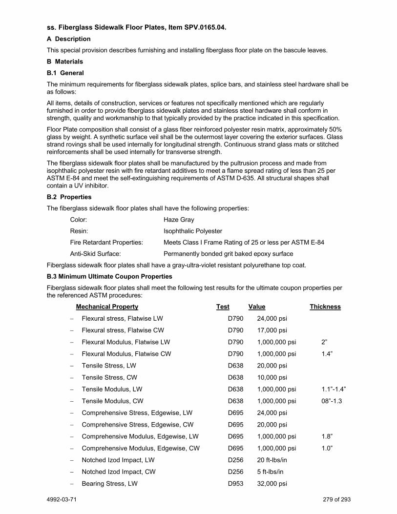
4992-03-71 279 of 293
Fiberglass Sidewalk Floor Plates, Item SPV.0165.04. A Description This special provision describes furnishing and installing fiberglass floor plate on the bascule leaves.
B Materials B.1 General The minimum requirements for fiberglass sidewalk plates, splice bars, and stainless steel hardware shall be as follows:
All items, details of construction, services or features not specifically mentioned which are regularly furnished in order to provide fiberglass sidewalk plates and stainless steel hardware shall conform in strength, quality and workmanship to that typically provided by the practice indicated in this specification.
Floor Plate composition shall consist of a glass fiber reinforced polyester resin matrix, approximately 50% glass by weight. A synthetic surface veil shall be the outermost layer covering the exterior surfaces. Glass strand rovings shall be used internally for longitudinal strength. Continuous strand glass mats or stitched reinforcements shall be used internally for transverse strength.
The fiberglass sidewalk floor plates shall be manufactured by the pultrusion process and made from isophthalic polyester resin with fire retardant additives to meet a flame spread rating of less than 25 per ASTM E-84 and meet the self-extinguishing requirements of ASTM D-635. All structural shapes shall contain a UV inhibitor.
B.2 Properties The fiberglass sidewalk floor plates shall have the following properties:
Color: Haze Gray
Resin: Isophthalic Polyester
Fire Retardant Properties: Meets Class I Frame Rating of 25 or less per ASTM E-84
Anti-Skid Surface: Permanently bonded grit baked epoxy surface
Fiberglass sidewalk floor plates shall have a gray-ultra-violet resistant polyurethane top coat.
B.3 Minimum Ultimate Coupon Properties Fiberglass sidewalk floor plates shall meet the following test results for the ultimate coupon properties per the referenced ASTM procedures:
Mechanical Property Test Value Thickness
− Flexural stress, Flatwise LW D790 24,000 psi
− Flexural stress, Flatwise CW D790 17,000 psi
− Flexural Modulus, Flatwise LW D790 1,000,000 psi 2”
− Flexural Modulus, Flatwise CW D790 1,000,000 psi 1.4”
− Tensile Stress, LW D638 20,000 psi
− Tensile Stress, CW D638 10,000 psi
− Tensile Modulus, LW D638 1,000,000 psi 1.1”-1.4”
− Tensile Modulus, CW D638 1,000,000 psi 08”-1.3
− Comprehensive Stress, Edgewise, LW D695 24,000 psi
− Comprehensive Stress, Edgewise, CW D695 20,000 psi
− Comprehensive Modulus, Edgewise, LW D695 1,000,000 psi 1.8”
− Comprehensive Modulus, Edgewise, CW D695 1,000,000 psi 1.0”
− Notched Izod Impact, LW D256 20 ft-lbs/in
− Notched Izod Impact, CW D256 5 ft-lbs/in
− Bearing Stress, LW D953 32,000 psi

4992-03-71 280 of 293
− Bearing Stress, CW D953 32,000 psi
− Perpendicular Shear Stress, LW(1) D3946 6,000 psi
− Perpendicular Shear Stress, CW D3946 6,000 psi
− Poisson's Ratio, LW 0.31 in/in
− Poisson's Ratio, CW 0.29 in/in
Physical Property Test Value
− Barcol Hardness 40
− 24 Hr. Water Absorption (2) D570 0.6% Max.
− Density D792 060-068 lbs/in^3
− Coefficient of Thermal Expansion D696 1,000,000 8.0in/in/ F
Electrical Property Test Value
− Arc Resistance D495 120 seconds
− Dielectric Strength, PF D149 N.T.
− Dielectric Strength, LW1 D149 35 KV/ in
− Dielectric Constant, PF D150 5 @ 60 Hz.
The following abbreviations pertain to the information on the above properties:
− LW = lengthwise
− CW = crosswise
− PF = perpendicular to the laminate face
− N.T. = not tested
Submit a sample of the sidewalk plate for to the engineer for review along with the shop drawing submittal.
Provide countersunk stainless steel bolts for attaching fiberglass plates to supporting structural steel members and for attaching fiberglass surface plates to underlying splice plates at butt joints as shown in the plans.
C Construction Drill all the holes connecting the plates to the 6.5-inch fiberglass splice plate in the shop and all other holes in the field.
Furnish sufficient fiberglass patch kits to patch all holes and cuts made in the field.
Stainless steel 1/2” diameter countersunk head screws, ½” nylon plug type key lock nuts, 1/2” washers and beveled washers shall be AISI Stainless Steel 304, or an approved equal.
Fiberglass plate shall be anti-skid abrasive grit with a surface buildup equal to 3550 mesh silica, as manufactured by Joseph T. Ryerson and Son, Inc., IKG Industries, or an approved equal. The 5” fiberglass splice plate does not require an anti-skid surface.
Fiberglass plates that do not meet the requirements set forth by these specifications and the plans shall be returned for a product that will receive the ultimate inspection and approval by the engineer.
Drilled holes in fiberglass are to have a minimum edge distance equal to 1 ½” measured from the center of the hole to the free edge of the material.
Fasteners for the non-metallic sidewalk plates shall comply with standard spec 513.2.2.5.
Bolts shall be socket type flat countersunk head cap screws, with washer and prevailing torque locking hex nuts.
The lock nuts shall be Anco lock nuts with a locking pin as manufactured by Lok-Mor Inc., IKG Industries, or an approved equal

4992-03-71 281 of 293
Predrill at the shop before delivery all holes where the plates are attached to adjacent plates and 6.5” splice plates. The splice plates shall be drilled in order that the smooth surface is up against the bottom of the walk plates.
Provide a qualified person to instruct the crews in the type of tools to use and proper methods to install and fabricate the fiberglass plates. Provide a minimum of 24 hours of on-the job instruction oversight of work by crews.
D Measurement The department will measure the Fiberglass Sidewalk Floor Plates by square feet, acceptably completed.
E Payment The department will pay for measured quantities at the contract unit price under the following bid item: ITEM NUMBER DESCRIPTION UNIT SPV.0165.04 Fiberglass Sidewalk Floor Plates SF
Payment is full compensation for furnishing, fabricating and installing all fiberglass sidewalk floor plates in conformance with the plans and this special provision.
12. Retaining Walls.
Backfill Coarse Aggregate Size No. 2, Item 209.0300.S. A Description
This special provision describes furnishing and placing coarse aggregate backfill as the plans show.
B Materials
Provide clean concrete aggregate graded according to the requirements as specified under standard spec 501.2.5.4.5. The soundness and wear requirements are deleted from this material.
C Construction
Construct the coarse aggregates according to standard spec 209.3.
D Measurement The department will measure Backfill Coarse Aggregate Size No. 2 in volume by the cubic yard in the vehicle.
E Payment The department will pay for measured quantities at the contract unit price under the following bid item: ITEM NUMBER DESCRIPTION UNIT 209.0300.S Backfill Coarse Aggregate Size No. 2 CY
Payment is full compensation for furnishing and installing the aggregate. stp-209-030 (20161130)
Anchoring System for Sheet Pile Wall R-70-159, Item SPV.0105.32; Anchoring System for Sheet Pile Wall R-70-160, Item SPV.0105.33.
A Description This special provision describes the design and installation of the anchoring system for retaining walls R-70-159 and R-70-160 located along the north shore of the Fox River. Perform all work for this item according to all applicable requirements of the standard specifications in general and standard spec 512 in particular, except as modified herein or as shown on the plans.
The work includes, but is not limited to, the following items:
− Design of a permanent sheet pile wall anchoring system, including tie-back anchor system, toe anchoring system and method of maintaining the soil stability during construction.
− Permanent steel wales, splice plates, connection bolts, nuts, washers and other required hardware.
− Tieback anchor rods, including nuts, washers, couplings and other required hardware.
4992-03-71 282 of 293
− Corrosion protection system for tieback anchor rods including coating with an approved corrosion inhibitor and covering with a polyethylene sheathing the entire length of the anchor rod.
− Tieback anchor system, including, depending on design, reinforced concrete deadmen, sheet pile wall anchor, H-pile anchor or another selected system.
− Toe anchor system, including, depending on design, rock anchors/pins or another selected system.
− Excavation required for installation of sheet piling, tieback anchor rods and anchor system.
B Materials B.1 Submittals Submit to the engineer full design calculations, construction drawings, shop drawings, catalog data, etc. for the proposed sheet pile wall anchoring systems. Submit for all materials for the bracing, wale system, tie back system, toe anchor system and corrosion protection system for the tie rods. Follow the submittal process as described in standard spec 105.2.2.
Design the dock wall anchoring systems according to AASHTO LRFD Bridge Design Specifications, 8th Edition, Chapter 11.5.6. The design calculations and drawings are to be sealed by a Wisconsin Licensed Professional Engineer.
B.2 Tie rods Furnish tie rods according to ASTM A722, Type II, with bar deformations in a thread-like pattern. Coat tie rods with an approved corrosion inhibitor. Provide a polyethylene sheath for the entire length of the tie rod. Provide a corrosion protection system for the tie rods with a 75-year design life.
B.3 Rolled steel shapes and plates Provide all rolled steel shapes and plates conforming to the requirements of ASTM A36 and all applicable requirements of standard spec 506.
B.4 Bolts and hardware Furnish high-strength, galvanized bolts and connection hardware conforming to standard spec 506.2.5 of the standard specification.
B.5 Anchor system Provide anchor system materials based on the design conforming to the requirements of all applicable sections of the standard specifications. If concrete deadmen are provided, furnish sub-foundation material conforming to standard spec 210. Steel reinforcing bars are uncoated.
C Construction C.2.1 Underground conflicts and coordination There are several underground conflicts existing in the area of the proposed dock walls and anchor systems as shown on the plan. Coordinate the construction sequence of the new retaining walls with the installation of the new storm sewer pipes and other utilities in the area. Coordinate construction of the new walls with construction of the north bascule bridge abutment.
C.2.2 Storm sewer pipe opening Provide an opening in the steel sheet piling wall for the 36-inch diameter concrete storm sewer pipe to pass through. After the pipe is placed through the opening, seal the gap around the pipe with a poured concrete collar.
C.2.3 Wales Install wales on the inside face of the sheet piling. Bolt the wales to every sheet pile.
C.2.4 Toe Anchors Install toe anchors on the river side of the sheeting at the inner pan/belly of the sheet pile. Utilize an installation method that accurately places the toe anchors and minimizes the distance between the sheet pile and the anchor. Install the toe anchor system at regular intervals or continuously along the base of the sheet piling. If individual anchors are used, install at a minimum frequency of one per sheet pair.

4992-03-71 283 of 293
D Measurement The department will measure Anchoring System for Sheet Pile Wall R-70-159 and Anchoring System for Sheet Pile Wall R-70-160 each as a single lump sum unit of work, acceptably completed.
E Payment The department will pay for measured quantities at the contract unit price under the following bid item: ITEM NUMBER DESCRIPTION UNIT SPV.0105.32 Anchoring System for Sheet Pile Wall R-70-159 LS SPV.0105.33 Anchoring System for Sheet Pile Wall R-70-160 LS
Payment is full compensation for the complete design of a sheet pile wall anchoring system for walls R-70-159 and R-70-160 and furnishing and installing all materials.
13. Drainage and Erosion Control.
Inlets 2x2.5-FT, Special, Item SPV.0060.02. A Description This special provision describes providing Inlets 2x2.5-FT, Special as the plans show. Conform to standard spec 611 and as follows.
B Materials Materials shall be conforming to standard spec 611.2. The rubber adjustment riser ring is to be on the department’s approved product list.
Use manufacturer approved mastic adhesive and polyurethane adhesive with a flexible set. Supply manufacture’s recommendations prior to installation.
C Construction Construction shall be conforming to the plans and with standard spec 611.3.
Replace standard spec 611.3.3(1) with the following:
(1) Set inlet cover on rubber adjustment riser ring. Use mastic adhesive between the ring and the inlet structure. Use polyurethane adhesive with a flexible set between the ring and the inlet cover. Use two 5/16-inch beads of adhesive placed 1 inch and 2 inches in from the outside edge of the ring. If multiple adjustment rings are necessary, a maximum of two adjustment rings can be used. A maximum of 3 inch adjustment is allowed. Use manufacturer approved polyurethane adhesive with a flexible set to join the two rings. If the adjustment rings must be cut, the joints must be staggered, and a polyurethane adhesive used to reattach the cut ends. No concrete adjustment rings or mortar is to be placed between the top of the structure and the inlet cover.
D Measurement The department will measure Inlets 2x2.5-FT, Special as each individual inlet, acceptably completed.
E Payment The department will pay for measured quantities at the contract unit price under the following bid item: ITEM NUMBER DESCRIPTION UNIT SPV.0060.02 Inlets 2x2.5-FT, Special EACH
Payment shall be conforming to standard spec 611.5. ner-611-030 (20190712)
Catch Basins 5-FT Diameter, Special, Item SPV.0060.10. A Description This special provision describes providing Catch Basins 5-FT Diameter, Special as the plans show. Conform to standard spec 611 and as follows.
B Materials Materials shall be conforming to standard spec 611.2. The rubber adjustment riser ring is to be on the department’s approved product list.

4992-03-71 284 of 293
Use manufacturer approved mastic adhesive and polyurethane adhesive with a flexible set. Supply manufacture’s recommendations prior to installation.
C Construction Construction shall be conforming to the plans and with standard spec 611.3.
Replace standard spec 611.3.3(1) with the following:
(1) Set inlet cover on rubber adjustment riser ring. Use mastic adhesive between the ring and the inlet structure. Use polyurethane adhesive with a flexible set between the ring and the inlet cover. Use two 5/16-inch beads of adhesive placed 1 inch and 2 inches in from the outside edge of the ring. If multiple adjustment rings are necessary, a maximum of two adjustment rings can be used. A maximum of 3 inch adjustment is allowed. Use manufacturer approved polyurethane adhesive with a flexible set to join the two rings. If the adjustment rings must be cut, the joints must be staggered, and a polyurethane adhesive used to reattach the cut ends. No concrete adjustment rings or mortar is to be placed between the top of the structure and the inlet cover.
D Measurement The department will measure Catch Basins 5-FT Diameter, Special as each individual Catch Basin, acceptably completed.
E Payment The department will pay for measured quantities at the contract unit price under the following bid item: ITEM NUMBER DESCRIPTION UNIT SPV.0060.10 Catch Basins 5-FT Diameter, Special EACH
Payment shall be conforming to standard spec 611.5.
Inlet Covers Type R-2569, Item SPV.0060.13. A Description This special provision describes providing Inlet Covers Type R-2569 as the plans show. Conform to standard spec 611 and as follows.
B Materials Use Neenah Foundry Inlet Frame R-2569 Type A with Type Q Grate. C Construction Set frames on full mortar beds except as specified for placing concrete in standard spec 415.3.6.1, or secure otherwise as the plans show. Fit or secure the grates and lids to the frames to eliminate rocking or chattering.
Set the frames, grates, and lids accurately so the complete installation is at the correct elevation required to fit the adjoining surfaces. If installed in concrete surfaces, set the frames or castings, and grout as necessary, as specified in standard spec 415.3.6.1. Make sure the grates or lids are not in place while striking off and finishing the adjoining concrete.
Set frames located in pavement areas so that they comply with the surface requirements specified in standard spec 450.3.2.9, Place a 6-foot straightedge over the centerline of each frame parallel to the direction of traffic at the completion of the paving. Make a measurement at each side of the frame, average the 2 measurements. If this average is greater than 5/8 inch, reset the frame to the correct plane and elevation. If this average is 5/8 inch or less but greater than 3/8 inch, the department will allow the frame to remain in place.
If the frame is higher than the adjacent pavement, then make the 2 measurements at each end of the straightedge and average them. D Measurement The department will measure Inlet Covers Type R-2569 as each individual inlet cover, acceptably completed.
4992-03-71 285 of 293
E Payment The department will pay for measured quantities at the contract unit price under the following bid item: ITEM NUMBER DESCRIPTION UNIT SPV.0060.13 Inlet Covers Type R-2569 EACH
Payment shall be conforming to standard spec 611.5.
Street Sweeping, Item SPV.0075.01. A Description Remove small dirt and dust particles from the roadway using a street sweeper for cleaning the roadway before traffic switches or cleaning of roadways from non-contractor vehicle traffic.
B (Vacant) C Construction Provide a self-contained mechanical or air conveyance street sweeper and dispose the accumulated material.
D Measurement The department will measure Street Sweeping by the hour that the street sweeper is on the project picking up and removing debris from the roadway.
E Payment The department will pay for measured quantities at the contract unit price under the following bid item: ITEM NUMBER DESCRIPTION UNIT SPV.0075.01 Street Sweeping HRS
Payment is full compensation for furnishing all labor, tools, equipment, and incidentals necessary to complete the contract work.
All street sweeping due to the contractors hauling operations is considered incidental to the contract.
Turbidity Barrier Special, Item SPV.0090.09. A Description Furnish, and install turbidity barrier as shown on the plans, as directed by the engineer, and as hereinafter provided.
B Materials Barrier system material shall be according to the plans and industry standard Type II Floating Turbidity Curtains. Minimum material design values shall be equal to or exceed those identified in “Engineering and Design – Handbook for the Preparation of Storm Water Pollution Prevention Plans for Construction Activities”, U.S. Army Corps of Engineers, Publication # EP 1110-1-16, Appendix C, BMP-27, 1997. http://140.194.76.129/publications/eng-pamphlets/ep1110-1-16/
C Construction Install turbidity barriers and danger buoys at locations shown on the plans or as directed by the engineer. Install per manufacturer specifications. Acceptance by the engineer is required.
Place all barriers, before beginning adjacent construction, in a manner that causes minimum disturbance of the lake bed and banks. Extend the barrier into the banks far enough to preclude washing out or eroding around the ends.
Maintain the integrity of the barrier as necessary to contain erosion from adjacent construction operations. Promptly correct all deficiencies. Barrier maintenance includes removing and disposing of accumulations of soil and other detrimental material. Adjust the barrier depth to account for fluctuating lake levels, wave action, current velocities, and water equilibrium on both sides of barrier.
Remove the barrier after completing the adjacent work. Delay removal until removing and disposing of accumulated soils and other suspended materials, and all suspended materials settle. Minimize disturbing the streambed and banks during removal operations.
4992-03-71 286 of 293
D Measurement The department will measure Turbidity Barrier Special by the linear foot, acceptably completed.
E Payment The department will pay for measured quantities at the contract unit price under the following bid item: ITEM NUMBER DESCRIPTION UNIT SPV.0090.09 Turbidity Barrier Special LF
Payment is full compensation for furnishing, assembling, installing, maintaining, repairing, and removing the turbidity barrier; for sandbags, buoys, navigational markers, anchors and anchor ropes, and for furnishing all labor, tools, equipment and incidentals required to complete the work. No payment will be made for reinstallation of turbidity barrier.
Insulation Board 2-Inch, Item SPV.0165.03. A Description This special provision describes providing insulation board.
B Materials Furnish materials conforming to Chapter 8.50.2 of the Standard Specifications for Sewer and Water Construction in Wisconsin (latest edition).
C Construction Perform all construction conforming to Chapter 4.17.2(a) of the Standard Specifications for Sewer and Water Construction in Wisconsin (latest edition).
D Measurement The department will measure Insulation Board 2-Inch by the square foot, acceptably completed.
E Payment The department will pay for measured quantities at the contract unit price under the following bid item: ITEM NUMBER DESCRIPTION UNIT SPV.0165.03 Insulation Board 2-Inch SF ner-900-035 (20171213)
14. Lighting.
General Requirements for Lighting Work. Unless otherwise indicated, State Specifications in this section shall be in reference to the State of Wisconsin Department of Transportation, Division of Highways, “Standard Specifications for Highway and Structure Construction”, Latest Edition, including Supplemental Specifications.
Lighting items for above ground equipment and hardware, equipment and materials furnished under each of the various bid items shall be exactly the same manufacturer, model, part, and style for every installation in this contract.
Contact City of Menasha prior to starting street lighting construction.
City of Menasha Contact – Adam Alix 920-967-3611
Electrical Service Meter Breaker Pedestal Racine Street & Ahnaip Street, Item 656.0200.01; Electrical Service Meter Breaker Pedestal Racine Street & Main Street, Item 656.0200.02.
Replace standard spec 656.2.3, Meter Breaker Pedestal Service, paragraph (1) with the following:
(1) Furnish an approved service having a meter breaker pedestal, 22,000-AIC circuit breakers unless the local utility requires otherwise, grounding electrodes and connections, conduit and fittings, and all necessary conductors and equipment required by the WSEC and the utility for a service connection. Furnish a pedestal with a 100 A 2-pole main breaker and a 30 A spare breaker. When the meter breaker pedestal is energized, install an approved meter seal at all access points on the meter trough. Meter shall be time of use type.

4992-03-71 287 of 293
Luminaires Utility LED, Item SPV.0060.03. A Description
This special provision describes furnishing and installing a LED luminaire fixture according to the pertinent provisions of standard spec 659 and as hereinafter provided. Specific items are noted in the plans.
B Materials
Furnish Eaton NVN Navion Model #NVN-AF-02-D-U-T3R-10K-BK luminaire fixtures. The luminaire fixture shall be black.
C Construction
Install luminaire fixture according to standard spec 659.3.
D Measurement The department will measure Luminaires Utility LED as each individual unit, acceptably completed.
E Payment The department will pay for measured quantities at the contract unit price under the following bid item: ITEM NUMBER DESCRIPTION UNIT SPV.0060.03 Luminaires Utility LED EACH
Payment is full compensation for providing materials including luminaires, fittings, brackets, hardware and attachments; and for luminaire fusing.
Concrete Bases Type 7 Modified, Item SPV.0060.04. A Description
This special provision describes constructing concrete bases for street lighting.
B Materials
Provide all materials according to standard spec 654.2 and as shown in the plan details. The Concrete Bases Type 7 Modified shall use a 12 ½-inch bolt circle as shown on plans.
C Construction
Construct concrete bases according to standard spec 654.3.
D Measurement The department will measure Concrete Bases Type 7 Modified as each unit, acceptably completed.
E Payment The department will pay for measured quantities at the contract unit price under the following bid item: ITEM NUMBER DESCRIPTION UNIT SPV.0060.04 Concrete Bases Type 7 Modified EACH
Payment is full compensation for providing concrete bases; for embedded conduit and electrical components; for anchor templates, rods, nuts, and washers; for bar steel reinforcement; and for excavating and backfilling.
Decorative Light Pole Assembly 12 FT, Item SPV.0060.05; Decorative Light Pole Assembly 16 FT, Item SPV.0060.06; Decorative Light Pole Assembly 30 FT, Item SPV.0060.07.
A Description
This special provision describes installing furnishing and installing decorative light pole assemblies.
B Materials Each assembly includes luminaire fixtures, light pole, and luminaire arms. A description of the lighting equipment included in each lighting assembly is provided in the tables below. Furnish each lighting assembly according to the applicable portions of standard spec 659, the manufacturer’s recommendations, and as shown in the plan details.

4992-03-71 288 of 293
Decorative Light Pole Assembly 12 FT
Lighting Equipment
Manufacturer Catalog No. Description
Luminaire Fixture Hadco 3100DBLKT64NA3NNNNSP1 MOD luminaires 2 decorative luminaire fixtures
Light Pole Hadco P5092-12ATG MOD 6" DOWN FROM TOP pole
12’ black decorative tapered fluted aluminum
pole with GFI outlet and 3” OD tenon
Luminaire Arm Hadco PTH2220-P3A MOD W/FLAT CAP arm Twin decorative arm bracket
Decorative Light Pole Assembly 16 FT
Lighting Equipment Manufacturer Catalog No. Description
Luminaire Fixture Hadco 3100DBLKT64NA3NNNNSP1 MOD luminaires 2 decorative luminaire fixtures
Light Pole Hadco P5092-16ATG6S MOD pole
16’ black decorative tapered fluted aluminum
pole with GFI outlet and 3” OD tenon
Luminaire Arm Hadco PTH2220-P3A MOD W/FLAT CAP arm Twin decorative arm bracket
Decorative Light Pole Assembly 30 FT
Lighting Equipment Manufacturer Catalog No. Description
Luminaire Fixture Hadco 3100DBLKT64NA3NNNNSP1 MOD luminaires 2 decorative luminaire fixtures
Light Pole Valmont FL210 900E300-FPGV-HH-AB-DECO BASE-(2)BURNSVILLE-ARMS
30’ decorative pole with 2 decorative arm brackets
Luminaire Arm Included with Light Pole
Verify all model/catalog numbers before ordering. Provide catalog cut sheets of the luminaire fixture, light pole, and luminaire arm for review by the engineer and Adam Alix of the City of Menasha at (920) 967-3611 prior to finalizing the order to the manufacturer. Furnish all other hardware and materials necessary to install decorative light pole assemblies. The color of luminaire fixture, light poles, and luminaire shall be black.
C Construction
Construct according to the applicable portions of standard spec 659 and the manufacturer’s recommendations. Fill in any open holes in the light pole using a grommet or other engineer-approved device to prevent water from entering the pole.
D Measurement The department will measure Decorative Light Pole Assemblies (Length) as each unit, acceptably completed.
4992-03-71 289 of 293
E Payment The department will pay for measured quantities at the contract unit price under the following bid item: ITEM NUMBER DESCRIPTION UNIT SPV.0060.05 Decorative Light Pole Assembly 12 FT EACH SPV.0060.06 Decorative Light Pole Assembly 16 FT EACH SPV.0060.07 Decorative Light Pole Assembly 30 FT EACH
Payment is full compensation for providing and installing all materials including hardware, fittings, mounting devices, and attachments.
Lighting Control Cabinet Special, Item SPV.0060.08. A Description
This special provision describes furnishing and installing a WisDOT Lighting Control Cabinet 120/240 30-Inch with the addition of festoon circuits as shown in the plans. This special provision includes all power and control components within the cabinet as shown on the Plans and as described hereinafter.
B Materials
Furnish a WisDOT Lighting Control Cabinet 120/240 30-Inch according to standard spec 659 and as shown in the plan details.
Submit shop drawings for all parts and wiring plans to the engineer for approval prior to ordering the equipment. The equipment shall not be ordered prior to approval of the shop drawings by the engineer.
C Construction
Construct the Lighting Control Cabinet according to standard spec 659.
Connect the control cabinet to the concrete base according to the cabinet manufacturer’s recommendations and industry standards.
Place a copy of the control cabinet wiring schematic in a plastic protector and affix to the inside of the door to the cabinet.
D Measurement The department will measure Lighting Control Cabinet Special completed according to the contract, and accepted as a unit of work. E Payment The department will pay for measured quantities at the contract unit price under the following bid item: ITEM NUMBER DESCRIPTION UNIT SPV.0060.08 Lighting Control Cabinet Special EACH
Payment is full compensation for furnishing and installing the lighting cabinet including circuit wiring connections, hardware, and fittings the plans show; and for making the lighting system fully operational.
Salvage Existing Traffic Signal and Lighting Equipment, Item SPV.0105.35. A Description
This special provision describes removing and salvaging existing traffic signal and lighting equipment, CCTV cameras and removing electrical wire at all the locations specified in the plans and as hereinafter provided. Specific salvage items are noted in the plans.
B (Vacant) C Construction Arrange for the de-energizing of the signal and lighting system with the local electrical utility after receiving approval from the engineer that the existing systems can be removed.
Notify the engineer and Adam Alix of the City of Menasha, (920) 967-3611, at least three working days prior to the removal of the signal and lighting equipment. Complete this work immediately following shut down of equipment.

4992-03-71 290 of 293
Salvage signal poles, trombone arms, signal heads, light poles, luminaire arms, luminaire fixtures, and CCTV cameras per plan from their concrete footing and disassemble out of traffic according to standard spec 204 and as shown on the plans. Remove wiring/cabling from the pole and dispose of off city right-of-way. Ensure that access handhold doors and hardware remain intact. Make a reasonable effort to inspect salvaged equipment for damage or defects.
Coordinate with Adam Alix of the City of Menasha, (920) 967-3611 to determine an acceptable location to stockpile salvaged equipment to be retained for the City of Menasha to pick up. D Measurement The department will measure Salvage Existing Traffic Signal and Lighting Equipment as a single lump sum unit of work, acceptably completed.
E Payment The department will pay for measured quantities at the contract unit price under the following bid item: ITEM NUMBER DESCRIPTION UNIT SPV.0105.35 Salvage Existing Traffic Signal and Lighting Equipment LS
Payment is full compensation for removing, salvaging, disassembling, disposing of scrap material, protecting from damage, and incidentals necessary to complete the contract work.
Lighting Equipment Painting, Item SPV.0105.36. A Description This special provision describes the painting of the exterior surfaces of street lighting equipment and associated mounting hardware as indicated in the plans. Individual lighting equipment is paid for in separate bid items.
B Materials Contact Adam Alix of the City of Menasha, (920) 967-3611, prior to ordering lighting equipment to obtain the exact color code.
Obtain lighting equipment powder-coated in the black color from the manufacturer or supplier. Lighting equipment includes luminaire arms, lighting poles, and metal bases as indicated in the plans. All black items shall match in color. All lighting hardware, sign hardware and stainless steel banding used on poles, shall be cleaned and painted with a primer and two finish coats of the best rust resistant synthetic resin enamel in the color that exactly matches the color code provided by the City of Menasha.
C Construction Install per manufacturer’s instructions. Marks and scratches on painted equipment and hardware shall be touched up with two coats of synthetic resin enamel consistent in color and texture to the original finish, or as directed by the engineer.
D Measurement The department will measure Lighting Equipment Painting as a single lump sum unit of work, acceptably completed.
E Payment The department will pay for measured quantities at the contract unit price under the following bid item: ITEM NUMBER DESCRPTION UNIT SPV.0105.36 Lighting Equipment Painting LS
Payment is full compensation for furnishing lighting equipment, hardware, and banding in the color specified by the City of Menasha.
15. Landscaping.
Planting Mixture, Item SPV.0035.04. A Description This special provision describes providing planting mixture at the locations the plans show. Conform to standard spec 632 and as follows.
4992-03-71 291 of 293
B Materials Provide Planting Mixture, as shown on plan. The planting mixture consists of the following blend by volume:
1. Two parts topsoil. Topsoil shall conform to standard spec 625. 2. One-part sand. Obtain the engineer’s approval for the sand. 3. One-part compost. Compost shall be either well-rotted shredded leaf mulch, free of disease; or well-rotted,
unleached, stable or cattle manure containing no more than 25 percent by volume of straw, sawdust, or other bedding materials and free of toxic substances. Either shall be free of stones, sticks, soil, weed seeds, debris, and other material harmful to plant growth.
4. One part peat moss. Peat moss shall conform to standard spec 632.
C Construction
Ensure proper excavation of planting area for all areas to receive Planting Mixture. Prepare planting beds by removing any construction materials, stone, or other debris larger than 2 inches in length or diameter for entire area of planting bed and to depths indicated on plans.
Provide planting mixture over entire planting bed area and fine grade to match grades as indicated on plans or to adjacent back of curb or other hardscape surface as indicated on plans and account for settling. Place Planting Mixture in 6-inch to 8-inch lifts, watering in or tamping to reduce settling potential. A minimum of 12-inch depth shall be provided in all locations; depth varies, see plans.
Obtain approval of Planting Mixture depths, locations, and elevations by supervising engineer.
D Measurement The department will measure Planting Mixture by the cubic yard, acceptably completed.
E Payment The department will pay for measured quantities at the contract unit price under the following bid item: ITEM NUMBER DESCRPTION UNIT SPV.0035.04 Planting Mixture CY
Payment is full compensation furnishing and installing all materials and for furnishing all labor, tools, equipment, and incidentals necessary to complete the contract work. ner-632-020 (20190710)
Landscape Edging, Item SPV.0090.10. A Description This special provision describes providing black polyethylene landscape edging at the locations the plans show.
B Materials Landscape edging shall be black Polyethylene supplied in 20-foot minimum lengths.
Landscape edging shall be a minimum of 5 inches in depth with a double “V” anchor on the bottom edge and a hollow 1-inch diameter round top edge.
Landscape edging segments shall be joined at the top edge with manufacturer’s supplied fittings that fit securely into the hollow top edge of each length.
C Construction Place Landscape edging in trench to a depth allowing the top edge to be 1” above finished grade.
Compact soil in trench so landscape edging is securely anchored in planting bed.
D Measurement The department will measure Landscape Edging by the linear foot, acceptably completed.

4992-03-71 292 of 293
E Payment The department will pay for measured quantities at the contract unit price under the following bid item: ITEM NUMBER DESCRIPTION UNIT SPV.0090.10 Landscape Edging LF Payment is for providing and installing the edging and disposing of all excess and waste materials. ner-645-015 (20190710)
Shredded Hardwood Bark Mulch, Item SPV.0180.01. A Description This special provision describes furnishing and installing Shredded Hardwood Bark Mulch at the locations shown on the plans and according to the requirements of standard spec 632, the plans, and as hereinafter provided.
B Materials Provide Shredded Hardwood Bark Mulch, as shown on plan and according to standard spec 632.2.6.
Shredded Hardwood Bark Mulch shall be finely shredded hardwood bark mulch and shall be the product of a mechanical chipper, hammermill, or tub grinder. The material shall be fibrous and uniformly dark brown in color, free of large wood chunks, and shall be substantially free of mold, dirt, sawdust, and foreign material. No portion of the material shall be in an advanced state of decomposition. The material shall not contain chipped up manufactured boards or chemically treated wood, including but not limited to wafer board, particle board, and chromated copper arsenate (CCA) or penta-treated wood. The material shall contain no bark of the black walnut tree. The material, when air dried, shall all pass a 4-inch screen and no more than 20 percent by mass of the material shall pass a 0.10-inch sieve. Unattached bark or greenleaf composition, either singly or combined, shall not exceed 20 percent each by mass. The maximum length of individual pieces shall not exceed 4 inches.
C Construction Install mulch according to standard spec 632.3.9 to a depth of 3 inches.
Place the hardwood bark mulch in such a manner as to not damage plants already in place.
D Measurement The department will measure Shredded Hardwood Bark Mulch by the square yard, acceptably completed.
E Payment The department will pay for measured quantities at the contract unit price under the following bid items: ITEM NUMBER DESCRIPTION UNIT SPV.0180.01 Shredded Hardwood Bark Mulch SY
Payment is full compensation furnishing and installing all materials and for furnishing all labor, tools, equipment, and incidentals necessary to complete the contract work. ner-627-005 (20190710)
16. Miscellaneous.
United States Post Office Bench. At the United States Post Office on Racine Street north of Broad Street, a bench is present on the southern edge of the property along the sidewalk adjacent to Racine Street. The bench must be protected at all times during construction. Moving of the bench is permitted as long as the integrity of the bench is maintained. This is incidental to the contract.
Field Office. Supplement standard spec 642 with the following:
Provide and maintain a portable handwashing station at every project field office. The station shall include a hands-free sink with foot pump-operated faucet, soap dispenser, paper towel dispenser, fresh water supply, and collection tank for gray water. Regularly service and maintain the handwashing station and all
4992-03-71 293 of 293
supplies as needed, and properly dispose of all materials. Costs associated with the handwashing station are incidental to the field office bid item.
Fence Safety, Item 616.0700.S. A Description
This special provision describes providing plastic fence at locations the plans show.
B Materials
Furnish notched conventional metal "T" or "U" shaped fence posts.
Furnish fence fabric meeting the following requirements.
Color: International orange (UV stabilized)
Roll Height: 4 feet
Mesh Opening: 1 inch min to 3 inch max
Resin/Construction: High density polyethylene mesh
Tensile Yield: Avg. 2000 lb per 4 ft. width (ASTM D638)
Ultimate Tensile Strength: Avg. 3000 lb per 4 ft. width (ASTM D638)
Elongation at Break (%): Greater than 100% (ASTM D638)
Chemical Resistance: Inert to most chemicals and acids
C Construction
Drive posts into the ground 12 to 18 inches. Space posts at 7 feet.
Use a minimum of three wire ties to secure the fence at each post. Weave tension wire through the top row of strands to provide a top stringer that prevents sagging.
Overlap two rolls at a post and secure with wire ties.
D Measurement The department will measure Fence Safety by the linear foot along the base of the fence, center-to-center of posts, acceptably completed.
E Payment The department will pay for measured quantities at the contract unit price under the following bid item: ITEM NUMBER DESCRIPTION UNIT 616.0700.S Fence Safety LF
Payment is full compensation for furnishing and installing fence and posts; maintaining the fence and posts in satisfactory condition; and for removing and disposing of fence and posts at project completion. stp-616-030 (20160607)

Effective January 2017 letting ASP-3
1
ADDITIONAL SPECIAL PROVISION 3
DISADVANTAGED BUSINESS ENTERPRISE [DBE] PROGRAM IMPLEMENTATION
1. Description
a. The federal DBE program requirements outlined in the Code of Federal Regulations at 49 CFR Part 26apply to this Wisconsin Department of Transportation contract. WisDOT is a recipient of federal funds andthis contract includes federal funds. United States Department of Transportation Federal DBE Programrequires the following provisions:
(1) Pursuant to the federal DBE program regulation at 49 CFR Part 26, a contractor’s failure to comply withany provision of the DBE regulations will be considered a material breach of contract. This is non-negotiable. If a contractor fails to carry out the DBE program and Title VI nondiscrimination requirementsof its contracts, the following sanctions will be assessed depending upon the facts, reasoning, severityand remedial efforts of the contractor: termination of contract, withholding payment, assessment ofmonetary sanctions, assessment of liquidated damages and/or suspension/debarment proceedings thatmay result in the disqualification of the contractor from bidding for a designated period of time.
(2) The contractor shall utilize the specific DBEs listed to perform the work and supply the materials forwhich each is listed unless the contractor obtains the federal fund recipient’s [DOT] written consent.Unless [WisDOT] consent is provided, the contractor shall not be entitled to any payment for work ormaterial unless it is performed or supplied by the listed DBE.
b. The Wisconsin Department of Transportation [WisDOT] is committed to the compliant administration of theDBE Program. Each WisDOT Secretary affirms this commitment with his/her signed assurance.
(1) The department encourages the contractor to assist and develop DBE firms to become fullyknowledgeable contractors to successfully perform on its contracts. Under the contract, the contractoragrees to provide the assistance to participating DBE's in the following areas:i. Produce accurate and complete quotes.ii. Understand highway plans applicable to their work.iii. Understand specifications and contract requirements applicable to their work.iv. Understand contracting reporting requirements.
(2) Wisconsin DOT identifies the assigned DBE goal in its contract advertisements and posts the contractDBE goal on the cover of the bidding proposal. The contractor can meet the assigned, specified contractDBE goal by subcontracting work to a DBE or by procuring services or materials from a DBE. Thedepartment calculates the DBE participation as the dollar value of DBE participation included in the bidexpressed as a percentage of the total contract bid amount.
(3) For more comprehensive information on the disadvantaged business program, visit the department'sCivil Rights and Compliance Section website at:

Effective January 2017 letting ASP-3
2
2. Definitions
Interpret these terms, used throughout this additional special provision, as follows: a. Bid Percentage: The DBE percentage indicated in the bidding proposal at the time of bid.
b. DBE: A small business certified as disadvantaged business enterprise (DBE) under the federal DBE
program and included on the Wisconsin UCP DBE Directory deemed ready, willing and able.
c. DBE goal: The amount of DBE participation expected in the contract as shown on the cover of the Highway Work Proposal.
d. Manufacturer: A firm that operates or maintains a factory or establishment that produces, on the premises,
the materials, supplies, articles, or equipment required under the contract.
e. Supplier: A firm that owns, operates, or maintains a store, warehouse, or other establishment in which the materials, supplies, articles or equipment required under the contract are bought, kept in stock, and regularly sold or leased to the public.
f. Voluntary Achievement: The amount of DBE participation achieved and reported in the contract in excess
of the assigned goal. 3. DBE Percentage Required at Bid Submission
Indicate the bid percentage (i.e. 0% through 100%) of DBE participation on the completed bidding proposal. For electronic submittals, show the percentage in the miscellaneous data folder, Item 3, DBE Percent. For paper submittals, show the percentage on the sheet included after the schedule of items. By submission of the bid, the bidder contractually commits to DBE participation at or above the bid percentage, or certifies that they have utilized comprehensive good faith efforts to solicit and utilize DBE firms to meet the DBE participation requirements of this contract proposal, and that the bid percentage is reflective of these good faith efforts. The bid percentage should demonstrate the efforts of the prime contractor prior to bid. If the bidder does not indicate the bid percentage of DBE participation on the completed bidding proposal, the department will consider the bid irregular and may reject the bid.
4. WisDOT Interpretation of Federal DBE Program Provision
Prime contractors must utilize the specific DBEs listed to perform the work and/or supply the materials for which each is listed on the Commitment to Subcontract to DBE Form [DT1506] and approved by WisDOT’s DBE office to execute its contract. The approved Commitment to Subcontract to DBE Form [DT1506] becomes a contract document/record. a. Department's DBE Evaluation Process
WisDOT evaluates DBE using the Commitment to Subcontract to DBE, payments to subcontractors and contract documentation. The prime contractor shall list the specific DBE certified firms and items of work s/he intends to use toward the fulfillment of the assigned DBE contract goal. The prime contractor receives DBE credit for payments made to the DBE firms performing the work listed on the approved Form DT1506.
b. Documentation Submittal The contractor is to identify, by name, the DBE firms whose utilization is intended to satisfy this provision, the items of work of the DBE subcontract or supply agreement and the dollar value of those items of work by completing the Commitment to Subcontract to DBE Form [DT1506]. Effective January 1, 2017, the contractor will be required to submit the documentation within 5 business days after bid opening. All necessary supporting documentation including Attachment ‘A’ forms and/or Good Faith Efforts Form
Effective January 2017 letting ASP-3
3
[DT1202] must be submitted no later than 2 business days from contractor’s initial submission of the DT 1506. The contractor must provide a signed Attachment ‘A’ form to the DBE office within the time limit in order to receive authorization for contract execution; the DBE office reserves the right accept alternate documentation in lieu of the signed form in extenuating circumstances. Documentation must be submitted to the DBE Office by email at [email protected] ([email protected]) or by postal mail ATTN: DBE Office, PO Box 7965, Madison, WI 53707-7965. (1) Bidder Meets DBE Goal
If the bidder indicates that the contract DBE goal is met, after award and before execution, the department will evaluate the Commitment to Subcontract to DBE Form DT1506 and attachment A(s) to verify the actual DBE percentage calculation. If the DBE commitment is verified, the contract is eligible for execution with respect to the DBE commitment.
(2) Bidder Does Not Meet DBE Goal i. If the bidder indicates a bid percentage on the Commitment to Subcontract to DBE Form [DT1506]
that does not meet the contract DBE goal, the bidder must submit a Good Faith Efforts Form [DT1202] and supporting documentation. After award and before execution, the department will evaluate the bidder's DBE commitment and consider the bidder's good faith efforts submission.
ii. The department will evaluate the bidder's good faith effort request and notify the bidder of one of the following: (a) If the department grants a good faith efforts, the bid is eligible for contract execution with
respect to DBE commitment. (b) If the department rejects the good faith efforts request, the department may declare the bid
ineligible for execution. The department will provide a written explanation of why the good faith efforts request was rejected. The bidder may appeal the department's rejection as allowed under 7 a. & b.
c. Bidder Fails to Submit Documentation
If the contractor fails to furnish the Commitment to Subcontract to DBE Form [DT1506] within the specified time, the department may cancel the award. Delay in fulfilling this requirement is not a cause for extension of the contract time and shall not be used as a tool to delay execution.
5. Department's Criteria for Good Faith Effort
Appendix A of 49 CFR Part 26, is the guiding regulation concerning good faith efforts. However, the federal regulations do not explicitly define “good faith” but states that bidder must actively and aggressively attempt to meet the goal. The federal regulations are general and do not include every factor or effort that can be considered. As a result, each state must establish its own processes and consider the factors established in its own practices to create a process for making a determination of adequate good faith. WisDOT evaluates good faith on a contract basis just as each contract award is evaluated individually. The department will only approve a contractor’s good faith efforts if the bidder has made the effort, given the relevant circumstances under the contract that a bidder actively and aggressively seeking to meet the goal would make. The department will evaluate the bidder's good faith effort to determine whether a good faith efforts will be granted. The bidder must demonstrate, on the DT1202 that they have aggressively solicited DBE participation in an attempt to meet the contract DBE goal and attaining the stated DBE goal is not feasible. a. The department, in conjunction with industry stakeholders, has developed the following guidance for
contractor good faith effort. The guidance and the attached appendices provide a framework for the actions required by all parties in the processing and evaluation of bidder’s total efforts to achieve the project specific DBE goal prior to the bid letting date.
Effective January 2017 letting ASP-3
4
b. Prime Contractors should: (1) Document all efforts and decisions made toward achieving the DBE goal on the contract. The bidder
should use the Civil Rights & Compliance System [CRCS] and related WisDOT- approved DBE outreach tools, including the Bid Express Small Business Network, to foster DBE participation on all applicable contracts.
(2) Prime contractors may request assistance with DBE outreach and follow-up by contacting the department's DBE Support Services Office by phone or email request at least 14 days prior to the bid letting date. Requesting assistance with outreach is not a decisive factor in the review Good faith effort evaluation. Phone numbers are 414-438-4584 and/or 414-659-0487; Fax: 414-438-5392; E-mail: [email protected].
(3) Request quotes by identifying potential items to subcontract and solicit. Prime contractors are strongly encouraged to include in their initial contacts a single page including a detailed list of items for which they are accepting quotes, by project, within a letting. See attached sample entitled “Sample Contractor Solicitation Letter” in Appendix A. Prime contractors should also indicate a willingness to accept quotes in areas they are planning to perform themselves, as required by federal rules. In some cases, it might be appropriate to use DBE’s to do work in a prime contractor’s area of specialization. i. Solicit quotes from certified DBE firms who match 'possible items to subcontract' using all
reasonable and available means. Additionally, forward copies of solicitations highlighting the work areas for which you are seeking quotes to [email protected].
ii. SBN is the preferred outreach tool. https://www.bidx.com/wi/main. Other acceptable means include postal mail, email, fax, phone call. (a) Primes must ask DBE firms for a response in their solicitations. See Sample
Contractors Solicitation Letter in Appendix. This letter can be included as an attachment to the SBN sub-quote request.
(b) Solicit quotes at least 10 calendar days prior to the letting date, at least two Fridays before the letting, to allow DBE firms sufficient time to respond. Prime contractors should contact DBE firms early, asking if they need help organizing their quote, assistance confirming equipment needs, or other assistance supporting their submission of a competitive quote for their services.
(c) Second solicitation should take place within 5 calendar days. Email and SBN are the preferred delivery of the follow-up solicitation.
iii. Upon request, provide interested DBE firms with adequate information about plans, specifications and the requirements of the contract by letter, information session, email, phone call and/or referral.
iv. When potential exists, the contractor should advise interested DBE firms on how to obtain bonding, line of credit or insurance if requested.
v. Document DBE firm’s interest in quoting by taking appropriate steps to follow up initial solicitation with: (a) Email to all prospective DBE firms in relevant work areas. (b) Phone call log to DBE firms who express interest via written response or call. (c) Fax/letter confirmation (d) Signed copy of Bid Express SBN Record of Subcontractor Outreach Effort.
c. Evaluate DBE quotes Documentation is critical if a prime does not utilize the DBE firm’s quote for any
reason. (1) Evaluate DBE firm's capability to perform 'possible items to subcontract' using legitimate reasons,
including but not limited to, a discussion with the DBE firm regarding its capabilities prior to the bid letting. If lack of capacity is your reason for not utilizing the DBE quote, you are required to contact the DBE by phone and email regarding their ability to perform the work indicated in the UCP directory listed as their work area by NAICS code. Only the work area and/or NAICS code listed in the UCP directory can be counted toward DBE credit. Documentation of the conversation is required.
(2) In striving to meet an assigned DBE contract goal, prime contractors are expected to use DBE quotes that are responsive and reasonable. This includes DBE quotes that are not the low quote.
Effective January 2017 letting ASP-3
5
(3) Special Circumstance - Evaluation of DBE quotes with tied bid items. “Tied quotes are the condition in which a subcontractor submits quotes including multiple areas of expertise across multiple work areas noting that the items and price are tied. Typically this type of quoting represents a cost saving to the prime but is not clearly stated as a discount; tied quotes are usually presented as ‘all or none’ quote to the prime.” When non-DBE subcontractors submit tied bid items in their quotes to the prime, the DBE firms’ quote may seem not competitive. In such a case, the following steps are taken in comparing the relevant quotes. These are qualitative examples. i. Compare bid items common to both quotes, noting the reasonableness in the price
comparison. ii. Review quotes from other firms for the bid items not quoted by the DBE firm to see if
combining both can provide the same competitive advantage that the tied bid items offered.
d. Immediately after notification of contract award, the prime submits all 'Commitment to Subcontract' forms to the DBE Office. Prime contractor has 5 days to submit the completed form for the DBE firms it intends to use on the contract for DBE credit. If the goal is not met in full, the prime contractor must provide the following information along with WisDOT form DT1202: Certificate of Good Faith Efforts. (1) The names, addresses, e-mail addresses, telephone numbers of DBE's contacted. The dates of both
initial and follow-up contact. (2) A description of information provided to the DBE's regarding the plans, specifications, and estimated
quantities for portions of the work to be performed by that DBE. (3) Photocopies or electronic copies of all written solicitations to DBE's. A printed copy of SBN solicitation
is acceptable. (4) Documentation of each quote received from a DBE and, if rejected, the reason for that rejection. (5) Bidder attendance at any pre-solicitation or pre-bid meetings the department held to inform DBE's of
participation opportunities available on the project.
The prime contractor must obtain written consent from the DBE Office to change or replace any DBE firm listed on the approved Commitment to Subcontract to DBE Form [DT1506]. If the prime contractor utilizes another contractor, including the use of its own workforce, to perform the work assigned to a DBE on the approved DT1506, the prime contractor will not be entitled to payment for that work. Any changes to DBE after the approval of the DT1506 must be reviewed and approved by the DBE office prior to the change.
6. Use of Joint Checks
The use of joint checks is allowable if it is a commonly recognized business practice in the material industry. A joint check is defined as a two-party check between a DBE, a prime contractor and the regular dealer of materials supplier who is neither the prime nor an affiliate of the prime. Typically, the prime contractor issues one check as payor to the DBE subcontractor and to the supplier jointly (to guarantee payment to the supplier) as payment for the material/supplies used by the DBE in cases where the prime has submitted the DBE and material for DBE credit. The DBE subcontractor gains the opportunity to establish a direct contracting relationship with the supplier to potentially facilitate a business rapport that results in a line of credit or increased partnering opportunities. The cost of material and supplies purchased by the DBE is part of the value of work performed by the DBE to be counted toward the goal. To receive credit, the DBE must be responsible for negotiating price, determining quality and quantity, ordering the materials, and installing (where applicable) and "paying for the material itself." See 49 CFR 26.55(c)(1). The approval to use joint checks constitutes a commitment to provide further information to WisDOT, upon request by staff. WisDOT will allow the use of joint checks when the following conditions are met:

Effective January 2017 letting ASP-3
6
a. The Prime must request permission to use joint checks from the DBE Office by submitting the Application to Use Joint Checks. (1) Request should be made when the DBE Commitment form or Request to Sublet is submitted; the
request will not be considered if submitted after the DBE Subcontractor starts its work. (2) Approval/Permission must be granted prior to the issuance of any joint checks. (3) The payment schedule for the supplier must be presented to the DBE office before the first check is
issued. (4) The joint check for supplies must be strictly for the cost of supplies.
b. DBE subcontractor is responsible to furnish and/or install the material/work item. The DBE subcontractor
shall not be an ‘extra participant’ in the transaction; the DBE’s role in the transaction cannot be limited solely to signing the check(s) to release payment to the material supplier. At a minimum, the DBE subcontractor’s tasks should include the following. (1) The DBE subcontractor (not the prime/payor) negotiates the quantities, price and delivery of materials; (2) The DBE subcontractor consents to sign/release the check to the supplier by signing the Application to
Use Joint Checks after establishing the conditions and documentation of payment within the subcontract terms or in a separate written document.
c. The Prime contractor/payor acts solely as a guarantor,
(1) The prime agrees to furnish the check used for the payment of materials/supplies under the contract. (2) The prime contractor/payor cannot require the subcontractor to use a specific supplier or the prime
contractors negotiated unit price. 7. Bidder's Appeal Process
a. A bidder can appeal the department's decision to deny the bidder’s good faith effort submission. The bidder must provide written documentation refuting the specific reasons for rejection as stated in the department's rejection notice. The bidder may meet in person with the department if so requested. Failure to appeal within 7 calendar days after receiving the department's written denial notice of a good faith effort evaluation constitutes a forfeiture of the bidder's right of appeal. A contract cannot be executed without documentation that the DBE provisions have been fulfilled.
b. The department will appoint a representative, who did not participate in the original determination, to
assess the bidder's appeal. The department will issue a written decision within 5 calendar days after the bidder presents all written and oral testimony. In that written decision, the department will explain the basis for finding that the bidder did or did not meet the contract DBE goal or make an adequate good faith effort to meet the contract DBE goal. The department's decision is final. If the department finds that the bidder did not meet the contract DBE goal or did not make adequate efforts to meet the DBE goal, the department may declare the bid ineligible for execution.
8. Department's Criteria for DBE Participation
Directory of DBE firms a. The only resource for DBE certified firms certified in the state of Wisconsin is the Wisconsin Unified
Certification Program [UCP] DBE List. Wisconsin Department of Transportation maintains a current list of certified DBE firms titled Wisconsin UCP DBE Directory on the website at:
b. The DBE office is also available to assist at 414-438-4583 or 608-267-3849.
Effective January 2017 letting ASP-3
7
9. Counting DBE Participation Assessing DBE Work
a. The department will only count the DBE usage towards the contract DBE goal if the DBE firm is certified as a DBE by one of the unified certification program agencies. If a firm becomes DBE certified before entering into a subcontract, the department may consider that DBE usage towards the contract goal. The department only counts the value of the work a DBE actually performs towards the DBE goal. The department assesses the DBE work as follows:
b. The department counts work performed by the DBE's own resources. The department includes the cost of
materials and supplies the DBE obtains for the work. The department also includes the cost of equipment the DBE leases for the work. The department will not include the cost of materials, supplies, or equipment the DBE purchases or leases from the prime contractor or its affiliate, except the department will count non-project specific leases the DBE has in place before the work is advertised.
c. The department counts fees and commissions the DBE charges for providing a bona fide professional,
technical, consultant, or managerial services. The department also counts fees and commissions the DBE charges for providing bonds or insurance. The department will only count costs the engineer deems reasonable based on experience or prevailing market rates.
d. If a DBE subcontracts work, the department counts the value of the subcontracted work only if the DBE's
subcontractor is also a DBE.
e. The contractor shall maintain records and may be required to furnish periodic reports documenting its performance under this item.
f. It is the prime contractor’s responsibility to determine whether the work that is committed and/or contracted to a
DBE certified firm can be counted for DBE credit by referencing the work type and NAICS code listed for the DBE firm on the Wisconsin UCP DBE Directory.
g. It is the prime contractor’s responsibility to assess the DBE firm’s ability to perform the work for which s/he is
committing/contracting the DBE to do. Note that the department encourages the prime contractor to assist and develop DBE firms to become fully knowledgeable contractors to successfully perform on its contracts.
10. Commercially Useful Function
a. Commercially useful function is evaluated after the contract has been executed, while the DBE certified firm is performing its work items. A DBE performs a commercially useful function when it is responsible for execution of the work of the contract and is carrying out its responsibilities by actually performing, managing, and supervising the work involved.
b. The department uses Form DT1011: DBE Commercially Useful Function Review and Certification to
evaluate whether the DBE is performing a commercially useful function. WisDOT counts expenditures of a DBE toward the DBE goal only if the DBE is performing a commercially useful function on that contract.
c. A DBE is performing a commercially useful function if the following conditions are met:
(1) For contract work, the DBE is responsible for executing a distinct portion of the contract work and it is carrying out its responsibilities by actually performing, managing, and supervising that work.
(2) For materials and supplies, the DBE is responsible for negotiating price, determining quality and quantity, ordering, and paying for those materials and supplies.
Effective January 2017 letting ASP-3
8
11. Credit Evaluation for Trucking
All bidders are expected to adhere to the department’s current trucking policy posted on the HCCI website at
12. Credit Evaluation for Manufacturers, Suppliers, Brokers
The department will calculate the amount of DBE credit awarded to a prime using a DBE firm for the provisions of materials and supplies on a contract-by-contract basis. The department will count the material and supplies that a DBE provides under the contract for DBE credit based on whether the DBE is a manufacturer, supplier or broker. Generally, DBE crediting measures and evaluates the DBE owner’s role, responsibility and contribution to the transaction: maximum DBE credit when the DBE manufactures materials or supplies; DBE credit decreases when the DBE solely supplies material and minimal credit is allotted when the DBE’s role is administrative or transactional. It is the bidder’s responsibility to find out if the DBE is considered a supplier or a manufacturer before listing them on Commitment to Subcontract to DBE form DT1506. a. Manufacturers
(1) A manufacturer is a firm that operates or maintains a factory or establishment that produces, on the premises, the materials, supplies, articles, or equipment required under the contract and of the general character described by the specifications.
(2) If the materials or supplies are obtained from a DBE manufacturer, count 100% percent of the cost of the materials or supplies toward DBE goals.
b. Regular Dealers of Material and/or Supplies (1) A regular dealer is a firm that owns, operates, or maintains a store, warehouse, or other establishment in
which the materials, supplies, articles or equipment of the general character described by the specifications and required under the contract are bought, kept in stock, and regularly sold or leased to the public in the usual course of business.
(2) If the materials or supplies are purchased from a DBE regular dealer, count 60% percent of the cost of the materials or supplies toward DBE goals.
(3) At a minimum, a regular dealer must meet the following criteria to be counted for DBE credit: i. The DBE firm must be an established, regular business that engages, as its principal business and
under its own name, in the purchase and sale or lease of the products in question. ii. The DBE firm must both own and operate distribution equipment for the product--bulk items such
as petroleum products, steel, cement, gravel, stone, or asphalt. If some of the distribution equipment is leased, the lease agreement must accompany the DBE Commitment form for evaluation of the dealer’s control before the DBE office approves the DBE credit.
c. Brokers, Transaction Expediters, Packagers, Manufacturers Representatives
(1) No portion of the cost of the materials, supplies, services themselves will count for DBE credit; however, WisDOT will evaluate the fees or commissions charged when a prime purchases materials, supplies or services from a DBE certified firm which is neither a manufacturer nor a regular dealer, namely: brokers, packagers, manufacturers’ representatives or other persons who arrange or expedite transactions.
(2) Brokerage fees have historically been calculated as 10% of the purchase amount. (3) WisDOT may count the amount of fees or commissions charged for assistance in the procurement of the
materials and supplies, or fees or transportation charges for the delivery of materials or supplies required on a job site.
(4) The evaluation will review the contract need for the item/service, review the sub-contract or invoice for the item/service, compare the fees customarily allowed for similar services to determine whether they are reasonable.
Effective January 2017 letting ASP-3
9
When DBE suppliers are contracted, additional documentation must accompany the DT1506 and Attachment ‘A’ forms. An invoice or bill-of-sale that includes the company names of the bidder and the DBE supplier and documentation of the calculations used as the basis for the purchase agreement, subcontract or invoice. WisDOT recognizes that the amount on the Attachment ‘A’ form may be more or less than the amount on the invoice. Please respond to the following questions and submit with your DBE Commitment Form.
1. What is the product or material? 2. Is this item in the prime’s inventory or was the item purchased when contract was awarded? 3. Which contract line items were referenced to develop this quote? 4. What is the amount of material or product used on the project?
13. Credit Evaluation for DBE Primes
Wisconsin DOT calculates DBE credit based on the amount and type of work performed by DBE certified firms. If the prime contractor is a DBE certified firm, the department will only count the work that DBE prime contractor performs with its own forces for DBE credit. We will also calculate DBE credit for the work performed by any other DBE certified subcontractor, DBE certified supplier, DBE certified manufacturer on that contract in that DBE’s approved work areas/NAICS code. Crediting for manufacturers and suppliers is calculated consistent with paragraph 12 of this document and 49 CFR Part 26.
14. Joint Venture
If a DBE performs as a participant in a joint venture, the department will only count that portion of the total dollar value of the contract equal to that portion of the work that the DBE performs with its own forces for DBE credit.
15. Mentor Protégé
a. If a DBE performs as a participant in a mentor protégé agreement, the department will count for credit the portion of the work performed by the DBE protégé firm.
b. DBE credit will be evaluated and confirmed by the DBE Office for any contracts on which the mentor
protégé team identifies itself to the DBE Office as a current participant of the Mentor Protégé Program.
c. Refer to WisDOT’s Mentor Protégé guidelines for guidance on the number of contracts and amount of DBE credit that can be counted on any WisDOT project.
16. DBE Replacement or Termination
Contractual Requirement The contractor shall utilize the specific DBEs listed to perform the work and supply the materials for which each is listed unless the contractor obtains written consent from the Department’s DBE Office. If the Department does not provide consent to replace or terminate a DBE firm, the prime contractor shall not be entitled to any payment for work or material unless it is performed or supplied by the listed DBE. Contractor Considerations a. A prime contractor cannot terminate and/or replace a DBE subcontractor listed on the approved
Commitment to Subcontract to DBE Form [DT1506] without prior written consent from the DBE Office. This includes, but is not limited to, instances in which a prime contractor seeks to perform work originally designated for a DBE subcontractor with its own forces or those of an affiliate, a non-DBE firm, or with another DBE firm.

Effective January 2017 letting ASP-3
10
b. If a prime contractor feels it is necessary to replace or terminate a DBE firm that has been approved for DBE credit toward its contract, s/he will be required to provide reasons and documentation to support why the prime cannot fulfill the contractual commitment that it made to the Department regarding the DBE utilization.
c. Prime contractor is required to make affirmative efforts to find another DBE subcontractor to perform at least
the same amount of work under the contract as the DBE that was terminated, to the extent needed to meet the assigned DBE contract goal.
d. In circumstances when a DBE subcontractor fails to complete its work on the contract for any reason or is
terminated from a contract, the prime contractor is expected to make affirmative efforts to maintain its commitment to the assigned DBE goal.
e. The DBE firm should communicate with the prime contractor regarding its schedule and capacity in the
context of the contract. If the DBE anticipates that it cannot fulfill its subcontract, s/he shall advise the prime contractor and suggest a DBE that may replace their services or provide written consent to be released from its subcontract.
(1) Before the prime contractor can request to terminate or substitute a DBE firm; s/he must:
i. Make every effort to fulfill the DBE commitment by working with the listed DBE to ensure that they are fully knowledgeable of your expectations for successful performance on the contract. Document these efforts in writing.
ii. If those efforts fail, provide written notice to the DBE subcontractor of your intent to request to terminate and/or replace the firm including the reason(s) you want to pursue this action.
iii. Copy the DBE Office on all correspondence related to changing a DBE firm who has been approved for DBE credit on a contract including the preparation and coordination efforts with the DBE on the contract.
iv. Clearly state the amount of time the DBE firm has to remedy and/or respond to your notice of intent to replace/terminate their firm from the contract. The DBE shall be allowed five days to respond, in writing. EXCEPTION: The prime contractor must provide a verifiable reason for a response period shorter than five days. For example a WisDOT project manager must verify that waiting 5 days for a DBE performing traffic control work to respond would affect the public safety.
v. The DBE subcontractor must forward a written response to the prime contractor and copy the DBE Office. The written response must outline why it objects to the proposed termination of its subcontract and list the reasons that WisDOT should not approve the request for their firm to be replaced or removed from the contract.
The Request to Replace or Terminate a DBE The prime contractor must provide a written request to replace or terminate a DBE firm that has been approved for DBE credit on a WisDOT contract. The written request can be an email or printed document delivered by email or fax; at minimum, the request must contain the following:
1. Contract ID number. 2. Wisconsin DOT Contract Project Manager name and contact information. 3. DBE name and work type and/or NAICS code. 4. Contract’s progress schedule. 5. Reason(s) for requesting that the DBE be replaced or terminated. 6. Attach/include all communication with the DBE to deploy/address/resolve work completion,
WisDOT will review your request and any supporting documentation that you submit to evaluate whether the circumstance and the reasons constitute a good cause for replacing or terminating the DBE that was approved for DBE credit on that contract.

Effective January 2017 letting ASP-3
11
Examples of Good Causes to Replace a DBE according to the federal DBE program guidelines {49 CFR part 26.53} · The listed DBE subcontractor fails or refuses to execute a written contract. · The listed DBE subcontractor fails or refuses to perform the work of its subcontract in a way consistent
with normal industry standards. Provided, however, that good cause does not exist if the failure or refusal of the DBE subcontractor to perform its work on the subcontract results from the bad faith or discriminatory action of the prime contractor.
· The listed DBE subcontractor fails or refuses to meet the prime contractor's reasonable, nondiscriminatory bond requirements.
· The listed DBE subcontractor becomes bankrupt, insolvent, or exhibits credit unworthiness. · The listed DBE subcontractor is ineligible to work on public works projects because of suspension and
debarment proceedings pursuant 2 CFR Parts 180, 215 and 1,200 or applicable state law. · You have determined that the listed DBE subcontractor is not a responsible contractor. · The listed DBE subcontractor voluntarily withdraws from the project and provides to you written notice of
its withdrawal. · The listed DBE is ineligible to receive DBE credit for the type of work required. · A DBE owner dies or becomes disabled with the result that the listed DBE contractor is unable to
complete its work on the contract.
Evaluation and Response to the Request If WisDOT determines that your reasons comply with the good cause standards; the DBE office will send the prime contractor and the WisDOT project manager an email stating that we concur with the reasons and approve the replacement or termination. If WisDOT determines that your reasons do not comply with the good cause standards of the federal DBE program, the DBE Office will send the prime contractor an email that includes the requirement to utilize the committed DBE, remedial actions to support the completion of the contractual commitment, a list of available WisDOT support services and administrative remedies that may be invoked for failure to comply with federal DBE guidelines for DBE replacement. The Wisconsin Department of transportation contact for all actions related to replacing a DBE is the DBE Program Chief and/or the DBE Program Engineer which can be reached at [email protected] or by calling 608-267-3849.
17. DBE Utilization beyond the approved DBE Commitment Form DT1506
If the Prime/subcontractor increases the scope of work for a participating DBE or adds a DBE subcontractor that was not on the approved Form DT1506 at any time after contract award, s/he should follow these steps so that the participation can be accurately credited toward the DBE goal. a. Send an email to the DBE Engineer at [email protected] describing the work to be performed by the
new DBE including the proposed schedule or duration, DBE name and contact information. You may also call the DBE Engineer at 414-659-0487 to notify him of the change verbally. If the scope change added work for a participating DBE; list the date and reason for the scope change.
b. Forward a complete, signed Attachment ‘A’ form to the DBE Office at [email protected]. A complete Attachment A includes DBE contact information, signature, subcontract value and proper description of the work areas to be performed by the DBE. The DBE office will confirm the DBE participation and revise the DT1506 based on the email/discussion and attach the new/revised Attachment A to the Contract record/documentation.

Effective January 2017 letting ASP-3
12
18. Contract Modifications
When additional opportunity is available by contract modifications, the Prime Contractor shall utilize DBE Subcontractors that were committed to equal work items, in the original contract.
19. Payment
Costs for conforming to this Additional Special Provision (ASP) and any associated DBE requirements are incidental to the contract.

Effective January 2017 letting ASP-3
13
APPENDIX A Sample Contractor Solicitation Letter Page 1
This sample is provided as a guide not a requirement
GFW SAMPLE MEMORANDUM
TO: DBE FIRMS FROM: POTENTIAL PRIME CONTRACTOR OR MAJOR SUBCONTRACTOR SUBJECT: REQUEST FOR DBE QUOTES LET DATE & TIME DATE: MONTH DAY YEAR CC: DBE OFFICE ENGINEER
Our company is considering bidding on the projects indicated on the next page, as a prime and/or a subcontractor for the Wisconsin Department of Transportation Month- date -year Letting. Page 2 lists the projects and work items that we may subcontract for this letting. We are interested in obtaining subcontractor quotes for these projects and work categories. Also note that we are willing to accept quotes in areas we may be planning to perform ourselves as required by federal rules. Please review page 2, respond whether you plan to quote, highlight the projects and work items you are interested in performing and return it via fax or email within 3 days. Plans, specifications and addenda are available through WisDOT at the DBE Support Services office or at the Highway Construction Contract Information (HCCI) site at
Your quote should include all of the costs required to complete the items you propose to perform including labor, equipment, material, and related bonding or insurance. The quote should note items that you are DBE certified to perform, tied items, and any special terms. Page 2, with the indicated projects and items you plan to quote, should be used as a cover sheet for your quote. Please make every effort to have your quotes into our office by time deadline the prior to the letting date. Make sure the correct letting date, project ID and proposal number, unit price and extension are included in your quote. We prefer quotes be sent via SBN but prime’s alternatives are acceptable. Our office hours are include hours and days. Please call our office as soon as possible prior to the letting if you need information/clarification to prepare your quote at contact number. If you wish to discuss or evaluate your quote in more detail, contact us after the contract is awarded. Status of the contract can be checked at WisDOT’s HCCI site at All questions should be directed to: Project Manager, John Doe, Phone: (000) 123-4567 Email: [email protected] Fax: (000) 123- 4657

Effective January 2017 letting ASP-3
14
Sample Contractor Solicitation Letter Page 2 This sample is provided as a guide not a requirement
REQUEST FOR QUOTATION
Prime’s Name: Letting Date: Project ID:
Please check all that apply
¨ Yes, we will be quoting on the projects and items listed below ¨ No, we are not interested in quoting on the letting or its items referenced below ¨ Please take our name off your monthly DBE contact list ¨ We have questions about quoting this letting. Please have someone contact me at this number
Prime Contractor ‘s Contact Person DBE Contractor Contact Person
Phone: Phone Fax: Fax Email: Email
Please circle the jobs and items you will be quoting below
Proposal No. 1 2 3 4 5 6 7 County
WORK DESCRIPTION:
Clear and Grub X X X X X Dump Truck Hauling X X X X X
Curb & Gutter/Sidewalk, Etc. X X X X X
Erosion Control Items X X X X X Signs and Posts/Markers X X X X X Traffic Control X X X X X Electrical Work/Traffic Signals X X X X Pavement Marking X X X X X X Sawing Pavement X X X X X X QMP, Base X X X X X X Pipe Underdrain X X Beam Guard X X X X Concrete Staining X Trees/Shrubs X X
Again please make every effort to have your quotes into our office by time deadline prior to the letting date. We prefer quotes be sent via SBN but prime’s preferred alternatives are acceptable. If there are further questions please direct them to the prime contractor’s contact person at phone number.
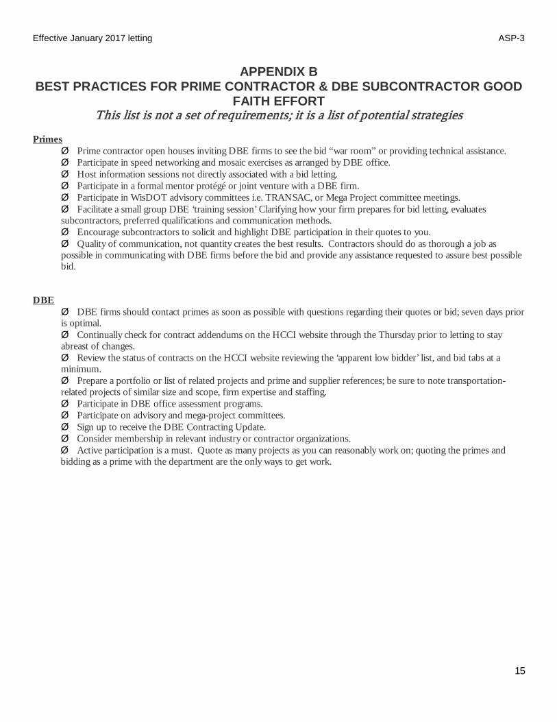
Effective January 2017 letting ASP-3
15
APPENDIX B BEST PRACTICES FOR PRIME CONTRACTOR & DBE SUBCONTRACTOR GOOD
FAITH EFFORT This list is not a set of requirements; it is a list of potential strategies
Primes
Ø Prime contractor open houses inviting DBE firms to see the bid “war room” or providing technical assistance. Ø Participate in speed networking and mosaic exercises as arranged by DBE office. Ø Host information sessions not directly associated with a bid letting. Ø Participate in a formal mentor protégé or joint venture with a DBE firm. Ø Participate in WisDOT advisory committees i.e. TRANSAC, or Mega Project committee meetings. Ø Facilitate a small group DBE ‘training session’ Clarifying how your firm prepares for bid letting, evaluates subcontractors, preferred qualifications and communication methods. Ø Encourage subcontractors to solicit and highlight DBE participation in their quotes to you. Ø Quality of communication, not quantity creates the best results. Contractors should do as thorough a job as possible in communicating with DBE firms before the bid and provide any assistance requested to assure best possible bid.
DBE
Ø DBE firms should contact primes as soon as possible with questions regarding their quotes or bid; seven days prior is optimal. Ø Continually check for contract addendums on the HCCI website through the Thursday prior to letting to stay abreast of changes. Ø Review the status of contracts on the HCCI website reviewing the ‘apparent low bidder’ list, and bid tabs at a minimum. Ø Prepare a portfolio or list of related projects and prime and supplier references; be sure to note transportation-related projects of similar size and scope, firm expertise and staffing. Ø Participate in DBE office assessment programs. Ø Participate on advisory and mega-project committees. Ø Sign up to receive the DBE Contracting Update. Ø Consider membership in relevant industry or contractor organizations. Ø Active participation is a must. Quote as many projects as you can reasonably work on; quoting the primes and bidding as a prime with the department are the only ways to get work.

Effective January 2017 letting ASP-3
16
APPENDIX C Types of Efforts considered in determining GFE
This list represents concepts being assessed; analysis requires additional steps
1. Whether the contractor attended any pre-solicitation or pre-bid meetings that were scheduled by WisDOT to inform DBEs of contracting and subcontracting opportunities.
2. Whether the contractor provided written notice to a reasonable number of specific DBEs that their interest in the contract was being solicited, in sufficient time to allow the DBEs to participate effectively.
3. Whether the contractor followed up initial solicitations of interest by contacting DBEs to determine if the DBEs were interested; returned the phone calls of interested DBE firms.
4. Whether the contractor selected portions of the work to be performed by DBEs in order to increase the likelihood of meeting the DBE goal.
5. Whether the contractor provided interested DBEs with adequate information about the plans, specifications and requirements of the contract.
6. Whether the contractor negotiated in good faith with interested DBEs, not rejected DBEs as unqualified without sound reasons based on a thorough investigation of their capabilities.
7. Whether the contractor made efforts to assist interested DBEs in being more competitive. 8. Whether the contractor effectively used the services of available minority community organizations: minority
contractors groups, local, state, and Federal minority business assistance offices, and other organizations that provide assistance to small businesses and DBE firms.
9. Whether Prime used CRCS to identify DBE who specialize in relevant work areas. 10. Whether the contractor used available resources including contacting the DBE office, using WisDOT’s website 11. Whether the contractor returned calls of firms expressing interest in a timely manner.
Effective January 2017 letting ASP-3
17
APPENDIX D Good Faith Effort Evaluation Guidance Excerpt from Appendix A of 49 CFR Part 26
APPENDIX A TO PART 26 -- GUIDANCE CONCERNING GOOD FAITH EFFORTS I. When, as a recipient, you establish a contract goal on a DOT assisted contract, a bidder must, in order to be
responsible and/or responsive, make good faith efforts to meet the goal. The bidder can meet this requirement in either of two ways. First, the bidder can meet the goal, documenting commitments for participation by DBE firms sufficient for this purpose. Second, even if it doesn't meet the goal, the bidder can document adequate good faith efforts. This means that the bidder must show that it took all necessary and reasonable steps to achieve a DBE goal or other requirement of this part which, by their scope, intensity, and appropriateness to the objective, could reasonably be expected to obtain sufficient DBE participation, even if they were not fully successful.
II. In any situation in which you have established a contract goal, part 26 requires you to use the good faith efforts mechanism of this part. As a recipient, it is up to you to make a fair and reasonable judgment whether a bidder that did not meet the goal made adequate good faith efforts. It is important for you to consider the quality, quantity, and intensity of the different kinds of efforts that the bidder has made. The efforts employed by the bidder should be those that one could reasonably expect a bidder to take if the bidder were actively and aggressively trying to obtain DBE participation sufficient to meet the DBE contract goal. Mere pro forma efforts are not good faith efforts to meet the DBE contract requirements. We emphasize, however, that your determination concerning the sufficiency of the firm's good faith efforts is a judgment call: meeting quantitative formulas is not required.
III. The Department also strongly cautions you against requiring that a bidder meet a contract goal (i.e., obtain a specified amount of DBE participation) in order to be awarded a contract, even though the bidder makes an adequate good faith efforts showing. This rule specifically prohibits you from ignoring bona fide good faith efforts.
IV. The following is a list of types of actions which you should consider as part of the bidder's good faith efforts to obtain DBE participation. It is not intended to be a mandatory checklist, nor is it intended to be exclusive or exhaustive. Other factors or types of efforts may be relevant in appropriate cases. A. Soliciting through all reasonable and available means (e.g. attendance at pre-bid meetings, advertising and/or
written notices) the interest of all certified DBEs who have the capability to perform the work of the contract. The bidder must solicit this interest within sufficient time to allow the DBEs to respond to the solicitation. The bidder must determine with certainty if the DBEs are interested by taking appropriate steps to follow up initial solicitations.
B. Selecting portions of the work to be performed by DBEs in order to increase the likelihood that the DBE
goals will be achieved. This includes, where appropriate, breaking out contract work items into economically feasible units to facilitate DBE participation, even when the prime contractor might otherwise prefer to perform these work items with its own forces.
C. Providing interested DBEs with adequate information about the plans, specifications, and requirements of
the contract in a timely manner to assist them in responding to a solicitation. D. (1) Negotiating in good faith with interested DBEs. It is the bidder's responsibility to make a portion of
the work available to DBE subcontractors and suppliers and to select those portions of the work or material needs consistent with the available DBE subcontractors and suppliers, so as to facilitate DBE participation. Evidence of such negotiation includes the names, addresses, and telephone numbers of DBEs that were considered; a description of the information provided regarding the plans and specifications for the work selected for subcontracting; and evidence as to why additional agreements could not be reached for DBEs to perform the work. (2) A bidder using good business judgment would consider a number of factors in negotiating with subcontractors, including DBE subcontractors, and would take a firm's price and capabilities as well as contract goals into consideration. However, the fact that there may be some additional costs involved in finding and using DBEs is not in itself sufficient reason for a bidder's failure to meet the contract DBE goal, as long as such costs are reasonable. Also, the ability or desire of a prime contractor to perform the work of a
Effective January 2017 letting ASP-3
18
contract with its own organization does not relieve the bidder of the responsibility to make good faith efforts. Prime contractors are not, however, required to accept higher quotes from DBEs if the price difference is excessive or unreasonable.
E. Not rejecting DBEs as being unqualified without sound reasons based on a thorough investigation of their capabilities. The contractor's standing within its industry, membership in specific groups, organizations, or associations and political or social affiliations (for example union vs. non-union employee status) are not legitimate causes for the rejection or non solicitation of bids in the contractor's efforts to meet the project goal.
F. Making efforts to assist interested DBEs in obtaining bonding, lines of credit, or insurance as required by the
recipient or contractor. G. Making efforts to assist interested DBEs in obtaining necessary equipment, supplies, materials, or related
assistance or services. H. Effectively using the services of available minority/women community organizations; minority/women
contractors' groups; local, state, and Federal minority/women business assistance offices; and other organizations as allowed on a case-by-case basis to provide assistance in the recruitment and placement of DBEs.
V. In determining whether a bidder has made good faith efforts, you may take into account the performance of other
bidders in meeting the contract. For example, when the apparent successful bidder fails to meet the contract goal, but others meet it, you may reasonably raise the question of whether, with additional reasonable efforts, the apparent successful bidder could have met the goal. If the apparent successful bidder fails to meet the goal, but meets or exceeds the average DBE participation obtained by other bidders, you may view this, in conjunction with other factors, as evidence of the apparent successful bidder having made good faith efforts.
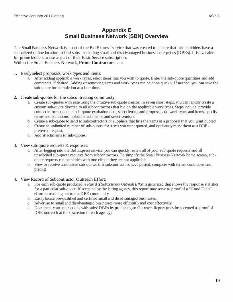
Effective January 2017 letting ASP-3
19
Appendix E Small Business Network [SBN] Overview
The Small Business Network is a part of the Bid Express® service that was created to ensure that prime bidders have a centralized online location to find subs - including small and disadvantaged business enterprises (DBEs). It is available for prime bidders to use as part of their Basic Service subscription. Within the Small Business Network, Prime Contractors can: 1. Easily select proposals, work types and items:
a. After adding applicable work types, select items that you wish to quote. Enter the sub-quote quantities and add comments, if desired. Adding or removing items and work types can be done quickly. If needed, you can save the sub-quote for completion at a later time.
2. Create sub-quotes for the subcontracting community:
a. Create sub-quotes with ease using the intuitive sub-quote creator. In seven short steps, you can rapidly create a custom sub-quote directed to all subcontractors that bid on the applicable work types. Steps include: provide contact information and sub-quote expiration date, select letting and proposal, add work types and items, specify terms and conditions, upload attachments, and select vendors.
b. Create a sub-quote to send to subcontractors or suppliers that lists the items in a proposal that you want quoted c. Create an unlimited number of sub-quotes for items you want quoted, and optionally mark them as a DBE-
preferred request. d. Add attachments to sub-quotes.
3. View sub-quote requests & responses:
a. After logging into the Bid Express service, you can quickly review all of your sub-quote requests and all unsolicited sub-quote requests from subcontractors. To simplify the Small Business Network home screen, sub-quote requests can be hidden with one click if they are not applicable.
b. View or receive unsolicited sub-quotes that subcontractors have posted, complete with terms, conditions and pricing.
4. View Record of Subcontractor Outreach Effort:
a. For each sub-quote produced, a Record of Subcontractor Outreach Effort is generated that shows the response statistics for a particular sub-quote. If accepted by the letting agency, this report may serve as proof of a “Good Faith” effort in reaching out to the DBE community.
b. Easily locate pre-qualified and certified small and disadvantaged businesses. c. Advertise to small and disadvantaged businesses more efficiently and cost effectively. d. Document your interactions with subs/DBEs by producing an Outreach Report (may be accepted as proof of
DBE outreach at the discretion of each agency).

Effective January 2017 letting ASP-3
20
The Small Business Network is a part of the Bid Express® service that was created to ensure that small businesses have a centralized area to access information about upcoming projects. It can help small businesses learn more about opportunities, compete more effectively, network with other contractors and subcontractors, and win more jobs. 1. View and reply to sub-quote requests from primes:
a. After logging into the Bid Express service, you can quickly review all incoming sub-quote requests and all unsolicited sub-quotes created by your company. Receive notifications by selected work type. To simplify on the Small Business Network home screen, sub-quote requests can be filtered by work types relevant to your interests, or hidden with one click if they are not applicable.
2. Select items when responding to sub-quote requests from primes:
a. You have the freedom to choose and price any number of items when responding to a sub-quote request. Quantities can be modified, and per-item comments are also available.
b. View requests for sub-quotes for work that primes have posted for projects they are bidding, add your pricing, terms, and conditions, and submit completed sub-quotes to the requesting primes.
c. Add attachments to a sub-quote. 3. Create and send unsolicited sub-quotes to specific contractors:
a. Create unsolicited sub-quotes with ease using the intuitive sub-quote creator. In eight short steps, you can rapidly create a custom sub-quote directed at any number of specific vendors of your choosing. Steps include: provide contact information and sub-quote expiration date, select letting and proposal, add work types and items, specify terms and conditions, upload attachments, and select vendors.
4. Easily select and price items for unsolicited sub-quotes:
a. After adding applicable work types, select items that you wish to quote. The extended price calculates automatically, cutting out costly calculation errors. Comments can be provided on a per-item basis as well.
b. Create an unsolicited sub-quote that lists the items from a proposal that you want to quote, include pricing, terms and conditions, and send it to selected prime/plan holder.
c. Add attachments to a sub-quote. d. Add unsolicited work items to sub-quotes that you are responding to.
5. Easy Access to Valuable Information
a. Receive a confirmation that your sub-quote was opened by a prime. b. View Bid Tab Analysis data from past bids, including the high, average and low prices of items. c. View important notices and publications from DOT targeted to small and disadvantaged businesses.
6. Accessing Small Business Network for WisDOT contracting opportunities
a. If you are a contractor not yet subscribing to the Bid Express service, go to and select “Order Bid Express.” The Small Business Network is a part of the Bid Express Basic Service.
b. DBE firms can request a Bid Express Small Business Network Account at no cost by calling 414-438-4588.

November 2013 ASP-4
ADDITIONAL SPECIAL PROVISION 4
Payment to First-Tier Subcontractors Within 10 calendar days of receiving a progress payment for work completed by a subcontractor, pay the subcontractor for that work. The prime contractor may withhold payment to a subcontractor if, within 10 calendar days of receipt of that progress payment, the prime contractor provides written notification to the subcontractor and the department documenting "just cause" for withholding payment.
The prime contractor may also withhold routine retainage from payments due subcontractors.
Payment to Lower-Tier Subcontractors Ensure that subcontracting agreements at all tiers provide prompt payment rights to lower-tier subcontractors that parallel those granted first-tier subcontractors in this provision.
Release of Routine Retainage After granting substantial completion the department may reduce the routine retainage withheld from the prime contractor to 75 percent of the original total amount retained.
When the Department sends the semi-final estimate the department may reduce the routine retainage withheld from the prime contractor to 10 percent of the original total amount retained.
Within 30 calendar days of receiving the semi-final estimate from the department, submit written certification that subcontractors at all tiers are paid in full for acceptably completed work and that no routine retainage is being withheld. The department will pay the prime contractor in full and reduce the routine retainage withheld from the prime contractor to zero when the department approves the final estimate.
This special provision does not limit the right of the department, prime contractor, or subcontractors at any tier to withhold payment for work not acceptably completed or work subject to an unresolved contract dispute.

Effective with June 2020 Letting ASP-6
page 1 of 18
Additional Special Provision 6 ASP 6 - Modifications to the standard specifications
Make the following revisions to the standard specifications:
104.3 Contractor Notification Replace the entire text with the following effective with the December 2019 letting:
104.3.1 General (1) Subsection 104.3 specifies the step-by-step communication process to be followed to expedite the
resolution of potential contract revisions identified by the contractor. Both contractor actions and department responses are outlined. The contractor's non-compliance with the requirements of 104.3 may constitute a waiver of entitlement to a pay adjustment under 109.4 or a time extension under 108.10. The department and contractor can mutually agree to extend any time frame specified throughout 104.3. 104.3.2 Contractor Initial Oral Notification
(1) If required by 104.2, or if the contractor believes that the department’s action, the department's lack of action, or some other situation results in or necessitates a contract revision, the contractor must promptly provide oral notification to the project engineer. Upon notification, the project engineer will attempt to resolve the identified issue. 104.3.3 Contractor 5-Day Written Statement
(1) If the project engineer has not responded or resolved the identified issue within 5 business days after receipt of initial notification, provide a contractor written statement to the project engineer in the following format: Part 1 - Executive Summary (label page 1.1 through page 1.x)
Include a detailed, factual statement of the request for additional compensation and contract time. Include the date the issue was identified, the date initial notification was given to the project engineer, and the dates and specific locations of work involved.
Part 2 - Contractor’s Basis of Entitlement (label page 2.1 through page 2.x) Include references to relevant contract provisions and a narrative summarizing how the contract provisions support the request for a revision to the original contract.
Part 3 - Contractor’s Request for Damages (label page 3.1 through page 3.x) When requesting additional compensation, include an itemized list of costs with a narrative supporting the requested amount and explaining how the costs are tied to the requested contract revision. When requesting additional contract time, include a copy of the schedule that was in effect when the issue occurred and a detailed narrative explaining how the issue impacted controlling items of work. Provide a time impact analysis utilizing base and updated schedules. If the full extent of either compensation or time is not known at the date of submittal of the contractor 5-Day written statement, provide a brief statement as to why, and include estimated compensation and time.
Part 4 - Supporting Documentation (label page 4.1 through page 4.x) Include copies of the following:
A. Relevant excerpts from specifications, special provisions, plans, change orders, or other contract documents.
B. Communication on the issue, including: letters, e-mails, meeting minutes, etc. C. Any other documentation to support or clarify the contractor’s position, including: daily work records,
cost summary sheets, weigh tickets, test results, sketches, etc. (2) With the submittal of the written statement, the contractor may also request a meeting with the region.
104.3.4 Region One-Day Written Acknowledgment (1) Within one business day after the contractor provides the 5-day written statement, the project engineer
will provide a region one-day written acknowledgment to the contractor. The project engineer will continue to resolve the issue. 104.3.5 Region 5-Day Written Response
(1) Within 5 business days after receiving the contractor 5-day written statement, the project engineer may request specific additional information to allow the project engineer to decide whether item 1 or 2 of 104.3.6(1) applies. The project engineer will state the information needed and date it is to be
Effective with June 2020 Letting ASP-6
page 2 of 18
received for further review. Submit additional information as an amendment to the contractor 5-day written statement. 104.3.6 Region Final Decision
(1) Within 10 business days after receiving the contractor 5-day written statement or additional information requested in 104.3.5(1), whichever comes last, the region will consider all information and provide a region final decision in writing to the contractor with one or more of the following responses:
1. The region will confirm that the contractor is entitled to a contract revision and a contract change order is necessary as specified in 104.2. The project engineer will give direction concerning the potential change.
2. The region will deny that the contractor is entitled to a contract revision. The project engineer will provide a statement as to why the issue is not a change to the contract. At a minimum, the project engineer will respond to the contractor’s issues and refer to the contract to show why the issues are not a change from the original contract.
(2) If the contractor does not agree with the region's decision the contractor may pursue the issue as a claim as specified in 105.13. Alternatively, if the contractor and department mutually agree, the department will get a third-party advisory opinion according to the department’s dispute resolution procedures.
(3) If a third party reviews the issue, their recommendation is not binding on either party. The region has 10 business days after receipt of the third party's written recommendation to render a decision. If the department fails to respond in writing within those 10 business days or the contractor disagrees with the region's decision, the contractor may pursue the issue as a claim as specified in 105.13.
104.6.1.2.1 General Replace paragraph one with the following effective with the December 2019 letting: (1) Conduct construction operations and provide facilities required to maintain the portion of the project
open to the public in a condition that safely and adequately accommodates public traffic. Use barricades, signs, flaggers, and temporary barrier as specified in part VI, of the WMUTCD and ensure that the contractor's use of the right-of-way conforms to 107.9. Throughout the life of the contract, and as the engineer directs, conduct construction operations and provide facilities as follows:
- Conduct flagging operations conforming to plan details and the department's flagging handbook. - Use drums, barricades, and temporary barrier to delineate and shield abrupt drop-offs and other hazards. - Furnish, erect, and maintain traffic control devices and facilities conforming to 643. - Furnish, erect, and maintain temporary pedestrian devices and facilities conforming to 644.
104.6.1.2.2 Flagging Replace paragraph three with the following effective with the December 2019 letting: (3) Provide associated advanced warning signs that meet the retroreflective requirements of 637.2.2.2.
Provide temporary portable rumble strips from the department's APL installed according to manufacturer's instructions and as specified in the flagging plan details. Provide guidance service through the worksite using pilot vehicles if required.
Replace paragraph five with the following effective with the December 2019 letting: (5) Flagging is incidental to the contract and includes costs for advance signing, temporary portable
rumble strips, and pilot vehicle guidance service.
Effective with June 2020 Letting ASP-6
page 3 of 18
104.8 Rights in the Use of Materials Found on the Project Replace paragraph two with the following effective with the December 2019 letting: (2) Do not excavate or remove material from within the right-of-way that is not within the vertical and
horizontal excavation limits the plans show except as follows: - If the contract does not identify potential source areas, obtain written authorization from the engineer to
use those sources. Complete required environmental documentation and obtain necessary permits. The department will reduce pay by $1.50 per cubic yard under the Material from Right-of-Way administrative item for material obtained from those areas.
- If the contract identifies potential source areas that were evaluated and permitted in the original environmental document, do not begin excavating in those areas until the engineer allows in writing. Additional environmental documentation and environmental permits are not required. The department will not reduce pay for material obtained from those areas.
The department may suspend use of these sources if the contractor's operation affects the essential functions or characteristics of the project.
104.10.1 General Replace paragraph one with the following effective with the December 2019 letting: (1) Subsection 104.10 specifies a 2-step process for contractors to follow in submitting a cost reduction
incentive (CRI) for modifying the contract in order to reduce direct construction costs computed at contract bid prices. The initial submittal is referred to as a CRI concept and the second submittal is a CRI proposal. The contractor and the department will equally share all savings generated to the contract due to a CRI as specified in 104.10.4.2(1). The department encourages the contractor to submit CRI concepts for the following situations:
1. The contractor generates the original cost savings idea and formulates it into a concept. 2. The department generates the original cost savings idea and obtains the contractor’s assistance to
formulate the idea into a concept. Replace paragraph five with the following effective with the December 2019 letting: (5) The department will consider a CRI that changes but does not impair the essential functions or
characteristics of the project. These functions or characteristics include, but are not limited to, appearance, service life, economy of operations, ease of maintenance, design, and safety of structures and pavements, construction phasing or procedures, or other contract requirements. The department will not consider a CRI that changes the following:
- Permanent pavement type. - Permanent structural cross section above the subgrade.
104.10.2 Submittal and Review of a CRI Concept Replace paragraphs five and six with the following effective with the December 2019 letting: (5) The department may consider a CRI concept that addresses a potential change under 104.2. (6) The department will not implement a contractor-initiated CRI concept, or portion of that concept,
without sharing the cost savings with the contractor as specified in 104.10.4.2. (7) The savings generated by the CRI must be sufficient to warrant its review and processing and offset
the level of risk. The department will assess the risk of the CRI relative to departmental design policies and criteria for the project. The department may reject a CRI concept for the following reasons:
1. It requires excessive time or costs for the contractor to develop the CRI proposal. 2. It requires excessive time or costs for review, evaluation, investigation, or implementation. 3. It introduces an inappropriate level of risk.

Effective with June 2020 Letting ASP-6
page 4 of 18
104.10.4.2 Payment for the CRI Work Replace paragraph one with the following effective with the December 2019 letting: (1) The department will pay for completed CRI work as specified for progress payments under 109.6. The
department will pay for CRI's under the Cost Reduction Incentive administrative item. When all CRI costs are determined, the department will execute a contract change order that does the following:
1. Adjusts the contract time, interim completion dates, or both. 2. Pays the contractor for the unpaid balance of the CRI work. 3. Pays the contractor 50 percent of the net savings resulting from the CRI, calculated as follows:
NS = CW - CRW - CC - DC Where:
NS = Net Savings CW = The cost of the work required by the original contract that is revised by
the CRI. CW is computed at contract bid prices if applicable. CRW = The cost of the revised work, computed at contract bid prices if
applicable. CC = The contractor’s cost of developing the CRI proposal. DC = The department’s cost for investigating, evaluating, and implementing
the CRI proposal.
105.13 Claims Process for Unresolved Changes Replace the entire text with the following effective with the December 2019 letting:
105.13.1 General (1) Before submitting a claim, the department and contractor can mutually agree to have the department
get a third-party advisory opinion as specified in 104.3.6. (2) The department and contractor can mutually agree to extend any time frame specified throughout
105.13 and can mutually agree to utilize an alternative dispute resolution method at any point before the department renders its final decision.
(3) The department and contractor share costs related to referral to a dispute review board (DRB) as prescribed in the department's dispute resolution procedures. 105.13.2 Notice of Claim
(1) If the contractor has followed the procedures for revising the contract specified in 104.2 and provided the notification specified in 104.3, but still disagrees with the region, the contractor may pursue the issue as a claim. File a notice of claim with the project engineer concerning the disagreement within 14 calendar days of receiving the region's decision under 104.3.6(1).
(2) The project engineer may deny the applicable portion of a claim if the contractor does not do the following:
1. File the notice of claim within 14 calendar days as specified in 105.13.2(1). 2. Give the project engineer sufficient access to keep a record of the actual labor, materials, and equipment
used to perform the claimed work. (3) Upon filing the notice of claim, maintain records as specified for force account statements in 109.4.5.
Unless the project engineer issues a suspension, continue to perform the disputed work. The department will continue to make progress payments to the contractor as specified in 109.6. 105.13.3 Submission of Claim
(1) Submit the claim to the project engineer as promptly as possible following the submission of the Notice of Claim, but not later than the end of the time allowed under 109.7 for the contractor to respond in writing to the engineer-issued semi-final estimate. If the contractor does not submit the claim within that response time, the department will deny the claim.
(2) The department will not accept the submission of a claim until the resolution process in 104.3 has been completed and the contractor makes no further requests to submit updated information that may affect the region’s final decision.

Effective with June 2020 Letting ASP-6
page 5 of 18
105.13.4 Content of Claim (1) The final contractor written statement under 104.3.3 is considered the content of the claim. If the
contractor makes a request to submit updated information that may affect the region’s final decision under 104.3.6, submit the updated information as an amendment to the contractor written statement and continue the resolution process in 104.3 before submitting a claim.
(2) The department may refer the claimant of a false claim to the appropriate authority for criminal prosecution. Certify the claim using the following form:
The undersigned is duly authorized to certify this claim on behalf of (the contractor). (The contractor) certifies that this claim is made in good faith, that the supporting data are accurate and complete to the best of (the contractor's) knowledge and belief, and that the amount requested accurately reflects the contract adjustment for which (the contractor) believes that the department is liable.
(THE CONTRACTOR) By:_____________________________________ (Name and Title) Date of Execution:_________________________
105.13.5 Department Final Decision (1) The department will have up to 28 calendar days, from the contractor's submission of the claim, to
perform a final review of the claim and conduct all meetings. The department may request, in writing, that the contractor submit additional information related to the claim. Submit that additional information, or notify the department in writing to base its decision on the information previously submitted. Either the contractor or region may request a meeting to present their views. Before the meeting, both parties will agree upon written ground rules for the meeting.
(2) Upon completion of the 28 calendar days for the department’s review and meetings, the department will have up to 21 calendar days to render a written decision. The department will consider written and oral submissions from the contractor and region, and may consider other relevant information in the project records.
(3) The department will provide the following in its final decision: 1. A concise description of the claim. 2. A clear, contractual basis for its decision that includes a reference to 104.2 on revisions to the contract and
as appropriate, specific reference to language regarding the bid items in question. 3. Other facts the department relies on to support its decision. 4. A concise statement of the circumstances surrounding the claim and reasons for its decision. If the
department rejects the claim in whole or in part, the department will explain why the claimed work is not a change to the contract work.
5. The amount of money or other relief, if any, the department will grant the contractor. (4) If the contractor disagrees with the department's final decision, the contractor may initiate a legal
action pursuant to state statutes.
106.3.4.2.2.2 Freeze-Thaw Soundness Replace paragraph one with the following effective with the December 2019 letting: (1) Perform freeze-thaw soundness testing according to AASHTO T103 as modified in CMM 8-60.2.
Provide freeze/thaw soundness test results based on the fraction retained on the No. 4 sieve as follows:
1. Using virgin crushed stone aggregates produced from limestone/dolomite sources in one or more of the following counties or from out of state: Brown Columbia Crawford Dane Dodge Fond du Lac Grant Green Green Lake Iowa Jefferson Lafayette Marinette Oconto Outagamie Rock Shawano Walworth Winnebago
2. Using gravel aggregates produced from pit sources in one or more of the following counties or from out of state: Dodge Washington Waukesha

Effective with June 2020 Letting ASP-6
page 6 of 18
108.10.3 Excusable Compensable Delays Replace paragraph two with the following effective with the June 2020 letting: (2) The following are compensable delays: 1. A contract change for revised work as specified for extra work under 104.2.2.1, for a differing site condition
under 104.2.2.2, or for significant changes in the character of the work under 104.2.2.4. 2. A contract change for an engineer-ordered suspension under 104.2.2.3. 3. The unexpected discovery of human remains, an archaeological find, or historical find consistent with
107.25. 4. The unexpected discovery of a hazardous substance consistent with 107.24. 5. The non-completion of work that utilities or other third parties perform, if the contract specifies a number of
days or a completion date for that utility or third-party work. For delays covered under Trans 220 of the Wisconsin administrative code, the engineer will grant a time extension, but the contractor must seek recovery of delay costs from the utility.
208.5 Payment Replace paragraph three with the following effective with the December 2019 letting: (3) The department will adjust pay for material obtained from within the project right-of-way limits but
outside project excavation limits, furnished under 208.2.2, as specified in 104.8.
301.2.3 Sampling and Testing Replace paragraph one with the following effective with the December 2019 letting: (1) Department and contractor testing shall conform to the following:
Sampling[1] ........................................................................................................................................ AASHTO T2 Percent passing the 200 sieve ........................................................................................................ AASHTO T11 Gradation[1] ..................................................................................................................................... AASHTO T27 Gradation of extracted aggregate ................................................................................................... AASHTO T30 Moisture content[1] ........................................................................................................................ AASHTO T255 Liquid limit ....................................................................................................................................... AASHTO T89 Plasticity index ................................................................................................................................ AASHTO T90 Wear ............................................................................................................................................... AASHTO T96 Sodium sulfate soundness (R-4, 5 cycles) .................................................................................... AASHTO T104 Freeze/thaw soundness[1] ............................................................................................................. AASHTO T103 Lightweight Pieces in Aggregate .................................................................................................. AASHTO T113 Fracture .................................................................................................. ASTM D5821 as modified in CMM 8-60 Moisture/density[1] ........................................................................................... AASHTO T99 and AASHTO T180 In-place density[1] .......................................................................................................................... AASHTO T191 Asphaltic material extraction .................................................................... CMM 8-36 WisDOT Test Method 1560
[1] As modified in CMM 8-60.
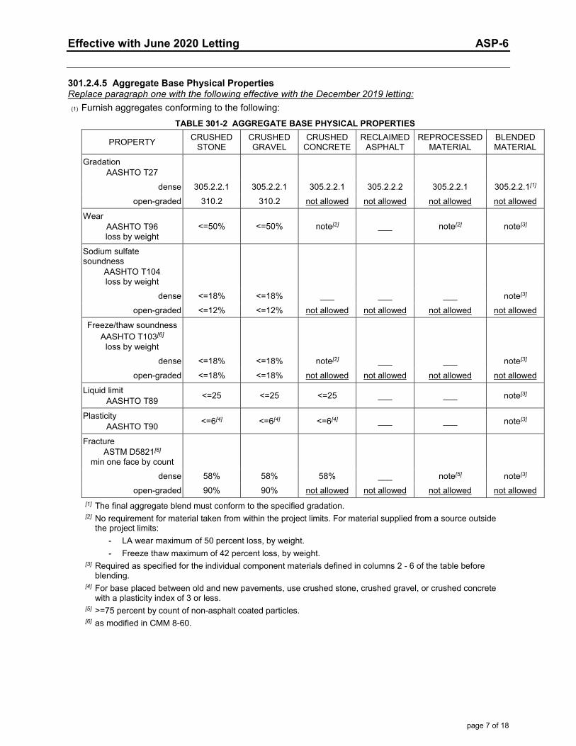
Effective with June 2020 Letting ASP-6
page 7 of 18
301.2.4.5 Aggregate Base Physical Properties Replace paragraph one with the following effective with the December 2019 letting: (1) Furnish aggregates conforming to the following:
TABLE 301-2 AGGREGATE BASE PHYSICAL PROPERTIES
PROPERTY CRUSHED STONE
CRUSHED GRAVEL
CRUSHED CONCRETE
RECLAIMED ASPHALT
REPROCESSED MATERIAL
BLENDED MATERIAL
Gradation AASHTO T27
dense 305.2.2.1 305.2.2.1 305.2.2.1 305.2.2.2 305.2.2.1 305.2.2.1[1] open-graded 310.2 310.2 not allowed not allowed not allowed not allowed
Wear AASHTO T96 loss by weight
<=50% <=50% note[2] ___ note[2] note[3]
Sodium sulfate soundness
AASHTO T104 loss by weight
dense <=18% <=18% ___ ___ ___ note[3] open-graded <=12% <=12% not allowed not allowed not allowed not allowed
Freeze/thaw soundness AASHTO T103[6]
loss by weight
dense <=18% <=18% note[2] ___ ___ note[3]
open-graded <=18% <=18% not allowed not allowed not allowed not allowed
Liquid limit AASHTO T89 <=25 <=25 <=25 ___ ___ note[3]
Plasticity AASHTO T90 <=6[4] <=6[4] <=6[4] ___ ___ note[3]
Fracture ASTM D5821[6]
min one face by count
dense 58% 58% 58% ___ note[5] note[3] open-graded 90% 90% not allowed not allowed not allowed not allowed
[1] The final aggregate blend must conform to the specified gradation. [2] No requirement for material taken from within the project limits. For material supplied from a source outside
the project limits: - LA wear maximum of 50 percent loss, by weight. - Freeze thaw maximum of 42 percent loss, by weight.
[3] Required as specified for the individual component materials defined in columns 2 - 6 of the table before blending.
[4] For base placed between old and new pavements, use crushed stone, crushed gravel, or crushed concrete with a plasticity index of 3 or less.
[5] >=75 percent by count of non-asphalt coated particles. [6] as modified in CMM 8-60.
Effective with June 2020 Letting ASP-6
page 8 of 18
450.2.2 Aggregate Sampling and Testing Replace paragraph one with the following effective with the December 2019 letting: (1) The department and the contractor will sample and test according to the following methods, except as
revised with the engineer's approval: Sampling aggregates ........................................................................................................................ AASHTO T2 Material finer than No. 200 sieve .................................................................................................... AASHTO T11 Sieve analysis of aggregates .......................................................................................................... AASHTO T27 Mechanical analysis of extracted aggregate ................................................................................... AASHTO T30 Sieve analysis of mineral filler ........................................................................................................ AASHTO T37 Los Angeles abrasion of coarse aggregate .................................................................................... AASHTO T96 Freeze-thaw soundness of coarse aggregate[1] ............................................................................ AASHTO T103 Sodium sulfate soundness of aggregates (R-4, 5 cycles) ............................................................. AASHTO T104 Extraction of bitumen .................................................................................................................... AASHTO T164
[1] As modified in CMM 8-60.2.
450.3.2.6.3 Compaction Roller Pattern Determined by Growth Curve Add 450.3.2.6.3 as a new subsection effective with the December 2019 letting:
450.3.2.6.3 Compaction Roller Pattern Determined by Growth Curve (1) When specified in 460.3.3.1, compact asphaltic mixture using the roller pattern established during
construction of a control strip. Use 2 or more rollers per paver if placing more than 165 tons per hour. (2) On the first day of production, construct a control strip under the direct observation of department
personnel. After compacting the control strip with a minimum of 3 passes, mark the gauge outline and take a one-minute wet density measurement using a nuclear density gauge in back scatter mode at a single location. Take a density measurement at the same location after each subsequent pass. Continue compacting and testing until the increase in density is less than 1 pcf for 3 consecutive passes. Submit the final roller pattern to the engineer in writing. Once the roller pattern is established do not change the pattern or decrease the number, type, or weight of rollers without the engineer's written approval.
(3) After establishing the roller pattern, and under the direct observation of the engineer, cut at least one 4-inch diameter or larger core from the control strip density gauge outline. Prepare cores and determine density according to AASHTO T166. Dry cores after testing. Fill core holes and obtain engineer approval before opening to traffic. The department will maintain custody of cores throughout the entire sampling and testing process. The department will label cores, transport cores to testing facilities, witness testing, store dried cores, and provide subsequent verification testing.
450.3.2.8 Jointing Replace paragraph three with the following effective with the December 2019 letting: (3) Construct notched wedge longitudinal joints for mainline paving of HMA layers 1.75 inches or greater.
Extend the wedge beyond the normal lane width as the plans show or as the engineer directs. Replace paragraph five with the following effective with the December 2019 letting: (5) Construct the wedge for each layer using an engineer-approved strike-off device that will provide a
uniform slope and will not restrict the main screed. Shape and compact the wedge with a weighted steel side roller wheel or vibratory plate compactor the same width as the wedge. Apply a tack coat to the wedge surface and both notches before placing the adjacent lane.
(6) Clean longitudinal and transverse joints coated with dust and, if necessary, paint with hot asphaltic material, a cutback, or emulsified asphalt to ensure a tightly bonded, sealed joint.
455.2.5 Tack Coat Replace paragraph one with the following effective with the December 2019 letting: (1) Under the Tack Coat bid item, furnish type SS-1h, CSS-1h, QS-1h, CQS-1h, or modified emulsified
asphalt with an “h” suffix, unless the contract specifies otherwise.
Effective with June 2020 Letting ASP-6
page 9 of 18
460.2.2.3 Aggregate Gradation Master Range Replace paragraph one with the following effective with the December 2019 letting: (1) Ensure that the aggregate blend, including recycled material and mineral filler, conforms to the
gradation requirements in table 460-1. The values listed are design limits; production values may exceed those limits.
TABLE 460-1 AGGREGATE GRADATION MASTER RANGE AND VMA REQUIREMENTS
SIEVE
PERCENT PASSING DESIGNATED SIEVES NOMINAL SIZE
No. 1 (37.5 mm)
No. 2 (25.0 mm)
No.3 (19.0 mm)
No. 4 (12.5 mm)
No. 5 (9.5 mm)
No. 6 (4.75 mm)
SMA No. 4 (12.5 mm)
SMA No. 5 (9.5 mm)
50.0-mm 100 37.5-mm 90 - 100 100 25.0-mm 90 max 90 - 100 100 19.0-mm ___ 90 max 90 - 100 100 100 12.5-mm ___ ___ 90 max 90 - 100 100 90 - 97 100 9.5-mm ___ ___ ___ 90 max 90 - 100 100 58 - 80 90 - 100
4.75-mm ___ ___ ___ ___ 90 max 90 - 100 25 - 35 35 - 45 2.36-mm 15 - 41 19 - 45 23 - 49 28 - 58 32 - 67 90 max 15 - 25 18 - 28 1.18-mm ___ ___ ___ ___ ___ 30 - 55 ___ ___ 0.60-mm ___ ___ ___ ___ ___ ___ 18 max 18 max
0.075-mm 0 - 6.0 1.0 - 7.0 2.0 - 8.0 2.0 - 10.0 2.0 - 10.0 6.0 - 13.0 8.0 - 11.0 8.0 - 12.0 % VMA 11.0 min 12.0 min 13.0 min 14.0 min[1] 15.0 min[2] 16.0 - 17.5 16.0 min 17.0 min
[1] 14.5 for LT and MT mixes. [2] 15.5 for LT and MT mixes.
460.2.7 HMA Mixture Design Replace paragraph one with the following effective with the December 2019 letting: (1) For each HMA mixture type used under the contract, develop and submit an asphaltic mixture design
according to CMM 8-66 and conforming to the requirements of table 460-1 and table 460-2. Ensure that SMA mixture designs adhere to AASHTO R 46 and AASHTO M 325 in addition to the required test procedures outlined in CMM 8-66 table 1 and CMM 8-66 table 2. Determine the specific gravity of fines or super fines used as a mineral filler or additional stabilizer in SMA designs according to AASHTO T 100. The values listed are design limits; production values may exceed those limits. The department will review mixture designs and report the results of that review to the designer according to CMM 8-66.

Effective with June 2020 Letting ASP-6
page 10 of 18
TABLE 460-2 MIXTURE REQUIREMENTS
Mixture type LT MT HT SMA
LA Wear (AASHTO T96) 100 revolutions(max % loss) 13 13 13 13 500 revolutions(max % loss) 50 45 45 35
Soundness (AASHTO T104) (sodium sulfate, max % loss) 12 12 12 12
Freeze/Thaw (AASHTO T103 as modified in CMM 8-60.2) (specified counties, max % loss)
18 18 18 18
Fractured Faces (ASTM D5821 as modified in CMM 860) (one face/2 face, % by count)
65/___ 75 / 60 98 / 90 100/90
Flat & Elongated (ASTM D4791) (max %, by weight)
5 (5:1 ratio)
5 (5:1 ratio)
5 (5:1 ratio)
20 (3:1 ratio)
Fine Aggregate Angularity (AASHTO T304, method A, min) 40[1] 43[1] 45 45
Sand Equivalency (AASHTO T176, min) 40 40[2] 45 50
Clay Lumps and Friable Particle in Aggregate (AASHTO T112) <= 1% <= 1% <= 1% <= 1%
Plasticity Index of Material Added to Mix Design as Mineral Filler (AASHTO T89/90) <= 4 <= 4 <= 4 <= 4
Gyratory Compaction Gyrations for Nini 6 7 8 7 Gyrations for Ndes 40 75 100 65 Gyrations for Nmax 60 115 160 100
Air Voids, %Va (%Gmm Ndes)
4.0 (96.0)
4.0 (96.0)
4.0 (96.0)
4.5 (95.5)
% Gmm Nini <= 91.5[3] <= 89.0[3] <= 89.0 ___
% Gmm Nmax <= 98.0 <= 98.0 <= 98.0 <= 98.0
Dust to Binder Ratio[4] (% passing 0.075/Pbe) 0.6 - 1.2[5] 0.6 - 1.2[5] 0.6 - 1.2[5] 1.2 - 2.0
Voids filled with Binder (VFB or VFA, %) 68 - 80[6] [8] 65 - 75[6] [7] [9] 65 - 75[6] [7] [9] 70 - 80
Tensile Strength Ratio (TSR) (AASHTO T283)[10] [11] no antistripping additive 0.75 min 0.75 min 0.75 min 0.80 min with antistripping additive 0.80 min 0.80 min 0.80 min 0.80 min
Draindown (AASHTO T305) (%) ___ ___ ___ <= 0.30
Minimum Effective Asphalt Content, Pbe (%) ___ ___ ___ 5.5
[1] For No 6 (4.75 mm) nominal maximum size mixes, the specified fine aggregate angularity is 43 for LT and 45 MT mixes.
[2] For No 6 (4.75 mm) nominal maximum size mixes, the specified sand equivalency is 43 for MT mixes. [3] The percent maximum density at initial compaction is only a guideline. [4] For a gradation that passes below the boundaries of the caution zone (ref. AASHTO M323), the dust to binder
ratio limits are 0.6 - 1.6. [5] For No 6 (4.75 mm) nominal maximum size mixes, the specified dust to binder ratio limits are 1.0 - 2.0 for LT
mixes and 1.5 - 2.0 for MT and HT mixes. [6] For No. 6 (4.75mm) nominal maximum size mixes, the specified VFB is 67 - 79 percent for LT mixes and 66 -
77 percent for MT and HT mixes. [7] For No. 5 (9.5mm) and No. 4 (12.5 mm) nominal maximum size mixtures, the specified VFB range is 70 - 76
percent. [8] For No. 2 (25.0mm) nominal maximum size mixes, the specified VFB lower limit is 67 percent.
Effective with June 2020 Letting ASP-6
page 11 of 18
[9] For No. 1 (37.5mm) nominal maximum size mixes, the specified VFB lower limit is 67 percent. [10] WisDOT eliminates freeze-thaw conditioning cycles from the TSR test procedure. [11] Run TSR at asphalt content corresponding to 3.0% air void regressed design, or 4.5% air void design for
SMA, using distilled water for testing.
460.2.8.2.1.3.1 Contracts with 5000 Tons of Mixture or Greater Replace paragraph four with the following effective with the December 2019 letting: (4) Use the test methods identified below, or other methods the engineer approves, to perform the
following tests at the frequency indicated: Blended aggregate gradations:
Drum plants: - Field extraction by ignition oven according to AASHTO T308 as modified in CMM 8-36.6.3.6,
chemical extraction according to AASHTO T-164 method A or B; or automated extraction according to ASTM D8159 as modified in CMM 8-36.6.3.1. Gradation of resulting aggregate sample determined according to AASHTO T30.
- Belt samples, optional for virgin mixtures, obtained from stopped belt or from the belt discharge using an engineer-approved sampling device and performed according to AASHTO T11 and T27.
Batch plants: - Field extraction by ignition oven according to AASHTO T308 as modified in CMM 8-36.6.3.6,
chemical extraction according to AASHTO T-164 method A or B; or automated extraction according to ASTM D8159 as modified in CMM 8-36.6.3.1. Gradation of resulting aggregate sample determined according to AASHTO T30.
Asphalt content (AC) in percent: AC by ignition oven according to AASHTO T308 (CMM 8-36.6.3.6), by chemical extraction according to AASHTO T-164 method A or B; or by automated extraction according to ASTM D8159 as modified in CMM 8-36.6.3.1. Gradation of resulting aggregate sample determined according to AASHTO T30.
Bulk specific gravity of the compacted mixture according to AASHTO T166. Maximum specific gravity according to AASHTO T209. Air voids (Va) by calculation according to AASHTO T269. VMA by calculation according to AASHTO R35.
460.2.8.2.1.4.2 Control Charts Replace paragraph one with the following effective with the December 2019 letting: (1) Maintain standardized control charts at the laboratory. Record contractor test results on the charts the
same day as testing. Record data on the standardized control charts as follows: - Blended aggregate gradation tests in percent passing. Of the following, plot sieves required in table 460-1:
37.5-mm, 25.0-mm, 19.0-mm, 12.5-mm, 9.5-mm, 4.75-mm, 2.36-mm, 1.18-mm, 0.60-mm, and 0.075-mm. - Asphalt material content in percent. - Air voids in percent. - VMA in percent.
(2) Plot both the individual test point and the running average of the last 4 data points on each chart. Show QC data in black with the running average in red. Draw the warning limits with a dashed green line and the JMF limits with a dashed red line. The contractor may use computer generated black-and-white printouts with a legend that clearly identifies the specified color-coded components.

Effective with June 2020 Letting ASP-6
page 12 of 18
460.2.8.2.1.5 Control Limits Replace paragraph one with the following effective with the December 2019 letting: (1) Conform to the following control limits for the JMF and warning limits based on a running average of
the last 4 data points: ITEM JMF LIMITS WARNING LIMITS Percent passing given sieve: 37.5-mm +/- 6.0 +/- 4.5 25.0-mm +/- 6.0 +/- 4.5 19.0-mm +/- 5.5 +/- 4.0 12.5-mm +/- 5.5 +/- 4.0 9.5-mm +/- 5.5 +/- 4.0 4.75-mm +/- 5.0 +/- 4.0 2.36-mm +/- 5.0 +/- 4.0 1.18-mm +/- 4.0 +/- 3.0 0.60-mm +/- 4.0 +/- 3.0 0.075-mm +/- 2.0 +/- 1.5 Asphaltic content in percent - 0.3 - 0.2 Air voids in percent[1] +1.3/-1.0 +1.0/-0.7 VMA in percent[2] - 0.5 - 0.2
[1] For SMA, JMF limits are +/-1.3 and warning limits are +/-1.0. [2] VMA limits are based on requirements for each mix design nominal maximum aggregate size in table 460-1.
For No. 6 (4.75mm) mixes, JMF limits are +/- 0.5 and warning limits are +/- 0.2.
460.3.2 Thickness Replace paragraph one with the following effective with the December 2019 letting: (1) Provide the plan thickness for lower and upper layers limited as follows:
NOMINAL MINIMUM MAX LOWER MAX UPPER MAX SINGLE SIZE LAYER LAYER LAYER LAYER THICKNESS THICKNESS THICKNESS THICKNESS[3] (in inches) (in inches) (in inches) (in inches) No. 1 (37.5 mm) 4.5 6 4.5 6 No. 2 (25.0 mm) 3.0 5 4 6 No. 3 (19.0 mm 2.25 4 3 5 No. 4 (12.5 mm)[1] 1.75 3[2] 2.5 4 No. 5 (9.5 mm)[1] 1.25 3[2] 2 3 No. 6 (4.75 mm) 0.75 1.25 1.25 1.25
[1] SMA mixtures use nominal size No. 4 (12.5 mm) or No. 5 (9.5 mm). [2] SMA mixtures with nominal sizes of No. 4 (12.5 mm) and No. 5 (9.5 mm) have no maximum lower layer
thickness specified. [3] For use on cross-overs and shoulders. (2) Place leveling layers using No. 4 (12.5 mm), No. 5 (9.5 mm), or No. 6 (4.75 mm) mixtures. Leveling
layers may be thinner than the minimum lower layer thickness for the mixture used. (3) Place wedging layers as the contract specifies or engineer directs. Wedging layers have no specified
minimum or maximum thickness.

Effective with June 2020 Letting ASP-6
page 13 of 18
460.3.3.1 Minimum Required Density Replace paragraph one with the following effective with the December 2019 letting: (1) Compact No. 6 mixtures in lower layers as specified in 450.3.2.6.2 and in upper layers as specified in
450.3.2.6.3. For other HMA mixtures, compact all layers to the density table 460-3 specifies. TABLE 460-3 MINIMUM REQUIRED DENSITY[1]
LOCATION LAYER
PERCENT OF TARGET MAXIMUM DENSITY
MIXTURE TYPE
LT and MT HT SMA[5]
TRAFFIC LANES[2] LOWER 93.0[3] 93.0[4] ___
UPPER 93.0 93.0 93.0
SHOULDERS & APPURTENANCES
LOWER 91.0 91.0 ___
UPPER 92.0 92.0 92.0
[1] The table values are for average lot density. If any individual density test result falls more than 3.0 percent below the minimum required target maximum density, the engineer will investigate the acceptability of that material according to CMM 8-15.11.
[2] Includes side roads, crossovers, turn lanes, ramps, parking lanes, bike lanes, and park-and-ride lots as defined by the contract plans.
[3] Minimum reduced by 2.0 percent for a lower layer constructed directly on crushed aggregate or recycled base courses.
[4] Minimum reduced by 1.0 percent for a lower layer constructed directly on crushed aggregate or recycled base courses.
460.3.3.2 Pavement Density Determination Replace paragraph three with the following effective with the December 2019 letting: (3) A lot is defined in CMM 8-15 and placed within a single layer for each location and target maximum
density category indicated in table 460-3. The lot density is the average of all samples taken for that lot. The department determines the number of tests per lot according to CMM 8-15.
460.5.2.1 General Replace paragraph six with the following effective with the December 2019 letting: (6) If during a QV dispute resolution investigation the department discovers unacceptable mixture defined
by one or more of the following: - Va less than 2.5 or greater than 6.5 percent for SMA, or for other mixes, less than 1.5 or greater than 5.0
percent. - VMA more than 1.0 percent below the minimum or above the maximum specified in table 460-1. - AC more than 0.5 % below the JMF target.
Remove and replace the material, or if the engineer allows the mixture to remain in place, the department will pay for the quantity of affected material at 50 percent of the contract price.
Effective with June 2020 Letting ASP-6
page 14 of 18
501.2.5.5 Sampling and Testing Replace paragraph one with the following effective with the December 2019 letting: (1) Sample and test aggregates for concrete according to the following:
Sampling aggregates[1] ..................................................................................................................... AASHTO T2 Lightweight pieces in aggregate ................................................................................................... AASHTO T113 Material finer than No. 200 sieve[1] ................................................................................................. AASHTO T11 Unit weight of aggregate ................................................................................................................. AASHTO T19 Organic impurities in sands ............................................................................................................ AASHTO T21 Sieve analysis of aggregates .......................................................................................................... AASHTO T27 Effect of organic impurities in fine aggregate .................................................................................. AASHTO T71 Los Angeles abrasion of coarse aggregate .................................................................................... AASHTO T96 Alkali Silica Reactivity of Aggregates .............................................................................................. ASTM C1260 Alkali Silica Reactivity of Combinations of Cementitious Materials and Aggregates ....................... ASTM C1567 Freeze-thaw soundness of coarse aggregate[1] ............................................................................ AASHTO T103 Sodium sulfate soundness of coarse aggregates (R-4, 5 cycles) ................................................. AASHTO T104 Specific gravity and absorption of fine aggregate ........................................................................... AASHTO T84 Specific gravity and absorption of coarse aggregate[1] ................................................................... AASHTO T85 Flat & elongated pieces based on a 3:1 ratio[1] ............................................................................... ASTM D4791 Sampling fresh concrete ................................................................................................................. AASHTO R60 Making and curing concrete compressive strength test specimens ................................................ AASHTO T23 Compressive strength of molded concrete cylinders ...................................................................... AASHTO T22
[1] As modified in CMM 8-60.
505.2.2 Bar Steel Reinforcement Replace paragraph one with the following effective with the December 2019 letting: (1) Conform to AASHTO M31, type S or type W.
505.2.3 High-Strength Bar Steel Reinforcement Replace paragraph one with the following effective with the December 2019 letting: (1) Conform to AASHTO M31, grade 60, type S or type W.
505.2.4.1 General Replace paragraph one with the following effective with the December 2019 letting: (1) Conform to AASHTO M31, grade 60, type S or type W. Ensure that the coating is applied in a CRSI
certified epoxy coating plant. Bend bars that require bending before coating, unless the fabricator can bend the bar without damaging the coating.
505.2.6.1 General Replace paragraph one with the following effective with the December 2019 letting: (1) For dowel bars and straight tie bars, there is no requirement for bend tests. Ensure that the bars are
the specified diameter and length the plans show.
505.2.6.2.2 Solid Dowel Bars Replace paragraph one with the following effective with the December 2019 letting: (1) Furnish coated bars conforming to AASHTO M31 grade 40 or 60. Alternatively the contractor may
furnish dowel bars conforming to AASHTO M227 grade 70-80. Coat in a plant certified by the Concrete Reinforcing Steel Institute with a thermosetting epoxy conforming to AASHTO M254, type B.
Effective with June 2020 Letting ASP-6
page 15 of 18
520.3.7 Deflection Testing Replace paragraphs three and four with the following effective with the June 2020 letting:
(3) Test 100 percent of the installed length of pipe 24 inches or greater in diameter. Ensure that the mandrel passes through the entire section in one pass when pulled by hand without using excessive force. If the designated length of pipe fails, the engineer may require additional testing.
(4) For pipe less than 24 inches in diameter, the engineer will designate at least 10 percent of the installed length of pipe for testing. The mandrel must pass through the entire section in one pass when pulled by hand without using excessive force. If the designated length of pipe fails, engineer may require additional testing.
(5) Relay or replace pipe that does not pass deflection testing. Retest all relayed or replaced pipe.
608.3.7 Deflection Testing Replace paragraphs three and four with the following effective with the June 2020 letting:
(3) Test 100 percent of the installed length of pipe 24 inches or greater in diameter. Ensure that the mandrel passes through the entire section in one pass when pulled by hand without using excessive force. If the designated length of pipe fails, the engineer may require additional testing.
(4) For pipe less than 24 inches in diameter, the engineer will designate at least 10 percent of the installed length of pipe for testing. The mandrel must pass through the entire section in one pass when pulled by hand without using excessive force. If the designated length of pipe fails, engineer may require additional testing.
(5) Relay or replace pipe that does not pass deflection testing. Retest all relayed or replaced pipe.
625.3.2 Processing Topsoil or Salvaged Topsoil Delete paragraph four effective with the December 2019 letting.

Effective with June 2020 Letting ASP-6
page 16 of 18
701.3.1 General Replace the entire text with the following effective with the December 2019 letting: (1) Perform contract required QC tests for samples randomly located according to CMM 8-30. Use the
test methods specified in table 701-1. TABLE 701-1 TESTING AND CERTIFICATION STANDARDS
TEST TEST STANDARD
MINIMUM REQUIRED CERTIFICATION (any one of the certifications listed for each test)
Random Sampling CMM 8-30.9.2
Transportation Materials Sampling Technician (TMS) Aggregate Technician I (AGGTEC-I)
AGGTEC-I Assistant Certified Technician (ACT-AGG) PCC Technician I (PCCTEC-I)
PCCTEC-I Assistant Certified Technician (ACT-PCC) Grading Technician I (GRADINGTEC-I)
Grading Assistant Certified Technician (ACT-GRADING) Sampling Aggregates AASHTO T2[1][4] TMS, AGGTECT-1, ACT-AGG
Percent passing the No. 200 sieve AASHTO T11[1]
AGGTEC-I, ACT-AGG Fine and coarse aggregate gradation AASHTO T27[1]
Aggregate moisture content AASHTO T255[1] Fractured faces ASTM D5821[1]
Liquid limit AASHTO T89 Aggregate Testing for Transportation Systems (ATTS) GRADINGTEC-I, or ACT-GRADING Plasticity index AASHTO T90[3]
Sampling freshly mixed concrete AASHTO R60
PCCTEC-1 ACT-PCC
Air content of fresh concrete AASHTO T152[2] Air void system of fresh concrete AASHTO TP118[5]
Concrete slump AASHTO T119[2] Concrete temperature ASTM C1064
Making and curing concrete cylinders AASHTO T23 Moist curing for concrete cylinders AASHTO M201
Concrete compressive strength AASHTO T22 Concrete Strength Tester (CST) CST Assistant Certified Technician (ACT-CST) Concrete flexural strength AASHTO T97
Profiling __ PROFILER
[1] As modified in CMM 8-60. [2] As modified in CMM 8-70. [3] A plasticity check, if required under individual QMP provisions, may be performed by an AGGTEC-I in addition
to the certifications listed for liquid limit and plasticity index tests. [4] Plant personnel may operate equipment to obtain samples under the direct observation of a TMS or higher. [5] Consolidate by rodding.
715.2.1 General Replace paragraph five with the following effective with the December 2019 letting: (5) For new lab-qualified mixes, test the air void system of the proposed concrete mix. Include the SAM
number as a part of the mix design submittal.

Effective with June 2020 Letting ASP-6
page 17 of 18
715.3.1.1 General Replace paragraph two with the following effective with the December 2019 letting:
(2) Test the air void system at least once per lot and enter the SAM number in the MRS for informationonly. SAM testing is not required for the following:
- For lots with less than 4 sublots.- High early strength (HES) concrete.- Special high early strength (SHES) concrete.- Concrete placed under the following bid items:
- Concrete Pavement Approach Slab- Concrete Masonry Culverts- Concrete Masonry Retaining Walls- Steel Grid Floor Concrete Filled- Crash Cushions Permanent- Crash Cushions Permanent Low Maintenance- Crash Cushions Temporary
730.3.1 General Replace paragraph three with the following effective with the December 2019 letting:
(3) Stockpile tests[1] can be used for multiple projects. If placement on a project does not begin within 120calendar days after the date the stockpile sample was obtained, retest the stockpile before placementbegins.
[1] Replace the stockpile test with an in-place production test for concrete pavement recycled and processed on-site; test on the first day of production.
730.3.2 Contractor QC Testing Replace paragraph four with the following effective with the December 2019 letting:
(4) Submit test results to the engineer within one business day of obtaining the sample, except anyaggregate classification with recycled asphalt may be submitted within two business days.
730.3.4.1 Contractor QC Testing Replace the entire text with the following effective with the December 2019 letting:
(1) For small quantity contracts with <= 500 tons, submit 2 production tests or 1 stockpile test. Production tests are valid for 3 years from the date the production sample was obtained. Begin placement within 3 years of the date sampled.
(2) For small quantity contracts with <= 6000 tons and > 500 tons, do the following:1. Conduct one QC stockpile test before placement.2. Submit 2 production tests or conduct 1 loadout test instead of placement tests. Production tests are valid
for 3 years from the date the production sample was obtained; the first day of placement must be within 3 years of the date sampled.
3. If the actual quantity placed is more than 6000 tons, on the next day of placement perform one additional random QC test for each 3000 tons of overrun, or fraction thereof.
740.3.2 Contractor QC Testing Replace paragraph three with the following effective with the December 2019 letting:
(3) Field-locate the beginning and ending points for each profile run. Measure the profiles of eachstandard and partial segment. Define primary segments starting at a project terminus and runningcontiguously along the mainline to the other project terminus. Define segments one wheel path wideand distinguished by length as follows:
1. Standard segments are 500 feet long.2. Partial segments are less than 500 feet long.
Effective with June 2020 Letting ASP-6
page 18 of 18
Errata
104.6.1.2.3 Drop-Off and Hazard Protection Correct errata by changing 2 inches or greater to greater than 2 inches. (1) Eliminate vertical drop-offs greater than 2 inches and edge slopes steeper than 3:1 between adjacent
lanes open to traffic.
305.3.3.3 Shoulders Adjacent to Asphaltic Pavement or Surfacing Correct errata by changing 2-inch or more to greater than 2-inch. (2) If the roadway remains open to through traffic during construction and a greater than 2-inch drop-off
occurs within 3 feet or less from the edge of the traveled way, eliminate the drop-off within 48 hours after completing that days paving. Unless the special provisions specify otherwise, provide aggregate shoulder material compacted to a temporary 3:1 or flatter cross slope from the surface of the pavement edge.
501.3.2.2 Concrete Proportions Correct errata in footnote [8] by allowing either grade 100 or grade 120 slag in C-S concrete. [8] For grade C-S concrete, use grade 100 or grade 120 slag.
614.3.6 Thrie Beam Structure Approach Retro Fits Correct errata by deleting the galvanization reference already required under 614.3.1. (2) Install posts and drill holes into existing thrie beam conforming to 614.3.2.
628.3.7 Mobilizations for Erosion Control Correct errata by clarifying that mobilizations for erosion control include proceeding with the work. (1) Move personnel, equipment, and materials to the project site and promptly proceed with construction
of erosion control items at the stages the contract indicates or the engineer directs.

Page 1 of 1
Effective with December 2017 Letting ASP 7
ADDITIONAL SPECIAL PROVISION 7
A. Reporting 1st Tier and DBE Payments During Construction
1. Comply with reporting requirements specified in the department’s Civil RightsCompliance, Contractor’s User Manual, Sublets and Payments.
2. Report payments to all DBE firms within 10 calendar days of receipt of a progresspayment by the department or a contractor for work performed, materials furnished, ormaterials stockpiled by a DBE firm. Report the payment as specified in A(1) for all worksatisfactorily performed and for all materials furnished or stockpiled.
3. Report payments to all first tier subcontractor relationships within 10 calendar days ofreceipt of a progress payment by the department for work performed. Report thepayment as specified in A(1) for all work satisfactorily performed.
4. All tiers shall report payments as necessary to comply with the DBE paymentrequirement as specified in A(2).
5. Require all first tier relationships, DBE firms and all other tier relationships necessaryto comply with the DBE payment requirement in receipt of a progress payment bycontractor to acknowledge receipt of payment as specified in A(1), (2), (3) and (4).
6. All agreements made by a contractor shall include the provisions in A(1), (2), (3), (4)and (5), and shall be binding on all first tier subcontractor relationships and allcontractors and subcontractors utilizing DBE firms on the project.
B. Costs for conforming to this special provision are incidental to the contract.
NOTE: CRCS Prime Contractor payment is currently not automated and will need to be manually loaded into the Civil Rights Compliance System. Copies of prime contractor payments received (check or ACH) will have to be forwarded to [email protected] within 5 days of payment receipt to be logged manually.
***Additionally, for information on Subcontractor Sublet assignments, Subcontractor Payments and Payment Tracking, please refer to the CRCS Payment and Sublets manual at:
https://wisconsindot.gov/Documents/doing-bus/civil-rights/labornwage/crcs-payments-sublets-manual.pdf

Effective January 2019 Letting ASP 9
ADDITIONAL SPECIAL PROVISION 9 Electronic Certified Payroll or Labor Data Submittal
(1) Use the department's Civil Rights Compliance System (CRCS) to electronically submit certifiedpayroll reports for contracts with federal funds and labor data for contracts with state funds only.Details are available online through the department’s highway construction contractor information(HCCI) site on the Labor, Wages, and EEO Information page at:
https://wisconsindot.gov/Pages/doing-bus/civil-rights/labornwage/default.aspx
(2) Ensure that all tiers of subcontractors, including all trucking firms, either submit theirweekly certified payroll reports (contracts with federal funds) or labor data (contracts withstate funds only) electronically through CRCS. These payrolls or labor data are due withinseven calendar days following the close of the payroll period. Every firm providing physicallabor towards completing the project is a subcontractor under this special provision.
(3) Upon receipt of contract execution, promptly make all affected firms aware of therequirements under this special provision and arrange for them to receive CRCS training as theyare about to begin their submittals. The department will provide training either in a classroomsetting at one of our regional offices or by telephone. Contact Paul Ndon at (414) 438-4584 toschedule the training.
(4) The department will reject all paper submittals for information required under thisspecial provision. All costs for conforming to this special provision are incidental to thecontract.
(5) Firms wishing to export payroll/labor data from their computer system into CRCSshould have their payroll coordinator contact Paul Ndon at [email protected]. Notevery contractor’s payroll system is capable of producing export files. For details, seeSection 4.8 CPR Auto Submit (Data Mapping) on pages 49-50; 66-71 of the CRCS PayrollManual at:
https://wisconsindot.gov/Documents/doing-bus/civil-rights/labornwage/crcs-payroll-manual.pdf

1
FHWA-1273 -- Revised May 1, 2012
REQUIRED CONTRACT PROVISIONS FEDERAL-AID CONSTRUCTION CONTRACTS
I. GeneralII. NondiscriminationIII. Nonsegregated FacilitiesIV. Davis-Bacon and Related Act ProvisionsV. Contract Work Hours and Safety Standards Act
ProvisionsVI. Subletting or Assigning the ContractVII. Safety: Accident PreventionVIII. False Statements Concerning Highway ProjectsIX. Implementation of Clean Air Act and Federal Water
Pollution Control ActX. Compliance with Governmentwide Suspension and
Debarment RequirementsXI. Certification Regarding Use of Contract Funds for
Lobbying
ATTACHMENTS
A. Employment and Materials Preference for AppalachianDevelopment Highway System or Appalachian Local AccessRoad Contracts (included in Appalachian contracts only)
I. GENERAL
1. Form FHWA-1273 must be physically incorporated in eachconstruction contract funded under Title 23 (excludingemergency contracts solely intended for debris removal). Thecontractor (or subcontractor) must insert this form in eachsubcontract and further require its inclusion in all lower tiersubcontracts (excluding purchase orders, rental agreementsand other agreements for supplies or services).
The applicable requirements of Form FHWA-1273 are incorporated by reference for work done under any purchase order, rental agreement or agreement for other services. The prime contractor shall be responsible for compliance by any subcontractor, lower-tier subcontractor or service provider.
Form FHWA-1273 must be included in all Federal-aid design-build contracts, in all subcontracts and in lower tier subcontracts (excluding subcontracts for design services, purchase orders, rental agreements and other agreements for supplies or services). The design-builder shall be responsible for compliance by any subcontractor, lower-tier subcontractor or service provider.
Contracting agencies may reference Form FHWA-1273 in bid proposal or request for proposal documents, however, the Form FHWA-1273 must be physically incorporated (not referenced) in all contracts, subcontracts and lower-tier subcontracts (excluding purchase orders, rental agreements and other agreements for supplies or services related to a construction contract).
2. Subject to the applicability criteria noted in the followingsections, these contract provisions shall apply to all workperformed on the contract by the contractor's own organizationand with the assistance of workers under the contractor'simmediate superintendence and to all work performed on thecontract by piecework, station work, or by subcontract.
3. A breach of any of the stipulations contained in theseRequired Contract Provisions may be sufficient grounds forwithholding of progress payments, withholding of finalpayment, termination of the contract, suspension / debarmentor any other action determined to be appropriate by thecontracting agency and FHWA.
4. Selection of Labor: During the performance of this contract,the contractor shall not use convict labor for any purposewithin the limits of a construction project on a Federal-aidhighway unless it is labor performed by convicts who are onparole, supervised release, or probation. The term Federal-aidhighway does not include roadways functionally classified aslocal roads or rural minor collectors.
II. NONDISCRIMINATION
The provisions of this section related to 23 CFR Part 230 are applicable to all Federal-aid construction contracts and to all related construction subcontracts of $10,000 or more. The provisions of 23 CFR Part 230 are not applicable to material supply, engineering, or architectural service contracts.
In addition, the contractor and all subcontractors must comply with the following policies: Executive Order 11246, 41 CFR 60, 29 CFR 1625-1627, Title 23 USC Section 140, the Rehabilitation Act of 1973, as amended (29 USC 794), Title VI of the Civil Rights Act of 1964, as amended, and related regulations including 49 CFR Parts 21, 26 and 27; and 23 CFR Parts 200, 230, and 633.
The contractor and all subcontractors must comply with: the requirements of the Equal Opportunity Clause in 41 CFR 60-1.4(b) and, for all construction contracts exceeding $10,000, the Standard Federal Equal Employment Opportunity Construction Contract Specifications in 41 CFR 60-4.3.
Note: The U.S. Department of Labor has exclusive authority to determine compliance with Executive Order 11246 and the policies of the Secretary of Labor including 41 CFR 60, and 29 CFR 1625-1627. The contracting agency and the FHWA have the authority and the responsibility to ensure compliance with Title 23 USC Section 140, the Rehabilitation Act of 1973, as amended (29 USC 794), and Title VI of the Civil Rights Act of 1964, as amended, and related regulations including 49 CFR Parts 21, 26 and 27; and 23 CFR Parts 200, 230, and 633.
The following provision is adopted from 23 CFR 230, Appendix A, with appropriate revisions to conform to the U.S. Department of Labor (US DOL) and FHWA requirements.
1. Equal Employment Opportunity: Equal employmentopportunity (EEO) requirements not to discriminate and to takeaffirmative action to assure equal opportunity as set forthunder laws, executive orders, rules, regulations (28 CFR 35,29 CFR 1630, 29 CFR 1625-1627, 41 CFR 60 and 49 CFR 27)and orders of the Secretary of Labor as modified by theprovisions prescribed herein, and imposed pursuant to 23U.S.C. 140 shall constitute the EEO and specific affirmativeaction standards for the contractor's project activities under

2
this contract. The provisions of the Americans with Disabilities Act of 1990 (42 U.S.C. 12101 et seq.) set forth under 28 CFR 35 and 29 CFR 1630 are incorporated by reference in this contract. In the execution of this contract, the contractor agrees to comply with the following minimum specific requirement activities of EEO:
a. The contractor will work with the contracting agency and the Federal Government to ensure that it has made every good faith effort to provide equal opportunity with respect to all of its terms and conditions of employment and in their review of activities under the contract. b. The contractor will accept as its operating policy the following statement:
"It is the policy of this Company to assure that applicants are employed, and that employees are treated during employment, without regard to their race, religion, sex, color, national origin, age or disability. Such action shall include: employment, upgrading, demotion, or transfer; recruitment or recruitment advertising; layoff or termination; rates of pay or other forms of compensation; and selection for training, including apprenticeship, pre-apprenticeship, and/or on-the-job training."
2. EEO Officer: The contractor will designate and make known to the contracting officers an EEO Officer who will have the responsibility for and must be capable of effectively administering and promoting an active EEO program and who must be assigned adequate authority and responsibility to do so. 3. Dissemination of Policy: All members of the contractor's staff who are authorized to hire, supervise, promote, and discharge employees, or who recommend such action, or who are substantially involved in such action, will be made fully cognizant of, and will implement, the contractor's EEO policy and contractual responsibilities to provide EEO in each grade and classification of employment. To ensure that the above agreement will be met, the following actions will be taken as a minimum:
a. Periodic meetings of supervisory and personnel office employees will be conducted before the start of work and then not less often than once every six months, at which time the contractor's EEO policy and its implementation will be reviewed and explained. The meetings will be conducted by the EEO Officer.
b. All new supervisory or personnel office employees will be given a thorough indoctrination by the EEO Officer, covering all major aspects of the contractor's EEO obligations within thirty days following their reporting for duty with the contractor.
c. All personnel who are engaged in direct recruitment for the project will be instructed by the EEO Officer in the contractor's procedures for locating and hiring minorities and women.
d. Notices and posters setting forth the contractor's EEO policy will be placed in areas readily accessible to employees, applicants for employment and potential employees.
e. The contractor's EEO policy and the procedures to implement such policy will be brought to the attention of employees by means of meetings, employee handbooks, or other appropriate means.
4. Recruitment: When advertising for employees, the contractor will include in all advertisements for employees the notation: "An Equal Opportunity Employer." All such advertisements will be placed in publications having a large circulation among minorities and women in the area from which the project work force would normally be derived.
a. The contractor will, unless precluded by a valid bargaining agreement, conduct systematic and direct recruitment through public and private employee referral sources likely to yield qualified minorities and women. To meet this requirement, the contractor will identify sources of potential minority group employees, and establish with such identified sources procedures whereby minority and women applicants may be referred to the contractor for employment consideration.
b. In the event the contractor has a valid bargaining agreement providing for exclusive hiring hall referrals, the contractor is expected to observe the provisions of that agreement to the extent that the system meets the contractor's compliance with EEO contract provisions. Where implementation of such an agreement has the effect of discriminating against minorities or women, or obligates the contractor to do the same, such implementation violates Federal nondiscrimination provisions.
c. The contractor will encourage its present employees to refer minorities and women as applicants for employment. Information and procedures with regard to referring such applicants will be discussed with employees. 5. Personnel Actions: Wages, working conditions, and employee benefits shall be established and administered, and personnel actions of every type, including hiring, upgrading, promotion, transfer, demotion, layoff, and termination, shall be taken without regard to race, color, religion, sex, national origin, age or disability. The following procedures shall be followed:
a. The contractor will conduct periodic inspections of project sites to insure that working conditions and employee facilities do not indicate discriminatory treatment of project site personnel.
b. The contractor will periodically evaluate the spread of wages paid within each classification to determine any evidence of discriminatory wage practices.
c. The contractor will periodically review selected personnel actions in depth to determine whether there is evidence of discrimination. Where evidence is found, the contractor will promptly take corrective action. If the review indicates that the discrimination may extend beyond the actions reviewed, such corrective action shall include all affected persons.
d. The contractor will promptly investigate all complaints of alleged discrimination made to the contractor in connection with its obligations under this contract, will attempt to resolve such complaints, and will take appropriate corrective action within a reasonable time. If the investigation indicates that the discrimination may affect persons other than the complainant, such corrective action shall include such other persons. Upon completion of each investigation, the contractor will inform every complainant of all of their avenues of appeal. 6. Training and Promotion:
a. The contractor will assist in locating, qualifying, and increasing the skills of minorities and women who are
3
applicants for employment or current employees. Such efforts should be aimed at developing full journey level status employees in the type of trade or job classification involved.
b. Consistent with the contractor's work force requirements and as permissible under Federal and State regulations, the contractor shall make full use of training programs, i.e., apprenticeship, and on-the-job training programs for the geographical area of contract performance. In the event a special provision for training is provided under this contract, this subparagraph will be superseded as indicated in the special provision. The contracting agency may reserve training positions for persons who receive welfare assistance in accordance with 23 U.S.C. 140(a).
c. The contractor will advise employees and applicants for employment of available training programs and entrance requirements for each.
d. The contractor will periodically review the training and promotion potential of employees who are minorities and women and will encourage eligible employees to apply for such training and promotion. 7. Unions: If the contractor relies in whole or in part upon unions as a source of employees, the contractor will use good faith efforts to obtain the cooperation of such unions to increase opportunities for minorities and women. Actions by the contractor, either directly or through a contractor's association acting as agent, will include the procedures set forth below:
a. The contractor will use good faith efforts to develop, in cooperation with the unions, joint training programs aimed toward qualifying more minorities and women for membership in the unions and increasing the skills of minorities and women so that they may qualify for higher paying employment.
b. The contractor will use good faith efforts to incorporate an EEO clause into each union agreement to the end that such union will be contractually bound to refer applicants without regard to their race, color, religion, sex, national origin, age or disability.
c. The contractor is to obtain information as to the referral practices and policies of the labor union except that to the extent such information is within the exclusive possession of the labor union and such labor union refuses to furnish such information to the contractor, the contractor shall so certify to the contracting agency and shall set forth what efforts have been made to obtain such information.
d. In the event the union is unable to provide the contractor with a reasonable flow of referrals within the time limit set forth in the collective bargaining agreement, the contractor will, through independent recruitment efforts, fill the employment vacancies without regard to race, color, religion, sex, national origin, age or disability; making full efforts to obtain qualified and/or qualifiable minorities and women. The failure of a union to provide sufficient referrals (even though it is obligated to provide exclusive referrals under the terms of a collective bargaining agreement) does not relieve the contractor from the requirements of this paragraph. In the event the union referral practice prevents the contractor from meeting the obligations pursuant to Executive Order 11246, as amended, and these special provisions, such contractor shall immediately notify the contracting agency. 8. Reasonable Accommodation for Applicants / Employees with Disabilities: The contractor must be familiar
with the requirements for and comply with the Americans with Disabilities Act and all rules and regulations established there under. Employers must provide reasonable accommodation in all employment activities unless to do so would cause an undue hardship. 9. Selection of Subcontractors, Procurement of Materials and Leasing of Equipment: The contractor shall not discriminate on the grounds of race, color, religion, sex, national origin, age or disability in the selection and retention of subcontractors, including procurement of materials and leases of equipment. The contractor shall take all necessary and reasonable steps to ensure nondiscrimination in the administration of this contract.
a. The contractor shall notify all potential subcontractors and suppliers and lessors of their EEO obligations under this contract.
b. The contractor will use good faith efforts to ensure subcontractor compliance with their EEO obligations. 10. Assurance Required by 49 CFR 26.13(b):
a. The requirements of 49 CFR Part 26 and the State DOT’s U.S. DOT-approved DBE program are incorporated by reference.
b. The contractor or subcontractor shall not discriminate on the basis of race, color, national origin, or sex in the performance of this contract. The contractor shall carry out applicable requirements of 49 CFR Part 26 in the award and administration of DOT-assisted contracts. Failure by the contractor to carry out these requirements is a material breach of this contract, which may result in the termination of this contract or such other remedy as the contracting agency deems appropriate. 11. Records and Reports: The contractor shall keep such records as necessary to document compliance with the EEO requirements. Such records shall be retained for a period of three years following the date of the final payment to the contractor for all contract work and shall be available at reasonable times and places for inspection by authorized representatives of the contracting agency and the FHWA.
a. The records kept by the contractor shall document the following: (1) The number and work hours of minority and non-minority group members and women employed in each work classification on the project;
(2) The progress and efforts being made in cooperation with unions, when applicable, to increase employment opportunities for minorities and women; and
(3) The progress and efforts being made in locating, hiring,
training, qualifying, and upgrading minorities and women;
b. The contractors and subcontractors will submit an annual report to the contracting agency each July for the duration of the project, indicating the number of minority, women, and non-minority group employees currently engaged in each work classification required by the contract work. This information is to be reported on Form FHWA-1391. The staffing data should represent the project work force on board in all or any part of the last payroll period preceding the end of July. If on-the-job training is being required by special provision, the contractor

4
will be required to collect and report training data. The employment data should reflect the work force on board during all or any part of the last payroll period preceding the end of July. III. NONSEGREGATED FACILITIES This provision is applicable to all Federal-aid construction contracts and to all related construction subcontracts of $10,000 or more. The contractor must ensure that facilities provided for employees are provided in such a manner that segregation on the basis of race, color, religion, sex, or national origin cannot result. The contractor may neither require such segregated use by written or oral policies nor tolerate such use by employee custom. The contractor's obligation extends further to ensure that its employees are not assigned to perform their services at any location, under the contractor's control, where the facilities are segregated. The term "facilities" includes waiting rooms, work areas, restaurants and other eating areas, time clocks, restrooms, washrooms, locker rooms, and other storage or dressing areas, parking lots, drinking fountains, recreation or entertainment areas, transportation, and housing provided for employees. The contractor shall provide separate or single-user restrooms and necessary dressing or sleeping areas to assure privacy between sexes. IV. DAVIS-BACON AND RELATED ACT PROVISIONS
This section is applicable to all Federal-aid construction projects exceeding $2,000 and to all related subcontracts and lower-tier subcontracts (regardless of subcontract size). The requirements apply to all projects located within the right-of-way of a roadway that is functionally classified as Federal-aid highway. This excludes roadways functionally classified as local roads or rural minor collectors, which are exempt. Contracting agencies may elect to apply these requirements to other projects.
The following provisions are from the U.S. Department of Labor regulations in 29 CFR 5.5 “Contract provisions and related matters” with minor revisions to conform to the FHWA-1273 format and FHWA program requirements.
1. Minimum wages
a. All laborers and mechanics employed or working upon the site of the work, will be paid unconditionally and not less often than once a week, and without subsequent deduction or rebate on any account (except such payroll deductions as are permitted by regulations issued by the Secretary of Labor under the Copeland Act (29 CFR part 3)), the full amount of wages and bona fide fringe benefits (or cash equivalents thereof) due at time of payment computed at rates not less than those contained in the wage determination of the Secretary of Labor which is attached hereto and made a part hereof, regardless of any contractual relationship which may be alleged to exist between the contractor and such laborers and mechanics.
Contributions made or costs reasonably anticipated for bona fide fringe benefits under section 1(b)(2) of the Davis-Bacon Act on behalf of laborers or mechanics are considered wages paid to such laborers or mechanics, subject to the provisions
of paragraph 1.d. of this section; also, regular contributions made or costs incurred for more than a weekly period (but not less often than quarterly) under plans, funds, or programs which cover the particular weekly period, are deemed to be constructively made or incurred during such weekly period. Such laborers and mechanics shall be paid the appropriate wage rate and fringe benefits on the wage determination for the classification of work actually performed, without regard to skill, except as provided in 29 CFR 5.5(a)(4). Laborers or mechanics performing work in more than one classification may be compensated at the rate specified for each classification for the time actually worked therein: Provided, That the employer's payroll records accurately set forth the time spent in each classification in which work is performed. The wage determination (including any additional classification and wage rates conformed under paragraph 1.b. of this section) and the Davis-Bacon poster (WH–1321) shall be posted at all times by the contractor and its subcontractors at the site of the work in a prominent and accessible place where it can be easily seen by the workers.
b. (1) The contracting officer shall require that any class of laborers or mechanics, including helpers, which is not listed in the wage determination and which is to be employed under the contract shall be classified in conformance with the wage determination. The contracting officer shall approve an additional classification and wage rate and fringe benefits therefore only when the following criteria have been met:
(i) The work to be performed by the classification requested is not performed by a classification in the wage determination; and
(ii) The classification is utilized in the area by the construction industry; and
(iii) The proposed wage rate, including any bona fide fringe benefits, bears a reasonable relationship to the wage rates contained in the wage determination.
(2) If the contractor and the laborers and mechanics to be employed in the classification (if known), or their representatives, and the contracting officer agree on the classification and wage rate (including the amount designated for fringe benefits where appropriate), a report of the action taken shall be sent by the contracting officer to the Administrator of the Wage and Hour Division, Employment Standards Administration, U.S. Department of Labor, Washington, DC 20210. The Administrator, or an authorized representative, will approve, modify, or disapprove every additional classification action within 30 days of receipt and so advise the contracting officer or will notify the contracting officer within the 30-day period that additional time is necessary.
(3) In the event the contractor, the laborers or mechanics to be employed in the classification or their representatives, and the contracting officer do not agree on the proposed classification and wage rate (including the amount designated for fringe benefits, where appropriate), the contracting officer shall refer the questions, including the views of all interested parties and the recommendation of the contracting officer, to the Wage and Hour Administrator for determination. The Wage and Hour Administrator, or an authorized representative, will issue a determination within 30 days of receipt and so advise the contracting officer or

5
will notify the contracting officer within the 30-day period that additional time is necessary.
(4) The wage rate (including fringe benefits where appropriate) determined pursuant to paragraphs 1.b.(2) or 1.b.(3) of this section, shall be paid to all workers performing work in the classification under this contract from the first day on which work is performed in the classification.
c. Whenever the minimum wage rate prescribed in the contract for a class of laborers or mechanics includes a fringe benefit which is not expressed as an hourly rate, the contractor shall either pay the benefit as stated in the wage determination or shall pay another bona fide fringe benefit or an hourly cash equivalent thereof.
d. If the contractor does not make payments to a trustee or other third person, the contractor may consider as part of the wages of any laborer or mechanic the amount of any costs reasonably anticipated in providing bona fide fringe benefits under a plan or program, Provided, That the Secretary of Labor has found, upon the written request of the contractor, that the applicable standards of the Davis-Bacon Act have been met. The Secretary of Labor may require the contractor to set aside in a separate account assets for the meeting of obligations under the plan or program.
2. Withholding
The contracting agency shall upon its own action or upon written request of an authorized representative of the Department of Labor, withhold or cause to be withheld from the contractor under this contract, or any other Federal contract with the same prime contractor, or any other federally-assisted contract subject to Davis-Bacon prevailing wage requirements, which is held by the same prime contractor, so much of the accrued payments or advances as may be considered necessary to pay laborers and mechanics, including apprentices, trainees, and helpers, employed by the contractor or any subcontractor the full amount of wages required by the contract. In the event of failure to pay any laborer or mechanic, including any apprentice, trainee, or helper, employed or working on the site of the work, all or part of the wages required by the contract, the contracting agency may, after written notice to the contractor, take such action as may be necessary to cause the suspension of any further payment, advance, or guarantee of funds until such violations have ceased.
3. Payrolls and basic records
a. Payrolls and basic records relating thereto shall be maintained by the contractor during the course of the work and preserved for a period of three years thereafter for all laborers and mechanics working at the site of the work. Such records shall contain the name, address, and social security number of each such worker, his or her correct classification, hourly rates of wages paid (including rates of contributions or costs anticipated for bona fide fringe benefits or cash equivalents thereof of the types described in section 1(b)(2)(B) of the Davis-Bacon Act), daily and weekly number of hours worked, deductions made and actual wages paid. Whenever the Secretary of Labor has found under 29 CFR 5.5(a)(1)(iv) that the wages of any laborer or mechanic include the amount of any costs reasonably anticipated in providing benefits under a plan or program described in section 1(b)(2)(B) of the Davis-
Bacon Act, the contractor shall maintain records which show that the commitment to provide such benefits is enforceable, that the plan or program is financially responsible, and that the plan or program has been communicated in writing to the laborers or mechanics affected, and records which show the costs anticipated or the actual cost incurred in providing such benefits. Contractors employing apprentices or trainees under approved programs shall maintain written evidence of the registration of apprenticeship programs and certification of trainee programs, the registration of the apprentices and trainees, and the ratios and wage rates prescribed in the applicable programs.
b. (1) The contractor shall submit weekly for each week in which any contract work is performed a copy of all payrolls to the contracting agency. The payrolls submitted shall set out accurately and completely all of the information required to be maintained under 29 CFR 5.5(a)(3)(i), except that full social security numbers and home addresses shall not be included on weekly transmittals. Instead the payrolls shall only need to include an individually identifying number for each employee ( e.g. , the last four digits of the employee's social security number). The required weekly payroll information may be submitted in any form desired. Optional Form WH–347 is available for this purpose from the Wage and Hour Division Web site at http://www.dol.gov/esa/whd/forms/wh347instr.htm or its successor site. The prime contractor is responsible for the submission of copies of payrolls by all subcontractors. Contractors and subcontractors shall maintain the full social security number and current address of each covered worker, and shall provide them upon request to the contracting agency for transmission to the State DOT, the FHWA or the Wage and Hour Division of the Department of Labor for purposes of an investigation or audit of compliance with prevailing wage requirements. It is not a violation of this section for a prime contractor to require a subcontractor to provide addresses and social security numbers to the prime contractor for its own records, without weekly submission to the contracting agency..
(2) Each payroll submitted shall be accompanied by a “Statement of Compliance,” signed by the contractor or subcontractor or his or her agent who pays or supervises the payment of the persons employed under the contract and shall certify the following:
(i) That the payroll for the payroll period contains the information required to be provided under §5.5 (a)(3)(ii) of Regulations, 29 CFR part 5, the appropriate information is being maintained under §5.5 (a)(3)(i) of Regulations, 29 CFR part 5, and that such information is correct and complete;
(ii) That each laborer or mechanic (including each helper, apprentice, and trainee) employed on the contract during the payroll period has been paid the full weekly wages earned, without rebate, either directly or indirectly, and that no deductions have been made either directly or indirectly from the full wages earned, other than permissible deductions as set forth in Regulations, 29 CFR part 3;
(iii) That each laborer or mechanic has been paid not less than the applicable wage rates and fringe benefits or cash equivalents for the classification of work performed, as specified in the applicable wage determination incorporated into the contract.
6
(3) The weekly submission of a properly executed certification set forth on the reverse side of Optional Form WH–347 shall satisfy the requirement for submission of the “Statement of Compliance” required by paragraph 3.b.(2) of this section.
(4) The falsification of any of the above certifications may subject the contractor or subcontractor to civil or criminal prosecution under section 1001 of title 18 and section 231 of title 31 of the United States Code.
c. The contractor or subcontractor shall make the records required under paragraph 3.a. of this section available for inspection, copying, or transcription by authorized representatives of the contracting agency, the State DOT, the FHWA, or the Department of Labor, and shall permit such representatives to interview employees during working hours on the job. If the contractor or subcontractor fails to submit the required records or to make them available, the FHWA may, after written notice to the contractor, the contracting agency or the State DOT, take such action as may be necessary to cause the suspension of any further payment, advance, or guarantee of funds. Furthermore, failure to submit the required records upon request or to make such records available may be grounds for debarment action pursuant to 29 CFR 5.12.
4. Apprentices and trainees
a. Apprentices (programs of the USDOL).
Apprentices will be permitted to work at less than the predetermined rate for the work they performed when they are employed pursuant to and individually registered in a bona fide apprenticeship program registered with the U.S. Department of Labor, Employment and Training Administration, Office of Apprenticeship Training, Employer and Labor Services, or with a State Apprenticeship Agency recognized by the Office, or if a person is employed in his or her first 90 days of probationary employment as an apprentice in such an apprenticeship program, who is not individually registered in the program, but who has been certified by the Office of Apprenticeship Training, Employer and Labor Services or a State Apprenticeship Agency (where appropriate) to be eligible for probationary employment as an apprentice.
The allowable ratio of apprentices to journeymen on the job site in any craft classification shall not be greater than the ratio permitted to the contractor as to the entire work force under the registered program. Any worker listed on a payroll at an apprentice wage rate, who is not registered or otherwise employed as stated above, shall be paid not less than the applicable wage rate on the wage determination for the classification of work actually performed. In addition, any apprentice performing work on the job site in excess of the ratio permitted under the registered program shall be paid not less than the applicable wage rate on the wage determination for the work actually performed. Where a contractor is performing construction on a project in a locality other than that in which its program is registered, the ratios and wage rates (expressed in percentages of the journeyman's hourly rate) specified in the contractor's or subcontractor's registered program shall be observed.
Every apprentice must be paid at not less than the rate specified in the registered program for the apprentice's level of progress, expressed as a percentage of the journeymen hourly
rate specified in the applicable wage determination. Apprentices shall be paid fringe benefits in accordance with the provisions of the apprenticeship program. If the apprenticeship program does not specify fringe benefits, apprentices must be paid the full amount of fringe benefits listed on the wage determination for the applicable classification. If the Administrator determines that a different practice prevails for the applicable apprentice classification, fringes shall be paid in accordance with that determination.
In the event the Office of Apprenticeship Training, Employer and Labor Services, or a State Apprenticeship Agency recognized by the Office, withdraws approval of an apprenticeship program, the contractor will no longer be permitted to utilize apprentices at less than the applicable predetermined rate for the work performed until an acceptable program is approved.
b. Trainees (programs of the USDOL).
Except as provided in 29 CFR 5.16, trainees will not be permitted to work at less than the predetermined rate for the work performed unless they are employed pursuant to and individually registered in a program which has received prior approval, evidenced by formal certification by the U.S. Department of Labor, Employment and Training Administration.
The ratio of trainees to journeymen on the job site shall not be greater than permitted under the plan approved by the Employment and Training Administration.
Every trainee must be paid at not less than the rate specified in the approved program for the trainee's level of progress, expressed as a percentage of the journeyman hourly rate specified in the applicable wage determination. Trainees shall be paid fringe benefits in accordance with the provisions of the trainee program. If the trainee program does not mention fringe benefits, trainees shall be paid the full amount of fringe benefits listed on the wage determination unless the Administrator of the Wage and Hour Division determines that there is an apprenticeship program associated with the corresponding journeyman wage rate on the wage determination which provides for less than full fringe benefits for apprentices. Any employee listed on the payroll at a trainee rate who is not registered and participating in a training plan approved by the Employment and Training Administration shall be paid not less than the applicable wage rate on the wage determination for the classification of work actually performed. In addition, any trainee performing work on the job site in excess of the ratio permitted under the registered program shall be paid not less than the applicable wage rate on the wage determination for the work actually performed.
In the event the Employment and Training Administration withdraws approval of a training program, the contractor will no longer be permitted to utilize trainees at less than the applicable predetermined rate for the work performed until an acceptable program is approved.
c. Equal employment opportunity. The utilization of apprentices, trainees and journeymen under this part shall be in conformity with the equal employment opportunity requirements of Executive Order 11246, as amended, and 29 CFR part 30.
7
d. Apprentices and Trainees (programs of the U.S. DOT).
Apprentices and trainees working under apprenticeship and skill training programs which have been certified by the Secretary of Transportation as promoting EEO in connection with Federal-aid highway construction programs are not subject to the requirements of paragraph 4 of this Section IV. The straight time hourly wage rates for apprentices and trainees under such programs will be established by the particular programs. The ratio of apprentices and trainees to journeymen shall not be greater than permitted by the terms of the particular program.
5. Compliance with Copeland Act requirements. The contractor shall comply with the requirements of 29 CFR part 3, which are incorporated by reference in this contract.
6. Subcontracts. The contractor or subcontractor shall insert Form FHWA-1273 in any subcontracts and also require the subcontractors to include Form FHWA-1273 in any lower tier subcontracts. The prime contractor shall be responsible for the compliance by any subcontractor or lower tier subcontractor with all the contract clauses in 29 CFR 5.5.
7. Contract termination: debarment. A breach of the contract clauses in 29 CFR 5.5 may be grounds for termination of the contract, and for debarment as a contractor and a subcontractor as provided in 29 CFR 5.12.
8. Compliance with Davis-Bacon and Related Act requirements. All rulings and interpretations of the Davis-Bacon and Related Acts contained in 29 CFR parts 1, 3, and 5 are herein incorporated by reference in this contract.
9. Disputes concerning labor standards. Disputes arising out of the labor standards provisions of this contract shall not be subject to the general disputes clause of this contract. Such disputes shall be resolved in accordance with the procedures of the Department of Labor set forth in 29 CFR parts 5, 6, and 7. Disputes within the meaning of this clause include disputes between the contractor (or any of its subcontractors) and the contracting agency, the U.S. Department of Labor, or the employees or their representatives.
10. Certification of eligibility.
a. By entering into this contract, the contractor certifies that neither it (nor he or she) nor any person or firm who has an interest in the contractor's firm is a person or firm ineligible to be awarded Government contracts by virtue of section 3(a) of the Davis-Bacon Act or 29 CFR 5.12(a)(1).
b. No part of this contract shall be subcontracted to any person or firm ineligible for award of a Government contract by virtue of section 3(a) of the Davis-Bacon Act or 29 CFR 5.12(a)(1).
c. The penalty for making false statements is prescribed in the U.S. Criminal Code, 18 U.S.C. 1001.
V. CONTRACT WORK HOURS AND SAFETY STANDARDS ACT
The following clauses apply to any Federal-aid construction contract in an amount in excess of $100,000 and subject to the overtime provisions of the Contract Work Hours and Safety Standards Act. These clauses shall be inserted in addition to the clauses required by 29 CFR 5.5(a) or 29 CFR 4.6. As used in this paragraph, the terms laborers and mechanics include watchmen and guards.
1. Overtime requirements. No contractor or subcontractor contracting for any part of the contract work which may require or involve the employment of laborers or mechanics shall require or permit any such laborer or mechanic in any workweek in which he or she is employed on such work to work in excess of forty hours in such workweek unless such laborer or mechanic receives compensation at a rate not less than one and one-half times the basic rate of pay for all hours worked in excess of forty hours in such workweek.
2. Violation; liability for unpaid wages; liquidated damages. In the event of any violation of the clause set forth in paragraph (1.) of this section, the contractor and any subcontractor responsible therefor shall be liable for the unpaid wages. In addition, such contractor and subcontractor shall be liable to the United States (in the case of work done under contract for the District of Columbia or a territory, to such District or to such territory), for liquidated damages. Such liquidated damages shall be computed with respect to each individual laborer or mechanic, including watchmen and guards, employed in violation of the clause set forth in paragraph (1.) of this section, in the sum of $10 for each calendar day on which such individual was required or permitted to work in excess of the standard workweek of forty hours without payment of the overtime wages required by the clause set forth in paragraph (1.) of this section.
3. Withholding for unpaid wages and liquidated damages. The FHWA or the contacting agency shall upon its own action or upon written request of an authorized representative of the Department of Labor withhold or cause to be withheld, from any moneys payable on account of work performed by the contractor or subcontractor under any such contract or any other Federal contract with the same prime contractor, or any other federally-assisted contract subject to the Contract Work Hours and Safety Standards Act, which is held by the same prime contractor, such sums as may be determined to be necessary to satisfy any liabilities of such contractor or subcontractor for unpaid wages and liquidated damages as provided in the clause set forth in paragraph (2.) of this section.
4. Subcontracts. The contractor or subcontractor shall insert in any subcontracts the clauses set forth in paragraph (1.) through (4.) of this section and also a clause requiring the subcontractors to include these clauses in any lower tier subcontracts. The prime contractor shall be responsible for compliance by any subcontractor or lower tier subcontractor with the clauses set forth in paragraphs (1.) through (4.) of this section.
8
VI. SUBLETTING OR ASSIGNING THE CONTRACT This provision is applicable to all Federal-aid construction contracts on the National Highway System. 1. The contractor shall perform with its own organization contract work amounting to not less than 30 percent (or a greater percentage if specified elsewhere in the contract) of the total original contract price, excluding any specialty items designated by the contracting agency. Specialty items may be performed by subcontract and the amount of any such specialty items performed may be deducted from the total original contract price before computing the amount of work required to be performed by the contractor's own organization (23 CFR 635.116).
a. The term “perform work with its own organization” refers to workers employed or leased by the prime contractor, and equipment owned or rented by the prime contractor, with or without operators. Such term does not include employees or equipment of a subcontractor or lower tier subcontractor, agents of the prime contractor, or any other assignees. The term may include payments for the costs of hiring leased employees from an employee leasing firm meeting all relevant Federal and State regulatory requirements. Leased employees may only be included in this term if the prime contractor meets all of the following conditions: (1) the prime contractor maintains control over the supervision of the day-to-day activities of the leased employees;
(2) the prime contractor remains responsible for the quality of the work of the leased employees;
(3) the prime contractor retains all power to accept or exclude individual employees from work on the project; and
(4) the prime contractor remains ultimately responsible for the payment of predetermined minimum wages, the submission of payrolls, statements of compliance and all other Federal regulatory requirements.
b. "Specialty Items" shall be construed to be limited to work
that requires highly specialized knowledge, abilities, or equipment not ordinarily available in the type of contracting organizations qualified and expected to bid or propose on the contract as a whole and in general are to be limited to minor components of the overall contract. 2. The contract amount upon which the requirements set forth in paragraph (1) of Section VI is computed includes the cost of material and manufactured products which are to be purchased or produced by the contractor under the contract provisions. 3. The contractor shall furnish (a) a competent superintendent or supervisor who is employed by the firm, has full authority to direct performance of the work in accordance with the contract requirements, and is in charge of all construction operations (regardless of who performs the work) and (b) such other of its own organizational resources (supervision, management, and engineering services) as the contracting officer determines is necessary to assure the performance of the contract. 4. No portion of the contract shall be sublet, assigned or otherwise disposed of except with the written consent of the contracting officer, or authorized representative, and such consent when given shall not be construed to relieve the contractor of any responsibility for the fulfillment of the contract. Written consent will be given only after the contracting agency has assured that each subcontract is
evidenced in writing and that it contains all pertinent provisions and requirements of the prime contract. 5. The 30% self-performance requirement of paragraph (1) is not applicable to design-build contracts; however, contracting agencies may establish their own self-performance requirements. VII. SAFETY: ACCIDENT PREVENTION T h i s p r o v i s i o n i s applicable to all Federal-aid construction contracts and to all related subcontracts. 1. In the performance of this contract the contractor shall comply with all applicable Federal, State, and local laws governing safety, health, and sanitation (23 CFR 635). The contractor shall provide all safeguards, safety devices and protective equipment and take any other needed actions as it determines, or as the contracting officer may determine, to be reasonably necessary to protect the life and health of employees on the job and the safety of the public and to protect property in connection with the performance of the work covered by the contract. 2. It is a condition of this contract, and shall be made a condition of each subcontract, which the contractor enters into pursuant to this contract, that the contractor and any subcontractor shall not permit any employee, in performance of the contract, to work in surroundings or under conditions which are unsanitary, hazardous or dangerous to his/her health or safety, as determined under construction safety and health standards (29 CFR 1926) promulgated by the Secretary of Labor, in accordance with Section 107 of the Contract Work Hours and Safety Standards Act (40 U.S.C. 3704). 3. Pursuant to 29 CFR 1926.3, it is a condition of this contract that the Secretary of Labor or authorized representative thereof, shall have right of entry to any site of contract performance to inspect or investigate the matter of compliance with the construction safety and health standards and to carry out the duties of the Secretary under Section 107 of the Contract Work Hours and Safety Standards Act (40 U.S.C.3704). VIII. FALSE STATEMENTS CONCERNING HIGHWAY PROJECTS T h i s p r o v i s i o n i s applicable to all Federal-aid construction contracts and to all related subcontracts. In order to assure high quality and durable construction in conformity with approved plans and specifications and a high degree of reliability on statements and representations made by engineers, contractors, suppliers, and workers on Federal-aid highway projects, it is essential that all persons concerned with the project perform their functions as carefully, thoroughly, and honestly as possible. Willful falsification, distortion, or misrepresentation with respect to any facts related to the project is a violation of Federal law. To prevent any misunderstanding regarding the seriousness of these and similar acts, Form FHWA-1022 shall be posted on each Federal-aid highway project (23 CFR 635) in one or more places where it is readily available to all persons concerned with the project: 18 U.S.C. 1020 reads as follows:
9
"Whoever, being an officer, agent, or employee of the United States, or of any State or Territory, or whoever, whether a person, association, firm, or corporation, knowingly makes any false statement, false representation, or false report as to the character, quality, quantity, or cost of the material used or to be used, or the quantity or quality of the work performed or to be performed, or the cost thereof in connection with the submission of plans, maps, specifications, contracts, or costs of construction on any highway or related project submitted for approval to the Secretary of Transportation; or Whoever knowingly makes any false statement, false representation, false report or false claim with respect to the character, quality, quantity, or cost of any work performed or to be performed, or materials furnished or to be furnished, in connection with the construction of any highway or related project approved by the Secretary of Transportation; or Whoever knowingly makes any false statement or false representation as to material fact in any statement, certificate, or report submitted pursuant to provisions of the Federal-aid Roads Act approved July 1, 1916, (39 Stat. 355), as amended and supplemented; Shall be fined under this title or imprisoned not more than 5 years or both." IX. IMPLEMENTATION OF CLEAN AIR ACT AND FEDERAL WATER POLLUTION CONTROL ACT This provision is applicable to all Federal-aid construction contracts and to all related subcontracts. By submission of this bid/proposal or the execution of this contract, or subcontract, as appropriate, the bidder, proposer, Federal-aid construction contractor, or subcontractor, as appropriate, will be deemed to have stipulated as follows: 1. That any person who is or will be utilized in the performance of this contract is not prohibited from receiving an award due to a violation of Section 508 of the Clean Water Act or Section 306 of the Clean Air Act. 2. That the contractor agrees to include or cause to be included the requirements of paragraph (1) of this Section X in every subcontract, and further agrees to take such action as the contracting agency may direct as a means of enforcing such requirements. X. CERTIFICATION REGARDING DEBARMENT, SUSPENSION, INELIGIBILITY AND VOLUNTARY EXCLUSION This provision is applicable to all Federal-aid construction contracts, design-build contracts, subcontracts, lower-tier subcontracts, purchase orders, lease agreements, consultant contracts or any other covered transaction requiring FHWA approval or that is estimated to cost $25,000 or more – as defined in 2 CFR Parts 180 and 1200. 1. Instructions for Certification – First Tier Participants: a. By signing and submitting this proposal, the prospective first tier participant is providing the certification set out below. b. The inability of a person to provide the certification set out below will not necessarily result in denial of participation in this
covered transaction. The prospective first tier participant shall submit an explanation of why it cannot provide the certification set out below. The certification or explanation will be considered in connection with the department or agency's determination whether to enter into this transaction. However, failure of the prospective first tier participant to furnish a certification or an explanation shall disqualify such a person from participation in this transaction. c. The certification in this clause is a material representation of fact upon which reliance was placed when the contracting agency determined to enter into this transaction. If it is later determined that the prospective participant knowingly rendered an erroneous certification, in addition to other remedies available to the Federal Government, the contracting agency may terminate this transaction for cause of default. d. The prospective first tier participant shall provide immediate written notice to the contracting agency to whom this proposal is submitted if any time the prospective first tier participant learns that its certification was erroneous when submitted or has become erroneous by reason of changed circumstances. e. The terms "covered transaction," "debarred," "suspended," "ineligible," "participant," "person," "principal," and "voluntarily excluded," as used in this clause, are defined in 2 CFR Parts 180 and 1200. “First Tier Covered Transactions” refers to any covered transaction between a grantee or subgrantee of Federal funds and a participant (such as the prime or general contract). “Lower Tier Covered Transactions” refers to any covered transaction under a First Tier Covered Transaction (such as subcontracts). “First Tier Participant” refers to the participant who has entered into a covered transaction with a grantee or subgrantee of Federal funds (such as the prime or general contractor). “Lower Tier Participant” refers any participant who has entered into a covered transaction with a First Tier Participant or other Lower Tier Participants (such as subcontractors and suppliers). f. The prospective first tier participant agrees by submitting this proposal that, should the proposed covered transaction be entered into, it shall not knowingly enter into any lower tier covered transaction with a person who is debarred, suspended, declared ineligible, or voluntarily excluded from participation in this covered transaction, unless authorized by the department or agency entering into this transaction. g. The prospective first tier participant further agrees by submitting this proposal that it will include the clause titled "Certification Regarding Debarment, Suspension, Ineligibility and Voluntary Exclusion-Lower Tier Covered Transactions," provided by the department or contracting agency, entering into this covered transaction, without modification, in all lower tier covered transactions and in all solicitations for lower tier covered transactions exceeding the $25,000 threshold. h. A participant in a covered transaction may rely upon a certification of a prospective participant in a lower tier covered transaction that is not debarred, suspended, ineligible, or voluntarily excluded from the covered transaction, unless it knows that the certification is erroneous. A participant is responsible for ensuring that its principals are not suspended, debarred, or otherwise ineligible to participate in covered transactions. To verify the eligibility of its principals, as well as the eligibility of any lower tier prospective participants, each participant may, but is not required to, check the Excluded Parties List System website (https://www.epls.gov/), which is compiled by the General Services Administration.
10
i. Nothing contained in the foregoing shall be construed to require the establishment of a system of records in order to render in good faith the certification required by this clause. The knowledge and information of the prospective participant is not required to exceed that which is normally possessed by a prudent person in the ordinary course of business dealings. j. Except for transactions authorized under paragraph (f) of these instructions, if a participant in a covered transaction knowingly enters into a lower tier covered transaction with a person who is suspended, debarred, ineligible, or voluntarily excluded from participation in this transaction, in addition to other remedies available to the Federal Government, the department or agency may terminate this transaction for cause or default. * * * * * 2. Certification Regarding Debarment, Suspension, Ineligibility and Voluntary Exclusion – First Tier Participants: a. The prospective first tier participant certifies to the best of its knowledge and belief, that it and its principals: (1) Are not presently debarred, suspended, proposed for debarment, declared ineligible, or voluntarily excluded from participating in covered transactions by any Federal department or agency; (2) Have not within a three-year period preceding this proposal been convicted of or had a civil judgment rendered against them for commission of fraud or a criminal offense in connection with obtaining, attempting to obtain, or performing a public (Federal, State or local) transaction or contract under a public transaction; violation of Federal or State antitrust statutes or commission of embezzlement, theft, forgery, bribery, falsification or destruction of records, making false statements, or receiving stolen property; (3) Are not presently indicted for or otherwise criminally or civilly charged by a governmental entity (Federal, State or local) with commission of any of the offenses enumerated in paragraph (a)(2) of this certification; and (4) Have not within a three-year period preceding this application/proposal had one or more public transactions (Federal, State or local) terminated for cause or default. b. Where the prospective participant is unable to certify to any of the statements in this certification, such prospective participant shall attach an explanation to this proposal. 2. Instructions for Certification - Lower Tier Participants: (Applicable to all subcontracts, purchase orders and other lower tier transactions requiring prior FHWA approval or estimated to cost $25,000 or more - 2 CFR Parts 180 and 1200) a. By signing and submitting this proposal, the prospective lower tier is providing the certification set out below. b. The certification in this clause is a material representation of fact upon which reliance was placed when this transaction was entered into. If it is later determined that the prospective lower tier participant knowingly rendered an erroneous certification, in addition to other remedies available to the Federal Government, the department, or agency with which
this transaction originated may pursue available remedies, including suspension and/or debarment. c. The prospective lower tier participant shall provide immediate written notice to the person to which this proposal is submitted if at any time the prospective lower tier participant learns that its certification was erroneous by reason of changed circumstances. d. The terms "covered transaction," "debarred," "suspended," "ineligible," "participant," "person," "principal," and "voluntarily excluded," as used in this clause, are defined in 2 CFR Parts 180 and 1200. You may contact the person to which this proposal is submitted for assistance in obtaining a copy of those regulations. “First Tier Covered Transactions” refers to any covered transaction between a grantee or subgrantee of Federal funds and a participant (such as the prime or general contract). “Lower Tier Covered Transactions” refers to any covered transaction under a First Tier Covered Transaction (such as subcontracts). “First Tier Participant” refers to the participant who has entered into a covered transaction with a grantee or subgrantee of Federal funds (such as the prime or general contractor). “Lower Tier Participant” refers any participant who has entered into a covered transaction with a First Tier Participant or other Lower Tier Participants (such as subcontractors and suppliers). e. The prospective lower tier participant agrees by submitting this proposal that, should the proposed covered transaction be entered into, it shall not knowingly enter into any lower tier covered transaction with a person who is debarred, suspended, declared ineligible, or voluntarily excluded from participation in this covered transaction, unless authorized by the department or agency with which this transaction originated. f. The prospective lower tier participant further agrees by submitting this proposal that it will include this clause titled "Certification Regarding Debarment, Suspension, Ineligibility and Voluntary Exclusion-Lower Tier Covered Transaction," without modification, in all lower tier covered transactions and in all solicitations for lower tier covered transactions exceeding the $25,000 threshold. g. A participant in a covered transaction may rely upon a certification of a prospective participant in a lower tier covered transaction that is not debarred, suspended, ineligible, or voluntarily excluded from the covered transaction, unless it knows that the certification is erroneous. A participant is responsible for ensuring that its principals are not suspended, debarred, or otherwise ineligible to participate in covered transactions. To verify the eligibility of its principals, as well as the eligibility of any lower tier prospective participants, each participant may, but is not required to, check the Excluded Parties List System website (https://www.epls.gov/), which is compiled by the General Services Administration. h. Nothing contained in the foregoing shall be construed to require establishment of a system of records in order to render in good faith the certification required by this clause. The knowledge and information of participant is not required to exceed that which is normally possessed by a prudent person in the ordinary course of business dealings. i. Except for transactions authorized under paragraph e of these instructions, if a participant in a covered transaction knowingly enters into a lower tier covered transaction with a person who is suspended, debarred, ineligible, or voluntarily excluded from participation in this transaction, in addition to other remedies available to the Federal Government, the
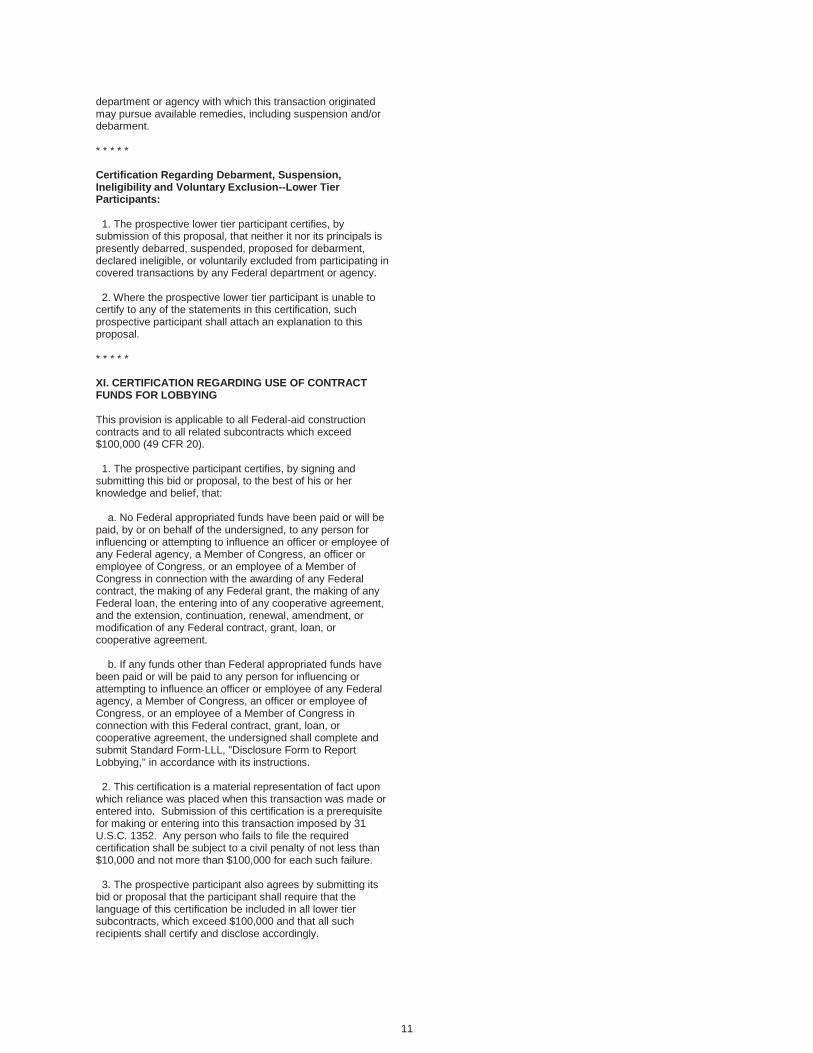
11
department or agency with which this transaction originated may pursue available remedies, including suspension and/or debarment. * * * * * Certification Regarding Debarment, Suspension, Ineligibility and Voluntary Exclusion--Lower Tier Participants: 1. The prospective lower tier participant certifies, by submission of this proposal, that neither it nor its principals is presently debarred, suspended, proposed for debarment, declared ineligible, or voluntarily excluded from participating in covered transactions by any Federal department or agency. 2. Where the prospective lower tier participant is unable to certify to any of the statements in this certification, such prospective participant shall attach an explanation to this proposal. * * * * * XI. CERTIFICATION REGARDING USE OF CONTRACT FUNDS FOR LOBBYING This provision is applicable to all Federal-aid construction contracts and to all related subcontracts which exceed $100,000 (49 CFR 20). 1. The prospective participant certifies, by signing and submitting this bid or proposal, to the best of his or her knowledge and belief, that: a. No Federal appropriated funds have been paid or will be paid, by or on behalf of the undersigned, to any person for influencing or attempting to influence an officer or employee of any Federal agency, a Member of Congress, an officer or employee of Congress, or an employee of a Member of Congress in connection with the awarding of any Federal contract, the making of any Federal grant, the making of any Federal loan, the entering into of any cooperative agreement, and the extension, continuation, renewal, amendment, or modification of any Federal contract, grant, loan, or cooperative agreement. b. If any funds other than Federal appropriated funds have been paid or will be paid to any person for influencing or attempting to influence an officer or employee of any Federal agency, a Member of Congress, an officer or employee of Congress, or an employee of a Member of Congress in connection with this Federal contract, grant, loan, or cooperative agreement, the undersigned shall complete and submit Standard Form-LLL, "Disclosure Form to Report Lobbying," in accordance with its instructions. 2. This certification is a material representation of fact upon which reliance was placed when this transaction was made or entered into. Submission of this certification is a prerequisite for making or entering into this transaction imposed by 31 U.S.C. 1352. Any person who fails to file the required certification shall be subject to a civil penalty of not less than $10,000 and not more than $100,000 for each such failure. 3. The prospective participant also agrees by submitting its bid or proposal that the participant shall require that the language of this certification be included in all lower tier subcontracts, which exceed $100,000 and that all such recipients shall certify and disclose accordingly.

12
ATTACHMENT A - EMPLOYMENT AND MATERIALS PREFERENCE FOR APPALACHIAN DEVELOPMENT HIGHWAY SYSTEM OR APPALACHIAN LOCAL ACCESS ROAD CONTRACTS This provision is applicable to all Federal-aid projects funded under the Appalachian Regional Development Act of 1965. 1. During the performance of this contract, the contractor undertaking to do work which is, or reasonably may be, done as on-site work, shall give preference to qualified persons who regularly reside in the labor area as designated by the DOL wherein the contract work is situated, or the subregion, or the Appalachian counties of the State wherein the contract work is situated, except: a. To the extent that qualified persons regularly residing in the area are not available. b. For the reasonable needs of the contractor to employ supervisory or specially experienced personnel necessary to assure an efficient execution of the contract work. c. For the obligation of the contractor to offer employment to present or former employees as the result of a lawful collective bargaining contract, provided that the number of nonresident persons employed under this subparagraph (1c) shall not exceed 20 percent of the total number of employees employed by the contractor on the contract work, except as provided in subparagraph (4) below. 2. The contractor shall place a job order with the State Employment Service indicating (a) the classifications of the laborers, mechanics and other employees required to perform the contract work, (b) the number of employees required in each classification, (c) the date on which the participant estimates such employees will be required, and (d) any other pertinent information required by the State Employment Service to complete the job order form. The job order may be placed with the State Employment Service in writing or by telephone. If during the course of the contract work, the information submitted by the contractor in the original job order is substantially modified, the participant shall promptly notify the State Employment Service. 3. The contractor shall give full consideration to all qualified job applicants referred to him by the State Employment Service. The contractor is not required to grant employment to any job applicants who, in his opinion, are not qualified to perform the classification of work required. 4. If, within one week following the placing of a job order by the contractor with the State Employment Service, the State Employment Service is unable to refer any qualified job applicants to the contractor, or less than the number requested, the State Employment Service will forward a certificate to the contractor indicating the unavailability of applicants. Such certificate shall be made a part of the contractor's permanent project records. Upon receipt of this certificate, the contractor may employ persons who do not normally reside in the labor area to fill positions covered by the certificate, notwithstanding the provisions of subparagraph (1c) above. 5. The provisions of 23 CFR 633.207(e) allow the contracting agency to provide a contractual preference for the use of mineral resource materials native to the Appalachian region.
6. The contractor shall include the provisions of Sections 1 through 4 of this Attachment A in every subcontract for work which is, or reasonably may be, done as on-site work.

Page 1 of 3
Non-discrimination Provisions
During the performance of this contract, the contractor, for itself, its assignees, and successors in interest (hereinafter referred to as the "contractor") agrees as follows:
1. Compliance with Regulations: The contractor (hereinafter includes consultants) will complywith the Acts and the Regulations relative to Non-discrimination in Federally-assisted programsof the U.S. Department of Transportation, Federal Highway Administration, as they may beamended from time to time, which are herein incorporated by reference and made a part of thiscontract.
2. Non-discrimination: The contractor, with regard to the work performed by it during thecontract, will not discriminate on the grounds of race, color, or national origin in the selection andretention of subcontractors, including procurements of materials and leases of equipment. Thecontractor will not participate directly or indirectly in the discrimination prohibited by the Actsand the Regulations, including employment practices when the contract covers any activity,project, or program set forth in Appendix B of 49 CFR Part 21.
3. Solicitations for Subcontracts, Including Procurements of Materials and Equipment: Inall solicitations, either by competitive bidding, or negotiation made by the contractor for work tobe performed under a subcontract, including procurements of materials, or leases of equipment,each potential subcontractor or supplier will be notified by the contractor of the contractor'sobligations under this contract and the Acts and the Regulations relative to Non-discrimination onthe grounds of race, color, or national origin.
4. Information and Reports: The contractor will provide all information and reports required bythe Acts, the Regulations, and directives issued pursuant thereto and will permit access to its books,records, accounts, other sources of information, and its facilities as may be determined by theRecipient or the Federal Highway Administration to be pertinent to ascertain compliance with suchActs, Regulations, and instructions. Where any information required of a contractor is in theexclusive possession of another who fails or refuses to furnish the information, the contractor willso certify to the Recipient or the Federal Highway Administration, as appropriate, and will setforth what efforts it has made to obtain the information.
5. Sanctions for Noncompliance: In the event of a contractor's noncompliance with the Non-discrimination provisions of this contract, the Recipient will impose such contract sanctions as itor the Federal Highway Administration may determine to be appropriate, including, but not limitedto:
a. Withholding payments to the contractor under the contract until the contractorcomplies; and/or
b. Cancelling, terminating, or suspending a contract, in whole or in part.

Page 2 of 3
6. Incorporation of Provisions: The contractor will include the provisions of paragraphs one through six in every subcontract, including procurements of materials and leases of equipment, unless exempt by the Acts, the Regulations and directives issued pursuant thereto. The contractor will take action with respect to any subcontract or procurement as the Recipient or the Federal Highway Administration may direct as a means of enforcing such provisions including sanctions for noncompliance. Provided, that if the contractor becomes involved in, or is threatened with litigation by a subcontractor, or supplier because of such direction, the contractor may request the Recipient to enter into any litigation to protect the interests of the Recipient. In addition, the contractor may request the United States to enter into the litigation to protect the interests of the United States.
During the performance of this contract, the contractor, for itself, its assignees, and successors in interest (hereinafter referred to as the "contractor") agrees to comply with the following non-discrimination statutes and authorities; including but not limited to:
Pertinent Non-Discrimination Authorities:
• Title VI of the Civil Rights Act of 1964 (42 U.S.C. § 2000d et seq., 78 stat. 252), (prohibits discrimination on the basis of race, color, national origin); and 49 CFR Part 21.
• The Uniform Relocation Assistance and Real Property Acquisition Policies Act of 1970, (42 U.S.C. § 4601), (prohibits unfair treatment of persons displaced or whose property has been acquired because of Federal or Federal-aid programs and projects);
• Federal-Aid Highway Act of 1973, (23 U.S.C. § 324 et seq.), (prohibits discrimination on the basis of sex);
• Section 504 of the Rehabilitation Act of 1973, (29 U.S.C. § 794 et seq.), as amended, (prohibits discrimination on the basis of disability); and 49 CFR Part 27;
• The Age Discrimination Act of 1975, as amended, (42 U.S.C. § 6101 et seq.), (prohibits discrimination on the basis of age);
• Airport and Airway Improvement Act of 1982, (49 USC § 471, Section 47123), as amended, (prohibits discrimination based on race, creed, color, national origin, or sex);
• The Civil Rights Restoration Act of 1987, (PL 100-209), (Broadened the scope, coverage and applicability of Title VI of the Civil Rights Act of 1964, The Age Discrimination Act of 1975 and Section 504 of the Rehabilitation Act of 1973, by expanding the definition of the terms "programs or activities" to include all of the programs or activities of the Federal-aid recipients, sub-recipients and contractors, whether such programs or activities are Federally funded or not);
• Titles II and III of the Americans with Disabilities Act, which prohibit discrimination on the basis of disability in the operation of public entities, public and private transportation systems, places of public accommodation, and certain testing entities (42 U.S.C. §§ 12131-12189) as implemented by Department of Transportation regulations at 49 C.F.R. parts 37 and 38;
• The Federal Aviation Administration's Non-discrimination statute (49 U.S.C. § 47123) (prohibits discrimination on the basis of race, color, national origin, and sex);
Page 3 of 3
• Executive Order 12898, Federal Actions to Address Environmental Justice in Minority Populations and Low-Income Populations, which ensures Non-discrimination against minority populations by discouraging programs, policies, and activities with disproportionately high and adverse human health or environmental effects on minority and low-income populations;
• Executive Order 13166, Improving Access to Services for Persons with Limited English Proficiency, and resulting agency guidance, national origin discrimination includes discrimination because of Limited English proficiency (LEP). To ensure compliance with Title VI, you must take reasonable steps to ensure that LEP persons have meaningful access to your programs (70 Fed. Reg. at 74087 to 74100);
• Title IX of the Education Amendments of 1972, as amended, which prohibits you from discriminating because of sex in education programs or activities (20 U.S.C. 1681 et seq).

1 of 2
SEPTEMBER 2002 NOTICE OF REQUIREMENT FOR AFFIRMATIVE ACTION TO ENSURE
EQUAL EMPLOYMENT OPPORTUNITY (EXECUTIVE ORDER 11246) 1. The Offeror's or Bidder's attention is called to the "Employment Practices" and "Equal
Opportunity Clause" set forth in the Required Contract Provisions, FHWA 1273.
2. The goals and timetables for minority and female participation expressed in percentageterms for the contractor's aggregate work force in each trade, on all construction work in thecovered area, are as follows:Goals for Minority Participation for Each Trade:
County % County % County %
Adams 1.7 Iowa 1.7 Polk 2.2
Ashland 1.2 Iron 1.2 Portage 0.6
Barron 0.6 Jackson 0.6 Price 0.6
Bayfield 1.2 Jefferson 7.0 Racine 8.4
Brown 1.3 Juneau 0.6 Richland 1.7
Buffalo 0.6 Kenosha 3.0 Rock 3.1
Burnett 2.2 Kewaunee 1.0 Rusk 0.6
Calumet 0.9 La Crosse 0.9 St. Croix 2.9
Chippewa 0.5 Lafayette 0.5 Sauk 1.7
Clark 0.6 Langlade 0.6 Sawyer 0.6
Columbia 1.7 Lincoln 0.6 Shawano 1.0
Crawford 0.5 Manitowoc 1.0 Sheboygan 7.0
Dane 2.2 Marathon 0.6 Taylor 0.6
Dodge 7.0 Marinette 1.0 Trempealeau 0.6
Door 1.0 Marquette 1.7 Vernon 0.6
Douglas 1.0 Menominee 1.0 Vilas 0.6
Dunn 0.6 Milwaukee 8.0 Walworth 7.0
Eau Claire 0.5 Monroe 0.6 Washburn 0.6
Florence 1.0 Oconto 1.0 Washington 8.0
Fond du Lac 1.0 Oneida 0.6 Waukesha 8.0
Forest 1.0 Outagamie 0.9 Waupaca 1.0
Grant 0.5 Ozaukee 8.0 Waushara 1.0
Green 1.7 Pepin 0.6 Winnebago 0.9
Green Lake 1.0 Pierce 2.2 Wood 0.6

2 of 2
Goals for female participation for each trade: 6.9% These goals are applicable to all the contractor's construction work, (whether or not it is
federal or federally assisted), performed in the covered area. If the contractor performs construction work in the geographical area located outside of the covered area, it shall apply the goals established for such geographical area where the work is actually performed. With regard to this second area, the contractor also is subject to the goals for both its federally involved and nonfederally involved construction.
The contractor's compliance with the Executive Order and the Regulations in 41 CFR Part
60-4 shall be based on its implementation of the Equal Opportunity Clause, specific affirmative action obligations required by the specifications set forth in 41 CFR 60-4.3(a), and its efforts to meet the goals. The hours of minority and female employment and training must be substantially uniform throughout the length of the contract, and in each trade, and the contractor shall make a good faith effort to employ minorities and women evenly on each of its projects. The transfer of minority or female employees or trainees from contractor to contractor or from project to project for the sole purpose of meeting the contractor's goals shall be a violation of the contract, the Executive Order and the Regulations in 41 CFR Part 60-4. Compliance with the goals will be measured against the total work hours performed.
3. The contractor shall provide written notification to the Director of the Office of Federal
Contract Compliance Programs within ten (10) working days of award of any construction subcontract in excess of $10,000.00 at any tier for construction work under the contract resulting from this solicitation. The notification shall list the name, address and telephone number of the subcontractor, employer identification number of the subcontractor; estimated dollar amount of the subcontract; estimated starting and completion dates of the subcontract; and the geographical area in which the subcontract is to be performed.
As referred to in this section, the Director means: Director Office of Federal Contract Compliance Programs Ruess Federal Plaza 310 W. Wisconsin Ave., Suite 1115 Milwaukee, WI 53202 The "Employer Identification Number" means the Federal Social Security number used on
the Employer's Quarterly Federal Tax Return, U.S. Treasury Department Form 941. 4. As used in this notice, and in the contract resulting from solicitation, the "covered area" is
the county(ies) in Wisconsin to which this proposal applies.

1 of 1
APRIL 2013
ADDITIONAL FEDERAL-AID PROVISIONS
NOTICE TO ALL BIDDERS
To report bid rigging activities call:
1-800-424-9071
The U.S. Department of Transportation (DOT) operates the above toll-free "hotline" Monday through Friday, 8:00 a.m. to 5:00 p.m., Eastern Time. Anyone with knowledge of possible bid rigging, bidding collusion, or other fraudulent activities should use the "hotline" to report such activities.
The "hotline" is part of the DOT's continuing effort to identify and investigate highway construction contract fraud and abuse and is operated under the direction of the DOT Inspector General. All information will be treated confidentially and caller anonymity will be respected.

1 of 1
Effective August 2015 letting
BUY AMERICA PROVISION
All steel and iron materials permanently incorporated in this project shall be domestic products and all manufacturing and coating processes for these materials from smelting forward in the manufacturing process must have occurred within the United States. Coating includes epoxy coating, galvanizing, painting and any other coating that protects or enhances the value of a material subject to the requirements of Buy America. The exemption of this requirement is the minimal use of foreign materials if the total cost of such material permanently incorporated in the product does not exceed one-tenth of one percent (1/10 of 1%) of the total contract cost or $2,500.00, whichever is greater. For purposes of this paragraph, the cost is that shown to be the value of the subject products as they are delivered to the project. The contractor shall take actions and provide documentation conforming to CMM 2-28.5 to ensure compliance with this “Buy America” provision.
https://wisconsindot.gov/rdwy/cmm/cm-02-28.pdf
Upon completion of the project certify to the engineer, in writing using department form WS4567, that all steel, iron, and coating processes for steel or iron incorporated into the contract work conform to these "Buy America" provisions. Attach a list of exemptions and their associated costs to the certification form. Department form WS4567 is available at:
https://wisconsindot.gov/hcciDocs/contracting-info/ws4567.doc

Effective February 2016 letting
Cargo Preference Act Requirement
All Federal-aid projects shall comply with 46 CFR 381.7 (a) – (b) as follows:
(a) Agreement Clauses. “Use of United States-flag vessels:"
(1) Pursuant to Pub. L. 664 (43 U.S.C. 1241(b)) at least 50 percent of any equipment, materials orcommodities procured, contracted for or otherwise obtained with funds granted, guaranteed, loaned, oradvanced by the U.S. Government under this agreement, and which may be transported by ocean vessel,shall be transported on privately owned United States-flag commercial vessels, if available.
(2) Within 20 days following the date of loading for shipments originating within the United States or within30 working days following the date of loading for shipments originating outside the United States, a legiblecopy of a rated, ‘on-board’ commercial ocean bill-of-lading in English for each shipment of cargo describedin paragraph (a)(1) of this section shall be furnished to both the Contracting Officer (through the primecontractor in the case of subcontractor bills-of-lading) and to the Division of National Cargo, Office of MarketDevelopment, Maritime Administration, Washington, DC 20590.”
(b) Contractor and Subcontractor Clauses. “Use of United States-flag vessels: The contractor agrees—“
(1) To utilize privately owned United States-flag commercial vessels to ship at least 50 percent of the grosstonnage (computed separately for dry bulk carriers, dry cargo liners, and tankers) involved, whenevershipping any equipment, material, or commodities pursuant to this contract, to the extent such vessels areavailable at fair and reasonable rates for United States-flag commercial vessels.
(2) To furnish within 20 days following the date of loading for shipments originating within the United Statesor within 30 working days following the date of loading for shipments originating outside the United States,a legible copy of a rated, ‘on-board’ commercial ocean bill-of-lading in English for each shipment of cargodescribed in paragraph (b) (1) of this section to both the Contracting Officer (through the prime contractorin the case of subcontractor bills-of-lading) and to the Division of National Cargo, Office of MarketDevelopment, Maritime Administration, Washington, DC 20590.
(3) To insert the substance of the provisions of this clause in all subcontracts issued pursuant to thiscontract.

Page 1 of 2
Effective with December 2017 Letting
WISCONSIN DEPARTMENT OF TRANSPORTATION DIVISION OF TRANSPORTATION AND SYSTEM DEVELOPMENT
SUPPLEMENTAL REQUIRED CONTRACT PROVISIONS FOR PROJECTS WITH FEDERAL AID
I. PREVAILING WAGE RATES
The attached U.S. Department of Labor (Davis-Bacon Minimum Wage Rates)furnishes the minimum prevailing wage rates pursuant to the Davis-Bacon andRelated Acts. The wage rates shown are the minimum rates required by the contractto be paid during its life, however this is not a representation that labor can beobtained at these rates. It is the responsibility of bidders to inform themselves as tothe local labor conditions and prospective changes or adjustments of wage rates.No increase in the contract price will be allowed or authorized on account of thepayment of wage rates in excess of those listed herein.
II. COVERAGE OF TRUCK DRIVERS
Truck drivers are covered by Davis-Bacon Minimum Wage Rates in the followingcircumstances:
· Drivers of a contractor or subcontractor for time spent working on the siteof the work.
· Drivers of a contractor or subcontractor for time spent loading and/orunloading materials and supplies on the site of the work, if such time isnot de minimis. https://www.dol.gov/whd/FOH/FOH_Ch15.pdf
· Truck drivers transporting materials or supplies between a facility that isdeemed part of the site of the work and the actual construction site.
· Truck drivers transporting portions of the building or work between a siteestablished specifically for the performance of the contract where asignificant portion of such building or work is constructed and the physicalplace where the building or work called for in the contract will remain.
Truck drivers are not covered by Davis-Bacon Minimum Wage Rates in the following circumstances:
· Material delivery truck drivers while off the site of the work.· Drivers of a contractor or subcontractor traveling between a Davis-Bacon
job and a commercial supply facility while they are off the site of thework.”
· Truck drivers whose time spent on the site of the work is de minimis, suchas only a few minutes at a time merely to pick up or drop off materials orsupplies.
Details are available online at: https://www.dol.gov/whd/recovery/pwrb/Tab9.pdf https://wisconsindot.gov/Pages/doing-bus/civil-rights/labornwage/trckng.aspx
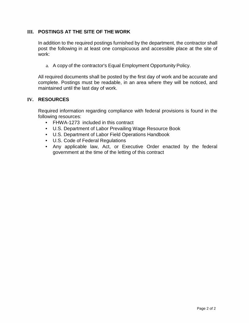
Page 2 of 2
III. POSTINGS AT THE SITE OF THE WORK
In addition to the required postings furnished by the department, the contractor shall post the following in at least one conspicuous and accessible place at the site of work:
a. A copy of the contractor's Equal Employment Opportunity Policy.
All required documents shall be posted by the first day of work and be accurate and complete. Postings must be readable, in an area where they will be noticed, and maintained until the last day of work.
IV. RESOURCES
Required information regarding compliance with federal provisions is found in the following resources:
· FHWA-1273 included in this contract · U.S. Department of Labor Prevailing Wage Resource Book · U.S. Department of Labor Field Operations Handbook · U.S. Code of Federal Regulations · Any applicable law, Act, or Executive Order enacted by the federal
government at the time of the letting of this contract
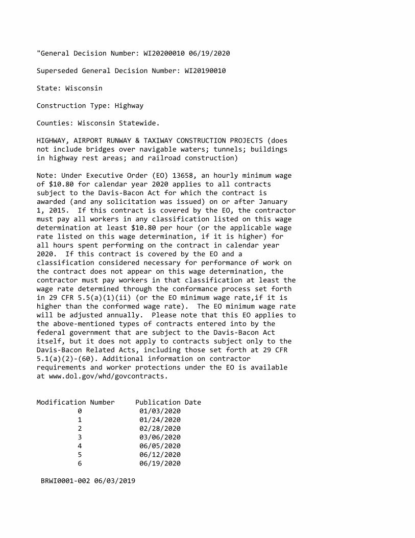
"General Decision Number: WI20200010 06/19/2020
Superseded General Decision Number: WI20190010
State: Wisconsin
Construction Type: Highway
Counties: Wisconsin Statewide.
HIGHWAY, AIRPORT RUNWAY & TAXIWAY CONSTRUCTION PROJECTS (doesnot include bridges over navigable waters; tunnels; buildingsin highway rest areas; and railroad construction)
Note: Under Executive Order (EO) 13658, an hourly minimum wageof $10.80 for calendar year 2020 applies to all contractssubject to the Davis‐Bacon Act for which the contract isawarded (and any solicitation was issued) on or after January1, 2015. If this contract is covered by the EO, the contractormust pay all workers in any classification listed on this wagedetermination at least $10.80 per hour (or the applicable wagerate listed on this wage determination, if it is higher) forall hours spent performing on the contract in calendar year2020. If this contract is covered by the EO and aclassification considered necessary for performance of work onthe contract does not appear on this wage determination, thecontractor must pay workers in that classification at least thewage rate determined through the conformance process set forthin 29 CFR 5.5(a)(1)(ii) (or the EO minimum wage rate,if it ishigher than the conformed wage rate). The EO minimum wage ratewill be adjusted annually. Please note that this EO applies tothe above‐mentioned types of contracts entered into by thefederal government that are subject to the Davis‐Bacon Actitself, but it does not apply to contracts subject only to theDavis‐Bacon Related Acts, including those set forth at 29 CFR5.1(a)(2)‐(60). Additional information on contractorrequirements and worker protections under the EO is availableat www.dol.gov/whd/govcontracts.
Modification Number Publication Date 0 01/03/2020 1 01/24/2020 2 02/28/2020 3 03/06/2020 4 06/05/2020 5 06/12/2020 6 06/19/2020
BRWI0001‐002 06/03/2019
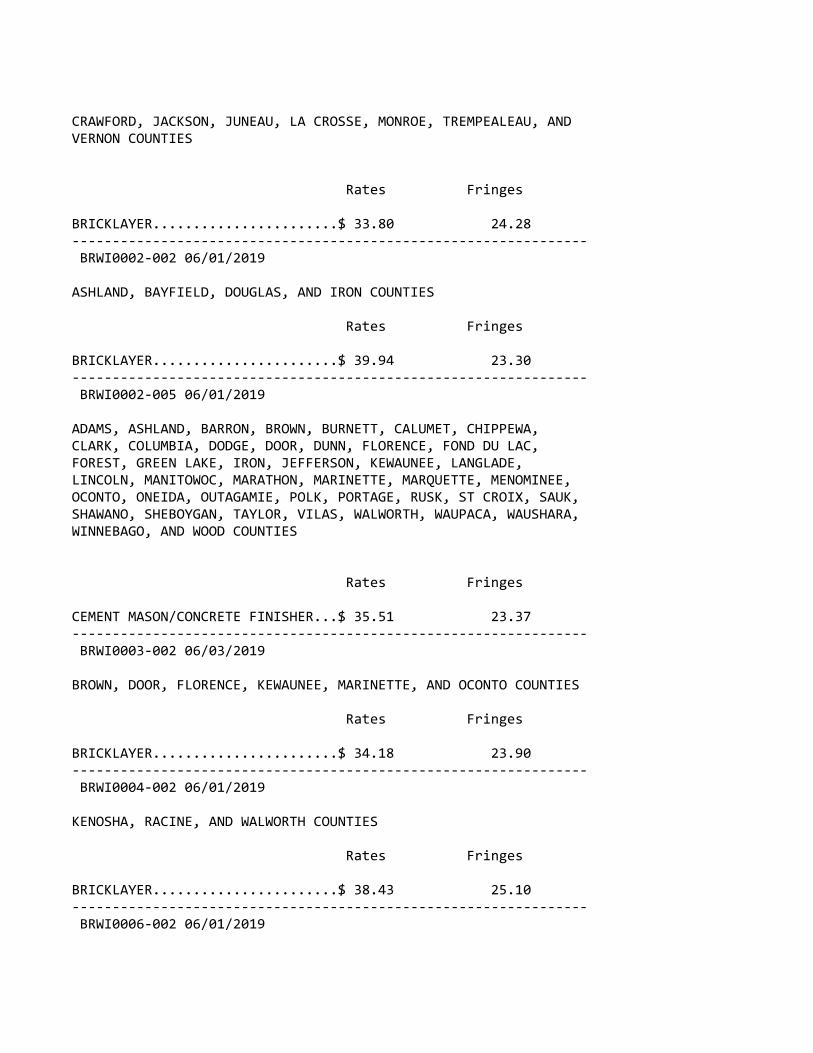
CRAWFORD, JACKSON, JUNEAU, LA CROSSE, MONROE, TREMPEALEAU, ANDVERNON COUNTIES
Rates Fringes
BRICKLAYER.......................$ 33.80 24.28‐‐‐‐‐‐‐‐‐‐‐‐‐‐‐‐‐‐‐‐‐‐‐‐‐‐‐‐‐‐‐‐‐‐‐‐‐‐‐‐‐‐‐‐‐‐‐‐‐‐‐‐‐‐‐‐‐‐‐‐‐‐‐‐ BRWI0002‐002 06/01/2019
ASHLAND, BAYFIELD, DOUGLAS, AND IRON COUNTIES
Rates Fringes
BRICKLAYER.......................$ 39.94 23.30‐‐‐‐‐‐‐‐‐‐‐‐‐‐‐‐‐‐‐‐‐‐‐‐‐‐‐‐‐‐‐‐‐‐‐‐‐‐‐‐‐‐‐‐‐‐‐‐‐‐‐‐‐‐‐‐‐‐‐‐‐‐‐‐ BRWI0002‐005 06/01/2019
ADAMS, ASHLAND, BARRON, BROWN, BURNETT, CALUMET, CHIPPEWA,CLARK, COLUMBIA, DODGE, DOOR, DUNN, FLORENCE, FOND DU LAC,FOREST, GREEN LAKE, IRON, JEFFERSON, KEWAUNEE, LANGLADE,LINCOLN, MANITOWOC, MARATHON, MARINETTE, MARQUETTE, MENOMINEE,OCONTO, ONEIDA, OUTAGAMIE, POLK, PORTAGE, RUSK, ST CROIX, SAUK,SHAWANO, SHEBOYGAN, TAYLOR, VILAS, WALWORTH, WAUPACA, WAUSHARA,WINNEBAGO, AND WOOD COUNTIES
Rates Fringes
CEMENT MASON/CONCRETE FINISHER...$ 35.51 23.37‐‐‐‐‐‐‐‐‐‐‐‐‐‐‐‐‐‐‐‐‐‐‐‐‐‐‐‐‐‐‐‐‐‐‐‐‐‐‐‐‐‐‐‐‐‐‐‐‐‐‐‐‐‐‐‐‐‐‐‐‐‐‐‐ BRWI0003‐002 06/03/2019
BROWN, DOOR, FLORENCE, KEWAUNEE, MARINETTE, AND OCONTO COUNTIES
Rates Fringes
BRICKLAYER.......................$ 34.18 23.90‐‐‐‐‐‐‐‐‐‐‐‐‐‐‐‐‐‐‐‐‐‐‐‐‐‐‐‐‐‐‐‐‐‐‐‐‐‐‐‐‐‐‐‐‐‐‐‐‐‐‐‐‐‐‐‐‐‐‐‐‐‐‐‐ BRWI0004‐002 06/01/2019
KENOSHA, RACINE, AND WALWORTH COUNTIES
Rates Fringes
BRICKLAYER.......................$ 38.43 25.10‐‐‐‐‐‐‐‐‐‐‐‐‐‐‐‐‐‐‐‐‐‐‐‐‐‐‐‐‐‐‐‐‐‐‐‐‐‐‐‐‐‐‐‐‐‐‐‐‐‐‐‐‐‐‐‐‐‐‐‐‐‐‐‐ BRWI0006‐002 06/01/2019
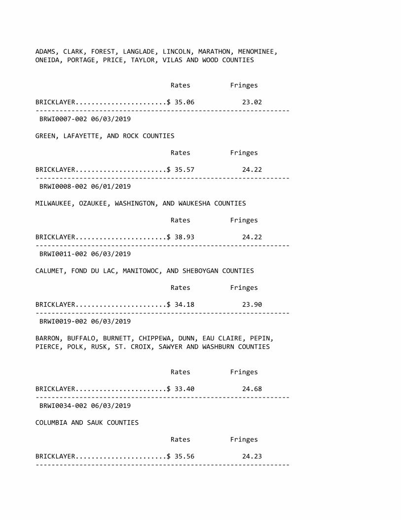
ADAMS, CLARK, FOREST, LANGLADE, LINCOLN, MARATHON, MENOMINEE,ONEIDA, PORTAGE, PRICE, TAYLOR, VILAS AND WOOD COUNTIES
Rates Fringes
BRICKLAYER.......................$ 35.06 23.02‐‐‐‐‐‐‐‐‐‐‐‐‐‐‐‐‐‐‐‐‐‐‐‐‐‐‐‐‐‐‐‐‐‐‐‐‐‐‐‐‐‐‐‐‐‐‐‐‐‐‐‐‐‐‐‐‐‐‐‐‐‐‐‐ BRWI0007‐002 06/03/2019
GREEN, LAFAYETTE, AND ROCK COUNTIES
Rates Fringes
BRICKLAYER.......................$ 35.57 24.22‐‐‐‐‐‐‐‐‐‐‐‐‐‐‐‐‐‐‐‐‐‐‐‐‐‐‐‐‐‐‐‐‐‐‐‐‐‐‐‐‐‐‐‐‐‐‐‐‐‐‐‐‐‐‐‐‐‐‐‐‐‐‐‐ BRWI0008‐002 06/01/2019
MILWAUKEE, OZAUKEE, WASHINGTON, AND WAUKESHA COUNTIES
Rates Fringes
BRICKLAYER.......................$ 38.93 24.22‐‐‐‐‐‐‐‐‐‐‐‐‐‐‐‐‐‐‐‐‐‐‐‐‐‐‐‐‐‐‐‐‐‐‐‐‐‐‐‐‐‐‐‐‐‐‐‐‐‐‐‐‐‐‐‐‐‐‐‐‐‐‐‐ BRWI0011‐002 06/03/2019
CALUMET, FOND DU LAC, MANITOWOC, AND SHEBOYGAN COUNTIES
Rates Fringes
BRICKLAYER.......................$ 34.18 23.90‐‐‐‐‐‐‐‐‐‐‐‐‐‐‐‐‐‐‐‐‐‐‐‐‐‐‐‐‐‐‐‐‐‐‐‐‐‐‐‐‐‐‐‐‐‐‐‐‐‐‐‐‐‐‐‐‐‐‐‐‐‐‐‐ BRWI0019‐002 06/03/2019
BARRON, BUFFALO, BURNETT, CHIPPEWA, DUNN, EAU CLAIRE, PEPIN,PIERCE, POLK, RUSK, ST. CROIX, SAWYER AND WASHBURN COUNTIES
Rates Fringes
BRICKLAYER.......................$ 33.40 24.68‐‐‐‐‐‐‐‐‐‐‐‐‐‐‐‐‐‐‐‐‐‐‐‐‐‐‐‐‐‐‐‐‐‐‐‐‐‐‐‐‐‐‐‐‐‐‐‐‐‐‐‐‐‐‐‐‐‐‐‐‐‐‐‐ BRWI0034‐002 06/03/2019
COLUMBIA AND SAUK COUNTIES
Rates Fringes
BRICKLAYER.......................$ 35.56 24.23‐‐‐‐‐‐‐‐‐‐‐‐‐‐‐‐‐‐‐‐‐‐‐‐‐‐‐‐‐‐‐‐‐‐‐‐‐‐‐‐‐‐‐‐‐‐‐‐‐‐‐‐‐‐‐‐‐‐‐‐‐‐‐‐
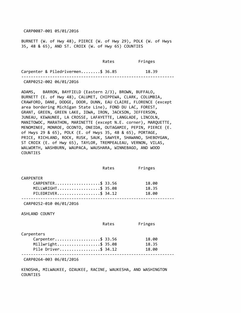
CARP0087‐001 05/01/2016
BURNETT (W. of Hwy 48), PIERCE (W. of Hwy 29), POLK (W. of Hwys35, 48 & 65), AND ST. CROIX (W. of Hwy 65) COUNTIES
Rates Fringes
Carpenter & Piledrivermen........$ 36.85 18.39‐‐‐‐‐‐‐‐‐‐‐‐‐‐‐‐‐‐‐‐‐‐‐‐‐‐‐‐‐‐‐‐‐‐‐‐‐‐‐‐‐‐‐‐‐‐‐‐‐‐‐‐‐‐‐‐‐‐‐‐‐‐‐‐ CARP0252‐002 06/01/2016
ADAMS, BARRON, BAYFIELD (Eastern 2/3), BROWN, BUFFALO,BURNETT (E. of Hwy 48), CALUMET, CHIPPEWA, CLARK, COLUMBIA,CRAWFORD, DANE, DODGE, DOOR, DUNN, EAU CLAIRE, FLORENCE (exceptarea bordering Michigan State Line), FOND DU LAC, FOREST,GRANT, GREEN, GREEN LAKE, IOWA, IRON, JACKSON, JEFFERSON,JUNEAU, KEWAUNEE, LA CROSSE, LAFAYETTE, LANGLADE, LINCOLN,MANITOWOC, MARATHON, MARINETTE (except N.E. corner), MARQUETTE,MENOMINEE, MONROE, OCONTO, ONEIDA, OUTAGAMIE, PEPIN, PIERCE (E.of Hwys 29 & 65), POLK (E. of Hwys 35, 48 & 65), PORTAGE,PRICE, RICHLAND, ROCK, RUSK, SAUK, SAWYER, SHAWANO, SHEBOYGAN,ST CROIX (E. of Hwy 65), TAYLOR, TREMPEALEAU, VERNON, VILAS,WALWORTH, WASHBURN, WAUPACA, WAUSHARA, WINNEBAGO, AND WOODCOUNTIES
Rates Fringes
CARPENTER CARPENTER...................$ 33.56 18.00 MILLWRIGHT..................$ 35.08 18.35 PILEDRIVER..................$ 34.12 18.00‐‐‐‐‐‐‐‐‐‐‐‐‐‐‐‐‐‐‐‐‐‐‐‐‐‐‐‐‐‐‐‐‐‐‐‐‐‐‐‐‐‐‐‐‐‐‐‐‐‐‐‐‐‐‐‐‐‐‐‐‐‐‐‐ CARP0252‐010 06/01/2016
ASHLAND COUNTY
Rates Fringes
Carpenters Carpenter...................$ 33.56 18.00 Millwright..................$ 35.08 18.35 Pile Driver.................$ 34.12 18.00‐‐‐‐‐‐‐‐‐‐‐‐‐‐‐‐‐‐‐‐‐‐‐‐‐‐‐‐‐‐‐‐‐‐‐‐‐‐‐‐‐‐‐‐‐‐‐‐‐‐‐‐‐‐‐‐‐‐‐‐‐‐‐‐ CARP0264‐003 06/01/2016
KENOSHA, MILWAUKEE, OZAUKEE, RACINE, WAUKESHA, AND WASHINGTONCOUNTIES
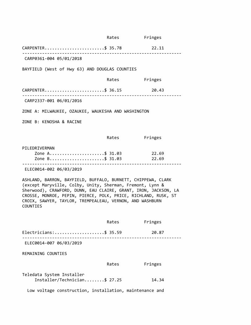
Rates Fringes
CARPENTER........................$ 35.78 22.11‐‐‐‐‐‐‐‐‐‐‐‐‐‐‐‐‐‐‐‐‐‐‐‐‐‐‐‐‐‐‐‐‐‐‐‐‐‐‐‐‐‐‐‐‐‐‐‐‐‐‐‐‐‐‐‐‐‐‐‐‐‐‐‐ CARP0361‐004 05/01/2018
BAYFIELD (West of Hwy 63) AND DOUGLAS COUNTIES
Rates Fringes
CARPENTER........................$ 36.15 20.43‐‐‐‐‐‐‐‐‐‐‐‐‐‐‐‐‐‐‐‐‐‐‐‐‐‐‐‐‐‐‐‐‐‐‐‐‐‐‐‐‐‐‐‐‐‐‐‐‐‐‐‐‐‐‐‐‐‐‐‐‐‐‐‐ CARP2337‐001 06/01/2016
ZONE A: MILWAUKEE, OZAUKEE, WAUKESHA AND WASHINGTON
ZONE B: KENOSHA & RACINE
Rates Fringes
PILEDRIVERMAN Zone A......................$ 31.03 22.69 Zone B......................$ 31.03 22.69‐‐‐‐‐‐‐‐‐‐‐‐‐‐‐‐‐‐‐‐‐‐‐‐‐‐‐‐‐‐‐‐‐‐‐‐‐‐‐‐‐‐‐‐‐‐‐‐‐‐‐‐‐‐‐‐‐‐‐‐‐‐‐‐ ELEC0014‐002 06/03/2019
ASHLAND, BARRON, BAYFIELD, BUFFALO, BURNETT, CHIPPEWA, CLARK(except Maryville, Colby, Unity, Sherman, Fremont, Lynn &Sherwood), CRAWFORD, DUNN, EAU CLAIRE, GRANT, IRON, JACKSON, LACROSSE, MONROE, PEPIN, PIERCE, POLK, PRICE, RICHLAND, RUSK, STCROIX, SAWYER, TAYLOR, TREMPEALEAU, VERNON, AND WASHBURNCOUNTIES
Rates Fringes
Electricians:....................$ 35.59 20.87‐‐‐‐‐‐‐‐‐‐‐‐‐‐‐‐‐‐‐‐‐‐‐‐‐‐‐‐‐‐‐‐‐‐‐‐‐‐‐‐‐‐‐‐‐‐‐‐‐‐‐‐‐‐‐‐‐‐‐‐‐‐‐‐ ELEC0014‐007 06/03/2019
REMAINING COUNTIES
Rates Fringes
Teledata System Installer Installer/Technician........$ 27.25 14.34
Low voltage construction, installation, maintenance and

removal of teledata facilities (voice, data, and video) including outside plant, telephone and data inside wire, interconnect, terminal equipment, central offices, PABX, fiber optic cable and equipment, micro waves, V‐SAT, bypass, CATV, WAN (wide area networks), LAN (local area networks), and ISDN (integrated systems digital network).
‐‐‐‐‐‐‐‐‐‐‐‐‐‐‐‐‐‐‐‐‐‐‐‐‐‐‐‐‐‐‐‐‐‐‐‐‐‐‐‐‐‐‐‐‐‐‐‐‐‐‐‐‐‐‐‐‐‐‐‐‐‐‐‐ ELEC0127‐002 06/01/2020
KENOSHA COUNTY
Rates Fringes
Electricians:....................$ 41.62 30%+12.70‐‐‐‐‐‐‐‐‐‐‐‐‐‐‐‐‐‐‐‐‐‐‐‐‐‐‐‐‐‐‐‐‐‐‐‐‐‐‐‐‐‐‐‐‐‐‐‐‐‐‐‐‐‐‐‐‐‐‐‐‐‐‐‐ ELEC0158‐002 06/03/2019
BROWN, DOOR, KEWAUNEE, MANITOWOC (except Schleswig),MARINETTE(Wausuakee and area South thereof), OCONTO, MENOMINEE(East of a ine 6 miles West of the West boundary of OcontoCounty), SHAWANO (Except Area North of Townships of Aniwa andHutchins) COUNTIES
Rates Fringes
Electricians:....................$ 33.52 29.75%+10.26‐‐‐‐‐‐‐‐‐‐‐‐‐‐‐‐‐‐‐‐‐‐‐‐‐‐‐‐‐‐‐‐‐‐‐‐‐‐‐‐‐‐‐‐‐‐‐‐‐‐‐‐‐‐‐‐‐‐‐‐‐‐‐‐ ELEC0159‐003 06/01/2019
COLUMBIA, DANE, DODGE (Area West of Hwy 26, except Chester andEmmet Townships), GREEN, LAKE (except Townships of Berlin,Seneca, and St. Marie), IOWA, MARQUETTE (except Townships ofNeshkoka, Crystal Lake, Newton, and Springfield), and SAUKCOUNTIES
Rates Fringes
Electricians:....................$ 40.30 22.24‐‐‐‐‐‐‐‐‐‐‐‐‐‐‐‐‐‐‐‐‐‐‐‐‐‐‐‐‐‐‐‐‐‐‐‐‐‐‐‐‐‐‐‐‐‐‐‐‐‐‐‐‐‐‐‐‐‐‐‐‐‐‐‐ ELEC0219‐004 06/01/2016
FLORENCE COUNTY (Townships of Aurora, Commonwealth, Fern,Florence and Homestead) AND MARINETTE COUNTY (Township ofNiagara)
Rates Fringes
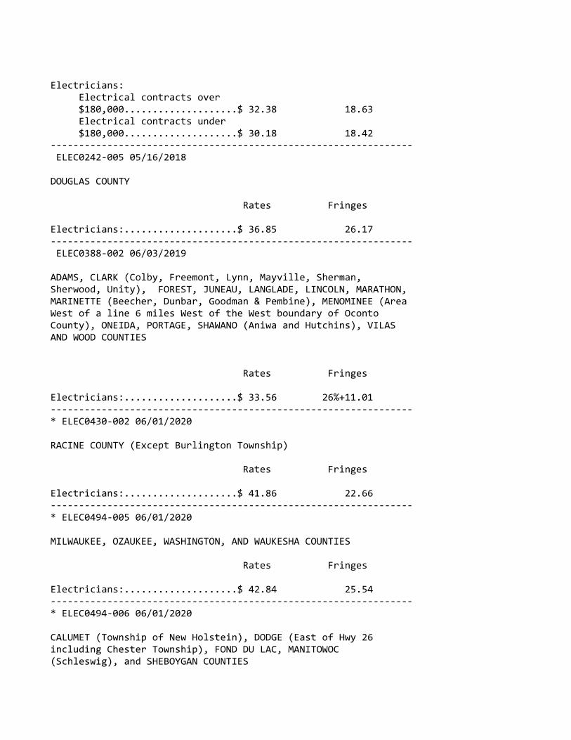
Electricians: Electrical contracts over $180,000....................$ 32.38 18.63 Electrical contracts under $180,000....................$ 30.18 18.42‐‐‐‐‐‐‐‐‐‐‐‐‐‐‐‐‐‐‐‐‐‐‐‐‐‐‐‐‐‐‐‐‐‐‐‐‐‐‐‐‐‐‐‐‐‐‐‐‐‐‐‐‐‐‐‐‐‐‐‐‐‐‐‐ ELEC0242‐005 05/16/2018
DOUGLAS COUNTY
Rates Fringes
Electricians:....................$ 36.85 26.17‐‐‐‐‐‐‐‐‐‐‐‐‐‐‐‐‐‐‐‐‐‐‐‐‐‐‐‐‐‐‐‐‐‐‐‐‐‐‐‐‐‐‐‐‐‐‐‐‐‐‐‐‐‐‐‐‐‐‐‐‐‐‐‐ ELEC0388‐002 06/03/2019
ADAMS, CLARK (Colby, Freemont, Lynn, Mayville, Sherman,Sherwood, Unity), FOREST, JUNEAU, LANGLADE, LINCOLN, MARATHON,MARINETTE (Beecher, Dunbar, Goodman & Pembine), MENOMINEE (AreaWest of a line 6 miles West of the West boundary of OcontoCounty), ONEIDA, PORTAGE, SHAWANO (Aniwa and Hutchins), VILASAND WOOD COUNTIES
Rates Fringes
Electricians:....................$ 33.56 26%+11.01‐‐‐‐‐‐‐‐‐‐‐‐‐‐‐‐‐‐‐‐‐‐‐‐‐‐‐‐‐‐‐‐‐‐‐‐‐‐‐‐‐‐‐‐‐‐‐‐‐‐‐‐‐‐‐‐‐‐‐‐‐‐‐‐* ELEC0430‐002 06/01/2020
RACINE COUNTY (Except Burlington Township)
Rates Fringes
Electricians:....................$ 41.86 22.66‐‐‐‐‐‐‐‐‐‐‐‐‐‐‐‐‐‐‐‐‐‐‐‐‐‐‐‐‐‐‐‐‐‐‐‐‐‐‐‐‐‐‐‐‐‐‐‐‐‐‐‐‐‐‐‐‐‐‐‐‐‐‐‐* ELEC0494‐005 06/01/2020
MILWAUKEE, OZAUKEE, WASHINGTON, AND WAUKESHA COUNTIES
Rates Fringes
Electricians:....................$ 42.84 25.54‐‐‐‐‐‐‐‐‐‐‐‐‐‐‐‐‐‐‐‐‐‐‐‐‐‐‐‐‐‐‐‐‐‐‐‐‐‐‐‐‐‐‐‐‐‐‐‐‐‐‐‐‐‐‐‐‐‐‐‐‐‐‐‐* ELEC0494‐006 06/01/2020
CALUMET (Township of New Holstein), DODGE (East of Hwy 26including Chester Township), FOND DU LAC, MANITOWOC(Schleswig), and SHEBOYGAN COUNTIES
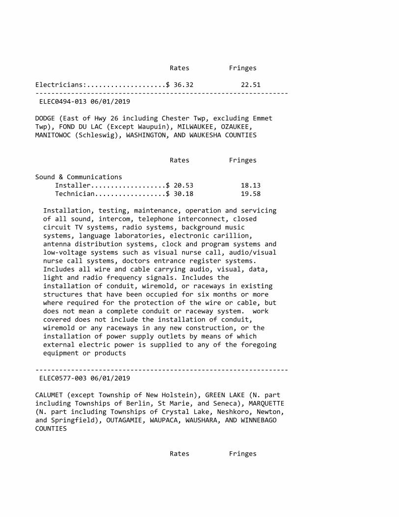
Rates Fringes
Electricians:....................$ 36.32 22.51‐‐‐‐‐‐‐‐‐‐‐‐‐‐‐‐‐‐‐‐‐‐‐‐‐‐‐‐‐‐‐‐‐‐‐‐‐‐‐‐‐‐‐‐‐‐‐‐‐‐‐‐‐‐‐‐‐‐‐‐‐‐‐‐ ELEC0494‐013 06/01/2019
DODGE (East of Hwy 26 including Chester Twp, excluding EmmetTwp), FOND DU LAC (Except Waupuin), MILWAUKEE, OZAUKEE,MANITOWOC (Schleswig), WASHINGTON, AND WAUKESHA COUNTIES
Rates Fringes
Sound & Communications Installer...................$ 20.53 18.13 Technician..................$ 30.18 19.58
Installation, testing, maintenance, operation and servicing of all sound, intercom, telephone interconnect, closed circuit TV systems, radio systems, background music systems, language laboratories, electronic carillion, antenna distribution systems, clock and program systems and low‐voltage systems such as visual nurse call, audio/visual nurse call systems, doctors entrance register systems. Includes all wire and cable carrying audio, visual, data, light and radio frequency signals. Includes the installation of conduit, wiremold, or raceways in existing structures that have been occupied for six months or more where required for the protection of the wire or cable, but does not mean a complete conduit or raceway system. work covered does not include the installation of conduit, wiremold or any raceways in any new construction, or the installation of power supply outlets by means of which external electric power is supplied to any of the foregoing equipment or products
‐‐‐‐‐‐‐‐‐‐‐‐‐‐‐‐‐‐‐‐‐‐‐‐‐‐‐‐‐‐‐‐‐‐‐‐‐‐‐‐‐‐‐‐‐‐‐‐‐‐‐‐‐‐‐‐‐‐‐‐‐‐‐‐ ELEC0577‐003 06/01/2019
CALUMET (except Township of New Holstein), GREEN LAKE (N. partincluding Townships of Berlin, St Marie, and Seneca), MARQUETTE(N. part including Townships of Crystal Lake, Neshkoro, Newton,and Springfield), OUTAGAMIE, WAUPACA, WAUSHARA, AND WINNEBAGOCOUNTIES
Rates Fringes
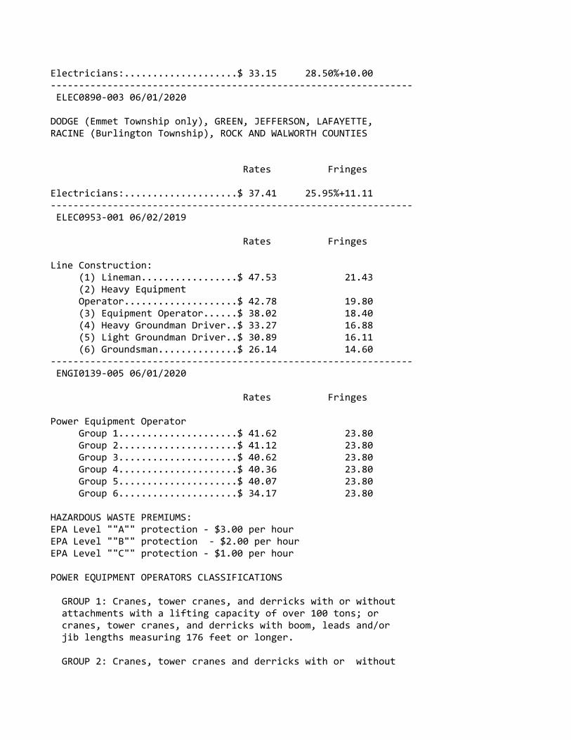
Electricians:....................$ 33.15 28.50%+10.00‐‐‐‐‐‐‐‐‐‐‐‐‐‐‐‐‐‐‐‐‐‐‐‐‐‐‐‐‐‐‐‐‐‐‐‐‐‐‐‐‐‐‐‐‐‐‐‐‐‐‐‐‐‐‐‐‐‐‐‐‐‐‐‐ ELEC0890‐003 06/01/2020
DODGE (Emmet Township only), GREEN, JEFFERSON, LAFAYETTE,RACINE (Burlington Township), ROCK AND WALWORTH COUNTIES
Rates Fringes
Electricians:....................$ 37.41 25.95%+11.11‐‐‐‐‐‐‐‐‐‐‐‐‐‐‐‐‐‐‐‐‐‐‐‐‐‐‐‐‐‐‐‐‐‐‐‐‐‐‐‐‐‐‐‐‐‐‐‐‐‐‐‐‐‐‐‐‐‐‐‐‐‐‐‐ ELEC0953‐001 06/02/2019
Rates Fringes
Line Construction: (1) Lineman.................$ 47.53 21.43 (2) Heavy Equipment Operator....................$ 42.78 19.80 (3) Equipment Operator......$ 38.02 18.40 (4) Heavy Groundman Driver..$ 33.27 16.88 (5) Light Groundman Driver..$ 30.89 16.11 (6) Groundsman..............$ 26.14 14.60‐‐‐‐‐‐‐‐‐‐‐‐‐‐‐‐‐‐‐‐‐‐‐‐‐‐‐‐‐‐‐‐‐‐‐‐‐‐‐‐‐‐‐‐‐‐‐‐‐‐‐‐‐‐‐‐‐‐‐‐‐‐‐‐ ENGI0139‐005 06/01/2020
Rates Fringes
Power Equipment Operator Group 1.....................$ 41.62 23.80 Group 2.....................$ 41.12 23.80 Group 3.....................$ 40.62 23.80 Group 4.....................$ 40.36 23.80 Group 5.....................$ 40.07 23.80 Group 6.....................$ 34.17 23.80
HAZARDOUS WASTE PREMIUMS:EPA Level ""A"" protection ‐ $3.00 per hourEPA Level ""B"" protection ‐ $2.00 per hourEPA Level ""C"" protection ‐ $1.00 per hour
POWER EQUIPMENT OPERATORS CLASSIFICATIONS
GROUP 1: Cranes, tower cranes, and derricks with or without attachments with a lifting capacity of over 100 tons; or cranes, tower cranes, and derricks with boom, leads and/or jib lengths measuring 176 feet or longer.
GROUP 2: Cranes, tower cranes and derricks with or without
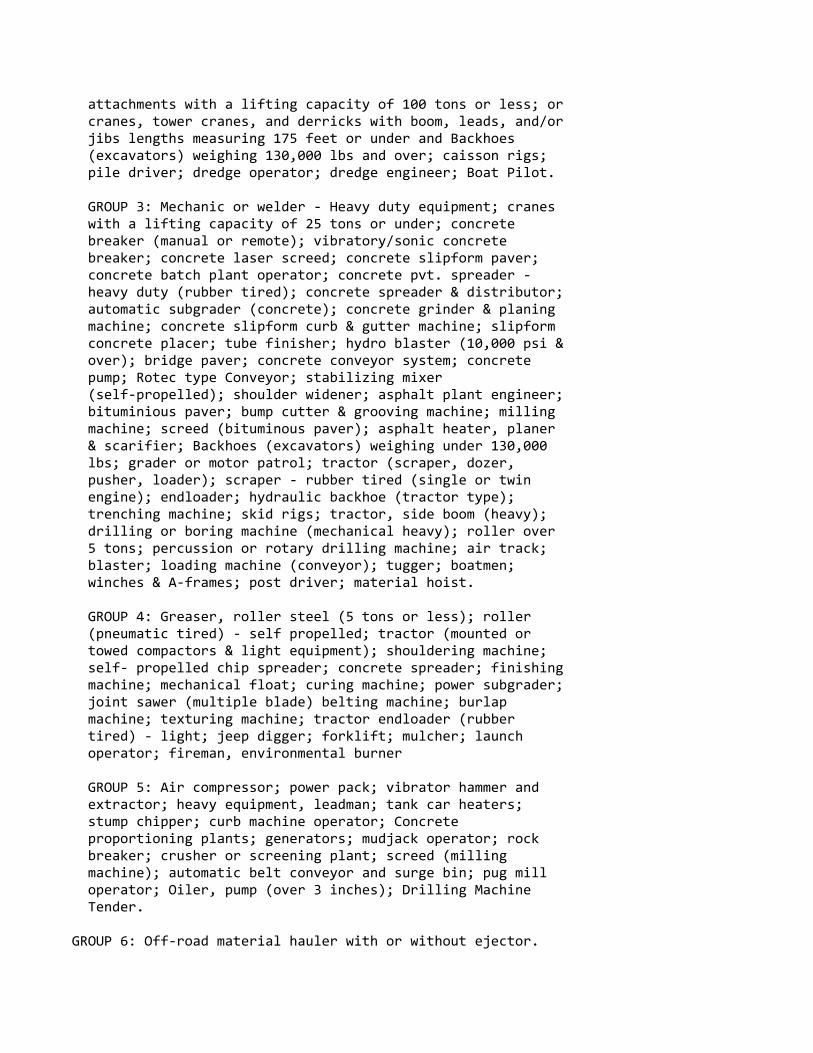
attachments with a lifting capacity of 100 tons or less; or cranes, tower cranes, and derricks with boom, leads, and/or jibs lengths measuring 175 feet or under and Backhoes (excavators) weighing 130,000 lbs and over; caisson rigs; pile driver; dredge operator; dredge engineer; Boat Pilot.
GROUP 3: Mechanic or welder ‐ Heavy duty equipment; cranes with a lifting capacity of 25 tons or under; concrete breaker (manual or remote); vibratory/sonic concrete breaker; concrete laser screed; concrete slipform paver; concrete batch plant operator; concrete pvt. spreader ‐ heavy duty (rubber tired); concrete spreader & distributor; automatic subgrader (concrete); concrete grinder & planing machine; concrete slipform curb & gutter machine; slipform concrete placer; tube finisher; hydro blaster (10,000 psi & over); bridge paver; concrete conveyor system; concrete pump; Rotec type Conveyor; stabilizing mixer (self‐propelled); shoulder widener; asphalt plant engineer; bituminious paver; bump cutter & grooving machine; milling machine; screed (bituminous paver); asphalt heater, planer & scarifier; Backhoes (excavators) weighing under 130,000 lbs; grader or motor patrol; tractor (scraper, dozer, pusher, loader); scraper ‐ rubber tired (single or twin engine); endloader; hydraulic backhoe (tractor type); trenching machine; skid rigs; tractor, side boom (heavy); drilling or boring machine (mechanical heavy); roller over 5 tons; percussion or rotary drilling machine; air track; blaster; loading machine (conveyor); tugger; boatmen; winches & A‐frames; post driver; material hoist.
GROUP 4: Greaser, roller steel (5 tons or less); roller (pneumatic tired) ‐ self propelled; tractor (mounted or towed compactors & light equipment); shouldering machine; self‐ propelled chip spreader; concrete spreader; finishing machine; mechanical float; curing machine; power subgrader; joint sawer (multiple blade) belting machine; burlap machine; texturing machine; tractor endloader (rubber tired) ‐ light; jeep digger; forklift; mulcher; launch operator; fireman, environmental burner
GROUP 5: Air compressor; power pack; vibrator hammer and extractor; heavy equipment, leadman; tank car heaters; stump chipper; curb machine operator; Concrete proportioning plants; generators; mudjack operator; rock breaker; crusher or screening plant; screed (milling machine); automatic belt conveyor and surge bin; pug mill operator; Oiler, pump (over 3 inches); Drilling Machine Tender.
GROUP 6: Off‐road material hauler with or without ejector.
‐‐‐‐‐‐‐‐‐‐‐‐‐‐‐‐‐‐‐‐‐‐‐‐‐‐‐‐‐‐‐‐‐‐‐‐‐‐‐‐‐‐‐‐‐‐‐‐‐‐‐‐‐‐‐‐‐‐‐‐‐‐‐‐* IRON0008‐002 06/01/2020
BROWN, CALUMET, DOOR, FOND DU LAC, KEWAUNEE, MANITOWOC,MARINETTE, OCONTO, OUTAGAMI, SHAWANO, SHEBOYGAN, AND WINNEBAGOCOUNTIES:
Rates Fringes
IRONWORKER.......................$ 37.31 27.62
Paid Holidays: New Year's Day, Memorial Day, July 4th, Labor Day, Thanksgiving Day & Christmas Day.
‐‐‐‐‐‐‐‐‐‐‐‐‐‐‐‐‐‐‐‐‐‐‐‐‐‐‐‐‐‐‐‐‐‐‐‐‐‐‐‐‐‐‐‐‐‐‐‐‐‐‐‐‐‐‐‐‐‐‐‐‐‐‐‐* IRON0008‐003 06/01/2020
KENOSHA, MILWAUKEE, OZAUKEE, RACINE, WALWORTH (N.E. 2/3),WASHINGTON, AND WAUKESHA COUNTIES
Rates Fringes
IRONWORKER.......................$ 39.11 27.87
Paid Holidays: New Year's Day, Memorial Day, July 4th, Labor Day, Thanksgiving Day & Christmas Day.
‐‐‐‐‐‐‐‐‐‐‐‐‐‐‐‐‐‐‐‐‐‐‐‐‐‐‐‐‐‐‐‐‐‐‐‐‐‐‐‐‐‐‐‐‐‐‐‐‐‐‐‐‐‐‐‐‐‐‐‐‐‐‐‐* IRON0383‐001 06/01/2020
ADAMS, COLUMBIA, CRAWFORD, DANE, DODGE, FLORENCE, FOREST,GRANT, GREENE, (Excluding S.E. tip), GREEN LAKE, IOWA,JEFFERSON, JUNEAU, LA CROSSE, LAFAYETTE, LANGLADE, MARATHON,MARQUETTE, MENOMINEE, MONROE, PORTAGE, RICHLAND, ROCK (Northernarea, vicinity of Edgerton and Milton), SAUK, VERNON, WAUPACA,WAUSHARA, AND WOOD COUNTIES
Rates Fringes
IRONWORKER.......................$ 37.10 27.06‐‐‐‐‐‐‐‐‐‐‐‐‐‐‐‐‐‐‐‐‐‐‐‐‐‐‐‐‐‐‐‐‐‐‐‐‐‐‐‐‐‐‐‐‐‐‐‐‐‐‐‐‐‐‐‐‐‐‐‐‐‐‐‐ IRON0498‐005 06/01/2019
GREEN (S.E. 1/3), ROCK (South of Edgerton and Milton), andWALWORTH (S.W. 1/3) COUNTIES:
Rates Fringes
IRONWORKER.......................$ 40.25 40.53‐‐‐‐‐‐‐‐‐‐‐‐‐‐‐‐‐‐‐‐‐‐‐‐‐‐‐‐‐‐‐‐‐‐‐‐‐‐‐‐‐‐‐‐‐‐‐‐‐‐‐‐‐‐‐‐‐‐‐‐‐‐‐‐ IRON0512‐008 06/03/2019
BARRON, BUFFALO, CHIPPEWA, CLARK, DUNN, EAU CLAIRE, JACKSON,PEPIN, PIERCE, POLK, RUSK, ST CROIX, TAYLOR, AND TREMPEALEAUCOUNTIES
Rates Fringes
IRONWORKER.......................$ 37.60 29.40‐‐‐‐‐‐‐‐‐‐‐‐‐‐‐‐‐‐‐‐‐‐‐‐‐‐‐‐‐‐‐‐‐‐‐‐‐‐‐‐‐‐‐‐‐‐‐‐‐‐‐‐‐‐‐‐‐‐‐‐‐‐‐‐ IRON0512‐021 06/03/2019
ASHLAND, BAYFIELD, BURNETT, DOUGLAS, IRON, LINCOLN, ONEIDA,PRICE, SAWYER, VILAS AND WASHBURN COUNTIES
Rates Fringes
IRONWORKER.......................$ 33.19 29.40‐‐‐‐‐‐‐‐‐‐‐‐‐‐‐‐‐‐‐‐‐‐‐‐‐‐‐‐‐‐‐‐‐‐‐‐‐‐‐‐‐‐‐‐‐‐‐‐‐‐‐‐‐‐‐‐‐‐‐‐‐‐‐‐ LABO0113‐002 06/03/2019
MILWAUKEE AND WAUKESHA COUNTIES
Rates Fringes
LABORER Group 1.....................$ 29.02 21.92 Group 2.....................$ 29.17 21.92 Group 3.....................$ 29.37 21.92 Group 4.....................$ 29.52 21.92 Group 5.....................$ 29.67 21.92 Group 6.....................$ 25.51 21.92
LABORERS CLASSIFICATIONS
GROUP 1: General Laborer; Tree Trimmer; Conduit Layer; Demolition and Wrecking Laborer; Guard Rail, Fence, and Bridge Builder; Landscaper; Multiplate Culvert Assembler; Stone Handler; Bituminous Worker (Shoveler, Loader, and Utility Man); Batch Truck Dumper or Cement Handler; Bituminous Worker (Dumper, Ironer, Smoother, and Tamper); Concrete Handler
GROUP 2: Air Tool Operator; Joint Sawer and Filler (Pavement); Vibrator or Tamper Operator (Mechanical Hand Operated); Chain Saw Operator; Demolition Burning Torch Laborer
GROUP 3: Bituminous Worker (Raker and Luteman); Formsetter (Curb, Sidewalk, and Pavement); Strike Off Man
GROUP 4: Line and Grade Specialist
GROUP 5: Blaster and Powderman
GROUP 6: Flagperson; traffic control person
‐‐‐‐‐‐‐‐‐‐‐‐‐‐‐‐‐‐‐‐‐‐‐‐‐‐‐‐‐‐‐‐‐‐‐‐‐‐‐‐‐‐‐‐‐‐‐‐‐‐‐‐‐‐‐‐‐‐‐‐‐‐‐‐ LABO0113‐003 06/03/2019
OZAUKEE AND WASHINGTON COUNTIES
Rates Fringes
LABORER Group 1.....................$ 28.27 21.92 Group 2.....................$ 28.37 21.92 Group 3.....................$ 28.42 21.92 Group 4.....................$ 28.62 21.92 Group 5.....................$ 28.47 21.92 Group 6.....................$ 25.36 21.92
LABORERS CLASSIFICATIONS
GROUP 1: General Laborer; Tree Trimmer; Conduit Layer; Demolition and Wrecking Laborer; Guard Rail, Fence, and Bridge Builder; Landscaper; Multiplate Culvert Assembler; Stone Handler; Bituminous Worker (Shoveler, Loader, and Utility Man); Batch Truck Dumper or Cement Handler; Bituminous Worker (Dumper, Ironer, Smoother, and Tamper); Concrete Handler
GROUP 2: Air Tool Operator; Joint Sawer and Filler (Pavement); Vibrator or Tamper Operator (Mechanical Hand Operated);
GROUP 3: Bituminous Worker (Raker and Luteman); Formsetter (Curb, Sidewalk, and Pavement); Strike Off Man
GROUP 4: Line and Grade Specialist
GROUP 5: Blaster; powderman
GROUP 6: Flagperson and Traffic Control Person
‐‐‐‐‐‐‐‐‐‐‐‐‐‐‐‐‐‐‐‐‐‐‐‐‐‐‐‐‐‐‐‐‐‐‐‐‐‐‐‐‐‐‐‐‐‐‐‐‐‐‐‐‐‐‐‐‐‐‐‐‐‐‐‐ LABO0113‐011 06/03/2019
KENOSHA AND RACINE COUNTIES
Rates Fringes
LABORER Group 1.....................$ 28.08 21.92 Group 2.....................$ 28.23 21.92 Group 3.....................$ 28.43 21.92 Group 4.....................$ 28.40 21.92 Group 5.....................$ 28.73 21.92 Group 6.....................$ 25.22 21.92
LABORERS CLASSIFICATIONS:
GROUP 1: General laborer; Tree Trimmer; Conduit Layer; Demolition and Wrecking Laborer; Guard Rail, Fence, and Bridge Builder; Landscaper; Multiplate Culvert Assembler; Stone Handler; Bituminous Worker (Shoveler, Loader, and Utility Man); Batch Truck Dumper or Cement Handler; Bituminous worker (Dumper, Ironer, Smoother, and Tamper); Concrete Handler
GROUP 2: Air Tool Operator; Joint Sawer and Filler (Pavement); Vibrator or Tamper Operator (Mechanical Hand Operated); Chain Saw Operator; Demolition Burning Torch Laborer
GROUP 3: Bituminous Worker (Raker and Luteman); Formsetter (Curb, Sidewalk, and Pavement); Strike Off Man
GROUP 4: Line and Grade Specialist
GROUP 5: Blaster and Powderman
GROUP 6: Flagman; traffic control person
‐‐‐‐‐‐‐‐‐‐‐‐‐‐‐‐‐‐‐‐‐‐‐‐‐‐‐‐‐‐‐‐‐‐‐‐‐‐‐‐‐‐‐‐‐‐‐‐‐‐‐‐‐‐‐‐‐‐‐‐‐‐‐‐ LABO0140‐002 06/03/2019
ADAMS, ASHLAND, BARRON, BAYFIELD, BROWN, BUFFALO, BURNETT,CALUMET, CHIPPEWA, CLARK, COLUMBIA, CRAWFORD, DODGE, DOOR,DOUGLAS, DUNN, EAU CLAIRE, FLORENCE, FOND DU LAC, FOREST,GRANT, GREEN, GREEN LAKE, IRON, JACKSON, JUNEAU, IOWA,JEFFERSON, KEWAUNEE, LA CROSSE, LAFAYETTE, LANGLADE, LINCOLN,MANITOWOC, MARATHON, MARINETTE, MARQUETTE, MENOMINEE, MONROE,

OCONTO, ONEIDA, OUTAGAMIE, PEPIN, PIERCE, POLK, PORTAGE, PRICE,RICHLAND, ROCK, RUSK, SAUK, SAWYER, SHAWANO, SHEBOYGAN, ST.CROIX, TAYLOR, TREMPEALEAU, VERNON, VILLAS, WALWORTH, WASHBURN,WAUPACA, WAUSHARA, WINNEBAGO, AND WOOD COUNTIES
Rates Fringes
LABORER Group 1.....................$ 32.84 17.54 Group 2.....................$ 32.94 17.54 Group 3.....................$ 32.99 17.54 Group 4.....................$ 33.19 17.54 Group 5.....................$ 33.04 17.54 Group 6.....................$ 29.47 17.54
LABORER CLASSIFICATIONS
GROUP 1: General Laborer; Tree Trimmer; Conduit Layer; Demolition and Wrecking Laborer; Guard Rail, Fence, and Bridge Builder; Landscaper; Multiplate Culvert Assembler; Stone Handler; Bitminous Worker (Shoveler, Loader, and Utility Man); Batch Truck Dumper or Cement Handler; Bituminous Worker (Dumper, Ironer, Smoother and Tamper); Concrete Handler
GROUP 2: Air Tool Operator; Joint Sawer and Filler (Pavement); Vibrator or Tamper Operator (Mechanical Hand Operated); Chain Saw Operator, Demolition Burning Torch Laborer
GROUP 3: Bituminous Worker (Raker and Luteman); Formsetter (Curb, Sidewalk and Pavement); Strike Off Man
GROUP 4: Line and Grade Secialist
GROUP 5: Blaster; powderman
GROUP 6: Flagperson; Traffic Control
‐‐‐‐‐‐‐‐‐‐‐‐‐‐‐‐‐‐‐‐‐‐‐‐‐‐‐‐‐‐‐‐‐‐‐‐‐‐‐‐‐‐‐‐‐‐‐‐‐‐‐‐‐‐‐‐‐‐‐‐‐‐‐‐ LABO0464‐003 06/03/2019
DANE COUNTY
Rates Fringes
LABORER Group 1.....................$ 33.12 17.54 Group 2.....................$ 33.22 17.54
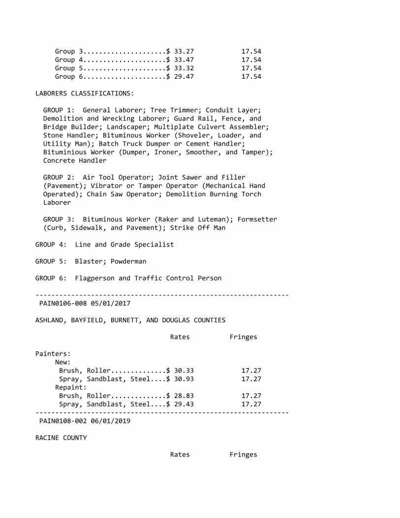
Group 3.....................$ 33.27 17.54 Group 4.....................$ 33.47 17.54 Group 5.....................$ 33.32 17.54 Group 6.....................$ 29.47 17.54
LABORERS CLASSIFICATIONS:
GROUP 1: General Laborer; Tree Trimmer; Conduit Layer; Demolition and Wrecking Laborer; Guard Rail, Fence, and Bridge Builder; Landscaper; Multiplate Culvert Assembler; Stone Handler; Bituminous Worker (Shoveler, Loader, and Utility Man); Batch Truck Dumper or Cement Handler; Bituminious Worker (Dumper, Ironer, Smoother, and Tamper); Concrete Handler
GROUP 2: Air Tool Operator; Joint Sawer and Filler (Pavement); Vibrator or Tamper Operator (Mechanical Hand Operated); Chain Saw Operator; Demolition Burning Torch Laborer
GROUP 3: Bituminous Worker (Raker and Luteman); Formsetter (Curb, Sidewalk, and Pavement); Strike Off Man
GROUP 4: Line and Grade Specialist
GROUP 5: Blaster; Powderman
GROUP 6: Flagperson and Traffic Control Person
‐‐‐‐‐‐‐‐‐‐‐‐‐‐‐‐‐‐‐‐‐‐‐‐‐‐‐‐‐‐‐‐‐‐‐‐‐‐‐‐‐‐‐‐‐‐‐‐‐‐‐‐‐‐‐‐‐‐‐‐‐‐‐‐ PAIN0106‐008 05/01/2017
ASHLAND, BAYFIELD, BURNETT, AND DOUGLAS COUNTIES
Rates Fringes
Painters: New: Brush, Roller..............$ 30.33 17.27 Spray, Sandblast, Steel....$ 30.93 17.27 Repaint: Brush, Roller..............$ 28.83 17.27 Spray, Sandblast, Steel....$ 29.43 17.27‐‐‐‐‐‐‐‐‐‐‐‐‐‐‐‐‐‐‐‐‐‐‐‐‐‐‐‐‐‐‐‐‐‐‐‐‐‐‐‐‐‐‐‐‐‐‐‐‐‐‐‐‐‐‐‐‐‐‐‐‐‐‐‐ PAIN0108‐002 06/01/2019
RACINE COUNTY
Rates Fringes
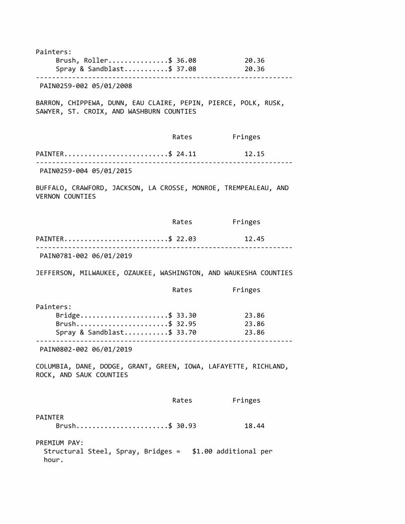
Painters: Brush, Roller...............$ 36.08 20.36 Spray & Sandblast...........$ 37.08 20.36‐‐‐‐‐‐‐‐‐‐‐‐‐‐‐‐‐‐‐‐‐‐‐‐‐‐‐‐‐‐‐‐‐‐‐‐‐‐‐‐‐‐‐‐‐‐‐‐‐‐‐‐‐‐‐‐‐‐‐‐‐‐‐‐ PAIN0259‐002 05/01/2008
BARRON, CHIPPEWA, DUNN, EAU CLAIRE, PEPIN, PIERCE, POLK, RUSK,SAWYER, ST. CROIX, AND WASHBURN COUNTIES
Rates Fringes
PAINTER..........................$ 24.11 12.15‐‐‐‐‐‐‐‐‐‐‐‐‐‐‐‐‐‐‐‐‐‐‐‐‐‐‐‐‐‐‐‐‐‐‐‐‐‐‐‐‐‐‐‐‐‐‐‐‐‐‐‐‐‐‐‐‐‐‐‐‐‐‐‐ PAIN0259‐004 05/01/2015
BUFFALO, CRAWFORD, JACKSON, LA CROSSE, MONROE, TREMPEALEAU, ANDVERNON COUNTIES
Rates Fringes
PAINTER..........................$ 22.03 12.45‐‐‐‐‐‐‐‐‐‐‐‐‐‐‐‐‐‐‐‐‐‐‐‐‐‐‐‐‐‐‐‐‐‐‐‐‐‐‐‐‐‐‐‐‐‐‐‐‐‐‐‐‐‐‐‐‐‐‐‐‐‐‐‐ PAIN0781‐002 06/01/2019
JEFFERSON, MILWAUKEE, OZAUKEE, WASHINGTON, AND WAUKESHA COUNTIES
Rates Fringes
Painters: Bridge......................$ 33.30 23.86 Brush.......................$ 32.95 23.86 Spray & Sandblast...........$ 33.70 23.86‐‐‐‐‐‐‐‐‐‐‐‐‐‐‐‐‐‐‐‐‐‐‐‐‐‐‐‐‐‐‐‐‐‐‐‐‐‐‐‐‐‐‐‐‐‐‐‐‐‐‐‐‐‐‐‐‐‐‐‐‐‐‐‐ PAIN0802‐002 06/01/2019
COLUMBIA, DANE, DODGE, GRANT, GREEN, IOWA, LAFAYETTE, RICHLAND,ROCK, AND SAUK COUNTIES
Rates Fringes
PAINTER Brush.......................$ 30.93 18.44
PREMIUM PAY: Structural Steel, Spray, Bridges = $1.00 additional per hour.

‐‐‐‐‐‐‐‐‐‐‐‐‐‐‐‐‐‐‐‐‐‐‐‐‐‐‐‐‐‐‐‐‐‐‐‐‐‐‐‐‐‐‐‐‐‐‐‐‐‐‐‐‐‐‐‐‐‐‐‐‐‐‐‐ PAIN0802‐003 06/01/2019
ADAMS, BROWN, CALUMET, CLARK, DOOR, FOND DU LAC, FOREST, GREENLAKE, IRON, JUNEAU, KEWAUNEE, LANGLADE, LINCOLN, MANITOWOC,MARATHON, MARINETTE, MARQUETTE, MENOMINEE, OCONTO, ONEIDA,OUTAGAMIE, PORTAGE, PRICE, SHAWANO, SHEBOYGAN, TAYLOR, VILAS,WAUSHARA, WAUPACA, WINNEBAGO, AND WOOD COUNTIES
Rates Fringes
PAINTER..........................$ 30.93 18.58‐‐‐‐‐‐‐‐‐‐‐‐‐‐‐‐‐‐‐‐‐‐‐‐‐‐‐‐‐‐‐‐‐‐‐‐‐‐‐‐‐‐‐‐‐‐‐‐‐‐‐‐‐‐‐‐‐‐‐‐‐‐‐‐ PAIN0934‐001 06/01/2017
KENOSHA AND WALWORTH COUNTIES
Rates Fringes
Painters: Brush.......................$ 33.74 18.95 Spray.......................$ 34.74 18.95 Structural Steel............$ 33.89 18.95‐‐‐‐‐‐‐‐‐‐‐‐‐‐‐‐‐‐‐‐‐‐‐‐‐‐‐‐‐‐‐‐‐‐‐‐‐‐‐‐‐‐‐‐‐‐‐‐‐‐‐‐‐‐‐‐‐‐‐‐‐‐‐‐ PAIN1011‐002 06/02/2019
FLORENCE COUNTY
Rates Fringes
Painters:........................$ 25.76 13.33‐‐‐‐‐‐‐‐‐‐‐‐‐‐‐‐‐‐‐‐‐‐‐‐‐‐‐‐‐‐‐‐‐‐‐‐‐‐‐‐‐‐‐‐‐‐‐‐‐‐‐‐‐‐‐‐‐‐‐‐‐‐‐‐ PLAS0599‐010 06/01/2017
Rates Fringes
CEMENT MASON/CONCRETE FINISHER Area 1......................$ 39.46 17.17 Area 2 (BAC)................$ 35.07 19.75 Area 3......................$ 35.61 19.40 Area 4......................$ 34.70 20.51 Area 5......................$ 36.27 18.73 Area 6......................$ 32.02 22.99
AREA DESCRIPTIONS
AREA 1: BAYFIELD, DOUGLAS, PRICE, SAWYER, AND WASHBURN COUNTIES

AREA 2: ADAMS, ASHLAND, BARRON, BROWN, BURNETT, CALUMET, CHIPPEWA, CLARK, COLUMBIA, DODGE, DOOR, DUNN, FLORENCE, FOND DU LAC, FOREST, GREEN LAKE, IRON, JEFFERSON, KEWAUNEE, LANGLADE, LINCOLN, MANITOWOC, MARATHON, MARINETTE, MARQUETTE, MENOMINEE, OCONTO, ONEIDA, OUTAGAMIE, POLK, PORTAGE, RUSK, ST CROIX, SAUK, SHAWANO, SHEBOYGAN, TAYLOR, VILAS, WALWORTH, WAUPACA, WAUSHARA, WINNEBAGO, AND WOOD COUNTIES
AREA 3: BUFFALO, CRAWFORD, EAU CLAIRE, JACKSON, JUNEAU, LA CROSSE MONROE, PEPIN, PIERCE, RICHLAND, TREMPEALEAU, AND VERNON COUNTIES
AREA 4: MILWAUKEE, OZAUKEE, WASHINGTON, AND WAUKESHA COUNTIES
AREA 5: DANE, GRANT, GREEN, IOWA, LAFAYETTE, AND ROCK COUNTIES
AREA 6: KENOSHA AND RACINE COUNTIES
‐‐‐‐‐‐‐‐‐‐‐‐‐‐‐‐‐‐‐‐‐‐‐‐‐‐‐‐‐‐‐‐‐‐‐‐‐‐‐‐‐‐‐‐‐‐‐‐‐‐‐‐‐‐‐‐‐‐‐‐‐‐‐‐ TEAM0039‐001 06/01/2019
Rates Fringes
TRUCK DRIVER 1 & 2 Axles.................$ 29.57 22.03 3 or more Axles; Euclids Dumptor & Articulated, Truck Mechanic..............$ 29.72 22.03 ‐‐‐‐‐‐‐‐‐‐‐‐‐‐‐‐‐‐‐‐‐‐‐‐‐‐‐‐‐‐‐‐‐‐‐‐‐‐‐‐‐‐‐‐‐‐‐‐‐‐‐‐‐‐‐‐‐‐‐‐WELL DRILLER.....................$ 16.52 3.70‐‐‐‐‐‐‐‐‐‐‐‐‐‐‐‐‐‐‐‐‐‐‐‐‐‐‐‐‐‐‐‐‐‐‐‐‐‐‐‐‐‐‐‐‐‐‐‐‐‐‐‐‐‐‐‐‐‐‐‐‐‐‐‐
WELDERS ‐ Receive rate prescribed for craft performingoperation to which welding is incidental.
================================================================ Note: Executive Order (EO) 13706, Establishing Paid Sick Leavefor Federal Contractors applies to all contracts subject to theDavis‐Bacon Act for which the contract is awarded (and anysolicitation was issued) on or after January 1, 2017. If thiscontract is covered by the EO, the contractor must provideemployees with 1 hour of paid sick leave for every 30 hoursthey work, up to 56 hours of paid sick leave each year.Employees must be permitted to use paid sick leave for theirown illness, injury or other health‐related needs, includingpreventive care; to assist a family member (or person who is

like family to the employee) who is ill, injured, or has otherhealth‐related needs, including preventive care; or for reasonsresulting from, or to assist a family member (or person who islike family to the employee) who is a victim of, domesticviolence, sexual assault, or stalking. Additional informationon contractor requirements and worker protections under the EOis available at www.dol.gov/whd/govcontracts.
Unlisted classifications needed for work not included withinthe scope of the classifications listed may be added afteraward only as provided in the labor standards contract clauses(29CFR 5.5 (a) (1) (ii)).
‐‐‐‐‐‐‐‐‐‐‐‐‐‐‐‐‐‐‐‐‐‐‐‐‐‐‐‐‐‐‐‐‐‐‐‐‐‐‐‐‐‐‐‐‐‐‐‐‐‐‐‐‐‐‐‐‐‐‐‐‐‐‐‐
The body of each wage determination lists the classificationand wage rates that have been found to be prevailing for thecited type(s) of construction in the area covered by the wagedetermination. The classifications are listed in alphabeticalorder of ""identifiers"" that indicate whether the particularrate is a union rate (current union negotiated rate for local),a survey rate (weighted average rate) or a union average rate(weighted union average rate).
Union Rate Identifiers
A four letter classification abbreviation identifier enclosedin dotted lines beginning with characters other than ""SU"" or""UAVG"" denotes that the union classification and rate wereprevailing for that classification in the survey. Example:PLUM0198‐005 07/01/2014. PLUM is an abbreviation identifier ofthe union which prevailed in the survey for thisclassification, which in this example would be Plumbers. 0198indicates the local union number or district council numberwhere applicable, i.e., Plumbers Local 0198. The next number,005 in the example, is an internal number used in processingthe wage determination. 07/01/2014 is the effective date of themost current negotiated rate, which in this example is July 1,2014.
Union prevailing wage rates are updated to reflect all ratechanges in the collective bargaining agreement (CBA) governingthis classification and rate.
Survey Rate Identifiers
Classifications listed under the ""SU"" identifier indicate thatno one rate prevailed for this classification in the survey and
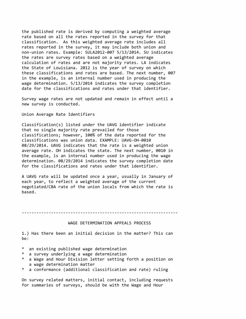
the published rate is derived by computing a weighted averagerate based on all the rates reported in the survey for thatclassification. As this weighted average rate includes allrates reported in the survey, it may include both union andnon‐union rates. Example: SULA2012‐007 5/13/2014. SU indicatesthe rates are survey rates based on a weighted averagecalculation of rates and are not majority rates. LA indicatesthe State of Louisiana. 2012 is the year of survey on whichthese classifications and rates are based. The next number, 007in the example, is an internal number used in producing thewage determination. 5/13/2014 indicates the survey completiondate for the classifications and rates under that identifier.
Survey wage rates are not updated and remain in effect until anew survey is conducted.
Union Average Rate Identifiers
Classification(s) listed under the UAVG identifier indicatethat no single majority rate prevailed for thoseclassifications; however, 100% of the data reported for theclassifications was union data. EXAMPLE: UAVG‐OH‐001008/29/2014. UAVG indicates that the rate is a weighted unionaverage rate. OH indicates the state. The next number, 0010 inthe example, is an internal number used in producing the wagedetermination. 08/29/2014 indicates the survey completion datefor the classifications and rates under that identifier.
A UAVG rate will be updated once a year, usually in January ofeach year, to reflect a weighted average of the currentnegotiated/CBA rate of the union locals from which the rate isbased.
‐‐‐‐‐‐‐‐‐‐‐‐‐‐‐‐‐‐‐‐‐‐‐‐‐‐‐‐‐‐‐‐‐‐‐‐‐‐‐‐‐‐‐‐‐‐‐‐‐‐‐‐‐‐‐‐‐‐‐‐‐‐‐‐
WAGE DETERMINATION APPEALS PROCESS
1.) Has there been an initial decision in the matter? This canbe:
* an existing published wage determination* a survey underlying a wage determination* a Wage and Hour Division letter setting forth a position on a wage determination matter* a conformance (additional classification and rate) ruling
On survey related matters, initial contact, including requestsfor summaries of surveys, should be with the Wage and Hour

Regional Office for the area in which the survey was conductedbecause those Regional Offices have responsibility for theDavis‐Bacon survey program. If the response from this initialcontact is not satisfactory, then the process described in 2.)and 3.) should be followed.
With regard to any other matter not yet ripe for the formalprocess described here, initial contact should be with theBranch of Construction Wage Determinations. Write to:
Branch of Construction Wage Determinations Wage and Hour Division U.S. Department of Labor 200 Constitution Avenue, N.W. Washington, DC 20210
2.) If the answer to the question in 1.) is yes, then aninterested party (those affected by the action) can requestreview and reconsideration from the Wage and Hour Administrator(See 29 CFR Part 1.8 and 29 CFR Part 7). Write to:
Wage and Hour Administrator U.S. Department of Labor 200 Constitution Avenue, N.W. Washington, DC 20210
The request should be accompanied by a full statement of theinterested party's position and by any information (wagepayment data, project description, area practice material,etc.) that the requestor considers relevant to the issue.
3.) If the decision of the Administrator is not favorable, aninterested party may appeal directly to the AdministrativeReview Board (formerly the Wage Appeals Board). Write to:
Administrative Review Board U.S. Department of Labor 200 Constitution Avenue, N.W. Washington, DC 20210
4.) All decisions by the Administrative Review Board are final.
================================================================
END OF GENERAL DECISION"

"General Decision Number: WI20200015 06/19/2020
Superseded General Decision Number: WI20190015
State: Wisconsin
Construction Type: Heavy
Counties: Wisconsin Statewide.
HEAVY CONSTRUCTION PROJECTS (Excluding Tunnel, Sewer, and WaterLines).
Note: Under Executive Order (EO) 13658, an hourly minimum wageof $10.80 for calendar year 2020 applies to all contractssubject to the Davis‐Bacon Act for which the contract isawarded (and any solicitation was issued) on or after January1, 2015. If this contract is covered by the EO, the contractormust pay all workers in any classification listed on this wagedetermination at least $10.80 per hour (or the applicable wagerate listed on this wage determination, if it is higher) forall hours spent performing on the contract in calendar year2020. If this contract is covered by the EO and aclassification considered necessary for performance of work onthe contract does not appear on this wage determination, thecontractor must pay workers in that classification at least thewage rate determined through the conformance process set forthin 29 CFR 5.5(a)(1)(ii) (or the EO minimum wage rate,if it ishigher than the conformed wage rate). The EO minimum wage ratewill be adjusted annually. Please note that this EO applies tothe above‐mentioned types of contracts entered into by thefederal government that are subject to the Davis‐Bacon Actitself, but it does not apply to contracts subject only to theDavis‐Bacon Related Acts, including those set forth at 29 CFR5.1(a)(2)‐(60). Additional information on contractorrequirements and worker protections under the EO is availableat www.dol.gov/whd/govcontracts.
Modification Number Publication Date 0 01/03/2020 1 01/24/2020 2 02/28/2020 3 03/06/2020 4 06/05/2020 5 06/12/2020 6 06/19/2020
BOIL0107‐001 01/01/2017
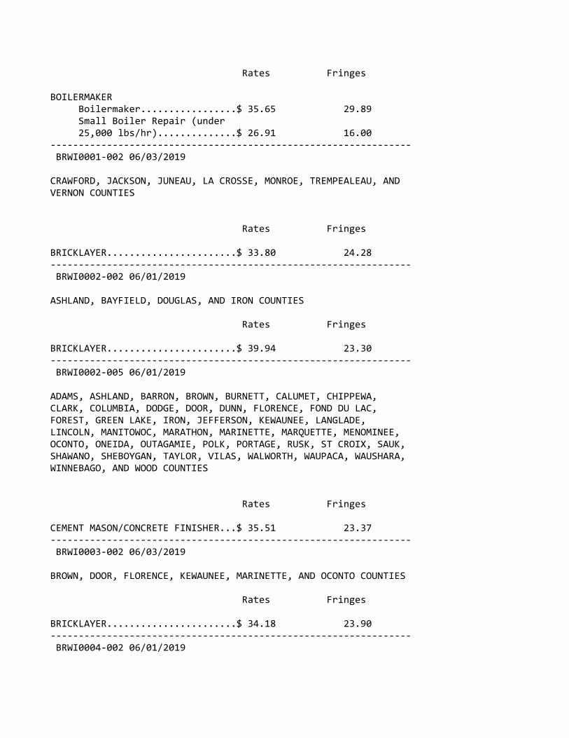
Rates Fringes
BOILERMAKER Boilermaker.................$ 35.65 29.89 Small Boiler Repair (under 25,000 lbs/hr)..............$ 26.91 16.00‐‐‐‐‐‐‐‐‐‐‐‐‐‐‐‐‐‐‐‐‐‐‐‐‐‐‐‐‐‐‐‐‐‐‐‐‐‐‐‐‐‐‐‐‐‐‐‐‐‐‐‐‐‐‐‐‐‐‐‐‐‐‐‐ BRWI0001‐002 06/03/2019
CRAWFORD, JACKSON, JUNEAU, LA CROSSE, MONROE, TREMPEALEAU, ANDVERNON COUNTIES
Rates Fringes
BRICKLAYER.......................$ 33.80 24.28‐‐‐‐‐‐‐‐‐‐‐‐‐‐‐‐‐‐‐‐‐‐‐‐‐‐‐‐‐‐‐‐‐‐‐‐‐‐‐‐‐‐‐‐‐‐‐‐‐‐‐‐‐‐‐‐‐‐‐‐‐‐‐‐ BRWI0002‐002 06/01/2019
ASHLAND, BAYFIELD, DOUGLAS, AND IRON COUNTIES
Rates Fringes
BRICKLAYER.......................$ 39.94 23.30‐‐‐‐‐‐‐‐‐‐‐‐‐‐‐‐‐‐‐‐‐‐‐‐‐‐‐‐‐‐‐‐‐‐‐‐‐‐‐‐‐‐‐‐‐‐‐‐‐‐‐‐‐‐‐‐‐‐‐‐‐‐‐‐ BRWI0002‐005 06/01/2019
ADAMS, ASHLAND, BARRON, BROWN, BURNETT, CALUMET, CHIPPEWA,CLARK, COLUMBIA, DODGE, DOOR, DUNN, FLORENCE, FOND DU LAC,FOREST, GREEN LAKE, IRON, JEFFERSON, KEWAUNEE, LANGLADE,LINCOLN, MANITOWOC, MARATHON, MARINETTE, MARQUETTE, MENOMINEE,OCONTO, ONEIDA, OUTAGAMIE, POLK, PORTAGE, RUSK, ST CROIX, SAUK,SHAWANO, SHEBOYGAN, TAYLOR, VILAS, WALWORTH, WAUPACA, WAUSHARA,WINNEBAGO, AND WOOD COUNTIES
Rates Fringes
CEMENT MASON/CONCRETE FINISHER...$ 35.51 23.37‐‐‐‐‐‐‐‐‐‐‐‐‐‐‐‐‐‐‐‐‐‐‐‐‐‐‐‐‐‐‐‐‐‐‐‐‐‐‐‐‐‐‐‐‐‐‐‐‐‐‐‐‐‐‐‐‐‐‐‐‐‐‐‐ BRWI0003‐002 06/03/2019
BROWN, DOOR, FLORENCE, KEWAUNEE, MARINETTE, AND OCONTO COUNTIES
Rates Fringes
BRICKLAYER.......................$ 34.18 23.90‐‐‐‐‐‐‐‐‐‐‐‐‐‐‐‐‐‐‐‐‐‐‐‐‐‐‐‐‐‐‐‐‐‐‐‐‐‐‐‐‐‐‐‐‐‐‐‐‐‐‐‐‐‐‐‐‐‐‐‐‐‐‐‐ BRWI0004‐002 06/01/2019
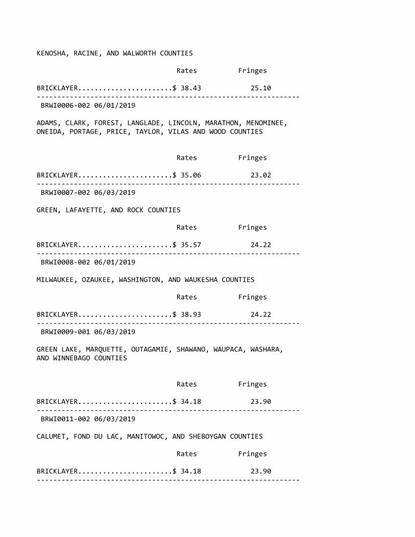
KENOSHA, RACINE, AND WALWORTH COUNTIES
Rates Fringes
BRICKLAYER.......................$ 38.43 25.10‐‐‐‐‐‐‐‐‐‐‐‐‐‐‐‐‐‐‐‐‐‐‐‐‐‐‐‐‐‐‐‐‐‐‐‐‐‐‐‐‐‐‐‐‐‐‐‐‐‐‐‐‐‐‐‐‐‐‐‐‐‐‐‐ BRWI0006‐002 06/01/2019
ADAMS, CLARK, FOREST, LANGLADE, LINCOLN, MARATHON, MENOMINEE,ONEIDA, PORTAGE, PRICE, TAYLOR, VILAS AND WOOD COUNTIES
Rates Fringes
BRICKLAYER.......................$ 35.06 23.02‐‐‐‐‐‐‐‐‐‐‐‐‐‐‐‐‐‐‐‐‐‐‐‐‐‐‐‐‐‐‐‐‐‐‐‐‐‐‐‐‐‐‐‐‐‐‐‐‐‐‐‐‐‐‐‐‐‐‐‐‐‐‐‐ BRWI0007‐002 06/03/2019
GREEN, LAFAYETTE, AND ROCK COUNTIES
Rates Fringes
BRICKLAYER.......................$ 35.57 24.22‐‐‐‐‐‐‐‐‐‐‐‐‐‐‐‐‐‐‐‐‐‐‐‐‐‐‐‐‐‐‐‐‐‐‐‐‐‐‐‐‐‐‐‐‐‐‐‐‐‐‐‐‐‐‐‐‐‐‐‐‐‐‐‐ BRWI0008‐002 06/01/2019
MILWAUKEE, OZAUKEE, WASHINGTON, AND WAUKESHA COUNTIES
Rates Fringes
BRICKLAYER.......................$ 38.93 24.22‐‐‐‐‐‐‐‐‐‐‐‐‐‐‐‐‐‐‐‐‐‐‐‐‐‐‐‐‐‐‐‐‐‐‐‐‐‐‐‐‐‐‐‐‐‐‐‐‐‐‐‐‐‐‐‐‐‐‐‐‐‐‐‐ BRWI0009‐001 06/03/2019
GREEN LAKE, MARQUETTE, OUTAGAMIE, SHAWANO, WAUPACA, WASHARA,AND WINNEBAGO COUNTIES
Rates Fringes
BRICKLAYER.......................$ 34.18 23.90‐‐‐‐‐‐‐‐‐‐‐‐‐‐‐‐‐‐‐‐‐‐‐‐‐‐‐‐‐‐‐‐‐‐‐‐‐‐‐‐‐‐‐‐‐‐‐‐‐‐‐‐‐‐‐‐‐‐‐‐‐‐‐‐ BRWI0011‐002 06/03/2019
CALUMET, FOND DU LAC, MANITOWOC, AND SHEBOYGAN COUNTIES
Rates Fringes
BRICKLAYER.......................$ 34.18 23.90‐‐‐‐‐‐‐‐‐‐‐‐‐‐‐‐‐‐‐‐‐‐‐‐‐‐‐‐‐‐‐‐‐‐‐‐‐‐‐‐‐‐‐‐‐‐‐‐‐‐‐‐‐‐‐‐‐‐‐‐‐‐‐‐

BRWI0013‐002 06/03/2019
DANE, GRANT, IOWA, AND RICHLAND COUNTIES
Rates Fringes
BRICKLAYER.......................$ 35.56 24.23‐‐‐‐‐‐‐‐‐‐‐‐‐‐‐‐‐‐‐‐‐‐‐‐‐‐‐‐‐‐‐‐‐‐‐‐‐‐‐‐‐‐‐‐‐‐‐‐‐‐‐‐‐‐‐‐‐‐‐‐‐‐‐‐ BRWI0019‐002 06/03/2019
BARRON, BUFFALO, BURNETT, CHIPPEWA, DUNN, EAU CLAIRE, PEPIN,PIERCE, POLK, RUSK, ST. CROIX, SAWYER AND WASHBURN COUNTIES
Rates Fringes
BRICKLAYER.......................$ 33.40 24.68‐‐‐‐‐‐‐‐‐‐‐‐‐‐‐‐‐‐‐‐‐‐‐‐‐‐‐‐‐‐‐‐‐‐‐‐‐‐‐‐‐‐‐‐‐‐‐‐‐‐‐‐‐‐‐‐‐‐‐‐‐‐‐‐ BRWI0021‐002 06/03/2019
DODGE AND JEFFERSON COUNTIES
Rates Fringes
BRICKLAYER.......................$ 35.75 24.02‐‐‐‐‐‐‐‐‐‐‐‐‐‐‐‐‐‐‐‐‐‐‐‐‐‐‐‐‐‐‐‐‐‐‐‐‐‐‐‐‐‐‐‐‐‐‐‐‐‐‐‐‐‐‐‐‐‐‐‐‐‐‐‐ BRWI0034‐002 06/03/2019
COLUMBIA AND SAUK COUNTIES
Rates Fringes
BRICKLAYER.......................$ 35.56 24.23‐‐‐‐‐‐‐‐‐‐‐‐‐‐‐‐‐‐‐‐‐‐‐‐‐‐‐‐‐‐‐‐‐‐‐‐‐‐‐‐‐‐‐‐‐‐‐‐‐‐‐‐‐‐‐‐‐‐‐‐‐‐‐‐ CARP0087‐001 05/01/2016
BURNETT (W. of Hwy 48), PIERCE (W. of Hwy 29), POLK (W. of Hwys35, 48 & 65), AND ST. CROIX (W. of Hwy 65) COUNTIES
Rates Fringes
Carpenter & Piledrivermen........$ 36.85 18.39‐‐‐‐‐‐‐‐‐‐‐‐‐‐‐‐‐‐‐‐‐‐‐‐‐‐‐‐‐‐‐‐‐‐‐‐‐‐‐‐‐‐‐‐‐‐‐‐‐‐‐‐‐‐‐‐‐‐‐‐‐‐‐‐ CARP0252‐002 06/01/2016
ADAMS, BARRON, BAYFIELD (Eastern 2/3), BROWN, BUFFALO,BURNETT (E. of Hwy 48), CALUMET, CHIPPEWA, CLARK, COLUMBIA,CRAWFORD, DANE, DODGE, DOOR, DUNN, EAU CLAIRE, FLORENCE (exceptarea bordering Michigan State Line), FOND DU LAC, FOREST,

GRANT, GREEN, GREEN LAKE, IOWA, IRON, JACKSON, JEFFERSON,JUNEAU, KEWAUNEE, LA CROSSE, LAFAYETTE, LANGLADE, LINCOLN,MANITOWOC, MARATHON, MARINETTE (except N.E. corner), MARQUETTE,MENOMINEE, MONROE, OCONTO, ONEIDA, OUTAGAMIE, PEPIN, PIERCE (E.of Hwys 29 & 65), POLK (E. of Hwys 35, 48 & 65), PORTAGE,PRICE, RICHLAND, ROCK, RUSK, SAUK, SAWYER, SHAWANO, SHEBOYGAN,ST CROIX (E. of Hwy 65), TAYLOR, TREMPEALEAU, VERNON, VILAS,WALWORTH, WASHBURN, WAUPACA, WAUSHARA, WINNEBAGO, AND WOODCOUNTIES
Rates Fringes
CARPENTER CARPENTER...................$ 33.56 18.00 MILLWRIGHT..................$ 35.08 18.35 PILEDRIVER..................$ 34.12 18.00‐‐‐‐‐‐‐‐‐‐‐‐‐‐‐‐‐‐‐‐‐‐‐‐‐‐‐‐‐‐‐‐‐‐‐‐‐‐‐‐‐‐‐‐‐‐‐‐‐‐‐‐‐‐‐‐‐‐‐‐‐‐‐‐ CARP0252‐010 06/01/2016
ASHLAND COUNTY
Rates Fringes
Carpenters Carpenter...................$ 33.56 18.00 Millwright..................$ 35.08 18.35 Pile Driver.................$ 34.12 18.00‐‐‐‐‐‐‐‐‐‐‐‐‐‐‐‐‐‐‐‐‐‐‐‐‐‐‐‐‐‐‐‐‐‐‐‐‐‐‐‐‐‐‐‐‐‐‐‐‐‐‐‐‐‐‐‐‐‐‐‐‐‐‐‐ CARP0264‐003 06/01/2016
KENOSHA, MILWAUKEE, OZAUKEE, RACINE, WAUKESHA, AND WASHINGTONCOUNTIES
Rates Fringes
CARPENTER........................$ 35.78 22.11‐‐‐‐‐‐‐‐‐‐‐‐‐‐‐‐‐‐‐‐‐‐‐‐‐‐‐‐‐‐‐‐‐‐‐‐‐‐‐‐‐‐‐‐‐‐‐‐‐‐‐‐‐‐‐‐‐‐‐‐‐‐‐‐ CARP0361‐004 05/01/2018
BAYFIELD (West of Hwy 63) AND DOUGLAS COUNTIES
Rates Fringes
CARPENTER........................$ 36.15 20.43‐‐‐‐‐‐‐‐‐‐‐‐‐‐‐‐‐‐‐‐‐‐‐‐‐‐‐‐‐‐‐‐‐‐‐‐‐‐‐‐‐‐‐‐‐‐‐‐‐‐‐‐‐‐‐‐‐‐‐‐‐‐‐‐ CARP2337‐001 06/01/2016
ZONE A: MILWAUKEE, OZAUKEE, WAUKESHA AND WASHINGTON
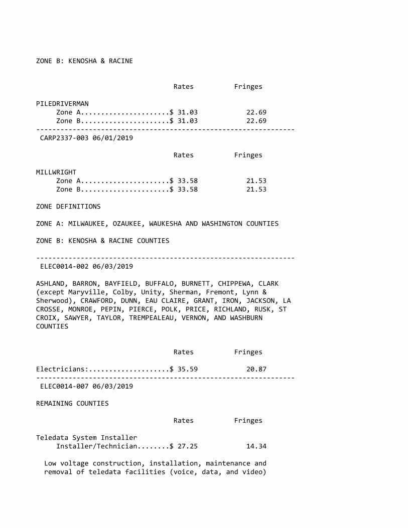
ZONE B: KENOSHA & RACINE
Rates Fringes
PILEDRIVERMAN Zone A......................$ 31.03 22.69 Zone B......................$ 31.03 22.69‐‐‐‐‐‐‐‐‐‐‐‐‐‐‐‐‐‐‐‐‐‐‐‐‐‐‐‐‐‐‐‐‐‐‐‐‐‐‐‐‐‐‐‐‐‐‐‐‐‐‐‐‐‐‐‐‐‐‐‐‐‐‐‐ CARP2337‐003 06/01/2019
Rates Fringes
MILLWRIGHT Zone A......................$ 33.58 21.53 Zone B......................$ 33.58 21.53
ZONE DEFINITIONS
ZONE A: MILWAUKEE, OZAUKEE, WAUKESHA AND WASHINGTON COUNTIES
ZONE B: KENOSHA & RACINE COUNTIES
‐‐‐‐‐‐‐‐‐‐‐‐‐‐‐‐‐‐‐‐‐‐‐‐‐‐‐‐‐‐‐‐‐‐‐‐‐‐‐‐‐‐‐‐‐‐‐‐‐‐‐‐‐‐‐‐‐‐‐‐‐‐‐‐ ELEC0014‐002 06/03/2019
ASHLAND, BARRON, BAYFIELD, BUFFALO, BURNETT, CHIPPEWA, CLARK(except Maryville, Colby, Unity, Sherman, Fremont, Lynn &Sherwood), CRAWFORD, DUNN, EAU CLAIRE, GRANT, IRON, JACKSON, LACROSSE, MONROE, PEPIN, PIERCE, POLK, PRICE, RICHLAND, RUSK, STCROIX, SAWYER, TAYLOR, TREMPEALEAU, VERNON, AND WASHBURNCOUNTIES
Rates Fringes
Electricians:....................$ 35.59 20.87‐‐‐‐‐‐‐‐‐‐‐‐‐‐‐‐‐‐‐‐‐‐‐‐‐‐‐‐‐‐‐‐‐‐‐‐‐‐‐‐‐‐‐‐‐‐‐‐‐‐‐‐‐‐‐‐‐‐‐‐‐‐‐‐ ELEC0014‐007 06/03/2019
REMAINING COUNTIES
Rates Fringes
Teledata System Installer Installer/Technician........$ 27.25 14.34
Low voltage construction, installation, maintenance and removal of teledata facilities (voice, data, and video)
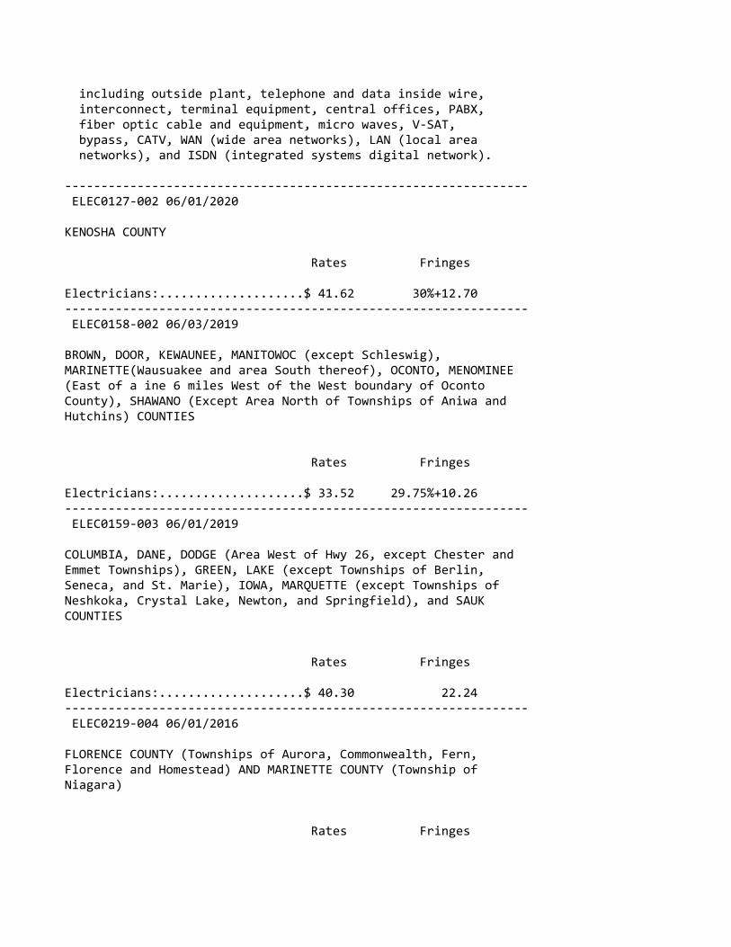
including outside plant, telephone and data inside wire, interconnect, terminal equipment, central offices, PABX, fiber optic cable and equipment, micro waves, V‐SAT, bypass, CATV, WAN (wide area networks), LAN (local area networks), and ISDN (integrated systems digital network).
‐‐‐‐‐‐‐‐‐‐‐‐‐‐‐‐‐‐‐‐‐‐‐‐‐‐‐‐‐‐‐‐‐‐‐‐‐‐‐‐‐‐‐‐‐‐‐‐‐‐‐‐‐‐‐‐‐‐‐‐‐‐‐‐ ELEC0127‐002 06/01/2020
KENOSHA COUNTY
Rates Fringes
Electricians:....................$ 41.62 30%+12.70‐‐‐‐‐‐‐‐‐‐‐‐‐‐‐‐‐‐‐‐‐‐‐‐‐‐‐‐‐‐‐‐‐‐‐‐‐‐‐‐‐‐‐‐‐‐‐‐‐‐‐‐‐‐‐‐‐‐‐‐‐‐‐‐ ELEC0158‐002 06/03/2019
BROWN, DOOR, KEWAUNEE, MANITOWOC (except Schleswig),MARINETTE(Wausuakee and area South thereof), OCONTO, MENOMINEE(East of a ine 6 miles West of the West boundary of OcontoCounty), SHAWANO (Except Area North of Townships of Aniwa andHutchins) COUNTIES
Rates Fringes
Electricians:....................$ 33.52 29.75%+10.26‐‐‐‐‐‐‐‐‐‐‐‐‐‐‐‐‐‐‐‐‐‐‐‐‐‐‐‐‐‐‐‐‐‐‐‐‐‐‐‐‐‐‐‐‐‐‐‐‐‐‐‐‐‐‐‐‐‐‐‐‐‐‐‐ ELEC0159‐003 06/01/2019
COLUMBIA, DANE, DODGE (Area West of Hwy 26, except Chester andEmmet Townships), GREEN, LAKE (except Townships of Berlin,Seneca, and St. Marie), IOWA, MARQUETTE (except Townships ofNeshkoka, Crystal Lake, Newton, and Springfield), and SAUKCOUNTIES
Rates Fringes
Electricians:....................$ 40.30 22.24‐‐‐‐‐‐‐‐‐‐‐‐‐‐‐‐‐‐‐‐‐‐‐‐‐‐‐‐‐‐‐‐‐‐‐‐‐‐‐‐‐‐‐‐‐‐‐‐‐‐‐‐‐‐‐‐‐‐‐‐‐‐‐‐ ELEC0219‐004 06/01/2016
FLORENCE COUNTY (Townships of Aurora, Commonwealth, Fern,Florence and Homestead) AND MARINETTE COUNTY (Township ofNiagara)
Rates Fringes
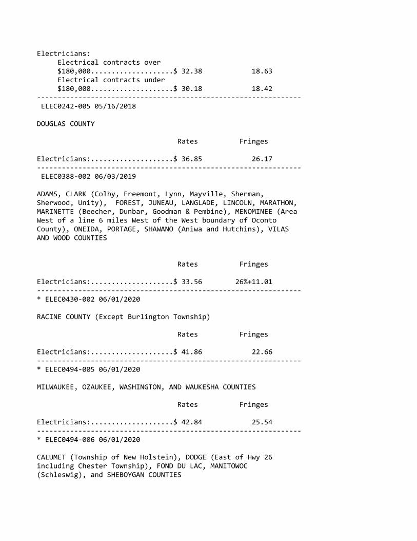
Electricians: Electrical contracts over $180,000....................$ 32.38 18.63 Electrical contracts under $180,000....................$ 30.18 18.42‐‐‐‐‐‐‐‐‐‐‐‐‐‐‐‐‐‐‐‐‐‐‐‐‐‐‐‐‐‐‐‐‐‐‐‐‐‐‐‐‐‐‐‐‐‐‐‐‐‐‐‐‐‐‐‐‐‐‐‐‐‐‐‐ ELEC0242‐005 05/16/2018
DOUGLAS COUNTY
Rates Fringes
Electricians:....................$ 36.85 26.17‐‐‐‐‐‐‐‐‐‐‐‐‐‐‐‐‐‐‐‐‐‐‐‐‐‐‐‐‐‐‐‐‐‐‐‐‐‐‐‐‐‐‐‐‐‐‐‐‐‐‐‐‐‐‐‐‐‐‐‐‐‐‐‐ ELEC0388‐002 06/03/2019
ADAMS, CLARK (Colby, Freemont, Lynn, Mayville, Sherman,Sherwood, Unity), FOREST, JUNEAU, LANGLADE, LINCOLN, MARATHON,MARINETTE (Beecher, Dunbar, Goodman & Pembine), MENOMINEE (AreaWest of a line 6 miles West of the West boundary of OcontoCounty), ONEIDA, PORTAGE, SHAWANO (Aniwa and Hutchins), VILASAND WOOD COUNTIES
Rates Fringes
Electricians:....................$ 33.56 26%+11.01‐‐‐‐‐‐‐‐‐‐‐‐‐‐‐‐‐‐‐‐‐‐‐‐‐‐‐‐‐‐‐‐‐‐‐‐‐‐‐‐‐‐‐‐‐‐‐‐‐‐‐‐‐‐‐‐‐‐‐‐‐‐‐‐* ELEC0430‐002 06/01/2020
RACINE COUNTY (Except Burlington Township)
Rates Fringes
Electricians:....................$ 41.86 22.66‐‐‐‐‐‐‐‐‐‐‐‐‐‐‐‐‐‐‐‐‐‐‐‐‐‐‐‐‐‐‐‐‐‐‐‐‐‐‐‐‐‐‐‐‐‐‐‐‐‐‐‐‐‐‐‐‐‐‐‐‐‐‐‐* ELEC0494‐005 06/01/2020
MILWAUKEE, OZAUKEE, WASHINGTON, AND WAUKESHA COUNTIES
Rates Fringes
Electricians:....................$ 42.84 25.54‐‐‐‐‐‐‐‐‐‐‐‐‐‐‐‐‐‐‐‐‐‐‐‐‐‐‐‐‐‐‐‐‐‐‐‐‐‐‐‐‐‐‐‐‐‐‐‐‐‐‐‐‐‐‐‐‐‐‐‐‐‐‐‐* ELEC0494‐006 06/01/2020
CALUMET (Township of New Holstein), DODGE (East of Hwy 26including Chester Township), FOND DU LAC, MANITOWOC(Schleswig), and SHEBOYGAN COUNTIES

Rates Fringes
Electricians:....................$ 36.32 22.51‐‐‐‐‐‐‐‐‐‐‐‐‐‐‐‐‐‐‐‐‐‐‐‐‐‐‐‐‐‐‐‐‐‐‐‐‐‐‐‐‐‐‐‐‐‐‐‐‐‐‐‐‐‐‐‐‐‐‐‐‐‐‐‐ ELEC0494‐013 06/01/2019
DODGE (East of Hwy 26 including Chester Twp, excluding EmmetTwp), FOND DU LAC (Except Waupuin), MILWAUKEE, OZAUKEE,MANITOWOC (Schleswig), WASHINGTON, AND WAUKESHA COUNTIES
Rates Fringes
Sound & Communications Installer...................$ 20.53 18.13 Technician..................$ 30.18 19.58
Installation, testing, maintenance, operation and servicing of all sound, intercom, telephone interconnect, closed circuit TV systems, radio systems, background music systems, language laboratories, electronic carillion, antenna distribution systems, clock and program systems and low‐voltage systems such as visual nurse call, audio/visual nurse call systems, doctors entrance register systems. Includes all wire and cable carrying audio, visual, data, light and radio frequency signals. Includes the installation of conduit, wiremold, or raceways in existing structures that have been occupied for six months or more where required for the protection of the wire or cable, but does not mean a complete conduit or raceway system. work covered does not include the installation of conduit, wiremold or any raceways in any new construction, or the installation of power supply outlets by means of which external electric power is supplied to any of the foregoing equipment or products
‐‐‐‐‐‐‐‐‐‐‐‐‐‐‐‐‐‐‐‐‐‐‐‐‐‐‐‐‐‐‐‐‐‐‐‐‐‐‐‐‐‐‐‐‐‐‐‐‐‐‐‐‐‐‐‐‐‐‐‐‐‐‐‐ ELEC0577‐003 06/01/2019
CALUMET (except Township of New Holstein), GREEN LAKE (N. partincluding Townships of Berlin, St Marie, and Seneca), MARQUETTE(N. part including Townships of Crystal Lake, Neshkoro, Newton,and Springfield), OUTAGAMIE, WAUPACA, WAUSHARA, AND WINNEBAGOCOUNTIES
Rates Fringes
Electricians:....................$ 33.15 28.50%+10.00
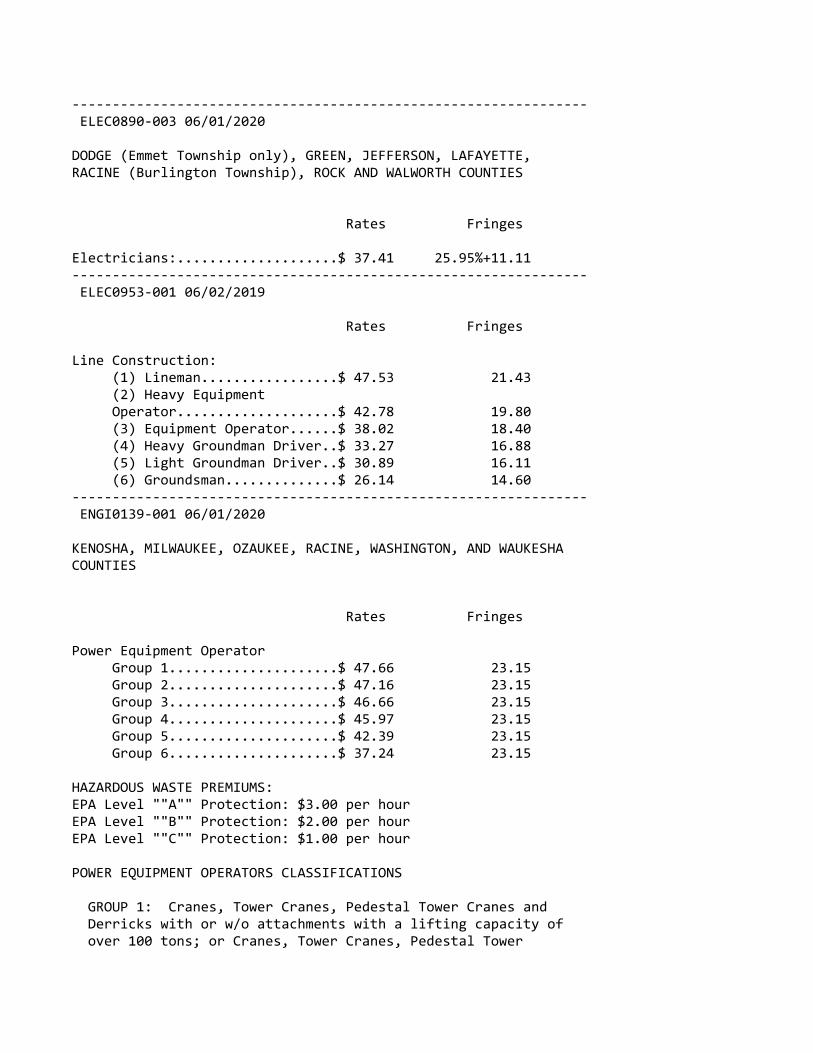
‐‐‐‐‐‐‐‐‐‐‐‐‐‐‐‐‐‐‐‐‐‐‐‐‐‐‐‐‐‐‐‐‐‐‐‐‐‐‐‐‐‐‐‐‐‐‐‐‐‐‐‐‐‐‐‐‐‐‐‐‐‐‐‐ ELEC0890‐003 06/01/2020
DODGE (Emmet Township only), GREEN, JEFFERSON, LAFAYETTE,RACINE (Burlington Township), ROCK AND WALWORTH COUNTIES
Rates Fringes
Electricians:....................$ 37.41 25.95%+11.11‐‐‐‐‐‐‐‐‐‐‐‐‐‐‐‐‐‐‐‐‐‐‐‐‐‐‐‐‐‐‐‐‐‐‐‐‐‐‐‐‐‐‐‐‐‐‐‐‐‐‐‐‐‐‐‐‐‐‐‐‐‐‐‐ ELEC0953‐001 06/02/2019
Rates Fringes
Line Construction: (1) Lineman.................$ 47.53 21.43 (2) Heavy Equipment Operator....................$ 42.78 19.80 (3) Equipment Operator......$ 38.02 18.40 (4) Heavy Groundman Driver..$ 33.27 16.88 (5) Light Groundman Driver..$ 30.89 16.11 (6) Groundsman..............$ 26.14 14.60‐‐‐‐‐‐‐‐‐‐‐‐‐‐‐‐‐‐‐‐‐‐‐‐‐‐‐‐‐‐‐‐‐‐‐‐‐‐‐‐‐‐‐‐‐‐‐‐‐‐‐‐‐‐‐‐‐‐‐‐‐‐‐‐ ENGI0139‐001 06/01/2020
KENOSHA, MILWAUKEE, OZAUKEE, RACINE, WASHINGTON, AND WAUKESHACOUNTIES
Rates Fringes
Power Equipment Operator Group 1.....................$ 47.66 23.15 Group 2.....................$ 47.16 23.15 Group 3.....................$ 46.66 23.15 Group 4.....................$ 45.97 23.15 Group 5.....................$ 42.39 23.15 Group 6.....................$ 37.24 23.15
HAZARDOUS WASTE PREMIUMS:EPA Level ""A"" Protection: $3.00 per hourEPA Level ""B"" Protection: $2.00 per hourEPA Level ""C"" Protection: $1.00 per hour
POWER EQUIPMENT OPERATORS CLASSIFICATIONS
GROUP 1: Cranes, Tower Cranes, Pedestal Tower Cranes and Derricks with or w/o attachments with a lifting capacity of over 100 tons; or Cranes, Tower Cranes, Pedestal Tower

Cranes and Derricks with boom, leads, and/or jib lengths measuring 176 feet or longer; Self‐Erecting Tower Cranes over 4000 lbs lifting capacity; All Cranes with Boom Dollies; Boring Machines (directional); Master Mechanic. $0.50 additional per hour per 100 tons or 100 ft of boom over 200 ft or lifting capacity of crane over 200 tons to a maximum of 300 tons or 300 ft. Thereafter an increase of $0.01 per ft or ton, whichever is greater.
GROUP 2: Cranes, Tower Cranes, Pedestal Tower Cranes and Derricks with or without attachments with a lifting capacity of 100 tons or less; or Cranes, Tower Cranes Portable Tower Cranes, Pedestal Tower Cranes and Derricks with boom, leadsand/or jib lengths measuring 175 feet or less; Backhoes (excavators) 130,000 lbs and over; Caisson Rigs; Pile Drivers; Boring Machines (vertical or horizontal), Versi‐Lift, Tri‐Lift, Gantry 20,000 lbs & over.
GROUP 3: Backhoe (excavator) under 130,000 lbs;Self‐erecting Tower Crane 4000 lbs & under lifting capacity;Traveling Crane (bridge type); Skid Rigs; Dredge Operator; Mechanic; Concrete Paver (over 27E); Concrete Spreader and Distributor; Forklift/ Telehandler (machinery‐ moving / steel erection); Hydro Blaster, 10,000 psi and over
GROUP 4: Material Hoists; Stack Hoists; Hydraulic Backhoe (tractor or truck mounted); Hydraulic Crane, 5 tons or under (tractor or truck mounted); Hoist (tuggers 5 tons & over); Hydro‐Excavators/Daylighters; Concrete Pumps Rotec type Conveyors; Tractor/Bulldozer/End Loader (over 40 hp); Motor Patrol; Scraper Operator; Sideboom; Straddle Carrier; Welder; Bituminous Plant and Paver Operator; Roller over 5 tons; Rail Leveling Machine (Railroad); Tie Placer; Tie Extractor; Tie Tamper; Stone Leveler; Rotary Drill Operator and Blaster; Percussion Drill Operator; Air Track Drill and/or Hammers; Gantrys (under 20,000 lbs); Tencher (wheel type or chain type having 8 inch or larger bucket); Milling Machine; Off‐Road Material Haulers.
GROUP 5: Backfiller; Concrete Auto Breaker (large); Concrete Finishing Machines (road type); Rubber Tired Roller; Concrete Batch Hopper; Concrete Conveyor Systems; Grout Pumps; Concrete Mixers (14S or over); Screw Type Pumps and Gypsum Pumps; Tractor, Bulldozer, End Loader (under 40 hp); Trencher (chain type, bucket under 8 inch); Industrial Locomotives; Rollers under 5 tons; Stump Grinder/Chipper (Large); Timber Equipment; Firemen (pile drivers and derricks); Personnel Hoist, Telehandler over 8000 lbs; Robotic Tool Carrier with or without attachments

GROUP 6: Tampers ‐ Compactors (riding type); Assistant Engineer; A‐Frames and Winch Trucks; Concrete Auto Breaker; Hydrohammers (small); Brooms and Sweepers; Hoist (tuggers under 5 tons); Boats (Tug, Safety, Work Barges, Launch); Shouldering Machine Operator; Prestress Machines; Screed Operator; Stone Crushers and Screening Plants; Screed Operators (milling machine), Farm or Industrial Tractor Mounted Equipment; Post Hole Digger; Fireman (asphalt plants); Air Compressors over 400 CFM; Generators, over 150 KW; Augers (vertical and horizontal); Air, Electric, Hydraulic Jacks (slipform); Skid Steer Loaders (with or without attachments); Boiler Operators (temporary heat); Refrigeration Plant/Freeze Machines; Power Pack Vibratory/Ultra Sound Drivers and Extractors; Welding Machines; Heaters (mechanical); Pumps; Winches (small electric); Oiler and Greaser; Rotary Drill Tender; Conveyor; Forklifts/Telehandler 8000 lbs & under; Elevators: Automatic Hoists; Pumps (well points); Combination Small Equipment Operators
‐‐‐‐‐‐‐‐‐‐‐‐‐‐‐‐‐‐‐‐‐‐‐‐‐‐‐‐‐‐‐‐‐‐‐‐‐‐‐‐‐‐‐‐‐‐‐‐‐‐‐‐‐‐‐‐‐‐‐‐‐‐‐‐ ENGI0139‐003 06/03/2019
REMAINING COUNTIES
Rates Fringes
Power Equipment Operator Group 1.....................$ 41.52 22.45 Group 2.....................$ 40.27 22.45 Group 3.....................$ 38.97 22.45 Group 4.....................$ 38.44 22.45 Group 5.....................$ 36.37 22.45 Group 6.....................$ 34.84 22.45
HAZARDOUS WASTE PREMIUMS:EPA Level ""A"" Protection: $3.00 per hourEPA Level ""B"" Protection: $2.00 per hourEPA Level ""C"" Protection: $1.00 per hour
POWER EQUIPMENT OPERATORS CLASSIFICATIONS
GROUP 1: Cranes, Tower Cranes and Derricks with or without attachments with a lifting capacity of over 100 tons; Cranes, Tower Cranes, and Derricks with boom, leads and/or jib lengths 176 ft or longer.
GROUP 2: Backhoes (Excavators) weighing 130,00 lbs and over; Cranes, Tower Cranes and Derricks with or without attachments with a lifting capacity of 100 tons or less;

Cranes, Tower Cranes, and Derricks with boom, leads, and/or jib lengths 175 ft or less; Caisson Rigs; Pile Driver
GROUP 3: Backhoes (Excavators) weighing under 130,000 lbs; Travelling Crane (bridge type); Milling Machine; Concrete Paver over 27 E; Concrete Spreader and Distributor; Concrete Laser Screed; Concrete Grinder and Planing Machine; Slipform Curb and Gutter Machine; Boring Machine (Directional); Dredge Operator; Skid Rigs; over 46 meter Concrete Pump.
GROUP 4: Hydraulic Backhoe (tractor or truck mounted); Hydraulic Crane, 10 tons or less; Tractor, Bulldozer, or End Loader (over 40 hp); Motor Patrol; Scraper Operator; Bituminous Plant and Paver Operator; Screed‐Milling Machine; Roller over 5 tons; Concrete pumps 46 meter and under; Grout Pumps; Rotec type machine; Hydro Blaster, 10,000 psi and over; Rotary Drill Operator; Percussion Drilling Machine; Air Track Drill with or without integral hammer; Blaster; Boring Machine (vertical or horizontal); Side Boom; Trencher, wheel type or chain type having 8 inch or larger bucket; Rail Leveling Machine (Railroad); Tie Placer; Tie Extractor; Tie Tamper; Stone Leveler; Straddle Carrier; Material Hoists; Stack Hoist; Man Hoists; Mechanic and Welder; Off Road Material Haulers.
GROUP 5: Tractor, Bulldozer, or Endloader (under 40 hp); Tampers ‐Compactors, riding type; Stump Chipper, large; Roller, Rubber Tire; Backfiller; Trencher, chain type (bucket under 8 inch); Concrete Auto Breaker, large; Concrete Finishing Machine (road type); Concrete Batch Hopper; Concrete Conveyor Systems; Concrete Mixers, 14S or over; Pumps, Screw Type and Gypsum); Hydrohammers, small; Brooms and Sweeeprs; Lift Slab Machine; Roller under 5 tons; Industrial Locomotives; Fireman (Pile Drivers and Derricks); Pumps (well points); Hoists, automatic; A‐Frames and Winch Trucks; Hoists (tuggers); Boats (Tug, Safety, Work Barges and Launches); Assistant Engineer
GROUP 6: Shouldering Machine Operator; Farm or Industrial Tractor mounted equipment; Post Hole Digger; Auger (vertical and horizontal); Skid Steer Loader with or without attachments; Robotic Tool Carrier with or without attachments; Power Pack Vibratory/Ultra Sound Driver and Extractor; Fireman (Asphalt Plants); Screed Operator; Stone Crushers and Screening Plants; Air, Electric, Hydraulic Jacks (Slip Form); Prestress Machines; Air Compressor, 400 CFM or over; Refrigeration Plant/Freese Machine; Boiler Operators (temporary heat); Forklifts; Welding Machines; Generators; Pumps over 3""; Heaters, Mechanical; Combination

small equipment operator; Winches, small electric; Oiler; Greaser; Rotary Drill Tender; Conveyor; Elevator Operator
‐‐‐‐‐‐‐‐‐‐‐‐‐‐‐‐‐‐‐‐‐‐‐‐‐‐‐‐‐‐‐‐‐‐‐‐‐‐‐‐‐‐‐‐‐‐‐‐‐‐‐‐‐‐‐‐‐‐‐‐‐‐‐‐* IRON0008‐002 06/01/2020
BROWN, CALUMET, DOOR, FOND DU LAC, KEWAUNEE, MANITOWOC,MARINETTE, OCONTO, OUTAGAMI, SHAWANO, SHEBOYGAN, AND WINNEBAGOCOUNTIES:
Rates Fringes
IRONWORKER.......................$ 37.31 27.62
Paid Holidays: New Year's Day, Memorial Day, July 4th, Labor Day, Thanksgiving Day & Christmas Day.
‐‐‐‐‐‐‐‐‐‐‐‐‐‐‐‐‐‐‐‐‐‐‐‐‐‐‐‐‐‐‐‐‐‐‐‐‐‐‐‐‐‐‐‐‐‐‐‐‐‐‐‐‐‐‐‐‐‐‐‐‐‐‐‐* IRON0008‐003 06/01/2020
KENOSHA, MILWAUKEE, OZAUKEE, RACINE, WALWORTH (N.E. 2/3),WASHINGTON, AND WAUKESHA COUNTIES
Rates Fringes
IRONWORKER.......................$ 39.11 27.87
Paid Holidays: New Year's Day, Memorial Day, July 4th, Labor Day, Thanksgiving Day & Christmas Day.
‐‐‐‐‐‐‐‐‐‐‐‐‐‐‐‐‐‐‐‐‐‐‐‐‐‐‐‐‐‐‐‐‐‐‐‐‐‐‐‐‐‐‐‐‐‐‐‐‐‐‐‐‐‐‐‐‐‐‐‐‐‐‐‐* IRON0383‐001 06/01/2020
ADAMS, COLUMBIA, CRAWFORD, DANE, DODGE, FLORENCE, FOREST,GRANT, GREENE, (Excluding S.E. tip), GREEN LAKE, IOWA,JEFFERSON, JUNEAU, LA CROSSE, LAFAYETTE, LANGLADE, MARATHON,MARQUETTE, MENOMINEE, MONROE, PORTAGE, RICHLAND, ROCK (Northernarea, vicinity of Edgerton and Milton), SAUK, VERNON, WAUPACA,WAUSHARA, AND WOOD COUNTIES
Rates Fringes
IRONWORKER.......................$ 37.10 27.06‐‐‐‐‐‐‐‐‐‐‐‐‐‐‐‐‐‐‐‐‐‐‐‐‐‐‐‐‐‐‐‐‐‐‐‐‐‐‐‐‐‐‐‐‐‐‐‐‐‐‐‐‐‐‐‐‐‐‐‐‐‐‐‐ IRON0512‐008 06/03/2019
BARRON, BUFFALO, CHIPPEWA, CLARK, DUNN, EAU CLAIRE, JACKSON,
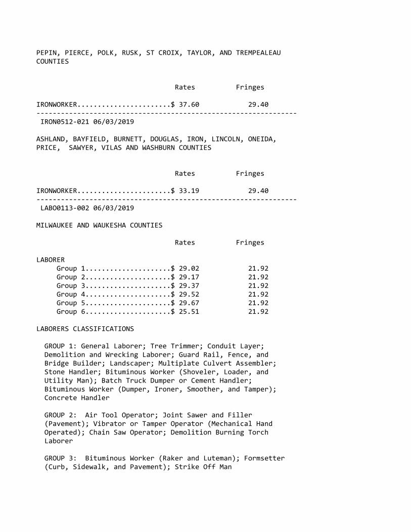
PEPIN, PIERCE, POLK, RUSK, ST CROIX, TAYLOR, AND TREMPEALEAUCOUNTIES
Rates Fringes
IRONWORKER.......................$ 37.60 29.40‐‐‐‐‐‐‐‐‐‐‐‐‐‐‐‐‐‐‐‐‐‐‐‐‐‐‐‐‐‐‐‐‐‐‐‐‐‐‐‐‐‐‐‐‐‐‐‐‐‐‐‐‐‐‐‐‐‐‐‐‐‐‐‐ IRON0512‐021 06/03/2019
ASHLAND, BAYFIELD, BURNETT, DOUGLAS, IRON, LINCOLN, ONEIDA,PRICE, SAWYER, VILAS AND WASHBURN COUNTIES
Rates Fringes
IRONWORKER.......................$ 33.19 29.40‐‐‐‐‐‐‐‐‐‐‐‐‐‐‐‐‐‐‐‐‐‐‐‐‐‐‐‐‐‐‐‐‐‐‐‐‐‐‐‐‐‐‐‐‐‐‐‐‐‐‐‐‐‐‐‐‐‐‐‐‐‐‐‐ LABO0113‐002 06/03/2019
MILWAUKEE AND WAUKESHA COUNTIES
Rates Fringes
LABORER Group 1.....................$ 29.02 21.92 Group 2.....................$ 29.17 21.92 Group 3.....................$ 29.37 21.92 Group 4.....................$ 29.52 21.92 Group 5.....................$ 29.67 21.92 Group 6.....................$ 25.51 21.92
LABORERS CLASSIFICATIONS
GROUP 1: General Laborer; Tree Trimmer; Conduit Layer; Demolition and Wrecking Laborer; Guard Rail, Fence, and Bridge Builder; Landscaper; Multiplate Culvert Assembler; Stone Handler; Bituminous Worker (Shoveler, Loader, and Utility Man); Batch Truck Dumper or Cement Handler; Bituminous Worker (Dumper, Ironer, Smoother, and Tamper); Concrete Handler
GROUP 2: Air Tool Operator; Joint Sawer and Filler (Pavement); Vibrator or Tamper Operator (Mechanical Hand Operated); Chain Saw Operator; Demolition Burning Torch Laborer
GROUP 3: Bituminous Worker (Raker and Luteman); Formsetter (Curb, Sidewalk, and Pavement); Strike Off Man

GROUP 4: Line and Grade Specialist
GROUP 5: Blaster and Powderman
GROUP 6: Flagperson; traffic control person
‐‐‐‐‐‐‐‐‐‐‐‐‐‐‐‐‐‐‐‐‐‐‐‐‐‐‐‐‐‐‐‐‐‐‐‐‐‐‐‐‐‐‐‐‐‐‐‐‐‐‐‐‐‐‐‐‐‐‐‐‐‐‐‐ LABO0113‐003 06/03/2019
OZAUKEE AND WASHINGTON COUNTIES
Rates Fringes
LABORER Group 1.....................$ 28.27 21.92 Group 2.....................$ 28.37 21.92 Group 3.....................$ 28.42 21.92 Group 4.....................$ 28.62 21.92 Group 5.....................$ 28.47 21.92 Group 6.....................$ 25.36 21.92
LABORERS CLASSIFICATIONS
GROUP 1: General Laborer; Tree Trimmer; Conduit Layer; Demolition and Wrecking Laborer; Guard Rail, Fence, and Bridge Builder; Landscaper; Multiplate Culvert Assembler; Stone Handler; Bituminous Worker (Shoveler, Loader, and Utility Man); Batch Truck Dumper or Cement Handler; Bituminous Worker (Dumper, Ironer, Smoother, and Tamper); Concrete Handler
GROUP 2: Air Tool Operator; Joint Sawer and Filler (Pavement); Vibrator or Tamper Operator (Mechanical Hand Operated);
GROUP 3: Bituminous Worker (Raker and Luteman); Formsetter (Curb, Sidewalk, and Pavement); Strike Off Man
GROUP 4: Line and Grade Specialist
GROUP 5: Blaster; powderman
GROUP 6: Flagperson and Traffic Control Person
‐‐‐‐‐‐‐‐‐‐‐‐‐‐‐‐‐‐‐‐‐‐‐‐‐‐‐‐‐‐‐‐‐‐‐‐‐‐‐‐‐‐‐‐‐‐‐‐‐‐‐‐‐‐‐‐‐‐‐‐‐‐‐‐ LABO0113‐011 06/03/2019
KENOSHA AND RACINE COUNTIES
Rates Fringes

LABORER Group 1.....................$ 28.08 21.92 Group 2.....................$ 28.23 21.92 Group 3.....................$ 28.43 21.92 Group 4.....................$ 28.40 21.92 Group 5.....................$ 28.73 21.92 Group 6.....................$ 25.22 21.92
LABORERS CLASSIFICATIONS:
GROUP 1: General laborer; Tree Trimmer; Conduit Layer; Demolition and Wrecking Laborer; Guard Rail, Fence, and Bridge Builder; Landscaper; Multiplate Culvert Assembler; Stone Handler; Bituminous Worker (Shoveler, Loader, and Utility Man); Batch Truck Dumper or Cement Handler; Bituminous worker (Dumper, Ironer, Smoother, and Tamper); Concrete Handler
GROUP 2: Air Tool Operator; Joint Sawer and Filler (Pavement); Vibrator or Tamper Operator (Mechanical Hand Operated); Chain Saw Operator; Demolition Burning Torch Laborer
GROUP 3: Bituminous Worker (Raker and Luteman); Formsetter (Curb, Sidewalk, and Pavement); Strike Off Man
GROUP 4: Line and Grade Specialist
GROUP 5: Blaster and Powderman
GROUP 6: Flagman; traffic control person
‐‐‐‐‐‐‐‐‐‐‐‐‐‐‐‐‐‐‐‐‐‐‐‐‐‐‐‐‐‐‐‐‐‐‐‐‐‐‐‐‐‐‐‐‐‐‐‐‐‐‐‐‐‐‐‐‐‐‐‐‐‐‐‐ LABO0140‐002 06/03/2019
ADAMS, ASHLAND, BARRON, BAYFIELD, BROWN, BUFFALO, BURNETT,CALUMET, CHIPPEWA, CLARK, COLUMBIA, CRAWFORD, DODGE, DOOR,DOUGLAS, DUNN, EAU CLAIRE, FLORENCE, FOND DU LAC, FOREST,GRANT, GREEN, GREEN LAKE, IRON, JACKSON, JUNEAU, IOWA,JEFFERSON, KEWAUNEE, LA CROSSE, LAFAYETTE, LANGLADE, LINCOLN,MANITOWOC, MARATHON, MARINETTE, MARQUETTE, MENOMINEE, MONROE,OCONTO, ONEIDA, OUTAGAMIE, PEPIN, PIERCE, POLK, PORTAGE, PRICE,RICHLAND, ROCK, RUSK, SAUK, SAWYER, SHAWANO, SHEBOYGAN, ST.CROIX, TAYLOR, TREMPEALEAU, VERNON, VILLAS, WALWORTH, WASHBURN,WAUPACA, WAUSHARA, WINNEBAGO, AND WOOD COUNTIES
Rates Fringes
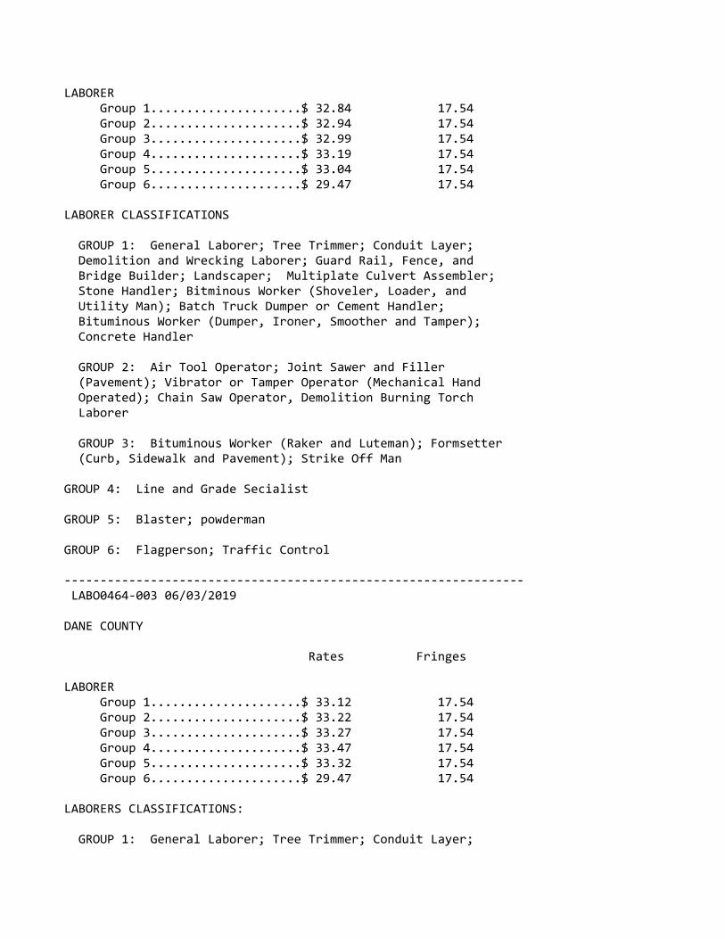
LABORER Group 1.....................$ 32.84 17.54 Group 2.....................$ 32.94 17.54 Group 3.....................$ 32.99 17.54 Group 4.....................$ 33.19 17.54 Group 5.....................$ 33.04 17.54 Group 6.....................$ 29.47 17.54
LABORER CLASSIFICATIONS
GROUP 1: General Laborer; Tree Trimmer; Conduit Layer; Demolition and Wrecking Laborer; Guard Rail, Fence, and Bridge Builder; Landscaper; Multiplate Culvert Assembler; Stone Handler; Bitminous Worker (Shoveler, Loader, and Utility Man); Batch Truck Dumper or Cement Handler; Bituminous Worker (Dumper, Ironer, Smoother and Tamper); Concrete Handler
GROUP 2: Air Tool Operator; Joint Sawer and Filler (Pavement); Vibrator or Tamper Operator (Mechanical Hand Operated); Chain Saw Operator, Demolition Burning Torch Laborer
GROUP 3: Bituminous Worker (Raker and Luteman); Formsetter (Curb, Sidewalk and Pavement); Strike Off Man
GROUP 4: Line and Grade Secialist
GROUP 5: Blaster; powderman
GROUP 6: Flagperson; Traffic Control
‐‐‐‐‐‐‐‐‐‐‐‐‐‐‐‐‐‐‐‐‐‐‐‐‐‐‐‐‐‐‐‐‐‐‐‐‐‐‐‐‐‐‐‐‐‐‐‐‐‐‐‐‐‐‐‐‐‐‐‐‐‐‐‐ LABO0464‐003 06/03/2019
DANE COUNTY
Rates Fringes
LABORER Group 1.....................$ 33.12 17.54 Group 2.....................$ 33.22 17.54 Group 3.....................$ 33.27 17.54 Group 4.....................$ 33.47 17.54 Group 5.....................$ 33.32 17.54 Group 6.....................$ 29.47 17.54
LABORERS CLASSIFICATIONS:
GROUP 1: General Laborer; Tree Trimmer; Conduit Layer;

Demolition and Wrecking Laborer; Guard Rail, Fence, and Bridge Builder; Landscaper; Multiplate Culvert Assembler; Stone Handler; Bituminous Worker (Shoveler, Loader, and Utility Man); Batch Truck Dumper or Cement Handler; Bituminious Worker (Dumper, Ironer, Smoother, and Tamper); Concrete Handler
GROUP 2: Air Tool Operator; Joint Sawer and Filler (Pavement); Vibrator or Tamper Operator (Mechanical Hand Operated); Chain Saw Operator; Demolition Burning Torch Laborer
GROUP 3: Bituminous Worker (Raker and Luteman); Formsetter (Curb, Sidewalk, and Pavement); Strike Off Man
GROUP 4: Line and Grade Specialist
GROUP 5: Blaster; Powderman
GROUP 6: Flagperson and Traffic Control Person
‐‐‐‐‐‐‐‐‐‐‐‐‐‐‐‐‐‐‐‐‐‐‐‐‐‐‐‐‐‐‐‐‐‐‐‐‐‐‐‐‐‐‐‐‐‐‐‐‐‐‐‐‐‐‐‐‐‐‐‐‐‐‐‐ PAIN0106‐008 05/01/2017
ASHLAND, BAYFIELD, BURNETT, AND DOUGLAS COUNTIES
Rates Fringes
Painters: New: Brush, Roller..............$ 30.33 17.27 Spray, Sandblast, Steel....$ 30.93 17.27 Repaint: Brush, Roller..............$ 28.83 17.27 Spray, Sandblast, Steel....$ 29.43 17.27‐‐‐‐‐‐‐‐‐‐‐‐‐‐‐‐‐‐‐‐‐‐‐‐‐‐‐‐‐‐‐‐‐‐‐‐‐‐‐‐‐‐‐‐‐‐‐‐‐‐‐‐‐‐‐‐‐‐‐‐‐‐‐‐ PAIN0108‐002 06/01/2019
RACINE COUNTY
Rates Fringes
Painters: Brush, Roller...............$ 36.08 20.36 Spray & Sandblast...........$ 37.08 20.36‐‐‐‐‐‐‐‐‐‐‐‐‐‐‐‐‐‐‐‐‐‐‐‐‐‐‐‐‐‐‐‐‐‐‐‐‐‐‐‐‐‐‐‐‐‐‐‐‐‐‐‐‐‐‐‐‐‐‐‐‐‐‐‐ PAIN0259‐002 05/01/2008
BARRON, CHIPPEWA, DUNN, EAU CLAIRE, PEPIN, PIERCE, POLK, RUSK,SAWYER, ST. CROIX, AND WASHBURN COUNTIES

Rates Fringes
PAINTER..........................$ 24.11 12.15‐‐‐‐‐‐‐‐‐‐‐‐‐‐‐‐‐‐‐‐‐‐‐‐‐‐‐‐‐‐‐‐‐‐‐‐‐‐‐‐‐‐‐‐‐‐‐‐‐‐‐‐‐‐‐‐‐‐‐‐‐‐‐‐ PAIN0259‐004 05/01/2015
BUFFALO, CRAWFORD, JACKSON, LA CROSSE, MONROE, TREMPEALEAU, ANDVERNON COUNTIES
Rates Fringes
PAINTER..........................$ 22.03 12.45‐‐‐‐‐‐‐‐‐‐‐‐‐‐‐‐‐‐‐‐‐‐‐‐‐‐‐‐‐‐‐‐‐‐‐‐‐‐‐‐‐‐‐‐‐‐‐‐‐‐‐‐‐‐‐‐‐‐‐‐‐‐‐‐ PAIN0781‐002 06/01/2019
JEFFERSON, MILWAUKEE, OZAUKEE, WASHINGTON, AND WAUKESHA COUNTIES
Rates Fringes
Painters: Bridge......................$ 33.30 23.86 Brush.......................$ 32.95 23.86 Spray & Sandblast...........$ 33.70 23.86‐‐‐‐‐‐‐‐‐‐‐‐‐‐‐‐‐‐‐‐‐‐‐‐‐‐‐‐‐‐‐‐‐‐‐‐‐‐‐‐‐‐‐‐‐‐‐‐‐‐‐‐‐‐‐‐‐‐‐‐‐‐‐‐ PAIN0802‐002 06/01/2019
COLUMBIA, DANE, DODGE, GRANT, GREEN, IOWA, LAFAYETTE, RICHLAND,ROCK, AND SAUK COUNTIES
Rates Fringes
PAINTER Brush.......................$ 30.93 18.44
PREMIUM PAY: Structural Steel, Spray, Bridges = $1.00 additional per hour.
‐‐‐‐‐‐‐‐‐‐‐‐‐‐‐‐‐‐‐‐‐‐‐‐‐‐‐‐‐‐‐‐‐‐‐‐‐‐‐‐‐‐‐‐‐‐‐‐‐‐‐‐‐‐‐‐‐‐‐‐‐‐‐‐ PAIN0802‐003 06/01/2019
ADAMS, BROWN, CALUMET, CLARK, DOOR, FOND DU LAC, FOREST, GREENLAKE, IRON, JUNEAU, KEWAUNEE, LANGLADE, LINCOLN, MANITOWOC,MARATHON, MARINETTE, MARQUETTE, MENOMINEE, OCONTO, ONEIDA,OUTAGAMIE, PORTAGE, PRICE, SHAWANO, SHEBOYGAN, TAYLOR, VILAS,WAUSHARA, WAUPACA, WINNEBAGO, AND WOOD COUNTIES

Rates Fringes
PAINTER..........................$ 30.93 18.58‐‐‐‐‐‐‐‐‐‐‐‐‐‐‐‐‐‐‐‐‐‐‐‐‐‐‐‐‐‐‐‐‐‐‐‐‐‐‐‐‐‐‐‐‐‐‐‐‐‐‐‐‐‐‐‐‐‐‐‐‐‐‐‐ PAIN0934‐001 06/01/2017
KENOSHA AND WALWORTH COUNTIES
Rates Fringes
Painters: Brush.......................$ 33.74 18.95 Spray.......................$ 34.74 18.95 Structural Steel............$ 33.89 18.95‐‐‐‐‐‐‐‐‐‐‐‐‐‐‐‐‐‐‐‐‐‐‐‐‐‐‐‐‐‐‐‐‐‐‐‐‐‐‐‐‐‐‐‐‐‐‐‐‐‐‐‐‐‐‐‐‐‐‐‐‐‐‐‐ PAIN1011‐002 06/02/2019
FLORENCE COUNTY
Rates Fringes
Painters:........................$ 25.76 13.33‐‐‐‐‐‐‐‐‐‐‐‐‐‐‐‐‐‐‐‐‐‐‐‐‐‐‐‐‐‐‐‐‐‐‐‐‐‐‐‐‐‐‐‐‐‐‐‐‐‐‐‐‐‐‐‐‐‐‐‐‐‐‐‐ PLAS0599‐010 06/01/2017
Rates Fringes
CEMENT MASON/CONCRETE FINISHER Area 1......................$ 39.46 17.17 Area 2 (BAC)................$ 35.07 19.75 Area 3......................$ 35.61 19.40 Area 4......................$ 34.70 20.51 Area 5......................$ 36.27 18.73 Area 6......................$ 32.02 22.99
AREA DESCRIPTIONS
AREA 1: BAYFIELD, DOUGLAS, PRICE, SAWYER, AND WASHBURN COUNTIES
AREA 2: ADAMS, ASHLAND, BARRON, BROWN, BURNETT, CALUMET, CHIPPEWA, CLARK, COLUMBIA, DODGE, DOOR, DUNN, FLORENCE, FOND DU LAC, FOREST, GREEN LAKE, IRON, JEFFERSON, KEWAUNEE, LANGLADE, LINCOLN, MANITOWOC, MARATHON, MARINETTE, MARQUETTE, MENOMINEE, OCONTO, ONEIDA, OUTAGAMIE, POLK, PORTAGE, RUSK, ST CROIX, SAUK, SHAWANO, SHEBOYGAN, TAYLOR, VILAS, WALWORTH, WAUPACA, WAUSHARA, WINNEBAGO, AND WOOD COUNTIES
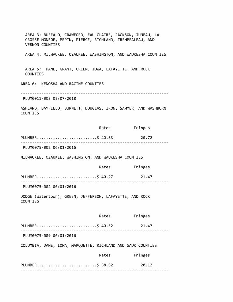
AREA 3: BUFFALO, CRAWFORD, EAU CLAIRE, JACKSON, JUNEAU, LA CROSSE MONROE, PEPIN, PIERCE, RICHLAND, TREMPEALEAU, AND VERNON COUNTIES
AREA 4: MILWAUKEE, OZAUKEE, WASHINGTON, AND WAUKESHA COUNTIES
AREA 5: DANE, GRANT, GREEN, IOWA, LAFAYETTE, AND ROCK COUNTIES
AREA 6: KENOSHA AND RACINE COUNTIES
‐‐‐‐‐‐‐‐‐‐‐‐‐‐‐‐‐‐‐‐‐‐‐‐‐‐‐‐‐‐‐‐‐‐‐‐‐‐‐‐‐‐‐‐‐‐‐‐‐‐‐‐‐‐‐‐‐‐‐‐‐‐‐‐ PLUM0011‐003 05/07/2018
ASHLAND, BAYFIELD, BURNETT, DOUGLAS, IRON, SAWYER, AND WASHBURNCOUNTIES
Rates Fringes
PLUMBER..........................$ 40.63 20.72‐‐‐‐‐‐‐‐‐‐‐‐‐‐‐‐‐‐‐‐‐‐‐‐‐‐‐‐‐‐‐‐‐‐‐‐‐‐‐‐‐‐‐‐‐‐‐‐‐‐‐‐‐‐‐‐‐‐‐‐‐‐‐‐ PLUM0075‐002 06/01/2016
MILWAUKEE, OZAUKEE, WASHINGTON, AND WAUKESHA COUNTIES
Rates Fringes
PLUMBER..........................$ 40.27 21.47‐‐‐‐‐‐‐‐‐‐‐‐‐‐‐‐‐‐‐‐‐‐‐‐‐‐‐‐‐‐‐‐‐‐‐‐‐‐‐‐‐‐‐‐‐‐‐‐‐‐‐‐‐‐‐‐‐‐‐‐‐‐‐‐ PLUM0075‐004 06/01/2016
DODGE (Watertown), GREEN, JEFFERSON, LAFAYETTE, AND ROCKCOUNTIES
Rates Fringes
PLUMBER..........................$ 40.52 21.47‐‐‐‐‐‐‐‐‐‐‐‐‐‐‐‐‐‐‐‐‐‐‐‐‐‐‐‐‐‐‐‐‐‐‐‐‐‐‐‐‐‐‐‐‐‐‐‐‐‐‐‐‐‐‐‐‐‐‐‐‐‐‐‐ PLUM0075‐009 06/01/2016
COLUMBIA, DANE, IOWA, MARQUETTE, RICHLAND AND SAUK COUNTIES
Rates Fringes
PLUMBER..........................$ 38.82 20.12‐‐‐‐‐‐‐‐‐‐‐‐‐‐‐‐‐‐‐‐‐‐‐‐‐‐‐‐‐‐‐‐‐‐‐‐‐‐‐‐‐‐‐‐‐‐‐‐‐‐‐‐‐‐‐‐‐‐‐‐‐‐‐‐

PLUM0111‐007 05/28/2018
MARINETTE COUNTY (Niagara only)
Rates Fringes
PLUMBER/PIPEFITTER...............$ 33.33 24.48‐‐‐‐‐‐‐‐‐‐‐‐‐‐‐‐‐‐‐‐‐‐‐‐‐‐‐‐‐‐‐‐‐‐‐‐‐‐‐‐‐‐‐‐‐‐‐‐‐‐‐‐‐‐‐‐‐‐‐‐‐‐‐‐ PLUM0118‐002 06/01/2019
KENOSHA, RACINE, AND WALWORTH COUNTIES
Rates Fringes
Plumber and Steamfitter..........$ 42.95 23.60‐‐‐‐‐‐‐‐‐‐‐‐‐‐‐‐‐‐‐‐‐‐‐‐‐‐‐‐‐‐‐‐‐‐‐‐‐‐‐‐‐‐‐‐‐‐‐‐‐‐‐‐‐‐‐‐‐‐‐‐‐‐‐‐ PLUM0400‐003 06/04/2018
ADAMS,BROWN, CALUMET, DODGE (except Watertown), DOOR, FOND DULAC, GREEN LAKE,KEWAUNEE, MANITOWOC, MARINETTE (exceptNiagara), MENOMINEE, OCONTO, OUTAGAMIE, SHAWANO, SHEBOYGAN,WAUPACA, WAUSHARA, AND WINNEBAGO COUNTIES
Rates Fringes
PLUMBER/PIPEFITTER...............$ 36.74 19.06‐‐‐‐‐‐‐‐‐‐‐‐‐‐‐‐‐‐‐‐‐‐‐‐‐‐‐‐‐‐‐‐‐‐‐‐‐‐‐‐‐‐‐‐‐‐‐‐‐‐‐‐‐‐‐‐‐‐‐‐‐‐‐‐ PLUM0434‐002 06/03/2018
BARON, BUFFALO, CHIPPEWA, CLARK, CRAWFORD, DUNN, EAU CLAIRE,FLORENCE, FOREST, GRANT, JACKSON, JUNEAU, LA CROSSE, LANGLADE,LINCOLN, MARATHON, MONROE, ONEIDA, PEPIN, PIERCE, POLK,PORTAGE, PRICE, RUSK, ST. CROIX, TAYLOR, TREMPEALEAU, VERNON,VILAS, AND WOOD COUNTIES
Rates Fringes
PIPEFITTER.......................$ 40.15 18.57‐‐‐‐‐‐‐‐‐‐‐‐‐‐‐‐‐‐‐‐‐‐‐‐‐‐‐‐‐‐‐‐‐‐‐‐‐‐‐‐‐‐‐‐‐‐‐‐‐‐‐‐‐‐‐‐‐‐‐‐‐‐‐‐ PLUM0601‐003 06/03/2019
DODGE (Watertown), GREEN, JEFFERSON, LAFAYETTE, MILWAUKEE,OZAUKEE, ROCK, WASHINGTON AND WAUKESHA COUNTIES
Rates Fringes
PIPEFITTER.......................$ 46.89 25.29

‐‐‐‐‐‐‐‐‐‐‐‐‐‐‐‐‐‐‐‐‐‐‐‐‐‐‐‐‐‐‐‐‐‐‐‐‐‐‐‐‐‐‐‐‐‐‐‐‐‐‐‐‐‐‐‐‐‐‐‐‐‐‐‐ PLUM0601‐009 06/04/2017
COLUMBIA, DANE, IOWA, MARQUETTE, RICHLAND AND SAUK COUNTIES
Rates Fringes
PIPEFITTER.......................$ 47.08 20.89‐‐‐‐‐‐‐‐‐‐‐‐‐‐‐‐‐‐‐‐‐‐‐‐‐‐‐‐‐‐‐‐‐‐‐‐‐‐‐‐‐‐‐‐‐‐‐‐‐‐‐‐‐‐‐‐‐‐‐‐‐‐‐‐ TEAM0039‐002 06/01/2019
Rates Fringes
TRUCK DRIVER 1 & 2 Axle Trucks...........$ 29.57 22.03 3 or more axles; Euclids or Dumptor, Articulated Truck, Mechanic.............$ 29.72 22.03‐‐‐‐‐‐‐‐‐‐‐‐‐‐‐‐‐‐‐‐‐‐‐‐‐‐‐‐‐‐‐‐‐‐‐‐‐‐‐‐‐‐‐‐‐‐‐‐‐‐‐‐‐‐‐‐‐‐‐‐‐‐‐‐ SUWI2011‐001 11/16/2011
Rates Fringes
WELL DRILLER.....................$ 16.52 ‐‐‐‐‐‐‐‐‐‐‐‐‐‐‐‐‐‐‐‐‐‐‐‐‐‐‐‐‐‐‐‐‐‐‐‐‐‐‐‐‐‐‐‐‐‐‐‐‐‐‐‐‐‐‐‐‐‐‐‐‐‐‐‐
WELDERS ‐ Receive rate prescribed for craft performingoperation to which welding is incidental.
================================================================ Note: Executive Order (EO) 13706, Establishing Paid Sick Leavefor Federal Contractors applies to all contracts subject to theDavis‐Bacon Act for which the contract is awarded (and anysolicitation was issued) on or after January 1, 2017. If thiscontract is covered by the EO, the contractor must provideemployees with 1 hour of paid sick leave for every 30 hoursthey work, up to 56 hours of paid sick leave each year.Employees must be permitted to use paid sick leave for theirown illness, injury or other health‐related needs, includingpreventive care; to assist a family member (or person who islike family to the employee) who is ill, injured, or has otherhealth‐related needs, including preventive care; or for reasonsresulting from, or to assist a family member (or person who islike family to the employee) who is a victim of, domesticviolence, sexual assault, or stalking. Additional informationon contractor requirements and worker protections under the EOis available at www.dol.gov/whd/govcontracts.
Unlisted classifications needed for work not included within

the scope of the classifications listed may be added afteraward only as provided in the labor standards contract clauses(29CFR 5.5 (a) (1) (ii)).
‐‐‐‐‐‐‐‐‐‐‐‐‐‐‐‐‐‐‐‐‐‐‐‐‐‐‐‐‐‐‐‐‐‐‐‐‐‐‐‐‐‐‐‐‐‐‐‐‐‐‐‐‐‐‐‐‐‐‐‐‐‐‐‐
The body of each wage determination lists the classificationand wage rates that have been found to be prevailing for thecited type(s) of construction in the area covered by the wagedetermination. The classifications are listed in alphabeticalorder of ""identifiers"" that indicate whether the particularrate is a union rate (current union negotiated rate for local),a survey rate (weighted average rate) or a union average rate(weighted union average rate).
Union Rate Identifiers
A four letter classification abbreviation identifier enclosedin dotted lines beginning with characters other than ""SU"" or""UAVG"" denotes that the union classification and rate wereprevailing for that classification in the survey. Example:PLUM0198‐005 07/01/2014. PLUM is an abbreviation identifier ofthe union which prevailed in the survey for thisclassification, which in this example would be Plumbers. 0198indicates the local union number or district council numberwhere applicable, i.e., Plumbers Local 0198. The next number,005 in the example, is an internal number used in processingthe wage determination. 07/01/2014 is the effective date of themost current negotiated rate, which in this example is July 1,2014.
Union prevailing wage rates are updated to reflect all ratechanges in the collective bargaining agreement (CBA) governingthis classification and rate.
Survey Rate Identifiers
Classifications listed under the ""SU"" identifier indicate thatno one rate prevailed for this classification in the survey andthe published rate is derived by computing a weighted averagerate based on all the rates reported in the survey for thatclassification. As this weighted average rate includes allrates reported in the survey, it may include both union andnon‐union rates. Example: SULA2012‐007 5/13/2014. SU indicatesthe rates are survey rates based on a weighted averagecalculation of rates and are not majority rates. LA indicatesthe State of Louisiana. 2012 is the year of survey on whichthese classifications and rates are based. The next number, 007

in the example, is an internal number used in producing thewage determination. 5/13/2014 indicates the survey completiondate for the classifications and rates under that identifier.
Survey wage rates are not updated and remain in effect until anew survey is conducted.
Union Average Rate Identifiers
Classification(s) listed under the UAVG identifier indicatethat no single majority rate prevailed for thoseclassifications; however, 100% of the data reported for theclassifications was union data. EXAMPLE: UAVG‐OH‐001008/29/2014. UAVG indicates that the rate is a weighted unionaverage rate. OH indicates the state. The next number, 0010 inthe example, is an internal number used in producing the wagedetermination. 08/29/2014 indicates the survey completion datefor the classifications and rates under that identifier.
A UAVG rate will be updated once a year, usually in January ofeach year, to reflect a weighted average of the currentnegotiated/CBA rate of the union locals from which the rate isbased.
‐‐‐‐‐‐‐‐‐‐‐‐‐‐‐‐‐‐‐‐‐‐‐‐‐‐‐‐‐‐‐‐‐‐‐‐‐‐‐‐‐‐‐‐‐‐‐‐‐‐‐‐‐‐‐‐‐‐‐‐‐‐‐‐
WAGE DETERMINATION APPEALS PROCESS
1.) Has there been an initial decision in the matter? This canbe:
* an existing published wage determination* a survey underlying a wage determination* a Wage and Hour Division letter setting forth a position on a wage determination matter* a conformance (additional classification and rate) ruling
On survey related matters, initial contact, including requestsfor summaries of surveys, should be with the Wage and HourRegional Office for the area in which the survey was conductedbecause those Regional Offices have responsibility for theDavis‐Bacon survey program. If the response from this initialcontact is not satisfactory, then the process described in 2.)and 3.) should be followed.
With regard to any other matter not yet ripe for the formalprocess described here, initial contact should be with theBranch of Construction Wage Determinations. Write to:

Branch of Construction Wage Determinations Wage and Hour Division U.S. Department of Labor 200 Constitution Avenue, N.W. Washington, DC 20210
2.) If the answer to the question in 1.) is yes, then aninterested party (those affected by the action) can requestreview and reconsideration from the Wage and Hour Administrator(See 29 CFR Part 1.8 and 29 CFR Part 7). Write to:
Wage and Hour Administrator U.S. Department of Labor 200 Constitution Avenue, N.W. Washington, DC 20210
The request should be accompanied by a full statement of theinterested party's position and by any information (wagepayment data, project description, area practice material,etc.) that the requestor considers relevant to the issue.
3.) If the decision of the Administrator is not favorable, aninterested party may appeal directly to the AdministrativeReview Board (formerly the Wage Appeals Board). Write to:
Administrative Review Board U.S. Department of Labor 200 Constitution Avenue, N.W. Washington, DC 20210
4.) All decisions by the Administrative Review Board are final.
================================================================
END OF GENERAL DECISION"

"General Decision Number: WI20200016 06/19/2020
Superseded General Decision Number: WI20190016
State: Wisconsin
Construction Type: Building
Counties: Calumet, Outagamie, Sheboygan and Winnebago Counties in Wisconsin.
BUILDING CONSTRUCTION PROJECTS (does not include residentialconstruction consisting of single family homes and apartmentsup to and including 4 stories)
Note: Under Executive Order (EO) 13658, an hourly minimum wageof $10.80 for calendar year 2020 applies to all contractssubject to the Davis‐Bacon Act for which the contract isawarded (and any solicitation was issued) on or after January1, 2015. If this contract is covered by the EO, the contractormust pay all workers in any classification listed on this wagedetermination at least $10.80 per hour (or the applicable wagerate listed on this wage determination, if it is higher) forall hours spent performing on the contract in calendar year2020. If this contract is covered by the EO and aclassification considered necessary for performance of work onthe contract does not appear on this wage determination, thecontractor must pay workers in that classification at least thewage rate determined through the conformance process set forthin 29 CFR 5.5(a)(1)(ii) (or the EO minimum wage rate,if it ishigher than the conformed wage rate). The EO minimum wage ratewill be adjusted annually. Please note that this EO applies tothe above‐mentioned types of contracts entered into by thefederal government that are subject to the Davis‐Bacon Actitself, but it does not apply to contracts subject only to theDavis‐Bacon Related Acts, including those set forth at 29 CFR5.1(a)(2)‐(60). Additional information on contractorrequirements and worker protections under the EO is availableat www.dol.gov/whd/govcontracts.
Modification Number Publication Date 0 01/03/2020 1 01/24/2020 2 01/31/2020 3 03/06/2020 4 04/17/2020 5 06/19/2020

ASBE0205‐010 06/01/1998
Rates Fringes
Asbestos Removal worker/hazardous material handler Includes preparation, wetting, stripping, removal, scrapping vacuuming, bagging and disposing of all insulation materials from mechanical systems whether they contain asbestos or not.........................$ 16.56 3.10‐‐‐‐‐‐‐‐‐‐‐‐‐‐‐‐‐‐‐‐‐‐‐‐‐‐‐‐‐‐‐‐‐‐‐‐‐‐‐‐‐‐‐‐‐‐‐‐‐‐‐‐‐‐‐‐‐‐‐‐‐‐‐‐ BOIL0107‐001 01/01/2017
Rates Fringes
BOILERMAKER Boilermaker.................$ 35.65 29.89 Small Boiler Repair (under 25,000 lbs/hr)..............$ 26.91 16.00‐‐‐‐‐‐‐‐‐‐‐‐‐‐‐‐‐‐‐‐‐‐‐‐‐‐‐‐‐‐‐‐‐‐‐‐‐‐‐‐‐‐‐‐‐‐‐‐‐‐‐‐‐‐‐‐‐‐‐‐‐‐‐‐ BRWI0011‐003 06/03/2019
Rates Fringes
BRICKLAYER Bricklayer, Cement Mason, Plasterer, Tile Layer.......$ 34.18 23.90‐‐‐‐‐‐‐‐‐‐‐‐‐‐‐‐‐‐‐‐‐‐‐‐‐‐‐‐‐‐‐‐‐‐‐‐‐‐‐‐‐‐‐‐‐‐‐‐‐‐‐‐‐‐‐‐‐‐‐‐‐‐‐‐ CARP0252‐001 06/01/2016
Rates Fringes
CARPENTER (Including Drywall Hanging, Acoustical work, Excluding Batt Insulation) CARPENTER & SOFT FLOOR LAYER.......................$ 33.56 18.00 MILLWRIGHT..................$ 35.08 18.35 PILEDRIVERMAN...............$ 34.12 18.00‐‐‐‐‐‐‐‐‐‐‐‐‐‐‐‐‐‐‐‐‐‐‐‐‐‐‐‐‐‐‐‐‐‐‐‐‐‐‐‐‐‐‐‐‐‐‐‐‐‐‐‐‐‐‐‐‐‐‐‐‐‐‐‐ ELEC0494‐003 06/01/2019
Rates Fringes

Sound & Communications Installer...................$ 20.53 18.13 Technician..................$ 30.18 19.58
Installation, testing, maintenance, operation and servicing ofall sound, intercom, telephone interconnect, closed circuit TVsystems, radio systems, background music systems, languagelaboratories, electronic carillion, antenna distributionsystems, clock and program systems and low‐voltage systems suchas visual nurse call, audio/visual nurse call systems, doctorsentrance register systems. Includes all wire and cablecarrying audio, visual, data, light and radio frequencysignals. Includes the installation of conduit, wiremold, orraceways in existing structures that have been occupied for sixmonths or more where required for the protection of the wire orcable, but does not mean a complete conduit or raceway system.work covered does not include the installation of conduit,wiremold or any raceways in any new construction, or theinstallation of power supply outlets by means of which externalelectric power is supplied to any of the foregoing equipment orproducts
‐‐‐‐‐‐‐‐‐‐‐‐‐‐‐‐‐‐‐‐‐‐‐‐‐‐‐‐‐‐‐‐‐‐‐‐‐‐‐‐‐‐‐‐‐‐‐‐‐‐‐‐‐‐‐‐‐‐‐‐‐‐‐‐* ELEC0494‐012 06/01/2020
CALUMET (New Holstein Twp.) & SHEBOYGAN COUNTIES
Rates Fringes
ELECTRICIAN......................$ 36.32 22.51‐‐‐‐‐‐‐‐‐‐‐‐‐‐‐‐‐‐‐‐‐‐‐‐‐‐‐‐‐‐‐‐‐‐‐‐‐‐‐‐‐‐‐‐‐‐‐‐‐‐‐‐‐‐‐‐‐‐‐‐‐‐‐‐ ELEC0577‐002 06/01/2019
CALUMET (Except Township of New Holstein), OUTAGAMIE, ANDWINNEBAGO COUNTIES
Rates Fringes
ELECTRICIAN......................$ 33.15 28.50%+10.00‐‐‐‐‐‐‐‐‐‐‐‐‐‐‐‐‐‐‐‐‐‐‐‐‐‐‐‐‐‐‐‐‐‐‐‐‐‐‐‐‐‐‐‐‐‐‐‐‐‐‐‐‐‐‐‐‐‐‐‐‐‐‐‐ ENGI0139‐002 06/03/2019
Rates Fringes
OPERATOR: Power Equipment Group 1.....................$ 41.52 22.45 Group 2.....................$ 40.27 22.45 Group 3.....................$ 38.97 22.45

Group 4.....................$ 38.44 22.45 Group 5.....................$ 36.37 22.45 Group 6.....................$ 34.84 22.45
HAZARDOUS WASTE PREMIUMS:EPA Level ""A"" Protection: $3.00 per hourEPA Level ""B"" Protection: $2.00 per hourEPA Level ""C"" Protection: $1.00 per hour
POWER EQUIPMENT OPERATORS CLASSIFICATIONS
GROUP 1: Cranes, Tower Cranes and Derricks with or without attachments with a lifting capacity of over 100 tons; Cranes, Tower Cranes, and Derricks with boom, leads and/or jib lengths 176 ft or longer.
GROUP 2: Backhoes (Excavators) weighing 130,000 lbs & over; Cranes, Tower Cranes and Derricks with or without attachments with a lifting capacity of 100 tons or less; Cranes, Tower Cranes, and Derricks with boom, leads, and/or jib lengths 175 ft or less; Caisson Rigs; Pile Driver
GROUP 3: Backhoes (Excavators) weighing under 130,000 lbs; Travelling Crane (bridge type); Milling Machine; Concrete Paver over 27 E; Concrete Spreader and Distributor; Concrete Laser Screed; Concrete Grinder and Planing Machine; Slipform Curb and Gutter Machine; Boring Machine (Directional); Dredge Operator; Skid Rigs; Over 46 meter Concrete Pump.
GROUP 4: Hydraulic Backhoe (tractor or truck mounted); Hydraulic Crane, 10 tons or less; Tractor, Bulldozer, or End Loader (over 40 hp); Motor Patrol; Scraper Operator; Bituminous Plant and Paver Operator; Screed‐Milling Machine; Roller over 5 tons; Concrete Pumps 46 meter & under; Grout Pumps; Rotec Type Machine; Hydro Blaster, 10,000 psi and over; Rotary Drill Operator; Percussion Drilling Machine; Air Track Drill with or without integral hammer; Blaster; Boring Machine (vertical or horizontal); Side Boom; Trencher, wheel type or chain type having 8 inch or larger bucket; Rail Leveling Machine (Railroad); Tie Placer; Tie Extractor; Tie Tamper; Stone Leveler; Straddle Carrier; Material Hoists; Stack Hoist; Man Hoists; Mechanic and Welder; Off Road Maaerial Haulers
GROUP 5: Tractor, Bulldozer, or Endloader (under 40 hp); Tampers ‐Compactors, riding type; Stump Chipper, large; Roller, Rubber Tire; Backfiller; Trencher, chain type (bucket under 8 inch); Concrete Auto Breaker, large; Concrete Finishing Machine (road type); Concrete Batch

Hopper; Concrete Conveyor Systems; Concrete Mixers, 14S or over; Pumps, Screw Type and Gypsum); Hydrohammers, small; Brooms and Sweeeprs; Lift Slab Machine; Roller under 5 tons; Industrial Locomotives; Fireman (Pile Drivers and Derricks); Pumps (well points); Hoists, automatic; A‐Frames and Winch Trucks; Hoists (tuggers); Boats (Tug, Safety, Work Barges and Launches); Assistant Engineer
GROUP 6: Shouldering Machine Operator; Farm or Industrial Tractor mounted equipment; Post Hole Digger; Auger (vertical and horizontal); Skid Steer Loader with or without attachments; Robotic Tool Carrier with or without attachments; Power Pack Vibratory/Ultra Sound Driver and Extractor; Fireman (Asphalt Plants); Screed Operator; Stone Crushers and Screening Plants; Air, Electric, Hydraulic Jacks (Slip Form); Prestress Machines; Air Compressor, 400 CFM or over; Refrigeration Plant/Freese Machine; Boiler Operators (temporary heat); Forklifts; Welding Machines; Generators; Pumps over 3""; Compressors, under 400 CFM; Heaters, Mechanical; Combination small equipment operator; Winches, small electric; Oiler; Greaser; Rotary Drill Tender; Conveyor; Elevator Operator
‐‐‐‐‐‐‐‐‐‐‐‐‐‐‐‐‐‐‐‐‐‐‐‐‐‐‐‐‐‐‐‐‐‐‐‐‐‐‐‐‐‐‐‐‐‐‐‐‐‐‐‐‐‐‐‐‐‐‐‐‐‐‐‐* IRON0008‐001 06/01/2020
Rates Fringes
IRONWORKER.......................$ 37.31 27.62
Paid Holidays: New Year's Day, Memorial Day, July 4th, Labor Day, Thanksgiving Day & Christmas Day.
‐‐‐‐‐‐‐‐‐‐‐‐‐‐‐‐‐‐‐‐‐‐‐‐‐‐‐‐‐‐‐‐‐‐‐‐‐‐‐‐‐‐‐‐‐‐‐‐‐‐‐‐‐‐‐‐‐‐‐‐‐‐‐‐ LABO0330‐004 06/03/2019
Rates Fringes
Asbestos Abatement/Hazardous Waste (Preparation, removal and Encapsulation of hazardous materials from non‐mechanical systems)..........$ 27.97 17.46Laborer, General.................$ 28.27 17.46
NOTE: Mason Tender $.25 over general laborer.‐‐‐‐‐‐‐‐‐‐‐‐‐‐‐‐‐‐‐‐‐‐‐‐‐‐‐‐‐‐‐‐‐‐‐‐‐‐‐‐‐‐‐‐‐‐‐‐‐‐‐‐‐‐‐‐‐‐‐‐‐‐‐‐ PAIN0802‐008 06/01/2019
Rates Fringes
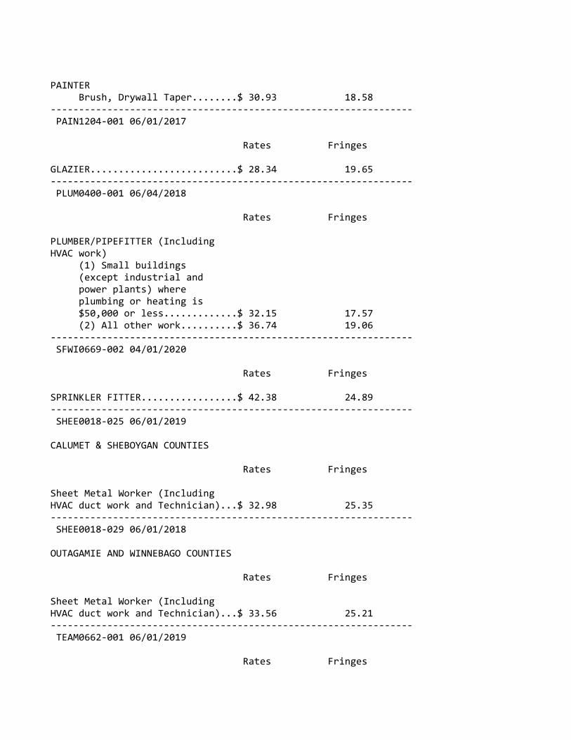
PAINTER Brush, Drywall Taper........$ 30.93 18.58‐‐‐‐‐‐‐‐‐‐‐‐‐‐‐‐‐‐‐‐‐‐‐‐‐‐‐‐‐‐‐‐‐‐‐‐‐‐‐‐‐‐‐‐‐‐‐‐‐‐‐‐‐‐‐‐‐‐‐‐‐‐‐‐ PAIN1204‐001 06/01/2017
Rates Fringes
GLAZIER..........................$ 28.34 19.65‐‐‐‐‐‐‐‐‐‐‐‐‐‐‐‐‐‐‐‐‐‐‐‐‐‐‐‐‐‐‐‐‐‐‐‐‐‐‐‐‐‐‐‐‐‐‐‐‐‐‐‐‐‐‐‐‐‐‐‐‐‐‐‐ PLUM0400‐001 06/04/2018
Rates Fringes
PLUMBER/PIPEFITTER (Including HVAC work) (1) Small buildings (except industrial and power plants) where plumbing or heating is $50,000 or less.............$ 32.15 17.57 (2) All other work..........$ 36.74 19.06‐‐‐‐‐‐‐‐‐‐‐‐‐‐‐‐‐‐‐‐‐‐‐‐‐‐‐‐‐‐‐‐‐‐‐‐‐‐‐‐‐‐‐‐‐‐‐‐‐‐‐‐‐‐‐‐‐‐‐‐‐‐‐‐ SFWI0669‐002 04/01/2020
Rates Fringes
SPRINKLER FITTER.................$ 42.38 24.89‐‐‐‐‐‐‐‐‐‐‐‐‐‐‐‐‐‐‐‐‐‐‐‐‐‐‐‐‐‐‐‐‐‐‐‐‐‐‐‐‐‐‐‐‐‐‐‐‐‐‐‐‐‐‐‐‐‐‐‐‐‐‐‐ SHEE0018‐025 06/01/2019
CALUMET & SHEBOYGAN COUNTIES
Rates Fringes
Sheet Metal Worker (Including HVAC duct work and Technician)...$ 32.98 25.35‐‐‐‐‐‐‐‐‐‐‐‐‐‐‐‐‐‐‐‐‐‐‐‐‐‐‐‐‐‐‐‐‐‐‐‐‐‐‐‐‐‐‐‐‐‐‐‐‐‐‐‐‐‐‐‐‐‐‐‐‐‐‐‐ SHEE0018‐029 06/01/2018
OUTAGAMIE AND WINNEBAGO COUNTIES
Rates Fringes
Sheet Metal Worker (Including HVAC duct work and Technician)...$ 33.56 25.21‐‐‐‐‐‐‐‐‐‐‐‐‐‐‐‐‐‐‐‐‐‐‐‐‐‐‐‐‐‐‐‐‐‐‐‐‐‐‐‐‐‐‐‐‐‐‐‐‐‐‐‐‐‐‐‐‐‐‐‐‐‐‐‐ TEAM0662‐001 06/01/2019
Rates Fringes
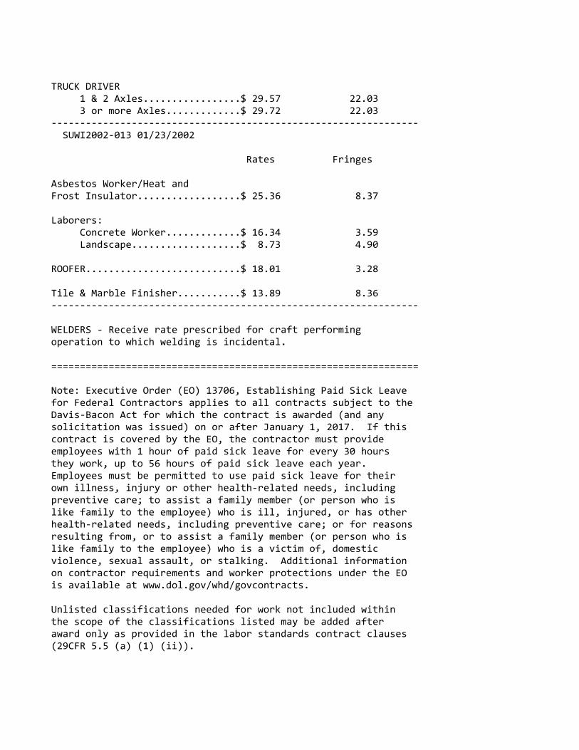
TRUCK DRIVER 1 & 2 Axles.................$ 29.57 22.03 3 or more Axles.............$ 29.72 22.03‐‐‐‐‐‐‐‐‐‐‐‐‐‐‐‐‐‐‐‐‐‐‐‐‐‐‐‐‐‐‐‐‐‐‐‐‐‐‐‐‐‐‐‐‐‐‐‐‐‐‐‐‐‐‐‐‐‐‐‐‐‐‐‐ SUWI2002‐013 01/23/2002
Rates Fringes
Asbestos Worker/Heat and Frost Insulator..................$ 25.36 8.37 Laborers: Concrete Worker.............$ 16.34 3.59 Landscape...................$ 8.73 4.90 ROOFER...........................$ 18.01 3.28 Tile & Marble Finisher...........$ 13.89 8.36‐‐‐‐‐‐‐‐‐‐‐‐‐‐‐‐‐‐‐‐‐‐‐‐‐‐‐‐‐‐‐‐‐‐‐‐‐‐‐‐‐‐‐‐‐‐‐‐‐‐‐‐‐‐‐‐‐‐‐‐‐‐‐‐
WELDERS ‐ Receive rate prescribed for craft performingoperation to which welding is incidental.
================================================================ Note: Executive Order (EO) 13706, Establishing Paid Sick Leavefor Federal Contractors applies to all contracts subject to theDavis‐Bacon Act for which the contract is awarded (and anysolicitation was issued) on or after January 1, 2017. If thiscontract is covered by the EO, the contractor must provideemployees with 1 hour of paid sick leave for every 30 hoursthey work, up to 56 hours of paid sick leave each year.Employees must be permitted to use paid sick leave for theirown illness, injury or other health‐related needs, includingpreventive care; to assist a family member (or person who islike family to the employee) who is ill, injured, or has otherhealth‐related needs, including preventive care; or for reasonsresulting from, or to assist a family member (or person who islike family to the employee) who is a victim of, domesticviolence, sexual assault, or stalking. Additional informationon contractor requirements and worker protections under the EOis available at www.dol.gov/whd/govcontracts.
Unlisted classifications needed for work not included withinthe scope of the classifications listed may be added afteraward only as provided in the labor standards contract clauses(29CFR 5.5 (a) (1) (ii)).

‐‐‐‐‐‐‐‐‐‐‐‐‐‐‐‐‐‐‐‐‐‐‐‐‐‐‐‐‐‐‐‐‐‐‐‐‐‐‐‐‐‐‐‐‐‐‐‐‐‐‐‐‐‐‐‐‐‐‐‐‐‐‐‐
The body of each wage determination lists the classificationand wage rates that have been found to be prevailing for thecited type(s) of construction in the area covered by the wagedetermination. The classifications are listed in alphabeticalorder of ""identifiers"" that indicate whether the particularrate is a union rate (current union negotiated rate for local),a survey rate (weighted average rate) or a union average rate(weighted union average rate).
Union Rate Identifiers
A four letter classification abbreviation identifier enclosedin dotted lines beginning with characters other than ""SU"" or""UAVG"" denotes that the union classification and rate wereprevailing for that classification in the survey. Example:PLUM0198‐005 07/01/2014. PLUM is an abbreviation identifier ofthe union which prevailed in the survey for thisclassification, which in this example would be Plumbers. 0198indicates the local union number or district council numberwhere applicable, i.e., Plumbers Local 0198. The next number,005 in the example, is an internal number used in processingthe wage determination. 07/01/2014 is the effective date of themost current negotiated rate, which in this example is July 1,2014.
Union prevailing wage rates are updated to reflect all ratechanges in the collective bargaining agreement (CBA) governingthis classification and rate.
Survey Rate Identifiers
Classifications listed under the ""SU"" identifier indicate thatno one rate prevailed for this classification in the survey andthe published rate is derived by computing a weighted averagerate based on all the rates reported in the survey for thatclassification. As this weighted average rate includes allrates reported in the survey, it may include both union andnon‐union rates. Example: SULA2012‐007 5/13/2014. SU indicatesthe rates are survey rates based on a weighted averagecalculation of rates and are not majority rates. LA indicatesthe State of Louisiana. 2012 is the year of survey on whichthese classifications and rates are based. The next number, 007in the example, is an internal number used in producing thewage determination. 5/13/2014 indicates the survey completiondate for the classifications and rates under that identifier.
Survey wage rates are not updated and remain in effect until a

new survey is conducted.
Union Average Rate Identifiers
Classification(s) listed under the UAVG identifier indicatethat no single majority rate prevailed for thoseclassifications; however, 100% of the data reported for theclassifications was union data. EXAMPLE: UAVG‐OH‐001008/29/2014. UAVG indicates that the rate is a weighted unionaverage rate. OH indicates the state. The next number, 0010 inthe example, is an internal number used in producing the wagedetermination. 08/29/2014 indicates the survey completion datefor the classifications and rates under that identifier.
A UAVG rate will be updated once a year, usually in January ofeach year, to reflect a weighted average of the currentnegotiated/CBA rate of the union locals from which the rate isbased.
‐‐‐‐‐‐‐‐‐‐‐‐‐‐‐‐‐‐‐‐‐‐‐‐‐‐‐‐‐‐‐‐‐‐‐‐‐‐‐‐‐‐‐‐‐‐‐‐‐‐‐‐‐‐‐‐‐‐‐‐‐‐‐‐
WAGE DETERMINATION APPEALS PROCESS
1.) Has there been an initial decision in the matter? This canbe:
* an existing published wage determination* a survey underlying a wage determination* a Wage and Hour Division letter setting forth a position on a wage determination matter* a conformance (additional classification and rate) ruling
On survey related matters, initial contact, including requestsfor summaries of surveys, should be with the Wage and HourRegional Office for the area in which the survey was conductedbecause those Regional Offices have responsibility for theDavis‐Bacon survey program. If the response from this initialcontact is not satisfactory, then the process described in 2.)and 3.) should be followed.
With regard to any other matter not yet ripe for the formalprocess described here, initial contact should be with theBranch of Construction Wage Determinations. Write to:
Branch of Construction Wage Determinations Wage and Hour Division U.S. Department of Labor 200 Constitution Avenue, N.W.

Washington, DC 20210
2.) If the answer to the question in 1.) is yes, then aninterested party (those affected by the action) can requestreview and reconsideration from the Wage and Hour Administrator(See 29 CFR Part 1.8 and 29 CFR Part 7). Write to:
Wage and Hour Administrator U.S. Department of Labor 200 Constitution Avenue, N.W. Washington, DC 20210
The request should be accompanied by a full statement of theinterested party's position and by any information (wagepayment data, project description, area practice material,etc.) that the requestor considers relevant to the issue.
3.) If the decision of the Administrator is not favorable, aninterested party may appeal directly to the AdministrativeReview Board (formerly the Wage Appeals Board). Write to:
Administrative Review Board U.S. Department of Labor 200 Constitution Avenue, N.W. Washington, DC 20210
4.) All decisions by the Administrative Review Board are final.
================================================================
END OF GENERAL DECISION"

Page 1 of 1
August 2018
NOTICE TO BIDDERS WAGE RATE DECISION
The wage rate decision of the Department of Labor which has been incorporated in these advertised specifications is incomplete in that the classifications may be omitted from the Department of Labor's decision.
Since the bidder is responsible, independently, for ascertaining area practice with respect to the necessity, or lack of necessity, for the use of these classifications in the prosecution of the work contemplated by this project, no inference may be drawn from the omission of these classifications concerning prevailing area practices relative to their use. Further, this omission will not, per se, be construed as establishing any governmental liability for increased labor cost if it is subsequently determined that such classifications are required.
There may be omissions and/or errors in the federal wage rates. The bidder is responsible for evaluating and determining the correct applicable rate.
If a project includes multiple types of construction (highway, bridge over navigable water, sanitary sewer and water main, building) and there is not a separate wage determination for this type of work included in the proposal, use the wage determination that is in the proposal.
If a project includes multiple types of construction, different wage rate determinations may be inserted into the contract (WI10/Highway = in all WisDOT highway contracts, WI15/Heavy = bridge over navigable water per USDOL and US Coast Guard designation, WI8/Heavy (Sewer & Water Line & Tunnel) = sanitary sewer and water main if the cost is more than 20% of the contract and/or at least $1,000,000, and Building). If multiple wage rate determinations are inserted into the contract, use the classification in the wage determination for the work being done. Use WI15 wage rates when working on the bridge and/or structure from bank to bank. Use WI8 wage rates when working on any sanitary sewer or water main work. Use Building wage rates for all work done within the footprint of the building. Use WI10 wage rates for all other highway work in the contract and approaches to structures. For example, if a laborer is working within the footprint of a building, use the Laborer rate in the Building wage determination inserted in the contract. If a laborer is working on a bridge/structure within the banks, use the Laborer rate in the WI15/Heavy wage determination if inserted in the contract. If the laborer is working on the highway, use the Laborer rate in the WI10/Highway wage determination.
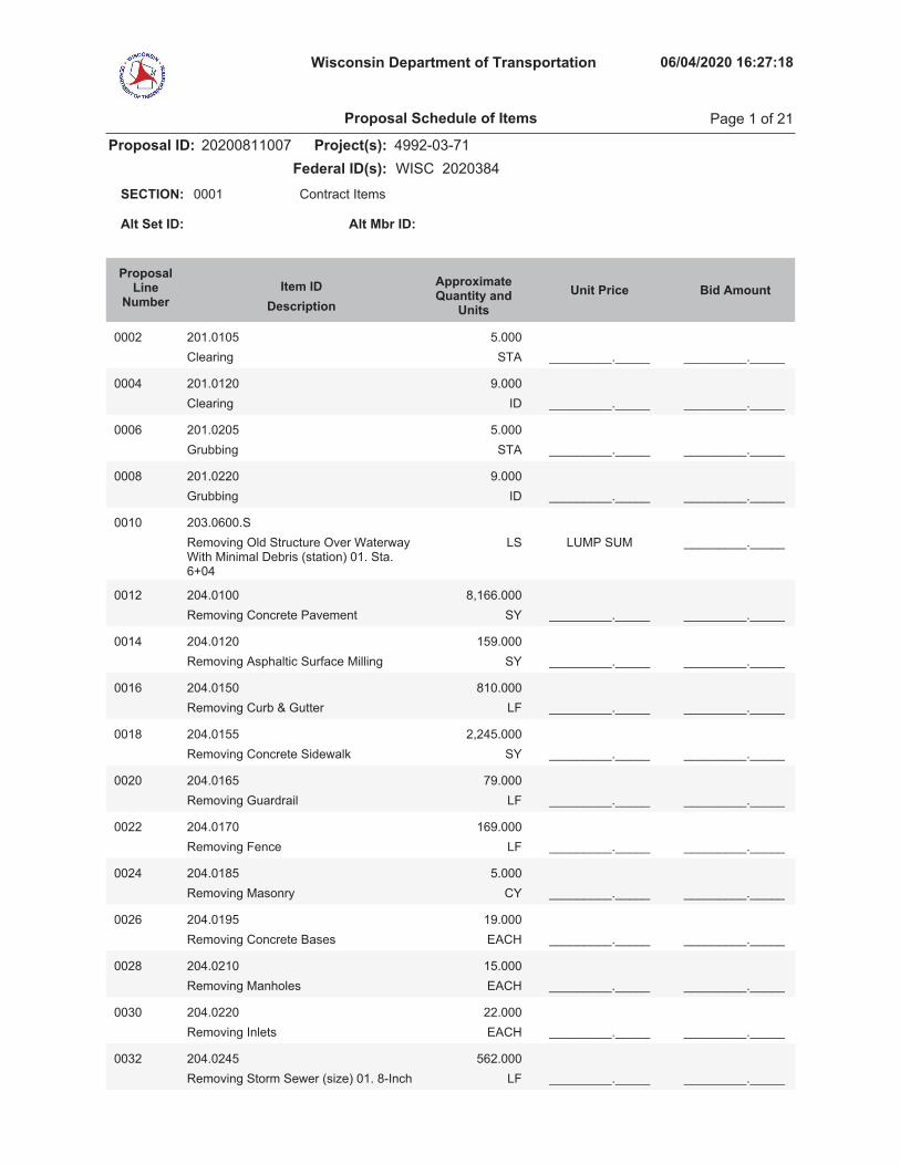
Wisconsin Department of Transportation 06/04/2020 16:27:18
Proposal ID: 20200811007 Project(s): 4992-03-71Federal ID(s): WISC 2020384
0001 Contract ItemsSECTION:
Alt Set ID: Alt Mbr ID:
Bid AmountUnit PriceApproximateQuantity and
UnitsDescriptionItem ID
ProposalLine
Number
0002 201.0105Clearing STA
5.000_________._____ _________._____
0004 201.0120Clearing ID
9.000_________._____ _________._____
0006 201.0205Grubbing STA
5.000_________._____ _________._____
0008 201.0220Grubbing ID
9.000_________._____ _________._____
0010 203.0600.SRemoving Old Structure Over WaterwayWith Minimal Debris (station) 01. Sta.6+04
LUMP SUM _________._____LS
0012 204.0100Removing Concrete Pavement SY
8,166.000_________._____ _________._____
0014 204.0120Removing Asphaltic Surface Milling SY
159.000_________._____ _________._____
0016 204.0150Removing Curb & Gutter LF
810.000_________._____ _________._____
0018 204.0155Removing Concrete Sidewalk SY
2,245.000_________._____ _________._____
0020 204.0165Removing Guardrail LF
79.000_________._____ _________._____
0022 204.0170Removing Fence LF
169.000_________._____ _________._____
0024 204.0185Removing Masonry CY
5.000_________._____ _________._____
0026 204.0195Removing Concrete Bases EACH
19.000_________._____ _________._____
0028 204.0210Removing Manholes EACH
15.000_________._____ _________._____
0030 204.0220Removing Inlets EACH
22.000_________._____ _________._____
0032 204.0245Removing Storm Sewer (size) 01. 8-Inch LF
562.000_________._____ _________._____
Proposal Schedule of Items Page 1 of 21
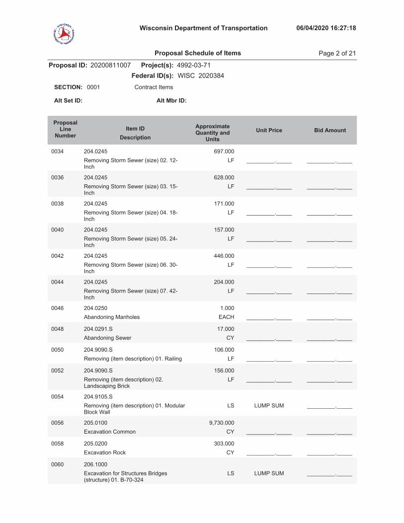
Wisconsin Department of Transportation 06/04/2020 16:27:18
Proposal ID: 20200811007 Project(s): 4992-03-71Federal ID(s): WISC 2020384
0001 Contract ItemsSECTION:
Alt Set ID: Alt Mbr ID:
Bid AmountUnit PriceApproximateQuantity and
UnitsDescriptionItem ID
ProposalLine
Number
0034 204.0245Removing Storm Sewer (size) 02. 12-Inch
LF697.000
_________._____ _________._____
0036 204.0245Removing Storm Sewer (size) 03. 15-Inch
LF628.000
_________._____ _________._____
0038 204.0245Removing Storm Sewer (size) 04. 18-Inch
LF171.000
_________._____ _________._____
0040 204.0245Removing Storm Sewer (size) 05. 24-Inch
LF157.000
_________._____ _________._____
0042 204.0245Removing Storm Sewer (size) 06. 30-Inch
LF446.000
_________._____ _________._____
0044 204.0245Removing Storm Sewer (size) 07. 42-Inch
LF204.000
_________._____ _________._____
0046 204.0250Abandoning Manholes EACH
1.000_________._____ _________._____
0048 204.0291.SAbandoning Sewer CY
17.000_________._____ _________._____
0050 204.9090.SRemoving (item description) 01. Railing LF
106.000_________._____ _________._____
0052 204.9090.SRemoving (item description) 02.Landscaping Brick
LF156.000
_________._____ _________._____
0054 204.9105.SRemoving (item description) 01. ModularBlock Wall
LUMP SUM _________._____LS
0056 205.0100Excavation Common CY
9,730.000_________._____ _________._____
0058 205.0200Excavation Rock CY
303.000_________._____ _________._____
0060 206.1000Excavation for Structures Bridges(structure) 01. B-70-324
LUMP SUM _________._____LS
Proposal Schedule of Items Page 2 of 21
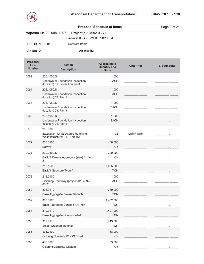
Wisconsin Department of Transportation 06/04/2020 16:27:18
Proposal ID: 20200811007 Project(s): 4992-03-71Federal ID(s): WISC 2020384
0001 Contract ItemsSECTION:
Alt Set ID: Alt Mbr ID:
Bid AmountUnit PriceApproximateQuantity and
UnitsDescriptionItem ID
ProposalLine
Number
0062 206.1050.SUnderwater Foundation Inspection(location) 01. South Abutment
EACH1.000
_________._____ _________._____
0064 206.1050.SUnderwater Foundation Inspection(location) 02. Pier 1
EACH1.000
_________._____ _________._____
0066 206.1050.SUnderwater Foundation Inspection(location) 03. Pier 3
EACH1.000
_________._____ _________._____
0068 206.1050.SUnderwater Foundation Inspection(location) 04. Pier 4
EACH1.000
_________._____ _________._____
0070 206.3000Excavation for Structures RetainingWalls (structure) 01. R-70-161
LUMP SUM _________._____LS
0072 208.0100Borrow CY
68.000_________._____ _________._____
0074 209.0300.SBackfill Coarse Aggregate (size) 01. No.2
CY390.000
_________._____ _________._____
0076 210.1500Backfill Structure Type A TON
7,005.000_________._____ _________._____
0078 213.0100Finishing Roadway (project) 01. 4992-03-71
EACH1.000
_________._____ _________._____
0080 305.0110Base Aggregate Dense 3/4-Inch TON
339.000_________._____ _________._____
0082 305.0120Base Aggregate Dense 1 1/4-Inch TON
4,452.000_________._____ _________._____
0084 310.0110Base Aggregate Open-Graded TON
4,427.000_________._____ _________._____
0086 312.0110Select Crushed Material TON
6,719.000_________._____ _________._____
0088 405.0100Coloring Concrete WisDOT Red CY
188.000_________._____ _________._____
0090 405.0200Coloring Concrete Custom CY
69.000_________._____ _________._____
Proposal Schedule of Items Page 3 of 21

Wisconsin Department of Transportation 06/04/2020 16:27:18
Proposal ID: 20200811007 Project(s): 4992-03-71Federal ID(s): WISC 2020384
0001 Contract ItemsSECTION:
Alt Set ID: Alt Mbr ID:
Bid AmountUnit PriceApproximateQuantity and
UnitsDescriptionItem ID
ProposalLine
Number
0092 415.0080Concrete Pavement 8-Inch SY
7,374.000_________._____ _________._____
0094 415.0410Concrete Pavement Approach Slab SY
157.000_________._____ _________._____
0096 415.5110.SConcrete Pavement Joint Layout LS
1.000_________._____ _________._____
0098 416.0160Concrete Driveway 6-Inch SY
132.000_________._____ _________._____
0100 416.0260Concrete Driveway HES 6-Inch SY
21.000_________._____ _________._____
0102 416.0512Concrete Truck Apron 12-Inch SY
560.000_________._____ _________._____
0104 416.0620Drilled Dowel Bars EACH
83.000_________._____ _________._____
0106 455.0605Tack Coat GAL
65.000_________._____ _________._____
0108 465.0105Asphaltic Surface TON
145.000_________._____ _________._____
0110 501.1000.SIce Hot Weather Concreting LB
36,794.000_________._____ _________._____
0112 502.0100Concrete Masonry Bridges CY
4,838.000_________._____ _________._____
0114 502.1100Concrete Masonry Seal CY
1,407.000_________._____ _________._____
0116 502.3101Expansion Device LF
69.000_________._____ _________._____
0118 502.3200Protective Surface Treatment SY
4,503.000_________._____ _________._____
0120 502.3210Pigmented Surface Sealer SY
1,135.000_________._____ _________._____
0122 502.4104Adhesive Anchors 1/2-inch EACH
40.000_________._____ _________._____
0124 502.4208Adhesive Anchors No. 8 Bar EACH
10.000_________._____ _________._____
Proposal Schedule of Items Page 4 of 21

Wisconsin Department of Transportation 06/04/2020 16:27:18
Proposal ID: 20200811007 Project(s): 4992-03-71Federal ID(s): WISC 2020384
0001 Contract ItemsSECTION:
Alt Set ID: Alt Mbr ID:
Bid AmountUnit PriceApproximateQuantity and
UnitsDescriptionItem ID
ProposalLine
Number
0126 502.9000.SUnderwater Substructure Inspection(Structure) 01. B-70-324
EACH4.000
_________._____ _________._____
0128 503.0172Prestressed Girder Type I 72W-Inch LF
4,270.000_________._____ _________._____
0130 504.0500Concrete Masonry Retaining Walls CY
256.000_________._____ _________._____
0132 505.0400Bar Steel Reinforcement HS Structures LB
304,795.000_________._____ _________._____
0134 505.0600Bar Steel Reinforcement HS CoatedStructures
LB775,748.000
_________._____ _________._____
0136 505.0800.SBar Steel Reinforcement HS StainlessStructures
LB100.000
_________._____ _________._____
0138 506.2605Bearing Pads Elastomeric Non-Laminated
EACH14.000
_________._____ _________._____
0140 506.2610Bearing Pads Elastomeric Laminated EACH
42.000_________._____ _________._____
0142 506.3005Welded Stud Shear Connectors 7/8x4-Inch
EACH1,746.000
_________._____ _________._____
0144 506.3008Welded Stud Shear Connectors 5/8x5-Inch
EACH358.000
_________._____ _________._____
0146 506.4000Steel Diaphragms (structure) 01. B-70-324
EACH48.000
_________._____ _________._____
0148 512.0500Piling Steel Sheet Permanent Delivered SF
4,637.000_________._____ _________._____
0150 512.0600Piling Steel Sheet Permanent Driven SF
4,637.000_________._____ _________._____
0152 513.2001Railing Pipe LF
25.000_________._____ _________._____
0154 514.0450Floor Drains Type WF EACH
6.000_________._____ _________._____
Proposal Schedule of Items Page 5 of 21

Wisconsin Department of Transportation 06/04/2020 16:27:18
Proposal ID: 20200811007 Project(s): 4992-03-71Federal ID(s): WISC 2020384
0001 Contract ItemsSECTION:
Alt Set ID: Alt Mbr ID:
Bid AmountUnit PriceApproximateQuantity and
UnitsDescriptionItem ID
ProposalLine
Number
0156 514.2608Downspout 8-Inch LF
40.000_________._____ _________._____
0158 516.0500Rubberized Membrane Waterproofing SY
232.000_________._____ _________._____
0160 517.0600Painting Epoxy System (structure) 01. B-70-324
LUMP SUM _________._____LS
0162 550.0020Pre-Boring Rock or ConsolidatedMaterials
LF368.000
_________._____ _________._____
0164 550.1120Piling Steel HP 12-Inch X 53 Lb LF
480.000_________._____ _________._____
0166 601.0405Concrete Curb & Gutter 18-Inch Type A LF
375.000_________._____ _________._____
0168 601.0409Concrete Curb & Gutter 30-Inch Type A LF
3,628.000_________._____ _________._____
0170 601.0411Concrete Curb & Gutter 30-Inch Type D LF
81.000_________._____ _________._____
0172 601.0452Concrete Curb & Gutter Integral 30-InchType D
LF138.000
_________._____ _________._____
0174 601.0580Concrete Curb & Gutter 4-Inch Sloped36-Inch Type R
LF539.000
_________._____ _________._____
0176 601.0600Concrete Curb Pedestrian LF
255.000_________._____ _________._____
0178 602.0410Concrete Sidewalk 5-Inch SF
29,173.000_________._____ _________._____
0180 602.0515Curb Ramp Detectable Warning FieldNatural Patina
SF520.000
_________._____ _________._____
0182 602.0615Curb Ramp Detectable Warning FieldRadial Natural Patina
SF160.000
_________._____ _________._____
0184 603.1432Concrete Barrier Type S32C LF
68.000_________._____ _________._____
Proposal Schedule of Items Page 6 of 21
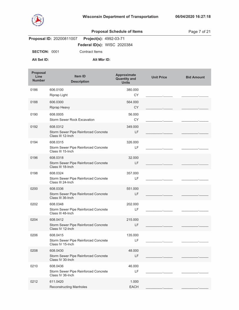
Wisconsin Department of Transportation 06/04/2020 16:27:18
Proposal ID: 20200811007 Project(s): 4992-03-71Federal ID(s): WISC 2020384
0001 Contract ItemsSECTION:
Alt Set ID: Alt Mbr ID:
Bid AmountUnit PriceApproximateQuantity and
UnitsDescriptionItem ID
ProposalLine
Number
0186 606.0100Riprap Light CY
380.000_________._____ _________._____
0188 606.0300Riprap Heavy CY
564.000_________._____ _________._____
0190 608.0005Storm Sewer Rock Excavation CY
56.000_________._____ _________._____
0192 608.0312Storm Sewer Pipe Reinforced ConcreteClass III 12-Inch
LF349.000
_________._____ _________._____
0194 608.0315Storm Sewer Pipe Reinforced ConcreteClass III 15-Inch
LF326.000
_________._____ _________._____
0196 608.0318Storm Sewer Pipe Reinforced ConcreteClass III 18-Inch
LF32.000
_________._____ _________._____
0198 608.0324Storm Sewer Pipe Reinforced ConcreteClass III 24-Inch
LF357.000
_________._____ _________._____
0200 608.0336Storm Sewer Pipe Reinforced ConcreteClass III 36-Inch
LF551.000
_________._____ _________._____
0202 608.0348Storm Sewer Pipe Reinforced ConcreteClass III 48-Inch
LF202.000
_________._____ _________._____
0204 608.0412Storm Sewer Pipe Reinforced ConcreteClass IV 12-Inch
LF215.000
_________._____ _________._____
0206 608.0415Storm Sewer Pipe Reinforced ConcreteClass IV 15-Inch
LF135.000
_________._____ _________._____
0208 608.0430Storm Sewer Pipe Reinforced ConcreteClass IV 30-Inch
LF48.000
_________._____ _________._____
0210 608.0436Storm Sewer Pipe Reinforced ConcreteClass IV 36-Inch
LF46.000
_________._____ _________._____
0212 611.0420Reconstructing Manholes EACH
1.000_________._____ _________._____
Proposal Schedule of Items Page 7 of 21

Wisconsin Department of Transportation 06/04/2020 16:27:18
Proposal ID: 20200811007 Project(s): 4992-03-71Federal ID(s): WISC 2020384
0001 Contract ItemsSECTION:
Alt Set ID: Alt Mbr ID:
Bid AmountUnit PriceApproximateQuantity and
UnitsDescriptionItem ID
ProposalLine
Number
0214 611.0530Manhole Covers Type J EACH
15.000_________._____ _________._____
0216 611.0606Inlet Covers Type B EACH
1.000_________._____ _________._____
0218 611.0624Inlet Covers Type H EACH
15.000_________._____ _________._____
0220 611.0639Inlet Covers Type H-S EACH
17.000_________._____ _________._____
0222 611.0652Inlet Covers Type T EACH
5.000_________._____ _________._____
0224 611.1003Catch Basins 3-FT Diameter EACH
1.000_________._____ _________._____
0226 611.1004Catch Basins 4-FT Diameter EACH
3.000_________._____ _________._____
0228 611.1006Catch Basins 6-FT Diameter EACH
1.000_________._____ _________._____
0230 611.1230Catch Basins 2x3-FT EACH
26.000_________._____ _________._____
0232 611.2004Manholes 4-FT Diameter EACH
4.000_________._____ _________._____
0234 611.2005Manholes 5-FT Diameter EACH
6.000_________._____ _________._____
0236 611.2006Manholes 6-FT Diameter EACH
2.000_________._____ _________._____
0238 611.2007Manholes 7-FT Diameter EACH
3.000_________._____ _________._____
0240 611.3220Inlets 2x2-FT EACH
1.000_________._____ _________._____
0242 611.3230Inlets 2x3-FT EACH
1.000_________._____ _________._____
0244 612.0406Pipe Underdrain Wrapped 6-Inch LF
535.000_________._____ _________._____
0246 616.0700.SFence Safety LF
500.000_________._____ _________._____
Proposal Schedule of Items Page 8 of 21

Wisconsin Department of Transportation 06/04/2020 16:27:18
Proposal ID: 20200811007 Project(s): 4992-03-71Federal ID(s): WISC 2020384
0001 Contract ItemsSECTION:
Alt Set ID: Alt Mbr ID:
Bid AmountUnit PriceApproximateQuantity and
UnitsDescriptionItem ID
ProposalLine
Number
0248 618.0100Maintenance And Repair of Haul Roads(project) 01. 4992-03-71
EACH1.000
_________._____ _________._____
0250 619.1000Mobilization EACH
1.000_________._____ _________._____
0252 620.0300Concrete Median Sloped Nose SF
562.000_________._____ _________._____
0254 624.0100Water MGAL
167.000_________._____ _________._____
0256 625.0100Topsoil SY
6,978.000_________._____ _________._____
0258 627.0200Mulching SY
1,800.000_________._____ _________._____
0260 628.1504Silt Fence LF
700.000_________._____ _________._____
0262 628.1520Silt Fence Maintenance LF
700.000_________._____ _________._____
0264 628.1905Mobilizations Erosion Control EACH
11.000_________._____ _________._____
0266 628.1910Mobilizations Emergency Erosion Control EACH
6.000_________._____ _________._____
0268 628.7005Inlet Protection Type A EACH
50.000_________._____ _________._____
0270 628.7010Inlet Protection Type B EACH
10.000_________._____ _________._____
0272 628.7015Inlet Protection Type C EACH
51.000_________._____ _________._____
0274 628.7020Inlet Protection Type D EACH
28.000_________._____ _________._____
0276 628.7560Tracking Pads EACH
1.000_________._____ _________._____
0278 629.0210Fertilizer Type B CWT
4.500_________._____ _________._____
Proposal Schedule of Items Page 9 of 21

Wisconsin Department of Transportation 06/04/2020 16:27:18
Proposal ID: 20200811007 Project(s): 4992-03-71Federal ID(s): WISC 2020384
0001 Contract ItemsSECTION:
Alt Set ID: Alt Mbr ID:
Bid AmountUnit PriceApproximateQuantity and
UnitsDescriptionItem ID
ProposalLine
Number
0280 630.0140Seeding Mixture No. 40 LB
30.000_________._____ _________._____
0282 630.0500Seed Water MGAL
38.000_________._____ _________._____
0284 631.0300Sod Water MGAL
118.000_________._____ _________._____
0286 631.1000Sod Lawn SY
5,179.000_________._____ _________._____
0288 634.0614Posts Wood 4x6-Inch X 14-FT EACH
38.000_________._____ _________._____
0290 634.0616Posts Wood 4x6-Inch X 16-FT EACH
10.000_________._____ _________._____
0292 634.0814Posts Tubular Steel 2x2-Inch X 14-FT EACH
11.000_________._____ _________._____
0294 634.0816Posts Tubular Steel 2x2-Inch X 16-FT EACH
8.000_________._____ _________._____
0296 637.2210Signs Type II Reflective H SF
477.700_________._____ _________._____
0298 637.2230Signs Type II Reflective F SF
216.000_________._____ _________._____
0300 638.2102Moving Signs Type II EACH
25.000_________._____ _________._____
0302 638.2601Removing Signs Type I EACH
3.000_________._____ _________._____
0304 638.2602Removing Signs Type II EACH
68.000_________._____ _________._____
0306 638.3000Removing Small Sign Supports EACH
22.000_________._____ _________._____
0308 638.3150Removing Overhead Sign SupportsCantilever (structure) 01. STA17+20'RSB'
EACH1.000
_________._____ _________._____
0310 638.3150Removing Overhead Sign SupportsCantilever (structure) 02. STA 2+10'RSB'
EACH1.000
_________._____ _________._____
Proposal Schedule of Items Page 10 of 21
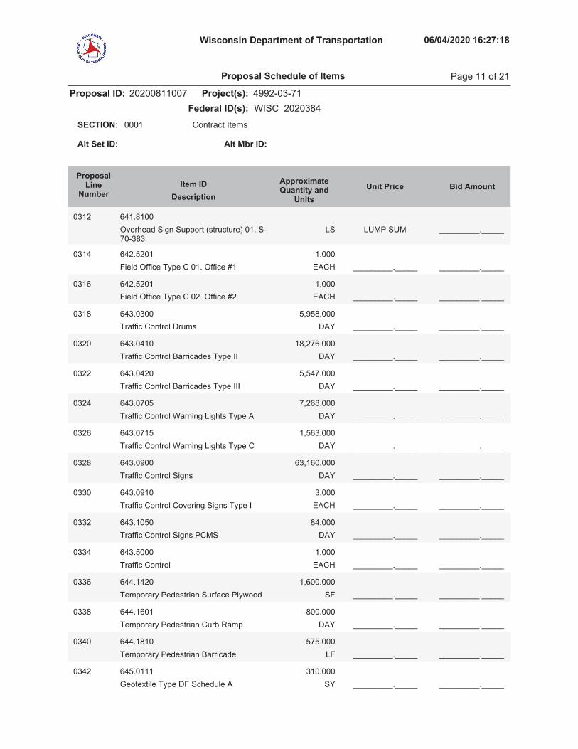
Wisconsin Department of Transportation 06/04/2020 16:27:18
Proposal ID: 20200811007 Project(s): 4992-03-71Federal ID(s): WISC 2020384
0001 Contract ItemsSECTION:
Alt Set ID: Alt Mbr ID:
Bid AmountUnit PriceApproximateQuantity and
UnitsDescriptionItem ID
ProposalLine
Number
0312 641.8100Overhead Sign Support (structure) 01. S-70-383
LUMP SUM _________._____LS
0314 642.5201Field Office Type C 01. Office #1 EACH
1.000_________._____ _________._____
0316 642.5201Field Office Type C 02. Office #2 EACH
1.000_________._____ _________._____
0318 643.0300Traffic Control Drums DAY
5,958.000_________._____ _________._____
0320 643.0410Traffic Control Barricades Type II DAY
18,276.000_________._____ _________._____
0322 643.0420Traffic Control Barricades Type III DAY
5,547.000_________._____ _________._____
0324 643.0705Traffic Control Warning Lights Type A DAY
7,268.000_________._____ _________._____
0326 643.0715Traffic Control Warning Lights Type C DAY
1,563.000_________._____ _________._____
0328 643.0900Traffic Control Signs DAY
63,160.000_________._____ _________._____
0330 643.0910Traffic Control Covering Signs Type I EACH
3.000_________._____ _________._____
0332 643.1050Traffic Control Signs PCMS DAY
84.000_________._____ _________._____
0334 643.5000Traffic Control EACH
1.000_________._____ _________._____
0336 644.1420Temporary Pedestrian Surface Plywood SF
1,600.000_________._____ _________._____
0338 644.1601Temporary Pedestrian Curb Ramp DAY
800.000_________._____ _________._____
0340 644.1810Temporary Pedestrian Barricade LF
575.000_________._____ _________._____
0342 645.0111Geotextile Type DF Schedule A SY
310.000_________._____ _________._____
Proposal Schedule of Items Page 11 of 21

Wisconsin Department of Transportation 06/04/2020 16:27:18
Proposal ID: 20200811007 Project(s): 4992-03-71Federal ID(s): WISC 2020384
0001 Contract ItemsSECTION:
Alt Set ID: Alt Mbr ID:
Bid AmountUnit PriceApproximateQuantity and
UnitsDescriptionItem ID
ProposalLine
Number
0344 645.0112Geotextile Type DF Schedule B SY
943.000_________._____ _________._____
0346 645.0120Geotextile Type HR SY
957.000_________._____ _________._____
0348 645.0130Geotextile Type R SY
1,569.000_________._____ _________._____
0350 646.1020Marking Line Epoxy 4-Inch LF
7,247.000_________._____ _________._____
0352 646.3020Marking Line Epoxy 8-Inch LF
685.000_________._____ _________._____
0354 646.5020Marking Arrow Epoxy EACH
13.000_________._____ _________._____
0356 646.5120Marking Word Epoxy EACH
10.000_________._____ _________._____
0358 646.5220Marking Symbol Epoxy EACH
7.000_________._____ _________._____
0360 646.6120Marking Stop Line Epoxy 18-Inch LF
72.000_________._____ _________._____
0362 646.6320Marking Dotted Extension Epoxy 18-Inch LF
109.000_________._____ _________._____
0364 646.7120Marking Diagonal Epoxy 12-Inch LF
175.000_________._____ _________._____
0366 646.7420Marking Crosswalk Epoxy TransverseLine 6-Inch
LF881.000
_________._____ _________._____
0368 646.8120Marking Curb Epoxy LF
48.000_________._____ _________._____
0370 646.8320Marking Parking Stall Epoxy LF
40.000_________._____ _________._____
0372 646.9200Marking Removal Line Wide LF
48.000_________._____ _________._____
0374 649.0105Temporary Marking Line Paint 4-Inch LF
250.000_________._____ _________._____
Proposal Schedule of Items Page 12 of 21

Wisconsin Department of Transportation 06/04/2020 16:27:18
Proposal ID: 20200811007 Project(s): 4992-03-71Federal ID(s): WISC 2020384
0001 Contract ItemsSECTION:
Alt Set ID: Alt Mbr ID:
Bid AmountUnit PriceApproximateQuantity and
UnitsDescriptionItem ID
ProposalLine
Number
0376 649.0150Temporary Marking Line RemovableTape 4-Inch
LF100.000
_________._____ _________._____
0378 650.4000Construction Staking Storm Sewer EACH
54.000_________._____ _________._____
0380 650.4500Construction Staking Subgrade LF
1,722.000_________._____ _________._____
0382 650.5500Construction Staking Curb Gutter andCurb & Gutter
LF5,072.000
_________._____ _________._____
0384 650.6500Construction Staking Structure Layout(structure) 01. B-70-324
LUMP SUM _________._____LS
0386 650.6500Construction Staking Structure Layout(structure) 02. R-70-160
LUMP SUM _________._____LS
0388 650.6500Construction Staking Structure Layout(structure) 03. R-70-161
LUMP SUM _________._____LS
0390 650.6500Construction Staking Structure Layout(structure) 04. R-70-159
LUMP SUM _________._____LS
0392 650.7000Construction Staking ConcretePavement
LF1,740.000
_________._____ _________._____
0394 650.9000Construction Staking Curb Ramps EACH
36.000_________._____ _________._____
0396 650.9910Construction Staking SupplementalControl (project) 01. 4992-03-71
LUMP SUM _________._____LS
0398 652.0125Conduit Rigid Metallic 2-Inch LF
244.000_________._____ _________._____
0400 652.0220Conduit Rigid Nonmetallic Schedule 40 11/2-Inch
LF128.000
_________._____ _________._____
0402 652.0225Conduit Rigid Nonmetallic Schedule 402-Inch
LF4,104.000
_________._____ _________._____
Proposal Schedule of Items Page 13 of 21

Wisconsin Department of Transportation 06/04/2020 16:27:18
Proposal ID: 20200811007 Project(s): 4992-03-71Federal ID(s): WISC 2020384
0001 Contract ItemsSECTION:
Alt Set ID: Alt Mbr ID:
Bid AmountUnit PriceApproximateQuantity and
UnitsDescriptionItem ID
ProposalLine
Number
0404 652.0235Conduit Rigid Nonmetallic Schedule 403-Inch
LF1,660.000
_________._____ _________._____
0406 652.0800Conduit Loop Detector LF
86.000_________._____ _________._____
0408 653.0164Pull Boxes Non-Conductive 24x42-Inch EACH
19.000_________._____ _________._____
0410 653.0222Junction Boxes 18x12x6-Inch EACH
11.000_________._____ _________._____
0412 653.0905Removing Pull Boxes EACH
4.000_________._____ _________._____
0414 654.0105Concrete Bases Type 5 EACH
9.000_________._____ _________._____
0416 654.0230Concrete Control Cabinet Bases TypeL30
EACH2.000
_________._____ _________._____
0418 655.0610Electrical Wire Lighting 12 AWG LF
4,572.000_________._____ _________._____
0420 655.0620Electrical Wire Lighting 8 AWG LF
30,900.000_________._____ _________._____
0422 655.0800Loop Detector Wire LF
282.000_________._____ _________._____
0424 656.0200Electrical Service Meter BreakerPedestal (location) 01. Racine Street &Ahnaip Street
LUMP SUM _________._____LS
0426 656.0200Electrical Service Meter BreakerPedestal (location) 02. Racine Street &Main Street
LUMP SUM _________._____LS
0428 657.0255Transformer Bases Breakaway 11 1/2-Inch Bolt Circle
EACH13.000
_________._____ _________._____
0430 657.0322Poles Type 5-Aluminum EACH
13.000_________._____ _________._____
Proposal Schedule of Items Page 14 of 21

Wisconsin Department of Transportation 06/04/2020 16:27:18
Proposal ID: 20200811007 Project(s): 4992-03-71Federal ID(s): WISC 2020384
0001 Contract ItemsSECTION:
Alt Set ID: Alt Mbr ID:
Bid AmountUnit PriceApproximateQuantity and
UnitsDescriptionItem ID
ProposalLine
Number
0432 657.0610Luminaire Arms Single Member 4 1/2-Inch Clamp 6-FT
EACH13.000
_________._____ _________._____
0434 657.6005Anchor Assemblies Light Poles onStructures
EACH6.000
_________._____ _________._____
0436 659.2130Lighting Control Cabinets 120/240 30-Inch
EACH1.000
_________._____ _________._____
0438 690.0150Sawing Asphalt LF
331.000_________._____ _________._____
0440 690.0250Sawing Concrete LF
442.000_________._____ _________._____
1.000000442 715.0415
Incentive Strength Concrete Pavement DOL2,410.000
2,410.00
1.000000444 715.0502
Incentive Strength Concrete Structures DOL31,122.000
31,122.00
1.000000446 715.0710
Optimized Aggregate Gradation Incentive DOL7,964.000
7,964.00
0448 SPV.0035Special 01. Counterweight Concrete CY
346.000_________._____ _________._____
0450 SPV.0035Special 02. Concrete Masonry BridgesLightweight
CY93.000
_________._____ _________._____
0452 SPV.0035Special 03. Excavation and Dewateringof Dredging Material
CY2,250.000
_________._____ _________._____
0454 SPV.0035Special 04. Planting Mixture CY
300.000_________._____ _________._____
0456 SPV.0060Special 01. Clearance Gauge EACH
2.000_________._____ _________._____
0458 SPV.0060Special 02. Inlets 2x2.5-FT, Special EACH
4.000_________._____ _________._____
0460 SPV.0060Special 03. Luminaires Utility LED EACH
13.000_________._____ _________._____
Proposal Schedule of Items Page 15 of 21
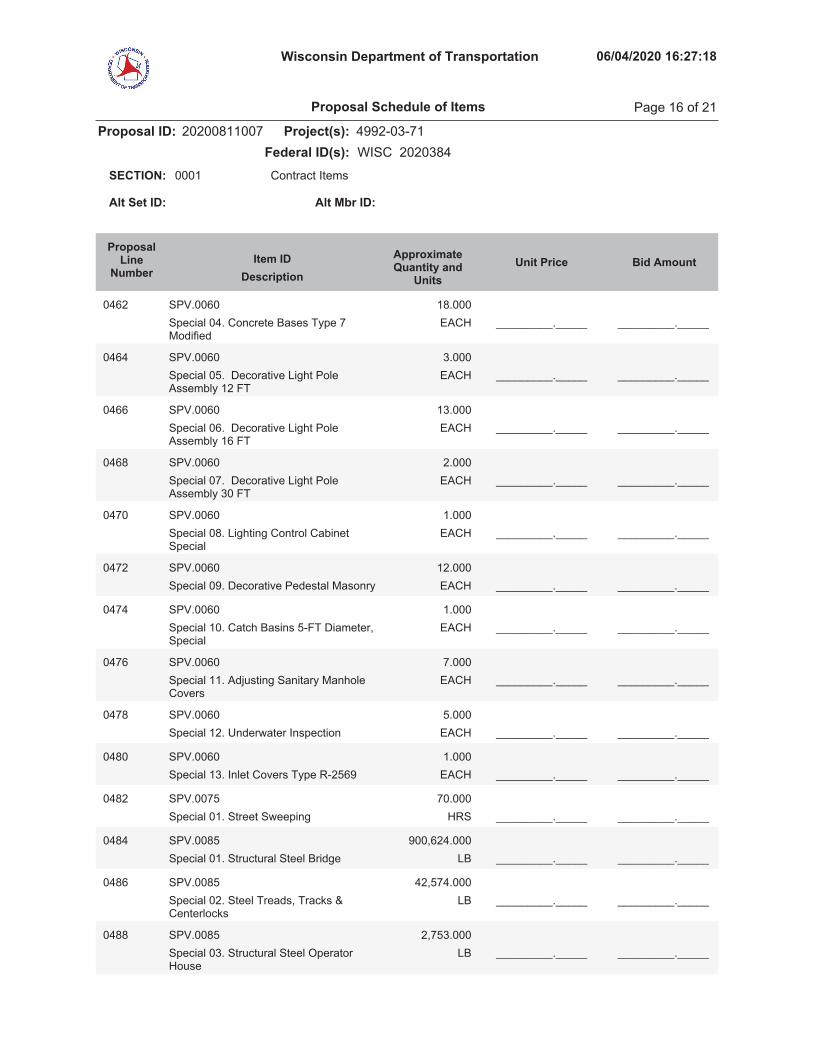
Wisconsin Department of Transportation 06/04/2020 16:27:18
Proposal ID: 20200811007 Project(s): 4992-03-71Federal ID(s): WISC 2020384
0001 Contract ItemsSECTION:
Alt Set ID: Alt Mbr ID:
Bid AmountUnit PriceApproximateQuantity and
UnitsDescriptionItem ID
ProposalLine
Number
0462 SPV.0060Special 04. Concrete Bases Type 7Modified
EACH18.000
_________._____ _________._____
0464 SPV.0060Special 05. Decorative Light PoleAssembly 12 FT
EACH3.000
_________._____ _________._____
0466 SPV.0060Special 06. Decorative Light PoleAssembly 16 FT
EACH13.000
_________._____ _________._____
0468 SPV.0060Special 07. Decorative Light PoleAssembly 30 FT
EACH2.000
_________._____ _________._____
0470 SPV.0060Special 08. Lighting Control CabinetSpecial
EACH1.000
_________._____ _________._____
0472 SPV.0060Special 09. Decorative Pedestal Masonry EACH
12.000_________._____ _________._____
0474 SPV.0060Special 10. Catch Basins 5-FT Diameter,Special
EACH1.000
_________._____ _________._____
0476 SPV.0060Special 11. Adjusting Sanitary ManholeCovers
EACH7.000
_________._____ _________._____
0478 SPV.0060Special 12. Underwater Inspection EACH
5.000_________._____ _________._____
0480 SPV.0060Special 13. Inlet Covers Type R-2569 EACH
1.000_________._____ _________._____
0482 SPV.0075Special 01. Street Sweeping HRS
70.000_________._____ _________._____
0484 SPV.0085Special 01. Structural Steel Bridge LB
900,624.000_________._____ _________._____
0486 SPV.0085Special 02. Steel Treads, Tracks &Centerlocks
LB42,574.000
_________._____ _________._____
0488 SPV.0085Special 03. Structural Steel OperatorHouse
LB2,753.000
_________._____ _________._____
Proposal Schedule of Items Page 16 of 21
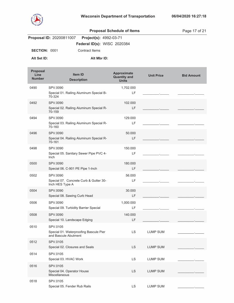
Wisconsin Department of Transportation 06/04/2020 16:27:18
Proposal ID: 20200811007 Project(s): 4992-03-71Federal ID(s): WISC 2020384
0001 Contract ItemsSECTION:
Alt Set ID: Alt Mbr ID:
Bid AmountUnit PriceApproximateQuantity and
UnitsDescriptionItem ID
ProposalLine
Number
0490 SPV.0090Special 01. Railing Aluminum Special B-70-324
LF1,702.000
_________._____ _________._____
0492 SPV.0090Special 02. Railing Aluminum Special R-70-159
LF102.000
_________._____ _________._____
0494 SPV.0090Special 03. Railing Aluminum Special R-70-160
LF129.000
_________._____ _________._____
0496 SPV.0090Special 04. Railing Aluminum Special R-70-161
LF50.000
_________._____ _________._____
0498 SPV.0090Special 05. Sanitary Sewer Pipe PVC 4-Inch
LF150.000
_________._____ _________._____
0500 SPV.0090Special 06. C-901 PE Pipe 1-Inch LF
180.000_________._____ _________._____
0502 SPV.0090Special 07. Concrete Curb & Gutter 30-Inch HES Type A
LF56.000
_________._____ _________._____
0504 SPV.0090Special 08. Sawing Curb Head LF
30.000_________._____ _________._____
0506 SPV.0090Special 09. Turbidity Barrier Special LF
1,000.000_________._____ _________._____
0508 SPV.0090Special 10. Landscape Edging LF
140.000_________._____ _________._____
0510 SPV.0105Special 01. Waterproofing Bascule Pierand Bascule Abutment
LUMP SUM _________._____LS
0512 SPV.0105Special 02. Closures and Seals LUMP SUM _________._____LS
0514 SPV.0105Special 03. HVAC Work LUMP SUM _________._____LS
0516 SPV.0105Special 04. Operator HouseMiscellaneous
LUMP SUM _________._____LS
0518 SPV.0105Special 05. Fender Rub Rails LUMP SUM _________._____LS
Proposal Schedule of Items Page 17 of 21
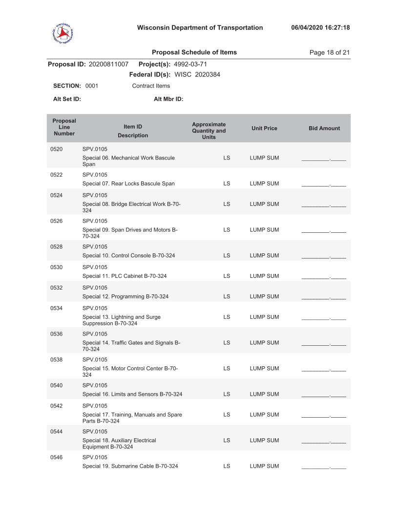
Wisconsin Department of Transportation 06/04/2020 16:27:18
Proposal ID: 20200811007 Project(s): 4992-03-71Federal ID(s): WISC 2020384
0001 Contract ItemsSECTION:
Alt Set ID: Alt Mbr ID:
Bid AmountUnit PriceApproximateQuantity and
UnitsDescriptionItem ID
ProposalLine
Number
0520 SPV.0105Special 06. Mechanical Work BasculeSpan
LUMP SUM _________._____LS
0522 SPV.0105Special 07. Rear Locks Bascule Span LUMP SUM _________._____LS
0524 SPV.0105Special 08. Bridge Electrical Work B-70-324
LUMP SUM _________._____LS
0526 SPV.0105Special 09. Span Drives and Motors B-70-324
LUMP SUM _________._____LS
0528 SPV.0105Special 10. Control Console B-70-324 LUMP SUM _________._____LS
0530 SPV.0105Special 11. PLC Cabinet B-70-324 LUMP SUM _________._____LS
0532 SPV.0105Special 12. Programming B-70-324 LUMP SUM _________._____LS
0534 SPV.0105Special 13. Lightning and SurgeSuppression B-70-324
LUMP SUM _________._____LS
0536 SPV.0105Special 14. Traffic Gates and Signals B-70-324
LUMP SUM _________._____LS
0538 SPV.0105Special 15. Motor Control Center B-70-324
LUMP SUM _________._____LS
0540 SPV.0105Special 16. Limits and Sensors B-70-324 LUMP SUM _________._____LS
0542 SPV.0105Special 17. Training, Manuals and SpareParts B-70-324
LUMP SUM _________._____LS
0544 SPV.0105Special 18. Auxiliary ElectricalEquipment B-70-324
LUMP SUM _________._____LS
0546 SPV.0105Special 19. Submarine Cable B-70-324 LUMP SUM _________._____LS
Proposal Schedule of Items Page 18 of 21

Wisconsin Department of Transportation 06/04/2020 16:27:18
Proposal ID: 20200811007 Project(s): 4992-03-71Federal ID(s): WISC 2020384
0001 Contract ItemsSECTION:
Alt Set ID: Alt Mbr ID:
Bid AmountUnit PriceApproximateQuantity and
UnitsDescriptionItem ID
ProposalLine
Number
0548 SPV.0105Special 20. Tayco Street RemoteOperations B-70-324
LUMP SUM _________._____LS
0550 SPV.0105Special 21. Steel Stairs, Platforms andRailing
LUMP SUM _________._____LS
0552 SPV.0105Special 22. Tool Box with Tools LUMP SUM _________._____LS
0554 SPV.0105Special 23. Substructure TemporaryDewatering System South Abutment
LUMP SUM _________._____LS
0556 SPV.0105Special 24. Substructure TemporaryDewatering System Pier 1
LUMP SUM _________._____LS
0558 SPV.0105Special 25. Substructure TemporaryDewatering System Pier 2
LUMP SUM _________._____LS
0560 SPV.0105Special 26. Substructure TemporaryDewatering System Pier 3
LUMP SUM _________._____LS
0562 SPV.0105Special 27. Substructure TemporaryDewatering System Pier 4
LUMP SUM _________._____LS
0564 SPV.0105Special 28. Substructure TemporaryDewatering System South Bascule Pier
LUMP SUM _________._____LS
0566 SPV.0105Special 29. Substructure TemporaryDewatering System North BasculeAbutment
LUMP SUM _________._____LS
0568 SPV.0105Special 30. Management of PetroleumContaminated Water
LUMP SUM _________._____LS
0570 SPV.0105Special 31. Plumbing Work LUMP SUM _________._____LS
0572 SPV.0105Special 32. Anchoring System for SheetPile Wall R-70-159
LUMP SUM _________._____LS
Proposal Schedule of Items Page 19 of 21

Wisconsin Department of Transportation 06/04/2020 16:27:18
Proposal ID: 20200811007 Project(s): 4992-03-71Federal ID(s): WISC 2020384
0001 Contract ItemsSECTION:
Alt Set ID: Alt Mbr ID:
Bid AmountUnit PriceApproximateQuantity and
UnitsDescriptionItem ID
ProposalLine
Number
0574 SPV.0105Special 33. Anchoring System for SheetPile Wall R-70-160
LUMP SUM _________._____LS
0576 SPV.0105Special 34. Substructure TemporaryDewatering R-70-161 Segment B
LUMP SUM _________._____LS
0578 SPV.0105Special 35. Salvage Existing TrafficSignal and Lighting Equipment
LUMP SUM _________._____LS
0580 SPV.0105Special 36. Lighting Equipment Painting LUMP SUM _________._____LS
0582 SPV.0105Special 37. Operator House Masonry LUMP SUM _________._____LS
0584 SPV.0105Special 38. Construction Staking WaterMain
LUMP SUM _________._____LS
0586 SPV.0120Special 01. Management of PetroleumContaminated Groundwater
MGAL1,041.000
_________._____ _________._____
0588 SPV.0165Special 01. Counterweight ConcreteSealer
SF4,983.000
_________._____ _________._____
0590 SPV.0165Special 02. Steel Grid Floor ConcreteFilled
SF3,339.000
_________._____ _________._____
0592 SPV.0165Special 03. Insulation Board 2-Inch SF
450.000_________._____ _________._____
0594 SPV.0165Special 04. Fiberglass Sidewalk FloorPlates
SF1,346.000
_________._____ _________._____
0596 SPV.0180Special 01. Shredded Hardwood BarkMulch
SY800.000
_________._____ _________._____
0598 SPV.0195Special 01. Excavation, Hauling, andDisposal of River Material atSubstructures
TON3,931.000
_________._____ _________._____
Proposal Schedule of Items Page 20 of 21
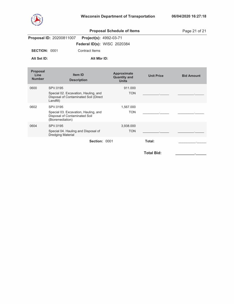
Wisconsin Department of Transportation 06/04/2020 16:27:18
Proposal ID: 20200811007 Project(s): 4992-03-71Federal ID(s): WISC 2020384
0001 Contract ItemsSECTION:
Alt Set ID: Alt Mbr ID:
Bid AmountUnit PriceApproximateQuantity and
UnitsDescriptionItem ID
ProposalLine
Number
0600 SPV.0195Special 02. Excavation, Hauling, andDisposal of Contaminated Soil (DirectLandfill)
TON911.000
_________._____ _________._____
0602 SPV.0195Special 03. Excavation, Hauling, andDisposal of Contaminated Soil(Bioremediation)
TON1,567.000
_________._____ _________._____
0604 SPV.0195Special 04. Hauling and Disposal ofDredging Material
TON3,938.000
_________._____ _________._____
Section: 0001 _________._____Total:
Total Bid: _________._____
Proposal Schedule of Items Page 21 of 21

PLEASE ATTACH SCHEDULE OF ITEMS HERE
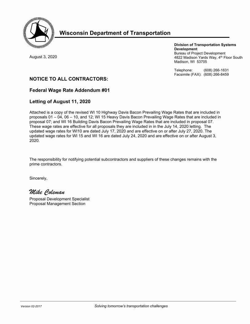
Wisconsin Department of Transportation
Version 02-2017 Solving tomorrow’s transportation challenges
Division of Transportation Systems Development Bureau of Project Development 4822 Madison Yards Way, 4th Floor South Madison, WI 53705 Telephone: (608) 266-1631 Facsimile (FAX): (608) 266-8459
August 3, 2020 NOTICE TO ALL CONTRACTORS: Federal Wage Rate Addendum #01 Letting of August 11, 2020 Attached is a copy of the revised WI 10 Highway Davis Bacon Prevailing Wage Rates that are included in proposals 01 – 04, 06 – 10, and 12; WI 15 Heavy Davis Bacon Prevailing Wage Rates that are included in proposal 07; and WI 16 Building Davis Bacon Prevailing Wage Rates that are included in proposal 07. These wage rates are effective for all proposals they are included in in the July 14, 2020 letting. The updated wage rates for WI10 are dated July 17, 2020 and are effective on or after July 27, 2020. The updated wage rates for WI 15 and WI 16 are dated July 24, 2020 and are effective on or after August 3, 2020. The responsibility for notifying potential subcontractors and suppliers of these changes remains with the prime contractors. Sincerely, Mike Coleman Proposal Development Specialist Proposal Management Section

"General Decision Number: WI20200010 07/17/2020
Superseded General Decision Number: WI20190010
State: Wisconsin
Construction Type: Highway
Counties: Wisconsin Statewide.
HIGHWAY, AIRPORT RUNWAY & TAXIWAY CONSTRUCTION PROJECTS (doesnot include bridges over navigable waters; tunnels; buildingsin highway rest areas; and railroad construction)
Note: Under Executive Order (EO) 13658, an hourly minimum wageof $10.80 for calendar year 2020 applies to all contractssubject to the Davis‐Bacon Act for which the contract isawarded (and any solicitation was issued) on or after January1, 2015. If this contract is covered by the EO, the contractormust pay all workers in any classification listed on this wagedetermination at least $10.80 per hour (or the applicable wagerate listed on this wage determination, if it is higher) forall hours spent performing on the contract in calendar year2020. If this contract is covered by the EO and aclassification considered necessary for performance of work onthe contract does not appear on this wage determination, thecontractor must pay workers in that classification at least thewage rate determined through the conformance process set forthin 29 CFR 5.5(a)(1)(ii) (or the EO minimum wage rate,if it ishigher than the conformed wage rate). The EO minimum wage ratewill be adjusted annually. Please note that this EO applies tothe above‐mentioned types of contracts entered into by thefederal government that are subject to the Davis‐Bacon Actitself, but it does not apply to contracts subject only to theDavis‐Bacon Related Acts, including those set forth at 29 CFR5.1(a)(2)‐(60). Additional information on contractorrequirements and worker protections under the EO is availableat www.dol.gov/whd/govcontracts.
Modification Number Publication Date 0 01/03/2020 1 01/24/2020 2 02/28/2020 3 03/06/2020 4 06/05/2020 5 06/12/2020 6 06/19/2020 7 07/17/2020
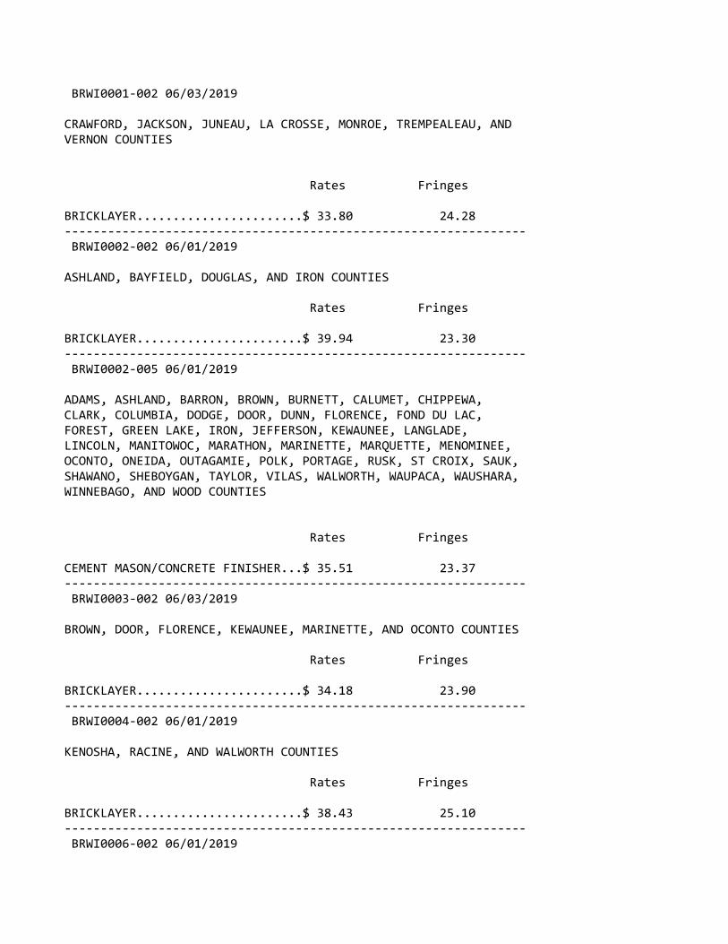
BRWI0001‐002 06/03/2019
CRAWFORD, JACKSON, JUNEAU, LA CROSSE, MONROE, TREMPEALEAU, ANDVERNON COUNTIES
Rates Fringes
BRICKLAYER.......................$ 33.80 24.28‐‐‐‐‐‐‐‐‐‐‐‐‐‐‐‐‐‐‐‐‐‐‐‐‐‐‐‐‐‐‐‐‐‐‐‐‐‐‐‐‐‐‐‐‐‐‐‐‐‐‐‐‐‐‐‐‐‐‐‐‐‐‐‐ BRWI0002‐002 06/01/2019
ASHLAND, BAYFIELD, DOUGLAS, AND IRON COUNTIES
Rates Fringes
BRICKLAYER.......................$ 39.94 23.30‐‐‐‐‐‐‐‐‐‐‐‐‐‐‐‐‐‐‐‐‐‐‐‐‐‐‐‐‐‐‐‐‐‐‐‐‐‐‐‐‐‐‐‐‐‐‐‐‐‐‐‐‐‐‐‐‐‐‐‐‐‐‐‐ BRWI0002‐005 06/01/2019
ADAMS, ASHLAND, BARRON, BROWN, BURNETT, CALUMET, CHIPPEWA,CLARK, COLUMBIA, DODGE, DOOR, DUNN, FLORENCE, FOND DU LAC,FOREST, GREEN LAKE, IRON, JEFFERSON, KEWAUNEE, LANGLADE,LINCOLN, MANITOWOC, MARATHON, MARINETTE, MARQUETTE, MENOMINEE,OCONTO, ONEIDA, OUTAGAMIE, POLK, PORTAGE, RUSK, ST CROIX, SAUK,SHAWANO, SHEBOYGAN, TAYLOR, VILAS, WALWORTH, WAUPACA, WAUSHARA,WINNEBAGO, AND WOOD COUNTIES
Rates Fringes
CEMENT MASON/CONCRETE FINISHER...$ 35.51 23.37‐‐‐‐‐‐‐‐‐‐‐‐‐‐‐‐‐‐‐‐‐‐‐‐‐‐‐‐‐‐‐‐‐‐‐‐‐‐‐‐‐‐‐‐‐‐‐‐‐‐‐‐‐‐‐‐‐‐‐‐‐‐‐‐ BRWI0003‐002 06/03/2019
BROWN, DOOR, FLORENCE, KEWAUNEE, MARINETTE, AND OCONTO COUNTIES
Rates Fringes
BRICKLAYER.......................$ 34.18 23.90‐‐‐‐‐‐‐‐‐‐‐‐‐‐‐‐‐‐‐‐‐‐‐‐‐‐‐‐‐‐‐‐‐‐‐‐‐‐‐‐‐‐‐‐‐‐‐‐‐‐‐‐‐‐‐‐‐‐‐‐‐‐‐‐ BRWI0004‐002 06/01/2019
KENOSHA, RACINE, AND WALWORTH COUNTIES
Rates Fringes
BRICKLAYER.......................$ 38.43 25.10‐‐‐‐‐‐‐‐‐‐‐‐‐‐‐‐‐‐‐‐‐‐‐‐‐‐‐‐‐‐‐‐‐‐‐‐‐‐‐‐‐‐‐‐‐‐‐‐‐‐‐‐‐‐‐‐‐‐‐‐‐‐‐‐ BRWI0006‐002 06/01/2019
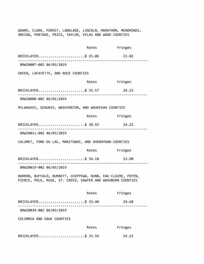
ADAMS, CLARK, FOREST, LANGLADE, LINCOLN, MARATHON, MENOMINEE,ONEIDA, PORTAGE, PRICE, TAYLOR, VILAS AND WOOD COUNTIES
Rates Fringes
BRICKLAYER.......................$ 35.06 23.02‐‐‐‐‐‐‐‐‐‐‐‐‐‐‐‐‐‐‐‐‐‐‐‐‐‐‐‐‐‐‐‐‐‐‐‐‐‐‐‐‐‐‐‐‐‐‐‐‐‐‐‐‐‐‐‐‐‐‐‐‐‐‐‐ BRWI0007‐002 06/03/2019
GREEN, LAFAYETTE, AND ROCK COUNTIES
Rates Fringes
BRICKLAYER.......................$ 35.57 24.22‐‐‐‐‐‐‐‐‐‐‐‐‐‐‐‐‐‐‐‐‐‐‐‐‐‐‐‐‐‐‐‐‐‐‐‐‐‐‐‐‐‐‐‐‐‐‐‐‐‐‐‐‐‐‐‐‐‐‐‐‐‐‐‐ BRWI0008‐002 06/01/2019
MILWAUKEE, OZAUKEE, WASHINGTON, AND WAUKESHA COUNTIES
Rates Fringes
BRICKLAYER.......................$ 38.93 24.22‐‐‐‐‐‐‐‐‐‐‐‐‐‐‐‐‐‐‐‐‐‐‐‐‐‐‐‐‐‐‐‐‐‐‐‐‐‐‐‐‐‐‐‐‐‐‐‐‐‐‐‐‐‐‐‐‐‐‐‐‐‐‐‐ BRWI0011‐002 06/03/2019
CALUMET, FOND DU LAC, MANITOWOC, AND SHEBOYGAN COUNTIES
Rates Fringes
BRICKLAYER.......................$ 34.18 23.90‐‐‐‐‐‐‐‐‐‐‐‐‐‐‐‐‐‐‐‐‐‐‐‐‐‐‐‐‐‐‐‐‐‐‐‐‐‐‐‐‐‐‐‐‐‐‐‐‐‐‐‐‐‐‐‐‐‐‐‐‐‐‐‐ BRWI0019‐002 06/03/2019
BARRON, BUFFALO, BURNETT, CHIPPEWA, DUNN, EAU CLAIRE, PEPIN,PIERCE, POLK, RUSK, ST. CROIX, SAWYER AND WASHBURN COUNTIES
Rates Fringes
BRICKLAYER.......................$ 33.40 24.68‐‐‐‐‐‐‐‐‐‐‐‐‐‐‐‐‐‐‐‐‐‐‐‐‐‐‐‐‐‐‐‐‐‐‐‐‐‐‐‐‐‐‐‐‐‐‐‐‐‐‐‐‐‐‐‐‐‐‐‐‐‐‐‐ BRWI0034‐002 06/03/2019
COLUMBIA AND SAUK COUNTIES
Rates Fringes
BRICKLAYER.......................$ 35.56 24.23

‐‐‐‐‐‐‐‐‐‐‐‐‐‐‐‐‐‐‐‐‐‐‐‐‐‐‐‐‐‐‐‐‐‐‐‐‐‐‐‐‐‐‐‐‐‐‐‐‐‐‐‐‐‐‐‐‐‐‐‐‐‐‐‐ CARP0087‐001 05/01/2016
BURNETT (W. of Hwy 48), PIERCE (W. of Hwy 29), POLK (W. of Hwys35, 48 & 65), AND ST. CROIX (W. of Hwy 65) COUNTIES
Rates Fringes
Carpenter & Piledrivermen........$ 36.85 18.39‐‐‐‐‐‐‐‐‐‐‐‐‐‐‐‐‐‐‐‐‐‐‐‐‐‐‐‐‐‐‐‐‐‐‐‐‐‐‐‐‐‐‐‐‐‐‐‐‐‐‐‐‐‐‐‐‐‐‐‐‐‐‐‐ CARP0252‐002 06/01/2016
ADAMS, BARRON, BAYFIELD (Eastern 2/3), BROWN, BUFFALO,BURNETT (E. of Hwy 48), CALUMET, CHIPPEWA, CLARK, COLUMBIA,CRAWFORD, DANE, DODGE, DOOR, DUNN, EAU CLAIRE, FLORENCE (exceptarea bordering Michigan State Line), FOND DU LAC, FOREST,GRANT, GREEN, GREEN LAKE, IOWA, IRON, JACKSON, JEFFERSON,JUNEAU, KEWAUNEE, LA CROSSE, LAFAYETTE, LANGLADE, LINCOLN,MANITOWOC, MARATHON, MARINETTE (except N.E. corner), MARQUETTE,MENOMINEE, MONROE, OCONTO, ONEIDA, OUTAGAMIE, PEPIN, PIERCE (E.of Hwys 29 & 65), POLK (E. of Hwys 35, 48 & 65), PORTAGE,PRICE, RICHLAND, ROCK, RUSK, SAUK, SAWYER, SHAWANO, SHEBOYGAN,ST CROIX (E. of Hwy 65), TAYLOR, TREMPEALEAU, VERNON, VILAS,WALWORTH, WASHBURN, WAUPACA, WAUSHARA, WINNEBAGO, AND WOODCOUNTIES
Rates Fringes
CARPENTER CARPENTER...................$ 33.56 18.00 MILLWRIGHT..................$ 35.08 18.35 PILEDRIVER..................$ 34.12 18.00‐‐‐‐‐‐‐‐‐‐‐‐‐‐‐‐‐‐‐‐‐‐‐‐‐‐‐‐‐‐‐‐‐‐‐‐‐‐‐‐‐‐‐‐‐‐‐‐‐‐‐‐‐‐‐‐‐‐‐‐‐‐‐‐ CARP0252‐010 06/01/2016
ASHLAND COUNTY
Rates Fringes
Carpenters Carpenter...................$ 33.56 18.00 Millwright..................$ 35.08 18.35 Pile Driver.................$ 34.12 18.00‐‐‐‐‐‐‐‐‐‐‐‐‐‐‐‐‐‐‐‐‐‐‐‐‐‐‐‐‐‐‐‐‐‐‐‐‐‐‐‐‐‐‐‐‐‐‐‐‐‐‐‐‐‐‐‐‐‐‐‐‐‐‐‐ CARP0264‐003 06/01/2016
KENOSHA, MILWAUKEE, OZAUKEE, RACINE, WAUKESHA, AND WASHINGTONCOUNTIES

Rates Fringes
CARPENTER........................$ 35.78 22.11‐‐‐‐‐‐‐‐‐‐‐‐‐‐‐‐‐‐‐‐‐‐‐‐‐‐‐‐‐‐‐‐‐‐‐‐‐‐‐‐‐‐‐‐‐‐‐‐‐‐‐‐‐‐‐‐‐‐‐‐‐‐‐‐ CARP0361‐004 05/01/2018
BAYFIELD (West of Hwy 63) AND DOUGLAS COUNTIES
Rates Fringes
CARPENTER........................$ 36.15 20.43‐‐‐‐‐‐‐‐‐‐‐‐‐‐‐‐‐‐‐‐‐‐‐‐‐‐‐‐‐‐‐‐‐‐‐‐‐‐‐‐‐‐‐‐‐‐‐‐‐‐‐‐‐‐‐‐‐‐‐‐‐‐‐‐ CARP2337‐001 06/01/2016
ZONE A: MILWAUKEE, OZAUKEE, WAUKESHA AND WASHINGTON
ZONE B: KENOSHA & RACINE
Rates Fringes
PILEDRIVERMAN Zone A......................$ 31.03 22.69 Zone B......................$ 31.03 22.69‐‐‐‐‐‐‐‐‐‐‐‐‐‐‐‐‐‐‐‐‐‐‐‐‐‐‐‐‐‐‐‐‐‐‐‐‐‐‐‐‐‐‐‐‐‐‐‐‐‐‐‐‐‐‐‐‐‐‐‐‐‐‐‐ ELEC0014‐002 06/03/2019
ASHLAND, BARRON, BAYFIELD, BUFFALO, BURNETT, CHIPPEWA, CLARK(except Maryville, Colby, Unity, Sherman, Fremont, Lynn &Sherwood), CRAWFORD, DUNN, EAU CLAIRE, GRANT, IRON, JACKSON, LACROSSE, MONROE, PEPIN, PIERCE, POLK, PRICE, RICHLAND, RUSK, STCROIX, SAWYER, TAYLOR, TREMPEALEAU, VERNON, AND WASHBURNCOUNTIES
Rates Fringes
Electricians:....................$ 35.59 20.87‐‐‐‐‐‐‐‐‐‐‐‐‐‐‐‐‐‐‐‐‐‐‐‐‐‐‐‐‐‐‐‐‐‐‐‐‐‐‐‐‐‐‐‐‐‐‐‐‐‐‐‐‐‐‐‐‐‐‐‐‐‐‐‐ ELEC0014‐007 06/03/2019
REMAINING COUNTIES
Rates Fringes
Teledata System Installer Installer/Technician........$ 27.25 14.34
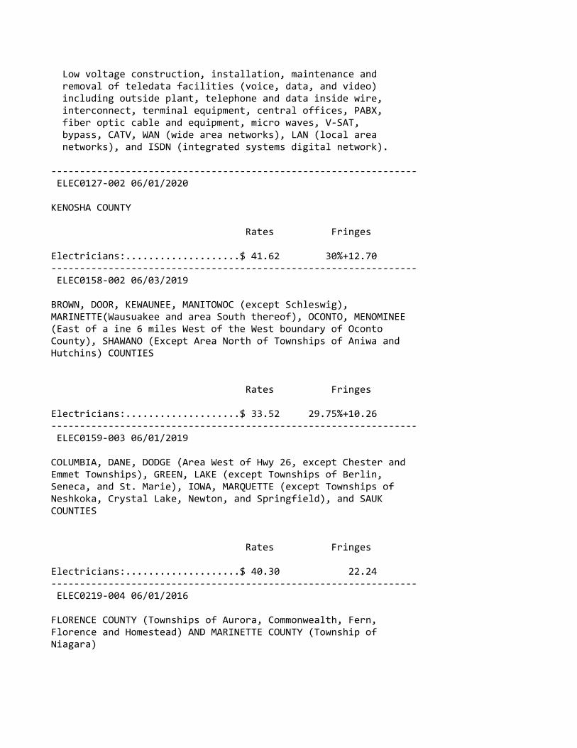
Low voltage construction, installation, maintenance and removal of teledata facilities (voice, data, and video) including outside plant, telephone and data inside wire, interconnect, terminal equipment, central offices, PABX, fiber optic cable and equipment, micro waves, V‐SAT, bypass, CATV, WAN (wide area networks), LAN (local area networks), and ISDN (integrated systems digital network).
‐‐‐‐‐‐‐‐‐‐‐‐‐‐‐‐‐‐‐‐‐‐‐‐‐‐‐‐‐‐‐‐‐‐‐‐‐‐‐‐‐‐‐‐‐‐‐‐‐‐‐‐‐‐‐‐‐‐‐‐‐‐‐‐ ELEC0127‐002 06/01/2020
KENOSHA COUNTY
Rates Fringes
Electricians:....................$ 41.62 30%+12.70‐‐‐‐‐‐‐‐‐‐‐‐‐‐‐‐‐‐‐‐‐‐‐‐‐‐‐‐‐‐‐‐‐‐‐‐‐‐‐‐‐‐‐‐‐‐‐‐‐‐‐‐‐‐‐‐‐‐‐‐‐‐‐‐ ELEC0158‐002 06/03/2019
BROWN, DOOR, KEWAUNEE, MANITOWOC (except Schleswig),MARINETTE(Wausuakee and area South thereof), OCONTO, MENOMINEE(East of a ine 6 miles West of the West boundary of OcontoCounty), SHAWANO (Except Area North of Townships of Aniwa andHutchins) COUNTIES
Rates Fringes
Electricians:....................$ 33.52 29.75%+10.26‐‐‐‐‐‐‐‐‐‐‐‐‐‐‐‐‐‐‐‐‐‐‐‐‐‐‐‐‐‐‐‐‐‐‐‐‐‐‐‐‐‐‐‐‐‐‐‐‐‐‐‐‐‐‐‐‐‐‐‐‐‐‐‐ ELEC0159‐003 06/01/2019
COLUMBIA, DANE, DODGE (Area West of Hwy 26, except Chester andEmmet Townships), GREEN, LAKE (except Townships of Berlin,Seneca, and St. Marie), IOWA, MARQUETTE (except Townships ofNeshkoka, Crystal Lake, Newton, and Springfield), and SAUKCOUNTIES
Rates Fringes
Electricians:....................$ 40.30 22.24‐‐‐‐‐‐‐‐‐‐‐‐‐‐‐‐‐‐‐‐‐‐‐‐‐‐‐‐‐‐‐‐‐‐‐‐‐‐‐‐‐‐‐‐‐‐‐‐‐‐‐‐‐‐‐‐‐‐‐‐‐‐‐‐ ELEC0219‐004 06/01/2016
FLORENCE COUNTY (Townships of Aurora, Commonwealth, Fern,Florence and Homestead) AND MARINETTE COUNTY (Township ofNiagara)
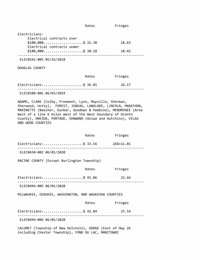
Rates Fringes
Electricians: Electrical contracts over $180,000....................$ 32.38 18.63 Electrical contracts under $180,000....................$ 30.18 18.42‐‐‐‐‐‐‐‐‐‐‐‐‐‐‐‐‐‐‐‐‐‐‐‐‐‐‐‐‐‐‐‐‐‐‐‐‐‐‐‐‐‐‐‐‐‐‐‐‐‐‐‐‐‐‐‐‐‐‐‐‐‐‐‐ ELEC0242‐005 05/16/2018
DOUGLAS COUNTY
Rates Fringes
Electricians:....................$ 36.85 26.17‐‐‐‐‐‐‐‐‐‐‐‐‐‐‐‐‐‐‐‐‐‐‐‐‐‐‐‐‐‐‐‐‐‐‐‐‐‐‐‐‐‐‐‐‐‐‐‐‐‐‐‐‐‐‐‐‐‐‐‐‐‐‐‐ ELEC0388‐002 06/03/2019
ADAMS, CLARK (Colby, Freemont, Lynn, Mayville, Sherman,Sherwood, Unity), FOREST, JUNEAU, LANGLADE, LINCOLN, MARATHON,MARINETTE (Beecher, Dunbar, Goodman & Pembine), MENOMINEE (AreaWest of a line 6 miles West of the West boundary of OcontoCounty), ONEIDA, PORTAGE, SHAWANO (Aniwa and Hutchins), VILASAND WOOD COUNTIES
Rates Fringes
Electricians:....................$ 33.56 26%+11.01‐‐‐‐‐‐‐‐‐‐‐‐‐‐‐‐‐‐‐‐‐‐‐‐‐‐‐‐‐‐‐‐‐‐‐‐‐‐‐‐‐‐‐‐‐‐‐‐‐‐‐‐‐‐‐‐‐‐‐‐‐‐‐‐ ELEC0430‐002 06/01/2020
RACINE COUNTY (Except Burlington Township)
Rates Fringes
Electricians:....................$ 41.86 22.66‐‐‐‐‐‐‐‐‐‐‐‐‐‐‐‐‐‐‐‐‐‐‐‐‐‐‐‐‐‐‐‐‐‐‐‐‐‐‐‐‐‐‐‐‐‐‐‐‐‐‐‐‐‐‐‐‐‐‐‐‐‐‐‐ ELEC0494‐005 06/01/2020
MILWAUKEE, OZAUKEE, WASHINGTON, AND WAUKESHA COUNTIES
Rates Fringes
Electricians:....................$ 42.84 25.54‐‐‐‐‐‐‐‐‐‐‐‐‐‐‐‐‐‐‐‐‐‐‐‐‐‐‐‐‐‐‐‐‐‐‐‐‐‐‐‐‐‐‐‐‐‐‐‐‐‐‐‐‐‐‐‐‐‐‐‐‐‐‐‐ ELEC0494‐006 06/01/2020
CALUMET (Township of New Holstein), DODGE (East of Hwy 26including Chester Township), FOND DU LAC, MANITOWOC

(Schleswig), and SHEBOYGAN COUNTIES
Rates Fringes
Electricians:....................$ 36.32 22.51‐‐‐‐‐‐‐‐‐‐‐‐‐‐‐‐‐‐‐‐‐‐‐‐‐‐‐‐‐‐‐‐‐‐‐‐‐‐‐‐‐‐‐‐‐‐‐‐‐‐‐‐‐‐‐‐‐‐‐‐‐‐‐‐* ELEC0494‐013 06/07/2020
DODGE (East of Hwy 26 including Chester Twp, excluding EmmetTwp), FOND DU LAC (Except Waupuin), MILWAUKEE, OZAUKEE,MANITOWOC (Schleswig), WASHINGTON, AND WAUKESHA COUNTIES
Rates Fringes
Sound & Communications Installer...................$ 21.46 18.52 Technician..................$ 31.34 20.00
Installation, testing, maintenance, operation and servicing of all sound, intercom, telephone interconnect, closed circuit TV systems, radio systems, background music systems, language laboratories, electronic carillion, antenna distribution systems, clock and program systems and low‐voltage systems such as visual nurse call, audio/visual nurse call systems, doctors entrance register systems. Includes all wire and cable carrying audio, visual, data, light and radio frequency signals. Includes the installation of conduit, wiremold, or raceways in existing structures that have been occupied for six months or more where required for the protection of the wire or cable, but does not mean a complete conduit or raceway system. work covered does not include the installation of conduit, wiremold or any raceways in any new construction, or the installation of power supply outlets by means of which external electric power is supplied to any of the foregoing equipment or products
‐‐‐‐‐‐‐‐‐‐‐‐‐‐‐‐‐‐‐‐‐‐‐‐‐‐‐‐‐‐‐‐‐‐‐‐‐‐‐‐‐‐‐‐‐‐‐‐‐‐‐‐‐‐‐‐‐‐‐‐‐‐‐‐ ELEC0577‐003 06/01/2019
CALUMET (except Township of New Holstein), GREEN LAKE (N. partincluding Townships of Berlin, St Marie, and Seneca), MARQUETTE(N. part including Townships of Crystal Lake, Neshkoro, Newton,and Springfield), OUTAGAMIE, WAUPACA, WAUSHARA, AND WINNEBAGOCOUNTIES
Rates Fringes
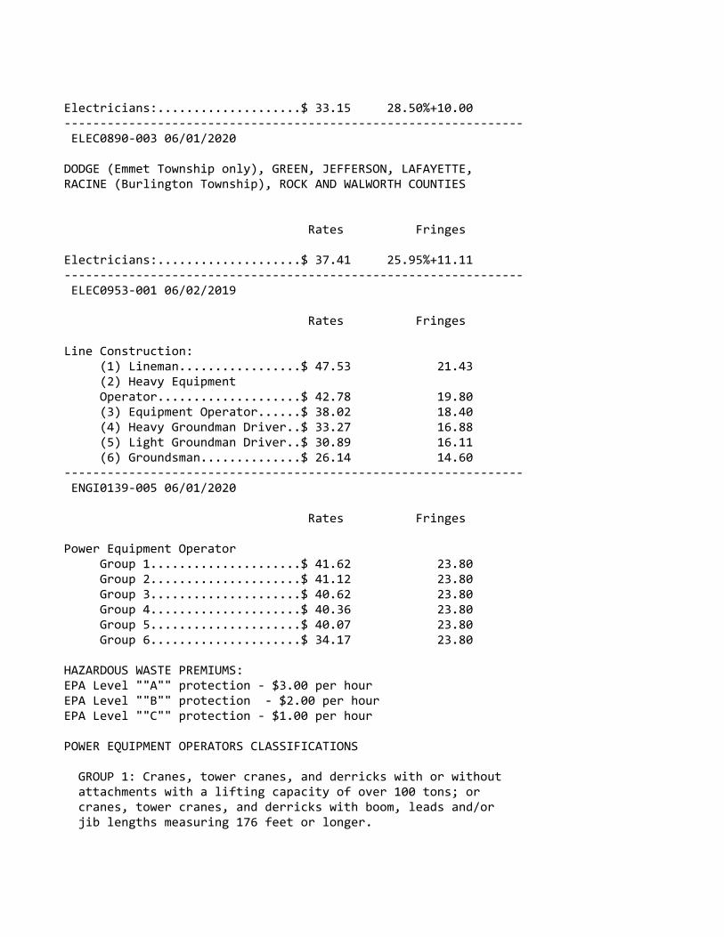
Electricians:....................$ 33.15 28.50%+10.00‐‐‐‐‐‐‐‐‐‐‐‐‐‐‐‐‐‐‐‐‐‐‐‐‐‐‐‐‐‐‐‐‐‐‐‐‐‐‐‐‐‐‐‐‐‐‐‐‐‐‐‐‐‐‐‐‐‐‐‐‐‐‐‐ ELEC0890‐003 06/01/2020
DODGE (Emmet Township only), GREEN, JEFFERSON, LAFAYETTE,RACINE (Burlington Township), ROCK AND WALWORTH COUNTIES
Rates Fringes
Electricians:....................$ 37.41 25.95%+11.11‐‐‐‐‐‐‐‐‐‐‐‐‐‐‐‐‐‐‐‐‐‐‐‐‐‐‐‐‐‐‐‐‐‐‐‐‐‐‐‐‐‐‐‐‐‐‐‐‐‐‐‐‐‐‐‐‐‐‐‐‐‐‐‐ ELEC0953‐001 06/02/2019
Rates Fringes
Line Construction: (1) Lineman.................$ 47.53 21.43 (2) Heavy Equipment Operator....................$ 42.78 19.80 (3) Equipment Operator......$ 38.02 18.40 (4) Heavy Groundman Driver..$ 33.27 16.88 (5) Light Groundman Driver..$ 30.89 16.11 (6) Groundsman..............$ 26.14 14.60‐‐‐‐‐‐‐‐‐‐‐‐‐‐‐‐‐‐‐‐‐‐‐‐‐‐‐‐‐‐‐‐‐‐‐‐‐‐‐‐‐‐‐‐‐‐‐‐‐‐‐‐‐‐‐‐‐‐‐‐‐‐‐‐ ENGI0139‐005 06/01/2020
Rates Fringes
Power Equipment Operator Group 1.....................$ 41.62 23.80 Group 2.....................$ 41.12 23.80 Group 3.....................$ 40.62 23.80 Group 4.....................$ 40.36 23.80 Group 5.....................$ 40.07 23.80 Group 6.....................$ 34.17 23.80
HAZARDOUS WASTE PREMIUMS:EPA Level ""A"" protection ‐ $3.00 per hourEPA Level ""B"" protection ‐ $2.00 per hourEPA Level ""C"" protection ‐ $1.00 per hour
POWER EQUIPMENT OPERATORS CLASSIFICATIONS
GROUP 1: Cranes, tower cranes, and derricks with or without attachments with a lifting capacity of over 100 tons; or cranes, tower cranes, and derricks with boom, leads and/or jib lengths measuring 176 feet or longer.
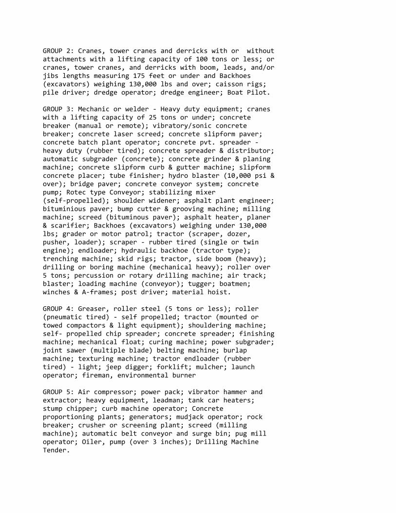
GROUP 2: Cranes, tower cranes and derricks with or without attachments with a lifting capacity of 100 tons or less; or cranes, tower cranes, and derricks with boom, leads, and/or jibs lengths measuring 175 feet or under and Backhoes (excavators) weighing 130,000 lbs and over; caisson rigs; pile driver; dredge operator; dredge engineer; Boat Pilot.
GROUP 3: Mechanic or welder ‐ Heavy duty equipment; cranes with a lifting capacity of 25 tons or under; concrete breaker (manual or remote); vibratory/sonic concrete breaker; concrete laser screed; concrete slipform paver; concrete batch plant operator; concrete pvt. spreader ‐ heavy duty (rubber tired); concrete spreader & distributor; automatic subgrader (concrete); concrete grinder & planing machine; concrete slipform curb & gutter machine; slipform concrete placer; tube finisher; hydro blaster (10,000 psi & over); bridge paver; concrete conveyor system; concrete pump; Rotec type Conveyor; stabilizing mixer (self‐propelled); shoulder widener; asphalt plant engineer; bituminious paver; bump cutter & grooving machine; milling machine; screed (bituminous paver); asphalt heater, planer & scarifier; Backhoes (excavators) weighing under 130,000 lbs; grader or motor patrol; tractor (scraper, dozer, pusher, loader); scraper ‐ rubber tired (single or twin engine); endloader; hydraulic backhoe (tractor type); trenching machine; skid rigs; tractor, side boom (heavy); drilling or boring machine (mechanical heavy); roller over 5 tons; percussion or rotary drilling machine; air track; blaster; loading machine (conveyor); tugger; boatmen; winches & A‐frames; post driver; material hoist.
GROUP 4: Greaser, roller steel (5 tons or less); roller (pneumatic tired) ‐ self propelled; tractor (mounted or towed compactors & light equipment); shouldering machine; self‐ propelled chip spreader; concrete spreader; finishing machine; mechanical float; curing machine; power subgrader; joint sawer (multiple blade) belting machine; burlap machine; texturing machine; tractor endloader (rubber tired) ‐ light; jeep digger; forklift; mulcher; launch operator; fireman, environmental burner
GROUP 5: Air compressor; power pack; vibrator hammer and extractor; heavy equipment, leadman; tank car heaters; stump chipper; curb machine operator; Concrete proportioning plants; generators; mudjack operator; rock breaker; crusher or screening plant; screed (milling machine); automatic belt conveyor and surge bin; pug mill operator; Oiler, pump (over 3 inches); Drilling Machine Tender.
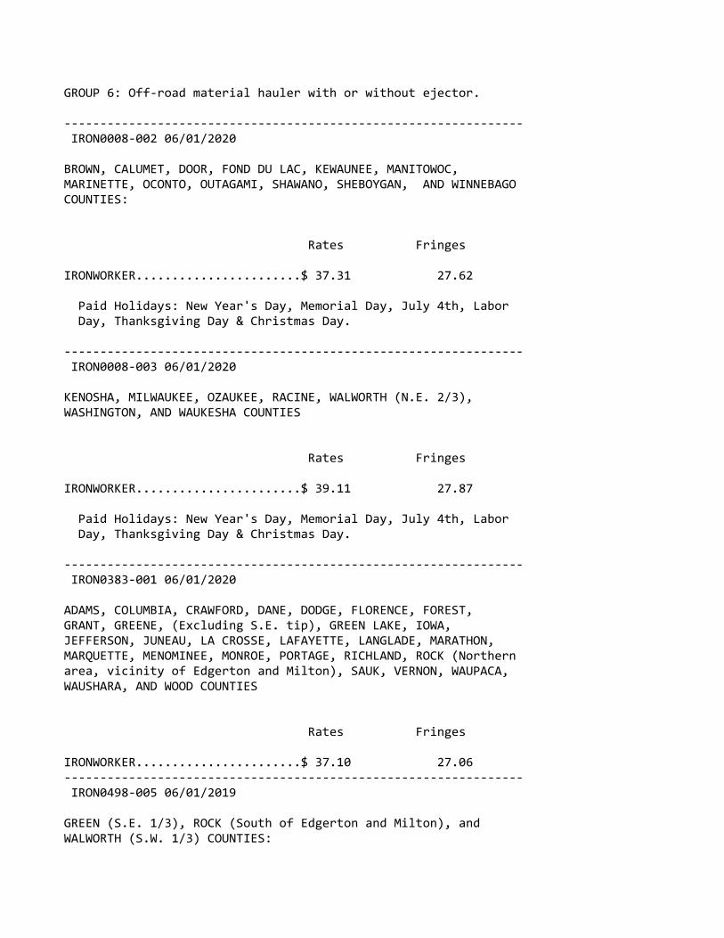
GROUP 6: Off‐road material hauler with or without ejector.
‐‐‐‐‐‐‐‐‐‐‐‐‐‐‐‐‐‐‐‐‐‐‐‐‐‐‐‐‐‐‐‐‐‐‐‐‐‐‐‐‐‐‐‐‐‐‐‐‐‐‐‐‐‐‐‐‐‐‐‐‐‐‐‐ IRON0008‐002 06/01/2020
BROWN, CALUMET, DOOR, FOND DU LAC, KEWAUNEE, MANITOWOC,MARINETTE, OCONTO, OUTAGAMI, SHAWANO, SHEBOYGAN, AND WINNEBAGOCOUNTIES:
Rates Fringes
IRONWORKER.......................$ 37.31 27.62
Paid Holidays: New Year's Day, Memorial Day, July 4th, Labor Day, Thanksgiving Day & Christmas Day.
‐‐‐‐‐‐‐‐‐‐‐‐‐‐‐‐‐‐‐‐‐‐‐‐‐‐‐‐‐‐‐‐‐‐‐‐‐‐‐‐‐‐‐‐‐‐‐‐‐‐‐‐‐‐‐‐‐‐‐‐‐‐‐‐ IRON0008‐003 06/01/2020
KENOSHA, MILWAUKEE, OZAUKEE, RACINE, WALWORTH (N.E. 2/3),WASHINGTON, AND WAUKESHA COUNTIES
Rates Fringes
IRONWORKER.......................$ 39.11 27.87
Paid Holidays: New Year's Day, Memorial Day, July 4th, Labor Day, Thanksgiving Day & Christmas Day.
‐‐‐‐‐‐‐‐‐‐‐‐‐‐‐‐‐‐‐‐‐‐‐‐‐‐‐‐‐‐‐‐‐‐‐‐‐‐‐‐‐‐‐‐‐‐‐‐‐‐‐‐‐‐‐‐‐‐‐‐‐‐‐‐ IRON0383‐001 06/01/2020
ADAMS, COLUMBIA, CRAWFORD, DANE, DODGE, FLORENCE, FOREST,GRANT, GREENE, (Excluding S.E. tip), GREEN LAKE, IOWA,JEFFERSON, JUNEAU, LA CROSSE, LAFAYETTE, LANGLADE, MARATHON,MARQUETTE, MENOMINEE, MONROE, PORTAGE, RICHLAND, ROCK (Northernarea, vicinity of Edgerton and Milton), SAUK, VERNON, WAUPACA,WAUSHARA, AND WOOD COUNTIES
Rates Fringes
IRONWORKER.......................$ 37.10 27.06‐‐‐‐‐‐‐‐‐‐‐‐‐‐‐‐‐‐‐‐‐‐‐‐‐‐‐‐‐‐‐‐‐‐‐‐‐‐‐‐‐‐‐‐‐‐‐‐‐‐‐‐‐‐‐‐‐‐‐‐‐‐‐‐ IRON0498‐005 06/01/2019
GREEN (S.E. 1/3), ROCK (South of Edgerton and Milton), andWALWORTH (S.W. 1/3) COUNTIES:

Rates Fringes
IRONWORKER.......................$ 40.25 40.53‐‐‐‐‐‐‐‐‐‐‐‐‐‐‐‐‐‐‐‐‐‐‐‐‐‐‐‐‐‐‐‐‐‐‐‐‐‐‐‐‐‐‐‐‐‐‐‐‐‐‐‐‐‐‐‐‐‐‐‐‐‐‐‐ IRON0512‐008 06/03/2019
BARRON, BUFFALO, CHIPPEWA, CLARK, DUNN, EAU CLAIRE, JACKSON,PEPIN, PIERCE, POLK, RUSK, ST CROIX, TAYLOR, AND TREMPEALEAUCOUNTIES
Rates Fringes
IRONWORKER.......................$ 37.60 29.40‐‐‐‐‐‐‐‐‐‐‐‐‐‐‐‐‐‐‐‐‐‐‐‐‐‐‐‐‐‐‐‐‐‐‐‐‐‐‐‐‐‐‐‐‐‐‐‐‐‐‐‐‐‐‐‐‐‐‐‐‐‐‐‐ IRON0512‐021 06/03/2019
ASHLAND, BAYFIELD, BURNETT, DOUGLAS, IRON, LINCOLN, ONEIDA,PRICE, SAWYER, VILAS AND WASHBURN COUNTIES
Rates Fringes
IRONWORKER.......................$ 33.19 29.40‐‐‐‐‐‐‐‐‐‐‐‐‐‐‐‐‐‐‐‐‐‐‐‐‐‐‐‐‐‐‐‐‐‐‐‐‐‐‐‐‐‐‐‐‐‐‐‐‐‐‐‐‐‐‐‐‐‐‐‐‐‐‐‐* LABO0113‐002 06/01/2020
MILWAUKEE AND WAUKESHA COUNTIES
Rates Fringes
LABORER Group 1.....................$ 30.05 22.26 Group 2.....................$ 30.20 22.26 Group 3.....................$ 30.40 22.26 Group 4.....................$ 30.55 22.26 Group 5.....................$ 30.70 22.26 Group 6.....................$ 26.54 22.26
LABORERS CLASSIFICATIONS
GROUP 1: General Laborer; Tree Trimmer; Conduit Layer; Demolition and Wrecking Laborer; Guard Rail, Fence, and Bridge Builder; Landscaper; Multiplate Culvert Assembler; Stone Handler; Bituminous Worker (Shoveler, Loader, and Utility Man); Batch Truck Dumper or Cement Handler; Bituminous Worker (Dumper, Ironer, Smoother, and Tamper); Concrete Handler
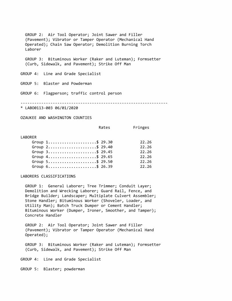
GROUP 2: Air Tool Operator; Joint Sawer and Filler (Pavement); Vibrator or Tamper Operator (Mechanical Hand Operated); Chain Saw Operator; Demolition Burning Torch Laborer
GROUP 3: Bituminous Worker (Raker and Luteman); Formsetter (Curb, Sidewalk, and Pavement); Strike Off Man
GROUP 4: Line and Grade Specialist
GROUP 5: Blaster and Powderman
GROUP 6: Flagperson; traffic control person
‐‐‐‐‐‐‐‐‐‐‐‐‐‐‐‐‐‐‐‐‐‐‐‐‐‐‐‐‐‐‐‐‐‐‐‐‐‐‐‐‐‐‐‐‐‐‐‐‐‐‐‐‐‐‐‐‐‐‐‐‐‐‐‐* LABO0113‐003 06/01/2020
OZAUKEE AND WASHINGTON COUNTIES
Rates Fringes
LABORER Group 1.....................$ 29.30 22.26 Group 2.....................$ 29.40 22.26 Group 3.....................$ 29.45 22.26 Group 4.....................$ 29.65 22.26 Group 5.....................$ 29.50 22.26 Group 6.....................$ 26.39 22.26
LABORERS CLASSIFICATIONS
GROUP 1: General Laborer; Tree Trimmer; Conduit Layer; Demolition and Wrecking Laborer; Guard Rail, Fence, and Bridge Builder; Landscaper; Multiplate Culvert Assembler; Stone Handler; Bituminous Worker (Shoveler, Loader, and Utility Man); Batch Truck Dumper or Cement Handler; Bituminous Worker (Dumper, Ironer, Smoother, and Tamper); Concrete Handler
GROUP 2: Air Tool Operator; Joint Sawer and Filler (Pavement); Vibrator or Tamper Operator (Mechanical Hand Operated);
GROUP 3: Bituminous Worker (Raker and Luteman); Formsetter (Curb, Sidewalk, and Pavement); Strike Off Man
GROUP 4: Line and Grade Specialist
GROUP 5: Blaster; powderman
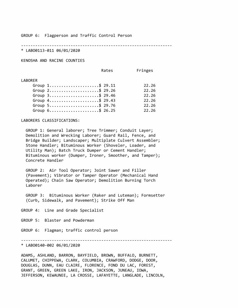
GROUP 6: Flagperson and Traffic Control Person
‐‐‐‐‐‐‐‐‐‐‐‐‐‐‐‐‐‐‐‐‐‐‐‐‐‐‐‐‐‐‐‐‐‐‐‐‐‐‐‐‐‐‐‐‐‐‐‐‐‐‐‐‐‐‐‐‐‐‐‐‐‐‐‐* LABO0113‐011 06/01/2020
KENOSHA AND RACINE COUNTIES
Rates Fringes
LABORER Group 1.....................$ 29.11 22.26 Group 2.....................$ 29.26 22.26 Group 3.....................$ 29.46 22.26 Group 4.....................$ 29.43 22.26 Group 5.....................$ 29.76 22.26 Group 6.....................$ 26.25 22.26
LABORERS CLASSIFICATIONS:
GROUP 1: General laborer; Tree Trimmer; Conduit Layer; Demolition and Wrecking Laborer; Guard Rail, Fence, and Bridge Builder; Landscaper; Multiplate Culvert Assembler; Stone Handler; Bituminous Worker (Shoveler, Loader, and Utility Man); Batch Truck Dumper or Cement Handler; Bituminous worker (Dumper, Ironer, Smoother, and Tamper); Concrete Handler
GROUP 2: Air Tool Operator; Joint Sawer and Filler (Pavement); Vibrator or Tamper Operator (Mechanical Hand Operated); Chain Saw Operator; Demolition Burning Torch Laborer
GROUP 3: Bituminous Worker (Raker and Luteman); Formsetter (Curb, Sidewalk, and Pavement); Strike Off Man
GROUP 4: Line and Grade Specialist
GROUP 5: Blaster and Powderman
GROUP 6: Flagman; traffic control person
‐‐‐‐‐‐‐‐‐‐‐‐‐‐‐‐‐‐‐‐‐‐‐‐‐‐‐‐‐‐‐‐‐‐‐‐‐‐‐‐‐‐‐‐‐‐‐‐‐‐‐‐‐‐‐‐‐‐‐‐‐‐‐‐* LABO0140‐002 06/01/2020
ADAMS, ASHLAND, BARRON, BAYFIELD, BROWN, BUFFALO, BURNETT,CALUMET, CHIPPEWA, CLARK, COLUMBIA, CRAWFORD, DODGE, DOOR,DOUGLAS, DUNN, EAU CLAIRE, FLORENCE, FOND DU LAC, FOREST,GRANT, GREEN, GREEN LAKE, IRON, JACKSON, JUNEAU, IOWA,JEFFERSON, KEWAUNEE, LA CROSSE, LAFAYETTE, LANGLADE, LINCOLN,
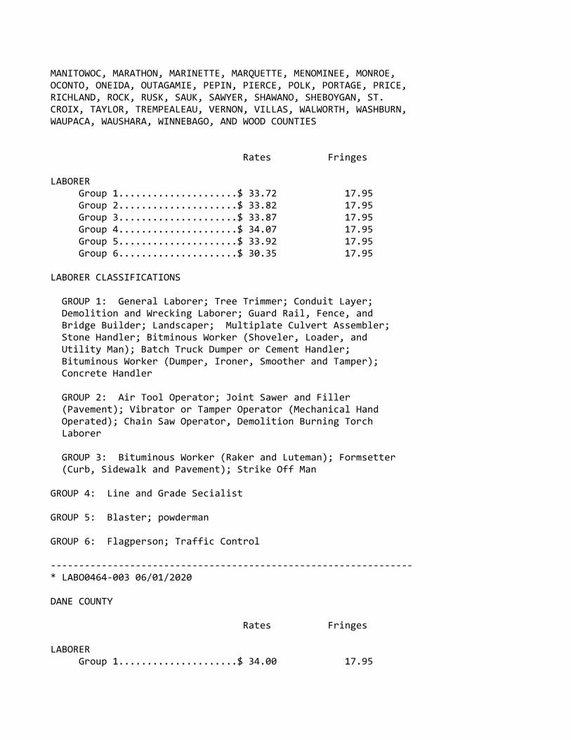
MANITOWOC, MARATHON, MARINETTE, MARQUETTE, MENOMINEE, MONROE,OCONTO, ONEIDA, OUTAGAMIE, PEPIN, PIERCE, POLK, PORTAGE, PRICE,RICHLAND, ROCK, RUSK, SAUK, SAWYER, SHAWANO, SHEBOYGAN, ST.CROIX, TAYLOR, TREMPEALEAU, VERNON, VILLAS, WALWORTH, WASHBURN,WAUPACA, WAUSHARA, WINNEBAGO, AND WOOD COUNTIES
Rates Fringes
LABORER Group 1.....................$ 33.72 17.95 Group 2.....................$ 33.82 17.95 Group 3.....................$ 33.87 17.95 Group 4.....................$ 34.07 17.95 Group 5.....................$ 33.92 17.95 Group 6.....................$ 30.35 17.95
LABORER CLASSIFICATIONS
GROUP 1: General Laborer; Tree Trimmer; Conduit Layer; Demolition and Wrecking Laborer; Guard Rail, Fence, and Bridge Builder; Landscaper; Multiplate Culvert Assembler; Stone Handler; Bitminous Worker (Shoveler, Loader, and Utility Man); Batch Truck Dumper or Cement Handler; Bituminous Worker (Dumper, Ironer, Smoother and Tamper); Concrete Handler
GROUP 2: Air Tool Operator; Joint Sawer and Filler (Pavement); Vibrator or Tamper Operator (Mechanical Hand Operated); Chain Saw Operator, Demolition Burning Torch Laborer
GROUP 3: Bituminous Worker (Raker and Luteman); Formsetter (Curb, Sidewalk and Pavement); Strike Off Man
GROUP 4: Line and Grade Secialist
GROUP 5: Blaster; powderman
GROUP 6: Flagperson; Traffic Control
‐‐‐‐‐‐‐‐‐‐‐‐‐‐‐‐‐‐‐‐‐‐‐‐‐‐‐‐‐‐‐‐‐‐‐‐‐‐‐‐‐‐‐‐‐‐‐‐‐‐‐‐‐‐‐‐‐‐‐‐‐‐‐‐* LABO0464‐003 06/01/2020
DANE COUNTY
Rates Fringes
LABORER Group 1.....................$ 34.00 17.95
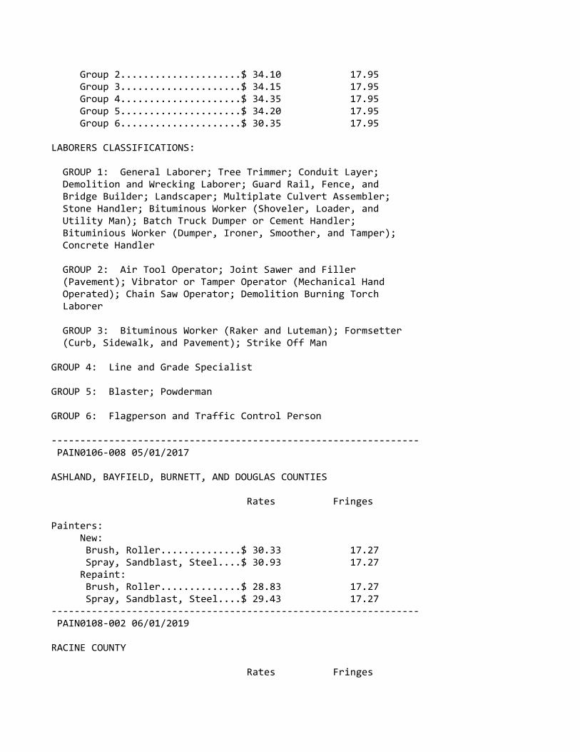
Group 2.....................$ 34.10 17.95 Group 3.....................$ 34.15 17.95 Group 4.....................$ 34.35 17.95 Group 5.....................$ 34.20 17.95 Group 6.....................$ 30.35 17.95
LABORERS CLASSIFICATIONS:
GROUP 1: General Laborer; Tree Trimmer; Conduit Layer; Demolition and Wrecking Laborer; Guard Rail, Fence, and Bridge Builder; Landscaper; Multiplate Culvert Assembler; Stone Handler; Bituminous Worker (Shoveler, Loader, and Utility Man); Batch Truck Dumper or Cement Handler; Bituminious Worker (Dumper, Ironer, Smoother, and Tamper); Concrete Handler
GROUP 2: Air Tool Operator; Joint Sawer and Filler (Pavement); Vibrator or Tamper Operator (Mechanical Hand Operated); Chain Saw Operator; Demolition Burning Torch Laborer
GROUP 3: Bituminous Worker (Raker and Luteman); Formsetter (Curb, Sidewalk, and Pavement); Strike Off Man
GROUP 4: Line and Grade Specialist
GROUP 5: Blaster; Powderman
GROUP 6: Flagperson and Traffic Control Person
‐‐‐‐‐‐‐‐‐‐‐‐‐‐‐‐‐‐‐‐‐‐‐‐‐‐‐‐‐‐‐‐‐‐‐‐‐‐‐‐‐‐‐‐‐‐‐‐‐‐‐‐‐‐‐‐‐‐‐‐‐‐‐‐ PAIN0106‐008 05/01/2017
ASHLAND, BAYFIELD, BURNETT, AND DOUGLAS COUNTIES
Rates Fringes
Painters: New: Brush, Roller..............$ 30.33 17.27 Spray, Sandblast, Steel....$ 30.93 17.27 Repaint: Brush, Roller..............$ 28.83 17.27 Spray, Sandblast, Steel....$ 29.43 17.27‐‐‐‐‐‐‐‐‐‐‐‐‐‐‐‐‐‐‐‐‐‐‐‐‐‐‐‐‐‐‐‐‐‐‐‐‐‐‐‐‐‐‐‐‐‐‐‐‐‐‐‐‐‐‐‐‐‐‐‐‐‐‐‐ PAIN0108‐002 06/01/2019
RACINE COUNTY
Rates Fringes

Painters: Brush, Roller...............$ 36.08 20.36 Spray & Sandblast...........$ 37.08 20.36‐‐‐‐‐‐‐‐‐‐‐‐‐‐‐‐‐‐‐‐‐‐‐‐‐‐‐‐‐‐‐‐‐‐‐‐‐‐‐‐‐‐‐‐‐‐‐‐‐‐‐‐‐‐‐‐‐‐‐‐‐‐‐‐ PAIN0259‐002 05/01/2008
BARRON, CHIPPEWA, DUNN, EAU CLAIRE, PEPIN, PIERCE, POLK, RUSK,SAWYER, ST. CROIX, AND WASHBURN COUNTIES
Rates Fringes
PAINTER..........................$ 24.11 12.15‐‐‐‐‐‐‐‐‐‐‐‐‐‐‐‐‐‐‐‐‐‐‐‐‐‐‐‐‐‐‐‐‐‐‐‐‐‐‐‐‐‐‐‐‐‐‐‐‐‐‐‐‐‐‐‐‐‐‐‐‐‐‐‐ PAIN0259‐004 05/01/2015
BUFFALO, CRAWFORD, JACKSON, LA CROSSE, MONROE, TREMPEALEAU, ANDVERNON COUNTIES
Rates Fringes
PAINTER..........................$ 22.03 12.45‐‐‐‐‐‐‐‐‐‐‐‐‐‐‐‐‐‐‐‐‐‐‐‐‐‐‐‐‐‐‐‐‐‐‐‐‐‐‐‐‐‐‐‐‐‐‐‐‐‐‐‐‐‐‐‐‐‐‐‐‐‐‐‐ PAIN0781‐002 06/01/2019
JEFFERSON, MILWAUKEE, OZAUKEE, WASHINGTON, AND WAUKESHA COUNTIES
Rates Fringes
Painters: Bridge......................$ 33.30 23.86 Brush.......................$ 32.95 23.86 Spray & Sandblast...........$ 33.70 23.86‐‐‐‐‐‐‐‐‐‐‐‐‐‐‐‐‐‐‐‐‐‐‐‐‐‐‐‐‐‐‐‐‐‐‐‐‐‐‐‐‐‐‐‐‐‐‐‐‐‐‐‐‐‐‐‐‐‐‐‐‐‐‐‐ PAIN0802‐002 06/01/2019
COLUMBIA, DANE, DODGE, GRANT, GREEN, IOWA, LAFAYETTE, RICHLAND,ROCK, AND SAUK COUNTIES
Rates Fringes
PAINTER Brush.......................$ 30.93 18.44
PREMIUM PAY: Structural Steel, Spray, Bridges = $1.00 additional per hour.
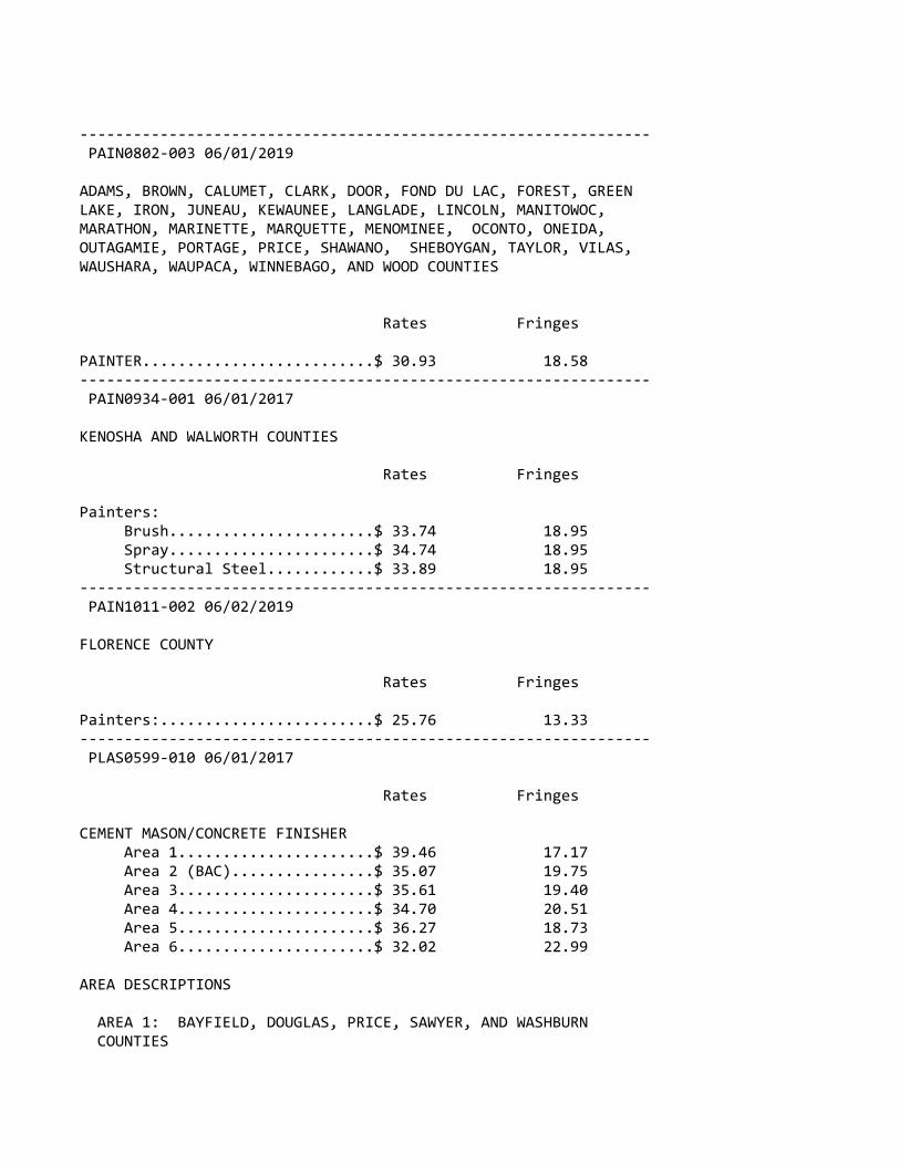
‐‐‐‐‐‐‐‐‐‐‐‐‐‐‐‐‐‐‐‐‐‐‐‐‐‐‐‐‐‐‐‐‐‐‐‐‐‐‐‐‐‐‐‐‐‐‐‐‐‐‐‐‐‐‐‐‐‐‐‐‐‐‐‐ PAIN0802‐003 06/01/2019
ADAMS, BROWN, CALUMET, CLARK, DOOR, FOND DU LAC, FOREST, GREENLAKE, IRON, JUNEAU, KEWAUNEE, LANGLADE, LINCOLN, MANITOWOC,MARATHON, MARINETTE, MARQUETTE, MENOMINEE, OCONTO, ONEIDA,OUTAGAMIE, PORTAGE, PRICE, SHAWANO, SHEBOYGAN, TAYLOR, VILAS,WAUSHARA, WAUPACA, WINNEBAGO, AND WOOD COUNTIES
Rates Fringes
PAINTER..........................$ 30.93 18.58‐‐‐‐‐‐‐‐‐‐‐‐‐‐‐‐‐‐‐‐‐‐‐‐‐‐‐‐‐‐‐‐‐‐‐‐‐‐‐‐‐‐‐‐‐‐‐‐‐‐‐‐‐‐‐‐‐‐‐‐‐‐‐‐ PAIN0934‐001 06/01/2017
KENOSHA AND WALWORTH COUNTIES
Rates Fringes
Painters: Brush.......................$ 33.74 18.95 Spray.......................$ 34.74 18.95 Structural Steel............$ 33.89 18.95‐‐‐‐‐‐‐‐‐‐‐‐‐‐‐‐‐‐‐‐‐‐‐‐‐‐‐‐‐‐‐‐‐‐‐‐‐‐‐‐‐‐‐‐‐‐‐‐‐‐‐‐‐‐‐‐‐‐‐‐‐‐‐‐ PAIN1011‐002 06/02/2019
FLORENCE COUNTY
Rates Fringes
Painters:........................$ 25.76 13.33‐‐‐‐‐‐‐‐‐‐‐‐‐‐‐‐‐‐‐‐‐‐‐‐‐‐‐‐‐‐‐‐‐‐‐‐‐‐‐‐‐‐‐‐‐‐‐‐‐‐‐‐‐‐‐‐‐‐‐‐‐‐‐‐ PLAS0599‐010 06/01/2017
Rates Fringes
CEMENT MASON/CONCRETE FINISHER Area 1......................$ 39.46 17.17 Area 2 (BAC)................$ 35.07 19.75 Area 3......................$ 35.61 19.40 Area 4......................$ 34.70 20.51 Area 5......................$ 36.27 18.73 Area 6......................$ 32.02 22.99
AREA DESCRIPTIONS
AREA 1: BAYFIELD, DOUGLAS, PRICE, SAWYER, AND WASHBURN COUNTIES

AREA 2: ADAMS, ASHLAND, BARRON, BROWN, BURNETT, CALUMET, CHIPPEWA, CLARK, COLUMBIA, DODGE, DOOR, DUNN, FLORENCE, FOND DU LAC, FOREST, GREEN LAKE, IRON, JEFFERSON, KEWAUNEE, LANGLADE, LINCOLN, MANITOWOC, MARATHON, MARINETTE, MARQUETTE, MENOMINEE, OCONTO, ONEIDA, OUTAGAMIE, POLK, PORTAGE, RUSK, ST CROIX, SAUK, SHAWANO, SHEBOYGAN, TAYLOR, VILAS, WALWORTH, WAUPACA, WAUSHARA, WINNEBAGO, AND WOOD COUNTIES
AREA 3: BUFFALO, CRAWFORD, EAU CLAIRE, JACKSON, JUNEAU, LA CROSSE MONROE, PEPIN, PIERCE, RICHLAND, TREMPEALEAU, AND VERNON COUNTIES
AREA 4: MILWAUKEE, OZAUKEE, WASHINGTON, AND WAUKESHA COUNTIES
AREA 5: DANE, GRANT, GREEN, IOWA, LAFAYETTE, AND ROCK COUNTIES
AREA 6: KENOSHA AND RACINE COUNTIES
‐‐‐‐‐‐‐‐‐‐‐‐‐‐‐‐‐‐‐‐‐‐‐‐‐‐‐‐‐‐‐‐‐‐‐‐‐‐‐‐‐‐‐‐‐‐‐‐‐‐‐‐‐‐‐‐‐‐‐‐‐‐‐‐* TEAM0039‐001 06/01/2020
Rates Fringes
TRUCK DRIVER 1 & 2 Axles.................$ 31.07 22.94 3 or more Axles; Euclids, Dumptor & Articulated, Truck Mechanic..............$ 31.22 22.94 ‐‐‐‐‐‐‐‐‐‐‐‐‐‐‐‐‐‐‐‐‐‐‐‐‐‐‐‐‐‐‐‐‐‐‐‐‐‐‐‐‐‐‐‐‐‐‐‐‐‐‐‐‐‐‐‐‐‐‐‐WELL DRILLER.....................$ 16.52 3.70‐‐‐‐‐‐‐‐‐‐‐‐‐‐‐‐‐‐‐‐‐‐‐‐‐‐‐‐‐‐‐‐‐‐‐‐‐‐‐‐‐‐‐‐‐‐‐‐‐‐‐‐‐‐‐‐‐‐‐‐‐‐‐‐
WELDERS ‐ Receive rate prescribed for craft performingoperation to which welding is incidental.
================================================================ Note: Executive Order (EO) 13706, Establishing Paid Sick Leavefor Federal Contractors applies to all contracts subject to theDavis‐Bacon Act for which the contract is awarded (and anysolicitation was issued) on or after January 1, 2017. If thiscontract is covered by the EO, the contractor must provideemployees with 1 hour of paid sick leave for every 30 hoursthey work, up to 56 hours of paid sick leave each year.Employees must be permitted to use paid sick leave for theirown illness, injury or other health‐related needs, including

preventive care; to assist a family member (or person who islike family to the employee) who is ill, injured, or has otherhealth‐related needs, including preventive care; or for reasonsresulting from, or to assist a family member (or person who islike family to the employee) who is a victim of, domesticviolence, sexual assault, or stalking. Additional informationon contractor requirements and worker protections under the EOis available at www.dol.gov/whd/govcontracts.
Unlisted classifications needed for work not included withinthe scope of the classifications listed may be added afteraward only as provided in the labor standards contract clauses(29CFR 5.5 (a) (1) (ii)).
‐‐‐‐‐‐‐‐‐‐‐‐‐‐‐‐‐‐‐‐‐‐‐‐‐‐‐‐‐‐‐‐‐‐‐‐‐‐‐‐‐‐‐‐‐‐‐‐‐‐‐‐‐‐‐‐‐‐‐‐‐‐‐‐
The body of each wage determination lists the classificationand wage rates that have been found to be prevailing for thecited type(s) of construction in the area covered by the wagedetermination. The classifications are listed in alphabeticalorder of ""identifiers"" that indicate whether the particularrate is a union rate (current union negotiated rate for local),a survey rate (weighted average rate) or a union average rate(weighted union average rate).
Union Rate Identifiers
A four letter classification abbreviation identifier enclosedin dotted lines beginning with characters other than ""SU"" or""UAVG"" denotes that the union classification and rate wereprevailing for that classification in the survey. Example:PLUM0198‐005 07/01/2014. PLUM is an abbreviation identifier ofthe union which prevailed in the survey for thisclassification, which in this example would be Plumbers. 0198indicates the local union number or district council numberwhere applicable, i.e., Plumbers Local 0198. The next number,005 in the example, is an internal number used in processingthe wage determination. 07/01/2014 is the effective date of themost current negotiated rate, which in this example is July 1,2014.
Union prevailing wage rates are updated to reflect all ratechanges in the collective bargaining agreement (CBA) governingthis classification and rate.
Survey Rate Identifiers
Classifications listed under the ""SU"" identifier indicate that
no one rate prevailed for this classification in the survey andthe published rate is derived by computing a weighted averagerate based on all the rates reported in the survey for thatclassification. As this weighted average rate includes allrates reported in the survey, it may include both union andnon‐union rates. Example: SULA2012‐007 5/13/2014. SU indicatesthe rates are survey rates based on a weighted averagecalculation of rates and are not majority rates. LA indicatesthe State of Louisiana. 2012 is the year of survey on whichthese classifications and rates are based. The next number, 007in the example, is an internal number used in producing thewage determination. 5/13/2014 indicates the survey completiondate for the classifications and rates under that identifier.
Survey wage rates are not updated and remain in effect until anew survey is conducted.
Union Average Rate Identifiers
Classification(s) listed under the UAVG identifier indicatethat no single majority rate prevailed for thoseclassifications; however, 100% of the data reported for theclassifications was union data. EXAMPLE: UAVG‐OH‐001008/29/2014. UAVG indicates that the rate is a weighted unionaverage rate. OH indicates the state. The next number, 0010 inthe example, is an internal number used in producing the wagedetermination. 08/29/2014 indicates the survey completion datefor the classifications and rates under that identifier.
A UAVG rate will be updated once a year, usually in January ofeach year, to reflect a weighted average of the currentnegotiated/CBA rate of the union locals from which the rate isbased.
‐‐‐‐‐‐‐‐‐‐‐‐‐‐‐‐‐‐‐‐‐‐‐‐‐‐‐‐‐‐‐‐‐‐‐‐‐‐‐‐‐‐‐‐‐‐‐‐‐‐‐‐‐‐‐‐‐‐‐‐‐‐‐‐
WAGE DETERMINATION APPEALS PROCESS
1.) Has there been an initial decision in the matter? This canbe:
* an existing published wage determination* a survey underlying a wage determination* a Wage and Hour Division letter setting forth a position on a wage determination matter* a conformance (additional classification and rate) ruling
On survey related matters, initial contact, including requests

for summaries of surveys, should be with the Wage and HourRegional Office for the area in which the survey was conductedbecause those Regional Offices have responsibility for theDavis‐Bacon survey program. If the response from this initialcontact is not satisfactory, then the process described in 2.)and 3.) should be followed.
With regard to any other matter not yet ripe for the formalprocess described here, initial contact should be with theBranch of Construction Wage Determinations. Write to:
Branch of Construction Wage Determinations Wage and Hour Division U.S. Department of Labor 200 Constitution Avenue, N.W. Washington, DC 20210
2.) If the answer to the question in 1.) is yes, then aninterested party (those affected by the action) can requestreview and reconsideration from the Wage and Hour Administrator(See 29 CFR Part 1.8 and 29 CFR Part 7). Write to:
Wage and Hour Administrator U.S. Department of Labor 200 Constitution Avenue, N.W. Washington, DC 20210
The request should be accompanied by a full statement of theinterested party's position and by any information (wagepayment data, project description, area practice material,etc.) that the requestor considers relevant to the issue.
3.) If the decision of the Administrator is not favorable, aninterested party may appeal directly to the AdministrativeReview Board (formerly the Wage Appeals Board). Write to:
Administrative Review Board U.S. Department of Labor 200 Constitution Avenue, N.W. Washington, DC 20210
4.) All decisions by the Administrative Review Board are final.
================================================================
END OF GENERAL DECISION"

"General Decision Number: WI20200015 07/24/2020
Superseded General Decision Number: WI20190015
State: Wisconsin
Construction Type: Heavy
Counties: Wisconsin Statewide.
HEAVY CONSTRUCTION PROJECTS (Excluding Tunnel, Sewer, and WaterLines).
Note: Under Executive Order (EO) 13658, an hourly minimum wageof $10.80 for calendar year 2020 applies to all contractssubject to the Davis‐Bacon Act for which the contract isawarded (and any solicitation was issued) on or after January1, 2015. If this contract is covered by the EO, the contractormust pay all workers in any classification listed on this wagedetermination at least $10.80 per hour (or the applicable wagerate listed on this wage determination, if it is higher) forall hours spent performing on the contract in calendar year2020. If this contract is covered by the EO and aclassification considered necessary for performance of work onthe contract does not appear on this wage determination, thecontractor must pay workers in that classification at least thewage rate determined through the conformance process set forthin 29 CFR 5.5(a)(1)(ii) (or the EO minimum wage rate,if it ishigher than the conformed wage rate). The EO minimum wage ratewill be adjusted annually. Please note that this EO applies tothe above‐mentioned types of contracts entered into by thefederal government that are subject to the Davis‐Bacon Actitself, but it does not apply to contracts subject only to theDavis‐Bacon Related Acts, including those set forth at 29 CFR5.1(a)(2)‐(60). Additional information on contractorrequirements and worker protections under the EO is availableat www.dol.gov/whd/govcontracts.
Modification Number Publication Date 0 01/03/2020 1 01/24/2020 2 02/28/2020 3 03/06/2020 4 06/05/2020 5 06/12/2020 6 06/19/2020 7 07/03/2020 8 07/17/2020 9 07/24/2020
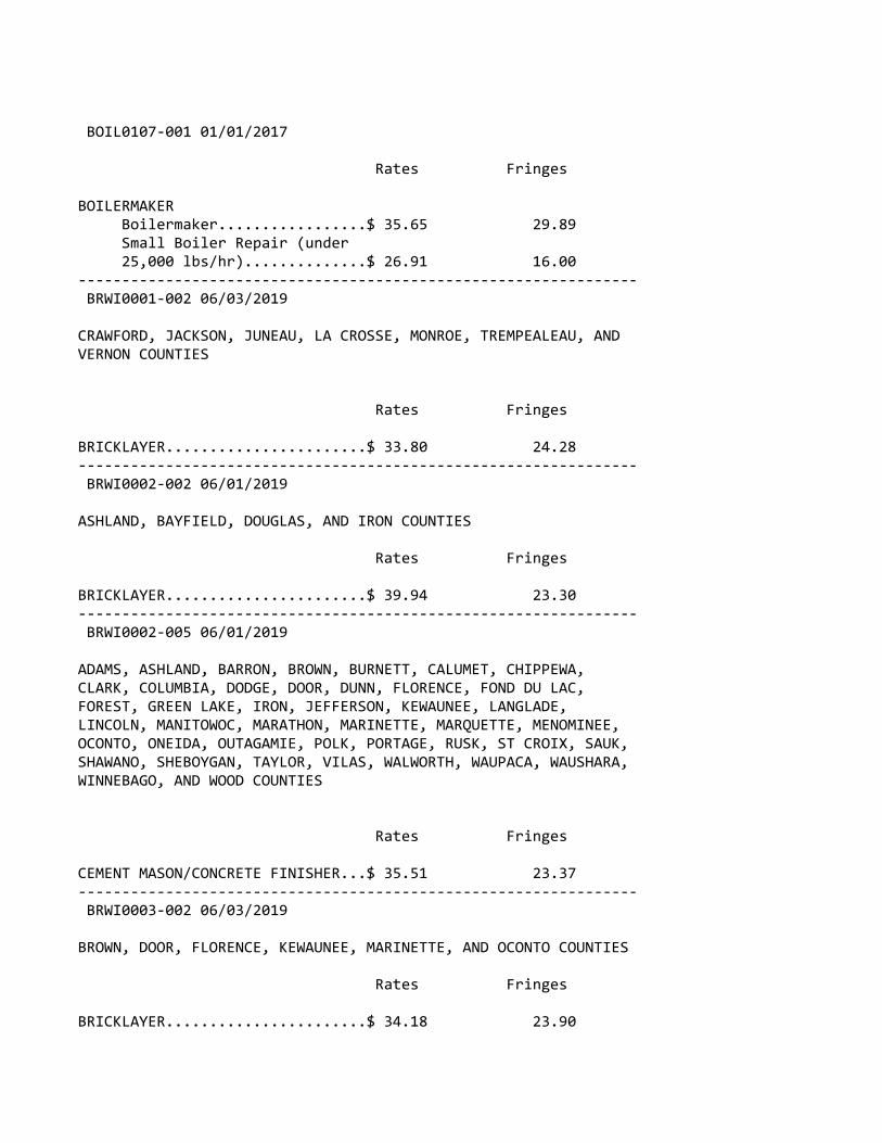
BOIL0107‐001 01/01/2017
Rates Fringes
BOILERMAKER Boilermaker.................$ 35.65 29.89 Small Boiler Repair (under 25,000 lbs/hr)..............$ 26.91 16.00‐‐‐‐‐‐‐‐‐‐‐‐‐‐‐‐‐‐‐‐‐‐‐‐‐‐‐‐‐‐‐‐‐‐‐‐‐‐‐‐‐‐‐‐‐‐‐‐‐‐‐‐‐‐‐‐‐‐‐‐‐‐‐‐ BRWI0001‐002 06/03/2019
CRAWFORD, JACKSON, JUNEAU, LA CROSSE, MONROE, TREMPEALEAU, ANDVERNON COUNTIES
Rates Fringes
BRICKLAYER.......................$ 33.80 24.28‐‐‐‐‐‐‐‐‐‐‐‐‐‐‐‐‐‐‐‐‐‐‐‐‐‐‐‐‐‐‐‐‐‐‐‐‐‐‐‐‐‐‐‐‐‐‐‐‐‐‐‐‐‐‐‐‐‐‐‐‐‐‐‐ BRWI0002‐002 06/01/2019
ASHLAND, BAYFIELD, DOUGLAS, AND IRON COUNTIES
Rates Fringes
BRICKLAYER.......................$ 39.94 23.30‐‐‐‐‐‐‐‐‐‐‐‐‐‐‐‐‐‐‐‐‐‐‐‐‐‐‐‐‐‐‐‐‐‐‐‐‐‐‐‐‐‐‐‐‐‐‐‐‐‐‐‐‐‐‐‐‐‐‐‐‐‐‐‐ BRWI0002‐005 06/01/2019
ADAMS, ASHLAND, BARRON, BROWN, BURNETT, CALUMET, CHIPPEWA,CLARK, COLUMBIA, DODGE, DOOR, DUNN, FLORENCE, FOND DU LAC,FOREST, GREEN LAKE, IRON, JEFFERSON, KEWAUNEE, LANGLADE,LINCOLN, MANITOWOC, MARATHON, MARINETTE, MARQUETTE, MENOMINEE,OCONTO, ONEIDA, OUTAGAMIE, POLK, PORTAGE, RUSK, ST CROIX, SAUK,SHAWANO, SHEBOYGAN, TAYLOR, VILAS, WALWORTH, WAUPACA, WAUSHARA,WINNEBAGO, AND WOOD COUNTIES
Rates Fringes
CEMENT MASON/CONCRETE FINISHER...$ 35.51 23.37‐‐‐‐‐‐‐‐‐‐‐‐‐‐‐‐‐‐‐‐‐‐‐‐‐‐‐‐‐‐‐‐‐‐‐‐‐‐‐‐‐‐‐‐‐‐‐‐‐‐‐‐‐‐‐‐‐‐‐‐‐‐‐‐ BRWI0003‐002 06/03/2019
BROWN, DOOR, FLORENCE, KEWAUNEE, MARINETTE, AND OCONTO COUNTIES
Rates Fringes
BRICKLAYER.......................$ 34.18 23.90

‐‐‐‐‐‐‐‐‐‐‐‐‐‐‐‐‐‐‐‐‐‐‐‐‐‐‐‐‐‐‐‐‐‐‐‐‐‐‐‐‐‐‐‐‐‐‐‐‐‐‐‐‐‐‐‐‐‐‐‐‐‐‐‐ BRWI0004‐002 06/01/2019
KENOSHA, RACINE, AND WALWORTH COUNTIES
Rates Fringes
BRICKLAYER.......................$ 38.43 25.10‐‐‐‐‐‐‐‐‐‐‐‐‐‐‐‐‐‐‐‐‐‐‐‐‐‐‐‐‐‐‐‐‐‐‐‐‐‐‐‐‐‐‐‐‐‐‐‐‐‐‐‐‐‐‐‐‐‐‐‐‐‐‐‐ BRWI0006‐002 06/01/2019
ADAMS, CLARK, FOREST, LANGLADE, LINCOLN, MARATHON, MENOMINEE,ONEIDA, PORTAGE, PRICE, TAYLOR, VILAS AND WOOD COUNTIES
Rates Fringes
BRICKLAYER.......................$ 35.06 23.02‐‐‐‐‐‐‐‐‐‐‐‐‐‐‐‐‐‐‐‐‐‐‐‐‐‐‐‐‐‐‐‐‐‐‐‐‐‐‐‐‐‐‐‐‐‐‐‐‐‐‐‐‐‐‐‐‐‐‐‐‐‐‐‐ BRWI0007‐002 06/03/2019
GREEN, LAFAYETTE, AND ROCK COUNTIES
Rates Fringes
BRICKLAYER.......................$ 35.57 24.22‐‐‐‐‐‐‐‐‐‐‐‐‐‐‐‐‐‐‐‐‐‐‐‐‐‐‐‐‐‐‐‐‐‐‐‐‐‐‐‐‐‐‐‐‐‐‐‐‐‐‐‐‐‐‐‐‐‐‐‐‐‐‐‐ BRWI0008‐002 06/01/2019
MILWAUKEE, OZAUKEE, WASHINGTON, AND WAUKESHA COUNTIES
Rates Fringes
BRICKLAYER.......................$ 38.93 24.22‐‐‐‐‐‐‐‐‐‐‐‐‐‐‐‐‐‐‐‐‐‐‐‐‐‐‐‐‐‐‐‐‐‐‐‐‐‐‐‐‐‐‐‐‐‐‐‐‐‐‐‐‐‐‐‐‐‐‐‐‐‐‐‐ BRWI0009‐001 06/03/2019
GREEN LAKE, MARQUETTE, OUTAGAMIE, SHAWANO, WAUPACA, WASHARA,AND WINNEBAGO COUNTIES
Rates Fringes
BRICKLAYER.......................$ 34.18 23.90‐‐‐‐‐‐‐‐‐‐‐‐‐‐‐‐‐‐‐‐‐‐‐‐‐‐‐‐‐‐‐‐‐‐‐‐‐‐‐‐‐‐‐‐‐‐‐‐‐‐‐‐‐‐‐‐‐‐‐‐‐‐‐‐ BRWI0011‐002 06/03/2019
CALUMET, FOND DU LAC, MANITOWOC, AND SHEBOYGAN COUNTIES
Rates Fringes

BRICKLAYER.......................$ 34.18 23.90‐‐‐‐‐‐‐‐‐‐‐‐‐‐‐‐‐‐‐‐‐‐‐‐‐‐‐‐‐‐‐‐‐‐‐‐‐‐‐‐‐‐‐‐‐‐‐‐‐‐‐‐‐‐‐‐‐‐‐‐‐‐‐‐ BRWI0013‐002 06/03/2019
DANE, GRANT, IOWA, AND RICHLAND COUNTIES
Rates Fringes
BRICKLAYER.......................$ 35.56 24.23‐‐‐‐‐‐‐‐‐‐‐‐‐‐‐‐‐‐‐‐‐‐‐‐‐‐‐‐‐‐‐‐‐‐‐‐‐‐‐‐‐‐‐‐‐‐‐‐‐‐‐‐‐‐‐‐‐‐‐‐‐‐‐‐ BRWI0019‐002 06/03/2019
BARRON, BUFFALO, BURNETT, CHIPPEWA, DUNN, EAU CLAIRE, PEPIN,PIERCE, POLK, RUSK, ST. CROIX, SAWYER AND WASHBURN COUNTIES
Rates Fringes
BRICKLAYER.......................$ 33.40 24.68‐‐‐‐‐‐‐‐‐‐‐‐‐‐‐‐‐‐‐‐‐‐‐‐‐‐‐‐‐‐‐‐‐‐‐‐‐‐‐‐‐‐‐‐‐‐‐‐‐‐‐‐‐‐‐‐‐‐‐‐‐‐‐‐ BRWI0021‐002 06/03/2019
DODGE AND JEFFERSON COUNTIES
Rates Fringes
BRICKLAYER.......................$ 35.75 24.02‐‐‐‐‐‐‐‐‐‐‐‐‐‐‐‐‐‐‐‐‐‐‐‐‐‐‐‐‐‐‐‐‐‐‐‐‐‐‐‐‐‐‐‐‐‐‐‐‐‐‐‐‐‐‐‐‐‐‐‐‐‐‐‐ BRWI0034‐002 06/03/2019
COLUMBIA AND SAUK COUNTIES
Rates Fringes
BRICKLAYER.......................$ 35.56 24.23‐‐‐‐‐‐‐‐‐‐‐‐‐‐‐‐‐‐‐‐‐‐‐‐‐‐‐‐‐‐‐‐‐‐‐‐‐‐‐‐‐‐‐‐‐‐‐‐‐‐‐‐‐‐‐‐‐‐‐‐‐‐‐‐ CARP0087‐001 05/01/2016
BURNETT (W. of Hwy 48), PIERCE (W. of Hwy 29), POLK (W. of Hwys35, 48 & 65), AND ST. CROIX (W. of Hwy 65) COUNTIES
Rates Fringes
Carpenter & Piledrivermen........$ 36.85 18.39‐‐‐‐‐‐‐‐‐‐‐‐‐‐‐‐‐‐‐‐‐‐‐‐‐‐‐‐‐‐‐‐‐‐‐‐‐‐‐‐‐‐‐‐‐‐‐‐‐‐‐‐‐‐‐‐‐‐‐‐‐‐‐‐ CARP0252‐002 06/01/2016
ADAMS, BARRON, BAYFIELD (Eastern 2/3), BROWN, BUFFALO,

BURNETT (E. of Hwy 48), CALUMET, CHIPPEWA, CLARK, COLUMBIA,CRAWFORD, DANE, DODGE, DOOR, DUNN, EAU CLAIRE, FLORENCE (exceptarea bordering Michigan State Line), FOND DU LAC, FOREST,GRANT, GREEN, GREEN LAKE, IOWA, IRON, JACKSON, JEFFERSON,JUNEAU, KEWAUNEE, LA CROSSE, LAFAYETTE, LANGLADE, LINCOLN,MANITOWOC, MARATHON, MARINETTE (except N.E. corner), MARQUETTE,MENOMINEE, MONROE, OCONTO, ONEIDA, OUTAGAMIE, PEPIN, PIERCE (E.of Hwys 29 & 65), POLK (E. of Hwys 35, 48 & 65), PORTAGE,PRICE, RICHLAND, ROCK, RUSK, SAUK, SAWYER, SHAWANO, SHEBOYGAN,ST CROIX (E. of Hwy 65), TAYLOR, TREMPEALEAU, VERNON, VILAS,WALWORTH, WASHBURN, WAUPACA, WAUSHARA, WINNEBAGO, AND WOODCOUNTIES
Rates Fringes
CARPENTER CARPENTER...................$ 33.56 18.00 MILLWRIGHT..................$ 35.08 18.35 PILEDRIVER..................$ 34.12 18.00‐‐‐‐‐‐‐‐‐‐‐‐‐‐‐‐‐‐‐‐‐‐‐‐‐‐‐‐‐‐‐‐‐‐‐‐‐‐‐‐‐‐‐‐‐‐‐‐‐‐‐‐‐‐‐‐‐‐‐‐‐‐‐‐ CARP0252‐010 06/01/2016
ASHLAND COUNTY
Rates Fringes
Carpenters Carpenter...................$ 33.56 18.00 Millwright..................$ 35.08 18.35 Pile Driver.................$ 34.12 18.00‐‐‐‐‐‐‐‐‐‐‐‐‐‐‐‐‐‐‐‐‐‐‐‐‐‐‐‐‐‐‐‐‐‐‐‐‐‐‐‐‐‐‐‐‐‐‐‐‐‐‐‐‐‐‐‐‐‐‐‐‐‐‐‐ CARP0264‐003 06/01/2016
KENOSHA, MILWAUKEE, OZAUKEE, RACINE, WAUKESHA, AND WASHINGTONCOUNTIES
Rates Fringes
CARPENTER........................$ 35.78 22.11‐‐‐‐‐‐‐‐‐‐‐‐‐‐‐‐‐‐‐‐‐‐‐‐‐‐‐‐‐‐‐‐‐‐‐‐‐‐‐‐‐‐‐‐‐‐‐‐‐‐‐‐‐‐‐‐‐‐‐‐‐‐‐‐ CARP0361‐004 05/01/2018
BAYFIELD (West of Hwy 63) AND DOUGLAS COUNTIES
Rates Fringes
CARPENTER........................$ 36.15 20.43‐‐‐‐‐‐‐‐‐‐‐‐‐‐‐‐‐‐‐‐‐‐‐‐‐‐‐‐‐‐‐‐‐‐‐‐‐‐‐‐‐‐‐‐‐‐‐‐‐‐‐‐‐‐‐‐‐‐‐‐‐‐‐‐
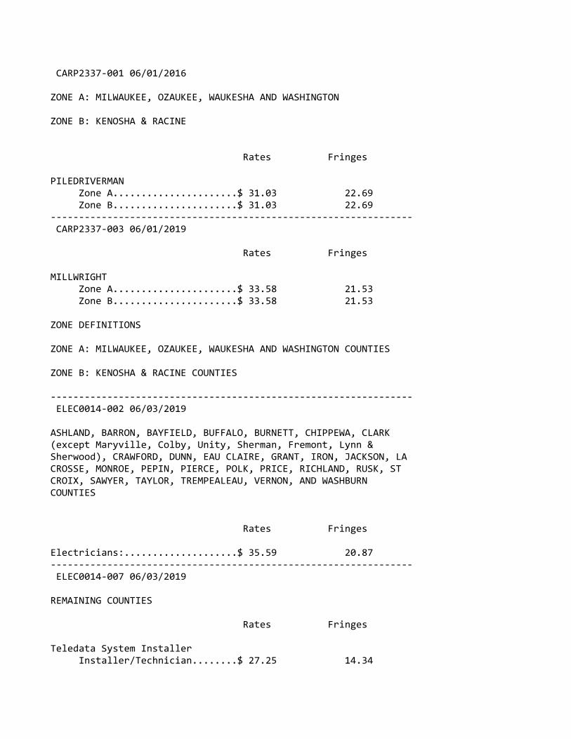
CARP2337‐001 06/01/2016
ZONE A: MILWAUKEE, OZAUKEE, WAUKESHA AND WASHINGTON
ZONE B: KENOSHA & RACINE
Rates Fringes
PILEDRIVERMAN Zone A......................$ 31.03 22.69 Zone B......................$ 31.03 22.69‐‐‐‐‐‐‐‐‐‐‐‐‐‐‐‐‐‐‐‐‐‐‐‐‐‐‐‐‐‐‐‐‐‐‐‐‐‐‐‐‐‐‐‐‐‐‐‐‐‐‐‐‐‐‐‐‐‐‐‐‐‐‐‐ CARP2337‐003 06/01/2019
Rates Fringes
MILLWRIGHT Zone A......................$ 33.58 21.53 Zone B......................$ 33.58 21.53
ZONE DEFINITIONS
ZONE A: MILWAUKEE, OZAUKEE, WAUKESHA AND WASHINGTON COUNTIES
ZONE B: KENOSHA & RACINE COUNTIES
‐‐‐‐‐‐‐‐‐‐‐‐‐‐‐‐‐‐‐‐‐‐‐‐‐‐‐‐‐‐‐‐‐‐‐‐‐‐‐‐‐‐‐‐‐‐‐‐‐‐‐‐‐‐‐‐‐‐‐‐‐‐‐‐ ELEC0014‐002 06/03/2019
ASHLAND, BARRON, BAYFIELD, BUFFALO, BURNETT, CHIPPEWA, CLARK(except Maryville, Colby, Unity, Sherman, Fremont, Lynn &Sherwood), CRAWFORD, DUNN, EAU CLAIRE, GRANT, IRON, JACKSON, LACROSSE, MONROE, PEPIN, PIERCE, POLK, PRICE, RICHLAND, RUSK, STCROIX, SAWYER, TAYLOR, TREMPEALEAU, VERNON, AND WASHBURNCOUNTIES
Rates Fringes
Electricians:....................$ 35.59 20.87‐‐‐‐‐‐‐‐‐‐‐‐‐‐‐‐‐‐‐‐‐‐‐‐‐‐‐‐‐‐‐‐‐‐‐‐‐‐‐‐‐‐‐‐‐‐‐‐‐‐‐‐‐‐‐‐‐‐‐‐‐‐‐‐ ELEC0014‐007 06/03/2019
REMAINING COUNTIES
Rates Fringes
Teledata System Installer Installer/Technician........$ 27.25 14.34
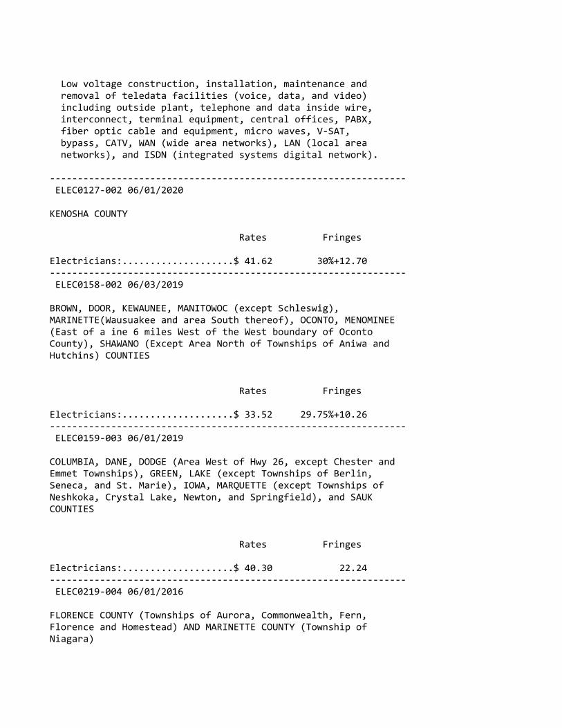
Low voltage construction, installation, maintenance and removal of teledata facilities (voice, data, and video) including outside plant, telephone and data inside wire, interconnect, terminal equipment, central offices, PABX, fiber optic cable and equipment, micro waves, V‐SAT, bypass, CATV, WAN (wide area networks), LAN (local area networks), and ISDN (integrated systems digital network).
‐‐‐‐‐‐‐‐‐‐‐‐‐‐‐‐‐‐‐‐‐‐‐‐‐‐‐‐‐‐‐‐‐‐‐‐‐‐‐‐‐‐‐‐‐‐‐‐‐‐‐‐‐‐‐‐‐‐‐‐‐‐‐‐ ELEC0127‐002 06/01/2020
KENOSHA COUNTY
Rates Fringes
Electricians:....................$ 41.62 30%+12.70‐‐‐‐‐‐‐‐‐‐‐‐‐‐‐‐‐‐‐‐‐‐‐‐‐‐‐‐‐‐‐‐‐‐‐‐‐‐‐‐‐‐‐‐‐‐‐‐‐‐‐‐‐‐‐‐‐‐‐‐‐‐‐‐ ELEC0158‐002 06/03/2019
BROWN, DOOR, KEWAUNEE, MANITOWOC (except Schleswig),MARINETTE(Wausuakee and area South thereof), OCONTO, MENOMINEE(East of a ine 6 miles West of the West boundary of OcontoCounty), SHAWANO (Except Area North of Townships of Aniwa andHutchins) COUNTIES
Rates Fringes
Electricians:....................$ 33.52 29.75%+10.26‐‐‐‐‐‐‐‐‐‐‐‐‐‐‐‐‐‐‐‐‐‐‐‐‐‐‐‐‐‐‐‐‐‐‐‐‐‐‐‐‐‐‐‐‐‐‐‐‐‐‐‐‐‐‐‐‐‐‐‐‐‐‐‐ ELEC0159‐003 06/01/2019
COLUMBIA, DANE, DODGE (Area West of Hwy 26, except Chester andEmmet Townships), GREEN, LAKE (except Townships of Berlin,Seneca, and St. Marie), IOWA, MARQUETTE (except Townships ofNeshkoka, Crystal Lake, Newton, and Springfield), and SAUKCOUNTIES
Rates Fringes
Electricians:....................$ 40.30 22.24‐‐‐‐‐‐‐‐‐‐‐‐‐‐‐‐‐‐‐‐‐‐‐‐‐‐‐‐‐‐‐‐‐‐‐‐‐‐‐‐‐‐‐‐‐‐‐‐‐‐‐‐‐‐‐‐‐‐‐‐‐‐‐‐ ELEC0219‐004 06/01/2016
FLORENCE COUNTY (Townships of Aurora, Commonwealth, Fern,Florence and Homestead) AND MARINETTE COUNTY (Township ofNiagara)
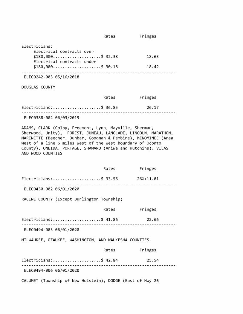
Rates Fringes
Electricians: Electrical contracts over $180,000....................$ 32.38 18.63 Electrical contracts under $180,000....................$ 30.18 18.42‐‐‐‐‐‐‐‐‐‐‐‐‐‐‐‐‐‐‐‐‐‐‐‐‐‐‐‐‐‐‐‐‐‐‐‐‐‐‐‐‐‐‐‐‐‐‐‐‐‐‐‐‐‐‐‐‐‐‐‐‐‐‐‐ ELEC0242‐005 05/16/2018
DOUGLAS COUNTY
Rates Fringes
Electricians:....................$ 36.85 26.17‐‐‐‐‐‐‐‐‐‐‐‐‐‐‐‐‐‐‐‐‐‐‐‐‐‐‐‐‐‐‐‐‐‐‐‐‐‐‐‐‐‐‐‐‐‐‐‐‐‐‐‐‐‐‐‐‐‐‐‐‐‐‐‐ ELEC0388‐002 06/03/2019
ADAMS, CLARK (Colby, Freemont, Lynn, Mayville, Sherman,Sherwood, Unity), FOREST, JUNEAU, LANGLADE, LINCOLN, MARATHON,MARINETTE (Beecher, Dunbar, Goodman & Pembine), MENOMINEE (AreaWest of a line 6 miles West of the West boundary of OcontoCounty), ONEIDA, PORTAGE, SHAWANO (Aniwa and Hutchins), VILASAND WOOD COUNTIES
Rates Fringes
Electricians:....................$ 33.56 26%+11.01‐‐‐‐‐‐‐‐‐‐‐‐‐‐‐‐‐‐‐‐‐‐‐‐‐‐‐‐‐‐‐‐‐‐‐‐‐‐‐‐‐‐‐‐‐‐‐‐‐‐‐‐‐‐‐‐‐‐‐‐‐‐‐‐ ELEC0430‐002 06/01/2020
RACINE COUNTY (Except Burlington Township)
Rates Fringes
Electricians:....................$ 41.86 22.66‐‐‐‐‐‐‐‐‐‐‐‐‐‐‐‐‐‐‐‐‐‐‐‐‐‐‐‐‐‐‐‐‐‐‐‐‐‐‐‐‐‐‐‐‐‐‐‐‐‐‐‐‐‐‐‐‐‐‐‐‐‐‐‐ ELEC0494‐005 06/01/2020
MILWAUKEE, OZAUKEE, WASHINGTON, AND WAUKESHA COUNTIES
Rates Fringes
Electricians:....................$ 42.84 25.54‐‐‐‐‐‐‐‐‐‐‐‐‐‐‐‐‐‐‐‐‐‐‐‐‐‐‐‐‐‐‐‐‐‐‐‐‐‐‐‐‐‐‐‐‐‐‐‐‐‐‐‐‐‐‐‐‐‐‐‐‐‐‐‐ ELEC0494‐006 06/01/2020
CALUMET (Township of New Holstein), DODGE (East of Hwy 26
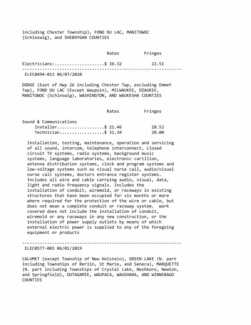
including Chester Township), FOND DU LAC, MANITOWOC(Schleswig), and SHEBOYGAN COUNTIES
Rates Fringes
Electricians:....................$ 36.32 22.51‐‐‐‐‐‐‐‐‐‐‐‐‐‐‐‐‐‐‐‐‐‐‐‐‐‐‐‐‐‐‐‐‐‐‐‐‐‐‐‐‐‐‐‐‐‐‐‐‐‐‐‐‐‐‐‐‐‐‐‐‐‐‐‐ ELEC0494‐013 06/07/2020
DODGE (East of Hwy 26 including Chester Twp, excluding EmmetTwp), FOND DU LAC (Except Waupuin), MILWAUKEE, OZAUKEE,MANITOWOC (Schleswig), WASHINGTON, AND WAUKESHA COUNTIES
Rates Fringes
Sound & Communications Installer...................$ 21.46 18.52 Technician..................$ 31.34 20.00
Installation, testing, maintenance, operation and servicing of all sound, intercom, telephone interconnect, closed circuit TV systems, radio systems, background music systems, language laboratories, electronic carillion, antenna distribution systems, clock and program systems and low‐voltage systems such as visual nurse call, audio/visual nurse call systems, doctors entrance register systems. Includes all wire and cable carrying audio, visual, data, light and radio frequency signals. Includes the installation of conduit, wiremold, or raceways in existing structures that have been occupied for six months or more where required for the protection of the wire or cable, but does not mean a complete conduit or raceway system. work covered does not include the installation of conduit, wiremold or any raceways in any new construction, or the installation of power supply outlets by means of which external electric power is supplied to any of the foregoing equipment or products
‐‐‐‐‐‐‐‐‐‐‐‐‐‐‐‐‐‐‐‐‐‐‐‐‐‐‐‐‐‐‐‐‐‐‐‐‐‐‐‐‐‐‐‐‐‐‐‐‐‐‐‐‐‐‐‐‐‐‐‐‐‐‐‐ ELEC0577‐003 06/01/2019
CALUMET (except Township of New Holstein), GREEN LAKE (N. partincluding Townships of Berlin, St Marie, and Seneca), MARQUETTE(N. part including Townships of Crystal Lake, Neshkoro, Newton,and Springfield), OUTAGAMIE, WAUPACA, WAUSHARA, AND WINNEBAGOCOUNTIES
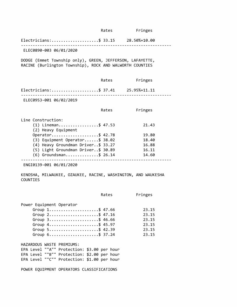
Rates Fringes
Electricians:....................$ 33.15 28.50%+10.00‐‐‐‐‐‐‐‐‐‐‐‐‐‐‐‐‐‐‐‐‐‐‐‐‐‐‐‐‐‐‐‐‐‐‐‐‐‐‐‐‐‐‐‐‐‐‐‐‐‐‐‐‐‐‐‐‐‐‐‐‐‐‐‐ ELEC0890‐003 06/01/2020
DODGE (Emmet Township only), GREEN, JEFFERSON, LAFAYETTE,RACINE (Burlington Township), ROCK AND WALWORTH COUNTIES
Rates Fringes
Electricians:....................$ 37.41 25.95%+11.11‐‐‐‐‐‐‐‐‐‐‐‐‐‐‐‐‐‐‐‐‐‐‐‐‐‐‐‐‐‐‐‐‐‐‐‐‐‐‐‐‐‐‐‐‐‐‐‐‐‐‐‐‐‐‐‐‐‐‐‐‐‐‐‐ ELEC0953‐001 06/02/2019
Rates Fringes
Line Construction: (1) Lineman.................$ 47.53 21.43 (2) Heavy Equipment Operator....................$ 42.78 19.80 (3) Equipment Operator......$ 38.02 18.40 (4) Heavy Groundman Driver..$ 33.27 16.88 (5) Light Groundman Driver..$ 30.89 16.11 (6) Groundsman..............$ 26.14 14.60‐‐‐‐‐‐‐‐‐‐‐‐‐‐‐‐‐‐‐‐‐‐‐‐‐‐‐‐‐‐‐‐‐‐‐‐‐‐‐‐‐‐‐‐‐‐‐‐‐‐‐‐‐‐‐‐‐‐‐‐‐‐‐‐ ENGI0139‐001 06/01/2020
KENOSHA, MILWAUKEE, OZAUKEE, RACINE, WASHINGTON, AND WAUKESHACOUNTIES
Rates Fringes
Power Equipment Operator Group 1.....................$ 47.66 23.15 Group 2.....................$ 47.16 23.15 Group 3.....................$ 46.66 23.15 Group 4.....................$ 45.97 23.15 Group 5.....................$ 42.39 23.15 Group 6.....................$ 37.24 23.15
HAZARDOUS WASTE PREMIUMS:EPA Level ""A"" Protection: $3.00 per hourEPA Level ""B"" Protection: $2.00 per hourEPA Level ""C"" Protection: $1.00 per hour
POWER EQUIPMENT OPERATORS CLASSIFICATIONS

GROUP 1: Cranes, Tower Cranes, Pedestal Tower Cranes and Derricks with or w/o attachments with a lifting capacity of over 100 tons; or Cranes, Tower Cranes, Pedestal Tower Cranes and Derricks with boom, leads, and/or jib lengths measuring 176 feet or longer; Self‐Erecting Tower Cranes over 4000 lbs lifting capacity; All Cranes with Boom Dollies; Boring Machines (directional); Master Mechanic. $0.50 additional per hour per 100 tons or 100 ft of boom over 200 ft or lifting capacity of crane over 200 tons to a maximum of 300 tons or 300 ft. Thereafter an increase of $0.01 per ft or ton, whichever is greater.
GROUP 2: Cranes, Tower Cranes, Pedestal Tower Cranes and Derricks with or without attachments with a lifting capacity of 100 tons or less; or Cranes, Tower Cranes Portable Tower Cranes, Pedestal Tower Cranes and Derricks with boom, leadsand/or jib lengths measuring 175 feet or less; Backhoes (excavators) 130,000 lbs and over; Caisson Rigs; Pile Drivers; Boring Machines (vertical or horizontal), Versi‐Lift, Tri‐Lift, Gantry 20,000 lbs & over.
GROUP 3: Backhoe (excavator) under 130,000 lbs;Self‐erecting Tower Crane 4000 lbs & under lifting capacity;Traveling Crane (bridge type); Skid Rigs; Dredge Operator; Mechanic; Concrete Paver (over 27E); Concrete Spreader and Distributor; Forklift/ Telehandler (machinery‐ moving / steel erection); Hydro Blaster, 10,000 psi and over
GROUP 4: Material Hoists; Stack Hoists; Hydraulic Backhoe (tractor or truck mounted); Hydraulic Crane, 5 tons or under (tractor or truck mounted); Hoist (tuggers 5 tons & over); Hydro‐Excavators/Daylighters; Concrete Pumps Rotec type Conveyors; Tractor/Bulldozer/End Loader (over 40 hp); Motor Patrol; Scraper Operator; Sideboom; Straddle Carrier; Welder; Bituminous Plant and Paver Operator; Roller over 5 tons; Rail Leveling Machine (Railroad); Tie Placer; Tie Extractor; Tie Tamper; Stone Leveler; Rotary Drill Operator and Blaster; Percussion Drill Operator; Air Track Drill and/or Hammers; Gantrys (under 20,000 lbs); Tencher (wheel type or chain type having 8 inch or larger bucket); Milling Machine; Off‐Road Material Haulers.
GROUP 5: Backfiller; Concrete Auto Breaker (large); Concrete Finishing Machines (road type); Rubber Tired Roller; Concrete Batch Hopper; Concrete Conveyor Systems; Grout Pumps; Concrete Mixers (14S or over); Screw Type Pumps and Gypsum Pumps; Tractor, Bulldozer, End Loader (under 40 hp); Trencher (chain type, bucket under 8 inch); Industrial Locomotives; Rollers under 5 tons; Stump Grinder/Chipper (Large); Timber Equipment; Firemen (pile drivers and
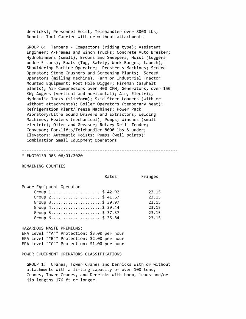
derricks); Personnel Hoist, Telehandler over 8000 lbs; Robotic Tool Carrier with or without attachments
GROUP 6: Tampers ‐ Compactors (riding type); Assistant Engineer; A‐Frames and Winch Trucks; Concrete Auto Breaker; Hydrohammers (small); Brooms and Sweepers; Hoist (tuggers under 5 tons); Boats (Tug, Safety, Work Barges, Launch); Shouldering Machine Operator; Prestress Machines; Screed Operator; Stone Crushers and Screening Plants; Screed Operators (milling machine), Farm or Industrial Tractor Mounted Equipment; Post Hole Digger; Fireman (asphalt plants); Air Compressors over 400 CFM; Generators, over 150 KW; Augers (vertical and horizontal); Air, Electric, Hydraulic Jacks (slipform); Skid Steer Loaders (with or without attachments); Boiler Operators (temporary heat); Refrigeration Plant/Freeze Machines; Power Pack Vibratory/Ultra Sound Drivers and Extractors; Welding Machines; Heaters (mechanical); Pumps; Winches (small electric); Oiler and Greaser; Rotary Drill Tender; Conveyor; Forklifts/Telehandler 8000 lbs & under; Elevators: Automatic Hoists; Pumps (well points); Combination Small Equipment Operators
‐‐‐‐‐‐‐‐‐‐‐‐‐‐‐‐‐‐‐‐‐‐‐‐‐‐‐‐‐‐‐‐‐‐‐‐‐‐‐‐‐‐‐‐‐‐‐‐‐‐‐‐‐‐‐‐‐‐‐‐‐‐‐‐* ENGI0139‐003 06/01/2020
REMAINING COUNTIES
Rates Fringes
Power Equipment Operator Group 1.....................$ 42.92 23.15 Group 2.....................$ 41.67 23.15 Group 3.....................$ 39.97 23.15 Group 4.....................$ 39.44 23.15 Group 5.....................$ 37.37 23.15 Group 6.....................$ 35.84 23.15
HAZARDOUS WASTE PREMIUMS:EPA Level ""A"" Protection: $3.00 per hourEPA Level ""B"" Protection: $2.00 per hourEPA Level ""C"" Protection: $1.00 per hour
POWER EQUIPMENT OPERATORS CLASSIFICATIONS
GROUP 1: Cranes, Tower Cranes and Derricks with or without attachments with a lifting capacity of over 100 tons; Cranes, Tower Cranes, and Derricks with boom, leads and/or jib lengths 176 ft or longer.

GROUP 2: Backhoes (Excavators) weighing 130,00 lbs and over; Cranes, Tower Cranes and Derricks with or without attachments with a lifting capacity of 100 tons or less; Cranes, Tower Cranes, and Derricks with boom, leads, and/or jib lengths 175 ft or less; Caisson Rigs; Pile Driver
GROUP 3: Backhoes (Excavators) weighing under 130,000 lbs; Travelling Crane (bridge type); Milling Machine; Concrete Paver over 27 E; Concrete Spreader and Distributor; Concrete Laser Screed; Concrete Grinder and Planing Machine; Slipform Curb and Gutter Machine; Boring Machine (Directional); Dredge Operator; Skid Rigs; over 46 meter Concrete Pump.
GROUP 4: Hydraulic Backhoe (tractor or truck mounted); Hydraulic Crane, 10 tons or less; Tractor, Bulldozer, or End Loader (over 40 hp); Motor Patrol; Scraper Operator; Bituminous Plant and Paver Operator; Screed‐Milling Machine; Roller over 5 tons; Concrete pumps 46 meter and under; Grout Pumps; Rotec type machine; Hydro Blaster, 10,000 psi and over; Rotary Drill Operator; Percussion Drilling Machine; Air Track Drill with or without integral hammer; Blaster; Boring Machine (vertical or horizontal); Side Boom; Trencher, wheel type or chain type having 8 inch or larger bucket; Rail Leveling Machine (Railroad); Tie Placer; Tie Extractor; Tie Tamper; Stone Leveler; Straddle Carrier; Material Hoists; Stack Hoist; Man Hoists; Mechanic and Welder; Off Road Material Haulers.
GROUP 5: Tractor, Bulldozer, or Endloader (under 40 hp); Tampers ‐Compactors, riding type; Stump Chipper, large; Roller, Rubber Tire; Backfiller; Trencher, chain type (bucket under 8 inch); Concrete Auto Breaker, large; Concrete Finishing Machine (road type); Concrete Batch Hopper; Concrete Conveyor Systems; Concrete Mixers, 14S or over; Pumps, Screw Type and Gypsum); Hydrohammers, small; Brooms and Sweeeprs; Lift Slab Machine; Roller under 5 tons; Industrial Locomotives; Fireman (Pile Drivers and Derricks); Pumps (well points); Hoists, automatic; A‐Frames and Winch Trucks; Hoists (tuggers); Boats (Tug, Safety, Work Barges and Launches); Assistant Engineer
GROUP 6: Shouldering Machine Operator; Farm or Industrial Tractor mounted equipment; Post Hole Digger; Auger (vertical and horizontal); Skid Steer Loader with or without attachments; Robotic Tool Carrier with or without attachments; Power Pack Vibratory/Ultra Sound Driver and Extractor; Fireman (Asphalt Plants); Screed Operator; Stone Crushers and Screening Plants; Air, Electric, Hydraulic Jacks (Slip Form); Prestress Machines; Air Compressor, 400

CFM or over; Refrigeration Plant/Freese Machine; Boiler Operators (temporary heat); Forklifts; Welding Machines; Generators; Pumps over 3""; Heaters, Mechanical; Combination small equipment operator; Winches, small electric; Oiler; Greaser; Rotary Drill Tender; Conveyor; Elevator Operator
‐‐‐‐‐‐‐‐‐‐‐‐‐‐‐‐‐‐‐‐‐‐‐‐‐‐‐‐‐‐‐‐‐‐‐‐‐‐‐‐‐‐‐‐‐‐‐‐‐‐‐‐‐‐‐‐‐‐‐‐‐‐‐‐ IRON0008‐002 06/01/2020
BROWN, CALUMET, DOOR, FOND DU LAC, KEWAUNEE, MANITOWOC,MARINETTE, OCONTO, OUTAGAMI, SHAWANO, SHEBOYGAN, AND WINNEBAGOCOUNTIES:
Rates Fringes
IRONWORKER.......................$ 37.31 27.62
Paid Holidays: New Year's Day, Memorial Day, July 4th, Labor Day, Thanksgiving Day & Christmas Day.
‐‐‐‐‐‐‐‐‐‐‐‐‐‐‐‐‐‐‐‐‐‐‐‐‐‐‐‐‐‐‐‐‐‐‐‐‐‐‐‐‐‐‐‐‐‐‐‐‐‐‐‐‐‐‐‐‐‐‐‐‐‐‐‐ IRON0008‐003 06/01/2020
KENOSHA, MILWAUKEE, OZAUKEE, RACINE, WALWORTH (N.E. 2/3),WASHINGTON, AND WAUKESHA COUNTIES
Rates Fringes
IRONWORKER.......................$ 39.11 27.87
Paid Holidays: New Year's Day, Memorial Day, July 4th, Labor Day, Thanksgiving Day & Christmas Day.
‐‐‐‐‐‐‐‐‐‐‐‐‐‐‐‐‐‐‐‐‐‐‐‐‐‐‐‐‐‐‐‐‐‐‐‐‐‐‐‐‐‐‐‐‐‐‐‐‐‐‐‐‐‐‐‐‐‐‐‐‐‐‐‐ IRON0383‐001 06/01/2020
ADAMS, COLUMBIA, CRAWFORD, DANE, DODGE, FLORENCE, FOREST,GRANT, GREENE, (Excluding S.E. tip), GREEN LAKE, IOWA,JEFFERSON, JUNEAU, LA CROSSE, LAFAYETTE, LANGLADE, MARATHON,MARQUETTE, MENOMINEE, MONROE, PORTAGE, RICHLAND, ROCK (Northernarea, vicinity of Edgerton and Milton), SAUK, VERNON, WAUPACA,WAUSHARA, AND WOOD COUNTIES
Rates Fringes
IRONWORKER.......................$ 37.10 27.06‐‐‐‐‐‐‐‐‐‐‐‐‐‐‐‐‐‐‐‐‐‐‐‐‐‐‐‐‐‐‐‐‐‐‐‐‐‐‐‐‐‐‐‐‐‐‐‐‐‐‐‐‐‐‐‐‐‐‐‐‐‐‐‐
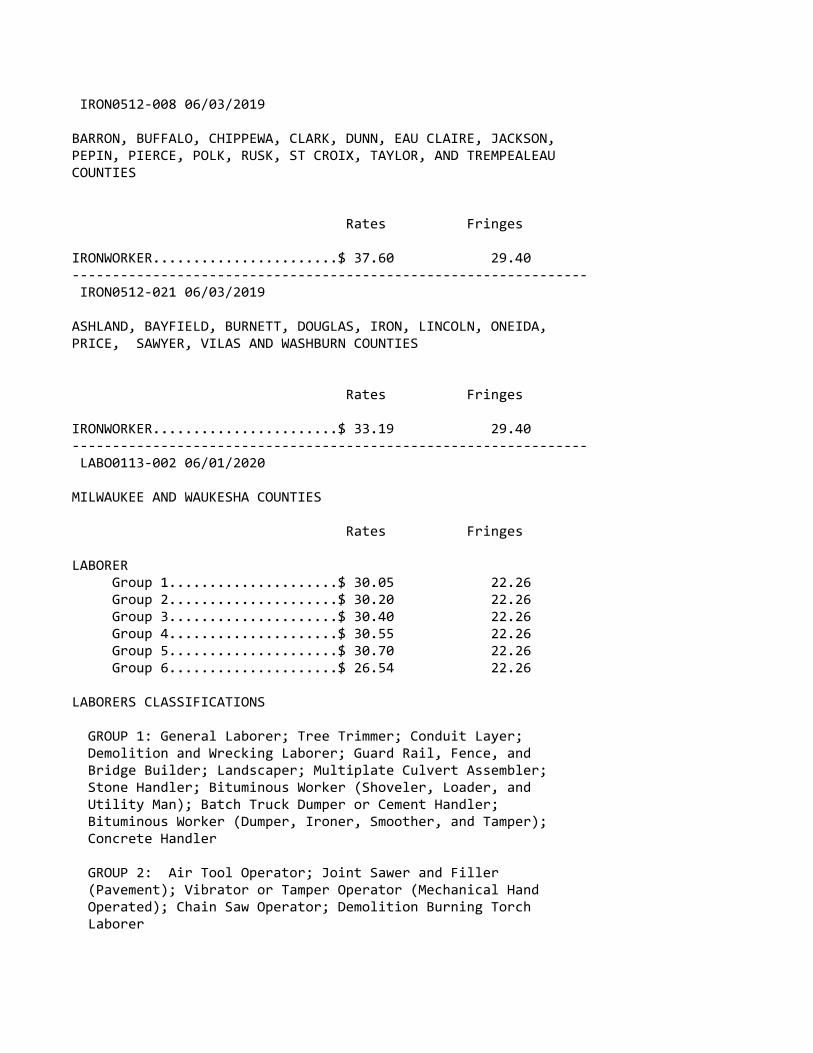
IRON0512‐008 06/03/2019
BARRON, BUFFALO, CHIPPEWA, CLARK, DUNN, EAU CLAIRE, JACKSON,PEPIN, PIERCE, POLK, RUSK, ST CROIX, TAYLOR, AND TREMPEALEAUCOUNTIES
Rates Fringes
IRONWORKER.......................$ 37.60 29.40‐‐‐‐‐‐‐‐‐‐‐‐‐‐‐‐‐‐‐‐‐‐‐‐‐‐‐‐‐‐‐‐‐‐‐‐‐‐‐‐‐‐‐‐‐‐‐‐‐‐‐‐‐‐‐‐‐‐‐‐‐‐‐‐ IRON0512‐021 06/03/2019
ASHLAND, BAYFIELD, BURNETT, DOUGLAS, IRON, LINCOLN, ONEIDA,PRICE, SAWYER, VILAS AND WASHBURN COUNTIES
Rates Fringes
IRONWORKER.......................$ 33.19 29.40‐‐‐‐‐‐‐‐‐‐‐‐‐‐‐‐‐‐‐‐‐‐‐‐‐‐‐‐‐‐‐‐‐‐‐‐‐‐‐‐‐‐‐‐‐‐‐‐‐‐‐‐‐‐‐‐‐‐‐‐‐‐‐‐ LABO0113‐002 06/01/2020
MILWAUKEE AND WAUKESHA COUNTIES
Rates Fringes
LABORER Group 1.....................$ 30.05 22.26 Group 2.....................$ 30.20 22.26 Group 3.....................$ 30.40 22.26 Group 4.....................$ 30.55 22.26 Group 5.....................$ 30.70 22.26 Group 6.....................$ 26.54 22.26
LABORERS CLASSIFICATIONS
GROUP 1: General Laborer; Tree Trimmer; Conduit Layer; Demolition and Wrecking Laborer; Guard Rail, Fence, and Bridge Builder; Landscaper; Multiplate Culvert Assembler; Stone Handler; Bituminous Worker (Shoveler, Loader, and Utility Man); Batch Truck Dumper or Cement Handler; Bituminous Worker (Dumper, Ironer, Smoother, and Tamper); Concrete Handler
GROUP 2: Air Tool Operator; Joint Sawer and Filler (Pavement); Vibrator or Tamper Operator (Mechanical Hand Operated); Chain Saw Operator; Demolition Burning Torch Laborer

GROUP 3: Bituminous Worker (Raker and Luteman); Formsetter (Curb, Sidewalk, and Pavement); Strike Off Man
GROUP 4: Line and Grade Specialist
GROUP 5: Blaster and Powderman
GROUP 6: Flagperson; traffic control person
‐‐‐‐‐‐‐‐‐‐‐‐‐‐‐‐‐‐‐‐‐‐‐‐‐‐‐‐‐‐‐‐‐‐‐‐‐‐‐‐‐‐‐‐‐‐‐‐‐‐‐‐‐‐‐‐‐‐‐‐‐‐‐‐ LABO0113‐003 06/01/2020
OZAUKEE AND WASHINGTON COUNTIES
Rates Fringes
LABORER Group 1.....................$ 29.30 22.26 Group 2.....................$ 29.40 22.26 Group 3.....................$ 29.45 22.26 Group 4.....................$ 29.65 22.26 Group 5.....................$ 29.50 22.26 Group 6.....................$ 26.39 22.26
LABORERS CLASSIFICATIONS
GROUP 1: General Laborer; Tree Trimmer; Conduit Layer; Demolition and Wrecking Laborer; Guard Rail, Fence, and Bridge Builder; Landscaper; Multiplate Culvert Assembler; Stone Handler; Bituminous Worker (Shoveler, Loader, and Utility Man); Batch Truck Dumper or Cement Handler; Bituminous Worker (Dumper, Ironer, Smoother, and Tamper); Concrete Handler
GROUP 2: Air Tool Operator; Joint Sawer and Filler (Pavement); Vibrator or Tamper Operator (Mechanical Hand Operated);
GROUP 3: Bituminous Worker (Raker and Luteman); Formsetter (Curb, Sidewalk, and Pavement); Strike Off Man
GROUP 4: Line and Grade Specialist
GROUP 5: Blaster; powderman
GROUP 6: Flagperson and Traffic Control Person
‐‐‐‐‐‐‐‐‐‐‐‐‐‐‐‐‐‐‐‐‐‐‐‐‐‐‐‐‐‐‐‐‐‐‐‐‐‐‐‐‐‐‐‐‐‐‐‐‐‐‐‐‐‐‐‐‐‐‐‐‐‐‐‐ LABO0113‐011 06/01/2020
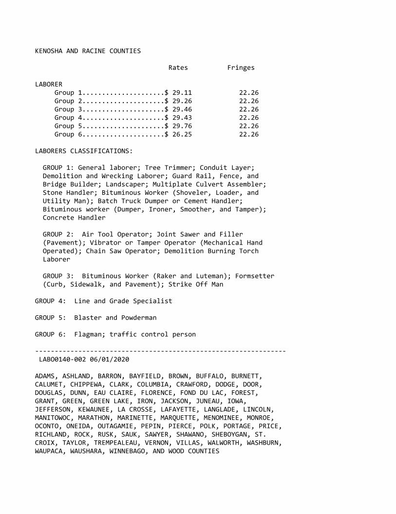
KENOSHA AND RACINE COUNTIES
Rates Fringes
LABORER Group 1.....................$ 29.11 22.26 Group 2.....................$ 29.26 22.26 Group 3.....................$ 29.46 22.26 Group 4.....................$ 29.43 22.26 Group 5.....................$ 29.76 22.26 Group 6.....................$ 26.25 22.26
LABORERS CLASSIFICATIONS:
GROUP 1: General laborer; Tree Trimmer; Conduit Layer; Demolition and Wrecking Laborer; Guard Rail, Fence, and Bridge Builder; Landscaper; Multiplate Culvert Assembler; Stone Handler; Bituminous Worker (Shoveler, Loader, and Utility Man); Batch Truck Dumper or Cement Handler; Bituminous worker (Dumper, Ironer, Smoother, and Tamper); Concrete Handler
GROUP 2: Air Tool Operator; Joint Sawer and Filler (Pavement); Vibrator or Tamper Operator (Mechanical Hand Operated); Chain Saw Operator; Demolition Burning Torch Laborer
GROUP 3: Bituminous Worker (Raker and Luteman); Formsetter (Curb, Sidewalk, and Pavement); Strike Off Man
GROUP 4: Line and Grade Specialist
GROUP 5: Blaster and Powderman
GROUP 6: Flagman; traffic control person
‐‐‐‐‐‐‐‐‐‐‐‐‐‐‐‐‐‐‐‐‐‐‐‐‐‐‐‐‐‐‐‐‐‐‐‐‐‐‐‐‐‐‐‐‐‐‐‐‐‐‐‐‐‐‐‐‐‐‐‐‐‐‐‐ LABO0140‐002 06/01/2020
ADAMS, ASHLAND, BARRON, BAYFIELD, BROWN, BUFFALO, BURNETT,CALUMET, CHIPPEWA, CLARK, COLUMBIA, CRAWFORD, DODGE, DOOR,DOUGLAS, DUNN, EAU CLAIRE, FLORENCE, FOND DU LAC, FOREST,GRANT, GREEN, GREEN LAKE, IRON, JACKSON, JUNEAU, IOWA,JEFFERSON, KEWAUNEE, LA CROSSE, LAFAYETTE, LANGLADE, LINCOLN,MANITOWOC, MARATHON, MARINETTE, MARQUETTE, MENOMINEE, MONROE,OCONTO, ONEIDA, OUTAGAMIE, PEPIN, PIERCE, POLK, PORTAGE, PRICE,RICHLAND, ROCK, RUSK, SAUK, SAWYER, SHAWANO, SHEBOYGAN, ST.CROIX, TAYLOR, TREMPEALEAU, VERNON, VILLAS, WALWORTH, WASHBURN,WAUPACA, WAUSHARA, WINNEBAGO, AND WOOD COUNTIES
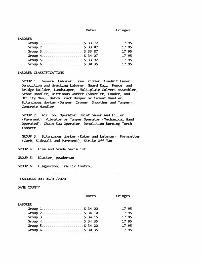
Rates Fringes
LABORER Group 1.....................$ 33.72 17.95 Group 2.....................$ 33.82 17.95 Group 3.....................$ 33.87 17.95 Group 4.....................$ 34.07 17.95 Group 5.....................$ 33.92 17.95 Group 6.....................$ 30.35 17.95
LABORER CLASSIFICATIONS
GROUP 1: General Laborer; Tree Trimmer; Conduit Layer; Demolition and Wrecking Laborer; Guard Rail, Fence, and Bridge Builder; Landscaper; Multiplate Culvert Assembler; Stone Handler; Bitminous Worker (Shoveler, Loader, and Utility Man); Batch Truck Dumper or Cement Handler; Bituminous Worker (Dumper, Ironer, Smoother and Tamper); Concrete Handler
GROUP 2: Air Tool Operator; Joint Sawer and Filler (Pavement); Vibrator or Tamper Operator (Mechanical Hand Operated); Chain Saw Operator, Demolition Burning Torch Laborer
GROUP 3: Bituminous Worker (Raker and Luteman); Formsetter (Curb, Sidewalk and Pavement); Strike Off Man
GROUP 4: Line and Grade Secialist
GROUP 5: Blaster; powderman
GROUP 6: Flagperson; Traffic Control
‐‐‐‐‐‐‐‐‐‐‐‐‐‐‐‐‐‐‐‐‐‐‐‐‐‐‐‐‐‐‐‐‐‐‐‐‐‐‐‐‐‐‐‐‐‐‐‐‐‐‐‐‐‐‐‐‐‐‐‐‐‐‐‐ LABO0464‐003 06/01/2020
DANE COUNTY
Rates Fringes
LABORER Group 1.....................$ 34.00 17.95 Group 2.....................$ 34.10 17.95 Group 3.....................$ 34.15 17.95 Group 4.....................$ 34.35 17.95 Group 5.....................$ 34.20 17.95 Group 6.....................$ 30.35 17.95

LABORERS CLASSIFICATIONS:
GROUP 1: General Laborer; Tree Trimmer; Conduit Layer; Demolition and Wrecking Laborer; Guard Rail, Fence, and Bridge Builder; Landscaper; Multiplate Culvert Assembler; Stone Handler; Bituminous Worker (Shoveler, Loader, and Utility Man); Batch Truck Dumper or Cement Handler; Bituminious Worker (Dumper, Ironer, Smoother, and Tamper); Concrete Handler
GROUP 2: Air Tool Operator; Joint Sawer and Filler (Pavement); Vibrator or Tamper Operator (Mechanical Hand Operated); Chain Saw Operator; Demolition Burning Torch Laborer
GROUP 3: Bituminous Worker (Raker and Luteman); Formsetter (Curb, Sidewalk, and Pavement); Strike Off Man
GROUP 4: Line and Grade Specialist
GROUP 5: Blaster; Powderman
GROUP 6: Flagperson and Traffic Control Person
‐‐‐‐‐‐‐‐‐‐‐‐‐‐‐‐‐‐‐‐‐‐‐‐‐‐‐‐‐‐‐‐‐‐‐‐‐‐‐‐‐‐‐‐‐‐‐‐‐‐‐‐‐‐‐‐‐‐‐‐‐‐‐‐ PAIN0106‐008 05/01/2017
ASHLAND, BAYFIELD, BURNETT, AND DOUGLAS COUNTIES
Rates Fringes
Painters: New: Brush, Roller..............$ 30.33 17.27 Spray, Sandblast, Steel....$ 30.93 17.27 Repaint: Brush, Roller..............$ 28.83 17.27 Spray, Sandblast, Steel....$ 29.43 17.27‐‐‐‐‐‐‐‐‐‐‐‐‐‐‐‐‐‐‐‐‐‐‐‐‐‐‐‐‐‐‐‐‐‐‐‐‐‐‐‐‐‐‐‐‐‐‐‐‐‐‐‐‐‐‐‐‐‐‐‐‐‐‐‐ PAIN0108‐002 06/01/2019
RACINE COUNTY
Rates Fringes
Painters: Brush, Roller...............$ 36.08 20.36 Spray & Sandblast...........$ 37.08 20.36‐‐‐‐‐‐‐‐‐‐‐‐‐‐‐‐‐‐‐‐‐‐‐‐‐‐‐‐‐‐‐‐‐‐‐‐‐‐‐‐‐‐‐‐‐‐‐‐‐‐‐‐‐‐‐‐‐‐‐‐‐‐‐‐ PAIN0259‐002 05/01/2008
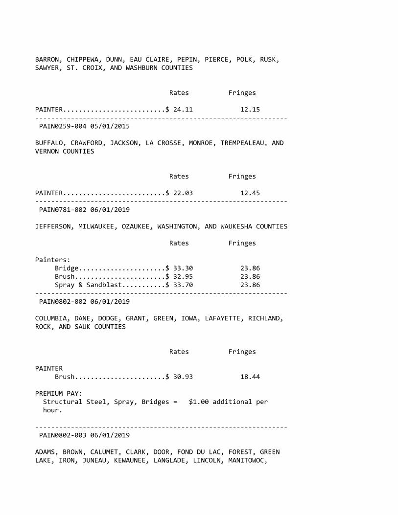
BARRON, CHIPPEWA, DUNN, EAU CLAIRE, PEPIN, PIERCE, POLK, RUSK,SAWYER, ST. CROIX, AND WASHBURN COUNTIES
Rates Fringes
PAINTER..........................$ 24.11 12.15‐‐‐‐‐‐‐‐‐‐‐‐‐‐‐‐‐‐‐‐‐‐‐‐‐‐‐‐‐‐‐‐‐‐‐‐‐‐‐‐‐‐‐‐‐‐‐‐‐‐‐‐‐‐‐‐‐‐‐‐‐‐‐‐ PAIN0259‐004 05/01/2015
BUFFALO, CRAWFORD, JACKSON, LA CROSSE, MONROE, TREMPEALEAU, ANDVERNON COUNTIES
Rates Fringes
PAINTER..........................$ 22.03 12.45‐‐‐‐‐‐‐‐‐‐‐‐‐‐‐‐‐‐‐‐‐‐‐‐‐‐‐‐‐‐‐‐‐‐‐‐‐‐‐‐‐‐‐‐‐‐‐‐‐‐‐‐‐‐‐‐‐‐‐‐‐‐‐‐ PAIN0781‐002 06/01/2019
JEFFERSON, MILWAUKEE, OZAUKEE, WASHINGTON, AND WAUKESHA COUNTIES
Rates Fringes
Painters: Bridge......................$ 33.30 23.86 Brush.......................$ 32.95 23.86 Spray & Sandblast...........$ 33.70 23.86‐‐‐‐‐‐‐‐‐‐‐‐‐‐‐‐‐‐‐‐‐‐‐‐‐‐‐‐‐‐‐‐‐‐‐‐‐‐‐‐‐‐‐‐‐‐‐‐‐‐‐‐‐‐‐‐‐‐‐‐‐‐‐‐ PAIN0802‐002 06/01/2019
COLUMBIA, DANE, DODGE, GRANT, GREEN, IOWA, LAFAYETTE, RICHLAND,ROCK, AND SAUK COUNTIES
Rates Fringes
PAINTER Brush.......................$ 30.93 18.44
PREMIUM PAY: Structural Steel, Spray, Bridges = $1.00 additional per hour.
‐‐‐‐‐‐‐‐‐‐‐‐‐‐‐‐‐‐‐‐‐‐‐‐‐‐‐‐‐‐‐‐‐‐‐‐‐‐‐‐‐‐‐‐‐‐‐‐‐‐‐‐‐‐‐‐‐‐‐‐‐‐‐‐ PAIN0802‐003 06/01/2019
ADAMS, BROWN, CALUMET, CLARK, DOOR, FOND DU LAC, FOREST, GREENLAKE, IRON, JUNEAU, KEWAUNEE, LANGLADE, LINCOLN, MANITOWOC,

MARATHON, MARINETTE, MARQUETTE, MENOMINEE, OCONTO, ONEIDA,OUTAGAMIE, PORTAGE, PRICE, SHAWANO, SHEBOYGAN, TAYLOR, VILAS,WAUSHARA, WAUPACA, WINNEBAGO, AND WOOD COUNTIES
Rates Fringes
PAINTER..........................$ 30.93 18.58‐‐‐‐‐‐‐‐‐‐‐‐‐‐‐‐‐‐‐‐‐‐‐‐‐‐‐‐‐‐‐‐‐‐‐‐‐‐‐‐‐‐‐‐‐‐‐‐‐‐‐‐‐‐‐‐‐‐‐‐‐‐‐‐ PAIN0934‐001 06/01/2017
KENOSHA AND WALWORTH COUNTIES
Rates Fringes
Painters: Brush.......................$ 33.74 18.95 Spray.......................$ 34.74 18.95 Structural Steel............$ 33.89 18.95‐‐‐‐‐‐‐‐‐‐‐‐‐‐‐‐‐‐‐‐‐‐‐‐‐‐‐‐‐‐‐‐‐‐‐‐‐‐‐‐‐‐‐‐‐‐‐‐‐‐‐‐‐‐‐‐‐‐‐‐‐‐‐‐ PAIN1011‐002 06/02/2019
FLORENCE COUNTY
Rates Fringes
Painters:........................$ 25.76 13.33‐‐‐‐‐‐‐‐‐‐‐‐‐‐‐‐‐‐‐‐‐‐‐‐‐‐‐‐‐‐‐‐‐‐‐‐‐‐‐‐‐‐‐‐‐‐‐‐‐‐‐‐‐‐‐‐‐‐‐‐‐‐‐‐ PLAS0599‐010 06/01/2017
Rates Fringes
CEMENT MASON/CONCRETE FINISHER Area 1......................$ 39.46 17.17 Area 2 (BAC)................$ 35.07 19.75 Area 3......................$ 35.61 19.40 Area 4......................$ 34.70 20.51 Area 5......................$ 36.27 18.73 Area 6......................$ 32.02 22.99
AREA DESCRIPTIONS
AREA 1: BAYFIELD, DOUGLAS, PRICE, SAWYER, AND WASHBURN COUNTIES
AREA 2: ADAMS, ASHLAND, BARRON, BROWN, BURNETT, CALUMET, CHIPPEWA, CLARK, COLUMBIA, DODGE, DOOR, DUNN, FLORENCE, FOND DU LAC, FOREST, GREEN LAKE, IRON, JEFFERSON, KEWAUNEE, LANGLADE, LINCOLN, MANITOWOC, MARATHON, MARINETTE, MARQUETTE, MENOMINEE, OCONTO, ONEIDA, OUTAGAMIE, POLK,
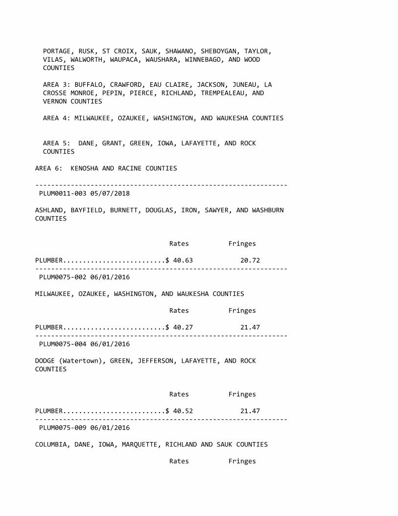
PORTAGE, RUSK, ST CROIX, SAUK, SHAWANO, SHEBOYGAN, TAYLOR, VILAS, WALWORTH, WAUPACA, WAUSHARA, WINNEBAGO, AND WOOD COUNTIES
AREA 3: BUFFALO, CRAWFORD, EAU CLAIRE, JACKSON, JUNEAU, LA CROSSE MONROE, PEPIN, PIERCE, RICHLAND, TREMPEALEAU, AND VERNON COUNTIES
AREA 4: MILWAUKEE, OZAUKEE, WASHINGTON, AND WAUKESHA COUNTIES
AREA 5: DANE, GRANT, GREEN, IOWA, LAFAYETTE, AND ROCK COUNTIES
AREA 6: KENOSHA AND RACINE COUNTIES
‐‐‐‐‐‐‐‐‐‐‐‐‐‐‐‐‐‐‐‐‐‐‐‐‐‐‐‐‐‐‐‐‐‐‐‐‐‐‐‐‐‐‐‐‐‐‐‐‐‐‐‐‐‐‐‐‐‐‐‐‐‐‐‐ PLUM0011‐003 05/07/2018
ASHLAND, BAYFIELD, BURNETT, DOUGLAS, IRON, SAWYER, AND WASHBURNCOUNTIES
Rates Fringes
PLUMBER..........................$ 40.63 20.72‐‐‐‐‐‐‐‐‐‐‐‐‐‐‐‐‐‐‐‐‐‐‐‐‐‐‐‐‐‐‐‐‐‐‐‐‐‐‐‐‐‐‐‐‐‐‐‐‐‐‐‐‐‐‐‐‐‐‐‐‐‐‐‐ PLUM0075‐002 06/01/2016
MILWAUKEE, OZAUKEE, WASHINGTON, AND WAUKESHA COUNTIES
Rates Fringes
PLUMBER..........................$ 40.27 21.47‐‐‐‐‐‐‐‐‐‐‐‐‐‐‐‐‐‐‐‐‐‐‐‐‐‐‐‐‐‐‐‐‐‐‐‐‐‐‐‐‐‐‐‐‐‐‐‐‐‐‐‐‐‐‐‐‐‐‐‐‐‐‐‐ PLUM0075‐004 06/01/2016
DODGE (Watertown), GREEN, JEFFERSON, LAFAYETTE, AND ROCKCOUNTIES
Rates Fringes
PLUMBER..........................$ 40.52 21.47‐‐‐‐‐‐‐‐‐‐‐‐‐‐‐‐‐‐‐‐‐‐‐‐‐‐‐‐‐‐‐‐‐‐‐‐‐‐‐‐‐‐‐‐‐‐‐‐‐‐‐‐‐‐‐‐‐‐‐‐‐‐‐‐ PLUM0075‐009 06/01/2016
COLUMBIA, DANE, IOWA, MARQUETTE, RICHLAND AND SAUK COUNTIES
Rates Fringes
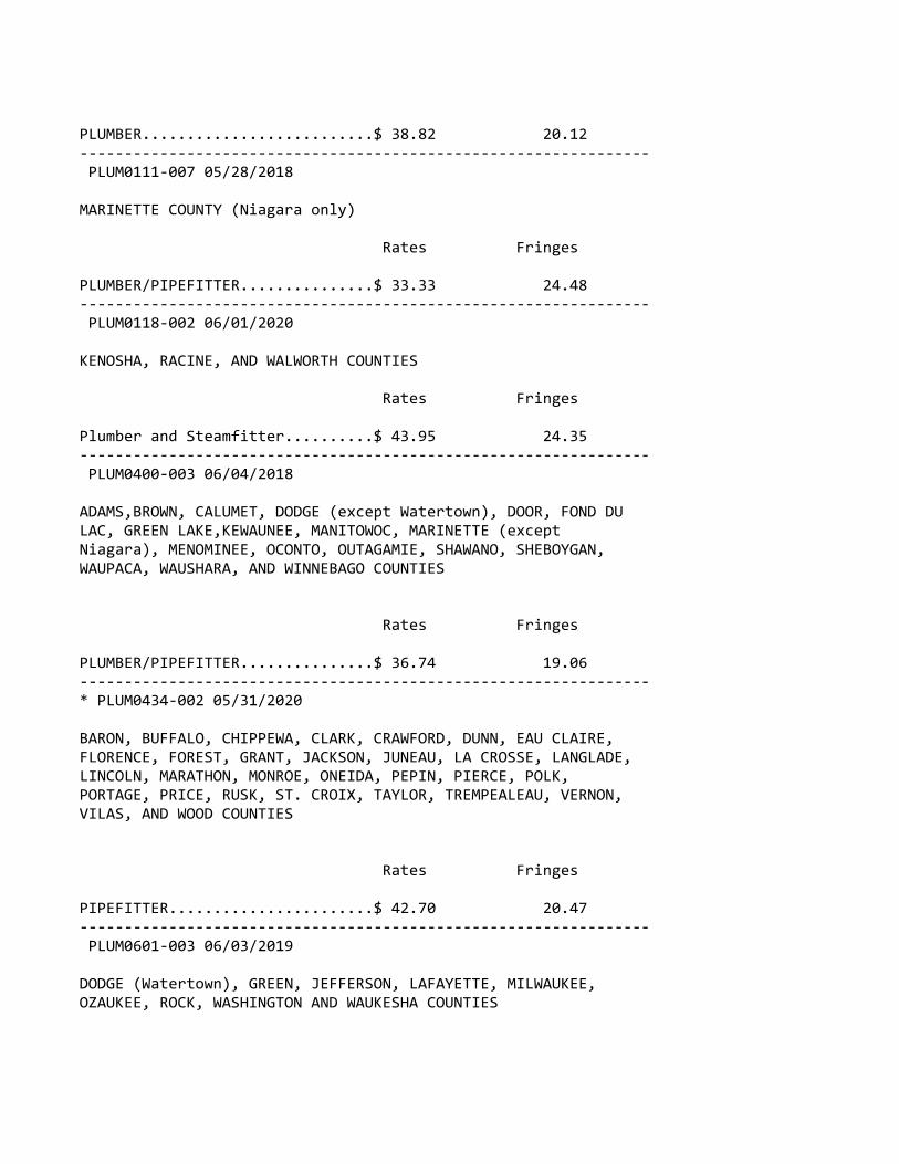
PLUMBER..........................$ 38.82 20.12‐‐‐‐‐‐‐‐‐‐‐‐‐‐‐‐‐‐‐‐‐‐‐‐‐‐‐‐‐‐‐‐‐‐‐‐‐‐‐‐‐‐‐‐‐‐‐‐‐‐‐‐‐‐‐‐‐‐‐‐‐‐‐‐ PLUM0111‐007 05/28/2018
MARINETTE COUNTY (Niagara only)
Rates Fringes
PLUMBER/PIPEFITTER...............$ 33.33 24.48‐‐‐‐‐‐‐‐‐‐‐‐‐‐‐‐‐‐‐‐‐‐‐‐‐‐‐‐‐‐‐‐‐‐‐‐‐‐‐‐‐‐‐‐‐‐‐‐‐‐‐‐‐‐‐‐‐‐‐‐‐‐‐‐ PLUM0118‐002 06/01/2020
KENOSHA, RACINE, AND WALWORTH COUNTIES
Rates Fringes
Plumber and Steamfitter..........$ 43.95 24.35‐‐‐‐‐‐‐‐‐‐‐‐‐‐‐‐‐‐‐‐‐‐‐‐‐‐‐‐‐‐‐‐‐‐‐‐‐‐‐‐‐‐‐‐‐‐‐‐‐‐‐‐‐‐‐‐‐‐‐‐‐‐‐‐ PLUM0400‐003 06/04/2018
ADAMS,BROWN, CALUMET, DODGE (except Watertown), DOOR, FOND DULAC, GREEN LAKE,KEWAUNEE, MANITOWOC, MARINETTE (exceptNiagara), MENOMINEE, OCONTO, OUTAGAMIE, SHAWANO, SHEBOYGAN,WAUPACA, WAUSHARA, AND WINNEBAGO COUNTIES
Rates Fringes
PLUMBER/PIPEFITTER...............$ 36.74 19.06‐‐‐‐‐‐‐‐‐‐‐‐‐‐‐‐‐‐‐‐‐‐‐‐‐‐‐‐‐‐‐‐‐‐‐‐‐‐‐‐‐‐‐‐‐‐‐‐‐‐‐‐‐‐‐‐‐‐‐‐‐‐‐‐* PLUM0434‐002 05/31/2020
BARON, BUFFALO, CHIPPEWA, CLARK, CRAWFORD, DUNN, EAU CLAIRE,FLORENCE, FOREST, GRANT, JACKSON, JUNEAU, LA CROSSE, LANGLADE,LINCOLN, MARATHON, MONROE, ONEIDA, PEPIN, PIERCE, POLK,PORTAGE, PRICE, RUSK, ST. CROIX, TAYLOR, TREMPEALEAU, VERNON,VILAS, AND WOOD COUNTIES
Rates Fringes
PIPEFITTER.......................$ 42.70 20.47‐‐‐‐‐‐‐‐‐‐‐‐‐‐‐‐‐‐‐‐‐‐‐‐‐‐‐‐‐‐‐‐‐‐‐‐‐‐‐‐‐‐‐‐‐‐‐‐‐‐‐‐‐‐‐‐‐‐‐‐‐‐‐‐ PLUM0601‐003 06/03/2019
DODGE (Watertown), GREEN, JEFFERSON, LAFAYETTE, MILWAUKEE,OZAUKEE, ROCK, WASHINGTON AND WAUKESHA COUNTIES

Rates Fringes
PIPEFITTER.......................$ 46.89 25.29‐‐‐‐‐‐‐‐‐‐‐‐‐‐‐‐‐‐‐‐‐‐‐‐‐‐‐‐‐‐‐‐‐‐‐‐‐‐‐‐‐‐‐‐‐‐‐‐‐‐‐‐‐‐‐‐‐‐‐‐‐‐‐‐ PLUM0601‐009 06/04/2017
COLUMBIA, DANE, IOWA, MARQUETTE, RICHLAND AND SAUK COUNTIES
Rates Fringes
PIPEFITTER.......................$ 47.08 20.89‐‐‐‐‐‐‐‐‐‐‐‐‐‐‐‐‐‐‐‐‐‐‐‐‐‐‐‐‐‐‐‐‐‐‐‐‐‐‐‐‐‐‐‐‐‐‐‐‐‐‐‐‐‐‐‐‐‐‐‐‐‐‐‐ TEAM0039‐002 06/01/2020
Rates Fringes
TRUCK DRIVER 1 & 2 Axle Trucks...........$ 31.07 22.94 3 or more axles; Euclids or Dumptor, Articulated Truck, Mechanic.............$ 31.22 22.94‐‐‐‐‐‐‐‐‐‐‐‐‐‐‐‐‐‐‐‐‐‐‐‐‐‐‐‐‐‐‐‐‐‐‐‐‐‐‐‐‐‐‐‐‐‐‐‐‐‐‐‐‐‐‐‐‐‐‐‐‐‐‐‐ SUWI2011‐001 11/16/2011
Rates Fringes
WELL DRILLER.....................$ 16.52 ‐‐‐‐‐‐‐‐‐‐‐‐‐‐‐‐‐‐‐‐‐‐‐‐‐‐‐‐‐‐‐‐‐‐‐‐‐‐‐‐‐‐‐‐‐‐‐‐‐‐‐‐‐‐‐‐‐‐‐‐‐‐‐‐
WELDERS ‐ Receive rate prescribed for craft performingoperation to which welding is incidental.
================================================================ Note: Executive Order (EO) 13706, Establishing Paid Sick Leavefor Federal Contractors applies to all contracts subject to theDavis‐Bacon Act for which the contract is awarded (and anysolicitation was issued) on or after January 1, 2017. If thiscontract is covered by the EO, the contractor must provideemployees with 1 hour of paid sick leave for every 30 hoursthey work, up to 56 hours of paid sick leave each year.Employees must be permitted to use paid sick leave for theirown illness, injury or other health‐related needs, includingpreventive care; to assist a family member (or person who islike family to the employee) who is ill, injured, or has otherhealth‐related needs, including preventive care; or for reasonsresulting from, or to assist a family member (or person who islike family to the employee) who is a victim of, domesticviolence, sexual assault, or stalking. Additional informationon contractor requirements and worker protections under the EO
is available at www.dol.gov/whd/govcontracts.
Unlisted classifications needed for work not included withinthe scope of the classifications listed may be added afteraward only as provided in the labor standards contract clauses(29CFR 5.5 (a) (1) (ii)).
‐‐‐‐‐‐‐‐‐‐‐‐‐‐‐‐‐‐‐‐‐‐‐‐‐‐‐‐‐‐‐‐‐‐‐‐‐‐‐‐‐‐‐‐‐‐‐‐‐‐‐‐‐‐‐‐‐‐‐‐‐‐‐‐
The body of each wage determination lists the classificationand wage rates that have been found to be prevailing for thecited type(s) of construction in the area covered by the wagedetermination. The classifications are listed in alphabeticalorder of ""identifiers"" that indicate whether the particularrate is a union rate (current union negotiated rate for local),a survey rate (weighted average rate) or a union average rate(weighted union average rate).
Union Rate Identifiers
A four letter classification abbreviation identifier enclosedin dotted lines beginning with characters other than ""SU"" or""UAVG"" denotes that the union classification and rate wereprevailing for that classification in the survey. Example:PLUM0198‐005 07/01/2014. PLUM is an abbreviation identifier ofthe union which prevailed in the survey for thisclassification, which in this example would be Plumbers. 0198indicates the local union number or district council numberwhere applicable, i.e., Plumbers Local 0198. The next number,005 in the example, is an internal number used in processingthe wage determination. 07/01/2014 is the effective date of themost current negotiated rate, which in this example is July 1,2014.
Union prevailing wage rates are updated to reflect all ratechanges in the collective bargaining agreement (CBA) governingthis classification and rate.
Survey Rate Identifiers
Classifications listed under the ""SU"" identifier indicate thatno one rate prevailed for this classification in the survey andthe published rate is derived by computing a weighted averagerate based on all the rates reported in the survey for thatclassification. As this weighted average rate includes allrates reported in the survey, it may include both union andnon‐union rates. Example: SULA2012‐007 5/13/2014. SU indicatesthe rates are survey rates based on a weighted average

calculation of rates and are not majority rates. LA indicatesthe State of Louisiana. 2012 is the year of survey on whichthese classifications and rates are based. The next number, 007in the example, is an internal number used in producing thewage determination. 5/13/2014 indicates the survey completiondate for the classifications and rates under that identifier.
Survey wage rates are not updated and remain in effect until anew survey is conducted.
Union Average Rate Identifiers
Classification(s) listed under the UAVG identifier indicatethat no single majority rate prevailed for thoseclassifications; however, 100% of the data reported for theclassifications was union data. EXAMPLE: UAVG‐OH‐001008/29/2014. UAVG indicates that the rate is a weighted unionaverage rate. OH indicates the state. The next number, 0010 inthe example, is an internal number used in producing the wagedetermination. 08/29/2014 indicates the survey completion datefor the classifications and rates under that identifier.
A UAVG rate will be updated once a year, usually in January ofeach year, to reflect a weighted average of the currentnegotiated/CBA rate of the union locals from which the rate isbased.
‐‐‐‐‐‐‐‐‐‐‐‐‐‐‐‐‐‐‐‐‐‐‐‐‐‐‐‐‐‐‐‐‐‐‐‐‐‐‐‐‐‐‐‐‐‐‐‐‐‐‐‐‐‐‐‐‐‐‐‐‐‐‐‐
WAGE DETERMINATION APPEALS PROCESS
1.) Has there been an initial decision in the matter? This canbe:
* an existing published wage determination* a survey underlying a wage determination* a Wage and Hour Division letter setting forth a position on a wage determination matter* a conformance (additional classification and rate) ruling
On survey related matters, initial contact, including requestsfor summaries of surveys, should be with the Wage and HourRegional Office for the area in which the survey was conductedbecause those Regional Offices have responsibility for theDavis‐Bacon survey program. If the response from this initialcontact is not satisfactory, then the process described in 2.)and 3.) should be followed.
With regard to any other matter not yet ripe for the formalprocess described here, initial contact should be with theBranch of Construction Wage Determinations. Write to:
Branch of Construction Wage Determinations Wage and Hour Division U.S. Department of Labor 200 Constitution Avenue, N.W. Washington, DC 20210
2.) If the answer to the question in 1.) is yes, then aninterested party (those affected by the action) can requestreview and reconsideration from the Wage and Hour Administrator(See 29 CFR Part 1.8 and 29 CFR Part 7). Write to:
Wage and Hour Administrator U.S. Department of Labor 200 Constitution Avenue, N.W. Washington, DC 20210
The request should be accompanied by a full statement of theinterested party's position and by any information (wagepayment data, project description, area practice material,etc.) that the requestor considers relevant to the issue.
3.) If the decision of the Administrator is not favorable, aninterested party may appeal directly to the AdministrativeReview Board (formerly the Wage Appeals Board). Write to:
Administrative Review Board U.S. Department of Labor 200 Constitution Avenue, N.W. Washington, DC 20210
4.) All decisions by the Administrative Review Board are final.
================================================================
END OF GENERAL DECISION"
"General Decision Number: WI20200016 07/24/2020
Superseded General Decision Number: WI20190016
State: Wisconsin
Construction Type: Building
Counties: Calumet, Outagamie, Sheboygan and Winnebago Counties in Wisconsin.
BUILDING CONSTRUCTION PROJECTS (does not include residentialconstruction consisting of single family homes and apartmentsup to and including 4 stories)
Note: Under Executive Order (EO) 13658, an hourly minimum wageof $10.80 for calendar year 2020 applies to all contractssubject to the Davis‐Bacon Act for which the contract isawarded (and any solicitation was issued) on or after January1, 2015. If this contract is covered by the EO, the contractormust pay all workers in any classification listed on this wagedetermination at least $10.80 per hour (or the applicable wagerate listed on this wage determination, if it is higher) forall hours spent performing on the contract in calendar year2020. If this contract is covered by the EO and aclassification considered necessary for performance of work onthe contract does not appear on this wage determination, thecontractor must pay workers in that classification at least thewage rate determined through the conformance process set forthin 29 CFR 5.5(a)(1)(ii) (or the EO minimum wage rate,if it ishigher than the conformed wage rate). The EO minimum wage ratewill be adjusted annually. Please note that this EO applies tothe above‐mentioned types of contracts entered into by thefederal government that are subject to the Davis‐Bacon Actitself, but it does not apply to contracts subject only to theDavis‐Bacon Related Acts, including those set forth at 29 CFR5.1(a)(2)‐(60). Additional information on contractorrequirements and worker protections under the EO is availableat www.dol.gov/whd/govcontracts.
Modification Number Publication Date 0 01/03/2020 1 01/24/2020 2 01/31/2020 3 03/06/2020 4 04/17/2020 5 06/19/2020 6 07/17/2020

7 07/24/2020
ASBE0205‐010 06/01/1998
Rates Fringes
Asbestos Removal worker/hazardous material handler Includes preparation, wetting, stripping, removal, scrapping vacuuming, bagging and disposing of all insulation materials from mechanical systems whether they contain asbestos or not.........................$ 16.56 3.10‐‐‐‐‐‐‐‐‐‐‐‐‐‐‐‐‐‐‐‐‐‐‐‐‐‐‐‐‐‐‐‐‐‐‐‐‐‐‐‐‐‐‐‐‐‐‐‐‐‐‐‐‐‐‐‐‐‐‐‐‐‐‐‐ BOIL0107‐001 01/01/2017
Rates Fringes
BOILERMAKER Boilermaker.................$ 35.65 29.89 Small Boiler Repair (under 25,000 lbs/hr)..............$ 26.91 16.00‐‐‐‐‐‐‐‐‐‐‐‐‐‐‐‐‐‐‐‐‐‐‐‐‐‐‐‐‐‐‐‐‐‐‐‐‐‐‐‐‐‐‐‐‐‐‐‐‐‐‐‐‐‐‐‐‐‐‐‐‐‐‐‐ BRWI0011‐003 06/03/2019
Rates Fringes
BRICKLAYER Bricklayer, Cement Mason, Plasterer, Tile Layer.......$ 34.18 23.90‐‐‐‐‐‐‐‐‐‐‐‐‐‐‐‐‐‐‐‐‐‐‐‐‐‐‐‐‐‐‐‐‐‐‐‐‐‐‐‐‐‐‐‐‐‐‐‐‐‐‐‐‐‐‐‐‐‐‐‐‐‐‐‐ CARP0252‐001 06/01/2016
Rates Fringes
CARPENTER (Including Drywall Hanging, Acoustical work, Excluding Batt Insulation) CARPENTER & SOFT FLOOR LAYER.......................$ 33.56 18.00 MILLWRIGHT..................$ 35.08 18.35 PILEDRIVERMAN...............$ 34.12 18.00‐‐‐‐‐‐‐‐‐‐‐‐‐‐‐‐‐‐‐‐‐‐‐‐‐‐‐‐‐‐‐‐‐‐‐‐‐‐‐‐‐‐‐‐‐‐‐‐‐‐‐‐‐‐‐‐‐‐‐‐‐‐‐‐ ELEC0494‐003 06/07/2020
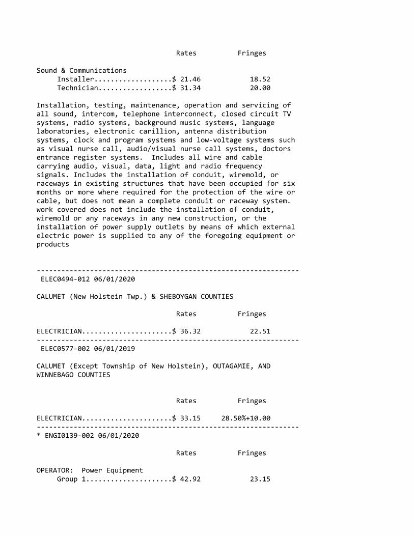
Rates Fringes
Sound & Communications Installer...................$ 21.46 18.52 Technician..................$ 31.34 20.00
Installation, testing, maintenance, operation and servicing ofall sound, intercom, telephone interconnect, closed circuit TVsystems, radio systems, background music systems, languagelaboratories, electronic carillion, antenna distributionsystems, clock and program systems and low‐voltage systems suchas visual nurse call, audio/visual nurse call systems, doctorsentrance register systems. Includes all wire and cablecarrying audio, visual, data, light and radio frequencysignals. Includes the installation of conduit, wiremold, orraceways in existing structures that have been occupied for sixmonths or more where required for the protection of the wire orcable, but does not mean a complete conduit or raceway system.work covered does not include the installation of conduit,wiremold or any raceways in any new construction, or theinstallation of power supply outlets by means of which externalelectric power is supplied to any of the foregoing equipment orproducts
‐‐‐‐‐‐‐‐‐‐‐‐‐‐‐‐‐‐‐‐‐‐‐‐‐‐‐‐‐‐‐‐‐‐‐‐‐‐‐‐‐‐‐‐‐‐‐‐‐‐‐‐‐‐‐‐‐‐‐‐‐‐‐‐ ELEC0494‐012 06/01/2020
CALUMET (New Holstein Twp.) & SHEBOYGAN COUNTIES
Rates Fringes
ELECTRICIAN......................$ 36.32 22.51‐‐‐‐‐‐‐‐‐‐‐‐‐‐‐‐‐‐‐‐‐‐‐‐‐‐‐‐‐‐‐‐‐‐‐‐‐‐‐‐‐‐‐‐‐‐‐‐‐‐‐‐‐‐‐‐‐‐‐‐‐‐‐‐ ELEC0577‐002 06/01/2019
CALUMET (Except Township of New Holstein), OUTAGAMIE, ANDWINNEBAGO COUNTIES
Rates Fringes
ELECTRICIAN......................$ 33.15 28.50%+10.00‐‐‐‐‐‐‐‐‐‐‐‐‐‐‐‐‐‐‐‐‐‐‐‐‐‐‐‐‐‐‐‐‐‐‐‐‐‐‐‐‐‐‐‐‐‐‐‐‐‐‐‐‐‐‐‐‐‐‐‐‐‐‐‐* ENGI0139‐002 06/01/2020
Rates Fringes
OPERATOR: Power Equipment Group 1.....................$ 42.92 23.15
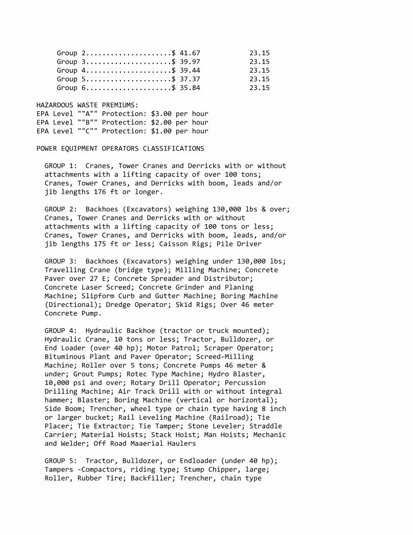
Group 2.....................$ 41.67 23.15 Group 3.....................$ 39.97 23.15 Group 4.....................$ 39.44 23.15 Group 5.....................$ 37.37 23.15 Group 6.....................$ 35.84 23.15
HAZARDOUS WASTE PREMIUMS:EPA Level ""A"" Protection: $3.00 per hourEPA Level ""B"" Protection: $2.00 per hourEPA Level ""C"" Protection: $1.00 per hour
POWER EQUIPMENT OPERATORS CLASSIFICATIONS
GROUP 1: Cranes, Tower Cranes and Derricks with or without attachments with a lifting capacity of over 100 tons; Cranes, Tower Cranes, and Derricks with boom, leads and/or jib lengths 176 ft or longer.
GROUP 2: Backhoes (Excavators) weighing 130,000 lbs & over; Cranes, Tower Cranes and Derricks with or without attachments with a lifting capacity of 100 tons or less; Cranes, Tower Cranes, and Derricks with boom, leads, and/or jib lengths 175 ft or less; Caisson Rigs; Pile Driver
GROUP 3: Backhoes (Excavators) weighing under 130,000 lbs; Travelling Crane (bridge type); Milling Machine; Concrete Paver over 27 E; Concrete Spreader and Distributor; Concrete Laser Screed; Concrete Grinder and Planing Machine; Slipform Curb and Gutter Machine; Boring Machine (Directional); Dredge Operator; Skid Rigs; Over 46 meter Concrete Pump.
GROUP 4: Hydraulic Backhoe (tractor or truck mounted); Hydraulic Crane, 10 tons or less; Tractor, Bulldozer, or End Loader (over 40 hp); Motor Patrol; Scraper Operator; Bituminous Plant and Paver Operator; Screed‐Milling Machine; Roller over 5 tons; Concrete Pumps 46 meter & under; Grout Pumps; Rotec Type Machine; Hydro Blaster, 10,000 psi and over; Rotary Drill Operator; Percussion Drilling Machine; Air Track Drill with or without integral hammer; Blaster; Boring Machine (vertical or horizontal); Side Boom; Trencher, wheel type or chain type having 8 inch or larger bucket; Rail Leveling Machine (Railroad); Tie Placer; Tie Extractor; Tie Tamper; Stone Leveler; Straddle Carrier; Material Hoists; Stack Hoist; Man Hoists; Mechanic and Welder; Off Road Maaerial Haulers
GROUP 5: Tractor, Bulldozer, or Endloader (under 40 hp); Tampers ‐Compactors, riding type; Stump Chipper, large; Roller, Rubber Tire; Backfiller; Trencher, chain type
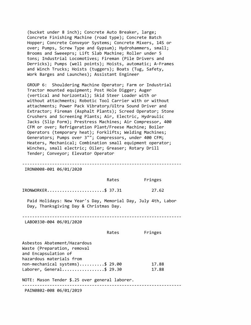
(bucket under 8 inch); Concrete Auto Breaker, large; Concrete Finishing Machine (road type); Concrete Batch Hopper; Concrete Conveyor Systems; Concrete Mixers, 14S or over; Pumps, Screw Type and Gypsum); Hydrohammers, small; Brooms and Sweeeprs; Lift Slab Machine; Roller under 5 tons; Industrial Locomotives; Fireman (Pile Drivers and Derricks); Pumps (well points); Hoists, automatic; A‐Frames and Winch Trucks; Hoists (tuggers); Boats (Tug, Safety, Work Barges and Launches); Assistant Engineer
GROUP 6: Shouldering Machine Operator; Farm or Industrial Tractor mounted equipment; Post Hole Digger; Auger (vertical and horizontal); Skid Steer Loader with or without attachments; Robotic Tool Carrier with or without attachments; Power Pack Vibratory/Ultra Sound Driver and Extractor; Fireman (Asphalt Plants); Screed Operator; Stone Crushers and Screening Plants; Air, Electric, Hydraulic Jacks (Slip Form); Prestress Machines; Air Compressor, 400 CFM or over; Refrigeration Plant/Freese Machine; Boiler Operators (temporary heat); Forklifts; Welding Machines; Generators; Pumps over 3""; Compressors, under 400 CFM; Heaters, Mechanical; Combination small equipment operator; Winches, small electric; Oiler; Greaser; Rotary Drill Tender; Conveyor; Elevator Operator
‐‐‐‐‐‐‐‐‐‐‐‐‐‐‐‐‐‐‐‐‐‐‐‐‐‐‐‐‐‐‐‐‐‐‐‐‐‐‐‐‐‐‐‐‐‐‐‐‐‐‐‐‐‐‐‐‐‐‐‐‐‐‐‐ IRON0008‐001 06/01/2020
Rates Fringes
IRONWORKER.......................$ 37.31 27.62
Paid Holidays: New Year's Day, Memorial Day, July 4th, Labor Day, Thanksgiving Day & Christmas Day.
‐‐‐‐‐‐‐‐‐‐‐‐‐‐‐‐‐‐‐‐‐‐‐‐‐‐‐‐‐‐‐‐‐‐‐‐‐‐‐‐‐‐‐‐‐‐‐‐‐‐‐‐‐‐‐‐‐‐‐‐‐‐‐‐ LABO0330‐004 06/01/2020
Rates Fringes
Asbestos Abatement/Hazardous Waste (Preparation, removal and Encapsulation of hazardous materials from non‐mechanical systems)..........$ 29.00 17.88Laborer, General.................$ 29.30 17.88
NOTE: Mason Tender $.25 over general laborer.‐‐‐‐‐‐‐‐‐‐‐‐‐‐‐‐‐‐‐‐‐‐‐‐‐‐‐‐‐‐‐‐‐‐‐‐‐‐‐‐‐‐‐‐‐‐‐‐‐‐‐‐‐‐‐‐‐‐‐‐‐‐‐‐ PAIN0802‐008 06/01/2019

Rates Fringes
PAINTER Brush, Drywall Taper........$ 30.93 18.58‐‐‐‐‐‐‐‐‐‐‐‐‐‐‐‐‐‐‐‐‐‐‐‐‐‐‐‐‐‐‐‐‐‐‐‐‐‐‐‐‐‐‐‐‐‐‐‐‐‐‐‐‐‐‐‐‐‐‐‐‐‐‐‐ PAIN1204‐001 06/01/2017
Rates Fringes
GLAZIER..........................$ 28.34 19.65‐‐‐‐‐‐‐‐‐‐‐‐‐‐‐‐‐‐‐‐‐‐‐‐‐‐‐‐‐‐‐‐‐‐‐‐‐‐‐‐‐‐‐‐‐‐‐‐‐‐‐‐‐‐‐‐‐‐‐‐‐‐‐‐ PLUM0400‐001 06/04/2018
Rates Fringes
PLUMBER/PIPEFITTER (Including HVAC work) (1) Small buildings (except industrial and power plants) where plumbing or heating is $50,000 or less.............$ 32.15 17.57 (2) All other work..........$ 36.74 19.06‐‐‐‐‐‐‐‐‐‐‐‐‐‐‐‐‐‐‐‐‐‐‐‐‐‐‐‐‐‐‐‐‐‐‐‐‐‐‐‐‐‐‐‐‐‐‐‐‐‐‐‐‐‐‐‐‐‐‐‐‐‐‐‐ SFWI0669‐002 04/01/2020
Rates Fringes
SPRINKLER FITTER.................$ 42.38 24.89‐‐‐‐‐‐‐‐‐‐‐‐‐‐‐‐‐‐‐‐‐‐‐‐‐‐‐‐‐‐‐‐‐‐‐‐‐‐‐‐‐‐‐‐‐‐‐‐‐‐‐‐‐‐‐‐‐‐‐‐‐‐‐‐ SHEE0018‐025 06/01/2019
CALUMET & SHEBOYGAN COUNTIES
Rates Fringes
Sheet Metal Worker (Including HVAC duct work and Technician)...$ 32.98 25.35‐‐‐‐‐‐‐‐‐‐‐‐‐‐‐‐‐‐‐‐‐‐‐‐‐‐‐‐‐‐‐‐‐‐‐‐‐‐‐‐‐‐‐‐‐‐‐‐‐‐‐‐‐‐‐‐‐‐‐‐‐‐‐‐ SHEE0018‐029 06/01/2018
OUTAGAMIE AND WINNEBAGO COUNTIES
Rates Fringes
Sheet Metal Worker (Including HVAC duct work and Technician)...$ 33.56 25.21‐‐‐‐‐‐‐‐‐‐‐‐‐‐‐‐‐‐‐‐‐‐‐‐‐‐‐‐‐‐‐‐‐‐‐‐‐‐‐‐‐‐‐‐‐‐‐‐‐‐‐‐‐‐‐‐‐‐‐‐‐‐‐‐ TEAM0662‐001 06/01/2020

Rates Fringes
TRUCK DRIVER 1 & 2 Axles.................$ 31.07 22.94 3 or more Axles.............$ 31.22 22.94‐‐‐‐‐‐‐‐‐‐‐‐‐‐‐‐‐‐‐‐‐‐‐‐‐‐‐‐‐‐‐‐‐‐‐‐‐‐‐‐‐‐‐‐‐‐‐‐‐‐‐‐‐‐‐‐‐‐‐‐‐‐‐‐ SUWI2002‐013 01/23/2002
Rates Fringes
Asbestos Worker/Heat and Frost Insulator..................$ 25.36 8.37 Laborers: Concrete Worker.............$ 16.34 3.59 Landscape...................$ 8.73 4.90 ROOFER...........................$ 18.01 3.28 Tile & Marble Finisher...........$ 13.89 8.36‐‐‐‐‐‐‐‐‐‐‐‐‐‐‐‐‐‐‐‐‐‐‐‐‐‐‐‐‐‐‐‐‐‐‐‐‐‐‐‐‐‐‐‐‐‐‐‐‐‐‐‐‐‐‐‐‐‐‐‐‐‐‐‐
WELDERS ‐ Receive rate prescribed for craft performingoperation to which welding is incidental.
================================================================ Note: Executive Order (EO) 13706, Establishing Paid Sick Leavefor Federal Contractors applies to all contracts subject to theDavis‐Bacon Act for which the contract is awarded (and anysolicitation was issued) on or after January 1, 2017. If thiscontract is covered by the EO, the contractor must provideemployees with 1 hour of paid sick leave for every 30 hoursthey work, up to 56 hours of paid sick leave each year.Employees must be permitted to use paid sick leave for theirown illness, injury or other health‐related needs, includingpreventive care; to assist a family member (or person who islike family to the employee) who is ill, injured, or has otherhealth‐related needs, including preventive care; or for reasonsresulting from, or to assist a family member (or person who islike family to the employee) who is a victim of, domesticviolence, sexual assault, or stalking. Additional informationon contractor requirements and worker protections under the EOis available at www.dol.gov/whd/govcontracts.
Unlisted classifications needed for work not included withinthe scope of the classifications listed may be added afteraward only as provided in the labor standards contract clauses(29CFR 5.5 (a) (1) (ii)).

‐‐‐‐‐‐‐‐‐‐‐‐‐‐‐‐‐‐‐‐‐‐‐‐‐‐‐‐‐‐‐‐‐‐‐‐‐‐‐‐‐‐‐‐‐‐‐‐‐‐‐‐‐‐‐‐‐‐‐‐‐‐‐‐
The body of each wage determination lists the classificationand wage rates that have been found to be prevailing for thecited type(s) of construction in the area covered by the wagedetermination. The classifications are listed in alphabeticalorder of ""identifiers"" that indicate whether the particularrate is a union rate (current union negotiated rate for local),a survey rate (weighted average rate) or a union average rate(weighted union average rate).
Union Rate Identifiers
A four letter classification abbreviation identifier enclosedin dotted lines beginning with characters other than ""SU"" or""UAVG"" denotes that the union classification and rate wereprevailing for that classification in the survey. Example:PLUM0198‐005 07/01/2014. PLUM is an abbreviation identifier ofthe union which prevailed in the survey for thisclassification, which in this example would be Plumbers. 0198indicates the local union number or district council numberwhere applicable, i.e., Plumbers Local 0198. The next number,005 in the example, is an internal number used in processingthe wage determination. 07/01/2014 is the effective date of themost current negotiated rate, which in this example is July 1,2014.
Union prevailing wage rates are updated to reflect all ratechanges in the collective bargaining agreement (CBA) governingthis classification and rate.
Survey Rate Identifiers
Classifications listed under the ""SU"" identifier indicate thatno one rate prevailed for this classification in the survey andthe published rate is derived by computing a weighted averagerate based on all the rates reported in the survey for thatclassification. As this weighted average rate includes allrates reported in the survey, it may include both union andnon‐union rates. Example: SULA2012‐007 5/13/2014. SU indicatesthe rates are survey rates based on a weighted averagecalculation of rates and are not majority rates. LA indicatesthe State of Louisiana. 2012 is the year of survey on whichthese classifications and rates are based. The next number, 007in the example, is an internal number used in producing thewage determination. 5/13/2014 indicates the survey completiondate for the classifications and rates under that identifier.
Survey wage rates are not updated and remain in effect until anew survey is conducted.
Union Average Rate Identifiers
Classification(s) listed under the UAVG identifier indicatethat no single majority rate prevailed for thoseclassifications; however, 100% of the data reported for theclassifications was union data. EXAMPLE: UAVG‐OH‐001008/29/2014. UAVG indicates that the rate is a weighted unionaverage rate. OH indicates the state. The next number, 0010 inthe example, is an internal number used in producing the wagedetermination. 08/29/2014 indicates the survey completion datefor the classifications and rates under that identifier.
A UAVG rate will be updated once a year, usually in January ofeach year, to reflect a weighted average of the currentnegotiated/CBA rate of the union locals from which the rate isbased.
‐‐‐‐‐‐‐‐‐‐‐‐‐‐‐‐‐‐‐‐‐‐‐‐‐‐‐‐‐‐‐‐‐‐‐‐‐‐‐‐‐‐‐‐‐‐‐‐‐‐‐‐‐‐‐‐‐‐‐‐‐‐‐‐
WAGE DETERMINATION APPEALS PROCESS
1.) Has there been an initial decision in the matter? This canbe:
* an existing published wage determination* a survey underlying a wage determination* a Wage and Hour Division letter setting forth a position on a wage determination matter* a conformance (additional classification and rate) ruling
On survey related matters, initial contact, including requestsfor summaries of surveys, should be with the Wage and HourRegional Office for the area in which the survey was conductedbecause those Regional Offices have responsibility for theDavis‐Bacon survey program. If the response from this initialcontact is not satisfactory, then the process described in 2.)and 3.) should be followed.
With regard to any other matter not yet ripe for the formalprocess described here, initial contact should be with theBranch of Construction Wage Determinations. Write to:
Branch of Construction Wage Determinations Wage and Hour Division
U.S. Department of Labor 200 Constitution Avenue, N.W. Washington, DC 20210
2.) If the answer to the question in 1.) is yes, then aninterested party (those affected by the action) can requestreview and reconsideration from the Wage and Hour Administrator(See 29 CFR Part 1.8 and 29 CFR Part 7). Write to:
Wage and Hour Administrator U.S. Department of Labor 200 Constitution Avenue, N.W. Washington, DC 20210
The request should be accompanied by a full statement of theinterested party's position and by any information (wagepayment data, project description, area practice material,etc.) that the requestor considers relevant to the issue.
3.) If the decision of the Administrator is not favorable, aninterested party may appeal directly to the AdministrativeReview Board (formerly the Wage Appeals Board). Write to:
Administrative Review Board U.S. Department of Labor 200 Constitution Avenue, N.W. Washington, DC 20210
4.) All decisions by the Administrative Review Board are final.
================================================================
END OF GENERAL DECISION"

Wisconsin Department of Transportation
Version 02-2017 Solving tomorrow’s transportation challenges
Division of Transportation Systems Development Bureau of Project Development 4822 Madison Yards Way, 4th Floor South Madison, WI 53705 Telephone: (608) 266-1631 Facsimile (FAX): (608) 266-8459
July 30, 2020
NOTICE TO ALL CONTRACTORS: Proposal #07: 4492-03-71, WISC 2020 384
Racine Street Bridge, C of Menasha Fox River Bridge and Approaches Local Str Winnebago County
Letting of August 11, 2020
This is Addendum No. 01, which provides for the following:
Special Provisions:
Revised Special Provisions Article
No. Description
7 Utilities 11 Bridge, w. Mechanical Work Bascule Span, Item SPV.0105.06
Plan Sheets:
Revised Plan Sheets Plan
Sheet Plan Sheet Title (brief description of changes to sheet)
15 Construction Details (revised pavement type) 393 Bascule Sidewalk Plan & Elevations (revised floor plate thickness) 549 Machinery Notes (clarified torque values) 550 Machinery Trimetric View (revised coupling notes) 551 Machinery Plan and Elevation (revised coupling notes) 552 Machinery Plan & Elevation 2 (revised coupling notes) 553 Bearing ‘A’ Assembly (revised bolt dimensions) 568 Electrical Notes (revised Task E-4 note) 572 Operator’s House Electrical Floor Plans (revised north arrow and added notes) 574 Single Line Diagram (1 of 2) (revised 400 amp service and notes) 575 Single Line Diagram (2 of 2) (revised amperage and disconnect) 594 Grounding and Lightning Protection Details 595 Grounding Riser
The responsibility for notifying potential subcontractors and suppliers of these changes remains with the prime contractor.
Sincerely,
Mike Coleman Proposal Development Specialist Proposal Management Section
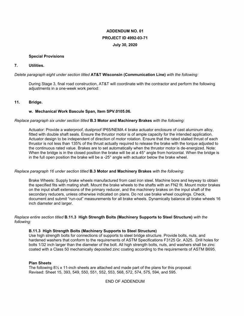
ADDENDUM NO. 01 PROJECT ID 4992-03-71
July 30, 2020
Special Provisions
7. Utilities.
Delete paragraph eight under section titled AT&T Wisconsin (Communication Line) with the following:
During Stage 3, final road construction, AT&T will coordinate with the contractor and perform the following adjustments in a one-week work period:
11. Bridge.
w. Mechanical Work Bascule Span, Item SPV.0105.06.
Replace paragraph six under section titled B.3 Motor and Machinery Brakes with the following:
Actuator: Provide a waterproof, dustproof IP65/NEMA 4 brake actuator enclosure of cast aluminum alloy, fitted with double shaft seals. Ensure the thrustor motor is of ample capacity for the intended application. Actuator design to be independent of direction of motor rotation. Ensure that the rated stalled thrust of each thrustor is not less than 135% of the thrust actually required to release the brake with the torque adjusted to the continuous rated value. Brakes are to set automatically when the thrustor motor is de-energized. Note: When the bridge is in the closed position the brake will be at a 45° angle from horizontal. When the bridge is in the full open position the brake will be a -25° angle with actuator below the brake wheel.
Replace paragraph 16 under section titled B.3 Motor and Machinery Brakes with the following:
Brake Wheels: Supply brake wheels manufactured from cast iron steel. Machine bore and keyway to obtain the specified fits with mating shaft. Mount the brake wheels to the shafts with an FN2 fit. Mount motor brakes on the input shaft extensions of the primary reducer, and the machinery brakes on the input shaft of the secondary reducers, unless otherwise indicated on plans. Do not use brake wheel couplings. Check, document and submit “run-out” measurements for all brake wheels. Dynamically balance all brake wheels 16 inch diameter and larger.
Replace entire section titled B.11.3 High Strength Bolts (Machinery Supports to Steel Structure) with the following:
B.11.3 High Strength Bolts (Machinery Supports to Steel Structure) Use high strength bolts for connections of supports to steel bridge structure. Provide bolts, nuts, and hardened washers that conform to the requirements of ASTM Specifications F3125 Gr. A325. Drill holes for bolts 1/32 inch larger than the diameter of the bolt. All high strength bolts, nuts, and washers shall be zinc coated with a Class 50 mechanically deposited zinc coating according to the requirements of ASTM B695.
Plan Sheets The following 8½ x 11-inch sheets are attached and made part of the plans for this proposal: Revised: Sheet 15, 393, 549, 550, 551, 552, 553, 568, 572, 574, 575, 594, and 595.
END OF ADDENDUM

SILT
FEN
CE
OPE
NIN
G12
" MIN
-18
" MAX
ROAD
SID
E
30" M
IN -
36" M
AXG
ENER
AL N
OTE
S:SI
LT F
ENCE
PO
STS
FOR
THE
TURN
-ARO
UN
D SH
OU
LD B
E O
N T
HE
OU
TSID
E O
F TH
ETU
RN-A
ROU
ND.
AN
D TR
ENCH
ED IN
ACC
ORD
ING
TO
SIL
T FE
NCE
REQ
UIR
EMEN
TS.
SEE
TEM
PORA
RY E
ROSI
ON
CO
NTR
OL
PLAN
S FO
R SI
LT F
ENCE
LO
CATI
ON
S. IN
STAL
LTU
RN-A
ROU
ND
AT E
ND
OF
SHO
WN
FEN
CIN
G O
N T
HE
PEN
INSU
LA.
ROAD
SIDE
OFF
SETS
DEP
ENDE
NT
ON
LO
CATI
ON
.
PLAN
VIE
W
TEM
POR
ARY
SMAL
L AN
IMAL
TU
RN
-AR
OU
ND
EXIS
TIN
G A
SPH
ALTI
C PA
VEM
ENT
2" D
EPTH
PAVE
MEN
T M
ATCH
FO
R AS
PHAL
T SI
DE R
OAD
S
REM
OVI
NG
ASP
HAL
TIC
SURF
ACE
MIL
LIN
G
REM
OVE
ASP
HAL
TIC
SURF
ACE
WED
GE
AT B
UTT
JOIN
T TO
CRE
ATE
VERT
ICAL
EDG
E .
10' T
YPIC
ALPA
Y LI
MIT
ASPH
ALTI
CSU
RFAC
E
FEAT
HER
ED JO
INT
REQ
'D
VERT
ICAL
EDG
E (S
AW C
UT
OPT
ION
AL)
EXIS
TIN
G B
ASE
COU
RSE
8-IN
CH C
ON
CRET
E PA
VEM
ENT
(NO
T TO
SCA
LE)
6-IN
CH B
ASE
AGG
REG
ATE
DEN
SE 1
1/4
-INCH
12-IN
CH S
ELEC
T CR
USH
ED M
ATER
IAL
INCI
DEN
TAL
TO "R
EMO
VIN
G A
SPH
ALTI
C SU
RFAC
E M
ILLI
NG
"
WIS
DOT/
CADD
S SH
EET
42EH
WY:
COU
NTY
:C:
\PW
WO
RKIN
G\A
ECO
M_D
S16_
NA\
JESS
ICA.
LAN
CELL
E@AE
COM
.CO
M\D
0117
278\
0210
02_C
D.DW
GFI
LE N
AME
:7/
28/2
020
8:39
AM
PLO
T DA
TE :
PLO
T BY
:LA
NCE
LLE,
JESS
ICA
2
PRO
JECT
NO
:PL
OT
NAM
E :
2
SHEE
T PL
OT
SCAL
E :
1 IN
:10
FT
4992
-03-
71LO
CAL
WIN
NEB
AGO
CON
STRU
CTIO
N D
ETAI
LS
LAYO
UT
NAM
E - 0
1
jessica.lancelle
Polygon
DOTMPC
Typewritten Text
15
DOTMPC
Text Box
Addendum No. 01 ID 4992-03-71 Revised Sheet 15 July 30. 2020
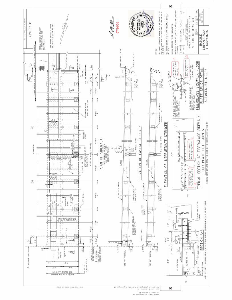
07/3
0/20
DOTMPC
Typewritten Text
393
DOTMPC
Text Box
Addendum No. 01 ID 4992-03-71 Revised Sheet 393 July 30. 2020

07/3
0/20
DOTMPC
Typewritten Text
549
DOTMPC
Text Box
Addendum No. 01 ID 4992-03-71 Revised Sheet 549 July 30. 2020
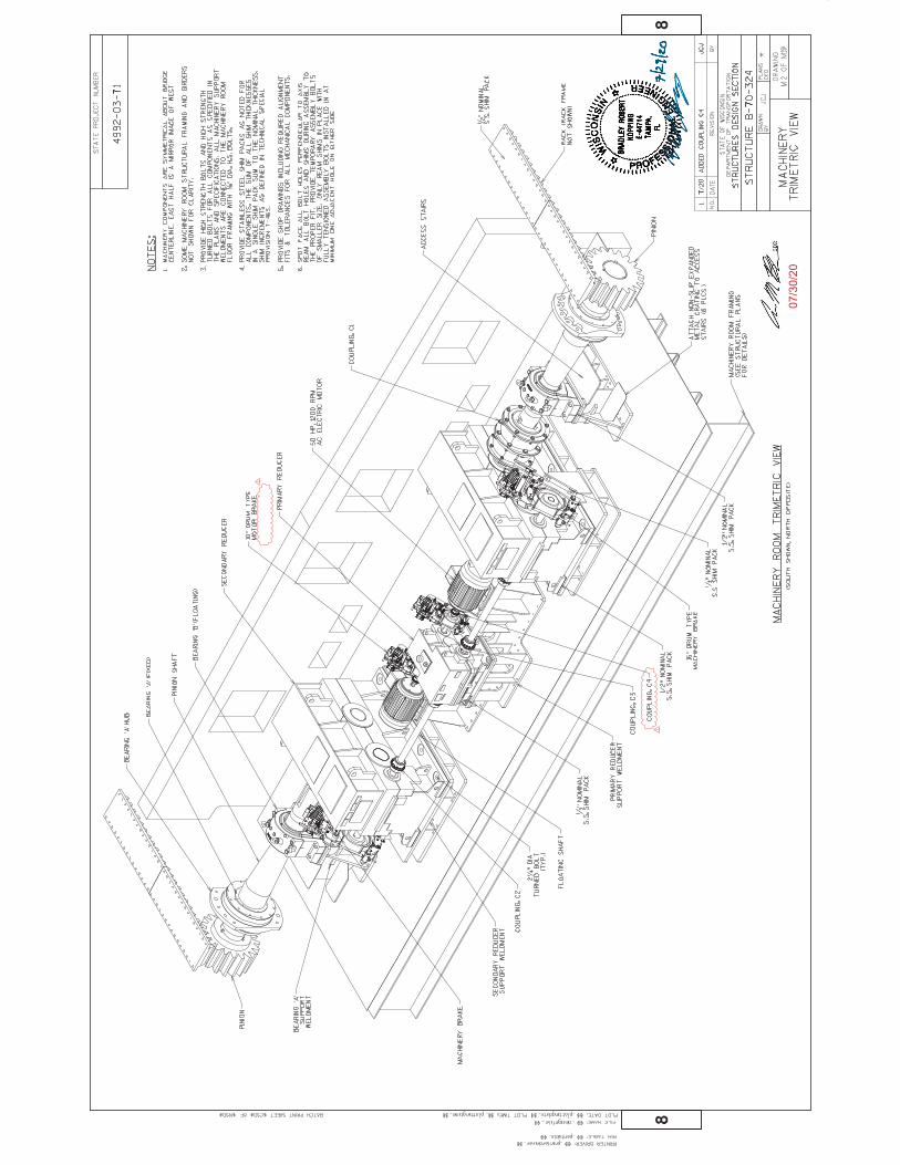
07/3
0/20
DOTMPC
Typewritten Text
550
DOTMPC
Text Box
Addendum No. 01 ID 4992-03-71 Revised Sheet 550 July 30. 2020
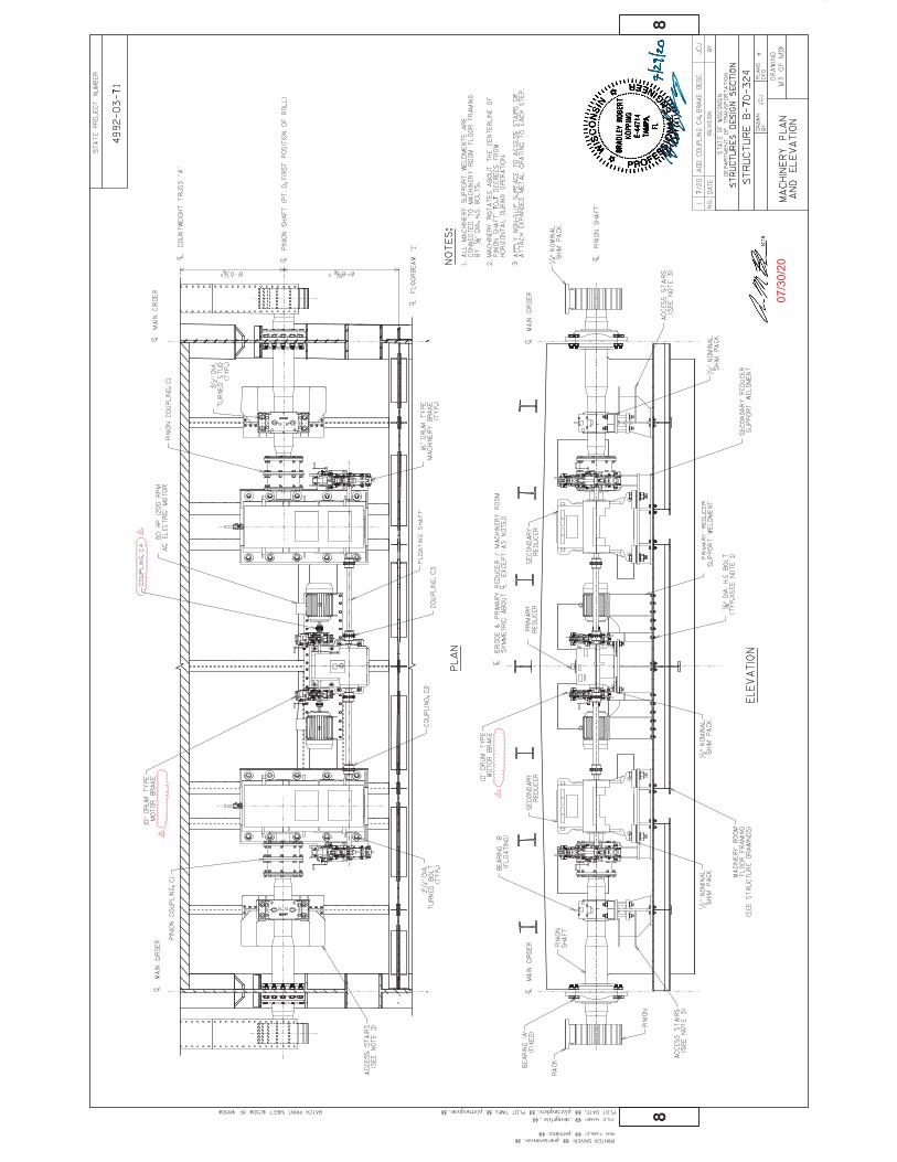
07/3
0/20
DOTMPC
Typewritten Text
551
DOTMPC
Text Box
Addendum No. 01 ID 4992-03-71 Revised Sheet 551 July 30. 2020
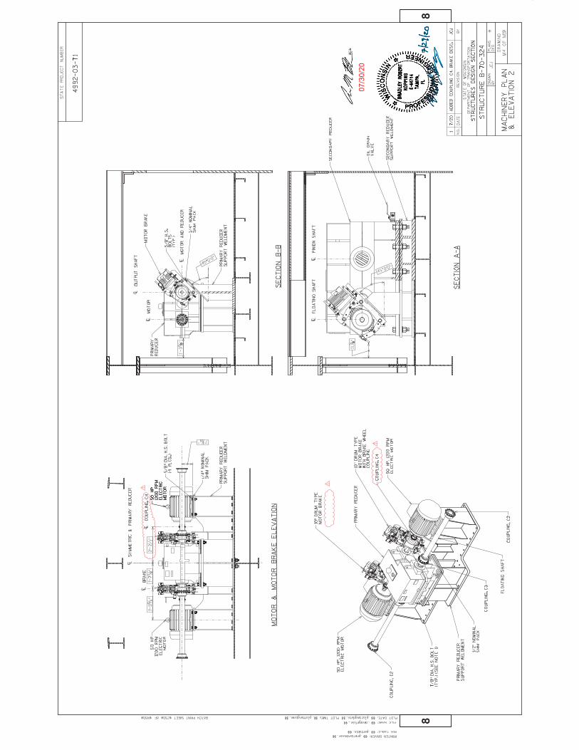
07/3
0/20
DOTMPC
Typewritten Text
552
DOTMPC
Text Box
Addendum No. 01 ID 4992-03-71 Revised Sheet 552 July 30. 2020
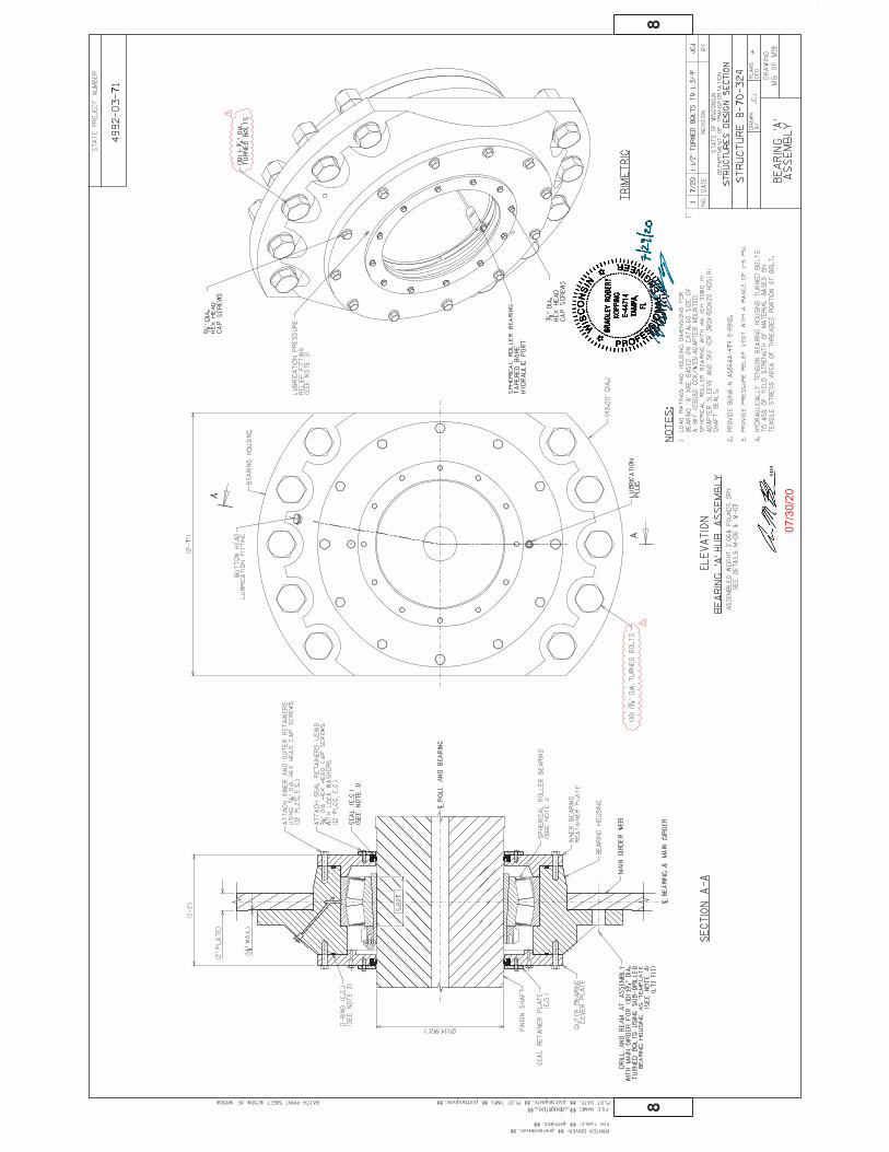
07/3
0/20
DOTMPC
Typewritten Text
553
DOTMPC
Text Box
Addendum No. 01 ID 4992-03-71 Revised Sheet 553 July 30. 2020

07/3
0/20
DOTMPC
Typewritten Text
568
DOTMPC
Text Box
Addendum No. 01 ID 4992-03-71 Revised Sheet 568 July 30. 2020

07/3
0/20
DOTMPC
Typewritten Text
572
DOTMPC
Text Box
Addendum No. 01 ID 4992-03-71 Revised Sheet 572 July 30. 2020
07/3
0/20
DOTMPC
Typewritten Text
574
DOTMPC
Text Box
Addendum No. 01 ID 4992-03-71 Revised Sheet 574 July 30. 2020

07/3
0/20
DOTMPC
Typewritten Text
575
DOTMPC
Text Box
Addendum No. 01 ID 4992-03-71 Revised Sheet 575 July 30. 2020

07/3
0/20
DOTMPC
Typewritten Text
594
DOTMPC
Text Box
Addendum No. 01 ID 4992-03-71 Revised Sheet 594 July 30. 2020
07/3
0/20
DOTMPC
Typewritten Text
595
DOTMPC
Text Box
Addendum No. 01 ID 4992-03-71 Revised Sheet 595 July 30. 2020


Wisconsin Department of Transportation
Version 02-2017 Solving tomorrow’s transportation challenges
Division of Transportation Systems Development Bureau of Project Development 4822 Madison Yards Way, 4th Floor South Madison, WI 53705 Telephone: (608) 266-1631 Facsimile (FAX): (608) 266-8459
August 4, 2020
NOTICE TO ALL CONTRACTORS: Proposal #07: 4492-03-71, WISC 2020 384
Racine Street Bridge, C of Menasha; Fox River Bridge and Approaches Local Str Winnebago County
Letting of August 11, 2020 This is Addendum No. 02, which provides for the following: Special Provisions:
Deleted Special Provisions Article
No. Description
4m Environmental; Management of Petroleum Contaminated Water, Item SPV.0105.30
Added Special Provisions Article
No. Description 13g Drainage and Erosion Control; Storm Sewer Pipe 8-Inch, Item SPV.0090.11
Schedule of Items:
Revised Bid Item Quantities
Bid Item Item Description Unit Old Quantity
Revised Quantity
Proposal Total
204.0245.01 Removing Storm Sewer (8-Inch) LF 562 32 594 305.0120 Base Aggregate Dense 1 ¼-Inch Ton 4,452 -4 4,448 416.0160 Concrete Driveway 6-inch SY 132 -13 119 455.0605 Tack Coat Gal 65 228 293 465.0105 Asphaltic Surface Ton 145 365 510 602.0410 Concrete Sidewalk 5-Inch SF 29,173 115 29288 625.0100 Topsoil SY 6,978 -33 6945 629.0210 Fertilizer Type B CWT 4.5 -0.1 4.4 631.0300 Sod Water MGal 118 -1 117 631.1000 Sod Lawn SY 5,179 -34 5145
SPV.0180.01 Shredded Hardwood Bark Mulch SY 800 32 832

Added Bid Item Quantities
Bid Item Item Description Unit Old Quantity
Revised Quantity
Proposal Total
SPV.0090.11 Storm Sewer Pipe 8-Inch LF 0 9 9
Deleted Bid Item Quantities
Bid Item Item Description Unit Old Quantity
Revised Quantity
Proposal Total
SPV.0105.30 Management of Petroleum Contaminated Water LS 1 -1 0 Plan Sheets:
Revised Plan Sheets Plan
Sheet Plan Sheet Title (brief description of changes to sheet)
26 Plan Details (Driveway widths and existing topography) 34 Storm Sewer Removal Plan (Additional removal for new pipe location) 50 Paving Grades (Driveway jointing update) 66 Erosion Control – Permanent (Updated sod and mulch for driveway changes) 70 Storm Sewer (Revised pipe at Broad Street intersection)
134 Miscellaneous Quantities (Revised storm sewer removal quantity)
136 Miscellaneous Quantities (Revised asphaltic surface for peninsula, revised driveway, sidewalk, base for Broad and Racine Street intersection NE quadrant)
137 Miscellaneous Quantities (Added storm sewer SPV) 141 Miscellaneous Quantities (Revised topsoil, fertilizer, sod, water, and mulch quantities) 151 Miscellaneous Quantities (Removed Management of Petroleum Contaminated Water item)
164 Plan and Profile: Racine Street Northbound (Revised utility and topography base files, proposed driveways)
166 Plan and Profile: Racine Street Southbound (Revised utility and topography base files, proposed driveways)
174 Plan and Profile: Broad Street (Revised utility and topography base files, proposed driveways)
The responsibility for notifying potential subcontractors and suppliers of these changes remains with the prime contractor.
Sincerely,
Mike Coleman Proposal Development Specialist Proposal Management Section

ADDENDUM NO. 02 PROJECT ID 4992-03-71
August 4, 2020
Special Provisions 4. Environmental,
m. Management of Petroleum Contaminated Water, Item SPV.0105.30 Delete entire article 13. Drainage & Erosion Control
Storm Sewer Pipe 8-Inch, Item SPV.0090.11. A Description This section describes providing new storm sewer. B Materials Furnish pipe consistent with the diameter the bid item indicates. Furnish pipe material the same as existing pipe being connected to.
Furnish pipe materials conforming to the following to match existing pipe:
PVC pipe………………………………………………………………….…….….………..ASTM D-3034 SDR-35
PVC Fittings…………………………………………………………….………………….……………ASTM F-477
Corrugated polyethylene pipe ........................................................................................... AASHTO M294 S
Composite pipe, couplings, fittings and joint materials ............................................................ ASTM D2680
Backfill materials shall conform to standard spec 608.2.2 Backfill
C Construction Construction shall conform to the plans and with standard spec 608. D Measurement Measurement shall conform with standard spec 608. E Payment The department will pay for measured quantities at the contract unit price under the following bid item: ITEM NUMBER DESCRIPTION UNIT SPV.0090.11 Storm Sewer Pipe 8-Inch LF
Payment shall conform to standard spec 608.5 except 608.5.2 as modified below.
Payment for the Storm Sewer Pipe bid items is full compensation for providing storm sewer; for providing fittings; for concrete collars not required under 520.3.1(5) or 608.3.3(10); for excavating, except for rock excavation; for providing and removing sheeting and shoring; for constructing the foundation; for backfilling; for cleaning out; and for restoring the site.

Schedule of Items Attached, dated August 4, 2020, are the revised Schedule of Items Pages 1 – 21. Plan Sheets The following 8½ x 11-inch sheets are attached and made part of the plans for this proposal: Revised: 26, 34, 50, 66, 70, 134, 136, 137, 141, 151, 164, 166, and 174.
END OF ADDENDUM
18'R
NB'
19'R
NB'
20'R
NB'
21'R
NB'
22'R
NB'
23'R
NB'
1'B'2'B'
17'R
SB'
18'R
SB'
19'R
SB'
20'R
SB'
40
41
4243 44
+90.
2'B'
, 12.
4' R
T
+88.
3'B'
, 21.
6' L
T
+94.
4'B'
, 21.
7' L
T
+01.
5'B'
, 14.
7' L
T+0
2.5'
B', 1
4.8'
LT
+10.
7'B'
, 12.
2' R
T
+05.
2'B'
, 15.
6' L
T
+78.
0'B'
, 16.
3' L
T+7
8.4'
B', 1
5.9'
RT
+17.
1'B'
, 16.
3' R
T
+62.
7'RS
B', 2
4.0'
LT
+65.
2'RS
B', 0
.0'
+36.
2'RS
B', 2
2.0'
LT
+45.
1'RS
B', 2
2.0'
LT
+43.
0'RS
B', 2
2.0'
LT
+90.
2'RN
B', 2
1.6'
RT
+31.
2'RN
B', 1
8.0'
RT
+72.
3'RN
B', 1
8.0'
RT
+10.
7'RN
B', 0
.0'
+86.
9'RN
B', 1
8.0'
RT
+88.
2'RN
B', 2
1.6'
RT
WIS
DOT/
CADD
S SH
EET
42EH
WY:
COU
NTY
:C:
\PW
WO
RKIN
G\A
ECO
M_D
S16_
NA\
JESS
ICA.
LAN
CELL
E@AE
COM
.CO
M\D
0117
278\
0212
00_P
D.DW
GFI
LE N
AME
:8/
3/20
20 1
:11
PMPL
OT
DATE
:PL
OT
BY :
LAN
CELL
E, JE
SSIC
A
2
PRO
JECT
NO
:PL
OT
NAM
E :
2
SHEE
T PL
OT
SCAL
E :
####
####
##
4992
-03-
71LO
CAL
WIN
NEB
AGO
PLAN
DET
AILS
LAYO
UT
NAM
E - 0
2120
4
RAC
INE
STR
EET
1ST STREET
BROAD STREET R/L
'B'
R/L
'RN
B'
R/L
'RSB
'CP CP
CPCP
CS
CS
CS
CS
CG30
CG30
CG30
CG30
CSCC
CSCC
MATCH LINE STA. 17+50 'RNB'
MO
MO
CS
DWY-
C
OVE
RHEA
DSI
GN
SU
PPO
RTS-
70-3
83
DWY-
C
LEG
END
CP CS CG30
CG36
CON
CRET
E PA
VEM
ENT
8-IN
CH, 6
-INCH
BAS
E AG
GRE
GAT
E DE
NSE
1 1
/4-IN
CH,
12-IN
CH S
ELEC
T CR
USH
ED M
ATER
IAL
CON
CRET
E SI
DEW
ALK
5-IN
CH, 3
-INCH
BAS
E AG
GRE
GAT
E DE
NSE
1 1
/4-IN
CH
CON
CRET
E SI
DEW
ALK
5-IN
CH, 3
-INCH
BAS
E AG
GRE
GAT
E DE
NSE
1 1
/4-IN
CH,
COLO
RIN
G C
ON
CRET
E CU
STO
M (G
REY)
CON
CRET
E CU
RB &
GU
TTER
30-
INCH
TYP
E A
CON
CRET
E CU
RB &
GU
TTER
30-
INCH
TYP
E A
(REV
ERSE
SLO
PE)
CON
CRET
E CU
RB &
GU
TTER
30-
INCH
TYP
E D
CON
CRET
E CU
RB &
GU
TTER
INTE
GRA
L 30
-INCH
TYP
E D
CON
CRET
E CU
RB &
GU
TTER
18-
INCH
TYP
E A
(REV
ERSE
SLO
PE)
CON
CRET
E CU
RB &
GU
TTER
4-IN
CH S
LOPE
D 36
-INCH
TYP
E R
CON
CRET
E CU
RB P
EDES
TRIA
N
CON
CRET
E M
EDIA
N S
LOPE
D N
OSE
(TYP
E 1)
CON
CRET
E M
EDIA
N S
LOPE
D N
OSE
(TYP
E 2)
CON
CRET
E TR
UCK
APR
ON
12-
INCH
, 2-IN
CH B
ASE
AGG
REG
ATE
DEN
SE 1
1/4
-INCH
,
12-IN
CH S
ELEC
T CR
USH
ED M
ATER
IAL,
CO
LORI
NG
CO
NCR
ETE
WIS
DOT
RED
2-IN
CH R
EMO
VIN
G A
SPH
ALTI
C SU
RFAC
E M
ILLI
NG
, 2-IN
CH A
SPH
ALTI
C SU
RFAC
E
CON
CRET
E PA
VEM
ENT
APPR
OAC
H S
LAB
3-IN
CH A
SPH
ALTI
C SU
RFAC
E O
VER
6-IN
CH B
ASE
AGG
REG
ATE
DEN
SE 1
1/4
-INCH
CON
CRET
E DR
IVEW
AY 6
-INCH
OVE
R 6-
INCH
BAS
E AG
GRE
GAT
E DE
NSE
1 1
/4-IN
CH
CG18
-R
CG30
-R
CMSN
1
AS
DWY-
A
DWY-
C
TA MO
CGI3
0-D
CSCC
CG30
-D
CMSN
2
PC
CG30
-R
CSM
N1
CSCC
CSCC
CSCC
DRIL
LED
DOW
EL B
ARS
CSCC
CSCS
NO
TES:
1.SE
E "P
LAN
TIN
G P
LAN
" AN
D "E
ROSI
ON
CO
NTR
OL
PLAN
-PE
RMAN
ENT"
SH
EETS
FO
R RO
UN
DABO
UT
CEN
TRAL
ISLA
ND,
ROAD
WAY
TER
RACE
, AN
D M
EDIA
N IS
LAN
D TR
EATM
ENTS
NO
TN
OTE
D O
N T
HES
E PL
ANS.
2.SE
E "C
URB
RAM
P DE
TAIL
S" S
HEE
TS F
OR
DETA
ILS
RELA
TED
TOCU
RB R
AMPS
AN
D SL
IP R
AMPS
NO
T N
OTE
D O
N T
HES
E PL
ANS.
3.SE
E "P
LAN
DET
AILS
- SI
DEW
ALK"
SH
EETS
FO
R DE
TAIL
SRE
LATE
D TO
TH
E SI
DEW
ALKS
NO
T N
OTE
D O
N T
HES
E PL
ANS.
PC
PC
PCPC
PRO
TECT
BEN
CHAN
D FE
NCE
jessica.lancelle
Polygon
jessica.lancelle
Polygon
DOTMPC
Typewritten Text
26
DOTMPC
Text Box
Addendum No. 02 ID 4992-03-71 Revised Sheet 26 August 4, 2020

15'RN
B'
16'R
NB'
17'RNB'
18'RNB'
19'RN
B'
20'RN
B'
21'R
NB'
1'MEB'
2'MEB'
3'M
EB'
1'B'
2'B'SS
SS
12"
12"
36"
30"
30"
30"30
"
12"
12"
15"
24"
24"
12"
12"
30"
12"
15"
18"
12"
8"
WIS
DOT/
CADD
S SH
EET
42EH
WY:
COU
NTY
:C:
\PW
WO
RKIN
G\A
ECO
M_D
S16_
NA\
JESS
E.W
EBER
@AE
COM
.CO
M\D
0117
278\
0212
04_R
MSS
.DW
GFI
LE N
AME
:8/
3/20
20 1
1:10
AM
PLO
T DA
TE :
PLO
T BY
:W
EBER
, JES
SE
2
PRO
JECT
NO
:PL
OT
NAM
E :
2
SHEE
T PL
OT
SCAL
E :
####
####
##
4992
-03-
71LO
CAL
WIN
NEB
AGO
STO
RM S
EWER
REM
OVA
L PL
AN
LAYO
UT
NAM
E - 0
2120
5
RACI
NE STR
EET
R/L
'RN
B'
R/L
'B'
BROAD STREET
MAIN STREET
STRU
CTU
RE B
-70-
001
(TO
BE
REM
OVE
D- S
EEST
RUCT
URE
PLA
NS)
FOX
RIVE
R
R/L
'MEB
'
END
PR
OJE
CT
STA
20+9
0.40
'RN
B'
LEG
END
REM
OVI
NG
MAN
HO
LES
REM
OVI
NG
INLE
TS
REM
OVI
NG
STO
RM S
EWER
ABAN
DON
ING
MAN
HO
LES
MAN
HO
LE T
OP
AND
CAST
ING
TO
REM
AIN
IN P
LACE
ABAN
DON
ING
SEW
ER
END
STO
RM S
EWER
REM
OVA
LAT
MH
16.
0
CON
NEC
T 30
" STO
RM T
O M
H 1
5.1
(SEE
STO
RM S
EWER
PLA
N)
ABAN
DON
ING
SEW
ER (2
0')
DOTMPC
Typewritten Text
34
DOTMPC
Text Box
Addendum No. 02 ID 4992-03-71 Revised Sheet 34 August 4, 2020

18'R
NB'
19'R
NB'
20'R
NB'
21'R
NB'
1'B'2'B'
18'R
SB'
19'R
SB'
20'R
SB'
WIS
DOT/
CADD
S SH
EET
42EH
WY:
COU
NTY
:C:
\PW
WO
RKIN
G\A
ECO
M_D
S16_
NA\
JESS
ICA.
LAN
CELL
E@AE
COM
.CO
M\D
0117
278\
0213
01_J
D.DW
GFI
LE N
AME
:8/
3/20
20 2
:19
PMPL
OT
DATE
:PL
OT
BY :
LAN
CELL
E, JE
SSIC
A
2
PRO
JECT
NO
:PL
OT
NAM
E :
2
SHEE
T PL
OT
SCAL
E :
1 IN
:20
FT
4992
-03-
71LO
CAL
WIN
NEB
AGO
PAVI
NG
GRA
DES
LAYO
UT
NAM
E - 0
6
RAC
INE
STR
EET
BROAD STREET
R/L
'B'
R/L
'RN
B'
R/L
'RSB
'
jessica.lancelle
Polygon
jessica.lancelle
Polygon
DOTMPC
Typewritten Text
50
DOTMPC
Text Box
Addendum No. 02 ID 4992-03-71 Revised Sheet 50 August 4, 2020

18'R
NB'
19'R
NB'
20'R
NB'
21'R
NB'
22'R
NB'
23'R
NB'
1'B'2'B'
17'R
SB'
18'R
SB'
19'R
SB'
20'R
SB'
WIS
DOT/
CADD
S SH
EET
42EH
WY:
COU
NTY
:C:
\PW
WO
RKIN
G\A
ECO
M_D
S16_
NA\
JESS
ICA.
LAN
CELL
E@AE
COM
.CO
M\D
0117
278\
0220
01_E
C_PR
OP.
DWG
FILE
NAM
E :
8/3/
2020
2:1
1 PM
PLO
T DA
TE :
PLO
T BY
:LA
NCE
LLE,
JESS
ICA
2
PRO
JECT
NO
:PL
OT
NAM
E :
2
SHEE
T PL
OT
SCAL
E :
####
####
##
4992
-03-
71LO
CAL
WIN
NEB
AGO
ERO
SIO
N C
ON
TRO
L PL
AN -
PERM
ANEN
T
LAYO
UT
NAM
E - 0
2120
4
RAC
INE
STR
EET
1ST STREET
BROAD STREET R/L
'B'
R/L
'RN
B'
R/L
'RSB
'
SEE
PLAN
DET
AILS
FO
RTE
RRAC
E TR
EATM
ENT
NEA
RBU
ILDI
NG
S (T
YP)
R/W
R/W
R/W
R/W
R/WEX R/W
R/W
TLE
R/W
TLE
TLE
TLE
MATCH LINE STA. 17+50 'RNB'
SOD
5' B
EYO
ND
SIDE
WAL
K,SE
ED R
EMAI
NIN
G A
REA
TOSL
OPE
LIM
ITS
UTI
LITY
PAD
(BY
OTH
ERS)
PRO
TECT
BEN
CH A
ND
FEN
CE
SHRE
DDED
HAR
DWO
OD
BARK
MU
LCH
(BEH
IND
SIDE
WAL
K TO
EXIS
TIN
G M
ULC
HLI
MIT
S-VE
RIFY
IN F
IELD
)
jessica.lancelle
Polygon
DOTMPC
Typewritten Text
66
DOTMPC
Text Box
Addendum No. 02 ID 4992-03-71 Revised Sheet 66 August 4, 2020

E
E
EE
E
G
GG
SS
E
EE
EE
EE
EE
E
E
ESA
N
SAN
SAN
SAN
SAN
W W WW
WW
WW
W
W
W
W
W W WW
SS
SS
SS
SS
SS
SSSS
SS
SS
SSSS
SSSS
SSSS
SAN
SAN
SAN
SAN
SST
T
TT
TT
V
TV
TV
TV TV TV
TVTV TV TV
TVTV
TVTV
G
G
GG
SAN
SSSS
SSSS
SS
SAN
SAN
SAN
SAN
SAN
SANSAN
OH OH
OH
OH
OH
OH
OH
OH
OH
OH
OH
OH
OH
FO
FOFO
FO
FO FO
FOFO
FOFO
17'R
NB'
18'R
NB'
19'R
NB'
20'R
NB'
21'R
NB'
SSSS
SS
750
755
760
765
750
755
760
765
745
750
755
760
745
750
755
760
13.0
13.3
15.1
15.0
15.3
39-L
F SS
PRC
CLAS
S IV
12-
INCH
@ 0
.50%
15.2
7-LF
SSP
RC C
LASS
IV 1
5-IN
CH @
0.5
0%
15.1
48-L
F SS
PRC
CLAS
S IV
30-
INCH
@ 0
.30%
39-L
F SS
PRC
CLAS
S III
15-
INCH
@ 0
.30%
13.4
8-LF
SSP
RC C
LASS
III 1
2-IN
CH @
0.5
0%
13.3
13.0
13.0
15.0
18.0
63-L
F SS
PRC
CLAS
S III
36-
INCH
@ 0
.30%
119-
LF S
SPRC
CLA
SS II
I 36-
INCH
@ 0
.30%
EX 2
4-IN
CH
16.0
16.0
26-L
F SS
PRC
CLAS
S IV
15-
INCH
@ 0
.30%
16.2
32-L
F SS
PRC
CLAS
S IV
15-
INCH
@ 0
.30%
16.4
16.5
35-L
F SS
PRC
CLAS
S IV
12-
INCH
@ 0
.50%
63-L
F SS
PRC
CLAS
S III
36-IN
CH @
0.3
0%
755.
8175
6.17
757.
0075
7.00
749.
4774
9.01
748.
3274
9.11
748.
8274
8.42
748.
61
755.
8175
5.44
755.
4575
6.41
756.
1775
5.81
756.
0175
7.00
756.
0475
4.95
754.
92
749.
6975
0.09
750.
5375
0.81
751.
4574
9.60
750.
8575
1.13
749.
8075
0.05
750.
6175
0.71
751.
2875
1.33
750.
88
749.
74
750.
23
18.1
18.0
18.2
32-L
F SS
PRC
CLAS
S III
12-
INCH
@ 1
.00%
14-L
F SS
PRC
CLAS
S III
12-
INCH
@ 1
.00%
751.
0275
1.20
751.
3475
1.34
756.
7075
7.00
756.
73
753.
1+/-
16.1
756.
10
750.
7875
0.93
30-L
F SS
PRC
CLAS
S IV
12-
INCH
@ 0
.50%
19-L
F SS
PRC
CLAS
S III
15-
INCH
@ 0
.50%
8-LF
SSP
RC C
LASS
III 1
2-IN
CH @
0.5
0%
16.3
751.
0375
0.91
755.
74
749.
6774
9.77
750.
0275
0.06
13.1
755.
40
13.2
755.
39
39-L
F SS
PRC
CLAS
S IV
15-
INCH
@ 0
.30%
749.
7+/-
E
E
E
E
E
E
E
SAN
SAN
SAN
SAN
W
SS
SS
SS
SS
SSSS
SAN
SAN
SAN
T
T
T
TV
TV
TV
TV
TV
OH
OH
OH
16'R
NB'
SAN
W
W
PLO
T SC
ALE
:1
IN:4
0 FT
4992
-03-
71LO
CAL
WIN
NEB
AGO
WIS
DOT/
CADD
S SH
EET
41EH
WY:
COU
NTY
:C:
\PW
WO
RKIN
G\A
ECO
M_D
S16_
NA\
JESS
E.W
EBER
@AE
COM
.CO
M\D
0117
278\
0225
01_S
S.DW
GFI
LE N
AME
:8/
3/20
20 1
1:26
AM
PLO
T DA
TE :
PLO
T BY
:W
EBER
, JES
SE
2
PRO
JECT
NO
:
2
SHEE
T ST
ORM
SEW
ERPL
OT
NAM
E :
LAYO
UT
NAM
E - 0
2250
4
RAC
INE
STR
EET
1ST STREET
BROAD STREET
PRO
POSE
D G
ROU
ND
OVE
R ST
ORM
SEW
ER (T
YP.)
ORI
GIN
AL G
ROU
ND
(TYP
.)
R/L
'RN
B'
15" S
ANIT
ARY
SEW
ER, P
ROVI
DE 8
'-2" C
LOSE
D CE
LLEX
TRU
DED
POLY
STYR
ENE
INSU
LATI
ON
CON
NEC
T TO
EXI
STIN
G 3
0" S
TORM
SEW
ERCO
NTR
ACTO
R TO
VER
IFY
EXIS
TIN
G S
IZE
AND
DEPT
H
CON
NEC
T TO
EXI
STIN
G 2
4" S
TORM
SEW
ERCO
NTR
ACTO
R TO
VER
IFY
EXIS
TIN
G S
IZE
AND
DEPT
H
9-LF
STO
RM S
EWER
PIP
E 8-
INCH
@ 2
.5%
CON
NEC
T 8-
INCH
STO
RM D
RAIN
TO
CB
16.2
CON
TRAC
TOR
TO V
ERIF
Y EX
ISTI
NG
MAT
ERIA
L, S
IZE
AND
DEPT
H
NO
SU
MP
CON
TRAC
TOR
VERI
FY D
EPTH
OF
F.O
. DU
CT B
ANK
SEE
PREV
IOU
S PA
GE
FOR
PLAN
AN
D PR
OFI
LEIN
FORM
ATIO
N N
OT
SHO
WN
ON
TH
IS P
AGE
NO
TE:
CO
NTA
CT D
ESIG
N E
NG
INEE
R IF
INVE
RTS
OF
EXIS
TIN
G S
TORM
SEW
ER C
ON
NEC
TIO
NS
ARE
SIG
NIF
ICAN
TLY
DIFF
EREN
T TH
AN P
LAN
.
DOTMPC
Typewritten Text
70
DOTMPC
Text Box
Addendum No. 02 ID 4992-03-71 Revised Sheet 70 August 4, 2020

PRO
JEC
T N
UM
BER
: 499
2-03
-71
HW
Y: L
OC
AL
CO
UN
TY: W
INN
EBAG
OM
ISC
ELLA
NEO
US
QU
ANTI
TIES
SHEE
T N
O:
EFI
LE N
AME:
\\17
2.25
.160
.16\
Pro
ject
s\Tr
ansp
orta
tion\
Rac
ine
St B
ridge
\Pha
se 2
\900
_CAD
\499
2030
0\D
esig
n\Q
uant
ities
\MQ
PLO
TTED
DAT
E: 8
/3/2
020
10:2
5 AM
33
ALL
ITEM
S AR
E C
ATEG
OR
Y 00
10 U
NLE
SS O
THER
WIS
E SP
ECIF
IED
.
OR
IGIN
ATO
R:
JES
SIC
A LA
NC
ELLL
EO
RIG
. DAT
E:5/
4/18
204.
0100
204.
0150
204.
0155
204.
0165
204.
0170
204.
0185
204.
9090
.S.0
120
4.90
90.S
.02
204.
9105
.S.0
1
REM
OVIN
GPA
VEM
ENT
REM
OVIN
GCU
RB &
GUTT
ER
REM
OVIN
GCO
NCRE
TESI
DEW
ALK
REM
OVIN
GGU
ARDR
AIL
REM
OVIN
GFE
NCE
REM
OVIN
GM
ASON
RYRE
MOV
ING
RAILI
NG
REM
OVIN
GLA
NDSC
APIN
GBR
ICK
REM
OVIN
GM
ODUL
ARBL
OCK
WAL
LLO
CATI
ONST
AST
ASI
DESY
LFSY
LFLF
CYLF
LFLS
SOUT
H-
3,51
358
21,
005
--
--
--
4RNB
+70
5RNB
+43
RT-
--
79-
--
--
5RNB
+98
6RNB
+34
LT-
--
--
-37
--
5RNB
+86
6RNB
+57
RT-
--
--
-69
--
6RNB
+07
6RNB
+34
LT-
--
-45
--
--
NORT
H-
4,65
322
81,
240
--
--
--
14RS
B+63
-LT
--
--
--
--
114
RSB+
6015
RSB+
14LT
--
--
--
-15
6-
14RS
B+68
14RS
B+79
LT/R
T-
--
-12
4-
--
-14
RSB+
55-
LT/R
T-
--
--
5-
--
TOTA
LS8,
166
810
2,24
579
169
510
615
61
REM
OVAL
S
WIT
HIN
LIMIT
S
WIT
HIN
LIMIT
S
201.
0105
201.
0205
201.
0120
201.
0220
CLEA
RING
GRUB
BING
CLEA
RING
GRUB
BING
LOCA
TION
STA-
STA
OFFS
ETST
AST
AID
IDSO
UTH
6RNB
+00
- 7RN
B+00
LT1
1-
-2R
NB+0
0LT
--
22
3RNB
+75
LT-
-3
30N
+75
LT-
-4
4PE
NINS
ULA
8RNB
+00
- 11R
NB+0
0LT
/RT
33
--
NORT
H15
RNB+
00 -
16RN
B+00
11
--
TOTA
LS5
59
9
CLEA
RING
AND
GRU
BBIN
G
204.
0210
204.
0220
204.
0245
.01
204.
0245
.02
204.
0245
.03
204.
0245
.04
204.
0245
.05
204.
0245
.06
204.
0245
.07
204.
0250
204.
0291
.S
REM
OVIN
GM
ANHO
LES
REM
OVIN
GIN
LETS
REM
OVIN
GST
ORM
SEW
ER(8
-INCH
)
REM
OVIN
GST
ORM
SEW
ER(1
2-IN
CH)
REM
OVIN
GST
ORM
SEW
ER(1
5-IN
CH)
REM
OVIN
GST
ORM
SEW
ER(1
8-IN
CH)
REM
OVIN
GST
ORM
SEW
ER(2
4-IN
CH)
REM
OVIN
GST
ORM
SEW
ER(3
0-IN
CH)
REM
OVIN
GST
ORM
SEW
ER(4
2-IN
CH)
ABAN
DONI
NGM
ANHO
LES
ABAN
DONI
NGSE
WER
LOCA
TION
EACH
EACH
LFLF
LFLF
LFLF
LFEA
CHCY
SOUT
H8
1456
236
032
915
9-
-20
4-
1
NORT
H7
832
337
299
1215
744
6-
116
TOTA
LS15
2259
469
762
817
115
744
620
41
17
STOR
M SE
WER
REMO
VALS
DOTMPC
Typewritten Text
134
DOTMPC
Text Box
Addendum No. 02 ID 4992-03-71 Revised Sheet 134 August 4, 2020
PRO
JEC
T N
UM
BER
: 499
2-03
-71
HW
Y: L
OC
ALC
OU
NTY
: WIN
NEB
AGO
MIS
CEL
LAN
EOU
S Q
UAN
TITI
ESSH
EET
NO
:E
FILE
NAM
E: \\
172.
25.1
60.1
6\Pr
ojec
ts\T
rans
porta
tion\
Rac
ine
St B
ridge
\Pha
se 2
\900
_CAD
\499
2030
0\D
esig
n\Q
uant
ities
\MQ
PLO
TTED
DAT
E: 8
/3/2
020
2:48
PM
33
ALL
ITEM
S AR
E C
ATEG
OR
Y 00
10 U
NLE
SS O
THER
WIS
E SP
ECIF
IED
.
OR
IGIN
ATO
R:
JESS
ICA
LAN
CEL
LLE
OR
IG. D
ATE:
5/4/
18
416.
0620
DRILL
ED
DOW
EL
BARS
LOCA
TION
EACH
SOUT
H29
NORT
H54
TOTA
LS83
DRIL
LED
BARS
415.5110.S
CONCRETE
PAVEMENT JOINT
LAYOUT
LOCATION
LS
PROJECT
1
TOTAL
1
CONCRETE PAVEMENT
JOINT LAYOUT
608.
0005
STOR
M S
EWER
ROC
K EX
CAVA
TION
LOCA
TION
STR
TOST
RCY
SOUT
H7.
0-
17.0
56
TOTA
LS56
STOR
M SE
WER
ROCK
EXC
AVAT
ION
513.2001
RAILING PIPE
STA
STA
LF
2'MWB'+65
-2'MWB'+90
25
TOTAL
25
RAILING PIPE
213.0100
FINISHING
ROADWAY
4992-03-71
LOCATION
EACH
PROJECT
1
TOTAL
1
FINISHING ROADWAY
204.
0120
305.
0120
312.
0110
405.
0100
405.
0200
415.
0080
415.
0410
416.
0160
416.
0260
416.
0512
455.
0605
465.
0105
602.
0410
620.
0300
624.
0100
REM
OVIN
G AS
PHAL
TIC
SURF
ACE
MILL
ING
*BA
SE
AGGR
EGAT
E DE
NSE
1 1/
4-IN
CH
SELE
CT
CRUS
HED
MAT
ERIA
L
COLO
RING
CO
NCRE
TE
WIS
DOT
RED
**CO
LORI
NG
CONC
RETE
CU
STOM
CONC
RETE
PA
VEM
ENT
8-IN
CH
CONC
RETE
PA
VEM
ENT
APPR
OACH
SL
AB
CONC
RETE
DR
IVEW
AY 6
-IN
CH
CONC
RETE
DR
IVEW
AY H
ES
6-IN
CH
CONC
RETE
TR
UCK
APRO
N 12
-INCH
TACK
CO
ATAS
PHAL
TIC
SURF
ACE
CONC
RETE
SI
DEW
ALK
5-IN
CH
CONC
RETE
M
EDIA
N SL
OPED
NO
SEW
ATER
LOCA
TION
SYTO
NTO
NCY
CYSY
SYSY
SYSY
GAL
TON
SFSF
MGA
LSO
UTH
851,
921
2,66
788
-2,
927
8938
2126
459
135
11,1
9428
169
NORT
H74
2,51
84,
052
100
694,
447
6881
-29
66
1018
,094
281
99
PENI
NSUL
A PA
RKIN
G AR
EA-
--
--
--
--
-22
836
5-
--
TOTA
LS15
94,
439
6,71
918
869
7,37
415
711
921
560
293
510
29,2
8856
216
7
* ADD
ITIO
NAL
QUAN
TITI
ES L
ISTE
D EL
SEW
HERE
** C
ATEG
ORY
0060
NOTE
: CON
CRET
E DR
IVEW
AY H
ES L
OCAT
ED A
T DA
M A
CCES
S. A
SPHA
LTIC
SUR
FACE
IN P
ENIN
SULA
PAR
KING
ARE
A IS
FOR
RES
TORA
TION
PUR
POSE
S IN
THE
STA
GING
ARE
A.
PAVI
NG IT
EMS
jessica.lancelle
Polygon
jessica.lancelle
Polygon
DOTMPC
Typewritten Text
136
DOTMPC
Text Box
Addendum No. 02 ID 4992-03-71 Revised Sheet 136 August 4, 2020
608.
0312
608.
0315
608.
0318
608.
0324
608.
0336
608.
0348
608.
0412
608.
0415
608.
0430
608.
0436
SPV.
0090
.11
STOR
M S
EWER
PIP
ERE
INFO
RCED
CON
CRET
ECL
ASS
III 12
-INCH
STOR
M S
EWER
PIP
ERE
INFO
RCED
CON
CRET
ECL
ASS
III 15
-INCH
STOR
M S
EWER
PIP
ERE
INFO
RCED
CON
CRET
ECL
ASS
III 18
-INCH
STOR
M S
EWER
PIP
ERE
INFO
RCED
CON
CRET
ECL
ASS
III 24
-INCH
STOR
M S
EWER
PIP
ERE
INFO
RCED
CON
CRET
ECL
ASS
III 36
-INCH
STOR
M S
EWER
PIP
ERE
INFO
RCED
CON
CRET
ECL
ASS
III 48
-INCH
STOR
M S
EWER
PIP
ERE
INFO
RCED
CON
CRET
ECL
ASS
IV 1
2-IN
CH
STOR
M S
EWER
PIP
ERE
INFO
RCED
CON
CRET
ECL
ASS
IV 1
5-IN
CH
STOR
M S
EWER
PIP
ERE
INFO
RCED
CON
CRET
ECL
ASS
IV 3
0-IN
CH
STOR
M S
EWER
PIP
ERE
INFO
RCED
CON
CRET
ECL
ASS
IV 3
6-IN
CHST
ORM
SEW
ER P
IPE
8-IN
CHJO
INT
TIES
*IN
LET
DISC
HARG
ESL
OPE
LOCA
TION
FROM
-TO
LFLF
LFLF
LFLF
LFLF
LFLF
LFEA
CHEL
EVAT
ION
ELEV
ATIO
NFT
/FT
SOUT
H17
.1-
1736
--
--
--
--
--
-75
0.29
749.
940.
0097
5.1
-5
18-
--
--
--
--
--
745.
0874
5.00
0.00
505.
2-
5-
18-
--
--
--
--
-74
4.84
744.
750.
0050
5.3
-5.
255
--
--
--
--
--
-74
5.36
745.
090.
0049
5-
6-
--
72-
--
--
--
-74
4.00
743.
640.
0050
6-
7-
--
--
57-
--
--
-74
1.55
741.
270.
0049
7-
8-
--
--
87-
--
--
-74
1.27
740.
850.
0048
17-
EX-1
--
--
-14
--
--
--
740.
6374
0.56
0.00
508
-17
--
--
-44
--
--
--
740.
8574
0.63
0.00
502
-3
--
-32
--
--
--
--
746.
1474
5.90
0.00
753.
4-
3.5
-54
--
--
--
--
--
747.
4874
6.94
0.01
001.
2-
123
--
--
--
--
--
-74
8.56
748.
440.
0050
1.1
-1
25-
--
--
--
--
--
748.
5774
8.44
0.00
501
-2
--
-12
3-
--
--
--
-74
7.16
746.
240.
0075
3-
8-
--
130
--
--
--
--
745.
8074
4.83
0.00
753.
1-
3.2
--
--
--
-31
--
--
747.
3974
7.23
0.00
523.
3-
3.2
--
--
--
8-
--
--
747.
8074
7.72
0.01
003.
1-
3.5
-39
--
--
--
--
--
747.
1374
6.94
0.00
493.
5-
3-
25-
--
--
--
--
-74
6.84
746.
590.
0100
157
136
035
70
202
831
00
00
NORT
H16
.2-
16-
--
--
--
26-
--
-75
0.61
750.
530.
0031
9.5
-9.
2-
--
--
-70
--
--
-74
9.99
747.
680.
0330
11.4
-11
.3-
50-
--
--
--
--
-75
0.35
750.
200.
0030
16.1
-16
--
--
--
30-
--
--
750.
9375
0.78
0.00
5015
.3-
15.2
--
--
--
39-
--
--
751.
3375
1.13
0.00
5115
.2-
15.1
--
--
--
-7
--
--
750.
8875
0.85
0.00
4313
.3-
13-
19-
--
--
--
--
-74
9.77
749.
670.
0053
16.2
-16
.3-
--
--
--
32-
--
-75
0.81
750.
710.
0031
16.4
-16
.5-
--
--
-35
--
--
-75
1.45
751.
280.
0049
15-
13-
--
-63
--
--
--
-74
8.61
748.
420.
0030
13-
11-
--
-10
3-
--
--
--
748.
3274
8.01
0.00
3018
.1-
1832
--
--
--
--
--
751.
3475
1.02
0.01
0011
-19
--
--
56-
--
--
--
747.
9174
7.74
0.00
3010
-9
--
--
71-
--
--
--
747.
3174
6.61
0.00
9919
-10
--
--
76-
--
--
--
747.
6474
7.41
0.00
309.
4-
9.3
6-
--
--
--
--
--
748.
5274
8.49
0.00
5018
.2-
1814
--
--
--
--
--
-75
1.34
751.
200.
0100
9.1
-9.
2-
8-
--
--
--
--
-74
7.43
747.
350.
0100
9.1
-9
--
32-
--
--
--
--
747.
1074
6.95
0.00
4713
.3-
13.4
8-
--
--
--
--
--
750.
0975
0.05
0.00
5013
.3-
13-
39-
--
--
--
--
-74
9.80
749.
690.
0028
18-
16-
--
-11
9-
--
--
--
749.
4774
9.11
0.00
3016
-15
--
--
63-
--
--
--
749.
0174
8.82
0.00
3011
.1-
11-
--
--
-33
--
--
-75
2.58
752.
410.
0052
11.3
-11
.2-
20-
--
--
--
--
-75
0.10
750.
000.
0050
11.2
-11
-23
--
--
--
--
--
749.
9074
9.67
0.01
0011
.5-
11.4
46-
--
--
--
--
--
750.
8375
0.60
0.00
509.
3-
9.1
-31
--
--
--
--
--
747.
5174
7.35
0.00
5210
.1-
1026
--
--
--
--
--
-75
1.31
751.
040.
0104
OF-1
-9
--
--
--
--
-46
--
746.
3974
5.93
0.01
0013
.1-
13.2
8-
--
--
--
--
--
750.
0675
0.02
0.00
5019
.1-
1952
--
--
--
--
--
-75
1.00
750.
740.
0050
15.1
-15
--
--
--
--
--
-6
749.
7474
9.60
0.00
2916
.3-
16.4
--
--
--
-39
48-
--
751.
0375
0.91
0.00
31EX
-PIP
E-
16.2
--
--
--
--
--
9-
753.
3075
3.08
0.00
25
192
190
320
551
020
710
448
469
634
932
632
357
551
202
215
135
4846
96
* NON
-BID
ITEM
: FOR
INFO
RMAT
ION
ONLY
STOR
M SE
WER
PIP
ES
SOUT
H SU
BTOT
AL
NORT
H SU
BTOT
ALTO
TALS
PRO
JEC
T N
UM
BER
: 499
2-03
-71
HW
Y: L
OC
AL
CO
UN
TY: W
INN
EBAG
OM
ISC
ELLA
NEO
US
QU
ANTI
TIES
SHEE
T N
O:
EFI
LE N
AME:
\\17
2.25
.160
.16\
Pro
ject
s\Tr
ansp
orta
tion\
Rac
ine
St B
ridge
\Pha
se 2
\900
_CAD
\499
2030
0\D
esig
n\Q
uant
ities
\MQ
PLO
TTED
DAT
E: 8
/3/2
020
10:2
5 AM
33
ALL
ITEM
S AR
E C
ATEG
OR
Y 00
10 U
NLE
SS O
THER
WIS
E SP
ECIF
IED
.
OR
IGIN
ATO
R:
JES
SIC
A LA
NC
ELLL
EO
RIG
. DAT
E:5/
4/18
DOTMPC
Typewritten Text
137
DOTMPC
Text Box
Addendum No. 02 ID 4992-03-71 Revised Sheet 137 August 4, 2020

PRO
JEC
T N
UM
BER
: 499
2-03
-71
HW
Y: L
OC
ALC
OU
NTY
: WIN
NEB
AGO
MIS
CEL
LAN
EOU
S Q
UAN
TITI
ESSH
EET
NO
:E
FILE
NAM
E: \\
172.
25.1
60.1
6\Pr
ojec
ts\T
rans
porta
tion\
Rac
ine
St B
ridge
\Pha
se 2
\900
_CAD
\499
2030
0\D
esig
n\Q
uant
ities
\MQ
PLO
TTED
DAT
E: 8
/3/2
020
2:48
PM
33
ALL
ITEM
S AR
E C
ATEG
OR
Y 00
10 U
NLE
SS O
THER
WIS
E SP
ECIF
IED
.
OR
IGIN
ATO
R:
JESS
ICA
LAN
CEL
LLE
OR
IG. D
ATE:
5/4/
18
******
******
******
******
SPV.
0035
.04SP
V.01
80.01
SPV.
0090
.10
TREE
S BU
R OA
K B&
B, 2"
CAL
.
TREE
S MA
PLE
(SIE
NNA
GLEN
) B&
B, 2"
CAL
.
TREE
S HO
NEY
LOCU
ST
(SKY
LINE)
B&
B, 2"
CAL
.
SHRU
BSDO
GWOO
D (R
EDOS
IER)
CG, 5
GAL
.
LAND
SCAP
E PL
ANTI
NG
SURV
EILL
ANCE
AND
CA
RE C
YCLE
S
PERE
NNIA
LSDA
YLILY
(STE
LLA
D'OR
O)CG
, 1 G
AL.
PERE
NNIA
LSKA
RL F
OERS
TER
REED
GRA
SSCG
, 3 G
AL.
PERE
NNIA
LSPR
AIRI
E DR
OPSE
EDCG
, 3 G
AL.
**PL
ANTI
NG M
IXTU
RE
**SH
REDD
ED
HARD
WOOD
BAR
K MU
LCH
**LA
NDSC
APE
EDGI
NGLO
CATI
ONEA
CHEA
CHEA
CHEA
CHEA
CHEA
CHEA
CHEA
CHCY
SYLF
SOUT
H-
--
--
--
--
--
NORT
H3
43
621
519
238
9530
080
014
0TO
TALS
34
362
151
923
895
300
800
140
**CAT
EGOR
Y 00
60***
FOR
INFO
RMAT
ION
ONLY
. TO
BE P
ROCU
RED
AND
PLAN
TED
BY C
ITY
OF M
ENAS
HA F
ORCE
S
LAND
SCAP
ING
ITEM
S
625.0100
627.0200
629.0210
630.0140
630.0500
631.1000
631.0300
SPV.0180.01*
TOPSOIL
MULCHING
FERTILIZER
SEEDING
SEED
SOD
SOD
SHREDDED
TYPE B
MIXTURE
WATER
LAWN
WATER
HARDWOOD BARK
NO.40
MULCH
LOCATION
SY
SY
CWT
LB
MGAL
SY
MGAL
SY
SOUTH
2,650
01.7
00
2,650
60
-
PENINSULA
541
541
0.4
10
13
--
-
NORTH
2,365
899
1.4
14
17
1,466
33
25
SUBTOTAL
5,556
1,440
3.5
24
30
4,116
93
25
UNDISTRIBUTED
1,389
360
0.9
68
1,029
24
7
TOTAL
6,945
1,800
4.4
30
38
5,145
117
32
*DENOTES QUANTITY FOUND ELSEWHERE
RESTORATION
jessica.lancelle
Polygon
jessica.lancelle
Polygon
jessica.lancelle
Polygon
jessica.lancelle
Polygon
DOTMPC
Typewritten Text
141
DOTMPC
Text Box
Addendum No. 02 ID 4992-03-71 Revised Sheet 141 August 4, 2020

PRO
JEC
T N
UM
BER
: 499
2-03
-71
HW
Y: L
OC
ALC
OU
NTY
: WIN
NEB
AGO
MIS
CEL
LAN
EOU
S Q
UAN
TITI
ESSH
EET
NO
:E
FILE
NAM
E: \\
172.
25.1
60.1
6\Pr
ojec
ts\T
rans
porta
tion\
Rac
ine
St B
ridge
\Pha
se 2
\900
_CAD
\499
2030
0\D
esig
n\Q
uant
ities
\MQ
PLO
TTED
DAT
E: 7
/30/
2020
9:2
7 AM
33
ALL
ITEM
S AR
E C
ATEG
OR
Y 00
10 U
NLE
SS O
THER
WIS
E SP
ECIF
IED
.
OR
IGIN
ATO
R:
JESS
ICA
LAN
CEL
LLE
OR
IG. D
ATE:
5/4/
18
SPV.0035.03
SPV.0195.02*
SPV.0195.03
SPV.0195.04
EXCAVATION
AND
DEWATERING
OF DREDGING
MATERIAL
EXCAVATION,
HAULING, AND
DISPOSAL OF
CONTAMINATED SOIL
(DIRECT LANDFILL)
EXCAVATION,
HAULING, AND
DISPOSAL OF
CONTAMINATED SOIL
(BIOREMEDIATION)
HAULING AND
DISPOSAL OF
DREDGING
MATERIAL
LOCATION
CY
TON
TON
TON
PROJECT
2,250
296
1,567
3,938
TOTAL
2,250
296
1,567
3,938
*DEN
OTES QUA
NTITY FO
UND ELSEWHE
RE
EXCAVATION, HAULING, AND DISPOSAL OF CONTAMINATED SOIL
SPV.0165.03
INSULATION BOARD
2-INCH
LOCATION
SF
PROJECT
450
TOTAL
450
INSULATION BOARD
SPV.0090.08
SAWING CURB HEAD
LOCATION
LF
CONTRACTOR ACCESS
30
TOTAL
30
SAWING CURB HEAD
SPV.0120.01
MANAGEMENT OF
PETROLEUM
CONTAMINATED
GROUNDWATER
LOCATION
MGAL
PROJECT
1,041
TOTAL
1,041
MANAGEMENT OF PETROLEUM CONTAMINATION
jessica.lancelle
Polygon
DOTMPC
Typewritten Text
151
DOTMPC
Text Box
Addendum No. 02 ID 4992-03-71 Revised Sheet 151 August 4, 2020
14'R
SB'
15'RSB'
16'R
SB'
17'R
SB'
18'R
SB'
19'R
SB'
20'R
SB'
10'NR'
11'NR'
12'N
R'
15'R
NB'
16'R
NB'
17'R
NB'
18'R
NB'
19'R
NB'
20'R
NB'
21'R
NB'
22'R
NB'
NO
RTH
RO
UN
DAB
OU
T15
+32.
71 'R
NB'
TO
16+
49.3
5 'R
NB'
BASC
ULE
13+4
9.50
'RN
B'TO
14+
53.7
5 'R
NB'
STA 15+29.50EL 759.28STA 15+32.71
EL 759.24
0.58
%-1
.74%STA 16+49.35
EL 756.81
STA 20+90.40EL 757.63
VPC STA 16+50.00'RNB'VPC EL 756.80
VPI STA 17+25.00'RNB'VPI EL 755.50
VPT STA 18+00.00'RNB'VPT EL 755.93
VCL
= 15
0.00
K =
64.4
4
14+5
015
+00
16+0
017
+00
18+0
019
+00
20+0
021
+00
22+0
0
-2.4
4%-1
.34%
WIS
DOT/
CADD
S SH
EET
44EH
WY:
COU
NTY
:C:
\PW
WO
RKIN
G\A
ECO
M_D
S16_
NA\
JESS
ICA.
LAN
CELL
E@AE
COM
.CO
M\D
0117
278\
0501
01_P
P_RN
B.DW
GFI
LE N
AME
:8/
3/20
20 1
2:34
PM
PLO
T DA
TE :
PLO
T BY
:LA
NCE
LLE,
JESS
ICA
5
PRO
JECT
NO
:PL
OT
NAM
E :
5
PLAN
AN
D PR
OFI
LE:
SHEE
T PL
OT
SCAL
E :
####
####
##
4992
-03-
71LO
CAL
WIN
NEB
AGO
RACI
NE
STRE
ET N
ORT
HBO
UN
D
LAYO
UT
NAM
E - 0
5010
3
END
CON
STRU
CTIO
NST
A 20
+90.
40 'R
NB'
MAT
CH E
XIST
ING
SAW
CU
T RE
Q'D
MAI
N STRE
ET
RACI
NE
STRE
ET
R/L
'RN
B'
STRU
CTU
REB-
70-3
24(S
EE S
TRU
CTU
REPL
ANS)
BROAD STREET
1 ST STREET
EXIS
TIN
G E
LEVA
TIO
NPR
OPO
SED
ELEV
ATIO
N
ORI
GIN
AL G
ROU
ND
PRO
POSE
D PR
OFI
LEO
N R
/L 'R
NB'
16'16'
7.5'
7.5'
24' 24'
18'
24'
R/L
'RSB
'
STA
14+7
3.31
'RNB
' =ST
A 13
+98.
05 'R
SB'
SLO
PE IN
TERC
EPT
(TYP
)
R/W
R/W
R/W
R/W
RETA
ININ
G W
ALL
R-70
-160
RETA
ININ
G W
ALL
R-70
-159
R/W
TLE
R/W
TLE
TLE
TLE
RIVE
RSID
E BU
ILDI
NG
, IN
C.
US
POST
ALSE
RVIC
E
CITY
OF
MEN
ASH
A
CITY
OF
MEN
ASH
A
EJB
PRO
PERT
IES,
LLC
206
CLU
B,IN
C.
NIC
OLA
S J.
CORR
ENTE
JEFF
RY A
.RO
STAS
JEFF
RY A
.RO
STAS
STEV
EN C
.SZ
YMAN
SKI
OVE
RHEA
D SI
GN
SUPP
ORT
S-7
0-38
3
CITY
OF
MEN
ASH
ASA
NIT
ARY
(TYP
.)
MEN
ASH
A U
TILI
TIES
WAT
ER (T
YP.)
CITY
OF
MEN
ASH
AST
ORM
(TYP
.)
TDS
(TYP
.)
MEN
ASH
A EL
ECTR
IC(T
YP.)
AT&
T (T
YP.)
CEN
TURY
LIN
K (T
YP.)
FACE TO FACE
jessica.lancelle
Polygon
DOTMPC
Typewritten Text
164
DOTMPC
Text Box
Addendum No. 02 ID 4992-03-71 Revised Sheet 164 August 4, 2020

14'R
SB'
15'RSB'
16'R
SB'
17'R
SB'
18'R
SB'
19'R
SB'
20'R
SB'
14'R
NB'
15'R
NB'
16'R
NB'
17'R
NB'
18'R
NB'
19'R
NB'
20'R
NB'
21'R
NB'
10'NR'
11'NR'
12'N
R'
WIS
DOT/
CADD
S SH
EET
44EH
WY:
COU
NTY
:C:
\PW
WO
RKIN
G\A
ECO
M_D
S16_
NA\
JESS
ICA.
LAN
CELL
E@AE
COM
.CO
M\D
0117
278\
0501
01_P
P_RS
B.DW
GFI
LE N
AME
:8/
3/20
20 1
2:38
PM
PLO
T DA
TE :
PLO
T BY
:LA
NCE
LLE,
JESS
ICA
5
PRO
JECT
NO
:PL
OT
NAM
E :
5
PLAN
AN
D PR
OFI
LE:
SHEE
T PL
OT
SCAL
E :
####
####
##
4992
-03-
71LO
CAL
WIN
NEB
AGO
RACI
NE
STRE
ET S
OU
THBO
UN
D
LAYO
UT
NAM
E - 0
5010
3 (2
)
END
CON
STRU
CTIO
NST
A 20
+90.
40 'R
NB'
=ST
A 20
+45.
11 'R
SB'
MAT
CH E
XIST
ING
SAW
CU
T RE
Q'D
MAI
N STRE
ET
RACI
NE
STRE
ET
R/L
'RN
B'
STRU
CTU
REB-
70-3
24(S
EE S
TRU
CTU
REPL
ANS)
BROAD STREET
1 ST STREET
EXIS
TIN
G E
LEVA
TIO
NPR
OPO
SED
ELEV
ATIO
N
ORI
GIN
AL G
ROU
ND
MAT
CH 'R
NB'
PRO
FILE
AT
STA
13+9
8.05
'RSB
'
16'16'
7.5'
7.5'
18'
24'
R/L
'RSB
'
STA
14+7
3.31
'RN
B' =
STA
13+9
8.05
'RSB
'
SLO
PE IN
TERC
EPT
(TYP
)
R/W
R/W
R/W
R/W
RETA
ININ
G W
ALL
R-70
-160
RETA
ININ
G W
ALL
R-70
-159
R/W
TLE
R/W
TLE
TLE
TLE
RIVE
RSID
E BU
ILDI
NG
, IN
C.
US
POST
ALSE
RVIC
E
CITY
OF
MEN
ASH
A
CITY
OF
MEN
ASH
A
EJB
PRO
PERT
IES,
LLC
206
CLU
B,IN
C.
NIC
OLA
S J.
CORR
ENTE
JEFF
RY A
.RO
STAS
JEFF
RY A
.RO
STAS
STEV
EN C
.SZ
YMAN
SKI
PRO
POSE
D PR
OFI
LE 'R
SB'
OVE
RHEA
DSI
GN
SU
PPO
RTS-
70-3
83CI
TY O
F M
ENAS
HA
SAN
ITAR
Y (T
YP.)
MEN
ASH
A U
TILI
TIES
WAT
ER (T
YP.)
CITY
OF
MEN
ASH
AST
ORM
(TYP
.)
TDS
(TYP
.)
MEN
ASH
A EL
ECTR
IC(T
YP.)
AT&
T (T
YP.)
CEN
TURY
LIN
K(TY
P.)
22'
24' 24'FACE TO FACE
jessica.lancelle
Polygon
DOTMPC
Typewritten Text
166
DOTMPC
Text Box
Addendum No. 02 ID 4992-03-71 Revised Sheet 166 August 4, 2020
B'18+00'RNB'
19+00'RNB'17+00'RSB'
18+00'RSB'19+00'RSB'
27'
1+00
'B'
2+00
'B'
-1.4
8%-2
.07%
1.13
%0.
00%
-0.2
7%-1
.38%
0.95
%
STA 0'B'+80.14EL 756.53
STA 2'B'+78.22EL 755.73
STA 2'B'+88.22EL 755.73
STA 0'B'+90.14EL 756.50
STA 1'B'+54.42EL 756.34
VPC STA 1'B'+16.81VPC EL 756.14
VPC STA 1'B'+91.66VPC EL 755.65
VPI STA 1'B'+23.47VPI EL 756.04
VPI STA 2'B'+19.56VPI EL 755.07
VPT STA 1'B'+30.13VPT EL 756.11
VPT STA 2'B'+47.46VPT EL 755.39
VCL
= 13
.32
K =
5.71
VCL
= 55
.80
K =
17.4
5
-2+0
0-1
+00
0+00
1+00
2+00
3+00
4+00
5+00
5+50
RAC
INE
STR
EET
WIS
DOT/
CADD
S SH
EET
44EH
WY:
COU
NTY
:C:
\PW
WO
RKIN
G\A
ECO
M_D
S16_
NA\
JESS
ICA.
LAN
CELL
E@AE
COM
.CO
M\D
0117
278\
0501
01_P
P_BR
OAD
.DW
GFI
LE N
AME
:8/
3/20
20 1
2:22
PM
PLO
T DA
TE :
PLO
T BY
:LA
NCE
LLE,
JESS
ICA
5
PRO
JECT
NO
:PL
OT
NAM
E :
5
PLAN
AN
D PR
OFI
LE:
SHEE
T PL
OT
SCAL
E :
####
####
##
4992
-03-
71LO
CAL
WIN
NEB
AGO
BRO
AD S
TREE
T
LAYO
UT
NAM
E - 0
5010
1
EXIS
TIN
G E
LEVA
TIO
NPR
OPO
SED
ELEV
ATIO
N
ORI
GIN
AL G
ROU
ND
PRO
POSE
D PR
OFI
LE O
N R
/L 'B
'
STA
1+67
.37
'B' =
STA
18+3
6.87
'RN
B'
STA
1+54
.42
'B' =
STA
17+9
2.81
'RSB
'
R/L
'RSB
'
R/L
'RN
B'
BEG
IN C
ON
STRU
CTIO
NST
A 0+
80.1
4 'B
'M
ATCH
EXI
STIN
GSA
W C
UT
REQ
UIR
ED
END
CON
STRU
CTIO
NST
A 2+
88.5
0 'B
'M
ATCH
EXI
STIN
GSA
W C
UT
REQ
UIR
ED
RACINE STREET
BRO
AD S
TREE
T
R/L
'B'
32'
SLO
PE IN
TERC
EPT
(TYP
)
WE
ENER
GIE
S(T
YP.)
R/W
R/W
R/W
R/W
TLE
TLE
TLE
TLE
CITY
OF
MEN
ASH
A
US
POST
AL S
ERVI
CE
RIVE
RSID
E BU
ILDI
NG
, IN
C.
EJB
PRO
PERT
IES,
LLC
206
CLU
B, IN
C.
NIC
OLA
S J.
CORR
ENTE
R/W
R/W
OVE
RHEA
D SI
GN
SU
PPO
RTS-
70-3
83
MEN
ASH
A U
TILI
TIES
WAT
ER (T
YP.)
CITY
OF
MEN
ASH
ASA
NIT
ARY
(TYP
.)
CITY
OF
MEN
ASH
AST
ORM
(TYP
.)TD
S (T
YP.) AT
&T
(TYP
.)
CEN
TURY
LIN
K(T
YP.)
jessica.lancelle
Polygon
DOTMPC
Typewritten Text
174
DOTMPC
Text Box
Addendum No. 02 ID 4992-03-71 Revised Sheet 174 August 4, 2020
Wisconsin Department of Transportation 08/04/2020 13:41:05
Proposal ID: 20200811007 Project(s): 4992-03-71
Federal ID(s): WISC 2020384
0001 Contract ItemsSECTION:
Alt Set ID: Alt Mbr ID:
Bid AmountUnit PriceApproximateQuantity and
UnitsDescription
Item IDProposal
LineNumber
0002 201.0105
Clearing STA
5.000
_________._____ _________._____
0004 201.0120
Clearing ID
9.000
_________._____ _________._____
0006 201.0205
Grubbing STA
5.000
_________._____ _________._____
0008 201.0220
Grubbing ID
9.000
_________._____ _________._____
0010 203.0600.S
Removing Old Structure Over WaterwayWith Minimal Debris (station) 01. Sta.6+04
LUMP SUM _________._____LS
0012 204.0100
Removing Concrete Pavement SY
8,166.000
_________._____ _________._____
0014 204.0120
Removing Asphaltic Surface Milling SY
159.000
_________._____ _________._____
0016 204.0150
Removing Curb & Gutter LF
810.000
_________._____ _________._____
0018 204.0155
Removing Concrete Sidewalk SY
2,245.000
_________._____ _________._____
0020 204.0165
Removing Guardrail LF
79.000
_________._____ _________._____
0022 204.0170
Removing Fence LF
169.000
_________._____ _________._____
0024 204.0185
Removing Masonry CY
5.000
_________._____ _________._____
0026 204.0195
Removing Concrete Bases EACH
19.000
_________._____ _________._____
0028 204.0210
Removing Manholes EACH
15.000
_________._____ _________._____
0030 204.0220
Removing Inlets EACH
22.000
_________._____ _________._____
0032 204.0245
Removing Storm Sewer (size) 01. 8-Inch LF
594.000
_________._____ _________._____
Proposal Schedule of Items Page 1 of 21
Wisconsin Department of Transportation 08/04/2020 13:41:05
Proposal ID: 20200811007 Project(s): 4992-03-71
Federal ID(s): WISC 2020384
0001 Contract ItemsSECTION:
Alt Set ID: Alt Mbr ID:
Bid AmountUnit PriceApproximateQuantity and
UnitsDescription
Item IDProposal
LineNumber
0034 204.0245
Removing Storm Sewer (size) 02. 12-Inch
LF
697.000
_________._____ _________._____
0036 204.0245
Removing Storm Sewer (size) 03. 15-Inch
LF
628.000
_________._____ _________._____
0038 204.0245
Removing Storm Sewer (size) 04. 18-Inch
LF
171.000
_________._____ _________._____
0040 204.0245
Removing Storm Sewer (size) 05. 24-Inch
LF
157.000
_________._____ _________._____
0042 204.0245
Removing Storm Sewer (size) 06. 30-Inch
LF
446.000
_________._____ _________._____
0044 204.0245
Removing Storm Sewer (size) 07. 42-Inch
LF
204.000
_________._____ _________._____
0046 204.0250
Abandoning Manholes EACH
1.000
_________._____ _________._____
0048 204.0291.S
Abandoning Sewer CY
17.000
_________._____ _________._____
0050 204.9090.S
Removing (item description) 01. Railing LF
106.000
_________._____ _________._____
0052 204.9090.S
Removing (item description) 02.Landscaping Brick
LF
156.000
_________._____ _________._____
0054 204.9105.S
Removing (item description) 01. ModularBlock Wall
LUMP SUM _________._____LS
0056 205.0100
Excavation Common CY
9,730.000
_________._____ _________._____
0058 205.0200
Excavation Rock CY
303.000
_________._____ _________._____
0060 206.1000
Excavation for Structures Bridges(structure) 01. B-70-324
LUMP SUM _________._____LS
Proposal Schedule of Items Page 2 of 21
Wisconsin Department of Transportation 08/04/2020 13:41:05
Proposal ID: 20200811007 Project(s): 4992-03-71
Federal ID(s): WISC 2020384
0001 Contract ItemsSECTION:
Alt Set ID: Alt Mbr ID:
Bid AmountUnit PriceApproximateQuantity and
UnitsDescription
Item IDProposal
LineNumber
0062 206.1050.S
Underwater Foundation Inspection(location) 01. South Abutment
EACH
1.000
_________._____ _________._____
0064 206.1050.S
Underwater Foundation Inspection(location) 02. Pier 1
EACH
1.000
_________._____ _________._____
0066 206.1050.S
Underwater Foundation Inspection(location) 03. Pier 3
EACH
1.000
_________._____ _________._____
0068 206.1050.S
Underwater Foundation Inspection(location) 04. Pier 4
EACH
1.000
_________._____ _________._____
0070 206.3000
Excavation for Structures RetainingWalls (structure) 01. R-70-161
LUMP SUM _________._____LS
0072 208.0100
Borrow CY
68.000
_________._____ _________._____
0074 209.0300.S
Backfill Coarse Aggregate (size) 01. No.2
CY
390.000
_________._____ _________._____
0076 210.1500
Backfill Structure Type A TON
7,005.000
_________._____ _________._____
0078 213.0100
Finishing Roadway (project) 01. 4992-03-71
EACH
1.000
_________._____ _________._____
0080 305.0110
Base Aggregate Dense 3/4-Inch TON
339.000
_________._____ _________._____
0082 305.0120
Base Aggregate Dense 1 1/4-Inch TON
4,448.000
_________._____ _________._____
0084 310.0110
Base Aggregate Open-Graded TON
4,427.000
_________._____ _________._____
0086 312.0110
Select Crushed Material TON
6,719.000
_________._____ _________._____
0088 405.0100
Coloring Concrete WisDOT Red CY
188.000
_________._____ _________._____
0090 405.0200
Coloring Concrete Custom CY
69.000
_________._____ _________._____
Proposal Schedule of Items Page 3 of 21
Wisconsin Department of Transportation 08/04/2020 13:41:05
Proposal ID: 20200811007 Project(s): 4992-03-71
Federal ID(s): WISC 2020384
0001 Contract ItemsSECTION:
Alt Set ID: Alt Mbr ID:
Bid AmountUnit PriceApproximateQuantity and
UnitsDescription
Item IDProposal
LineNumber
0092 415.0080
Concrete Pavement 8-Inch SY
7,374.000
_________._____ _________._____
0094 415.0410
Concrete Pavement Approach Slab SY
157.000
_________._____ _________._____
0096 415.5110.S
Concrete Pavement Joint Layout LS
1.000
_________._____ _________._____
0098 416.0160
Concrete Driveway 6-Inch SY
119.000
_________._____ _________._____
0100 416.0260
Concrete Driveway HES 6-Inch SY
21.000
_________._____ _________._____
0102 416.0512
Concrete Truck Apron 12-Inch SY
560.000
_________._____ _________._____
0104 416.0620
Drilled Dowel Bars EACH
83.000
_________._____ _________._____
0106 455.0605
Tack Coat GAL
293.000
_________._____ _________._____
0108 465.0105
Asphaltic Surface TON
510.000
_________._____ _________._____
0110 501.1000.S
Ice Hot Weather Concreting LB
36,794.000
_________._____ _________._____
0112 502.0100
Concrete Masonry Bridges CY
4,838.000
_________._____ _________._____
0114 502.1100
Concrete Masonry Seal CY
1,407.000
_________._____ _________._____
0116 502.3101
Expansion Device LF
69.000
_________._____ _________._____
0118 502.3200
Protective Surface Treatment SY
4,503.000
_________._____ _________._____
0120 502.3210
Pigmented Surface Sealer SY
1,135.000
_________._____ _________._____
0122 502.4104
Adhesive Anchors 1/2-inch EACH
40.000
_________._____ _________._____
0124 502.4208
Adhesive Anchors No. 8 Bar EACH
10.000
_________._____ _________._____
Proposal Schedule of Items Page 4 of 21

Wisconsin Department of Transportation 08/04/2020 13:41:05
Proposal ID: 20200811007 Project(s): 4992-03-71
Federal ID(s): WISC 2020384
0001 Contract ItemsSECTION:
Alt Set ID: Alt Mbr ID:
Bid AmountUnit PriceApproximateQuantity and
UnitsDescription
Item IDProposal
LineNumber
0126 502.9000.S
Underwater Substructure Inspection(Structure) 01. B-70-324
EACH
4.000
_________._____ _________._____
0128 503.0172
Prestressed Girder Type I 72W-Inch LF
4,270.000
_________._____ _________._____
0130 504.0500
Concrete Masonry Retaining Walls CY
256.000
_________._____ _________._____
0132 505.0400
Bar Steel Reinforcement HS Structures LB
304,795.000
_________._____ _________._____
0134 505.0600
Bar Steel Reinforcement HS CoatedStructures
LB
775,748.000
_________._____ _________._____
0136 505.0800.S
Bar Steel Reinforcement HS StainlessStructures
LB
100.000
_________._____ _________._____
0138 506.2605
Bearing Pads Elastomeric Non-Laminated
EACH
14.000
_________._____ _________._____
0140 506.2610
Bearing Pads Elastomeric Laminated EACH
42.000
_________._____ _________._____
0142 506.3005
Welded Stud Shear Connectors 7/8x4-Inch
EACH
1,746.000
_________._____ _________._____
0144 506.3008
Welded Stud Shear Connectors 5/8x5-Inch
EACH
358.000
_________._____ _________._____
0146 506.4000
Steel Diaphragms (structure) 01. B-70-324
EACH
48.000
_________._____ _________._____
0148 512.0500
Piling Steel Sheet Permanent Delivered SF
4,637.000
_________._____ _________._____
0150 512.0600
Piling Steel Sheet Permanent Driven SF
4,637.000
_________._____ _________._____
0152 513.2001
Railing Pipe LF
25.000
_________._____ _________._____
0154 514.0450
Floor Drains Type WF EACH
6.000
_________._____ _________._____
Proposal Schedule of Items Page 5 of 21

Wisconsin Department of Transportation 08/04/2020 13:41:05
Proposal ID: 20200811007 Project(s): 4992-03-71
Federal ID(s): WISC 2020384
0001 Contract ItemsSECTION:
Alt Set ID: Alt Mbr ID:
Bid AmountUnit PriceApproximateQuantity and
UnitsDescription
Item IDProposal
LineNumber
0156 514.2608
Downspout 8-Inch LF
40.000
_________._____ _________._____
0158 516.0500
Rubberized Membrane Waterproofing SY
232.000
_________._____ _________._____
0160 517.0600
Painting Epoxy System (structure) 01. B-70-324
LUMP SUM _________._____LS
0162 550.0020
Pre-Boring Rock or ConsolidatedMaterials
LF
368.000
_________._____ _________._____
0164 550.1120
Piling Steel HP 12-Inch X 53 Lb LF
480.000
_________._____ _________._____
0166 601.0405
Concrete Curb & Gutter 18-Inch Type A LF
375.000
_________._____ _________._____
0168 601.0409
Concrete Curb & Gutter 30-Inch Type A LF
3,628.000
_________._____ _________._____
0170 601.0411
Concrete Curb & Gutter 30-Inch Type D LF
81.000
_________._____ _________._____
0172 601.0452
Concrete Curb & Gutter Integral 30-InchType D
LF
138.000
_________._____ _________._____
0174 601.0580
Concrete Curb & Gutter 4-Inch Sloped36-Inch Type R
LF
539.000
_________._____ _________._____
0176 601.0600
Concrete Curb Pedestrian LF
255.000
_________._____ _________._____
0178 602.0410
Concrete Sidewalk 5-Inch SF
29,288.000
_________._____ _________._____
0180 602.0515
Curb Ramp Detectable Warning FieldNatural Patina
SF
520.000
_________._____ _________._____
0182 602.0615
Curb Ramp Detectable Warning FieldRadial Natural Patina
SF
160.000
_________._____ _________._____
0184 603.1432
Concrete Barrier Type S32C LF
68.000
_________._____ _________._____
Proposal Schedule of Items Page 6 of 21

Wisconsin Department of Transportation 08/04/2020 13:41:05
Proposal ID: 20200811007 Project(s): 4992-03-71
Federal ID(s): WISC 2020384
0001 Contract ItemsSECTION:
Alt Set ID: Alt Mbr ID:
Bid AmountUnit PriceApproximateQuantity and
UnitsDescription
Item IDProposal
LineNumber
0186 606.0100
Riprap Light CY
380.000
_________._____ _________._____
0188 606.0300
Riprap Heavy CY
564.000
_________._____ _________._____
0190 608.0005
Storm Sewer Rock Excavation CY
56.000
_________._____ _________._____
0192 608.0312
Storm Sewer Pipe Reinforced ConcreteClass III 12-Inch
LF
349.000
_________._____ _________._____
0194 608.0315
Storm Sewer Pipe Reinforced ConcreteClass III 15-Inch
LF
326.000
_________._____ _________._____
0196 608.0318
Storm Sewer Pipe Reinforced ConcreteClass III 18-Inch
LF
32.000
_________._____ _________._____
0198 608.0324
Storm Sewer Pipe Reinforced ConcreteClass III 24-Inch
LF
357.000
_________._____ _________._____
0200 608.0336
Storm Sewer Pipe Reinforced ConcreteClass III 36-Inch
LF
551.000
_________._____ _________._____
0202 608.0348
Storm Sewer Pipe Reinforced ConcreteClass III 48-Inch
LF
202.000
_________._____ _________._____
0204 608.0412
Storm Sewer Pipe Reinforced ConcreteClass IV 12-Inch
LF
215.000
_________._____ _________._____
0206 608.0415
Storm Sewer Pipe Reinforced ConcreteClass IV 15-Inch
LF
135.000
_________._____ _________._____
0208 608.0430
Storm Sewer Pipe Reinforced ConcreteClass IV 30-Inch
LF
48.000
_________._____ _________._____
0210 608.0436
Storm Sewer Pipe Reinforced ConcreteClass IV 36-Inch
LF
46.000
_________._____ _________._____
0212 611.0420
Reconstructing Manholes EACH
1.000
_________._____ _________._____
Proposal Schedule of Items Page 7 of 21

Wisconsin Department of Transportation 08/04/2020 13:41:05
Proposal ID: 20200811007 Project(s): 4992-03-71
Federal ID(s): WISC 2020384
0001 Contract ItemsSECTION:
Alt Set ID: Alt Mbr ID:
Bid AmountUnit PriceApproximateQuantity and
UnitsDescription
Item IDProposal
LineNumber
0214 611.0530
Manhole Covers Type J EACH
15.000
_________._____ _________._____
0216 611.0606
Inlet Covers Type B EACH
1.000
_________._____ _________._____
0218 611.0624
Inlet Covers Type H EACH
15.000
_________._____ _________._____
0220 611.0639
Inlet Covers Type H-S EACH
17.000
_________._____ _________._____
0222 611.0652
Inlet Covers Type T EACH
5.000
_________._____ _________._____
0224 611.1003
Catch Basins 3-FT Diameter EACH
1.000
_________._____ _________._____
0226 611.1004
Catch Basins 4-FT Diameter EACH
3.000
_________._____ _________._____
0228 611.1006
Catch Basins 6-FT Diameter EACH
1.000
_________._____ _________._____
0230 611.1230
Catch Basins 2x3-FT EACH
26.000
_________._____ _________._____
0232 611.2004
Manholes 4-FT Diameter EACH
4.000
_________._____ _________._____
0234 611.2005
Manholes 5-FT Diameter EACH
6.000
_________._____ _________._____
0236 611.2006
Manholes 6-FT Diameter EACH
2.000
_________._____ _________._____
0238 611.2007
Manholes 7-FT Diameter EACH
3.000
_________._____ _________._____
0240 611.3220
Inlets 2x2-FT EACH
1.000
_________._____ _________._____
0242 611.3230
Inlets 2x3-FT EACH
1.000
_________._____ _________._____
0244 612.0406
Pipe Underdrain Wrapped 6-Inch LF
535.000
_________._____ _________._____
0246 616.0700.S
Fence Safety LF
500.000
_________._____ _________._____
Proposal Schedule of Items Page 8 of 21
Wisconsin Department of Transportation 08/04/2020 13:41:05
Proposal ID: 20200811007 Project(s): 4992-03-71
Federal ID(s): WISC 2020384
0001 Contract ItemsSECTION:
Alt Set ID: Alt Mbr ID:
Bid AmountUnit PriceApproximateQuantity and
UnitsDescription
Item IDProposal
LineNumber
0248 618.0100
Maintenance And Repair of Haul Roads(project) 01. 4992-03-71
EACH
1.000
_________._____ _________._____
0250 619.1000
Mobilization EACH
1.000
_________._____ _________._____
0252 620.0300
Concrete Median Sloped Nose SF
562.000
_________._____ _________._____
0254 624.0100
Water MGAL
167.000
_________._____ _________._____
0256 625.0100
Topsoil SY
6,945.000
_________._____ _________._____
0258 627.0200
Mulching SY
1,800.000
_________._____ _________._____
0260 628.1504
Silt Fence LF
700.000
_________._____ _________._____
0262 628.1520
Silt Fence Maintenance LF
700.000
_________._____ _________._____
0264 628.1905
Mobilizations Erosion Control EACH
11.000
_________._____ _________._____
0266 628.1910
Mobilizations Emergency Erosion Control EACH
6.000
_________._____ _________._____
0268 628.7005
Inlet Protection Type A EACH
50.000
_________._____ _________._____
0270 628.7010
Inlet Protection Type B EACH
10.000
_________._____ _________._____
0272 628.7015
Inlet Protection Type C EACH
51.000
_________._____ _________._____
0274 628.7020
Inlet Protection Type D EACH
28.000
_________._____ _________._____
0276 628.7560
Tracking Pads EACH
1.000
_________._____ _________._____
0278 629.0210
Fertilizer Type B CWT
4.400
_________._____ _________._____
Proposal Schedule of Items Page 9 of 21
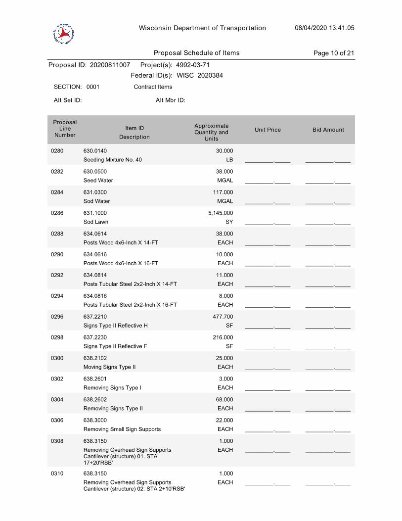
Wisconsin Department of Transportation 08/04/2020 13:41:05
Proposal ID: 20200811007 Project(s): 4992-03-71
Federal ID(s): WISC 2020384
0001 Contract ItemsSECTION:
Alt Set ID: Alt Mbr ID:
Bid AmountUnit PriceApproximateQuantity and
UnitsDescription
Item IDProposal
LineNumber
0280 630.0140
Seeding Mixture No. 40 LB
30.000
_________._____ _________._____
0282 630.0500
Seed Water MGAL
38.000
_________._____ _________._____
0284 631.0300
Sod Water MGAL
117.000
_________._____ _________._____
0286 631.1000
Sod Lawn SY
5,145.000
_________._____ _________._____
0288 634.0614
Posts Wood 4x6-Inch X 14-FT EACH
38.000
_________._____ _________._____
0290 634.0616
Posts Wood 4x6-Inch X 16-FT EACH
10.000
_________._____ _________._____
0292 634.0814
Posts Tubular Steel 2x2-Inch X 14-FT EACH
11.000
_________._____ _________._____
0294 634.0816
Posts Tubular Steel 2x2-Inch X 16-FT EACH
8.000
_________._____ _________._____
0296 637.2210
Signs Type II Reflective H SF
477.700
_________._____ _________._____
0298 637.2230
Signs Type II Reflective F SF
216.000
_________._____ _________._____
0300 638.2102
Moving Signs Type II EACH
25.000
_________._____ _________._____
0302 638.2601
Removing Signs Type I EACH
3.000
_________._____ _________._____
0304 638.2602
Removing Signs Type II EACH
68.000
_________._____ _________._____
0306 638.3000
Removing Small Sign Supports EACH
22.000
_________._____ _________._____
0308 638.3150
Removing Overhead Sign SupportsCantilever (structure) 01. STA17+20'RSB'
EACH
1.000
_________._____ _________._____
0310 638.3150
Removing Overhead Sign SupportsCantilever (structure) 02. STA 2+10'RSB'
EACH
1.000
_________._____ _________._____
Proposal Schedule of Items Page 10 of 21

Wisconsin Department of Transportation 08/04/2020 13:41:05
Proposal ID: 20200811007 Project(s): 4992-03-71
Federal ID(s): WISC 2020384
0001 Contract ItemsSECTION:
Alt Set ID: Alt Mbr ID:
Bid AmountUnit PriceApproximateQuantity and
UnitsDescription
Item IDProposal
LineNumber
0312 641.8100
Overhead Sign Support (structure) 01. S-70-383
LUMP SUM _________._____LS
0314 642.5201
Field Office Type C 01. Office #1 EACH
1.000
_________._____ _________._____
0316 642.5201
Field Office Type C 02. Office #2 EACH
1.000
_________._____ _________._____
0318 643.0300
Traffic Control Drums DAY
5,958.000
_________._____ _________._____
0320 643.0410
Traffic Control Barricades Type II DAY
18,276.000
_________._____ _________._____
0322 643.0420
Traffic Control Barricades Type III DAY
5,547.000
_________._____ _________._____
0324 643.0705
Traffic Control Warning Lights Type A DAY
7,268.000
_________._____ _________._____
0326 643.0715
Traffic Control Warning Lights Type C DAY
1,563.000
_________._____ _________._____
0328 643.0900
Traffic Control Signs DAY
63,160.000
_________._____ _________._____
0330 643.0910
Traffic Control Covering Signs Type I EACH
3.000
_________._____ _________._____
0332 643.1050
Traffic Control Signs PCMS DAY
84.000
_________._____ _________._____
0334 643.5000
Traffic Control EACH
1.000
_________._____ _________._____
0336 644.1420
Temporary Pedestrian Surface Plywood SF
1,600.000
_________._____ _________._____
0338 644.1601
Temporary Pedestrian Curb Ramp DAY
800.000
_________._____ _________._____
0340 644.1810
Temporary Pedestrian Barricade LF
575.000
_________._____ _________._____
0342 645.0111
Geotextile Type DF Schedule A SY
310.000
_________._____ _________._____
Proposal Schedule of Items Page 11 of 21
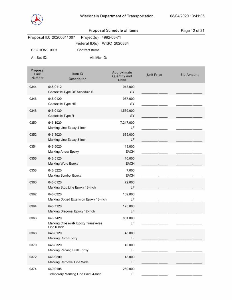
Wisconsin Department of Transportation 08/04/2020 13:41:05
Proposal ID: 20200811007 Project(s): 4992-03-71
Federal ID(s): WISC 2020384
0001 Contract ItemsSECTION:
Alt Set ID: Alt Mbr ID:
Bid AmountUnit PriceApproximateQuantity and
UnitsDescription
Item IDProposal
LineNumber
0344 645.0112
Geotextile Type DF Schedule B SY
943.000
_________._____ _________._____
0346 645.0120
Geotextile Type HR SY
957.000
_________._____ _________._____
0348 645.0130
Geotextile Type R SY
1,569.000
_________._____ _________._____
0350 646.1020
Marking Line Epoxy 4-Inch LF
7,247.000
_________._____ _________._____
0352 646.3020
Marking Line Epoxy 8-Inch LF
685.000
_________._____ _________._____
0354 646.5020
Marking Arrow Epoxy EACH
13.000
_________._____ _________._____
0356 646.5120
Marking Word Epoxy EACH
10.000
_________._____ _________._____
0358 646.5220
Marking Symbol Epoxy EACH
7.000
_________._____ _________._____
0360 646.6120
Marking Stop Line Epoxy 18-Inch LF
72.000
_________._____ _________._____
0362 646.6320
Marking Dotted Extension Epoxy 18-Inch LF
109.000
_________._____ _________._____
0364 646.7120
Marking Diagonal Epoxy 12-Inch LF
175.000
_________._____ _________._____
0366 646.7420
Marking Crosswalk Epoxy TransverseLine 6-Inch
LF
881.000
_________._____ _________._____
0368 646.8120
Marking Curb Epoxy LF
48.000
_________._____ _________._____
0370 646.8320
Marking Parking Stall Epoxy LF
40.000
_________._____ _________._____
0372 646.9200
Marking Removal Line Wide LF
48.000
_________._____ _________._____
0374 649.0105
Temporary Marking Line Paint 4-Inch LF
250.000
_________._____ _________._____
Proposal Schedule of Items Page 12 of 21

Wisconsin Department of Transportation 08/04/2020 13:41:05
Proposal ID: 20200811007 Project(s): 4992-03-71
Federal ID(s): WISC 2020384
0001 Contract ItemsSECTION:
Alt Set ID: Alt Mbr ID:
Bid AmountUnit PriceApproximateQuantity and
UnitsDescription
Item IDProposal
LineNumber
0376 649.0150
Temporary Marking Line RemovableTape 4-Inch
LF
100.000
_________._____ _________._____
0378 650.4000
Construction Staking Storm Sewer EACH
54.000
_________._____ _________._____
0380 650.4500
Construction Staking Subgrade LF
1,722.000
_________._____ _________._____
0382 650.5500
Construction Staking Curb Gutter andCurb & Gutter
LF
5,072.000
_________._____ _________._____
0384 650.6500
Construction Staking Structure Layout(structure) 01. B-70-324
LUMP SUM _________._____LS
0386 650.6500
Construction Staking Structure Layout(structure) 02. R-70-160
LUMP SUM _________._____LS
0388 650.6500
Construction Staking Structure Layout(structure) 03. R-70-161
LUMP SUM _________._____LS
0390 650.6500
Construction Staking Structure Layout(structure) 04. R-70-159
LUMP SUM _________._____LS
0392 650.7000
Construction Staking ConcretePavement
LF
1,740.000
_________._____ _________._____
0394 650.9000
Construction Staking Curb Ramps EACH
36.000
_________._____ _________._____
0396 650.9910
Construction Staking SupplementalControl (project) 01. 4992-03-71
LUMP SUM _________._____LS
0398 652.0125
Conduit Rigid Metallic 2-Inch LF
244.000
_________._____ _________._____
0400 652.0220
Conduit Rigid Nonmetallic Schedule 40 11/2-Inch
LF
128.000
_________._____ _________._____
0402 652.0225
Conduit Rigid Nonmetallic Schedule 402-Inch
LF
4,104.000
_________._____ _________._____
Proposal Schedule of Items Page 13 of 21
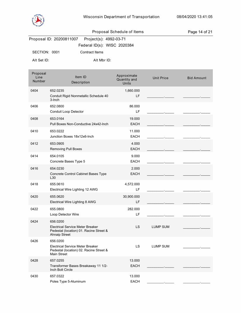
Wisconsin Department of Transportation 08/04/2020 13:41:05
Proposal ID: 20200811007 Project(s): 4992-03-71
Federal ID(s): WISC 2020384
0001 Contract ItemsSECTION:
Alt Set ID: Alt Mbr ID:
Bid AmountUnit PriceApproximateQuantity and
UnitsDescription
Item IDProposal
LineNumber
0404 652.0235
Conduit Rigid Nonmetallic Schedule 403-Inch
LF
1,660.000
_________._____ _________._____
0406 652.0800
Conduit Loop Detector LF
86.000
_________._____ _________._____
0408 653.0164
Pull Boxes Non-Conductive 24x42-Inch EACH
19.000
_________._____ _________._____
0410 653.0222
Junction Boxes 18x12x6-Inch EACH
11.000
_________._____ _________._____
0412 653.0905
Removing Pull Boxes EACH
4.000
_________._____ _________._____
0414 654.0105
Concrete Bases Type 5 EACH
9.000
_________._____ _________._____
0416 654.0230
Concrete Control Cabinet Bases TypeL30
EACH
2.000
_________._____ _________._____
0418 655.0610
Electrical Wire Lighting 12 AWG LF
4,572.000
_________._____ _________._____
0420 655.0620
Electrical Wire Lighting 8 AWG LF
30,900.000
_________._____ _________._____
0422 655.0800
Loop Detector Wire LF
282.000
_________._____ _________._____
0424 656.0200
Electrical Service Meter BreakerPedestal (location) 01. Racine Street &Ahnaip Street
LUMP SUM _________._____LS
0426 656.0200
Electrical Service Meter BreakerPedestal (location) 02. Racine Street &Main Street
LUMP SUM _________._____LS
0428 657.0255
Transformer Bases Breakaway 11 1/2-Inch Bolt Circle
EACH
13.000
_________._____ _________._____
0430 657.0322
Poles Type 5-Aluminum EACH
13.000
_________._____ _________._____
Proposal Schedule of Items Page 14 of 21
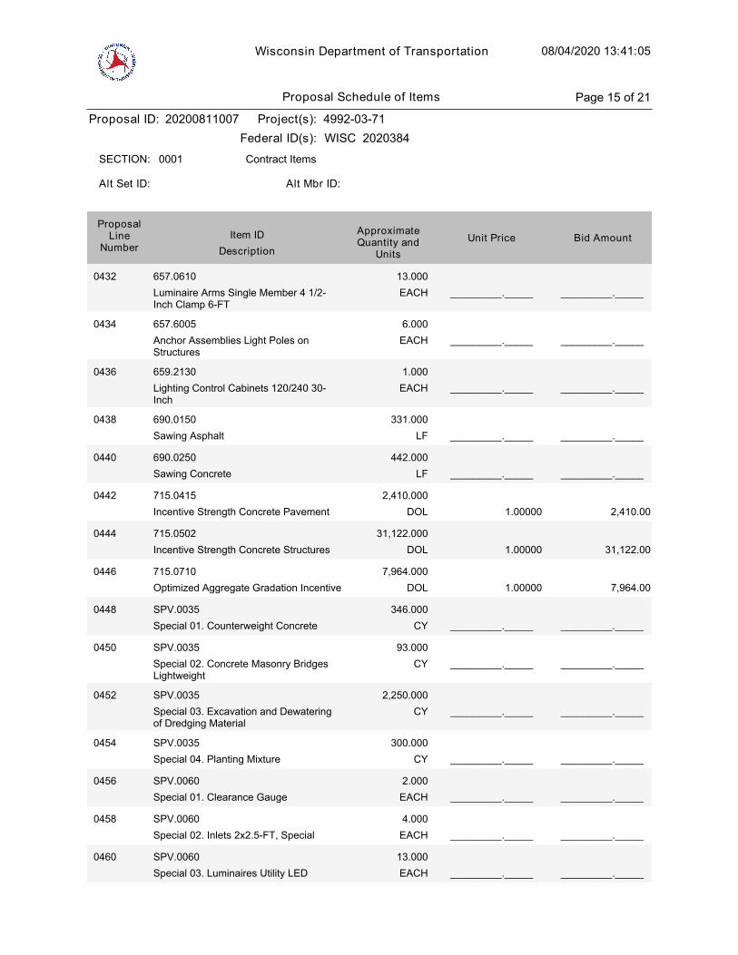
Wisconsin Department of Transportation 08/04/2020 13:41:05
Proposal ID: 20200811007 Project(s): 4992-03-71
Federal ID(s): WISC 2020384
0001 Contract ItemsSECTION:
Alt Set ID: Alt Mbr ID:
Bid AmountUnit PriceApproximateQuantity and
UnitsDescription
Item IDProposal
LineNumber
0432 657.0610
Luminaire Arms Single Member 4 1/2-Inch Clamp 6-FT
EACH
13.000
_________._____ _________._____
0434 657.6005
Anchor Assemblies Light Poles onStructures
EACH
6.000
_________._____ _________._____
0436 659.2130
Lighting Control Cabinets 120/240 30-Inch
EACH
1.000
_________._____ _________._____
0438 690.0150
Sawing Asphalt LF
331.000
_________._____ _________._____
0440 690.0250
Sawing Concrete LF
442.000
_________._____ _________._____
1.00000
0442 715.0415
Incentive Strength Concrete Pavement DOL
2,410.000
2,410.00
1.00000
0444 715.0502
Incentive Strength Concrete Structures DOL
31,122.000
31,122.00
1.00000
0446 715.0710
Optimized Aggregate Gradation Incentive DOL
7,964.000
7,964.00
0448 SPV.0035
Special 01. Counterweight Concrete CY
346.000
_________._____ _________._____
0450 SPV.0035
Special 02. Concrete Masonry BridgesLightweight
CY
93.000
_________._____ _________._____
0452 SPV.0035
Special 03. Excavation and Dewateringof Dredging Material
CY
2,250.000
_________._____ _________._____
0454 SPV.0035
Special 04. Planting Mixture CY
300.000
_________._____ _________._____
0456 SPV.0060
Special 01. Clearance Gauge EACH
2.000
_________._____ _________._____
0458 SPV.0060
Special 02. Inlets 2x2.5-FT, Special EACH
4.000
_________._____ _________._____
0460 SPV.0060
Special 03. Luminaires Utility LED EACH
13.000
_________._____ _________._____
Proposal Schedule of Items Page 15 of 21
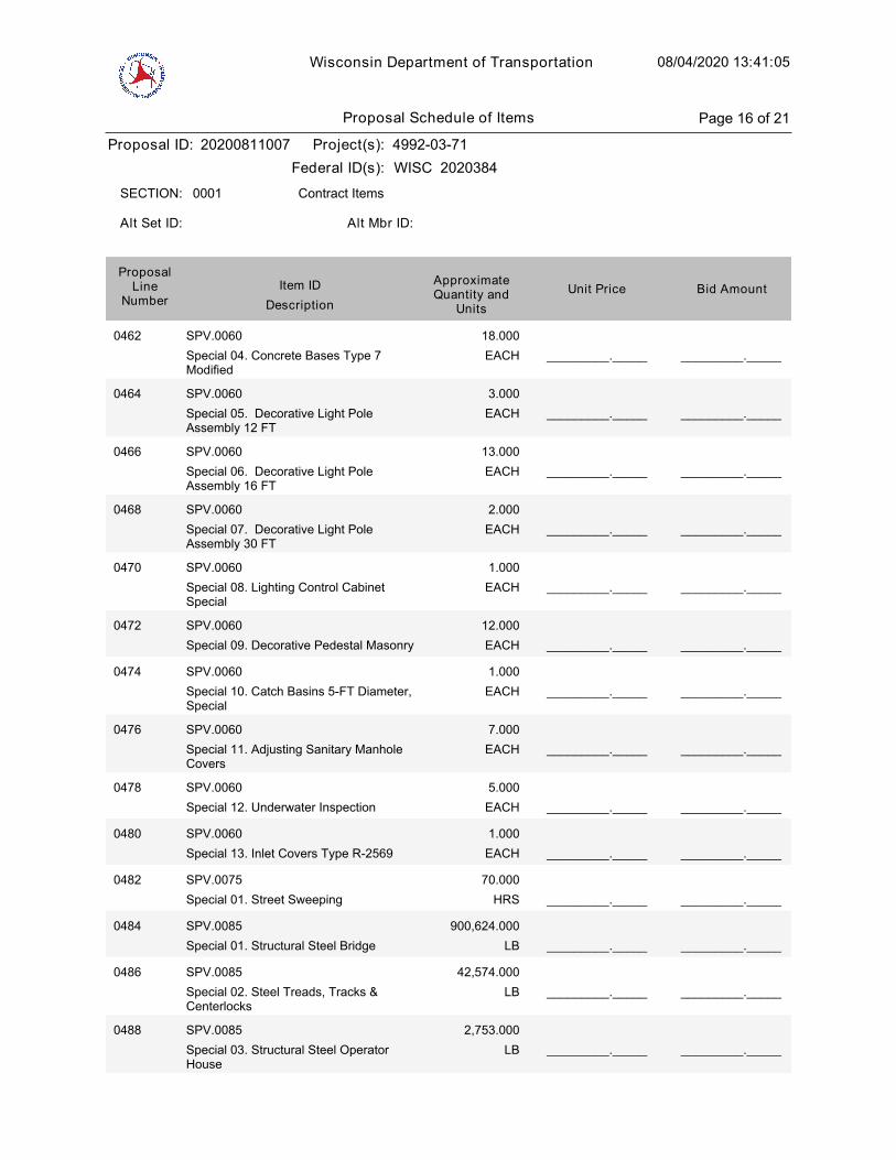
Wisconsin Department of Transportation 08/04/2020 13:41:05
Proposal ID: 20200811007 Project(s): 4992-03-71
Federal ID(s): WISC 2020384
0001 Contract ItemsSECTION:
Alt Set ID: Alt Mbr ID:
Bid AmountUnit PriceApproximateQuantity and
UnitsDescription
Item IDProposal
LineNumber
0462 SPV.0060
Special 04. Concrete Bases Type 7Modified
EACH
18.000
_________._____ _________._____
0464 SPV.0060
Special 05. Decorative Light PoleAssembly 12 FT
EACH
3.000
_________._____ _________._____
0466 SPV.0060
Special 06. Decorative Light PoleAssembly 16 FT
EACH
13.000
_________._____ _________._____
0468 SPV.0060
Special 07. Decorative Light PoleAssembly 30 FT
EACH
2.000
_________._____ _________._____
0470 SPV.0060
Special 08. Lighting Control CabinetSpecial
EACH
1.000
_________._____ _________._____
0472 SPV.0060
Special 09. Decorative Pedestal Masonry EACH
12.000
_________._____ _________._____
0474 SPV.0060
Special 10. Catch Basins 5-FT Diameter,Special
EACH
1.000
_________._____ _________._____
0476 SPV.0060
Special 11. Adjusting Sanitary ManholeCovers
EACH
7.000
_________._____ _________._____
0478 SPV.0060
Special 12. Underwater Inspection EACH
5.000
_________._____ _________._____
0480 SPV.0060
Special 13. Inlet Covers Type R-2569 EACH
1.000
_________._____ _________._____
0482 SPV.0075
Special 01. Street Sweeping HRS
70.000
_________._____ _________._____
0484 SPV.0085
Special 01. Structural Steel Bridge LB
900,624.000
_________._____ _________._____
0486 SPV.0085
Special 02. Steel Treads, Tracks &Centerlocks
LB
42,574.000
_________._____ _________._____
0488 SPV.0085
Special 03. Structural Steel OperatorHouse
LB
2,753.000
_________._____ _________._____
Proposal Schedule of Items Page 16 of 21

Wisconsin Department of Transportation 08/04/2020 13:41:05
Proposal ID: 20200811007 Project(s): 4992-03-71
Federal ID(s): WISC 2020384
0001 Contract ItemsSECTION:
Alt Set ID: Alt Mbr ID:
Bid AmountUnit PriceApproximateQuantity and
UnitsDescription
Item IDProposal
LineNumber
0490 SPV.0090
Special 01. Railing Aluminum Special B-70-324
LF
1,702.000
_________._____ _________._____
0492 SPV.0090
Special 02. Railing Aluminum Special R-70-159
LF
102.000
_________._____ _________._____
0494 SPV.0090
Special 03. Railing Aluminum Special R-70-160
LF
129.000
_________._____ _________._____
0496 SPV.0090
Special 04. Railing Aluminum Special R-70-161
LF
50.000
_________._____ _________._____
0498 SPV.0090
Special 05. Sanitary Sewer Pipe PVC 4-Inch
LF
150.000
_________._____ _________._____
0500 SPV.0090
Special 06. C-901 PE Pipe 1-Inch LF
180.000
_________._____ _________._____
0502 SPV.0090
Special 07. Concrete Curb & Gutter 30-Inch HES Type A
LF
56.000
_________._____ _________._____
0504 SPV.0090
Special 08. Sawing Curb Head LF
30.000
_________._____ _________._____
0506 SPV.0090
Special 09. Turbidity Barrier Special LF
1,000.000
_________._____ _________._____
0508 SPV.0090
Special 10. Landscape Edging LF
140.000
_________._____ _________._____
0510 SPV.0105
Special 01. Waterproofing Bascule Pierand Bascule Abutment
LUMP SUM _________._____LS
0512 SPV.0105
Special 02. Closures and Seals LUMP SUM _________._____LS
0514 SPV.0105
Special 03. HVAC Work LUMP SUM _________._____LS
0516 SPV.0105
Special 04. Operator HouseMiscellaneous
LUMP SUM _________._____LS
0518 SPV.0105
Special 05. Fender Rub Rails LUMP SUM _________._____LS
Proposal Schedule of Items Page 17 of 21
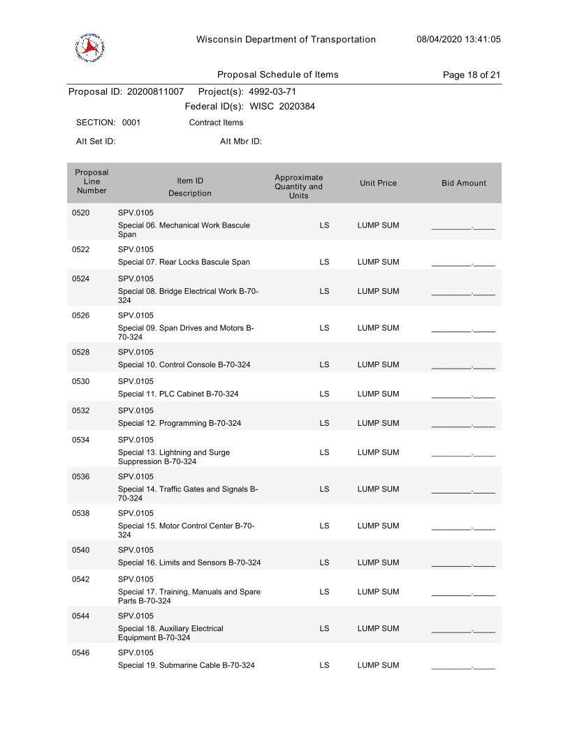
Wisconsin Department of Transportation 08/04/2020 13:41:05
Proposal ID: 20200811007 Project(s): 4992-03-71
Federal ID(s): WISC 2020384
0001 Contract ItemsSECTION:
Alt Set ID: Alt Mbr ID:
Bid AmountUnit PriceApproximateQuantity and
UnitsDescription
Item IDProposal
LineNumber
0520 SPV.0105
Special 06. Mechanical Work BasculeSpan
LUMP SUM _________._____LS
0522 SPV.0105
Special 07. Rear Locks Bascule Span LUMP SUM _________._____LS
0524 SPV.0105
Special 08. Bridge Electrical Work B-70-324
LUMP SUM _________._____LS
0526 SPV.0105
Special 09. Span Drives and Motors B-70-324
LUMP SUM _________._____LS
0528 SPV.0105
Special 10. Control Console B-70-324 LUMP SUM _________._____LS
0530 SPV.0105
Special 11. PLC Cabinet B-70-324 LUMP SUM _________._____LS
0532 SPV.0105
Special 12. Programming B-70-324 LUMP SUM _________._____LS
0534 SPV.0105
Special 13. Lightning and SurgeSuppression B-70-324
LUMP SUM _________._____LS
0536 SPV.0105
Special 14. Traffic Gates and Signals B-70-324
LUMP SUM _________._____LS
0538 SPV.0105
Special 15. Motor Control Center B-70-324
LUMP SUM _________._____LS
0540 SPV.0105
Special 16. Limits and Sensors B-70-324 LUMP SUM _________._____LS
0542 SPV.0105
Special 17. Training, Manuals and SpareParts B-70-324
LUMP SUM _________._____LS
0544 SPV.0105
Special 18. Auxiliary ElectricalEquipment B-70-324
LUMP SUM _________._____LS
0546 SPV.0105
Special 19. Submarine Cable B-70-324 LUMP SUM _________._____LS
Proposal Schedule of Items Page 18 of 21
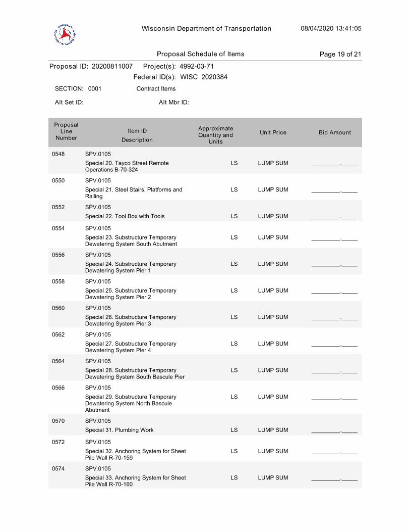
Wisconsin Department of Transportation 08/04/2020 13:41:05
Proposal ID: 20200811007 Project(s): 4992-03-71
Federal ID(s): WISC 2020384
0001 Contract ItemsSECTION:
Alt Set ID: Alt Mbr ID:
Bid AmountUnit PriceApproximateQuantity and
UnitsDescription
Item IDProposal
LineNumber
0548 SPV.0105
Special 20. Tayco Street RemoteOperations B-70-324
LUMP SUM _________._____LS
0550 SPV.0105
Special 21. Steel Stairs, Platforms andRailing
LUMP SUM _________._____LS
0552 SPV.0105
Special 22. Tool Box with Tools LUMP SUM _________._____LS
0554 SPV.0105
Special 23. Substructure TemporaryDewatering System South Abutment
LUMP SUM _________._____LS
0556 SPV.0105
Special 24. Substructure TemporaryDewatering System Pier 1
LUMP SUM _________._____LS
0558 SPV.0105
Special 25. Substructure TemporaryDewatering System Pier 2
LUMP SUM _________._____LS
0560 SPV.0105
Special 26. Substructure TemporaryDewatering System Pier 3
LUMP SUM _________._____LS
0562 SPV.0105
Special 27. Substructure TemporaryDewatering System Pier 4
LUMP SUM _________._____LS
0564 SPV.0105
Special 28. Substructure TemporaryDewatering System South Bascule Pier
LUMP SUM _________._____LS
0566 SPV.0105
Special 29. Substructure TemporaryDewatering System North BasculeAbutment
LUMP SUM _________._____LS
0570 SPV.0105
Special 31. Plumbing Work LUMP SUM _________._____LS
0572 SPV.0105
Special 32. Anchoring System for SheetPile Wall R-70-159
LUMP SUM _________._____LS
0574 SPV.0105
Special 33. Anchoring System for SheetPile Wall R-70-160
LUMP SUM _________._____LS
Proposal Schedule of Items Page 19 of 21
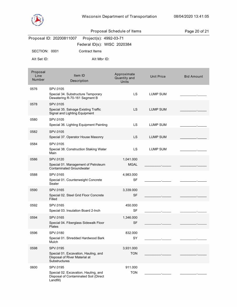
Wisconsin Department of Transportation 08/04/2020 13:41:05
Proposal ID: 20200811007 Project(s): 4992-03-71
Federal ID(s): WISC 2020384
0001 Contract ItemsSECTION:
Alt Set ID: Alt Mbr ID:
Bid AmountUnit PriceApproximateQuantity and
UnitsDescription
Item IDProposal
LineNumber
0576 SPV.0105
Special 34. Substructure TemporaryDewatering R-70-161 Segment B
LUMP SUM _________._____LS
0578 SPV.0105
Special 35. Salvage Existing TrafficSignal and Lighting Equipment
LUMP SUM _________._____LS
0580 SPV.0105
Special 36. Lighting Equipment Painting LUMP SUM _________._____LS
0582 SPV.0105
Special 37. Operator House Masonry LUMP SUM _________._____LS
0584 SPV.0105
Special 38. Construction Staking WaterMain
LUMP SUM _________._____LS
0586 SPV.0120
Special 01. Management of PetroleumContaminated Groundwater
MGAL
1,041.000
_________._____ _________._____
0588 SPV.0165
Special 01. Counterweight ConcreteSealer
SF
4,983.000
_________._____ _________._____
0590 SPV.0165
Special 02. Steel Grid Floor ConcreteFilled
SF
3,339.000
_________._____ _________._____
0592 SPV.0165
Special 03. Insulation Board 2-Inch SF
450.000
_________._____ _________._____
0594 SPV.0165
Special 04. Fiberglass Sidewalk FloorPlates
SF
1,346.000
_________._____ _________._____
0596 SPV.0180
Special 01. Shredded Hardwood BarkMulch
SY
832.000
_________._____ _________._____
0598 SPV.0195
Special 01. Excavation, Hauling, andDisposal of River Material atSubstructures
TON
3,931.000
_________._____ _________._____
0600 SPV.0195
Special 02. Excavation, Hauling, andDisposal of Contaminated Soil (DirectLandfill)
TON
911.000
_________._____ _________._____
Proposal Schedule of Items Page 20 of 21
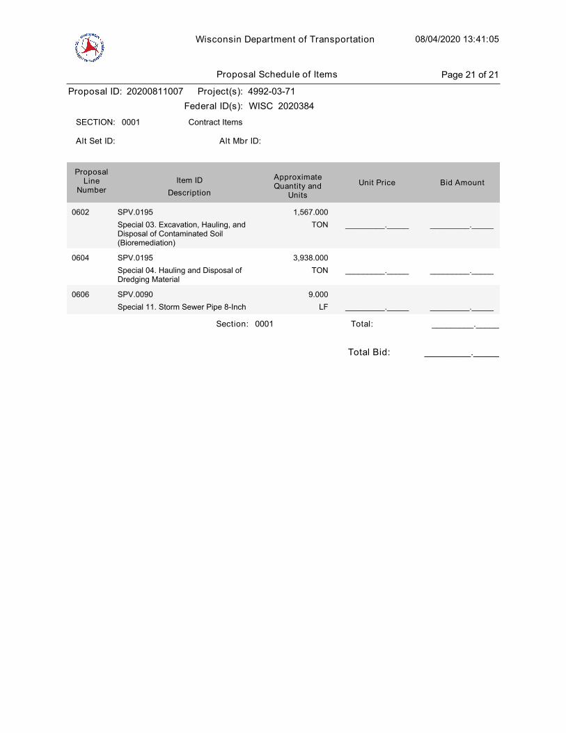
Wisconsin Department of Transportation 08/04/2020 13:41:05
Proposal ID: 20200811007 Project(s): 4992-03-71
Federal ID(s): WISC 2020384
0001 Contract ItemsSECTION:
Alt Set ID: Alt Mbr ID:
Bid AmountUnit PriceApproximateQuantity and
UnitsDescription
Item IDProposal
LineNumber
0602 SPV.0195
Special 03. Excavation, Hauling, andDisposal of Contaminated Soil(Bioremediation)
TON
1,567.000
_________._____ _________._____
0604 SPV.0195
Special 04. Hauling and Disposal ofDredging Material
TON
3,938.000
_________._____ _________._____
0606 SPV.0090
Special 11. Storm Sewer Pipe 8-Inch LF
9.000
_________._____ _________._____
Section: 0001 _________._____Total:
Total Bid: _________._____
Proposal Schedule of Items Page 21 of 21