Addendum 02 - Garmann Miller
148
Page 1 Project Number: 21059.01 Addendum 02 Addendum 02 DOCUMENT 00 9100 DATE: June 9, 2022 PROJECT: BCS R.C. Waters Elem School Addition Renovation 220 E Ottawa St. Oak Harbor, Ohio 43449 PROJECT #: 21059.01 OWNER: Benton-Carroll-Salem Local School District Guy Parmigian, Superintendent 11685 W. State Route 163 Oak Harbor, OH 43449 ARCHITECT: Garmann Miller 38 South Lincoln Drive P.O. Box 71 Minster, Ohio 45865 TO: Prospective Bidders This addendum form is a part of the Contract Documents and modifies the Bidding Documents dated May 20, 2022, with amendments and additions noted below. Acknowledge receipt of this Addendum on the Bid Form. Failure to do so may disqualify the Bidder. This addendum consists of 3 pages and 27 specification sections. FOR INFORMATION ONLY 1. N/A CHANGES TO THE PROJECT MANUAL 1. Section 27 05 01 BASIC COMMUNICATIONS REQUIREMENTS: Add section in its entirety. 2. Section 27 05 02 AGREEMENT AND WAIVER FOR USE OF ELECTRONIC FILES: Add section in its entirety. 3. Section 27 05 02A ELECTRONIC FILES - HEAPY RELEASE FORM TO CONTRACTORS: Add section in its entirety.
-
Upload
khangminh22 -
Category
Documents
-
view
4 -
download
0
Transcript of Addendum 02 - Garmann Miller
Page 1 Project Number: 21059.01
Addendum 02
Addendum 02 DOCUMENT 00 9100
DATE: June 9, 2022
PROJECT: BCS R.C. Waters Elem School Addition Renovation
220 E Ottawa St.
Oak Harbor, Ohio 43449
PROJECT #: 21059.01
OWNER: Benton-Carroll-Salem Local School District
Guy Parmigian, Superintendent
11685 W. State Route 163
Oak Harbor, OH 43449
ARCHITECT: Garmann Miller
38 South Lincoln Drive
P.O. Box 71
Minster, Ohio 45865
TO: Prospective Bidders
This addendum form is a part of the Contract Documents and modifies the Bidding
Documents dated May 20, 2022, with amendments and additions noted below.
Acknowledge receipt of this Addendum on the Bid Form. Failure to do so may disqualify
the Bidder.
This addendum consists of 3 pages and 27 specification sections.
FOR INFORMATION ONLY
1. N/A
CHANGES TO THE PROJECT MANUAL
1. Section 27 05 01 BASIC COMMUNICATIONS REQUIREMENTS: Add section in its entirety.
2. Section 27 05 02 AGREEMENT AND WAIVER FOR USE OF ELECTRONIC FILES: Add
section in its entirety.
3. Section 27 05 02A ELECTRONIC FILES - HEAPY RELEASE FORM TO CONTRACTORS: Add
section in its entirety.
Page 2 Project Number: 21059.01
Addendum 02
4. Section 27 05 04 BASIC COMMUNICATIONS MATERIALS AND METHODS: Add section in
its entirety.
5. Section 27 05 05 FIRESTOPPING: Add section in its entirety.
6. Section 27 05 26 GROUNDING AND BONDING FOR COMMUNICATIONS SYSTEMS: Add
section in its entirety.
7. Section 27 05 28 COMMUNICATIONS SYSTEMS PATHWAYS AND SUPPORT EQUIPMENT:
Add section in its entirety.
8. Section 27 05 33 RACEWAY AND BOXES FOR COMMUNICATIONS SYSTEMS: Add
section in its entirety.
9. Section 27 05 53 IDENTIFICATION FOR COMMUNICATIONS SYSTEMS: Add section in its
entirety.
10. Section 27 11 00 COMMUNICATIONS EQUIPMENT ROOM FITTINGS: Add section in its
entirety.
11. Section 27 13 13 COMMUNICATIONS COPPER BACKBONE CABLING: Add section in its
entirety.
12. Section 27 13 23 COMMUNICATIONS OPTICAL FIBER BACKBONE CABLING: Add
section in its entirety.
13. Section 27 15 13 COMMUNICATIONS COPPER HORIZONTAL CABLING: Add section in
its entirety.
14. Section 27 41 19 VIDEO DISPLAY EQUIPMENT: Add section in its entirety.
15. Section 27 51 23 B CENTRAL PUBLIC ADDRESS-PROGRAM DISTRIBUTION SYSTEM: Add
section in its entirety.
16. Section 27 51 24 A GYMNASIUM SOUND REINFORCEMENT SYSTEM: Add section in its
entirety.
17. Section 27 51 27 CLASSROOM SOUND REINFORCEMENT SYSTEM: Add section in its
entirety.
18. Section 27 51 35 B GPS SATELLITE CLOCK SYSTEM: Add section in its entirety.
19. Section 28 05 01 BASIC ELECTRONIC SAFETY AND SECURITY REQUIREMENTS: Add
section in its entirety.
20. Section 28 05 02 AGREEMENT AND WAIVER FOR USE OF ELECTRONIC FILES: Add
section in its entirety.
21. Section 28 05 02A ELECTRONIC FILES - HEAPY RELEASE FORM TO CONTRACTORS: Add
section in its entirety.
22. Section 28 05 04 BASIC ELECTRONIC SAFETY AND SECURITY MATERIALS AND METHODS:
Add section in its entirety.
23. Section 28 05 05 FIRESTOPPING: Add section in its entirety.
24. Section 28 05 33 RACEWAY AND BOXES FOR ELECTRONIC SAFETY AND SECURITY
SYSTEMS: Add section in its entirety.
25. Section 28 05 53 IDENTIFICATION FOR ELECTRONIC SAFETY AND SECURITY SYSTEMS:
Add section in its entirety.
26. Section 28 13 00 SECURITY MANAGEMENT SYSTEM: Add section in its entirety.
27. Section 28 23 01 VIDEO SURVEILLANCE – IP: Add section in its entirety.
CHANGES TO THE DRAWINGS
a. N/A

Page 3 Project Number: 21059.01
Addendum 02
ATTACHMENTS
The following attachments are included and are part of this addendum:
Specification Sections 27 05 01, 27 05 02, 27 05 02A, 27 05 04, 27 05 05, 27 05 26, 27 05 28,
27 05 33, 27 05 53, 27 11 00, 27 13 13, 27 13 23, 27 15 13, 27 41 19, 27 51 23 B, 27 51 24 A,
27 51 27, 27 51 35 B, 28 05 01, 28 05 02, 28 05 02A, 28 05 04, 28 05 05, 28 05 33, 28 05 53, 28
13 00, 28 23 01
END OF ADDENDUM
21059.01 BCS RC Waters Elem School Addition Renovation Addendum 02
BASIC COMMUNICATIONS REQUIREMENTS
27 05 01 - 1June 9, 2022
27 05 01 BASIC COMMUNICATIONS REQUIREMENTS
PART 1 - GENERAL
1.1 Refer to Section 26 05 01 Basic Electrical Requirements which are hereby made part of Division 27 - Communications.

21059.01 BCS RC Waters Elem School Addition Renovation Addendum 02
AGREEMENT AND WAIVER FOR USE OF ELECTRONIC
FILES
27 05 02 - 1June 9, 2022
27 05 02 AGREEMENT AND WAIVER FOR USE OF ELECTRONIC FILES
PART 1 - GENERAL
1.1 The Engineer, at his sole discretion and without obligation, makes graphic portions of the contract documents available for use by the contractor in electronic format. These electronic files are proprietary, and remain the Engineer’s Instruments of Service and shall be for use solely with respect to this project, as provided in the Standard Form of Agreement between Owner/Architect and Engineer.
1.2 Electronic files shall be released only after bids have been received for the project and contracts have been signed with the contractors.
1.3 The contractor shall acknowledge receipt of electronic files in the requested format for this project. The electronic files are provided as a convenience to the User, for use in preparing shop drawings and/or coordination drawings related to the construction of only the project identified in the Agreement. The electronic files and the information contained within are the property of the Engineer and/or the Architect and/or the Owner, and may not be reproduced or used in any format except in conjunction with the project identified in the Agreement.
1.4 The User acknowledges that the information provided in the electronic files is not a substitution or replacement for the Contract Documents and does not become a Contract Document. The User acknowledges that neither the Engineer, the Architect, the Consultants, the Client or the Owner make any warrant or representation that the information contained in the electronic files reflect the Contract Documents in their entirety. The User assumes full responsibility in the use of the electronic files, including the responsibility to see that all manual modifications, addenda, bulletins, clarifications and Change Orders to the drawings executed as a part of the Contract Documents have been incorporated.
1.5 The User acknowledges that the receipt of electronic files in no way relieves the User from the responsibility for the preparation of shop drawings or other schedules as set forth in the Contract between the Contractor and the Owner.
1.6 Electronic files are available in the AutoCAD .DWG or Revit model format for a cost as indicated in the Agreement and Waiver Form. Providing the documents in the .DXF format will be an additional charge per sheet as indicated in the Agreement and Waiver Form. Charges are for the Engineer’s time to prepare the documents in the format stated. They are available through the Engineer’s office on a C.O.D. basis only. A sample of the format will be provided by the Engineer upon request by the contractor, for the purpose of testing the compatibility of the format to contractor’s systems.
1.7 Projects developed using AutoCAD MEP will have all drawings converted to the AutoCAD format, when requested to be DWG or DXF format.
1.8 Project models will be furnished without views.
1.9 The electronic files shall be stripped of the Project’s name and address, the Architect’s / and / Engineer’s / and / any consultant’s name and address, and any professional licenses indicated on the contract documents, (and all dimensions, verbiage, and statistical information). Use of these electronic files is solely at the contractor’s risk, and shall in no way alter the contractor’s Contract for Construction.
1.10 The User agrees to indemnify, hold harmless and defend the Engineer, the Architect, the Consultants, the Owner, the Client and any of their agents from any litigation resulting from the use of (by any means of reproduction or electronic media) these files. The Engineer makes no

21059.01 BCS RC Waters Elem School Addition Renovation Addendum 02
AGREEMENT AND WAIVER FOR USE OF ELECTRONIC
FILES
27 05 02 - 2June 9, 2022
representation regarding fitness for any particular purpose, or suitability for use with any software or hardware, and shall not be responsible or liable for errors, defects, inexactitudes, or anomalies in the data, information, or documents (including drawings and specifications) caused by the Engineer’s or its consultant’s computer software or hardware defects or errors; the Engineer’s or its consultant’s electronic or disk transmittal of data, information or documents; or the Engineer’s or its consultant’s reformatting or automated conversion of data, information or documents electronically or disk transmitted from the Engineer’s consultants to the Engineer.
1.11 The contractor waives all claims against the Engineer, its employees, officers and consultants for any and all damages, losses, or expenses the contractor incurs from such defects or errors in the electronic files. Furthermore, the contractor shall indemnify, defend, and hold harmless the Engineer, and its consultants together with their respective employees and officers, harmless from and against any claims, suits, demands, causes of action, losses, damages or expenses (including all attorney’s fees and litigation expenses) attributed to errors or defects in data, information or documents, including drawings and specifications, resulting from the contractor’s distribution of electronic files to other contractors, persons, or entities.
PART 2 - PRODUCTS – NOT USED
PART 3 - EXECUTION
3.1 Attached “Agreement” shall be submitted with accompanying payment to the Engineer prior to delivery of electronic files.
END OF SECTION

21059.01 BCS RC Waters Elem School Addition Renovation Addendum 02
ELECTRONIC FILES – HEAPY RELEASE FORM TO
CONTRACTORS
27 05 02A - 1
ELECTRONIC FILES HEAPY RELEASE FORM TO CONTRACTORS
Project: RC Waters Elementary Addition
220 East Ottawa Street
Oak Harbor, OH 43449
Owner: Benton-Carroll-Salem Schools
Heapy Engineering Project Number: 2022-91001
Heapy Engineering Project Manager: Michael Jankowski The Provider, named below, will furnish the Recipient, named below, certain documents prepared by the Provider or its sub consultants in an electronic format. These documents are hereinafter collectively referred to as "Electronic Files". The Electronic Files are instruments of the Provider services performed solely for the Owner's benefit and to be used solely for this Project. The Provider does not represent that the information contained in the Electronic Files are suitable for use on any other project or for any other purpose. If the Electronic Files are used for any other project or purpose without the Provider's specific written permission, the risk of such use shall be assumed solely by the Recipient or other user. Prior to the use of the Electronic Files the Provider and the Recipient agree to the following terms and conditions:
1. The Provider and Recipient fully understand that the data contained in these electronic files are part of the Provider’s Instruments of Service. The Provider shall be deemed the author of the drawings and data, and shall retain all common law, statutory law and other rights, including copyrights.
2. The Recipient confirms their request to the Provider for Electronic Files for the Project listed above, which the Recipient understands are to be provided only in accordance with, and conditioned upon, the terms and conditions of this Agreement and Waiver for Use of Electronic Files.
3. The Provider agrees that the Recipient may use the Electronic Files for the sole purpose of preparing shop drawings and/or coordination drawings for the above Project only. Any Electronic Files provided are strictly for the use of the Recipient in regard to the Project named above, and shall not be utilized for any other purpose or provided by the Recipient to any entity other than its subcontractors for the Project named above.
4. The Recipient acknowledges that the furnishing of Electronic Files in no way relieves the Recipient from the responsibility of shop drawings or other schedules as set forth in the Contract between the Contractor and the Owner.
5. The Recipient acknowledges:
a. That the Electronic Files do not contain all of the information of the Bid Documents or Contract Documents for the construction of the Project above.
b. That information in the Bid Documents or Contract Documents may be revised or modified in the future.
sdemange
Text Box
June 9, 2022

21059.01 BCS RC Waters Elem School Addition Renovation Addendum 02
ELECTRONIC FILES – HEAPY RELEASE FORM TO
CONTRACTORS
27 05 02A - 2 June 9, 2022
c. The Provider does not have, and will not have, any duty or obligation to advise or give notice to the Recipient of any such revisions or modifications.
d. That the Recipient agrees that its use of the Electronic Files is at the Recipient’s sole risk of liability, and that the Recipient shall make no claim or demand of any kind against the Provider arising out of Recipient’s receipt or use of the Electronic Files.
6. The Provider makes no representation or warranty of any kind, express or implied, with respect to the Electronic Files and specifically makes no warranty that the Electronic Files shall be merchantable or fit for any particular purpose, or accurate or complete. Furthermore, any description of said Electronic Files shall not be deemed to create an implied or express warranty that such Electronic Files shall conform to said description.
7. Due to the unsecured nature of the Electronic Files and the inability of the Provider or the Recipient to establish controls over their use, the Provider assumes no responsibility for any consequences arising out of the use of the data. It is the sole responsibility of the Recipient to check the validity of all information contained within the Electronic Files. The Recipient shall at all times refer to the Construction Documents of the project during all phases of the project. The Recipient shall assume all risks and liabilities resulting from the use of this data, and the Recipient agree(s) to waive any and all claims and liability against the Provider and its sub consultants resulting in any way from the use of the Electronic Files.
8. Electronic Files are provided strictly as a courtesy by the Provider solely for the convenience of the Recipient, and are not part of the Bid Documents or Contract Documents for the Project. The Electronic Files do not replace or supplement the paper copies of any drawings, specifications, or other documents included in the Contract Documents for use on the project.
a. The Recipient assumes full responsibility in the use of Electronic Files, including the responsibility to see that all manual modifications, addenda, bulletins, clarifications and Change Orders to the drawings executed as a part of the Contract Documents have been incorporated.
9. As stated herein, the possibility exists that the Electronic Files provided may differ from the Bid Documents or Contract Documents for construction of the Project. The Provider shall not be responsible, nor be held responsible, for differences between Electronic Files, the Bid Documents, and Contract Documents. The Bid Documents or Contract Documents for the Project may be modified by the Provider at any time, either before or after construction begins. The Provider has no responsibility, either before or after any such modification, to determine or to advise the Recipient whether any such modification causes Electronic Files provided to the Recipient to be out of date, inconsistent with the Bid Documents or Contract Documents, or otherwise unsuitable or unfit for use in any way.
10. The Recipient assumes all risk and liability for any losses, damages, claims, or expenses (including defense and attorney fees) resulting from its receipt, use, or possession of Electronic Files furnished by the Provider. The Provider makes no representation, warranty or guarantee that the Electronic Files:
a. Are suitable for any other usage or purpose.
b. Have any particular durability.
c. Will not damage or impair the Recipient's computer or software.
d. Contain no errors or mechanical flaws or other discrepancies that may render them unsuitable for the purpose intended by the Recipient.
11. Recipient agrees to indemnify, defend and hold harmless the Provider, agents, employees, and the Owner from, and against, any and all claims, suits, losses, damages or costs, of any kind or nature, including attorney’s fees, arising from or by reason of the Recipient’s use of Electronic Files provided by the Provider,

21059.01 BCS RC Waters Elem School Addition Renovation Addendum 02
ELECTRONIC FILES – HEAPY RELEASE FORM TO
CONTRACTORS
27 05 02A - 3 June 9, 2022
and such defense and indemnification obligation duties shall survive any use under this Agreement and Waiver for Use of Electronic Files.
12. The Recipient agrees that the Provider shall have no responsibility whatsoever for problems of any nature arising from transmitting and storing electronic files at a Recipient requested FTP or project management site or the conversion of the Electronic Files by the Recipient or others for use in non-native applications. The Provider will not provide Electronic Files in compressed formats. Recipient agrees to accept the files in the format provided by the Provider, and that Recipient’s conversion or electronic file storage at the Recipient’s requested site, shall be at Recipient’s sole risk.
13. Recipient acknowledges:
a. That the Electronic Files provided by the Provider are a graphical representation of the building in order to generate two-dimensional industry standard drawings.
b. That the data contained in the Electronic Files may not be 100% accurate and should not be used for dimensional control, building layout, shop drawings, or any other similar purpose
c. That any schedule of materials produced directly from the Electronic Files has not been checked for accuracy.
d. That the information in the Electronic Files should be used only for comparative purposes and shall not be relied upon for accurate quantity estimates or used in establishing pricing.
14. Electronic Files provided by the Provider will only contain elements and content that the Provider deems necessary and appropriate to share. No specific Level of Detail (LoD) is implied or expected. The Recipient agrees that no proprietary content, MvParts or Revit Families or any other AutoCAD MEP or Revit MEP content shall be removed from the model and/or used for any other purpose but to support this specific project.
15. The Provider, at its sole discretion, may modify the Electronic files before they are provided to the Recipient. Such modifications may include, but are not necessarily limited to, removal of certain information. The Provider, at its sole discretion, may refuse to provide some or all Electronic Files requested by Recipient.
16. The availability of Electronic Files that were not prepared by the Provider is subject to the consent of the Owner or consultant that prepared those Electronic Files. The Provider will not negotiate with the Owner or consultant or repeatedly solicit the Owner or consultant to obtain such consent. Neither this Agreement and Waiver for Use of Electronic Files nor any such separate Consultant’s consent may be assigned or transferred by Recipient to any other person or entity.
Provider (Name of Company):
Recipient (Name of Company):
Recipient Address:
Name of authorized Recipient Representative:
Title of authorized Recipient Representative:
E-mail address of authorized Recipient Representative:
Signature of authorized Recipient Representative:
Date:

21059.01 BCS RC Waters Elem School Addition Renovation Addendum 02
ELECTRONIC FILES – HEAPY RELEASE FORM TO
CONTRACTORS
27 05 02A - 4 June 9, 2022
NOTE: Select requested Electronic File format and complete applicable cost summary.
1. DWG / DXF Format - List of Drawings Requested:
2. Revit Project Model Requested (Model only, no Views included)
The following costs are applicable to Delivery of Electronic Files (select one): CD-ROM Heapy FTP User’s FTP site Flash Drive
Requested Electronic DWG / DXF file format (select one):
2010 DWG 2007 DWG 2004 DWG 2000 DWG R12 DWG 2010 DXF 2007 DXF 2004 DXF 2000 DXF R12 DXF
Cost of Preparation of Division 27 Electronic DWG / DXF Files:
First Drawing: $50.00 $50.00 Additional Drawings $15.00 each x $15.00 = $ Conversion to DXF Format: $5.00 additional/sheet x $ 5.00 = $
Total Cost: (Please make check payable to Heapy Engineering and include a copy of this form.) $
All files will be bound together. Requested electronic Revit file format (Select One): 2021 RVT
Cost of Preparation of Division 27 Electronic Revit Model Files:
Revit Project Model without Views $500.00 Total Cost: (Please make check payable to Heapy Engineering and include a copy of this form.) $
21059.01 BCS RC Waters Elem School Addition Renovation Addendum 02
BASIC COMMUNICATIONS MATERIALS AND METHODS
27 05 04 - 1 June 9, 2022
27 05 04 BASIC COMMUNICATIONS MATERIALS AND METHODS
PART 1 - GENERAL
1.1 Refer to Section 26 05 50 Basic Electrical Materials and Methods which are hereby made part of Division 27 - Communications.

21059.01 BCS RC Waters Elem School Addition Renovation Addendum 02
FIRESTOPPING 27 05 05 - 1
June 9, 2022
27 05 05 FIRESTOPPING
PART 1 - GENERAL
1.1 Firestopping assemblies shall be provided at penetrations of conduits, bus ducts, cables, cable trays and other electrical items thru fire rated floors, fire rated floor-ceiling and roof ceiling assemblies, fire rated walls and partitions and fire rated shaft walls and partitions. In addition, firestopping assemblies shall be provided at penetrations thru 0-hour rated floors. Refer to the drawings for fire rated building elements.
1.2 All existing penetrations which have firestopping which are disturbed as part of this project, shall have the existing firestop restored to its UL listed approved condition.
1.3 Firestopping assemblies shall be tested and rated in accordance with ASTM E814, E119 and listed in accordance with UL 1479, as published in the UL Fire Resistance Directory. Firestopping shall provide a fire rating equal to that of the construction being penetrated.
1.4 Firestopping materials, assemblies and installation shall conform to requirements of the OBC and the Authority Having Jurisdiction.
1.5 For those firestopping applications that exist for which no UL tested system is available through any manufacturer, a manufacturer’s engineering judgment derived from similar UL system designs or other tests will be submitted to local authorities having jurisdiction for their review and approval prior to installation. Engineer judgment drawings must follow requirements set forth by the International Firestop Council.
1.6 Shop drawings shall be prepared and submitted for review and approval. Submittals shall include manufacturer’s specifications and technical data of each material, documentation of U.L. firestopping assemblies and installation instructions. Submittals shall include all information required in OBC Chapter 1, Section 106 and Chapter 7, Section 712
PART 2 - PRODUCTS
2.1 Firestopping materials shall be manufactured and/or supplied by Hilti, 3M, Rectorseal-Metacaulk, Tremco, Nelson, Specified Technologies or other approved manufacturer.
2.2 Materials shall be in the form of caulk, putty, sealant, intumescent material, wrap strip, fire blocking, ceramic wool and other materials required for the UL listed assemblies. These shall be installed in conjunction with sleeves and materials for fill and damming.
2.3 Combination pre-set floor sleeve and firestopping assemblies shall be equal to STI EZ-Path.
PART 3 - EXECUTION
3.1 Installation of all materials and assemblies shall be in accordance with UL assembly drawings and the manufacturer’s instructions.
3.2 Installation shall be done by an experienced installer who is certified, licensed or otherwise qualified by the firestopping manufacturer as having the necessary training and experience.
3.3 Refer to 27 05 33 Raceway and Boxes for Communication Systems for sleeve requirements and treatment of penetrations not requiring firestopping.
END OF SECTION
21059.01 BCS RC Waters Elem School Addition Renovation Addendum 02
GROUNDING AND BONDING FOR COMMUNICATIONS
SYSTEMS
27 05 26 - 1 June 9, 2022
27 05 26 GROUNDING AND BONDING FOR COMMUNICATIONS SYSTEMS
PART 1 - GENERAL
1.1 Scope of Work
A. Work includes the provision of the technical grounding system including connections within technology rooms/closets.
B. Work includes bonding of technology pathways and equipment to the technical grounding system.
1.2 System Description
A. Provide a Telecommunications Main Ground Bar (TMGB) in TC-01. This ground bar shall be electrically bonded to the Building Main Electrical Service Ground with a minimum insulated, #2/0, copper grounding conductor. Provided under Division 26 Bid Package.
B. Provide a Telecommunications Ground Bar (TGB) in each TC and at the telephone and CATV service entrance points. Provided under Division 26 Bid Package.
C. Provide a Telecommunications Bonding Conductor (TBC) from each TGB to a local electrical panelboard ground. This bonding conductor shall consist of a minimum #6, bare copper grounding conductor. Provide a warning label attached to each Telecommunications Bonding Conductor at each end stating “WARNING: Building telecommunications grounding system. Do not remove or disconnect without prior approval from building Telecommunications Department.” Provided under Division 26 Bid Package.
D. Provide a Telecommunications Bonding Conductor (TBC) from each TGB to the TMGB. This bonding conductor shall consist of bare copper grounding conductor, sized per TIA 607 based upon distance. Provide a warning label attached to each Telecommunications Bonding Conductor at each end stating “WARNING: Building telecommunications grounding system. Do not remove or disconnect without prior approval from building Telecommunications Department.” Provided under Division 26 Bid Package.
E. Provide bonding between all joints of cable tray and ladder rack. Provide bonding to all conduit sleeves. Provide bonding to all technology equipment racks and cabinets within each wiring closet.
F. Provide bonding from the Technology grounding system to the telephone and CATV demarc equipment and protector panels. Coordinate this grounding prior to installation of telephone and CATV services.
G. This contract shall be responsible for providing all equipment, cable tray, ladder rack, conduit and sleeve grounding in each TC to the grounding system installed under Division 26.
H. All work shall be in compliance with NEC, Article 250 and EIA/TIE J-STD-607.
1.3 Quality Assurance
A. All work shall be installed in compliance with the latest edition of the Commercial Building Telecommunications Wiring Standard EIA/TIA, BICSI Standards, applicable National Electric Code Sections, Ohio Building Codes.
B. All equipment shall be UL listed.

21059.01 BCS RC Waters Elem School Addition Renovation Addendum 02
GROUNDING AND BONDING FOR COMMUNICATIONS
SYSTEMS
27 05 26 - 2 June 9, 2022
1.4 Shop Drawings
A. A complete list of materials with model and part numbers and references to the Part 2 specification paragraph numbers.
B. Manufacturers Data Sheets of all products and cabling, specific to the project. Data sheets shall show the exact parts, with model numbers and options as required and clearly identified.
C. Job specific wiring diagrams.
1. Riser diagram showing conduit requirements with pull boxes, outlet boxes, part numbers of cable used, and a number of circuits in each conduit.
D. 30x42 floor plans at a scale of not less than 1/8 inch =1 foot -0 inches showing the location of all items of equipment. Drawings shall also indicate each location where electrical power is required, and the specific configuration of that power connection (voltage, plug type, mounting height, etc.)
1.5 Relevant Standards
A. The Telecommunications Grounding Installation shall comply with the following at a minimum:
1. All local, state and national codes 2. The National Electric Code (NEC) 3. The National Electrical Safety Code (NESC) 4. Electronic Industries Alliance (EIA) / Telecommunications Industry Association (TIA) 606,
J-STD-607 and all applicable and current Technical Service Bulletins (TSB). PART 2 - PRODUCTS
2.1 Telecommunications Main Ground Bar (TMGB)
A. Ground bar shall be solid copper, 4 inches high, .25 inch thick, minimum 36 inches long with pre-drilled holes for standard-sized Lugs and must be UL listed. Provide final length as required to accommodate grounding lug attachments.
B. Ground bars shall be provided with insulated stand-off brackets for wall mounting providing a minimum of 2 inch wall clearance. Insulators shall have a minimum voltage rating of 600V and a minimum Short Time Electrical Strength of 55kVv.
C. All connections shall be made with double-bolted, compression style grounding lugs.
D. Manufactured by StormCopper or equal by B-Line, Andrew, Tessco Technologies.
2.2 Telecommunications Ground Bar (TGB)
A. Ground bar shall be solid copper, 4 inches high, .25 inch thick, minimum 12 inches long with pre-drilled holes for standard-sized Lugs and must be UL listed. Provide final length as required to accommodate grounding lug attachments.
B. Ground bars shall be provided with insulated stand-off brackets for wall mounting providing a minimum of 2 inch wall clearance. Insulators shall have a minimum voltage rating of 600V and a minimum Short Time Electrical Strength of 55kVv.
C. All connections shall be made with double-bolted, compression style grounding lugs.
21059.01 BCS RC Waters Elem School Addition Renovation Addendum 02
GROUNDING AND BONDING FOR COMMUNICATIONS
SYSTEMS
27 05 26 - 3 June 9, 2022
D. Bus bar and standoff assembly manufactured by StormCopper or equal by B-Line, Andrew, Tessco Technologies, Hubbell.
2.3 Telecommunications Bonding Conductor (TBC)
A. Utilized for connections of TMGB to main service building ground, and for TMGB to TGB connections. Sized as required in TIA 607 standards.
B. Insulated Conductors - Soft, annealed bare copper per ASTM B-3. Concentric, compressed stranded (class B or C Alternate ASTmB-787) per ASTM B-8, UL-83 and UL-854. Insulation Jacket: Nylon per UL-83. Insulation: High dielectric polyvinyl chloride per UL-83 and UL-854.
C. Uninsulated Conductor: Soft, annealed bare copper per ASTM B-3. Stranded as specified herein. Overall Finish: Gray polyvinyl chloride (PVC) per UL-824.
D. All connections shall be made with double-bolted, compression style grounding lugs.
E. RATINGS - Cables conform to the following standards:
1. UL-83 for THHN-THWN Cdrs. 2. Federal Specification J-C-30B
2.4 Bonding Conductors
A. Conductor shall be minimum #6AWG and may be either stranded or solid, insulated or bare.
B. Cable as manufactured by Superior/Essex, Rome, AIWC.
C. All connections shall be made with double-bolted, compression style grounding lugs.
PART 3 - EXECUTION
3.1 General
A. The telecommunications grounding system shall provide an electrically continuous, low impedance path for all connected telecommunications equipment and pathways.
B. When using grounding conductors installed in rigid, ferrous metallic conduit, both ends of the bonding conductor must be bonded to the conduit ends.
C. The bonding conductors shall have no splices or connections.
D. The bonding conductor shall be connected to the building main electrical grounding system through the use of exothermic weld, listed lugs, listed pressure connectors, listed clamps, or other listed means.
E. All metallic telecommunications pathways and equipment within telecommunications spaces shall be bonded to the local TGB/TMGB utilizing Bonding Conductors (BC).
3.2 Wiring
A. In large buildings with multiple floors and multiple riser closets per floor, the TGB in the closets at the top floor and every third floor shall be joined with the Grounding Equalizer (GE).
B. Refer to drawings for specific location and arrangement of telecommunications Bonding Backbone and Telecommunications Ground bars.
21059.01 BCS RC Waters Elem School Addition Renovation Addendum 02
GROUNDING AND BONDING FOR COMMUNICATIONS
SYSTEMS
27 05 26 - 4 June 9, 2022
C. The drawings do not indicate specific routes for telecommunications grounding cables. The Telecommunications Contractor is responsible for developing all cabling routes utilizing existing cable management pathways and systems or providing supplemental cable management pathways and systems so that all structured cabling adhere to specific codes and standards specifically developed for the installation of such cables. Where the use of existing cable management systems and pathways would cause the grounding system to violate specific codes and standards regarding cable lengths, environments, proximity to EMI and RF noise sources, etc, the Telecommunications Contractor shall be responsible for developing alternative pathways and shall include all labor and material for doing so within the scope of this work.
D. TC-01 shall be provided with the Main Telecommunications Ground Bar (MTGB). The MTGB shall be bonded to the building electrical system ground and shall be bonded to one additional building electrical system ground (such as building steel).
E. Each Telecommunications Closet (TC) shall be provided with a Telecommunications Ground Bar (TGB).
F. Provide a Telecommunications Bonding Conductor (TBC) from each TGB.
3.3 Grounding/Bonding Connections
A. Ground all backbone cable sheaths, shield drain wires from all voice/data horizontal cable, equipment racks and equipment to the local TGB / MTGB.
B. All grounding and bonding shall be in conformance with the National Electric Code, article 250 and as recommended by EIA/TIA-607.
C. All joints of all cable tray and ladder rack shall be bonded together. When bonding to painted equipment, methods shall be utilized to ensure continuity of grounding connection.
D. Telephone and CATV Service entrance equipment and primary protection panels, shall be bonded to the technical grounding system. Coordinate with serving utilities regarding configuration of grounding connections.
E. All connection to ground bars (TGB, TMGB) shall be made using listed lugs appropriate for mounting provisions in the supplied ground bar.
3.4 Testing General
A. The Contractor shall be responsible for testing the complete technology grounding system.
B. No testing shall be executed until the entire system has had the Owner approved labeling scheme applied and accepted.
C. Test reports shall be provided to indicate.
1. Impedance values across each TBB from the TMGB to the TGB. 2. Impedance values across the TBC from the TMGB to the main electrical service ground. 3. Impedance values across each GE between TGB on a common floor.
D. Tests shall be witnessed by Architect / Engineer / Owner and shall be monitored by a recorder.

21059.01 BCS RC Waters Elem School Addition Renovation Addendum 02
GROUNDING AND BONDING FOR COMMUNICATIONS
SYSTEMS
27 05 26 - 5 June 9, 2022
E. System testing shall be performed with final test results turned over to the Owner prior to acceptance of the system. Missing or incomplete test results will not be reviewed and the system will not be commissioned by the Owner / Architect / Engineer.
F. Instruments and labor required for tests shall be furnished by the Contractor. All system test equipment shall be approved by the Owner/ Architect / Engineer prior to application.
G. Instruments required for tests shall be furnished by the Contractor.
3.5 Labeling
A. The Contractor shall be responsible for labeling all telecommunications grounding equipment, cable, etc. in accordance with the guidelines as described herein.
B. Each telecommunications ground bar shall be provided with a warning label to read:
1. “WARNING: Building telecommunications grounding system. Do not remove or disconnect without prior approval from building Telecommunications Department.”
C. Each Telecommunications Bonding Conductor (TBC, TBB, GE, etc.) to be provided with a label indicating source and destination ground bars.
3.6 As-Built Documentation
A. Refer to Section 27 05 01 for submittal requirements.
B. Copies of all approved shop drawings with the Engineer’s stamp.
C. Copy of all test reports.
D. Technology drawings updated with final as-built information. This shall be in the form of a complete set of Technology drawings with as-built information indicated in colored pen based upon actual field conditions.
1. System schematic and block diagrams for technology grounding system updated with final as-built information. These drawings shall define the exact arrangement of each system including wiring configuration, device locations and cable types.
3.7 Warranty
A. The entire grounding and bonding system as specified herein shall be guaranteed against defects in workmanship and materials for a period of one (1) year as described herein. Period shall commence after system has been commissioned by the Owner, Engineer and Architect. The Installing Contractor shall provide the initial warranty service. Provide a written statement of this warranty as part of the shop drawing submittal and included in the O&M Manuals.
END OF SECTION
21059.01 BCS RC Waters Elem School Addition Renovation Addendum 02
COMMUNICATIONS SYTEMS PATHWAYS AND SUPPORT
EQUIPMENT
27 05 28 - 1 June 9, 2022
27 05 28 COMMUNICATIONS SYSTEMS PATHWAYS AND SUPPORT EQUIPMENT
PART 1 - GENERAL
1.1 Scope of Work
A. Work consists of pathways to carry communication wiring of all descriptions, including empty conduits, conduit sleeves, cable tray, ladder rack, basket tray, cable management systems, innerduct, etc.
B. Work includes support equipment for telecommunications cabling including backboards, rough-in boxes and cabinets.
C. Work consists of re-using existing pathways to carry communication wiring of all descriptions, including conduits, conduit sleeves, cable tray, ladder rack, basket tray, cable management systems, etc.
D. Work includes new cable management systems to support all installed communications cabling per standards and manufacturer’s recommendations where portions of the cabling are run in areas with insufficient or unusable existing pathways.
1.2 Quality Assurance
A. Communications pathways and support equipment shall be closely coordinated with other trades to provide adequate access, appropriate clearances and required separation between systems.
1.3 Shop Drawings
A. A complete list of materials with model and part numbers and references to the Part 2 specification paragraph numbers.
B. Manufacturers Data Sheets of all products and cabling, specific to the project. Data sheets shall show the exact parts, with model numbers and options as required and clearly identified.
1.4 Drawings
A. The drawings, which constitute a part of these bid documents, indicate the general route of the pathways to carry communication wiring systems. Data presented on these drawings are as accurate as preliminary surveys and planning can determine until final equipment selection is made. Accuracy is not guaranteed and field verification, of all dimensions, routing, etc., is directed.
B. Specifications and drawings are for assistance and guidance, but exact routing, locations, distances and levels will be governed by actual field conditions. Contractor is directed to make field surveys as part of his work prior to submitting system layout drawings.
1.5 Related Work by Others
A. Communications cabling shall be included as stated in the specification section for each individual system.
PART 2 - PRODUCTS
2.1 Conduit Systems

21059.01 BCS RC Waters Elem School Addition Renovation Addendum 02
COMMUNICATIONS SYTEMS PATHWAYS AND SUPPORT
EQUIPMENT
27 05 28 - 2 June 9, 2022
A. Refer to specification section 27 05 33 Raceway and Boxes for Communications Systems.
2.2 Wireways shall be metal trough with a removable hinged cover and generous knockout arrangement. Provide necessary ells, tees and fittings for a complete installation. All components shall be hot dip galvanized after fabrication or provided with a rust inhibiting phosphatizing coating and finished in baked enamel. All hardware shall be plated to prevent corrosion. Wireways shall
2.3 Cable Tray (Wire Mesh / Basket – Steel)
A. General: Provide wire basket of types and sizes indicated; with all necessary horizontal and vertical bends, closures, junctions, connector assemblies, clamp assemblies, connector plates, splice plates and splice bars. Construct units with rounded edges and smooth surfaces; in compliance with applicable standards; and with the following additional construction features.
B. Materials and Finishes: Material and finish specifications for each wire basket type are as follows:
1. Pre-Galvanized Zinc: Wall brackets and other pre-galvanized accessories shall be coated with zinc in accordance with ASTM A653.
C. All straight section longitudinal wires shall be straight (with no bends).
D. Wire basket shall be made of high strength steel wires and formed into a standard 2-inch by 4-inch wire mesh pattern with intersecting wires welded together. All wire ends along wire basket sides (flanges) shall be rounded during manufacturing for safety of cables and installers.
E. Wire basket sizes shall conform to the following nominal criteria:
1. Straight sections shall be furnished in standard 9 or 10 foot lengths. 2. Wire basket shall have a 4-inch usable loading depth by sized as indicated on drawings
width with 12 inch radius.
F. All fittings shall be field formed as needed.
G. All 90 deg bends and corners shall be made with manufacturer recommended radius fittings. No fittings shall exceed 45deg bend.
H. All splicing assemblies shall be the bolted type using serrated flange locknuts. Hardware shall be either yellow zinc dichromate in accordance with ASTM B633 SC2 or AISI Type 304 stainless steel.
I. Wire basket supports shall be center support hangers, trapeze hangers or wall brackets as provided by the manufacturer and as otherwise indicated on the drawings.
J. Trapeze hangers or center support hangers shall be supported by minimum 3/8 inch diameter rods.
K. Special accessories shall be furnished as required to protect, support and install a wire basket support system.
L. Coordinate wire basket with other electrical work as necessary to properly interface installation of wire basket with other work.

21059.01 BCS RC Waters Elem School Addition Renovation Addendum 02
COMMUNICATIONS SYTEMS PATHWAYS AND SUPPORT
EQUIPMENT
27 05 28 - 3 June 9, 2022
M. Provide sufficient space encompassing wire basket to permit access for installing and maintaining cables.
N. Tray shall be manufactured by Cooper B-Line, Cope “Cat-Tray”, Mono Systems “Mono-Mesh”, Chalfaunt “Versa-Tray”, Wiremold or Cablofil “EZ Tray”.
2.4 Cable Management System
A. Provide pre-manufactured cable supports as manufactured by Panduit, Cooper B-Line, Caddy, Mineralac, Mono-Systems or Rayco. Cable supports shall be secured to building structure through threaded rod, beam clamps or other UL approved supports as required by site conditions. Components shall provide a minimum cable support point spacing of 48 inches.
B. Cable management devices must be sized to accommodate 100 percent spare capacity of the final installed cable base.
C. Cable management system support components shall be designed with wide support surfaces that do not cause cables to be bend, crushed or otherwise deformed when installed within component loading parameters. Cable management system shall meet UL standards and be UL labeled. Utilizing elements of the building’s structure such as beams, joists, etc. to hang cable from will not be acceptable.
D. Bridle rings shall not be acceptable.
2.5 Innerduct
A. Exterior Innerduct – Flexible corrosion-resistant innerduct with corrugated interior and crush resistant construction. Innerduct to be available in a variety of multi-cell construction, colors and shall range in individual cell size from ½ inch to 2 inch I.D. Refer to plans for specific size.
B. Interior Innerduct – UL listed, plenum rated, flexible innerduct, corrugated with pull line. Refer to drawings for specific size.
2.6 Cabinets
A. Telephone, communication and data systems cabinets shall be provided by the same manufacturer as panelboards with matching trim, hinges, latches, locks, finish and color unless included as part of another communication system specification. Refer to Section "Panelboard" and Section "Cabinets and Enclosures".
2.7 Backboards
A. Refer to Section 27 05 04 – Basic Communications Materials and Methods.
2.8 Rough-In Boxes
A. Refer to Section 27 05 33 – Raceway and Boxes for Communications Systems.
B. Refer to drawings for types, quantities and configurations of outlet boxes used to serve communications cabling.
PART 3 - EXECUTION
3.1 General Installation

21059.01 BCS RC Waters Elem School Addition Renovation Addendum 02
COMMUNICATIONS SYTEMS PATHWAYS AND SUPPORT
EQUIPMENT
27 05 28 - 4 June 9, 2022
A. Refer to drawings for pathway types, locations and routing.
B. Cable pathways shall provide the following minimum clearances:
1. Motors and transformers – 4 ft. 2. Conduit and cable used for electrical power distribution – 1 ft. 3. Fluorescent lighting – 5 inches. 4. Power lines up to 5 kV – 5 inches. 5. Power lines over 5 kV. – 24 inches.
C. Backboards and cabinets shall be installed in telecommunications rooms/spaces to support telecommunications equipment and wiring. Coordinate locations of backboards and cabinets with Owner prior to installation.
D. Restore fire rating and smoke stoppage integrity where all wireways, raceways and cable trays pierce walls, floors and ceilings by sealing with approved means; refer to 27 05 33 Raceway and Boxes for Communications Systems paragraph.
E. Provide necessary pathways in areas that have exposed structure or plastered ceilings to provide a wiring path for cables from area above suspended ceilings to respective backboards.
F. No non-metallic or combustible materials shall be installed in ceiling or other plenums used for circulating room air used for heating, ventilation or cooling.
G. Cabling pathways shall be installed with a minimum of 6/12” clearance above and 6” clearance below. It shall not be acceptable for any other building systems including piping, ductwork, equipment, etc. to infringe upon this clear space.
H. In no circumstances are components of other building system allowed to run through or penetrate the plane of the cable tray channel. This includes piping/conduit passing through cable tray.
3.2 Conduit Systems – Coordinate with Division 26 Contractor to ensure that conduit system installed for telecommunications cabling shall conform to the following:
A. No section of conduit shall be longer than 100 feet between pulling points.
B. No more than two 90 deg. bends in a section of conduit between pulling points.
C. Each section of conduit shall be labeled for length, destination closet and origination closet.
D. Refer to EIA/TIA 569-A for specific conduit and pull box requirements.
E. Conduit and wiring above accessible ceilings shall be run as high as possible, above piping and ductwork, so as to not interfere with mechanical trades, access to mechanical and electrical devices and to allow freedom to remove ceiling panels.
F. Provide a No. 12 gauge pull wire or nylon pull cord in each empty conduit run.
3.3 Wireways
A. Wireways shall be supported with factory made hangers designed expressly for this purpose and 0.375 inch diameter solid hanger rods approximately 5 ft. on center or approved strap hangers for surface mounting.
21059.01 BCS RC Waters Elem School Addition Renovation Addendum 02
COMMUNICATIONS SYTEMS PATHWAYS AND SUPPORT
EQUIPMENT
27 05 28 - 5 June 9, 2022
3.4 Cable Tray
A. Furnish all necessary horizontal and vertical bends, closures, junctions, devices, etc. normally recommended by the manufacturer and install same in strict accordance with their recommendations.
B. “Ladder Type” cable trays shall be supported from continuous wall inserts and shelf brackets in a manner to permit laying cables in the trays without interference of a supporting rod on one side. All inserts, supports and necessary wall modifications and bracing shall be furnished by this Contractor.
C. “Center Hung Type” and “Wire Basket Type” cable tray shall be supported from continuous overhead center rods or hangers compatible with the building structure and cable tray furnished and in accordance with manufacturers recommendations. Where cable tray is wall supported it shall be continuous with wall inserts and shelf brackets. Cable tray shall be installed to allow laying cables in both sides of tray without interference. All inserts, supports and necessary wall modifications and bracing shall be furnished by this Contractor. Coordinate with the Architect and General Contractor and provide all required structural and wall modifications.
D. Cable tray shall not utilize any sections with greater than 45 deg bend. For transitions that require more than 45 deg bend, utilize manufacturer’s recommended radius fittings.
3.5 Cable Management System
A. The drawings do not indicate specific routes for telecommunications cables. The Division 27 Contractor is responsible for developing all cabling routes utilizing existing cable management pathways and systems or providing supplemental management pathways and systems so that all structured cabling adhere to specific codes and standards specifically developed for the installation of such cables. Where the use of existing cable management systems and pathways would cause the structured cable system to violate specific codes and standards regarding cable lengths, environments, proximity to EMI and RF noise sources, etc., the Division 27 Contractor shall be responsible for developing alternative pathways and shall include all labor and material for doing so within the scope of this work.
B. In areas where there is not an installed raceway system (conduits or cable tray) and a cable support system is required, this contract shall be responsible for providing a cable management system. Where cables are installed open wired through the use of cable management systems, they shall be installed such that there is a minimum sag of 4 inches for every 4 foot of horizontal run. Cable pathways shall provide the following minimum clearances:
1. Motors and transformers – 4 feet. 2. Conduit and cable use for electrical power distribution – 1 feet. 3. Fluorescent lighting – 5 inch. 4. Power lines up to 2kVA – 5 inch. 5. Power lines over 5kVA – 24 inch cable management system shall be secured to building
structure utilizing manufactured approved methods and hardware.
C. Cable management system support components shall be designed with wide support surfaces that do not cause cables to be bent, crushed or otherwise deformed when installed within component loading parameters. Cable management system shall meet UL standards and be UL labeled. Utilizing elements of the building’s structure such as beams, joists, etc. to hang cable from will not be acceptable.
3.6 Innerduct

21059.01 BCS RC Waters Elem School Addition Renovation Addendum 02
COMMUNICATIONS SYTEMS PATHWAYS AND SUPPORT
EQUIPMENT
27 05 28 - 6 June 9, 2022
A. Innerduct shall be installed with pull string in each innerduct to facilitate placement of future cables.
3.7 Cabinets
A. Mount top of wall mounted cabinets 6 feet-0 inches above floor. Coordinate location of recessed cabinets to be accessible and to avoid interference with other equipment and trades.
B. Each cabinet shall be fitted with a full size 0.75 inch thick backboard for mounting terminal strips, equipment, etc.
3.8 Identification / Labeling
A. All continuous communications pathways such as conduit, cable tray, etc. shall be labeled to indicate origination and destination. Label shall be applied every 50 feet wherever accessible or subject to administration. Coordinate label information with Owner.
B. Label shall consist of mechanically printed, permanent adhesive label, applied to cleaned / prepped area of raceway.
3.9 As-Built Documentation
A. Provide a complete set of architectural floor plan drawings indicating final communications pathway systems with accurate “as-built” locations to show the actual route for the communications systems pathways.
B. Drawings shall indicate each pathway type and provide sizing information such as conduit/innerduct diameter, cable tray width, cable management ring size, etc.
C. Component Service Manuals: Include information for testing, repair, troubleshooting, assembly, disassembly, and required / recommended maintenance intervals for all types of pathways.
3.10 Restore fire rating and smoke stoppage integrity where all wireways, raceways and cable trays pierce walls, floors and ceilings by sealing with approved means; refer to Raceway and Boxes for Communications Systems Section 27 05 33.
Note: When using cable tray and tray rated cables in industrial establishments, coordinate any specific fire ratings / protection with Owner and Plumbing Designer – Factory Mutual, Industrial Risk Insurers (IRI) and ISO may require added fire rating requirements such as special cable insulation or foaming open cables in cable trays. Also, be aware of spaces above ceilings being used for air plenums.
END OF SECTION
21059.01 BCS RC Waters Elem School Addition Renovation Addendum 02
RACEWAY AND BOXES FOR COMMUNICATIONS SYSTEMS
27 05 33 - 1 June 9, 2022
27 05 33 RACEWAY AND BOXES FOR COMMUNICATIONS SYSTEMS
PART 1 - GENERAL
1.1 Refer to Section 26 05 33.13 Conduit and 26 05 33.16 Boxes which are hereby made part of Division 27 - Communications.

21059.01 BCS RC Waters Elem School Addition Renovation Addendum 02
IDENTIFICATION FOR COMMUNICATIONS SYSTEMS
27 05 23 - 1 June 9, 2022
27 05 53 IDENTIFICATION FOR COMMUNICATIONS SYSTEMS
PART 1 - GENERAL
1.1 Refer to Section 26 05 53 Identification for Electrical Systems which are hereby made part of Division 27 - Communications.

21059.01 BCS RC Waters Elem School Addition Renovation Addendum 02
COMMUNICATIONS EQUIPMENT ROOM FITTINGS
27 11 00 - 1 June 9, 2022
27 11 00 COMMUNICATIONS EQUIPMENT ROOM FITTINGS
PART 1 - GENERAL
1.1 Scope of Work
A. The intent of this specification section is to cover the materials and installation of a communications equipment room fitting system as outlined herein and as detailed on the drawings. Work shall consist of:
1. Telecommunications Room termination and cable management including racks, cabinets, ladder rack, backboards, backboard mounted wire management, etc.
2. Cabling pathways including raised floor cable tray, overhead fiber duct, overhead ladder rack, innerduct, etc.
3. Cable management system within racks and cabinets. 4. System labeling conforming to EIA/TIA-606 standards and as supplemented and
modified by proposed TIA-942 DATA CENTER STANDARDS.
1.2 System Description
A. Termination Equipment – Racks and Cabinets
1. Racks and cabinets with wire management systems in the EDA, HDA and MDA.
B. Cable Management – Ladder rack, rack mounted horizontal and vertical cable management, backboards, backboard mounted cable management.
C. Cabling pathways including raised floor cable tray, overhead fiber duct, overhead ladder rack, innerduct, etc.
1.3 Quality Assurance
A. All work shall be installed in compliance with the latest edition of the Commercial Building Telecommunications Wiring Standard EIA/TIA. BICSI Standards, applicable National Electric Code Sections, Ohio Building Codes.
1.4 Shop Drawings
A. A complete list of materials with model and part numbers and references to the Part 2 specification paragraph numbers.
B. Manufacturers Data Sheets of all products and cabling, specific to the project. Data sheets shall show the exact parts, with model numbers and options as required and clearly identified.
C. Supplier shall provide rack elevations showing the configuration of all rack mounted equipment including detailed interconnection diagrams between equipment
D. 30x42 floor plans at a scale of not less than 1/8 inch=1 foot-0 inches showing the location of all items of equipment. Drawings shall also indicate each location where electrical power is required, and the specific configuration of that power connection (voltage, plug type, mounting height, etc.)
1.5 Relevant Standards
A. The structured cabling installation shall comply with the following at a minimum:

21059.01 BCS RC Waters Elem School Addition Renovation Addendum 02
COMMUNICATIONS EQUIPMENT ROOM FITTINGS
27 11 00 - 2 June 9, 2022
1. All local, state and national codes. 2. The National Electric Code (NEC) 3. The National Electrical Safety Code (NESC) 4. Electronic Industries Alliance (EIA) / Telecommunications Industry Association (TIA) 526,
568, 569, 598, 606, J-STD-607, 758 and all applicable and current Technical Service Bulletins (TSB).
PART 2 - PRODUCTS
2.1 Product Equivalency
A. Where products are listed with multiple manufacturers, these manufacturers will be approved as equals if all specified features are provided. Any equipment not specifically approved in writing prior to the bid date will not be considered regardless of qualifications. Failure to provide the "precise functional equivalent" shall result in the removal of the alternate equipment at the Contractor’s expense.
B. Different manufacturers may require various options, accessories, converters, patch cables, etc. to perform the specified features and functions. Therefore, all material and/or equipment necessary for proper operation of the system shall be deemed part of these specifications.
2.2 Free Standing 19 inch Relay Racks
A. Open style two post data racks shall be 19 inches wide, 84 inches high, and shall meet EIA standards. Racks shall be listed to the UL 1863 Standard for Communication Circuit Accessory. Both vertical and horizontal cable management systems must be provided on all relay racks. All racks must be grounded to the building technical grounding system.
B. Provide a full height front/rear vertical wire management panel with integral cable spools with each floor mounted rack on each side. Where multiple racks are ganged together, there shall be one vertical wire management section between each two racks and one additional section at each end of the line-up.
C. Provide one - six outlet power strip with integral surge suppression and a 10 ft. cord with 20A plug in each rack. Each plug strip to connect to rack mounted UPS unit. Refer to drawings for quantities and locations. Power strip must rack mounted.
D. Coordinate location at each rack with Owner.
E. Racks and cabinets shall be manufactured by ADC, Great Lakes, Middle Atlantic, Panduit, Hubbell, XMARK, Rittal, Chatsworth, B Line or APW.
F. Refer to drawings for quantities and arrangement.
2.3 Overhead Ladder Rack
A. Runway shall be tubular steel, ladder type with 1.50 inch stringer height with welded rungs. Refer to plans for width. Stringer side rail shall conform to the minimum chemical and mechanical properties of ASTM A513 Grade 1008 steel.
B. Cable runway shall be flat black powder coat including all fittings, hardware and accessories to provide a unified color for the complete installation.

21059.01 BCS RC Waters Elem School Addition Renovation Addendum 02
COMMUNICATIONS EQUIPMENT ROOM FITTINGS
27 11 00 - 3 June 9, 2022
C. All fittings, supports, splices, etc. for the runway system shall be installed to provide a complete assembly – including fasteners, hardware and other items required to complete the installation as indicated on the drawings.
D. Cable runway shall be capable of carrying a uniformly distributed load of 95 lbs./ft. on a 5-foot support span with a safety factory of 1.5 when supported as a simple span. Load and safety factors specified are applicable to both side rails and rung capacities.
E. Ladder Rack as manufactured by B-Line, Damac, Hubbell, ICC, Great Lakes.
F. Refer to drawings for quantities and arrangement.
2.4 Overhead Fiber Duct
A. Provide a system of non-metallic, overhead fiber and copper cable management. System shall be modular with a full compliment of channel, fittings, brackets, and covers designed to segregate, route and protect fiber and copper cabling between equipment racks and cabinets within the Data Center. System shall employ materials and construction to provide a minimum 2 inch bend radius for all cabling transitions.
B. Fiber duct shall be V-0 class flame rated and UL listed.
C. System shall be available in minimum 2x2 and 4x4 channel sizes and shall be sized as indicated on plans.
D. Contractor shall be responsible for proper selection of mounting brackets, fittings, couplers, drop-outs, etc. as required for a manufacturer and standards compliant system installation.
E. Panduit fiber runner system.
F. Refer to drawings for quantities and arrangements.
2.5 Innerduct
A. Exterior Innerduct – Flexible corrosion-resistant innerduct with corrugated interior and crush resistant construction. Innerduct to be available in a variety of multi-cell construction, colors and shall range in individual cell size from ½ inch to 2 inch I.D. Refer to plans for specific size.
B. Interior Innerduct – UL listed, plenum rated, flexible innerduct, corrugated with pull line. . All interior fiber optic cables shall be installed in innerduct.
C. Refer to drawings for quantities and arrangements.
2.6 PDU - Provide the following PDU units in each TR:
A. Provide all required 120V and 280V power distributed units through rack as required by installed equipment:
1. PDU’s shall have IP monitoring and switchable outlets. 2. PDU’s shall be “zero-U” mounting with the cord exiting the top of the PDU. A
minimum cord length of 6’ is required. Refer to drawings for locations. 3. PDU shall have an onboard display. 4. PDU shall have the ability to connect to other types of sensors (such as a thermal probe).
B. Acceptable manufacturers: Liebert, Geist, APC.
21059.01 BCS RC Waters Elem School Addition Renovation Addendum 02
COMMUNICATIONS EQUIPMENT ROOM FITTINGS
27 11 00 - 4 June 9, 2022
2.7 Backboards
A. Where shown on the drawings / on all walls in each TR, backboards shall be provided for wall mounting of devices and technology equipment.
B. General
1. Backboard shall be 0.75 inch thick waterproof flame retardant plywood secured to structure.
2. Each board shall be painted with fire retardant paint. 3. Backboards shall be normally 4 ft. x 8 ft. mounted 6 inch above floor. Where other sizes
are required, they will be noted on the drawings.
C. Refer to drawings for quantities and arrangement.
2.8 Backboard Mounted Cable Management
A. D-Rings
1. Non-conductive, smooth bearing. Available in 2x2, 3x3, 3x5. Size as required for 50 percent spare capacity.
2. Provide on backboards for management of cabling.
B. Slotted Raceway
1. Provide non-metallic, wall mounted slotted raceway with covers, Available in 2x2/3x3/4x4. Refer to plans for locations. Size as required for 50 percent spare capacity.
PART 3 - EXECUTION
3.1 General Installation
A. Refer to drawings for quantity and arrangement of Telecom Room equipment.
B. Where cabling is routed along backboards, utilize wall mounted cable management systems to provide cable support at an interval no less than 60 inch O.C.
C. Telecommunications Rooms – Provide ladder rack in telecommunications rooms in configurations as indicated on the drawings.
D. Provide cable drop outs at each rack/cabinet location for management and support of cables drops into racks/cabinets.
E. Where ladder rack is routed above racks/cabinets, provide additional support/anchors to attach the ladder rack to the racks/cabinets.
3.2 Telecommunications Rooms
A. The lay-out of the telecommunications rooms as depicted on the drawings shall be utilized as a general guide for bidding purposes. The final room layout shall be carefully coordinated with input from the Owner and from other trades with equipment and/or cabinets to be placed in the room. Final configuration of telecom rooms shall be submitted to Engineer as a coordination drawing with information from all other trades occupying the same room for review prior to permanent mounting of equipment or termination of cabling.

21059.01 BCS RC Waters Elem School Addition Renovation Addendum 02
COMMUNICATIONS EQUIPMENT ROOM FITTINGS
27 11 00 - 5 June 9, 2022
B. Provide ladder rack in telecommunications rooms in configurations as required by final room layout.
C. Coordinate layout of telecom rooms to avoid placing telecommunications equipment and cabinets under water piping (other than sprinkler heads) or HVAC units.
D. Coordinate layout of telecom rooms with electrical plans and locations of electrical outlets.
E. Layout of telecommunications equipment cabinets and racks shall provide a minimum of 36 inch isle in front and behind equipment racks and cabinets which is clear of obstructions or equipment protrusions.
F. Within the various telecom rooms, coordinate rack locations and orientation to maintain required clearances including any equipment depths that may have to be accounted for. Some equipment, such as servers and UPS units may have special mounting requirements that need additional coordination.
3.3 Grounding – Not Applicable
3.4 Programming – Not Applicable
3.5 Identification/Labeling
A. The Contractor shall be responsible for labeling all supplied communications equipment, in accordance with the guidelines as described herein.
B. Equipment racks/cabinets shall be labeled to indicate closet designation and sequential number within each closet.
C. On renovation projects where there already exists a numbering scheme, this contractor shall be responsible for maintaining and extending that numbering scheme as directed by the Owner.
D. All labeling and recording shall be approved by the Owner and the Engineer prior to application.
3.6 Testing - Not Applicable
3.7 Coordination With Communications Service Providers – Not Applicable
3.8 Training Requirements – Not Applicable
3.9 As-Built Documentation
A. Refer to Section 27 05 01 for submittal requirements.
B. Copies of all approved shop drawings with the Engineer’s stamp.
C. Owner’s manuals for every item of equipment when available from the manufacturer. These shall be the technical manuals provided by the manufacturer and shall not consist of generic sales brochures. Technical manuals shall provide complete specifications for the equipment as well as complete operating, maintenance, troubleshooting and product repair/replacement information. Where available only in electronic format, the contractor may provide a CD with electronic versions of Owner’s manuals. CDs containing electronic versions of Owner’s manuals must contain the proper software viewers for each document type.
21059.01 BCS RC Waters Elem School Addition Renovation Addendum 02
COMMUNICATIONS EQUIPMENT ROOM FITTINGS
27 11 00 - 6 June 9, 2022
1. Racks/Cabinets 2. Ladder Rack 3. Power Strips 4. Cable Tray
D. Technology drawings updated with final as-built information. This shall be in the form of a complete set of Technology drawings with as-built information indicated in colored pen based upon actual field conditions.
1. AutoCAD architectural floor plans at a scale of 0.25 inches=1 foot-0 inches on 30x42, 24x36 size sheets showing the telecommunications equipment layout in each IDF closet and the MDF closet. This layout shall include the racks, backboards, cable tray, conduit sleeves, 120V power, etc. Each piece of equipment where labeled in the field shall have the corresponding label on these plans. These drawings shall be as-built conditions.
3.10 Warranty
A. The entire system as specified herein shall be guaranteed against defects in workmanship and materials for a period of three (3) years. Period shall commence after system has been commissioned by the Owner, Engineer and Architect. The Installing Contractor shall provide the initial warranty service. The extended warranty shall be provided by the manufacturer. Provide a written statement of this warranty as part of the shop drawing submittal and included in the O&M Manuals.
PART 4 - UNIT PRICES
4.1 Unit Price Schedule
A. The Contractor(s) shall provide a unit price for the following items listed in this document. All unit prices shall reflect the total installed cost including labor, material, termination, testing, and any other incremental costs such as patch panel port: Free Standing 19 inch Relay Racks
1. Wall Mounted 19 inch Relay Racks 2. Network Server Cabinet 3. Floor Standing, Enclosed 4. Wall Mounted Cabinet 5. Wall Mounted Full-Height Cabinet
END OF SECTION

21059.01 BCS RC Waters Elem School Addition Renovation Addendum 02
COMMUNICAITONS COPPER BACKBONE CABLING
27 13 13 - 1 June 9, 2022
27 13 13 COMMUNICATIONS COPPER BACKBONE CABLING
PART 1 - GENERAL
1.1 Scope of Work
A. The intent of this specification section is to cover the materials and installation of a structured cabling system and termination equipment as outlined herein and as detailed on the drawings. Work shall consist of:
1. Voice and data backbone cabling between telecommunications rooms including termination, testing and labeling.
2. Voice and data backbone cabling between buildings including termination, testing and labeling.
1.2 System Description
A. Voice and Data Backbone Cabling System shall consist of:
1. Voice and Data backbone cabling as specified herein from each TR to ER and Voice Backbone cabling from the main telephone service entrance to ER. Refer to the drawings for specific cabling requirements.
2. Voice and data intra-building backbone cables as specified herein. Refer to drawings for specific requirements.
3. Backbone cable termination equipment in each TR and at the telephone service entrance.
4. Final connections of the backbone cabling on the termination equipment in each TR and at the telephone service entrance.
5. Testing and labeling.
1.3 Quality Assurance
A. All work shall be installed in compliance with the latest edition of the Commercial Building Telecommunications Wiring Standard EIA/TIA. BICSI Standards, applicable National Electric Code Sections, Ohio Building Codes.
1.4 Contractor Qualifications
A. Work shall be performed by a BICSI certified Telecommunications Contractor that is properly certified in the cabling system being installed. Contractor’s requesting pre-approval from the Engineer to perform the work as specified in this section shall meet the following requirements:
B. The Contractor must have an on-staff, full time RCDD. The personnel assigned to project manager for this project must be a current RCDD in good standing.
C. The personnel assigned to project foreman at the project site must be a minimum BICSI Level II certified installer.
D. The Contractor must have at least one BICSI Level I certified installer in the daily work crew.
E. The Contractor must hold a current certification from the manufacturer of the proposed cabling system solution. This certification must be valid for both installation and testing and shall enable the Contractor to offer the full manufacturer’s product and applications warranties as specified herein.

21059.01 BCS RC Waters Elem School Addition Renovation Addendum 02
COMMUNICAITONS COPPER BACKBONE CABLING
27 13 13 - 2 June 9, 2022
F. Requests for consideration shall be sent to the Construction Manager/Architect/Engineer (by mail or fax) and shall include the following:
1. Copy of the BICSI RCDD certificate for the Contractor’s on-staff, full time project manager.
2. Copy of the BICSI Level I, II and III certificate(s) for the Contractor’s on-staff, full time installation personnel. Prior to commencement of work, the Contractor shall submit the resume of personnel assigned to the project. Any approval given during bidding shall be based upon the information submitted. Change in approved personnel prior to completion of the project shall be brought to the attention of the Engineer for review.
3. Copy of the Voice/Data System Manufacturers Approval Certificate indicating that the Contractor is a certified installer of the proposed voice and data cabling system solution.
4. It will not be the responsibility of the Engineer to recognize or respond to incomplete or incorrect requests.
G. It shall not be acceptable for any portion of the work specified herein to be performed by a Subcontractor unless such sub-contractor has been pre-approved by the Engineer in writing. Refer to following requirements:
1. The Engineer will respond in writing to applicants who meet the requirements of this specification or to the project’s construction manager. This response will serve as formal notice that the Contractor is approved for the listed project.
2. Contractors who have not received approval from the Engineer prior to issue of formal contracts will not be approved to perform the work outlined in this specification section regardless of their qualifications.
1.5 Shop Drawings
A. A complete list of materials with model and part numbers and references to the Part 2 specification paragraph numbers.
B. Manufacturers Data Sheets of all products and cabling, specific to the project. Data sheets shall show the exact parts, with model numbers and options as required and clearly identified.
1.6 Relevant Standards
A. The Structured Cabling Installation shall comply with the following at a minimum:
1. All local, state and national codes 2. The National Electric Code (NEC) 3. The National Electrical Safety Code (NESC) 4. Electronic Industries Alliance (EIA)/ Telecommunications Industry Association (TIA) 526,
568, 569, 598, 606, J-STD-607, 758 and all applicable and current Technical Service Bulletins (TSB).
PART 2 - PRODUCTS
2.1 Structured Cabling System
A. The entire voice/data copper backbone cabling solution shall be a listed EIA/TIA cabling system solution from a single Manufacturer/Source as required by the Manufacturer/Source. Provide a listed cabling system solution utilizing cable/components from the following list of acceptable manufacturers:
1. Cable – Systimax, Belden (CDT), Berk-Tek, Commscope, Draka, General BICC, Mohawk, Superior Essex, ICC, HCM.

21059.01 BCS RC Waters Elem School Addition Renovation Addendum 02
COMMUNICAITONS COPPER BACKBONE CABLING
27 13 13 - 3 June 9, 2022
2. Components – Systimax, Belden (CDT), Hubbell, Leviton, Molex, Ortronics, Panduit, Siemon, Wiremold, ICC.
B. UTP/Data backbone cabling shall be terminated utilizing EIA/TIA 568A/B standards.
C. Indoor backbone cabling shall be plenum/non-plenum rated.
D. Outdoor and underground backbone cabling shall be OSP rated.
2.2 Data Backbone Cable
A. Copper - Unshielded, twisted pair.
1. Category 6, 4 twisted pair, non-shielded (UTP) station cable shall be used for serving data outlets. Cable shall guarantee performance out to 350/450 Mhz. Cable shall be sequentially marked at 2 foot intervals. Color as selected by Owner.
2. Each cable shall be a dedicated home run from the workstation outlet jack to the data termination equipment in the local TR. Terminate cable at the workstation and at the TR termination equipment as specified herein and as indicated on the drawings.
B. Copper – Foil Unshielded twisted pair/Shielded twisted pair.
1. Category 6a, 4 twisted pair, non-shielded (FUTP) cable, rated for minimum 500 Mhz, support for 10Gig Ethernet at 100 m. Cable shall be sequentially marked at 2 foot intervals. Color as selected by Owner.
2. Terminate cable at both ends in termination equipment as specified herein, as indicated on the drawings, and as required by the manufacturer to maintain the system performance warranty.
C. Cable shall be labeled at both ends to indicate rack, patch panel and port served. Coordinate labeling scheme with Owner and submit to Engineer for review.
2.3 Voice Backbone Cable
A. Outdoor Type shall consist of a core of 24-gauge, Category 3, unshielded twisted (UTP) solid copper conductors dual insulated with foam skin and plastic encapsulated with a water blocking compound, surrounded by a corrugated aluminum shield, a corrugated steel shield and a polyethylene outer jacket. Pair sizes shall be available in 25, 50, and 100 pair. Pair quantities as specified herein and shown on the drawings.
1. Cable shall be labeled at both ends and at all accessible points. Coordinate labeling scheme with Owner and submit to Engineer for review.
2. Cable shall be protected at both ends with UL listed equipment.
B. Indoor type shall consist of a core of 24-gauge, Category 3, unshielded twisted (UTP) solid copper conductors insulated. Pair sizes shall be available in 25, 50, and 100 pair. Pair quantities as specified herein and shown on the drawings.
1. Refer to the drawings for cable pair size to each TR. Cable shall be terminated on both ends as specified herein and as shown on the drawings.
2. Refer to the drawings for cable pair size from the phone service entrance backboard to ER. Cable shall be terminated on both ends as specified herein and as shown on the drawings.
3. Provide one (1) 1000 ft. spool of 1 pair cross-connect wire (white/blue) at backbone cable termination point in ER.

21059.01 BCS RC Waters Elem School Addition Renovation Addendum 02
COMMUNICAITONS COPPER BACKBONE CABLING
27 13 13 - 4 June 9, 2022
4. Cable shall be labeled at both ends and at each point where the cable is accessible and can be administered. Coordinate labeling scheme with Owner and submit to Engineer for review.
C. Indoor type (used for interior applications) shall consist of a core of 24-gauge, Category 5, unshielded twisted (UTP) solid copper conductors insulated. Pair sizes shall be available in 25 pair.
1. Refer to the drawings for cable pair size to each TR. Cable shall be terminated on both ends as specified herein and as shown on the drawings.
2. Refer to the drawings for cable pair size from the phone service entrance backboard to ER. Cable shall be terminated on both ends as specified herein and as shown on the drawings.
3. Provide one (1) 1000 ft. spool of 1 pair cross-connect wire (white/blue) at backbone cable termination point in ER.
4. Cable shall be labeled at both ends and at each point where the cable is accessible and can be administered. Coordinate labeling scheme with Owner and submit to Engineer for review.
5. This cable type shall NOT be used in underground conduit installations.
2.4 Data Termination Equipment
A. Twisted pair patch panels, rack mounted, Cat. 5e/6 rated, 110 termination, RJ-45, multi-port (24 or 48). Equipment to be of manufacturer and series as required by Specified Link/Channel Solution Warranty. Provide quantity of patch panels as required by quantity of data station cable. Mount panels in data racks in each TR. Each panel shall be fully loaded. Provide labeling for each connected port as coordinated with Owner.
B. Twisted pair patch panels, rack mounted, Cat. 6a rated, 110 termination, RJ-45, multi-port (24 or 48). Equipment to be of manufacturer and series as required by Specified Link/Channel Solution Warranty. Provide quantity of patch panels as required by quantity of data station cable. Mount panels in equipment racks/cabinets and ZO/CP boxes below floor as indicated on drawings. Each panel shall be fully loaded. Provide labeling for each connected port as coordinated with Owner.
C. Provide quantity of copper patch panels to accommodate complete termination of all installed copper station cables plus an additional 20 percent spare capacity.
2.5 Voice Termination Equipment (Indoor)
D. Twisted pair patch panels, rack mounted, Cat. 6 rated, 110 termination, RJ-45, multi-port (24 or 48). Equipment to be of manufacturer and series as required by Specified Link/Channel Solution Warranty. Provide quantity of patch panels as required by quantity of voice backbone cable pairs. Mount panels in data racks in each TR. Each panel shall be fully loaded. Provide labeling for each connected port as coordinated with Owner. Terminate 2 pairs per port.
E. Voice termination field – Blocks shall be used for both voice riser and station cabling. Separate blocks or rows of blocks will be used for riser cables and for station cables. Riser cable blocks shall be mounted on the left, station wire blocks will be mounted on the right in the TR. Terminate the riser cable following the standard telephone color code using the first row of pins on the left and the last row of pins on the right of the block. The riser and station cable will be fed up from the bottom of the blocks standoff brackets. The blocks are to be stacked no more than 4 blocks high with a 2-inch space between rows of blocks.
2.6 Voice Termination Equipment (Outdoor)
21059.01 BCS RC Waters Elem School Addition Renovation Addendum 02
COMMUNICAITONS COPPER BACKBONE CABLING
27 13 13 - 5 June 9, 2022
F. Wall Mounted (splice type) – Cable shall terminate in a protector panel upon entrance to building. Cable and protector panel grounds shall be bonded to the electrical service ground as required by the N.E.C. Protector panel shall provide UL listed protection utilizing solid state surge protection. Provide protector panel fully loaded. Protector panel shall be sized to accommodate backbone cable pair count as specified herein. Input field shall be type 25/50/10 pair tails, output field shall be type 25/50/100 pair tails connectors. Provide wall mounted, re-enterable copper splice case to connect OSP cable to protector panel input multi-pair cable. Terminate output multi-pair cable onto wall mounted type 66/110 blocks.
2.7 Patch Cables
A. This contract shall be responsible for providing all required patch cables to make a complete and fully functioning network. The following patch cables requirements are considered part of these specifications:
1. Data Backbone (copper) – Provide a nominal 7 ft.patch cable for each patch panel port at each termination point for each copper backbone cable. Coordinate the patch cable length and color with the Owner by establishing specific color types and various cable lengths throughout the installation. The Owner may requests various lengths at various patch panels depending upon the field conditions and the locations of the equipment which utilizes any given jack.
PART 3 - EXECUTION
3.1 General Installation
A. Backboard mounted wiring connecting blocks shall be mounted such that the top of block is no more than 72 inches from the floor and the bottom of lowest block is no lower than 30 inches from the floor.
B. Cross connects / patch cables from voice backbone cable to voice station cables shall be provided by this Contractor.
C. Refer to drawings for quantity and arrangement of voice/data backbone cabling system.
D. Make all voice and data backbone terminations at TR termination equipment at each end utilizing a tool appropriate for the equipment as recommended by the equipment manufacturer.
E. Coordinate all cable and termination equipment color requirements with Owner / Engineer. Color coding shall be consistent for all like equipment.
F. Delivery of all loose equipment which is to be turned over to Owner shall be carefully coordinated and scheduled with Owner prior to shipment.
3.2 Wiring Installation
A. Backbone cabling shall not exceed the EIA/TIA maximum lengths for the specified Category rating. The contractor shall be responsible for verifying adequate cable pathways to limit cable lengths prior to installation. Where existing or designed pathways do not allow for compliance to distance limitations for backbone cabling, the contractor shall provide alternate pathway routes to the Engineer for review.
B. Backbone multi-pair copper shall maintain a 10X cable diameter bending radius during cable pull.

21059.01 BCS RC Waters Elem School Addition Renovation Addendum 02
COMMUNICAITONS COPPER BACKBONE CABLING
27 13 13 - 6 June 9, 2022
C. Interior - All cables shall be run in conduit/cable tray/cable management system between communications equipment rooms as indicated on drawings and specifications. All cabling shall be run parallel or perpendicular to building lines.
D. Exterior – all cables shall be run direct buried / in duct bank system / as shown on drawings.
E. The drawings do not indicate specific or complete routes for telecommunications cables. The Contractor is responsible for developing all cabling routes utilizing existing cable management pathways and systems or providing supplemental cable management pathways and systems so that all structured cabling adhere to specific codes and standards specifically developed for the installation of such cables. Where the use of existing cable management systems and pathways would cause the structured cable system to violate specific codes and standards regarding cable lengths, environments, proximity to EMI and RF noise sources, etc, the Contractor shall be responsible for developing alternative pathways and shall include all labor and material for doing so within the scope of this work.
F. In areas where there is not an installed raceway system (conduits or cable tray) and a cable support system is required, this contract shall be responsible for providing a cable management system. Cable management system shall provide support no more than 5 ft. on center. Where cables are installed open wired through the use of cable management systems, they shall be installed such that there is a minimum sag of 4 inches for every 4 foot of horizontal run. Cable pathways shall provide the following minimum clearances (parallel or perpendicular):
1. Motors and transformers – 48 inches 2. Conduit and cable used for electrical power distribution – 12 inches 3. Fluorescent lighting – 5 inches 4. Power lines up to 2kVA – 5 inches 5. Power lines over 5kVA – 24 inches 6. Hot water/steam lines - Bare –18 inches, Insulated – 6 inches
G. Cable management system shall be secured to building structure utilizing manufactured approved methods and hardware.
H. Cable management system support components shall be designed with wide support surfaces that do not cause cables to be bent, crushed or otherwise deformed when installed within component loading parameters. Cable management system shall meet UL standards and be UL labeled. Utilizing elements of the building’s structure such as beams, joists, etc. to hang cable from will not be acceptable.
I. Data backbone cables shall be handled and installed with extreme care. Twisted pairs shall be untwisted less than .5 inch at terminations for Cat, 5e, Cat. 6. Tie wraps shall loosely hold cables; do not overtighten. Cables shall have sweeping bends and shall have a maximum bending radius at any point in the installation of not less than 4 times the outer diameter of the cable. The cable manufacturer’s recommended bending radius and maximum pulling tensions shall be strictly adhered and shall not be exceeded. Failure to comply will result in the removal and replacement of affected cable at no additional cost to the Owner.
J. Provide adequate cable slack at each Communications Equipment Room termination equipment as follows:
1. Data Backbone – Provide adequate slack to move the data termination equipment a minimum of 10 feet in any direction.
2. Voice Backbone – Provide adequate slack to move the voice termination equipment a minimum of 10 feet in any direction.

21059.01 BCS RC Waters Elem School Addition Renovation Addendum 02
COMMUNICAITONS COPPER BACKBONE CABLING
27 13 13 - 7 June 9, 2022
K. Where cables are installed in conduit, the conduit system shall conform to the following:
1. No section of conduit shall be longer than 100 feet between pulling points. 2. No more than two 90 deg. Bends in a section of conduit between pulling points. 3. Each section of conduit shall be labeled for length, destination closet and origination
closet. 4. Refer to EIA/TIA 569-A for specific conduit and pull box requirements.
L. At voice termination equipment at TR racks/backboards, voice backbone cables shall be terminated following the standard telephone color code unless otherwise indicated.
M. All cabling installed in underground conduit installations shall be outdoor rated cables, acceptable for use by the manufacturer in underground applications.
N. Where cabling passes through partitions, contractor shall provide sleeves in accordance with the fire rating of the wall. Rated wall sleeves shall be in accordance with 27 05 05 and all applicable local codes and standards. Non-rated sleeves shall be provided in accordance with sleeve requirements as outlined elsewhere in specifications. No cable shall be installed through any partition without the use of a sleeve.
3.3 Telecommunications Rooms
A. The lay-out of the telecommunications rooms as depicted on the drawings shall be utilized as a general guide for bidding purposes. The final room layout shall be carefully coordinated with input from the Owner and from other trades with equipment and/or cabinets to be placed in the room. Final configuration of telecom rooms shall be submitted to Engineer as a coordination drawing with information from all other trades occupying the same room for review prior to permanent mounting of equipment or termination of cabling.
3.4 Grounding – Not Applicable
3.5 Programming – Not Applicable
3.6 Identification/Labeling
A. The Contractor shall be responsible for labeling all supplied communications equipment, cable, etc. in accordance with the guidelines as described herein. The end of each cable, each jack, patch panel, cross-connect and rack/backboard shall be identified and permanently recorded on 8.50 X 11 sheets attached to each rack/backboard.
B. Each cable, jack cross-connect and patch panel shall be labeled at every location where they are administered per TIA/EIA-606.
C. Backbone cable shall be identified and labeled on the blocks and patch panels. Both ends of data and telephone system cabling shall be tagged and identified utilizing a permanent cable marking system or other system as approved by the Owner / Engineer. DYMO style labels, cloth or plastic “numbers” or hand written labels WILL NOT BE ACCEPTED.
D. This contractor shall be responsible for creating/maintaining a numbering scheme as directed by the Owner.
E. All labeling and recording shall be approved by the Owner and the Engineer prior to application.
3.7 Testing General

21059.01 BCS RC Waters Elem School Addition Renovation Addendum 02
COMMUNICAITONS COPPER BACKBONE CABLING
27 13 13 - 8 June 9, 2022
A. The Contractor shall be responsible for testing all installed Structured cables including:
1. Voice and data backbone
B. No testing shall be executed until the entire system has had the Owner approved labeling scheme applied and accepted. All final test reports shall utilize the field installed labels at each outlet for the test of the corresponding outlet. Test reports which contain temporary generic or incorrect labels will not be accepted.
C. The Contractor shall be responsible for testing all backbone cables.
D. No testing shall be executed until the entire system has had the Owner approved labeling scheme applied and accepted.
E. Tests shall be witnessed by Architect / Engineer / Owner and shall be monitored by a recorder.
F. System testing shall be performed with final test results turned over to the Owner prior to acceptance of the system. Missing or incomplete test results will not be reviewed and the system will not be commissioned by the Owner / Architect / Engineer.
G. Instruments and labor required for tests shall be furnished by the Contractor. All system test equipment shall be approved by the Owner/ Architect / Engineer prior to application.
H. The Owner / Architect / Engineer reserve the right to spot test 5 percent of the installed cabling plant to verify documented test results. Where the Owner / Architect / Engineer have determined that the installed cable plant does not agree with the documented test results, the contractor shall be responsible for re-testing the installed voice/data/fiber cabling plant and revising/updating all test documentation as required.
I. Instruments required for tests shall be furnished by the Contractor.
3.8 Testing Data Backbone
A. Each data backbone cable system shall be electronically verified. The respondent's test plan will specify the procedures for the following tests:
1. Wire Map - A continuity test to determine correct 568A/B eight position pin-out. The test inherently verifies correct circuit identification.
2. Length - Each cable pair is TDR scanned to determine each pair's individual length. The test results are recorded in feet. The EIA/TIA specification limit of 90 meters is used to qualify the overall length of each circuit.
3. Attenuation - This test measures the loss or attenuation that each pair exhibits to determine whether or not high speed data packets will be discernible at their destination.
4. Induced Noise - The noise test measures the presence of external signals at three critical frequency ranges. The test results of each pair are recorded. The three ranges to be tested are as follows: a. Low Band (10Hz-150 Khz) b. Mid Band (150 Khz-16 Mhz) c. High Band (16 Mhz-100 Mhz)
5. Resistance - This test individually measures loop resistance on each of the four pairs. Resistance is checked to see that it is within manufacturer's tolerance limits for the circuit's length and gauge.
6. Near End Crosstalk (NEXT) - The NEXT of each pair is measured as impacted by every other possible pair combination. The test sweeps the specification bandwidth to determine the worst case NEXT frequency for a particular pair. Both the NEXT value and
21059.01 BCS RC Waters Elem School Addition Renovation Addendum 02
COMMUNICAITONS COPPER BACKBONE CABLING
27 13 13 - 9 June 9, 2022
occurring frequency are documented for each possible pair combination. The order of testing is as follows: a. Pair 1 & 2 to Pair 3 & 6 b. Pair 1 & 2 to Pair 4 & 5 c. Pair 1 & 2 to Pair 7 & 8 d. Pair 3 & 6 to Pair 4 & 5 e. Pair 3 & 6 to Pair 7 & 8 f. Pair 4 & 5 to Pair 7 & 8
7. Provide a hard copy of the test results of each and every voice and data channel tested to the Owner. Documentation shall be in the following format:
8. Cable ID 9. Test parameter used 10. Date of test 11. Length 12. Pass / Fail result
3.9 Testing Voice Backbone
A. Each user voice backbone cable system shall be electronically verified. The respondent's test plan will specify the procedures for the following tests:
1. Wire Map - A continuity test to determine correct pin-out at each end. The test inherently verifies correct circuit identification.
2. Length - Each cable pair is TDR scanned to determine each pair's individual length. The test results are recorded in feet.
3. DC Resistance 4. Mutual Capacitance 5. Capacitance Unbalance: Pair-to-ground 6. Characteristic Impedance 7. Structural Return Loss 8. Insertion Loss
B. Provide a hard copy of the test results of each and every voice and data channel tested to the Owner. Documentation shall be in the following format:
1. Cable ID 2. Date of test 3. Length 4. Pass / Fail result 5. Provide an electronic copy of the LINK/CHANNEL testing done with a cable analyzer and
saved on 3.5 inch floppy disc / CD Rom. Test results saved in a proprietary file type shall be included with software for reading the test results on the Owner’s computer system. Test results shall be verified by the Owner as part of the acceptance procedure. Provide with hard copies and a CD containing the electronic files with the O&M Manuals.
3.10 Coordination With Communications Service Providers – Not Applicable
3.11 Training Requirements – Not Applicable
3.12 System Acceptance Requirements
A. The contractor shall submit printed test results per the testing specification requirements for review by the Engineer/Owner prior to system acceptance. Any cable components that have not passed the full requirements of the system testing shall be replaced and re-tested at the contractor’s expense prior to system acceptance.

21059.01 BCS RC Waters Elem School Addition Renovation Addendum 02
COMMUNICAITONS COPPER BACKBONE CABLING
27 13 13 - 10 June 9, 2022
3.13 As-Built Documentation
A. Refer to Section 27 05 01 for submittal requirements.
B. Copies of all approved shop drawings with the Engineer’s stamp.
C. Technology drawings updated with final as-Built information. This shall be in the form of a complete set of Technology drawings with as-built information indicated in colored pen based upon actual field conditions.
1. AutoCAD architectural floor plans at a scale of 0.125 inch =1 foot-0 inches on 30x42 size sheets showing the routing of all backbone cables between communications equipment rooms. Labeling shall match the labeling installed in the field. These drawings shall be as-built conditions.
2. System schematic and block diagrams for every system updated with final as-built information. These drawings shall define the exact arrangement of each system including wiring configuration, device locations and cable types.
3. Rack and wall elevations for all backbone cable termination systems. The details shall indicate each piece of telecommunications equipment in each rack including equipment labels such as patch panel, wire management panel, blank panel, space, etc. Each port of each patch panel shall be fully labeled to match the labeling installed in the field.
D. Cable Test Results - Provide bound documents of all cable test results in printed format and in software version on a compact disc. Software version must include any required reader software where file formats are proprietary or non-standard text files. Cable test results shall be organized by type (data, voice) and by closet. Information must be included in O&M Manuals.
E. Create a detailed record sheet for each backbone cable. Record shall indicate connection rack / backboard, patch panel / cross-connect and jack / port, at both ends, for each cable within each backbone cable assembly. Provide with O&M Manual.
F. The entire structured cabling system as specified herein shall be guaranteed against defects in workmanship and materials as described herein. Provide a written statement of this warranty as part of the shop drawing submittal and included in the O&M Manuals.
3.14 Warranty
A. The entire structured cabling system as specified herein shall be guaranteed against defects in workmanship and materials for a period of three (3) years. Period shall commence after system has been commissioned by the Owner, Engineer and Architect. The Installing Contractor shall provide the initial warranty service. The extended warranty shall be provided by the manufacturer. Provide a written statement of this warranty as part of the shop drawing submittal and included in the O&M Manuals.
3.15 Certification
A. The contractor shall be responsible for filing all required paperwork on behalf of the Owner to acquire the system performance warranty and certification as outlined in the Structured Cabling System Solution.
PART 4 – UNIT PRICES – NOT USED
END OF SECTION

21059.01 BCS RC Waters Elem School Addition Renovation Addendum 02
COMMUNICAITONS COPPER BACKBONE CABLING
27 13 13 - 11 June 9, 2022

21059.01 BCS RC Waters Elem School Addition Renovation Addendum 02
COMMUNICATIONS OPTICAL FIBER BACKBONE CABLING
27 13 23 - 1 June 9, 2022
27 13 23 COMMUNICATIONS OPTICAL FIBER BACKBONE CABLING
PART 1 - GENERAL
1.1 Scope of Work
A. The intent of this specification section is to cover the materials and installation of a structured cabling system and termination equipment as outlined herein and as detailed on the drawings. Work shall consist of:
1. Backbone cabling between telecommunications rooms including termination, testing and labeling.
2. Backbone cabling between buildings including termination, testing and labeling.
1.2 System Description
A. Data Backbone cabling system shall consist of:
1. Backbone cabling as specified herein between each communications equipment room. Refer to the drawings for specific cabling requirements.
2. Intra-building backbone cables as specified herein. Refer to drawings for specific requirements.
3. Backbone Cable Termination equipment on both ends of each backbone cable. 4. Testing and labeling.
1.3 Quality Assurance
A. All work shall be installed in compliance with the latest edition of the Commercial Building Telecommunications Wiring Standard EIA/TIA, ANSI, ICEA, BICSI Standards, applicable National Electric Code Sections, Ohio Building Codes.
1.4 Contractor Qualifications
A. Work shall be performed by a BICSI certified Telecommunications Contractor that is properly certified in the cabling system being installed. Contractor’s requesting pre-approval from the Engineer to perform the work as specified in this section shall meet the following requirements:
B. The Contractor must have an on-staff, full time RCDD. The personnel assigned to project manager for this project must be a current RCDD in good standing.
C. The personnel assigned to project foreman at the project site must be a minimum BICSI Level II certified installer.
D. The Contractor must have at least one BICSI Level I certified installer in the daily work crew.
E. The Contractor must hold a current certification from the manufacturer of the proposed cabling system solution. This certification must be valid for both installation and testing and shall enable the Contractor to offer the full manufacturer’s product and applications warranties as specified herein.
F. Requests for consideration shall be sent to the Construction Manager/Architect/Engineer (by mail or fax) and shall include the following:

21059.01 BCS RC Waters Elem School Addition Renovation Addendum 02
COMMUNICATIONS OPTICAL FIBER BACKBONE CABLING
27 13 23 - 2 June 9, 2022
1. Copy of the BICSI RCDD certificate for the Contractor’s on-staff, full time project manager.
2. Copy of the BICSI Level I, II and III certificate(s) for the Contractor’s on-staff, full time installation personnel. Prior to commencement of work, the Contractor shall submit the resume of personnel assigned to the project. Any approval given during bidding shall be based upon the information submitted. Change in approved personnel prior to completion of the project shall be brought to the attention of the Engineer for review.
3. Copy of the Voice/Data System Manufacturers Approval Certificate indicating that the Contractor is a certified installer of the proposed voice and data Cabling System Solution.
4. It will not be the responsibility of the Engineer to recognize or respond to incomplete or incorrect requests.
G. It shall not be acceptable for any portion of the work specified herein to be performed by a sub-contractor unless such sub-contractor has been pre-approved by the Engineer in writing. Refer to following requirements:
1. The Engineer will respond in writing to applicants who meet the requirements of this specification or to the project’s construction manager. This response will serve as formal notice that the Contractor is approved for the listed project.
2. Contractors who have not received approval from the Engineer prior to issue of formal contracts will not be approved to perform the work outlined in this specification section regardless of their qualifications.
1.5 Shop Drawings
A. A complete list of materials with model and part numbers and references to the Part 2 specification paragraph numbers.
B. Manufacturers Data Sheets of all products and cabling, specific to the project. Data sheets shall show the exact parts, with model numbers and options as required and clearly identified.
1.6 Relevant Standards
A. The Structured Cabling Installation shall comply with the following at a minimum:
1. All local, state and national codes. 2. The National Electric Code (NEC), 3. The National Electrical Safety Code (NESC). 4. Electronic Industries Alliance (EIA)/ Telecommunications Industry Association (TIA) 526,
568, 569, 598, 606, J-STD-607, 758 and all applicable and current Technical Service Bulletins (TSB).
PART 2 - PRODUCTS
2.1 Structured Cabling System
A. The entire voice/data vertical fiber optic backbone cabling solution shall be a listed EIA/TIA cabling system solution from a single Manufacturer/Source as required by the Manufacturer/Source. Provide a listed Cabling System Solution utilizing cable/components from the following list of acceptable manufacturers:
1. Cable – ADC/Krone, Belden (CDT), Berk-Tek, Commscope, Corning, Draka, OCC, Mohawk, Molex, 3M, HCM.
2. Components – ADC/Krone, Systimax, Belden (CDT), Corning, Hubbell, Leviton, Molex, Ortronics, Panduit, Siemon, Wiremold.
21059.01 BCS RC Waters Elem School Addition Renovation Addendum 02
COMMUNICATIONS OPTICAL FIBER BACKBONE CABLING
27 13 23 - 3 June 9, 2022
B. Indoor backbone cabling shall be plenum/non-plenum rated.
C. Outdoor and underground fiber shall be dual OFNP / OSP rated.
2.2 Data Backbone Cable - Fiber
A. Indoor type shall be loose/tight tube buffered, indoor, distribution, type OFNP
1. Singlemode – S2 2. Multimode – OM4 3. Cable shall be terminated on both ends as specified herein. 4. Provide a 3m Figure 8 maintenance loop at the termination point. Consult the cable
manufacturer for the recommended loop radius. 5. Each cable shall be labeled on both ends and at all accessible points. Coordinate
labeling scheme with Owner and submit to Engineer for review. 6. Refer to drawings for quantities and locations.
B. Outdoor type shall be tight tube buffered, distribution/breakout, armored, type OFNP,
1. Singlemode – OS2 2. Multimode – OM4 3. Cable shall be terminated on both ends as specified herein. Utilize appropriate break-out
kit. 4. Provide a 3 meter Figure 8 maintenance loop at the termination point. Consult the cable
manufacturer for the recommended loop radius. 5. Cable shall be labeled on both ends and at all accessible points where the cable can be
administered. Coordinate labeling scheme with Owner and submit to Engineer for review. 6. All fiber shall be run in innerduct. 7. Refer to the drawings for quantities and locations. 8. This cable type shall NOT be used in underground conduit installations.
2.3 Communications Equipment Room Termination Equipment
A. Frames
1. Rack and Cabinet Mounted Installation - Provide fiber optic, rack mounted termination cabinets including patching bulkheads and fiber splicing management. Provide cabinets with bulkhead space as required for termination of associated fiber cabling, plus xx spare.. Equipment to be of manufacturer and series as required by Specified Link/Channel Solution Warranty. . Each connected port to be labeled as coordinated with Owner. Refer to drawings for locations of rack mounted patch panels.
2. Wall Mounted Installation - Provide a wall mounted fiber optic Light Interface Unit (L.I.U.) with coupler panels as specified herein. Provide cabinets with bulkhead space as required for termination of associated fiber cabling, plus 20% spare. Equipment to be of manufacturer and series as required by Specified Link/Channel Solution Warranty. Each connected port to be labeled as coordinated with Owner. Refer to drawings for locations of wall mounted L.I.U.s.
B. Connectors
1. Individual a. Provide bulkheads with type LC couplers for termination of all fiber cabling.
2. Cassette a. Provide coupler/breakout cassettes as indicated in system drawings.
2.4 Fiber Terminations – Field terminated

21059.01 BCS RC Waters Elem School Addition Renovation Addendum 02
COMMUNICATIONS OPTICAL FIBER BACKBONE CABLING
27 13 23 - 4 June 9, 2022
A. Singlemode
1. All fiber terminations at patch panels shall be done utilizing fusion splice (core alignment) pigtails/mechanical crimp pre-loaded connectors.
2. Provide factory recommended polishing of fiber ends as required.
B. Multimode
1. All fiber terminations at patch panels shall be done utilizing fusion splice (core alignment) pigtails.
2. Provide factory recommended polishing of fiber ends as required.
C. Polarity
1. Contractor shall coordinate polarity scheme with owner. (A-no change, B-Transpose, C-Pair wise flip).
2.5 Innerduct
A. Exterior Innerduct – flexible corrosion-resistant innerduct with corrugated interior and crush resistant construction. Innerduct to be available in a variety of multi-cell construction, colors and shall range in individual cell size from ½ inches to 2 inches I.D. Refer to plans for specific size. All exterior fiber optic cables in duct banks shall be installed in innerduct.
B. Interior Innerduct – UL listed, plenum rated, flexible innerduct, corrugated with pull line. . All interior fiber optic cables shall be installed in innerduct.
2.6 Patch Cables
A. This contract shall be responsible for providing all required patch cables to make a complete and fully functioning network. The following patch cables requirements are considered part of these specifications:
1. Data Backbone - Provide three (3) 2 meter 2 strand fiber jumper cables at each termination point for each fiber backbone cable. Coordinate jumper type and length with Owner.
PART 3 - EXECUTION
3.1 General Installation
A. Refer to drawings for quantity and arrangement of backbone cabling system.
B. Make all backbone terminations at TR termination equipment at each end utilizing a tool appropriate for the equipment as recommended by the equipment manufacturer.
C. Coordinate all cable and termination equipment color requirements with Owner / Engineer. Color coding shall be consistent for all like equipment.
D. Delivery of all loose equipment which is to be turned over to Owner shall be carefully coordinated and scheduled with Owner prior to shipment.
3.2 Wiring Installation

21059.01 BCS RC Waters Elem School Addition Renovation Addendum 02
COMMUNICATIONS OPTICAL FIBER BACKBONE CABLING
27 13 23 - 5 June 9, 2022
A. Backbone cabling shall not exceed the maximum lengths for the specified rating. The contractor shall be responsible for verifying adequate cable pathways to limit cable lengths prior to installation. Where existing or designed pathways do not allow for compliance to distance limitations for backbone cabling, the contractor shall provide alternate pathway routes to the Engineer for review.
B. Interior - All cables shall be run in conduit/cable tray/cable management system between Communications Equipment Rooms as indicated on drawings and specifications. All cabling shall be run parallel or perpendicular to building lines.
C. Exterior – all cables shall be run direct buried / in duct bank system as shown on drawings.
D. The drawings do not indicate specific or complete routes for telecommunications cables. The Contractor is responsible for developing all cabling routes utilizing existing cable management pathways and systems or providing supplemental cable management pathways and systems so that all structured cabling adhere to specific codes and standards specifically developed for the installation of such cables. Where the use of existing cable management systems and pathways would cause the structured cable system to violate specific codes and standards regarding cable lengths, environments, proximity to EMI and RF noise sources, etc, the Contractor shall be responsible for developing alternative pathways and shall include all labor and material for doing so within the scope of this work.
E. In areas where there is not an installed raceway system (conduits or cable tray) and a cable support system is required, this contract shall be responsible for providing a Cable Management System. Cable management system shall provide support no more than 5 feet on center. Where cables are installed open wired through the use of cable management systems, they shall be installed such that there is a minimum sag of 4 inches for every 4 foot of horizontal run. Cable pathways shall provide the following minimum clearances (parallel or perpendicular):
1. Motors and transformers – 48 inches 2. Conduit and cable used for electrical power distribution – 12 inches 3. Fluorescent lighting – 5 inches 4. Power lines up to 2kVA – 5 inches 5. Power lines over 5kVA – 24 inches 6. Hot water/steam lines - Bare –18 inches, Insulated – 6 inches
F. Cable management system shall be secured to building structure utilizing manufactured approved methods and hardware.
G. Cable management system support components shall be designed with wide support surfaces that do not cause cables to be bent, crushed or otherwise deformed when installed within component loading parameters. Cable management system shall meet UL standards and be UL labeled. Utilizing elements of the building’s structure such as beams, joists, etc. to hang cable from will not be acceptable.
H. Data backbone cables shall be handled and installed with extreme care. Tie wraps shall loosely hold cables; do not overtighten. Cables shall have sweeping bends and shall have a maximum bending radius at any point in the installation of not less than 10 times the outer diameter of the cable. The cable manufacturer’s recommended bending radius and maximum pulling tensions shall be strictly adhered and shall not be exceeded. Failure to comply will result in the removal and replacement of affected cable at no additional cost to the Owner.
I. Provide adequate cable slack at each Communications Equipment Room termination equipment as follows:

21059.01 BCS RC Waters Elem School Addition Renovation Addendum 02
COMMUNICATIONS OPTICAL FIBER BACKBONE CABLING
27 13 23 - 6 June 9, 2022
1. Provide adequate slack to move the data termination equipment a minimum of 10 feet in any direction.
J. Where cables are installed in conduit, the conduit system shall conform to the following:
1. No section of conduit shall be longer than 100 feet between pulling points. 2. No more than two 90 deg. Bends in a section of conduit between pulling points. 3. Each section of conduit shall be labeled for length, destination closet and origination
closet. 4. Refer to EIA/TIA 569-A for specific conduit and pull box requirements.
K. All cabling installed in underground conduit installations shall be outdoor rated cables, acceptable for use by the manufacturer in underground applications.
L. Where cabling passes through partitions, contractor shall provide sleeves in accordance with the fire rating of the wall. Rated wall sleeves shall be in accordance with 27 05 05 and all applicable local codes and standards. Non-rated sleeves shall be provided in accordance with sleeve requirements as outlined elsewhere in specifications. No cable shall be installed through any partition without the use of a sleeve.
3.3 Telecommunications Rooms
A. The lay-out of the telecommunications rooms as depicted on the drawings shall be utilized as a general guide for bidding purposes. The final room layout shall be carefully coordinated with input from the Owner and from other trades with equipment and/or cabinets to be placed in the room. Final configuration of telecom rooms shall be submitted to Engineer as a coordination drawing with information from all other trades occupying the same room for review prior to permanent mounting of equipment or termination of cabling.
3.4 Identification/Labeling
A. The Contractor shall be responsible for labeling all supplied communications equipment, cable, etc. in accordance with the guidelines as described herein. The end of each cable, each jack, patch panel, cross-connect and rack/backboard shall be identified and permanently recorded on 8.50 X 11 sheets attached to each rack/backboard.
B. Each cable, jack cross-connect and patch panel shall be labeled at every location where they are administered per TIA/EIA-606.
C. Backbone cable shall be identified and labeled on the blocks and patch panels. Both ends of data and telephone system cabling shall be tagged and identified utilizing a permanent cable marking system or other system as approved by the Owner / Engineer. DYMO style labels, cloth or plastic “numbers” or hand written labels WILL NOT BE ACCEPTED.
D. This contractor shall be responsible for creating/maintaining the numbering scheme as directed by the Owner.
E. All labeling and recording shall be approved by the Owner and the Engineer prior to application.
3.5 Testing General
A. The Contractor shall be responsible for testing all installed structured cables.

21059.01 BCS RC Waters Elem School Addition Renovation Addendum 02
COMMUNICATIONS OPTICAL FIBER BACKBONE CABLING
27 13 23 - 7 June 9, 2022
B. The Contractor shall submit a written fiber test plan to the Engineer for review. The test plan shall include the following.
1. Make/Model of fiber inspection unit and analytical software. 2. Make/Model of testers being utilized for power meter and OTDR tests. 3. Launch cable length/attenuation for SM and MM. 4. Automatic or manual settings for length/pulse/time. If manual, indicate how the settings
will be determined. 5. Pass/fail criteria for Power Meter Tests.
C. No testing shall be executed until the entire system has had the Owner approved labeling scheme applied and accepted. All final test reports shall utilize the field installed labels at each outlet for the test of the corresponding outlet. Test reports which contain temporary generic or incorrect labels will not be accepted.
D. The Contractor shall be responsible for performing the following fiber optic testing:
1. Fiber end-face inspection per 7. IEC 61300-3-35 inspection standards 2. OTDR (with launch and receive cords) bi-directional 3. OLTS/power meter. Test shall include a report showing the Refence Cord and
Reference test cord along with actual results. 4. The OTDR results shall be submitted in digital format (trace files) along with required
viewer software 5. The power meter tests shall be submitted in digital format directly as saved from the test
equipment along with software viewer.
6. The visual inspection tests shall be submitted in digital format directly as saved from the test equipment along with software viewer.
E. The contractor shall provide independent 3rd party testing of 10 percent of all installed voice and data outlets. This independent testing shall be assembled in a separate binder and submitted along with the test reports in the O&M manual. Significant discrepancies in test results between the independent testing and the Contractor’s testing shall be addressed by the Contractor to the Engineer and the Owner’s satisfaction.
F. No testing shall be executed until the entire system has had the Owner approved labeling scheme applied and accepted.
G. Tests shall be witnessed by Architect / Engineer / Owner and shall be monitored by a recorder.
H. System testing shall be performed with final test results turned over to the Owner prior to acceptance of the system. Missing or incomplete test results will not be reviewed and the system will not be commissioned by the Owner / Architect / Engineer.
I. Instruments and labor required for tests shall be furnished by the Contractor. All system test equipment shall be approved by the Owner/ Architect / Engineer prior to application.
J. The Owner / Architect / Engineer reserve the right to spot test 5 percent of the installed cabling plant to verify documented test results. Where the Owner / Architect / Engineer have determined that the installed cable plant does not agree with the documented test results, the contractor shall be responsible for re-testing the installed voice/data/fiber cabling plant and revising/updating all test documentation as required.
K. Instruments required for tests shall be furnished by the Contractor.

21059.01 BCS RC Waters Elem School Addition Renovation Addendum 02
COMMUNICATIONS OPTICAL FIBER BACKBONE CABLING
27 13 23 - 8 June 9, 2022
3.6 Testing Data Backbone Fiber
A. Multi-mode - Provide an end-to-end attenuation test at 850 nm and 1300 nm for all multi-mode fiber links after installation and terminations. The dB loss test shall be performed in accordance with EIA/TIA-526-14; "Optical Power Loss Measurements of Installed Multimode Fiber Cable Plant". Provide a hard copy of the test results to the Owner. Launch cable shall be a minimum of 300 meters for OTDR tests. In lieu of bi-directional testing, the Contractor may utilize a receive cable of sufficient length to allow accurate readings of the final end connector pair.
B. Single-mode - Provide an end-to-end attenuation test at 1310 nm and 1550 nm for all single-mode fiber optic cable links after installation and terminations. The dB loss test shall be performed in accordance with EIA/TIA-526-7; "Measurement of Optical Power Loss of Installed Single-mode Fiber Cable Plant". Provide a hard copy of the test results to the Owner. Launch cable shall be a minimum of 500 meters for OTDR tests. In lieu of bi-directional testing, the Contractor may utilize a receive cable of sufficient length to allow accurate readings of the final end connector pair.
C. Fiber cables shall be pre-tested for length and OTDR on the spool prior to installation. A variance of more than 3dB from the Manufacturer’s OTDR or a length discrepancy of more than 10 percent shall be reported to the Owner.
D. Each optical fiber cable strand and jack shall be electronically verified based upon the following criteria:
1. Visual inspection with analytical software to verify clean, undamaged, and foreign matter free end faces.
2. Continuity Test 3. Insertion Loss Test 4. Return Loss Test 5. Optical Time Domain Reflectometer (OTDR) (EIA/TIA – TSB140) 6. Bandwidth Certification or Link Confidence Testing (LCT) 7. The raw information which is generated from these test methods will be compiled,
organized and presented as an indication of the installed fiber optic network's compliance to specifications and overall quality. These test results shall be included in the O&M manuals.
E. The fiber plant shall be certified to meet the following performance criteria:
1. SM insertion loss < 0.3 dB 2. SM ORL < -26 dB 3. MM insertion loss < 0.5 dB 4. MM ORL < -20 dB 5. APC ORL < -65 dB
3.7 System Acceptance Requirements
A. The contractor shall submit printed test results per the testing specification requirements for review by the Engineer/Owner prior to system acceptance. Any cable components that have not passed the full requirements of the system testing shall be replaced and re-tested at the contractor’s expense prior to system acceptance.
3.8 As-Built Documentation
A. Refer to Section 27 05 01 for submittal requirements.

21059.01 BCS RC Waters Elem School Addition Renovation Addendum 02
COMMUNICATIONS OPTICAL FIBER BACKBONE CABLING
27 13 23 - 9 June 9, 2022
B. Copies of all approved shop drawings with the Engineer’s stamp.
C. Cable Test Results - Provide bound documents of all cable test results in printed format and in software version on a compact disc. Software version must include any required reader software where file formats are proprietary or non-standard text files. Cable test results shall be organized by media (fiber, copper) and by closet. Information must be included in O&M Manuals.
1. Fiber Test Results - The raw information which is generated from these test methods will be compiled, organized and presented as an indication of the installed fiber optic network's compliance to specifications and overall quality. These test results shall be included in the O&M manuals.
2. Multi-mode Fiber test results - Provide an end-to-end attenuation test at 850 nm and 1300 nm for all multi-mode fiber links after installation and terminations. The dB loss test shall be performed in accordance with EIA/TIA-526-14; "Optical Power Loss Measurements of Installed Multimode Fiber Cable Plant". Provide a hard copy of the test results to the Owner. Each optical fiber cable and jack shall be electronically verified based upon the following criteria: a. Continuity Test b. Insertion Loss Test c. Return Loss Test d. Optical Time Domain Reflectometer (OTDR) e. Bandwidth Certification or Link Confidence Testing (LCT)
3. Single-mode Fiber test results - Provide an end-to-end attenuation test at 1310 nm and 1550 nm for all single-mode fiber optic cable links after installation and terminations. The dB loss test shall be performed in accordance with EIA/TIA-526-7; "Measurement of Optical Power Loss of Installed Single-mode Fiber Cable Plant". Provide a hard copy of the test results to the Owner. Each optical fiber cable and jack shall be electronically verified based upon the following criteria: a. Continuity Test b. Insertion Loss Test c. Return Loss Test d. Optical Time Domain Reflectometer (OTDR) e. Bandwidth Certification or Link Confidence Testing (LCT)
D. The entire structured cabling system as specified herein shall be guaranteed against defects in workmanship and materials as described herein. Provide a written statement of this warranty as part of the shop drawing submittal and included in the O&M Manuals.
3.9 Warranty
A. The entire structured cabling system as specified herein shall be guaranteed against defects in workmanship and materials for a period of three (3) years. Period shall commence after system has been commissioned by the Owner, Engineer and Architect. The Installing Contractor shall provide the initial warranty service. The extended warranty shall be provided by the manufacturer. Provide a written statement of this warranty as part of the shop drawing submittal and included in the O&M Manuals.
3.10 Certification
A. The contractor shall be responsible for filing all required paperwork on behalf of the Owner to acquire the system performance warranty and certification as outlined in the Structured Cabling System Solution.
B. Project final completion will be pending delivery of manufacturer’s warranty certificate.

21059.01 BCS RC Waters Elem School Addition Renovation Addendum 02
COMMUNICATIONS OPTICAL FIBER BACKBONE CABLING
27 13 23 - 10 June 9, 2022
END OF SECTION
21059.01 BCS RC Waters Elem School Addition Renovation Addendum 02
COMMUNICATIONS COPPER HORIZONTAL CABLING
27 15 13 - 1 June 9, 2022
27 15 13 COMMUNICATIONS COPPER HORIZONTAL CABLING
PART 1 - GENERAL
1.1 Scope of Work
A. The intent of this specification section is to cover the materials and installation of a structured cabling system and termination equipment as outlined herein and as detailed on the drawings. Work shall consist of
1. Work area outlets including faceplates, jacks (voice, data, CATV, A/V), and labels. Boxes and conduit are being provided by Division 26 contractor.
2. Voice and data copper station cabling from work area outlets to telecommunications rooms including termination testing and labeling.
3. Voice and data work area equipment cords. 4. Voice and data horizontal cross-connect jumpers and patch cables including labeling.
1.2 System Description
A. Voice and Data station cabling (copper) system shall consist of:
1. Workstation outlet jacks. 2. Voice and data station cabling as specified herein from each workstation outlet to the
termination equipment located in the Local Telecom Closet (TR-0X) or the Main Telecom Room (ER).
3. Station Cable Termination Equipment in each TR. 4. Final connections of the station cabling at the workstation outlet jack and the termination
equipment in each TR. 5. Cross connects / patch cable to connect work area outlets to backbone / network
electronics. 6. Testing and labeling.
1.3 System Description – Data Center
A. Horizontal Cabling System (copper and fiber) system shall consist of:
1. Horizontal cabling between EDA, ZDA, and HDA. 2. Horizontal cable termination equipment in EDA, ZDA, and HDA equipment racks/cabinets. 3. Final connections of the horizontal cabling at the termination equipment on each end. 4. Testing and labeling.
1.4 Quality Assurance
A. All work shall be installed in compliance with the latest edition of the Commercial Building Telecommunications Wiring Standard EIA/TIA, ANSI, ICEA, BICSI Standards, applicable National Electric Code Sections, Ohio Building Codes.
1.5 Contractor Qualifications
A. Work shall be performed by a BICSI certified Telecommunications Contractor that is properly certified in the cabling system being installed. Contractor’s requesting pre-approval from the Engineer to perform the work as specified in this section shall meet the following requirements:
B. The Contractor must have an on-staff, full time RCDD. The personnel assigned to project manager for this project must be a current RCDD in good standing.
C. The personnel assigned to project foreman at the project site must be a minimum BICSI Level II certified installer.

21059.01 BCS RC Waters Elem School Addition Renovation Addendum 02
COMMUNICATIONS COPPER HORIZONTAL CABLING
27 15 13 - 2 June 9, 2022
D. The Contractor must have at least one BICSI Level I certified installer in the daily work crew.
E. The Contractor must hold a current certification from the manufacturer of the proposed cabling system solution. This certification must be valid for both installation and testing and shall enable the Contractor to offer the full manufacturer’s product and applications warranties as specified herein.
F. Requests for consideration shall be sent to the Construction Manager/Architect/Engineer (by mail or fax) and shall include the following:
1. Copy of the BICSI RCDD certificate for the Contractor’s on-staff, full time project manager. 2. Copy of the BICSI Level I, II and III certificate(s) for the Contractor’s on-staff, full time
installation personnel. Prior to commencement of work, the Contractor shall submit the resume of personnel assigned to the project. Any approval given during bidding shall be based upon the information submitted. Change in approved personnel prior to completion of the project shall be brought to the attention of the Engineer for review.
3. Copy of the Voice/Data System Manufacturers Approval Certificate indicating that the Contractor is a certified installer of the proposed voice and data Cabling System Solution.
4. It will not be the responsibility of the Engineer to recognize or respond to incomplete or incorrect requests.
G. It shall not be acceptable for any portion of the work specified herein to be performed by a sub-contractor unless such sub-contractor has been pre-approved by the Engineer in writing. Refer to following requirements:
1. The Engineer will respond in writing to applicants who meet the requirements of this specification or to the project’s construction manager. This response will serve as formal notice that the Contractor is approved for the listed project.
2. Contractors who have not received approval from the Engineer prior to issue of formal contracts will not be approved to perform the work outlined in this specification section regardless of their qualifications.
1.6 Shop Drawings
A. A complete list of materials with model and part numbers and references to the Part 2 specification paragraph numbers.
B. Manufacturers Data Sheets of all products and cabling, specific to the project. Data sheets shall show the exact parts, with model numbers and options as required and clearly identified.
C. Qualifications
1. Copy of current BICSI and manufacturers certifications. Certifications that are past the expire date will not be accepted.
2. A statement of contractor’s qualifications to verify compliance with other provisions within the specifications, unless the contractor has been pre-approved.
1.7 Relevant Standards
A. The Structured Cabling Installation shall comply with the following at a minimum:
1. All local, state and national codes 2. The National Electric Code (NEC) 3. The National Electrical Safety Code (NESC) 4. Electronic Industries Alliance (EIA)/ Telecommunications Industry Association (TIA) 526,
568, 569, 598, 606, J-STD-607, 758 and all applicable and current Technical Service Bulletins (TSB).
1.8 Related Sections

21059.01 BCS RC Waters Elem School Addition Renovation Addendum 02
COMMUNICATIONS COPPER HORIZONTAL CABLING
27 15 13 - 3 June 9, 2022
A. The following specification sections shall be deemed to be included in part or in whole and require close coordination to ensure total system interoperability and compatibility:
B. 27 11 00 – Communications Equipment Room Fittings
C. 27 13 13 – Communications Copper Backbone Cabling
D. 27 13 23 – Communications Optical Fiber Backbone Cabling
PART 2 - PRODUCTS
2.1 Structured Cabling System
A. The entire voice/data horizontal station cabling solution shall be a listed EIA/TIA cabling system solution from a single Manufacturer/Source as required by the Manufacturer/Source. Provide a listed Cabling System Solution utilizing cable/components from the following list of acceptable manufacturers:
1. Cable –Systimax, Belden (CDT), Berk-Tek, Commscope, General BICC, Mohawk,. 2. Components –Systimax, Belden (CDT), Hubbell, Leviton, Ortronics, Panduit, Siemon,
Wiremold. B. Horizontal cabling systems shall be channel configuration for voice and channel configuration
for data.
C. Horizontal (station) cable shall be non-plenum rated.
D. Voice/Data station cabling shall be terminated utilizing EIA/TIA 568A/B standards.
E. Cables installed in underground conduits shall be wet label/ indoor/outdoor rated.
1. Where wet label cables are required to feed floor boxes, the contractor shall transition cable back to plenum rated cable by providing “consolidation point” above ceiling consisting of Category rated 110 block and plenum enclosure and make transition from wet label cable to indoor plenum rated cable.
2. Where indoor/outdoor rated CM cables are run through plenum spaces, the contractor shall provide rigid metallic conduit and sealed junction boxes to completely enclose the cable route through the plenum space.
3. Refer to drawings for locations with floor box outlets. Transition shall not affect system warranty.
2.2 Data Station Cable
F. Category 6, 4 twisted pair, non-shielded (UTP) station cable (capable of transmissions speeds in excess of 1.2 Gb/s and supporting IEEE 802.3ab Gigabit Ethernet) shall be used for serving data outlets. Cable shall be sequentially marked at 2 foot intervals. Color as selected by Owner.
G. Category 6a, 4 twisted pair, non-shielded (FUTP)/shielded (STP) cable, rated for minimum 500 Mhz, support for 10Gig Ethernet at 100 m. Cable shall be sequentially marked at 2 foot intervals. Color as selected by Owner.
H. Each cable shall be a dedicated home run from the workstation outlet jack to the data termination equipment in the local TR. Terminate cable at the workstation and at the TR termination equipment as specified herein and as indicated on the drawings.
I. Cable shall be labeled at both ends to indicate patch panel and port served. Coordinate labeling scheme with Owner and submit to Engineer for review.

21059.01 BCS RC Waters Elem School Addition Renovation Addendum 02
COMMUNICATIONS COPPER HORIZONTAL CABLING
27 15 13 - 4 June 9, 2022
2.3 Voice Station Cable
J. Category 6, 4 twisted pair, non-shielded (UTP) station cable (capable of transmissions speeds in excess of 1.2 Gb/s and supporting IEEE 802.3ab Gigabit Ethernet) shall be used for serving data outlets. Cable shall be sequentially marked at 2 foot intervals. Color as selected by Owner.
K. Each cable shall be a dedicated home run from the workstation outlet to the voice termination equipment in the local TR. Terminate each cable at the workstation outlet and in the TR as specified herein and as indicated on the drawings.
L. Cable shall be labeled at both ends to indicate patch panel / punch block and port served. Coordinate labeling scheme with Owner and submit to Engineer for review.
2.4 Workstation Outlets
A. Data Jacks
1. Served from Category 5e/6 cable shall be Cat. 5e/6 rated, 8 position, 8 wire flush mounted modular jack (RJ-45). Equipment to be of manufacturer and series as required by Specified Link/Channel Solution Warranty. Color as selected by Owner. Modular mounting straps under duplex outlet faceplates shall not be acceptable.
2. Modular Plug Terminated Link (MPTL) – TIA 568.D-2 may be utilized to serve the following PoE powered end devices in lieu of surface outlets at the device location: a. IP Cameras b. Wireless Access Points (WAPs)
B. Outlet Components
1. Faceplates shall be modular 6 port and shall accept the approved voice/ data and video jacks including voice/data (RJ-11, RJ-45), Video (type F, type RCA, type BNC and S-Video), Audio (type RCA) and fiber (type ST, SC, LC and MT-RJ). Faceplates and jacks shall be by a single manufacturer. Equipment to be of manufacturer and series as required by Specified Link/Channel Solution Warranty. Color as selected by Owner. Modular mounting straps under standard outlet faceplates shall not be acceptable. a. It shall not be acceptable to utilize standard outlet style-line faceplates with modular
mounting straps for the jacks. All jacks must mount directly to modular ports within the faceplate.
b. Where standard faceplates are not available from the manufacturer for the full line of jacks designed at a particular location, the contractor shall be responsible for providing a custom punched and engraved faceplate to meet the application.
2. Outlets designated to serve wall phones shall be of a type that is designed to support a wall mounted telephone. Equipment to be of manufacturer and series as required by Specified Link/Channel Solution Warranty. Color as selected by Owner.
3. Outlets to be installed in floor boxes/pole-thru to be installed in faceplates, compatible with floor box/poke-thru make/model and secured within floor box/poke-thru. The use of loose or un-mounted jacks shall not be acceptable. Where floor box/poke-thru is provided by others, coordinate during construction with floor box/poke-thru to determine specific requirements for jacks and coverplate.
4. Each and every voice/data jack shall be labeled to corresponding patch panel and port. Each and every audio/video and CATV jack shall be labeled to indicate function (audio “L” and “R”, video, CATV, etc.). Coordinate labeling scheme with Owner. Labels shall be computer generated on an adhesive media and attached to the workstation outlet. Labels applied with pens or markers will not be acceptable.
5. Provide blank inserts for all unused ports. 6. Refer to drawings for arrangement of various workstation outlets including jack types and
quantities within each outlet type. All voice/data/video/audio and fiber jacks indicated in the faceplate shall be deemed included in this specification unless specifically noted otherwise.

21059.01 BCS RC Waters Elem School Addition Renovation Addendum 02
COMMUNICATIONS COPPER HORIZONTAL CABLING
27 15 13 - 5 June 9, 2022
7. Outlet faceplates shall be stainless steel. Where manufacturer does not provide a full compliment of voice/data and AV modules as required by design configurations, the contractor shall be responsible for utilizing a custom punch plate including all associated costs.
8. Outlet faceplates shall be same material/finish as faceplates of adjacent electrical outlets unless specifically indicated or otherwise required for custom applications.
2.5 TR Data/Voice Termination Equipment
A. Twisted pair modular patch panels, rack rail mounted, 6 rated, 110 termination, RJ-45, multi-port (24 or 48). Equipment to be of manufacturer and series as required by Specified Link/Channel Solution Warranty. Provide quantity of patch panels as required by quantity of data station cable. Mount panels in data racks in each TR. Each panel shall be fully loaded. Provide labeling for each connected port as coordinated with Owner.
B. Twisted pair modular patch panels, rack rail mounted, Cat. 6a rated, 110 termination, RJ-45, multi-port (24 or 48) with rear cable management lacing bars for additional cable management and support.. Equipment to be of manufacturer and series as required by Specified Link/Channel Solution Warranty. Provide quantity of patch panels as required by quantity of data station cable. Mount panels in equipment racks/cabinets and ZO/CP boxes below floor as indicated on drawings. Each panel shall be fully loaded. Provide labeling for each connected port as coordinated with Owner.
C. Provide quantity of copper patch panels to accommodate complete termination of all installed copper station cables plus an additional 20 percent spare capacity.
2.6 Station Cable Termination Assignments
A. Refer to the drawings for assignment of room station cabling to the respective TR termination equipment.
2.7 Patch Cables
A. This contract shall be responsible for providing all required patch cables to make a complete and fully functioning network. The following patch cables requirements are considered part of these specifications:
1. Data Station (copper) at Workstation – Provide a nominal 12 feet patch cable with every workstation jack to match the EIA/TIA channel configuration of the cabling system. Coordinate the patch cable length and color with the Owner by establishing specific color types and various cable lengths throughout the installation. The Owner may requests various lengths at various outlets depending upon the field conditions and the locations of the equipment which utilizes any given jack.
2. Data Station (copper) at TR – Provide a nominal 7 foot patch cable with every patch panel port to match the EIA/TIA channel configuration of the cabling system. Coordinate the patch cable length and color with the Owner by establishing specific color types and various cable lengths throughout the installation. The Owner may requests various lengths at various patch panel ports depending upon the field conditions and the locations of the equipment which utilizes any given port.
3. Voice Station at Workstation – None required. Telephone handsets cables are specified under section 27 31 13.
4. Voice Station at TR – Provide a nominal 7 foot patch cable with every patch panel port to match the EIA/TIA channel configuration of the cabling system. Coordinate the patch cable length and color with the Owner by establishing specific color types and various cable lengths throughout the installation. The Owner may requests various lengths at various patch panel ports depending upon the field conditions and the locations of the equipment which utilizes any given port.

21059.01 BCS RC Waters Elem School Addition Renovation Addendum 02
COMMUNICATIONS COPPER HORIZONTAL CABLING
27 15 13 - 6 June 9, 2022
PART 3 - EXECUTION
3.1 General Installation
A. Backboard mounted wiring connecting blocks shall be mounted such that the top of block is no more than 72 inches from the floor and the bottom of lowest block is no lower than 30 inches from the floor.
B. Cross connects / patch cables from voice backbone cable to voice station cables shall be furnished / provided by this Contractor, installed by 27 21 00 Contractor. Patch cables from data backbone and data station cable patch panels to network electronic equipment shall be furnished / provided by this Contractor, installed by Division 27 21 00 Contractor.
C. Refer to drawings for quantity and arrangement of voice/data/technology outlets including jacks and cabling.
D. Make all telephone and data terminations at TR termination equipment and at each workstation outlet jack utilizing a tool appropriate for the equipment as recommended by the equipment manufacturer.
E. Coordinate color requirements for all jacks, station cables, patch panels, patch cables, etc. with Owner / Engineer. Color coding shall be consistent for all like equipment.
F. Delivery of all loose equipment which is to be turned over to Owner shall be carefully coordinated and scheduled with Owner prior to shipment.
3.2 Wiring Installation
A. Voice and data station cable shall not exceed the EIA/TIA maximum lengths for the specified Category rating. The contractor shall be responsible for verifying adequate cable pathways to limit cable lengths prior to installation. Where existing or designed pathways do not allow for compliance to distance limitations for voice and data cabling, the contractor shall provide alternate pathway routes to the Engineer for review.
B. Interior - All voice/data/CATV station cables shall be run in conduit surface raceway from outlet to above accessible ceiling/ in conduit from outlet to nearest section of corridor cable tray/ extended from suspended cable management system out to nearest section of corridor cable tray/in conduit from outlet to local TR or ER extended via corridor cable tray and/or cable management system to local TR or ER as indicated on drawings and specifications. All cabling shall be run parallel or perpendicular to building lines. The contractor will be responsible for all cable management required to support cables per standards between installed fixed raceways (conduit, cable tray, wireways, etc.).
C. The drawings do not indicate specific routes for telecommunications cables. The Contractor is responsible for developing all cabling routes utilizing existing cable management pathways and systems or providing supplemental cable management pathways and systems so that all structured cabling adhere to specific codes and standards specifically developed for the installation of such cables. Where the use of existing cable management systems and pathways would cause the structured cable system to violate specific codes and standards regarding cable lengths, environments, proximity to EMI and RF noise sources, etc, the Contractor shall be responsible for developing alternative pathways and shall include all labor and material for doing so within the scope of this work.
D. In areas where there is not an installed raceway system (conduits or cable tray) and a cable support system is required, this contract shall be responsible for providing a Cable Management System. Cable management system shall provide support no more than 5 feet on center. Where
21059.01 BCS RC Waters Elem School Addition Renovation Addendum 02
COMMUNICATIONS COPPER HORIZONTAL CABLING
27 15 13 - 7 June 9, 2022
cables are installed open wired through the use of cable management systems, they shall be installed such that there is a minimum sag of 4 inches for every 4 foot of horizontal run. Cable pathways shall provide the following minimum clearances (parallel or perpendicular):
1. Motors and transformers – 48 inches 2. Conduit and cable used for electrical power distribution – 12 inches 3. Fluorescent lighting – 5 inches 4. Power lines up to 2kVA – 5 inches 5. Power lines over 5kVA – 24 inches 6. Hot water/steam lines - Bare –18 inches, Insulated – 6 inches
E. Cable management system shall be secured to building structure utilizing manufactured approved methods and hardware.
F. Cable management system support components shall be designed with wide support surfaces that do not cause cables to be bent, crushed or otherwise deformed when installed within component loading parameters. Cable management system shall meet UL standards and be UL labeled. Utilizing elements of the building’s structure such as beams, joists, etc. to hang cable from will not be acceptable.
G. Each voice and data jack shall be wired with a dedicated home run. Each voice and data jack shall be identified. The jacks shall be labeled on the faceplate. Station cables shall be labeled at TR termination point with corresponding workstation outlet jack number.
H. Voice and data cables shall be handled and installed with extreme care. Twisted pairs shall be untwisted less than .5 inch at terminations for Cat, 5e, Cat. 6. Tie wraps shall loosely hold cables; do not overtighten. Cables shall have sweeping bends and shall have a maximum bending radius at any point in the installation of not less than 4 times the outer diameter of the cable. The cable manufacturer’s recommended bending radius and maximum pulling tensions shall be strictly adhered and shall not be exceeded. Failure to comply will result in the removal and replacement of affected cable at no additional cost to the Owner.
I. Voice and data horizontal station cable shall not exceed the EIA/TIA guidelines for LINK distances. The permanent LINK shall be as defined in the EIA/TIA standards as the distance from the workstation outlet jack to the TR termination equipment patch panel/cross-connect port.
J. Provide adequate cable slack at each workstation outlet and the IDF/MDF termination equipment as follows:
1. Workstation outlet a. 12 inches of copper cable slack.
K. Where cables are installed in conduit, the conduit system shall conform to the following:
1. No section of conduit shall be longer than 100 feet between pulling points. 2. No more than two 90 deg. Bends in a section of conduit between pulling points. 3. Each section of conduit shall be labeled for length, destination closet and origination closet. 4. Refer to EIA/TIA 569-A for specific conduit and pull box requirements.
L. At voice termination equipment at TR racks/backboards, voice backbone and station cables shall be terminated following the standard telephone color code unless otherwise indicated.
M. All cabling installed in underground conduit installations shall be outdoor rated cables, acceptable for use by the manufacturer in underground applications.
N. Lubricant – Utilize only lubricant specifically rated for the cable being installed.

21059.01 BCS RC Waters Elem School Addition Renovation Addendum 02 COMMUNICATIONS COPPER HORIZONTAL CABLING
27 15 13 - 8 June 9, 2022
O. Where cabling passes through partitions, contractor shall provide sleeves in accordance with the fire rating of the wall. Rated wall sleeves shall be in accordance with 27 05 05 and all applicable local codes and standards. Non-rated sleeves shall be provided in accordance with sleeve requirements as outlined elsewhere in specifications. No cable shall be installed through any partition without the use of a sleeve.
3.3 Telecommunications Rooms
A. The lay-out of the telecommunications rooms as depicted on the drawings shall be utilized as a general guide for bidding purposes. The final room layout shall be carefully coordinated with input from the Owner and from other trades with equipment and/or cabinets to be placed in the room. Final configuration of telecom rooms shall be submitted to Engineer as a coordination drawing with information from all other trades occupying the same room for review prior to permanent mounting of equipment or termination of cabling.
B. Coordinate lay-out of telecom rooms to avoid placing telecommunications equipment and cabinets under water piping (other than sprinkler heads) or HVAC units.
C. Coordinate lay-out of telecom rooms with electrical plans and locations of electrical outlets.
D. Lay-out of telecommunications equipment cabinets and racks shall provide a minimum of 36 inch isle in front and behind equipment racks and cabinets which is clear of obstructions or equipment protrusions.
E. Within the various telecom rooms, coordinate rack locations and orientation to maintain required clearances including any equipment depths that may have to be accounted for. Some equipment, such as servers and UPS units may have special mounting requirements that need additional coordination.
3.4 Grounding – Not Applicable
3.5 Programming – Not Applicable
3.6 Identification/Labeling
A. The Contractor shall be responsible for labeling all supplied communications equipment, cable, etc. in accordance with the guidelines as described herein. The end of each cable, each jack, patch panel, cross-connect and rack/backboard shall be identified and permanently recorded on 8.50 X 11 sheets attached to each rack/backboard.
B. No labeling for any system which relies on room names/numbers as part of the equipment/cable labels shall be applied until the final building signage package with approved room names/numbers has been reviewed and incorporated. Labeling done based upon bid document room names/numbers prior to approved building signage package will not be accepted and may require the contractor to revise labeling at their expense.
C. Each cable, jack cross-connect and patch panel shall be labeled at every location where they are administered per TIA/EIA-606.
D. Both ends of data and telephone system cabling shall be tagged and identified utilizing a permanent cable marking system or other system as approved by the Owner / Engineer. DYMO style labels, cloth or plastic “numbers” or hand written labels WILL NOT BE ACCEPTED.
E. Utilize a three (3) syllable labeling scheme as follows:

21059.01 BCS RC Waters Elem School Addition Renovation Addendum 02
COMMUNICATIONS COPPER HORIZONTAL CABLING
27 15 13 - 9 June 9, 2022
1. Sample label for station cable / jack “S3-D3-05” (read as: Station cable, fed from IDF 3 - terminated in the data rack on the third patch panel - jack number five).
2. First syllable shall consist of a letter and a numeral. The letter shall be “S” indicating “station cable”. The numeral shall indicate the wiring closet “IDF”, the jack and cable feed from (IDF 2 would be “2”, IDF 7 would be “7”, etc.).
3. The second syllable shall consist of a letter and a numeral. The letter shall indicate the type of rack/frame the cable is fed from (“D” - Data, “T” - Telephone). The numeral shall indicate which patch panel in the rack (for data) or BIX cross-connect (for telephone) the cable is connected to.
4. The third syllable shall consist of a numeral (starting at 01) to indicate which jack in the patch panel (for data) or which wiring pair group in the cross-connect (for telephone) the cable is connected to.
F. Patch panels to have panel # / port # / room number for each terminated cable.
G. This contractor shall be responsible for creating/maintaining the numbering scheme as directed by the Owner.
H. Create a detailed records sheet for the station cabling including floor plans showing outlet locations and which jacks are in which outlet. Records shall indicate connection rack/backboard, patch panel / cross-connect and jack / port, at both ends, for each cable. Provide with O&M Manual
I. All labeling and recording shall be approved by the Owner and the Engineer prior to application.
3.7 Testing General
A. The Contractor shall be responsible for testing all installed structured cables including:
1. Voice and data station B. No testing shall be executed until the entire system has had the Owner approved labeling
scheme applied and accepted. All final test reports shall utilize the field installed labels at each outlet for the test of the corresponding outlet. Test reports which contain temporary generic or incorrect labels will not be accepted.
C. The Contractor shall be responsible for testing 10 percent of all installed data station cables, 10 percent of all installed voice station cables, where required to test a percentage of each cable type, the contractor shall choose the cables to test in such a manner as to provide a good cross sectional representation of the entire installed cabling plant. In such a manner, the Contractor shall avoid choosing all of the test cables from a single location or termination room.
D. The contractor shall provide independent 3rd party testing of 10 percent of all installed voice and data outlets. This independent testing shall be assembled in a separate binder and submitted along with the test reports in the O&M manual. Significant discrepancies in test results between the independent testing and the Contractor’s testing shall be addressed by the Contractor to the Engineer and the Owner’s satisfaction.
E. No testing shall be executed until the entire system has had the Owner approved labeling scheme applied and accepted.
F. Tests shall be witnessed by Architect / Engineer / Owner and shall be monitored by a recorder.
G. System testing shall be performed with final test results turned over to the Owner prior to acceptance of the system. Missing or incomplete test results will not be reviewed and the system will not be commissioned by the Owner / Architect / Engineer.

21059.01 BCS RC Waters Elem School Addition Renovation Addendum 02
COMMUNICATIONS COPPER HORIZONTAL CABLING
27 15 13 - 10 June 9, 2022
H. Instruments and labor required for tests shall be furnished by the Contractor. All system test equipment shall be approved by the Owner/ Architect / Engineer prior to application.
I. The Owner / Architect / Engineer reserve the right to spot test 5 percent of the installed cabling plant to verify documented test results. Where the Owner / Architect / Engineer have determined that the installed cable plant does not agree with the documented test results, the contractor shall be responsible for re-testing the installed voice/data/fiber cabling plant and revising/updating all test documentation as required.
J. Instruments required for tests shall be furnished by the Contractor.
3.8 Testing Voice/Data Station
A. Each user voice and data station cable system shall be electronically verified. The voice / data system shall be tested in the permanent LINK (from the workstation outlet jack to the termination equipment patch panel port/cross-connect port) configuration. Each voice and data permanent LINK shall meet or exceed the EIA / TIA Solution Manufacturer’s specified parameters of components within each permanent LINK. The respondent's test plan will specify the procedures for the following tests:
1. Wire Map - A continuity test to determine correct 568A/B eight position pin-out. The test inherently verifies correct circuit identification.
2. Length - Each cable pair is TDR scanned to determine each pair's individual length. The test results are recorded in feet. The EIA/TIA specification limit of 90 meters is used to qualify the overall length of each circuit.
3. Attenuation - This test measures the loss or attenuation that each pair exhibits to determine whether or not high speed data packets will be discernible at their destination.
4. Induced Noise - The noise test measures the presence of external signals at three critical frequency ranges. The test results of each pair are recorded. The three ranges to be tested are as follows: a. Low Band (10Hz-150 Khz) b. Mid Band (150 Khz-16 Mhz) c. High Band (16 Mhz-100 Mhz)
5. Resistance - a) Loop resistance, pair balance, pair-to-pair unbalance 6. Near End Crosstalk (NEXT) - The NEXT of each pair is measured as impacted by every
other possible pair combination. The test sweeps the specification bandwidth to determine the worst case NEXT frequency for a particular pair. Both the NEXT value and occurring frequency are documented for each possible pair combination. The order of testing is as follows: a. Pair 1 & 2 to Pair 3 & 6 b. Pair 1 & 2 to Pair 4 & 5 c. Pair 1 & 2 to Pair 7 & 8 d. Pair 3 & 6 to Pair 4 & 5 e. Pair 3 & 6 to Pair 7 & 8 f. Pair 4 & 5 to Pair 7 & 8
7. Test for Return Loss, Delay, Delay Skew, NEXT, PSNEXT, ELFEXT, PSELFEXT, ACR and PSACR shall be as required by the latest edition of EIA / TIA Level III tests and the latest edition of the Manufacturer’s/Source’s Channel Solution Program to verify adherence to these specifications of the cabling system.
8. All tests shall pass without any “marginals”. B. The contractor shall provide independent 3rd party testing of 10 percent of all installed voice
and data outlets. This independent testing shall be assembled in a separate binder and submitted along with the test reports in the O&M manual. Significant discrepancies in test results between the independent testing and the Contractor’s testing shall be addressed by the Contractor to the Engineer and the Owner’s satisfaction.

21059.01 BCS RC Waters Elem School Addition Renovation Addendum 02
COMMUNICATIONS COPPER HORIZONTAL CABLING
27 15 13 - 11 June 9, 2022
C. Provide a hard copy of the test results of each and every voice and data channel tested to the Owner. Documentation shall be in the following format:
1. Cable ID 2. Test parameter used 3. Date of test 4. Length 5. Pass / Fail result 6. Provide an electronic copy of the LINK/CHANNEL testing done with a cable analyzer and
saved on removable media. Test results saved in a proprietary file type shall be included with software for reading the test results on the Owner’s computer system. Test results shall be verified by the Owner as part of the acceptance procedure. Provide with hard copies and a removable media containing the electronic files with the O&M Manuals.
3.9 Coordination With Communications Service Providers – Not Applicable
3.10 Training Requirements – Not Applicable
3.11 System Acceptance Requirements
A. The contractor shall submit printed test results per the testing specification requirements for review by the Engineer/Owner prior to system acceptance. Any cable components that have not passed the full requirements of the system testing shall be replaced and re-tested at the contractor’s expense prior to system acceptance.
3.12 As-Built Documentation
A. Refer to Section 27 05 01 for submittal requirements.
B. Copies of all approved shop drawings with the Engineer’s stamp.
C. Owner’s manuals for every item of equipment when available from the manufacturer. These shall be the technical manuals provided by the manufacturer and shall not consist of generic sales brochures. Technical manuals shall provide complete specifications for the equipment as well as complete operating, maintenance, troubleshooting and product repair/replacement information. Where available only in electronic format, the contractor may provide a CD with electronic versions of Owner’s manuals. CDs containing electronic versions of Owner’s manuals must contain the proper software viewers for each document type.
1. Termination cabinets, panels and enclosures D. Technology drawings updated with final as-Built information. This shall be in the form of a
complete set of Technology drawings with as-built information indicated in colored pen based upon actual field conditions.
1. AutoCAD architectural floor plans at a scale of 0.125 inches =1 foot-0 inches on 30x42 size sheets showing the location and label of each workstation outlet, IDF closet and MDF closet. Labeling shall match the labeling installed in the field. These drawings shall be as-built conditions.
2. AutoCAD architectural floor plans at a scale of 0.25 inches =1 foot-0 inches on 30x42, 24x36 size sheets showing the telecommunications equipment layout in each IDF closet and the MDF closet. This layout shall include the racks, backboards, cable tray, conduit sleeves, 120V power, etc. Each piece of equipment where labeled in the field shall have the corresponding label on these plans. These drawings shall be as-built conditions.
3. System schematic and block diagrams for every system updated with final as-built information. These drawings shall define the exact arrangement of each system including wiring configuration, device locations and cable types.

21059.01 BCS RC Waters Elem School Addition Renovation Addendum 02
COMMUNICATIONS COPPER HORIZONTAL CABLING
27 15 13 - 12 June 9, 2022
4. Rack elevations for all systems with rack mounted equipment. The details shall indicate each piece of telecommunications equipment in each rack including equipment labels such as patch panel, wire management panel, blank panel, space, etc. Each port of each patch panel shall be fully labeled to match the labeling installed in the field.
E. Cable Test Results - Provide bound documents of all cable test results in printed format and in software version on a compact disc. Software version must include any required reader software where file formats are proprietary or non-standard text files. Cable test results shall be organized by media (fiber, copper) and by closet. Information must be included in O&M Manuals.
1. Copper Test Results a. Documentation shall be in the following format:
1) Cable ID 2) Test parameter used 3) Date of test 4) Length 5) Pass / Fail result
F. Create a detailed records sheet for the station cabling including floor plans showing outlet locations and which jacks are in which outlet. Records shall indicate connection rack/backboard, patch panel / cross-connect and jack / port, at both ends, for each cable. Provide with O&M Manual.
G. The entire structured cabling system as specified herein shall be guaranteed against defects in workmanship and materials as described herein. Provide a written statement of this warranty as part of the shop drawing submittal and included in the O&M Manuals.
3.13 Warranty
A. The entire structured cabling system as specified herein shall be guaranteed against defects in workmanship and materials. Period shall commence after system has been commissioned by the Owner, Engineer and Architect. The Installing Contractor shall provide the initial warranty service. The extended warranty shall be provided by the manufacturer. Provide a written statement of this warranty as part of the shop drawing submittal and included in the O&M Manuals.
B. The entire voice / data station cabling system warranty shall be a listed cabling system solution from a single Manufacturer / Source. The system shall carry an industry standard, performance based warranty, by the manufacturer, for a period of at least 20 years on the horizontal cabling; including patch panels, patch cables, terminations and labor. The remaining portions of the system shall be warranted for a period of three (3) years from date of substantial completion.
C. The warranty shall not be affected by the use of power over Ethernet on any or all of the links.
D. The warranty shall not be affected by selected links required to have transition points from OSP to indoor where serving underground conduits to floor boxes. It shall be the Contractors responsibility to provide manufacturer’s approved transition points to maintain system warranty on any affected runs.
3.14 Certification
A. The contractor shall be responsible for filing all required paperwork on behalf of the Owner to acquire the system performance warranty and certification as outlined in the Structured Cabling System Solution.
PART 4 - UNIT PRICES
4.1 Unit Price Schedule

21059.01 BCS RC Waters Elem School Addition Renovation Addendum 02
COMMUNICATIONS COPPER HORIZONTAL CABLING
27 15 13 - 13 June 9, 2022
A. The Contractor(s) shall provide a unit price for the following items listed in this document. All unit prices shall reflect the total installed cost including labor, material, termination, testing, and any other incremental costs such as patch panel port:
1. Office Data Outlet with two (2) data ports and one (1) voice port, 200 feet cable length to wiring closet, patch cables on both ends, terminated, tested.
2. Classroom teacher outlet, 200 feet cable length to wiring closet (voice/data/CATV) and 50 cable length AV, patch cables both ends, terminated, tested.
END OF SECTION

21059.01 BCS RC Waters Elem School Addition Renovation Addendum 02
VIDEO DISPLAY EQUIPMENT 27 41 19 - 1
June 9, 2022
27 41 19 VIDEO DISPLAY EQUIPMENT
PART 1 - GENERAL
1.1 Scope of Work
A. The work described by this section includes the furnishing of all components, materials, equipment, installation and technical labor and the performance of all operations necessary for the complete installation of an audio/visual system in operating condition as indicated on the drawings and/or specified herein.
B. Included in the Scope of this Section:
1. Licenses, permits as may be applicable 2. Provision of submittal information 3. Installation in accordance with contract documents, manufacturers’ recommendations
and applicable codes 4. Programming and configuration of control and signal processing software 5. Testing and adjustments, including documentation thereof 6. Provision of manuals 7. Maintenance and warranty services
C. Applicable References:
1. National Electric Code (NEC) 2. Underwriters Laboratories (UL) 3. Infocomm International AV Installation Handbook –2nd Edition 4. Telecommunications Distribution Methods Manual (TDMM)
D. In general, the conduit and/or cable tray, junction boxes, electrical power circuits and outlets and terminal cabinets, as required for a complete operating system, shall be furnished and installed by the Electrical Contractor under a separate contract. The entire responsibility for the system, its installation, operation and function shall be that of the Systems Contractor.
1.2 Description of Work
A. Work consists of new A/V Display Equipment including:
1. Television/Flat Panel Monitors complete with wall/ceiling mounting hardware and connection to the Network/broadband video distribution system and the local AV Distribution System as detailed on the drawings and as specified herein.
2. All classroom touch interactive monitors shown on plans are as provided by Owner. Contractor shall be responsible for the installation of all classroom display devices as furnished by the Owner.
B. All material and/or equipment necessary for proper operation of the system, not specified or described herein, shall be deemed part of these specifications.
1.3 Quality Assurance
A. All system components shall be UL listed.
B. Installation shall be in compliance with the National Electric Code and all other applicable codes.

21059.01 BCS RC Waters Elem School Addition Renovation Addendum 02
VIDEO DISPLAY EQUIPMENT 27 41 19 - 2
June 9, 2022
C. All equipment described herein or otherwise required to perform the specified system functions shall be a regular product line, produced by the system manufacturer.
D. All materials furnished under this contract shall be new, of highest quality and shall be of a regularly manufactured line, currently in production at the time of installation.
1.4 Contractor Qualifications
A. The A/V equipment package shall be furnished and installed by a contractor who meets all the requirements listed herein. It shall not be acceptable for the A/V contractor to utilize a Subcontractor for any portion of the work, unless the Subcontractor has been approved in writing by the Engineer based upon adherence to the qualifications listed herein.
B. The Contractor shall maintain a fully equipped, factory certified service organization capable of providing full maintenance and service of the installed system within 24 hours. This facility shall be available for inspection by the Engineer.
C. Equipment supplier shall have a service organization within 75 miles of the project site.
D. The Contractor shall employ factory trained service personnel for the service and maintenance of the system.
1.5 Shop Drawings
A. A complete and comprehensive list of materials with quantity, manufacturer, model and part number and reference to the Part 2 specification paragraph number for each item.
B. Manufacturers Data Sheets of all products and cabling, specific to the project. Data sheets shall show the exact parts, with model numbers and options as required and clearly identified.
1. Drawings shall include designations, dimensions, operating controls, electrical requirements, input/output configurations, operating controls, etc.
2. Major components including all sub-assembly components (daughter cards, option cards, etc.) required to perform the specified functions.
3. Any items of equipment which have features and/or functions that deviate from the specifications contained herein, shall have these deviations clearly called out by a separate attachment with the shop drawings specifically listing and detailing the deviation along with a justification. Deviations must be approved specifically in writing.
C. Job specific diagrams.
D. 30x42 floor plans at a scale of not less than 1/8 inches=1 foot-0 inches showing the location of all items of equipment. Drawings shall also indicate each location where electrical power is required, and the specific configuration of that power connection (voltage, plug type, mounting height, etc.)
E. Proposed construction details for all custom fabricated items, including wall plates, interface panels, mounting hardware and systems, and rigging hardware. These details shall show labeling, dimensions and indicate finishes and color selection.
F. Submittals that do not contain all the required information will be REJECTED unless prior approval for partial submittals has been approved.
PART 2 - PRODUCTS

21059.01 BCS RC Waters Elem School Addition Renovation Addendum 02
VIDEO DISPLAY EQUIPMENT 27 41 19 - 3
June 9, 2022
2.1 Product Equivalency
A. Where products are listed with multiple manufacturers, these manufacturers will be approved as equals if all specified features are provided. Any equipment not specifically approved in writing prior to the bid date will not be considered regardless of qualifications. Failure to provide the "precise functional equivalent" shall result in the removal of the alternate equipment at the Contractor’s expense.
B. Different manufacturers may require various options, accessories, converters, patch cables, etc. to perform the specified features and functions. Therefore, all material and/or equipment necessary for proper operation of the system shall be deemed part of these specifications.
2.2 HDTV Flat Panel Displays
A. As Sized on Drawings, Wide-screen, LCD flat panel, high definition display with 16:9 aspect ratio, 1920 x 1080p x4 sub pixels native display resolution, 120Hz refresh rate.
1. Display Formats: 480i, 480p, 1080i, 1080p_60, 1080p_24, 1080p_30 2. A/V inputs (Refer to drawing schedule for required quantities of each.)
a. Composite video + L/R audio (RCA jacks) b. HD Component (Y,Pb,Pr) + L/R audio (RCA jacks) c. VGA/RGB (15-pin HD) + L/R audio d. HDMI 1.3/HDCP e. USB f. Stereo audio
3. A/V Outputs (Refer to schedule for required quantities of each.) a. HDMI 1.3/HDCP b. Digital Audio (Optical, Coax) c. Analog audio – variable line level d. Other Inputs/Outputs e. RS-232 (Control/Setup/Service)
4. NTSC/ATSC Tuners with Clear QAM must support all FCC compliant analog and digital broadcasts.
5. All functions shall be IR remote controllable. 6. Provide a remote control with each unit.
2.3 Flat Panel Display Mounts & Enclosures
A. All flat panel displays shall conform to the following specification:
1. The flat panel display mounts shall be comprised of a flush, in-wall box with integral contoured swing arms. The swing arms shall recessed into the in-wall box and provide extension range from .62 inches up to 22.4 inches from the wall.
2. The mounts shall provide adjustable vertical tilt of -15 degrees/+15 degrees, horizontal swivel of 76.5 degrees and roll of +/- 2 degrees.
3. Wall box dimensions shall be 20 inches H x 30 inches W x 3.63 inches D. Color: Black 4. Weight capacity shall be 200 lbs. 5. Provide Chief model PAC501 and PNRIWUB universal mount with model PACHFK1
header/footer kit and all other required supporting hardware as required by field conditions
6. Coordinate mounting location and elevation with Architectural elevations and room furnishings.
B. Mount
21059.01 BCS RC Waters Elem School Addition Renovation Addendum 02
VIDEO DISPLAY EQUIPMENT 27 41 19 - 4
June 9, 2022
1. Wall mounts shall be supplied for displays. Provide all required supporting hardware as required by field conditions. Verify structural integrity of mounting location.
2. Wall mounts shall utilize an adjustable minimum 5 degree forward tilt. 3. Wall mounts shall be fully articulating with all necessary brackets, bracing and hardware
to make a complete and fully functioning system. 4. Coordinate location and elevation of wall mounts with Architectural elevations and room
furnishings.
2.4 Flat Panel Display Mounts & Enclosure
A. Wall mounts shall be supplied for displays. Provide all required supporting hardware as required by field conditions. Verify structural integrity of mounting location. Peerless ST660 or equivalent by Chief.
B. Ceiling mount where indicated to utilize the Peerless PLCM-2-UNL kit with ceiling plate and adjustable length column. Column length as required for TV mounting height. Provide supplemental support structure as necessary based upon field conditions at required mounting location.
C. Coordinate location and elevation of mounts with Architectural elevations and room furnishings.
D. All exposed hardware to have color/finish to match attachment surfaces and/or as coordinated with owner. This may require the use of custom colors which are considered to be included in this contract.
2.5 Surge Suppressors (for all display devices): The surge suppressor shall be a compact mountable unit in a magnetic shielding steel enclosure. It shall operate from 120 volts AC and include a separate 3-foot, grounded, 3-wire #18 line cord. There shall be 2 grounded AC receptacles. Overall dimensions shall be 1.75 inches H x 5.31 inches W x 9.06 inches D. Weight shall be 3.4 pounds. It shall have a load rating of 8 amps @ 120 volts. It shall be listed to UL 1449-2 and certified to Federal Grade A, Class 1, Mode 1 Guidelines for powerline surge suppressors. The unit shall provide auto-resetting overvoltage shutdown. There shall be three limiter circuits: a series surge reactor current limiter, a cascaded auto-tracking dual-polarity voltage limiter, and a pulse inverter. The onset clamping voltage shall be 172 volts nominal, and the unit shall have an instant-reacting snubber to protect against fast-rising surges generated within the installation location. The surge suppressor shall have an unlimited Applied Surge Current rating (8 x 20 μs) and shall withstand at least 1000 occurrences of Surge Pulse Voltages up to 6000 volts. Provide a Surgex model SA82 Flatpak for each flat panel monitor and projector. No substitutes.
PART 3 - EXECUTION
3.1 General Installation
A. Equipment shall be furnished and installed in accordance with manufacturer’s recommendations in compliance with all local, city, state and national codes.
B. Provide all hardware, framing members, etc. as required for mounting supports.
C. All penetrations in smoke or firewalls shall be sealed with fire stop rated for this purpose.
D. The installation of all work shall be neat and of professional quality. Cooperate with other trades in order to achieve well-coordinated progress and satisfactory final results. Execute without claim for extra payment minor moves or changes in equipment locations to accommodate equipment of other trades or the architectural symmetry of the facility.

21059.01 BCS RC Waters Elem School Addition Renovation Addendum 02
VIDEO DISPLAY EQUIPMENT 27 41 19 - 5
June 9, 2022
3.2 Projector Installation
A. Contractor shall field verify the location of projector, structural elements at the proposed mounting location, and the scree/lens combination to ensure proper installation prior to mounting equipment. Where field conditions will not provide the correct application for the proposed projector type/location/mounting method, the contractor shall notify the Engineer/Architect in writing. Notification shall include proposed alternatives for review.
B. Projectors shall be mounted straight, level and true and shall provide the desired image size/orientation on the projection surface.
C. Contractor shall custom configure the projector video/image/setting menus once source equipment and AV system is operational. Projector set-up shall be completed and the optimal settings stored for later recall.

21059.01 BCS RC Waters Elem School Addition Renovation Addendum 02
CENTRAL PUBLIC ADDRESS-PROGRAM DISTRIBUTION
SYSTEM
27 51 23 B - 1 June 9, 2022
27 51 23 B CENTRAL PUBLIC ADDRESS/PROGRAM DISTRIBUTION SYSTEM
PART 1 - GENERAL REQUIREMENTS
1.1 Scope:
A. Furnish and install an extension to the existing facility public address system. The extension shall include, but not be limited to, additional amplifiers and speakers as required for proper coverage of new spaces and any/all programming required to integrate new zones created as a function of this project and updates to existing zones as required (ie All Call).
B. Included in the Scope of this Section:
1. Licenses, permits as may be applicable 2. Provision of submittal information 3. Installation in accordance with contract documents, manufacturers’ recommendations
and applicable codes 4. Programming and configuration of control and signal processing software 5. Testing and adjustments, including documentation thereof 6. Provision of manuals 7. Maintenance and warranty services
C. Applicable References:
1. National Electric Code (NEC) 2. Underwriters Laboratories (UL) 3. Sound System Engineering (Davis & Patronis) – 3rd Edition 2006 4. Audio Systems Design and Installation (Giddings) 1990 5. Telecommunications Distribution Methods Manual (TDMM)
D. In general, the conduit, electrical outlets and terminal cabinets, as required for a complete operating system, shall be furnished and installed under the Electrical Contract. The entire responsibility for the system, its operation and function shall be that of the Electrical Contractor.
1.2 Description of the Work:
A. The system shall consist of speakers, am
B. A Program Source Cabinet and all-call announcement microphone shall be extended to the head end electronics and functionally connected to same.
1.3 System Functions:
A. System shall provide centralized, telephone-accessed, zoned paging, allowing for public address announcements, program distribution and the transmission of program time signals as triggered by a central master clock.
B. System Operation: Headend equipment shall be located as shown on plans and shall consist of a programmable, modular, zoned paging interface designed for operation with a PBX or KEY telephone switch as provided by others. Also included shall be power amplifiers and a program source cabinet. The system shall provide the following functions:
1. Receive and distribute programs from AM/FM Radio, audio cassette deck and CD changer to any one, several or all speaker zones simultaneously

21059.01 BCS RC Waters Elem School Addition Renovation Addendum 02
CENTRAL PUBLIC ADDRESS-PROGRAM DISTRIBUTION
SYSTEM
27 51 23 B - 2 June 9, 2022
2. Transmit paging announcements originating from the owner-provided telephone system to any one or all speaker zones simultaneously
3. Transmit microphone announcements to all speaker zones simultaneously 4. Transmit time tone signals as provided by a master time clock
C. Provide a minimum of twelve (12) hardwired speaker zones as follows:
1. Seven (7) classroom zones 2. Administrative Area Cafeteria 3. Gymnasium 4. Library/Music/Art 5. Exterior 6. All Call
D. Functional prioritization of signals shall be as follows in descending order:
1. Time Program and Emergency Tones 2. Microphone-originated Public Address Announcements 3. Telephone-originated Public Address Announcements 4. Program Sources
1.4 Quality Assurance
A. The intent of these Specifications is to describe and provide for a complete Public Address System of professional quality and reliability. Professional performance standards as provided by a qualified and experienced sound systems contractor (hereafter referred to as Systems Contractor) will be required. References and documentation of the System Contractor’s experience and following qualifications shall be provided, if requested.
B. The Systems Contractor shall:
1. Be an authorized dealer/service organization for all major items of electronic equipment furnished.
2. Be located with 100 miles of the project. 3. Have completed, within the past two (2) years the satisfactory installation of at least three
(3) systems of similar size and type as that herein specified. 4. Maintain a factory trained service department on call 24 hours a day, 365 days a year, to
service the specified product. 5. Employ, on a full-time basis, a qualified audio/electronics Engineer under whose direction
and supervision the entire installation shall be carried out. Infocomm, NICET or C-EST audio certification required.
6. Employ, on a full-time basis, technician(s) who are experienced in the installation of sound reinforcement equipment, its interconnection and setup. Qualified technicians shall perform the assembly, wiring, interconnection setup and programming of all equipment, jacks and devices. Infocomm, NICET or C-EST audio certification required.
C. The Systems Contractor shall coordinate final utility rough-in locations with actual equipment furnished. Verify dimensions and conditions at the job site prior to installation, and perform installation in accordance with these Specifications, manufacturer's recommendations and all applicable code requirements.
D. In all cases, the Owner and Engineer shall determine the acceptability of the work based upon site visits and observations.
1.5 Cooperation and Coordination

21059.01 BCS RC Waters Elem School Addition Renovation Addendum 02
CENTRAL PUBLIC ADDRESS-PROGRAM DISTRIBUTION
SYSTEM
27 51 23 B - 3 June 9, 2022
A. Cooperate and coordinate as required with the other contractors who are responsible for work not included in this section.
B. Provide any and all information as required or requested by the Owner, Engineer, or Construction Manager in order for this work to be completed to the satisfaction of the Owner, and in the best interests of the Project. Such assistance or information shall be transmitted in writing to the requesting party in all cases.
1.6 Warranty
A. Warrant all workmanship, equipment, material and software entering into this contract for a period of three (3) years from date of final acceptance or date of beneficial use, as agreed to between Contractor and Architect or Construction Manager. Any materials or equipment proving to be defective during the warranty period shall be made good without expense to the Owner. Provide a statement of this warranty with the O & M Manuals.
B. Where manufacturers’ warranties on certain equipment exceed three (3) years, the guarantee period on that particular equipment shall match the extended warranty period.
1.7 Shop Drawings and Submittals
A. Completely detailed shop drawings shall be prepared prior to the procurement of equipment or commencement of work. Blue-line drawings shall be prepared and submitted on 30 inches x 42 inches paper. Equipment lists, data sheets, etc. Shall be 8-1/2 inches x 11 inches size properly bound into a single or multiple volumes.
B. Submit the following for approval:
1. A complete equipment list, with manufacturers' names, model numbers, and quantities of each item.
2. Manufacturer's data sheets on all equipment items. 3. System block diagram(s) 4. Floor plan showing zone assignments. 5. Proposed construction details for all custom fabricated items, including interface panels,
patch panels, and wall plates. These details shall show dimensions, materials, finishes and color selection.
6. Certain other submittals as noted elsewhere in this specification, and as may be required for various equipment items prior to construction, fabrication, or finishing of that item.
C. Refer to Shop Drawing requirements in Specification General Requirements.
1.8 Final Documentation: All final documentation shall be submitted and approved before final acceptance by the Owner will be granted. Within 45 days after completion of the work, deliver to the Owner the following:
A. A complete as-installed equipment list, listed by room, with manufacturer's names, model numbers, serial numbers and quantities of each item.
B. A complete and correct system schematic, showing detailed connections for all parts of the system, including wire numbers, terminal block numbers, layouts and other designations and codings.
C. Operations instructions for each major item of equipment furnished.
D. Manufacturer's warranty for each major item of equipment furnished.

21059.01 BCS RC Waters Elem School Addition Renovation Addendum 02
CENTRAL PUBLIC ADDRESS-PROGRAM DISTRIBUTION
SYSTEM
27 51 23 B - 4 June 9, 2022
E. Technical Systems Operations Manual, custom-written by the Contractor, for the purpose of instructing the Owner’s operating personnel in the detailed step-by-step operation of the system and preventive maintenance procedures. This manual shall include descriptions of the system components and their relationship to system function. This manual shall be bound separately and labeled appropriately.
F. Refer to Record Drawing and Operating and Maintenance requirements in General Requirements.
1.9 Related Work by Others
A. System shall interface with the Integrated Telephone System as provided by Owner.
B. System shall interface with a master time clock to provide class change program tones. Refer to Specification Section 27 51 35.
PART 2 - PRODUCTS
2.1 General
A. All equipment items shall be new and unused.
B. The following sections specifically list the acceptable equipment types and items for this project. Where quantities are not noted, they may be obtained from the drawing. In the event of a discrepancy between the specifications and the drawings, the greater quantity or better quality shall be furnished.
2.2 Substitutions: Products specified herein by manufacturer’s name and model numbers are intended to establish a minimal level of quality, performance and function. Proposed substitute equipment by listed equal manufacturers shall be equal in all respects to the specified product.
2.3 Equipment
C. Power Amplifier: The power amplifier shall be wall-mounted and capable of continuous operation at a rated 250 watts RMS. It shall provide a frequency response of 70Hz to 15kHz (+/-1dB) and deliver rated power at less than 1 percent THD. The signal-activated paging channel shall automatically mute music programs during a telephone-initiated page and have a VOX sensitivity adjustment to eliminate transmission of background noise. An automatic output leveling (ALC) circuit shall compensate for varying voice levels. An adjustable Aphex aural exciter circuit shall provide enhanced speech intelligibility. Input terminals shall be furnished for a telephone line and balanced microphone. An RCA jack or screw terminals shall be provided to input a music source. Terminals shall also be provided to control music mute during a microphone page. Balance or unbalance outputs shall be provided for 16-ohm, 25V, 25VCT and 70V speaker lines. Individual controls shall be provided to set the telephone and mic page volume, music volume, night ringer volume, VOX sensitivity and music mute level. The amplifier shall be equipped with a resetable circuit breaker and thermal and electronic overload protection. The unit shall be suitable for mounting directly to a wall or telephone backboard. Provide two (2) Bogen model TPU250B wall-mounted amplifiers or equal by Valcom or Viking.
D. Miscellaneous Control Electronics
1. Digital Feedback Terminator – The digital feedback terminator shall record and playback audio pages upon replacement of the telephone handset in the cradle. It shall provide 120-seconds of total audio memory and be capable of recording a message while another is being played, stacking up to eight (8) messages for playback. It shall
21059.01 BCS RC Waters Elem School Addition Renovation Addendum 02
CENTRAL PUBLIC ADDRESS-PROGRAM DISTRIBUTION
SYSTEM
27 51 23 B - 5 June 9, 2022
regenerate zone-controlling DTMF signals while stripping them from the playback message. Operation shall be either automatic or externally controlled. Messages shall be able to be aborted before playback by special DTMF signals. Provide one (1) Bogen model DFT-120 digital feedback terminator or equal by Valcom or Viking.
2. Telephone Access Module – The telephone access module shall be capable of providing either trunk port access to the digital feedback terminator when station port access is provided by the telephone switch. It shall automatically terminate paging access upon hang up. It is not required when the paging signal from the telephone switch is provided from a trunk port or paging port. Provide one (1) Bogen model TAMB telephone access module or equal by Valcom or Viking where necessary.
E. Speakers
1. Classroom and Corridor Ceiling Speaker Assemblies a. Provide an 8-inch speaker with a 5 oz. magnet complete with 25-volt multi-tap line
matching transformer. Program rating shall be 15 watts continuous. b. Provide a white round recessed steel baffle with each unit and matching backbox
and tile support. c. Unit shall be Quam C5/B25/W speaker assembly with ERD8-NS backbox and SSB-
2 T-bar support or equal by Bogen, Rauland, Telecor, Atlas Sound, or Lowell. Provide where shown on drawings.
2. Surface-mounted Speakers: The surface-mounted speakers shall be comprised of an 8-inch speaker with a 5 oz. magnet complete with 25/70-volt multi-tap line matching transformer with taps of 5/16, 5/8, 1-1/4, 2-1/2, 5 watts and a program rating of 15 watts continuous. The speaker shall be mounted in a .030 zinc-treated steel enclosure finished in white baked powder epoxy with matching steel baffle. Provide Quam model System 3 or equal by Atlas Sound, Bogen, Dukane, EVI or Lowell.
3. Horn speakers; Atlas Sound Model AP30T reentrant type horn with 30-watt drive with screwdriver-selectable, 25/70-volt multi-tap transformer.
F. Wiring
1. All wire and cables shall be new and unused. 2. Wire not installed in equipment racks, not portable, or not installed in conduit shall be
plenum rated and meet all applicable codes. 3. Hallway and Common Area Speaker cable: West Penn 25224 stranded 18AWG twisted
pair, or equal, from the central equipment cabinet, parallel-wired to the loudspeaker transformers.
4. Classroom Speaker Cable: West Penn 25357 stranded 22 AWG twisted pair with foil shield plus 22 AWG twisted pair or equal. The shielded pair shall be terminated at the individual speaker transformer, while the unshielded pair remains unterminated for future utilization.
5. Microphone-level and line-level audio cable (installed, not portable): West Penn 25357 stranded 22 AWG twisted pair with foil shield plus 22 AWG twisted pair or equal.
6. Portable microphone cables: ProCo M-Series black flexible cable or equal by Whirlwind, Conquest or Rapco.
7. Acceptable cable manufacturers: Belden, Carol, General or West Penn 8. Other equipment control cables shall be stranded wire, appropriately shielded, of gauge
and number of conductors in accordance with the recommendations of the systems manufacturer and in compliance with the National Electric Code and local regulations.
PART 3 - EXECUTION
3.1 Equipment shall be installed and wired in accordance with manufacturer's requirements and accepted engineering and installation practices. Only the highest degree of workmanship will be accepted.
21059.01 BCS RC Waters Elem School Addition Renovation Addendum 02
CENTRAL PUBLIC ADDRESS-PROGRAM DISTRIBUTION
SYSTEM
27 51 23 B - 6 June 9, 2022
3.2 Contractor shall identify and tag all cables with permanent type markers to denote location served.
3.3 All splices shall be made in approved manner and shall be located only in junction boxes or other accessible points. No splices are permitted in conduits or raceways. When splicing shielded cables, continuity and isolation of the shield shall be maintained throughout the circuit.
3.4 All cables shall be installed in conduit except above accessible ceilings, where they shall be installed utilizing J-hooks or bridle rings on minimum 4 ft. centers or cable tray, where available. Provide an electrical wall box with conduit stubbed above accessible ceilings for all wall-mounted peripheral devices.
3.5 Speakers may need to be re-tapped to accommodate special conditions such as high noise areas or non-standard ceiling heights. This shall be done, as necessary, at no additional cost. Under no condition shall the average audio levels be less than 20dB above the average ambient noise level of an occupied space as measured at 2KHz. In the absence of such special conditions, speakers shall be tapped as follows:
A. Eight-inch/25-volt classroom, restroom and office speakers – ½ watt
B. Eight-inch/25-volt corridor or public area speakers – 1 watt
C. Eight-inch/25-volt auditeria/dining room speakers – 2 watts
D. Gymnasium paging horns - 7 or 8 watts
E. Shop paging horns – 3 or 4 watts
F. Exterior horns – 15 watts
3.6 As-Built Documentation
A. The Contractor shall furnish to the Owner two (2) complete as-built manuals. These manuals shall be assembled in loose-leaf binder and shall contain:
1. System Operating Instructions 2. System Functional Block Diagram(s) 3. System Schematic Diagram(s) 4. System Operating Manual(s) 5. System Wiring Schedule(s)
3.7 Final Checkout and Acceptance
A. The Contractor shall verify that the system is complete and fully operational before requesting final approval and before scheduling system demonstration.
B. This Contractor shall be available to demonstrate the operation and use of the system to the Architect/Engineer and to the Owner’s representatives.
C. At the time of the demonstration, this Contractor shall furnish to the Owner two (2) complete record manuals.
D. Final acceptance of the system will be given upon completion of all of the above requirements.
3.8 Programming: Coordinate programming of the system with Owner. Programming shall include, but not be limited to paging zones and zone groups, priority levels and selectable tones.

21059.01 BCS RC Waters Elem School Addition Renovation Addendum 02
CENTRAL PUBLIC ADDRESS-PROGRAM DISTRIBUTION
SYSTEM
27 51 23 B - 7 June 9, 2022
3.9 Owner Training and Familiarization: Training of owner's personnel shall be done by the Contractor. The Owner and/or his designated representative shall be fully advised as to the function of all operating controls and in techniques necessary to ensure proper operation of the entire system. The training session may include more than one trainee. If possible, several people should be trained. It may be necessary to return for another session, possibly during an actual use of the system. Provide a minimum of eight (8) hours of instruction and familiarization for this purpose. Video record all training and provide two (2) copies to Owner. The Engineer or his representative will participate during the training period.
END OF SECTION

21059.01 BCS RC Waters Elem School Addition Renovation Addendum 02
GYMNASIUM SOUND REINFORCEMENT SYSTEM
27 51 24 A - 1 June 9, 2022
27 51 24 A GYMNASIUM SOUND REINFORCEMENT SYSTEM
PART 1 - GENERAL
1.1 Scope
A. The work described by this section includes the furnishing of all materials, equipment, labor and service and the performance of all operations necessary for the installation of a gymnasium sound reinforcement system in operating condition as indicated on the drawings and/or described herein.
B. Included in the Scope of this Section:
1. Licenses, permits as may be applicable 2. Provision of submittal information 3. Installation in accordance with contract documents, manufacturers’ recommendations
and applicable codes 4. Programming and configuration of control and signal processing software 5. Testing and adjustments, including documentation thereof 6. Provision of manuals 7. Maintenance and warranty services
C. Applicable References:
1. National Electric Code (NEC) 2. Underwriters Laboratories (UL) 3. Sound System Engineering (Davis & Patronis) – 3rd Edition 2006 4. Audio Systems Design and Installation (Giddings) 1990 5. Telecommunications Distribution Methods Manual (TDMM)
D. In general, the conduit, outlets and terminal cabinets, as required for a complete operating system, shall be furnished and installed by the Electrical/ Contractor. The entire responsibility of the system, its operation and function shall be that of the Electrical/Systems Contractor.
1.2 Description of the Work
A. The intent of this specification is to provide a Sound Reinforcement System for sports programs, assemblies and other functions conducted in the Gymnasium.
B. The complete sound system for the Gymnasium includes, but is not limited to the following items:
1. A distributed speaker system, located as shown on the drawings, for coverage of the entire room, including bleachers and floor area. Each bank of speakers (home bleachers, visitor bleachers, floor, mezzanine) shall be separately switchable via scene selection through the digital signal processor and delayed in reference to the real time floor speakers.
2. Equipment rack housing the processors, equalizers, power amplifiers and ancillary devices necessary to the operation of the system.
3. Mobile source mixer cabinet housing the portable mixer, wireless microphone, program sources for insertion into the system via any microphone jack.
4. An SPL-computer shall provide automatic level adjustment based on changes in the ambient noise level.
5. Microphones, jacks, wire and all miscellaneous parts of the system.
21059.01 BCS RC Waters Elem School Addition Renovation Addendum 02
GYMNASIUM SOUND REINFORCEMENT SYSTEM
27 51 24 A - 2 June 9, 2022
C. All inputs to the system shall automatically mute during pages or audio signals from the Central Sound System.
D. All inputs to the system shall automatically mute upon signal from the building fire alarm system.
E. The system shall be provided with the hardware, programming, wiring and required interface modules to perform an automatic mute override upon activation from the local fire alarm system.
1.3 Quality Assurance
A. The intent of these Specifications is to describe and provide for a complete Sound Reinforcement System of professional quality and reliability. Professional performance standards as provided by a qualified and experienced sound systems contractor (hereafter referred to as Systems Contractor) will be required. References and documentation of the System Contractor’s experience and following qualifications shall be provided, if requested.
B. The Systems Contractor shall:
1. Be an authorized dealer/service organization for all major items of electronic equipment furnished.
2. Be located within 100 miles of the project 3. Have completed, within the past two (2) years the satisfactory installation of at least three
(3) systems of similar size and type as that herein specified. 4. Maintain a factory trained service department on call 24 hours a day, 365 days a year, to
service the specified product. 5. Employ, on a full-time basis, a qualified audio/electronics Engineer under whose direction
and supervision the entire installation shall be carried out. Infocomm, NICET or C-EST audio certification required.
6. Employ, on a full-time basis, technician(s) who are experienced in the installation of sound reinforcement equipment, its interconnection and setup. Qualified technicians shall perform the assembly, wiring, interconnection setup and programming of all equipment, jacks and devices. Infocomm, NICET or C-EST audio certification required.
C. The Systems Contractor shall coordinate final utility rough-in locations with actual equipment furnished. Verify dimensions and conditions at the job site prior to installation, and perform installation in accordance with these Specifications, manufacturer's recommendations and all applicable code requirements.
D. In all cases, the Owner and Engineer shall determine the acceptability of the work based upon site visits and observations.
1.4 Cooperation and Coordination
A. Cooperate and coordinate as required with the other contractors who are responsible for work not included in this section.
B. Verify dimensions and conditions at the job site prior to installation, and perform installation in accordance with these Specifications, manufacturer's recommendations and all applicable code requirements.
C. Coordinate final utility rough-in locations with actual equipment furnished.

21059.01 BCS RC Waters Elem School Addition Renovation Addendum 02
GYMNASIUM SOUND REINFORCEMENT SYSTEM
27 51 24 A - 3 June 9, 2022
D. Provide any and all information as required or requested by the Owner, Engineer, or Construction Manager in order for this work to be completed to the satisfaction of the Owner, and in the best interests of the Project. Such assistance or information shall be transmitted in writing to the requesting party in all cases.
1.5 Warranty
A. Warrant all workmanship, equipment, material and software entering into this contract for a period of three (3) years from date of final acceptance or date of beneficial use, as agreed to between Contractor and Architect or Construction Manager. Any materials or equipment proving to be defective during the warranty period shall be made good without expense to the Owner. Provide a statement of this warranty with the O & M Manuals.
B. Where manufacturers’ warranties on certain equipment exceed three (3) years, the guarantee period on that particular equipment shall match the extended warranty period.
1.6 Shop Drawings and Submittals
A. A complete and comprehensive list of materials with quantity, manufacturer, model and part number and reference to the Part 2 specification paragraph number for each item.
B. Manufacturers Data Sheets of all products and cabling, specific to the project. Data sheets shall show the exact parts, with model numbers and options as required and clearly identified.
C. Qualifications: A statement of contractor’s qualifications to verify compliance with other provisions within the specifications, unless the contractor has been pre-approved.
D. Job specific diagrams. 1. This indicates a block schematic diagram that shows all major items of equipment
required for the contract project and the actual interconnections that will be installed, including details of interconnection with other systems.
2. Electrical power requirements for the head-end and ancillary equipment. Include diagrams for any remote control of electrical power, in sufficient detail to coordinate with electrical work. Electrical diagrams shall also indicate all required plug and power outlet configurations including where direct connection is required/preferred.
3. Rack elevations showing the configuration of all rack mounted equipment.
E. 30x42 floor plans at a scale of not less than 1/8 inch=1 foot-0 inches showing the location of all items of equipment. Drawings shall also indicate each location where electrical power is required, and the specific configuration of that power connection (voltage, plug type, mounting height, etc.)
F. Proposed construction details for all custom fabricated items, including wall plates, interface panels, mounting hardware and systems, and rigging hardware. These details shall show labeling, dimensions and indicate finishes and color selection.
G. Software data – The data package shall consist of manufacturer’s data sheets of all system and application software being provided with sufficient information to verify that all specified features and functions are being addressed.
1.7 O&M Manuals - Final Documentation: All final documentation shall be submitted and approved before final acceptance by the Owner will be granted.
A. Within 45 days after completion of the work, deliver to the Owner, four (4) sets of blue-line drawings on full-size (D or E size) paper and four (4) identical copies of the following:

21059.01 BCS RC Waters Elem School Addition Renovation Addendum 02
GYMNASIUM SOUND REINFORCEMENT SYSTEM
27 51 24 A - 4 June 9, 2022
1. A complete as-installed equipment list, listed by room, with manufacturer's names, model numbers, serial numbers and quantities of each item.
2. A complete and correct system schematic, showing detailed connections for all parts of the system, including wire numbers, terminal block numbers and layouts and other designations and codings. System performance measurements as noted elsewhere in this specification shall be documented. Include diagrams or charts showing final setting of all control knobs in the system (mixers, equalizers, power amplifiers, etc.).
3. Complete equipment rack layouts showing all rack mounted equipment items. 4. Floor plans, prepared at a scale of not less than 1/8 inch = 1 foot 0 inches, showing loud
speaker locations and orientation, wall plates, rack locations and other related device locations.
5. Operations manuals for each and every major equipment item furnished. 6. Copies of any application software and setup data files. 7. Manufacturer's warranties and operating instructions for each and every equipment item
furnished. Include a copy of the Certificate of Warranty, signed by both parties. 8. Technical Systems Operations Manual, custom-written by the Contractor, for the purpose
of instructing the Owner’s operating personnel in the detailed step-by-step operation of the system and preventive maintenance procedures. This manual shall include descriptions of the system components and their relationship to system function. This manual shall be bound separately and labeled appropriately.
B. Refer to Record Drawing and Operating and Maintenance requirements in the Basic Requirements specification section.
PART 2 - PRODUCTS
2.1 General
A. All equipment items shall be new and unused.
B. Where quantities are not noted, they may be obtained from the drawing. In the event of a discrepancy between the specifications and the drawings, the greater quantity or better quality shall be furnished.
C. Speaker locations are shown on the drawings for bidding purposes only. The exact speaker locations, aiming points and mounting angles shall be coordinated with the Engineer and determined through the use of an acoustical modeling program and/or good engineering practices and field conditions. Speaker aiming shall be adjusted as required after installation to provide optimal coverage and system performance.
D. Substitutions
1. Products specified herein by manufacturer’s name and model number are intended to establish a minimal level of quality, performance and function. Proposed substitute equipment by listed equal manufacturers shall be equal in all respects to the specified product.
2. Proposed speaker substitute requests shall additionally be supported by electro-acoustic modeling data showing proposed speaker location(s) and orientation, maximum SPL levels and evenness of coverage at key frequencies, interaction between multiple speakers and intelligibility predictions (Alcons or STI).
2.2 Products
A. Equipment Rack(s)
1. Main Equipment Cabinet:
21059.01 BCS RC Waters Elem School Addition Renovation Addendum 02
GYMNASIUM SOUND REINFORCEMENT SYSTEM
27 51 24 A - 5 June 9, 2022
a. Furnish an equipment rack for use in housing the equalizers, processors, power amplifiers and ancillary devices necessary to the operation of the system. Install the required number of units, of sufficient size to accommodate the equipment specified, at the locations indicated in the drawings.
b. Furnish five (5) keys for each type of equipment rack lock installed. Lock types shall be coordinated with Owner.
c. Provide a Middle Atlantic ERK-XX25 series or approved equal cabinet with FD series solid locking front door and ERK-VT vented top panel. Approved equals as manufactured by Atlas Sound, Lowell Mfg., HOME, or Homaco. The rack shall be utilized to house the following in addition to providing a minimum of four EIA spare rack spaces for future expansion: 1) Mixer/Preamplifier 2) Power Amplifiers 3) Digital Signal Processor 4) Feedback Eliminator 5) SPL Computer 6) Assistive Listening System 7) Storage Drawer 8) Sequencing AC Power Strip
2. Mobile equipment cabinet: Mobile equipment cabinet: Provide one (1) ten-EIA space mobile, rack mount high-impact polyethylene equipment cabinet with locking front and back covers and casters. SKB model SKB-19-10U or equal by Anvil or Cabbage. Provide with one (1) 20 ft. output patch cable. Rack shall be utilized to house the following: a. Portable Mixer/Preamplifier b. Media Player c. Wireless Microphone Receiver d. AC Power Strip e. Jack Panel: Provide one (1) custom rear-mounted jack panel with 3-pin balanced
XLR-F input connectors and XLR-M output connector.
B. Mixer/Preamplifier: Shall provide up to eight (8) channels of modular input. Each channel shall be field configurable with plug in modules. Unit shall provide individual volume controls for each channel as well as a master volume and tone controls. Unit shall be provided with number and configuration of plug in modules as required by system description. TOA M-900MK2 or equal by Intellix, Ashly or Biamp. (Qty. 1) Provide with rack mount kit and the following modules:
1. Microphone Input Module with mute-receive. TOA Model M-11S for each microphone-level input.
2. Unbalanced Line Input Module with mute-receive. TOA Model U-13R for CD Player/Cassette Deck.
3. Unbalanced Line Input Module with mute-send. TOA Model U-43S for interface with Central Sound System for muting during pages.
C. Central Sound System Interface: The Central Sound System Interface shall convert the 25 volt speaker-level audio signal to the wall-mounted paging horns to an unbalanced line level signal for insertion into the mute send module of the mixer amplifier. An 18awg twisted pair cable shall be parallel-wired to and extended from the nearest paging horn to the equipment cabinet to provide required the muting input signal. The mute-send line input module shall have its gain control set at minimum so that no paging signal is amplified by the local sound system. Provide one (1) Radio Design Labs TX-70A 25 volt interface or equal by FSR or Jensen.
D. Power Amplifier: The power amplifier shall be a dual-channel, high performance model with switch mode power supply. Front panel indicators shall include, at a minimum, bridge mode,

21059.01 BCS RC Waters Elem School Addition Renovation Addendum 02
GYMNASIUM SOUND REINFORCEMENT SYSTEM
27 51 24 A - 6 June 9, 2022
ready, signal, clip, fault, data and thermal protection LED’s. Selectable high pass filters shall protect speakers. The unit shall be capable of bridged-mono, stereo and parallel operation. Channel gain controls shall be located on the rear panel and provide 21-position, -70dB detented rotary operation. An automatic variable speed fan shall provide front-to-rear airflow through a heat sink. Both direct constant voltage high-impedance (70V/100V/140V) or low-impedance (2/4/8 ohm) output shall be available on both channels. Frequency response at one-watt shall be 20Hz to 20kHz (+/-0.5dB). Distortion shall be < 0.05 percent THD and the damping factor (10Hz – 200Hz) shall be > 500 @ 8-ohms. The no-fault warranty period shall be three-years. The power rating shall be 600 watts/channel at 8-ohm or 70-volt. Provide Crown model CTs1200 power amplifier, or equal by Ashly, QSC, EVI, Crest or Carver.
E. Audio Digital Signal Processor 1. The Audio Digital Signal Processor shall be a two-channel, software-controlled (RS-232
interface to external computer) multi-function unit incorporating the following functions: a. Parametric Equalizers: 3-, 5-, 7-, and 10-filter modules with 1/70-octave to 4-octave
bandwidth and up to 18dB filter depth. b. Graphic Equalizers: 10- and 30-band modules; combining and non-combining. c. Cut/Shelf Equalizer: High/low shelf filters with selectable 6 and 12 dB/octave slopes;
high/low cut filters with selectable 6, 12, 18 and 24dB/octave slopes, with selectable filter types (Butterworth, Bessel and Linkwitz-Riley).
d. Crossover with independently adjustable slopes and selectable types (Butterworth, Bessel and Linkwitz-Riley).
e. Digital Delay – up to 10 seconds of available delay memory with 20 microsecond resolution.
f. Feedback Reduction Filters – 5-, 10- and 16-filter, single-channel and stereo modules; 1/10-octave to 1/70-octave adjustable Q adaptive notch filters; auto clear mode removes dynamic filters and restores the DFR to your ideally-tuned configuration after a specified amount of time or upon power cycling.
g. Compressor/Peak Limiter: Selectable soft knee or fixed hard knee; single-channel or stereo; peak stop limiter.
h. Ducking, gating and downward expander. i. Automatic gain control with a maximum boost of 12dB. j. Matrix mixer: capable of routing any input to any output with independently
adjustable crosspoint gain, muting and polarity. k. Window-based software interface. l. Optional remote control wall plate for selection of up to ten (10) presets.
2. Additionally, the unit shall have the following features: a. Frequency response of 20Hz to 20kHz; THD< 0.05 percent (+4dBu, 20Hz to 20kHz). b. Minimum 48kHz sampling rate for flat response to 20 kHz. c. Minimum 110dB, A-weighted dynamic range. d. Minimum 24-bit digital-analog conversion. e. Front panel 16-scene selection and DFR filter control.
3. Provide one (1) Shure model DFR22 or equal by dbx, Biamp or Rane or with rack-mount hardware.
F. CD Player: The CD Player shall be a rack-mountable professional-grade unit capable of playing CD, CD-DA, CD-R and CD-RW discs. It shall feature a jog wheel, pitch control, frame-accurate search and index search capability, programmable auto-cue, 21 presets and instant-start operation. Digitization shall be accomplished with a 16-bit linear/channel, 44.1 kHz converter. Signal-top-noise ratio shall be > 100dB with a dynamic range of > 90dB and THD of < 0.0005 percent. Provide one (1) rack-mounted Tascam CD-200BT CD player or approved equal by Denon or Marantz.
G. The Assistive Listening System: Provide an assistive listening system that shall consist of:

21059.01 BCS RC Waters Elem School Addition Renovation Addendum 02
GYMNASIUM SOUND REINFORCEMENT SYSTEM
27 51 24 A - 7 June 9, 2022
1. One (1) stationary FM transmitter capable of broadcasting on 57 channels. The transmitter shall have a SNR of 80 dB or greater. The output power shall be adjustable to quarter, half or full. Channel tuning shall be capable of being locked. The device shall broadcast on both wide and narrow band channels. The device shall have an audio frequency response of 50 Hz to 15k Hz, ±3 dB at 72 MHz. It shall have two mixing audio inputs. The device shall have the following audio controls: input level, mix level and an adjustable low pass filter. The device shall have an audio processor that is capable of automatic gain control and limiting. The Listen Technologies model LT-800 is specified. Provide with a model LA-326 rack mount kit and a model LA-122 universal antenna kit designed to locate the antenna outside of the equipment cabinet.
2. A quantity of six (6) personal receivers with both dual earbuds and a lightweight ear speaker. The FM receiver shall be capable of receiving on 57 wide and narrow band channels with a SNR of 80 dB or greater. The receiver shall be capable of seeking channels. The device shall have an adjustable squelch. The device shall have an audio frequency response of 50 Hz to 15 KHz, ±3 dB at 72 MHz. The device will incorporate a stereo headset jack that allows the user to plug in either a mono or stereo headset and listen to the audio normally. The device shall incorporate an LCD display that indicates channel, battery level, low battery, battery charging, RF signal strength. The receiver shall incorporate automatic battery charging circuitry for recharging of NiMH batteries. The Listen Technologies model LR-400 is specified. Provide each with a Listen Technologies model LA-162 dual ear bud with four (4) sets of spare foam replacement cushions and one model LA-164 Ear Speaker.
3. Equal systems by Williams Sound or Telex.
H. AC Power Systems.
I. Main Equipment Cabinet: Provide a combination of rack-mounted sequential-switching power strips and vertical power strips to adequately power all active audio devices in the main equipment cabinet.
1. The rack-mounted controller shall provide 6-step sequencing to remote switchable outlets via 12VDC and/or switch closure. Adjustable sequence delay intervals of 1-3-6 seconds and 4-step start delays shall be provided. The unit shall have six (6) LED sequencing status indicators and an LED for power indication. Provide one (1) Middle Atlantic model USC-6R Universal Sequencing Controller or equal by Lowell, Atlas Sound, Furman or Surge-X.
2. The switchable power modules shall be capable of being remotely switched via 12VDC. They shall be wired to multiple 20-amp 120VAC circuits as required to provide adequate load distribution. Provide Middle Atlantic R-20 20-amp duplex modules or equal by Lowell, Atlas Sound, Furman or Surge-X. Quantity as required.
3. Provide one (1) Middle Atlantic M-15 un-switched module or equal. 4. Provide one (1) Middle Atlantic MPR-6 modular power raceway or equal with power
jumpers as needed. 5. Provide one (1) Middle Atlantic USC-KL remote key switch and LED status indicator
panel. Locate where shown on drawings.
J. Mobile Equipment Cabinet: Provide one (1) rack-mounted power distribution unit with eight (8) rear-panel outlets and one (1) front-panel outlet and spike/surge protection with EMI filtering and a 9-foot cord terminated with a NEMA 5-15R plug and an illuminated combination switch/circuit breaker. The rack-mounted power distribution unit shall occupy one (1) EIA rack space and be a Middle Atlantic PD-915R or approved equal by Lowell, Atlas Sound or Furman.
K. Wireless Microphone System

21059.01 BCS RC Waters Elem School Addition Renovation Addendum 02
GYMNASIUM SOUND REINFORCEMENT SYSTEM
27 51 24 A - 8 June 9, 2022
1. The Wireless Microphone System shall be a UHF diversity type with handheld microphone/transmitter. It shall provide dual diversity reception from two external equipment cabinet-mounted ½ wave dipole antennas. The receiver shall provide automatic frequency selection with group scan function. A minimum of 1400 selectable frequencies shall be available. It shall feature five-segment LED audio and RF meters, an advance function LCD display and a three-segment transmitter battery gauge. Frequency and volume shall be able to be locked out, once selected. The metal chassis shall be ½-rack-mountable.
2. The handheld transmitter/microphone shall have an 8-hour battery life using a single 9V battery. It shall provide adjustable gain control, three-segment LED battery power indicator, mute and power switches and a grip/switch cover. A backlit LCD display shall show group and channel. Frequency and power settings shall be capable of being locked out. The operating range shall be up to 300 ft. The microphone element shall be a cardioid condenser type. Provide with stand-mount swivel adaptor.
3. Provide one Shure ULXP4 rack-mounted, dual diversity receiver with ULX2/BETA58 handheld microphone/transmitter and two (2) Shure model UA820 remote ½-wave antennas.
4. Equals by Audio Technica, Telex, Beyer.
L. Microphones
1. Provide one (1) handheld cardioid dynamic microphone with 25ft. cord and microphone stand. Shure SM58 microphone or equal by EVI or Audix with ProCo M-25 mic cord and Atlas Sound MS-12CE mic stand or equals by K&M or Ultimate.
2. Provide one (1) cardioid dynamic noise-canceling desk microphone with telescoping neck and non-locking switch with frequency response of 40Hz-10KHz. Shure model 522 microphone or equal by Telex or Audio Technica with ProCo M-25 mic cord or approved equals.
M. Loudspeakers:
1. Bleacher Coverage: Provide two-way speaker systems with a passive crossover, 12-inch woofer and a constant-directivity (65 degrees H x 65 degrees V) high frequency horn with a titanium compression driver with 1 inch throat. The speaker shall have an axial frequency response of 80Hz-25KHz and a long-term power handling capacity of 300 watts. Sensitivity shall be 99.5 dB (1w/1m). Provide EVI Sx300PI speaker systems with Mb200 mounting brackets or equal by JBL, Community, Renkus-Heinz or Frazier where shown on drawings.
2. Floor Coverage: The loudspeaker shall consist of one 12 in low-frequency transducer and one 1.375 in high-frequency transducer with a frequency dividing network installed in a ported enclosure. The low-frequency voice coil diameter shall be 2.0 in. The low-frequency transducer shall have treated fiber cone material with a treated cloth surround. The high-frequency transducer shall be constructed of Mylar material. Performance specifications of a typical production unit shall be as follows: Usable frequency range shall extend from 73 Hz - 19 kHz, -10 dB. The loudspeaker shall be available with selectable 25/70.7/100 Volt and 8 Ohm/voice coil direct tap switch. The frequency-dividing network shall have a crossover frequency of 2.2 kHz. Rated power capacity of the components and network shall be at least 150-watts continuous RMS and conform to EIA-426-B testing. Maximum continuous output at 1 meter shall be at least 119 dB. The ported enclosure shall be constructed from injection molded, glass reinforced ABS with a total volume of 1700 cubic inches. The grille shall be constructed of iridite-plated steel with a powder coat finish and affix to the speaker via friction fit with two blind mounted, radial screws. The unit shall ship complete with mounting hardware including hanging and safety cables, Euroblock connector and terminal weather boot. The manufacturer’s warranty shall be 5 years. Provide EVI Sx300PI speaker systems with Mb200 mounting

21059.01 BCS RC Waters Elem School Addition Renovation Addendum 02
GYMNASIUM SOUND REINFORCEMENT SYSTEM
27 51 24 A - 9 June 9, 2022
brackets or equal by JBL, Community, Renkus-Heinz or Frazier where shown on drawings. Wire and Cable
3. All wire and cable shall be new and unused.
4. Wire not installed in equipment racks, not portable, or not installed in conduit shall be plenum-rated and meet all applicable codes.
5. Speaker cable: West Penn 226 14awg twisted pair, plenum-rated for equipment rack internal wiring and from the equipment rack pullbox to the loudspeakers.
6. Microphone-level and line-level audio cable (installed in conduit, not portable): West Penn 291 stranded 22 AWG twisted pair with foils shield.
7. Portable microphone cables: ProCo M-Series black flexible cable or equal by Whirlwind, Conquest or Rapco.
8. Equal manufacturers: Belden, Carroll, Comscope, General
N. Jack, Connectors and Wall Plates
1. All plate-mounted connectors shall be ground-insulated from the plates on which they are mounted.
2. All other jacks shall be installed on standard stainless steel finish plates. Nomenclature shall be engraved into the plate with 1/8 inch block letters filled with black paint. All mic jack locations shall be numbered consecutively, starting from one (1).
3. Unless otherwise specified, all jacks and connectors for the sound system shall be as follows: a. Microphone and line input receptacles shall be 3-pin XLR-F with locking tab
equivalent to Neutrik model NC3FP-1 or equal by Switchcraft or Cannon. b. Microphone and line output receptacles shall be 3-pin XLR-M equivalent to Neutrik
model NC3MP or equal by Switchcraft or Cannon. c. Cable-end Microphone/Auxiliary Connectors shall be 3-pin XLR equivalent to Neutrik
model NC3XX or equal by Switchcraft or Cannon. d. Furnish and install the required number of jacks and connectors as indicated on the
drawings.
PART 3 - EXECUTION
3.1 General
A. Installation shall follow industry standard wiring and installation practice, and shall meet or exceed industry standards for such work, with particular attention given to any installation instructions in Parts 1 and 2 of these Specifications.
B. Equipment shall be secured firmly with proper types of mounting hardware. All equipment affixed to the building structure must be self-supporting with a safety factor of at least three. All overhead or wall-mounted speaker systems or other devices shall be supported from the building structure utilizing the materials and methods recommended by the manufacturer and good rigging practices, providing a load-rated safety factor of six (6). All required rigging material and labor shall be deemed included in these specifications.
1. The rigging scheme shall provide a clean look with no unnecessary visible structural or support members.
2. Provide additional structural steel as needed to provide proper attachment points. 3. All flown speakers shall have internal mounting brackets and be certified by the
manufacturer to be specifically designed for safe overhead suspension.
C. All equipment shall be installed so as to provide reasonable safety to the operator.

21059.01 BCS RC Waters Elem School Addition Renovation Addendum 02
GYMNASIUM SOUND REINFORCEMENT SYSTEM
27 51 24 A - 10 June 9, 2022
D. All work shall be performed in accordance with the recommendations of the equipment manufacturers.
E. Furnish the system to facilitate expansion and servicing using modular, solid-state components. All equipment shall be designed and rated for continuous operation and shall be UL listed where applicable, or manufactured to UL standards.
3.2 Labeling
A. Clearly and permanently label all jacks, controls and connections with engraved laminated plastic labels or with engraved and back-filled mounting plates. Attach laminated plastic labels with contact cement.
B. Identify and permanently label all wires and cables at every point of termination and connection point with industry-standard cable markers. All cable identifications shall be logged, marked on drawings where appropriate and included in the owners’ manual.
3.3 Cabinets, Cables, Connectors and Miscellaneous Equipment
A. Equipment Cabinets
1. Locate freestanding equipment cabinet(s) where indicated and provide service access to both front and rear without having to move cabinets.
2. The 120 VAC power to the equipment racks shall be terminated inside the racks to plug mold plugstrips or quad convenience outlets.
3. All conduit systems shall be insulated from the equipment racks using non-metallic bushings or raceways.
4. Install equipment in cabinets using solid and vented panels and fans as required to provide adequate ventilation in accordance with industry standard principles of thermal management and recommendations of specific equipment manufacturers. Fill all unoccupied rack space with blank or ventilating panels finished to match cabinet color.
5. Connect all microphone, line level, DC control and speaker cables to equipment cabinets via approved audio terminal blocks. Use spade lugs if barrier strips are used. Do not buss commons together. Do not ground.
6. Locate patch panels and all frequently used controls at least 30 inch above floor. 7. Signal processing equipment with front panel controls that are to be permanently set (e.g.
equalizers, limiters, digital delays) shall be furnished with security panels or sub-panel mounted behind blank panels. Provide plastic vision panels to allow viewing of operational indicators such as meters or clipping indicators.
B. Wiring and Interconnections
1. Observe proper circuit polarity and loudspeaker wiring polarity. No cables shall be wired with a polarity reversal between connectors with respect to either end. Special care shall be taken when wiring microphone cables, to ensure that uniform polarity is maintained. Balanced audio connectors shall be wired with shield at Pin #1, hi/positive at Pin #2.
2. Build-out all link circuits containing active components where necessary to provide proper impedance matching and optimum gain structure for maximum operating headroom and signal-to-noise ratio. Record all pad values in the final documentation.
3. All audio circuits shall be balanced and floating, except as noted in the specifications or directed by the Engineer at the time of final equalization and testing. Shields of audio cables installed between active interconnected equipment components shall be grounded at the sending end only.
4. All cables shall be installed in conduit except above accessible ceilings, where they shall be supported utilizing J-hooks or bridle rings on minimum 4 ft. centers. Provide an

21059.01 BCS RC Waters Elem School Addition Renovation Addendum 02
GYMNASIUM SOUND REINFORCEMENT SYSTEM
27 51 24 A - 11 June 9, 2022
electrical wall box with conduit stubbed above accessible ceilings for all wall-mounted peripheral devices.
5. Separate conduits and/or cable harnesses shall be maintained for cables in the following categories: a. Levels below -20 dBm (microphone). b. Nominal levels from -20 dBm to +30 dBm (line). c. Loudspeaker d. Control e. Power
6. Group and route all cables within equipment cabinets according to type and function and separate according to signal levels. All cables shall be continuous lengths without splices.
7. All system wire shall be terminated by approved soldered or mechanical means. No unterminated wire ends will be accepted. Heat shrink type tubing shall be used to insulate and dress the ends of all ground or drain wires.
8. All solder joints and terminations shall be made with rosin-core silver solder. 9. Mechanical connections shall be made using approved connectors of the correct size and
type for the connections. Wire nuts are not acceptable except in the case of distributed, constant-voltage speaker systems.
3.4 Grounding
A. Ground active components, equipment cabinets and audio line shields to independent audio system ground and to the ground buss in the power panel.
B. Ground all conduits ONLY to power system ground. Insulate all conduits and electrical boxes from sound system, including audio equipment cabinets and audio system ground.
C. Insulate all conductors, including shields, from conduit, backboxes and from each other for the entire conduit length.
D. Take such precautions as may be necessary to prevent and guard against electro-magnetic and electro-static hum and to install the equipment so as to provide normal and reasonable safety for the operator.
3.5 Tests And Adjustments
A. The completed sound system is to be inspected and tested for compliance with the Specifications.
B. The testing and equalization work shall be performed after the installation work has been completed, but prior to any use of the system.
C. The process of equalizing and testing the system may necessitate moving, adjusting or re-aiming certain loudspeakers. Adjustments shall be performed without claim for additional payment.
D. Coordinate as necessary to ensure a totally quiet room during the sound reinforcement systems testing and balancing period.
E. Tests - Prior to requesting systems acceptance testing, verify the following:
1. Polarity Test: Using a polarity checker, ensure that all input and output connections are consistent with regard to polarity.
2. Absolute Impedance: a. With loudspeaker level controls at zero attenuation and amplifiers disconnected,
measure and record the absolute impedance value of each loudspeaker line at 250,

21059.01 BCS RC Waters Elem School Addition Renovation Addendum 02
GYMNASIUM SOUND REINFORCEMENT SYSTEM
27 51 24 A - 12 June 9, 2022
1000 and 4000 Hz. Impedance shall be at least 90 percent of rated load impedance of respective amplifier. Correct any field readings that differ by more than 20 percent from the calculated impedance.
b. Check and record resistance of all lines to input receptacles, with receptacles open and short-circuited.
3. Parasitic Oscillation And RFI Pickup a. Set up system for each mode of operation. b. Use 5MHz bandwidth oscilloscope and loudspeaker monitoring. c. Check to ensure that the system is free of spurious oscillation and RF pickup in the
absence of any input signal and also with the system driven momentarily at full output at 160 Hz.
4. Buzzes, Rattles And Distortion a. Apply a high quality music signal to the system. Adjust for frequent peaks at the
specified system maximum sound pressure level. b. Apply a sine-wave sweep from 30-5,000 Hz at 6 dB below full amplifier power. c. In both cases, listen carefully for buzzes, rattles and objectionable distortion. d. Correct all causes of such defects. If a cause is outside the system, promptly notify
the Engineer of the cause and suggested corrective procedures.
F. Setup and Adjustments
1. Gain Structure: Adjust input sensitivity and output levels of interconnecting active devices in each signal chain for maximum headroom and signal-to-noise ratio. All devices in each signal chain should clip at the same time as gain is increased. Record electrical levels between all active devices.
2. Equalization a. Measure system acoustical performance using a calibrated sound level meter set for
"slow" meter damping and flat response with random incidence. All interior furnishings shall be in place and system gain shall be adjusted to provide levels of 70 to 80dB and at least 20dB above ambient noise levels at the measuring locations.
b. Using a precision calibrated 1/3 octave audio frequency analyzer and filtered pink noise, with all control equalization set for flat response, measure and record loudspeaker frequency response in 1/3-octave bands. Measurement microphone shall be placed on-axis to the pertinent speaker, in the center of each seating area.
c. Adjust equalization to provide average system response within +/-3 dB of a response curve that is flat from 300-3000 Hz then sloped uniformly to -4dB at 12KHz. Record both equalizer settings and analyzer curves.
3. Amplifier Level Adjustment: Adjust the level of each system to achieve a volume level appropriate for the location and intended use. After setting the amplifier level for each system, use a pink noise input signal and a sound level meter to identify any areas where the SPL changes by more than 3dB. Identify the cause of the level discrepancy and correct the problem by adjusting amplifier levels or speaker taps. Record the amplifier settings in the final project documentation
G. Preset scenes on the digital signal processor shall be selectable via rack-panel mounted selector switch and shall provide the following selections:
1. Home Bleachers 2. Home Bleachers and Floor 3. Home Bleachers and Visitor Bleachers 4. All speakers
H. Should the performance testing show that the Contractor has not properly completed the systems, the Contractor shall make all necessary corrections or adjustments, and a second demonstration shall be arranged at the Contractor's additional expense.
21059.01 BCS RC Waters Elem School Addition Renovation Addendum 02
GYMNASIUM SOUND REINFORCEMENT SYSTEM
27 51 24 A - 13 June 9, 2022
3.6 System Performance
A. After equalization and testing, the sound system shall meet or exceed the following specifications:
1. System shall be free of short circuits, ground loops, parasitic oscillation, excessive system noise, hum, RF interference and instability of any form.
2. Maximum SPL with 300Hz to 3000Hz band limited pink noise input to the system shall be 105dB-SPL before audible distortion or clipping occurs.
3. Seat to seat variation of SPL at 2kHz octave band pink noise shall be within a tolerance of +/-3dB.
4. Acoustic response of the system shall be +/-3dB along a line which is flat from 300Hz to 3000Hz and which rolls off at 2dB/octave to 12kHz and 12dB/octave below 200Hz as measured in the seating area.
3.7 Systems Acceptance Testing And Training
A. A qualified technical representative of the system contractor shall do systems acceptance testing. Installation must be complete in all respects before acceptance testing. Acceptance testing and training must be scheduled on separate dates to allow time for corrections, if necessary. Once all functions and devices within the system have been adequately demonstrated to be working properly, a complete owner's manual will be presented to the Owner's agent. It shall contain a comprehensive list of all supplied equipment, a complete point-to-point system wiring diagram with "AS BUILT" wire numbers indicated, details of hook-up connections including build-out devices (active and passive), systems control settings record, the final test results including plotted frequency response curves, operation and maintenance manuals for each active device including schematic diagrams and parts list.
B. The contractor shall ensure that test equipment is on site during the testing period. He shall provide a listing of the specific equipment to be made available, prior to the testing appointment. The following minimal standard test equipment shall be provided:
1. Oscilloscope - 10 MHz bandwidth 2. 1/3 Octave real time analyzer 3. Three-dimensional, FFT-based measurement system (TEF, Smaart, SIM II, WINMLS,
etc.) 4. Calibrated microphone with portable mic cord of sufficient length to reach all speaker
measurement locations 5. Broadband random noise source 6. Low distortion sweepable sine wave generator 7. Distortion analyzer 8. AC impedance bridge 9. Sound level meter: Class 2 filters per ANSI S1.4; range 40 to 120 dBA 10. True RMS Multimeter – Minimum range: DC to 20kHz, 100mV to 300V, 10ma to 10A.
C. Acceptance tests may include speech intelligibility surveys and subjective evaluations by observers listening at various positions under various conditions using speech, music, and live or recorded program material.
D. Measurement of frequency response, distortion, noise, or other characteristics shall be performed (or a demonstration test requested) if deemed necessary to determine conformity with specifications.
E. The Contractor shall make additional mechanical and electrical adjustments within the scope of the work and which are deemed necessary by the Architect/Engineer as a result of acceptance tests.

21059.01 BCS RC Waters Elem School Addition Renovation Addendum 02
GYMNASIUM SOUND REINFORCEMENT SYSTEM
27 51 24 A - 14 June 9, 2022
F. Test Reports And Certification: Submit results of all tests conducted above and certification that the installation is complete and ready for checkout as specified.
3.8 Owner Training and Familiarization
A. Training of owner's personnel shall be done by the Contractor. The Owner and/or his designated representative shall be fully advised as to the function of all operating controls and in techniques necessary to ensure proper operation of the entire system. The training session may include more than one trainee. If possible, several people should be trained. It may be necessary to return for another session, possibly during an actual use of the system. Provide a minimum of eight (8) hours of instruction and familiarization for this purpose.
B. The Engineer or his representative will participate during the training period.
C. The training phase shall be accompanied by complete as-built documentation and the custom Technical System Operation manual. Review of the owner's manual and demonstration of all systems functions is required.
D. Video record the instruction session(s) and provide two (2) copies of the tape to the Owner. Adhere, additionally to the Operating Demonstration and Instructions requirements in General Requirements.
END OF SECTION
21059.01 BCS RC Waters Elem School Addition Renovation Addendum 02
CLASSROOM SOUND REINFORCEMENT SYSTEM
27 51 27 - 1 June 9, 2022
27 51 27 CLASSROOM SOUND REINFORCEMENT SYSTEM
PART 1 - GENERAL
1.1 Scope
A. The work described by this section includes the furnishing of all materials, equipment, labor and service and the performance of all operations necessary for the installation of a classroom sound reinforcement system in operating condition as indicated on the drawings and/or described herein.
B. Included in the Scope of this Section:
1. Licenses, permits as may be applicable 2. Provision of submittal information 3. Installation in accordance with contract documents, manufacturers’ recommendations
and applicable codes 4. Programming and configuration of control and signal processing software 5. Testing and adjustments, including documentation thereof 6. Provision of manuals 7. Maintenance and warranty services
C. Applicable References:
1. National Electric Code (NEC) 2. Underwriters Laboratories (UL) 3. Sound System Engineering (Davis & Patronis) – 3rd Edition 2006 4. Audio Systems Design and Installation (Giddings) 1990 5. Telecommunications Distribution Methods Manual (TDMM)
1.2 Description of the Work
A. The intent of this specification is to provide a Classroom Sound Reinforcement System to amplify the instructor’s voice and provide program playback of program sources.
B. Each complete classroom system includes, but is not limited to, the following items:
1. Combination audio mixer/amplifier and infrared microphone receiver 2. Flush-mounted ceiling speakers – Qty. Four (4) 3. Handheld microphone/transmitter – Qty. One (1) 4. Collar microphone with body pack transmitter– Qty. One (1) 5. IR sensors, minimum of 1. However, the contractor will be required at his own expense
and at the Engineer’s option to add a second IR sensor in any room where coverage for a single IR receiver is deemed by the Engineer to be not adequate to provide completely drop-out-free reception. a. The contractor shall verify the selected equipment will not have interference related
issues with other IR operated equipment within the same or visibly adjacent spaces such as occupancy sensors, interactive projectors, etc.
6. All interconnecting wiring and connections to integrate the system with provided equipment and to connect to classroom DVD/VCR and A/V outlets.
7. The system shall be configured to mute local source audio on detection of incoming signals from the main building paging system.
C. Each system shall mix and amplify discrete audio input signals from the following sources:

21059.01 BCS RC Waters Elem School Addition Renovation Addendum 02
CLASSROOM SOUND REINFORCEMENT SYSTEM
27 51 27 - 2 June 9, 2022
1. Two (2) infrared microphone/transmitters 2. Instructor’s classroom PC 3. Combination DVD/VHS program source unit 4. AV Set-top Box
1.3 Quality Assurance
A. The Systems Contractor shall:
1. Be an authorized dealer/service organization for all major items of electronic equipment furnished.
2. Be located within 100 miles of the project 3. Have completed, within the past two (2) years the satisfactory installation of at least three
(3) systems of similar size and type as that herein specified. 4. Maintain a factory trained service department on call 24 hours a day, 365 days a year, to
service the specified product. 5. Employ, on a full-time basis, a qualified audio/electronics Engineer under whose direction
and supervision the entire installation shall be carried out. Infocomm, NICET or C-EST audio certification required.
6. Employ, on a full-time basis, technician(s) who are experienced in the installation of sound reinforcement equipment, its interconnection and setup. Qualified technicians shall perform the assembly, wiring, interconnection setup and programming of all equipment, jacks and devices. Infocomm, NICET or C-EST audio certification required.
B. The Systems Contractor shall coordinate final utility rough-in locations with actual equipment furnished. Verify dimensions and conditions at the job site prior to installation, and perform installation in accordance with these Specifications, manufacturer's recommendations and all applicable code requirements.
C. In all cases, the Owner and Engineer shall determine the acceptability of the work based upon site visits and observations.
1.4 Cooperation and Coordination
A. Cooperate and coordinate as required with the other contractors who are responsible for work not included in this section.
B. Verify dimensions and conditions at the job site prior to installation, and perform installation in accordance with these Specifications, manufacturer's recommendations and all applicable code requirements.
C. Coordinate final utility rough-in locations with actual equipment furnished.
D. Provide any and all information as required or requested by the Owner, Engineer, or Construction Manager in order for this work to be completed to the satisfaction of the Owner, and in the best interests of the Project. Such assistance or information shall be transmitted in writing to the requesting party in all cases.
1.5 Warranty
A. Warrant all workmanship, equipment, material and software entering into this contract for a period of three (3) years from date of final acceptance or date of beneficial use, as agreed to between Contractor and Architect or Construction Manager. Any materials or equipment proving to be defective during the warranty period shall be made good without expense to the Owner. Provide a statement of this warranty with the O & M Manuals.

21059.01 BCS RC Waters Elem School Addition Renovation Addendum 02
CLASSROOM SOUND REINFORCEMENT SYSTEM
27 51 27 - 3 June 9, 2022
B. Where manufacturers’ warranties on certain equipment exceed three (3) years, the guarantee period on that particular equipment shall match the extended warranty period.
1.6 Shop Drawings and Submittals
A. A complete and comprehensive list of materials with quantity, manufacturer, model and part number and reference to the Part 2 specification paragraph number for each item.
B. Manufacturers Data Sheets of all products and cabling, specific to the project. Data sheets shall show the exact parts, with model numbers and options as required and clearly identified.
1.7 O&M Manuals - Final Documentation: All final documentation shall be submitted and approved before final acceptance by the Owner will be granted.
A. Within 45 days after completion of the work, deliver to the Owner, four (4) sets of blue-line drawings on full-size (D or E size) paper and four (4) identical copies of the following:
1. A complete as-installed equipment list, listed by room, with manufacturer's names, model numbers, serial numbers and quantities of each item.
2. A complete and correct system schematic, showing detailed connections for all parts of the system, including wire numbers, terminal block numbers and layouts and other designations and codings. System performance measurements as noted elsewhere in this specification shall be documented. Include diagrams or charts showing final setting of all control knobs in the system (mixers, equalizers, power amplifiers, etc.)
3. Complete equipment rack layouts showing all rack mounted equipment items. 4. Floor plans, prepared at a scale of not less than 1/8 inches = 1 foot 0 inches, showing
loud speaker locations and orientation, wall plates, rack locations and other related device locations.
5. Operations manuals for each and every major equipment item furnished. 6. Copies of any application software and setup data files. 7. Manufacturer's warranties and operating instructions for each and every equipment item
furnished. Include a copy of the Certificate of Warranty, signed by both parties. 8. Technical Systems Operations Manual, custom-written by the Contractor, for the purpose
of instructing the Owner’s operating personnel in the detailed step-by-step operation of the system and preventive maintenance procedures. This manual shall include descriptions of the system components and their relationship to system function. This manual shall be bound separately and labeled appropriately.
B. Refer to Record Drawing and Operating and Maintenance requirements in the Basic Requirements specification section.
PART 2 - PRODUCTS
2.1 Product Equivalency
A. Where products are listed with multiple manufacturers, these manufacturers will be approved as equals if all specified features are provided. Any equipment not specifically approved in writing prior to the bid date will not be considered regardless of qualifications. Failure to provide the "precise functional equivalent" shall result in the removal of the alternate equipment at the Contractor’s expense.
B. Different manufacturers may require various options, accessories, converters, patch cables, etc. to perform the specified features and functions. Therefore, all material and/or equipment necessary for proper operation of the system shall be deemed part of these specifications.
2.2 General

21059.01 BCS RC Waters Elem School Addition Renovation Addendum 02
CLASSROOM SOUND REINFORCEMENT SYSTEM
27 51 27 - 4 June 9, 2022
A. This specification is intended to establish a carefully planned minimum level of quality and performance for all components, and will be rigorously enforced by Owner. Acceptable manufacturers of components described herein are:
B. Basis of Design: Light Speed
C. Acceptable Alternate Manufacturers: Atlas, Teach Logic, Audio Enhancements.
2.3 Infrared Receiver/Audio Amplifier:
A. Infrared Receiver/Amplifier shall have a minimum of two (2) microphone input channels (each with its own dedicated IR frequency and volume control), a minimum of three (3) auxiliary line input channels (each with a separate volume control) and one adjustable level line output. A three-band equalizer or equivalent boost-cut filters shall provide tone adjustments. The receiver shall be capable of accommodating two remote infrared sensors.
B. Performance:
1. The speaker level output of the internal amplifier(s) shall be rated at a minimum combined total of 30-watts into 8ohms and be capable of driving a minimum of four (4) speakers.
2. Frequency response of the IR receiver/amplifier shall be 40Hz to 20kHz +/-6dB. 3. Signal to noise shall be less than 73dB. 4. THD shall be less than 1 percent at full output. 5. Image and spurious rejection of IR receiver shall be less than 70dB.
2.4 Handheld Microphone/Transmitter:
A. Provide one (1) battery-operated, rechargeable, cardioid dynamic microphone with integral infrared transmitter. The transmitter shall have an on-off switch and a channel frequency switch to allow it to selectively transmit on either of the two infrared frequencies.
B. The contractor shall be responsible for equipment selection that will not cause or contribute to IR interference between other IR operated equipment within the same space or in visibly adjacent spaces such as occupancy sensors, interactive projectors, adjacent room sound field systems, etc.
2.5 Body Pack Transmitter with Collar Microphone:
A. Provide one (1) collar microphone/emitter with body pack transmitter. The battery-powered, rechargeable, transmitter shall have an on-off switch and a channel frequency switch to allow it to selectively transmit on either of the two infrared frequencies. Alternately, a standard lavaliere microphone may be provided in lieu of the collar microphone.
B. The contractor shall be responsible for equipment selection that will not cause or contribute to IR interference between other IR operated equipment within the same space or in visibly adjacent spaces such as occupancy sensors, interactive projectors, adjacent room sound field systems, etc.
2.6 Battery Charger: The charging unit shall be capable of charging the NiMH-type batteries in either the handheld or body pack transmitters without removing the battery packs from the units. Provide one (1) charger for each transmitter.
2.7 Infrared Sensor: Provide at least one (1) remote infrared sensor, suitable for mounting in the ceiling or on a wall. Locate the sensor within the room for optimum, drop-out-free reception. Provide an additional sensor should the two units prove insufficient to receive a good signal at all

21059.01 BCS RC Waters Elem School Addition Renovation Addendum 02
CLASSROOM SOUND REINFORCEMENT SYSTEM
27 51 27 - 5 June 9, 2022
location within the room. The Contractor will be required at his own expense and at the Engineer’s option to add the second IR sensor in any room where coverage for a single IR receiver is deemed by the Engineer to be not adequate to provide completely drop-out-free reception.
2.8 Speakers: Provide a minimum of four (4) flush-mounted 8-ohm ceiling speakers, each with a power-handling capacity of 20 watts, a minimum sensitivity rating of 86dB-SPL @ 1W/1m and a frequency response of 65Hz – 20kHz. Speakers shall utilize an all metal back can construction.
2.9 Wall Shelf
A. Provide Quam model AS18x16 metal wall shelf, finished in white powder-coat epoxy, to support the receiver/amplifier if, and where, shown on plans.
B. Equal by Atlas Sound, Lowell Mfg., Middle Atlantic Products, Chief or Peerless.
2.10 Installed Cable
A. All wire and cable shall be new and unused.
B. Wire not installed in equipment racks or not installed in conduit shall be plenum rated and meet all applicable codes.
C. Speaker cable: West Penn 25225 stranded 16AWG twisted pair, CL2P-rated from the wall-mounted speaker plates to the loudspeaker drivers.
D. Microphone-level and line-level audio cable (installed in conduit, not portable): West Penn 25291 stranded 22 awg shielded twisted pair, CL2P-rated,
E. Sensor cable: Per manufacturers’ recommendations.
F. Approved cable manufacturers: Belden, General, Carroll or West Penn.
2.11 Jack, Connectors and Wall Plates
A. Speaker Output Wallplate: Provide two single-gang stainless steel wall plates with a 1/2 inches diameter grommeted hole adjacent to the infrared receiver/amplifier shelf.
B. Line level and IR sensor wiring wallplate: Provide two single-gang stainless steel wall plates with a 1/2 inches diameter grommeted hole adjacent to the infrared receiver/amplifier shelf.
PART 3 - EXECUTION
3.1 Installation
A. Furnish components, racks, wire, cabinetry, connectors, materials, parts, equipment and labor necessary for the complete installation of the systems, in full accordance with the recommendations of the equipment manufacturers and the requirements of the drawings and specifications.
B. Installation shall follow standard broadcast wiring and installation practice, and shall meet or exceed industry standards for such work, with particular attention given to any installation instructions in Parts 1 and 2 of these Specifications.
C. All work shall be performed in accordance with the recommendations of the equipment manufacturers.

21059.01 BCS RC Waters Elem School Addition Renovation Addendum 02
CLASSROOM SOUND REINFORCEMENT SYSTEM
27 51 27 - 6 June 9, 2022
D. Equipment shall be held firmly in place with proper types of mounting hardware. All equipment shall be installed so as to provide reasonable safety to the operator. Supply adequate ventilation for all enclosed equipment items that produce heat.
E. All overhead or wall-mounted speaker systems shall be supported from the building structure utilizing the materials and methods required by the speaker manufacturer and providing a load-rated safety factor of 6X. All required installation material and labor shall be deemed included in these specifications.
F. Observe proper polarity in all wiring circuits, including but not limited to loudspeaker and microphone circuits. No cables shall be wired with a polarity reversal between each end or with respect to other circuits.
G. All microphone and line level circuits shall be balanced and floating, except as noted in the specifications or directed by the engineer at the time of final equalization and testing.
H. All cables shall be installed in conduit except above accessible ceilings, where they shall be installed utilizing J-hooks or bridle rings on minimum 4 ft. centers or cable tray, where available. Provide an electrical wall box with conduit stubbed above accessible ceilings for all wall-mounted peripheral devices.
I. Route cables and wiring within equipment racks and cabinetry according to function, separating wires of different signal levels (microphone level, line level, speaker level, 120VAC) by as much physical distance as possible. Neatly arrange and bundle all cables loosely with plastic cable ties. All cables shall be continuous lengths without splices.
J. Mechanical connections shall be made using approved connectors of the correct size and type for the connections. Wire nuts will not be accepted except in the case of distributed, constant-voltage speaker systems.
K. Label all cable lengths at each end and record same on record drawings.
L. Clearly and permanently label all jacks, controls and connections with permanent engraved laminated plastic labels or by engraving and filling mounting plates, unless otherwise noted. Attach laminated plastic labels with contact cement. Embossed or printed label tape, and press-on or lift-off lettering systems will not be accepted. All labeling shall be completed prior to final system inspections. If permanent labels cannot be furnished prior to system testing, temporarily label all controls with write-on tape.
3.2 Final Testing
A. The completed sound system is to be inspected and tested for compliance with the Specifications.
B. The testing shall be performed after the installation work has been completed, but prior to any use of the system.
C. The process of equalizing and testing the system may necessitate moving, adjusting or re-aiming certain loudspeakers. Adjustments shall be performed without claim for additional payment.
D. Prior to requesting systems acceptance testing, verify the following:
1. All systems are in first class working condition and free of short circuits, ground loops, parasitic oscillations, excessive system noise beyond published specifications of the equipment, hum, RF interference, or instability of any form.

21059.01 BCS RC Waters Elem School Addition Renovation Addendum 02
CLASSROOM SOUND REINFORCEMENT SYSTEM
27 51 27 - 7 June 9, 2022
2. All loudspeaker circuits have been tested for opens, shorts and proper impedance and are in perfect working order. Furnish impedance measurements of each circuit prior to final tests.
3. All equipment controls are labeled, even if unused 4. Operation manuals for every furnished equipment item are on hand at the job site.
E. Should the acceptance testing show that the Contractor has not properly completed the systems, the Contractor shall make all necessary corrections or adjustments, and a second demonstration shall be arranged at the Contractor's additional expense.
3.3 Owner Training and Familiarization
A. The Contractor shall furnish the Owner's representatives with training necessary to properly operate the systems. Demonstrate in detail all functions of the systems. Provide a minimum of two (2) hours of instruction and familiarization for this purpose.
B. The training phase shall be accompanied by complete as-built documentation and the custom Technical System Operation manual.
C. Video record all training and provide two (2) copies to Owner.
END OF SECTION

21059.01 BCS RC Waters Elem School Addition Renovation Addendum 02
GPS SATELLITE CLOCK SYSTEM
27 51 35 B - 1 June 9, 2022
27 51 35 B GPS SATELLITE CLOCK SYSTEM
PART 1 - GENERAL
1.1 Scope of Work
A. The work described by this section includes the furnishing of all components, materials, equipment, installation and technical labor and the performance of all operations necessary for the complete installation of a battery-operated, synchronous clock system in operating condition as indicated on the drawings and/or specified herein.
B. Included in the Scope of this Section:
1. Licenses, permits as may be applicable 2. Provision of submittal information 3. Installation in accordance with contract documents, manufacturers’ recommendations
and applicable codes 4. Programming and configuration of control and signal processing software 5. Testing and adjustments, including documentation thereof 6. Provision of manuals 7. Maintenance and warranty services
C. Applicable References:
1. National Electric Code (NEC) 2. Underwriters Laboratories (UL) 3. Telecommunications Distribution Methods Manual (TDMM)
D. In general, the conduit, outlets and terminal cabinets, as required for a complete operating system, shall be furnished and installed under the Electrical Contract. The entire responsibility for the system, its operation and function shall be that of the Electrical/Systems Contractor.
1.2 Description of Work
A. Provide a master satellite time system including a Receiver/Wireless transmitter, battery-operated receiver clocks and wireless tone generator as shown on plans and defined in these specifications.
B. The system shall provide wireless synchronized precision time that is referenced to the US Government’s official NIST time standard (coordinated universal time) through GPS satellite or NTP internet connection. All clocks and the Central Sound System internal clock (if applicable) shall be synchronized with the NIST standard time.
C. Interconnection with Central Sound System:
1. Where interconnected to a microprocessor based two-way classroom communications system, the clock system shall have the ability to synchronize with the Central Sound System internal master clock. The “bell” scheduling program function shall be provided by the Central Sound System as a software application.
2. Where interconnected with a one-way, zoned public address system, the system shall have the ability to provide both selectable class change tones and the “bell” scheduling program function. a. Scheduling software shall be provided to setup and select programmable bell
schedules. The ability to select alternate schedules and manually trigger audible tones shall be possible from the
main office, either through manual selection or via software program.

21059.01 BCS RC Waters Elem School Addition Renovation Addendum 02
GPS SATELLITE CLOCK SYSTEM
27 51 35 B - 2 June 9, 2022
3. Provisions shall be made to enable the following functions to be performed from the main school office: a. Selection of alternate bell schedules b. Manual activation of the class change tone
4. With any system that requires a dedicated computer on which scheduling and/or control software resides, this Contractor shall provide the appropriate computer at no additional charge as an integral part of the system. Interconnection of same to the LAN shall be coordinated with the Contractor(s) responsible the voice/data and network electronics.
1.3 Quality Assurance
A. A System Contractor Qualifications: The system shall be supplied by an electronic systems contractor that is manufacturer-authorized and qualified in the proper installation, operation, programming and service of the system. The contractor must be located within 100 miles of the school and shall have completed, within the past two (2) years the satisfactory installation of at least three (3) systems of similar size and type as that herein specified. The contractor shall have a factory trained service department on call 24 hours a day, 365 days a year, to service the specified product.
B. Manufacturers’ Qualifications: The manufacturer shall have been regularly engaged in the manufacture of communication systems for at least five (5) years and be able to show at least five (5) satisfactory system installations, completed within the past two (2) years, of the similar size and type as that herein specified.
C. All system components shall be installed per all NEC codes and comply with all UL requirements.
D. Transmitter and receiver shall comply with Part 15 and Part 90 of FCC rules, as follows:
1. This device may not cause harmful interference. 2. This device must accept any interference received, including interference that may cause
undesired operation. 3. Transmitter frequency shall be governed by FCC Part 90.35. 4. Transmitter output power shall be governed by FCC Part 90.257 (b).
E. Obtain operating license for the transmitter from the FCC if required by same.
F. System shall be installed in compliance with local and state authorities having jurisdiction.
1.4 Shop Drawings and Submittals - Submit the following for approval:
A. A complete equipment list, with manufacturers' names, model numbers, and quantities of each item.
B. Manufacturers Data Sheets of all products and cabling, specific to the project. Data sheets shall show the exact parts, with model numbers and options as required and clearly identified. Data shall include
1. Designations, dimensions, operating controls, electrical requirements, input/outlet configurations, operating controls, etc.
2. Major components including all sub-assembly components (daughter cards, option cards, etc.) required to perform the specified functions.
3. Any items of equipment which have features and/or functions that deviate from the specifications contained herein, shall have these deviations clearly called out by a

21059.01 BCS RC Waters Elem School Addition Renovation Addendum 02
GPS SATELLITE CLOCK SYSTEM
27 51 35 B - 3 June 9, 2022
separate attachment with the shop drawings specifically listing and detailing the deviation along with a justification. Deviations must be approved specifically in writing.
C. Operating License (if applicable): Submit evidence of application for operating license prior to installing equipment. Furnish the license, or if the license has not been received, a copy of the application for the license, to the Owner prior to operating the equipment. When license is received, deliver original license to Owner.
D. Qualifications: A statement of contractor’s qualifications to verify compliance with other provisions within the specifications, unless the contractor has been pre-approved.
1.5 Final Documentation: All final documentation shall be submitted and approved before final acceptance by the Owner will be granted. Within 45 days after completion of the work, deliver to the Owner the following:
A. A complete as-installed equipment list
B. Operations instructions for each major item of equipment furnished
C. Manufacturer's warranty
D. Copy of applicable software
E. Copy of initial program schedule
F. Technical Systems Operations Manual, custom-written by the Contractor, for the purpose of instructing the Owner’s operating personnel in the detailed step-by-step operation of the system and preventive maintenance procedures. This manual shall include descriptions of the system components and their relationship to system function. This manual shall be bound separately and labeled appropriately.
1.6 Warranty
A. Warrant all workmanship, equipment, material and software entering into this contract for a period of three (3) years from date of final acceptance or date of beneficial use, as agreed to between Contractor and Architect or Construction Manager. Any materials or equipment proving to be defective during the warranty period shall be made good without expense to the Owner. Provide a statement of this warranty with the O & M Manuals.
B. Where manufacturers’ warranties on certain equipment exceed three (3) years, the guarantee period on that particular equipment shall match the extended warranty period.
1.7 Related Sections: Section 27 51 23 Central Sound System
PART 2 - PRODUCTS
2.1 General
A. All equipment items shall be new and unused.
B. Where quantities are not noted, they may be obtained from the drawing. In the event of a discrepancy between the specifications and the drawings, the greater quantity or better quality shall be furnished.
21059.01 BCS RC Waters Elem School Addition Renovation Addendum 02
GPS SATELLITE CLOCK SYSTEM
27 51 35 B - 4 05/20/2022
C. Substitutions: Products specified herein by manufacturer’s name and model number are intended to establish a minimal level of quality, performance and function. Proposed substitute equipment by listed equal manufacturers shall be equal in all respects to the specified product.
2.2 Products
A. The Wireless Clock Synchronization System shall utilize GPS or NTP internet connection technology to provide atomic time synchronization to all wireless system clocks and the internal clock of the Central Sound System.
1. Clocks shall be capable of automatically adjusting for Daylight Savings Time and be accurate to +/- 1 second per day and be synchronized at least once per day.
2. The system shall include an internal clock so that failure of the GPS or NTP internet signal shall not cause the system clocks to lose synchronization.
B. Transmitter/Receiver: The transmitter/receiver shall consist of a wireless transmitter with a NIST standard time receiver. It shall obtain current time from a GPS satellite or NTP internet signal and transmit the synchronizing signal to all clocks within the system.
1. A minimum of seven (7) selectable channels shall be provided. 2. Time zone selection, daylight savings bypass and 12-24 hours display switches shall be
provided. 3. Transmitter shall have the following switches:
a. Time zone adjustment switches for all time zones in the world. Includes all US time zones: Eastern, Central, Mountain, Pacific, Alaska and Hawaii.
b. Daylight savings time bypass switch. c. 12-hour or 24-hour display.
4. Transmitter shall contain an internal clock such that failure of reception from the GPS will not disable the operation of the WT generators.
5. Provide where shown on drawings. Coordinate location of antenna with Architect.
C. The GPS receiver shall be a complete GPS receiver and antenna in a waterproof case. Provide with interconnecting cable and mounting bracket for attachment to roof structure or equal where shown on drawings. Coordinate location of antenna with Architect.
D. Tone Generator: The wireless tone generator shall provide two basic functions: an adjustable, programmable tone for insertion into sound systems and two sets of form D contact closures, one closed and one open.
1. The tone generator shall be programmable through the transmitter. The output level of the transformer-isolated line level signal shall be variable and selectable 150/600-ohm impedance.
2. The tone generator shall have the ability to schedule up to 96 programmable events with 7-day selectable operations.
3. Provide programming software capable of working on any Windows platform, from Windows 95 through Windows Vista. The computer programming of the tone generator shall be accomplished via the transmitter.
4. Provide one (1) wireless tone generator.
E. Repeater(s): Systems that require repeaters to provide wireless synchronization to all clocks shall be installed according to manufacturer’s recommendations in such a manner as to provide adequate coverage of the entire facility. Should repeaters need special provisions such as dedicated electrical outlets or cabling, such provisions shall be the responsibility of this Contractor and coordinated with the other trades at no additional cost to the Owner.
21059.01 BCS RC Waters Elem School Addition Renovation Addendum 02
GPS SATELLITE CLOCK SYSTEM
27 51 35 B - 5 June 9, 2022
F. Clocks
1. All clocks shall be battery operated. Battery life shall be five (5) years. 2. All clocks shall incorporate an internal FM antenna. 3. Upon losing the synchronizing signal from the transmitter, the clocks shall continue to
function as accurate stand-alone quartz clocks until regaining reception of a valid time signal.
4. Provide 12 or 12.5 inch diameter clocks in classrooms. 5. Provide 15 or 16 inch diameter clocks in dining/auditeria, gymnasiums, auxiliary
gymnasiums and multi-purpose rooms. 6. Provide 12 or 12.5 inch diameter double-faced clocks in corridors where shown on
drawings. 7. Each clock shall have a white 12-hour dial face with a quartz crystal movement, red
sweeping second hand. 8. Each clock shall be surface mounted and have an impact resistant molded polycarbonate
case. 9. Provide protective Lexan shields or wire guards on all clocks located in gymnasium,
locker rooms, and auxiliary gymnasiums.
G. Clock systems by ATS, DC-Digital, Franklin, Primex, Sapling or Visiplex are acceptable, provided all functional specifications described herein are met.
H. Wiring: Provide wiring as recommended by the manufacturer to interconnect components as necessary to provide the specified functionality.
PART 3 - EXECUTION
3.1 Installation
A. GPS Unit: Coordinate installation of GPS receiver with work on the roof so that the bracket and related fasteners are watertight. Install on roof in location indicated, in clear view of the sky. Install unit in location free from standing water, and above accumulations of leaves or debris. Seal cable connection to GPS with cable connection sealant.
B. Transmitter: Locate transmitter where recommended by manufacturer, as high as possible and away from large metal objects such as filing cabinets, lockers or metal framed walls. Provide transmitters and/or repeaters in such quantities and locations as required to provide totally drop-free reception of all installed clocks. The Contractor may be required to perform a site survey in the completed building to determine final quantity and location of transmitters. The cost for this survey and any additional components shall be included in this contract.
C. WT Generator: Install the WT generator within close proximity to the Central Sound System Program Source Cabinet in the main office, and connect the audio output to the Central Sound System headend.
D. Verify that a PC having the specified minimum system requirements will be available for use in programming the tone schedules into the Wireless Tone generator or Transmitter.
E. Setup and program the initial bell schedule(s) as coordinated with the school administrative personnel
F. Install and set the time on clocks at all locations shown on the plans.
3.2 Final Checkout and Acceptance
21059.01 BCS RC Waters Elem School Addition Renovation Addendum 02
GPS SATELLITE CLOCK SYSTEM
27 51 35 B - 6 June 9, 2022
A. The Contractor shall verify that the system is complete and fully operational before requesting final approval and before scheduling system demonstration.
B. This Contractor shall be available to demonstrate the operation and use of the system to the Architect/Engineer and to the owner’s representatives and provide training to Owner's representative on replacing batteries and routine maintenance.
C. At the time of the demonstration, this Contractor shall furnish to the Owner two (2) complete record manuals.
D. Video record the instruction session. Provide two (2) copies as part of the O&M manuals.
E. Final acceptance of the system will be given upon completion of all of the above requirements.
END OF SECTION
21059.01 BCS RC Waters Elem School Addition Renovation Addendum 02
ELECTRONIC SAFETY AND SECURITY REQUIREMENTS
28 05 01 - 1 June 9, 2022
28 05 01 BASIC ELECTRONIC SAFETY AND SECURITY REQUIREMENTS
PART 1 - GENERAL
1.1 Refer to Section 26 05 01 Basic Electrical Requirements which are hereby made part of Division 28 – Electronic Safety and Security.

21059.01 BCS RC Waters Elem School Addition Renovation Addendum 02
AGREEMENT AND WAIVER FOR USE OF ELECTRONIC
FILES
28 05 02 - 1 June 9, 2022
28 05 02 AGREEMENT AND WAIVER FOR USE OF ELECTRONIC FILES
PART 1 - GENERAL
1.1 The Engineer, at his sole discretion and without obligation, makes graphic portions of the contract documents available for use by the contractor in electronic format. These electronic files are proprietary, and remain the Engineer’s Instruments of Service and shall be for use solely with respect to this project, as provided in the Standard Form of Agreement between Owner/Architect and Engineer.
1.2 Electronic files shall be released only after bids have been received for the project and contracts have been signed with the contractors.
1.3 The contractor shall acknowledge receipt of electronic files in the requested format for this project. The electronic files are provided as a convenience to the User, for use in preparing shop drawings and/or coordination drawings related to the construction of only the project identified in the Agreement. The electronic files and the information contained within are the property of the Engineer and/or the Architect and/or the Owner, and may not be reproduced or used in any format except in conjunction with the project identified in the Agreement.
1.4 The User acknowledges that the information provided in the electronic files is not a substitution or replacement for the Contract Documents and does not become a Contract Document. The User acknowledges that neither the Engineer, the Architect, the Consultants, the Client or the Owner make any warrant or representation that the information contained in the electronic files reflect the Contract Documents in their entirety. The User assumes full responsibility in the use of the electronic files, including the responsibility to see that all manual modifications, addenda, bulletins, clarifications and Change Orders to the drawings executed as a part of the Contract Documents have been incorporated.
1.5 The User acknowledges that the receipt of electronic files in no way relieves the User from the responsibility for the preparation of shop drawings or other schedules as set forth in the Contract between the Contractor and the Owner.
1.6 Electronic files are available in the AutoCAD .DWG or Revit model format for a cost as indicated in the Agreement and Waiver Form. Providing the documents in the .DXF format will be an additional charge per sheet as indicated in the Agreement and Waiver Form. Charges are for the Engineer’s time to prepare the documents in the format stated. They are available through the Engineer’s office on a C.O.D. basis only. A sample of the format will be provided by the Engineer upon request by the contractor, for the purpose of testing the compatibility of the format to contractor’s systems.
1.7 Projects developed using AutoCAD MEP will have all drawings converted to the AutoCAD format, when requested to be DWG or DXF format.
1.8 Project models will be furnished without views.
1.9 The electronic files shall be stripped of the Project’s name and address, the Architect’s / and / Engineer’s / and / any consultant’s name and address, and any professional licenses indicated on the contract documents, (and all dimensions, verbiage, and statistical information). Use of these electronic files is solely at the contractor’s risk, and shall in no way alter the contractor’s Contract for Construction.
1.10 The User agrees to indemnify, hold harmless and defend the Engineer, the Architect, the Consultants, the Owner, the Client and any of their agents from any litigation resulting from the use of (by any means of reproduction or electronic media) these files. The Engineer makes no

21059.01 BCS RC Waters Elem School Addition Renovation Addendum 02
AGREEMENT AND WAIVER FOR USE OF ELECTRONIC
FILES
28 05 02 - 2 June 9, 2022
representation regarding fitness for any particular purpose, or suitability for use with any software or hardware, and shall not be responsible or liable for errors, defects, inexactitudes, or anomalies in the data, information, or documents (including drawings and specifications) caused by the Engineer’s or its consultant’s computer software or hardware defects or errors; the Engineer’s or its consultant’s electronic or disk transmittal of data, information or documents; or the Engineer’s or its consultant’s reformatting or automated conversion of data, information or documents electronically or disk transmitted from the Engineer’s consultants to the Engineer.
1.11 The contractor waives all claims against the Engineer, its employees, officers and consultants for any and all damages, losses, or expenses the contractor incurs from such defects or errors in the electronic files. Furthermore, the contractor shall indemnify, defend, and hold harmless the Engineer, and its consultants together with their respective employees and officers, harmless from and against any claims, suits, demands, causes of action, losses, damages or expenses (including all attorney’s fees and litigation expenses) attributed to errors or defects in data, information or documents, including drawings and specifications, resulting from the contractor’s distribution of electronic files to other contractors, persons, or entities.
PART 2 - PRODUCTS – NOT USED
PART 3 - EXECUTION
3.1 Attached “Agreement” shall be submitted with accompanying payment to the Engineer prior to delivery of electronic files.
END OF SECTION

21059.01 BCS RC Waters Elem School Addition Renovation Addendum 02
ELECTRONIC FILES – HEAPY RELEASE FORM TO
CONTRACTORS
28 05 02 A - 1 June 9, 2022
ELECTRONIC FILES HEAPY RELEASE FORM TO CONTRACTORS
Project: RC Waters Elementary Addition
220 East Ottawa Street
Oak Harbor, OH 43449
Owner: Benton-Carroll-Salem Schools
Heapy Engineering Project Number: 2022-91001
Heapy Engineering Project Manager: Michael Jankowski The Provider, named below, will furnish the Recipient, named below, certain documents prepared by the Provider or its sub consultants in an electronic format. These documents are hereinafter collectively referred to as "Electronic Files". The Electronic Files are instruments of the Provider services performed solely for the Owner's benefit and to be used solely for this Project. The Provider does not represent that the information contained in the Electronic Files are suitable for use on any other project or for any other purpose. If the Electronic Files are used for any other project or purpose without the Provider's specific written permission, the risk of such use shall be assumed solely by the Recipient or other user. Prior to the use of the Electronic Files the Provider and the Recipient agree to the following terms and conditions:
1. The Provider and Recipient fully understand that the data contained in these electronic files are part of the Provider’s Instruments of Service. The Provider shall be deemed the author of the drawings and data, and shall retain all common law, statutory law and other rights, including copyrights.
2. The Recipient confirms their request to the Provider for Electronic Files for the Project listed above, which the Recipient understands are to be provided only in accordance with, and conditioned upon, the terms and conditions of this Agreement and Waiver for Use of Electronic Files.
3. The Provider agrees that the Recipient may use the Electronic Files for the sole purpose of preparing shop drawings and/or coordination drawings for the above Project only. Any Electronic Files provided are strictly for the use of the Recipient in regard to the Project named above, and shall not be utilized for any other purpose or provided by the Recipient to any entity other than its subcontractors for the Project named above.
4. The Recipient acknowledges that the furnishing of Electronic Files in no way relieves the Recipient from the responsibility of shop drawings or other schedules as set forth in the Contract between the Contractor and the Owner.
5. The Recipient acknowledges:
a. That the Electronic Files do not contain all of the information of the Bid Documents or Contract Documents for the construction of the Project above.
b. That information in the Bid Documents or Contract Documents may be revised or modified in the future.

21059.01 BCS RC Waters Elem School Addition Renovation Addendum 02
ELECTRONIC FILES – HEAPY RELEASE FORM TO
CONTRACTORS
28 05 02 A - 2 June 9, 2022
c. The Provider does not have, and will not have, any duty or obligation to advise or give notice to the Recipient of any such revisions or modifications.
d. That the Recipient agrees that its use of the Electronic Files is at the Recipient’s sole risk of liability, and that the Recipient shall make no claim or demand of any kind against the Provider arising out of Recipient’s receipt or use of the Electronic Files.
6. The Provider makes no representation or warranty of any kind, express or implied, with respect to the Electronic Files and specifically makes no warranty that the Electronic Files shall be merchantable or fit for any particular purpose, or accurate or complete. Furthermore, any description of said Electronic Files shall not be deemed to create an implied or express warranty that such Electronic Files shall conform to said description.
7. Due to the unsecured nature of the Electronic Files and the inability of the Provider or the Recipient to establish controls over their use, the Provider assumes no responsibility for any consequences arising out of the use of the data. It is the sole responsibility of the Recipient to check the validity of all information contained within the Electronic Files. The Recipient shall at all times refer to the Construction Documents of the project during all phases of the project. The Recipient shall assume all risks and liabilities resulting from the use of this data, and the Recipient agree(s) to waive any and all claims and liability against the Provider and its sub consultants resulting in any way from the use of the Electronic Files.
8. Electronic Files are provided strictly as a courtesy by the Provider solely for the convenience of the Recipient, and are not part of the Bid Documents or Contract Documents for the Project. The Electronic Files do not replace or supplement the paper copies of any drawings, specifications, or other documents included in the Contract Documents for use on the project.
a. The Recipient assumes full responsibility in the use of Electronic Files, including the responsibility to see that all manual modifications, addenda, bulletins, clarifications and Change Orders to the drawings executed as a part of the Contract Documents have been incorporated.
9. As stated herein, the possibility exists that the Electronic Files provided may differ from the Bid Documents or Contract Documents for construction of the Project. The Provider shall not be responsible, nor be held responsible, for differences between Electronic Files, the Bid Documents, and Contract Documents. The Bid Documents or Contract Documents for the Project may be modified by the Provider at any time, either before or after construction begins. The Provider has no responsibility, either before or after any such modification, to determine or to advise the Recipient whether any such modification causes Electronic Files provided to the Recipient to be out of date, inconsistent with the Bid Documents or Contract Documents, or otherwise unsuitable or unfit for use in any way.
10. The Recipient assumes all risk and liability for any losses, damages, claims, or expenses (including defense and attorney fees) resulting from its receipt, use, or possession of Electronic Files furnished by the Provider. The Provider makes no representation, warranty or guarantee that the Electronic Files:
a. Are suitable for any other usage or purpose.
b. Have any particular durability.
c. Will not damage or impair the Recipient's computer or software.
d. Contain no errors or mechanical flaws or other discrepancies that may render them unsuitable for the purpose intended by the Recipient.
11. Recipient agrees to indemnify, defend and hold harmless the Provider, agents, employees, and the Owner from, and against, any and all claims, suits, losses, damages or costs, of any kind or nature, including attorney’s fees, arising from or by reason of the Recipient’s use of Electronic Files provided by

21059.01 BCS RC Waters Elem School Addition Renovation Addendum 02
ELECTRONIC FILES – HEAPY RELEASE FORM TO
CONTRACTORS
28 05 02 A - 3 June 9, 2022
the Provider, and such defense and indemnification obligation duties shall survive any use under this Agreement and Waiver for Use of Electronic Files.
12. The Recipient agrees that the Provider shall have no responsibility whatsoever for problems of any nature arising from transmitting and storing electronic files at a Recipient requested FTP or project management site or the conversion of the Electronic Files by the Recipient or others for use in non-native applications. The Provider will not provide Electronic Files in compressed formats. Recipient agrees to accept the files in the format provided by the Provider, and that Recipient’s conversion or electronic file storage at the Recipient’s requested site, shall be at Recipient’s sole risk.
13. Recipient acknowledges:
a. That the Electronic Files provided by the Provider are a graphical representation of the building in order to generate two-dimensional industry standard drawings.
b. That the data contained in the Electronic Files may not be 100% accurate and should not be used for dimensional control, building layout, shop drawings, or any other similar purpose
c. That any schedule of materials produced directly from the Electronic Files has not been checked for accuracy.
d. That the information in the Electronic Files should be used only for comparative purposes and shall not be relied upon for accurate quantity estimates or used in establishing pricing.
14. Electronic Files provided by the Provider will only contain elements and content that the Provider deems necessary and appropriate to share. No specific Level of Detail (LoD) is implied or expected. The Recipient agrees that no proprietary content, MvParts or Revit Families or any other AutoCAD MEP or Revit MEP content shall be removed from the model and/or used for any other purpose but to support this specific project.
15. The Provider, at its sole discretion, may modify the Electronic files before they are provided to the Recipient. Such modifications may include, but are not necessarily limited to, removal of certain information. The Provider, at its sole discretion, may refuse to provide some or all Electronic Files requested by Recipient.
16. The availability of Electronic Files that were not prepared by the Provider is subject to the consent of the Owner or consultant that prepared those Electronic Files. The Provider will not negotiate with the Owner or consultant or repeatedly solicit the Owner or consultant to obtain such consent. Neither this Agreement and Waiver for Use of Electronic Files nor any such separate Consultant’s consent may be assigned or transferred by Recipient to any other person or entity.
Provider (Name of Company):
Recipient (Name of Company):
Recipient Address:
Name of authorized Recipient Representative:
Title of authorized Recipient Representative:
E-mail address of authorized Recipient Representative:
Signature of authorized Recipient Representative:
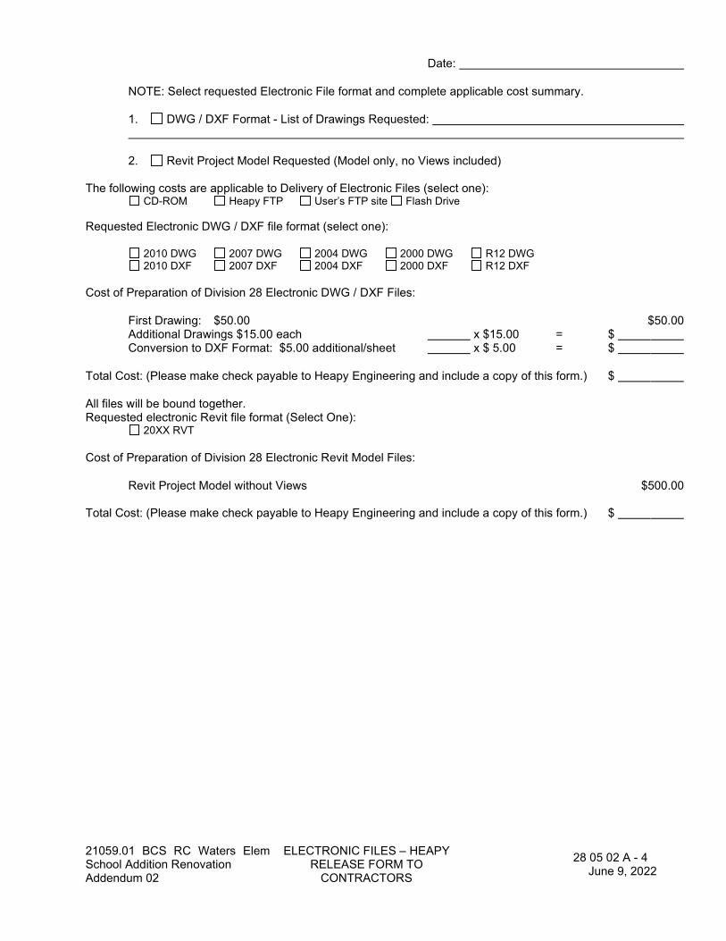
21059.01 BCS RC Waters Elem School Addition Renovation Addendum 02
ELECTRONIC FILES – HEAPY RELEASE FORM TO
CONTRACTORS
28 05 02 A - 4 June 9, 2022
Date:
NOTE: Select requested Electronic File format and complete applicable cost summary.
1. DWG / DXF Format - List of Drawings Requested:
2. Revit Project Model Requested (Model only, no Views included)
The following costs are applicable to Delivery of Electronic Files (select one): CD-ROM Heapy FTP User’s FTP site Flash Drive
Requested Electronic DWG / DXF file format (select one):
2010 DWG 2007 DWG 2004 DWG 2000 DWG R12 DWG 2010 DXF 2007 DXF 2004 DXF 2000 DXF R12 DXF
Cost of Preparation of Division 28 Electronic DWG / DXF Files:
First Drawing: $50.00 $50.00 Additional Drawings $15.00 each x $15.00 = $ Conversion to DXF Format: $5.00 additional/sheet x $ 5.00 = $
Total Cost: (Please make check payable to Heapy Engineering and include a copy of this form.) $
All files will be bound together. Requested electronic Revit file format (Select One): 20XX RVT
Cost of Preparation of Division 28 Electronic Revit Model Files:
Revit Project Model without Views $500.00 Total Cost: (Please make check payable to Heapy Engineering and include a copy of this form.) $
21059.01 BCS RC Waters Elem School Addition Renovation Addendum 02
BASIC ELECTRONIC SAFETY AND SECURITY MATERIALS
AND METHODS
28 05 04 - 1 June 9, 2022
28 05 04 BASIC ELECTRONIC SAFETY AND SECURITY MATERIALS AND METHODS
PART 1 - GENERAL
1.1 Refer to Section 26 05 50 Basic Electrical Materials and Methods which are hereby made part of Division 28 - Electronic Safety and Security.

21059.01 BCS RC Waters Elem School Addition Renovation Addendum 02
FIRESTOPPING 28 05 05 - 1
June 9, 2022
28 05 05 FIRESTOPPING
PART 1 - GENERAL
1.1 Firestopping assemblies shall be provided at penetrations of conduits, cables, cable trays and other electrical items thru fire rated floors, fire rated floor-ceiling and roof ceiling assemblies, fire rated walls and partitions and fire rated shaft walls and partitions. In addition, firestopping assemblies shall be provided at penetrations thru 0-hour rated floors. Refer to the drawings for fire rated building elements.
1.2 Firestopping assemblies shall be tested and rated in accordance with ASTM E814, E119 and listed in accordance with UL 1479, as published in the UL Fire Resistance Directory. Firestopping shall provide a fire rating equal to that of the construction being penetrated.
1.3 Firestopping materials, assemblies and installation shall conform to requirements of the OBC / Chapter 1, Section 106 and Chapter 7, Section 712 and the Authority Having Jurisdiction.
1.4 For those firestopping applications that exist for which no UL tested system is available through any manufacturer, a manufacturer’s engineering judgment derived from similar UL system designs or other tests will be submitted to local authorities having jurisdiction for their review and approval prior to installation. Engineer judgment drawings must follow requirements set forth by the International Firestop Council.
1.5 Shop drawings shall be prepared and submitted for review and approval. Submittals shall include manufacturer’s specifications and technical data of each material, documentation of U.L. firestopping assemblies and installation instructions. Submittals shall include all information required in OBC Chapter 1, Section 106 and Chapter 7, Section 712
PART 2 - PRODUCTS
2.1 Firestopping materials shall be manufactured and/or supplied by Hilti, 3M, Rectorseal-Metacaulk, Tremco, Nelson, Specified Technologies or other approved manufacturer.
2.2 Materials shall be in the form of caulk, putty, sealant, intumescent material, wrap strip, fire blocking, ceramic wool and other materials required for the UL listed assemblies. These shall be installed in conjunction with sleeves and materials for fill and damming.
2.1 Combination pre-set floor sleeve and firestopping assemblies shall be equal to STI EZ-Path.
PART 3 - EXECUTION
3.1 Installation of all materials and assemblies shall be in accordance with UL assembly drawings and the manufacturer’s instructions.
3.2 Installation shall be done by an experienced installer who is certified, licensed or otherwise qualified by the firestopping manufacturer as having the necessary training and experience.
3.3 Refer to 28 05 33 Raceway and Boxes for Electronic Safety and Security Systems for sleeve requirements and treatment of penetrations not requiring firestopping.
END OF SECTION

21059.01 BCS RC Waters Elem School Addition Renovation Addendum 02
RACEWAY AND BOXES FOR ELECTRONIC SAFETY AND
SECURITY SYSTEMS
28 05 33 - 1 June 9, 2022
28 05 33 RACEWAY AND BOXES
FOR ELECTRONIC SAFETY AND SECURITY SYSTEMS
PART 1 - GENERAL
1.1 Refer to Section 26 05 33.13 Conduit and 26 05 33.16 Boxes which are hereby made part of Division 27 - Communications.
21059.01 BCS RC Waters Elem School Addition Renovation Addendum 02
IDENTIFICATION FOR ELECTRONC SAFETY AND
SECURITY SYSTEMS
28 05 53 - 1 June 9, 2022
28 05 53 IDENTIFICATION FOR ELECTRONIC SAFETY AND SECURITY SYSTEMS
PART 1 - GENERAL
1.1 Refer to Section 26 05 53 Identification for Electrical Systems which are hereby made part of Division 28 – Electronic Safety and Security.

21059.01 BCS RC Waters Elem School Addition Renovation Addendum 02
SECURITY MANAGEMENT SYSTEM
28 13 00 - 1 June 9, 2022
28 13 00 SECURITY MANAGEMENT SYSTEM
PART 1 - GENERAL
1.1 Scope of Work
A. These specifications shall be utilized for the complete system as specified herein and as shown on the bid documents. The Security Management System shall be an extension of existing and as provided by District’s Security Vendor.
1.2 Scope of Work
A. Provide a Security Management System (SMS) which fully integrates all the functions and features specified herein for door access control and intrusion alarm and badge creation. Additionally, the SMS shall provide integration with the digital CCTV system covered under a separate specification section. Refer to system description below for required integration.
B. The scope includes all hardware, software, training and services required to provide a fully functional extension of the Owner’s existing system.
C. These specifications contained herein describe specific functional requirements of the SMS as required by the Owner. It is the intent of these specifications to detail and describe the performance of the system. The system features outlined in the specifications are deemed mandatory for the project. References to model numbers are intended only for descriptive purposes. Systems that deviate from these Performance Specifications shall be considered alternate systems.
1.3 System Description
A. The SMS shall provide for graphical based control and monitoring of local door access, elevator access and intrusion alarm within each building and centralized, graphical based control and monitoring through the owner’s LAN/WAN. The SMS shall also provide software integration with the digital CCTV system. The SMS shall consist of four basic modules:
1. The Communications and database server module. a. The server shall provide network communications (both thru the dedicated
hardwired network and the Owner’s LAN) to all remote hardware and software components of the system. The server shall provide system communications to remote control panels, administer the database and provide system programming. The SMS server shall utilize industry standard relational database management for the storage and manipulation of related data. The server shall only be required on the SMS to perform programming and administrative functions. The SMS remote components shall be capable of operating without the presence of the server once the system is programmed.
b. The relational database shall provide for central storage and management of all user records including personal text and picture information, door access privileges and system activity logs. The database shall be integrated with the owner’s HR database (PD Express) to allow sharing of personnel records between systems and to remove the need for multiple data entry. The data base sharing shall allow the HR database administrator to send appropriate information the card holder database as staff is either added or removed. The system shall be able to support in excess of 30,000 users.
c. The database system shall also store and provide industry standard reporting functions for all system activity including alarm events. System reports shall be customizable to include different fields and provide flexible search options.
21059.01 BCS RC Waters Elem School Addition Renovation Addendum 02
SECURITY MANAGEMENT SYSTEM
28 13 00 - 2 June 9, 2022
d. The card holder database shall be partitioned into various user levels. The basic level will be by building, with administrator privileges to view all levels.
e. This module shall contain the necessary Ethernet communication hardware and software for system communications through the Owner’s LAN/WAN.
f. The server shall be a rack mounted hardware appliance with appropriate software and will be located by the owner in the District N.O.C. This module shall contain the necessary Ethernet communication hardware and software for system communications through the Owner’s LAN/WAN.
2. Door access control module (ACM). a. The ACM shall control access and provide positional status at exterior doors and all
controlled doors through the use of proximity cards, proximity card readers and door sensors.
b. The ACM shall interface with the electronic door hardware to provide lock/unlock signaling based upon valid card reads, schedules, real time control from user workstation or remote pushbuttons, and programming.
c. The ACM shall consist of Request to Exit devices where shown on the drawings or as required by system operation. These devices shall consist of either motion detectors or contacts in panic hardware and shall provide alarm free exit of card reader doors without the need to de-activate the alarm system.
d. The ACM shall provide interface with handicap door operators at access control doors to prevent activation of door opener if door is in locked position. Additional interface may be required for free egress to unlock doors when the Request-To-Exit handicap opener is pressed.
e. The ACM shall interface with the elevator controllers to provide lock-out of floors/elevators based upon card holder privileges for card readers. Card readers will be installed in elevator cabs or elevator lobby as indicated on drawings.
f. Each building is provided with a handicap operators on interior and exterior main doors. The General trades package will supply the operators and pushbuttons (1exterior, 2 vestibules, 1 interior) with low voltage wiring whips left above accessible ceiling. The electrical Contractor will make all required 120V connections. The security contractor will be responsible for making all low voltage wiring connections from the handicap opener, handicap push buttons, door hardware electrified hinge (electronic latch retraction and RX switch in panic hardware), magnetic door contact switch (provided under the security scope), door hardware power supply and the SMS system door control panels for a fully functional entry. The security contractor is to coordinate the proper operation, interlocking, timing and sequencing of doors and door operators with door hardware supplier.
g. The ACM shall also provide door position annunciation for all exterior doors and through all card reader controlled doors through the use of flush frame door contacts. Real time door position annunciation shall be provided by the remote software.
h. The ACM shall provide TOD schedule and real-time control of all exterior doors equipped with Magnetic locking devices. In addition, The ACM shall integrate with the building fire alarm system to provide code required release of mag lock doors under fire alarm conditions.
i. The system shall support “double tap” features on the card readers which allow the following basic additional system functionality
1) Swap lock state
2) Timed Override of current schedule
3) Custom to be written, verify with manufacturer
j. The ACM shall provide interface and controls of electromagnetic door hold opens to close doors on TOD schedules and on Panic/duress situations. Where hold open
21059.01 BCS RC Waters Elem School Addition Renovation Addendum 02
SECURITY MANAGEMENT SYSTEM
28 13 00 - 3 June 9, 2022
doors are connected to the FA system, the ACM shall signal the FA system to release the associated doors.
k. Panic/Duress – The ACM shall provide for immediate TOD schedule override on all access doors under panic/duress alarm. In addition, the ACM shall provide immediate override of card holder privileges and restrict valid card reads to a select group of users during panic/duress alarm. ACM shall also interface with fire alarm system to drop ALL door hold opens under panic/duress alarm.
l. The ACM control software must provide a graphical floor plan of the finished building with real time interactive annunciation and control of monitored and controlled doors. The graphical floor plan shall be entered and configured as part of this contract. User interface shall provide visual indication of door position status and hot links at each door on the floor plan drawing.
m. This module shall contain remote access and control software installed on individual building workstations as directed by the Owner. These workstations, through the LAN connection, shall be able to perform access, control, monitoring and programming features. The software shall be provided with all required licensing and password protected.
n. The ACM shall provide for any combination of real time and calendar based, Time Of Day operation for all controlled doors.
3. Alarm management module (AMM) a. The AMM shall provide for the control and annunciation of alarm conditions. The
module shall accept inputs from the door access module, remote devices such as motion detectors and keypads and from other systems such as fire alarm and CCTV. The module shall include alarm reporting to off-site services, event logging with printouts and annunciation through audible devices.
b. The AMM shall consist of the hardware and software required to generate multiple alarm zones within each building. Each zone shall be capable of independently controlling input and out devices programmed to that zone regardless of physical location within the building. The system shall be able to control up to sixteen (16) alarm zones per building. Selection of alarm zones and grouping of corresponding devices shall be coordinated with Owner.
c. The AMM shall consist of door contacts for perimeter protection, and motion detectors for interior protection. The AMM shall utilize system keypads for arm/disarm locally of building intrusion alarms. The keypads shall be capable of controlling multiple zones based upon user codes. The system shall provide for the ability to assign unique arm/disarm codes to staff with codes granting user definable access to the various zones within a building.
d. The AMM shall consist of Request to Exit devices where shown on the drawings or as required by system operation. These devices shall consist of either motion detectors or contacts in panic hardware and shall provide alarm free exit of monitored doors without the need to de-activate the alarm system.
e. The AMM shall include all software programming features required to generate multiple schedules for the automatic arming and disarming of zones and individual devices. The AMM shall interface with the door position sensors and be capable of supporting temporary deactivation of door sensors upon valid card reads or “REX” devices.
f. The AMM must provide a graphical floor plan of the finished building with real time interactive annunciation and control of alarm points. The graphical floor plan shall be entered and configured as part of this contract. User interface shall provide visual indication of alarm point status and hot links at each alarm point on the floor plan drawing.
g. The AMM must provide a graphical interface on the building workstation showing real time alarm activity in the form of a scrolling alarm log screen. Alarms shall be fully customizable with name, location, directions, and priority level. The Alarm log shall provide users the ability to acknowledge and silence alarms as well as logging
21059.01 BCS RC Waters Elem School Addition Renovation Addendum 02
SECURITY MANAGEMENT SYSTEM
28 13 00 - 4 June 9, 2022
required responses to alarm events. Alarms shall include the following at a minimum: 1) Motion Detectors and door contacts activated after system is “armed” 2) Access Control Door alarms such as door forced, invalid card read 3) Propped door alarm with user definable interval for length of time open prior to
generating alarm. 4) System hardware failure 5) Loss of network connection
h. The AMM shall provide for calendar based, Time Of Day operation for all alarm monitoring devices and security zones.
i. The AMM shall include a digital dialer panel with cellular back-up. The alarm management module shall consist of a 3 year service contract with an UL listed off-site monitoring company (Hamilton currently utilizes ADT). Monitoring company shall be available from a local or toll-free telephone number. Service contract shall be included in the bid price but shall be as selected by the Owner.
j. Provide a contact closure signal to the Central Sound System, installed by others, for alarm activation. The contact closure shall be programmed to operate during the pre-alarm delay. The SMS contractor shall provide all required hardware and wiring to the Central Sound System and assist the CSS Contractor in providing a unique building wide all call chime to sound for the duration of the pre-alarm state. Once the alarm has been activated, the chime shall be discontinued.
4. Digital CCTV integrations module a. The digital CCTV integration shall be a software based integration without the
requirement for hardwiring contacts to DVR alarm input ports. b. The Digital CCTV integration shall provide for alarm interface with the CCTV system
with the following minimum features: 1) Start event based recording for alarm conditions at cameras selected to be
associated with various alarm points (motion detectors, door contacts). 2) Start event based recording for door access alarm conditions such as forced
door, invalid card read, door propped open, etc. at cameras selected to be associated with each alarm point.
3) Provide hot link to video file associated with SMS system alarm in SMS alarm event software.
c. Event based recording shall be capable of changing camera recording settings including frame rate, pre/post alarm, resolution and position (for PTZ cameras) based upon event parameters.
d. Event based recording shall cross link video files with alarm activity events to provide a single “hot link” allowing selection of an alarm event to automatically pull up any corresponding live or recorded video.
5. Badging Station Module (BSM) – a. The BSM must include all hardware required to provide photographs, images, text,
etc. onto the selected access and ID cards. Hardware shall include PC with image capture card, camera station, dual sided color badge printer, server, etc.
b. The BSM must include all software required for image capture, editing and printing including client and server modules with licenses.
c. The BSM must include the following features at a minimum; Inline Magnetic Stripe Encoding, Industry Standard Barcodes, Badge Design Mapping, Chroma Key and Ghosting (printer dependent), Dual-Sided color Badge Printer, Wanted Poster Preview and Print, Dossier Preview and Print, Batch Print, Multiple Ways to Input Images (Cameras, digital, S-video, RGB, composite, USB, Industry standard TWAIN scanner, Import of an existing graphic file) Signature capture device.
d. Provide a total of two (2) badging stations for creation of student IDs. 6. Graphical User Interface Module
a. Each user workstation shall have the ability to provide graphical based, real time alarm management, access control monitoring, door position monitoring and CCTV live/recorded video viewing.

21059.01 BCS RC Waters Elem School Addition Renovation Addendum 02
SECURITY MANAGEMENT SYSTEM
28 13 00 - 5 June 9, 2022
b. Alarm management shall provide for both graphical building floor plans with interactive user icons for all alarm points, and an alarm log screen.
c. Electronic door management shall provide for both a menu tree structure listing all available controlled doors installed throughout and a graphical building floor plan for all buildings with user interactive icons for all controlled doors allowing real time control of door lock/unlock status.
d. Video management shall provide for both a menu tree structure listing all available video cameras installed throughout and a graphical building floor plan for all buildings with user interactive icons for all cameras allowing instant access to live video.
e. The graphical user interface shall be provided with content restrictions based upon user log-in and authorization levels. Typical restrictions would include the ability to prevent users from making system programming changes, viewing certain cameras, unlocking specified doors, etc.
B. The system shall consist of a user workstation in each building for real time control and monitoring of controlled doors/elevators, alarm devices (door contacts, motion detectors, keypads), and viewing of live and recorded video from local cameras. The system shall support and be licensed for a minimum of 32 concurrently operating user workstations.
C. The Contractor shall be responsible for developing and programming a total system sequence of operation for the system to include at a minimum:
1. Input of all student and staff personal records into the card holder database (1000 staff with door privileges, 9300 students with ID cards only)
2. Creation of door access groups for all buildings. Assigning door access groups to access card holders.
3. Creation of alarm codes for all staff including building and zone privileges for each code. 4. Creation of multiple Time Of Day schedules for all controlled doors, alarm devices and
security zones to account for various modes of operation (normal, holiday, snow day, in-service day, etc.) in each building.
5. Creation of security zones within each building including assigning associated alarm devices to respective zones.
D. Alarm dialer codes and telephone numbers to communicate with Central Station.
1.4 Quality Assurance
A. All system components shall be UL listed.
B. Installation shall be in compliance with the National Electric Code and all other applicable codes. The system shall be in compliance withal FCC Rules and Regulations.
C. All equipment described herein shall be the product of a manufacturer of established reputation and experience, who shall have produced similar equipment for a period of at least 2 years and who shall be able to refer to similar installations within a 75 mile radius now rendering satisfactory service.
D. The manufacturer and their local agent shall show satisfactory evidence upon request that they maintain a fully equipped service center capable of furnishing adequate inspection and service to the equipment including standard replacement parts. The manufacturer and /or agent shall be prepared to offer a service contract for the maintenance of the system after the warranty period.
E. To establish continuity in the manufacturer, systems components shall be the standard product of one manufacturer. Further, an effort shall be made to establish common sources

21059.01 BCS RC Waters Elem School Addition Renovation Addendum 02
SECURITY MANAGEMENT SYSTEM
28 13 00 - 6 June 9, 2022
for equipment of all systems. The manufacturer will have a minimum of five (5) years’ experience in the manufacture of progressive products specified.
F. All materials furnished under this contract shall be new, of highest quality and shall be of a regularly manufactured line, currently in production at the time of installation.
G. All material furnished under this contract shall meet or exceed minimum performance and operational requirements as established by the system vendors for the configurations being implemented for this project.
1.5 Contractor Qualifications
A. The Security Management System shall be furnished, installed and programmed by a contractor who meets all the requirements listed herein. It shall not be acceptable for the SMS contractor to utilize a sub-contractor for any portion of the work, unless the sub-contractor has been approved in writing by the Engineer based upon adherence to the qualifications listed herein.
B. The Contractor shall maintain a fully equipped, factory certified service organization capable of providing full maintenance and service of the installed system within 24 hours. This facility shall be available for inspection by the Engineer.
C. The Contractor shall employ factory trained service personnel for the service and maintenance of the system.
D. The Contractor shall have had a minimum of 1 year experience with the specified SMS. This experience shall include having completed a minimum of 2 installations in the past 24 months of similar size and scope. The Contractor shall provide references and contact information for the project sites in which the qualifying installations occurred.
1.6 Shop Drawings – The submittals shall consist of the following information:
A. Job specific system block diagram indicating the actual hardware required for the project including part numbers and interconnecting wiring requirements.
B. Details of interconnection with CCTV system.
C. Complete and comprehensive Equipment Catalog Specification Sheets of each component provided, job specific.
D. 30x42 floor plans at a scale of not less than 1/8 inches=1 feet-0 inches showing location of all items of equipment. Drawings shall also indicate each location where 120 power is required.
E. Scale elevation of all racks including configuration of equipment within racks and interconnection diagrams.
F. Software Data: The data package shall consist of descriptions of the operation and capability of system and application software as specified. This shall also include licensing information where applicable.
G. Submittals that do not contain all the above information will be rejected.
1.7 Related Work by Others

21059.01 BCS RC Waters Elem School Addition Renovation Addendum 02
SECURITY MANAGEMENT SYSTEM
28 13 00 - 7 June 9, 2022
A. The door hardware and associated power supplies are being provided under the General trades Contract. The electrical branch circuitry, conduit and box rough-ins are being provided under the Electrical trades package.
1.8 Related Sections
A. 28 23 01 – Video Surveillance - IP
PART 2 - PRODUCTS
2.1 Product Equivalency
A. Where products are listed with multiple manufacturers, these manufacturers will be approved as equals if all specified features are provided. Any equipment not specifically approved in writing prior to the bid date will not be considered regardless of qualifications. Failure to provide the “precise functional equivalent" shall result in the removal of the alternate equipment at the Contractor’s expense.
B. Different manufacturers may require various options, accessories, converters, patch cables, etc. to perform the specified features and functions. Therefore, all material and/or equipment necessary for proper operation of the system shall be deemed part of these specifications.
C. The SMS shall be a regularly manufactured system offered by a single manufacturer/source as an integrated system.
D. Contractors shall submit reference letter with information regarding current installations utilizing the listed manufacturer pairings along with contact information at each installation site. Reference letter shall include brief summary of system scope for both CCTV and SMS and level of integration being utilized.
E. Final approval of systems listed above shall be at the discretion of the owner/engineer pending review of system reference information and back-up documentation. Upon request by Owner/Engineer, contractor and/or manufacturer may provide on-site product demonstration to validate system ability to meet specified level of integration.
2.2 General
A. The main control panel and all door control panels shall be backed up by internal batteries or provided with UPS units as required to provide a minimum of 1 hour operation upon loss of building power. Refer to additional requirements for back-up of SMS server PC.
2.3 Communications, Database and Control Server
A. All software and PC workstations provided under this project required to operate on or through the Owner’s LAN, shall be compatible and provided with the current version of the Owner’s Network Operating System Client. Software and hardware incompatibility issues with equipment and software provided under this project and the Owner’s Network Operating System Client shall be considered the responsibility of this contract and shall be resolved to the Owner’s satisfaction to provide a stable and consistent operating environment.
B. Proximity Cards
1. Proximity card which support photo identification technologies. Card shall feature a graphics quality surface optimized for Photo ID printing.

21059.01 BCS RC Waters Elem School Addition Renovation Addendum 02
SECURITY MANAGEMENT SYSTEM
28 13 00 - 8 June 9, 2022
2. Card shall be a composite polyester/PVC construction for more demanding high wear and tear environments and be provided with pre-punched horizontal/vertical slot as coordinated with owner.
3. Provide a total of 250 proximity cards for each building and program for personnel as directed by the Owner.
2.4 Access Control Module
A. Door Control Panel(s) shall consist of network communications via Ethernet based IP loop and shall contain all electronics and on-board memory to provide door access and interface with card readers, door position sensors, electronic door hardware, auxiliary I/O points, and the local fire alarm system in the event of loss of server communications. The panel(s) shall provide access control, alarm monitoring, and time zone control for both access and egress of selected areas. The panel shall have the capability for system expansion. Panels shall support both centralized and distributed locations with IP and PoE to distributed locations for panel connectivity and power.
B. Credential Readers – Provide readers as indicated on plans. Readers shall either mount to gang wall box or to door mullion as indicated on drawings. Readers shall employ proximity, NFC, Bluetooth, biometric, etc. as specified herein.
C. Door position sensors – Recessed mounted door magnetic switch contacts to function as door position sensors and alarm points. Refer to drawings for locations. Utilize sensors to provide door position status during occupied hours as required by Owner’s programming and alarm points when so programmed or required by the Owner’s sequence of operation.
D. Electronic door hardware – Provide wiring and controls to electronic door hardware to remotely lock/unlock selected doors in real time via the software GUI, through local credential readers, through TOD schedules, interface with intercom system, or remote push button devices. System shall provide the Owner with the ability to remotely control doors from the remote access workstations, head end server, associated credential readers, request-to-exit devices, intercom system and the fire alarm system. Electronic door hardware with operating power supplies are supplied by the General Trades Contract with wiring pig tails. Electronic hardware is being installed in the door frames by others. This contract shall be responsible for low voltage door hardware power supplies, connecting all low voltage wiring from door hardware and power supplies to the access control system for a complete, functional and operating system.
E. Handicap Operator Doors – Provide wiring and interface with local secured door electronic hardware to interlock operator with Electronic Access Control System.
F. Elevators – Credential readers shall be installed in the elevator lobbies/elevator cabs and elevator control panels installed in the elevator machine rooms. Credential readers shall be programmed for restriction on elevator use based upon card holder privileges. Coordinate tie in with elevator controller.
G. Electromagnetic door hold opens – Provide controls to electromagnetic door hold open devices to release selected doors through real time (via the GUI interface), TOD schedules, or in panic/duress operation. Devices connected to the FA system shall be controlled via signaling from the SMS to the FA system. Electronic hardware is being installed at the door by others. This contract shall be responsible for connecting all wiring from door hold open hardware and power supplies to the access control system for a complete, functional and operating system.
H. Provide push button/switch units as indicated on plans to provide remote unlock of selected access control doors.

21059.01 BCS RC Waters Elem School Addition Renovation Addendum 02
SECURITY MANAGEMENT SYSTEM
28 13 00 - 9 June 9, 2022
I. Request to Exit Devices (alarm shunt) – Provide REX devices such as motion detectors or contacts in push bar panic hardware to provide alarm free exit of monitored doors during system operation. REX devices shall be installed, powered, wired and programmed as part of this contract.
J. Request to Exit Devices (door unlock) – Provide REX devices such as motion detectors, contacts in push bar panic hardware, or wall mount button stations to provide alarm free exit of monitored doors during system operation. REX devices shall be installed, powered, wired and programmed as part of this contract.
K. Provide wall mounted panic/duress button with locking/reset feature as indicated on plans. Duress buttons shall initiate panic/duress condition in SMS as follows:
1. The ACM shall provide for immediate TOD schedule override on all access doors to lock doors.
2. The ACM shall provide immediate override of card holder privileges and restrict valid card reads to a select group of users.
3. The ACM shall also interface with fire alarm system to drop ALL door hold opens. 4. The ACM shall signal to the Central Monitoring Agency the Panic/Duress alarm condition. 5. Upon de-activation of panic and re-set of panic button, system shall return to currently
scheduled operation.
L. Provide battery back-up for door control panels to provide 1 hour operation.
M. Contractor shall include all necessary wire, cable and accessories for a complete working system.
2.5 Digital CCTV Integration Module – Software
A. Provide software integration with CCTV system DVR units. The Digital CCTV integration shall provide for alarm interface with the CCTV system with the following minimum features:
1. Start event based recording for alarm conditions at cameras selected to be associated with each alarm point.
2. Start event based recording for door access alarm conditions such as forced door, door propped open, etc. at cameras selected to be associated with each alarm point.
3. Event based recording shall be capable of changing camera recording settings including frame rate, pre/post alarm, resolution and position (for PTZ cameras) based upon event parameters.
B. Event based recording shall cross link video files with alarm activity events to provide a single “hot link” allowing selection of an alarm event to automatically pull up any corresponding video.
C. Alarm view graphical floor plans shall have user interactive icons for cameras to quickly access live video.
2.6 Badging Station Module
A. The BSM shall be a complete and operational badging station including high resolution color camera with tripod, single sided color printer compatible with proximity access cards and ID cards, Image capture and editing PC, software modules and clients required to create access control and ID badges, and all other associated hardware and software. Refer to section 2.3 above for workstation specs.

21059.01 BCS RC Waters Elem School Addition Renovation Addendum 02
SECURITY MANAGEMENT SYSTEM
28 13 00 - 10 June 9, 2022
B. Coordinate badging requirements including templates, layouts, colors, badge design, etc. with Owner and provide operational badging station at location as identified with Owner. Each station shall include all programming as required to provide an operational system.
C. Provide a total of two (2) badging stations for creation of student IDs.
2.7 Audio/Video Door Intercom
A. Door intercom shall consist of master stations and sub stations as indicated on plans. The system shall utilize a master controller which includes the telephone system gateway.
B. The master station(s) shall be telephone handsets with 2-way audio and real-time video capability to all sub stations. The master station shall also be able to initiate system signals that allow momentary unlock of assigned access control doors.
C. The sub stations shall be 2 way voice stations with fixed color camera and handsfree speaker and call button. Exterior stations shall be weatherproof and vandal resistant.
D. Intercom Controller – Provide Main control unit to interface between sub stations, master stations, and electronic door hardware. In addition, controller must provide access to building IP based telephone system to allow un-answered calls to roll-over from intercom master stations to user selected building telephone system extensions. Telephone system will then allow 2-way audio to remote door station and remote unlock of selected doors via pushbuttons on the telephone system handset.
E. Operation
1. When a call is placed from a sub station, the master station shall produce both audible and visual annunciation of call as well as bring up live video from the call. The master station shall display a unique identifier in the form of “caller ID” to associate the correct sub station.
2. When the call is answered, the sub station shall be placed in full duplex, handsfree operation.
3. The master station shall be able to initiate door lock release during the active intercom call.
4. If the remote door station does not receive an answer within a user definable number of rings, the system will automatically forward the call to a user selected telephone system handset.
F. Equal systems by Valcom, Viking, Stentofon or Aiphone.
2.8 System UPS
A. The SMS server shall be backed up by an extended run time UPS unit providing a minimum of 1 hour of battery time. The UPS shall be rack mounted with the SMS server PC and shall meet or exceed the following specifications:
1. Serial port interface using RS-232 2. Input voltage rang (92V-142V) 3. Input frequency range (50/60 Hz +/- 3 Hz (auto sensing) 4. Batteries
a. Maintenance free sealed lead acid
21059.01 BCS RC Waters Elem School Addition Renovation Addendum 02
SECURITY MANAGEMENT SYSTEM
28 13 00 - 11 June 9, 2022
b. Hot swappable c. Intelligent battery management d. Surge protection – 480 joules e. Filtering – UL 1449 f. UL listed
5. APC #SU1400RMXL3U or equal by TrippLite or Liebert, rack mounted.
2.9 Cable Management System
B. Provide pre-manufactured cable supports. Cable supports shall be secured to building structure through threaded rod, beam clamps or other UL approved supports as required by site conditions. Components shall provide a minimum cable support point spacing of 48 inches.
C. Cable management devices must be sized to accommodate 100 percent spare capacity of the final installed cable base.
D. Cable management system shall be secured to building structure utilizing manufactured approved methods and hardware.
E. Cable management system support components shall be designed with wide support surfaces that do not cause cables to be bent, crushed or otherwise deformed when installed within component loading parameters. Cable management system shall meet UL standards and be UL labeled. Utilizing elements of the building’s structure such as beams, joists, etc. to hang cable from will not be acceptable.
F. Bridle rings shall not be acceptable.
G. Manufactured by Caddy, Mineralac or B-Line.
2.10 Contractor shall include all necessary wire, cable and accessories for a complete working system.
PART 3 - INSTALLATION
3.1 General Installation
A. Install systems in accordance with UL, NEC and all other applicable codes. Install system to comply with drawings and final shop drawings in compliance with manufacturer instructions. Provide all required hardware and labor for rack mounting of head-end system components.
B. Refer to plans for locations and quantities of equipment. Equipment locations shown on plans will be required to be field coordinated to ensure proper system operation.
C. No items of equipment shall be installed in such a manner as to void or reduce the proper operating characteristics of individual components or of the system. Devices such as motion detectors, audio detectors, glass break sensors, etc. shall be installed following the manufacturer’s recommendations.
D. Perform all work under the on-site supervision of a factory authorized trained technician. It shall be the responsibility of the technician to check, inspect and adjust this installation to the engineer’s and Owner approval. A CSR of the installing contractor or manufacturer shall train the Owner’s personnel on the proper operation and maintenance of the equipment. Perform all work in conjunction with this installation in accordance with good engineering practices as established by NEC.
21059.01 BCS RC Waters Elem School Addition Renovation Addendum 02
SECURITY MANAGEMENT SYSTEM
28 13 00 - 12 June 9, 2022
3.2 Wiring Installation
A. All wiring between devices shall be run open wired above accessible ceilings. Where existing cable management systems are in place and there is adequate capacity to install the SMS wiring, the contractor may utilize these pathways providing they have coordinated with all other wiring contractor on site.
B. Where pathways do not exist for SMS wiring, this contract shall be responsible for providing all required cable management systems such as sleeves, conduits, J-hooks, etc. to support communications cabling to meet building codes and manufacturer’s recommendations.
C. All cabling installed in ceiling spaces that are used for air distribution plenums shall be UL plenum rated.
D. This contract shall be responsible for furnishing and installing all required cabling between components to form a complete and operational system meeting all the requirements of this specifications.
E. The SMS contractor shall be responsible for interconnection and signaling including all wiring and terminations at both ends for the following auxiliary systems
1. Fire Alarm – for control of doors during fire alarm, and for release of door hold opens connected directly to the FA system
2. Paging System – Connection to the building wide paging system for pre-alarm all-call tone/announcement
3. Building automation System – Connection to the building automation system for signaling for morning entry (first valid swipe and alarm de-activation) and evening vacancy (alarm activation).
4. Elevator – Connection to the elevator controller for card reader access to the elevator. 5. Intercom – Connection to the intercom system I/) panel for signaling of electronic door
locks via pushbutton operation of intercom master stations. 6. IP CCTV – Connection to the IP CCTV system for video file links and live video icons on
the graphical floor plans.
3.3 Telecommunications Rooms
A. The lay-out of the telecommunications rooms as depicted on the drawings shall be utilized as a general guide for bidding purposes. The final room layout shall be carefully coordinated with input from the Owner and from other trades with equipment and/or cabinets to be placed in the room. Final configuration of telecom rooms shall be submitted to Engineer as a coordination drawing with information from all other trades occupying the same room for review prior to permanent mounting of equipment or termination of cabling.
B. Coordinate lay-out of telecom rooms to avoid placing telecommunications equipment and cabinets under water piping (other than sprinkler heads) or HVAC units.
C. Coordinate lay-out of telecom rooms with electrical plans and locations of electrical outlets.
D. Lay-out of telecommunications equipment cabinets and racks shall provide a minimum of 36 inch isle in front and behind equipment racks and cabinets which is clear of obstructions or equipment protrusions.
E. Coordinate rack locations and orientation to maintain required clearances including any equipment depths that may have to be accounted for. Some equipment, such as UPS units may have special mounting requirements that need additional coordination.

21059.01 BCS RC Waters Elem School Addition Renovation Addendum 02
SECURITY MANAGEMENT SYSTEM
28 13 00 - 13 June 9, 2022
3.4 Grounding
A. The installing contractor shall be responsible for ensuring the grounding integrity of all installed equipment to eliminate the potential for equipment or personnel hazards due to improperly or inadequately grounded systems.
B. All grounding and bonding shall be in conformance with the National Electric Code, article 250 and as recommended by EIA/TIA-607.
C. The Division 26 Contractor has provided 120V branch circuitry for use by the SMS system contractor. The branch circuitry is run with a dedicated equipment grounding conductor which shall be utilized by the SMS system equipment. In no case shall the SMS system installation compromise the integrity of the Building Electrical Grounding System.
3.5 Programming
A. It is the Contractor’s responsibility to program the system in this section according to the Owner’s wishes. This involves day and night restrictions, time schedules, building zoning, access control schedules, sequence of operation, etc.
B. The Contractor shall meet with the Owner and/or Engineer and reach agreement on the programming. This programming agreement shall then be written out in detail and forwarded to the Engineer for approval.
C. After approval is granted, proceed with final programming. The programming shall include the following at a minimum:
1. Input of all student and staff personal records into the card holder database 2. Creation of door and elevator access groups. Assigning door and elevator access groups
to access card holders. 3. Creation of alarm codes in all buildings for all staff including building and zone privileges
for each code. 4. Creation of multiple Time Of Day schedules for all controlled doors, alarm devices and
security zones to account for various modes of operation (normal, holiday, snow day, in-service day, etc.) in all buildings.
5. Creation of security zones within each building including assigning associated alarm devices to respective zones and creation of arm/disarm codes for each zone.
6. Software interface with CCTV system for camera icons on the Graphical floor plans, TOD operations and alarm modes.
7. Software interface with FA system for release of door hold opens and for release of door locks on fire alarm
8. Software interface with building paging system to initiate pre-alarm all-call.
D. Alarm dialer codes and numbers to communicate with Central Station.
3.6 Identification/Labeling
A. Contractor shall identify all major items of equipment and tag all cables with permanent type markers to denote equipment served. Cables shall be tagged at both ends and at each point where the cable is administered.
B. All labeling and recording shall be approved by the Owner and the Engineer prior to application.
3.7 Testing

21059.01 BCS RC Waters Elem School Addition Renovation Addendum 02
SECURITY MANAGEMENT SYSTEM
28 13 00 - 14 June 9, 2022
A. The Contractor shall provide all personnel, equipment, instrumentation, and supplies necessary to perform all site testing. The Owner will witness all performance verification. Original copies of all data produced during performance verification shall be turned over to the Owner at the conclusion of testing prior to final approval.
B. The field testing shall as a minimum include:
1. Verification that alarm points are received, annunciated properly and transmitted through the central monitoring station.
2. Verification that all motion detectors have the proper coverage patterns and that false alarms are not being generated due to motion coverage patterns into adjacent areas.
3. Verification that all user input and control features are accessible at each keypad and operators control station.
4. Verification that the final system programming including schedules and sequence of operation are performing as expected.
5. Verification that access control features including door control and door position sensing are operating properly and as required by the Owner and as established during the programming phase.
C. The Contractor shall deliver a report describing results of functional tests, diagnostics, and calibrations including written certification to the Owner that the installed complete system has been calibrated, tested, and is ready to begin performance verification testing. The report shall also include a copy of the approved performance verification test procedure.
D. Performance Verification Test: The Contractor shall demonstrate that the completed SMS complies with the contract requirements. Using approved test procedures, all physical and functional requirements of the project shall be demonstrated and shown. The performance verification test, as specified, shall not be started until receipt by the Contractor of written permission from the Owner, based on the Contractor's written report. This shall include certification of successful completion of Contractor Field Testing as specified in paragraph "Contractor's Field Testing," and upon successful completion of training as specified. The Owner may terminate testing at any time when the system fails to perform as specified.
3.8 System Start-Up Requirements
A. The equipment supplier shall provide system integration, set-up and start-up assistance to the Installing Contractor. The proposal shall include complete technical on-site assistance for these activities as required for this system’s size and complexity. After completion of the installation, the supplier shall commission the system and request an initial acceptance test by the Owner and Engineer. A final acceptance test shall then be scheduled after correcting any system deficiencies or functionality issues that are determined in the initial test. Provide training, by a system certified trainer, at the project site as coordinated with the Owner and Engineer. The training shall include the following elements:
1. Start-up shall include a complete working demonstration of the SMS. 2. Demonstrate purpose, adjustment, operation and maintenance of the system including
each component and control. 3. Review binder containing instructions and equipment and systems data. 4. Technical training sessions, which shall include hands-on training, accompanied by full
system documentation and system as-built drawings. 5. Training shall include any documentation and hands-on exercises necessary to enable
operations personnel to assume full operating responsibility for the SMS after completion of the training period.
6. Provide a manufacturer’s “Certificate of Completion” that is signed, dated and documented for each trainee.
7. The SMS manufacturer shall have available technical support for the Owner.

21059.01 BCS RC Waters Elem School Addition Renovation Addendum 02
SECURITY MANAGEMENT SYSTEM
28 13 00 - 15 June 9, 2022
B. Division 28 Contractor shall have the total single point of contact responsibility for all aspects of the SMS implementation, including equipment supply, integration, customization, start-up and on-going systems support.
C. Division 28 Contractor shall employ a service technician to the Cincinnati/Hamilton area that is specially trained and certified to modify and repair the SMS system and who specializes in SMS and Security system integration.
3.9 Training Requirements
A. Provide the Owner with a minimum of 24 hours of training for each building and an additional 24 hours of training for personnel designed to make all users familiar with the full and complete operation of the system. All training shall be executed by factory trained and certified personnel. Provide documentation of qualifications prior to training.
B. The training periods shall be scheduled with the Owner after the successful completion of the system. Training on a demonstration system will not be accepted.
C. Training shall be provided to cover three general classes of users
1. Monitoring/control only end user – This user should be able to access the system for monitoring and control of local equipment only. Provide this level at each building.
2. Local Administrator end user – This user should be able to perform all functions of the monitoring/control end user and be able to perform local programming features such as TOD schedule changes. Provide this level at each building.
3. Administrator end user – This user should be able to perform all functions of the Local Administrator end user and be able to perform all global programming, maintenance, reporting, database management, etc. to be fully capable of managing all aspects of system operation. Provide this level at the NOC only.
D. Provide all training and utilize specified manuals and record documentation. All training shall be provided at the project site and coordinated with the Owner.
E. Training shall include multiple four-hour sessions encompassing all instructions required for system operation. Provide operators manuals and user guides with training. Provide follow up training after initial training.
F. Training shall utilize the equipment provided at the project site. Coordinate use, time and availability of equipment with the Owner.
G. Demonstrate adjustment, operation and maintenance of the system including each component and control.
H. Contractor shall provide a follow-up site inspection / training refresher to the Owner 1 month, 3 months and 6 months after final acceptance to verify system is operating correctly within programmed parameters and to review operational and training with Owner personnel.
I. All training shall be video-taped and stored in digital format for the Owner’s future use. Contractor responsible for providing required video recording and digital encoding equipment.
3.10 System Acceptance Requirements
A. The contractor shall demonstrate proper operation of all aspects of the system to the Owner’s representative.

21059.01 BCS RC Waters Elem School Addition Renovation Addendum 02
SECURITY MANAGEMENT SYSTEM
28 13 00 - 16 June 9, 2022
3.11 Warranty
A. Warrant all workmanship, equipment, material and software entering into this contract for a period of three (3) years from date of final acceptance or date of beneficial use, as agreed to between Contractor and Architect or Construction Manager. Any materials or equipment proving to be defective during the warranty period shall be made good without expense to the Owner. Provide a statement of this warranty with the O & M Manuals.
B. Make available a service contract offering continuing factory authorized service of this system after the initial warranty period. Provide estimated cost of this service contract within the proposal.
C. Contractor shall be responsible to provide service during normal working hours within (8) hours after notification by the Owner for normal service or within (2) hours for emergency service. Emergency service is defined as the loss of any system component inhibiting access to the system operation, or the loss of the main server.
D. If equipment cannot be repaired with 24 hours of service visit, the Contractor shall provide “loaner” equipment to the Owner at no charge.
E. Proper identification is required and must be visible while on-site for warranty/service calls. Provide notification of completion to the Owner prior to departing the site.
3.12 O&M Manuals
A. Copies of all approved shop drawings with the Engineer’s stamp.
B. Owner’s manuals for every item of equipment when available from the manufacturer. These shall be the technical manuals provided by the manufacturer and shall not consist of generic sales brochures. Technical manuals shall provide complete specifications for the equipment as well as complete operating, maintenance, troubleshooting and product repair/replacement information. Where available only in electronic format, the contractor may provide a CD with electronic versions of Owner’s manuals. CDs containing electronic versions of Owner’s manuals must contain the proper software viewers for each document type.
1. Security System Component Manuals a. Keypads b. Alarm Panel c. Dialer Panel d. Motion Detectors e. Door Contacts
2. Access Control System Component Manuals a. Card readers b. System Software c. Door Control Panels d. Badging Station
C. Technology drawings updated with final as-Built information. This shall be in the form of a complete set of Technology drawings with as-built information indicated in colored pen based upon actual field conditions.
D. System schematic and block diagrams for every system updated with final as-built information. These drawings shall define the exact arrangement of each system including wiring configuration, device locations and cable types.
E. Rack elevations for all systems with rack mounted equipment.
21059.01 BCS RC Waters Elem School Addition Renovation Addendum 02
SECURITY MANAGEMENT SYSTEM
28 13 00 - 17 June 9, 2022
F. System Operating Instructions: Provide a clear and concise description of operation which gives, in detail, the information required to properly operate the equipment and system.
G. Warranty: Provide statement of warranty with O&M manuals.
PART 4 - UNIT PRICES
4.1 Unit Price Schedule
A. The Contractor(s) shall provide a Unit Price for the following items listed in this document.
1. Access control software. 2. Prox. card. 3. Prox. reader (installed w/cabling to door controller). 4. 2-door controller panel. 5. Keypad (installed w/cabling to door controller). 6. Alarm input module. 7. Alarm output module. 8. Wall / ceiling mounted motion sensor (installed w/wiring to alarm input module). 9. Badging station with camera, printer and PC.
B. These unit prices will be used to add or deduct items.
END OF SECTION

21059.01 BCS RC Waters Elem School Addition Renovation Addendum 02
SECURITY MANAGEMENT SYSTEM
28 13 00 - 18 June 9, 2022
THIS PAGE LEFT INTENTIONALLY BLANK

21059.01 BCS RC Waters Elem School Addition Renovation Addendum 02
VIDEO SURVEILLANCE - IP 28 23 01 - 1
June 9, 2022
28 23 01 VIDEO SURVEILLANCE - IP
PART 1 - GENERAL
1.1 General
A. These specifications shall be utilized for the complete system as specified herein and as shown on the bid documents. This system shall be an extension of the existing Digital Watchdog Spectrum system.
1.2 Scope of Work
A. These Specifications contained herein describe specific functional requirements of the CCTV system. It is not the intent of these specifications to detail and describe the exact performance of the system. The system features outlined in the Specifications are deemed mandatory for the project. References to model numbers are intended only for descriptive purposes. Systems that deviate from these Performance Specifications shall be considered alternate systems.
B. IP based video surveillance supporting a single building/single site.
1. The system shall provide a true client-server architecture enabling the total system to appear as a single logical device regardless of the number of cameras or individual NVS/NVR units that are utilized across either the LAN or WAN. System shall be Single Site, Multiple Site Enterprise Class, Multiple Site Global Class.
C. Interior Camera System - System consists of multiple IP based cameras with specified housings, mounting, lenses, features, etc. throughout the building interior as indicated on the drawings and as specified herein.
D. Exterior Camera System - System consists of multiple IP based cameras with specified housings, mounting, lenses, local power supplies, features, etc. around the perimeter of the building and throughout the project site as indicated on the drawings and as specified herein.
1. Free standing camera mounting pole, equipment enclosures, and fiber-optic transmission systems.
E. Video Management - Equipment and software to process video from all cameras and provide control/distribution as required for storage, archive, preview, and live monitoring of all video files and streams.
F. Video Recording - Equipment and software to receive, store and archive the network video from all cameras as indicated on the drawings and as specified herein.
G. Video Clients – Equipment and software to provide direct, real-time, GUI based access to live and recorded video.
H. Video Monitoring – Equipment and software to provide reception, decoding and display of real-time encoded network video.
I. Network Electronics – Provided under section 27 21 00.
J. Network Camera Cabling
1. Data/Video Provided under section 27 15 13
21059.01 BCS RC Waters Elem School Addition Renovation Addendum 02
VIDEO SURVEILLANCE - IP 28 23 01 - 2
June 9, 2022
2. Low voltage power – Provided under this section
K. Equipment Rack – Provided under section 27 11 00
L. System Integration – Refer to section 28 11 00 for integration of the Video Surveillance systems with other systems (e.g. Access Control, Intrusion Alarm, Building Automation, etc.)
M. Software Support – Project to include a minimum 1year software support which will include complete software/license upgrades within the timeframe of the support and 24/7 tech support.
1.3 Quality Assurance
A. All system components shall be UL listed.
B. Installation shall be in compliance with the National Electric Code and all other applicable codes. The system shall be in compliance withal FCC Rules and Regulations.
C. All equipment described herein shall be the product of a manufacturer of established reputation and experience, who shall have produced similar equipment for a period of at least 2 years and who shall be able to refer to similar installations within a 75 mile radius now rendering satisfactory service.
D. The manufacturer and their local agent shall show satisfactory evidence upon request that they maintain a fully equipped service center capable of furnishing adequate inspection and service to the equipment including standard replacement parts. The manufacturer and /or agent shall be prepared to offer a service contract for the maintenance of the system after the warranty period.
E. To establish continuity in the manufacturer, like systems components (e.g. all cameras) shall be the standard product of one manufacturer. The manufacturer will have a minimum of two (2) years’ experience in the manufacture of products specified.
F. All materials furnished under this contract shall be new, of highest quality and shall be of a regularly manufactured line, currently in production at the time of installation.
G. All material furnished under this contract shall meet or exceed minimum performance and operational requirements as established by the system vendors for the configurations being implemented for this project.
1.4 Contractor Qualifications
A. The Closed Circuit Television System shall be furnished, installed and programmed by a contractor who meets all the requirements listed herein. It shall not be acceptable for the CCTV contractor to utilize a sub-contractor for any portion of the work, unless the sub-contractor has been approved in writing by the Engineer based upon adherence to the qualifications listed herein.
B. The Contractor shall maintain a fully equipped, factory certified service organization capable of providing full maintenance and service of the installed system within 24 hours. This facility shall be available for inspection by the Engineer.
C. The Contractor shall employ factory trained service personnel for the service and maintenance of the system.

21059.01 BCS RC Waters Elem School Addition Renovation Addendum 02
VIDEO SURVEILLANCE - IP 28 23 01 - 3
June 9, 2022
D. The Contractor shall have had a minimum of 1 year experience with the specified CCTV system. This experience shall include having completed a minimum of 2 installations in the past 12 months of similar size and scope. The Contractor shall provide references and contact information for the project sites in which the qualifying installations occurred.
1.5 Shop Drawings - Submit shop drawings including product data sheets and wiring diagrams per requirements in the General Conditions including the following:
A. A complete list of materials with model and part numbers and references to the Part 2 specification paragraph numbers.
B. Manufacturers Data Sheets of all products and cabling, specific to the project. Data sheets shall show the exact parts, with model numbers and options as required and clearly identified.
C. Qualifications
1. A statement of contractor’s qualifications to verify compliance with other provisions within the specifications, unless the contractor has been pre-approved.
D. Job specific wiring diagrams.
1. This indicates a block diagram that shows all major items of equipment required for the contract project and the actual interconnection that will be installed.
2. Details of interconnection with other systems. Refer to section 28 11 00.
E. Supplier shall provide rack elevations showing the configuration of all rack mounted equipment including detailed interconnection diagrams between equipment
F. 30x42 floor plans at a scale of not less than 1/8 inch =1 foot-0 inches showing the location of all items of equipment. Drawings shall also indicate each location where electrical power is required, and the specific configuration of that power connection (voltage, plug type, mounting height, etc.)
G. Software data – The data package shall consist of manufacturer’s data sheets of all system and application software being provided with sufficient information to verify that all specified features and functions are being addressed.
H. Submittals that do not contain all the required information will be REJECTED unless prior approval for partial submittals has been approved.
PART 2 - PRODUCTS
2.1 Product Equivalency
A. Where products are listed with multiple manufacturers, these manufacturers will be approved as equals if all specified features are provided. Any equipment not specifically approved in writing prior to the bid date will not be considered regardless of qualifications. Failure to provide the "precise functional equivalent" shall result in the removal of the alternate equipment at the Contractor’s expense.
B. Different manufacturers may require various options, accessories, converters, patch cables, etc. to perform the specified features and functions. Therefore, all material and/or equipment necessary for proper operation of the system shall be deemed part of these specifications.

21059.01 BCS RC Waters Elem School Addition Renovation Addendum 02
VIDEO SURVEILLANCE - IP 28 23 01 - 4
June 9, 2022
C. This specification is intended to establish a carefully planned minimum level of quality and performance for all components, and will be rigorously enforced by Owner. Acceptable manufacturers of components described herein are listed within the specific product section.
D. The requirements for this specification require the cameras and video management platforms to be a common manufacturer.
2.2 Cameras
A. The following sub-paragraphs define the basic camera/lens/housing types and minimum performance specifications that must be met by the selected products. The contract documents indicate which of these features/functions/housings/etc. must be included with each specific camera.
B. IP based, IPv6 compliant, Cameras shall be Open Network Video Interface Forum (ONVIF) compliant: 1. Profile C - For IP-based basic access control, Site information and configuration, Event
and alarm management, , Door access control.
C. Environment
1. Exterior Domes – Housing shall be IP66/outdoor rated. Housings shall utilize internal heater, blower, sunshield, and widow wiper.
2. Interior Domes – Housings shall be general purpose/heavy duty and shall utilize clear/smoked polycarbonate domes. Unless otherwise noted, all interior cameras shall be unitized domes.
3. Vandal Resistant – Housings shall utilize all vandal/tamper resistant hardware and impact resistant polycarbonate domes.
D. Mounting
1. Surface – Wall. Unit shall mount on directly on wall surface/utilizing a wall mounted arm to a recessed electrical outlet box as indicated on the drawings.
2. Surface - Ceiling. Unit shall mount on surface of ceiling to either an electrical outlet box or directly on the ceiling surface as indicated on the drawings.
3. Recessed – Ceiling. Unit shall mount recessed in an accessible ceiling via the use of ceiling grid support hardware or shall be recessed directly into a fixed ceiling system with appropriate hardware.
E. Imager/Resolution (refer to camera schedule for specific minimum resolution requirements for each camera) 1. Unit shall include a single megapixel imager with the following minimum specifications:
a. 1MP – 1/3”, 1280x720, 30fps b. 2MP – 1/2.8”, 1920x1080/1920x1200, 30fps c. 3MP – 1/3”, 2048x1536, 30fps d. 4MP – 1/2.8”, 2688/1520, 20fps e. 5MP – 1/3”, 2592x1944, 12fps f. 6MP – 1/1.8”, 3072x2048, 12fps g. 4K (UHD) – 1/2.5”, 3480x2160, 15fps h. 12MP – 1/1.7”, 4000x3000, 12fps
2. Imager shall be color progressive scan. 3. Sensitivity
a. Standard – 0.8 b. Low Light Option - 0.15 (color)/0.03 (B/W)
4. Dynamic Range
21059.01 BCS RC Waters Elem School Addition Renovation Addendum 02
VIDEO SURVEILLANCE - IP 28 23 01 - 5
June 9, 2022
a. Standard – minimum 60dB b. Wide Dynamic Range Option (true WDR, not digital WDR) – Camera to utilize
electronic shutter combined with taking multiple images at various shutter settings. The camera shall then re-combine the images utilizing an algorithm to provide enhanced dynamic range via on-board DSP. Minimum 120dB.
5. Camera shall utilize Electronic shutter, dynamic backlight compensation, automatic gain control, automatic White balance.
F. CODEC 1. Compression
a. Up to 8MP - MJPEG, H.264. b. 4K and above - MJPEG, H.264, H.265, proprietary dynamic compression.
2. Streams – Minimum 3 streams, each at full resolution.
G. Lens 1. Vari-focal – Lens to be high resolution, Aspherical, multicoated with adjustable zoom,
focus and iris. Focal length range as specified on drawings 2. Mega-pixel – Lens to be mega-pixel compatible, hybrid aspherical maintaining image
resolution from center to edge, multicoated with adjustable zoom, focus and iris. Lens resolution rating shall be matched to camera resolution.
3. All cameras shall utilize a manual lens for zoom/auto/back focus. 4. All cameras shall utilize a manual control for F-stop/depth of field control.
H. Audio 1. Camera shall include an integral microphone with full duplex audio and external audio
output.
I. Enhanced Features – Refer to drawings and camera schedule for additional special feature requirements such as Low Light Sensitivity, Wide Dynamic Range, PTZ, and Day/Night.
1. Wide Dynamic Range – Camera to utilize electronic shutter combined with taking multiple images at various shutter settings. The camera shall then re-combine the images utilizing an algorithm to provide enhanced dynamic range via on-board DSP.
2. Low Light – Light Sensitivity 0.1 lux at f1.3 or better. 3. Day/Night – The camera shall utilize a true (not digitally synthesized) low light operation
which switches the camera from color to B/W mode by removing the IR cut filter. Low light sensitivity shall be increased in night mode to 0.06lux minimum. D/N feature shall be automatic and not switched manually. Camera to utilize enhanced day/night lens (IR corrected) and imager to prevent focus issues when the IR cut filter is removed. Camera to also utilize automatic back-focus.
4. Pan/Tilt/Zoom – Camera shall utilize highly reliable, heavy duty rated mechanism for true 360deg panning, 0-90deg tilt with minimum 1deg/s and max 300deg/s pan and tilt speeds. Zoom lens shall be as indicated on drawings. Camera to be fully programmable including home position minimum 25 presets, and tours. Unless otherwise noted, all PTZ cameras to be incorporated in unitized domes (autodomes).
5. Analytics – Real time video analytics which provide basic processing for events such as virtual trigger, abandoned objects, perimeter breaches, loitering, and object removal.
6. IR Illuminator – Camera shall include 25/50 IR LED illuminators with practical range of 30/60/100ft. Cameras with integral IR shall utilize an IR “shield” coating to prevent internal reflections of IR on dusty or dirty dome housings.
7. Manufacturer specific dynamic compression.
J. Connectivity 1. IP Cameras – Camera to utilize integral NIC for 100MBs minimum Ethernet connection.
21059.01 BCS RC Waters Elem School Addition Renovation Addendum 02
VIDEO SURVEILLANCE - IP 28 23 01 - 6
June 9, 2022
K. Power
1. IP - Interior cameras to utilize IEEE 802.3af Power over Ethernet (PoE). 2. Analog – Interior cameras to utilize centrally distributed multi-circuit low voltage camera
power supples with individual fused outputs. 3. Exterior cameras to be provided with local 120V power supplies. 4. All exterior cameras to be provided with surge arrestors on the power/signaling cabling.
L. Manufacturers - The following list of manufacturers are considered approved for use provided the individual camera selections conform at a minimum to the above listed specifications – Bosch, Interlogix/Truvision, Axis, Sony, Avigilon, Vicon/IQeye, American Dynamics, Samsung/Hanwha,
1. Panoramic – Axis, Arecont, Avigilon, Vicon/IQeye, Samsung/Hanwha
2.3 Distribution Equipment
A. Fiber Converters
1. Fiber Transmitter and Receiver (Ethernet) – Unit IP full duplex, 10/100 ethernet conversion from UTP to fiber optics over standard multimode fiber optic cable (1310 nm wavelength, 20dB power budget) up to distances of 1KM.
2. Unit in building shall be rack mount chassis, modular with integrated low voltage power supply. Provide quantity of IP converters as required to serve exterior pole mounted cameras.
3. Unit at lighting pole shall be rated for outdoor use and shall be installed in pole base or supplemental pull box provided by this contractor as required. Provide mounting kits and remote low voltage power supplies as required.
4. Provide all required fiber optic and copper jumpers to patch units into fiber backbone and local camera for a complete and operational system.
B. Remote Video Encoders
1. Unit shall be a network attached video encoder, providing 1/4/8 channels of network video as indicated on drawings.
2. Video - Each unit shall accept analog video inputs on all ports at 30ips/4CIF resolution simultaneously. Unit shall support MJPEG, MPEG-4 and H.264 compression with various quality level settings and a minimum of two (2) simultaneous streams per channel.
3. Network - Connectivity shall be via RJ-45 connector to 10/100 BASE-T Network Interface Card. Unit shall support HTTP, TCP and DHCP with bandwidth limits adjustable per camera per stream. Unit shall provide web enabled remote management capabilities with multi-level password.
4. Controls – Unit shall provide pass-thru controls of cameras for PTZ, focus, Aperture, menu, and presets and shall be fully compatible with brand and control requirements of all connected cameras.
5. Power – Unit shall accept local DC power or shall accept 802.3af Power over Ethernet. 6. Manufacturers - The following list of manufacturers are considered approved for use
provided the individual selections conform at a minimum to the above listed specifications:
C. Remote Video Decoders
1. 1 Channel Video Decoder a. Unit shall be a network attached video decoder, providing 1 channel of decoded
video up to 720P along with embedded audio. Unit shall be capable of providing
21059.01 BCS RC Waters Elem School Addition Renovation Addendum 02
VIDEO SURVEILLANCE - IP 28 23 01 - 7
June 9, 2022
video output of 1/up to four live video feeds. Unit shall utilize a composite video/VGA video output port.
b. Network - Connectivity shall be via RJ-45 connector to 10/100 BASE-T Network Interface Card. Unit shall support HTTP, TCP/IP and DHCP. Unit shall provide web enabled remote management capabilities with multi-level password and shall support HTTPS with SSL certificates. Unit shall support 802.1x authentication for RADIUS servers and AES encryption.
c. Power – Unit shall accept local DC power or shall accept 802.3af Power over Ethernet.
d. Manufacturers - The following list of manufacturers are considered approved for use provided the individual selections conform at a minimum to the above listed specifications: AXIS, VICON, ACTi, BOSCH, COSTAR, GE
2. 2 Channel Video Decoder a. Unit shall be a network attached video decoder, providing 2 independent channels of
decoded video up to 2MP cameras with embedded audio. Unit shall be capable of supporting a minimum of 4 live video feeds per channel at 2MP/4CIF per camera, 7FPS. Output shall be HDMI/DVI / Composite/VGA.
b. Unit shall be configurable and controllable from the Video Management Server and shall be capable of performing a virtual matrix function/shall be configured utilizing a local USB/keyboard/mouse port.
c. Network - Connectivity shall be via RJ-45 connector to 10/100 BASE-T Network Interface Card. Unit shall support HTTP, TCP/IP and DHCP. Unit shall provide web enabled remote management capabilities with multi-level password and shall support HTTPS with SSL certificates. Unit shall support 802.1x authentication for RADIUS servers and AES encryption.
d. Power – Unit shall accept local DC power. e. Manufacturers - The following list of manufacturers are considered approved for use
provided the individual selections conform at a minimum to the above listed specifications: VICON, COSTAR, Dedicated Micros, Samsung
2.4 Video Management System
A. The video management platform shall consist of the following modules which may be deployed as a “1” box solution (for smaller systems) or purpose built servers (typically for larger systems):
1. Network Video Server (NVS) 2. Network Video Recording/Archiving 3. Network Video Client 4. Network Video Monitoring 5. Video Integration
B. Network Video Server (NVS)
1. For the purposes of this specification, NVS shall refer to a system of Hardware, Software and Licenses to receive, process and distribute: a. Live video from remote IP CCTV cameras (or analog cameras attached to encoders)
to network attached video recorders and archiving. b. Live and recorded video to User Client workstations. c. Live and recorded video to video display and monitoring equipment. d. Integration with other systems as specified in section 28 11 00.
2. The NVS shall provide the centralized management of the CCTV system including rights and privileges, system event and error logging, system wide reporting database, error and alarm processing, default system time server, and distributed administration of all remote devices.
21059.01 BCS RC Waters Elem School Addition Renovation Addendum 02
VIDEO SURVEILLANCE - IP 28 23 01 - 8
June 9, 2022
3. NVS shall provide full compatibility with all associated camera controls including PTZ, focus, menu and settings. NVS shall be fully compatible with all video streams and compression algorithms for all associated cameras.
4. Provide virtual Matrix capabilities including interface with remote decoders, Video Client Workstations and User controls such as joysticks and keyboards. a. For the purposes of this specification, VMN shall refer to a system of Hardware,
Software and Licenses to receive, process and distribute live video from remote IP CCTV cameras as well as recorded video from remote NVS/NVR units to live view monitors/decoders and to live view workstations.
b. The VM shall utilize a GUI user interface along with keyboard and joystick controllers to allow the scalable and real-time allocation of any live or recorded video stream to any display/decoding device or workstation. The VM shall support all video types (NTSC & HD) used by the various cameras and the various display types on the system.
c. The VM shall provide capabilities for multi-camera views on monitors and workstations.
5. Manage alarms, events, and alerts. Provide system monitoring and reports. 6. Provide Policy management to enable administrators to assign detailed privileges to user
and user group accounts for local and remote access. 7. Provide Interactive graphical site and building maps which include user interactive
camera icons for real time interface. 8. Hardware – System shall utilize rack mounted form factor with single/dual power supply,
RAID 5/6 HDD, hot swappable, 1TB minimum storage, integrated DVD-RW, dual 1GB/10GB NICs, and keyboard/monitor/mouse ports. Processor , RAM, Video, and other hardware specifications shall be as required by the manufacturer to support the configurations being implemented. Where NVS provides recording functions as well, storage shall be increased as required to provide the minimum specifications as listed in the NVR section below.
C. Network Video Recorder (NVR)
1. For the purposes of this specification, NVR shall refer to a system of Hardware, Software and Licenses to receive, record, and archive video from remote IP CCTV cameras.
2. NVR shall be fully compatible with all video streams and compression algorithms for all associated cameras.
3. Hardware – System shall utilize rack mounted form factor with RAID 6 HDD, hot swappable HDD, integrated DVD-RW, dual 1GB/10GB NICs, and keyboard/monitor/mouse ports. Processor , RAM, Video, and other hardware specifications shall be as required by the manufacturer to support the configurations being implemented. Unit shall utilize redundant power supplies. a. Hardware shall be purpose built for processing and recording video surveillance.
Hardware shall be optimized for the non-linear, constant write environment of network video. The use of generic “file servers” or hardware with general duty hard drives will not be acceptable.
4. Storage – Provide storage as required to support a minimum of thirty (30) days for all associated cameras for each NVR based upon the following criteria: a. Frame Rate per camera – 7 ips b. Resolution – Maximum resolution for each individual camera. c. Compression – H.264/High MPEG4. d. Fixed Cameras recording mode - Motion Recording – 24x7, TOD, 50 percent, As
required at each individual camera. e. PTZ cameras recording mode – 24x7. f. POS Metadata for each camera associated with transactions.
5. Video Archiving
21059.01 BCS RC Waters Elem School Addition Renovation Addendum 02
VIDEO SURVEILLANCE - IP 28 23 01 - 9
June 9, 2022
a. System shall provide a dedicated appliance with multiple (minimum six (6)), hot-swappable, hardware RAID configured hard drives, providing direct network access. System shall utilize iSCSI communications. Processor , RAM, Video, and other hardware specifications shall be as required by the manufacturer to support the configurations being implemented.
b. Configure system with 1TB enterprise class drives to provide a minimum back-up capacity of 9TB.
c. System shall be fully compatible with Video management and recording software and appliances to provide full archiving capabilities for previously stored video and system files.
d. Manufacturers - The following list of manufacturers are considered approved for use provided the individual selections conform at a minimum to the above listed specifications: NEXSAN, PIVOT 3, Intransa.
2.5 CCTV Data/Video Cabling
A. Refer to section 27 15 13 Communications Copper Horizontal Cabling.
B. Refer to section 27 15 23 Communications Optical Fiber Horizontal Cabling.
2.6 Power Wiring – The following cable types are approved for use. The Contractor shall be responsible for selecting the proper wire type for the installation conditions with regards to codes, environment and signal quality.
A. Indoor Power Cable - Provide non-plenum 1-pair power cable from each camera to remote power supply as required by camera power draw and voltage drop calculations.
B. All outdoor power cables shall be transitioned to indoor rated, plenum rated cable upon entrance to building. Transition point shall include all required lightning and grounding protection as required by NEC and the manufacturer.
C. Cable as manufactured by WestPenn, Belden, or CommScope.
2.7 Low Voltage Camera Power Supplies – The following power supplies are listed for use. It shall be the contractor’s responsibility to provide all operating power for all cameras regardless of voltage, current and distance requirements.
A. Multi-camera 120V to 24VAC, 60Hz power supply with individual 1.85A max current, self-resetting overcurrent on each circuit. Provide quantity of units in each building as required by quantity of cameras to be powered. Provide 120V branch circuit and connection to each unit.
B. Multi-camera for outdoor cameras, 120V to 24VAC, 60Hz power supply with high power 4A individual circuits, isolated and fused outputs and built in system surge protection. Provide quantity of units in each building as required by quantity of cameras to be powered. Provide 120V branch circuit and connection to each unit.
C. Individual 120V to 24VAC, 60Hz, 80VA power supply with surge protection and screw terminals for 120V input. Provide unit in junction box above ceiling near camera. Provide 120V branch circuit and connection to unit.
D. Individual 120V to 24VAC, 60Hz, 80VA power supply with screw terminals for 120V input. Provide unit in weatherproof junction box mounted to structure near camera. Provide 120V branch circuit and connection to unit.

21059.01 BCS RC Waters Elem School Addition Renovation Addendum 02
VIDEO SURVEILLANCE - IP 28 23 01 - 10
June 9, 2022
E. Where local 120V power is provided and transformed at individual cameras, provide line isolation transformers to prevent noise and interference due to ground loops, unbalanced voltages, etc.
F. Power supplies as manufactured by Altronix, Pelco or Preferred Power Products.
2.8 Network Electronics – Refer to 27 21 00 Network Electronics
2.9 Cable Management System
A. Provide pre-manufactured cable supports. Cable supports shall be secured to building structure through threaded rod, beam clamps or other UL approved supports as required by site conditions. Components shall provide a minimum cable support point spacing of 48 inches.
B. Cable management devices must be sized to accommodate 100 percent spare capacity of the final installed cable base.
C. Cable management system shall be secured to building structure utilizing manufactured approved methods and hardware.
D. Cable management system support components shall be designed with wide support surfaces that do not cause cables to be bent, crushed or otherwise deformed when installed within component loading parameters. Cable management system shall meet UL standards and be UL labeled. Utilizing elements of the building’s structure such as beams, joists, etc. to hang cable from will not be acceptable.
E. Bridle rings shall not be acceptable.
F. Manufactured by Panduit, Caddy, Mineralac or B-Line.
PART 3 - EXECUTION
3.1 General Installation
A. Install systems in accordance with UL, NEC and all other applicable codes. Install system to comply with drawings and final shop drawings in compliance with manufacturer instructions. Provide all required hardware and labor for rack mounting of head-end system components.
B. Refer to plans for locations and quantities of equipment. Equipment locations shown on plans will be required to be field coordinated to ensure proper system operation. The contractor shall provide adequate costs in the bid to locate interior cameras within 10 feet in any direction of the location indicated on the bid drawings. Exact location of each camera shall be coordinated with the owner in the field prior to installation. This coordination shall include a site survey with the owner in which the use of a field of view comparator is employed.
C. No items of equipment shall be installed in such a manner as to void or reduce the proper operating characteristics of individual components or of the system. Camera placement shall be coordinated with glass and exterior exposures to reduce or eliminate the requirement for sever back light compensation.
D. Perform all work under the on-site supervision of a factory authorized trained technician. It shall be the responsibility of the technician to check, inspect and adjust this installation to the engineer’s and owner approval. A CSR of the installing contractor or manufacturer shall train the owner’s personnel on the proper operation and maintenance of the equipment. Perform

21059.01 BCS RC Waters Elem School Addition Renovation Addendum 02
VIDEO SURVEILLANCE - IP 28 23 01 - 11
June 9, 2022
all work in conjunction with this installation in accordance with good engineering practices as established by NEC.
E. Camera Mounts: The Contractor shall install the camera mounts as specified by the manufacturer and as shown; provide mounting hardware sized appropriately to secure the mount, camera and housing, provide electrical and signal transmission cabling to the mount location as specified.
F. Cameras: The Contractor shall install the cameras with power and signal lines to the camera; aim camera to give field of view as required by owner.
G. Video Recording Equipment: The Contractor shall install the video recording equipment as shown and as specified by the manufacturer; connect video signal inputs and outputs as shown and specified; connect alarm signal inputs and outputs as shown and specified; and connect video recording equipment to AC power.
H. Delivery of all loose equipment which is to be turned over to owner shall be carefully coordinated and scheduled with owner prior to shipment
3.2 Wiring Installation
A. CCTV wiring shall be furnished and installed in accordance with manufacturer's recommendations in compliance with all Local, State and National codes. This contract shall be responsible for furnishing and installing all required cabling between components to form a complete and operational system meeting all the requirements of this specifications.
B. Provide firestop material and seal all cable penetrations in the building.
C. All wiring between devices shall be run open wired above accessible ceilings. Where existing cable management systems are in place and there is adequate capacity to install the CCTV wiring, the contractor may utilize these pathways providing they have coordinated with all other wiring contractor on site. Where multiple runs are required all cables shall be bundled with approved cable ties on four foot centers.
D. Where pathways do not exist for SMS wiring, this contract shall be responsible for providing all required cable management systems such as J-hooks to support communications cabling to meet building codes and manufacturer’s recommendations.
E. Cables shall not be laid upon ceilings or supported in a manner that would violate any codes or standards.
F. All cabling installed in ceiling spaces that are used for air distribution plenums shall be UL plenum rated.
G. All control and signal cable shall be installed continuous and without splices. Provide appropriate connectors or pre-manufactured cables for each application.
3.3 Telecommunications Rooms
A. The lay-out of the telecommunications rooms as depicted on the drawings shall be utilized as a general guide for bidding purposes. The final room layout shall be carefully coordinated with input from the owner and from other trades with equipment and/or cabinets to be placed in the room. Final configuration of telecom rooms shall be submitted to Engineer as a coordination drawing with information from all other trades occupying the same room for review prior to permanent mounting of equipment or termination of cabling.

21059.01 BCS RC Waters Elem School Addition Renovation Addendum 02
VIDEO SURVEILLANCE - IP 28 23 01 - 12
June 9, 2022
B. Coordinate lay-out of telecom rooms to avoid placing telecommunications equipment and cabinets under water piping (other than sprinkler heads) or HVAC units.
C. Coordinate lay-out of telecom rooms with electrical plans and locations of electrical outlets.
D. Lay-out of telecommunications equipment cabinets and racks shall provide a minimum of 36 inches isle in front and behind equipment racks and cabinets which is clear of obstructions or equipment protrusions.
E. Coordinate rack locations and orientation to maintain required clearances including any equipment depths that may have to be accounted for. Some equipment, such as UPS units may have special mounting requirements that need additional coordination.
3.4 Grounding
A. The installing contractor shall be responsible for ensuring the grounding integrity of all installed equipment to eliminate the potential for equipment or personnel hazards due to improperly or inadequately grounded systems.
B. All grounding and bonding shall be in conformance with the National Electric Code, article 250 and as recommended by EIA/TIA-607.
C. The Division 16 Contractor has provided 120V branch circuitry for use by the CCTV system contractor. The branch circuitry is run with a dedicated equipment grounding conductor which shall be utilized by the CCTV system equipment. In no case shall the CCTV system installation compromise the integrity of the Building Electrical Grounding System.
3.5 Programming
A. It is the Contractor’s responsibility to program the system in this section according to the Owner’s wishes. This involves camera labeling, camera operation sequences, camera and recorder schedules, etc. The Contractor shall meet with the Owner and/or Engineer and reach agreement on the programming. This programming agreement shall then be written out in detail and forwarded to the Engineer for approval. After approval is granted, proceed with final programming.
B. Each building shall have the following minimum programming:
1. Camera labels programmed in each NVS/NVR. 2. Camera record rates based upon TOD schedules, alarm events, motion events. 3. Camera motion detection recording based upon TOD schedules. Motion detection scene
masking. 4. PTZ cameras – Home position, tours, alarm pre-sets. 5. Camera username/password changed from the default to owner selected.
C. Additional programming at each building shall include set-up of graphical floor plans with interactive camera icons for all cameras local to that building. District NOC shall include set-up of graphical floor plans with interactive camera icons for all sites.
D. Set-up of passwords and a minimum of four (4) user access levels including assignment of specific privileges for each user access level.
3.6 Identification/Labeling
21059.01 BCS RC Waters Elem School Addition Renovation Addendum 02
VIDEO SURVEILLANCE - IP 28 23 01 - 13
June 9, 2022
A. Contractor shall identify all major items of equipment and tag all cables with permanent type markers to denote equipment served. Cables shall be tagged at both ends and at each point where the cable is administered.
B. The contractor shall be responsible for generating and programming the labeling for camera information within the recorder software.
C. All labeling and recording shall be approved by the Owner and the Engineer prior to application.
3.7 Site Testing
A. General: The Contractor shall provide all personnel, equipment, instrumentation, and supplies necessary to perform all site testing. The Owner will witness all performance verification.
B. Contractor's Field Testing: The contractor shall place the entire system into operation and shall field verify that all aspects of the CCTV system including camera video, recording schedules, alarm events, GUI operation, System administration, etc. At the completion of testing, the contractor shall produce a written document indicating successful system testing.
C. Performance Verification Test: The Contractor shall demonstrate to the owner that all aspects, features and functions of the completed CCTV system comply with the contract requirements. The performance verification test, as specified, shall not be started until receipt by the Contractor of written permission from the Owner, based on the Contractor's Field Testing sign-off. The Owner may terminate testing at any time when the system fails to perform as specified.
3.8 Training Requirements
A. Provide the owner with a minimum of 24 hours of training designed to make all users familiar with the operation of the system.
1. The Contractor shall conduct training courses for designated personnel in the maintenance and operation of the CCTV system as specified. The training shall be oriented to the specific system being installed under this contract. Training manuals shall be delivered for each trainee with two additional manuals delivered for archiving at the project site. The Contractor is responsible for furnishing all audio-visual equipment and all other training materials and supplies. A training day is Monday through Friday, during normal working hours for the trained staff at the facility. Approval of the planned training schedule shall be obtained from the Owner at least 14 days prior to the training.
2. The course shall be taught at the project site only after successful completion of the Contractor's Performance Verification Testing. No part of the training given during this course will be counted toward completion of the performance verification test. The course shall consist of classroom instruction, hands-on training, instruction on the specific hardware configuration of the installed system, and specific instructions for operating the installed system. The course shall demonstrate system start up, system operation, system shutdown, system recovery after a failure, the specific hardware configuration, and operation of the system and its software. The Contractor shall prepare and insert additional training material in the training manuals when the need for additional material becomes apparent during instruction. The course shall include: a. General CCTV hardware, installed system architecture and configuration. b. Functional operation of the installed system and software. c. Operator commands. d. Fault diagnostics and correction. e. General system maintenance.

21059.01 BCS RC Waters Elem School Addition Renovation Addendum 02
VIDEO SURVEILLANCE - IP 28 23 01 - 14
June 9, 2022
f. Replacement of failed components and integration of replacement components into the operating CCTV system.
3. Provide all training and utilize specified manuals and record documentation. All training shall be provided at the project site and coordinated with the Owner.
B. Training shall utilize the equipment provided at the project site. Coordinate use, time and availability of equipment with the Owner.
C. Demonstrate adjustment, operation and maintenance of the system including each component and control.
D. This training period shall be scheduled with the Owner after the successful completion of the system.
3.9 As Built Documentation
A. Copies of all approved shop drawings with the Engineer’s stamp.
B. Owner’s manuals for every item of equipment when available from the manufacturer. These shall be the technical manuals provided by the manufacturer and shall not consist of generic sales brochures. Technical manuals shall provide complete specifications for the equipment as well as complete operating, maintenance, troubleshooting and product repair/replacement information. Where available only in electronic format, the contractor may provide a CD with electronic versions of Owner’s manuals. CDs containing electronic versions of owner’s manuals must contain the proper software viewers for each document type.
1. Interior Camera assembly including housing and lens 2. Exterior Camera Assembly including housing and lens. 3. Each type of camera power supply 4. Camera recorder 5. Racks/Cabinets 6. System Software.
C. Technology floor plan/site drawings updated with final as-Built information. This shall be in the form of a complete set of Technology drawings with as-built information indicated in colored pen based upon actual field conditions.
D. System schematic and block diagrams for every system updated with final as-built information. These drawings shall define the exact arrangement of each system including wiring configuration, device locations and cable types.
E. Rack elevations for all systems with rack mounted equipment.
F. Provide statement of warranty.
3.10 Warranty
A. Warrant all workmanship, equipment, material and software entering into this contract for a period of three (3) years from the date of final acceptance or date of beneficial use, as agreed to between Contractor and Architect or Construction Manager. Any materials or equipment proving to be defective during the warranty period shall be made good without expense to the Owner. Provide statement of this warranty with the O&M manuals.
B. During the first year’s warranted operation, the Contractor shall perform two inspections at 6-month intervals or less. This work shall be performed during regular working hours, Monday through Friday, excluding legal holidays. These inspections shall include:
21059.01 BCS RC Waters Elem School Addition Renovation Addendum 02
VIDEO SURVEILLANCE - IP 28 23 01 - 15
June 9, 2022
1. Visual checks and operational test of the multiplexer, peripheral equipment, interface panels, recording devices, monitors, video equipment electrical and mechanical controls, and a check of the picture quality from each camera.
2. Correct all diagnosed problems. 3. Resolve any previous outstanding problems.
C. Make available a service contract offering continuing factory authorized service of this system after the initial warranty period.
D. The Contractor shall be responsible to provide service during normal working hours within (4) hours after notification by the Owner for normal service or within (2) hours for emergency service. Emergency service is defined as the loss of 25 percent or more of system component operation, or the loss of the video switcher or other head-end equipment. Provide an on-site authorized factory technician within 24 hours if required.
E. If equipment cannot be repaired within 24 hours of service visit, Contractor shall provide “loaner” equipment to the Owner at no charge.
3.11 Certification
A. Upon completion of the testing, the manufacturer or representative shall issue to the Owner a letter of certification attesting to the fact that he has tested and adjusted the system, that all components are properly installed and free of defects, and that the system is in compliance with this specification
END OF SECTION