
addendum-2-to-22-99418-rebid.pdf - City of Duluth
199
Addendum 2 Solicitation 22-99418 REBID REBID City Hall MEP Renewal (General Conditions Work Scope Only) This addendum serves to notify all bidders of the following changes to the solicitation documents: Bid information from the original solicitation is included in this REBID solicitation per the documents from KFI attached. Please acknowledge receipt of this Addendum by checking the acknowledgment box within the www.bidexpress.com solicitation. Posted: 6/29/22
-
Upload
khangminh22 -
Category
Documents
-
view
1 -
download
0
Transcript of addendum-2-to-22-99418-rebid.pdf - City of Duluth

Addendum 2 Solicitation 22-99418 REBID
REBID City Hall MEP Renewal (General Conditions Work Scope Only) This addendum serves to notify all bidders of the following changes to the solicitation documents: Bid information from the original solicitation is included in this REBID solicitation per the documents from KFI attached. Please acknowledge receipt of this Addendum by checking the acknowledgment box within the www.bidexpress.com solicitation. Posted: 6/29/22

ADDENDUM
Page 1 of 1 Find a way.
Date: 6/28/2022 Project: City of Duluth City Hall MEP Renewal WS1 Rebid KFI Project Number: 21-0486.00 Addendum Number: 2 THIS ADDENDUM IS A CONTRACT DOCUMENT AND MAY APPLY TO ANY OR ALL CONTRACTS AND SUBCONTRACTS UNLESS OTHERWISE SPECIFIED HEREIN OR SHOWN ON THE ATTACHED DRAWINGS (IF ANY). ALL WORK REQUIRED BY THIS ADDENDUM SHALL BE IN COMPLETE ACCORD WITH THE CONTRACT DOCUMENTS AND SUBSEQUENT ADDENDA THERETO. THE ITEMS LISTED IN THIS ADDENDUM ARE NOT IN ANY ORDER IN REGARD TO THE DRAWINGS OR THE SPECIFICATIONS. ALL CONTRACTORS ARE CAUTIONED TO EXAMINE EACH AND EVERY ITEM OF THIS ADDENDUM. THE FOLLOWING CHANGES OR CLARIFICATIONS TO THE PLANS & SPECIFICATIONS SHALL BE INCLUDED AS PART OF THE CONTRACT DOCUMENT DESCRIPTION OF CHANGES:
1. Include information from original work scope 1 bid package, which was issued by City of Duluth in Addendums 1 and 3. Addendum 2, 4, 5, 6 & 7 modified bid dates only or were incorporated within the conformed set of plans and specifications as part of this solicitation.
ATTACHMENTS: 1. Addendum 1 2. Addendum 3
END OF ADDENDUM
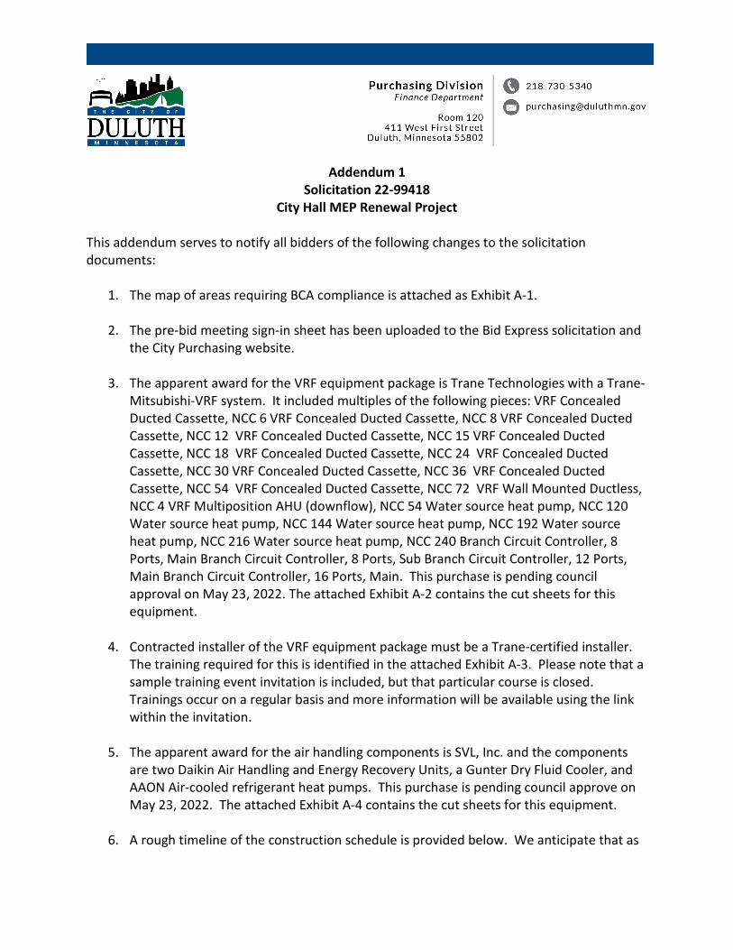
Addendum 1 Solicitation 22-99418
City Hall MEP Renewal Project This addendum serves to notify all bidders of the following changes to the solicitation documents:
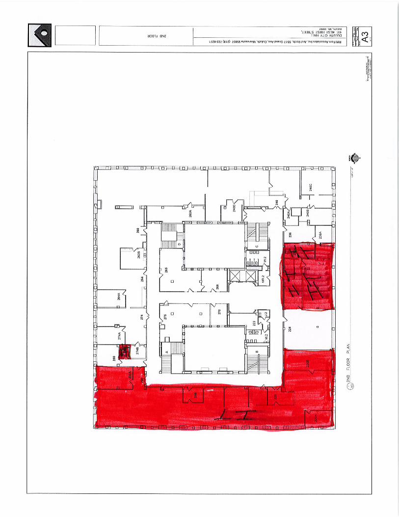
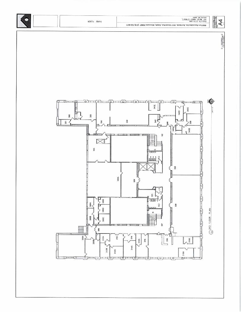
1. The map of areas requiring BCA compliance is attached as Exhibit A-1.
2. The pre-bid meeting sign-in sheet has been uploaded to the Bid Express solicitation and the City Purchasing website.
3. The apparent award for the VRF equipment package is Trane Technologies with a Trane-Mitsubishi-VRF system. It included multiples of the following pieces: VRF Concealed Ducted Cassette, NCC 6 VRF Concealed Ducted Cassette, NCC 8 VRF Concealed Ducted Cassette, NCC 12 VRF Concealed Ducted Cassette, NCC 15 VRF Concealed Ducted Cassette, NCC 18 VRF Concealed Ducted Cassette, NCC 24 VRF Concealed Ducted Cassette, NCC 30 VRF Concealed Ducted Cassette, NCC 36 VRF Concealed Ducted Cassette, NCC 54 VRF Concealed Ducted Cassette, NCC 72 VRF Wall Mounted Ductless, NCC 4 VRF Multiposition AHU (downflow), NCC 54 Water source heat pump, NCC 120 Water source heat pump, NCC 144 Water source heat pump, NCC 192 Water source heat pump, NCC 216 Water source heat pump, NCC 240 Branch Circuit Controller, 8 Ports, Main Branch Circuit Controller, 8 Ports, Sub Branch Circuit Controller, 12 Ports, Main Branch Circuit Controller, 16 Ports, Main. This purchase is pending council approval on May 23, 2022. The attached Exhibit A-2 contains the cut sheets for this equipment.
4. Contracted installer of the VRF equipment package must be a Trane-certified installer. The training required for this is identified in the attached Exhibit A-3. Please note that a sample training event invitation is included, but that particular course is closed. Trainings occur on a regular basis and more information will be available using the link within the invitation.
5. The apparent award for the air handling components is SVL, Inc. and the components are two Daikin Air Handling and Energy Recovery Units, a Gunter Dry Fluid Cooler, and AAON Air-cooled refrigerant heat pumps. This purchase is pending council approve on May 23, 2022. The attached Exhibit A-4 contains the cut sheets for this equipment.
6. A rough timeline of the construction schedule is provided below. We anticipate that as

lead times are confirmed and contractors are brought on board, this schedule will be shorter and much more defined. 4th Fl west and 3rd FL west ceiling 10 weeks 3rd Fl west and 2nd Fl west ceiling 10 weeks 2nd Fl west and 1st Fl west ceiling 10 weeks 1st Fl west and Gnd Fl west ceiling 10 weeks Gnd Fl west 10 weeks 4th Fl south and 3rd FL south ceiling 10 weeks 3rd Fl south and 2nd Fl south ceiling 10 weeks 2nd Fl south and 1st Fl south ceiling 10 weeks 1st Fl south and Gnd Fl south ceiling 10 weeks Gnd Fl south 10 weeks 4th Fl east and 3rd FL east ceiling 10 weeks 3rd Fl east and 2nd Fl east ceiling 10 weeks 2nd Fl east and 1st Fl east ceiling 10 weeks 1st Fl east and Gnd Fl east ceiling 10 weeks Gnd Fl east 10 weeks 2nd Fl north and 1st Fl north ceiling 10 weeks 1st Fl north and Gnd Fl north ceiling 10 weeks Gnd Fl north 10 weeks Total time: 180 weeks Anticipated Start: August 1, 2022 Estimated Finish: February 1, 2026
7. The City Hall garage and driveway located on the 4th Avenue (East) side of the building will be the designated area for parking and laydown.
8. The City intends to reuse all existing office and corridor lighting, ceiling tiles, decorative vents and radiator covers. Contractors should take precautions to preserve these items.
9. Each trade contractor is responsible for their own core drilling.
10. The City, State and Federal governments encourage contracting with disadvantaged businesses; however, there is no DBE goal or preference on this project.
11. Changes and clarifications to the plans and specs are identified in Exhibit A-5. Please acknowledge receipt of this Addendum by checking the acknowledgment box within the www.bidexpress.com solicitation. Posted: 5/18/22

Exhibit A-1


Specifications are subject to change without notice. © 2022 Mitsubishi Electric Trane HVAC US LLC. All rights reserved.
Job Name:System Reference: Date:
GENERAL FEATURES• Dual set point functionality• Multiple fan speed settings• Auto fan mode• 9-7/8” (250mm) high for low ceiling heights• Built-in condensate lift; lifts to 27-9/16” (700 mm)• Ducted fan coil supporting multiple configurations for flexible installation
Specifications SystemUnit Type PEFY-P18NMAU-E4
Cooling capacity (Nominal)1 BTU/H 18,000Heating capacity (Nominal)1 BTU/H 20,000Power source Voltage, Phase, Hertz 208/230V, 1-phase, 60 Hz
Power ConsumptionCooling kW 0.082Heating kW 0.08
CurrentCooling A 0.82/0.74Heating A 0.82/0.74
MCA A 2.94Maximum Overcurrent Protection (MOCP) A 15External finish Galvanized steel sheetExternal Dimensions In. [mm] 35-7/16 x 28-7/8 x 9-7/8 [900 x 732 x 250]Net weight Lbs [kg] 58 [26]Heat exchanger Cross fin (Aluminum fin and copper tube)
Fan
Type x quantity Sirocco fan x 2
External Static pressure in.WG 0.14, 0.2, 0.28, 0.4, 0.6 factory set to 0.2 In. WG
Airflow rate CFM 424–512–600Motor type DC MotorMotor Output kW 0.121Motor FLA A 2.35
Sound pressure level (Measured in anechoic room)3 dB(A) 29–33–37Air filter PP Honeycomb fabric
Diameter of refrigerant pipe (O.D.)Liquid (High Pressure) In. [mm] 1/4 [6.35] BrazedGas (Low Pressure) In. [mm] 1/2 [12.7] Brazed
Diameter of drain pipe In. [mm] O.D. 1-1/4 [32]NOTES:1Cooling / Heating capacity indicated at the maximum value at operation under the following conditions:Cooling | Indoor: 80° F (26.7° C) DB / 67° F (19.4° C) WB; Outdoor 95° F (35° C) DBHeating | Indoor: 70° F (21.1° C) DB; Outdoor 47° F (8.3° C) DB / 43° F (6.1° C) WB
PEFY-P18NMAU-E418,000 BTU/H MEDIUM STATIC DUCTED

Specifications are subject to change without notice. © 2022 Mitsubishi Electric Trane HVAC US LLC. All rights reserved.
INDOOR UNIT ACCESSORIES: PEFY-P18NMAU-E4
Control Interface
3-Pin Connector PAC-715ADBACnet® and Modbus® Interface PAC-UKPRC001-CN-1CN24 Relay Kit CN24RELAY-KIT-CM3Connector and wire for Operation status/error using CN51 PAC-725ADIT Extender PAC-WHS01IE-Ekumo station® for kumo cloud® PAC-WHS01HC-EThermostat Interface PAC-US444CN-1Wireless Interface for kumo cloud® PAC-USWHS002-WF-2
Remote Sensor
Flush Mount Temperature Sensor PAC-USSEN001-FM-1Remote Temperature Sensor PAC-SE41TS-EWireless temperature and humitity sensor for kumo cloud® PAC-USWHS003-TH-1
Terminal Signal Adapter Terminal Signal Adapter PAC-IT51AD-E
Wired Remote Controller
Deluxe Wired MA Remote Controller† PAR-40MAAUSimple MA Remote Controller† PAC-YT53CRAU-JSmart ME Remote Controller - Backlit touchscreen PAR-U01MEDU-KTouch MA Controller† PAR-CT01MAU-SB
Wireless Remote Controller
kumo touch™ RedLINK™ Wireless Controller MHK2Wireless MA Controller Receiver PAR-FA32MA-WWireless MA Remote Controller PAR-FL32MA-E
Condensate
Blue Diamond (Advanced) Mini Condensate Pump w/ Reservoir & Sensor (208/230V) [recommended] X87-721Blue Diamond (MicroBlue) Mini Condensate Pump (110/208/230V) up to 18,000 BTU/H X86-003Blue Diamond MultiTank — collection tank for use with multiple pumps C21-014Blue Diamond Sensor Extension Cable — 15 Ft. C13-103Sauermann Condensate Pump SI30-230
Filter Box Filter Box with MERV 13 Filter FBM2-2-A

Specifications are subject to change without notice. © 2022 Mitsubishi Electric Trane HVAC US LLC. All rights reserved.
FORM# PEFY-P18NMAU-E4 - 202201
1340 Satellite Boulevard Suwanee, GA 30024Toll Free: 800-433-4822 www.mehvac.com
3-Ø2
.9 (1
/8) m
ount
hole
Air f
ilter
Drain
pipe
(O.D
. Ø32
(1-1
/4) (E
merg
ency
drain
)
Li
quid
pipe
Gas p
ipe
Ø12.7
(1/2)
Ø6.35
(1/4)
Ø9.52
(3/8)
Ø15.8
8 (5
/8)
1558
1500
1615
6017
0016
5416
00
Fres
h air i
ntake
Ø10
0 (3-
15/16
)kn
ock o
ut ho
le
954
900A
Mode
l
1400
1100
GF
BC
DE
1000
1413
6015
0014
54
1154
1060
1112
00
1300
1358
1058
700
754
1000800
860
660
858
9765
8
800
600
(O.D
.Ø32
(1-1
/4))
Drain
pipe Dr
ain pi
pe (O
.D.Ø
32 (1
-1/4)
) (Gr
avity
drain
)
Term
inal b
lock (
Tran
smiss
ion)
Term
inal b
lock (
Powe
r sou
rce)
Contr
ol bo
x
Drain
pump
Refrig
eran
t pipi
ngbr
azing
conn
ectio
n (ga
s)
Refrig
eran
t pipi
ngbr
azing
conn
ectio
n (liq
uid)
2XE-
Ø2.9
(1/8)
Air
inlet
Air
outle
t
2x2-
Ø2.9
(1/8)
120°
120°
(4-15
/16)
Ø125
21 (7/8)
23 (15/16)
(DUCT)
200 (7-7/8)
378 (
14-1
5/16)
Unit:m
m(in.
)
Unit:m
m(in.
)
(63)
(65-1/
8)(66
-15/16
)(61
-7/16
)(59
-1/16
)(61
-3/8)
(43-5/
16)
(55-1/
8)(57
-1/4)
(45-7/
16)
(47-1/
4)
(59-1/
16)(
53-9/
16)
(41-3/
4)(39
-3/8)
(51-3/
16)
(53-1/
2)
(41-11
/16)
(33-7/
8)(31
-1/2)
(33-13
/16)
(39-3/
8)(37
-9/16
)(35
-7/16
)
)8/5-32()62(
)61/9-72((25
-15/16
)(29
-11/16
)(31
-1/2)
(5-3/8)13515
3 (6-
1/16)
73 (2-7/8)
100 (3-15/16)
(2-11
/16)
(5-3
/8)
(Sus
pens
ion bo
lt pitc
h)
18 (3
/4)21
0 (8-
5/16)
40 (1-5/8) 40 (1-5/8)
250 (9-7/8)
40 (1-5/8)33 (1-5/16)122 (4-13/16)
D (Duct) 20 (13/16)
100 (3-15/16)X(E-1)=F 30 (1-3/16)
100 (3-15/16)
217 (8-9/16)41 (1-5/8)
100 (3-15/16)
356 (
14-1
/16)67
136
732 (
28-7
/8)70
0 (27
-9/16
)32
(1-5
/16)
238 (
9-3/8
)10
(7/16
)
23 (15/16) 178 (7-1/16)
643 (
25-3
/8)
B (Suspension bolt pitch)
A
10 (7
/16)
57 (2
-1/4)
58 (2-5/16)15
(5/8)
Note
1. U
se a
n M
10 sc
rew
for t
he su
spen
sion
bolt (
field
supp
ly).
2.
Kee
p th
e se
rvice
spac
e fo
r main
tena
nce
at th
e bo
ttom
.
3. T
his d
rawi
ng is
for P
EFY-
P24·
27·3
0NM
AU-E
4 m
odels
, whic
h
ha
ve 2
fans
. PEF
Y-P0
6·08
·12N
MAU
-E4
mod
els h
ave
1 fa
n.
PEFY
-P15
·18N
MAU
-E4
mod
els h
ave
2 fa
ns.
PEFY
-P36
·48·
54NM
AU-E
4 m
odels
hav
e 3
fans
.
4. If
the
inlet
duc
t is u
sed,
rem
ove
the
air fil
ter
(sup
plied
with
the
unit)
, the
n ins
tall t
he fil
ter
(field
supp
ly) a
t the
sucti
on si
de.
5.
Hea
t air
to 0
°C (3
2°F)
or h
igher
whe
n ta
king
fresh
air
with
a fr
esh
air in
take
.
1
2
12
Mode
l
PEFY
-P15
,18NM
AU-E
4
PEFY
-P24
,27,30
NMAU
-E4
PEFY
-P36
,48NM
AU-E
4
PEFY
-P54
NMAU
-E4
PEFY
-P06
,08,12
NMAU
-E4
PEFY
-P06
,08,12
NMAU
-E4
PEFY
-P15
,18NM
AU-E
4
PEFY
-P24
,27,30
NMAU
-E4
PEFY
-P36
,48NM
AU-E
4
PEFY
-P54
NMAU
-E4
C
G
Inle
t air
side
vie
w
Unit : mm(in.)
Out
let a
irsi
de v
iew
Top
viewTo
p
Bot
tom
Opp
osite
pip
ing
side
vie
w
Note
5
(Integ
ral lif
t pum
p outl
et)
Pip
ing
side
vie
w
Top
Bot
tom
INDOOR UNIT DIMENSIONS: PEFY-P18NMAU-E4

Specifications are subject to change without notice. © 2021 Mitsubishi Electric Trane HVAC US LLC. All rights reserved.
Job Name:System Reference: Date:
ACCESSORIES Optical Relay for Flow Switch (One Piece)* RIBTE24B Transformer 50VA (One Piece)** TR50VA015 1.5” Temp sensor, optional (One Piece)** ZM-TW150NPT KIT 1.5” EPIV Valve (One Piece)* EV150S396NRXME Twinning Kit (Required) CMY-Q200CBK Twinning Kit (Required) CMY-R100CBK2 BC Controller (Required) for details see BC Controller Submittals Joint Kit for details see Pipe Accessories Submittal
*Requires two EPIV valves *Requires two optical relays**Requires four transformers**Requires four temp sensors per two EPIV valves if optional temp sensors are used.
208/230V MODULAR WATER-SOURCE VRF HEAT PUMP SYSTEM
Specifications SystemUnit Type PQRY-P288TSLMU-A1
Cooling Capacity (Nominal) BTU/H 288,000Heating Capacity (Nominal) BTU/H 323,000Net Weight Lbs. [kg] 962 [436]Refrigerant Piping Diameter From Twinning Kit to First Joint or Header
Liquid (High Pressure) In. [mm] 1-1/8 [28.58] BrazedGas (Low Pressure) In. [mm] 1-3/8 [34.93] Brazed
Max. Total Refrigerant Line Length Ft. 2460Max. Refrigerant Line Length (Between ODU & IDU) Ft. 541Max. Control Wiring Length Ft. 1640
Indoor Unit ConnectableTotal Capacity 50.0~150.0% of heatsource unit capacityModel/Quantity P06~P96/2.0~50.0
Sound Pressure Level dB(A) 57.0/57.0Compressor Operating Range 9.0% to 100.0%
AHRI Ratings (Ducted/Non-ducted)
EER 11.4/13.7IEER 18.5/20.6COP 4.9/5.25SCHE 20.1/19.0
Specifications Module 1 Module 2Unit Type PQRY-P144TLMU-A1 PQRY-P144TLMU-A1
Cooling Capacity (Nominal) BTU/H 144,000 144,000Heating Capacity (Nominal) BTU/H 160,000 160,000
Operating Temperature RangeCooling (Indoor) °F WB [°C WB] 59~75 [ 15.0~ 24.0] 59~75 [ 15.0~ 24.0]Heating (Indoor) °F DB [°C DB] 59~81 [15.0~27.0] 59~81 [15.0~27.0]
Operating Water Temperature Range1 Cooling/Heating °F [°C] 50~113 [10~45] 50~113 [10~45]External Dimensions (H x W x D) In. [mm] 57-1/8 x 34-11/16 x 21-11/16 [1450 x 880 x 550] 57-1/8 x 34-11/16 x 21-11/16 [1450 x 880 x 550]Net Weight Lbs. [kg] 481 [218] 481 [218]External Finish Galvanized steel sheets Galvanized steel sheetsElectrical Power Requirements Voltage, Phase, Hertz, Power Tolerance 208/230, 3, 60, ±10 208/230, 3, 60, ±10Minimum Circuit Ampacity A 35.0/0.0 35.0/0.0Maximum Overcurrent Protection A 60/50 60/50SCCR kA 5 5
Flow RateG/min [gpm] 31.7 31.7
L/min 120 120
Pressure Droppsi 6.38 6.38Ft. 14.7 14.7
Operation Volume RangeG/min [gpm] 19.8~50.9 19.8~50.9
m3/h 4.5~11.6 4.5~11.6Refrigerant Piping Diameter (From Twinning Kit)
Liquid (High Pressure) In. [mm] 7/8 [ 22.2] Brazed 7/8 [ 22.2] BrazedGas (Low Pressure) In. [mm] 1-1/8 [28.58] Brazed 1-1/8 [28.58] Brazed
Compressor Type x Quantity Inverter scroll hermetic x 1 Inverter scroll hermetic x 1Compressor Motor Output kW 9.5 9.5Refrigerant Type x Original Charge R410A x 13 lbs. + 4.0oz. [6.0 kg] R410A x 13 lbs. + 4.0oz. [6.0 kg]Lubricant Lubricant Lubricant MEL32 MEL32
Protection DevicesHigh Pressure Protection High Pressure Protection High pressure sensor, High pressure switch at 4.15
Mpa (601 psi)High pressure sensor, High pressure switch at 4.15
Mpa (601 psi)Inverter Circuit Inverter Circuit Over-heat protection, Over-current protection Over-heat protection, Over-current protectionCompressor Compressor Over-heat protection Over-heat protection
NOTES:123°F EWT (Entering water temperature) is possible with glycol.Each individual module requires a separate electrical connection. Refer to electrical data for each individual module.
24-TON PQRY-P288TSLMU-A1

Specifications are subject to change without notice. © 2021 Mitsubishi Electric Trane HVAC US LLC. All rights reserved.
OUTDOOR UNIT: PQRY-P288TSLMU-A1 – DIMENSIONS
Heat Source unit 1 Heat Source unit 2
20(13/16) 880(34-11/16)880(34-11/16)
550(21-11/16)
145
0(57
-1/8
)
1780(70-1/8)
b
e acd
To BC controllerTwinning pipe (High pressure)<Optional parts>
Twinning pipe (Low pressure)<Optional parts>
To BC controller
Package unit name
Twinning pipe connection size
Component unit name Heat Source unit 1Heat Source unit 2
Twinning pipe Kit(optional parts)
PQRY-P288TSLMU-A1PQRY-P144TLMU-A1
CMY-Q200CBK
Unit model
Twinning pipe~Heat source unit
High pressure Low pressurec or e d
P144P168
ø22.2(7/8)
High pressureBC controller~Twinning pipeLow pressure
ab
ø28.58(1-1/8)
PQRY-P144TLMU-A1
PQRY-P312TSLMU-A1PQRY-P168TLMU-A1PQRY-P144TLMU-A1
PQRY-P336TSLMU-A1PQRY-P168TLMU-A1
Note 1.Connect the pipes as shown in the figure above. Refer to the table below for the pipe size.
PQRY-P168TLMU-A1
ø34.93(1-3/8) ø41.28(1-5/8)
ø28.58(1-1/8)
2.Twinning pipe (High pressure) should not be tilted more than 15 degrees from the horizontal plane.3.See the Installation Manual for the details of Twinning pipe installation.4.Only use the Twinning pipe by Mitsubishi (optional parts).
Unit : mm(in)

Specifications are subject to change without notice. © 2021 Mitsubishi Electric Trane HVAC US LLC. All rights reserved.
Unit : m
m(in)
(7/8)ø22.2 Brazed
*1
<Accessories>
2×2-14(9/16)×31(1-1/4) Oval hole
(P144/P168/P192 ; Packaged in the accessory kit)• Sealing material for panel• • • • • 1pc.
(P144/P168/P192 ; Packaged in the accessory kit)
6
Top view
7
5
1
43
8
Control box
Front view
Service panel
8
Right side view
Refrigerant service valve <High pressure>
Back view
valve <Low pressure> Refrigerant service
2
Bottom view
Fig.B
control boxThe space for
replacement(front side)
Service clearance
control box
Top view
The space forreplacement
(1)(1-1/8) (1-1/8)ø25.4ø28.58 Brazed
Refrigerant pipe
ø28.58
Service valveDiameter
ModelLow pressure
Fig.AConnecting pipe specifications
High pressure
*1
• Refrigerant (high pressure) conn. pipe • • • • • 1pc.(P144/P168/P192 ; Packaged in the accessory kit)
• Refrigerant (low pressure) conn. pipe • • • • • 1pc.(P144/P168/P192 ; Packaged in the accessory kit)
• Water stopper • • • • • 1pc.(P144/P168/P192 ; Packaged in the accessory kit)
• Sealing material for water stopper• • • • • 1pc.(P144/P168/P192 ; Packaged in the accessory kit)
• Sealing material for field piping (high pressure, low pressure) • • • • • 1pc. each(P144/P168/P192 ; Packaged in the accessory kit)
• Sealing material for drain socket • • • • • 1pc.(P144/P168/P192 ; Packaged in the accessory kit)
• Pipe cover for low pressure • • • • • 1pc.(P144/P168/P192 ; Packaged in the accessory kit)
• Sealing material for base leg (two types) • • • • • 4pc. each
PQRY-P144TLMU-A1
PQRY-P168TLMU-A1
Low pressure High pressure
PQRY-P192TLMU-A1
1450
(57-
1/8)
*1.Connect by using the connecting pipes that are supplied.
880(34-11/16)
550(
21-1
1/16
)
367
23
434(17-1/8)82(3-1/4)
421(16-5/8)75(3)58(2-5/16)
393(15-1/2)140(5-9/16)32
0(1
4-1/
2)(1
2-5/
8)
(15/
16)
29(1-3/16)
83(3-5/16) 426(16-13/16)
84(3-5/16)
278(
11)
569(22-7/16)
216(
8-9/
16)
89(3
-9/1
6)77
(3-1
/16)
145(
5-3/
4)
721(28-7/16)
473(
470~
476)
31
.531
.572.5 72.5(866)(34-1/8) (2-7/8)
(Mounting pitch)
(2-7/8)
(536
)(21-
1/8)
(Mou
nting
pitc
h)
(18-5/
8)(18
-9/16
~18-3
/4)(1
-1/4
)(1
-1/4
)
163(6-7/16)
840(
33-1
/8)
536
600(23-5/8)450(17-3/4)
1450
(57-
1/8)
600(
23-5
/8)
450(
17-3
/4)
163(
6-7/
16)
350(13-13/16)700(27-9/16)880(34-11/16)
(69)
(
(111)
21-1
/8)
(4-3/8)(2-3/4)NO.
For pipes
140 × 77 Knockout hole(5-9/16) (3-1/16)
For wires
For transmissioncables
Usage
Front through hole
Front through hole
Front through hole
Front through hole
Specifications
Rc3/4 ScrewNPT1-1/2 ScrewNPT1-1/2 Screwinlet
outletDrain pipeWater pipe
1
2
4
3
5
678
ø62.7 or ø34.5 Knockout hole(2-1/2) (1-3/8)
ø43.7 or ø22.2 Knockout hole(1-3/4) (7/8)
(1-13/16)ø45 Knockout hole
(1-3/8)ø34 Knockout hole
Front through hole(Uses when twinning kit (optional parts) is mounted.)
Top of unit casing not suitable for supporting systemmodules stacked above - field framing required for stackingmodules of additional systems
Note1.Seal around the water piping, the refrigerant piping, the power supply, and the control wiring and plug unused knockout holes with putty, etc., to prevent moisture or dirt from entering cabinet.
Note2.At the time of product shipment, the front side piping serves as the local drainage connection. When connecting on the rear side, please remove the rear side plug sealing corks, and attach on the front side. Ensure there is no leak in piping system once connected.
•Circulate the water all the time even if heat source unit is not in operation and provide glycol for freeze protection.
possibility to drop under 0°C(32°F), be careful for the following point to prevent the pipe burst by the water pipe freeze-up.
•Drain the water from inside of the heat source unit when the heat source unit will not operate for a long term.
Note3.See Fig. A and Fig. B for service clearances.Note4.If piping is installed in front of the unit, provide clearances
as shown in Fig. A and Fig. B. Note5.Environmental condition for installation; -20~40°C(DB) (-4~104°F)
for indoor installation.Note6.In case the temperature around the heat source unit has
Note7.Ensure that the drain piping is downward with a pitch of more than 1/100.
Note8.At brazing of pipes, wrap the refrigerant service valve with wet cloth and keep the temperature of refrigerant service valve under 120°C(248°F).
(front side)Service clearance
MODULE 1: PQRY-P144TLMU-A1 – DIMENSIONS

Specifications are subject to change without notice. © 2021 Mitsubishi Electric Trane HVAC US LLC. All rights reserved.
Unit : m
m(in)
(7/8)ø22.2 Brazed
*1
<Accessories>
2×2-14(9/16)×31(1-1/4) Oval hole
(P144/P168/P192 ; Packaged in the accessory kit)• Sealing material for panel• • • • • 1pc.
(P144/P168/P192 ; Packaged in the accessory kit)
6
Top view
7
5
1
43
8
Control box
Front view
Service panel
8
Right side view
Refrigerant service valve <High pressure>
Back view
valve <Low pressure> Refrigerant service
2
Bottom view
Fig.B
control boxThe space for
replacement(front side)
Service clearance
control box
Top view
The space forreplacement
(1)(1-1/8) (1-1/8)ø25.4ø28.58 Brazed
Refrigerant pipe
ø28.58
Service valveDiameter
ModelLow pressure
Fig.AConnecting pipe specifications
High pressure
*1
• Refrigerant (high pressure) conn. pipe • • • • • 1pc.(P144/P168/P192 ; Packaged in the accessory kit)
• Refrigerant (low pressure) conn. pipe • • • • • 1pc.(P144/P168/P192 ; Packaged in the accessory kit)
• Water stopper • • • • • 1pc.(P144/P168/P192 ; Packaged in the accessory kit)
• Sealing material for water stopper• • • • • 1pc.(P144/P168/P192 ; Packaged in the accessory kit)
• Sealing material for field piping (high pressure, low pressure) • • • • • 1pc. each(P144/P168/P192 ; Packaged in the accessory kit)
• Sealing material for drain socket • • • • • 1pc.(P144/P168/P192 ; Packaged in the accessory kit)
• Pipe cover for low pressure • • • • • 1pc.(P144/P168/P192 ; Packaged in the accessory kit)
• Sealing material for base leg (two types) • • • • • 4pc. each
PQRY-P144TLMU-A1
PQRY-P168TLMU-A1
Low pressure High pressure
PQRY-P192TLMU-A1
1450
(57-
1/8)
*1.Connect by using the connecting pipes that are supplied.
880(34-11/16)
550(
21-1
1/16
)
367
23
434(17-1/8)82(3-1/4)
421(16-5/8)75(3)58(2-5/16)
393(15-1/2)140(5-9/16)32
0(1
4-1/
2)(1
2-5/
8)
(15/
16)
29(1-3/16)
83(3-5/16) 426(16-13/16)
84(3-5/16)
278(
11)
569(22-7/16)
216(
8-9/
16)
89(3
-9/1
6)77
(3-1
/16)
145(
5-3/
4)
721(28-7/16)
473(
470~
476)
31
.531
.572.5 72.5(866)(34-1/8) (2-7/8)
(Mounting pitch)
(2-7/8)
(536
)(21-
1/8)
(Mou
nting
pitc
h)
(18-5/
8)(18
-9/16
~18-3
/4)(1
-1/4
)(1
-1/4
)
163(6-7/16)
840(
33-1
/8)
536
600(23-5/8)450(17-3/4)
1450
(57-
1/8)
600(
23-5
/8)
450(
17-3
/4)
163(
6-7/
16)
350(13-13/16)700(27-9/16)880(34-11/16)
(69)
(
(111)
21-1
/8)
(4-3/8)(2-3/4)NO.
For pipes
140 × 77 Knockout hole(5-9/16) (3-1/16)
For wires
For transmissioncables
Usage
Front through hole
Front through hole
Front through hole
Front through hole
Specifications
Rc3/4 ScrewNPT1-1/2 ScrewNPT1-1/2 Screwinlet
outletDrain pipeWater pipe
1
2
4
3
5
678
ø62.7 or ø34.5 Knockout hole(2-1/2) (1-3/8)
ø43.7 or ø22.2 Knockout hole(1-3/4) (7/8)
(1-13/16)ø45 Knockout hole
(1-3/8)ø34 Knockout hole
Front through hole(Uses when twinning kit (optional parts) is mounted.)
Top of unit casing not suitable for supporting systemmodules stacked above - field framing required for stackingmodules of additional systems
Note1.Seal around the water piping, the refrigerant piping, the power supply, and the control wiring and plug unused knockout holes with putty, etc., to prevent moisture or dirt from entering cabinet.
Note2.At the time of product shipment, the front side piping serves as the local drainage connection. When connecting on the rear side, please remove the rear side plug sealing corks, and attach on the front side. Ensure there is no leak in piping system once connected.
•Circulate the water all the time even if heat source unit is not in operation and provide glycol for freeze protection.
possibility to drop under 0°C(32°F), be careful for the following point to prevent the pipe burst by the water pipe freeze-up.
•Drain the water from inside of the heat source unit when the heat source unit will not operate for a long term.
Note3.See Fig. A and Fig. B for service clearances.Note4.If piping is installed in front of the unit, provide clearances
as shown in Fig. A and Fig. B. Note5.Environmental condition for installation; -20~40°C(DB) (-4~104°F)
for indoor installation.Note6.In case the temperature around the heat source unit has
Note7.Ensure that the drain piping is downward with a pitch of more than 1/100.
Note8.At brazing of pipes, wrap the refrigerant service valve with wet cloth and keep the temperature of refrigerant service valve under 120°C(248°F).
(front side)Service clearance
MODULE 2: PQRY-P144TLMU-A1 – DIMENSIONS

Job Name:System Reference: Date:
Specifications are subject to change without notice. © 2020 Mitsubishi Electric Trane HVAC US LLC. All rights reserved.
TCMBM1012JA11N4BVMain BC Controller with Pre-Installed Ball Valves
ACCESSORIES Branch Joint (Downstream capacity ≤72,000 Btu/h) CMY-Y102SS-G2* Branch Joint (Downstream capacity 73,000-96,000 Btu/h) CMY-Y102LS-G2* Branch Joint (Downstream capacity ≤126,000 Btu/h) CMY-R201S-G* Branch Joint (Downstream capacity 127,000-216,000 Btu/h) CMY-R202S-G* Branch Joint (Downstream capacity 217,000-234,000 Btu/h) CMY-R203S-G* Branch Joint (Downstream capacity 235,000-360,000 Btu/h) CMY-R204S-G* Branch Joint (Downstream capacity ≥316,000 Btu/h CMY-R205S-G* Condensate Pump (Blue Diamond X87-721 Condensate Pump (Sauermann) SI3100-230 Reducer (Between ODU and BC) CMY-R302S-G1* Reducer (Between Main and Sub BC) CMY-R303S-G1
*See Data Book or Install Manual for more details
NOTES:1. Installation/foundation work, electrical connection work, insulation work, power source switch, and other items shall be referred to the Installation Manual.2. The equipment is for R410A refrigerant.3. Install this product in a location where noise (refrigerant noise) emitted by the unit will not disturb the neighbors. (For use in quiet environments with low background noise, position the BC
CONTROLLER at least 5m away from any indoor units.)4. Sound pressure/power level differs depending on the connected outdoor/heat source unit capacity or operation condition. The sound pressure/power level at the rated operation is the value of the
cooling mode.5. The sound pressure/power level values were obtained in an anechoic room. Actual sound pressure level is usually greater than that measured in anechoic room due to ambient noise and deflection
sound. 6. The sound pressure level values were obtained at the location below 1.5m from the unit.7. The solenoid valve switching sound is 56 dB (sound pressure level) regardless of the unit model.8. Refrigerant piping diameter for connection of plural indoor units with 1 branch shall be referred to the Installation Manual.9. This unit is not designed for outside installations.10. When brazing the pipes, be sure to braze, after covering a wet cloth to the insulation pipes of the units in order to prevent it from burning and shrinking by heat.11. Indoor unit capacity connectable to 1 branch is changed depending on the indoor unit type and connection method. Please refer to the Installation Manual for more information.12. For the refrigerant pipe size, refer to Installation Manual of outdoor units/heat source units.
SPECIFICATIONSIndoor Unit Capacity Connectable to 1 Branch Btu/h 54,000
Number Of Branches 12
Electrical Requirements
Electrical Power Requirements 208 / 230V, 1 phase, 60Hz
Minimum Circuit Ampacity (MCA) A 1.57 / 1.82
Maximum Overcurrent Protection (MOCP) A 15
Power Input (208 / 230V
CoolingkW
0.198 / 0.255
Heating 0.106 / 0.137
Current Input (208 / 230V)
CoolingA
0.95 / 0.11
Heating 0.52 / 0.60
External Dimensions In. (mm) 9-7/8 x 44-11/16 x 21-1/2 (250 x 1,135 x 545)
Net Weight Lbs. (kg) 156 (71)
External finish Galvanized steel plate (Lower part drain pan:Pre-coated galvanized sheets + powder coating)
Connectable Outdoor / Heat Source Unit Capacity 72,000 to 336,000
Refrigerant Piping Diameter to Indoor Unit (Brazed)
Liquid Gas
Less than 18,000 Btu/h In. (mm) 1/4 (6.35) 1/2 (12.7)
Greater than 18,000 Btu/h
In. (mm) 3/8 (9.52) 5/8 (15.88)
In. (mm) 3/8 (9.52) 3/4 (19.05)
In. (mm) 3/8 (9.52) 7/8 (22.2)
Refrigerant Piping Diameter to Outdoor Unit (Brazed)
High Pressure Low Pressure
P72 In. (mm) 5/8 (15.88) 3/4 (19.05)
P96 In. (mm) 3/4 (19.05) 7/8 (22.2)
P120 In. (mm) 3/4 (19.05) 7/8 (22.2) or 1-1/8 (28.58)
P144 to P192 In. (mm) 3/4 (19.05) 1-1/8 (28.58)
P216 In. (mm) 7/8 (22.2) or 1-1/8 (28.58) 1-1/8 (28.58)
P240 In. (mm) 7/8 (22.2) or 1-1/8 (28.58) 1-3/8 (34.93)
P264 to P288 In. (mm) 1-1/8 (28.58) 1-3/8 (34.93)
P312 In. (mm) 1-1/8 (28.58) 1-3/8 (34.93) or 1-5/8 (41.28)
P336 In. (mm) 1-1/8 (28.58) 1-5/8 (41.28)
Refrigerant Piping Diameter to other BC Controller (Brazed)
High Pressure Liquid Pipe Low Pressure Pipe
P72 In. (mm) 5/8 (15.88) 3/8 (9.52) 3/4 (19.05)
P73 to P108 In. (mm) 3/4 (19.05) 3/8 (9.52) 7/8 (22.2)
P109 to P126 In. (mm) 3/4 (19.05) 1/2 (12.7) 1-1/8 (28.58)
P127 to P144 In. (mm) 7/8 (22.2) 1/2 (12.7) 1-1/8 (28.58)
P145 to P216 In. (mm) 7/8 (22.2) 5/8 (15.88) 1-1/8 (28.58)
P217 to P234 In. (mm) 1-1/8 (28.58) 5/8 (15.88) 1-1/8 (28.58)
P235 to P288 In. (mm) 1-1/8 (28.58) 3/4 (19.05) 1-3/8 (34.93)
P289 to P360 In. (mm) 1-1/8 (28.58) 3/4 (19.05) 1-5/8 (41.28)
P361 or above In. (mm) 1-3/8 (34.93) 3/4 (19.05) 1-5/8 (41.28)
Field drain pipe size In. (mm) 3/4 NPT
Refrigerant R410A
Sound power level (measured in anechoic room)
Rated operationdB(A)
68
Defrost 74
Sound pressure level (measured in anechoic room)
Rated operationdB(A)
50
Defrost 56
Image for reference only
ASSEMBLED FOR MITSUBISHI ELECTRIC TRANE HVAC US

Specifications are subject to change without notice. © 2020 Mitsubishi Electric Trane HVAC US LLC. All rights reserved.
DIMENSIONS: TCMBM1012JA11N4BV
TCMBM1012JA11N4BVTCMBM1016JA11N4BVTCMBM0108JA11N4BV
Unit: mm(in)
Con
nect
ion
pipe
of o
utdo
or u
nit
(Hig
h pr
essu
re)
ATC
MB
M01
08JA
11N
4BV
218(
8-5/
8)
(3-5
/8)
913/
4 N
PT
scre
w(E
mer
genc
y dr
aini
ng)
X
Con
nect
ion
pipe
of
SU
B B
C C
ON
TRO
LLE
R(L
iqui
d)
(1-7
/8)
47
ø19.
05(3
/4) (
Not
e 6)
Con
nect
ion
pipe
of
SU
B B
C C
ON
TRO
LLE
R(L
ow)
3/4
NP
T sc
rew
(2-1
1/16
)68
(9/1
6)14
Det
ail o
f X s
ectio
n
14
56
710
1113
14
<Acc
esso
ries>
• Squ
are
was
her (
with
cus
hion
)•••
••••
••4p
cs.
• Squ
are
was
her•
••••
••••
••••
••••
••••
••••
••4p
cs.
Not
e 1.
Sus
pens
ion
bolt(
ø10)
and
nut
(M10
) pre
pare
in th
e fie
ld.
2. T
ake
notic
e of
ser
vice
spa
ce a
s sh
own.
(Ple
ase
give
atte
ntio
n no
t to
occu
py s
ervi
cesp
ace
by le
tting
duc
ts a
nd p
ipes
thro
ugh.
)3.
Ple
ase
take
ser
vice
spa
ce fo
r con
nect
ion
pipe
of S
UB
BC
CO
NTR
OLL
ER
.4.
Inst
all t
his
prod
uct i
n a
loca
tion
whe
re n
oise
(ref
riger
ant n
oise
)em
itted
by
the
unit
will
not
dis
turb
the
neig
hbor
s.(F
or u
se in
qui
et e
nviro
nmen
ts w
ith lo
w b
ackg
roun
d no
ise,
pos
ition
the
BC
CO
NTR
OLL
ER
at l
east
5m
aw
ay fr
om a
ny in
door
uni
ts.)
5. R
efer
to th
e In
stal
latio
n M
anua
l for
refri
gera
nt p
ipin
g di
amet
er s
ize
whe
n co
nnec
ting
plur
al in
door
uni
ts w
ith 1
bra
nch.
6. R
efer
to th
e Ta
ble-
1,2
conn
ectio
n pi
pe o
f out
door
uni
tor
SU
B B
C C
ON
TRO
LLE
R d
iam
eter
siz
e.7.
Ref
er to
the
Inst
alla
tion
Man
ual f
or in
sula
tion
of c
onne
ctio
n pi
pe a
nddr
ain
pipi
ng.
8. D
o no
t pla
ce th
e B
C c
ontro
ller d
irect
ly o
n th
e flo
or.
(15/
16)
2315
8
60(2
-3/8
)
60(2
-3/8
)×C
=D
(6-1
/8)
155
Con
nect
ion
pipe
of
indo
or u
nit (
Gas
)In
door
uni
t mod
el (N
ote
5)P
18 o
r les
s:ø1
2.7(
1/2)
<Bra
zed>
P18
ove
r:ø1
5.88
(5/8
)<B
raze
d>
80(3
-3/1
6)S
ervi
ce s
pace
(8-1
3/16
)22
3
(6-1
/8)
155
60(2
-3/8
)
25(1
)A B
(Lift
ing
bolt
pitc
h)
60(2
-3/8
)×C
=D
Con
nect
ion
pipe
of
indo
or u
nit (
Liqu
id)
Indo
or u
nit m
odel
(Not
e 5)
P18
or l
ess:
ø6.3
5(1/
4)<B
raze
d>P
18 o
ver:
ø9.5
2(3/
8)<B
raze
d>
Ser
vice
spac
e
(1-7
/8)
47
(17-
3/4)
450
Acc
ess
door
E(9
-7/8
)25
0
ø38.
1(1-
1/2)
(Not
e 6)
ø34.
93(1
-3/8
) (N
ote
6)C
onne
ctio
n pi
pe o
f out
door
uni
t
(Low
pre
ssur
e)ø3
8.1(
1-1/
2) (N
ote
6)
Con
trol b
ox
911(
35-7
/8)
TCM
BM
1012
JA11
N4B
V
97
D98
3(38
-3/4
)66
0(26
)TC
MB
M10
16JA
11N
4BV
(3-7
/8)
E 231(
9-1/
8)34
3(13
-9/1
6)34
3(13
-9/1
6)
Con
nect
ion
pipe
of
SU
B B
C C
ON
TRO
LLE
R(H
igh
pres
sure
)ø2
8.58
(1-1
/8) (
Not
e 6)
(11-
13/1
6)30
0
Tabl
e-1.
To
outd
oor/h
eat s
ourc
e un
it (N
ote.
6)
Hig
h pr
ess.
Pip
eC
onne
ctab
leun
it ca
paci
tyP
72P
96P
120
P24
0
P31
2P
336
ø15.
88(5
/8)
ø19.
05(3
/4)
ø19.
05(3
/4)
P14
4 to
P19
2P
216
ø22.
2(7/
8) o
r ø28
.58(
1-1/
8)ø2
2.2(
7/8)
or ø
28.5
8(1-
1/8)
P26
4 to
P28
8ø2
8.58
(1-1
/8)
ø28.
58(1
-1/8
)
Tabl
e-2.
To
othe
r BC
con
trolle
r (N
ote.
6)
Low
pre
ss. P
ipe
ø19.
05(3
/4)
ø22.
2(7/
8)ø2
2.2(
7/8)
or ø
28.5
8(1-
1/8)
ø28.
58(1
-1/8
)ø2
8.58
(1-1
/8)
ø34.
93(1
-3/8
)ø3
4.93
(1-3
/8)
ø34.
93(1
-3/8
) or ø
41.2
8(1-
5/8)
ø41.
28(1
-5/8
)
*For
the
refri
gera
nt p
ipe
size
, ref
er to
Inst
alla
tion
Man
ual o
f out
door
uni
ts/h
eat s
ourc
e un
its.
* * * *
Tota
l dow
nstre
amIn
door
uni
t cap
acity
~P72
P73
~108
P10
9~12
6P
127~
144
P14
5~21
6P
217~
234
P23
5~28
8P
289~
360
P36
1~
Hig
h pr
ess.
Pip
e
ø15.
88(5
/8)
ø19.
05(3
/4)
ø19.
05(3
/4)
ø22.
2(7/
8)ø2
2.2(
7/8)
ø28.
58(1
-1/8
)ø2
8.58
(1-1
/8)
ø28.
58(1
-1/8
)ø3
4.93
(1-3
/8)
ø9.5
2(3/
8)ø9
.52(
3/8)
ø12.
7(1/
2)ø1
2.7(
1/2)
ø15.
88(5
/8)
ø15.
88(5
/8)
ø19.
05(3
/4)
ø19.
05(3
/4)
ø19.
05(3
/4)
Low
pre
ss. P
ipe
ø19.
05(3
/4)
ø22.
2(7/
8)ø2
8.58
(1-1
/8)
ø28.
58(1
-1/8
)ø2
8.58
(1-1
/8)
ø28.
58(1
-1/8
)ø3
4.93
(1-3
/8)
ø41.
28(1
-5/8
)ø4
1.28
(1-5
/8)
(1-3/16)
(1/2)30
12
273(10-3/4)
252(9-15/16)22(7/8)264(10-7/16)
342(13-1/2)
(1-5/8)
(12-11/16)
41
323
(Lifting bolt pitch)463(18-1/4)
545(21-1/2)
264(10-7/16)325 (12-13/16)
379 (14-15/16)
(3-1/16)77
(7-7/8)200
(3-15/16)100
(9-7/8)250
(17-3/4)450
700(27-3/8)
1135
(44-
11/1
6)11
35(4
4-11
/16)
B
1207
(47-
9/16
)12
07(4
7-9/
16)
C7 11 15
420(
16-9
/16)
900(
35-7
/16)
1516
128
92
3
(6-1
/4)
(7-7
/16)
188
204(8-1/16)
Liqu
id P
ipe
ø22.
2(7/
8)
ø28.
58(1
-1/8
)

Specifications are subject to change without notice. © 2020 Mitsubishi Electric Trane HVAC US LLC. All rights reserved.
BV-BB SERIES BALL VALVES BRAZED CONNECTIONS
SPECIFICATIONS• Engineered for Mini-split and Multi-split HVAC Units• Full Port Design• 800 PSIG Rated• R-410A Compatible• Brazed Connections• UL listed ball valves
MODEL NUMBERS:BV38BBSI and BV58BBSI• BV38BBSI pre-installed on each liquid line with a brazed straight-pipe
extension• BV58BBSI pre-installed on each gas line with a brazed straight-pipe
extension• Fully factory assembled• Furnace brazed and pressure tested• Each ball valve is equipped with Schrader Valve for refrigerant service—
valve rated to 800 psi• Design working pressure: 700 PSIG• Temperature range: -40˚ F to +325˚ F (-40˚ C to +149˚ C)• Forged brass body and seal cap• PTFE seals and gaskets (no synthetic O-rings)• Seal cap design permits valve operation without removal of seal cap• One year limited materials and workmanship warranty on Ball Valves• Made in the U.S.A
*ball valves come with an insulation piece
(B)(A)
(G)
(F)
Part Number ODS A B C D E F G
BV38BBSI (w/ Suction Tube) 3/8 9.57 6.13 1.81 1.41 0.19 1.42 3.07
BV58BBSI (w/ Suction Tube) 5/8 9.56 6.12 1.81 1.41 0.31 1.42 3.06
(E)
(D)(C)
SUCTION TUBE EXTENSIONSPUN CLOSED
Suction Tube Extension1. Dimensions: a. Outside: Ø 3/8” and 5/8” on the BV38BBSI and BV58BBSI respectively b. Thickness: 0.035, ±0.012. 2500 PSI burst per UL3. Free of sharp edges, burrs and wrinkles

FORM# T_Submittal_TCMBM1012JA11N4BV - 202011
Specifications are subject to change without notice. © 2020 Mitsubishi Electric Trane HVAC US LLC. All rights reserved.
BV-BB SERIES BALL VALVES BRAZED CONNECTIONS (INSULATION DETAILS)
Product name: Ball valve insulationProduct code: HKG-20HF
Materials:1. Insulation: Inner and outer layer Polyethylene foam (PEF)2. Covering: Adhesive tape of Polyvinyl chloride (PVC)3. Separator: Soft film of Polyvinyl chloride (PVC)
Physical property:Insulation
Performance items Unit Performance
Density lb/ft3 (kg/m3) 1.87 (30)
Heat Conductivity (at 23˚ C) W/m•K 0.040
Tensile Strength N/cm2 23
Heat Resistant ˚ F ( ˚ C) =<176 ( =<80)
UL-94 – HF-1
Product Code d1 t (D) L1 (d2) (d3) (L2) (L3)
HKG-20HF Unit: inches (mm)
1 3/8(30)
3/4(20)
2 3/4(70)
8 9/16220
7/8(11)
1 9/64(29)
1 15/32(37)
2 7/8(73)
Product Structure:
Product Structure:

Exhibit A-3
The following information has been provided by our Trane Technologies representative and is being shared as a courtesy to bidders:
See below for the installers training course description. We host these trainings just about every month at our St. Paul Commercial sales office. Please note the attached invitation is for this month’s class and registration is already closed. But the information in the invitation is still relevant. The class costs $480 per person.
Along with this, our technical specialist, Ryan Goss, will assist the installers throughout the process, and will submit the needed warranty information to Mitsubishi.

REGISTER
You’re Invited to Trane CITY MULTI Start Up and Service Essentials
Do you want to receive hands-on, in-person training on your Variable Refrigerant Flow (VRF) System? Join us for a 2-day Trane CITY MULTI Start Up and Service Essentials interactive session. Sign up as early, as this class is limited to a maximum of 8 attendees!
WHEN:Tuesday, May 24, 2022 8:00 AM – 4:30 PM Wednesday, May 25, 2022 8:00 AM – 4:30 PMNote: You must attend both days to receive your certification
WHERE: Trane Commercial Sales Office775 Vandalia StreetSt. Paul, MN 55114
PREREQUISITE WORK:Complete CITY MULTI Installation Essentials, now a set of 4 online modules that are required to be completed prior to attending the 2 day in-person portion of the course. 1. Use a laptop or desktop with Google Chrome as your browser2. Login or Create and Account: https://meushvac.force.com/Contractor/s/3. Click on Learning > Find Learning4. Select the Catalog: Commercial VRF5. In Learning Plans, click on CITY MULTI Installation Essentials6. Click Register and Launch
This course also requires you to bring a laptop with the following software pre-installed. • Diamond System Builder: Download• Maintenance Tool Software: Download• Central Controllers AE-200, AE 50, EW-50 Initial and BACnet Setting Tool: Download
All trademarks referenced are the trademarks of their respective owners. © 2022 Trane. All Rights Reserved.
WHO:Contractors looking to qualify CITY MULTI VRF projects for the extended 10 year parts/compressor warranty
COST:$480 per student
2425 South Yukon Ave - Tulsa, Oklahoma 74107-2728 - Ph. (918) 583-2266 Fax (918) 583-6094AAONEcat32 Ver. 4.316 (SN: 7661808-CEN5JAPA)
A1
A2
A3
A4
A5
1
2A
2B 3A
3B
4
5
6A
6B
6C
7
8A
8B
8C
8D
9
10
11
12
13
14
15
16
17
18
19
20
21
22
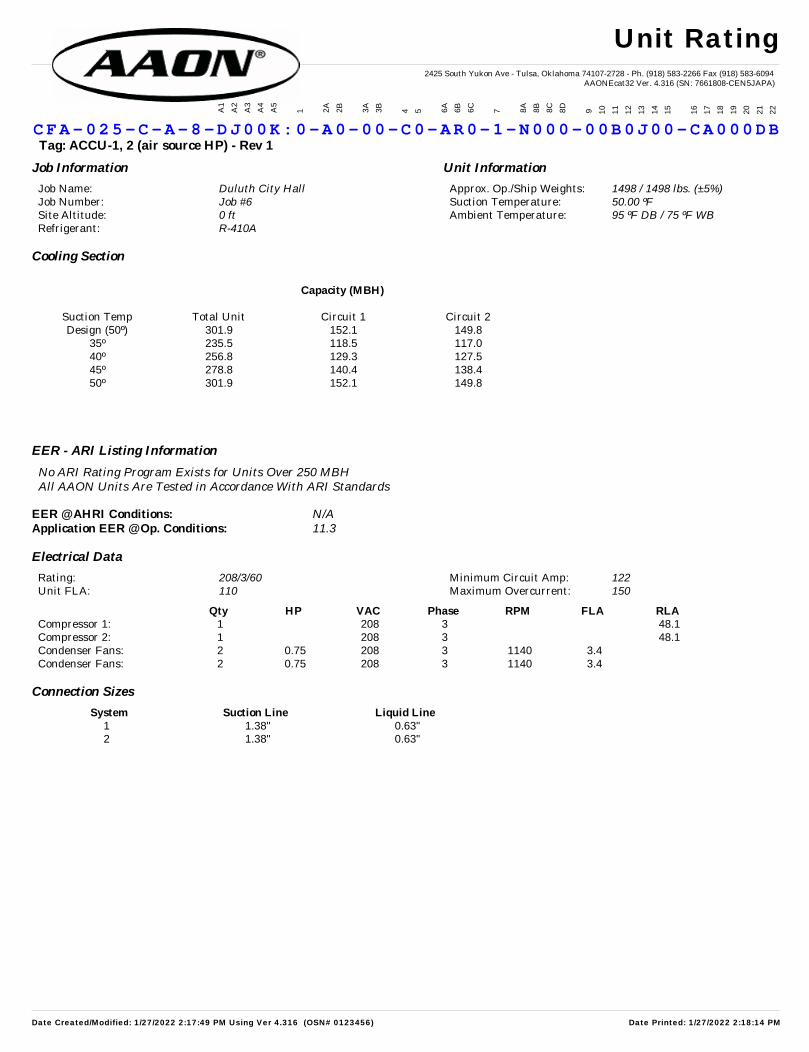
C FA -025 -C -A-8 -D J00K:0 -A 0-00 -C 0-AR 0- 1-N000 -0 0B0J 00 -CA0 00 DB Tag: ACCU-1, 2 (air source HP) - Rev 1
Job Information Unit Information
Job Name: Approx. Op./Ship Weights: Job Number: Suction Temperature: Site Altitude: Ambient Temperature: Refrigerant:
Duluth City Hall 1498 / 1498 lbs. (±5%)Job #6 50.00 ºF0 ft 95 ºF DB / 75 ºF WBR-410A
Cooling Section
Capacity (MBH)
Suction Temp Total Unit Circuit 1 Circuit 2 Design (50º) 301.9 152.1 149.8
35º 235.5 118.5 117.0 40º 256.8 129.3 127.5 45º 278.8 140.4 138.4 50º 301.9 152.1 149.8
EER - ARI Listing Information
No ARI Rating Program Exists for Units Over 250 MBH All AAON Units Are Tested in Accordance With ARI Standards
EER @ AHRI Conditions:Application EER @ Op. Conditions:
N/A11.3
Electrical Data
Rating: Minimum Circuit Amp: Unit FLA: Maximum Overcurrent:
208/3/60 122110 150
Qty HP VAC Phase RPM FLA RLA Compressor 1: 1 208 3 48.1 Compressor 2: 1 208 3 48.1 Condenser Fans: 2 0.75 208 3 1140 3.4 Condenser Fans: 2 0.75 208 3 1140 3.4
Connection Sizes
System Suction Line Liquid Line1 1.38" 0.63" 2 1.38" 0.63"
Unit Rating
Date Created/Modified: 1/27/2022 2:17:49 PM Using Ver 4.316 (OSN# 0123456) Date Printed: 1/27/2022 2:18:14 PM

2425 South Yukon Ave - Tulsa, Oklahoma 74107-2728 - Ph. (918) 583-2266 Fax (918) 583-6094AAONEcat32 Ver. 4.316 (SN: 7661808-CEN5JAPA)
CFA-025-C-A-8-DJ00K:0-A0-00-C0-AR0-1-N000-00B0J00-CA000DB Condensing Unit Tag:
Job Information
Job Name: Duluth City Hall Job Number: Job #6
Factory Supplied / Factory Installed
Quantity Description Part #: Location
Factory Supplied / Field Installed
Quantity Description Part #: Location- N/A - -
Field Supplied / Field Installed
Quantity Description Part #: Location- P-Trap(s) AHU
Refrigeration Accessories
Date Created/Modified: 1/27/2022 2:17:49 PM Using Ver 4.316 (OSN# 0123456) Date Printed: 1/27/2022 2:18:14 PM

Circuit #: 1
Date Created/Modified: 1/27/2022 2:17:49 PM Using Ver 4.316 (OSN# 0123456) Date Printed: 1/27/2022 2:18:14 PM

Circuit #: 2
Date Created/Modified: 1/27/2022 2:17:49 PM Using Ver 4.316 (OSN# 0123456) Date Printed: 1/27/2022 2:18:14 PM

2425 South Yukon Ave - Tulsa, Oklahoma 74107-2728 - Ph. (918) 583-2266 Fax (918) 583-6094AAONEcat32 Ver. 4.316 (SN: 7661808-CEN5JAPA)
A1
A2
A3
A4
A5
1
2A
2B 3A
3B
4
5
6A
6B
6C
7
8A
8B
8C
8D
9
10
11
12
13
14
15
16
17
18
19
20
21
22
C FA -025 -C -A-8 -D J00K:0 -A 0-00 -C 0-AR 0- 1-N000 -0 0B0J 00 -CA0 00 DB Tag: ACCU-1, 2 (air source HP) - Rev 1
Job Name: Duluth City Hall Unit Submittal For: Job Number: Job #6 Unit Submittal Date: January 27, 2022
Base Option Description
CF Generation CF - Condensing Unit
A Major Rev Major Revision
025 Unit Size Twenty Five
C Series C Cabinet
A Revision Minor Revision
8 Voltage 208V/3Ø/60Hz
D Compressor Style R-410A Variable Capacity Scroll Comp
J Condenser Style Air-Source Heat Pump (Fin and Tube)
0 Configuration Standard
0 Coating Standard
K Staging 1 Variable Refrig System + 1 On/Off Refrig System
Feature Option Description
0 1. Unit Orientation Vertical Condenser Discharge with End Control Panel
A 2A. Refrigeration Control 5 Minute Compressor Off Timer & 20 Second Compressor Stage Delay
0 2B. Blank Standard
0 3A. Refrigeration Options Standard
0 3B. Blank Standard
C 4. Refrigeration Accessories Sight Glass + Compressor Isolation Valves
0 5. Blank Standard
A 6A. Unit Disconnect Type Single Point Power Non-Fused Disconnect
R 6B. Disconnect Size 150 Amps
0 6C. Blank Standard
1 7. Accessories Phase & Brown Out Protection + Suction Pressure Transducer on Each Refrigeration System + Compressor Sound Blanket
N 8A. Control Sequence Field Installed DDC Controls Furnished by Others with Isolation Relays
0 8B. Control suppliers Standard Terminal Block
0 8C. Control Supplier Options Standard
0 8D.BMS Connection and Diagnostics Standard
0 9. Blank Standard
0 10. Blank Standard
B 11. Maintenance Accessories 115VAC Convenience Outlet - Field Wired
0 12. Code Options Standard ETL U.S.A. Listing
J 13.Air Cooled Condenser Accessories Cond. Coil Guards + VFD Controlled Cond. Fans - Head Pressure Control
0 14. Blank Standard
0 15. Blank Standard
C 16. Electrical Options 10 KAIC
A 17. Shipping Options Crating
0 18. Blank Standard
0 19. Blank Standard
0 20. Cabinet Material Standard - Galvanized Steel Cabinet
D 21. Warranty Extended Compressor Warranty - Years 2-5
B 22. Paint and SPAs Premium AAON Gray Paint Exterior
Unit Submittal
Date Created/Modified: 1/27/2022 2:17:49 PM Using Ver 4.316 (OSN# 0123456) Date Printed: 1/27/2022 2:18:19 PM

2425 South Yukon Ave - Tulsa, Oklahoma 74107-2728 - Ph. (918) 583-2266 Fax (918) 583-6094AAONEcat32 Ver. 4.316 (SN: 7661808-CEN5JAPA)
A1
A2
A3
A4
A5
1
2A
2B 3A
3B
4
5
6A
6B
6C
7
8A
8B
8C
8D
9
10
11
12
13
14
15
16
17
18
19
20
21
22
C FA -025 -C -A-8 -D J00K:0 -A 0-00 -C 0-AR 0- 1-N000 -0 0B0J 00 -CA0 00 DB Tag: ACCU-1, 2 (air source HP) - Rev 1 Job Name: Duluth City Hall For: Job Number: Job #6 Date: January 27, 2022
Terminals Available/Required for Controlling the Unit
Terminal Description[C] Common
[Y1], [Y2] Cooling Stage Enable + Isolation Relay[CC1-] & [CS1+] Variable Capacity Compressor (0-5 VDC) Signal
[0] Cool Enable for Heat Pump[P51-] & [P61+],[P52-] & [P62+], Suction Pressure Sensor (0-5 VDC)
[P3] Suction Pressor Sensor Power (+5 VDC)[W1] Heat Enable Stage 1
[R+], [SH], [T-] AAON Communications
Points List
Date Created/Modified: 1/27/2022 2:17:49 PM Using Ver 4.316 (OSN# 0123456) Date Printed: 1/27/2022 2:18:20 PM


Vision® Air Handling Unit
Page 1 of 10 www.DaikinApplied.com
Job Information Technical Data Sheet
Job Name Duluth City Hall Date January 27 2022
Submitted By CV
Software Version 12.71
Unit Tag DOAS-1, 2 - Rev 5 (with heat wheel)
Unit Overview
Model Number
Supply Return/Exhaust
Air Volume
cfm
Static Pressure External Dimensions Air Volume
cfm
Static Pressure External Dimensions
External inWc
Total inWc
Height in
Width in
Length in
External inWc
Total inWc
Height in
Width in
Length in
CAH018GDGM 7000 2.00 5.25 54* 68* 290 7000 1.50 3.26 54* 68* 150
*Not including base rails, coil connectors, drain connectors and control boxes.
Unit
Model Number: CAH018GDGM
Approval: ETL Listed / ETL Listed to Canadian Safety Standards (ETL Label / ETLc Label)
Outer Panel: Painted 24 gauge G60 Galvanized Steel Liner: 24 gauge Galvanized Steel (unless noted per section)
Insulation: R-13 Injected Foam
Sound Baffles: Included in Fan, Plenum, Access and Manual section (unless noted per section)
Unit Configuration: Stacked with opposed air flows Drive (Handling) Location: Right
Base: 6" formed channel Wall Thickness: 2 in
Altitude: 842 ft Parts Warranty: Standard One Year
Vision® Air Handling Unit
Page 2 of 10 www.DaikinApplied.com
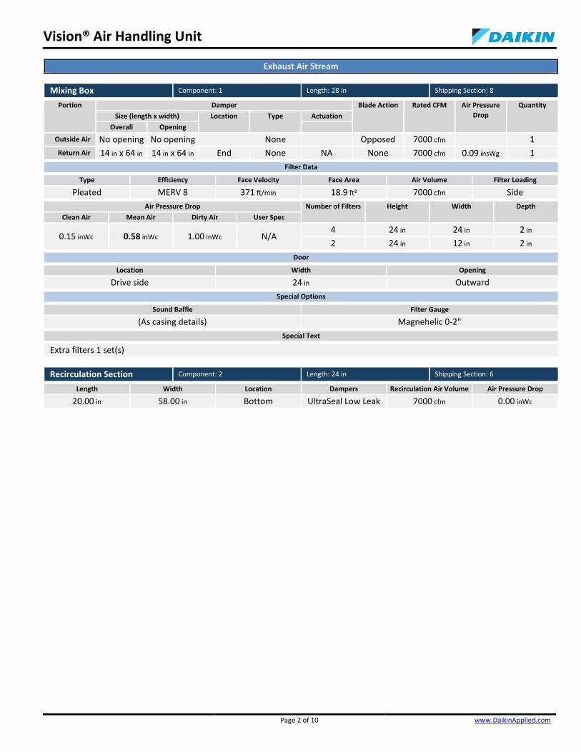
Exhaust Air Stream
Mixing Box Component: 1 Length: 28 in Shipping Section: 8
Portion Damper Blade Action Rated CFM Air Pressure Drop
Quantity Size (length x width) Location Type Actuation
Overall Opening
Outside Air No opening No opening None Opposed 7000 cfm 1
Return Air 14 in x 64 in 14 in x 64 in End None NA None 7000 cfm 0.09 insWg 1
Filter Data
Type Efficiency Face Velocity Face Area Air Volume Filter Loading
Pleated MERV 8 371 ft/min 18.9 ft² 7000 cfm Side
Air Pressure Drop Number of Filters Height Width Depth Clean Air Mean Air Dirty Air User Spec
0.15 inWc 0.58 inWc 1.00 inWc N/A 4 24 in 24 in 2 in
2 24 in 12 in 2 in
Door
Location Width Opening
Drive side 24 in Outward
Special Options
Sound Baffle Filter Gauge
(As casing details) Magnehelic 0-2"
Special Text
Extra filters 1 set(s)
Recirculation Section Component: 2 Length: 24 in Shipping Section: 6
Length Width Location Dampers Recirculation Air Volume Air Pressure Drop
20.00 in 58.00 in Bottom UltraSeal Low Leak 7000 cfm 0.00 inWc

Vision® Air Handling Unit
Page 3 of 10 www.DaikinApplied.com
Energy Recovery Component: 3 Length: 22 in Shipping Section: 5
Heat Wheel Model
Media Type Wheel Diameter
Supply Air Volume
Face Velocity Segmented Wheel Supply Air Return Air
Summer Winter Summer Winter
ECW 546-3A
Synthetic fiber - 3
angstrom
54 in 7000 cfm 858 ft/min 950 ft/min 869 ft/min 882 ft/min No
Electrical Supply
Bypass Damper Opening
Pressure Drop Exhaust Air Volume
VFD Adjustable Purge Plate
Motor Power Supply Air Return Air
Summer Winter Summer Winter
115/60/1 V/Hz/Phase
16.00 x 64.00 / 16.00 x 64.00
0.97 insWg 0.97 insWg 0.94 insWg 0.94 insWg 7000 cfm Yes Yes 0.75 HP
Summer Conditions
Outside Air Return Air Supply Air Exhaust Air Effectiveness Total Energy Recovered Dry Bulb Wet Bulb Dry Bulb Wet Bulb Dry Bulb Wet Bulb Dry Bulb Wet Bulb Latent Sensible Total
88.0 °F 72.0 °F 75.0 °F 62.0 °F 80.0 °F 66.4 °F 83.1 °F 68.1 °F 57.97 % 63.75 % 60.27 % 139204 Btu/hr
Winter Conditions
Outside Air Return Air Supply Air Exhaust Air Effectiveness Total Energy Recovered Dry Bulb Wet Bulb Dry Bulb Wet Bulb Dry Bulb Wet Bulb Dry Bulb Wet Bulb Latent Sensible Total
-20.0 °F -20.0 °F 70.0 °F 54.0 °F 34.1 °F 31.3 °F 11.0 °F 14.5 °F 60.73 % 66.61 % 65.41 % 522962 Btu/hr
AHRI 1060 Certification
Application Rating is outside of the scope of AHRI ERV Certification Program but is rated in accordance with AHRI Standard 1060.
Door
Location Width Opening
Drive side 18 in Outward
Special Options
Sound Baffle Static Pressure
(As casing details) 0.94 inWc
Access Section Component: 4 Length: 22 in Shipping Section: 2
Air Pressure Drop
0.00 inWc
Door
Location Width Opening
Drive side 18 in Outward
Special Options
Sound Baffle
(As casing details)

Vision® Air Handling Unit
Page 4 of 10 www.DaikinApplied.com
Return/Exhaust Fan Component: 5 Length: 54 in Shipping Section: 1
Fan Performance
Air Volume Static Pressure Fan Energy Index(FEI)
Total Input Power
Fan Shaft Power
Speed Outlet Velocity
External Total Cabinet
Operating Maximum
7000 cfm 1.50 inWc 3.26 inWc 0.14 inWc 1.34 4.5 kW 5.21 BHP 1675 rpm 2403 rpm 0 ft/min
Fan Data
Fan Type Blade Type / Class Quantity of Fans Wheel Diameter Material Type Number of Blades Discharge Motor Location
Centrifugal - Plenum
Airfoil / 2 1 22.25 in Aluminum 9 - Behind Fan
Motor Data
Power Electrical Supply
Speed Efficiency Enclosure Frame Size Supplier Number of Poles
Lock Rotor Current
Full Load Current
7.5 HP 200/60/3 V/Hz/Phase
1750 rpm Premium ODP 213 T frame Generic 4 162.28 A 23.30 A
Fan Options
Wheel Guard: Provided Shaft Grounding Kit: Provided
Isolator Type: Spring
VFD/Starter/Disconnect Data
Selection Type: VFD Vendor: Daikin Applied
Auxiliary Control: Disconnect Voltage: 200 V
Disconnect Type: Fused Height x Width x Depth: 19.25 in x 7.36 in x 10.15 in
Mounting: Door Side Enclosure: NEMA 1
VFD Quantity: 1
Custom Openings
Custom Opening Location Width Height Rainhood w/Screen
1 End 48 in 28 in None
Door
Location Width Opening Light
Drive side 24 in Outward LED marine light kit with GFI outlet
Special Options
Sound Baffle
(As casing details)
Special Text
Add damper to EA opening

Vision® Air Handling Unit
Page 5 of 10 www.DaikinApplied.com
Supply Air Stream
Plenum Section Component: 1 Length: 30 in Shipping Section: 3
Air Pressure Drop
0.09 inWc
Custom Dampers
Custom Damper Damper Type Location Size (Width x Height) Material Blade Action Rainhood w/Screen Overall Opening
1 UltraSeal Low
Leak End 54 in x 28 in 44 in x 24 in Galv. Steel Parallel None
Door
Location Width Opening
Drive side 26 in Outward
Special Options
Sound Baffle
(As casing details)
Combination Filter Component: 2 Length: 22 in Shipping Section: 3
Access Face Velocity Face Area Air Volume
Side 371 ft/min 18.9 ft² 7000 cfm
Portion Type Efficiency Air Pressure Drop Number of Filters
Height Width Depth Clean Air Mean Air Dirty Air User Spec
Pre-Filter Pleated MERV 8 0.15 inWc 0.58 inWc 1.00 inWc N/A 4 24 in 24 in 2 in
2 24 in 12 in 2 in
Filter Pre Pleat MERV 13 0.15 inWc 0.57 inWc 1.00 inWc N/A 4 24 in 24 in 4 in
2 24 in 12 in 4 in
Door
Location Width Opening
Drive side 12 in Outward
Special Options
Sound Baffle Pre-Filter Gauge Final-Filter Gauge
(As casing details) Magnehelic Magnehelic
Special Text
Extra filters 1 set(s)
Access Section Component: 3 Length: 24 in Shipping Section: 4
Air Pressure Drop
0.00 inWc
Door
Location Width Opening
Drive side 20 in Outward
Special Options
Sound Baffle
(As casing details)
Energy Recovery Section Component: 4 Length: 22 in Shipping Section: 5
See Exhaust Air Stream

Vision® Air Handling Unit
Page 6 of 10 www.DaikinApplied.com
Recirculation Section Component: 5 Length: 24 in Shipping Section: 7
Length Width Location Dampers Recirculation Air Volume Air Pressure Drop
20.00 in 64.00 in Top UltraSeal Low Leak 7000 cfm 0.00 inWc
Direct Expansion Coil Component: 6 Length: 34 in Shipping Section: 9
Coil Model Total Capacity Sensible Capacity Number of Coils Number of Rows Fins per Inch Tube Diameter Tube Spacing (Face x Row)
5EJ0806B 264502 Btu/hr 174594 Btu/hr 1 6 8 0.625 in 1.50 in x 1.299 in
Air Volume Air Temperature Coil Air Pressure
Drop
Finned Height
Finned Length
Face Area Face Velocity Entering Leaving
Dry Bulb Wet Bulb Dry Bulb Wet Bulb
7000 cfm 80.0 °F 67.0 °F 56.5 °F 54.7 °F 0.58 insWg 42 in 55 in 16.04 ft² 436 ft/min
Fluid Sub-Cooled Refrigerant Liquid Temp.
Suction Vapor Superheat
Temp. at Coil Outlet
Design Saturated Condensing Temp.
Total Refrigerant Weight Suction Temp. Refrigerant
46.0 °F R410a 110.0 °F 8.0 °F 110.0 °F 51.00 lb
Connection [Data Per Coil] Min. Fin Surface Temp.
Min. Tube Wall Surface Temp. Type Liquid [Qty - Size] Suction [Qty - Size] Location Material
OD Sweat 2-0.88 in 2-1.63 in Drive side Copper tube 32.0 °F 32.0 °F
Material Drain Pan Drain Side Fin Tube Header Case
Aluminum .0075 in Copper .020 in Copper Galv. steel Stainless steel Drive side
Total Refrigerant Weight is the total for all circuits of all coils in this coil section and is estimated. Refer to the AHU and Condensing Unit IOMs for recommendations on system start-up.
AHRI 410 Certification
Coil is NOT certified by AHRI Door
Location Width Opening
Drive side 18 in Outward
Special Options
Sound Baffle
(As casing details)

Vision® Air Handling Unit
Page 7 of 10 www.DaikinApplied.com
Future Hot Water Coil Component: 7 Length: 28 in Shipping Section: 10
Number of Coils Number of Rows
1 1 Coil Air Pressure Drop Finned Height Finned Width Face Area Face Velocity
0.20 inWc 42 in 52 in 15.17 ft² 462 ft/min Connection Location Connection Material
Drive side Carbon steel Coil Model Drain Pan Drain Pan Side
Future Coil (Not Supplied) None -
AHRI 410 Certification
Coil is NOT certified by AHRI Door
Location Width Opening
Drive side 18 in Outward
Special Options
Sound Baffle
(As casing details)
Special Text
HGRH Coil
Hot Water Coil Component: 8 Length: 30 in Shipping Section: 11
Coil Model Total Capacity Number of Coils Number of Rows Fins per Inch Tube Diameter Tube Spacing (Face x Row)
5WH0903B 726205 Btu/hr 1 3 9 0.625 in 1.50 in x 1.299 in
Air Volume Air Temperature Coil Air Pressure Drop
Finned Height Finned Length Face Area Face Velocity Entering Leaving Dry Bulb Dry Bulb
7000 cfm -20.0 °F 77.9 °F 0.21 inWc 42 in 55 in 16.04 ft² 436 ft/min
Fluid Flow Rate Pressure Drop Velocity Volume Weight Entering Leaving
160.0 °F 118.8 °F 37.50 gpm 3.80 ftHd 2.90 ft/s 7.0 gal 66.00 lb
Connection [Data Per Coil] Glycol Type Min. Fin Surface Temp.
Min. Tube Wall Surface Temp.
Fouling Factor Type Size Location Material
Threaded 2.00 in Drive side Carbon steel Propylene
(35%) 118.8 °F 118.8 °F 0.000
Material Fin Tube Header Case
Aluminum .0075 in Copper .020 in Copper Galv. steel AHRI 410 Certification
Coil is NOT certified by AHRI Door
Location Width Opening
Drive side 18 in Outward
Special Options
Sound Baffle
(As casing details)

Vision® Air Handling Unit
Page 8 of 10 www.DaikinApplied.com
Supply Fan Component: 9 Length: 44 in Shipping Section: 12
Fan Performance
Air Volume Static Pressure Fan Energy Index(FEI)
Total Input Power
Fan Shaft Power
Speed Outlet Velocity
External Total Cabinet
Operating Maximum
7000 cfm 2.00 inWc 5.25 inWc 0.00 inWc 1.30 7.0 kW 8.30 BHP 1951 rpm 2403 rpm 0 ft/min
Fan Data
Fan Type Blade Type / Class Quantity of Fans Wheel Diameter Material Type Number of Blades Discharge Motor Location
Centrifugal - Plenum
Airfoil / 2 1 22.25 in Aluminum 9 Axial Behind Fan
Motor Data
Power Electrical Supply
Speed Efficiency Enclosure Frame Size Supplier Number of Poles
Lock Rotor Current
Full Load Current
10.0 HP 200/60/3 V/Hz/Phase
1750 rpm Premium ODP 215 T frame Generic 4 193.29 A 29.50 A
Fan Options
Wheel Guard: Provided Shaft Grounding Kit: Provided
Isolator Type: Spring
VFD/Starter/Disconnect Data
Selection Type: VFD Vendor: Daikin Applied
Auxiliary Control: Disconnect Voltage: 200 V
Disconnect Type: Fused Height x Width x Depth: 19.25 in x 7.36 in x 10.15 in
Mounting: Door Side Enclosure: NEMA 1
VFD Quantity: 1
Panel
Location Width Opening
Removable panels - in Outward
Special Options
Sound Baffle
(As casing details)
Plenum Section Component: 10 Length: 32 in Shipping Section: 13
Air Pressure Drop
0.05 inWc
Custom Openings
Custom Opening Location Width Height Rainhood w/Screen
1 End 48 in 24 in None
Door
Location Width Opening Light
Drive side 20 in Inward LED marine light kit with GFI outlet
Unit Sound Power (dB)
Type 63 Hz 125 Hz 250 Hz 500 Hz 1000 Hz 2000 Hz 4000 Hz 8000 Hz
Radiated: 74 75 78 66 63 56 46 51
Unit Discharge: 78 75 82 77 78 76 70 64
Unit Return: 74 77 83 77 71 69 62 56

Vision® Air Handling Unit
Page 9 of 10 www.DaikinApplied.com
Shipping Section Details
Section Length in
Weight lb
Corner Weights (lb) Center of Gravity (in) P1 P2 P3 P4 XX YY ZZ
1 54 902 281 259 169 192 22 32 28
2 22 213 46 46 60 60 12 34 33
3 52 602 143 143 159 159 27 34 29
4 24 283 64 64 78 78 13 34 27
5 22 1015 234 234 254 254 11 34 57
6 24 199 49 49 61 61 13 34 33
7 24 261 64 64 76 76 13 34 26
8 28 326 74 74 88 88 15 34 33
9 34 767 240 226 143 158 13 33 28
10 28 367 95 95 89 89 14 34 26
11 30 582 187 176 105 115 11 33 29
12 44 862 251 225 180 205 20 32 25
13 32 470 117 117 117 117 16 34 29
Entire Unit
290 Lower level only
6849
n/a
n/a
n/a
n/a
n/a
n/a
n/a
NOTE: Special components aren't included in the corner weights and center of gravity data.
Supply Static Pressure Drop
Component Option Static Pressure Drop
Plenum Section Plenum Section 0.09 insWg
Panel and Bag Filter Panel and Bag Filter 1.15 insWg
Access Section Access Section
Energy Recovery Section Summer 0.97 insWg
Bottom Recirc Section Bottom Recirc Section
DX Coil DX Coil 0.58 insWg
Hot Water Coil Hot Water Coil 0.20 insWg
Hot Water Coil Hot Water Coil 0.21 insWg
Supply Fan Cabinet
Plenum Section Plenum Section 0.05 insWg
External Static External Static 2.00 insWg
Total Supply Fan Static 5.25 insWg
FAN
54
1
54
54
ACCESS
22
2
22
PLENUM
30
PBFILT
22
3
54
52
ACCESS
24
4
24
WHEEL
22
22
5
22
22
RECIRC TOP
24
6
24
RECIRC BOTTOM
24
7
24MIX
28
8
54
28
DXC34
9
34
HWC
28
10
28
HWC
30
11
30
FAN
44
12
44
PLENUM
32
13
54
32Elevation View
XZ
Vision® Air Handling Unit
Page 10 of 10 www.DaikinApplied.com
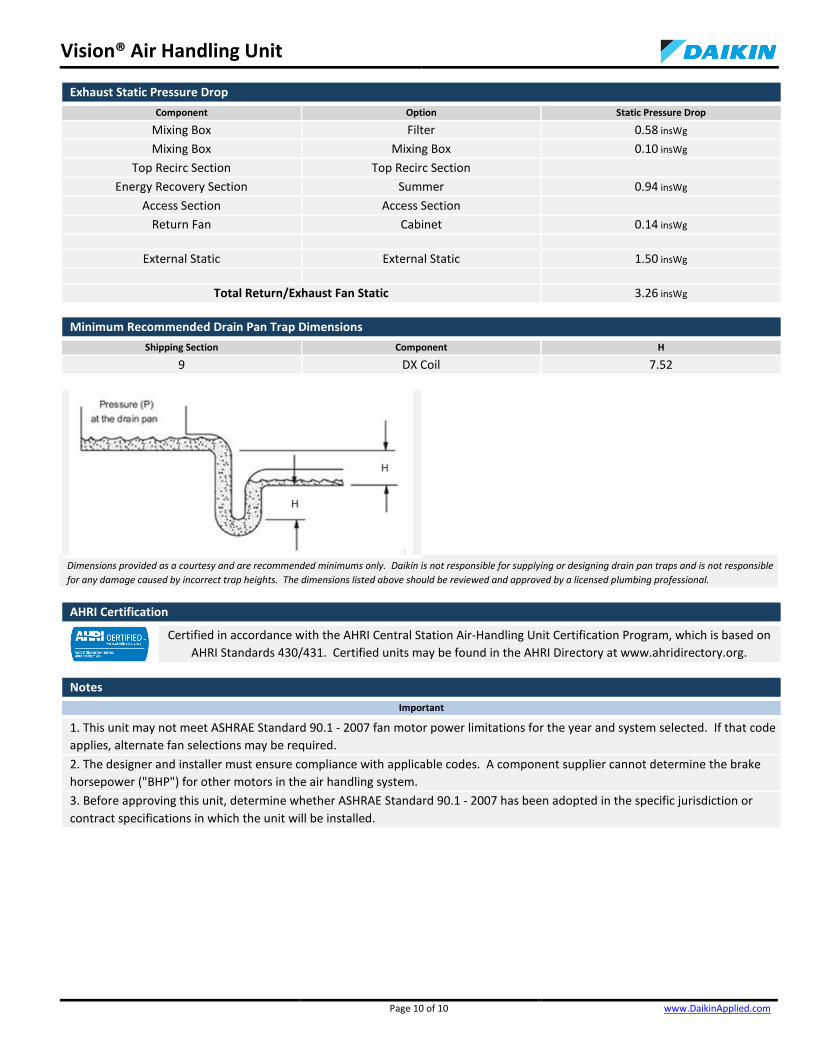
Exhaust Static Pressure Drop
Component Option Static Pressure Drop
Mixing Box Filter 0.58 insWg
Mixing Box Mixing Box 0.10 insWg
Top Recirc Section Top Recirc Section
Energy Recovery Section Summer 0.94 insWg
Access Section Access Section
Return Fan Cabinet 0.14 insWg
External Static External Static 1.50 insWg
Total Return/Exhaust Fan Static 3.26 insWg
Minimum Recommended Drain Pan Trap Dimensions
Shipping Section Component H
9 DX Coil 7.52
Dimensions provided as a courtesy and are recommended minimums only. Daikin is not responsible for supplying or designing drain pan traps and is not responsible for any damage caused by incorrect trap heights. The dimensions listed above should be reviewed and approved by a licensed plumbing professional.
AHRI Certification
Certified in accordance with the AHRI Central Station Air-Handling Unit Certification Program, which is based on AHRI Standards 430/431. Certified units may be found in the AHRI Directory at www.ahridirectory.org.
Notes
Important
1. This unit may not meet ASHRAE Standard 90.1 - 2007 fan motor power limitations for the year and system selected. If that code applies, alternate fan selections may be required. 2. The designer and installer must ensure compliance with applicable codes. A component supplier cannot determine the brake horsepower ("BHP") for other motors in the air handling system. 3. Before approving this unit, determine whether ASHRAE Standard 90.1 - 2007 has been adopted in the specific jurisdiction or contract specifications in which the unit will be installed.

Güntner is not liable for unit and system damage due to lack of freeze protection for coils installed in freezing climates
Selection ID: 183953 Page 1 of 1 GPS v2.9 January 2022 (DF DLL v 3.7)
Selection ID: 183953
Date: 01/28/2022
Dry Fluid Cooler GFW 090.2D06/6SA-E255U/04P.M
Quantity: 1
Design Working Fluid Flow/Capacity: 255.0 GPM / 1203 MBH Working Fluid: 35% Propylene Glycol
Rated Capacity vs. Design: 101.3 % Entering Fluid Temperature: 110.0 °F
Air Flow per Unit: 93316 CFM Leaving Fluid Temperature: 100.0 °F
Air Inlet Dry Bulb Temperature: 9 2 . 0 °F Fluid Pres. Drop at Design Flow: 10.53 psig
Air Inlet Wet Bulb Temperature: 7 5 . 0 °F Elevation: 0 ft
Detailed Unitary Data
Fans: 6, suitable for 230V/3Ph/60Hz Sound Pressure @ 3ft: 73 dB(A)
Total Fan Power in/out: 15.3 kW / 18.9 HP, nominal Sound Pressure @ 30ft: 61 dB(A)
FLA: 46.8 A Sound Power Level: 93 dB(A)
MCA: 48.8 A
MOCP: 50.0 A
Angular Fan Velocity: 1050 RPM
Casing: Galv. Powder coated Interior Coil Volume: 12.8 ft³
Coil: Copper Max Operating Pressure: 232 psia
Number of Support Anchors: 14
Fin Material: Aluminum
Fin Spacing: 12.7 FPI
Dimensions Headers and Connections (Diameters) Reference Information
Height: 5.7 ft Coil
Width: 4.7 ft Inlet Connections: 2 x 3.125 in S-GFWD 090.1/6-U(4)-G6/01/4P.M
Length, nominal: 26.4 ft Outlet Connections: 2 x 3.125 in
Weights Headers:
Shipping: 6463 lbs Inlet: 3.125 in
Operating: 6510 lbs Outlet: 3.125 in
Options
Flange connections, ANSI 150#
BACnet MSTP
Service
Important Remarks / Explanatory Notes
Price does not include freight unless otherwise stated
Terms of Delivery: FCA Laredo, TX
Payment Cond: .
Delivery Time: .
Validity: 03/29/2022
Our general terms of sales and delivery apply.

meas
ures
with
out
spec
ifica
tion
of t
oler
ance
s:we
ldin
g / b
razi
ng:
DI
N EN
ISO
1392
0, to
lera
nce
clas
s D
gene
ral t
oler
ance
s:
D
IN IS
O 27
68-1
, tol
eran
ce c
lass
com
pone
nt p
arts
m /
asse
mbly
v ;
leng
th >
4m D
IN 7
168,
tol
eran
ce c
lass
com
pone
nt p
arts
m /
asse
mbly
sg,
gene
ral t
oler
ance
s:
D
IN IS
O 27
68-2
, tol
eran
ce c
lass
com
pone
nt p
arts
K /
asse
mbly
L; l
engt
h >3
m EN
101
62,
tole
ranc
est
raig
htne
ss a
nd f
latn
ess
0,002
xl (l
engt
h)
prot
ectio
n no
te a
cc. t
o D
IN IS
O 16
016
Güntner U.S. LLC.3601 Algonquin Rd Ste 925Rolling Meadows, IL 60008USATel. + 1 847 781 0900www.guntnerus.com
Baan-No.
DIN A2size
material
weight [kg]
scale
type
name
notice
drawing number
customer
project/ quantity
order/ position
namedate
namedate
drawn:
certified:
indexrevision
sheet
Reference #: Project:
Notes:
Dimensions in inches (mm)Guentner U.S. Ref.#: 1/1
1142021102544
1 : 20
GVW-GFW 090.2/6
cadbot1/14/2021
Preliminary Drawing. Do not use for construction.Coil inlet and outlet details and quantities often vary from the sample shown above
50 1/2"1282mm
3 1/2"89mm
TYP.
36 3/4"935mm
O 17 mm (11/16") @ 14 Locations
283 1/2"7200mm
25"635mm
47 1/4"1200mm
TYP.
1"26mm (TYP.)
47 1/4"1200mm
TYP.
31 1/2
"80
0mm
43 3/4"1113mm
97 1/4"2473mm
94 1/2"2400mm
68 1/2
"17
42mm
Crane Lifting Bracket (2x)
316 1/2"8036mm
2"50mm (TYP.)
Condenser / Cooler
In
Out

Addendum 3 Solicitation 22-99418
City Hall MEP Renewal Project This addendum serves to notify all bidders of the following changes to the solicitation documents:
1. Bidders must provide a bid amount for each unit price, alternate, and lump sum bid within Bid Express in order to have a responsive bid. If you are not bidding a particular work scope, enter $0.00 for those bid amounts. Any work scope that has alternates or unit prices must have all prices for that work scope completed.
2. Test results from previous lead and asbestos testing in 2018 and 2021 is attached. If a contractor encounters what is suspected to be hazardous materials, it is the contractor’s responsibility to immediately notify the City. The City will contract for the testing and removal of hazardous material.
3. As an alternate, the general conditions contractor will be responsible for moving and protecting furniture, and removing and replacing acoustical ceiling. This will include but not be limited to desks/work stations, filing cabinets and other officer furniture (conference tables, etc.). If the alternate is included, it is the general conditions contractor’s responsibility to protect all furniture, whether moved or left in place, and to return any moved furniture to its original location and status. Contractor shall be responsible for damage. City staff will be responsible for their own personal belongings. An alternate bid item has been added to the solicitation for contractors to include the lump sum for this item, as well as an hourly rate in the event of any scope change. A layout of the furniture was included in Addendum 2.
4. Piping & Wiring Submittal and Equipment Submittal received from Trane are attached.
5. The awarded mechanical contractor installing the VRF equipment must have
successfully completed the CIT MULTI MEUS approved training course prior to installation. The contractor must also submit a completed and approved MEUS Extended Warranty Process report. Per Trane, the cost as of 5/26/22 for this training is $480/person. Trane recommends more than one installer be trained. Trane will assist the contractor with submitting the approved MEUS extended warranty process report.
6. Acoustical ceiling tiles are USG Eclipse 78775. General conditions contractor is responsible for the removal as needed and replacement of the acoustical ceiling. Contractor shall be responsible for damage.
7. The Luminaire Schedule, electrical sheet E500, is attached.
8. Some activities due to noise level, may require scheduling outside of City Hall operational hours (8am-4:30pm, M-F).
9. Project shutdown instructions are attached.
10. Additional changes and clarifications are included in KFI’s Addendum 3 attached.
Please acknowledge receipt of this Addendum by checking the acknowledgment box within the www.bidexpress.com solicitation. Posted: June 2, 2022 Attachments:
Lead/Asbestos Test Results Piping & Wiring Submittal Equipment Submittal Electrical Sheet E500 Project Shutdown Instructions KFI’s Addendum 3


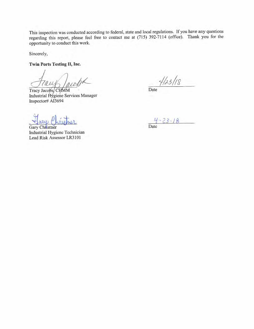


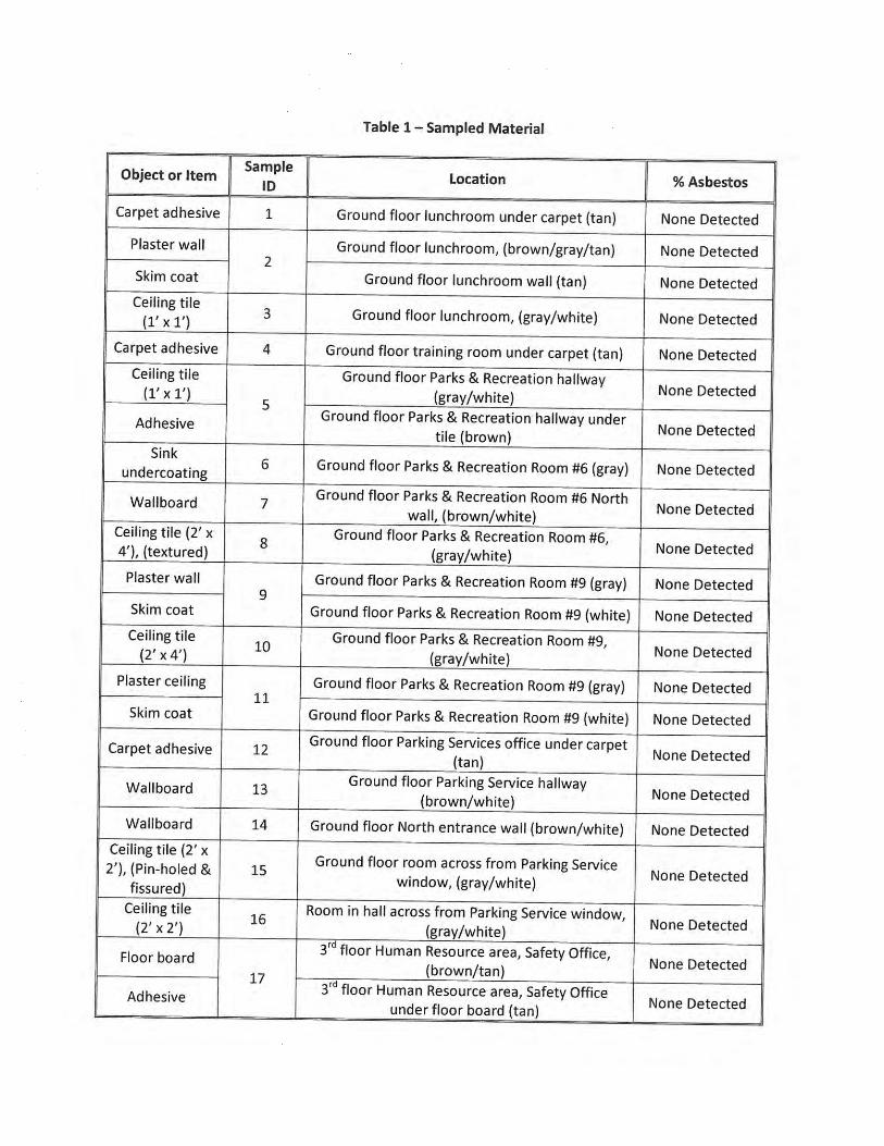


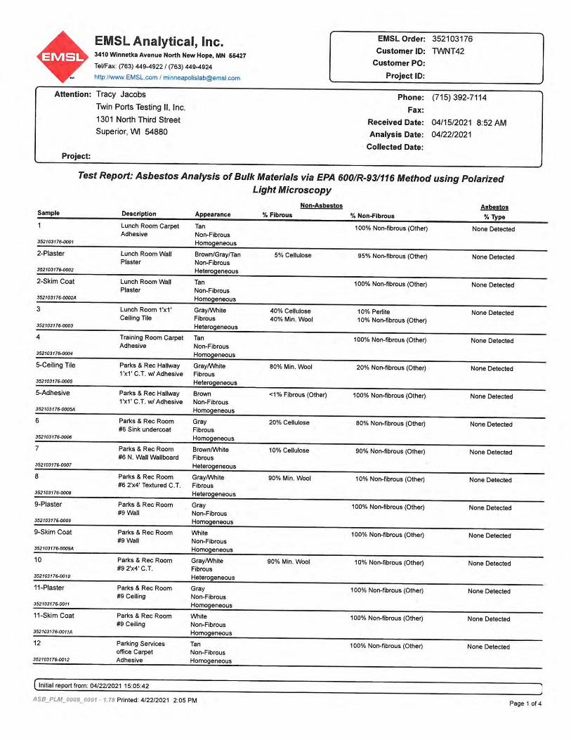


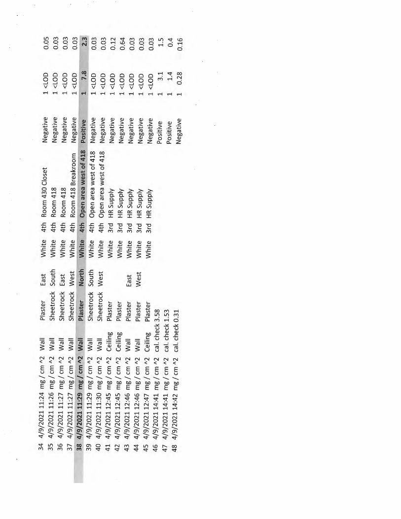


Duluth City Hall - VRF May 17, 2022
Equipment Submittal Page 1 of 1
Submittal
Prepared For: City of Duluth
Date: May 17, 2022 Job Name: Duluth City Hall - VRF
_____________________________________________________________________________________________ Trane U.S. Inc. is pleased to provide the following submittal for your review and approval. Product Summary
Qty Product 9 Trane - Mitsubishi VRF Outdoor Unit
13 Trane - Mitsubishi VRF Branch Controller 132 Trane - Mitsubishi VRF Indoor Unit
_____________________________________________________________________________________________ Notes:
1. Labor warranty NOT included. 2. Startup assistance by Trane Ductless Technical Specialist included. 3. Disconnect switch NOT included. 4. Linesets NOT included.
Trane Mitsubishi Products - Standard warranty: The parts are warranted to the original owner a period of one (1) year, and Compressor a period of seven (7) years from the date of installation by a licensed contractor. Extended warranty: The parts and compressor will be warranted for a period of ten (10) years to the original owner if (1) the System is designed by a Diamond Designer using the MEUS Diamond System Builder™ (2) the installing contractor has successfully completed the CITI MULTI MEUS approved training course, and (3) the contractor has submitted a completed and approved MEUS Extended Warranty Process report. Joey Beisbier / Richard Youngdahl Trane U.S. Inc. 775 Vandalia Street Saint Paul, MN 55114 Office Phone: (651) 468-2700
The attached information describes the equipment we propose to furnish for this project, and is submitted for your approval. Product performance and submittal data is valid for a period of 6 months from the date of submittal generation. If six months or more has elapsed between submittal generation and equipment release, the product performance and submittal data will need to be verified. It is the customer’s responsibility to obtain such verification.

Design View Piping Diagrams
2

3
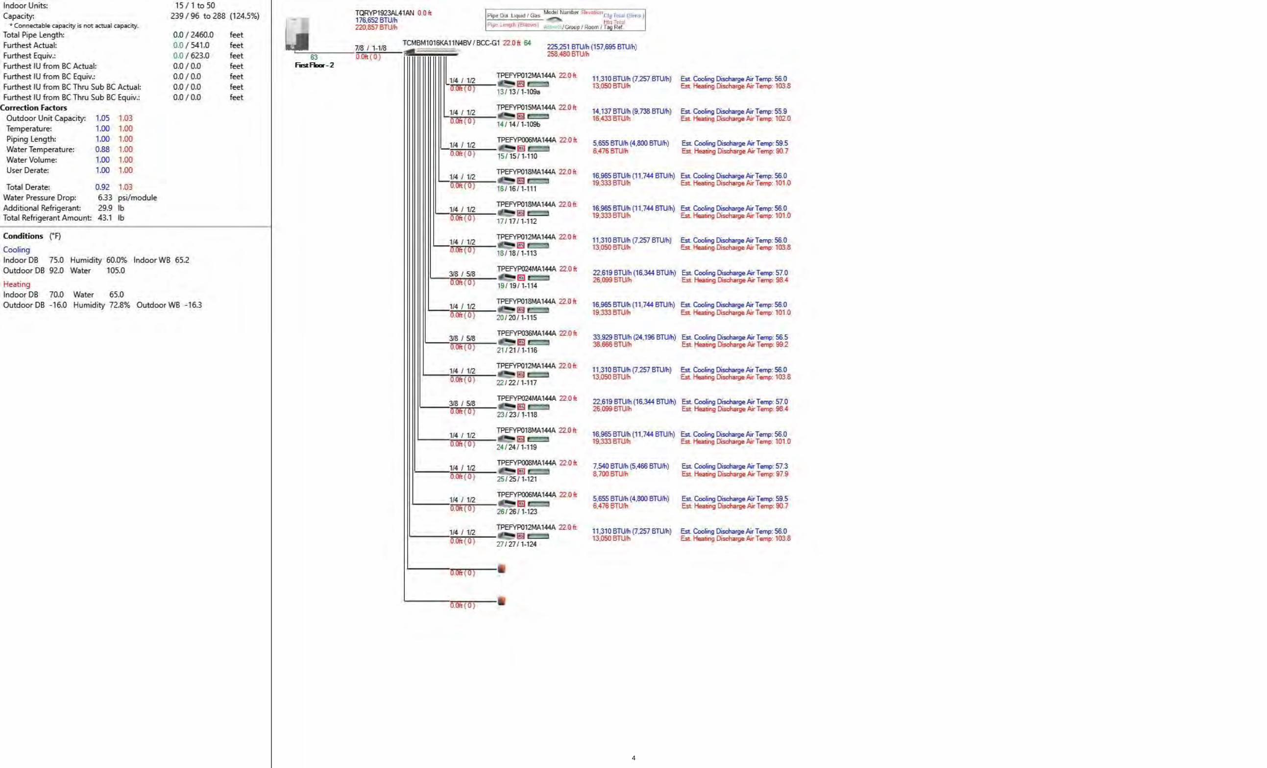
4

5

6

7

8

9

10
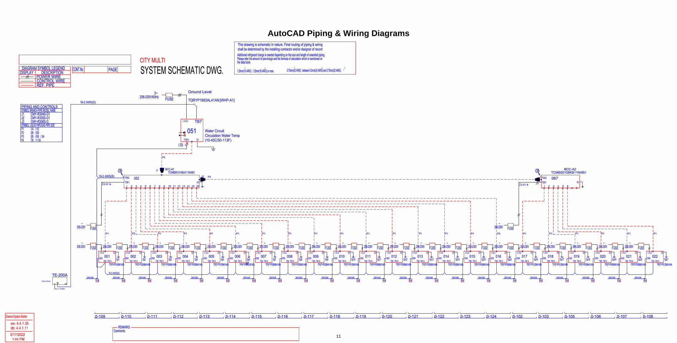
TB2
TB1r e2 c o G
16-2 AWG(S)
FUSE~
208-230V
052TCMBM1016KA11N4BV
BCC-A1J1
1
TB5 TB1 5
L1L2 GFUSE
~208-230V
TPEFYP015MA144A
001Gp1CN20
RSCable Included
P1
2
B1 5T5BT
L1L2 GFUSE
~208-230V
16-2 AWG(S)
TPEFYP024MA144A
002Gp2CN20
RSCable Included
P2
3
B1 5T5BT
L1L2 GFUSE
~208-230V
TPEFYP006MA144A
003Gp3CN20
RSCable Included
P1
4
B1 5T5BT
L1L2 GFUSE
~208-230V
TPEFYP006MA144A
004Gp4CN20
RSCable Included
P1
5
B1 5T5BT
L1L2 GFUSE
~208-230V
TPEFYP015MA144A
005Gp5CN20
RSCable Included
P1
6
B1 5T5BT
L1L2 GFUSE
~208-230V
TPKFYP004LM140A
006Gp6CN20
RSCable Included
P1
7
B1 5T5BT
L1L2 GFUSE
~208-230V
TPEFYP006MA144A
007Gp7CN20
RSCable Included
P1
8
B1 5T5BT
L1L2 GFUSE
~208-230V
TPEFYP008MA144A
008Gp8CN20
RSCable Included
P1
9
B1 5T5BT
L1L2 GFUSE
~208-230V
TPEFYP006MA144A
009Gp9CN20
RSCable Included
P1
10
B1 5T5BT
L1L2 GFUSE
~208-230V
TPEFYP012MA144A
010Gp10CN20
RSCable Included
P1
11
B1 5T5BT
L1L2 GFUSE
~208-230V
TPEFYP006MA144A
011Gp11CN20
RSCable Included
P1
12
B1 5T5BT
L1L2 GFUSE
~208-230V
TPEFYP008MA144A
012Gp12CN20
RSCable Included
P1
13
B1 5T5BT
L1L2 GFUSE
~208-230V
TPEFYP006MA144A
013Gp13CN20
RSCable Included
P1
14
B1 5T5BT
L1L2 GFUSE
~208-230V
TPEFYP006MA144A
014Gp14CN20
RSCable Included
P1
15
B1 5T5BT
L1L2 GFUSE
~208-230V
TPEFYP006MA144A
015Gp15CN20
RSCable Included
P1
16
B1 5T5BT
L1L2 GFUSE
~208-230V
TPEFYP036MA144A
016Gp22CN20
RSCable Included
P2
TB2
TB1r ec2 oG
FUSE~
208-230V
067TCMBS0108KB11N4BV
BCC-A2
1
B1 5T5BT
L1L2 GFUSE
~208-230V
TPEFYP012MA144A
017Gp16CN20
RSCable Included
P1
2
B1 5T5BT
L1L2 GFUSE
~208-230V
TPEFYP012MA144A
018Gp17CN20
RSCable Included
P1
3
B1 5T5BT
L1L2 GFUSE
~208-230V
TPEFYP006MA144A
019Gp18CN20
RSCable Included
P1
4
B1 5T5BT
L1L2 GFUSE
~208-230V
TPEFYP006MA144A
020Gp19CN20
RSCable Included
P1
5
B1 5T5BT
L1L2 GFUSE
~208-230V
TPEFYP006MA144A
021Gp20CN20
RSCable Included
P1
6
B1 5T5BT
L1L2 GFUSE
~208-230V
TPEFYP012MA144A
022Gp21CN20
RSCable Included
P1
a aJ2
J3
P3
P4
TQRYP1683AL41AN [WHP-A1]
BT 3
L1L2L3
)S(G
Water CircuitCirculation Water Temp(10-45C/50-113F)
051
208-230V/60Hz3~
FUSE
TB7
Ground Level
0-109 0-110 0-111 0-112 0-113 0-114 0-115 0-116 0-117 0-118 0-119 0-120 0-121 0-122 0-123 0-124 0-102 0-103 0-105 0-106 0-107 0-108
LANTB3TB1M-Net
100~240V1 F
TE-200ABACnet Master
16-2 AWG(S)PIPING AND CONTROLSSYMBOL BRANCH PIPE MODEL NAMEJ1 CMY-R304S-G1J2 CMY-R305S-G1J3 CMY-R306S-GSYMBOL LIQUID PIPE/GAS PIPE SIZEP1 1/4 / 1/2P2 3/8 / 5/8P3 3/8 / 5/8 / 3/4P4 7/8 / 1-1/8
CITY MULTI
SYSTEM SCHEMATIC DWG.PAGECONT.No
REF. PIPE
DISPLAYDIAGRAM SYMBOL LEGEND
DESCRIPTION
CONTROL WIREPOWER WIRE
2
the data book.Please refer the amount of pre-charge and the formula of calculation which is mentioned onAdditional refrigerant charge is needed depending on the size and length of extended piping.
0.75mm(20 AWG) : between 0.5mm(24 AWG) and 0.75mm(20 AWG).1.25mm(16 AWG) : 1.25mm(16 AWG) or more.2 2 2 2 2
shall be determined by the installing contractor and/or designer of recordThis drawing is schematic in nature. Final routing of piping & wiring
Diamond System Builder
sw: 4.4.1.35db: 4.4.1.115/17/2022
1:44 PM
REMARKSComments:
AutoCAD Piping & Wiring Diagrams
11

TB2
TB1r e2 c o G
16-2 AWG(S)
FUSE~
208-230V
052TCMBM1016KA11N4BV
BCC-F1J1
1
TB5 TB1 5
L1L2 GFUSE
~208-230V
TPEFYP024MA144A
001Gp1CN20
RSCable Included
P1
2
B1 5T5BT
L1L2 GFUSE
~208-230V
16-2 AWG(S)
TPEFYP008MA144A
002Gp2CN20
RSCable Included
P2
3
B1 5T5BT
L1L2 GFUSE
~208-230V
TPEFYP006MA144A
003Gp3CN20
RSCable Included
P2
4
B1 5T5BT
L1L2 GFUSE
~208-230V
TPEFYP012MA144A
004Gp4CN20
RSCable Included
P2
5
B1 5T5BT
L1L2 GFUSE
~208-230V
TPEFYP006MA144A
005Gp5CN20
RSCable Included
P2
6
B1 5T5BT
L1L2 GFUSE
~208-230V
TPEFYP024MA144A
006Gp6CN20
RSCable Included
P1
7
B1 5T5BT
L1L2 GFUSE
~208-230V
TPEFYP008MA144A
007Gp7CN20
RSCable Included
P2
8
B1 5T5BT
L1L2 GFUSE
~208-230V
TPEFYP006MA144A
008Gp8CN20
RSCable Included
P2
9
B1 5T5BT
L1L2 GFUSE
~208-230V
TPEFYP015MA144A
009Gp9CN20
RSCable Included
P2
10
B1 5T5BT
L1L2 GFUSE
~208-230V
TPEFYP015MA144A
010Gp10CN20
RSCable Included
P2
11
B1 5T5BT
L1L2 GFUSE
~208-230V
TPEFYP036MA144A
011Gp11CN20
RSCable Included
P1
12
B1 5T5BT
L1L2 GFUSE
~208-230V
TPEFYP006MA144A
012Gp12CN20
RSCable Included
P2
P3
TQRYP1443AL41AN [WHP-B1]
BT 3
L1L2L3
)S(G
Water CircuitCirculation Water Temp(23-113F) - GLYCOL REQUIRED5F ProtectionGeo Function Setting 773
051
208-230V/60Hz3~
FUSE
TB7
First Floor - 1
1-101 1-102 1-103 1-104 1-106 1-108 1-122 1-125 1-127 1-128 1-129 1-131
TB2
TB1r e2 c o G
16-2 AWG(S)
FUSE~
208-230V
064TCMBM1016KA11N4BV
BCC-G1J1
1
TB5 TB1 5
L1L2 GFUSE
~208-230V
TPEFYP012MA144A
013Gp13CN20
RSCable Included
P2
2
B1 5T5BT
L1L2 GFUSE
~208-230V
16-2 AWG(S)
TPEFYP015MA144A
014Gp14CN20
RSCable Included
P2
3
B1 5T5BT
L1L2 GFUSE
~208-230V
TPEFYP006MA144A
015Gp15CN20
RSCable Included
P2
4
B1 5T5BT
L1L2 GFUSE
~208-230V
TPEFYP018MA144A
016Gp16CN20
RSCable Included
P2
5
B1 5T5BT
L1L2 GFUSE
~208-230V
TPEFYP018MA144A
017Gp17CN20
RSCable Included
P2
6
B1 5T5BT
L1L2 GFUSE
~208-230V
TPEFYP012MA144A
018Gp18CN20
RSCable Included
P2
7
B1 5T5BT
L1L2 GFUSE
~208-230V
TPEFYP024MA144A
019Gp19CN20
RSCable Included
P1
8
B1 5T5BT
L1L2 GFUSE
~208-230V
TPEFYP018MA144A
020Gp20CN20
RSCable Included
P2
9
B1 5T5BT
L1L2 GFUSE
~208-230V
TPEFYP036MA144A
021Gp21CN20
RSCable Included
P1
10
B1 5T5BT
L1L2 GFUSE
~208-230V
TPEFYP012MA144A
022Gp22CN20
RSCable Included
P2
11
B1 5T5BT
L1L2 GFUSE
~208-230V
TPEFYP024MA144A
023Gp23CN20
RSCable Included
P1
12
B1 5T5BT
L1L2 GFUSE
~208-230V
TPEFYP018MA144A
024Gp24CN20
RSCable Included
P2
13
B1 5T5BT
L1L2 GFUSE
~208-230V
TPEFYP008MA144A
025Gp25CN20
RSCable Included
P2
14
B1 5T5BT
L1L2 GFUSE
~208-230V
TPEFYP006MA144A
026Gp26CN20
RSCable Included
P2
15
B1 5T5BT
L1L2 GFUSE
~208-230V
TPEFYP012MA144A
027Gp27CN20
RSCable Included
P2
P3
TQRYP1923AL41AN [WHP-B2]
BT 3
L1L2L3
)S(G
Water CircuitCirculation Water Temp(10-45C/50-113F)
063
208-230V/60Hz3~
FUSE
TB7
First Floor - 2
1-109a 1-109b 1-110 1-111 1-112 1-113 1-114 1-115 1-116 1-117 1-118 1-119 1-121 1-123 1-124
LANTB3TB1M-Net
100~240V1 F
TE-50ABACnet Expansion
16-2 AWG(S)PIPING AND CONTROLSSYMBOL BRANCH PIPE MODEL NAMEJ1 CMY-R304S-G1SYMBOL LIQUID PIPE/GAS PIPE SIZEP1 3/8 / 5/8P2 1/4 / 1/2P3 7/8 / 1-1/8
CITY MULTI
SYSTEM SCHEMATIC DWG.PAGECONT.No
REF. PIPE
DISPLAYDIAGRAM SYMBOL LEGEND
DESCRIPTION
CONTROL WIREPOWER WIRE
2
the data book.Please refer the amount of pre-charge and the formula of calculation which is mentioned onAdditional refrigerant charge is needed depending on the size and length of extended piping.
0.75mm(20 AWG) : between 0.5mm(24 AWG) and 0.75mm(20 AWG).1.25mm(16 AWG) : 1.25mm(16 AWG) or more.2 2 2 2 2
shall be determined by the installing contractor and/or designer of recordThis drawing is schematic in nature. Final routing of piping & wiring
Diamond System Builder
sw: 4.4.1.35db: 4.4.1.115/17/2022
1:45 PM
REMARKSComments:
12

TB2
TB1r e2 c o G
16-2 AWG(S)
FUSE~
208-230V
052TCMBM1016KA11N4BV
BCC-H1J1
1
TB5 TB1 5
L1L2 GFUSE
~208-230V
TPEFYP024MA144A
001Gp1CN20
RSCable Included
P1
2
B1 5T5BT
L1L2 GFUSE
~208-230V
16-2 AWG(S)
TPEFYP008MA144A
002Gp2CN20
RSCable Included
P2
3
B1 5T5BT
L1L2 GFUSE
~208-230V
TPEFYP006MA144A
003Gp3CN20
RSCable Included
P2
4
B1 5T5BT
L1L2 GFUSE
~208-230V
TPEFYP015MA144A
004Gp4CN20
RSCable Included
P2
5
B1 5T5BT
L1L2 GFUSE
~208-230V
TPEFYP027MA144A
005Gp5CN20
RSCable Included
P1
6
B1 5T5BT
L1L2 GFUSE
~208-230V
TPEFYP024MA144A
006Gp6CN20
RSCable Included
P1
7
B1 5T5BT
L1L2 GFUSE
~208-230V
TPEFYP006MA144A
007Gp7CN20
RSCable Included
P2
8
B1 5T5BT
L1L2 GFUSE
~208-230V
TPEFYP006MA144A
008Gp8CN20
RSCable Included
P2
9
B1 5T5BT
L1L2 GFUSE
~208-230V
TPEFYP024MA144A
009Gp9CN20
RSCable Included
P1
10
B1 5T5BT
L1L2 GFUSE
~208-230V
TPEFYP006MA144A
010Gp10CN20
RSCable Included
P2
11
B1 5T5BT
L1L2 GFUSE
~208-230V
TPEFYP012MA144A
011Gp11CN20
RSCable Included
P2
12
B1 5T5BT
L1L2 GFUSE
~208-230V
TPEFYP012MA144A
012Gp12CN20
RSCable Included
P2
13
B1 5T5BT
L1L2 GFUSE
~208-230V
TPEFYP018MA144A
013Gp13CN20
RSCable Included
P2
TB2
TB1r ec2 oG
FUSE~
208-230V
064TCMBS0108KB11N4BV
BCC-H2
1
B1 5T5BT
L1L2 GFUSE
~208-230V
TPEFYP015MA144A
014Gp14CN20
RSCable Included
P2
2
B1 5T5BT
L1L2 GFUSE
~208-230V
TPEFYP006MA144A
015Gp15CN20
RSCable Included
P2
3
B1 5T5BT
L1L2 GFUSE
~208-230V
TPEFYP024MA144A
016Gp16CN20
RSCable Included
P1
4
B1 5T5BT
L1L2 GFUSE
~208-230V
TPEFYP015MA144A
017Gp17CN20
RSCable Included
P2
5
B1 5T5BT
L1L2 GFUSE
~208-230V
TPEFYP006MA144A
018Gp18CN20
RSCable Included
P2
6
B1 5T5BT
L1L2 GFUSE
~208-230V
TPEFYP012MA144A
019Gp19CN20
RSCable Included
P2
a aJ2
J3
P3
P4
TQRYP2163AL41AN [WHP-C1]
BT 3
L1L2L3
)S(G
Water CircuitCirculation Water Temp(10-45C/50-113F)
051
208-230V/60Hz3~
FUSE
TB7
Second Floor - 1
2-101 2-102 2-103 2-104 2-106 2-108 2-109 2-111 2-131 2-132 2-133 2-134 2-135 2-112 2-114 2-115 2-116 2-117 2-118
TB2
TB1r e2 oc G
16-2 AWG(S)
FUSE~
208-230V
071TCMBM0108JA11N4BV
BCC-I1J4
1 2
J5
TB5 TB1 5
L1L2 GFUSE
~208-230V
TPEFYP072MH140A
020Gp20CN20
RSCable Included
P5
3
B1 5T5BT
L1L2 GFUSE
~208-230V
16-2 AWG(S)
TPEFYP054MH142A
021Gp21CN20
RSCable Included
P1
4
B1 5T5BT
L1L2 GFUSE
~208-230V
TPEFYP012MA144A
022Gp22CN20
RSCable Included
P2
5
B1 5T5BT
L1L2 GFUSE
~208-230V
TPEFYP008MA144A
023Gp23CN20
RSCable Included
P2
6
B1 5T5BT
L1L2 GFUSE
~208-230V
TPEFYP012MA144A
024Gp24CN20
RSCable Included
P2
7
B1 5T5BT
L1L2 GFUSE
~208-230V
TPVFYP054AM141A
025Gp25CN20
RSCable Included
P1
8
B1 5T5BT
L1L2 GFUSE
~208-230V
TPVFYP054AM141A
026Gp26CN20
RSCable Included
P1
TB2
TB1r ec2 oG
FUSE~
208-230V
077TCMBS0108KB11N4BV
BCC-I2
1
B1 5T5BT
L1L2 GFUSE
~208-230V
TPEFYP006MA144A
027Gp27CN20
RSCable Included
P2
2
B1 5T5BT
L1L2 GFUSE
~208-230V
TPEFYP012MA144A
028Gp28CN20
RSCable Included
P2
3
B1 5T5BT
L1L2 GFUSE
~208-230V
TPEFYP015MA144A
029Gp29CN20
RSCable Included
P2
4
B1 5T5BT
L1L2 GFUSE
~208-230V
TPEFYP012MA144A
030Gp30CN20
RSCable Included
P2
5
B1 5T5BT
L1L2 GFUSE
~208-230V
TPEFYP018MA144A
031Gp31CN20
RSCable Included
P2
6
B1 5T5BT
L1L2 GFUSE
~208-230V
TPEFYP006MA144A
032Gp32CN20
RSCable Included
P2
7
B1 5T5BT
L1L2 GFUSE
~208-230V
TPEFYP006MA144A
033Gp33CN20
RSCable Included
P2
a aJ6
J3
P3
P6
TQRYP2403AL41AN [WHP-C2]
BT 3
L1L2L3
)S(G
Water CircuitCirculation Water Temp(10-45C/50-113F)
070
208-230V/60Hz3~
FUSE
TB7
Second Floor - 2
3-110 3-111 2-120 2-121 2-123 2-137A 2-137B 2-124 2-125 2-126 2-127 2-129 2-130 2-136
LANTB3TB1M-Net
100~240V1 F
TE-50ABACnet Expansion
16-2 AWG(S)PIPING AND CONTROLSSYMBOL BRANCH PIPE MODEL NAMEJ1 CMY-R304S-G1J2 CMY-R305S-G1J3 CMY-R306S-GJ4 CMY-R302S-G1J5 CMY-R160-J1J6 CMY-R303S-G1SYMBOL LIQUID PIPE/GAS PIPE SIZEP1 3/8 / 5/8P2 1/4 / 1/2P3 3/8 / 3/4 / 7/8P4 7/8 / 1-1/8P5 3/8 / 3/4P6 7/8 / 1-3/8
CITY MULTI
SYSTEM SCHEMATIC DWG.PAGECONT.No
REF. PIPE
DISPLAYDIAGRAM SYMBOL LEGEND
DESCRIPTION
CONTROL WIREPOWER WIRE
2
the data book.Please refer the amount of pre-charge and the formula of calculation which is mentioned onAdditional refrigerant charge is needed depending on the size and length of extended piping.
0.75mm(20 AWG) : between 0.5mm(24 AWG) and 0.75mm(20 AWG).1.25mm(16 AWG) : 1.25mm(16 AWG) or more.2 2 2 2 2
shall be determined by the installing contractor and/or designer of recordThis drawing is schematic in nature. Final routing of piping & wiring
Diamond System Builder
sw: 4.4.1.35db: 4.4.1.115/17/2022
1:45 PM
REMARKSComments:
13

TB2
TB1r e2 c o
G
16-2 AWG(S)
FUSE~
208-230V
052TCMBM1012JA11N4BV
BCC-J1J1
1
TB5 TB1 5
L1L2 GFUSE
~208-230V
TPEFYP036MA144A
001Gp1CN20
RSCable Included
P1
2
B1 5T5BT
L1L2 GFUSE
~208-230V
16-2 AWG(S)
TPEFYP008MA144A
002Gp2CN20
RSCable Included
P2
3
B1 5T5BT
L1L2 GFUSE
~208-230V
TPEFYP024MA144A
003Gp3CN20
RSCable Included
P1
4
B1 5T5BT
L1L2 GFUSE
~208-230V
TPEFYP006MA144A
004Gp4CN20
RSCable Included
P2
5
B1 5T5BT
L1L2 GFUSE
~208-230V
TPEFYP008MA144A
005Gp5CN20
RSCable Included
P2
6
B1 5T5BT
L1L2 GFUSE
~208-230V
TPEFYP030MA144A
006Gp6CN20
RSCable Included
P1
7
B1 5T5BT
L1L2 GFUSE
~208-230V
TPEFYP015MA144A
007Gp7CN20
RSCable Included
P2
8
B1 5T5BT
L1L2 GFUSE
~208-230V
TPEFYP006MA144A
008Gp8CN20
RSCable Included
P2
9
B1 5T5BT
L1L2 GFUSE
~208-230V
TPEFYP012MA144A
009Gp9CN20
RSCable Included
P2
P3
TQRYP1203AL41AN [WHP-D1]
BT 3
L1L2L3
)S(G
Water CircuitCirculation Water Temp(10-45C/50-113F)
051
208-230V/60Hz3~
FUSE
TB7
Third Floor - 1
3-101 3-102 3-103 3-104 3-105 3-106 3-108 3-109 3-128
TB2
TB1r e2 c o G
16-2 AWG(S)
FUSE~
208-230V
061TCMBM1016KA11N4BV
BCC-K1J2
1
TB5 TB1 5
L1L2 GFUSE
~208-230V
TPEFYP018MA144A
010Gp10CN20
RSCable Included
P2
2
B1 5T5BT
L1L2 GFUSE
~208-230V
16-2 AWG(S)
TPEFYP012MA144A
011Gp11CN20
RSCable Included
P2
3
B1 5T5BT
L1L2 GFUSE
~208-230V
TPEFYP006MA144A
012Gp12CN20
RSCable Included
P2
4
B1 5T5BT
L1L2 GFUSE
~208-230V
TPEFYP015MA144A
013Gp13CN20
RSCable Included
P2
5
B1 5T5BT
L1L2 GFUSE
~208-230V
TPEFYP024MA144A
014Gp14CN20
RSCable Included
P1
6
B1 5T5BT
L1L2 GFUSE
~208-230V
TPEFYP018MA144A
015Gp15CN20
RSCable Included
P2
7
B1 5T5BT
L1L2 GFUSE
~208-230V
TPEFYP012MA144A
016Gp16CN20
RSCable Included
P2
8
B1 5T5BT
L1L2 GFUSE
~208-230V
TPEFYP006MA144A
017Gp17CN20
RSCable Included
P2
9
B1 5T5BT
L1L2 GFUSE
~208-230V
TPEFYP024MA144A
018Gp18CN20
RSCable Included
P1
10
B1 5T5BT
L1L2 GFUSE
~208-230V
TPEFYP008MA144A
019Gp19CN20
RSCable Included
P2
11
B1 5T5BT
L1L2 GFUSE
~208-230V
TPEFYP015MA144A
020Gp20CN20
RSCable Included
P2
12
B1 5T5BT
L1L2 GFUSE
~208-230V
TPEFYP008MA144A
021Gp21CN20
RSCable Included
P2
13
B1 5T5BT
L1L2 GFUSE
~208-230V
TPEFYP015MA144A
022Gp22CN20
RSCable Included
P2
P4
TQRYP1443AL41AN [WHP-D2]
BT 3
L1L2L3
)S(G
Water CircuitCirculation Water Temp(10-45C/50-113F)
060
208-230V/60Hz3~
FUSE
TB7
Third Floor - 2
3-112 3-114 3-115 3-116 3-119 3-120 3-121 3-122 3-123 3-124 3-125 3-126 3-127
LANTB3TB1M-Net
100~240V1 F
TE-50ABACnet Expansion
16-2 AWG(S)PIPING AND CONTROLSSYMBOL BRANCH PIPE MODEL NAMEJ1 CMY-R302S-G1J2 CMY-R304S-G1SYMBOL LIQUID PIPE/GAS PIPE SIZEP1 3/8 / 5/8P2 1/4 / 1/2P3 3/4 / 7/8P4 7/8 / 1-1/8
CITY MULTI
SYSTEM SCHEMATIC DWG.PAGECONT.No
REF. PIPE
DISPLAYDIAGRAM SYMBOL LEGEND
DESCRIPTION
CONTROL WIREPOWER WIRE
2
the data book.Please refer the amount of pre-charge and the formula of calculation which is mentioned onAdditional refrigerant charge is needed depending on the size and length of extended piping.
0.75mm(20 AWG) : between 0.5mm(24 AWG) and 0.75mm(20 AWG).1.25mm(16 AWG) : 1.25mm(16 AWG) or more.2 2 2 2 2
shall be determined by the installing contractor and/or designer of recordThis drawing is schematic in nature. Final routing of piping & wiring
Diamond System Builder
sw: 4.4.1.35db: 4.4.1.115/17/2022
1:45 PM
REMARKSComments:
14

TB2
TB1r e2 c o G
16-2 AWG(S)
FUSE~
208-230V
052TCMBM1016KA11N4BV
BCC-L1J1
1
TB5 TB1 5
L1L2 GFUSE
~208-230V
TPEFYP036MA144A
001Gp1CN20
RSCable Included
P1
2
B1 5T5BT
L1L2 GFUSE
~208-230V
16-2 AWG(S)
TPEFYP012MA144A
002Gp2CN20
RSCable Included
P2
3
B1 5T5BT
L1L2 GFUSE
~208-230V
TPEFYP018MA144A
003Gp3CN20
RSCable Included
P2
4
B1 5T5BT
L1L2 GFUSE
~208-230V
TPEFYP008MA144A
004Gp4CN20
RSCable Included
P2
5
B1 5T5BT
L1L2 GFUSE
~208-230V
TPEFYP012MA144A
005Gp5CN20
RSCable Included
P2
6
B1 5T5BT
L1L2 GFUSE
~208-230V
TPEFYP008MA144A
006Gp6CN20
RSCable Included
P2
7
B1 5T5BT
L1L2 GFUSE
~208-230V
TPEFYP012MA144A
007Gp7CN20
RSCable Included
P2
8
B1 5T5BT
L1L2 GFUSE
~208-230V
TPEFYP018MA144A
008Gp8CN20
RSCable Included
P2
9
B1 5T5BT
L1L2 GFUSE
~208-230V
TPEFYP024MA144A
009Gp9CN20
RSCable Included
P1
10
B1 5T5BT
L1L2 GFUSE
~208-230V
TPEFYP015MA144A
010Gp10CN20
RSCable Included
P2
11
B1 5T5BT
L1L2 GFUSE
~208-230V
TPEFYP012MA144A
011Gp11CN20
RSCable Included
P2
12
B1 5T5BT
L1L2 GFUSE
~208-230V
TPEFYP008MA144A
012Gp12CN20
RSCable Included
P2
13
B1 5T5BT
L1L2 GFUSE
~208-230V
TPEFYP008MA144A
013Gp13CN20
RSCable Included
P2
P3
TQRYP1443AL41AN [WHP-E1]
BT 3
L1L2L3
)S(G
Water CircuitCirculation Water Temp(10-45C/50-113F)
051
208-230V/60Hz3~
FUSE
TB7
Fourth Floor - 1
4-101 4-102 4-103 4-104 4-105 4-106 4-107 4-108 4-110 4-111 4-112 4-113 4-114
TB2
TB1r e2 c o
G
16-2 AWG(S)
FUSE~
208-230V
065TCMBM1012JA11N4BV
BCC-M1J2
1
TB5 TB1 5
L1L2 GFUSE
~208-230V
TPEFYP012MA144A
014Gp14CN20
RSCable Included
P2
2
B1 5T5BT
L1L2 GFUSE
~208-230V
16-2 AWG(S)
TPEFYP036MA144A
015Gp15CN20
RSCable Included
P1
3
B1 5T5BT
L1L2 GFUSE
~208-230V
TPEFYP030MA144A
016Gp16CN20
RSCable Included
P1
4
B1 5T5BT
L1L2 GFUSE
~208-230V
TPEFYP006MA144A
017Gp17CN20
RSCable Included
P2
5
B1 5T5BT
L1L2 GFUSE
~208-230V
TPEFYP012MA144A
018Gp18CN20
RSCable Included
P2
6
B1 5T5BT
L1L2 GFUSE
~208-230V
TPEFYP006MA144A
019Gp19CN20
RSCable Included
P2
7
B1 5T5BT
L1L2 GFUSE
~208-230V
TPEFYP024MA144A
020Gp20CN20
RSCable Included
P1
8
B1 5T5BT
L1L2 GFUSE
~208-230V
TPEFYP015MA144A
021Gp21CN20
RSCable Included
P2
9
B1 5T5BT
L1L2 GFUSE
~208-230V
TPEFYP008MA144A
022Gp22CN20
RSCable Included
P2
10
B1 5T5BT
L1L2 GFUSE
~208-230V
TPEFYP018MA144A
023Gp23CN20
RSCable Included
P2
11
B1 5T5BT
L1L2 GFUSE
~208-230V
TPEFYP008MA144A
024Gp24CN20
RSCable Included
P2
TB2
TB1eroc2
G
FUSE~
208-230V
075TCMBS0104KB11N4BV
BCC-M2
1
B1 5T5BT
L1L2 GFUSE
~208-230V
TPEFYP027MA144A
025Gp25CN20
RSCable Included
P1
2
B1 5T5BT
L1L2 GFUSE
~208-230V
TPEFYP024MA144A
026Gp26CN20
RSCable Included
P1
3
B1 5T5BT
L1L2 GFUSE
~208-230V
TPEFYP008MA144A
027Gp27CN20
RSCable Included
P2
4
B1 5T5BT
L1L2 GFUSE
~208-230V
TPEFYP036MA144A
028Gp28CN20
RSCable Included
P1
a aJ3
J4
P4
P3
TQRYP2163AL41AN [WHP-E2]
BT 3
L1L2L3
)S(G
Water CircuitCirculation Water Temp(10-45C/50-113F)
064
208-230V/60Hz3~
FUSE
TB7
Fourth Floor - 2
4-134 4-116 4-118 4-119 4-120 4-121 4-123 4-124 4-125 4-126 4-127 4-128 4-130 4-132 4-133
LANTB3TB1M-Net
100~240V1 F
TW-50ABACnet Master
16-2 AWG(S)PIPING AND CONTROLSSYMBOL BRANCH PIPE MODEL NAMEJ1 CMY-R304S-G1J2 CMY-R302S-G1J3 CMY-R303S-G1J4 CMY-R306S-GSYMBOL LIQUID PIPE/GAS PIPE SIZEP1 3/8 / 5/8P2 1/4 / 1/2P3 7/8 / 1-1/8P4 3/8 / 3/4 / 7/8
CITY MULTI
SYSTEM SCHEMATIC DWG.PAGECONT.No
REF. PIPE
DISPLAYDIAGRAM SYMBOL LEGEND
DESCRIPTION
CONTROL WIREPOWER WIRE
2
the data book.Please refer the amount of pre-charge and the formula of calculation which is mentioned onAdditional refrigerant charge is needed depending on the size and length of extended piping.
0.75mm(20 AWG) : between 0.5mm(24 AWG) and 0.75mm(20 AWG).1.25mm(16 AWG) : 1.25mm(16 AWG) or more.2 2 2 2 2
shall be determined by the installing contractor and/or designer of recordThis drawing is schematic in nature. Final routing of piping & wiring
Diamond System Builder
sw: 4.4.1.35db: 4.4.1.115/17/2022
1:46 PM
REMARKSComments:
15

Duluth City Hall - VRF May 17, 2022
Equipment Submittal Page 1 of 1
Submittal
Prepared For: City of Duluth
Date: May 17, 2022 Job Name: Duluth City Hall - VRF
_____________________________________________________________________________________________ Trane U.S. Inc. is pleased to provide the following submittal for your review and approval. Product Summary
Qty Product 9 Trane - Mitsubishi VRF Outdoor Unit
13 Trane - Mitsubishi VRF Branch Controller 132 Trane - Mitsubishi VRF Indoor Unit
_____________________________________________________________________________________________ Notes:
1. Labor warranty NOT included. 2. Startup assistance by Trane Ductless Technical Specialist included. 3. Disconnect switch NOT included. 4. Linesets NOT included.
Trane Mitsubishi Products - Standard warranty: The parts are warranted to the original owner a period of one (1) year, and Compressor a period of seven (7) years from the date of installation by a licensed contractor. Extended warranty: The parts and compressor will be warranted for a period of ten (10) years to the original owner if (1) the System is designed by a Diamond Designer using the MEUS Diamond System Builder™ (2) the installing contractor has successfully completed the CITI MULTI MEUS approved training course, and (3) the contractor has submitted a completed and approved MEUS Extended Warranty Process report. Joey Beisbier / Richard Youngdahl Trane U.S. Inc. 775 Vandalia Street Saint Paul, MN 55114 Office Phone: (651) 468-2700
The attached information describes the equipment we propose to furnish for this project, and is submitted for your approval. Product performance and submittal data is valid for a period of 6 months from the date of submittal generation. If six months or more has elapsed between submittal generation and equipment release, the product performance and submittal data will need to be verified. It is the customer’s responsibility to obtain such verification.

irjhfa
Text Box
Table of Contents
irjhfa
Image

irjhfa
Image
irjhfa
Text Box
Bill of Material

Condensing Units

Specifications are subject to change without notice. © 2021 Mitsubishi Electric Trane HVAC US LLC. All rights reserved.
Job Name:System Reference: Date:
ACCESSORIES Optical Relay for Flow Switch (One Piece) RIBTE24B 1.5” Temp sensor, optional (One Piece) ZM-TW150NPT KIT Transformer 50VA (One Piece) TR50VA015 1.5” EPIV Valve (One Piece) EV150S396NRXME BC Controller (Required) for details see BC Controller Submittals Joint Kit for details see Pipe Accessories Submittal
NOTE:Requires two transformersRequires one optical relayRequires two temp sensors per one EPIV valve if optional temps sensors are used.
208/230V MODULAR WATER-SOURCE VRF HEAT PUMP SYSTEM
Specifications SystemUnit Type TQRYP1203AL41AN
Cooling Capacity (Nominal) BTU/H 120,000Heating Capacity (Nominal) BTU/H 135,000
Operating Temperature RangeCooling (Indoor) °F WB [°C WB] 59~75 [15.0~24.0]Heating (Indoor) °F DB [°C DB] 59~81 [15.0~27.0]
Operating Water Temperature Range1 Cooling/Heating °F [°C] 50~113 [10~45]External Dimensions (H x W x D) In. [mm] 43-5/16 x 34-11/16 x 21-11/16 [ 1100 x 880 x 550]Net Weight Lbs. [kg] 382 [173]External Finish Galvanized steel sheetsElectrical Power Requirements Voltage, Phase, Hertz, Power Tolerance 208/230, 3, 60, ±10%Minimum Circuit Ampacity A 29.0/0.0Maximum Overcurrent Protection A 50/45SCCR kA 5
Flow RateG/min (gpm) 25.4
L/min 96
Pressure Droppsi 3.48Ft. 8.0
Operation Volume RangeG/min (gpm) 13.2~31.7
m3/h 3.0~7.2
Refrigerant Piping DiameterLiquid (High Pressure) In. [mm] 3/4 [19.05] BrazedGas (Low Pressure) In. [mm] 7/8 [22.2] Brazed
Max. Total Refrigerant Line Length Ft. 2460Max. Refrigerant Line Length (Between ODU & IDU) Ft. 541Max. Control Wiring Length Ft. 1640
Indoor Unit ConnectableTotal Capacity 50.0~150.0% of heatsource unit capacityModel/Quantity P06~P96/1.0~30.0
Sound Pressure Level dB(A) 54.0/54.0Compressor Operating Range 14.0% to 100.0%Compressor Type x Quantity Inverter scroll hermetic x 1Compressor Motor Output kW 7.7Refrigerant Type x Original Charge R410A x 11 lbs. + 1.0oz. [5.0 kg]
Protection DevicesHigh Pressure Protection High pressure sensor, High pressure switch at 4.15 Mpa (601 psi)Inverter Circuit Over-heat protection, Over-current protectionCompressor Over-heat protection
Lubricant MEL32
AHRI Ratings (Ducted/Non-ducted)
EER 13.4/15.6IEER 23.2/29.0COP 5.51/5.6SCHE 19.7/19.7
NOTES:123°F EWT (Entering water temperature) is possible with glycol.
10-TON TQRYP1203AL41AN
88

Specifications are subject to change without notice. © 2021 Mitsubishi Electric Trane HVAC US LLC. All rights reserved.
OUTDOOR UNIT: TQRYP1203AL41AN – DIMENSIONS
FORM# TQRYP1203AL41AN - 202106 Variable Refrigerant Flow (VRF) Multi-Split AC and HPAHRI Standard 1230
<Accessories>
(5/8)(3/4)
ø19.05 Brazedø15.88 Brazed
Low pressureHigh pressure
Low pressureHigh pressure
Diameter
Model
Connecting pipe specifications
(1)ø25.4
Refrigerant pipeService valve
(3/4)ø19.05
*1 *2
*2.Use the pipe joint(field supply) and connect to the refrigerant service valve piping.*1.Connect by using the connecting pipes and elbow that are supplied.
*1 *2
(3/4)(7/8)
ø22.2 Brazedø19.05 Brazed
*1*1 *2
1100(43-5/16)
435(17-3/16)23(15/16)
124(4-15/16) 208
394(15-9/16)
422(16-5/8)58(2-5/16)
570(22-1/2)
185(7-5/16)
(8-1/4)
77(3-1/16)
140(5-9/16)75(3)
83(3-5/16)
(8-9/16)
29(1-3/16)91 (3-5/8)
77(3-1/16)216
145(5-3/4)
89(3-9/16)
880(34-11/16)
550(21-11/16)
721 (28-7/16)
473(470~476) 31.531.5(1-1/4)(18-5/8)(18-9/16~18-3/4)(1-1/4)
(2-7/8)(2-7/8)
72.572.5 2×2-14(9/16)×31(1-1/4) Oval hole
(Mounting pitch)
(Mounting pitch)
(536)(21-1/8)
(866)(34-1/8)
Bottom view
600(23-5/8)450(17-3/4)
163(6-7/16)
(503)1100(43-5/16)
350(13-13/16)
(90)700
(90)
(34-11/16)880
450(17-3/4)163(6-7/16)
600(23-5/8)
(19-13/16)
(3-9/16)(3-9/16)
(27-9/16)
(21-1/8)536
Control box
Refrigerant service valve <High pressure>
Refrigerant service valve <Low pressure>
Service panel
Top view
(front side)Service clearance
control boxThe space forreplacem
ent
control boxThe space for
replacement
Top view
Front viewR
ight side viewBack view
Fig.BFig.A
761 5 4
382
8
NO.
For pipes
For wires
For transmissioncables
Usage
Front through hole
Front through hole
Front through hole
Front through hole
Specifications
Rc3/4 ScrewNPT1-1/2
ScrewNPT1-1/2
Screwinletoutlet
Drain pipe
Water pipe
124 35678
140 × 77 Knockout hole(5-9/16) (3-1/16)
ø62.7 or ø34.5 Knockout hole(2-1/2) (1-3/8)
ø43.7 or ø22.2 Knockout hole(1-3/4) (7/8)
ø45 Knockout hole(1-13/16)
ø34 Knockout hole(1-3/8)
(Uses when twinning kit (optional parts) is mounted.)
Front through hole
• Refrigerant (high pressure) conn. pipe
• • • • • 1pc.(P
72/P96/P120 ; Packaged in the accessory kit)
• Refrigerant (low
pressure) conn. elbow • • • • • 1pc.
(P72/P
96/P120 ; Packaged in the accessory kit)• W
ater stopper • • • • • 1pc.(P
72/P96/P120 ; Packaged in the accessory kit)
• Sealing material for w
ater stopper • • • • • 1pc.(P
72/P96/P120 ; Packaged in the accessory kit)
• Sealing material for field piping (high pressure, low
pressure) • • • • • 1pc. each(P
72/P96/P120 ; Packaged in the accessory kit)
• Sealing material for drain socket • • • • • 1pc.
(P72/P
96/P120 ; Packaged in the accessory kit)• Pipe cover for low
pressure • • • • • 1pc.
(P72/P
96/P120 ; Packaged in the accessory kit)
(front side)Service clearance
Note1.Seal around the w
ater piping, the refrigerant piping, the power supply,
Note2.At the tim
e of product shipment, the front side piping
serves as the local drainage connection. W
hen connecting on the rear side, please remove the
rear side plug sealing corks, and attach on the front side. Ensure there is no leak in piping system
once connected.N
ote3.See Fig. A and Fig. B for service clearances.N
ote4.If piping is installed in front of the unit, provide clearances as show
n in Fig. A and Fig. B. N
ote5.Environmental condition for installation; -20~40°C
(DB) (-4~104°F)
for indoor installation.N
ote6.In case the temperature around the heat source unit has
possibility to drop under 0°C(32°F), be careful for the follow
ing point to prevent the pipe burst by the w
ater pipe freeze-up.•C
irculate the water all the tim
e even if heat source unit is not in operation and provide glycol for freeze protection.
•Drain the w
ater from inside of the heat source unit w
henthe heat source unit w
ill not operate for a long term.
Note7.Ensure that the drain piping is dow
nward w
ith a pitch of m
ore than 1/100.N
ote8.At brazing of pipes, wrap the refrigerant service valve
with w
et cloth and keep the temperature of
refrigerant service valve under 120°C(248°F).
and the control wiring and plug unused knockout holes w
ith putty, etc., to prevent m
oisture or dirt from entering cabinet.
Top of unit casing not suitable for supporting systemm
odules stacked above - field framing required for stacking
modules of additional system
s
Unit : mm(in)
89

Specifications are subject to change without notice. © 2020 Mitsubishi Electric Trane HVAC US LLC. All rights reserved.
Job Name:System Reference: Date:
ACCESSORIES BC Controller (Required) for details see BC Controller Submittals Joint Kit for details see Pipe Accessories Submittal
208/230V MODULAR WATER-SOURCE VRF HEAT PUMP SYSTEM
Specifications SystemUnit Type TQRYP1443AL41AN
Cooling Capacity (Nominal) BTU/H 144,000Heating Capacity (Nominal) BTU/H 160,000
Operating Temperature RangeCooling (Indoor) °F WB [°C WB] 59.0~75.0 [15.0~24.0]Heating (Indoor) °F DB [°C DB] 59.0~81.0 [15.0~27.0]
Operating Water Temperature Range1 Cooling/Heating °F [°C] 50.0~113.0 [10.0~45.0]External Dimensions (H x W x D) In. [mm] 57-1/8 x 34-11/16 x 21-11/16 [ 1450 x 880 x 550]Net Weight Lbs. [kg] 481 [218]External Finish Galvanized steel sheetsElectrical Power Requirements Voltage, Phase, Hertz, Power Tolerance 208/230, 3, 60, ±10%Minimum Circuit Ampacity A 35.0/32.0Maximum Overcurrent Protection A 60/50SCCR kA 5
Flow RateG/min (gpm) 31.7
L/min 120
Pressure Droppsi 6.38Ft. 14.7
Operation Volume RangeG/min (gpm) 19.8~50.9
m3/h 4.5~11.6
Refrigerant Piping DiameterLiquid (High Pressure) In. [mm] 7/8 [22.2] BrazedGas (Low Pressure) In. [mm] 1-1/8 [28.58] Brazed
Max. Total Refrigerant Line Length Ft. 2460Max. Refrigerant Line Length (Between ODU & IDU) Ft. 541Max. Control Wiring Length Ft. 1640
Indoor Unit ConnectableTotal Capacity 50.0~150.0% of heatsource unit capacityModel/Quantity P06~P96/1.0~36.0
Sound Pressure Level dB(A) 54.0/54.0Compressor Operating Range 19.0% to 100.0%Compressor Type x Quantity Inverter scroll hermetic x 1Compressor Motor Output kW 9.5Refrigerant Type x Original Charge R410A x 13 lbs. + 4oz. [6.0 kg]
Protection DevicesHigh Pressure Protection High pressure sensor, High pressure switch at 4.15 Mpa (601 psi)Inverter Circuit Over-heat protection, Over-current protectionCompressor Over-heat protection
Lubricant MEL32
AHRI Ratings (Ducted/Non-ducted)
EER 12.1/15.4IEER 19.5/23.1COP 4.9/5.5SCHE 20.1/20.1
NOTES:123°F EWT (Entering water temperature) is possible with glycol.
12-TON TQRYP1443AL41AN
56

Specifications are subject to change without notice. © 2020 Mitsubishi Electric Trane HVAC US LLC. All rights reserved.
OUTDOOR UNIT: TQRYP1443AL41AN – DIMENSIONS
FORM# TQRYP1443AL41AN - 202008 Variable Refrigerant Flow (VRF) Multi-Split AC and HPAHRI Standard 1230
Unit : m
m(in)
(7/8)ø22.2 Brazed
*1
<Accessories>
2×2-14(9/16)×31(1-1/4) Oval hole
(P144/P168/P192 ; Packaged in the accessory kit)• Sealing material for panel• • • • • 1pc.
(P144/P168/P192 ; Packaged in the accessory kit)
6
Top view
7
5
1
43
8
Control box
Front view
Service panel
8
Right side view
Refrigerant service valve <High pressure>
Back view
valve <Low pressure> Refrigerant service
2
Bottom view
Fig.B
control boxThe space for
replacement(front side)
Service clearance
control box
Top view
The space forreplacement
(1)(1-1/8) (1-1/8)ø25.4ø28.58 Brazed
Refrigerant pipe
ø28.58
Service valveDiameter
ModelLow pressure
Fig.AConnecting pipe specifications
High pressure
*1
• Refrigerant (high pressure) conn. pipe • • • • • 1pc.(P144/P168/P192 ; Packaged in the accessory kit)
• Refrigerant (low pressure) conn. pipe • • • • • 1pc.(P144/P168/P192 ; Packaged in the accessory kit)
• Water stopper • • • • • 1pc.(P144/P168/P192 ; Packaged in the accessory kit)
• Sealing material for water stopper• • • • • 1pc.(P144/P168/P192 ; Packaged in the accessory kit)
• Sealing material for field piping (high pressure, low pressure) • • • • • 1pc. each(P144/P168/P192 ; Packaged in the accessory kit)
• Sealing material for drain socket • • • • • 1pc.(P144/P168/P192 ; Packaged in the accessory kit)
• Pipe cover for low pressure • • • • • 1pc.(P144/P168/P192 ; Packaged in the accessory kit)
• Sealing material for base leg (two types) • • • • • 4pc. each
TQRYP1443AL41AN
TQRYP1683AL41AN
Low pressure High pressure
TQRYP1923AL41AN
1450
(57-
1/8)
*1.Connect by using the connecting pipes that are supplied.
880(34-11/16)
550(
21-1
1/16
)
367
23
434(17-1/8)82(3-1/4)
421(16-5/8)75(3)58(2-5/16)
393(15-1/2)140(5-9/16)
320
(14-
1/2)
(12-
5/8)
(15/
16)
29(1-3/16)
83(3-5/16) 426(16-13/16)
84(3-5/16)
278(
11)
569(22-7/16)
216(
8-9/
16)
89(3
-9/1
6)77
(3-1
/16)
145(
5-3/
4)
721(28-7/16)
473(
470~
476)
31
.531
.572.5 72.5(866)(34-1/8) (2-7/8)
(Mounting pitch)
(2-7/8)
(536
)(21-
1/8)
(Mou
nting
pitch
)
(18-5/
8)(18
-9/16
~18-3
/4)(1
-1/4
)(1
-1/4
)
163(6-7/16)
840(
33-1
/8)
536
600(23-5/8)450(17-3/4)
1450
(57-
1/8)
600(
23-5
/8)
450(
17-3
/4)
163(
6-7/
16)
350(13-13/16)700(27-9/16)880(34-11/16)
(69)
(
(111)
21-1
/8)
(4-3/8)(2-3/4)NO.
For pipes
140 × 77 Knockout hole(5-9/16) (3-1/16)
For wires
For transmissioncables
Usage
Front through hole
Front through hole
Front through hole
Front through hole
Specifications
Rc3/4 ScrewNPT1-1/2 ScrewNPT1-1/2 Screwinlet
outletDrain pipeWater pipe
1
2
4
3
5
678
ø62.7 or ø34.5 Knockout hole(2-1/2) (1-3/8)
ø43.7 or ø22.2 Knockout hole(1-3/4) (7/8)
(1-13/16)ø45 Knockout hole
(1-3/8)ø34 Knockout hole
Front through hole(Uses when twinning kit (optional parts) is mounted.)
Top of unit casing not suitable for supporting systemmodules stacked above - field framing required for stackingmodules of additional systems
Note1.Seal around the water piping, the refrigerant piping, the power supply, and the control wiring and plug unused knockout holes with putty, etc., to prevent moisture or dirt from entering cabinet.
Note2.At the time of product shipment, the front side piping serves as the local drainage connection. When connecting on the rear side, please remove the rear side plug sealing corks, and attach on the front side. Ensure there is no leak in piping system once connected.
•Circulate the water all the time even if heat source unit is not in operation and provide glycol for freeze protection.
possibility to drop under 0°C(32°F), be careful for the following point to prevent the pipe burst by the water pipe freeze-up.
•Drain the water from inside of the heat source unit when the heat source unit will not operate for a long term.
Note3.See Fig. A and Fig. B for service clearances.Note4.If piping is installed in front of the unit, provide clearances
as shown in Fig. A and Fig. B. Note5.Environmental condition for installation; -20~40°C(DB) (-4~104°F)
for indoor installation.Note6.In case the temperature around the heat source unit has
Note7.Ensure that the drain piping is downward with a pitch of more than 1/100.
Note8.At brazing of pipes, wrap the refrigerant service valve with wet cloth and keep the temperature of refrigerant service valve under 120°C(248°F).
(front side)Service clearance
57

Specifications are subject to change without notice. © 2020 Mitsubishi Electric Trane HVAC US LLC. All rights reserved.
Job Name:System Reference: Date:
ACCESSORIES BC Controller (Required) for details see BC Controller Submittals Joint Kit for details see Pipe Accessories Submittal
208/230V MODULAR WATER-SOURCE VRF HEAT PUMP SYSTEM
Specifications SystemUnit Type TQRYP1683AL41AN
Cooling Capacity (Nominal) BTU/H 168,000Heating Capacity (Nominal) BTU/H 188,000
Operating Temperature RangeCooling (Indoor) °F WB [°C WB] 59.0~75.0 [15.0~24.0]Heating (Indoor) °F DB [°C DB] 59.0~81.0 [15.0~27.0]
Operating Water Temperature Range1 Cooling/Heating °F [°C] 50.0~113.0 [10.0~45.0]External Dimensions (H x W x D) In. [mm] 57-1/8 x 34-11/16 x 21-11/16 [ 1450 x 880 x 550]Net Weight Lbs. [kg] 481 [218]External Finish Galvanized steel sheetsElectrical Power Requirements Voltage, Phase, Hertz, Power Tolerance 208/230, 3, 60, ±10%Minimum Circuit Ampacity A 44.0/39.0Maximum Overcurrent Protection A 70/70SCCR kA 5
Flow RateG/min (gpm) 31.7
L/min 120
Pressure Droppsi 6.38Ft. 14.7
Operation Volume RangeG/min (gpm) 19.8~50.9
m3/h 4.5~11.6
Refrigerant Piping DiameterLiquid (High Pressure) In. [mm] 7/8 [22.2] BrazedGas (Low Pressure) In. [mm] 1-1/8 [28.58] Brazed
Max. Total Refrigerant Line Length Ft. 2460Max. Refrigerant Line Length (Between ODU & IDU) Ft. 541Max. Control Wiring Length Ft. 1640
Indoor Unit ConnectableTotal Capacity 50.0~150.0% of heatsource unit capacityModel/Quantity P06~P96/1.0~42.0
Sound Pressure Level dB(A) 56.0/56.0Compressor Operating Range 16.0% to 100.0%Compressor Type x Quantity Inverter scroll hermetic x 1Compressor Motor Output kW 11.0Refrigerant Type x Original Charge R410A x 13 lbs. + 4oz. [6.0 kg]
Protection DevicesHigh Pressure Protection High pressure sensor, High pressure switch at 4.15 Mpa (601 psi)Inverter Circuit Over-heat protection, Over-current protectionCompressor Over-heat protection
Lubricant MEL32
AHRI Ratings (Ducted/Non-ducted)
EER 11.9/13.5IEER 18.0/21.8COP 4.73/5.39SCHE 19.7/19.7
NOTES:123°F EWT (Entering water temperature) is possible with glycol.
14-TON TQRYP1683AL41AN
Submittal Documents
16

Specifications are subject to change without notice. © 2020 Mitsubishi Electric Trane HVAC US LLC. All rights reserved.
OUTDOOR UNIT: TQRYP1683AL41AN – DIMENSIONS
FORM# TQRYP1683AL41AN - 202008 Variable Refrigerant Flow (VRF) Multi-Split AC and HPAHRI Standard 1230
Unit : m
m(in)
(7/8)ø22.2 Brazed
*1
<Accessories>
2×2-14(9/16)×31(1-1/4) Oval hole
(P144/P168/P192 ; Packaged in the accessory kit)• Sealing material for panel• • • • • 1pc.
(P144/P168/P192 ; Packaged in the accessory kit)
6
Top view
7
5
1
43
8
Control box
Front view
Service panel
8
Right side view
Refrigerant service valve <High pressure>
Back view
valve <Low pressure> Refrigerant service
2
Bottom view
Fig.B
control boxThe space for
replacement(front side)
Service clearance
control box
Top view
The space forreplacement
(1)(1-1/8) (1-1/8)ø25.4ø28.58 Brazed
Refrigerant pipe
ø28.58
Service valveDiameter
ModelLow pressure
Fig.AConnecting pipe specifications
High pressure
*1
• Refrigerant (high pressure) conn. pipe • • • • • 1pc.(P144/P168/P192 ; Packaged in the accessory kit)
• Refrigerant (low pressure) conn. pipe • • • • • 1pc.(P144/P168/P192 ; Packaged in the accessory kit)
• Water stopper • • • • • 1pc.(P144/P168/P192 ; Packaged in the accessory kit)
• Sealing material for water stopper• • • • • 1pc.(P144/P168/P192 ; Packaged in the accessory kit)
• Sealing material for field piping (high pressure, low pressure) • • • • • 1pc. each(P144/P168/P192 ; Packaged in the accessory kit)
• Sealing material for drain socket • • • • • 1pc.(P144/P168/P192 ; Packaged in the accessory kit)
• Pipe cover for low pressure • • • • • 1pc.(P144/P168/P192 ; Packaged in the accessory kit)
• Sealing material for base leg (two types) • • • • • 4pc. each
TQRYP1443AL41AN
TQRYP1683AL41AN
Low pressure High pressure
TQRYP1923AL41AN
1450
(57-
1/8)
*1.Connect by using the connecting pipes that are supplied.
880(34-11/16)
550(
21-1
1/16
)
367
23
434(17-1/8)82(3-1/4)
421(16-5/8)75(3)58(2-5/16)
393(15-1/2)140(5-9/16)
320
(14-
1/2)
(12-
5/8)
(15/
16)
29(1-3/16)
83(3-5/16) 426(16-13/16)
84(3-5/16)
278(
11)
569(22-7/16)
216(
8-9/
16)
89(3
-9/1
6)77
(3-1
/16)
145(
5-3/
4)
721(28-7/16)
473(
470~
476)
31
.531
.572.5 72.5(866)(34-1/8) (2-7/8)
(Mounting pitch)
(2-7/8)
(536
)(21-
1/8)
(Mou
nting
pitch
)
(18-5/
8)(18
-9/16
~18-3
/4)(1
-1/4
)(1
-1/4
)
163(6-7/16)
840(
33-1
/8)
536
600(23-5/8)450(17-3/4)
1450
(57-
1/8)
600(
23-5
/8)
450(
17-3
/4)
163(
6-7/
16)
350(13-13/16)700(27-9/16)880(34-11/16)
(69)
(
(111)
21-1
/8)
(4-3/8)(2-3/4)NO.
For pipes
140 × 77 Knockout hole(5-9/16) (3-1/16)
For wires
For transmissioncables
Usage
Front through hole
Front through hole
Front through hole
Front through hole
Specifications
Rc3/4 ScrewNPT1-1/2 ScrewNPT1-1/2 Screwinlet
outletDrain pipeWater pipe
1
2
4
3
5
678
ø62.7 or ø34.5 Knockout hole(2-1/2) (1-3/8)
ø43.7 or ø22.2 Knockout hole(1-3/4) (7/8)
(1-13/16)ø45 Knockout hole
(1-3/8)ø34 Knockout hole
Front through hole(Uses when twinning kit (optional parts) is mounted.)
Top of unit casing not suitable for supporting systemmodules stacked above - field framing required for stackingmodules of additional systems
Note1.Seal around the water piping, the refrigerant piping, the power supply, and the control wiring and plug unused knockout holes with putty, etc., to prevent moisture or dirt from entering cabinet.
Note2.At the time of product shipment, the front side piping serves as the local drainage connection. When connecting on the rear side, please remove the rear side plug sealing corks, and attach on the front side. Ensure there is no leak in piping system once connected.
•Circulate the water all the time even if heat source unit is not in operation and provide glycol for freeze protection.
possibility to drop under 0°C(32°F), be careful for the following point to prevent the pipe burst by the water pipe freeze-up.
•Drain the water from inside of the heat source unit when the heat source unit will not operate for a long term.
Note3.See Fig. A and Fig. B for service clearances.Note4.If piping is installed in front of the unit, provide clearances
as shown in Fig. A and Fig. B. Note5.Environmental condition for installation; -20~40°C(DB) (-4~104°F)
for indoor installation.Note6.In case the temperature around the heat source unit has
Note7.Ensure that the drain piping is downward with a pitch of more than 1/100.
Note8.At brazing of pipes, wrap the refrigerant service valve with wet cloth and keep the temperature of refrigerant service valve under 120°C(248°F).
(front side)Service clearance
17

Specifications are subject to change without notice. © 2020 Mitsubishi Electric Trane HVAC US LLC. All rights reserved.
Job Name:System Reference: Date:
ACCESSORIES BC Controller (Required) for details see BC Controller Submittals Joint Kit for details see Pipe Accessories Submittal
208/230V MODULAR WATER-SOURCE VRF HEAT PUMP SYSTEM
Specifications SystemUnit Type TQRYP1923AL41AN
Cooling Capacity (Nominal) BTU/H 192,000Heating Capacity (Nominal) BTU/H 215,000
Operating Temperature RangeCooling (Indoor) °F WB [°C WB] 59.0~75.0 [15.0~24.0]Heating (Indoor) °F DB [°C DB] 59.0~81.0 [15.0~27.0]
Operating Water Temperature Range1 Cooling/Heating °F [°C] 50.0~113.0 [10.0~45.0]External Dimensions (H x W x D) In. [mm] 57-1/8 x 34-11/16 x 21-11/16 [ 1450 x 880 x 550]Net Weight Lbs. [kg] 481 [218]External Finish Galvanized steel sheetsElectrical Power Requirements Voltage, Phase, Hertz, Power Tolerance 208/230, 3, 60, ±10%Minimum Circuit Ampacity A 54.0/49.0Maximum Overcurrent Protection A 90/80SCCR kA 5
Flow RateG/min (gpm) 31.7
L/min 120
Pressure Droppsi 6.38Ft. 14.7
Operation Volume RangeG/min (gpm) 19.8~50.9
m3/h 4.5~11.6
Refrigerant Piping DiameterLiquid (High Pressure) In. [mm] 7/8 [22.2] BrazedGas (Low Pressure) In. [mm] 1-1/8 [28.58] Brazed
Max. Total Refrigerant Line Length Ft. 2460Max. Refrigerant Line Length (Between ODU & IDU) Ft. 541Max. Control Wiring Length Ft. 1640
Indoor Unit ConnectableTotal Capacity 50.0~150.0% of heatsource unit capacityModel/Quantity P06~P96/1.0~48.0
Sound Pressure Level dB(A) 58.0/58.0Compressor Operating Range 14.0% to 100.0%Compressor Type x Quantity Inverter scroll hermetic x 1Compressor Motor Output kW 12.4Refrigerant Type x Original Charge R410A x 13 lbs. + 4oz. [6.0 kg]
Protection DevicesHigh Pressure Protection High pressure sensor, High pressure switch at 4.15 Mpa (601 psi)Inverter Circuit Over-heat protection, Over-current protectionCompressor Over-heat protection
Lubricant MEL32
AHRI Ratings (Ducted/Non-ducted)
EER 11.5/12.4IEER 18.4/21.7COP 4.6/5.15SCHE 20.3/20.3
NOTES:123°F EWT (Entering water temperature) is possible with glycol.
16-TON TQRYP1923AL41AN
58

Specifications are subject to change without notice. © 2020 Mitsubishi Electric Trane HVAC US LLC. All rights reserved.
OUTDOOR UNIT: TQRYP1923AL41AN – DIMENSIONS
FORM# TQRYP1923AL41AN - 202008 Variable Refrigerant Flow (VRF) Multi-Split AC and HPAHRI Standard 1230
Unit : m
m(in)
(7/8)ø22.2 Brazed
*1
<Accessories>
2×2-14(9/16)×31(1-1/4) Oval hole
(P144/P168/P192 ; Packaged in the accessory kit)• Sealing material for panel• • • • • 1pc.
(P144/P168/P192 ; Packaged in the accessory kit)
6
Top view
7
5
1
43
8
Control box
Front view
Service panel
8
Right side view
Refrigerant service valve <High pressure>
Back view
valve <Low pressure> Refrigerant service
2
Bottom view
Fig.B
control boxThe space for
replacement(front side)
Service clearance
control box
Top view
The space forreplacement
(1)(1-1/8) (1-1/8)ø25.4ø28.58 Brazed
Refrigerant pipe
ø28.58
Service valveDiameter
ModelLow pressure
Fig.AConnecting pipe specifications
High pressure
*1
• Refrigerant (high pressure) conn. pipe • • • • • 1pc.(P144/P168/P192 ; Packaged in the accessory kit)
• Refrigerant (low pressure) conn. pipe • • • • • 1pc.(P144/P168/P192 ; Packaged in the accessory kit)
• Water stopper • • • • • 1pc.(P144/P168/P192 ; Packaged in the accessory kit)
• Sealing material for water stopper• • • • • 1pc.(P144/P168/P192 ; Packaged in the accessory kit)
• Sealing material for field piping (high pressure, low pressure) • • • • • 1pc. each(P144/P168/P192 ; Packaged in the accessory kit)
• Sealing material for drain socket • • • • • 1pc.(P144/P168/P192 ; Packaged in the accessory kit)
• Pipe cover for low pressure • • • • • 1pc.(P144/P168/P192 ; Packaged in the accessory kit)
• Sealing material for base leg (two types) • • • • • 4pc. each
TQRYP1443AL41AN
TQRYP1683AL41AN
Low pressure High pressure
TQRYP1923AL41AN
1450
(57-
1/8)
*1.Connect by using the connecting pipes that are supplied.
880(34-11/16)
550(
21-1
1/16
)
367
23
434(17-1/8)82(3-1/4)
421(16-5/8)75(3)58(2-5/16)
393(15-1/2)140(5-9/16)
320
(14-
1/2)
(12-
5/8)
(15/
16)
29(1-3/16)
83(3-5/16) 426(16-13/16)
84(3-5/16)
278(
11)
569(22-7/16)
216(
8-9/
16)
89(3
-9/1
6)77
(3-1
/16)
145(
5-3/
4)
721(28-7/16)
473(
470~
476)
31
.531
.572.5 72.5(866)(34-1/8) (2-7/8)
(Mounting pitch)
(2-7/8)
(536
)(21-
1/8)
(Mou
nting
pitch
)
(18-5/
8)(18
-9/16
~18-3
/4)(1
-1/4
)(1
-1/4
)
163(6-7/16)
840(
33-1
/8)
536
600(23-5/8)450(17-3/4)
1450
(57-
1/8)
600(
23-5
/8)
450(
17-3
/4)
163(
6-7/
16)
350(13-13/16)700(27-9/16)880(34-11/16)
(69)
(
(111)
21-1
/8)
(4-3/8)(2-3/4)NO.
For pipes
140 × 77 Knockout hole(5-9/16) (3-1/16)
For wires
For transmissioncables
Usage
Front through hole
Front through hole
Front through hole
Front through hole
Specifications
Rc3/4 ScrewNPT1-1/2 ScrewNPT1-1/2 Screwinlet
outletDrain pipeWater pipe
1
2
4
3
5
678
ø62.7 or ø34.5 Knockout hole(2-1/2) (1-3/8)
ø43.7 or ø22.2 Knockout hole(1-3/4) (7/8)
(1-13/16)ø45 Knockout hole
(1-3/8)ø34 Knockout hole
Front through hole(Uses when twinning kit (optional parts) is mounted.)
Top of unit casing not suitable for supporting systemmodules stacked above - field framing required for stackingmodules of additional systems
Note1.Seal around the water piping, the refrigerant piping, the power supply, and the control wiring and plug unused knockout holes with putty, etc., to prevent moisture or dirt from entering cabinet.
Note2.At the time of product shipment, the front side piping serves as the local drainage connection. When connecting on the rear side, please remove the rear side plug sealing corks, and attach on the front side. Ensure there is no leak in piping system once connected.
•Circulate the water all the time even if heat source unit is not in operation and provide glycol for freeze protection.
possibility to drop under 0°C(32°F), be careful for the following point to prevent the pipe burst by the water pipe freeze-up.
•Drain the water from inside of the heat source unit when the heat source unit will not operate for a long term.
Note3.See Fig. A and Fig. B for service clearances.Note4.If piping is installed in front of the unit, provide clearances
as shown in Fig. A and Fig. B. Note5.Environmental condition for installation; -20~40°C(DB) (-4~104°F)
for indoor installation.Note6.In case the temperature around the heat source unit has
Note7.Ensure that the drain piping is downward with a pitch of more than 1/100.
Note8.At brazing of pipes, wrap the refrigerant service valve with wet cloth and keep the temperature of refrigerant service valve under 120°C(248°F).
(front side)Service clearance
59

Specifications are subject to change without notice. © 2021 Mitsubishi Electric Trane HVAC US LLC. All rights reserved.
Job Name:System Reference: Date:
ACCESSORIES Optical Relay for Flow Switch (One Piece) RIBTE24B Transformer 50VA (One Piece) TR50VA015 2” Temp sensor, optional (One Piece) ZM-TW200NPT KIT 2” EPIV Valve (One Piece) EV200S761ARXME BC Controller (Required) for details see BC Controller Submittals Joint Kit for details see Pipe Accessories Submittal
NOTE:Requires two transformersRequires one optical relayRequires two temp sensors per one EPIV valve if optional temps sensors are used.
208/230V MODULAR WATER-SOURCE VRF HEAT PUMP SYSTEM
Specifications SystemUnit Type TQRYP2163AL41AN
Cooling Capacity (Nominal) BTU/H 216,000Heating Capacity (Nominal) BTU/H 243,000
Operating Temperature RangeCooling (Indoor) °F WB [°C WB] 59~75 [15.0~24.0]Heating (Indoor) °F DB [°C DB] 59~81 [15.0~27.0]
Operating Water Temperature Range1 Cooling/Heating °F [°C] 50~113 [10~45]External Dimensions (H x W x D) In. [mm] 57-1/8 x 34-11/16 x 21-11/16 [ 1450 x 880 x 550]Net Weight Lbs. [kg] 558 [253]External Finish Galvanized steel sheetsElectrical Power Requirements Voltage, Phase, Hertz, Power Tolerance 208/230, 3, 60, ±10%Minimum Circuit Ampacity A 69.0/0.0Maximum Overcurrent Protection A 110/110SCCR kA 5
Flow RateG/min (gpm) 50.7
L/min 192
Pressure Droppsi 6.53Ft. 15.1
Operation Volume RangeG/min (gpm) 26.4~63.4
m3/h 6.0~14.4
Refrigerant Piping DiameterLiquid (High Pressure) In. [mm] 7/8 (1-1/8 for the part that exceeds 65 m) [22.2 (28.58 for the part that exceeds
65 m)] BrazedGas (Low Pressure) In. [mm] 1-1/8 [28.58] Brazed
Max. Total Refrigerant Line Length Ft. 2460Max. Refrigerant Line Length (Between ODU & IDU) Ft. 541Max. Control Wiring Length Ft. 1640
Indoor Unit ConnectableTotal Capacity 50.0~150.0% of heatsource unit capacityModel/Quantity P06~P96/2.0~50.0
Sound Pressure Level dB(A) 58.0/58.0Compressor Operating Range 13.0% to 100.0%Compressor Type x Quantity Inverter scroll hermetic x 1Compressor Motor Output kW 14.5Refrigerant Type x Original Charge R410A x 25 lbs. + 13.0oz. [11.7 kg]
Protection DevicesHigh Pressure Protection High pressure sensor, High pressure switch at 4.15 Mpa (601 psi)Inverter Circuit Over-heat protection, Over-current protectionCompressor Over-heat protection
Lubricant MEL32
AHRI Ratings (Ducted/Non-ducted)
EER 11.2/10.9IEER 19.0/21.2COP 4.75/5.23SCHE 19.7/19.7
NOTES:123°F EWT (Entering water temperature) is possible with glycol.
18-TON TQRYP2163AL41AN
67

Specifications are subject to change without notice. © 2021 Mitsubishi Electric Trane HVAC US LLC. All rights reserved.
OUTDOOR UNIT: TQRYP2163AL41AN – DIMENSIONS
FORM# TQRYP2163AL41AN - 202106 Variable Refrigerant Flow (VRF) Multi-Split AC and HPAHRI Standard 1230
(7/8)ø22.2 Brazed
*1 *2
<Accessories>
2×2-14(9/16)×31(1-1/4) Oval hole
(P216/P240 ; Packaged in the accessory kit)• Sealing material for panel• • • • • 1pc.
(P216/P240 ; Packaged in the accessory kit)
Right side view
Top view
Front view
Bottom view
Back view
(1)(1-1/8)
(1-1/8)ø25.4
ø28.58 Brazedø28.58*1
(1-3/8)ø34.93 Brazed
*1 *3
Fig.AConnecting pipe specifications
Refrigerant pipe Service valveDiameter
the part that exceeds 65 m.*3.Use the pipe joint(field supply) and connect to the refrigerant service valve piping.
ModelLow pressure High pressure Low pressure High pressure
TQRYP2163AL41AN
1450
(57-
1/8)
TQRYP2403AL41AN
880(34-11/16)
367
550(
21-1
1/16
)23
434(17-1/8)82(3-1/4)
421(16-5/8)75(3)58(2-5/16)
• Refrigerant (high pressure) conn. pipe • • • • • 1pc.(P216/P240 ; Packaged in the accessory kit)
• Refrigerant (low pressure) conn. pipe • • • • • 1pc.(P216/P240 ; Packaged in the accessory kit)
• Water stopper • • • • • 1pc.(P216/P240 ; Packaged in the accessory kit)
• Sealing material for water stopper• • • • • 1pc.(P216/P240 ; Packaged in the accessory kit)
• Sealing material for field piping (high pressure, low pressure) • • • • • 1pc. each(P216/P240 ; Packaged in the accessory kit)
• Sealing material for drain socket • • • • • 1pc.(P216/P240 ; Packaged in the accessory kit)
• Pipe cover for low pressure • • • • • 1pc.(P216/P240 ; Packaged in the accessory kit)
• Sealing material for base leg (two types) • • • • • 4pc. each
393(15-1/2)140(5-9/16)32
0(1
4-1/
2)(1
2-5/
8)
(15/
16)
29(1-3/16)
83(3-5/16) 426(16-13/16)
84(3-5/16)
278(
11)
569(22-7/16)
216(
8-9/
16)
89(3
-9/1
6)77
(3-1
/16)
145(
5-3/
4)
721(28-7/16)
473(
470~
476)
31.5
31.572.5 72.5
(866)(34-1/8) (2-7/8)
(Mounting pitch)
(2-7/8)
(536
)(21-
1/8)
(Mou
nting
pitch
)
(18-5/
8)(18
-9/16
~18-3
/4)(1
-1/4
)(1
-1/4
)
6
7
5
1
43
8
Control box
Service panel
8
Refrigerant service valve <High pressure>
Refrigerant service valve <Low pressure>
2
NO.
*1.Connect by using the connecting pipes that are supplied.*2.When the piping length is 65 m or longer, use the ø28.58(1-1/8) pipe for
For pipes
140 × 77 Knockout hole(5-9/16) (3-1/16)
For wires
For transmissioncables
Usage
Front through hole
Front through hole
Front through hole
Front through hole
Specifications
Rc3/4 ScrewNPT1-1/2 ScrewNPT1-1/2 Screwinlet
outletDrain pipe
1
Water pipe
2
4
3
5
678
ø62.7 or ø34.5 Knockout hole(2-1/2) (1-3/8)
ø43.7 or ø22.2 Knockout hole(1-3/4) (7/8)
ø45 Knockout hole(1-13/16)
ø34 Knockout hole(1-3/8)
Front through hole(Uses when twinning kit (optional parts) is mounted.)
Note1.Seal around the water piping, the refrigerant piping, the power supply, and the control wiring and plug unused knockout holes with putty, etc., to prevent moisture or dirt from entering cabinet.
Note2.At the time of product shipment, the front side piping serves as the local drainage connection. When connecting on the rear side, please remove the rear side plug sealing corks, and attach on the front side. Ensure there is no leak in piping system once connected.
•Circulate the water all the time even if heat source unit is not in operation and provide glycol for freeze protection.
possibility to drop under 0°C(32°F), be careful for the following point to prevent the pipe burst by the water pipe freeze-up.
•Drain the water from inside of the heat source unit when the heat source unit will not operate for a long term.
Note3.See Fig. A and Fig. B for service clearances.Note4.If piping is installed in front of the unit, provide clearances
as shown in Fig. A and Fig. B. Note5.Environmental condition for installation; -20~40°C(DB) (-4~104°F)
for indoor installation.Note6.In case the temperature around the heat source unit has
Note7.Ensure that the drain piping is downward with a pitch of more than 1/100.
Note8.At brazing of pipes, wrap the refrigerant service valve with wet cloth and keep the temperature of refrigerant service valve under 120°C(248°F).
450(17-3/4)
840(
33-1
/8)
536
600(23-5/8)
1450
(57-
1/8)
Top of unit casing not suitable for supporting systemmodules stacked above - field framing required for stackingmodules of additional systems
600(
23-5
/8)
450(
17-3
/4)
350(13-13/16)705(27-13/16)880(34-11/16)
(108)(67)
(
(4-5/16)
21-1
/8)
(2-11/16)
220(8-11/16)
220(
8-11
/16)
Fig.B
control boxThe space for
replacement(front side)Service clearance
Top view
control boxThe space forreplacement
(front side)
Unit : mm(in)
Service clearance
68

Specifications are subject to change without notice. © 2021 Mitsubishi Electric Trane HVAC US LLC. All rights reserved.
Job Name:System Reference: Date:
ACCESSORIES Transformer 50VA (One Piece) TR50VA015 2” Temp sensor, optional (One Piece) ZM-TW200NPT KIT 2” EPIV Valve (One Piece) EV200S761ARXME Optical Relay for Flow Switch (One Piece) RIBTE24B BC Controller (Required) for details see BC Controller Submittals Joint Kit for details see Pipe Accessories Submittal
NOTE:Requires two transformersRequires one optical relayRequires two temp sensors per one EPIV valve if optional temps sensors are used.
208/230V MODULAR WATER-SOURCE VRF HEAT PUMP SYSTEM
Specifications SystemUnit Type TQRYP2403AL41AN
Cooling Capacity (Nominal) BTU/H 240,000Heating Capacity (Nominal) BTU/H 270,000
Operating Temperature RangeCooling (Indoor) °F WB [°C WB] 59~75 [15.0~24.0]Heating (Indoor) °F DB [°C DB] 59~81 [15.0~27.0]
Operating Water Temperature Range1 Cooling/Heating °F [°C] 50~113 [10~45]External Dimensions (H x W x D) In. [mm] 57-1/8 x 34-11/16 x 21-11/16 [ 1450 x 880 x 550]Net Weight Lbs. [kg] 558 [253]External Finish Galvanized steel sheetsElectrical Power Requirements Voltage, Phase, Hertz, Power Tolerance 208/230, 3, 60, ±10%Minimum Circuit Ampacity A 79.0/0.0Maximum Overcurrent Protection A 125/125SCCR kA 5
Flow RateG/min (gpm) 50.7
L/min 192
Pressure Droppsi 6.53Ft. 15.1
Operation Volume RangeG/min (gpm) 26.4~63.4
m3/h 6.0~14.4
Refrigerant Piping DiameterLiquid (High Pressure) In. [mm] 7/8 (1-1/8 for the part that exceeds 65 m) [22.2 (28.58 for the part that exceeds
65 m)] BrazedGas (Low Pressure) In. [mm] 1-3/8 [34.93] Brazed
Max. Total Refrigerant Line Length Ft. 2460Max. Refrigerant Line Length (Between ODU & IDU) Ft. 541Max. Control Wiring Length Ft. 1640
Indoor Unit ConnectableTotal Capacity 50.0~150.0% of heatsource unit capacityModel/Quantity P06~P96/2.0~50.0
Sound Pressure Level dB(A) 58.0/58.0Compressor Operating Range 12.0% to 100.0%Compressor Type x Quantity Inverter scroll hermetic x 1Compressor Motor Output kW 16.1Refrigerant Type x Original Charge R410A x 25 lbs. + 13.0oz. [11.7 kg]
Protection DevicesHigh Pressure Protection High pressure sensor, High pressure switch at 4.15 Mpa (601 psi)Inverter Circuit Over-heat protection, Over-current protectionCompressor Over-heat protection
Lubricant MEL32
AHRI Ratings (Ducted/Non-ducted)
EER 10.8/11.0IEER 18.8/21.2COP 4.52/9.05SCHE 19.7/19.7
NOTES:123°F EWT (Entering water temperature) is possible with glycol.
20-TON TQRYP2403AL41AN
69

Specifications are subject to change without notice. © 2021 Mitsubishi Electric Trane HVAC US LLC. All rights reserved.
OUTDOOR UNIT: TQRYP2403AL41AN – DIMENSIONS
FORM# TQRYP2403AL41AN - 202106 Variable Refrigerant Flow (VRF) Multi-Split AC and HPAHRI Standard 1230
(7/8)ø22.2 Brazed
*1 *2
<Accessories>
2×2-14(9/16)×31(1-1/4) Oval hole
(P216/P240 ; Packaged in the accessory kit)• Sealing material for panel• • • • • 1pc.
(P216/P240 ; Packaged in the accessory kit)
Right side view
Top view
Front view
Bottom view
Back view
(1)(1-1/8)
(1-1/8)ø25.4
ø28.58 Brazedø28.58*1
(1-3/8)ø34.93 Brazed
*1 *3
Fig.AConnecting pipe specifications
Refrigerant pipe Service valveDiameter
the part that exceeds 65 m.*3.Use the pipe joint(field supply) and connect to the refrigerant service valve piping.
ModelLow pressure High pressure Low pressure High pressure
TQRYP2163AL41AN
1450
(57-
1/8)
TQRYP2403AL41AN
880(34-11/16)
367
550(
21-1
1/16
)23
434(17-1/8)82(3-1/4)
421(16-5/8)75(3)58(2-5/16)
• Refrigerant (high pressure) conn. pipe • • • • • 1pc.(P216/P240 ; Packaged in the accessory kit)
• Refrigerant (low pressure) conn. pipe • • • • • 1pc.(P216/P240 ; Packaged in the accessory kit)
• Water stopper • • • • • 1pc.(P216/P240 ; Packaged in the accessory kit)
• Sealing material for water stopper• • • • • 1pc.(P216/P240 ; Packaged in the accessory kit)
• Sealing material for field piping (high pressure, low pressure) • • • • • 1pc. each(P216/P240 ; Packaged in the accessory kit)
• Sealing material for drain socket • • • • • 1pc.(P216/P240 ; Packaged in the accessory kit)
• Pipe cover for low pressure • • • • • 1pc.(P216/P240 ; Packaged in the accessory kit)
• Sealing material for base leg (two types) • • • • • 4pc. each
393(15-1/2)140(5-9/16)32
0(1
4-1/
2)(1
2-5/
8)
(15/
16)
29(1-3/16)
83(3-5/16) 426(16-13/16)
84(3-5/16)
278(
11)
569(22-7/16)
216(
8-9/
16)
89(3
-9/1
6)77
(3-1
/16)
145(
5-3/
4)
721(28-7/16)
473(
470~
476)
31.5
31.572.5 72.5
(866)(34-1/8) (2-7/8)
(Mounting pitch)
(2-7/8)
(536
)(21-
1/8)
(Mou
nting
pitch
)
(18-5/
8)(18
-9/16
~18-3
/4)(1
-1/4
)(1
-1/4
)
6
7
5
1
43
8
Control box
Service panel
8
Refrigerant service valve <High pressure>
Refrigerant service valve <Low pressure>
2
NO.
*1.Connect by using the connecting pipes that are supplied.*2.When the piping length is 65 m or longer, use the ø28.58(1-1/8) pipe for
For pipes
140 × 77 Knockout hole(5-9/16) (3-1/16)
For wires
For transmissioncables
Usage
Front through hole
Front through hole
Front through hole
Front through hole
Specifications
Rc3/4 ScrewNPT1-1/2 ScrewNPT1-1/2 Screwinlet
outletDrain pipe
1
Water pipe
2
4
3
5
678
ø62.7 or ø34.5 Knockout hole(2-1/2) (1-3/8)
ø43.7 or ø22.2 Knockout hole(1-3/4) (7/8)
ø45 Knockout hole(1-13/16)
ø34 Knockout hole(1-3/8)
Front through hole(Uses when twinning kit (optional parts) is mounted.)
Note1.Seal around the water piping, the refrigerant piping, the power supply, and the control wiring and plug unused knockout holes with putty, etc., to prevent moisture or dirt from entering cabinet.
Note2.At the time of product shipment, the front side piping serves as the local drainage connection. When connecting on the rear side, please remove the rear side plug sealing corks, and attach on the front side. Ensure there is no leak in piping system once connected.
•Circulate the water all the time even if heat source unit is not in operation and provide glycol for freeze protection.
possibility to drop under 0°C(32°F), be careful for the following point to prevent the pipe burst by the water pipe freeze-up.
•Drain the water from inside of the heat source unit when the heat source unit will not operate for a long term.
Note3.See Fig. A and Fig. B for service clearances.Note4.If piping is installed in front of the unit, provide clearances
as shown in Fig. A and Fig. B. Note5.Environmental condition for installation; -20~40°C(DB) (-4~104°F)
for indoor installation.Note6.In case the temperature around the heat source unit has
Note7.Ensure that the drain piping is downward with a pitch of more than 1/100.
Note8.At brazing of pipes, wrap the refrigerant service valve with wet cloth and keep the temperature of refrigerant service valve under 120°C(248°F).
450(17-3/4)
840(
33-1
/8)
536
600(23-5/8)
1450
(57-
1/8)
Top of unit casing not suitable for supporting systemmodules stacked above - field framing required for stackingmodules of additional systems
600(
23-5
/8)
450(
17-3
/4)
350(13-13/16)705(27-13/16)880(34-11/16)
(108)(67)
(
(4-5/16)
21-1
/8)
(2-11/16)
220(8-11/16)
220(
8-11
/16)
Fig.B
control boxThe space for
replacement(front side)Service clearance
Top view
control boxThe space forreplacement
(front side)
Unit : mm(in)
Service clearance
70

Indoor Units
irjhfa
Rectangle
irjhfa
Text Box
Branch Controllers

Job Name:System Reference: Date:
Specifications are subject to change without notice. © 2021 Mitsubishi Electric Trane HVAC US LLC. All rights reserved.
Main BC Controller: TCMBM1016KA11N4
ACCESSORIES Branch Joint (Downstream capacity ≤72,000 Btu/h) CMY-Y102SS-G2* Branch Joint (Downstream capacity 73,000-96,000 Btu/h) CMY-Y102LS-G2* Branch Joint (Downstream capacity ≤126,000 Btu/h) CMY-R201S-G* Branch Joint (Downstream capacity 127,000-216,000 Btu/h) CMY-R202S-G* Branch Joint (Downstream capacity 217,000-234,000 Btu/h) CMY-R203S-G* Branch Joint (Downstream capacity 235,000-360,000 Btu/h) CMY-R204S-G* Branch Joint (Downstream capacity ≥316,000 Btu/h CMY-R205S-G* Condensate Pump (Blue Diamond X87-721 Condensate Pump (Sauermann) SI3100-230 Ball Valve (3/8” SAE Brazed) BV38BBSI Ball Valve (5/8” SAE Brazed) BV58BBSI Reducer (Between ODU and BC) CMY-R302S-G1* Reducer (Between Main and Sub BC) CMY-R303S-G1
*See Data Book or Install Manual for more details
NOTES:1. Installation/foundation work, electrical connection work, insulation work, power source switch, and
other items shall be referred to the Installation Manual.2. The equipment is for R410A refrigerant.3. Install this product in a location where noise (refrigerant noise) emitted by the unit will not disturb
the neighbors. (For use in quiet environments with low background noise, position the BC CONTROLLER at least 5m away from any indoor units.)
4. Sound pressure/power level differs depending on the connected outdoor/heat source unit capacity or operation condition. The sound pressure/power level at the rated operation is the value of the cooling mode.
5. The sound pressure/power level values were obtained in an anechoic room. Actual sound pressure level is usually greater than that measured in anechoic room due to ambient noise and deflection sound.
6. The sound pressure level values were obtained at the location below 1.5m from the unit.7. The solenoid valve switching sound is 56 dB (sound pressure level) regardless of the unit model.8. Refrigerant piping diameter for connection of plural indoor units with 1 branch shall be referred to
the Installation Manual.9. This unit is not designed for outside installations.10. When brazing the pipes, be sure to braze, after covering a wet cloth to the insulation pipes of the
units in order to prevent it from burning and shrinking by heat.11. Indoor unit capacity connectable to 1 branch is changed depending on the indoor unit type and
connection method. Please refer to the Installation Manual for more information.12. For the refrigerant pipe size, refer to Installation Manual of outdoor units/heat source units.
SPECIFICATIONS
Indoor Unit Capacity Connectable to 1 Branch Btu/h 54,000w
Number Of Branches 16
Electrical Requirements
Electrical Power Requirements 208 / 230V, 1 phase, 60Hz
Minimum Circuit Ampacity (MCA) A 1.57 / 1.82
Maximum Overcurrent Protection (MOCP) A 15
Power Input (208 / 230V
CoolingkW
0.258 / 0.333
Heating 0.137 / 0.176
Current Input (208 / 230V)
CoolingA
1.25 / 1.45
Heating 0.66 / 0.77
External Dimensions In. (mm) 9-7/8 x 44-11/16 x 21-1/2 (250 x 1,135 x 545)
Net Weight Lbs. (kg) 153 (69)
External finish Galvanized steel plate (Lower part drain pan:Pre-coated galvanized sheets + powder coating)
Connectable Outdoor / Heat Source Unit Capacity 72,000 to 432,000
Refrigerant Piping Diameter to Indoor Unit (Brazed)
Liquid Gas
Less than 18,000 Btu/h In. (mm) 1/4 (6.35) 1/2 (12.7)
Greater than 18,000 Btu/h
In. (mm) 3/8 (9.52) 5/8 (15.88)
In. (mm) 3/8 (9.52) 3/4 (19.05)
In. (mm) 3/8 (9.52) 7/8 (22.2)
Refrigerant Piping Diameter to Outdoor Unit (Brazed)
High Pressure Low Pressure
P72 In. (mm) 5/8 (15.88) 3/4 (19.05)
P96 In. (mm) 3/4 (19.05) 7/8 (22.2)
P120 In. (mm) 3/4 (19.05) 7/8 (22.2) or 1-1/8 (28.58)
P144 to P192 In. (mm) 3/4 (19.05) 1-1/8 (28.58)
P216 In. (mm) 7/8 (22.2) or 1-1/8 (28.58) 1-1/8 (28.58)
P240 In. (mm) 7/8 (22.2) or 1-1/8 (28.58) 1-3/8 (34.93)
P264 to P288 In. (mm) 1-1/8 (28.58) 1-3/8 (34.93)
P312 In. (mm) 1-1/8 (28.58) 1-3/8 (34.93) or 1-5/8 (41.28)
P336 In. (mm) 1-1/8 (28.58) 1-5/8 (41.28)
Refrigerant Piping Diameter to other BC Controller (Brazed)
High Pressure Liquid Pipe Low Pressure Pipe
P72 In. (mm) 5/8 (15.88) 3/8 (9.52) 3/4 (19.05)
P73 to P108 In. (mm) 3/4 (19.05) 3/8 (9.52) 7/8 (22.2)
P109 to P126 In. (mm) 3/4 (19.05) 1/2 (12.7) 1-1/8 (28.58)
P127 to P144 In. (mm) 7/8 (22.2) 1/2 (12.7) 1-1/8 (28.58)
P145 to P216 In. (mm) 7/8 (22.2) 5/8 (15.88) 1-1/8 (28.58)
P217 to P234 In. (mm) 1-1/8 (28.58) 5/8 (15.88) 1-1/8 (28.58)
P235 to P288 In. (mm) 1-1/8 (28.58) 3/4 (19.05) 1-3/8 (34.93)
P289 to P360 In. (mm) 1-1/8 (28.58) 3/4 (19.05) 1-5/8 (41.28)
P361 or above In. (mm) 1-3/8 (34.93) 3/4 (19.05) 1-5/8 (41.28)Field drain pipe size In. (mm) 3/4 NPT
Refrigerant R410ASound power level (measured in anechoic room)
Rated operationdB(A)
66
Defrost 73
Sound pressure level (measured in anechoic room)
Rated operationdB(A)
48
Defrost 55
18
irjhfa
Text Box
Duluth City Hall
irjhfa
Text Box
16-Port Main BC
irjhfa
Text Box
5-18-22

FORM# T_SUBMITTAL_TCMBM1016KA11N4 - 202105
Specifications are subject to change without notice. © 2021 Mitsubishi Electric Trane HVAC US LLC. All rights reserved.
Model: TCMBM1016KA11N4 - DIMENSIONS
MEES18K054
BC
con
trol
ler
16
2. EXTERNAL DIMENSIONS BC controller
TCMBM1016KA11N4 Unit: mm(in)
12
34
56
78
910
1112
1314
1516
(Lift
ing
bolt
pitc
h)
(Lifting bolt pitch)
ø38.
1(1-
1/2)
(Not
e 7)
(7-7
/16)
(6-1
/8)
(15/
16)
(6-1
/4)
(1-7
/8)
(3-5
/8)
(3-7
/8)
(1-7
/8)
(1-5/8)
(5-1/8)(3-1/16)
(6-1
/8)
(2-3
/8)
(2-1
1/16
)
(8-1
3/16
)
(1)
ø34.
93(1
-3/8
) (N
ote
7)
Indo
or u
nit m
odel
(Not
e 6)
P18
or le
ss:ø
6.35
(1/4
)<Br
azed
>P1
8 ov
er
:ø9.
52(3
/8)<
Braz
ed>
Indoo
r unit
mod
el (N
ote 6)
P18 o
r less
:ø12
.7(1/2
)<Br
azed
>P1
8 ove
r :ø
15.88
(5/8)
<Bra
zed>
ø34.
93(1
-3/8
) (N
ote
7)
ø19.
05(3
/4) (
Not
e 7)
ø38.
1(1-
1/2)
(Not
e 7)
Con
trol b
ox(E
mer
genc
y dr
aini
ng)
Det
ail o
f X s
ectio
n
Det
ail o
f Y s
ectio
n
(13/
16)
(9/1
6)
(1-3/16)
(1/2)
(Indo
or u
nit M
odel
:P18
ove
r)
(Indo
or u
nit M
odel
:P18
or l
ess)
<Acc
esso
ries>
•Sq
uare
was
her (
with
cus
hion
)•••
••••
••4p
cs.
•Sq
uare
was
her•
••••
••••
••••
••••
••••
••••
••4p
cs.
(10-7/16) 264(13-1/2) 342
(10-3/4) 273(8-1/16) 204
41(18-1/4) 463
(21-1/2) 54577 130
(44-
11/1
6)11
35(4
7-9/
16)
1207
4791
47
97
23155
188
60
60(2
-3/8
)×15
=900
(35-
7/16
)
158
(2-3
/8)
60
60(2
-3/8
)×15
=900
(35-
7/16
)
(9-15/16) 252
(7/8) 22(3
-3/1
6)80
155
(10-7/16) 264(12-13/16) 325
(14-15/16) 379
2568
223
(8-5
/8)
218
1412
30
20
(2)
50
Cut
ting
poin
t
Cut
ting
poin
t
Y
Con
nect
ion
pipe
of
outd
oor u
nit
(Low
pre
ssur
e)
Con
nect
ion
pipe
of o
utdo
or u
nit
(Hig
h pr
essu
re)
Con
nect
ion
pipe
of
indo
or u
nit (
Liqu
id)
Conn
ectio
n pip
e of
indoo
r unit
(Gas
)
Con
nect
ion
pipe
of
SUB
BC C
ON
TRO
LLER
(Hig
h pr
essu
re)
Con
nect
ion
pipe
of
SUB
BC C
ON
TRO
LLER
(Liq
uid)
Con
nect
ion
pipe
of
SUB
BC C
ON
TRO
LLER
(Low
)
X
3/4
NPT
scr
ew
3/4
NPT
scr
ew
Con
nect
able
unit
capa
city
Hig
h pr
ess.
Pip
eLo
w p
ress
. Pip
e
072
ø15.
88(5
/8)
ø19.
05(3
/4)
096
ø19.
05(3
/4)
ø22.
2(7/
8)12
0ø1
9.05
(3/4
)ø2
2.2(
7/8)
or ø
28.5
8(1-
1/8)
144
to 1
92
ø2
2.2(
7/8)
ø28.
58(1
-1/8
)21
6ø2
2.2(
7/8)
or ø
28.5
8(1-
1/8)
ø28.
58(1
-1/8
)24
0ø2
2.2(
7/8)
or ø
28.5
8(1-
1/8)
ø34.
93(1
-3/8
)ø3
4.93
(1-3
/8)
ø34.
93(1
-3/8
) or ø
41.2
8(1-
5/8)
ø41.
28(1
-5/8
)
264
to
288
ø28.
58(1
-1/8
) 31
2 ø2
8.58
(1-1
/8)
336
to
384
ø28.
58(1
-1/8
) 40
8 to
432
ø3
4.93
(1-3
/8)
ø41.
28(1
-5/8
)
Tabl
e-1.
To
outd
oor/h
eat s
ourc
e un
it (N
ote.
7)
Tota
l dow
nstre
am
Indo
or u
nit c
apac
ityH
igh
pres
s. P
ipe
Liqu
id P
ipe
Low
pre
ss. P
ipe
~072
ø15.
88(5
/8)
ø9.5
2(3/
8)ø1
9.05
(3/4
)07
3~10
8ø1
9.05
(3/4
)ø9
.52(
3/8)
ø22.
2(7/
8)10
9~12
6ø1
9.05
(3/4
)ø1
2.7(
1/2)
ø28.
58(1
-1/8
)12
7~14
4ø2
2.2(
7/8)
ø12.
7(1/
2)ø2
8.58
(1-1
/8)
145~
216
ø22.
2(7/
8)ø1
5.88
(5/8
)ø2
8.58
(1-1
/8)
217~
234
ø28.
58(1
-1/8
)ø1
5.88
(5/8
)ø2
8.58
(1-1
/8)
235~
288
ø28.
58(1
-1/8
)ø1
9.05
(3/4
)ø3
4.93
(1-3
/8)
289~
360
ø28.
58(1
-1/8
)ø1
9.05
(3/4
)ø4
1.28
(1-5
/8)
361~
ø34.
93(1
-3/8
)ø1
9.05
(3/4
)ø4
1.28
(1-5
/8)
Tab
le-2
. To
oth
er B
C c
ontro
ller (
Not
e.7)
*For
the
refri
gera
nt p
ipe
size,
refe
r to
Inst
alla
tion
Man
ual o
f out
door
uni
ts/h
eat s
ourc
e un
its.* * * *
Note
1. S
uspe
nsio
n bo
lt(ø1
0) a
nd n
ut(M
10) p
repa
re in
the
field
.2.
Tak
e no
tice
of s
ervic
e sp
ace
as s
hown
.(P
leas
e gi
ve a
ttent
ion
not t
o oc
cupy
ser
vice
spac
e by
letti
ng d
ucts
and
pip
es th
roug
h.)
3. P
leas
e ta
ke s
ervic
e sp
ace
for c
onne
ctio
n pi
pe o
f SUB
BC
CONT
ROLL
ER.
4. W
hen
usin
g an
out
door
uni
t-38H
P(P9
50) o
r mor
e, u
se th
is pr
oduc
t.5.
Inst
all t
his
prod
uct i
n a
loca
tion
wher
e no
ise (r
efrig
eran
t noi
se)
emitt
ed b
y th
e un
it wi
ll not
dist
urb
the
neig
hbor
s.(F
or u
se in
qui
et e
nviro
nmen
ts w
ith lo
w ba
ckgr
ound
noi
se, p
ositio
nth
e BC
CO
NTRO
LLER
at l
east
5m
awa
y fro
m a
ny in
door
uni
ts.)
6. R
efer
to th
e In
stal
latio
n M
anua
l for
refri
gera
nt p
ipin
g di
amet
er s
ize
when
con
nect
ing
plur
al in
door
uni
ts w
ith 1
bra
nch.
7.
Ref
er to
the
Tabl
e-1,
2 fo
r con
nect
ion
pipe
of o
utdo
or u
nit o
rSU
B BC
CO
NTRO
LLER
dia
met
er s
ize.
8.Re
fer t
o th
e In
stal
latio
n M
anua
l for
insu
latio
n of
con
nect
ion
pipe
and
dr
ain
pipi
ng.
9.Do
not
pla
ce th
e BC
con
trolle
r dire
ctly
on th
e flo
or.
Acce
ssdo
or
(17-
3/4)
(13-
9/16)
(9-7
/8)
(11-13
/16)
(17-3/4) (9-7/8) (3-15/16) (7-7/8)(100) (200)250450
(27-3/8) (700)
250
343
450
(300)
Servi
ce sp
ace
sp
ace
Serv
ice
0000005075.BOOK 16 ページ 2018年12月5日 水曜日 午後2時30分
FORM# T_SUBMITTAL_TCMBM1016KA11N4 - 202105
Specifications are subject to change without notice. © 2021 Mitsubishi Electric Trane HVAC US LLC. All rights reserved.
19

Specifications are subject to change without notice. © 2019 Mitsubishi Electric Trane HVAC US LLC. All rights reserved.
Job Name:System Reference: Date:
Main BC Controller: TCMBM1012JA11N4
ACCESSORIES Branch Joint (Downstream capacity ≤72,000 Btu/h) CMY-Y102SS-G2* Branch Joint (Downstream capacity 73,000-96,000 Btu/h) CMY-Y102LS-G2* Branch Joint (Downstream capacity ≤126,000 Btu/h) CMY-R201S-G* Branch Joint (Downstream capacity 127,000-216,000 Btu/h) CMY-R202S-G* Branch Joint (Downstream capacity 217,000-234,000 Btu/h) CMY-R203S-G* Branch Joint (Downstream capacity 235,000-360,000 Btu/h) CMY-R204S-G* Branch Joint (Downstream capacity ≥316,000 Btu/h CMY-R205S-G* Condensate Pump (Blue Diamond X87-721 Condensate Pump (Sauermann) SI3100-230 Ball Valve (3/8” SAE Brazed) BV38BBSI Ball Valve (5/8” SAE Brazed) BV58BBSI Reducer (Between ODU and BC) CMY-R302S-G1* Reducer (Between Main and Sub BC) CMY-R303S-G1
*See Data Book or Install Manual for more details
NOTES:1. Installation/foundation work, electrical connection work, insulation work, power source switch, and other items shall be referred to the Installation Manual.2. The equipment is for R410A refrigerant.3. Install this product in a location where noise (refrigerant noise) emitted by the unit will not disturb the neighbors. (For use in quiet environments with low background noise, position the BC CONTROLLER at least
5m away from any indoor units.)4. Sound pressure/power level differs depending on the connected outdoor/heat source unit capacity or operation condition. The sound pressure/power level at the rated operation is the value of the cooling mode.5. The sound pressure/power level values were obtained in an anechoic room. Actual sound pressure level is usually greater than that measured in anechoic room due to ambient noise and deflection sound. 6. The sound pressure level values were obtained at the location below 1.5m from the unit.7. The solenoid valve switching sound is 56 dB (sound pressure level) regardless of the unit model.8. Refrigerant piping diameter for connection of plural indoor units with 1 branch shall be referred to the Installation Manual.9. This unit is not designed for outside installations.10. When brazing the pipes, be sure to braze, after covering a wet cloth to the insulation pipes of the units in order to prevent it from burning and shrinking by heat.11. Indoor unit capacity connectable to 1 branch is changed depending on the indoor unit type and connection method. Please refer to the Installation Manual for more information.12. For the refrigerant pipe size, refer to Installation Manual of outdoor units/heat source units.
SPECIFICATIONSIndoor Unit Capacity Connectable to 1 Branch Btu/h 54,000
Number Of Branches 12
Electrical Requirements
Electrical Power Requirements 208 / 230V, 1 phase, 60Hz
Minimum Circuit Ampacity (MCA) A 1.57 / 1.82
Power Input (208 / 230V
CoolingkW
0.198 / 0.255
Heating 0.106 / 0.137
Current Input (208 / 230V)
CoolingA
0.95 / 0.11
Heating 0.52 / 0.60
External Dimensions In. (mm) 9-7/8 x 44-11/16 x 21-1/2 (250 x 1,135 x 545)
Net Weight Lbs. (kg) 133 (60)
External finish Galvanized steel plate (Lower part drain pan:Pre-coated galvanized sheets + powder coating)
Connectable Outdoor / Heat Source Unit Capacity 72,000 to 336,000
Refrigerant Piping Diameter to Indoor Unit (Brazed)
Liquid Gas
Less than 18,000 Btu/h In. (mm) 1/4 (6.35) 1/2 (12.7)
Greater than 18,000 Btu/h
In. (mm) 3/8 (9.52) 5/8 (15.88)
In. (mm) 3/8 (9.52) 3/4 (19.05)
In. (mm) 3/8 (9.52) 7/8 (22.2)
Refrigerant Piping Diameter to Outdoor Unit (Brazed)
High Pressure Low Pressure
072 In. (mm) 5/8 (15.88) 3/4 (19.05)
096 In. (mm) 3/4 (19.05) 7/8 (22.2)
120 In. (mm) 3/4 (19.05) 7/8 (22.2) or 1-1/8 (28.58)
144 to 192 In. (mm) 3/4 (19.05) 1-1/8 (28.58)
216 In. (mm) 7/8 (22.2) or 1-1/8 (28.58) 1-1/8 (28.58)
240 In. (mm) 7/8 (22.2) or 1-1/8 (28.58) 1-3/8 (34.93)
264 to 288 In. (mm) 1-1/8 (28.58) 1-3/8 (34.93)
312 In. (mm) 1-1/8 (28.58) 1-3/8 (34.93) or 1-5/8 (41.28)
336 In. (mm) 1-1/8 (28.58) 1-5/8 (41.28)
Refrigerant Piping Diameter to other BC Controller (Brazed)
High Pressure Liquid Pipe Low Pressure Pipe
072 In. (mm) 5/8 (15.88) 3/8 (9.52) 3/4 (19.05)
073 to 108 In. (mm) 3/4 (19.05) 3/8 (9.52) 7/8 (22.2)
109 to 126 In. (mm) 3/4 (19.05) 1/2 (12.7) 1-1/8 (28.58)
127 to 144 In. (mm) 7/8 (22.2) 1/2 (12.7) 1-1/8 (28.58)
145 to 216 In. (mm) 7/8 (22.2) 5/8 (15.88) 1-1/8 (28.58)
217 to 234 In. (mm) 1-1/8 (28.58) 5/8 (15.88) 1-1/8 (28.58)
235 to 288 In. (mm) 1-1/8 (28.58) 3/4 (19.05) 1-3/8 (34.93)
289 to 360 In. (mm) 1-1/8 (28.58) 3/4 (19.05) 1-5/8 (41.28)
361 or above In. (mm) 1-3/8 (34.93) 3/4 (19.05) 1-5/8 (41.28)
Field drain pipe size In. (mm) 3/4 NPT
Refrigerant R410A
Sound power level (measured in anechoic room)
Rated operationdB(A)
68
Defrost 74
Sound pressure level (measured in anechoic room)
Rated operationdB(A)
50
Defrost 56
90

Model: TCMBM1012JA11N4 - DIMENSIONS
MEES18K054
BC
controller
15
2. EXTERNAL DIMENSIONS BC controller
TCMB0108, 1012, 1016JA Unit: mm(in)
12
34
56
78
910
1112
1314
1516
(Lift
ing
bolt
pitc
h)
(Lifting bolt pitch)
ø38.
1(1-
1/2)
(Not
e 6)
(7-7
/16)
(6-1
/8)
(15/
16)
(6-1
/4)
(1-7
/8)
(3-5
/8)
(3-7
/8)
(1-7
/8)
(1-5/8)
(5-1/8)(3-1/16)
(6-1
/8)
(2-1
1/16
)
(8-1
3/16
)
ø34.
93(1
-3/8
) (N
ote
6)
Indo
or u
nit m
odel
(Not
e 5)
P18
or le
ss:ø
6.35
(1/4
)<Br
azed
>P1
8 ov
er
:ø9.
52(3
/8)<
Braz
ed>
Indo
or u
nit m
odel
(Not
e 5)
P18 o
r less
:ø12
.7(1/2
)<Br
azed
>P1
8 ove
r :ø
15.88
(5/8)
<Bra
zed>
ø28.
58(1
-1/8
) (N
ote
6)
ø19.
05(3
/4) (
Not
e 6)
ø38.
1(1-
1/2)
(Not
e 6)
Con
trol b
ox(E
mer
genc
y dr
aini
ng)
Det
ail o
f X s
ectio
n
Det
ail o
f Y s
ectio
n
(13/
16)
(9/1
6)
(1-3/16)
(1/2)
(Indo
or u
nit M
odel
:P18
ove
r)
(Indo
or u
nit M
odel
:P18
or l
ess)
<Acc
esso
ries>
•Sq
uare
was
her (
with
cus
hion
)•••
••••
••4p
cs.
•Sq
uare
was
her•
••••
••••
••••
••••
••••
••••
••4p
cs.
(10-7/16) 264(13-1/2) 342
(10-3/4) 273(8-1/16) 204
41(18-1/4) 463
(21-1/2) 54577 130
A B
4791
4797
23155
188
(2-3
/8)
60
60(2
-3/8
)×C
=D
158
(2-3
/8)
60
60(2
-3/8
)×C
=D(9-15/16) 252
(7/8) 22(3
-3/1
6)80
155
(10-7/16) 264(12-13/16) 325
(14-15/16) 379
(1)
2568
223
(8-5
/8)
218
14
12
30
20(2
)50
Y
Con
nect
ion
pipe
of
outd
oor u
nit
(Low
pre
ssur
e)
Con
nect
ion
pipe
of o
utdo
or u
nit
(Hig
h pr
essu
re)
Con
nect
ion
pipe
of
indo
or u
nit (
Liqu
id)
Conn
ectio
n pip
e of
indoo
r unit
(Gas
)
Con
nect
ion
pipe
of
SUB
BC C
ON
TRO
LLER
(Hig
h pr
essu
re)
Con
nect
ion
pipe
of
SUB
BC C
ON
TRO
LLER
(Liq
uid)
Con
nect
ion
pipe
of
SUB
BC C
ON
TRO
LLER
(Low
)
X
3/4
NPT
scr
ew
3/4
NPT
scr
ew
Cut
ting
poin
t
Cut
ting
poin
t
Note
1. S
uspe
nsio
n bo
lt(ø1
0) a
nd n
ut(M
10) p
repa
re in
the
field
. 2.
Tak
e no
tice
of s
ervic
e sp
ace
as s
hown
.(P
leas
e gi
ve a
ttent
ion
not t
o oc
cupy
ser
vice
spac
e by
letti
ng d
ucts
and
pip
es th
roug
h.)
3. P
leas
e ta
ke s
ervic
e sp
ace
for c
onne
ctio
n pi
pe o
f SUB
BC
CONT
ROLL
ER.
4. In
stal
l thi
s pr
oduc
t in
a lo
catio
n wh
ere
noise
(ref
riger
ant n
oise
) em
itted
by
the
unit
will n
ot d
istur
b th
e ne
ighb
ors.
(For
use
in q
uiet
env
ironm
ents
with
low
back
grou
nd n
oise
, pos
ition
the
BC C
ONT
ROLL
ER a
t lea
st 5
m a
way
from
any
indo
or u
nits
.) 5.
Ref
er to
the
Inst
alla
tion
Man
ual f
or re
frige
rant
pip
ing
diam
eter
size
wh
en c
onne
ctin
g pl
ural
indo
or u
nits
with
1 b
ranc
h.
6. R
efer
to th
e Ta
ble-
1,2
conn
ectio
n pi
pe o
f out
door
uni
t or
SUB
BC
CONT
ROLL
ER d
iam
eter
size
.7.
Ref
er to
the
Inst
alla
tion
Man
ual f
or in
sula
tion
of c
onne
ctio
n pi
pe a
nd
drai
n pi
ping
.8.
Do
not p
lace
the
BC c
ontro
ller d
irect
ly on
the
floor
.
Conn
ecta
ble
unit
capa
city
High
pre
ss. P
ipe
Low
pres
s. P
ipe
072
ø15.
88(5
/8)
ø19.
05(3
/4)
096
ø19.
05(3
/4)
ø22.
2(7/
8)12
0ø1
9.05
(3/4
)ø2
2.2(
7/8)
or ø
28.5
8(1-
1/8)
144
to 1
92
ø
22.2
(7/8
)ø2
8.58
(1-1
/8)
216
ø22.
2(7/
8) o
r ø28
.58(
1-1/
8)ø2
8.58
(1-1
/8)
240
ø22.
2(7/
8) o
r ø28
.58(
1-1/
8)ø3
4.93
(1-3
/8)
264
to 2
88
ø
28.5
8(1-
1/8)
ø34.
93(1
-3/8
)31
2ø2
8.58
(1-1
/8)
ø34.
93(1
-3/8
) or ø
41.2
8(1-
5/8)
336
ø28.
58(1
-1/8
)ø4
1.28
(1-5
/8)
Tabl
e-1.
To
outd
oor/h
eat s
ourc
e un
it (N
ote.
6)
Tota
l dow
nstre
am
Indo
or u
nit c
apac
ityHi
gh p
ress
. Pip
eLi
quid
Pip
eLo
w pr
ess.
Pip
e
~072
ø15.
88(5
/8)
ø9.5
2(3/
8)ø1
9.05
(3/4
)07
3~10
8ø1
9.05
(3/4
)ø9
.52(
3/8)
ø22.
2(7/
8)10
9~12
6ø1
9.05
(3/4
)ø1
2.7(
1/2)
ø28.
58(1
-1/8
)12
7~14
4ø2
2.2(
7/8)
ø12.
7(1/
2)ø2
8.58
(1-1
/8)
145~
216
ø22.
2(7/
8)ø1
5.88
(5/8
)ø2
8.58
(1-1
/8)
217~
234
ø28.
58(1
-1/8
)ø1
5.88
(5/8
)ø2
8.58
(1-1
/8)
235~
288
ø28.
58(1
-1/8
)ø1
9.05
(3/4
)ø3
4.93
(1-3
/8)
289~
360
ø28.
58(1
-1/8
)ø1
9.05
(3/4
)ø4
1.28
(1-5
/8)
361~
ø34.
93(1
-3/8
)ø1
9.05
(3/4
)ø4
1.28
(1-5
/8)
Tab
le-2
. To
oth
er B
C c
ontro
ller (
Not
e.6)
*For
the
refri
gera
nt p
ipe si
ze, r
efer
to In
stalla
tion
Man
ual o
f out
door
unit
s/hea
t sou
rce
units
.* * * *
Acce
ssdo
or
(17-
3/4)
(9-7
/8)
(11-13
/16)
(17-3/4) (9-7/8) (3-15/16) (7-7/8)
AB
CD
ECM
B-P1
08NU
-JA1
911(
35-7
/8)
983(
38-3
/4)
742
0(16
-9/1
6)23
1(9-
1/8)
CMB-
P101
2NU-
JA1
1135
(44-
11/1
6)12
07(4
7-9/
16)
1166
0(26
)34
3(13
-9/1
6)CM
B-P1
016N
U-JA
111
35(4
4-11
/16)
1207
(47-
9/16
)15
900(
35-7
/16)
343(
13-9
/16)
(100) (200)250
(27-3/8) (700)
250
(300)
450
E
450
Serv
ice sp
ace
sp
ace
Serv
ice
0000005075.BOOK 15 ページ 2018年12月5日 水曜日 午後2時30分
FORM# TCMBM1012JA11N4 Product Data Sheet - 202005
Specifications are subject to change without notice. © 2020 Mitsubishi Electric Trane HVAC US LLC. All rights reserved.
91

Specifications are subject to change without notice. © 2019 Mitsubishi Electric Trane HVAC US LLC. All rights reserved.
Job Name:System Reference: Date:
Main BC Controller: TCMBM0108JA11N4
ACCESSORIES Branch Joint (Downstream capacity ≤72,000 Btu/h) CMY-Y102SS-G2* Branch Joint (Downstream capacity 73,000-96,000 Btu/h) CMY-Y102LS-G2* Branch Joint (Downstream capacity ≤126,000 Btu/h) CMY-R201S-G* Branch Joint (Downstream capacity 127,000-216,000 Btu/h) CMY-R202S-G* Branch Joint (Downstream capacity 217,000-234,000 Btu/h) CMY-R203S-G* Branch Joint (Downstream capacity 235,000-360,000 Btu/h) CMY-R204S-G* Branch Joint (Downstream capacity ≥316,000 Btu/h CMY-R205S-G* Condensate Pump (Blue Diamond X87-721 Condensate Pump (Sauermann) SI3100-230 Ball Valve (3/8” SAE Brazed) BV38BBSI Ball Valve (5/8” SAE Brazed) BV58BBSI Reducer (Between ODU and BC) CMY-R302S-G1* Reducer (Between Main and Sub BC) CMY-R303S-G1
*See Data Book or Install Manual for more details
NOTES:1. Installation/foundation work, electrical connection work, insulation work, power source switch, and other items shall be referred to the Installation Manual.2. The equipment is for R410A refrigerant.3. Install this product in a location where noise (refrigerant noise) emitted by the unit will not disturb the neighbors. (For use in quiet environments with low background noise, position the BC CONTROLLER at least
5m away from any indoor units.)4. Sound pressure/power level differs depending on the connected outdoor/heat source unit capacity or operation condition. The sound pressure/power level at the rated operation is the value of the cooling mode.5. The sound pressure/power level values were obtained in an anechoic room. Actual sound pressure level is usually greater than that measured in anechoic room due to ambient noise and deflection sound. 6. The sound pressure level values were obtained at the location below 1.5m from the unit.7. The solenoid valve switching sound is 56 dB (sound pressure level) regardless of the unit model.8. Refrigerant piping diameter for connection of plural indoor units with 1 branch shall be referred to the Installation Manual.9. This unit is not designed for outside installations.10. When brazing the pipes, be sure to braze, after covering a wet cloth to the insulation pipes of the units in order to prevent it from burning and shrinking by heat.11. Indoor unit capacity connectable to 1 branch is changed depending on the indoor unit type and connection method. Please refer to the Installation Manual for more information.12. For the refrigerant pipe size, refer to Installation Manual of outdoor units/heat source units.
SPECIFICATIONSIndoor Unit Capacity Connectable to 1 Branch Btu/h 54,000
Number Of Branches 8
Electrical Requirements
Electrical Power Requirements 208 / 230V, 1 phase, 60Hz
Minimum Circuit Ampacity (MCA) A 0.83 / 0.97
Maximum Overcurrent Protection (MOCP) A 15
Power Input (208 / 230V
CoolingkW
0.137 / 0.176
Heating 0.076 / 0.098
Current Input (208 / 230V)
CoolingA
0.66 / 0.77
Heating 0.37 / 0.43
External Dimensions In. (mm) 9-7/8 x 35-7/8 x 21-1/2 (250 x 911 x 545)
Net Weight Lbs. (kg) 106 (48)
External finish Galvanized steel plate (Lower part drain pan:Pre-coated galvanized sheets + powder coating)
Connectable Outdoor / Heat Source Unit Capacity 72,000 to 336,000
Refrigerant Piping Diameter to Indoor Unit (Brazed)
Liquid Gas
Less than 18,000 Btu/h In. (mm) 1/4 (6.35) 1/2 (12.7)
Greater than 18,000 Btu/h
In. (mm) 3/8 (9.52) 5/8 (15.88)
In. (mm) 3/8 (9.52) 3/4 (19.05)
In. (mm) 3/8 (9.52) 7/8 (22.2)
Refrigerant Piping Diameter to Outdoor Unit (Brazed)
High Pressure Low Pressure
072 In. (mm) 5/8 (15.88) 3/4 (19.05)
096 In. (mm) 3/4 (19.05) 7/8 (22.2)
120 In. (mm) 3/4 (19.05) 7/8 (22.2) or 1-1/8 (28.58)
144 to 192 In. (mm) 3/4 (19.05) 1-1/8 (28.58)
216 In. (mm) 7/8 (22.2) or 1-1/8 (28.58) 1-1/8 (28.58)
240 In. (mm) 7/8 (22.2) or 1-1/8 (28.58) 1-3/8 (34.93)
264 to 288 In. (mm) 1-1/8 (28.58) 1-3/8 (34.93)
312 In. (mm) 1-1/8 (28.58) 1-3/8 (34.93) or 1-5/8 (41.28)
336 In. (mm) 1-1/8 (28.58) 1-5/8 (41.28)
Refrigerant Piping Diameter to other BC Controller (Brazed)
High Pressure Liquid Pipe Low Pressure Pipe
072 In. (mm) 5/8 (15.88) 3/8 (9.52) 3/4 (19.05)
073 to 108 In. (mm) 3/4 (19.05) 3/8 (9.52) 7/8 (22.2)
109 to 126 In. (mm) 3/4 (19.05) 1/2 (12.7) 1-1/8 (28.58)
127 to 144 In. (mm) 7/8 (22.2) 1/2 (12.7) 1-1/8 (28.58)
145 to 216 In. (mm) 7/8 (22.2) 5/8 (15.88) 1-1/8 (28.58)
217 to 234 In. (mm) 1-1/8 (28.58) 5/8 (15.88) 1-1/8 (28.58)
235 to 288 In. (mm) 1-1/8 (28.58) 3/4 (19.05) 1-3/8 (34.93)
289 to 360 In. (mm) 1-1/8 (28.58) 3/4 (19.05) 1-5/8 (41.28)
361 or above In. (mm) 1-3/8 (34.93) 3/4 (19.05) 1-5/8 (41.28)
Field drain pipe size In. (mm) 3/4 NPT
Refrigerant R410A
Sound power level (measured in anechoic room)
Rated operationdB(A)
68
Defrost 74
Sound pressure level (measured in anechoic room)
Rated operationdB(A)
50
Defrost 56
74

Model: TCMBM0108JA11N4 - DIMENSIONS
MEES18K054
BC
controller
15
2. EXTERNAL DIMENSIONS BC controller
TCMB0108, 1012, 1016JA Unit: mm(in)
12
34
56
78
910
1112
1314
1516
(Lift
ing
bolt
pitc
h)
(Lifting bolt pitch)
ø38.
1(1-
1/2)
(Not
e 6)
(7-7
/16)
(6-1
/8)
(15/
16)
(6-1
/4)
(1-7
/8)
(3-5
/8)
(3-7
/8)
(1-7
/8)
(1-5/8)
(5-1/8)(3-1/16)
(6-1
/8)
(2-1
1/16
)
(8-1
3/16
)
ø34.
93(1
-3/8
) (N
ote
6)
Indo
or u
nit m
odel
(Not
e 5)
P18
or le
ss:ø
6.35
(1/4
)<Br
azed
>P1
8 ov
er
:ø9.
52(3
/8)<
Braz
ed>
Indo
or u
nit m
odel
(Not
e 5)
P18 o
r less
:ø12
.7(1/2
)<Br
azed
>P1
8 ove
r :ø
15.88
(5/8)
<Bra
zed>
ø28.
58(1
-1/8
) (N
ote
6)
ø19.
05(3
/4) (
Not
e 6)
ø38.
1(1-
1/2)
(Not
e 6)
Con
trol b
ox(E
mer
genc
y dr
aini
ng)
Det
ail o
f X s
ectio
n
Det
ail o
f Y s
ectio
n
(13/
16)
(9/1
6)
(1-3/16)
(1/2)
(Indo
or u
nit M
odel
:P18
ove
r)
(Indo
or u
nit M
odel
:P18
or l
ess)
<Acc
esso
ries>
•Sq
uare
was
her (
with
cus
hion
)•••
••••
••4p
cs.
•Sq
uare
was
her•
••••
••••
••••
••••
••••
••••
••4p
cs.
(10-7/16) 264(13-1/2) 342
(10-3/4) 273(8-1/16) 204
41(18-1/4) 463
(21-1/2) 54577 130
A B
4791
4797
23155
188
(2-3
/8)
60
60(2
-3/8
)×C
=D
158
(2-3
/8)
60
60(2
-3/8
)×C
=D(9-15/16) 252
(7/8) 22(3
-3/1
6)80
155
(10-7/16) 264(12-13/16) 325
(14-15/16) 379
(1)
2568
223
(8-5
/8)
218
14
12
30
20(2
)50
Y
Con
nect
ion
pipe
of
outd
oor u
nit
(Low
pre
ssur
e)
Con
nect
ion
pipe
of o
utdo
or u
nit
(Hig
h pr
essu
re)
Con
nect
ion
pipe
of
indo
or u
nit (
Liqu
id)
Conn
ectio
n pip
e of
indoo
r unit
(Gas
)
Con
nect
ion
pipe
of
SUB
BC C
ON
TRO
LLER
(Hig
h pr
essu
re)
Con
nect
ion
pipe
of
SUB
BC C
ON
TRO
LLER
(Liq
uid)
Con
nect
ion
pipe
of
SUB
BC C
ON
TRO
LLER
(Low
)
X
3/4
NPT
scr
ew
3/4
NPT
scr
ew
Cut
ting
poin
t
Cut
ting
poin
t
Note
1. S
uspe
nsio
n bo
lt(ø1
0) a
nd n
ut(M
10) p
repa
re in
the
field
. 2.
Tak
e no
tice
of s
ervic
e sp
ace
as s
hown
.(P
leas
e gi
ve a
ttent
ion
not t
o oc
cupy
ser
vice
spac
e by
letti
ng d
ucts
and
pip
es th
roug
h.)
3. P
leas
e ta
ke s
ervic
e sp
ace
for c
onne
ctio
n pi
pe o
f SUB
BC
CONT
ROLL
ER.
4. In
stal
l thi
s pr
oduc
t in
a lo
catio
n wh
ere
noise
(ref
riger
ant n
oise
) em
itted
by
the
unit
will n
ot d
istur
b th
e ne
ighb
ors.
(For
use
in q
uiet
env
ironm
ents
with
low
back
grou
nd n
oise
, pos
ition
the
BC C
ONT
ROLL
ER a
t lea
st 5
m a
way
from
any
indo
or u
nits
.) 5.
Ref
er to
the
Inst
alla
tion
Man
ual f
or re
frige
rant
pip
ing
diam
eter
size
wh
en c
onne
ctin
g pl
ural
indo
or u
nits
with
1 b
ranc
h.
6. R
efer
to th
e Ta
ble-
1,2
conn
ectio
n pi
pe o
f out
door
uni
t or
SUB
BC
CONT
ROLL
ER d
iam
eter
size
.7.
Ref
er to
the
Inst
alla
tion
Man
ual f
or in
sula
tion
of c
onne
ctio
n pi
pe a
nd
drai
n pi
ping
.8.
Do
not p
lace
the
BC c
ontro
ller d
irect
ly on
the
floor
.
Conn
ecta
ble
unit
capa
city
High
pre
ss. P
ipe
Low
pres
s. P
ipe
072
ø15.
88(5
/8)
ø19.
05(3
/4)
096
ø19.
05(3
/4)
ø22.
2(7/
8)12
0ø1
9.05
(3/4
)ø2
2.2(
7/8)
or ø
28.5
8(1-
1/8)
144
to 1
92
ø
22.2
(7/8
)ø2
8.58
(1-1
/8)
216
ø22.
2(7/
8) o
r ø28
.58(
1-1/
8)ø2
8.58
(1-1
/8)
240
ø22.
2(7/
8) o
r ø28
.58(
1-1/
8)ø3
4.93
(1-3
/8)
264
to 2
88
ø
28.5
8(1-
1/8)
ø34.
93(1
-3/8
)31
2ø2
8.58
(1-1
/8)
ø34.
93(1
-3/8
) or ø
41.2
8(1-
5/8)
336
ø28.
58(1
-1/8
)ø4
1.28
(1-5
/8)
Tabl
e-1.
To
outd
oor/h
eat s
ourc
e un
it (N
ote.
6)
Tota
l dow
nstre
am
Indo
or u
nit c
apac
ityHi
gh p
ress
. Pip
eLi
quid
Pip
eLo
w pr
ess.
Pip
e
~072
ø15.
88(5
/8)
ø9.5
2(3/
8)ø1
9.05
(3/4
)07
3~10
8ø1
9.05
(3/4
)ø9
.52(
3/8)
ø22.
2(7/
8)10
9~12
6ø1
9.05
(3/4
)ø1
2.7(
1/2)
ø28.
58(1
-1/8
)12
7~14
4ø2
2.2(
7/8)
ø12.
7(1/
2)ø2
8.58
(1-1
/8)
145~
216
ø22.
2(7/
8)ø1
5.88
(5/8
)ø2
8.58
(1-1
/8)
217~
234
ø28.
58(1
-1/8
)ø1
5.88
(5/8
)ø2
8.58
(1-1
/8)
235~
288
ø28.
58(1
-1/8
)ø1
9.05
(3/4
)ø3
4.93
(1-3
/8)
289~
360
ø28.
58(1
-1/8
)ø1
9.05
(3/4
)ø4
1.28
(1-5
/8)
361~
ø34.
93(1
-3/8
)ø1
9.05
(3/4
)ø4
1.28
(1-5
/8)
Tab
le-2
. To
oth
er B
C c
ontro
ller (
Not
e.6)
*For
the
refri
gera
nt p
ipe si
ze, r
efer
to In
stalla
tion
Man
ual o
f out
door
unit
s/hea
t sou
rce
units
.* * * *
Acce
ssdo
or
(17-
3/4)
(9-7
/8)
(11-13
/16)
(17-3/4) (9-7/8) (3-15/16) (7-7/8)
AB
CD
ECM
B-P1
08NU
-JA1
911(
35-7
/8)
983(
38-3
/4)
742
0(16
-9/1
6)23
1(9-
1/8)
CMB-
P101
2NU-
JA1
1135
(44-
11/1
6)12
07(4
7-9/
16)
1166
0(26
)34
3(13
-9/1
6)CM
B-P1
016N
U-JA
111
35(4
4-11
/16)
1207
(47-
9/16
)15
900(
35-7
/16)
343(
13-9
/16)
(100) (200)250
(27-3/8) (700)
250
(300)
450
E
450
Serv
ice sp
ace
sp
ace
Serv
ice
0000005075.BOOK 15 ページ 2018年12月5日 水曜日 午後2時30分
FORM# TCMBM0108JA11N4 Product Data Sheet - 202005
Specifications are subject to change without notice. © 2020 Mitsubishi Electric Trane HVAC US LLC. All rights reserved.
75

Specifications are subject to change without notice. © 2019 Mitsubishi Electric Trane HVAC US LLC. All rights reserved.
Job Name:System Reference: Date:
Sub BC Controller: TCMBS0108KB11N4
ACCESSORIES Branch Joint (Downstream capacity ≤72,000 Btu/h) CMY-Y102SS-G2* Branch Joint (Downstream capacity 73,000-96,000 Btu/h) CMY-Y102LS-G2* Condensate Pump (Blue Diamond X87-721 Condensate Pump (Sauermann) SI3100-230 Ball Valve (3/8” SAE Brazed) BV38BBSI Ball Valve (5/8” SAE Brazed) BV58BBSI Reducer (Between Main and Sub BC) CMY-R306S-G1
*See Data Book or Install Manual for more details
NOTES:1. Installation/foundation work, electrical connection work, insulation work, power source switch, and other items shall be referred to the Installation Manual.2. The equipment is for R410A refrigerant.3. Install this product in a location where noise (refrigerant noise) emitted by the unit will not disturb the neighbors. (For use in quiet environments with low background noise, position the BC CONTROLLER at least
5m away from any indoor units.)4. Sound pressure/power level differs depending on the connected outdoor/heat source unit capacity or operation condition. The sound pressure/power level at the rated operation is the value of the cooling mode.5. The sound pressure/power level values were obtained in an anechoic room. Actual sound pressure level is usually greater than that measured in anechoic room due to ambient noise and deflection sound. 6. The sound pressure level values were obtained at the location below 1.5m from the unit.7. The solenoid valve switching sound is 56 dB (sound pressure level) regardless of the unit model.8. Refrigerant piping diameter for connection of plural indoor units with 1 branch shall be referred to the Installation Manual.9. This unit is not designed for outside installations.10. When brazing the pipes, be sure to braze, after covering a wet cloth to the insulation pipes of the units in order to prevent it from burning and shrinking by heat.11. Indoor unit capacity connectable to 1 branch is changed depending on the indoor unit type and connection method. Please refer to the Installation Manual for more information.12. For the refrigerant pipe size, refer to Installation Manual of outdoor units/heat source units.13. Sub BC Controllers cannot be used alone or with a Single BC Controller. They must be used in conjunction with a main BC Controller
SPECIFICATIONSIndoor Unit Capacity Connectable to 1 Branch Btu/h 54,000
Number Of Branches 8
Electrical Requirements
Electrical Power Requirements 208 / 230V, 1 phase, 60Hz
Minimum Circuit Ampacity (MCA) A 0.74 / 0.87
Maximum Overcurrent Protection (MOCP) A 15
Power Input (208 / 230V
CoolingkW
0.122 / 0.157
Heating 0.061 / 0.078
Current Input (208 / 230V)
CoolingA
0.59 / 0.69
Heating 0.30 / 0.35
External Dimensions In. (mm) 9-7/8 x 23-1/2 x 15-11/16 (250 x 596 x 398)
Net Weight Lbs. (kg) 69 (31)
External finish Galvanized steel plate (Lower part drain pan:Pre-coated galvanized sheets + powder coating)
Maximum Connectable Capacity of Indoor Units 126,000
Maximum Connectable Sub BC Controllers 11
Refrigerant Piping Diameter to Indoor Unit (Brazed)
Liquid Gas
Less than 18,000 Btu/h In. (mm) 1/4 (6.35) 1/2 (12.7)
Greater than 18,000 Btu/hIn. (mm) 3/8 (9.52) 5/8 (15.88)
In. (mm) 3/8 (9.52) 3/4 (19.05)
Refrigerant Piping Diameter to other BC Controller
High Pressure Liquid Pipe Low Pressure Pipe
072 In. (mm) 5/8 (15.88) 3/8 (9.52) 3/4 (19.05)
073 to 108 In. (mm) 3/4 (19.05) 3/8 (9.52) 7/8 (22.2)
109 to 126 In. (mm) 3/4 (19.05) 1/2 (12.7) 1-1/8 (28.58)
127 to 144 In. (mm) 7/8 (22.2) 1/2 (12.7) 1-1/8 (28.58)
145 to 216 In. (mm) 7/8 (22.2) 5/8 (15.88) 1-1/8 (28.58)
217 to 234 In. (mm) 1-1/8 (28.58) 5/8 (15.88) 1-1/8 (28.58)
235 to 288 In. (mm) 1-1/8 (28.58) 3/4 (19.05) 1-3/8 (34.93)
289 to 360 In. (mm) 1-1/8 (28.58) 3/4 (19.05) 1-5/8 (41.28)
361 or above In. (mm) 1-3/8 (34.93) 3/4 (19.05) 1-5/8 (41.28)
Field drain pipe size In. (mm) 3/4 NPT
Refrigerant R410A
Sound power level (measured in anechoic room)
Rated operationdB(A)
59
Defrost 71
Sound pressure level (measured in anechoic room)
Rated operationdB(A)
40
Defrost 53
41

Model: TCMBS0108KB11N4 - DIMENSIONS
MEES18K054
BC
controller
17
2. EXTERNAL DIMENSIONS BC controller
TCMB0104, 0108KB Unit: mm(in)
120
2388
60(2
-3/8
)×A=
B
118
6060(2
-3/8
)×A=
B101
166
121
38 2568
130
35
78
130
14
30
20
12
34
56
78
(Lift
ing
bolt
pitc
h)
Con
trol b
ox
(Lifting bolt pitch)
(3-1/8)398(15-11/16)
(5-1/8)
(1-7/16)323(12-3/4)
648
(25-
9/16
)59
6(2
3-1/
2)
(4-13
/16)
(4)
(6-9/16)
267(10-9/16)
199(7-7/8)
(1-1
/2)
(1)
(2-11
/16)
223(
8-13
/16)
(4-1
1/16
)
(2-3
/8)
(4-3
/4)
89(3
-9/1
6)
60(2
-3/8
)
(3-1
/2)
(15/
16)
250(9-7/8)11 (7/16)
Indo
or u
nit m
odel
(Not
e 5)
P18
or le
ss :ø
6.35
(1/4
)<Br
azed
>P1
8 ov
er
:ø9
.52(
3/8)
<Bra
zed>
Indo
or u
nit m
odel
(Not
e 5)
P18
or le
ss :ø
12.7
(1/2
)<Br
azed
>P1
8 ov
er
:ø1
5.88
(5/8
)<Br
azed
>
ø19.
05(3
/4) (
Not
e 6)
ø15.
88(5
/8) (
Not
e 6)
ø28.
58(1
-1/8
) (N
ote
6)
(5-1/8)
218
(8-5
/8)
(Em
erge
ncy
drai
ning
)
Det
ail o
f X s
ectio
n
(Indo
or un
it Mod
el : P
18 ov
er)
Det
ail o
f Y s
ectio
n
(1-3/16)
12(1/2)
(9/1
6)50
(2)
(13/
16)
(Indo
or un
it Mod
el : P
18 or
less
)
<Acc
esso
ries>
•Sq
uare
was
her (
with
cus
hion
)•••
••••
••4p
cs.
•Sq
uare
was
her•
••••
••••
••••
••••
••••
••••
••4p
cs.
Not
e 1.
Sus
pens
ion
bolt(
ø10)
and
nut
(M10
) pre
pare
in th
e fie
ld.
2. T
ake
notic
e of
ser
vice
spa
ce a
s sh
own.
(Ple
ase
give
atte
ntio
n no
t to
occu
py s
ervi
ce s
pace
by
letti
ng d
ucts
and
pipe
s th
roug
h.)
3. C
an't
use
sing
lene
ss. (
MAI
N B
C C
ON
TRO
LLER
is n
eces
sary
.)4.
Inst
all t
his
prod
uct i
n a
loca
tion
whe
re n
oise
(ref
riger
ant n
oise
) em
itted
by
the
unit
will
not d
istu
rb th
e ne
ighb
ors.
(For
use
in q
uiet
env
ironm
ents
with
low
bac
kgro
und
nois
e, p
ositi
onth
e BC
CO
NTR
OLL
ER a
t lea
st 5
m a
way
from
any
indo
or u
nits
.) 5.
Ref
er to
the
Inst
alla
tion
Man
ual f
or re
frige
rant
pip
ing
diam
eter
siz
e w
hen
conn
ectin
g pl
ural
indo
or u
nits
with
1 b
ranc
h.
6. R
efer
to th
e Ta
ble-
1 fo
r con
nect
ion
pipe
of M
AIN
BC
CO
NTR
OLL
ER.
7. R
efer
to th
e In
stal
latio
n M
anua
l for
insu
latio
n of
con
nect
ion
pipe
and
dra
in p
ipin
g.8.
Do
not p
lace
the
BC c
ontro
ller d
irect
ly o
n th
e flo
or.
AB
CMB-
P104
NU-K
B13
180(
7-1/
8)CM
B-P1
08NU
-KB1
742
0(16
-9/1
6)
Cut
ting
poin
tC
uttin
g po
int
Con
nect
ion
pipe
of
indo
or u
nit (
Liqu
id)
Con
nect
ion
pipe
of
indo
or u
nit (
Gas
)
3/4
NPT
scr
ew
Con
nect
ion
pipe
of M
AIN
BC
CO
NTR
OLL
ER(H
igh
pres
sure
)
Con
nect
ion
pipe
of M
AIN
BC
CO
NTR
OLL
ER(L
ow p
ress
ure)
Con
nect
ion
pipe
of M
AIN
BC
CO
NTR
OLL
ER(L
iqui
d)
X
Y
3/4
NPT
scr
ew
Tota
l dow
nstre
am
Indo
or u
nit c
apac
ityH
igh
pres
s. P
ipe
Liqu
id P
ipe
Low
pre
ss. P
ipe
~072
ø15.
88(5
/8)
ø9.5
2(3/
8)ø1
9.05
(3/4
)07
3~10
8ø1
9.05
(3/4
)ø9
.52(
3/8)
ø22.
2(7/
8)10
9~12
6ø1
9.05
(3/4
)ø1
2.7(
1/2)
ø28.
58(1
-1/8
)12
7~14
4ø2
2.2(
7/8)
ø12.
7(1/
2)ø2
8.58
(1-1
/8)
145~
216
ø22.
2(7/
8)ø1
5.88
(5/8
)ø2
8.58
(1-1
/8)
217~
234
ø28.
58(1
-1/8
)ø1
5.88
(5/8
)ø2
8.58
(1-1
/8)
235~
288
ø28.
58(1
-1/8
)ø1
9.05
(3/4
)ø3
4.93
(1-3
/8)
289~
360
ø28.
58(1
-1/8
)ø1
9.05
(3/4
)ø4
1.28
(1-5
/8)
361~
ø34.
93(1
-3/8
)ø1
9.05
(3/4
)ø4
1.28
(1-5
/8)
Tab
le-1
. To
oth
er B
C c
ontro
ller (
Not
e.6)
250
73
(250
)
450(
17-3
/4)
(100) (200)
(Not
e 2)Ac
cess
door
(2-7
/8) 450(17-3/4)
(9-7/8)
(700)(27-9/16)
(9-7
/8)
(3-15/16) (7-7/8)
spac
eSe
rvice
spac
eSe
rvice
0000005075.BOOK 17 ページ 2018年12月5日 水曜日 午後2時30分
FORM# TCMBS0108KB11N4 Product Data Sheet - 202006
Specifications are subject to change without notice. © 2020 Mitsubishi Electric Trane HVAC US LLC. All rights reserved.
42

Specifications are subject to change without notice. © 2019 Mitsubishi Electric Trane HVAC US LLC. All rights reserved.
Job Name:System Reference: Date:
Sub BC Controller: TCMBS0104KB11N4
ACCESSORIES Branch Joint (Downstream capacity ≤72,000 Btu/h) CMY-Y102SS-G2* Branch Joint (Downstream capacity 73,000-96,000 Btu/h) CMY-Y102LS-G2* Condensate Pump (Blue Diamond X87-721 Condensate Pump (Sauermann) SI3100-230 Ball Valve (3/8” SAE Brazed) BV38BBSI Ball Valve (5/8” SAE Brazed) BV58BBSI Reducer (Between Main and Sub BC) CMY-R306S-G1
*See Data Book or Install Manual for more details
NOTES:1. Installation/foundation work, electrical connection work, insulation work, power source switch, and other items shall be referred to the Installation Manual.2. The equipment is for R410A refrigerant.3. Install this product in a location where noise (refrigerant noise) emitted by the unit will not disturb the neighbors. (For use in quiet environments with low background noise, position the BC CONTROLLER at least
5m away from any indoor units.)4. Sound pressure/power level differs depending on the connected outdoor/heat source unit capacity or operation condition. The sound pressure/power level at the rated operation is the value of the cooling mode.5. The sound pressure/power level values were obtained in an anechoic room. Actual sound pressure level is usually greater than that measured in anechoic room due to ambient noise and deflection sound. 6. The sound pressure level values were obtained at the location below 1.5m from the unit.7. The solenoid valve switching sound is 56 dB (sound pressure level) regardless of the unit model.8. Refrigerant piping diameter for connection of plural indoor units with 1 branch shall be referred to the Installation Manual.9. This unit is not designed for outside installations.10. When brazing the pipes, be sure to braze, after covering a wet cloth to the insulation pipes of the units in order to prevent it from burning and shrinking by heat.11. Indoor unit capacity connectable to 1 branch is changed depending on the indoor unit type and connection method. Please refer to the Installation Manual for more information.12. For the refrigerant pipe size, refer to Installation Manual of outdoor units/heat source units.13. Sub BC Controllers cannot be used alone or with a Single BC Controller. They must be used in conjunction with a main BC Controller
SPECIFICATIONSIndoor Unit Capacity Connectable to 1 Branch Btu/h 54,000
Number Of Branches 4
Electrical Requirements
Electrical Power Requirements 208 / 230V, 1 phase, 60Hz
Minimum Circuit Ampacity (MCA) A 0.34 / 0.44
Maximum Overcurrent Protection (MOCP) A 15
Power Input (208 / 230V
CoolingkW
0.061 / 0.078
Heating 0.030 / 0.039
Current Input (208 / 230V)
CoolingA
0.30 / 0.35
Heating 0.15 / 0.18
External Dimensions In. (mm) 9-7/8 x 23-1/2 x 15-11/16 (250 x 596 x 398)
Net Weight Lbs. (kg) 51 (23)
External finish Galvanized steel plate (Lower part drain pan:Pre-coated galvanized sheets + powder coating)
Maximum Connectable Capacity of Indoor Units 126,000
Maximum Connectable Sub BC Controllers 11
Refrigerant Piping Diameter to Indoor Unit (Brazed)
Liquid Gas
Less than 18,000 Btu/h In. (mm) 1/4 (6.35) 1/2 (12.7)
Greater than 18,000 Btu/hIn. (mm) 3/8 (9.52) 5/8 (15.88)
In. (mm) 3/8 (9.52) 3/4 (19.05)
Refrigerant Piping Diameter to other BC Controller
High Pressure Liquid Pipe Low Pressure Pipe
072 In. (mm) 5/8 (15.88) 3/8 (9.52) 3/4 (19.05)
073 to 108 In. (mm) 3/4 (19.05) 3/8 (9.52) 7/8 (22.2)
109 to 126 In. (mm) 3/4 (19.05) 1/2 (12.7) 1-1/8 (28.58)
127 to 144 In. (mm) 7/8 (22.2) 1/2 (12.7) 1-1/8 (28.58)
145 to 216 In. (mm) 7/8 (22.2) 5/8 (15.88) 1-1/8 (28.58)
217 to 234 In. (mm) 1-1/8 (28.58) 5/8 (15.88) 1-1/8 (28.58)
235 to 288 In. (mm) 1-1/8 (28.58) 3/4 (19.05) 1-3/8 (34.93)
289 to 360 In. (mm) 1-1/8 (28.58) 3/4 (19.05) 1-5/8 (41.28)
361 or above In. (mm) 1-3/8 (34.93) 3/4 (19.05) 1-5/8 (41.28)
Field drain pipe size In. (mm) 3/4 NPT
Refrigerant R410A
Sound power level (measured in anechoic room)
Rated operationdB(A)
59
Defrost 71
Sound pressure level (measured in anechoic room)
Rated operationdB(A)
40
Defrost 53
95

Model: TCMBS0104KB11N4 - DIMENSIONS
MEES18K054
BC
controller
17
2. EXTERNAL DIMENSIONS BC controller
TCMB0104, 0108KB Unit: mm(in)
120
2388
60(2
-3/8
)×A=
B
118
6060(2
-3/8
)×A=
B101
166
121
38 2568
130
35
78
130
14
30
20
12
34
56
78
(Lift
ing
bolt
pitc
h)
Con
trol b
ox
(Lifting bolt pitch)
(3-1/8)398(15-11/16)
(5-1/8)
(1-7/16)323(12-3/4)
648
(25-
9/16
)59
6(2
3-1/
2)
(4-13
/16)
(4)
(6-9/16)
267(10-9/16)
199(7-7/8)
(1-1
/2)
(1)
(2-11
/16)
223(
8-13
/16)
(4-1
1/16
)
(2-3
/8)
(4-3
/4)
89(3
-9/1
6)
60(2
-3/8
)
(3-1
/2)
(15/
16)
250(9-7/8)11 (7/16)
Indo
or u
nit m
odel
(Not
e 5)
P18
or le
ss :ø
6.35
(1/4
)<Br
azed
>P1
8 ov
er
:ø9
.52(
3/8)
<Bra
zed>
Indo
or u
nit m
odel
(Not
e 5)
P18
or le
ss :ø
12.7
(1/2
)<Br
azed
>P1
8 ov
er
:ø1
5.88
(5/8
)<Br
azed
>
ø19.
05(3
/4) (
Not
e 6)
ø15.
88(5
/8) (
Not
e 6)
ø28.
58(1
-1/8
) (N
ote
6)
(5-1/8)
218
(8-5
/8)
(Em
erge
ncy
drai
ning
)
Det
ail o
f X s
ectio
n
(Indo
or un
it Mod
el : P
18 ov
er)
Det
ail o
f Y s
ectio
n
(1-3/16)
12(1/2)
(9/1
6)50
(2)
(13/
16)
(Indo
or un
it Mod
el : P
18 or
less
)
<Acc
esso
ries>
•Sq
uare
was
her (
with
cus
hion
)•••
••••
••4p
cs.
•Sq
uare
was
her•
••••
••••
••••
••••
••••
••••
••4p
cs.
Not
e 1.
Sus
pens
ion
bolt(
ø10)
and
nut
(M10
) pre
pare
in th
e fie
ld.
2. T
ake
notic
e of
ser
vice
spa
ce a
s sh
own.
(Ple
ase
give
atte
ntio
n no
t to
occu
py s
ervi
ce s
pace
by
letti
ng d
ucts
and
pipe
s th
roug
h.)
3. C
an't
use
sing
lene
ss. (
MAI
N B
C C
ON
TRO
LLER
is n
eces
sary
.)4.
Inst
all t
his
prod
uct i
n a
loca
tion
whe
re n
oise
(ref
riger
ant n
oise
) em
itted
by
the
unit
will
not d
istu
rb th
e ne
ighb
ors.
(For
use
in q
uiet
env
ironm
ents
with
low
bac
kgro
und
nois
e, p
ositi
onth
e BC
CO
NTR
OLL
ER a
t lea
st 5
m a
way
from
any
indo
or u
nits
.) 5.
Ref
er to
the
Inst
alla
tion
Man
ual f
or re
frige
rant
pip
ing
diam
eter
siz
e w
hen
conn
ectin
g pl
ural
indo
or u
nits
with
1 b
ranc
h.
6. R
efer
to th
e Ta
ble-
1 fo
r con
nect
ion
pipe
of M
AIN
BC
CO
NTR
OLL
ER.
7. R
efer
to th
e In
stal
latio
n M
anua
l for
insu
latio
n of
con
nect
ion
pipe
and
dra
in p
ipin
g.8.
Do
not p
lace
the
BC c
ontro
ller d
irect
ly o
n th
e flo
or.
AB
CMB-
P104
NU-K
B13
180(
7-1/
8)CM
B-P1
08NU
-KB1
742
0(16
-9/1
6)
Cut
ting
poin
tC
uttin
g po
int
Con
nect
ion
pipe
of
indo
or u
nit (
Liqu
id)
Con
nect
ion
pipe
of
indo
or u
nit (
Gas
)
3/4
NPT
scr
ew
Con
nect
ion
pipe
of M
AIN
BC
CO
NTR
OLL
ER(H
igh
pres
sure
)
Con
nect
ion
pipe
of M
AIN
BC
CO
NTR
OLL
ER(L
ow p
ress
ure)
Con
nect
ion
pipe
of M
AIN
BC
CO
NTR
OLL
ER(L
iqui
d)
X
Y
3/4
NPT
scr
ew
Tota
l dow
nstre
am
Indo
or u
nit c
apac
ityH
igh
pres
s. P
ipe
Liqu
id P
ipe
Low
pre
ss. P
ipe
~072
ø15.
88(5
/8)
ø9.5
2(3/
8)ø1
9.05
(3/4
)07
3~10
8ø1
9.05
(3/4
)ø9
.52(
3/8)
ø22.
2(7/
8)10
9~12
6ø1
9.05
(3/4
)ø1
2.7(
1/2)
ø28.
58(1
-1/8
)12
7~14
4ø2
2.2(
7/8)
ø12.
7(1/
2)ø2
8.58
(1-1
/8)
145~
216
ø22.
2(7/
8)ø1
5.88
(5/8
)ø2
8.58
(1-1
/8)
217~
234
ø28.
58(1
-1/8
)ø1
5.88
(5/8
)ø2
8.58
(1-1
/8)
235~
288
ø28.
58(1
-1/8
)ø1
9.05
(3/4
)ø3
4.93
(1-3
/8)
289~
360
ø28.
58(1
-1/8
)ø1
9.05
(3/4
)ø4
1.28
(1-5
/8)
361~
ø34.
93(1
-3/8
)ø1
9.05
(3/4
)ø4
1.28
(1-5
/8)
Tab
le-1
. To
oth
er B
C c
ontro
ller (
Not
e.6)
250
73
(250
)
450(
17-3
/4)
(100) (200)
(Not
e 2)Ac
cess
door
(2-7
/8) 450(17-3/4)
(9-7/8)
(700)(27-9/16)
(9-7
/8)
(3-15/16) (7-7/8)
spac
eSe
rvice
spac
eSe
rvice
0000005075.BOOK 17 ページ 2018年12月5日 水曜日 午後2時30分
FORM# TCMBS0104KB11N4 Product Data Sheet - 202006
Specifications are subject to change without notice. © 2020 Mitsubishi Electric Trane HVAC US LLC. All rights reserved.
96

Indoor Units

Specifications are subject to change without notice. © 2021 Mitsubishi Electric Trane HVAC US LLC. All rights reserved.
Job Name:System Reference: Date:
GENERAL FEATURES• Dual set point functionality• Multiple fan speed settings• Auto fan mode• 9-7/8” (250mm) high for low ceiling heights• Built-in condensate lift; lifts to 27-9/16” (700 mm)• Ducted fan coil supporting multiple configurations for flexible installation
Specifications SystemUnit Type TPEFYP006MA144A
Cooling capacity (Nominal)1 BTU/H 6,000Heating capacity (Nominal)1 BTU/H 6,700Power source Voltage, Phase, Hertz 208/230V, 1-phase, 60 Hz
Power ConsumptionCooling kW 0.042Heating kW 0.04
CurrentCooling A 0.42/0.38Heating A 0.42/0.38
MCA A 1.75Maximum Overcurrent Protection (MOCP) A 15External finish Galvanized steel sheetExternal Dimensions In. [mm] 27-9/16 x 28-7/8 x 9-7/8 [700 x 732 x 250]Net weight Lbs [kg] 47 [21]Heat exchanger Cross fin (Aluminum fin and copper tube)
Fan
Type x quantity Sirocco fan x 1
External Static pressure in.WG 0.14, 0.2, 0.28, 0.4, 0.6 factory set to 0 In. WG
Airflow rate CFM 212–265–300Motor type DC MotorMotor Output kW 0.085Motor FLA A 1.4
Sound pressure level (Measured in anechoic room)<sup>3</sup> dB(A) 24–28–30Air filter PP Honeycomb fabric
Diameter of refrigerant pipe (O.D.)Liquid (High Pressure) In. [mm] 1/4 [6.35] BrazedGas (Low Pressure) In. [mm] 1/2 [12.7] Brazed
Diameter of drain pipe In. [mm] O.D. 1-1/4 [32]NOTES:1Cooling / Heating capacity indicated at the maximum value at operation under the following conditions:Cooling | Indoor: 80° F (26.7° C) DB / 67° F (19.4° C) WB; Outdoor 95° F (35° C) DBHeating | Indoor: 70° F (21.1° C) DB; Outdoor 47° F (8.3° C) DB / 43° F (6.1° C) WB
TPEFYP006MA144AMEDIUM STATIC CEILING-CONCEALED DUCTED
26
irjhfa
Text Box
0-111, 0-112, 0-115, 0-117, 0-119, 0-121, 0-122, 0-123, 0-105, 0-106, 0-107, 1-103, 1-106, 1-125, 1-131, 1-110, 1-123, 2-103, 2-109, 2-111, 2-132, 2-114, 2-117, 2-124, 2-130, 2-136, 3-104, 3-109, 3-115, 3-122, 4-119, 4-121

Specifications are subject to change without notice. © 2021 Mitsubishi Electric Trane HVAC US LLC. All rights reserved.
INDOOR UNIT ACCESSORIES: TPEFYP006MA144A
Control Interface
3-Pin Connector PAC-715ADBACnet® and Modbus Interface PAC-UKPRC001-CN-1CN24 Relay Kit CN24RELAY-KIT-CM3Connector and wire for Operation status/error using CN51 PAC-725ADIT Extender PAC-WHS01IE-Ekumo station® for kumo cloud® TAC-WHS01HC-EThermostat Interface PAC-US444CN-1Wireless Interface for kumo cloud® PAC-USWHS002-WF-2
Remote Sensor
Flush Mount Temperature Sensor PAC-USSEN001-FM-1Remote Temperature Sensor PAC-SE41TS-EWireless temperature and humitity sensor for kumo cloud® PAC-USWHS003-TH-1
Terminal Signal Adapter Terminal Signal Adapter PAC-IT51AD-E
Wired Remote Controller
Deluxe Wired MA Remote Controller† TAR-40MAAUSimple MA Remote Controller† TAC-YT53CRAU-JTouch MA Controller† TAR-CT01MAU-SB
Wireless Remote Controllerkumo touch™ RedLINK™ Wireless Controller MHK2Wireless MA Remote Controller TAR-FL32MA-E
Condensate
Blue Diamond (Advanced) Mini Condensate Pump w/ Reservoir & Sensor (208/230V) [recommended] X87-721Blue Diamond (MicroBlue) Mini Condensate Pump (110/208/230V) up to 18,000 BTU/H X85-003Blue Diamond MultiTank — collection tank for use with multiple pumps C21-014Blue Diamond Sensor Extension Cable — 15 Ft. C13-103Sauermann Condensate Pump SI30-230
Disconnect Switch(30A/600V/UL) [fits 2” X 4” utility box] - Black TAZ-MS303(30A/600V/UL) [fits 2” X 4” utility box] - White TAZ-MS303W
Filter Filter Box with MERV 13 Filter FBM2-1-A
Lineset
100’ x 1/4” x 100’ / 1/2” Lineset (Twin-Tube Insulation) MLS141212T-10015’ x 1/4” x 15’ / 1/2” Lineset (Twin-Tube Insulation) MLS141212T-1530’ x 1/4” x 30’ / 1/2” Lineset (Twin-Tube Insulation) MLS141212T-3050’ x 1/4” x 50’ / 1/2” Lineset (Twin-Tube Insulation) MLS141212T-5065’ x 1/4” x 65’ / 1/2” Lineset (Twin-Tube Insulation) MLS141212T-65
27
irjhfa
Highlight
Remote Temperature Sensor PAC-SE41TS-E
irjhfa
Highlight
Filter Box with MERV 13 Filter FBM2-1-A

Specifications are subject to change without notice. © 2021 Mitsubishi Electric Trane HVAC US LLC. All rights reserved.
FORM# TPEFYP006MA144A - 202107
3-Ø2.9
(1/8)
mou
nt ho
le
Air fil
ter
Drain
pipe
(O.D
. Ø32
(1-1/
4) (E
merge
ncy d
rain)
Li
quid
pipe
Gas p
ipe
Ø12.7
(1/2)
Ø6.35
(1/4)
Ø9.52
(3/8)
Ø15.8
8 (5
/8)
1558
1500
1615
6017
0016
5416
00
Fres
h air i
ntake
Ø10
0 (3-1
5/16)
knoc
k out
hole
954
900A
Mode
l
1400
1100
GF
BC
DE
1000
1413
6015
0014
54
1154
1060
1112
00
1300
1358
1058
700
754
1000800
860
660
858
9765
8
800
600
(O.D
.Ø32
(1-1/
4))
Drain
pipe Dr
ain pi
pe (O
.D.Ø
32 (1
-1/4))
(Grav
ity dr
ain)
Term
inal b
lock (
Trans
miss
ion)
Term
inal b
lock (
Powe
r sou
rce)
Contr
ol bo
x
Drain
pump
Refrig
erant
piping
brazin
g con
necti
on (g
as)
Refrig
erant
piping
brazin
g con
necti
on (li
quid)
2XE-
Ø2.9
(1/8)
Air inlet
Air outle
t
2x2-Ø
2.9 (1
/8)
120°
120°
(4-15
/16)
Ø125
21 (7/8)
23 (15/16)
(DUCT)
200 (7-7/8)
378 (
14-15
/16)
Unit:m
m(in.
)
Unit:m
m(in.
)
(63)
(65-1/
8)(66
-15/16
)(61-7
/16)
(59-1/
16)
(61-3/
8)
(43-5/
16)
(55-1/
8)(57
-1/4)
(45-7/
16)
(47-1/
4)
(59-1/
16)(
53-9/
16)
(41-3/
4)(39
-3/8)
(51-3/
16)
(53-1/
2)
(41-11
/16)
(33-7/
8)(31
-1/2)
(33-13
/16)
(39-3/
8)(37
-9/16
)(35
-7/16
)
)8/5-32()62(
)61/9-72((25
-15/16
)(29
-11/16
)(31
-1/2)
(5-3/8)13515
3 (6-1
/16)
73 (2-7/8)
100 (3-15/16)
(2-11
/16)
(5-3/8
)(Sus
pens
ion bo
lt pitc
h)
18 (3
/4)21
0 (8-5
/16)
40 (1-5/8) 40 (1-5/8)
250 (9-7/8)
40 (1-5/8)33 (1-5/16)122 (4-13/16)
D (Duct) 20 (13/16)
100 (3-15/16)X(E-1)=F 30 (1-3/16)100 (3-15/16)
217 (8-9/16)41 (1-5/8)
100 (3-15/16)
356 (
14-1/
16)67
136
732 (
28-7/
8)70
0 (27
-9/16
)32
(1-5/
16)
238 (
9-3/8)
10 (7
/16)
23 (15/16) 178 (7-1/16)
643 (
25-3/
8)
B (Suspension bolt pitch)
A
10 (7
/16)
57 (2
-1/4)
58 (2-5/16)15
(5/8)
Note
1. U
se a
n M
10 sc
rew
for t
he su
spen
sion
bolt (
field
supp
ly).
2.
Kee
p th
e se
rvice
spac
e fo
r main
tena
nce
at th
e bo
ttom
.
3. T
his d
rawi
ng is
for T
PEFY
P024
·027
·030
MA1
44A
mod
els, w
hich
have
2 fa
ns. T
PEFY
P006
·008
·012
MA1
44A
mod
els h
ave
1 fa
n.
TPEF
YP01
5·01
8MA1
44A
mod
els h
ave
2 fa
ns.
TPEF
YP03
6·04
8·05
4MA1
44A
mod
els h
ave
3 fa
ns.
4.
If th
e inl
et d
uct is
use
d, re
mov
e th
e air
filte
r
(s
uppli
ed w
ith th
e un
it), t
hen
insta
ll the
filte
r
(fi
eld su
pply)
at t
he su
ction
side
.
5. H
eat a
ir to
0°C
(32°
F) o
r high
er w
hen
takin
g fre
sh a
ir
wi
th a
fres
h air
inta
ke.
1
2
12
Mode
l
TPEF
YP01
5,018
MA14
4A
TPEF
YP02
4,027
,030M
A144
A
TPEF
YP03
6,048
MA14
4A
TPEF
YP05
4MA1
44A
TPEF
YP00
6,008
,012M
A144
A
TPEF
YP00
6,008
,012M
A144
A
TPEF
YP01
5,018
MA14
4A
TPEF
YP02
4,027
,030M
A144
A
TPEF
YP03
6,048
MA14
4A
TPEF
YP05
4MA1
44A
C
G
Inle
t air
side
vie
w
Unit : mm(in.)
Out
let a
irsi
de v
iew
Top
viewTo
p
Botto
m
Opp
osite
pip
ing
side
vie
w
Note
5
(Integ
ral lif
t pum
p outl
et)
Pipi
ngsi
de v
iew
Top
Botto
m
INDOOR UNIT DIMENSIONS: TPEFYP006MA144A
28

Specifications are subject to change without notice. © 2021 Mitsubishi Electric Trane HVAC US LLC. All rights reserved.
Job Name:System Reference: Date:
GENERAL FEATURES• Dual set point functionality• Multiple fan speed settings• Auto fan mode• 9-7/8” (250mm) high for low ceiling heights• Built-in condensate lift; lifts to 27-9/16” (700 mm)• Ducted fan coil supporting multiple configurations for flexible installation
Specifications SystemUnit Type TPEFYP008MA144A
Cooling capacity (Nominal)1 BTU/H 8,000Heating capacity (Nominal)1 BTU/H 9,000Power source Voltage, Phase, Hertz 208/230V, 1-phase, 60 Hz
Power ConsumptionCooling kW 0.042Heating kW 0.04
CurrentCooling A 0.42/0.38Heating A 0.42/0.38
MCA A 1.75Maximum Overcurrent Protection (MOCP) A 15External finish Galvanized steel sheetExternal Dimensions In. [mm] 27-9/16 x 28-7/8 x 9-7/8 [700 x 732 x 250]Net weight Lbs [kg] 47 [21]Heat exchanger Cross fin (Aluminum fin and copper tube)
Fan
Type x quantity Sirocco fan x 1
External Static pressure in.WG 0.14, 0.2, 0.28, 0.4, 0.6 factory set to 0.2 In. WG
Airflow rate CFM 212–265–300Motor type DC MotorMotor Output kW 0.085Motor FLA A 1.4
Sound pressure level (Measured in anechoic room)3 dB(A) 24–28–30Air filter PP Honeycomb fabric
Diameter of refrigerant pipe (O.D.)Liquid (High Pressure) In. [mm] 1/4 [6.35] BrazedGas (Low Pressure) In. [mm] 1/2 [12.7] Brazed
Diameter of drain pipe In. [mm] O.D. 1-1/4 [32]NOTES:1Cooling / Heating capacity indicated at the maximum value at operation under the following conditions:Cooling | Indoor: 80° F (26.7° C) DB / 67° F (19.4° C) WB; Outdoor 95° F (35° C) DBHeating | Indoor: 70° F (21.1° C) DB; Outdoor 47° F (8.3° C) DB / 43° F (6.1° C) WB
TPEFYP008MA144A8,000 BTU/H MEDIUM STATIC CEILING-CONCEALED DUCTED
32
irjhfa
Text Box
0-116, 0-120, 1-102, 1-122, 1-121, 2-102, 2-121, 3-102, 3-105, 3-124, 3-126, 4-104, 4-106, 4-113, 4-114, 4-125, 4-127, 4-132

Specifications are subject to change without notice. © 2021 Mitsubishi Electric Trane HVAC US LLC. All rights reserved.
INDOOR UNIT ACCESSORIES: TPEFYP008MA144A
Control Interface
3-Pin Connector PAC-715ADBACnet® and Modbus® Interface PAC-UKPRC001-CN-1CN24 Relay Kit CN24RELAY-KIT-CM3Connector and wire for Operation status/error using CN51 PAC-725ADIT Extender PAC-WHS01IE-Ekumo station® for kumo cloud® TAC-WHS01HC-EThermostat Interface PAC-US444CN-1Wireless Interface for kumo cloud® PAC-USWHS002-WF-2
Remote Sensor
Flush Mount Temperature Sensor PAC-USSEN001-FM-1Remote Temperature Sensor PAC-SE41TS-EWireless temperature and humitity sensor for kumo cloud® PAC-USWHS003-TH-1
Terminal Signal Adapter Terminal Signal Adapter PAC-IT51AD-E
Wired Remote Controller
Deluxe Wired MA Remote Controller† TAR-40MAAUSimple MA Remote Controller† TAC-YT53CRAU-JTouch MA Controller† TAR-CT01MAU-SB
Wireless Remote Controllerkumo touch™ RedLINK™ Wireless Controller MHK2Wireless MA Remote Controller TAR-FL32MA-E
Condensate
Blue Diamond (Advanced) Mini Condensate Pump w/ Reservoir & Sensor (208/230V) [recommended] X87-721Blue Diamond (MicroBlue) Mini Condensate Pump (110/208/230V) up to 18,000 BTU/H X85-003Blue Diamond MultiTank — collection tank for use with multiple pumps C21-014Blue Diamond Sensor Extension Cable — 15 Ft. C13-103Sauermann Condensate Pump SI30-230
Disconnect Switch(30A/600V/UL) [fits 2” X 4” utility box] - Black TAZ-MS303(30A/600V/UL) [fits 2” X 4” utility box] - White TAZ-MS303W
Filter Filter Box with MERV 13 Filter FBM2-1-A
Lineset
100’ x 1/4” x 100’ / 1/2” Lineset (Twin-Tube Insulation) MLS141212T-10015’ x 1/4” x 15’ / 1/2” Lineset (Twin-Tube Insulation) MLS141212T-1530’ x 1/4” x 30’ / 1/2” Lineset (Twin-Tube Insulation) MLS141212T-3050’ x 1/4” x 50’ / 1/2” Lineset (Twin-Tube Insulation) MLS141212T-5065’ x 1/4” x 65’ / 1/2” Lineset (Twin-Tube Insulation) MLS141212T-65
33
irjhfa
Highlight
Remote Temperature Sensor PAC-SE41TS-E
irjhfa
Highlight
Filter Box with MERV 13 Filter FBM2-1-A

Specifications are subject to change without notice. © 2021 Mitsubishi Electric Trane HVAC US LLC. All rights reserved.
FORM# TPEFYP008MA144A - 202110
3-Ø2.9
(1/8)
mou
nt ho
le
Air fil
ter
Drain
pipe
(O.D
. Ø32
(1-1/
4) (E
merge
ncy d
rain)
Li
quid
pipe
Gas p
ipe
Ø12.7
(1/2)
Ø6.35
(1/4)
Ø9.52
(3/8)
Ø15.8
8 (5
/8)
1558
1500
1615
6017
0016
5416
00
Fres
h air i
ntake
Ø10
0 (3-1
5/16)
knoc
k out
hole
954
900A
Mode
l
1400
1100
GF
BC
DE
1000
1413
6015
0014
54
1154
1060
1112
00
1300
1358
1058
700
754
1000800
860
660
858
9765
8
800
600
(O.D
.Ø32
(1-1/
4))
Drain
pipe Dr
ain pi
pe (O
.D.Ø
32 (1
-1/4))
(Grav
ity dr
ain)
Term
inal b
lock (
Trans
miss
ion)
Term
inal b
lock (
Powe
r sou
rce)
Contr
ol bo
x
Drain
pump
Refrig
erant
piping
brazin
g con
necti
on (g
as)
Refrig
erant
piping
brazin
g con
necti
on (li
quid)
2XE-
Ø2.9
(1/8)
Air inlet
Air outle
t
2x2-Ø
2.9 (1
/8)
120°
120°
(4-15
/16)
Ø125
21 (7/8)
23 (15/16)
(DUCT)
200 (7-7/8)
378 (
14-15
/16)
Unit:m
m(in.
)
Unit:m
m(in.
)
(63)
(65-1/
8)(66
-15/16
)(61-7
/16)
(59-1/
16)
(61-3/
8)
(43-5/
16)
(55-1/
8)(57
-1/4)
(45-7/
16)
(47-1/
4)
(59-1/
16)(
53-9/
16)
(41-3/
4)(39
-3/8)
(51-3/
16)
(53-1/
2)
(41-11
/16)
(33-7/
8)(31
-1/2)
(33-13
/16)
(39-3/
8)(37
-9/16
)(35
-7/16
)
)8/5-32()62(
)61/9-72((25
-15/16
)(29
-11/16
)(31
-1/2)
(5-3/8)13515
3 (6-1
/16)
73 (2-7/8)
100 (3-15/16)
(2-11
/16)
(5-3/8
)(Sus
pens
ion bo
lt pitc
h)
18 (3
/4)21
0 (8-5
/16)
40 (1-5/8) 40 (1-5/8)
250 (9-7/8)
40 (1-5/8)33 (1-5/16)122 (4-13/16)
D (Duct) 20 (13/16)
100 (3-15/16)X(E-1)=F 30 (1-3/16)100 (3-15/16)
217 (8-9/16)41 (1-5/8)
100 (3-15/16)
356 (
14-1/
16)67
136
732 (
28-7/
8)70
0 (27
-9/16
)32
(1-5/
16)
238 (
9-3/8)
10 (7
/16)
23 (15/16) 178 (7-1/16)
643 (
25-3/
8)
B (Suspension bolt pitch)
A
10 (7
/16)
57 (2
-1/4)
58 (2-5/16)15
(5/8)
Note
1. U
se a
n M
10 sc
rew
for t
he su
spen
sion
bolt (
field
supp
ly).
2.
Kee
p th
e se
rvice
spac
e fo
r main
tena
nce
at th
e bo
ttom
.
3. T
his d
rawi
ng is
for T
PEFY
P024
·027
·030
MA1
44A
mod
els, w
hich
have
2 fa
ns. T
PEFY
P006
·008
·012
MA1
44A
mod
els h
ave
1 fa
n.
TPEF
YP01
5·01
8MA1
44A
mod
els h
ave
2 fa
ns.
TPEF
YP03
6·04
8·05
4MA1
44A
mod
els h
ave
3 fa
ns.
4.
If th
e inl
et d
uct is
use
d, re
mov
e th
e air
filte
r
(s
uppli
ed w
ith th
e un
it), t
hen
insta
ll the
filte
r
(fi
eld su
pply)
at t
he su
ction
side
.
5. H
eat a
ir to
0°C
(32°
F) o
r high
er w
hen
takin
g fre
sh a
ir
wi
th a
fres
h air
inta
ke.
1
2
12
Mode
l
TPEF
YP01
5,018
MA14
4A
TPEF
YP02
4,027
,030M
A144
A
TPEF
YP03
6,048
MA14
4A
TPEF
YP05
4MA1
44A
TPEF
YP00
6,008
,012M
A144
A
TPEF
YP00
6,008
,012M
A144
A
TPEF
YP01
5,018
MA14
4A
TPEF
YP02
4,027
,030M
A144
A
TPEF
YP03
6,048
MA14
4A
TPEF
YP05
4MA1
44A
C
G
Inle
t air
side
vie
w
Unit : mm(in.)
Out
let a
irsi
de v
iew
Top
viewTo
p
Botto
m
Opp
osite
pip
ing
side
vie
w
Note
5
(Integ
ral lif
t pum
p outl
et)
Pipi
ngsi
de v
iew
Top
Botto
m
INDOOR UNIT DIMENSIONS: TPEFYP008MA144A
34

Specifications are subject to change without notice. © 2021 Mitsubishi Electric Trane HVAC US LLC. All rights reserved.
Job Name:System Reference: Date:
GENERAL FEATURES• Dual set point functionality• Multiple fan speed settings• Auto fan mode• 9-7/8” (250mm) high for low ceiling heights• Built-in condensate lift; lifts to 27-9/16” (700 mm)• Ducted fan coil supporting multiple configurations for flexible installation
Specifications SystemUnit Type TPEFYP012MA144A
Cooling capacity (Nominal)1 BTU/H 12,000Heating capacity (Nominal)1 BTU/H 13,500Power source Voltage, Phase, Hertz 208/230V, 1-phase, 60 Hz
Power ConsumptionCooling kW 0.052Heating kW 0.05
CurrentCooling A 0.56/0.51Heating A 0.56/0.51
MCA A 2.13Maximum Overcurrent Protection (MOCP) A 15External finish Galvanized steel sheetExternal Dimensions In. [mm] 27-9/16 x 28-7/8 x 9-7/8 [700 x 732 x 250]Net weight Lbs [kg] 47 [21]Heat exchanger Cross fin (Aluminum fin and copper tube)
Fan
Type x quantity Sirocco fan x 1
External Static pressure in.WG 0.14, 0.2, 0.28, 0.4, 0.6 factory set to 0 In. WG
Airflow rate CFM 265–318–371Motor type DC MotorMotor Output kW 0.085Motor FLA A 1.7
Sound pressure level (Measured in anechoic room)<sup>3</sup> dB(A) 26–30–34Air filter PP Honeycomb fabric
Diameter of refrigerant pipe (O.D.)Liquid (High Pressure) In. [mm] 1/4 [6.35] BrazedGas (Low Pressure) In. [mm] 1/2 [12.7] Brazed
Diameter of drain pipe In. [mm] O.D. 1-1/4 [32]NOTES:1Cooling / Heating capacity indicated at the maximum value at operation under the following conditions:Cooling | Indoor: 80° F (26.7° C) DB / 67° F (19.4° C) WB; Outdoor 95° F (35° C) DBHeating | Indoor: 70° F (21.1° C) DB; Outdoor 47° F (8.3° C) DB / 43° F (6.1° C) WB
TPEFYP012MA144AMEDIUM STATIC CEILING-CONCEALED DUCTED
35
irjhfa
Text Box
0-118, 0-102, 0-103, 0-108, 1-104, 1-109a, 1-113, 1-117, 1-124, 2-133, 2-134, 2-118, 2-120, 2-123, 2-125, 2-127, 3-128, 3-114, 3-121, 4-102, 4-105, 4-107, 4-112, 4-134, 4-120

Specifications are subject to change without notice. © 2021 Mitsubishi Electric Trane HVAC US LLC. All rights reserved.
INDOOR UNIT ACCESSORIES: TPEFYP012MA144A
Control Interface
3-Pin Connector PAC-715ADBACnet® and Modbus Interface PAC-UKPRC001-CN-1CN24 Relay Kit CN24RELAY-KIT-CM3Connector and wire for Operation status/error using CN51 PAC-725ADIT Extender PAC-WHS01IE-Ekumo station® for kumo cloud® TAC-WHS01HC-EThermostat Interface PAC-US444CN-1Wireless Interface for kumo cloud® PAC-USWHS002-WF-2
Remote Sensor
Flush Mount Temperature Sensor PAC-USSEN001-FM-1Remote Temperature Sensor PAC-SE41TS-EWireless temperature and humitity sensor for kumo cloud® PAC-USWHS003-TH-1
Terminal Signal Adapter Terminal Signal Adapter PAC-IT51AD-E
Wired Remote Controller
Deluxe Wired MA Remote Controller† TAR-40MAAUSimple MA Remote Controller† TAC-YT53CRAU-JTouch MA Controller† TAR-CT01MAU-SB
Wireless Remote Controllerkumo touch™ RedLINK™ Wireless Controller MHK2Wireless MA Remote Controller TAR-FL32MA-E
Condensate
Blue Diamond (Advanced) Mini Condensate Pump w/ Reservoir & Sensor (208/230V) [recommended] X87-721Blue Diamond (MicroBlue) Mini Condensate Pump (110/208/230V) up to 18,000 BTU/H X85-003Blue Diamond MultiTank — collection tank for use with multiple pumps C21-014Blue Diamond Sensor Extension Cable — 15 Ft. C13-103Sauermann Condensate Pump SI30-230
Disconnect Switch(30A/600V/UL) [fits 2” X 4” utility box] - Black TAZ-MS303(30A/600V/UL) [fits 2” X 4” utility box] - White TAZ-MS303W
Filter Filter Box with MERV 13 Filter FBM2-1-A
Lineset
100’ x 1/4” x 100’ / 1/2” Lineset (Twin-Tube Insulation) MLS141212T-10015’ x 1/4” x 15’ / 1/2” Lineset (Twin-Tube Insulation) MLS141212T-1530’ x 1/4” x 30’ / 1/2” Lineset (Twin-Tube Insulation) MLS141212T-3050’ x 1/4” x 50’ / 1/2” Lineset (Twin-Tube Insulation) MLS141212T-5065’ x 1/4” x 65’ / 1/2” Lineset (Twin-Tube Insulation) MLS141212T-65
36
irjhfa
Highlight
Remote Temperature Sensor PAC-SE41TS-E
irjhfa
Highlight
Filter Box with MERV 13 Filter FBM2-1-A

Specifications are subject to change without notice. © 2021 Mitsubishi Electric Trane HVAC US LLC. All rights reserved.
FORM# TPEFYP012MA144A - 202107
3-Ø2.9
(1/8)
mou
nt ho
le
Air fil
ter
Drain
pipe
(O.D
. Ø32
(1-1/
4) (E
merge
ncy d
rain)
Li
quid
pipe
Gas p
ipe
Ø12.7
(1/2)
Ø6.35
(1/4)
Ø9.52
(3/8)
Ø15.8
8 (5
/8)
1558
1500
1615
6017
0016
5416
00
Fres
h air i
ntake
Ø10
0 (3-1
5/16)
knoc
k out
hole
954
900A
Mode
l
1400
1100
GF
BC
DE
1000
1413
6015
0014
54
1154
1060
1112
00
1300
1358
1058
700
754
1000800
860
660
858
9765
8
800
600
(O.D
.Ø32
(1-1/
4))
Drain
pipe Dr
ain pi
pe (O
.D.Ø
32 (1
-1/4))
(Grav
ity dr
ain)
Term
inal b
lock (
Trans
miss
ion)
Term
inal b
lock (
Powe
r sou
rce)
Contr
ol bo
x
Drain
pump
Refrig
erant
piping
brazin
g con
necti
on (g
as)
Refrig
erant
piping
brazin
g con
necti
on (li
quid)
2XE-
Ø2.9
(1/8)
Air inlet
Air outle
t
2x2-Ø
2.9 (1
/8)
120°
120°
(4-15
/16)
Ø125
21 (7/8)
23 (15/16)
(DUCT)
200 (7-7/8)
378 (
14-15
/16)
Unit:m
m(in.
)
Unit:m
m(in.
)
(63)
(65-1/
8)(66
-15/16
)(61-7
/16)
(59-1/
16)
(61-3/
8)
(43-5/
16)
(55-1/
8)(57
-1/4)
(45-7/
16)
(47-1/
4)
(59-1/
16)(
53-9/
16)
(41-3/
4)(39
-3/8)
(51-3/
16)
(53-1/
2)
(41-11
/16)
(33-7/
8)(31
-1/2)
(33-13
/16)
(39-3/
8)(37
-9/16
)(35
-7/16
)
)8/5-32()62(
)61/9-72((25
-15/16
)(29
-11/16
)(31
-1/2)
(5-3/8)13515
3 (6-1
/16)
73 (2-7/8)
100 (3-15/16)
(2-11
/16)
(5-3/8
)(Sus
pens
ion bo
lt pitc
h)
18 (3
/4)21
0 (8-5
/16)
40 (1-5/8) 40 (1-5/8)
250 (9-7/8)
40 (1-5/8)33 (1-5/16)122 (4-13/16)
D (Duct) 20 (13/16)
100 (3-15/16)X(E-1)=F 30 (1-3/16)100 (3-15/16)
217 (8-9/16)41 (1-5/8)
100 (3-15/16)
356 (
14-1/
16)67
136
732 (
28-7/
8)70
0 (27
-9/16
)32
(1-5/
16)
238 (
9-3/8)
10 (7
/16)
23 (15/16) 178 (7-1/16)
643 (
25-3/
8)
B (Suspension bolt pitch)
A
10 (7
/16)
57 (2
-1/4)
58 (2-5/16)15
(5/8)
Note
1. U
se a
n M
10 sc
rew
for t
he su
spen
sion
bolt (
field
supp
ly).
2.
Kee
p th
e se
rvice
spac
e fo
r main
tena
nce
at th
e bo
ttom
.
3. T
his d
rawi
ng is
for T
PEFY
P024
·027
·030
MA1
44A
mod
els, w
hich
have
2 fa
ns. T
PEFY
P006
·008
·012
MA1
44A
mod
els h
ave
1 fa
n.
TPEF
YP01
5·01
8MA1
44A
mod
els h
ave
2 fa
ns.
TPEF
YP03
6·04
8·05
4MA1
44A
mod
els h
ave
3 fa
ns.
4.
If th
e inl
et d
uct is
use
d, re
mov
e th
e air
filte
r
(s
uppli
ed w
ith th
e un
it), t
hen
insta
ll the
filte
r
(fi
eld su
pply)
at t
he su
ction
side
.
5. H
eat a
ir to
0°C
(32°
F) o
r high
er w
hen
takin
g fre
sh a
ir
wi
th a
fres
h air
inta
ke.
1
2
12
Mode
l
TPEF
YP01
5,018
MA14
4A
TPEF
YP02
4,027
,030M
A144
A
TPEF
YP03
6,048
MA14
4A
TPEF
YP05
4MA1
44A
TPEF
YP00
6,008
,012M
A144
A
TPEF
YP00
6,008
,012M
A144
A
TPEF
YP01
5,018
MA14
4A
TPEF
YP02
4,027
,030M
A144
A
TPEF
YP03
6,048
MA14
4A
TPEF
YP05
4MA1
44A
C
G
Inle
t air
side
vie
w
Unit : mm(in.)
Out
let a
irsi
de v
iew
Top
viewTo
p
Botto
m
Opp
osite
pip
ing
side
vie
w
Note
5
(Integ
ral lif
t pum
p outl
et)
Pipi
ngsi
de v
iew
Top
Botto
m
INDOOR UNIT DIMENSIONS: TPEFYP012MA144A
37

Specifications are subject to change without notice. © 2022 Mitsubishi Electric Trane HVAC US LLC. All rights reserved.
Job Name:System Reference: Date:
GENERAL FEATURES• Dual set point functionality• Multiple fan speed settings• Auto fan mode• 9-7/8” (250mm) high for low ceiling heights• Built-in condensate lift; lifts to 27-9/16” (700 mm)• Ducted fan coil supporting multiple configurations for flexible installation
Specifications SystemUnit Type TPEFYP015MA144A
Cooling capacity (Nominal)1 BTU/H 15,000Heating capacity (Nominal)1 BTU/H 17,000Power source Voltage, Phase, Hertz 208/230V, 1-phase, 60 Hz
Power ConsumptionCooling kW 0.062Heating kW 0.06
CurrentCooling A 0.64/0.58Heating A 0.64/0.58
MCA A 2.88Maximum Overcurrent Protection (MOCP) A 15External finish Galvanized steel sheetExternal Dimensions In. [mm] 35-7/16 x 28-7/8 x 9-7/8 [900 x 732 x 250]Net weight Lbs [kg] 58 [26]Heat exchanger Cross fin (Aluminum fin and copper tube)
Fan
Type x quantity Sirocco fan x 2
External Static pressure in.WG 0.14, 0.2, 0.28, 0.4, 0.6 factory set to 0.2 In. WG
Airflow rate CFM 353–424–494Motor type DC MotorMotor Output kW 0.121Motor FLA A 2.3
Sound pressure level (Measured in anechoic room)3 dB(A) 27–31–34Air filter PP Honeycomb fabric
Diameter of refrigerant pipe (O.D.)Liquid (High Pressure) In. [mm] 1/4 [6.35] BrazedGas (Low Pressure) In. [mm] 1/2 [12.7] Brazed
Diameter of drain pipe In. [mm] O.D. 1-1/4 [32]NOTES:1Cooling / Heating capacity indicated at the maximum value at operation under the following conditions:Cooling | Indoor: 80° F (26.7° C) DB / 67° F (19.4° C) WB; Outdoor 95° F (35° C) DBHeating | Indoor: 70° F (21.1° C) DB; Outdoor 47° F (8.3° C) DB / 43° F (6.1° C) WB
TPEFYP015MA144A15,000 BTU/H MEDIUM STATIC DUCTED
20
irjhfa
Text Box
0-109, 0-113, 1-127, 1-128, 1-109b, 2-104, 2-112, 2-116, 2-126, 3-108, 3-116, 3-125, 3-127, 4-111, 4-124

Specifications are subject to change without notice. © 2022 Mitsubishi Electric Trane HVAC US LLC. All rights reserved.
INDOOR UNIT ACCESSORIES: TPEFYP015MA144A
Control Interface
3-Pin Connector PAC-715ADBACnet® and Modbus® Interface PAC-UKPRC001-CN-1CN24 Relay Kit CN24RELAY-KIT-CM3Connector and wire for Operation status/error using CN51 PAC-725ADIT Extender PAC-WHS01IE-Ekumo station® for kumo cloud® TAC-WHS01HC-EThermostat Interface PAC-US444CN-1Wireless Interface for kumo cloud® PAC-USWHS002-WF-2
Remote Sensor
Flush Mount Temperature Sensor PAC-USSEN001-FM-1Remote Temperature Sensor PAC-SE41TS-EWireless temperature and humitity sensor for kumo cloud® PAC-USWHS003-TH-1
Terminal Signal Adapter Terminal Signal Adapter PAC-IT51AD-E
Wired Remote Controller
Deluxe Wired MA Remote Controller† TAR-40MAAUSimple MA Remote Controller† TAC-YT53CRAU-JSmart ME Remote Controller - Backlit touchscreen TAR-U01MEDU-KTouch MA Controller† TAR-CT01MAU-SB
Wireless Remote Controller
kumo touch™ RedLINK™ Wireless Controller MHK2Wireless MA Controller Receiver PAR-SR32MA-EWireless MA Remote Controller TAR-FL32MA-E
Condensate
Blue Diamond (Advanced) Mini Condensate Pump w/ Reservoir & Sensor (208/230V) [recommended] X87-721Blue Diamond (MicroBlue) Mini Condensate Pump (110/208/230V) up to 18,000 BTU/H X86-003Blue Diamond MultiTank — collection tank for use with multiple pumps C21-014Blue Diamond Sensor Extension Cable — 15 Ft. C13-103Sauermann Condensate Pump SI30-230
Filter Box Filter Box with MERV 13 Filter FBM2-2-A
21
irjhfa
Highlight
Remote Temperature Sensor PAC-SE41TS-E
irjhfa
Highlight
Filter Box with MERV 13 Filter FBM2-2-A

Specifications are subject to change without notice. © 2022 Mitsubishi Electric Trane HVAC US LLC. All rights reserved.
FORM# TPEFYP015MA144A - 202201
3-Ø2.9
(1/8)
mou
nt ho
le
Air fil
ter
Drain
pipe
(O.D
. Ø32
(1-1/
4) (E
merge
ncy d
rain)
Li
quid
pipe
Gas p
ipe
Ø12.7
(1/2)
Ø6.35
(1/4)
Ø9.52
(3/8)
Ø15.8
8 (5
/8)
1558
1500
1615
6017
0016
5416
00
Fres
h air i
ntake
Ø10
0 (3-1
5/16)
knoc
k out
hole
954
900A
Mode
l
1400
1100
GF
BC
DE
1000
1413
6015
0014
54
1154
1060
1112
00
1300
1358
1058
700
754
1000800
860
660
858
9765
8
800
600
(O.D
.Ø32
(1-1/
4))
Drain
pipe Dr
ain pi
pe (O
.D.Ø
32 (1
-1/4))
(Grav
ity dr
ain)
Term
inal b
lock (
Trans
miss
ion)
Term
inal b
lock (
Powe
r sou
rce)
Contr
ol bo
x
Drain
pump
Refrig
erant
piping
brazin
g con
necti
on (g
as)
Refrig
erant
piping
brazin
g con
necti
on (li
quid)
2XE-
Ø2.9
(1/8)
Air inlet
Air outle
t
2x2-Ø
2.9 (1
/8)
120°
120°
(4-15
/16)
Ø125
21 (7/8)
23 (15/16)
(DUCT)
200 (7-7/8)
378 (
14-15
/16)
Unit:m
m(in.
)
Unit:m
m(in.
)
(63)
(65-1/
8)(66
-15/16
)(61-7
/16)
(59-1/
16)
(61-3/
8)
(43-5/
16)
(55-1/
8)(57
-1/4)
(45-7/
16)
(47-1/
4)
(59-1/
16)(
53-9/
16)
(41-3/
4)(39
-3/8)
(51-3/
16)
(53-1/
2)
(41-11
/16)
(33-7/
8)(31
-1/2)
(33-13
/16)
(39-3/
8)(37
-9/16
)(35
-7/16
)
)8/5-32()62(
)61/9-72((25
-15/16
)(29
-11/16
)(31
-1/2)
(5-3/8)13515
3 (6-1
/16)
73 (2-7/8)
100 (3-15/16)
(2-11
/16)
(5-3/8
)(Sus
pens
ion bo
lt pitc
h)
18 (3
/4)21
0 (8-5
/16)
40 (1-5/8) 40 (1-5/8)
250 (9-7/8)
40 (1-5/8)33 (1-5/16)122 (4-13/16)
D (Duct) 20 (13/16)
100 (3-15/16)X(E-1)=F 30 (1-3/16)100 (3-15/16)
217 (8-9/16)41 (1-5/8)
100 (3-15/16)
356 (
14-1/
16)67
136
732 (
28-7/
8)70
0 (27
-9/16
)32
(1-5/
16)
238 (
9-3/8)
10 (7
/16)
23 (15/16) 178 (7-1/16)
643 (
25-3/
8)
B (Suspension bolt pitch)
A
10 (7
/16)
57 (2
-1/4)
58 (2-5/16)15
(5/8)
Note
1. U
se a
n M
10 sc
rew
for t
he su
spen
sion
bolt (
field
supp
ly).
2.
Kee
p th
e se
rvice
spac
e fo
r main
tena
nce
at th
e bo
ttom
.
3. T
his d
rawi
ng is
for T
PEFY
P024
·027
·030
MA1
44A
mod
els, w
hich
have
2 fa
ns. T
PEFY
P006
·008
·012
MA1
44A
mod
els h
ave
1 fa
n.
TPEF
YP01
5·01
8MA1
44A
mod
els h
ave
2 fa
ns.
TPEF
YP03
6·04
8·05
4MA1
44A
mod
els h
ave
3 fa
ns.
4.
If th
e inl
et d
uct is
use
d, re
mov
e th
e air
filte
r
(s
uppli
ed w
ith th
e un
it), t
hen
insta
ll the
filte
r
(fi
eld su
pply)
at t
he su
ction
side
.
5. H
eat a
ir to
0°C
(32°
F) o
r high
er w
hen
takin
g fre
sh a
ir
wi
th a
fres
h air
inta
ke.
1
2
12
Mode
l
TPEF
YP01
5,018
MA14
4A
TPEF
YP02
4,027
,030M
A144
A
TPEF
YP03
6,048
MA14
4A
TPEF
YP05
4MA1
44A
TPEF
YP00
6,008
,012M
A144
A
TPEF
YP00
6,008
,012M
A144
A
TPEF
YP01
5,018
MA14
4A
TPEF
YP02
4,027
,030M
A144
A
TPEF
YP03
6,048
MA14
4A
TPEF
YP05
4MA1
44A
C
G
Inle
t air
side
vie
w
Unit : mm(in.)
Out
let a
irsi
de v
iew
Top
viewTo
p
Botto
m
Opp
osite
pip
ing
side
vie
w
Note
5
(Integ
ral lif
t pum
p outl
et)
Pipi
ngsi
de v
iew
Top
Botto
m
INDOOR UNIT DIMENSIONS: TPEFYP015MA144A
22

Specifications are subject to change without notice. © 2022 Mitsubishi Electric Trane HVAC US LLC. All rights reserved.
Job Name:System Reference: Date:
GENERAL FEATURES• Dual set point functionality• Multiple fan speed settings• Auto fan mode• 9-7/8” (250mm) high for low ceiling heights• Built-in condensate lift; lifts to 27-9/16” (700 mm)• Ducted fan coil supporting multiple configurations for flexible installation
Specifications SystemUnit Type TPEFYP018MA144A
Cooling capacity (Nominal)1 BTU/H 18,000Heating capacity (Nominal)1 BTU/H 20,000Power source Voltage, Phase, Hertz 208/230V, 1-phase, 60 Hz
Power ConsumptionCooling kW 0.082Heating kW 0.08
CurrentCooling A 0.82/0.74Heating A 0.82/0.74
MCA A 2.94Maximum Overcurrent Protection (MOCP) A 15External finish Galvanized steel sheetExternal Dimensions In. [mm] 35-7/16 x 28-7/8 x 9-7/8 [900 x 732 x 250]Net weight Lbs [kg] 58 [26]Heat exchanger Cross fin (Aluminum fin and copper tube)
Fan
Type x quantity Sirocco fan x 2
External Static pressure in.WG 0.14, 0.2, 0.28, 0.4, 0.6 factory set to 0.2 In. WG
Airflow rate CFM 424–512–600Motor type DC MotorMotor Output kW 0.121Motor FLA A 2.35
Sound pressure level (Measured in anechoic room)3 dB(A) 29–33–37Air filter PP Honeycomb fabric
Diameter of refrigerant pipe (O.D.)Liquid (High Pressure) In. [mm] 1/4 [6.35] BrazedGas (Low Pressure) In. [mm] 1/2 [12.7] Brazed
Diameter of drain pipe In. [mm] O.D. 1-1/4 [32]NOTES:1Cooling / Heating capacity indicated at the maximum value at operation under the following conditions:Cooling | Indoor: 80° F (26.7° C) DB / 67° F (19.4° C) WB; Outdoor 95° F (35° C) DBHeating | Indoor: 70° F (21.1° C) DB; Outdoor 47° F (8.3° C) DB / 43° F (6.1° C) WB
TPEFYP018MA144A18,000 BTU/H MEDIUM STATIC DUCTED
60
irjhfa
Text Box
1-111, 1-112, 1-115, 1-119, 2-135, 2-129, 3-112, 3-120, 4-103, 4-108, 4-126

Specifications are subject to change without notice. © 2022 Mitsubishi Electric Trane HVAC US LLC. All rights reserved.
INDOOR UNIT ACCESSORIES: TPEFYP018MA144A
Control Interface
3-Pin Connector PAC-715ADBACnet® and Modbus® Interface PAC-UKPRC001-CN-1CN24 Relay Kit CN24RELAY-KIT-CM3Connector and wire for Operation status/error using CN51 PAC-725ADIT Extender PAC-WHS01IE-Ekumo station® for kumo cloud® TAC-WHS01HC-EThermostat Interface PAC-US444CN-1Wireless Interface for kumo cloud® PAC-USWHS002-WF-2
Remote Sensor
Flush Mount Temperature Sensor PAC-USSEN001-FM-1Remote Temperature Sensor PAC-SE41TS-EWireless temperature and humitity sensor for kumo cloud® PAC-USWHS003-TH-1
Terminal Signal Adapter Terminal Signal Adapter PAC-IT51AD-E
Wired Remote Controller
Deluxe Wired MA Remote Controller† TAR-40MAAUSimple MA Remote Controller† TAC-YT53CRAU-JSmart ME Remote Controller - Backlit touchscreen TAR-U01MEDU-KTouch MA Controller† TAR-CT01MAU-SB
Wireless Remote Controller
kumo touch™ RedLINK™ Wireless Controller MHK2Wireless MA Controller Receiver PAR-SR32MA-EWireless MA Remote Controller TAR-FL32MA-E
Condensate
Blue Diamond (Advanced) Mini Condensate Pump w/ Reservoir & Sensor (208/230V) [recommended] X87-721Blue Diamond (MicroBlue) Mini Condensate Pump (110/208/230V) up to 18,000 BTU/H X86-003Blue Diamond MultiTank — collection tank for use with multiple pumps C21-014Blue Diamond Sensor Extension Cable — 15 Ft. C13-103Sauermann Condensate Pump SI30-230
Filter Box Filter Box with MERV 13 Filter FBM2-2-A
61
irjhfa
Highlight
Remote Temperature Sensor PAC-SE41TS-E
irjhfa
Highlight
Filter Box with MERV 13 Filter FBM2-2-A
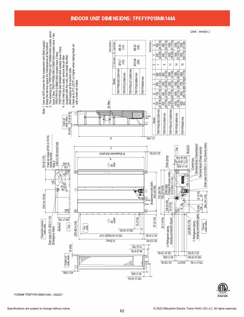
Specifications are subject to change without notice. © 2022 Mitsubishi Electric Trane HVAC US LLC. All rights reserved.
FORM# TPEFYP018MA144A - 202201
3-Ø2.9
(1/8)
mou
nt ho
le
Air fil
ter
Drain
pipe
(O.D
. Ø32
(1-1/
4) (E
merge
ncy d
rain)
Li
quid
pipe
Gas p
ipe
Ø12.7
(1/2)
Ø6.35
(1/4)
Ø9.52
(3/8)
Ø15.8
8 (5
/8)
1558
1500
1615
6017
0016
5416
00
Fres
h air i
ntake
Ø10
0 (3-1
5/16)
knoc
k out
hole
954
900A
Mode
l
1400
1100
GF
BC
DE
1000
1413
6015
0014
54
1154
1060
1112
00
1300
1358
1058
700
754
1000800
860
660
858
9765
8
800
600
(O.D
.Ø32
(1-1/
4))
Drain
pipe Dr
ain pi
pe (O
.D.Ø
32 (1
-1/4))
(Grav
ity dr
ain)
Term
inal b
lock (
Trans
miss
ion)
Term
inal b
lock (
Powe
r sou
rce)
Contr
ol bo
x
Drain
pump
Refrig
erant
piping
brazin
g con
necti
on (g
as)
Refrig
erant
piping
brazin
g con
necti
on (li
quid)
2XE-
Ø2.9
(1/8)
Air inlet
Air outle
t
2x2-Ø
2.9 (1
/8)
120°
120°
(4-15
/16)
Ø125
21 (7/8)
23 (15/16)
(DUCT)
200 (7-7/8)
378 (
14-15
/16)
Unit:m
m(in.
)
Unit:m
m(in.
)
(63)
(65-1/
8)(66
-15/16
)(61-7
/16)
(59-1/
16)
(61-3/
8)
(43-5/
16)
(55-1/
8)(57
-1/4)
(45-7/
16)
(47-1/
4)
(59-1/
16)(
53-9/
16)
(41-3/
4)(39
-3/8)
(51-3/
16)
(53-1/
2)
(41-11
/16)
(33-7/
8)(31
-1/2)
(33-13
/16)
(39-3/
8)(37
-9/16
)(35
-7/16
)
)8/5-32()62(
)61/9-72((25
-15/16
)(29
-11/16
)(31
-1/2)
(5-3/8)13515
3 (6-1
/16)
73 (2-7/8)
100 (3-15/16)
(2-11
/16)
(5-3/8
)(Sus
pens
ion bo
lt pitc
h)
18 (3
/4)21
0 (8-5
/16)
40 (1-5/8) 40 (1-5/8)
250 (9-7/8)
40 (1-5/8)33 (1-5/16)122 (4-13/16)
D (Duct) 20 (13/16)
100 (3-15/16)X(E-1)=F 30 (1-3/16)100 (3-15/16)
217 (8-9/16)41 (1-5/8)
100 (3-15/16)
356 (
14-1/
16)67
136
732 (
28-7/
8)70
0 (27
-9/16
)32
(1-5/
16)
238 (
9-3/8)
10 (7
/16)
23 (15/16) 178 (7-1/16)
643 (
25-3/
8)
B (Suspension bolt pitch)
A
10 (7
/16)
57 (2
-1/4)
58 (2-5/16)15
(5/8)
Note
1. U
se a
n M
10 sc
rew
for t
he su
spen
sion
bolt (
field
supp
ly).
2.
Kee
p th
e se
rvice
spac
e fo
r main
tena
nce
at th
e bo
ttom
.
3. T
his d
rawi
ng is
for T
PEFY
P024
·027
·030
MA1
44A
mod
els, w
hich
have
2 fa
ns. T
PEFY
P006
·008
·012
MA1
44A
mod
els h
ave
1 fa
n.
TPEF
YP01
5·01
8MA1
44A
mod
els h
ave
2 fa
ns.
TPEF
YP03
6·04
8·05
4MA1
44A
mod
els h
ave
3 fa
ns.
4.
If th
e inl
et d
uct is
use
d, re
mov
e th
e air
filte
r
(s
uppli
ed w
ith th
e un
it), t
hen
insta
ll the
filte
r
(fi
eld su
pply)
at t
he su
ction
side
.
5. H
eat a
ir to
0°C
(32°
F) o
r high
er w
hen
takin
g fre
sh a
ir
wi
th a
fres
h air
inta
ke.
1
2
12
Mode
l
TPEF
YP01
5,018
MA14
4A
TPEF
YP02
4,027
,030M
A144
A
TPEF
YP03
6,048
MA14
4A
TPEF
YP05
4MA1
44A
TPEF
YP00
6,008
,012M
A144
A
TPEF
YP00
6,008
,012M
A144
A
TPEF
YP01
5,018
MA14
4A
TPEF
YP02
4,027
,030M
A144
A
TPEF
YP03
6,048
MA14
4A
TPEF
YP05
4MA1
44A
C
G
Inle
t air
side
vie
w
Unit : mm(in.)
Out
let a
irsi
de v
iew
Top
viewTo
p
Botto
m
Opp
osite
pip
ing
side
vie
w
Note
5
(Integ
ral lif
t pum
p outl
et)
Pipi
ngsi
de v
iew
Top
Botto
m
INDOOR UNIT DIMENSIONS: TPEFYP018MA144A
62
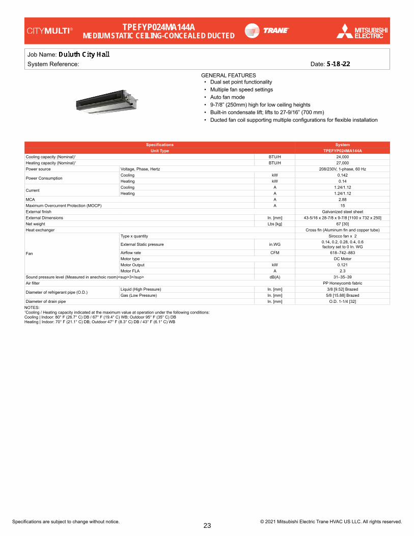
Specifications are subject to change without notice. © 2021 Mitsubishi Electric Trane HVAC US LLC. All rights reserved.
Job Name:System Reference: Date:
GENERAL FEATURES• Dual set point functionality• Multiple fan speed settings• Auto fan mode• 9-7/8” (250mm) high for low ceiling heights• Built-in condensate lift; lifts to 27-9/16” (700 mm)• Ducted fan coil supporting multiple configurations for flexible installation
Specifications SystemUnit Type TPEFYP024MA144A
Cooling capacity (Nominal)1 BTU/H 24,000Heating capacity (Nominal)1 BTU/H 27,000Power source Voltage, Phase, Hertz 208/230V, 1-phase, 60 Hz
Power ConsumptionCooling kW 0.142Heating kW 0.14
CurrentCooling A 1.24/1.12Heating A 1.24/1.12
MCA A 2.88Maximum Overcurrent Protection (MOCP) A 15External finish Galvanized steel sheetExternal Dimensions In. [mm] 43-5/16 x 28-7/8 x 9-7/8 [1100 x 732 x 250]Net weight Lbs [kg] 67 [30]Heat exchanger Cross fin (Aluminum fin and copper tube)
Fan
Type x quantity Sirocco fan x 2
External Static pressure in.WG 0.14, 0.2, 0.28, 0.4, 0.6 factory set to 0 In. WG
Airflow rate CFM 618–742–883Motor type DC MotorMotor Output kW 0.121Motor FLA A 2.3
Sound pressure level (Measured in anechoic room)<sup>3</sup> dB(A) 31–35–39Air filter PP Honeycomb fabric
Diameter of refrigerant pipe (O.D.)Liquid (High Pressure) In. [mm] 3/8 [9.52] BrazedGas (Low Pressure) In. [mm] 5/8 [15.88] Brazed
Diameter of drain pipe In. [mm] O.D. 1-1/4 [32]NOTES:1Cooling / Heating capacity indicated at the maximum value at operation under the following conditions:Cooling | Indoor: 80° F (26.7° C) DB / 67° F (19.4° C) WB; Outdoor 95° F (35° C) DBHeating | Indoor: 70° F (21.1° C) DB; Outdoor 47° F (8.3° C) DB / 43° F (6.1° C) WB
TPEFYP024MA144AMEDIUM STATIC CEILING-CONCEALED DUCTED
23
irjhfa
Text Box
0-110, 1-101, 1-108, 1-114, 1-118, 2-101, 2-108, 2-131, 2-115, 3-103, 3-119, 3-123, 4-110, 4-123, 4-130

Specifications are subject to change without notice. © 2021 Mitsubishi Electric Trane HVAC US LLC. All rights reserved.
INDOOR UNIT ACCESSORIES: TPEFYP024MA144A
Control Interface
3-Pin Connector PAC-715ADBACnet® and Modbus Interface PAC-UKPRC001-CN-1CN24 Relay Kit CN24RELAY-KIT-CM3Connector and wire for Operation status/error using CN51 PAC-725ADIT Extender PAC-WHS01IE-Ekumo station® for kumo cloud® TAC-WHS01HC-EThermostat Interface PAC-US444CN-1Wireless Interface for kumo cloud® PAC-USWHS002-WF-2
Remote Sensor
Flush Mount Temperature Sensor PAC-USSEN001-FM-1Remote Temperature Sensor PAC-SE41TS-EWireless temperature and humitity sensor for kumo cloud® PAC-USWHS003-TH-1
Terminal Signal Adapter Terminal Signal Adapter PAC-IT51AD-E
Wired Remote Controller
Deluxe Wired MA Remote Controller† TAR-40MAAUSimple MA Remote Controller† TAC-YT53CRAU-JTouch MA Controller† TAR-CT01MAU-SB
Wireless Remote Controllerkumo touch™ RedLINK™ Wireless Controller MHK2Wireless MA Remote Controller TAR-FL32MA-E
Condensate
Blue Diamond (Advanced) Mini Condensate Pump w/ Reservoir & Sensor (208/230V) [recommended] X87-721Blue Diamond (MegaBlue Advanced) Condensate Pump w/ Reservoir & Sensor X87-835Blue Diamond MultiTank — collection tank for use with multiple pumps C21-014Blue Diamond Sensor Extension Cable — 15 Ft. C13-103Sauermann Condensate Pump SI30-230
Disconnect Switch(30A/600V/UL) [fits 2” X 4” utility box] - Black TAZ-MS303(30A/600V/UL) [fits 2” X 4” utility box] - White TAZ-MS303W
Filter Box Filter Box with MERV 13 Filter FBM2-3-A
Lineset
10’ x 3/8” x 10’ x 5/8” Lineset (Twin-Tube Insulation) MPLS385812T-10100’ x 3/8” x 100’ x 5/8” Lineset (Twin-Tube Insulation) MPLS385812T-10015’ x 3/8” x 15’ x 5/8” Lineset (Twin-Tube Insulation) MPLS385812T-1530’ x 3/8” x 30’ x 5/8” Lineset (Twin-Tube Insulation) MPLS385812T-3050’ x 3/8” x 50’ x 5/8” Lineset (Twin-Tube Insulation) MPLS385812T-5065’ x 3/8” x 65’ x 5/8” Lineset (Twin-Tube Insulation) MPLS385812T-65
24
irjhfa
Highlight
Remote Temperature Sensor PAC-SE41TS-E
irjhfa
Highlight
Filter Box with MERV 13 Filter FBM2-3-A

Specifications are subject to change without notice. © 2021 Mitsubishi Electric Trane HVAC US LLC. All rights reserved.
FORM# TPEFYP024MA144A - 202107
3-Ø2.9
(1/8)
mou
nt ho
le
Air fil
ter
Drain
pipe
(O.D
. Ø32
(1-1/
4) (E
merge
ncy d
rain)
Li
quid
pipe
Gas p
ipe
Ø12.7
(1/2)
Ø6.35
(1/4)
Ø9.52
(3/8)
Ø15.8
8 (5
/8)
1558
1500
1615
6017
0016
5416
00
Fres
h air i
ntake
Ø10
0 (3-1
5/16)
knoc
k out
hole
954
900A
Mode
l
1400
1100
GF
BC
DE
1000
1413
6015
0014
54
1154
1060
1112
00
1300
1358
1058
700
754
1000800
860
660
858
9765
8
800
600
(O.D
.Ø32
(1-1/
4))
Drain
pipe Dr
ain pi
pe (O
.D.Ø
32 (1
-1/4))
(Grav
ity dr
ain)
Term
inal b
lock (
Trans
miss
ion)
Term
inal b
lock (
Powe
r sou
rce)
Contr
ol bo
x
Drain
pump
Refrig
erant
piping
brazin
g con
necti
on (g
as)
Refrig
erant
piping
brazin
g con
necti
on (li
quid)
2XE-
Ø2.9
(1/8)
Air inlet
Air outle
t
2x2-Ø
2.9 (1
/8)
120°
120°
(4-15
/16)
Ø125
21 (7/8)
23 (15/16)
(DUCT)
200 (7-7/8)
378 (
14-15
/16)
Unit:m
m(in.
)
Unit:m
m(in.
)
(63)
(65-1/
8)(66
-15/16
)(61-7
/16)
(59-1/
16)
(61-3/
8)
(43-5/
16)
(55-1/
8)(57
-1/4)
(45-7/
16)
(47-1/
4)
(59-1/
16)(
53-9/
16)
(41-3/
4)(39
-3/8)
(51-3/
16)
(53-1/
2)
(41-11
/16)
(33-7/
8)(31
-1/2)
(33-13
/16)
(39-3/
8)(37
-9/16
)(35
-7/16
)
)8/5-32()62(
)61/9-72((25
-15/16
)(29
-11/16
)(31
-1/2)
(5-3/8)13515
3 (6-1
/16)
73 (2-7/8)
100 (3-15/16)
(2-11
/16)
(5-3/8
)(Sus
pens
ion bo
lt pitc
h)
18 (3
/4)21
0 (8-5
/16)
40 (1-5/8) 40 (1-5/8)
250 (9-7/8)
40 (1-5/8)33 (1-5/16)122 (4-13/16)
D (Duct) 20 (13/16)
100 (3-15/16)X(E-1)=F 30 (1-3/16)100 (3-15/16)
217 (8-9/16)41 (1-5/8)
100 (3-15/16)
356 (
14-1/
16)67
136
732 (
28-7/
8)70
0 (27
-9/16
)32
(1-5/
16)
238 (
9-3/8)
10 (7
/16)
23 (15/16) 178 (7-1/16)
643 (
25-3/
8)
B (Suspension bolt pitch)
A
10 (7
/16)
57 (2
-1/4)
58 (2-5/16)15
(5/8)
Note
1. U
se a
n M
10 sc
rew
for t
he su
spen
sion
bolt (
field
supp
ly).
2.
Kee
p th
e se
rvice
spac
e fo
r main
tena
nce
at th
e bo
ttom
.
3. T
his d
rawi
ng is
for T
PEFY
P024
·027
·030
MA1
44A
mod
els, w
hich
have
2 fa
ns. T
PEFY
P006
·008
·012
MA1
44A
mod
els h
ave
1 fa
n.
TPEF
YP01
5·01
8MA1
44A
mod
els h
ave
2 fa
ns.
TPEF
YP03
6·04
8·05
4MA1
44A
mod
els h
ave
3 fa
ns.
4.
If th
e inl
et d
uct is
use
d, re
mov
e th
e air
filte
r
(s
uppli
ed w
ith th
e un
it), t
hen
insta
ll the
filte
r
(fi
eld su
pply)
at t
he su
ction
side
.
5. H
eat a
ir to
0°C
(32°
F) o
r high
er w
hen
takin
g fre
sh a
ir
wi
th a
fres
h air
inta
ke.
1
2
12
Mode
l
TPEF
YP01
5,018
MA14
4A
TPEF
YP02
4,027
,030M
A144
A
TPEF
YP03
6,048
MA14
4A
TPEF
YP05
4MA1
44A
TPEF
YP00
6,008
,012M
A144
A
TPEF
YP00
6,008
,012M
A144
A
TPEF
YP01
5,018
MA14
4A
TPEF
YP02
4,027
,030M
A144
A
TPEF
YP03
6,048
MA14
4A
TPEF
YP05
4MA1
44A
C
G
Inle
t air
side
vie
w
Unit : mm(in.)
Out
let a
irsi
de v
iew
Top
viewTo
p
Botto
m
Opp
osite
pip
ing
side
vie
w
Note
5
(Integ
ral lif
t pum
p outl
et)
Pipi
ngsi
de v
iew
Top
Botto
m
INDOOR UNIT DIMENSIONS: TPEFYP024MA144A
25

Specifications are subject to change without notice. © 2021 Mitsubishi Electric Trane HVAC US LLC. All rights reserved.
Job Name:System Reference: Date:
GENERAL FEATURES• Dual set point functionality• Multiple fan speed settings• Auto fan mode• 9-7/8” (250mm) high for low ceiling heights• Built-in condensate lift; lifts to 27-9/16” (700 mm)• Ducted fan coil supporting multiple configurations for flexible installation
Specifications SystemUnit Type TPEFYP027MA144A
Cooling capacity (Nominal)1 BTU/H 27,000Heating capacity (Nominal)1 BTU/H 30,000Power source Voltage, Phase, Hertz 208/230V, 1-phase, 60 Hz
Power ConsumptionCooling kW 0.142Heating kW 0.14
CurrentCooling A 1.24/1.12Heating A 1.24/1.12
MCA A 2.88Maximum Overcurrent Protection (MOCP) A 15External finish Galvanized steel sheetExternal Dimensions In. [mm] 43-5/16 x 28-7/8 x 9-7/8 [1100 x 732 x 250]Net weight Lbs [kg] 67 [30]Heat exchanger Cross fin (Aluminum fin and copper tube)
Fan
Type x quantity Sirocco fan x 2
External Static pressure in.WG 0.14, 0.2, 0.28, 0.4, 0.6 factory set to 0 In. WG
Airflow rate CFM 618–742–883Motor type DC MotorMotor Output kW 0.121Motor FLA A 2.3
Sound pressure level (Measured in anechoic room)<sup>3</sup> dB(A) 31–35–39Air filter PP Honeycomb fabric
Diameter of refrigerant pipe (O.D.)Liquid (High Pressure) In. [mm] 3/8 [9.52] BrazedGas (Low Pressure) In. [mm] 5/8 [15.88] Brazed
Diameter of drain pipe In. [mm] O.D. 1-1/4 [32]NOTES:1Cooling / Heating capacity indicated at the maximum value at operation under the following conditions:Cooling | Indoor: 80° F (26.7° C) DB / 67° F (19.4° C) WB; Outdoor 95° F (35° C) DBHeating | Indoor: 70° F (21.1° C) DB; Outdoor 47° F (8.3° C) DB / 43° F (6.1° C) WB
TPEFYP027MA144AMEDIUM STATIC CEILING-CONCEALED DUCTED
71

Specifications are subject to change without notice. © 2021 Mitsubishi Electric Trane HVAC US LLC. All rights reserved.
INDOOR UNIT ACCESSORIES: TPEFYP027MA144A
Control Interface
3-Pin Connector PAC-715ADBACnet® and Modbus Interface PAC-UKPRC001-CN-1CN24 Relay Kit CN24RELAY-KIT-CM3Connector and wire for Operation status/error using CN51 PAC-725ADIT Extender PAC-WHS01IE-Ekumo station® for kumo cloud® TAC-WHS01HC-EThermostat Interface PAC-US444CN-1Wireless Interface for kumo cloud® PAC-USWHS002-WF-2
Remote Sensor
Flush Mount Temperature Sensor PAC-USSEN001-FM-1Remote Temperature Sensor PAC-SE41TS-EWireless temperature and humitity sensor for kumo cloud® PAC-USWHS003-TH-1
Terminal Signal Adapter Terminal Signal Adapter PAC-IT51AD-E
Wired Remote Controller
Deluxe Wired MA Remote Controller† TAR-40MAAUSimple MA Remote Controller† TAC-YT53CRAU-JTouch MA Controller† TAR-CT01MAU-SB
Wireless Remote Controllerkumo touch™ RedLINK™ Wireless Controller MHK2Wireless MA Remote Controller TAR-FL32MA-E
Condensate
Blue Diamond (Advanced) Mini Condensate Pump w/ Reservoir & Sensor (208/230V) [recommended] X87-721Blue Diamond (MegaBlue Advanced) Condensate Pump w/ Reservoir & Sensor X87-835Blue Diamond MultiTank — collection tank for use with multiple pumps C21-014Blue Diamond Sensor Extension Cable — 15 Ft. C13-103Sauermann Condensate Pump SI30-230
Disconnect Switch(30A/600V/UL) [fits 2” X 4” utility box] - Black TAZ-MS303(30A/600V/UL) [fits 2” X 4” utility box] - White TAZ-MS303W
Filter Box Filter Box with MERV 13 Filter FBM2-3-A
Lineset
10’ x 3/8” x 10’ x 5/8” Lineset (Twin-Tube Insulation) MPLS385812T-10100’ x 3/8” x 100’ x 5/8” Lineset (Twin-Tube Insulation) MPLS385812T-10015’ x 3/8” x 15’ x 5/8” Lineset (Twin-Tube Insulation) MPLS385812T-1530’ x 3/8” x 30’ x 5/8” Lineset (Twin-Tube Insulation) MPLS385812T-3050’ x 3/8” x 50’ x 5/8” Lineset (Twin-Tube Insulation) MPLS385812T-5065’ x 3/8” x 65’ x 5/8” Lineset (Twin-Tube Insulation) MPLS385812T-65
72
irjhfa
Highlight
Remote Temperature Sensor PAC-SE41TS-E
irjhfa
Highlight
Filter Box with MERV 13 Filter FBM2-3-A

Specifications are subject to change without notice. © 2021 Mitsubishi Electric Trane HVAC US LLC. All rights reserved.
FORM# TPEFYP027MA144A - 202107
3-Ø2.9
(1/8)
mou
nt ho
le
Air fil
ter
Drain
pipe
(O.D
. Ø32
(1-1/
4) (E
merge
ncy d
rain)
Li
quid
pipe
Gas p
ipe
Ø12.7
(1/2)
Ø6.35
(1/4)
Ø9.52
(3/8)
Ø15.8
8 (5
/8)
1558
1500
1615
6017
0016
5416
00
Fres
h air i
ntake
Ø10
0 (3-1
5/16)
knoc
k out
hole
954
900A
Mode
l
1400
1100
GF
BC
DE
1000
1413
6015
0014
54
1154
1060
1112
00
1300
1358
1058
700
754
1000800
860
660
858
9765
8
800
600
(O.D
.Ø32
(1-1/
4))
Drain
pipe Dr
ain pi
pe (O
.D.Ø
32 (1
-1/4))
(Grav
ity dr
ain)
Term
inal b
lock (
Trans
miss
ion)
Term
inal b
lock (
Powe
r sou
rce)
Contr
ol bo
x
Drain
pump
Refrig
erant
piping
brazin
g con
necti
on (g
as)
Refrig
erant
piping
brazin
g con
necti
on (li
quid)
2XE-
Ø2.9
(1/8)
Air inlet
Air outle
t
2x2-Ø
2.9 (1
/8)
120°
120°
(4-15
/16)
Ø125
21 (7/8)
23 (15/16)
(DUCT)
200 (7-7/8)
378 (
14-15
/16)
Unit:m
m(in.
)
Unit:m
m(in.
)
(63)
(65-1/
8)(66
-15/16
)(61-7
/16)
(59-1/
16)
(61-3/
8)
(43-5/
16)
(55-1/
8)(57
-1/4)
(45-7/
16)
(47-1/
4)
(59-1/
16)(
53-9/
16)
(41-3/
4)(39
-3/8)
(51-3/
16)
(53-1/
2)
(41-11
/16)
(33-7/
8)(31
-1/2)
(33-13
/16)
(39-3/
8)(37
-9/16
)(35
-7/16
)
)8/5-32()62(
)61/9-72((25
-15/16
)(29
-11/16
)(31
-1/2)
(5-3/8)13515
3 (6-1
/16)
73 (2-7/8)
100 (3-15/16)
(2-11
/16)
(5-3/8
)(Sus
pens
ion bo
lt pitc
h)
18 (3
/4)21
0 (8-5
/16)
40 (1-5/8) 40 (1-5/8)
250 (9-7/8)
40 (1-5/8)33 (1-5/16)122 (4-13/16)
D (Duct) 20 (13/16)
100 (3-15/16)X(E-1)=F 30 (1-3/16)100 (3-15/16)
217 (8-9/16)41 (1-5/8)
100 (3-15/16)
356 (
14-1/
16)67
136
732 (
28-7/
8)70
0 (27
-9/16
)32
(1-5/
16)
238 (
9-3/8)
10 (7
/16)
23 (15/16) 178 (7-1/16)
643 (
25-3/
8)
B (Suspension bolt pitch)
A
10 (7
/16)
57 (2
-1/4)
58 (2-5/16)15
(5/8)
Note
1. U
se a
n M
10 sc
rew
for t
he su
spen
sion
bolt (
field
supp
ly).
2.
Kee
p th
e se
rvice
spac
e fo
r main
tena
nce
at th
e bo
ttom
.
3. T
his d
rawi
ng is
for T
PEFY
P024
·027
·030
MA1
44A
mod
els, w
hich
have
2 fa
ns. T
PEFY
P006
·008
·012
MA1
44A
mod
els h
ave
1 fa
n.
TPEF
YP01
5·01
8MA1
44A
mod
els h
ave
2 fa
ns.
TPEF
YP03
6·04
8·05
4MA1
44A
mod
els h
ave
3 fa
ns.
4.
If th
e inl
et d
uct is
use
d, re
mov
e th
e air
filte
r
(s
uppli
ed w
ith th
e un
it), t
hen
insta
ll the
filte
r
(fi
eld su
pply)
at t
he su
ction
side
.
5. H
eat a
ir to
0°C
(32°
F) o
r high
er w
hen
takin
g fre
sh a
ir
wi
th a
fres
h air
inta
ke.
1
2
12
Mode
l
TPEF
YP01
5,018
MA14
4A
TPEF
YP02
4,027
,030M
A144
A
TPEF
YP03
6,048
MA14
4A
TPEF
YP05
4MA1
44A
TPEF
YP00
6,008
,012M
A144
A
TPEF
YP00
6,008
,012M
A144
A
TPEF
YP01
5,018
MA14
4A
TPEF
YP02
4,027
,030M
A144
A
TPEF
YP03
6,048
MA14
4A
TPEF
YP05
4MA1
44A
C
G
Inle
t air
side
vie
w
Unit : mm(in.)
Out
let a
irsi
de v
iew
Top
viewTo
p
Botto
m
Opp
osite
pip
ing
side
vie
w
Note
5
(Integ
ral lif
t pum
p outl
et)
Pipi
ngsi
de v
iew
Top
Botto
m
INDOOR UNIT DIMENSIONS: TPEFYP027MA144A
73

Specifications are subject to change without notice. © 2021 Mitsubishi Electric Trane HVAC US LLC. All rights reserved.
Job Name:System Reference: Date:
GENERAL FEATURES• Dual set point functionality• Multiple fan speed settings• Auto fan mode• 9-7/8” (250mm) high for low ceiling heights• Built-in condensate lift; lifts to 27-9/16” (700 mm)• Ducted fan coil supporting multiple configurations for flexible installation
Specifications SystemUnit Type TPEFYP030MA144A
Cooling capacity (Nominal)1 BTU/H 30,000Heating capacity (Nominal)1 BTU/H 34,000Power source Voltage, Phase, Hertz 208/230V, 1-phase, 60 Hz
Power ConsumptionCooling kW 0.142Heating kW 0.14
CurrentCooling A 1.24/1.12Heating A 1.24/1.12
MCA A 2.88Maximum Overcurrent Protection (MOCP) A 15External finish Galvanized steel sheetExternal Dimensions In. [mm] 43-5/16 x 28-7/8 x 9-7/8 [1100 x 732 x 250]Net weight Lbs [kg] 67 [30]Heat exchanger Cross fin (Aluminum fin and copper tube)
Fan
Type x quantity Sirocco fan x 2
External Static pressure in.WG 0.14, 0.2, 0.28, 0.4, 0.6 factory set to 0.2 In. WG
Airflow rate CFM 618–742–883Motor type DC MotorMotor Output kW 0.121Motor FLA A 2.3
Sound pressure level (Measured in anechoic room)3 dB(A) 31–35–39Air filter PP Honeycomb fabric
Diameter of refrigerant pipe (O.D.)Liquid (High Pressure) In. [mm] 3/8 [9.52] BrazedGas (Low Pressure) In. [mm] 5/8 [15.88] Brazed
Diameter of drain pipe In. [mm] O.D. 1-1/4 [32]NOTES:1Cooling / Heating capacity indicated at the maximum value at operation under the following conditions:Cooling | Indoor: 80° F (26.7° C) DB / 67° F (19.4° C) WB; Outdoor 95° F (35° C) DBHeating | Indoor: 70° F (21.1° C) DB; Outdoor 47° F (8.3° C) DB / 43° F (6.1° C) WB
92
irjhfa
Image
irjhfa
Image
irjhfa
Text Box
30

Specifications are subject to change without notice. © 2021 Mitsubishi Electric Trane HVAC US LLC. All rights reserved.
INDOOR UNIT ACCESSORIES: TPEFYP030MA144A
Control Interface
3-Pin Connector PAC-715ADBACnet® and Modbus® Interface PAC-UKPRC001-CN-1CN24 Relay Kit CN24RELAY-KIT-CM3Connector and wire for Operation status/error using CN51 PAC-725ADIT Extender PAC-WHS01IE-Ekumo station® for kumo cloud® TAC-WHS01HC-EThermostat Interface PAC-US444CN-1Wireless Interface for kumo cloud® PAC-USWHS002-WF-2
Remote Sensor
Flush Mount Temperature Sensor PAC-USSEN001-FM-1Remote Temperature Sensor PAC-SE41TS-EWireless temperature and humitity sensor for kumo cloud® PAC-USWHS003-TH-1
Terminal Signal Adapter Terminal Signal Adapter PAC-IT51AD-E
Wired Remote Controller
Deluxe Wired MA Remote Controller† TAR-40MAAUSimple MA Remote Controller† TAC-YT53CRAU-JTouch MA Controller† TAR-CT01MAU-SB
Wireless Remote Controllerkumo touch™ RedLINK™ Wireless Controller MHK2Wireless MA Remote Controller TAR-FL32MA-E
Condensate
Blue Diamond (Advanced) Mini Condensate Pump w/ Reservoir & Sensor (208/230V) [recommended] X87-721Blue Diamond (MegaBlue Advanced) Condensate Pump w/ Reservoir & Sensor X87-835Blue Diamond MultiTank — collection tank for use with multiple pumps C21-014Blue Diamond Sensor Extension Cable — 15 Ft. C13-103Sauermann Condensate Pump SI30-230
Disconnect Switch(30A/600V/UL) [fits 2” X 4” utility box] - Black TAZ-MS303(30A/600V/UL) [fits 2” X 4” utility box] - White TAZ-MS303W
Filter Box Filter Box with MERV 13 Filter FBM2-3-A
Lineset
10’ x 3/8” x 10’ x 5/8” Lineset (Twin-Tube Insulation)†† MPLS385812T-10100’ x 3/8” x 100’ x 5/8” Lineset (Twin-Tube Insulation)†† MPLS385812T-10015’ x 3/8” x 15’ x 5/8” Lineset (Twin-Tube Insulation)†† MPLS385812T-1530’ x 3/8” x 30’ x 5/8” Lineset (Twin-Tube Insulation)†† MPLS385812T-3050’ x 3/8” x 50’ x 5/8” Lineset (Twin-Tube Insulation)†† MPLS385812T-5065’ x 3/8” x 65’ x 5/8” Lineset (Twin-Tube Insulation)†† MPLS385812T-65
93
irjhfa
Highlight
Remote Temperature Sensor PAC-SE41TS-E
irjhfa
Highlight
Filter Box with MERV 13 Filter FBM2-3-A

Specifications are subject to change without notice. © 2021 Mitsubishi Electric Trane HVAC US LLC. All rights reserved.
FORM# TPEFYP030MA144A - 202110
3-Ø2.9
(1/8)
mou
nt ho
le
Air fil
ter
Drain
pipe
(O.D
. Ø32
(1-1/
4) (E
merge
ncy d
rain)
Li
quid
pipe
Gas p
ipe
Ø12.7
(1/2)
Ø6.35
(1/4)
Ø9.52
(3/8)
Ø15.8
8 (5
/8)
1558
1500
1615
6017
0016
5416
00
Fres
h air i
ntake
Ø10
0 (3-1
5/16)
knoc
k out
hole
954
900A
Mode
l
1400
1100
GF
BC
DE
1000
1413
6015
0014
54
1154
1060
1112
00
1300
1358
1058
700
754
1000800
860
660
858
9765
8
800
600
(O.D
.Ø32
(1-1/
4))
Drain
pipe Dr
ain pi
pe (O
.D.Ø
32 (1
-1/4))
(Grav
ity dr
ain)
Term
inal b
lock (
Trans
miss
ion)
Term
inal b
lock (
Powe
r sou
rce)
Contr
ol bo
x
Drain
pump
Refrig
erant
piping
brazin
g con
necti
on (g
as)
Refrig
erant
piping
brazin
g con
necti
on (li
quid)
2XE-
Ø2.9
(1/8)
Air inlet
Air outle
t
2x2-Ø
2.9 (1
/8)
120°
120°
(4-15
/16)
Ø125
21 (7/8)
23 (15/16)
(DUCT)
200 (7-7/8)
378 (
14-15
/16)
Unit:m
m(in.
)
Unit:m
m(in.
)
(63)
(65-1/
8)(66
-15/16
)(61-7
/16)
(59-1/
16)
(61-3/
8)
(43-5/
16)
(55-1/
8)(57
-1/4)
(45-7/
16)
(47-1/
4)
(59-1/
16)(
53-9/
16)
(41-3/
4)(39
-3/8)
(51-3/
16)
(53-1/
2)
(41-11
/16)
(33-7/
8)(31
-1/2)
(33-13
/16)
(39-3/
8)(37
-9/16
)(35
-7/16
)
)8/5-32()62(
)61/9-72((25
-15/16
)(29
-11/16
)(31
-1/2)
(5-3/8)13515
3 (6-1
/16)
73 (2-7/8)
100 (3-15/16)
(2-11
/16)
(5-3/8
)(Sus
pens
ion bo
lt pitc
h)
18 (3
/4)21
0 (8-5
/16)
40 (1-5/8) 40 (1-5/8)
250 (9-7/8)
40 (1-5/8)33 (1-5/16)122 (4-13/16)
D (Duct) 20 (13/16)
100 (3-15/16)X(E-1)=F 30 (1-3/16)100 (3-15/16)
217 (8-9/16)41 (1-5/8)
100 (3-15/16)
356 (
14-1/
16)67
136
732 (
28-7/
8)70
0 (27
-9/16
)32
(1-5/
16)
238 (
9-3/8)
10 (7
/16)
23 (15/16) 178 (7-1/16)
643 (
25-3/
8)
B (Suspension bolt pitch)
A
10 (7
/16)
57 (2
-1/4)
58 (2-5/16)15
(5/8)
Note
1. U
se a
n M
10 sc
rew
for t
he su
spen
sion
bolt (
field
supp
ly).
2.
Kee
p th
e se
rvice
spac
e fo
r main
tena
nce
at th
e bo
ttom
.
3. T
his d
rawi
ng is
for T
PEFY
P024
·027
·030
MA1
44A
mod
els, w
hich
have
2 fa
ns. T
PEFY
P006
·008
·012
MA1
44A
mod
els h
ave
1 fa
n.
TPEF
YP01
5·01
8MA1
44A
mod
els h
ave
2 fa
ns.
TPEF
YP03
6·04
8·05
4MA1
44A
mod
els h
ave
3 fa
ns.
4.
If th
e inl
et d
uct is
use
d, re
mov
e th
e air
filte
r
(s
uppli
ed w
ith th
e un
it), t
hen
insta
ll the
filte
r
(fi
eld su
pply)
at t
he su
ction
side
.
5. H
eat a
ir to
0°C
(32°
F) o
r high
er w
hen
takin
g fre
sh a
ir
wi
th a
fres
h air
inta
ke.
1
2
12
Mode
l
TPEF
YP01
5,018
MA14
4A
TPEF
YP02
4,027
,030M
A144
A
TPEF
YP03
6,048
MA14
4A
TPEF
YP05
4MA1
44A
TPEF
YP00
6,008
,012M
A144
A
TPEF
YP00
6,008
,012M
A144
A
TPEF
YP01
5,018
MA14
4A
TPEF
YP02
4,027
,030M
A144
A
TPEF
YP03
6,048
MA14
4A
TPEF
YP05
4MA1
44A
C
G
Inle
t air
side
vie
w
Unit : mm(in.)
Out
let a
irsi
de v
iew
Top
viewTo
p
Botto
m
Opp
osite
pip
ing
side
vie
w
Note
5
(Integ
ral lif
t pum
p outl
et)
Pipi
ngsi
de v
iew
Top
Botto
m
INDOOR UNIT DIMENSIONS: TPEFYP030MA144A
94

Specifications are subject to change without notice. © 2021 Mitsubishi Electric Trane HVAC US LLC. All rights reserved.
Job Name:System Reference: Date:
GENERAL FEATURES• Dual set point functionality• Multiple fan speed settings• Auto fan mode• 9-7/8” (250mm) high for low ceiling heights• Built-in condensate lift; lifts to 27-9/16” (700 mm)• Ducted fan coil supporting multiple configurations for flexible installation
Specifications SystemUnit Type TPEFYP036MA144A
Cooling capacity (Nominal)1 BTU/H 36,000Heating capacity (Nominal)1 BTU/H 40,000Power source Voltage, Phase, Hertz 208/230V, 1-phase, 60 Hz
Power ConsumptionCooling kW 0.222Heating kW 0.22
CurrentCooling A 2.01/1.82Heating A 2.01/1.82
MCA A 4.25Maximum Overcurrent Protection (MOCP) A 15External finish Galvanized steel sheetExternal Dimensions In. [mm] 55-1/8 x 28-7/8 x 9-7/8 [1400 x 732 x 250]Net weight Lbs [kg] 84 [38]Heat exchanger Cross fin (Aluminum fin and copper tube)
Fan
Type x quantity Sirocco fan x 3
External Static pressure in.WG 0.14, 0.2, 0.28, 0.4, 0.6 factory set to 0 In. WG
Airflow rate CFM 883–1077–1271Motor type DC MotorMotor Output kW 0.3Motor FLA A 3.4
Sound pressure level (Measured in anechoic room)<sup>3</sup> dB(A) 35–39–43Air filter PP Honeycomb fabric
Diameter of refrigerant pipe (O.D.)Liquid (High Pressure) In. [mm] 3/8 [9.52] BrazedGas (Low Pressure) In. [mm] 5/8 [15.88] Brazed
Diameter of drain pipe In. [mm] O.D. 1-1/4 [32]NOTES:1Cooling / Heating capacity indicated at the maximum value at operation under the following conditions:Cooling | Indoor: 80° F (26.7° C) DB / 67° F (19.4° C) WB; Outdoor 95° F (35° C) DBHeating | Indoor: 70° F (21.1° C) DB; Outdoor 47° F (8.3° C) DB / 43° F (6.1° C) WB
TPEFYP036MA144AMEDIUM STATIC CEILING-CONCEALED DUCTED
38

Specifications are subject to change without notice. © 2021 Mitsubishi Electric Trane HVAC US LLC. All rights reserved.
INDOOR UNIT ACCESSORIES: TPEFYP036MA144A
Control Interface
3-Pin Connector PAC-715ADBACnet® and Modbus Interface PAC-UKPRC001-CN-1CN24 Relay Kit CN24RELAY-KIT-CM3Connector and wire for Operation status/error using CN51 PAC-725ADIT Extender PAC-WHS01IE-Ekumo station® for kumo cloud® TAC-WHS01HC-EThermostat Interface PAC-US444CN-1Wireless Interface for kumo cloud® PAC-USWHS002-WF-2
Remote Sensor
Flush Mount Temperature Sensor PAC-USSEN001-FM-1Remote Temperature Sensor PAC-SE41TS-EWireless temperature and humitity sensor for kumo cloud® PAC-USWHS003-TH-1
Terminal Signal Adapter Terminal Signal Adapter PAC-IT51AD-E
Wired Remote Controller
Deluxe Wired MA Remote Controller† TAR-40MAAUSimple MA Remote Controller† TAC-YT53CRAU-JTouch MA Controller† TAR-CT01MAU-SB
Wireless Remote Controllerkumo touch™ RedLINK™ Wireless Controller MHK2Wireless MA Remote Controller TAR-FL32MA-E
Condensate
Blue Diamond (Advanced) Mini Condensate Pump w/ Reservoir & Sensor (208/230V) [recommended] X87-721Blue Diamond (MegaBlue Advanced) Condensate Pump w/ Reservoir & Sensor X87-835Blue Diamond MultiTank — collection tank for use with multiple pumps C21-014Blue Diamond Sensor Extension Cable — 15 Ft. C13-103Sauermann Condensate Pump SI30-230
Disconnect Switch(30A/600V/UL) [fits 2” X 4” utility box] - Black TAZ-MS303(30A/600V/UL) [fits 2” X 4” utility box] - White TAZ-MS303W
Filter Box Filter Box with MERV 13 Filter FBM2-4-A
Lineset
10’ x 3/8” x 10’ x 5/8” Lineset (Twin-Tube Insulation) MPLS385812T-10100’ x 3/8” x 100’ x 5/8” Lineset (Twin-Tube Insulation) MPLS385812T-10015’ x 3/8” x 15’ x 5/8” Lineset (Twin-Tube Insulation) MPLS385812T-1530’ x 3/8” x 30’ x 5/8” Lineset (Twin-Tube Insulation) MPLS385812T-3050’ x 3/8” x 50’ x 5/8” Lineset (Twin-Tube Insulation) MPLS385812T-5065’ x 3/8” x 65’ x 5/8” Lineset (Twin-Tube Insulation) MPLS385812T-65
39
irjhfa
Highlight
Remote Temperature Sensor PAC-SE41TS-E
irjhfa
Highlight
Filter Box with MERV 13 Filter FBM2-4-A

Specifications are subject to change without notice. © 2021 Mitsubishi Electric Trane HVAC US LLC. All rights reserved.
FORM# TPEFYP036MA144A - 202107
3-Ø2.9
(1/8)
mou
nt ho
le
Air fil
ter
Drain
pipe
(O.D
. Ø32
(1-1/
4) (E
merge
ncy d
rain)
Li
quid
pipe
Gas p
ipe
Ø12.7
(1/2)
Ø6.35
(1/4)
Ø9.52
(3/8)
Ø15.8
8 (5
/8)
1558
1500
1615
6017
0016
5416
00
Fres
h air i
ntake
Ø10
0 (3-1
5/16)
knoc
k out
hole
954
900A
Mode
l
1400
1100
GF
BC
DE
1000
1413
6015
0014
54
1154
1060
1112
00
1300
1358
1058
700
754
1000800
860
660
858
9765
8
800
600
(O.D
.Ø32
(1-1/
4))
Drain
pipe Dr
ain pi
pe (O
.D.Ø
32 (1
-1/4))
(Grav
ity dr
ain)
Term
inal b
lock (
Trans
miss
ion)
Term
inal b
lock (
Powe
r sou
rce)
Contr
ol bo
x
Drain
pump
Refrig
erant
piping
brazin
g con
necti
on (g
as)
Refrig
erant
piping
brazin
g con
necti
on (li
quid)
2XE-
Ø2.9
(1/8)
Air inlet
Air outle
t
2x2-Ø
2.9 (1
/8)
120°
120°
(4-15
/16)
Ø125
21 (7/8)
23 (15/16)
(DUCT)
200 (7-7/8)
378 (
14-15
/16)
Unit:m
m(in.
)
Unit:m
m(in.
)
(63)
(65-1/
8)(66
-15/16
)(61-7
/16)
(59-1/
16)
(61-3/
8)
(43-5/
16)
(55-1/
8)(57
-1/4)
(45-7/
16)
(47-1/
4)
(59-1/
16)(
53-9/
16)
(41-3/
4)(39
-3/8)
(51-3/
16)
(53-1/
2)
(41-11
/16)
(33-7/
8)(31
-1/2)
(33-13
/16)
(39-3/
8)(37
-9/16
)(35
-7/16
)
)8/5-32()62(
)61/9-72((25
-15/16
)(29
-11/16
)(31
-1/2)
(5-3/8)13515
3 (6-1
/16)
73 (2-7/8)
100 (3-15/16)
(2-11
/16)
(5-3/8
)(Sus
pens
ion bo
lt pitc
h)
18 (3
/4)21
0 (8-5
/16)
40 (1-5/8) 40 (1-5/8)
250 (9-7/8)
40 (1-5/8)33 (1-5/16)122 (4-13/16)
D (Duct) 20 (13/16)
100 (3-15/16)X(E-1)=F 30 (1-3/16)100 (3-15/16)
217 (8-9/16)41 (1-5/8)
100 (3-15/16)
356 (
14-1/
16)67
136
732 (
28-7/
8)70
0 (27
-9/16
)32
(1-5/
16)
238 (
9-3/8)
10 (7
/16)
23 (15/16) 178 (7-1/16)
643 (
25-3/
8)
B (Suspension bolt pitch)
A
10 (7
/16)
57 (2
-1/4)
58 (2-5/16)15
(5/8)
Note
1. U
se a
n M
10 sc
rew
for t
he su
spen
sion
bolt (
field
supp
ly).
2.
Kee
p th
e se
rvice
spac
e fo
r main
tena
nce
at th
e bo
ttom
.
3. T
his d
rawi
ng is
for T
PEFY
P024
·027
·030
MA1
44A
mod
els, w
hich
have
2 fa
ns. T
PEFY
P006
·008
·012
MA1
44A
mod
els h
ave
1 fa
n.
TPEF
YP01
5·01
8MA1
44A
mod
els h
ave
2 fa
ns.
TPEF
YP03
6·04
8·05
4MA1
44A
mod
els h
ave
3 fa
ns.
4.
If th
e inl
et d
uct is
use
d, re
mov
e th
e air
filte
r
(s
uppli
ed w
ith th
e un
it), t
hen
insta
ll the
filte
r
(fi
eld su
pply)
at t
he su
ction
side
.
5. H
eat a
ir to
0°C
(32°
F) o
r high
er w
hen
takin
g fre
sh a
ir
wi
th a
fres
h air
inta
ke.
1
2
12
Mode
l
TPEF
YP01
5,018
MA14
4A
TPEF
YP02
4,027
,030M
A144
A
TPEF
YP03
6,048
MA14
4A
TPEF
YP05
4MA1
44A
TPEF
YP00
6,008
,012M
A144
A
TPEF
YP00
6,008
,012M
A144
A
TPEF
YP01
5,018
MA14
4A
TPEF
YP02
4,027
,030M
A144
A
TPEF
YP03
6,048
MA14
4A
TPEF
YP05
4MA1
44A
C
G
Inle
t air
side
vie
w
Unit : mm(in.)
Out
let a
irsi
de v
iew
Top
viewTo
p
Botto
m
Opp
osite
pip
ing
side
vie
w
Note
5
(Integ
ral lif
t pum
p outl
et)
Pipi
ngsi
de v
iew
Top
Botto
m
INDOOR UNIT DIMENSIONS: TPEFYP036MA144A
40

Specifications are subject to change without notice. © 2022 Mitsubishi Electric Trane HVAC US LLC. All rights reserved.
Job Name:System Reference: Date:
GENERAL FEATURES• Multi-position design is suitable for any application requires no additional
kits, even for downflow configuration• Highly efficient DC motor and a forward curved blower ensures quiet,
consistent fan operation• Selectable external static pressure: 0.30, 0.50 and 0.80 in.WG with 3 fan
speeds at each static setting• 1 inch R4.2 fiberglass free insulation reduces condensation and boosts
efficiency• Positive pressure cabinet with air leakage of less than 2.0% at 1.0 In.WG
(Tested per ASHRAE Standard 193)• Unique blow through design allows simple coil cleaning when the blower is
removed• Optional electric heat kit for additional heat capacity• Optional humidifier control and ERV control
Specifications SystemUnit Type TPVFYP054AM141A
Cooling capacity (Nominal)1 BTU/H 54,000Heating capacity (Nominal)1 BTU/H 60,000Power source Voltage, Phase, Hertz 208/230V, 1-phase, 60 HzMCA A 5.6Maximum Overcurrent Protection (MOCP) A 15External finish High-gloss polyester powder coatedExternal Dimensions In. [mm] 25 x 21-5/8 x 59-1/2 [635 x 548 x 1511]Net weight Lbs [kg] 172 [78]Heat exchanger Cross fin (Aluminum fin and copper tube)
Fan
Type x quantity Sirocco fan x 1External Static pressure in.WG 0.30, 0.5, 0.8Airflow rate CFM 1040–1262–1485Motor type DC motor
Sound pressure level (Measured in anechoic room) dB(A) 36–40–44Air filter Polypropylene Honeycomb
Diameter of refrigerant pipe (O.D.)Liquid (High Pressure) In. [mm] 3/8 [9.52] BrazedGas (Low Pressure) In. [mm] 5/8 [15.88] Brazed
Diameter of drain pipe In. [mm] FPT 3/4 [19.05]NOTES:1Cooling / Heating capacity indicated at the maximum value at operation under the following conditions:Cooling | Indoor: 80° F (26.7° C) DB / 67° F (19.4° C) WB; Outdoor 95° F (35° C) DBHeating | Indoor: 70° F (21.1° C) DB; Outdoor 47° F (8.3° C) DB / 43° F (6.1° C) WB
TPVFYP054AM141A54 KBTU/H MULTI-POSITION AIR HANDLER
80

Specifications are subject to change without notice. © 2022 Mitsubishi Electric Trane HVAC US LLC. All rights reserved.
INDOOR UNIT ACCESSORIES: TPVFYP054AM141A
Control Interface
BACnet® and Modbus® Interface PAC-UKPRC001-CN-1CN24 Relay Kit CN24RELAY-KIT-CM3IT Extender PAC-WHS01IE-Ekumo station® for kumo cloud® TAC-WHS01HC-EThermostat Interface PAC-US444CN-1
Remote SensorFlush Mount Temperature Sensor PAC-USSEN001-FM-1Remote Temperature Sensor PAC-SE41TS-E
Terminal Signal AdapterTerminal Signal Adapter PAC-IT51AD-ETerminal Signal Adapter PAC-IT52AD-E
Wired Remote Controller
Deluxe Wired MA Remote Controller† TAR-40MAAUSimple MA Remote Controller† TAC-YT53CRAU-JSmart ME Remote Controller - Backlit touchscreen TAR-U01MEDU-KTouch MA Controller† TAR-CT01MAU-SB
Wireless Remote Controller
kumo touch™ RedLINK™ Wireless Controller MHK2Wireless MA Controller Receiver PAR-SR32MA-EWireless MA Remote Controller TAR-FL32MA-E
Condensate
Blue Diamond (Advanced) Mini Condensate Pump w/ Reservoir & Sensor (208/230V) [recommended] X87-721Blue Diamond (MegaBlue Advanced) Condensate Pump w/ Reservoir & Sensor X87-835Blue Diamond MultiTank — collection tank for use with multiple pumps C21-014Blue Diamond Sensor Extension Cable — 15 Ft. C13-103Sauermann Condensate Pump SI30-230
Electric Heat Lockout Electric Heat Lockout ETC-211000-MIT
81
irjhfa
Highlight
Remote Temperature Sensor PAC-SE41TS-E
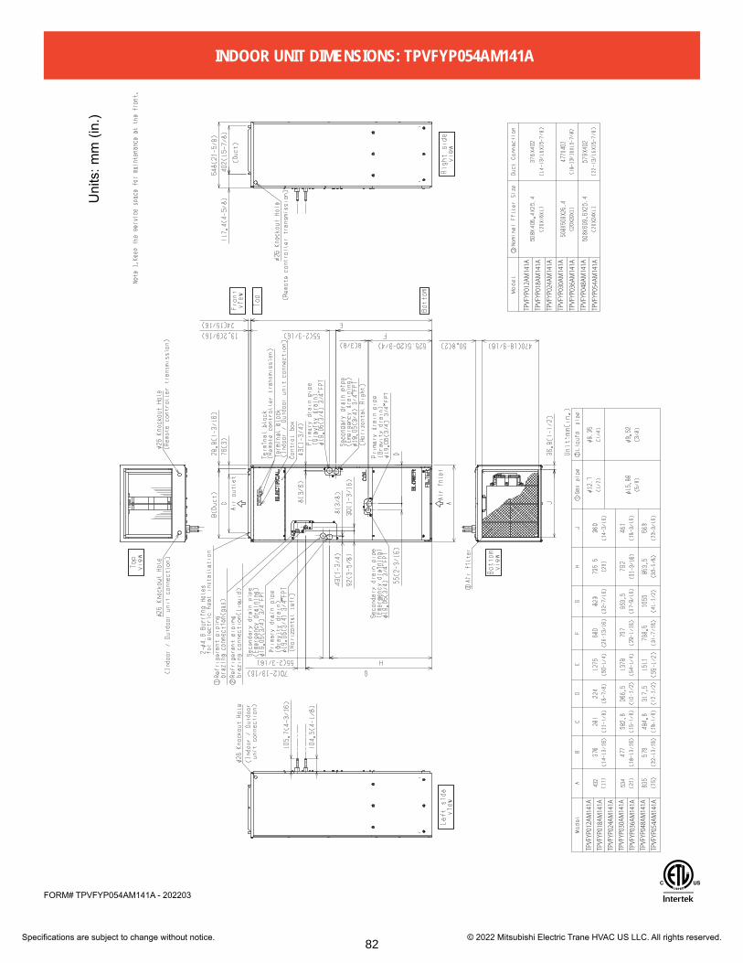
Specifications are subject to change without notice. © 2022 Mitsubishi Electric Trane HVAC US LLC. All rights reserved.
FORM# TPVFYP054AM141A - 202203
Uni
ts: m
m (i
n.)
TPVFYP012AM141A
TPVFYP018AM141A
TPVFYP024AM141A
TPVFYP030AM141A
TPVFYP036AM141A
TPVFYP048AM141A
TPVFYP054AM141A
TPVFYP012AM141A
TPVFYP018AM141A
TPVFYP024AM141A
TPVFYP030AM141A
TPVFYP036AM141A
TPVFYP048AM141A
TPVFYP054AM141A
INDOOR UNIT DIMENSIONS: TPVFYP054AM141A
82

Specifications are subject to change without notice. © 2019 Mitsubishi Electric Trane HVAC US, LLC
Job Name:
System Reference: Date:
TPEFYP054MH142AJob Name:Schedule Reference: Date:
Specifications are subject to change without notice. © 2014 Mitsubishi Electric US, Inc.
Notes:
Model: PEFY-P54NMHU-E2
OPTIONS □ Condensate Pump…..…BlueDiamond X87-711/721; 115/230V □ Condensate Pump…..…..Sauermann SI30-115/230; 115/230V □ Filter Box (Includes 2” MERV 13 filter)…......................…FBH2-3 □ CN24 Relay Kit………………………...…CN24RELAY-KIT-CM3
GeNer a l F ea TUre S• Dual set point functionality• High external static pressure capabilities• Ducted fan coil supports multiple configurations for
flexible installation• Built-in condensate pump; lifts to 27-9/16 inches• Suitable for use in air handling spaces in accordance with
Section 18.2 of UL 1995 4th Edition
SPec IFIca TIONSc apacity* Cooling…………………………………………....54,000 Btu/h Heating…………………………………………....60,000 Btu/h
Power Power Source……………..........208 / 230V, 1-phase, 60HzPower c onsumption* Cooling……………………………………….....0.63 / 0.62 kW Heating………………………………………….0.61 / 0.60 kWc urrent* Cooling……........................................................3.11 / 2.78 A Heating…….................................................…..3.00 / 2.67 AMinimum c ircuit a mpacity (Mc a ) @ 208V…...........................................................................4.18 A @ 230V…...........................................................................3.69 A
Fuse Size.........................................................................….......15 A
external Finish…………...….…….….Galvanized-steel Sheet
external Dimensions Inches…………………………...15 H x 47-1/16 W x 35-7/16 D mm……………………………………380 H x 1,195 W x 900 D
Net Weight…………..…...……………................157 lbs. / 71 kg
c oil Type………………...........................................….Cross Fin(Aluminum Plate Fin and Copper Tube)
FanType x Quantity………………………………Sirocco Fan x 2Airflow Rate (Low - High)………...............……....989 - 1,412 CFMExternal Static Pressure @ 208V…...........................................................0.40 - 1.00”WG @ 230V…...........................................................0.60 - 1.00”WGMotor Type…………………..………….1-phase induction motor
r efrigerant Piping Dimensions Liquid (High Pressure)……............3/8” / 9.52 mm (Brazed) Gas (Low Pressure)……………...5/8” / 15.88 mm (Brazed)
Drainpipe Dimension……............……...…O.D. 1-1/4” / 32 mm
Sound Pressure l evels Low - High….……….................…...……………41 - 47 dB(A)
* Cooling / Heating capacity indicated at operation under the following conditions:
Cooling | Indoor: 80° F (27° C) DB / 67° F (19° C) WB, Cooling | Outdoor 95° F (35° C) DB
Heating | Indoor: 70° F (21° C) DB, Heating | Outdoor 47° F (8° C) DB / 43° F (6° C) WB
78
irjhfa
Highlight
□ Filter Box (Includes 2” MERV 13 flter)…......................…FBH2-3

Specifications are subject to change without notice. © 2019 Mitsubishi Electric Trane HVAC US, LLC
Model: TPEFYP054MH142A – DIMENSIONS
Unit :mm(in.)
DE
GH
FA
CB
ø6.3
5ø1
2.7
ø9.5
2ø1
5.88
1085
1250
(31-
1/2)
(42-
3/4)
(49-
1/4)
1039
1204
754
(29-
11/1
6)
(40-
15/1
6)
(47-
7/16
)
965
1130
680
(38)
(44-
1/2)
885
1050
600
(23-
5/8)
(34-
7/8)
(41-
3/8)
835
1000
550
(21-
11/1
6)
(32-
7/8)
(39-
3/8)
42.5 2550 (2)
(1-1
1/16
)
(1)
17 2111
800
1000
(19-
11/1
6)
(31-
1/2)
(39-
3/8)
(1/4
)
(3/8
)70
0
900
(17-
3/4)
(27-
9/16
)
(35-
7/16
)
J
67 5050 (2)
(2-1
1/16
)
(2)L
K
(26-
13/1
6)80
0
15 191050
045
0(1
/2)
(5/8
)
Air i
nlet
Air o
utle
t
Mod
el
Gas
pip
e1
L
iqui
d pi
pe2
2×5-
ø3(1
/8) h
oles
15(5
/8)
L
50(2)
50x(J-1)=K (2x(J-1)=K)
23(15/16)B(Suspension bolt pitch)
A
60(2
-3/8
)81
4(32
-1/1
6)
904(
35-5
/8)
15(5
/8)
29(1
-3/1
6)
900(
35-7
/16)
24(1
)84
7(33
-3/8
)
10(7
/16)
41
E(Duct)
94(3
-3/4
)25
0(9-
7/8)
2×J-
ø3(1
/8) h
oles
14358
25(1)50x4=200
50(2)
326.5(12-7/8)
6918
7
180
164.
5
432(
17-1
/16)
50(2)
45(1-13/16)50x5=250
380(15)
F
50(2)
40(1-5/8)
65(2-9/16)C
50x(G-1)=H (2x(G-1)=H)
10(7
/16)
16(1
1/16
)34
0(13
-7/1
6)
D(Duct)
(Duc
t)
Susp
ensi
on b
olt h
ole
(Sus
pens
ion
bolt
pitc
h)
80(3-3/16)
(2x4=7-7/8)
(2-3
/4)
(7-1
/8)
(6-1
/2)
4-14
×30(
9/16
x1-3
/16)
Slo
t2×
G-ø
3(1/
8) h
oles
(7-3
/8)
(Duc
t)
(2-5/16)
Term
inal
blo
ckTe
rmin
al b
ox
(Pow
er s
ourc
e)
Con
trol b
oxD
rain
pum
p
Dra
in p
ipe
braz
ing
conn
ectio
n (g
as)
Term
inal
blo
ck
(2x5=9-7/8)
Dra
in p
ipe
Dra
in p
ipe
(O.D
.Ø32
(1-1
/4))
2×6-
ø3(1
/8) h
oles
braz
ing
conn
ectio
n (li
quid
)
(O.D
.ø32
(1-1
/4))
(5-11/16)
(1-5/8)
(Em
erge
ncy
drai
n)(O
.D.ø
32(1
-1/4
))(G
ravi
ty d
rain
)
62(2-1/2)
115(4-9/16)
44.5(1-13/16)
115(4-9/16)
(Tra
nsm
issi
on)
Term
inal
blo
ck
29
34(1-3/8)
(1-3/16)
700(27-9/16) Max
300(
11-1
3/16
) or l
ess
(Act
ual l
engt
h)
Dra
in h
ose
<Acc
esso
ry>
(I.D
.ø32
(1-1
/4))
0 -10
65
(2-9
/16
)
-7/1
6 0
20(13/16) or more 20(13/16) or more
Acce
ss d
oor
Cei
ling
surfa
ce
Mak
e th
e ac
cess
doo
r at t
he a
ppoi
nted
pos
ition
pro
perly
fo
r ser
vice
mai
nten
ance
.
Note2
50(2
)50
(2)
M
625(
24-5
/8)
450(1
7-3/4)
100~
200(
3-15
/16~
7-7/
8)
150~
200(
5-15
/16~
7-7/
8)
700(
27-9
/16)
450(
17-3
/4)Ac
cess
door
1065
1230
(30-
3/4)
(4-1
5/16)
(48-
7/16)
780
Mode
l
Req
uire
d sp
ace
for s
ervi
ce a
nd m
aint
enan
ce.
M
R
efrig
eran
t pip
ing
1 R
efrig
eran
t pip
ing
2
Not
e 1.
Use
an
M10
scr
ew fo
r the
sus
pens
ion
bolt
(fiel
d su
pply
).
2. K
eep
the
serv
ice
spac
e fo
r the
mai
nten
ance
from
the
botto
m
w
hen
the
heat
exc
hang
er is
cle
aned
.
3. Th
is d
raw
ing
is fo
r TPE
FYP0
27˜3
0˜36
˜48˜
54M
H14
2A, m
odel
s
whi
ch h
ave
2 fa
ns. T
PEFY
P015
˜18˜
24M
H14
2A m
odel
s ha
ve 1
fan.
4.
Mak
e su
re to
inst
all t
he a
ir fil
ter (
field
sup
ply)
on
the
air i
ntak
e si
de.
In c
ase
field
sup
plie
d ai
r filt
er is
use
d, a
ttach
it
w
here
the
filte
r ser
vice
is e
asily
don
e.
TPEF
YP02
7˜30
MH
142A
TPEF
YP03
6˜48
˜54M
H14
2A
TPEF
YP02
4MH
142A
TPEF
YP01
5˜18
MH
142A
TPEF
YP02
7˜30
MH14
2A
TPEF
YP03
6˜48
˜54M
H142
A
TPEF
YP01
5˜18
˜24M
H142
A
79

Specifications are subject to change without notice. © 2019 Mitsubishi Electric Trane HVAC US, LLC
Job Name:
System Reference: Date:
TPEFYP072MH140AJob Name:Schedule Reference: Date:
Notes:
Specifications are subject to change without notice. © 2014 Mitsubishi Electric US, Inc.
Model: PEFY-P72NMHSU-E
Gener a l Fea TUre S
Spe c iFica Tion Sc apacity* Cooling……………………………………………72,000 Btu/h Heating……………………………………………80,000 Btu/h
power Power Source……………………208 / 230V, 1-phase, 60 Hzpower consumption Cooling………………………………………….………0.63 kW Heating………………………………………….………0.63 kWc urrent Cooling……....................................………………. 3.67/3.32 A Heating…….................................………...………. 3.67/3.32 AMinimum Circuit Ampacity (MCA)………………............... 7.7 AMaximum Overcurrent Protection (MOCP) Fuse..…....... 15 A
external Finish………….….………...Galvanized-steel Sheet
external Dimensions Inches…………………………18-9/16 H x 49-1/4 W x 44-1/8 D mm……………………………………470 H x 1,250 W x 1,120D
net Weight Unit……………..…..……………………………214 lbs / 97 kg
c oil Type…………………………………………………Cross Fin(Aluminum Plate Fin and Copper Tube)
Fan Type x Quantity………….…………......………..Sirocco Fan x 2Airflow Rate (Low-Mid-High)...…………1,766 - 2,154 - 2,542 CFMExternal Static Pressure…… 0.20-0.40-0.60-0.80-1.00 "WG
(External static pressure is factory set to 0.60”WG)Motor Type………..………..………..…………..DC Brushless Motor
Refrigerant Piping Dimensions Liquid (High Pressure)…….............3/8" / 9.52 mm (Brazed) Gas (Low Pressure)………………....3/4" / 19.05 mm (Brazed)
Drainpipe Dimension……............……...…O.D. 1-1/4" / 32 mm
Sound pressure l evels (l ow-Mid-High) Low-Mid-High….…………….……………...36 - 39 - 43 dB(A)
• Single phase• Dual set point functionality• DC Motor• Static Pressure Features
- Adjustable up to 1” - No change in static pressure with voltage change
• Side access control panel• Flexibility in duct configuration• Choice of fan speed
* Cooling / Heating capacity indicated at the maximum value at operation under the following conditions:
Cooling: Indoor 80°F (27°C) DB / 67°F (19°C) WB, Outdoor 95°F (35°C) DB Heating: Indoor 70°F (21°C) DB, Outdoor 47°F (8°C) DB / 43°F (6°C) WB
op Tion S □ Joint Adapter (Port Connector)……….………….CMY-R160C-J □ Drain pump………………………….……………PAC-KE05DM-F □ External Heater Adapter…………………CN24RELAY-KIT-CM3 □ Filter Box (With 4” MERV 13 filter)….............................FBH4-4
76
irjhfa
Highlight
□ Filter Box (With 4” MERV 13 flter)….............................FBH4-4

Specifications are subject to change without notice. © 2019 Mitsubishi Electric Trane HVAC US, LLC
Model: TPEFYP072MH140A – DIMENSIONS
Air i
nlet
Air o
utle
t
(DU
CT)
(7/1
6)
(2-3
/8)
(3-3
/16)
(2-3/8)
(3-15/16x3=11-13/16)
(3-15/16x3=11-13/16)
(1-3/4)
(9-1
3/16
)
(DU
CT)
(7/1
6)
(5/8
)
(3-15/16)
(3-15/16)
(15/16)
(3-15/16)
(Act
ual l
engt
h)
Dra
in P
ipin
g.
(21-
11/16
)(7-
7/8~1
1-13/1
6)(17
-3/4)
(5-15
/16~7
-7/8)
(17-
3/4)
2X4-
ø3(1
/8) h
oles
2X11
-ø3(
1/8)
hol
es
Dra
in h
ole
Option
al Lift P
ump O
utlet P
ipe
Con
trol b
ox
(Pow
er s
ourc
e)Te
rmin
al b
lock
(MA
rem
ocon
)(T
rans
mis
sion
wiri
ng)
(Pow
er s
ouse
wiri
ng)
(Gra
vity
type
)
(Opt
ion)
(Tra
nsm
issi
on)
Susp
ensi
on b
olt h
ole
Ter
min
al b
lock
Knoc
kout
hol
e ø2
2.2(
7/8)
Knoc
kout
hol
e ø2
2.2(
7/8)
Ter
min
al b
lock
4-14
X30(
9/16
x3/1
6) S
lot
2X4-
ø3(1
/8) h
oles
2X11
-ø3(
1/8)
hol
es
Mak
e th
e ac
cess
doo
rat
the
appo
inte
d po
sitio
n pr
oper
lyfo
r ser
vice
mai
nten
ance
.
Acce
ss d
oor
Cei
ling
surfa
ce
Acce
ss d
oor
Note
2
Not
e3
Req
uire
d sp
ace
for s
ervi
ce a
nd m
aint
enan
ce.
MO
DEL
TPEF
YP07
2MH1
40A
TPEF
YP09
6MH1
40A
ø 19.
05(3
/4)
ø 22.
2(7/
8)ø9
.52(
3/8)
Dra
in h
ose
32m
m
(1-1
/4in
ch)
<fle
xibl
e jo
int>
<acc
esso
ry>
Not
e 1.
Use
M10
scr
ew fo
r the
sus
pens
ion
bolt
(fiel
d su
pply
).
2
.Kee
p th
e se
rvic
e sp
ace
for t
he m
aint
enan
ce fr
om th
e bo
ttom
w
hen
the
heat
exc
hang
er is
cle
aned
.
3
.Kee
p th
e se
rvic
e sp
ace
for t
he m
aint
enan
ce fr
om th
e bo
ttom
w
hen
the
fan
mot
or is
cha
nged
.
4
.Mak
e su
re to
inst
all t
he a
ir fil
ter (
field
sup
ply)
on
the
air i
ntak
e si
de.
I
n ca
se fi
eld
supp
lied
air f
ilter
is u
sed,
atta
ch it
w
here
the
filte
r ser
vice
is e
asily
don
e.U
nit:m
m(in
.)
Uni
t:mm
(in.)
249
95(3
-4/3) 34
2(13
-1/2
)80
170(
6-3/
4±1/
4)
23
100
470(18-9/16)
20(1
3/16)
102(4-1/16)
105(
4-3/
16)
420(
16-9
/16)
1100(43-5/16)(DUCT)
1250(49-1/4)
1372(54-1/16)
1124
(44-
5/16
)
1510
100x10=1000(3-15/16x10=39-3/8)100(3-15/16)
50(2)60
1326(52-1/4)(Suspension bolt pitch)
1034
(40-
3/4)
(Sus
pens
ion
bolt
pitc
h)34
0(13
-7/1
6)
1100(43-5/16)(DUCT)
100
100
29(1
-3/1
6)
41(1-5/8)
1067
(42-
1/16
)24
(1)
1120
(44-
1/8) 48
9(19
-5/1
6)
327(12-7/8)44 164(6-1/2)
30(1-3/16)
15(5
/8)
100X3(=300)100(3-15/16)
20(13/16)
100(3-15/16)10
100x3=300 60
100x10=1000(3-15/16x10=39-3/8) 50(2)100(3-15/16)
More than 20(13/16) More than 20(13/16)
55050
(2)
150~
200
50(2
)
50(2
)
450
800(
31-1
/2)
450
200~
300
1350
(53-3/
16)73
0(28-3
/4)TPEFYP072¤96MH140A
Gas
pip
eLi
quid
pip
e
Gas
pip
eLi
quid
pip
eD
rain
hos
e
Drai
n ho
se
77

Job Name: System Reference: Date:
GENERAL FEATURES• Dual set point functionality• Compact, lightweight, flat-white, flat-panel, modern design• Quiet operation• Multiple fan speed settings• Intake grille filter is easily removed for cleaning• Back and right-side wiring take-out• Wireless receiver on boardSPECIFICATIONS
MODEL: TPKFYP004LM140A
Specifications are subject to change without notice. © 2020 Mitsubishi Electric Trane HVAC US LLC. All rights reserved.
Power source 1-phase, 208/230V, 60HzCooling Capacity1
(Nominal)BTU/H 4,000
Heating Capacity2
(Nominal)BTU/H 4,500
Power ConsumptionCooling kW 0.02Heating kW 0.01
CurrentCooling A 0.20Heating A 0.15
Minimum Circuit Ampacity (MCA) A 0.24Maximum Overcurrent Protection (MOCP) A 15Recommended Fuse Size A 15External finish Plastic, MUNSELL (0.7PB 9.2/0.4)
External Dimensions (H x W x D)In. 11-25/32 x 30-7/16 x 9-11/32mm 299 x 733 x 237
Net weight Lbs (kg) 23.6 (10.7)Heat exchanger Cross fin (Aluminum fin and copper tube)
Fan
Type x quantity Line flow fan x 1External Static pressure in.WG 0Airflow rate CFMMotor type
117-124-134-148DC Motor
Motor Output kW 0.030Motor FLA A 0.19
Sound pressure level(Measured in anechoic room)3
dB(A) 22-24-26-28
Air filter PP honeycomb
Diameter of refrigerant pipe(O.D.)
Liquid (R410A) in. (mm) 1/4 (6.35) FlareGas (R410A) in. (mm) 1/2 (12.70) Flare
Diameter of drain pipe in. (mm) I.D. 5/8 (16)
NotesCooling / Heating capacity indicated at the maximum value at operation under the following conditions:1Cooling | Indoor: 81° F (27° C) DB / 66° F (19°C) WB; Outdoor 95° F (35° C) DB 2Heating | Indoor: 68° F (20° C) DB; Outdoor 45° F (7° C) DB / 43° F (6° C) WB
29

Wireless Signal Receiver □ PAR-SR32MA-WWireless Signal Receiver □ PAR-FA32MA-EWireless Remote Controller □ TAR-FL32MA-Ekumo touch™ RedLINK™ Wireless Controller □ MHK2Deluxe MA Remote Controller □ TAR-40MAAUSimple MA Controller □ TAC-YT53CRAU-JTouch MA Controller □ TAR-CT01MAU-SBWired Remote Sensor □ PAC-SE41TS-ETerminal Signal Adapter □ PAC-IT52AD-ETerminal Signal Adapter □ PAC-IT51AD-EWireless Temperature and Humidity Sensor □ PAC-USWHS003-TH-1Flush Mount Remote Temperature Sensor □ PAC-USSEN001-FM-1System Control Interface □ MAC-334IF-EWireless Interface 2 □ PAC-USWHS002-WF-2Thermostat Interface □ PAC-US444CN-1kumo station®
USNAP InterfaceIT Extender
□ TAC-WHS01HC-E□ PAC-WHS01UP-E□ PAC-WHS01IE-E
BACnet® and MODBUS® Interface □ PAC-UKPRC001-CN-1External Fan / Heater Control Relay Adapter □ CN24RELAY-KIT-CM3Wire for Remote on/off with CN32 connector □ PAC-715ADConnector and wire for Operation status/error using CN51 □ PAC-725ADConnector cable for remote display □ PAC-SA88HA-EPWire for Remote on/off with CN32 connector □ PAC-715ADRemote Operation Adapter1 □ PAC-SF40RM-E3D i-see Sensor® Corner Panel □ PAC-SF1ME-EGrille with 3D i-see Sensor® □ SLP-18FAEUInstallation/Trim Panels □ PLFY-ITP2Space Panel □ PAC-SJ38AS-EBottom Return Plate (Converts low-profile ducted indoor unit from rear return to bottom return) □ BRP-1Blue Diamond Sensor Extension Cable — 15 Ft. □ C13-103Blue Diamond MultiTank — collection tank for use with multiple pumps □ C21-014Mini Condensate Pump — 230 volt application □ SI30-230Advanced Blue Diamond Mini Condensate Pump w/ Reservoir & Sensor (208/230V) [recommended] □ X87-721 - 208/230V(30A/600V/UL) [fits 2" X 4" utility box] - Black □ TAZ-MS303(30A/600V/UL) [fits 2" X 4" utility box] - White □ TAZ-MS303W
1 Unable to use with wireless remote controller
ACCESSORIES: TPKFYP004LM140A
Specifications are subject to change without notice. © 2020 Mitsubishi Electric Trane HVAC US LLC. All rights reserved.30
irjhfa
Highlight
Wired Remote Sensor □PAC-SE41TS-E

Unit: in(mm)
FORM# TPKFYP004LM140A - 202003
DIMENSIONS: TPKFYP004LM140A
Specifications are subject to change without notice. © 2020 Mitsubishi Electric Trane HVAC US LLC. All rights reserved.31

Accessories

Job Name:Schedule Reference: Date:
Specifications are subject to change without notice. © 2014 Mitsubishi Electric & Electronics USA, Inc.
FBH Series Filter Boxes
GENERAL FEATURES
Manufactured for MITSUBISHI ELECTRIC US, INC. CITY MULTI® PEFY-P72,96-NMHSU-E HIGH-STATIC INDOOR UNITS
SPECIFICATIONS
FBH Series Filter Boxes Designed for CITY MULTI® PEFY-P72, 96NMHSU-E High-Static Indoor Units
Job Name:
Drawing Reference Schedule No.
GENERAL FEATURES Filter box includes 4" thick pleated MERV 13 filter(s) installed Rated MERV 13 when tested in accordance with ANSI/ASHRAE 52.2 Standard Rated Class 2 under U.L. Standard 900 Cabinet is constructed of non-insulated 20 gauge G-60 galvanized steel Knurled thumb screws on access door allows easy filter replacement Foam gasket provides air-tight connection to indoor unit and access door Gasket material complies with UL 723 requirements Screw-through cabinet design for secure attachment to indoor unit Return connection in rear easily field converted to bottom Filter access door includes area to record maintenance schedule
SPECIFICATIONSUsed on Ship Net
CITY MULTI Models Weight lbs. Weight lbs.FBH4-4 PEFY-P72, P96NMHSU-E (2) - 24" x 24" x 4" MERV 13 44 40
EXTERNAL DIMENSIONS
Part Number Filters Included
Meets LEED requirement of MERV 13
Filter Box Accessory Part #
Filter Size: (2) - 24" x 24 x 4"
Date Installed:
Filter(s) Changed:
FBH4-4
Manufactured for Mitsubishi Electric & Electron ics USA
AIRFLOW
June 2012 Manufactured for Mitsubishi Electric and Electronics USA
End View
Rear Inlet(standard)
Bottom Inlet(field convertible)
Rear Inlet(standard)
Back View (inlet air)
18-3/8" 14"
3-5/8"
FBH4-4 49-3/8" 44-1/2"
"B""A"
Top View
5-1/4"
Model "A" "B"
3/4"
20"
3/4"1"
14"
Indoor Unit
3-1/8"1-3/4"
EXTERNAL DIMENSIONS
FBH Series Filter Boxes Designed for CITY MULTI® PEFY-P72, 96NMHSU-E High-Static Indoor Units
Job Name:
Drawing Reference Schedule No.
GENERAL FEATURES Filter box includes 4" thick pleated MERV 13 filter(s) installed Rated MERV 13 when tested in accordance with ANSI/ASHRAE 52.2 Standard Rated Class 2 under U.L. Standard 900 Cabinet is constructed of non-insulated 20 gauge G-60 galvanized steel Knurled thumb screws on access door allows easy filter replacement Foam gasket provides air-tight connection to indoor unit and access door Gasket material complies with UL 723 requirements Screw-through cabinet design for secure attachment to indoor unit Return connection in rear easily field converted to bottom Filter access door includes area to record maintenance schedule
SPECIFICATIONSUsed on Ship Net
CITY MULTI Models Weight lbs. Weight lbs.FBH4-4 PEFY-P72, P96NMHSU-E (2) - 24" x 24" x 4" MERV 13 44 40
EXTERNAL DIMENSIONS
Part Number Filters Included
Meets LEED requirement of MERV 13
Filter Box Accessory Part #
Filter Size: (2) - 24" x 24 x 4"
Date Installed:
Filter(s) Changed:
FBH4-4
Manufactured for Mitsubishi Electric & Electron ics USA
AIRFLOW
June 2012 Manufactured for Mitsubishi Electric and Electronics USA
End View
Rear Inlet(standard)
Bottom Inlet(field convertible)
Rear Inlet(standard)
Back View (inlet air)
18-3/8" 14"
3-5/8"
FBH4-4 49-3/8" 44-1/2"
"B""A"
Top View
5-1/4"
Model "A" "B"
3/4"
20"
3/4"1"
14"
Indoor Unit
3-1/8"1-3/4"
83

1340 Satellite Boulevard Suwanee, GA 30024Tele: 678-376-2900 • Fax: 800-889-9904Toll Free: 800-433-4822www.mehvac.com
FORM# FBM Filter Boxes for PEFY-P72,96-NMHSU-E Indoor Units- 201402Specifications are subject to change without notice. © 2014 Mitsubishi Electric US, Inc.
Manufactured for MITSUBISHI ELECTRIC US, INC.
Initial Filter Pressure Drop with 4" MERV 13 Filter(s) InstalledInitial Filter Pressure Drop with 4" MERV 13 Filters Installed
0.09
0.10
0.11
0.12
0.13
0.14
0.15
0.16
0.17
0.18
0.19
0.20
1766 1877 1988 2099 2209 2320 2431 2542
Stat
ic P
ress
ure
(in. W
G)
Airflow rate (cfm)
Indoor Unit PEFY-P72NMHSU-E
High
Med
Low
0.25
Indoor Unit PEFY-P96NMHSU-EHigh
0.120.130.140.150.160.170.180.190.200.210.220.230.240.25
2048 2179 2310 2441 2573 2704 2835 2966
Stat
ic P
ress
ure
(in. W
G)
Airflow rate (cfm)
High
Med
Low
84

Job Name:Schedule Reference: Date:
Specifications are subject to change without notice. © 2013 Mitsubishi Electric US, Inc.
FBH Series Filter Boxes
GENERAL FEATURES
Manufactured for MITSUBISHI ELECTRIC US, INC. CITY MULTI® PEFY-P-NMHU-E2 HIGH-STATIC INDOOR UNITS
• All filter boxes include 2” thick pleated MERV 13 filter(s) installed - Rated MERV 13 when tested in accordance with ANSI/ ASHRAE 52.2 Standard - Rated Class 2 under U.L. Standard 900
• Cabinet is constructed of non-insulated 20 gauge G-60 galvanized steel
• Knurled thumb screws on access door allow easy filter replacement
• Foam gasket provides air-tight connection to indoor unit and access door
• Gasket material complies with UL 723 requirements• Screw-through cabinet design for secure attachment to
indoor unit• Return connection in rear easily field converted to bottom• Filter access door includes area to record maintenance
schedule
EXTERNAL DIMENSIONS
Part Number Use onCITY MULTI Models Filters Included Ship Weight (lbs.) Net Weight (lbs.)
FBH2-1 PEFY-P15, P18, P24-NMHU-E2 (1) - 20" x 24" x 2" 16 14
FBH2-2 PEFY-P27, P30-NMHU-E2 (1) - 20" x 16" x 2", (1) - 20" x 20" x 2" 26 24
FBH2-3 PEFY-P36, P48 P54-NMHU-E2 (2) - 20" x 20" x 2" 29 27
SPECIFICATIONS
Model "A" "B" "C"FBH2-1 22-1/4" 23-3/4" 26-3/4"
FBH2-2 33-1/2" 35" 38"
FBH2-3 40" 41-1/2" 44-1/2"
Rear Inlet(standard)
(field convertible)
3/4"
"B"
3/4"
Back View (inlet air)
Top View
15"
Bottom Inlet"A"
End View3/4"
3/4"
"C"
13-1/2"
1-1/2"
IndoorUnit
Filter Box Accessory Part #
Filter Size: (2) - 24" x 24 x 4"
Date Installed:
Filter(s) Changed:
FBH4-4
Manufactured for Mitsubishi Electric & Electronics USA
AIRFLOW
Rear Inlet(standard)
ModelFBH2-1 23-3/4"
FBH2-3FBH2-2 38"
1"
22-1/4"33-1/2"
40"
"A"
15-3/4"
2-1/4"
3/4"
12-3/4"
35"41-1/2"
"B" "C"26-3/4"
44-1/2"
Rear Inlet(standard)
(field convertible)
3/4"
"B"
3/4"
Back View (inlet air)
Top View
15"
Bottom Inlet"A"
End View3/4"
3/4"
"C"
13-1/2"
1-1/2"
IndoorUnit
Filter Box Accessory Part #
Filter Size: (2) - 24" x 24 x 4"
Date Installed:
Filter(s) Changed:
FBH4-4
Manufactured for Mitsubishi Electric & Electronics USA
AIRFLOW
Rear Inlet(standard)
ModelFBH2-1 23-3/4"
FBH2-3FBH2-2 38"
1"
22-1/4"33-1/2"
40"
"A"
15-3/4"
2-1/4"
3/4"
12-3/4"
35"41-1/2"
"B" "C"26-3/4"
44-1/2"
s Filter Boxes ITY MULTI® PEFY-P-NMHU-E2 High-Static Indoor Units
.oN eludehcSe
TURESclude 2" thick pleated MERV 13 filter(s) installedwhen tested in accordance with ANSI/ASHRAE 52.2 Standard
nder U.L. Standard 900ucted of non-insulated 20 gauge G-60 galvanized steelcrews on access door allow easy filter replacementvides air-tight connection to indoor unit and access doorcomplies with UL 723 requirementsabinet design for secure attachment to indoor unitn in rear easily field converted to bottomr includes area to record maintenance schedule
teNpihSno desU.sbl thgieW.sbl thgieWsledoM ITLUM YTIC
EFY-P15, P18, P24-NMHU-E2 (1) - 20" x 24" x 2" 16 14
PEFY-P27, P30-NMHU-E2 (1) - 20" x 16" x 2", (1) - 20" x 20" x 2" 26 24
EFY-P36, P48 P54-NMHU-E2 (2) - 20" x 20" x 2" 29 27
dedulcnI sretliF
Meets LEED requirement of MERV 13
Filter Box Accessory Part #
Filter Size: (2) - 24" x 24 x 4"
Date Installed:
Filter(s) Changed:
FBH4-4
Manufactured for Mitsubishi Electric US, Inc
AIRFLOW
MENSIONS
85

Specifications are subject to change without notice. © 2013 Mitsubishi Electric US, Inc.
Initial Filter Pressure Drop with 2" MERV 13 Filter(s) InstalledInitial Filter Pressure Drop with 2" MERV 13 Filter(s) Installed
0.08
0.09
0.10
0.11
0.12
0.13
0.14
353 373 393 413 433 453 473 494
Stat
ic P
ress
ure
(in. W
G)
Airflow rate (cfm)
Indoor Unit PEFY-P15-18NMHU-E2
LOW
HIGH
0.11
0.12
0.13
0.14
0.15
0.16
0.17
0.18
477 504 531 558 585 612 639 671
Stat
ic P
ress
ure
(in. W
G)
Airflow rate (cfm)
Indoor Unit PEFY-P24NMHU-E2
LOW
HIGH
0.08
0.09
0.10
0.11
0.12
0.13
0.14
547 579 611 643 675 707 739 777
Stat
ic P
ress
ure
(in. W
G)
Airflow rate (cfm)
Indoor Unit PEFY-P27NMHU-E2
LOW
HIGH
86

Manufactured for MITSUBISHI ELECTRIC US, INC. 1340 Satellite Boulevard Suwanee, GA 30024Tele: 678-376-2900 • Fax: 800-889-9904Toll Free: 800-433-4822www.mehvac.com
Specifications are subject to change without notice. © 2013 Mitsubishi Electric US, Inc.
Initial Filter Pressure Drop with 2" MERV 13 Filter(s) Installed
0.10
0.11
0.12
0.13
0.14
0.15
0.16
636 671 706 741 776 811 846 883
Stat
ic P
ress
ure
(in. W
G)
Airflow rate (cfm)
Indoor Unit PEFY-P30NMHU-E2
0.13
0.14
0.15
0.16
0.17
0.18
0.19
0.20
0.21
0.22
936 994 1052 1110 1168 1226 1284 1342
Stat
ic P
ress
ure
(in. W
G)
Airflow rate (cfm)
Indoor Unit PEFY-P36-48NMHU-E2
0.14
0.15
0.16
0.17
0.18
0.19
0.20
0.21
0.22
0.23
989 1049 1109 1169 1229 1289 1349 1412
Stat
ic P
ress
ure
(in. W
G)
Airflow rate (cfm)
Indoor Unit PEFY-P54NMHU-E2
LOW
LOW
LOW
HIGH
HIGH
HIGH
FORM# FBH Filter Boxes for PEFY-P-NMHU-E2 Indoor Units - 201312
87

Job Name:System Reference: Date:
Specifications are subject to change without notice. © 2020 Mitsubishi Electric Trane HVAC US LLC. All rights reserved.
FBM Series Filter BoxesManufactured for MITSUBISHI ELECTRIC US, INC.
CITY MULTI® TPEFYP***MA143A and Nv-P PEAD-A*AA7 Medium-Static Indoor Units
PRODUCT OVERVIEW
• FBM filter boxes include 2" thick pleated MERV 13 filter(s) installed - Rated MERV 13 when tested in accordance with ANSI/ASHRAE 52.2 Standard - Rated Class 2 under UL Standard 900
• Low static loss design• Cabinet is constructed of non-insulated G-60 galvanized steel• Knurled thumb screws on access door allow easy filter replacement• Cabinet may be inverted to locate access from other side• Foam gasket provides airtight connection to indoor unit and access door• Gasket material complies with UL 723 requirements• Screw-through cabinet design for secure attachment to indoor unit• Return connection in rear easily field converted to bottom return• Filter access door includes area to record maintenance schedule
FBM
Part Number
Used onCITY MULTI® Models
Used on Nv- and P-Series Ducted Models
Filters Included
NetWeight lbs.
FBM2-1-A TPEFYP006, 008, 012MA143A — (1) - 14" x 25" x 2" 20
FBM2-2-A TPEFYP015, 018MA143A PEAD-A09, A12, A15, 18AA7 (1) - 14" x 20" x 2" (1) - 14" x 14" x 2" 24
FBM2-3-A TPEFYP024, 027, 030MA143A PEAD-A24, 30AA7 (2) - 14" x 20" x 2" 29
FBM2-4-A TPEFYP036, 048MA143A PEAD-A36, 42AA7 (2) - 14" x 20" x 2" (1) - 14" x 14" x 2" 35
FBM2-5-A TPEFYP054MA143A — (3) - 14" x 20" x 2" 37
Part Number “A” “B”
FBM2-1-A 27 - 5/8" 26"
FBM2-2-A 35 - 1/2" 34"
FBM2-3-A 43 - 3/8" 42"
FBM2-4-A 55 - 1/8" 53 - 5/8"
FBM2-5-A 63" 61 - 1/2"
FBM DIMENSIONS
45

Specifications are subject to change without notice. © 2020 Mitsubishi Electric Trane HVAC US LLC. All rights reserved.
Initial Filter Pressure Drop with 2” MERV 13 Filter(s) Installed
TPEFYP006, 008MA143Awith Filter Box FBM2-1-A
TPEFYP012MA143Awith Filter Box FBM2-1-A
TPEFYP015MA143Awith Filter Box FBM2-2-A
46

Specifications are subject to change without notice. © 2020 Mitsubishi Electric Trane HVAC US LLC. All rights reserved.
Initial Filter Pressure Drop with 2” MERV 13 Filter(s) Installed, contd.
TPEFYP018MA143Awith Filter Box FBM2-2-A
PEAD-A09AA7with Filter Box FBM2-2-A
PEAD-A12AA7with Filter Box FBM2-2-A
47

Specifications are subject to change without notice. © 2020 Mitsubishi Electric Trane HVAC US LLC. All rights reserved.
Initial Filter Pressure Drop with 2” MERV 13 Filter(s) Installed, contd.
PEAD-A15AA7with Filter Box FBM2-2-A
PEAD-A18AA7with Filter Box FBM2-2-A
TPEFYP024, 027, 030MA142Awith Filter Box FBM2-3-A
48

Specifications are subject to change without notice. © 2020 Mitsubishi Electric Trane HVAC US LLC. All rights reserved.
Initial Filter Pressure Drop with 2” MERV 13 Filter(s) Installed, contd.
TPEFYP036MA142Awith Filter Box FBM2-4-A
PEAD-A24AA7with Filter Box FBM2-3-A
PEAD-A30AA7with Filter Box FBM2-3-A
49
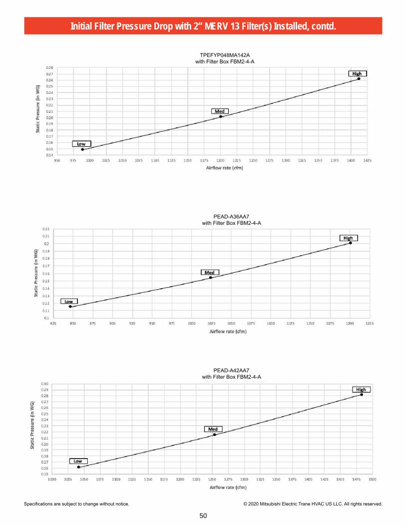
Specifications are subject to change without notice. © 2020 Mitsubishi Electric Trane HVAC US LLC. All rights reserved.
Initial Filter Pressure Drop with 2” MERV 13 Filter(s) Installed, contd.
TPEFYP048MA142Awith Filter Box FBM2-4-A
PEAD-A36AA7with Filter Box FBM2-4-A
PEAD-A42AA7with Filter Box FBM2-4-A
50

© 2020 Mitsubishi Electric Trane HVAC US LLC. All rights reserved.Specifications are subject to change without notice.T_Submittal_FBM_Series_Filter_Boxes 02-2020
Initial Filter Pressure Drop with 2” MERV 13 Filter(s) Installed, contd.
TPEFYP054MA142Awith Filter Box FBM2-5-A
51

Controls

Job Name: Location:
Drawing Reference: Schedule No.
System No.: Date:
Model: PAC-SE41TSERemote Temperature Sensor
REMOTE SENSOR (PAC-SE41TSE) Capabilities•Allowsforremotetemperaturemonitoringwithinan areafortheindoorunit.•WiresbacktotheindoorunitatCN20toreplacethe returnairtemperaturesensor.
General Specifications•Powersupply:Throughtheindoorunit.•Dimensions:2-3/4Wx4-3/4Hx5/8"D(70x120x15mm).•Exterior:ABSresin(MunsellNo.4.48Y7.92/0.66)•EnvironmentConditions
- Operatingtemperaturerange:-4°to+149°F(-20°to +65°C).- Relativehumidity:30to90%(nocondensation).- Installinasingle-typeswitchboxordirectlyonawall.
•Maximumwiringlength:39'(12m).• Ifcombinedwithenvironmentalmeasurement controller:
- Temperaturemeasurementrange:-4°to+149°F (-20°to+65°C).- Measurementresolution:0.2°F(0.1°C)for50°to 95°F(10°to35°C);0.9°F(0.5°C)fortemperatures outsidespecifiedrange.
OVERVIEW Of CITY MULTI® COnTROLs nETWORk (CMCn)•ConsistsofTG-2000integratedsystemsoftware,AG-150/ GB-50ADA/GB-24/TC-24centralizedcontrollers,web browsers,timers,remotecontrollers,andBMSinterfaces.•TG-2000integratedsystemsoftwaresupportsupto40 AG-150/GB-50ADAcentralizedcontrollers(licensedfor PCsoftwarefeatures)foramaximumof2,000indoor unitsfromasinglePC.•AG-150centralizedcontrolleroperatesupto50indoor unitswithoptionalcontrolviaafield-suppliedPCwith licensedsoftware.•GB-50ADAcentralizedcontrolleroperatesupto50 indoorunitsviaafield-suppliedPCwithlicensed software.•GB-24centralcontrolleroperatesupto24indoorunits viaafield-suppliedPCwithlicensedsoftware.•TC-24standalonecentralizedcontrolleroperatesupto24 indoorunitsviaanintegraltouchscreeninterface.•RemotecontrollersconsistofDeluxeMA,SimpleMA WirelessMA,andME.• I/OcontrollersconsistofDIDO(PAC-YG66DCA)and AI(PAC-YG63MCA)forthird-partyequipmentcontrol.•LonWorks®andBACnet®interfacesalsoavailable.• InterlockingofLOSSNAY®ERVunitsforcontrolvia theAG-150/GB-50ADA/GB-24/TC-24centralized controllers.
43

HVAC Advanced Products DivisionMitsubishi Electric & Electronics USA, Inc.3400 Lawrenceville Suwanee Rd.Suwanee, GA 30024Tele: 678-376-2900 • Fax: 800-889-9904Toll Free: 800-433-4822 (#4)www.mehvac.comSpecifications are subject to change without notice.
Model: PAC-SE41TSE
C SD - PAC-SE41TSE - 1 - 201008 © MITSUBISHI ELECTRIC / HVAC 2010
Certificate Number FM33568
Certificate Number EC97J1227
Mitsubishi Electric Air Conditioning & Refrigeration Systems Works acquired ISO 9001 certification under Series 9000 of the International Standard Organization (ISO) based on a review of quality warranties for the production of refrigeration and air conditioning equipment.
ISO Authorization SystemThe ISO 9000 series is a plant authorization system relating to quality warranties as stipulated by the ISO. ISO 9001 certifies quality warranties based on the "design, development, production, installation and auxiliary services" for products built at an authorized plant.
Mitsubishi Electric Air Conditioning & Refrigeration Systems Works acquired environmentalmanagement system standard ISO 14001 certification.
The ISO 14000 series is a set of standards applying to environmental protection set by the International Standard Organization (ISO).
2-3/4 (70)
Unit: Inch (mm)
4-3/
4 (1
20)
5/8 (15)
1/4
(5)
3/8 (10)
ø1/4 (ø6)
3/8(10)
1/4
(5)
5/16
(7)
3-1/
4 (8
3.5)
Inst
alla
tion
Pitc
h
44

Specifications are subject to change without notice. © 2019 Mitsubishi Electric Trane HVAC US LLC. All rights reserved.
Job Name:System Reference: Date:
TE-200A• TE-200A is the Master Controller• Master Controller can operate and monitor up to 50 indoor units• Expansion Controllers can expand an TE-200A to operate and
monitor up to 50 additional indoor units through the touchscreen or web browser
• Network up to three TE-50A or TW-50A to one TE-200A to allow the TE-200A to manage up to 200 indoor units
OPTIONAL LICENSES• SW-BACnet Master: BACnet Function
- Connected air conditioning units can be monitored and operated not only from the existing web browser or the TE-200/TE-50’s LCD, but also from the building management system using the BACnet® communication protocol. See SW-BACnet Data Sheet for more information.
• SW-Charge Master: Energy Allocation - The apportioned electricity billing function is an electric energy - apportionment system that apportions electric energy using
input from electricity meters with a pulse generator function. The respective amounts of electric energy can be apportioned based on the operating status and capacity of each tenant. See SW-Charge Data Sheet for more information.
• SW-PWeb Master: Online Personal Browser - Allows tenant managers and general users to control their
respective zone conditions via a networked PC, tablet, or mobile phone with or without local remote controllers installed in the space. See SW-PWeb Data Sheet for more information.
SPECIFICATIONS• Supports dual set point functionality (connected equipment
dependent)• Displays:
- CITY MULTI® compressor speed and hi/low pressure - AdvancedHVAC Controller (DC-A2IO) input/output status - Indoor unit free contact input/output status - Space temperature and humidity (from Smart ME or AI controller) - Error code (Can be emailed automatically to specified recipients) - Unoccupied setback up temperature range
• Functions - Hold function (temporarily disables schedules indoor unit model
dependent) - Initial setting - Operation data back-up
• Permits or prohibits remote controller functions: - On/Off
MODEL: TE-200A
- Change Operation Mode - Change Set Point Temperature - Filter Status - Change Fan Speed - Change Air Direction
• External input/output signals can be used for batch operations such as Start/Stop and Emergency Stop (requires PAC-YG10HA)
• Pulse signal input can obtain watt-hour meter, billing data and energy management data based on the cumulative number of pulse signal pulse signals directly input from a metering device
• Temperature set point range limits can be set for local remote controllers
• User defined indoor unit functions: - On/Off - Monitoring and Operation - Operation mode:
◦ Auto* (Dual or Single set point) ◦ Heat ◦ Fan ◦ Drying ◦ Setback*
Note: *R2 Series only (connected equipment dependent)
- Temperature Setting - Fan Speed - Airflow Direction
• • Monitoring and Control: - CITY MULTI® indoor units - Nv- & P-Series units (requires M-Net adapter) - Lossnay® units - TPWFY hydronic heat pump units - DIDO controllers - CITY MULTI® DOAS - Interlock setting enables integration of general equipment inputs/
outputs and indoor units• Scheduling
- Daily - Annually - Five pattern of weekly seasonal schedule
• Twenty four scheduled events per day, indoor unit model dependent: - ON/OFF - Mode - Temperature Setting - Vane Direction - Fan - Speed - Operation Prohibits
• Trend data: - Fan operation time - Thermo-on time - Set temperature - Room temperature - AI Controller temperature and humidity
(requires PAC-YG63-MCA, 2 inputs total for each controller)• Memory back up via USB (universal serial bus)• Memory back up via LAN (local area network) port
52
irjhfa
Rectangle

Specifications are subject to change without notice. © 2019 Mitsubishi Electric Trane HVAC US LLC. All rights reserved.
TE-200A - SPECIFICATIONS, CONT.
Item Specifications
Power SupplyRated input 100–240 VAC ± 10%; 0.3–0.2 A 50/60 Hz Single-phase
Fuse 250 VAC 6.3 A Time-Lag type (IEC 60127-2S.S.5)
M-NET power feeding capability No specifications**Only an MN converter can be connected.
Ambient conditionsTemperature
Operating Range 0° C to +40° C (+32° F to +104° F)
Non-operating Range -20° C to +60° C (-4° F to +140° F)
Humidity 30% to 90% RH (no condensation)
Weight 2.3 kg (5-5/64 lbs)
Dimensions (W x H x D) 11-5/32 × 7-55/64 × 2-17/32 in. (284 × 200 × 65 mm)
Installation conditions Indoor only **To be used in a business office or similar environment
Item RequirementsCPU 1 GHz or faster
Memory 512 MB or more
Screen Resolution 1024 x 768 or higher recommended
CompatibleBrowser Windows®
Microsoft® Internet Explorer 8.0Microsoft® Internet Explorer 9.0Microsoft® Internet Explorer 10.0Microsoft® Internet Explorer 11.0**Java execution environment is required.(Oracle® Java Plug-in Ver. 1.8.0_60)**Install Oracle® Java Plug-in that is appropriate for your operating system. When using a 64-bit Internet Explorer, install a 64-bit Java Plug-in.**The version of the Oracle® Java Plug-in can be verified by clicking [Java] in the Control Panel.
Onboard LAN Port or LAN Card 100 BASE-TX
100 BASE-TX e.g., mouse
TE-200A CENTRALIZED CONTROLLER
WEB BROWSER REQUIREMENTS
NOTES:
53

Specifications are subject to change without notice. © 2019 Mitsubishi Electric Trane HVAC US LLC. All rights reserved.
CONTROLLING 50 OR FEWER UNITS OF EQUIPMENT
CONTROLLING MORE THAN 50 UNITS OF EQUIPMENT (WITH CONNECTION TO A TE-200 CONTROLLER)NoteTE-200 is required when using TE-50
WHEN USING AN APPORTIONED ELECTRICITY BULLING FUNCTIONNotesTE-200 is required to use a billing function.TE-200 M-NET cannot be used when a billing function is used“Charge”license is requited to use a billing function.
1. TE-200 2. TW-50
*TE-200A is indicated as TE-200*TE-50A is indicated as TE-50
MODEL: TE-200A - SYSTEM CONFIGURATION
54

Specifications are subject to change without notice. © 2019 Mitsubishi Electric Trane HVAC US LLC. All rights reserved.
TE-200A - DIMENSIONS
*TE-200A is indicated as TE-200*TE-50A is indicated as TE-50
55

Specifications are subject to change without notice. © 2019 Mitsubishi Electric Trane HVAC US LLC. All rights reserved.
Job Name:System Reference: Date:
MODEL: TE-50A
TE-50A• TE-50A is the Expansion Controller• Expansion Controller can expand TE-200A to operate and monitor
up to 50 additional indoor units through the touchscreen or web browser
• Network up to three TE-50A to one TE-200A to allow the TE-200A to manage up to 200 indoor units.
OPTIONAL LICENSES• SW-BACnet Expansion: BACnet Function
- Connected air conditioning units can be monitored and operated not only from the existing web browser or the TE-200/TE-50’s LCD, but also from the building management system using the BACnet® communication protocol. See SW-BACnet Data Sheet for more information.
• SW-Charge Expansion: Energy Allocation - The apportioned electricity billing function is an electric energy
apportionment system that apportions electric energy using input from electricity meters with a pulse generator function. The respective amounts of electric energy can be apportioned based on the operating status and capacity of each tenant. See SW-Charge Data Sheet for more information.
• SW-PWeb Expansion: Online Personal Browser - Allows tenant managers and general users to control their
respective zone conditions via a networked PC, tablet, or mobile phone with or without local remote controllers installed in the space. See SW-PWeb Data Sheet for more information.
SPECIFICATIONS• Manages up to 50 indoor units individually, in a group or in a
collective batch operation• Networked three TE-50A to one TE-200A to allow the TE-200A to
manage up to 200 indoor units.• Supports dual set point functionality (connected equipment
dependent)• Displays:
- CITY MULTI® compressor speed and hi/low pressure - AdvancedHVAC Controller (DC-A2IO) input/output status - Indoor unit free contact input/output status - Space temperature and humidity (from Smart ME or AI controller) - Error code (Can be emailed automatically to specified recipients) - Unoccupied setback up temperature range
• Functions - Hold function (temporarily disables schedules indoor unit model
dependent) - Initial setting - Operation data back-up
• Permits or prohibits remote controller functions: - On/Off
- Change Operation Mode - Change Set Point Temperature - Filter Status - Change Fan Speed - Change Air Direction
• External input/output signals can be used for batch operations such as Start/Stop and Emergency Stop (requires PAC-YG10HA)
• Pulse signal input can obtain watt-hour meter, billing data and energy management data based on the cumulative number of pulse signal pulse signals directly input from a metering device
• Temperature set point range limits can be set for local remote controllers
• User defined indoor unit functions: - On/Off - Monitoring and Operation - Operation mode:
◦ Auto* (Dual or Single set point) ◦ Heat ◦ Fan ◦ Drying ◦ Setback*
Note: *R2 Series only (connected equipment dependent)
- Temperature Setting - Fan Speed - Airflow Direction
• Monitoring and Control: - CITY MULTI® indoor units - Nv & P-Series units (requires M-Net adapter) - Lossnay® units - TPWFY hydronic heat pump units - DIDO controllers - CITY MULTI® DOAS - Interlock setting enables integration of general equipment inputs/
outputs and indoor units• Scheduling
- Daily - Annually - Five pattern of weekly seasonal schedule
• Twenty four scheduled events per day, indoor unit model dependent: - ON/OFF - Mode - Temperature Setting - Vane Direction - Fan - Speed - Operation Prohibits
• Trend data: - Fan operation time - Thermo-on time - Set temperature - Room temperature - AI Controller temperature and humidity
(requires PAC-YG63-MCA, 2 inputs total for each controller)• Memory back up via USB (universal serial bus)• Memory back up via LAN (local area network) port
63
irjhfa
Rectangle

Specifications are subject to change without notice. © 2019 Mitsubishi Electric Trane HVAC US LLC. All rights reserved.
TE-50A - SPECIFICATIONS, CONT.
Item Specifications
Power SupplyRated input 100–240 VAC ± 10%; 0.3–0.2 A 50/60 Hz Single-phase
Fuse 250 VAC 6.3 A Time-Lag type (IEC 60127-2S.S.5)
M-NET power feeding capability No specifications**Only an MN converter can be connected.
Ambient conditionsTemperature
Operating Range 0° C to +40° C (+32° F to +104° F)
Non-operating Range -20° C to +60° C (-4° F to +140° F)
Humidity 30% to 90% RH (no condensation)
Weight 2.3 kg (5-5/64 lbs)
Dimensions (W x H x D) 11-5/32 × 7-55/64 × 2-17/32 in. (284 × 200 × 65 mm)
Installation conditions Indoor only **To be used in a business office or similar environment
Item RequirementsCPU 1 GHz or faster
Memory 512 MB or more
Screen Resolution 1024 x 768 or higher recommended
CompatibleBrowser Windows®
Microsoft® Internet Explorer 8.0Microsoft® Internet Explorer 9.0Microsoft® Internet Explorer 10.0Microsoft® Internet Explorer 11.0**Java execution environment is required.(Oracle® Java Plug-in Ver. 1.8.0_60)**Install Oracle® Java Plug-in that is appropriate for your operating system. When using a 64-bit Internet Explorer, install a 64-bit Java Plug-in.**The version of the Oracle® Java Plug-in can be verified by clicking [Java] in the Control Panel.
Onboard LAN Port or LAN Card 100 BASE-TX
100 BASE-TX e.g., mouse
TE-50A EXPANSION CONTROLLER
WEB BROWSER REQUIREMENTS
NOTES:
64

Specifications are subject to change without notice. © 2019 Mitsubishi Electric Trane HVAC US LLC. All rights reserved.
CONTROLLING 50 OR FEWER UNITS OF EQUIPMENT
CONTROLLING MORE THAN 50 UNITS OF EQUIPMENT (WITH CONNECTION TO A TE-200 CONTROLLER)NoteTE-200 is required when using TE-50
WHEN USING AN APPORTIONED ELECTRICITY BULLING FUNCTIONNotesTE-200 is required to use a billing function.TE-200 M-NET cannot be used when a billing function is used“Charge”license is requited to use a billing function.
1. TE-200 2. TW-50
*TE-200A is indicated as TE-200*TE-50A is indicated as TE-50
MODEL: TE-50A - SYSTEM CONFIGURATION
65

Specifications are subject to change without notice. © 2019 Mitsubishi Electric Trane HVAC US LLC. All rights reserved.
TE-50A - DIMENSIONS
*TE-200A is indicated as TE-200*TE-50A is indicated as TE-50
66
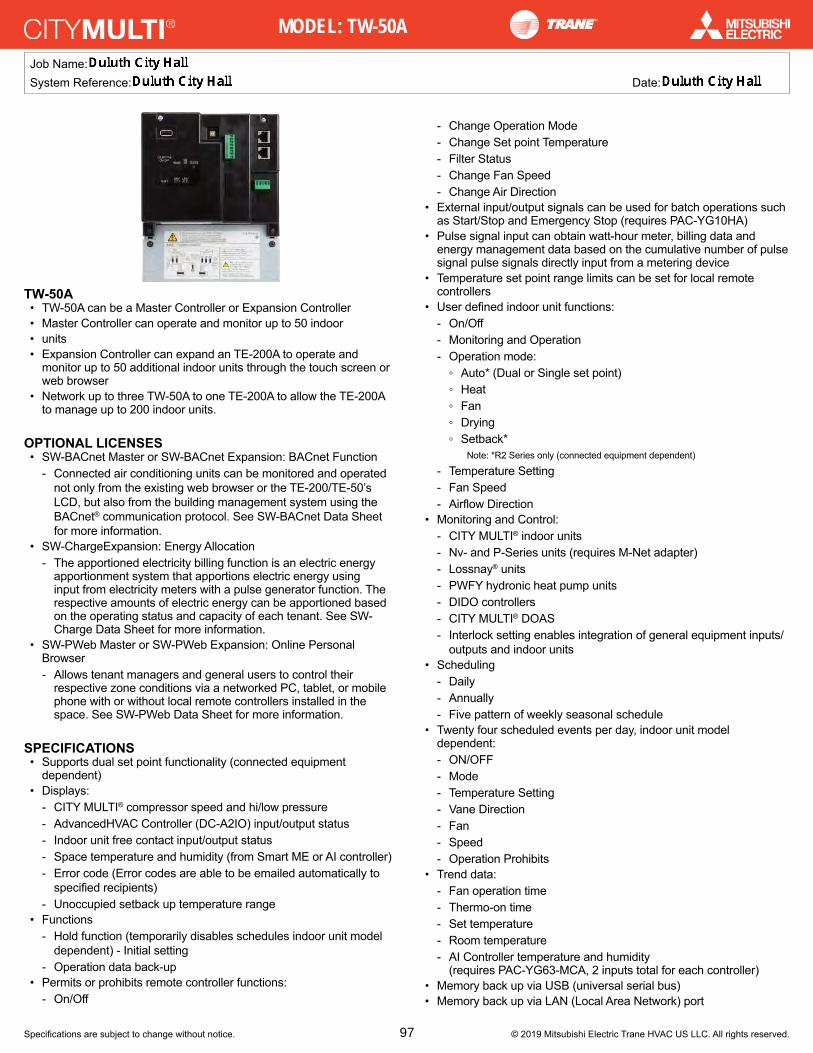
Specifications are subject to change without notice. © 2019 Mitsubishi Electric Trane HVAC US LLC. All rights reserved.
Job Name:System Reference: Date:
MODEL: TW-50A
TW-50A• TW-50A can be a Master Controller or Expansion Controller• Master Controller can operate and monitor up to 50 indoor• units• Expansion Controller can expand an TE-200A to operate and
monitor up to 50 additional indoor units through the touch screen or web browser
• Network up to three TW-50A to one TE-200A to allow the TE-200A to manage up to 200 indoor units.
OPTIONAL LICENSES• SW-BACnet Master or SW-BACnet Expansion: BACnet Function
- Connected air conditioning units can be monitored and operated not only from the existing web browser or the TE-200/TE-50’s LCD, but also from the building management system using the BACnet® communication protocol. See SW-BACnet Data Sheet for more information.
• SW-ChargeExpansion: Energy Allocation - The apportioned electricity billing function is an electric energy
apportionment system that apportions electric energy using input from electricity meters with a pulse generator function. The respective amounts of electric energy can be apportioned based on the operating status and capacity of each tenant. See SW-Charge Data Sheet for more information.
• SW-PWeb Master or SW-PWeb Expansion: Online Personal Browser - Allows tenant managers and general users to control their
respective zone conditions via a networked PC, tablet, or mobile phone with or without local remote controllers installed in the space. See SW-PWeb Data Sheet for more information.
SPECIFICATIONS• Supports dual set point functionality (connected equipment
dependent)• Displays:
- CITY MULTI® compressor speed and hi/low pressure - AdvancedHVAC Controller (DC-A2IO) input/output status - Indoor unit free contact input/output status - Space temperature and humidity (from Smart ME or AI controller) - Error code (Error codes are able to be emailed automatically to
specified recipients) - Unoccupied setback up temperature range
• Functions - Hold function (temporarily disables schedules indoor unit model
dependent) - Initial setting - Operation data back-up
• Permits or prohibits remote controller functions: - On/Off
- Change Operation Mode - Change Set point Temperature - Filter Status - Change Fan Speed - Change Air Direction
• External input/output signals can be used for batch operations such as Start/Stop and Emergency Stop (requires PAC-YG10HA)
• Pulse signal input can obtain watt-hour meter, billing data and energy management data based on the cumulative number of pulse signal pulse signals directly input from a metering device
• Temperature set point range limits can be set for local remote controllers
• User defined indoor unit functions: - On/Off - Monitoring and Operation - Operation mode:
◦ Auto* (Dual or Single set point) ◦ Heat ◦ Fan ◦ Drying ◦ Setback*
Note: *R2 Series only (connected equipment dependent)
- Temperature Setting - Fan Speed - Airflow Direction
• Monitoring and Control: - CITY MULTI® indoor units - Nv- and P-Series units (requires M-Net adapter) - Lossnay® units - PWFY hydronic heat pump units - DIDO controllers - CITY MULTI® DOAS - Interlock setting enables integration of general equipment inputs/
outputs and indoor units• Scheduling
- Daily - Annually - Five pattern of weekly seasonal schedule
• Twenty four scheduled events per day, indoor unit model dependent: - ON/OFF - Mode - Temperature Setting - Vane Direction - Fan - Speed - Operation Prohibits
• Trend data: - Fan operation time - Thermo-on time - Set temperature - Room temperature - AI Controller temperature and humidity
(requires PAC-YG63-MCA, 2 inputs total for each controller)• Memory back up via USB (universal serial bus)• Memory back up via LAN (Local Area Network) port
97
irjhfa
Rectangle

Specifications are subject to change without notice. © 2019 Mitsubishi Electric Trane HVAC US LLC. All rights reserved.
TW-50A - SPECIFICATIONS, CONT.
Item RequirementsCPU 1 GHz or faster
Memory 512 MB or more
Screen Resolution 1024 x 768 or higher recommended
CompatibleBrowser Windows®
Microsoft® Internet Explorer 8.0Microsoft® Internet Explorer 9.0Microsoft® Internet Explorer 10.0Microsoft® Internet Explorer 11.0**Java execution environment is required.(Oracle® Java Plug-in Ver. 1.8.0_60)**Install Oracle® Java Plug-in that is appropriate for your operating system. When using a 64-bit Internet Explorer, install a 64-bit Java Plug-in.**The version of the Oracle® Java Plug-in can be verified by clicking [Java] in the Control Panel.
Onboard LAN Port or LAN Card 100 BASE-TX
100 BASE-TX e.g., mouse
TW-50A EXPANSION CONTROLLER
WEB BROWSER REQUIREMENTS
NOTES:
Item SpecificationsPower Supply Rated input 100–240 VAC ± 10%; 0.3–0.2 A 50/60 Hz Single-phase
M-NET power feeding capability 1.5
Ambient conditionsTemperature
Operating Range -10°C to +55°C (+14°F to +131°F)
Non-operating Range -20°C to +60°C (-4°F to +140°F)
Humidity 30% to 90% RH (no condensation)
Weight 1.7 kg (4 lbs)
Dimensions (W x H x D) 172 × 209 × 92 mm (6-13/16 × 8-4/16 × 3-10/16 in)**253 × 172 × 92 mm (10 × 6-13/16 × 3-10/16 in) when using L-fittings
Installation conditions Only in a metal control box indoors
98

Specifications are subject to change without notice. © 2019 Mitsubishi Electric Trane HVAC US LLC. All rights reserved.
CONTROLLING 50 OR FEWER UNITS OF EQUIPMENT
CONTROLLING MORE THAN 50 UNITS OF EQUIPMENT (WITH CONNECTION TO AN TE-200 CONTROLLER)NoteTE-200 is required when using TE-50
WHEN USING AN APPORTIONED ELECTRICITY BULLING FUNCTIONNotesTE-200 is required to use a billing function.TE-200 M-NET cannot be used when a billing function is used“Charge”license is requited to use a billing function.
1. TE-200 2. TW-50
*TE-200A is indicated as TE-200*TE-50A is indicated as TE-50
MODEL: TW-50A - SYSTEM CONFIGURATION
99

Specifications are subject to change without notice. © 2019 Mitsubishi Electric Trane HVAC US LLC. All rights reserved.
TW-50A - DIMENSIONS
(1) WHEN USING L-FITTINGS
(2) WHEN USING DIN RAIL
100

Sheet Number:
Revision Number:Sheet Title:Project Title:
© 2022 KFI Engineers
05-03-2022
GAA
LAA
21-0486
CITY OF DULUTHCITY HALL MEP RENEWAL DESIGN
DATE: REG. NO.:
PRINT NAME:
30x42Sheet Size:
DWG Scale:
Project No:
Checked By:
Drawn By:
Date:
AS NOTED
No: Date: By: Revision:05-03-2022 27049
I HEREBY CERTIFY THAT THIS PLAN,SPECIFICATION OR REPORT WAS PREPARED BYME OR UNDER MY DIRECT SUPERVISION AND THATI AM A DULY LICENSED PROFESSIONAL ENGINEERUNDER THE LAWS OF THE STATE OF MINNESOTA.
LUCIA A. ANDERSON
411 WEST 1ST STREETDULUTH, MN 55802
E500
LUMINAIRE SCHEDULE
1
OFFICES WITH EXTERIOR WINDOWS
LIGHTING CONTROL MATRIX
SYSTEM INPUTS
OFFICES WITHOUT EXTERIOR WINDOWS
STORAGE ROOMS
SYSTEM IN
PUTS
CONTROLL
ED BY LOCAL P
HOTO G
ATHERIN
G DEVIC
E 15' F
ROM WIN
DOW
CONTROLL
ED BY LOCAL S
WITCH AND C
EILING O
CCUPANCY SENSOR
CONTROLL
ED BY LOCAL L
V OVERRID
E SWITCH
1 5-17-2022 NNA ADDENDUM #1

City of Duluth, MN Project Shutdown Plan In the event that employee illness or a governmental agency requires that the project cease or suspend, prior to suspension the contractor shall provide a written plan to the architect/engineer on the project and to the City for their prior approval and, upon such approval, shall be implemented by the contractor as part of this contract. The plan shall include the following requirements which shall apply to the status of the work at the time of interruption:
1. Time, if any, between the determination of the necessity of suspension and the actual suspension of work will be allocated in this order of priority; Life Safety Issues, Asset Integrity, Environmental Impacts, & Economic Impacts.
2. Excavations will be completed or temporarily filled. 3. Equipment will be removed from the site or secured by the contractor. 4. Physical barricades shall be installed as necessary to protect the work from damage or
destruction and the public from injury in the event of trespass on the site. 5. Warning signs shall be installed where reasonably necessary to warn the public of
any hazardous condition on the site. 6. Erosion control necessary to protect the site shall be in place and functioning and
vegetation shall be in place and properly protected; all exposed and or erodible soil surfaces shall be fully stabilized per the SWPPP/NPDES permit requirements.
7. Onsite materials shall be removed from the site to safe storage or protected on site from damage or theft.
When work is being performed inside a building, the following additional requirements shall apply:
8. Building/Workspace shall be left in a safe and secure manner. Access to the work area
will be accessible with a lockable physical barrier. 9. The building shall be left with a weather tight envelope. 10. Electrical infrastructure shall be left in a safe manner compliant with electrical code. 11. Plumbing infrastructure shall be left in a safe and leak-proof manner compliant with
plumbing code. 12. Emergency exit routes shall be open and accessible, unless agreed to by the City of
Duluth. 13. Fire suppression systems will be left in an operable manner, unless agreed to by the City of
Duluth. 14. Alarm systems will be left in an operable manner, unless agreed to by the City of Duluth. 15. The work area will need to be cleaned/sterilized. 16. If the general contractor is unable to meet these requirements; the work related to these
items will need to be contracted out by the general contractor.