ADDENDUM NO. 1 - SD1
92
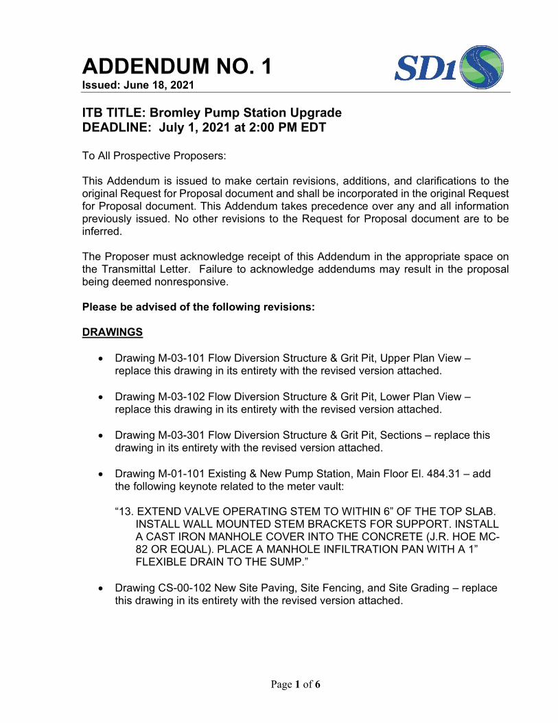
Page 1 of 6 ADDENDUM NO. 1 Issued: June 18, 2021 ITB TITLE: Bromley Pump Station Upgrade DEADLINE: July 1, 2021 at 2:00 PM EDT To All Prospective Proposers: This Addendum is issued to make certain revisions, additions, and clarifications to the original Request for Proposal document and shall be incorporated in the original Request for Proposal document. This Addendum takes precedence over any and all information previously issued. No other revisions to the Request for Proposal document are to be inferred. The Proposer must acknowledge receipt of this Addendum in the appropriate space on the Transmittal Letter. Failure to acknowledge addendums may result in the proposal being deemed nonresponsive. Please be advised of the following revisions: DRAWINGS Drawing M-03-101 Flow Diversion Structure & Grit Pit, Upper Plan View – replace this drawing in its entirety with the revised version attached. Drawing M-03-102 Flow Diversion Structure & Grit Pit, Lower Plan View – replace this drawing in its entirety with the revised version attached. Drawing M-03-301 Flow Diversion Structure & Grit Pit, Sections – replace this drawing in its entirety with the revised version attached. Drawing M-01-101 Existing & New Pump Station, Main Floor El. 484.31 – add the following keynote related to the meter vault: “13. EXTEND VALVE OPERATING STEM TO WITHIN 6” OF THE TOP SLAB. INSTALL WALL MOUNTED STEM BRACKETS FOR SUPPORT. INSTALL A CAST IRON MANHOLE COVER INTO THE CONCRETE (J.R. HOE MC- 82 OR EQUAL). PLACE A MANHOLE INFILTRATION PAN WITH A 1” FLEXIBLE DRAIN TO THE SUMP.” Drawing CS-00-102 New Site Paving, Site Fencing, and Site Grading – replace this drawing in its entirety with the revised version attached.
-
Upload
khangminh22 -
Category
Documents
-
view
7 -
download
0
Transcript of ADDENDUM NO. 1 - SD1
Page 1 of 6
ADDENDUM NO. 1 Issued: June 18, 2021 ITB TITLE: Bromley Pump Station Upgrade DEADLINE: July 1, 2021 at 2:00 PM EDT To All Prospective Proposers:
This Addendum is issued to make certain revisions, additions, and clarifications to the original Request for Proposal document and shall be incorporated in the original Request for Proposal document. This Addendum takes precedence over any and all information previously issued. No other revisions to the Request for Proposal document are to be inferred. The Proposer must acknowledge receipt of this Addendum in the appropriate space on the Transmittal Letter. Failure to acknowledge addendums may result in the proposal being deemed nonresponsive. Please be advised of the following revisions: DRAWINGS
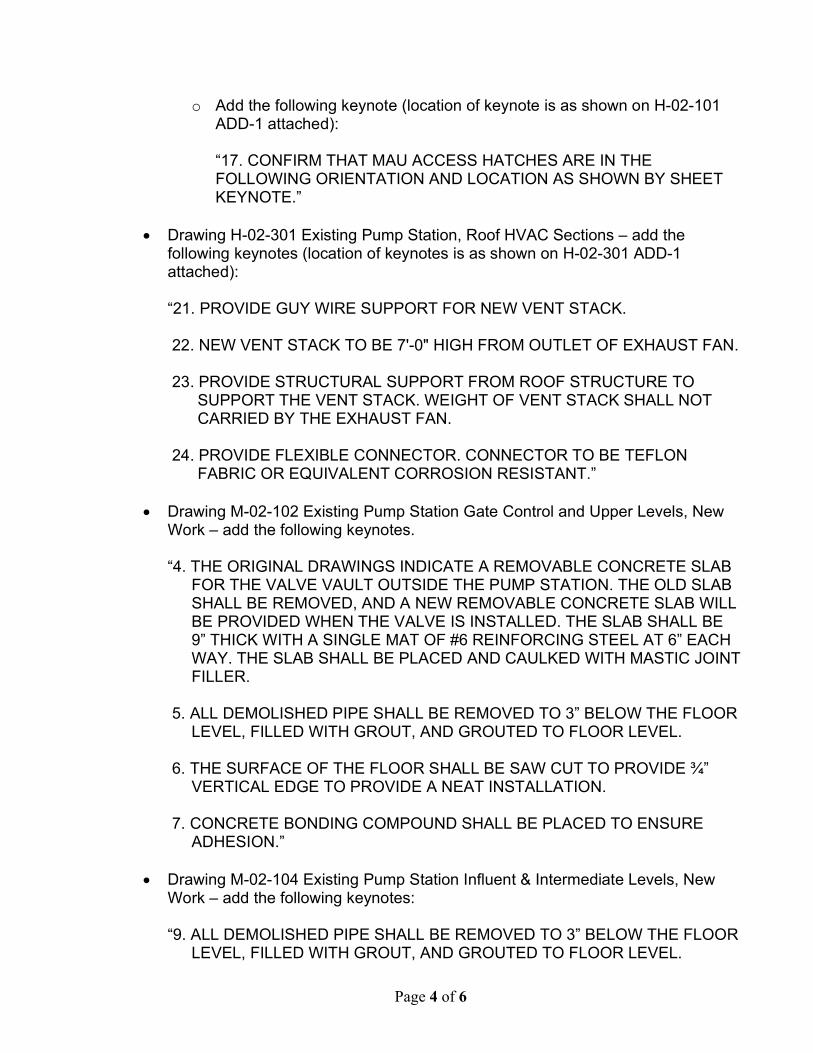
Drawing M-03-101 Flow Diversion Structure & Grit Pit, Upper Plan View –
replace this drawing in its entirety with the revised version attached.
Drawing M-03-102 Flow Diversion Structure & Grit Pit, Lower Plan View – replace this drawing in its entirety with the revised version attached.
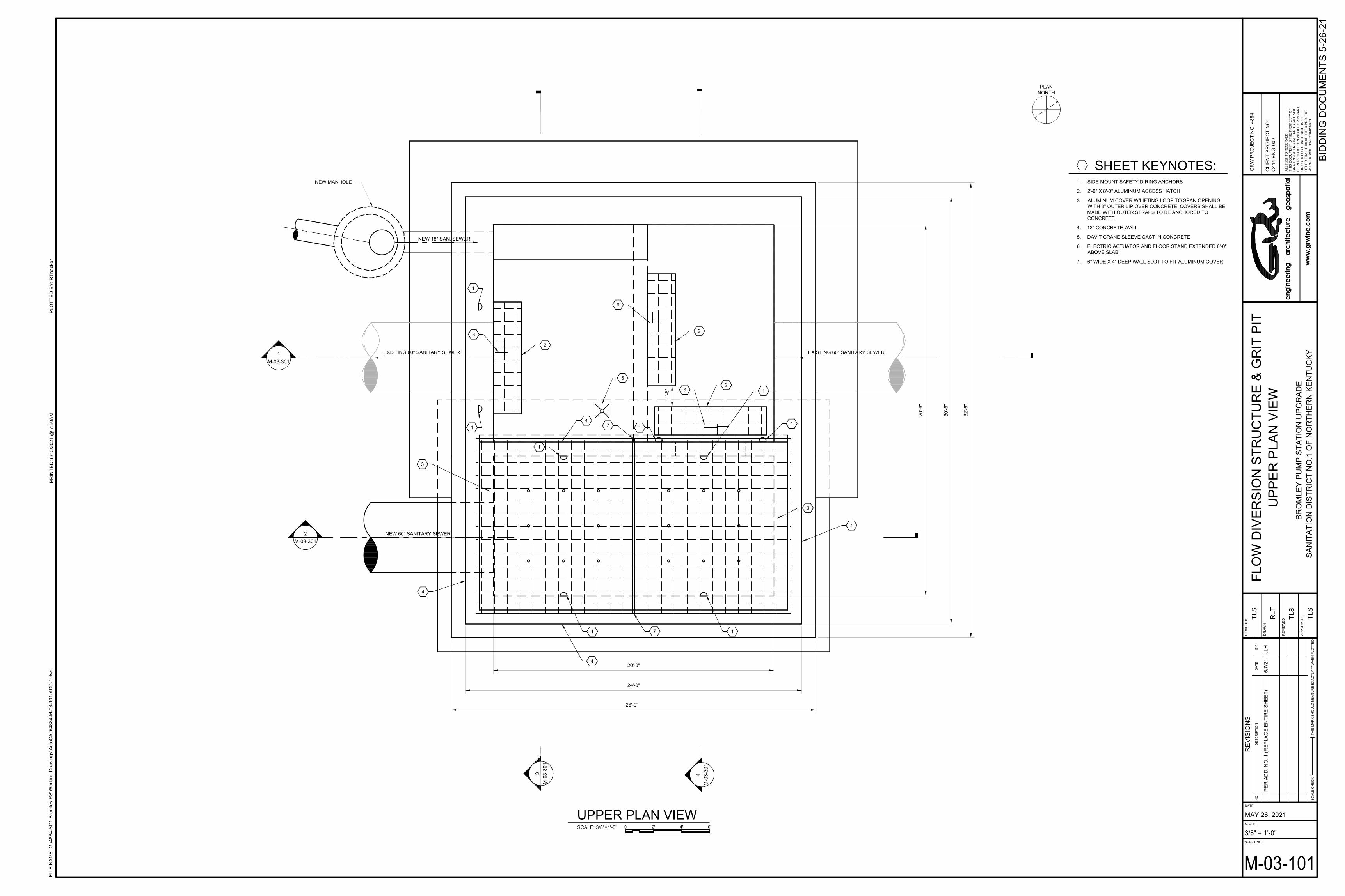
Drawing M-03-301 Flow Diversion Structure & Grit Pit, Sections – replace this
drawing in its entirety with the revised version attached.
Drawing M-01-101 Existing & New Pump Station, Main Floor El. 484.31 – add the following keynote related to the meter vault: “13. EXTEND VALVE OPERATING STEM TO WITHIN 6” OF THE TOP SLAB.
INSTALL WALL MOUNTED STEM BRACKETS FOR SUPPORT. INSTALL A CAST IRON MANHOLE COVER INTO THE CONCRETE (J.R. HOE MC-82 OR EQUAL). PLACE A MANHOLE INFILTRATION PAN WITH A 1” FLEXIBLE DRAIN TO THE SUMP.”
Drawing CS-00-102 New Site Paving, Site Fencing, and Site Grading – replace
this drawing in its entirety with the revised version attached.

Page 2 of 6
Drawing H-00-001 Existing & New Pump Station, HVAC General Notes & HVAC Legend – add the following general note:
“30. ALL EXISTING AIR DISTRIBUTION SYSTEMS THAT ARE TO REMAIN IN
PLACE INCLUDING DUCTWORK AND HVAC ACCESSORIES IN THE EXISTING BUILDING SHALL BE CLEANED PER SPECIFICATION 230130.5 HVAC AIR DISTRIBUTION SYSTEM CLEANING.”
Drawing H-00-501 Existing & New Pump Station, HVAC Details – replace detail
numbers 3 and 8 with the revised details attached titled: H-00-501-A ADD-1 H-00-501-B ADD-1
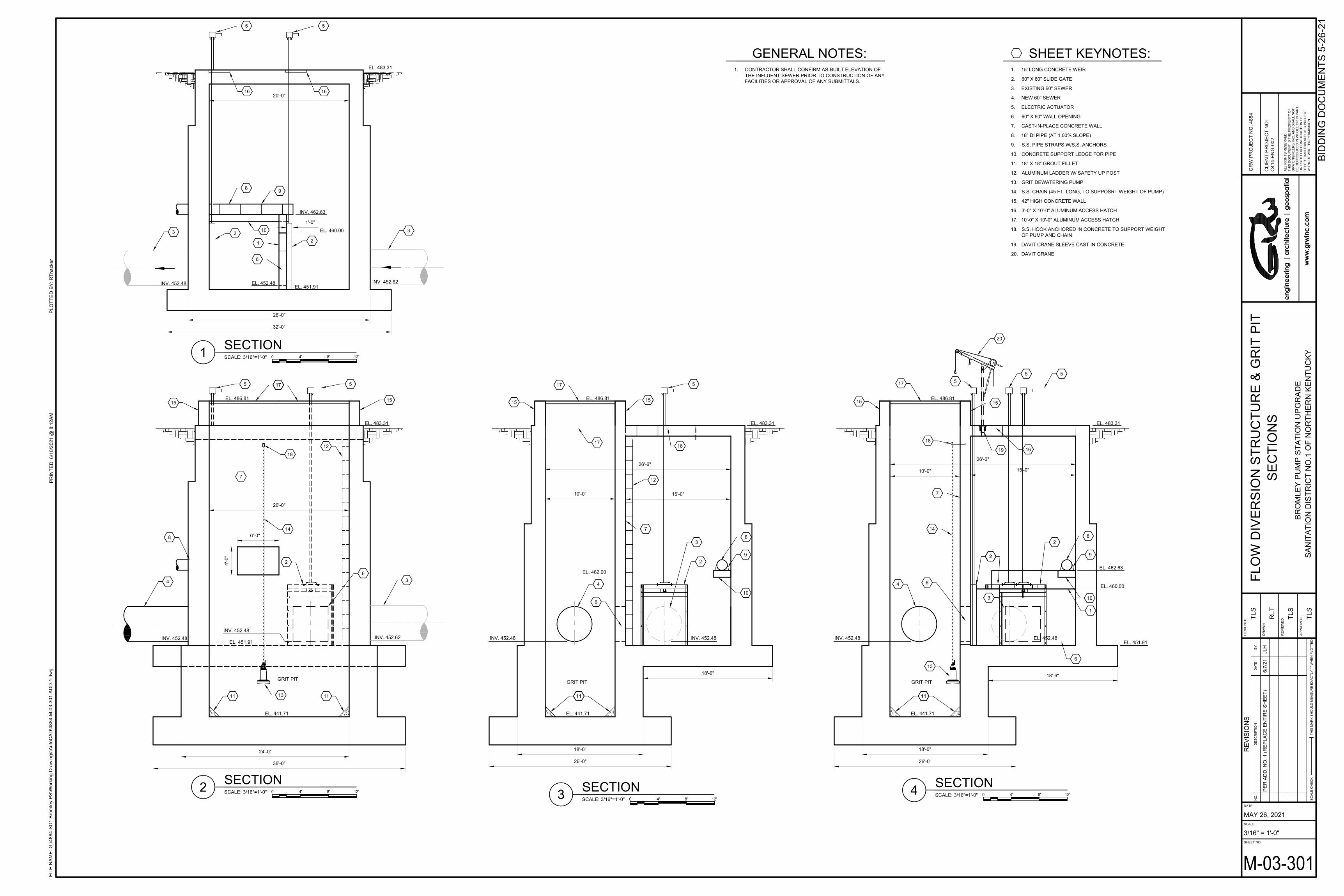
Drawing H-00-601 Existing & New Pump Station, HVAC Schedules – replace this
drawing in its entirety with the revised version attached.
Drawing H-00-701 Existing & New Pump Station, HVAC Schedules – make the following changes:
o Change sheet title to “EXISTING & NEW PUMP STATION, HVAC
CONTROLS”
o Change Tag AF-1 to AF-2 as shown on H-00-701 ADD-1 attached.
Drawing H-00-702 Existing & New Pump Station, HVAC Schedules – make the following changes:
o Change sheet title to “EXISTING & NEW PUMP STATION, HVAC CONTROLS”
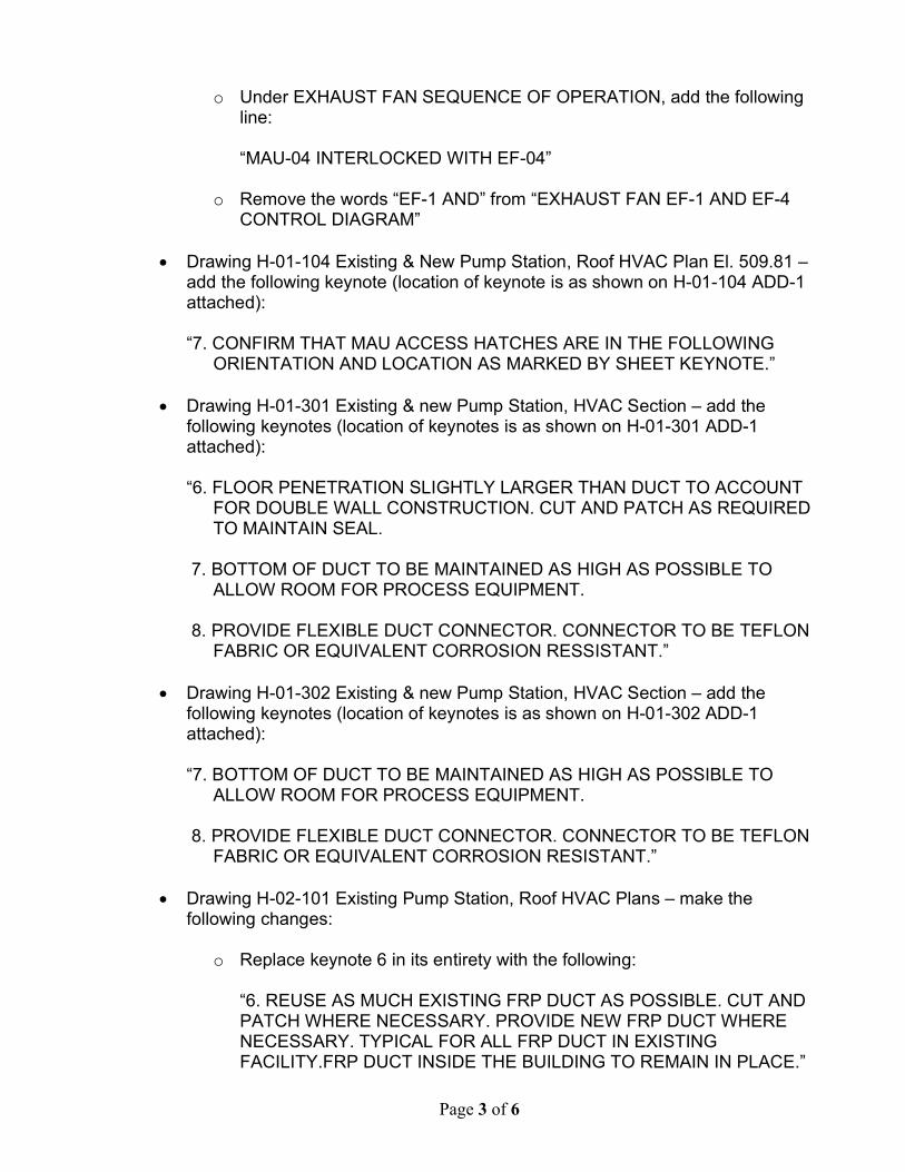
o Under EXHAUST FAN SEQUENCE OF OPERATION, add the following line: “MAU-04 INTERLOCKED WITH EF-04”
o Remove the words “EF-1 AND” from “EXHAUST FAN EF-1 AND EF-4 CONTROL DIAGRAM”
Drawing H-00-703 Existing & New Pump Station, HVAC Schedules – make the following changes:
o Change sheet title to “EXISTING & NEW PUMP STATION, HVAC
CONTROLS”
Page 3 of 6
o Under EXHAUST FAN SEQUENCE OF OPERATION, add the following line: “MAU-04 INTERLOCKED WITH EF-04”
o Remove the words “EF-1 AND” from “EXHAUST FAN EF-1 AND EF-4 CONTROL DIAGRAM”
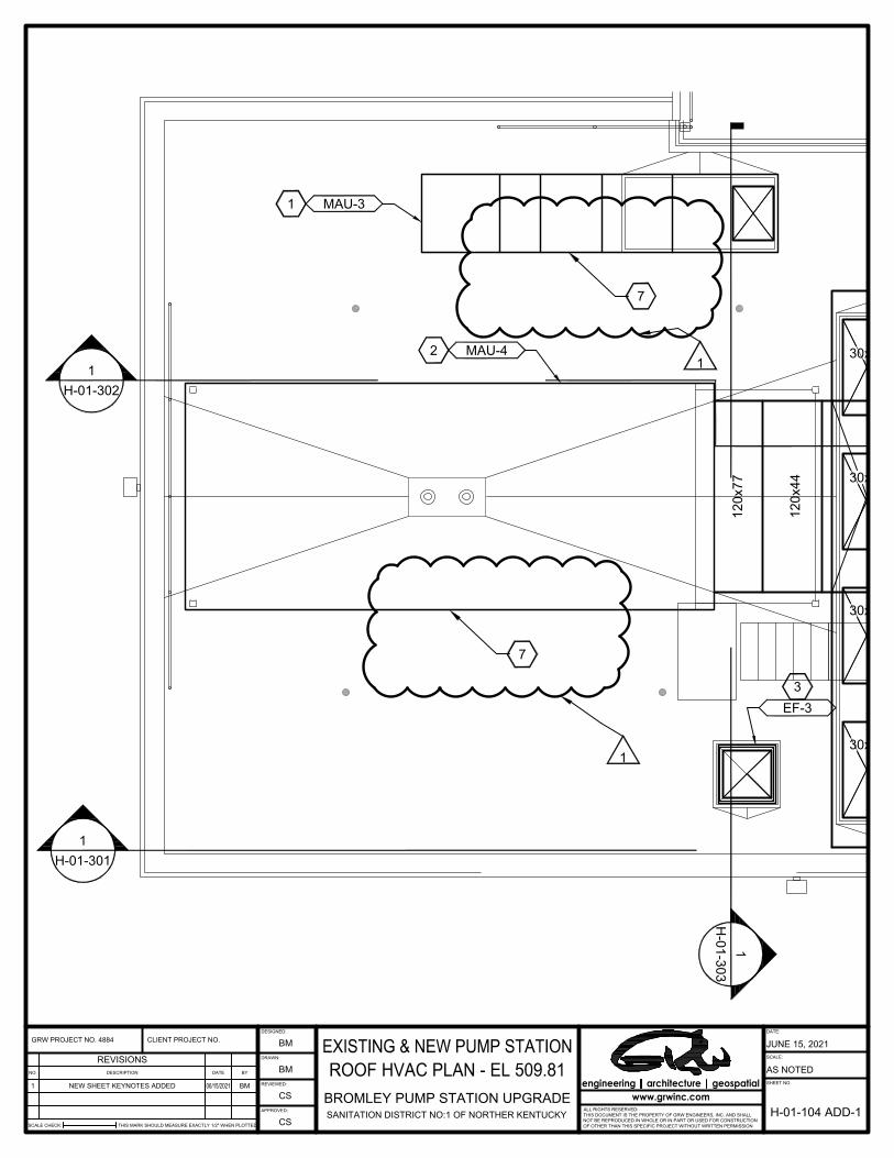
Drawing H-01-104 Existing & New Pump Station, Roof HVAC Plan El. 509.81 –
add the following keynote (location of keynote is as shown on H-01-104 ADD-1 attached): “7. CONFIRM THAT MAU ACCESS HATCHES ARE IN THE FOLLOWING
ORIENTATION AND LOCATION AS MARKED BY SHEET KEYNOTE.”
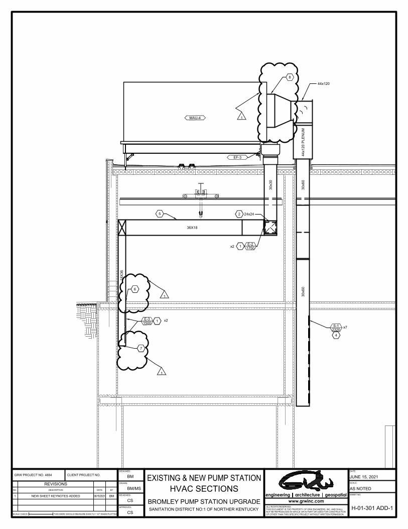
Drawing H-01-301 Existing & new Pump Station, HVAC Section – add the following keynotes (location of keynotes is as shown on H-01-301 ADD-1 attached):
“6. FLOOR PENETRATION SLIGHTLY LARGER THAN DUCT TO ACCOUNT
FOR DOUBLE WALL CONSTRUCTION. CUT AND PATCH AS REQUIRED TO MAINTAIN SEAL.
7. BOTTOM OF DUCT TO BE MAINTAINED AS HIGH AS POSSIBLE TO
ALLOW ROOM FOR PROCESS EQUIPMENT. 8. PROVIDE FLEXIBLE DUCT CONNECTOR. CONNECTOR TO BE TEFLON
FABRIC OR EQUIVALENT CORROSION RESSISTANT.”
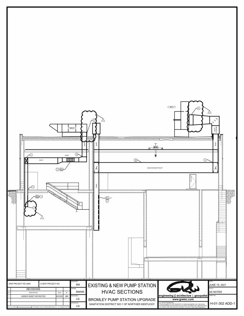
Drawing H-01-302 Existing & new Pump Station, HVAC Section – add the following keynotes (location of keynotes is as shown on H-01-302 ADD-1 attached): “7. BOTTOM OF DUCT TO BE MAINTAINED AS HIGH AS POSSIBLE TO
ALLOW ROOM FOR PROCESS EQUIPMENT. 8. PROVIDE FLEXIBLE DUCT CONNECTOR. CONNECTOR TO BE TEFLON
FABRIC OR EQUIVALENT CORROSION RESISTANT.”
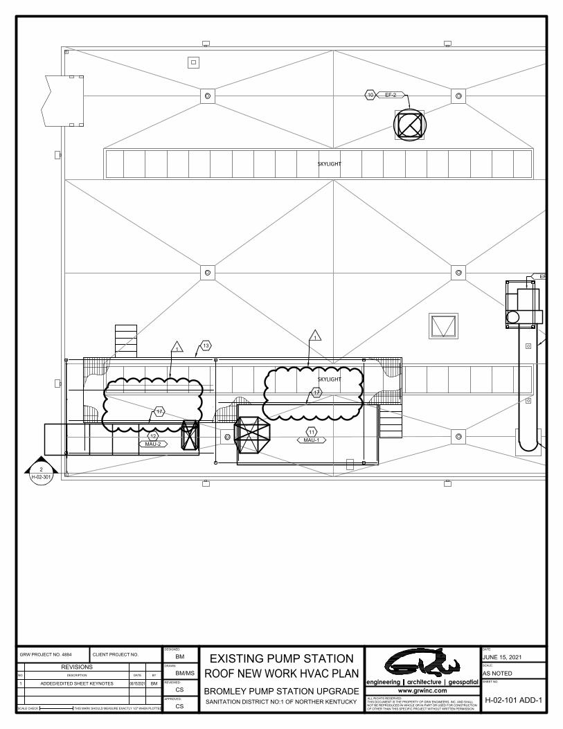
Drawing H-02-101 Existing Pump Station, Roof HVAC Plans – make the following changes:
o Replace keynote 6 in its entirety with the following: “6. REUSE AS MUCH EXISTING FRP DUCT AS POSSIBLE. CUT AND PATCH WHERE NECESSARY. PROVIDE NEW FRP DUCT WHERE NECESSARY. TYPICAL FOR ALL FRP DUCT IN EXISTING FACILITY.FRP DUCT INSIDE THE BUILDING TO REMAIN IN PLACE.”
Page 4 of 6
o Add the following keynote (location of keynote is as shown on H-02-101
ADD-1 attached): “17. CONFIRM THAT MAU ACCESS HATCHES ARE IN THE FOLLOWING ORIENTATION AND LOCATION AS SHOWN BY SHEET KEYNOTE.”
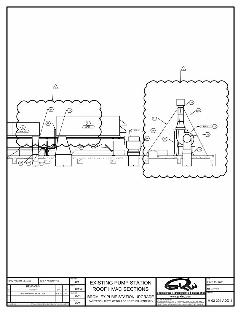
Drawing H-02-301 Existing Pump Station, Roof HVAC Sections – add the
following keynotes (location of keynotes is as shown on H-02-301 ADD-1 attached): “21. PROVIDE GUY WIRE SUPPORT FOR NEW VENT STACK. 22. NEW VENT STACK TO BE 7'-0" HIGH FROM OUTLET OF EXHAUST FAN. 23. PROVIDE STRUCTURAL SUPPORT FROM ROOF STRUCTURE TO
SUPPORT THE VENT STACK. WEIGHT OF VENT STACK SHALL NOT CARRIED BY THE EXHAUST FAN.
24. PROVIDE FLEXIBLE CONNECTOR. CONNECTOR TO BE TEFLON
FABRIC OR EQUIVALENT CORROSION RESISTANT.”
Drawing M-02-102 Existing Pump Station Gate Control and Upper Levels, New Work – add the following keynotes. “4. THE ORIGINAL DRAWINGS INDICATE A REMOVABLE CONCRETE SLAB
FOR THE VALVE VAULT OUTSIDE THE PUMP STATION. THE OLD SLAB SHALL BE REMOVED, AND A NEW REMOVABLE CONCRETE SLAB WILL BE PROVIDED WHEN THE VALVE IS INSTALLED. THE SLAB SHALL BE 9” THICK WITH A SINGLE MAT OF #6 REINFORCING STEEL AT 6” EACH WAY. THE SLAB SHALL BE PLACED AND CAULKED WITH MASTIC JOINT FILLER.
5. ALL DEMOLISHED PIPE SHALL BE REMOVED TO 3” BELOW THE FLOOR
LEVEL, FILLED WITH GROUT, AND GROUTED TO FLOOR LEVEL. 6. THE SURFACE OF THE FLOOR SHALL BE SAW CUT TO PROVIDE ¾”
VERTICAL EDGE TO PROVIDE A NEAT INSTALLATION. 7. CONCRETE BONDING COMPOUND SHALL BE PLACED TO ENSURE
ADHESION.”
Drawing M-02-104 Existing Pump Station Influent & Intermediate Levels, New Work – add the following keynotes: “9. ALL DEMOLISHED PIPE SHALL BE REMOVED TO 3” BELOW THE FLOOR
LEVEL, FILLED WITH GROUT, AND GROUTED TO FLOOR LEVEL.

Page 5 of 6
10. THE SURFACE OF THE FLOOR SHALL BE SAW CUT TO PROVIDE ¾” VERTICAL EDGE TO PROVIDE A NEAT INSTALLATION.
11. CONCRETE BONDING COMPOUND SHALL BE PLACED TO ENSURE
ADHESION.”
Drawing CS-00-103 New Site Piping – add the following note: “2. THE EXISTING GAS SERVICE WILL BE REPLACED WITH A NEW 6” GAS
MAIN AND REGULATOR. THE CONTRACTOR IS RESPONSIBLE FOR BRINGING THE GAS SERVICE TO THE HVAC UNITS. THE LOCATION OF THE NEW METER AND THE GAS SERVICE IS UNKNOWN AT THIS TIME. THE CONTRACTOR SHALL PROVIDE THE EQUIVALENT LENGTH OF NEW GAS MAIN AS SHOWN FOR THE EXISTING GAS MAIN, EXCEPT FOR BEING 6” IN LIEU OF 2”. ALL CONNECTIONS AND TESTING SHALL BE BY THE CONTRACTOR.”
Drawing S-04-102 Electrical Platform, Framing Plan – add the following plan
note: “9. LIGHTWEIGHT CONCRETE SHALL BE 5000 PSI 28-DAY COMPRESSIVE
STRENGTH, AIR-ENTRAINED CONCRETE WITH A MAXIMUM UNIT WEIGHT OF 110 PCF.”
SPECIFICATIONS
Section 032313 Concrete Paving – add this attached section to the bid
documents.
Section 432114 Vertical Centrifugal Pump Retrofit – replace this section in its entirety with the revised version attached.
Section 432100 Closed Coupled End Suction Pump Impeller – remove this
section in its entirety from the bid documents.
Section 233116 Non-Metal Ducts – replace this section in its entirety with the revised version attached.
Section 028310 Fencing – delete all references to “polyvinylchloride coated” in
this section.
Section 033000 Cast-in-Place Concrete – replace this section in its entirety with the revised version attached.
Section 050000 Miscellaneous Metals, paragraph 2.2.L – add the following to this
paragraph: “All manual bar screens shall be 304 stainless steel material.”

Page 6 of 6
Section 333140 Cast Iron Slide Gates – replace the table in paragraph 1.3.A.3
with the following table (additional cast iron slide gate has been added):
Location
Operating Head
(Seating/ Unseating)
Design Head
(Seating/ Unseating)
Wall Thimble
Operator Type
Pump Station 60” DI Pipe Inlet – 1 Each w/ Round Back Adapter for Direct 60” DI Flanged Pipe attachment
Unseating 60’ No Electric
Pump Station 60” x 60” Channel Inlet – 3 Each
Seating 35’ Yes Electric
Pump Station 60” x 60” Channel Outlet – 3 Each
Seating 35’ Yes Electric
Diversion Structure – 60” x 60” – 2 Each Seating 60’ Yes Electric
Submersible Diversion Structure – 60” x 60” DI Pipe Outlet – 1 Each
Seating 60’ No Electric
Submersible
ATTACHMENTS
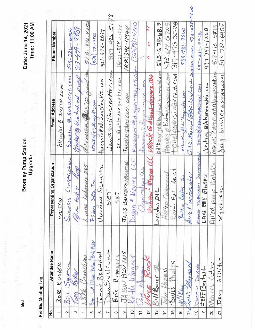
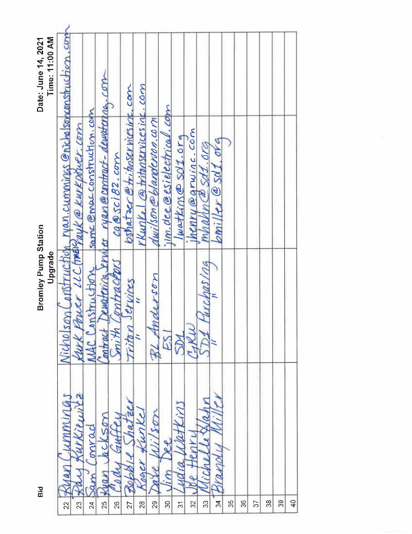
M-03-101 – Flow Diversion Structure & Grit Pit – Upper Plan View M-03-102 – Flow Diversion Structure & Grit Pit – Lower Plan View M-03-301 – Flow Diversion Structure & Grit Pit – Sections CS-00-102 – New Site Paving, Site Fencing and Site Grading H-00-601 – Existing & New Pump Station HVAC Schedules H-00-501A H-00-501B H-00-701 – Existing & New Pump Station HVAC Schedules H-01-104 – Existing & New Pump Station – Roof HVAC Plan – EL 509.81 H-01-301 – Existing & New Pump Station – HVAC Section H-01-302 – Existing & New Pump Station – HVAC Sections H-02-101 – Existing Pump Station – Roof HVAC Plans H-02-301 – Existing Pump Station – Roof HVAC Sections Section 032313 – Concrete Paving Section 432114 – Vertical Centrifugal Pump Retrofit Section 233116 – Nonmetal Ducts Section 033000 – Cast In Place Concrete Q&A Memo Pre-bid Meeting Attendance Sheet
Brandy Miller Purchasing Administrator Office: 859-578-6767 Email: [email protected]
1M-03-301
2M-03-301
3M
-03-
301
4M
-03-
301
26'-6
"
30'-6
"
32'-6
"
20'-0"
24'-0"
26'-0"
1'-6
"
M-03-1013/8" = 1'-0"
TLS
RLT
TLS
TLS
FLO
W D
IVER
SIO
N S
TRU
CTU
RE
& G
RIT
PIT
UPP
ER P
LAN
VIE
W
SCALE: 3/8"=1'-0" 0 4' 6'2'
UPPER PLAN VIEW
EXISTING 60" SANITARY SEWEREXISTING 60" SANITARY SEWER
NEW 60" SANITARY SEWER
PLANNORTH
NEW 18" SAN. SEWER
SHEET KEYNOTES:1. SIDE MOUNT SAFETY D RING ANCHORS
2. 2'-0" X 8'-0" ALUMINUM ACCESS HATCH
3. ALUMINUM COVER W/LIFTING LOOP TO SPAN OPENINGWITH 3" OUTER LIP OVER CONCRETE. COVERS SHALL BEMADE WITH OUTER STRAPS TO BE ANCHORED TOCONCRETE
4. 12" CONCRETE WALL
5. DAVIT CRANE SLEEVE CAST IN CONCRETE
6. ELECTRIC ACTUATOR AND FLOOR STAND EXTENDED 6'-0"ABOVE SLAB
7. 6" WIDE X 4" DEEP WALL SLOT TO FIT ALUMINUM COVER
1
1
1
1
1 1
2
2
3
NEW MANHOLE
4
4
4
4
5
3
6
6
1
1
7
7
2
6
PRIN
TED
: 6/1
0/20
21 @
7:5
0AM
FILE
NAM
E: G
:\488
4-SD
1 Br
omle
y PS
\Wor
king
Dra
win
gs\A
utoC
AD\4
884-
M-0
3-10
1-AD
D-1
.dw
g
DATE:
SCALE:
SHEET NO.
BRO
MLE
Y PU
MP
STAT
ION
UPG
RAD
E
DES
IGN
ED:
DR
AWN
:
REV
IEW
ED:
APPR
OVE
D:
DAT
EBY
DES
CR
IPTI
ON
NO
.
REV
ISIO
NS
SCAL
E C
HEC
K:TH
IS M
ARK
SHO
ULD
MEA
SUR
E EX
ACTL
Y 1"
WH
EN P
LOTT
ED
GR
W P
RO
JEC
T N
O. 4
884
ALL
RIG
HTS
RES
ERVE
D:
THIS
DO
CU
MEN
T IS
TH
E PR
OPE
RTY
OF
GR
W E
NG
INEE
RS,
INC
. AN
D S
HAL
L N
OT
BE R
EPR
OD
UC
ED IN
WH
OLE
OR
IN P
ART
OR
USE
D F
OR
CO
NST
RU
CTI
ON
OF
OTH
ER T
HAN
TH
IS S
PEC
IFIC
PR
OJE
CT
WIT
HO
UT
WR
ITTE
N P
ERM
ISSI
ON
MAY 26, 2021
BID
DIN
G D
OC
UM
ENTS
5-2
6-21
engine
eringa
rchitectureg
eosp
atial
PLO
TTED
BY:
RTh
acke
r www.grw
inc.co
mSA
NIT
ATIO
N D
ISTR
ICT
NO
.1 O
F N
OR
THER
N K
ENTU
CKY
CLI
ENT
PRO
JEC
T N
O:
C41
4-EN
G-0
02PE
R A
DD
. NO
. 1 (R
EPLA
CE
ENTI
RE
SHEE
T)6/
7/21
JLH

1M-03-301
2M-03-301
3M
-03-
301
4M
-03-
301
26'-6
"
32'-6
" 36'-6
"
20'-0"
26'-0"
32'-0"
28'-0"
10'-0
"
15'-0
"
PRIN
TED
: 6/1
0/20
21 @
7:5
1AM
FILE
NAM
E: G
:\488
4-SD
1 Br
omle
y PS
\Wor
king
Dra
win
gs\A
utoC
AD\4
884-
M-0
3-10
2-AD
D-1
.dw
g
DATE:
SCALE:
SHEET NO.
BRO
MLE
Y PU
MP
STAT
ION
UPG
RAD
E
DES
IGN
ED:
DR
AWN
:
REV
IEW
ED:
APPR
OVE
D:
DAT
EBY
DES
CR
IPTI
ON
NO
.
REV
ISIO
NS
SCAL
E C
HEC
K:TH
IS M
ARK
SHO
ULD
MEA
SUR
E EX
ACTL
Y 1"
WH
EN P
LOTT
ED
GR
W P
RO
JEC
T N
O. 4
884
ALL
RIG
HTS
RES
ERVE
D:
THIS
DO
CU
MEN
T IS
TH
E PR
OPE
RTY
OF
GR
W E
NG
INEE
RS,
INC
. AN
D S
HAL
L N
OT
BE R
EPR
OD
UC
ED IN
WH
OLE
OR
IN P
ART
OR
USE
D F
OR
CO
NST
RU
CTI
ON
OF
OTH
ER T
HAN
TH
IS S
PEC
IFIC
PR
OJE
CT
WIT
HO
UT
WR
ITTE
N P
ERM
ISSI
ON
MAY 26, 2021
BID
DIN
G D
OC
UM
ENTS
5-2
6-21
engine
eringa
rchitectureg
eosp
atial
PLO
TTED
BY:
RTh
acke
r www.grw
inc.co
mSA
NIT
ATIO
N D
ISTR
ICT
NO
.1 O
F N
OR
THER
N K
ENTU
CKY
CLI
ENT
PRO
JEC
T N
O:
C41
4-EN
G-0
02
M-03-1023/8" = 1'-0"
TLS
RLT
TLS
TLS
FLO
W D
IVER
SIO
N S
TRU
CTU
RE
& G
RIT
PIT
LOW
ER P
LAN
VIE
W
SCALE: 3/8"=1'-0" 0 4' 6'2'
LOWER PLAN VIEW
GRIT PIT
EXISTING 60" SEWER
60" X 60"SLIDE GATE(NORMALLY OPEN)
60" X 60" SLIDE GATE(NORMALLY OPEN)
EXISTING 60" SEWER
NEW 60" SEWER
PLANNORTH
60" SQUAREOPENING
SHEET KEYNOTES:1. GRIT PIT DEWATERING PUMP
2. S.S. PIPE TIE DOWNS
3. ALUMINUM LADDER W/SAFETY UP POST
4. 18" C900 PVC SANITARY SEWER
5. EXISTING 60" SEWER
6. LINK-SEAL WATERSTOP
7. EXPANSIVE WATERSTOP
1
CONCRETE LEDGETO SUPPORT PIPE
2 TYP.
3
3
18" X 18" GROUT FILLET
NEW 18"SAN. SEWER
NEW MANHOLE
4
SEE GENERAL NOTES5 77
6
GENERAL NOTES:1. CONTRACTOR SHALL BE RESPONSIBLE FOR MAINTAINING SANITARY
SEWER FLOW AND PUMPING AT ALL TIMES.
2. CONTRACTOR SHALL CONSTRUCT THE STRUCTURE AROUND THEEXISTING 60" SEWER.
3. THE CONTRACTOR SHALL PREPARE THE SURFACE AND INSTALL THEEXPANSIVE WATERSTOP IN TWO PARALLEL LAYERS AT EACH ENDOF STRUCTURE AROUND PIPE.
4. AT THE TIME THE STRUCTURE IS TO BE PLACED IN SERVICE, THECONTRACTOR SHALL COORDINATE AND PROVIDE FLOW BULKHEADAND BYPASS PUMPING TO DIVERT FLOW. EACH END OF PIPE SHALLTHEN BE "WIRE CUT" AND PIPE SECTION REMOVED.
5. THE WEIR SECTION SHALL THEN BE CONSTRUCTED.
6. THE CONTRACTOR SHALL SUBMIT A BRIEF DESCRIPTION OF HOWTHE WORK WILL BE ACCOMPLISHED FOR APPROVAL.
7. CONTRACTOR TO CONFIRM INVERT ELEVATION OF EXISTING 60"SEWER.
4' TALL X 6' WIDE OPENINGINV. EL. 462.00
EL. 4
60.0
0
60" X 60" SLIDE GATE
PER
AD
D. N
O. 1
(REP
LAC
E EN
TIR
E SH
EET)
6/7/
21JL
H
1'-0"
10'-0" 15'-0"
26'-6"
18'-0"
26'-0"
20'-0"
26'-0"
32'-0"
10'-0" 15'-0"
26'-6"
18'-0"
26'-0"
20'-0"
18'-6" 18'-6"
4'-0
"
6'-0"
36'-0"
24'-0"
PRIN
TED
: 6/1
0/20
21 @
8:1
2AM
FILE
NAM
E: G
:\488
4-SD
1 Br
omle
y PS
\Wor
king
Dra
win
gs\A
utoC
AD\4
884-
M-0
3-30
1-AD
D-1
.dw
g
DATE:
SCALE:
SHEET NO.
BRO
MLE
Y PU
MP
STAT
ION
UPG
RAD
E
DES
IGN
ED:
DR
AWN
:
REV
IEW
ED:
APPR
OVE
D:
DAT
EBY
DES
CR
IPTI
ON
NO
.
REV
ISIO
NS
SCAL
E C
HEC
K:TH
IS M
ARK
SHO
ULD
MEA
SUR
E EX
ACTL
Y 1"
WH
EN P
LOTT
ED
GR
W P
RO
JEC
T N
O. 4
884
ALL
RIG
HTS
RES
ERVE
D:
THIS
DO
CU
MEN
T IS
TH
E PR
OPE
RTY
OF
GR
W E
NG
INEE
RS,
INC
. AN
D S
HAL
L N
OT
BE R
EPR
OD
UC
ED IN
WH
OLE
OR
IN P
ART
OR
USE
D F
OR
CO
NST
RU
CTI
ON
OF
OTH
ER T
HAN
TH
IS S
PEC
IFIC
PR
OJE
CT
WIT
HO
UT
WR
ITTE
N P
ERM
ISSI
ON
MAY 26, 2021
BID
DIN
G D
OC
UM
ENTS
5-2
6-21
engine
eringa
rchitectureg
eosp
atial
PLO
TTED
BY:
RTh
acke
r www.grw
inc.co
mSA
NIT
ATIO
N D
ISTR
ICT
NO
.1 O
F N
OR
THER
N K
ENTU
CKY
CLI
ENT
PRO
JEC
T N
O:
C41
4-EN
G-0
02
M-03-3013/16" = 1'-0"
TLS
RLT
TLS
TLS
FLO
W D
IVER
SIO
N S
TRU
CTU
RE
& G
RIT
PIT
SEC
TIO
NS
SCALE: 3/16"=1'-0" 0 8' 12'4'1 SECTION
SCALE: 3/16"=1'-0" 0 8' 12'4'2 SECTIONSCALE: 3/16"=1'-0" 0 8' 12'4'3 SECTION
SCALE: 3/16"=1'-0" 0 8' 12'4'4 SECTION
EL. 483.31
EL. 483.31EL. 483.31 EL. 483.31
EL. 460.00
EL. 460.00
EL. 441.71
INV. 452.48 INV. 452.62
INV. 452.48 INV. 452.62 INV. 452.48 INV. 452.48 INV. 452.48
EL. 451.91
EL. 451.91 EL. 451.91
SHEET KEYNOTES:1. 15' LONG CONCRETE WEIR
2. 60" X 60" SLIDE GATE
3. EXISTING 60" SEWER
4. NEW 60" SEWER
5. ELECTRIC ACTUATOR
6. 60" X 60" WALL OPENING
7. CAST-IN-PLACE CONCRETE WALL
8. 18" DI PIPE (AT 1.00% SLOPE)
9. S.S. PIPE STRAPS W/S.S. ANCHORS
10. CONCRETE SUPPORT LEDGE FOR PIPE
11. 18" X 18" GROUT FILLET
12. ALUMINUM LADDER W/ SAFETY UP POST
13. GRIT DEWATERING PUMP
14. S.S. CHAIN (45 FT. LONG, TO SUPPOSRT WEIGHT OF PUMP)
15. 42" HIGH CONCRETE WALL
16. 3'-0" X 10'-0" ALUMINUM ACCESS HATCH
17. 10'-0" X 10'-0" ALUMINUM ACCESS HATCH
18. S.S. HOOK ANCHORED IN CONCRETE TO SUPPORT WEIGHTOF PUMP AND CHAIN
19. DAVIT CRANE SLEEVE CAST IN CONCRETE
20. DAVIT CRANE
1
1
22
2
2 33
3
3
64
3
4
5
5
15
5
GRIT PIT
7
7
7
6
INV. 452.48
4
EL. 441.71
GRIT PIT
EL. 441.71
GRIT PIT
2
8 9
10
INV. 462.63
5
5
8
9
10
8
10
8
11 11 1111 1111
12
12
13
13
14 14
15 15
16
16
17
1719
16
9
17
15
18
17
15 15
517
20
18
EL. 486.81 EL. 486.81 EL. 486.81
EL. 462.00EL. 462.63
EL. 452.48
2
5
EL. 452.48
2
5
16
6
6
6
PER
AD
D. N
O. 1
(REP
LAC
E EN
TIR
E SH
EET)
6/7/
21JL
H
GENERAL NOTES:1. CONTRACTOR SHALL CONFIRM AS-BUILT ELEVATION OF
THE INFLUENT SEWER PRIOR TO CONSTRUCTION OF ANYFACILITIES OR APPROVAL OF ANY SUBMITTALS.

OH
U
OH
U
OH
U
OH
U
OH
U
OH
U
OH
U
XX
XX
XX
XX
XX
XX
XX
X
XXXXXXXXXXXXXXXXXXXXXXXXXXXXXXX
XX
XX
XX
XX
XX
XX
XX
XX
X
XX
X
X X X X X X X
XX
X
XX
XX
X
X X X X
X XX X
XXXXXXXXX
GAT
E
GAT
E
EX. CONCRETE
EX. FENCINGX
OHU
LEGEND
NEW FENCINGX
NEW PAVINGCONCRETE
5'
PRIN
TED
: 6/1
8/20
21 @
7:4
8AM
FILE
NAM
E: G
:\488
4-SD
1 Br
omle
y PS
\Wor
king
Dra
win
gs\A
utoC
AD\4
884-
CS-
00-1
02-A
DD
-1.d
wg
DATE:
SCALE:
SHEET NO.
BRO
MLE
Y PU
MP
STAT
ION
UPG
RAD
E
DES
IGN
ED:
DR
AWN
:
REV
IEW
ED:
APPR
OVE
D:
DAT
EBY
DES
CR
IPTI
ON
NO
.
REV
ISIO
NS
SCAL
E C
HEC
K:TH
IS M
ARK
SHO
ULD
MEA
SUR
E EX
ACTL
Y 1"
WH
EN P
LOTT
ED
GR
W P
RO
JEC
T N
O. 4
884
ALL
RIG
HTS
RES
ERVE
D:
THIS
DO
CU
MEN
T IS
TH
E PR
OPE
RTY
OF
GR
W E
NG
INEE
RS,
INC
. AN
D S
HAL
L N
OT
BE R
EPR
OD
UC
ED IN
WH
OLE
OR
IN P
ART
OR
USE
D F
OR
CO
NST
RU
CTI
ON
OF
OTH
ER T
HAN
TH
IS S
PEC
IFIC
PR
OJE
CT
WIT
HO
UT
WR
ITTE
N P
ERM
ISSI
ON
MAY 26, 2021
BID
DIN
G D
OC
UM
ENTS
5-2
6-21
engine
eringa
rchitectureg
eosp
atial
PLO
TTED
BY:
RTh
acke
r www.grw
inc.co
mSA
NIT
ATIO
N D
ISTR
ICT
NO
.1 O
F N
OR
THER
N K
ENTU
CKY
CLI
ENT
PRO
JEC
T N
O:
C41
4-EN
G-0
02
CS-00-1021" = 10'
TLS
NM
H
TLS
JLH
NEW
SIT
E PA
VIN
G, S
ITE
FEN
CIN
G A
ND
SI
TE G
RAD
ING
2
5
6
7
9
STRUCTURE NUMBER INDEX
EX. DIVERSION STRUCTURE
7
6
8
9
EX. ELECTRICAL PLATFORM
NEW METER VAULT
SEPTAGE RECEIVING (ABANDONED)
NEW PUMP STATION A
2
1
3
4
EX. PUMP STATION B
NEW DIVERSION STRUCTURE
NEW ELECTRICAL PLATFORM
5 EX. GRIT PIT
10 NEW 10' DIAMETER MANHOLE1" = 10'-0"
20'10'0 30'5'
1
3
4
8
10
NEWFENCE
20' GATE(2-10')
DEMOLISHEX. FENCE
5'
2'
CONSTRUCTION NOTES :1. PRE CONSTRUCTION PHOTOGRAPHS AND VIDEO SHALL BE PROVIDED
BY THE CONTRACTOR AND SUBMITTED FOR APPROVAL.
2. ALL CONTOURING TO BE RETURNED TO ORIGINAL GRADE.
3. CONTRACTOR SHALL BE RESPONSIBLE FOR ANY SETTLEMENT OFPAVEMENT.
X 485
.64
X 485
.07
X 484
.66
X 484
.88
X 484
.86
X 484
.34
X 484
.10
X 483
.86
X 484
.31
X 485
.32
X 484
.40
X 482
.39
X 481
.98
X 481
.94
X 482
.21
X 482
.88
X 487
.11
X 487
.65
X 486
.38
X 486
.26
BOLLARD (TYP)
SCORED JOINT (TYP.)
CONC. PAVEMENT NOTES:1. PROOF ROLL PAVEMENT SUBGRADES WITH A
HEAVILY LOADED PIECE OF EQUIPMENT UNDERREVIEW OF GEOTECHNICAL ENGINEER OR HISREPRESENTATIVE. SOFT OR YIELDING SOILSSHALL BE UNDERCUT FOUR (4) FEET ANDBACKFILLED WITH NEW COMPACTED FILLMEETING THE REQUIREMENTS OF SECTION 6.4OF THE GEOTECHNICAL REPORT. EXTENDUNDERCUT A DISTANCE OF AT LEAST TWICETHE DEPTH OF THE UNDERCUT AROUND EACHAREA.
2. PROVIDE JOINTING AS SHOWN ON THEDRAWINGS OR SUBMIT AN ALTERNATEJOINTING PLAN FOR REVIEW. JOINT SPACINGAND CONSTRUCTION SHALL BE INACCORDANCE WITH ACI 302.1R.
3. MAXIMUM JOINT SPACING SHALL BEAPPROXIMATELY 15 FEET. DOWELED ISOLATIONJOINTS SHALL BE INSTALLED TO ISOLATESLABS FROM STRUCTURES, INTERSECTINGPAVEMENTS AND EXISTING CONCRETEPAVEMENTS.
4. JOINTS SHALL BE IN ACCORDANCE WITH KYTCSTANDARD DRAWINGS RPN-015-05, RPS-010-11AND RPS-020-14.
5. CONSTRUCT THICKENED EDGE AT ALLPAVEMENT EDGES.
6. CONCRETE SHALL MATCH EXISTING SLOPES,BUT SHALL NOT BE LESS THAN 1% FOR PROPERDRAINAGE, OR GREATER THAN 2% IF IN AREASWITH ACCESSIBILITY REQUIREMENTS.
7. CONTRACTOR SHALL BE RESPONSIBLE TOREPLACE ALL EXISTING PAVEMENT ANDSUBGRADE DAMAGED DURING CONSTRUCTION.
9" CLASS ACONCRETEPAVEMENT
COMPACTEDSUBGRADE(PROOFROLL)
12"
NOT TO SCALE
THICKENED EDGE
6" DENSEGRADEDAGGREGATE
NOT TO SCALE
CONCRETE PAVING
6" DENSEGRADEDAGGREGATE
9" CLASS ACONCRETEPAVEMENT
COMPACTEDSUBGRADE(PROOFROLL)
18"
SCORED JOINT (TYP.)
SIDEWALK
SCORED JOINT (TYP.)
PER
AD
D. N
O. 1
(REP
LAC
E EN
TIR
E SH
EET)
6/7/
21JL
H
PR
IN
TE
D: 6/14/2021 @
1:16P
M
FILE
N
AM
E: G
:\4884-S
D1 B
rom
ley P
S\W
orking D
raw
ings\A
utoC
AD
\4884-H
-00-601.dw
g
DATE:
SCALE:
SHEET NO.
BR
OM
LE
Y P
UM
P S
TA
TIO
N U
PG
RA
DE
DE
SIG
NE
D:
DR
AW
N:
RE
VIE
WE
D:
AP
PR
OV
ED
:
DA
TE
BY
DE
SC
RIP
TIO
NN
O.
RE
VIS
IO
NS
SC
ALE
C
HE
CK
:T
HIS
M
AR
K S
HO
ULD
M
EA
SU
RE
E
XA
CT
LY
1" W
HE
N P
LO
TT
ED
GR
W P
RO
JE
CT
N
O. 4884
ALL R
IG
HT
S R
ES
ER
VE
D:
TH
IS
D
OC
UM
EN
T IS
T
HE
P
RO
PE
RT
Y O
F
GR
W E
NG
IN
EE
RS
, IN
C. A
ND
S
HA
LL N
OT
BE
R
EP
RO
DU
CE
D IN
W
HO
LE
O
R IN
P
AR
T
OR
U
SE
D F
OR
C
ON
ST
RU
CT
IO
N O
F
OT
HE
R T
HA
N T
HIS
S
PE
CIF
IC
P
RO
JE
CT
WIT
HO
UT
W
RIT
TE
N P
ER
MIS
SIO
N
MAY 26, 2021
BID
DIN
G D
OC
UM
EN
TS
5
-2
6-2
1
engine
eringa
rchitectureg
eosp
atial
PLO
TT
ED
B
Y: bm
anohar www.grw
inc.co
mS
AN
IT
AT
IO
N D
IS
TR
IC
T N
O.1
O
F N
OR
TH
ER
N K
EN
TU
CK
Y
CLIE
NT
P
RO
JE
CT
N
O:
C414-E
NG
-002
H-00-601
NO SCALE
BM
BM
CV
S
CV
S
EX
IS
TIN
G &
N
EW
P
UM
P S
TA
TIO
N
HV
AC
S
CH
ED
UL
ES
06-15-2021
BM
ED
IT
ED
T
HE
S
CH
ED
ULE
1

ANCHOR COLLAR
FIRE PROOF SILICON
MOTORIZED DAMPER
(AS REQUIRED)
GRAVITY DAMPER
(AS REQUIRED)
ROOF
300mm HIGH PREFABRICATED
GALVANIZED STEEL CURB WITH
INSULATION AND BUILT IN CANT
STRIP
UPBLAST CENTRIFUGAL
EXHAUST VENTILATOR
WOOD NAILER
LAG BOLTS IN ACCORD
WITH FAN MFR'S.
RECOMMENDATIONS
PROVIDE SECURITY
BARS WHERE REQ'D
FOR ROOF CONSTRUCTION
SEE ARCH. DRAWINGS
DUCT SIZE TO MATCH
FAN INLET OPENING
NOT TO SCALE
5
TYPICAL UPBLAST CENTRIFUGAL
EXHAUST VENTILATOR DETAIL
6
RECTANGULAR DUCTWORK DETAILS
D
R
A
I
N
N
E
U
T
R
A
L
I
Z
E
R
B
L
O
W
E
R
N
A
T
G
A
S
F
U
R
N
A
C
E
C
O
N
D
.
D
R
A
I
N
3
0
"
M
I
N
.
W
O
R
K
A
R
E
A
S
U
P
P
L
Y
A
I
R
F
L
O
W
O
A
I
N
T
A
K
E
A
I
RV
E
N
T
S
E
C
O
N
D
A
R
Y
D
R
A
I
N
P
A
N
P
R
O
V
I
D
E
C
O
M
B
U
S
T
I
O
N
A
I
R
A
N
D
V
E
N
T
P
I
P
E
N
A
T
.
G
A
S
I
N
S
U
L
A
T
E
D
A
N
D
J
A
C
K
E
T
E
D
.
S
L
O
P
E
1
/
4
"
P
E
R
F
T
.
NOTES:
1. PROVIDE AND INSTALL CONDENSATE HIGH LEVEL CUT-OFF
SWITCH IN DRAIN PAN.
NOT TO SCALE
8
HORIZONTAL GAS FIRED FURNACE
OUTSIDE AIR
SECONDARY DRAIN PAN
CONDENSATE DRAIN
INSULATED AND JACKETED
1
BROMLEY PUMP STATION UPGRADE
DATE BYDESCRIPTIONNO.
REVISIONS
SCALE CHECK: THIS MARK SHOULD MEASURE EXACTLY 1/2" WHEN PLOTTED
DATE:
SCALE:
SHEET NO.
JUNE 15, 2021
DESIGNED:
DRAWN:
REVIEWED:
APPROVED:
ALL RIGHTS RESERVED:
THIS DOCUMENT IS THE PROPERTY OF GRW ENGINEERS, INC. AND SHALL
NOT BE REPRODUCED IN WHOLE OR IN PART OR USED FOR CONSTRUCTION
OF OTHER THAN THIS SPECIFIC PROJECT WITHOUT WRITTEN PERMISSION
GRW PROJECT NO. 4884 CLIENT PROJECT NO.
engineeringarchitecturegeospatialwww.grwinc.com
BM
BM
CS
CS
EXISTING & NEW PUMP STATION
HVAC DETAILS
AS NOTED
H-00-501-A ADD 1
06/15/2021 BMEDITED DETAILS1
SANITATION DISTRICT NO:1 OF NORTHER KENTUCKY

NOT TO SCALE
3
DUCT HANGERS DETAIL
FOR BRACING
ANGLE SEE
NOTE 3
NUT & WASHER AT
END OF ROD
HANGER ROD:
TYPE "B" 5/16" DIA.
TYPE "C" 3/8" DIA.
TYPE "D" 1/2" DIA.
SECURE TO INSERTS
IN FLOOR SLAB
TYPE "B" "C" & "D"
(8 FT. MAX. HANGER SPACING)
DUCT
DIMENSIONS
(INCHES)
TYPE
HANGER
DUCT SCHEDULE
UP THRU 12
13 THRU 18
19 THRU 30
31 THRU 42
43 THRU 54
55 THRU 60
61 THRU 84 C
B
B
B
B
B
B
MAX. SIDE
NOTES:
1. REFER TO SMACNA THERMOSET FRP
DUCT CONSTRUCTION MANUAL FOR
ALLOWED MATERIALS, TYPE OF
HANGERS AND SPACING.
VCD VCD
R1
VCD
R2
R1
W2Y
VCD
R2
W1
1
BROMLEY PUMP STATION UPGRADE
DATE BYDESCRIPTIONNO.
REVISIONS
SCALE CHECK: THIS MARK SHOULD MEASURE EXACTLY 1/2" WHEN PLOTTED
DATE:
SCALE:
SHEET NO.
JUNE 15, 2021
DESIGNED:
DRAWN:
REVIEWED:
APPROVED:
ALL RIGHTS RESERVED:
THIS DOCUMENT IS THE PROPERTY OF GRW ENGINEERS, INC. AND SHALL
NOT BE REPRODUCED IN WHOLE OR IN PART OR USED FOR CONSTRUCTION
OF OTHER THAN THIS SPECIFIC PROJECT WITHOUT WRITTEN PERMISSION
GRW PROJECT NO. 4884 CLIENT PROJECT NO.
engineeringarchitecturegeospatialwww.grwinc.com
BM
BM
CS
CS
EXISTING & NEW PUMP STATION
HVAC DETAILS
AS NOTED
H-00-501-B ADD 1
06/15/2021 BMDETAILS EDITED1
SANITATION DISTRICT NO:1 OF NORTHER KENTUCKY

NOT TO SCALE
MAU-02 AND MAU-03 CONTROL DIAGRAM
SUPPLY
FAN
NG
HEATING/VENTILATING
UNIT
HV UNIT
CONTROLLER
C/W HOA SWITCH
ROOM
SPACE
SENSOR
02
TS
01
TSH
01
IR
01
GPH
01
VA
01
PC
01
AF
01
DP
01
DA
02
CR
01
CR
01
IS
01
TS
NG
100% OA
01
SD
DUCT SMOKE
DETECTOR BY
OTHERS
02
AF
DUCT AIRFLOW
SWITCH WIRING BY
ELECTRICAL
MAU UNIT SEQUENCE OF OPERATION:
FAN CONTROL:
SUPPLY FAN SHALL BE SETUP FOR CONTINOUS OPERATION UNDER HAND-OFF-AUTOMATIC (H-O-A) CONTROL. EXHAUST FAN
SHALL BE INTERLOCKED WITH CORRESPONDING MAKEUP AIR UNIT DURING AUTOMATIC (A) CONTROL.
NATURAL GAS FIRED HEAT:
UPON PROOF OF OPERATIONAL START-UP SAFETIES: AIR FLOW PROVEN, HIGH GAS PRESSURE NORMAL, AND HV SUPPLY AIR
TEMPERATURE LESS THAN SETPOINT (ADJ) ENABLE GAS FIRED HEAT. MODULATE GAS VALVE TO MAINTAIN SPACE THERMOSTAT
AT SETPOINT. DURING NON HEATING VENTILATION THE NATURAL GAS FURNACE SHALL BE DISABLED.
1
1
BROMLEY PUMP STATION UPGRADE
DATE BYDESCRIPTIONNO.
REVISIONS
SCALE CHECK: THIS MARK SHOULD MEASURE EXACTLY 1/2" WHEN PLOTTED
DATE:
SCALE:
SHEET NO.
JUNE 15, 2021
DESIGNED:
DRAWN:
REVIEWED:
APPROVED:
ALL RIGHTS RESERVED:
THIS DOCUMENT IS THE PROPERTY OF GRW ENGINEERS, INC. AND SHALL
NOT BE REPRODUCED IN WHOLE OR IN PART OR USED FOR CONSTRUCTION
OF OTHER THAN THIS SPECIFIC PROJECT WITHOUT WRITTEN PERMISSION
GRW PROJECT NO. 4884 CLIENT PROJECT NO.
engineeringarchitecturegeospatialwww.grwinc.com
BM
BM/MS
CS
CS
EXISTING & NEW PUMP STATION
HVAC CONTROLS
AS NOTED
H-00-701 ADD-1
06/15/2021 BMTAGS CHANGED1
SANITATION DISTRICT NO:1 OF NORTHER KENTUCKY
EF-3
MAU-3
MAU-4
30x60
30x60
30x60
120x44
120x77
30x60
1
H-01-303
2
1
3
1
H-01-302
1
H-01-301
7
7
1
1
BROMLEY PUMP STATION UPGRADE
DATE BYDESCRIPTIONNO.
REVISIONS
SCALE CHECK: THIS MARK SHOULD MEASURE EXACTLY 1/2" WHEN PLOTTED
DATE:
SCALE:
SHEET NO.
JUNE 15, 2021
DESIGNED:
DRAWN:
REVIEWED:
APPROVED:
ALL RIGHTS RESERVED:
THIS DOCUMENT IS THE PROPERTY OF GRW ENGINEERS, INC. AND SHALL
NOT BE REPRODUCED IN WHOLE OR IN PART OR USED FOR CONSTRUCTION
OF OTHER THAN THIS SPECIFIC PROJECT WITHOUT WRITTEN PERMISSION
GRW PROJECT NO. 4884 CLIENT PROJECT NO.
engineeringarchitecturegeospatialwww.grwinc.com
BM
BM
CS
CS
EXISTING & NEW PUMP STATION
ROOF HVAC PLAN - EL 509.81
AS NOTED
H-01-104 ADD-1
06/15/2021 BMNEW SHEET KEYNOTES ADDED1
SANITATION DISTRICT NO:1 OF NORTHER KENTUCKY
MAU-4
44x120
44
x1
20
P
LE
NU
M3
0x6
03
0x6
0
EF-3
30
x3
0
24x24
36X18
18
X3
6
E-2
1750
1
2
S-1
2320
4
x7
E-3
1500
x2
x2
5
1
6
7
8
1
1
1
BROMLEY PUMP STATION UPGRADE
DATE BYDESCRIPTIONNO.
REVISIONS
SCALE CHECK: THIS MARK SHOULD MEASURE EXACTLY 1/2" WHEN PLOTTED
DATE:
SCALE:
SHEET NO.
JUNE 15, 2021
DESIGNED:
DRAWN:
REVIEWED:
APPROVED:
ALL RIGHTS RESERVED:
THIS DOCUMENT IS THE PROPERTY OF GRW ENGINEERS, INC. AND SHALL
NOT BE REPRODUCED IN WHOLE OR IN PART OR USED FOR CONSTRUCTION
OF OTHER THAN THIS SPECIFIC PROJECT WITHOUT WRITTEN PERMISSION
GRW PROJECT NO. 4884 CLIENT PROJECT NO.
engineeringarchitecturegeospatialwww.grwinc.com
BM
BM/MS
CS
CS
EXISTING & NEW PUMP STATION
HVAC SECTIONS
AS NOTED
H-01-301 ADD-1
06/15/2021 BMNEW SHEET KEYNOTES ADDED1
SANITATION DISTRICT NO:1 OF NORTHER KENTUCKY
44x120 P
LE
NU
M30x60
30x60
60x30 EXHAUST DUCT
30x60
44x70
PLE
NU
M
EF-4
30x30
26x34
MAU-3
36x18
E-1
2320
2
3
x7
S-2
3500
S-3
3000
1
1
3
4
5
6
7
8
8
1
1
1
BROMLEY PUMP STATION UPGRADE
DATE BYDESCRIPTIONNO.
REVISIONS
SCALE CHECK: THIS MARK SHOULD MEASURE EXACTLY 1/2" WHEN PLOTTED
DATE:
SCALE:
SHEET NO.
JUNE 15, 2021
DESIGNED:
DRAWN:
REVIEWED:
APPROVED:
ALL RIGHTS RESERVED:
THIS DOCUMENT IS THE PROPERTY OF GRW ENGINEERS, INC. AND SHALL
NOT BE REPRODUCED IN WHOLE OR IN PART OR USED FOR CONSTRUCTION
OF OTHER THAN THIS SPECIFIC PROJECT WITHOUT WRITTEN PERMISSION
GRW PROJECT NO.4884 CLIENT PROJECT NO.
engineeringarchitecturegeospatialwww.grwinc.com
BM
BM/MS
CS
CS
EXISTING & NEW PUMP STATION
HVAC SECTIONS
AS NOTED
H-01-302 ADD-1
06/15/2021 BMADDED SHEET KEYNOTES1
SANITATION DISTRICT NO:1 OF NORTHER KENTUCKY
MAU-2
12
MAU-1
11
SKYLIGHT
SKYLIGHT
13
EF-1
10 EF-2
2
H-02-301
17
17
1
1
BROMLEY PUMP STATION UPGRADE
DATE BYDESCRIPTIONNO.
REVISIONS
SCALE CHECK: THIS MARK SHOULD MEASURE EXACTLY 1/2" WHEN PLOTTED
DATE:
SCALE:
SHEET NO.
JUNE 15, 2021
DESIGNED:
DRAWN:
REVIEWED:
APPROVED:
ALL RIGHTS RESERVED:
THIS DOCUMENT IS THE PROPERTY OF GRW ENGINEERS, INC. AND SHALL
NOT BE REPRODUCED IN WHOLE OR IN PART OR USED FOR CONSTRUCTION
OF OTHER THAN THIS SPECIFIC PROJECT WITHOUT WRITTEN PERMISSION
GRW PROJECT NO. 4884 CLIENT PROJECT NO.
engineeringarchitecturegeospatialwww.grwinc.com
BM
BM/MS
CS
CS
EXISTING PUMP STATION
ROOF NEW WORK HVAC PLAN
AS NOTED
H-02-101 ADD-1
06/15/2021 BMADDED/EDITED SHEET KEYNOTES1
SANITATION DISTRICT NO:1 OF NORTHER KENTUCKY
MAU-2
12
MAU-1
11
14
16
EF-1
10EF-2
15
17 21
19
16
17
20
13
21
21
22
23
24
24
1
1
BROMLEY PUMP STATION UPGRADE
DATE BYDESCRIPTIONNO.
REVISIONS
SCALE CHECK: THIS MARK SHOULD MEASURE EXACTLY 1/2" WHEN PLOTTED
DATE:
SCALE:
SHEET NO.
JUNE 15, 2021
DESIGNED:
DRAWN:
REVIEWED:
APPROVED:
ALL RIGHTS RESERVED:
THIS DOCUMENT IS THE PROPERTY OF GRW ENGINEERS, INC. AND SHALL
NOT BE REPRODUCED IN WHOLE OR IN PART OR USED FOR CONSTRUCTION
OF OTHER THAN THIS SPECIFIC PROJECT WITHOUT WRITTEN PERMISSION
GRW PROJECT NO. 4884 CLIENT PROJECT NO.
engineeringarchitecturegeospatialwww.grwinc.com
BM
BM/MS
CVS
CVS
EXISTING PUMP STATION
ROOF HVAC SECTIONS
AS NOTED
H-02-301 ADD-1
06-14-2021 BMADDED SHEET KEYNOTES1
SANITATION DISTRICT NO:1 OF NORTHER KENTUCKY
321313-1Bromley Pump Station Upgrade Issue Date:, 2021
SECTION 321313
CONCRETE PAVING ADD1
PART 1 - GENERAL
1.1 RELATED DOCUMENTS
A. Drawings and general provisions of the Contract, including General and SupplementaryConditions and Division 01 Specification Sections, apply to this Section.
1.2 SUMMARY
A. Section Includes Concrete Paving Including the Following:
1. Curbs and gutters.2. Paving and Walks.
B. Related Requirements:
1. Comply with Kentucky Transportation Cabinet Standard (KYTC) specifications for Roadand Bridge Construction.
1.3 DEFINITIONS
A. Cementitious Materials: Portland cement alone or in combination with one or more of blendedhydraulic cement, fly ash, slag cement, and other pozzolans.
B. W/C Ratio: The ratio by weight of water to cementitious materials.
1.4 ACTION SUBMITTALS
A. Product Data: For each type of product.
B. Samples for Initial Selection: For each type of product, ingredient, or admixture.
C. Design Mixtures: For each concrete paving mixture. Include alternate design mixtures whencharacteristics of materials, Project conditions, weather, test results, or other circumstanceswarrant adjustments.
1.5 INFORMATIONAL SUBMITTALS
A. Qualification Data: For qualified testing agency.
B. Field quality-control reports.

321313-2Bromley Pump Station Upgrade Issue Date:, 2021
1.6 QUALITY ASSURANCE
A. Ready-Mix-Concrete Manufacturer Qualifications: A firm experienced in manufacturing ready-mixed concrete products and that complies with ASTM C 94/C 94M requirements forproduction facilities and equipment.
1. Manufacturer certified according to NRMCA's "Certification of Ready Mixed ConcreteProduction Facilities" (Quality Control Manual - Section 3, "Plant CertificationChecklist").
B. Testing Agency Qualifications: Qualified according to ASTM C 1077 and ASTM E 329 fortesting indicated.
1. Personnel conducting field tests shall be qualified as ACI Concrete Field TestingTechnician, Grade 1, according to ACI CP-1 or an equivalent certification program.
1.7 FIELD CONDITIONS
A. Traffic Control: Maintain access for vehicular and pedestrian traffic as required for otherconstruction activities.
B. Cold-Weather Concrete Placement: Protect concrete work from physical damage or reducedstrength that could be caused by frost, freezing, or low temperatures. Comply with ACI 306.1and the following:
1. When air temperature has fallen to or is expected to fall below 40 deg F, uniformly heatwater and aggregates before mixing to obtain a concrete mixture temperature of not lessthan 50 deg F and not more than 80 deg F at point of placement.
2. Do not use frozen materials or materials containing ice or snow.3. Do not use calcium chloride, salt, or other materials containing antifreeze agents or
chemical accelerators unless otherwise specified and approved in design mixtures.
C. Hot-Weather Concrete Placement: Comply with ACI 301 and as follows when hot-weatherconditions exist:
1. Cool ingredients before mixing to maintain concrete temperature below 90 deg F at timeof placement. Chilled mixing water or chopped ice may be used to control temperature,provided water equivalent of ice is calculated in total amount of mixing water.
2. Cover steel reinforcement with water-soaked burlap, so steel temperature will not exceedambient air temperature immediately before embedding in concrete.
3. Fog-spray forms, steel reinforcement, and subgrade just before placing concrete. Keepsubgrade moisture uniform without standing water, soft spots, or dry areas.
PART 2 - PRODUCTS
2.1 CONCRETE, GENERAL
A. ACI Publications: Comply with ACI 301 unless otherwise indicated.
321313-3Bromley Pump Station Upgrade Issue Date:, 2021
B. Concrete shall be Class A in accordance with KYTC Standard Specifications.
2.2 CURING MATERIALS
A. Absorptive Cover: AASHTO M 182, Class 3, burlap cloth made from jute or kenaf, weighingapproximately 9 oz./sq. yd. dry or cotton mats.
B. Moisture-Retaining Cover: ASTM C 171, polyethylene film or white burlap-polyethylene sheet.
C. Water: Potable.
D. Evaporation Retarder: Waterborne, monomolecular, film forming, manufactured for applicationto fresh concrete.
E. Clear, Waterborne, Membrane-Forming Curing Compound: ASTM C 309, Type 1, Class B,dissipating.
F. White, Waterborne, Membrane-Forming Curing Compound: ASTM C 309, Type 2, Class B,dissipating.
2.3 CONCRETE MIXTURES
A. Prepare design mixtures, proportioned according to ACI 301, for each type and strength ofnormal-weight concrete, and as determined by either laboratory trial mixtures or fieldexperience.
1. Use a qualified independent testing agency for preparing and reporting proposed concretedesign mixtures for the trial batch method.
2. When automatic machine placement is used, determine design mixtures and obtainlaboratory test results that comply with or exceed requirements.
2.4 DETECTABLE WARNING MATS
A. Surface-Applied Detectable Warning Mats: Accessible truncated-dome detectable warningresilient mats, UV resistant, manufactured for adhering to existing concrete walkway surfaces,with slip-resistant surface treatment on domes, field of mat, and beveled outside edges.1. Material: Modified rubber compound, UV resistant.2. Color: Match existing on-site mats.3. Shapes and Sizes: As required for application.4. Dome Spacing and Configuration: Match existing on-site mats.5. Mounting: Adhered to pavement surface with adhesive and fasteners.
2.5 DETECTABLE WARNING MAT ACCESSORIES
A. Fasteners and Anchors: Manufacturer's standard as required for secure anchorage of tactilewarning surfaces, noncorrosive and compatible with each material joined, and complying withthe following:
321313-4Bromley Pump Station Upgrade Issue Date:, 2021
1. Furnish stainless-steel fasteners for exterior use.2. Fastener Heads: For nonstructural connections, countersunk screws and bolts with
tamper-resistant heads, colored to match tile.
B. Adhesive: As recommended by manufacturer for adhering tactile warning surfacing unit topavement.
C. Sealant: As recommended by manufacturer for sealing perimeter of tactile warning surfacingunit.
PART 3 - EXECUTION
3.1 EXAMINATION
A. Examine exposed subgrades and subbase surfaces for compliance with requirements fordimensional, grading, and elevation tolerances.
B. Proof-roll prepared subbase surface below concrete paving to identify soft pockets and areas ofexcess yielding.
1. Completely proof-roll subbase in one direction and repeat in perpendicular direction.Limit vehicle speed to 3 mph.
2. Proof-roll with a pneumatic-tired and loaded, 10-wheel, tandem-axle dump truckweighing not less than 15 tons.
3. Correct subbase with soft spots and areas of pumping or rutting exceeding depth of 1/2inch according to requirements in Section 312000 "Earthwork."
C. Proceed with installation only after unsatisfactory conditions have been corrected.
3.2 PREPARATION
A. Remove loose material from compacted subbase surface immediately before placing concrete.
3.3 EDGE FORMS AND SCREED CONSTRUCTION
A. Set, brace, and secure edge forms, bulkheads, and intermediate screed guides to required lines,grades, and elevations. Install forms to allow continuous progress of work and so forms canremain in place at least 24 hours after concrete placement.
B. Clean forms after each use and coat with form-release agent to ensure separation from concretewithout damage.
3.4 JOINTS
A. General: Form construction, isolation, and contraction joints and tool edges true to line, withfaces perpendicular to surface plane of concrete. Construct transverse joints at right angles tocenterline unless otherwise indicated.
321313-5Bromley Pump Station Upgrade Issue Date:, 2021
1. When joining existing paving, place transverse joints to align with previously placedjoints unless otherwise indicated.
B. Construction Joints: Set construction joints at side and end terminations of paving and atlocations where paving operations are stopped for more than one-half hour unless pavingterminates at isolation joints.
1. Butt Joints: Use bonding agent or epoxy-bonding adhesive at joint locations where freshconcrete is placed against hardened or partially hardened concrete surfaces.
C. Isolation Joints: Form isolation joints of preformed joint-filler strips abutting concrete curbs,catch basins, manholes, inlets, structures, other fixed objects, and where indicated.
1. Extend joint fillers full width and depth of joint.2. Terminate joint filler not less than 1/2 inch or more than 1 inch below finished surface if
joint sealant is indicated.3. Place top of joint filler flush with finished concrete surface if joint sealant is not
indicated.4. Furnish joint fillers in one-piece lengths. Where more than one length is required, lace or
clip joint-filler sections together.5. During concrete placement, protect top edge of joint filler with metal, plastic, or other
temporary preformed cap. Remove protective cap after concrete has been placed on bothsides of joint.
D. Contraction Joints: Form weakened-plane contraction joints, sectioning concrete into areas asindicated. Construct contraction joints for a depth equal to at least one-fourth of the concretethickness.
1. Grooved Joints: Form contraction joints after initial floating by grooving and finishingeach edge of joint with grooving tool to a 1/4-inch radius. Repeat grooving of contractionjoints after applying surface finishes.
2. Sawed Joints: Form contraction joints with power saws equipped with shatterproofabrasive or diamond-rimmed blades. Cut 1/8-inch-wide joints into concrete when cuttingaction will not tear, abrade, or otherwise damage surface and before developing randomcontraction cracks.
E. Edging: After initial floating, tool edges of paving, gutters, curbs, and joints in concrete with anedging tool to a 1/4-inch radius. Repeat tooling of edges after applying surface finishes.
3.5 CONCRETE PLACEMENT
A. Before placing concrete, inspect and complete formwork installation and items to be embeddedor cast-in.
B. Remove snow, ice, or frost from subbase surface before placing concrete. Do not place concreteon frozen surfaces.
C. Moisten subbase to provide a uniform dampened condition at time concrete is placed. Do notplace concrete around manholes or other structures until they are at required finish elevation andalignment.
321313-6Bromley Pump Station Upgrade Issue Date:, 2021
D. Comply with ACI 301 requirements for measuring, mixing, transporting, and placing concrete.
E. Do not add water to concrete during delivery or at Project site. Do not add water to freshconcrete after testing.
F. Deposit and spread concrete in a continuous operation between transverse joints. Do not push ordrag concrete into place or use vibrators to move concrete into place.
G. Consolidate concrete according to ACI 301 by mechanical vibrating equipment supplementedby hand spading, rodding, or tamping.
1. Consolidate concrete along face of forms and adjacent to transverse joints with aninternal vibrator. Keep vibrator away from joint assemblies or side forms. Use onlysquare-faced shovels for hand spreading and consolidation.
H. Screed paving surface with a straightedge and strike off.
I. Commence initial floating using bull floats or darbies to impart an open-textured and uniformsurface plane before excess moisture or bleedwater appears on the surface. Do not furtherdisturb concrete surfaces before beginning finishing operations or spreading surface treatments.
J. Curbs and Gutters: Use design mixture for automatic machine placement. Produce curbs andgutters to required cross section, lines, grades, finish, and jointing.
K. Slip-Form Paving: Use design mixture for automatic machine placement. Produce paving torequired thickness, lines, grades, finish, and jointing.
1. Compact subbase and prepare subgrade of sufficient width to prevent displacement ofslip-form paving machine during operations.
3.6 FLOAT FINISHING
A. General: Do not add water to concrete surfaces during finishing operations.
B. Float Finish: Begin the second floating operation when bleedwater sheen has disappeared andconcrete surface has stiffened sufficiently to permit operations. Float surface with power-drivenfloats or by hand floating if area is small or inaccessible to power units. Finish surfaces to trueplanes. Cut down high spots and fill low spots. Refloat surface immediately to uniform granulartexture.
1. Burlap Finish: Drag a seamless strip of damp burlap across float-finished concrete,perpendicular to line of traffic, to provide a uniform, gritty texture.
2. Medium-to-Fine-Textured Broom Finish: Draw a soft-bristle broom across float-finishedconcrete surface, perpendicular to line of traffic, to provide a uniform, fine-line texture.
3.7 CONCRETE PROTECTION AND CURING
A. General: Protect freshly placed concrete from premature drying and excessive cold or hottemperatures.
321313-7Bromley Pump Station Upgrade Issue Date:, 2021
B. Comply with ACI 306.1 for cold-weather protection.
C. Evaporation Retarder: Apply evaporation retarder to concrete surfaces if hot, dry, or windyconditions cause moisture loss approaching 0.2 lb/sq. ft. x h before and during finishingoperations. Apply according to manufacturer's written instructions after placing, screeding, andbull floating or darbying concrete but before float finishing.
D. Begin curing after finishing concrete but not before free water has disappeared from concretesurface.
E. Curing Methods: Cure concrete by moisture curing, moisture-retaining-cover curing, curingcompound, or a combination of these as follows:
1. Moisture Curing: Keep surfaces continuously moist for not less than seven days with thefollowing materials:
a. Water.b. Continuous water-fog spray.c. Absorptive cover, water saturated and kept continuously wet. Cover concrete
surfaces and edges with 12-inch lap over adjacent absorptive covers.
2. Moisture-Retaining-Cover Curing: Cover concrete surfaces with moisture-retainingcover, placed in widest practicable width, with sides and ends lapped at least 12 inches,and sealed by waterproof tape or adhesive. Immediately repair any holes or tearsoccurring during installation or curing period, using cover material and waterproof tape.
3. Curing Compound: Apply uniformly in continuous operation by power spray or rolleraccording to manufacturer's written instructions. Recoat areas subjected to heavy rainfallwithin three hours after initial application. Maintain continuity of coating, and repairdamage during curing period.
3.8 PAVING TOLERANCES
A. Comply with tolerances in ACI 117 and as follows:
1. Elevation: 1/2 inch.2. Thickness: Plus 3/8 inch, minus 1/4 inch.3. Surface: Gap below 10-feet-long; unleveled straightedge not to exceed 1/2 inch.4. Contraction Joint Depth: Plus 1/4 inch, no minus.5. Joint Width: Plus 1/8 inch, no minus.
3.9 FIELD QUALITY CONTROL
A. Testing and inspection: The Contractor shall retain a qualified laboratory for testing andinspection.
B. Testing Services: Testing and inspecting of composite samples of fresh concrete obtainedaccording to ASTM C 172/C 172M shall be performed according to the following requirements:
321313-8Bromley Pump Station Upgrade Issue Date:, 2021
1. Testing Frequency: Obtain at least one composite sample for each 100 cu. yd. or fractionthereof of each concrete mixture placed each day.
2. Slump: ASTM C 143/C 143M; one test at point of placement for each composite sample,but not less than one test for each day's pour of each concrete mixture. Perform additionaltests when concrete consistency appears to change.
3. Air Content: ASTM C 231/C 231M, pressure method; one test for each compositesample, but not less than one test for each day's pour of each concrete mixture.
4. Concrete Temperature: ASTM C 1064/C 1064M; one test hourly when air temperature is40 deg F and below and when it is 80 deg F and above, and one test for each compositesample.
5. Compression Test Specimens: ASTM C 31/C 31M; cast and laboratory cure one set ofthree standard cylinder specimens for each composite sample.
6. Compressive-Strength Tests: ASTM C 39/C 39M; test one specimen at seven days andtwo specimens at 28 days.
a. A compressive-strength test shall be the average compressive strength from twospecimens obtained from same composite sample and tested at 28 days.
C. Strength of each concrete mixture will be satisfactory if average of any three consecutivecompressive-strength tests equals or exceeds specified compressive strength and nocompressive-strength test value falls below specified compressive strength by more than 500psi.
D. Test results shall be reported in writing to Engineer, concrete manufacturer, and Contractorwithin 48 hours of testing. Reports of compressive-strength tests shall contain Projectidentification name and number, date of concrete placement, name of concrete testing andinspecting agency, location of concrete batch in Work, design compressive strength at 28 days,concrete mixture proportions and materials, compressive breaking strength, and type of breakfor both 7- and 28-day tests.
E. Additional Tests: Testing and inspecting agency shall make additional tests of concrete whentest results indicate that slump, air entrainment, compressive strengths, or other requirementshave not been met, as directed by Engineer.
F. Concrete paving will be considered defective if it does not pass tests and inspections.
G. Additional testing and inspecting, at Contractor's expense, will be performed to determinecompliance of replaced or additional work with specified requirements.
H. Prepare test and inspection reports.
3.10 REPAIR AND PROTECTION
A. Remove and replace concrete paving that is broken, damaged, or defective or that does notcomply with requirements in this Section. Remove work in complete sections from joint to jointunless otherwise approved by Engineer.
B. Drill test cores, where directed by Engineer, when necessary to determine magnitude of cracksor defective areas. Fill drilled core holes in satisfactory paving areas with portland cementconcrete bonded to paving with epoxy adhesive.

321313-9Bromley Pump Station Upgrade Issue Date:, 2021
C. Protect concrete paving from damage. Exclude traffic from paving for at least 14 days afterplacement. When construction traffic is permitted, maintain paving as clean as possible byremoving surface stains and spillage of materials as they occur.
D. Maintain concrete paving free of stains, discoloration, dirt, and other foreign material. Sweeppaving not more than two days before date scheduled for inspections.
3.11 INSTALLATION OF TACTILE WARNING SURFACING
A. General: Prepare substrate and install tactile warning surfacing according to manufacturer'swritten instructions unless otherwise indicated.
B. Surface-Applied Detectable Warning Tiles: Prepare existing paving surface by grinding andcleaning as recommended by manufacturer. Apply adhesive in amounts and patternrecommended by manufacturer. Install anchor devices into pavement using anchors located asrecommended by manufacturer. Apply sealant in continuous bead around perimeter ofinstallation.
++END OF SECTION ++

432114 - 1Bromley Pump Station Issue Date: June 11, 2021
SECTION 432114ADD1
VERTICAL CENTRIGUGAL PUMP REPAIR
PART 1 - GENERAL
1.1 SCOPE OF WORK
A. Furnish all labor, materials, equipment, and services for manufacturing, assembling,delivering, installing, testing, and placing in service all pumping equipment includingpumps, motors, bases, and appurtenances.
B. Unless otherwise specified, the pump manufacturer shall furnish each pumping unitcomplete with drive motor and all other components and shall be held entirelyresponsible for the compatibility in all respects of all components furnished.
C. The two (2) large Morris pumps in the existing pump station shall be retrofit with newimpellers and new motors. The pumping units shall also have a condition inspectioncompleted. The intent of the retrofit is to provide a long service-life for these pumpsand the completion of the work.
1.2 RELATED WORK SPECIFIED ELSEWHERE
A. Submittals: Section 013323
B. Operating & Maintenance Data: Section 017823
C. Precast Concrete: Section 034140
D. Precision Grouting: Section 036000
E. Painting: Section 099601
F. Electrical:
1.3 DEFINITION
A. When the term "pumping unit" is used hereinafter, it shall be deemed to mean a pumpor pumps, complete with, but not limited to, drive motor, connecting shafting, bearings,couplings, accessories, appurtenances, and all associated equipment.
432114 - 2Bromley Pump Station Issue Date: June 11, 2021
1.4 CONTRACT DRAWINGS
A. The contract drawings are intended to show a general arrangement of pumpingequipment, drives, structural supports, foundations, connected piping and valves.
B. The pump suction and discharges shown shall be considered minimum sizes unlessotherwise specified.
1.5 MANUFACTURER
A. Quality Assurance: All pumping units shall be of approved design and make and shallbe products of manufacturers who have built equipment of similar type, size andcapacity.
B. Additional Submittals: The Contractor shall submit, upon request, any additionalinformation that the Engineer may deem necessary to determine the ability of theproposed manufacturer to produce the specified equipment.
C. Replacement Parts Capability: Pumping units shall be the products of manufacturerswho can produce evidence of their ability to promptly furnish any and allinterchangeable replacement parts as many be needed at any time within the expectedlife of the pumps.
1. Upon request, the Contractor shall submit full details of the proposedmanufacturer's ability to promptly fill replacement orders.
D. Manufacturer Information: All manufacturer information required by the specificationsshall be submitted by the Contractor within thirty (30) calendar days of the date ofreceipt of the Notice to Proceed.
1. Any additional information or data, specifically requested by the Engineer,concerning manufacturer's capabilities (especially relating to requirementsdescribed hereinbefore), shall be submitted by the Contractor within fourteen (14)calendar days of the receipt of the written request therefore, unless otherwisespecified.
2. Approval of manufacturers or suppliers will not be given until all informationrequired by the specifications or requested by the Engineer has been submittedand acceptable.
E. Disqualification of Manufacturer:
1. Failure to successfully comply with the provisions of subparagraphs A through D,inclusive, will constitute grounds for disqualification of pump manufacturer.
2. Poor performance of similar pumping equipment now in operation under thespecified conditions of service and pump rating constitute grounds for

432114 - 3Bromley Pump Station Issue Date: June 11, 2021
disqualification of the pump manufacturer, supplier, or both, unless such poorperformance has been corrected.
1.6 SUBMITTALS (SHOP DRAWINGS)
A. General: The Contractor shall comply with the provisions of the specificationsregarding submittals, unless otherwise specified herein.
B. Content of Submittals: The following shall be included in submittals as a minimum.However, any additional information or data shall be added if and whenever requestedby the Owner or the Engineer. Where applicable, submit separate data for each pump.
1. Descriptive Literature:
a. Dimensionsb. Materials of Construction (including required coating).c. Performance Data.
1) Size of Pump2) GPM3) TDH4) BHP5) Overall pump efficiency (inlet thought discharge head)6) RPM7) Performance curves showing overall pump efficiencies.8) NPSH curve (if applicable)9) Shutoff head10) Weight of pump11) Head12) Rated HP of motor13) Weight of motor
2. Installation Information: Submit drawings and information necessary for finaldesign of foundations, connecting piping and valves, pump drip and drainagepiping, electrical connections, starting, speed regulating and protective equipment,and auxiliary equipment.
a. Submit details for mechanical seal assemblies.b. Submit drawings showing locations, size and full details of foundation bolts
for all components for all pumping units.c. For all pumping units, a dimensioned and scaled assembly outline drawing
or drawings of the complete pump, drive, and all associated equipmentfurnished shall be submitted for approval. Such drawing or drawings shallshow plan, elevation, and any other views or sections requested.

432114 - 4Bromley Pump Station Issue Date: June 11, 2021
d. For all pumping units, a scaled cross-sectional drawing of the assembledpump showing full details and materials of construction shall be submittedfor approval.
e. The Contractor shall submit all other drawings, material lists and otherinformation specified, requested and/or necessary to show completecompliance with all details of the contract documents.
3. Maintenance and Operations Manual: Manual shall contain all informationnecessary for proper operation and maintenance of pumping units, as well as thelocation of the nearest permanent service headquarters.
1.7 TESTS
A. Field Tests:
1. The field tests shall be made by the Contractor in the presence of and as directedby the Engineer. Testing shall be done in accordance with the Hydraulic InstituteStandards.
2. Field tests shall be made on each pumping unit. Included therein, each pumpshall be run at maximum rated speed for at least three (3) rates of flowcorresponding to minimum rate, design rate, and maximum rate of flows specifiedas evidenced by the corresponding total dynamic head shown by the pump gages;simultaneous ammeter readings shall be taken. Variation of the rate of flow shallbe made by throttling the discharge valve (where applicable). The rated motornameplate current and power shall not be exceeded at any rate of flow within thespecified range.
3. Before any pump is rotated, the Contractor shall make certain that no debris ispresent in suction well, pumps or pipe lines. Any internal damage done toequipment while starting up shall be assumed to be caused by debris and shall bereplaced at the Contractor's expense. No pump shall be rotated under powerunless filled with liquid.
4. When water can be pumped, the Contractor shall commence pumping and shallhave representatives from the pump manufacturer to start the pumps. When flowconditions are favorable, the Contractor or pump manufacturer shall in thepresence of the Engineer, run a series of tests to establish the adequacy of thepumping program.
B. Failure of Tests: Any defects in the equipment or failure to meet the guarantees orrequirements of the specifications shall be promptly corrected by the Contractor byreplacements or otherwise. The decision of the Engineer as to whether or not theContractor has fulfilled his obligations under the Contract shall be final and conclusive.If the Contractor fails or refuses to make these corrections or if the improvedequipment, when tested, shall fail again to meet the guarantees of specifiedrequirements, the Owner notwithstanding its having made partial payment for work and
432114 - 5Bromley Pump Station Issue Date: June 11, 2021
materials which have entered into the manufacture of said equipment, may reject saidequipment and order the Contractor to remove it from the premises at his own expense.
1. In case the Owner rejects said equipment, then the Contractor hereby agrees torepay to the Owner all sums of money paid to him for said rejected equipment onprogress certificates or otherwise on account of the lump sum prices hereinspecified, and upon the receipt of said sum of money the Owner will execute anddeliver to the Contractor a bill of sale of all its rights, title, and interest in and tosaid rejected equipment; provided, however, that said equipment shall not beremoved from the premises of the Owner until the Owner obtains from othersources the equipment to take the place of the rejected. The Owner hereby agreesto obtain said other equipment within a reasonable time and the Contractor agreesthat the Owner may use the equipment furnished by him without rental or othercharge until said other new equipment is obtained.
C. Responsibility During Test: The Contractor shall be fully responsible for the properoperation of equipment during tests and instruction periods and shall neither have normake any claim for damage which may occur to equipment prior to the time when theOwner formally takes over the operation thereof.
D. Manufacturer's Representative: For all pumping units, the Contractor shall furnish theservices of accredited representatives of the pump manufacturer who shall supervise theinstallation, adjustment, and field tests of each pumping unit and give instructions to theoperating personnel. As one condition necessary to acceptance of any pumping unit,the Contractor shall submit a certificate from the manufacturer, stating that theinstallation of the pumping unit is satisfactory, that the unit is ready for operation, andthat the operating personnel have been suitably instructed in the operation, lubrication,and care of the unit.
1.8 IDENTIFICATION - NAMEPLATES
A. Each piece of equipment shall be provided with a substantial nameplate, securelyfastened in place and clearly inscribed with the manufacturer's name, year ofmanufacture, serial number and principal rating date.
1.9 GUARANTEE PERIOD
A. After successful completion of tests and trials under operating conditions on allequipment, the Contractor shall guarantee all equipment and materials from undue wearand tear from mechanical and electrical defects, and from any failure whatever exceptthose resulting from proven carelessness or deliberate actions of the Owner, for aminimum of one (1)year. This one (1) year minimum shall not replace a standardmanufacturer’s guarantee if it exceeds one (1) year.
432114 - 6Bromley Pump Station Issue Date: June 11, 2021
1.10 PUMP WARRANTY
A. The Contractor guarantees and warrants that during the first one year of operation, thepumps will operate satisfactorily and continuously according to the pump schedulespecified herein, and that after due notice has been given by the Owner, he or the pumpmanufacturer will proceed, within a reasonable time, to adjust, regulate, repair andrenew at his own expense or perform such work as is necessary to maintain theguaranteed capacities, efficiencies and performances.
PART 2 - PRODUCTS
2.1 VERTICAL CENTRIFUGAL PUMP RETROFIT/REPAIR
A. Pump Impeller Replacement General Descriptions
1. The existing two (2) large Morris Pumps in the existing pump station shall beretrofit with a new and larger impeller.
2. The impeller shall be a 5 vane design specifically manufactured to fit onto bearingframe assemblies as supplied on Grundfos/Morris serial numbers M17411 andM17412, as modified. The impeller bore design shall match the shaft design. Theimpellers shall be 41 inch diameter to fit into the existing pump casings The pumpimpeller shall be of the single suction enclosed type of the non-clogging design.The impeller shall be designed with smooth water passages to prevent clogging bylarge chunks, splinters or fibrous material and shall be capable of passing solids.The impeller material shall be cast iron in accordance with ASTM A48, Class 35.The impeller shall be furnished as an assembly including an AISI 420 stainlesssteel, hardened to 350 BHN, wear ring mounted onto the impeller. Theimpeller/wear ring assembly shall be dynamically balanced in accordance with ISO21940 grade G6.3 or better. Also included in the assembly shall be an impellerfastener specifically designed to meet the requirements of the bearing frameassemblies referenced previously. Impeller specifics are Morris Curve ID No. BM-9769Xand, Impeller ID – 5615324.
B. Motor Replacement General Description
1. The new motors for the Grundfos/Morris pumps shall be rated 1000 HP at 600RPM (nominal speed) for operation on a variable speed drive. The motors supplypower is 3 phase, 60 hertz at nominal 2300 volts. The motors shall have thefollowing features, as a minimum:
Vertical Solid Shaft WPI Enclosure
432114 - 7Bromley Pump Station Issue Date: June 11, 2021
Form Wound 1.15 Service Factor on Sine Wave Power (Suitable for use on VFD with 1.0
Service Factor) Class "F" Insulation Insulife 5000 Insulation System 3300 Ft.(1000 M) Altitude +40 C Ambient
Premium Efficiency Vertical Centrifugal Pump Application Class "F" Rise @ 1.15 Service Factor (by Resistance) Direct-On-Line Start (Suitable for use on VFD in accordance with NEMA
standards) Continuous Duty Insulated Bearing - Upper Bracket Size 4.5 Conduit Box – Fabricated Steel ~Copper Bus Bar ~Standoff Insulators
2. The motors shall be suitable for mounting on the existing fabricated steel motorpedestals modified as shown in the Grundfos/Morris drawings provided at time ofsubmittal. Should the existing fabricated steel motor pedestals not be capable ofsupporting the new motor load, the motor supplier shall be responsible forreplacing the motor supports for adequate support.
3. Also included shall be a new coupling for each pump/motor combination. Thecoupling between the pump and the drive system shall be a vertical type unitproviding a flexible connection between the pump and the drive.
4. The selection of the size of the coupling required shall be on the basis of themaximum horsepower of the drive system including the service factor and anyother special conditions outlined in this hydraulic specification.
5. In addition to the torque requirements of the drive system, the selection of thecoupling size shall be verified through Grundfos/Morris by performing a torsionalanalysis.
6. Also included shall be the services of factory trained field service personnel toprovide the following:
Inspection of existing casings and motor support pedestals to verifysuitability for use.
Supervision assistance to contractor for installation of impellers andmotors.
Laser alignment services for new couplings. Start-up assistance.
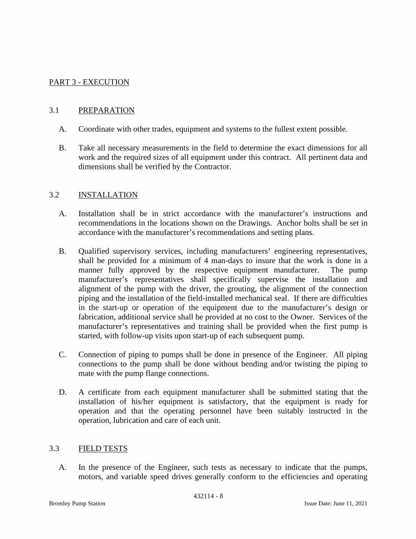
432114 - 8Bromley Pump Station Issue Date: June 11, 2021
PART 3 - EXECUTION
3.1 PREPARATION
A. Coordinate with other trades, equipment and systems to the fullest extent possible.
B. Take all necessary measurements in the field to determine the exact dimensions for allwork and the required sizes of all equipment under this contract. All pertinent data anddimensions shall be verified by the Contractor.
3.2 INSTALLATION
A. Installation shall be in strict accordance with the manufacturer’s instructions andrecommendations in the locations shown on the Drawings. Anchor bolts shall be set inaccordance with the manufacturer’s recommendations and setting plans.
B. Qualified supervisory services, including manufacturers’ engineering representatives,shall be provided for a minimum of 4 man-days to insure that the work is done in amanner fully approved by the respective equipment manufacturer. The pumpmanufacturer’s representatives shall specifically supervise the installation andalignment of the pump with the driver, the grouting, the alignment of the connectionpiping and the installation of the field-installed mechanical seal. If there are difficultiesin the start-up or operation of the equipment due to the manufacturer’s design orfabrication, additional service shall be provided at no cost to the Owner. Services of themanufacturer’s representatives and training shall be provided when the first pump isstarted, with follow-up visits upon start-up of each subsequent pump.
C. Connection of piping to pumps shall be done in presence of the Engineer. All pipingconnections to the pump shall be done without bending and/or twisting the piping tomate with the pump flange connections.
D. A certificate from each equipment manufacturer shall be submitted stating that theinstallation of his/her equipment is satisfactory, that the equipment is ready foroperation and that the operating personnel have been suitably instructed in theoperation, lubrication and care of each unit.
3.3 FIELD TESTS
A. In the presence of the Engineer, such tests as necessary to indicate that the pumps,motors, and variable speed drives generally conform to the efficiencies and operating

432114 - 9Bromley Pump Station Issue Date: June 11, 2021
conditions specified shall be performed. A thirty-day operating period of the pumpswill be required before acceptance. If a pump performance does not meet theSpecifications, corrective measures shall be taken or the pump shall be removed andreplaced with a pump which satisfies the conditions specified. All test procedures shallbe in accordance with Hydraulic Institute Standards certified results of tests shall besubmitted. Provide, calibrate and install all temporary gauges and meters, shall makenecessary tapped holes in the pipes, and install all temporary piping and wiring requiredfor the field acceptance tests. Written test procedures shall be submitted to the Engineerfor approval 30 days prior to testing.
3.4 TRAINING
A. A factory representative shall provide a minimum of eight (8) man-hours of training tothe Owner’s operations staff concerning the recommended operation and maintenanceof the equipment. Training shall be performed after substantial completion of theproject with the use of operating equipment.
++END OF SECTION++
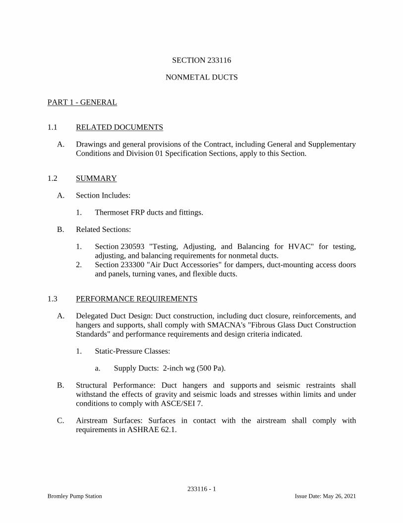
233116 - 1Bromley Pump Station Issue Date: May 26, 2021
SECTION 233116
NONMETAL DUCTS
PART 1 - GENERAL
1.1 RELATED DOCUMENTS
A. Drawings and general provisions of the Contract, including General and SupplementaryConditions and Division 01 Specification Sections, apply to this Section.
1.2 SUMMARY
A. Section Includes:
1. Thermoset FRP ducts and fittings.
B. Related Sections:
1. Section 230593 "Testing, Adjusting, and Balancing for HVAC" for testing,adjusting, and balancing requirements for nonmetal ducts.
2. Section 233300 "Air Duct Accessories" for dampers, duct-mounting access doorsand panels, turning vanes, and flexible ducts.
1.3 PERFORMANCE REQUIREMENTS
A. Delegated Duct Design: Duct construction, including duct closure, reinforcements, andhangers and supports, shall comply with SMACNA's "Fibrous Glass Duct ConstructionStandards" and performance requirements and design criteria indicated.
1. Static-Pressure Classes:
a. Supply Ducts: 2-inch wg (500 Pa).
B. Structural Performance: Duct hangers and supports and seismic restraints shallwithstand the effects of gravity and seismic loads and stresses within limits and underconditions to comply with ASCE/SEI 7.
C. Airstream Surfaces: Surfaces in contact with the airstream shall comply withrequirements in ASHRAE 62.1.
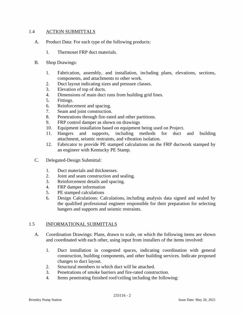
233116 - 2Bromley Pump Station Issue Date: May 26, 2021
1.4 ACTION SUBMITTALS
A. Product Data: For each type of the following products:
1. Thermoset FRP duct materials.
B. Shop Drawings:
1. Fabrication, assembly, and installation, including plans, elevations, sections,components, and attachments to other work.
2. Duct layout indicating sizes and pressure classes.3. Elevation of top of ducts.4. Dimensions of main duct runs from building grid lines.5. Fittings.6. Reinforcement and spacing.7. Seam and joint construction.8. Penetrations through fire-rated and other partitions.9. FRP control damper as shown on drawings10. Equipment installation based on equipment being used on Project.11. Hangers and supports, including methods for duct and building
attachment, seismic restraints, and vibration isolation.12. Fabricator to provide PE stamped calculations on the FRP ductwork stamped by
an engineer with Kentucky PE Stamp.
C. Delegated-Design Submittal:
1. Duct materials and thicknesses.2. Joint and seam construction and sealing.3. Reinforcement details and spacing.4. FRP damper information5. PE stamped calculations6. Design Calculations: Calculations, including analysis data signed and sealed by
the qualified professional engineer responsible for their preparation for selectinghangers and supports and seismic restraints.
1.5 INFORMATIONAL SUBMITTALS
A. Coordination Drawings: Plans, drawn to scale, on which the following items are shownand coordinated with each other, using input from installers of the items involved:
1. Duct installation in congested spaces, indicating coordination with generalconstruction, building components, and other building services. Indicate proposedchanges to duct layout.
2. Structural members to which duct will be attached.3. Penetrations of smoke barriers and fire-rated construction.4. Items penetrating finished roof/ceiling including the following:

233116 - 3Bromley Pump Station Issue Date: May 26, 2021
a. Lighting fixtures.b. Air outlets and inlets.c. Sprinklers.d. Access panels.
B. Welding certificates.
C. Field quality-control reports.
1.6 QUALITY ASSURANCE
A. Welding Qualifications: Qualify procedures and personnel according toAWS D1.1/D1.1M, "Structural Welding Code - Steel," for hangers and supports.
B. ASHRAE Compliance: Applicable requirements in ASHRAE 62.1, Section 5 -"Systems and Equipment" and Section 7 - "Construction and System Start-up."
C. ASHRAE/IESNA Compliance: Applicable requirements in ASHRAE/IESNA 90.1,Section 6.4.4 - "HVAC System Construction and Insulation."
D. NFPA Compliance:
1. NFPA 90A, "Installation of Air Conditioning and Ventilating Systems."2. NFPA 90B, "Installation of Warm Air Heating and Air Conditioning Systems."
PART 2 - PRODUCTS
2.1 THERMOSET FRP DUCTS AND FITTINGS
A. Manufacturers: Subject to compliance with requirements, available manufacturersoffering products that may be incorporated into the Work include, but are not limited tothe following:
1. Industrial Fiberglass Specialties.2. Perry Fiberglass Products, Inc.3. Spunstrand Inc.
B. Duct and Fittings:
1. Thermoset FRP Resin: Manufacture duct with resin that complies with UL 181,Class 1, maximum flame-spread index of 25 and maximum smoke-developedindex of 250 when tested by an NRTL according to ASTM E 84 with use of anexterior gel coat.
2. Resin system throughout the laminate shall be a Class 1 Vinyl Ester Resin. Noexceptions (Interplastic Copr, Inos, Ashland or equal)
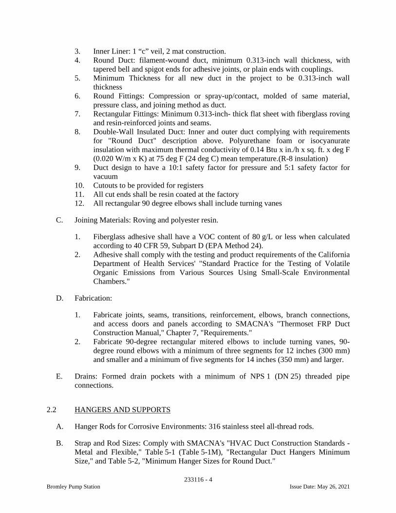
233116 - 4Bromley Pump Station Issue Date: May 26, 2021
3. Inner Liner: 1 “c” veil, 2 mat construction.4. Round Duct: filament-wound duct, minimum 0.313-inch wall thickness, with
tapered bell and spigot ends for adhesive joints, or plain ends with couplings.5. Minimum Thickness for all new duct in the project to be 0.313-inch wall
thickness6. Round Fittings: Compression or spray-up/contact, molded of same material,
pressure class, and joining method as duct.7. Rectangular Fittings: Minimum 0.313-inch- thick flat sheet with fiberglass roving
and resin-reinforced joints and seams.8. Double-Wall Insulated Duct: Inner and outer duct complying with requirements
for "Round Duct" description above. Polyurethane foam or isocyanurateinsulation with maximum thermal conductivity of 0.14 Btu x in./h x sq. ft. x deg F(0.020 W/m x K) at 75 deg F (24 deg C) mean temperature.(R-8 insulation)
9. Duct design to have a 10:1 safety factor for pressure and 5:1 safety factor forvacuum
10. Cutouts to be provided for registers11. All cut ends shall be resin coated at the factory12. All rectangular 90 degree elbows shall include turning vanes
C. Joining Materials: Roving and polyester resin.
1. Fiberglass adhesive shall have a VOC content of 80 g/L or less when calculatedaccording to 40 CFR 59, Subpart D (EPA Method 24).
2. Adhesive shall comply with the testing and product requirements of the CaliforniaDepartment of Health Services' "Standard Practice for the Testing of VolatileOrganic Emissions from Various Sources Using Small-Scale EnvironmentalChambers."
D. Fabrication:
1. Fabricate joints, seams, transitions, reinforcement, elbows, branch connections,and access doors and panels according to SMACNA's "Thermoset FRP DuctConstruction Manual," Chapter 7, "Requirements."
2. Fabricate 90-degree rectangular mitered elbows to include turning vanes, 90-degree round elbows with a minimum of three segments for 12 inches (300 mm)and smaller and a minimum of five segments for 14 inches (350 mm) and larger.
E. Drains: Formed drain pockets with a minimum of NPS 1 (DN 25) threaded pipeconnections.
2.2 HANGERS AND SUPPORTS
A. Hanger Rods for Corrosive Environments: 316 stainless steel all-thread rods.
B. Strap and Rod Sizes: Comply with SMACNA's "HVAC Duct Construction Standards -Metal and Flexible," Table 5-1 (Table 5-1M), "Rectangular Duct Hangers MinimumSize," and Table 5-2, "Minimum Hanger Sizes for Round Duct."
233116 - 5Bromley Pump Station Issue Date: May 26, 2021
C. Steel Cables: ASTM A 492, stainless steel and ASTM A555 stainless steel (316) withend connections made of cadmium-plated steel assemblies with brackets, swivel, andbolts designed for duct hanger service; with an automatic-locking and clamping device.
D. Duct Attachments: 316 stainless steel sheet metal screws, blind rivets, or self-tappingmetal screws; compatible with duct materials.
E. Trapeze and Riser Supports: Steel shapes complying with ASTM A 36/A 36M.
2.3 SEISMIC-RESTRAINT DEVICES
A. Manufacturers: Subject to compliance with requirements, available manufacturersoffering products that may be incorporated into the Work include, but are not limited tothe following:
1. B-line, an Eaton business.2. Ductmate Industries, Inc.3. Hilti, Inc.4. Kinetics Noise Control, Inc.5. Loos & Co., Inc.6. Mason Industries, Inc.7. TOLCO.8. Unistrut; Part of Atkore International.
B. General Requirements for Restraint Components: Rated strengths, features, andapplications shall be as defined in reports by an agency acceptable to authorities havingjurisdiction.
1. Structural Safety Factor: Allowable strength in tension, shear, and pullout force ofcomponents shall be at least four times the maximum seismic forces to which theywill be subjected.
C. Channel Support System: Shop- or field-fabricated support assembly made of slottedsteel channels with accessories for attachment to braced component at one end and tobuilding structure at the other end. Include matching components and corrosion-resistant coating.
D. Restraint Cables: ASTM A 492, stainless-steel cables with end connections made ofcadmium-plated steel assemblies with brackets, swivel, and bolts designed forrestraining cable service; and with an automatic-locking and clamping device or double-cable clips.
E. Hanger Rod Stiffener: Steel tube or steel slotted-support-system sleeve with internallybolted connections to hanger rod.
F. Mechanical Anchor Bolts: Drilled-in and stud-wedge or female-wedge type. Selectanchor bolts with strength required for anchor and as tested according to ASTM E 488.
233116 - 6Bromley Pump Station Issue Date: May 26, 2021
PART 3 - EXECUTION
3.1 DUCT INSTALLATION
A. Install ducts with fewest possible joints.
B. Unless otherwise indicated, install ducts vertically and horizontally, and parallel andperpendicular to building lines.
C. Install ducts close to walls, overhead construction, columns, and other structural andpermanent enclosure elements of building.
D. Install ducts with a clearance of 1 inch (25 mm), plus allowance for insulationthickness.
E. Where ducts pass through non-fire-rated interior partitions and exterior walls and areexposed to view, cover the opening between the partition and duct or duct insulationwith sheet metal flanges. Overlap openings on four sides by at least 1-1/2 inches (38mm).
F. Where ducts pass through fire-rated interior partitions and exterior walls, install firedampers. Comply with requirements in Section 233300 "Air Duct Accessories" for fireand smoke dampers.
G. Protect duct interiors from the moisture, construction debris and dust, and other foreignmaterials.
H. Install thermoset FRP ducts and fittings to comply with SMACNA's "Thermoset FRPDuct Construction Manual."
3.2 HANGER AND SUPPORT INSTALLATION
A. Install hangers and supports for thermoset FRP ducts and fittings to comply withSMACNA's "Thermoset FRP Duct Construction Manual," Chapter 7, "Requirements."
B. Building Attachments: Concrete inserts, powder-actuated fasteners, or structural-steelfasteners appropriate for construction materials to which hangers are being attached.
1. Install concrete inserts before placing concrete.2. Install powder-actuated concrete fasteners after concrete is placed and completely
cured.3. Use powder-actuated concrete fasteners for standard-weight aggregate concretes
or for slabs more than 4 inches (100 mm) thick.4. Do not use powder-actuated concrete fasteners for lightweight-aggregate
concretes or for slabs less than 4 inches (100 mm) thick.5. Do not use powder-actuated concrete fasteners for seismic restraints.
233116 - 7Bromley Pump Station Issue Date: May 26, 2021
C. Install upper attachments to structures. Select and size upper attachments with pull-out,tension, and shear capacities appropriate for supported loads and building materialswhere used.
3.3 SEISMIC-RESTRAINT-DEVICE INSTALLATION
A. Install ducts with hangers and braces designed to support the duct and to restrain againstseismic forces required by applicable building codes. Comply with SMACNA's"Seismic Restraint Manual: Guidelines for Mechanical Systems."
1. Space lateral supports a maximum of 40 feet (12 m) o.c., and longitudinalsupports a maximum of 80 feet (24 m) o.c.
2. Brace a change of direction longer than 12 feet (3.7 m).
B. Select sizes of components so strength will be adequate to carry present and future staticand seismic loads within restraint device capacity.
C. Install cables so they do not bend across edges of adjacent equipment or buildingstructure.
D. Install cable restraints where ducts are suspended with vibration isolators.
E. Install seismic-restraint devices using methods approved by an agency acceptable toauthorities having jurisdiction.
F. Attachment to Structure: If specific attachment is not indicated, anchor bracing andrestraints to structure to flanges of beams, to upper truss chords of bar joists, or toconcrete members.
G. Drilling for and Setting Anchors:
1. Identify position of reinforcing steel and other embedded items prior to drillingholes for anchors. Do not damage existing reinforcement or embedded itemsduring drilling. Notify the Architect if reinforcing steel or other embedded itemsare encountered during drilling. Locate and avoid prestressed tendons, electricaland telecommunications conduit, and gas lines.
2. Do not drill holes in concrete or masonry until concrete, mortar, or grout hasachieved full design strength.
3. Wedge Anchors: Protect threads from damage during anchor installation. Heavy-duty sleeve anchors shall be installed with sleeve fully engaged in the structuralelement to which anchor is to be fastened.
4. Set anchors to manufacturer's recommended torque, using a torque wrench.5. Install zinc-coated steel anchors for interior applications and stainless-steel
anchors for applications exposed to weather.
233116 - 8Bromley Pump Station Issue Date: May 26, 2021
3.4 PAINTING
A. Paint interior of thermoset FRP ducts that are visible through registers and grilles andthat do not have duct liner. Apply one coat of flat, black, latex paint over a compatiblegalvanized-steel primer. Paint materials and application requirements are specified inSection 099123 "Interior Painting."
3.5 FIELD QUALITY CONTROL
A. Perform tests and inspections.
B. Leakage Tests:
1. Comply with SMACNA's "HVAC Air Duct Leakage Test Manual." Submit a testreport for each test.
2. Test the following systems:
a. Supply Ducts with a Pressure Class of 2-Inch wg (500 Pa) or Higher: Testrepresentative duct sections totaling no less than 50 percent of total installedduct area for each designated pressure class.
b. Outdoor Air Ducts with a Pressure Class of 2-Inch wg (500 Pa) or Higher:Test representative duct sections totaling no less than 50 percent of totalinstalled duct area for each designated pressure class.
3. Disassemble, reassemble, and seal segments of systems to accommodate leakagetesting and for compliance with test requirements.
4. Test for leaks before applying external insulation.5. Conduct tests at static pressures equal to maximum design pressure of system or
section being tested. If static-pressure classes are not indicated, test entire systemat maximum system design pressure. Do not pressurize systems above maximumdesign operating pressure. Give seven days' advance notice for testing.
C. Duct System Cleanliness Tests:
1. Visually inspect duct system to ensure that no visible contaminants are present.2. Test sections of nonmetal duct system, chosen randomly by Owner, for
cleanliness according to "Vacuum Test" in NADCA ACR, "Assessment, Cleaningand Restoration of HVAC Systems."
a. Acceptable Cleanliness Level: Net weight of debris collected on the filtermedia shall not exceed 0.75 mg/100 sq. cm.
D. Duct system will be considered defective if it does not pass tests and inspections.
E. Prepare test and inspection reports.
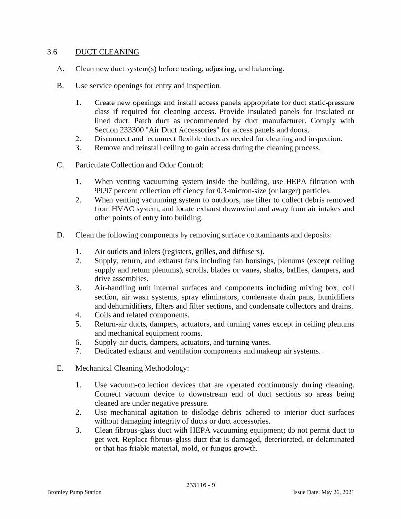
233116 - 9Bromley Pump Station Issue Date: May 26, 2021
3.6 DUCT CLEANING
A. Clean new duct system(s) before testing, adjusting, and balancing.
B. Use service openings for entry and inspection.
1. Create new openings and install access panels appropriate for duct static-pressureclass if required for cleaning access. Provide insulated panels for insulated orlined duct. Patch duct as recommended by duct manufacturer. Comply withSection 233300 "Air Duct Accessories" for access panels and doors.
2. Disconnect and reconnect flexible ducts as needed for cleaning and inspection.3. Remove and reinstall ceiling to gain access during the cleaning process.
C. Particulate Collection and Odor Control:
1. When venting vacuuming system inside the building, use HEPA filtration with99.97 percent collection efficiency for 0.3-micron-size (or larger) particles.
2. When venting vacuuming system to outdoors, use filter to collect debris removedfrom HVAC system, and locate exhaust downwind and away from air intakes andother points of entry into building.
D. Clean the following components by removing surface contaminants and deposits:
1. Air outlets and inlets (registers, grilles, and diffusers).2. Supply, return, and exhaust fans including fan housings, plenums (except ceiling
supply and return plenums), scrolls, blades or vanes, shafts, baffles, dampers, anddrive assemblies.
3. Air-handling unit internal surfaces and components including mixing box, coilsection, air wash systems, spray eliminators, condensate drain pans, humidifiersand dehumidifiers, filters and filter sections, and condensate collectors and drains.
4. Coils and related components.5. Return-air ducts, dampers, actuators, and turning vanes except in ceiling plenums
and mechanical equipment rooms.6. Supply-air ducts, dampers, actuators, and turning vanes.7. Dedicated exhaust and ventilation components and makeup air systems.
E. Mechanical Cleaning Methodology:
1. Use vacuum-collection devices that are operated continuously during cleaning.Connect vacuum device to downstream end of duct sections so areas beingcleaned are under negative pressure.
2. Use mechanical agitation to dislodge debris adhered to interior duct surfaceswithout damaging integrity of ducts or duct accessories.
3. Clean fibrous-glass duct with HEPA vacuuming equipment; do not permit duct toget wet. Replace fibrous-glass duct that is damaged, deteriorated, or delaminatedor that has friable material, mold, or fungus growth.
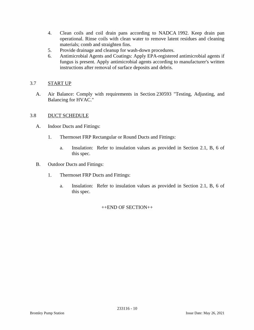
233116 - 10Bromley Pump Station Issue Date: May 26, 2021
4. Clean coils and coil drain pans according to NADCA 1992. Keep drain panoperational. Rinse coils with clean water to remove latent residues and cleaningmaterials; comb and straighten fins.
5. Provide drainage and cleanup for wash-down procedures.6. Antimicrobial Agents and Coatings: Apply EPA-registered antimicrobial agents if
fungus is present. Apply antimicrobial agents according to manufacturer's writteninstructions after removal of surface deposits and debris.
3.7 START UP
A. Air Balance: Comply with requirements in Section 230593 "Testing, Adjusting, andBalancing for HVAC."
3.8 DUCT SCHEDULE
A. Indoor Ducts and Fittings:
1. Thermoset FRP Rectangular or Round Ducts and Fittings:
a. Insulation: Refer to insulation values as provided in Section 2.1, B, 6 ofthis spec.
B. Outdoor Ducts and Fittings:
1. Thermoset FRP Ducts and Fittings:
a. Insulation: Refer to insulation values as provided in Section 2.1, B, 6 ofthis spec.
++END OF SECTION++
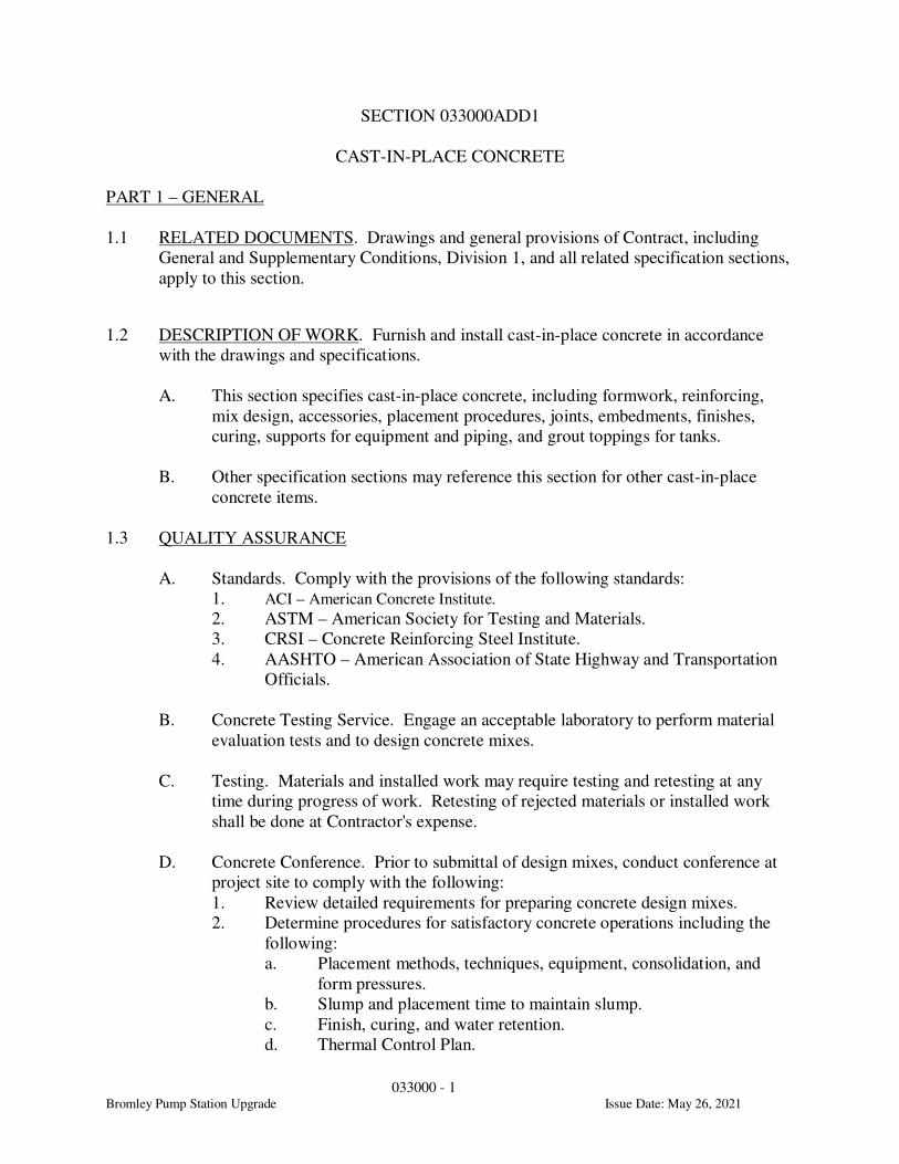
033000 - 1
Bromley Pump Station Upgrade Issue Date: May 26, 2021
SECTION 033000ADD1
CAST-IN-PLACE CONCRETE
PART 1 – GENERAL
1.1 RELATED DOCUMENTS. Drawings and general provisions of Contract, including
General and Supplementary Conditions, Division 1, and all related specification sections,
apply to this section.
1.2 DESCRIPTION OF WORK. Furnish and install cast-in-place concrete in accordance
with the drawings and specifications.
A. This section specifies cast-in-place concrete, including formwork, reinforcing,
mix design, accessories, placement procedures, joints, embedments, finishes,
curing, supports for equipment and piping, and grout toppings for tanks.
B. Other specification sections may reference this section for other cast-in-place
concrete items.
1.3 QUALITY ASSURANCE
A. Standards. Comply with the provisions of the following standards:
1. ACI – American Concrete Institute.
2. ASTM – American Society for Testing and Materials.
3. CRSI – Concrete Reinforcing Steel Institute.
4. AASHTO – American Association of State Highway and Transportation
Officials.
B. Concrete Testing Service. Engage an acceptable laboratory to perform material
evaluation tests and to design concrete mixes.
C. Testing. Materials and installed work may require testing and retesting at any
time during progress of work. Retesting of rejected materials or installed work
shall be done at Contractor's expense.
D. Concrete Conference. Prior to submittal of design mixes, conduct conference at
project site to comply with the following:
1. Review detailed requirements for preparing concrete design mixes.
2. Determine procedures for satisfactory concrete operations including the
following:
a. Placement methods, techniques, equipment, consolidation, and
form pressures.
b. Slump and placement time to maintain slump.
c. Finish, curing, and water retention.
d. Thermal Control Plan.

033000 - 2
Bromley Pump Station Upgrade Issue Date: May 26, 2021
e. Protection procedures for weather conditions.
3. Review requirements for submittals, status of coordinating work, and
availability of materials.
4. Establish preliminary work progress schedule and procedures for materials
inspection, testing, and certifications.
5. Request that representatives of each entity directly concerned with cast-in-
place concrete attend conference, including, but not limited to, the
following:
a. Contractor's superintendent.
b. Laboratory responsible for concrete mix design.
c. Laboratory responsible for field quality control.
d. Ready-Mix concrete supplier.
e. Concrete subcontractor.
f. Primary admixture manufacturers.
g. Engineer/Architect and/or Owner's Representative.
1.4 SUBMITTALS. Submit all submittals in accordance with the Division 1 Submittal
Requirements and the requirements within this specification section.
A. Submittal Package No. 1 – Shop Drawings and Product Data
1. Product data for materials and items, such as cement, reinforcement,
embedded forming accessories, admixtures, patching compounds,
waterstops, joint systems, and curing compounds.
2. Framing designs and details for each type of wall and slab bulkhead
containing Stay-Form product by Amico. See structural details for
minimum requirements.
3. Reinforcement shop drawings for fabrication, bending, and placement of
concrete reinforcement. Comply with ACI SP-66 (88), "ACI Detailing
Manual," showing bar schedules, stirrup spacing, diagrams of bent bars,
and arrangement of concrete reinforcement. Include special reinforcement
required for openings through concrete structures, and dowel
reinforcement for masonry.
4. Concrete mix designs for each class of concrete to be used on the project
including specifics regarding pozzolans and admixtures proposed for each
mix design. Include concrete test reports to substantiate trial batch mixes
or previous performance of the same mix design.
5. Thermal Control Plan: For concrete sections with a minimum specified
thickness that is greater than or equal to 3’-0”. The Thermal Control Plan
shall include the following minimum requirements:
a. Calculated or measured adiabatic temperature rise of concrete.
b. Upper limit for concrete temperature at time of placement.
c. Description of specific measures and equipment that will be used
to ensure maximum temperature in placement will not exceed
specified maximum temperature limit.
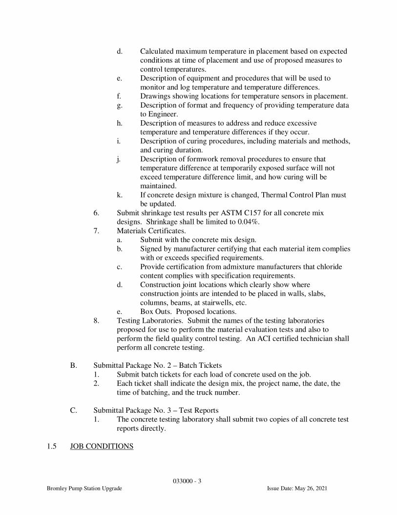
033000 - 3
Bromley Pump Station Upgrade Issue Date: May 26, 2021
d. Calculated maximum temperature in placement based on expected
conditions at time of placement and use of proposed measures to
control temperatures.
e. Description of equipment and procedures that will be used to
monitor and log temperature and temperature differences.
f. Drawings showing locations for temperature sensors in placement.
g. Description of format and frequency of providing temperature data
to Engineer.
h. Description of measures to address and reduce excessive
temperature and temperature differences if they occur.
i. Description of curing procedures, including materials and methods,
and curing duration.
j. Description of formwork removal procedures to ensure that
temperature difference at temporarily exposed surface will not
exceed temperature difference limit, and how curing will be
maintained.
k. If concrete design mixture is changed, Thermal Control Plan must
be updated.
6. Submit shrinkage test results per ASTM C157 for all concrete mix
designs. Shrinkage shall be limited to 0.04%.
7. Materials Certificates.
a. Submit with the concrete mix design.
b. Signed by manufacturer certifying that each material item complies
with or exceeds specified requirements.
c. Provide certification from admixture manufacturers that chloride
content complies with specification requirements.
d. Construction joint locations which clearly show where
construction joints are intended to be placed in walls, slabs,
columns, beams, at stairwells, etc.
e. Box Outs. Proposed locations.
8. Testing Laboratories. Submit the names of the testing laboratories
proposed for use to perform the material evaluation tests and also to
perform the field quality control testing. An ACI certified technician shall
perform all concrete testing.
B. Submittal Package No. 2 – Batch Tickets
1. Submit batch tickets for each load of concrete used on the job.
2. Each ticket shall indicate the design mix, the project name, the date, the
time of batching, and the truck number.
C. Submittal Package No. 3 – Test Reports
1. The concrete testing laboratory shall submit two copies of all concrete test
reports directly.
1.5 JOB CONDITIONS

033000 - 4
Bromley Pump Station Upgrade Issue Date: May 26, 2021
A. Coordination. Coordinate installation of joint materials, embedded items, etc.,
with placement of forms and reinforcing steel to prevent delays, errors, or
omissions.
B. Reference Material. Provide a copy of ACI SP-15, Field Reference Manual, in
the field office at all times during concrete construction.
C. Climatic Conditions. Perform placement and curing of concrete under various
weather conditions in accordance with ACI 301, "Specifications for Structural
Concrete for Buildings," ACI 305, "Hot Weather Concreting," and ACI 306,
"Cold Weather Concreting," except as modified herein.
1.6 DELIVERY, STORAGE, AND HANDLING. Comply with ACI 304, "Recommended
Practice for Measuring, Mixing, and Placing Concrete."
PART 2 – PRODUCTS
2.1 MATERIALS
A. Forms
1. Forms for exposed finish concrete shall be plywood, metal, metal framed
plywood faced, or other acceptable panel type materials, to provide
continuous, straight, smooth, exposed surfaces. Furnish in largest
practicable sizes to minimize number of joints and to conform to joint
system shown.
2. Forms for unexposed finish concrete shall be plywood, lumber, metal, or
other acceptable material. Provide lumber dressed on at least two edges
and one side for tight fit.
3. Forms for cylindrical columns and supports shall be metal, fiberglass
reinforced plastic, or paper or fiber tubes.
a. When used, provide paper or fiber tubes of laminated plies with
water resistant adhesive and wax impregnated exterior for weather
and moisture protection.
b. Provide sufficient wall thickness to resist wet concrete loads
without deformation.
4. Form coatings shall be commercial formulation form coating compounds
with a maximum volatile organic compound (VOC) of 350 milligrams per
liter (mg/l) that will not bond with, stain, or adversely affect concrete
surfaces and will not impair subsequent treatments of concrete surfaces.
5. Form ties shall be factory-fabricated, adjustable length, removable or
snap-off metal form ties, designed to prevent form deflection and to
prevent spalling concrete upon removal.
a. Provide units that will leave no metal closer than 1-1/2 inches to
exposed surface.
033000 - 5
Bromley Pump Station Upgrade Issue Date: May 26, 2021
b. Provide ties that, when removed, will leave holes not larger than 1-
1/2 inch diameter in concrete surface.
c. Ties shall have 3/4” to 1” diameter cones on each end.
d. Through-wall ties that are designed to be entirely removed are not
permitted in liquid retaining structures.
e. Provide rubber plug-type water stops at interior tie holes; exterior
holes shall be patched per concrete repair procedure herein.
B. Reinforcing Materials
1. Reinforcing Bars. ASTM A 615, A 616, including Supplemental
Requirement S1.
2. Welded Wire Fabric. ASTM A 185, welded steel wire fabric, provided in
flat sheets.
3. Supports for Reinforcement. Bolsters, chairs, spacers, and other devices
for spacing, supporting, and fastening reinforcing bars and welded wire
fabric in place. Use steel bar supports or precast concrete bar supports
complying with CRSI specifications.
a. For slabs on grade, use steel bar supports with sand plates or
horizontal runners or precast concrete bar supports where base
material will not support chair legs.
b. For exposed-to-view concrete surfaces, where legs of supports are
in contact with forms, provide supports with legs that are plastic
protected (CRSI, Class 1) or stainless steel (CRSI,
Class 2).
C. Concrete Materials
1. Portland Cement. ASTM C 150, Type I/II or Type II in areas where
alkali-aggregate reaction is a problem. Use one brand of cement
throughout project. Do not use ASTM C 150 type III cement for mass
concrete.
2. Fly Ash. ASTM C 618, Type C or Type F including supplementary
optional physical requirements, except loss on ignition shall not exceed
3 percent.
3. Ground Granulated Blast Furnace Slag. ASTM C989
4. Silica Fume. ASTM C1240, amorphous silica
5. Normal Weight Aggregates. ASTM C 33 and as herein specified.
a. For exposed concrete, provide aggregates from a single source.
b. For exterior exposed surfaces, do not use fine or coarse aggregates
containing deleterious substances which might cause spalling.
c. Fine Aggregate. Fine aggregate shall consist of natural sand or
manufactured sand.
d. Coarse Aggregate. Coarse aggregate shall consist of crushed rock,
gravel, or crushed gravel.
1) Grading. The coarse aggregate shall conform to requirements
for Size #67, unless otherwise approved. For grout topping, the
coarse aggregate shall conform to the requirements for Size #8, unless otherwise approved.
033000 - 6
Bromley Pump Station Upgrade Issue Date: May 26, 2021
2) Deleterious substances shall not exceed the percentages for
Class 4S.
6. Water. Potable.
7. Admixtures.
a. General. Provide admixtures that contain not more than
0.05 percent chloride ions by weight of cement when tested in
accordance with AASHTO T260. Certificate from admixture
manufacturer will be required prior to mix design approval.
b. Air-Entraining Admixture.
1) ASTM C 260, certified by manufacturer to be compatible
with other required admixtures.
2) Available Products. Subject to compliance with
requirements, products that may be incorporated in the
work include, but are not limited to, the following:
a) Darex II or Daravair, W.R. Grace & Co.
b) MB-VR or Micro-Air, Master Builders, Inc.
c) Sika AER, Sika Corp.
d) AEA-92 or Air Mix 200, Euclid Chemical Co.
c. Water-Reducing Admixture.
1) ASTM C 494, Type A.
2) Available Products. Subject to compliance with
requirements, products that may be incorporated in the
work include, but are not limited to, the following:
a) Eucon WR-75 or WR-89, Euclid Chemical Co.
b) WRDA with Hycol, or Daracem-55, W.R. Grace &
Co.
c) Pozzolith 220-N, Pozzolith 322-N, or Polyheed,
Master Builders, Inc.
d) Plastokrete 161, Sika Corp.
d. High-Range Water-Reducing (HRWR) Admixture (Super
Plasticizer).
1) ASTM C 494, Type F or Type G.
2) Available Products. Subject to compliance with
requirements, products that may be incorporated in the
work include, but are not limited to, the following:
a) Eucon 37, Euclid Chemical Co.
b) Daracem 19, Daracem ML330, or Daracem ML500,
W.R. Grace & Co.
c) Rheobuild, Master Builders, Inc.
d) Sikament 300, Sika Corp.
e. Noncorrosive, Nonchloride Accelerating Admixture.
1) ASTM C 494, Type C or E.
2) Available Products. Subject to compliance with
requirements, products that may be incorporated in the
work include, but are not limited to, the following:
a) Accelguard 80, Euclid Chemical Co.
033000 - 7
Bromley Pump Station Upgrade Issue Date: May 26, 2021
b) Polarset, W.R. Grace & Co.
c) Pozzutec 20, Master Builders, Inc.
f. Water-Reducing, Retarding Admixture.
1) ASTM C 494, Type D.
2) Available Products. Subject to compliance with
requirements, products that may be incorporated in the
work include, but are not limited to, the following:
a) Eucon Retarder 75, Euclid Chemical Co.
b) Daratard-17, W.R. Grace & Co.
c) Pozzolith R, Master Builders, Inc.
d) Plastiment, Sika Corporation.
g. Shrinkage Reducing Admixture.
1) ASTM C494, Type S.
2) Available Products. Subject to compliance with
requirements, products that may be incorporated in the
work include, but are not limited to, the following:
a) Masterlife SRA 20, Master Builders, Inc.
b) Eucon SRA, Euclid Chemical Co.
c) Sika Control-75, Sika Corporation.
h. Mass Concrete
1) Do not use accelerating admixtures for mass concrete
unless otherwise specified or permitted.
2) Use an acceptable retarding admixture whenever prevailing
temperature conditions make it necessary to prevent cold
joints due to the quantity of concrete placed, to offset the
effects of high concrete temperature, to permit revibration
of the concrete, or to reduce maximum temperature and rate
of temperature rise.
2.2 ACCESSORIES
A. Reglets. Where resilient or elastomeric sheet flashing or bituminous membranes
are terminated in reglets, provide reglets of not less than 0.0217-inch-thick (26-
gauge) galvanized sheet steel. Fill reglet or cover face opening to prevent
intrusion of concrete or debris.
B. Polyvinyl (PVC) Chloride Waterstops
1. Corps of Engineers CRD-C 572.
2. Waterstops for construction joints shall be serrated type without center
bulb and at least 3/8 inch thick and 6 inches wide. Type shall be similar to
Greenstreak profile #679.
3. Waterstops for expansion joints shall be serrated type with center bulb and
at least 3/8 inch thick and 9 inches wide. Type shall be similar to
Greenstreak profile #738.
033000 - 8
Bromley Pump Station Upgrade Issue Date: May 26, 2021
4. Available Manufacturers. Subject to compliance with requirements,
manufacturers offering products that may be incorporated in the work
include, but are not limited to, the following:
a. The Burke Co.
b. Greenstreak Plastic Products Co.
c. W.R. Meadows, Inc.
d. DuraJoint.
C. Hydrophilic (Swelling) Waterstops
1. Non-bentonite, modified chloroprene rubber.
2. Available Manufacturers. Subject to compliance with requirements,
manufacturers offering products that may be incorporated in the work
include, but are not limited to, the following:
a. Hydrotite, Sika Corporation
D. Sand Cushion. Clean, manufactured or natural sand conforming to ASTM C 33
or C 144.
E. Sealer/Dustproofer
1. Floor seeler compound for new concrete shall be an acrylic containing not
less than 14 percent solids.
2. Available Products. Subject to compliance with requirements, products
that may be incorporated in the work include, but are not limited to, the
following:
a. Super Diamond Clear VOX, Euclid Chemical Company.
b. Dress and Seal WB30, L&M Construction Chemicals, Inc.
F. Absorptive Cover. Burlap cloth made from jute or kenaf, weighing
approximately 9 ounces per square yard, complying with AASHTO M 182, Class
2.
G. Moisture-Retaining Cover. One of the following complying with ASTM C 171.
1. Waterproof paper.
2. Polyethylene film.
3. Polyethylene coated burlap.
H. Curing Compound
1. Clear styrene acrylate type, 30 percent solids content minimum.
2. Test data from an independent testing laboratory indicating a maximum
moisture loss of 0.55 kilograms (kg) per square meter when applied at a
coverage rate of 200 square feet per gallon.
3. Verify compatibility of curing compound with finishes to be used.
4. Available Products. Subject to compliance with requirements, products
that may be incorporated in the work include, but are not limited to, the
following:
a. Super Diamond Clear VOX, Euclid Chemical Company.
033000 - 9
Bromley Pump Station Upgrade Issue Date: May 26, 2021
b. Dress and Seal WB30, L&M Construction Chemicals, Inc.
I. Evaporation-Control Compound
1. Monomolecular film-forming compound applied to exposed concrete slab
surfaces for temporary protection from rapid moisture loss.
2. Available Products. Subject to compliance with requirements, products
that may be incorporated in the work include, but are not limited to, the
following:
a. Aquafilm, Conspec Marketing and Mfg. Co.
b. Eucobar, Euclid Chemical Co.
c. E-Con, L&M Construction Chemicals, Inc.
d. Confilm, Master Builders, Inc.
J. Bonding Compound
1. Polyvinyl acetate or acrylic base.
2. Available Products. Subject to compliance with requirements, products
that may be incorporated in the work include, but are not limited to, the
following:
a. Polyvinyl Acetate (Interior Only).
1) Superior Concrete Bonder, Dayton Superior Corp.
2) Euco Weld, Euclid Chemical Co.
3) Weld-Crete, Larsen Products Corp.
4) Everweld, L&M Construction Chemicals, Inc.
b. Acrylic or Styrene Butadiene.
1) SBR Latex, Euclid Chemical Co.
2) Daraweld C, W.R. Grace & Co.
3) Acryl-Set, Master Builders, Inc.
4) Stonlock LB2, Stonhard, Inc.
K. Epoxy Adhesive
1. ASTM C 881, two-component material suitable for use on dry or damp
surfaces.
2. Available Products. Subject to compliance with requirements, products
that may be incorporated in the work include, but are not limited to, the
following:
a. Euco Epoxy System #452 or #620, Euclid Chemical Co.
b. Epabond, L&M Construction Chemicals, Inc.
c. Concresive 1001, Master Builders, Inc.
d. Sikadur 32 Hi-Mod, Sika Corp.
L. Expansion Joint and Isolation Joint Material. Use one of the following unless
noted otherwise.
1. Self-expanding cork conforming to ASTM D 1752, Type III.
2. Cellular fiber-asphalt conforming to ASTM D 1751.
3. Neoprene/SBR polymer conforming to ASTM D 1056-67.
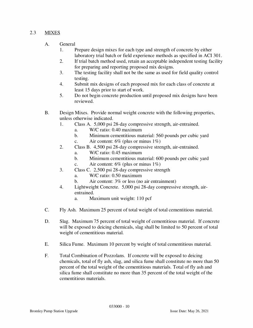
033000 - 10
Bromley Pump Station Upgrade Issue Date: May 26, 2021
2.3 MIXES
A. General
1. Prepare design mixes for each type and strength of concrete by either
laboratory trial batch or field experience methods as specified in ACI 301.
2. If trial batch method used, retain an acceptable independent testing facility
for preparing and reporting proposed mix designs.
3. The testing facility shall not be the same as used for field quality control
testing.
4. Submit mix designs of each proposed mix for each class of concrete at
least 15 days prior to start of work.
5. Do not begin concrete production until proposed mix designs have been
reviewed.
B. Design Mixes. Provide normal weight concrete with the following properties,
unless otherwise indicated.
1. Class A. 5,000 psi 28-day compressive strength, air-entrained.
a. W/C ratio: 0.40 maximum
b. Minimum cementitious material: 560 pounds per cubic yard
c. Air content: 6% (plus or minus 1%)
2. Class B. 4,500 psi 28-day compressive strength, air-entrained.
a. W/C ratio: 0.45 maximum
b. Minimum cementitious material: 600 pounds per cubic yard
c. Air content: 6% (plus or minus 1%)
3. Class C. 2,500 psi 28-day compressive strength
a. W/C ratio: 0.50 maximum
b. Air content: 3% or less (no air entrainment)
4. Lightweight Concrete. 5,000 psi 28-day compressive strength, air-
entrained.
a. Maximum unit weight: 110 pcf
C. Fly Ash. Maximum 25 percent of total weight of total cementitious material.
D. Slag. Maximum 75 percent of total weight of cementitious material. If concrete
will be exposed to deicing chemicals, slag shall be limited to 50 percent of total
weight of cementitious material.
E. Silica Fume. Maximum 10 percent by weight of total cementitious material.
F. Total Combination of Pozzolans. If concrete will be exposed to deicing
chemicals, total of fly ash, slag, and silica fume shall constitute no more than 50
percent of the total weight of the cementitious materials. Total of fly ash and
silica fume shall constitute no more than 35 percent of the total weight of the
cementitious materials.
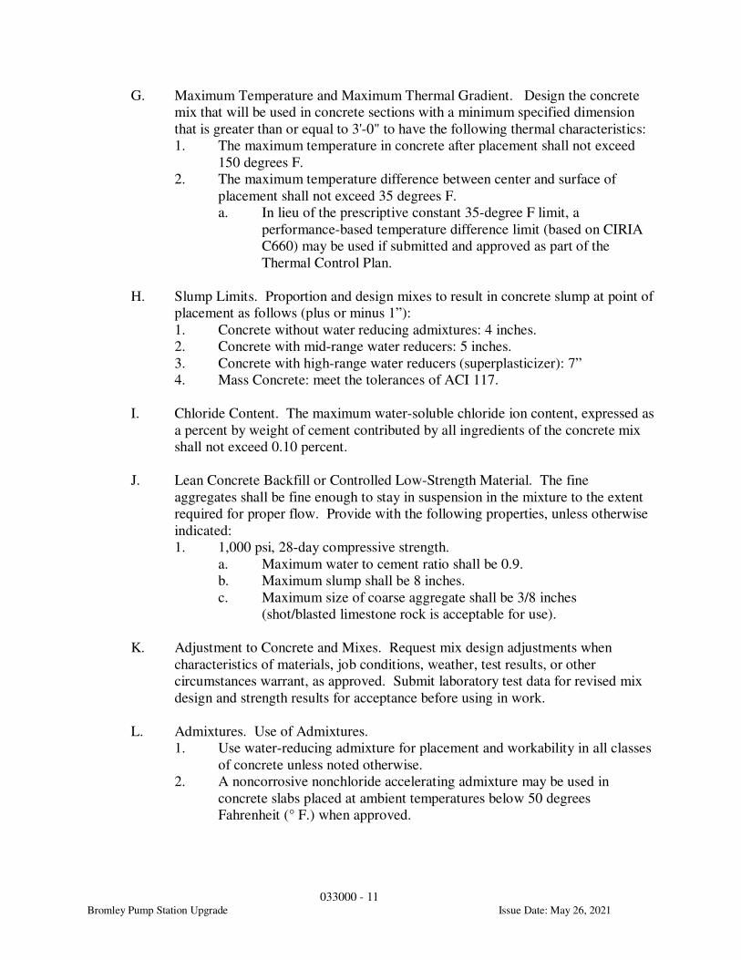
033000 - 11
Bromley Pump Station Upgrade Issue Date: May 26, 2021
G. Maximum Temperature and Maximum Thermal Gradient. Design the concrete
mix that will be used in concrete sections with a minimum specified dimension
that is greater than or equal to 3'-0" to have the following thermal characteristics:
1. The maximum temperature in concrete after placement shall not exceed
150 degrees F.
2. The maximum temperature difference between center and surface of
placement shall not exceed 35 degrees F.
a. In lieu of the prescriptive constant 35-degree F limit, a
performance-based temperature difference limit (based on CIRIA
C660) may be used if submitted and approved as part of the
Thermal Control Plan.
H. Slump Limits. Proportion and design mixes to result in concrete slump at point of
placement as follows (plus or minus 1”):
1. Concrete without water reducing admixtures: 4 inches.
2. Concrete with mid-range water reducers: 5 inches.
3. Concrete with high-range water reducers (superplasticizer): 7”
4. Mass Concrete: meet the tolerances of ACI 117.
I. Chloride Content. The maximum water-soluble chloride ion content, expressed as
a percent by weight of cement contributed by all ingredients of the concrete mix
shall not exceed 0.10 percent.
J. Lean Concrete Backfill or Controlled Low-Strength Material. The fine
aggregates shall be fine enough to stay in suspension in the mixture to the extent
required for proper flow. Provide with the following properties, unless otherwise
indicated:
1. 1,000 psi, 28-day compressive strength.
a. Maximum water to cement ratio shall be 0.9.
b. Maximum slump shall be 8 inches.
c. Maximum size of coarse aggregate shall be 3/8 inches
(shot/blasted limestone rock is acceptable for use).
K. Adjustment to Concrete and Mixes. Request mix design adjustments when
characteristics of materials, job conditions, weather, test results, or other
circumstances warrant, as approved. Submit laboratory test data for revised mix
design and strength results for acceptance before using in work.
L. Admixtures. Use of Admixtures.
1. Use water-reducing admixture for placement and workability in all classes
of concrete unless noted otherwise.
2. A noncorrosive nonchloride accelerating admixture may be used in
concrete slabs placed at ambient temperatures below 50 degrees
Fahrenheit (° F.) when approved.

033000 - 12
Bromley Pump Station Upgrade Issue Date: May 26, 2021
3. Add air-entraining admixture at manufacturer's prescribed rate to result in
concrete at point of placement having total air content as indicated in the
design mix.
M. Concrete Mixing
1. Ready Mix Concrete. Comply with requirements of ASTM C 94 and as
specified.
a. When air temperature is between 85° F. and 90° F., mixing and
delivery time shall not exceed 75 minutes.
b. When air temperature is above 90° F., mixing and delivery time
shall not exceed 60 minutes unless approved otherwise.
N. Shrinkage Reducing Admixture. If an SRA is needed to meet the 0.04%
shrinkage requirement, it shall be added at a minimum dosage of 2.0% of
cementitious materials (by weight). Submit shrinkage test results per Section 1.4.
It is the responsibility of the concrete supplier to adjust other mix constituents as
required to accommodate the shrinkage compensating admixture and keep the mix
strength, slump, air content, and set time within required limits.
PART 3 – EXECUTION
3.1 EXAMINATION
A. Tolerances. Unless otherwise specified, tolerances shall be in accordance with
ACI 117 and ACI 301.
B. Inspection
1. Before placing concrete, inspect and complete formwork installation,
reinforcing steel, and items to be embedded or cast-in.
2. Notify other trades to permit installation of their work; cooperate with
other trades in setting such work.
3. Verify that all wood, dirt, foreign objects, and all other debris have been
removed from inside the formwork.
4. Verify that reinforcing steel is spaced to provide the proper coverage
against forms and against earth for slabs on grade.
5. When requested, provide documentation of inspection prior to placing
concrete.
C. Site and Weather Conditions. Do not place concrete when site conditions exist
such as standing water, extreme heat or cold, etc., unless the proper precautions
have been taken to properly place and protect concrete as recommended by ACI
and as acceptable. Do not place concrete on frozen ground.
3.2 PREPARATION
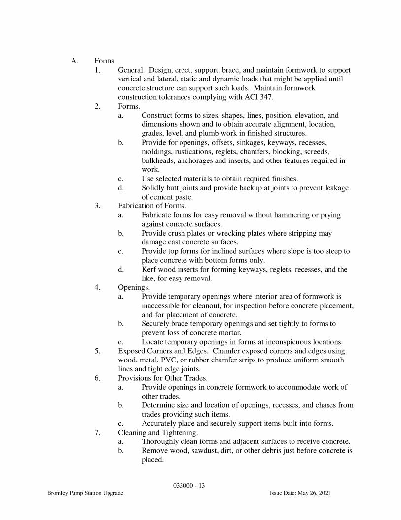
033000 - 13
Bromley Pump Station Upgrade Issue Date: May 26, 2021
A. Forms
1. General. Design, erect, support, brace, and maintain formwork to support
vertical and lateral, static and dynamic loads that might be applied until
concrete structure can support such loads. Maintain formwork
construction tolerances complying with ACI 347.
2. Forms.
a. Construct forms to sizes, shapes, lines, position, elevation, and
dimensions shown and to obtain accurate alignment, location,
grades, level, and plumb work in finished structures.
b. Provide for openings, offsets, sinkages, keyways, recesses,
moldings, rustications, reglets, chamfers, blocking, screeds,
bulkheads, anchorages and inserts, and other features required in
work.
c. Use selected materials to obtain required finishes.
d. Solidly butt joints and provide backup at joints to prevent leakage
of cement paste.
3. Fabrication of Forms.
a. Fabricate forms for easy removal without hammering or prying
against concrete surfaces.
b. Provide crush plates or wrecking plates where stripping may
damage cast concrete surfaces.
c. Provide top forms for inclined surfaces where slope is too steep to
place concrete with bottom forms only.
d. Kerf wood inserts for forming keyways, reglets, recesses, and the
like, for easy removal.
4. Openings.
a. Provide temporary openings where interior area of formwork is
inaccessible for cleanout, for inspection before concrete placement,
and for placement of concrete.
b. Securely brace temporary openings and set tightly to forms to
prevent loss of concrete mortar.
c. Locate temporary openings in forms at inconspicuous locations.
5. Exposed Corners and Edges. Chamfer exposed corners and edges using
wood, metal, PVC, or rubber chamfer strips to produce uniform smooth
lines and tight edge joints.
6. Provisions for Other Trades.
a. Provide openings in concrete formwork to accommodate work of
other trades.
b. Determine size and location of openings, recesses, and chases from
trades providing such items.
c. Accurately place and securely support items built into forms.
7. Cleaning and Tightening.
a. Thoroughly clean forms and adjacent surfaces to receive concrete.
b. Remove wood, sawdust, dirt, or other debris just before concrete is
placed.
033000 - 14
Bromley Pump Station Upgrade Issue Date: May 26, 2021
c. Retighten forms and bracing before concrete placement as required
to prevent mortar leaks and maintain proper alignment.
8. Form Coatings. Coat contact surfaces of forms with an approved,
nonresidual, low VOC, form coating compound before reinforcement is
placed.
a. Do not allow excess form coating material to accumulate in forms
or to come into contact with in-place concrete surfaces against
which fresh concrete will be placed. Apply in compliance with
manufacturer's instructions.
b. Coat steel forms with a nonstaining, rust preventative material.
Rust-stained steel formwork is not acceptable.
c. Form coatings for use in water treatment plants shall be nontoxic
after 30 days from the date the forms are removed.
B. Reuse of Forms
1. Clean and repair surfaces of all forms to be reused in work. Split, frayed,
delaminated, or otherwise damaged form facing material will not be
acceptable for exposed surfaces.
2. Apply form coating compound as specified for new formwork.
3. Successive Reuse.
a. When forms are extended for successive concrete placement,
thoroughly clean surfaces, remove fins and laitance, and tighten
forms to close joints.
b. Align and secure joint to avoid offsets.
c. Do not use "patched" forms for exposed concrete surfaces except
as approved.
3.3 INSTALLATION
A. Placing Reinforcement
1. Comply with CRSI's recommended practice for "Placing Reinforcing
Bars" for details and methods of reinforcement placement and supports
and as herein specified.
2. Clean reinforcement of loose rust and mill scale, earth, ice, and other
materials that reduce or destroy bond with concrete.
3. Installation.
a. Accurately position, support, and secure reinforcement against
displacement.
b. Locate and support reinforcing by metal chairs, runners, bolsters,
spacers, and hangers, as approved.
c. Place reinforcement to obtain at least minimum coverages for
concrete protection as noted in ACI 301.
d. Arrange, space, and securely tie bars and bar supports to hold
reinforcement in position during concrete placement operations.
e. Set wire ties so ends are directed into concrete, not toward exposed
concrete surfaces.
033000 - 15
Bromley Pump Station Upgrade Issue Date: May 26, 2021
f. Install welded wire fabric in lengths as long as practicable.
g. Lap adjoining pieces at least one full mesh plus 2 inches or
8 inches and lace splices with wire.
h. Offset laps of adjoining widths to prevent continuous laps in either
direction.
B. Joints
1. Construction Joints. Locate and install construction joints where indicated
in Structural Drawings.
a. Provide roughened surface to 1/4-inch minimum amplitude in
horizontal construction joints in walls and between walls and
footings.
b. Continue reinforcement across construction joints except as
otherwise indicated.
c. All vertical construction joints in walls and slabs shall be formed
using Stay-Form product by Amico. See structural details for
minimum requirements.
d. The maximum length of wall pours shall not exceed 50 feet unless
otherwise approved. Locate construction joints in slabs where
indicated on the Structural Plans.
e. Bond fresh concrete to hardened new concrete as follows:
Thoroughly clean the surface of the hardened concrete and remove
all laitance prior to placing new concrete. Apply specified
chemical bonding agent in accordance with the manufacturer’s
specifications. Place adjacent concrete, vibrate thoroughly near
joint.
f. Make provisions to support and protect exposed waterstops during
progress of work. Provide factory made waterstop fabrications at
all changes in direction, intersections and transitions, leaving only
straight butt splices for the field. Provide continuous waterstops in
construction joints as follows:
1) Liquid-bearing walls and slabs.
2) Walls or slabs subject to groundwater and/or in contact
with ground.
3) Elsewhere as indicated.
2. Isolation Joints in Slabs-on-Ground. Construct isolation joints as
indicated in slabs-on-ground at points of contact between slabs-on-ground
and vertical surfaces, such as column pedestals, foundation walls, grade
beams, and elsewhere as shown. Fill joints where noted with sealant
specified in Division 7 sections of these specifications.
3. Contraction (Control) Joints in Slabs-on-Ground.
a. Construct contraction joints in slabs-on-ground to form panels of
patterns as shown.
b. Use saw cuts 1/8 inch wide by 1/4 slab depth or insert premolded
plastic, hardboard, or fiberboard strip into fresh concrete until top
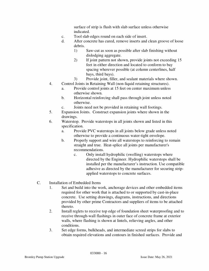
033000 - 16
Bromley Pump Station Upgrade Issue Date: May 26, 2021
surface of strip is flush with slab surface unless otherwise
indicated.
c. Tool slab edges round on each side of insert.
d. After concrete has cured, remove inserts and clean groove of loose
debris.
1) Saw-cut as soon as possible after slab finishing without
dislodging aggregate.
2) If joint pattern not shown, provide joints not exceeding 15
feet in either direction and located to conform to bay
spacing wherever possible (at column centerlines, half
bays, third bays).
3) Provide joint, filler, and sealant materials where shown.
4. Control Joints in Retaining Wall (non-liquid retaining structures).
a. Provide control joints at 15 feet on center maximum unless
otherwise shown.
b. Horizontal reinforcing shall pass through joint unless noted
otherwise.
c. Joints need not be provided in retaining wall footings.
5. Expansion Joints. Construct expansion joints where shown in the
drawings.
6. Waterstop. Provide waterstops in all joints shown and listed in this
specification.
a. Provide PVC waterstops in all joints below grade unless noted
otherwise to provide a continuous water-tight envelope.
b. Properly support and wire all waterstops to reinforcing to remain
straight and true. Heat-splice all joints per manufacturer's
recommendations.
c. Only install hydrophilic (swelling) waterstops where
directed by the Engineer. Hydrophilic waterstops shall be
installed per the manufacturer’s instruction. Use compatible
adhesive as directed by the manufacturer for securing strip-
applied waterstops to concrete surfaces.
C. Installation of Embedded Items
1. Set and build into the work, anchorage devices and other embedded items
required for other work that is attached to or supported by cast-in-place
concrete. Use setting drawings, diagrams, instructions, and directions
provided by other prime Contractors and suppliers of items to be attached
thereto.
2. Install reglets to receive top edge of foundation sheet waterproofing and to
receive through-wall flashings in outer face of concrete frame at exterior
walls, where flashing is shown at lintels, relieving angles, and other
conditions.
3. Set edge forms, bulkheads, and intermediate screed strips for slabs to
obtain required elevations and contours in finished surfaces. Provide and
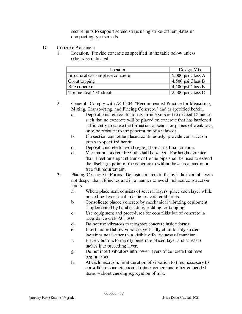
033000 - 17
Bromley Pump Station Upgrade Issue Date: May 26, 2021
secure units to support screed strips using strike-off templates or
compacting type screeds.
D. Concrete Placement
1. Location. Provide concrete as specified in the table below unless
otherwise indicated.
Location Design Mix
Structural cast-in-place concrete 5,000 psi Class A
Grout topping 4,500 psi Class B
Site concrete 4,500 psi Class B
Tremie Seal / Mudmat 2,500 psi Class C
2. General. Comply with ACI 304, "Recommended Practice for Measuring,
Mixing, Transporting, and Placing Concrete," and as specified herein.
a. Deposit concrete continuously or in layers not to exceed 18 inches
such that no concrete will be placed on concrete that has hardened
sufficiently to cause the formation of seams or planes of weakness,
or to be resistant to the penetration of a vibrator.
b. If a section cannot be placed continuously, provide construction
joints as specified herein.
c. Deposit concrete to avoid segregation at its final location.
d. Maximum concrete free fall shall be 4 feet. For heights greater
than 4 feet an elephant trunk or tremie pipe shall be used to extend
the discharge point of the concrete to within the 4-foot maximum
free fall requirement.
3. Placing Concrete in Forms. Deposit concrete in forms in horizontal layers
not deeper than 18 inches and in a manner to avoid inclined construction
joints.
a. Where placement consists of several layers, place each layer while
preceding layer is still plastic to avoid cold joints.
b. Consolidate placed concrete by mechanical vibrating equipment
supplemented by hand spading, rodding, or tamping.
c. Use equipment and procedures for consolidation of concrete in
accordance with ACI 309.
d. Do not use vibrators to transport concrete inside forms.
e. Insert and withdraw vibrators vertically at uniformly spaced
locations not farther than visible effectiveness of machine.
f. Place vibrators to rapidly penetrate placed layer and at least 6
inches into preceding layer.
g. Do not insert vibrators into lower layers of concrete that have
begun to set.
h. At each insertion, limit duration of vibration to time necessary to
consolidate concrete around reinforcement and other embedded
items without causing segregation of mix.
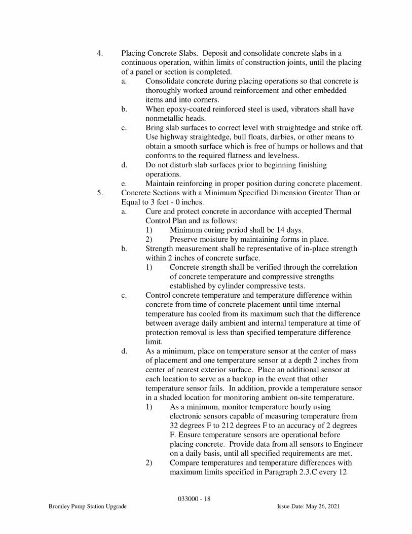
033000 - 18
Bromley Pump Station Upgrade Issue Date: May 26, 2021
4. Placing Concrete Slabs. Deposit and consolidate concrete slabs in a
continuous operation, within limits of construction joints, until the placing
of a panel or section is completed.
a. Consolidate concrete during placing operations so that concrete is
thoroughly worked around reinforcement and other embedded
items and into corners.
b. When epoxy-coated reinforced steel is used, vibrators shall have
nonmetallic heads.
c. Bring slab surfaces to correct level with straightedge and strike off.
Use highway straightedge, bull floats, darbies, or other means to
obtain a smooth surface which is free of humps or hollows and that
conforms to the required flatness and levelness.
d. Do not disturb slab surfaces prior to beginning finishing
operations.
e. Maintain reinforcing in proper position during concrete placement.
5. Concrete Sections with a Minimum Specified Dimension Greater Than or
Equal to 3 feet - 0 inches.
a. Cure and protect concrete in accordance with accepted Thermal
Control Plan and as follows:
1) Minimum curing period shall be 14 days.
2) Preserve moisture by maintaining forms in place.
b. Strength measurement shall be representative of in-place strength
within 2 inches of concrete surface.
1) Concrete strength shall be verified through the correlation
of concrete temperature and compressive strengths
established by cylinder compressive tests.
c. Control concrete temperature and temperature difference within
concrete from time of concrete placement until time internal
temperature has cooled from its maximum such that the difference
between average daily ambient and internal temperature at time of
protection removal is less than specified temperature difference
limit.
d. As a minimum, place on temperature sensor at the center of mass
of placement and one temperature sensor at a depth 2 inches from
center of nearest exterior surface. Place an additional sensor at
each location to serve as a backup in the event that other
temperature sensor fails. In addition, provide a temperature sensor
in a shaded location for monitoring ambient on-site temperature.
1) As a minimum, monitor temperature hourly using
electronic sensors capable of measuring temperature from
32 degrees F to 212 degrees F to an accuracy of 2 degrees
F. Ensure temperature sensors are operational before
placing concrete. Provide data from all sensors to Engineer
on a daily basis, until all specified requirements are met.
2) Compare temperatures and temperature differences with
maximum limits specified in Paragraph 2.3.C every 12
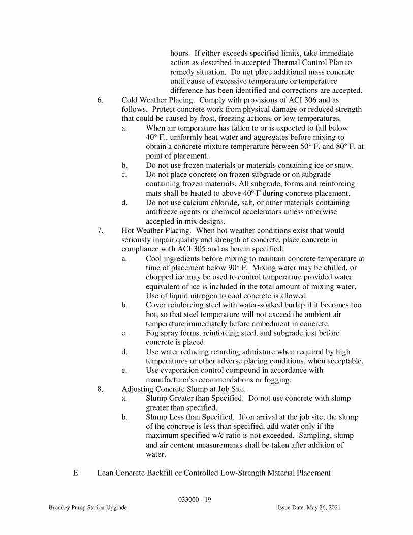
033000 - 19
Bromley Pump Station Upgrade Issue Date: May 26, 2021
hours. If either exceeds specified limits, take immediate
action as described in accepted Thermal Control Plan to
remedy situation. Do not place additional mass concrete
until cause of excessive temperature or temperature
difference has been identified and corrections are accepted.
6. Cold Weather Placing. Comply with provisions of ACI 306 and as
follows. Protect concrete work from physical damage or reduced strength
that could be caused by frost, freezing actions, or low temperatures.
a. When air temperature has fallen to or is expected to fall below
40° F., uniformly heat water and aggregates before mixing to
obtain a concrete mixture temperature between 50° F. and 80° F. at
point of placement.
b. Do not use frozen materials or materials containing ice or snow.
c. Do not place concrete on frozen subgrade or on subgrade
containing frozen materials. All subgrade, forms and reinforcing
mats shall be heated to above 40º F during concrete placement.
d. Do not use calcium chloride, salt, or other materials containing
antifreeze agents or chemical accelerators unless otherwise
accepted in mix designs.
7. Hot Weather Placing. When hot weather conditions exist that would
seriously impair quality and strength of concrete, place concrete in
compliance with ACI 305 and as herein specified.
a. Cool ingredients before mixing to maintain concrete temperature at
time of placement below 90° F. Mixing water may be chilled, or
chopped ice may be used to control temperature provided water
equivalent of ice is included in the total amount of mixing water.
Use of liquid nitrogen to cool concrete is allowed.
b. Cover reinforcing steel with water-soaked burlap if it becomes too
hot, so that steel temperature will not exceed the ambient air
temperature immediately before embedment in concrete.
c. Fog spray forms, reinforcing steel, and subgrade just before
concrete is placed.
d. Use water reducing retarding admixture when required by high
temperatures or other adverse placing conditions, when acceptable.
e. Use evaporation control compound in accordance with
manufacturer's recommendations or fogging.
8. Adjusting Concrete Slump at Job Site.
a. Slump Greater than Specified. Do not use concrete with slump
greater than specified.
b. Slump Less than Specified. If on arrival at the job site, the slump
of the concrete is less than specified, add water only if the
maximum specified w/c ratio is not exceeded. Sampling, slump
and air content measurements shall be taken after addition of
water.
E. Lean Concrete Backfill or Controlled Low-Strength Material Placement
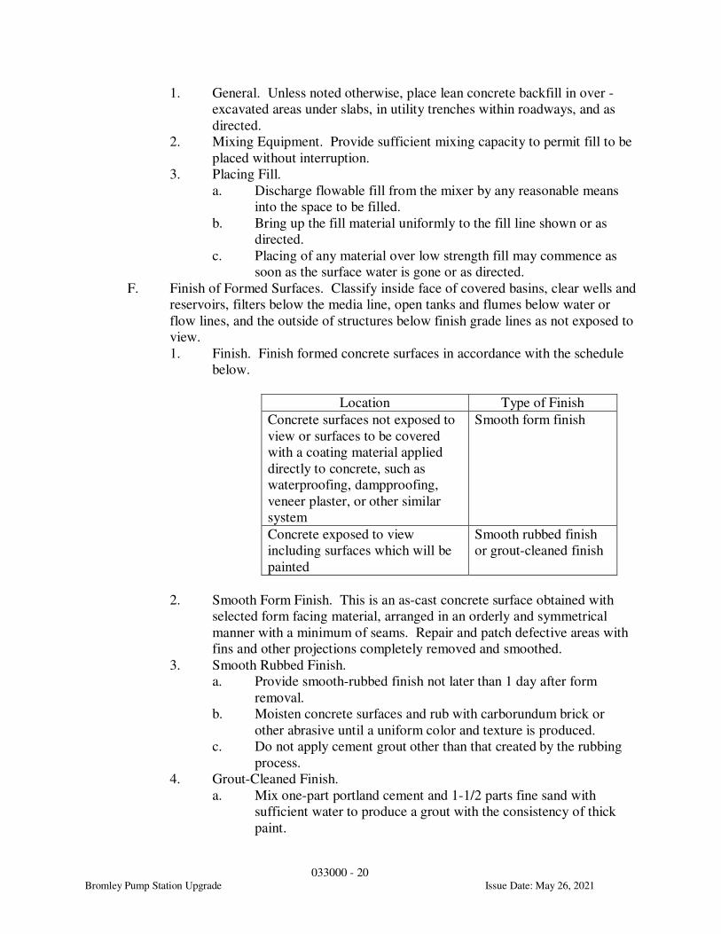
033000 - 20
Bromley Pump Station Upgrade Issue Date: May 26, 2021
1. General. Unless noted otherwise, place lean concrete backfill in over -
excavated areas under slabs, in utility trenches within roadways, and as
directed.
2. Mixing Equipment. Provide sufficient mixing capacity to permit fill to be
placed without interruption.
3. Placing Fill.
a. Discharge flowable fill from the mixer by any reasonable means
into the space to be filled.
b. Bring up the fill material uniformly to the fill line shown or as
directed.
c. Placing of any material over low strength fill may commence as
soon as the surface water is gone or as directed.
F. Finish of Formed Surfaces. Classify inside face of covered basins, clear wells and
reservoirs, filters below the media line, open tanks and flumes below water or
flow lines, and the outside of structures below finish grade lines as not exposed to
view.
1. Finish. Finish formed concrete surfaces in accordance with the schedule
below.
Location Type of Finish
Concrete surfaces not exposed to
view or surfaces to be covered
with a coating material applied
directly to concrete, such as
waterproofing, dampproofing,
veneer plaster, or other similar
system
Smooth form finish
Concrete exposed to view
including surfaces which will be
painted
Smooth rubbed finish
or grout-cleaned finish
2. Smooth Form Finish. This is an as-cast concrete surface obtained with
selected form facing material, arranged in an orderly and symmetrical
manner with a minimum of seams. Repair and patch defective areas with
fins and other projections completely removed and smoothed.
3. Smooth Rubbed Finish.
a. Provide smooth-rubbed finish not later than 1 day after form
removal.
b. Moisten concrete surfaces and rub with carborundum brick or
other abrasive until a uniform color and texture is produced.
c. Do not apply cement grout other than that created by the rubbing
process.
4. Grout-Cleaned Finish.
a. Mix one-part portland cement and 1-1/2 parts fine sand with
sufficient water to produce a grout with the consistency of thick
paint.
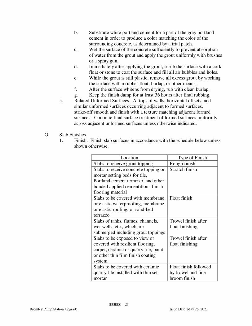
033000 - 21
Bromley Pump Station Upgrade Issue Date: May 26, 2021
b. Substitute white portland cement for a part of the gray portland
cement in order to produce a color matching the color of the
surrounding concrete, as determined by a trial patch.
c. Wet the surface of the concrete sufficiently to prevent absorption
of water from the grout and apply the grout uniformly with brushes
or a spray gun.
d. Immediately after applying the grout, scrub the surface with a cork
float or stone to coat the surface and fill all air bubbles and holes.
e. While the grout is still plastic, remove all excess grout by working
the surface with a rubber float, burlap, or other means.
f. After the surface whitens from drying, rub with clean burlap.
g. Keep the finish damp for at least 36 hours after final rubbing.
5. Related Unformed Surfaces. At tops of walls, horizontal offsets, and
similar unformed surfaces occurring adjacent to formed surfaces,
strike-off smooth and finish with a texture matching adjacent formed
surfaces. Continue final surface treatment of formed surfaces uniformly
across adjacent unformed surfaces unless otherwise indicated.
G. Slab Finishes
1. Finish. Finish slab surfaces in accordance with the schedule below unless
shown otherwise.
Location Type of Finish
Slabs to receive grout topping Rough finish
Slabs to receive concrete topping or
mortar setting beds for tile,
Portland cement terrazzo, and other
bonded applied cementitious finish
flooring material
Scratch finish
Slabs to be covered with membrane
or elastic waterproofing, membrane
or elastic roofing, or sand-bed
terrazzo
Float finish
Slabs of tanks, flumes, channels,
wet wells, etc., which are
submerged including grout toppings
Trowel finish after
float finishing
Slabs to be exposed to view or
covered with resilient flooring,
carpet, ceramic or quarry tile, paint
or other thin film finish coating
system
Trowel finish after
float finishing
Slabs to be covered with ceramic
quarry tile installed with thin set
mortar
Float finish followed
by trowel and fine
broom finish

033000 - 22
Bromley Pump Station Upgrade Issue Date: May 26, 2021
Exterior concrete platforms, steps,
ramps
Float finish followed
by nonslip broom
finish
2. Floor Levelness, General. Floor levelness requirements below do not
apply to sloped slabs or unshored slabs on metal deck.
3. Scratch Finish.
a. After placing slabs, plane surface to tolerances for floor flatness
(Ff) of 20 and floor levelness (Fl) of 17.
b. Slope surfaces uniformly to drains where required.
c. After leveling, roughen surface before final set with stiff brushes,
brooms, or rakes.
4. Float Finish.
a. After screeding, consolidating, and leveling concrete slabs, do not
work surface until ready for floating.
b. Begin floating, using float blades or float shoes only, when surface
water has disappeared, and/or when concrete has stiffened
sufficiently to permit operation of power driven floats.
c. Consolidate surface with power driven floats or by hand floating if
area is small or inaccessible to power units.
d. Check and level surface plane to tolerances of Ff 25 - Fl 20.
e. Cut down high spots and fill low spots.
f. Uniformly slope surfaces to drains.
g. Immediately after leveling, refloat surface to a uniform, smooth,
granular texture.
5. Trowel Finish.
a. After floating, begin first trowel finish operation using a power
driven trowel.
b. Begin final troweling when surface produces a ringing sound as
trowel is moved over surface.
c. Consolidate concrete surface by final hand troweling operation,
free of trowel marks, uniform in texture and appearance, and with
surface leveled to tolerances of Ff 50 - Fl 35.
d. Grind smooth surface defects that would telegraph through applied
floor covering system.
6. Trowel and Fine Broom Finish. Apply trowel finish as specified, then
immediately follow with slightly scarifying surface by fine brooming.
7. Nonslip Broom Finish. Immediately after float finishing, slightly roughen
concrete surface by brooming with stiff fiber bristle broom perpendicular
to main traffic route. Coordinate required final finish with
Engineer/Architect before application.
8. Rough Finish. The bottom of concrete tanks which are to receive grout
topping shall receive a rough finish for maximum adhesion. The surface
to receive the grout topping shall be intentionally roughened to a
minimum amplitude of 1/4 inch.
9. Sealer/Dustproofer Finish.
033000 - 23
Bromley Pump Station Upgrade Issue Date: May 26, 2021
a. Coat all exposed surfaces and floors within buildings which will be
subject to pedestrian or vehicular traffic under normal operation.
b. Accomplish this by applying a liquid sealer/dustproofer in three
applications in accordance with the manufacturer's directions.
c. Apply the sealer/dustproofer as late as possible and just prior to
completion of construction.
H. Placing Grout Toppings. Grout toppings shall be Class A or Class B concrete mix
design per the table provided under section 3.3.E.1.
1. Prior to placement of the structurally bonded topping, remove all laitance,
debris, and loose and foreign material from the base slab. Use water-
blasting, sandblasting, or other acceptable methods.
2. Thoroughly wet the base slab before placing the grout topping. Remove
all standing water from the surface.
3. Apply SikaDur 32 epoxy bonding agent immediately prior to placing
grout.
4. Trowel finish topping as specified above.
5. Moisture cure grout toppings as specified herein.
6. All concrete substrates to receive grout topping shall be cured by
conventional means (burlap, plastic, wetting, etc.). If chemical curing
compounds are used on substrates to receive topping the Contractor is
responsible for the complete removal of the curing material prior to
placement of the topping.
I. Miscellaneous Concrete Items
1. Filling In Holes and Openings.
a. Fill in holes and openings left in concrete structures for passage of
work by other trades, unless otherwise shown or directed, after
work of other trades is in place.
b. Mix, place, and cure concrete as herein specified, to blend with
in-place construction.
c. Provide other miscellaneous concrete filling shown or required to
complete work.
2. Equipment Bases and Foundations. Provide machine and equipment bases
and foundations as shown. Set anchor rods for machines and equipment
complying with diagrams or templates of manufacturer furnishing
machines and equipment.
3.4 CONCRETE SURFACE REPAIRS
A. Patching Defective Areas. Repair and patch defective areas and plug form tie
holes with cement mortar immediately after removal of forms, when acceptable.
1. Cut out honeycomb, rock pockets, and voids over 1/4 inch in any
dimension down to solid concrete but in no case to a depth of less than 1
inch.
a. Make edges of cuts perpendicular to the concrete surface.
033000 - 24
Bromley Pump Station Upgrade Issue Date: May 26, 2021
b. Thoroughly clean, dampen with water, and brush coat the area to
be patched with specified bonding compound.
c. Place patching mortar before bonding compound has dried.
2. For exposed-to-view surfaces, blend white portland cement and standard
portland cement so that, when dry, patching mortar will match color
surrounding.
a. Provide test areas at inconspicuous location to verify mixture and
color match before proceeding with patching.
b. Compact mortar in place and strike-off slightly higher than
surrounding surface.
c. After shrinkage has occurred, grind surface until flush.
B. Repair of Formed Surfaces. Remove and replace concrete having defective
surfaces if defects cannot be repaired satisfactorily. Surface defects include color
and texture irregularities, cracks, spalls, air bubbles, honeycomb, rock pockets,
fins and other projections on surface, and stains and other discolorations that
cannot be removed by cleaning.
C. Repair of Unformed Surfaces. Repair or replace supported slabs that fail to meet
the specified finish requirements.
1. Correct levelness and flatness, and low and high areas as herein specified.
2. For slabs on grade, remove slab between control joints and replace with
concrete slab meeting floor finish and tolerances.
3. For all other unformed surfaces, repair as follows:
a. Repair surface defects that affect the durability of the concrete.
These include crazing and cracks in excess of 0.01 inch wide or
that penetrate to reinforcement or completely through
nonreinforced sections regardless of width, spalling, popouts,
honeycomb, rock pockets, and other objectionable conditions.
b. Correct high areas in unformed surfaces by grinding after concrete
has cured at least 14 days.
c. Correct low areas in unformed surfaces during or immediately
after completion of surface finishing operations by cutting out low
areas and replacing with patching compound.
d. Finish repaired areas to blend into adjacent concrete.
e. Underlayment compounds may be used when acceptable.
f. Repair defective areas, except random cracks and single holes not
exceeding 1 inch in diameter, by cutting out and replacing with
fresh concrete.
1) Remove defective areas to sound concrete with clean,
square cuts and expose reinforcing steel with at least
3/4 inch clearance all around.
2) Dampen concrete surfaces in contact with patching
concrete and apply bonding compound.
3) Mix patching concrete of same materials to provide
concrete of same type or class as original concrete.
033000 - 25
Bromley Pump Station Upgrade Issue Date: May 26, 2021
4) Place, compact, and finish to blend with adjacent finished
concrete.
5) Cure in same manner as adjacent concrete.
D. Crack Repairs. The Contractor is responsible for the repair of all cracking over
0.015” (15 mils) in width within cast-in-place concrete work (this includes the
repair of the back faces of walls and top slabs prior to backfilling). If cracks are
observed to be greater than 0.035” (35 mils) in width contact Engineer for review.
For non-leaking cracks the repair procedure shall be per Section 3.4.E below.
Where cracks are leaking (due to exterior groundwater) they shall be ported and
injected with Sika HH+ (or approved equal) until all water filtration is stopped.
After termination of water infiltration the surface of the crack shall be repaired
per Section 3.4.E. All crack injection and repair work shall be performed at no
additional cost to the Owner.
E. Miscellaneous Repairs. Repair isolated random cracks and single holes not over 1
inch in diameter by dry pack method.
1. Groove top of cracks and cut out holes to sound concrete and clean of
dust, dirt, and loose particles.
2. Dampen cleaned concrete surfaces and apply bonding compound.
3. Place dry pack mortar before bonding compound has dried.
4. Compact dry pack mixture in place and finish to match adjacent concrete.
5. Keep patched area continuously moist for not less than 72 hours.
F. Approval. Perform structural repairs with prior approval for method and
procedure, using specified epoxy adhesive and mortar.
G. Alternative Repair Methods. Repair methods not specified above may be used,
subject to acceptance.
3.5 QUALITY CONTROL TESTING DURING CONSTRUCTION
A. General
1. Employ an approved testing laboratory to perform tests and submit test
reports.
2. ACI Grade 1 certified technician employed by the testing laboratory shall
be present during the placing of all concrete.
3. The concrete testing laboratory shall submit two copies of all test reports
directly to the Engineer/Architect.
B. Sampling Fresh Concrete. Sample concrete in accordance with ASTM C 172,
except modified for slump to comply with ASTM C 94.
1. Slump. Perform slump tests at the point of truck discharge in accordance
with ASTM C 143.

033000 - 26
Bromley Pump Station Upgrade Issue Date: May 26, 2021
a. For each class of concrete, perform one test for each compressive
strength test and additional tests when concrete consistency seems
to have changed.
b. If the slump is adjusted at the job site, the concrete testing agency
shall be responsible for reporting the following.
1) Method used to adjust slump.
2) Quantity of each material added.
3) Resulting slump.
2. Air Content. Perform daily for each class of concrete placed in
accordance with ASTM C 173 volumetric method for lightweight
concrete; ASTM C 231 pressure method for normal weight concrete; one
test for each compressive strength test, one test for the first load of each
type of air entrained concrete delivered, and one test for each truck when
air content is adjusted until consistent results are obtained.
3. Concrete Temperature. Test hourly when air temperature is 40° F. and
below, when 80° F. and above, and each time a set of compressive test
specimens is made.
4. Compressive Test Specimen. Perform in accordance with ASTM C 31
and as follows:
a. Prepare one set of four standard cylinders for each compressive
strength test, unless otherwise directed. Mold and store cylinders
for laboratory cured test specimens except when field cured test
specimens are required. The 7-day test specimen shall be field
cured. Contractor may also prepare additional field cured test
specimens to be used for early form removal.
b. Prepare one set of cylinders for each 100 cy of concrete or fraction
thereof, of each concrete class placed in any one day.
c. Perform compressive strength tests in accordance with ASTM C
39. Test one specimen at 7 days, and two specimens at 28 days,
and hold one specimen in reserve for later testing if required.
d. When frequency of testing will provide fewer than five strength
tests for a given class of concrete, conduct testing from at least five
randomly selected batches or from each batch if fewer than five are
used.
e. When total quantity of a given class of concrete is less than 50 cy,
Engineer may waive strength test if adequate evidence of
satisfactory strength is provided.
f. When strength of field-cured cylinders is less than 85 percent of
companion laboratory-cured cylinders, evaluate current operations
and provide corrective procedures for protecting and curing the in-
place concrete.
g. Strength level of concrete will be considered satisfactory if
averages of sets of three consecutive strength test results equal or
exceed specified compressive strength, and no individual strength
test result falls below specified compressive strength by more than
300 psi.

033000 - 27
Bromley Pump Station Upgrade Issue Date: May 26, 2021
C. Compressive Strength Test Reporting. Report test results in writing to Engineer,
Ready-Mix producer, and Contractor within 24 hours after tests. Reports of
compressive strength tests shall contain the project identification name and
number, date of concrete placement, name of concrete testing service, concrete
type and class, location of concrete batch in structure, design compressive
strength at 28 days, concrete mix proportions and materials, compressive breaking
strength, and type of break for both 7-day tests and 28-day tests.
D. Flatness and Levelness. Conduct random tests for flatness and levelness in
accordance with ASTM E 1155 within 24 hours after final finish and as directed.
Pay the cost for testing and any retesting after the defects are corrected.
E. Floor Slope. Test unformed surfaces sloped to drain for trueness of slope and
smoothness by using a template having required slope within 24 hours after final
finish and as directed.
F. Nondestructive Testing. Impact hammer, ultrasonic pulse velocity, or other
nondestructive testing device may be permitted if approved, but shall not be used
as the sole basis for acceptance or rejection.
G. Additional Tests. The testing service will make additional tests of in-place
concrete when test results indicate specified concrete strengths and other
characteristics have not been attained in the structure.
1. These tests shall be as directed.
2. Testing service shall conduct tests to determine adequacy of concrete by
cored cylinders complying with ASTM C 42, or by other methods as
directed.
3. Be responsible for all costs associated with such tests.
3.6 DEMONSTRATION
A. General. Prior to final acceptance of concrete work, demonstrate to
representatives of the Owner and the Engineer/Architect that there are no
mechanical defects or damaged areas and that concrete exposed to view is
acceptable as to function and appearance.
1. Walls and Other Formed Surfaces. Representatives of the Owner,
Contractor, and Engineer/Architect shall review concrete work to verify
that tie holes and air voids have been patched, seams have been ground
smooth, all surface defects have been repaired, and all rubbed or rubbed
and painted surfaces are acceptable in appearance.
2. Floors.
a. Representatives of the Owner, Contractor, and Engineer/ Architect
shall review concrete work to verify that all surface defects have
been repaired, all stains removed, residue from floor

033000 - 28
Bromley Pump Station Upgrade Issue Date: May 26, 2021
sealer/dustproof or chemical hardener has been removed, and that
the required finish is acceptable.
b. Where requested, flood selected areas of floor to a depth
satisfactory to demonstrate that the area or areas drain properly to
the floor drains and sumps and that there are no areas ponding
water outside acceptable tolerances.
c. Furnish water for testing and convey it to the areas being
examined.
3. Liquid-Bearing Structures. Demonstrate that all structures designed to
hold water or other liquids are watertight.
B. Repair or Replacement of Defective Work. Correct concrete work which is
unacceptable in accordance with paragraph 3.4 of this section. Replace concrete
which cannot be repaired satisfactorily in an acceptable manner at no additional
cost to the Owner.
3.7 CONCRETE CURING AND PROTECTION
A. General. Protect freshly placed concrete from premature drying and excessively
cold or hot temperatures. In hot, dry, and windy weather, protect concrete from
rapid moisture loss before and during finishing operations with an evaporation
control compound applied in accordance with manufacturer's instructions.
B. Curing Duration
1. Start initial curing as soon as free water has disappeared from concrete
surface after placing and finishing.
2. Keep continuously moist for not less than 7 days; 14 days for concrete
sections with a minimum specified dimension that is greater than or equal
to 3'-0".
3. Maintain concrete temperatures as recommended in ACI 301 throughout
the curing period.
C. Curing Methods. Perform curing of concrete by curing compound, by moist
curing, by moisture-retaining-cover curing, and by combinations thereof in
accordance with the schedule below unless noted otherwise.
1. If unspecified, all methods specified below are acceptable.
2. Prior to use of curing compound on any surface, verify compatibility
between curing compound and finish surface treatment.
Location Curing Method
Floors and other unformed
concrete surfaces
Any specified curing method
below
Formed concrete surfaces Moist curing prior to form
removal, followed by any of the
methods specified below
Slabs to receive grout topping Moisture cure
033000 - 29
Bromley Pump Station Upgrade Issue Date: May 26, 2021
All other concrete Any specified curing method
below
3. Moisture Curing. Provide moisture curing by following methods:
a. Keep concrete surface continuously wet by with a continuous
water fog spray.
b. Cover concrete surface with specified absorptive cover, thoroughly
saturate cover with water, and keep continuously wet.
c. Place absorptive cover to provide coverage of concrete surfaces
and edges, with 4-inch lap over adjacent absorptive covers.
4. Moisture-Retaining-Cover Curing. Cover concrete surfaces with
moisture-retaining cover for curing concrete, placed in widest practicable
width with sides and ends lapped at least 3 inches. Immediately repair any
holes or tears during curing period using cover material and waterproof
tape.
5. Curing Compound. Provide curing compound as follows:
a. Apply specified curing compound to concrete as soon as final
finishing operations are complete (within 2 hours and after surface
water sheen has disappeared).
b. For formed surfaces, apply curing compound immediately after
form removal.
c. Apply uniformly in continuous operation by power spray or roller
in accordance with manufacturer's directions. Apply in two coats,
spread in perpendicular directions.
d. Recoat areas subjected to heavy rainfall within 3 hours after initial
application.
e. Maintain continuity of coating and repair damage during curing
period.
f. Use curing compounds that will not affect finish materials applied
directly to concrete.
g. Do not use curing compounds on surfaces which are to be covered
with coating material applied directly to concrete, chemical
hardener, waterproofing, dampproofing, membrane roofing,
flooring (such as ceramic or quarry tile, glue down carpet that is
not compatible with curing compound), painting, and other
coatings and finish materials, unless otherwise approved.
6. Cold Weather:
a. Follow recommendations of ACI 306R.
b. Maintain temperature of concrete between 50 and 70 degrees F for
required curing period, when outdoor temperature is 40 degrees F,
or less.
c. For mass concrete, protect the concrete from freezing and moisture
loss for required curing period. Do not use steam or other curing
methods that will add heat to the concrete only for mass concrete.
033000 - 30
Bromley Pump Station Upgrade Issue Date: May 26, 2021
d. Use heating, covering, insulating, or housing of the concrete work
to maintain required temperature without injury due to
concentration of heat.
e. Do not use combustion heaters unless precautions are taken to
prevent exposure of concrete to exhaust gases which contain
carbon dioxide.
f. Interior slabs in areas intended to be heated shall be adequately
protected so that frost does not develop in the supporting subgrade.
7. Hot Weather:
a. Follow recommendations of ACI 305R.
b. Make provision for cooling forms, reinforcement and concrete,
windbreaks, shading, fog spraying, sprinkling, ponding, or wet
covering with a light-colored material.
c. Provide protective measures as quickly as concrete hardening and
finishing operations will allow.
d. For mass concrete, keep forms and exposed concrete continuously
wet during the curing period whenever the surrounding air
temperature is above 90 degrees F.
8. Rate of Temperature Change:
a. Keep changes in temperature of air immediately adjacent to
concrete as uniform as possible, during and immediately following
curing period.
b. Do not exceed a temperature change of 5 degrees F in any 1 HR or
50 degrees F in any 24 HR period.
c. For mass concrete, a surface temperature drop during and at the
conclusion of the specified curing period shall not exceed 20
degrees F in any 24 HR period.
d. For mass concrete, internal concrete temperature during the during
period shall not exceed 160 degrees F. When the adiabatic
temperature rise indicates that the expected internal temperature
will exceed 160 degrees F and when required, provide thermal
instrumentation. Take temperature readings at the center of the
placement and within 4 IN of each plan surface.
3.8 SHORES AND SUPPORTS. Comply with ACI 347 for shoring and reshoring in
multistory construction, and as herein specified.
A. Extend shoring from ground to roof for structures four stories or less, unless
otherwise permitted.
B. Extend shoring at least three floors under floor or roof being placed for structures
over four stories.
1. Shore floor directly under floor or roof being placed, so that loads from
construction above will transfer directly to these shores.
033000 - 31
Bromley Pump Station Upgrade Issue Date: May 26, 2021
2. Space shoring in stories below this level in such a manner that no floor or
member will be excessively loaded or will induce tensile stress in concrete
members where no reinforcing steel is provided.
3. Extend shores beyond minimums to ensure proper distribution of loads
throughout structure.
C. Remove shores and reshore in a planned sequence to avoid damage to partially
cured concrete or to supporting floors. Locate and provide adequate reshoring to
support work without excessive stress or deflection.
D. Keep reshores in place a minimum of 15 days after placing upper tier, and longer
if required, until concrete has attained its required 28-day strength and heavy
loads due to construction operations have been removed.
3.9 REMOVAL OF FORMS
A. Formwork which is not supporting the weight of concrete, such as sides of beams,
walls, columns, and similar parts of the work may be removed after cumulatively
curing at not less than 50° F. for 24 hours, provided concrete is sufficiently hard
not to be damaged by form removal operations, and provided curing and
protection operations are maintained. Backfill operations at retaining walls shall
not be commenced until concrete has reached its full 28-day compressive
strength.
B. Formwork supporting weight of concrete, such as beam soffits, joists, slabs, and
other structure elements, may not be removed in less than 14 days and concrete
has attained at least 75 percent of the design 28-day minimum compressive
strength. Determine potential compressive strength of in-place concrete by
testing field cured specimens representative of concrete location or members.
C. Form facing material may be removed 3 days after placement only if shores and
other vertical supports have been arranged to permit removal of form facing
material without loosening or disturbing shores and supports.
3.10 PROTECTION OF FORMED AND UNFORMED CONCRETE SURFACES. Protect
concrete from damage or discoloration during the construction period caused by
subsequent work performed by all other trades, including, but not limited to, concrete
forming, resteel placement, equipment installation, plumbing work, electrical work,
construction loading to the point of overstressing concrete, and all other actions which
might adversely affect the strength or appearance of the concrete. Repair chipped or
damaged concrete and remove rust, stains, efflorescence, and surface deposits by
acceptable methods.
END OF SECTION

Page 1 of 11
Questions & Answers Project Title: Bromley Pump Station Upgrade Date: June 18, 2021 To All Prospective Bidders: Below are questions and answers for the above referenced project that have been received. Additional questions have been received and will be answered on a future Q&A Memo.
Question 1: The table of contents lists Section 432114-Vertical Centrifugal Pump Retrofit. The specification inserted for that section is 432114- Horizontal Split Case Pumps. Please let me know if there are Horizontal Split Case Pumps on the project
Answer 1: No horizontal spit case pumps exist on the project. See Addendum 1.
Question 2: Please verify if all the existing roof curbs on dwg H-02-101 are to be replaced. Answer 2: Yes, per sheet notes all existing roof curbs on existing building to be replaced. Question 3: Please verify if the HVAC permit is being purchased by the owner or the contractor? Answer 3: See Specification 230100 General Provision for Mechanical, paragraph 1.3.
Question 4: This being an 870-day completion project and the volatility of material prices right now. If prices continue to go up after award will we have the ability to recoup these costs? Answer 4: No, bid pricing cannot be changed after award.
Question 5: Is EF-3 & MUA-3 the only FRP duct that is double wall construction? Answer 5: Yes, duct work served by EF-3 and MAU-3 will be double wall and EF-4 and MAU-4 will be single wall.
Question 6: Looking at the duct drawings on H-01-103. There is an overhead crane in both areas. Are we to assume to use knee braces for the 30x60, 18x36, & 30x30 runs in the plan view because trapeze hangers may interfere with the crane?
Answer 6: Knee Braces are acceptable for duct supports. See Addendum 1 for additional specifications.

Page 2 of 11
Question 7: Please provide a curb & flashing detail along with type of material for the rooftop ductwork penetrations from the MAU-1, MAU-2, MUA-4, EF-1 & EF-4. A detail is shown on A-01-501 but it just shows the plenum sitting on top of the curb. Answer 7: See Addendum 1.
Question 8: Is duct cleaning required on the new ductwork if it is kept covered? Answer 8: Duct cleaning is only required on old, reused ductwork.
Question 9: Is duct cleaning required on the existing duct? Is some of this existing duct internally lined? The spec calls for Fiberlock IAQ8500 to be coated on the internal insulation.
Answer 9: See Answer 8. Contractor will need to verify condition of existing ductwork. Fiberlock IAQ8500 is to be coated on the internal insulation to prevent fiberglass and inanimate particulate from becoming airborne.
Question 10: What material is the duct for MUA-1, MUA-2, EF-1 & EF-2 Answer 10: Existing ductwork is FRP.
Question 11: Is all duct to be fabricated for 2” static? EF-1 on the schedule has an external static pressure of 8.5. Answer 11: Ductwork to be fabricated per dimensions noted on drawings and/or per Specification 233116 Non-Metal Ducts. Existing equipment is being replaced with like for like Higher ESP on Fans due to potential plans for future Odor Control Devices.
Question 12: Please clarify what rooms are considered to be corrosive and require 316 stainless hardware.
Answer 12: All locations in new construction portions of the project require 316 stainless hardware to prevent rusting.
Question 13: Does all HVAC equipment warranties start after completion and final payment? With that being 870 days, this equipment could be 4 or 5 years old before it is out of warranty and if we sit on ordering the equipment, the costs could go up.
Answer 13: HVAC equipment warranties will start after completion of the association milestone. For example, when the work is accepted for milestone 1, the warranty will initiate on the equipment associated with the new pump station being placed into service.
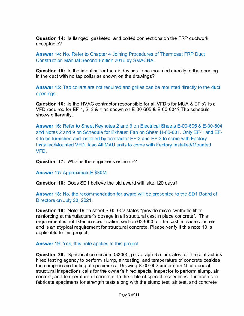
Page 3 of 11
Question 14: Is flanged, gasketed, and bolted connections on the FRP ductwork acceptable?
Answer 14: No. Refer to Chapter 4 Joining Procedures of Thermoset FRP Duct Construction Manual Second Edition 2016 by SMACNA.
Question 15: Is the intention for the air devices to be mounted directly to the opening in the duct with no tap collar as shown on the drawings? Answer 15: Tap collars are not required and grilles can be mounted directly to the duct openings.
Question 16: Is the HVAC contractor responsible for all VFD’s for MUA & EF’s? Is a VFD required for EF-1, 2, 3 & 4 as shown on E-00-605 & E-00-604? The schedule shows differently. Answer 16: Refer to Sheet Keynotes 2 and 9 on Electrical Sheets E-00-605 & E-00-604 and Notes 2 and 9 on Schedule for Exhaust Fan on Sheet H-00-601. Only EF-1 and EF-4 to be furnished and installed by contractor.EF-2 and EF-3 to come with Factory Installed/Mounted VFD. Also All MAU units to come with Factory Installed/Mounted VFD.
Question 17: What is the engineer’s estimate? Answer 17: Approximately $30M.
Question 18: Does SD1 believe the bid award will take 120 days? Answer 18: No, the recommendation for award will be presented to the SD1 Board of Directors on July 20, 2021.
Question 19: Note 19 on sheet S-00-002 states “provide micro-synthetic fiber reinforcing at manufacturer’s dosage in all structural cast in place concrete”. This requirement is not listed in specification section 033000 for the cast in place concrete and is an atypical requirement for structural concrete. Please verify if this note 19 is applicable to this project. Answer 19: Yes, this note applies to this project. Question 20: Specification section 033000, paragraph 3.5 indicates for the contractor’s hired testing agency to perform slump, air testing, and temperature of concrete besides the compressive testing of specimens. Drawing S-00-002 under item N for special structural inspections calls for the owner’s hired special inspector to perform slump, air content, and temperature of concrete. In the table of special inspections, it indicates to fabricate specimens for strength tests along with the slump test, air test, and concrete
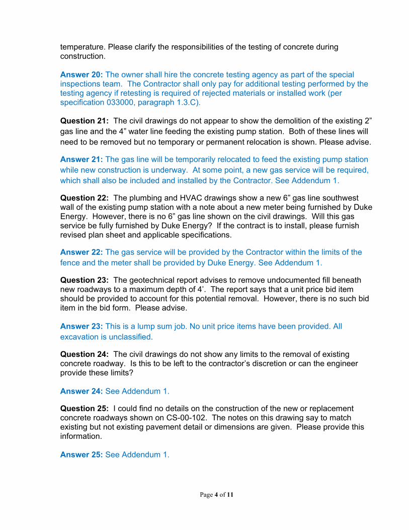
Page 4 of 11
temperature. Please clarify the responsibilities of the testing of concrete during construction. Answer 20: The owner shall hire the concrete testing agency as part of the special inspections team. The Contractor shall only pay for additional testing performed by the testing agency if retesting is required of rejected materials or installed work (per specification 033000, paragraph 1.3.C). Question 21: The civil drawings do not appear to show the demolition of the existing 2” gas line and the 4” water line feeding the existing pump station. Both of these lines will need to be removed but no temporary or permanent relocation is shown. Please advise.
Answer 21: The gas line will be temporarily relocated to feed the existing pump station while new construction is underway. At some point, a new gas service will be required, which shall also be included and installed by the Contractor. See Addendum 1.
Question 22: The plumbing and HVAC drawings show a new 6” gas line southwest wall of the existing pump station with a note about a new meter being furnished by Duke Energy. However, there is no 6” gas line shown on the civil drawings. Will this gas service be fully furnished by Duke Energy? If the contract is to install, please furnish revised plan sheet and applicable specifications.
Answer 22: The gas service will be provided by the Contractor within the limits of the fence and the meter shall be provided by Duke Energy. See Addendum 1.
Question 23: The geotechnical report advises to remove undocumented fill beneath new roadways to a maximum depth of 4’. The report says that a unit price bid item should be provided to account for this potential removal. However, there is no such bid item in the bid form. Please advise. Answer 23: This is a lump sum job. No unit price items have been provided. All excavation is unclassified.
Question 24: The civil drawings do not show any limits to the removal of existing concrete roadway. Is this to be left to the contractor’s discretion or can the engineer provide these limits? Answer 24: See Addendum 1.
Question 25: I could find no details on the construction of the new or replacement concrete roadways shown on CS-00-102. The notes on this drawing say to match existing but not existing pavement detail or dimensions are given. Please provide this information. Answer 25: See Addendum 1.
Page 5 of 11
Question 26: The soils report does not identify the material used to backfill the existing pump station within the limits of the sheet piling. Given the vastly different levels of effort required to remove this backfill if it is flowable fill versus granular fill, can the engineer please direct all contractors to count on removing the same material? Answer 26: The fill is anticipated to be a mix of granular material and demolished materials. The bidder shall treat this as an unclassified material and shall be responsible for the removal of the material. The fill material is not anticipated to be cast-in-place concrete, except in the areas as shown on the drawings.
Question 27: Fence specification 028310 lists most materials of construction to be Galvanized steel. However, some components such as wire ties are specified to be PVC coated. Please confirm the materials required for new fencing. Answer 27: See Addendum 1.
Question 28: The geotechnical report states that the excavation of the pump station should be completed without using dewatering with excavation inspection by qualified divers. Please confirm that this is a requirement and that the new diversion structure and 60” influent sewer can be conventionally dewatered as long as groundwater levels are maintained above the construction limits for these facilities. Answer 28: This recommendation does not apply to the new diversion structure and 60” influent sewer, as the bases of these excavations are 21 feet higher than that for the new pump station.
Question 29: Drawing CS-00-105 indicates removal of the top concrete wale and at least a portion of the existing cofferdam sheet piling but is not clear about the limits of this removal. It is likely that the lower concrete wale and the existing base slab and tremie seal were poured against the cofferdam, which will yield a profile identical in shape to PZ-27 piling if the sheeting is removed. Section 1/S-01-303 shows that a portion of the existing pump station base slab edge will be permanently exposed in the new wetwell. However, the entire new pump station base slab is being poured against the existing edge of the existing pump station after receiving retrofit waterstop. Please confirm the elevation sheet piling is to be removed and if anything is to be done to the existing slab edge prior to new concrete construction. Answer 29: The sheet piling shall be removed to expose the face of the concrete (left roughened) to allow for the proposed base slab to be cast against it. This means the sheet piling will need to be demoed down to at least EL. 435.48 (the bottom of proposed base slab). After removing the sheet piling, the concrete shall be demoed to a flush surface by grinding off the concrete flutes that follow the contour of the sheet piling.
Page 6 of 11
Question 30: The Watertight pairs of doors # 102 and 104B on the mullion occurring between door leaves: is mullion fixed type or will it need to be removable?
Answer 30: The doors shall be rated for submergence as specified. The double door shall have a removable mullion for equipment removal.
Question 31: At the entrance of the existing pump station, is the concrete slab replaceable?
Answer 31: See Addendum 1.
Question 32: On M-02-103, can we remove the pipe to the existing floor and blind flange the ends?
Answer 32: No, the pipe shall be removed at least 3” below the floor level, filled with grout, and grouted to floor level. The surface of the floor shall be saw cut to provide a ¾” smooth vertical edge and grouted smooth to floor level. Concrete bonding compound shall be applied to the surface.
Question 33: On M-02-306, the suction pipes of pumps 1 & 4 extend above the floor roughly 18”. Are we to blind flange these pipes after pump removal?
Answer 33: See Answer 32.
Question 34: On M-02-307, note 3 shows the removal of a surge relief valve. Can that pipe be removed to the first flange above the header and then installed with a blind flange?
Answer 34: See Answer 32.
Question 35: Please confirm that all the insulated wall paneling of the existing pump station is to be removed on the shared wall?
Answer 35: Yes.
Question 36: Can the owner please provide average flow per month data?
Answer 36: The Contractor shall be responsible for providing up to 40 MGD of bypass pumping capacity when required. Average monthly flow data is not consistent.
Question 37: Which building permits is the GC responsible for? What is the cost of these building permits?
Answer 37: The Contractor is responsible for all construction permits, contractor license fees, taxes, and other fees required for the locality of the work. The contractor shall determine what the cost is.
Page 7 of 11
Question 38: Regarding specification 033000, paragraph 2.3 MIXES, the spec lists a maximum of 50% slag to be used based on the total cementitious in a given mix. Can this be increased to help satisfy any potential Thermal Control Plan measures for Mass Concrete? (We have done on other Mass Concrete work recently with great success at 75%.)
Answer 38: Slag content may be increased to 75% except where the concrete will be exposed to de-icing chemicals (total combination of pozzolans may also be increased to a 75% maximum). Where the concrete will be exposed to de-icing chemicals (top slabs of Diversion Structure and Meter Vault), slag shall be limited to 50% of total cementitious content.
Question 39: Regarding specification 033000, paragraph 2.3 MIXES, the spec also lists a minimum of 658 total pounds of cementitious material per yd3. Can this be decreased (to say 615) to also help satisfy any potential Thermal Control Plan measures, as well as shrinkage concerns? (Less total cement improves shrinkage results, as does higher percentages of Supplementary Cementitious Materials, like Slag. With regards to Mass Concrete this also helps lower internal temps due to less heat of hydration.)
Answer 39: The minimum total cementitious material may be reduced to 560 lb./cy for class A concrete. For Class B concrete, minimum total cementitious material shall be 600 lb./cy.
Question 40: Regarding specification 033000, paragraph 2.3 MIXES, the spec indicates that an SRA is needed, but does not list a shrinkage limit requirement. What is the shrinkage limit requirement? And if this requirement can be met without using SRA, can this product be omitted? We have experience achieving results that can accommodate a .04% maximum shrinkage requirement (which is common) without the use of SRA. This includes our most recent WWTP project that included Mass Concrete.
Answer 40: Shrinkage shall be limited to 0.04%. SRA may be omitted from the concrete as long as tests are submitted (per specification 033000, paragraph 1.4) to verify the 0.04% maximum shrinkage.
Question 41: What type of material & construction should the flexible connections be?
Answer 41: See Addendum No.1.
Question 42: The new build pump station must be done before the renovation of the old pump station. When can the HVAC be done?
Answer 42: HVAC can be done at any time. The Contractor shall provide any temporary ventilation or heating, as required, to prevent overheating or unacceptable colder conditions, preventing operation of the pump station properly.

Page 8 of 11
Question 43: What is the start date?
Answer 43: The recommendation of award will be presented to the Board of Directors on July 20, 2021. Once the awarded contractor gets all required paperwork submitted, a pre-construction meeting will be scheduled at which the Notice to Proceed will be signed.
Question 44: What is the average flow rate and the peak flow rate?
Answer 44: 14-18 MGD (average). 50+ MGD (peak). Currently designed for peak of 39 MGD.
Question 45: Can we do a walk through/site visit?
Answer 45: Yes. Contact Lydia Watkins at [email protected] to schedule a site visit.
Question 46: Will the sign in sheet be made public?
Answer 46: See Addendum 1.
Question 47: Are the milestone schedules related to consent decree schedule?
Answer 47: Yes, they are related but do not match entirely. This is a time sensitive project though.
Question 48: What is the estimated cost?
Answer 48: See Answer 17.
Question 49: What is the total budget?
Answer 49: The total capital budget is $24M.
Question 50: Can you award if over the budget?
Answer 50: Yes.
Question 51: Can contractor extend wale around?
Answer 51: Means and methods are up to the contractor but recommended to remove old and put in new.
Question 52: Is this a lump sum bid?
Answer 52: Yes.
Page 9 of 11
Question 53: Is funding already in place?
Answer 53: Yes. There is no federal money being used, so there’s no Davis-Bacon Wage Rates or American Iron and Steel requirements.
Question 54: Any price escalation considerations?
Answer 54: See Answer 4.
Question 55: Are there any MBE requirements?
Answer 55: No.
Question 56: Is a business license required?
Answer 56: Required through permitting, handled by PDS of Kenton County.
Question 57: Who is responsible for permits?
Answer 57: Contractor.
Question 49: Is HVAC included with building permit?
Answer 58: Yes.
Question 59: When is the last day to submit questions?
Answer 59: Monday, June 21, 2021, by 4:00 PM. SD1 will try to have all questions answered by June 24, 2021.
Question 60: Are pumps 1 and 4 in good working condition?
Answer 60: Yes.
Question 61: Do you have more information on gate valves?
Answer 61: This question needs to be more specific. Please resubmit question.
Question 62: What is the average flow per month for the station? May help determine demolition timeframe. Can we get a chart with the flow data?
Answer 62: See information attached.
Page 10 of 11
Question 63: Has there been specific items identified to be salvaged and returned to SD1?
Answer 63: Large motors will be returned to SD1. Other items may be identified later.
Question 64: Was a lead paint survey done?
Answer 64: No. This is late 1970s construction, so there should not be lead paint. Confirmation will be on a future Q&A Memo.
Question 65: Can the hydrants be used for flush out?
Answer 65: The hydrants located within the fence have been abandoned.
Question 66: Is the GC allowed to utilize the existing bridge crane for any pipe/pump/equipment removal?
Answer 66: Yes, at their own risk. The Contractor will be responsible for any damage or misuse of the bridge crane.
Question 67: C.I.P. Concrete Note #19 calls for providing micro-synthetic fiber reinforcing at the manufacturers recommended dosage in all structural concrete. Specification 033000 does not list the use of fibers nor a manufacturer of fiber reinforcing. Does this note apply to this project? If so, please provide manufacturers list.
Answer 67: See Answer 19.
Question 68: Standard General Conditions and Special Conditions – Are the bidders required to carry Builder’s Risk insurance for the Existing Pump Station and associated modifications? Is so, is the covered value to be just the value of all improvements?
Answer 68: Yes, “the coverage amount shall be equal to that of the cost of the contract and shall insure all materials, supplies, & equipment to be installed while on the jobsite, in transit or stored at a temporary location.”
Question 69: Drawing S-04-102 calls for lightweight concrete for the slab on metal deck. Please provide design mix requirements for this mix.
Answer 69: Provide 5000 psi 28-day compressive strength, air-entrained concrete with a maximum unit weight of 110 pcf.
Question 70: Drawing M-01-101 shows a detail for the portable metal ramps. Please provide additional details such as surface and construction type.
Answer 70: The portable metal ramps are covered by an allowance.

Page 11 of 11
Question 71: Drawing M-01-301 calls for an aluminum ladder (keynote 54). Please verify that this ladder is to be aluminum.
Answer 71: Yes.
Question 72: Drawing M-01-303 calls for the bar screens to be stainless steel but the specs call out aluminum. Please clarify.
Answer 72: The manual bar screens shall be 304 stainless steel.
Brandy Miller Purchasing Administrator Office: 859-578-6767 Email: [email protected]
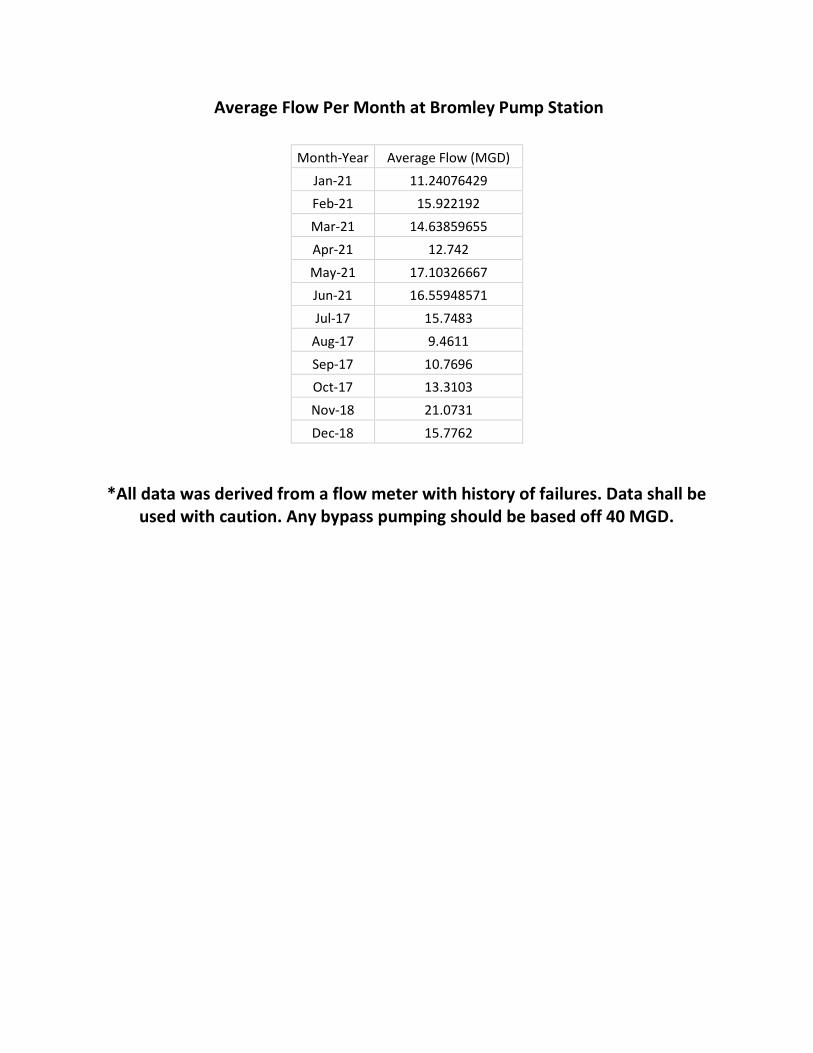
Average Flow Per Month at Bromley Pump Station
*All data was derived from a flow meter with history of failures. Data shall be
used with caution. Any bypass pumping should be based off 40 MGD.
Month-Year Average Flow (MGD)
Jan-21 11.24076429
Feb-21 15.922192
Mar-21 14.63859655
Apr-21 12.742
May-21 17.10326667
Jun-21 16.55948571
Jul-17 15.7483
Aug-17 9.4611
Sep-17 10.7696
Oct-17 13.3103
Nov-18 21.0731
Dec-18 15.7762