
Bharat Heavy Electricals Limited Addendum-2 to RFQ No ...
245
Gram : BHARATELEC Telex : 0845-2436 BHCE IN 0845-8151 BHCE IN Fax : 080-2698 9225 Bharat Heavy Electricals Limited (A Government of India Undertaking) ELECTRONICS DIVISION P.B.No-. 2606, Mysore Road, Bangalore 560026 Dt. 13.07.2016 Addendum-2 to RFQ No. LNK0000014 Due Date: 11.07.2016 (Extended due date 19.07.2016) for Design, Supply, Installation, Commissioning, Operations and Maintenance of 132kV switchyards, transmission lines / towers for 16MW (AC) Solar Photovoltaic Grid-connected Power plant at Ordnance Factory Medak (OFMK) – Telengana Following revisions / modifications are incorporated in the Tender document: 1. Addendum-2 to Purchase Specification PS-439-1033 (1 Page enclosed). All other terms and conditions of RFQ remain unchanged. SDGM (SC&PV/MM)
-
Upload
khangminh22 -
Category
Documents
-
view
0 -
download
0
Transcript of Bharat Heavy Electricals Limited Addendum-2 to RFQ No ...
Gram : BHARATELEC Telex : 0845-2436 BHCE IN 0845-8151 BHCE IN Fax : 080-2698 9225 Bharat Heavy Electricals Limited
(A Government of India Undertaking) ELECTRONICS DIVISION
P.B.No-. 2606, Mysore Road, Bangalore 560026
Dt. 13.07.2016
Addendum-2 to RFQ No. LNK0000014 Due Date: 11.07.2016 (Extended due date 19.07.2016) for Design, Supply, Installation, Commissioning,
Operations and Maintenance of 132kV switchyards, transmission lines / towers for 16MW (AC) Solar Photovoltaic Grid-connected Power plant at
Ordnance Factory Medak (OFMK) – Telengana Following revisions / modifications are incorporated in the Tender document:
1. Addendum-2 to Purchase Specification PS-439-1033 (1 Page enclosed).
All other terms and conditions of RFQ remain unchanged.
SDGM (SC&PV/MM)
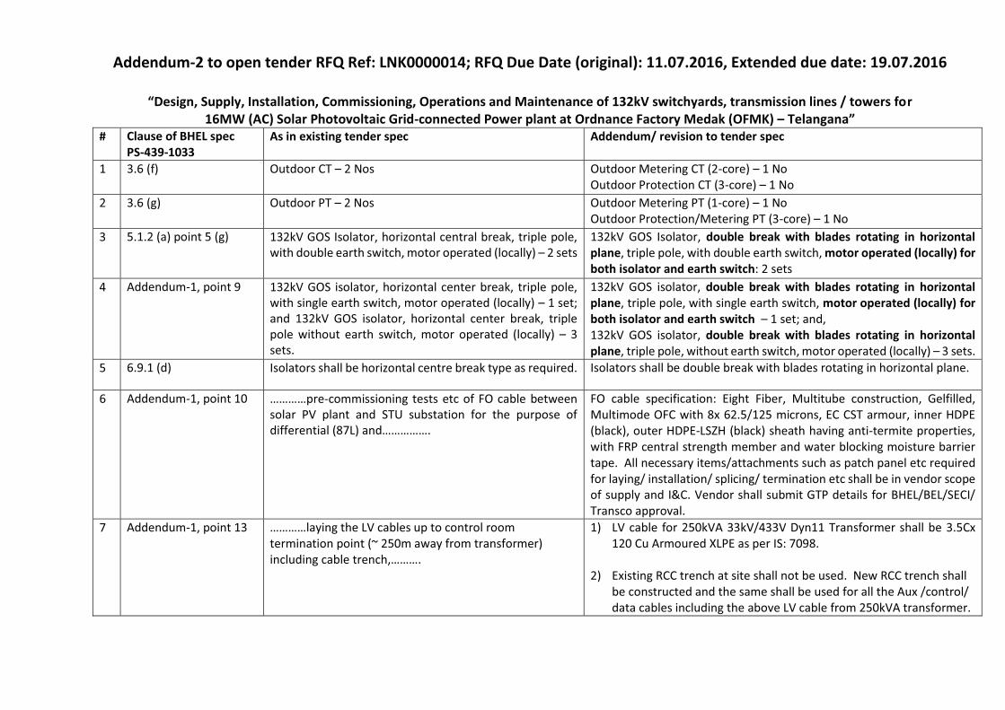
Addendum-2 to open tender RFQ Ref: LNK0000014; RFQ Due Date (original): 11.07.2016, Extended due date: 19.07.2016
��������� ���������������������������� ����������������������������!�"���#����������������������$��"�����r 16MW (AC) Solar Photovoltaic Grid-connected Power plant at Ordnance Factory Medak (OFMK) % Tela�����&
# Clause of BHEL spec PS-439-1033
As in existing tender spec Addendum/ revision to tender spec
1 3.6 (f) Outdoor CT � 2 Nos Outdoor Metering CT (2-core) � 1 No Outdoor Protection CT (3-core) � 1 No
2 3.6 (g) Outdoor PT � 2 Nos Outdoor Metering PT (1-core) � 1 No Outdoor Protection/Metering PT (3-core) � 1 No
3 5.1.2 (a) point 5 (g)
132kV GOS Isolator, horizontal central break, triple pole, with double earth switch, motor operated (locally) � 2 sets
132kV GOS Isolator, double break with blades rotating in horizontal plane, triple pole, with double earth switch, motor operated (locally) for both isolator and earth switch: 2 sets
4 Addendum-1, point 9
132kV GOS isolator, horizontal center break, triple pole, with single earth switch, motor operated (locally) � 1 set; and 132kV GOS isolator, horizontal center break, triple pole without earth switch, motor operated (locally) � 3 sets.
132kV GOS isolator, double break with blades rotating in horizontal plane, triple pole, with single earth switch, motor operated (locally) for both isolator and earth switch � 1 set; and, 132kV GOS isolator, double break with blades rotating in horizontal plane, triple pole, without earth switch, motor operated (locally) � 3 sets.
5 6.9.1 (d) Isolators shall be horizontal centre break type as required. Isolators shall be double break with blades rotating in horizontal plane.
6 Addendum-1, point 10 �������-commissioning tests etc of FO cable between solar PV plant and STU substation for the purpose of �������� ���������������
FO cable specification: Eight Fiber, Multitube construction, Gelfilled, Multimode OFC with 8x 62.5/125 microns, EC CST armour, inner HDPE (black), outer HDPE-LSZH (black) sheath having anti-termite properties, with FRP central strength member and water blocking moisture barrier tape. All necessary items/attachments such as patch panel etc required for laying/ installation/ splicing/ termination etc shall be in vendor scope of supply and I&C. Vendor shall submit GTP details for BHEL/BEL/SECI/ Transco approval.
7 Addendum-1, point 13 ���� �������� LV cables up to control room termination point (~ 250m away from transformer) including cable trench,����
1) LV cable for 250kVA 33kV/433V Dyn11 Transformer shall be 3.5Cx 120 Cu Armoured XLPE as per IS: 7098.
2) Existing RCC trench at site shall not be used. New RCC trench shall be constructed and the same shall be used for all the Aux /control/ data cables including the above LV cable from 250kVA transformer.

Gram : BHARATELEC Telex : 0845-2436 BHCE IN 0845-8151 BHCE IN Fax : 080-2698 9225 Bharat Heavy Electricals Limited
(A Government of India Undertaking) ELECTRONICS DIVISION
P.B.No-. 2606, Mysore Road, Bangalore 560026
Dt. 09.07.2016
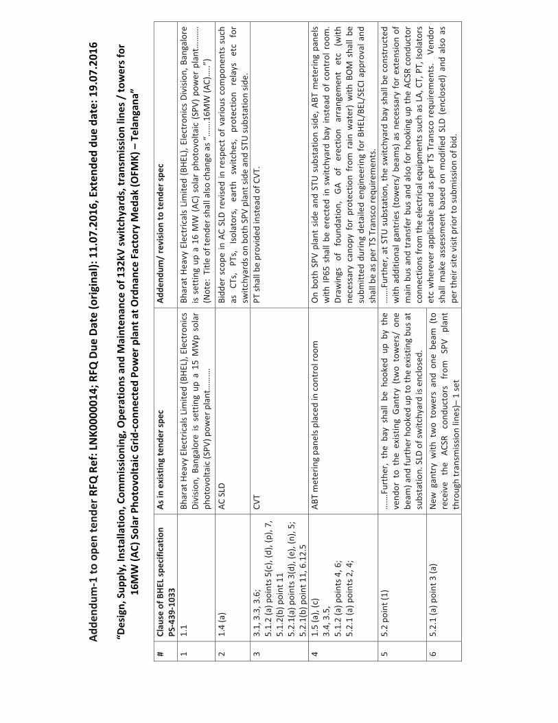
Addendum-1 to RFQ No. LNK0000014 Due Date: 11.07.2016 for Design, Supply, Installation, Commissioning, Operations and Maintenance of 132kV switchyards, transmission lines / towers for 15MW (AC) Solar Photovoltaic Grid-connected Power plant at Ordnance Factory Medak
(OFMK) – Telengana Following revisions / modifications are incorporated in the Tender document :
1. Addendum-1 to Purchase Specification PS-439-1033 (4 Pages enclosed). 2. Item 11 included in the scope. 3. Annexures-A, A1, A2, B, B1 and B2 revised. 4. Due date for the tender is revised to 19.07.2016. 5. Formats for Bank Guarantee, List of Airports and List of Consortium
banks changed.
All other terms and conditions of RFQ remain unchanged.
SDGM (SC&PV/MM)
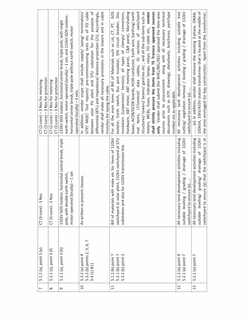
Adde
ndum
�1�to
�ope
n�te
nder
�RFQ
�Ref
:�LN
K000
0014
;�RFQ
�Due
�Dat
e�(o
rigin
al):�
11.0
7.20
16,�E
xten
ded�
due�
date
:�19.
07.2
016�
�“D
esig
n,�S
uppl
y,�In
stal
latio
n,�C
omm
issi
onin
g,�O
pera
tions
�and
�Mai
nten
ance
�of�1
32kV
�switc
hyar
ds,�t
rans
mis
sion
�line
s�/�to
wer
s�for
��16
MW
�(AC)
�Sol
ar�P
hoto
volta
ic�G
rid�c
onne
cted
�Pow
er�p
lant
�at�O
rdna
nce�
Fact
ory�
Med
ak�(O
FMK)
�–�T
elan
gana
” �� #�
Clau
se�o
f�BH
EL�sp
ecifi
catio
n��
PS�4
39�1
033�
As�in
�exi
stin
g�te
nder
�spec
�Ad
dend
um/�
revi
sion
�to�te
nder
�spec
�
1�1.
1��
Bhar
at�H
eavy
�Ele
ctric
als�L
imite
d�(B
HEL)
,�Ele
ctro
nics
�Di
visio
n,�B
anga
lore
�is�s
ettin
g�up
�a�1
5�M
Wp�
sola
r�ph
otov
olta
ic�(S
PV)�p
ower
�pla
nt…
……
.�
Bhar
at�H
eavy
�Ele
ctric
als�
Lim
ited�
(BHE
L),�E
lect
roni
cs�D
ivisi
on,�B
anga
lore
�is�
sett
ing�
up�a
�16�
MW
�(AC
)�sol
ar�p
hoto
volta
ic�(S
PV)�p
ower
�pla
nt…
……
.�(N
ote:
��Titl
e�of
�tend
er�sh
all�a
lso�c
hang
e�as
�“…
….1
6MW
�(AC)
…..”
)�2�
1.4�
(a)��
AC�S
LDBi
dder
�sco
pe�in
�AC�
SLD�
revi
sed�
in�r
espe
ct�o
f�var
ious
�com
pone
nts�
such
�as
�CT
s,�
PTs,
�Is
olat
ors,
�ea
rth�
switc
hes,
�pr
otec
tion�
rela
ys�
etc�
for�
switc
hyar
ds�o
n�bo
th�S
PV�p
lant
�side
�and
�STU
�subs
tatio
n�sid
e.�
3�3.
1,�3
.3,�3
.6;�
5.1.
2�(a
)�poi
nts�5
(c),�
(d),�
(p),�
7,��
5.1.
2(b)
�poi
nt�1
1��
5.2.
1(a)
�poi
nts�3
(d),�
(e),�
(n),�
5;�
5.2.
1(b)
�poi
nt�1
1,�6
.12.
5��
CVT
PT�sh
all�b
e�pr
ovid
ed�in
stea
d�of
�CVT
.
4�1.
5�(a
),�(c
)��3.
4,�3
.5,�
5.1.
2�(a
)�poi
nts�4
,�6;��
�5.
2.1�
(a)�p
oint
s�2,�4
;�
ABT�
met
erin
g�pa
nels�
plac
ed�in
�con
trol
�room
�O
n�bo
th�S
PV�p
lant
�sid
e�an
d�ST
U�s
ubst
atio
n�sid
e,�A
BT�m
eter
ing�
pane
ls�w
ith�IP
65�s
hall�
be�e
rect
ed�in
�sw
itchy
ard�
bay�
inst
ead�
of�c
ontr
ol�r
oom
.��Dr
awin
gs�
of�
foun
datio
n,�
GA�
of�
erec
tion�
arra
ngem
ent�
etc�
(with
�ne
cess
ary�
cano
py�f
or�p
rote
ctio
n�fr
om�r
ain�
wat
er)�
with
�BO
M�s
hall�
be�
subm
itted
�dur
ing�
deta
iled�
engi
neer
ing�
for�
BHEL
/BEL
/SEC
I�app
rova
l�and
�sh
all�b
e�as
�per
�TS�
Tran
sco�
requ
irem
ents
.��5�
5.2�
poin
t�(1)
��
……
.Fur
ther
,�th
e�ba
y�sh
all�
be�h
ooke
d�up
�by�
the�
vend
or�t
o�th
e�ex
istin
g�G
antr
y�(t
wo�
tow
ers/
�one
�be
am)�a
nd�fu
rthe
r�hoo
ked�
up�to
�the�
exist
ing�
bus�a
t�su
bsta
tion.
�SLD
�of�s
witc
hyar
d�is�
encl
osed
.��
……
.Fur
ther
,�at�S
TU�s
ubst
atio
n,�th
e�sw
itchy
ard�
bay�
shal
l�be�
cons
truc
ted�
with
�add
ition
al�g
antr
ies�
(tow
ers/
�bea
ms)
�as�
nece
ssar
y�fo
r�ex
tens
ion�
of�
mai
n�bu
s�an
d�tr
ansf
er�b
us�a
nd�a
lso�fo
r�hoo
king
�up�
the�
ACSR
�con
duct
or�
conn
ectio
ns�fr
om�th
e�el
ectr
ical
�equ
ipm
ents
�suc
h�as
�LA,
�CT,
�PT,
�Isol
ator
s�et
c�w
here
ver�
appl
icab
le�a
nd�a
s�pe
r�TS
�Tra
nsco
�req
uire
men
ts.��
�Ven
dor�
shal
l�mak
e�as
sess
men
t�ba
sed�
on�m
odifi
ed�S
LD�(
encl
osed
)�an
d�al
so�a
s�pe
r�the
ir�sit
e�vi
sit�p
rior�t
o�su
bmiss
ion�
of�b
id.��
�
6�5.
2.1�
(a)�p
oint
�3�(a
)�N
ew�g
antr
y�w
ith�t
wo�
tow
ers�
and�
one�
beam
�(to
�re
ceiv
e�th
e�AC
SR�
cond
ucto
rs�
from
�SP
V�pl
ant�
thro
ugh�
tran
smiss
ion�
lines
)–�1
�set��
7�5.
1.2�
(a),�
poin
t�5�(e
)�CT
�(5�c
ore)
��3�
Nos
CT�(2
�cor
e)�–
3�N
os�fo
r�met
erin
g�CT
�(3�c
ore)
�–�3
�Nos
�for�p
rote
ctio
n�8�
5.2.
1�(a
),�po
int�3
�(f)�
CT�(5
�cor
e)��
3�N
osCT
�(2�c
ore)
�–3�
Nos
�for�m
eter
ing�
CT�(3
�cor
e)�–
�3�N
os�fo
r�pro
tect
ion�
9�5.
2.1�
(a),�
poin
t�3�(h
)�13
2kV�
GO
S�Is
olat
or,�h
orizo
ntal
�cen
tral
�bre
ak,�t
riple
�po
le,�w
ith�d
oubl
e�ea
rth�
switc
h,�
mot
or�o
pera
ted�
(loca
lly)�–
�1�se
t�
132k
V�G
OS�
isola
tor,�
horiz
onta
l�cen
ter�b
reak
,�trip
le�p
ole,
�with
�sing
le�
eart
h�sw
itch,
�mot
or�o
pera
ted�
(loca
lly)�–
�1�se
t;�an
d�13
2kV�
GOS�
isola
tor,�
horiz
onta
l�cen
ter�b
reak
,�trip
le�p
ole�
with
out�e
arth
�switc
h,�m
otor
�op
erat
ed�(l
ocal
ly)�–
�3�se
ts.�
10�
5.3.
2�(a
)�poi
nt�4
�5.
3.2�
(b)�p
oint
s�2,�5
,�6,�7
�5.
4�(1
)�B11
�
As�w
ritte
n�in
�pre
sent
�cla
uses
.�In
�add
ition
,�ve
ndor
�sco
pe�s
hall�
incl
ude�
supp
ly/�
layi
ng/�
term
inat
ion/
�G
TP/�
MQ
P/�T
est�
repo
rts/
�pre
�com
miss
ioni
ng�t
ests
�etc
�of�
FO�c
able
�be
twee
n�so
lar�
PV�
plan
t�an
d�ST
U�
subs
tatio
n�fo
r�th
e�pu
rpos
e�of
�di
ffere
ntia
l�(87
L)�a
nd�im
peda
nce/
�dist
ance
�pro
tect
ion�
(21)
.�Acc
ordi
ngly
,�ve
ndor
�sha
ll�m
ake�
all�n
eces
sary
�pro
visio
ns�in
�the
�tow
ers�
and�
in�c
able
�tr
ench
es�fo
r�lay
ing�
the�
cabl
e.���
���11
�5.
1.2�
(b)�p
oint
�7�
5.2.
1�(b
)�poi
nt�7
�5.
3.2�
(b)�p
oint
�2�
Bill�
of�m
ater
ials�
with
�mak
e�et
c�fo
r�ite
ms�
of�1
32kV
�sw
itchy
ard�
at�s
olar
�pla
nt,�1
32kV
�sw
itchy
ard�
at�S
TU�
subs
tatio
n�an
d�al
so�fo
r�132
kV�tr
ansm
issio
n�lin
e.���
�
For�
all�
the�
mai
n�ite
ms�
of�B
ill�o
f�M
ater
ials�
such
�as�
LA,�
CT,�
PT,�
�GO
S�Is
olat
or,�
Eart
h�sw
itch,
�Bus
�pos
t�in
sula
tor,�
SF6�
circ
uit�
brea
ker,�
Disc
�in
sula
tors
�(s
uspe
nsio
n/�
tens
ion)
,�al
l�ty
pes�
of�
clam
ps/�
conn
ecto
rs,�
Hard
war
e,�A
BT�m
eter
,�AB
T�m
eter
ing�
pane
l,��C
&R�
pane
l,�M
arsh
allin
g�bo
xes,
�ACD
B/DC
DB�b
oard
s,�A
CSR�
cond
ucto
r,�Ea
rth�
wire
,�Ear
thin
g/�e
arth
�m
at�
item
s,�
LT/c
ontr
ol/�
data
�ca
bles
,�GI
�se
ctio
ns�
of�
switc
hyar
d�st
ruct
ures
/�to
wer
s/�b
eam
s/�g
antr
ies�
etc�
,�and
�all�
the�
sub�
item
s�su
ch�a
s�m
eter
s,�M
CBs,
�fus
es,�
indi
catio
n�la
mps
,�re
lays
,�FO
�cab
le�e
tc,�
�ven
dor�
shal
l�st
rictly
�pro
cure
�the
�ite
ms�
from
�TS�
Tran
sco�
appr
oved
�sou
rces
�on
ly.��
Vend
or�s
hall�
subm
it�(fo
r�BH
EL/B
EL/S
ECI�a
ppro
val)�
the�
item
�wise
�so
urce
s�pr
ior�
to�p
rocu
rem
ent�
�alo
ng�w
ith�a
ll�ne
cess
ary�
tech
nica
l�do
cum
ents
�suc
h�as
�GTP
,�dr
awin
gs,�
data
shee
ts,�
broc
hure
s,�p
art/
type
�nu
mbe
r�etc
�as�a
pplic
able
.��12
�5.
1.2�
(a)�p
oint
�9�
5.2.
1�(a
)�poi
nt�7
�Al
l�nec
essa
ry�la
nd�d
evel
opm
ent�a
ctiv
ities
�incl
udin
g�su
itabl
e�le
velin
g�/�
grad
ing�
/�dr
aina
ge�o
f�13
2kV�
switc
hyar
d�to
�ens
ure�
(a)…
…��
All�
nece
ssar
y�la
nd�
deve
lopm
ent�
activ
ities
�in
clud
ing�
suita
ble�
tree
�cu
ttin
g/�v
eget
atio
n�re
mov
al�/
�lev
elin
g�/�
grad
ing�
/�dr
aina
ge�o
f�13
2kV�
switc
hyar
d�to
�ens
ure�
(a)…
…�
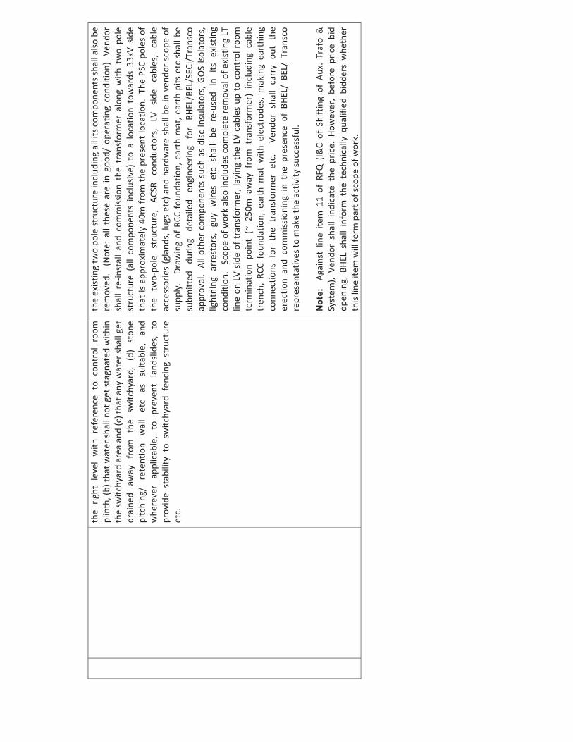
13�
5.2.
1�(a
)�poi
nt�7
�Al
l�nec
essa
ry�la
nd�d
evel
opm
ent�a
ctiv
ities
�incl
udin
g�su
itabl
e�le
velin
g/�
grad
ing/
�dr
aina
ge�
of�
132k
V�sw
itchy
ard�
to�e
nsur
e�(a
)�th
at�t
he�s
witc
hyar
d�is�
at�
……
…(e
)�in
�add
ition
,�ven
dor�
shal
l�rem
ove�
the�
exist
ing�
3�ph
ase,
�ON
AN,�
250k
VA,�3
3kV/
433V
�sta
tion�
tran
sfor
mer
�that
�is�lo
cate
d�at
�the�
mid
dle�
of�
the�
area
�env
isage
d�fo
r�ba
y�co
nstr
uctio
n.��
Apar
t�fr
om�t
he�t
rans
form
er,�
the�
right
�lev
el�w
ith�r
efer
ence
�to�
cont
rol�
room
�pl
inth
,�(b)
�that
�wat
er�sh
all�n
ot�g
et�st
agna
ted�
with
in�
the�
switc
hyar
d�ar
ea�a
nd�(c
)�tha
t�any
�wat
er�sh
all�g
et�
drai
ned�
away
�fr
om�
the�
switc
hyar
d,�
(d)�
ston
e�pi
tchi
ng/�
rete
ntio
n�w
all�
etc�
as�
suita
ble,
�an
d�w
here
ver�
appl
icab
le,�
to�
prev
ent�
land
slide
s,�
to�
prov
ide�
stab
ility
�to�
switc
hyar
d�fe
ncin
g�st
ruct
ure�
etc.
�
the�
exist
ing�
two�
pole
�stru
ctur
e�in
clud
ing�
all�i
ts�c
ompo
nent
s�sha
ll�al
so�b
e�re
mov
ed.�
�(N
ote:
�all�
thes
e�ar
e�in
�goo
d/�o
pera
ting�
cond
ition
).�Ve
ndor
�sh
all�
re�in
stal
l�an
d�co
mm
issio
n�th
e�tr
ansf
orm
er�a
long
�with
�tw
o�po
le�
stru
ctur
e�(a
ll�co
mpo
nent
s�in
clus
ive)
�to�
a�lo
catio
n�to
war
ds�3
3kV�
side�
that
�is�a
ppro
xim
atel
y�40
m�fr
om�th
e�pr
esen
t�loc
atio
n.��T
he�P
SC�p
oles
�of�
the�
two�
pole
�st
ruct
ure,
�AC
SR�
cond
ucto
rs,�
LV�
side�
cabl
es,�
cabl
e�ac
cess
orie
s�(g
land
s,�lu
gs�e
tc)�a
nd�h
ardw
are�
shal
l�be�
in�v
endo
r�sc
ope�
of�
supp
ly.��
�Dra
win
g�of
�RCC
�foun
datio
n,�e
arth
�mat
,�ear
th�p
its�e
tc�s
hall�
be�
subm
itted
�du
ring�
deta
iled�
engi
neer
ing�
for�
BHEL
/BEL
/SEC
I/Tr
ansc
o�ap
prov
al.��
All�o
ther
�com
pone
nts�
such
�as�
disc
�insu
lato
rs,�G
OS�
isola
tors
,�lig
htni
ng�a
rres
tors
,�gu
y�w
ires�
etc�
shal
l�be
�re�
used
�in�
its�e
xist
ing�
cond
ition
.���S
cope
�of�w
ork�
also
�incl
udes
�com
plet
e�re
mov
al�o
f�exi
stin
g�LT
�lin
e�on
�LV�
side�
of�t
rans
form
er,�l
ayin
g�th
e�LV
�cab
les�
up�t
o�co
ntro
l�roo
m�
term
inat
ion�
poin
t�(~
�250
m�a
way
�fro
m�t
rans
form
er)�
incl
udin
g�ca
ble�
tren
ch,�
RCC�
foun
datio
n,�e
arth
�mat
�with
�ele
ctro
des,
�mak
ing�
eart
hing
�co
nnec
tions
�for
�the
�tra
nsfo
rmer
�etc
.��V
endo
r�sh
all�
carr
y�ou
t�th
e�er
ectio
n�an
d�co
mm
issio
ning
�in�
the�
pres
ence
�of�
BHEL
/�BE
L/�T
rans
co�
repr
esen
tativ
es�to
�mak
e�th
e�ac
tivity
�succ
essf
ul.��
�� N
ote:
��Ag
ains
t�lin
e�ite
m�1
1�of
�RFQ
�(I&
C�of
�Shi
ftin
g�of
�Aux
.�Tr
afo�
&�
Syst
em),�
Vend
or�s
hall�
indi
cate
�the
�pric
e.�H
owev
er,�
befo
re�p
rice�
bid�
open
ing,
�BH
EL�s
hall�
info
rm�t
he�t
echn
ical
ly�q
ualif
ied�
bidd
ers�
whe
ther
�th
is�lin
e�ite
m�w
ill�fo
rm�p
art�o
f�sco
pe�o
f�wor
k.��
�
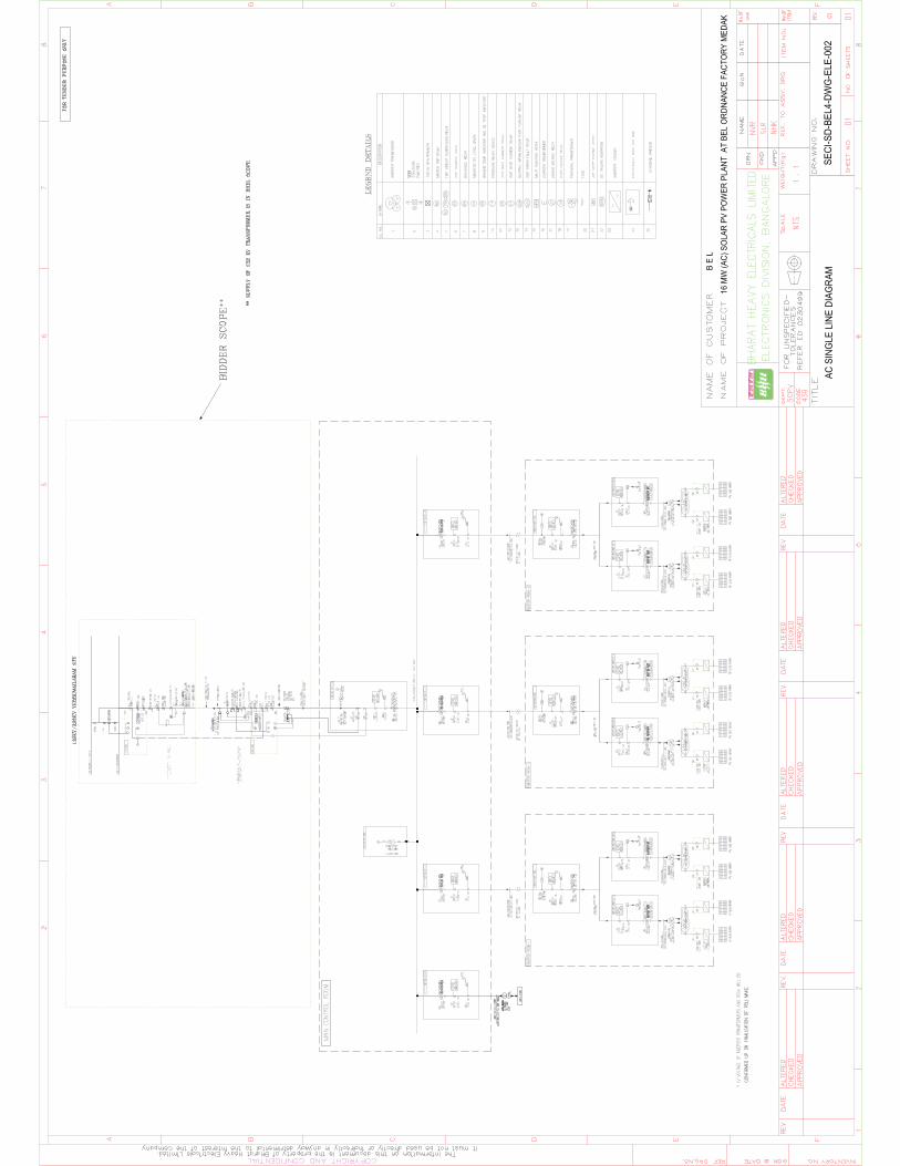
B E
L
16 M
W (A
C) S
OLA
R PV
PO
WER
PLA
NT A
T BE
L O
RDNA
NCE
FACT
ORY
MED
AK
SECI
-SD-
BEL4
-DW
G-E
LE-0
02AC
SIN
GLE
LIN
E DI
AGRA
M
M

Bharat Heavy Electricals Ltd
Electronics Division
Mysore Road, Bangalore – 560 026
Tender Documents for Design, Supply, Installation, Commissioning, Operations and Maintenance of
132kV switchyards, transmission lines / towers for 15MW (AC) Solar Photovoltaic Grid-connected Power plant at
Ordnance Factory Medak (OFMK) - Telengana
RFQ Ref: LNK0000014 RFQ Due Date: 11.07.2016
This Tender Document Contains:
(1) Request For Quotation
(2) Technical Specifications : PS- 439-1033
(3) Annexures A,A1 & A2 for Foreign Vendors & Annexures B,B1&B2 for indigenous
vendors
(4) General Commercial Conditions (GCC), Instruction to Bidders (ITB) & Annexures
(5) Integrity Pact Format
Note: Bids shall be submitted through e-Procurement portal
https://bheleps.buyjunction.in of M/s Mjunction Services Limited.
For any clarification pls contact: Mr. Chendhil Kumar, Sr. DGM (SC&PV-MM)
Ph: 080-26998391
e-mail : [email protected]
Mr. L. Nanda Kishore, Sr. Engineer (SC&PV-MM)
Ph : 080 26999548
e-mail : [email protected]
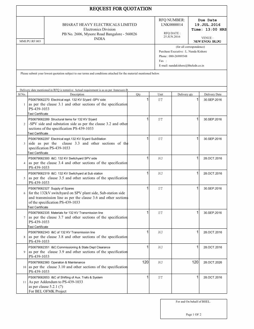
Delivery date mentioned in RFQ is tentative. Actual requirement is as as per Annexure-B.Sl No. Description Qty Unit Delivery qty Delivery Date
1PS0679062270 Electrical eqpt. 132 KV S/yard -SPV sideas per the clause 3.1 and other sections of the specificationPS-439-1033
Test Certificate
1 ST 1 30.SEP.2016
2PS0679062289 Structural items for 132 KV S/yard-SPV side and substation side as per the clause 3.2 and othersections of the specification PS-439-1033
Test Certificate
1 ST 1 30.SEP.2016
3PS0679062297 Electrical eqpt.132 KV S/yard SubStationside as per the clause 3.3 and other sections of thespecification PS-439-1033
Test Certificate
1 ST 1 30.SEP.2016
4PS0679062300 I&C: 132 KV Switchyard SPV sideas per the clause 3.4 and other sections of the specificationPS-439-1033
1 AU 1 28.OCT.2016
5PS0679062319 I&C: 132 KV Switchyard at Sub stationas per the clause 3.5 and other sections of the specificationPS-439-1033
1 AU 1 28.OCT.2016
6PS0679062327 Supply of Sparesfor the 132kV switchyard on SPV plant side, Sub-station sideand transmission line as per the clause 3.6 and other sectionsof the specification PS-439-1033
Test Certificate
1 ST 1 30.SEP.2016
7PS0679062335 Materials for 132 KV Transmission lineas per the clause 3.7 and other sections of the specificationPS-439-1033
Test Certificate
1 ST 1 30.SEP.2016
8PS0679062343 I&C of 132 KV Transmission lineas per the clause 3.8 and other sections of the specificationPS-439-1033
1 AU 1 28.OCT.2016
9PS0679062351 I&C:Commissioning & State Dept Clearanceas per the clause 3.9 and other sections of the specificationPS-439-1033
1 AU 1 28.OCT.2016
10PS0679062360 Operation & Maintenanceas per the clause 3.10 and other sections of the specificationPS-439-1033
120 AU 120 28.OCT.2026
11PS0679062653 I&C of Shifting of Aux. Trafo & SystemAs per Addendum to PS-439-1033as per clause 5.2.1 (7)For BEL OFMK Project
1 ST 1 28.OCT.2016
MMI:PU:RF:003
BHARAT HEAVY ELECTRICALS LIMITEDElectronics Division
PB No. 2606, Mysore Road Bangalore - 560026INDIA
For and On behalf of BHEL.
Page 1 OF 2
RFQ NUMBER:LNK0000014
RFQ DATE :25.JUN.2016
Please submit your lowest quotation subject to our terms and conditions attached for the material mentioned below. The quotation must be enclosed in a sealedenvelope / Fax superscribed with RFQ no.and due date, should reach us on or before the due date by13.00 hours IST and will be opened on the same dayat 13.30 hours at the venue mentioned above. PLEASE DROP THE OFFER IN THE BOX PROVIDED AT RECEPTION.
PURCHASE FILE COPY
Due Date19.JUL.2016
Time: 13:00 HRS
VENUE :
(for all correspondence)Purchase Executive : L. Nanda KishorePhone : 080-26989548Fax :E-mail: [email protected]

Total Number of Items - 11Please note that the tender will be opened in the presence of the bidders or his authorised representatives (maximum two per organisation) who choose to be presentwith authorisation letters. Refer annexure for the terms and conditions.Preference will be given to vendors who accepts our standard payment terms i.e.100% payment - 30 days after receipt of material at our works subject to acceptance.Please specify Terms of delivery, Excise duty, sales tax, Ex-BHEL, Ex-works surcharge, Insurance,P&F, Freight and other taxes very clearly .For evaluation,exchange rate(TT selling rate of SBI) as on scheduled date of tender opening (Part-I bid incase of two part bid) shall be considered.The offers of the bidders who are on the banned list as also the offer of the bidders, who engage the services of the banned firms, shall be rejected.The list of bannedfirms is available on BHEL web site www.bhel.com
i). This is only RFQ not an order.ii). In all correspondence quote RFQ No. & due date.iii). In Quotation BHEL material code / RFQ Sl. No. should be mentioned clearly.iv). Quotation Envelope / Fax not superscribed with RFQ No.and due date is liable for rejection.v). Quotation should remain valid for a minimum peiod of 90 days from due date.vi). In case of non-receipt of Quotation or regret letter for 3 consecutive RFQs you are liable to be removed from our vendors list.vii). All Prices should be written in words and numbers.viii). Excise Chapter Heading should be mentioned for all items where VAT is applicable .Vendors list to whom RFQ has been sent:
1. BHEL, Electronics Division (X563699) - 6400068653
MMI:PU:RF:003
BHARAT HEAVY ELECTRICALS LIMITEDElectronics Division
PB No. 2606, Mysore Road Bangalore - 560026INDIA
For and On behalf of BHEL.
Page 2 OF 2
RFQ NUMBER:LNK0000014
RFQ DATE :25.JUN.2016
Please submit your lowest quotation subject to our terms and conditions attached for the material mentioned below. The quotation must be enclosed in a sealedenvelope / Fax superscribed with RFQ no.and due date, should reach us on or before the due date by13.00 hours IST and will be opened on the same dayat 13.30 hours at the venue mentioned above. PLEASE DROP THE OFFER IN THE BOX PROVIDED AT RECEPTION.
PURCHASE FILE COPY
Due Date19.JUL.2016
Time: 13:00 HRS
VENUE :
(for all correspondence)Purchase Executive : L. Nanda KishorePhone : 080-26989548Fax :E-mail: [email protected]
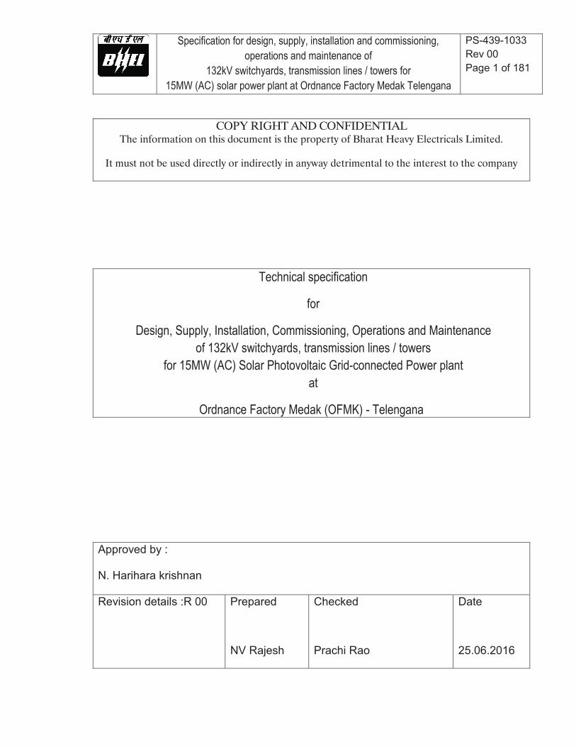
Specification for design, supply, installation and commissioning, operations and maintenance of
132kV switchyards, transmission lines / towers for 15MW (AC) solar power plant at Ordnance Factory Medak Telengana
PS-439-1033 Rev 00 Page 1 of 181
COPY RIGHT AND CONFIDENTIAL The information on this document is the property of Bharat Heavy Electricals Limited.
It must not be used directly or indirectly in anyway detrimental to the interest to the company
Technical specification
for
Design, Supply, Installation, Commissioning, Operations and Maintenance of 132kV switchyards, transmission lines / towers
for 15MW (AC) Solar Photovoltaic Grid-connected Power plant at
Ordnance Factory Medak (OFMK) - Telengana
Approved by : N. Harihara krishnan Revision details :R 00 Prepared
NV Rajesh
Checked
Prachi Rao
Date
25.06.2016
Specification for design, supply, installation and commissioning, operations and maintenance of
132kV switchyards, transmission lines / towers for 15MW (AC) solar power plant at Ordnance Factory Medak Telengana
PS-439-1033 Rev 00 Page 2 of 181
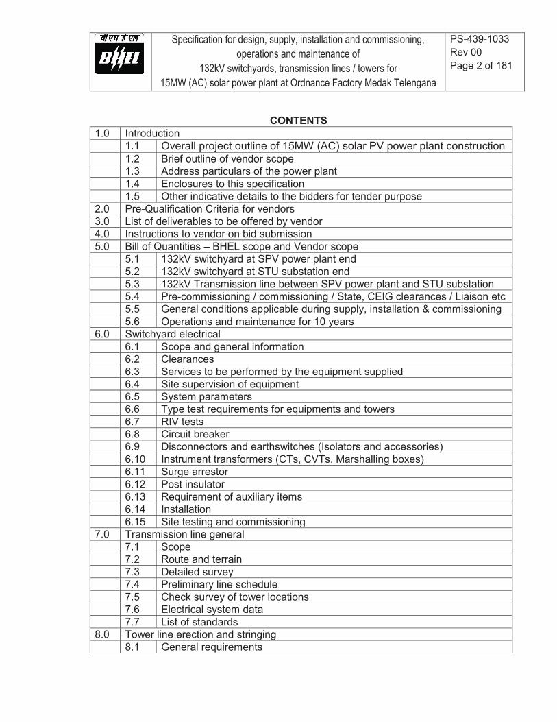
CONTENTS 1.0 Introduction 1.1 Overall project outline of 15MW (AC) solar PV power plant construction 1.2 Brief outline of vendor scope 1.3 Address particulars of the power plant 1.4 Enclosures to this specification 1.5 Other indicative details to the bidders for tender purpose 2.0 Pre-Qualification Criteria for vendors 3.0 List of deliverables to be offered by vendor 4.0 Instructions to vendor on bid submission 5.0 Bill of Quantities – BHEL scope and Vendor scope 5.1 132kV switchyard at SPV power plant end 5.2 132kV switchyard at STU substation end 5.3 132kV Transmission line between SPV power plant and STU substation 5.4 Pre-commissioning / commissioning / State, CEIG clearances / Liaison etc 5.5 General conditions applicable during supply, installation & commissioning 5.6 Operations and maintenance for 10 years 6.0 Switchyard electrical 6.1 Scope and general information 6.2 Clearances 6.3 Services to be performed by the equipment supplied 6.4 Site supervision of equipment 6.5 System parameters 6.6 Type test requirements for equipments and towers 6.7 RIV tests 6.8 Circuit breaker 6.9 Disconnectors and earthswitches (Isolators and accessories) 6.10 Instrument transformers (CTs, CVTs, Marshalling boxes) 6.11 Surge arrestor 6.12 Post insulator 6.13 Requirement of auxiliary items 6.14 Installation 6.15 Site testing and commissioning 7.0 Transmission line general 7.1 Scope 7.2 Route and terrain 7.3 Detailed survey 7.4 Preliminary line schedule 7.5 Check survey of tower locations 7.6 Electrical system data 7.7 List of standards 8.0 Tower line erection and stringing 8.1 General requirements

Specification for design, supply, installation and commissioning, operations and maintenance of
132kV switchyards, transmission lines / towers for 15MW (AC) solar power plant at Ordnance Factory Medak Telengana
PS-439-1033 Rev 00 Page 3 of 181
8.2 Treatment of minor galvanizing damage 8.3 Assembly 8.4 Insulator hoisting 8.5 Handling of conductor and earthwire 8.6 Stringing of conductor and earthwire 8.7 Replacement 8.8 Final checking testing and commissioning 9.0 Transmission line towers 9.1 General description of towers 9.2 Spans and clearances 9.3 Loading conditions 9.4 Design of towers 9.5 Tower materials 9.6 Tower fabrication 9.7 Tower earthing 9.8 Inspection and tests 9.9 Packing 9.10 Design calculation and drawings 10.0 Tower line foundations 10.1 Types of foundation 10.2 Soil investigation 10.3 Loads on foundations 10.4 Stability analysis 10.5 Properties of concrete 10.6 Design of foundations 10.7 Construction of tower foundation 11.0 Line material 11.1 General 11.2 Earthwire 11.3 Conductor 11.4 Conductor accessories 11.5 Earthwire accessories 11.6 Hardware fittings 11.7 Insulator 11.8 Test requirement 12.0 Control and protection of 132kV line bay 12.1 Control panels for HV switchyard 12.2 Annunciation system 12.3 General requirements of protection system 12.4 Operational requirements for numerical relays and auxiliary relays 12.5 Interface with existing bus bar protection 12.6 Panels 12.7 Earthing
Specification for design, supply, installation and commissioning, operations and maintenance of
132kV switchyards, transmission lines / towers for 15MW (AC) solar power plant at Ordnance Factory Medak Telengana
PS-439-1033 Rev 00 Page 4 of 181
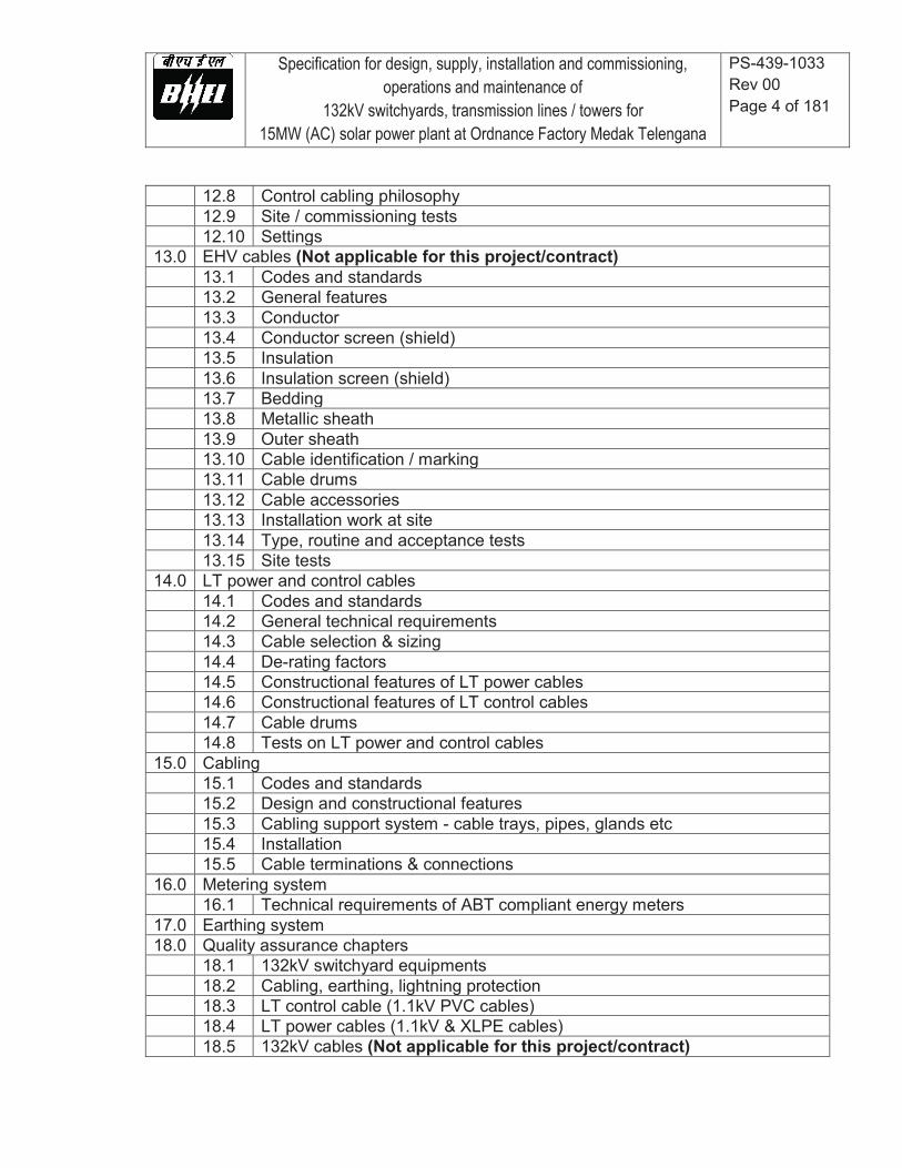
12.8 Control cabling philosophy 12.9 Site / commissioning tests 12.10 Settings 13.0 EHV cables (Not applicable for this project/contract) 13.1 Codes and standards 13.2 General features 13.3 Conductor 13.4 Conductor screen (shield) 13.5 Insulation 13.6 Insulation screen (shield) 13.7 Bedding 13.8 Metallic sheath 13.9 Outer sheath 13.10 Cable identification / marking 13.11 Cable drums 13.12 Cable accessories 13.13 Installation work at site 13.14 Type, routine and acceptance tests 13.15 Site tests 14.0 LT power and control cables 14.1 Codes and standards 14.2 General technical requirements 14.3 Cable selection & sizing 14.4 De-rating factors 14.5 Constructional features of LT power cables 14.6 Constructional features of LT control cables 14.7 Cable drums 14.8 Tests on LT power and control cables 15.0 Cabling 15.1 Codes and standards 15.2 Design and constructional features 15.3 Cabling support system - cable trays, pipes, glands etc 15.4 Installation 15.5 Cable terminations & connections 16.0 Metering system 16.1 Technical requirements of ABT compliant energy meters 17.0 Earthing system 18.0 Quality assurance chapters 18.1 132kV switchyard equipments 18.2 Cabling, earthing, lightning protection 18.3 LT control cable (1.1kV PVC cables) 18.4 LT power cables (1.1kV & XLPE cables) 18.5 132kV cables (Not applicable for this project/contract)

Specification for design, supply, installation and commissioning, operations and maintenance of
132kV switchyards, transmission lines / towers for 15MW (AC) solar power plant at Ordnance Factory Medak Telengana
PS-439-1033 Rev 00 Page 5 of 181
19.0 Civil and mechanical works 19.1 Topographic survey, area grading and land development 19.2 Geotechnical investigations 19.3 Other investigations 19.4 Design loads 19.5 Concrete works 19.6 Miscellaneous steel works 19.7 Masonry works 19.8 Plastering, pointing and coping works 19.9 Cable trench works 19.10 Transformer yard/ switchyard works (foundations, fencing/ gate etc) 19.11 Quality considerations

Specification for design, supply, installation and commissioning, operations and maintenance of
132kV switchyards, transmission lines / towers for 15MW (AC) solar power plant at Ordnance Factory Medak Telengana
PS-439-1033 Rev 00 Page 6 of 181
1.0 Introduction 1.1 Overall project outline of 15MWp solar photovoltaic power plant Bharat Heavy Electricals Limited (BHEL), Electronics Division, Bangalore is setting up a 15 MWp solar photovoltaic (SPV) power plant at Ordnance Factory of Bharat Electronics Limited (BEL), Yeddumailaram village, Sangareddy taluk, Medak district, Telengana with the overall project scope comprising of three major portions as follows: Solar PV modules employed at the plant generates DC electricity that in turn is inverted to AC in the range 300-400V. Output of each solar block (2.5 - 5 MWp) is stepped up to 33kV. All the blocks are combined to achieve 15MWp that is stepped up to 132kV using a 16.5MVA power transformer. At this outgoer level, there is outdoor switchyard together with necessary gantries/ towers/ beams to facilitate 132kV transmission.
Power generated at above SPV plant is transported to STU substation using 132kV overhead (OH) transmission line (line supported by transmission towers of double circuit type with ACSR conductors laid on one circuit for the present project). Distance between SPV plant and substation is 1Km approximately. At substation, there is outdoor switchyard together with necessary gantries/ towers/ beams to facilitate 132kV transmission. 1.2 Brief outline of vendor scope Vendor scope includes design, supply, installation, testing, commissioning, operations and maintenance for a period of 10 years from the date of successful commissioning of the plant as certified by BEL/SECI. This scope includes activities but not limited to design, engineering, drafting of drawings, obtaining approval from BHEL/BEL/SECI for the drawings, manufacture/ testing/ inspection at manufacturer’s works, packing, supply, transportation, transit insurance, delivery to site, unloading, storage, civil activities (topo survey, soil testing, route survey for transmission line, land development viz tree cutting, land leveling/grading, foundations for electrical equipment and switchyard structures etc), erection of switchyard structures/ equipment, right of way issues during construction, coordination/ liaison with concerned state/ central authorities such as Transco/ CEIG/ SECI etc for the following three specific portions of the project: (1) 132kV outdoor switchyard on SPV plant end including erection and commissioning of
16.5MVA 33/132kV power transformer that is in BHEL scope of supply. (2) 132kV transmission line between SPV power plant and STU substation (3) 132kV switchyard bay at STU substation
Specification for design, supply, installation and commissioning, operations and maintenance of
132kV switchyards, transmission lines / towers for 15MW (AC) solar power plant at Ordnance Factory Medak Telengana
PS-439-1033 Rev 00 Page 7 of 181
The vendor shall have design capability for substation / switchyard / transmission tower. In case they do not have design/drafting capability, after receiving purchase order from BHEL, the vendor shall tie up with competent design consultants in which case vendor shall submit the credentials of the proposed consultants to BHEL for approval by BHEL. Vendor shall award the work on the consultants only after approval by BHEL. All drawings/ design documents shall be originated by the consultants, endorsed by the vendor clearly stating the name of the project, names of clients (BHEL/BEL), drawing/document number, revision number, number of sheets etc. Details of drawings/ design documents to be submitted are brought out under section 5.0 of this specification.
All civil related works shall be tested as per BHEL/BEL-approved FQP that will be issued during course of project execution. All third party testing shall be carried out only at NABL accredited laboratories (or) Government laboratories.
Note: The above is only a broad outline of vendor scope for the sake of introduction. The detailed vendor scope is listed under sections 3.0 and 5.0 and elaborated in various other sections of this specification.
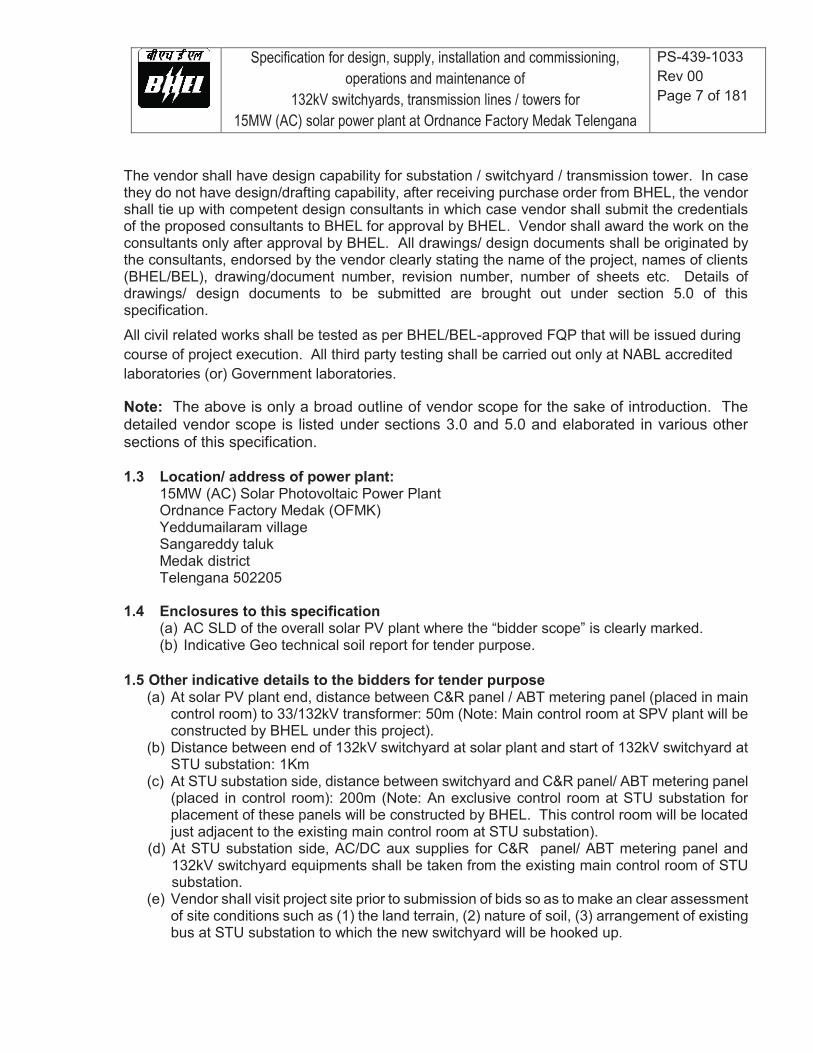
1.3 Location/ address of power plant:
15MW (AC) Solar Photovoltaic Power Plant Ordnance Factory Medak (OFMK) Yeddumailaram village Sangareddy taluk Medak district Telengana 502205
1.4 Enclosures to this specification
(a) AC SLD of the overall solar PV plant where the “bidder scope” is clearly marked. (b) Indicative Geo technical soil report for tender purpose.
1.5 Other indicative details to the bidders for tender purpose
(a) At solar PV plant end, distance between C&R panel / ABT metering panel (placed in main control room) to 33/132kV transformer: 50m (Note: Main control room at SPV plant will be constructed by BHEL under this project).
(b) Distance between end of 132kV switchyard at solar plant and start of 132kV switchyard at STU substation: 1Km
(c) At STU substation side, distance between switchyard and C&R panel/ ABT metering panel (placed in control room): 200m (Note: An exclusive control room at STU substation for placement of these panels will be constructed by BHEL. This control room will be located just adjacent to the existing main control room at STU substation).
(d) At STU substation side, AC/DC aux supplies for C&R panel/ ABT metering panel and 132kV switchyard equipments shall be taken from the existing main control room of STU substation.
(e) Vendor shall visit project site prior to submission of bids so as to make an clear assessment of site conditions such as (1) the land terrain, (2) nature of soil, (3) arrangement of existing bus at STU substation to which the new switchyard will be hooked up.
Specification for design, supply, installation and commissioning, operations and maintenance of
132kV switchyards, transmission lines / towers for 15MW (AC) solar power plant at Ordnance Factory Medak Telengana
PS-439-1033 Rev 00 Page 8 of 181
2.0 Pre-Qualification Criteria (PQC) for vendors: 2.1 Vendor should have supplied and installed substations / switchyards with voltage rating of
110kV and above in India. Evidence of certificates from clients for successful completion and copies of purchase orders from clients shall be submitted along with technical offer.
2.2 Vendor should have supplied and installed transmission towers of 110kV and above in India. Evidence of certificates of installations from clients for successful completion and copies of purchase order from clients shall be submitted along with technical offer.
2.3 In case vendor has experience in substations / switchyards of 110kV and above (as per clause 2.1 above) but not in transmission towers of 110kV and above (as per clause 2.2 above), the vendor shall avail the services of a sub-vendor who has the experience in transmission towers of 110kV and above. In such a case, vendor shall submit evidence for the experience of sub-vendor in the form of certificates from clients and copies of purchase order from clients, along with technical offer.
3.0 List of deliverables to be offered by vendor # Deliverables Qty
3.1 Supply of all electrical equipments and materials of 132kV switchyard (at SPV plant) such as CTs, CVTs, surge arrestors/ lightning arrestors, Bus post insulators / Bushings, GOS Isolators/disconnectors, Earth switches, Motors & related controls for isolators/ disconnectors / earth switches, SF6 circuit breaker, ACSR conductors, Electrical cables & cable trays, Marshalling boxes / panels / distribution boards, Control and Relay panel, ABT meters & metering panels, Earth wire on top of towers, Earthmat items(rods/risers etc), Earth strips/ electrodes, fencing materials, fence gate, stone jelly etc together with all related accessories (disc insulators, clamps, connectors/ bimetallic where required, cable glands/lugs/ties etc) and complete set of hardware required to meet the electrical requirements of the switchyard. Scope shall also include supply of neutral CT (33kV side) for BHEL-supplied 16.5MVA 33/132kV transformer. Detailed scope as per section 5.0 of this spec.
1 Set
3.2 Supply of structural items of 132kV switchyards (of both SPV plant and STU substation put together) for construction of galvanized steel gantry towers / beams and structures for mounting the electrical equipments together with all related accessories and complete set of hardware required to meet the structural support requirements of the switchyards.
1 Set

Specification for design, supply, installation and commissioning, operations and maintenance of
132kV switchyards, transmission lines / towers for 15MW (AC) solar power plant at Ordnance Factory Medak Telengana
PS-439-1033 Rev 00 Page 9 of 181
3.3 Supply of all electrical equipments and materials of 132kV switchyard (of STU substation) such as CTs, CVTs, surge arrestors/ lightning arrestors, Bus post insulators / Bushings, GOS Isolators/ disconnectors, Earth switches, Motors & related controls for GOS isolators/ Earth switches, ACSR conductors, Electrical cables & cable trays, Marshalling boxes / panels / distribution boards, Control and Relay panel, ABT meters & metering panels, ACDB/DCDB panels for aux AC/DC supplies, Earth wire on top of towers, Earth mat items (rods/risers etc), Earth strips/electrodes, fencing materials, fence gates, stone jelly etc together with all related accessories (disc insulators, clamps, connectors/ bimetallic where required, cable glands/lugs/ties etc) and complete set of hardware required to meet the electrical requirements of the switchyard and, also all the related items required to hook up the switchyard to the existing bus of STU substation. Detailed scope as per section 5.0 of this spec.
1 Set
3.4 Installation of 132kV switchyard (at SPV plant) using vendor-supplied electrical equipments and steel structures/ towers/ gantries - including topo survey where applicable, soil testing, water testing, land leveling/ grading, laying of earthmat grid for complete switchyard, civil foundations for all structures/ towers/ gantries/ electrical equipments, cable trenches, laying of cable trays and cables, cable terminations/ interconnections, installation of earthing electrodes, construction of earthing chambers with lids, earthing terminations, stone jelly spreading, switchyard fencing & gates, land development works viz stone pitching/ retaining walls/ drains/ drainage pipes etc together with all related activities such as painting of fencing/ gates/ civil foundations/ cable trenches etc, marking of all electrical equipment / cables, installation of sign / danger boards etc. Scope shall also include civil foundations and installation of (a) BHEL- supplied transformer (16.5MVA, 33/132kV), (b) vendor-supplied Neutral CT (33kV). Scope shall also include installation of (vendor-supplied) control and relay protection panel and ABT metering panels within the control room at SPV plant including all related electrical cable trenching (from switchyard to control room), laying, terminations, interconnections and earthing connections. (Note: control room is of BHEL scope). Detailed scope as per section 5.0 of this spec.
1 AU

Specification for design, supply, installation and commissioning, operations and maintenance of
132kV switchyards, transmission lines / towers for 15MW (AC) solar power plant at Ordnance Factory Medak Telengana
PS-439-1033 Rev 00 Page 10 of 181
3.5 Installation of 132kV switchyard (at STU substation) using vendor-supplied electrical equipments and steel structures/ towers/ gantries - including topo survey where applicable, soil testing, water testing, land leveling/ grading, laying of earthmat grid for the complete switchyard, civil foundations for all structures / towers/ gantries/ electrical equipments, cable trenches, laying of cable trays and cables, cable terminations/ interconnections, installation of earthing electrodes, construction of earthing chambers with lids, earthing terminations, stone jelly spreading, switchyard fencing & gates, land development works viz stone pitching/ retaining walls/ drains/ drainage pipes etc together with all related activities such as painting of fencing/ gate/ civil foundations/ cable trenches etc, marking of all electrical equipment / cables, installation of sign / danger boards etc and hooking up the switchyard to the existing bus at STU substation. Scope shall also include civil foundations and installation of (a) BHEL- supplied transformer (16.5MVA, 33/132kV), (b) vendor-supplied Neutral CT (33kV). Scope shall also include installation of (vendor-supplied) control and relay protection panel, ABT metering panels, ACDB/DCDB panels for aux AC/DC supplies within the control room (of BHEL scope) including all related electrical cable trenching, laying, terminations, interconnections and earthing connections. Detailed scope as per section 5.0 of this spec.
1 AU
3.6 Supply of spare items for 132kV switchyards: (a) MCBs, fuses – 5 % of total population (in each type) (b) Motor, fixed contact, moving contact of GOS isolators: 2 Nos each (c) Tripping coil of SF6 breaker: 2 Nos (d) Closing coil of SF6 breaker: 2 Nos (e) Spring charge motor of SF6 breaker: 2 Nos (f) Outdoor CT – 2 Nos (g) Outdoor CVT – 2 Nos (h) Outdoor surge arrestor / lightning arrestor – 3 Nos (i) Disc insulators – 10% of total population (in each type)
1 set
3.7 Supply of 132kV overhead transmission line items such as galvanized steel structures, ACSR conductors, earth wire (for laying on top of towers), GI earthing strips/ rods/ electrodes etc together with all related accessories (disc insulators, clamps, connectors, anti-climbing device, display/ danger boards etc) and complete set of hardware items required to meet the electrical and structural requirements of the transmission lines. Detailed scope as per section 5.0 of this spec.
1 set
Specification for design, supply, installation and commissioning, operations and maintenance of
132kV switchyards, transmission lines / towers for 15MW (AC) solar power plant at Ordnance Factory Medak Telengana
PS-439-1033 Rev 00 Page 11 of 181
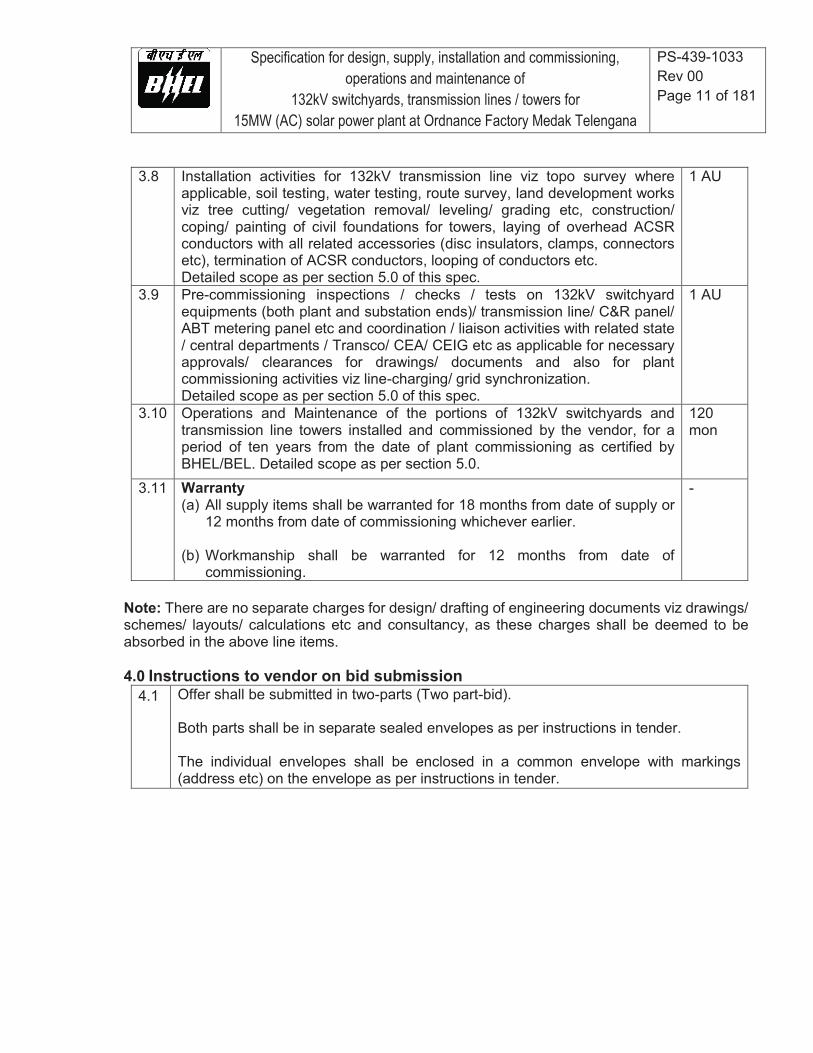
3.8 Installation activities for 132kV transmission line viz topo survey where applicable, soil testing, water testing, route survey, land development works viz tree cutting/ vegetation removal/ leveling/ grading etc, construction/ coping/ painting of civil foundations for towers, laying of overhead ACSR conductors with all related accessories (disc insulators, clamps, connectors etc), termination of ACSR conductors, looping of conductors etc. Detailed scope as per section 5.0 of this spec.
1 AU
3.9 Pre-commissioning inspections / checks / tests on 132kV switchyard equipments (both plant and substation ends)/ transmission line/ C&R panel/ ABT metering panel etc and coordination / liaison activities with related state / central departments / Transco/ CEA/ CEIG etc as applicable for necessary approvals/ clearances for drawings/ documents and also for plant commissioning activities viz line-charging/ grid synchronization. Detailed scope as per section 5.0 of this spec.
1 AU
3.10 Operations and Maintenance of the portions of 132kV switchyards and transmission line towers installed and commissioned by the vendor, for a period of ten years from the date of plant commissioning as certified by BHEL/BEL. Detailed scope as per section 5.0.
120 mon
3.11 Warranty (a) All supply items shall be warranted for 18 months from date of supply or
12 months from date of commissioning whichever earlier.
(b) Workmanship shall be warranted for 12 months from date of commissioning.
-
Note: There are no separate charges for design/ drafting of engineering documents viz drawings/ schemes/ layouts/ calculations etc and consultancy, as these charges shall be deemed to be absorbed in the above line items. 4.0 Instructions to vendor on bid submission
4.1 Offer shall be submitted in two-parts (Two part-bid). Both parts shall be in separate sealed envelopes as per instructions in tender. The individual envelopes shall be enclosed in a common envelope with markings (address etc) on the envelope as per instructions in tender.

Specification for design, supply, installation and commissioning, operations and maintenance of
132kV switchyards, transmission lines / towers for 15MW (AC) solar power plant at Ordnance Factory Medak Telengana
PS-439-1033 Rev 00 Page 12 of 181
4.2 First-part shall be techno-commercial bid with following details: (a) List of installations of substations / switchyards / transmission towers of 110kV and
above in past three years from date of tender opening shall be submitted with details viz client name, project name, rating of installation, scope of supply, scope of installation and year of installation.
(b) Technical offer (c) Filled-up enclosures as per BHEL formats provided in the tender. (d) Vendor company profile and brochure (e) Statement expressing compliance to this BHEL specification. (f) List of spares offered (with quantity) and without prices.
4.3
Second part shall be price bid with filled up enclosures as per BHEL format provided in the tender. Spares shall be quoted separately with price.
4.4 In addition to the above instructions, tender document provides detailed instructions for bid submission. Vendor shall submit the bid based on instructions in tender document.
5.0 Detailed BHEL scope and Vendor scope 5.1 132kV switchyard at SPV plant This switchyard is attached to the main control room (BHEL scope) at SPV plant end. The overall size and layout of switchyard shall be proposed by the vendor (for approval by BHEL/BEL/SECI) based on the space required to accommodate the electrical equipments (including the 16.5MVA power transformer and 200kVA aux transformer that are in BHEL scope of supply), neutral CT for 33kV side of 16.5MVA transformer, earth mat grid, earth chambers, various marshaling boxes etc duly considering the spacing / clearances between the various electrical equipment as per relevant standards and Indian electricity rules (1956), CBIP, state electricity board / Transco/ DISCOM/ CEIG regulations etc. Accordingly, the respective scopes of BHEL and the vendor are listed as below, whereas detailed specifications are provided in other sections of this specification. 5.1.1 BHEL scope
# Scope description Quantity 1 Supply of oil-filled, 16.5 MVA, 33/132kV transformer. 1 No
2 Supply, civil foundation and installation of oil-filled, 200kVA 33kV/433V aux transformer to be placed in the same 132kV switchyard at SPV plant.
1 No
3 Supply, laying and termination of 33kV cables for the above transformers. - 4 Supply, laying and termination of LT (433V side) cables for the aux
transformer. -
5 Construction of main control room at SPV plant. -
Specification for design, supply, installation and commissioning, operations and maintenance of
132kV switchyards, transmission lines / towers for 15MW (AC) solar power plant at Ordnance Factory Medak Telengana
PS-439-1033 Rev 00 Page 13 of 181
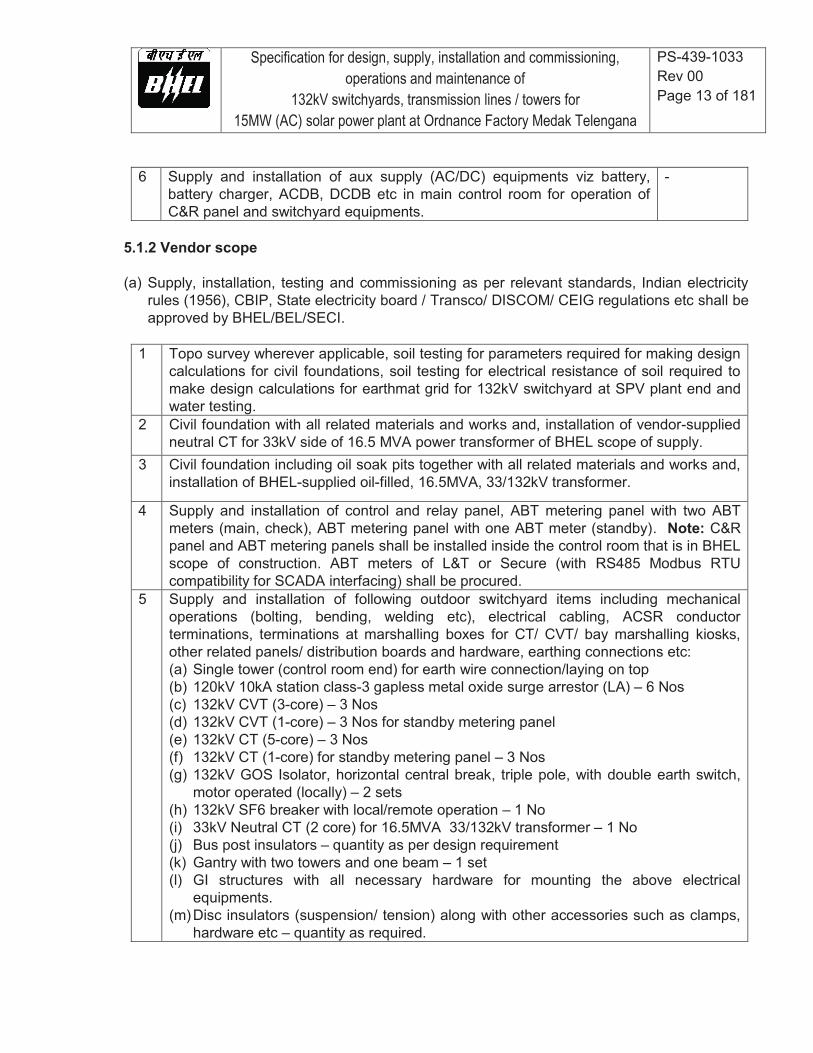
6 Supply and installation of aux supply (AC/DC) equipments viz battery, battery charger, ACDB, DCDB etc in main control room for operation of C&R panel and switchyard equipments.
-
5.1.2 Vendor scope (a) Supply, installation, testing and commissioning as per relevant standards, Indian electricity
rules (1956), CBIP, State electricity board / Transco/ DISCOM/ CEIG regulations etc shall be approved by BHEL/BEL/SECI.
1 Topo survey wherever applicable, soil testing for parameters required for making design calculations for civil foundations, soil testing for electrical resistance of soil required to make design calculations for earthmat grid for 132kV switchyard at SPV plant end and water testing.
2 Civil foundation with all related materials and works and, installation of vendor-supplied neutral CT for 33kV side of 16.5 MVA power transformer of BHEL scope of supply.
3 Civil foundation including oil soak pits together with all related materials and works and, installation of BHEL-supplied oil-filled, 16.5MVA, 33/132kV transformer.
4 Supply and installation of control and relay panel, ABT metering panel with two ABT meters (main, check), ABT metering panel with one ABT meter (standby). Note: C&R panel and ABT metering panels shall be installed inside the control room that is in BHEL scope of construction. ABT meters of L&T or Secure (with RS485 Modbus RTU compatibility for SCADA interfacing) shall be procured.
5 Supply and installation of following outdoor switchyard items including mechanical operations (bolting, bending, welding etc), electrical cabling, ACSR conductor terminations, terminations at marshalling boxes for CT/ CVT/ bay marshalling kiosks, other related panels/ distribution boards and hardware, earthing connections etc: (a) Single tower (control room end) for earth wire connection/laying on top (b) 120kV 10kA station class-3 gapless metal oxide surge arrestor (LA) – 6 Nos (c) 132kV CVT (3-core) – 3 Nos (d) 132kV CVT (1-core) – 3 Nos for standby metering panel (e) 132kV CT (5-core) – 3 Nos (f) 132kV CT (1-core) for standby metering panel – 3 Nos (g) 132kV GOS Isolator, horizontal central break, triple pole, with double earth switch,
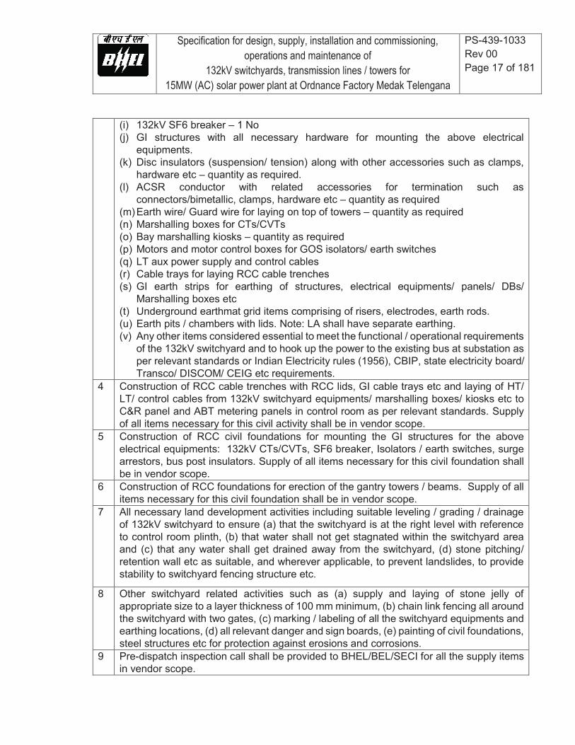
motor operated (locally) – 2 sets (h) 132kV SF6 breaker with local/remote operation – 1 No (i) 33kV Neutral CT (2 core) for 16.5MVA 33/132kV transformer – 1 No (j) Bus post insulators – quantity as per design requirement (k) Gantry with two towers and one beam – 1 set (l) GI structures with all necessary hardware for mounting the above electrical
equipments. (m) Disc insulators (suspension/ tension) along with other accessories such as clamps,
hardware etc – quantity as required.

Specification for design, supply, installation and commissioning, operations and maintenance of
132kV switchyards, transmission lines / towers for 15MW (AC) solar power plant at Ordnance Factory Medak Telengana
PS-439-1033 Rev 00 Page 14 of 181
(n) ACSR conductor with related accessories for termination such as connectors/ bimetallic where required, clamps, hardware etc – quantity as required
(o) Earth wire for laying on top of towers – quantity as required (p) Marshalling boxes for CTs/CVTs – quantity as required (q) Bay marshalling kiosks – quantity as required (r) Motors and motor control boxes for GOS isolators/ earth switches (s) LT aux power supply and control cables (t) Cable trays for laying in RCC cable trenches (u) Underground earthmat grid items comprising of risers, electrodes, earth rods etc (v) GI earth strips for earthing of structures, electrical equipments, panels/ DBs/
marshalling boxes etc (w) Earth pits / chambers with lids. Note: LA shall have separate earthing. (x) Any other items considered essential to meet the functional / operational requirements
of the 132kV switchyard as per relevant standards or Indian Electricity rules (1956), CBIP, state electricity board/ Transco/ DISCOM/ CEIG etc requirements.
6 Construction of RCC cable trenches with RCC lids, GI cable trays etc and laying of HT/ LT/ control cables from “132kV switchyard equipments/ marshalling boxes/ kiosks/ 33kV Neutral CT/ 16.5MVA 33/132kV transformer etc” to “C&R panel/ ABT metering panels/ ACDB/DCDB boards in control room” as per relevant standards. Supply of all items necessary for this civil activity shall be in vendor scope.
7 Construction of RCC civil foundations for mounting the GI structures for the above electrical equipments: 33kV neutral CT, 132kV CTs/CVTs, SF6 breaker, Isolators / earth switches, surge arrestors, bus post insulators. Supply of all items necessary for this civil foundation shall be in vendor scope.
8 Construction of RCC foundations for erection of the all towers, gantries with towers / beams. Supply of all items necessary for this civil foundation shall be in vendor scope.
9 All necessary land development activities including suitable leveling / grading / drainage of 132kV switchyard to ensure (a) that the switchyard is at the right level with reference to control room plinth, (b) that water shall not get stagnated within the switchyard area and (c) that any water shall get drained away from the switchyard, (d) stone pitching/ retention wall etc as suitable, and wherever applicable, to prevent landslides, to provide stability to switchyard fencing structure etc. Supply of all items necessary for these civil activities shall be in vendor scope.
10 Other switchyard related activities such as (a) supply and laying of stone jelly of appropriate size to a layer thickness of 100 mm minimum, (b) chain link fencing all around the switchyard with two gates, (c) marking / labeling of all the switchyard equipments and earthing locations, (d) all relevant danger and sign boards, (e) painting of civil foundations, steel structures etc for protection against erosions and corrosions.
11 Pre-dispatch inspection call shall be provided to BHEL/BEL/SECI for all the supply items in vendor scope.
Specification for design, supply, installation and commissioning, operations and maintenance of
132kV switchyards, transmission lines / towers for 15MW (AC) solar power plant at Ordnance Factory Medak Telengana
PS-439-1033 Rev 00 Page 15 of 181
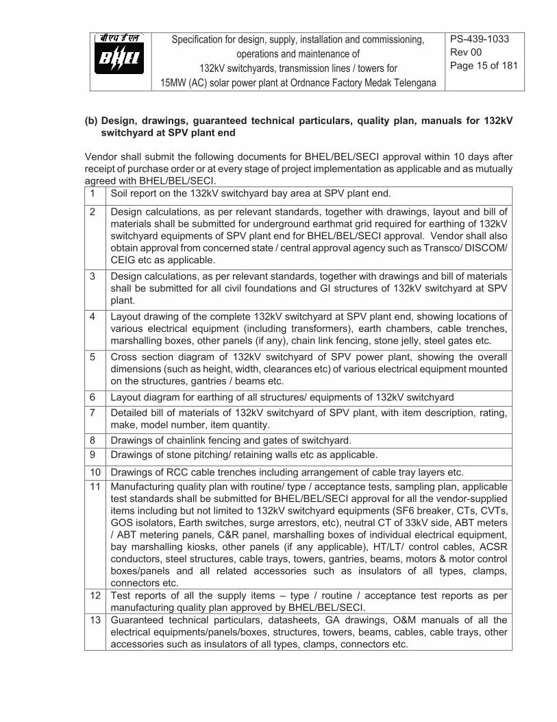
(b) Design, drawings, guaranteed technical particulars, quality plan, manuals for 132kV switchyard at SPV plant end
Vendor shall submit the following documents for BHEL/BEL/SECI approval within 10 days after receipt of purchase order or at every stage of project implementation as applicable and as mutually agreed with BHEL/BEL/SECI. 1 Soil report on the 132kV switchyard bay area at SPV plant end.
2 Design calculations, as per relevant standards, together with drawings, layout and bill of materials shall be submitted for underground earthmat grid required for earthing of 132kV switchyard equipments of SPV plant end for BHEL/BEL/SECI approval. Vendor shall also obtain approval from concerned state / central approval agency such as Transco/ DISCOM/ CEIG etc as applicable.
3 Design calculations, as per relevant standards, together with drawings and bill of materials shall be submitted for all civil foundations and GI structures of 132kV switchyard at SPV plant.
4 Layout drawing of the complete 132kV switchyard at SPV plant end, showing locations of various electrical equipment (including transformers), earth chambers, cable trenches, marshalling boxes, other panels (if any), chain link fencing, stone jelly, steel gates etc.
5 Cross section diagram of 132kV switchyard of SPV power plant, showing the overall dimensions (such as height, width, clearances etc) of various electrical equipment mounted on the structures, gantries / beams etc.
6 Layout diagram for earthing of all structures/ equipments of 132kV switchyard 7 Detailed bill of materials of 132kV switchyard of SPV plant, with item description, rating,
make, model number, item quantity. 8 Drawings of chainlink fencing and gates of switchyard. 9 Drawings of stone pitching/ retaining walls etc as applicable.
10 Drawings of RCC cable trenches including arrangement of cable tray layers etc. 11 Manufacturing quality plan with routine/ type / acceptance tests, sampling plan, applicable
test standards shall be submitted for BHEL/BEL/SECI approval for all the vendor-supplied items including but not limited to 132kV switchyard equipments (SF6 breaker, CTs, CVTs, GOS isolators, Earth switches, surge arrestors, etc), neutral CT of 33kV side, ABT meters / ABT metering panels, C&R panel, marshalling boxes of individual electrical equipment, bay marshalling kiosks, other panels (if any applicable), HT/LT/ control cables, ACSR conductors, steel structures, cable trays, towers, gantries, beams, motors & motor control boxes/panels and all related accessories such as insulators of all types, clamps, connectors etc.
12 Test reports of all the supply items – type / routine / acceptance test reports as per manufacturing quality plan approved by BHEL/BEL/SECI.
13 Guaranteed technical particulars, datasheets, GA drawings, O&M manuals of all the electrical equipments/panels/boxes, structures, towers, beams, cables, cable trays, other accessories such as insulators of all types, clamps, connectors etc.
Specification for design, supply, installation and commissioning, operations and maintenance of
132kV switchyards, transmission lines / towers for 15MW (AC) solar power plant at Ordnance Factory Medak Telengana
PS-439-1033 Rev 00 Page 16 of 181
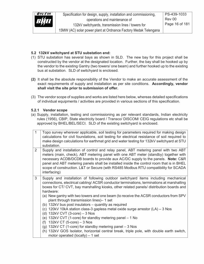
5.2 132kV switchyard at STU substation end: (1) STU substation has several bays as shown in SLD. The new bay for this project shall be
constructed by the vendor at the designated location. Further, the bay shall be hooked up by the vendor to the existing Gantry (two towers/ one beam) and further hooked up to the existing bus at substation. SLD of switchyard is enclosed.
(2) It shall be the absolute responsibility of the Vendor to make an accurate assessment of the exact requirements of supply and installation as per site conditions. Accordingly, vendor shall visit the site prior to submission of offer.
(3) The vendor scope of supplies and works are listed here below, whereas detailed specifications
of individual equipments / activities are provided in various sections of this specification. 5.2.1 Vendor scope (a) Supply, installation, testing and commissioning as per relevant standards, Indian electricity
rules (1956), CBIP, State electricity board / Transco/ DISCOM/ CEIG regulations etc shall be approved by BHEL/BEL/SECI. SLD of the existing switchyard is enclosed.
1 Topo survey wherever applicable, soil testing for parameters required for making design calculations for civil foundations, soil testing for electrical resistance of soil required to make design calculations for earthmat grid and water testing for 132kV switchyard at STU substation.
2 Supply and installation of control and relay panel, ABT metering panel with two ABT meters (main, check), ABT metering panel with one ABT meter (standby) together with necessary ACDB/DCDB boards to provide aux AC/DC supply to the panels. Note: C&R panel and ABT metering panels shall be installed inside the control room that is in BHEL scope of construction. L&T or Secure (with RS485 Modbus RTU compatibility for SCADA interfacing)
3 Supply and installation of following outdoor switchyard items including mechanical connections, electrical cabling/ ACSR conductor terminations, terminations at marshalling boxes for CT/ CVT, bay marshalling kiosks, other related panels/ distribution boards and hardware: (a) New gantry with two towers and one beam (to receive the ACSR conductors from SPV
plant through transmission lines)– 1 set (b) 132kV bus post insulators – quantity as required (c) 120kV 10kA station class-3 gapless metal oxide surge arrestor (LA) – 3 Nos (d) 132kV CVT (3-core) – 3 Nos (e) 132kV CVT (1-core) for standby metering panel – 1 No (f) 132kV CT (5-core) – 3 Nos (g) 132kV CT (1-core) for standby metering panel – 3 Nos (h) 132kV GOS Isolator, horizontal central break, triple pole, with double earth switch,
motor operated (locally) – 1 set
Specification for design, supply, installation and commissioning, operations and maintenance of
132kV switchyards, transmission lines / towers for 15MW (AC) solar power plant at Ordnance Factory Medak Telengana
PS-439-1033 Rev 00 Page 17 of 181
(i) 132kV SF6 breaker – 1 No (j) GI structures with all necessary hardware for mounting the above electrical
equipments. (k) Disc insulators (suspension/ tension) along with other accessories such as clamps,
hardware etc – quantity as required. (l) ACSR conductor with related accessories for termination such as
connectors/bimetallic, clamps, hardware etc – quantity as required (m) Earth wire/ Guard wire for laying on top of towers – quantity as required (n) Marshalling boxes for CTs/CVTs (o) Bay marshalling kiosks – quantity as required (p) Motors and motor control boxes for GOS isolators/ earth switches (q) LT aux power supply and control cables (r) Cable trays for laying RCC cable trenches (s) GI earth strips for earthing of structures, electrical equipments/ panels/ DBs/
Marshalling boxes etc (t) Underground earthmat grid items comprising of risers, electrodes, earth rods. (u) Earth pits / chambers with lids. Note: LA shall have separate earthing. (v) Any other items considered essential to meet the functional / operational requirements
of the 132kV switchyard and to hook up the power to the existing bus at substation as per relevant standards or Indian Electricity rules (1956), CBIP, state electricity board/ Transco/ DISCOM/ CEIG etc requirements.
4 Construction of RCC cable trenches with RCC lids, GI cable trays etc and laying of HT/ LT/ control cables from 132kV switchyard equipments/ marshalling boxes/ kiosks etc to C&R panel and ABT metering panels in control room as per relevant standards. Supply of all items necessary for this civil activity shall be in vendor scope.
5 Construction of RCC civil foundations for mounting the GI structures for the above electrical equipments: 132kV CTs/CVTs, SF6 breaker, Isolators / earth switches, surge arrestors, bus post insulators. Supply of all items necessary for this civil foundation shall be in vendor scope.
6 Construction of RCC foundations for erection of the gantry towers / beams. Supply of all items necessary for this civil foundation shall be in vendor scope.
7 All necessary land development activities including suitable leveling / grading / drainage of 132kV switchyard to ensure (a) that the switchyard is at the right level with reference to control room plinth, (b) that water shall not get stagnated within the switchyard area and (c) that any water shall get drained away from the switchyard, (d) stone pitching/ retention wall etc as suitable, and wherever applicable, to prevent landslides, to provide stability to switchyard fencing structure etc.
8 Other switchyard related activities such as (a) supply and laying of stone jelly of appropriate size to a layer thickness of 100 mm minimum, (b) chain link fencing all around the switchyard with two gates, (c) marking / labeling of all the switchyard equipments and earthing locations, (d) all relevant danger and sign boards, (e) painting of civil foundations, steel structures etc for protection against erosions and corrosions.
9 Pre-dispatch inspection call shall be provided to BHEL/BEL/SECI for all the supply items in vendor scope.
Specification for design, supply, installation and commissioning, operations and maintenance of
132kV switchyards, transmission lines / towers for 15MW (AC) solar power plant at Ordnance Factory Medak Telengana
PS-439-1033 Rev 00 Page 18 of 181
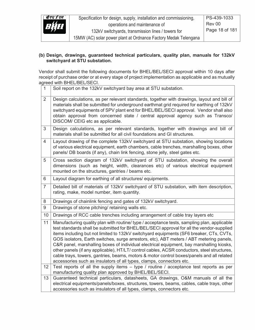
(b) Design, drawings, guaranteed technical particulars, quality plan, manuals for 132kV switchyard at STU substation.
Vendor shall submit the following documents for BHEL/BEL/SECI approval within 10 days after receipt of purchase order or at every stage of project implementation as applicable and as mutually agreed with BHEL/BEL/SECI.
1 Soil report on the 132kV switchyard bay area at STU substation.
2 Design calculations, as per relevant standards, together with drawings, layout and bill of materials shall be submitted for underground earthmat grid required for earthing of 132kV switchyard equipments of SPV plant end for BHEL/BEL/SECI approval. Vendor shall also obtain approval from concerned state / central approval agency such as Transco/ DISCOM/ CEIG etc as applicable.
3 Design calculations, as per relevant standards, together with drawings and bill of materials shall be submitted for all civil foundations and GI structures.
4 Layout drawing of the complete 132kV switchyard at STU substation, showing locations of various electrical equipment, earth chambers, cable trenches, marshalling boxes, other panels/ DB boards (if any), chain link fencing, stone jelly, steel gates etc.
5 Cross section diagram of 132kV switchyard of STU substation, showing the overall dimensions (such as height, width, clearances etc) of various electrical equipment mounted on the structures, gantries / beams etc.
6 Layout diagram for earthing of all structures/ equipments.
7 Detailed bill of materials of 132kV switchyard of STU substation, with item description, rating, make, model number, item quantity.
8 Drawings of chainlink fencing and gates of 132kV switchyard. 9 Drawings of stone pitching/ retaining walls etc. 10 Drawings of RCC cable trenches including arrangement of cable tray layers etc 11 Manufacturing quality plan with routine/ type / acceptance tests, sampling plan, applicable
test standards shall be submitted for BHEL/BEL/SECI approval for all the vendor-supplied items including but not limited to 132kV switchyard equipments (SF6 breaker, CTs, CVTs, GOS isolators, Earth switches, surge arrestors, etc), ABT meters / ABT metering panels, C&R panel, marshalling boxes of individual electrical equipment, bay marshalling kiosks, other panels (if any applicable), HT/LT/ control cables, ACSR conductors, steel structures, cable trays, towers, gantries, beams, motors & motor control boxes/panels and all related accessories such as insulators of all types, clamps, connectors etc.
12 Test reports of all the supply items – type / routine / acceptance test reports as per manufacturing quality plan approved by BHEL/BEL/SECI.
13 Guaranteed technical particulars, datasheets, GA drawings, O&M manuals of all the electrical equipments/panels/boxes, structures, towers, beams, cables, cable trays, other accessories such as insulators of all types, clamps, connectors etc.

Specification for design, supply, installation and commissioning, operations and maintenance of
132kV switchyards, transmission lines / towers for 15MW (AC) solar power plant at Ordnance Factory Medak Telengana
PS-439-1033 Rev 00 Page 19 of 181
5.3 132kV Transmission line from SPV power plant to STU substation (line supported by transmission towers of double circuit type with ACSR conductors laid on one circuit for the present project)
5.3.1 BHEL scope
# Scope description
1 NIL. Note: Vendor shall carry out the entire scope of work.
5.3.2 Vendor scope (a) Supply, installation, testing and commissioning as per relevant standards, Indian
electricity rules (1956), CBIP, State electricity board / Transco/ DISCOM/ CEIG regulations etc and as shall be approved by BHEL/BEL/SECI.
1 Jungle clearance (removal of vegetation, cutting of trees etc), land leveling / grading en route, wherever applicable, to enable erection of transmission towers.
2 Route survey of the transmission line route between SPV power plant and STU substation. The survey shall bring out TBM points, railway tracks, railway crossings, bridges, culverts, river crossings, buildings, existing transmission towers/lines etc (along with coordinates) that are required to plan and finalize the desired locations of towers and underground cables. Based on the route survey map, an approach plan shall be submitted to BHEL/BEL/SECI for approval. The plan shall bring out number of towers, locations of towers etc. Vendor shall commence construction works only after BHEL/BEL/SECI approval.
3 Testing of soil for all necessary parameters including soil strength, soil resistivity etc required to compute the civil foundation and electrical earthing requirements of transmission towers.
4 Supply and erection of GI sections/ members of 132kV transmission towers, ACSR conductors with all necessary accessories such as insulators, supports, clamps, connectors, earth strips, fasteners, other hardware etc.
5 Civil foundation and erection of 132kV transmission towers, laying of ACSR conductors, all necessary electrical interconnections, all necessary earthing connections using all necessary accessories such as insulators, supports, clamps, connectors, earth strips, fasteners, other hardware etc.
(b) Design, drawings, guaranteed technical particulars, quality plan, manuals Vendor shall submit the following documents for BHEL/BEL/SECI approval within 10 days after receipt of purchase order or at every stage of project execution as applicable and as mutually
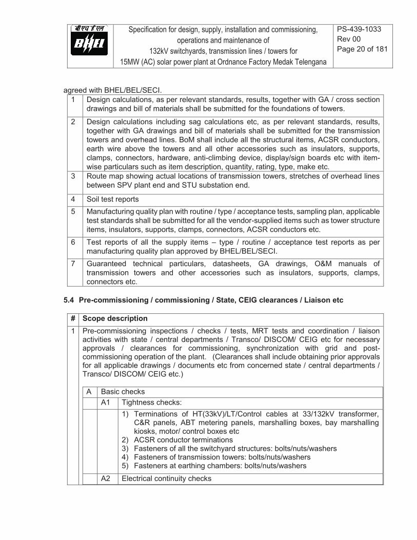
Specification for design, supply, installation and commissioning, operations and maintenance of
132kV switchyards, transmission lines / towers for 15MW (AC) solar power plant at Ordnance Factory Medak Telengana
PS-439-1033 Rev 00 Page 20 of 181
agreed with BHEL/BEL/SECI. 1 Design calculations, as per relevant standards, results, together with GA / cross section
drawings and bill of materials shall be submitted for the foundations of towers.
2 Design calculations including sag calculations etc, as per relevant standards, results, together with GA drawings and bill of materials shall be submitted for the transmission towers and overhead lines. BoM shall include all the structural items, ACSR conductors, earth wire above the towers and all other accessories such as insulators, supports, clamps, connectors, hardware, anti-climbing device, display/sign boards etc with item-wise particulars such as item description, quantity, rating, type, make etc.
3 Route map showing actual locations of transmission towers, stretches of overhead lines between SPV plant end and STU substation end.
4 Soil test reports 5 Manufacturing quality plan with routine / type / acceptance tests, sampling plan, applicable
test standards shall be submitted for all the vendor-supplied items such as tower structure items, insulators, supports, clamps, connectors, ACSR conductors etc.
6 Test reports of all the supply items – type / routine / acceptance test reports as per manufacturing quality plan approved by BHEL/BEL/SECI.
7 Guaranteed technical particulars, datasheets, GA drawings, O&M manuals of transmission towers and other accessories such as insulators, supports, clamps, connectors etc.
5.4 Pre-commissioning / commissioning / State, CEIG clearances / Liaison etc
# Scope description 1 Pre-commissioning inspections / checks / tests, MRT tests and coordination / liaison
activities with state / central departments / Transco/ DISCOM/ CEIG etc for necessary approvals / clearances for commissioning, synchronization with grid and post-commissioning operation of the plant. (Clearances shall include obtaining prior approvals for all applicable drawings / documents etc from concerned state / central departments / Transco/ DISCOM/ CEIG etc.) A Basic checks A1 Tightness checks: 1) Terminations of HT(33kV)/LT/Control cables at 33/132kV transformer,
C&R panels, ABT metering panels, marshalling boxes, bay marshalling kiosks, motor/ control boxes etc
2) ACSR conductor terminations 3) Fasteners of all the switchyard structures: bolts/nuts/washers 4) Fasteners of transmission towers: bolts/nuts/washers 5) Fasteners at earthing chambers: bolts/nuts/washers
A2 Electrical continuity checks
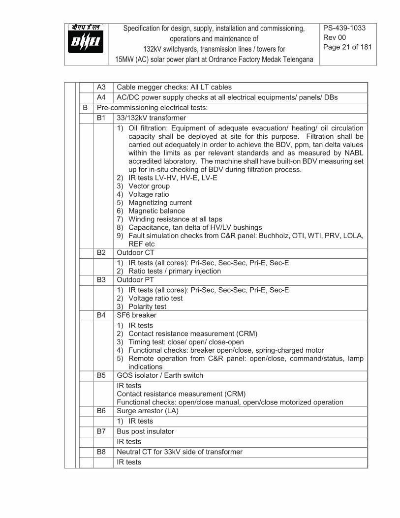
Specification for design, supply, installation and commissioning, operations and maintenance of
132kV switchyards, transmission lines / towers for 15MW (AC) solar power plant at Ordnance Factory Medak Telengana
PS-439-1033 Rev 00 Page 21 of 181
A3 Cable megger checks: All LT cables A4 AC/DC power supply checks at all electrical equipments/ panels/ DBs B Pre-commissioning electrical tests: B1 33/132kV transformer 1) Oil filtration: Equipment of adequate evacuation/ heating/ oil circulation
capacity shall be deployed at site for this purpose. Filtration shall be carried out adequately in order to achieve the BDV, ppm, tan delta values within the limits as per relevant standards and as measured by NABL accredited laboratory. The machine shall have built-on BDV measuring set up for in-situ checking of BDV during filtration process.
2) IR tests LV-HV, HV-E, LV-E 3) Vector group 4) Voltage ratio 5) Magnetizing current 6) Magnetic balance 7) Winding resistance at all taps 8) Capacitance, tan delta of HV/LV bushings 9) Fault simulation checks from C&R panel: Buchholz, OTI, WTI, PRV, LOLA,
REF etc B2 Outdoor CT 1) IR tests (all cores): Pri-Sec, Sec-Sec, Pri-E, Sec-E
2) Ratio tests / primary injection B3 Outdoor PT 1) IR tests (all cores): Pri-Sec, Sec-Sec, Pri-E, Sec-E
2) Voltage ratio test 3) Polarity test
B4 SF6 breaker 1) IR tests
2) Contact resistance measurement (CRM) 3) Timing test: close/ open/ close-open 4) Functional checks: breaker open/close, spring-charged motor 5) Remote operation from C&R panel: open/close, command/status, lamp
indications B5 GOS isolator / Earth switch IR tests
Contact resistance measurement (CRM) Functional checks: open/close manual, open/close motorized operation
B6 Surge arrestor (LA) 1) IR tests B7 Bus post insulator IR tests B8 Neutral CT for 33kV side of transformer IR tests
Specification for design, supply, installation and commissioning, operations and maintenance of
132kV switchyards, transmission lines / towers for 15MW (AC) solar power plant at Ordnance Factory Medak Telengana
PS-439-1033 Rev 00 Page 22 of 181
B9 Numerical relays at C&R panel 1) Relay calibration using applicable kit/ software
2) Overcurrent/ earth fault pickup/ tripping time tests
B10 Earth resistance measurements for all chambers 1) With electrode connected to grid
2) Without connecting electrode to grid B11 Transmission line 1) Line megger test C Testing agency Credentials of testing agency to be submitted to BHEL for approval prior to
awarding of work. D Coordination and Liaison activities to be carried out by vendor: 1) Vendor shall prepare and submit the drawings/ schemes/ layouts/
calculations (earth mat etc) to the concerned state/central agency Transco/ DISCOM/ CEIG/ CEA etc for their approval after clearance from BHEL.
2) Submission of site test reports to customer (BEL/SECI/CEIG etc) after obtaining approval from BHEL.
3) Preparation of application (along with supporting documents: drawings, factory test reports, site test reports etc) to concerned agency (CEIG/CEA etc) for site inspection, obtaining signatures from customer (BEL/SECI) and submission to the inspection agency.
4) Coordination with customer (BEL/SECI) and liaison with inspection agency (CEIG/CEA etc) for inviting the inspectors for site inspection prior to plant commissioning.
5) Vendor shall organize inspection at site by above agency with all suitable technical and commercial arrangements. All necessary testing kits/ instruments shall be arranged as per the requirements of inspection agency. Basic instruments such as digital multimeter, 5kV digital megger, earth resistance meter etc shall be organized at site at the time of inspection. Competent electrical technical shall also be made available at the site.
6) Subsequent to site inspection, vendor shall follow-up with the inspection agency, coordinate with the customer to obtain early clearance for plant commissioning.
7) Vendor shall implement all the observations of CEIG so as to secure their final approval that is mandatory to continue with regular operation of the plant.
Notes: 1. Vendor shall take frontline lead in obtaining the clearance of inspection
agency. 2. Vendor shall suitably interact with the contractors of BHEL executing the
other portions of solar plant (from solar array up to 33kV side of 16.5MVA 33/132kV transformer) and mobilize all necessary inputs/ documents

Specification for design, supply, installation and commissioning, operations and maintenance of
132kV switchyards, transmission lines / towers for 15MW (AC) solar power plant at Ordnance Factory Medak Telengana
PS-439-1033 Rev 00 Page 23 of 181
required from them in the process of getting approval of the inspecting agency for commissioning.
3. Scope of coordinating with concerned state/central electricity
departments, Transco/ DISCOM/ CEIG/ CEA etc to get their clearances / approvals for licensed/ statutory operation of the power plant on a continuous basis includes all transactions required for successful liaison and clearances. Application fees and renewal fees (say, in the form of DD/ web-based online payment) to be enclosed with application/ renewal documents shall be in the scope of BHEL/BEL. All other expenses in the above process shall be in the scope of vendor.
E Commissioning of power plant 1) Vendor shall organize presence of an HT electrical consultant at site at the
time of commissioning with no additional charges to BHEL. The consultant shall have adequate expertise in the form of knowledge/ experience in this field. He shall be able to guide the site team on the steps/ procedure/ precautions to be adopted during commissioning. Also, he shall be cable of extempore trouble-shooting in case of any technical problems encountered on 132kV side of power plant.
2) Vendor shall organize all necessary tools/ measuring instruments required to operate the various electrical equipments on 132kV side of power plant at the time of commissioning.
3) It is the responsibility of the vendor to interact technically with the substation for successful charging of 132kV grid line followed by charging of 33/132kV transformer at SPV plant end.
4) Vendor shall suitably interact with the contractors of BHEL executing the
other portions of solar plant (from solar array up to 33kV side of 33/132kV transformer) to enable successful grid synchronization of inverters.
5) Vendor shall participate actively in the commissioning until it is established
that there is successful flow of power through the 132kV portion of power plant following the synchronization of inverters with grid.
6) Vendor shall deploy competent technicians at site to effectively interact
with the substation on every technical aspect so as to ensure resolution of any technical problems related to grid encountered during commissioning.
Specification for design, supply, installation and commissioning, operations and maintenance of
132kV switchyards, transmission lines / towers for 15MW (AC) solar power plant at Ordnance Factory Medak Telengana
PS-439-1033 Rev 00 Page 24 of 181
5.5 General conditions applicable during supply, installation and commissioning phase
1 Vendor shall arrange for safe storage of all the vendor supplied materials. For this purpose,
vendor shall construct appropriate storage shed with gates, locks and keys. Security watch and ward shall be deployed round the clock. Insurance of the vendor-supplied items shall be in vendor scope until the end of trial run following the commissioning of the power plant.
2 Vendor shall organize power supply on their own. Accordingly, DG sets of suitable capacity shall be deployed by the vendor for construction works.
3 Similarly, water required for construction works shall be organized by vendor. 4 All machinery such as cranes, hydra, JCBs, forklifts, transport trucks, trolleys etc necessary for
movement and installation of materials / panels / equipment etc shall be organized by the vendor.
5 All necessary tools and tackles such as crimping tool, screw driver set, power screw drivers, cutting pliers, nose pliers, spanner sets, adjustable spanners, hole saw cutter set, bending tools, torque wrenches, hack saw blades, pipe wrenches, flat / round files, HV termination tools, drilling machines, welding machines, concrete mixers, steel bar bending tools / templates for RCC works, spade, shovel, hammer etc shall be organized by the vendor.
6 All necessary measuring instruments such as digital multimeters, electrical testers, digital meggers (1kV, 2.5kV, 5kV) with feature to display PI, earth resistance meters, weighing machines, water level indicators etc shall be organized by the vendor.
7 Vendor shall make their own arrangements for necessary food, drinking water and accommodation for their labour and employees posted at the site. Similarly, food and drinking water required at the site, during the construction operations, shall also be in scope of vendor.
8 Vendor shall organize all necessary steps to meet statutory requirements such as labour license, PF, ESI etc and also ensure compliance with relevant acts such as minimum wages act, income tax act, employee insurance act etc for their labour deployed at site.
9 Vendor shall maintain updated labour register, with name, age, qualification, salary, attendance details etc at the site.
10 Vendor shall use danger boards, appropriate warning/sign boards, wherever required, to ensure safety of the persons during the work at site.
11 Vendor shall adhere to all necessary safety norms such as use of helmet, goggles, hand gloves, gumboots, aprons etc. It is the ultimate responsibility of the vendor in all respect to prevent accidents at the site and safeguard their labour from accidents.
12 Vendor shall, at the completion of every work, clear off the debris, which resulted out of the work. In case of excavation work such as cable trench etc, vendor shall finish the land neatly with necessary leveling, rolling etc.
13 Vendor shall carry out the work without causing inconvenience to other contractors of BHEL at site. In case of conflicts with other contractors, it is the responsibility of the vendor to ensure that the matter is resolved at once amicably so that the progress of work is not affected.
14 Any damages on the building, structures etc attributable to the acts of labour / employees of vendor shall be rectified and made good by the vendor at their own cost.
15 No child labour shall be employed for execution of the present contract.

Specification for design, supply, installation and commissioning, operations and maintenance of
132kV switchyards, transmission lines / towers for 15MW (AC) solar power plant at Ordnance Factory Medak Telengana
PS-439-1033 Rev 00 Page 25 of 181
16 Any miscellaneous materials, which are found essential for technical completion of the contract but not mentioned explicitly in this specification, shall be deemed to be included in the specification. Accordingly, such materials shall be included by the vendor as part of the offer.
17 BHEL/BEL/SECI shall witness routine/ acceptance/ type tests performed at manufacturer works for the items supplied by vendor. Vendor shall accordingly provide inspection call to BHEL with submission of internal test results in advance. For the items bought out from dealers, test certificates, as per relevant IS / IEC standards, as issued by manufacturer shall be submitted to BHEL. However, prior approval shall be obtained from BHEL/BEL/SECI for procurement of the item from dealers.
18 Field Quality Plan / Quality control system
Vendor shall set up a field quality control laboratory with full set up to facilitate testing of all civil construction materials in accordance with FQP (Field quality control plan) that shall be submitted to BHEL for approval by BHEL/BEL/SECI. Similarly, FQP for electrical works in respect of switchyards / transmission tower line shall also be submitted to BHEL. Vendor shall deploy a well experienced quality control engineer to monitor all QC activities at site as per approved FQP. Specifically with reference to civil works, vendor shall submit all concrete mix designs and bituminous mix designs for BHEL/BEL/SECI approval before starting of work. All the third party testings should be conducted in laboratories approved by BHEL/BEL/SECI for which relevant details shall be submitted to BHEL prior to taking up work with the laboratory.
19 Any deviations shall be discussed with BHEL/BEL site engineers and implementation shall be taken up only after approval from BHEL/BEL/SECI.
20 Vendor shall submit periodic status report, on daily as well as weekly consolidated basis, to BHEL on the progress of the contract.
5.6 Operations and Maintenance of 132kV switchyards and transmission towers / lines
1 Date of commencement of operations and maintenance Zero date for O&M shall be the date on which the power plant is fully commissioned as certified by BHEL/BEL following the synchronization / export of power to 132kV grid.
2 Period for O&M Vendor shall operate and maintain those portions of the overall 15MWp solar photovoltaic power plant project implemented by them for a period of 10 years commencing immediately after the above declared date of commissioning.

Specification for design, supply, installation and commissioning, operations and maintenance of
132kV switchyards, transmission lines / towers for 15MW (AC) solar power plant at Ordnance Factory Medak Telengana
PS-439-1033 Rev 00 Page 26 of 181
O&M shall be for the two 132kV switchyards (SPV plant end, STU substation end) and the intermediate transmission towers / lines.
3 During O&M period, performance ratio (PR) test will be carried out for a period of 7 days at regular intervals in order to check the continued performance of the plant and to determine the necessary steps to meet the capacity utility factor (CUF) commitment to the customer. Vendor shall organize all necessary activities on 132kV side in respect of equipment monitoring, data collection/ reporting etc in coordination with BHEL/BEL/SECI teams, the execution contractors on SPV plant side (up to 33kV) and also with STU substation for making the test successful.
3 O&M personnel 1. Vendor shall deploy following minimum personnel:
(a) One technical-cum-administrative in-charge having graduation in electrical / electronics engineering and experience with overall responsibility for complete plant operations. The in-charge shall have competence to deftly handle technical and operational / crisis problems.
(b) Three working level staff with ITI / diploma level qualifications in engineering with competence for operating electrical / electronics / mechanical equipment, taking measurements, data logging / maintaining registers, preparation of reports in computer.
(c) Two unskilled persons for regular house-keeping of switchyards and transmission line: cleaning activities such as garbage removal, removal of bushes/ vegetation grown in switchyards etc.
(d) Note: At least one among the technical personnel shall essentially be a certified / licensed person for HT operations (132kV minimum). This is a mandatory requirement.
2. Vendor shall provide separately identifiable uniforms for the respective office staff.
3. Similarly, O&M personnel shall be provided with raincoats, toolsets, earthing rods, safety gloves, safety goggles, gumboots, helmets and all other personal protective equipment (PPE) that will be relevant to ensure human safety.
4. Names, qualification, work responsibility of personnel shall be listed on a display board within control room.
5. Attendance register shall be maintained for both the teams.
6. Vendor shall ensure statutory requirements such as ESI, PF and labour license for their
O&M personnel posted at site.
7. BHEL/BEL shall have right to disallow any O&M employee, if found unfit to perform. BHEL/BEL instructions issued in writing shall be binding on vendor who shall replace the person.
Specification for design, supply, installation and commissioning, operations and maintenance of
132kV switchyards, transmission lines / towers for 15MW (AC) solar power plant at Ordnance Factory Medak Telengana
PS-439-1033 Rev 00 Page 27 of 181
8. O&M personnel at site shall be deemed to be aware of damages and risks incidental to
conditions of ordinance factory from time to time and BHEL/BEL shall not be responsible for any injury to personnel arising therefrom.
9. Training to O&M personnel
It is the absolute responsibility of vendor to ensure imparting of necessary training to their O&M personnel to get them acquainted with the operations of various electrical and mechanical equipment of the power plant. For this purpose, vendor shall identify the O&M personnel well in advance and involve them during installation and commissioning stages so that they become well versed with various functional aspects of the power plant.
10. Availability of O&M personnel at power plant (a) Vendor shall ensure that operating staff are present in the power plant round the
clock (24 hours) on all days. (b) Vendor shall ensure that certain minimum operating staffs are present at the power
plant even on festivals, public holidays and any other unique occasions so that the plant is run under competent supervision on all days.
11. O&M personnel shall, strictly, not use any part of the power plant for their personal /
residential purposes. Their presence at the plant shall, strictly, be meant only for the purpose of operation and maintenance of plant.
4 O&M operations – daily basis
(1) Upkeeping of 132kV switchyard with removal of garbage / litter, removal of weeds /
grass / bush. (2) Monitoring the switchyard and the associated C&R panel at the main control room for
line faults, transformer faults or any other technical problems and attending to them with the needed response / corrective action.
(3) Manual logging in a register with signature and date: (a) Daily exported energy as recorded at the 33kV and 132kV ABT meters, (b) events of any equipment tripping/ breakdown, (c) Grid outage duration, (d) damages / accidents / injuries / theft etc as per BHEL formats.
(4) Drinking water and food to be arranged for the deployed O&M personnel at site. (5) Operation of appropriate fire extinguishers in the 132kV switchyard upon fire incident.
5 O&M activities – monthly basis
(1) Monitoring and logging of 132kV switchyard fire extinguisher levels / pressures as per BHEL formats: Applicable for both the 132kV switchyards (SPV plant end, STU substation end).
(2) Earthing resistance measurements for all the switchyard equipment: measured values shall be recorded in registers and reported to BHEL as per BHEL-approved recording formats.

Specification for design, supply, installation and commissioning, operations and maintenance of
132kV switchyards, transmission lines / towers for 15MW (AC) solar power plant at Ordnance Factory Medak Telengana
PS-439-1033 Rev 00 Page 28 of 181
(3) Submission of values / status of plant parameters and events for the corresponding month, as below, as per BHEL-approved formats: a. Daily energy generation: at both the 33kV and 132kV meters (on SPV and STU
substation ends) b. Events (with date, time) of faults / tripping / breakdown of equipment c. Events (with date, time) of grid outage d. Events (with date, time) of equipment damages, accidents and thefts
(4) Monthly reports shall be submitted to BHEL for all the above data. (5) Energy generation / ABT meters reading report to be prepared and submitted to the
concerned state electricity department. Signatures from BHEL/BEL and substation representatives shall be obtained as applicable.
7 O&M activities - quarterly basis (1) Cleaning of AC/DC DB panels, marshalling boxes, bay marshalling kiosks, C&R panels
etc to remove accumulated dust within the panel. (2) Monitoring and status review, followed by rectification / calibration / replenishment /
replacement actions as necessary and applicable for following: (a) Spare items of all electrical equipment (b) First aid box items - medicines and accessories (c) Safety gadgets (d) Tool kits and measuring instruments
(3) Submission of quarterly report on above activities to BHEL.
8 O&M activities – yearly basis (once during every year of the 10-year O&M period) (1) BDV measurements for oil samples from 16MVA, 33/132kV transformer as per relevant
standards and submission of report to BHEL. (2) Filtration of oil to be arranged, if required, based on BDV measurement report as per
relevant standards. (3) Lubrication of moving contacts (GOS isolator switches, Earth switches etc) with
appropriate grease etc as per relevant standards. (4) Painting of switchyard gate / fencing, earthing chambers, other steel structures within
the two 132kV switchyards, if required, based on conditions of rusting etc. (5) Checking tightness of hardware and cable terminations in 132kV switchyards wherever
required.
9 O&M activities - as and when required (contextual basis) (1) Monitoring and operation of plant electrical equipment as and when required:
(a) GOS Air break isolator switches (with / without earth switch) (b) SF6 breaker on/off: local operations from C&R panel and remote operations from
SCADA. (c) Settings of numerical relays: review and revision in consultation with BHEL. (d) AC/DC DB operations on LT side

Specification for design, supply, installation and commissioning, operations and maintenance of
132kV switchyards, transmission lines / towers for 15MW (AC) solar power plant at Ordnance Factory Medak Telengana
PS-439-1033 Rev 00 Page 29 of 181
(2) Coordinating, on behalf of BHEL, and obtaining renewal of statutory licenses, clearances and approvals from state electricity departments / Transco/ DISCOM/ CEIG etc.
(3) Repair and replacement of vendor supplied items, by vendor, with urgent action plans and implementation, when the items are found non-working / damaged. The same shall be reported to BHEL within 12 hours from time of observation.
(4) Reporting, on an immediate basis (within max 2 hours) of functional problems / damages in BHEL supplied items to facilitate repair / replacement by BHEL. Further, vendor shall correspond / coordinate with respective equipment vendors / service centers, on behalf of BHEL, for getting the service engineers to the site. Later, coordinating with the service engineers during their visit to site, and assisting them in the trouble shooting process until the problem is resolved. Vendor shall report to BHEL (within max 2 hours) immediately after the problem is resolved.
(5) Vendor shall keep updating the spares inventory at the site every time there is consumption of spare items towards replacement. In case of shortage of spares, the same shall be reported on an urgent basis (within max 2 hours) to BHEL.
(6) Coordinating with STU substation upon grid failures, line problems etc and implementing the needful steps to restore the plant to normal operation.
(7) Theft incidents: immediate reporting to BHEL, filing FIRs with police stations on behalf of BHEL, coordination for site inspection by insurance companies and clearance of insurance claims, logging of events (date, time) and maintaining records.
(8) Accidents: immediate reporting to BHEL, coordinating with hospitals, logging of events (data, time) and maintaining records.
Specification for design, supply, installation and commissioning, operations and maintenance of
132kV switchyards, transmission lines / towers for 15MW (AC) solar power plant at Ordnance Factory Medak Telengana
PS-439-1033 Rev 00 Page 30 of 181
6 SWITCHYARD ELECTRICAL
6.3 SCOPE AND GENERAL INFORMATION
6.3.2 The intent of this specification for various electrical equipments shall cover the following scope:
6.3.3 Contractor shall be responsible for design and engineering of overall system/station,
and all elements, systems, sub-systems, facilities, equipments, material, etc. The Contractor shall submit design calculations, drawings, codes, codes of practices, construction drawings, etc. for BHEL approval.
6.3.4 The basic design shall include, but not limited to, the following:
a) Development of general arrangement. b) Development of detailed layout (plan & section/elevation) drawings. c) Development of single line diagram with parameters of equipment and details of
protection. d) Protection and control philosophy and selection of protection, control and annunciation
schemes. e) Development of interlocking schemes. f) Development of switchyard structure loading details. g) Development of earthing system. i) Insulation coordination of the EHV equipment. j) Calculation of static and dynamic force load, and selection of spacer spans and
equipment terminal loading. k) Development of clearance diagrams. l) Lighting design, Lux level calculation and conduit wiring diagram.
m) Development of power & control cable laying and termination schedules. n) Relay setting calculations. o) Development of erection key diagram with bill of material. p) Foundation design and construction drawings. q) Development of cable trench layout and sections and construction drawings.
6.3.5 Contractor shall furnish detailed drawings for the various equipments covered in their
scope for BHEL approval. The equipment shall conform to type tests as per specification and applicable standards, and reports of the same shall be furnished for approval.
6.3.6 Contractor shall furnish the schematics, general arrangement drawings, cable schedules, interconnection schedules, panel wiring diagrams, etc. for various control and relay panels for BHEL approval. Contractor shall also furnish the recommended relay settings to be adopted.

Specification for design, supply, installation and commissioning, operations and maintenance of
132kV switchyards, transmission lines / towers for 15MW (AC) solar power plant at Ordnance Factory Medak Telengana
PS-439-1033 Rev 00 Page 31 of 181
6.3.7 The Contractor shall note that the list of standards specified elsewhere in this specification is not complete. Whenever necessary the list of standards shall be considered in conjunction with specification, IS & IEC. In case governing standards for the equipment is different from IS or IEC, the salient points shall be clearly brought out along with English language version of the same.
6.3.8 Exposed live parts shall be placed high enough above ground to meet the requirements of Indian Electricity Rules and other statutory codes. All responsibilities regarding co-ordination with Electrical Inspection Agencies and obtaining clearance certificate from them rests with the Contractor. The necessary fees for such clearances shall be borne by BHEL.
6.3.9 All equipment shall be supplied with suitable terminal connectors. The terminal connector shall be well coordinated with the rating/type/size of equipment to be connected. The conductor terminations for equipment shall be either rigid or expansion type suitable for 3“ IPS tube or horizontal or vertical take-off suitable for single ASCR conductor. The type of terminal clamps would be finalised by the Contractor in consultation with BHEL based on layout requirement. The terminal pads shall preferably be capable of taking the required conductor span under normal, short circuit and meteorological conditions, without effecting the performance of the equipment.
6.3.10 The rigid busbars of 3” IPS tube for equipment inter connections shall have rigid connections at one end and expansion /flexible at other end. The tubular connections shall have not more than one joint per span. Corona Bell shall be provided at the end of the rigid busbars.
6.3.11 The minimum vertical distance from the bottom of the lowest porcelain part of the bushing, porcelain enclosures or supporting insulators to the bottom of the equipment base, where it rests on the foundation pad shall be 2.55 meters.
6.3.12 All the cables used for the switchyard shall be armored type.
6.3.13 All equipment shall be suitable for hot line washing.
6.3.14 The Contractor shall cooperate in all respects and exchange the necessary technical data/ drawings with other agencies and BHEL’s other Contractors under intimation to BHEL to ensure proper coordination and completion of work in time.
6.3.15 The sag tension, conductor spacing, short circuit forces, spacers location, conductor swing and clearances shall be carried out in accordance with IEC 60865 to achieve the specified clearances.
6.3.16 Post insulators shall be provided at line entry so as to avoid mechanical forces on the LA's etc.

Specification for design, supply, installation and commissioning, operations and maintenance of
132kV switchyards, transmission lines / towers for 15MW (AC) solar power plant at Ordnance Factory Medak Telengana
PS-439-1033 Rev 00 Page 32 of 181
6.3.17 The towers and gantries shall be suitable for a normal conductor tension of minimum 2T/conductor. The foundations and structures etc shall be designed accordingly. The minimum height of 132kV gantry and equipment shall be 12500mm (with 5200mm peak for earthwire as required) or as required to match with existing levels and 4900 mm from ground respectively. The gantry width for 132 kV system shall be 12000 mm.
6.3.18 Voltage drop for sizing of power cables shall not be more than 6%.
6.3.19 The illumination level shall be 20 lux in general and 50 lux on equipment boxes. No lighting fixture shall be mounted on gantries, they shall be mounted on lighting masts only. Existing Lighting mast can also be used for the purpose.
6.3.20 The connectors and clamps shall be rated same as the connected equipments.
6.4 CLEARANCES
The minimum clearances for 132kV switchyard shall be as given below:
Phase to earth clearance 1300 mm Phase to phase clearance 1300 mm Section clearance 4000 mm
The Contractor shall supply the structures suitable to meet the above clearances.
6.5 SERVICES TO BE PERFORMED BY THE EQUIPMENT BEING SUPPLIED
All the equipment/materials covered in this specification shall perform all its function satisfactorily without undue strain, restrike etc. under normal operating voltage conditions.
6.6 SITE SUPERVISION OF EQUIPMENTS
The contractor shall ensure that, erection, testing and commissioning of Circuit Breaker, Isolator, Instrument Transformer, Surge Arrestor, Substation Automation System & Protective relays is carried out under the supervision of manufacturer of respective equipment.

Specification for design, supply, installation and commissioning, operations and maintenance of
132kV switchyards, transmission lines / towers for 15MW (AC) solar power plant at Ordnance Factory Medak Telengana
PS-439-1033 Rev 00 Page 33 of 181
6.7 SYSTEM PARAMETERS
The system parameters shall be as under:
132kV
a) Highest system voltage : b) Lightning Impulse voltage : c) Power frequency withstand : for 1 min. (rms) : d) Max. fault level (1 sec.) : e) Minimum creepagedistance : f) Rated ambient temperature :
g) System earthing : h) Seismic acceleration : i) Rated frequency : j) Max. Radio interference : for freq. between 0.5 MHz and 2.0 MHz at 92 kV rms.
k) Phase to phase spacing :
l) Support structure height :
145 kV rms 650 kVp
275kV(rms) 31.5 kA 3625 mm 50 deg. C Effectively earthed 0.3 g 50Hz 1000 micro volts 3000 mm Adequate so that lowest part of support insulator of equipment is minimum 2550 mm from ground or plinth level.
Specification for design, supply, installation and commissioning, operations and maintenance of
132kV switchyards, transmission lines / towers for 15MW (AC) solar power plant at Ordnance Factory Medak Telengana
PS-439-1033 Rev 00 Page 34 of 181
6.8 TYPE TEST REQUIREMENTS FOR EQUIPMENTS AND TOWERS
a) All equipments to be supplied shall be of type tested design. During detail engineering,
the contractor shall submit for BHEL approval the reports of all the type tests as listed in this specification and carried out within last ten years (other than that of transmission line towers for which the type test reports conducted prior to ten years shall also be accepted) from the date of bid opening. These reports should be for the test conducted on the equipment similar to those proposed to be supplied under this contract and the test(s) should have been either conducted at an independent laboratory or should have been witnessed by a Client.
c) However if contractor is not able to submit report of the type test(s) conducted within
last ten years from the date of bid opening, or in the case of type test report(s) are not found to be meeting the specification requirements, the contractor shall conduct all such tests under this contract at no additional cost to the BHEL either at third party lab or in presence of client/ BHEL representative and submit the reports for approval.
d) All acceptance and routine tests as per the specification and relevant standards shall
be carried out. Charges for these shall be deemed to be included in the equipment price.
6.9 RIV TESTS
The RIV tests shall confirm to the requirements as per detailed below. RADIO INTERFERENCE VOLTAGE (RIV) TEST
6.9.2 General
Unless otherwise stipulated, all equipment together with its associated connectors where applicable shall be tested for external corona both by and measurement of radio interference voltage (RIV).
6.9.3 Test Levels
The test voltage levels for measurement of external RIV are listed under the relevant clauses of the specification.
6.9.4 Test Methods for RIV:
6.7.3.1 RIV tests shall be made according to measuring circuit as per International Special
– committee on Radio Interference (CISPR) Publication 16 -1 ( 1993) Part – I. The measuring circuit shall preferably be tuned to frequency with 10% of 0.5 MHz but other frequencies in the range of 0.5 MHZ to 2 MHz may be used, the measuring frequency being recorded. The result shall be in microvolts.
6.7.3.2 Alternatively, RIV tests shall be in accordance with NEMA standard Publication No.
Specification for design, supply, installation and commissioning, operations and maintenance of
132kV switchyards, transmission lines / towers for 15MW (AC) solar power plant at Ordnance Factory Medak Telengana
PS-439-1033 Rev 00 Page 35 of 181
107 – 1964 except otherwise noted herein. 6.7.3.3 In measurement of RIV temporary additional external corona shielding may be
provided. In measurement of RIV only standard fittings of identical type supplied with the equipment and a simulation of the connections as used in the actual installation will be permitted in the vicinity within 3.5 meters of terminals.
6.7.3.4 Ambient noise shall be measured before and after each series of tests to ensure that there is no variation in ambient noise level. If variation is present, the lowest ambient noise level will form basis for the measurements. RIV levels shall be measured at increasing and decreasing voltages of 85%, 100%, 115% and 130% for the specified RIV test voltage for all equipment unless otherwise specified. The specified RIV test voltage for 145 KV is listed in the detailed specification together with maximum permissible RIV level in microvolts.
6.7.3.5 The metering instruments shall be as per CISPR recommendations or equivalent device so long as it has been used by other testing authorities.
6.7.3.6 The RIV measurement may be made with a noise meter. A calibration procedure of the frequency to which noise meter shall be tuned shall establish the ratio of voltage at the high voltage terminal to the voltage read by the noise meter.
6.10 CIRCUIT BREAKER
6.10.2 GENERAL
Circuit Breakers shall be outdoor type, comprising three identical single pole units, complete in all respects with all fittings and wiring. The circuit breakers and accessories shall conform to IEC- 62271-100 or equivalent Indian Standard.
6.10.3 DUTY REQUIREMENTS 6.8.2.1 Circuit breaker shall be C2/M1class under all duty conditions and shall be capable
of performing their duties without opening resistor. The circuit breaker shall meet the duty requirement of any type of fault or fault location and shall be suitable for line charging and dropping when used on 132 kV effectively grounded or ungrounded systems and perform make and break operations as per the stipulated duty cycles satisfactorily.
6.8.2.2 The Bidder may note that total break time of the breaker shall not be exceeded
under any duty conditions specified such as with the combined variation of the trip coil voltage, pneumatic/hydraulic pressure and arc extinguishing medium pressure, etc. While furnishing the proof of the total break time of complete circuit breaker, the Bidder may specifically bring out the effect of non-simultaneity between same pole and poles and show how it is covered in the guaranteed total break time.
6.10.4 CONSTRUCTIONAL FEATURES
6.8.3.1 All the three poles of the breaker shall be linked together either
electrically/pneumatically or electro hydraulically.
Specification for design, supply, installation and commissioning, operations and maintenance of
132kV switchyards, transmission lines / towers for 15MW (AC) solar power plant at Ordnance Factory Medak Telengana
PS-439-1033 Rev 00 Page 36 of 181
6.8.3.2 Circuit breakers shall be provided with two (2) independent trip coils, suitable for
trip circuit supervision. The trip circuit supervision relay shall also be provided. Necessary terminals shall be provided in the central control cabinet of the circuit breaker.
6.10.5 SULPHUR HEXAFLOURIDE (SF6) GAS CIRCUIT BREAKER
6.8.4.1 Circuit breakers shall be single pressure type.
6.8.4.2 Each pole shall form an enclosure filled with SF6 gas independent of two other
poles. Common monitoring of SF6 gas can be provided for the three poles of circuit breaker having a common drive. The interconnecting pipes in this case shall be such that the SF6 gas from one pole could be removed for maintenance purposes.
6.8.4.3 Sufficient SF6 gas shall be supplied to fill all the circuit breakers installed plus an additional 20% of the quantity as spare.
6.10.6 OPERATING MECHANISM
6.8.5.1 Circuit breaker shall be operated by pneumatic mechanism or electrically
spring charged mechanism or electro-hydraulic mechanism or a combination of these. It shall be gang operated for 3-phase reclosing operation.
6.8.5.2 The pneumatically operated mechanism shall offer unit compressor with each
circuit breaker with the breaker local air receivers having a capacity for two ‘CO’ operations of the breaker at the lowest pressure for reclose duty without refilling.
6.8.5.3 The spring operated mechanism shall be complete with motor, opening spring & closing spring with limit switch for automatic charging and other necessary accessories to make the mechanism a complete operating unit. As long as power is available to the motor, a continuous sequence of closing and opening operations shall be possible. The motor shall have adequate thermal rating for this duty. After failure of power supply to the motor, one close-open operation shall be possible with the energy contained in the operating mechanism. Motor ratings shall be such that it requires not more than 30 seconds for fully charging the closing spring.
6.8.5.4 The hydraulic mechanism shall be suitable for at least two close open operations after failure of ac supply to the motor starting at pressure equal to lowest pressure of auto-reclose duty. All hydraulic joints shall have no oil leakage under the site conditions and joints shall be tested at factory against oil leakage at a minimum of 1.5 times maximum working pressure.
6.10.7 FITTINGS AND ACCESSORIES
6.8.6.1 The insulators and terminal connectors shall conform to requirements
stipulated elsewhere. All routine tests shall be conducted on the insulators as per relevant IEC.
6.10.8 UNIT COMPRESSED AIR SYSTEM
Specification for design, supply, installation and commissioning, operations and maintenance of
132kV switchyards, transmission lines / towers for 15MW (AC) solar power plant at Ordnance Factory Medak Telengana
PS-439-1033 Rev 00 Page 37 of 181
6.8.7.1 The unit compressed air system for each breaker shall be provided with
compressed air piping, piping accessories, control and non-return valves, filters, coolers of adequate capacity, pressure reducing valves(if any), isolating valves, drain ports, etc. The air compressor shall be driven by automatically controlled motor. It shall be of air cooled type complete with preferably oil-less cylinder lubrication. The compressors or pumps shall be mounted within the operating mechanism housing or a separate weather-proof and dust-proof housing. Each compressor shall be equipped with a time totaliser.
6.8.7.2 (i) The compressor size shall be such that it is capable of performing following
operations satisfactorily: (ii) Total running time of compressor not exceeding 45 minutes per day, considering 2% leakage and 2 CO-operations. (iii) Air charging time not exceeding 20 minutes after one CO operation of the breaker.
6.8.7.3 Air Receivers:
i) The capacity of receivers shall be sufficient for two (2) CO operations of the breaker.
ii) Air receiver shall be designed in accordance with the latest edition of the ASME Code for Pressure Vessel - Section VIII of BS:5179. A corrosion allowance of 3.0 mm shall be provided for shell and dished ends. Receivers shall be hot dip galvanized.
6.8.7.4 Controls and Control Equipment:
i. The compressor control shall be of automatic start stop type initiated by pressure
switches on the receiver. Supplementary manual control shall also be provided.
ii. All control equipment shall be housed in a totally enclosed cabinet. Pressure gauges and other indicating devices, control switches shall be mounted on the control cabinet.
iii. Facility to annunciate failure of power supply to the compressor control shall also be
provided.
6.8.7.5 Compressed Air Piping, Valves and Fittings:
i. The flow capacity of all valves shall be at least 20% greater than the compressor capacity.
ii. The high pressure system shall be such that after one 0 - 0.3 Sec - CO operation, the breaker shall be capable of performing one CO operation within 3 minutes.
iii. All compressed air piping shall be bright annealed, seamless phosphorous Deoxidized Non-Arsenical Copper alloy or stainless steel pipe (C-106 of BS:2871).
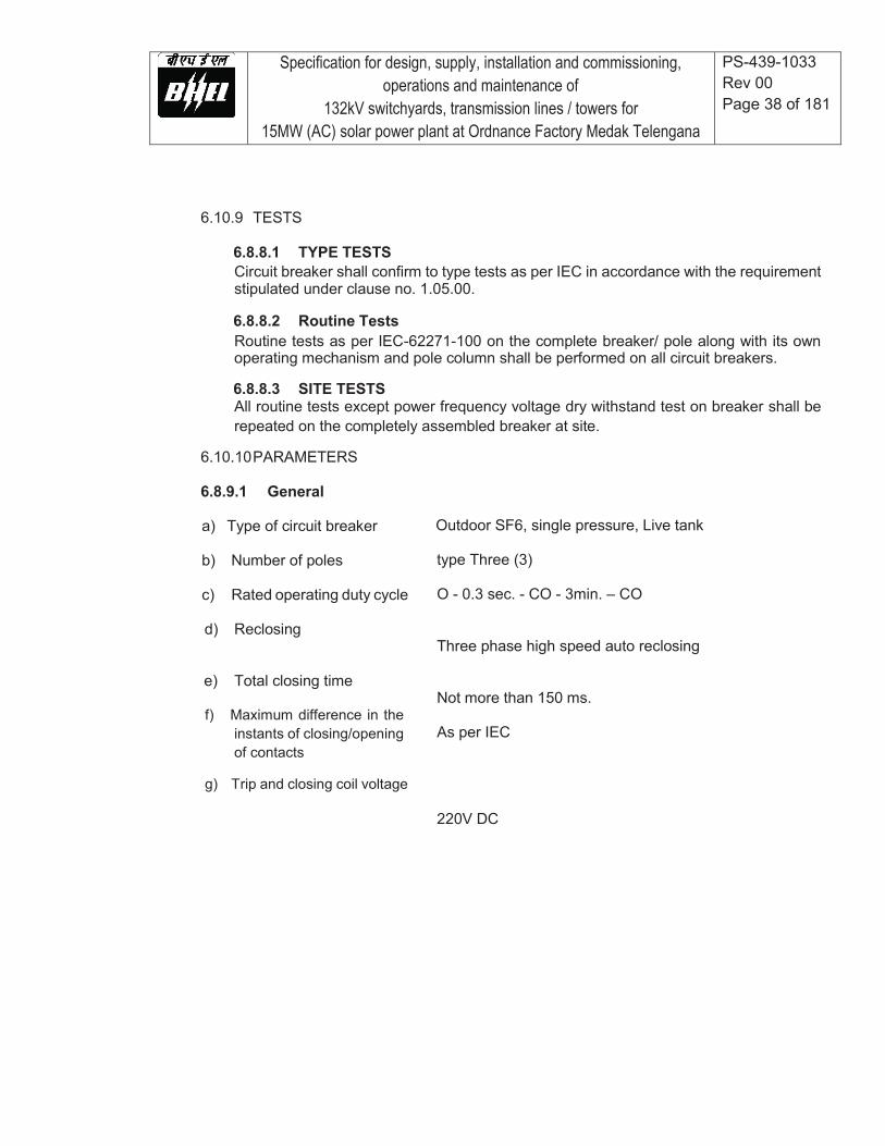
Specification for design, supply, installation and commissioning, operations and maintenance of
132kV switchyards, transmission lines / towers for 15MW (AC) solar power plant at Ordnance Factory Medak Telengana
PS-439-1033 Rev 00 Page 38 of 181
6.10.9 TESTS
6.8.8.1 TYPE TESTS Circuit breaker shall confirm to type tests as per IEC in accordance with the requirement stipulated under clause no. 1.05.00.
6.8.8.2 Routine Tests Routine tests as per IEC-62271-100 on the complete breaker/ pole along with its own operating mechanism and pole column shall be performed on all circuit breakers.
6.8.8.3 SITE TESTS All routine tests except power frequency voltage dry withstand test on breaker shall be repeated on the completely assembled breaker at site.
6.10.10 PARAMETERS
6.8.9.1 General
a) Type of circuit breaker
b) Number of poles
c) Rated operating duty cycle
d) Reclosing
e) Total closing time
f) Maximum difference in the instants of closing/opening of contacts
g) Trip and closing coil voltage
Outdoor SF6, single pressure, Live tank
type Three (3) O - 0.3 sec. - CO - 3min. – CO Three phase high speed auto reclosing Not more than 150 ms. As per IEC 220V DC

Specification for design, supply, installation and commissioning, operations and maintenance of
132kV switchyards, transmission lines / towers for 15MW (AC) solar power plant at Ordnance Factory Medak Telengana
PS-439-1033 Rev 00 Page 39 of 181
h) Auxiliary contacts As required plus 10 NO and 10 NC contacts per pole as spare. The contacts shall have continuous rating of 10A and breaking capacity of 2A with circuit time constant of minimum 20 millisecond at 220V DC.
i) Noise level Maximum 140dB at 50m distance from base of
circuit breaker
j) Rated terminal load Adequate to withstand 100kg static load as well as wind, seismic and short circuit forces without
impairing reliability or current carrying capacity.
k) Type of operating mechanism Pneumatic/spring/hydraulic/or a combination of these
6.8.9.2 132kV Class Circuit Breakers
a) Rated voltage 145 kVrms
b) Rated continuous current 1250 A at rated ambient temperature
c) Rated short circuit breaking 31.5kA with percentage of DC component as per current at rated voltage IEC corresponding to minimum opening time under operating conditions specified.
d) Symmetrical interrupting 31.5 kA rms Capability
e) Short time current carrying 31.5 kA rms for One (1) second Capability
f) Short circuit making current 80 kAp Capability
g) Rated out-of-phase breaking 7.8 kA rms
h) Rated line charging breaking As per IEC Current (voltage factor of 1.4)
i) Rated small inductive current 0.5 to 10 A Switching capability with over voltage less than 2.3 pu
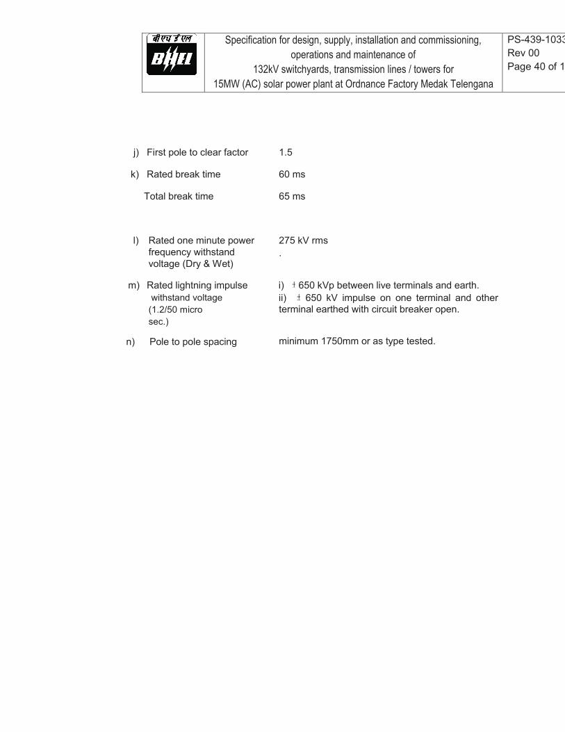
Specification for design, supply, installation and commissioning, operations and maintenance of
132kV switchyards, transmission lines / towers for 15MW (AC) solar power plant at Ordnance Factory Medak Telengana
PS-439-1033Rev 00 Page 40 of 18
j) First pole to clear factor k) Rated break time
Total break time
l) Rated one minute power frequency withstand voltage (Dry & Wet)
m) Rated lightning impulse
withstand voltage (1.2/50 micro sec.)
n) Pole to pole spacing
1.5 60 ms 65 ms 275 kV rms . i) 650 kVp between live terminals and earth. ii) 650 kV impulse on one terminal and other terminal earthed with circuit breaker open. minimum 1750mm or as type tested.
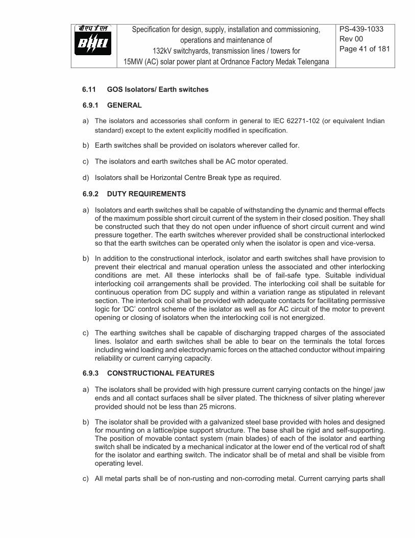
Specification for design, supply, installation and commissioning, operations and maintenance of
132kV switchyards, transmission lines / towers for 15MW (AC) solar power plant at Ordnance Factory Medak Telengana
PS-439-1033 Rev 00 Page 41 of 181
6.11 GOS Isolators/ Earth switches
6.9.1 GENERAL
a) The isolators and accessories shall conform in general to IEC 62271-102 (or equivalent Indian standard) except to the extent explicitly modified in specification.
b) Earth switches shall be provided on isolators wherever called for.
c) The isolators and earth switches shall be AC motor operated.
d) Isolators shall be Horizontal Centre Break type as required.
6.9.2 DUTY REQUIREMENTS
a) Isolators and earth switches shall be capable of withstanding the dynamic and thermal effects
of the maximum possible short circuit current of the system in their closed position. They shall be constructed such that they do not open under influence of short circuit current and wind pressure together. The earth switches wherever provided shall be constructional interlocked so that the earth switches can be operated only when the isolator is open and vice-versa.
b) In addition to the constructional interlock, isolator and earth switches shall have provision to
prevent their electrical and manual operation unless the associated and other interlocking conditions are met. All these interlocks shall be of fail-safe type. Suitable individual interlocking coil arrangements shall be provided. The interlocking coil shall be suitable for continuous operation from DC supply and within a variation range as stipulated in relevant section. The interlock coil shall be provided with adequate contacts for facilitating permissive logic for ‘DC’ control scheme of the isolator as well as for AC circuit of the motor to prevent opening or closing of isolators when the interlocking coil is not energized.
c) The earthing switches shall be capable of discharging trapped charges of the associated
lines. Isolator and earth switches shall be able to bear on the terminals the total forces including wind loading and electrodynamic forces on the attached conductor without impairing reliability or current carrying capacity.
6.9.3 CONSTRUCTIONAL FEATURES
a) The isolators shall be provided with high pressure current carrying contacts on the hinge/ jaw
ends and all contact surfaces shall be silver plated. The thickness of silver plating wherever provided should not be less than 25 microns.
b) The isolator shall be provided with a galvanized steel base provided with holes and designed
for mounting on a lattice/pipe support structure. The base shall be rigid and self-supporting. The position of movable contact system (main blades) of each of the isolator and earthing switch shall be indicated by a mechanical indicator at the lower end of the vertical rod of shaft for the isolator and earthing switch. The indicator shall be of metal and shall be visible from operating level.
c) All metal parts shall be of non-rusting and non-corroding metal. Current carrying parts shall

Specification for design, supply, installation and commissioning, operations and maintenance of
132kV switchyards, transmission lines / towers for 15MW (AC) solar power plant at Ordnance Factory Medak Telengana
PS-439-1033 Rev 00 Page 42 of 181
be from high conductivity electrolytic copper/aluminium. Bolts, screws and pins shall be provided with lock washers. Keys or equivalent locking facilities, if provided on current carrying parts, shall be made of copper silicon alloy or equivalent. The live parts shall be designed to eliminate sharp joints, edges and other corona producing surfaces.
d) The isolators shall be so constructed that the switch blade will not fall to the closed position
if the operating shaft gets disconnected. Isolators and earthing switches including their operating parts shall be such that they cannot be dislodged from their open or closed positions by gravity, wind pressure, vibrations shocks or accidental touching of the connecting rods of the operating mechanism. The switch shall be designed such that no lubrication of any part is required except at very infrequent intervals.
e) The insulator of the isolator shall conform to the requirements stipulated elsewhere and shall
have a min. cantilever strength of 600 kg.
6.9.4 EARTHING SWITCHES Where earthing switches are specified, these shall include the complete operating mechanism and auxiliary contacts. The earthing switches shall form an integral part of the isolator and shall be mounted on the base frame of the isolator. Earthing switches shall be suitable for local operation only. The earthing switches shall be constructionally interlocked with the isolator so that the earthing switches can be operated only when isolator is open and vice versa.
6.9.5 OPERATING MECHANISM AND CONTROL a) The Contractor shall offer motor operated switches having padlock arrangement for both ‘ON’
and ‘OFF’ positions.
b) Limit switches for control shall be fitted on the isolator/ earth switch shaft, within the cabinet to sense the open and close positions of the isolators and earth switches.
c) It shall not be possible, after final adjustment has been made for any part of the mechanism
to be displaced at any point in the travel sufficient enough to allow improper functioning of the isolator when the isolator is opened or closed at any speed.
d) Control cabinet/operating mech. box shall conform to requirements stipulated under auxiliary
part and IS:5039/IS 8623/IEC 60439 as applicable.
6.9.6 OPERATION a) Isolator shall be electrically/mechanically gang operated for main blades and earth switches.
The operation of the three poles shall be well synchronised and interlocked.
b) The design shall be such as to provide maximum reliability under all service conditions. All operating linkages carrying mechanical loads shall be designed for negligible deflection. The length of inter insulator and interpole operating rods shall be capable of adjustments.
c) The design of linkages and gears be such so as to allow one man to operate the handle with

Specification for design, supply, installation and commissioning, operations and maintenance of
132kV switchyards, transmission lines / towers for 15MW (AC) solar power plant at Ordnance Factory Medak Telengana
PS-439-1033 Rev 00 Page 43 of 181
ease for isolator and earth switch.
6.9.7 TESTS a) In continuation to the requirements stipulated elsewhere, the isolator alongwith operating
mechanism shall conform to the type tests and shall be subjected to routine tests and acceptance tests in accordance with IEC 62271-102. During final testing of isolator sequential closing/ opening of earth switch shall also be checked only after isolator is fully open/close.
b) The insulator shall conform to all the type tests as per IEC 60168. In addition to all type,
routine and acceptance tests, as per IEC-60168, the following additional routine/ acceptance tests shall also be carried out: i) Bending load test in four directions at 50% min. bending load guaranteed in all insulators. ii) Bending load test in four directions at 100% min. bending load guaranteed on sample
insulators in a lot. iii) Torsional test on sample insulator of a lot.
6.9.8 PARAMETERS 6.9.8.1 General
a) Type of isolator Outdoor type
b) Number of poles Three (3)
d) Operating time Not more than 12 sec.
e) Control voltage 220V DC
f) Auxiliary contacts on Isolator As required plus 8NO and 8NC contacts per pole/isolator as spare. The contacts shall have continuous rating of 10A and breaking capacity of 2A with circuit time constant of minimum 20 millisecond at 220V dc. Additionally MBB contacts as required shall also be provided.
g) Auxiliary contacts on earth switch Total 6NO and 6NC
h) Rated mechanical terminal load As per table III of IEC 62271-102
i) Temperature rise over As per IEC:62271-102 ambient
j) Rated mechanical terminal As per table III of IEC 62271-102 Load
k) Operating mechanism of A. C. /Universal Motor operated Isolator and Earth Switch
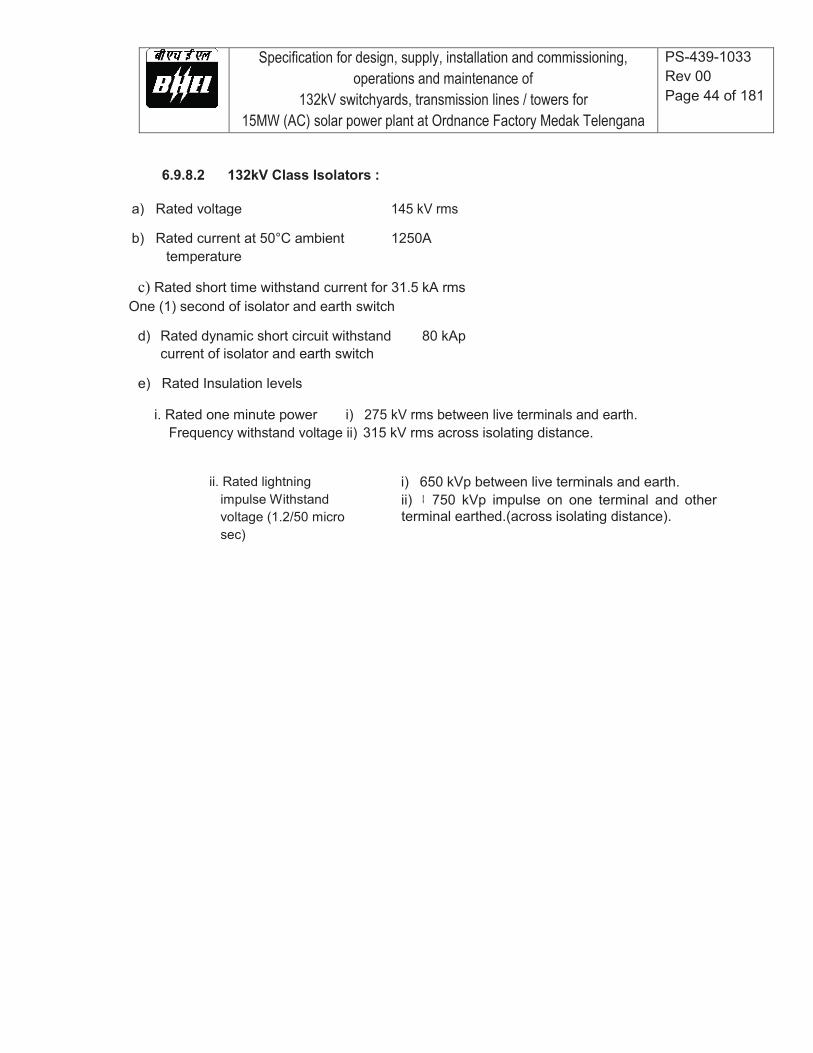
Specification for design, supply, installation and commissioning, operations and maintenance of
132kV switchyards, transmission lines / towers for 15MW (AC) solar power plant at Ordnance Factory Medak Telengana
PS-439-1033 Rev 00 Page 44 of 181
6.9.8.2 132kV Class Isolators :
a) Rated voltage 145 kV rms
b) Rated current at 50°C ambient 1250A temperature c) Rated short time withstand current for 31.5 kA rms
One (1) second of isolator and earth switch d) Rated dynamic short circuit withstand 80 kAp
current of isolator and earth switch e) Rated Insulation levels
i. Rated one minute power i) 275 kV rms between live terminals and earth. Frequency withstand voltage ii) 315 kV rms across isolating distance.
ii. Rated lightning
impulse Withstand voltage (1.2/50 micro sec)
i) 650 kVp between live terminals and earth. ii) 750 kVp impulse on one terminal and other terminal earthed.(across isolating distance).
Specification for design, supply, installation and commissioning, operations and maintenance of
132kV switchyards, transmission lines / towers for 15MW (AC) solar power plant at Ordnance Factory Medak Telengana
PS-439-1033 Rev 00 Page 45 of 181
6.12 INSTRUMENT TRANSFORMERS
6.12.2 CODES AND STANDARDS
Current transformers IEC 60044, BS:3938, IS: 2705 Voltage transformers IEC 60044 IEC 60358, IS:3156 Insulating oil IS: 335
6.12.3 GENERAL REQUIREMENTS
a) The instrument transformers i.e. current and voltage transformers shall be single phase
transformer units and shall be supplied with a common marshaling box for a set of three single phase units.
b) The tank as well as top metallics shall be hot dip galvanized or painted with Grey color of
shade RAL 9002.
c) The instrument transformers shall be hermetically sealed units. The instrument transformers shall be provided with filling and drain plugs.
d) Polarity marks shall indelibly be marked on each instrument transformer and at the lead
terminals at the associated terminal block.
e) The insulators shall have a cantilever strength of more than 350 kg.
6.12.4 CURRENT TRANSFORMERS (CTs)
a) The CTs shall have single primary of either ring type or hair pin type or bar type. The Wound Primary type is not acceptable.
In case of "Bar Primary" inverted type CTs, the following requirements shall be met:
i. The secondaries shall be totally encased in metallic shielding providing a
uniform equipotential surface for even electric field distribution.
ii. The lowest part of insulation assembly shall be properly secured to avoid any risk of damage due to transportation stresses.
iii. The upper part of insulation assembly sealing on primary bar shall be properly
secured to avoid any damage during transportation due to relative movement between insulation assembly and top dome.
iv. The insulator shall be one piece without any metallic flange joint.
b) The CT shall be provided with oil sight glass which should be clearly visible to maintenance
personnel standing on ground.
c) The core lamination shall be of cold rolled grain oriented silicon steel or other equivalent alloys.

Specification for design, supply, installation and commissioning, operations and maintenance of
132kV switchyards, transmission lines / towers for 15MW (AC) solar power plant at Ordnance Factory Medak Telengana
PS-439-1033 Rev 00 Page 46 of 181
The cores shall produce undistorted secondary current under transient conditions at all ratios with specified parameters.
d) Different ratios shall be achieved by secondary taps only, and primary reconnections shall not
be accepted.
e) The guaranteed burdens and accuracy class are to be intended as simultaneous for all cores.
f) The instrument security factor at all ratios shall be less than five (5) for metering core. If any auxiliary CT/reactor is used, then all parameters specified shall be met treating auxiliary CTs/reactors as integral part of CT. The auxiliary CT/reactor shall preferably be in-built construction of the CT. In case it is separate, it shall be mounted in secondary terminal box.
g) The physical disposition of protection secondary cores shall be in the same order as given under CT requirement table(s) given below.
h) The secondary terminals shall be terminated on stud type suitable no’s of non-disconnecting and disconnecting terminal blocks as required inside the terminal box of degree of protection IP:55 at the bottom of CT.
i) The CTs shall have provision for taking oil samples from bottom of CT without exposure to atmosphere to carry out dissolved gas analysis periodically. Contractor shall give his recommendations for such analysis, i.e. frequency of test, norms of acceptance, quantity of oil to be withdrawn, and treatment of CT.
j) The CT shall have provision for measurement of capacitance and tan delta as erected at site.
6.12.5 VOLTAGE TRANSFORMERS (CVTs)
a) Voltage transformers shall be of capacitor voltage divider type with electromagnetic unit.
b) The CVTs shall be thermally and dielectrically safe when the secondary terminals are loaded with guaranteed thermal burdens.
c) The electro-magnetic unit (EMU) shall comprise of compensating reactor, intermediate
transformer, and protective and damping devices. The oil level indicator of EMU with danger level marking shall be clearly visible to maintenance personnel standing on ground.
d) The secondaries shall be protected by HRC cartridge type fuses for all windings In addition
fuses shall also be provided for protection and metering windings for connection to fuse monitoring scheme. The secondary terminals shall be terminated on stud type non-disconnecting terminal blocks via the fuse inside the terminal box of degree of protection IP: 55. The access to secondary terminals shall be without the danger of access to high voltage circuit.
e) The protection cores shall not saturate at about 1.5 times the rated voltage for amin. duration
of 30 secs.

Specification for design, supply, installation and commissioning, operations and maintenance of
132kV switchyards, transmission lines / towers for 15MW (AC) solar power plant at Ordnance Factory Medak Telengana
PS-439-1033 Rev 00 Page 47 of 181
f) The accuracy of metering core shall be maintained through the entire burden range upto 75VA
on all three windings without any adjustments during operations.
6.12.6 MARSHALLING BOX
Marshaling box shall conform to all requirements as given elsewhere. The wiring diagram for the interconnection of three phase instrument transformer shall be pasted inside the box. Terminal blocks in the marshaling box shall have facility for star/delta formation, short circuiting and grounding of secondary terminals. The box shall have enough terminals to wire all control circuits plus 20 spare terminals.
6.12.7 PARAMETERS FOR CURRENT TRANSFORMERS
6.12.7.1 General Parameters
a) One minute power frequency 5 kV
withstand voltage between secondary terminal and earth
b) Partial discharge level 10 pico Coulombs max.
c) Temperature rise d) Type of insulation e) Number of cores f) Installation g) Number of terminals in
marshalling box h) System Neutral earthing i) Seismic acceleration
As per IEC 60044 Class A Provided in AC SLD of plant. Outdoor (up right) All terminals of control circuits wired uptomarshalling box plus 20 terminals spare. Effectively earthed 0.3g Horizontal
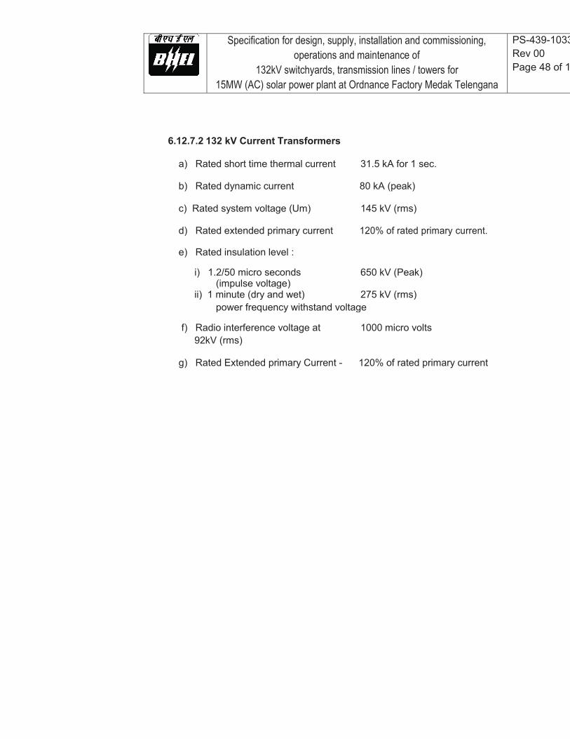
Specification for design, supply, installation and commissioning, operations and maintenance of
132kV switchyards, transmission lines / towers for 15MW (AC) solar power plant at Ordnance Factory Medak Telengana
PS-439-1033Rev 00 Page 48 of 1
6.12.7.2 132 kV Current Transformers
a) Rated short time thermal current 31.5 kA for 1 sec.
b) Rated dynamic current 80 kA (peak)
c) Rated system voltage (Um) 145 kV (rms)
d) Rated extended primary current 120% of rated primary current.
e) Rated insulation level :
i) 1.2/50 micro seconds 650 kV (Peak) (impulse voltage) ii) 1 minute (dry and wet) 275 kV (rms) power frequency withstand voltage
f) Radio interference voltage at 1000 micro volts 92kV (rms)
g) Rated Extended primary Current - 120% of rated primary current
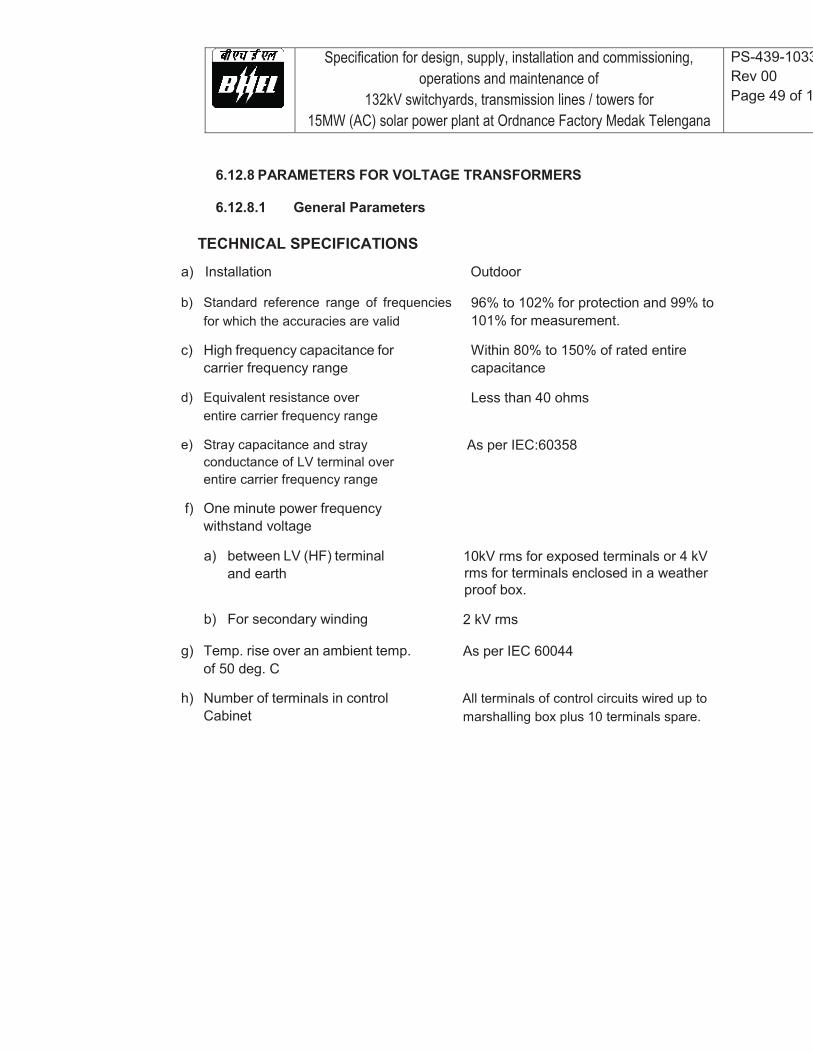
Specification for design, supply, installation and commissioning, operations and maintenance of
132kV switchyards, transmission lines / towers for 15MW (AC) solar power plant at Ordnance Factory Medak Telengana
PS-439-1033Rev 00 Page 49 of 1
6.12.8 PARAMETERS FOR VOLTAGE TRANSFORMERS
6.12.8.1 General Parameters TECHNICAL SPECIFICATIONS
a) Installation b) Standard reference range of frequencies
for which the accuracies are valid c) High frequency capacitance for
carrier frequency range d) Equivalent resistance over
entire carrier frequency range e) Stray capacitance and stray
conductance of LV terminal over entire carrier frequency range
f) One minute power frequency
withstand voltage
a) between LV (HF) terminal and earth
b) For secondary winding g) Temp. rise over an ambient temp.
of 50 deg. C h) Number of terminals in control
Cabinet
Outdoor
96% to 102% for protection and 99% to 101% for measurement.
Within 80% to 150% of rated entire capacitance
Less than 40 ohms
As per IEC:60358 10kV rms for exposed terminals or 4 kV rms for terminals enclosed in a weather proof box. 2 kV rms As per IEC 60044 All terminals of control circuits wired up to marshalling box plus 10 terminals spare.

Specification for design, supply, installation and commissioning, operations and maintenance of
132kV switchyards, transmission lines / towers for 15MW (AC) solar power plant at Ordnance Factory Medak Telengana
PS-439-1033 Rev 00 Page 50 of 181
i) Rated total thermal burden 750 VA
j) Partial discharge level 10 pico Coulombs max.
k) Number of cores As per details given in AC SLD of plant.
l) Rated Voltage factor 1.2 continuous , 1.5 – 30sec
6.12.8.2 132kV Voltage Transformer
a) Rated system voltage 145 kV (rms)
b) HF Capacitance 4400 pf (nominal)
c) Rated insulation levels
i) 1.2 micro sec. impulse 650 kV (peak)
ii) 1 min (dry & wet) power 1050 kV (peak) frequency withstand voltage
d) Radio Interference voltage at 92 kV(rms) 1000 micro volts (max.)
6.12.9 TESTS
The current and voltage transformers shall confirm to type tests and shall be subjected to routine tests in accordance with the relevant IS/IEC and shall also conform to the following additional type tests as applicable : i) Radio Interference test- As per IS:8263 ii) Thermal withstand test i.e. application of rated voltage and rated current
simultaneously by synthetic test circuit.(For CT only) iii) Thermal co-efficient test i.e. measurement of Tan-Delta as function of
temperature (at ambient and between 80 deg. C and 90 deg. C) and voltage (at 0.3, 0.7, 1.0 and 1.1 Um). (For CT only)
iv) Multiple chopped impulse test on Primary winding.
Specification for design, supply, installation and commissioning, operations and maintenance of
132kV switchyards, transmission lines / towers for 15MW (AC) solar power plant at Ordnance Factory Medak Telengana
PS-439-1033 Rev 00 Page 51 of 181
6.13 SURGE ARRESTOR (LIGHTNING ARRESTOR, LA)
6.13.2 GENERAL
a) The surge arrestors shall conform in general to IEC-60099-4 and IS:3070 except to the extent modified in the specification.
b) Arrestors shall be hermetically sealed units, self-supporting construction, suitable for
mounting on lattice/tubular type support structures.
6.13.3 DUTY REQUIREMENTS
a) The Surge Arresters (SAs) shall be capable of discharging over-voltages occurring due to switching of unloaded transformers, reactors and long lines.
b) The reference current of SAs shall be high enough to eliminate the influence of grading
and stray capacitance on the measured reference voltage.
c) The SAs shall be capable of withstanding meteorological and short circuit forces under site conditions.
6.13.4 CONSTRUCTIONAL FEATURES
a) Each Surge Arrester (SA) shall be hermetically sealed single phase unit.
b) The non linear blocks shall be sintered metal oxide material. The SA construction shall be
robust with excellent mechanical and electrical properties.
c) SAs shall have pressure relief devices and arc diverting ports suitable for preventing shattering of porcelain housing and to provide path for flow of rated fault currents in the event of SA failure.
d) The SA shall not fail due to porcelain contamination.
e) Seals shall be effectively maintained even when SA discharges rated lightning current.
f) Porcelain shall be so coordinated that external flashover will not occur due to application
of any impulse or switching surge voltage up to maximum design value for SA. The cantilever strength of the insulator shall be minimum 350kg.
g) The end fittings shall be non-magnetic and of corrosion proof material. The metal flanges
shall be fixed with the porcelain by cement or other materials so as to withstand the forces experienced in normal operation and provide continuous sealing for entry of moisture for a period of minimum 20 years.
h) The Contractor shall furnish the following:
a. The heat treatment cycle details with necessary quality checks used for individual
blocks along with insulation layer formed across each block.

Specification for design, supply, installation and commissioning, operations and maintenance of
132kV switchyards, transmission lines / towers for 15MW (AC) solar power plant at Ordnance Factory Medak Telengana
PS-439-1033 Rev 00 Page 52 of 181
b. Metalizing coating thickness for reduced resistance between adjacent discs along with procedure for checking the same.
c. Details of thermal stability test for uniform distribution of current on individual discs. d. Detailed energy calculations to prove thermal capability of discs.
6.13.5 FITTINGS AND ACCESSORIES
a) Each SA shall be complete with insulating base for mounting on structure.
b) SAs shall be provided with grading and/or corona rings as required.
c) Self contained discharge counters, suitably enclosed for outdoor use (IP:55 degree of
protection) and requiring no auxiliary or battery supply shall be fitted with each SAalong with necessary connections to SA and earth. Suitable leakage current meters shall also be supplied in the same enclosure. The reading of milli-ammeter and counter shall be visible through an inspection glass panel to a man standing on ground. A pressure relief vent/suitable provision shall be made to prevent pressure build up.
6.13.6 PARAMETERS
6.13.6.1 General
a) System neutral earthing Effectively earthed
b) Installation Outdoor
c) i) Nominal discharge current 10 kA of 8/20 microsec. wave
ii) Discharge current at which 20 kA of 8/20 microsec. wave insulationcoord. is done
d) Rated frequency 50 Hz
e) Long duration discharge class 3
f) Current for pressure relief test 31.5kA rms
g) Prospective symmetrical fault current 31.5 kA rms for 1 second
h) Low current long duration test 800 A value (2000 micro sec.)
i) Pressure relief class Class A of Table VII of IS:3070 or equivalent IEC.
j) Partial discharge at 1.05 MCOV Not more than 50 pC (Continuous operating voltage)

Specification for design, supply, installation and commissioning, operations and maintenance of
132kV switchyards, transmission lines / towers for 15MW (AC) solar power plant at Ordnance Factory Medak Telengana
PS-439-1033 Rev 00 Page 53 of 181
k) Siesmic acceleration 0.3 g horizontal
l) Reference ambient temp. 50 deg. C
6.13.6.2 132 kV class Surge Arrestors
a) Rated system voltage 145 kV
b) Rated arrestor voltage Not less than 120 kV
c) Minimum discharge capability 5 kJ/kV (referred to rated arrestor voltage corresponding to minimum discharge characteristics).
d) Continuous operating voltage 102 kV rms (COV) at 50 deg. C
e) Maximum Switching surge residual 280 kVp voltage (1 kA)
f) Maximum residual voltage at
i) 5kA nominal discharge current 310 kVp
ii) 10kA nominal discharge current 330 kVp
g) Steep fronted wave residual 370 kVp voltage at 10kA
h) High current short duration test 100 kAp value (4/10 microsec. wave)
i) One minute dry/wet power frequency 275 kV (rms) withstand voltage of arrestor housing
j) Impulse withstand voltage of arrestor 650 kVp Housing with 1.2/50 micro sec. wave.
k) RIV at 92 kV (rms) Less than 1000 micro volts
l) The surge arrestors are provided to protect the following equipment whose insulation levels are indicated in the table I given below. The contractor shall carry out the insulation coordination studies for deciding the location of the surge arrestors.

Specification for design, supply, installation and commissioning, operations and maintenance of
132kV switchyards, transmission lines / towers for 15MW (AC) solar power plant at Ordnance Factory Medak Telengana
PS-439-1033 Rev 00 Page 54 of 181
TABLE – I
S.NO. EQUIPMENT TO BE INSULATION LEVEL PROTECTED
___________________________________________________________________ LIGHTNING IMPULSE (kVp)
FOR 132 KV SYSTEM
1. Power Transformer 550
2. Instrument Transformer 650
CB/Isolator
- Phase to ground 650
- Across open contacts 650
6.13.7 Surge Arrestors shall conform to all type tests as per IEC and shall be subjected to routine and acceptance tests in accordance with IEC-60099-4.
6.13.8 The resistive current drawn by the arrestor at rated voltage shall be indicated in the
routine test report.
6.14 POST INSULATOR
6.14.2 GENERAL The post insulators shall conform in general to latest IS:2544 and IEC – 60815, 60168.
6.14.3 CONSTRUCTIONAL FEATURES
a) Post type insulators shall consist of a porcelain part permanently secured in a metal base
to be mounted on the supporting structures. They shall be capable of being mounted upright. They shall be designed to withstand any shocks to which they may be subjected to by the operation of the associated equipment. Only solid core insulators shall be accepted. Height of post insulator shall be preferably as given under parameters of this part.
b) Other requirements of insulator as given under auxiliary requirements shall also be
applicable.
6.14.4 TESTS 6.14.4.1 In accordance with the stipulations elsewhere the post insulators shall conform
to type tests and acceptance, sample and routine tests as per IS:2544, IEC-60168 shall be carried out.
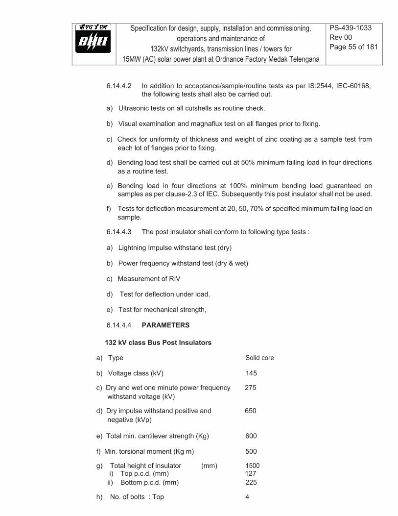
Specification for design, supply, installation and commissioning, operations and maintenance of
132kV switchyards, transmission lines / towers for 15MW (AC) solar power plant at Ordnance Factory Medak Telengana
PS-439-1033 Rev 00 Page 55 of 181
6.14.4.2 In addition to acceptance/sample/routine tests as per IS:2544, IEC-60168, the following tests shall also be carried out.
a) Ultrasonic tests on all cutshells as routine check.
b) Visual examination and magnaflux test on all flanges prior to fixing.
c) Check for uniformity of thickness and weight of zinc coating as a sample test from
each lot of flanges prior to fixing.
d) Bending load test shall be carried out at 50% minimum failing load in four directions as a routine test.
e) Bending load in four directions at 100% minimum bending load guaranteed on
samples as per clause-2.3 of IEC. Subsequently this post insulator shall not be used.
f) Tests for deflection measurement at 20, 50, 70% of specified minimum failing load on sample.
6.14.4.3 The post insulator shall conform to following type tests :
a) Lightning Impulse withstand test (dry)
b) Power frequency withstand test (dry & wet)
c) Measurement of RIV
d) Test for deflection under load.
e) Test for mechanical strength,
6.14.4.4 PARAMETERS
132 kV class Bus Post Insulators
a) Type Solid core
b) Voltage class (kV) 145
c) Dry and wet one minute power frequency 275 withstand voltage (kV)
d) Dry impulse withstand positive and 650 negative (kVp)
e) Total min. cantilever strength (Kg) 600
f) Min. torsional moment (Kg m) 500
g) Total height of insulator (mm) 1500 i) Top p.c.d. (mm) 127 ii) Bottom p.c.d. (mm) 225
h) No. of bolts : Top 4
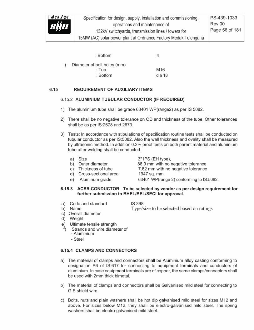
Specification for design, supply, installation and commissioning, operations and maintenance of
132kV switchyards, transmission lines / towers for 15MW (AC) solar power plant at Ordnance Factory Medak Telengana
PS-439-1033 Rev 00 Page 56 of 181
: Bottom 4
i) Diameter of bolt holes (mm) : Top M16 : Bottom dia 18
6.15 REQUIREMENT OF AUXILIARY ITEMS
6.15.2 ALUMINIUM TUBULAR CONDUCTOR (IF REQUIRED)
1) The aluminium tube shall be grade 63401 WP(range2) as per IS 5082.
2) There shall be no negative tolerance on OD and thickness of the tube. Other tolerances shall be as per IS:2678 and 2673.
3) Tests: In accordance with stipulations of specification routine tests shall be conducted on
tubular conductor as per IS:5082. Also the wall thickness and ovality shall be measured by ultrasonic method. In addition 0.2% proof tests on both parent material and aluminium tube after welding shall be conducted.
a) Size 3" IPS (EH type), b) Outer diameter 88.9 mm with no negative tolerance c) Thickness of tube 7.62 mm with no negative tolerance d) Cross-sectional area 1947 sq. mm. e) Aluminum grade 63401 WP(range 2) conforming to IS:5082.
6.15.3 ACSR CONDUCTOR: To be selected by vendor as per design requirement for
further submission to BHEL/BEL/SECI for approval.
a) Code and standard IS 398 b) Name Type/size to be selected based on ratings c) Overall diameter d) Weight e) Ultimate tensile strength f) Strands and wire diameter of
- Aluminium - Steel
6.15.4 CLAMPS AND CONNECTORS
a) The material of clamps and connectors shall be Aluminium alloy casting conforming to
designation A6 of IS:617 for connecting to equipment terminals and conductors of aluminium. In case equipment terminals are of copper, the same clamps/connectors shall be used with 2mm thick bimetal.
b) The material of clamps and connectors shall be Galvanised mild steel for connecting to
G.S.shield wire.
c) Bolts, nuts and plain washers shall be hot dip galvanised mild steel for sizes M12 and above. For sizes below M12, they shall be electro-galvanised mild steel. The spring washers shall be electro-galvanised mild steel.
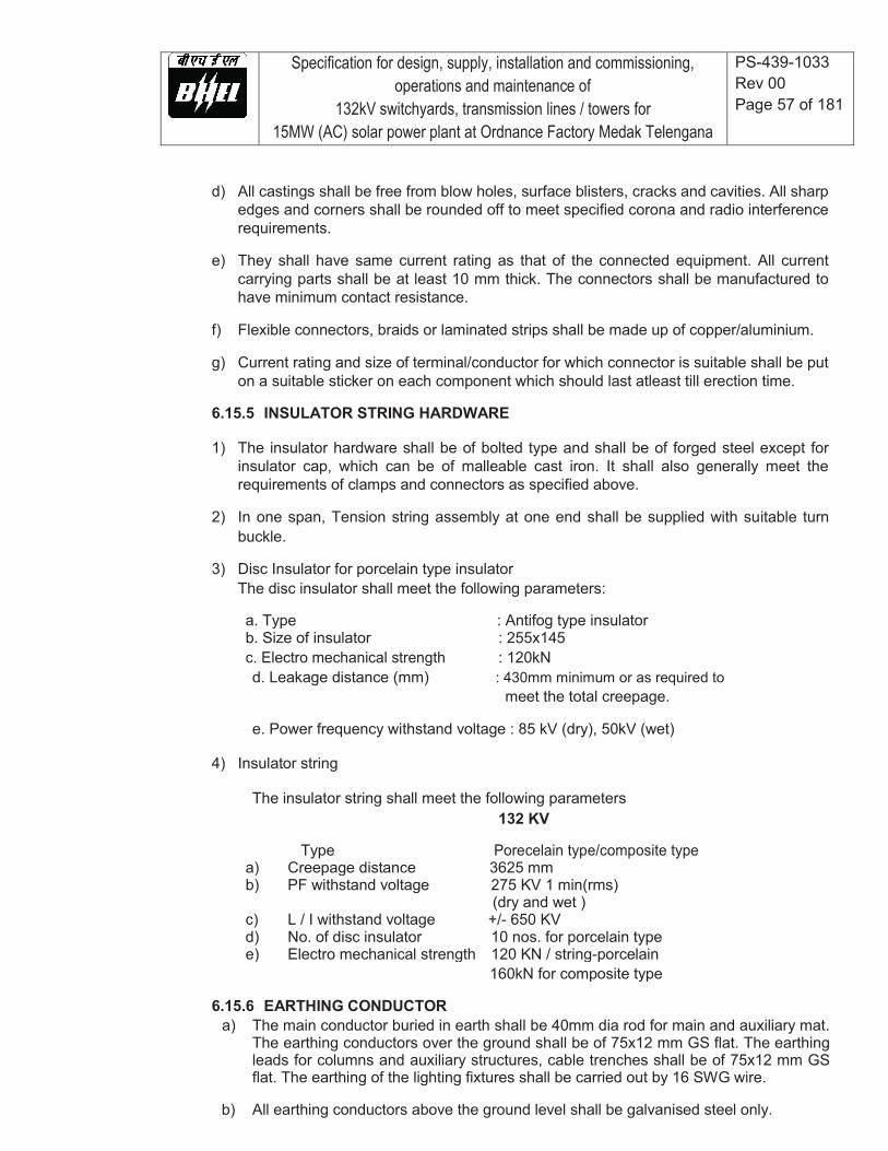
Specification for design, supply, installation and commissioning, operations and maintenance of
132kV switchyards, transmission lines / towers for 15MW (AC) solar power plant at Ordnance Factory Medak Telengana
PS-439-1033 Rev 00 Page 57 of 181
d) All castings shall be free from blow holes, surface blisters, cracks and cavities. All sharp edges and corners shall be rounded off to meet specified corona and radio interference requirements.
e) They shall have same current rating as that of the connected equipment. All current
carrying parts shall be at least 10 mm thick. The connectors shall be manufactured to have minimum contact resistance.
f) Flexible connectors, braids or laminated strips shall be made up of copper/aluminium.
g) Current rating and size of terminal/conductor for which connector is suitable shall be put
on a suitable sticker on each component which should last atleast till erection time.
6.15.5 INSULATOR STRING HARDWARE
1) The insulator hardware shall be of bolted type and shall be of forged steel except for insulator cap, which can be of malleable cast iron. It shall also generally meet the requirements of clamps and connectors as specified above.
2) In one span, Tension string assembly at one end shall be supplied with suitable turn
buckle.
3) Disc Insulator for porcelain type insulator The disc insulator shall meet the following parameters:
a. Type : Antifog type insulator b. Size of insulator : 255x145 c. Electro mechanical strength : 120kN d. Leakage distance (mm) : 430mm minimum or as required to
meet the total creepage.
e. Power frequency withstand voltage : 85 kV (dry), 50kV (wet)
4) Insulator string
The insulator string shall meet the following parameters 132 KV
Type Porecelain type/composite type a) Creepage distance 3625 mm b) PF withstand voltage 275 KV 1 min(rms) (dry and wet ) c) L / I withstand voltage +/- 650 KV d) No. of disc insulator 10 nos. for porcelain type e) Electro mechanical strength 120 KN / string-porcelain 160kN for composite type
6.15.6 EARTHING CONDUCTOR
a) The main conductor buried in earth shall be 40mm dia rod for main and auxiliary mat. The earthing conductors over the ground shall be of 75x12 mm GS flat. The earthing leads for columns and auxiliary structures, cable trenches shall be of 75x12 mm GS flat. The earthing of the lighting fixtures shall be carried out by 16 SWG wire.
b) All earthing conductors above the ground level shall be galvanised steel only.
Specification for design, supply, installation and commissioning, operations and maintenance of
132kV switchyards, transmission lines / towers for 15MW (AC) solar power plant at Ordnance Factory Medak Telengana
PS-439-1033 Rev 00 Page 58 of 181
6.15.7 Earthwire for Lightning Protection
a) Number of strands 7 of steel b) Strand diameter 3.66 mm c) Overall diameter 10.98 mm d) Weight 583 kg/km approx. e) Ultimate tensile strength 68.4 kN minimum f) Total cross-sectional area 73.65 sq.mm. g) Calculated d.c. resistance 2.5 ohms/km at 20 deg.C. h) Direction of lay of outer layer Right hand i) Protective coating for storage Boiled linseed oil to avoid wet storage stains (white rust)
The earth wire shall be preformed and post formed quality.
6.15.8 BUSHINGS, HOLLOW COLUMN INSULATORS, SUPPORT INSULATORS, AND DISC INSULATORS
a) Bushings shall be manufactured and tested in accordance with IS:2099& IEC:60137 while
hollow column insulators shall be manufactured and tested in accordance with IEC 62155/IS 5284. The support insulators shall be manufactured and tested as per IS:2544 / IEC 60168/IEC 60273. The insulators shall also conform to IEC 60815 as applicable having alternate long and short sheds. Support insulators/ bushings/ hollow column insulators shall be designed to have ample insulation, mechanical strength and rigidity for the conditions under which they will be used.
b) Porcelain used shall be homogenous, free from laminations, cavities and other flaws or
imperfections that might affect the mechanical or dielectric quality and shall be thoroughly vitrified, tough and impervious to moisture.
c) Glazing of the porcelain shall be uniform brown in colour, free form blisters, burns and
other similar defects.
d) The design of the insulator shall be such that stresses due to expansion and contraction in any part of the insulator shall not lead to deterioration. All ferrous parts shall be hot dip galvanised.
e) Post type insulators shall consist of a porcelain part permanently secured in metal base
to be mounted on supporting structures. They shall be capable of being mounted upright. They shall be designed to withstand all shocks to which they may be subjected to during operation of the associated equipment.
f) Bushing porcelain shall be robust and capable of withstanding the internal pressures
likely to occur in service. The design and location of clamps, the shape and the strength of the porcelain flange securing the bushing to the tank shall be such that there is no risk of fracture. All portions of the assembled porcelain enclosures and supports other than gaskets, which may in any way be exposed to the atmosphere shall be composed of completely non hygroscopic material such as metal or glazed porcelain.
g) All iron parts shall be hot dip galvanised and all joints shall be air tight. Surface of joints
shall be trued, porcelain parts by grinding and metal parts by machining. Insulator/ bushing design shall be such as to ensure a uniform compressive pressure on the joints.
Specification for design, supply, installation and commissioning, operations and maintenance of
132kV switchyards, transmission lines / towers for 15MW (AC) solar power plant at Ordnance Factory Medak Telengana
PS-439-1033 Rev 00 Page 59 of 181
h) In accordance with the requirements stipulated elsewhere, bushings, hollow column
insulators and support insulators shall conform to type tests and shall be subjected to routine tests and acceptance test/ sample test in accordance with relevant standards.
6.15.9 CABINETS, BOXES, KIOSKS, PANELS, ETC.
All types of control cabinets, junction boxes, marshaling boxes, lighting panels, terminal boxes, operating mechanism boxes, Kiosks etc. shall generally conform to IS:5039, IS:8623 and IEC: 60439 as applicable. They shall meet all other requirements specified elsewhere in the specification.
6.15.10 BAY MARSHALLING BOX
a) Bay Marshaling Box located at a convenient location to receive and distribute cables shall be provided as required. It shall meet all the requirements as specified for cabinets/boxes.
b) It shall have three separate distinct compartments for following purposes:
i. To receive two incoming 415V, three phase, AC supplies controlled by 100A four pole MCBs with auto changeover provision, and to distribute five (5) three phase ac supplies controlled by 32A four pole MCBs. It shall also be provided with 63A, 3 phase 4 pin industrial grade receptacle with rotary switch.
ii. To receive three phase incoming from first compartment and to distribute ten (10) single phase ac supplies controlled by 16A two pole MCBs.
iii. 150 nos. terminal blocks in vertical formation for interlocking facility.
6.15.11 AUXILIARY SWITCH FOR CIRCUIT BREAKERS
The auxiliary switch shall conform of following type tests:
a) Electrical endurance test - A minimum of 1000 operations for 2A. D.C. with a time constant greater than or equal to 20 milliseconds with a subsequent examination of mV drop/ visual defects/ temperature rise test.
b) Mechanical endurance test - A minimum of 5000 operations with a subsequent checking
of contact pressure test/ visual examination
c) Heat run test on contacts
d) IR/HV test, etc.
6.15.12 Type tests
All equipment with their terminal connectors, control cabinets, main protective relays, etc. as well as insulators, insulator strings with hardwares, clamps and connectors, marshalling boxes, etc., shall conform to type tests and shall be subjected to routine and acceptance tests in accordance with the requirements stipulated under respective equipment sections.
6.16 INSTALLATION
6.16.2 EARTHING
Specification for design, supply, installation and commissioning, operations and maintenance of
132kV switchyards, transmission lines / towers for 15MW (AC) solar power plant at Ordnance Factory Medak Telengana
PS-439-1033 Rev 00 Page 60 of 181
The earthing shall be done in accordance with requirements given in Annexure-I of this section and drawing enclosed with the specifications. Earthing of panels shall be done in line with the requirements given in respective equipment section of this specification.
6.16.3 CIVIL WORKS
The civil works shall be done in accordance with requirements stipulated elsewhere in the specification.
6.16.4 STRUCTURAL STEEL WORKS
The structural steel works shall be done in accordance with requirements stipulated elsewhere in the specification.
6.16.5 BAY EQUIPMENT
a) The disposition of equipment to be supplied is shown in enclosed tender drawings.
b) The Contractor shall prepare layout drawings and submit the same for approval of
the BHEL. The approval of drg. shall not absolve Contractor from his responsibility regarding designing & engineering of switchyard and Contractor shall be fully responsible for all works covered in the scope of this specification.
6.16.6 EQUIPMENT ERECTION NOTES a) All support insulators, circuit breaker interrupters and other fragile equipment shall
be handled with cranes with suitable booms and handling capacity.
b) Where assemblies are supplied in more than one section, Contractor shall make all necessary mechanical and electrical connections between sections including the connection between buses. Contractor shall also do necessary adjustments/alignments necessary for proper operation of circuit breakers, isolators and their operating mechanisms. All components shall be protected against damage during unloading, transportation, storage, installation, testing and commissioning. Any equipment damaged due to negligence or carelessness or otherwise shall be replaced by the Contractor at his own expense. The contractor shall strictly follow manufacturer’s recommendations for handling and erection of equipment.
c) The slings shall be of sufficient length to avoid any damage to insulator due to
excessive swing, scratching by sling ropes etc. Handling equipment, sling ropes etc. should be tested before erection and periodically thereafter for strength.
d) Bending of piping should be done by a bending machine and through cold bending
only. Bending shall be such that inner diameter of pipe is not reduced. The pipes shall be thoroughly cleaned before installation.
e) Cutting of the pipes wherever required shall be such as to avoid flaring of the ends.
Hence only a proper pipe cutting tool shall be used. Hack saw shall not be used.
f) For cleaning the inside and outside of hollow insulators only Muslin or leather cloth shall be used.
g) The rigid busbars for equipment interconnections shall have rigid connections at
Specification for design, supply, installation and commissioning, operations and maintenance of
132kV switchyards, transmission lines / towers for 15MW (AC) solar power plant at Ordnance Factory Medak Telengana
PS-439-1033 Rev 00 Page 61 of 181
one end and expansion / flexible at the other end. The tubular aluminium connections shall have not more than one joint per span. Since no wastages are permissible, the bidder shall work out the cut lengths of aluminum tube based on finalized layout and dispatch the same to site without requiring BHEL approval. Corona bells shall be provided at the end of the rigid busbars.
6.16.7 CABLING
a) Cabling shall be on cable racks, in trenches, vertical shafts, excavated trenches for
direct burial, pulled through pipes and conduits run clamped on steel structures etc. in accordance with the requirements specified elsewhere in the specification.
b) Cables inside the switchyard shall be laid on GI angle supports at 600mm spacing
with separate tiers for control and power cables. The GI angles shall be bolted / welded to galvanized insert plates inside RCC trenches.
c) Cables shall be generally located adjoining the electrical equipment through the
pipe insert embedded in the ground. In the case of equipment located away from cable trench either pipe inserts shall be embedded in the ground connecting the cable trench and the equipment or in case the distance is small, notch/opening shall be provided. In all these cases necessary bending radii as recommended by the cable supplier shall be maintained.
d) Cabling in the control room shall be done on ladder type cable trays with supports
at an interval of 2000mm.
e) All interpole cables (both power & control circuit) for equipments shall be laid in cable trenches/G.I. Conduit Pipe of NB 50/100mm which shall be burried in the ground at a depth of 300mm.
6.16.8 EARTHING FOR SWITCHYARD
a) GENERAL
i. Earthing of operating boxes, cubicles shall be done by 50 X 6 mm GS flat while cable trenches and structure by 75 X 12 mm GS flat.
ii. Neutral points of systems of different voltages, metallic enclosures and
frame works associated with all current carrying equipments and extraneous metal works associated with electric system shall be connected to a single earthing system unless stipulated otherwise.
iii. Earthing system installation shall be in strict accordance with the latest
editions of Indian Electricity Rules, relevant Indian Standards and Codes of practice and Regulations existing in the locality where the system is installed.
b) DETAILS OF EARTHING SYSTEM
Item Size Material
Main Earthing conductor 40mm dia rod Mild steel

Specification for design, supply, installation and commissioning, operations and maintenance of
132kV switchyards, transmission lines / towers for 15MW (AC) solar power plant at Ordnance Factory Medak Telengana
PS-439-1033 Rev 00 Page 62 of 181
Conductor above ground & 75 x 12/ G.S. Flat Galvanized
earthing leads 50 x 6 steel (for equipment)
Rod Electrode 40mm dia, 3000mm Mild steel
G.I. Earthwire 7/8 SWG GI
c) For Step and Touch Potential the following parameters shall be considered
i) Current distribution factor – 1 (one) ii) Duration of fault current – 0.5 sec iii) Human body weight – 50kg
d) Grid resistance shall be less than 1(one) ohm.
e) EARTHING CONDUCTOR LAYOUT
i. Earthing conductors in outdoor areas shall be buriedatleast 600mm below finished
grade level unless stated otherwise. ii. Minimum 6000mm or higher spacing between rod electrodes shall be provided
based on the earthmat design calculations. iii. Wherever earthing conductors cross cable trenches, underground service ducts,
pipes, tunnels, railway tracks etc., it shall be laid atleast 300mm below them and shall be re-routed in case it fouls with equipment/structure foundations.
iv. Tap connections from the earthing grid to the equipment/structure to be earthed,
shall be terminated on the earthing terminals of the equipment/structure, if the equipment is available at the time of laying the grid. Otherwise, “earth insert” with temporary wooden cover or “earth riser” shall be provided near the equipment foundation/pedestal for future connections to the equipment earthing terminals.
v. Earthing conductor along their run on cable trench ladder columns, beams, walls,
etc. shall be supported by suitable welding/cleating at intervals of 750mm. Earthing conductors along cable trenches shall be on the wall nearer to the equipment. Wherever it passes through walls, floors etc. galvanized iron sleeves shall be provided for the passage of the conductor. Both ends of the sleeves shall be sealed to prevent the passage of water through the sleeves.
vi. Earthing conductor around the building shall be buried in earth at a minimum
distance of 1500mm from the outer boundary of the building. In case high temperature is encountered at some location, the earthing conductor shall be laid minimum 1500mm away from such location.
vii. In outdoor areas, tap connections shall be brought 300mm above ground level for
making connections in future, in case equipment is not available at the time of grid installations.
viii. Earthing conductors crossing the road shall be either installed in hume pipes or
laid at greater depth to suit the site conditions.
Specification for design, supply, installation and commissioning, operations and maintenance of
132kV switchyards, transmission lines / towers for 15MW (AC) solar power plant at Ordnance Factory Medak Telengana
PS-439-1033 Rev 00 Page 63 of 181
ix. Earthing conductors embedded in the concrete fibre shall have approximately 50mm concrete cover.
f) EQUIPMENT AND STRUCTURE EARTHING
i. The connection between earthing pads and the earthing grid shall be made by
short and direct earthing leads free from kinks and splices. In case earthing pads are not provided on the item to be earthed, same shall be provided in consultation with engineer.
ii. Metallic pipes, conduits and cable tray sections for cable installation shall be
bonded to ensure electrical continuity and connected to earthing conductors at regular interval. Apart from intermediate connections, beginning points shall also be connected to earthing system.
iii. Metallic conduits shall not be used as earth continuity conductor. iv. A separate earthing conductor shall be provided for earthing lighting fixtures,
lighting poles, receptacles, switches, junction boxes, lighting conduits, etc. v. Wherever earthing conductor crosses or runs along metallic structures such as
gas, water, steam, conduits, etc. and steel reinforcement in concrete it shall be bonded to the same.
vi. Cable and cable boxes/glands, lockout switches etc. shall be connected to the
earthing conductor running alongwith the supply cable which, in turn, shall be connected to earthing grid conductor at minimum two points, whether specifically shown or not.
vii. Railway tracks within switchyard area shall be bonded across fish plates and
connected to earthing grid at several locations. viii. Earthing conductor shall be buried 2000mm outside the switchyard fence. Every
post of the fence and gates shall be connected to earthing loop by one lead. ix. Flexible earthing connectors shall be provided where flexible conduits are
connected to rigid conduits to ensure continuity. x. Equipment earthing (Riser & welding of two conductors) shall be done as per
standard drawing enclosed in this part.
g) JOINTING
i. Earthing connections with equipment earthing pads shall be of bolted type. Contact surfaces shall be free from scales, paint, enamel, grease, rust or dirt. Two bolts shall be provided for making each connection. Equipment bolted connections, after being checked and tested, shall be painted with anti-corrosive paint/compound.
ii. Connection between equipment earthing lead and between main earthing
conductors shall be welded/brazed type. For rust protections, the welds should be treated with red lead and afterwards thickly coated with bitumen compound to
Specification for design, supply, installation and commissioning, operations and maintenance of
132kV switchyards, transmission lines / towers for 15MW (AC) solar power plant at Ordnance Factory Medak Telengana
PS-439-1033 Rev 00 Page 64 of 181
prevent corrosion. iii. Steel to copper connections shall be brazed type and shall be treated to prevent
moisture ingression. iv. Resistance of the joint shall not be more than the resistance of the equivalent
length of the conductor. v. All ground connections shall be made by electric arc welding. All welded joints
shall be allowed to cool down gradually to atmospheric temperature before putting any load on it. Artificial cooling shall not be allowed.
vi. Bending of large diameter rod/thick conductor shall be done preferably by gas
heating. vii. All arc welding with large diameter conductors shall be done with low hydrogen
content electrodes.
h) POWER CABLE EARTHING
Metallic sheaths and armour of all multi core power cables shall be earthed at both equipment and switchgear end. Sheath and armour of single core power cables shall be earthed at switchgear end only.
i) SPECIFIC REQUIREMENT FOR EARTHING SYSTEMS
i. Earthing terminal of each surge arrester, capacitor voltage transformer and
lightning down conductors shall be directly connected to rod electrode which in turn, shall be connected to station earthing grid.
ii. Earthing mat comprising of closely spaced (300mm x 300mm) conductors shall be
provided below the operating handles of the isolators.
6.17 SITE TESTING AND COMMISSIONING
6.17.2 INTRODUCTION
An indicative list of tests is given below. Contractor shall perform any additional test based on specialties of the items as per the field QP/ instructions of the equipment supplier or BHEL without any extra cost to the BHEL. The Contractor shall arrange all instruments required for conducting these tests alongwith calibration certificates and shall get the list of instruments approved from the BHEL.
6.17.3 GENERAL CHECKS
a) Check for physical damage. b) Visual examination of zinc coating/ plating c) Check from name plate that all items are as per older/ specification. d) Check tightness of all bolts, clamps and connecting terminals using toque wrenches. e) For oil filled equipment check for oil leakage, if any. Also check oil level and top up. f) Check ground connections for quality of weld and application of zinc rich paint over weld
joint of galvanized surfaces. g) Check cleanliness of insulator and bushings. h) All checks and tests specified by the manufactures in their drawings and manuals
Specification for design, supply, installation and commissioning, operations and maintenance of
132kV switchyards, transmission lines / towers for 15MW (AC) solar power plant at Ordnance Factory Medak Telengana
PS-439-1033 Rev 00 Page 65 of 181
as well as all tests specified in the relevant code of erection. j) Pressure test on all pneumatic lines at 1.5 times the rated pressure shall be conducted.
6.17.4 CIRCUIT BREAKERS
a) Insulation resistance of each pole. b) Check adjustments, if any, suggested by manufacturer. c) Breaker closing and tripping time. d) Slow and power closing operation and opening e) Trip free and anti pumping operation. f) Minimum pick up volts of coils g) Contact resistance h) Functional checking of compressed air plant and all accessories i) Functional checking of control circuits, interlocks, tripping through protective relays j) Insulation resistance of control circuits, motor etc. k) Resistance of closing and tripping coils.
6.17.5 ISOLATORS
a) Insulation resistance of each pole b) Manual and electrical operation on interlocks c) Insulation resistance of control circuits and motors. d) Ground connections e) Contact resistance f) Proper alignment to minimise the vibration to the extreme possible during operation. g) Measurement of operating torque for isolator and Earth switch h) Resistance of operating and interlocking coils.
6.17.6 CURRENT TRANSFORMERS
a) Insulation Resistance Test b) Polarity test. c) Ratio identification test-checking of all ratios on all cores by primary injection of current. d) Dielectric test of oil (wherever applicable). e) Magnetizing characteristics test. f) Capacitance and tan delta measurement at minimum 10kV.
6.17.7 VOLTAGE TRANSFORMERS/CAPACITOR VOLTAGE
TRANSFOREMER a) Insulation resistance test. b) Polarity test. c) Ratio test. d) Dielectric test of oil (if applicable). e) Capacitance and tan delta measurement at minimum 10kV.
6.17.8 SURGE ARRESTER
a) Grading leakage current. b) Resistance of ground connection. c) Resistive current drawn at rated voltage after energisation.
6.17.9 PHASING OUT
The phasing out of all supplies in the station system shall be carried out.
6.17.10 STATION EARTHING a) Check soil resistivity
Specification for design, supply, installation and commissioning, operations and maintenance of
132kV switchyards, transmission lines / towers for 15MW (AC) solar power plant at Ordnance Factory Medak Telengana
PS-439-1033 Rev 00 Page 66 of 181
b) Check continuity of grid wires c) Check earth resistance of the entire grid as well as various sections of the same. d) Check for weld joint and application of zinc rich paint on galvanised surface. e) Dip test on earth conductor prior to use.
6.17.11 CONDUCTOR STRINGING AND POWER CONNECTORS a) Physical check for finish b) Electrical clearance check c) Testing of torque by torque by torque wrenches on all bus power connectors and other
accessories. d) Sag and tension check on conductors.
6.17.12 INSULATORS
Visual examination for finish damage, creepage distance, etc.
Specification for design, supply, installation and commissioning, operations and maintenance of
132kV switchyards, transmission lines / towers for 15MW (AC) solar power plant at Ordnance Factory Medak Telengana
PS-439-1033 Rev 00 Page 67 of 181
7.0 TRANSMISSION LINE GENERAL
7.1 SCOPE
Following is the scope of work for overhead Transmission line work:
a) This specification covers detailed survey, tower spotting, optimization of tower/ pole
location, soil resistively measurements and geo-technical investigation, tower design, fabrication and supply of all type of 132 kV single circuit transmission line towers which are already designed and tested for equal or higher loads specified in this specification including bolts, nuts and washers, hanger, D-shackle and all type of tower accessories like phase plate, number plate, danger plate, anti-climbing device, etc.; foundation design, selecting type of foundation for different towers and casting of foundation for towers and erection of towers, tack welding of bolts and nuts along with subsequent application of zinc coating on the welded portion, supply and application of zinc rich paint, tower earthing, fixing of insulator string, stringing of conductors and earth wires along with all necessary line accessories and testing and commissioning of the erected transmission lines.
b) Further for type tested towers bidder shall furnish design calculation for
transmission line tower structures along with foundation design and drawing meeting the requirements of this technical specification.
c) This specification includes the design and supply of insulator and their hardware
conductor and earthwire, earthwire suspension and tension clamps and all the other lien accessories to be incorporated in the towers during erection and stringing.
d) All the raw materials such as steel, zinc for galvanising, reinforcement steel and
cement for foundation, coke and salt for earthing, bird guards, anticlimbing devices, bolts, nuts, washers, D-shackles, hangers, links, danger plates, phase plate, number plate etc. required for tower manufacture and erection shall be included in the scope of supply.
e) The entire stringing work of conductor and earthwire shall be carried out as per
standard stringing practice.
f) The Contractor shall carry out the detailed survey and shall submit report/results within one (1) month of date of mobilization at site. No other details except those included in tender documents shall be furnished by the Owner. Also no topographical maps shall be furnished by Owner. However, Owner’s assistance may be given in obtaining these maps from Survey of India.

Specification for design, supply, installation and commissioning, operations and maintenance of
132kV switchyards, transmission lines / towers for 15MW (AC) solar power plant at Ordnance Factory Medak Telengana
PS-439-1033 Rev 00 Page 68 of 181
g) The tree-cutting shall be responsibility of the Contractor. The Contractor shall count, mark and put proper numbers with suitable quality of paint at his own cost on all the trees that are to be cut. Contractor may note that Owner shall not pay any compensation for any loss or damage to the properties or for tree cutting due to Contractor’s work.
7.2 ROUTE AND TERRAIN
a) The line survey of the corridor with the route, crossing, ground profile and levels
has to be done by the bidder during detailed engineering.
b) Right of way and way leave clearance shall be arranged by the Owner.
c) To evaluate and tabulate the trees and bushes coming within 13.5 meters on either side of the central line alignment, the trees will be numbered and marked with quality paint serially from angle point 1 onwards and the corresponding number will be painted on the stem of trees at a height of one meter from ground level. The trees list should contain the following:
d) Girth (circumference) measured at a height of 1 meter from ground level.
i) Approximate height of the tree with an accuracy of + 2 meters. ii) Name of the type of the species/tree. iii) The bushy and under growth encountered in the 1.5 meters belt should also be
evaluated with its type, height, girth and area in square meters, clearly indicating the growth in the tree/bush statement.
e) Payment of compensation towards the clearances, etc. will be the responsibility of
the Owner.
7.3 DETAILED SURVEY
a) The detailed survey shall be carried out along the Transmission Line alignment.
b) Route Marking
At the starting point of the commencement of route survey, an angle iron spike of 65 x 65 x 6 mm section and 1000 mm long shall be driven firmly into the ground to project only 150 mm above the ground level. A punch mark on the top section of the angle iron shall be made to indicate location of the survey instrument. Teak wood peg 50 x 50 x 650 mm size shall be driven at prominent position at intervals of not more than 750 meter along the transmission line to be surveyed upto the next angle point. Nails of 100 mm length should be fixed on the top of these pegs to show the location of instrument. The pegs shall be driven firmly into the ground to project 100 mm only above ground level. At angle position stone/concrete pillar with “BHEL” marked on them shall be put firmly on the ground for easy identification.
c) Profile Plotting & Tower Spotting
Specification for design, supply, installation and commissioning, operations and maintenance of
132kV switchyards, transmission lines / towers for 15MW (AC) solar power plant at Ordnance Factory Medak Telengana
PS-439-1033 Rev 00 Page 69 of 181
From the field book entries the route plan with route details and level profile shall be plotted and prepared as per approved procedure. Reference levels at every 20 meters along the profile are also to be indicated on the profile besides R/Ls at undulations. Areas along the profile, which in the view of the Contractor are not suitable for tower spotting, shall also be clearly marked on the profile plots. If the difference in levels is too high, the chart may be broken up according to requirement. A 10mm overlap shall be shown on each following sheet. The chart shall progress from left to right. Sheet shall be in accordance with the IS Standard. For `as built’ profile these shall be A1 size
d) Sag Template
Necessary data in respect of conductor, earth wire and insulator have been given in the specifications. On the basis of these, the Contractor shall prepare the sag template drawing and tower spotting data and submit the same alongwith sag tension calculations for the approval of the Owner. Sag template prepared based on the approved sag-template curve drawing shall only be used for tower spotting on the profiles. Two numbers of the approved template, prepared on rigid transparent plastic sheets, shall be provided by the Contractor to the Owner for the purpose of checking the tower spotting. The templates shall be on the same scale as that of the profile.
e) Tower Spotting
With the help of approved sag template and tower spotting data, tower locations shall be marked on the profiles. While locating the towers on the profile sheet, the following shall be borne in mind:
f) Span
The number of consecutive spans between the section points shall not exceed 15 spans Section point shall comprise of tension point with B type, C type or D Type towers as applicable. For all crossing spans such as major road crossings, railway crossings, power line crossings etc. the span shall not exceed 80% of design span.
g) Extension
An individual span shall be as near to the normal design span as far as possible. In case an individual span becomes too short with normal supports on account of undulations in ground profile, one or both the supports of the span may be extended by inserting standard body extension designed for the purpose according to technical specification.
h) Road Crossing At all important road crossings, the towers shall be fitted with double tension insulator strings depending on the type of towers but the ground clearance at the roads under maximum temperature and in still air shall be such that even with conductor broken in adjacent span, ground clearance of the conductor from the road surfaces shall be in line with IE rules. At all national highway crossings,
Specification for design, supply, installation and commissioning, operations and maintenance of
132kV switchyards, transmission lines / towers for 15MW (AC) solar power plant at Ordnance Factory Medak Telengana
PS-439-1033 Rev 00 Page 70 of 181
tensions towers shall be used. i) Railways Crossings
At the time of detail survey all the railway crossings coming enroute the transmission line shall be finalized as per the regulation laid down by the Railway Authorities. The following are the important features of the prevailing regulations (revised in 1987):
a) The crossing shall be supported on D type tower on either side of railway line with
double tension insulator strings.
b) The crossing shall normally be at right angle to the railway track.
c) The crossing span shall be limited to 80% of design span.
d) The minimum distance of the crossing tower shall be at least equal to the height of the tower plus 6 meters away measured from the centre of the nearest railway track..
e) No crossing shall be located over a booster transformer, traction switching station,
traction sub-station or a track cabin location in an electrified area.
f) Minimum ground clearance above rail level of the lowest portion of any conductor under condition of maximum sag shall be maintained as per IE rules.
The approval for crossing railway track shall be obtained by the Owner from the Railway Authority. However, six copies of profile and plan, tower and foundation design and drawings, required for the approval from the Railway Authority shall supplied by the Contractor to the Owner.
j) River Crossings
In case of major river crossing, towers shall be of suspension type and the anchor towers on either side of the main river crossing shall be C type tower. Clearance required by navigation authority shall be provided. For non navigable river, clearance shall be reckoned with respect to highest flood level (HFL). k) Power Line Crossing
Where this line is to cross over another line of the same voltage or lower voltage, towers with suitable extension shall be used. Provisions to prevent the possibility of its coming into contact with other overhead lines shall be made in accordance with the Indian Electricity Rules, 1956. The Contractor may be required to under-cross higher voltage lines by erecting gantries/suitable Rail Pole structures.
l) Telecommunication Line Crossing
The angle of crossing shall be as near 90 degree as possible. However, deviation to the extent of 30 degree may be permitted under exceptionally difficult situations.

Specification for design, supply, installation and commissioning, operations and maintenance of
132kV switchyards, transmission lines / towers for 15MW (AC) solar power plant at Ordnance Factory Medak Telengana
PS-439-1033 Rev 00 Page 71 of 181
When the angle of crossing has to be below 60 degree, the matter will be referred to the authority incharge of the telecommunication
system. On a request from the Contractor, the permission of the telecommunication authority may be obtained by the Owner. Also, in the crossing span power line support will be as near the telecommunication line as possible, to obtain increased vertical clearance between the wires.
m) Details enroute
All topographical details, permanent features, such as trees, building etc. 13.5m on either side of the alignment shall be detailed on the profile plan.
n) Ash Pipe Line (If applicable)
Adequate clearances shall be maintained from ash pipe line and adjacent road.
o) Clearance from Ground, Building, Trees, etc.
Clearance from ground, buildings, trees and telephone lines shall be provided in conformity with the Indian Electricity Rules, 1956 as amended upto date.
7.4 PRELIMINARY LINE SCHEDULE
The profile sheets, duly spotted, alongwith preliminary schedules indicating type of towers, wind span, weight span, angle of deviation, river, power line, railway or road crossing and other details shall be submitted for the approval of the Owner. After approval, the Contractor shall submit six more sets of the approved reports along with two sets in soft copy of final profile drawings to the Owner for record purpose.
7.5 CHECK SURVEY OF TOWER LOCATIONS
a) The detailed survey shall be conducted to locate and peg mark the tower
positions on ground conforming to the approved profile and tower schedule. In the process, it is necessary to have the pit centers marked according to the excavation marking charts. The levels, up or down of each pit center with respect to the center of the tower locations shall be noted and recorded for determining the amount of earthwork required to meet the approved design parameters.
b) Changes, if required, after detailed survey in the preliminary tower schedule
shall be carried out by the Contractor and he shall thereafter submit a final tower schedule for the approval of Owner. The tower schedule shall show position of all towers, type of towers, span length, type of foundation for each tower and the deviation at all angles as set out with other details.
7.6 ELECTRICAL SYSTEM DATA
a) Nominal voltage 132 kV
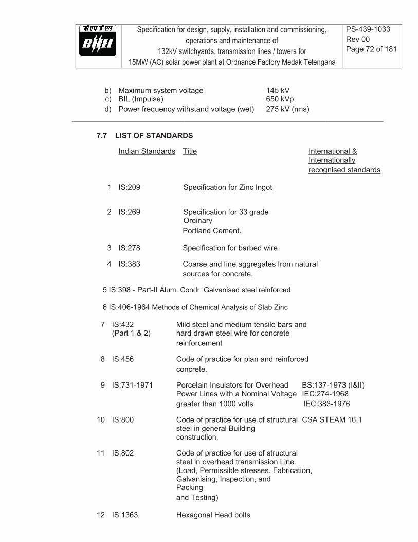
Specification for design, supply, installation and commissioning, operations and maintenance of
132kV switchyards, transmission lines / towers for 15MW (AC) solar power plant at Ordnance Factory Medak Telengana
PS-439-1033 Rev 00 Page 72 of 181
b) Maximum system voltage 145 kV c) BIL (Impulse) 650 kVp d) Power frequency withstand voltage (wet) 275 kV (rms)
7.7 LIST OF STANDARDS
Indian Standards Title International & Internationally recognised standards
1 IS:209 Specification for Zinc Ingot
2 IS:269 Specification for 33 grade Ordinary Portland Cement.
3 IS:278 Specification for barbed wire
4 IS:383 Coarse and fine aggregates from natural sources for concrete.
5 IS:398 - Part-II Alum. Condr. Galvanised steel reinforced
6 IS:406-1964 Methods of Chemical Analysis of Slab Zinc
7 IS:432 Mild steel and medium tensile bars and (Part 1 & 2) hard drawn steel wire for concrete reinforcement
8 IS:456 Code of practice for plan and reinforced concrete.
9 IS:731-1971 Porcelain Insulators for Overhead BS:137-1973 (I&II) Power Lines with a Nominal Voltage IEC:274-1968 greater than 1000 volts IEC:383-1976
10 IS:800 Code of practice for use of structural CSA STEAM 16.1
steel in general Building construction.
11 IS:802 Code of practice for use of structural steel in overhead transmission Line. (Load, Permissible stresses. Fabrication,
Galvanising, Inspection, and Packing
and Testing)
12 IS:1363 Hexagonal Head bolts
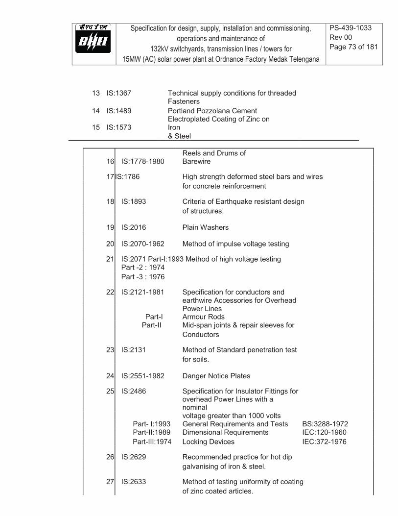
Specification for design, supply, installation and commissioning, operations and maintenance of
132kV switchyards, transmission lines / towers for 15MW (AC) solar power plant at Ordnance Factory Medak Telengana
PS-439-1033 Rev 00 Page 73 of 181
13 IS:1367 Technical supply conditions for threaded Fasteners
14 IS:1489 Portland Pozzolana Cement
15 IS:1573 Electroplated Coating of Zinc on Iron
& Steel
16 IS:1778-1980 Reels and Drums of Barewire
17 IS:1786 High strength deformed steel bars and wires for concrete reinforcement
18 IS:1893 Criteria of Earthquake resistant design of structures.
19 IS:2016 Plain Washers
20 IS:2070-1962 Method of impulse voltage testing
21 IS:2071 Part-I:1993 Method of high voltage testing Part -2 : 1974 Part -3 : 1976
22 IS:2121-1981 Specification for conductors and earthwire Accessories for Overhead Power Lines Part-I Armour Rods Part-II Mid-span joints & repair sleeves for Conductors
23 IS:2131 Method of Standard penetration test for soils.
24 IS:2551-1982 Danger Notice Plates
25 IS:2486 Specification for Insulator Fittings for
overhead Power Lines with a nominal
voltage greater than 1000 volts Part- I:1993 General Requirements and Tests BS:3288-1972 Part-II:1989 Dimensional Requirements IEC:120-1960 Part-III:1974 Locking Devices IEC:372-1976
26 IS:2629 Recommended practice for hot dip galvanising of iron & steel.
27 IS:2633 Method of testing uniformity of coating of zinc coated articles.

Specification for design, supply, installation and commissioning, operations and maintenance of
132kV switchyards, transmission lines / towers for 15MW (AC) solar power plant at Ordnance Factory Medak Telengana
PS-439-1033 Rev 00 Page 74 of 181
28 IS:3043-1987 Code of Practice for earthing (with amendment No. 1 & 2).
29 IS:3063-1994 Single Coil Rectangular Section spring washers for bolts, nuts, screws.
30 IS:3188-1980 Characteristics of string insulator units
31 IS:4091 Code of practice for design and transmission line tower and poles.
32 IS:4218 Metric Screw Threads.
33 IS:4759 Hot-dip zinc coatings on structural steel and other allied products
34 IS:4826 Galvanised coatings on round steel wire
35 IS:5300-1980 Porcelain Guy strain insulators
36 IS:5613 (Part-II) Code of practice for Design, installation & maintenance of overhead power lines
37 IS:6610 Specification for heavy washers for steel structures.
38 IS:6639 Hexagonal bolts for structure
39 IS:6745 Methods for determination of weight
Pub. No. 19 (N)/ Regulation for Electrical Crossing of 40 700-1963 Railway Tracks.
41 IS:7814 Phosphor bronze sheet, strip and foil
42 IS:8263-1976 Method of Radio Interference tests NEEMA:107 – 1964
On high voltage insulators CISPR/IEC:437-1937
43 IS:8269-1976 Method of switching impulse test IEC:506-1975 On high voltage insulators
44 IS:8500 Structural steel – Microalloyed (Medium and High Strenght qualities) – Specification
Specification for design, supply, installation and commissioning, operations and maintenance of
132kV switchyards, transmission lines / towers for 15MW (AC) solar power plant at Ordnance Factory Medak Telengana
PS-439-1033 Rev 00 Page 75 of 181
45 IS:9708-1993 Specifications for Stockbridge Vibration Dampers for overhead power lines
46 Thermal mechanical performance test IEC:575-1971
and mechanical performance test on
String insulator units
47 IS:12427 Fasteners - Threaded Steel Fasteners - Hexagon Head Transmission Tower Bolts – Specification
Specification for design, supply, installation and commissioning, operations and maintenance of
132kV switchyards, transmission lines / towers for 15MW (AC) solar power plant at Ordnance Factory Medak Telengana
PS-439-1033 Rev 00 Page 76 of 181
8.0 TOWER LINE ERECTION AND STRINGING
8.1 GENERAL REQUIREMENTS
a) The details of the scope of erection work shall include the cost of labour, all tools and plants like tension stringing equipment and all other incidental expenses in connection with erection and stringing work.
b) The Contractor shall be responsible for transportation of all the materials to be
provided by the Contractor as per the scope of work to site, proper storage and preservation at their own cost till such time the erected line is taken over by the Owner.
c) The quantities of conductor, earthwire, insulators hardware, accessories of conductor
&earthwire, etc. are estimated by the Owner include excess material towards wastages and damages during erection.
8.2 TREATMENT OF MINOR GALVANISING DAMAGE
In case any minor damage to galvanizing is noticed, the same shall be treated with zinc rich paint (having at least 90% zinc content) before erection.
8.3 ASSEMBLY
8.3.1 The method followed for the erection of towers, shall ensure the points
mentioned below:
Straining of the members shall not be permitted for bringing them into position. It may, however, be necessary to match hole positions at joints and to facilitate this, tommy bars not more than 450 mm long may be used.
Before starting erection of an upper section, the lower section shall be completely braced and all bolts provided and tightened adequately in accordance with approved drawings to prevent any mishap during tower erection.
All plan diagonals relevant to a section of tower shall be placed in position before assembly of upper section is taken up.
The bolt position in assembled towers shall be as per IS:5613 (Part-II/Section2)-1976.
Tower shall be fitted with number plate, danger plate, phase plate and anti- climbing device as described.
All bank holes, if any left, after complete erection of the tower, are to be filled up by bolts and nuts of correct size.
8.3.2 Tightening and Punching of Bolts and Nuts
a) All nuts shall be tightened properly using correct size spanner/torque wrench. Before
tightening, it shall be ensured that filler washers and plates are placed in gaps between members wherever applicable, bolts of proper size and length are inserted, and one spring washer is inserted under each nut. In case of step bolts, spring washers shall be placed under the outer nut. The tightening shall progressively be carried out from the top downwards, care being taken that all bolts at every level are tightened
Specification for design, supply, installation and commissioning, operations and maintenance of
132kV switchyards, transmission lines / towers for 15MW (AC) solar power plant at Ordnance Factory Medak Telengana
PS-439-1033 Rev 00 Page 77 of 181
simultaneously. The threads of bolts projecting outside the nuts shall be punched at their position on the diameter to ensure that the nuts are not loosened in course of time. If during tightening a nut is found to be slipping or running over the bolt threads, the bolt together with the nut shall be replaced.
b) The threads of all the bolts projected outside the nuts shall be welded at two
diametrically opposite places. The welding shall be provided from ground level to waist level for single circuit towers and to bottom cross arm level for double circuit towers. After welding, cold galvanised paint having at least 90% Zinc content shall be applied to the welded portion. At least two coats of the paint shall be applied. The cost of welding and paint including application of paint shall be deemed to be included in the erection price.
c) In addition to the tack welding of nuts with bolts, as described above, the Contractor
can also propose some alternative arrangements, like use of epoxy resin adhesive which can serve the purpose of locking the nut permanently with the bolt and thus preventing pilferage of the tower members.
8.4 INSULATOR HOISTING
I-Suspension insulator strings shall be used on suspension towers and tension insulator strings on angle and dead end towers. These shall be fixed on all the towers just prior to the stringing. Damaged insulators and fittings, if any, shall not be employed in the assemblies. Before hoisting, all insulators shall be cleaned in a manner that will not spoil, injure or scratch the surface of the insulator, but in no case shall any oil be used for the purpose. Corona control rings/arching horn shall be fitted in an approved manner. The yoke arrangements be horizontal for tensions strings. Torque wrench shall be used for fixing different line materials and their components, like suspension clamp for conductor and earthwire, etc., whenever recommended by the manufacturer of the same of river crossing towers.
8.5 HANDLING OF CONDUCTOR AND EARTHWIRE
a) The Contractor shall be entirely responsible for any damage to the towers or conductors during stringing. While running out the conductors, care shall be taken that the conductors do not touch or rub against the ground or objects which could cause scratches or damages to the strands. The conductors shall be run out of the drums from the top in order to avoid damage due to chafing. Immediately after running out, the conductor shall be raised at the supports to the levels of the clamps and placed into the running blocks. The groove of the running blocks shall be of such a design that the seat is semi-circular and larger than the diameter of the conductor earthwire and it does not slip over or rub against the sides. The grooves shall be lined with hard rubber or neoprene to avoid damage to conductor and shall be mounted on properly lubricated bearings.
b) The running blocks shall be suspended in a manner to suit the design of the crossarm.
All running blocks, especially those at the tension end, will be fitted on the cross-arm with jute cloth wrapped over the steel work and under the slings to avoid damage to the slings as well as to the protective surface finish of the steel work. In case suspension, or section towers are used even for temporary terminations, if this be unavoidable, they shall be well guyed and steps shall be taken by the Contractor to

Specification for design, supply, installation and commissioning, operations and maintenance of
132kV switchyards, transmission lines / towers for 15MW (AC) solar power plant at Ordnance Factory Medak Telengana
PS-439-1033 Rev 00 Page 78 of 181
avoid damage. Guying proposal alongwith necessary calculations shall be submitted by the Contractor to Owner by the Contractor for checking the tensions in the guy made available to the Owner by the Contractor for checking the tensions in the guy wires. The drums shall be provided with a suitable braking device to avoid damages, loose running out and kinking of the conductor. The conductor shall be continuously observed for loose or broken strands or any other damage. When approaching end of a drum length, at least three coils shall be left when the stringing operations are to be stopped. These coils are to be removed carefully, and if another length is required to be run out, a joint shall be made as per the recommendations of the manufacturers.
c) Repairs to conductors, if necessary, shall be carried out during the running out operations,
with repair sleeves. Repairing of conductor surface shall be done only in case of minor damage, scuff marks etc. keeping in view both electrical and mechanical safe requirements. The final conductor surface shall be clean smooth and without any projections, sharp points, cuts, abrasions etc.
d) Conductor splices shall be so made that they do not crack or get damaged in the stringing
operation. The contractor shall use only such equipment/methods during conductor stringing which ensures complete compliance in this regard.
e) Derricks shall be used where roads, rivers, channels, telecommunication or overhead
power lines, railway lines, fences or walls have to be crossed during stringing operations. It shall be seen that normal services are not interrupted or damage caused to property. Shut down shall be obtained when working at crossing of overhead power lines. The Contractor shall be entirely responsible for the proper handling of the conductor, earth-wire and accessories in the field.
f) The sequence of running out shall be from top to downwards i.e. the earthwire shall
be run out first, followed by the conductors in succession. Unbalances of loads on towers shall be avoided as far as possible.
g) The proposed 132 kV transmission line may run parallel for certain distance with the
existing Transmission lines which may remain energised during the stringing period. As a result there is a possibility of dangerous voltage build up due to electromagnetic and electrostatic coupling in the pulling wire, conductors and earthwires, which although comparatively small during normal operations can be severe during switching. It shall be the Contractor's responsibility to take adequate safety precautions to protect his employees and others from this potential danger.
h) B and C type of towers are not designed for one side stringing. Thereforeproper guying
arrangement shall be made for B and C type of towers during stringing on one section while the other section is not strung. The Contractor has to submit the detailed proposal alongwith the calculation for guying which shall be approved by the Owner. Proper T&P shall be made available to the Owner by the Contractor for checking the tensions in the guy wires. All the expenditure on account of the above work is deemed to be included in the bid price and no extra payment shall be made for the same.
8.6 STRINGING OF CONDUCTOR AND EARTHWIRE
8.6.1 The stringing of the conductor shall be done by standard stringing method.
8.6.2 After being pulled the conductor/earthwire shall not be allowed to hang in the
stringing blocks for more than 96 hours before being pulled to the specified sag.

Specification for design, supply, installation and commissioning, operations and maintenance of
132kV switchyards, transmission lines / towers for 15MW (AC) solar power plant at Ordnance Factory Medak Telengana
PS-439-1033 Rev 00 Page 79 of 181
8.6.3 Conductor creep are to be compensated by over tensioning the conductor at
appropriate temperature for which calculations are to be submitted by the contractor for Owner's approval.
8.6.4 The Bidder shall give complete details of the stringing methods which be proposes to follow. Before the commencement of stringing the Contractor shall submit the stringing charts for the conductor and earthwire for various temperatures and span alongwith equivalent spans for the approval of the Owner.
8.6.5 Jointing
a) All the joints on the conductor and earthwire shall be of compression type, in
accordance with the recommendations of the manufacturer for which all necessary tools and equipment like compressors, dies, processes etc. shall have to be arranged by the Contractor. Each part of the joint shall be cleaned by wire brush to make it free of rust or dirt etc. and properly greased with anti-corrosive compound if required, and as recommended by the contractor before the final compression is done with the compressors.
b) All joints or splices shall be made at least 30 meters away from the structures
. No joints or splices shall be made in spans crossing over main road, railways, small rivers with tension spans. During compression or splicing operation the conductor shall be handled in such a manner as to prevent lateral or vertical bearing against the dies. After pressing the joint the aluminium sleeve shall have all corners rounded, burrs and sharp edges removed and smoothened.
c) During stringing of conductor to avoid any damage to the joint, the Contractor
shall use a suitable protector with mid span compression joints in case joints are to be passed over pulley blocks/aerial rollers. The size of the groove of the pulley shall be such that the joint along with protection can be passed over it smoothly.
8.6.6 Sagging-in-Operation
a) The conductor shall be pulled upto the desired sag and left in running blocksfor
atleast one hour after which the sag shall be re-checked and adjusted, if necessary before transferring the conductor from the running blocks to the suspension clamps. The conductors shall be clamped within 36 hours of sagging in.
b) The sag will be checked in the first and the last span of the section in case of
sections upto eight spans and in one intermediate span also for sections with more than eight spans. The sag shall also be checked when the conductors have been drawn up and transferred from running blocks to the insulator clamps.
c) The running blocks, when suspended from the transmission structure for sagging
shall be so adjusted that the conductors on running blocks will be at the same height as the suspension clamp to which it is to be secured,
d) At sharp vertical angles, the sags and tensions shall be checked on both sides of
the angle, he conductor and earthwire shall be checked on the running blocks for
Specification for design, supply, installation and commissioning, operations and maintenance of
132kV switchyards, transmission lines / towers for 15MW (AC) solar power plant at Ordnance Factory Medak Telengana
PS-439-1033 Rev 00 Page 80 of 181
equality of tension on both sides. The suspension insulator assemblies will normally assume vertical positions when the conductor is clamped.
e) Tensioning and sagging operations shall be carried out in clam weather when rapid
changes in temperatures are not likely to occur. Tensioning and Sagging of Conductors and Earthwire The tensioning and sagging shall be done in accordance with the approved stringing charts before the conductors and earthwire are finally attached to the tower through the earthwire clamps for the earthwire and insulator strings for the conductor. The `Initial' stinging chart shall be used for the conductor and `final' stringing chart for earth-wire should be employed for this purpose. Dynamometers shall be employed for measuring tension in the conductor and earthwire. The dynamometers employed shall be periodically checked and calibrated with the standard dynamometer.
8.6.7 Clipping In
a) Clipping of the conductors in positions hall be done in accordance with the
recommendations of the manufacturer. Conductor shall be fitted with armour rods where it is made to pass through suspension clamps.
b) The jumpers at the section and angle towers shall be formed to parabolic shape to
ensure maximum clearance requirements and shall match the jumper drops shown in the tower drawings.
c) Fasteners in all fittings and accessories shall be secured in position. The security
clip shall be properly opened and sprung into position.
8.6.8 Fixing of Conductor and Earthwire Accessories
Vibration dampers for conductor and earthwire and other conductor and earthwire accessories shall be installed by the Contractor as per the design requirement and respective manufacturer's instructions within 24 hours of the conductor/earthwire clamping. While installing the conductor and earthwire accessories, proper care shall be taken to ensure that the surfaces are clean and smooth and no damage shall occur to any part of the accessories.
8.7 REPLACEMENT
a) If any replacements are to be effected after stringing and tensioning or during maintenance, leg members and bracings shall not be removed without reducing the tension on the tower with proper guying or releasing the conductor. If the replacement of cross arms becomes necessary after stringing, the conductor shall be suitably tied to the tower at tension points or transferred to suitable roller pulleys as suspension points.
b) The Contractor shall not be required to return to the Owner, empty conductor and
earthwire drums and shall dispose off the same at his cost except for steel drums which shall be returned to Owner.

Specification for design, supply, installation and commissioning, operations and maintenance of
132kV switchyards, transmission lines / towers for 15MW (AC) solar power plant at Ordnance Factory Medak Telengana
PS-439-1033 Rev 00 Page 81 of 181
c) Any conductor and earthwire drum which has been opened by the Contractor shall not be taken back by Owner and the unused conductor or earthwire in such drum shall be treated as wastage permissible within the overall limits.
8.8 FINAL CHECKING TESTING AND COMMISSIONING
After completion of the works, final checking of the line shall be done by the Contractor to ensure that all the foundation works, tower erection, and stringing have been done strictly according to the specifications and as approved by the Owner. All the works shall be thoroughly inspected keeping in view of the following main points:
a) Sufficient backfilled earth is lying over each foundation pit and it is adequately
compacted. b) Concrete chimneys and their copings are is good finally shaped conditions. c) All the tower members are correctly used, strictly according to final approved drawing
and are free of any defect or damage, whatsoever. d) All bolts are properly tightened and punched/tack welded. e) The stringing of the conductors and earthwire has been done as per the approved sag
and tension charts and desired clearances are clearly available. f) All conductor and earthwire accessories are properly installed. g) All other requirements to complete the work like fixing of danger plate, phase plate,
number plate, anti climbing device etc., are properly installed. h) Wherever required it should be ensured that revetment is provided. i) The original tracings of profile route alignment and tower, design, structural drawings,
bill of material, shop drawings of all towers are submitted to the Owner for reference and record.
j) The insulation of line as a whole is tested by the Contractor by providing his own
equipment, labour etc. to the satisfaction of the Owner. k) All towers are properly grounded. l) The line is tested satisfactorily for commissioning purpose.

Specification for design, supply, installation and commissioning, operations and maintenance of
132kV switchyards, transmission lines / towers for 15MW (AC) solar power plant at Ordnance Factory Medak Telengana
PS-439-1033 Rev 00 Page 82 of 181
9.0 TRANSMISSION LINE TOWERS
9.1 GENERAL DESCRIPTION OF TOWERS
9.1.1 Types of Towers
a) The towers shall be of self supporting lattice steel type, designed to carry the line
conductors with necessary insulators, earth wires and all fittings under all loading conditions.
b) The tower shall be of a fully galvanised structure, using structural mild steel sections
for members. Bolts and nuts with spring washers shall be used for connections.
c) Bidders can also use high tensile steel and cold formed steel for fabrication of towers provided they furnish the justification for use of such steel with reference to national or international standards. However, the factors of safety, limitation on member length, requirement of fasteners and galvanisation shall be as specified in this specification.
The towers shall be classified as given in Table 1-1
Table T1-1 Type of Tower Deviation limit
A 0 to 2
B 0 to 15
Typical use To be used as tangent/suspension tower
a) Angle towers with tension
insulator string b) Tension tower for uplift forces
resulting from an uplift span upto half of ruling span under broken wire conditon.
c) Also to be designed for
unbalanced tension resulting from unequal ruling span as specified in table T1-2.
B 0 d) to be used as section tower
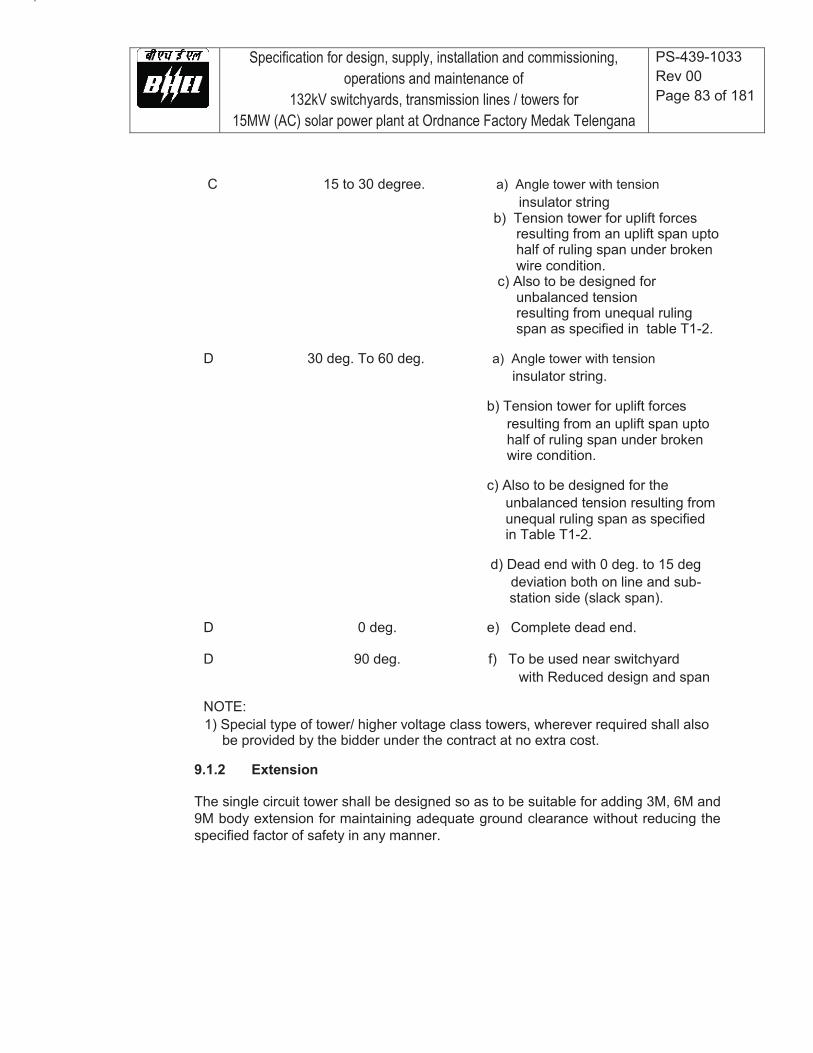
Specification for design, supply, installation and commissioning, operations and maintenance of
132kV switchyards, transmission lines / towers for 15MW (AC) solar power plant at Ordnance Factory Medak Telengana
PS-439-1033 Rev 00 Page 83 of 181
C 15 to 30 degree. a) Angle tower with tension
insulator string b) Tension tower for uplift forces
resulting from an uplift span upto half of ruling span under broken wire condition.
c) Also to be designed for unbalanced tension resulting from unequal ruling span as specified in table T1-2.
D 30 deg. To 60 deg. a) Angle tower with tension
insulator string.
b) Tension tower for uplift forces resulting from an uplift span upto half of ruling span under broken wire condition.
c) Also to be designed for the
unbalanced tension resulting from unequal ruling span as specified in Table T1-2.
d) Dead end with 0 deg. to 15 deg
deviation both on line and sub- station side (slack span).
D 0 deg. e) Complete dead end.
D 90 deg. f) To be used near switchyard
with Reduced design and span
NOTE: 1) Special type of tower/ higher voltage class towers, wherever required shall also
be provided by the bidder under the contract at no extra cost.
9.1.2 Extension
The single circuit tower shall be designed so as to be suitable for adding 3M, 6M and 9M body extension for maintaining adequate ground clearance without reducing the specified factor of safety in any manner.
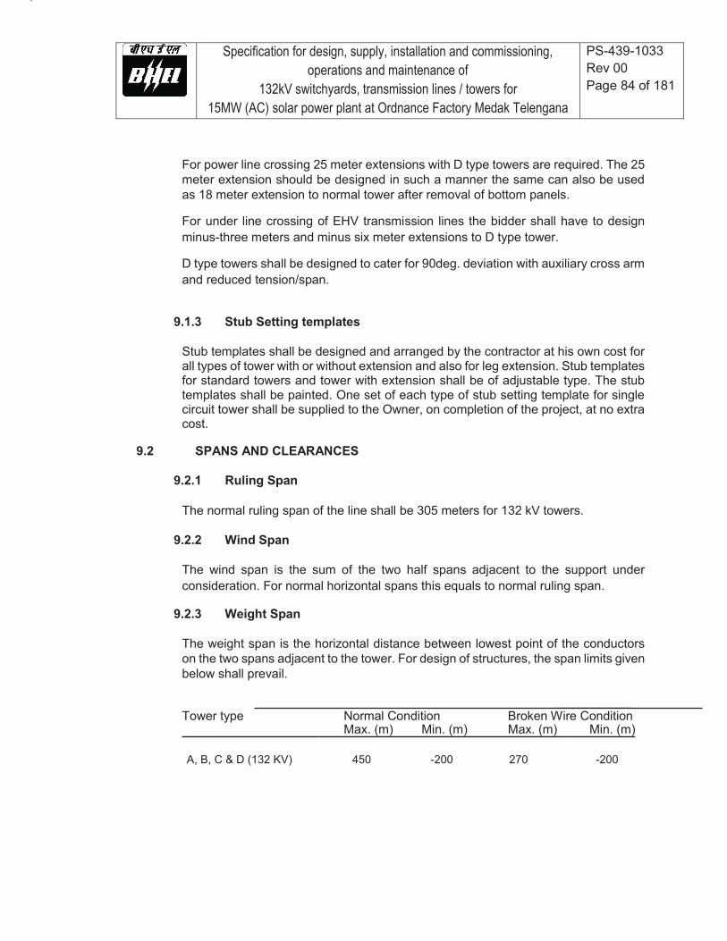
Specification for design, supply, installation and commissioning, operations and maintenance of
132kV switchyards, transmission lines / towers for 15MW (AC) solar power plant at Ordnance Factory Medak Telengana
PS-439-1033 Rev 00 Page 84 of 181
For power line crossing 25 meter extensions with D type towers are required. The 25 meter extension should be designed in such a manner the same can also be used as 18 meter extension to normal tower after removal of bottom panels.
For under line crossing of EHV transmission lines the bidder shall have to design minus-three meters and minus six meter extensions to D type tower.
D type towers shall be designed to cater for 90deg. deviation with auxiliary cross arm and reduced tension/span.
9.1.3 Stub Setting templates
Stub templates shall be designed and arranged by the contractor at his own cost for all types of tower with or without extension and also for leg extension. Stub templates for standard towers and tower with extension shall be of adjustable type. The stub templates shall be painted. One set of each type of stub setting template for single circuit tower shall be supplied to the Owner, on completion of the project, at no extra cost.
9.2 SPANS AND CLEARANCES
9.2.1 Ruling Span
The normal ruling span of the line shall be 305 meters for 132 kV towers.
9.2.2 Wind Span
The wind span is the sum of the two half spans adjacent to the support under consideration. For normal horizontal spans this equals to normal ruling span.
9.2.3 Weight Span
The weight span is the horizontal distance between lowest point of the conductors on the two spans adjacent to the tower. For design of structures, the span limits given below shall prevail.
___________
Tower type Normal Condition Broken Wire Condition Max. (m) Min. (m) Max. (m) Min. (m)
A, B, C & D (132 KV) 450 -200 270 -200
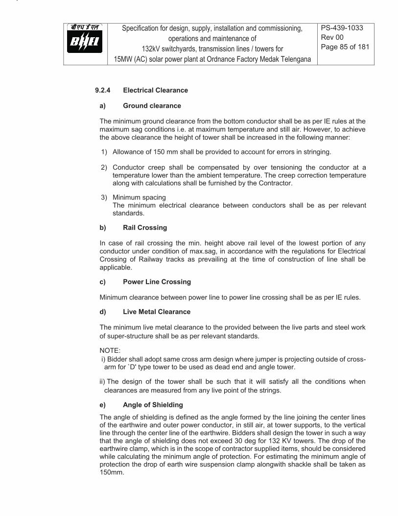
Specification for design, supply, installation and commissioning, operations and maintenance of
132kV switchyards, transmission lines / towers for 15MW (AC) solar power plant at Ordnance Factory Medak Telengana
PS-439-1033 Rev 00 Page 85 of 181
9.2.4 Electrical Clearance
a) Ground clearance
The minimum ground clearance from the bottom conductor shall be as per IE rules at the maximum sag conditions i.e. at maximum temperature and still air. However, to achieve the above clearance the height of tower shall be increased in the following manner:
1) Allowance of 150 mm shall be provided to account for errors in stringing.
2) Conductor creep shall be compensated by over tensioning the conductor at a
temperature lower than the ambient temperature. The creep correction temperature along with calculations shall be furnished by the Contractor.
3) Minimum spacing
The minimum electrical clearance between conductors shall be as per relevant standards.
b) Rail Crossing
In case of rail crossing the min. height above rail level of the lowest portion of any conductor under condition of max.sag, in accordance with the regulations for Electrical Crossing of Railway tracks as prevailing at the time of construction of line shall be applicable.
c) Power Line Crossing
Minimum clearance between power line to power line crossing shall be as per IE rules.
d) Live Metal Clearance
The minimum live metal clearance to the provided between the live parts and steel work of super-structure shall be as per relevant standards.
NOTE: i) Bidder shall adopt same cross arm design where jumper is projecting outside of cross-arm for `D' type tower to be used as dead end and angle tower.
ii) The design of the tower shall be such that it will satisfy all the conditions when
clearances are measured from any live point of the strings.
e) Angle of Shielding
The angle of shielding is defined as the angle formed by the line joining the center lines of the earthwire and outer power conductor, in still air, at tower supports, to the vertical line through the center line of the earthwire. Bidders shall design the tower in such a way that the angle of shielding does not exceed 30 deg for 132 KV towers. The drop of the earthwire clamp, which is in the scope of contractor supplied items, should be considered while calculating the minimum angle of protection. For estimating the minimum angle of protection the drop of earth wire suspension clamp alongwith shackle shall be taken as 150mm.
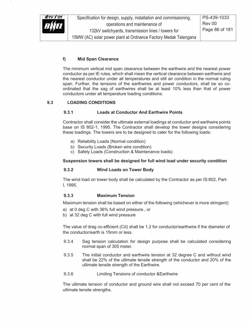
Specification for design, supply, installation and commissioning, operations and maintenance of
132kV switchyards, transmission lines / towers for 15MW (AC) solar power plant at Ordnance Factory Medak Telengana
PS-439-1033 Rev 00 Page 86 of 181
f) Mid Span Clearance
The minimum vertical mid span clearance between the earthwire and the nearest power conductor as per IE rules, which shall mean the vertical clearance between earthwire and the nearest conductor under all temperatures and still air condition in the normal ruling span. Further, the tensions of the earthwires and power conductors, shall be so co-ordinated that the sag of earthwires shall be at least 10% less than that of power conductors under all temperature loading conditions.
9.3 LOADING CONDITIONS
9.3.1 Loads at Conductor And Earthwire Points
Contractor shall consider the ultimate external loadings at conductor and earthwire points base on IS 802-1, 1995. The Contractor shall develop the tower designs considering these loadings. The towers are to be designed to cater for the following loads:
a) Reliability Loads (Normal condition) b) Security Loads (Broken wire condition) c) Safety Loads (Construction & Maintenance loads)
Suspension towers shall be designed for full wind load under security condition
9.3.2 Wind Loads on Tower Body
The wind load on tower body shall be calculated by the Contractor as per IS:802, Part-I, 1995.
9.3.3 Maximum Tension Maximum tension shall be based on either of the following (whichever is more stringent): a) at 0 deg C with 36% full wind pressure., or b) at 32 deg C with full wind pressure
The value of drag co-efficient (Cd) shall be 1.2 for conductor/earthwire if the diameter of the conductor/earth is 15mm or less.
9.3.4 Sag tension calculation for design purpose shall be calculated considering
normal span of 305 meter.
9.3.5 The initial conductor and earthwire tension at 32 degree C and without wind shall be 22% of the ultimate tensile strength of the conductor and 20% of the ultimate tensile strength of the Earthwire.
9.3.6 Limiting Tensions of conductor &Earthwire
The ultimate tension of conductor and ground wire shall not exceed 70 per cent of the ultimate tensile strengths.
Specification for design, supply, installation and commissioning, operations and maintenance of
132kV switchyards, transmission lines / towers for 15MW (AC) solar power plant at Ordnance Factory Medak Telengana
PS-439-1033 Rev 00 Page 87 of 181
9.3.7 Broken Wire Condition
The loads for broken wire conditions shall be considered as per clause 16 of IS 802 (Part I/ Sec 1): 1995. The tower type B & C shall be considered as small and medium angle towers whereas tower type D shall be considered as large angle tension tower/ dead end tower.
9.3.8 Design Loads
Owner’s requirement for most stringent design longitudinal and transverse loads is summarized in Table T1-2.
9.4 DESIGN OF TOWERS
9.4.1 Design Criteria
Towers shall be designed based on spans and clearances, and loading conditions as detailed above.
9.4.2 Design Temperatures
The following temperature range for the conductors and ground wires shall be adopted for line design:
a) Minimum temperature : 0 deg.C b) Everyday temperature of conductor : 32 deg.C c) Max. temperature of Conductor : 75 deg.C d) Max. temperature of Earthwire exposed to sun : 53 deg.C
Specification for design, supply, installation and commissioning, operations and maintenance of
132kV switchyards, transmission lines / towers for 15MW (AC) solar power plant at Ordnance Factory Medak Telengana
PS-439-1033 Rev 00 Page 88 of 181
9.4.3 Redundant Design
All redundants in the towers are to be triangulated. Redundants, having an angle of 15 deg or less with horizontal are to be designed for a concentric vertical ultimate load of 1.5 KN acting at center of the unsupported length. The Contractor has to furnish the calculation for the same. The redundants shall also be designed for 2.5% of max. axial load of connecting members (i.e. leg members, bracing members etc.).
9.4.4 Steel Sections
For designing of towers, preferably rationalised steel sections shall be used. During execution of the project, if any particular section is not available same shall be substituted by higher section at no extra cost to Owner and the same shall be borne by the Contractor. However, design approval for such substitution shall be obtained from the Owner before any substitution.
9.4.5 Thickness of Members
The minimum thickness of angle sections used in the design of tower, unless otherwise specified elsewhere in this Specification, shall be kept not less than the following values:
a) Main corner leg members including the groundwire peak and main cross arm : 5 mm b) For all other members : 4 mm
9.4.6 Bolts & Nuts
a) The minimum bolt spacing and rolled edge distance and sheared edge distance from
the centers of the bolt holes to be maintained are given below:
1) Diameter of bolts 16 mm 2) Hole diameter 17.5 mm 3) Min. bolt spacing 40 mm 4) Min. rolled distance 20 mm 5) Min. sheared edge distance 23 mm
b) Bolts sizes mentioned above shall only be used. The minimum width of the flanges
without bolt holes shall be 30mm.
c) For the purpose of calculating shearing stress and bearing stress for bolts, IS:802-Part-II-1993 may be referred.

Specification for design, supply, installation and commissioning, operations and maintenance of
132kV switchyards, transmission lines / towers for 15MW (AC) solar power plant at Ordnance Factory Medak Telengana
PS-439-1033 Rev 00 Page 89 of 181
9.4.7 Slenderness Ratio
a) Slenderness ratio for members shall be computed in accordance with IS:802, Part-
II, 1993. Slenderness ratio for compression and tension members shall not exceed the values specified therein.
b) The following maximum limit of the slenderness ratio i.e. the ratio of unsupported
length of the section in any plane to the appropriate radius of gyration will be adopted:
1) For main corner leg members including the corner 120 members of earthwire peak and the lower corner members of the cross-arms 2) For other members having calculated stresses 200 3) For redundant members 250 4) For members having tensile stress only 400
c) The bracing pattern, including that of secondary bracings (redundants) shall be
identical on transverse and longitudinal faces of the tower, i.e. staggering of primary and secondary bracings are not permitted. Primary bracings and redundants shall be properly triangulated, i.e. the overall pattern of bracing on tower body and cross arms shall be triangular only.
9.4.8 Erection Stress
Where erection stress combined with other permissible co-existent stresses could produce a working stress in any member appreciably above the specified working stress, such other provisions are to be made as may be necessary to bring the working stress within the specified limit.
9.5 TOWER MATERIALS
9.5.1 Tower Steel Sections
IS steel sections of tested quality in conformity with IS: 2062 or IS: 8500 are to be used in towers, extensions and stub setting templates. No individual member shall be longer than 6000mm. The Bidder can also use most efficient grades of structural steel angle sections and plates conforming to latest international standards. However, the Bidders are permitted to opt for not more than two (2) grades of steel for any particular package.

Specification for design, supply, installation and commissioning, operations and maintenance of
132kV switchyards, transmission lines / towers for 15MW (AC) solar power plant at Ordnance Factory Medak Telengana
PS-439-1033 Rev 00 Page 90 of 181
9.5.2 Fasteners: Bolts, Nuts and Washers a) All bolts and nuts shall conform to IS: 6639. All bolts and nuts shall be galvanised
and shall have hexagonal head and nuts, the heads being forged out of the solid, truly concentric, and square with the shank, which must be perfectly straight.
b) The bolt shall be of 16 mm dia and of property class 5.6 as specified in IS:1367 (Part-
III) 1979 and matching nut of property class as specified in IS:1367 (Part-VI).
c) Bolts upto M16 and having length upto 10 times the diameter of the bolt should be manufactured by cold forging and thread rolling process to obtain good and reliable mechanical properties and effective dimensional control. The shear strength of bolts for 5.6 grade should be 310 MP a minimum as per IS:12427. Bolts should be provided with washer face in accordance with IS:1363 Part-I to ensure proper bearing.
d) To ensure uniformity of galvanizing, bolts and nuts should be galvanised by high
temperature hot-dip galvanizing.
e) Nuts should be double chamfered as per the requirement of IS:1363 Part-III. It should be ensured by the manufacturer that nuts should not be overtapped beyond 0.4 MM oversize on effective diameter for size upto M16.
f) Fully threaded bolts shall not be used. The length of bolts shall be such that the
threaded portion will not extend into the place of contact of the members.
g) All bolts shall be threaded to take the full depth of the nuts and threaded enough to permit firm gripping of the members, but not further. It shall be ensured that the threaded portion of each bolt protrudes not less than 3 mm and not more than 8mm when fully tightened. All nuts shall fit and tight to the point where the shank of the bolt connects to the head.
h) Flat and tapered washers shall be provided wherever necessary. Spring washers
shall be provided for insertion under all nuts. These washers shall be of steel electro-galvanised, positive lock type and 3.5mm in thickness for 16mm dia.
i) The Bidder shall furnish bolt schedules giving thickness of members connected, the
nut and the washer and the length of shank and the threaded portion bolts and sizes of holes and any other special details of this nature.
j) To obviate bending stress in bolts or to reduce to minimum, no bolt shall connect
aggregate thickness of more than three (3) times its diameter.
k) The bolt positions in assembled towers shall be as per IS:5613 (Part-II/Section-2).
l) Bolts at the joints shall be so staggered that nuts may be tightened with spanners without fouling.
9.5.3 Tower Accessories
a) Step Bolts & ladders

Specification for design, supply, installation and commissioning, operations and maintenance of
132kV switchyards, transmission lines / towers for 15MW (AC) solar power plant at Ordnance Factory Medak Telengana
PS-439-1033 Rev 00 Page 91 of 181
Each tower shall be provided with step bolts of not less than 16mm diameter and 175 mm long, spaced not more than 450mm apart and extending from about 3.5 meters above the ground level to the top of the tower. Step bolt shall be provided with two nuts on one end to fasten the bolt securely to the tower and button head at the other end to prevent the feet from slipping away. The step bolts shall be capable of withstanding a vertical load not less than 1.5 KN. For special structures, where the height of the super structure exceeds 50 meters, ladders along with protection rings shall be provided in continuation of the step bolts on one face of the tower from 30 meters above ground level to the top of the special structure. From 3.5 m to 30 m height of super structure step bolts shall be provided. Suitable railing for access from step bolts to the ladder and from the ladder to each cross arm tip and the groundwire support shall be fixed on tower by using countersunk bolts.
b) Insulator Strings and Earthwire Clamps Attachments
1) For the attachment of suspension insulator string a suitable dimensioned
swinging hanger on the tower shall be provided so as to obtain requisite clearance under extreme swinging conditions and free from swinging of the string. The hanger shall be designed to withstand an UTS equivalent to that of insulators. The supply of design & supply of hanger is in the scope of the Contractor.
2) At tension towers strain plates of suitable dimensions on the underside of each
cross-arm tip and at the top of earthwire peak, suitable plate should be provided for taking the hooks or D-Shackle of the tension insulator strings or earthwire tension clamps, as the case may be. Full details of the attachments shall be submitted by the bidder for Owner's approval before starting the mass fabrication.
c) Earthwire peaks/crossarms are to be suitably designed to accommodate the shackle
of the suspension clamp/tension clamps.
d) Anti-climbing Device
Barbed wire type anti-climbing device shall be provided and installed by the Contractor for all towers. The height of the anti-climbing device should be provided approximately 3m above ground level. The barbed wire shall conform to IS-278-1978. The barbed wires shall be given chromating dip as per procedure laid down in IS:1340-1959.
Specification for design, supply, installation and commissioning, operations and maintenance of
132kV switchyards, transmission lines / towers for 15MW (AC) solar power plant at Ordnance Factory Medak Telengana
PS-439-1033 Rev 00 Page 92 of 181
e) Danger plate, Number plates, Circuit Plate, Phase plate & Bird Guards.
Danger, Number Plates, Phase Plates & Bird Guards shall be provided and installed by the Contractor:
1) Each tower shall be fitted with a number plate, and danger plate. Each tension tower
shall be provided with a set of phase plates also. The arrangement for fixing these accessories shall not be more than 4.5m above the ground level.
2) The letters, figures and the conventional skull and bones of data plates shall conform to IS:2551-1963 and shall be in a single red on the front of the plate.
3) The corners of the number and danger plate shall be rounded off to remove sharp edges.
4) To prevent birds from perching immediately above the suspension insulator strings
and thus fouling it with droppings suitable birdguards shall be provided at cross arm tips of all suspension towers. The arrangement shall conform to IS:5613 part-2/Sec.I.
9.6 TOWER FABRICATION
9.6.1 Except where hereinafter modified, details of fabrication shall conform to IS:802
(Part-II) or the relevant international standards.
9.6.2 Butt splices shall be used and the inside Angle and outside plate shall be designed to transmit the load and inside cleat angle, shall not be less than half the thickness of the heavier member connected plus 2mm. Lap splice may be used for connecting members of unequal size and the inside angle of lap splice shall be rounded at the heel to fit the fillet of the outside angle. All splices shall develop full stress in the member connected through bolts. Butt as well as lap splice shall be made as above and as close to the main panel point as possible.
9.6.3 Joints shall be so designed as to avoid eccentricity as far as possible. The use of
gusset plates for joining tower members shall be avoided as far as possible. However, where the connections are such that the elimination of the gusset plates would result in eccentric joints, gussets plates and spacer plates may be used in conformity with modern practices. The thickness of the gusset plates required to transmit stress shall not be less than that of members connected.
9.6.4 The use of filler in connection shall be avoided as far as possible. The diagonal web members in tension may be connected entirely to the gusset plate wherever necessary to avoid the use of filler and it shall be connected at the point of intersection by one or more bolts.
9.6.5 The tower structures shall be accurately fabricated to connect together easily at site without any undue strain on the bolts.

Specification for design, supply, installation and commissioning, operations and maintenance of
132kV switchyards, transmission lines / towers for 15MW (AC) solar power plant at Ordnance Factory Medak Telengana
PS-439-1033 Rev 00 Page 93 of 181
9.6.6 No angle member shall have the two leg flanges brought together by closing
angle.
9.6.7 The diameter of the hole shall be equal to the diameter of bolt plus 1.5mm.
9.6.8 The structure shall be designed so that all parts shall be accessible for inspection and cleaning. Drain holes shall be provided at all points where pockets depression are likely to hold water.
9.6.9 All similar parts shall be made strictly inter-changeable. All steel sections before any work is done on them, shall be carefully leveled, straightened and made true to detailed drawings by methods which will not injure the materials so that when assembled, the adjacent matching surfaces are in close contact through out. No rough edges shall be permitted in the entire structure.
9.6.10 Drilling and Punching
a) Before any cutting work is started all steel sections shall be carefully straightened and
trued by pressure and not by hammering. They shall again be trued after being punched and drilled.
b) Holes for bolts shall be drilled on punched with a jig but drilled holes shall be preferred.
The following maximum tolerance of accuracy of punched holes is permissible.
1) Holes must be perfectly circular and no tolerance in this respect permissible. 2) The max. allowable difference in diameter of the holes on the two sides of
plates or angle is 0.8mm. i.e. the allowable taper in a punched holes should not exceed 0.8mm on diameter.
3) Holes must be square with the plates or angles and have their walls parallel.
c) All burrs left by drills or punch shall be removed completely. When the tower members are in position the holes shall be truly opposite to each other. Drilling or reaming to enlarge holes shall not be permitted.
9.6.11 Erection mark

Specification for design, supply, installation and commissioning, operations and maintenance of
132kV switchyards, transmission lines / towers for 15MW (AC) solar power plant at Ordnance Factory Medak Telengana
PS-439-1033 Rev 00 Page 94 of 181
a) Each individual member shall have erection mark conforming to the component number given to it in the fabrication drawings. This mark shall be marked with marking dies of 16mm size before galvanising and shall be legible after galvanising.
b) Erection Mark shall be “A - BB- CC – DDD”, where
A = Owner's code assigned to the Contractor Alphabet. BB = Contractor's Mark-Numerical CC = Tower Type-Alphabet DDD = Number mark to be assigned by Contractor.
9.6.12 Quantities and Weights
The unit weight of each type of tower, stubs and extensions shall be furnished by the bidder. The weight of tower shall mean the weight of tower calculated by using the black sectional (i.e. un-galvanised) weight of steel members of the size indicated in the approved fabrication drawings and bills of materials, without taking into consideration the reduction in weights, holes, notches and bevel cuts etc, but taking into consideration the weight of the fasteners, anti-climbing devices etc.
9.6.13 Galvanising
Fully galvanised towers and stub shall be used for the line. Galvanisation of the member of the towers shall conform to IS:2629 and IS:4759. The minimum weight of galvanisation shall be 610 gms/sqm. The galvanisation shall be done after all fabrication work is completed, except that the nuts may be tapped or re-run after galvanising. Threads of bolts and nuts shall have a neat fit and shall be such that they can be turned with finger throughout the length of the threads of bolts and they shall be capable of developing full strength of the bolts. Spring washers shall be electro-galvanised as per Grade 4 of IS:1573.
9.7 TOWER EARTHING
The footing resistance of all towers shall be measured by the Contractor in dry weather after tower erection but before the stringing of earthwire. All the tower are to be earthed. In no case tower footing resistance shall exceed 10 ohms. Pipe type earthing and counterpoise type earthing wherever required shall be provided in accordance with the stipulations made in IS:3043-1987 and IS:5613 (part-II/Section- 2) 1985. The details for pipe and counterpoise type earthing are given in drawing enclosed with the specification.
9.8 INSPECTION AND TESTS
9.8.1 All standard tests, including quality control tests, in accordance with appropriate
Indian/International standard, shall be carried out unless otherwise specified herein.
9.8.2 Inspection

Specification for design, supply, installation and commissioning, operations and maintenance of
132kV switchyards, transmission lines / towers for 15MW (AC) solar power plant at Ordnance Factory Medak Telengana
PS-439-1033 Rev 00 Page 95 of 181
In addition to the provisions as specified elsewhere in this specification, the following shall also apply:
a) The Contractor shall keep the Owner informed in advance about the time of starting
and the progress of manufacture and fabrication of various tower parts at various stages, so that arrangements could be made for inspection.
b) The acceptance of any part of items shall in no way relieve the Contractor of any part
of his responsibility for meeting all the requirements of the Specification.
c) The Owner or his representative shall have free access at all reasonable times to those parts of the Contractor's works which are concerned with the fabrication of the Owner's material for satisfying himself that the fabrication is being done in accordance with the provisions of the specifications.
d) Unless specified otherwise inspection shall be made at the place of manufacture prior
to dispatch and shall be conducted so as not to interfere unnecessarily with the operation of the work.
e) Should any member of the structure be found not to comply with the approved design,
it shall be liable to rejection. No member once rejected shall be resubmitted for inspection, except in cases where the Owner or his authorised representative considers that the defects can be rectified.
f) Defect which may appear during fabrication shall be made good with the consent of,
and according to the procedure proposed by the Contractor and approved by the Owner.
g) All gauges and templates necessary to satisfy the Owner shall be supplied by the
manufacturer.
h) The correct grade and quality of steel shall be used by the Contractor. To ascertain the quality of steel used the inspector may at his discretion get the material tested at an approved laboratory.
9.8.3 Tower Load Tests
a) The Contractor shall submit one set of shop drawings alongwith the bill of materials.
Further, Contractor shall submit one copy of test reports and final tracings of shop drawings and Bill of materials for Owner's reference and record.
b) The Contractor shall ensure that the specification of materials and workmanship of
all towers actually supplied conform strictly to the towers which have successfully under gone the tests. In case any deviation is detected, the Contractor shall replace such defective towers free of cost to the Owner. All expenditure incurred in erection, to and fro transportation and any other expenditure or losses incurred by the Owner on this account shall be fully borne by the Contractor. No extension in delivery time shall be allowed on this account.
9.8.4 Tower Testing Procedure

Specification for design, supply, installation and commissioning, operations and maintenance of
132kV switchyards, transmission lines / towers for 15MW (AC) solar power plant at Ordnance Factory Medak Telengana
PS-439-1033 Rev 00 Page 96 of 181
The testing of towers shall be as per the procedure described below:
a) Bolt Slip Test
In the bolt slip test, the test loads shall be gradually applied up to the 50% of design loads under normal condition and held for two (2) minutes at that loads and then released gradually. The initial and final readings on the scales (for measurement of defection) before application and after the release of Loads respectively shall be taken with the help of theodolite. The difference between these readings gives the values of the bolt slip.
b) Normal/Broken Wire Load Tests
All the loads, for a particular load-combination test shall be applied gradually upto the full design loads in the following steps and shall also be released in the similar manner:
50 percent 75 percent 90 percent 95 percent 100 percent
c) Observation Periods
1) Under normal and broken wire load tests, the tower shall be kept under
observation for sign of any failure for two minutes (excluding the time for adjustment of loads) for all intermediate steps of loading upto and including 95 per cent of full design loads.
2) For normal, as well as broken wire tests, the tower shall be kept under
observation for five (5) minutes (excluding the time for adjustment of loads) after it is loaded upto 100 percent of full design loads.
3) While the loading operation are in progress, the tower shall be constantly
watched, and if it shows any tendency of failure anywhere, the loading shall be immediately stopped, released and then entire tower shall be inspected. The reloading shall be started only after the corrective measures are taken.
4) The structure shall be considered to be satisfactory, if it is able to support the
specified full design loads for five (5) minutes, with no visible local deformation after unloading (such as bowing, buckling etc.) and no breakage of elements or constituent parts.
5) Ovalization of holes and permanent deformation of bolts shall not be
considered as failure.
d) Recording
The deflection of the tower shall be recorded at each intermediate and final stage of normal load and broken wire load tests by means of a theodolite and graduated scale. The scale

Specification for design, supply, installation and commissioning, operations and maintenance of
132kV switchyards, transmission lines / towers for 15MW (AC) solar power plant at Ordnance Factory Medak Telengana
PS-439-1033 Rev 00 Page 97 of 181
shall be of about one meter long with marking upto 5 mm accuracy.
e) Destruction Test
1. The destruction test shall be carried out under normal condition or broken wire condition. The Owner at the time of approval of rigging chart/test data sheet shall intimate the contractor. Under which load condition the destruction test is to be carried out.
2. The procedure for application of load for normal/broken wire test shall also be
applicable for destruction test. However, the load shall be increased in steps of five (5) percent after the full design loads have been reached.
9.9 PACKING
The packings shall be properly done to avoid losses/damages during transit. Each bundle or package shall be appropriately marked.
9.10 DESIGN CALCULATION AND DRAWINGS
9.10.1 The following design calculation and drawings are required to be furnished
during detailed engineering.
a) Computation of wind load b) Sag-tension calculation c) Tower loading d) Single line diagram of towers slowing electrical clearances and steel sections.
9.10.2 The Contractor shall also furnish following to the owner:
a) Detailed design calculation and drawing for towers and foundations. b) Detailed structural drawings indicating section size, length of members sizes of plate
along with hole to hole distance, joint details etc. c) Bill of materials, indicating cutting and bending details against each member. d) Shop drawings showing all details relevant to fabrication. e) All the drawings for the tower accessories.
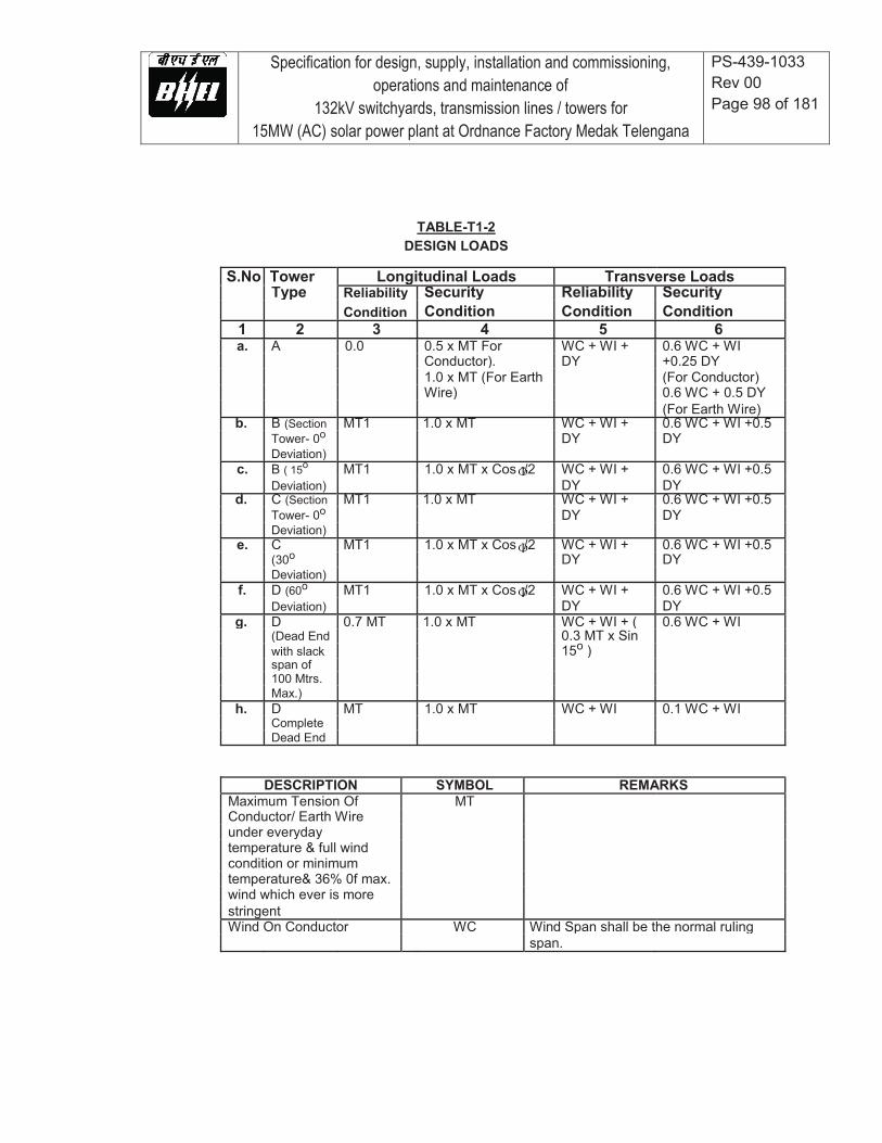
Specification for design, supply, installation and commissioning, operations and maintenance of
132kV switchyards, transmission lines / towers for 15MW (AC) solar power plant at Ordnance Factory Medak Telengana
PS-439-1033 Rev 00 Page 98 of 181
TABLE-T1-2 DESIGN LOADS S.No Tower Longitudinal Loads Transverse Loads Type Reliability Security Reliability Security Condition Condition Condition Condition 1 2 3 4 5 6 a. A 0.0 0.5 x MT For WC + WI + 0.6 WC + WI Conductor). DY +0.25 DY 1.0 x MT (For Earth (For Conductor) Wire) 0.6 WC + 0.5 DY (For Earth Wire) b. B (Section MT1 1.0 x MT WC + WI + 0.6 WC + WI +0.5 Tower- 0o DY DY Deviation) c. B ( 15o MT1 1.0 x MT x Cos /2 WC + WI + 0.6 WC + WI +0.5 Deviation) DY DY d. C (Section MT1 1.0 x MT WC + WI + 0.6 WC + WI +0.5 Tower- 0o DY DY Deviation) e. C MT1 1.0 x MT x Cos /2 WC + WI + 0.6 WC + WI +0.5 (30o DY DY Deviation) f. D (60o MT1 1.0 x MT x Cos /2 WC + WI + 0.6 WC + WI +0.5 Deviation) DY DY g. D 0.7 MT 1.0 x MT WC + WI + ( 0.6 WC + WI (Dead End 0.3 MT x Sin with slack 15o ) span of 100 Mtrs. Max.) h. D MT 1.0 x MT WC + WI 0.1 WC + WI Complete Dead End
DESCRIPTION SYMBOL REMARKS Maximum Tension Of MT Conductor/ Earth Wire under everyday temperature & full wind condition or minimum temperature& 36% 0f max. wind which ever is more stringent Wind On Conductor WC Wind Span shall be the normal ruling span.
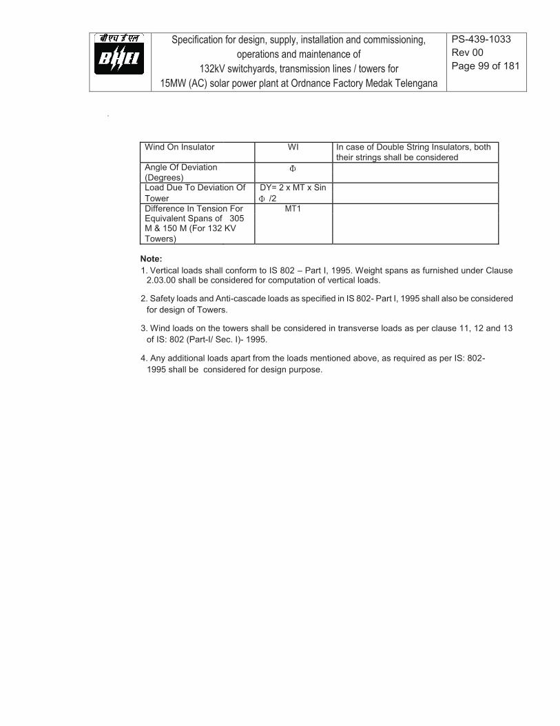
Specification for design, supply, installation and commissioning, operations and maintenance of
132kV switchyards, transmission lines / towers for 15MW (AC) solar power plant at Ordnance Factory Medak Telengana
PS-439-1033 Rev 00 Page 99 of 181
Wind On Insulator WI In case of Double String Insulators, both their strings shall be considered Angle Of Deviation (Degrees) Load Due To Deviation Of DY= 2 x MT x Sin Tower /2 Difference In Tension For MT1 Equivalent Spans of 305 M & 150 M (For 132 KV Towers)
Note: 1. Vertical loads shall conform to IS 802 – Part I, 1995. Weight spans as furnished under Clause
2.03.00 shall be considered for computation of vertical loads.
2. Safety loads and Anti-cascade loads as specified in IS 802- Part I, 1995 shall also be considered for design of Towers.
3. Wind loads on the towers shall be considered in transverse loads as per clause 11, 12 and 13
of IS: 802 (Part-I/ Sec. I)- 1995.
4. Any additional loads apart from the loads mentioned above, as required as per IS: 802- 1995 shall be considered for design purpose.
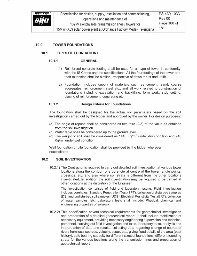
Specification for design, supply, installation and commissioning, operations and maintenance of
132kV switchyards, transmission lines / towers for 15MW (AC) solar power plant at Ordnance Factory Medak Telengana
PS-439-1033 Rev 00 Page 100 of 181
10.0 TOWER FOUNDATIONS
10.1 TYPES OF FOUNDATION l
10.1.1 GENERAL
1) Reinforced concrete footing shall be used for all type of tower in conformity
with the IS Codes and the specifications. All the four footings of the tower and their extension shall be similar, irrespective of down thrust and uplift.
2) Foundation includes supply of materials such as cement, sand, coarse
aggregates, reinforcement steel etc., and all work related to construction of foundations including excavation and backfilling, form work, stub setting, placing of reinforcement, concreting etc.
10.1.2 Design criteria for Foundations
The foundation shall be designed for the actual soil parameters based on the soil investigation carried out by the bidder and approved by the owner. For design purposes:
(a) The angle of repose shall be considered as two-third (2/3) of the value as obtained
from the soil investigation (b) Water table shall be considered up to the ground level. (c) The weight of soil shall be considered as 1440 Kg/m3 under dry condition and 940
Kg/m3 under wet condition.
Well foundation or pile foundation shall be provided by the bidder wherever necessitated.
10.2 SOIL INVESTIGATION
10.2.1) The Contractor is required to carry out detailed soil investigation at various tower
locations along the corridor, one borehole at centre of the tower, angle points, crossings, etc. and also where soil strata is different from the other locations investigated. In addition the soil investigation may be required to be carried at other locations at the discretion of the Engineer. The investigation comprises of field and laboratory testing. Field investigation includes boreholes, Standard Penetration Test (SPT), collection of disturbed samples (DS) and undisturbed soil samples (UDS), Electrical Resistivity Test (ERT), collection of water samples, etc. Laboratory tests shall include, Physical, chemical and engineering properties of soil/rock.
10.2.2) This specification covers technical requirements for geotechnical investigation
and preparation of a detailed geotechnical report. It shall include mobilization of necessary equipment, providing necessary engineering supervision and technical personnel, carrying out field investigation and tests, laboratory tests, analysis and interpretation of data and results, collecting data regarding change of course of rivers from local sources, velocity, scour, etc., giving flood details of the area (past history), safe bearing capacity for different sizes of foundations, different founding strata for the various locations along the transmission lines and preparation of geotechnical report.

Specification for design, supply, installation and commissioning, operations and maintenance of
132kV switchyards, transmission lines / towers for 15MW (AC) solar power plant at Ordnance Factory Medak Telengana
PS-439-1033 Rev 00 Page 101 of 181
10.2.3) The diameter of borehole shall be minimum 150 mm in soil and 76 mm in rock.
Depth of bore holes at river/bridge crossings shall be 40m, at angle points depth shall be 15.0m and at the centre of tower along the corridor depth of BH shall be 10.0m. Boring shall be terminated at the above specified depth or 3.0m continuous in rock with RQD>25% for river crossings and for balance areas 3.0m in refusal whichever is earlier. Refusal means SPT ‘N’ value greater than 100. SPT shall be carried out in all types of soil deposits and in all rock formations with core recovery up to 20%, met within a borehole. This test shall be conducted at every 3.0 m interval or at change of strata, up to the final depth. At refusal penetration shall be measured and the same shall be reported in Borelog. UDS shall be collected at every 3.0 m interval or at change of strata up to depth of borehole. UDS may be replaced by additional SPT, if SPT’N’ value in the strata is above 50. The diameter of UDS sampler shall be 100 mm minimum.
10.2.4) Laboratory tests shall be done as per relevant IS codes. The laboratory tests, not be limited to the following shall be conducted on disturbed and undisturbed soil samples, rock samples & water samples collected during field investigations in sufficient numbers.
a) Laboratory Tests on Soil Samples Laboratory tests shall be carried out on disturbed and undisturbed soil samples for Grain Size Analysis, Hydrometer Analysis, Atterberg Limits, Triaxial Shear Tests (UU), Natural Moisture Content, Specific Gravity and Bulk Unit Weight, Consolidation Tests, Unconfined Compression Test, Free swell Index, Shrinkage Limit, Swell Pressure Test, Chemical Analysis test on soil and water samples to determine the carbonates, sulphates, chlorides, nitrates, pH, organic matter and any other chemicals harmful to concrete and reinforcement/ steel. b) Laboratory Tests on Rock Samples Moisture content, porosity & density, Specific Gravity, Hardness, Soundness, Slake durability index, Unconfined compression test (Both at saturated and in-situ water content), Point load strength index and deformability test (Both at saturated and in-situ water content) shall be carried out on rock samples.
10.2.5) The laboratory tests shall be carried out progressively during the field work after
sufficient numbers of samples have reached the laboratory in order that the test results of the initial boreholes can be made use of in planning the later stages of the field investigation and quantum of laboratory tests. All samples brought from field, whether disturbed or undisturbed shall be extracted/prepared and examined by competent technical personnel and the tests shall be carried out as per the procedures laid out in the latest editions of the relevant IS codes. Soil shall be classified as per the provisions of Indian standards.
Specification for design, supply, installation and commissioning, operations and maintenance of
132kV switchyards, transmission lines / towers for 15MW (AC) solar power plant at Ordnance Factory Medak Telengana
PS-439-1033 Rev 00 Page 102 of 181
10.2.6) On completion of all field & laboratory work, geotechnical investigation report
shall be submitted for Owner’s review/approval. The Geotechnical investigation report shall contain geological information of the region, procedure adopted for investigation, field & laboratory observations/ data/ records, analysis of results & recommendations on type of foundation envisaged for all areas of work with supporting calculations. Recommendations on treatment for soil, foundation, based on subsoil characteristics, soft soils, aggressive chemicals, expansive soils, etc.
10.2.7) The Geotechnical report shall include, but not limited to the following:
a) Borelogs: A true cross section of all individual boreholes with reduced levels and
coordinates, showing the classification and thickness of individual stratum, position of ground water table, details of various in-situ tests conducted and samples collected at different depths and the rock stratum, wherever met with.
b) Results of all laboratory tests summarized for each Borehole along with a
consolidated table giving the layer wise soil and rock properties. All the relevant charts, tables, graphs, figures, supporting calculations, conditions and photographs of representative rock cores shall be furnished.
c) Recommendations : The report should contain specific recommendations on type
of foundations to be adopted for various structures, duly considering the sub soil characteristics, water table, total/ differential settlement permissible for structures and equipments, minimum depth and width of foundation. The observation/recommendations shall include but not limited to the following:
i) Geological information of the area, past observations or historical data, if
available, for the area and for the structures in the nearby area, fluctuations of water table etc.
ii) Net safe allowable bearing pressure on the soil at various depths for different
sizes of the foundations based on shear strength and settlements characteristics of soil with supporting calculations for the recommendations.
iii) Based on the chemical nature of soil and ground water and exposure
condition, recommendations for protective measures on concrete and steel shall be mentioned.
iv) If expansive soil is met with, recommendation and removal or retainment of
the same under structures/ roads etc. shall be given. In the later case detailed specification of any special treatment required including specifications for materials to be used, construction method, equipments to be deployed, etc. shall be furnished.
iv) Additional investigation other then specified above, if any, the same shall be
carried out by the bidder at no extra cost to owner.
Specification for design, supply, installation and commissioning, operations and maintenance of
132kV switchyards, transmission lines / towers for 15MW (AC) solar power plant at Ordnance Factory Medak Telengana
PS-439-1033 Rev 00 Page 103 of 181
10.2.8) Indian Standard References
IS:1498Classification and Identification of Soils for general Engineering Purposes. IS:1892 Code of practice for Subsurface Investigation for Foundation. IS:1904 Code of practice for design and construction of foundations in Soils: General
Requirements. IS:2131 Method of Standard Penetration Test for Soils. IS:2132 Code of practice for Thin walled Tube Sampling of soils. IS:2470 Code of practice for design and construction of Septic (Part-I) Tanks. IS:2720 Method of Test for Soils (Relevant Parts). IS:5313 Guide for Core Drilling Observations. IS:4968 Method for subsurface Sounding for Soils - Dynamic (Part-II) method using Cone and Bentonite slurry. IS:4968 Method for subsurface Sounding for Soils- Static Cone (Part-III) Penetration Test.
10.3 LOADS ON FOUNDATIONS
10.3.1) The foundations shall be designed to withstand the specific loads of the
superstructure and for the full footings reactions obtained from the structural stress analysis in conformity with the relevant over load factors. The over load factor for foundation design shall be 1.10 for all loads except dead loads.
10.3.2) The reactions on the footings shall be composed of the following type of loads
for which these shall be required to be checked:
a) Max. tension or uplift along the leg slope. b) Max. compression or down-thrust along the leg slope. c) Max. horizontal shear or side thrust.
10.3.3) The base slab of the foundation shall be designed for additional moments developing due to eccentricity of the loads.
10.3.4) The additional weight of concrete in the footing below ground level over the earth weight and the full weight of concrete above the ground level in the footing and embedded steel parts will also be taken into account adding to the down thrust.
10.4 STABILITY ANALYSIS
10.4.1) In addition to the strength design, stability analysis of the foundation shall be
done to check the possibility of failure by over-turning, uprooting, sliding and tilting of the foundation.
10.4.2) The following primary type of soil resistance shall be assumed to act in resisting
the loads imposed on the footing in earth:

Specification for design, supply, installation and commissioning, operations and maintenance of
132kV switchyards, transmission lines / towers for 15MW (AC) solar power plant at Ordnance Factory Medak Telengana
PS-439-1033 Rev 00 Page 104 of 181
a) Resistance against uplift
The uplift loads will be assumed to be resisted by the weight of earth in an inverted frustum of a conical pyramid of earth on the footing pad whose sides make an angle equal to the angle of repose of the earth with the vertical. However, the angle of repose for uplift resistance shall be considered two-third (2/3) of the value as obtained from the soil investigation report. The weight of concrete embedded in earth and that above the ground will also be considered for resisting the uplift. In case where the frustum of earth pyramids of two adjoining legs super-impose each other, the earth frustum will be assumed truncated by a vertical plane passing through the center line of the tower base.
b) Resistance against down thrust
The down-thrust load combined with the additional weight of concrete above earth will be resisted by bearing strength of the soil assumed to be acting on the total area of the bottom of the footings.
c) Resistance against side-thrust
The chimney portion of the foundation shall be designed as per limit state method of IS-456, considering the chimney as a column subjected to axial loads (down thrust loads) and biaxial bending moments resulting from side thrust forces. The passive earth pressure (as per Rankine's formula) shall be considered for the design of chimney against side thrust. If uplift and down thrust are computed in vertical direction for the foundation design, full resultant horizontal shear shall be taken at footing tip for design of the footing to resist side thrust.
10.5 PROPERTIES OF CONCRETE
10.5.1) The cement concrete used for the foundations shall be of grade M20 (nominal
mix) with 20mm coarse aggregate.
10.5.2) All the properties of concrete regarding its strength under compression tension, shear, punching and bending etc. as well as workmanship will conform to IS:456.
10.5.3) The water used for mixing concrete shall be fresh, clean and free from oil, acids and alkalies, organic materials or other deleterious substances. Potable water is generally preferred.
10.6 DESIGN OF FOUNDATIONS
10.6.1) Structural design of the foundations shall be done by limit State method
conforming to IS 456.
10.6.2) The chimney should have all around clearance of 150mm from any part of stub angle limiting to 450mm sq. minimum.
10.6.3) The chimney top or muffing must be at least 225 mm above ground level and
Specification for design, supply, installation and commissioning, operations and maintenance of
132kV switchyards, transmission lines / towers for 15MW (AC) solar power plant at Ordnance Factory Medak Telengana
PS-439-1033 Rev 00 Page 105 of 181
also the coping shall be extended upto lower most joint level between the bottom lattices and the main corner legs of the tower.
10.6.4) Minimum thickness of foundation shall be 300 mm.
10.6.5) The distance between the lowest edge of the stub angle and the bottom surface of concrete footing shall not be less than 150 mm or more than 200mm.
10.6.6) The total depth of foundations below the ground level shall not be less than 1.5 meters. To maintain the interchangeability of stubs for all types of foundations, for each type of tower, the same depths of foundations shall be used for different types of foundations.
10.6.7) The portion of the stub in the chimney and foundation slab shall be designed to take full down-thrust or uplift loads by the cleats combined with the bond between stub angles and concrete. The Contractor shall furnish the calculation for uprooting of stub along with the foundation design.
10.6.8) Minimum 50mm thick pad of lean concrete corresponding to 1:3:6 nominal mix shall be provided to avoid the possibility of reinforcement rod being exposed due to unevenness of the bottom of the excavated pit.
10.6.9) Over Load Factor
The overload factor for foundations shall be considered as 1.1 i.e. the reaction except due to dead loads on foundations shall be increased by 10 per cent.
10.7 CONSTRUCTION OF TOWER FOUNDATION
10.7.1 Excavation
a) Excavation work must not be started until the tower schedule & profile and foundation
drawing are approved by the Owner.
b) Except specified otherwise, all excavation for footing shall be made to the lines and grades of the foundation. All excavation shall be protected so as to maintain a clean subgrade, until the footing is placed, using timbering/shuttering, shoring etc., if necessary. Any sand, mud, silt or other undesirable materials which may accumulate in the excavated pit shall be removed by the Contractor before placing concrete.
10.7.2 Rock excavation requiring Blasting
Wherever blasting is required for excavation in rock, the same shall be done after obtaining license from the competent authority. Following shall be adhered to:
a) All provisions of explosive acts shall be adhered to.
b) The magazine for the storage of explosive shall be to suit as per the requirements of
explosive department.

Specification for design, supply, installation and commissioning, operations and maintenance of
132kV switchyards, transmission lines / towers for 15MW (AC) solar power plant at Ordnance Factory Medak Telengana
PS-439-1033 Rev 00 Page 106 of 181
c) Where blasting is required, same shall be controlled blasting.
d) Contractor shall prepare the detailed blasting scheme and get the same approved from Engineer-in-charge before carrying out the blasting operation. All blasting shall be done as per the approved blasting scheme.
e) The Contractor shall obtain Licenses from Competent Authorities for undertaking blasting
work as well as for procuring, transporting to site and storing the explosives as per explosives act. The Contractor shall be responsible for the safe transport, use, custody and proper accounting of the explosive Materials.
f) The Contractor shall also observe any specific instructions given by the Engineer-in-
charge. The Contractor shall be responsible and liable for any accident and injury / damage which may occur to any person or property of the project or public on account of any operations connected with the storage, transportation, handling or use of explosives and the blasting operations. The Engineer-in-charge or his authorised representative shall frequently check the Contractor's compliance with these precautions and the manner of storing and accounting of explosives. The Contractor shall provide necessary facilities for this the above.
g) Controlled blasting shall be done by a specialised agency duly approved by Engineer-
in-charge. All controlled blasting shall be done by using time delay detonators (i.e. excel type).
h) All rules under the Explosives Act and other local rules in force shall be fully observed.
All blasting works shall be done in accordance with the stipulations contained in IS: 4081.
10.7.3 Setting of Stubs
a) The stubs shall be set correctly in accordance with approved method at the exact
location and alignment and precisely at correct levels with the help of stub setting templates and leveling instrument. Stubs shall be set in the presence of Owner's representative available at site where required and for which adequate advance intimation shall be given to the Owner by the Contractor.
b) Setting of stub at each location shall be approved by the Owner's representative.
c) Stub setting templates shall be designed and arranged by the Contractor at his own
cost for all types of towers with or without extension and also for leg extension. Stub templates for standard towers and towers with extension upto 6M shall be of adjustable type. The stub templates shall be painted. Generally for each transmission line tower package, following numbers of stub setting templates shall be deployed by the Contractor:

Specification for design, supply, installation and commissioning, operations and maintenance of
132kV switchyards, transmission lines / towers for 15MW (AC) solar power plant at Ordnance Factory Medak Telengana
PS-439-1033 Rev 00 Page 107 of 181
For each A type tower : 3 Nos. For each of B, C and D type : 2 Nos.
However, if Owner feels that more number of templates are required for timely completion of a particular line the Contractor shall have to deploy the same without any extra cost to Owner.
d) One set of each type of stub setting template as applicable, shall be supplied to the
Owner, on completion of the project at no extra cost to Owner.
10.7.4 Mixing, Placing and Compacting of Concrete
a) The concrete shall be mixed in a mechanical mixer. However, in case of difficult terrain hand mixing may be permitted at the discretion of Owner. The water for mixing concrete shall be fresh, clean and free from oil, acids and alkalies. Saltish or blackish water shall not be used.
b) Mixing shall be continued until there is uniform distribution of material and the mix is
uniform in colour and consistency, but in no case the mixing be done for less than two minutes. Normally mixing shall be done close to the foundation, but in case it is not possible the concrete may be mixed at the nearest convenient place. The concrete shall be transported from the place of mixing to the place of final deposit as rapidly as practicable by methods which shall prevent the segregation or loss of any ingredient. The concrete shall be placed and compacted before setting commences.
c) Form boxes shall be used for casting all type of foundations. The concrete shall be
well compacted such that no honey-combing is left in the concrete. The mechanical vibrator shall be employed for compaction of the concrete. However, in case of difficult terrain, manual compaction may be permitted at the discretion of Owner. After concreting the chimney portion to the required height, the top surface should be finished smooth with a slight slope towards the outer edge, to drain off any rain water falling on the coping.
d) In wet locations, the site must be kept complete de-watered, both during the placing
of the concrete and for 24 hours thereafter. There should be no disturbance of concrete by water during this period.
e) After the form-work has been removed if the concrete surface is found to be defective,
the damage shall be repaired with rich cement and sand mortar to the satisfaction of the Owner's representative before the foundation pits are backfilled.
10.7.5 Back-Filling and Removal of Stub Template
a) After opening of form-work and removal of shoring and timbering, if any, backfilling
shall be started, after repairs, if any, to the foundation concrete. Backfilling shall normally be done with excavated soil, unless it consists of large boulders/stones, in which case the boulders shall be broken to a maximum size of 80 mm. At such locations where borrowed earth is required for backfilling, shall be done by the Contractor at his own cost, irrespective of lead.
Specification for design, supply, installation and commissioning, operations and maintenance of
132kV switchyards, transmission lines / towers for 15MW (AC) solar power plant at Ordnance Factory Medak Telengana
PS-439-1033 Rev 00 Page 108 of 181
b) The backfilling materials should be clean and free from organic or other foreign
materials. The earth shall be deposited in maximum 200 mm layers, leveled and wetted and tempered properly before another layer is deposited. Care shall be taken that the backfilling is started from the foundation ends of the pits, towards the outer ends. After the pits have been backfilled to full depth, the stub template may be removed.
c) The backfilling and grading shall be carried to an elevation of about 75 mm above the
finished ground level to drain out water. After backfilling 50 mm high earthen embankment (bandh) will be made along the sides of excavation pits and sufficient water will be poured in the backfilled earth for atleast 24 hours.
10.7.6 Curing
The concrete after setting for 24 hours shall be cured by keeping the concrete wet continuously for a period of 10 days after laying. The pit may be back filled with selected earth sprinkled with necessary amount of water and well consolidated in layers not exceeding 200 mm of consolidated thickness after a minimum period of 24 hours and thereafter both the backfilled earth and exposed chimney top shall be kept wet for the remainder of the prescribed time of 10 days. The uncovered concrete chimney above the backfilled earth shall be kept wet by providing empty cement bags dipped in water fully wrapped around the concrete chimney for curing and ensuring that the bags are kept wet by the frequent pouring of water on them.
10.7.7 Benching
When the line passes through hilly/undulated terrain, for a few tower locations it may be required to level the ground for casting of tower footings on same elevation. All the activities related to make the required area of ground in same elevation for casting of foundation, shall be termed as benching work. Benching work shall include cutting of excess earth and removing the same to a suitable point of disposal as required by the Owner. Benching shall be resorted to only after getting specific approval from the Owner.
10.7.8 Protection of Tower Footing
a) The work shall include all necessary stone revetments, concreting and earth filling
above ground level in hilly/undulated terrain and special measures like RCC retaining walls for protection of foundation close to or in nallah, river bed etc. The top seal cover of the stone revetments shall be done with M20 concrete (nominal mix). The Contractor shall furnish recommendations for providing protection at these locations wherever required.
b) The quantity of excavated earth obtained from a particular location shall generally be
utilised in back-filling work in protection of tower footing of same locations, unless it is unsuitable for such purpose. In the latter case, the back-filling shall be done with borrowed earth of suitable quality. The consolidation of earth shall however be done after backfilling.

Specification for design, supply, installation and commissioning, operations and maintenance of
132kV switchyards, transmission lines / towers for 15MW (AC) solar power plant at Ordnance Factory Medak Telengana
PS-439-1033 Rev 00 Page 109 of 181
11.0 LINE MATERIAL
11.1 GENERAL
11.1.1) All the equipment shall be of the latest design and conform to the best modern practice adopted in the extra high voltage field. The Bidder shall offer only such equipment as guaranteed by him to be satisfactory and suitable for 132 kV AC transmission with single conductor and will give continued good performance.
11.1.2) The design, manufacturing process and quality control of all the materials shall
be such as to give maximum factor of safety, maximum possible working load, highest mobility, elimination of sharp edges and a good finish.
11.1.3) All ferrous parts shall be hot dip galvanised, after all machining has been completed, nuts may, however, be tapped (threaded) after galvanising and the threads oiled. Spring washers shall be electrogalvanised. The bolt threads shall be undercut to take care of increase in diameter due to galvanising .Galvanising shall be done in accordance with IS:2629-1972. Fasteners shall withstand four dips while spring washers shall withstand three dips. Other galvanised materials shall be guaranteed to withstand at least six dips each lasting one minute under the standard preece tests for galvanising.
11.1.4) The zinc coating shall be perfectly adherent, of uniform thickness, smooth, reasonably bright, continues and free from imperfection such as flux, ash, rust stains, bulky white deposits and blisters. The zinc used for galvanising shall be of grade Zn. 99.95 as per IS:209-1966.
11.1.5) Electrical System Data for 132 kV Lines
Nominal voltage 132 kV
Maximum voltage 145 kV
BIL(Impulse) 650 kV(peak)
Power Frequency 275 kV(rms) Withstand Voltage
11.1.6) Line Data Conductor:
Type of ACSR conductor to be selected as per design requirement (current rating etc) Location of earthwire: one continuous earthwire to run horizontally on top of the towers and conductors.
11.2 EARTHWIRE
11.2.1) The galvanised steel earthwire shall generally conform to the specification of ACSR core wire as mentioned in IS 398 (Part-II)-1976 except where otherwise specified herein.
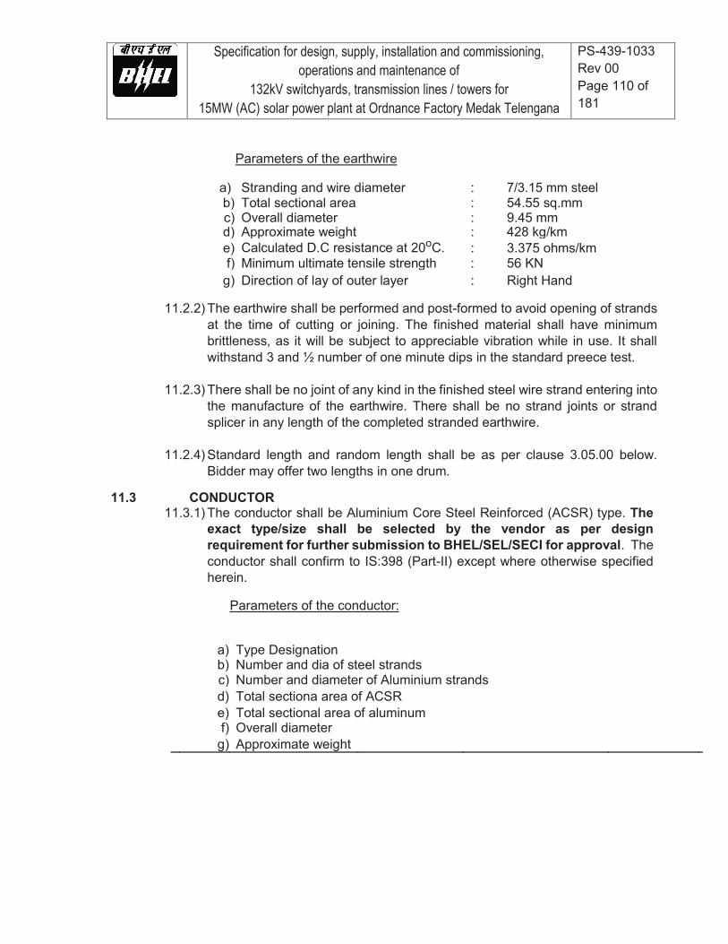
Specification for design, supply, installation and commissioning, operations and maintenance of
132kV switchyards, transmission lines / towers for 15MW (AC) solar power plant at Ordnance Factory Medak Telengana
PS-439-1033 Rev 00 Page 110 of 181
Parameters of the earthwire
a) Stranding and wire diameter : 7/3.15 mm steel b) Total sectional area : 54.55 sq.mm c) Overall diameter : 9.45 mm d) Approximate weight : 428 kg/km e) Calculated D.C resistance at 20oC. : 3.375 ohms/km f) Minimum ultimate tensile strength : 56 KN
g) Direction of lay of outer layer : Right Hand
11.2.2) The earthwire shall be performed and post-formed to avoid opening of strands at the time of cutting or joining. The finished material shall have minimum brittleness, as it will be subject to appreciable vibration while in use. It shall withstand 3 and ½ number of one minute dips in the standard preece test.
11.2.3) There shall be no joint of any kind in the finished steel wire strand entering into the manufacture of the earthwire. There shall be no strand joints or strand splicer in any length of the completed stranded earthwire.
11.2.4) Standard length and random length shall be as per clause 3.05.00 below. Bidder may offer two lengths in one drum.
11.3 CONDUCTOR
11.3.1) The conductor shall be Aluminium Core Steel Reinforced (ACSR) type. The exact type/size shall be selected by the vendor as per design requirement for further submission to BHEL/SEL/SECI for approval. The conductor shall confirm to IS:398 (Part-II) except where otherwise specified herein.
Parameters of the conductor:
a) Type Designation b) Number and dia of steel strands c) Number and diameter of Aluminium strands d) Total sectiona area of ACSR e) Total sectional area of aluminum f) Overall diameter g) Approximate weight
Specification for design, supply, installation and commissioning, operations and maintenance of
132kV switchyards, transmission lines / towers for 15MW (AC) solar power plant at Ordnance Factory Medak Telengana
PS-439-1033 Rev 00 Page 111 of 181
h) Calculated d.c. resistance at 20 deg.C i) Minimum UTS
11.3.2) The steel strands shall generally comply with the requirements stipulated for
earthwire at clause 2.00.00 above.
11.3.3) Joints shall be permitted in the individual Aluminium wires in all layers except the outer most layer of the finished conductor. These joints shall be made by cold pressure butt-welding and shall be such that no two such joints are within 15 metres of each other in the complete stranded conductor.
11.3.4) The standard length of the conductor shall be 2000 metres. A tolerance of 5% on the standard length offered by the bidder shall be permitted. All lengths outside this limit of tolerance shall be treated as random lengths. Random lengths will be accepted provided no length is less than 70% of the standard length and the total quantity of random lengths shall not be more than 10% of the total quantity ordered.
11.4 CONDUCTOR ACCESSORIES
11.4.1 Mid Span Compression Joint For Conductor
As per details given in IS:2121 Part-2..
11.4.2 Repair Sleeve
Repair Sleeve of compression type shall be used to repair conductor with not more than two strands broken in the outer layer. The sleeve shall be manufactured from 99.5% pure aluminium and shall have a smooth surface. The repair sleeve shall comprise of two pieces with a provision of seat for sliding of the keeper piece. The edges of the seat as well as the keeper piece shall be of rounded that the conductor strands are not damaged during installation.
11.4.3 The Bidder shall clearly specify the before and after compression dimensions of
the mid span compression joint and repair sleeve. The compression pressure shall also be indicated by the Bidder. The dimensions and dimensioanl tolerances for Mid Span Compression Joint and Repair Sleevs for ACSR conductor shall be determined based on type/size of ACSR conductor selected for the project requirement.
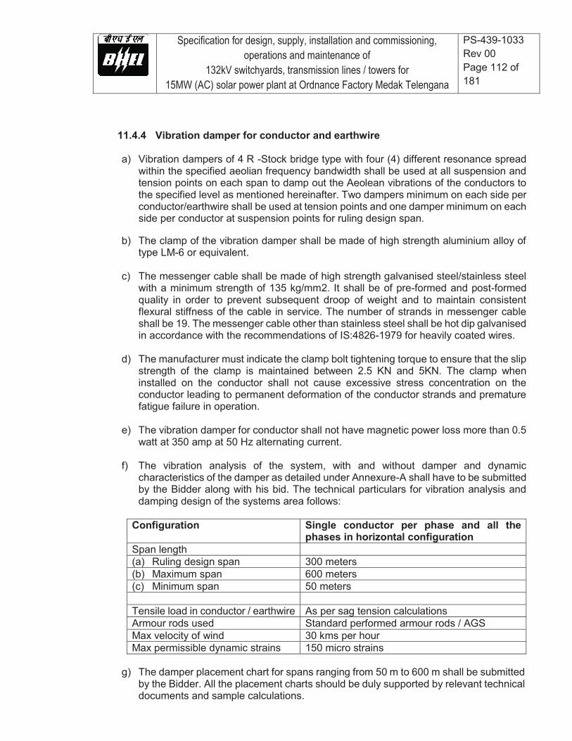
Specification for design, supply, installation and commissioning, operations and maintenance of
132kV switchyards, transmission lines / towers for 15MW (AC) solar power plant at Ordnance Factory Medak Telengana
PS-439-1033 Rev 00 Page 112 of 181
11.4.4 Vibration damper for conductor and earthwire
a) Vibration dampers of 4 R -Stock bridge type with four (4) different resonance spread
within the specified aeolian frequency bandwidth shall be used at all suspension and tension points on each span to damp out the Aeolean vibrations of the conductors to the specified level as mentioned hereinafter. Two dampers minimum on each side per conductor/earthwire shall be used at tension points and one damper minimum on each side per conductor at suspension points for ruling design span.
b) The clamp of the vibration damper shall be made of high strength aluminium alloy of
type LM-6 or equivalent.
c) The messenger cable shall be made of high strength galvanised steel/stainless steel with a minimum strength of 135 kg/mm2. It shall be of pre-formed and post-formed quality in order to prevent subsequent droop of weight and to maintain consistent flexural stiffness of the cable in service. The number of strands in messenger cable shall be 19. The messenger cable other than stainless steel shall be hot dip galvanised in accordance with the recommendations of IS:4826-1979 for heavily coated wires.
d) The manufacturer must indicate the clamp bolt tightening torque to ensure that the slip strength of the clamp is maintained between 2.5 KN and 5KN. The clamp when installed on the conductor shall not cause excessive stress concentration on the conductor leading to permanent deformation of the conductor strands and premature fatigue failure in operation.
e) The vibration damper for conductor shall not have magnetic power loss more than 0.5 watt at 350 amp at 50 Hz alternating current.
f) The vibration analysis of the system, with and without damper and dynamic characteristics of the damper as detailed under Annexure-A shall have to be submitted by the Bidder along with his bid. The technical particulars for vibration analysis and damping design of the systems area follows:
Configuration Single conductor per phase and all the
phases in horizontal configuration Span length (a) Ruling design span 300 meters (b) Maximum span 600 meters (c) Minimum span 50 meters Tensile load in conductor / earthwire As per sag tension calculations Armour rods used Standard performed armour rods / AGS Max velocity of wind 30 kms per hour Max permissible dynamic strains 150 micro strains
g) The damper placement chart for spans ranging from 50 m to 600 m shall be submitted
by the Bidder. All the placement charts should be duly supported by relevant technical documents and sample calculations.
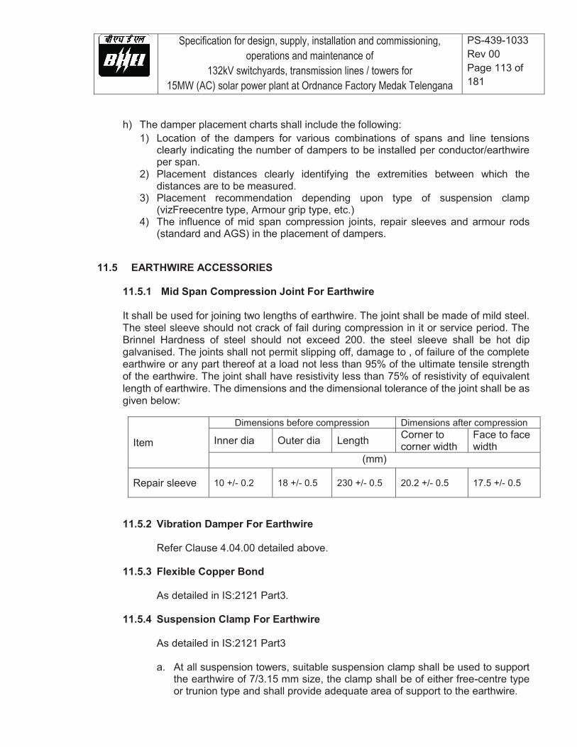
Specification for design, supply, installation and commissioning, operations and maintenance of
132kV switchyards, transmission lines / towers for 15MW (AC) solar power plant at Ordnance Factory Medak Telengana
PS-439-1033 Rev 00 Page 113 of 181
h) The damper placement charts shall include the following: 1) Location of the dampers for various combinations of spans and line tensions
clearly indicating the number of dampers to be installed per conductor/earthwire per span.
2) Placement distances clearly identifying the extremities between which the distances are to be measured.
3) Placement recommendation depending upon type of suspension clamp (vizFreecentre type, Armour grip type, etc.)
4) The influence of mid span compression joints, repair sleeves and armour rods (standard and AGS) in the placement of dampers.
11.5 EARTHWIRE ACCESSORIES
11.5.1 Mid Span Compression Joint For Earthwire
It shall be used for joining two lengths of earthwire. The joint shall be made of mild steel. The steel sleeve should not crack of fail during compression in it or service period. The Brinnel Hardness of steel should not exceed 200. the steel sleeve shall be hot dip galvanised. The joints shall not permit slipping off, damage to , of failure of the complete earthwire or any part thereof at a load not less than 95% of the ultimate tensile strength of the earthwire. The joint shall have resistivity less than 75% of resistivity of equivalent length of earthwire. The dimensions and the dimensional tolerance of the joint shall be as given below:
Item
Dimensions before compression Dimensions after compression
Inner dia Outer dia Length Corner to corner width
Face to face width
(mm)
Repair sleeve 10 +/- 0.2 18 +/- 0.5 230 +/- 0.5 20.2 +/- 0.5 17.5 +/- 0.5
11.5.2 Vibration Damper For Earthwire
Refer Clause 4.04.00 detailed above.
11.5.3 Flexible Copper Bond
As detailed in IS:2121 Part3.
11.5.4 Suspension Clamp For Earthwire
As detailed in IS:2121 Part3 a. At all suspension towers, suitable suspension clamp shall be used to support
the earthwire of 7/3.15 mm size, the clamp shall be of either free-centre type or trunion type and shall provide adequate area of support to the earthwire.

Specification for design, supply, installation and commissioning, operations and maintenance of
132kV switchyards, transmission lines / towers for 15MW (AC) solar power plant at Ordnance Factory Medak Telengana
PS-439-1033 Rev 00 Page 114 of 181
b. The total drop of the suspension assembly from the center point of the attachment to the centre point of the Earthwire shall not exceed 150 mm. The complete assembly shall be guaranteed for slip strength of not less than 9 kN and not more than 14 kN. The breaking strength of the assembly shall not be less than 25 kN.
11.5.5 Tension Clamp For Earthwire
The details shall be as per IS:2121 part-3. Only Compression type tension clamp shall be used to hold 7/3.15 mm galvanised steel earthwire. Anchor shackle shall be supplied which shall be suitable for attaching the tension clamp to strain plates. The strain plates supplied with the towers will have a minimum thickness of 8 mm with a hole of 17.5 mm diameter. Suitable lugs for jumper connection shall also be supplied alongwith necessary bolts and nuts.
11.6 HARDWARE FITTINGS
11.6.1 The hardware fittings shall be as per the specification for hardware fittings along with its component for the following insulator strings: (a) Single – `I’ suspension insulator string. (b) Single Suspension –I string with Pilot Clamp (c) Double suspension insulator string. (d) Single tension insulator string. (e) Double tension insulator string.
11.6.2 Each hardware fittings shall be supplied complete in all respects and include the
following hardware parts:
a) Ball hook for suspension hardware fittings suitable for attaching to V-hanger of the tower. Anchor shackle shall be supplied which shall be suitable for attaching the tension hardware fittings to 12mm thick strain plate having 17.5 mm dia hole, of the tower.
b) Suitable yoke plates for double suspension and double tension hardware
fittings for the single conductor arrangement complying with the specifications given hereinafter.
c) Suspension and deadend assembly to suit conductor size.
d) Other necessary fittings such as eye links, ball clevis, socket clevis, clevis eye,
U-clevis, ball link, arcing horn etc. to make the hardware fittings complete.
e) 2.5% extra fasteners shall be supplied along with the hardware fittings.
f) Socket fittings shall be provided with only R-shaped security clip in accordance with IS-2486 (part-II).
11.6.3 Suspension Assembly

Specification for design, supply, installation and commissioning, operations and maintenance of
132kV switchyards, transmission lines / towers for 15MW (AC) solar power plant at Ordnance Factory Medak Telengana
PS-439-1033 Rev 00 Page 115 of 181
a) The suspension assembly shall include one AGS type suspension clamp alongwith standard performed armour rods set suitable for the type of ACSR conductor. The elastomer used for AGS clamp shall be neoprene rubber with insert. This shall be suitable to withstand upto 75deg. Cetrigrade temperature and atmospheric ozone.
b) The suspension clamp assembly alongwith standard armour rods shall have a
slip strength between 11to 16 KN.
c) The length and diameter of each rod shall be 1550+/-16 mm minimum and 6.35+/-.10 mm respectively. The tolerance in length of the rods in completed set should be within 13 mm between the longest and shortest rod. The ends of armour rod shall be parrot billed or ball ended.
d) The number of armour rods in each set shall be eleven. Each rod shall be
marked in the middle with paint for easy applications on the line.
e) The armour rod shall not loose, their resilience even after five applications. The conductivity of each rod of the set shall not be less than 40% of the conductivity of the International Annealed Copper Standard (IACS).
f) The armour rods shall be made of aluminium alloy of type 6061 or equivalent.
The alloy shall have a minimum tensile strength of 35 kg / mm2.
11.6.4 Dead end Assembly
The bidder shall clearly specify the before and after compression dimensions of the deadend clamp. The compression pressure shall also be indicated by the bidder. The dimensions and dimensional tolerances of the cross section of aluminium dead-end for conductor shall be as given below:
Item
Dimensions before compression Dimensions after compression
Inner dia Outer dia Corner to corner width
Face to face width
(mm)
Al sleeve 23 +/- 1 38 +/- 1 37 +/- 0.5 32 +/- 0.5
Steel sleeve 9.3 +/- 0.5 18 +/- 0.5 17.4 +/- 0.5 15.1 +/- 0.5
11.6.5 Yoke Plates
The strength of yoke plates shall be adequate to withstand the minimum ultimate tensile strength, as specified in clause 7.01.00
The Plates shall be either triangular or rectangular in shape as may be necessary. The design of yoke plate shall take into account the most unfavourable loading conditions likely to be experienced as a result of dimensional tolerances for disc
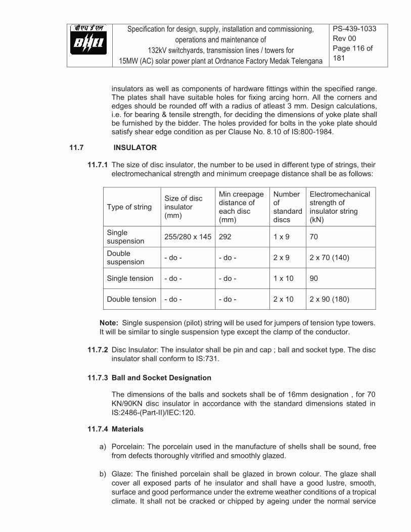
Specification for design, supply, installation and commissioning, operations and maintenance of
132kV switchyards, transmission lines / towers for 15MW (AC) solar power plant at Ordnance Factory Medak Telengana
PS-439-1033 Rev 00 Page 116 of 181
insulators as well as components of hardware fittings within the specified range. The plates shall have suitable holes for fixing arcing horn. All the corners and edges should be rounded off with a radius of atleast 3 mm. Design calculations, i.e. for bearing & tensile strength, for deciding the dimensions of yoke plate shall be furnished by the bidder. The holes provided for bolts in the yoke plate should satisfy shear edge condition as per Clause No. 8.10 of IS:800-1984.
11.7 INSULATOR
11.7.1 The size of disc insulator, the number to be used in different type of strings, their
electromechanical strength and minimum creepage distance shall be as follows:
Type of string Size of disc insulator (mm)
Min creepage distance of each disc (mm)
Number of standard discs
Electromechanical strength of insulator string (kN)
Single suspension 255/280 x 145 292 1 x 9 70
Double suspension - do - - do - 2 x 9 2 x 70 (140)
Single tension - do - - do - 1 x 10 90
Double tension - do - - do - 2 x 10 2 x 90 (180)
Note: Single suspension (pilot) string will be used for jumpers of tension type towers. It will be similar to single suspension type except the clamp of the conductor.
11.7.2 Disc Insulator: The insulator shall be pin and cap ; ball and socket type. The disc
insulator shall conform to IS:731.
11.7.3 Ball and Socket Designation
The dimensions of the balls and sockets shall be of 16mm designation , for 70 KN/90KN disc insulator in accordance with the standard dimensions stated in IS:2486-(Part-II)/IEC:120.
11.7.4 Materials
a) Porcelain: The porcelain used in the manufacture of shells shall be sound, free
from defects thoroughly vitrified and smoothly glazed.
b) Glaze: The finished porcelain shall be glazed in brown colour. The glaze shall cover all exposed parts of he insulator and shall have a good lustre, smooth, surface and good performance under the extreme weather conditions of a tropical climate. It shall not be cracked or chipped by ageing under the normal service
Specification for design, supply, installation and commissioning, operations and maintenance of
132kV switchyards, transmission lines / towers for 15MW (AC) solar power plant at Ordnance Factory Medak Telengana
PS-439-1033 Rev 00 Page 117 of 181
conditions. The glaze shall have the same co-efficient of expansion as of the porcelain body throughout the working temperature range.
c) Toughened Glass : In case of glass insulator, the glass used for the shells shall be sound, free from defects such as flows, bubbles, inclusions etc. and be of uniform toughness over its entire surface. All exposed glass surfaces shall be smooth.
d) Cement: Cement used in the manufacture of the insulator shall not cause fracture by expansion or loosening by contraction. The cement shall not give rise to chemical reaction with metal fittings and its thickness shall be as small and uniform as possible. Proper care shall be taken to correctly centre and locate individual parts during cementing.
e) Pins and Caps: Pins and Caps shall be made of drop forged steel and malleable cast iron/spheriodal graphite iron/drop forged steel respectively, duly hot dip galvanised and shall not be made by jointing, welding, shrink fitting or any other process from more than one piece of material.
f) Security Clips: Security clips shall be made of good quality stainless steel or phosphor bronze as per IS:1385-1968 2.5% extra Security clip shall be provided.
11.7.5 Hot Line Maintenance
a) The insulators offered shall be suitable for employment of hot line maintenance technique so that the usual hot line operations can be carried out with ease, speed and safety.
b) Bidders shall indicate the methods generally used in the routine hot and dead line
maintenance of HV lines for which similar insulator have been supplied by them. Bidders shall also indicate the recommended periodicity of such maintenance.
11.8 TEST REQUIREMENT
GENERAL The materials shall conform to all the type tests as per relevant standards. The acceptance, routine tests and tests during manufacturer shall be carried out as per the specification and relevant standards on the line material.
12.0 CONTROL & PROTECTION OF 132 kV of line bay at STU substation The Bidder's scope of work shall include the supply, delivery, installation, testing and commissioning of the following including full protection, control, metering, monitoring, mimic diagram and all other equipment required as detailed in this specification:
1. Conventional hardwired Control Panel including control, metering, monitoring, annunciation windows, mimic diagram, and all other equipment required.
2. Numerical Protection Panels including ( Main I as distance and Main II as over current and EF)
.Augmentation of existing 132kV bus bar protection ( CAG) including supply required hardware e.g
Specification for design, supply, installation and commissioning, operations and maintenance of
132kV switchyards, transmission lines / towers for 15MW (AC) solar power plant at Ordnance Factory Medak Telengana
PS-439-1033 Rev 00 Page 118 of 181
WPRP, CT switching relays and trip relays etc.
3. Scope also covers other items like Event logger, time synchronizing equipment, dynamic relay test kit, furniture etc also as mentioned at relevant portions of the specification.
4. All associated power and control cabling as detailed in the specification shall be in the scope.
5. The testing of all control & protection functions for the 132 kV bays shall be the responsibility
of the bidder.
6. It shall be possible to monitor and control all the Switchyard bay equipment from the control panel in Switchyard Control Room.
7. Interlocking to prevent unsafe operation of Switchyard equipment such as circuit breakers,
isolators, earth switches etc. shall be implemented. Proper interfacing with the existing scheme shall be ensured.
8. The Employer shall approve the list of alarms and plant status (Analog and Digital) to be wired
for Sequence of Events log, existing RTU and annunciation system during detailed engineering stage.
9. The historical data logs received from Bay Protection Relays shall include Digital Fault
Records and Sequence of Events.
10. All Protection Relays shall be provided with self-diagnosis and supervision functions to ensure maximum availability. An alarm contact shall be provided for hardware failures, failures of internal and external auxiliary supplies etc.

Specification for design, supply, installation and commissioning, operations and maintenance of
132kV switchyards, transmission lines / towers for 15MW (AC) solar power plant at Ordnance Factory Medak Telengana
PS-439-1033 Rev 00 Page 119 of 181
12.1 Control Panels for HV Switchyard
Conventional Control Panels shall be provided for following bays: 1. 132 kV line - Bay 01 Control Panel.
Control Panels for various feeders shall comprise minimum of the equipment as listed below:
12.2 Annunciation System The annunciation system shall be either relay based or based on state of the art static system of proven design. The annunciation facia shall be at least of 35mm x 50mm size for each point. The system shall have accept, reset and test facilities for alarms in each control panel. Annunciation alarm shall be provided for failure of annunciation dc supply by means of separate AC supply. No of annunciation windows per control panel shall be decided during detailed engineering. Any contact multiplication relays required to multiply the contacts of existing isolators, CBs, trip relays etc to be used in the scheme logics related to bays under present scope shall be provided by the bidder. Any cabling between the bidder's panels and existing control & relay panels for this purpose shall also be in bidder's scope. Any modification and associated cabling in existing scheme logics required due to addition of new bays in the existing switchyards shall also be in the bidder's scope. All such existing schemes shall be revised to show the modifications and submitted to BHEL for reference. 12.3 General Requirements of protection system
i) The manufacturer of the offered numerical protection system shall carry out complete engineering, testing & commissioning at site of the offered protections including the associated relay & protection panels.
ii) The protection system shall be arranged to provide two independent, high performance and reliable systems with separate monitored DC supplies, separate CT/VT cores, separate cables and trip relays to obtain 100% redundancy. Associated trip relays of the two systems shall be separate, having sufficient number of contacts for all the functions. Each protection shall energize both trip coils of the circuit breakers to be tripped.
iii) All numerical relays shall be supplied with all protection functions / features in disabled condition. Relevant features / protection functions shall be enabled at the time of commissioning at site as per approved logic and relay settings.
iv) The total critical fault clearance time from fault initiation in any part of the system shall be 80 m sec for phase to phase fault in the generator-transformer unit and for phase to phase and phase to earth faults in the EHV system inter-connection.
v) Modification and interfacing with the existing protection scheme, including supply of any hardware/ software, such as bus bar protection shall be in bidder’s scope.
12.4 Operational Requirements for Numerical Relays and Auxiliary Relays
i) All protection relays to be supplied under this package shall be Numerical type and IEC 61850 compliant.
ii) All numerical relays, auxiliary relays and devices shall be of latest version, reputed make and types proven for the application, satisfying requirement covered elsewhere and shall be subject to Owner’s approval. Relays and timers shall have appropriate setting ranges, accuracy, resetting ratio, transient overreach and other characteristics to provide required sensitivity to the satisfaction of the Owner.
iii) Numerical relays shall be suitable for efficient and reliable operation of the protection scheme.
Specification for design, supply, installation and commissioning, operations and maintenance of
132kV switchyards, transmission lines / towers for 15MW (AC) solar power plant at Ordnance Factory Medak Telengana
PS-439-1033 Rev 00 Page 120 of 181
Necessary auxiliary relays, timers, trip relays, etc. required for complete scheme, interlocking, alarm, logging, etc. shall be provided. No control relay, which shall trip the circuit breaker when relay is de-energized, shall be employed in the circuits.
iv) Relays shall be provided with self-reset contacts except for the trip lockout relays, which shall have manual reset facility. Suitable measures shall be provided to ensure that transients present in CT & VT connections due to extraneous sources in EHV system do not cause damage to the numerical and other relays. CT saturation shall not cause mal-operation of numerical relays.
v) Except for event logging, alarm and annunciation type of non-trip functions, protective relay contact multiplier relay shall be high speed trip relay only.
vi) Only DC/DC converters shall be provided in the solid state devices / numerical relays wherever necessary to provide a stable auxiliary supply for relay operation. DC batteries in protective relays and timers necessary for relay operation shall not be acceptable. Equipment shall be protected against voltage spikes in auxiliary DC supply.
vii) Pick up range of the Binary inputs shall be minimum 70 V DC /AC.” viii) The numerical relays offered shall have self-diagnostic features to reduce the down time of the
relay and provide useful diagnostic information on detection of an internal fault to speed up the maintenance. Necessary support documentation explaining the self-diagnostic features of the numerical relays in detail shall be furnished for owner’s use.
ix) The numerical protection shall have continuous self-monitoring & cyclical test facilities. The internal clock of all the numerical relays being supplied under this package shall be synchronized through the GPS Time Synchronizing System, under present scope. A timing accuracy of 1ms shall be achieved for all the numerical relays.
x) The sampling rate of analog inputs, the processing speed and processing cycle of digital values shall be selected so as to achieve the operating times of various protection functions specified.
xi) Display of various measured parameters during normal as well as fault condition on segregated phase basis shall be provided. In addition to a local HMI, Numerical relays shall also have LEDs and back lit LCD screen shall be provided for visual indication and display of messages related to major trips / alarms generated in the relays.
xii) All the numerical relays shall have adequate processor capability to carry out programmable scheme logics (PSL) required for implementing approved protection and control schemes over and above its inbuilt protection functions algorithm.
xiii) The numerical relays shall be provided with built-in disturbance recorder. The data from DR function shall be available in IEEE/COMTRADE format and compatible with the dynamic relay test system being supplied in this contract.
12.5 Interface with Existing Bus Bar protection
The bidder shall provide all interfacing requirements with the existing 132 kV bus bar protection scheme at switchyard of STU substation. All trip relays, multiplication relays, CT switching relays (if required), Weather Proof Relay Panels (if provided in existing scheme), cable and associated cabling required to achieve this interfacing shall be provided under this package. Bidder to take note of existing B/B protection (CAG) relay at STU substation. Details of existing system shall be given to the successful bidder during detail engineering.
12.6 Panels
- The dimensions of control / relay panel shall be matching with the existing panels at site, details of which shall be furnished during the detailed engineering.
- Each panel shall be provided with a 240V AC fluorescent lighting fixture controlled by door switch as well as a 5A, 240V AC switch-socket unit.
- Synchronizing socket matching with the existing trolley shall be provided else separate synchronizing trolley shall be provided.
Specification for design, supply, installation and commissioning, operations and maintenance of
132kV switchyards, transmission lines / towers for 15MW (AC) solar power plant at Ordnance Factory Medak Telengana
PS-439-1033 Rev 00 Page 121 of 181
- Shall be provided with necessary arrangements for receiving, distributing, isolating and fusing of AC & DC supplies for various circuits for control, signaling, lighting, interlocking, etc. Selection of main and sub-circuit fuse rating shall ensure selective clearance of the sub-circuit faults.
- Voltage circuits for protection and metering shall be protected by fuses. Suitable fuse failure relays shall be provided to give an alarm for voltage circuits of protection/metering. Voltage selection scheme based on relays shall be provided for meters wherever possible.
- The DC supplies at the individual relay and protection panels shall be monitored by suitable relays and failure of DC supplies shall be annunciated.
- All equipments mounted on front and rear side of the panels should shall have individual name-plates with equipment designation engraved.
- Each panel shall also have circuit/feeder designation name plate
(a) All panels shall be free standing, floor mounting type and completely metal enclosed. Cable entries shall be from the bottom. Panels shall be of IP 31 class or better.
(b) Panels shall have removable gland plates with glands made of brass and shall be suitable for armoured cables.
(c) Panels shall be painted. The colour of paint for exterior of the panels shall be matching with other panels in the station & shall be decided during detail engineering
(d) Panels shall have a lockable front Plexiglas door and a swing frame. Panels shall facilitate direct access to any component mounted inside and shall have at least 20% free space for future expansion.
(e) All equipment mounted on the panels shall have individual name-plates with equipment designation engraved.
(f) Internal wiring to be connected to external equipment shall terminate on terminal blocks. Shall have 20% terminals as spare terminals in each panel.
(g) The terminal blocks for CTs and VTs shall be provided with test links and isolating facilities. The CT terminal blocks shall be provided with short circuiting and earthing facilities.
(h) Contractor shall be solely responsible for completeness and correctness of all the wiring, and for proper functioning of the connected equipment.
12.7 Earthing (a) The panels shall be equipped with an earth bus of at least 50x6mm2 galvanized steel
flat bar or equivalent copper. (b) Earth buses of adjoining panels shall be connected for continuity. The continuous earth
bus so formed shall be connected to the main earth grid at one end only. (c) All metallic cases of the mounted equipment shall be separately connected to the earth
bus by 2.5mm2 copper wires. No loops in the earth wiring shall be permitted. (d) CT/VT neutral secondary shall only be earthed at the terminal block of the panel
through links, such that the earthing of one group may be removed without disturbing others.
(e) An independent Electronic Earth System shall be provided as per bidder’s standard. The electronic earth shall be connected to the substation earth mat through a dedicated riser.

Specification for design, supply, installation and commissioning, operations and maintenance of
132kV switchyards, transmission lines / towers for 15MW (AC) solar power plant at Ordnance Factory Medak Telengana
PS-439-1033 Rev 00 Page 122 of 181
12.8 Control Cabling Philosophy
(a) Each three phase secondary core of each CT/VT shall be brought to the associated relay panel through independent cables.
(b) Duplicated cores with at least 2 x 2.5 sq.mm2 CU/equivalent core cross-sectional area per connection shall be used for connection of all CT/VT circuits.
(c) VT leads used for tariff metering shall have an equivalent core cross-sectional area of at least 10 mm2 CU/equivalent per phase/neutral connection.
(d) Duplicate channels of protection shall have independent cables for tripping, DC supply, etc. Duplicated cores shall be used for ALL closing/tripping commands and interlocking signals involving long (more than 500 m) cable lengths.
(e) For the following applications multiple cores with at least 2 x 2.5 mm2 CU / equivalent core cross - sectional area per connection shall be used:
- DC supply to Bay Marshalling box - DC supply to circuit-breaker cubicle - DC looping for closing and tripping circuits of circuit-breaker (f) All the interconnections (both AC/DC) within the switchyard and between switchyard
and other systems required for the successful implementation of the control, interlocks and protection schemes under present package, as shown in the tender drawings for control & protection SLD, shall be in the scope of the bidder. Such interconnections between switchyard and other system shall include but not limited to the following:
- Extension of switchyard bus voltages to Control & Protection Panels. - Necessary interconnections for the Inter tripping / closing interlocking between
upstream and down stream systems of transformer. - Necessary interfacing between Transformer MBs & Control Panel for various
Transformer monitoring systems shall also be in bidder’s scope - Any screened cable required for connecting 4-20 mA analog signals. - Cables for interfacing different protections & control schemes of the new bay to the
existing 132 kV SWYD protections & schemes. (g) Spare cores shall be provided as per following norms:
- Up to 3-core cable - Nil - 5 Core Cable - Min. 1 core - 7 to 14 core cables - Min. 2 cores - More than 14 core - Min. 3 cores
12.9 Mimic Diagram Colour mimic diagram showing the exact representation of the system shall be provided in front of the control panel. Mimic colour shall be matching with that of the existing control panels and the details shall be furnished by the Owner during detailed engineering.
12.10 Auxiliary Equipment All control and instrumentation switches shall be rotary operated type with escutcheon plate showing the operating position and circuit designation. All switches shall be flush mounted. Handles of different shapes shall be provided as approved by Owner.
Control switches for breaker or disconnecting switch shall be of spring return to neutral type, while all other shall be stay-put type all the synchronizing switches shall have a removable
Specification for design, supply, installation and commissioning, operations and maintenance of
132kV switchyards, transmission lines / towers for 15MW (AC) solar power plant at Ordnance Factory Medak Telengana
PS-439-1033 Rev 00 Page 123 of 181
common handle, removable only in off-position. Lockable type switches shall be provided for same application as specified by the Owner. The contact combination and their operation shall ensure completeness of the scheme function and interlock requirements. Contact ratings of the switches shall be as per relevant standards. Contacts shall be spring assisted and contact faces shall be made pure silver. Cluster type LED indicating lamps shall be provided. Position indicators for the earth switches of semaphore type shall be provided as specified in the mimic diagram. It shall be suitable for DC operation.
12.11 Indicating Instruments
a) Shall conform to IS: 1248 b) Shall be suitable for the instrument transformers as indicated in the drawings enclosed and
shall be calibrated to read directly the primary quantities. c) Shall be calibrated and adjusted at works and shall also be tested and calibrated at site
before commissioning. All these instruments shall be flush mounted. d) Shall be transducer operated, having 240 deg. scale and a dial of 96x96 mm2, have an
accuracy of 1.5 class and resolution of at least 50% of accuracy class e) Current coils shall be 120% of rated current and 10 times for 0.5 sec. without loosing
accuracy. 12.12 Recording Instruments (if applicable)
The recorders shall a. Shall be draw out type and suitable for back connection. b. Provision for automatic shorting of CT leads shall be provided when recorder is
drawn out. c. Shall be dual pen employing potentiometric servo principle. d. Shall record continuously on a calibrated 100mm (min) wide plain paper chart. e. The accuracy of the recording shall be 0.5 % span. Full span response time shall
not be less than 2 sec. f. Shall include an inverter for operating on AC supply in case of DC supply failure. Switching
shall be automatic. 12.13 Transducers
a) Shall conform to IEC: 688-1. b) The output of the transducers shall be 4-20mA/0-10mA/10-0-10mA dc as necessary for the
instruments. c) Accuracy class shall be 0.5 or better except for frequency transducer, which shall have an
accuracy of 0.2. d) Summation transducer shall be suitable for taking multiple inputs from individual
MW/MVAR transducers. e) Shall have dual output. One output shall be used for the indicating instrument/recorder
provided and other shall be wired up to terminal block of the panel for Owner's use in future. f) Energy transducers shall be suitable for 3 phase, 4 wire connection.
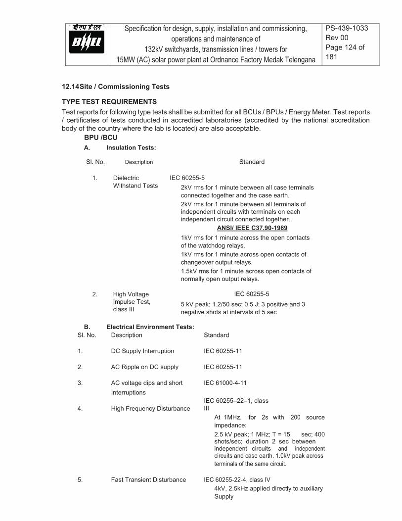
Specification for design, supply, installation and commissioning, operations and maintenance of
132kV switchyards, transmission lines / towers for 15MW (AC) solar power plant at Ordnance Factory Medak Telengana
PS-439-1033 Rev 00 Page 124 of 181
12.14 Site / Commissioning Tests TYPE TEST REQUIREMENTS Test reports for following type tests shall be submitted for all BCUs / BPUs / Energy Meter. Test reports / certificates of tests conducted in accredited laboratories (accredited by the national accreditation body of the country where the lab is located) are also acceptable.
BPU /BCU A. Insulation Tests: Sl. No. Description
1. Dielectric Withstand Tests
Standard
IEC 60255-5
2kV rms for 1 minute between all case terminals connected together and the case earth. 2kV rms for 1 minute between all terminals of independent circuits with terminals on each independent circuit connected together.
ANSI/ IEEE C37.90-1989 2. High Voltage
Impulse Test, class III
1kV rms for 1 minute across the open contacts of the watchdog relays. 1kV rms for 1 minute across open contacts of changeover output relays. 1.5kV rms for 1 minute across open contacts of normally open output relays.
IEC 60255-5 5 kV peak; 1.2/50 sec; 0.5 J; 3 positive and 3 negative shots at intervals of 5 sec
B. Electrical Environment Tests:
Sl. No. Description Standard
1. DC Supply Interruption IEC 60255-11
2. AC Ripple on DC supply IEC 60255-11
3. AC voltage dips and short IEC 61000-4-11 Interruptions
4. High Frequency Disturbance IEC 60255–22–1, class III
At 1MHz, for 2s with 200 source impedance: 2.5 kV peak; 1 MHz; T = 15 sec; 400 shots/sec; duration 2 sec between independent circuits and independent circuits and case earth. 1.0kV peak across terminals of the same circuit.
5. Fast Transient Disturbance IEC 60255-22-4, class IV 4kV, 2.5kHz applied directly to auxiliary Supply
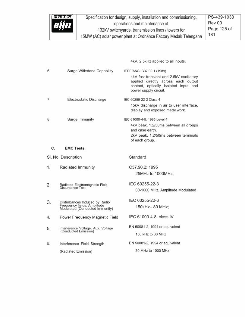
Specification for design, supply, installation and commissioning, operations and maintenance of
132kV switchyards, transmission lines / towers for 15MW (AC) solar power plant at Ordnance Factory Medak Telengana
PS-439-1033 Rev 00 Page 125 of 181
4kV, 2.5kHz applied to all inputs. 6. Surge Withstand Capability IEEE/ANSI C37.90.1 (1989)
4kV fast transient and 2.5kV oscillatory applied directly across each output contact, optically isolated input and power supply circuit.
7. Electrostatic Discharge IEC 60255-22-2 Class 4
15kV discharge in air to user interface, display and exposed metal work.
8. Surge Immunity IEC 61000-4-5: 1995 Level 4
4kV peak, 1.2/50ms between all groups and case earth. 2kV peak, 1.2/50ms between terminals of each group.
C. EMC Tests:
Sl. No. Description 1. Radiated Immunity
2. Radiated Electromagnetic Field Disturbance Test
3. Disturbances Induced by Radio Frequency fields, Amplitude Modulated (Conducted Immunity)
4. Power Frequency Magnetic Field
5. Interference Voltage, Aux. Voltage (Conducted Emission)
6. Interference Field Strength
(Radiated Emission)
Standard C37.90.2: 1995
25MHz to 1000MHz, IEC 60255-22-3
80-1000 MHz, Amplitude Modulated IEC 60255-22-6
150kHz– 80 MHz; IEC 61000-4-8, class IV EN 50081-2, 1994 or equivalent
150 kHz to 30 MHz EN 50081-2, 1994 or equivalent
30 MHz to 1000 MHz

Specification for design, supply, installation and commissioning, operations and maintenance of
132kV switchyards, transmission lines / towers for 15MW (AC) solar power plant at Ordnance Factory Medak Telengana
PS-439-1033 Rev 00 Page 126 of 181
D. Atmospheric Environment Tests:
E. Mechanical Stress Tests:
Sl. No. Description Standard
1. Vibration (during IEC 255-21-1; IEC 68-2-6
Operation and Transportation)
2. Shock (during IEC 255-21-2, IEC 68-2-27
Operation and Transportation)
3. Seismic Vibration (during Operation IEC 60255-21-3 12.15 Settings The bidder shall provide the Employer with a philosophy document clearly setting out the philosophy the bidder will use in determining setting levels. Each setting will have a brief description of the specific function or element. The setting calculation and formula will also be shown on the document. All relevant system parameters, line data, transformer data additionally used for calculating the setting will appear in the setting document. The bidder will conduct system studies in determining fault levels on different locations. These study results will also form part of the setting document. Any additional information required to complete this exercise shall be timely requested by the bidder. The setting document will be presented and discussed with the Employer prior to final issue of the document. The final accepted setting document should be made available to the Employer in PDF format. It is the bidder’s responsibility to configure each protection relay to provide the protection and control facilities required. A full set of relay configuration and setting files shall be included in the design and documentation submissions. The bidder will issue three sets of setting documents once accepted by the client and consultant
Sl. No. Description Standard
1. Humidity IEC 60068-2-3
2. Temperature IEC 60255-6 IEC 60068-2-1 for Cold IEC 60068-2-2 for Dry heat
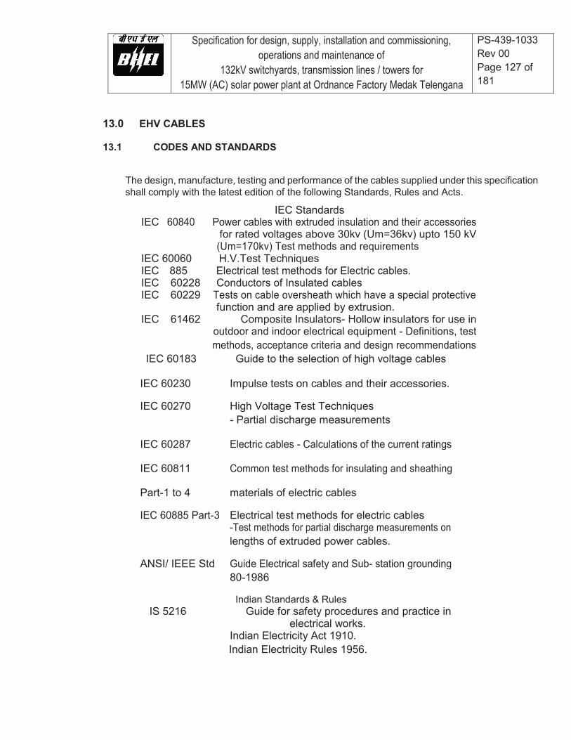
Specification for design, supply, installation and commissioning, operations and maintenance of
132kV switchyards, transmission lines / towers for 15MW (AC) solar power plant at Ordnance Factory Medak Telengana
PS-439-1033 Rev 00 Page 127 of 181
13.0 EHV CABLES 13.1 CODES AND STANDARDS
The design, manufacture, testing and performance of the cables supplied under this specification shall comply with the latest edition of the following Standards, Rules and Acts.
IEC Standards IEC 60840 Power cables with extruded insulation and their accessories for rated voltages above 30kv (Um=36kv) upto 150 kV (Um=170kv) Test methods and requirements IEC 60060 H.V.Test Techniques IEC 885 Electrical test methods for Electric cables. IEC 60228 Conductors of Insulated cables IEC 60229 Tests on cable oversheath which have a special protective function and are applied by extrusion. IEC 61462 Composite Insulators- Hollow insulators for use in outdoor and indoor electrical equipment - Definitions, test methods, acceptance criteria and design recommendations IEC 60183 Guide to the selection of high voltage cables
IEC 60230 Impulse tests on cables and their accessories.
IEC 60270 High Voltage Test Techniques - Partial discharge measurements
IEC 60287 Electric cables - Calculations of the current ratings
IEC 60811 Common test methods for insulating and sheathing
Part-1 to 4 materials of electric cables
IEC 60885 Part-3 Electrical test methods for electric cables -Test methods for partial discharge measurements on lengths of extruded power cables.
ANSI/ IEEE Std Guide Electrical safety and Sub- station grounding 80-1986
Indian Standards & Rules IS 5216 Guide for safety procedures and practice in
electrical works. Indian Electricity Act 1910. Indian Electricity Rules 1956.
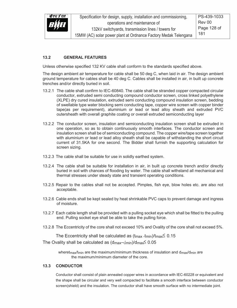
Specification for design, supply, installation and commissioning, operations and maintenance of
132kV switchyards, transmission lines / towers for 15MW (AC) solar power plant at Ordnance Factory Medak Telengana
PS-439-1033 Rev 00 Page 128 of 181
13.2 GENERAL FEATURES Unless otherwise specified 132 KV cable shall conform to the standards specified above. The design ambient air temperature for cable shall be 50 deg C, when laid in air. The design ambient ground temperature for cables shall be 40 deg C. Cables shall be installed in air, in built up concrete trenches and/or directly buried in soil. 13.2.1 The cable shall confirm to IEC-60840. The cable shall be stranded copper compacted circular
conductor, extruded semi conducting compound conductor screen, cross linked polyethylene (XLPE) dry cured insulation, extruded semi conducting compound insulation screen, bedding of swellable type water blocking semi conducting tape, copper wire screen with copper binder tape(as per requirement), aluminium or lead or lead alloy sheath and extruded PVC outersheath with overall graphite coating or overall extruded semiconducting layer
13.2.2 The conductor screen, insulation and semiconducting insulation screen shall be extruded in one operation, so as to obtain continuously smooth interfaces. The conductor screen and insulation screen shall be of semiconducting compound. The copper wire/tape screen together with aluminium or lead or lead alloy sheath shall be capable of withstanding the short circuit current of 31.5KA for one second. The Bidder shall furnish the supporting calculation for screen sizing.
13.2.3 The cable shall be suitable for use in solidly earthed system. 13.2.4 The cable shall be suitable for installation in air, in built up concrete trench and/or directly
buried in soil with chances of flooding by water. The cable shall withstand all mechanical and thermal stresses under steady state and transient operating conditions.
13.2.5 Repair to the cables shall not be accepted. Pimples, fish eye, blow holes etc. are also not
acceptable.
13.2.6 Cable ends shall be kept sealed by heat shrinkable PVC caps to prevent damage and ingress of moisture.
13.2.7 Each cable length shall be provided with a pulling socket eye which shall be fitted to the pulling end. Pulling socket eye shall be able to take the pulling force.
13.2.8 The Eccentricity of the core shall not exceed 10% and Ovality of the core shall not exceed 5%.
The Eccentricity shall be calculated as (tmax -tmin)/tmax 0.15 The Ovality shall be calculated as (dmax– min)/dmax 0.05
wheretmax/tmin are the maximum/minimum thickness of insulation and dmax/dmin are the maximum/minimum diameter of the core.
13.3 CONDUCTOR
Conductor shall consist of plain annealed copper wires in accordance with IEC-60228 or equivalent and the shape shall be circular and very well compacted to facilitate a smooth interface between conductor screen(shield) and the insulation. The conductor shall have smooth surface with no intermediate joint.

Specification for design, supply, installation and commissioning, operations and maintenance of
132kV switchyards, transmission lines / towers for 15MW (AC) solar power plant at Ordnance Factory Medak Telengana
PS-439-1033 Rev 00 Page 129 of 181
13.4 CONDUCTOR SCREEN (SHIELD)
Conductor screen shall consist of extruded semi-conducting compound applied over the conductor, which shall be firmly bonded to the inner surface of the insulation layer. The semi-conducting compound shall be free from any void and protrusion.
13.5 INSULATION
Insulation shall be of extruded Cross Linked Polyethylene (XLPE). The insulation shall be free from any void and contaminant.
13.6 INSULATION SCREEN(SHIELD)
Insulation screen shall consist of extruded semi-conducting compound and shall firmly be bonded to the insulation. The semi-conducting compound shall be free from any void and protrusion.
13.7 BEDDING
Bedding shall consist of layer(s) of swellable semi conducting tape(s) to be applied over the extruded semi-conducting insulation screen with suitable overlap. Semiconducting swelling tape(s) shall also be provided over copper wire screen(if applicable).
13.8 METALLIC SHEATH
The metallic innersheath shall consist of aluminium or lead or lead alloy. The calculations for sizing and short circuit withstand capability of the metallic sheath, alongwith copper wire screen & copper binder tape(if applicable) shall be submitted during detailed design stage.
13.9 OUTER SHEATH
Outer sheath shall consist of extruded black PVC compound, in accordance with IEC-60840.
13.10 CABLE IDENTIFICATION/ MARKING
Atleast the following clear markings shall be provided over outer sheath of the cable at an interval of five metres throughout the length of the cable by embossing:
Rated voltage Conductor size Type of insulation Manufacturer’s name Year of manufacture Purchaser’s name
Sequential marking of length of cable in metres by embossing/printing at
Specification for design, supply, installation and commissioning, operations and maintenance of
132kV switchyards, transmission lines / towers for 15MW (AC) solar power plant at Ordnance Factory Medak Telengana
PS-439-1033 Rev 00 Page 130 of 181
every meter.
The embossing/printing shall be progressive, automatic, in line and marking shall be legible and indelible and incase of printing it should be done with the help a contact less printer.
13.11 CABLE DRUMS
Cables shall be supplied in steel drums of heavy construction.
13.12 CABLE ACCESSORIES
The termination and jointing kits shall be suitable for the cable and shall be complete with all accessories including crimping type cable lugs, jointing materials and consumables. Accessories offered shall be of proven design.
13.12.1 OUT DOOR SEALING ENDS
The termination shall be suitable for outdoor installation in heavily polluted atmosphere and shall be made completely weather proof through cable sealing ends. Accessories shall consist of stress relief system comprising of premoulded material. The termination for open connection shall be housed in porcelain insulator/composite insulator to give high creepage resistance. The minimum nominal specific creepage distance shall be 25mm/kV. Each outdoor type sealing ends shall be supplied complete with mounting plate insulators to insulate the sealing end from supporting structures. Each sealing end shall be provided with two terminals, diametrically opposite each, suitable for bolting of the copper screen and/or metallic sheath of cable.
13.12.2 LINK BOXES
Link boxes shall be suitable for outdoor installation in heavily polluted atmosphere and shall be made completely weather proof. There shall be one link box for each phase. The cable screen/sheath connections shall be bolted type. The connecting bar and disconnecting link shall be of copper. The arrangement shall be installed in a water tight box of min. 2mm thick CRCA steel having degree of protection as IP 55.
The cost of link boxes shall be deemed to be included in the supply price of 132KV cable outdoor sealing ends.
13.12.3 FRP TRENCH COVER
The FRP Trench cover shall be made of non biodegradable& non corrosive material/fillers, suitable designed for required strength. FRP trench cover shall be of medium duty type as per IS1726. Suitable locking & lifting features shall be provided for the FRP trench Cover. Further FRP trench cover shall be UV resistant type. Surface profile of the FRP trench cover shall be anti-skid type.
Erection of FRP trench covers shall be in the scope of contractor.
All accessories shall be suitable for the technical parameters as specified and shall be suitably

Specification for design, supply, installation and commissioning, operations and maintenance of
132kV switchyards, transmission lines / towers for 15MW (AC) solar power plant at Ordnance Factory Medak Telengana
PS-439-1033 Rev 00 Page 131 of 181
derated to the site conditions.
13.12.4 CABLE /ACCESSORIES PARAMETERS
1 Type of Cables Cross-linked polyethylene insulated
2 No. of Cores Single.
3 Conductor size --
4 Conductor material Copper
5 Normal system voltage 132KV
6 Maximum system voltage 145kV
7 Fault current Symmetrical short circuit
31.5kA r.m.s for 1 second
8 System frequency 50hz
9 Frequency variation +/- 5%
10 Rated continuous Current 350 Amp.
11 Overload capacity Nil

Specification for design, supply, installation and commissioning, operations and maintenance of
132kV switchyards, transmission lines / towers for 15MW (AC) solar power plant at Ordnance Factory Medak Telengana
PS-439-1033Rev 00 Page 132 of 181
12 Maximum allowable temperature for cable and accessories.
a) At rated full load and at site conditions.
b) The conductor temperature after a short circuit for 1 second shall not exceed (with conductor temp. at inception of short circuit as 90 deg. C)
13 Basic impulse insulation level (1.2/50 micro second wave)
14 Laying conditions (a) Directly Buried in soil in flat
formation with spacing between cables center.
(b) Earthing of screen (c) Ambient air temp. (d) Type of atmosphere (e) Ground temperature (f) Thermal resistivity of soil (g) Depth of buried cable
90 deg C 250 deg C 650 kV (peak) 500 mm centre to centre (typical) Bonded to earth at both ends. 50 deg. C Heavily polluted 40 deg C 150 degC.cm/watt 1 metre

Specification for design, supply, installation and commissioning, operations and maintenance of
132kV switchyards, transmission lines / towers for 15MW (AC) solar power plant at Ordnance Factory Medak Telengana
PS-439-1033 Rev 00 Page 133 of 181
13.13 INSTALLATION WORK AT SITE
13.13.1 Cable installation shall be carried out generally as per applicable standard/ manufacturer guidelines. Cable shall be laid buried/in trench/on trestle. All necessary work like cable tagging, marking, dressing etc. as required shall be in contractor's scope.
13.13.2 Cable drums shall be unloaded, handled and stored in an approved
manner on hard and well drained surface so that they may not sink. In no case shall the drum be stored flat i.e. with flange horizontal. Rolling of drums shall be avoided as far as possible. For unreeling the cable, the drum shall be mounted on suitable jacks or on cable wheels and shall be rolled slowly so that cable comes out from over the drum and not from below. All possible care shall be taken during unreeling and laying to avoid damage due to twist, kink or sharp bends. Cable ends shall be kept sealed by heat shrinkable PVC caps to prevent damage and ingress of moisture.
13.13.3 While laying cable, ground rollers shall be used at every 2 meter interval to avoid cable touching ground. The cables shall be pushed over the rollers by a gang of people positioned in between the rollers. Cables shall not be pulled from the end without having intermediate pushing arrangement. Pulling tension shall not exceed the values recommended by cable Manufacturer. Cable ends shall be kept sealed by heat shrinkable PVC caps to prevent damage and ingress of moisture. Selection of cable drums for each run shall be so planned so as to avoid straight through joints. Cable splices will not be allowed except where called for by the drawings or is unavoidable and permitted by the Project Manager. Care should be taken while laying the cables so as to avoid damage to cables.
13.13.4 Bending radii for cables shall be as per manufacturer’s recommendations. Manufacturer’s instructions shall be strictly adhered to and necessary conducting medium for checking healthiness of outersheath shall be applied.
13.13.5 Where cables cross roads/rail tracks underground, the cables shall be laid
in HDPE pipes embedded in PCC in ground with a minimum cover of 1 metre. HDPE pipe shall also be provided where cables cross existing HT/LT cable trenches. The HDPE pipes and accessories shall be supplied, laid and encased in PCC by the employer. Ends of HDPE pipes shall be sealed properly after laying of cable.
13.13.6 In each cable run, extra length shall be kept at suitable point to enable two straight joints to be made, should the cable develop fault at a later stage.
13.13.7 Construction of buried cable trench shall include excavation, preparation

Specification for design, supply, installation and commissioning, operations and maintenance of
132kV switchyards, transmission lines / towers for 15MW (AC) solar power plant at Ordnance Factory Medak Telengana
PS-439-1033 Rev 00 Page 134 of 181
of sieved sand bedding, riddled soil cover, supply and installation of concrete protective covers, back filling and compacting, supply and installation of route markers. Bidder shall furnish the details for burying the cable in ground.
13.13.8 RCC cable route markers and RCC joint markers shall be provided as required for buried cable trench. The voltage grade of cables shall be engraved on the marker. Location of underground cable joint shall be indicated with cable marker with an additional inscription “Cable Joint”. The marker shall project 150 mm above ground and shall be provided at every change in direction. Top of cable marker/ joint marker shall be sloped to avoid accumulation of water/dust on marker. Bidder shall ensure that the drawings, instructions and recommendations are correctly followed to avoid damage to the equipment.
13.13.9 Bidder shall carry out the bonding of screen at the both ends of terminal using usingthe insulated conductor of required size with earth mat.
13.13.10 The bidder shall ensure that the cables and accessories supplied by him are installed in a neat workman-like manner such that it is levelled, properly aligned and well oriented. The tolerance shall be as established in the bidder’s drawing and/or as stipulated by the Employer.
13.13.11 The cable termination work shall be carried out by an experienced
cable jointer who shall have adequate experience in jointing and termination of 132kV or higher grade XLPE cables. The successful bidder shall submit, sufficiently in advance, the bio-data of the cable jointer giving the details of his qualification and experience for employer’s approval.
13.14 TYPE, ROUTINE AND ACCEPTANCE TESTS
FOR 132 KV CABLES &ACCESSORIES:
(a) Reports for type tests on 132kV cables shall be furnished in line with IEC 60840 and accessories as per IEC 60840/ IEC 61462.
(b) All equipments to be supplied shall be of type tested design. During detailed engineering, the contractor shall submit for Owner’s approval the reports of all the type tests as listed in this specification and carried out within last ten years from the date of bid opening. These reports should be for the test conducted on the equipment similar to those proposed to be supplied under this contract and the test(s) should have been either conducted at an independent laboratory or should have been witnessed by a client. However if the contractor is not able to submit report of the type test(s) conducted within last ten years from the date of bid opening, or in the case of type test report(s) are not found to be meeting the specification

Specification for design, supply, installation and commissioning, operations and maintenance of
132kV switchyards, transmission lines / towers for 15MW (AC) solar power plant at Ordnance Factory Medak Telengana
PS-439-1033 Rev 00 Page 135 of 181
requirements, the contractor shall conduct all such tests under this contract at no additional cost to the owner either at third party lab or in presence of client /owners representative and submit the reports for approval. All acceptance and routine tests as per the specification and relevant standards shall be carried out. Charges for these shall be deemed to be included in the equipment price The type test reports once approved for any projects shall be treated as reference .
(c) All acceptance and routine tests as per the specification and relevant standards shall be carried out. Charges for these shall be deemed to be included in the equipment price.
Routine tests and Acceptance tests shall be conducted on cables as per IEC 60840, QA table and other relevant standards.
13.15 SITE TESTS:
Following site tests shall be carried out by the bidder and all the equipment required for the site tests shall be arranged by the bidder.
a) HV test as per clause 15.2 IEC 60840. b) After completion of installation non metallic outer sheath shall be tested
in accordance with clause- 5 IEC 60229. c) The insulation resistance of the cable shall be checked before & after the HV
test on cable. d) The core resistance shall be measured and the value corrected in
accordance with clause 5 of IEC 60228.

Specification for design, supply, installation and commissioning, operations and maintenance of
132kV switchyards, transmission lines / towers for 15MW (AC) solar power plant at Ordnance Factory Medak Telengana
PS-439-1033 Rev 00 Page 136 of 181
14.0 LT POWER AND CONTROL CABLES LT Power & control cables shall be of minimum 1100 volts grade XLPE / PVC insulated conforming to IS 1554 for utilization voltages less than equal to 415 V. Instrumentation / signal cable shall be of 225 V grade. MV / HV cables shall be manufactured using dry curing method. 14.1 Codes and standards
All standards, specifications and codes of practice referred to herein shall be the latest editions including all applicable official amendments and revisions as on date of opening of bid. In case of conflict between this specification and those (IS codes, standards, etc.) referred to herein, the former shall prevail. All the cables shall conform to the requirements of the following standards and codes:
TUV specification 2 DC cable for photovoltaic system Pfg 1169/08.2007
IS :1554 - I PVC insulated (heavy duty) electric cables for working voltagesupto and including 1100V. IS : 3961 Recommended current ratings for cables IS : 3975 Low carbon galvanised steel wires, formed wires and
tapes for armouring of cables. IS : 5831 PVC insulation and sheath of electrical cables. IS:7098 (Part -I) Cross linked polyethylene insulated PVC sheathed
cables for working voltages upto and including 1100V. IS : 8130 Conductors for insulated electrical cables and flexible
cords. IS : 10418 Specification for drums for electric cables. IS : 10810 Methods of tests for cables. ASTM-D -2843 Standard test method for density of smoke from the
burning or decomposition of plastics. IEC-754 (Part-I) Tests on gases evolved during combustion of electric
cables. IEC-332 Tests on electric cables under fire conditions. Part-3:
Tests on bunched wires or cables (Category-B). 14.2 General technical requirements The cables shall be suitable for laying on racks, in ducts, trenches, conduits and under ground buried installation with chances of flooding by water. All cables including EPR cables shall be flame retardant, low smoke (FRLS) type designed to withstand all mechanical, electrical and thermal stresses developed under steady state and transient operating conditions as specified elsewhere in this specification. All cables of module area if laid on cable trays should be covered. If cables are to be laid underground, laying shall be as per latest relevant IS code.
Specification for design, supply, installation and commissioning, operations and maintenance of
132kV switchyards, transmission lines / towers for 15MW (AC) solar power plant at Ordnance Factory Medak Telengana
PS-439-1033 Rev 00 Page 137 of 181
Copper/aluminium conductor used in power cables shall have tensile as per relevant standards. Conductors shall be stranded. Conductor of control cables shall be made of stranded, plain annealed copper. XLPE insulation shall be suitable for a continuous conductor temperature of 120 deg. C and short circuit conductor temperature of 200 deg C for 5 secs. XLPE insulation shall be suitable for a continuous conductor temperature of 90 deg. C and short circuit conductor temperature of 250 deg C. PVC insulation shall be suitable for continuous conductor temperature of 70 deg C and short circuit conductor temperature of 160 deg. C. The cable cores shall be laid up with fillers between the cores wherever necessary. It shall not stick to insulation and inner sheath. All the cables, other than single core unarmoured cables, shall have distinct extruded PVC inner sheath of black colour as per IS : 5831. For single core armoured cables, armouring shall be of copper/aluminium wires/ formed wires. For multicore armoured cables, armouring shall be of galvanised steel as follows : Calculated nominal dia. Size and Type of armour of cable under armour Upto 13 mm 1.4mm dia GS wire Above 13 &upto 25mm 0.8 mm thick GS formed wire / 1.6 mm dia GS wire Above 25 &upto 40 mm 0.8mm thick GS formed wire / 2.0mm dia GS wire Above 40 &upto 55mm 1.4 mm thick GS formed wire /2.5mm dia GS wire Above 55 &upto 70 mm 1.4mm thick GS formed wire / 3.15mm dia GS wire Above 70mm 1.4 mm thick GS formed wire / 4.0 mm dia GS wire The aluminium used for armouring shall be of H4 grade as per IS: 8130 with maximum resistivity of 0.028264 ohm mm2 per meter at 20 deg C. The sizes of aluminiumarmouring shall be same as indicated above for galvanized steel. The gap between armour wires / formed wires shall not exceed one armour wire / formed wire space and there shall be no cross over / over-riding of armour wire / formed wire. The minimum area of coverage of armouring shall be 90%. The breaking load of armour joint shall not be less than 95% of that of armour wire / formed wire. Zinc rich paint shall be applied on armour joint surface of GS wire / formed wire. Outer sheath of module inter-connecting DC cable as per TUV specification 2 Pfg 1169/08.2007. Outer sheath shall be of PVC as per IS: 5831 & black in colour for power cables & grey in colour for control cables.. In addition to meeting all the requirements of Indian standards referred to, outer sheath of all the cables shall have the following FRLS
Specification for design, supply, installation and commissioning, operations and maintenance of
132kV switchyards, transmission lines / towers for 15MW (AC) solar power plant at Ordnance Factory Medak Telengana
PS-439-1033 Rev 00 Page 138 of 181
properties.
(a.) Oxygen index of min. 29 (as per IS 10810 Part-58). (b.) Acid gas emission of max. 20% (as per IEC-754-I). (c.) Smoke density rating shall not be more than 60 % (as per ASTMD-
2843). Cores of the cables shall be identified by colouring of insulation. Following colour scheme shall be adopted:
1 core - Red, Black, Yellow or Blue 2 core - Red & Black 3 core - Red, Yellow & Blue 4 core - Red, Yellow, Blue and Black
For control cables having more than 5 cores, core identification shall be done by numbering the insulation of cores sequentially, starting by number 1 in the inner layer (e.g. say for 10 core cable, core numbering shall be from 1 to 10). The number shall be printed in Hindu-Arabic numerals on the outer surfaces of the cores. All the numbers shall be of the same colour, which shall contrast with the colour of insulation. The colour of insulation for all the cores shall be grey only. The numerals shall be legible and indelible. The numbers shall be repeated at regular intervals along the core, consecutive numbers being inverted in relation to each other. When the number is a single numeral, a dash shall be placed underneath it. If the number consists of two numerals, these shall be disposed one below the other and a dash placed below the lower numeral. The spacing between consecutive numbers shall not exceed 50 mm. For reduced neutral conductors (in case of power cable), the core shall be black. In addition to manufacturer's identification on cables as per IS, following marking shall also be provided over outer sheath.
(a) Cable size and voltage grade - To be embossed (b) Word 'FRLS' at every 5 metre - To be embossed (c) Sequential marking of length of the cable in metres at every one
metre -To be embossed / printed The embossing shall be progressive, automatic, in line and marking shall be legible and indelible. For EPR cables identification shall be printed on outer sheath. All cables except module inter-connecting DC cable shall meet the fire resistance requirement as per Category-B of IEC 332 Part-3. Module inter-connecting DC cable shall meet the fire resistance requirement as per TUV specification 2 Pfg 1169/08.2007. Allowable tolerances on the overall diameter of the cables shall be +\-2 mm maximum, over the declared value in the technical data sheets.
Specification for design, supply, installation and commissioning, operations and maintenance of
132kV switchyards, transmission lines / towers for 15MW (AC) solar power plant at Ordnance Factory Medak Telengana
PS-439-1033 Rev 00 Page 139 of 181
Repaired cables shall not be accepted. Pimples, fish eye, blow holes etc. are not acceptable. 14.3 Cable selection & sizing Cables shall be sized based on the following considerations:
(a) Rated current of the equipment
(b) The voltage drop in the cable, during motor starting condition, shall be limited to 10% and during full load running condition, shall be limited to 3% of the rated voltage
(c) Short circuit withstand capability
This will depend on the feeder type. For a fuse protected circuit, cable should be sized to withstand the letout energy of the fuse. For breaker controlled feeder, cable shall be capable of withstanding the system fault current level for total breaker tripping time inclusive of relay pickup time. Control cables shall be sized based on the following considerations:
(a) The minimum conductor cross-section shall be 1.5 sq.mm. (b) The minimum number of spare cores in control cables shall be as follows:
No. of cores in cable Min. No. of spare cores
2C, 3C NIL 5C 1 7C-12C 2 14C & above 3
14.4 De rating Factors De rating factors for various conditions of installations including the following shall be considered while selecting the cable sizes:
a) Variation in ambient temperature for cables laid in air b) Grouping of cables c) Variation in ground temperature and soil resistivity for buried cables.
Cable lengths shall be considered in such a way that straight through cable joints are avoided. Cables shall be armoured type if laid in switchyard area or directly buried. All LT power cables of sizes more than 120 sq.mm. shall be XLPE insulated.
Specification for design, supply, installation and commissioning, operations and maintenance of
132kV switchyards, transmission lines / towers for 15MW (AC) solar power plant at Ordnance Factory Medak Telengana
PS-439-1033 Rev 00 Page 140 of 181
14.5 Constructional features of LT Power Cables 1.1 KV Grade Power Cables 1.1 KV grade XLPE power cables shall have compacted aluminium/ copper conductor, XLPE insulated, PVC inner-sheathed (as applicable), armoured/ unarmoured, PVC outer-sheathed conforming to IS:7098. (Part-I). 1.1KV grade PVC power cables shall have aluminium/copper conductor(compacted type for sizes above 10 sq.mm), PVC Insulated, PVC inner sheathed (as applicable) armoured/ unarmoured, PVC outer-sheathed conforming to IS:1554 (Part-I). 1.1 KV grade Trailing cables shall have tinned copper (class 5) conductor, insulated with heat resistant elastomeric compound based on Ethylene PropylineRubber(EPR) suitable for withstanding 90 deg.C continuous conductor temperature and 250deg C during short circuit, inner-sheathed with heat resistant elastomeric compound, nylon cord reinforced, outer-sheathed with heat resistant, oil resistant and flame retardant heavy duty elastomeric compound conforming to IS 9968. 14.6 Constructional features of LT control cables 1.1 KV Grade Control Cables shall have stranded copper conductor and shall be multicore PVC insulated, PVC inner sheathed, armoured / unarmoured, FRLS PVC outer sheathed conforming to IS: 1554. (Part-I). 1.1 KV grade Trailing cables shall have tinned copper (class 5) conductor, insulated with heat resistant elastomeric compound based on Ethylene PropylineRubber(EPR) suitable for withstanding 90 deg.C continuous conductor temperature and 250deg C during short circuit, inner-sheathed with heat resistant elastomeric compound, nylon cord reinforced, outer-sheathedwith heat resistant, oil resistant and flame retardant heavy duty elastomeric compound conforming to IS 9968. Minimum conductor size shall be 2.5 sqmm. 14.7 Cable Drums Cables shall be supplied in non returnable wooden or steel drums of heavy construction. The surface of the drum and the outer most cable layer shall be covered with water proof cover. Both the ends of the cables shall be properly sealed with heat shrinkable PVC/ rubber caps secured by 'U' nails so as to eliminate ingress of water during transportation, storage and erection. Wood preservative anti-termite treatment shall be applied to the entire drum. Wooden drums shall comply with IS: 10418. Each drum shall carry manufacturer's name, purchaser’s name, address and contract number, item number and type, size and length of cable and net gross weight stenciled on both sides of the drum. A tag containing same information shall be attached to the leading end of the cable. An arrow and suitable accompanying wording shall be marked on one end of the reel indicating the direction in which it should be rolled. 14.8 Tests on LT power and control cables Indicative list of tests/checks, Routine and Acceptance tests shall be as perQuality
Specification for design, supply, installation and commissioning, operations and maintenance of
132kV switchyards, transmission lines / towers for 15MW (AC) solar power plant at Ordnance Factory Medak Telengana
PS-439-1033 Rev 00 Page 141 of 181
Assurance & Inspection table of LT power and control cables enclosed at relevant section. 15.0 Cabling 15.1 Codes and standards
All standards, specifications and codes of practice referred to herein shall be the latest editions including all applicable official amendments and revisions as on date of opening of bid. In case of conflict between this specification and those (IS codes, standards, etc.) referred to herein, the former shall prevail. All work shall be carried out as per the following standards/ codes as applicable.
IS:513 Cold rolled low carbon steel sheets and strips.
IS:802 Code of practice for the use of Structural Steel in
Overhead Transmission Line Towers.
IS:1079 Hot Rolled carbon steel sheet & strips
IS:1239 Mild steel tubes, tubulars and other wrought steel
fIttings
IS:1255 Code of practice for installation and maintenance of
power cables upto and including 33 KV rating
IS:1367 Part-13 Technical supply conditions for threaded Steel
fasteners. (Hot dip galvanized coatings on threaded
fasteners).
IS:2147 Degree of protection provided by enclosures for low
voltage switchgear and control gear
IS:2309 Code of Practice for the protection of building and
allied structures against lightning.
IS:2629 Recommended practice for hot dip galvanising of
iron & steel
IS:2633 Method for testing uniformity of coating on zinc
coated articles.
IS:3043 Code of practice for Earthing
IS:3063 Fasteners single coil rectangular section spring
washers.
Specification for design, supply, installation and commissioning, operations and maintenance of
132kV switchyards, transmission lines / towers for 15MW (AC) solar power plant at Ordnance Factory Medak Telengana
PS-439-1033 Rev 00 Page 142 of 181
IS:6745 Methods for determination of mass of zinc coating on zinc coated iron & steel articles.
IS:8308 Compression type tubular in- line connectors for aluminium conductors of insulated cables
IS:8309 Compression type tubular terminal ends for aluminium conductors of insulated cables.
IS:9537 Conduits for electrical installation.
IS:9595 Metal - arc welding of carbon and carbon manganese steels - recommendations.
IS:13573 Joints and terminations for polymeric cables for working voltages from 6.6kv upto and including 33kv performance requirements and type tests.
BS:476 Fire tests on building materials and structures
IEEE:80 IEEE guide for safety in AC substation grounding
IEEE:142 Grounding of Industrial & commercial power systems
DIN 46267 (Part-II) Non tension proof compression joints for Aluminium conductors.
DIN 46329 Cable lugs for compression connections, ring type ,for Aluminium conductors
VDE 0278 Tests on cable terminations and straight through joints
BS:6121 Specification for mechanical Cable glands for elastomers and plastic insulated cables. Indian
Electricity Act.
Indian Electricity Rules. Equipment complying with other internationally accepted standards such as IEC, BS, DIN, USA, VDE, NEMA etc. will also be considered if they ensure performance and constructional features equivalent or superior to standards listed above. In such a case, the Bidder shall clearly indicate the standard(s) adopted, furnish a copy in English of the latest revision of the standards alongwith copies of all official amendments and revisions in force as on date of opening of bid and shall clearly bring out the salient features for comparison. 15.2 Design and constructional features 15.2.1 Inter Plant Cabling Interplant cabling for main routes shall be laid in Cable trenches/duct banks. Cables from main plant to control room shall be laid in Cable trenches/duct banks. In case of Duct banks,
Specification for design, supply, installation and commissioning, operations and maintenance of
132kV switchyards, transmission lines / towers for 15MW (AC) solar power plant at Ordnance Factory Medak Telengana
PS-439-1033 Rev 00 Page 143 of 181
pull-pits shall be filled with sand and provided with a PCC covering. Directly burried cables, if essential ,shall not have concentration of more than 4 cables in one route. All buried cables shall be armoured. 15.2.2 Trenches PCC flooring of built up trenches shall be sloped for effective drainage with sump pits and sump pumps. No sub zero level cable vault/trenches shall be provided below control building/switchgear rooms in plant. 15.2.3 General a) The cable slits to be used for motor/equipment power/control supply shall be sand filled
& covered with PCC after cabling. b) Sizing criteria, derating factors for the cables shall be met as per respective chapters.
However for the power cables, the minimum conductor size shall be 6 sq.mm. foraluminium conductor and 2.5 sq.mm. for copper conductor cable.
c) Conscious exceptions to the above guidelines may be accepted under special conditions
but suitable measures should be taken at such location to:
1. Meet all safety requirements 2. Safeguard against fire hazards, mechanical damage, flooding of water, oil
accumulation, electrical faults/interferences, etc 15.3 Cabling support system – cable trays, pipes, glands etc 15.3.1 Cable trays, Fittings & Accessories
a) Cable trays shall be ladder/perforated type as specified complete with matching fittings (like brackets, elbows, bends, reducers, tees, crosses, etc.) accessories (like side coupler plates, etc. and hardware (like bolts, nuts, washers, G.I. strap, hook etc.) as required. Cable tray shall be ladder type for power & control cables and perforated for instrumentation cables.
b) Cable trays, fittings and accessories shall be fabricated out of rolled mild steel sheets
free from flaws such as laminations, rolling marks, pitting etc. These (including hardware) shall be hot dip galvanized as per relevant IS.
c) Cable trays shall have standard width of 150 mm, 300 mm & 600 mm and standard
lengths of 2.5 metre. Thickness of mild steel sheets used for fabrication of cable trays and fittings shall be 2 mm. The thickness of side coupler plates shall be 3 mm.
d) Cable troughs shall be required for branching out few cables from main cable route.
These shall be U-shaped, fabricated of mild steel sheets of thickness 2 mm and shall be hot dip galvanised as per relevant IS. Troughs shall be standard width of 50 mm & 75 mm with depth of 25 mm
Specification for design, supply, installation and commissioning, operations and maintenance of
132kV switchyards, transmission lines / towers for 15MW (AC) solar power plant at Ordnance Factory Medak Telengana
PS-439-1033 Rev 00 Page 144 of 181
15.3.2 Support System for Cable Trays Cable tray support system shall be pre-fabricated similar or equivalent to "Unistrut make". Support system for cable trays shall essentially comprise of the two components i.e. main support channel and cantilever arms. The main support channel shall be of two types : (i) C1:- having provision of supporting cable trays on one side and (ii) C2:-having provision of supporting cable trays on both sides. The support system shall be the type described hereunder: a. Cable supporting steel work for cable racks/cables shall comprise of various channel
sections, cantilever arms, various brackets, clamps, floor plates, all hardwares such as lock washers, hexagon nuts, hexagon head bolt, support hooks, stud nuts, hexagon head screw, channel nut, channel nut with springs, fixing studs, etc.
b. The system shall be designed such that it allows easy assembly at site by using bolting.
All cable supporting steel work, hardwaresfitings and accessories shall be prefabricated factory galvanised.
c. The main support and cantilever arms shall be fixed at site using necessary brackets,
clamps, fittings, bolts, nuts and other hardware etc. to form various arrangements required to support the cable trays. Welding of the components shall not be allowed. However, welding of the bracket (to which the main support channel is bolted) to the overhead beams, structural steel, insert plates or reinforcement bars will be permitted. Any cutting or welding of the galvansied surface shall be brushed and red lead primer, oil primer &aluminium paint shall be applied
d. All steel components, accessories,fittings and hardware shall be hot dip galvanised
after completing welding, cutting, drilling and other machining operation. e. The typical arrangement of flexible support system is described briefly below:
The main support channel and cantilever arms shall be fabricated out of 2.5 thick rolled steel sheet conforming to IS.
Cantilever arms of 320 mm, 620mm and 750 mm in length are required, and shall be as shown in the enclosed drawing. The arm portion shall be suitable for assembling the complete arm assembly on to component constructed of standard channel section. The back plate shall allow sufficient clearance for fixing bolt to be tightened with tray in position.
Support system shall be able to withstand
weight of the cable trays weight of the cables (75 Kg/Metre run of each cable tray) Concentrated load of 75 Kg between every support span. Factor of safety of minimum 1.5 shall be considered.
The size of structural steel members or thickness of sheet steel of main support channel and cantilever arms and other accessories as indicated above are indicative only. Nevertheless, the support system shall be designed by the bidder to fully meet the requirements of type
Specification for design, supply, installation and commissioning, operations and maintenance of
132kV switchyards, transmission lines / towers for 15MW (AC) solar power plant at Ordnance Factory Medak Telengana
PS-439-1033 Rev 00 Page 145 of 181
tests as specified. In case the system fails in the tests, the components design modification shall be done by the Bidder without any additional cost to the Employer. The bidder shall submit the detailed drawings of the system offered by him alongwith the bid.
15.3.3 Pipes, Fittings & Accessories
a) Pipes offered shall be complete with fittings and accessories (like tees, elbows, bends, check nuts, bushings, reducers, enlargers, coupling caps, nipples etc.) The size of the pipe shall be selected on the basis of maximum 40% fill criteria
b) GI Pipes shall be of medium duty as per IS:1239
c) Duct banks shall be High Density PE pipes encased in PCC (10% spare of each
size, subject to minimum one) with suitable water-proof manholes.
d) Hume pipes shall be NP3 type as per IS 458. 15.3.4 Junction Boxes
a) Junction Boxes with IP:55 degree of protection, shall comprise of a case with hinged door constructed from cold rolled sheet steel of thickness 2mm. Top of the boxes shall be arranged to slope towards rear of the box. Gland plate shall be 3mm thick sheet steel with neoprene/synthetic rubber gaskets. All junction boxes shall be of adequate strength and rigidity, hot dip galvanised as per relevant IS, and suitable for mounting on wall, columns, structures etc. The boxes shall include brackets, bolts, nuts, screws M8 earthing stud etc. required for installation.
b) Terminal blocks shall be 1100V grade, 10Amps rated, made up of unbreakable
polyamide 6.6 grade. The terminals shall be screw type or screw-less (spring loaded) / cage clamp type with lugs. Marking on terminal strips shall correspond to the terminal numbering in wiring diagrams. All metal parts shall be of non-ferrous material. In case of screw type terminals the screw shall be captive, preferably with screw locking design. All terminal blocks shall be suitable for terminating on each side two (2) nos. stranded copper conductors of size upto 2.5 sq mm each. All internal wiring shall be of minimum 1.5 sq. mm cu. Conductor PVC wire.
15.3.5 Terminations & Straight Through Joints
a) Termination and jointing kits for 33kV,11kV,6.6 kV and 3.3 kV grade XLPE insulated cables shall be of proven design and make which have already been extensively used and type tested. Termination kits and jointing kits shall be pre-moulded type, taped type or heat shrinkable type. 33kV, 11kV and 6.6 kV grade joints and terminations shall be type tested as per IS:13573. 3.3kV grade joints and terminations shall be type tested as per VDE0278. Critical components used in cable accessories shall be of tested and proven quality as per relevant product specification/ESI specification. Kit contents shall be supplied from the same source as were used for type testing. The kit shall be complete with the aluminiumsolderless crimping type cable lugs & ferrule as per DIN standard.
b) Straight through joint and termination shall be capable of withstanding the fault level

Specification for design, supply, installation and commissioning, operations and maintenance of
132kV switchyards, transmission lines / towers for 15MW (AC) solar power plant at Ordnance Factory Medak Telengana
PS-439-1033 Rev 00 Page 146 of 181
for the system.
c) 1.1KV grade Straight Through Joint shall be of proven design. 15.3.6 Cable glands Cable shall be terminated using double compression type cable glands. Cable glands shall conform to BS:6121 and be of robust construction capable of clamping cable and cable armour (for armoured cables) firmly without injury to insulation. Cable glands shall be made of heavy duty brass machine finished and nickel chrome plated. Thickness of plating shall not be less than 10 micron. All washers and hardware shall also be made of brass with nickel chrome plating Rubber components shall be of neoprene or better synthetic material and of tested quality. Cable glands shall be suitable for the sizes of cable supplied/erected.
15.3.7 Cable lugs/ferrules Cable lugs/ferrules for power cables shall be tinned copper solderless crimping type suitable for aluminium compacted conductor cables. Cable lugs and ferrules for control cables shall be tinned copper type. The cable lugs for control cables shall be provided with insulating sleeve and shall suit the type of terminals provided on the equipments. Cable lugs and ferrule shall conform to relevant standard 15.3.8 Trefoil clamps Trefoil clamps for single core cables shall be pressure die cast aluminum or fibre glass or nylon and shall include necessary fixing accessories like G.I. nuts, bolts, washers, etc. Trefoil clamps shall have adequate mechanical strength to withstand the forces generated by the peak value of maximum system short circuit current. 15.3.9 Cable Clamps & Straps The cable clamps required to clamp multicore cables on vertical run shall be made up of Aluminium strip of 25x3 mm size. For clamping the multicore cables, self-locking, de-interlocking type nylon clamps/straps shall be used. The clamps/straps shall have sufficient strength and shall not get affected by direct exposure to sun rays and outdoor environment 15.3.10 Receptacles
Receptacles boxes shall be fabricated out of MS sheet of 2mm thickness and hot dip galvanized or of die-cast aluminium alloy of thickness not less than 2.5 mm. The boxes shall be provided with two nos. earthing terminals, gasket to achieve IP55 degree of protection, terminal blocks for loop-in loop-out for cable of specified sizes, mounting brackets suitable for surface mounting on wall/column/structure, gland plate etc. The ON-OFF switch shall be rotary type heavy duty, double break,AC23 category, suitable for AC supply. Plug and Socket shall be shrouded Die-cast aluminium. Socket shall be provided with lid safety cover. Robust mechanical interlock shall be provided such that the switch can be put ON only when the plug is fully engaged and plug can be withdrawn only when the switch is in OFF position. Also cover can be opened only when the switch is in OFF position. Wiring shall be carried out with 1100 V grade PVC insulated stranded aluminium/copper wire of adequate size. The Terminal blocks shall be of 1100 V grade. The Terminal blocks shall be of 1100 V grade made up of unbreakable polymide 6.6 grade with adequate current rating and size. The
Specification for design, supply, installation and commissioning, operations and maintenance of
132kV switchyards, transmission lines / towers for 15MW (AC) solar power plant at Ordnance Factory Medak Telengana
PS-439-1033 Rev 00 Page 147 of 181
welding receptacles shall be provided with inbuilt ELCB rated for suitable mA sensitivity. Galvanising Galvanising of steel components and accessories shall conform to IS:2629 , IS4759 & IS:2633. Additionally galvanising shall be uniform, clean smooth, continuous and free from acid spots. The amount of zinc deposit over threaded portion of bolts, nuts, screws and washers shall be as per IS:1367 . The removal of extra zinc on threaded portion of components shall be carefully done to ensure that the threads shall have the required zinc coating on them as specified 15.3.11 Welding The welding shall be carried out in accordance with IS:9595. All welding procedures and welders qualification shall also be followed strictly in line with IS:9595 15.4 INSTALLATION 15.4.1 Cable tray and Support System Installation a) Cables shall run in cable trays mounted horizontally or vertically on cable tray support
system which in turn shall be supported from floor, ceiling, overhead structures, trestles, pipe racks, trenches or other building structures.
b) Horizontally running cable trays shall be clamped by bolting to cantilever arms and vertically running cable trays shall be bolted to main support channel by suitable bracket/clamps on both top and bottom side rails at an interval of 2000 mm in general . For vertical cable risers/shafts cable trays shall be supported at an interval of 1000mm in general . Fixing of cable trays to cantilever arms or main support channel by welding shall not be accepted. Cable tray installation shall generally be carried out as per the approved guidelines/ drawings. Vendor shall design the support system along with tray, spacing etc in line with relevant standard .
c) The cantilever arms shall be positioned on the main support channel with a minimum vertical spacing of 300 mm unless otherwise indicated.
d) The contractor shall fix the brackets/ clamps/ insert plates using anchor fasteners. Minimum size of anchor fasteners shall be M 8 X 50 and material shall be stainless steel grade 316 or better. Anchor fastener shall be fixed as recommended by manufacturer and as approved by site engineer. For brick wall suitable anchor fasteners shall be used as per the recommendations of manufacturer. Make of anchor fasteners subject to QA approval and the same shall be finalized at pre-award stage.
e) All cable way sections shall have identification, designations as per cable way layout drawings and painted/stenciled at each end of cable way and where there is a branch connection to another cable way. Minimum height of letter shall be not less than 75 mm. For long lengths of trays, the identification shall be painted at every 10 meter. Risers shall additionally be painted/stenciled with identification numbers at every floor.
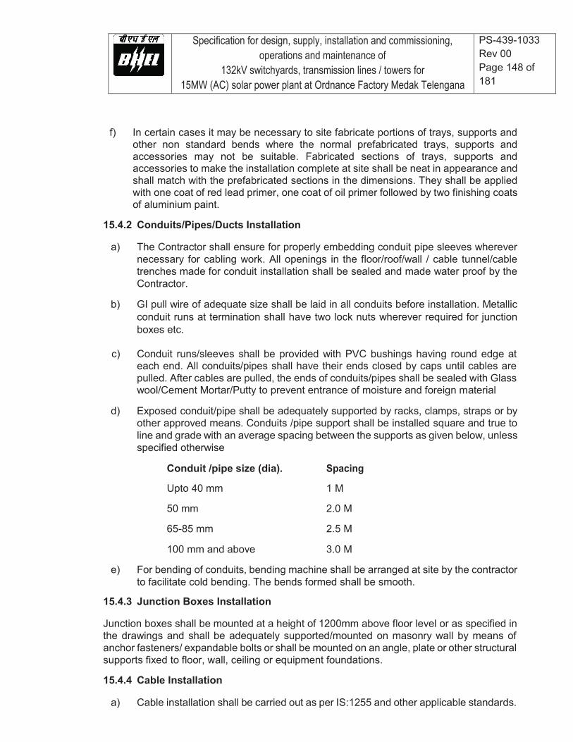
Specification for design, supply, installation and commissioning, operations and maintenance of
132kV switchyards, transmission lines / towers for 15MW (AC) solar power plant at Ordnance Factory Medak Telengana
PS-439-1033 Rev 00 Page 148 of 181
f) In certain cases it may be necessary to site fabricate portions of trays, supports and
other non standard bends where the normal prefabricated trays, supports and accessories may not be suitable. Fabricated sections of trays, supports and accessories to make the installation complete at site shall be neat in appearance and shall match with the prefabricated sections in the dimensions. They shall be applied with one coat of red lead primer, one coat of oil primer followed by two finishing coats of aluminium paint.
15.4.2 Conduits/Pipes/Ducts Installation
a) The Contractor shall ensure for properly embedding conduit pipe sleeves wherever necessary for cabling work. All openings in the floor/roof/wall / cable tunnel/cable trenches made for conduit installation shall be sealed and made water proof by the Contractor.
b) GI pull wire of adequate size shall be laid in all conduits before installation. Metallic
conduit runs at termination shall have two lock nuts wherever required for junction boxes etc.
c) Conduit runs/sleeves shall be provided with PVC bushings having round edge at
each end. All conduits/pipes shall have their ends closed by caps until cables are pulled. After cables are pulled, the ends of conduits/pipes shall be sealed with Glass wool/Cement Mortar/Putty to prevent entrance of moisture and foreign material
d) Exposed conduit/pipe shall be adequately supported by racks, clamps, straps or by
other approved means. Conduits /pipe support shall be installed square and true to line and grade with an average spacing between the supports as given below, unless specified otherwise
Conduit /pipe size (dia). Spacing
Upto 40 mm 1 M
50 mm 2.0 M
65-85 mm 2.5 M
100 mm and above 3.0 M
e) For bending of conduits, bending machine shall be arranged at site by the contractor to facilitate cold bending. The bends formed shall be smooth.
15.4.3 Junction Boxes Installation Junction boxes shall be mounted at a height of 1200mm above floor level or as specified in the drawings and shall be adequately supported/mounted on masonry wall by means of anchor fasteners/ expandable bolts or shall be mounted on an angle, plate or other structural supports fixed to floor, wall, ceiling or equipment foundations. 15.4.4 Cable Installation
a) Cable installation shall be carried out as per IS:1255 and other applicable standards.
Specification for design, supply, installation and commissioning, operations and maintenance of
132kV switchyards, transmission lines / towers for 15MW (AC) solar power plant at Ordnance Factory Medak Telengana
PS-439-1033 Rev 00 Page 149 of 181
b) For Cable unloading , pulling etc following guidelines shall be followed in general :
i. Cable drums shall be unloaded, handled and stored in an approved manner on
hard and well drained surface so that they may not sink. In no case shall be drum be stored flat i.e. with flange horizontal. Rolling of drums shall be avoided as far as possible. For short distances, the drums may be rolled provided they are rolled slowly and in proper direction as marked on the drum. In absence of any indication, the drums may be rolled in the same direction as it was rolled during taking up the cables. For unreeling the cable, the drum shall be mounted on suitable jacks or on cable wheels and shall be rolled slowly so that cable comes out over the drum and not from below. All possible care shall be taken during unreeling and laying to avoid damage due to twist, kink or sharp bends. Cable ends shall be provided with sealed plastic caps to prevent damage and ingress of moisture.
ii. While laying cable, ground rollers shall be used at every 2 meter interval to avoid
cable touching ground. The cables shall be pushed over the rollers by a gang of people positioned in between the rollers. Cables shall not be pulled from the end without having intermediate pushing arrangements. Pulling tension shall not exceed the values recommended by cable manufacturer. Selection of cable drums for each run shall be so planned so as to avoid using straight through joints. Care should be taken while laying the cables so as to avoid damage to cables. If any particular cable is damaged, the same shall be repaired or changed to the satisfaction of Project Manager.
c) Cables shall be laid on cable trays strictly in line with cable schedule
d) Power and control cables shall be laid on separate tiers in line with approved
guidelines/drawings. The laying of different voltage grade cables shall be on different tiers according to the voltage grade of the cables. In horizontal tray stacks, H.T. cables shall be laid on topmost tier and cables of subsequent lower voltage grades on lower tiers of trays. Single core cable in trefoil formation shall be laid with a distance of four times the diameter of cable between trefoil center lines and clamped at every two meter. All multi core cables shall be laid in touching formation. Power and control cables shall be secured fixed to trays/support with self locking type nylon cable straps with de-interlocking facilities. For horizontal trays arrangements, multi core power cables and control cables shall be secured at every five meter interval. For vertical tray arrangement, individual multi core power cables and control cables shall be secured at every one meter by nylon cable strap. After completion of cable laying work in the particular vertical tray, all the control cables shall be binded to trays/supports by aluminium strips at every five meter interval and at every bend.
e) Bending radii for cables shall be as per manufacturer's recommendations and IS:1255.
f) Where cables cross roads/rail tracks, the cables shall be laid in hume pipe/HDPE pipe.

Specification for design, supply, installation and commissioning, operations and maintenance of
132kV switchyards, transmission lines / towers for 15MW (AC) solar power plant at Ordnance Factory Medak Telengana
PS-439-1033 Rev 00 Page 150 of 181
g) No joints shall be allowed in trip circuits, protection circuits and CT/PT circuits. Also joints in critical equipment in main plant area shall not be permitted. Vendor shall identify and accordingly procure the cable drum length.
h) In each cable run some extra length shall be kept at suitable point to enable one LT/two HT straight through joints to made, should the cable develop fault at a later stage. Control cable termination inside equipment enclosure shall have sufficient lengths so that shifting of termination in terminal blocks can be done without requiring any splicing.
i) Wherever few cables are branching out from main trunk route troughs shall be used.
j) Wind loading shall be considered for designing support as well Cable trays wherever required.
k) Where there is a considerable risk of steam, hot oil or mechanical damage cable routes shall be protected by barriers or enclosures.
l) The installation work shall be carried out in a neat workman like manner & areas of work shall be cleaned of all scraps, water, etc. after the completion of work in each area every day. Contractor shall replace RCC/Steel trench covers after the Installation work in that particular area is completed or when further work is not likely to be taken up for some time.
15.4.5 Separation At least 300mm clearance shall be provided between
HT power & LT power cables,
LT power & LT control/instrumentation cables, 15.4.6 Segregation a. Segregation means physical isolation to prevent fire jumping. b. All cables associated with the unit shall be segregated from cables of other units. c. Interplant cables of station auxiliaries and unit critical drives shall be segregated in such
a way that not more than half of the drives are lost in case of single incident of fire. Power and control cables for AC drives and corresponding emergency AC or DC drives shall be laid in segregated routes. Cable routes for one set of auxiliaries of same unit shall be segregated from the other set.
d. In switchyard, control cables of each bay shall be laid on separate racks/trays. 15.4.7 Minimum number of spare cores required to be left for interconnection in control

Specification for design, supply, installation and commissioning, operations and maintenance of
132kV switchyards, transmission lines / towers for 15MW (AC) solar power plant at Ordnance Factory Medak Telengana
PS-439-1033 Rev 00 Page 151 of 181
cables shall be as follows: Minimum number of spare cores required to be left for interconnection in control cables shall be as follows:
No. of cores in cable
No. of spare cores
2C,3C NIL 5C 1
7C-10C 2 14C and above 3
15.4.8 Directly Buried Cables a) Cable trenches shall be constructed for directly buried cables. Construction of cable
trench for cables shall include excavation, preparation of sieved sand bedding, riddled soil cover, supply and installation of brick or concrete protective covers, back filling and compacting, supply and installation of route markers and joint markers. Laying of cables and providing protective covering shall be as per IS:1255.
b) RCC cable route and RCC joint markers shall be provided wherever required. The
voltage grade of the higher voltage cables in route shall be engraved on the marker. Location of underground cable joints shall be indicated with cable marker with an additional inscription "Cable Joint". The marker shall project 150 mm above ground and shall be spaced at an interval of 30 meters and at every change in direction. They shall be located on both sides of road crossings and drain crossings. Top of cable marker/joint marker shall be sloped to avoid accumulation of water/dust on marker.
15.4.9 Cable tags shall be provided on all cables at each end (just before entering the
equipment enclosure), on both sides of a wall or floor crossing, on each duct/conduit entry, and at every 20 meters in cable tray/trench runs. Cable tags shall also be provided inside the switchgear, motor control centers, control and relay panels etc. where a number of cables enter together through a gland plate. Cable tag shall be of rectangular shape for power cables and control cables. Cable tag shall be of 2 mm thick aluminum with number punched on it and securely attached to the cable by not less than two turns of 20 SWG GI wire conforming to IS:280. Alternatively, the Contractor may also provide cable tags made of nylon, cable marking ties with cable number heat stamped on the cable tags
15.4.10 While crossing the floors, unarmoured cables shall be protected in conduits upto a
height of 500 mm from floor level if not laid in tray. 15.5 Cable Terminations & Connections
a) The termination and connection of cables shall be done strictly in accordance with cable termination kit manufacturer'' instructions, drawings and/or as directed by Project Manager. Cable jointer shall be qualified to carryout satisfactory cable jointing/termination. Contractor shall furnish for review documentary evidence/experience reports of the jointers to be deployed at site.
Specification for design, supply, installation and commissioning, operations and maintenance of
132kV switchyards, transmission lines / towers for 15MW (AC) solar power plant at Ordnance Factory Medak Telengana
PS-439-1033 Rev 00 Page 152 of 181
b) Work shall include all clamps, fittings etc. and clamping, fitting, fixing, plumbing,
soldering, drilling, cutting, taping, preparation of cable end, crimping of lug, insulated sleeving over control cable lugs, heat shrinking (where applicable), connecting to cable terminal, shorting and grounding as required to complete the job to the satisfaction of the Project Manager.
c) The equipment will be generally provided with undrilled gland plates for
cables/conduit entry. The Contractor shall be responsible for punching of gland plates, painting and touching up. Holes shall not be made by gas cutting . The holes shall be true in shape. All cable entry points shall be sealed and made vermin and dust proof. Unused openings shall be effectively sealed by 2mm thick aluminium sheets.
d) Control cable cores entering control panel/switchgear/MCC/miscellaneous panels
shall be neatly bunched, clamped and tied with self locking type nylon cable ties with de interlocking facility to keep them in position.
e) All the cores of the control cable to be terminated shall have identification by
providing ferrules at either end of the core, each ferrule shall be indelible, printed single tube ferrule and shall include the complete wire number and TB number as per the drawings. The ferrule shall fit tightly on the core. Spare cores shall have similar ferrules with suffix sp1, sp2, ---etc along with cable numbers and coiled up after end sealing.
f) All cable terminations shall be appropriately tightened to ensure secure and reliable
connections. 16.0 Metering System All the tariff meters (Main, Check & Standby may be installed by Central Transmission Utility and as per practice being followed in thermal units accordingly space for these owners supplied meters shall be provided in respective C&R panels.) Only one set of meters may be included in present scope for 33kV and 132kV side. (a) Three Energy Meters (Main, Check, Standby) of Class 0.2S accuracy suitable
for ABT requirement shall be provided for the 132 kV side of the transformer at Solar Plant.
(b) Three Energy Meters (Main, Check, Standby) of Class 0.2S accuracy suitable for ABT requirement shall be provided for the 132 kV feeder at STU substation.
(c) Meter shall be suitable for interfacing for synchronizing the built-in clock of the meter by GPS time synchronization equipment. Bidder shall synchronize the meter using GPS time synchronization equipment. All the hardware required for synchronization shall be in the scope of bidder
All type test reports as per IEC 62052-11/IEC 62053-22 16.1 Technical Requirements of ABT Compliant Energy Meters i) Shall be microprocessor-based conforming to IEC 60687 /IEC 62052-11/IEC
62053-22 / IEC 62056 /IS15959 for category B.
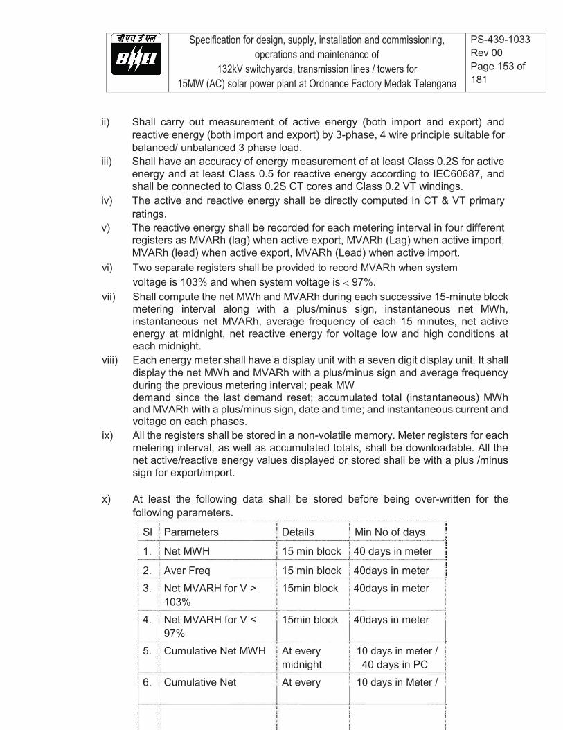
Specification for design, supply, installation and commissioning, operations and maintenance of
132kV switchyards, transmission lines / towers for 15MW (AC) solar power plant at Ordnance Factory Medak Telengana
PS-439-1033 Rev 00 Page 153 of 181
ii) Shall carry out measurement of active energy (both import and export) and reactive energy (both import and export) by 3-phase, 4 wire principle suitable for balanced/ unbalanced 3 phase load.
iii) Shall have an accuracy of energy measurement of at least Class 0.2S for active energy and at least Class 0.5 for reactive energy according to IEC60687, and shall be connected to Class 0.2S CT cores and Class 0.2 VT windings.
iv) The active and reactive energy shall be directly computed in CT & VT primary ratings.
v) The reactive energy shall be recorded for each metering interval in four different registers as MVARh (lag) when active export, MVARh (Lag) when active import, MVARh (lead) when active export, MVARh (Lead) when active import.
vi) Two separate registers shall be provided to record MVARh when system voltage is 103% and when system voltage is 97%.
vii) Shall compute the net MWh and MVARh during each successive 15-minute block metering interval along with a plus/minus sign, instantaneous net MWh, instantaneous net MVARh, average frequency of each 15 minutes, net active energy at midnight, net reactive energy for voltage low and high conditions at each midnight.
viii) Each energy meter shall have a display unit with a seven digit display unit. It shall display the net MWh and MVARh with a plus/minus sign and average frequency during the previous metering interval; peak MW demand since the last demand reset; accumulated total (instantaneous) MWh and MVARh with a plus/minus sign, date and time; and instantaneous current and voltage on each phases.
ix) All the registers shall be stored in a non-volatile memory. Meter registers for each metering interval, as well as accumulated totals, shall be downloadable. All the net active/reactive energy values displayed or stored shall be with a plus /minus sign for export/import.
x) At least the following data shall be stored before being over-written for the
following parameters. Sl Parameters Details Min No of days
1. Net MWH 15 min block 40 days in meter
2. Aver Freq 15 min block 40days in meter 3. Net MVARH for V > 15min block 40days in meter 103% 4. Net MVARH for V < 15min block 40days in meter 97% 5. Cumulative Net MWH At every 10 days in meter / midnight 40 days in PC 6. Cumulative Net At every 10 days in Meter /
Specification for design, supply, installation and commissioning, operations and maintenance of
132kV switchyards, transmission lines / towers for 15MW (AC) solar power plant at Ordnance Factory Medak Telengana
PS-439-1033 Rev 00 Page 154 of 181
MVARH for V> 103% midnight 40 days in PC 7. Cumulative Net At every 10 days in Meter / MVARH for V < 97% midnight 40 days in PC
Date and time blocks of VT failure on any phase xi) Shall have a built in clock and calendar with an accuracy of less than 15 seconds
per month drift without assistance of external time synchronizing pulse. xii) Date/time shall be displayed on demand. The clock shall be synchronized by GPS
time synchronization equipment. xiii) The meter shall be suitable to operate with power drawn from the VT supplies.
The burden of the meters shall be as per relevant standard. xiv) The power supply to the meter shall be healthy even with a single-phase VT
supply. An automatic backup, in the event of non-availability of voltage in all the phases, shall be provided by a built in long life battery and shall not need replacement for at least 10 years with a continuous VT interruption of at least 2 years. Date and time of VT interruption and restoration shall be automatically stored in a non-volatile memory.
xv) Even under the absence of VT input, energy meter display shall be available and it shall be possible to download data from the energy meters.
xvi) Shall have an optical port on the front of the meter for data collection from either a hand held meter reading instrument (MRI) having a display for energy readings or from a notebook computer with suitable software.
xvii) The meter shall have means to test MWh and MVARh accuracy and calibration at site in-situ and test terminal blocks shall be provided for the same.
xviii) The meter shall have a unique identification code provided by the Employer and shall be permanently marked on the front of the meter and stored in the non volatilememory of the meter.
The owner shall have the right to carry out surprise inspections of the Metering Systems from time to time to check their accuracy. In addition to above, space for mounting another energy meter shall be provided in the C&R panel. 17.0 EARTHING SYSTEM 17.1 Earthing system shall be in strict accordance with IS: 3043 and Indian Electricity
Rules/Acts. 17.2 Earthing system network/earthmat shall be interconnected mesh of mild steel rods
buried in ground in the plant. All off-site areas shall be interconnected together by minimum two parallel conductors. The Contractor shall furnish the detailed design and
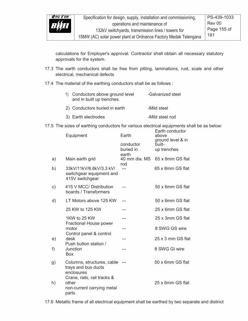
Specification for design, supply, installation and commissioning, operations and maintenance of
132kV switchyards, transmission lines / towers for 15MW (AC) solar power plant at Ordnance Factory Medak Telengana
PS-439-1033 Rev 00 Page 155 of 181
calculations for Employer's approval. Contractor shall obtain all necessary statutory approvals for the system.
17.3 The earth conductors shall be free from pitting, laminations, rust, scale and other
electrical, mechanical defects 17.4 The material of the earthing conductors shall be as follows :
1) Conductors above ground level -Galvanized steel and in built up trenches.
2) Conductors buried in earth -Mild steel
3) Earth electrodes -Mild steel rod 17.5 The sizes of earthing conductors for various electrical equipments shall be as below:
Equipment Earth Earth conductor above
conductor ground level & in built-
buried in up trenches earth a) Main earth grid 40 mm dia. MS 65 x 8mm GS flat rod b) 33kV/11kV/6.6kV/3.3 kV/ --- 65 x 8mm GS flat switchgear equipment and 415V switchgear
c) 415 V MCC/ Distribution --- 50 x 6mm GS flat boards / Transformers
d) LT Motors above 125 KW --- 50 x 6mm GS flat
25 KW to 125 KW --- 25 x 6mm GS flat
1KW to 25 KW --- 25 x 3mm GS flat
Fractional House power motor --- 8 SWG GS wire
e) Control panel & control desk --- 25 x 3 mm GS flat
f) Push button station / Junction --- 8 SWG GI wire
Box
g) Columns, structures, cable --- 50 x 6mm GS flat
trays and bus ducts enclosures
h) Crane, rails, rail tracks & other 25 x 6mm GS flat
non-current carrying metal parts
17.6 Metallic frame of all electrical equipment shall be earthed by two separate and distinct
Specification for design, supply, installation and commissioning, operations and maintenance of
132kV switchyards, transmission lines / towers for 15MW (AC) solar power plant at Ordnance Factory Medak Telengana
PS-439-1033 Rev 00 Page 156 of 181
connections to earthing system, each of 100% capacity, Crane rails, tracks, metal pipes and conduits shall also be effectively earthed at two points. Steel RCC columns, metallic stairs, and rails etc. of the building housing electrical equipment shall be connected to the nearby earthing grid conductor by one earthing ensured by bonding the different sections of hand rails and metallic stairs. Metallic sheaths/screens, and armour of multi-core cables shall be earthed at both ends. Metallic Sheaths and armour of single core cables shall be earthed at switchgear end only unless otherwise approved. Every alternate post of the switchyard fence shall be connected to earthing grid by one GS flat and gates by flexible lead to the earthed post. Railway tracks within the plant area shall be bonded across fish plates and connected to earthing grid at several locations. Portable tools, appliances and welding equipment shall be earthed by flexible insulated cable.
17.7 Each continuous laid lengths of cable tray shall be earthed at minimum two places by
G.S. flats to earthing system, the distance between earthing points shall not exceed 30 meter. Wherever earth mat is not available , necessary connections shall be done by driving an earth electrode in the ground
17.8 Neutral points of HT transformer shall be earthed through NG resistors. The Contractor
shall connect the NGR earthing point to earth electrodes by suitable earth conductors.
17.9 Neutral connections and metallic conduits/pipes shall not be used for the equipment earthing.
17.10 Connections between earth leads and equipment shall normally be of bolted type.
Contact surfaces shall be thoroughly cleaned before connections. Equipment bolted connections after being tested and checked shall be painted with anti corrosive paint/compound.
17.11 Suitable earth risers as approved shall be provided above finished floor/ground level, if the equipment is not available at the time of laying of main earth conductor.
17.12 Connections between equipment earthing leads and between main earthing conductors shall be of welded type. For rust protection the welds should be treated with red lead compound and afterwards thickly coated with bitumen compound. All welded connections shall be made by electric arc welding.
17.13 Resistance of the joint shall not be more than the resistance of the equivalent length of conductors.
17.14 Earthing conductors buried in ground shall be laid minimum 600 mm below grade level unless otherwise indicated in the drawing. Back filling material to be placed over buried conductors shall be free from stones and harmful mixtures. Back filling shall be placed in layers of 150 mm.
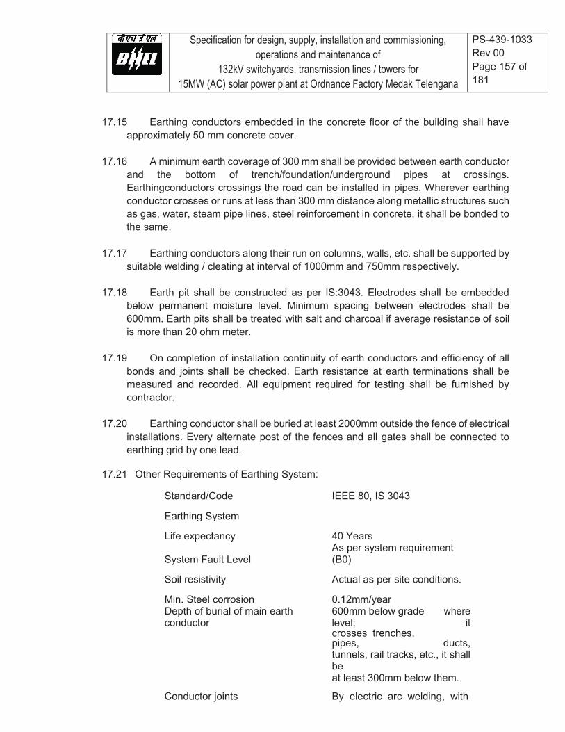
Specification for design, supply, installation and commissioning, operations and maintenance of
132kV switchyards, transmission lines / towers for 15MW (AC) solar power plant at Ordnance Factory Medak Telengana
PS-439-1033 Rev 00 Page 157 of 181
17.15 Earthing conductors embedded in the concrete floor of the building shall have approximately 50 mm concrete cover.
17.16 A minimum earth coverage of 300 mm shall be provided between earth conductor and the bottom of trench/foundation/underground pipes at crossings. Earthingconductors crossings the road can be installed in pipes. Wherever earthing conductor crosses or runs at less than 300 mm distance along metallic structures such as gas, water, steam pipe lines, steel reinforcement in concrete, it shall be bonded to the same.
17.17 Earthing conductors along their run on columns, walls, etc. shall be supported by suitable welding / cleating at interval of 1000mm and 750mm respectively.
17.18 Earth pit shall be constructed as per IS:3043. Electrodes shall be embedded below permanent moisture level. Minimum spacing between electrodes shall be 600mm. Earth pits shall be treated with salt and charcoal if average resistance of soil is more than 20 ohm meter.
17.19 On completion of installation continuity of earth conductors and efficiency of all bonds and joints shall be checked. Earth resistance at earth terminations shall be measured and recorded. All equipment required for testing shall be furnished by contractor.
17.20 Earthing conductor shall be buried at least 2000mm outside the fence of electrical installations. Every alternate post of the fences and all gates shall be connected to earthing grid by one lead.
17.21 Other Requirements of Earthing System:
Standard/Code IEEE 80, IS 3043
Earthing System
Life expectancy 40 Years
System Fault Level As per system requirement (B0)
Soil resistivity Actual as per site conditions.
Min. Steel corrosion 0.12mm/year Depth of burial of main earth conductor
600mm below grade level;
where it
crosses trenches, pipes, ducts,
tunnels, rail tracks, etc., it shall be
at least 300mm below them.
Conductor joints By electric arc welding, with
Specification for design, supply, installation and commissioning, operations and maintenance of
132kV switchyards, transmission lines / towers for 15MW (AC) solar power plant at Ordnance Factory Medak Telengana
PS-439-1033 Rev 00 Page 158 of 181
resistance of joint not more than
that of the conductor.
Welds to be treated with red lead for rust protection and then coated with bitumen compound for corrosion protection.
Surface resistivity - Gravel 3000 ohm-meter
- Concrete 500 ohm-meter
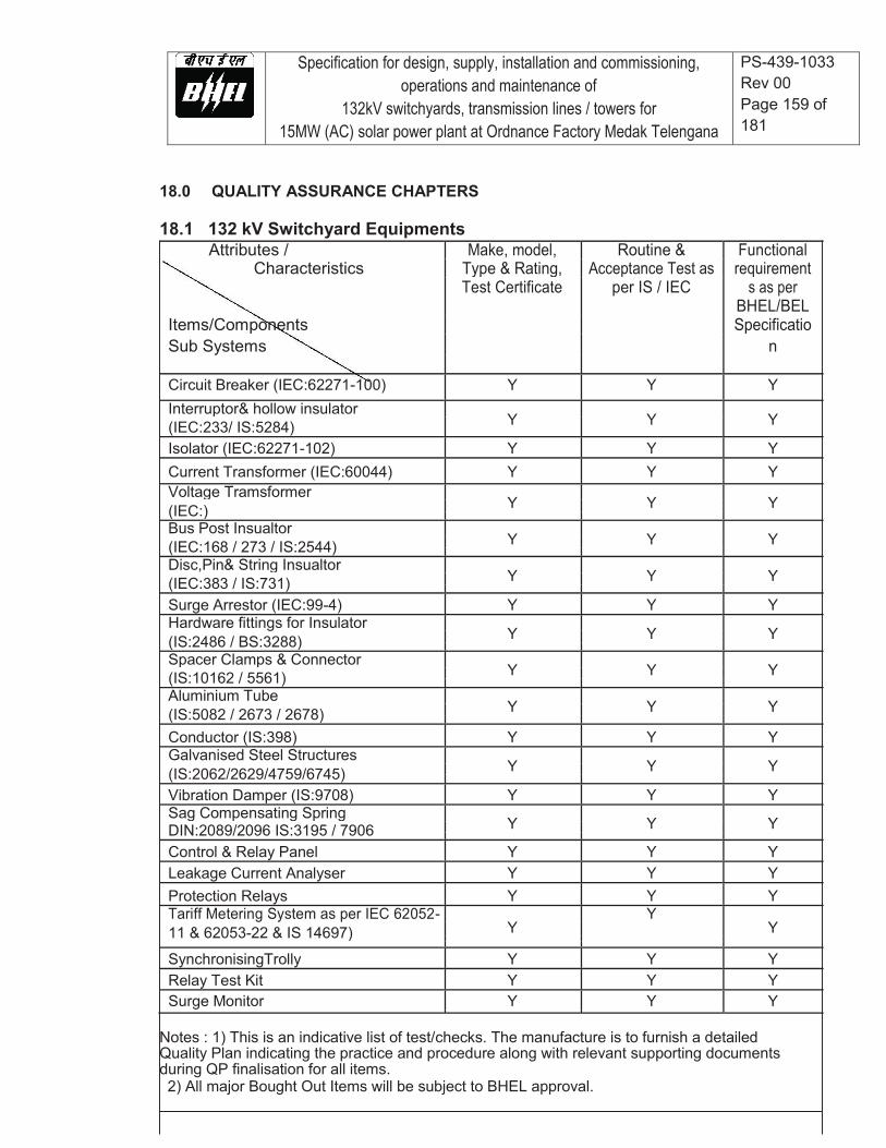
Specification for design, supply, installation and commissioning, operations and maintenance of
132kV switchyards, transmission lines / towers for 15MW (AC) solar power plant at Ordnance Factory Medak Telengana
PS-439-1033 Rev 00 Page 159 of 181
18.0 QUALITY ASSURANCE CHAPTERS
18.1 132 kV Switchyard Equipments Attributes / Make, model, Routine & Functional
Characteristics Type & Rating, Acceptance Test as requirement
Test Certificate per IS / IEC s as per
BHEL/BEL
Items/Components Specificatio
Sub Systems n
Circuit Breaker (IEC:62271-100) Y Y Y
Interruptor& hollow insulator Y Y Y
(IEC:233/ IS:5284)
Isolator (IEC:62271-102) Y Y Y
Current Transformer (IEC:60044) Y Y Y
Voltage Tramsformer Y Y Y
(IEC:)
Bus Post Insualtor Y Y Y
(IEC:168 / 273 / IS:2544)
Disc,Pin& String Insualtor Y Y Y
(IEC:383 / IS:731)
Surge Arrestor (IEC:99-4) Y Y Y
Hardware fittings for Insulator Y Y Y
(IS:2486 / BS:3288)
Spacer Clamps & Connector Y Y Y
(IS:10162 / 5561)
Aluminium Tube Y Y Y
(IS:5082 / 2673 / 2678)
Conductor (IS:398) Y Y Y
Galvanised Steel Structures Y Y Y
(IS:2062/2629/4759/6745)
Vibration Damper (IS:9708) Y Y Y
Sag Compensating Spring Y Y Y
DIN:2089/2096 IS:3195 / 7906
Control & Relay Panel Y Y Y
Leakage Current Analyser Y Y Y
Protection Relays Y Y Y
Tariff Metering System as per IEC 62052- Y
Y Y
11 & 62053-22 & IS 14697)
SynchronisingTrolly Y Y Y
Relay Test Kit Y Y Y
Surge Monitor Y Y Y
Notes : 1) This is an indicative list of test/checks. The manufacture is to furnish a detailed Quality Plan indicating the practice and procedure along with relevant supporting documents during QP finalisation for all items. 2) All major Bought Out Items will be subject to BHEL approval.
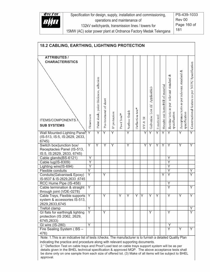
Specification for design, supply, installation and commissioning, operations and maintenance of
132kV switchyards, transmission lines / towers for 15MW (AC) solar power plant at Ordnance Factory Medak Telengana
PS-439-1033 Rev 00 Page 160 of 181
18.2 CABLING, EARTHING, LIGHTNING PROTECTION
ATTRIBUTES / CHARACTERISTICS
ITEMS/COMPONENTS / SUB SYSTEMS
Wall Mounted-Lighting Panel Y Y Y Y Y Y Y Y Y Y Y Y (IS-513, IS:5, IS:2629, 2633, 6745) Switch box/junction box/ Y Y Y Y Y Y Y Y Y Y Y Y Receptacles Panel (IS-513, IS:5, IS:2629, 2633, 6745) Cable glands(BS-6121) Y Y Cable lug(IS-8309) Y Y Lighting wire(IS-694) Y Y Flexible conduits Y Y Y Conduits(Galvanise& Epoxy) Y Y Y Y Y IS-9537 & IS-2629,2633 ,6745 RCC Hume Pipe (IS-458) Y Cable termination & straight Y Y Y through joint (VDE-0278) Cable Trays, Flexible supports Y Y Y Y Y Y Y Y Y Y Y system & accessories IS-513, 2629,2633,6745 Trefoil clamp Y Y GI flats for earthing& lighting Y Y Y Y Y protection (IS 2062, 2629, 6745,2633) GI wire (IS-280) Y Y Fire Sealing System ( BS – Y Y Y 476) Note: 1.This is an indicative list of tests /checks. The manufacturer is to furnish a detailed Quality Plan indicating the practice and procedure along with relevant supporting documents. 2.* Deflection Test on cable trays and Proof Load test on cable trays support system will be as per details given in the BHEL technical specification & approved MQP. The above acceptance tests shall be done only on one sample from each size of offered lot. (3) Make of all items will be subject to BHEL approval.

Specification for design, supply, installation and commissioning, operations and maintenance of
132kV switchyards, transmission lines / towers for 15MW (AC) solar power plant at Ordnance Factory Medak Telengana
PS-439-1033 Rev 00 Page 161 of 181
18.3 LT Control Cable (1.1 KV PVC Cables)
Attributes / Characteristics
Item / Components / Sub System Assembly
Copper Conductor (IS-8130) Y Y Y Y Y PVC Compound (IS-5831) Y Y Y Y FRLS PVC Compound IS- Y Y Y Y 5831
ASTM-D-2843/ IS 10810 (Part-58 ) IEC 60754 Part-1 Armour wire/strip (IS-3975) Y Y Y Insulated Core Y Y Y Y Laid up core Y Y PVC Inner sheath Y Armouring Y Y Outer sheath Y Y Y Y Y Finish cable (IS-1554- 1 ) Y Y Y Y Y Y Y Y Y ASTM-D-2843/ IS 10810 (Part-58 ) IEC-60754 Part-1 Swedish Chimney: SEN SS 424-1475( F3 category) Flammability test IEC-60332 Part-3 Cat-B Wooden drum( IS : 10418) / Y Y Steel drum 1.Note : This is an indicative list of test/checks. The manufacturer is to furnish a detailed quality plan indicating the Practice and procedure along with relevant supporting documents.
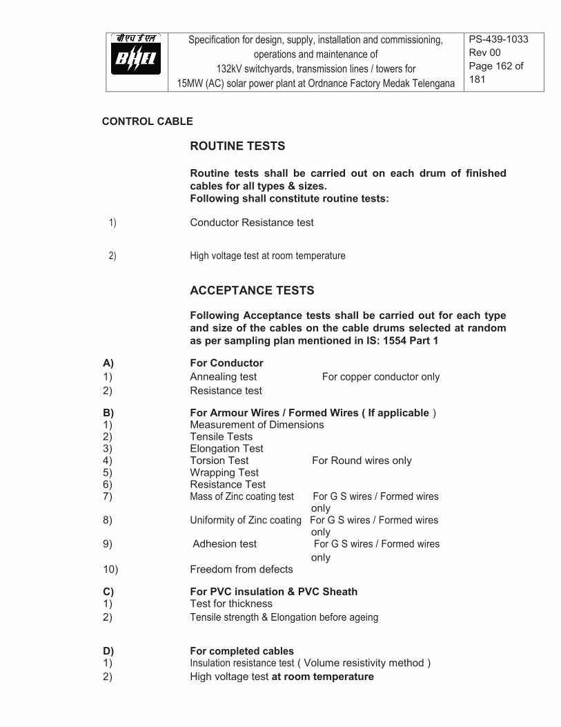
Specification for design, supply, installation and commissioning, operations and maintenance of
132kV switchyards, transmission lines / towers for 15MW (AC) solar power plant at Ordnance Factory Medak Telengana
PS-439-1033 Rev 00 Page 162 of 181
CONTROL CABLE
ROUTINE TESTS
Routine tests shall be carried out on each drum of finished cables for all types & sizes. Following shall constitute routine tests:
1) Conductor Resistance test
2) High voltage test at room temperature
ACCEPTANCE TESTS
Following Acceptance tests shall be carried out for each type and size of the cables on the cable drums selected at random as per sampling plan mentioned in IS: 1554 Part 1
A) For Conductor
1) Annealing test For copper conductor only
2) Resistance test
B) For Armour Wires / Formed Wires ( If applicable )
1) Measurement of Dimensions
2) Tensile Tests
3) Elongation Test
4) Torsion Test For Round wires only
5) Wrapping Test
6) Resistance Test
7) Mass of Zinc coating test For G S wires / Formed wires
only
8) Uniformity of Zinc coating For G S wires / Formed wires
only
9) Adhesion test For G S wires / Formed wires
10) Freedom from defects only
C) For PVC insulation & PVC Sheath
1) Test for thickness
2) Tensile strength & Elongation before ageing
D) For completed cables
1) Insulation resistance test ( Volume resistivity method )
2) High voltage test at room temperature
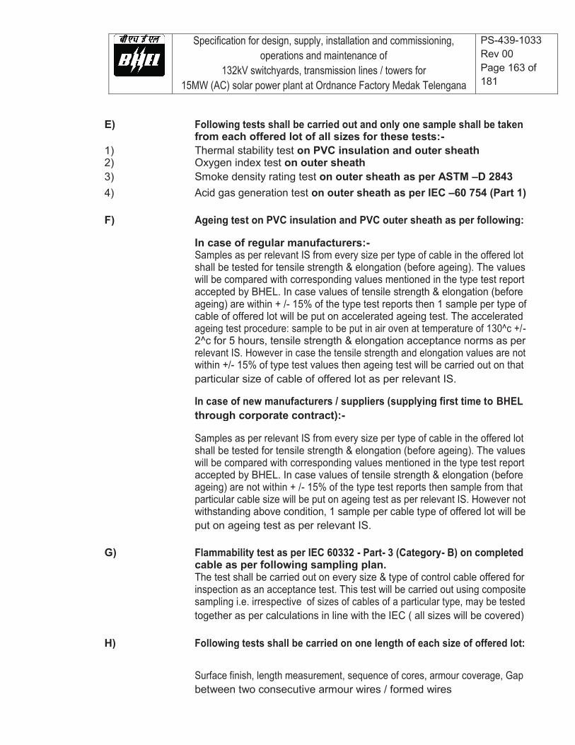
Specification for design, supply, installation and commissioning, operations and maintenance of
132kV switchyards, transmission lines / towers for 15MW (AC) solar power plant at Ordnance Factory Medak Telengana
PS-439-1033 Rev 00 Page 163 of 181
E) Following tests shall be carried out and only one sample shall be taken
from each offered lot of all sizes for these tests:-
1) Thermal stability test on PVC insulation and outer sheath
2) Oxygen index test on outer sheath
3) Smoke density rating test on outer sheath as per ASTM –D 2843
4) Acid gas generation test on outer sheath as per IEC –60 754 (Part 1)
F) Ageing test on PVC insulation and PVC outer sheath as per following:
In case of regular manufacturers:-
Samples as per relevant IS from every size per type of cable in the offered lot
shall be tested for tensile strength & elongation (before ageing). The values
will be compared with corresponding values mentioned in the type test report
accepted by BHEL. In case values of tensile strength & elongation (before
ageing) are within + /- 15% of the type test reports then 1 sample per type of
cable of offered lot will be put on accelerated ageing test. The accelerated
ageing test procedure: sample to be put in air oven at temperature of 130^c +/-
2^c for 5 hours, tensile strength & elongation acceptance norms as per
relevant IS. However in case the tensile strength and elongation values are not
within +/- 15% of type test values then ageing test will be carried out on that
particular size of cable of offered lot as per relevant IS.
In case of new manufacturers / suppliers (supplying first time to BHEL
through corporate contract):-
Samples as per relevant IS from every size per type of cable in the offered lot
shall be tested for tensile strength & elongation (before ageing). The values
will be compared with corresponding values mentioned in the type test report
accepted by BHEL. In case values of tensile strength & elongation (before
ageing) are not within + /- 15% of the type test reports then sample from that
particular cable size will be put on ageing test as per relevant IS. However not
withstanding above condition, 1 sample per cable type of offered lot will be
put on ageing test as per relevant IS.
G) Flammability test as per IEC 60332 - Part- 3 (Category- B) on completed
cable as per following sampling plan.
The test shall be carried out on every size & type of control cable offered for
inspection as an acceptance test. This test will be carried out using composite
sampling i.e. irrespective of sizes of cables of a particular type, may be tested
together as per calculations in line with the IEC ( all sizes will be covered)
H) Following tests shall be carried on one length of each size of offered lot:
Surface finish, length measurement, sequence of cores, armour coverage, Gap
between two consecutive armour wires / formed wires
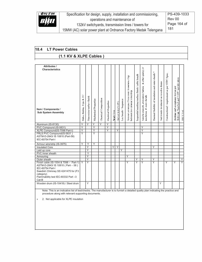
Specification for design, supply, installation and commissioning, operations and maintenance of
132kV switchyards, transmission lines / towers for 15MW (AC) solar power plant at Ordnance Factory Medak Telengana
PS-439-1033 Rev 00 Page 164 of 181
18.4 LT Power Cables
(1.1 KV & XLPE Cables )
Attributes / Characteristics
Item / Components / Sub System Assembly
Aluminum (IS-8130) Y Y Y Y Y PVC Compound (IS-5831) Y Y Y Y XLPE Compound(IS-7098 Part-I) Y Y Y Y Y FRLS PVC Compound(IS-5831 ) Y Y Y ASTM-D-2843/ IS 10810 (Part-58) IEC-60754 Part-I
Armour wire/strip (IS-3975) Y Y Y Insulated Core Y Y Y Y Laid up core Y Y PVC Inner sheath Y Armouring Y Y Outer sheath Y Y Y Y Y Finish cable (IS-1554 & 7098 – Part-1) Y Y Y Y Y Y Y Y Y ASTM-D-2843/ IS 10810 ( Part- - 58 ) IEC-60754 Part-I Swedish Chimney SS 4241475 for (F3 category) Flammability test IEC-60332 Part –3 Cat-B Wooden drum (IS-10418) / Steel drum Y Y
Note: This is an indicative list of test/checks. The manufacturer is to furnish a detailed quality plan indicating the practice and procedure along with relevant supporting documents.
2. Not applicable for XLPE insulation

Specification for design, supply, installation and commissioning, operations and maintenance of
132kV switchyards, transmission lines / towers for 15MW (AC) solar power plant at Ordnance Factory Medak Telengana
PS-439-1033 Rev 00 Page 165 of 181
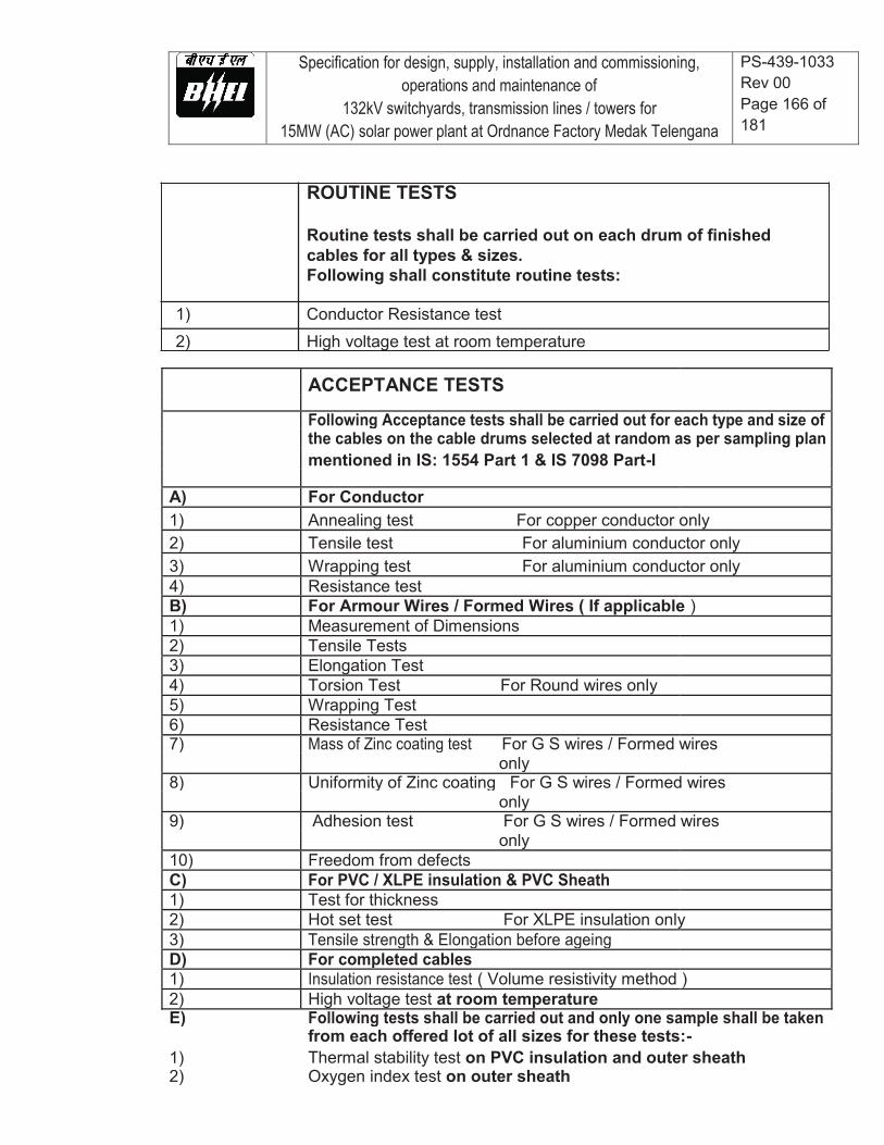
Specification for design, supply, installation and commissioning, operations and maintenance of
132kV switchyards, transmission lines / towers for 15MW (AC) solar power plant at Ordnance Factory Medak Telengana
PS-439-1033 Rev 00 Page 166 of 181
ROUTINE TESTS
Routine tests shall be carried out on each drum of finished cables for all types & sizes. Following shall constitute routine tests:
1) Conductor Resistance test
2) High voltage test at room temperature ACCEPTANCE TESTS
Following Acceptance tests shall be carried out for each type and size of
the cables on the cable drums selected at random as per sampling plan
mentioned in IS: 1554 Part 1 & IS 7098 Part-I
A) For Conductor
1) Annealing test For copper conductor only
2) Tensile test For aluminium conductor only
3) Wrapping test For aluminium conductor only
4) Resistance test
B) For Armour Wires / Formed Wires ( If applicable )
1) Measurement of Dimensions
2) Tensile Tests
3) Elongation Test
4) Torsion Test For Round wires only
5) Wrapping Test
6) Resistance Test
7) Mass of Zinc coating test For G S wires / Formed wires
only
8) Uniformity of Zinc coating For G S wires / Formed wires
only
9) Adhesion test For G S wires / Formed wires
only
10) Freedom from defects
C) For PVC / XLPE insulation & PVC Sheath
1) Test for thickness
2) Hot set test For XLPE insulation only
3) Tensile strength & Elongation before ageing
D) For completed cables
1) Insulation resistance test ( Volume resistivity method )
2) High voltage test at room temperature
E) Following tests shall be carried out and only one sample shall be taken
from each offered lot of all sizes for these tests:-
1) Thermal stability test on PVC insulation and outer sheath
2) Oxygen index test on outer sheath
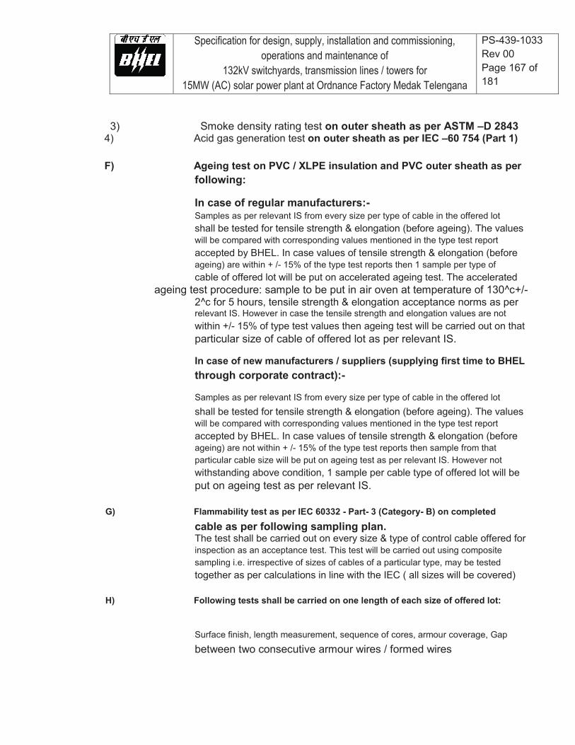
Specification for design, supply, installation and commissioning, operations and maintenance of
132kV switchyards, transmission lines / towers for 15MW (AC) solar power plant at Ordnance Factory Medak Telengana
PS-439-1033 Rev 00 Page 167 of 181
3) Smoke density rating test on outer sheath as per ASTM –D 2843
4) Acid gas generation test on outer sheath as per IEC –60 754 (Part 1) F) Ageing test on PVC / XLPE insulation and PVC outer sheath as per
following:
In case of regular manufacturers:- Samples as per relevant IS from every size per type of cable in the offered lot shall be tested for tensile strength & elongation (before ageing). The values will be compared with corresponding values mentioned in the type test report accepted by BHEL. In case values of tensile strength & elongation (before ageing) are within + /- 15% of the type test reports then 1 sample per type of cable of offered lot will be put on accelerated ageing test. The accelerated
ageing test procedure: sample to be put in air oven at temperature of 130^c+/- 2^c for 5 hours, tensile strength & elongation acceptance norms as per relevant IS. However in case the tensile strength and elongation values are not within +/- 15% of type test values then ageing test will be carried out on that particular size of cable of offered lot as per relevant IS.
In case of new manufacturers / suppliers (supplying first time to BHEL through corporate contract):-
Samples as per relevant IS from every size per type of cable in the offered lot shall be tested for tensile strength & elongation (before ageing). The values will be compared with corresponding values mentioned in the type test report accepted by BHEL. In case values of tensile strength & elongation (before ageing) are not within + /- 15% of the type test reports then sample from that particular cable size will be put on ageing test as per relevant IS. However not withstanding above condition, 1 sample per cable type of offered lot will be put on ageing test as per relevant IS.
G) Flammability test as per IEC 60332 - Part- 3 (Category- B) on completed
cable as per following sampling plan. The test shall be carried out on every size & type of control cable offered for inspection as an acceptance test. This test will be carried out using composite sampling i.e. irrespective of sizes of cables of a particular type, may be tested together as per calculations in line with the IEC ( all sizes will be covered)
H) Following tests shall be carried on one length of each size of offered lot:
Surface finish, length measurement, sequence of cores, armour coverage, Gap between two consecutive armour wires / formed wires
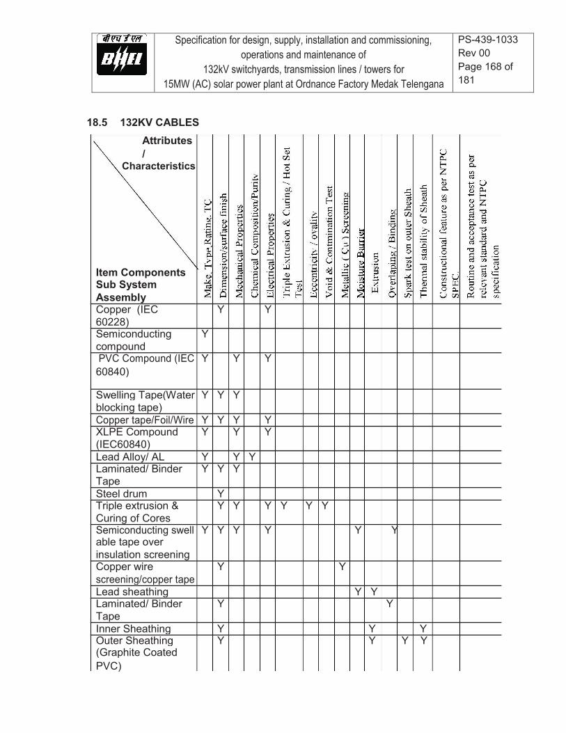
Specification for design, supply, installation and commissioning, operations and maintenance of
132kV switchyards, transmission lines / towers for 15MW (AC) solar power plant at Ordnance Factory Medak Telengana
PS-439-1033 Rev 00 Page 168 of 181
18.5 132KV CABLES Attributes /
Characteristics
Item Components Sub System Assembly Copper (IEC Y Y 60228) Semiconducting Y compound PVC Compound (IEC Y Y Y 60840)
Swelling Tape(Water Y Y Y blocking tape) Copper tape/Foil/Wire Y Y Y Y XLPE Compound Y Y Y (IEC60840) Lead Alloy/ AL Y Y Y Laminated/ Binder Y Y Y Tape Steel drum Y Triple extrusion & Y Y Y Y Y Y Curing of Cores Semiconducting swell Y Y Y Y Y Y able tape over insulation screening Copper wire Y Y screening/copper tape Lead sheathing Y Y Laminated/ Binder Y Y Tape Inner Sheathing Y Y Y Outer Sheathing Y Y Y Y (Graphite Coated PVC)
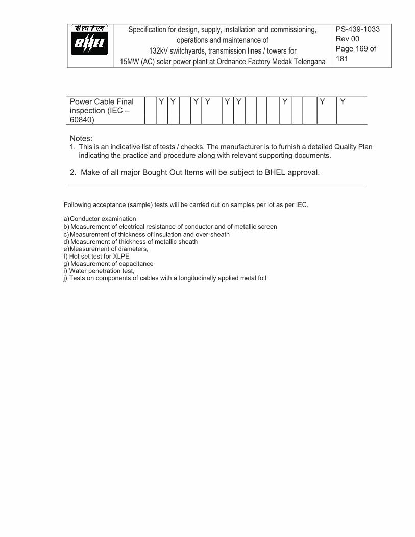
Specification for design, supply, installation and commissioning, operations and maintenance of
132kV switchyards, transmission lines / towers for 15MW (AC) solar power plant at Ordnance Factory Medak Telengana
PS-439-1033 Rev 00 Page 169 of 181
Power Cable Final Y Y Y Y Y Y Y Y Y inspection (IEC – 60840) Notes: 1. This is an indicative list of tests / checks. The manufacturer is to furnish a detailed Quality Plan
indicating the practice and procedure along with relevant supporting documents.
2. Make of all major Bought Out Items will be subject to BHEL approval.
Following acceptance (sample) tests will be carried out on samples per lot as per IEC. a) Conductor examination b) Measurement of electrical resistance of conductor and of metallic screen c) Measurement of thickness of insulation and over-sheath d) Measurement of thickness of metallic sheath e) Measurement of diameters, f) Hot set test for XLPE g) Measurement of capacitance i) Water penetration test, j) Tests on components of cables with a longitudinally applied metal foil

Specification for design, supply, installation and commissioning, operations and maintenance of
132kV switchyards, transmission lines / towers for 15MW (AC) solar power plant at Ordnance Factory Medak Telengana
PS-439-1033 Rev 00 Page 170 of 181
19.0 Civil and mechanical works
This section of Technical Specifications describes detailed technical and functional
requirements of all civil, Mechanical & Plumbing works included in the scope excluding civil
works for Transmission Line towers, Tower extensions & Tower accessories.
All design and construction of civil works shall conform to relevant Indian standards such as
BIS, IRC, MORST, NBC etc. Design of steel structures shall conform to IS: 800, 802 or 802 as
applicable with working stress method (WSD) of design. Design of concrete structure shall
conform to IS: 456. For design of liquid retaining structure IS: 3374 shall be followed. Only in
case of non-availability of Indian standard, equivalent American or British standard may be used
for design with prior approval of the Employer and the contractor shall submit proper justification
along with his request to the Employer for his review. All the design/ drawings shall be prepared/
approved by the chartered structural engineer. The design calculations for MMS, RCC
structure, steel structure, foundation system, road work, drainage work, etc. shall be submitted
for prior approval of BHEL/BEL/SECI before commencement of construction.
The design calculations shall be supplemented with a neat sketch showing the structure geometry,
node and member nos., Lengths of various typical members, support points and type of supports,
types of materials with design properties considered, type of sections used in analysis & design.
The report shall also include back-up calculations for various loads adopted in design, brief write-
up on primary load cases and load combinations considered and conclusions on design results
with supporting sketches for easy reference and clarity. Where a computer program (other than
STAAD Pro) is used for analysis and design, the contractor shall also include a write-up on the
computer program used along with validation check. Input and output file shall also be given in
the design report to facilitate its review and approval by the BHEL/BEL/SECI.
The construction methodology for MMS and its foundations, road works, drains and pile load
test procedure shall also be submitted for prior approval of BHEL/BEL/SECI before start of
works. The construction shall be done only as per approved drawings.
Specification for design, supply, installation and commissioning, operations and maintenance of
132kV switchyards, transmission lines / towers for 15MW (AC) solar power plant at Ordnance Factory Medak Telengana
PS-439-1033 Rev 00 Page 171 of 181
19.1 Topographical Survey, Area Grading and Land Development
The contractor shall be responsible for detailed Topographical Survey of the proposed project
site. The work shall be carried out through an agency with relevant experience and shall have
qualified survey team. The Topographical survey shall be conducted at 20m x20m grid, or as
directed by the Engineer, with the help of digital surveying instruments like Total Station. The
Contractor shall carry the Bench Mark from nearest GTS Bench Mark, or any other establish
source like Railway station etc. as approved by the Employer, by fly-levelling and establish two
permanent bench marks (PBM) at site. All subsequent transfer of levels shall be carried out with
respect to these PBMs. The work shall also include constructing permanent reference pillars at
suitable locations as approved by the BHEL/BEL/SECI. These reference pillars shall be labelled
permanently with their respective coordinates and reduced levels for future use. The Permanent
Bench Marks and reference pillars shall be shown on the survey drawings.
While carrying bench mark to the project site, levels shall be established on the permanent
objects like culverts etc. at least on one object in every one km. if available along with route with
adequate description about the objects. These levels shall be maintained at site & also
mentioned in the survey report to facilitate locating these objects later on.
The work survey work shall be carried out in UTM grids system. The contractor shall also establish
the latitudes and longitudes of the corners of the project site. At least 50m width of the adjoining
plots and surrounding areas shall also be covered in the survey for correlation with adjoining plots
and facilities. The grids for the survey work shall be established in N-S & E-W direction
(corresponding to magnetic North) or the plant North as directed by the Employer. Positions, both in
plan and elevation, of all natural and artificial features in the area like waterways, railway tracks,
trees, cultivation, houses, fences, pucca and kutcha roads including culverts and crossings, foot
tracks, other permanent objects like telephone posts and transmission towers etc. are to be
established and subsequently shown on survey maps by means of conventional symbols
(preferably, symbols of survey of India Maps). All hills and valleys within the area/areas are to
be surveyed and plotted on maps by contours. Any unusual condition or formations on the
ground, locations of rock outcrops (if visible on the surface) and spring/falls, sand heap/dune,
possible aggregate deposits etc. shall also be noted and plotted on contour maps.
Specification for design, supply, installation and commissioning, operations and maintenance of
132kV switchyards, transmission lines / towers for 15MW (AC) solar power plant at Ordnance Factory Medak Telengana
PS-439-1033 Rev 00 Page 172 of 181
The record of measurement of all Reduced Levels (RL) shall be submitted in digital format, (in x, y
z coordinate system) along with preliminary contour plan of the site, for Employer’s review before
submission of final contour Map. The contour interval shall be as required for proper representation
of the topography however it shall not be more than 0.5m. The Contractor shall submit survey maps
of the site in 1:10,000 scale indicating grid lines and contour lines, demarcating all permanent
features like roads, railways, waterways, buildings, power lines, natural streams, trees, sand dunes
etc. Present use of the site i.e. mining, quarrying, agriculture etc, existing drainage pattern of the
site, possibility of water logging and high flood level of the area shall also be captured in the
document. The project plot boundary with coordinates of all corner points along with coordinate grid
of 50x50M interval shall be marked on the contour map. The Finished Grade Level (FGL) of the
proposed plant shall be fixed with reference to the highest flood level and surrounding ground profile
at proposed site. The data regarding highest flood level at proposed site shall be obtained from the
metrological department by the contractor. In case of absence of this data, the contractor shall
assess the required information through local site reconnaissance. The minimum plinth level of all
buildings shall be 450mm above FGL. Module mounting structure foundation or any other pedestal
shall be min. 250mm above FGL. A detailed drawing for site levelling and grading (if necessary)
shall be submitted by the contractor before commencement of grading and area development works.
The estimated volume of cutting and filling shall also be marked on the Grading drawings for
reference. The final grade levels thus adopted for different blocks shall be clearly marked on the
Plant Layout drawing. The contractor is responsible for making the site ready and easily
approachable by clearing bushes, felling of trees (Mandatory permissions/ licenses/ statutory
clearances from competent authorities if required for cutting of trees, blasting or mining operations,
disposal of waste material etc. shall be obtained by the contractor), cutting, filling with selected
excavated earth or borrowed earth including identifying borrow areas. Except in exceptional cases
(with approval of the Employer), filling shall normally be made up of cohesive non-swelling material.
The filling for levelling/ reclaiming the ground/ area shall be done in layers not more than 150mm of
compacted thickness in case of cohesive (clayey) soils and 250mm compacted thickness in case
of granular (sandy) soils with compacting up to 95% of modified proctor density in case of
cohesive (clayey) soils and 80% of relative density in case of granular (sandy) soils. The slope
at edge of graded areas shall not be flatter than 1:1.5 (1 Vertical: 1.5 Horizontal) in cutting and
1:2 (1 Vertical: 2 Horizontal) in filling. In case of filling is done with rock material the edges shall
be provided in line with provisions of relevant BIS standard. It shall be ensured that the land is
graded or levelled properly for free flow of surface runoff and the grade levels shall be fixed
Specification for design, supply, installation and commissioning, operations and maintenance of
132kV switchyards, transmission lines / towers for 15MW (AC) solar power plant at Ordnance Factory Medak Telengana
PS-439-1033 Rev 00 Page 173 of 181
w.r.t. high flood level at site, drainage pattern and system requirements. It shall be ensured that
the land is used optimally to have max. Solar power generation considering full utilization of the
plot areas It is advisable to follow the natural flow of water at the ground. In case the filled up
earth is brought from outside the plant/ borrow areas, the contractor shall carry out all required
soil investigations to ascertain the suitability of the soil for land development and filling purposes.
Contractor’s scope shall also include arranging land lease, getting all necessary statutory
approvals for mining, payment of necessary challans etc. Excess earth if any shall be disposed
of properly at location as directed by the Engineer-in-charge.
19.2 Geotechnical Investigations
The contractor shall be responsible for detailed soil investigations at the proposed project site
for the purpose of foundation design for various buildings, structures, HT lines, MMS etc. and
other design/ planning requirements. The investigation work shall be carried out through any
Govt. approved/ NABL accredited agency. The contractor shall submit the credentials of the
proposed agency along with relevant certificates in support thereof for verification/approval by
the Employer.
The scope of work includes execution of complete soil exploration including boring and drilling,
standard penetration test (SPT), collecting disturbed(DS) and undisturbed samples (UDS),
collecting ground water samples, electrical resistivity tests (ERT) and conducting laboratory
tests on collected samples of soil, ground water analysis, preparation and submission of report.
The field investigations shall mainly include drilling of min. 5 m deep boreholes (50% of total No. of
boreholes shall be 10m deep), conducting SPT and collecting Disturbed (DS) and Undisturbed
samples (UDS); conducting in-situ CBR test for approach road to the plant, internal roads &
peripheral road; ERT and Trial pits. Number and location of bore holes, CBR tests and trial pits shall
be decided as per the project layout, site topography and soil conditions in consultation with the
Employer. However, there shall be minimum 1 No. of borehole per 10 acres of the area & No. of
samples for laboratory investigations shall not be less than 25.
The proposed Geotechnical investigation plan indicating proposed locations of Trial pits, Bore
holes and CBR tests shall be submitted to the BHEL/BEL/SECI for review and approval before
start of work.

Specification for design, supply, installation and commissioning, operations and maintenance of
132kV switchyards, transmission lines / towers for 15MW (AC) solar power plant at Ordnance Factory Medak Telengana
PS-439-1033 Rev 00 Page 174 of 181
Laboratory tests shall be conducted on DS & UDS samples and water samples in sufficient no. and
shall include, Soil classification, Grain size analysis including Hydrometer analysis, determination of
Bulk and dry density, Specific gravity, Natural moisture content, Atterberg limits, Tri-axial shear tests
(UU), Consolidation tests, Unconfined compression tests, Free swell index, chemical analysis of soil
and water samples to determine the carbonates, sulphates, chlorides, nitrates, pH, Organic matter
and any other chemicals harmful to concrete and reinforcement/ steel. Laboratory tests on rock
samples shall be carried out for Hardness, Specific Gravity, Unit Weight, Uniaxial Compressive
Strength (in-situ & saturated), Slake Durability etc.
After completion of field and laboratory work, the contractor shall submit a Geotechnical Investigation Report for approval by BHEL/BEL/SECI. All bore log details and lab test results shall be presented in the report as per provisions of relevant BIS standards. The report shall include a Map showing the locations of various field tests including coordinates, calculations and recommendations for foundation type and safe bearing capacity (SBC) for buildings, switch yard structures, Sub-Station, Transformer foundation, HT lines, MMS foundation etc. corresponding to settlement of 25mm.
All switchyard and sub-station area shall have levelled ground. No foundation for switch yard
equipment & structures, sub-stations, transmission line (TL) towers shall rest on filled up ground.
Minor structures like cable trench, pipe pedestal etc. with max. safe bearing capacity of soil not
more than 3 T/ Sq.
The report shall also include ground water analysis to ascertain its suitability for construction
purposes, recommendations for type of cement, grade of concrete & minimum cement content
as per prevalent soil characteristics with respect to presence of aggressive chemicals,
environment exposure conditions as per relevant BIS specifications. However, minimum grade
of concrete shall be M25 for all RCC works except liquid retaining structures like underground
water tank etc. where minimum grade of concrete shall be M30.
19.3 Other Investigations
The contractor shall also obtain and study other input data at proposed project site for design
of the project. This shall include data related to earthquake and wind, rainfall, maximum &
minimum ambient temperature, humidity, high food level (HFL) etc.
The contractor shall also identify potential quarry areas for coarse and fine aggregates to be used
for concrete and shall carry out the concrete mix design for different grades of concrete to be used

Specification for design, supply, installation and commissioning, operations and maintenance of
132kV switchyards, transmission lines / towers for 15MW (AC) solar power plant at Ordnance Factory Medak Telengana
PS-439-1033 Rev 00 Page 175 of 181
in the work. The concrete mix shall be designed for each source of cement and quarry as per
provisions of relevant Indian Standard. The concrete mix design shall be carried out through NABL
accredited Laboratory or any Gov. Engineering college as approved by the Employer.
19.4 Design Loads
Unless otherwise specified elsewhere, Dead load, Live load, Wind load and Seismic load for
buildings and structures shall be considered as per provisions of relevant IS standards.
The following minimum imposed load as indicated for some of the important areas shall,
however be considered for the design. If actual expected load is more than the specified
minimum load, then actual load is to be considered.
Sl.No. Area Imposed Load
a Roof 150 kg/ Sqm b Building floors 1000 kg/ Sq c RCC Floors (General) 500 kg/ Sqm d Outdoor platforms, Stairs, Landing and 500 kg/ Sqm
Balconies, Walkway, Chequred plate & Grating floor
e Road As per IRC Standard f Road culverts & allied structures over drain & Design for class -‘AA’ loading (Wheeled
pipe crossings & Tracked both) and check for Class – ‘A’ loading as per IRC Standard
g Underground structures such as Sumps, Pits, In addition to Earth pressure and Trench, Drain etc. Ground water table at FGL, a surcharge of 1 T/Sqm shall also be considered
h Pre-cast cover over cable trench 400 kg/ Sqm Primary Loads
1. Dead Load (DL)
2. Live Load (LL)
3. Wind Load (WL) – Both along X & Z directions
4. Seismic Load (EL) – Both along X & Z direction
WL for MMS design
(i) Load due to fair (positive pressure) wind direction on design tilt angles of MMS members
Specification for design, supply, installation and commissioning, operations and maintenance of
132kV switchyards, transmission lines / towers for 15MW (AC) solar power plant at Ordnance Factory Medak Telengana
PS-439-1033 Rev 00 Page 176 of 181
(ii) Load due to adverse (negative pressure) wind direction on design tilt angles of MMS members
(iii) Load due to wind on side face of MMS members.
Design Load combinations
1. DL+LL
2. DL+LL ± WLx
3. DL +LL± WLz
4. DL+LL ± ELx
5. DL+LL ± ELz
Note - For MMS design, WL corresponding to (iii) shall be considered along with (i) & (ii) as applicable in calculation of WL under Primary Load (3).
All buildings, structures and foundations shall be designed to withstand loads
corresponding to worst design load combinations. Unless otherwise specified
elsewhere in the specifications, the DL, LL, WL and EL shall be estimated as per
provisions of relevant BIS standards.
Wind Load Factors K2, K2 and K3 – As per IS 875 (Part-3). However, minimum value
for K1, K2 and K3 shall be 1.0.
Unless otherwise specified elsewhere in the specifications, the Seismic Load shall be
considered corresponding to Earth quake zone at site as per IS: 1893 – (Part- 4)
19.5 Concrete Works
All RCC works shall be with design mix as per IS 456 and the materials used viz. Cement,
coarse & fine aggregate, Reinforcement steel etc. shall conform to relevant BIS standards.
Specification for design, supply, installation and commissioning, operations and maintenance of
132kV switchyards, transmission lines / towers for 15MW (AC) solar power plant at Ordnance Factory Medak Telengana
PS-439-1033 Rev 00 Page 177 of 181
The contractor shall carry out concrete mix design well in advance prior to construction through
NABL accredited laboratory/ Reputed Engineering Institute (IITs/NITs/ Government
Engineering Institutes only).
The minimum grade of RCC shall be M25 except for underground (UG) water tank where the
grade of concrete shall be min. M30. PCC shall be of min. grade M10 (equivalent nominal Mix
– 1:3:6) unless otherwise specified.
Reinforcement steel shall be of high strength TMT bars of grade Fe500 D conforming to IS:
1786. Ductile detailing in accordance with IS: 13920 shall be adopted for superstructure and
sub-structure of all RCC buildings and structures.
For grouting works anti shrink ready mix grout of approved make or cement mortar (CM) grout
with non-shrink additive shall be used. The grout shall be high strength grout having min.
characteristic strength of 30 N/ mm2 at 28 days.
19.6 Miscellaneous Steel Works
Unless otherwise specified all structural steel work shall be designed as per provisions
of IS: 800 with working stress method of design (WSD).
Structural steel hot rolled sections, flats and plates shall conform IS: 2062.
Structural Pipes shall be medium (M)/high (H) grade conforming to IS: 1161.
Chequered plate shall conform to IS: 3502 and Hollow steel sections for structural
purposes shall conform to IS: 4923.
19.7 Masonry Works
The masonry work shall be of bricks or concrete blocks.
All external walls of buildings shall be 230mm and internal walls shall be 230/ 115mm as per requirements.
All concrete block masonry walls shall be min. 200mm thick. Brick work shall be in cement mortar (CM) 1:6 & 1:4 for 230 mm and 115 mm thick brick wall respectively.
Specification for design, supply, installation and commissioning, operations and maintenance of
132kV switchyards, transmission lines / towers for 15MW (AC) solar power plant at Ordnance Factory Medak Telengana
PS-439-1033 Rev 00 Page 178 of 181
Bricks shall be of class designation 7.5 conforming to IS: 1077, IS: 2212 & IS: 3495. All concrete blocks shall be of min. compressive strength of 7.5 N/mm2 and shall be of Grade-A conforming to IS: 2185. Suitable damp proof course (DPC) shall be provided. The DPC shall be with PCC (1:2:4) using 6 down coarse aggregate and water proofing admixture. The min. thickness of DPC shall be 40mm
19.8 Plastering, Pointing & Coping Works.
All brick masonry work shall be provided with plaster.
Wall and ceiling plaster shall be in cement mortar (CM) – 1:6 and 1:3 respectively. Thickness
of plaster shall be 18mm and 12mm for rough and smooth surface of the brick wall respectively.
The ceiling plaster shall be 6mm thick.
All joints in stone masonry shall be raked and pointed in cement mortar (CM) – 1:3 except specified
otherwise. Exposed top surface of brick or stone masonry shall be provided with 50 thick plain
cement concrete (PCC) coping (1:2:4) with trawl finish. All exposed coping shall be provided with
suitable slope and projection for easy drainage of water.
19.9 Cable Trenches
All trenches shall be of RCC. The min. wall and base slab thickness shall be 100mm for depth ≤
750mm and 150mm for depths > 750mm. The trench shall be designed for lateral load due to
external soil fill, ground water table at FGL and 50 KN/ Sqm surcharge. External trenches shall be
kept min. 100mm above FGL to avoid entry of rain water.
In case of the straight length of the trench being more than 40m, suitable expansion joints with
PVC water stop shall be provided.
The trench bed shall have a slope of approx. 1(V):250(H) along and 1(V):50(H) across the length
of the trench. The cable trench shall a dewatering sump of size 450x450x450 mm deep at
suitable location to facilitate collection & pumping out of rain water from the trench.

Specification for design, supply, installation and commissioning, operations and maintenance of
132kV switchyards, transmission lines / towers for 15MW (AC) solar power plant at Ordnance Factory Medak Telengana
PS-439-1033 Rev 00 Page 179 of 181
19.10 Transformer Yard/ Switchyard Civil Works (foundations, fencing/gate etc)
Transformer and equipment foundations shall be founded on piles/isolated spread footings
depending on the final geotechnical investigation report.
Transformer foundations shall have its own pit which would cover the area of the transformer
and cooler banks, so as to collect any spillage of oil or oil drainage in case of emergency.
The oil pit shall be filled with granite stone gravel of 40 mm size uniformly graded. The retention
capacity of the transformer pit shall be min. 1/3 volume of the transformer oil which is filled with
gravel with 300mm free space above gravel fill.
The individual transformer oil pit shall be connected to an oil collection pit which shall be sized
to accommodate full oil volume of the transformer connected to it, without backflow. The oil
collection pit shall be connected to oily water drainage system. Dimensions of the discharge
pipe shall consider rainfall intensity also. The water shall be discharged into the nearest drain
by gravity flow or pumping.
Both, the transformer pit and the oil collection pit shall be of RCC. The oil collection pit shall be
provided with RCC cover.
Transformer track rails shall conform to IS: 3443.
The switchyard area around the transformer and other equipment shall be covered with gravel.
The area shall be provided with galvanized chain link fence of height min 1.8 m with gate. The
fencing shall be of GI chain link mesh fabric, max. mesh size 40x40mm (minimum wire gauge
3.15mm), both ends twisted conforming to IS 2721 with suitable internal, corner and stay posts
of GI angles along with 230 thick brick/ 300 thick RR masonry toe wall, 150mm height above
GL.
The brick masonry toe wall shall be plastered with 15 thick CM (1:4) plaster on both faces and shall
have min. 50 thick PCC (1:2:4) coping finished smooth and projecting 40mm on either side of the
wall and top sloping inwards.

Specification for design, supply, installation and commissioning, operations and maintenance of
132kV switchyards, transmission lines / towers for 15MW (AC) solar power plant at Ordnance Factory Medak Telengana
PS-439-1033 Rev 00 Page 180 of 181
Minimum size of angle for internal, corner and stay post shall be 50x50x6 mm. Spacing of
intermediate posts shall not be more than 2.5m. Every 10th intermediate post shall be provided
with a stay post along fence and every corner post shall be provided with two stay posts along
either side fence. The Main entry gate shall of rugged design with GI steel sections. The gate
shall be complete with MS flat guide track, castor wheel(s), all fittings and fixtures like hinges,
aldrop, locking arrangement, posts etc.
The Gate of size (width) 3.5m shall be of MS pipe frame with welded wire fabric mesh including
all accessories and fittings. MS angle posts shall conform to IS: 2062. The portion of the fence
covering towards rail track shall be made of removable type for movement of transformer during
erection /removal.
In addition, a small gate, 1.2 m wide shall be provided for man entry for maintenance purpose.
The transformer yard/ switchyard fencing work shall conform to CEIG requirements.
19.11 Quality Considerations
Contractor will submit and get finalized detailed comprehensive Standard Field Quality Plan
(SFQP) within 30 days from date of issue of the order for bought out items and items
manufactured by them. The Standard Field Quality Plan shall relate to the specific and objective
erection practices right from storage of equipment till final inspection and testing to be followed
for bought out items and items manufactured by Contractor. Accordingly, the Manufacturing
Quality Plan shall be submitted broadly under following sub-heads:-
� Raw material/Bought Out items and Components.��
� In process inspection and test/checks to establish successful completion/ accomplishment of the process.��
� Final tests/checks in accordance with relevant national/ international standards/ specification.�
�
The quantum of check for each and every inspection/test items shall be based on an established
sampling method and the quantum of check indicated in the SFQP should be designed
adequate quality protection.
Specification for design, supply, installation and commissioning, operations and maintenance of
132kV switchyards, transmission lines / towers for 15MW (AC) solar power plant at Ordnance Factory Medak Telengana
PS-439-1033 Rev 00 Page 181 of 181
In case reference documents/acceptance norms are indicated as per plant standards then the
same shall be duly substantiated/properly explained by well-established and proven
engineering practices. All submissions will be in English language only.
Bidder will to allow BHEL to carry out Quality/Audit/Quality surveillance on bidders and our sub-
vendor’s work with reference to contractual obligations to ensure that the quality management
practices/norms as detailed out in the Quality Manual are adhered to. To facilitate this activity,
you shall keep BHEL informed all progress of work in this contract on monthly basis.
Contractor will associate/fully witness in each inspection being carried out at their/their sub-
vendor’s works by our authorized inspection engineer(s).
BHEL shall also carry out quality audit and quality surveillance of your systems, procedures and
quality control activities. However, this shall not relive you of any of your contractual
responsibilities under the contract.

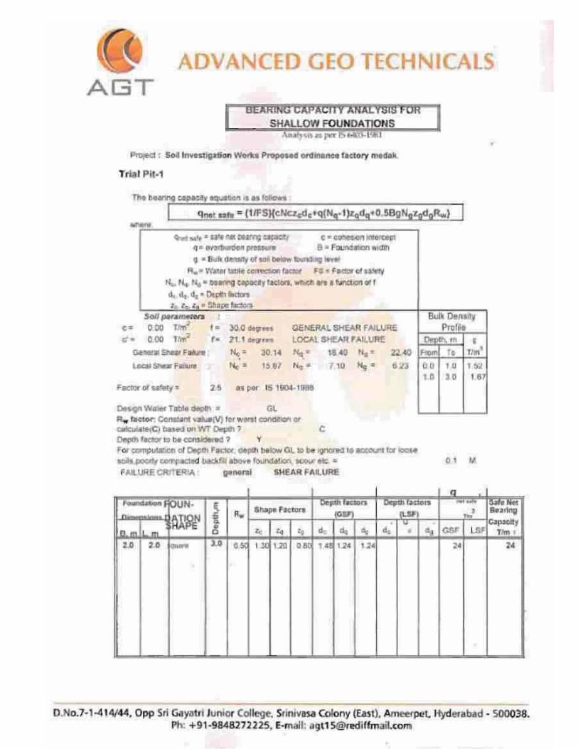


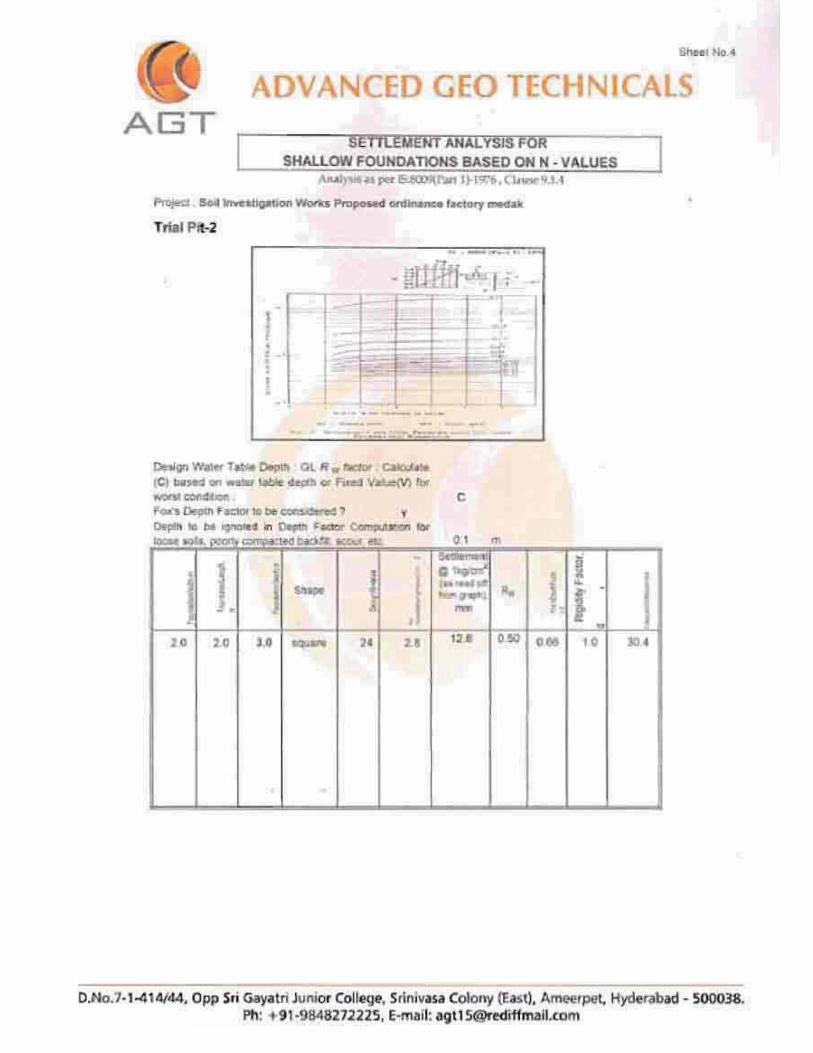
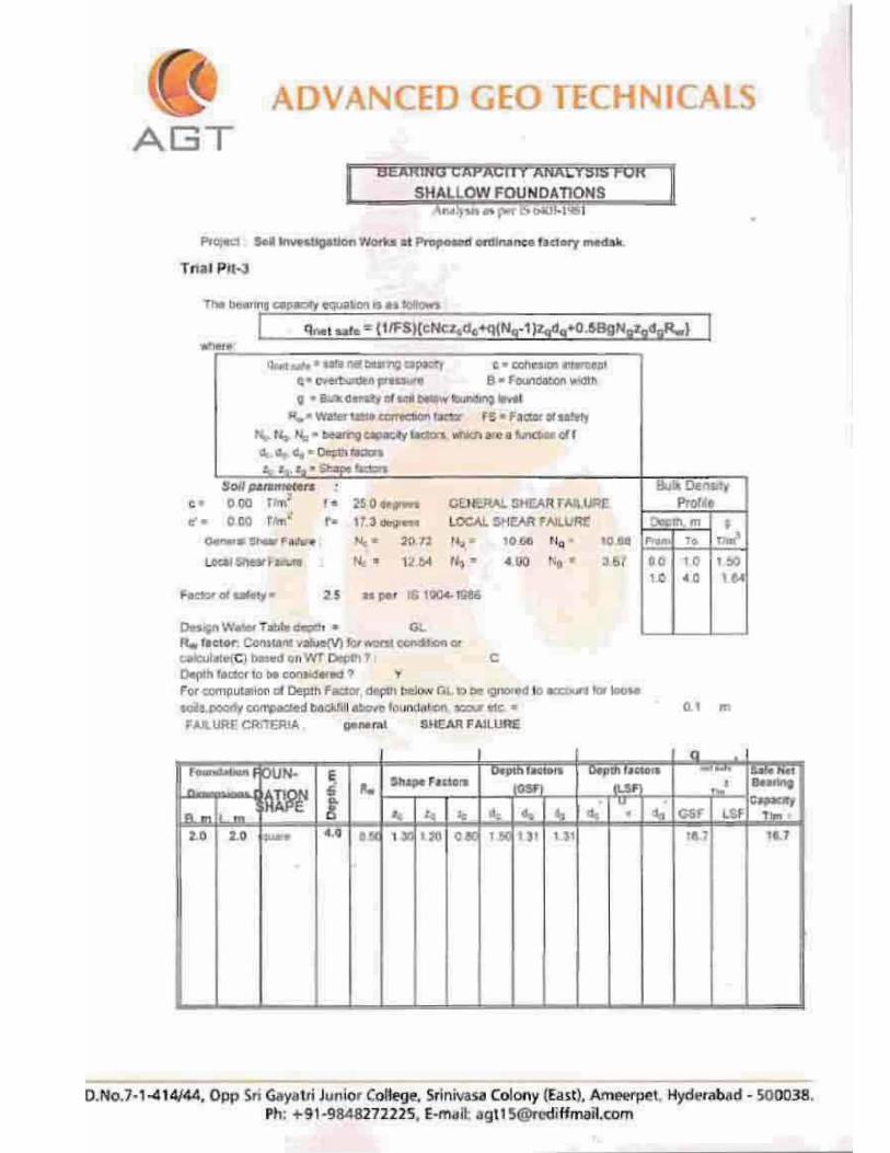
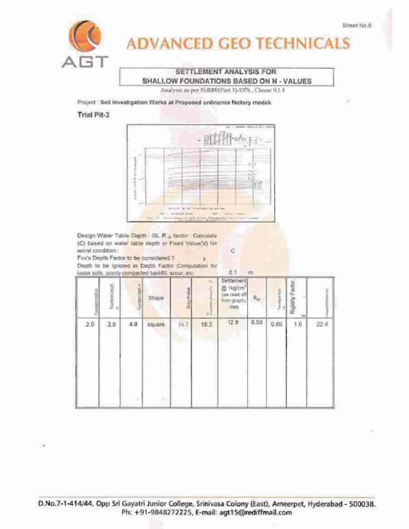
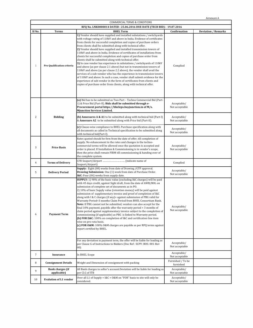
Annexure A
Sl No. Terms BHEL Term Confirmation Deviation / Remarks
1 Pre Qualification criteria
1) Vendor should have supplied and installed substations / switchyards
with voltage rating of 110kV and above in India. Evidence of certificates
from clients for successful completion and copies of purchase orders
from clients shall be submitted along with technical offer.
2) Vendor should have supplied and installed transmission towers of
110kV and above in India. Evidence of certificates of installations from
clients for successful completion and copies of purchase order from
clients shall be submitted along with technical offer.
3) In case vendor has experience in substations / switchyards of 110kV
and above (as per clause 2.1 above) but not in transmission towers of
110kV and above (as per clause 2.2 above), the vendor shall avail the
services of a sub-vendor who has the experience in transmission towers
of 110kV and above. In such a case, vendor shall submit evidence for the
experience of sub-vendor in the form of certificates from clients and
copies of purchase order from clients, along with technical offer.
Complied
(a) Bid has to be submitted as Two Part – Techno Commercial Bid (Part-
1) & Price Bid (Part-II). Bids shall be submitted through e-Procurement portal https://bheleps.buyjunction.in of M/s. Mjunction Services Limited.
Acceptable/
Not acceptable
(b) Annexures A & A1 to be submitted along with technical bid (Part-I)
& Annexure A2 to be submitted along with Price bid (Part-II).
Acceptable/
Not acceptable
(c) Clause-wise compliance to BHEL Purchase specification along with
all documents as called in Technical specification to be submitted along
with technical bid(Part-I).
Acceptable/
Not acceptable
3 Price Basis
Rates quoted should be firm from the date of offer, till completion of
supply. No enhancement in the rates and changes in the techno-
commercial terms will be allowed once the quotation is accepted and
order is placed. If Installation & Commissioning is in vendor’s scope,
then the price shall remain FIRM till commissioning & handing over of
the complete system.
Acceptable/
Not acceptable
4 Terms of Delivery CFR Seaport/Airport ………………………….. (indicate name of
Seaport/Airport)Complied
5 Delivery Period Supply: Eight (08) weeks from date of Drawing /GTP approval.
Drawing Submission: One (1) week from date of Purchase Order.
I&C: Four (04) weeks from supply date.
Acceptable/
Not acceptable
SUPPLY: 1) 90% of the basic value (excluding I&C charges) will be paid
with 45 days credit, against Sight draft, from the date of AWB/BOL on
submission of complete set of documents as in PO.
2) 10% of basic Supply value (retention money) will be paid against
submission of supplementary invoice and proof of completion of I&C
along with I & C charges (if any)+ against submission of PBG valid for
Warranty Period+3 months Claim Period from BHEL Consortium Bank.
Note: If PBG cannot not be submitted, vendors can also accept for the
final 10% payment, payable after the warranty period + 3 months of
claim period against supplementary invoice subject to the completion of
commissioning (if applicable) as PBG is linked to Warranty period.
(b) FOR E&C: 100% on completion of I&C and certification line item
wise on pro-rata basis.
(c) FOR O&M: 100% O&M charges are payable as per RFQ terms against
report certified by BHEL.
Acceptable/
Not acceptable
For any deviation in payment term, the offer will be liable for loading as
per Clause G of Instructions to Bidders (Doc Ref : SCPV: BOS: 001-Rev
00)
Acceptable/
Not acceptable
7 Insurance In BHEL ScopeAcceptable/
Not acceptable
8 Consignment Details Weight and Dimension of consignment with packingFurnished / To be
furnished
9Bank charges (if
applicable)All Bank charges to seller's account.Deviation will be liable for loading as
per Cl.G of ITB
Acceptable/
Not acceptable
10 Evalution of L1 vendor Over all L1 of Supply + I&C + O&M on “FOR” basis to site will only be
considered.
Acceptable/
Not acceptable
COMMERCIAL TERMS & CONDITIONS
RFQ No. LNK0000014 DATED : 25.06.2016 DUE DATE (TECH BID) : 19.07.2016
2 Bidding
6 Payment Term
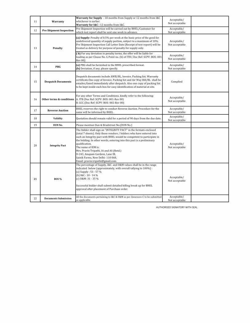
11 WarrantyWarranty for Supply : 18 months from Supply or 12 months from I&C
whichever is earlier.
Warranty for I&C : 12 months from I&C.
Acceptable/
Not acceptable
12 Pre Shipment Inspection Pre Shipment Inspection will be carried out by BHEL/Customer for
which test report shall be sent one week in advance.
Acceptable/
Not acceptable
(a) Supply: Penalty of 0.5% per week at the basic price of the good for
undelivered quantity of supply portion, subject to a maximum of 10%.
Pre Shipment Inspection Call Letter Date (Receipt of test report) will be
treated as delivery for purpose of penalty for supply only.
Acceptable/
Not acceptable
( b) For any deviation in penalty terms, the offer will be liable for
loading as per Clause No. G Point no. (b) of ITB ( Doc Ref: SCPV: BOS: 001-
Rev 00)
Acceptable/
Not acceptable
14 PBG (a) PBG shall be furnished in the BHEL prescribed format.
(b) Deviation, if any, please specify.
Acceptable/
Not acceptable
15 Despatch Documents
Despatch documents include AWB/BL, Invoice, Packing list, Warranty
certificate.One copy of Invoice, Packing list and Air Way Bill/BL shall be
emailes/faxed immediately after despatch. Also one copy of packing list
to be kept inside each box for easy identification of material at site.
Complied
16 Other terms & conditionsFor any other Terms and Conditions, kindly refer to the following:
A. ITB (Doc Ref: SCPV: BOS: 001-Rev 00)
B. GCC (Doc Ref: SCPV: BOS: 002-Rev 00)
Acceptable/
Not acceptable
17 Reverse Auction BHEL reserves the right to conduct Reverse Auction. Procedure for the
same will be informed by BHEL .
Acceptable/
Not acceptable
18 Validity Quotation should remain valid for a period of 90 days from the due date.Acceptable/
Not acceptable
19 DUN No. Please mention Dun & Bradstreet No.(DUN No.)
20 Integrity Pact
The bidder shall sign an "INTEGRITY PACT" in the formats enclosed
(total 7 sheets). Only those vendors / bidders who have entered into
such an Integrity pact with BHEL would be competent to participate in
the bidding. In other words, entering into this pact is a preliminary
qualification.
The name of IEM is:
Mrs. Pravin Tripathi, IA and AS (Retd.)
D-243, Anupam Gardens, Lane IB,
Sainik Farms, New Delhi- 110 068,
Email: [email protected].
Acceptable/
Not acceptable
21 BOS %
The percentage of Supply, I&C and O&M values shall be in the range
indicated below (approximately, with overall tallying to 100%) :
(a) Supply : 53 - 57 %
(b) I&C : 10 - 14 %
(c) O&M: 31 - 35 %
Successful bidder shall submit detailed billing break up for BHEL
approval after placement of Purchase order.
Acceptable/
Not acceptable
22 Documents Submission All the documents pertaining to I&C & O&M as per Annexure-C to be submitted
as applicable.
Acceptable/
Not acceptable
AUTHORISED SIGNATORY WITH SEAL
13 Penalty
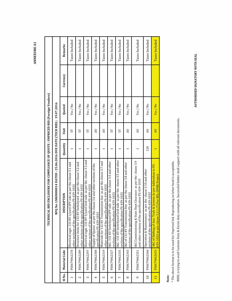
ANN
EXU
RE A
1
Sl N
o.M
ater
ial C
ode
DES
CRIP
TIO
NQ
uant
ity
Uni
t Q
uote
d Cu
rren
cyRe
mar
ks
1P
S0
67
90
62
27
0E
lect
rica
l e
qp
t. 1
32
KV
s/
ya
rd S
PV
sid
e a
s p
er
the
cla
use
3.1
an
d
oth
er
sect
ion
s o
f th
e s
pe
cifi
cati
on
PS
-43
9-1
03
31
ST
Ye
s /
No
Ta
xe
s In
clu
de
d
2P
S0
67
90
62
28
9S
tru
ctu
re i
tem
s fo
r 1
32
KV
Sw
itch
ya
rd a
s p
er
the
cla
use
3.2
an
d
oth
er
sect
ion
s o
f th
e s
pe
cifi
cati
on
PS
-43
9-1
03
31
ST
Ye
s /
No
Ta
xe
s In
clu
de
d
3P
S0
67
90
62
29
7E
lect
rica
l e
qp
t. 1
32
KV
S/
ya
rd G
rid
sid
e a
s p
er
the
cla
use
3.3
an
d
oth
er
sect
ion
s o
f th
e s
pe
cifi
cati
on
PS
-43
9-1
03
31
ST
Ye
s /
No
Ta
xe
s In
clu
de
d
4P
S0
67
90
62
30
0S
up
ply
of
Sp
are
s a
s p
er
the
cla
use
3.6
an
d o
the
r se
ctio
ns
of
the
spe
cifi
cati
on
PS
-43
9-1
03
31
AU
Ye
s /
No
Ta
xe
s In
clu
de
d
5P
S0
67
90
62
31
9M
ate
ria
ls f
or
13
2 K
V T
ran
smis
sio
n l
ine
as
pe
r th
e c
lau
se 3
.7 a
nd
oth
er
sect
ion
s o
f th
e s
pe
cifi
cati
on
PS
-43
9-1
03
31
AU
Ye
s /
No
Ta
xe
s In
clu
de
d
6P
S0
67
90
62
32
7I&
C:
13
2 K
V S
wit
chy
ard
SP
V s
ide
as
pe
r th
e c
lau
se 3
.4 a
nd
oth
er
sect
ion
s o
f th
e s
pe
cifi
cati
on
PS
-43
9-1
03
31
ST
Ye
s /
No
Ta
xe
s In
clu
de
d
7P
S0
67
90
62
33
5I&
C:
13
2 K
V S
wit
chy
ard
Gri
d s
ide
as
pe
r th
e c
lau
se 3
.5 a
nd
oth
er
sect
ion
s o
f th
e s
pe
cifi
cati
on
PS
-43
9-1
03
31
ST
Ye
s /
No
Ta
xe
s In
clu
de
d
8P
S0
67
90
62
34
3I&
C o
f 1
32
KV
Tra
nsm
issi
on
lin
e a
s p
er
the
cla
use
3.8
an
d o
the
r
sect
ion
s o
f th
e s
pe
cifi
cati
on
PS
-43
9-1
03
31
AU
Ye
s /
No
Ta
xe
s In
clu
de
d
9P
S0
67
90
62
35
1I&
C:C
om
mis
sio
nin
g &
Sta
te D
ep
t C
lea
ran
ce a
s p
er
the
cla
use
3.9
an
d o
the
r se
ctio
ns
of
the
sp
eci
fica
tio
n P
S-4
39
-10
33
1A
UY
es
/ N
oT
ax
es
Incl
ud
ed
10
PS
06
79
06
23
60
Op
era
tio
n &
Ma
inte
na
nce
as
pe
r th
e c
lau
se 3
.10
an
d o
the
r
sect
ion
s o
f th
e s
pe
cifi
cati
on
PS
-43
9-1
03
31
20
AU
Ye
s /
No
Ta
xe
s In
clu
de
d
11
PS
06
79
06
26
53
I&
C o
f S
hif
tin
g o
f A
ux
. Tra
fo &
Sy
ste
m A
s p
er
Ad
de
nd
um
to
PS
-
43
9-1
03
3 a
s p
er
cla
use
5.2
.1 (
7)
Fo
r B
EL
OF
MK
Pro
ject
1A
UY
es
/ N
oT
ax
es
Incl
ud
ed
Not
e:
AUTH
ORI
SED
SIG
NAT
ORY
WIT
H S
EAL
BH
EL
is
try
ing
to
av
ail
Cu
sto
ms
Du
ty &
Ex
cise
du
ty e
xe
mp
tio
n. S
ucc
ess
ful
bid
de
r sh
all
su
pp
ort
wit
h a
ll r
ele
va
nt
do
cum
en
ts.
TECH
NIC
AL B
ID E
NCL
OSU
RE F
OR
COM
PLIA
NCE
OF
QU
OTE
: U
NPR
ICED
BID
(For
eign
Ven
dors
)
RFQ
No.
LN
K00
0001
4 D
ATED
: 25
.06.
2016
DU
E D
ATE
(TEC
H B
ID) :
19.
07.2
016
* T
he
ab
ov
e f
orm
at
is t
o b
e u
sed
fo
r U
np
rice
d b
id. R
ep
rod
uci
ng
on
le
tte
r h
ea
d i
s a
cce
pta
ble
.
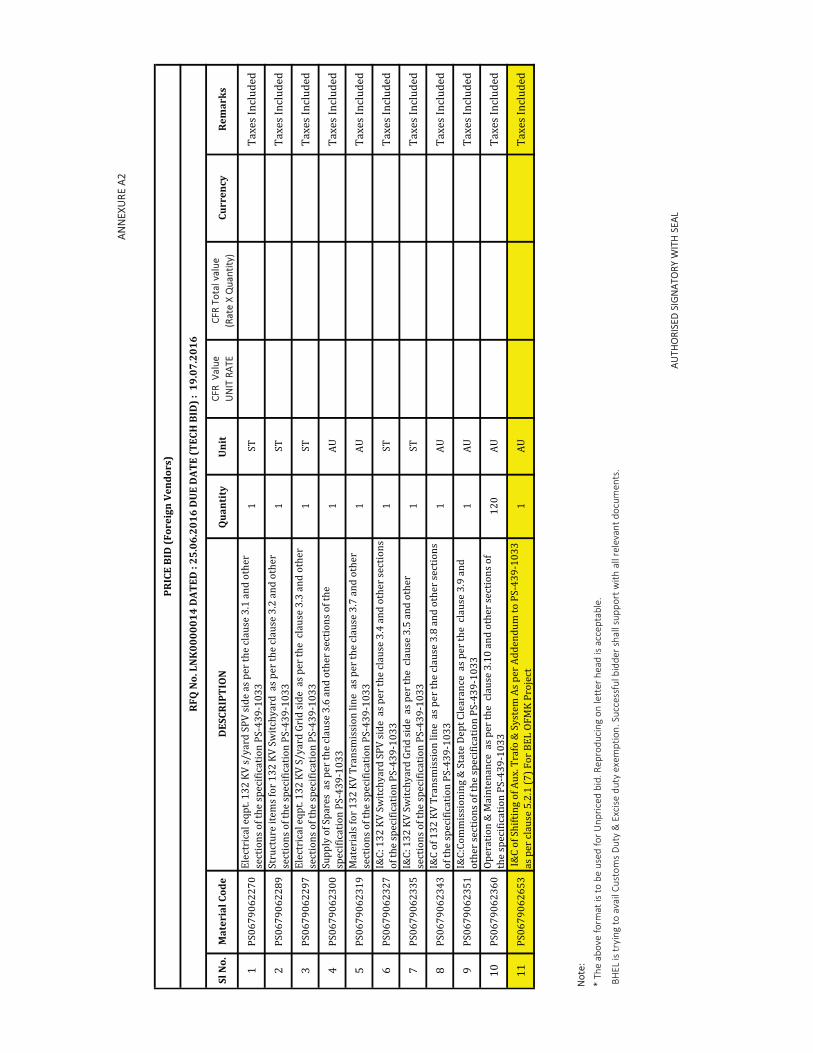
ANN
EXU
RE A
2
Sl N
o.M
ater
ial C
ode
DES
CRIP
TIO
NQ
uant
ity
Uni
t CF
R V
alue
UN
IT R
ATE
CFR
Tota
l val
ue
(Rat
e X
Qua
ntity
)Cu
rren
cyRe
mar
ks
1P
S0
67
90
62
27
0E
lect
rica
l e
qp
t. 1
32
KV
s/
ya
rd S
PV
sid
e a
s p
er
the
cla
use
3.1
an
d o
the
r
sect
ion
s o
f th
e s
pe
cifi
cati
on
PS
-43
9-1
03
31
ST
Ta
xe
s In
clu
de
d
2P
S0
67
90
62
28
9S
tru
ctu
re i
tem
s fo
r 1
32
KV
Sw
itch
ya
rd a
s p
er
the
cla
use
3.2
an
d o
the
r
sect
ion
s o
f th
e s
pe
cifi
cati
on
PS
-43
9-1
03
31
ST
Ta
xe
s In
clu
de
d
3P
S0
67
90
62
29
7E
lect
rica
l e
qp
t. 1
32
KV
S/
ya
rd G
rid
sid
e a
s p
er
the
cla
use
3.3
an
d o
the
r
sect
ion
s o
f th
e s
pe
cifi
cati
on
PS
-43
9-1
03
31
ST
Ta
xe
s In
clu
de
d
4P
S0
67
90
62
30
0S
up
ply
of
Sp
are
s a
s p
er
the
cla
use
3.6
an
d o
the
r se
ctio
ns
of
the
spe
cifi
cati
on
PS
-43
9-1
03
31
AU
Ta
xe
s In
clu
de
d
5P
S0
67
90
62
31
9M
ate
ria
ls f
or
13
2 K
V T
ran
smis
sio
n l
ine
as
pe
r th
e c
lau
se 3
.7 a
nd
oth
er
sect
ion
s o
f th
e s
pe
cifi
cati
on
PS
-43
9-1
03
31
AU
Ta
xe
s In
clu
de
d
6P
S0
67
90
62
32
7I&
C:
13
2 K
V S
wit
chy
ard
SP
V s
ide
as
pe
r th
e c
lau
se 3
.4 a
nd
oth
er
sect
ion
s
of
the
sp
eci
fica
tio
n P
S-4
39
-10
33
1S
TT
ax
es
Incl
ud
ed
7P
S0
67
90
62
33
5I&
C:
13
2 K
V S
wit
chy
ard
Gri
d s
ide
as
pe
r th
e c
lau
se 3
.5 a
nd
oth
er
sect
ion
s o
f th
e s
pe
cifi
cati
on
PS
-43
9-1
03
31
ST
Ta
xe
s In
clu
de
d
8P
S0
67
90
62
34
3I&
C o
f 1
32
KV
Tra
nsm
issi
on
lin
e a
s p
er
the
cla
use
3.8
an
d o
the
r se
ctio
ns
of
the
sp
eci
fica
tio
n P
S-4
39
-10
33
1A
UT
ax
es
Incl
ud
ed
9P
S0
67
90
62
35
1I&
C:C
om
mis
sio
nin
g &
Sta
te D
ep
t C
lea
ran
ce a
s p
er
the
cla
use
3.9
an
d
oth
er
sect
ion
s o
f th
e s
pe
cifi
cati
on
PS
-43
9-1
03
31
AU
Ta
xe
s In
clu
de
d
10
PS
06
79
06
23
60
Op
era
tio
n &
Ma
inte
na
nce
as
pe
r th
e c
lau
se 3
.10
an
d o
the
r se
ctio
ns
of
the
sp
eci
fica
tio
n P
S-4
39
-10
33
12
0A
UT
ax
es
Incl
ud
ed
11
PS
06
79
06
26
53
I&
C o
f S
hif
tin
g o
f A
ux
. Tra
fo &
Sy
ste
m A
s p
er
Ad
de
nd
um
to
PS
-43
9-1
03
3
as
pe
r cl
au
se 5
.2.1
(7
) F
or
BE
L O
FM
K P
roje
ct1
AU
Ta
xe
s In
clu
de
d
Not
e:
AUTH
ORI
SED
SIG
NAT
ORY
WIT
H S
EAL
* Th
e ab
ove
form
at is
to b
e us
ed fo
r Unp
riced
bid
. Rep
rodu
cing
on
lett
er h
ead
is ac
cept
able
.
BH
EL is
tryi
ng to
ava
il Cu
stom
s Du
ty &
Exc
ise d
uty
exem
ptio
n. S
ucce
ssfu
l bid
der s
hall
supp
ort w
ith a
ll re
leva
nt d
ocum
ents
.
PRIC
E BI
D (F
orei
gn V
endo
rs)
RFQ
No.
LN
K00
0001
4 D
ATED
: 25
.06.
2016
DU
E D
ATE
(TEC
H B
ID) :
19.
07.2
016
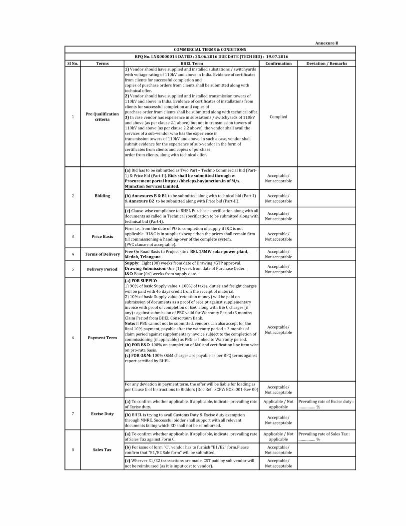
Annexure B
Sl No. Terms BHEL Term Confirmation Deviation / Remarks
1 Pre Qualification criteria
1) Vendor should have supplied and installed substations / switchyards
with voltage rating of 110kV and above in India. Evidence of certificates
from clients for successful completion and
copies of purchase orders from clients shall be submitted along with
technical offer.
2) Vendor should have supplied and installed transmission towers of
110kV and above in India. Evidence of certificates of installations from
clients for successful completion and copies of
purchase order from clients shall be submitted along with technical offer.
3) In case vendor has experience in substations / switchyards of 110kV
and above (as per clause 2.1 above) but not in transmission towers of
110kV and above (as per clause 2.2 above), the vendor shall avail the
services of a sub-vendor who has the experience in
transmission towers of 110kV and above. In such a case, vendor shall
submit evidence for the experience of sub-vendor in the form of
certificates from clients and copies of purchase
order from clients, along with technical offer.
Complied
(a) Bid has to be submitted as Two Part – Techno Commercial Bid (Part-
1) & Price Bid (Part-II). Bids shall be submitted through e-Procurement portal https://bheleps.buyjunction.in of M/s. Mjunction Services Limited.
Acceptable/
Not acceptable
(b) Annexures B & B1 to be submitted along with technical bid (Part-I)
& Annexure B2 to be submitted along with Price bid (Part-II).
Acceptable/
Not acceptable
(c) Clause-wise compliance to BHEL Purchase specification along with all
documents as called in Technical specification to be submitted along with
technical bid (Part-I).
Acceptable/
Not acceptable
3 Price Basis
Firm i.e., from the date of PO to completion of supply if I&C is not
applicable. If I&C is in supplier's scope,then the prices shall remain firm
till commissioning & handing-over of the complete system.
(PVC clause not acceptable).
Acceptable/
Not acceptable
4 Terms of Delivery Free On Road Basis to Project site : BEL 15MW solar power plant, Medak, Telangana
Acceptable/
Not acceptable
5 Delivery Period Supply: Eight (08) weeks from date of Drawing /GTP approval.
Drawing Submission: One (1) week from date of Purchase Order.
I&C: Four (04) weeks from supply date.
Acceptable/
Not acceptable
(a) FOR SUPPLY:1) 90% of basic Supply value + 100% of taxes, duties and freight charges
will be paid with 45 days credit from the receipt of material.
2) 10% of basic Supply value (retention money) will be paid on
submission of documents as a proof of receipt against supplementary
invoice with proof of completion of E&C along with E & C charges (if
any)+ against submission of PBG valid for Warranty Period+3 months
Claim Period from BHEL Consortium Bank.
Note: If PBG cannot not be submitted, vendors can also accept for the
final 10% payment, payable after the warranty period + 3 months of
claim period against supplementary invoice subject to the completion of
commissioning (if applicable) as PBG is linked to Warranty period.
(b) FOR E&C: 100% on completion of I&C and certification line item wise
on pro-rata basis.
(c) FOR O&M: 100% O&M charges are payable as per RFQ terms against
report certified by BHEL.
Acceptable/
Not acceptable
For any deviation in payment term, the offer will be liable for loading as
per Clause G of Instructions to Bidders (Doc Ref : SCPV: BOS: 001-Rev 00)Acceptable/
Not acceptable
(a) To confirm whether applicable. If applicable, indicate prevailing rate
of Excise duty.
Applicable / Not
applicable
Prevailing rate of Excise duty :
................... %
(b) BHEL is trying to avail Customs Duty & Excise duty exemption
through MNRE. Successful bidder shall support with all relevant
documents failing which ED shall not be reimbursed.
Acceptable/
Not acceptable
(a) To confirm whether applicable. If applicable, indicate prevailing rate
of Sales Tax against Form C.
Applicable / Not
applicable
Prevailing rate of Sales Tax :
................... %
(b) For issue of form "C", vendor has to furnish "E1/E2" form.Please
confirm that "E1/E2 Sale form" will be submitted.
Acceptable/
Not acceptable
(c) Wherver E1/E2 transactions are made, CST paid by sub vendor will
not be reimbursed (as it is input cost to vendor).
Acceptable/
Not acceptable
COMMERCIAL TERMS & CONDITIONS RFQ No. LNK0000014 DATED : 25.06.2016 DUE DATE (TECH BID) : 19.07.2016
2 Bidding
6 Payment Term
7 Excise Duty
8 Sales Tax
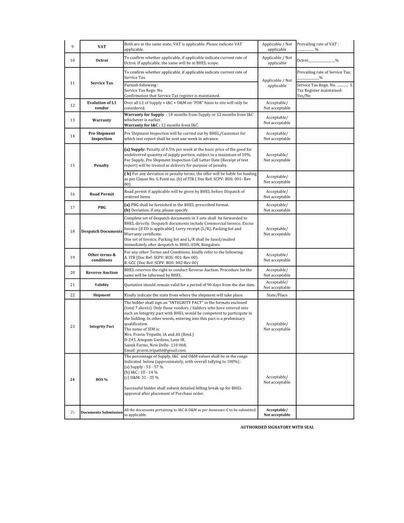
9 VAT Both are in the same state, VAT is applicable. Please indicate VAT
applicable.
Applicable / Not
applicable
Prevailing rate of VAT :
................... %
10 Octroi To confirm whether applicable, if applicable indicate current rate of
Octroi. If applicable, the same will be in BHEL scope.
Applicable / Not
applicableOctroi_________________%
To confirm whether applicable, if applicable indicate current rate of
Service Tax.
Prevailing rate of Service Tax:
______________%
Furnish following :
Service Tax Regn. No.
Confirmation that Service Tax register is maintained.
Service Tax Regn. No. ……….. S.
Tax Register maintained:
Yes/No
12Evalution of L1
vendorOver all L1 of Supply + I&C + O&M on “FOR” basis to site will only be
considered.
Acceptable/
Not acceptable
13 WarrantyWarranty for Supply : 18 months from Supply or 12 months from I&C
whichever is earlier.
Warranty for I&C : 12 months from I&C.
Acceptable/
Not acceptable
14Pre Shipment
Inspection Pre Shipment Inspection will be carried out by BHEL/Customer for
which test report shall be sent one week in advance.
Acceptable/
Not acceptable
(a) Supply: Penalty of 0.5% per week at the basic price of the good for
undelivered quantity of supply portion, subject to a maximum of 10%.
For Supply, Pre Shipment Inspection Call Letter Date (Receipt of test
report) will be treated as delivery for purpose of penalty.
Acceptable/
Not acceptable
( b) For any deviation in penalty terms, the offer will be liable for loading
as per Clause No. G Point no. (b) of ITB ( Doc Ref: SCPV: BOS: 001- Rev
00)
Acceptable/
Not acceptable
16 Road Permit Road permit if applicable will be given by BHEL before Dispatch of
ordered Items.
Acceptable/
Not acceptable
17 PBG (a) PBG shall be furnished in the BHEL prescribed format.
(b) Deviation, if any, please specify.
Acceptable/
Not acceptable
18 Despatch Documents
Complete set of despatch documents in 3 sets shall be forwarded to
BHEL directly. Despatch documents include Commercial Invoice, Excise
Invoice (if ED is applicable), Lorry receipt (L/R), Packing list and
Warranty certificate.
One set of Invoice, Packing list and L/R shall be faxed/mailed
immediately after despatch to BHEL-EDN, Bangalore.
Acceptable/
Not acceptable
19Other terms &
conditions
For any other Terms and Conditions, kindly refer to the following:
A. ITB (Doc Ref: SCPV: BOS: 001-Rev 00)
B. GCC (Doc Ref: SCPV: BOS: 002-Rev 00)
Acceptable/
Not acceptable
20 Reverse Auction BHEL reserves the right to conduct Reverse Auction. Procedure for the
same will be informed by BHEL .
Acceptable/
Not acceptable
21 Validity Quotation should remain valid for a period of 90 days from the due date.Acceptable/
Not acceptable
22 Shipment Kindly indicate the state from where the shipment will take place. State/Place
23 Integrity Pact
The bidder shall sign an "INTEGRITY PACT" in the formats enclosed
(total 7 sheets). Only those vendors / bidders who have entered into
such an Integrity pact with BHEL would be competent to participate in
the bidding. In other words, entering into this pact is a preliminary
qualification.
The name of IEM is:
Mrs. Pravin Tripathi, IA and AS (Retd.)
D-243, Anupam Gardens, Lane IB,
Sainik Farms, New Delhi- 110 068,
Email: [email protected].
Acceptable/
Not acceptable
24 BOS %
The percentage of Supply, I&C and O&M values shall be in the range
indicated below (approximately, with overall tallying to 100%) :
(a) Supply : 53 - 57 %
(b) I&C : 10 - 14 %
(c) O&M: 31 - 35 %
Successful bidder shall submit detailed billing break up for BHEL
approval after placement of Purchase order.
Acceptable/
Not acceptable
25 Documents Submission All the documents pertaining to I&C & O&M as per Annexure-C to be submitted
as applicable.
Acceptable/ Not acceptable
AUTHORISED SIGNATORY WITH SEAL
Applicable / Not
applicable
15 Penalty
11 Service Tax
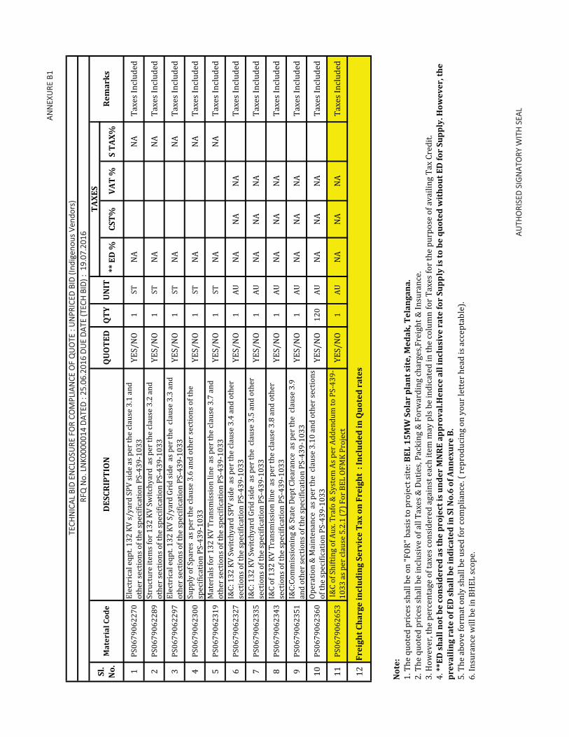
ANN
EXU
RE B
1
** E
D %
CST%
VAT
%S
TAX%
1P
S0
67
90
62
27
0E
lect
rica
l e
qp
t. 1
32
KV
s/
ya
rd S
PV
sid
e a
s p
er
the
cla
use
3.1
an
d
oth
er
sect
ion
s o
f th
e s
pe
cifi
cati
on
PS
-43
9-1
03
3Y
ES
/N
O1
ST
NA
NA
Ta
xe
s In
clu
de
d
2P
S0
67
90
62
28
9S
tru
ctu
re i
tem
s fo
r 1
32
KV
Sw
itch
ya
rd a
s p
er
the
cla
use
3.2
an
d
oth
er
sect
ion
s o
f th
e s
pe
cifi
cati
on
PS
-43
9-1
03
3Y
ES
/N
O1
ST
NA
NA
Ta
xe
s In
clu
de
d
3P
S0
67
90
62
29
7E
lect
rica
l e
qp
t. 1
32
KV
S/
ya
rd G
rid
sid
e a
s p
er
the
cla
use
3.3
an
d
oth
er
sect
ion
s o
f th
e s
pe
cifi
cati
on
PS
-43
9-1
03
3Y
ES
/N
O1
ST
NA
NA
Ta
xe
s In
clu
de
d
4P
S0
67
90
62
30
0S
up
ply
of
Sp
are
s a
s p
er
the
cla
use
3.6
an
d o
the
r se
ctio
ns
of
the
spe
cifi
cati
on
PS
-43
9-1
03
3Y
ES
/N
O1
ST
NA
NA
Ta
xe
s In
clu
de
d
5P
S0
67
90
62
31
9M
ate
ria
ls f
or
13
2 K
V T
ran
smis
sio
n l
ine
as
pe
r th
e c
lau
se 3
.7 a
nd
oth
er
sect
ion
s o
f th
e s
pe
cifi
cati
on
PS
-43
9-1
03
3Y
ES
/N
O1
ST
NA
NA
Ta
xe
s In
clu
de
d
6P
S0
67
90
62
32
7I&
C:
13
2 K
V S
wit
chy
ard
SP
V s
ide
as
pe
r th
e c
lau
se 3
.4 a
nd
oth
er
sect
ion
s o
f th
e s
pe
cifi
cati
on
PS
-43
9-1
03
3Y
ES
/N
O1
AU
NA
NA
NA
Ta
xe
s In
clu
de
d
7P
S0
67
90
62
33
5I&
C:
13
2 K
V S
wit
chy
ard
Gri
d s
ide
as
pe
r th
e c
lau
se 3
.5 a
nd
oth
er
sect
ion
s o
f th
e s
pe
cifi
cati
on
PS
-43
9-1
03
3Y
ES
/N
O1
AU
NA
NA
NA
Ta
xe
s In
clu
de
d
8P
S0
67
90
62
34
3I&
C o
f 1
32
KV
Tra
nsm
issi
on
lin
e a
s p
er
the
cla
use
3.8
an
d o
the
r
sect
ion
s o
f th
e s
pe
cifi
cati
on
PS
-43
9-1
03
3Y
ES
/N
O1
AU
NA
NA
NA
Ta
xe
s In
clu
de
d
9P
S0
67
90
62
35
1I&
C:C
om
mis
sio
nin
g &
Sta
te D
ep
t C
lea
ran
ce a
s p
er
the
cla
use
3.9
an
d o
the
r se
ctio
ns
of
the
sp
eci
fica
tio
n P
S-4
39
-10
33
YE
S/
NO
1A
UN
AN
AN
AT
ax
es
Incl
ud
ed
10
PS
06
79
06
23
60
Op
era
tio
n &
Ma
inte
na
nce
as
pe
r th
e c
lau
se 3
.10
an
d o
the
r se
ctio
ns
of
the
sp
eci
fica
tio
n P
S-4
39
-10
33
YE
S/
NO
12
0A
UN
AN
AN
AT
ax
es
Incl
ud
ed
11
PS
06
79
06
26
53
I&
C o
f S
hif
tin
g o
f A
ux
. Tra
fo &
Sy
ste
m A
s p
er
Ad
de
nd
um
to
PS
-43
9-
10
33
as
pe
r cl
au
se 5
.2.1
(7
) F
or
BE
L O
FM
K P
roje
ctY
ES
/N
O1
AU
NA
NA
NA
Ta
xe
s In
clu
de
d
12
AUTH
ORI
SED
SIG
NAT
ORY
WIT
H S
EAL
TEC
HN
ICAL
BID
EN
CLO
SURE
FO
R CO
MPL
IAN
CE O
F Q
UO
TE :
UN
PRIC
ED B
ID (I
ndig
enou
s Ve
ndor
s)
RFQ
No.
LN
K000
0014
DAT
ED :
25.0
6.20
16 D
UE
DATE
(TEC
H B
ID) :
19.
07.2
016
Sl.
No.
Mat
eria
l Cod
eD
ESCR
IPTI
ON
QU
OTE
DQ
TYU
NIT
TA
XES
Rem
arks
Frei
ght C
harg
e in
clud
ing
Serv
ice
Tax
on F
reig
ht :
Incl
uded
in Q
uote
d ra
tes
Not
e:
1. T
he
qu
ote
d p
rice
s sh
all
be
on
"F
OR
" b
asi
s to
pro
ject
sit
e:
BEL
15M
W S
olar
pla
nt s
ite,
Med
ak, T
elan
gana
.2
. Th
e q
uo
ted
pri
ces
sha
ll b
e i
ncl
usi
ve
of
all
Ta
xe
s &
Du
tie
s, P
ack
ing
& F
orw
ard
ing
ch
arg
es,
Fre
igh
t &
In
sura
nce
.
3. H
ow
ev
er,
th
e p
erc
en
tag
e o
f ta
xe
s co
nsi
de
red
ag
ain
st e
ach
ite
m m
ay
pls
be
in
dic
ate
d i
n t
he
co
lum
n f
or
Ta
xe
s fo
r th
e p
urp
ose
of
av
ail
ing
Ta
x C
red
it.
4. *
*ED
sha
ll no
t be
cons
ider
ed a
s th
e pr
ojec
t is
unde
r M
NRE
app
rova
l.Hen
ce a
ll in
clus
ive
rate
for
Supp
ly is
to b
e qu
oted
wit
hout
ED
for
Supp
ly. H
owev
er, t
he
prev
ailin
g ra
te o
f ED
sha
ll be
indi
cate
d in
Sl N
o.6
of A
nnex
ure
B.5
. Th
e a
bo
ve
fo
rma
t o
nly
sh
all
be
use
d f
or
com
pli
an
ce. (
re
pro
du
cin
g o
n y
ou
r le
tte
r h
ea
d i
s a
cce
pta
ble
).
6. I
nsu
ran
ce w
ill
be
in
BH
EL
sco
pe
.
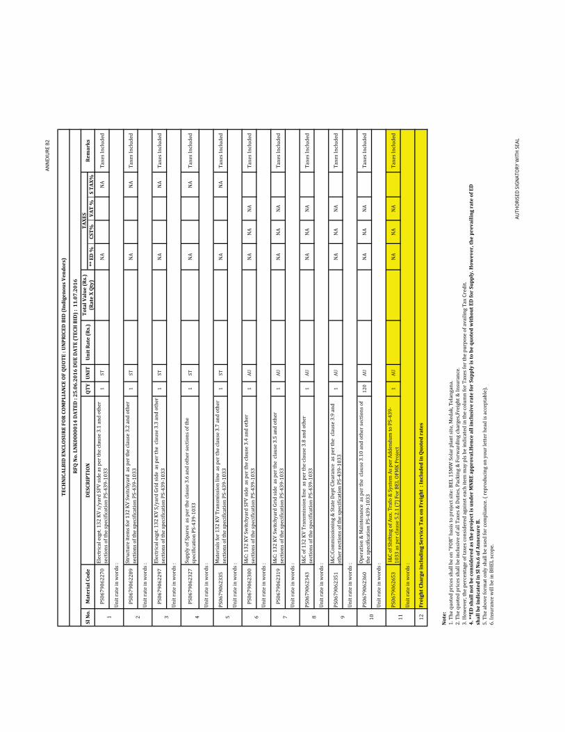
ANN
EXU
RE B
2
** E
D %
CST%
VAT
%S
TAX%
PS
06
79
06
22
70
Ele
ctri
cal
eq
pt.
13
2 K
V s
/y
ard
SP
V s
ide
as
pe
r th
e c
lau
se 3
.1 a
nd
oth
er
sect
ion
s o
f th
e s
pe
cifi
cati
on
PS
-43
9-1
03
31
ST
NA
NA
Ta
xe
s In
clu
de
d
PS
06
79
06
22
89
Str
uct
ure
ite
ms
for
13
2 K
V S
wit
chy
ard
as
pe
r th
e c
lau
se 3
.2 a
nd
oth
er
sect
ion
s o
f th
e s
pe
cifi
cati
on
PS
-43
9-1
03
31
ST
NA
NA
Ta
xe
s In
clu
de
d
PS
06
79
06
22
97
Ele
ctri
cal
eq
pt.
13
2 K
V S
/y
ard
Gri
d s
ide
as
pe
r th
e c
lau
se 3
.3 a
nd
oth
er
sect
ion
s o
f th
e s
pe
cifi
cati
on
PS
-43
9-1
03
31
ST
NA
NA
Ta
xe
s In
clu
de
d
PS
06
79
06
23
27
Su
pp
ly o
f S
pa
res
as
pe
r th
e c
lau
se 3
.6 a
nd
oth
er
sect
ion
s o
f th
e
spe
cifi
cati
on
PS
-43
9-1
03
31
ST
NA
NA
Ta
xe
s In
clu
de
d
PS
06
79
06
23
35
Ma
teri
als
fo
r 1
32
KV
Tra
nsm
issi
on
lin
e a
s p
er
the
cla
use
3.7
an
d o
the
r
sect
ion
s o
f th
e s
pe
cifi
cati
on
PS
-43
9-1
03
31
ST
NA
NA
Ta
xe
s In
clu
de
d
PS
06
79
06
23
00
I&C
: 1
32
KV
Sw
itch
ya
rd S
PV
sid
e a
s p
er
the
cla
use
3.4
an
d o
the
r
sect
ion
s o
f th
e s
pe
cifi
cati
on
PS
-43
9-1
03
31
AU
NA
NA
NA
Ta
xe
s In
clu
de
d
PS
06
79
06
23
19
I&C
: 1
32
KV
Sw
itch
ya
rd G
rid
sid
e a
s p
er
the
cla
use
3.5
an
d o
the
r
sect
ion
s o
f th
e s
pe
cifi
cati
on
PS
-43
9-1
03
31
AU
NA
NA
NA
Ta
xe
s In
clu
de
d
PS
06
79
06
23
43
I&C
of
13
2 K
V T
ran
smis
sio
n l
ine
as
pe
r th
e c
lau
se 3
.8 a
nd
oth
er
sect
ion
s o
f th
e s
pe
cifi
cati
on
PS
-43
9-1
03
31
AU
NA
NA
NA
Ta
xe
s In
clu
de
d
PS
06
79
06
23
51
I&C
:Co
mm
issi
on
ing
& S
tate
De
pt
Cle
ara
nce
as
pe
r th
e c
lau
se 3
.9 a
nd
oth
er
sect
ion
s o
f th
e s
pe
cifi
cati
on
PS
-43
9-1
03
31
AU
NA
NA
NA
Ta
xe
s In
clu
de
d
PS
06
79
06
23
60
Op
era
tio
n &
Ma
inte
na
nce
as
pe
r th
e c
lau
se 3
.10
an
d o
the
r se
ctio
ns
of
the
sp
eci
fica
tio
n P
S-4
39
-10
33
12
0A
UN
AN
AN
AT
ax
es
Incl
ud
ed
PS
06
79
06
26
53
I&
C o
f S
hif
tin
g o
f A
ux
. Tra
fo &
Sy
ste
m A
s p
er
Ad
de
nd
um
to
PS
-43
9-
10
33
as
pe
r cl
au
se 5
.2.1
(7
) F
or
BE
L O
FM
K P
roje
ct1
AU
NA
NA
NA
Ta
xe
s In
clu
de
d
12
AUTH
ORI
SED
SIG
NAT
ORY
WIT
H S
EAL
Un
it r
ate
in
wo
rds
:
Un
it r
ate
in
wo
rds
:
Un
it r
ate
in
wo
rds
:
Un
it r
ate
in
wo
rds
:
Not
e:
1. T
he
qu
ote
d p
rice
s sh
all
be
on
"F
OR
" b
asi
s to
pro
ject
sit
e:
BE
L 1
5M
W S
ola
r p
lan
t si
te, M
ed
ak
, Te
lan
ga
na
.
2. T
he
qu
ote
d p
rice
s sh
all
be
in
clu
siv
e o
f a
ll T
ax
es
& D
uti
es,
Pa
ckin
g &
Fo
rwa
rdin
g c
ha
rge
s,F
reig
ht
& I
nsu
ran
ce.
3. H
ow
ev
er,
th
e p
erc
en
tag
e o
f ta
xe
s co
nsi
de
red
ag
ain
st e
ach
ite
m m
ay
pls
be
in
dic
ate
d i
n t
he
co
lum
n f
or
Ta
xe
s fo
r th
e p
urp
ose
of
av
ail
ing
Ta
x C
red
it.
4. *
*ED
sha
ll no
t be
cons
ider
ed a
s th
e pr
ojec
t is
unde
r M
NRE
app
rova
l.Hen
ce a
ll in
clus
ive
rate
for
Supp
ly is
to b
e qu
oted
wit
hout
ED
for
Supp
ly. H
owev
er, t
he p
reva
iling
rat
e of
ED
sh
all b
e in
dica
ted
in S
l No.
6 of
Ann
exur
e B.
5. T
he
ab
ov
e f
orm
at
on
ly s
ha
ll b
e u
sed
fo
r co
mp
lia
nce
. ( r
ep
rod
uci
ng
on
yo
ur
lett
er
he
ad
is
acc
ep
tab
le).
6. I
nsu
ran
ce w
ill
be
in
BH
EL
sco
pe
.
1 2 3 6 7
TEC
HN
ICAL
BID
EN
CLO
SURE
FO
R CO
MPL
IAN
CE O
F Q
UO
TE :
UN
PRIC
ED B
ID (I
ndig
enou
s Ve
ndor
s)
RFQ
No.
LN
K00
0001
4 D
ATED
: 25
.06.
2016
DU
E D
ATE
(TEC
H B
ID) :
11.
07.2
016
Sl N
o.M
ater
ial C
ode
DES
CRIP
TIO
NQ
TYU
NIT
U
nit R
ate
(Rs.
)To
tal V
alue
(Rs.
)(R
ate
X Q
ty)
TAXE
S Re
mar
ks
10
Un
it r
ate
in
wo
rds
:
Un
it r
ate
in
wo
rds
:
Un
it r
ate
in
wo
rds
:
Un
it r
ate
in
wo
rds
:
4 5 8 9
Un
it r
ate
in
wo
rds
:
Un
it r
ate
in
wo
rds
:
Frei
ght C
harg
e in
clud
ing
Serv
ice
Tax
on F
reig
ht :
Incl
uded
in Q
uote
d ra
tes
11
Un
it r
ate
in
wo
rds
:

Confirmation on submission Deviation / Remarks
IR Documents (Type - A): For all Civil & I&C & O&MSl No. Documents
1 Wage Sheet (Form 17) YES / NO
2 Attendance Register (w.r.t Sl No.1) YES / NO
3 Workman Policy & Additional Insurance (Automotive Liability, Group Serivs Insuarnce Policy et YES / NO
4 PF Challan YES / NO
5 ESI (Employee State Insurance) YES / NO
6 ECR (Electronic Challan Receipt) YES / NO
7 Bank Statement for PF deposit YES / NO
8 RCS (Remittance Confirmation Slip) YES / NO
Quality Documents (Type - B): For all MMS Civil WorksSl No. Documents
1 FQA (Field Quality Assuarance) NA
2 Field Content, Slump Test NA
3 Gradiation of Aggregate (10mm, 20mm) NA
4 Fine Aggregate Test (for Sand) NA
5 Cube Test Registered NA
6 Material Test Certificate for Steel & Cement NA
7 Consumption Register for Steel & Invoice NA
8 Pour Card for Concreting purpose NA
9 Royalty Reports (10mm, 20mm, Sand) NA
10 Sand Soundess Test Reports NA
11 Slump Test Register NA
12 Sieve Analysis, Flakiness Index, Elongation Index - Register to be maintained NA
13 Moisture Content Coarse and Fine Aggregate - Register to be maintained NA
14 Water Test Report for Concrete NA
15 Design Mix Report for Concrete NA
Quality Documents (Type - B): For all Civil related WorksSl No. Documents
1 FQA (Field Quality Assuarance) YES / NO
2 Field Content, Slump Test YES / NO
3 Gradiation of Aggregate (10mm, 20mm) YES / NO
4 Fine Aggregate Test (for Sand) YES / NO
5 Cube Test Registered YES / NO
6 Material Test Certificate for Steel & Cement YES / NO
7 Consumption Register for Steel & Invoice YES / NO
8 Pour Card for Concreting purpose YES / NO
9 Royalty Reports (10mm, 20mm, Sand) YES / NO
10 Sand Soundess Test Reports YES / NO
11 Warpage of Bricks Test Reports YES / NO
12 Core Cutting (Compaction Test) - Roads & Pathways YES / NO
13 Slump Test Register YES / NO
14 Sieve Analysis, Flakiness Index, Elongation Index - Register to be maintained YES / NO
15 Moisture Content Coarse and Fine Aggregate - Register to be maintained* YES / NO
16 Brick Test Reports YES / NO
17 Plastering profile and thickness YES / NO
18 Compaction test beneath floor of all buildings. - Reports YES / NO
19 Test Certificates for Paint, Glan, Glazing, etc. YES / NO
20 Test Certificates Aluminium Section for doors and windows (Anodisation Certificates also) YES / NO
21 BBS for Buildings YES / NO
22 Water Test Report for Concrete YES / NO
23 Design Mix Report for Concrete YES / NO
Quality Documents: for Electrical & Mechanical Installation Works (BOS)Sl No. Documents
1 FQA (Field Quality Assuarance) YES / NO
2 Inspection Reports YES / NO
3 Guarantee Certificates YES / NO
4 Factory Acceptance Test Reports YES / NO
5 Commissioning Reports YES / NO
NOTE:
List of Documents to be submitted by Vendors/Subcontractors for SPV Contracts.
* This list of documents is indicative and intended towards all Solar Projects.
* Apart from the above, any other document required by the Customer and which are mandatory for Billing by BHEL to the Customer, the same needs to be provided by the respective vendors.
Page 1 of 7
SCPV: BOS: 002- Rev 00
GENERAL COMMERCIAL CONDITIONS FOR CONTRACT These ‘General Commercial Conditions for Contract for Purchase’ hereinafter referred to as GCC
apply to all enquiries, tenders, requests for quotations, orders, contracts and agreements
concerning the supply of goods and the rendering of related services (hereinafter referred to as
"deliveries") to Bharat Heavy Electricals Limited and any of its units, regions or divisions
(hereinafter referred to as "BHEL" or the Purchaser) or its projects / customers.
Any deviations from or additions to these GCC require BHEL’s express written consent. The
general terms of business or sale of the vendor shall not apply to BHEL. Acceptance, receipt of shipments or services or effecting payment shall not mean that the general terms of business or
sale of the vendor have been accepted.
Orders, agreements and amendments thereto shall be binding if made or confirmed by BHEL in
writing. Only the Purchasing department of BHEL is authorized to issue the Purchase Order or any
amendment thereof.
Definitions: Throughout these conditions and in the specifications, the following terms shall have the meanings assigned to them, unless the subject matter or the context requires otherwise.
a) ‘The Purchaser’ means Bharat Heavy Electricals Limited, Electronics division, Mysore road,
Bangalore 560 026, a Unit of Bharat Heavy Electricals Limited (A Govt. of India Undertaking)
incorporated under the Companies Act having its registered office at BHEL House, Siri Fort, New
Delhi-110049, India and shall be deemed to include its successors and assigns. It may also be referred to as BHEL.
b) ‘The vendor’ means the person, firm, company or organization on whom the Purchase Order is
placed and shall be deemed to include the vendor’s successors, representative heirs, executors
and administrator as the case may be. It may also be referred to as Seller, Contractor or Supplier.
c) ‘Contract’ shall mean and include the Purchase Order incorporating various agreements, viz.
tender/ RFQ, offer, letter of intent / acceptance / award, the General Conditions of Contract and
Special Conditions of Contract for Purchase, Specifications, Inspection / Quality Plan, Schedule of Prices and Quantities, Drawings, if any enclosed or to be provided by BHEL or his authorized
nominee and the samples or patterns if any to be provided under the provisions of the contract.
d) ‘Parties to the Contract’ shall mean the ‘The Vendor’ and the Purchaser as named in the main
body of the Purchase Order.
e) “Bidder” shall mean duly established reputed organisation , manufacturer etc. having requisite financial and technical capability and experience of participating in the bid invited by the purchaser for the tender.
f) Bid- The term “bid” or “bidding” can also relate to the documented Offer submitted in response to a request for quotation (RFQ) /Tender.
Interpretation:
In the contract, except where the context requires otherwise:
a) words indicating one gender include all genders; b) words indicating the singular also include the plural and words indicating the plural also include
the singular;
c) provisions including the word "agree", "agreed" or "agreement" require the agreement to be
recorded in writing, and
Bharat Heavy Electricals Ltd.,
(A Government of India undertaking) Electronics Division
PB 2606 , Mysore Road Bangalore , 560026 INDIA

Page 2 of 7
d) "Written" or "in writing" means hand-written, type-written, printed or electronically made, and
resulting in a permanent record.
Applicable Conditions:
1. Price Basis: All prices shall be firm until the purchase order is executed / completed in all respects.
No price variations / escalation shall be permitted unless otherwise such variations / escalations are provided for and agreed by BHEL in writing in the purchase order.
2. Validity: The offer will be valid for a period of 90 days from the date of technical bid opening date.
Validity beyond 90 days, if required, will be specified in the SCC (special conditions of contract).
3. Ordering and confirmation of Order: Vendor shall send the order acceptance on their company
letter head within two weeks from the date of Purchase Order or such other period as specified / agreed by BHEL. BHEL reserves the right to revoke the order placed if the order confirmation differs
from the original order placed. The acceptance of goods/services/supplies by BHEL as well as
payments made in this regard shall not imply acceptance of any deviations.
The purchase order will be deemed to have been accepted if no communication to the contrary is
received within two weeks (or the time limit as specified / agreed by BHEL) from the date of the
purchase order.
4. Documentation: After receipt of Purchase Order, vendor should submit required documents like
drawings, bill of materials, datasheets, catalogues, quality plan, test procedure, type test report , O & M Manuals and/or any other relevant documents as per Specification/Purchase Order, as and when
required by BHEL/Customer.
At any stage within the contract period, the vendor shall notify of any error, fault or other defect
found in BHEL’s documents /specifications or any other items for reference. If and to the extent that
(taking account of cost and time) any vendor exercising due care would have discovered the error,
fault or other defect when examining the documents/specifications before submitting the tender, the time for completion shall not be extended. However if errors, omissions, ambiguities, inconsistencies,
inadequacies or other defects are found in the vendor's documents, they shall be corrected at his cost,
notwithstanding any consent or approval.
5. TERMS OF DELIVERY: FOR IMPORTED PURCHASE:
Price offered shall be for goods packed and delivered FOB Seaport,/FCA International Airport
including packing, forwarding, Handling, Ancillary charges like processing of Sight Draft, negotiation
charges of bank, Export declaration, Certificate of origin etc.
Packing shall be Air/Sea worthy, best suitable for trans-shipment and to take care of transit damages. If containerized, no. of containers & size of container shall be mentioned. Packing weight (gross &
net) Packing dimensions shall be given prior to shipment to ascertain whether the consignment can
be carried on standard cargo in contract or as ODC.
Wooden packing material for all the foreign consignments should be treated as per ISPM-15 &
Fumigation / Phytosanitary certificate to be submitted to the freight forwarders/ BHEL along with the invoice, B/L, packing list etc.
Vendors shall indicate the name of International Airport/Seaport. Approved Airports are as per
Annexure-C. The consignment shall be handed over to BHEL approved freight forwarder as
mentioned in PO.
FOR INDIGENOUS PURCHASE:
Page 3 of 7
Equipment shall be delivered on “FOR SITE” basis, inclusive of freight, packing, insurance &
forwarding charges.
Packing shall be Road / Rail / Air / Sea worthy, best suitable for transhipment and to take care of
transit damages. Smaller consignments can be dispatched through Courier services/ RPP with the
prior approval of the purchasing Executive.
Deviation for the delivery term is liable for rejection.
6. Penalty: For delay in delivery: In the event of delay in agreed contractual delivery as per Purchase Order,
penalty @ 0.5 % (half percent ) per week or part thereof but limited to a max of 10% (ten percent)
value of undelivered portion (basic material cost) will be applicable. Delivery will commence from
the date of document approval by customer / BHEL or date of issue of manufacturing clearance,
whichever is later. The date for which Inspection call is issued by vendor along with test certificates
/ test reports / Certificate of Conformance / calibration reports, as proof of completion of
manufacturing will be treated as date of deemed delivery for penalty calculation. In the absence of
furnishing such document indicated above as proof of completion of manufacturing along with inspection call, actual date of inspection will be considered as date of deemed delivery and BHEL
will not be responsible for delay in actual date of inspection.
Penalty for delayed documentation/delayed delivery, if applicable, shall be deducted at the time of
first payment. If penalty is applicable for duration of less than a week, penalty @ 0.5% (half percent)
of the basic material value will be deducted.
7. Contract variations (Increase or decrease in the scope of supply): BHEL may vary the contracted
scope as per requirements at site. If vendor is of the opinion that the variation has an effect on the
agreed price or delivery period, BHEL shall be informed of this immediately in writing along with
technical details. Where unit rates are available in the Contract, the same shall be applied to such
additional work. Vendor shall not perform additional work before BHEL has issued written
instructions / amendment to the Purchase Order to that effect. The work which the vendor should have or could have anticipated in terms of delivering the service(s) and functionality (i.e.) as
described in this agreement, or which is considered to be the result of an attributable error on the
vendor's part, shall not be considered additional work.
8. Reverse Auction: BHEL reserves the right to follow REVERSE AUCTION PROCEDURE (ONLINE
BIDDING ON NETWORK) before finalising the Purchase order on technically competent bidders, as
per the guidelines given in Annexure XII. In case BHEL does not resort to Reverse Auction, the price bids and price impacts (if any) already submitted and available with BHEL shall be opened as per
BHEL's standard practice.
9. Pre Shipment Inspection: Prior written notice of at least 10 days shall be given along with internal
test certificates / COC and applicable test certificates. Materials will be inspected by BHEL-EDN-
QS/CQS or BHEL nominated Third Party Inspection Agency (TPIA) or BHEL authorized Inspection Agency or Customer / Consultant or jointly by BHEL & Customer / consultant. All tests have to be
conducted as applicable in line with approved Quality plan or QA Checklist or Purchase specification
and original reports shall be furnished to BHEL-EDN, Bangalore for verification / acceptance for issue
of dispatch clearance.
All costs related to inspections & re-inspections shall be borne by vendor. Whether the Contract
provides for tests on the premises of the vendor or any of his Sub-contractor/s, vendor shall be
responsible to provide such assistance, labour, materials, electricity, fuels, stores, apparatus, instruments as may be required and as may be reasonably demanded to carry out such tests
efficiently. Cost of any type test or such other special tests shall be borne by BHEL only if specifically
agreed to in the purchase order.
10. Transit Insurance: Transit Insurance is in Vendor’s scope for all Inclusive value or as specified in
RFQ.
For imported items with FOB / ex-Works terms contracts, BHEL will provide Insurance.

Page 4 of 7
11. High Sea Sales (HSS): Customs clearance of the consignment landed on Indian Sea / Air ports will be
done by BHEL based on the original HSS documents provided by vendors.
Any delay in submission of complete / correct HSS documents to BHEL may incur demurrage charges.
All demurrage charges on account of incomplete / incorrect HSS documents submission by vendor will be to vendor’s account and all such charges will be recovered from any of the available
vendor bills with BHEL.
12. Packaging and dispatch: The Seller shall package the goods safely and carefully and pack them
suitably in all respects considering the peculiarity of the material for normal safe transport by Sea /
Air / Rail / Road to its destination suitably protected against loss, damage, corrosion in transit and the effect of tropical salt laden atmosphere. The packages shall be provided with fixtures / hooks and
sling marks as may be required for easy and safe handling. If any consignment needs special handling
instruction, the same shall be clearly marked with standard symbols / instructions. Hazardous
material should be notified as such and their packing, transportation and other protection must
conform to relevant regulations.
The packing, shipping, storage and processing of the goods must comply with the prevailing
legislation and regulations concerning safety, the environment and working conditions. Any Imported/Physical Exports items packed with raw / solid wood packing material should be treated
as per ISPM – 15 (fumigation) and accompanied by Phytosanitory / Fumigation certificate. If safety
information sheets (MSDS – Material Safety Data Sheet) exist for an item or the packaging, vendor
must provide this information without fail along with the consignment.
Each package must be marked with Consignee name, Purchase order number, Package number, Gross
weight and net weight, dimensions (L x B x H) and Seller’s name. Packing list of goods inside each
package with PO item number and quantity must also be fixed securely outside the box to indicate the contents of each box. Total number of packages in the consignment must also be indicated.
Separate packing & identification of items should be as follows.
1. Main Scope - All items must be tagged with part no. & item description.
2. Commissioning spares - All items must be tagged with part no. & item description.
3. Mandatory spares - All items must be tagged with part no. & item description.
13. Assignment of Rights & Obligations; Subcontracting: Vendor is not permitted to subcontract the
delivery or any part thereof to third party or to assign the rights and obligations resulting from this
agreement in whole or in part to third parties without prior written permission from BHEL. Any
permission or approval given by the BHEL shall, however, not absolve the vendor of the
responsibility of his obligations under the Contract.
14. Progress report: Vendor shall render such report as to the progress of work and in such form as may be called for by the concerned purchase officer from time to time. The submission and acceptance of
such reports shall not prejudice the rights of BHEL in any manner.
15. Non-disclosure and Information Obligations: Vendor shall provide with all necessary information
pertaining to the goods as it could be of importance to BHEL. Vendor shall not reveal confidential
information that may be divulged by BHEL to Vendor’s employees not involved with the tender/ contract & its execution and delivery or to third parties, unless BHEL has agreed to this in writing
beforehand. Vendor shall not be entitled to use the BHEL name in advertisements and other
commercial publications without prior written permission from BHEL.
16. Cancellation / Termination of contract: BHEL shall have the right to completely or partially
terminate the agreement by means of written notice to that effect. Termination of the Contract, for
whatever reason, shall be without prejudice to the rights of the parties accrued under the Contract up to the time of termination.
BHEL shall have the right to cancel/foreclose the Order/ Contract, wholly or in part, in case it is
constrained to do so, on account of any decline, diminution, curtailment or stoppage of the business.
17. Risk Purchase Clause: In case of failure of supplier, BHEL at its discretion may make purchase of the
materials / services NOT supplied / rendered in time at the RISK & COST of the supplier. Under such
situation, the supplier who fails to supply the goods in time shall be wholly liable to make good to BHEL any loss due to risk purchase.
Page 5 of 7
In case of items demanding services at site like erection and commissioning, vendor should send his
servicemen /representatives within 7 days from the service call. In case a vendor fails to attend to
the service call, BHEL at its discretion may also make arrangements to attend such service by other
parties at the RISK & COST of the supplier. Under such situation the supplier who fails to attend the service shall be wholly liable to make good to BHEL any loss due to risk purchase / service including
additional handling charges due to the change.
18. Shortages: In the event of shortage on receipt of goods and/or on opening of packages at site, all
such shortages shall be made good within a reasonable time that BHEL may allow from such
intimation and free of cost. Transit Damages: In the event of receipt of goods in damaged condition or having found them so
upon opening of packages at site, Supplier shall make good of all such damages within a reasonable
time from such intimation by BHEL.
19. Remedial work: Notwithstanding any previous test or certification, BHEL may instruct the vendor to
remove and replace materials/goods or remove and re-execute works/services which are not in
accordance with the purchase order. Similarly BHEL may ask the vendor to supply materials or to execute any services which are urgently required for any safety reasons, whether arising out of or
because of an accident, unforeseeable event or otherwise. In such an event, Vendor shall provide such
services within a reasonable time as specified by BHEL.
20. Indemnity Clause: Vendor shall comply with all applicable safety regulations and take care for the
safety of all persons involved. Vendor is fully responsible for the safety of its personnel or that of his
subcontractor’s men / property, during execution of the Purchase Order and related services. All statutory payments including PF, ESI or other related charges have to be borne by the vendor.
Vendor is fully responsible for ensuring that all legal compliances are followed in course of such
employment.
21. Product Information, Drawings and Documents: Drawings, technical documents or other technical
information received by Vendor from BHEL or vice versa shall not, without the consent of the other party, be used for any other purpose than that for which they were provided. They may not, without
the consent of the Disclosing party, otherwise be used or copied, reproduced, transmitted or
communicated to third parties. All information and data contained in general product documentation,
whether in electronic or any other form, are binding only to the extent that they are by reference
expressly included in the contract.
Vendor, as per agreed date/s but not later than the date of delivery, provide free of charge
information and drawings which are necessary to permit and enable BHEL to erect, commission, operate and maintain the product. Such information and drawings shall be supplied in as many
numbers of copies as may be agreed upon.
All intellectual properties, including designs, drawings and product information etc. exchanged
during the formation and execution of the Contract shall continue to be the property of the disclosing
party.
22. Intellectual Property Rights, Licenses: If any Patent, design, Trade mark or any other intellectual
property rights apply to the delivery (goods / related service) or accompanying documentation shall
be the exclusive property of the Vendor and BHEL shall be entitled to the legal use thereof free of
charge by means of a non-exclusive, worldwide, perpetual license. All intellectual property rights that
arise during the execution of the Purchase Order/ contract for delivery by vendor and/or by its
employees or third parties involved by the vendor for performance of the agreement shall belong to
BHEL. Vendor shall perform everything necessary to obtain or establish the above mentioned rights. The Vendor guarantees that the delivery does not infringe on any of the intellectual property rights of
third parties. The Vendor shall do everything necessary to obtain or establish the alternate acceptable
arrangement pending resolution of any (alleged) claims by third parties. The Vendor shall indemnify
BHEL against any (alleged) claims by third parties in this regard and shall reimburse BHEL for any
damages suffered as a result thereof.
23. Force Majeure: Notwithstanding anything contained in the purchase order or any other document relevant thereto, neither party shall be liable for any failure or delay in performance to the extent said
failures or delays are caused by the “Act of God” and occurring without its fault or negligence,
Page 6 of 7
provided that, force majeure will apply only if the failure to perform could not be avoided by the
exercise of due care and vendor doing everything reasonably possible to resume its performance.
A party affected by an event of force majeure which may include fire, tempest, floods, earthquake,
riot, war, damage by aircraft etc., shall give the other party written notice, with full details as soon as possible and in any event not later than seven (7) calendar days of the occurrence of the cause relied
upon. If force majeure applies, dates by which performance obligations are scheduled to be met will
be extended for a period of time equal to the time lost due to any delay so caused.
Notwithstanding above provisions, in an event of Force Majeure, BHEL reserves for itself the right to
cancel the order/ contract, wholly or partly, in order to meet the overall project schedule and make alternative arrangements for completion of deliveries and other schedules.
24. Guarantee / Warranty: Wherever required, and so provided in the specifications / Purchaser Order,
the Seller shall guarantee that the stores supplied shall comply with the specifications laid down, for
materials, workmanship and performance. The guarantee / warranty period as described above shall
apply afresh to replaced, repaired or re-executed parts of a delivery. Unless otherwise specifically
provided in the Purchase Order, Vendor’s liability shall be co terminus with the expiration of the applicable guarantee / warranty period.
25. Limitation of Liability: Vendor’s liability towards this contract is limited to a maximum of 100% of
the contract value and consequential damages are excluded. However the limits of liability will have
no effect in cases of criminal negligence or wilful misconduct.
The total liability of Vendor for all claims arising out of or relating to the performance or breach of
the Contract or use of any Products or Services or any order shall not exceed the total Contract price.
26. Liability during guarantee / warranty: Vendor shall arrange replacement / repair of all the
defective materials / services under its obligation under the guarantee / warranty period. The
rejected goods shall be taken away by vendor and replaced / repaired. In the event of the vendor’s
failure to comply, BHEL may take appropriate action including disposal of rejections and
replenishment by any other sources at the cost and risk of the vendor. In case, defects attributable to vendor are detected during first time commissioning or use, vendor
shall be responsible for replacement / repair of the goods as required by BHEL at vendor’s cost. In all
such cases expiry of guarantee / warranty will not be applicable.
27. Liability after guarantee / warranty period: At the end of the guarantee / warranty, the Vendor’s
liability ceases except for latent defects (latent defects are defects / performance issues notices after
the guarantee / warranty has expired). The Contractor’s liability for latent defects warranty for the plant and equipment including spares shall be limited to a period of six months from the end of the
guarantee / as specified in RFQ.
28. Compliance with Laws: Vendor shall, in performing the contract, comply with all applicable laws.
The vendor shall make all remittances, give all notices, pay all taxes, duties and fees, and obtain all
permits, licences and approvals, as required by the laws in relation to the execution and completion of the contract and for remedying of any defects; and the Contractor shall indemnify and hold BHEL
harmless against and from the consequences of any failure to do so.
29. Settlement of Disputes: Except as otherwise specifically provided in the Purchase Order, decision of
BHEL shall be binding on the vendor with respect to all questions relating to the interpretation or
meaning of the terms and conditions and instructions herein before mentioned and as to the
completion of supplies/work/services, other questions, claim, right, matter or things whatsoever in any way arising out of or relating to the contract, instructions, orders or these conditions or
otherwise concerning the supply or the execution or failure to execute the order, whether arising
during the schedule of supply/work or after the completion or abandonment thereof. Any disputes
or differences among the parties shall to the extent possible be settled amicably between the parties
thereto, failing which the disputed issues shall be settled through arbitration. Vendor shall continue
to perform the contract, pending settlement of dispute(s).
30. Arbitration Clause: In case amicable settlement is not reached in the event of any dispute or
difference arising out of the execution of the Contract or the respective rights and liabilities of the

Page 7 of 7
parties or in relation to interpretation of any provision in any manner touching upon the Contract,
such dispute or difference shall (except as to any matters, the decision of which is specifically
provided for therein) be referred by either party to the sole arbitration of an Arbitrator appointed by
the Executive Director/ General Manager of the purchasing unit/ region/ division of BHEL. Vendor shall have no objection even if the Arbitrator so appointed is an employee of BHEL or has ever dealt/
had to deal with any matter relating to this Contract.
Subject as aforesaid the provisions of the Arbitration and Conciliation Act, 1996 of India or any
statutory modification or re-enactment thereof and the rules made there under and for the time
being in force shall apply to the arbitration proceedings under this clause. It is a term of contract that
the party initiating arbitration shall specify the dispute or disputes to be referred to arbitration under this clause together with the amount or amounts claimed in respect of each such dispute. The venue
for the arbitration shall be Bangalore, India. The award of the arbitrator shall be a speaking award
and shall be final, conclusive and binding on all parties to this contract.
The cost of arbitration shall be borne equally by the parties. Notwithstanding the existence of any
dispute or difference or any reference for the arbitration, the vendor shall proceed with and continue
without hindrance the performance of the work under the contract with due diligence and expedition
in a professional manner.
31. Applicable Laws and Jurisdiction of Courts: Prevailing Indian laws both substantive and
procedural, including modifications thereto, shall govern the Contract. Subject to the conditions as
aforesaid, the competent courts in BANGALORE alone shall have jurisdiction to consider over any
matters touching upon this contract.
32. General Terms: That any non-exercise, forbearance or omission of any of the powers conferred on BHEL and /or any of its authorities will not in any manner constitute waiver of the conditions hereto
contained in these presents.
That the headings used in this agreement are for convenience of reference only. That all notices etc., to be given under the Purchase order shall be in writing, type script or printed
and if sent by registered post or by courier service to the address given in this document shall be
deemed to have been served on the date when in the ordinary course, they would have been delivered to the addressee.

Page 1 of 8
SCPV: BOS: 001- Rev 00
INSTRUCTIONS TO BIDDERS (Common for all RFQs) Bidder is requested to read the instructions carefully and submit their quotation covering all the points: A. GENERAL INSTRUCTIONS:
1. Any Purchase Order resulting from this enquiry shall be governed by the Instructions to Bidders (document
reference: SCPV: BOS: 001 – Rev 00), General Conditions of Contract (document reference: SCPV: BOS: 002 - Rev
00) and Special Conditions of Contract, if any, of the enquiry.
2. Any deviations from or additions to the “General Conditions of Contract” or “Special Conditions of Contract” require BHEL’s express written consent. The general terms of business or sale of the bidder shall not apply to this
tender.
3. Bidders (also includes the term suppliers / contractors wherever used in this document) are instructed to quote their most competitive price and best delivery, etc. in the offer. Prices should be indicated in both figures & words.
(Please also refer clause 11 under section B)
4. Regret letter (either through post or by mail) indicating reasons for not quoting must be submitted without fail, in
case of non-participation in this tender. If a bidder fails to respond against 3 consecutive tenders for the same item, he will be liable for removal as a registered vendor of BHEL.
5. Procurement directly from the manufacturers shall be preferred. However, if the OEM / Principal insist on engaging the services of an agent, such agent shall not be allowed to represent more than one manufacturer /
supplier in the same tender. Moreover, either the agent could bid on behalf of the manufacturer / supplier or the
manufacturer / supplier could bid directly but not both. In case bids are received from the manufacturer / supplier and his agent, bid received from the agent shall be ignored.
6. Consultant / firm (and any of its affiliates) shall not be eligible to participate in the tender/s for the related goods for the same project if they were engaged for consultancy services for the same project.
7. If an Indian representative / associate / liaison office quotes on behalf of a foreign based bidder, such
representative shall furnish compulsorily the following documents:
a. Authorization letter to quote and negotiate on behalf of such foreign-based bidder. b. Undertaking from such foreign based bidder that such contract will be honored and executed according to
agreed scope of supply and commercial terms and conditions.
c. Undertaking shall be furnished by the Indian representative stating that the co-ordination and smooth execution of the contract and settlement of shortages / damages / replacement / repair of imported scope till
system is commissioned and handed over to customer will be the sole responsibility of the Indian
representative / associates / agent / liaison office.
8. In case of imported scope of supply, customs clearance & customs duty payment will be to BHEL account after the consignment is received at Indian Airport / Seaport. Bidders must provide all original documents required for
completing the customs clearance along with the shipment. Warehousing charges due to incomplete or missing
documentation will be recovered from the supplier’s bill. All offers for imported scope of supply must be made from any of the gateway ports (within the country) indicated. (Refer Annexure I)
9. The offers of the bidders who are on the banned list and also the offers of the bidders, who engage the services of the banned firms, shall be rejected. The list of the banned firms is available on BHEL website: www.bhel.com
Bharat Heavy Electricals Ltd.,
(A Government of India undertaking) Electronics Division
PB 2606 , Mysore Road Bangalore , 560026 INDIA
Bharat Heavy Electricals Ltd.,
(A Government of India undertaking) Electronics Division
PB 2606 , Mysore Road Bangalore , 560026 INDIA
Page 2 of 8
10. Business dealings with bidders will be suspended if they are found to have indulged in any malpractices /
misconduct which are contrary to business ethics like bribery, corruption, fraud, pilferage, cartel formation, submission of fake/false/forged documents, poor quality, certificates, information to BHEL or if they tamper with
tendering procedure affecting the ordering process or fail to execute a contract, or rejection of 3 consecutive supplies or if their firms / works are under strike / lockout for a long period.
B. GUIDELINES FOR PREPARATION OF OFFER:
1. Quotation shall be submitted in Single Part Bid, Two Part Bid or Three Part Bid, as called for in the tender:
� SINGLE PART BID: Technical and Commercial Bid with prices along with price summary & filled in BHEL Standard Commercial terms and conditions in a single sealed envelope.
� TWO PART BID: Unpriced offer i.e. “Techno-commercial Bid” with filled in BHEL Standard Commercial terms and conditions in a sealed envelope along with the copy of the “Price Bid” without the prices
should be enclosed in one cover and the cover must be super scribed “Techno-commercial offer) and
Priced offer i.e. “Price Bid” containing price summary in a separate sealed envelope and must be super scribed “Price Bid”. Both these envelopes shall be enclosed in a single sealed envelope super scribed
with enquiry number due date of tender and any other details as called for in the tender document.
� THREE PART BID: Pre-qualification Bid (Part-I), Techno Commercial Bid with filled in BHEL Standard Commercial terms and conditions (Part-II), and Price Bid (Part-III). All three envelopes shall be enclosed
in a single sealed envelope super scribed with enquiry number due date of tender and any other details as called for in the tender document.
If any of the offers (Part I, Part II or Part III) are not submitted before the due date and time of submission at the
venue/place specified or if any part of the offer is incomplete the entire offer of the bidder is liable for rejection.
2. Supplier shall ensure to super scribe each envelope with RFQ number, RFQ Date, RFQ Due date and time, Item Description and Project clearly & boldly. Also mention on the envelope whether it is “Techno Commercial Bid” or
“Price Bid” or “Pre-Qualification Bid”. Pease ensure complete address, department name and purchase executive
name is mentioned on the envelope (before dropping in the tender box or handing over) so that the tender is available in time for bid opening.
3. BHEL standard Commercial Terms and Conditions shall be duly filled, signed & stamped and must accompany Technical-Commercial offer without fail and should be submitted in original only. Xerox copy will not be
accepted.
4. Any of the terms and conditions not acceptable to supplier, shall be explicitly mentioned in the Techno-Commercial Bid. If no deviations are brought out in the offer it will be treated as if all terms and conditions of this
enquiry are accepted by the supplier without any deviation.
5. Deviation to this specification / item description, if any, shall be brought out clearly indicating “DEVIATION TO BHEL SPECIFICATION” without fail, as a part of Techno-Commercial Bid. If no deviations are brought out in the
offer it will be treated as if the entire specification of this enquiry is accepted without deviation.
6. Suppliers shall submit one set of original catalogue, datasheets, bill of materials, dimensional drawings, mounting
details and / or any other relevant documents called in purchase specification as part of Technical Bid.
7. “Price Bid” shall be complete in all respects containing price break-up of all components along with all applicable taxes and duties, packing & forwarding charges (if applicable), freight charges (if applicable) etc. Once submitted
no modification / addition / deletion will be allowed in the “Price Bid.” Bidders are advised to thoroughly check the unit price, total price to avoid any discrepancy.
8. In addition, bidder shall also quote for erection & commissioning charges (E&C charges), documentation charges,
service charges, testing Charges (type & routine), training charges, service tax, etc. wherever applicable. The price summary must indicate all the elements clearly.
9. Vendors should indicate “lump sum” charges (including To & Fro Fare, Boarding, Lodging, Local Conveyance etc.)
for Supervision of Erection, Commissioning and handing over to customer. The quotation shall clearly indicate scope of work, likely duration of commissioning, pre-commissioning checklist and service tax (if any).
10. Wherever bidders require PAC (Project Authority Certificate) for import of raw materials, components required for Mega Power Projects, Export Projects, MNRE Concession or other similar projects wherein supplies are
Page 3 of 8
eligible for customs duty benefits, lists and quantities of such items and their values (CIF) has to be mentioned in
the offer. Prices must be quoted taking into account of such benefits.
11. All quotations shall be free from corrections /overwriting. Corrections if any should be authenticated with
signature and seal. Any typographical error, totaling mistakes, currency mistake, multiplication mistake, summing mistakes etc. observed in the price bids will be evaluated as per Annexure VI “Guidelines for dealing with
Discrepancy in Words & Figures – quoted in price bid”. BHEL decision will be final.
C. GUIDELINES FOR OFFER SUBMISSION:
1. Offers / Quotations must be dropped in tender box before 13.00 Hrs. on or before due date mentioned in RFQ. The offers are to be dropped in the proper slot of the Tender Box kept in our reception area with caption "CE, SC&PV,
DEFENCE." Tenders are opened on 3 days in a week (Monday/Wednesday/Friday). Tender must be deposited in the slot corresponding to the day (Monday - Box no.4/Wednesday - Box no. 6 /Friday - Box no.8) while depositing the offer. (This clause will not be applicable for e-tenders)
2. E-Mail / Internet / EDI offers received in time shall be considered only when such offers are complete in all
respects. In case of offers received through E-mail, please send the offer to the email ID specified in the SCC of the
tender. (Refer to SCC document of tender) within time of submission of tender.
3. In cases where tender documents are bulky, or due to some reasons tender documents are required to be submitted by hand or through posts/couriers, the offers are to be handed over either of the two officers whose
names are mentioned in the RFQ. (Refer to SCC document of tender)
4. Tenders will be opened on due date, time and venue as indicated in the RFQ in the presence of bidders at the
venue indicated in the RFQ. In case of e-procurement, bidders can see tender results till seven days after due date and time.
5. Vendor will be solely responsible:
a. For submission of offers before due date and time. Offers submitted after due date and time will be treated as "Late offers" and will be rejected.
b. For submission of offers in the correct compartment of the tender box based on the day of due date (Monday/Wednesday/Friday). Please check before dropping your offer in the correct tender box.
c. For depositing offers in proper sealed condition in the tender box. If the bidder drops the tender in the wrong
tender box or if the tender document is handed over to the wrong person BHEL will not be responsible for any such delays.
d. For offers received through email/courier etc., suppliers are fully responsible for lack of secrecy on information and ensuring timely receipt of such offers in the tender box before due date & time.
e. In case of e-tender, all required documents should be uploaded before due date and time. Availability of
power, internet connections, etc. will be the sole responsibility of the vendor. Wherever assistance is needed
for submission of e-tenders, help line numbers and executives of service provider of BHEL may be contacted.
Service provider: M-junction Website address: https://bheleps.buyjunction.in/ Helpline no.: 033-66106426/6217/6013/6046/6176 (9:30 am to 5:30 pm)
9163348283/9163348284/9163348285/9163348286/8584008116 (5:30 pm to 8:30 pm)
Purchase Executive / BHEL will not be responsible for any of the activities relating to submission of offer.
D. PROCESSING OFFERS RECEIVED:
1. Any discount / revised offer submitted by the supplier on its own shall be accepted provided it is received on or
before the due date and time of offer submission (i.e. Part-I bid). The discount shall be applied on pro-rata basis to all items unless specified otherwise by the bidder.
2. Changes in offers or Revised offers given after Part-I bid opening shall not be considered as a part of the original offer unless such changes / revisions are requested by BHEL.
3. In case there is no change in the technical scope and / or specifications and / or commercial terms & conditions by
BHEL, the supplier will not be allowed to change any of their bids after Technical bids are opened (after the due date and time of tender opening of Part-1 Bid).
Page 4 of 8
4. In case of changes in scope and/ or technical specifications and/ or commercial terms & conditions by BHEL and it accounts for price implications from vendors, all techno-commercially acceptable bidders shall be asked by BHEL
(after freezing the scope, technical specifications and commercial terms & conditions) to submit the impact of
such changes on their price bid. Impact price will be applicable only for changes in technical specification / commercial conditions by BHEL. The impact price must be submitted on or before the cut-off date specified by BHEL and the original price bid and the price impact bid will be opened together at the time of price bid opening. Impact price means only for those items which have been impacted by addition / deletion / changes in the
technical specifications or commercial conditions. The impact may be +/- incremental value of the currency in which originally quoted. The impact price bid to be submitted on the cut-off date, time & venue as specified by
BHEL. The impact price bid shall be opened along with original price bid. f
5. BHEL EDN reserves the right to adopt Reverse Auction or standard Price Bid Opening procedure for price
evaluation, at its discretion. This will be decided after completion of technical evaluation of tender. (Refer Annexure XII for Guidelines for Reverse Auction).
6. Un-opened bids (including price bids) will be returned to the respective bidders after release of PO and receipt of
order acknowledgement from the successful bidder.
7. After receipt of Purchase Order, supplier should submit required documents like drawings, bill of materials,
datasheets, catalogues, quality plan, test procedure, type test report , O & M Manuals and / or any other relevant documents as per Specification / Purchase Order, as and when required by BHEL / Customer.
8. Any deviation to the terms and conditions not mentioned in the quotation by supplier in response to this enquiry
will not be considered, if put forth subsequently or after issue of Purchase Order, unless clarification is sought for
by BHEL EDN and agreed upon in the Purchase Order.
9. Evaluation shall be on the basis of delivered cost (i.e. “Total Cost to BHEL"). As per RFQ terms.
“Total Cost to BHEL” shall include total basic cost, packing & forwarding charges, taxes and duties, freight charges, test charges, insurance, service tax for services, any other cost indicated by vendor for execution of the contract
and loading factors (for non-compliance to BHEL Standard Commercial Terms & Conditions). Benefits arising out
of Nil Import Duty on Mega Projects, Physical Imports or such 100% exemptions & MNRE Exemptions (statutory benefits), customer reimbursements of statutory duties (like Excise Duty, CST, VAT) will also be taken into account at the time of tender evaluation. (Wherever applicable and as indicated in SCC document of tender)
10. For evaluation of offers in foreign currency, the exchange rate (TT selling rate of SBI) shall be taken as under:
Single part bids: Date of tender opening Two/three part bids: Date of Part-I bid opening Reverse Auction: Date of Part-I bid opening
In case of Performance Bank Guarantee (PBG) also, exchange rate will be considered as mentioned above for
converting foreign currency to Indian currency and vice versa.
If the relevant day happens to be a bank holiday, then the exchange rate as on the previous working day of the bank (SBI) shall be taken.
11. Ranking (L-1, L-2 etc.) shall be done only for the techno-commercially acceptable offers and on the basis or evaluation of Total Cost to BHEL.
E. INFORMATION ON PAYMENT TERMS:
1. All payments will be through Electronic Fund transfer (EFT). Vendor has to furnish necessary details as per BHEL standard format (Refer Annexure XI) for receiving all payments through NEFT. (Applicable for Indian vendors
only)
2. In case of High Sea Sales transaction, customs clearance of the consignment landed on Indian Sea / Air ports will
be done by BHEL based on the original HSS documents provided by vendors. All warehousing charges due to
delay in submission of complete and or correct HSS documents to BHEL will be to suppliers account only. Such recovery will be made out of any of the available bills.
3. Statutory deductions, if any, will be made and the deduction certificate shall be issued. In case vendor does not provide PAN details, the TDS deduction shall be at the maximum percentage stipulated as per the provisions of
Income Tax Act. (Applicable for Indian vendors only).
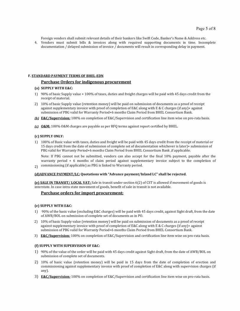
Page 5 of 8
Foreign vendors shall submit relevant details of their bankers like Swift Code, Banker’s Name & Address etc.
4. Vendors must submit bills & invoices along with required supporting documents in time. Incomplete documentation / delayed submission of invoice / documents will result in corresponding delay in payment.
F. STANDARD PAYMENT TERMS OF BHEL-EDN
Purchase Orders for indigenous procurement (a) SUPPLY WITH E&C: 1) 90% of basic Supply value + 100% of taxes, duties and freight charges will be paid with 45 days credit from the
receipt of material.
2) 10% of basic Supply value (retention money) will be paid on submission of documents as a proof of receipt against supplementary invoice with proof of completion of E&C along with E & C charges (if any)+ against
submission of PBG valid for Warranty Period+6 months Claim Period from BHEL Consortium Bank.
(b) E&C/Supervision: 100% on completion of E&C/Supervision and certification line item wise on pro-rata basis.
(c) O&M: 100% O&M charges are payable as per RFQ terms against report certified by BHEL.
(c) SUPPLY ONLY: 1) 100% of Basic value with taxes, duties and freight will be paid with 45 days credit from the receipt of material or
15 days credit from the date of submission of complete set of documentation whichever is later)+ submission of PBG valid for Warranty Period+6 months Claim Period from BHEL Consortium Bank ,if applicable.
Note: If PBG cannot not be submitted, vendors can also accept for the final 10% payment, payable after the
warranty period + 6 months of claim period against supplementary invoice subject to the completion of
commissioning (if applicable) as PBG is linked to Warranty period. 2) (d)ADVANCE PAYMENT/LC: Quotations with “Advance payment/Inland LC” shall be rejected.
(e) SALE IN TRANSIT/ LOCAL VAT: Sale in transit under section 6(2) of CST is allowed if movement of goods is
interstate. In case intra state movement of goods, benefit of sale in transit is not available.
Purchase orders for import procurement:
(e) SUPPLY WITH E&C: 1) 90% of the basic value (excluding E&C charges) will be paid with 45 days credit, against Sight draft, from the date
of AWB/BOL on submission of complete set of documents as in PO.
2) 10% of basic Supply value (retention money) will be paid on submission of documents as a proof of receipt
against supplementary invoice with proof of completion of E&C along with E & C charges (if any)+ against submission of PBG valid for Warranty Period+6 months Claim Period from BHEL Consortium Bank.
3) E&C/Supervision: 100% on completion of E&C/Supervision and certification line item wise on pro-rata basis.
(f) SUPPLY WITH SUPERVISION OF E&C: 1) 90% of the value of the order will be paid with 45 days credit against Sight draft, from the date of AWB/BOL on
submission of complete set of documents.
2) 10% of basic value (retention money) will be paid in 15 days from the date of completion of erection and commissioning against supplementary invoice with proof of completion of E&C along with supervision charges (if
any).
3) E&C/Supervision: 100% on completion of E&C/Supervision and certification line item wise on pro-rata basis.
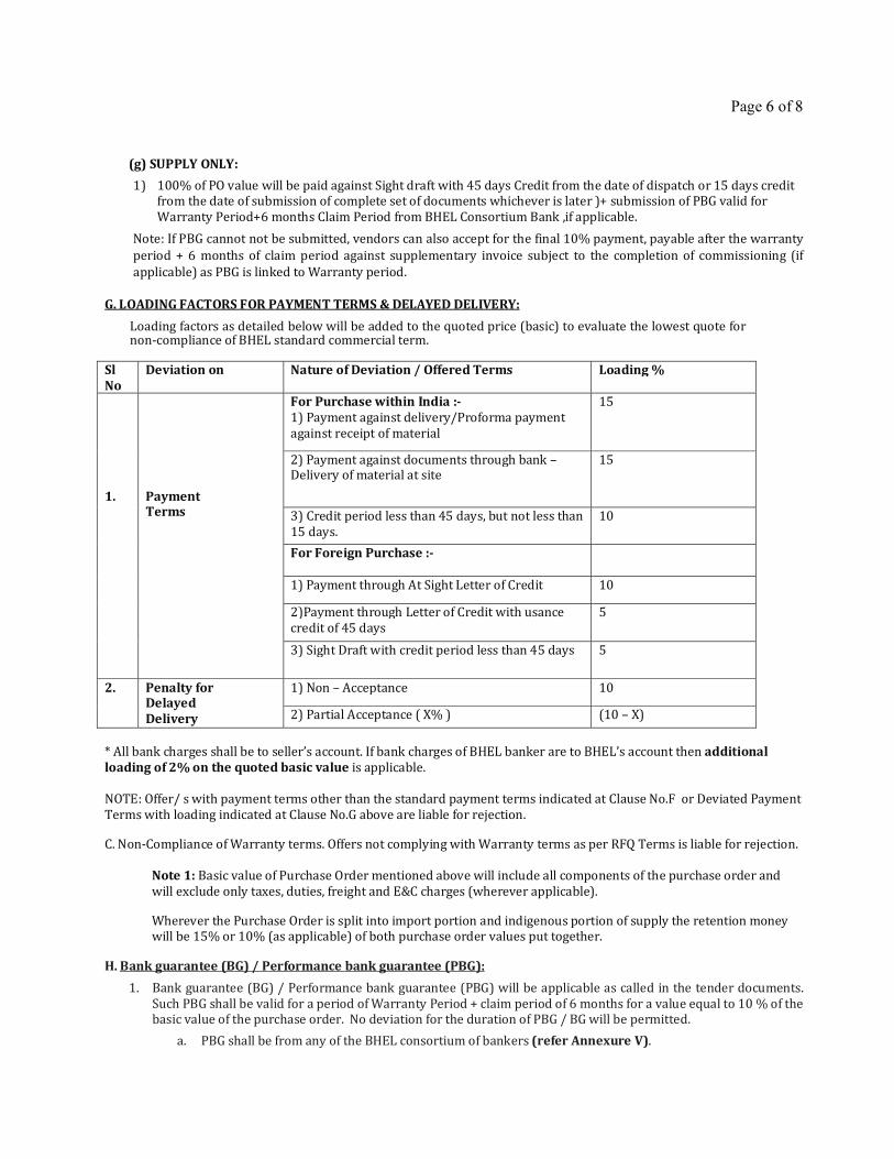
Page 6 of 8
(g) SUPPLY ONLY: 1) 100% of PO value will be paid against Sight draft with 45 days Credit from the date of dispatch or 15 days credit
from the date of submission of complete set of documents whichever is later )+ submission of PBG valid for
Warranty Period+6 months Claim Period from BHEL Consortium Bank ,if applicable.
Note: If PBG cannot not be submitted, vendors can also accept for the final 10% payment, payable after the warranty
period + 6 months of claim period against supplementary invoice subject to the completion of commissioning (if
applicable) as PBG is linked to Warranty period.
G. LOADING FACTORS FOR PAYMENT TERMS & DELAYED DELIVERY:
Loading factors as detailed below will be added to the quoted price (basic) to evaluate the lowest quote for non-compliance of BHEL standard commercial term.
Sl No
Deviation on Nature of Deviation / Offered Terms Loading %
1.
Payment Terms
For Purchase within India :- 1) Payment against delivery/Proforma payment
against receipt of material
15
2) Payment against documents through bank – Delivery of material at site
15
3) Credit period less than 45 days, but not less than
15 days. 10
For Foreign Purchase :-
1) Payment through At Sight Letter of Credit 10
2)Payment through Letter of Credit with usance
credit of 45 days 5
3) Sight Draft with credit period less than 45 days 5
2. Penalty for Delayed Delivery
1) Non – Acceptance 10
2) Partial Acceptance ( X% ) (10 – X) * All bank charges shall be to seller’s account. If bank charges of BHEL banker are to BHEL’s account then additional loading of 2% on the quoted basic value is applicable.
NOTE: Offer/ s with payment terms other than the standard payment terms indicated at Clause No.F or Deviated Payment
Terms with loading indicated at Clause No.G above are liable for rejection.
C. Non-Compliance of Warranty terms. Offers not complying with Warranty terms as per RFQ Terms is liable for rejection.
Note 1: Basic value of Purchase Order mentioned above will include all components of the purchase order and
will exclude only taxes, duties, freight and E&C charges (wherever applicable).
Wherever the Purchase Order is split into import portion and indigenous portion of supply the retention money will be 15% or 10% (as applicable) of both purchase order values put together.
H. Bank guarantee (BG) / Performance bank guarantee (PBG): 1. Bank guarantee (BG) / Performance bank guarantee (PBG) will be applicable as called in the tender documents.
Such PBG shall be valid for a period of Warranty Period + claim period of 6 months for a value equal to 10 % of the basic value of the purchase order. No deviation for the duration of PBG / BG will be permitted.
a. PBG shall be from any of the BHEL consortium of bankers (refer Annexure V).
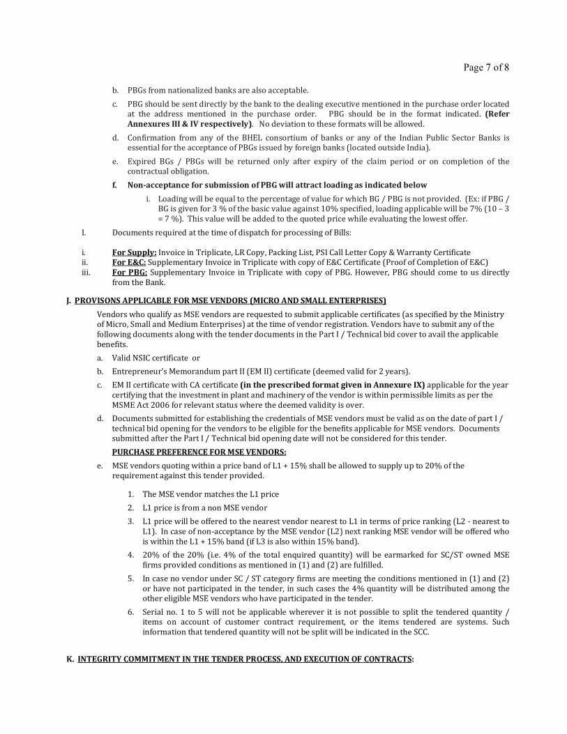
Page 7 of 8
b. PBGs from nationalized banks are also acceptable.
c. PBG should be sent directly by the bank to the dealing executive mentioned in the purchase order located at the address mentioned in the purchase order. PBG should be in the format indicated. (Refer Annexures III & IV respectively). No deviation to these formats will be allowed.
d. Confirmation from any of the BHEL consortium of banks or any of the Indian Public Sector Banks is essential for the acceptance of PBGs issued by foreign banks (located outside India).
e. Expired BGs / PBGs will be returned only after expiry of the claim period or on completion of the contractual obligation.
f. Non-acceptance for submission of PBG will attract loading as indicated below i. Loading will be equal to the percentage of value for which BG / PBG is not provided. (Ex: if PBG /
BG is given for 3 % of the basic value against 10% specified, loading applicable will be 7% (10 – 3
= 7 %). This value will be added to the quoted price while evaluating the lowest offer.
I. Documents required at the time of dispatch for processing of Bills:
i. For Supply: Invoice in Triplicate, LR Copy, Packing List, PSI Call Letter Copy & Warranty Certificate ii. For E&C: Supplementary Invoice in Triplicate with copy of E&C Certificate (Proof of Completion of E&C)
iii. For PBG: Supplementary Invoice in Triplicate with copy of PBG. However, PBG should come to us directly
from the Bank.
J. PROVISONS APPLICABLE FOR MSE VENDORS (MICRO AND SMALL ENTERPRISES) Vendors who qualify as MSE vendors are requested to submit applicable certificates (as specified by the Ministry of Micro, Small and Medium Enterprises) at the time of vendor registration. Vendors have to submit any of the
following documents along with the tender documents in the Part I / Technical bid cover to avail the applicable
benefits.
a. Valid NSIC certificate or
b. Entrepreneur’s Memorandum part II (EM II) certificate (deemed valid for 2 years).
c. EM II certificate with CA certificate (in the prescribed format given in Annexure IX) applicable for the year
certifying that the investment in plant and machinery of the vendor is within permissible limits as per the
MSME Act 2006 for relevant status where the deemed validity is over.
d. Documents submitted for establishing the credentials of MSE vendors must be valid as on the date of part I /
technical bid opening for the vendors to be eligible for the benefits applicable for MSE vendors. Documents submitted after the Part I / Technical bid opening date will not be considered for this tender.
PURCHASE PREFERENCE FOR MSE VENDORS: e. MSE vendors quoting within a price band of L1 + 15% shall be allowed to supply up to 20% of the
requirement against this tender provided.
1. The MSE vendor matches the L1 price
2. L1 price is from a non MSE vendor
3. L1 price will be offered to the nearest vendor nearest to L1 in terms of price ranking (L2 - nearest to
L1). In case of non-acceptance by the MSE vendor (L2) next ranking MSE vendor will be offered who
is within the L1 + 15% band (if L3 is also within 15% band).
4. 20% of the 20% (i.e. 4% of the total enquired quantity) will be earmarked for SC/ST owned MSE
firms provided conditions as mentioned in (1) and (2) are fulfilled.
5. In case no vendor under SC / ST category firms are meeting the conditions mentioned in (1) and (2)
or have not participated in the tender, in such cases the 4% quantity will be distributed among the other eligible MSE vendors who have participated in the tender.
6. Serial no. 1 to 5 will not be applicable wherever it is not possible to split the tendered quantity / items on account of customer contract requirement, or the items tendered are systems. Such
information that tendered quantity will not be split will be indicated in the SCC.
K. INTEGRITY COMMITMENT IN THE TENDER PROCESS, AND EXECUTION OF CONTRACTS:
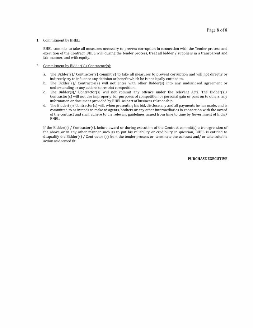
Page 8 of 8
1. Commitment by BHEL:
BHEL commits to take all measures necessary to prevent corruption in connection with the Tender process and
execution of the Contract. BHEL will, during the tender process, treat all bidder / suppliers in a transparent and fair manner, and with equity.
2. Commitment by Bidder(s)/ Contractor(s):
a. The Bidder(s)/ Contractor(s) commit(s) to take all measures to prevent corruption and will not directly or
indirectly try to influence any decision or benefit which he is not legally entitled to. b. The Bidder(s)/ Contractor(s) will not enter with other Bidder(s) into any undisclosed agreement or
understanding or any actions to restrict competition. c. The Bidder(s)/ Contractor(s) will not commit any offence under the relevant Acts. The Bidder(s)/
Contractor(s) will not use improperly, for purposes of competition or personal gain or pass on to others, any
information or document provided by BHEL as part of business relationship.
d. The Bidder(s)/ Contractor(s) will, when presenting his bid, disclose any and all payments he has made, and is
committed to or intends to make to agents, brokers or any other intermediaries in connection with the award of the contract and shall adhere to the relevant guidelines issued from time to time by Government of India/ BHEL.
If the Bidder(s) / Contractor(s), before award or during execution of the Contract commit(s) a transgression of
the above or in any other manner such as to put his reliability or credibility in question, BHEL is entitled to
disqualify the Bidder(s) / Contractor (s) from the tender process or terminate the contract and/ or take suitable action as deemed fit.
PURCHASE EXECUTIVE
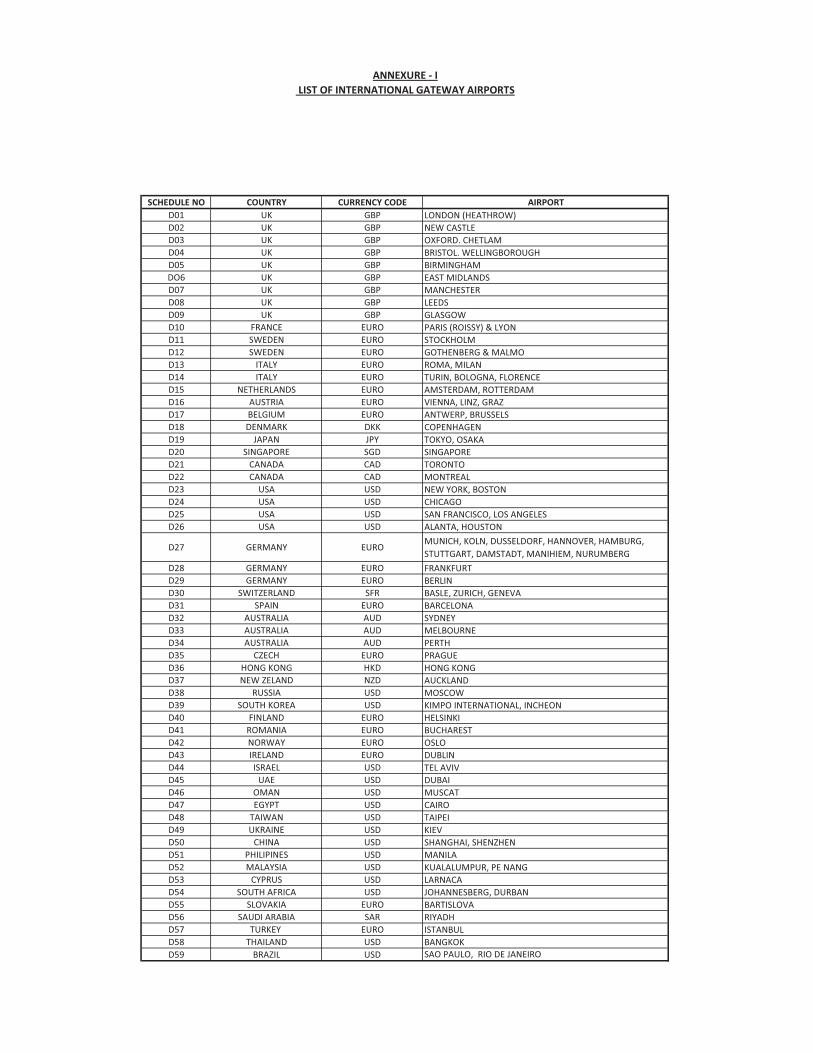
SCHEDULE NO COUNTRY CURRENCY CODE AIRPORTD01 UK GBP LONDON (HEATHROW)D02 UK GBP NEW CASTLED03 UK GBP OXFORD. CHETLAMD04 UK GBP BRISTOL. WELLINGBOROUGHD05 UK GBP BIRMINGHAMDO6 UK GBP EAST MIDLANDSD07 UK GBP MANCHESTERD08 UK GBP LEEDSD09 UK GBP GLASGOWD10 FRANCE EURO PARIS (ROISSY) & LYOND11 SWEDEN EURO STOCKHOLMD12 SWEDEN EURO GOTHENBERG & MALMOD13 ITALY EURO ROMA, MILAND14 ITALY EURO TURIN, BOLOGNA, FLORENCED15 NETHERLANDS EURO AMSTERDAM, ROTTERDAMD16 AUSTRIA EURO VIENNA, LINZ, GRAZD17 BELGIUM EURO ANTWERP, BRUSSELSD18 DENMARK DKK COPENHAGEND19 JAPAN JPY TOKYO, OSAKAD20 SINGAPORE SGD SINGAPORED21 CANADA CAD TORONTOD22 CANADA CAD MONTREALD23 USA USD NEW YORK, BOSTOND24 USA USD CHICAGOD25 USA USD SAN FRANCISCO, LOS ANGELESD26 USA USD ALANTA, HOUSTON
D27 GERMANY EURO MUNICH, KOLN, DUSSELDORF, HANNOVER, HAMBURG, STUTTGART, DAMSTADT, MANIHIEM, NURUMBERG
D28 GERMANY EURO FRANKFURTD29 GERMANY EURO BERLIND30 SWITZERLAND SFR BASLE, ZURICH, GENEVAD31 SPAIN EURO BARCELONAD32 AUSTRALIA AUD SYDNEYD33 AUSTRALIA AUD MELBOURNED34 AUSTRALIA AUD PERTHD35 CZECH EURO PRAGUED36 HONG KONG HKD HONG KONGD37 NEW ZELAND NZD AUCKLANDD38 RUSSIA USD MOSCOWD39 SOUTH KOREA USD KIMPO INTERNATIONAL, INCHEOND40 FINLAND EURO HELSINKID41 ROMANIA EURO BUCHARESTD42 NORWAY EURO OSLOD43 IRELAND EURO DUBLIND44 ISRAEL USD TEL AVIVD45 UAE USD DUBAID46 OMAN USD MUSCATD47 EGYPT USD CAIROD48 TAIWAN USD TAIPEID49 UKRAINE USD KIEVD50 CHINA USD SHANGHAI, SHENZHEND51 PHILIPINES USD MANILAD52 MALAYSIA USD KUALALUMPUR, PE NANGD53 CYPRUS USD LARNACAD54 SOUTH AFRICA USD JOHANNESBERG, DURBAND55 SLOVAKIA EURO BARTISLOVAD56 SAUDI ARABIA SAR RIYADHD57 TURKEY EURO ISTANBULD58 THAILAND USD BANGKOKD59 BRAZIL USD SAO PAULO, RIO DE JANEIRO
ANNEXURE - I
For airbased consignment, terms of delivery will be on FCA basis from following listed airports only. This list is valid from 01.03.2013 to 28.02.2015.Vendors are requested to verify this list for use after 28.02.2015.
LIST OF INTERNATIONAL GATEWAY AIRPORTS
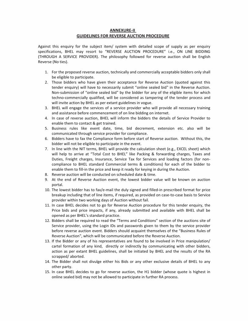
ANNEXURE-III GUIDELINES FOR REVERSE AUCTION PROCEDURE
Against this enquiry for the subject item/ system with detailed scope of supply as per enquiry �������������� ����� !��� ������� ��� "#�$�#%�� '*<=>?@� [#?<�\*#�]� ������ ?@� �>@�� �>\\>@^�(THROUGH A SERVICE PROVIDER). The philosophy followed for reverse auction shall be English Reverse (No ties).
1. For the proposed reverse auction, technically and commercially acceptable bidders only shallbe eligible to participate.
2. Those bidders who have given their acceptance for Reverse Auction (quoted against thistender enquiry) w� ���_������������� ���`{!���"� ������ ���{��|� ������#�_�rse Auction.Non-�`{!��������"� ������ ���{��|�{������{������������������� ���{ �����!�����}����techno-commercially qualified, will be considered as tampering of the tender process andwill invite action by BHEL as per extant guidelines in vogue.
3. BHEL will engage the services of a service provider who will provide all necessary trainingand assistance before commencement of on line bidding on internet.
4. In case of reverse auction, BHEL will inform the bidders the details of Service Provider toenable them to contact & get trained.
5. Business rules like event date, time, bid decrement, extension etc. also will becommunicated through service provider for compliance.
6. Bidders have to fax the Compliance form before start of Reverse auction. Without this, thebidder will not be eligible to participate in the event.
7. In line with the NIT terms, BHEL will provide the calculation sheet (e.g., EXCEL sheet) which}� � �� �� ��� ����_�� ��� "=��� � <���� ��� ����]� ���� [������ �� ��}������ ��������� =����� ��Duties, Freight charges, Insurance, Service Tax for Services and loading factors (for non-compliance to BHEL standard Commercial terms & conditions) for each of the bidder toenable them to fill-in the price and keep it ready for keying in during the Auction.
8. Reverse auction will be conducted on scheduled date & time.9. At the end of Reverse Auction event, the lowest bidder value will be known on auction
portal.10. The lowest bidder has to fax/e-mail the duly signed and filled-in prescribed format for price
breakup including that of line items, if required, as provided on case-to-case basis to Serviceprovider within two working days of Auction without fail.
11. In case BHEL decides not to go for Reverse Auction procedure for this tender enquiry, thePrice bids and price impacts, if any, already submitted and available with BHEL shall beopened a�����������s standard practice.
12. ����������� �{�����`�����������������"=��!�����<�������]���������������`ctions site ofService provider, using the Login IDs and passwords given to them by the service providerbefore reverse auction event. Bidders sho` �����`�������!�� _���������"Business Rules of#�_�����'`����|��}�����}� �{����!!`�������{���������#�_�rse Auction.
13. If the Bidder or any of his representatives are found to be involved in Price manipulation/cartel formation of any kind, directly or indirectly by communicating with other bidders,action as per extant BHEL guidelines, shall be initiated by BHEL and the results of the RAscrapped/ aborted.
14. The Bidder shall not divulge either his Bids or any other exclusive details of BHEL to anyother party.
15. In case BHEL decides to go for reverse auction, the H1 bidder (whose quote is highest inonline sealed bid) may not be allowed to participate in further RA process.
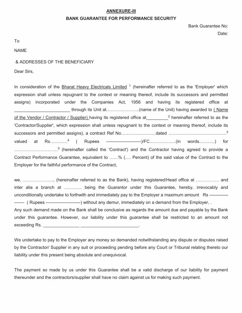
ANNEXURE-IIIBANK GUARANTEE FOR PERFORMANCE SECURITY
Bank Guarantee No:
Date:
To
NAME
& ADDRESSES OF THE BENEFICIARY
Dear Sirs,
In consideration of the Bharat Heavy Electricals Limited 1 (hereinafter referred to as the 'Employer' which
expression shall unless repugnant to the context or meaning thereof, include its successors and permitted
assigns) incorporated under the Companies Act, 1956 and having its registered office at
���������������������������������� ���������������������������� ����������������������( Name
of the Vendor / Contractor / Supplier) having its registered office at_________2 hereinafter referred to as the
'Contractor/Supplier', which expression shall unless repugnant to the context or meaning thereof, include its
successors and permitted assig��������������������������������������������������3
������ ��� ������4 ( Rupees ------------------------��!"���������� ������������ ����
����������5 (hereinafter called the 'Contract') and the Contractor having agreed to provide a
Contract Performance Guarantee, equivalent to ��% ��� Percent) of the said value of the Contract to the
Employer for the faithful performance of the Contract,
we������������������������ ��������� ������ ����#��$��������� ����������%��������������������� and
inter alia �� &������ ��� ����� &eing the Guarantor under this Guarantee, hereby, irrevocably and
unconditionally undertake to forthwith and immediately pay to the Employer a maximum amount Rs -------------
------- ( Rupees ------------------------) without any demur, immediately on a demand from the Employer, .
Any such demand made on the Bank shall be conclusive as regards the amount due and payable by the Bank
under this guarantee. However, our liability under this guarantee shall be restricted to an amount not
exceeding Rs. _______________ ________________________.
We undertake to pay to the Employer any money so demanded notwithstanding any dispute or disputes raised
by the Contractor/ Supplier in any suit or proceeding pending before any Court or Tribunal relating thereto our
liability under this present being absolute and unequivocal.
The payment so made by us under this Guarantee shall be a valid discharge of our liability for payment
thereunder and the contractors/supplier shall have no claim against us for making such payment.
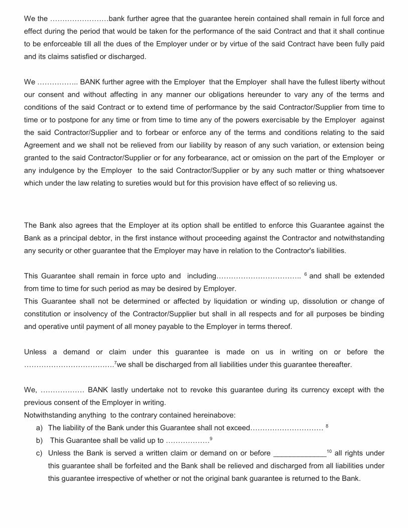
We ������������&��$ further agree that the guarantee herein contained shall remain in full force and
effect during the period that would be taken for the performance of the said Contract and that it shall continue
to be enforceable till all the dues of the Employer under or by virtue of the said Contract have been fully paid
and its claims satisfied or discharged.
We ������� BANK further agree with the Employer that the Employer shall have the fullest liberty without
our consent and without affecting in any manner our obligations hereunder to vary any of the terms and
conditions of the said Contract or to extend time of performance by the said Contractor/Supplier from time to
time or to postpone for any time or from time to time any of the powers exercisable by the Employer against
the said Contractor/Supplier and to forbear or enforce any of the terms and conditions relating to the said
Agreement and we shall not be relieved from our liability by reason of any such variation, or extension being
granted to the said Contractor/Supplier or for any forbearance, act or omission on the part of the Employer or
any indulgence by the Employer to the said Contractor/Supplier or by any such matter or thing whatsoever
which under the law relating to sureties would but for this provision have effect of so relieving us.
The Bank also agrees that the Employer at its option shall be entitled to enforce this Guarantee against the
Bank as a principal debtor, in the first instance without proceeding against the Contractor and notwithstanding
any security or other guarantee that the Employer may have in relation to the Contractor's liabilities.
This Guarantee shall remain in force upto and including������������� 6 and shall be extended
from time to time for such period as may be desired by Employer.
This Guarantee shall not be determined or affected by liquidation or winding up, dissolution or change of
constitution or insolvency of the Contractor/Supplier but shall in all respects and for all purposes be binding
and operative until payment of all money payable to the Employer in terms thereof.
Unless a demand or claim under this guarantee is made on us in writing on or before the
�������������7we shall be discharged from all liabilities under this guarantee thereafter.
'��� ������� #*�+� �����-� ������$�� ���� ��� ����$�� ����� �������� ����� ���� ������-� �2��4�� ����� ����
previous consent of the Employer in writing.
Notwithstanding anything to the contrary contained hereinabove:
a) The liability of the Bank under this Guara����������������2���������������8
b) 5����6��������������&��������4����������9
c) Unless the Bank is served a written claim or demand on or before _____________10 all rights under
this guarantee shall be forfeited and the Bank shall be relieved and discharged from all liabilities under
this guarantee irrespective of whether or not the original bank guarantee is returned to the Bank.

We, _____________ Bank, have power to issue this Guarantee under law and the undersigned as a duly
authorized person has full powers to sign this Guarantee on behalf of the Bank.
For and on behalf of
(Name of the Bank)
8�����������
9��������:����������
1 NAME AND ADDRESS OF EMPLOYER I.e Bharat Heavy Electricals Limited
2 NAME AND ADDRESS OF THE VENDOR /CONTRACTOR / SUPPLIER.
3 DETAILS ABOUT THE NOTICE OF AWARD/CONTRACT REFERENCE
4 PROJECT/SUPPLY DETAILS
5 BG AMOUNT IN FIGURES AND WORDS
6 VALIDITY DATE
7 DATE OF EXPIRY OF CLAIM PERIOD
8 BG AMOUNT IN FIGURES AND WORDS.
9 VALIDITY DATE
10 DATE OF EXPIRY OF CLAIM PERIOD
Note: 1. Units are advised that expiry of claim period may be kept 3 months after validity date.
2. In Case of Bank Guarantees submitted by Foreign Vendors- a. From Nationalized/Public Sector / Private Sector/ Foreign Banks (BG issued by Branches in
India) can be accepted subject to the condition that the Bank Guarantee should be enforceable in the town/city or at nearest branch where the Unit is located i.e. Demand can be presented at the Branch located in the town/city or at nearest branch where the Unit is located.
b. From Foreign Banks (wherein Foreign Vendors intend to provide BG from local branch of the ������������ �������
b.1 In such cases, in the Tender Enquiry/ Contract itself, it may be clearly specified that Bank Guarantee issued by any of the Consortium Banks only will be accepted by BHEL. As such, Foreign Vendor needs to make necessary arrangements for issuance of Counter- Guarantee by Foreign Bank in �������������:������#��$��#%;<=��"���������#��k). It is advisable that all charges for issuance of Bank Guarantee/ counter- Guarantee should be borne by the Foreign Vendor. The tender stipulation should clearly specify these requirements.
b.2 In case, Foreign Vendors intend to provide BG from Overseas Branch of our Consortium Bank (e.g. if a BG is to be issued by SBI Frankfurt), the same is acceptable. However, the procedure at sl.no. b.1 will required to be followed.
b.3 The BG issued may preferably be subject to Uniform Rules for Demand Guarantees (URDG) 758 (as amended from time to time). In case, of Foreign Vendors, the BG Format provided to them should clearly specify the same.
b.4 The BG should clearly specify that the demand or other document can be presented in electronic form.
ANNEXURE- IV
FRAUD PREVENTION POLICY:
The bidder along with its associate/collaborators/sub-contractors/ sub-vendors/ consultants/ service providers shall strictly adhere to BHEL Fraud Prevention Policy displayed on BHEL website http://www.bhel.com and shall immediately bring to the notice of BHEL Management about any fraud or suspected fraud as soon as it comes to their notice. Fraud Prevention policy and List of Nodal Officers shall be hosted on BHEL website, vendor portals of Units/regions intranet.
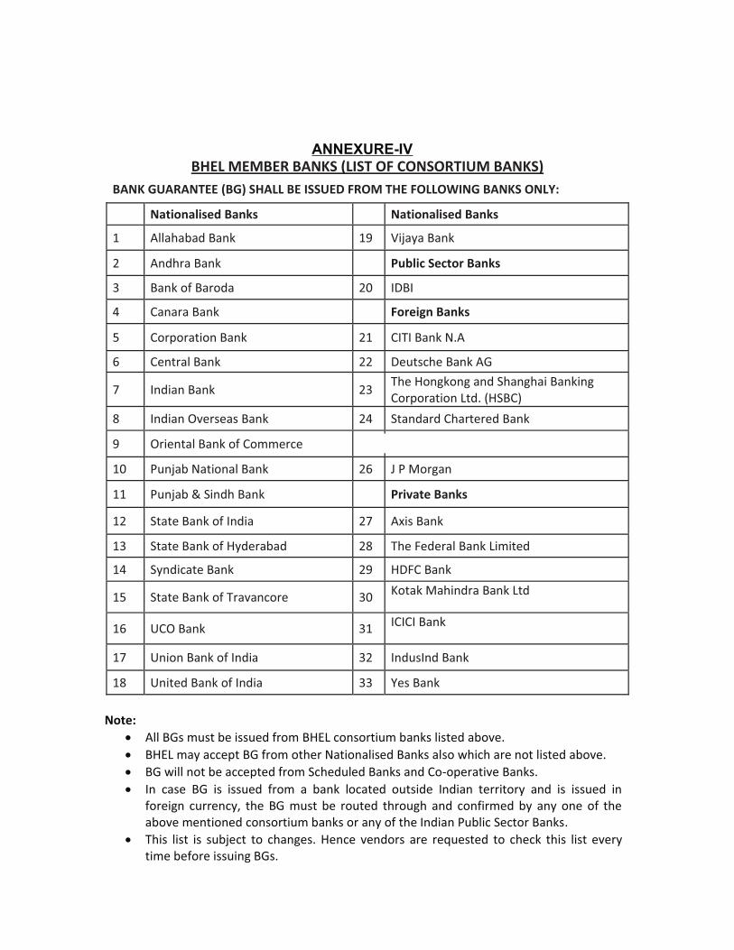
Annexure-VI
BHEL MEMBER BANKS (LIST OF CONSORTIUM BANKS) BANK GUARANTEE (BG) SHALL BE ISSUED FROM THE FOLLOWING BANKS ONLY:
Nationalised Banks Nationalised Banks
1 Allahabad Bank 19 Vijaya Bank
2 Andhra Bank Public Sector Banks
3 Bank of Baroda 20 IDBI
4 Canara Bank Foreign Banks
5 Corporation Bank 21 CITI Bank N.A
6 Central Bank 22 Deutsche Bank AG
7 Indian Bank 23 The Hongkong and Shanghai Banking Corporation Ltd. (HSBC)
8 Indian Overseas Bank 24 Standard Chartered Bank
9 Oriental Bank of Commerce 25 The Royal Bank of Scotland N.V.
10 Punjab National Bank 26 J P Morgan
11 Punjab & Sindh Bank Private Banks
12 State Bank of India 27 Axis Bank
13 State Bank of Hyderabad 28 The Federal Bank Limited
14 Syndicate Bank 29 HDFC Bank
15 State Bank of Travancore 30 Kotak Mahindra Bank Ltd
16 UCO Bank 31 ICICI Bank
17 Union Bank of India 32 IndusInd Bank
18 United Bank of India 33 Yes Bank
Note: � All BGs must be issued from BHEL consortium banks listed above.� BHEL may accept BG from other Nationalised Banks also which are not listed above.� BG will not be accepted from Scheduled Banks and Co-operative Banks.� In case BG is issued from a bank located outside Indian territory and is issued in
foreign currency, the BG must be routed through and confirmed by any one of theabove mentioned consortium banks or any of the Indian Public Sector Banks.
� This list is subject to changes. Hence vendors are requested to check this list everytime before issuing BGs.
ANNEXURE-IV
ANNEXURE � VI
DISCREPANCY IN WORDS & FIGURES � QUOTED IN PRICE BID
Following guidelines will be followed in case of discrepancy in words & figures-quoted in price bid:
(a) If, in the price structure quoted for the required goods/services/works, there is
discrepancybetween the unit price and the total price (which is obtained by multiplying the unit
price by thequantity), the unit price shall prevail and the total price corrected accordingly, unless
in theopinion of the purchaser there is an obvious misplacement of the decimal point in the unit
price,in which case the total price as quoted shall govern and the unit price corrected accordingly.
(b) If there is an error in a total corresponding to the addition or subtraction of subtotals, the subtotals
shall prevail and the total shall be corrected; and
(c) If there is a discrepancy between words and figures, the amount in words shall prevail, unless the
amount expressed in words is related to an arithmetic error, in which case the amount in figures
shall prevail subject to (a) and (b) above.
(d) If there is such discrepancy in an offer, the same shall be conveyed to the bidder with target date
upto which the bidder has to send his acceptance on the above lines and if the bidder does not
agree to the decision of the purchaser, the bid is liable to be ignored.
ANNEXURE � VII BENEFITS FOR MSE SUPPLIERS AS PER MSMED ACT 2006 AND PUBLIC PROCUREMENT POLICY 2012 MSE suppliers can avail the intended benefits only if they submit along with the offer, attested
copies of either EM II certificate having deemed validity (five years from the date of issue of
Acknowledgement in EM II).
Or
Valid NSIC certificate or EM II certificate along with attested copy of CA certificate (Format enclosed:
ANNEXURE VIII) where deemed validity of EM II certificate of five years has expired) applicable for the
relevant financial year (latest audited).
Date to be reckoned for determining the deemed validity will be the date of bid opening (Part 1 in case of
two part bid).
Non-submission of such documents will lead to consideration of their bid at par with other bidders.
No benefit shall be applicable for this enquiry if any deficiency in the above required documents are not
submitted before price bid opening. If the tender is to be submitted through e-procurement portal, then the
above required documents are to be uploaded on the portal. Documents should be notarized or attested by
a Gazette officer.
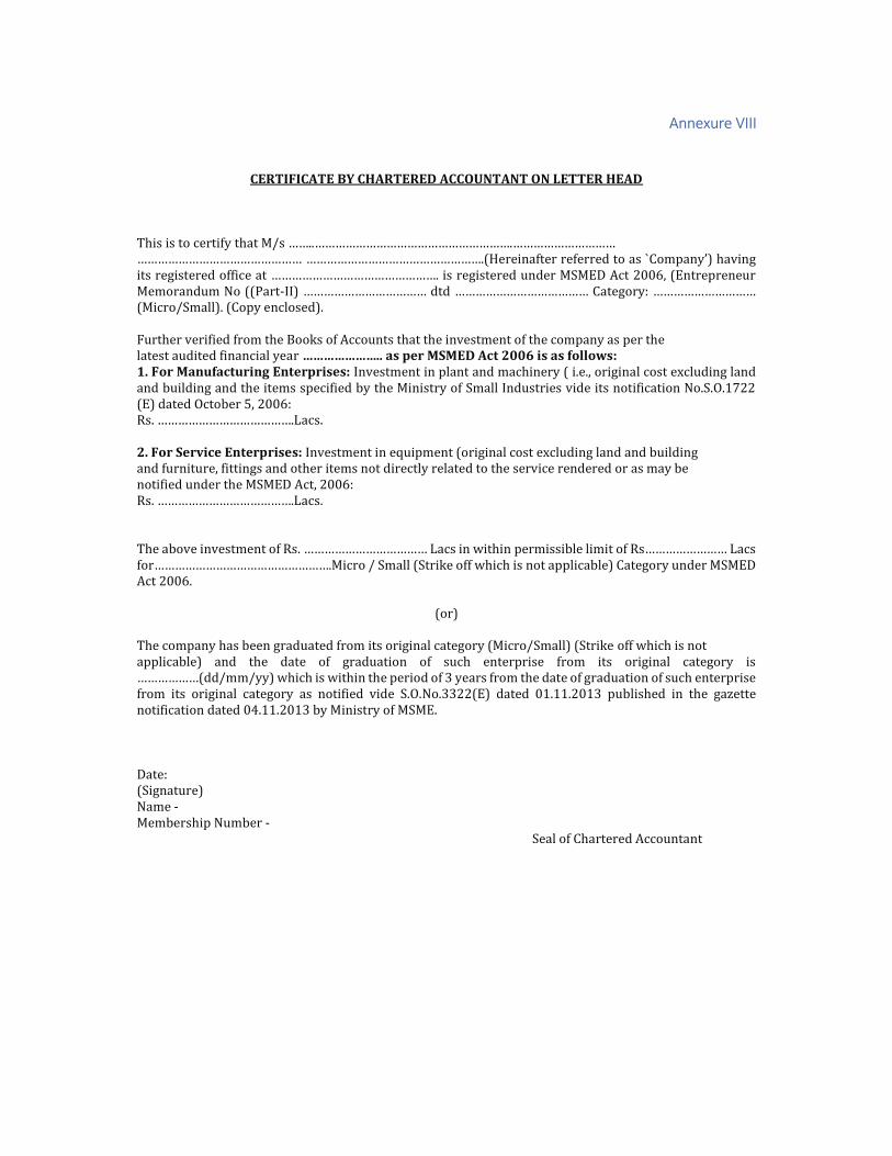
Annexure VIII
CERTIFICATE BY CHARTERED ACCOUNTANT ON LETTER HEAD
�������������� ���������������������������������������������
������������������������������������������� ������ ����������������������������
��������������� ��������������������������������������!������#�$<�>��?JJZ[��$���������!��
Memorandum No ((Part-\\����������������������������������������]������������
(Micro/Small). (Copy enclosed).
Further verified from the Books of Accounts that the investment of the company as per the
latest audited financial year ������������������ ������������������������� 1. For Manufacturing Enterprises: Investment in plant and machinery ( i.e., original cost excluding land
and building and the items specified by the Ministry of Small Industries vide its notification No.S.O.1722
(E) dated October 5, 2006:
^�����������������`���
2. For Service Enterprises: Investment in equipment (original cost excluding land and building
and furniture, fittings and other items not directly related to the service rendered or as may be
notified under the MSMED Act, 2006:
^�����������������`���
The above investment of Rs���������������`������{��������������|}��}����� �^����������`���
�������������������������#��}}��#���~�� �{�������������}��|}�����������!������#�$<�
Act 2006.
(or)
The company has been graduated from its original category (Micro/Small) (Strike off which is not
applicable) and the date of graduation of such enterprise from its original category is
�����������������{�������{���������������� ��������� ������������ �����!����� ��!�������������
from its original category as notified vide S.O.No.3322(E) dated 01.11.2013 published in the gazette
notification dated 04.11.2013 by Ministry of MSME.
Date:
(Signature)
Name -
Membership Number -
Seal of Chartered Accountant

AAnnexure IX
PURCHASE PREFERENCE FOR MSE VENDORS:
MSE vendors quoting within a price band of L1 + 15% shall be allowed to supply up to 20% of the
requirement against this tender provided
1. The MSE vendor matches the L1 price
2. L1 price is from a non MSE vendor
3. L1 price will be offered to the nearest vendor nearest to L1 in terms of price ranking (L2 � nearest to L1).
In case of non-acceptance by the MSE vendor (L2) next ranking vendor will be offered who is within the L1
+ 15% band (if L3 is also within 15% band).
4. 20% of the 20% (i.e. 4% of the total enquired quantity) will be earmarked for SC/ST owned MSE firms
provided conditions as mentioned in (1) and (2) are fulfilled.

AANNEXURE-X
REQUEST FOR C FORM
NAME OF VENDOR :
VENDOR CODE ALLOTED BY BHEL :
E mail id for c form correspondence :
BHEL
PO NO
INVOICE
NO
INVOICE
DATE
INVOICE
AMOUNT
SUPPLY
FROM -
STATE
SUPPLY
TO -
STATE
CST TIN
NUMBER
(SUPPLIER
)
INVOICE
AMOUNT
EXCLUDING
FREIGHT
C FORM
QTR
YEAR SUPPLY
TO BHEL
EDN / SITE
Please ���������������� ���{�}}�|�����!��� �����!������
Any modification and cancellation of c form is not possible from our end since it is generated online
therefore include all invoices pertaining to quarter in your request
Also check the data are correct in all respect
General Instruction:
1. C form request should be given only in this file.
2. Amount should be 100% of Invoice value but should Not include freight, Insurance etc.
3. PO No. should be numeric, starting with 4 and has 10 digits
4. For every quarter separate file to be provided
5. All Invoices pertaining to the relevant quarter to be included.
6. No corrections will be entertained once c-form is issued.

ANNEXUR- XI
Please Fill up the form in CAPITAL LETTERS only.TYPE OF REQUEST(Tick one): ________ CREATE ________ CHANGE
BHEL Vendor / Supplier Code: Company Name :Permanent Account Number(PAN):Address
City: _____________________ PINCODE ___________ STATE _____________
Contact Person(s)Telephone No:Fax No:e-mail id:
1 Bank Name:2 Bank Address:
3 Bank Telephone No:4 Bank Account No:5 Account Type: Savings/Cash Credit6 9 Digit Code Number of Bank and branch
appearing on MICR cheque issued by Bank7 Bank swift Code(applicable for EFT only)8 Bank IFSC code(applicable for RTGS)9 Bank IFSC code(applicable for NEFT)
A I hereby certify that the particulars given above are true, correct and complete andthat I, as a representative for the above named Company, hereby authorise BHEL, EDN,Bangalore to electronically deposit payments to the designated bank account.
B If the transaction is delayed or not effected at all for reasons of incomplete or incorrectinformation, I would not hold BHEL / transfering Bank responsible.
C This authority remains in full force until BHEL, EDN,Bangalore receives written notificationrequesting a change or cancellation.
D I have read the contents of the covering letter and agree to discharge the resposibility expected of me as a participant under ECS / EFT.
Date:
Authorised Signatory:Designation: Telephone NO. with STD Code
Company Seal
We certify that____________________has an Account No_____________________ with us andwe confirm that the bank details given above are correct as per our records.
Date: (……………………………...)Place:Please return completed form along with a blank cancelled cheque or photocopy thereof to:Bharath Heavy Electricals Ltd,Attn:Electronics Division, Mysore Road,BANGALORE - 560 026In case of any Querry, please call : 080-26998xxx / 2674xxxx or fax no. 080-2674xxxx
Electronic Funds Transfer (EFT) ORPaylink Direct Credit Form
Bank Certificate
Signature
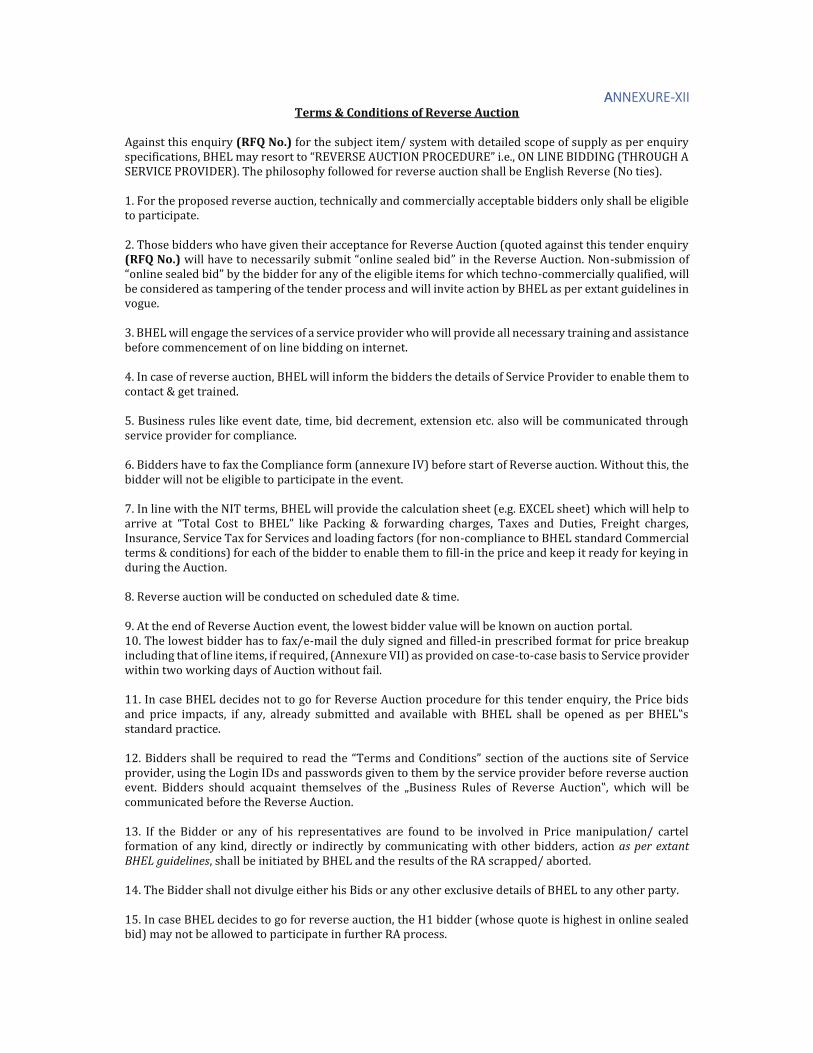
AANNEXURE-XII Terms & Conditions of Reverse Auction
Against this enquiry (RFQ No.) for the subject item/ system with detailed scope of supply as per enquiry
���� ������[���$`��������������^$�$^#$�>���\����^��$<�^$������[����`\�$��\<<\������^�����>�
SERVICE PROVIDER). The philosophy followed for reverse auction shall be English Reverse (No ties).
1. For the proposed reverse auction, technically and commercially acceptable bidders only shall be eligible
to participate.
2. Those bidders who have given their acceptance for Reverse Auction (quoted against this tender enquiry
(RFQ No.) {�}}����������������}���!|������}�������}���|�����������^�������>!�������-submission of
��}�������}���|����|������|������ ������ ������}���|}�������� ��{��������-commercially qualified, will
be considered as tampering of the tender process and will invite action by BHEL as per extant guidelines in
vogue.
3. BHEL will engage the services of a service provider who will provide all necessary training and assistance
before commencement of on line bidding on internet.
4. In case of reverse auction, BHEL will inform the bidders the details of Service Provider to enable them to
contact & get trained.
5. Business rules like event date, time, bid decrement, extension etc. also will be communicated through
service provider for compliance.
6. Bidders have to fax the Compliance form (annexure IV) before start of Reverse auction. Without this, the
bidder will not be eligible to participate in the event.
7. In line with the NIT terms, BHEL will provide the calculation sheet (e.g. EXCEL sheet) which will help to
������� ��� ����}� ���� �� ��$`�� }�~�� ��~���� �� �{������� ������[� ������ ���� <!����[� �������� ������[�
Insurance, Service Tax for Services and loading factors (for non-compliance to BHEL standard Commercial
terms & conditions) for each of the bidder to enable them to fill-in the price and keep it ready for keying in
during the Auction.
8. Reverse auction will be conducted on scheduled date & time.
9. At the end of Reverse Auction event, the lowest bidder value will be known on auction portal.
10. The lowest bidder has to fax/e-mail the duly signed and filled-in prescribed format for price breakup
including that of line items, if required, (Annexure VII) as provided on case-to-case basis to Service provider
within two working days of Auction without fail.
11. In case BHEL decides not to go for Reverse Auction procedure for this tender enquiry, the Price bids
���� ����� ������[� � � ���[� �}������ �!|������� ���� ����}�|}�� {���� ��$`� ���}}� |�� ������ ��� ���� ��$`���
standard practice.
12. Bidd�������}}�|�����!������������������������������������������� ������!���������� �#������
provider, using the Login IDs and passwords given to them by the service provider before reverse auction
������� �������� ��!}�� ��!����� ������}���� � ���� ��!������� ^!}��� � ^������� >!����[� {���� {�}}� |��
communicated before the Reverse Auction.
13. If the Bidder or any of his representatives are found to be involved in Price manipulation/ cartel
formation of any kind, directly or indirectly by communicating with other bidders, action as per extant BHEL guidelines, shall be initiated by BHEL and the results of the RA scrapped/ aborted.
14. The Bidder shall not divulge either his Bids or any other exclusive details of BHEL to any other party.
15. In case BHEL decides to go for reverse auction, the H1 bidder (whose quote is highest in online sealed
bid) may not be allowed to participate in further RA process.

ANNEXURE-XIII
Region State
Nodal Unit responsible for all other units
except those in column 4
Contact Details- Landline No. E-mail TIN No. CST No.
1 2 3 7 8 9Jammu & Kashmir PSNR 01291101313Himachal Pradesh PSNR 02011000622
Punjab PSNR 03451148722Haryana PSNR 06962606884
Rajasthan PSNR 08232903345
Uttar Pradesh PSNR 0120-2416536 [email protected] / [email protected] 09365800914
Uttarakhand Hardwar 01334-285449 [email protected] 05001757277 Dated 30th Sep 2005
5000030 Dated 13/03/1965
Delhi TBG 0120-6748429 [email protected] 07472001760 07472001760
Madhya Pradesh Bhopal 0755-2503231 [email protected] 23573600001 (HEL/05/01/0001/S dated 15/11/1979 under MPCT)
HEL/05/01/0004/C dated 15/11/1979
Chattisgarh PSWR 0712-3048609 [email protected] 22173202974
Gujarat PSWR 0265-2370321 [email protected] 24190101571
Maharashtra ROD Mumbai 022-22126061/22187850 [email protected] 27060300130V 27060300130C
Daman & Diu EDN 080-26998724 / 26998830 [email protected] 25000009902
Orissa PSSR 044-28286773 [email protected] , [email protected] 21031301916
Tamil Nadu Trichy 0431-2577757/ 2577229
[email protected] /[email protected] 33243560005 239383 dt.11.6.91
Kerala PSSR 044-28286773 [email protected] 32072043622
Karnataka EDN 080-26998724 / 26998830 [email protected] 29180069268 00850081
Telangana HPEP RC, Puram 040-23185406/ 040-23182238
[email protected] [email protected] 36360151179
Andhra Pradesh HPVP, Vizag 0891-6681298 [email protected] �����������
Puducherry PSSR
West Bengal PSER 033-23216130-3238 [email protected] 19200936019 19200936213
Bihar PSER 0612-2231275 [email protected] 10010994046 10010994046
Jharkhand PSER
06549-266351(Sh. Parmanand Swaroop)/06534-292179 (Sh. K.K.Ajeet)
[email protected] (Bokaro) [email protected]
(Koderma/Abhijeet/North Karanpura)
[email protected] (Chandrapura)/kpsubbu@bhelp
ser.co.in [email protected]
20352205642 (Bokaro) 20082005255 (Maithon) 20512405410 (Koderma)
20122200394 (Chandrapura) 20620905730(Adhunik) 20650507026(Abhijeet)
20452110016 (North Karanpura)
TG-729(C)
Mizoram PSER 033-23216130-3249 [email protected] 15501465017
Arunachal Pradesh PSER 033-23216130-3249 [email protected] 12020122182 Not Applied
Assam PSER 033-23216130-3249 [email protected] 18790101415 18179903204Tripura PSER 03821-265209 [email protected] 16060947071 16060947273Sikkim PSER
Meghalaya PSER
Manipur PSER
Nagaland PSER
Since PSER presently does not have any operations in these States, the requisite Formats/Instructions not yet
issued by PSER. However in case any Units have any VAT transaction, then please contact Sr DGM (F) PSERSince PSER presently does not have any operations in these States, the requisite Formats/Instructions not yet
Since PSSR presently does not have any operations in this State, the requisite Formats/Instructions not yetissued by PSSR. However in case any Units have any VAT transaction, then please contact AGM (F) PSSR
In case of intrastate movement i.e. supply within same state and VAT is applicable, the vendor shall furnish the respective BHEL’s nodal agency TIN no. and address in their invoice. (Refer Annexure IX)
List of Statewise Nodal Officers with Contact Details
Nor
ther
Sta
tes
Wes
tern
Sta
tes
Sout
hern
Sta
tes
East
ern
Stat
es
Since PSER presently does not have any operations in this State, the requisite Formats/Instructions not yet
0120-2510488/2416452
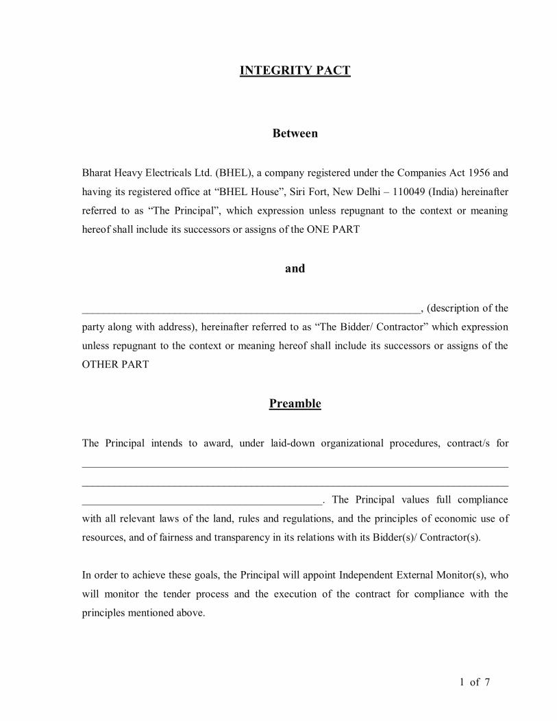
of 7 1
INTEGRITY PACT
Between
Bharat Heavy Electricals Ltd. (BHEL), a company registered under the Companies Act 1956 and
having its registered office at “BHEL House”, Siri Fort, New Delhi – 110049 (India) hereinafter
referred to as “The Principal”, which expression unless repugnant to the context or meaning
hereof shall include its successors or assigns of the ONE PART
and
______________________________________________________________, (description of the
party along with address), hereinafter referred to as “The Bidder/ Contractor” which expression
unless repugnant to the context or meaning hereof shall include its successors or assigns of the
OTHER PART
Preamble
The Principal intends to award, under laid-down organizational procedures, contract/s for
______________________________________________________________________________
______________________________________________________________________________
____________________________________________. The Principal values full compliance
with all relevant laws of the land, rules and regulations, and the principles of economic use of
resources, and of fairness and transparency in its relations with its Bidder(s)/ Contractor(s).
In order to achieve these goals, the Principal will appoint Independent External Monitor(s), who
will monitor the tender process and the execution of the contract for compliance with the
principles mentioned above.
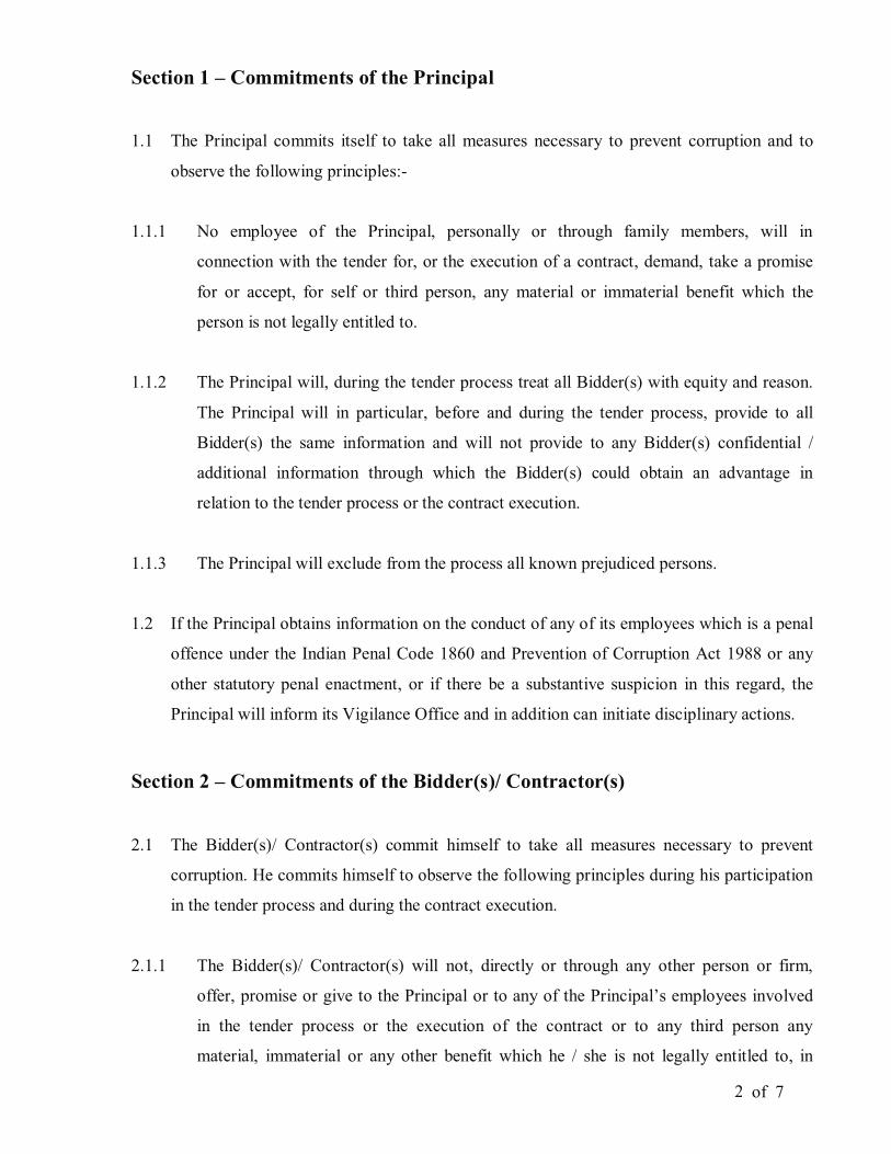
of 7 2
Section 1 – Commitments of the Principal
1.1 The Principal commits itself to take all measures necessary to prevent corruption and to
observe the following principles:-
1.1.1 No employee of the Principal, personally or through family members, will in
connection with the tender for, or the execution of a contract, demand, take a promise
for or accept, for self or third person, any material or immaterial benefit which the
person is not legally entitled to.
1.1.2 The Principal will, during the tender process treat all Bidder(s) with equity and reason.
The Principal will in particular, before and during the tender process, provide to all
Bidder(s) the same information and will not provide to any Bidder(s) confidential /
additional information through which the Bidder(s) could obtain an advantage in
relation to the tender process or the contract execution.
1.1.3 The Principal will exclude from the process all known prejudiced persons.
1.2 If the Principal obtains information on the conduct of any of its employees which is a penal
offence under the Indian Penal Code 1860 and Prevention of Corruption Act 1988 or any
other statutory penal enactment, or if there be a substantive suspicion in this regard, the
Principal will inform its Vigilance Office and in addition can initiate disciplinary actions.
Section 2 – Commitments of the Bidder(s)/ Contractor(s)
2.1 The Bidder(s)/ Contractor(s) commit himself to take all measures necessary to prevent
corruption. He commits himself to observe the following principles during his participation
in the tender process and during the contract execution.
2.1.1 The Bidder(s)/ Contractor(s) will not, directly or through any other person or firm,
offer, promise or give to the Principal or to any of the Principal’s employees involved
in the tender process or the execution of the contract or to any third person any
material, immaterial or any other benefit which he / she is not legally entitled to, in
of 7 3
order to obtain in exchange any advantage of any kind whatsoever during the tender
process or during the execution of the contract.
2.1.2 The Bidder(s)/ Contractor(s) will not enter with other Bidder(s) into any illegal or
undisclosed agreement or understanding, whether formal or informal. This applies in
particular to prices, specifications, certifications, subsidiary contracts, submission or
non-submission of bids or any other actions to restrict competitiveness or to introduce
cartelization in the bidding process.
2.1.3 The Bidder(s)/ Contractor(s) will not commit any penal offence under the relevant IPC/
PC Act; further the Bidder(s)/ Contractor(s) will not use improperly, for purposes of
competition or personal gain, or pass on to others, any information or document
provided by the Principal as part of the business relationship, regarding plans, technical
proposals and business details, including information contained or transmitted
electronically.
2.1.4 The Bidder(s)/ Contractor(s) will, when presenting his bid, disclose any and all
payments he has made, and is committed to or intends to make to agents, brokers or any
other intermediaries in connection with the award of the contract.
2.2 The Bidder(s)/ Contractor(s) will not instigate third persons to commit offences outlined
above or be an accessory to such offences.
Section 3 – Disqualification from tender process and exclusion from future
contracts
If the Bidder(s)/ Contractor(s), before award or during execution has committed a transgression
through a violation of Section 2 above, or acts in any other manner such as to put his reliability
or credibility in question, the Principal is entitled to disqualify the Bidders(s)/ Contractor(s) from
the tender process or take action as per the separate “Guidelines for Suspension of Business
Dealings with Suppliers/ Contractors” framed by the Principal.
of 7 4
Section 4 – Compensation for Damages
4.1 If the Principal has disqualified the Bidder(s) from the tender process prior to the award
according to Section 3, the Principal is entitled to demand and recover the damages
equivalent to Earnest Money Deposit/ Bid Security.
4.2 If the Principal has terminated the contract according to Section 3, or if the Principal is
entitled to terminate the contract according to section 3, the Principal shall be entitled to
demand and recover from the Contractor liquidated damages equivalent to 5% of the
contract value or the amount equivalent to Security Deposit/Performance Bank Guarantee,
whichever is higher.
Section 5 – Previous Transgression
5.1 The Bidder declares that no previous transgressions occurred in the last 3 years with any
other company in any country conforming to the anti-corruption approach or with any other
Public Sector Enterprise in India that could justify his exclusion from the tender process.
5.2 If the Bidder makes incorrect statement on this subject, he can be disqualified from the
tender process or the contract, if already awarded, can be terminated for such reason.
Section 6 – Equal treatment of all Bidders/ Contractors/ Sub-contractors
6.1 The Bidder(s)/ Contractor(s) undertake(s) to demand from his sub-contractors a
commitment consistent with this Integrity Pact. This commitment shall be taken only from
those sub-contractors whose contract value is more than 20% of Bidder’s/ Contractor’s
contract value with the Principal.
6.2 The Principal will enter into agreements with identical conditions as this one with all
Bidders and Contractors.
6.3 The Principal will disqualify from the tender process all bidders who do not sign this pact
or violate its provisions.

of 7 5
Section 7 – Criminal Charges against violating Bidders/ Contractors /Sub-
contractors
If the Principal obtains knowledge of conduct of a Bidder, Contractor or Subcontractor, or of an
employee or a representative or an associate of a Bidder, Contractor or Subcontractor which
constitutes corruption, or if the Principal has substantive suspicion in this regard, the Principal
will inform the Vigilance Office.
Section 8 –Independent External Monitor(s)
8.1 The Principal appoints competent and credible Independent External Monitor for this Pact.
The task of the Monitor is to review independently and objectively, whether and to what
extent the parties comply with the obligations under this agreement.
8.2 The Monitor is not subject to instructions by the representatives of the parties and performs
his functions neutrally and independently. He reports to the CMD, BHEL.
8.3 The Bidder(s)/ Contractor(s) accepts that the Monitor has the right to access without
restriction to all contract documentation of the Principal including that provided by the
Bidder(s)/ Contractor(s). The Bidder(s)/ Contractor(s) will grant the monitor, upon his
request and demonstration of a valid interest, unrestricted and unconditional access to his
contract documentation. The same is applicable to Sub-contractor(s). The Monitor is under
contractual obligation to treat the information and documents of the Bidder(s)/
Contractor(s) / Sub-contractor(s) with confidentiality.
8.4 The Principal will provide to the Monitor sufficient information about all meetings among
the parties related to the contract provided such meetings could have an impact on the
contractual relations between the Principal and the Contractor. The parties offer to the
Monitor the option to participate in such meetings.
8.5 As soon as the Monitor notices, or believes to notice, a violation of this agreement, he will
so inform the Management of the Principal and request the Management to discontinue or
of 7 6
take corrective action, or heal the situation, or to take other relevant action. The Monitor
can in this regard submit non-binding recommendations. Beyond this, the Monitor has no
right to demand from the parties that they act in a specific manner, refrain from action or
tolerate action.
8.6 The Monitor will submit a written report to the CMD, BHEL within 8 to 10 weeks from the
date of reference or intimation to him by the Principal and, should the occasion arise,
submit proposals for correcting problematic situations.
8.7 The CMD, BHEL shall decide the compensation to be paid to the Monitor and its terms and
conditions.
8.8 If the Monitor has reported to the CMD, BHEL, a substantiated suspicion of an offence
under relevant IPC / PC Act, and the CMD, BHEL has not, within reasonable time, taken
visible action to proceed against such offence or reported it to the Vigilance Office, the
Monitor may also transmit this information directly to the Central Vigilance
Commissioner, Government of India.
8.9 The number of Independent External Monitor(s) shall be decided by the CMD, BHEL.
8.10 The word ‘Monitor’ would include both singular and plural.
Section 9 – Pact Duration
9.1 This Pact begins when both parties have legally signed it. It expires for the Contractor 12
months after the last payment under the respective contract and for all other Bidders 6
months after the contract has been awarded.
9.2 If any claim is made / lodged during this time, the same shall be binding and continue to be
valid despite the lapse of this pact as specified as above, unless it is discharged/ determined
by the CMD, BHEL.
of 7 7
Section 10 – Other Provisions
10.1 This agreement is subject to Indian Laws and jurisdiction shall be registered office of the
Principal, i.e. New Delhi.
10.2 Changes and supplements as well as termination notices need to be made in writing. Side
agreements have not been made.
10.3 If the Contractor is a partnership or a consortium, this agreement must be signed by all
partners or consortium members.
10.4 Should one or several provisions of this agreement turn out to be invalid, the remainder of
this agreement remains valid. In this case, the parties will strive to come to an agreement to
their original intentions.
10.5 Only those bidders/ contractors who have entered into this agreement with the Principal
would be competent to participate in the bidding. In other words, entering into this
agreement would be a preliminary qualification.
------------------------------------ -----------------------------------
For & On behalf of the Principal For & On behalf of the Bidder/ Contractor
(Office Seal) (Office Seal)
Place----------------------
Date-----------------------
Witness: ____________________ Witness: _______________________
(Name & Address) ____________ (Name & Address)________________
____________________________ _______________________________