
Protective Films on Molten Magnesium - NTNU Open
192
Protective Films on Molten Magnesium Kari Aarstad May 2004 Thesis submitted in partial fulfilment of the requirements for the degree Doktor Ingeniør Norwegian University of Science and Technology Department of Materials Technology
-
Upload
khangminh22 -
Category
Documents
-
view
3 -
download
0
Transcript of Protective Films on Molten Magnesium - NTNU Open

Protective Films on Molten Magnesium
Kari Aarstad
May 2004
Thesis submitted in partial fulfilment of the requirements for the degree Doktor Ingeniør
Norwegian University of Science and TechnologyDepartment of Materials Technology


III
Preface
This work has been carried out at the Norwegian University of Science andTechnology (NTNU). It has been funded by the Norwegian Research Council andNorsk Hydro.
I will express my gratitude to my supervisor, professor Thorvald A. Engh for allhis enthusiasm, help and guidance through this work.
I would also like to thank Dr. Gabriella Tranell and everyone that worked with theIMA project at SINTEF for good cooperation. Dr. Martin Syvertsen has providedinvaluable help far beyond the limits of the IMA project. I also take theopportunity to thank Håvard Gjestland at Norsk Hydro for giving me usefulinformation from an industrial point of view. Jan Martin Eriksen is acknowledgedfor his contribution through his project work and diploma thesis.
The following persons have been of assistance in different ways: Morten Raanesfor microprobe analysis, and the discussion of the results. Per Ola Grøntvedt atSINTEF for good cooperation on the hot stage, Dr. Jo Fenstad for putting at mydisposal the furnace used in the solubility experiments in Chapter 4 and Dr. UlfSödervall at Chalmers University of Technology for taking time to discuss theSIMS results with me. Dr. Kai Tang at SINTEF is thanked for assistance with thethermodynamic calculations in FactSage. Also thanks to Jan Arve Båtnes andBjørn Olsen with team for valuable technical assistance.
My colleagues at the Department of Material Technology and SINTEF MaterialTechnology are thanked for creating a pleasant working environment. Inparticular Anne Kvithyld who has become a very dear friend through these years.
I will express my gratitude to my parents, Eli and Nils, for all their help. Finally,to Ole Kristian and Torstein: Thank you so much for all the joy and support yougive me.
Parts of chapters 3 and 4 have already been published:
Aarstad, K, Syvertsen, M and Engh, T A (2002) Solubility of Fluorine in MoltenMagnesium Magnesium Technology 2002, TMS, ed. Howard I Kaplan pp. 39-42.

IV
Aarstad, K, Tranell, G and Engh, T A (2003) Various Techniques to Study theSurface of Magnesium Protected by SF6 Magnesium Technology 2003 TMS, ed.Howard I Kaplan pp.5-10.
Trondheim, May 2004Kari Aarstad

V
AbstractMolten magnesium will oxidize uncontrollably in an atmosphere of air. Toinhibit this, a protective gas is used to cover the melt. The gas most commonlyused today is SF6. Fluorine is known to be the active component of the gas.There is a major problem with SF6, and that is that it has a strong GlobalWarming Potential (GWP). The GWP of SF6 is 23 900 times that of CO2.
The aim of the present work is to understand the mechanism of the protection ofmolten magnesium. Hopefully, this allows us to find less problematic alternativesto the use of SF6 gas.
The present work was performed with three different experimental units: - A furnace was especially built to expose molten magnesium to variousatmospheres. - A hot stage made it possible to study the surface of the molten or solid sampleunder the microscope at high temperature with SF6 or with other gases in theatmosphere. - Finally, the solubility of fluorine in magnesium was measured at temperaturesfrom 700°C to 950°C.
To obtain a basic knowledge of magnesium melt protection, molten magnesiumwas exposed to various combinations of gases. Both SF6 and SO2 in air protectsmolten magnesium well from oxidation. It is also known that pure CO2 has aprotective effect. In these experiments, it was tested whether SF6 and SO2 in othercarrier gases than air will be protective. Nitrogen, argon and CO2 were used ascarrier gases. Also, air was added to CO2 to see how much air the CO2 cancontain and still be protective. An important conclusion for SF6 and SO2 is thatair is necessary to build a protective film on the melt surface. Inert gases likenitrogen and argon will obviously not oxidize the metal, but since no film formson the melt, the metal will keep on evaporating. A CO2 atmosphere can contain atleast 20% air, and still be protective. Problems employing CO2, are that the metalsurface gets discolored, which is at least a cosmetic problem, and that C may beintroduced into the metal, which may give corrosion problems.
The hot stage placed under an optical microscope made it possible to observe themagnesium sample as it was heated under an atmosphere of SF6 in air, pure CO2
and 1% SO2 in air. The samples were held at temperatures from 635°C to 705°Cfor varying holding times. The partial pressure of SF6 was varied between 0.5 and5%. The samples produced were excellent for further studies with TransmissionElectron Microscope (TEM), Field Emission Scanning Electron Microscope (FE-

VI
SEM), microprobe and Focused Ion Beam Milling (FIB). The examinationsshowed that a thin, dense film was formed. Magnesium fluoride particles formedon the interface between the metal and the oxide film in some cases. It issuggested that then the magnesium oxide is saturated with fluorine. The fluorinediffuses through the oxide layer and forms magnesium fluoride at the interfacebetween MgO and Mg. In other cases, it is seen that a matrix rich in fluorineforms in between larger oxide grains. Combinations of these two situations arealso seen.
Proposed explanations for the protective behavior of SF6 are:-the formation of a second phase, that is magnesium fluoride, which helps to givea Pilling-Bedworth ratio close to one.-the formation of a MgO matrix containing F.
The thickness of the films formed with SF6 is found to be proportional to thesquare root of time. The proportionality constant depends on temperature and thepartial pressure of SF6 in the gas.
Samples in CO2 heated above the melting point did not keep their initial shape.The films formed with CO2 are probably therefore not as strong as the filmsformed in SF6 since these samples managed to keep their initial shape even afterthey had melted. The surfaces after exposure to CO2 were black and uneven.Formation of MgCO3 has not been confirmed in this work. Also thermodynamiccalculations indicated that MgCO3 does not form.
It was not possible to tell experimentally whether the sulphur found in thesamples exposed to SO2 is bound as magnesium sulphide or magnesium sulphateor even dissolved in MgO, although it may look like two different phases arepresent with a slightly different sulphur content. Thermodynamic calculations donot indicate that MgSO4 should form.
It was considered to introduce fluorine directly into the melt as an alternative tothe use of SF6. In this case formation of MgF2 would limit the content of fluorinein the molten magnesium. Therefore, the solubility of fluorine in moltenmagnesium has been studied by melting magnesium in a magnesium fluoridecrucible. Samples were taken at various temperatures from 700°C up to 950°C.Three different analytical methods were employed to measure the fluorinecontent: The Sintalyzer method, Glow Discharge Mass Spectrometry (GD-MS)and Secondary Ion Mass Spectrometry (SIMS). The various analytical methodsdid not all give the same results. However, it is suggested that the SIMS resultsare the most reliable. The value for the dissolution of fluorine, 1/2 F2 (g) = F (inmass%) is then:

VII
G°3/2 = (- 329 000 + 65 000) - (83+64)T
Go for the equilibrium between magnesium and magnesium fluoride, MgF2 = Mg (l) + 2F is found to be:
Go = (471 000 ± 131 000) - (350±130) T
Iron is found to have no effect on the solubility of fluorine in molten magnesium.
The solubility of fluorine does not seem to be sufficiently high for directdissolution of fluorine into the melt to be an alternative to SF6.

VIII

IX
Contents
Preface . . . . . . . . . . . . . . . . . . . . . . . . . . . . . . . . . . . . . . . . . . . . . . . . . . IIIAbstract . . . . . . . . . . . . . . . . . . . . . . . . . . . . . . . . . . . . . . . . . . . . . . . . . VContents . . . . . . . . . . . . . . . . . . . . . . . . . . . . . . . . . . . . . . . . . . . . . . . . . IX
Chapter 1 .Literature Survey of Protection of Molten Magnesium . . . . . . . . . . . . . . . . 1
Magnesium . . . . . . . . . . . . . . . . . . . . . . . . . . . . . . . . . . . . . . . . . . . . . . . 1 The problem with oxidation. . . . . . . . . . . . . . . . . . . . . . . . . . . . . . . . . . . 3 Protective gas mixtures . . . . . . . . . . . . . . . . . . . . . . . . . . . . . . . . . . . . . . 6 SF6 . . . . . . . . . . . . . . . . . . . . . . . . . . . . . . . . . . . . . . . . . . . . . . . . . . . . . . 7
Gaseous by-products . . . . . . . . . . . . . . . . . . . . . . . . . . . . . . . . . . . 8 The reaction product between SF6 and molten magnesium . . . . . 9 The amount of SF6 needed to protect molten magnesium. . . . . . 11 Proposed mechanisms . . . . . . . . . . . . . . . . . . . . . . . . . . . . . . . . . 12 Nitrogen as carrier gas for SF6 . . . . . . . . . . . . . . . . . . . . . . . . . . 12
SO2 . . . . . . . . . . . . . . . . . . . . . . . . . . . . . . . . . . . . . . . . . . . . . . . . . . . . . 13 The amount of SO2 needed to protect molten magnesium . . . . . 13 Proposed mechanisms . . . . . . . . . . . . . . . . . . . . . . . . . . . . . . . . . 14 Nitrogen as carrier gas. . . . . . . . . . . . . . . . . . . . . . . . . . . . . . . . . 16 Industrial use . . . . . . . . . . . . . . . . . . . . . . . . . . . . . . . . . . . . . . . . 16
Alternatives to SF6 and SO2. . . . . . . . . . . . . . . . . . . . . . . . . . . . . . . . . . 17 CO2 . . . . . . . . . . . . . . . . . . . . . . . . . . . . . . . . . . . . . . . . . . . . . . . 17 Gas mixtures of air/CO2/SF6. . . . . . . . . . . . . . . . . . . . . . . . . . . . 19 Beryllium. . . . . . . . . . . . . . . . . . . . . . . . . . . . . . . . . . . . . . . . . . . 20 Other alloying elements. . . . . . . . . . . . . . . . . . . . . . . . . . . . . . . . 21 Flux . . . . . . . . . . . . . . . . . . . . . . . . . . . . . . . . . . . . . . . . . . . . . . . 21 Hydro fluorocarbon gases . . . . . . . . . . . . . . . . . . . . . . . . . . . . . . 22 BF3 . . . . . . . . . . . . . . . . . . . . . . . . . . . . . . . . . . . . . . . . . . . . . . . . 22 Fluorinated ketones . . . . . . . . . . . . . . . . . . . . . . . . . . . . . . . . . . . 23
Bibliography . . . . . . . . . . . . . . . . . . . . . . . . . . . . . . . . . . . . . . . . . . . . . 24
Chapter 2 .Experiments with New Surface in Vacuum Unit . . . . . . . . . . . . . . . . . . . . . . . . . . . . . . . . . . . . . . . . . . . . . . . . . . 29
Introduction . . . . . . . . . . . . . . . . . . . . . . . . . . . . . . . . . . . . . . . . . . . . . . 29 Experimental . . . . . . . . . . . . . . . . . . . . . . . . . . . . . . . . . . . . . . . . . . . . . 30

X
Procedure. . . . . . . . . . . . . . . . . . . . . . . . . . . . . . . . . . . . . . . . . . . 30 Experiments conducted . . . . . . . . . . . . . . . . . . . . . . . . . . . . . . . . 32
Results . . . . . . . . . . . . . . . . . . . . . . . . . . . . . . . . . . . . . . . . . . . . . . . . . . 35 SF6 . . . . . . . . . . . . . . . . . . . . . . . . . . . . . . . . . . . . . . . . . . . . . . . . 35 SO2. . . . . . . . . . . . . . . . . . . . . . . . . . . . . . . . . . . . . . . . . . . . . . . . 43 CO2/CO2 and air . . . . . . . . . . . . . . . . . . . . . . . . . . . . . . . . . . . . . 54
Discussion . . . . . . . . . . . . . . . . . . . . . . . . . . . . . . . . . . . . . . . . . . . . . . . 61 Conclusion . . . . . . . . . . . . . . . . . . . . . . . . . . . . . . . . . . . . . . . . . . . . . . . 66 Bibliography . . . . . . . . . . . . . . . . . . . . . . . . . . . . . . . . . . . . . . . . . . . . . 67
Chapter 3 . High-temperature Microscope Studies of Films on Magnesium . . . . . . . . 69
Experimental . . . . . . . . . . . . . . . . . . . . . . . . . . . . . . . . . . . . . . . . . . . . . 70 Experimental unit, Linkam TS1500 . . . . . . . . . . . . . . . . . . . . . . 70 Calibration . . . . . . . . . . . . . . . . . . . . . . . . . . . . . . . . . . . . . . . . . . 72 Sample preparation . . . . . . . . . . . . . . . . . . . . . . . . . . . . . . . . . . . 74 Procedure. . . . . . . . . . . . . . . . . . . . . . . . . . . . . . . . . . . . . . . . . . . 75 Image analysis . . . . . . . . . . . . . . . . . . . . . . . . . . . . . . . . . . . . . . . 75 Microprobe analysis (EPMA) . . . . . . . . . . . . . . . . . . . . . . . . . . . 76 Transmission Electron Microscope (TEM). . . . . . . . . . . . . . . . . 77 Scanning Electron Microscope (SEM) . . . . . . . . . . . . . . . . . . . . 77 Field Emission SEM . . . . . . . . . . . . . . . . . . . . . . . . . . . . . . . . . . 77 Focused Ion Beam Milling (FIB) . . . . . . . . . . . . . . . . . . . . . . . . 77 X-ray Diffraction (XRD). . . . . . . . . . . . . . . . . . . . . . . . . . . . . . . 77 Experiments conducted . . . . . . . . . . . . . . . . . . . . . . . . . . . . . . . . 78
Results . . . . . . . . . . . . . . . . . . . . . . . . . . . . . . . . . . . . . . . . . . . . . . . . . . 83 Microscope studies, image analysis . . . . . . . . . . . . . . . . . . . . . . 86 Microprobe “mappings” . . . . . . . . . . . . . . . . . . . . . . . . . . . . . . . 93 Cross sectional examination of MgF2 particles . . . . . . . . . . . . . 103 Film thickness . . . . . . . . . . . . . . . . . . . . . . . . . . . . . . . . . . . . . . 105 Focused Ion Beam Milling (FIB) . . . . . . . . . . . . . . . . . . . . . . . 111 CO2 . . . . . . . . . . . . . . . . . . . . . . . . . . . . . . . . . . . . . . . . . . . . . . 111
SO2 . . . . . . . . . . . . . . . . . . . . . . . . . . . . . . . . . . . . . . . . . . . . . . . . . . . . 114 Discussion . . . . . . . . . . . . . . . . . . . . . . . . . . . . . . . . . . . . . . . . . . . . . . 117
Thickness of films . . . . . . . . . . . . . . . . . . . . . . . . . . . . . . . . . . . 122 CO2 . . . . . . . . . . . . . . . . . . . . . . . . . . . . . . . . . . . . . . . . . . . . . . 128 SO2. . . . . . . . . . . . . . . . . . . . . . . . . . . . . . . . . . . . . . . . . . . . . . . 128
Conclusion . . . . . . . . . . . . . . . . . . . . . . . . . . . . . . . . . . . . . . . . . . . . . . 129 CO2 . . . . . . . . . . . . . . . . . . . . . . . . . . . . . . . . . . . . . . . . . . . . . . 130 SO2. . . . . . . . . . . . . . . . . . . . . . . . . . . . . . . . . . . . . . . . . . . . . . . 130
Bibliography . . . . . . . . . . . . . . . . . . . . . . . . . . . . . . . . . . . . . . . . . . . . 131

XI
Chapter 4. Solubility of Fluorine in Magnesium. . . . . . . . . . . . . . . . . . . . . . . . . . . . . . 133
Introduction . . . . . . . . . . . . . . . . . . . . . . . . . . . . . . . . . . . . . . . . . . . . . 133 Theory . . . . . . . . . . . . . . . . . . . . . . . . . . . . . . . . . . . . . . . . . . . . . . . . . 134 Experimental . . . . . . . . . . . . . . . . . . . . . . . . . . . . . . . . . . . . . . . . . . . . 135
The crucible . . . . . . . . . . . . . . . . . . . . . . . . . . . . . . . . . . . . . . . . 135 The furnace . . . . . . . . . . . . . . . . . . . . . . . . . . . . . . . . . . . . . . . . 135 Sampling . . . . . . . . . . . . . . . . . . . . . . . . . . . . . . . . . . . . . . . . . . 136
Analysis of fluorine in magnesium . . . . . . . . . . . . . . . . . . . . . . . . . . . 137 Sintalyzer. . . . . . . . . . . . . . . . . . . . . . . . . . . . . . . . . . . . . . . . . . 137 Glow Discharge Mass Spectrometry (GDMS) . . . . . . . . . . . . . 139 Secondary Ion Mass Spectrometry (SIMS). . . . . . . . . . . . . . . . 140
Results . . . . . . . . . . . . . . . . . . . . . . . . . . . . . . . . . . . . . . . . . . . . . . . . . 142 Solubility of fluorine in pure magnesium . . . . . . . . . . . . . . . . . 142 Solubility of fluorine in magnesium saturated with iron. . . . . . 147
Discussion . . . . . . . . . . . . . . . . . . . . . . . . . . . . . . . . . . . . . . . . . . . . . . 149 Particles in the melt . . . . . . . . . . . . . . . . . . . . . . . . . . . . . . . . . . 151 The effect of iron . . . . . . . . . . . . . . . . . . . . . . . . . . . . . . . . . . . . 153 Protection of molten magnesium by dissolving fluorine. . . . . . 154
Conclusion . . . . . . . . . . . . . . . . . . . . . . . . . . . . . . . . . . . . . . . . . . . . . . 155 Bibliography . . . . . . . . . . . . . . . . . . . . . . . . . . . . . . . . . . . . . . . . . . . . 156
Chapter 5 .Discussion and Further Work . . . . . . . . . . . . . . . . . . . . . . . . . . . . . . . . . . . 157
SF6 . . . . . . . . . . . . . . . . . . . . . . . . . . . . . . . . . . . . . . . . . . . . . . . . . . . . 158 CO2. . . . . . . . . . . . . . . . . . . . . . . . . . . . . . . . . . . . . . . . . . . . . . . . . . . . 159 SO2 . . . . . . . . . . . . . . . . . . . . . . . . . . . . . . . . . . . . . . . . . . . . . . . . . . . . 159 Experimental methods . . . . . . . . . . . . . . . . . . . . . . . . . . . . . . . . . . . . . 159 Industry . . . . . . . . . . . . . . . . . . . . . . . . . . . . . . . . . . . . . . . . . . . . . . . . 161 Future work . . . . . . . . . . . . . . . . . . . . . . . . . . . . . . . . . . . . . . . . . . . . . 161 Bibliography . . . . . . . . . . . . . . . . . . . . . . . . . . . . . . . . . . . . . . . . . . . . 163
Chapter 6 . Summary. . . . . . . . . . . . . . . . . . . . . . . . . . . . . . . . . . . . . . . . . . 165Appendix 1 . . . . . . . . . . . . . . . . . . . . . . . . . . . . . . . . . . . . . . . . . . . . . 169Appendix 2 . . . . . . . . . . . . . . . . . . . . . . . . . . . . . . . . . . . . . . . . . . . . . 170Appendix 3 . . . . . . . . . . . . . . . . . . . . . . . . . . . . . . . . . . . . . . . . . . . . . 171Appendix 4 . . . . . . . . . . . . . . . . . . . . . . . . . . . . . . . . . . . . . . . . . . . . . 172Appendix 5 . . . . . . . . . . . . . . . . . . . . . . . . . . . . . . . . . . . . . . . . . . . . . 173Appendix 6 . . . . . . . . . . . . . . . . . . . . . . . . . . . . . . . . . . . . . . . . . . . . . 176Appendix 7 . . . . . . . . . . . . . . . . . . . . . . . . . . . . . . . . . . . . . . . . . . . . . 177Appendix 8 . . . . . . . . . . . . . . . . . . . . . . . . . . . . . . . . . . . . . . . . . . . . . 179

XII

1
Chapter 1 .Literature Survey of Protection of
Molten Magnesium
MAGNESIUM
Magnesium is one of the light metals. Its density is 1.7 g/cm3 [Aylward andFindlay, 1974]. This is low compared to other commercial metals. Commonlyused metals like aluminum and steel have densities of 2.7 g/cm3 and 7.9 g/cm3
respectively. Pure magnesium has low strength and is therefore not used forconstructional purposes [Solberg,1996]. Alloyed magnesium on the other hand,has a high strength-to-weight ratio [Leontis, 1986] compared to other metals. Itis therefore possible to save weight by replacing parts made of steel oraluminum, by magnesium, without reducing the strength significantly. Of coursechanges regarding the design may have to be carried out to compensate for thelower strength of magnesium [Metals Handbook, 1979] and this may again leadto an increase in volume. Still, the overall result is a decrease in weight for thecomponent. Parts that are not exposed to strain like the steering wheel on a carcan be made of magnesium without changing the original design. Otherexamples of components that are made of magnesium are cellular phones, lap-top computers and car components like gearbox housings, dashboard mountingbrackets and seat components.
Magnesium has a melting point of 650°C and is the eighth most abundantelement at the earth’s crust [Emley, 1966]. Seawater has a magnesium content of

Chapter 1. Literature Survey of Protection of Molten Magnesium
2
0.13% which means that one liter of seawater contains 1.3 gram magnesium.Thus the magnesium industry should never experience a shortage of rawmaterials. Other raw materials worth mentioning are magnesite (MgCO3) anddolomite (MgCO3 CaCO3) [Thonstad, 1997]. The production of magnesium inPorsgrunn, Norway was based on dolomite and seawater. From the raw materials,magnesium chloride was produced through a chlorination process. Magnesiumwas then produced by electrolysis of the magnesium chloride.
IMA (International Magnesium Association) and Norsk Hydro have estimatedthe world’s demand of magnesium in the year 2000 to be 360 000 tons. Figure 1.1shows that in 1998, 43% of the magnesium produced was used as an alloyingcomponent in aluminum. A large part, 31%, goes to die casting.
Figure 1.1 The various uses of magnesium. [Hydro Magnesium home page,2000]
In Table 1.1, the physical properties of magnesium and various magnesiumcompounds are presented. The values for G°f are given for the formation of thecompounds from standard states at 25°C. The values vary in different datacollections, but the values presented here are taken from SI Chemical Data[Aylward and Findlay, 1974]. It would have been an advantage to give thedensities at 700°C. It is possible to calculate densities by extrapolation from roomtemperature. However, experience indicates that such results may not represent asignificant improvement. The room temperature densities have been used in thecalculation of the data in Table 1.2.

The problem with oxidation
3
Table 1.1: Physical properties of magnesium and magnesium compounds [Aylward and Findlay, 1974, Emley*, 1966]. d=decompses
THE PROBLEM WITH OXIDATIONIt is a well-known fact that molten magnesium will oxidize very rapidly when leftexposed to air. Even with infinitesimal amounts of oxygen in the atmosphere,molten magnesium will oxidize. The calculations performed with FactSage inAppendix 1 show that at 700°C, a partial pressure of oxygen of 5·10-54 or higherwill give oxidation of magnesium. Thus, thermodynamically, it should not bepossible to prevent oxidation of the magnesium.
Below 450°C, when magnesium is still solid, oxidation of the metal is not aproblem. The oxide layer formed on the metal is protective, and the oxidation rateis nearly parabolic. However, at higher temperatures, that is from 475°C, the filmbecomes porous and is no longer protective. The oxidation rate is then linear withtime. The metal will be oxidized until it is all consumed [Kubaschewski andHopkins, 1953, Gregg and Jepson, 1958-1959, Gulbransen, 1945]. Abovemagnesium’s ignition temperature, which is 623°C [Kubaschewski and Hopkins,1953], the magnesium will burn uncontrollably in air. Obviously, this beprevented. The most common solution today is to cover the magnesium-melt witha protective gas; both SF6 and SO2 are used in magnesium melting-plants andfoundries. There are, however, problems connected to the use of these gases. SF6
CompoundMolarmass
(g/mole)
Melting point (°C)
Density
(g/cm3)25°C
H°f
(kJ/mol)
G°f
(kJ/mol)
Hm
(kJ/mol)
Mg (s) 24.3 650 1.7 0 0 9
Mg (l) 1.58*
MgF2 62.3 1396 3.0 -1123 -1070 58
MgO 40.3 2800 3.6 -601 -570 77
MgSO4 120.4 d1124 2.7 -1288 -1171 15
MgS 56.4 d>2000 2.8 -346 -342
MgCO3 84.3 d350 3.1 -1096 -1012
Mg3N2 101.0 d800 2.7 -461 -401

Chapter 1. Literature Survey of Protection of Molten Magnesium
4
has a very strong greenhouse-potential, which means that it contributes to theglobal warming of the earth. SO2 is toxic, and it is also corrosive to thesurroundings inside the plant.
The Pilling-Bedworth ratio, which is the volume ratio between a metal’s oxideand the metal itself, may be employed to determine whether an oxide film will beprotective or not. The idea behind is as follows:If the oxide/metal volume ratio is less than one, the oxide will not be able to coverthe entire metal surface, and the oxide film is therefore non protective. If, on theother hand, the volume ratio is higher than one, the film will cover the surface andbe protective. The ratio is of limited validity. Partly the reason should be that inthe, the bulk densities for the compound in the layer and for the metal areemployed. However, the surface properties are different from the bulk. Also, it isnot taken into account that there may be some re-alignement of the atoms at thesurface. Therefore, the Pilling Bedworth ratio seems to be valid for metals with asimple atomic structure such as the alkali and alkali earth metals, but not formetals with a complex structure such as Ti, Nb and Ta.
It has been assumed that it is relevant to employ an average Pilling Bedworthratio when two separate phases form, for instance MgO and MgS. This procedurebreaks down if mixtures form, e.g. Mg-Ca-O, Mg-Be-O and Mg-Zr-O.
Table 1.2 presents Pilling-Bedworth ratios for compounds that are of interestregarding protection of molten magnesium. All the gases that are known to beprotective, that is SF6, SO2 and CO2, have favorable Pilling-Bedworth ratiosassuming they form MgF2, MgS or MgSO4, or MgCO3 respectively, in contactwith magnesium.

The problem with oxidation
5
Table 1.2: Pilling-Bedworthratios for compounds[Kubaschewski and Hopkins,1953, or calculated with numbersfrom Aylward and Findlay,1974].
Magnesium’s high vapor pressure is a problem as the metal will evaporate unlessa protective film is formed on top of the melt. It is therefore not possible toprevent oxidation of magnesium by using an inert atmosphere. Gulbransen [1945]found that films that protect the melt from evaporation also inhibit oxidation ofthe metal.
It has been proposed that when the oxide film is thin, forces only act in twodirections along the surface, and the film is strong enough to withstand thesetensile forces [Czerwinski, 2003]. The problems start when forces start acting inthree directions.
CompoundPilling-Bedworth
ratio
MgO 0.81
MgF2 1.45
MgSO4 3.2
MgS 1.4
MgCO3 1.6
Mg3N2 0.89
CaO 0.64
BeO 1.68
ZrO2 1.56
Al2O3 1.28

Chapter 1. Literature Survey of Protection of Molten Magnesium
6
PROTECTIVE GAS MIXTURESIt is important to determine if a metal, solid or liquid, will react with itssurroundings in such a way that a protective layer is created. Protective heremeans that the layer is thin and ceases to grow further. An example is aluminumoxide on aluminum. A protective layer on molten magnesium should also preventevaporation. It seems to be reasonable to assume that the reaction products areprotective if they -on reacting with a metal atom on the surface- give a productwith the same volume, or slightly higher than the metal atom. For instance, thevolume ratio for AlO1.5/Al is 1.28. As mentioned, if the Pilling Bedworth ratio isless than one, the surface is not covered and the reaction does not stop. If the ratiois much greater than one, stress build up in the film, and the film may crack.
To study the effect of protective gas mixtures, the FactSage consortiumthermochemical database has been used [FactSage 5.0]. The following solutionspecies have been taken into account [Tang, 2004]:1) Liquid light metal (Mg-F-C-O)2) Liquid salt (Mg/F, O, S)3) Liquid slag (MgO-MgF2-MgS-MgSO4)4) Ideal gas mixture (47 gaseous species)
Magnesium nitrides are not included in the calculations. The reason is thatnitrogen is known to react slowly with Mg. Thus, one can not expect magnesiumnitrides to be at equilibrium. Liquid salts and slags are not stable under theconditions given here. The stable solid products after the different reactions aremagnesium sulphide, magnesium oxide, carbon and magnesium fluoride.
In Figure 1.2, an Ellingham diagram is presented. The diagram gives the Gibb’sfree energy for formation of the various species in Table 1.1 as a function oftemperature. The data used in this diagram are calculated using the “Reaction”sub-program in FactSage. The values refer to the formation from the elements,but for magnesium carbonate and sulphate, formation from CO2 and SO2 isassumed.
As can be seen from the Ellingham diagram, magnesium fluoride is the moststable compound and magnesium sulphide is more stable than magnesiumsulphate.

SF6
7
Figure 1.2 Ellingham diagram of magnesium compounds.
SF6
SF6 has been used as a protective gas for molten magnesium since the early1970’s [Cashion, 1998, Erickson, King and Mellerud, 1998]. At that time, thegreenhouse effect was not an issue. Maiss and Brenninkmeijer [1998] state thatSF6 has a greenhouse potential 23 900 times that of CO2 on a 100 years timehorizon. The atmospheric lifetime of this gas is 3200 years, and its concentrationin the atmosphere has increased by a factor 100 since the commercial productionof SF6 started in 1953. Due to the global warming potential of SF6, taxation isintroduced to restrict the consumption. It is expected that the European Unionwill ban HKFK gases in 2010 [Net site: Air pollution network for early warningand on-line information exchange in Europe 2003], and this will most likely alsohappen to SF6 sooner or later.
Fruehling [1970] was not aware of the greenhouse problem when he wrote histhesis. He stated that SF6 is a non-toxic gas to humans, which is agreed upon alsoby Maiss and Brenninkmeijer [1998].
400 600 800 1000 1200 1400
-1000000
-800000
-600000
-400000
-200000
0
200000
G° (J)
MgO+CO2=MgCO3
MgO+SO2+1/2O2=MgSO4 3Mg+N2=Mg3N2
Mg+1/2S2=MgS
Mg+1/2O2=MgO
Mg+F2=MgF2
Temperature (K)

Chapter 1. Literature Survey of Protection of Molten Magnesium
8
Gaseous by-productsFruehling [1970] considered the possibility that SF6 can break down into SF4 andS2F10 that are highly toxic gases, but he did not register any toxic decompositionproducts during his measurements at 810°C. Hanawalt [1972] also mentions thatSF6 is non-toxic, while the decomposition product SF4 is toxic and S2F10
extremely toxic. However, S2F10 is not stable in the high temperature area wheremagnesium is molten. SF4 is very reactive, and will therefore react the momentthat it is formed.
Couling, Bennett and Leontis [1977] analysed the gas above a melt protectedwith SF6. The gas samples were taken from the pot-room. They were not able todetect any toxic breakdown products above the melt. During the experiments,special measurements were performed to check if there was any toxic HF in theatmosphere inside the furnace, but no HF was detected. The conclusion of thesestudies is that there were no toxic gases in the breathing zones of the operators. Ina different study, Couling and Leontis [1980] again checked the atmosphereabove the melt for HF. This time they detected HF at the ppm-level (parts permillion). At 705°C, the concentration of HF was 30-40 ppm. The concentration ofHF depended on the temperature and the presence of flux. The fact that theydetected HF inside the furnace did not mean that the operators were exposed toHF. Measurements carried out in the operators breathing zone indicated that theHF-concentration outside the furnace was below 1 ppm.
Hanawalt [1972] found that SO2 was formed when magnesium was protectedwith SF6, and that the formation depended on the concentration of SF6 in the gasmixture. At concentrations of SF6 lower than 0.1%, no detectable SO2 wasformed. However, at a concentration of 3% SF6, 0.3% SO2 was detected above themelt under stirring. These experiments were performed at 665°C. Additionalweak peaks were also found in the mass spectra, but it was not determined whichgases they belonged to.
A more recent study [Bartos et al. 2003] concentrates on the decomposition ofSF6. The decomposition was found to be 10% on an average, increasing duringcasting and feeding, and decreasing in quiet periods. SO2 and HF were the onlygaseous by-products detected at temperatures from 653 to 658°C. Theconcentrations of these species remained in the order of 20 ppm as a total. It wastherefore concluded that most of the decomposition occurs at the melt surfacewith hardly any gaseous by-products.
Table 1.3 presents the decomposition products of SF6 at 700°C. The calculationsare performed in FactSage, starting with one mole SF6. The pressure of SF6 is setto 0.01 bar since 1% SF6 in air is a common gas mixture. Only a small fraction of

SF6
9
the gas decomposes. It is however possible that these decomposition productswill react further, either with magnesium to form magnesium fluoride, or withother gaseous compounds, like for example humidity in the air to form HF.
The reaction product between SF6 and molten magnesium
To study the film formed between molten magnesium and SF6, different methodscan be applied to produce samples.
By first melting magnesium, and then scraping off the initial film, Cashion [1998]exposed fresh magnesium to the desired atmosphere. The furnace where themelting took place had to contain the correct atmosphere when the experimentstarted. The sample was lowered into a quenching zone when the experiment wasfinished. X-ray photoelectron spectroscopy (XPS) was used to analyze thesamples, and it indicated that MgO and MgF2 were present in the films formed.He was not able to detect any sulphur.
Walzak et al. [2001] have used a different method to study the initial reactionproduct between molten magnesium and SF6. 1% SF6 in dry air is bubbledthrough molten magnesium, followed by rapid quenching of the cruciblecontaining the metal. They assume that the interface formed between the metaland the gas bubbles is the same film which is formed when molten magnesium isprotected with SF6 during handling and casting. The sample must be cut toexpose the gas bubbles so that they can be studied in SEM/EDX and with laserRaman spectroscopy. On the surfaces inside the voids formed, magnesium,oxygen and fluorine was found. Walzak et al. [2001] found an associationbetween carbon and oxygen, and between magnesium and fluorine. The surfaces
Table 1.3: Decomposition products when 1 mole SF6
decomposes at 700°C, pressure of 0.01 bar
Decomposition products
1.5·10-4 mole F
7.7·10-5 mole SF4
1.0·10-6 mole SF5
4.3·10-8 mole F2

Chapter 1. Literature Survey of Protection of Molten Magnesium
10
appeared to consist of a layer of magnesium oxide containing fluorine overlaidwith small magnesium oxide particles. Sulphur was found not to be connected tothe fluorine.
Pettersen et al. [2002] have studied films formed under SF6 atmospheres using X-ray diffraction (XRD), electron probe microanalysis (EPMA) and transmissionelectron microscopy (TEM). The film formed after 5 minutes exposure was about100 nm thick and it appears to be dense. MgO is the only phase found accordingto the diffraction pattern produced in TEM, but microprobe analysis also showsthat the film contains a considerable amount of fluorine in addition to magnesiumand oxygen. Figure 1.3 shows a TEM micrograph of the film. Sulphur was notfound in this film.
Figure 1.3 The micrograph shows the film formed on magnesium after 5minutes exposure to 1% SF6 in air at 700°C. Pettersen et al. [2002]
Using the computer software FactSage, it is possible to calculate which reactionproducts are the most thermodynamically favorable when molten magnesium isexposed to SF6 with air as carrier gas. This is done in Figure 1.3 where the majorreaction products are given. Since the ratio between the amount of gas mixtureand the amount of magnesium available to react is unknown, the amount of gasintroduced, given as protective gas mixture at the x-axis, is varied. The amount ofmagnesium is fixed. The calculations are performed for 700°C. Nitrides are nottaken into account as already reasoned. It is assumed that the gas mixture entersthe furnace, reacts with the liquid magnesium and then leaves the reactor.
100 nmMg
Surface film
Glue

SF6
11
Figure 1.4 The reaction between molten magnesium and 1% SF6 in air. Theamount of gas is varied on the x-axis from 0 to 0.1 gram, while the amount ofmagnesium is fixed at 100 grams. Temperature is 700°C.
As can be seen from Figure 1.4, with a very small amount of gas present,compared to the amount of magnesium, only magnesium oxide and sulphide willform. No magnesium fluoride forms due to a finite solubility of fluorine inmolten magnesium. However, with an increasing volume of gas available, moremagnesium oxide and sulphide will form, and also magnesium fluoride after themelt is saturated with fluorine.
The amount of SF6 needed to protect molten magnesiumSF6 is always mixed with another gas, usually air, or air and CO2, when used formelt protection. It is important that the gas-mixture contains enough SF6 to givesatisfactorily protection of the melt, but the level should be kept at a minimum,both to protect the environment and to reduce the costs of gas. Fruehling [1970]found that at 690°C, 0.05% SF6 mixed with the air was enough to protect themelt. At 660°C the corresponding value was found to be 0.02%. Busk andJackson [1980] also did some work on the lower limit of SF6 in air. According totheir paper, a volume percent of 0.02% SF6 is sufficient to protect the molten
0.00 0.01 0.02 0.03 0.04 0.05 0.06 0.07 0.08 0.09 0.10-5
-4
-3
-2
-1
0
1
2
3
1%SF6+air
MgS
MgF2
MgO
Liq.Mg
Log 10
(Pha
se fr
actio
n)
Protective gas mixture, 1%SF6 in air (grams)

Chapter 1. Literature Survey of Protection of Molten Magnesium
12
metal at 650°C, while at temperatures between 705°C and 815°C, the content ofSF6 should lie between 0.04 and 0.06%. In a paper by Erickson et al. [1998], therecommended amount of SF6 is 0.04% between 650 and 705°C. Gjestland,Westengen and Plathe [1996] give exactly the same limits. They refer to therecommendations given by the International Magnesium Association.
It should be kept in mind when looking at these data, that the minimum amount ofSF6 needed given in different studies, are derived in laboratory experiments. Thereal amounts needed in practice are probably higher. A melting plant or a foundrywill not have as ideal and controlled situations as in the laboratory.
The total consumption of SF6 in year 2001 in the magnesium industry is 211metric tons, which counts for 3% of the total SF6 consumption [Smythe, 2002].Hydro Magnesium reduced their emissions of SF6 with 3.5 million tonnes CO2
equivalents from 1991 to 1996. In 2002, Norsk Hydro used 0.7 kg SF6/metric tonmagnesium ingot produced in Becancour, Canada, and slightly less, 0.55 kg/metric ton, for their remelting unit in Porsgrunn, Norway [Albright, 2002].
Proposed mechanismsVarious mechanisms have been proposed on how the SF6 gas protects the moltenmagnesium. The suggested mechanisms become more detailed and specific as theexperimental methods improve. Film formed on molten magnesium in air will bethick and porous and will not prevent oxidation of the underlying metal. In histhesis, Fruehling [1970] suggested that the SF6-gas contributed to the formationof a thin, dense and continuous film of MgO. This film will not let any oxygenthrough, and therefore the problem with oxidation is avoided. Cashion [1998]gave a different explanation in his work. He suggested that the SF6-gas helps the“wetting” of the magnesium surface. This means that the SF6 gas increases theadhesion of the MgO to the magnesium surface, and a cohesive, protective film isformed so that no oxygen can reach the liquid metal. This theory is repeated byCashion, Ricketts and Hayes [2002].
Nitrogen as carrier gas for SF6
Performing the same calculations as was done with SF6 in air, Figure 1.5 gives thereaction products when molten magnesium is exposed to a gas mixture of SF6 andnitrogen. The same assumptions are made as for the previous calculation.
Magnesium sulphide and magnesium fluoride are the main reaction products.This fraction will increase with more gas available.

SO2
13
Figure 1.5 Reaction products forming when liquid magnesium reacts with1%SF6 in nitrogen. The amount of gas introduced is given on the x-axis.Temperature 700°C.
SO2
As mentioned, SO2 is poisonous to humans if inhaled [Pohanish and Green,1996]. The long-term effects may be lung damage and mutagen. SO2 is also acorrosive gas. This may cause problems with corrosion of equipment and materialinside the building where the gas is used. In addition, SO2 also contributes to acidrain.
The amount of SO2 needed to protect molten magnesium
The concentrations of SO2 in air needed to give satisfactorily protection of themelt varies considerably in the literature. Hanawalt [1972] writes in his articlethat the concentration of SO2 in air has to be four or five times greater than theconcentration of SF6 to give the same protection. If a concentration of 0,04% SF6
is used, that means that 0.2% SO2 will protect the melt. At the other extreme,Busk and Jackson [1980] say a few percent. This is a factor ten higher than thevalue given by Hanawalt. Cashion [1998] refers to Loose’s work [1946] on the
0.00 0.01 0.02 0.03 0.04 0.05 0.06 0.07 0.08 0.09 0.10-5
-4
-3
-2
-1
0
1
2
3
1%SF6+N
2
MgS
MgF2
Liq.Mg
Log 10
(Pha
se fr
actio
n)
Protective gas mixture,1%SF6 in N2 (gram)

Chapter 1. Literature Survey of Protection of Molten Magnesium
14
topic. 0.5% SO2 will, according to his work, protect magnesium from oxidation.Aleksandrova and Roshchina [1977] have found that about 1% SO2 in air issufficient to form a protective film at temperatures around 700°C.
Proposed mechanismsAleksandrova and Roshchina [1977] state that the following reactions take placebetween magnesium and sulphur dioxide:
3 Mg + SO2 = 2 MgO + MgSMgS + SO2 = MgSO4 + S2
In the first step, magnesium sulfide is formed. The sulfide reacts with SO2 to givemagnesium sulfate. These reactions were observed at 600°C. At 700°C the mainproducts are magnesium oxide and sulphur. At a higher temperature, 750°C,magnesium oxide and magnesium sulfide is formed.
Kubaschewski and Hopkins [1953] have a short explanation on why SO2 protectsmagnesium from oxidation. Sulfates are formed on the metal surface and thesulfates have a higher specific volume than the metal (Pilling-Bedworth ratio).This means that the sulfates can cover the metal surface completely and therebyprevent oxidation.
Performing the same calculations as was done with SF6 in air using FactSage,gives the diagram in Figure 1.6. Only MgO and MgS are formed. Note that nomagnesium sulphate is formed according to these calculations.
Looking at the decomposition of SO2, minor amounts of SO3, SO, S2O and S2
form as shown in Table 1.4. These reaction products will not likely form anyother sulphur compound with magnesium than those already mentioned. Thecalculations are performed at 700°C with 1 mole SO2 initially and at partialpressure of 0.01 bar.

SO2
15
Figure 1.6 The reaction products of the reaction between molten magnesiumand SO2 in air. The amount of gas introduced is given at the x-axis, while thefraction of the reaction product is given at the y-axis. The temperature is700°C
Table 1.4: Decomposition products of 1 mole of SO2
at 700°C, 0.01 bar partial pressure.
Decomposition product
1.4·10-6 mole SO3
1.3·10-6 mole SO
1.5·10-8 mole S2O
7.1·10-9 mole S2
0.00 0.01 0.02 0.03 0.04 0.05 0.06 0.07 0.08 0.09 0.10-5
-4
-3
-2
-1
0
1
2
3
1%SO2+air
MgS
MgO
Liq.Mg
Log 10
(Pha
se fr
actio
n)
Protective gas mixture, 1% SO2 in air (gram)

Chapter 1. Literature Survey of Protection of Molten Magnesium
16
Nitrogen as carrier gasArgo and Lefebvre [2003] tested nitrogen as a carrier gas instead of air incombination with SO2. Gas mixtures with 1 and 2% SO2 in nitrogen providedbetter protection than the standard air/SF6 mixture for the particular alloystrontium tested, AJ52, which contains 5% aluminum and 2% strontium.
Figure 1.7 indicates that magnesium oxide and sulphide are the phases formingwhen nitrogen is used as a carrier gas for SO2 at 700°C. No magnesium sulphateis formed. Calculations are performed with FactSage in the same way as inprevious calculations.
Figure 1.7 The reaction products between molten magnesium and 1%SO2 innitrogen at 700°C. The amount of gas introduced is given at the x-axis, whilethe fraction of the reaction product is given at the y-axis.
Industrial useNorsk Hydro considers SO2 as an acceptable alternative as long as there are noother well suited substitutes. They use a mixture of dry air and SO2 in theirremelting facilities in Bottorp, Germany and Xi’an in China, and in their researchfoundry in Porsgrunn, Norway [Albright, 2002]. Experiments carried out by
0.00 0.01 0.02 0.03 0.04 0.05 0.06 0.07 0.08 0.09 0.10-5
-4
-3
-2
-1
0
1
2
3
1%SO2+N
2
MgSMgO
Liq.Mg
Log 10
(Pha
se fr
actio
n)
Protective gas mixture, 1% SO2 in N2 (gram)

Alternatives to SF6 and SO2
17
Norsk Hydro show that 0.5% SO2 in air gives sufficient melt protection[Gjestland et al., 1996].
ALTERNATIVES TO SF6 AND SO2
So far, no real alternatives to SF6 or SO2 have been suggested. There aredisadvantages with all the suggested solutions. Several factors have to beconsidered. One does not want a substance that may be toxic to the personnelworking with it, or that is harmful to the environment, either inside or outside.Finally, the method used must not lead to a decline in metal quality.
CO2
Fruehling [1970] concludes in his work that an atmosphere of pure CO2 canprotect molten magnesium perfectly well. Comparing CO2-atmospheres to gasmixtures of air and SF6 or SO2, he found that pure CO2 gave the best protectionof the melt. The reaction film was smooth and metallic. After 10 minutes at660°C the CO2-gas was replaced with air. Breakdown of the film was registeredafter 6 minutes. Fruehling refers to an article by Delavault where it was observedthat molten magnesium oxidizes slowly in an atmosphere of dry CO and CO2. Healso cites McIntosh and Baley’s work. They did not observe ignition ofmagnesium when the melt was protected with flowing CO2 at 700°C.
Aleksandrova and Roshchina [1977] have presented an equation which describesthe interaction of carbon dioxide with magnesium:
2 Mg + CO2 = 2 MgO + C
The equation implies that solid carbon (soot) is formed. Even if the oxidation ofmagnesium proceeds much more slowly in CO2 than in air, Aleksandrova andRoshchina [1977] claim that an atmosphere of CO2 will not protect moltenmagnesium against oxidation.
If one only considers CO2 at 700°C, according to FactSage, only a minor fractionof the gas will decompose. The major decomposition products are presented inTable 1.5, assuming 1 mole CO2 at 1 bar in the beginning.

Chapter 1. Literature Survey of Protection of Molten Magnesium
18
In Figure 1.8, the thermodynamic calculations for the reaction between moltenmagnesium and CO2 are performed. The only reaction products are MgO andcarbon. No magnesium carbonate forms according to FactSage. One can see thatthe magnesium must be saturated with carbon before pure carbon starts forming.
Figure 1.8 Reaction products when liquid magnesium has reacted with pureCO2. The amount of gas introduced is given at the x-axis, while the fraction ofthe reaction product is given at the y-axis.
Table 1.5: Decomposition products of 1 mole CO2 at
700°C, 1 bar pressure.
Decomposition product
1.0·10-7 moles CO
5.1·10-8 mole O2
0.00 0.01 0.02 0.03 0.04 0.05 0.06 0.07 0.08 0.09 0.10-5
-4
-3
-2
-1
0
1
2
3
100%CO2
C
MgO
Liq.Mg
Log 10
(Pha
se fr
actio
n)
Protective gas, 100% CO2 (gram)
Alternatives to SF6 and SO2
19
A recent paper by Bach et al. [2003] suggests the use of carbon dioxide snowinstead of gaseous CO2. It is stated that the advantage with this method is that nocarbon monoxide and soot is formed.
The results regarding CO2 are not very consistent. Not much work on CO2 as aprotective atmosphere has been carried out, and the industry needs proof that it atleast works in the laboratory before they start implementing such gas in theirproduction. If it is true that CO2 is protective, there are some practical problemsthat have to be solved. As mentioned, soot may be formed at the surface. Thismay give a black surface on the casting, which is not desirable. There is theproblem of how to close the system in order to attain an atmosphere of pure CO2.Closing the casting system will cause problems for the operators.
Gas mixtures of air/CO2/SF6
Some researchers have found it advantageous to mix the SF6-gas with both airand CO2. Couling and Leontis [1980] claim that melt protection is improvedwhen a mixture of air/CO2/SF6 is used instead of just air and SF6. The mixtureconsisted of air mixed with 30 to 70% CO2 and 0.15-0.4% SF6. In a differentpaper, Couling [1979] recommends the same ratio of air and CO2 as in the abovepaper. Øymo et al. [1992] chose a gas mixture of 20% CO2, 0.2% SF6 and dry airwhen they were melting magnesium scrap. Also Argo and Lefebvre [2003]declare that the addition of CO2 to the carrier gas is advantageous, although theyused a particular alloy, AJ52.
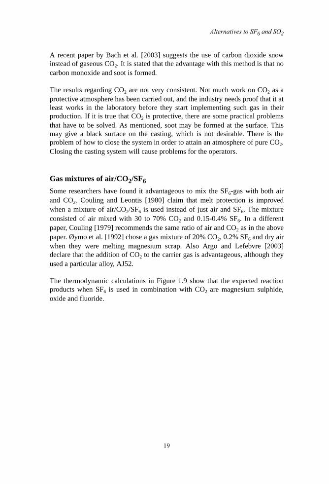
The thermodynamic calculations in Figure 1.9 show that the expected reactionproducts when SF6 is used in combination with CO2 are magnesium sulphide,oxide and fluoride.

Chapter 1. Literature Survey of Protection of Molten Magnesium
20
Figure 1.9 Reaction products when magnesium is exposed to 1% SF6 in air.
It seems to be difficult to see any clear advantages of using the gas mixturesdiscussed above, compared to employing just a mixture of air and SF6. It is saidthat addition of CO2 improves the melt protection, but the amount of SF6 is alsoincreased. So if you get sufficient protection with air and 0.04% SF6, whyincrease the amount SF6 and add CO2 to get even better protection?
BerylliumHouska [1988] has discussed the advantages of adding beryllium to magnesiumand aluminum. Beryllium prevents oxidation of the magnesium because aberyllium oxide film is formed on top of the magnesium melt. The film is formedbecause beryllium is more reactive to oxygen than magnesium. 0.001% Be willincrease the ignition temperature for magnesium as much as 200°C. This meansthat you can handle molten magnesium at casting temperatures and the melt willnot start burning. Spiegelberg, Ali and Dunstone [1992] have also recognized thatberyllium has a positive effect on the oxidation of magnesium. It may bementioned that the Pilling-Bedworth ratio for BeO is 1.68. In addition, berylliumwill refine the melt by precipitating iron and other impurities.
Zeng et al. [2001] have performed a thorough study of the oxide film formed on amolten Mg-9Al-0.5Zn-0.3Be alloy. The oxide film is built up of two layers. One
0.00 0.01 0.02 0.03 0.04 0.05 0.06 0.07 0.08 0.09 0.10-5
-4
-3
-2
-1
0
1
2
3
MgF2
1%SF6+CO
2
C
MgS
MgO
Liq.MgLo
g 10(P
hase
frac
tion)
Protective gas mixture, 1% SF6 in CO2 (gram)

Alternatives to SF6 and SO2
21
outer layer which mainly consists of MgO, and one inner layer containing amixture of BeO and MgO. This inner layer is said to act as a barrier to thediffusion of magnesium ions, Mg2+. This alloy has a great resistance againstoxidation, and it can be melted in the atmosphere without further protection.
There is obviously a disadvantage to this method. As mentioned, beryllium oxidewill be formed, and the dust of the oxide is poisonous if inhaled. According toPohanish and Greene [1996], exposure to dust of beryllium oxide may causedisease in the lymph nodes, the liver, the kidneys and the lungs. Spiegelberg et al.[1992] consider that this not to be a problem as long as the concentration of theBeO-dust in the foundry atmosphere is below the specified threshold, which is0.002 mg/m3 according to Pohanish and Greene [1996].
Other alloying elementsCalcium and zirconium are known to increase the ignition point of magnesiumand thereby possibly prevent ignition of the molten metal [Chang et al, 1998 andSakamoto, Akiyama and Ogi, 1997]. According to Sakamoto et al. [1997], theaddition of calcium gives a CaO film on top of the melt. This layer stops oxygenfrom the air reaching the magnesium, and it also inhibits the strong evaporation ofmagnesium. The calcium oxide film is most probably formed by the reduction ofMgO with calcium which is reasonable based on thermodynamical data where itcan be seen that CaO is more stable than MgO. CaO has a Pilling-Bedworth ratioof 0.64 [Kubaschewski and Hopkins, 1953]. Possibly the surface layer iscomposed of a mixture of MgO and CaO and the Pilling Bedworth ratiocalculation is difficult to apply.
Ignition can be prevented entirely with the simultaneous addition of 1.3 mass%Ca and 1.4 mass% Zr, even at temperatures higher than 810°C [Chang et al.,1998].
FluxBefore SF6 was introduced as protection for molten magnesium, the magnesiumindustry used flux to inhibit oxidation. A flux is added as a powder spread out onthe metal surface where it melts and gives a liquid, protective film on top of themelt. Fruehling and Hanawalt [1969] mention three disadvantages of this method.The first problem is that the flux itself oxidizes and forms a thick and hard layer.This layer may crack and expose the melt under the layer to the atmosphere. Thequality of the finished casting may also be reduced because you may get flux-inclusions in the finished product. The third problem is associated to flux fumesand flux dust which can cause corrosion in a foundry.

Chapter 1. Literature Survey of Protection of Molten Magnesium
22
Emley [1966] had some requirements on an ideal flux. It should have a liquidustemperature below the solidus temperature of the magnesium alloy so that at themoment the metal starts melting, the flux is liquid and able to protect the meltingmetal. The flux should wet the magnesium, and the fluidity of the flux has to behigh enough so that it can spread out on the entire surface. Solidus temperaturesfor magnesium alloys can be as low as 420°C. However, a mixture of the saltsMgCl2, KCl and NaCl has a melting point below 400°C and may thereforeprotect the melt. The density of the flux has to be lower than the density of themagnesium in order not to sink to the bottom of the furnace.
Hydro fluorocarbon gasesRicketts and Cashion [2001] suggests a hydro fluorocarbon gas as a possiblereplacement for SF6. They introduce the hydro fluorocarbon gas 1,1,1,2-tetrafluoroethane, HFC-134a which has a global warming potential 18 timeslower than SF6, but still 1500 times worse than CO2. The film formed mightcontain up to 50% magnesium fluoride.
In their experiments, Ricketts and Cashion used dry air, carbon dioxide andnitrogen as carrier gases, and all of them seemed to be effective. The amount ofHFC-134a in the mentioned carrier gases was between 0.3 and 0.7%.
The time of protection after removal of the protective atmosphere was measuredby first protecting the melt with 0.7% HFC-134a in dry air for 3 hours, thenexposing the melt to 100% dry air. After two minutes, the surface was still shinyand bright with no signs of oxidation. The same experiment was also conductedwith 0.7% SF6 in dry air. In this case the protection only lasted for 15 seconds.The alloy used in both cases was AZ91D. When pure magnesium and HFC-134awas used, burning of the melt started after 5-10 seconds.
The HFC-134a was further tested at Magnesium Elektron in production scalewith good results [Lyon et al., 2003]. However, this gas will most likely bebanned in Europe within some years, so this is at least not a long-term alternativefor producers and die casters here.
BF3
Revankar et al. [2000] have found a method of protecting molten magnesiumwith BF3 which does not have a global warming potential. It is known that BF3
protects magnesium melts, but there has been problems with storage ofcompressed gas, and it is quite an expensive gas. This new method called the

Alternatives to SF6 and SO2
23
Magshield system produces BF3 in situ by thermal decomposition of KBF4. Thesystem is sealed to prevent leakages of BF3.
The amount of BF3 in dry air varied from 0.2 vol% to 1.0 vol%, butconcentrations less than 0.5% gave a discoloration of the surface. The protectionof the melt lasted for 45 minutes after the gas was shut of, compared to SF6 wherethe protection lasted for 30 minutes.
Borontrifluoride is a highly toxic compound [Genium, 1989, The Royal Societyof Chemistry, 1991]. The recommended limit for BF3 in air is 1 ppm. However,Revankar et al. did not find concentrations exceeding 0.2 ppm in the workingarea.
Fluorinated ketonesThe company 3M has developed a fluorinated ketone liquid that easily vaporizesto provide a protective gas. The trade name of this ketone is Novec 612. Thegreatest advantage of this protection fluid/gas is the Global Warming Potentialwhich is equal to 1. The atmospheric life time is approximately 5 days, and theozone depletion potential is 0.0. [Preliminary Product Information, 3M, 2002]
Preliminary experiments with Novec 612 shows that it is able to effectivelyprotect molten magnesium [Milbrath and Owens, 2002, Argo and Lefebvre,2003]. The problem is rather the thermal degradation products produced which isstill an issue to be studied. Toxic gases like HF, or gases that are potential GreenHouse Gases such as perfluorocarbon gases may be formed [Milbrath andOwens, 2002].

Chapter 1. Literature Survey of Protection of Molten Magnesium
24
BIBLIOGRAPHYAir pollution network for early warning and on-line information exchange inEurope. Netsite: http://apnee.norgit.no:8080/regional/servlet/regional/template/Pollutants.vm. Accessed December 11th 2003.
Albright D.L. (2002) Corporate perspectives: Hydro Magnesium. Proceedings ofthe International Conference on SF6 and the Environment: Emission ReductionStrategies, San Diego, CA, November 21-22, 2002
Aleksandrova Y.P. and Roshchina I.N. (1977) Interaction of Magnesium withGases. Metallovedenie i Termicheskaya Obrabotka Metallov 3:218-221.
Argo D. and Lefebvre M. (2003) Melt Protection for the AJ52 MagnesiumStrontium Alloy. Magnesium Technology 2003 4:15-21.
Aylward, G.H. and Findlay, T.J.V. (1974) SI Chemical Data. Milton:John Wiley &Sons.
Bach F.W., Karger A., Pelz C., Schacht S. and Schaper M. (2003) Verwendungvon CO2-Schnee zur Abdeckung von Magnesiumscmelzen. Metall 57:285-288.
Bartos S., Marks J., Kantamaneni R. and Laush C. (2003) Measured SF6
Emissions from Magnesium Die Casting Operations. Magnesium Technology2003 4:23-27.
Busk, R.S., Jackson, R.B. (1980) Use of SF6 in the Magnesium Industry.Proceedings of the International Magnesium Association 37th Annual WorldConference on Magnesium.
Cashion, S.P. (1998) The Use of Sulphur Hexafluoride for Protecting MoltenMagnesium PhD-thesis The University of Queensland, Australia.
Cashion S.P., Ricketts N.J. and Hayes P.C. (2002) The mechanism of protectionof molten magnesium by cover gas mixtures containing sulphur hexafluoride.Journal of light metals 2:43-47.
Chang S.-Y., Matsushita M., Tezuka H. and Kamio A. (1998) Ignition Preventionof Magnesium by Simultaneous Addition of Calcium and Zirconium.International Journal of Cast Metals Research 10: 345-351.
Couling, S.L. (1979) Use of Air/CO2/SF6 Mixtures for Improved Protection ofMolten Magnesium. Proceedings of the International Magnesium Association

Bibliography
25
36th Annual World Conference on Magnesium.
Couling, S.L. and Bennett, F.C. and Leontis, T.E. (1977) Fluxless Melting ofMagnesium. Light Metals. 1:545-560.
Couling, S.L. and Leontis, T.E. (1980) Improved Protection of MoltenMagnesium with Air/CO2/SF6 Gas Mixtures. Light Metals 4:997-1009.
Czerwinski F. (2003) The Oxidation of Magnesium Alloys in Solid andSemisolid States. Magnesium Technology 2003 4:39-42
Emley, E.F. (1966) Principles of Magnesium Technology.London: PergamonPress
Erickson, S.C., King, J.F. and Mellerud, T. (1998) Conserving SF6 in MagnesiumMelting Operations Foundry Management & Technology 126(6): 40-44.
FactSage 5.0. Computer software
Fruehling, J.W. and Hanawalt, JD. (1969) Protective Atmospheres for MeltingMagnesium Alloys Transactions of the American Foundrymen’s Society 77:159-164.
Fruehling, J.W. (1970) Protective Atmospheres for Molten Magnesium. PhD-thesis University of Michigan.
Gjestland H., Westengen H. and Plathe S. (1996) Use of SF6 in the MagnesiumIndustry - An Environmental Challenge. Proceedings of the Third InternationalMagnesium Conference, Manchester, UK, 10-12 Apr 1996
Gregg S.J. and Jepson W.B. (1958-59) The High-temperature Oxidation ofMagnesium in Dry and in Moist Oxygen. Journal of the institute of metal 87:187-203.
Hanawalt, J.D. (1972) Practical Protective Atmospheres for Molten Magnesium.Metals Engineering Quarterly 12(4): 6-10.
Houska, C. (1988) Beryllium in Aluminium and Magnesium. Metals andMaterials 4(2):2.
Hydro magnesium Home Page http://www.magnesium.hydro.com/ AccessedOctober 27th 2003.

Chapter 1. Literature Survey of Protection of Molten Magnesium
26
Kofstad, P. (1966) High-temperature Oxidation of Metals.New York: Wiley.
Kubaschewski, O. and Hopkins, B.E. (1953) Oxidation of Metals and Alloys.London: Butterworths Scientific Publications.
Leontis T.E. (1986) Magnesium: Properties. In Encyclopedia of MaterialsScience and Engineering. 4:2638-2640.
Lyon P., Rogers P.D., King J.F., Cashion S.P. and Ricketts N.J. (2003)Magnesium Melt Protection at Magnesium Elektron Using HFC-134a.Magnesium Technology 2003 4:11-14.
Maiss M. and Brenninkmeijer C.A.M. (1998) Atmospheric SF6: Trends, Sources,and Prospects. Environmental Science & Technology 32:3077-3086.
Metals Handbook. Ninth ed. (1979). Ohio: American Society for Metals.
Milbrath D.S. and Owens J.G. (2002) Use of Fluorinated Ketones in Cover Gasesfor Molten Magnesium. Presented at the 131st Annual Meeting TMS, February17-21, 2002, Seattle, Washington.
Pettersen G., Øvrelid E., Tranell G., Fenstad J. and Gjestland H. (2002)Characterization of the Surface Films Formed on Molten Magnesium. MaterialsScience and Engineering A 332: 285-294.
Pohanish, R.P. and Greene, S.A. (1996) Hazardous Materials Handbook. NewYork: Van Nostrand Reinhold.
Sakamoto M., Akiyama S. and Ogi K. (1997) Suppression of Ignition andburning of Molten Mg Alloys by Ca bearing stable oxide film. Journal ofMaterials Science Letters 16: 1048-1050.
Smythe K.D. (2002) Update on SF6 Global Sales Study. Proceedings of theInternational Conference on SF6 and the Environment: Emission ReductionStrategies, San Diego, CA, november 21-22, 2002.
Solberg, J.K. (1996) Teknologiske Metaller og Legeringer. Metallurgisk Institutt,NTH.
Spiegelberg W., Ali S. and Dunstone S. (1992) The Effects of BerylliumAdditions on Magnesium and Magnesium Containing Alloys. In DGMInformationsgesellschaft m.b.H. DGM Informationsgesellschaft m.b.H.,Oberursel.:259-266.

Bibliography
27
Tang, K. (2004) Equilibrium Calculation for Mg Protection Gas Mixtures MemoSINTEF Materials Technology
Thonstad, J. (1997) Elektrolyseprosesser. Institutt for Teknisk Elektrokjemi,NTNU.
Zeng X., Wang Q., Lü Y., Ding W., Zhu Y., Zhai C., Lu C. and Xu X. (2001)Behavior of Surface Oxidation on Molten Mg-9Al-0.5Zn-0.3Be Alloy. Materialsscience & engineering A, Structural Materials 301: 154-161.
Øymo D., Holta O., Hustoft O.M. and Henriksson J. (1992) MagnesiumRecycling in the Die Casting Shop. Metall: Fachzeitschrift für Handel,Wirtschaft, Technik und Wissenschaft 46: 898-902.
Walzak, M. J.; Davidson, R. D.; McIntyre, N. S.; Argo, D.; Davis, B. R. (2001)Interfacial Reactions Between SF6 and Molten Magnesium. MagnesiumTechnology 2001 2: 37-41.

Chapter 1. Literature Survey of Protection of Molten Magnesium
28

29
Chapter 2 .Experiments with New Surface in
Vacuum Unit
INTRODUCTIONAs is well known, SF6 or SO2 with air as a carrier gas gives a gas mixture thatprotects molten magnesium from uncontrolled oxidation. In these experiments, itis studied if the same protective effect is achieved with other carrier gases. Thecarrier gases tested are nitrogen, argon and carbon dioxide.
An experimental unit, somewhat similar to the set-up Cashion employed for hiswork [Cashion, 1998], was especially built for this purpose.
An atmosphere of an inert gas such as nitrogen or argon will obviously preventoxidation since oxygen is not present, but there will be a problem withevaporation of magnesium since no dense oxide film at the surface restrainsevaporation. It is investigated if the addition of SO2 or SF6 will help build aprotective film.
The gas-mixtures tested are 1% SF6 in air, nitrogen, argon and carbon dioxide,1% SO2 in air, nitrogen and carbon dioxide.
To conduct the experiments without SF6, it was found to be necessary to takeextreme measures to clean the furnace to remove remnants of SF6 in the furnace:

Chapter 2. Experiments with New Surface in Vacuum Unit
30
Then it was tested how much air a CO2 atmosphere can contain and still beprotective. It is also studied how low the content of SO2 in air can be.
EXPERIMENTAL
ProcedureA sketch of the furnace used is given in Figure 2.1. Note that the sketch is notdrawn to scale. The furnace is a Kanthal wound furnace connected to a rotation
pump and a diffusion pump. A vacuum of at least 1·10-4 mbar can be achieved.
Figure 2.1. The figure shows a simplified sketch of the furnace.
Diffusionpump
Gas in
Crucible with sample
Scraper
Heatingzone
Thermocouple
RotationpumpGas out

Experimental
31
About 7 g of pure magnesium from Hydro Magnesium was placed in the stainlesssteel crucible (quality W-1-4762) sketched in Figure 2.2, and the crucible waspositioned in the heating zone of the furnace as shown in Figure 2.1. The cruciblewas sprayed with boron nitride before use to prevent sticking of magnesium tothe crucible walls. A thermocouple is placed below the melt in a hole in thebottom of the crucible as shown in Figure 2.2. The temperature measured by thisthermocouple is taken to be the temperature of the magnesium metal in thecrucible.
Figure 2.2 A sketch of the crucible with the molten metal (red). The sketch tothe left shows the situation before the surface is scraped, the left sketch showsthe situation afterwards.
Gas was introduced with a stainless steel tube through the top lid and blown downon to the melt surface. The gas flow was set to 200 ml/min. and controlled by aBronkhorst flowmeter. Gas was let out through a valve in the lower part of thefurnace.
The furnace was first evacuated down to about 1·10-4 mbar. Then the furnacechamber was filled with either CO2 or N2 when these gases were used as carriergases until the pressure reached atmospheric pressure. The evacuation procedurewas repeated once more, and the chamber was filled with the specific gas-mixture. However, thermodynamically oxide can still form since there could bean oxygen pressure of the order of magnitude of 10-5 mbar. When the pressureinside the chamber was slightly higher than atmospheric pressure, the off-gasvalve was opened, and gas was allowed to flow through the furnace. When thisprocedure was completed, the heating of the sample started.
At 700°C when the metal was melted, fresh metal was exposed by removing thesurface of the melt with a scraper. The procedure can be understood by looking at
Thermocouple

Chapter 2. Experiments with New Surface in Vacuum Unit
32
Figure 2.2. More metal than is necessary to fill the cavity is initially placed in thecrucible. During melting, the metal will form a meniscus at the surface. Thescraper will remove this meniscus and thereby expose fresh bulk magnesium tothe furnace atmosphere. The excess metal will flow into the channel around thecavity.
Experiments were carried out with 5, 30 and 60 minutes exposure after thesurface was scraped. After exposure, the crucible with the sample was loweredout of the heating zone down to the cooling zone where the sample was quenchedwith helium gas.
Experiments conductedThe experiments conducted with SF6 and different carrier gases are given in Table2.1. Table 2.2 presents the experiments with SO2, and experiments in CO2, eitherpure or with varying amounts of air, are given in Table 2.3.
Many of the experiments have been repeated. One reason for this is an importantlesson learnt during the first series of experiments: SF6 gas contaminated thefurnace with fluorine, so that we got fluorine on samples that should not containfluorine at all. Therefore, we carried out a second and third series where wereplaced the radiation shields and the refractory materials. Parts were sandblastedand washed in acid. This time, the experiments with SF6 were performed at theend. The experiments carried out before the replacement of the furnaceequipment, are in the tables referred to as series 1. The microprobe analysis ofthese samples show high values of fluorine, even though there is not supposed tobe fluorine there at all. For example, one should not expect that there would befluorine on a sample exposed to SO2 in CO2. Still, the analysis showed that thesamples contained 20%fluorine. Experiments from series 2 and 3, where thefurnace is supposed to be free of fluorine, are denoted in the tables. A morethorough cleaning of the furnace was carried out before series 3 started than

Experimental
33
before series 2.
As can be seen from the table, only the 5 minutes exposure experiments wereperformed with 1% SF6 in N2, 1% SF6 in Ar. The reason is that the furnacebecame heavily contaminated with powder during these experiments, so we didnot continue with the 30 minutes experiments.
Also here, only the five minute experiment was performed with 1% SO2 in N2 dueto contamination of the furnace.
Table 2.1 : Experiments with SF6 in various carrier gases.
Gas mixture5 min. exposure
time30 min. exposure
time 60 min. exposure
time
1|% SF6 in air Series 2 Series 2 Series 2
1% SF6 in N2 Series 1,Series 2
1% SF6 in Ar Series 2
1% SF6 in CO2 Series 1,Series 2 Series 1,Series 2 Series 2
Table 2.2 :Experiments with SO2 in various carrier gases.
Gas mixture5 min. exposure
time30 min. exposure
time 60 min. exposure
time
1% SO2 in air Series 2 Series 2 Series 2
0.5% SO2 in air Series 3 Series 3
0.2% SO2 in air Series 3 Series 3 Series 3
0.1% SO2 in air Series 3 Series 3
1% SO2 in N2 Series 1
1% SO2 in CO2 Series 1,Series 2 Series 1,Series 2 Series 2

Chapter 2. Experiments with New Surface in Vacuum Unit
34
It should also be mentioned that in series 2, experiments with both SF6 in air andSO2 in air were carried out. This protects magnesium very well. However, theseexperiments were performed in order to provide a reference for what a wellprotected melt looks like. Also, it was attempted to determine the composition ofthe surface.
In addition, 2 to 20% air was added to CO2 to see if the metal still would beprotected. Also, the content of SO2 in air was lowered to see at which percentagethe protective effect ceased. Experiments were performed with 1, 0.5, 0.2 and0.1% SO2 in air.
Before the analysis of the samples, pictures were taken with a digital camera todocument the appearance of the samples.
The samples were examined with a microprobe. Each sample was analyzed atthree to five different spots at the surface. The diameter of each spot analyzed isabout 50 micrometer.
Since the microprobe is intended for polished surfaces, it should be kept in mindwhen looking at the results that some of the surfaces were very uneven, and thiswill affect the results. Therefore, the numbers should not be considered asabsolute values. Another factor that has to be mentioned, is the accelerationvoltage. During these analysis, it was set to 15 kV since only the surface layer isinteresting. This low value was chosen to avoid that the electron beam penetrates
Table 2.3 :Experiments in CO2 and CO2 combined with air.
Gas mixture5 min. exposure
time30 min. exposure
time 60 min. exposure
time
CO2 Series 1,Series 2 Series 1,Series 2 Series 2
2% air in CO2 Series 3 Series 3
3% air in CO2 Series 3
4% air in CO2 Series 3
5% air in CO2 Series 3 Series 3
10% air in CO2 Series 3
20% air in CO2 Series 3

Results
35
too deep into the sample. If the electron beam penetrates down into the bulkmagnesium, this bulk metal will contribute to the results and the analysis resultswill be too high in magnesium. It is not possible in general to tell how deep intothe sample the beam goes since this depends on the density of the film. A materialwith high density will have a low penetration depth, while the opposite is the casefor materials with low density. If the exact composition of the film is known, thenit is possible by Monte Carlo simulation to tell how deep the beam goes.
The K peaks are used to perform the analysis, and the ZAF method is employedto correct the results. All results are given in atomic percent. Since themicroprobe analyzes a volume, the compositions given here will be an average ofthe composition within this volume. The standard deviation of the measurementsis given as the uncertainty in the measurements.
RESULTS
SF6
SF6 in air, series 2 (Table 2.1)As mentioned, these experiments in Figures 2.3-2.5 were performed to provide areference for different gas mixtures since SF6 in air is known to provide verygood protection. Also, we wished to determine the surface composition.
As is seen from Table 2.4, the surface film contains mainly magnesium fluorideand oxygen. Very small amounts of sulphur are detected.
Very roughly, these results indicate that about equal amounts of MgO and MgF2
are formed. After 60 minutes, assuming the formation of these two phases, thefilm consists of 13/13+25 = 34% MgO and 25/13+25 = 66% MgF2.
Table 2.4 : The table shows the composition of three samples in atomic percent exposed to 1%SF6 in air. Series 2.
C S O F Mg
5 minutes 0.4 ± 0.1 0.1 ± 0.1 12 ± 2 45 ± 15 43 ± 14
30 minutes 0.2 ± 0.1 0.4 ± 0.1 18 ± 3 46 ± 3 35 ± 1
60 minutes 0.4 ± 0.1 0.14 ±0.03 13 ± 2 49 ± 4 38 ± 2

Chapter 2. Experiments with New Surface in Vacuum Unit
36
These samples were, as expected, very well protected. The surface was shiny orsometimes a bit duller grey. The dullness seemed to increase with increasingexposure time. The carbon found is probably only due to contamination of the sample duringhandling of the sample.
Figure 2.3 Sample exposed to 1% SF6 in air, series 2. (See Table 2.1 and 2.4,60 minutes.)
Figure 2.4 Sample exposed to 1% SF6 in air for 5 minutes, series 2. (See Table2.1 and 2.4, 5 minutes.)
10mm
10mm

Results
37
Figure 2.5 Surface of sample exposed to 1% SF6 in air, series 2. See Table 2.1and 2.4, 30 minutes. Picture taken with backscatter electrons in themicroprobe.
1% SF6 in N2, series 1 and 2 (Table 2.1)As mentioned earlier, the furnace became heavily polluted performing thisexperiment. A white powder covered the radiation screens, while the sample itselfwas covered with a very thick layer, approximately 1 mm, which detaches fromthe metal during handling. The top surface of the layer was black and velvet like,while the rest was white.
Table 2.5 gives the surface composition of magnesium exposed to 1% SF6 innitrogen. Series 2 still in italic.
Nitrogen is not detected at all, but considerable amounts of fluorine are found atthe surface. The high amount of oxygen may be somewhat surprising since thereshould be little oxygen in the furnace atmosphere. The composition indicatessomewhat more MgF2 than MgO in series 1. It is possible that some Mg3N2 hasformed and converted to MgO when the furnace is opened. The Mg3N2 may haveformed in the gas phase by reaction between evaporated magnesium and nitrogen.

Chapter 2. Experiments with New Surface in Vacuum Unit
38
Figure 2.6 shows the surface. One can not see a distinct film here as was the casewith many of the other samples.
Figure 2.6 Molten magnesium exposed to 1% SF6 in N2 for 5 minutes, series1. Picture taken with backscatter electrons in the microprobe. See Table 2.1and 2.5, 5 minutes.
SF6 in argon, series 2 (Table 2.1)
Table 2.6 gives the surface composition of one sample exposed to 1% SF6 inargon for five minutes. This experiment was only performed once since theexperiment caused a very high level of contamination in the furnace. The samplecontains much oxygen, but this has probably reacted with the unprotected sample
Table 2.5 :The composition of molten magnesium exposed to a gas mixture of 1% SF6 in N2 for 5 minutes.
C S O F N Mg
5 minutes 0.7 ± 0.1 5.9 ± 1.3 13 ± 1 46 ± 4 0.7 ± 0.7 33 ± 2
5 minutes 0.6 ± 0.4
5.8 ± 3.8
19.6 ± 19.6
40 ± 21 0.22 ± 0.22
34 ± 7

Results
39
when the furnace was opened. Also, as mentioned previously, even though thefurnace is evacuated well before the experiment started, there will always besome oxygen left inside.
The surface was, as expected, not very well protected. This is illustrated with apicture in Figure 2.7 and a micrograph of the surface in Figure 2.8. As can beseen in the micrograph, there are small droplets of magnesium on the surface,probably formed from magnesium vapor. There is no film protecting the metalfrom evaporation.
Figure 2.7 Sample exposed to 1% SF6 in Ar. No protective film is formed. SeeTable 2.1 and 2.6, 5 minutes.
Table 2.6 :The surface composition of a sample exposed to 1% SF6 in argon for 5 minutes.
C S O F Mg
5 min 0.4 ± 0.4 1.3 ± 1.0 29 ± 21 8 ± 6 61 ± 15
10 mm

Chapter 2. Experiments with New Surface in Vacuum Unit
40
Figure 2.8 Magnesium exposed to 1% SF6 in argon, series 2. See Table 2.1and 2.6, 5 minutes. The Mg droplets are clearly seen. Picture taken withbackscatter electrons in the microprobe.
SF6 in CO2, series 1 and 2 (Table 2.1)
SF6 in CO2 gave a black surface as can be seen from Figure 2.9, although thesample seemed to be well protected from uncontrolled oxidation.

Results
41
Figure 2.9 Sample exposed to 1% SF6 in CO2. See Table 2.1 and 2.7, 30minutes.
Figure 2.10 shows the surface of a sample exposed to 1% SF6 in CO2 for 30minutes. The metal underneath the film seems to have contracted more than thefilm itself during solidification, giving the wrinkled surface. This might indicatethat the film has a composition different from that obtained with SF6 in air.
10 mm

Chapter 2. Experiments with New Surface in Vacuum Unit
42
Figure 2.10 The micrograph shows a surface exposed to 1% SF6 in CO2 for 30minutes, series 1. See Table 2.1 and 2.7, 30 minutes. Picture taken withbackscatter electrons in the microprobe.
Table 2.7 shows the surface composition of magnesium exposed to a gas mixtureof 1% SF6 in CO2. Series 2 in the table is given in italic typing.
The high value obtained for Mg after 5 minutes in series 2 may indicate that thefilm is thin initially. The amount of carbon has decreased with increasing
Table 2.7 :The composition of magnesium exposed to 1% SF6 in CO2 for 5, 30 and 60 minutes.
C S O F Mg
5 minutes 9 ± 4 2.9 ± 2.1 6 ± 6 66 ± 9 16 ± 6
30 minutes 1.2 ± 0.1 2.0 ± 1.4 0.8 ± 0.3 76 ± 9 20 ± 7
5 minutes 6 ± 5 0.3 ± 0.0 14.3 ± 1.3 3.3 ± 0.4 76 ± 4
30 minutes 0.9 ± 0.8 0.5 ± 0.1 10 ± 5 65 ± 6 24 ± 4
60 minutes 0.3 ± 0.1 0.04 ± 0.05
1.1 ± 0.3 71 ± 1 28 ± 1

Results
43
exposure time in both series. The opposite is the case with fluorine where theamount of fluorine on the surface has increased with increasing exposure time.Another significant change is the oxygen-content which decreases withincreasing exposure time. Compared to magnesium, the fluorine content is highexcept in the five minute experiment in the last series. These analysis wereperformed twice since the results varied strongly in the fluorine content, but theresults were the same.
SO2
SO2 in air, series 2 and 3 (Table 2.2)As will be seen later, approximately 0.2% SO2 is required to protect the metalwell. Below this value, the gas does not protect the surface sufficiently.
Table 2.8 gives the surface composition of samples exposed to varying amountsof SO2 in synthetic air for 5, 30 and 60 minutes. The small amounts of fluorineand carbon found are probably due to contamination and uncertainty in themicroprobe results.
The films are most likely a mixture of magnesium oxide and magnesium sulphideor magnesium oxide with dissolved sulphur. Thermodynamically, magnesiumsulphate is not expected to form. The oxygen content for many of the samples isunreasonably high, and there is still oxygen “left” even if one assumed that all thesulphur binds the oxygen as sulphate and the magnesium binds the oxygen asMgO.

Chapter 2. Experiments with New Surface in Vacuum Unit
44
The samples exposed to 1 and 0.5% SO2 were well protected from oxidation. Thesurfaces were grey/dark grey, and in some cases and some parts, shiny. Figure2.11 below shows a sample that was exposed for 5 minutes. Also a sampleexposed to 0.5% SO2 for 60 minutes is seen in Figure 2.13. There is a black endof the sample, but that is the film that was scraped away when the exposurestarted.
Table 2.8 :The table shows the composition in atomic percent of surfaces exposed to varying amount of SO2 in synthetic air. Series 2 in italic, series 3 in
bold.
1% SO2 in air
C S O F Mg
5 minutes 0.8 ± 0.2 4.5 ± 1.6 39 ± 4 2.3 ± 0.4 53 ± 4
30 minutes 0.4 ± 0.3 7.3 ± 2.2 41 ± 18 1.2 ± 0.6 50 ± 18
60 minutes 0.7 ± 0.3 2.6 ± 3.4 26 ± 23 0.2 ± 0.6 71 ± 25
0.5% SO2 in air
5 minutes 0.6 ± 0.1 1.9 ± 1.9 33 ± 18 0.1 ± 0.1 64 ± 21
60 minutes 0.01±0.01 3.6 ± 3.6 77 ± 11 0.01±0.01 19 ± 8
0.2% SO2 in air
5 minutes 0.3 ± 0.3 6.4 ± 1.1 63 ± 7 0.01±0.01 30 ± 7
30 minutes 0.04±0.04 6.4 ± 3.9 62 ± 18 0.2 ± 0.1 31 ± 14
60 minutes 0 3.8 ± 2.4 63 ± 17 0.05±0.05 34 ± 14
0.1% SO2 in air
5 minutes 0.04±0.04 0.14 ±0.03 56 ± 7 0 43 ± 7
30 minutes 0.1 ± 0.04 5.1 ± 1.0 51 ± 6 0.05±0.05 44 ± 5

Results
45
Figure 2.11 Sample exposed to 1% SO2 in air, series 2. See Table 2.2 and 2.8, 5 minutes.
A closer look at the surface from Figure 2.11 is seen in Figure 2.12. The surfaceis not very even as is the case with SF6, but it is still protective.The surface filmseems to have expanded and wrinkled up..
Figure 2.12 Sample exposed to 1% SO2 in air for 5 minutes, series 2. See Table 2.2 and 2.8, 5 minutes. Picture taken with backscatter electrons in the
microprobe.
10 mm

Chapter 2. Experiments with New Surface in Vacuum Unit
46
Figure 2.13 Sample exposed to 0.5% SO2 in air for 60 minutes. See Table 2.2and 2.8.
When only 0.1-0.2% SO2 was added to the air, the metal was not as wellprotected, although parts of the surfaces are shiny, Figure 2.14 and 2.15. Theshiny part is just below where the gas enters the furnace through the gas tube.However, the appearance of the surface is not the major problem, but the fact thatthe inside of the furnace was covered with a white powder, most likely MgO, andmagnesium had started condensing on the scraper.
10 mm

Results
47
Figure 2.14 Sample held in 0.2% SO2 in air for 60 minutes. See Table 2.2 and2.8.
Figure 2.15 Sample exposed to 0.1% SO2 in air for 30 minutes. See Table 2.2and 2.8.
10 mm
10 mm

Chapter 2. Experiments with New Surface in Vacuum Unit
48
A closer look at the surface that was exposed to 0.1% SO2 in air for 5 minutes isseen in Figure 2.16. There seems to be a film on the surface, and there are alsocracks in the film.
Figure 2.16 Microprobe picture of surface of sample exposed to 0.1% SO2 inair. See Table 2.2 and 2.8, 5 minutes. Picture taken with backscatter electronsin the microprobe.
1% SO2 in N2, series 1 (Table 2.2)Also in this case, white powder was formed and deposited everywhere inside thefurnace, including the sample. For this to happen, there had to be a strongevaporation of the magnesium, and with a strong evaporation, the metal isobviously not protected.
Table 2.9 presents microprobe measurements of the surface composition ofmolten magnesium exposed to a gas mixture of 1% SO2 in N2. Two differentareas were analyzed. Also some powder from the radiation screens was analyzed.

Results
49
It is seen from the table that there is little variation between the two differentareas. The surface mainly consists of magnesium and oxygen and some nitrogen,the 1st area more rich on nitrogen than the 2nd. Roughly speaking mainly MgOseems to have formed. The content of sulphur is low. Boron is included in theseanalysis only because the analysis set-up included boron this time. The crucible issprayed with boron nitride in the beginning of the experiment and this is probablythe reason why small amounts of boron are found on the surface.
The powder on the radiation screen contains large amounts of fluorine andoxygen, but no nitrogen. Again there is fluorine inside the furnace, but only insignificant amounts on the radiation screens. This fluorine must be, as previouslymentioned, “left over” fluorine from earlier experiments.
The surface of the sample is shown in Figure 2.17. As can be seen, the surface isvery irregular and rough. There are small droplets of magnesium on the surface inthe lower left hand corner, probably formed from magnesium vapor.
Table 2.9 : Surface concentration of molten magnesium exposed to 1% SO2 in N2, series 1.
C S O B N F Mg
5 min., 1st area
0.7±0.1
1.2±0.2
51 ±11 0.08±0.04
4.1±1.0
0.6±0.3
43 ±11
5 min., 2nd area
0.5±0.4
3.3±3.8
52 ±14 0.09±0.04
1.5±1.5
1.1±0.6
42 ±11
Powder from radiation screen
1.0±0.6
3.6±3.1
50 ± 8 0 18 ± 7 28 ± 6

Chapter 2. Experiments with New Surface in Vacuum Unit
50
Figure 2.17 The surface of molten magnesium exposed to a mixture of 1%SO2 in N2 for 5 minutes, series 1. See Table 2.2 and 2.9, 5 minutes. Notice theMg droplets. Picture taken with backscatter electrons in the microprobe.
1% SO2 in CO2, series 1 and 2 (Table 2.2)The two samples protected with 1% SO2 in CO2 in series 1 seemed to be wellprotected with a golden surface film formed and with black edges. In the secondseries a more colorful, but still protective film formed, see Figure 2.18.

Results
51
Figure 2.18 Sample exposed to 1% SO2 in CO2, series 2. See Table 2.2 and2.10, 30 minutes.
Table 2.10 gives the surface composition of molten magnesium exposed to 1%SO2 in CO2. Two different areas were analyzed on the 30 minute sample in series1, but the composition is very similar in both areas.
10 mm

Chapter 2. Experiments with New Surface in Vacuum Unit
52
The high values of Mg in the second series should be noted. Possibly the films arevery thin in these cases so that the electrons in the microprobe penetrate into themetal. In the first series, as mentioned earlier, the samples contained highamounts of fluorine due to contamination of the furnace. In the second series,smaller amounts were found. It is possible that some fluorine dissolved in themetal has entered the surface during the experiment, or that this amount is withinthe limit of error for the microprobe.
Figure 2.19 shows a micrograph of the surface of a sample from series 1 exposedto 1% SO2 in CO2 for 30 minutes. The surface appears very smooth, but a smallcrack is seen in the lower part of the picture. A different sample, exposed to thesame conditions for 60 minutes, from series 2 is seen in Figure 2.20. The film isnot quite as smooth in this case. A picture of a sample exposed for 60 minutes inthe second series is seen in Figure 2.21. The surface is as already mentioned,partly shiny and partly colored.
Table 2.10 :The surface concentration of molten magnesium exposed to 1% SO2 in CO2, Series 1 and series 2 (in italic).
C S O B F Mg
5 min. 0.5±0.1 0.03±0.03
45±5 27±1 28±6
30 min., dark area
0.4±0.1 0.03±0.03
47±7 1.8±0.4 21±5 29±2
30 min., light area
0.25±0.03
0.00 45±1 0.8±0.2 20±1 34±1
5 min. 0.8 ± 0.04
0.05± 0.01
12 ± 1 - 0.4 ± 0.1 87 ± 1
30 min. 0.3 ± 0.1 0.03± 0.01
28 ± 2 - 1.8 ± 0.4 70 ± 2
60 min. 1.7 ± 0.7 0.06 ± 0.05
18 ± 16 - 1.7 ± 3.1 78± 19

Results
53
Figure 2.19 The surface of a sample exposed to 1% SO2 in CO2, series 1. SeeTable 2.2 and 2.10, 30 minutes. Picture taken with backscatter electrons in themicroprobe.
Figure 2.20 This sample is exposed to 1% SO2 in CO2, series 2. See Table 2.2and 2.10, 60 minutes. Picture taken with backscatter electrons in themicroprobe.

Chapter 2. Experiments with New Surface in Vacuum Unit
54
Figure 2.21 Sample exposed to 1% SO2 in CO2, series 2. See Table 2.2 and2.10, 60 minutes.
CO2/CO2 and air Table 2.11 shows the average composition in atomic percent of surfaces exposedto CO2 and CO2 in combination with air for 5, 30 and 60 minutes. Series 1 isgiven in regular typing, series 2 in italic and series 3 in bold.
All the surfaces are more or less discolored, whether the samples are exposed topure CO2 or CO2 with added air. The surfaces seem to get more black withincreasing amount of air in the gas, as will be shown.
10 mm

Results
55
Table 2.11 : The table shows the surface composition of magnesium exposed to atmospheres of CO2 and CO2 in combination with air. Series 1 in regular
typing, series 2 in italic, series 3 in bold.
C S O F Mg
100% CO2
5 minutes 1.7 ± 0.2 0.01 ± 0.01
46 ± 18 1.1 ± 0.1 51 ± 18
30 minutes 1.8 ± 0.3 0.01 ± 0.01
55 ± 20 1.2 ± 0.2 42 ± 21
5 minutes 2.8 ± 1.8 0.006±0.003
24 ± 10 0.8 ± 0.5 73 ± 11
30 minutes 0.9 ± 0.6 0.00 40 ± 2 5.4 ± 2.1 54 ± 4
60 minutes 0.5 ± 0.2 0.009 ± 0.004
47 ± 6 1.0 ± 0.4 51 ± 6
2% air in CO2
5 min 1.8±1.3 0.06±0.06
15±4 0 83±4
5 min 0.38±0.17
0.006±0.005
58±8 0.1±0.1 42±8
60 min 0.7 ± 0.4 0.001±0.001
27 ± 16 0.24 ± 0.07
72±16
3% air in CO2
5 min 1.7±0.5 0.007±0.007
66±2 0 33±2
4% air in CO2
4% air in CO2
5 min
0.9±0.4 0.2±0.2 44±10 0 55±10

Chapter 2. Experiments with New Surface in Vacuum Unit
56
The surfaces consists of small amounts of carbon, around 1%, and large amountsof oxygen and magnesium which indicates magnesium oxide. One should expectthat the films at short holding times were high in magnesium since these films arethin, and vice versa, but this is not the case.
One of the samples that was exposed to 5% air in CO2 for 5 minutes is seen inFigure 2.26. The sample to the right had one part of the surface that was black,and one which was more regular grey-brown. This sample was analyzed both atthe black part and the other part. Still, one could not see a difference incomposition. There does not seem to be more carbon at the surfaces that are blackthan the ones that are brown-grey.
Pure CO2, series 1 and 2 (Table 2.3)
Figure 2.22 shows the sample that has been exposed to CO2 for 30 minutes.Although this surface is shiny, many of the samples exposed to CO2 had a grey-brown surface. Still, all the samples were well protected from oxidation. Figure2.23 gives a closer look at the same surface through the microprobe.
5% air in CO2
5 min 0.7±0.3 0.014±0.007
26±3 0.24±0.24
73±3
5 min 1.2±0.4 0.005±0.005
53±8 0 46±8
60 min 0.6 ± 0.2 0.006 ±0.006
41 ± 6 0.5 ± 0.1 58 ± 6
10% air in CO2
5 min 0.8 ± 0.1 0.003±0.003
20 ± 1 0.32 ± 0.05
79 ± 1
20% air in CO2
5 min 0.3 ± 0.1 0.013 ± 0.007
49 ± 8 0.003 ± 0.003
51 ± 8
Table 2.11 : (Continued)The table shows the surface composition of magnesium exposed to atmospheres of CO2 and CO2 in combination with
air. Series 1 in regular typing, series 2 in italic, series 3 in bold.
C S O F Mg

Results
57
Figure 2.22 Sample exposed to pure CO2, series 2. See Table 2.3 and 2.11, 30minutes.
Figure 2.23 A closer look at the surface of the sample exposed to pure CO2,series 2. See Table 2.3 and 2.11, 30 minutes. Picture taken with backscatterelectrons in the microprobe.
10 mm

Chapter 2. Experiments with New Surface in Vacuum Unit
58
Air in CO2, series 3 (Table 2.3)For air in CO2, there seemed to be a limit at approximately 3% air in CO2. Withmore air in the gas mixture, a black layer, possibly soot, forms on the samplesurface. Figure 2.24 shows a sample held in 2% air in CO2 for 5 minutes. Thissurface looks almost exactly like the grey-brown ones with pure CO2. With 3%air in CO2, the surface appears as in Figure 2.25. However, with 5% air in CO2,the surface is covered with a black layer as seen in Figure 2.26.
Figure 2.24 Two samples exposed to 2% air in CO2, series 3. See Table 2.3and 2.11, 5 minutes.
10 mm

Results
59
Figure 2.25 Sample exposed to 3% air in CO2, series 3. See Table 2.3 and2.11, 30 minutes.
Figure 2.26 Two samples exposed to 5% air in CO2, series 3. See Table 2.3and 2.11, 5 minutes.
10 mm
10 mm

Chapter 2. Experiments with New Surface in Vacuum Unit
60
Figure 2.27 shows a micrograph of the surface of a sample exposed to 2% air inCO2. This sample was grey-brown, just like samples exposed to pure CO2. Onecan see that there is a film covering the surface, and that parts of the film iswrinkled.
A micrograph of a sample that had a black surface is seen in Figure 2.28. Alsothis film is wrinkled, although not to a large extent. The surface appeared to becovered with a layer of soot on a macroscopic scale.
However, it is not possible to distinguish between the two samples from themicrographs. The surface that was believed to be covered with soot, does notappear different from the one that was not on a microscopic scale.
Figure 2.27 Sample exposed to 2% air in CO2 for 5 minutes, series 3. SeeTable 2.3 and 2.11, 5 minutes. Picture taken with backscatter electrons in themicroprobe.

Discussion
61
Figure 2.28 Molten magnesium exposed to 5% air in CO2 for 5 minutes, series3. See Table 2.3 and 2.11, 5 minutes. Picture taken with backscatter electronsin the microprobe.
DISCUSSIONOxygen inside the furnaceThe furnace can be evacuated to 1·10-5 mbar. Since there is approximately 20%oxygen in air, the partial pressure of oxygen may be 0.2 10-5 mbar afterevacuation. The volume of the furnace chamber is estimated to be 1.8 liters.Using these numbers and the ideal gas law makes it possible to calculate thenumber of moles of oxygen left inside the furnace chamber after evacuation at25°C:
where R=82.05 cm3 atm/mol K.Assuming that all the oxygen will react with magnesium to form magnesiumoxide, this gives 3·10-10 moles MgO. This amount equals an oxide volume of3·10-9 cm3. This oxide can be assumed to be distributed evenly at the sample
npO2
VRT
---------------- 1.5 10 10– moles O2= =

Chapter 2. Experiments with New Surface in Vacuum Unit
62
surface which is approximately 2 cm in diameter. This gives a thickness of theoxide film in the order of 0.01 nm.
One can therefore conclude that “left over” oxygen from the evacuation does notcontribute significantly to the formation of the oxide films formed when scrapingof the surface is performed. Even with an oxygen pressure decades higher, thethickness of films formed due to oxygen left in the furnace will be insignificant asthe films formed are expected to be in the area of 0.1 m, see Figure 1.3.
It should also be kept in mind that the initial surface layer is scraped away whenthe exposure starts.
SF6 in nitrogen/argonSF6 in nitrogen did not protect the molten magnesium at all. It is expected thatany reaction between nitrogen and magnesium is slow [Turkdogan, 1980]. Ifmagnesium nitride is formed, it would happen in the gas phase and not at thesurface. Thus, no protective layer of magnesium nitride can form. Thecontamination inside the furnace indicates that there has been evaporation of themetal. The black surface is not acceptable. Pettersen et al. [2002] have suggestedthat a magnesium oxide film has to form to achieve protection from furtheroxidation of the magnesium. As seen from Table 2.5, there is too little oxygen(from leakage and left from evacuation) to give MgO.
According to the thermodynamic calculations in Figure 1.5, only magnesiumfluoride and sulphide should form with nitrogen as carrier gas, and there are largeamounts of fluorine at the surface. As can be seen from the figure, more fluoridethan sulphide seems to form when there is sufficient gas available, so this mightindicate that there is enough gas flowing though the furnace to give MgF2.Compared to many of the other samples, there is relatively much sulphur in thissample. This sulphur may then be found as sulphide.
In the experiments reported here, there should have been little oxygen inside thefurnace. Nevertheless, almost 14% oxygen is found at the surface. This oxygencould be due to a leakage in the furnace, oxygen remaining after evacuation orthere could be some magnesium oxide remaining in the furnace from earlierexperiments. In Appendix 1, it is calculated how little oxygen there can be in theatmosphere before magnesium oxide starts forming. At 700°C, a partial pressureof oxygen higher than 5·10-54 bar will start the oxidation of the magnesium. Inpractice it is not possible to attain such low levels of oxygen.
It is also possible that there is some oxide on the steel crucible. One should expectthough, that if sufficient amounts of air leaked into the furnace, the metal shouldbe protected in the same way as with air and SF6. As previously mentioned, it

Discussion
63
may be that magnesium nitride, Mg3N2, was formed in the gas phase. When thefurnace was opened, and air got into contact with the sample, the nitride wastransformed to oxide. The samples were analyzed days after the experimentswere performed, which could give time for the reaction.
Similar experiments with SF6 in argon gave the same result: The gas mixture didnot protect the metal surface at all, and one could tell that there had been a strongevaporation of the magnesium as seen in Figure 2.8. The conclusion for all theseexperiments with inert gases is that it does not seem to be possible to build adense, protective film without oxygen. This has already been shown by Pettersenet al. [2002].
SF6 in CO2
Adding SF6 to the CO2 did not improve the surface finish of the magnesium. Infact, the surface finish was of a poorer quality than the ones with SF6 in air. Thisis somewhat surprising since a mixture of SF6, air and CO2 is reported to givegood protection, and even used for industrial purposes [Fruehling, 1970]. Coulingand Leontis [1980] registered improved protection with a mixture of air, CO2 andSF6. The amount of CO2 in the gas varied between 30 and 70%. Since the onlydifference between the two atmospheres is air, it must be oxygen that is the key togive a better surface finish. The reaction products should be the same as with SF6
in air, with magnesium oxide as the dominant phase. However, this is not the caselooking at the analysis of the sample surfaces. There is much more fluorine thanoxygen, and the high values of fluorine at the surfaces of the samples suggestsformation of magnesium fluoride.
SO2 in airAs was seen in Figure 2.12, the film at the sample exposed to 1% SO2 in air for 5minutes had wrinkled up. It is not possible to tell whether this happened duringthe experiment or during quenching.
When the amount of SO2 in air was lowered to 0.2%, magnesium oxide starteddepositing on the furnace walls and magnesium condensed on the scraper. A partof the surface which was situated just below the gas inlet was shiny and seemedto be well protected. Therefore, one can say that it may be possible to protectmolten magnesium from oxidation with as little as 0.1 or 0.2% SO2 in the gas, butthen the gas distribution system becomes very critical. If you need a gas inletevery 5 cm, this is probably not a good solution. It should also be considered thatthis is a value attained in a laboratory furnace. In practice, one does not have sucha closely controlled system and the amount of SO2 needed will probably increase.This will magnify the disadvantages with SO2 which have already been discussedin the literature review chapter.

Chapter 2. Experiments with New Surface in Vacuum Unit
64
Magnesium sulphate has a high Pilling-Bedworth ratio of 3.2, which means that aratio of 1 is achieved with only 8% MgSO4 in an MgO film. The correspondingnumbers for magnesium sulphide is 1.44 and 30%. Although magnesiumsulphate has the “best” Pilling Bedworth ratio, magnesium sulphide is the mostthermodynamically stable phase as was seen in Figure 1.6. According to thecalculations performed in FactSage, only sulphide should form.
Sulphur is found at the surfaces of these samples. It is not possible to tell whetherit is bound as magnesium sulphide or as sulphur in MgO. It is also difficult to tellhow much of the film that these phases add up to due to the uncertainty connectedto the oxygen content.
SO2 in nitrogenAlso SO2 in nitrogen (Figure 2.17) did not provide satisfactory protection of themolten metal although there is oxygen in the sulphur dioxide. The calculationsperformed in FactSage show that these conditions should give almost equalamounts of magnesium oxide and sulphide, but relatively small amounts. Theamount of oxygen corresponded to MgO, and the amount of sulphur was low.
SO2 in CO2
SO2 in CO2 seemed to protect the metal well. In the first series, the surfacecontained high amounts of fluorine when there was not supposed to be anyfluorine there at all. This taught us an important lesson: Once you get fluorineinto the furnace, it remains there for a long time. Since there was fluorine, onecan not really determine whether the protective effect was due to the gas mixtureof SO2 in CO2, or if it was due to the fluorine. However, also when theexperiments were repeated after the refractory materials had been replaced, thegas mixture still gave a good protective effect. The high value of magnesiumindicates that the film was very thin.
It is surprising that hardly any carbon or sulphur was found in these samples.
CO2
The only reaction products between molten magnesium and CO2 should bemagnesium oxide and solid carbon as seen in Figure 1.8. It is not likely thatmagnesium carbonate will form. Magnesium carbonate will decompose at 350°C,and is therefore not stable at temperatures when magnesium is melted. There waslittle carbon at the sample surfaces, but much oxygen which may confirm thepresence of magnesium oxide. The “secrete” of CO2 may be that CO2 reactsslowly with magnesium, thus giving the surface layers time to realign and preventevaporation of magnesium.

Discussion
65
The fact that there is less carbon than expected may imply that there was little gasavailable compared to the amount of metal for example in the beginning of theexperiment. Then, no carbon forms due to a finite solubility of carbon inmagnesium as is seen from Figure 1.8.This may lower the average carbon contentof the film.
An atmosphere of pure CO2 seemed to protect the molten magnesium well, butthe surface was discolored, and that is an unwanted effect. The fact that pure CO2
protects liquid magnesium is in accordance with Fruehling’s work [1970],although the films formed in his experiments appeared metallic. One of thegreatest problem with using CO2 industrially might be to attain a sufficiently pureCO2 atmosphere above the melt. It was therefore tested how much air the furnaceatmosphere could contain while still protecting the metal from excessiveoxidation.
Even with 20% air in CO2, the magnesium did not oxidize uncontrollably.However, when the amount of air in CO2 exceeded 3-4%, the surfaces becameblack with a carbon-like layer. The formation of the black surface might be aproblem, but since the film/black layer seems to be very thin and partly like apowder, it might be removed mechanically. For example, the surface could bebrushed with steel wool, or something similar. Of course, this is an extra step thatincreases the production costs. It is also a possibility to sell the metal as it is, andlet the buyer do what is necessary. Perhaps magnesium producers could sell“environmentally friendly magnesium” produced with CO2 cheaper thanmagnesium produced with SF6. The costumer may have to machine away thediscolored surface, but gets cheaper metal. The producer might even employsome of their CO2 off-gases for the protection of the magnesium. Theexperiments demonstrate that a leakage of air is not catastrophic, and thereforethe gas systems covering the melt do not have to be 100% tight.
CO2 is already used for casting in some plants and foundries. Concern has to betaken regarding the gas delivery system. Using CO2 as melt protection for holdingfurnaces may be more problematic. Since a film containing carbon may form onthe surface, carbon may be drawn into the melt during operations such as alloyaddition. It has been stated that carbon has a strong negative effect on thecorrosion resistance in magnesium. Comparison of the carbon content from thefilms formed in air with SF6 and films formed in CO2 shows that the CO2 filmscontain approximately twice as much carbon, but still only about 1% as was seenfrom the microprobe results.

Chapter 2. Experiments with New Surface in Vacuum Unit
66
Fluorine contaminationDuring these experiments, it seemed that if you let fluorine enter your system, itis almost impossible to get rid of it again. Samples exposed to pure CO2 while thefurnace was contaminated with fluorine had a very nice and shiny surface, similarto the ones exposed to SF6 in air. Maybe this fact could be exploited in some wayto protect molten magnesium. If you are able to “contaminate” your system withfluorine, it may help protect the metal as long as there is some fluorine left.
CONCLUSIONDifferent gas-mixtures as an alternative to SF6 in air have been tested todetermine if they protect molten magnesium from oxidation and evaporation.
Inert gases (Ar and N2) as carrier gases for SF6 and SO2 do not build protectivefilms, and can therefore not be used.
Pure CO2 as a gas atmosphere provides good protection, although the surfacefinish is not excellent. A small amount of air in the CO2, say 1-2%, does not affectthe protective ability of the gas, but a black soot like layer forms at the surface asthe amount of air in the gas increases to 3-4%, although there is not a significantincrease in the carbon content of the surfaces with increasing amount of air in theCO2. Even with 20% air in the CO2 gas, the metal did not oxidize uncontrollably.CO2 seems to react slowly with magnesium, and possibly allows the MgO torealign and prevent evaporation of magnesium.
SF6 in CO2 was surprisingly not a successful combination in these experiment,but experience in the industry and other people’s work indicates that when air isadded, it can be used with success.
0.2% SO2 in air seemed to be a critical limit for how low it was possible to go inSO2 content in the experimental unit employed here. The surfaces probablycontain magnesium sulphide in addition to magnesium oxide, or even sulphurdissolved in MgO. SO2 in CO2 also provides good protection, but gives adiscolored surface.

Bibliography
67
BIBLIOGRAPHYCashion, S.P. (1998) The Use of Sulphur Hexafluoride for Protecting MoltenMagnesium PhD-thesis The University of Queensland, Australia.
Couling S.L. and Leontis T.E. (1980) Improved Protection of Molten Magnesiumwith Air/CO2/SF6 Gas Mixtures. Light Metals:997-1009.
Fruehling, J.W. (1970) Protective Atmospheres for Molten Magnesium. Ph.D.thesis, University of Michigan.
Kubaschewski, O. and Hopkins, B.E. (1953) Oxidation of Metals and Alloys.Butterworths Scientific Publications, London.
Pettersen, G., Øvrelid, E., Tranell, G., Fenstad, J. and Gjestland, H. (2002)Characterisation of the Surface Films Formed on Molten Magnesium in DifferentProtective Atmospheres. Materials Science and Engineering A 332:285-294.
Turkdogan, E.T. (1980) Physical Chemistry of High Temperature Technology,Academic Press, New York, pp.253-256.

Chapter 2. Experiments with New Surface in Vacuum Unit
68

69
Chapter 3 . High-temperature Microscope Studies of Films on Magnesium
Magnesium oxide/fluoride films on magnesium protected by air and SF6 attemperatures ranging from 635°C to 705°C, are studied as they are formed. Theexperiments are performed with a hot stage microscope. Magnesium samplestreated with SF6 in air, are heated to various temperatures, both above and belowthe melting point, and held there for specified holding times. The partial pressureof SF6 in the gas is varied between 0.5% to 5%. Under the microscope, thesamples can be observed and pictures taken. Samples were taken out andexamined with electron microprobe (EPMA), Transmission Electron Microscope(TEM), regular scanning electron microscope (SEM), Field Emission SEM andFocused Ion Beam Milling (FIB) to study the structure of the film, the surfaceand to determine the thickness of the oxide layer.
Since also CO2 and SO2 in air are known to protect molten magnesium, and sincethe hot stage provided samples with a very well-defined surface film,experiments are also performed with these gases in the hot stage. The purpose isto produce films that are suitable for further studies, for example with themicroprobe to determine the composition of the surface and to see if otherphases form during the experiment that can be observed through the opticalmicroscope.

Chapter 3. High-temperature Microscope Studies of Films on Magnesium
70
EXPERIMENTAL
Experimental unit, Linkam TS1500The Linkam TS1500 is a high temperature heating stage for microscopy. Theheating rate can vary from 1°C/min to 130°C/min and a maximum temperature of1500°C can be reached. The desired temperature profile/run can be programmedwith the controller, TMS 93. As can be seen from Figure 3.1, the heating rate canbe varied during the run, and the sample can be held at a particular temperaturefor as long time as wanted.
Figure 3.1 An example of a typical temperature-time profile. The sample isinitially heated at a rate of 50°C/min. Then the heating is slower, 5°C/min.When the desired temperature is reached, the sample is held there for thespecified time before it is cooled.
Figure 3.2 shows a picture of the heating stage. There is a window in the middleof the lid where one can look down on the sample. The chamber is water cooled,and there are inlets and outlets for water on the top lid and on the sides of thechamber. Also there is one inlet and one outlet to allow gas flow though thefurnace. The gas flow can be maximum 60 ml/min without disturbing thetemperature inside the chamber.
Time
Temperature
50°C/min
5 °C/minHold for specified time
50°C/min

Experimental
71
Figure 3.2 The heating stage TS1500.
Platinum heating wires are wound around a ceramic cup which forms the samplechamber shown in Figure 3.3. The reason for placing the sample on a sapphiredisc is to prevent contamination of the sample chamber. Sapphire has excellentheat transfer properties and is a material well suited for high temperatures. Aradiation shield is placed on top of the sample chamber. This ensures that thesample attains an even temperature, and also protects the lens of the microscopefrom high temperatures. The controlling thermocouple is cemented into thebottom of the sample chamber. The thermocouple, type S Pl-10% Rh/Pl isconnected to the controller and the temperature registered is displayed in thewindow. There is, however, a difference between the temperature registered bythis thermocouple and the true temperature of the sample. Therefore, a calibrationhas to be performed.

Chapter 3. High-temperature Microscope Studies of Films on Magnesium
72
Figure 3.3 The illustration shows the sample placed inside thefurnace chamber.
Calibration
The calibration was performed by melting elements or compounds with aknown melting point. Several criteria have to be satisfied for a goodcalibration standard [Roedder, 1984]. We found that metals that form a ballduring melting, are advantageous to use. Criteria for a good calibrationstandard are presented in Appendix 3.
In the calibration the following standards with their respective melting point wereemployed, Table 3.1:

Experimental
73
Attempts were made to use antimony, but this did not succeed.
A few, very small pieces of the standard were placed on the sapphire disc in thebottom of the crucible. Silver and gold shavings were used, which upon meltingwill form a ball. The melting point will therefore be easily observed. Thestandards used should of course be as pure as possible.
A stream of argon of approximately 20-30 ml/min flows through the hot stageduring calibration. Hopefully, this can partly prevent oxidation of the samplesduring heating.
The samples were heated at a rate of 50°C/min up to 5-10°C below the knownmelting point. From there, the standards were heated at a low rate, usually 1°C/min until melting was observed. The temperature measured with thethermocouple shown on the controller, Tc, was registered and the deviationbetween Tc and the true melting point of the standard was found. The results areplotted in Figure 3.4 where the deviation is given as a function of the meltingpoint.
As is seen from the figure, the thermocouple measures a higher temperature thanthe true temperature of the sample.
Table 3.1: The standards used for calibration
and their melting points.
Standard Melting point(°C)
Te 450
NaCl 801
Ag 961
Au 1063

Chapter 3. High-temperature Microscope Studies of Films on Magnesium
74
Figure 3.4 The graph shows the deviation between the true temperature of thesample and what is shown on the controller at different temperatures. Gasflow is 30 ml argon/min.
There are several reasons why there is deviation between the true temperature ofthe sample and what is registered by the thermocouple. As mentioned, the sampleis placed on a sapphire disc. This means that the sample is not in direct contactwith the thermocouple that measures the temperature displayed on the controller.The sapphire disc is supposed to provide good contact between the sample andthe cemented layer around the thermocouple. Still there is a difference betweenthe thermocouple and the sample temperatures.
Temperature measured is the temperature at the bottom of the sample, the partthat is in contact with the sapphire disc.
In the following, the values of Tc given by the thermocouple are reduced by 4°C.
Sample preparationMagnesium samples were prepared by cutting discs approximately 2 mm thickfrom a 5 mm in diameter magnesium rod. The analysis of the magnesium metal isgiven in below:
0
2
4
6
8
10
12
14
0 200 400 600 800 1000 1200
Melting point (°C)
Dev
iatio
n fr
om m
eltin
g po
int (
°C)

Experimental
75
The samples are mounted into plastic and ground and polished. Afterwards,the plastic with the polished samples is cooled in liquid nitrogen so that theplastic easily cracks and the samples can be taken out. The samples are kept inethanol to prevent unnecessary oxidation before the experiments start. Still,one can expect that there is an oxide layer on the surface. Nordlien et al. [1997]studied naturally formed oxide films on pure magnesium. Samples exposed to theatmosphere with 35-55% humidity at 25-30°C for 15-60 minutes were found tohave a dense film of approximately equal amounts of magnesium oxide andmagnesium hydroxide. The thickness of the film was between 20 and 50 nm.
ProcedureThe sample was placed on the sapphire disc inside the heating chamber. Thegas mixture, either SF6 in synthetic air, pure CO2 or 1% SO2 in synthetic air,approximately 30 ml/min, was allowed to flow through the furnace. Thepartial pressure of SF6 in air was varied, as mentioned, between 0.5 and 5%.Five different heating programmes were used. The sample was always heatedat a heating rate of 50°C/min up to 30°C below the maximum temperature.Then the heating rate was lowered to 5°C/min until the holding temperature isreached, see Figure 3.1. The five holding temperatures are 635, 665, 685, 700 and705°C. Holding time varied between no holding time at all to 53 hours. All theexperiments performed, with the maximum temperatures, holding times, partialpressure of SF6 and analysis methods are given in Tables 3.5-3.8. Pictures weretaken before the experiments is started and during the run.
Image analysisAs will be shown later in Figure 3.6, “spots” start appearing on the surface onmany of the samples. The size and the number of these spots was studied, and the
Al 0.0111 %Zn 0.0001 %Mn 0.0164 %Fe 0.0011 %Cu 0.0000 %Ni 0.0000 %Pb 0.0000 %Sn 0.0000 %P 0.0001 %Ca 0.0003 %Na 0.0002 %Cd 0.00000 %Mg 99.9363 %

Chapter 3. High-temperature Microscope Studies of Films on Magnesium
76
fraction of the surface that they cover as a function of time. The number of spots
in one particular area 50700 m of the surface was counted manually frompictures taken at various times throughout the experiment.
An average size of the spots was determined in the following way: Five differentspots within the area already mentioned, were monitored on each picture takenover a period from 1 hour to 53 hours. The area of each spot was found byenlarging the pictures 160 times on the computer screen. This made it possible tocount the number of pixels that one spot is made up of. The average size and thenumber of spots within the particular area chosen is given in Appendix 2. Thegreatest problem with counting manually like this, is to decide which pixels toinclude into the particle and which ones to exclude. To minimize this error, thecounting of all spots in one experiment was done on the same day and under thesame light conditions.
Given these data, it was possible to calculate the fraction of the surface coveredwith these spots.
It was also attempted to calculate the fraction of the surface covered with spotsusing image analysis. Here too, one has to determine which shadows of grey toinclude in the spots, and which shadows that should be excluded. Once you havemade this decision, the computer does the rest of the work.
Microprobe analysis (EPMA)Some of the samples where one clearly could see spots or different phases wereanalyzed with the microprobe. The samples were analyzed with so-calledmapping which determines where in the sample a particular element is found. Inthis case, the elements of interest are of course magnesium, oxygen and fluorine.Aluminum was included in one sample since the sample material contained0.01% aluminum. Sulphur was not included in the SF6 samples as experience aswell as other studies (Pettersen et al.[2002], Cashion et al. [2002]) have indicatedthat this is not an active element regarding melt protection. However, carbon andsulphur were included for the samples exposed to CO2 and SO2.
To try to estimate the thickness of the films, various methods were employed.These are discussed in the following. Initially, a relative electron microprobemethod was used. The chemical composition of the surface of the sample wasanalyzed with increasing accelerating voltages. It was assumed that all theoxygen and fluorine is found as magnesium oxide and magnesium fluoride. Ifyou then still have some “free” magnesium, that is magnesium not bound toeither oxygen or fluorine, then it can be assumed that the electron beam has

Experimental
77
penetrated through the film, and down into the bulk metal. At the particularaccelerating voltage where the amount of free magnesium is zero, one canassume that the depth of the film equals the penetration depth of the electronbeam which can be calculated with Monte Carlo simulations. For further detailson Monte Carlo simulations, see Joy [1991]. However, using these simulations todetermine thickness turned out to be a rather problematic method.
Transmission Electron Microscope (TEM)Cross sections of three samples were prepared for the transmission electronmicroscope (TEM). The intention was to measure the film thickness. This gives amore reliable measurement of the film thickness since you actually can see thefilm. Only three samples were studied since sample preparation for TEM is both avery time consuming and demanding task.
Scanning Electron Microscope (SEM) It was attempted to use a regular SEM to measure thickness on cross sections ofthe films formed. The pictures did not show the film clearly in most of the cases,and it was therefore hard to interpret the pictures and to estimate a thickness.
Field Emission SEMField Emission SEM gives improved resolution, and thereby better pictures.
Focused Ion Beam Milling (FIB)Focused Ion Beam Milling was used to visualize the mophology of the surface.An electron beam of Ga ions cuts down through the sample. The beam cutsdown through the surface layer and down to the bulk metal, giving a cavity inthe sample.
X-ray Diffraction (XRD)It was attempted to determine the lattice parameters of the surface films usingx-ray diffraction. The samples were not ideal for this kind of analysis since thesurfaces are not completely even and the films are thin. The results are thereforegiven in Appendix 6.

Chapter 3. High-temperature Microscope Studies of Films on Magnesium
78
Experiments conductedIn the tables below is given a summary of all the experiments performed with thehot stage. Table 3.2 describes an initial experiment, Table 3.3 presents theexperiments performed in 1% SF6 in air, Table 3.4 the experiments in 5% SF6 andTable 3.5 experiments in 0.5% SF6 and Table 3.6 with 2% SF6. In addition to theholding temperature and time for the samples, the various analysis techniquesemployed on each sample are included. Where pictures are presented in the text,this is referred to in the table. The names of the samples are chosen arbitrarily.However, the samples whose names start with an E-, are experiments performedby Eriksen [Eriksen, 2003].
The four experiments performed in pure CO2 are given in Table 3.7, while theexperiments in SO2 in air are found in Table 3.8.
Table 3.2: Initial experiment in 1% SF6 in air.
Sample name Heating profile Analysis
A Heat with 50°C/min to 635°C, hold for 2 min, then heat with 2°C/min to 662°C, hold for 3 min., cool with 50°C
EPMA: Fig. 3.6

Experimental
79
. Tab
le 3
.3:
Exp
erim
ents
per
form
ed in
1%
SF
6 in
air.
Giv
en in
the
tab
le is
the
hol
ding
tim
e at
the
max
imum
tem
pera
ture
, th
e va
riou
s an
alyt
ical
met
hods
use
d, r
efer
red
to fi
gure
s pr
esen
ted
in th
e te
xt. I
A=
Imag
e A
naly
sis
MC
= M
onte
Car
lo
sim
ulat
ions
Sam
ple
nam
e
Hol
ding
te
mpe
ratu
re(°
C)
Hol
ding
tim
e (m
in)
Ana
lysi
sSa
mpl
e na
me
Hol
ding
te
mpe
ratu
re(°
C)
Hol
ding
tim
e (m
in)
Ana
lysi
s
H66
512
0T
635
300
MC
I66
531
20IA
:Fig
.3.6
-3.1
2, F
IB, M
CU
665
0
J66
530
MC
V66
560
MC
K66
560
W66
50
MC
M66
50
X66
510
MC
N66
55
MC
Y63
510
MC
O66
510
Z63
560
FIB
P66
560
Æ63
50
MC
Q63
50
Ø63
530
MC
R63
510
MC
AA
635
60TE
M, M
C
S63
530
AB
685
5M
C

Chapter 3. High-temperature Microscope Studies of Films on Magnesium
80
AC
665
300
MC
AN
635
200
MC
AD
685
0M
CA
O66
520
0TE
M, M
C
AE
685
20M
CA
P68
520
0M
C
AG
685
5M
CA
Q70
510
FIB
AH
685
80M
CA
R70
530
AI
685
160
MC
AS
705
60Fi
g.3.
18, E
PMA
:Fig
.3.1
9
AJ
685
10FI
B, M
CAT
705
300
FIB
AK
685
40TE
M, F
ig.3
.26,
MC
, Fig
.3.2
7A
U70
510
0
AL
685
320
AV70
520
0X
RD
:App
endi
x 6
AM
665
300
Fig.
3.1
3, F
IB:F
ig. 3
.29,
EP
MA
: Fig
. 3.2
1
Tabl
e 3.
3: (
Con
tinu
ed)E
xper
imen
ts p
erfo
rmed
in 1
% S
F6
in a
ir. G
iven
in t
he t
able
is t
he h
oldi
ng t
ime
at t
he m
axim
um
tem
pera
ture
, the
var
ious
ana
lyti
cal m
etho
ds u
sed,
ref
erre
d to
figu
res
pres
ente
d in
the
tex
t. I
A=
Imag
e A
naly
sis
MC
= M
onte
Car
lo s
imul
atio
ns
Sam
ple
nam
e
Hol
ding
te
mpe
ratu
re(°
C)
Hol
ding
tim
e (m
in)
Ana
lysi
sSa
mpl
e na
me
Hol
ding
te
mpe
ratu
re(°
C)
Hol
ding
tim
e (m
in)
Ana
lysi
s

Experimental
81
Tabl
e 3.
4: E
xper
imen
ts p
erfo
rmed
in 5
% S
F6
in a
ir. I
A=
Imag
e A
naly
sis
MC
= M
onte
Car
lo s
imul
atio
ns
Sam
ple
nam
eH
oldi
ng
tem
p. (°
C)
Hol
ding
tim
e (m
in)
Ana
lysi
sSa
mpl
e na
me
Hol
ding
te
mp.
(°C
)H
oldi
ng
time
(min
)A
naly
sis
BA
635
60E4
635
30EP
MA
BB
635
30E5
635
60EP
MA
BC
635
200
E663
514
40EP
MA
, SEM
BD
635
100
E766
55
EPM
A
BE
685
100
E866
520
Fig.
3.1
7, E
PMA
, SEM
BF
685
60E9
665
30EP
MA
BG
635
300
E10
665
60EP
MA
, SEM
BH
635
10E1
166
514
40EP
MA
, SEM
BI
685
10Fi
g. 3
.5, E
PMA
:Fig
. 3.2
0E1
268
55
EPM
A, S
EM
BJ
685
30E1
368
510
EPM
A, S
EM
BK
685
200
XR
D:A
ppen
dix
6E1
468
520
EPM
A, S
EM
E163
55
EPM
AE1
568
530
EPM
A
E263
510
EPM
A: F
ig. 3
.15
E16
685
60EP
MA
, SEM
E363
520
EPM
A

Chapter 3. High-temperature Microscope Studies of Films on Magnesium
82
Table 3.7: Experiments performed in pure CO2.
Table 3.5: Experiments performed in 0.5% SF6 in air.
Sample name
Holding temperature (°C)
Holding time (min) Analysis
E17 665 150 EPMA, FE-SEM: Fig. 3.22
E18 700 120 EPMA, FE-SEM: Fig.3.28
E19 700 150
Table 3.6: Experiment performed in 2% SF6 in air.
Sample name
Holding temperature (°C)
Holding time (min) Analysis
DA 700 300 XRD: Appendix 6
Sample name
Holding temperature (°C)
Holding time (min) Analysis method
GA 685 60
GB 685 120
GC 665 60
GD 635 60 Fig.3.30EPMA: Fig. 3.31

Results
83
RESULTSThe results from the experiments performed with SF6 in air are presented first.The results from the experiments in CO2 and SO2 in air are given towards the endof this section.
First, two features of these experiments in SF6 should be denoted: The surfacefilm that forms on the sample seems to be very strong: The reason for this is thateven though the sample melts, the surface film keeps the sample in its place. Thatis, there is hardly any difference in the shape between a sample that has melted,and a sample that has not.
The other issue worth noting, is that the surface film seems to “crack” when themetal below melts. This is easily observed under the microscope: As thetemperature goes past the melting point, the surface suddenly “cracks”, and thesurface is not that smooth any more.
In 24 of 41 samples, the formation of spots were observed when samples wereexposed to 1% SF6 in air at elevated temperatures. The samples where spotswere formed is indicated in Table 3.9. These spots turned out to be very rich influorine, and are therefore most likely MgF2 particles.
For the experiments with 5% SF6 in air, the surfaces do not have the distinct MgF2
particles. Almost every sample has a finer structure as seen in Figure 3.5. Thisstructure is discussed more thoroughly in Figure 3.20. The samples where thisstructure is formed are indicated in Table 3.9.
Table 3.8: Experiments performed in 1% SO2 in air.
Sample name
Holding temperature (°C)
Holding time (min) Analysis method
FA 635 180 Fig. 3.32, Table 3.14,EPMA: Fig. 3.33
FB 685 120
FC 665 60

Chapter 3. High-temperature Microscope Studies of Films on Magnesium
84
Figure 3.5 Sample exposed to 5% SF6 in air at 685°C for 10 minutes. Seesample BI Table 3.4. Picture taken in optical microscope.
For the three samples exposed to 0.5% SF6 in air, it is not possible to say that theyhave a characteristic appearance. Spots were observed in one of the sampleswhen looking at cross sections with FE-SEM, but not in the two others. SeeTable 3.9.
Table 3.9: Samples where MgF2 and the finer structure is seen. + indicates the presence of the structure.
Samplename
Holding temperature
(°C)
Holding time (min)
pSF6(%) MgF2
particlesFine
structure
H 665 120 1 +I 665 3120 1 +J 665 30 1 +K 665 60 1M 665 0 1N 665 5 1 +O 665 10 1 +P 665 60 1Q 635 0 1R 635 10 1S 635 30 1 +
100 m

Results
85
T 635 300 1 +U 665 0 1V 665 60 1 +W 665 0 1 +X 665 10 1 +Y 635 10 1Z 635 60 1Æ 635 0 1Ø 635 30 1 +
AA 635 60 1AB 685 5 1AC 665 300 1AD 685 0 1AE 685 20 1AG 685 5 1 +AH 685 80 1 +AI 685 160 1 +AJ 685 10 1AK 685 40 1AL 685 320 1 +AM 665 300 1 +AN 635 200 1 +AO 665 200 1AP 685 200 1 +AQ 705 10 1AR 705 30 1 +AS 705 60 1 +AT 705 300 1 +AU 705 100 1 +AV 705 200 1 +BA 635 60 5 +BB 635 30 5 +BC 635 200 5 +BD 635 100 5
Table 3.9: (Continued) Samples where MgF2 and the finer structure is seen. + indicates the presence of the structure.
Samplename
Holding temperature
(°C)
Holding time (min)
pSF6(%) MgF2
particlesFine
structure

Chapter 3. High-temperature Microscope Studies of Films on Magnesium
86
Microscope studies, image analysisThe nine pictures below, Figure 3.6, illustrates, as the experiment proceeded, howthe surface of a sample appeared looking through the optical microscope. Thesample was held at 665°C for 2 days. The pictures are taken at the same positionon the sample, starting at room temperature and ending when the sample hadbeen held at 665°C for 48 hours.
BE 685 100 5 +BF 685 60 5 +BG 635 300 5 +BH 635 10 5 +BI 685 10 5 +BJ 685 30 5 +BK 685 200 5 +E1 635 5 5E2 635 10 5E3 635 20 5 +E4 635 30 5E5 635 60 5 +E6 635 1440 5 +E7 665 5 5E8 665 20 5 +E9 665 30 5E10 665 60 5 +E11 665 1440 5 +E12 685 5 5 +E13 685 10 5 +E14 685 20 5 +E15 685 30 5E16 685 60 5 +E17 665 150 0.5 +E18 700 120 0.5E19 700 150 0.5
Table 3.9: (Continued) Samples where MgF2 and the finer structure is seen. + indicates the presence of the structure.
Samplename
Holding temperature
(°C)
Holding time (min)
pSF6(%) MgF2
particlesFine
structure

Results
87
Figure 3.6 A series of micrographs taken in the optical microscope fromthe same surface area of a sample held at 665°C in 1% SF6 in air. Sample Iin Table 3.3.
As seen from the pictures, the surface in this case seems to be covered withspots. These spots will later be shown to be MgF2 particles.
Expanded images of the sample surface are given in Figures 3.7-3.9 after 4, 24and 48 hours.
Roomtemperature
640°C 665°C
665°C 30 min 665°C 2 hours 665°C 4 hours
665°10.5 hours 665°C 24 hours 665°C 48 hours
100 m

Chapter 3. High-temperature Microscope Studies of Films on Magnesium
88
Figure 3.7 The surface of sample I in Table 3.3 after 4 hours in 1% SF6 in airat 665°C, same sample as in Figure 3.6. Picture taken in optical microscope.
In Figure 3.7, the MgF2 particle size can be estimated to be approximately 5 mafter 4 hours. The distance between the particles is roughly 10 m.
Figure 3.8 The surface of sample I in Table 3.3 after 10.5 hours in 1% SF6 inair at 665°C, same sample as in Figures 3.6-3.7. Picture taken in opticalmicroscope.
100 m
100 m

Results
89
The particle “diameter” in Figure 3.8 is somewhere between 5 and 10 mm, andthe spacing between them has decreased.
Figure 3.9 Closer look at surface of sample I in Table 3.3 after 48 hours in 1%SF6 in air at 665°C. Picture taken in optical microscope.
In Figure 3.9, the spots have grown together, so that it is hard to separate them.However, approximately 10 m would be a qualified guess for the size.
A comparison of the MgF2 particle sizes and the distances between themfound from various figures in the text, is presented in the discussion section,Table 3.15.
The number of spots (MgF2 particles) within one particular area for the samesample as above is given in Figure 3.10. The actual numbers may be of limitedinterest, but the trend is important: The number of spots decreases as a function oftime. After approximately 10 hours, the decrease seems to level out. Theexplanation for the decrease is most likely that since the spots grow withincreasing exposure time, spots grow into each other and appear as one spot.
100 m

Chapter 3. High-temperature Microscope Studies of Films on Magnesium
90
Figure 3.10 The number of spots in a particular area as a function of exposuretime. Sample I in Table 3.3, same sample as in Figures 3.6-3.9.
Still considering the same sample as in Figure 3.10, Figure 3.11 gives the averagesize of five randomly chosen spots as a function of time. The size seems to levelout after 10-20 hours. However, this does not have to mean that the spots ceasegrowing. Possibly they can still grow in the direction perpendicular to the surfaceinwards into the film and bulk metal as will be discussed later.
0
100
200
300
400
500
600
700
800
900
0 10 20 30 40 50 60
Time (hours)
Num
ber o
f spo
ts

Results
91
Figure 3.11 The figure gives the average size of one spot as a function of timefor a sample held at 665°C in 1% SF6 in air. Sample I in Table 3.3, samesample as in Figures 3.6 -3.10.
This analysis could have been performed by image analysis on a computer, but asmentioned there is one critical aspect, and that is the lighting used on themicroscope when the pictures are taken. In the beginning of the experiment, verylittle light is necessary to take a good picture. As the experiment proceeds and thesurface of the sample is getting duller, more light is needed to get a good picture.It is therefore a problem to compare two pictures since they are taken underdifferent lighting conditions.
When the average size of the particles and the number of particles within onespecific area is known, the fraction of the surface which is covered with spots canbe calculated. This calculation is performed in Figure 3.12 from the data given inFigure 3.10 and 3.11. The triangles are the manually generated numbers and thesquares are the fractions that were calculated using image analysis.
For the manually calculated fractions, the fraction covered levels out afterapproximately 10 hours. At that point, approximately 25% of the surface iscovered with spots. For the computer generated numbers, the curve does not levelout as early, but after two days, according to this estimate, 50% of the surface iscovered with the spots.
0
5
10
15
20
25
30
35
40
0 10 20 30 40 50 60
Time (hours)
Ave
rage
siz
e of
spo
ts (
m2 )

Chapter 3. High-temperature Microscope Studies of Films on Magnesium
92
Figure 3.12 The figure shows the fraction of the surface which is coveredwith spots as a function of time. The data are from Figure 3.10 and 3.11.Sample I in Table 3.3, held in 1% SF6 in air at 665°C.
Figure 3.10-3.12 are produced from the data given in Appendix 2.
Figure 3.13 shows a sample different from that in Figure 3.6 in the opticalmicroscope. The “diameter” of the small MgF2 spots is approximately 5 m,while the distance between them is approximately 10 m. Also some larger oxideflakes on top of the surface is seen in addition to the smaller MgF2 particles.
The size of the oxide flakes is approximately 10-20 m.
It is difficult to say whether the flakes are formed during the experiment, or ifthey were formed after the sample were taken out of the hot stage and exposed tothe atmosphere.
0
0,1
0,2
0,3
0,4
0,5
0,6
0 20 40 60
Time (hours)
Frac
tion
of s
urfa
ce c
over
ed
Manual count
Computergenerated

Results
93
Figure 3.13 Micrograph taken with optical microscope of sample AM inTable 3.3, 665°C for 300 minutes in 1% SF6 in air. Large magnesium oxideflakes on the surface are seen in addition to the smaller MgF2 spots.
Microprobe “mappings”A microprobe “mapping” from a test sample in 1% SF6 in air, held at 640°C for 2minutes, then 3 minutes at 667°C, is presented in Figure 3.14. An intensity scalefor each element is given to the right in the figure. The analysis of the selectedareas denoted in the upper left picture in Figure 3.14, is given in Table 3.10.
As can be seen from the element map, the spots that started appearing on thesurface around 640°C contain large amounts of fluorine, which indicates that theyare magnesium fluoride particles. This is confirmed by the point analysis, points5 and 6 in Table 3.10: The spots contain large amounts of fluorine. The analysisshowed that the areas with the spots contained 20/(20+17+6) = 47% MgF2, 17/(20+17+6) = 40% MgO and 6/(20+17+6) = 14% Mg. The fact that there is notonly magnesium fluoride, but also magnesium oxide and pure magnesium, ismost likely due to the analytical method: It is not possible to focus the electronbeam just exactly at the spot. The electron beam, which in this case is 10 m indiameter, is larger than the spots, and the areas around will also contribute. Thepure magnesium is a contribution probably because the electron beam penetratesthrough the film and down into the bulk metal.
MgOflakes
100 m

Chapter 3. High-temperature Microscope Studies of Films on Magnesium
94
Figu
re 3
.14
Mic
ropr
obe
elem
ent
map
ping
of
the
mag
nesi
um s
urfa
ce e
xpos
ed t
o 1%
SF
6 in
air.
The
sam
ple
is h
eld
at 6
40°C
for
2 m
inut
es, t
hen
3 m
inut
es a
t 667
°C. S
ampl
e A
in T
able
3.2
.
1
2 3
5
46

Results
95
Again, we make a balance in terms of MgO, MgF2 and Mg. The areas with nospots may be taken to contain 7/(7+22+35) = 11% MgF2, 22/(7+22+35) =34% MgO and 35/(7+22+35) = 55% Mg. The high amount of magnesiumshould mean that there is a large contribution from the bulk metal.
As will be seen later, the MgF2 particles do no stand out from the surface as itmay appear from the upper left picture in Figure 3.14. The MgF2 particles form“droplets” at the interface between the film and the metal that go down into themetal. When one analyzes on such particles, the electron beam hits these dropletsin addition to the bulk metal, and the analysis does not show that muchmagnesium.
In the upper left corner of Figure 3.14, some circular, lighter areas can beobserved. From the mapping, it seems that they are a little poorer in oxygen.Points 1 and 2 in Table 3.10 are from such areas, and it is seen that we are onlytalking of areas with 1-2% less oxygen than in the areas around.
The MgF2 particles are approximately 5 m in diameter. The distance betweenthese particles is estimated to be approximately 10 m.
An other sample is studied in Figure 3.15. In this case, the sample is held at635°C for 10 minutes. The gas mixture is 5% SF6 in air. An intensity scale isgiven to the right in the picture.
The situation is a bit different in Figure 3.15 from other experiments with 5%SF6: It appears that there are large magnesium oxide grains on the surface. The
Table 3.10: Composition in atomic% of points denoted in Figure 3.14 measured with microprobe.
Point in Figure 3.14 C S O F Mg
1 0.7 0.2 20.0 12.5 66.7
2 0.7 0.1 21.3 13.4 64.5
3 0.7 0.2 23.1 13.6 62.5
4 0.7 0.2 22.5 13.7 62.9
5 0.5 0.1 16.6 39.1 43.6
6 0.6 0.1 17.3 39.8 42.1

Chapter 3. High-temperature Microscope Studies of Films on Magnesium
96
phase in between these large grains seems to be slightly richer in fluorine than thegrains themselves. Possibly it is magnesium fluoride since this phase is also lowin oxygen. Between these large particles, at the grain boundaries, there aresmaller particles. The ones that appear white in the picture in the upper left cornerare low in fluorine, but high in magnesium. Also one can see some particles thatappear darker in the same picture. It is difficult to determine the chemicalcomposition of these particles. An illustration is sketched in Figure 3.16. Theparticles with unknown composition are drawn as small black spots.

Results
97
Figu
re 3
.15
Mic
ropr
obe
“map
ping
” of
sam
ple
held
for
10
min
utes
at
635°
C i
n a
gas
mix
ture
of
5% S
F 6 i
n ai
r. Sa
mpl
e E
2 in
Tabl
e 3.
4.

Chapter 3. High-temperature Microscope Studies of Films on Magnesium
98
The oxide grain size in this sample is around 20-30 m, although some grainsare even larger.
Figure 3.16 A simplification of Figure 3.15: The large oxide grains (green),matrix (red) and particles (white)
An almost similar structure is also seen on a sample held at 665°C for 20 minutes,also in 5% SF6 in air, Figure 3.17. Ignoring the large grains, the structure looksvery much alike the other structures formed in 5% SF6, for example Figure 3.20.
Figure 3.17 Sample held at 665°C for 20 minutes in 5% SF6 in air. Sample E8in Table 3.4. Picture taken with microprobe.
F-poorO-rich
F-richO-poorMg-rich
Very F-poorMg-rich

Results
99
Unfortunately, there are some stripes disturbing the picture in Figure 3.17. Still, itis possible to see a structure somewhat similar to the one seen in Figure 3.15. Thecoarser magnesium oxide grains are observed, and also smaller “spots”. These“spots” seem to be evenly distributed all over the surface, not only at the grainboundaries as seen in Figure 3.15. Their composition has not been determined.
A third example of this particular structure is seen in Figure 3.18 and 3.19. Thissample has been held at 705°C for 60 minutes. Also here it is seen that there arelarge grains that are rich in oxygen and magnesium, which probably means theyare magnesium oxide. The matrix phase is richer in fluorine. Due to topographyat the surface, there are some shadow effects on the edges of the oxide grains inFigure 3.19.
The micrograph from the optical microscope of this sample is presented inFigure 3.18. Here, one can see some smaller, dark particles which are most likelymagnesium fluoride particles. Studying the mapping in Figure 3.19, one can seethat the particles that lie inside a larger grain, are richer in fluorine than the grainitself, but not as rich as the matrix. This may be due to the experimental method,since the magnesium fluoride particles are positioned underneath the film, andthe low acceleration voltage applied here has the purpose of only analyzing thesurface.
Figure 3.18 Micrograph taken in optical microscope. Sample AS in Table 3.3,705°C for 60 minutes in 1% SF6 in air.
100 m

Chapter 3. High-temperature Microscope Studies of Films on Magnesium
100
Figu
re 3
.19
Mic
ropr
obe
“map
ping
” of
sam
ple
AS
in T
able
3.3
, 705
°C f
or 6
0 m
inut
es in
1%
SF 6
in a
ir.
1
2
3
4
56

Results
101
The composition (atomic percent) of the six spots denoted in Figure 3.19 is givenin Table 3.11. The three first points are from the matrix. This phase is very rich influorine, and if it assumed that all the fluorine is bound as magnesium fluoride,and all the oxygen as magnesium oxide, we get for the matrix phaseapproximately: 21/(18+21) = 54% MgF2 and 18/(18+21) = 46% MgO.
The same calculation for the grains, gives 15/(15+30) = 33% MgF2 andapproximately 30/(15+30) = 67% MgO.
The diameter of the electron beam used in these analysis is 10 m.
A microprobe mapping was also performed on the surface of a sample that hadthe characteristic fine structure that was seen in may of the samples with 5% SF6.This mapping is shown in Figure 3.20.
Table 3.11: Composition in atomic% of points indicated in Figure 3.19. Sample AS in Table 3.3, held at 705°C for 60 minutes in 1% SF6 in air.
Point in Figure 3.19 C S O F Mg
1 0.2 0.05 19.0 42.1 38.6
2 0.3 0.03 18.6 42.7 38.3
3 0.3 0.07 17.4 44.7 37.5
Average 0.27±0.05 0.05±0.01 18.4±0.8 43.2±1.3 38.1±0.5
4 0.4 0.05 24.0 36.4 39.1
5 0.4 0.03 31.5 27.4 40.6
6 0.4 0.04 33.6 25.2 40.8
Average 0.36±0.01 0.04±0.01 29.7±5.1 29.7±6.0 40.2±0.9

Chapter 3. High-temperature Microscope Studies of Films on Magnesium
102
Figu
re 3
.20
Mic
ropr
obe
map
ping
of
sam
ple
BI
in T
able
3.4
, 10
min
utes
at 6
85°C
in 5
% S
F 6 in
air.

Results
103
The composition of the dark phase (matrix) and the light phase (grains) as theyappear in the upper left corner in Figure 3.20 is given in Table 3.12.
From Table 3.12, it is seen that the matrix phase consists of almost pure MgF2.The grains seem to contain 9/(9+3+66) = 12% MgF2, 3/(9+3+66) = 4% MgO and66/(9+3+66) = 85% Mg.
The probe diameter is 10 m in diameter in these analysis.
Cross sectional examination of MgF2 particlesA micrograph of the cross section of a sample held at 665°C for 5 hours in 1%SF6 in air is shown in Figure 3.21. This figure illustrates very well the situationwith the spots seen in for example Figure 3.6 and the surface film: The darkerspots lie underneath the surface film, not on top as is the impression at firstglance in the optical microscope. The particles are magnesium fluoride, and theyare situated under the protective film, going down into the bulk metal.
The reason one could see them with the optical microscope, is that themagnesium oxide is transparent.
Table 3.12: Composition in atomic% of matrix and grains as they appear in Figure 3.20. Sample BI in Table 3.4, 685°C for 10 minutes in 5% SF6 in air.
Area C S O F Mg
Matrix 0.3 0.01 1.3 67.3 31.1
Matrix 0.3 0.01 1.1 68.2 30.3
Matrix 0.3 0.01 1.5 66.5 31.7
Average 0.31±0.02 0.01±0.00 1.3±0.2 67.3±0.9 31.1±0.7
Grain 0.4 0.00 5.6 18.0 79.1
Grain 0.5 0 3.8 17.1 78.6
Grain 0.6 0.00 2.1 20.0 77.3
Average 0.49±0.07 0.00 2.8±0.9 18.4±1.5 78.3±0.9

Chapter 3. High-temperature Microscope Studies of Films on Magnesium
104
This is the same sample as in Figure 3.13. The “diameter” of the particles in themicroprobe picture seen here in Figure 3.21 is 5-10 m. The distance betweenthem is 10-20 m.
Figure 3.21 Cross section of sample held at 665°C for 300 minutes in 1% SF6
in air taken with microprobe. Sample AM in Table 3.3.
The formation of magnesium fluoride particles on the interface between the oxideand the metal could also be seen in the Field Emission SEM. Figure 3.22 shows asample that has been held at 665°C for 150 minutes in an atmosphere of 0.5%SF6 in synthetic air. For this sample, the diameter of the magnesium fluorideparticles is approximately 2 m, and the distance between particles is 1-1.5 m.
Bulk Mg
MgF2
Film

Results
105
Figure 3.22 Magnesium fluoride particles formed underneath the protectivefilm, going into the bulk metal, shown with Field Emission SEM. Sample isheld at 665°C for 150 minutes in an atmosphere of 0.5% SF6 in synthetic air.Sample E17 in Table 3.5.
Film thickness
The attempt to determine the thickness using the microprobe and Monte Carlosimulations was not very successful as will be discussed below. The results areincluded since they give an indication of the relative thickness as a function oftemperature. The results are presented here in Figure 3.23. The composition dataat various acceleration voltages, which are the data employed in thesecalculations are given in Appendix 7.
As can be seen, the thickness increases with exposure time. The increase inthickness seems to level out at 2-3 m after approximately 100-150 minutes. Inmost cases, the samples that have been held at 685°C have a thicker film than theones at lower temperatures.
2.5 m
Film
MgF2MgF2

Chapter 3. High-temperature Microscope Studies of Films on Magnesium
106
Figure 3.23 Thickness of film, estimated with Monte Carlo simulations. Filmsformed on magnesium at temperatures from 635 to 685°C in an atmosphere of1% SF6 in air. (See Table 3.3)
The thickness of the three samples studied in the Transmission ElectronMicroscope (TEM) is given in Table 3.13. In addition, the thicknesses calculatedwith the Monte Carlo simulations are found in the same table. As can be seen, theMonte Carlo simulation gives values that are approximately 2.7 times higher thanthe TEM measurements.
Table 3.13: Thicknesses of protective films formed in a gas atmosphere of 1% SF6 in air, measured with TEM and estimated with Monte Carlo
simulations. Samples AA, AO and AK in Table 3.3.
Sample TEM thickness Monte Carlo simulation
60 minutes at 635°C 0.28 m 0.8 m
200 minutes at 665°C 0.75 m 2.2 m
40 minutes at 685°C 0.50 m 1.3 m
0 50 100 150 200 250 300 350
0
1
2
3
4
5
6Fi
lm th
ickn
ess
(m
)
Holding time (minutes)
635°C 665°C 685°C

Results
107
The thicknesses found from the SEM and the FE-SEM pictures are presented inFigure 3.25. There is an increase of thickness with increasing time, but the resultsvary considerably. It is not easy to determine thickness from regular SEMpictures since the films appear rather blurry [Eriksen, 2003]. An example of sucha regular SEM picture is given in Figure 3.24.
Figure 3.24 Example of SEM micrograph of cross section of film. SampleE10 in Table 3.4, 60 minutes at 665°C in 5% SF6 in air.

Chapter 3. High-temperature Microscope Studies of Films on Magnesium
108
Figure 3.25 Thickness of films formed on magnesium in 5 and 0.5% SF6 inair. Samples E6, E8, E10-E14 and E16 in Table 3.4, and samples E17 and E18in Table 3.5.
Figure 3.26 shows one of the micrographs from the TEM examination. As can beseen, there is a continuous film. The film seems to consist of a cellular structurereaching out from the surface. The thickness of the film is 0.5 m, see Table 3.13.
10 100 1000
0,5
1,0
1,5
2,0
Thic
knes
s (
m)
Holding time (min)
Eriksen 5% SF6 (SEM) Eriksen 0.5% SF6 (FE-SEM)
685
685
685
665
685
665
665
700
635
685

Results
109
Figure 3.26 A TEM micrograph of the protective film. Sample held at685°C for 40 minutes in 1% SF6 in air. Sample AK in Table 3.3.
No spots were observed forming at the surface of sample AK. A part of thesurface seen through the optical microscope is shown in Figure 3.27. No spots areobserved at this picture as well. The “grain size” in this picture is 30-50 m.
2 m
Bulk Mg
Film

Chapter 3. High-temperature Microscope Studies of Films on Magnesium
110
Figure 3.27 Picture from the optical microscope of sample AK in Table 3.3,685°C for 40 minutes in 1% SF6 in air.
The Field Emission SEM provided better pictures of the film compared to theregular SEM as seen in Figure 3.28. The thickness of the film is measured to be0.55 m.
Figure 3.28 Micrograph of film taken with Field Emission SEM. Sampleheld at 700°C for 120 min. in 0.5% SF6 in synthetic air. Sample E18 inTable 3.5.
100 m
2.5 m
Mg
Film

Results
111
Focused Ion Beam Milling (FIB)In Figure 3.29, the situation with the oxide flakes, the film and the magnesiumfluoride particles is illuminated using FIB. As can be seen, there is a large oxideflake on top of the surface, approximately 20-30 m in “diameter”. Underneaththe protective film, one can see the magnesium fluoride particles, also referred toas spots. The largest MgF2 spot to the left, partly seen in this picture, isapproximately 5 m, while the distance between the two spots is about 10 m.
Figure 3.29 FIB-micrograph of a sample held at 665°C for 5 hours in 1%SF6 in air. Sample AM in Table 3.3.
CO2
All the samples that were held above the melting point, samples GA-GC, had ablack surface after the experiments were finished. The surfaces were uneven, andthe samples were not in the original shape. It was therefore not possible to getuseful pictures with the microscope.
Sample GD on the other hand, which was held at 635°C for 60 minutes, had asmooth, shiny surface after the experiment was finished, and the sample had the
MgOflake
MgF2 Film

Chapter 3. High-temperature Microscope Studies of Films on Magnesium
112
same shape as initially. An image of the surface taken with the optical microscopeis seen in Figure 3.30. If one looks closely, one can see small, darker spots on thesurface of the sample.
Figure 3.30 Surface of sample exposed to pure CO2 at 635°C for 60 minutesseen in the optical microscope. Sample GD in Table 3.7.
A microprobe mapping of the same sample GD, is seen in Figure 3.31. Thesurface consists mainly of magnesium, which means that this is a thin film. Thereis also some oxygen, and insignificant amounts of carbon and fluorine. It is notpossible to say something about the small darker spots that are seen in the upperleft picture.
100 m

Results
113
Figu
re 3
.31
Mic
ropr
obe
map
ping
of
sam
ple
GD
in T
able
3.7
, 60
min
utes
at 6
35°C
in 1
00%
CO
2.

Chapter 3. High-temperature Microscope Studies of Films on Magnesium
114
SO2
A part of a surface exposed to 1% SO2 in air is seen in Figure 3.32. It looks likethere are some large grains at the surface which may be up to 1-200 m in“diameter”.
Figure 3.32 Surface exposed to 1% SO2 in air at 635°C for 180 minutesseen in the optical microscope. Sample FA in Table 3.8.
A microprobe “mapping” of the same sample is seen in Figure 3.33. One can seethat there is a slight variation in the distribution of sulphur: What appears to belarger grains seem to be a little richer in sulphur.
Point analysis of the surface gave the composition in Table 3.14. The diameter ofthe electron beam is 10 m also in this case. As is seen, the surface containsapproximately 7% sulphur and 42% oxygen. As expected, there is somefluorine on the surface due to previous use of SF6 in the hot stage.
100 m

SO2
115
Table 3.14: Composition of surface of sample FA in atomic percent.
Measurement # C S O F Mg
1 0 7.9 41.7 4.0 46.4
2 0 6.1 41.9 6.3 45.8
3 0 5.6 42.0 5.5 46.8
4 0 8.2 43.5 3.6 44.7
5 0 7.0 40.4 4.7 47.6
Average 0 6.9±1.1 42±1 4.9±1.1 46±1

Chapter 3. High-temperature Microscope Studies of Films on Magnesium
116
Figu
re 3
.33
Mic
ropr
obe
“map
ping
” of
sam
ple
FA in
Tab
le 3
.8, 1
80 m
inut
es a
t 635
°C in
1%
SO
2 in
air.

Discussion
117
DISCUSSIONFirst, there is an issue that should be brought up: In this work, it is often assumedthat all the fluorine in the samples is bound as magnesium fluoride and all theoxygen as magnesium oxide. We do not really know that this is the case. Sharma[1988] studied the phase equilibria in the system MgF2-MgO. This system has aneutectic point at 8.5 mol% MgO at 1228°C. Samples that were slowly cooled toroom temperature showed the separation into the two primary phases. No solidsolution or compound formation was detected. Putz, Schön and Jansen [1998]have published a computational thermodynamics paper where they investigated ifit is possible that the phase Mg2OF2 forms. They varied the composition betweenMg3OF4 and Mg3O2F2, but the result was that the ternary system Mg/O/F is mostlikely to separate into the binary compounds MgO and MgF2 and that thesynthesis of magnesium oxide fluoride (Mg2OF2) should be a difficult task. Still,we do not know to what extent magnesium fluoride may contain oxygen ormagnesium oxide can contain fluorine.
An important finding in this study is the formation of the magnesium fluorideparticles underneath the protective surface film. It is, however, difficult to tellunder which conditions these spots form. They form both at low temperatures(635°C) and at high temperatures and at short and with long holding times. Spotswere only observed when the percentage of SF6 in the gas was 1 or 0.5%. With5% SF6 in the gas, a finer structure was observed instead of the characteristicspots.
A comparison of the MgF2 particle sizes and distance between them issummarized in Table 3.15. Although the parameters may vary, it is possible tocompare some of the samples, for example Sample I after 240 minutes, andSample AM. As is seen from the table, the particle size is approximately 5 m,and the distance between them about 10 m. A sample held at the sametemperature, but not for so long, and with less fluorine in the gas, Sample E17,has smaller particles. The MgF2 spots in Figure 3.22 are only approximately 2
m which is reasonable considering that this sample has not been held at thegiven temperature for as long as most of the other samples presented here.Surprisingly, the distance between the particles is very short. This may be acoincidence since when the pictures were taken, we were looking for an area witha high density of particles. The two spots seen in Figure 3.22, may even be soclose that they appear as one spot looking at it from above in the opticalmicroscope.
Another sample that may have unreasonable large MgF2 spots, is Sample A inFigure 3.14. This sample has fluoride particles that are equal in size to samples

Chapter 3. High-temperature Microscope Studies of Films on Magnesium
118
that have been held at the sample temperature for much longer time, e.g. SampleAM that was held at 665°C for 300 minutes.
The same sample as is given in the three first rows in the table here, Sample I, isthe basis for Figure 3.11. One should therefore expect that the results in the Table3.15 and Figure 3.11 should correspond well. After 240 minutes (4 hours), theaverage particle size from Figure 3.11 is approximately 4 m, and there is goodcorrespondence. After 2280 minutes (48 hours) on the other hand, Figure 3.11gives a size of approximately 6 m, while the size given in Table 3.15 is 10 m.The reason for this is probably that Figure 3.11 is produced in a more accurateway: The pictures were enlarged 160 times which made it possible to count pixelsto determine the size. The numbers given in the table here are only measured witha ruler at the magnification on the pictures, which may give a larger source oferror.
The spots that were observed under the protective surface film, are probablyformed when the oxide film is saturated with fluorine, and magnesium fluoridestarts forming from the excess fluorine. This indicates that the fluorine diffusesdownwards through the surface film and down to the bulk metal.
Table 3.15: Comparison of MgF2 particle sizes, distance between them, and size of oxide flakes where seen, measured on pictures presented in the text.
Figure Samplename
Holding time(min), temp(°C),%SF6
MgF2
particle size ( m)
Distance( m)
Oxide flake ( m)
3.7 I 240 min at 665°C, 1%SF6 5 10
3.8 I 630 min at 665°C, 1%SF6 5-10 <10
3.9 I 2280 min at 665°C, 1%SF6 10 5
3.13 AM 300 min at 665°C, 1%SF6 5 10 10-20
3.21 AM 300 min at 665°C, 1%SF6 7 10-20
3.29 AM 300 min at 665°C, 1%SF6 5 10 20-30
3.14 A 2 min at 640°C, 3 min at 667°C, 1%SF6
5 10
3.22 E17 150min at 665°C, 0.5%SF6 2 1-1.5

Discussion
119
In a few cases, the formation of grains in a matrix was very clear. In Figure 3.15and 3.19 we also see that a fluorine rich phase forms in between the larger grains.The matrix composition in Figure 3.19 corresponds to 54% MgF2 and 46% MgOwhen measured with the microprobe. The composition analysis showed that thegrains contained more oxygen and less fluorine than the matrix phase, that is 33%MgF2 and 67% MgO. For the sample that was exposed to 5% SF6 in Figure 3.20,the matrix phase contained solely magnesium fluoride. The grains, which arevery small in this case, seem to contain large amounts of pure magnesium, 85%.A reason for this, may be that the film thickness is very thin in this area, and thatthe bulk magnesium underneath contributes. Since the grains are so small, it ispossible that the area around the grain will also contribute in the analysis. If oneneglects the contribution from the bulk magnesium to get the composition of thefilm only in the grains, the ratio between the MgF2 and the MgO in the film is 4:1.Since these spots contain more oxygen than matrix, this may be sites whereoxidation began, but after a while was stopped by the formation of fluoride.
A simplistic explanation of the protective effect of SF6 may be that themagnesium fluoride fills “cracks” in the oxide film and forms a continuousfilm. Considering Pilling Bedworth’s ratio, it is possible to calculate howmuch of the surface that has to be magnesium fluoride to achieve an averagePilling Bedworth ratio of at least one. Using the Pilling Bedworth ratio forboth magnesium oxide and magnesium fluoride, 0.81 and 1.45 respectively, itcan be calculated that at least 30% of the surface layer should be magnesiumfluoride. It is seen in several cases that large parts of the surface are coveredwith magnesium fluoride, e.g. in Figure 3.19. There are however many caseswhere one can not clearly see two phases. Maybe the surface films in these caseswere a mixture of magnesium oxide and fluoride, and that the phases did notseparate.
Some of the fluorine probably remains in the lattice of the oxide film. Hodge andGordon [1978] estimated that fluorine in magnesium oxide lattice may varybetween 0.002 and 0.07 anion%. This probably expands the lattice somewhat.This is seen for the samples in this work in Appendix 6. Especially for the sampleexposed to 5% SF6, sample BK in Table 3.4, one can see that the lattice is slightlyexpanded. An explanation for the formation of the protective oxide layer could bethat the lattice of the magnesium oxide that forms, expands due to the fluorinepresent while it is built. This modified oxide may have a higher volume than puremagnesium oxide, and is able to cover the molten metal surface. To cover themagnesium melt, the oxide would have to expand almost 20% by volume.However, if the oxide lattice were to expand that much, the unit cell might beexpected to collapse.

Chapter 3. High-temperature Microscope Studies of Films on Magnesium
120
The presence of fluorine at the grain boundaries may give enhanced grain growthand creep due to increasing diffusion rates of magnesium both in the lattice and atthe grain boundaries. Magnesium lattice diffusion in MgO containing fluorine isthree time higher than in pure MgO [Hodge and Gordon, 1978]. They suggestthat the mechanism for enhanced lattice diffusion is due to the formation ofmagnesium vacancies due to the substitution of fluorine on oxygen sites.
A possible explanation for the effect of fluorine may be a combination of thesemechanisms; the fluorine gives increased grain growth and creep. In addition,magnesium fluoride forms and fills grain boundaries in the oxide film. However,it should be kept in mind that the particular structure in Figure 3.15 is seen only ina few samples, for example sample AS in Table 3.3, E2 and E8 in Table 3.4.Notice that sample E2 in Figure 3.15 is held below the melting point, whilesample E8 in Figure 3.17 is held at a temperature above the melting point. TheSF6 content in the gas was 5% for samples E2 and E8, and 1% for sample AS.Since the structure seen in Figure 3.15 is formed both below and above themelting point, this indicates that what happens within the oxide layer isindependent of the metal below.
This is also the case for the magnesium fluoride spots which formed mainly for1% SF6: Spots are formed both above and below the melting point, and also atshort and long holding times. There seems to be no pattern when they form. It hasnot been observed that the magnesium fluoride particles form for example atthe oxide grain boundaries. Even where oxide grains clearly were seen, e.g. inFigure 3.18, the spots seemed to form everywhere at the surface.
The four different situations that are observed are summarized in Figure 3.34:Situation 1 is when there is magnesium fluoride particles underneath acontinuous oxide film, e.g. sample I in Figures 3.6-3.9. Situation 2 is the casewhen both magnesium fluoride particles form and there are larger oxide grainsinstead of a continuous surface film as was seen in sample AS in Figures 3.18-3.19. Situation 3 is when either magnesium fluoride particles or oxide grains areobserved, but there is still fluorine present. This was the case with sample AK asshown in Figure 3.26 with a TEM micrograph. Finally, situation 4 illustrates thecase when a fluorine richer matrix forms in between the oxide grains which wasthe case in Figure 3.15.

Discussion
121
Figure 3.34 Illustration of the four different situations seen in theseexperiments when magnesium is exposed to SF6.
The formation of the magnesium fluoride spots has not been reported before. Thisis probably a merit of the experimental method used here. The hot stage gives avery calm and smooth surface and a melt with no agitation compared to someequipment employed in previous studies.
Oxide film
Bulk metal
Oxide film with dissolved F
Bulk metal
Bulk metal
Oxide grain
Magnesium fluoride
Magnesium fluoride
1
2
3
4 Oxide
Bulk metalFluorine rich phase

Chapter 3. High-temperature Microscope Studies of Films on Magnesium
122
Thickness of filmsCashion et al. [2002] have also studied the thickness of films produced in anatmosphere of 0.3% SF6 in air. The method they used to determine thethicknesses was Auger Electron Spectroscopy. The film thickness wasproportional with the square root of time, and varied between 0.08 m for asample held at 700°C for 1 minute to 0.50 m for a 60 minute exposure sample.
Figure 3.35 compares the measurements of thickness using TEM, FE-SEM andAuger Electron Spectroscopy. The content of SF6 in the gas and temperature isgiven in the figure. The TEM samples are denoted AA, AO and AK in Table 3.3.In these samples, MgF2 particles are not seen. The experiments by Eriksen (FE-SEM) are included because the micrographs of the film seem to give a welldefined thickness. However the temperature dependence is not in accordancewith the TEM measurements. One would expect the thickness to increase withtemperature. Magnesium fluoride particles are seen in the sample at 665°C.Possibly, a greater thickness is measured when magnesium fluoride particles areformed. Therefore, the two points obtained from Eriksen are not used in thefollowing calculations. All the various methods that have been used to try todetermine thickness are compared in Appendix 4. The data from the Monte Carlosimulations are not included here since they seem to give unreasonably highvalues. The thicknesses determined from SEM micrographs are also ratheruncertain, and are therefore also excluded in Figure 3.35.
The measurements performed by Cashion using Auger Electron Spectroscopyfollow a straight line when the thickness squared is plotted against exposure time.It would seem that the Auger Electron Spectroscopy is a superior way to measurethickness although it is desirable to have pictures of the films.
Transmission Electron Microscopy gave pictures of the film which made iteasy to determine the film thickness. There is one great disadvantage with thismethod, that the sample preparation is very time consuming and requiresconsiderable experience. The other methods that were used also demandcareful sample preparation, but not to the same extent.
As can be seen from Figure 3.35, the TEM measurements lie both below andabove Cashion’s results. A closer look shows that the TEM sample at 635°C liesbelow Cashion’s results. This is reasonable since the formation of the film shouldbe slower at low temperatures. The sample at 665°C also lies below Cashion’sresults but not as much, while the one at 685°C is above. There is one obviousexplanation to this, and that is the content of SF6 in the gas. The samplesexamined with TEM were exposed to 1% SF6 in air, whereas the samplesexamined with AES were exposed to only 0.3% SF6 in air.

Discussion
123
Figure 3.35 Thickness of film squared as a function of holding time usingTEM and AES to determine the thickness.
To quantify the results, the following calculations were done:
The growth of the film thickness (L) is assumed to follow the equation:
L2= k · time ( 3.1)
The basis for equation 3.1 is that transport of a component such as F or Mg
through a film of thickness L is given by Fick’s law:
0 20 40 60 80 100 120 140 160 180 200 220
0,0
0,1
0,2
0,3
0,4
0,5
0,6
0,7
0,8
0,9
Thic
knes
s2 (m
2 )
Holding time (min)
TEM (Aarstad, 1% SF6) Auger (Cashion 700°C, 0.3% SF6) FE-SEM (Eriksen, 0.5% SF6)
665°C
635°C
685°C
700°C
665°C
n· F DFdcFdx---------–=

Chapter 3. High-temperature Microscope Studies of Films on Magnesium
124
where is the flux given in moles/(m2 s). DF is a diffusion coefficient given in
m2/s. is the concentration gradient of F down through the film in units of
moles/m.
If accumulation of F inside the film is neglected,
The growth rate of the film,
Thus,
Integration of this equation gives equation 3.1.
It is assumed that DF is constant, also the simultaneous transport of Mg and Fmust be taken into account. The problem is taken to be planar (one dimensional).The driving force for transfer of fluorine is determined by SF6 in the gas andMgF2 under the film.
To determine k in Equation 3.1, a line was drawn from origin and out towards thethree TEM measurements. Also a line was plotted through origin, and fitted toCashion’s measurements to determine the slope of this line as well. This isillustrated in Figure 3.36.
n· FdcFdx---------
dcFdx--------- constant driving force term
L-----------------------------------------------------------------–
dLdt------ nF
·
dLdt------ constant
L--------------------=

Discussion
125
Figure 3.36 Determination of k-values for the various measurements.
The three values of k determined from the TEM measurements were plottedagainst temperature. These values were fitted using a non-linear curve fittingmethod in Origin 6.1, shown in Figure 3.37.
0 50 100 150 2000,0
0,1
0,2
0,3
0,4
0,5
0,6Th
ickn
ess2 (
m2 )
Holding time (min)
Auger (Cashion, 0.3% SF6) TEM (Aarstad, 1% SF6)
k665 0.0028
k635=0.0013
k700=0.0042
k685=0.0063

Chapter 3. High-temperature Microscope Studies of Films on Magnesium
126
Figure 3.37 Curve fitting to determine k as a function of temperature for theTEM measurements.
k is expressed as a function of the activation energy E and temperature, T:
( 3.2)
From this it is seen that k0 equals ea from the fitting, and E=b·R in Figure 3.37.
To determine k*0 which is the slope if the partial pressure of SF6 is 1%, and thetemperature 700°C, equation 3.2 can be rewritten:
( 3.3)
900 920 940 960
0,001
0,002
0,003
0,004
0,005
0,006
0,007
y=ea+b/(c+x)
a 22.76842 ±2.80945b -26761.0984 ±2623.89733c 0 ±0
k (
m2 /m
in)
Temp (K)
k(E, T) k0 eE
RT-------–
=
k T ea E
R 973-----------------– E
RT------- E
E 973-----------------––
=

Discussion
127
( 3.4)
where
( 3.5)
Inserting the numbers from the fitting in Figure 3.37, we get the following values:
E = 22 000 J/mol
k*0 = 0.009 ( m)2/min
The dependence of the partial pressure of SF6 in the gas is assumed to follow arelation
Knowing k*0, it is possible to calculate n employing the line obtained fromCashion’s results for pSF6 = 0.3:This gives
n=0.6
Finally, we obtain:
( 3.6)
inserting numbers for k*0, E and R gives:
k T k 973 eER---– 1
T--- 1
973---------–
=
k 973 k 0 ea E
R 973-----------------–
= =
k700pSF6
1%----------
nko=
k T pSF6k 0 e
ERT-------– E
R 973-----------------+ pSF6
1%----------
0.6=

Chapter 3. High-temperature Microscope Studies of Films on Magnesium
128
( 3.7)
The above equation may not be valid when MgF2 particles form.
An alternative way to do this calculation is presented in Appendix 5. This method
gives E = 24 000 J/mol, k*0 = 0.010 ( m)2/min and n = 0.7.
CO2
The samples above the melting point were black after being exposed to a flow ofpure CO2, while the sample that was held below the melting point was shiny.No magnesium carbonate was detected in sample GD which was held at 635°Cfor 60 minutes. This is also what was predicted with thermodynamic calculations:The only reaction products should be C and MgO (see Figure 1.8).
The surface oxide films that formed in CO2, can not be that strong since thesamples above the melting point did not maintain their original shapes, as was thecase with the samples that were exposed to SF6. Since the surface was quiteuneven on these samples, it was not possible to get good pictures from the opticalmicroscope. Also, these samples were not suitable for microprobe examinationsbecause of the topography.
The sample below the melting point appeared to be almost exactly the same asbefore the experiment started. It is therefore probably best to produce samples atlow temperatures if the aim is to study the film that forms. It is seen in theexperiments with SF6 that it does not matter whether the film forms below orabove the melting point. The only thing that differs, is the thickness of the film,and that the film “cracks” when the metal underneath melts.
SO2
It was seen that there is sulphur in the samples that were exposed to SO2. It is,considering the analysis methods employed here, not possible to tell whetherthis sulphur is found as magnesium sulphide or if sulphur is dissolved in the MgOmatrix. The sulphide is most favorable thermodynamically as was shown inFigure 1.6, while the sulphate has the highest Pilling-Bedworth ratio. The Pilling-Bedworth ratio for MgS is 1.44. To achieve an average Pilling-Bedworth ratio of1, it is necessary that 30% of the surface film is MgS.
k T pSF60.009
pSF6
1%----------
0.6e
2600– 1T--- 1
973---------–
=

Conclusion
129
First, using the analysis in Table 3.14, and assuming that the film consists of amixture of MgO and MgS: There is 7% S, which means that there is 7 “parts”MgS, 42% O equals 42 “parts” MgO. The fluorine is not taken into account. Thecomposition of the surface film is then 7/(7+42) = 14% MgS and 42/(7+42) =86% MgO. If it is the case that MgS forms, this is not enough to give a Pilling-Bedworth ratio of 1.
In Figure 3.32, the structure that was seen through the optical microscope mayresemble structures that were seen with SF6 with grains in a matrix. It was alsoseen in Figure 3.33 that there is a variation in the sulphur content between thegrains and the matrix. The grains seem to be slightly richer in sulphur than thematrix. This difference in composition is almost not detectable, and not asdominant as was the case with fluorine and SF6.
CONCLUSIONProtective films formed both on liquid and solid magnesium in gas atmosphereswith varying partial pressure of SF6 in air, pure CO2 and SO2 in air have beenstudied in a hot stage. The method used made it possible to actually observe thesurface of the film as it was formed. It also provided a smooth surface film thatwas very well suited for further studies with different types of analysis andmicroscopic equipment.
When the content of SF6 in the gas was 1%, in more than half of the samples,magnesium fluoride particles formed underneath the protective film, down intothe bulk metal. See Figures 3.21 and 3.22. These spots started appearing justbelow the melting point, and they grew in size as the samples were held attemperatures ranging from 635 to 685°C. After a given time, the film growthseemed to level out. At this point, the spots covered 25-50% of the total surface.The positions where the particles formed, seemed to be randomly distributed.
With 5% SF6 in the gas, a very fine structure was seen with very small grains in amatrix. The grains contained less fluorine than the matrix phase which wasalmost pure MgF2.
In some cases, a fluorine rich matrix is formed in between grains which arelower in fluorine and richer in oxygen, see Figure 3.19. As an explanation to theprotective effect of SF6, it is suggested that magnesium fluoride fills the openingsbetween the magnesium oxide grains. Also, in the lattice, fluorine diffuses downthrough the MgO while Mg2+ diffuses up through the film. The presence offluorine may slightly expand the MgO structure.

Chapter 3. High-temperature Microscope Studies of Films on Magnesium
130
The thickness, L, ( m) of the films are found to follow the equation
L2= k · time
where k is given by the expression below. The equation may possibly only bevalid when magnesium fluoride particles do not form.
In future work it would be interesting to determine the crystal structure of theMg-O-F film.
CO2
The preliminary experiments with CO2 in the hot stage, showed that it might bedifficult to produce smooth surfaces above the melting point. The sample heldbelow the melting point had a shiny and smooth surface while the samples thatwere held above the melting point, had a black, uneven surface after theexperiments were finished. Below the melting point, the sample keeps the initialshape, and the surface can be studied with various techniques.
The surface films formed with CO2 do not seem to be as strong as the films thatare formed with SF6.
SO2
Considerable amounts of sulphur were found in the films of the samples that wereexposed to SO2. It is not possible to tell if the sulphur is bound as MgS or assulphur dissolved in MgO. There seems to be a very small, but detectable,variation in the sulphur content between grains and matrix.
k T pSF60.009
pSF6
1%----------
0.6e
2600– 1T--- 1
973---------–
=

Bibliography
131
BIBLIOGRAPHYCashion, S.P., Ricketts, N.J., Hayes, P.C.(2002) Characterisation of ProtectiveSurface Films Formed on Molten Magnesium Protected by Air/SF6 AtmospheresJournal of Light Metals 2: 37-42.
Chiang Y.M., Birnie D.P. and Kingery W.D. (1997) Physical Ceramics -Principles for Ceramic Science and Engineering. Wiley, New York.
Goldstein J.I, Newbury D.E., Echlin P, Joy D.C., Romig A.D., Lyman C.E., FioriC, Lifshin E.( Scanning Electron Microscopy and X-ray Microanalysis 2nded. New York:81-83.
Hodge, J.D., Gordon, R.S. (1978) Grain Growth and Creep in PolycrystallineMagnesium Oxide Fabricated with and without a LiF Additive CeramurgiaInternational 4 (1): 17-20.
Joy, D.C (1991) An Introduction to Monte-Carlo Simulations ScanningMicroscopy 5(2): 329-337.
Nordlien J.H., Ono S., Masuko N. and Nisancioglu K. (1997) A TEMInvestigation of Naturally Formed Oxide Films on Pure Magnesium. CorrosionScience 39: 1397-1414.
Pettersen, G., Øvrelid, E., Tranell, G., Fenstad, J., Gjestland, H. (2002)Characterisation of the Surface Films Formed on Molten Magnesium in DifferentProtective Atmospheres Materials Science and Engineering A 332 (1-2): 285-292.
Putz H., Schön J.C. and Jansen M. (1998) Investigation of the Energy Landscapeof Mg2OF2. Computational Materials Science 11: 309-322.
Roedder E. (1984) Reviews in Mineralogy: Fluid Inclusions. MineralogicalSociety of America, Washington.
Sharma R.A. (1988) Phase Equilibria and Structural Species in MgF2-MgO,MgF2-CaO, and MgF2-Al2O3 Systems. Journal of the American Ceramic Society71 (4): 272-276.
Semploinski D.R., Kingery W.D. and Tuller H.L. (1980) Electronic Conductivityof Single Crystalline Magnesium Oxide. Journal of the American CeramicSociety 63: 669-675.

Chapter 3. High-temperature Microscope Studies of Films on Magnesium
132

133
Chapter 4.Solubility of Fluorine in Magnesium
INTRODUCTIONThe solubility of fluorine in magnesium at different temperatures is studied bymelting pure magnesium in a magnesium fluoride crucible. The reason for doingthis is that fluorine is the active component of SF6 which protects the magnesiummelt from oxidation. Therefore, it might be a solution to introduce fluorinedirectly into the melt. If fluorine could be introduced directly into the melt,one should expect that the maximum possible concentration of fluorine isdetermined by the formation of an MgF2 phase.
In addition to measuring the solubility of fluorine in pure magnesium, we wouldalso like to measure the solubility of fluorine in molten magnesium saturatedwith iron. The reason for doing this is that magnesium is melted in steelcrucibles, and the melt will therefore be saturated with iron. However, the ironsolubility is low.
It is also interesting from a fundamental point of view to find the solubility offluorine in magnesium.
Nayeb-Hashemi and Clark did an extensive literature search before publishingtheir book on phase diagrams of magnesium in 1988. They were not able to findany data on the solubility of fluorine in magnesium, which is the sameexperience as in this work.

Chapter 4. Solubility of Fluorine in Magnesium
134
THEORYIn these experiments, it is assumed that we have equilibrium between the solidmagnesium fluoride crucible and the liquid magnesium.
The following data for G°1 and G°2 are used [Engh, 1992]. The values arechecked against the FACT database for 1000K: MgF2 = Mg + F2 G°1 = 1 120 000 - 171.2T
Mg = Mg (l) G°2 = 8 960 - 9.71T
F2 = 2F G°3
MgF2 = Mg (l) + 2F G°
The experiments should give us G° and thereby G°3.
The equilibrium for the total reaction above can be written as:
( 4.1)
Setting
aMg(l) = 1
and taking fF equal to 1 so that:
Equation 4.1 reduces to:
( 4.2)
aF2 aMg laMgF2
---------------------------------- e G– RT=
aMgF21=
aF % F=
%F e G– 2RT=

Experimental
135
EXPERIMENTAL
The crucibleMgF2 from Merck, quality 5836, was mixed with polyvinyl alcohol. Thepolyvinyl alcohol acts as an adhesive, and 2% by weight was dissolved in 250 mlwater and heated to 80°C. The solution was poured into a bottle together with250g magnesium fluoride. The bottle was left on a ball grinder for two hours tomake sure that the solution was mixed completely. The solution was then left in avacuum furnace at 80°C over night to evaporate the water. What was left wascrushed and pressed in a rubber mould at 2000 bar.
It is necessary to sinter the crucible afterwards to give strength. This was carriedout by holding the crucible at 1050-1100°C for about an hour. The size of thecrucible after sintering was then about 50 mm in outer diameter with a height of80 mm.
The furnaceFigure 4.1 shows a sketch of the inside of the furnace. The magnesium fluoridecrucible is placed in the middle of the furnace. There are radiation shields bothabove and below the crucible to make sure that a uniform temperature of the meltis achieved.
Before the experiments were started, the furnace was evacuated to 1 mbar. Thechamber was filled with argon (purity 99.99%), evacuated once more, filled withargon so that the pressure was a little higher than atmospheric pressure and theoutgas valve was opened and Ar was allowed to flow through the furnace. Thegas flow was controlled by a Bronkhorst flowmeter and was set to approximately70 ml/min.
The temperature in the melt was measured with a thermocouple placed inside analumina tube. There is also a hole in the top lid that can be opened and a samplingtube can be lowered into the melt. The sampling tubes are alumina tubes that areopen in both ends.

Chapter 4. Solubility of Fluorine in Magnesium
136
Figure 4.1. A sketch of the inside of the furnace where the samples are taken.
Sampling
The flow of argon was increased before the lid of the sampling hole was removedand the sampling tube was lowered into the furnace. This was done to create anexcess pressure inside the furnace so that air is not drawn into the furnace.
Samples are taken by placing a syringe at the end of an alumina tube. The tubewas carefully lowered into the melt, and liquid metal drawn into the tube. Thetube was then quickly taken out of the melt and cooled with helium at the top ofthe furnace in the cooling zone. The sample was allowed to cool for a fewminutes before the alumina around the sample was removed with a hammer.
Samples were taken after holding the melt at the given temperature for a specifiedtime. With long experimental holding times at high temperatures in some series,the evaporation of magnesium was so significant that at the end of the

Analysis of fluorine in magnesium
137
experiments, samples had to be drawn from points close to the bottom of thecrucible in order to reach the magnesium. In these cases, there was practically nomagnesium left in the crucible when the experiment ended.
ANALYSIS OF FLUORINE IN MAGNESIUMIt is not an easy task to analyze small amounts of fluorine in magnesium. Threedifferent methods have been employed with varying degree of success. The firstmethod employed is called the Sintalyzer method. This method gave a straightline in a 1/T - log [F] plot, as may be expected, for the first three seriesperformed. The next ten series gave very scattered results. Since the first threeseries gave very reasonable results, we believed that there was somethingwrong with the experiments rather than the analytical method. However, whenthe samples were split and one part analyzed with the Sintalyzer and one witha second method, Glow Discharge-Mass Spectrometry, the results from GD-MS gave a straight line in a 1/T -log[F] plot, whereas the results from theSintalyzer did not give corresponding results. See Appendix 8.
In a search for alternative methods to analyze fluorine, we ended up withGlow Discharge Mass Spectrometry. These analysis are performed by ShivaTechnologies, USA. In addition, analysis using Secondary Ion MassSpectrometry (SIMS) were also carried out. These analysis are performed byUlf Sødervall at the SIMS laboratory at Chalmers Tekniska Högskola.
In addition to the methods mentioned here, an attempt was made initially todissolve the samples in acid and use an ion selective electrode. This did notsucceed due to contamination of the samples from the glass where the sampleswere dissolved. A different method, Inductively Coupled Plasma (ICP-MS), wasalso considered, but it was argued that this is not a suitable method foranalyzing fluorine.
SintalyzerThe “SINTALYZER” is an analysis method developed by Sintef for use in thealuminum industry. The method is based on ion selective electrodes.
The samples are dissolved in a buffer and the EMF of this solution is determined,illustrated as the blue square placed on the y-axis in Figure 4.2. This particularbuffer provides ligands for complexes with a higher stability than for those ofmagnesium and fluorine. Hence, the fluorine ions remain free in the solutionand can be detected by the LaF selective electrode.

Chapter 4. Solubility of Fluorine in Magnesium
138
Controlled amounts of fluoride in the form of NaF are added to the solution threetimes, seen as the green square indicators in the figure. After each addition, theEMF of the solution is measured. The amount of fluorine added is given on the x-axis. Then it is possible to calculate a regression line through the four points, andextrapolate this line to the x-axis intercept. This interception relates the EMF ofthe initial sample to the fluorine concentration of the sample. The total amount offluorine in the sample is given on the lower x-axis.
Figure 4.2 An illustration of the principle that the Sintalyzer is based on.
It should be mentioned that also this method measures the total amount offluorine in the sample, so if there are particles, these will also contribute to themeasured fluorine.
The uncertainty in the measurements is given by the laboratory to be 10% forvalues higher than 5 mg F/kg and 20% for values less than 5 mg F/kg.
0
exp(
-F/R
T*E)
F added
Total F-content0
Ei = E0 + (RT/nF) ln K
f· [%F] = exp [nF/RT(Ei-E0)]

Analysis of fluorine in magnesium
139
Glow Discharge Mass Spectrometry (GDMS)Glow Discharge Mass Spectrometry is a method for analyzing trace elements insolid, inorganic materials. The analysis principle is that the solid sample isatomized by sputtering in a low-pressure DC plasma. The atoms are then ionizedin the plasma and can be extracted out of the plasma by a gas flow and electricalpotential. The ions are accelerated through a series of electronic optics, andseparated by their mass to charge ratio in the high-resolution mass analyzer. Theinstrument used in this case can detect any element in the periodic table withatomic masses from one to 260 down to concentrations as low as in the ppt wtlevel. [http://www.shivatec.com/new/gdmsdesc.php4, 2003]
Figure 4.3 illustrates what happens in the first step of the GDMS analysis whenthe magnesium sample first is atomized and then ionized. The plasma, ordischarge gas if you like, is usually ultra high purity argon. In some casesdifferent gases like helium, neon or krypton may be used. This support gas will bepartly ionized because of the current applied (electrical breakdown). Thesepositively charged discharge gas ions start accelerating towards the negativelybiased cathode (the sample) and the sputtering process and the atomization of thesample starts. Secondary ions formed are returned to the sample surface again.The ionization process of the magnesium atoms takes place in the negative glowregion of the plasma. There, the atoms collide with electrons and metastableargon atoms and the ionization process is complete. [http://www.shivatec.com/new/gdmsdesc.php4, 2003, King, Teng and Steiner, 1995, Becker and Dietze,2000]
From the glow discharge, the ions are transported through the optical system toachieve a focused beam into the mass analyzer. Here, the ions are separated bytheir mass to charge ratio. Two different detectors are used: A Faraday cup tomeasure major species and elements down to 1000 ppm, and a Daly detector fortrace elements. The detection limit for the Daly detector is below the ppb level.[http://www.shivatec.com/new/gdmsdesc.php4, 2003, King, Teng and Steiner,1995]
In many mass spectrometric methods, such as Thermal Ionization MassSpectrometry (TIMS), Laser Ion-desorption Mass Spectrometry (LIMS) andSecondary Ion Mass Spectrometry (SIMS), the ionization takes placeconcurrently with the atomization. This may give matrix effects which you do notget when you do the atomization and the ionization in two separate steps as youdo with GDMS. [King, Teng and Steiner, 1995]
To quantify the results from the GD-MS, the ion intensities have to be multipliedby a relative sensitivity factor (RSF) to obtain real concentrations [Bogaerts andGijbels, 1999]. The laboratory conducting the analysis remarked that they did not

Chapter 4. Solubility of Fluorine in Magnesium
140
have a well characterized Mg base reference material, that would be good foraccurate RSF(F) evaluations. Therefore, a calculated value, based on analogieswith Cl and O, was used for fluorine. This factor was set to 2.
Figure 4.3 The figure illustrates how the sample is atomized and ionizedbefore the ion beam is analyzed in the mass spectrometer. (Reproduced fromShiva Technologies internet pages, http://www.shivatec.com/new/gdmsdesc.php4)
The samples analyzed are 2 mm in diameter and 20 mm in length. Half of thelength of the sample is sputtered.
Secondary Ion Mass Spectrometry (SIMS)Secondary Ion Mass Spectrometry is a surface sensitive technique withexcellent depth resolution. The method is illustrated in Figure 4.4. A focused ionbeam, consisting of Ar+, Cs+, Ga+, O- or O2
+ ions, sputters the surface, producingionized secondary particles to be analyzed. In the case of fluorine in magnesium,
both O2+ ions and Cs+ ions were used in two separate analysis to sputter the
sample. The oxygen ions give positively charged secondary ions while cesium
ions give negative ions, e.g. F- which are analyzed with a mass spectrometer. Csions are assumed to give the best sensitivity for fluorine.
PLASMA
HIGH PURITY ARGON
SAMPLE
Ar+
ATOMIZATION IONIZATION
Mo
M+ + Ar+Highresolutionmass analyzer
IONBEAMM+/Ar+

Analysis of fluorine in magnesium
141
Most of the secondary particles produced are neutral, and only the secondary ionsare extracted by electric fields. The detectors used are electron multiplier,Faraday cup or ion sensitive image amplifier for imaging [Wilson, Stevie andMagee, 1989 Katz, 1993, Becker and Dietze, 2000].
As also can be seen from Figure 4.4, three types of results may be produced withSIMS. The mass spectrum gives the intensity of the secondary ions of the givenelement as a function of mass. The second alternative is ion images. Secondaryions from the sample which are detected with the mass spectrometer are used toform an image. The image can be a map which shows where specific elementscan be found. The results can also be given as a depth profile which gives signalsfrom further and further down into the sample.
Figure 4.4 An illustration of the SIMS technique.[Wilson, Stevie and Magee,1989]
To be able to quantify the concentration of fluorine, it is necessary to have areference with a known amount of fluorine. This was provided by ionimplantation of 19F ions into one of the samples sent them. Measurements arecarried out on the original sample and also after implantation of fluorine. Then itis possible to determine the initial amount of fluorine in the sample.
The area sputtered is approximately 200 by 200 micrometers, but only ions fromthe center 50 microns in diameter are analyzed.

Chapter 4. Solubility of Fluorine in Magnesium
142
RESULTS
Solubility of fluorine in pure magnesiumThe results for the solubility of fluorine using the various analytical methods arepresented below. The solubilities are given in ppm (wt) as a function of 1/T.
SintalyzerAs mentioned, the three first experimental series that were analyzed with theSintalyzer, gave a straight line when plotted in a log[F]-1/T diagram. This is seenin Figure 4.5. The next six series, performed exactly the same way, are presentedin Figure 4.6. However, these measurements seem to be distributed in a randommanner, and there is no trend in the data. Note that the scale on the y-axis isdifferent in the figures.
Samples were taken both after a short time (approximately 5 hours) and a longtime (approximately 24 hours). This is indicated in the figures, but there seems tobe no significant difference between the samples taken after 5 hours and the onesafter 24 hours.
Figure 4.5 Results for fluorine in molten Mg in equilibrium with MgF2 fromthe three first series of experiments that were analyzed with the Sintalyzermethod.
0,00080 0,00085 0,00090 0,00095 0,00100 0,00105
10
100
a 13.74587 ±0.33863b -11030.40783 ±358.07327
Long tim e 24 h Short tim e 5 h
Amou
nt o
f flu
orin
e (p
pm)
1 /T (1/K)
950 900 850 800 750 700
Tem perature (°C)

Results
143
The data in Figure 4.5 are fitted to the following equation using a non-linearcurve fitting method [Press, 1992]:
( 4.3)
This is compared to Equation 4.2:
From this, the expression for G° is derived:
( 4.4)
The uncertainty is used as weight during the fitting, and the result is given as ablack line in the figure. In addition, a 95% confidence interval is also presented asdotted lines.
The values for G° and G°3 are already published [Aarstad, Syvertsen andEngh, 2002]:
G°3/2 = (-473 000 ± 3250) + (53 ± 3)T
G° = (183 400 ± 6000) - (75 ±6)T
% F 10 4– ppm F ea bx+ 10 4–= e
a bT---+ 4ln10–
==
ea b
T---+ 4ln10–
e G– 2RT=
G 2RT a bT--- 4 10ln–+–=

Chapter 4. Solubility of Fluorine in Magnesium
144
Figure 4.6 Solubility of fluorine in molten Mg in equilibrium with MgF2 fromsix more series that were analyzed with the Sintalyzer method.
Glow Discharge Mass SpectrometryThe results from three experimental series analyzed with GD-MS are presented inFigure 4.7. The solubility of fluorine in magnesium is given as a function ofinverse temperature. As can be seen, the solubility increases with increasingtemperature. The standard deviations for the fluorine measurements are given aserror bars. The measurements are fitted to equation 4.3 by a non-linear curvefitting method [Press, 1992], using the uncertainty as weight. The fitting is shownas the black line in the diagram. A 95% confidence interval is also calculated,given as dotted lines.
0,00085 0,00090 0,00095 0,00100 0,001051
10
Long time 24 hours Short time 5 hours
Amou
nt o
f flu
orin
e (p
pm)
1/T (1/K)
900 850 800 750 700 Temperature (°C)

Results
145
Figure 4.7 Solubility of fluorine in molten magnesium in equilibrium withMgF2 as a function of temperature. Method of analysis is GD-MS.
There were no indications that increased holding time increased the solubility.The samples were reported to be very homogenous. The first series seems to lie abit higher than the following two.
Go for these series of experiments are found to be:
Go = 311 566±228 - (147±4) T ( 4.5)
This gives for the reaction F2 (g) = 2F (in mass%):
G°3 = (- 818 000 + 3800) + (34+4)T ( 4.6)
0,00080 0,00085 0,00090 0,00095 0,00100 0,001050,1
1
10
950 900 850 800 750 700
y = ea+bx
a 18.07774 ±0.20283b -18738.18233 ±228.18645
ppm
F
1/T (1/K)
1st series 2nd series 3rd series
Temperature (°C)

Chapter 4. Solubility of Fluorine in Magnesium
146
when GD-MS is used as the method of analysis.
Secondary Ion Mass SpectrometryThe analysis with SIMS was performed with two different types of ions used tosputter the sample: Cs+ and O2+. As mentioned, the Cs+ ions usually give the bestaccuracy. The results from the Cs+ and the O2+ analysis are given in Figure 4.8and 4.9, respectively. As one can see, using O+2 ions instead of Cs+ ions giveshigher fluorine values.
Figure 4.8 Solubility of fluorine in molten magnesium in equilibrium withMgF2 as a function of temperature measured with Secondary Ions MassSpectrometry (SIMS) using Cs+ ions.
Particles were found in the samples taken at 850 and 700°C.
The Cs+ data are used to calculate the Go value:
Go = (470 700 ± 130 600) - (346±128) T ( 4.7)
0,00080 0,00085 0,00090 0,00095 0,00100 0,00105
1
10
100
950 900 850 800 750 700
y = eax+b
a 30.03484 ±7.74152b -28307.79628 ±8336.31437
Cs+ions
ppm
F
1/T
Temperature (°C)

Results
147
and for the reaction F2 (g) = 2F (in mass%):
G°3 = (- 658 000 + 130 600) - (165+128)T ( 4.8)
Figure 4.9 Solubility of fluorine in molten magnesium in equilibrium withMgF2 as a function of temperature measured with SIMS using O2+ ions.
Solubility of fluorine in magnesium saturated with ironThe solubility of fluorine in magnesium saturated with iron as a function oftemperature is plotted in Figure 4.10.
The method of analysis is GD-MS.
0,00080 0,00085 0,00090 0,00095 0,00100 0,001051
10
100
1000950 900 850 800 750 700
y = eax+b
a 24.50748 ±1.72678b -20678.66971 ±1852.53415
ppm
F
1/T (1/K)
O2+ ions
Temperature (°C)

Chapter 4. Solubility of Fluorine in Magnesium
148
Figure 4.10 Solubility of fluorine in molten magnesium in equilibrium withMgF2 saturated with iron, measured with GD-MS.
Using the data for the solubility, the Gibb’s energy for the reaction F2 (g) = 2Fcan be calculated:
G°3= -899 260 + 55.3T [J/mol] ( 4.9)
The standard Gibb’s energy for the reaction between fluorine dissolved in moltenmagnesium saturated with iron and solid magnesium fluoride is given as:
G° = 229 700 - 70.3T [J/mol] ( 4.10)
For more details, see Eriksen [2002].
The results for the solubility of fluorine in iron saturated magnesium arecompared to those for fluorine in pure magnesium in Figure 4.15. The data from
0,00080 0,00085 0,00090 0,00095 0,00100 0,001050,1
1
10
950 900 850 800 750 700
Fluo
rine
(ppm
)
1/T (1/K)
Temperature (°C)

Discussion
149
the iron saturated melt follow the other data, so one may conclude that iron doesnot significantly affect the solubility of fluorine on molten magnesium.
DISCUSSIONThe main problem encountered during these experiments was to find suitablemethods for analyzing the fluorine in magnesium. The three various analysismethods employed are compared in Figure 4.11. There are two series withSintalyzer results. The triangles (Sintalyzer 1) indicate the three first series wherethe results seemed reasonable, whereas the stars (Sintalyzer 2) give the last sixseries with more uncertain measurements.
Figure 4.11 A comparison of the solubility of fluorine in equilibrium withMgF2 for different analytical methods.
All the methods, except the six last series with the Sintalyzer, give an increasingtrend for the solubility of fluorine with temperature. The three reasonable serieswith the Sintalyzer and the samples analyzed with SIMS lie in the same area,starting at approximately 10ppm at 700°C and going up to approximately 100
0,00080 0,00085 0,00090 0,00095 0,00100 0,001050,1
1
10
100
950 900 850 800 750 700
ppm
F
1/T (1/K)
SIMS GD-MS Sintalyzer 1 Sintalyzer 2
Temperature (°C)

Chapter 4. Solubility of Fluorine in Magnesium
150
ppm at 900°C. Both the Sintalyzer method and SIMS give values of fluorineapproximately ten times higher than the GD-MS method.
Even if the Sintalyzer method is rejected, there is still the question of whether theresults from SIMS or the ones from GD-MS are the correct ones. SIMS has theadvantage that a standard produced specially for these analysis is employed. Inaddition, there is some uncertainty connected to the relative uncertainty factor forthe GD-MS analysis. It is therefore assumed that the results from the SIMSmeasurements are the correct ones. The results from both GD-MS and SIMS arecompared in Figure 4.12, and it can be seen that if the fitted line for GD-MS ismoved, it has approximately the same slope as the data from SIMS.
Figure 4.12 A comparison of the solubility using GD-MS and SIMS.
There is a possibility that fluorine might evaporate from the melt. The vaporpressure of fluorine can be calculated from the data in equation 4.8 at 1000K:
0,00080 0,00085 0,00090 0,00095 0,00100 0,00105
1
10
100
ppm
F
1/T (1/K)
SIMS (Cs+ions) GD-MS

Discussion
151
This shows that the vapor pressure at 1000K is so low, that it should not affect theresults.
Particles in the meltFigure 4.13 shows a crucible after the experiment is finished. There aremagnesium droplets on the crucible walls and also on the metal surface. Theseare probably formed from magnesium vapor when the furnace is cooled. Themagnesium fluoride crucible is very solid so if the metal did not adhere so well tothe crucible walls, it could have been used several times.
Figure 4.13 The crucible after the experiment is completed.
Not many particles were found when the metal remaining in the crucible after theexperiment was examined. However, some particles were detected at the bottomof the crucible and close to the crucible walls as can be seen in Figure 4.14.Possibly the laboratory using the Sintalyzer got samples with a high amount ofparticles. Particles should give a higher value of fluorine. The GD-MS analysis
pF2
% F-------------- e
329000–T
--------------------- 336– 8.314
e 80–= =

Chapter 4. Solubility of Fluorine in Magnesium
152
did not reveal any inhomogenity in the samples. The SIMS analysis on the otherhand, detected particles in two of five analyzed samples.
All the methods measure total fluorine content, both fluorine in solution and inparticles. Therefore, one could argue that the method giving the lowest solubility,i.e. GD-MS would be the most correct one. The Sintalyzer dissolves the wholesample. The GD-MS method uses approximately 10 mm of the sample rod,whereas SIMS is only a surface technique, only analyzing a few microns downinto the sample.
Figure 4.14 MgF2 particles found in the melt remaining in the crucible.Picture taken close to the crucible walls and the bottom as illustrated to theleft.
There is a possibility that the laboratory using GD-MS were fortunate with thesamples they got, since they reported that the samples were homogenous, and theresults plotted fit a straight line in a log F versus 1/T plot. Probably, the GD-MSmeasurements give a good estimate of the slope of the log F versus 1/T line, seeFigure 4.12. It is unfortunate that a reliable relative sensitivity factor (RSF) forfluorine in magnesium is not available.
In the cases where magnesium fluoride particles actually were found with SIMS,we can see that the results then deviate from the straight line and that they havehigh uncertainties as was seen for the samples at 700 and 850°C in Figures 4.8and 4.9.
MgF2
50 m

Discussion
153
The effect of ironThe addition of iron to the melt did not affect the solubility of fluorine as seenfrom Figure 4.15. It is not surprising that iron does not affect the solubility sincethe solubility of iron in magnesium is less than 0.1 at%. (See Figure 4.16)
Figure 4.15 Comparison of solubility of fluorine in pure magnesium versusiron saturated magnesium. The method of analysis is GD-MS.
The GD-MS measurements with iron gave the same results as without iron.
The amount of iron in the samples was also measured at the same time as thefluorine. The solubility of iron in magnesium is well known, and bycomparing our results to other works, we can see that our results fit veryneatly in, Figure 4.16. This indicates that GD-MS is a method at least well suitedfor measuring iron in magnesium.
0,00080 0,00085 0,00090 0,00095 0,00100 0,001050,1
1
10
950 900 850 800 750 700
Fluo
rine
(ppm
)
1/T (1/K)
1st series pure Mg 2nd series pure Mg 3rd series pure Mg Iron saturated Mg
y = ea+bx
a 14.92625 ±0.13984b -15295.24002 ±156.32993
Temperature (°C)

Chapter 4. Solubility of Fluorine in Magnesium
154
Figure 4.16 Solubility of iron in molten magnesium given in literaturecompared with the present study using GD-MS [Eriksen, 2002] formagnesium held in a magnesium fluoride crucible.
Protection of molten magnesium by dissolving fluorineThe main idea behind this study was to see whether it is possible to dissolvefluorine into the melt itself, and that this fluorine could help build a stable film onthe melt surface. However, the solubility of fluorine in molten magnesium is solow that probably this is not an alternative. Considering a temperature of 700°C,which is a normal melt temperature in the industry, the amount of fluorine liesbetween 0.2 ppm (GD-MS) and 20 ppm (Sintalyzer and SIMS). This fluorine“bottleneck” would seem to be too small to supply the surface with the necessaryfluorine.
0,00080 0,00085 0,00090 0,00095 0,00100 0,00105 0,00110
0,01
0,1
1000 950 900 850 800 750 700 650
Fahrenhorst & Bulian Siebel Mitchell Beeerwald Yensen & Ziegler Eriksen
at.%
Fe
1/T (1/K)
Temperature (°C)

Conclusion
155
CONCLUSIONMeasurements of the solubility of fluorine in molten magnesium have beencarried out. Various analytical methods have been applied: Sintalyzer, GlowDischarge Mass Spectrometry (GD-MS) and Secondary Ion Mass Spectrometry(SIMS). The results from the different methods may vary by a factor ten.However, it is concluded that the results from the SIMS analysis are probably themost correct ones. The G°3 value for the dissolution of fluorine, 1/2 F2 (g) = F (in mass%) is:
G°3/2 = (- 329 000 + 65 000) - (83+64)T
Iron has no effect on the solubility of fluorine in molten magnesium.
For the F solubility in equilibrium with MgF2, MgF2(s) = Mg (l) + F, the G° isgiven by:
Go = (471 000 ± 131 000) - (350±130) T
It does not seem to be a viable approach to dissolve fluorine into the melt toprotect the melt surface from uncontrolled oxidation.

Chapter 4. Solubility of Fluorine in Magnesium
156
BIBLIOGRAPHYAarstad, K, Syvertsen, M and Engh, T A (2002) Solubility of Fluorine in MoltenMagnesium Magnesium Technology 2002 3: 39-42.
Becker J.S. and Dietze H.J. (2000) Inorganic Mass Spectrometric Methods forTrace, Ultratrace, Isotope, and Surface Analysis. International Journal of MassSpectrometry 197: 1-35.
Boegaerts A. and Gijbels R. (1999) New Developments and Applications inGDMS. Fresenius Journal of Analytical Chemistry 364: 367-375.
Engh, T A (1992) Principles of Metal Refining Oxford: Oxford University Press:407-425
Eriksen, J M (2002) Solubility of Fluorine in Molten Magnesium Saturated withIron. Project in Process Metallurgy. Norwegian University of Science andTechnology.
King, F L, Teng J. and Steiner R.E. (1995) Glow Discharge Mass Spectrometry:Trace Element Determinations in Solid Samples. Journal of Mass Spectrometry30: 1061-1075.
Katz W. (1993) Secondary-Ion Mass Spectrometry. In Concise Encyclopedia ofMaterials Characterization. Edited by Cahn Frs R.W. and Lifshin E. PergamonPress, Oxford. 438-445.
Press, W. H. et al. (1992) Numerical Recipes in C: The Art of ScientificComputing (2nd ed.) Cambridge: Cambridge University Press, Chapter 15.
Shiva Technologies home page http://www.shivatec.com/new/gdmsdesc.php4Accessed May 15th 2003.
Wilson R.G., Stevie F.A. and Magee C.W. (1989) Secondary Ion MassSpectrometry. John Wiley & Sons, Chichester.

157
Chapter 5 .Discussion and Further Work
A table of the Pilling-Bedworth ratios of compounds mentioned here waspresented in Table 1.2.
It is documented in this work that magnesium fluoride forms when magnesium isexposed to SF6. With CO2, magnesium carbonate was not detected in thesesamples, neither in Chapter 2 with the Kanthal furnace or in Chapter 3 with thehot stage, which is in accordance with the thermodynamic calculations. Variousexplanations as to why CO2 protects be suggested:-The CO2 is adsorbed at the melt surface and prevents oxygen from reaching themetal-The magnesium oxidizes according to the reaction 2 Mg + CO2 = 2 MgO + C.This reaction is much slower than oxidation of Mg in air [Aleksandrova andRoshchina, 1977] and atoms in the surface have time to realign.-The exothermic heat generation is lower than when magnesium reacts withoxygen. This reaction takes place in the gas phase and the heat generated isdissipated in the gas so that the surface is not heated up.
For SO2, sulphide is most likely to form thermodynamically. Sulphur is found inconsiderable amounts in some samples.
Calcium has a preventive effect on the ignition of magnesium [Chang et al, 1998and Sakamoto, Akiyama and Ogi, 1997]. Aluminum and beryllium are known tohave preventive effects on the oxidation of the melt. However, there are limits of

Chapter 5. Discussion and Further Work
158
how much of such elements that can be added to melt without affecting thephysical properties of the metal.
It may therefore be favorable to add a protective element as a gas if possible. Thisof course limits the options.
In addition, it is required that the gas should not be harmful to either people orenvironment, or decompose to such gases, and unwanted elements must not beintroduced into the melt. Concern might also have to be taken regarding thesurface finish. Customers may not like the black surfaces that occur when CO2
is employed. All these factors narrows down the gases that can be used.
It may be that when a phase with a high volume forms at the surface, the filmhas to “wrinkle up” to be able to fit the surface. This concept could be applied tothe samples in Chapter 2. It should be kept in mind though, that the experimentalset-up is relatively crude for these experiments. For example, in Figure 2.12, asurface exposed to SO2 in air is seen. This surface seems to be very wrinkled. Thesamples in CO2 in Figures 2.23, 2.27 and 2.28 are not very wrinkled compared tothe sample in SO2.
SF6
This work confirms that fluorine is the active element in SF6, and that it isnecessary to have oxygen present to build a strong surface film. As was seen here,the surfaces exposed to SF6 contained large amounts of fluorine.
According to the thermodynamic calculations performed with FactSage, thereaction products between molten magnesium and SF6 in air should bemagnesium fluoride and magnesium sulphide. The presence of fluoride is wellestablished, but no sulphide is revealed. This is the same experience as Pettersenat al.[2002] and Cashion[1998] had.
A protective gas must be able to deliver enough fluorine to the magnesiumsurface, but must not contain or decompose to any harmful products. This is aproblem since most fluorine containing gases have disadvantages.
It is suggested in this work that, at least as a partial explanation, that theprotective effect of SF6 is due to the formation of a second phase, MgF2, inaddition to the magnesium oxide. To understand this, one may refer to the Pilling-Bedworth ratio. Using fluorine containing gases, magnesium fluoride forms andmay give a Pilling-Bedworth ratio close to one. This is a simple explanation, butshould not be rejected.

CO2
159
The assumption that the only two phases found in the films containing fluorineare MgF2 and MgO may be questioned as was discussed in chapter 3. However,publications found on the topic both conclude that there is no mutual solubility,and that there is a separation into the two primary phases [Sharma, 1988 andPutz, Schön and Jansen, 1998].
CO2
Carbon dioxide is an alternative that should be considered more closely. There aretwo major problems using CO2: The surfaces may turn black, and carbon may beintroduced into the metal which is harmful for the corrosion resistance. Althoughthe black surfaces look as they are covered with soot, they do not contain morethan approximately 1% C. Also, the black color may not be caused by soot, butmay be due to a certain modification of the oxide as has been seen withaluminum. It is seen that the gas distribution system becomes more criticalwhen using CO2. There has to be enough CO2, and the gas has to circulatesufficiently.
It was seen that when the furnace in Chapter 2 was contaminated with fluorine,magnesium samples exposed to CO2 were well protected and shiny. Possibly onecould dissolve fluorine in the melt in addition to using CO2 as a protectiveatmosphere. The small amount of fluorine present in the molten metal might besufficient when combined with CO2 in the gas.
SO2
Sample FA in Chapter 3 shows a wrinkled surface in Figure 3.32, even with thesample held below the melting point at 635°C. Probably the surface gets wrinkledwhen a volumnious phase forms as was proposed above. This would suggest thatthe protective effect is due to the formation of MgS. However, 30% of the oxidefilm has to consist of MgS in order to achieve an average Pilling Bedworth ratioof 1. The experiments indicated that the film consisted of 7 “parts” MgS and 40“parts” MgO (see Table 3.14), which equals approximately 15% magnesiumsulphide.
EXPERIMENTAL METHODSRegarding experimental equipment, the hot stage provided samples that werevery well suited for further studies with for example TEM, X-ray, microprobe andFE-SEM. The experiments could be repeated with other gas mixtures than SF6 inair, e.g. the gas mixtures that were tested in Chapter 2. It would be interesting tocompare these films to the ones produced with SF6. The hot stage should also be

Chapter 5. Discussion and Further Work
160
suitable to test “new” gases that are suggested for magnesium melt protection.This would be a fast and easy-to-handle way of doing initial experiments beforetesting on a larger scale is carried out.
It should be kept in mind that fluorine contaminates the equipment once it hasbeen introduced. It would be advantageous if the hot stage could be evacuated sothat the atmosphere could be better controlled, and that it is vacuum tight so thatair does not leak into the chamber.
One disadvantage using the hot stage described here is that the film forms asthe sample is heated up to the experimental temperature. It does not seem to bepossible to start with a “fresh” molten magnesium surface as was the case withthe Kanthal furnace in Chapter 2. However, the Kanthal furnace, which made afresh surface possible, did not provide a smooth surfaces. Smooth surfaces arerequired for most analytical methods to give reliable results.
It was seen in this work that there is no difference in the films whether they formjust below or above the melting point, except for the thickness of the films. Thismeans that you really do not have to melt the metal to produce a film for furtherstudies. Therefore, one may conclude that if you want to produce a film foracademic studies, it is not necessary to cross the melting point. However, theremay be other effects that are enhanced with increasing temperature, assuggested here, the decomposition of the gas and reaction rates. If the aim is totest a gas mixture for industrial use, the temperature of the sample should - atleast eventually - be the same as the melt temperature in real life.
The microprobe is commonly used as an analysis tool in these experiments. It isimportant to be aware that a volume is being analyzed. In Figure 5.1, a typicalanalysis volume is illustrated. Signals are received from the volume illustrated.However, the film will in may cases only be a small part of the analysis volume,depending on the acceleration voltage which determines the depth of the analysisvolume, and the thickness of the film. The depth of the analysis volume istypically 3-5 m for these kinds of samples. This means that if the film is 0.1-1mm, only a part of the signal will originate from the film.

Industry
161
Figure 5.1 The microprobe analysis volume of a sample with an imaginaryfilm.
INDUSTRYThere have been a few suggestions by commercial companies for alternatives toSF6 the last couple of years, but none of them seem to be very promising so far.Replacing SF6 with for example HFC-134a, which has a GWP of 1500, wouldonly be a short-term solution since this gas probably also will be forbidden in thenearest future. A problem with new suggestions for melt protection gases, is thatinitially one does not know if other harmful gases are produced during use.
It is also a problem that commercial companies have an economic incentive totake over the research and development of new protective gas systems. Thus,commercial considerations complicate cooperation with academic communitiesand between companies.
FUTURE WORKFrom an academic point of view, it would be very interesting to understand thekinetics governing Equation 3.1.
More experiments should be performed with SO2 and CO2. Cross sections offilms could hopefully tell more about the formation and composition of these
Film thickness
m

Chapter 5. Discussion and Further Work
162
films. It would be a step forward if one was able to confirm the presence of otherphases such as magnesium sulphide/sulphate and carbonate if this is the case.
Methods for the effect of direct addition of fluorine to the molten metal shouldbe studied.
It would be advantageous, when melting magnesium with various gasatmospheres, to be able to measure the off-gases produced. This could be usedboth to make sure that no harmful gases form, and to study the kinetics. Forinstance, a mass spectrometer could be employed.
The Mg-O-F, Mg-O-S and Mg-O-C systems at temperatures around 1000Kshould be studied further. Perhaps X-ray diffraction studies would be useful. Forinstance, the solubilities of F in MgO and O in MgF2 and diffusivities of Mg2+,O2- and F- should be determined. It would be interesting to find the conditions forthe formation of one or several phases.
The mechanisms for CO2 protection of magnesium should be studied in depth.Such understanding might allow us to find a gas or a gas mixture that does notdeposit carbon.
Since one of the arguments against using CO2 is that it may affect the corrosionresistance, this problem should be investigated more thoroughly. Carbon mayalso affect other mechanical properties, but this should be looked into. Thecause of “blackening” should be studied. The possibility of using CO2 inindustry should seriously be considered by doing experiments with CO2, also on alarger scale.

Bibliography
163
BIBLIOGRAPHYAleksandrova Y.P. and Roshchina I.N. (1977) Interaction of Magnesium withGases. Metallovedenie i Termicheskaya Obrabotka Metallov 3:218-221.
Cashion, S.P. (1998) The Use of Sulphur Hexafluoride for Protecting MoltenMagnesium PhD-thesis The University of Queensland, Australia.
Chang S.-Y., Matsushita M., Tezuka H. and Kamio A. (1998) Ignition Preventionof Magnesium by Simultaneous Addition of Calcium and Zirconium.International Journal of Cast Metals Research 10: 345-351.
Pettersen G., Øvrelid E., Tranell G., Fenstad J. and Gjestland H. (2002)Characterization of the Surface Films Formed on Molten Magnesium. MaterialsScience and Engineering A 332: 285-294.
Putz H., Schön J.C. and Jansen M. (1998) Investigation of the Energy Landscapeof Mg2OF2. Computational Materials Science 11: 309-322.
Sakamoto M., Akiyama S. and Ogi K. (1997) Suppression of Ignition andburning of Molten Mg Alloys by Ca bearing stable oxide film. Journal ofMaterials Science Letters 16: 1048-1050.
Sharma R.A. (1988) Phase Equilibria and Structural Species in MgF2-MgO,MgF2-CaO, and MgF2-Al2O3 Systems. Journal of the American Ceramic Society71 (4): 272-276.

Chapter 5. Discussion and Further Work
164

165
Chapter 6 . Summary
As is well known, it is found that SF6 in air protects molten magnesium fromuncontrolled oxidation. Inert carrier gases, like nitrogen and argon, for SF6 orSO2 do not build protective films that will prevent evaporation of magnesium.
High amounts of magnesium fluoride are seen in the protective film which formswhen magnesium is exposed to SF6 in air. The fluorine is distributed in variousways, see Figure 3.34:-Magnesium fluoride particles underneath a continuous film-Both as magnesium fluoride particles underneath the film and as a fluorine richmatrix in the film-Fluorine is found in what seems to be a continuous film.-As a fluorine rich matrix phase between oxide grains.
When 5% SF6 is used in the gas mixture, a fine structure with a fluorine richmatrix phase and oxide grains were formed.
SF6 in CO2 as carrier gas did not provide a satisfying result in this work.
It is suggested that this magnesium fluoride gives a favorable Pilling-Bedworthratio, and therefore the metal is covered completely by the film.
The thickness, L, of the film is found to be proportional to the square root oftime:
L2 = k · time

Chapter 6. Summary
166
The thickness also depends on the temperature and the partial pressure of SF6 inthe gas, expressed with k:
The best suitable methods to measure film thickness were the Auger ElectronSpectroscopy, transmission electron microscope (TEM) and field emissionscanning electron microscope (FE-SEM).
With SO2 in air as a protective gas, sulphur is found in the film. It has not beenpossible to tell experimentally whether this sulphur is found as magnesiumsulphide, magnesium sulphate or dissolved in MgO. Sulphide is the mostthermodynamically stable, while sulphate has the most favorable PillingBedworth ratio. There seems to be a separation into two phases with grains in amatrix. The difference in sulphur content is small. 0.2% SO2 in air seems to bethe limit of how low the SO2 content can go to still protect the magnesiumsatisfactorily. SO2 in CO2 as carrier gas provided good protection, but resulted ina discolored surface.
Pure CO2 prevents both oxidation and evaporation, but gives a discolored surface,and problems with C in the metal may be encountered. Films built with CO2 donot seem to be as strong as films formed with SF6. Formation of magnesiumcarbonate has not been observed in the samples exposed to CO2.
The dissolution of fluorine in molten magnesium, 1/2 F2(g) = F (in mass%) isfound to have the following G°3/2 value:
G°3/2 = (- 329 000 + 65 000) - (83+64)T
For the solubility of fluorine in equilibrium with magnesium fluoride,
MgF2 = Mg (l) + 2F, the Go value is presented below:
Go = (471 000 ± 130 600) - (350±130) T
These calculation are based on the results from the Secondary Ion MassSpectrometry (SIMS) measurements since these are believed to be more reliablethan the measurements with the Sintalyzer and Glow Discharge-MassSpectrometry (GD-MS).
k T pSF60.009
pSF6
1%----------
0.6e
2600– 1T--- 1
973---------–
=

167
Molten magnesium in equilibrium with magnesium fluoride, is found to have asolubility of 20 ppm at 700°C. This “bottleneck” seems to be to small to supplythe metal surface with enough fluorine to give a protective film.
Iron did not affect the solubility of fluorine in magnesium.

Chapter 6. Summary
168

Appendix 1
169
Appendix 1
For the reaction MgO=Mg(l)+1/2O2, G° equals 496 333 J at 700°C [Data fromFactSage].
This means that for pressures above 5·10-54 bar, under equilibrium conditions,magnesium oxide will start forming.
G RT Kln– 8.314 973 pO2ln–= =
pO25 10 54– bar=

Appendix 2
170
Appendix 2 Average size and number of spots within one area of sample Iwhich is held at 665°C in 1% SF6 in air.
Time (hour) Average size ( m) # spots1 7,0278 764
1,5 9,01 7512 9,5506 679
2,5 12,2536 5503,5 17,8398 495
4 18,02 6196,5 30,4538 428
10,5 29,733 30823 32,2558 41224 34,238 33126 36,2202 40430 34,5984 39048 33,6974 33253 34,5984 373

Appendix 3
171
Appendix 3Criteria for a good calibration standard:1. The compound should have a sharp melting point. There will, however,
always be impurities in the compound which give a melting range insteadof a melting point. The melting of the last crystal is closer to the realmelting point than the beginning of the melting.
2. The standard should have a known melting point. Melting points given inthe literature may vary with several degrees.
3. The melting should be easily observed. If the refraction index of the crystalis close to that of the liquid, the melting of the last crystal may be difficultto observe.
4. Reproducibility. The calibrations may be difficult to reproduce if theimpurities are unevenly distributed since very small amounts of standardsare used.
5. The standard has to fall in to the desired temperature range.6. Some standards have sharp melting points, but decompose during the run.7. Surface oxide on metal chips may prevent the metal from coalescing into a
ball at the melting point.8. Reusability. Metals that form a ball upon melting can not be used again as
melting of a crystalline ball not is very obvious.9. If the standard sublimes rapidly, nothing of the standard will be left when
the melting point is reached.10. Transparency is not a necessity.11. The standard should not be toxic, although very small amounts are used.[Roedder, 1984]

Appendix 4
172
Appendix 4Comparison of thickness of films derived with variousanalytical methods.The thickness is given as a function of holding time on a double logarithmicplot. The holding temperature for the samples analyzed with TEM and SEMvaried within the samples between 635°C 700°C. No temperature is given forthese methods in the figure.
Since the results achieved with Monte Carlo simulations seemed to be 2.7times too high, the values given here have been divided by this factor.
1 10 100 10001E-3
0,01
0,1
1
Thic
knes
s2 (m
2 )
Holding time (min)
TEM (Aarstad 1% SF6) Auger 700°C (Cashion 0.3% SF6 ) SEM (Eriksen 0.5% SF6) SEM (Eriksen 5% SF6) Monte Carlo 635°C (Aarstad 1% SF6) Monte Carlo 665°C (Aarstad 1% SF6) Monte Carlo 685°C (Aarstad 1% SF6)

Appendix 5
173
Appendix 5 Calculation of k*700, E and n
The slope of the three points from the TEM measurement is determined to be:k635=0.0013k665=0.0028k685=0.0063
The slope of Cashion’s data is determined to be:k700=0.0042
Assuming the following relations:
k700=0.3n·k*0
where k*0 is the slope at 700°C and with 1% SF6
E = temperature dependence
Using the relationships
which gives E=0.18·106
k635 k 0 eE
R 908-----------------– E
R 973-----------------+
=
k665 k 0 eE
R 938-----------------– E
R 973-----------------+
=
k685 k 0 eE
R 958-----------------– E
R 973-----------------+
=
k635k665--------- e
ER 908-----------------– E
R 938-----------------+
=

Appendix 5
174
which gives E=0.30·106
Taking the average of these two values, E=0.24·106 which will be used in thecalculations from now on.
Using the expressions for k635, k665 and k685, k*0 can be calculated from each ofthe three expressions:
giving k*0 = 0.011
giving k*0 = 0.0085
giving k*0 = 0.010
Taking the average of the three k*0 values gives k*0 =0.010
Using k700=0.3n·k*0
gives n=0.72
The expression for k as a function of temperature and partial pressure of SF6 willthen be as follows:
k685k665--------- e
ER 958-----------------– E
R 938-----------------+
=
k635 k 0 eE
R 908-----------------– E
R 973-----------------+
=
k665 k 0 eE
R 938-----------------– E
R 973-----------------+
=
k685 k 0 eE
R 958-----------------– E
R 973-----------------+
=

Appendix 5
175
Inserting values for k*700, E and R, we end up with
k T pSF6k 0 e
ERT-------– E
R 973-----------------+ pSF6
1%----------
0.72=
k T pSF6
k 0------------------------ e0.03 T 973–
=

Appendix 6
176
App
endi
x 6
X-r
ay d
iffr
acti
on o
f sa
mpl
es D
A, B
K a
nd A
V in
Cha
pter
3.
35-0
821
(*) -
Mag
nesi
um -
Mg
- Y: 5
0.03
% -
d x
by: 1
. - W
L: 1
.540
56 -
0 -
41-1
443
(*) -
Sella
ite, s
yn -
MgF
2 - Y
: 50.
03 %
- d
x by
: 1. -
WL:
1.5
4056
- 0
- 74
-122
5 (C
) - P
erikl
ase
- MgO
- Y:
50.
03 %
- d
x by:
1. -
WL:
1.5
4056
- 0
- I/Ic
3. -
O
pera
tions
: Y S
cale
Add
100
0 | B
ackg
roun
d 0.
000,
1.00
0 | I
mpo
rtc:
\dat
a\IM
T\Ka
ri\AV
.raw
- File
: AV.
raw
- Typ
e: 2
Th/T
h lo
cked
- St
art:
29.0
00 °
- End
: 83.
990
° - S
tep:
0.0
Ope
ratio
ns: Y
Sca
le A
dd 4
58 |
Impo
rtc:
\dat
a\IM
T\Ka
ri\BK
.raw
- File
: BK.
raw
- Typ
e: 2
Th/T
h lo
cked
- St
art:
29.0
00 °
- End
: 83.
990
° - S
tep:
0.0
Ope
ratio
ns: I
mpo
rtc:
\dat
a\IM
T\Ka
ri\DA
.raw
- File
: DA.
raw
- Typ
e: 2
Th/T
h lo
cked
- St
art:
29.0
00 °
- End
: 83.
990
° - S
tep:
0.0
Lin (Counts)
0
1000
2000
3000
4000
d - S
cale
1.2
1.3
1.4
1.5
1.6
1.7
1.8
1.9
2.0
2.1
2.2
2.3
2.4
2.5
2.6
2.7
2.8
2.9
3.0
MgO
pe
aks
disp
lace
dfr
om
stan
dard
M
gOpe
ak
give
n as
re
dve
rtic
al li
ne.
Sam
ple
DA
Sam
ple
BK
Sam
ple
AV

Appendix 7
177
App
endi
x 7
Com
posi
tion
of
surf
aces
mea
sure
d w
ith
the
mic
ropr
obe
wit
h va
ryin
g ac
cele
rati
on v
olta
ges.
Sam
ple
3 kV
5 kV
10 k
V15
kV
20 k
VF
OM
gF
OM
gF
OM
gF
OM
gF
OM
gA
Q64
531
4817
3428
2547
2219
5917
1666
AU
1143
4711
4445
1241
4713
3552
1330
58B
A55
1234
579
3458
339
452
5334
264
AV23
3344
2434
4225
3441
2533
4223
3146
BH
4614
4044
848
353
6225
273
192
79B
F47
1736
4221
3753
1236
577
3652
642
BE
4817
3544
2036
5411
3459
734
566
38A
R58
933
5412
3333
2245
2418
5819
1665
BC
5412
3447
1736
518
4146
548
385
58B
I59
833
586
3657
241
501
4841
158
AT18
3844
2037
4325
3342
2631
4324
2947
BG
4419
3750
1535
605
3550
346
403
57B
D51
1435
4419
3745
946
386
5630
564
AS
5213
3541
2237
3426
4130
2248
2619
55B
J54
1234
5610
3460
436
543
4345
253
BK
4321
3641
2237
5412
3457
835
537
39Æ
1131
586
1876
28
901
693
15
94R
1241
4710
4150
522
743
1582
213
85Ø
5313
3332
2741
1619
6610
1376
711
83T
1340
4713
4344
1640
4515
3252
1228
60W
1242
4612
3949
820
735
1481
313
83

Appendix 7
178
J62
731
4521
3426
2648
1920
6117
1865
V15
3946
1343
449
2962
622
724
1977
I9
4447
848
4410
4843
1047
439
4645
AD
1341
4712
4344
926
646
2074
417
78A
K57
1033
5016
3430
2446
2219
5916
1767
AH
2832
4129
3438
2933
3827
2746
2324
53A
L13
4344
1348
3918
4636
2042
3818
3944
AC
1240
4811
4445
1343
4412
3553
1331
57A
B11
4148
943
485
2669
318
792
1682
X32
2741
1938
4315
2461
1017
748
1577
AE
1439
4711
4445
937
546
2965
627
68A
G10
4248
945
459
3359
623
715
2175
N11
4346
1047
437
3162
422
744
2077
AJ
3922
3921
3742
930
6110
2367
820
72A
A13
3948
1144
459
3160
622
734
1976
Y10
4149
837
554
1779
212
862
1187
AP
2829
4320
3743
1640
4414
3452
1330
57A
I16
3747
1541
4415
4243
1437
4914
3353
AM
1042
4812
4444
1740
4314
3452
1230
57A
O9
4347
1344
4414
4343
1136
5310
3258
AN
4120
3943
1938
3421
4424
1759
2015
65S
ampl
e3
kV5
kV10
kV
15 k
V20
kV

Appendix 8
179
Appendix 8Samples from one series from the solubility experiments were split into twopieces, one piece sent to be analyzed with the Sintalyzer, the other part with GD-MS. The GD-MS results showed stability while the Sintalyzer results were moreunstable.
1
10
100
0,0008 0,00085 0,0009 0,00095 0,001
1/T (1/K)
[F] GD-MS
Sintalyzer

Appendix 8
180