Asfafaw Haileselassie Tesfay - NTNU Open
168
Doctoral theses at NTNU, 2015:60 Doctoral theses at NTNU, 2015:60 Asfafaw Haileselassie Tesfay Asfafaw Haileselassie Tesfay Experimental Investigation of a Concentrating Solar Fryer with Heat Storage ISBN 978-82-326-0780-8 (printed version) ISBN 978-82-326-0781-5 (electronic version) ISSN 1503-8181 NTNU Norwegian University of Science and Technology Faculty of Engineering Science and Technology Department of Energy and Process Engineering
-
Upload
khangminh22 -
Category
Documents
-
view
6 -
download
0
Transcript of Asfafaw Haileselassie Tesfay - NTNU Open

Doctoral theses at NTNU, 2015:60
Doctoral theses at NTN
U, 2015:60
Asfafaw Haileselassie Tesfay
Asfafaw H
aileselassie Tesfay
Experimental Investigation of aConcentrating Solar Fryerwith Heat Storage
ISBN 978-82-326-0780-8 (printed version)ISBN 978-82-326-0781-5 (electronic version)
ISSN 1503-8181
NTNU
Nor
weg
ian
Univ
ersi
ty o
fSc
ienc
e an
d Te
chno
logy
Facu
lty o
f Eng
inee
ring
Scie
nce
and
Tech
nolo
gyDe
part
men
t of E
nerg
y an
dPr
oces
s En
gine
erin
g

Norwegian University of Science and Technology
Thesis for the degree of Philosophiae Doctor
Asfafaw Haileselassie Tesfay
Experimental Investigation of aConcentrating Solar Fryerwith Heat Storage
Trondheim, March, 2015
Faculty of Engineering Science and TechnologyDepartment of Energy and Process Engineering
NTNUNorwegian University of Science and Technology
Thesis for the degree of Philosophiae Doctor
ISBN 978-82-326-0780-8 (printed version)ISBN 978-82-326-0781-5 (electronic version)ISSN 1503-8181
Doctoral theses at NTNU, 2015:60
Printed by Skipnes Kommunikasjon as
© Asfafaw Haileselassie Tesfay
Faculty of Engineering Science and TechnologyDepartment of Energy and Process Engineering

i
Preface
This thesis has been submitted in partial fulfillment of the requirement for the degree of
Philosphiae Doctor (PhD) at Norwegian University of Science and Technology (NTNU). The
doctoral research has been performed at the Department of Energy and Process Engineering in the
faculty of Engineering Science and Technology with Professor Ole Jørgen Nydal as main
supervisor and Department of Mechanical Engineering, Mekelle University, with Associate
Professor Mulu Bayray Kahsay as co-supervisor.
This research work has been carried out between February 2011 and February 2015, as part of
the PhD program on small-scale solar concentrating system with heat storage for high temperature
applications. The quota scheme and the Norwegian programme for capacity development in higher
education and research for development within the fields of Energy and Petroleum (EnPe) have
been kindly supporting the finance of the PhD.

ii

iii
Acknowledgement
Above all, I thank my God for giving me all the strength and health during this period of
challenges. Next, I am very pleased to thank all the people who in one way or another helped me
to successfully accomplished this PhD. Especially; I would like to express my profound and sincere
gratitude to my supervisor, Professor Ole Jørgen Nydal, for his supervision, advice and inspiration
from the early stage of the research work to the final level. His valuable guidance and immense
interest in the research topic was a prime mover for my daily activities. I am very grateful for his
all-around assistance, and family type relationship. I am also very much thankful to my co-
supervisor, Associate Professor Mulu Bayray Kahsay for his wise supervision and guidance.
Moreover, very special thanks to Professor Jørgen Løvseth for his constructive suggestions and
discussions in my work particular and in the solar team in general.
I am very grateful to the help I received from the technical persons in the Department,
particularly from Paul Svendsen, Martin Bustadmo, Marius Østnor Døllner and Eugen Uthaug, is
very much appreciated. Collective and individual acknowledgments also to, Harald Adreassen,
Arkibom Hailu, Chimango Mvula and Kibrom Gebremedihim for their interest to work their MSc
thesis in my research.
I gratefully acknowledge the funding provided by the Quota scheme and EnPe that made my
PhD work possible. I would like to thank my contacts Anette Moen from the Quota program, Anita
Yttersian and Gunhild Valsø Engdal from EPT for their exceptional and friendly administrative
support. In addition, I would like to thank Elzabeth Gilly, Tove Rødder, Gerd Randi Fremstad,
Maren Agdestein and Wenche Johansen for all the administration helps with in the department.
It is an honor for me to express my sincere gratefulness to my late father, my mother, my
brothers and all of my siblings for their support and love. I am especially grateful to my wonderful
and caring brother yirga H. Tesfay for his efforts and encouragement all the way in my life. This
is a great reward for him to see the result of his inspiration. Yirga, your inspiration and dedication
were my springboards in every step of my careers, Thank you very much and God bless you.
This PhD work would have not been possible without the love and encouragement of my
beloved wife Trhas A. Asmelash and my beautiful daughter Nolawit. Your support, passion and
love have been my energizer all the way throughout this research work. Trhas, I owe you my heart-

iv
felt appreciation for devoting yourself and your time to taking care of the family. You are the most
important person in my life and I will always love you. Nolawit, you made our home very enjoyable
with your entire activities, fun and your lessons I thank you and love you so much. Nathan and
Nuhamin you came in the right time to make Nolawit happy by sharing her loneliness and you add
a blessing to our family, I love you all and God bless you.
Lastly but not least, my special regard to my friend zeytu Gashaw and his family (Hana Y. and
Nathania Z.), Yonas Tesfay and his family (Rishan D. and Winta Y.) and Zerihun knife and his
family (Asnakech A. and Natnael Z.) your friendly and family interactions made my stay in
Trondheim very enjoyable and memorable.
v
Abstract
Today many of the solar cookers available in the market are direct cookers, without storage,
and they are used for low to medium temperature cooking purposes. In this dissertation,
experiments of heat collection, transportation and storage have been carried out using parabolic
dish concentrators, steam as heat carrier and phase change material (PCM) as heat storage
respectively. The design of the system has been focused to meet the demand for high temperature
heat storage, in an economical, safe, robust and simplified way. The stored heat has mainly been
tested for Injera baking purpose, the national food of Ethiopia, which requires intensive energy.
Most households eat Injera three to four times per day. Injera needs a heat supply in the range of
180-220°C and more than 85% of Ethiopians use biomass fuel to bake this food. A nitrate salt
mixture (solar salt) that has a melting point in this range of temperature was therefore selected as
PCM media in this research.
The research starts by developing two polar mounted parabolic dish concentrators that are
suitable to closed loop self-circulation heat transportation. The first system was placed at NTNU
and was coupled to an aluminum block heat storage that has PCM cavities and steam channels.
This system was tested for natural and artificial heat source charging. The stored heat was tested
for egg frying and water boiling. The second system, at Mekelle University, was coupled to Injera
baking clay plate, which has an Imbedded coiled stainless steel steam pipe as a heating element.
This system demonstrated an indirect solar Injera baking at about 160°C. However, the heating up
time and the baking time interval were very long 3 hours and about 15 minutes respectively. The
steam based solar Injera baking result has led to a new research line on Injera baking process and
a review of its actual baking temperature. Therefore, Injera baking was tested on three different
stove materials regarding its baking time, temperature and Injera quality on different baking surface
temperatures. These experiments have identified the possibility of Injera baking as low as 120°C
surface temperatures and the ordinary stove design can then be modified to save about 50% of its
energy consumption.
Another system was tested for alternative way of using solar energy indirectly. In this system,
the high intensity solar radiation from the receiver’s of a double reflector parabolic dish
concentrator was transported onto an absorber using a light guide. The system was designed for
short distance radiation transportation and water was boiled in an experimental case.

vi
A third version of a heat storage was designed with conducting fines coupling a coiled top plate
with a solar salt bed in a container below. Two units were made and tested at NTNU and Mekelle
University. Injera baking tests were carried out on the top plate of the heat storage. Injera baking
on a fully charged storage shows shorter baking times compared to conventional electric stoves.
The system was demonstrated to the public and the Injeras baked on it and a solar cooked Ethiopian
stews were served as a free lunch to the participants at Mekelle university. This was the first
complete solar prepared Ethiopian food in the history of solar research in Ethiopia.

vii
Table of Contents Preface ............................................................................................................................................................ i
Acknowledgement ......................................................................................................................................... iii
Abstract .......................................................................................................................................................... v
Table of Figures............................................................................................................................................. ix
1 Introduction ........................................................................................................................................... 1
1.1 Back ground on cooking and its energy consumption ................................................................... 1
1.2 Solar cookers ................................................................................................................................. 3
1.2.1 Direct solar cookers ............................................................................................................... 3
1.2.2 Indirect solar cookers ............................................................................................................ 6
1.2.3 Solar cookers in developing countries ................................................................................... 7
1.3 Solar collectors .............................................................................................................................. 7
1.3.1 Stationary collectors .............................................................................................................. 8
1.3.2 Sun tracking concentrating collectors.................................................................................. 10
1.4 Thermal energy storage ............................................................................................................... 14
1.4.1 Sensible thermal energy storage (STES) ............................................................................. 16
1.4.2 Latent thermal energy storage (LTES) ................................................................................ 16
1.4.3 Thermo Chemical Storage ................................................................................................... 18
1.5 Charging of PCM storages for solar cooking application ........................................................... 19
1.5.1 Direct illumination............................................................................................................... 19
1.5.2 Using heat transfer fluid ...................................................................................................... 20
2 Objectives ............................................................................................................................................ 21
3 System description .............................................................................................................................. 23
3.1.1 Collector .............................................................................................................................. 23
3.1.2 Tracking mechanism for polar mounted parabolic dish ...................................................... 24
3.1.3 Two phase closed loop thermosyphon heat transfer ............................................................ 25
3.1.4 Heat storage ......................................................................................................................... 25
3.1.5 Frying pan ............................................................................................................................ 25
4 List of papers ....................................................................................................................................... 27
References ................................................................................................................................................... 31
Contribution of the thesis ............................................................................................................................ 35
5 Conclusion and recommendation ........................................................................................................ 37

viii
5.1 Conclusion ................................................................................................................................... 37
5.2 Recommendation ......................................................................................................................... 38

ix
Table of Figures
Figure 1.1: Number and share of population relying on the traditional use of biomass as their primary
cooking fuel by region ................................................................................................................................... 2
Figure 1.2: Classification of solar cookers ................................................................................................... 3
Figure 1.3: Types of direct solar cookers: (a) solar panel cooker; (b) solar parabolic cooker and (c) solar
box cooker. .................................................................................................................................................... 4
Figure 1.4: Solar box cooker prototype ......................................................................................................... 4
Figure 1.5: Concentrating type cooker: panel cooker.................................................................................... 4
Figure 1.6: Concentrating direct solar cooker and water heater operating in the cooking mode .................. 5
Figure 1.7: Flat plate indirect solar cooker Figure 1.8: Schematic indirect parabolic solar cooker ............. 6
Figure 1.9: World’s largest steam based indirect solar cooker ...................................................................... 7
Figure 1.10: Classification of solar collectors ............................................................................................... 8
Figure 1.11: Flat plate collector absorber (a) straight sheet absorber (b) corrugated sheet absorbers .......... 9
Figure 1.12: A typical evacuated tube - CPC solar water heater system ..................................................... 10
Figure 1.13: Installation and daily tracking details of Scheffler reflector. .................................................. 12
Figure 1.14: Schematic of a parabolic trough collector and receiver .......................................................... 12
Figure 1.15: Schematic of parabolic dish collector ..................................................................................... 13
Figure 1.16: Schematic of central receiver system ...................................................................................... 14
Figure 1.17: Schematic representation of TES integration and operation. .................................................. 15
Figure 1.18: Thermal energy storage technologies ..................................................................................... 15
Figure 1.19: Heat storage and release processes of the PCM ...................................................................... 17
Figure 1.20: Classification of phase change materials ............................................................................... 18
Figure 3.1: Schematic representation of Storage integrated solar stove. ..................................................... 23
Figure 3.2: actual system during test (a) Alonod reflector (Mekelle) and (b) glass reflector (NTNU) ....... 24
Figure 3.3: Tracking mechanisms (a) sprocket-chain (NTNU) and (b) gear-based (Mekelle) .................. 24
Figure 3.4: Actual test units of heat exchanger for PCM storage a) aluminum block with PCM cavity b)
aluminum plate with fins and c) aluminum box with helical steam pipe .................................................... 25
Figure 3.5: Polishing of the storage integrated solar stove.......................................................................... 26

x

xi
List of Tables
Table 1.1: General categories of cooking and heating mechanisms .............................................................. 2
Table 1.2: Solar energy collectors ................................................................................................................. 8
Table 1.3: pros and cons of concentrating collectors .................................................................................. 10
Table 1.4: Most important features required for PCMs............................................................................... 18
Table 1.5: Properties of Selected Anhydrous Inorganic Salt Mixtures sorted by Anion and Melting
Temperature................................................................................................................................................. 18
Table 1.6: Advantages and disadvantages of TES concepts ....................................................................... 19

xii
1
1 Introduction
This section provides the background and some literature review related to the research topic.
It covers background of cooking and energy consumption, solar cookers, solar collectors and
thermal energy storage in particular on PCM (phase change material).
1.1 Back ground on cooking and its energy consumption
Cooking is the art of preparing food with the help of heat for human/animal consumption and
dates back 1.8 to 2.3 million years ago [1]. Cooking is carried out almost on a daily basis and
therefore it requires a study of energy supply. Cooking may be classified into different groups such
as baking, boiling, frying, roasting etc.
Household energy use for storage and food preparation in developed countries can generally
be categorized as for cooking (~20%), refrigeration (>40%), and hot water generation for washing
dishes (~40%) [2]. For example, In the USA, 63% of the population use electricity for cooking,
35% use natural gas and smaller portion utilize propane/LPG (5%), kerosene (<0.3%) and wood
(<1.5%) [3]. Similarly, in Europe mostly cooking is based on electricity with a small fraction of
gas ovens and stoves [4]. The average energy consumption of households in developed countries
has decreased due to improved cooking appliance technologies [5]. In addition, some countries
have suitable policies that favor energy optimization, for example UK has set a 10% and 24% target
to reduce the primary energy consumption of ovens and stoves respectively by 2020 [4]. Table 1.1
shows the different categories of cooking, their temperature requirement, the mode of heat transfer
they follow during cooking and the different food items in each category of cooking.
2
Table 1.1: General categories of cooking and heating mechanisms [4]
Category Description Heat transfer mechanism Uses
Baking Food in oven:100–300C Convection (air); radiation (oven walls);
conduction (pan)
Flour-based foods;
fruits
Roasting Food in oven:100–300C Convection (air); radiation (oven walls);
conduction (pan)
Meats; nuts
Broiling Food in oven:100–300C Primarily radiation (burner); some convection
(air); Some conduction (pan)
Meats
Frying Food submerged in hot oil
(deep-frying) or cooked in a
thin layer of fat (pan-frying)
Deep-frying: conduction (pan); convection
(liquid) Pan-frying: conduction (pan)
Meats; vegetables
Stewing/b
oiling
Food cooked in
boiling/simmering water
Conduction (pan);convection (liquid) Meats; vegetables;
grains; pastas
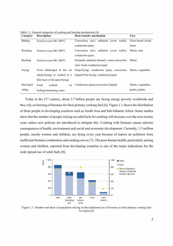
Today in the 21st century, about 2.7 billion people are facing energy poverty worldwide and
they rely on burning of biomass for their primary cooking fuel [6]. Figure 1.1 shows the distribution
of these people in developing countries such as South Asia and Sub-Saharan Africa. Some studies
show that the number of people relying on solid fuels for cooking will increase over the next twenty
years unless new policies are introduced to mitigate this. Cooking with biomass causes adverse
consequences of health, environment and social and economic development. Currently, 1.5 million
people, mostly women and children, are dying every year because of indoor air pollution from
inefficient biomass combustion and cooking stoves [7]. The poor human health, particularly among
women and children, reported from developing countries is one of the major indications for the
wide spread use of solid fuels [8].
Figure 1.1: Number and share of population relying on the traditional use of biomass as their primary cooking fuel
by region [6]
3
1.2 Solar cookers
Solar cooking provides a clean and healthy way of food preparation. A solar cooker cooks food
using solar radiation directly or indirectly. Though the first attempt of solar energy for cooking
food was published in 1767, the extensive development of solar cookers took place in the 1950s
[9].
Recent studies indicate that out of many developing countries India, China, Pakistan, Ethiopia,
and Nigeria have the highest potential for solar cooking by 2020. This is due to their annual solar
radiation, percentage of forest coverage, estimated populations, and estimated share of the
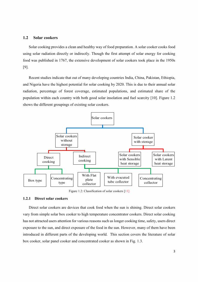
population within each country with both good solar insolation and fuel scarcity [10]. Figure 1.2
shows the different groupings of existing solar cookers.
Solar cookers
without
storage
Solar cooker
with storage
Direct
cooking
Indirect
cooking
Box type Concentrating
type
With Flat
plate
collector
With evacuted
tube collector Concentrating
collector
Solar cookers
with Sensible
heat storage
Solar cookers
with Latent
heat storage
Solar cookers
Figure 1.2: Classification of solar cookers [11]
1.2.1 Direct solar cookers
Direct solar cookers are devices that cook food when the sun is shining. Direct solar cookers
vary from simple solar box cooker to high temperature concentrator cookers. Direct solar cooking
has not attracted users attention for various reasons such us longer cooking time, safety, users direct
exposure to the sun, and direct exposure of the food in the sun. However, many of them have been
introduced in different parts of the developing world. This section covers the literature of solar
box cooker, solar panel cooker and concentrated cooker as shown in Fig. 1.3.
4
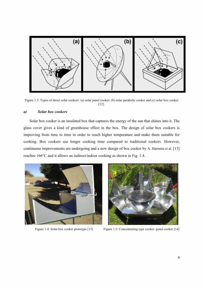
Figure 1.3: Types of direct solar cookers: (a) solar panel cooker; (b) solar parabolic cooker and (c) solar box cooker
[12].
a) Solar box cookers
Solar box cooker is an insulated box that captures the energy of the sun that shines into it. The
glass cover gives a kind of greenhouse effect in the box. The design of solar box cookers is
improving from time to time in order to reach higher temperature and make them suitable for
cooking. Box cookers use longer cooking time compared to traditional cookers. However,
continuous improvements are undergoing and a new design of box cooker by A. Harmim et al. [13]
reaches 166C and it allows an indirect/indoor cooking as shown in Fig. 1.4.
Figure 1.4: Solar box cooker prototype [13] Figure 1.5: Concentrating type cooker: panel cooker [14]

5
b) Panel type solar cookers
Panel type solar cooker is the least expensive and simple type of solar cooker. It is designed to
reflect the incoming sunlight over the surface of a cooking pot. The cooking pot (receiver) is
painted black on the outside in order to absorb the reflected rays as shown in Fig. 1.5. The
inexpensive cardboard and aluminum foil solar kit are some of the most widely used panel cookers.
These cookers might be the most common type of cookers available due to their ease of
construction and low-cost. Moreover, it is highly useful for people leading a nomadic or travelling
life. The most popular design of panel cooker is the design of Roger Bernard [13].
c) Parabolic or concentrating cookers
Parabolic solar cookers have a higher cooking temperature compared to box and panel type
cookers. These cookers focus a narrow beam of sun radiation on the bottom of the cooking pot that
sits on the focus of the collector as shown in Fig. 1.6. This cooker instantly gets hot as high as 232-
260ºC, which is similar to open fire or a gas burner [15]. Parabolic solar cookers need to track the
movement of the sun during the day in order to give the required cooking temperature. Many
families in China and India use these types of cookers to cook their food and for water boiling. In
addition, large-scale parabolic collectors such as the Scheffler has implemented for community
cooking in these places. Parabolic solar cookers are supposed to give higher efficiencies; however,
they often give low performance due to the huge heat loss from their cooking pot [16].
(a) (b)
Figure 1.6: Concentrating direct solar cooker and water heater operating in the cooking mode [17, 18]
6
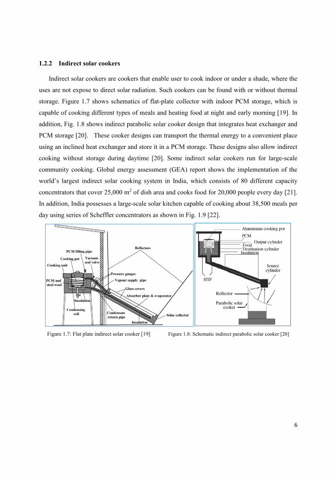
1.2.2 Indirect solar cookers
Indirect solar cookers are cookers that enable user to cook indoor or under a shade, where the
uses are not expose to direct solar radiation. Such cookers can be found with or without thermal
storage. Figure 1.7 shows schematics of flat-plate collector with indoor PCM storage, which is
capable of cooking different types of meals and heating food at night and early morning [19]. In
addition, Fig. 1.8 shows indirect parabolic solar cooker design that integrates heat exchanger and
PCM storage [20]. These cooker designs can transport the thermal energy to a convenient place
using an inclined heat exchanger and store it in a PCM storage. These designs also allow indirect
cooking without storage during daytime [20]. Some indirect solar cookers run for large-scale
community cooking. Global energy assessment (GEA) report shows the implementation of the
world’s largest indirect solar cooking system in India, which consists of 80 different capacity
concentrators that cover 25,000 m2 of dish area and cooks food for 20,000 people every day [21].
In addition, India possesses a large-scale solar kitchen capable of cooking about 38,500 meals per
day using series of Scheffler concentrators as shown in Fig. 1.9 [22].
Figure 1.7: Flat plate indirect solar cooker [19] Figure 1.8: Schematic indirect parabolic solar cooker [20]

7
Figure 1.9: World’s largest steam based indirect solar cooker [22]
1.2.3 Solar cookers in developing countries
Many households and institutions in developing countries use biomass as a basic energy supply.
Solar cooking can be an instrument against firewood shortage, desertification, and a means of relief
for women and children in the developing world [23]. However, despite the negative health and
environmental impacts of unsustainable biomass use, solar cookers show little success. This is
because of most researchers focus more on technical improvements of solar cookers than on the
reasons of their failure [24]. In addition to proper communication between technical and socio-
economical researches, the success of solar cookers depend on materials cost, production facility,
cooker size, financing schemes, government cooperation and marketing strategies. [25]. It is a
common practice to see some initiatives of solar cooking running for short period and discontinued
after wards. To increase the sustainability of such initiatives in developing countries, introduction
of solar cookers should be considered as a small-scale renewable energy projects affecting socio-
economic, environmental, gender and geographic issues [26].
1.3 Solar collectors
Solar collectors are devises that collect solar radiation, convert it in to thermal energy to run
some applications. The major components of any solar collector includes the reflector, absorber
and heat transportation medium. There are two types of collectors: concentrating and non-
concentrating. While concentrating collectors use different areas of intercepting and focusing, non-
8
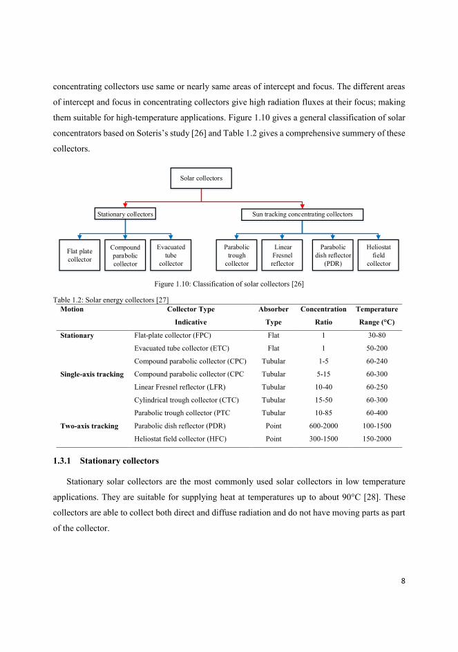
concentrating collectors use same or nearly same areas of intercept and focus. The different areas
of intercept and focus in concentrating collectors give high radiation fluxes at their focus; making
them suitable for high-temperature applications. Figure 1.10 gives a general classification of solar
concentrators based on Soteris’s study [26] and Table 1.2 gives a comprehensive summery of these
collectors.
Solar collectors
Stationary collectors Sun tracking concentrating collectors
Flat plate
collector
Compound
parabolic
collector
Evacuated
tube
collector
Parabolic
trough
collector
Linear
Fresnel
reflector
Parabolic
dish reflector
(PDR)
Heliostat
field
collector
Figure 1.10: Classification of solar collectors [26]
Table 1.2: Solar energy collectors [27]
Motion Collector Type
Indicative
Absorber
Type
Concentration
Ratio
Temperature
Range (°C)
Stationary Flat-plate collector (FPC) Flat 1 30-80
Evacuated tube collector (ETC) Flat 1 50-200
Compound parabolic collector (CPC) Tubular 1-5 60-240
Single-axis tracking Compound parabolic collector (CPC Tubular 5-15 60-300
Linear Fresnel reflector (LFR) Tubular 10-40 60-250
Cylindrical trough collector (CTC) Tubular 15-50 60-300
Parabolic trough collector (PTC Tubular 10-85 60-400
Two-axis tracking Parabolic dish reflector (PDR) Point 600-2000 100-1500
Heliostat field collector (HFC) Point 300-1500 150-2000
1.3.1 Stationary collectors
Stationary solar collectors are the most commonly used solar collectors in low temperature
applications. They are suitable for supplying heat at temperatures up to about 90°C [28]. These
collectors are able to collect both direct and diffuse radiation and do not have moving parts as part
of the collector.
9
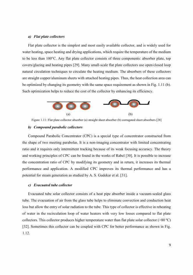
a) Flat plate collectors
Flat plate collector is the simplest and most easily available collector, and is widely used for
water heating, space heating and drying applications, which require the temperature of the medium
to be less than 100°C. Any flat plate collector consists of three components: absorber plate, top
covers/glazing and heating pipes [29]. Many small-scale flat plate collectors use open/closed loop
natural circulation techniques to circulate the heating medium. The absorbers of these collectors
are straight copper/aluminum sheets with attached heating pipes. Thus, the heat collection area can
be optimized by changing its geometry with the same space requirement as shown in Fig. 1.11 (b).
Such optimization helps to reduce the cost of the collector by enhancing its efficiency.
(a) (b)
Figure 1.11: Flat plate collector absorber (a) straight sheet absorber (b) corrugated sheet absorbers [28]
b) Compound parabolic collectors
Compound Parabolic Concentrator (CPC) is a special type of concentrator constructed from
the shape of two meeting parabolas. It is a non-imaging concentrator with limited concentrating
ratio and it requires only intermittent tracking because of its weak focusing accuracy. The theory
and working principles of CPC can be found in the works of Rabel [30]. It is possible to increase
the concentration ratio of CPC by modifying its geometry and in return, it increases its thermal
performance and application. A modified CPC improves its thermal performance and has a
potential for steam generation as studied by A. S. Gudekar et al. [31].
c) Evacuated tube collector
Evacuated tube solar collector consists of a heat pipe absorber inside a vacuum-sealed glass
tube. The evacuation of air from the glass tube helps to eliminate convection and conduction heat
loss but allow the entry of solar radiation to the tube. This type of collector is effective in reheating
of water in the recirculation loop of water heaters with very low losses compared to flat plate
collectors. This collector produces higher temperature water than flat plate solar collector (>80 ºC)
[32]. Sometimes this collector can be coupled with CPC for better performance as shown in Fig.
1.12.

10
Figure 1.12: A typical evacuated tube - CPC solar water heater system [32]
1.3.2 Sun tracking concentrating collectors
The temperature of heat transfer fluids from solar collectors can be increased if the heat loss of
their receivers is reduced and if a large amount of solar radiation can be concentrated on a relatively
small receiver area (high concentration ratio). Concentrating collectors have certain advantages
over non-concentrating collectors. Table 1.3 shows the pros and cons of concentrating collectors.
Table 1.3: pros and cons of concentrating collectors
Pros Cons
Can have higher thermal efficiency Do not collect diffuse radiation
Able to supply high temperature heat Require a tracking system to track the sun
Have smaller cost per unit area of reflector
compared to the cost of others for same energy
Reflecting surfaces lose their reflectance with time
and require periodic cleaning and renewing
Require small area of receiver i.e. economically
feasible to apply selective surface treatment and
vacuum insulation to reduce heat losses and
improve the collector efficiency.
11
Nowadays many designs of concentrating collectors are existing in different applications.
These designs can be reflector/refractor type concentrator, cylindrical/parabolic type, and
continuous/segmented. These collectors may also use convex, flat, cylindrical, or concave type of
receiver and the receiver may be covered with glazing to reduce heat loss. The concentration ratio
of these collectors may vary from unity to high values about 10,000 [33]. However, higher
concentration ratio system requires extreme precision in optical quality and positioning of the
optical system. Practical concentration ratios are often in the range of 10-100.
Concentrating collector systems may apply for solar power generation and process heat
production because of their capability of higher temperature energy delivery. In spite of the huge
potentials for solar thermal concentrators in industrial heat supply, between 50 and 1,500°C, so far
they have not been applied for more than 400°C for this purpose [34]. Among the many types of
concentrators, this part of the study only covers the literature related to parabolic trough, parabolic
dish and heliostat collectors and offset reflectors (Scheffler type reflector).
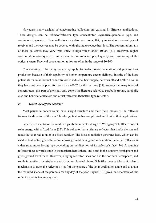
a) Offset (Scheffler) collector
Most parabolic concentrators have a rigid structure and their focus moves as the reflector
follows the direction of the sun. This design feature has complicated and limited their applications.
Scheffler concentrator is a modified parabolic reflector design of Wolfgang Scheffler to collect
solar energy with a fixed focus [35]. This collector has a primary reflector that tracks the sun and
focus the solar radiation onto a fixed receiver. The focused radiation generates heat, which can be
used to boil water, generate steam, cooking, bread baking and incineration. Scheffler reflector is
either standing or laying type depending on the direction of its reflector’s face [36]. A standing
reflector faces towards south in the northern hemisphere, and north in the southern hemisphere and
gives ground level focus. However, a laying reflector faces north in the northern hemisphere, and
south in southern hemisphere and gives an elevated focus. Scheffler uses a telescopic clamp
mechanism to track the reflector by half of the change of the solar declination angle and to attain
the required shape of the parabola for any day of the year. Figure 1.13 gives the schematic of this
reflector and its tracking system.
12
Figure 1.13: Installation and daily tracking details of Scheffler reflector [36].
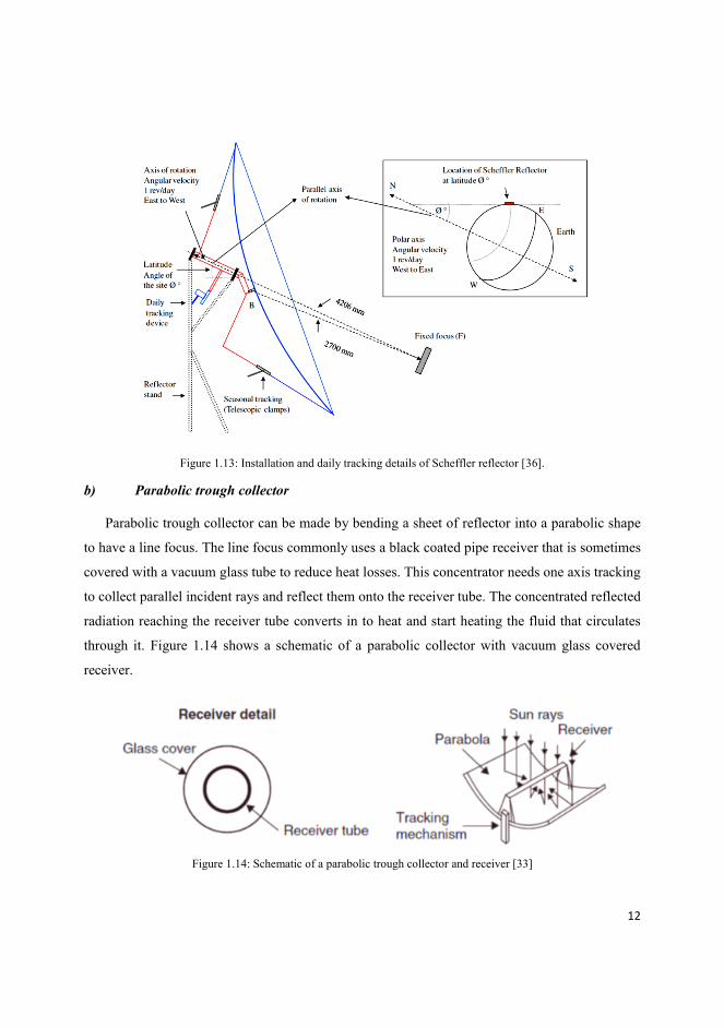
b) Parabolic trough collector
Parabolic trough collector can be made by bending a sheet of reflector into a parabolic shape
to have a line focus. The line focus commonly uses a black coated pipe receiver that is sometimes
covered with a vacuum glass tube to reduce heat losses. This concentrator needs one axis tracking
to collect parallel incident rays and reflect them onto the receiver tube. The concentrated reflected
radiation reaching the receiver tube converts in to heat and start heating the fluid that circulates
through it. Figure 1.14 shows a schematic of a parabolic collector with vacuum glass covered
receiver.
Figure 1.14: Schematic of a parabolic trough collector and receiver [33]
13
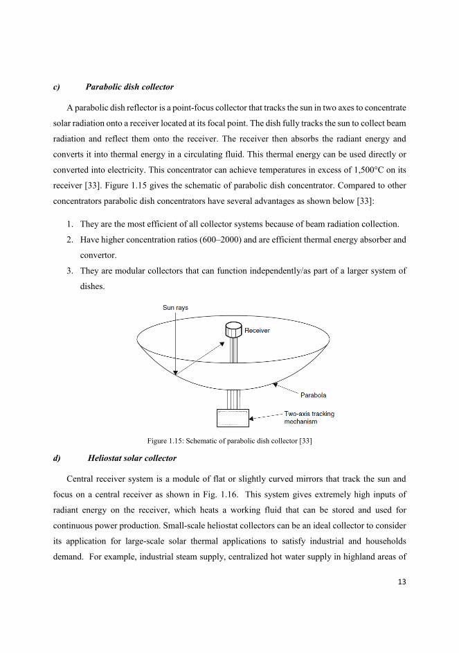
c) Parabolic dish collector
A parabolic dish reflector is a point-focus collector that tracks the sun in two axes to concentrate
solar radiation onto a receiver located at its focal point. The dish fully tracks the sun to collect beam
radiation and reflect them onto the receiver. The receiver then absorbs the radiant energy and
converts it into thermal energy in a circulating fluid. This thermal energy can be used directly or
converted into electricity. This concentrator can achieve temperatures in excess of 1,500°C on its
receiver [33]. Figure 1.15 gives the schematic of parabolic dish concentrator. Compared to other
concentrators parabolic dish concentrators have several advantages as shown below [33]:
1. They are the most efficient of all collector systems because of beam radiation collection.
2. Have higher concentration ratios (600–2000) and are efficient thermal energy absorber and
convertor.
3. They are modular collectors that can function independently/as part of a larger system of
dishes.
Figure 1.15: Schematic of parabolic dish collector [33]
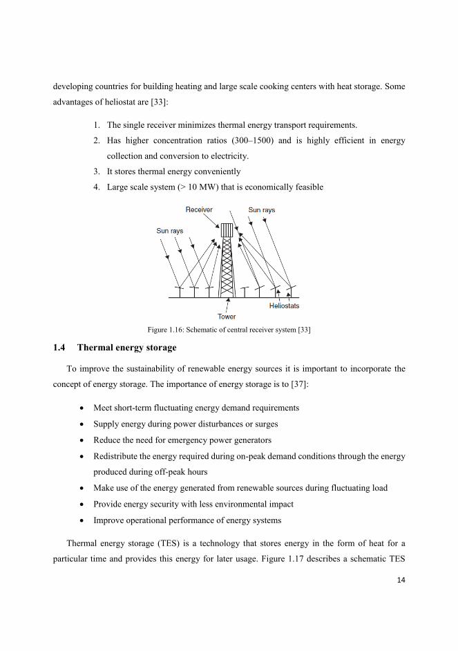
d) Heliostat solar collector
Central receiver system is a module of flat or slightly curved mirrors that track the sun and
focus on a central receiver as shown in Fig. 1.16. This system gives extremely high inputs of
radiant energy on the receiver, which heats a working fluid that can be stored and used for
continuous power production. Small-scale heliostat collectors can be an ideal collector to consider
its application for large-scale solar thermal applications to satisfy industrial and households
demand. For example, industrial steam supply, centralized hot water supply in highland areas of
14
developing countries for building heating and large scale cooking centers with heat storage. Some
advantages of heliostat are [33]:
1. The single receiver minimizes thermal energy transport requirements.
2. Has higher concentration ratios (300–1500) and is highly efficient in energy
collection and conversion to electricity.
3. It stores thermal energy conveniently
4. Large scale system (> 10 MW) that is economically feasible
Figure 1.16: Schematic of central receiver system [33]
1.4 Thermal energy storage
To improve the sustainability of renewable energy sources it is important to incorporate the
concept of energy storage. The importance of energy storage is to [37]:
Meet short-term fluctuating energy demand requirements
Supply energy during power disturbances or surges
Reduce the need for emergency power generators
Redistribute the energy required during on-peak demand conditions through the energy
produced during off-peak hours
Make use of the energy generated from renewable sources during fluctuating load
Provide energy security with less environmental impact
Improve operational performance of energy systems
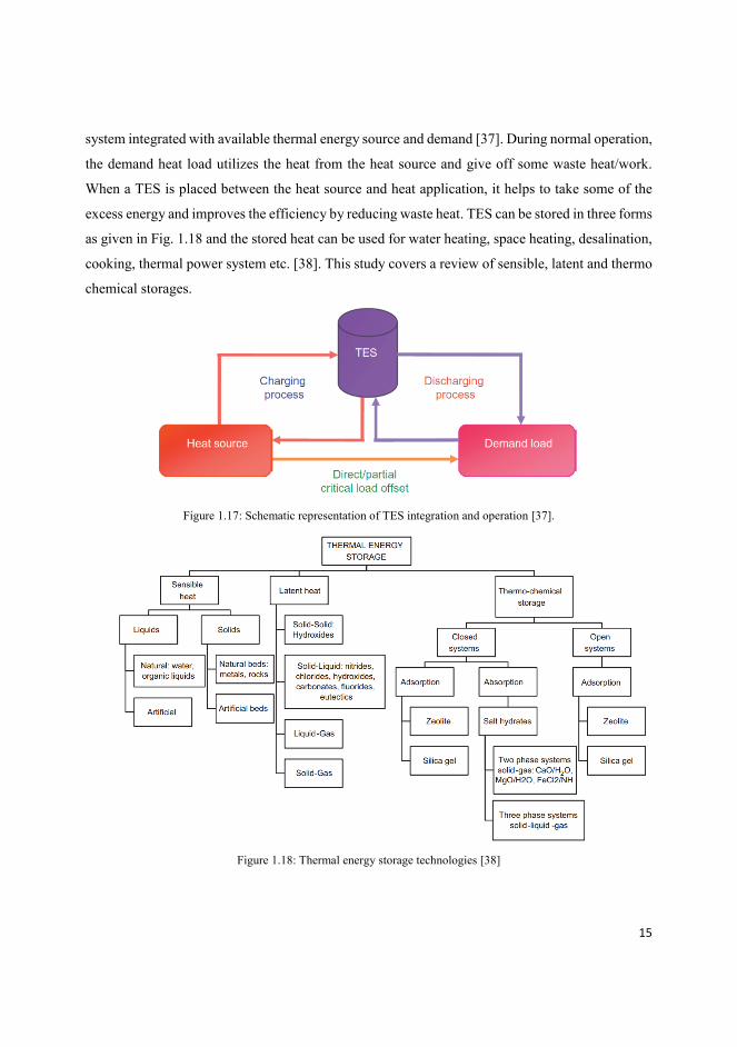
Thermal energy storage (TES) is a technology that stores energy in the form of heat for a
particular time and provides this energy for later usage. Figure 1.17 describes a schematic TES
15
system integrated with available thermal energy source and demand [37]. During normal operation,
the demand heat load utilizes the heat from the heat source and give off some waste heat/work.
When a TES is placed between the heat source and heat application, it helps to take some of the
excess energy and improves the efficiency by reducing waste heat. TES can be stored in three forms
as given in Fig. 1.18 and the stored heat can be used for water heating, space heating, desalination,
cooking, thermal power system etc. [38]. This study covers a review of sensible, latent and thermo
chemical storages.
Figure 1.17: Schematic representation of TES integration and operation [37].
Figure 1.18: Thermal energy storage technologies [38]
16
1.4.1 Sensible thermal energy storage (STES)
In sensible heat storage technology, the temperature of the storage material increases when
energy is applied to it, the stored energy is in the form of internal energy of the storage material
that increases with the temperature of the material. In an STES, the heat energy stored in the
material is directly proportional to the mass (m), specific heat capacity (cp), and temperature
difference (ΔT) of the material [39].
STES materials are commonly classified as solid and liquid storage materials. Solid storage
materials include rocks, stones, brick, iron, soil, concrete etc. and liquid storage materials include
mainly water and oils [40]. Solid STESs are common for space heating and high temperature (solar)
heating applications. It usually operated in temperature ranges of 40 to 75 °C for rock beds/concrete
and over 150 °C for metals in these applications respectively. The reason behind developing solid
storage includes [37]:
Reduced risks of leakage at elevated temperatures
Feasible to store very high temperatures (solar power plants)
However, they have also the following limitations:
Relatively low specific heat capacity (~1200 kJ /m3/K)
Reduced energy storage density compared to liquid storage materials
Increased risks of self-discharge (heat losses) in long-term storage systems
Thermo-physical properties of the heat and energy transport medium
Stratification of storage unit
On the other hand, liquid STES and transfer material have been widely preferred for low and
medium temperature application ranges. In which, water is the most commonly used material due
to its higher specific heat capacity, availability, and cost [41].
1.4.2 Latent thermal energy storage (LTES)
The material of LTES undergoes a phase change process for storing or discharging heat energy.
The phase change process, solid to liquid or vice versa, normally occurs at/near isothermal
conditions. The heat energy stores in a material when the material undergoes phase transition from
solid to liquid state by absorbing the heat energy supplied to it. Similarly, the energy discharges

17
from the material when it solidifies. Materials with this property are called phase change materials
(PCMs). PCMs have the capacity of storing sensible heat as a change of their temperature, below
and above phase transition temperature, and latent heat enthalpy during their phase transition.
Figure 1.19 gives the storing and discharging process of LTES.
Figure 1.19: Heat storage and release processes of the PCM [37]
The overall storage capacity of LTES system with a PCM is given by:
𝑄 = ∫ 𝑚𝑐𝑝𝑑𝑇𝑇𝑚
𝑇𝑖 + 𝑚𝑎𝑚∆𝐻𝑚 + ∫ 𝑚𝑐𝑝𝑑𝑇
𝑇𝑓
𝑇𝑚 (1)
Where 𝑎𝑚–fraction melted, ∆𝐻𝑚– heat of melting per unit mass (J/kg), Ti- initial temperature,
Tm-melting temperature, Tf- final temperature, m- mass of PCM and Cp- PCM heat capacity
Figure 1.20 gives the classification of PCM with important characteristics in Table 1.4.
Moreover, Table 1.5 gives the properties of the salt mixture of 40%KNO3 and 60%NaNO3, which
is used in this research.

18
Figure 1.20: Classification of phase change materials [43]
Table 1.4: Most important features required for PCMs [42, 43]
PCM properties
Thermal Physical Kinetic properties Chemical Economic
Phase change
temperature fitted to
application
Higher enthalpy per
unit volume near
temperature of use
High thermal
conductivity in both
phases
high specific heat, to
provide additional
SHS
Lower density
variation
High density
Small or no sub-
cooling
Low vapor
pressure at the
operating
temperature,
No super cooling
High nucleation
rate
Adequate rate of
crystallization
long-term chemical stability
a completely reversible
freeze/melt cycle
Compatibility with container
materials, Nontoxic. non-
flammable, non-polluting
Cheap
and
abundant
Table 1.5: Properties of Selected Anhydrous Inorganic Salt Mixtures sorted by Anion and Melting Temperature [44]
Salt System (wt %) 𝑻𝒎(℃) 𝑻𝒎𝒂𝒙(℃) H (J g -1) 𝐜𝒑(𝐉 𝐠−𝟏𝐊−𝟏) 𝝆(𝒈 𝒄𝒎−𝟑) 𝝆. 𝒄𝒑(𝑱 𝒄𝒎−𝟑𝑲−𝟏)
KNO3-NaNO3(eu) (54-46) 222 ~550 101 1.52a 1.84a 2.80a
KNO3-NaNO3(solar) (40- 60) 240b 530-565 113 1.55a 1.84a 2.85a
NaNO3 306 520 178 1.66a 1.85a 3.07a a Values at 400°C, b Approximate liquidus temperature.
1.4.3 Thermo Chemical Storage
Thermo chemical storage uses reversible chemical reactions of reactants to store and release
the required heat energy. The supply of heat energy to pairs of chemical material breaks the bonding
between them and they separates into individual reactive components. In this process, the materials

19
able to store heat energy and release it when they undergoes a reverse reaction. In comparison to
LTES and STES, thermo chemical storage has the smallest volume of storage size followed by
LTES to store a certain amount of energy. Table 1.6 gives the list of advantages and disadvantages
of the three thermal energy storages. For example, dehydration and rehydration of Ca(OH)2 in a
reactor with direct heat transfer for thermo-chemical heat storage is given by eq. 2 [45].
𝐶𝑎(𝑂𝐻)2 ↔ 𝐶𝑎𝑂 + 𝐻2𝑂 (2)
Table 1.6: Advantages and disadvantages of TES concepts [38]
TES technique Advantage Disadvantage
Sensible heat storage Simple design Size of the systems
Not isothermal storage process
Latent heat storage Isothermal storage process
High storage density
Price
Low thermal conductivity
Almost no convection
Thermo-chemical
storage
High energy density Complexity
Expensive compounds
Relatively high temperature required
Limited experience with long-term operation
1.5 Charging of PCM storages for solar cooking application
PCM storages in solar cooking application have increased the reliability of solar cookers;
however, the charging and discharging process of these storages is challenging. Depending on the
type of solar collector to which the storage is coupled, the storage can be charged either through
direct illumination or by the help of a HTF (heat transfer fluid). Scheffler and double reflector
parabolic dish collectors can charge their storage by direct illumination. On the other hand,
parabolic dish and parabolic trough collectors can charge their storage by using heat transfer
liquids.
1.5.1 Direct illumination
In a direct illumination chagrining process, the collector reflects the incoming solar radiation
onto the top part of the PCM storage. The radiation starts heating the top plate of the storage and
fins integrated to this plate starts to conduct the heat to the PCM material. Parabolic dish with
secondary reflector and Scheffler concentrator are possible collectors for this technique. In this
charging process, the storage remains stationary and the charging follows a top-down heating
process. Foong et al. [46] used a double reflector concentrator to melt a solar salt storage by a top-

20
down heating/charging process, where the storage has fitted with aluminum plate fins to conduct
the heat into the salt materials.
1.5.2 Using heat transfer fluid
a) Oil bath charging
A HTF can carry the heat developed in the receivers over some distance to a heat storages. The
transportation can be through a natural circulation or forced circulation of the HTF. To minimize
the complexity of solar concentrator’s design, natural circulation in a closed loop system is often a
preferred method. An example of an oil bath to melt a solar salt contained in an aluminum container
with natural oil circulation is given by Mussard and Nydal [47].
b) Steam charging
Some fixed focus solar concentrators use steam as heat transfer fluid. Steam is suitable as heat
carrier in solar power generations due to its higher heat capacity, chemically inertness, abundancy,
and nontoxicity. Scheffler has introduced his collector for steam baking in India and still the
product is getting wider and more useful [48]. In the present work, water and steam is tested for
heat transfer between the receiver and a storage. Natural circulation is obtained by boiling in the
receiver and condensing in the storage. The steam in this case was operated at about 40-bar
pressure, where pressure safety valves and pressure gages were properly fitted.

21
2 Objectives
The general objective of this study is to investigate a small-scale concentrating solar system
with latent heat storage that stores solar thermal energy during the day when the sun is shining and
provides energy to bake Injera (national food of Ethiopia) during the night or early morning.
Specific objectives:
Design and develop a small-scale solar concentrator with latent heat storage, phase
change material (PCM), and a heat transfer loop to charge the storage.
Investigate the charging-discharging behavior of the PCM storage
Design and develop a suitable solar stove that is capable of Injera baking
Investigate the performance of the system
Study the market penetration potential of the stove

22
23
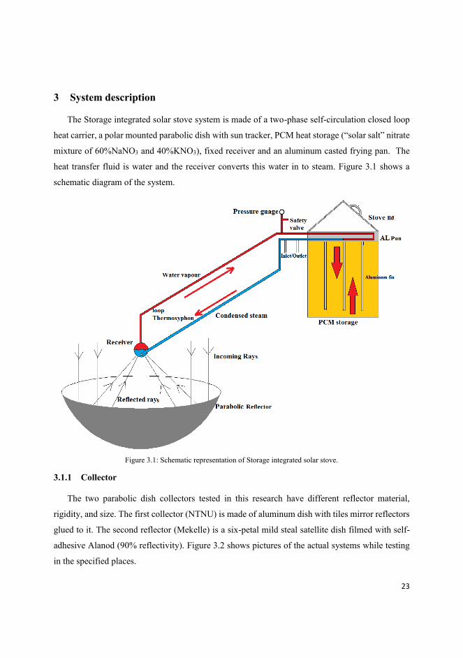
3 System description
The Storage integrated solar stove system is made of a two-phase self-circulation closed loop
heat carrier, a polar mounted parabolic dish with sun tracker, PCM heat storage (“solar salt” nitrate
mixture of 60%NaNO3 and 40%KNO3), fixed receiver and an aluminum casted frying pan. The
heat transfer fluid is water and the receiver converts this water in to steam. Figure 3.1 shows a
schematic diagram of the system.
Figure 3.1: Schematic representation of Storage integrated solar stove.
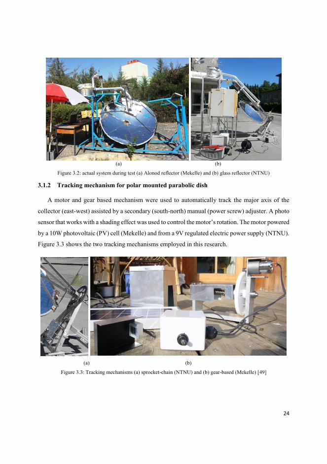
3.1.1 Collector
The two parabolic dish collectors tested in this research have different reflector material,
rigidity, and size. The first collector (NTNU) is made of aluminum dish with tiles mirror reflectors
glued to it. The second reflector (Mekelle) is a six-petal mild steal satellite dish filmed with self-
adhesive Alanod (90% reflectivity). Figure 3.2 shows pictures of the actual systems while testing
in the specified places.
24
(a) (b)
Figure 3.2: actual system during test (a) Alonod reflector (Mekelle) and (b) glass reflector (NTNU)
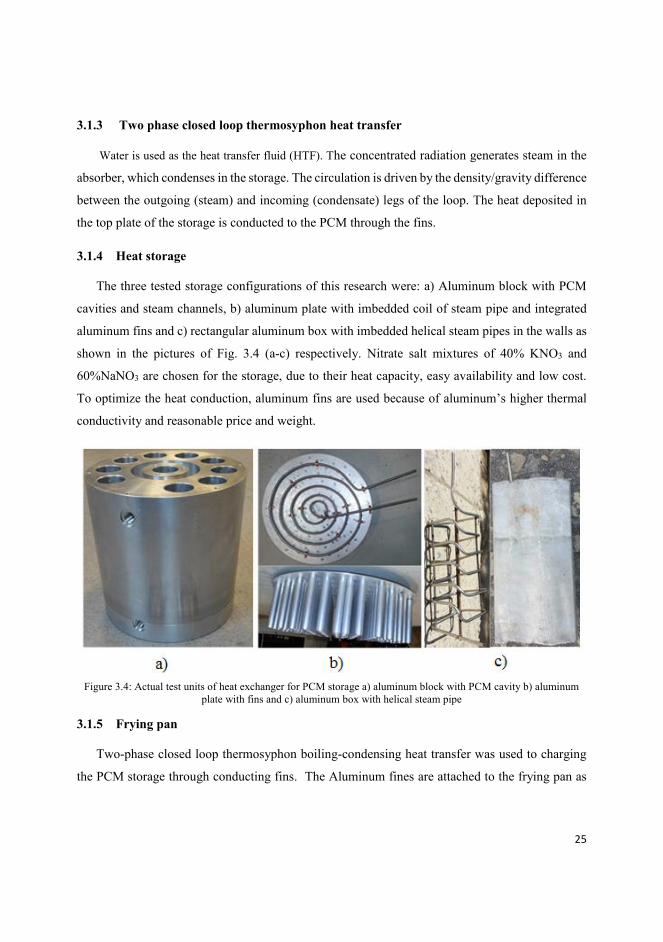
3.1.2 Tracking mechanism for polar mounted parabolic dish
A motor and gear based mechanism were used to automatically track the major axis of the
collector (east-west) assisted by a secondary (south-north) manual (power screw) adjuster. A photo
sensor that works with a shading effect was used to control the motor’s rotation. The motor powered
by a 10W photovoltaic (PV) cell (Mekelle) and from a 9V regulated electric power supply (NTNU).
Figure 3.3 shows the two tracking mechanisms employed in this research.
(a) (b)
Figure 3.3: Tracking mechanisms (a) sprocket-chain (NTNU) and (b) gear-based (Mekelle) [49]
25
3.1.3 Two phase closed loop thermosyphon heat transfer
Water is used as the heat transfer fluid (HTF). The concentrated radiation generates steam in the
absorber, which condenses in the storage. The circulation is driven by the density/gravity difference
between the outgoing (steam) and incoming (condensate) legs of the loop. The heat deposited in
the top plate of the storage is conducted to the PCM through the fins.
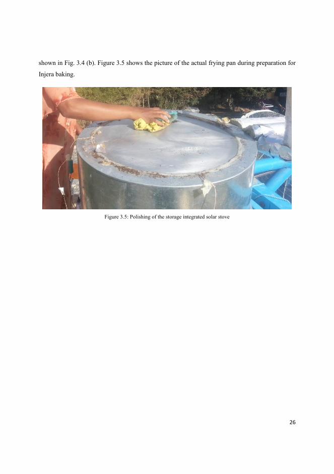
3.1.4 Heat storage
The three tested storage configurations of this research were: a) Aluminum block with PCM
cavities and steam channels, b) aluminum plate with imbedded coil of steam pipe and integrated
aluminum fins and c) rectangular aluminum box with imbedded helical steam pipes in the walls as
shown in the pictures of Fig. 3.4 (a-c) respectively. Nitrate salt mixtures of 40% KNO3 and
60%NaNO3 are chosen for the storage, due to their heat capacity, easy availability and low cost.
To optimize the heat conduction, aluminum fins are used because of aluminum’s higher thermal
conductivity and reasonable price and weight.
Figure 3.4: Actual test units of heat exchanger for PCM storage a) aluminum block with PCM cavity b) aluminum
plate with fins and c) aluminum box with helical steam pipe
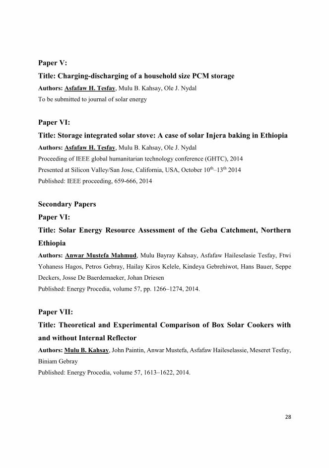
3.1.5 Frying pan
Two-phase closed loop thermosyphon boiling-condensing heat transfer was used to charging
the PCM storage through conducting fins. The Aluminum fines are attached to the frying pan as
26
shown in Fig. 3.4 (b). Figure 3.5 shows the picture of the actual frying pan during preparation for
Injera baking.
Figure 3.5: Polishing of the storage integrated solar stove

27
4 List of papers
Main Papers
Paper I:
Title: Solar powered heat storage for Injera baking in Ethiopia
Authors: Asfafaw H. Tesfay, Mulu B. Kahsay, Ole J. Nydal
Published: Energy Procedia, volume 57, pp. 1603–1612, 2014.
Paper II:
Title: Design and development of solar thermal Injera baking: steam based
direct baking
Authors: Asfafaw H Tesfay, Mulu B. Kahsay, Ole J. Nydal
Published: Energy Procedia, volume 57, pp. 2946 – 2955, 2014
Paper III:
Title: Energy Consumption Assessment of Injera: A Strategy for Energy-
Efficient Stove Designs in Ethiopia
Authors: Asfafaw H. Tesfay, Ole J. Nydal, and Mulu B. Kahsay
Submitted to journal of Applied Energy
Year: 2014
Paper IV:
Title: Experimental Investigation of Optical Pipe as a Means of Radiation
Transfer for Solar Thermal Applications
Authors: Asfafaw H. Tesfay, Getachew M. Derese, Chimango Mvula, Ole J. Nydal and Mulu B.
Kahsay
Submitted to journal of Solar Energy
Year: 2014
28
Paper V:
Title: Charging-discharging of a household size PCM storage
Authors: Asfafaw H. Tesfay, Mulu B. Kahsay, Ole J. Nydal
To be submitted to journal of solar energy
Paper VI:
Title: Storage integrated solar stove: A case of solar Injera baking in Ethiopia
Authors: Asfafaw H. Tesfay, Mulu B. Kahsay, Ole J. Nydal
Proceeding of IEEE global humanitarian technology conference (GHTC), 2014
Presented at Silicon Valley/San Jose, California, USA, October 10th–13th 2014
Published: IEEE proceeding, 659-666, 2014
Secondary Papers
Paper VI:
Title: Solar Energy Resource Assessment of the Geba Catchment, Northern
Ethiopia
Authors: Anwar Mustefa Mahmud, Mulu Bayray Kahsay, Asfafaw Haileselasie Tesfay, Ftwi
Yohaness Hagos, Petros Gebray, Hailay Kiros Kelele, Kindeya Gebrehiwot, Hans Bauer, Seppe
Deckers, Josse De Baerdemaeker, Johan Driesen
Published: Energy Procedia, volume 57, pp. 1266–1274, 2014.
Paper VII:
Title: Theoretical and Experimental Comparison of Box Solar Cookers with
and without Internal Reflector
Authors: Mulu B. Kahsay, John Paintin, Anwar Mustefa, Asfafaw Haileselassie, Meseret Tesfay,
Biniam Gebray
Published: Energy Procedia, volume 57, 1613–1622, 2014.

29
Conference presentations
i.
Title: Storage integrated solar stove and its perspectives in Ethiopia
Authors: Asfafaw H. Tesfay, Ole J. Nydal, Mulu B. Kahsay
Presented at renewable energy research conference (rerc), Oslo, Norway, 16th-18th September 2014
ii.
Title: Solar energy for Sustainable energy and climate security
Authors: Asfafaw H. Tesfay, Ole J. Nydal, Mulu B. Kahsay
Presented at Sustainable Land and Watershed Management (SLWM) Conference, Mekelle,
Ethiopia, 26th-27th May, 2014

30

31
References
[1] Chris O. et al., Phylogenetic rate shifts in feeding time during the evolution of Homo, PNAS, vol. 108; pp: 14555-
14559, 2011.
[2] Heller M.C. and Keoleian G.A., Life Cycle-based Sustainability Indicators for Assessment of the U.S. Food
System. Report CSS00-04, University of Michigan: Center for Sustainable Systems, School of Natural Resources
and Environment, University of Michigan, Ann Arbor, MI. 2000.
[3] 2009 U.S. Energy Information Agency, Annual Energy Review. Washington, DC. August 2010
[4] T.J. Hager, and R. Morawicki Energy consumption during cooking in the residential sector of developed nations:
A review
[5] Thim, C., Domestic appliances, Technology Guide: Principles, Applications, Trends. Springer-Verlag, Bullinger,
H. J. (Ed.), pp.458–461, 2009.
[6] IEA, International Energy Agency, World Energy Outlook 2010, 2010.
[7] IEA, International Energy Agency, World Energy Outlook 2010, 2010. and World Health Organization, Global
Health Risks: Mortality and Burden of disease Attributable to Selected Major Risks. 2009
[8] W. Foell et al., Household cooking fuels and technologies in developing economies, Energy Policy, vol.39; pp:
7487–7496, 2011
[9] A. Harmim et al., Design and experimental testing of an innovative building-integrated box type solar cooker,
Solar Energy, vol.98; pp: 422–433, 2013
[10] Global Energy Assessment (GEA) Toward a Sustainable Future, International Institute for Applied Systems
Analysis 2012
[11] R.M. Muthusivagami, R. Velraj, R. Sethumadhavan, Solar cookers with and without thermal storage—A review,
Renewable and Sustainable Energy Reviews 14 (2010) 691–701
[12] Erdem Cuce and Pinar Mert Cuce, A comprehensive review on solar cookers, Applied Energy 102 (2013) 1399–
1421
[13] A. Harmim et al., Design and experimental testing of an innovative building-integrated box type solar cooker,
Solar Energy, vol.98; pp- 422–433, 2013
[14] R.M. Muthusivagami et al., Solar cookers with and without thermal storage—A review, Renewable and
Sustainable Energy Reviews 14 (2010) 691–701
[15] Linda Hanna and Patricia McArdle, Solar Cooker Project Best Practices Manual, Jewish World Watch
[16] N.L. Panwar et al., State of the art of solar cooking: An overview, renewable and sustainable energy reviews,
Vol.16: pp; 3776-3785,2012
[17] A.A. Badran et al., Portable solar cooker and water heater, Energy Conversion and Management 51 (2010) 1605–
1609
[18] N.L. Panwar et al., State of the art of solar cooking: An overview, renewable and sustainable energy reviews,
Vol.16: pp; 3776-3785,2012

32
[19] H. M. S. Hussein, experimental investigation of Novel indirect solar cooker with indoor PCM thermal storage and
cooking unit
[20] A. Sharma et al., solar cooker with latent heat storage system- A review, renewable and Sustainable Energy
Reviews
[21] Global Energy Assessment (GEA) Toward a Sustainable Future, International Institute for Applied Systems
Analysis 2012
[22] http://inhabitat.com/world%E2%80%99s-largest-solar-kitchen-in-india-can-cook-upto-38500-meals-per-day/
[retrieve on 30.09.2014]
[23] K. Kuhnke, SOLAR COOKERS FOR DEVELOPING COUNTRIES: A WORLDWIDE STUDY, Advances In
Solar Energy Technology, 1988, Pages 2678-2682
[24] P. P. Otte, Solar cookers in developing countries—What is their key to success?, Energy Policy, Vol. 63; pp 375–
381, 2013
[25] Richard C. Wareham, Parameters for a solar cooker program, Renewable Energy, Vol. 10, pp. 217-219, 1997
[26] J. Terrapon-Pfaff et al., How effective are small-scale energy interventions in developing countries results from a
post-evaluation on project level, Applied Energy xxx (2014) xxx–xxx
[27] Soteris A. Kalogirou, Solar Energy Collectors, Solar Energy Engineering (Second Edition), Chapter 3, Pages 125-
220, 2014
[28] Y.G. Caouris, Low Temperature Stationary Collectors, Reference Module in Earth Systems and Environmental
Sciences, Comprehensive Renewable Energy, Volume 3, 2012, Pages 103-147
[29] Sunil.K.Amrutkar et al., Solar Flat Plate Collector Analysis, IOSR Journal of Engineering (IOSRJEN), Vol. 2,
pp.207-213, 2012
[30] Rabl, A., Concentrating collectors. In: Dickinson, W.C., Cheremisinoff, P.N. (Eds.), Solar Energy Technology
Handbook Part A – Engineering Fundamentals. Marcel Dekker Inc., New York, pp. 257– 343, 1980.
[31] A. S. Gudekar et al., Cost effective design of compound parabolic collector for steam generation, Solar Energy,
Vol. 90: pp; 43–50, 2013
[32] Wisut Chamsa-ard et al., Thermal Performance Testing of Heat Pipe Evacuated Tube with compound parabolic
concentrating solar collector by ISO 9806-1, Energy Procedia, vol. 56: pp; 237 – 246, 2014
[33] Soteris A. Kalogirou, Solar Energy Collectors, Solar Energy Engineering (Second Edition), pp; 125-220, 2014
[34] A. Häberle, Concentrating solar technologies for industrial process heat and cooling, Concentrating Solar Power
Technology, 2012, Pages 602-619
[35] R.J.Patil et al., Comparison of performance analysis of Scheffler reflector and model formulation, Indian Journal
of Science and Technology, Vol. 4: pp; 1335-1339, 2011.
[36] A. Munir et al., Design principle and calculations of a Scheffler fixed focus concentrator for medium temperature
applications, Solar Energy, vol. 84: pp; 1490–1502, 2010
[37] S. Kalaiselvam, and R. Parameshwaran, Thermal Energy Storage Technologies, Thermal Energy Storage
Technologies for Sustainability, chapter 3, pp; 57–64, 2014
[38] U. Stritih et al., Exploiting solar energy potential through thermal energy storage in Slovenia and Turkey,
Renewable and Sustainable Energy Reviews, 25, 442–461, 2013

33
[39] M.E. Navarro et al., Selection and characterization of recycled materials for sensible thermal energy storage, Solar
Energy Materials & Solar Cells, Vol. 107: pp;131–135, 2012
[40] S.M. Hasnaina, Review on sustainable thermal energy storage technologies, part I: heat storage materials and
techniques, Energy Conversion and Management 39 (11) (1998) 1127–1138
[41] T. Kousksou et al., Numerical simulation of fluid flow and heat transfer in a phase change thermal energy storage,
International Journal of Energy Technology and Policy (IJETP), Vol. 6, No. 1/2, 2008
[42] K. Pielichowska and K. Pielichowsk, Phase change materials for thermal energy storage, Progress in Materials
Science 65 (2014) 67–123
[43] P. Tatsidjodoung et al., A review of potential materials for thermal energy storage in building applications,
Renewable and Sustainable Energy Reviews 18 (2013) 327–349
[44] T. Bauer et al., High-Temperature Molten Salts for Solar Power Application, Molten Salts Chemistry, chapter 20,
pp; 415-438, 2013
[45] F. Schaube, I. Utz, A. Wörner , H. Müller-Steinhagen, De- and rehydration of Ca(OH)2 in a reactor with direct
heat transfer for thermo-chemical heat storage. Part B: Validation of model, chemical engineering research and
design 9 1 ( 2 0 1 3 ) 865–873
[46] C.W. Foong et al., Investigation of a small scale double-reflector solar concentrating system with high temperature
heat storage, Applied Thermal Engineering, 31 (2011) 1807-1815
[47] M. Mussard and O.J. Nydal, Charging of a heat storage coupled with a low-cost small-scale solar parabolic trough
for cooking purposes, Solar Energy 95 (2013) 144–154
[48] Wolfgang Scheffler, Introduction To The Revolutionary Design Of Scheffler Reflectors, www.solare-
Bruecke.org/, [last retrieved 23-10-2014]
[49] http://www.simply-solar.de/index.php/products/tracking-systems/electronic-daily-tracking-system [last retrieved
on 15-12-2014].

34

35
Contribution of the thesis
In this thesis, experimentation on the various aspects of small-scale parabolic dish solar
concentrator for Injera baking were studied, and the results are presented in papers and the thesis
as summarized below:
Paper I: Solar powered heat storage for Injera baking in Ethiopia
An aluminum block with three-steam channels and ten salt (40% KNO3 and 60% NaNO3)
cavities was constructed, coupled to a parabolic dish concentrator, and tested for latent heat storage
charging with a self-circulating steam loop. Experiment s were compared with simulation results
of COMSOL multiphysiscs. A frying pan was placed on top of the storage to discharge the stored
heat by frying eggs, which took about 30minutes. The aluminum block efficiently separates the
salt from the high pressure steam, but the number of steam channels were few and was limiting the
heat transfer process.
Paper II: Design and development of solar thermal Injera baking: steam based
direct baking
An indirect solar cooker that uses self-circulating steam to heat a frying pan was tested for Injera
baking. The frying pan was developed from clay, like the original Injera stove, by imbedding coiled
stainless steel steam tubes as its heating elements. The results of this work show three important
results. The first result demonstrates the possibility of using solar energy for Injera baking, which
is a challenge. Secondly, it shows the intensive energy demand of Injera baking can be obtained
from solar energy indirectly in an indoor kitchen. Finally, it was demonstrated that Injera baking
can be made in the range of 135-160oC, which is significantly lower than other published values
(180-220ºC).
Paper III: Energy Consumption Assessment of Injera: A Strategy for Energy-
Efficient Stove Designs in Ethiopia
Injera baking has been compared using three different materials, lay, borosilicate glass and metal
(Norwegian take). The baking process demonstrated Injera baking at stove surface temperature of
120-160°C, as long as sufficient heat transfer can be sustained. In addition, it shows 32% of the
baking power can be saved simply by changing the baking plate material from clay to glass without
compromising on the quality of Injera. Moreover, it shows existing clay Injera stove uses only
about 50% of the supplied power and loses the remaining. The results of this paper complements
the findings of paper I and II and gave a strong base for the works of paper V. Moreover, it helped
to realize the need for developing hybrid stoves, solar-electricity and solar-biomass, based on the
available energy supply options in the rural and urban areas respectively.
36
Paper IV: Experimental Investigation of Optical Pipe as a Means of Radiation
Transfer for Solar Thermal Applications
This paper demonstrates the capabilities of an optical pipe in transmitting concentrated radiation
over short distances. A transmission coefficient of 19.6% or an attenuation coefficient of 3.08dB/m
was attained with a 2.3m long, 70mm diameter optical pipe having two 90-degree bends. The
optimal bend angles for the pipe was found with the help of a ray tracer simulation. The main
challenge in this experiment was in directing the radiation into the optical pipe. Parallel inlet rays
were obtained using a double reflector system. The result of this study has indicated that light
guides can potentially be used for radiation transportation in solar thermal applications, particularly
for indoor solar cooking applications.
Paper V: charging and discharging of PCM storage
Two storage integrated solar Injera stoves, which are fit for average household size (four-five family
members), were developed as demonstration units. The baking (frying) pan of these units were developed
from aluminum cast based on the understandings of Injera baking practice obtained in papers1-3. The units
are coupled to 1.2m and 1.8m diameter of parabolic dishes collectors and they are stationed at Norway
(NTNU) and Ethiopia (Mekelle University) respectively. The latitude difference of the locations gave the
two systems different system size. Natural and artificial heat sources (solar and electricity with a heating
element) were used to charge the salt storage. These units were tested for discharging of fully/and partially
charged storage and simultaneous charging-discharging to demonstrate the system’s compatibility to the
intermittent nature of solar energy. Baking tests were successful and equivalent to ordinary electric Injera
stoves, without compromising quality. The unit found in Ethiopia was demonstrated to the public, which
gave strong positive feedback from the end users. Further prototype development should focus on reducing
the losses in particular at the receiver
Paper VI: Storage integrated solar stove: A case of solar Injera baking in
Ethiopia
This paper demonstrates the possibility of using solar energy to bake the unique Ethiopian food Injera,
which was a challenging application. It also shows the competitiveness of the technology to existing electric
Injera stove technologies concerning its baking time and quality of the Injera. This can make it an acceptable
solution by both biomass and electricity power source users. The high initial price of the prototype can be
reduced through optimization and by avoiding unnecessary parts. To investigate the potential of the
technology, a survey of about 320 households were conducted in Mekelle city to map the energy sources
for Injera baking. The survey reveals biomass as a primary energy source and currently the annual expense
for biomass is more expensive than electricity. The survey also demonstrates the need for and importance
of creating awareness among the public on new and emerging technologies.
37
5 Conclusion and recommendation
5.1 Conclusion
A small scale concentrating solar energy system has been constructed and tested, with the
objective of integrating a thermal energy storage which can be used for baking of the Ethiopian
bread Injera.
"Solar Salt" (40% KNO3 and 60% NaNO3) was selected as a suitable PCM for a latent heat
storage, as the melting temperature is in a suitable range for frying (210-220°C). Steam was
selected as the heat transfer medium, with natural circulation between a boiler at the focal point
and a condenser at the storage.
The following conclusions can be drawn from the work:
Steam based heat transfer
Boiling /condensing heat transfer systems are attractive. The density difference between steam
and water contributes to efficient natural circulation and the boiling at the receiver tolerates high
heat fluxes. The drawback is the safety aspects with the rather high pressure required (30-40 bar)
in the heat transfer loop. The conclusion from the test work is that the pressure is manageable, as
long as the volume of the heat transfer loop is small. The operational restart procedure based on
water flushing and boil-off during heating worked satisfactory.
Heat storage medium
Solar Salt is suitable as a latent heat storage medium, where the application requires heat supply
at a given temperature (frying, baking). The heat storage should then preferably be stationary. One
limitation can be the availability of the chemicals in some African countries.
Heat storage design
A major concern is to have safe barriers between the Solar Salt and high pressure steam. This
was achieved with an aluminum block with cavities for the salt and with channels for the steam.
The tests showed that the heat transfer was rather inefficient, and a second concept was developed
with less aluminum and more salt. The barrier between steam and salt was now achieved by
38
imbedding a steam coil in a top plate (frying pan), which was then fitted with fins extending down
into a salt container. This proved to be a useful design, as well as more suitable for later upscaling.
Prototype solar system
A polar mount setup, with single axis tracking and occasional adjustments for the declination
changes is appropriate. Gears are preferred instead of chains; a well-balanced system reduces the
power requirements for the tracking motor. Commercial tracking electronics were applied. Mirror
tiled parabolic dishes (antennas) are more durable than surfaces covered with reflecting films.
Test results
Prototype systems were demonstrated at NTNU and at Mekelle University. The solar based
Injera baking drew strong public attention at a demonstration event at Mekelle. The overall energy
efficiencies are not satisfactory (about 20%), the systems needs to be optimized with respect to
insulation and heat losses (absorber, valves etc.).
Injera baking
Injera can be baked on an aluminum surface, with quality comparable to that from the
traditional clay based pan. The required surface temperature is less (130-150°C) than earlier
guidelines (180-220ºC), as long as the heat transfer rate can be maintained during the baking. This
opens for design of new and more energy optimized frying pans for Injera baking, as well as a
reduction in the temperature requirements of a heat storage.
5.2 Recommendation
The author wants to recommend the following points based on the result of this thesis.
Further computational and optimization work should continue in the heat transfer and
system sizing
Pilot sites should established with robust fully automated gear type tracking mechanism
The casting of the baking plate (frying pan) with integral fin should take considerable
care during casting to make sure there existed a solid connection between them.
It is quite interesting to test charging of this system with oil and analyze its performance

39
This system should further evolve with hybrid options of charging the storage by other
forms of energies such as electricity, biomass and biogas either by damping pick load
while in use or use the system with these sources when there is no sun (cloudy season).

40

41
Papers

42

43
I: Solar powered heat storage for Injera baking in Ethiopia
Asfafaw H. Tesfay, Mulu B. Kahsay, Ole J. Nydal
Energy Procedia, Volume 57, pp. 1603 – 1612, 2014.

44

Energy Procedia 57 ( 2014 ) 1603 – 1612
Available online at www.sciencedirect.com
ScienceDirect
1876-6102 © 2014 The Authors. Published by Elsevier Ltd. This is an open access article under the CC BY-NC-ND license (http://creativecommons.org/licenses/by-nc-nd/3.0/).Selection and/or peer-review under responsibility of ISES.doi: 10.1016/j.egypro.2014.10.152
2013 ISES Solar World Congress
Solar powered heat storage for Injera baking in Ethiopia
Asfafaw Haileselassie Tesfaya,b,*, Mulu Bayray Kahsayb, Ole Jørgen Nydala
a. Department of Energy and Process Engineering, Norwegian University of Scinece and Technology, 7491 Trondheim, Norway
b. Department of Mechanical Engineering, Ethiopian Institute of Technology-Mekelle, Mekelle University P.O.box 231 Mekelle, Ethiopia
Abstract
Ethiopia with a population of about 85 million meets 96% of its energy needs with bio-mass, charcoal, wood, animal dung and plant residues. More than 50% of this energy goes entirely on baking Injera. Injera the national food of the country demands 180-220 oC to be well cooked. In this article; Injera baking with solar energy on off-focus system, status of electric powered stove and the potential for solar powered stoves is discussed. The research and development of solar thermal for household energy consumption has not been well developed and adopted. One reason for this is that the system can only be used outdoor and at time of sun shine. In addition to the off-focus solar thermal application this paper discussed the integration of solar thermal with heat storage for a sustainable future use. The prototype for direct steam based baking was developed and tested in Mekelle University (Ethiopia) and Phase change material based heat storage prototype was developed and tested at NTNU. Both experiments showed the possibility of solar energy for Injera baking and its sustainability by including latent heat storage. This research gave hope to break the bottleneck related with on- focus solar cookers. © 2013 Asfafaw H, Mulu B K and Ole J N. Published by Elsevier Ltd. Selection and/or peer-review under responsibility of ISES Keywords: Steam based baking, solar Injera stove; PCM heat storage
1. Introduction
Injera, a processed food of different cereals, teff, millet, sorghum, maize, wheat, rice etc., or combinations of those passed through fermentation and rigorous baking process, is the widely and cultural food of some east African countries particularly Ethiopia, Eritrea and to some extent Somalia. Injera was baked most commonly on a clay plate called Mitad that is placed over a three stone stove or on specialized electric stove. When a fermented dough poured on a hot clay pan and stayed until the boiling
* Corresponding author. Tel.: +47 41015917; fax: +47 73593580. E-mail address: [email protected], [email protected] (A. H. Tesfay)
© 2014 The Authors. Published by Elsevier Ltd. This is an open access article under the CC BY-NC-ND license (http://creativecommons.org/licenses/by-nc-nd/3.0/).Selection and/or peer-review under responsibility of ISES.

1604 Asfafaw Haileselassie Tesfay et al. / Energy Procedia 57 ( 2014 ) 1603 – 1612
temperature reached; bubbles from the boiling water escape forming thousands of tiny craters (eyes) that give the peculiar Injera texture. The traditional Mitad consists of a griddle plate of ‘black’ clay set on a base of stone and clay [1, 2].
Injera baking practice is similar all over the country with a slight difference in pan dimension and stove
efficiency. Some researchers indicated the traditional clay stoves, 11-20 mm thickness and 500-600 mm diameter, have an estimated efficiency of 5% [2, 3]. Others show the Tigray state Mitad and Mirt Stove, improved stove, has registered an efficiency of 25 % and 35 % respectively [4, 5]. The people Ethiopia eat Injera two to four times a day. The major energy supply for cooking and hot water supply of the country come from biomass. Injera baking requires over 50 % of the primary energy consumption and over 75 % households’ energy consumption. This intensive biomass utilization is accounted for deforestation, expensive fire wood price and poor kitchen environment [6]. This traditional biomass based cooking affected health, energy, school time, and hardship issues of women and children [7]. In Ethiopia, most households have no access to clean energy and most cooking activities are performed in a separated chimneyless confined kitchen and this is worse in rural parts of the country where majorities live. The world energy outlook predicted developing countries dependency on biomass energy supply will increase from what is today. This shows 700 million people in 2030 will be dependent only in Sub-Saharan African [8].
Regardless of the huge solar energy potential of the world, the research and development on solar
thermal has not yet matured. Solar PV is a helpful technology to light rural areas and started booming in some African countries, like Kenya and Tanzania, [9]. It is also expected to have a competitive future with grid in Ethiopia [10]; however, its thermal side is in its infant stage to be considered as a reliable clean energy option. The main concern of many researches on high temperature solar cooking to date was dedicated to direct cooking that has safety issues. These cookers were less accepted because of unable: to cook indoor; night cooking, higher system cost, and longer cooking time. Likewise, cooking of energy intensive foods like Injera was difficult. Nevertheless, their introduction in some African countries resulted in considerable fuel and time savings escorted by reliable energy security of households [11]. Solar cooking could be realistic and considered as a clean energy source if its utilization is not limited to the presence of the sun and outdoor cooking, i.e., when solar energy in the form of heat is possible to transport and store. An integrated collector-storage design helps to transport and store thermal energy directly or indirectly using heat transfer fluid (HTF).
Designs of solar thermal energy storage system need to consider three important factors: technical
properties, cost effectiveness and environmental impact [12]. Thermal energy researches of latent heat storage with Phase Change Materials (PCM) have drawn attentions of solar power generation and other applications due to their high phase transition enthalpy and high working temperature. Sometimes, it is good to use a combination of latent and sensible thermal storage for optimal utilization of the available energy. Two stage and three stage thermal energy storages are common in solar thermal power plants, where the sensible heat is used to preheat or/and superheat the HTF [13]. A combined thermal storage for cooking purpose was tested in South Africa and suggested PCM latent heat storage need further investigation and design [14]. Another study at Norwegian university of science and technology (NTNU) also indicated PCM storage could have a potential for energy intensive cooking [15] and [16]. Both investigations used a mixture of NaNO3- KNO3 PCM as latent heat storage and tried to realize if this storage works for cooking. In addition Foong studied the heat capacity of different binary mixtures of the binary salt and concluded the melting point of this mixture did not vary significantly but the specific heat of fusion for the mixture 60% NaNO3 - 40% KNO3 remains optimal with 108.67 ±1.47 [Jg-1]. A recent

Asfafaw Haileselassie Tesfay et al. / Energy Procedia 57 ( 2014 ) 1603 – 1612 1605
study of phase diagram and thermodynamic property of this mixture confirmed varying the mixing values of KNO3 from 0.2 to 0.8 % did not changed the melting point; however, the heat capacity was optimal at 0.6-0.4 % by mol ratio. Its phase diagram developed by different researchers numerically was examined with experimental results of a Differential Scanning Calorimeter (DSC) [15], [16] and [17]. In most literatures this binary mixture is called solar salt; its melting point ranges between 216-2220C and was suggested as a good latent heat storage for high temperature applications. This PCM is found compatible for Injera baking as Injera requires a temperature of 180-220 0C to be well cooked [18].
Following the latent heat of storage study by Foong, two lines of investigation have been continuing
one with parabolic trough –oil HTF and the other parabolic dish-steam HTF (research of the author) and use both used binary nitrate salt PCM. Maxim’s nitrate based heat storage coupled to parabolic trough used self-circulating oil HTF and insulated absorber with evacuated tube show the real scenarios with concentrated collectors at higher temperature. However, this colleague has claim the rough top surface of his system as a reason for the poor performance of his system during frying and boiling as he tries to compare it with regular electric stove without considering the difference in heat transfer phenomenon of the two systems [19]. Regardless of its size and performance; this was a good case to the team to consider customizing the three stages, sensible-latent-sensible, thermal storage concept of Thomas B. et al. for power generation [20] if the polar mounted dish concentrator presented in this paper did not show advantages in performance and cost when compared to trough at large scale. The author believed insulating concentrating collectors’ receiver can generally improve the overall performance of such systems with particular advantage to dish collectors. The main heat loss of dish concentrator is from its receiver as discussed in, accompanied paper of the author to this conference, Injera baking using solar steam directly. While indirect (indoor) solar cookers integrated to thermal energy storages show high demand, efficient heat discharging process will play vital role for their future expansion. Mawre et al. discharge simulation model was validated experimentally on packed pebbled bed heat storage that use oil as HTF; both results show energy extraction by regulated flow rate of HTF has better efficiency over constant flow rate [21]. The author’s work as a continuation of this paper is inline to the later literature in which he is integrating storage to stove and study it’s discharging behavior through conduction and steam HTF.
The main objective of the study presented in this paper is to investigate the charging behavior of solar
salt and its potential for Injera baking both experimentally and using COMSOL multiphysics simulation. Nomenclature
am Fraction melted
Clp Average specific heat between Tm and Tf [J/kg K]
Cp Specific heat [kJ/kg K]
Csp Average specific heat between Ti and Tm [kJ/kg K]
DSC Differential scanning calorimeter
∆hm Heat of fusion per unit mass [J/kg]
KNO3 Potassium nitrate
m Mass of heat storage medium [kg]
MU Mekelle University
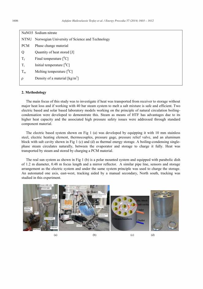
1606 Asfafaw Haileselassie Tesfay et al. / Energy Procedia 57 ( 2014 ) 1603 – 1612
NaNO3 Sodium nitrate
NTNU Norwegian University of Science and Technology
PCM Phase change material
Q Quantity of heat stored [J]
Tf Final temperature [0C]
Ti Initial temperature [0C]
Tm Melting temperature [0C]
Density of a material [kg/m3]
2. Methodology
The main focus of this study was to investigate if heat was transported from receiver to storage without major heat loss and if working with 40 bar steam system to melt a salt mixture is safe and efficient. Two electric based and solar based laboratory models working on the principle of natural circulation boiling- condensation were developed to demonstrate this. Steam as means of HTF has advantages due to its higher heat capacity and the associated high pressure safety issues were addressed through standard component material.
The electric based system shown on Fig 1 (a) was developed by equipping it with 10 mm stainless
steel, electric heating element, thermocouples, pressure gage, pressure relief valve, and an aluminum block with salt cavity shown in Fig 1 (c) and (d) as thermal energy storage. A boiling-condensing single-phase steam circulates naturally, between the evaporator and storage to charge it fully. Heat was transported by steam and stored by charging a PCM material.
The real sun system as shown in Fig 1 (b) is a polar mounted system and equipped with parabolic dish
of 1.2 m diameter, 0.48 m focus length and a mirror reflector. A similar pipe line, sensors and storage arrangement as the electric system and under the same system principle was used to charge the storage. An automated one axis, east-west, tracking aided by a manual secondary, North south, tracking was studied in this experiment.
(a) (b) (c) (d)
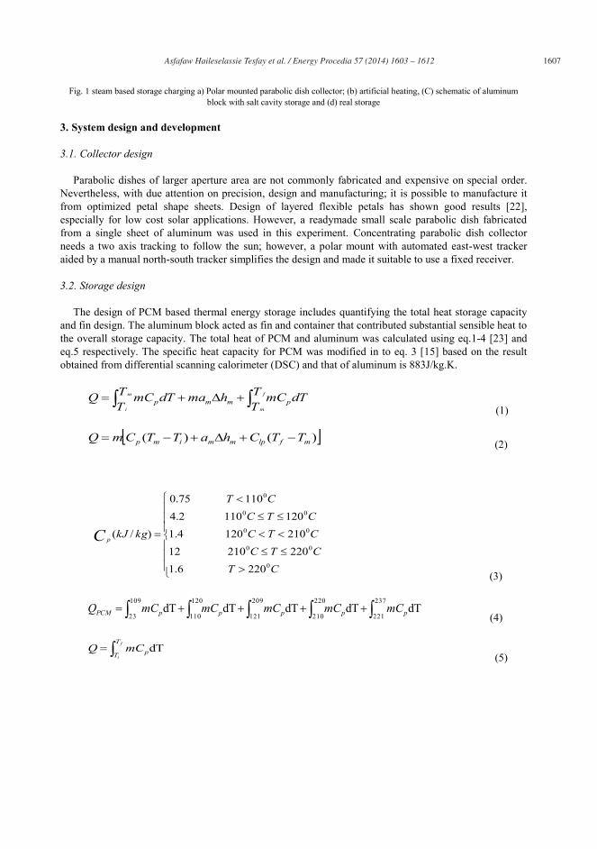
Asfafaw Haileselassie Tesfay et al. / Energy Procedia 57 ( 2014 ) 1603 – 1612 1607
Fig. 1 steam based storage charging a) Polar mounted parabolic dish collector; (b) artificial heating, (C) schematic of aluminum block with salt cavity storage and (d) real storage
3. System design and development
3.1. Collector design
Parabolic dishes of larger aperture area are not commonly fabricated and expensive on special order. Nevertheless, with due attention on precision, design and manufacturing; it is possible to manufacture it from optimized petal shape sheets. Design of layered flexible petals has shown good results [22], especially for low cost solar applications. However, a readymade small scale parabolic dish fabricated from a single sheet of aluminum was used in this experiment. Concentrating parabolic dish collector needs a two axis tracking to follow the sun; however, a polar mount with automated east-west tracker aided by a manual north-south tracker simplifies the design and made it suitable to use a fixed receiver.
3.2. Storage design
The design of PCM based thermal energy storage includes quantifying the total heat storage capacity and fin design. The aluminum block acted as fin and container that contributed substantial sensible heat to the overall storage capacity. The total heat of PCM and aluminum was calculated using eq.1-4 [23] and eq.5 respectively. The specific heat capacity for PCM was modified in to eq. 3 [15] based on the result obtained from differential scanning calorimeter (DSC) and that of aluminum is 883J/kg.K.
TT
dTmCTT
hmadTmCQ f
m
m
ipmmp
(1)
)()( mflpmmimp TTChaTTCmQ (2)
CTCTCCTCCTC
CT
kgkJC p
0
00
00
00
0
2206.1220210122101204.11201102.4
11075.0
)/(
(3)
209
121
220
210
237
221
109
23
120
110dTdTdTdTdT pppppPCM mCmCmCmCmCQ
(4)
f
i
T
T pmCQ dT (5)
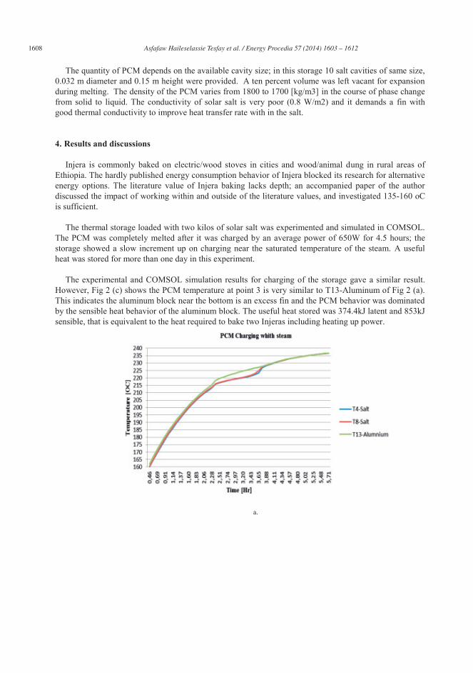
1608 Asfafaw Haileselassie Tesfay et al. / Energy Procedia 57 ( 2014 ) 1603 – 1612
The quantity of PCM depends on the available cavity size; in this storage 10 salt cavities of same size, 0.032 m diameter and 0.15 m height were provided. A ten percent volume was left vacant for expansion during melting. The density of the PCM varies from 1800 to 1700 [kg/m3] in the course of phase change from solid to liquid. The conductivity of solar salt is very poor (0.8 W/m2) and it demands a fin with good thermal conductivity to improve heat transfer rate with in the salt.
4. Results and discussions
Injera is commonly baked on electric/wood stoves in cities and wood/animal dung in rural areas of Ethiopia. The hardly published energy consumption behavior of Injera blocked its research for alternative energy options. The literature value of Injera baking lacks depth; an accompanied paper of the author discussed the impact of working within and outside of the literature values, and investigated 135-160 oC is sufficient.
The thermal storage loaded with two kilos of solar salt was experimented and simulated in COMSOL.
The PCM was completely melted after it was charged by an average power of 650W for 4.5 hours; the storage showed a slow increment up on charging near the saturated temperature of the steam. A useful heat was stored for more than one day in this experiment.
The experimental and COMSOL simulation results for charging of the storage gave a similar result.
However, Fig 2 (c) shows the PCM temperature at point 3 is very similar to T13-Aluminum of Fig 2 (a). This indicates the aluminum block near the bottom is an excess fin and the PCM behavior was dominated by the sensible heat behavior of the aluminum block. The useful heat stored was 374.4kJ latent and 853kJ sensible, that is equivalent to the heat required to bake two Injeras including heating up power.
a.

Asfafaw Haileselassie Tesfay et al. / Energy Procedia 57 ( 2014 ) 1603 – 1612 1609
b.
c.
Fig. 2 PCM and aluminum temperature profile a) experimental results, b) Locations of temperature measurement points in COMSOL and c) Simulation of temperature development PCM (1-Black, 2-Magenta, 3-Green and time [S])
Fig 3 (b) shows the PCM temperature was getting constant when discharging was approached to the phase change zone, where a massive near isothermal heat supply is expected. The other interesting result is the temperature of the aluminum container which decreased rapidly indicating Aluminum is not an appropriate container material. The aluminum block improves thermal conductivity during charging when it acts as a fin and very fast deterioration of the stored heat when used as storage container. Considering the mass of the PCM the storage was tested for night cooking by frying egg. The egg frying took about 32 minutes and it only utilized the sensible heat part of the stored heat. The longer frying time was occurred because the frying pan was not fully griped the aluminum surface due to the presence of thermocouples. The thermocouples shown on Fig 3(a) hindered a firm grip between the pan and the top surface of the
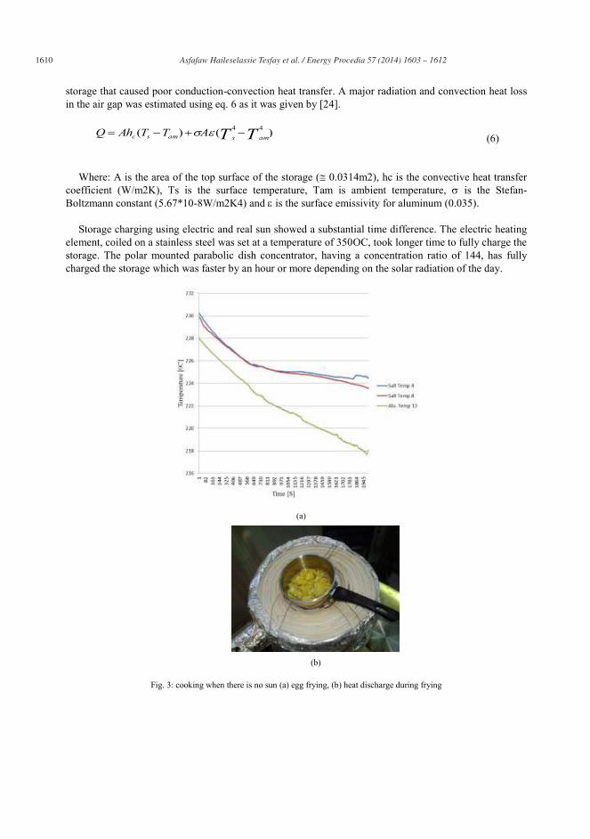
1610 Asfafaw Haileselassie Tesfay et al. / Energy Procedia 57 ( 2014 ) 1603 – 1612
storage that caused poor conduction-convection heat transfer. A major radiation and convection heat loss in the air gap was estimated using eq. 6 as it was given by [24].
)()( 44 TT amsamsc ATTAhQ (6)
Where: A is the area of the top surface of the storage ( 0.0314m2), hc is the convective heat transfer
coefficient (W/m2K), Ts is the surface temperature, Tam is ambient temperature, is the Stefan-Boltzmann constant (5.67*10-8W/m2K4) and is the surface emissivity for aluminum (0.035).
Storage charging using electric and real sun showed a substantial time difference. The electric heating
element, coiled on a stainless steel was set at a temperature of 350OC, took longer time to fully charge the storage. The polar mounted parabolic dish concentrator, having a concentration ratio of 144, has fully charged the storage which was faster by an hour or more depending on the solar radiation of the day.
(a)
(b)
Fig. 3: cooking when there is no sun (a) egg frying, (b) heat discharge during frying
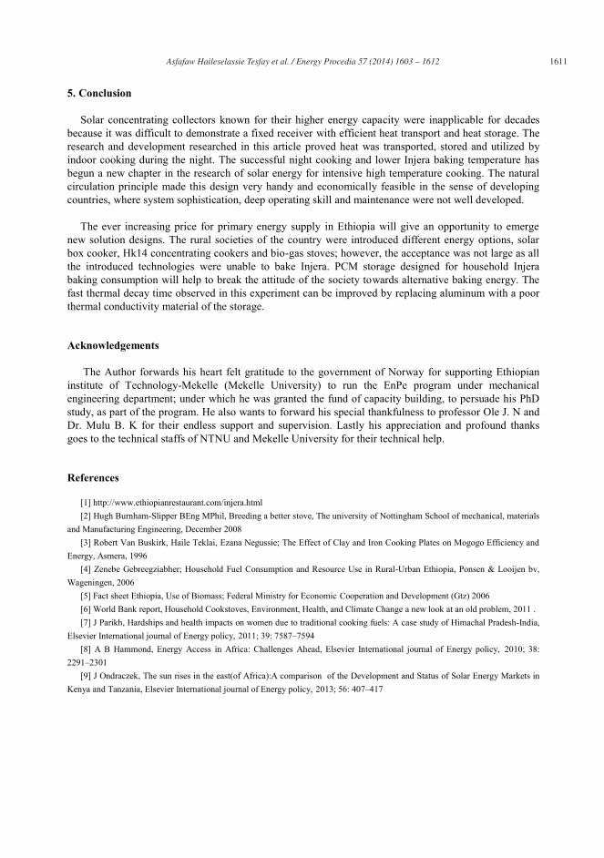
Asfafaw Haileselassie Tesfay et al. / Energy Procedia 57 ( 2014 ) 1603 – 1612 1611
5. Conclusion
Solar concentrating collectors known for their higher energy capacity were inapplicable for decades because it was difficult to demonstrate a fixed receiver with efficient heat transport and heat storage. The research and development researched in this article proved heat was transported, stored and utilized by indoor cooking during the night. The successful night cooking and lower Injera baking temperature has begun a new chapter in the research of solar energy for intensive high temperature cooking. The natural circulation principle made this design very handy and economically feasible in the sense of developing countries, where system sophistication, deep operating skill and maintenance were not well developed.
The ever increasing price for primary energy supply in Ethiopia will give an opportunity to emerge
new solution designs. The rural societies of the country were introduced different energy options, solar box cooker, Hk14 concentrating cookers and bio-gas stoves; however, the acceptance was not large as all the introduced technologies were unable to bake Injera. PCM storage designed for household Injera baking consumption will help to break the attitude of the society towards alternative baking energy. The fast thermal decay time observed in this experiment can be improved by replacing aluminum with a poor thermal conductivity material of the storage.
Acknowledgements
The Author forwards his heart felt gratitude to the government of Norway for supporting Ethiopian institute of Technology-Mekelle (Mekelle University) to run the EnPe program under mechanical engineering department; under which he was granted the fund of capacity building, to persuade his PhD study, as part of the program. He also wants to forward his special thankfulness to professor Ole J. N and Dr. Mulu B. K for their endless support and supervision. Lastly his appreciation and profound thanks goes to the technical staffs of NTNU and Mekelle University for their technical help.
References
[1] http://www.ethiopianrestaurant.com/injera.html [2] Hugh Burnham-Slipper BEng MPhil, Breeding a better stove, The university of Nottingham School of mechanical, materials
and Manufacturing Engineering, December 2008 [3] Robert Van Buskirk, Haile Teklai, Ezana Negussie; The Effect of Clay and Iron Cooking Plates on Mogogo Efficiency and
Energy, Asmera, 1996 [4] Zenebe Gebreegziabher; Household Fuel Consumption and Resource Use in Rural-Urban Ethiopia, Ponsen & Looijen bv,
Wageningen, 2006 [5] Fact sheet Ethiopia, Use of Biomass; Federal Ministry for Economic Cooperation and Development (Gtz) 2006 [6] World Bank report, Household Cookstoves, Environment, Health, and Climate Change a new look at an old problem, 2011 . [7] J Parikh, Hardships and health impacts on women due to traditional cooking fuels: A case study of Himachal Pradesh-India,
Elsevier International journal of Energy policy, 2011; 39: 7587–7594 [8] A B Hammond, Energy Access in Africa: Challenges Ahead, Elsevier International journal of Energy policy, 2010; 38:
2291–2301 [9] J Ondraczek, The sun rises in the east(of Africa):A comparison of the Development and Status of Solar Energy Markets in
Kenya and Tanzania, Elsevier International journal of Energy policy, 2013; 56: 407–417
1612 Asfafaw Haileselassie Tesfay et al. / Energy Procedia 57 ( 2014 ) 1603 – 1612
[10] U Deichmann, C Meisner, S Murray, and D Wheeler, The Economics of Renewable Energy Expansion in Rural Sub-Saharan Africa, Elsevier International journal of Energy policy, 2011; 39: 215–227
[11] M Wentzel and A Pouris,The Development Impact of Solar Cookers: A Review of Solar Cooking Impact Research in South Africa, Elsevier International journal of Energy policy, 2007; 35: 1909–1919
[12] Y Tian, and C Y Zhao, A review of Solar Collectors and Thermal Energy Storage in Solar Thermal Applications, Elsevier International journal of Aplied Energy, 2013; 104: 538–553
[13] S Kuravi, J Trahan, D Y Goswami, M M Rahman and E K Stefanakos, Thermal Energy Storage Technologies and Systems for Concentrating Solar Power Plants, Progress in Energy and Combustion Science, 2013; 39: 285–319
[14] S.A. Sulaiman and F.L. Inambao, Development of a Thermal Energy Storage for the Integrated Solar Energy Project, R & D Journal of the South African Institution of Mechanical Engineering, 2010; 26: 6-11
[15] Chee Woh Foong, Ole Jørgen Nydal, Jørgen Løvseth, Investigation of a small scale double-reflector solar concentrating system with high temperature heat storage, Applied Thermal Engineering, 2011; 31:1807-1815
[16] Foong Chee Who, Jørgen Løvseth, and Ole Jørgen Nydal, Heat Capacity Measurements of NaNO3 – KNO3 Binary System, submitted paper to International journal of Thermophysics, 2011,
[17] Xuejun Zhang, Jun Tian, Kangcheng Xu, and Yici Gao, Thermodynamic Evaluation of Phase Equilibria in NaNO3-KNO3 System, Phase Equilibria, 2003; 24: 5.
[18]Abdulkadir A. Hassen, Demiss A. Amibe, and Ole J. Nydal, Performance Investigation of Solar Powered Injera Baking Oven for Indoor Cooking, ISES solar world congress 2011 proceedings, 186-196.
[19] Maxime Mussard, Ole J Nydal, Charging of a heat storage coupled with a low-cost small-scale solar parabolic trough for cooking purposes, Solar Energy, 2013; 95:144–154.
[20] Doerte Laing, Carsten Bahl, Thomas Bauer, Dorothea Lehmann, Wolf-Dieter Steinmann, Thermal energy storage for direct steam generation, Solar Energy, 2011; 85: 627-633.
[21] A Mawire, M.McPherson, R.R.J.vandenHeetkamp, Discharging simulations of a thermal energy storage (TES) system for an indirect solar cooker, Solar Energy Materials & Solar Cells, 2010; 94:1100–1106.
[22] A New Design Approach for Solar Concentrating Parabolic Dish Based on Optimized Flexible Petals [23] Atul Sharma, V.V. Tyagi, C.R. Chen, and D. Buddhi, Review on thermal energy storage with phase change materials and
applications, Renewable and Sustainable Energy Reviews 13 (2009) 318–345 [24] A.F. Milles, Heat and Mass Transfer 1995, 28-29

55
II: Design and development of solar thermal Injera baking:
steam based direct baking
Asfafaw H Tesfay, Mulu B. Kahsay, Ole J. Nydal
Energy Procedia, volume 57, pp. 2946 – 2955, 2014.

56

Energy Procedia 57 ( 2014 ) 2946 – 2955
Available online at www.sciencedirect.com
ScienceDirect
1876-6102 © 2014 The Authors. Published by Elsevier Ltd. This is an open access article under the CC BY-NC-ND license (http://creativecommons.org/licenses/by-nc-nd/3.0/).Selection and/or peer-review under responsibility of ISES.doi: 10.1016/j.egypro.2014.10.330
2013 ISES Solar World Congress
Design and development of solar thermal Injera baking: steam based direct baking
Asfafaw Haileselassie Tesfaya,b*, Mulu Bayray Kahsayb, Ole Jørgen Nydala a. Department of Energy and Process Engineering, Norwegian University of Scinece and Technology, 7491 Trondheim,
Norway b. Department of Mechanical Engineering, Ethiopian Institute of Technology-Mekelle, Mekelle University P.O.box 231
Mekelle, Ethiopia
Abstract
Ethiopia, the second most populated country in Africa, meets 96% of its energy need from bio-mass and majority of this energy goes entirely to Injera baking. Injera, a pan-cake like bread that is consumed by most of the population, demands a temperature of 180-220 oC to be well baked. Both traditional and newly developed biomass Injera stoves are energy inefficient; besides the kitchen environment is highly polluted with soot and smoke that affect the health of household inhabitants. This article introduces new technology that enables Injera baking using indirect solar stove. A parabolic dish with an aperture area of 2.54 m2, a well-insulated stainless steel pipe of 10mm, a coiled stainless steel heat exchanger, a pressure relief valve and three gate valves were equipped in the system and K-type thermocouples were used to record the temperature. The heat transfer process has been governed by the principle of natural circulation boiling-condensation between receiver and stove. A preset pressure relief valve is used to control the self-circulating working heat transfer fluid (steam at a temperature of 250 oC). The system was developed and tested for steam based direct baking in the same fashion as the traditional Injera stove. In this experiment, heat transport without significant loss from the receiver for baking at some distance is demonstrated. The challenge with manual tracking and direct steam based baking model indicates the performance of the technology can be improved. It can also win more acceptances if it is equipped with auto trackers and heat storage mechanism. In conclusion, unlike previous efforts, the experiment demonstrated that a high temperature indirect baking of Injera is possible. © 2013 Asfafaw H T, Mulu B K, and Ole J N. Published by Elsevier Ltd. Selection and/or peer-review under responsibility of ISES
Keywords: Steam based Injera baking stove; fixed focus parabolic concentrator; polar mount two axis tracking parabolic dish
1. Introduction
The main energy source of developing countries comes from biomass. Generally biomass is considered as renewable source of energy; however, this is a misleading concept for developing countries where deforestation and afforestation actions are not balanced. Studies show about 800 million people who are dependent on this form of energy are exposed to death and critical health problems [1]. This is worse in
* Corresponding author. Tel.: +47 41015917; fax: +47 73593580. E-mail address: [email protected], [email protected] (A. H. Tesfay).
© 2014 The Authors. Published by Elsevier Ltd. This is an open access article under the CC BY-NC-ND license (http://creativecommons.org/licenses/by-nc-nd/3.0/).Selection and/or peer-review under responsibility of ISES.
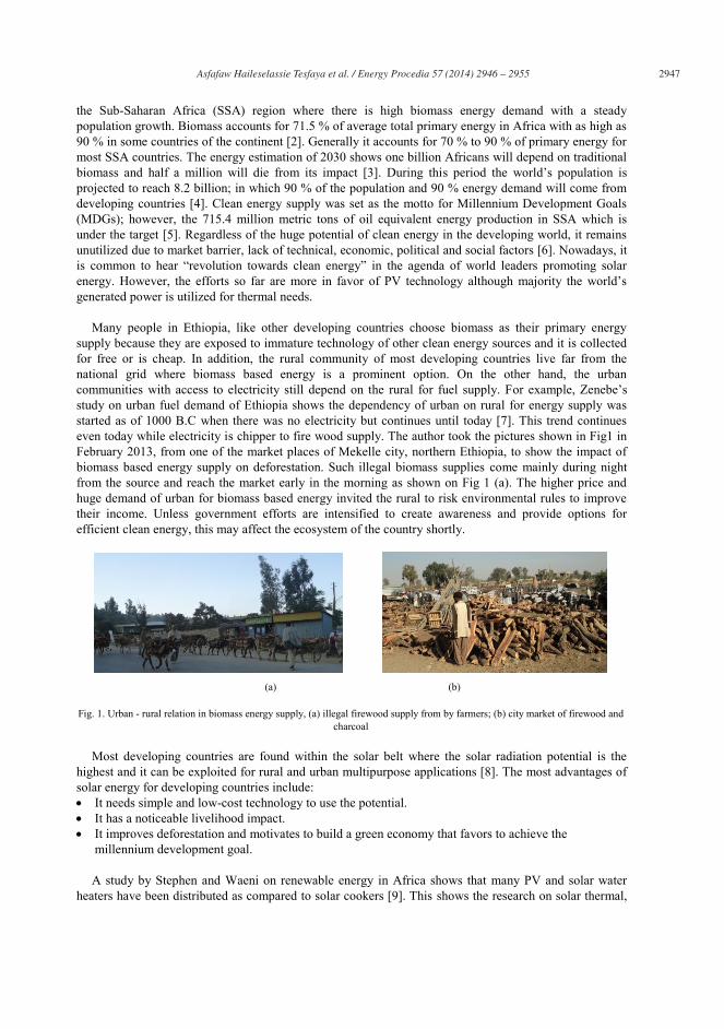
Asfafaw Haileselassie Tesfaya et al. / Energy Procedia 57 ( 2014 ) 2946 – 2955 2947
the Sub-Saharan Africa (SSA) region where there is high biomass energy demand with a steady population growth. Biomass accounts for 71.5 % of average total primary energy in Africa with as high as 90 % in some countries of the continent [2]. Generally it accounts for 70 % to 90 % of primary energy for most SSA countries. The energy estimation of 2030 shows one billion Africans will depend on traditional biomass and half a million will die from its impact [3]. During this period the world’s population is projected to reach 8.2 billion; in which 90 % of the population and 90 % energy demand will come from developing countries [4]. Clean energy supply was set as the motto for Millennium Development Goals (MDGs); however, the 715.4 million metric tons of oil equivalent energy production in SSA which is under the target [5]. Regardless of the huge potential of clean energy in the developing world, it remains unutilized due to market barrier, lack of technical, economic, political and social factors [6]. Nowadays, it is common to hear “revolution towards clean energy” in the agenda of world leaders promoting solar energy. However, the efforts so far are more in favor of PV technology although majority the world’s generated power is utilized for thermal needs.
Many people in Ethiopia, like other developing countries choose biomass as their primary energy
supply because they are exposed to immature technology of other clean energy sources and it is collected for free or is cheap. In addition, the rural community of most developing countries live far from the national grid where biomass based energy is a prominent option. On the other hand, the urban communities with access to electricity still depend on the rural for fuel supply. For example, Zenebe’s study on urban fuel demand of Ethiopia shows the dependency of urban on rural for energy supply was started as of 1000 B.C when there was no electricity but continues until today [7]. This trend continues even today while electricity is chipper to fire wood supply. The author took the pictures shown in Fig1 in February 2013, from one of the market places of Mekelle city, northern Ethiopia, to show the impact of biomass based energy supply on deforestation. Such illegal biomass supplies come mainly during night from the source and reach the market early in the morning as shown on Fig 1 (a). The higher price and huge demand of urban for biomass based energy invited the rural to risk environmental rules to improve their income. Unless government efforts are intensified to create awareness and provide options for efficient clean energy, this may affect the ecosystem of the country shortly.
(a) (b)
Fig. 1. Urban - rural relation in biomass energy supply, (a) illegal firewood supply from by farmers; (b) city market of firewood and charcoal
Most developing countries are found within the solar belt where the solar radiation potential is the highest and it can be exploited for rural and urban multipurpose applications [8]. The most advantages of solar energy for developing countries include: It needs simple and low-cost technology to use the potential. It has a noticeable livelihood impact. It improves deforestation and motivates to build a green economy that favors to achieve the
millennium development goal. A study by Stephen and Waeni on renewable energy in Africa shows that many PV and solar water
heaters have been distributed as compared to solar cookers [9]. This shows the research on solar thermal,
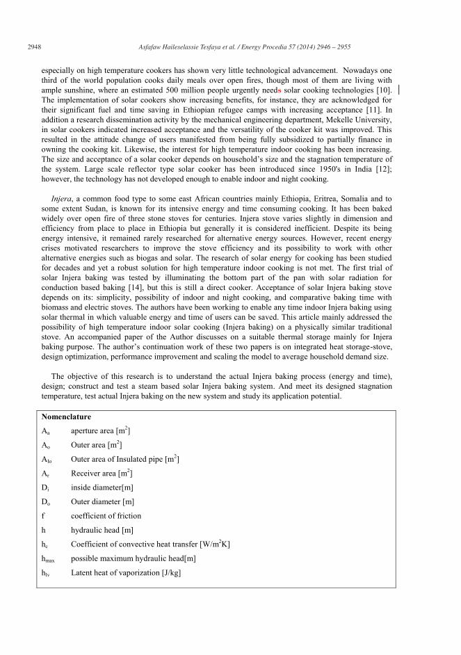
2948 Asfafaw Haileselassie Tesfaya et al. / Energy Procedia 57 ( 2014 ) 2946 – 2955
especially on high temperature cookers has shown very little technological advancement. Nowadays one third of the world population cooks daily meals over open fires, though most of them are living with ample sunshine, where an estimated 500 million people urgently needs solar cooking technologies [10]. The implementation of solar cookers show increasing benefits, for instance, they are acknowledged for their significant fuel and time saving in Ethiopian refugee camps with increasing acceptance [11]. In addition a research dissemination activity by the mechanical engineering department, Mekelle University, in solar cookers indicated increased acceptance and the versatility of the cooker kit was improved. This resulted in the attitude change of users manifested from being fully subsidized to partially finance in owning the cooking kit. Likewise, the interest for high temperature indoor cooking has been increasing. The size and acceptance of a solar cooker depends on household’s size and the stagnation temperature of the system. Large scale reflector type solar cooker has been introduced since 1950's in India [12]; however, the technology has not developed enough to enable indoor and night cooking.
Injera, a common food type to some east African countries mainly Ethiopia, Eritrea, Somalia and to
some extent Sudan, is known for its intensive energy and time consuming cooking. It has been baked widely over open fire of three stone stoves for centuries. Injera stove varies slightly in dimension and efficiency from place to place in Ethiopia but generally it is considered inefficient. Despite its being energy intensive, it remained rarely researched for alternative energy sources. However, recent energy crises motivated researchers to improve the stove efficiency and its possibility to work with other alternative energies such as biogas and solar. The research of solar energy for cooking has been studied for decades and yet a robust solution for high temperature indoor cooking is not met. The first trial of solar Injera baking was tested by illuminating the bottom part of the pan with solar radiation for conduction based baking [14], but this is still a direct cooker. Acceptance of solar Injera baking stove depends on its: simplicity, possibility of indoor and night cooking, and comparative baking time with biomass and electric stoves. The authors have been working to enable any time indoor Injera baking using solar thermal in which valuable energy and time of users can be saved. This article mainly addressed the possibility of high temperature indoor solar cooking (Injera baking) on a physically similar traditional stove. An accompanied paper of the Author discusses on a suitable thermal storage mainly for Injera baking purpose. The author’s continuation work of these two papers is on integrated heat storage-stove, design optimization, performance improvement and scaling the model to average household demand size.
The objective of this research is to understand the actual Injera baking process (energy and time),
design; construct and test a steam based solar Injera baking system. And meet its designed stagnation temperature, test actual Injera baking on the new system and study its application potential.
Nomenclature
Aa aperture area [m2]
Ao Outer area [m2]
AIo Outer area of Insulated pipe [m2]
Ar Receiver area [m2]
Di inside diameter[m]
Do Outer diameter [m]
f coefficient of friction
h hydraulic head [m]
hc Coefficient of convective heat transfer [W/m2K]
hmax possible maximum hydraulic head[m]
hlv Latent heat of vaporization [J/kg]

Asfafaw Haileselassie Tesfaya et al. / Energy Procedia 57 ( 2014 ) 2946 – 2955 2949
Ib Mean Insolation [W]
K Thermal conductivity [W/m. K]
l length [m]
Le equivalent length[m]
Ploss Pipe loss [W]
q Heat transfer rate [W]
Rloss Receiver loss [W]
Sloss Stove loss [W]
t insulation thickness[m]
Ta Ambient Temperature [oC]
Tpipe Temperature of pipe [oC]
TIpipe Temperature of insulated pipe [oC]
Ts Temperature of steam [oC]
UL over all heat loss [W]
V speed [m/s]
Density [kg/m3]
Stephan Boltzmann Constant (5.67*10-8) [w/m2k4]
Material emissivity
Absolute viscosity [Pa.s]
t Thermal efficiency
o optical efficiency
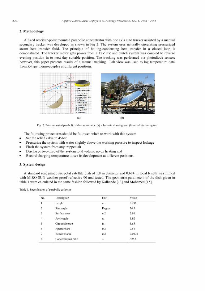
2950 Asfafaw Haileselassie Tesfaya et al. / Energy Procedia 57 ( 2014 ) 2946 – 2955
2. Methodology
A fixed receiver-polar mounted parabolic concentrator with one axis auto tracker assisted by a manual secondary tracker was developed as shown in Fig 2. The system uses naturally circulating pressurized steam heat transfer fluid. The principle of boiling-condensing heat transfer in a closed loop is demonstrated. The tracker motor gets power from a 12V PV and clutch system was coupled to reverse evening position in to next day suitable position. The tracking was performed via photodiode sensor; however, this paper presents results of a manual tracking. Lab view was used to log temperature data from K-type thermocouples at different positions.
(a) (b)
Fig. 2. Polar mounted parabolic dish concentrator: (a) schematic drawing, and (b) actual rig during test
The following procedures should be followed when to work with this system Set the relief valve to 45bar Pressurize the system with water slightly above the working pressure to inspect leakage Flash the system from any trapped air Discharge two-third of the system total volume up on heating and Record charging temperature to see its development at different positions.
3. System design
A standard readymade six petal satellite dish of 1.8 m diameter and 0.684 m focal length was filmed with MIRO-SUN weather proof reflective 90 and tested. The geometric parameters of the dish given in table 1 were calculated in the same fashion followed by Kalbande [13] and Mohamed [15].
Table 1. Specification of parabolic collector
No. Description Unit Value
1 Height m 0.296
2 Rim angle Degree 74.5
3 Surface area m2 2.80
4 Arc length m 1.92
5 Circumference m 5.65
6 Aperture are m2 2.54
7 Receiver area m2 0.0078
8 Concentration ratio -- 325.6
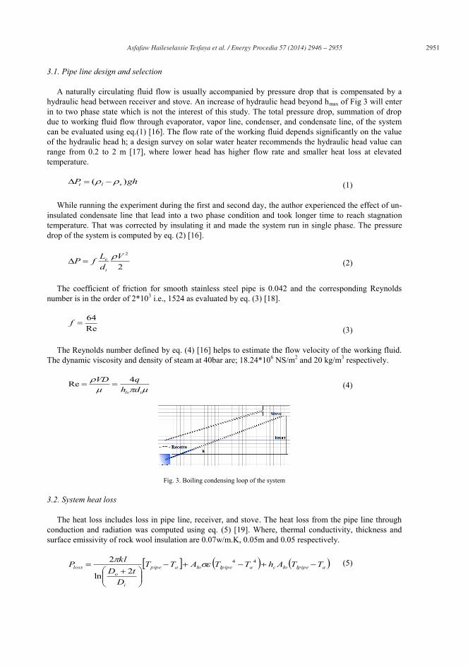
Asfafaw Haileselassie Tesfaya et al. / Energy Procedia 57 ( 2014 ) 2946 – 2955 2951
3.1. Pipe line design and selection
A naturally circulating fluid flow is usually accompanied by pressure drop that is compensated by a hydraulic head between receiver and stove. An increase of hydraulic head beyond hmax of Fig 3 will enter in to two phase state which is not the interest of this study. The total pressure drop, summation of drop due to working fluid flow through evaporator, vapor line, condenser, and condensate line, of the system can be evaluated using eq.(1) [16]. The flow rate of the working fluid depends significantly on the value of the hydraulic head h; a design survey on solar water heater recommends the hydraulic head value can range from 0.2 to 2 m [17], where lower head has higher flow rate and smaller heat loss at elevated temperature.
ghP vlt )( (1)
While running the experiment during the first and second day, the author experienced the effect of un-insulated condensate line that lead into a two phase condition and took longer time to reach stagnation temperature. That was corrected by insulating it and made the system run in single phase. The pressure drop of the system is computed by eq. (2) [16].
2
2VdLfP
i
e (2)
The coefficient of friction for smooth stainless steel pipe is 0.042 and the corresponding Reynolds number is in the order of 2*103 i.e., 1524 as evaluated by eq. (3) [18].
Re64f
(3)
The Reynolds number defined by eq. (4) [16] helps to estimate the flow velocity of the working fluid. The dynamic viscosity and density of steam at 40bar are; 18.24*106 NS/m2 and 20 kg/m3 respectively.
ilv dhqVD 4Re (4)
Fig. 3. Boiling condensing loop of the system
3.2. System heat loss
The heat loss includes loss in pipe line, receiver, and stove. The heat loss from the pipe line through conduction and radiation was computed using eq. (5) [19]. Where, thermal conductivity, thickness and surface emissivity of rock wool insulation are 0.07w/m.K, 0.05m and 0.05 respectively.
aIpipeIocaIpipeIoapipe
i
oloss TTAhTTATT
DtD
klP 44
2ln
2 (5)

2952 Asfafaw Haileselassie Tesfaya et al. / Energy Procedia 57 ( 2014 ) 2946 – 2955
Convective and radiation losses from receiver and stove were computed by eq. (6) and (7). Where, average value of 350oC, 80oC and 25w/m2.K were taken as receiver temperature (Tr), stove lead temperature (Tl) and hc of air. Pipe conduction heat loss was neglected and the external wall temperature of the pipe (250 oC) is used as the temperature of the fluid.
44)( arrarrcloss TTATTAhR (6)
44)( alSalScloss TTATTAhS (7)
Theoretically computed heat losses at stagnation temperature of the system shows a maximum loss be encountered from receiver that accounts for 304.4 W when compared to the losses from stove and pipe line which contribute 269.95 and 94.8 w respectively. This suggests optimization should be done to decrease losses from the receiver to improve overall baking time of the system. Interestingly enough the theoretical losses from receiver shows the same result while pipe line loss becomes insignificant and stove loss lowered to 171.14W practically.
4. Results and discussions
The traditional electric Injera stove was tested for different ranges of baking temperature; the quality of Injera in the range of 135-220 oC remains the same, however, a slightly baking time difference was observed. Fig 3(a) shows well-cooked Injera and Fig 4 (b) presents the experimental values of Injera baking temperature in which the rise and fall of baking temperature during the baking cycle is clearly shown. Per Injera power and time requirements are shown in Fig 4 (c) and (d) respectively. One Injera needs an average of 0.1 kWh and 150 second to be well cooked. Looking at the range of 6th-9th cycles of Fig 4 (b), the literature value of Injera baking is far from actual value. While this test was running, the author was developing the polar mount solar stove in parallel that was tested for no-load, with load and its result is presented in Fig 5.
(a) (b)
(c) (d)
Fig. 4. Injera baking behavior, (a) fresh Injera; (b) baking Cycle, (c) baking power and (d) baking time
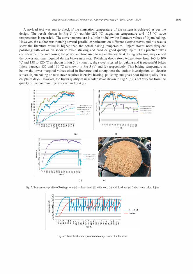
Asfafaw Haileselassie Tesfaya et al. / Energy Procedia 57 ( 2014 ) 2946 – 2955 2953
A no-load test was run to check if the stagnation temperature of the system is achieved as per the design. The result shown in Fig 5 (a) exhibits 255 oC stagnation temperature and 175 oC stove temperatures is recorded. The stove temperature is a little bit below the literature values of Injera baking. However, the author was running several parallel experiments on different electric stoves and his results show the literature value is higher than the actual baking temperature. Injera stoves need frequent polishing with oil or oil seeds to avoid sticking and produce good quality Injera. This practice takes considerable time and power; the power and time used to regain the lost heat during polishing may exceed the power and time required during bakes intervals. Polishing drops stove temperature from 165 to 100 oC and 158 to 120 oC as shown in Fig 5 (b). Finally, the stove is tested for baking and it successful bakes Injera between 135 and 160 oC as shown in Fig 5 (b) and (c) respectively. This baking temperature is below the lower marginal values cited in literature and strengthens the author investigation on electric stoves. Injera baking on new stove requires intensive heating, polishing and gives poor Injera quality for a couple of days. However, the Injera quality of new solar stove shown in Fig 5 (d) is not very far from the quality of the common Injera shown in Fig 4 (a).
(a) (b)
(c) (d)
Fig. 5. Temperature profile of baking stove (a) without load; (b) with load; (c) with load and (d) Solar steam baked Injera
Fig. 6. Theoretical and experimental comparisons of solar stove
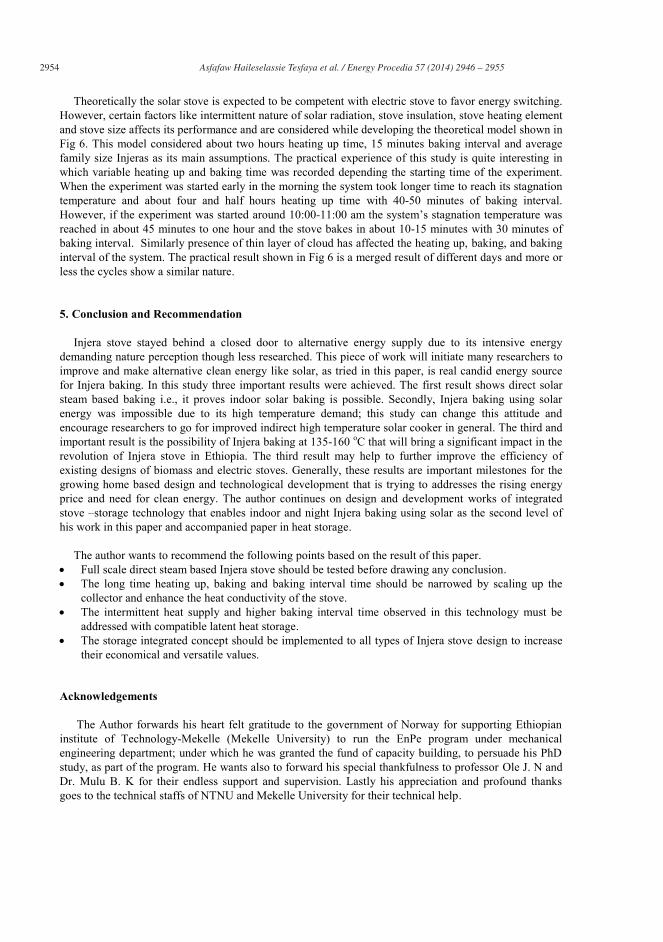
2954 Asfafaw Haileselassie Tesfaya et al. / Energy Procedia 57 ( 2014 ) 2946 – 2955
Theoretically the solar stove is expected to be competent with electric stove to favor energy switching. However, certain factors like intermittent nature of solar radiation, stove insulation, stove heating element and stove size affects its performance and are considered while developing the theoretical model shown in Fig 6. This model considered about two hours heating up time, 15 minutes baking interval and average family size Injeras as its main assumptions. The practical experience of this study is quite interesting in which variable heating up and baking time was recorded depending the starting time of the experiment. When the experiment was started early in the morning the system took longer time to reach its stagnation temperature and about four and half hours heating up time with 40-50 minutes of baking interval. However, if the experiment was started around 10:00-11:00 am the system’s stagnation temperature was reached in about 45 minutes to one hour and the stove bakes in about 10-15 minutes with 30 minutes of baking interval. Similarly presence of thin layer of cloud has affected the heating up, baking, and baking interval of the system. The practical result shown in Fig 6 is a merged result of different days and more or less the cycles show a similar nature.
5. Conclusion and Recommendation
Injera stove stayed behind a closed door to alternative energy supply due to its intensive energy demanding nature perception though less researched. This piece of work will initiate many researchers to improve and make alternative clean energy like solar, as tried in this paper, is real candid energy source for Injera baking. In this study three important results were achieved. The first result shows direct solar steam based baking i.e., it proves indoor solar baking is possible. Secondly, Injera baking using solar energy was impossible due to its high temperature demand; this study can change this attitude and encourage researchers to go for improved indirect high temperature solar cooker in general. The third and important result is the possibility of Injera baking at 135-160 oC that will bring a significant impact in the revolution of Injera stove in Ethiopia. The third result may help to further improve the efficiency of existing designs of biomass and electric stoves. Generally, these results are important milestones for the growing home based design and technological development that is trying to addresses the rising energy price and need for clean energy. The author continues on design and development works of integrated stove –storage technology that enables indoor and night Injera baking using solar as the second level of his work in this paper and accompanied paper in heat storage.
The author wants to recommend the following points based on the result of this paper.
Full scale direct steam based Injera stove should be tested before drawing any conclusion. The long time heating up, baking and baking interval time should be narrowed by scaling up the
collector and enhance the heat conductivity of the stove. The intermittent heat supply and higher baking interval time observed in this technology must be
addressed with compatible latent heat storage. The storage integrated concept should be implemented to all types of Injera stove design to increase
their economical and versatile values.
Acknowledgements
The Author forwards his heart felt gratitude to the government of Norway for supporting Ethiopian institute of Technology-Mekelle (Mekelle University) to run the EnPe program under mechanical engineering department; under which he was granted the fund of capacity building, to persuade his PhD study, as part of the program. He wants also to forward his special thankfulness to professor Ole J. N and Dr. Mulu B. K for their endless support and supervision. Lastly his appreciation and profound thanks goes to the technical staffs of NTNU and Mekelle University for their technical help.
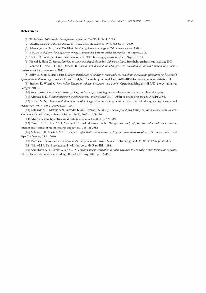
Asfafaw Haileselassie Tesfaya et al. / Energy Procedia 57 ( 2014 ) 2946 – 2955 2955
References
[1] World bank. 2013 world development indicators. The World Bank; 2013 [2] USAID. Environmental Guidelines for Small-Scale Activities in Africa (EGSSAA). 2009. [3] Adeola Ijeoma Eleri, Ewah Otu Eleri. Rethinking biomass energy in Sub-Sahara Africa. 2009. [4] IMARA. A different kind of power struggle. Imara Sub Saharan Africa Energy Sector Report; 2012. [5] The OPEC Fund for International Development (OFID), Energy poverty in africa. Nigeria; 2008. [6] Nicolai S, Fiona Z. Market barriers to clean cooking fuels in Sub-Saharan Africa. Stockholm environment institute; 2008 [7] Zenebe G, Arie J O and Demeke B. Urban fuel demand in Ethiopia: An almost-ideal demand system approach .
Environment for development; 2010. [8] Aftim A. Zeina R. and Yester K. Solar disinfection of drinking water and oral rehydratoin solutions guidelines for household
Application in developing countries. Beirut; 1984, http://almashriq.hiof.no/lebanon/600/610/614/solar-water/unesco/24-26.html [9] Stephen K, Waeni K. Renewable Energy in Africa: Prospects and Limits. Operationalizing the NEPAD energy initiative:
Senegal; 2003. [10] Solar cooker international. Solar cooking and water pasteurizing. www.solarcookers.org, www.solarcooking.org. [11] Alemayehu K. Evaluation report to solar cookers’ international (SCI). Aisha solar cooking project (ASCP); 2003. [12] Nahar M N. Design and development of a large sizenon-tracking solar cooker. Journal of engineering science and
technology, Vol. 4, No. 3; 2009, p. 264 - 271 [13] Kalbande S R, Mathur A N, Surendra K AND Pawar S N. Design, development and testing of paraboloidal solar cooker.
Karnataka Journal of Agricultural Sciences : 20(3); 2007, p. 571-574 [14] Alan G. A solar fryer. Scinece direct, Solar energy 85; 2011, p. 496–505 [15] Fareed M M, Auatf S J, Yaseen H M and Mohamad A K. Design and study of portable solar dish concentrator.
International journal of recent research and review, Vol. III; 2012 [16] Milanez F H, Mantelli M B H. Heat transfer limit due to pressure drop of a loop thermosyphon. 15th International Heat
Pipe Conference, USA; 2010 [17] Morrison L G. Reverse circulation in thermosyphon solar water heaters. Solar energy Vol. 36, No. 4; 1996, p. 377-379 [18 ] White M F. Fluid mechanics. 4th ed. New york: McGraw-Hill; 1998 [19] Abdulkadir A H, Demiss A A, Ole J N. Performance investigation of solar powered Injera baking oven for indoor cooking.
ISES solar world congress proceedings, Kassel, Germany; 2011, p. 186-196

67
III: Energy Consumption Assessment of Injera: A Strategy for
Energy-Efficient Stove Designs in Ethiopia
Asfafaw H Tesfay, Ole Jorgen Nydal, and Mulu Bayray Kahsay
Submitted to Applied Energy

68

1 Energy Consumption Assessment of Injera: A Strategy for Energy-Efficient Stove Designs in Ethiopia
Energy Consumption Assessment of Injera Baking: A Strategy for
Energy-efficient Stoves Design in Ethiopia
Asfafaw Haileselassie Tesfaya*, Ole Jørgen Nydala, and Mulu Bayray Kahsayb,
a Department of Energy and Process Engineering, Norwegian University of Science and Technology, 7491 Trondheim, Norway b Department of Mechanical Engineering, Ethiopian Institute of Technology-Mekelle, Mekelle University P.O.box 231 Mekelle, Ethiopia
Abstract: Ethiopia, the second most populated country in Africa still depends on biomass as its primary energy supply. For
households Injera baking accounts for more than 50% of this energy. In this paper, intensive experiment of Injera baking
process was conducted on three different stove materials. The results of the experiment were analyzed for power
consumption, baking time and Injera quality. The inefficiency of existing Injera bakingstoves (Mitad) was accounted for
approximately 54% of the energy losses. The study further discussed how such inefficiency could be mitigated. If the
ordinary stove undergoes design improvements such as avoiding the mould and material change to the baking plate, there
could be significant gain on power, time, and economic savings. A new Injera baking temperature range of 130-160C was
found in the current study. In turn, this has opened a window for energy shift from biomass to other renewable energies and
new stove designs. The investigation has laid a new target to future biomass/electric stove designs which can easily improve
existing Mitad efficiency by 27%. Parallel studies by the authors on solar energy with heat storage for Injera baking has also
shown a similar range of temperature. The findings of this study will give introduction of new and improved Mitad designs in
Ethiopia which will bring livelihood improvement, environmental security and combat health problems associated with
biomass fuels.
Keywords: Injera; Glass stove; solar stove; steam-based stove; thermal energy storage; power consumption.
1. Introduction
1.1. Background on Injera stove
Injera is the most common staple food served two to three times a day in Ethiopia. It demands significant
amount of energy for its cooking. There are two types of traditional Injera baking stove designs (locally called
Mitad). These are electric and biomass based baking stoves. These Mitads use the same clay material for the
baking. The design of the electric stove has two clay plates. The first plate is used as a mould for the heating
element while the second is used as hot baking plate. Soil or rocks are used as insulation at its bottom part. The
traditional biomass Mitad use single plate without insulation. Both Mitads are known for their low overall
efficiency, due to their baking plate thickness, material, insulation and fuel quality. Figure 1 shows the
traditional biomass Mitad and its Injera. This closed oven has the highest efficiency among the other traditional
open Mitad designs.
Fig. 1: Traditional Mitad design
2 Energy Consumption Assessment of Injera: A Strategy for Energy-Efficient Stove Designs in Ethiopia
Injera is a yeast-risen flatbread with slightly a spongy texture and crater (holes) on its front face. Although “teff”
(Eragrostis tef) is the best and most common crop for Injera, other types of crops are also used based on the
location and income of households. It is a national dish in Ethiopia, Eritrea and a similar variant is also eaten in
Somalia (Canjeero), Sudan and Yemen (Lahoh) [1]. Injera is baked in the traditional Mitad with energy at high
temperature regardless of the type of energy source. The clay material used as a hot plate has hardly investigated
for its effectiveness in heat transfer nor tried for its improvement. The kitchen environment of the biomass Mitad
is associated with smoke and soot which affects the health of users. The electric Mitad is safe and environmental
friendly but has higher capital and operating cost.
1.2. Back ground on cooking stoves
Today, over one third of world’s population use biomass which emits a significant amount of greenhouse gases
(GHGs) and other particulate matter for everyday cooking. Indoor air pollution (IAP) from biomass traditional
cook stoves (TCS) in developing countries results in poor respiratory health. Some of the consequences of using
TCS are:
Demands intense human labour
Need large amount of fuels to compensate for low energy efficiency.
Generate products of incomplete combustion (PIC), which are health threatening
The concentration of CO, CO2, and CH4 from TCS, based on Kirk’s triple carbon balance analysis (TCBA), has
led to recommending a switch to fossil fuel stoves [2]. Countries that switched from biomass to kerosene fuels,
such as Nicaragua, reported a 50% decrease in their deforestation; and this shift did not violate the international
minimum annual CO2 emission standards [3]. It also resulted in reduced household health and environmental
risks related to smoke deposits of toxic metallic elements (lead, cobalt, and copper) and non-metallic compounds
(sulphate, nitrate, and phosphate) that are generated by biomass stoves [4]. However, adoption of improved cook
stove (ICS) can also reduce IAPs and GHG emissions in areas where biomass is the only source of household
energy. A study by Nordica et al. [5] reported that ICSs can result in 40-95% fuel savings and reduce the
negative impacts from PICs. In such circumstances, effective stove outreach programs and selection of target
groups who can influence others to adopt the technology were considered as the primary methods to ensure a
successful shift. This strategy registered good results in rural Mexico (Michoacan), maximized resources from
non-governmental organizations (NGOs), increased the reliability of the intervention process, and kept more
stoves in use [6]. Household energy interventions using mud ICS in Nepal and China reduced significant
concentrations of particulate matter to less than 2.5 μm in aerodynamic diameter, PM2.5, [7] and CO [8].
Many developing countries have attempted to introduce and distribute ICSs to reduce deforestation and IAP. A
study on ICSs in Pakistan reported their potential to reduce the total biomass consumption for cooking and
heating by 50% if all TCSs were replaced [9]. However, the distribution and replacement of ICSs was slow
despite their economic and environmental benefits. Some researchers have stated that the shift from TCSs to
ICSs can yield benefits for both local development and global climate change if it is recognized as a strategy
[10]. However, the distribution of ICS has not got widespread acceptance in developing countries because of:
ICSs are not highly efficient or do not reduce smoke emissions compared to TCSs,
Differences in ICS programs and interest of beneficiaries, i.e., the program consider only energy
efficiency, whereas the beneficiaries emphasize on technical performance of the stove,
Distribution without consideration of the primary needs of the beneficiaries [11].
The use of ICS has resulted in household energy savings of approximately 27-66% in Nepal and Peru and 59%
in India, respectively. End-user training and petroleum gas mixtures were responsible for the significant savings
in Peru and India [12]. Despite their importance, published data on household basic energy usage in developing
countries is minimal. This has led to difficulties to understand basic daily energy consumption and effectiveness
of programs aimed at reducing health, environmental, and socioeconomic impacts of TCSs and fuels.
ICS designs have advanced over time and provide economical, health, and ecological advantages. However,
surveys on new ICSs indicated a low rate of success. The authors believe that subsidy-based ICS interventions in
developing countries missed to incorporate cooking culture, user interest, and geographical factor considerations
in the design of such stoves. An intervention without pre-program assessment fails to identify the beneficiaries
from each intervention and, in some cases, fails to meet its objective, as was the case with China [13]. A
worthwhile distribution of ICSs requires public sector investment intervention. Unless public funds are available
to develop capacity, create awareness, and improve research and development (R&D), the intended millennium
development goal might not be attainable, as GTZ’s (Deutsche Gesellschaft für Internationale Zusammenarbeit)
study indicated in Uganda [14].
3 Energy Consumption Assessment of Injera: A Strategy for Energy-Efficient Stove Designs in Ethiopia
Ethiopia, a home to about 90 million people, is the third largest consumer of traditional fuel in the world [15].
The rural area is the source of primary energy from biomass and agricultural food items to the urban area [16].
The collection of biomass fuel is a burden of women and children, who often spend their time and energy to
travel long distances in search of it. Berhe and Sosina estimated that firewood collection required 12% of a
child’s school time [17]. In addition to the valuable school time, girls and women are exposed to IAP in the
kitchen and sexual harassment in the field.
Injera uses considerable amount of energy when prepared on traditional energy-inefficient clay stoves [18].
Previous studies show that Injera required a temperature of 180-220°C to be well baked [19]. This range was
lowered to 135-160C by Tesfay et al. [20] using a modified clay stove and solar as source of energy. In
Ethiopia, firewood and animal dung are the sole fuel options in the rural while the urban have electrical energy
options depending on household’s income. The price of firewood in Ethiopia is quite cheap and often free. Due
to this fact, there is less awareness of the energy conservation both in the rural and urban areas. On the other
hand, the conventional type of direct biomass burning is associated with incomplete combustion that has major
effect on the health of the population, women in particular. Previously, very little efforts have been made on
using alternative clean energies to reduce the health and environmental risks associated with traditional biomass
energy use. However, the recent economic growth of the country demanded alternative clean energy supply and
adoption of ICSs have increased. Moreover, the country’s growth and transformation plan (GTP), pro-poor
legacy of the government and United Nations millennium development goal (UN MDG) strategies have created
favourable environment of research in this area. Ongoing research on alternative energy sources, new stove
designs and improving the efficiency of existing stoves are expected to yield significant results.
Ethiopia’s dependence and use of biomass resources has reduced the forest coverage, increased IAP, and
contributed to poor health condition in the country. In response to these effects, the government and other
institutions have attempted to introduce ICS technologies with only limited success. A study in the capital city
(Addis Ababa) indicated that households’ decision to switch from a TCS to ICS was found to be largely
influenced by their income [21]. I In addition, a survey on adoption of Mirte and Lakech cook stoves (common
ICSs) in urban Ethiopia by Abebe et al. showed product price and regional demand are other factors that affect
such decision [22]. Most recently, ethanol-based ICSs of project Gaia that used by-products from sugar industry
has got acceptance, particularly in refugee camps. However, more effort is required for further penetration [23].
This effort alone cannot solve the 85% dependency of urban domestic cooking on biomass based energy source.
High fuel shortage is expected to happen accompanied by high prices unless some optimized Mitad designs are
introduced. The simplest way forward to reduce this dependency is to implement energy switch from biomass to
electricity in urban areas connected to the national grid. However, this change is not easy to implement unless
there is determination and commitment at governmental and individual levels. But, a partial switch in to
alternative energy sources for some activities (e.g., Injera baking) can result in a significant change. A study by
Zenebe et al. [24] reported that the primary challenge of switching to electricity in Tigray (northern Ethiopia) is
the attitude of households toward adopting electric stoves, which is primarily influenced by household’s level of
education and income. Abebe et al. [25] suggested to shift the property rights of publicly accessible forests to
private ownership to monitor rural deforestation and thereby reduce the dependency of urban areas on rural areas
for energy supply.
Power generation in Ethiopia has been rapidly expanding since 2002 but at a slower pace as compared to the
growth of household and industry energy demands. The country’s electrical coverage in 2007 was 20% in areas
that were already electrified [26]. This power shortage was followed by rationed power distribution, particularly
in 2009 and 2010, when many of the large industries in the country were forced to reduce their production [27].
This continuous power shortage encouraged policy makers to focus their strategies and budget for clean energy
for electricity generation. At the same time, the demand of clean energy for cooking has grown beyond the
capabilities of NGOs and the limited budget of the government. Biomass energy sources have become more
expensive with demographic growth, urbanization, and government ban on tree cutting. The various interests of
the country can be achieved only if extensive research and development efforts can yield fundamental changes to
TCSs, which have an efficiency of 5-35% [17]. The country’s energy shift perspective suggests a difficult
transformation, and the government will encounter challenges to fight poverty and provide clean energy supply.
A study by Bereket et al. [28] found that research and development must involve pro-poor robust technology that
considers the urban poor income. Similarly, the importance of new energy sources to rural should get emphasis.
Some subsidy programs have introduced biogas for its dual purpose of energy and fertilizer (e.g., cooking and
lighting, bioslurry) in some rural and registered successful results [29]; however, this trial has failed in its
application for Injera baking. Adoption of biogas could increase its energy and could also be able to bake Injera.
Another untapped renewable energy source of the country is solar thermal. Although the use of solar energy for

4 Energy Consumption Assessment of Injera: A Strategy for Energy-Efficient Stove Designs in Ethiopia
cooking at household and community levels in developing countries has been studied [30]; only few researches
have tried to develop a compatible Injera stove. A direct solar Injera stove was introduced by Allan, and its
surface temperature requirement was 180-220°C [31].
In the current study, efforts have been made to lower the Injera baking temperature by varying the baking plate
thickness and material. In addition, the Mitad is also designed to work with solar energy. The hypothesis for the
current research is emanated from the type of baking. Injera baking is regarded as boiling type of cooking which
require tight sealing. When the water in the dough starts evaporating, it leaves many craters (called eyes) on its
upper face of the Injera that give its peculiar quality. In addition to dealing with baking temperature, other
parameters like quality, baking time and energy consumption nature of Injera were also analysed.
Nomenclature
a Fraction of melted PCM
A Area [𝑚2]
𝐶𝑝 Specific heat capacity [J/kg K]
𝐶𝐻4 Methane
CO Carbon monoxide
𝐶𝑂2 Carbon dioxide
ℎ𝑐 Coefficient of convective heat transfer [𝑊/𝑚2𝐾]
HTF Heat transfer fluid
∆hm Heat of fusion per unit mass [J/kg]
GHG Greenhouse gas
IAP Indoor air pollution
ICS Improved cook stove
K Thermal conductivity [W/m. K]
𝐾𝑁𝑂3 Potassium nitrate
LPG Liquefied petroleum gas
m mass [kg]
𝑁𝑎𝑁𝑂3 Sodium nitrate
NGO Non-governmental organization
PCM Phase change material
PFOA Perfluorooctanoic acid
PIC Product of incomplete combustion
PM Particulate matter
Qc Heat [W]
T Temperature [°C]
TCS Traditional cook stove
TCBA triple carbon Balance analysis
x Pan thickness [m]
Greek letters
Density [𝑘𝑔/𝑚3]
Stefan-Boltzmann constant (5.67×10⁻⁸) [w/m2k4]
Material emissivity
Subscripts
a Ambient
b Bottom
c Conduction
L Stove Lead
m mass
s stove
t Top
2. Materials and Methodology
The current study is an experimental study and the methodologies followed are explained in detail in this section.
The Injera stove in Fig. 2 represents an existing electric clay Mitad design. This design has two clay plates which
are used to sandwich the heating element. The lower plate functions as a mould with groves to accept the heating
elements connected in parallel electric circuit. The upper plate is coated black and has a shining surface suitable
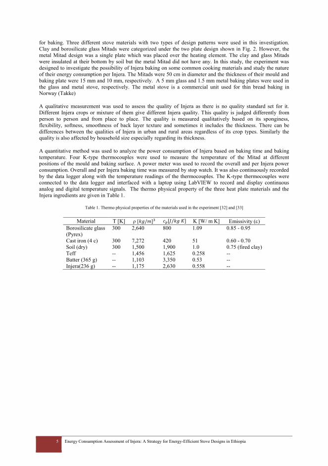
5 Energy Consumption Assessment of Injera: A Strategy for Energy-Efficient Stove Designs in Ethiopia
for baking. Three different stove materials with two types of design patterns were used in this investigation.
Clay and borosilicate glass Mitads were categorized under the two plate design shown in Fig. 2. However, the
metal Mitad design was a single plate which was placed over the heating element. The clay and glass Mitads
were insulated at their bottom by soil but the metal Mitad did not have any. In this study, the experiment was
designed to investigate the possibility of Injera baking on some common cooking materials and study the nature
of their energy consumption per Injera. The Mitads were 50 cm in diameter and the thickness of their mould and
baking plate were 15 mm and 10 mm, respectively. A 5 mm glass and 1.5 mm metal baking plates were used in
the glass and metal stove, respectively. The metal stove is a commercial unit used for thin bread baking in
Norway (Takke)
A qualitative measurement was used to assess the quality of Injera as there is no quality standard set for it.
Different Injera crops or mixture of them give different Injera quality. This quality is judged differently from
person to person and from place to place. The quality is measured qualitatively based on its sponginess,
flexibility, softness, smoothness of back layer texture and sometimes it includes the thickness. There can be
differences between the qualities of Injera in urban and rural areas regardless of its crop types. Similarly the
quality is also affected by household size especially regarding its thickness.
A quantitative method was used to analyze the power consumption of Injera based on baking time and baking
temperature. Four K-type thermocouples were used to measure the temperature of the Mitad at different
positions of the mould and baking surface. A power meter was used to record the overall and per Injera power
consumption. Overall and per Injera baking time was measured by stop watch. It was also continuously recorded
by the data logger along with the temperature readings of the thermocouples. The K-type thermocouples were
connected to the data logger and interfaced with a laptop using LabVIEW to record and display continuous
analog and digital temperature signals. The thermo physical property of the three heat plate materials and the
Injera ingredients are given in Table 1.
Table 1. Thermo physical properties of the materials used in the experiment [32] and [33]
Material T [K] [𝑘𝑔/𝑚]3 𝑐𝑝[𝐽/𝑘𝑔 𝐾] K [W/ m K] Emissivity ()
Borosilicate glass
(Pyrex)
300 2,640 800 1.09 0.85 - 0.95
Cast iron (4 c) 300 7,272 420 51 0.60 - 0.70
Soil (dry) 300 1,500 1,900 1.0 0.75 (fired clay)
Teff -- 1,456 1,625 0.258 --
Batter (365 g) -- 1,103 3,350 0.53 --
Injera(236 g) -- 1,175 2,630 0.558 --

6 Energy Consumption Assessment of Injera: A Strategy for Energy-Efficient Stove Designs in Ethiopia
Thermocouple
Laptop
Power Meter
Clay Stove
Data logger
Data cable
Fig. 2: Schematics of experimental set-up
3. Thermal analysis of Injera
The rarely published literatures gave limited information on the thermal properties and energy consumption of
Injera baking. Injera is one of the oldest processed foods in Africa that has not changed its processing methods
over the time. Some users attempted to replace the clay Mitad (thermal conductivity of 0.25 W/m.K) with a
ceramic (thermal conductivity of 2 W/m.K) [33]. However, ceramic Mitads has experienced cracking at high
temperatures. The Injera batter contains many components, including protein, lipids, carbohydrates, water, and
ash. The specific heat of Injera used in the thermal analysis is 3.35 [𝐽/𝑘𝑔 𝐾] as given in Table 1 [33].
3.1. Conduction heat transfer
Conduction heat transfer is the primary means of heat transfer used in stoves to bake Injera. The heating element
conducts heat through the mould to the top of the stove, and conduction continues into the batter at the boiling
temperature as water evaporates from the food. The heat conduction through the pan is:
sb st
c s
T TQ KA
x
(1)
The solid fraction and moisture content of both the batter and Injera were determined to be about 27/72 and
57/42, respectively [32]. The average batter of one Injera is a mixture of 100 g of flour and 265 ml of water.
Water has a heat of vaporization of 2.3 J/g and absorbs heat during cooking when the batter starts losing water
during evaporation. The boiling point of water is altitude dependent, and for this experiment, the boiling point is
about 92°C at an altitude of 2,200 m (Mekelle). The average total heat required to bake one Injera was calculated
as 0.104 kWh. In these stoves, convection and radiation are the two common heat losses and can be calculated
using Eq. 2 [6]. These losses leaked from the lead, polished aluminium, of the stove. A 0.04 surface emissivity
and ℎ𝑐 of air was used. The clay and glass stoves used an ash insulator at the bottom, but there was no insulation
on the sides and top of the stove.

7 Energy Consumption Assessment of Injera: A Strategy for Energy-Efficient Stove Designs in Ethiopia
44)( alSalScloss TTATTAhS
(2)
4. Results and discussion
Injera baking was limited to clay Mitad because users do not spend time and energy to try other materials that
require extended practice and considerable cost. The most common problems associated with Injera baking on
other materials include, sticking, less number of craters and overall poor quality. Baking on some common cook
plates with coating materials such as Teflon has been tried but often ended up with poor Injera quality.
Borosilicate and clay have very close material properties except for their thermal shock difference. In this
experiment glass was used to bake at intermittent power supply while metal and clay used continuous supply.
Nonetheless, glass stove was able to bake high-quality Injera with shorter overall baking time and less power as
compared to the other two. On the other hand, clay stove was observed to have longer initial heating time and
equal quality of Injera with glass. The experiment was repeated nine times and the results were similar. Injera
baking on a metal stove was very difficult to manage and resulted in poor quality as compared to the other two.
The Injera quality was still possible to be consumed but failed to pass through the common qualitative quality
measures. The clay stove used in the experiment has smaller thickness as compared to ordinary wood fired plate
thickness of 20 mm.
4.1. Ordinary electric clay stove
Most common household Mitads are about 50-60 cm in diameter. These Mitads are used on average two to three
times per week depending on households’ family size. One time baking for an average family size of four takes
about two hours on traditional biomass Mitad and about one and half hours on ordinary electric Mitad. The
thickness of these Mitads varies from place to place and lies in the range of 20-30 mm. The electric Mitad has
been in use for decades in places which have electricity access. Following the recent development of the country,
the expansion of electricity and adoption of electric Mitad has increased, leading to concerns of efficiency and
power saving potentials. The clay Mitad used in this work has a thickness of 15 mm and 10 mm for its mould
and baking plate, respectively. The extreme temperature fluctuation per baking cycle at the mould and baking
surface were 15 and 175C, correspondingly. This Mitad lost at least 31% and at most 54% of its usable energy.
The different initial temperature levels of each cycle, as shown in Fig. 3(b) indicates that the initial surface
temperature has little impact on baking time and Injera quality. The nominal lower and upper temperature limits
of Injera baking found in literature seem very high and unjustifiable. Such research inputs might also contributed
to the present heating element choice and stove design too. In this experiment, the Mitad was heated up beyond
the nominal literature limits (as low as 140°C and as high as 225°C) to study the impact of baking plate surface
temperature on quality and baking speed. Nine consecutive experiments were conducted and the result showed
no observable difference in quality and baking time. The longer baking time shown in the first and second cycle
of Fig. 3(b) is in line with the general behaviour of baking start up. However, the shortest baking time of the fifth
and sixth cycle was an indicator to how low the surface temperature could lower and still the baking cycle
remained unaffected. The temperature of the mould below the baking surface has reached steady state and
remained unaffected by the surface temperature fluctuation. A heat flux computation indicates that about 40% of
the energy loss could be saved if a 100C baking cycle fluctuation, 125C baking surface and 225C mould
temperatures could be set. The clay stove required the largest preheating power and longest baking time due to
the low thermal conductivity between its mould and baking plate and their thickness. The thickness of the mould
and stove act as a heat buffer to some degree. However, users (particularly those who use biomass fuels) prefer
a thin stove made of high-quality clay and fired at higher temperatures to save firewood.

8 Energy Consumption Assessment of Injera: A Strategy for Energy-Efficient Stove Designs in Ethiopia
(a)
(b)
Fig. 3: Baking on the clay stove: (a) Injera texture and (b) baking surface and mould temperature profile
4.2. Glass stove
Borosilicate glass is designed to withstand thermal shock better than other glass materials because of its low
expansion coefficient and higher strength. The glass can be safely used up to a temperature of 232°C if it is not
subjected to a sudden temperature change of more than 120°C. This material has been in use in modern stoves as
an appliance and stove hot surface. However, such applications do not experience continuous temperature
fluctuation like in Injera baking. The experiment of Injera baking on borosilicate glass lowered the baking
temperature range to 120-150°C, as shown in Fig. 4(b). This baking range was achieved when the stove was
operated at alternating power supply which has registered an efficiency of 32% as compared to the clay Mitad
discussed in section 4.1. This Mitad demanded regulated power supply. However, existing stove designs does
not accommodate temperature/current regulator and it is not easy to get it in local markets. In the beginning, this
0
25
50
75
100
125
150
175
200
225
250
275
300
325
350
1 501 1001 1501 2001 2501 3001 3501 4001 4501
Sto
ve
tem
per
ature
[C
]
Baking time [S]
baking Surface temperature Mould temperature
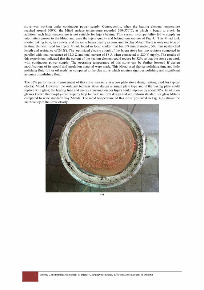
9 Energy Consumption Assessment of Injera: A Strategy for Energy-Efficient Stove Designs in Ethiopia
stove was working under continuous power supply. Consequently, when the heating element temperature
reached around 600°C; the Mitad surface temperature recorded 560-570°C, at which it began to crack. In
addition, such high temperature is not suitable for Injera baking. This system incompatibility led to supply an
intermittent power to the Mitad and gave the Injera quality and baking temperature of Fig. 4. This Mitad took
shorter baking time, less power, and the same Injera quality as compared to clay Mitad. There is only one type of
heating element, used for Injera Mitad, found in local market that has 0.9 mm diameter, 500 mm upstretched
length and resistance of 24.5. The optimized electric circuit of the Injera stove has two resistors connected in
parallel with total resistance of 12.3 and total current of 18 A when connected to 220 V supply. The results of
this experiment indicated that the current of the heating element could reduce by 32% so that the stove can work
with continuous power supply. The operating temperature of this stove can be further lowered if design
modifications of its mould and insulation material were made. This Mitad used shorter polishing time and little
polishing fluid (oil or oil seeds) as compared to the clay stove which requires rigorous polishing and significant
amounts of polishing fluid.
The 32% performance improvement of this stove was only in a two plate stove design setting used for typical
electric Mitad. However, the ordinary biomass stove design is single plate type and if the baking plate could
replace with glass; the heating time and energy consumption per Injera could improve by about 50%. In addition
glasses known thermo-physical property help to made uniform design and set uniform standard for glass Mitads
compared to none standard clay Mitads. The mold temperature of this stove presented in Fig. 4(b) shows the
inefficiency of the stove clearly.
(a)
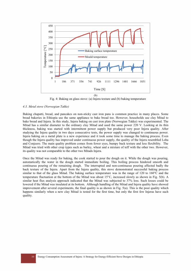
10 Energy Consumption Assessment of Injera: A Strategy for Energy-Efficient Stove Designs in Ethiopia
(b)
Fig. 4: Baking on glass stove: (a) Injera texture and (b) baking temperature
4.3. Metal stove (Norwegian Takke)
Baking chapatti, bread, and pancakes on non-sticky cast iron pans is common practice in many places. Some
bread bakeries in Ethiopia use the same appliance to bake bread too. However, households use clay Mitad to
bake bread and Injera. In this study, Injera baking on cast iron plate (Norwegian Takke) was experimented. The
Mitad has a similar diameter to the ordinary clay Mitad and used the same power 220 V. Looking at its thin
thickness, baking was started with intermittent power supply but produced very poor Injera quality. After
studying the Injera quality in two days consecutive tests, the power supply was changed to continuous power.
Injera baking on a metal plate is a new experience and it took some time to manage the baking process. Even
though the Injera quality has improved under continuous power supply, the quality of the Injera resembled Loha
and Conjeero. The main quality problem comes from fewer eyes, bumpy back texture and less flexibility. The
Mitad was tried with other crop types such as barley, wheat and a mixture of teff with the other two. However,
its quality was not comparable to the other two Mitads Injera.
Once the Mitad was ready for baking, the cook started to pour the dough on it. While the dough was pouring,
automatically the water in the dough started immediate boiling. This boiling process hindered smooth and
continuous pouring of the remaining dough. The interrupted and non-continuous pouring affected badly the
back texture of the Injera. Apart from the Injera quality, this stove demonstrated successful baking process
similar to that of the glass Mitad. The baking surface temperature was in the range of 120 to 160°C and the
temperature fluctuation at the bottom of the Mitad was about 15C, increased slowly as shown in Fig. 5(b). A
similar heat flux analysis approach indicated that the Mitad was subjected to 37% loss. Such losses could be
lowered if the Mitad was insulated at its bottom. Although handling of the Mitad and Injera quality have showed
improvement after several experiments, the final quality is as shown in Fig. 5(a). This is the poor quality which
happens similarly when a new clay Mitad is tested for the first time, but only the first few Injeras have such
quality.
0
50
100
150
200
250
300
350
400
450
1 186 371 556 741 926 1111 1296 1481 1666 1851
Tem
per
ature
[C
]
Time [S]
Baking surface temperature
Mould temperature
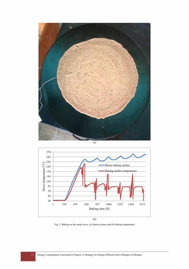
11 Energy Consumption Assessment of Injera: A Strategy for Energy-Efficient Stove Designs in Ethiopia
(a)
(b)
Fig. 5. Baking on the metal stove: (a) Injera texture and (b) baking temperature
20
45
70
95
120
145
170
195
220
245
270
1 210 419 628 837 1046 1255 1464 1673
Sto
ve
tem
per
ature
[C
]
Baking time [S]
Below baking surface
Baking surface temperature

12 Energy Consumption Assessment of Injera: A Strategy for Energy-Efficient Stove Designs in Ethiopia
4.4. Comparison of baking time and energy
Even though Injera quality depends on subjective standards, its quality remains similar if its flour and bakery
remained the same. With this regard, the Injera qualities from clay and glass Mitad were better than that of the
metal Mitad. It was also found that the glass Mitad has reduced the baking time and power consumption of clay
Mitad by 60% and 63%, respectively. These savings can be further improved by using a suitable mould and
heating element that allows the borosilicate glass bake under continuous power supply. The average baking time
and power consumption per Injera of the three Mitads are shown in Fig. 6(a) and (b), respectively. From Fig.
3(b) and 6(b), it was observed that the clay stove required the longest preheating time and largest power of the
three. Similarly, Fig. 4(b) and 6(b) shows that glass Mitad required less preheating time and power while the
metal Mitad consume moderate. Fig. 3(b) and 4(b) indicated that clay Mitad took about three times the time
taken by glass Mitad to bake the same amount of Injera. The metal and glass Mitads took similar baking time. A
continuous power supply has lowered the overall power requirement of metal Mitad as compared to clay stove,
as shown in Fig. 6(b). However, it was not possible to give continuous power to the glass Mitad; and the data
shown in Fig. 6(b) were taken from the intermittent supply. None of the stoves have power-regulator, users used
to regulate excess energy through rapid baking, cool baking surface by drizzling with water or switching off the
power until it cools down
(a)
(b)
Fig. 6. Injera baking process: (a) baking time and (b) power recordings during the Injera baking
0102030405060708090
100110120130140150
1 2 3 4 5 6
Bak
ing t
ime/
Inje
ra [
S]
Number of Injeras
glass metal clay
0.00
0.05
0.10
0.15
0.20
0.25
0.30
0.35
0.40
0.45
0.50
1 2 3 4 5 6 7
Po
wer
co
nsu
pti
on/I
nje
ra [
kW
h]
Number of Injeras
glass metal clay
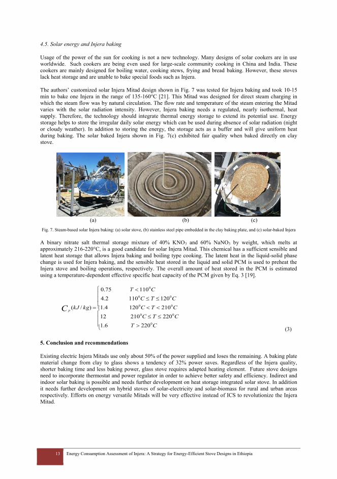
13 Energy Consumption Assessment of Injera: A Strategy for Energy-Efficient Stove Designs in Ethiopia
4.5. Solar energy and Injera baking
Usage of the power of the sun for cooking is not a new technology. Many designs of solar cookers are in use
worldwide. Such cookers are being even used for large-scale community cooking in China and India. These
cookers are mainly designed for boiling water, cooking stews, frying and bread baking. However, these stoves
lack heat storage and are unable to bake special foods such as Injera.
The authors’ customized solar Injera Mitad design shown in Fig. 7 was tested for Injera baking and took 10-15
min to bake one Injera in the range of 135-160°C [21]. This Mitad was designed for direct steam charging in
which the steam flow was by natural circulation. The flow rate and temperature of the steam entering the Mitad
varies with the solar radiation intensity. However, Injera baking needs a regulated, nearly isothermal, heat
supply. Therefore, the technology should integrate thermal energy storage to extend its potential use. Energy
storage helps to store the irregular daily solar energy which can be used during absence of solar radiation (night
or cloudy weather). In addition to storing the energy, the storage acts as a buffer and will give uniform heat
during baking. The solar baked Injera shown in Fig. 7(c) exhibited fair quality when baked directly on clay
stove.
(a) (b) (c)
Fig. 7. Steam-based solar Injera baking: (a) solar stove, (b) stainless steel pipe embedded in the clay baking plate, and (c) solar-baked Injera
A binary nitrate salt thermal storage mixture of 40% KNO3 and 60% NaNO3 by weight, which melts at
approximately 216-220°C, is a good candidate for solar Injera Mitad. This chemical has a sufficient sensible and
latent heat storage that allows Injera baking and boiling type cooking. The latent heat in the liquid-solid phase
change is used for Injera baking, and the sensible heat stored in the liquid and solid PCM is used to preheat the
Injera stove and boiling operations, respectively. The overall amount of heat stored in the PCM is estimated
using a temperature-dependent effective specific heat capacity of the PCM given by Eq. 3 [19].
CT
CTC
CTC
CTC
CT
kgkJC p
0
00
00
00
0
2206.1
22021012
2101204.1
1201102.4
11075.0
)/(
(3)
5. Conclusion and recommendations
Existing electric Injera Mitads use only about 50% of the power supplied and loses the remaining. A baking plate
material change from clay to glass shows a tendency of 32% power saves. Regardless of the Injera quality,
shorter baking time and less baking power, glass stove requires adapted heating element. Future stove designs
need to incorporate thermostat and power regulator in order to achieve better safety and efficiency. Indirect and
indoor solar baking is possible and needs further development on heat storage integrated solar stove. In addition
it needs further development on hybrid stoves of solar-electricity and solar-biomass for rural and urban areas
respectively. Efforts on energy versatile Mitads will be very effective instead of ICS to revolutionize the Injera
Mitad.
14 Energy Consumption Assessment of Injera: A Strategy for Energy-Efficient Stove Designs in Ethiopia
Acknowledgements
The authors express appreciation to the government of Norway for supporting the Ethiopian Institute of
Technology-Mekelle (Mekelle University) to conduct the EnPe preject in the Department of Mechanical
Engineering under which this study was sponsored. The authors would also like to thank Ftwi Y Hagos for his
interesting review comments.
References
[1] http://en.wikipedia.org/wiki/Injera [2] K. R. Smith, “Health, energy, and greenhouse-gas impacts of biomass combustion in household stoves”, Energy for
Sustainable Development, Volume I, No. 4, pp. 23-29, November 1994. [3] H. Alberts, C. Moreira and R. Maria Pérez, “Firewood substitution by kerosene stoves in rural and urban areas of
Nicaragua, social acceptance, energy policies, greenhouse effect and financial implications”, Energy for Sustainable Development, Volume III, No. 5, pp. 26-39, January 1997.
[4] A. Salam, M. Hasan, B. A. Begum, M. Begum, and S. K. Biswas, “Chemical characterization of biomass burning deposits from cooking stoves in Bangladesh”, Biomass and Bioenergy, Vol. 5 2, pp. 122-130, 2 0 1 3.
[5] N. MacCarty, D. Ogle, D. Still, T. Bond and C Roden, “A laboratory comparison of the global warming impact of five major types of biomass cooking stoves”, Energy for Sustainable Development, Volume XII, No. 2, pp. 56-65, June 2008.
[6] K. Pine, R. Edwards, O. Masera, A. Schilmann, A. Marrón-Mares, and H. Riojas-Rodríguez, “Adoption and use of improved biomass stoves in Rural Mexico”, Energy for Sustainable Development, Vol. 15, pp. 176–183, 2011.
[7] A. Singh, B. Tuladhar, K. Bajracharya and A. Pillarisetti, “Assessment of effectiveness of improved cook stoves in reducing indoor air pollution and improving health in Nepal”, Energy for Sustainable Development, Vol. 16, pp. 406–414, 2012.
[8] Z. Chowdhury, L. Campanella, C. Gray, A. Al Masud, J. Marter-Kenyon, D. Pennise, D. Charron, and X. Zuzhang, “Measurement and modeling of indoor air pollution in rural households with multiple stove interventions in Yunnan, China”, Atmospheric Environment, Vol. 67, pp. 161-169, 2013.
[9] K. Harijan and M. A. Uqaili, “Potential of biomass conservation through dissemination of efficient cook stoves in Pakistan”, 5th APCBEE Procedia, Dubai, UAE, pp.: 358 – 362, 19-20 January 2013.
[10] G. L. Simon, A. G. Bumpus and P. Mann, “Win-win scenarios at the climate–development interface: Challenges and opportunities for stove replacement programs through carbon finance”, Global Environmental Change, Vol. 22, pp. 275–287, 2012.
[11] J. Gill, “Improved stoves in developing countries”, Energy Policy, pp.: 135-144, April 1987. [12] M. A. Johnson, V. Pilco, R. Torres, S. Joshi, R. M. Shrestha, M. Yagnaraman et al., “Impacts on household fuel
consumption from biomass stove programs in India, Nepal, and Peru”, Energy for Sustainable Development, Article in press, 2013.
[13] M. Kumar, S. Kumar and S.K. Tyagi, “Design, development and technological advancement in the biomass cook stoves: A review”, Renewable and Sustainable Energy Reviews, Vol. 26, pp. 265–285, 2013.
[14] M. Kees and L. Feldmann,” The role of donor organisations in promoting energy efficient cook stoves”, Energy Policy, Vol. 39, pp. 7595–7599, 2011.
[15] Mariangela Bizzarri, Safe Access to Firewood and alternative Energy in Ethiopia: An Appraisal Report, 2010. [16] 2Oxfam, Country Profile: Ethiopia, 2012. [17] B. Gebru and S. Bezu, Environmental Resource Collection versus Children’s Schooling: Evidence from Tigray,
Northern Ethiopia, EDRI Working Paper 007, 2012. [18] A. H. Tesfay, M. B. Kahsay, and O. J. Nydal, “Solar powered heat storage for Injerabaking in Ethiopia”, 2013 ISES
Solar World Congress, Cancun, Mexico 3-7 November 2013 [19] A. A. Hassen, D. A. Amibe, and O. J. Nydal, “Performance Investigation of Solar Powered InjeraBaking Oven for
Indoor Cooking”, ISES solar world congress 2011 proceedings, Kassel, Germany 186-196, 28 August - 2 September 2011.
[20] 6A. H. Tesfay, M. B. Kahsay, and O. J. Nydal, “ Design and development of indoor solar Injera stove: steam based direct baking”, 2013 ISES Solar World Congress, 3-7 November 2013
[21] T. Takama, S. Tsephel and F. X. Johnson, “Evaluating the relative strength of product-specific factors in fuel switching and stove choice decisions in Ethiopia. A discrete choice model of household preferences for clean cooking alternatives”, Energy Economics, Vol. 34, pp. 1763–1773, 2012.
[22] A. D. Beyene and S. F. Koch, “Clean fuel-saving technology adoption in urban Ethiopia”, Energy Economics, Vol. 36, pp. 605–613, 2013.
[23] C. Rogers, B. K. Sovacool and S. Clarke, “Sweet nectar of the Gaia: Lessons from Ethiopia's “Project Gaia””, Energy for Sustainable Development, Vol. 17, pp. 245–251, 2013.
[24] Z. Gebreegziabher, A. Mekonnen, M. Kassie and G. Köhlin, “Urban energy transition and technology adoption: The case of Tigrai, northern Ethiopia”, Energy Economics, Vol. 34, pp. 410–418, 2012.
[25] A. D. Beyene and S. F. Koch, “Property rights, institutions and choice of fuelwood source in rural Ethiopia”, Forest Policy and Economics, Vol. 30, pp. 30–38, 2013.
[26] Embassy of Japan in Ethiopia, “Study on the Energy Sector in Ethiopia”, September 2008. [27] E. Engida, E. Tsehaye and S. Tamru, “Does Electricity Supply Strategy Matter? Shortage and Investment: Reflections
based on CGE Analysis”, EDRI Working Paper 006, December 2011. [28] B. Kebede, A. Bekeleb and E. Kedir, “Can the urban poor afford modern energy? The case of Ethiopia”, Energy Policy,
Vol. 30, pp. 1029–1045, 2002.

15 Energy Consumption Assessment of Injera: A Strategy for Energy-Efficient Stove Designs in Ethiopia
[29] S.G. Gwavuya, S. Abele, I. Barfuss, M. Zeller and J. Müller, “Household energy economics in rural Ethiopia: A cost-benefit analysis of biogas energy”, Renewable Energy, Vol. 48, pp. 202-209, 2012.
[30] N. L. Panwa, S.C. Kaushik and S. Kothari, “State of the art of solar cooking: An overview”, Renewable and Sustainable Energy Reviews, Vol. 16, pp. 3776– 3785, 2012.
[31] A. Gallagher, “A solar fryer”, Solar Energy, Vol. 85, pp. 496–505, 2011. [32] A. F. Mills, “Heat and mass transfer”, [33] A. T. Tafere, “Experimental investigation on performance characteristics and efficiency of electric Injerabaking pans
(“Mitad”)”, master thesis, pp. 23-33, November 2011. [34] Y. Choi, and R. M. Okos, “Effects of Temperature and Composition on the Thermal Properties of Foods”. Journal of
Food Process and Applications, Vol. 1, pp. 1 93 –101, 1986.

84

85
IV: Experimental Investigation of Optical Pipe as a Means of
Radiation Transfer for Solar Thermal Applications
Asfafaw H. Tesfay, Getachew M. Derese, Chimango Mvula, Ole J. Nydal and Mulu B.
Kahsay
Submitted to Solar energy

86

EXPERIMENTAL INVESTIGATION OF OPTICAL PIPE AS A MEANS
OF RADIATION TRANSFER FOR SOLAR THERMAL
APPLICATIONS
Asfafaw H. Tesfay1, Getachew Muche Derese2, Chimango Mvula2, Ole J. Nydal1 and
Mulu B. Kahsay2 1Department of Energy and Process Engineering, Norwegian University of Science and
Technology, 7491 Trondheim, Norway [email protected],[email protected]
2Department of Mechanical Engineering, Ethiopian Institute of Technology-Mekelle, Mekelle
University, P.O.box 231 Mekelle, Ethiopia [email protected], [email protected], [email protected]
ABSTRACT Currently, concentrating solar thermal technologies like parabolic dish cookers can only be used by placing the
cooking pot at the focus point. Such solar cooker technologies have led to their current low adoption. This
article discusses transportation of solar energy from the receiver to some distance of utilization in the form of
radiation. A large hollow waveguide called an optical pipe was used as a means to transport the solar energy.
Forward sequential ray tracing was used to design the optical pipe prior to its manufacturing and performance
testing. The experiment of this study was conducted by using a 1.2m and 10cm aperture diameter primary and
secondary parabolic dish reflectors respectively; and a 2.3m long, 70mm inner diameter optical pipe. K-type
thermocouples were used to measure the temperature of metallic disks attached at the inlet and outlet of the
optical pipe. A transmission coefficient of 19.6% that is equivalent to an attenuation coefficient of 3.08dB/m was
obtained experimentally. Through this research, the possibility of transmitting concentrated solar energy over
short distances was demonstrated. The results show possibilities to transform concentrating parabolic dish
outdoor cookers into indoor cookers and thereby increase their adoption potential. The findings of this study
needs further work on optimization of the optical pipe to increase its transmission coefficient before testing it
for cooking purpose.
KEYWORDS: optical pipe guide, solar cooker; parabolic dish collector; ray tracing; secondary reflector
I. INTRODUCTION
Today the world is moving towards renewable energy technologies as one way of achieving
sustainable energy generation. One of the most promising renewable energy resources is solar energy.
It is the most abundant and ultimate source of energy in the world. Point focus solar collectors are
useful for high temperature applications. An example of such application is parabolic dish solar
cooker. However, such collectors have two main problems: the energy can only be utilized at the
focus point of the collector and this focus is in constant motion. These problems contribute for the low
widespread rates of these cookers. A solution to the two problems could improve some of the
technical barriers to their adoption and expansion. This in turn will help in the living condition of
millions of people living in developing countries.
In these countries, women and girls travel long distance in search of fuel wood and yet they are
reluctant to use solar cookers. This is because current situations in developing countries show people
are forced to adapt existing solar cookers technology regardless of their cooking habit. However,
intellectuals effort to internalize and simplify the technology to people’s need could improve its
acceptance. In the past decades ergonomics has had a small share in the development of parabolic dish
solar cookers. Nonetheless, acceptance of parabolic solar cookers in the future will depend on how
well the technology fits to the norm of users.
There are different undergoing hot researches to separate the cooking pan from the solar receiver.
Among these researches use of heat storage [1] and thermal energy transportation using heat transfer
fluid (HTF) [2], [3] such as oil and steam have increased the interest for indirect indoor solar cooking.
In addition to thermal energy transportation solar radiation transportation is also one of the potential
means to avoid on focus solar cooking. The current study is targeted at the latter option. A leaky
hollow waveguide is one probable solution to the problems of point focus collector. Leaky hollow
waveguides use the principle of specular reflection to transmit the solar energy. They have simple
structure, strong optical confinement and high power transmission capability [4-6]. On the other hand,
they have small numerical aperture and high transmission losses hence they are only applicable to
short-distance applications [5]. Ohmic loss is the major cause of transmission loss in leaky hollow
waveguides [6]. In their previous researchers, Lan and Tong [7] have demonstrated the transmission
of xenon light, which has similar spectrum with sunlight, using silver coated leaky hollow waveguides
and their was satisfactory for solar energy transmission too.
Therefore, the objective of the current study is to investigate a leaky hollow waveguide to transport
solar radiation over short distance from a tracking double reflector parabolic dish concentrator to
cooking pan
1.1.Nomenclatures
Symbols Description Unit
𝐴 Surface area of receiver disk m2
𝐴𝑝 Primary reflector aperture area m2
𝐴𝑠𝑢𝑟𝑟 Surface area of surrounding objects m2
f Frequency Hz
f Product of reflectance’s of the primary and secondary reflectors
G Global radiation W/m2
𝐺𝑏 Beam radiation W/m2
𝐺𝑑 Diffuse radiation W/m2
IR Intercept ratio
𝑘𝑇 Clearness index
𝐿𝑠𝑡 Standard meridian for the local time zone degrees
𝐿𝑙𝑜𝑐 Longitude of the location east of the Greenwich meridian degrees
𝒏 Unit normal vector to the plane of reflection
n Number of reflected rays emerging from the exit of the optical
pipe
�̇�1 Power at pipe inlet W
�̇�2 Power at pipe outlet W
𝐩 Incident ray in space
𝐩′ Reflected ray in space
r Ray vector
𝑅 Reflectance of the waveguide material
𝑇𝑠 Surface temperature of the receiver Kelvin
𝑇𝑠𝑢𝑟𝑟 Temperature of the surrounding objects Kelvin
𝑡 Time sec
∈ Free space dielectric constant
𝜎 Stefan-Boltzmann constant W/m2K4
𝜖 Emissivity
𝜖𝑠𝑢𝑟𝑟 Emissivity of surrounding objects
II. Materials and methodology
In this study both experimental and numerical methods were used in the construction of the prototype.
In the numerical analysis LabVIEW and ray tracing software were used to record data and analyse the
design of the optical pipe. The leaky hollow waveguide was designed and manufactured from

anodized aluminium with a reflectivity of 95% in the solar spectrum. A 1.2m and 10cm diameter
primary and secondary parabolic reflector respectively were used in this system. The solar radiation
focused by the primary reflector is directed in to the secondary reflector and then into the hollow
guide. Input and output energy measurements were used to analyse the transmission characteristics of
the hollow guide. Additional materials used for the experiment and analysis were pyranometer
(Sensitivity~ 8 μV/Wm-2), K-type thermocouples, manual tracking aid, data logger, Meteon logger,
black metal disks, circular receiver with a shield on top, and receiver without shield. The Pyranometer
together with meteon logger were used to record the global solar radiation during the experiments and
LabVIEW, data logger and the K- type thermocouples were used to record temperatures. The manual
tracking aid works with visualization of shadow. The shadow length of the tracking aid is proportional
to the misalignment and the direction of the shadow is opposite to the direction of the sun.
III. DESIGN APPROACH
3.1. Ray Tracing
A regular grid of rays was used to design and predict the performance of the hollow waveguide.
Although Monte Carlo method is popular in the simulation of solar rays, a regular grid of rays gives
better results [8]. Use of a finite number of rays introduces errors in the simulation of solar rays and
this error was analyzed using a method described in [4]. The geometry of the waveguide was
modelled mathematically as a cylinder for the straight sections and as a section of a torus for the
bends. The surface and normal vector equations of the cylinder and torus are given by eqs. (1- 4).The
equation for the cylinder surface in vector form is:
(𝑡) = 𝑟 cos 𝑡 𝒊 + 𝑟 sin 𝑡 𝒋 (1)
The equation for the cylinder unit normal in vector form is
𝒏(𝑡) = − cos 𝑡 𝒊 − sin 𝑡 𝒋 (2)
The equation for the torus surface in vector form is (4.7)
(𝑡, ) = (𝑅 + 𝑟 cos 𝑡) cos 𝒊 + (𝑅 + 𝑟 cos 𝑡) sin 𝒋 + 𝑟 sin 𝑡 𝒌 (3)
The equation for the torus unit normal in vector form is:
𝒏(𝑡, ) = − cos 𝑡 cos 𝒊 − cos 𝑡 sin 𝒋 − sin 𝑡 𝒌 (4)
The law of specular reflection in space is:
𝒑′ = 𝒑 + 𝟐(𝒑 ∙ 𝒏)𝒏 (5)
These equations governed the numerical calculations of the ray tracing simulations. The inputs to the
ray tracing were the geometry and the reflectivity of the material. Figure (1) shows the dependence of
transmission coefficient on reflectivity and average number of reflections in the waveguide.The
transmission coefficient of the optical pipe is given by eq. (6).
𝑻 = 𝑹𝒏 (6)

Fig.1: Effects of reflectivity and number of reflection on transmission coefficient
Bends in the waveguide introduce an additional loss in the waveguide. Bends tend to disperse the rays
thereby increasing the number of reflections in the subsequent length of the waveguide. Extent of the
ray dispersion depends on the bend radius as shown in Fig. (2) (A - F).
Fig. 2 Ray dispersion and bend radius relation: A=0.04m, B=0.07m, C=0.1m, D=0.15m, E=0.2m and F=0.3m
bend radii
Figure (3), shows the effect of varying the bend radius on exit cone and number of reflections. The
number of radiations has a direct relation with bend radius while the exit cone angle has inverse
relation with bend radius. The variation of exit cone is less sensitive to the number reflections in the
bend.

Fig. 3: Effects of bend radius on exit cone angle and number of reflections
Pipe diameter affects the path length of the rays. However, this effect is not very significant when the
variations in the diameter are relatively small as shown in Fig. (4).The range for the diameter was
constrained by smallest cylinder available in the local market. And the optimal size 90mm diameter.
Fig. 4: Effects of length and diameter on transmission coefficient of pipe
Ray tracing simulation of the final designed pipe is shown in Fig. (5).

Fig. 5: Ray tracing simulation of optical pipe
Ray tracing simulation of the final designed pipe is shown in Fig. (5). From the ray tracing
simulations, an optimum pipe dimension of an overall pipe length of 2.3 m , diameter of 70 mm,
minimum bend radius of 100 mm and maximum bend angle of 90 degree is obtained in order to have
a transmission coefficient of at least 0.35. Decreasing the bend angle improves the pipe performance,
however, for short pipe length (<5 m), varying the bend radius from the optimum angle results in
performance loss.
3.2. Maximum Power in the Optical Pipe
Optical pipe of a given bore diameter has a maximum amount of power that can be transmitted. Rays
bouncing off the walls of the optical pipe heat up the optical pipe. Hence transmission is only possible
when the temperature of the optical pipe walls is less than a certain threshold value. This threshold
temperature is the melting point of the wall material or the base material, whichever is smaller.
Transmission characteristics of the optical pipe are that the highest power is at the entry and the least
power is at the exit as such the highest temperature is expected at the entry. Determination of the
maximum power in the optical pipe is based on the works of [9-11]. Fig. 6 shows the maximum
power versus the melting temperature.
Fig. 6: Maximum power transmission as a function of melting point
Aluminium melts at around 600C, and from Fig (6) it can be inferred the maximum power
transmission of the aluminium optical pipe cooled by natural convection is about 11kW. In practice
the optical pipe has to work below the melting point hence maximum power of about 8 kW is
considered.
3.3. Design of the secondary reflector
100 200 300 400 500 600 7000
2
4
6
8
10
12
Maximum Power Transmission as a function of melting point
Melting Point Temperature (degree Celsius)
Max
Po
wer (
KW
)
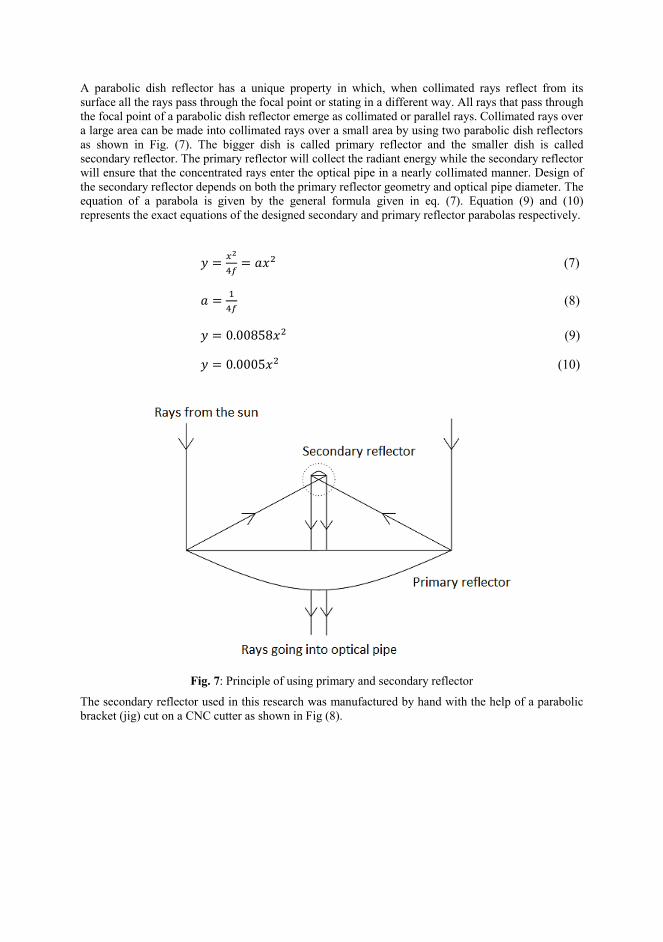
A parabolic dish reflector has a unique property in which, when collimated rays reflect from its
surface all the rays pass through the focal point or stating in a different way. All rays that pass through
the focal point of a parabolic dish reflector emerge as collimated or parallel rays. Collimated rays over
a large area can be made into collimated rays over a small area by using two parabolic dish reflectors
as shown in Fig. (7). The bigger dish is called primary reflector and the smaller dish is called
secondary reflector. The primary reflector will collect the radiant energy while the secondary reflector
will ensure that the concentrated rays enter the optical pipe in a nearly collimated manner. Design of
the secondary reflector depends on both the primary reflector geometry and optical pipe diameter. The
equation of a parabola is given by the general formula given in eq. (7). Equation (9) and (10)
represents the exact equations of the designed secondary and primary reflector parabolas respectively.
𝑦 =𝑥2
4𝑓= 𝑎𝑥2 (7)
𝑎 =1
4𝑓 (8)
𝑦 = 0.00858𝑥2 (9)
𝑦 = 0.0005𝑥2 (10)
Fig. 7: Principle of using primary and secondary reflector
The secondary reflector used in this research was manufactured by hand with the help of a parabolic
bracket (jig) cut on a CNC cutter as shown in Fig (8).
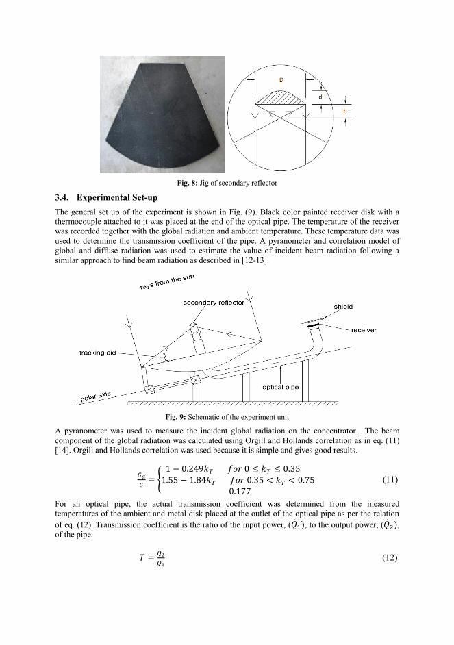
Fig. 8: Jig of secondary reflector
3.4. Experimental Set-up
The general set up of the experiment is shown in Fig. (9). Black color painted receiver disk with a
thermocouple attached to it was placed at the end of the optical pipe. The temperature of the receiver
was recorded together with the global radiation and ambient temperature. These temperature data was
used to determine the transmission coefficient of the pipe. A pyranometer and correlation model of
global and diffuse radiation was used to estimate the value of incident beam radiation following a
similar approach to find beam radiation as described in [12-13].
Fig. 9: Schematic of the experiment unit
A pyranometer was used to measure the incident global radiation on the concentrator. The beam
component of the global radiation was calculated using Orgill and Hollands correlation as in eq. (11)
[14]. Orgill and Hollands correlation was used because it is simple and gives good results.
𝐺𝑑
𝐺= {
1 − 0.249𝑘𝑇 𝑓𝑜𝑟 0 ≤ 𝑘𝑇 ≤ 0.35 1.55 − 1.84𝑘𝑇 𝑓𝑜𝑟 0.35 < 𝑘𝑇 < 0.75
0.177
(11)
For an optical pipe, the actual transmission coefficient was determined from the measured
temperatures of the ambient and metal disk placed at the outlet of the optical pipe as per the relation
of eq. (12). Transmission coefficient is the ratio of the input power, (�̇�1), to the output power, (�̇�2),
of the pipe.
𝑇 =�̇�2
�̇�1 (12)
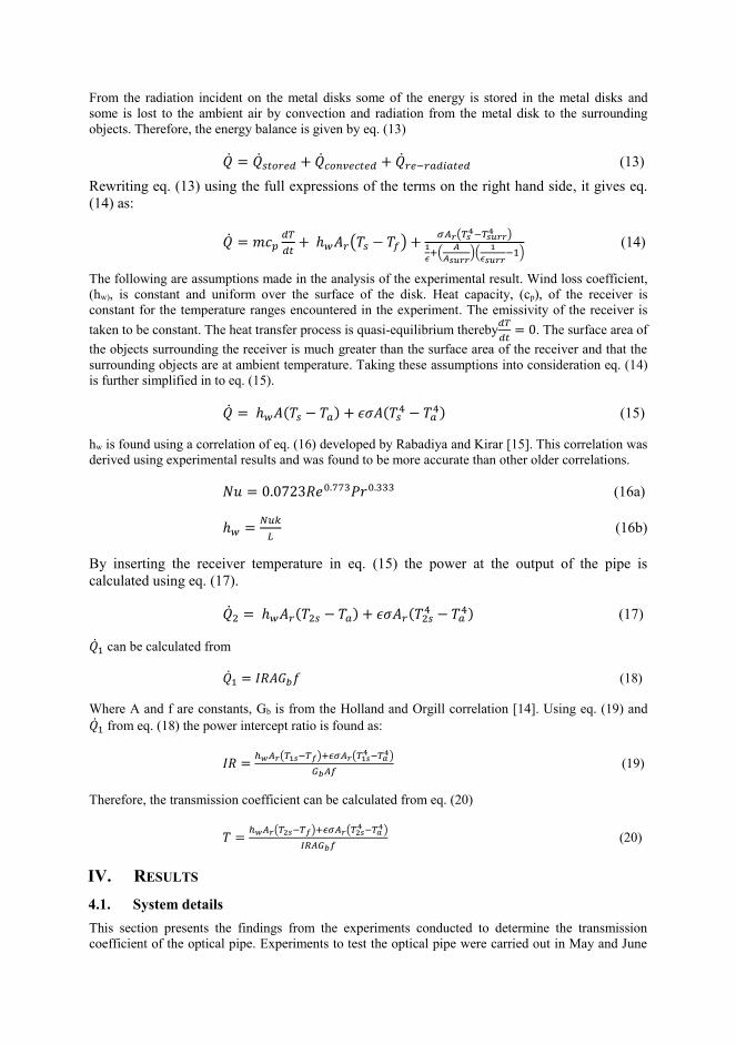
From the radiation incident on the metal disks some of the energy is stored in the metal disks and
some is lost to the ambient air by convection and radiation from the metal disk to the surrounding
objects. Therefore, the energy balance is given by eq. (13)
�̇� = �̇�𝑠𝑡𝑜𝑟𝑒𝑑 + �̇�𝑐𝑜𝑛𝑣𝑒𝑐𝑡𝑒𝑑 + �̇�𝑟𝑒−𝑟𝑎𝑑𝑖𝑎𝑡𝑒𝑑 (13)
Rewriting eq. (13) using the full expressions of the terms on the right hand side, it gives eq.
(14) as:
�̇� = 𝑚𝑐𝑝𝑑𝑇
𝑑𝑡+ ℎ𝑤𝐴𝑟(𝑇𝑠 − 𝑇𝑓) +
𝜎𝐴𝑟(𝑇𝑠4−𝑇𝑠𝑢𝑟𝑟
4 )1
𝜖+(
𝐴
𝐴𝑠𝑢𝑟𝑟)(
1
𝜖𝑠𝑢𝑟𝑟−1)
(14)
The following are assumptions made in the analysis of the experimental result. Wind loss coefficient,
(hw), is constant and uniform over the surface of the disk. Heat capacity, (cp), of the receiver is
constant for the temperature ranges encountered in the experiment. The emissivity of the receiver is
taken to be constant. The heat transfer process is quasi-equilibrium thereby𝑑𝑇
𝑑𝑡= 0. The surface area of
the objects surrounding the receiver is much greater than the surface area of the receiver and that the
surrounding objects are at ambient temperature. Taking these assumptions into consideration eq. (14)
is further simplified in to eq. (15).
�̇� = ℎ𝑤𝐴(𝑇𝑠 − 𝑇𝑎) + 𝜖𝜎𝐴(𝑇𝑠4 − 𝑇𝑎
4) (15)
hw is found using a correlation of eq. (16) developed by Rabadiya and Kirar [15]. This correlation was
derived using experimental results and was found to be more accurate than other older correlations.
𝑁𝑢 = 0.0723𝑅𝑒0.773𝑃𝑟0.333 (16a)
ℎ𝑤 =𝑁𝑢𝑘
𝐿 (16b)
By inserting the receiver temperature in eq. (15) the power at the output of the pipe is
calculated using eq. (17).
�̇�2 = ℎ𝑤𝐴𝑟(𝑇2𝑠 − 𝑇𝑎) + 𝜖𝜎𝐴𝑟(𝑇2𝑠4 − 𝑇𝑎
4) (17)
�̇�1 can be calculated from
�̇�1 = 𝐼𝑅𝐴𝐺𝑏𝑓 (18)
Where A and f are constants, Gb is from the Holland and Orgill correlation [14]. Using eq. (19) and
�̇�1 from eq. (18) the power intercept ratio is found as:
𝐼𝑅 =ℎ𝑤𝐴𝑟(𝑇1𝑠−𝑇𝑓)+𝜖𝜎𝐴𝑟(𝑇1𝑠
4 −𝑇𝑎4)
𝐺𝑏𝐴𝑓 (19)
Therefore, the transmission coefficient can be calculated from eq. (20)
𝑇 =ℎ𝑤𝐴𝑟(𝑇2𝑠−𝑇𝑓)+𝜖𝜎𝐴𝑟(𝑇2𝑠
4 −𝑇𝑎4)
𝐼𝑅𝐴𝐺𝑏𝑓 (20)
IV. RESULTS
4.1. System details
This section presents the findings from the experiments conducted to determine the transmission
coefficient of the optical pipe. Experiments to test the optical pipe were carried out in May and June
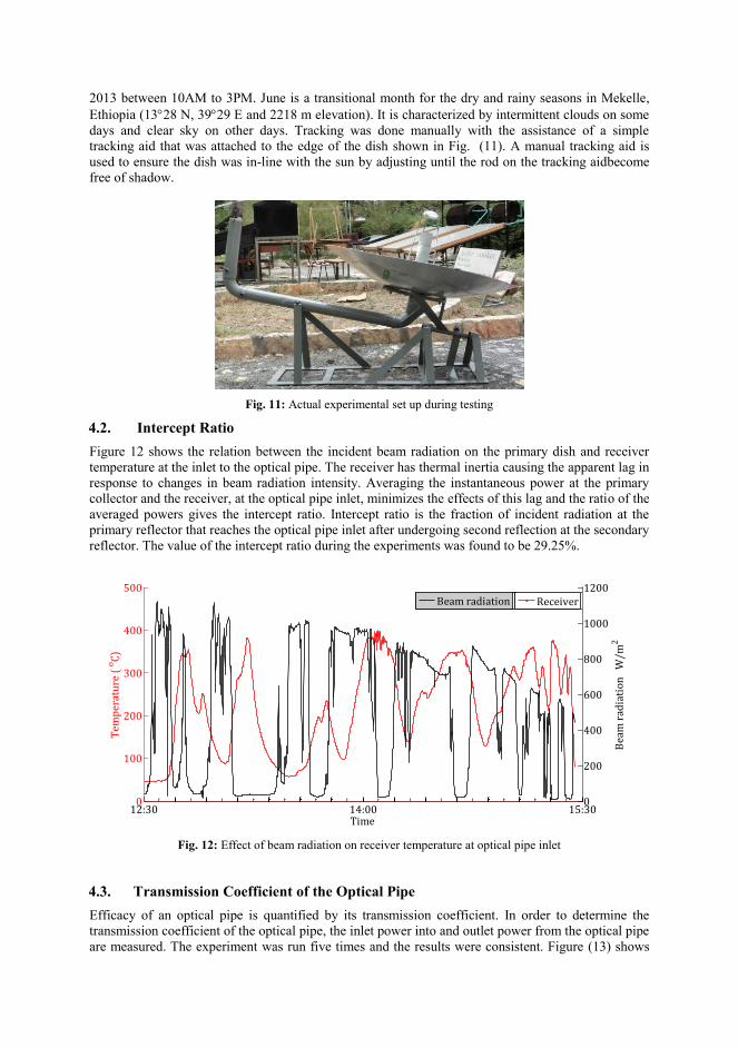
2013 between 10AM to 3PM. June is a transitional month for the dry and rainy seasons in Mekelle,
Ethiopia (1328 N, 3929 E and 2218 m elevation). It is characterized by intermittent clouds on some
days and clear sky on other days. Tracking was done manually with the assistance of a simple
tracking aid that was attached to the edge of the dish shown in Fig. (11). A manual tracking aid is
used to ensure the dish was in-line with the sun by adjusting until the rod on the tracking aidbecome
free of shadow.
Fig. 11: Actual experimental set up during testing
4.2. Intercept Ratio
Figure 12 shows the relation between the incident beam radiation on the primary dish and receiver
temperature at the inlet to the optical pipe. The receiver has thermal inertia causing the apparent lag in
response to changes in beam radiation intensity. Averaging the instantaneous power at the primary
collector and the receiver, at the optical pipe inlet, minimizes the effects of this lag and the ratio of the
averaged powers gives the intercept ratio. Intercept ratio is the fraction of incident radiation at the
primary reflector that reaches the optical pipe inlet after undergoing second reflection at the secondary
reflector. The value of the intercept ratio during the experiments was found to be 29.25%.
Fig. 12: Effect of beam radiation on receiver temperature at optical pipe inlet
4.3. Transmission Coefficient of the Optical Pipe
Efficacy of an optical pipe is quantified by its transmission coefficient. In order to determine the
transmission coefficient of the optical pipe, the inlet power into and outlet power from the optical pipe
are measured. The experiment was run five times and the results were consistent. Figure (13) shows
0
100
200
300
400
500
Tem
per
atu
re (
oC
)
Receiver
12:30 14:00 15:300
200
400
600
800
1000
1200
Bea
m r
adia
tio
n
W/m
2
Time
Beam radiation
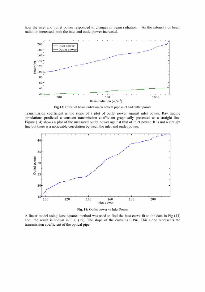
how the inlet and outlet power responded to changes in beam radiation. As the intensity of beam
radiation increased, both the inlet and outlet power increased.
Fig.13: Effect of beam radiation on optical pipe inlet and outlet power
Transmission coefficient is the slope of a plot of outlet power against inlet power. Ray tracing
simulations predicted a constant transmission coefficient graphically presented as a straight line.
Figure (14) shows a plot of the measured outlet power against that of inlet power. It is not a straight
line but there is a noticeable correlation between the inlet and outlet power.
Fig. 14: Outlet power vs Inlet Power
A linear model using least squares method was used to find the best curve fit to the data in Fig.(13)
and the result is shown in Fig. (15). The slope of the curve is 0.196. This slope represents the
transmission coefficient of the optical pipe.
200 600 100020
40
60
80
100
120
140
160
180
200
Beam radiation (w/m2)
Pow
er (
w)
Inlet power
Outlet power
100 120 140 160 180 20015
20
25
30
35
40
Outlet
pow
er
Inlet power
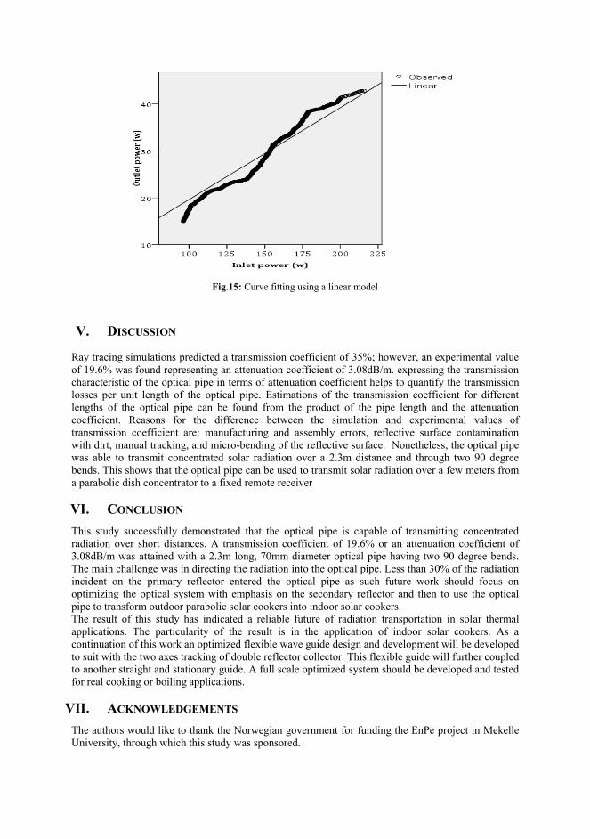
Fig.15: Curve fitting using a linear model
V. DISCUSSION
Ray tracing simulations predicted a transmission coefficient of 35%; however, an experimental value
of 19.6% was found representing an attenuation coefficient of 3.08dB/m. expressing the transmission
characteristic of the optical pipe in terms of attenuation coefficient helps to quantify the transmission
losses per unit length of the optical pipe. Estimations of the transmission coefficient for different
lengths of the optical pipe can be found from the product of the pipe length and the attenuation
coefficient. Reasons for the difference between the simulation and experimental values of
transmission coefficient are: manufacturing and assembly errors, reflective surface contamination
with dirt, manual tracking, and micro-bending of the reflective surface. Nonetheless, the optical pipe
was able to transmit concentrated solar radiation over a 2.3m distance and through two 90 degree
bends. This shows that the optical pipe can be used to transmit solar radiation over a few meters from
a parabolic dish concentrator to a fixed remote receiver
VI. CONCLUSION
This study successfully demonstrated that the optical pipe is capable of transmitting concentrated
radiation over short distances. A transmission coefficient of 19.6% or an attenuation coefficient of
3.08dB/m was attained with a 2.3m long, 70mm diameter optical pipe having two 90 degree bends.
The main challenge was in directing the radiation into the optical pipe. Less than 30% of the radiation
incident on the primary reflector entered the optical pipe as such future work should focus on
optimizing the optical system with emphasis on the secondary reflector and then to use the optical
pipe to transform outdoor parabolic solar cookers into indoor solar cookers.
The result of this study has indicated a reliable future of radiation transportation in solar thermal
applications. The particularity of the result is in the application of indoor solar cookers. As a
continuation of this work an optimized flexible wave guide design and development will be developed
to suit with the two axes tracking of double reflector collector. This flexible guide will further coupled
to another straight and stationary guide. A full scale optimized system should be developed and tested
for real cooking or boiling applications.
VII. ACKNOWLEDGEMENTS
The authors would like to thank the Norwegian government for funding the EnPe project in Mekelle
University, through which this study was sponsored.
REFERENCES
[1] A. H. Tesfay, M. B. Kahsay, and O. J. Nydal, “Solar powered heat storage for Injera baking in Ethiopia”,
2013 ISES Solar World Congress, Cancun, Mexico 3-7 November 2013
[2] A. H. Tesfay, M. B. Kahsay, and O. J. Nydal, “Design and development of indoor solar Injera stove: steam
based direct baking”, 2013 ISES Solar World Congress, 3-7 November 2013
[3] Maxime Mussard, Ole J Nydal, Charging of a heat storage coupled with a low-cost small-scale solar
parabolic trough for cooking purposes, Solar Energy, 2013; 95:144–154
[4] Jenkins, R M, et al.,Hollow optical waveguided devices and systems,SPIE 2008, Vols. 71130E-1.
[5] Harrington, J.A. s.l, A Review of IR Transmitting Hollow Waveguides, Fiber and Integrated Optics 2000,
Vol. 19, pp: 211-217.
[6] Pal, B., Frontiers in Guided Wave Optics and Optoelectronics.Intech 2010 Croatia, PP: 343-362. ISBN 978-
953-7619-82-4.
[7] He LAN et al. 3, s.l., Ag/PMMA Hollow Waveguide for Solar Energy Transmission, Front. Chem. Sci. Eng.,
2011, Vol. 5, pp. 303-307.
[8] J. W. 172, s.l., Fourier series Representation of the Position of the Sun. Spencer Search, 1971, Vol. 2(5).
[9] Rabadiya A.V. and Kirar, R. 9, s.l., Comparative Analysis of Wind Loss Coefficient (Wind Heat Transfer
Coefficient) For Solar Flat Plate Collector, International Journal of Emerging Technology and
Advanced Engineering, September 2012, Vol. 2, pp. 463-468.
[10] Nubling R. K and Harrington, J, Hollow-waveguide delivery systems for high-power, industrial CO2 lasers.
A. 3, 1996, APPLIED OPTICS, Vol. 34, pp. 372-380.
[11] Karasawa, S, Miyagi, M and Nishida, S, Temperature distribution along oversized hollow-core waveguides
for infrared radiation, Applied Optics, 1987, Vol. 26.
[12] Davies, P.A, Methods of choosing sample rays in ray-tracing computations, Applied Optics, 1992, Vol. 31.
[13] WMO Omm, Guide to meteorological instruments and methods of observation, Geneva: Secretariat of the
World Meteorological Organization, 1983, Vol. 8.
[14] Orgill, J. F and Hollands K.G.T, Correlation equation for hourly diffuse radiation on a horizontal surface.
Solar Energy, 1977, Vol. 19, pp. 357–359.
[15] Amara S et al., Concentration Heating System with Optical Fiber Supply, Energy Procedia, 2011,Vol. 6,
pp. 805-814.

100

101
V: Charging-discharging of a household size PCM storage
Asfafaw H Tesfay, Mulu Bayray Kahsay, Ole J. Nydal
Will submit to Journal of solar energy
Year: 2015

102

1
Charging-discharging of a household size PCM storage
1. Introduction
1.1. Background on solar cookers
Many developing countries use biomass as primary energy supply for their household’s energy
consumption. This energy affects the environment, health and livelihood development. Women
and children are often in charge of fetching firewood and cooking, in which they spent most of
their valuable energy and time traveling long distance in search of this fuel. In addition, they are
also the most affected from indoor air pollution caused by this energy.
The progress of solar cookers is very slow in spite of their benefits. One reason for this can be
lack of integration between social and technology side researchers. Secondly, the outreach of these
cookers often do not include the active participation of end users. In addition, many studies of solar
cooker with heat storage have been concentrated on low temperature cookers.
Many of the developing countries, who are dependent on biomass, have huge potentials for solar
energy that can potentially substitute the role of the biomass. However, solar energy technology
has been rarely introduced in these places. Moreover, generally solar thermal technology has not
reached a robust stage of mass production and distribution. Although some countries have
introduced solar box cookers, their success has been limited due to technological and social factors
in which none of the cookers enabled night cooking and indoor use. These technical limitations
also affect users’ norm of cooking, which may cause a social limitation on the adaption to new
technology.
To improve acceptance of solar cookers and assure their widespread use, a continuous
advancement in both technical development and social awareness is required. One of the key
elements for the success of solar cookers is thermal energy storage. Thermal energy storage helps
to store the surplus solar energy during the day and keep it for late evening use. In addition, it helps
to supply nearly uniform heat during the process of cooking. Some solar cooker design features
also allow to charge and use the cooker simultaneously. A. Lecuona et al.’s solar cooker could
cook family lunch while charging the storage simultaneously [1]. The stored heat of this cooker
allows dinner cooking and breakfast heating for the following day. Such design features help to
expand the acceptance of solar cooking. Another solar cooker design, which used heat pipes, flat-
plate collector and integrated indoor phase change material (PCM) storage, was able to cook food
at noon, evening and keep the food warm at night and morning [2]. Even though the past three
decades showed investigations and developments of PCM storage, M.M. Kenisarin’s review on
PCM storage shows the limitation of these researches to measurement of melting temperature and
heat of fusion [3]. The methods used in studying these thermal properties were differential thermal
2
analysis (DTA) and differential scanning calorimetry (DSC), which are quick methods but show
significant discrepancies in the results. PCM materials generally have low thermal conductivity
that slows their charging and discharging process. However, the use of fins can improve this
shortcoming. Lizarraga-Garcia and Mitsos’s study on heat transfer structure has significantly
decreased the cost of thermal energy storage (TES) and improves discharge efficiency and
discharging time of the storage [4].
The use of integrated thermal storage in solar cookers can solve these barriers and enable users
to perform any time indoor cooking practice. Thermal energy can be stored as sensible or latent
heat form. The stored heat in both storages can be used for cooking purpose. However, the later
provide higher storage capacity, compact size, and nearly isothermal heat supply. The motivation
of the present study is to design a PCM storage, which can be used to store heat for baking the
Ethiopian food called Injera.
Injera, a yeast-risen flat bread with slightly spongy texture, is the most common staple food type
served three to four times a day in Ethiopia. A similar food type is also eaten in, Eritrea (Injera),
Somalia (Canjeero), Sudan and Yemen (Lahoh) [5]. Injera demands a significant amount of energy.
The main energy supply for Injera baking comes from biomass as most of the population live
without connection to the power grid. The kitchen of the biomass stove (“Mitad”) is full of smoke
and soot that affects the health of millions. The solar stove designed in this study has tried to give
a solution for this acute problem.
1.2. Back ground on thermal storage and charging
Sensible heat storages such as Rock bed, water, oil etc. are larger storage and the temperature
decays faster compared to latent heat storages of the same capacity. However, these properties can
be improved by combining PCM material in their design as studied by D. Okello et al. [6]. The
PCMs used in solar energy applications undergo solid-liquid phase transition to store the heat and
vice versa to release the stored heat. The use of PCM storage for cooking is increasing and
diversifying with time. For example, H.M.S. Hussein et al. [2] have tested a PCM storage coupled
to flat plate collectors for indoor cooking and heating of food during the evening. In addition, A.
Lecuona et al.’s [1] portable solar cooker with PCM storage enables day and nighttime cooking.
In general, PCM materials have poor thermal conductivities and they took longer time to charge
them. In addition to thermal conductivity, mass flow rate and inlet temperature of the heat transfer
fluid (HTF) affects the charging-discharging process as shown by A.A. Al-Abidi et al. [7].
However, the charging-discharging process can be improved by designing multi stage storages with
different thermo physical properties as shown in Aldoss and Rahman [8] study. Murray and Groulx
[9] have shown the advantage of fast flowing over slow flowing HTF used in PCM charging-
discharging process. In this study, two-phase closed loop thermosyphon based heat transfer was
used to charge the PCM storage. This requires a height difference between the evaporator and the
condenser in the thermosyphon loop to drive the natural circulation by the gravity difference. Two-
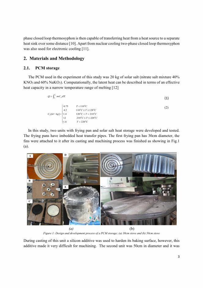
3
phase closed loop thermosyphon is then capable of transferring heat from a heat source to a separate
heat sink over some distance [10]. Apart from nuclear cooling two-phase closed loop thermosyphon
was also used for electronic cooling [11].
2. Materials and Methodology
2.1. PCM storage
The PCM used in the experiment of this study was 20 kg of solar salt (nitrate salt mixture 40%
KNO3 and 60% NaKO3). Computationally, the latent heat can be described in terms of an effective
heat capacity in a narrow temperature range of melting [12]
f
i
T
TpmCQ dT
(1)
0
0 0
0 0
0 0
0
0.75 110
4.2 110 120
[ / ] 1.4 120 210
12 210 220
1.6 220
P
T C
C T C
C kJ kg C T C
C T C
T C
(2)
In this study, two units with frying pan and solar salt heat storage were developed and tested.
The frying pans have imbedded heat transfer pipes. The first frying pan has 30cm diameter, the
fins were attached to it after its casting and machining process was finished as showing in Fig.1
(a).
(a) (b)
Figure 1: Design and development process of a PCM storage; (a) 30cm stove and (b) 50cm stove
During casting of this unit a silicon additive was used to harden its baking surface, however, this
additive made it very difficult for machining. The second unit was 50cm in diameter and it was
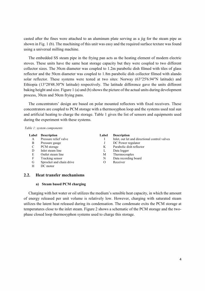
4
casted after the fines were attached to an aluminum plate serving as a jig for the steam pipe as
shown in Fig. 1 (b). The machining of this unit was easy and the required surface texture was found
using a universal milling machine.
The embedded SS steam pipe in the frying pan acts as the heating element of modern electric
stoves. These units have the same heat storage capacity but they were coupled to two different
collector sizes. The 30cm diameter was coupled to 1.2m parabolic dish filmed with tiles of glass
reflector and the 50cm diameter was coupled to 1.8m parabolic dish collector filmed with alando
solar reflector. These systems were tested at two sites: Norway (63°25'6.94"N latitude) and
Ethiopia (13°28'48.30"N latitude) respectively. The latitude difference gave the units different
baking height and size. Figure 1 (a) and (b) shows the picture of the actual units during development
process, 30cm and 50cm frying pans.
The concentrators’ design are based on polar mounted reflectors with fixed receivers. These
concentrators are coupled to PCM storage with a thermosyphon loop and the systems used real sun
and artificial heating to charge the storage. Table 1 gives the list of sensors and equipments used
during the experiment with these systems.
Table 1: system components
Label Description Label Description
A Pressure relief valve I Inlet, out let and directional control valves
B Pressure gauge J DC Power regulator
C PCM storage K Parabolic dish reflector
D Inlet steam line L Data logger
E Outlet steam line M Thermocouples
F Tracking sensor N Data recording board
G Sprocket and chain drive O Receiver
H DC motor
2.2. Heat transfer mechanisms
a) Steam based PCM charging
Charging with hot water or oil utilizes the medium’s sensible heat capacity, in which the amount
of energy released per unit volume is relatively low. However, charging with saturated steam
utilizes the latent heat released during its condensation. The condensate exits the PCM storage at
temperatures close to the inlet steam. Figure 2 shows a schematic of the PCM storage and the two-
phase closed loop thermosyphon systems used to charge this storage.

5
Figure 2: Schematic of storage integrated solar stove with two-phase thermosyphon loop heat transfer
The loop was first flushed to free any trapped air and filled 2/3 of its volume with water. There is
no expansion tank in this loop design. A boiling-condensing mode of heat transfer technique was
followed to transport the heat from the receiver to the frying pan. Theoretically, the mass flow rate
of the fluid circulating in the loop can be found by conducting a momentum balance around the
loop [13] and the heat transfer in the imbedded pipe is treated as film condensation in nearly
horizontal pipes.
b) Heat transfer between pipe and frying pan
The mode of heat transfer between the stainless steel pipe and aluminum block is a pure
conduction between composite solids as shown in Fig. 3. This heat transfer was analyzed using
Fourier’s conduction equations (3-5).
Figure 3: Composite materials of aluminum and SS
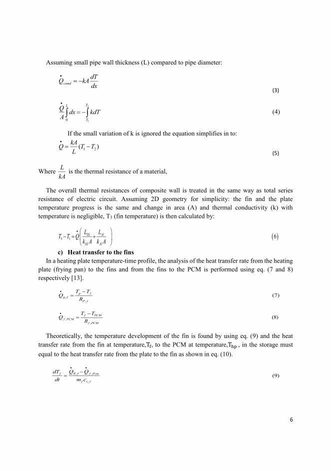
6
Assuming small pipe wall thickness (L) compared to pipe diameter:
cond
dTQ kA
dx
(3)
2
10
TL
T
Qdx kdT
A
(4)
If the small variation of k is ignored the equation simplifies in to:
1 2( )kA
Q T TL
(5)
Where L
kA is the thermal resistance of a material,
The overall thermal resistances of composite wall is treated in the same way as total series
resistance of electric circuit. Assuming 2D geometry for simplicity: the fin and the plate
temperature progress is the same and change in area (A) and thermal conductivity (k) with
temperature is negligible, T3 (fin temperature) is then calculated by:
3 1 6SS Al
SS Al
L LT T Q
k A k A
c) Heat transfer to the fins
In a heating plate temperature-time profile, the analysis of the heat transfer rate from the heating
plate (frying pan) to the fins and from the fins to the PCM is performed using eq. (7 and 8)
respectively [13].
p,
,
(7)p f
f
P f
T TQ
R
,
,
(8)f PCM
f PCM
f PCM
T TQ
R
Theoretically, the temperature development of the fin is found by using eq. (9) and the heat
transfer rate from the fin at temperature,Tf, to the PCM at temperature,Thp , in the storage must
equal to the heat transfer rate from the plate to the fin as shown in eq. (10).
P, ,
,
(9)f f f Pcm
f v f
Q QdT
dt m c
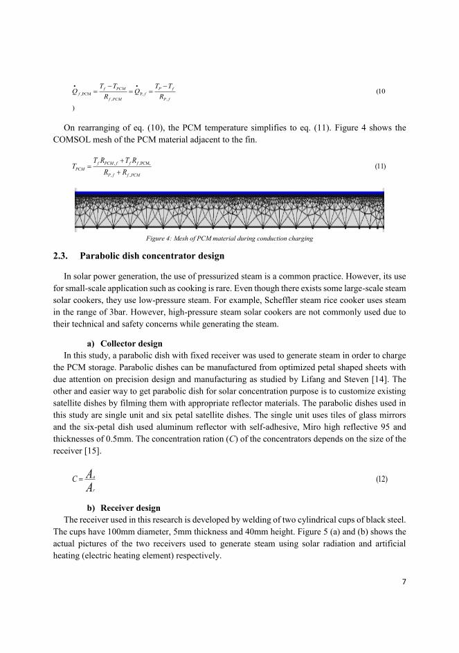
7
,PCM P,
, ,
(10
)
f PCM P f
f f
f PCM P f
T T T TQ Q
R R
On rearranging of eq. (10), the PCM temperature simplifies to eq. (11). Figure 4 shows the
COMSOL mesh of the PCM material adjacent to the fin.
, ,PCM,
, ,
(11)f PCM f f f
PCM
P f f PCM
T R T RT
R R
Figure 4: Mesh of PCM material during conduction charging
2.3. Parabolic dish concentrator design
In solar power generation, the use of pressurized steam is a common practice. However, its use
for small-scale application such as cooking is rare. Even though there exists some large-scale steam
solar cookers, they use low-pressure steam. For example, Scheffler steam rice cooker uses steam
in the range of 3bar. However, high-pressure steam solar cookers are not commonly used due to
their technical and safety concerns while generating the steam.
a) Collector design
In this study, a parabolic dish with fixed receiver was used to generate steam in order to charge
the PCM storage. Parabolic dishes can be manufactured from optimized petal shaped sheets with
due attention on precision design and manufacturing as studied by Lifang and Steven [14]. The
other and easier way to get parabolic dish for solar concentration purpose is to customize existing
satellite dishes by filming them with appropriate reflector materials. The parabolic dishes used in
this study are single unit and six petal satellite dishes. The single unit uses tiles of glass mirrors
and the six-petal dish used aluminum reflector with self-adhesive, Miro high reflective 95 and
thicknesses of 0.5mm. The concentration ration (C) of the concentrators depends on the size of the
receiver [15].
(12)a
r
C AA
b) Receiver design
The receiver used in this research is developed by welding of two cylindrical cups of black steel.
The cups have 100mm diameter, 5mm thickness and 40mm height. Figure 5 (a) and (b) shows the
actual pictures of the two receivers used to generate steam using solar radiation and artificial
heating (electric heating element) respectively.
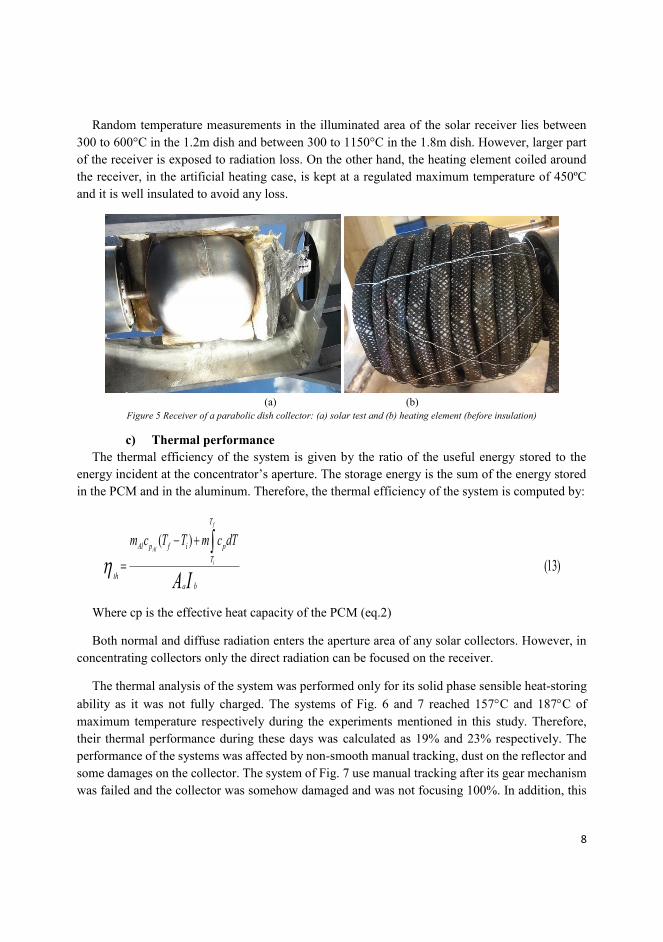
8
Random temperature measurements in the illuminated area of the solar receiver lies between
300 to 600°C in the 1.2m dish and between 300 to 1150°C in the 1.8m dish. However, larger part
of the receiver is exposed to radiation loss. On the other hand, the heating element coiled around
the receiver, in the artificial heating case, is kept at a regulated maximum temperature of 450ºC
and it is well insulated to avoid any loss.
(a) (b)
Figure 5 Receiver of a parabolic dish collector: (a) solar test and (b) heating element (before insulation)
c) Thermal performance
The thermal efficiency of the system is given by the ratio of the useful energy stored to the
energy incident at the concentrator’s aperture. The storage energy is the sum of the energy stored
in the PCM and in the aluminum. Therefore, the thermal efficiency of the system is computed by:
( )
(13)
f
Al
i
T
Al p f i p
T
tha b
m c T T m c dT
A I
Where cp is the effective heat capacity of the PCM (eq.2)
Both normal and diffuse radiation enters the aperture area of any solar collectors. However, in
concentrating collectors only the direct radiation can be focused on the receiver.
The thermal analysis of the system was performed only for its solid phase sensible heat-storing
ability as it was not fully charged. The systems of Fig. 6 and 7 reached 157C and 187C of
maximum temperature respectively during the experiments mentioned in this study. Therefore,
their thermal performance during these days was calculated as 19% and 23% respectively. The
performance of the systems was affected by non-smooth manual tracking, dust on the reflector and
some damages on the collector. The system of Fig. 7 use manual tracking after its gear mechanism
was failed and the collector was somehow damaged and was not focusing 100%. In addition, this

9
system was exposed to higher wind speed, which resulted in higher convective loss from its
receiver and the system as whole. The two systems were tested in two different regions and seasons
and have different global solar radiation.
d) Tracking mechanism
The two units used two different auto trackers to track the sun in the east-west direction. The
1.2m uses a chain and sprocket tracker mechanism and the 1.8m dish uses a gear mechanism. Both
trackers have the same carrying capacity and use the same driving motor (9V DC motor). The
motors get its power from a 10W photovoltaic (PV) source and from a voltage regulator. The gear
ratio of the motors is 1:600 and its shaft runs at 9 rpm. This speed is further reduced in to a 1:10
gear/sprocket ratio to transfer the required torque to track the concentrator. This speed of the motor
allows the mechanism to catch up with the position of the sun in case the sun comes out, after a
longer period with clouds. A light diode and a shading device control the motor. The reflector starts
to track the sun automatically until the sensor becomes perpendicular to the sun radiation. Tracking
happens when the sun shines and if there is no sun, there is no tracking.
e) Insulation
Aerogel and Rockwool insulations were used to insulate the storage and the steam pipelines
respectively. Although the insulations maximum working temperature is about 650C, the
maximum working temperature of the systems’ was set to 250°C (by adjusting the pressure relief
valve) and the design thickness of the insulation is 25mm for the storage and 50mm for the pipeline.
The insulations thermal conductivity is 0.03W/Km and 0.07 W/Km respectively and they have the
same surface emissivity of 0.05.
f) Pipe lines
The size of the steam pipeline were 10mm and 8mm pipe with 1mm thickness. The 8mm
diameter pipe is used only as a heating element for the 30cm frying pan; however, the 10mm pipe
is used as a pipeline for the two units and as a heating element for the 50cm frying pan. The pipes
have 100bar design pressure but used for 40bar working pressure. The pipeline used Swagelok
connectors and valves. A pressure gage is used to measure the pressure of the steam and regulated
with the help of a safety valve that reliefs the pressure when it passed the preset value (40bar). The
pipeline was used to flash before the beginning of experiment to avoid air inclusion.
3. Results and discussion
The two storage integrated solar stove units developed in this research are shown in Fig. 6 and
7. The polar mounted concept eases the tracking mechanism in the secondary axis. The fixed focus
of the concentrator, receiver, was found suitable for steam generation. The steam circulates
between the evaporator (receiver) and frying pan (condenser) in a closed loop naturally. The steam
carries the heat from the receiver and deposits it on the frying pan (casted aluminum plate). The
fins attached to this plate in return carries this energy to the PCM storage. These units were tested
for indirect charging, simultaneous charging-discharging and discharging of a fully and partially
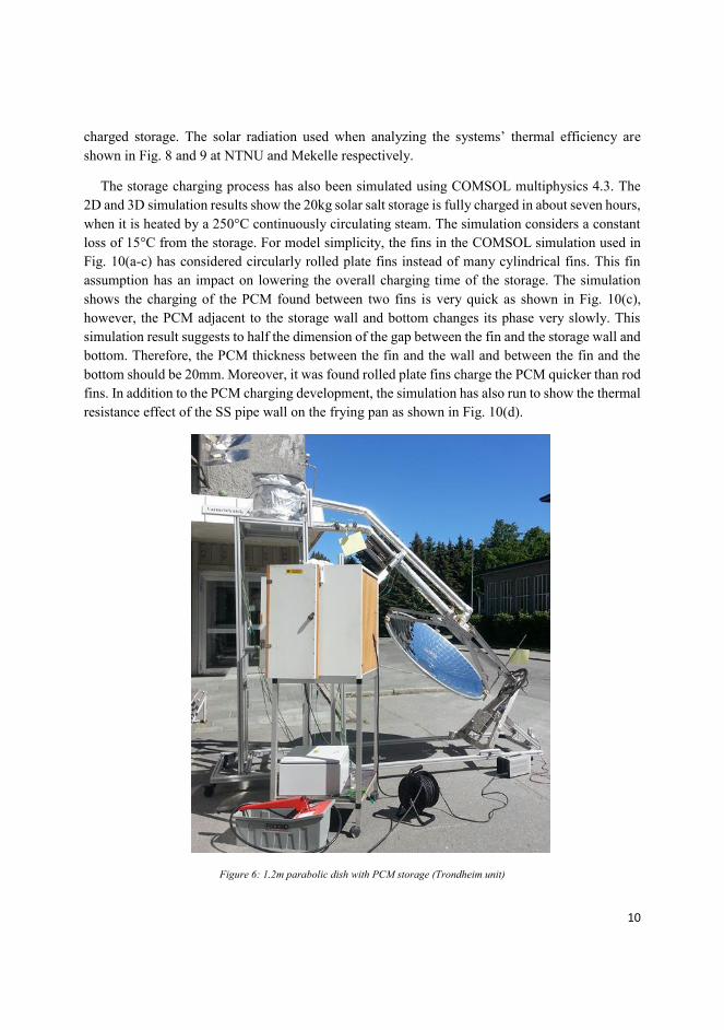
10
charged storage. The solar radiation used when analyzing the systems’ thermal efficiency are
shown in Fig. 8 and 9 at NTNU and Mekelle respectively.
The storage charging process has also been simulated using COMSOL multiphysics 4.3. The
2D and 3D simulation results show the 20kg solar salt storage is fully charged in about seven hours,
when it is heated by a 250°C continuously circulating steam. The simulation considers a constant
loss of 15°C from the storage. For model simplicity, the fins in the COMSOL simulation used in
Fig. 10(a-c) has considered circularly rolled plate fins instead of many cylindrical fins. This fin
assumption has an impact on lowering the overall charging time of the storage. The simulation
shows the charging of the PCM found between two fins is very quick as shown in Fig. 10(c),
however, the PCM adjacent to the storage wall and bottom changes its phase very slowly. This
simulation result suggests to half the dimension of the gap between the fin and the storage wall and
bottom. Therefore, the PCM thickness between the fin and the wall and between the fin and the
bottom should be 20mm. Moreover, it was found rolled plate fins charge the PCM quicker than rod
fins. In addition to the PCM charging development, the simulation has also run to show the thermal
resistance effect of the SS pipe wall on the frying pan as shown in Fig. 10(d).
Figure 6: 1.2m parabolic dish with PCM storage (Trondheim unit)

11
Figure 7: 1.8m parabolic dish collector with PCM storage (Mekelle Unit)
Figure 8: Trondheim’s global and normal beam radiation for 25-07-2013
0
100
200
300
400
500
600
700
800
900
1000
03:5
3
04:4
3
05:3
3
06:2
3
07:1
3
08:0
3
08:5
3
09:4
3
10:3
3
11:2
3
12:1
3
13:0
3
13:5
3
14:4
3
15:3
3
16:2
3
17:1
3
18:0
3
18:5
3
19:4
3
20:3
3
Rad
iati
on[W
/m2
]
Time [hr]
Global Radiation
Normal radition
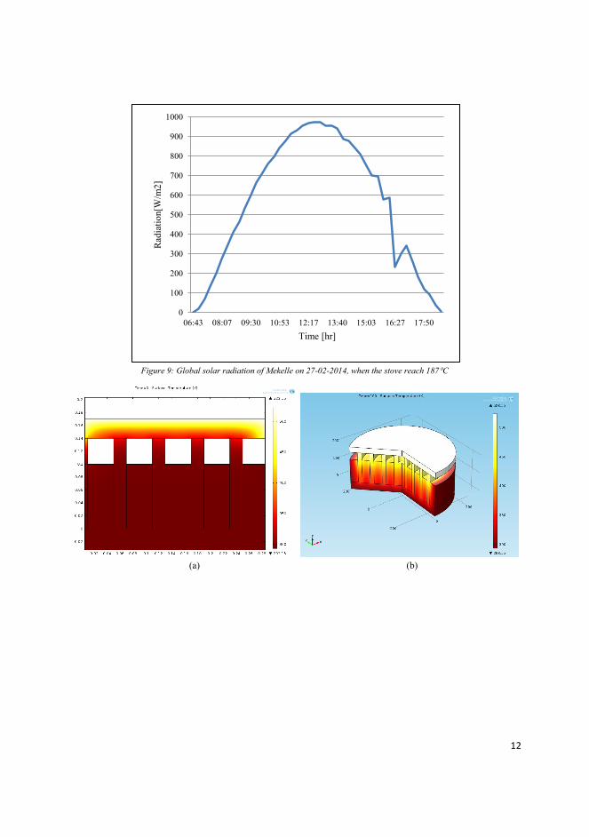
12
Figure 9: Global solar radiation of Mekelle on 27-02-2014, when the stove reach 187C
(a) (b)
0
100
200
300
400
500
600
700
800
900
1000
06:43 08:07 09:30 10:53 12:17 13:40 15:03 16:27 17:50
Rad
iati
on[W
/m2
]
Time [hr]

13
(C) (D)
Figure 10: COMSOL simulation of PCM charging and heat transfer between SS and aluminum wall
3.1. PCM Storage charging
The charging testing of the PCM storage was carried out from real sun and artificial heat
source.
3.1.1. Trondheim PCM charging-discharging test
a) Simultaneous charging-discharging
When the solar reflector starts focusing the solar radiation on the receiver, the water inside
the receiver starts boiling and a vapor at low temperature starts circulating. The stagnation
temperature of this unit could not reach the melting point of the PCM. The storage was tried to
charge in successive days using the advantage of the PCM material’s heat retention ability.
However, this did not help to charge fully, this was probably due to the losses at the receiver.
Simultaneous charging-discharging was then carried out during the peak hours of solar
radiation. When simultaneous charging-discharging test was started, the circulating steam and
PCM storage had reached a temperature of about 160°C and 150°C respectively. During this
test, both Injera and bread were baked. When the Injera baking was started, the circulating
steam and the PCM storage have experienced a sudden drop in their temperature. However, the
temperature has slowly been raising during the baking period. Figure 11 shows the charging
and simultaneous charging-discharging behavior of the unit.
During the first cycles of the Injera baking, the progress of the storage temperature was very
slow, because there was large radiation loss while taking of the Injera. However, when the
baking surface become suitable as shown in the last two cycles of the Fig 11(b), the baking
speed and storage temperatures have improved.

14
(a)
(b)
Figure 11: PCM charging and baking practice simultaneously from the sun
In the beginning of Injera baking on this stove, the surface texture of the frying pan was
rough and it stacked the Injeras. Taking out the baked Injera from the surface of stove was a
big challenge. In addition, the quality of the Injera was not attractive. To avoid the sticking
40
50
60
70
80
90
100
110
120
130
140
150
160
9:4
1
9:5
8
10:1
5
10:3
2
10:4
9
11:0
7
11:2
4
11:4
1
11:5
8
12:1
5
12:3
3
12:5
0
13:0
7
13:2
4
13:4
1
13:5
9
14:1
6
14:3
3
14:5
0
15:0
7
15:2
5
15:4
2
15:5
9
16:1
6
16:3
3
16:5
1
17:0
8
17:2
5
17:4
2
Tem
per
ature
[ºC
]
Time [hr]
Bottom
Mid height
top part of storage
Baking surface
Outlet from storage
Inlet to storage
60
70
80
90
100
110
120
130
140
150
160
9:5
5
10:0
6
10:1
7
10:2
8
10:3
9
10:5
1
11:0
2
11:1
3
11:2
4
11:3
5
11:4
6
11:5
7
12:0
9
12:2
0
12:3
1
12:4
2
12:5
3
13:0
4
13:1
5
13:2
7
13:3
8
13:4
9
14:0
0
14:1
1
14:2
2
14:3
3
14:4
5
14:5
6
Tem
per
ature
[ºC
]
Time [hr]
Bottom
Mid height
top part of storage
Baking surface

15
impact of the silicon mixed aluminum-baking surface, a borosilicate glass has been placed on
top of it as shown in Fig. 12 (D), but the Injera quality was not attractive. The Injera quality
was poor for two reasons. One, the ingredient of the dough was different from the ordinary
Injera ingredient. Secondly, dough contained more water than the expected water flour ratio of
the ideal Injera that comes as a result of the first reason. The sticking nature of the stove results
in longer baking cycle per Injera, which was because of the additional time taken to take off the
Injera from the sticky surface piece-by-piece. Despite of the sticky surface challenge, the
average Injera baking speed was recorded 3minutes/Injera that was quite good compared to
ordinary stove baking speed.
The frying pan has not faced the same challenge during bread baking. The baking surface
was found comfortable during the baking process as shown in Fig. 12 (A and C). Simultaneous
changing-discharging process helps to utilize more energy during the day. However, the storage
charging process takes more time as the inlet heat splits in to charging and baking.
Figure 12: baking process and quality of food during simultaneous charging-discharging
The heat distribution and propagation nature of the frying pan was also simulated in
COMSOL multiphysics. The 3D simulation of the pan when the steam circulating at 250°C in
the SS pipe is shown in Fig. 13. The simulation shows the propagation of the heat in the baking
plate is very fast and the surface temperature reached uniform to the source temperature within
five minutes.
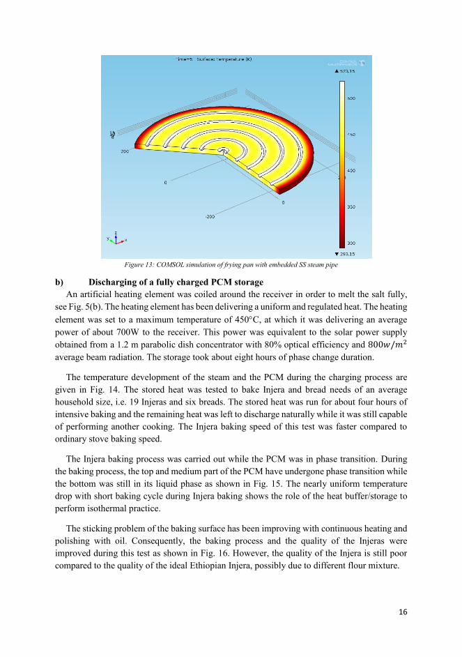
16
Figure 13: COMSOL simulation of frying pan with embedded SS steam pipe
b) Discharging of a fully charged PCM storage
An artificial heating element was coiled around the receiver in order to melt the salt fully,
see Fig. 5(b). The heating element has been delivering a uniform and regulated heat. The heating
element was set to a maximum temperature of 450C, at which it was delivering an average
power of about 700W to the receiver. This power was equivalent to the solar power supply
obtained from a 1.2 m parabolic dish concentrator with 80% optical efficiency and 800𝑤/𝑚2
average beam radiation. The storage took about eight hours of phase change duration.
The temperature development of the steam and the PCM during the charging process are
given in Fig. 14. The stored heat was tested to bake Injera and bread needs of an average
household size, i.e. 19 Injeras and six breads. The stored heat was run for about four hours of
intensive baking and the remaining heat was left to discharge naturally while it was still capable
of performing another cooking. The Injera baking speed of this test was faster compared to
ordinary stove baking speed.
The Injera baking process was carried out while the PCM was in phase transition. During
the baking process, the top and medium part of the PCM have undergone phase transition while
the bottom was still in its liquid phase as shown in Fig. 15. The nearly uniform temperature
drop with short baking cycle during Injera baking shows the role of the heat buffer/storage to
perform isothermal practice.
The sticking problem of the baking surface has been improving with continuous heating and
polishing with oil. Consequently, the baking process and the quality of the Injeras were
improved during this test as shown in Fig. 16. However, the quality of the Injera is still poor
compared to the quality of the ideal Ethiopian Injera, possibly due to different flour mixture.
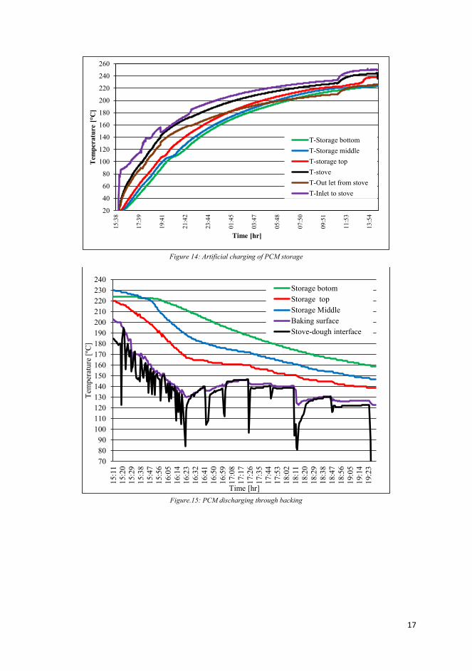
17
Figure 14: Artificial charging of PCM storage
Figure.15: PCM discharging through backing
20
40
60
80
100
120
140
160
180
200
220
240
260
15
:38
17
:39
19
:41
21
:42
23
:44
01
:45
03
:47
05
:48
07
:50
09
:51
11
:53
13
:54
Tem
per
atu
re [°C
]
Time [hr]
T-Storage bottom
T-Storage middle
T-storage top
T-stove
T-Out let from stove
T-Inlet to stove
70
80
90
100
110
120
130
140
150
160
170
180
190
200
210
220
230
240
15:1
1
15:2
0
15:2
9
15:3
8
15:4
7
15:5
6
16:0
5
16:1
4
16:2
3
16:3
2
16:4
1
16:5
0
16:5
9
17:0
8
17:1
7
17:2
6
17:3
5
17:4
4
17:5
3
18:0
2
18:1
1
18:2
0
18:2
9
18:3
8
18:4
7
18:5
6
19:0
5
19:1
4
19:2
3
Tem
per
ature
[ºC
]
Time [hr]
Storage botom
Storage top
Storage Middle
Baking surface
Stove-dough interface

18
Figure 16: improvement of baking surface and type of bake
3.1.2. Mekelle PCM charging-discharging test
a) Discharging of partially charged storage
The frying pan of the Mekelle system was casted from aluminum ingots and has 3cm
thickness that embedded a 10mm diameter coiled SS steam pipe. The plate was machined to
the required thickness and surface finish using universal milling machine. Since the casting of
this plate did not contain any additive, its machining process was easier compared to the frying
pan developed at NTNU. This pan has 120 aluminum rod fins. The fins are 20mm in diameter
and 140mm long. The Al fins were immersed into a 20kg PCM storage that was coupled to
1.8m diameter parabolic dish concentrator. During a one day charging, the storage was able to
reach a maximum temperature of 187C. The charging was run for successive days to melt the
salt, but the temperature inside the storage could not attain higher temperature.
The next trial for this system is to prove if it works for cloudy seasons in which the available
radiation is not capable of melting the salt. Injera baking test has run for several days from the
partially charged storage. This system has smooth baking surface texture similar to the ordinary
stove and it used oil seeds to polish it. Unlike oil, oil seeds have the ability to give smooth
baking surfaces by filling its irregularities. The several baking tests show smooth baking
process with very good Injera quality, which is the same as the quality of Injera baked on
customary Injera stove as shown in Fig. 17.
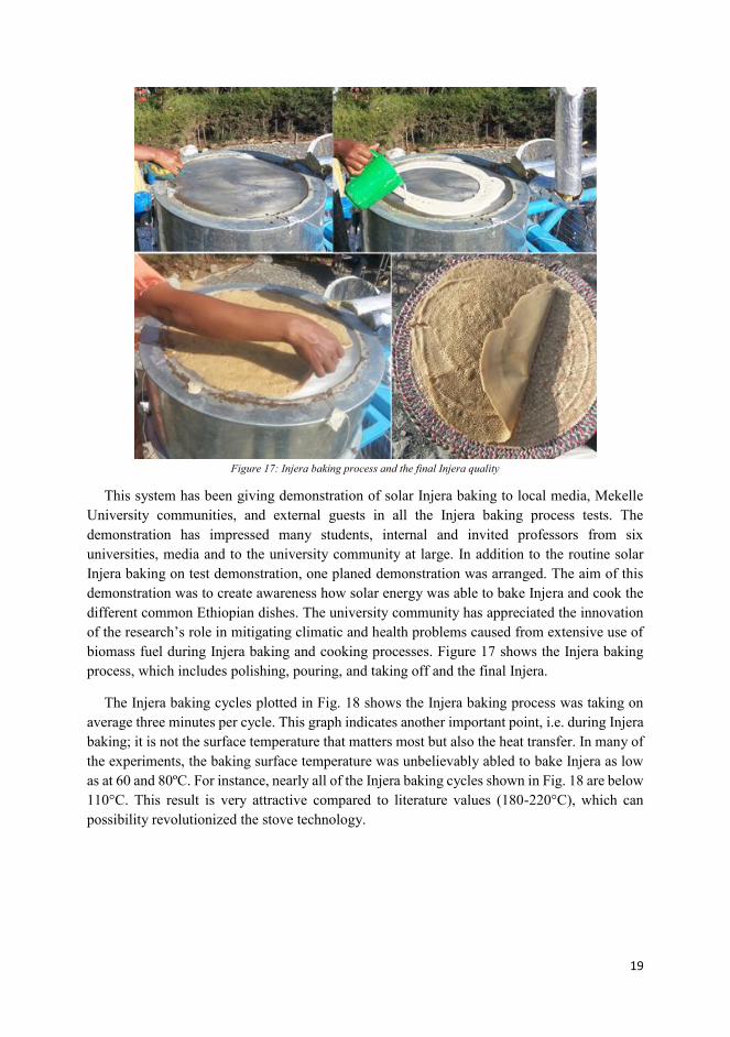
19
Figure 17: Injera baking process and the final Injera quality
This system has been giving demonstration of solar Injera baking to local media, Mekelle
University communities, and external guests in all the Injera baking process tests. The
demonstration has impressed many students, internal and invited professors from six
universities, media and to the university community at large. In addition to the routine solar
Injera baking on test demonstration, one planed demonstration was arranged. The aim of this
demonstration was to create awareness how solar energy was able to bake Injera and cook the
different common Ethiopian dishes. The university community has appreciated the innovation
of the research’s role in mitigating climatic and health problems caused from extensive use of
biomass fuel during Injera baking and cooking processes. Figure 17 shows the Injera baking
process, which includes polishing, pouring, and taking off and the final Injera.
The Injera baking cycles plotted in Fig. 18 shows the Injera baking process was taking on
average three minutes per cycle. This graph indicates another important point, i.e. during Injera
baking; it is not the surface temperature that matters most but also the heat transfer. In many of
the experiments, the baking surface temperature was unbelievably abled to bake Injera as low
as at 60 and 80ºC. For instance, nearly all of the Injera baking cycles shown in Fig. 18 are below
110°C. This result is very attractive compared to literature values (180-220°C), which can
possibility revolutionized the stove technology.

20
Figure 18: Injera baking from a partially charged PCM storage
Conclusion
A concept for Injera baking (Ethiopian bread) on top of a heat storage charged from a solar
concentrator has been developed and demonstrated. Heat transfer is by a thermosyphon
principle, with water as the working fluid at about 35-bar pressure. Vapor is generated at the
heat absorber in the focus point of the parabolic concentrator and condenses in coiled tube,
which is casted into an aluminum baking plate. The baking plate has heat-conducting rods
extending into a latent heat storage (“solar salt”, Nitrate mixture). Two systems have been
constructed and tested, one at NTNU (Norway) and one at Ethiopian Institute of Technology –
Mekelle. The following conclusions can be noted:
Injera can be baked on an aluminum surface, provided the surface is sufficiently smooth
and otherwise prepared similarly as for the traditional clay based pan during the frying
process.
Injera can be baked at lower temperatures (110-150°C) than previously assumed (180-
220°C), as long as sufficient heat transfer can be maintained during the baking process.
The required temperature will then depend on the material of the baking plate.
A boiling/condensing natural circulation loop (thermosyphon) is feasible with water as
the heat transfer fluid. As the water volume is small, the high pressure is manageable
but requires high quality pipe and valve components. A boil-off startup procedure is
operationally easy.
The system can be optimized with respect to losses in the heat transfer loop, in particular
at the absorber. The absorber is a spherical boiler in a fixed position, with the solar
illuminated area moving from one side to the other during the daily sun tracking.
0
10
20
30
40
50
60
70
80
90
100
110
120
130
140
150
160
1 449 897 1345 1793 2241 2689 3137 3585 4033 4481
Tem
per
atu
re [C
]
Time [S]
Baking surface temp
Storage top part temp
Storage middle part temp
Storage bottom part temp

21
Reference
[1] Antonio Lecuona et al., Solar cooker of the portable parabolic type incorporating heat storage
based on PCM, Applied Energy, vol. 111; pp: 1136–1146, 2013
[2] H.M.S. Hussein et al., Experimental investigation of novel indirect solar cooker with indoor PCM
thermal storage and cooking unit, Energy Conversion and Management 49 (2008) 2237–2246.
[3] M.M. Kenisarin, Thermophysical properties of some organic phase change materials for latent
heat storage, A review, Solar Energy 107 (2014) 553–575.
[4] E. Lizarraga-Garcia and A. Mitsos, Effect of heat transfer structures on thermoeconomic
performance of solid thermal storage, Energy 68 (2014) 896-909.
[5] http://en.wikipedia.org/wiki/Injera, [last retrieved on 10.09.2014]
[6] Denis Okello , Ole J. Nydal and Eldad J.K. Banda, Experimental investigation of thermal de-
stratification in rock bed TES systems for high temperature applications, Energy Conversion and
Management, vol. 86; pp: 125–131, 2014.
[7] Abduljalil A. Al-Abidi et al., Experimental study of melting and solidification of PCM in a
triplextube heat exchanger with fins, Energy and Buildings, Vol. 68; pp: 33–41, 2014.
[8] Taha K. Aldoss and Muhammad M. Rahman, Comparison between the single-PCM and multi-
PCM thermal energy storage design, Energy Conversion and Management, vol. 83; pp: 79–87,
2014.
[9] Robynne E. Murray and Dominic Groulx, Experimental study of the phase change and energy
characteristics inside a cylindrical latent heat energy storage system: Part 1consecutive charging
and discharging, Renewable Energy, vol. 62; pp: 571-581, 2014.
[10] Alessandro Franco and Sauro Filippeschi, Experimental analysis of Closed Loop Two Phase
Thermosyphon (CLTPT) for energy systems, Experimental Thermal and Fluid Science, vol. 51;
pp: 302–311, 2013.
[11] Liang Zhang et al., An indoor experimental investigation of the thermal performance of a TPLT-
based natural circulation steam generator as applied to PTC systems, Applied Thermal
Engineering, vol. 62; pp: 330-340, 2014.
[12] [Foong Chee Who, Jørgen Løvseth, and Ole Jørgen Nydal, “Heat Capacity Measurements of
NaNO3 – KNO3 Binary System”, submitted paper to International journal of Thermophysics,
2011.
[13] R T Dobson and J C Ruppersberg, flow and heat transfer in a closed loop thermosyphon: part I-
theoretical simulation, Journal of Energy in South Africa, Vol. 18; pp: 32-80, 2007.
[14] Lifang Li and Steven Dubowsky, A new design approach for solar concentrating parabolic dish
based on optimized flexible petals, Mechanism and Machine Theory, vol. 46; pp: 1536–1548,
2011.

22
[15] Ibrahim Ladan Mohammed, Design and Development of a Parabolic Dish Solar Thermal Cooker,
International Journal of Engineering Research and Applications, Vol. 3; p: 1179-1186, 2013.
[16] A. F. Mills, heat and mass transfer, CRC press, 2009.

125
VI: Storage integrated solar stove: A case of solar Injera
baking in Ethiopia
Asfafaw H Tesfay, Mulu Bayray Kahsay, Ole J. Nydal
Presented at IEEE GHTC, conference, San Jose, California, USA, October 2014
Published: IEEE proceeding, 659-666, 2014

Is not included due to copyright

126

135
Appendix: secondary papers

136

137
Paper VII: Solar Energy Resource Assessment of the Geba
Catchment, Northern Ethiopia
Authors: Anwar Mustefa Mahmud, Mulu Bayray Kahsay, Asfafaw Haileselasie Tesfay, Ftwi
Yohaness Hagos, Petros Gebray, Hailay Kiros Kelele, Kindeya Gebrehiwot, Hans Bauer,
Seppe Deckers, Josse De Baerdemaeker, Johan Driesen
Energy Procedia, volume 57, pp. 1266–1274, 2014.

138
Energy Procedia 57 ( 2014 ) 1266 – 1274
Available online at www.sciencedirect.com
ScienceDirect
1876-6102 © 2014 The Authors. Published by Elsevier Ltd. This is an open access article under the CC BY-NC-ND license (http://creativecommons.org/licenses/by-nc-nd/3.0/).Selection and/or peer-review under responsibility of ISES.doi: 10.1016/j.egypro.2014.10.116
2013 ISES Solar World Congress
Solar Energy Resource Assessment of the Geba Catchment, Northern Ethiopia
Anwar Mustefa Mahmuda,b*, Mulu Bayray Kahsaya, Asfafaw Hailesilasiec, Ftwi Yohaness Hagosd, Petros Gebraya, Hailay Kiros Kelelea, Kindeya Gebrehiwote, Hans Bauerf, Seppe
Deckersg, Josse De Baerdemaekerh, Johan Driesenb aDepartment of Mechanical Engineering, Mekelle University (MU), Main Campus, Mekelle, P.O.Box 231, Ethiopia
bResearch group Electa (ESAT), KUL, Kasteelpark Arenberg 10, 3001 Heverlee, Belgium c Department of Energy and Process Engineering, Norwegian University of Science and Technology, 7491 Trondheim, Norway
dMechanical Engineering, Universiti Teknologi PETRONAS, 87 Jalan putra, 31750 TRONOH, PERAK, MALAYSIAl eDepartment of Land Resource Management and Environmental Protection, MU, Main Campus, Mekelle, P.O.Box 231, Ethiopia
fProgram Office, MU-IUC, Mekelle University, P.O.Box 231, Mekelle, Ethiopia
gDepartment of Soil and Water Management, KUL, Celestijnenlaan 200E, B - 3001 Leuven, Belgium iDepartment of Biosystems, KUL, Kasteelpark Arenberg 30, B-3001 Heverlee, Belgium
Abstract
The global shift towards renewable energy is manifested in developing countries such as Ethiopia primarily because of continuous economic growth in the last two decades and secondly due to the vast untapped potential resources. In addition to other factors, the lack of accurate data of the resources has, however, hampered the development of solar energy technologies. The aim of this paper is to investigate the resource estimation by undertaking direct measurements at selected sites in the Northern part of Ethiopia. This paper presents an assessment of the solar energy resource based on the primary data collected between January 2011 and December 2012. The daily and monthly average global solar radiation is analyzed based on the 10 minute interval measurement retrieved from the data loggers. From the analysis it is seen that the measured values give a better accuracy and distribution of the global solar radiation than earlier Fig.s that were based on satellite images and model calculations. Furthermore, these results can be used to determine the solar resource potential of Northern Ethiopia for further energy development. © 2013 The Authors. Published by Elsevier Ltd. Selection and/or peer-review under responsibility of ISES Keywords: solar radiation, assessment, resource potential
* Corresponding author. Tel.: +32-468-330166; fax: +32-16-321985 E-mail address: [email protected].
© 2014 The Authors. Published by Elsevier Ltd. This is an open access article under the CC BY-NC-ND license (http://creativecommons.org/licenses/by-nc-nd/3.0/).Selection and/or peer-review under responsibility of ISES.
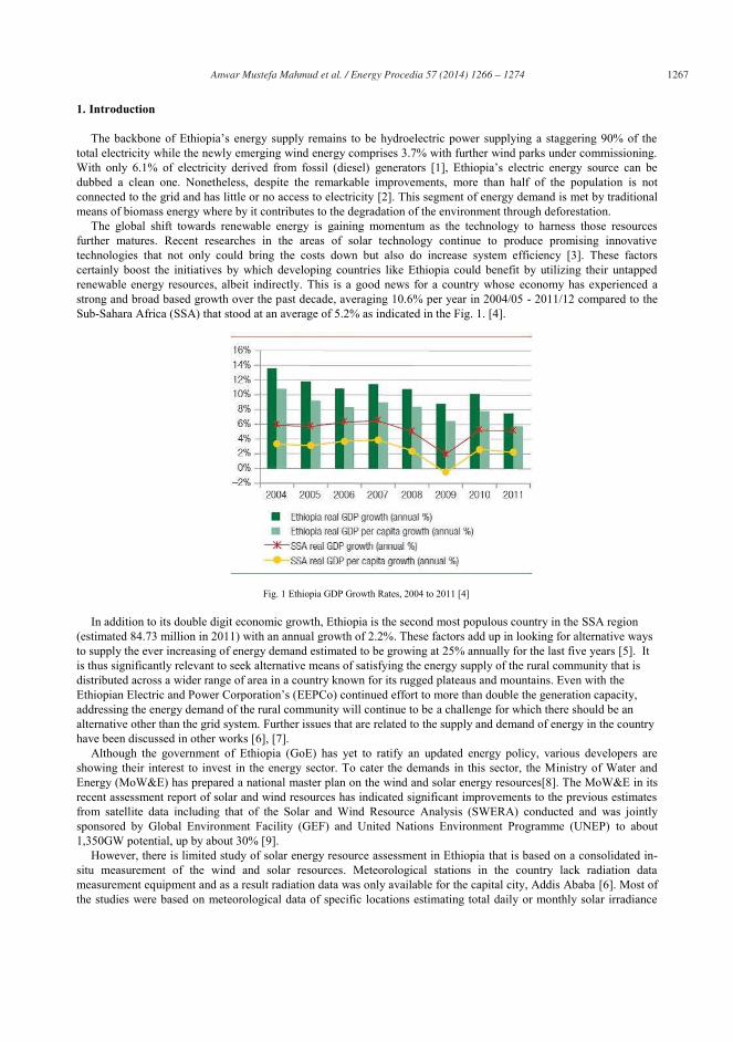
Anwar Mustefa Mahmud et al. / Energy Procedia 57 ( 2014 ) 1266 – 1274 1267
1. Introduction
The backbone of Ethiopia’s energy supply remains to be hydroelectric power supplying a staggering 90% of the total electricity while the newly emerging wind energy comprises 3.7% with further wind parks under commissioning. With only 6.1% of electricity derived from fossil (diesel) generators [1], Ethiopia’s electric energy source can be dubbed a clean one. Nonetheless, despite the remarkable improvements, more than half of the population is not connected to the grid and has little or no access to electricity [2]. This segment of energy demand is met by traditional means of biomass energy where by it contributes to the degradation of the environment through deforestation.
The global shift towards renewable energy is gaining momentum as the technology to harness those resources further matures. Recent researches in the areas of solar technology continue to produce promising innovative technologies that not only could bring the costs down but also do increase system efficiency [3]. These factors certainly boost the initiatives by which developing countries like Ethiopia could benefit by utilizing their untapped renewable energy resources, albeit indirectly. This is a good news for a country whose economy has experienced a strong and broad based growth over the past decade, averaging 10.6% per year in 2004/05 - 2011/12 compared to the Sub-Sahara Africa (SSA) that stood at an average of 5.2% as indicated in the Fig. 1. [4].
Fig. 1 Ethiopia GDP Growth Rates, 2004 to 2011 [4]
In addition to its double digit economic growth, Ethiopia is the second most populous country in the SSA region (estimated 84.73 million in 2011) with an annual growth of 2.2%. These factors add up in looking for alternative ways to supply the ever increasing of energy demand estimated to be growing at 25% annually for the last five years [5]. It is thus significantly relevant to seek alternative means of satisfying the energy supply of the rural community that is distributed across a wider range of area in a country known for its rugged plateaus and mountains. Even with the Ethiopian Electric and Power Corporation’s (EEPCo) continued effort to more than double the generation capacity, addressing the energy demand of the rural community will continue to be a challenge for which there should be an alternative other than the grid system. Further issues that are related to the supply and demand of energy in the country have been discussed in other works [6], [7].
Although the government of Ethiopia (GoE) has yet to ratify an updated energy policy, various developers are showing their interest to invest in the energy sector. To cater the demands in this sector, the Ministry of Water and Energy (MoW&E) has prepared a national master plan on the wind and solar energy resources[8]. The MoW&E in its recent assessment report of solar and wind resources has indicated significant improvements to the previous estimates from satellite data including that of the Solar and Wind Resource Analysis (SWERA) conducted and was jointly sponsored by Global Environment Facility (GEF) and United Nations Environment Programme (UNEP) to about 1,350GW potential, up by about 30% [9].
However, there is limited study of solar energy resource assessment in Ethiopia that is based on a consolidated in-situ measurement of the wind and solar resources. Meteorological stations in the country lack radiation data measurement equipment and as a result radiation data was only available for the capital city, Addis Ababa [6]. Most of the studies were based on meteorological data of specific locations estimating total daily or monthly solar irradiance
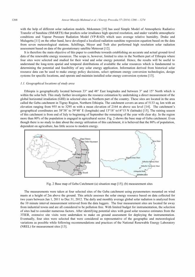
1268 Anwar Mustefa Mahmud et al. / Energy Procedia 57 ( 2014 ) 1266 – 1274
with the help of different solar radiation models. Mekonnen [10] has used Simple Model of Atmospheric Radiative Transfer of Sunshine (SMARTS) that predicts solar irradiance high spectral resolution, and under variable atmospheric conditions and Vapour Pressure Radiation Model (VP-RAD) which uses average relative humidity. Drake and Mulugetta [11] on the other hand, have developed a localized radiation-sunshine regression equation based on the data from seven meteorological stations. Schillings, Meyer and Treb also performed high resolution solar radiation assessment based on data of the geostationary satellite Meteosat [12].
It is therefore the main objective of this paper to contribute towards establishing an accurate and actual ground-level data of the renewable energy resources. The scope is, however, limited to sites in the Northern part of Ethiopia where four sites were selected and studied for their wind and solar energy potential. Hence, the results will be useful to understand the long-term spatial and temporal distributions of available the solar resources which is fundamental to determining the potential and feasibility of any solar energy application. Information derived from historical solar resource data can be used to make energy policy decisions, select optimum energy conversion technologies, design systems for specific locations, and operate and maintain installed solar energy conversion systems [13].
1.1. Geographical locations of study area
Ethiopia is geographically located between 33° and 48° East longitudes and between 3° and 15° North which is within the solar belt. This study further investigates the resource estimation by undertaking a direct measurement of the global horizontal irradiation (GHI) in selected sites on Northern part of the country. These sites are located in the area called the Geba catchment in Tigray Region, Northern Ethiopia. The catchment covers an area of 5133 sq. km with an elevation ranging from 955 m to 3295 m with a mean elevation of 2164 m above sea level [14]. The catchment’s geographical coordinates are 38°38’ to 39°48’ E (longitude) and 13°18’ to14°15 N (latitude) [15]. The raining season of this catchment is from end of July to beginning of September the remaining of the year with clear sky. In the region more than 80% of the population is engaged in agricultural sector. Fig. 2 shows the base map of Geba catchment. Even though there is no study to date about the energy utilization of this catchment, it is believed that the 80% of population, dependent on agriculture, has little access to modern energy.
Fig. 2 Base map of Geba Catchment (a) situation map [15]; (b) measurement sites
The measurements were taken at four selected sites of the Geba catchment using pyranometers mounted on wind
masts at a height of 2m above the ground. This article assesses the solar energy resource based on data collected for two years between Jan 1, 2011 to Dec 31, 2012. The daily and monthly average global solar radiation is analyzed from the 10 minute interval measurement retrieved from the data loggers. The four measurement sites are located far away from industrial towns and are all considered to be pollution free. With limited budget for instrumentation, the selection of sites had to consider numerous factors. After identifying potential sites with good solar resource estimates from the 3TIER, extensive site visits were undertaken to make on ground assessment for deploying the instrumentation. Eventually, four sites were selected that were considered as representative of the geographic and meteorological variations as possible while following recommendations and practices of the National Renewable Energy Laboratory (NREL) for measurement sites [13].

Anwar Mustefa Mahmud et al. / Energy Procedia 57 ( 2014 ) 1266 – 1274 1269
Table 1 Name of the measurement sites, location and altitude and duration of measurement
Site No
Site Name Location Altitude (m) Latitude Longitude
1 Dera 13°59.377’N 39°43.849’E 2870 2 Hagereselam 13°39.623’N 39°11.530’E 2632 3 Mayderhu 13°17.670’N 39°23.885’E 2512 4 Mekelle University (MU)
Campus 13°28.694’N 39°29.244’E 2208
2. Materials and Methods
2.1. Materials
The instruments were mounted on wind masts that also had anemometers, wind vanes and temperature sensors in addition to data loggers powered by alkaline battery. The pyranometers used are of type Si-photodiode pyranometers DS6450 of ®Davis Instruments Corp, USA. The accuracy of the instrument is ±5% of full scale and its sensitivity is 1 W/m2, it has operating temperature of -40° to +65°C and range of measurement from 0-1800 W/m2. These sensors have been a relatively low-cost alternative for irradiance measurements and nowadays are widely used. They are used to measure global radiation, the sum at the point of measurement of both the direct and diffuse components of solar irradiance. The readings were logged into a data logger of type ®EKO21 N Data logger. Frequent site visits were conducted periodically to perform inspections for the overall care and maintenance.
2.2. Methods
Measured data logged every ten minutes including the minimum, average and maximum during the interval in the data logger is stored in a memory card which is retrieved periodically and backed up to a laptop. The data exported in text format were further processed using statistical tools and spreadsheet. The collected data from each measurement site was subjected to validation and filtering. Furthermore, daily and monthly average global solar radiation is calculated and compared for each measurement site to get the temporal as well as spatial distribution of the global solar radiation in the catchment. Measurements have been conducted since June 2010 and the analysis covers the time between June 2011 till May 2012. The average daily solar radiation for each month is then plotted as shown in subsequent figures.
3. Results and Discussion
The daily average solar energy is obtained from the ten minutes average data recorded from the pyranometers. The solar radiation in W/m2 in each ten minute interval for each day is added and converted in to kWh/m2/day. The daily average solar radiation of the four sites is discussed in subsequent sections. It is worth to note that Ethiopia lies in the tropical zone laying just above the Equator and below the Tropic of Cancer having four climatic seasons where the summer months of June, July and August are characterized by heavy rain falls and clouds while in contrast, in the winter dry season that falls in the months between December, January and February is known for its clear sky and hot temperatures.
3.1. Spatial Distribution
Apart from the temporal variation, it is quite important to investigate the spatial distribution of the global solar radiation across the region. Previous works did lack that accuracy through employing approximate models and coarse satellite resolution resulting in poor estimates.
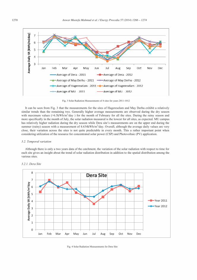
1270 Anwar Mustefa Mahmud et al. / Energy Procedia 57 ( 2014 ) 1266 – 1274
It can be seen from Fig. 3 that the measurements for the sites of Hagereselam and May Derhu exhibit a relatively similar trends than the remaining two. Generally higher average measurements are observed during the dry season with maximum values (>6.5kWh/m2/day ) for the month of February for all the sites. During the rainy season and more specifically in the month of July, the solar radiation measured is the lowest for all sites, as expected. MU campus has relatively higher radiation during the dry season while Dera site’s measurements are on the upper end during the summer (rainy) season with a measurement of 4.634kWh/m2/day. Overall, although the average daily values are very close, their variation across the sites is not quite predictable in every month. This a rather important point when considering utilization of the resource for concentrated solar power (CSP) and Photovoltaic (PV) application.
3.2. Temporal variation
Although there is only a two years data of the catchment, the variation of the solar radiation with respect to time for each site gives an insight about the trend of solar radiation distribution in addition to the spatial distribution among the various sites.
3.2.1. Dera Site
Fig. 3 Solar Radiation Measurements of 4 sites for years 2011-1012
Fig. 4 Solar Radiation Measurements for Dera Site
0
1
2
3
4
5
6
7
8
Jan Feb Mar Apr May Jun Jul Aug Sep Oct Nov Dec
Aver
age
Daily
SR
[kW
h/m
2 day
Dera Site
Year 2011
Year 2012
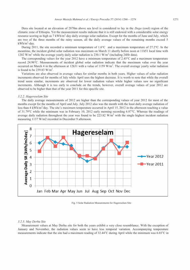
Anwar Mustefa Mahmud et al. / Energy Procedia 57 ( 2014 ) 1266 – 1274 1271
Dera site located at an elevation of 2870m above sea level is considered to lay in the Dega (cool) region of the climatic zone of Ethiopia. Yet the measurement results indicate that it is still endowed with a considerable solar energy resource scoring as high as 7 kWh/m2-day daily average solar radiation. Except for the months of June and July, which are two of the three months of the rainy season, all the daily average values of the remaining months exceed 5 kWh/m2-day.
During 2011, the site recorded a minimum temperature of 1.6°C and a maximum temperature of 27.2°C. In the meantime, the incident global solar radiation was maximum on March 11 shortly before noon at 11h51 local time with 1202 W/m2 while the average yearly daily solar radiation is 230.1 W/m2 (including 24Hr data).
The corresponding values for the year 2012 have a minimum temperature of 2.45°C and a maximum temperature record 24.96°C. Measurements of incident global solar radiation indicate that the maximum value over the year occurred on March 4 in the afternoon at 12h31 with a value of 1159 W/m2. The overall average yearly solar radiation is found to be 239.83 W/m2.
Variations are also observed in average values for similar months in both years. Higher values of solar radiation increments observed for months of July while April sees the highest decrease. It is worth to note that while the overall trend seem similar, increments are observed for lower radiation values while higher values saw no significant increments. Although it is too early to conclude on the trends, however, overall average values of year 2012 are observed to be higher than that of the year 2011 for this specific site.
3.2.2. Hagereselam Site The daily average measurements of 2012 are higher than the corresponding values of year 2012 for most of the
months except for the months of April and July. July 2012 also was the month with the least daily average radiation of less than 4 kWh/m2/day. The site’s maximum temperature occurred in April 15, 2012 in the afternoon reaching a value of 31.79oC while the minimum was in February 10, 2012 early morning recording 6.87oC. Whereas the readings of average daily radiation throughout the year was found to be 223.82 W/m2 with the single highest incident radiation measuring 1137 W/m2 recorded in December 9 afternoon.
3.2.3. May Derhu Site Measurement values at May Derhu site for both the years exhibit a very close resemblance. With the exception of
January and November, the radiation values seem to have less temporal variation. Accompanying temperature measurements indicate that the site had a maximum reading of 32.44oC during April while the minimum was 6.03oC in
Fig. 5 Solar Radiation Measurements for Hagereselam Site

1272 Anwar Mustefa Mahmud et al. / Energy Procedia 57 ( 2014 ) 1266 – 1274
late January (In 01/25/2012 at 7:49). The average daily global radiation was found to be 237.67 W/m2 while the maximum incident radiation was 1194 W/m2 in the month of September (in 17/09/2012 at 13:17). This site also has low radiation measurements during the months of the rainy season between June and August with average reading of less than 4 kWh/m2/day.
3.2.4. MU Main Campus The measurements for the MU campus site includes 4 months of recording from 2011 and full data for 2012. Due to
meintenance needs of the data logger in this site, no measurements were taken during the period between May to
Fig. 7 Solar Radiation Measurements for Main campus Site
0
1
2
3
4
5
6
7
8
Jan Feb Mar Apr May Jun Jul Aug Sep Oct Nov Dec
Aver
age
Daily
SR
[kW
h/m
2day
]
May Derhu
Year 2012
Year 2011
Fig. 6 Solar Radiation Measurements for May Derhu Site

Anwar Mustefa Mahmud et al. / Energy Procedia 57 ( 2014 ) 1266 – 1274 1273
December 2011. However, after replacing the data logger, recordings of measurements continued as of January 2012. With the exception of the months of July and August, the average daily solar radiation is observed to be greater than
5kWh/m2/day. In fact, this site exihibits measurements greater than 6 kWh/m2/day for half of the year in the months between October and May. As far as the yearly average solar radiation is considered the average value is found to be 236 W/m2 while the single maximum incidence of solar radiation was 1209 W/m2 recorded on the May 5, 2012 at 13h13 local time.
This site is the nearest one to Mekelle whose solar radiation estimates has been one of the few locations previously investigated. In its final report the SWERA [9] , [16] has estimated Mekelle’s Average Daily Global Radiation on Horizontal Surface to be 2.27 kWh/m2/day which is considerably lower than the 2012 yearly average of 5.7412 kWh/m2/day. Yet, NASA’s estimates are found to be the closest with a value of 5.86 kWh/m2/day while results of CESEN estimates [8] , [16] indicated higher etimates of 6.59 kWh/m2/day.
4. Conclusion
The measurements indicate and justify that the global horizontal radiation of the sites is far greater than the previous estimates of SWERA. The MoW&E in its recent national master plan report correctly indicates that the Northern part of the country receive higher radiation due to the movement of high-radiation zone northwards. However, the conclusion of low solar radiation over the country during the dry season between October to January is not corroborated by results of the measurements in all four sites. This indicates that there is a strong need for previous estimates mostly based on models and geostationary satellites reliability to validate their estimates using long term and in-situ measurements. Based on the two years measurements, the results indicate that Geba Catchment is endowed with a considerable amount of horizontal solar radiation with an average of 5.59 kWh/m2/day. This considerable potential could a good alternative source of energy for the rural community. The results can also contribute to studies and developments that are aimed to develop large-scale Photo-voltaic and CSP systems. In conclusion, the measured values give a better accuracy and distribution of the global solar radiation than earlier Fig.s that were based on satellite images and model calculations.
Acknowledgements
The authors would like acknowledge The authors acknowledge the financial support of the Flemish Interuniversity Council (VLIR) under the framework of ‘VLIR & Mekelle University Inter University Partnership Programme, 2003–2013; subproject Farm Technology’, the National Agricultural Research Fund (NARF) of Ethiopian Institute of Agricultural Research (EIAR), the Norwegian Programme for Development, Research and Education (NUFU) and Norad's Master Programme for Energy and Petroleum (EnPe).
References
[1] EEPCo, "Press Release: EEPCo," 5 February 2013. [Online]. Available: http://www.eepco.gov.et/flyersandmagazines.php. [Accessed 22 May 2013].
[2] World Energy Outlook, "Publications: World Energy Outlook 2012," 2012 November 2012. [Online]. Available: http://www.worldenergyoutlook.org/media/weowebsite/energydevelopment/2012updates/Measuringprogresstowardsenergyforall_WEO2012.pdf. [Accessed 1 June 2013].
[3] J. Laird, "Taking solar technology forward," Renewable energy focus, vol. 13, no. 5, pp. 32-38, September/October 2012. [4] M. Geiger and C. Goh, "Ethiopia Economic Update iv — Overcoming Inflation, Raising Competitiveness," The World Bank, Washington,
2012. [5] EEPCo, "Projects," 2013. [Online]. Available: http://www.eepco.gov.et/project.php?pid=1&pcatid=2. [Accessed 25 May 2013]. [6] G. Bekele and . B. Palm, "Feasibility study for a standalone solar-wind-based hybrid energy system for application in Ethiopia," Applied
Enery, vol. 87, no. 2, pp. 487-495, 4 February 2010. [7] G. Bekele and B. Palm, "Wind energy potential assessment at four typical locations in Ethiopia," Applied Energy, vol. 86, no. 3, pp. 388-
396, March 2009. [8] Y. Wang, "Global Edition: English.news.cn Xinhwa," 16 August 2012. [Online]. Available: http://news.xinhuanet.com/english/world/2012-
08/16/c_131787912.htm. [Accessed 26 May 2013]. [9] HydroChina Corporation, "Master Plan Report of Wind and Solar Energy in the Federal Democratic Republic of Ethiopia," Unpublished,
Addis Ababa, 2012.

1274 Anwar Mustefa Mahmud et al. / Energy Procedia 57 ( 2014 ) 1266 – 1274
[10] S. A. Mekonnen, "Solar Energy Assessment in Ethiopia: Modeling and Measurement," AAU, Addis Ababa, 2007. [11] F. Drake and Y. Mulugeta, "Assessment of solar and wind energy resources in Ethiopia. I solar energy," Solar energy, vol. 57, no. 3, pp.
205-217, September 1996. [12] C. Schillings, R. Meyer and F. Trieb, "High Resolution Solar Radiation Assessment for Ethiopia," Deutsches Zentrum für Luft- und
Raumfahrt (DLR), Stuttgart, 2004. [13] T. Stoffe, D. Renné, D. Myers, S. Wilcox, M. Sengupta, R. George and C. Turchi, "CONCENTRATING SOLAR POWER. Best Practices
Handbook for the Collection and Use of Solar Resource Data.," NREL, Golden, 2010. [14] A. Z. Abraha, "Assessment of spatial and temporal variability of river discharge, sediment yield and sediment-fixed nutrient export in Geba
River catchment, northern Ethiopia," PhD thesis, KUL, Leuven, 2009. [15] D. Nadew and K. Walraevens, "The Positive Effect of Micro-Dams for Groundwater Enhancement: a Case Study around Tsinkanet and
Rubafeleg Area, Tigray, Northern Ethiopia," Momona Ethiopian Journal of Science, vol. 1, pp. 59-73, 2009. [16]Ethio Resource Group with Partners for SWERA-UNEP, "Country background information-Solar and wind energy utilization and project
development scenarios," Ethiopian Rural Energy Development, Addis Ababa, 2007.

148

149
Paper VIII: Theoretical and Experimental Comparison of Box
Solar Cookers with and without Internal Reflector
Authors: Mulu B. Kahsay, John Paintin, Anwar Mustefa, Asfafaw Haileselassie, Meseret
Tesfay, Biniam Gebray
Energy Procedia, volume 57, 1613–1622, 2014.

150
Energy Procedia 57 ( 2014 ) 1613 – 1622
Available online at www.sciencedirect.com
ScienceDirect
1876-6102 © 2014 The Authors. Published by Elsevier Ltd. This is an open access article under the CC BY-NC-ND license (http://creativecommons.org/licenses/by-nc-nd/3.0/).Selection and/or peer-review under responsibility of ISES.doi: 10.1016/j.egypro.2014.10.153
2013 ISES Solar World Congress
Theoretical and Experimental Comparison of Box Solar Cookers with and without Internal Reflector
Mulu Bayray Kahsaya*, John Paintinb, Anwar Mustefaa, Asfafaw Haileselassiea, Meseret Tesfaya, Biniam Gebraya
aDepartment of Mechanical Engineering, EiT – M, Mekelle University, P.O.Box 231, Mekelle, Ethiopia bDepartment of Electrical Engineering, EiT – M, Mekelle University, P.O.Box 231, Mekelle, Ethiopia
Abstract
Box solar cookers are commonly built with internal sheet metal painted black as an absorber. In order to increase the performance, a design which incorporates internal reflection is proposed in this paper. The aim of this paper is to report comparisons made between box solar cookers with and without internal reflector. Theoretical modelling of the two types of cookers has been made by considering the radiation, convection and conduction heat transfer employing the thermal network method. The theoretical analysis made was based on steady state heat transfer analysis of the cookers. Experimental comparisons were also made on two cookers having the same aperture area and made from the same type of materials except the internal absorber. The tests were made as per the American Society of Agricultural Engineers (ASAE) procedure. The result of the theoretical analysis predicts that the performance will be higher in the cooker with internal reflector than the same cooker without reflector. The steady state analysis shows that for the cooker with reflection the temperature of the bottom absorber plate is higher than the cooker without reflector. Similarly, results of dry test and water boiling test show better performance by the cooker with reflector. The standard stagnation temperature and the cooking power were higher in the cooker with reflector as compared to the cooker without reflector. In conclusion, the performance of box solar cookers can be enhanced by making appropriate angle side walls of the absorber and providing internal reflection. © 2013 The Authors. Published by Elsevier Ltd. Selection and/or peer-review under responsibility of ISES Keywords: Box solar cooker, thermal network method, steady state analysis, dry test, water boiling test
* Corresponding author. Tel.: +251 914 301683; fax: +251 344409304. E-mail address: [email protected]
© 2014 The Authors. Published by Elsevier Ltd. This is an open access article under the CC BY-NC-ND license (http://creativecommons.org/licenses/by-nc-nd/3.0/).Selection and/or peer-review under responsibility of ISES.
1614 Mulu Bayray Kahsay et al. / Energy Procedia 57 ( 2014 ) 1613 – 1622
1. Introduction
Solar cooking is one of the cheapest alternatives in countries where there is plenty of sunshine. There are various kinds of solar cooker technologies. One of the simplest technologies is the box solar cooker. Box solar cookers can be used to cook variety of food items. However, box solar cookers have their own limitation. It is not possible to cook food items which need high temperature. Hence, the cookers cannot completely replace other energy sources. It can reduce the dependence on unsustainable use of biomass or any other non-renewable sources. The other limitation is that box solar cookers need sometime which may range 2-3 hours to cook food. Compared to electric or biomass stoves, the cooking time is long. This limitation is probably the most influencing factor for users to accept solar cooking.
Improvements in the performance of box solar cookers will have positive influence in reducing
cooking time and hence increase the acceptance by users. In order to make improvements on performance, it is essential to look at theoretical models. Such models can be used to study the effect of changing some parameters on the performance and optimize the geometry, size and materials to be employed. Once such models are developed experimental tests are necessary to validate the models. The modeling discussed in this paper is to look at inner reflectors in enhancing performance.
Reflectors on the sides and in the rear of the box are used to increase solar radiation entering into the
cooker. Such reflectors which are commonly made on the outside edges of the box have the advantage of reflecting solar radiation in to the box. On the other hand, the disadvantages are that the reflector materials add weight and cost to the cooker and require more frequent tracking to avoid shading. The back reflector can be kept since it has the additional function of a cover and protection for the cooker glazing when not in use. The outer side reflectors have to be replaced to avoid the above disadvantages. The design which is discussed in this paper is to use all the sides of the box cooker as reflector and the bottom as an absorber.
Nomenclature
Aap Aperture area of the cooker [m2]
Cp Heat capacity of water [J/kg oC ]
G Global solar radiation [W/m2]
I Solar power through aperture of the cooker [W]
Pbab, Psp Heat input at bottom absorber plate and side plate, respectively [W]
qij Heat flow between nodes i and j [W]
Re,ij Equivalent thermal resistance between nodes i and j [oC/W]
SST Standard stagnation temperature [oC]
Tamb,Ti,Ts Temperature at ambient, node i and at stagnation, respectively [oC]
η Efficiency of cooker

Mulu Bayray Kahsay et al. / Energy Procedia 57 ( 2014 ) 1613 – 1622 1615
2. Literature Review
The time needed for cooking food items using box solar cookers is an important factor in acceptance of the cookers by users. The time needed to cook for different food items are indicated in many reports and user manuals of cookers, for example [1]. Any improvements in the performance of the box cookers will have influence in the cooking time. Theoretical analysis coupled with experiments can provide an optimized option. By making comparison between theoretical and experimental results real situation thermal behavior can be found. For this reason mathematical structured modeling is useful for designing solar cookers.
Theoretical modeling of the box solar cookers can be done using different methods. Numerical
methods such as finite difference, finite element and computational fluid dynamics (CFD) are the alternative techniques. However, the complexity and computational time are high for the methods such as CFD [2]. The analogy between the equations of heat transfer and electrical circuit can be used quite easily for the steady state modeling of the cookers. The method is based on the similarities between the diffusion equation for thermal analysis and electrical circuit analysis. The method is called thermal resistance network modeling [3, 4]. In this method voltage is analogous to temperature while current is analogous to heat flow. Hence the nodal analysis method used in solving electrical circuit problems can be implemented in a spreadsheet to solve for nodal temperatures.
Experimental procedures for performance testing are recommended in international standards. The two
widely reported in literature are the American Society of Agricultural Engineers (ASAE) [5] and European Committee on Solar Cooking Research (ECSCR) [6]. The standards describe the conditions during testing, controlled variables, instrumentations and performance parameters.
3. Methodology
3.1 Description of the cookers
The cookers are made from the same types of materials. The outer box is made of wood, the inner box is made of metal sheet and the upper cover is made of double glazing. The only difference is in the geometry of the inner metal box. For the cooker without reflector the metal box is painted black all around the inner surfaces. For the cooker with reflector the sides and front are shaped at 60 degree slope and the surfaces are covered with reflecting film. Figure 1 shows the schematic diagram of the cookers. For the cooker without reflector inner metal box is shown in solid lines and for the cooker with reflector inner metal box shown in dashed lines. The aperture area remains the same for both designs. Table 1 shows dimensions and materials used for the fabrication of the cookers.
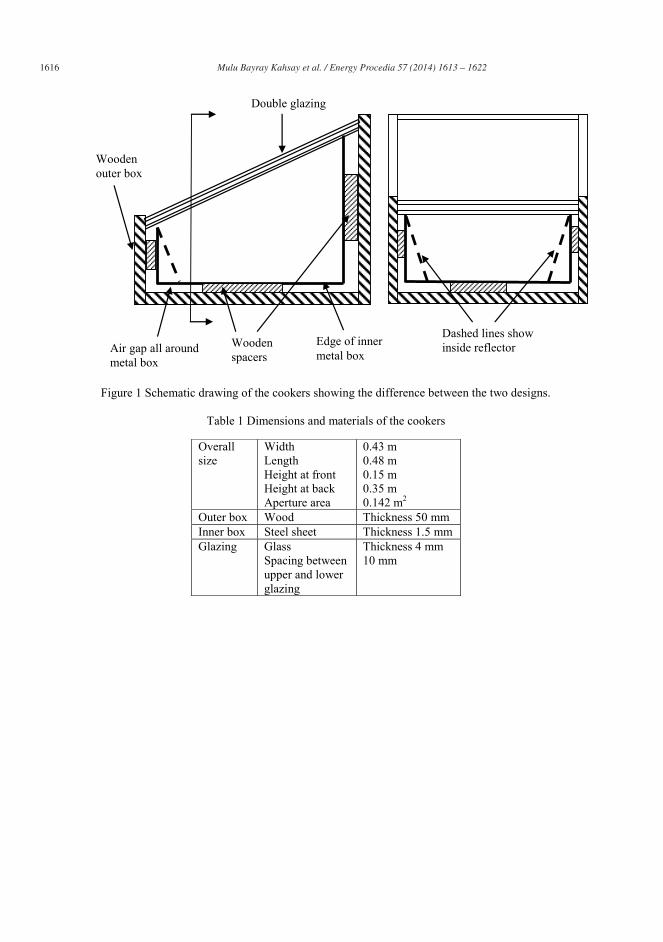
1616 Mulu Bayray Kahsay et al. / Energy Procedia 57 ( 2014 ) 1613 – 1622
Figure 1 Schematic drawing of the cookers showing the difference between the two designs.
Table 1 Dimensions and materials of the cookers
Overall size
Width Length Height at front Height at back Aperture area
0.43 m 0.48 m 0.15 m 0.35 m 0.142 m2
Outer box Wood Thickness 50 mm Inner box Steel sheet Thickness 1.5 mm Glazing Glass
Spacing between upper and lower glazing
Thickness 4 mm 10 mm
Dashed lines show inside reflector Wooden
spacers
Wooden outer box
Edge of inner metal box
Double glazing
Air gap all around metal box
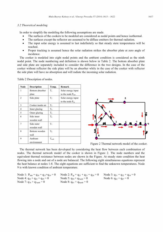
Mulu Bayray Kahsay et al. / Energy Procedia 57 ( 2014 ) 1613 – 1622 1617
3.2 Theoretical modeling In order to simplify the modeling the following assumptions are made.
The surfaces of the cookers to be modeled are considered as nodal points and hence isothermal. The surfaces except the reflector are assumed to be diffuse emitters for thermal radiation. The input solar energy is assumed to last indefinitely so that steady state temperatures will be
reached. Proper tracking is assumed hence the solar radiation strikes the absorber plate at zero angle of
incidence. The cooker is modeled into eight nodal points and the ambient condition is considered as the ninth nodal point. The node numbering and definition is shown below in Table 2. The bottom absorber plate and side plate are separately included to consider the difference in the two designs. In the case of the cooker without reflector the side plate will be an absorber while in the case of the cooker with reflector the side plate will have no absorption and will radiate the incoming solar radiation. Table 2 Description of nodes.
Node Description Temp. Remark 1 Bottom absorber
plate T1 Solar energy input
to the node Pbab 2 Side plate T2
Solar energy input to the node Psp
3 Cooker inside air T3 4 Inner glazing T4 5 Outer glazing T5 6 Side inner
wooden wall T6
7 Side outer wooden wall
T7
8 Bottom wooden wall
T8
9 Ambient environment
Tamb
The thermal network has been developed by considering the heat flow between each combination of nodes. The thermal network model of the cooker is shown in Figure 2. The node numbers and the equivalent thermal resistance between nodes are shown in the Figure. At steady state condition the heat flowing into a node and out of a node are balanced. The following eight simultaneous equations represent the heat balance at nodes 1-8. The eight equations are sufficient to find the unknown temperatures. Node 9 is with known condition of ambient temperature. Node 1: Pbab + q18 + q13+q14 = 0 Node 2: Psp + q21 + q23 + q26 = 0 Node 3: q31 + q32 + q34 = 0 Node 4: q41 + q43 + q45 = 0 Node 5: q54 + q5amb = 0 Node 6: q62 + q67 = 0 Node 7: q76 + q7amb = 0 Node 8: q81 + q8amb = 0
3
219
8
6 7
4 5
Figure 2 Thermal network model of the cooker.
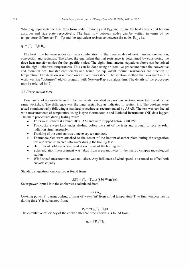
1618 Mulu Bayray Kahsay et al. / Energy Procedia 57 ( 2014 ) 1613 – 1622
Where qij represents the heat flow from node i to node j and Pbab and Psp are the heat absorbed at bottom absorber and side plate respectively. The heat flow between nodes can be written in terms of the temperature difference (Ti – Tj) and the equivalent resistance between the nodes Re,ij , i.e: qij = (Ti – Tj)/ Re,ij The heat flow between nodes can be a combination of the three modes of heat transfer: conduction, convection and radiation. Therefore, the equivalent thermal resistance is determined by considering the three heat transfer modes for the specific nodes. The eight simultaneous equations above can be solved for the eight unknown temperatures. This can be done using an iterative procedure since the convective and radiation heat transfer coefficients and hence the equivalent thermal resistances are function of temperature. The iteration was made on an Excel worksheet. The solution method that was used in this work was the “optimize” add-in program with Newton-Raphson algorithm. The details of the procedure may be referred in [7]. 3.3 Experimental tests Two box cookers made from similar materials described in previous section, were fabricated in the same workshop. The difference was the inner metal box as indicated in section 3.1. The cookers were tested simultaneously following a standard procedure as recommended by ASAE. The test was conducted with measurements of temperature using k-type thermocouple and National Instruments (NI) data logger. The main procedures during testing were:
Tests were started at around 10:00 AM and were stopped before 2:00 PM. The cookers were kept under shading before the start of the tests and brought to receive solar
radiation simultaneously. Tracking of the cookers was done every ten minutes. Thermocouples were attached to the center of the bottom absorber plate during the stagnation
test and were immersed into water during the boiling test. Half liter of cold water was used at each start of the boiling test. Solar radiation measurement was taken from a pyranometer in the nearby campus metrological
station. Wind speed measurement was not taken. Any influence of wind speed is assumed to affect both
cookers equally. Standard stagnation temperature is found from:
SST = (Ts – Tamb) (850 W/m2)/G Solar power input I into the cooker was calculated from:
I = G Aap Cooking power Pc during boiling of mass of water ‘m’ from initial temperature Ti to final temperature Tf during time ‘t’ is calculated from:
Pc = mCp(Tf – Ti)/t The cumulative efficiency of the cooker after ‘n’ time intervals is found from:
ηn = ∑Pci/∑Ii
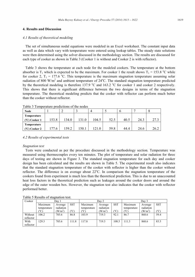
Mulu Bayray Kahsay et al. / Energy Procedia 57 ( 2014 ) 1613 – 1622 1619
4. Results and Discussion
4.1 Results of theoretical modeling The set of simultaneous nodal equations were modeled in an Excel worksheet. The constant input data as well as data which vary with temperature were entered using lookup tables. The steady state solutions were then determined using the solver discussed in the methodology section. The results are discussed for each type of cooker as shown in Table 3 (Cooker 1 is without and Cooker 2 is with reflector). Table 3 shows the temperature at each node for the modeled cookers. The temperature at the bottom absorber is T1 which is expected to be the maximum. For cooker 1 the result shows T1 = 153.8 oC while for cooker 2, T1 = 177.6 oC. This temperature is the maximum stagnation temperature assuming solar radiation of 800 W/m2 and ambient temperature of 24oC. The standard stagnation temperature predicted by the theoretical modeling is therefore 137.9 oC and 163.2 oC for cooker 1 and cooker 2 respectively. This shows that there is significant difference between the two designs in terms of the stagnation temperature. The theoretical modeling predicts that the cooker with reflector can perform much better than the cooker without reflector. Table 3 Temperature predictions of the nodes
Node 1 2 3 4 5 6 7 8 Temperature (oC) Cooker 1 153.8 134.0 131.0 104.5 52.5 40.5 24.3 27.3 Temperature (oC) Cooker 2
177.6 159.2 150.1 121.0 59.8 44.4 24.6 26.2
4.2 Results of experimental tests Stagnation test Tests were conducted as per the procedure discussed in the methodology section. Temperature was measured using thermocouples every ten minutes. The plot of temperature and solar radiation for three days of testing are shown in Figure 3. The standard stagnation temperature for each day and cooker design has been calculated and the results are shown in Table 5. The experimental result also indicates that the standard stagnation temperature of the cooker with reflector is higher than the cooker without reflector. The difference is on average about 22oC. In comparison the stagnation temperature of the cookers found from experiment is much less than the theoretical prediction. This is due to an unaccounted heat loss factors in the theoretical prediction such as leakages around the cooker doors and around the edge of the outer wooden box. However, the stagnation test also indicates that the cooker with reflector performed better. Table 5 Results of stagnation test.
Cooker Day 1 Day 2 Day 3 Maximum temperature (oC)
Average radiation (W/m2)
SST (oC)
Maximum temperature (oC)
Average radiation (W/m2)
SST (oC)
Maximum temperature (oC)
Average radiation (W/m2)
SST (oC)
Without reflector
106.2 785.6 86.8 103.9 719.3 92.1 86.7 868.6 59.4
With reflector
129.3 785.6 111.8 117.8 719.3 108.5 111.3 868.6 83.5
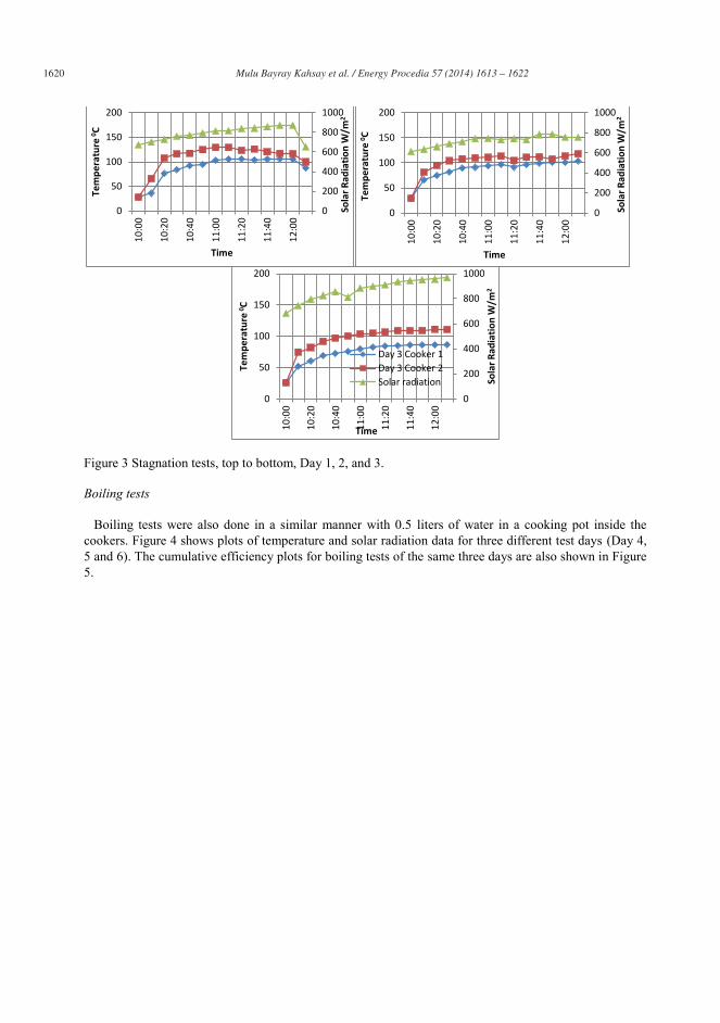
1620 Mulu Bayray Kahsay et al. / Energy Procedia 57 ( 2014 ) 1613 – 1622
Figure 3 Stagnation tests, top to bottom, Day 1, 2, and 3. Boiling tests Boiling tests were also done in a similar manner with 0.5 liters of water in a cooking pot inside the cookers. Figure 4 shows plots of temperature and solar radiation data for three different test days (Day 4, 5 and 6). The cumulative efficiency plots for boiling tests of the same three days are also shown in Figure 5.
0
200
400
600
800
1000
0
50
100
150
200
10:0
0
10:2
0
10:4
0
11:0
0
11:2
0
11:4
0
12:0
0
Sola
r Rad
iatio
n W
/m2
Tem
pera
ture
0 C
Time
0
200
400
600
800
1000
0
50
100
150
200
10:0
0
10:2
0
10:4
0
11:0
0
11:2
0
11:4
0
12:0
0
Sola
r Rad
iatio
n W
/m2
Tem
pera
ture
0 C
Time
0
200
400
600
800
1000
0
50
100
150
200 10
:00
10:2
0
10:4
0
11:0
0
11:2
0
11:4
0
12:0
0
Sola
r Rad
iatio
n W
/m2
Tem
pera
ture
0 C
Time
Day 3 Cooker 1 Day 3 Cooker 2 Solar radiation

Mulu Bayray Kahsay et al. / Energy Procedia 57 ( 2014 ) 1613 – 1622 1621
Figure 4 Boiling tests, top to bottom Day 4, 5 and 6.
Figure 5 Cumulative efficiencies of the cookers during the boiling test.
0
200
400
600
800
1000
0
20
40
60
80
100
10:0
0
10:2
0
10:4
0
11:0
0
11:2
0
11:4
0
12:0
0
12:2
0
12:4
0
1:00
Sola
r rad
iatio
n W
/m2
Tem
pera
ture
0 C
Time
0
200
400
600
800
1000
0
20
40
60
80
100
10:0
0
10:2
0
10:4
0
11:0
0
11:2
0
11:4
0
12:0
0 Sola
r Rad
iatio
n W
/m2
Tem
pera
ture
0 C
Time
0
200
400
600
800
1000
0
20
40
60
80
100
10:2
0
10:4
0
11:0
0
11:2
0
11:4
0
12:0
0
12:2
0
12:4
0
Sola
r Rad
iatio
n W
/m2
Tem
pera
ture
0 C
Time
Day 6 Cooker 1 Day 6 Cooker 2 Solar Radiation
0%
5%
10%
15%
20%
10:1
0 10
:20
10:3
0 10
:40
10:5
0 11
:00
11:1
0 11
:20
11:3
0 11
:40
11:5
0 12
:00
12:1
0 12
:20
12:3
0 12
:40
12:5
0 1:
00
Time
0%
5%
10%
15%
20%
10:1
0 10
:20
10:3
0 10
:40
10:5
0 11
:00
11:1
0 11
:20
11:3
0 11
:40
11:5
0 12
:00
Time
0%
5%
10%
15%
20%
10:1
0 10
:20
10:3
0 10
:40
10:5
0 11
:00
11:1
0 11
:20
11:3
0 11
:40
11:5
0 12
:00
12:1
0 12
:20
12:3
0 12
:40
12:5
0
Time
Cooker 1 Cooker 2
1622 Mulu Bayray Kahsay et al. / Energy Procedia 57 ( 2014 ) 1613 – 1622
5. Conclusion The study has clearly shown that in both the theoretical prediction and experimental tests, the performance of box solar cookers can be enhanced using internal reflectors. The steady state theoretical analysis predicted difference in standard stagnation temperature of about 25oC. The experiment on stagnation test also concluded that the standard stagnation temperature was higher by about 22oC. However, the predicted stagnation temperature for both the cookers was higher than the experimental value. Similarly the boiling test indicated that the water temperature and the cumulative efficiency were higher for the cooker with reflector. Therefore, the performance of box cookers can be enhanced by making appropriate angle side walls of the absorber and providing internal reflection.
Acknowledgements
The authors would like to acknowledge funding for the study from Mekelle University, KTT office and Tigray Science and Technology Agency. The authors also acknowledge EnPe project for sponsoring a student for an M.Sc. thesis work during the study.
References
1. Mulu Bayray and John Paintin, “Box Solar Cooker User Manual,” EiT – M, Mekelle University, 2012.
2. Chin, Y.K., Staton, D.A., “Transient thermal analysis using both lumped –circuit approach and finite element method of a permanent magnet traction motor,”
3. Bruce, Lindberg, “Analogy between thermal and electrical conduction,” www.egr.msu.edu/-raguin/ame812/Final projects, retrieved on 4/17/2012 .
4. Khas, Hauz “Natural convective heat transfer coefficient in a trapezoidal enclosure of box – type solar cooker.” Center of Energy Studies Indian Institute of Technology, 2003.
5. Testing and Reporting Solar Cooker Performance, ASAE S580 JAN03, http://solarcooking.org/asae_test_std.pdf, viewed May 2013.
6. Schwarzer, Klemens, Vieira da Silva, Maria, “Characterization and design methods of solar cookers,” Solar Energy, 82, 157–163, 2008.
7. Biniam Gebray,” Theoretical Modeling and Experimental Analysis of Box Solar Cooker,” M.Sc. Thesis, Department of Mechanical Engineering, EiT – M, Mekelle University, 2012.