
Master's degree thesis - NTNU Open
87
Master’s degree thesis IP501909 MSc thesis, discipline oriented master Creating and Processing Ship Design Data for Sheet Metal Cutting Candidate(s) number/Author(s) Tobias Fiskum Number of pages including this page: 87 Aalesund, 03.06.2016
-
Upload
khangminh22 -
Category
Documents
-
view
0 -
download
0
Transcript of Master's degree thesis - NTNU Open

Master’s degree thesis
IP501909 MSc thesis, discipline oriented master
Creating and Processing Ship Design Data for Sheet
Metal Cutting
Candidate(s) number/Author(s)
Tobias Fiskum
Number of pages including this page: 87
Aalesund, 03.06.2016

2
Mandatory statement
Each student is responsible for complying with rules and regulations that relate to
examinations and to academic work in general. The purpose of the mandatory statement is to
make students aware of their responsibility and the consequences of cheating. Failure to
complete the statement does not excuse students from their responsibility.
Please complete the mandatory statement by placing a mark in each box for statements 1-6 below.
1. I/we hereby declare that my/our paper/assignment is my/our own
work, and that I/we have not used other sources or received other
help than is mentioned in the paper/assignment.
2. I/we herby declare that this paper
1. Has not been used in any other exam at another
department/university/university college
2. Is not referring to the work of others without
acknowledgement
3. Is not referring to my/our previous work without
acknowledgement
4. Has acknowledged all sources of literature in the text and in
the list of references
5. Is not a copy, duplicate or transcript of other work
Mark each
box:
1.
2.
3.
4.
5.
3.
I am/we are aware that any breach of the above will be considered as cheating, and may result in annulment of the examination and exclusion from all universities and university colleges in Norway for up to one year, according to the Act relating to Norwegian Universities and University Colleges, section 4-7 and 4-8 and Examination regulations .
4. I am/we are aware that all papers/assignments may be checked for plagiarism by a software assisted plagiarism check
5. I am/we are aware that NTNU will handle all cases of suspected cheating according to prevailing guidelines.
6. I/we are aware of the NTNU’s rules and regulation for using sources.
Publication agreement
ECTS credits: 90
Supervisor: Ola Jon Mork
Co-supervisor: Henrik Kihlman
Agreement on electronic publication of master thesis
Author(s) have copyright to the thesis, including the exclusive right to publish the document (The
Copyright Act §2).
All theses fulfilling the requirements will be registered and published in Brage, with the approval of the
author(s).
Theses with a confidentiality agreement will not be published.
I/we hereby give NTNU the right to, free of
charge, make the thesis available for electronic publication: yes no
Is there an agreement of confidentiality? yes no (A supplementary confidentiality agreement must be filled in and included in this document)
- If yes: Can the thesis be online published when the
period of confidentiality is expired? yes no
This master’s thesis has been completed and approved as part of a master’s degree programme
at NTNU Ålesund. The thesis is the student’s own independent work according to section 6 of
Regulations concerning requirements for master's degrees of December 1st, 2005.
Date: 03.06.2016

Preface
This report is the result of my Master’s thesis in Product and System Design, written for the
Department of Maritime Technology and Operations at The Norwegian University of Science
and Technology (NTNU), located in Ålesund, Norway. As of the end of May 2016, I have for
the past eight months been preparing, researching and completing the assigned project.
Initially, the goal of the thesis was to analyse the current process of fabricating the foundation
used for sheet metal cutting, with focus on the preparation of cutting data/information in
3DEXPERIENCE, improvement of nesting by using ALMA instead of Nestix, and finally how
to perform the procedure with purchased data which is not native to 3DEXPERIENCE
(imported data).
It is safe to say that the topics of the thesis has slightly changed since the beginning, resulting
in the development of a new method, instead of improving the current one. The investigation
and experiments performed during the thesis is accomplished solely with the use of the tools
Kleven currently possesses. Thus the method is regarded as a best practice, and can actually be
implemented at the shipyard and provide covet benefits.
The investigation and analyse of purchased data has unfortunately been left out. However, I
will continue to work on the topic after graduating, as I have been offered an engineering
position at Kleven, with prefabrication processes as a main discipline.
The thesis has given me much deeper insight in the shipbuilding process and digital
manufacturing. I look forward to continue my work in this area, and hope to contribute to the
development of technology within the industry in the future.
I would like to thank Dr. Henrik Kihlman of Prodtex and Chalmers Institute of Technology
who has supervised the project externally, for software support and helpful guidance throughout
the past months.
I would also like to thank associate professor Ola Jon Mork of NTNU Ålesund who has been
the projects internal supervisor, for motivation and good follow-up on the thesis.
Finally I would like to thank my co-workers at Kleven for invitations to workshops and
providing me with relevant information not available anywhere else.
Ålesund, 3rd June 2016
Gjenopprettelig signatur
XTobias Fiskum
Signert av: [email protected]
Summary
The process from the creation of a design to the initiation of production in the shipbuilding
industry is a complex procedure. Recently more and more shipyards has started moving away
from traditional shipbuilding methods. Production processes are being automated, and
engineering and design digitalized.
Kleven is a company that is investing a great amount in modernization and automatization of
the shipyard’s production facility, and is currently working on moving much of the engineering
work onto the digital PLM platform, 3DEXPERIENCE. The development is still a project in
progress, yet much is successfully operational today.
One of the remaining challenges is to figure out to connect 3DEXPEIENCE with the process
of sheet metal cutting on the production floor. Through the development of work methodology
for modelling, digital manufacturing and CAM processing of ship design data, where the output
is documentation intended for the sheet metal cutting of plates; the initial stage of hull
production.
By using state of the art digital tools, a best practice is developed, bringing Kleven one small
step closer to their goal of reducing manual labour in the production and to gain highly valuable
competitive benefits.

TABLE OF CONTENTS
TERMINOLOGY ....................................................................................................................... 1
1. INTRODUCTION .............................................................................................................. 2
1.1. Project background ...................................................................................................... 3
1.2. Problem formulation .................................................................................................... 4
1.3. Thesis objectives.......................................................................................................... 5
1.4. Research and literature review .................................................................................... 7
2. METHODS ......................................................................................................................... 9
2.1. Case study - Kleven ................................................................................................... 10
3. TECHNOLOGY AND TOOLS ....................................................................................... 11
3.1. Nesting ....................................................................................................................... 11
3.2. Computer Numerical Control .................................................................................... 13
3.2.1. NC-program ....................................................................................................... 13
3.2.2. Machine Control Unit (MCU) ............................................................................ 14
3.2.3. Machine tools ..................................................................................................... 14
3.3. The 3DEXPERIENCE platform ................................................................................ 15
3.3.1. CATIA ................................................................................................................ 18
3.3.2. DELMIA ............................................................................................................ 18
3.3.3. ENOVIA ............................................................................................................. 18
3.4. ALMA and Act/Cut for shipbuilding ........................................................................ 19
4. INVESTIGATION OF MANUFACTURING FEATURES............................................ 21
4.1. Compensation for welding distortion ........................................................................ 21
4.2. Edge preparation ........................................................................................................ 23
4.3. Marking ..................................................................................................................... 24
5. CONFIGURING THE COLLABORATIVE SPACE...................................................... 25
6. MODELLING .................................................................................................................. 26
6.1. Space Referential ....................................................................................................... 27
6.2. Structure Functional Design ...................................................................................... 28
6.3. Structure Design ........................................................................................................ 33
7. MANUFACTURE PREPARATION ............................................................................... 35
7.1. Marine Manufacturing ............................................................................................... 38
7.2. Marine Structure Fabrication ..................................................................................... 41
8. DATA EXPORT & IMPORT FOR PROCESSING IN CAM SOFTWARE .................. 46
8.1. IGES .......................................................................................................................... 46
8.2. DXF ........................................................................................................................... 47
8.3. XML .......................................................................................................................... 48
9. CAM PROCESSING ....................................................................................................... 49
9.1. Post processing the NC-program ............................................................................... 58
10. DISCUSSION ............................................................................................................... 60
10.1. Design , assembly planning and manufacture preparation .................................... 60
10.2. Data export/import ................................................................................................. 61
10.3. CAM processing .................................................................................................... 62
10.4. Further work ........................................................................................................... 63
11. CONCLUSION ............................................................................................................. 64
BIBLOGRAPHY ..................................................................................................................... 65
APPENDIX .............................................................................................................................. 66
A-1 Comparison of shrinkage compensated and original plate ........................................ 66
A-2 Process description: Export and import of parts ........................................................ 67
A-3 Generated workshop document (ALMA) .................................................................. 73
A-4 Article draft: Creating and processing ship design data for sheet metal cutting ....... 75

1
TERMINOLOGY
CAD Computer Aided Design
CAE Computer Aided Engineering
CAM Computer Aided Manufacturing
CNC Computer Numerical Control
NC Numerical Command
MCU Machine Control Unit
PLM Product Lifecycle Management
MOG Marine and Offshore Manufacturing Planning
EKL Enterprise Knowledge Language
EBOM Engineering Bill Of Materials
MBOM Manufacturing Bill Of Materials
DWG Drawing
DPR Drafter Document (ALMA)
IGES Initial Graphics Exchange Specification
DXF Drawing Exchange Format
XML Extensible Markup Language
2
1. INTRODUCTION
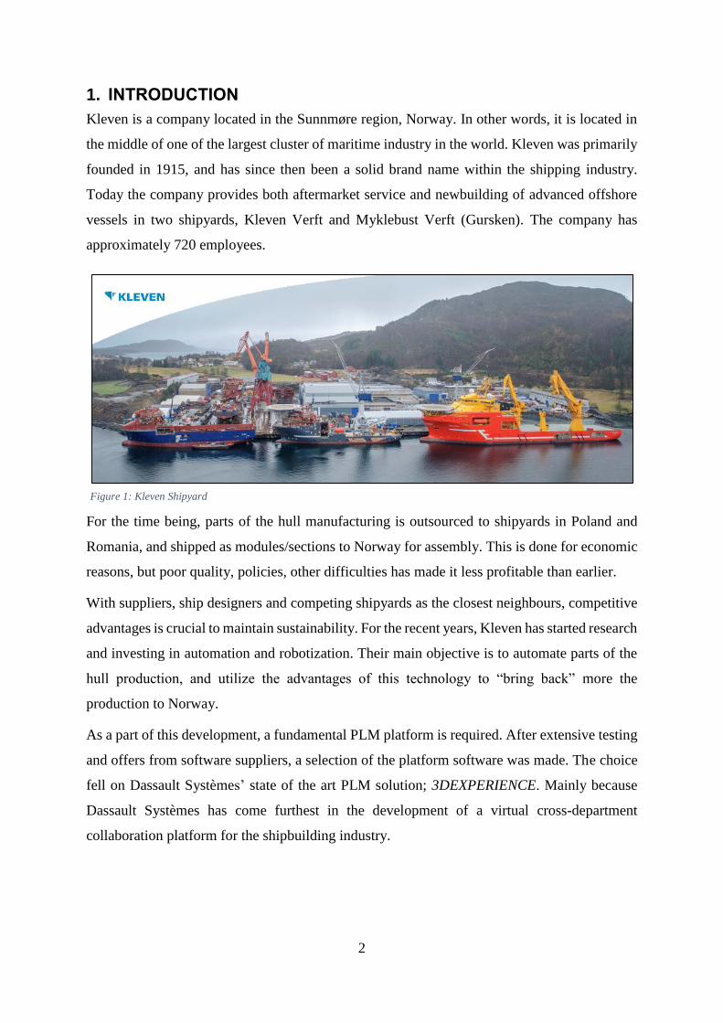
Kleven is a company located in the Sunnmøre region, Norway. In other words, it is located in
the middle of one of the largest cluster of maritime industry in the world. Kleven was primarily
founded in 1915, and has since then been a solid brand name within the shipping industry.
Today the company provides both aftermarket service and newbuilding of advanced offshore
vessels in two shipyards, Kleven Verft and Myklebust Verft (Gursken). The company has
approximately 720 employees.
Figure 1: Kleven Shipyard
For the time being, parts of the hull manufacturing is outsourced to shipyards in Poland and
Romania, and shipped as modules/sections to Norway for assembly. This is done for economic
reasons, but poor quality, policies, other difficulties has made it less profitable than earlier.
With suppliers, ship designers and competing shipyards as the closest neighbours, competitive
advantages is crucial to maintain sustainability. For the recent years, Kleven has started research
and investing in automation and robotization. Their main objective is to automate parts of the
hull production, and utilize the advantages of this technology to “bring back” more the
production to Norway.
As a part of this development, a fundamental PLM platform is required. After extensive testing
and offers from software suppliers, a selection of the platform software was made. The choice
fell on Dassault Systèmes’ state of the art PLM solution; 3DEXPERIENCE. Mainly because
Dassault Systèmes has come furthest in the development of a virtual cross-department
collaboration platform for the shipbuilding industry.

3
1.1. Project background
Today, Kleven is purchasing complete design packages from external design companies such
as Marin Teknikk, Rolls-Royce, Salt, Wärtsilä, etc. These packages include all the required
design data such as basic design1, detail design, piping, outfitting, etc. In other words, Kleven
is not producing any design themselves. But this is about to change; the management of Kleven
has decided that the company shall purchase only basic design packages from external vendors,
and perform the rest of the design and digital manufacturing processes internally. This leads to
various challenges for the company. First of all, it requires a reliable and custom tailored 3D
design tool with the ability to ensure reliable and flexible/adaptable design. Secondly a digital
manufacturing platform capable of simulating the shipyard’s manufacturing facility is required.
Kleven decided on the design and digital manufacturing tools CATIA and DELMIA, which is a
part of the 3DEXPERIENCE platform, a state of the art PLM solution developed by Dassault
Systèmes.
Once these tools were introduced and running smoothly, an interface between the
manufacturing equipment had to be implemented. This is where the foundation of this thesis
lie; if Kleven no longer is going to purchase complete design packages, they will no longer be
provided with the data required for cutting sheet metal parts. Kleven’s current approach is to
purchase separate packages which includes the cutting data, complete with nesting and NC-
codes2 for the CNC-cutting machine3. If Kleven will produce their own detailed design work
they will have to generate the input for the cutting machine themselves by using data from
designs created internally.
The main challenge is to develop a method describing how the data can be created, prepared
for production and transferred to the CAM software for nesting and sequencing of the sheet
metal cutting. This whole process needs to result in generated workshop documentation and
NC programs for the sheet metal cutting operation on the work floor.
If Kleven is able to use this information to create their own cutting machine input for cutting
sheet metal parts, this will both contribute to greater corporate independency and economic
benefits.
.
1 Class approved design data: Arrangement of spaces, structural design, stability analysis, etc. 2 Numerical Control – Common denomination for machine programming language. 3 Computer Numerical Controlled cutting machine – A cutting machine which has its actions/operations controlled
by NC-codes (programs)

4
1.2. Problem formulation
Kleven is facing challenges regarding preparing and processing internally created design data
so that it becomes compatible with the interfaces of computer aided manufacturing (CAM)
software that is used for managing the sheet metal cutting. A secondary challenge is that the
output data from the CAM software (NC program) is not compatible with the interface of the
cutting machine “as is”.
The lack of a fundamental method describing each process from design to production initiation
is hampering the progress of going live with the design and digital manufacturing solutions the
company has purchased.
In order to arrive at a satisfactory best practice, the problem needs to be divided into sub-
problems, and addressed one by one. The problem is divided into four sub-problems focusing
on the different stages of the process, in chronological order.
Firstly a design model needs to be established by using 3DEXPERIENCE. The design
has to have be flexible, meaning that it can rapidly be modified in case of possible
revisions and specification changes. In order to replicate a “live” design project, all
relevant design features needs to be included in the model.
Further the design model has to undergo assembly planning and manufacture
preparation, also by using 3DEXPERIENCE. The assembly process must be planned in
such a manner that it is adaptable to Kleven’s production facility. The elements in the
assembly also needs to have manufacturing features applied before it can be further
processed in the CAM software.
How to transfer the data between 3DEXPERIENCE and ALMA must be investigated.
Compatible file formats, complexity of export/import processes and the quality of
exported data must be evaluated to determine the most convenient transfer method.
Finally the data must be processed in the CAM software, ALMA. Imported data must
be prepared for nesting, raw material must be assigned and cutting sequences must be
planned. Further, output in the form of workshop documentation and NC programs must
be generated.

5
1.3. Thesis objectives
In this thesis, it is assumed that all design tasks is performed by Kleven, apart from the creation
of hull geometry, which is supplied by an external design company. This means that all data
that will be processed is native to 3DEXPERIENCE, and not imported data which is native to
third party design platforms such as Nupas, Aveva, etc. Most imported data has information,
attributes and properties that are incompatible with 3DEXPERIENCE, so handling this data has
proven to be somewhat problematic. Especially when it comes to manufacture preparation.
The main objective for the thesis is to investigate methods on how to create a design unit from
scratch, and processing it in the digital manufacturing platform that Kleven is operating on
today. Experiments focusing on the creation, processing and preparation of the design data
which will be used as input data in the process of sheet metal cutting is to be performed in order
to establish reliable methods. In order to obtain the most accurate view of the different
processes, all involved processes are to be performed from start to finish.
A generic 3D model of ship section is to be modelled. Further, the section needs to be broken
down into the data which will be used for sheet metal cutting. The data is then to be exported
into formats which is compatible with the nesting software. Different export methods is to be
investigated and evaluated in terms of complexity, time consumption and quality of the
exported data. This will conclude the experiments on the 3DEXPERIENCE platform, and
verify if it is a viable solution for the task.
Once the data is exported into the desired format, it is to be imported into the nesting software,
where further processing is to be investigated and explained. At this stage it is important that
all the necessary information is included in the import data (export data from
3DEXPERIENCE). This information will be discussed later in the report. Nesting, adjustments,
preparation, etc. is then performed in order to generate the NC-program required to operate the
CNC-cutting machine. It is also here important that the output data (NC-program) is compatible
and in accordance with the interface/programming language of the cutting machine.
Figure 2, presented on the next page describes the work flow which is desired to achieve once
both the design platform and nesting software is fully operational.

6
BASIC DESIGN
Fully defined, simplified
representation
Structural design
Space arrangement
Analyses
Documentation
DETAIL ENGINEERING
Division by blocks
Detail design
System design
Steel outfitting
Documentation
CUTTING PREPARATION
Import part geometry data into
nesting software
Minor corrections of data (if required)
Nesting of parts
Sequencing
Generate NC-code
Post processing of NC
PRODUCTION INITIATION
Input machine compatible NC
Preparation of machine/workshop
Start cutting/marking
ASSEMBLY PLANNING
Assembly sequence
Weld planning
Edge preparation
Shrinkage planning
Export part geometry data for cutting
preparation
Figure 2: Design workflow
7
1.4. Research and literature review
In order to determine what information is available on the respective topics, systematic methods
of obtaining this information is performed. Information is obtained by performing subject
relevant searches in various electronic databases. Among the databases are scientific electronic
databases such as Google Scholar, NTNU BIBSYS and various databases provided by
international universities. Also common electronic sites such as Google search and online
libraries has provided helpful information. Searches is performed by using thesis specific search
phrases such as plasma cutting, hull production, digital ship design, manufacturing, CAD data
formats only to mention a few.
The most valued information is provided by the software providers themselves;
3DEXPERIENCE and ALMA. Both provide help documentation on the software’s tools and
features. 3DEXPERIENCE provides the information through an online service called
3DEXPERIENCE User Assistance, which requires a personal user account (3DPassport) to
access [1]. ALMA utilizes a more traditional approach, by integrating the information into their
software as HTML Help documentation. The help documentation for both 3DEXPERIENCE
and ALMA can easily be accessed by pressing F1 on the keyboard, upon selecting the tool or
function desired one desires to know more about.
Obtaining the information more informative external information on 3DEXPERIENCE proved
to be very challenging. Apparently, very little documentation apart from the user assistance data
base is available for the public, due to Dassault Systèmes’ strict business confidentiality policy.
However, by consulting the project supervisor and Kleven, beneficial training and course
material has been obtained. Also through an informative practical workshop together with
Kleven and Dassault Systèmes many questions were enlightened. During this workshop,
professional relations were established between the thesis candidate and DS, opening up for
more direct communication between the parts.
The same challenge were experienced with ALMA. Even though the software is fairly known
in various businesses, relevant information were not available for public use. By consulting
ALMA’s software distributor, useful training material were obtained, helping the candidate to
establish sufficient knowledge on how to operate the software. [2]
Another valued source of information is the University Library, which has provided informative
literature regarding ship building. The book “Ship Construction” authored by George Bruce
and David Eyres [3] is considered as one of the most superior guides in the shipbuilding
industry. It covers the complete construction process including the development of ship types,
8
materials and strengths, welding, cutting and shipyard processes. Every subject is clearly
described by using descriptive diagrams and figures.
To summarize information obtained through the performed research, brief descriptions of the
findings are categorized and presented below.
Ship design and building process:
The subjects welding distortion, edge preparation and general sheet metal cutting (CNC) has
been very much enlightened by G. Bruce and D. Eyres book Ship Construction. The book has
also provided an informative overview of how traditional ship building is executed. Also
through previous work experience and co-operation with Kleven’s production department, the
thesis candidate has been able to connect the textbook theory with today’s existing procedures.
3DEXPERIENCE platform:
Various training and course material developed by Dassault Systèmes (regarded as confidential
information) has proven itself useful in some cases. However, the material is very general, and
does not go into detail on important subjects, such as software configuration and data
management. The online user assistance provide a useful encyclopaedia on the
3DEXPERIENCE platform’s applications and features. It includes a full-text search engine,
guides and tutorials. Also in this case, previous wort experience and co-operation with Kleven’s
detail engineering department, has contributed to valuable knowledge.
ALMA Act/Cut:
Like 3DEXPERIENCE, ALMA has its user assistance easily available (literally by a
keystroke), and provide very informative documentation on the user interface and applications
within the software. In order to obtain the information on how to perform a realistic simulation
of a CAM processing situation, ALMA were contacted and provided helpful training material,
including a tutorial for the software. Not all tools and function available are described in the
documentation, but enough were provided to implement a pilot project for the thesis.

9
2. METHODS
To solve the challenges and reach the objective discussed in the previous chapter, appropriate
methods are to be used. The methods discussed in the report will be software based, which
means that all tasks will be performed inside the various software that is being investigated.
Though there is little available information on the subjects, the theory concerning “trial and
error” will be put into practice.
With this fundamental method for solving problems, various attempts of success is practiced
until satisfactory results are achieved. [4]
Experimental learning or “learning-by-doing” is also a valued method throughout the progress
of the project. The goal is to build as much competence and knowledge on the topics as possible,
and highlight features and functions which is not well documented by others. This method will
not only build the necessary knowledge, but also help verify the results in the process. It will
also highlight weaknesses/flaws in the different software’s interface.
A case study is an efficient tool used to obtain a deeper and detailed understanding of the
topic(s). It is an account of an activity, event or problem that contains a real or hypothetical
situation and includes the complexities one would encounter at the workplace. [5]
The case study illustrates real life issues and challenges that the Kleven is up against today. For
the thesis, this regards processing and preparing the design data through the design- and
manufacture preparation phases, and at the end being able to use the data for generating usable
output data in the form of NC-programs and workshop documentation for sheet metal cutting.

10
2.1. Case study - Kleven
As mentioned, the thesis will reflect upon the manufacture preparation methods concerning
plate/sheet metal cutting in Kleven’s hull production line. More specifically; interfaces and
compatibility between the design platform (3DEXPERIENCE), nesting software (ALMA) and
cutting machine input data. In order to obtain the most realistic overview of the design process,
a ship section model is to be established by using the available tools that Kleven is planning to
use. Once the model is established, assembly planning is performed so that the assembly process
is adapted to Kleven’s production facility. Further, manufacture preparation is performed in
order to apply the correct manufacturing features to the model.
The designed model of the ship section is of a generic character, which means that the design
data will not be put into production. However, the data are to be treated as a real design project,
and include various ship design elements such as plating, brackets, openings, girders, etc. The
more elements included, the more realistic the case. Listed in table 1 is elements and design
features which are commonly included in a structural design model of a ship section. In this
case, most of these features will be included in order to simulate a realistic case.
Plate types Stiffeners/girders Opening types Details
Shell plates Vertical
Manholes
Lightening
holes
Access
openings
Penetration/slot
Brackets
End cuts
Face plates
Collars
Plate thickness
Material
Horizontal
Decks Longitudinal
Transversal
Longitudinal
bulkheads
Vertical
Horizontal
Transversal
bulkheads
Vertical
Horizontal
Table 1: Structural design features
Once the structural design model is established and the variety of design features is satisfactory,
the data processing can commence to the assembly planning and manufacture preparation
stages. Finally, the data is transferred to the CAM processing software where nesting and
sequencing is performed, and NC-programs and workshop documentation is generated. The
methods for each stage and the data export/import process between CAD and CAM software is
explained in detail later in the report.

11
3. TECHNOLOGY AND TOOLS
This chapter will discuss the different technologies and tools that are used in throughout the
project. Technology concerns the theory around nesting and G-code programming4, and tools
concerns the main software solutions utilized. The 3DEXPERIENCE platform and ALMA
Act/Cut are also given detailed descriptions. For the software, the overall functionalities and
interfaces are described. The design and digital manufacturing solutions in 3DEXPERIENCE
that are relevant to the thesis will also be given brief descriptions.
3.1. Nesting
Nesting is generally referred to as fitting an object (or objects) inside a larger one. In this case
it concerns the process of fitting the maximum amount of plates inside a standard sized
rectangular steel sheet, and at the same time minimizing the scrap raw material produced when
cutting. In other words; optimizing the sheet metal cutting process. This may seem like a simple
task when addressing only rectangular profiles, but this is not the case in the shipbuilding
industry. Various structural elements such as brackets, collars, girders, etc. may have complex
and odd shapes. The procedure is performed by a computer, through a software which
specializes on optimized nesting. The input can be 2D, 3D or coded data, and the software
utilizes advanced algorithms in order to determine how to lay out the parts in such a way on the
sheet that most of the raw material is utilized, and at the same time the correct amount of parts
is produced. An example of a sheet with nested parts assigned is presented in figure 3:
4 Most common NC programming language
Figure 3: Nested sheet metal parts

12
Many machine manufacturers develop their own nesting software which can be customized
accordingly to the specific cutting machine. This helps the machine operator/programmer to
take full advantage of the machine’s features. Also nesting software developed by third party-
vendors is preferred by some fabricators. This is common if the fabricator operates two or more
machines, from different machine brands. The operator/programmer then only needs to deal
with one common customized software rather than various machine dependent software.

13
3.2. Computer Numerical Control
CNC, or Computer Numerical Control is a system which is used to control advanced machines.
The technology can be used for machining centres such as lathes, drill presses and milling
machines. It can also be used for sheet metal processing such as plasma/laser cutting, punching,
etc. The machines is controlled by a NC-program which contains coded alphanumerical data.
The program controls the motions of the workpiece, tool/torch, feed rate, depth of cuts, speeds
and all other machine functions. The only thing which is limiting the programming is basically
the capabilities of the machine.
The CNC system consists of three basic components:
3.2.1. NC-program
The NC-program is a detailed set of commands to be followed by the machine tool/torch. Each
command specifies a position according to the Cartesian coordinate system 5 , a motion,
machining parameters or on/off functions. The program can be written manually according to
production drawings, or it can be generated from design data, and is performed in a CAM
software. Such software can also automatically generate complete NC-programs for the
machine, given that the software is equipped with the correct post processor 6 . The post
processor edits the “raw” program in so that it is readable both for the user and the machine.
The most common language for a NC-program is called G-code or G-programming language.
A typical simple program for cutting in a straight line can look like as presented in figure 4
below:
Figure 4: Example of a simple NC-program
5 A coordinate system that specifies each point uniquely in a plane or space by numerical coordinates. Coordinates
are relative to the origin of the system. 6 An extension from the nesting software which processes and edits the automatically generated NC-program so
that it is compatible with the specified machine.

14
The block numbers, also known as sequence numbers is to identify the specific machine
operation throughout the program. Preferably the block numbers is in chronological order, but
it is possible to rearrange the blocks as desired. Following the block numbers is G-codes and
M-codes, or preparatory- and miscellaneous functions. The G-codes prepares the machine to
perform a specific machining operation. The M-codes concerns more “internal” machine
functions such as torch on/off, temporary stop, end/loop program, etc.
Following these functions is the coordinates relative to the origin of the work piece/sheet metal,
feed rate, and tool/torch selection.
3.2.2. Machine Control Unit (MCU)
The MCU is the machines internal computer. It interpret and stores the NC-program, and
executes the commands into actions performed by the tool/torch. It includes the system software
and user interface, calculation algorithms and translation software which translate the G-code
to a format that the can be processed by the machine. Sensors monitor all actuators and tools,
and give highly accurate feedback to the MCU during all actions. The operator can inspect and
survey all this information on a monitor connected to the MCU.
3.2.3. Machine tools
A CNC plasma cutting machine is always equipped with a plasma cutting torch. However,
various accessories can be equipped to improve the functionality of the machine. Examples of
this equipment is tool rotators, tilters, multi torch systems, drilling- and marking tools, vision-
and scanning systems. All this equipment can be controlled in the NC-program or manually at
the machine control station. A selection of plasma cutting machine tools provided by the
machine vendor Microstep is presented in figure 5 below.
Figure 5: Various plasma cutting machine tools

15
3.3. The 3DEXPERIENCE platform
In the highly dispersed and interconnected marine and offshore landscape, the struggle to stay
competitive is intense. Innovative and sustainable concepts, on-time and on-budget delivery,
compliance with strict safety and environmental regulations, and greater design,
manufacturing and operational efficiencies are some of many challenges organizations has to
overcome if they want to stay relevant. The challenges are many, but so are the opportunities.
Safer, cleaner, greener vessels and offshore structures, as well as new sources of energy,
require a whole new way of thinking. The possibilities are as boundless as the oceans
themselves. Leveraging over 30 years of expertise across 12 industries, Dassault Systèmes
helps progressive naval architects, designers, shipyards and suppliers successfully transform
their practices to create unique value for their customers. [6]
Dassault Systèmes, the company behind major CAD/CAE, CAM and PLM software such as
CATIA, DELMIA, SOLIDWORKS and more introduced the 3DEXPERIENCE platform in
2013. They call it a Business Experience Platform, because it provide software solutions for all
organizations/departments within a company. Dassault direct the platform towards a variety of
industries such as transportation, aerospace, marine and offshore, industrial equipment, finance,
consumer goods retail, just to mention a few. Through a cloud-based7 service, the platform
provide its industry-leading applications; Design and engineering, manufacturing and
production, simulation, governance and lifecycle.
The user interface of 3DEXPERIENCE is quite different from any of Dassault Systèmes’ other
software. Where their previous software have completely different interfaces among
themselves, 3DEXPERIENCE offers a common interface that ties all these software together
in the same environment. All the applications are cloud based, which means that only the
3DEXPERIENCE client software has to be installed on the user’s computer. The user’s
available applications are available through hosted services, and require specific licenses in
order to be launched.
The access to the applications are found under the characteristic 3DEXPERIENCE Compass.
Four different categories (north, west, south and east) divides the applications into their
respective quadrants of the compass.
7 “On-demand computing”: Internet based storage solutions which provide users and enterprises with various
capabilities to store and process their data.

16
Figure 6: 3DEXPERIENCE dashboard
Social and Collaborative applications
Provides a comprehensive set of user experiences to enterprise users across the product
lifecycle, from product planners, designers, and program managers to manufacturing planners,
purchasing agents, suppliers, and compliancy managers that allows them to collaborate with
each other in the overall context of the product data. Social and Collaborative applications
provide functionality for businesses related to product planning, configuration management,
design management, engineering management and manufacturing management.
3D Modelling applications
Offers a set of digital engineering and design applications. CATIA applications offers a full
spectrum of next generation solutions design, engineering, systems modelling and architecture,
electrical and electronic systems. SOLIDWORKS offers a conceptual mechanical design
solution that merges the benefits of history, parametrics, and editing into a single interface.
17
Content and Simulation applications
Applications in this category explore the boundaries between the virtual and real world. They
reduce physical prototyping, increase confidence in product performance, accurate design
decisions, and enhance knowledge of real world behaviour in a virtual environment. DELMIA
offers solutions that enable planning and simulation of manufacturing processes. Key
functionalities are optimization of processes, mapping of human factor issues and resource
planning. SIMULIA provides a full spectrum of solutions for simulating the behaviour of
designs in a multiphysics environment, including finite element analyses (structural, thermal
and fluid dynamics).
Information Intelligence applications
These applications enable any employee in a company to collect, connect, discover consolidate
and understand information from the platform’s wide selection of functionalities.
[1]
18
3.3.1. CATIA
CATIA is an advanced 3D product lifecycle management software, and the main 3D-modelling
solution in 3DEXPERIENCE. CATIA offers a vast selection of industry specific workbenches,
which provides multiple stages of product development. CATIA can be applied to a wide
variety of industries, but this thesis will focus on the ship design solution for CATIA. This
solution is one of the leading 3D tools when it comes to marine and offshore construction. This
is a powerful design tool that provides the user with intuitive and easy-to-use functionalities,
covering all processes from conceptual design to a complete detailed design.
3.3.2. DELMIA
DELMIA is the digital manufacturing solution in 3DEXPERIENCE platform. It enables
manufacturers in any industry to efficiently plan, manage and optimize their industrial
operations. This includes process- and assembly planning, work instructions planning, and
robotic programming. By performing digital simulation of manufacture processes at an early
stage, the fabricator is able to evaluate “what-if-scenarios”, perform modifications/corrections,
optimize floor operations, and identify and eliminate expensive errors and poor design.
DELMIA Marine and Offshore Manufacturing Planning (MOG) provide the foundation for all
shipbuilding manufacturing solutions of 3DEXPERIENCE. With a unified data model and a
single workbench/environment MOG enables all manufacturing disciplines to collaborate.
3.3.3. ENOVIA
ENOVIA provides the collaborative management part of 3DEXPERIENCE. It is a framework
for collaboration between the different departments in a company. It is an online environment
which involves designers, programmers and work floor employees in the product lifecycle.
Fully integrated with other solutions from Dassault Systèmes, ENOVIA’s intuitive user
interface offers powerful capabilities via a standard web browser. It is ready to be used “out of
the box”, so the benefits of effective collaboration, project management and planning can
rapidly be achieved.
19
3.4. ALMA and Act/Cut for shipbuilding
Sheet metal cutting is a key link in a shipyards manufacturing process. It can be either a
bottleneck hampering the whole production, or a huge productivity and profit booster. In order
to achieve the maximum potential efficiency of the sheet metal cutting machines, the
programming system must perfectly answer the needs of the production. The software Act/Cut
developed by the company ALMA promises to deliver a solution to these challenges.
In addition to maximizing the material utilization, the programming system must manage the
plasma technology as well as the specific processes in the industry, adapt to existing processes,
and reduce to a minimum the necessary preparation and production kick-off time as well as the
machine’s cycle time.
ALMA Act/Cut is a complete, craft-oriented solution for cutting machine programming. It
supports a variety of cutting technologies, such as plasma, laser, oxy-cutting and punching. It
has specialized on all the shipbuilding specific functions; edge preparation management,
symmetrical dual sheet cutting and marking. Also included in the software is powerful nesting-
and material optimization tools. It also has the capability to be perform many tasks
automatically.
Compatibility with shipyard-dedicated design solutions is also an important feature included in
ALMA Act/Cut. In addition to 2D DWG/DXF8 data import, the software is also capable of
importing and managing native 3D data from different brands such as CATIA, SmartMarine
and Tribon M3, and XML-coded data.
The software’s user interface is fairly simple and straightforward. As shown in figure 7 on the
next page, both 2D- and 3D data can be imported into Act/Cut, as well as coded data. Further
the imported data is translated into a native format called DPR. The parts, now translated into
.dpr, are then processed in various applications. Before the final output (NC program and
workshop docs.) can be generated, all the parts geometries has to be analysed and defects
corrected. When the geometry is satisfactory, the nesting process can commence. This is can
be done automatically, partially automatic or manually. Further the sequence of the cutting
process needs to be planned before the NC program is automatically generated.
8 2D data formats

20
Figure 7, below shows the data flow between the PLM and CAM system, production
management and production floor. The processing in ALMA Act/Cut is briefly explained.
CAM System
PLM/Engineering System
3D Output
CATIA V5, IGES
2D Output
DXF/DWG
Code Output
XML
3D
IN
TE
RF
AC
E
2D
IN
TE
RF
AC
E
CO
DE
INT
ER
FA
CE
DPR FileConversion
NC Code
Production floor – Cutting
machine
Production management
Manufacturing orders
Stock list
Production data
Logistics
LAUNCHING ORDER
Minor adjustments at part
level and tooling
assignment.
Nesting and optimization
to minimize remnants and
waste.
Define cutting/marking
sequence.
Simulation of
cutting sequence,
NC code and
workshop document
generation.
Feedback
Produced parts
Used sheets
Remnants generated
Figure 7: Data flow through the departments

21
4. INVESTIGATION OF MANUFACTURING FEATURES
Before establishing the design unit, a few manufacturing features needs to be discussed. These
are important features that must be understood before starting the modelling: Compensation for
welding distortion, edge preparation and marking of parts.
4.1. Compensation for welding distortion
During the welding process of steel structures the metal is subjected to highly localized heating,
which causes the material surrounding the welding area to expand, and then contract upon
cooldown. This inconvenience is called weld distortion, and is basically shrinkage of the welded
plate. Distortion from arc welding is a common challenge, and is a major cause of extra work
during the assembly and construction of a ship. The need for adjusting parts so that they will fit
together correctly can take considerable time and effort.
Uniform stresses are introduced due to the expansion and contraction of the heated material.
Initially, compressive stresses are created in the cooler material surrounding the weld pool due
to thermal expansion of the heated material in the HAZ.9 Further, tensile stresses occur when
the material is cooling down, and the weld metal will start contracting, while the HAZ is resisted
by the surrounding cold material. The magnitude of these thermal stresses can be seen by the
volume change in the weld area on solidification and subsequent cooldown to room
temperature. If the stresses exceeds the yield strength of the material, localized plastic
deformation of the material occurs. This results in distortion and permanent reduction in the
structures component dimensions.
For repeatable processes, which are very common in shipbuilding, the shrinkage of the plates
can be measured, documented and collected in order to predict the behaviour of a plate when
welded. Computer-aided design systems (CAD) take advantage of these measurements and
allows the designer/modeller to compensate for the shrinkage at an early stage of the design
process and include the modifications in the plate cutting information. The plates are then cut
oversized and the shrinkage after welding brings it to the correct fit. This prediction method
can also be applied to more complex parts such as stiffeners and structural webs with face
plates. [3]
9 Heat Affected Zone – the heat affected area adjacent to the weld pool

22
Figure 8 visualizes the most common distortion types on two simple butt welded steel plates.
These types of distortion is called transverse shrinkage and longitudinal shrinkage. Other types
of distortion can also occur in a welded plate. These are known as longitudinal bending,
rotational-, angular- and buckling distortion. However, these will not be considered in this case.
Figure 8: Weld distortion (shrinkage)
These deformations needs to be taken into consideration at an early stage, before the plate
cutting is initiated. 3DEXPERIENCE offers a tool called Shrinkage Planning, which allows the
user to input the shrinkage of the plates by scaling the plate’s dimensions. This is done inside
the application which governs the manufacture preparation of the section.

23
4.2. Edge preparation
On thick plates it becomes necessary to bevel10 the connecting edges of plates that are to be
welded together. This is done in order to achieve complete penetration of the weld metal and
sufficient strength in the connection. There are various methods on how to create the bevels,
such as machining, grinding or by performing it at the plasma (or similar) cutting stage. For
plates of a larger dimension such as those used in shipbuilding, the most convenient method for
creating bevels would be during the plasma cutting. For the cutting machine to be able to
perform this task it is necessary that it is equipped with nozzles out of phase that can be set at
a different angle. This is the method which will be focused on in this thesis. In figure 9 different
types of edge preparation is shown. [3]
Figure 9: Edge preparation types
10 Trim or chamfer along the edge of a plate resulting in a non-perpendicular transition between the plates faces.

24
4.3. Marking
Marking of the plates will aid the manufacturing process both in logistics and assembly. By
marking each plate physically with a part identification number, such as a position number, it
can easily be identified on the work floor and transported to the correct place. Convenient
enough, the plasma cutting machine is able to mark plates with both numbers and letters by
using the torch or a special marking/grinding tool. One way of marking the plates is by the
current vessels build number, following by the position or part number of the current plate.
Marking also proves itself useful when assembling parts. Attachment lines for stiffeners can be
marked physically onto the plates, reducing measurement errors drastically when welding the
stiffeners to the plate.
Figure 10, below shows an example of a plate labelled with a part identification number and
marked stiffener attachment lines. The stiffeners’ orientation is also included and visualized
with semi-circular symbols on the lines’ centre mark.
Figure 10: Plate marked with ID number and stiffener attachment lines
25
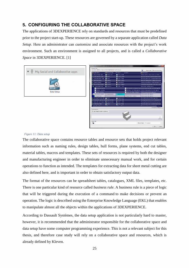
5. CONFIGURING THE COLLABORATIVE SPACE
The applications of 3DEXPERIENCE rely on standards and resources that must be predefined
prior to the project start-up. These resources are governed by a separate application called Data
Setup. Here an administrator can customize and associate resources with the project’s work
environment. Such an environment is assigned to all projects, and is called a Collaborative
Space in 3DEXPERIENCE. [1]
Figure 11: Data setup
The collaborative space contains resource tables and resource sets that holds project relevant
information such as naming rules, design tables, hull forms, plane systems, end cut tables,
material tables, macros and templates. These sets of resources is required by both the designer
and manufacturing engineer in order to eliminate unnecessary manual work, and for certain
operations to function as intended. The templates for extracting data for sheet metal cutting are
also defined here, and is important in order to obtain satisfactory output data.
The format of the resources can be spreadsheet tables, catalogues, XML files, templates, etc.
There is one particular kind of resource called business rule. A business rule is a piece of logic
that will be triggered during the execution of a command to make decisions or prevent an
operation. The logic is described using the Enterprise Knowledge Language (EKL) that enables
to manipulate almost all the objects within the applications of 3DEXPERIENCE.
According to Dassault Systèmes, the data setup application is not particularly hard to master,
however, it is recommended that the administrator responsible for the collaborative space and
data setup have some computer programming experience. This is not a relevant subject for this
thesis, and therefore case study will rely on a collaborative space and resources, which is
already defined by Kleven.

26
6. MODELLING
Regarding the case study which is the practical foundation of the thesis, the modelling part of
the process is an important stage. As mentioned, the 3D modelling applications of
3DEXPERIENCE is represented by CATIA. For ship design, three CATIA applications is
required in order to establish the 3D data for the ship unit. These three are called Space
Referential, Structure Functional Design and Structure Design and is included in
3DEXPERIENCE’s Marine & Offshore solution. This chapter will give a brief explanation of
the functions and interfaces of the above mentioned applications. Further, the methods applied
(app by app) to the case study will be explained.
Figure 12: Main modelling applications
Due to the high level of complexity of a ship’s unit/section, mistakes will most likely be made
during the design stage. Therefore it is crucial that the design is flexible enough so that it is
receptive to modifications/corrections without introducing a lot of extra work when edited.
Apart from establishing a 3D model of the vessel, the purpose of the modelling stage is to also
establish an Engineering Bill Of Materials (EBOM). The EBOM is defined as a structured list
of parts and assemblies that constitutes a product definition. It is a link between a part and its
sub-parts, containing “as designed” product information which are used later at the
manufacturing stage. [1]
It is not much to say about the environment of the modelling applications. However, they are
designed with an intuitive and flexible user interface in mind. A customizable toolbar provides
the user with all the necessary tools and commands. User assistance for each command/tool is
available as online help documentation, which can be accessed by selecting a command and
pressing the F1-key on the keyboard. The user assistance web page will then open in the users’
web browser. A personal user account11 has to be created in order to access this database.
11 DS Passport is a web based service for accessing support, documentation, forums, etc. in Dassault Systèmes
database

27
6.1. Space Referential
Before the modelling can start, a few important design parameters needs to be established.
These are reference plane systems. Most ships are designed relative to fixed distances between
decks transversal- and longitudinal frames. A reference plane system consists of planes which
are placed where design features like bulkheads and decks will be placed. The planes can then
be used as design supports for the applied design features.
Figure 13: Reference plane system configuration
With the Space Referential application, the user can easily establish the plane system by
introducing the length, width and height of the ship. Further, the distance between decks,
transversal- and longitudinal bulkheads are set. A plane system as shown in figure 14 is then
created (the ship model is only included for visual purposes)
Figure 14: Reference plane system
The plane system is also important when it comes to the naming of the design features. Upon
creation of the plane system, the application will add prefixes to all the planes, identifying them
as FRAME, LONG or DECK. For example: A transversal bulkhead placed on frame #29, will
automatically be given the name TBhd-Frame.29.

28
6.2. Structure Functional Design
The Structure Functional Design application is where the first structural design features is
applied to the conceptual ship design. The model created in this application is a very lightweight
and undemanding in terms of computing power. This is because only surfaces represent all the
features created, and the plate thickness is not visualized. The plate thicknesses is instead added
as an attribute for the feature. With such a lightweight model the time needed for creation,
editing and updating of design features is significantly reduced compared to a more traditional
approach where the plate thickness is included.
STEP I – Hull import
The first task on this stage is to import a representation of the already designed hull form. The
hull representation’s purpose is to act as a support for the shell panel that will be used in the
model itself.
Figure 15: Imported hull form used as shell panel support
STEP II – Decks and bulkheads
When the hull representation is established, bulkhead and deck plates can be created. These use
the planes in the reference plane system for support, and needs to be limited by either planes or
other design features (plates or sketches). Material, plate thickness and orientation is defined as
attributes. Also inclined/angled planes can be used for support.
Figure 16: Creating a panel (deck)

29
STEP III – Seaming/breaking of plates
Once all the fundamental plates are is placed, seams and breaks must be applied. This operation
can also be performed at later stages, but may cause difficulties related to the openings which
will be applied to the plates in STEP V.
Breaks are added where plates intersect, and once applied, the break will create new
independent plate objects. In this case, the transverse bulkheads is split by the longitudinal
bulkheads in order to maintain the ship’s longitudinal strength.
Figure 17: Splitting/breaking of plates (bulkhead)
Panels such as decks may have variable plate thickness along the surface due to placement of
heavy machinery or equipment. In that case the panel can be seamed, instead of broken. Unlike
breaks, the seam does not create new independent plate objects. Instead, the plate object will be
divided into smaller sections with a common plate object. The seaming function can use both
plates and sketches as splitting objects. Seams can also be applied to shell panels and bulkheads.
The crane capacity and maximum dimension of plates is also decisive when applying seams.
For the case study the tank top deck of the unit is seamed using a sketch.

30
Figure 18: Seaming of a plate (deck)
STEP IV – Stiffeners
Stiffeners is divided into different types according to what kind of plate they are attached to:
Shell stiffeners (longitudinal and transverse), transverse bulkhead stiffeners (vertical and
horizontal), longitudinal bulkhead stiffeners (vertical and horizontal), and deck stiffeners
(transverse and longitudinal). The type needs to be selected before placing the stiffeners on a
plate. Similar to creating plates, also stiffeners require both supports and limits. Planes is used
for support, and the limits (start/end point of stiffener) can be plate edges, planes, intersecting
plates, etc. Material, dimension, plate side, anchor point and orientation is defined as attributes.
Figure 19: Placing stiffeners
31
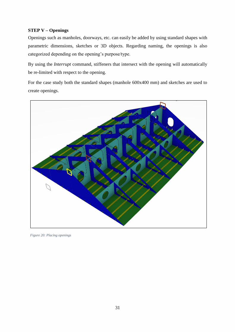
STEP V – Openings
Openings such as manholes, doorways, etc. can easily be added by using standard shapes with
parametric dimensions, sketches or 3D objects. Regarding naming, the openings is also
categorized depending on the opening’s purpose/type.
By using the Interrupt command, stiffeners that intersect with the opening will automatically
be re-limited with respect to the opening.
For the case study both the standard shapes (manhole 600x400 mm) and sketches are used to
create openings.
Figure 20: Placing openings

32
STEP VI – Brackets
Brackets is created from parametric features that should be available as resources in the
project’s collaborative space. Each project has a library of parametric bracket designs, from
which the designer can select the desired type. Brackets needs one support, and 2-4 limiting
features depending on the type. The parameters define the dimensions of the bracket.
Figure 21: Placing brackets
33
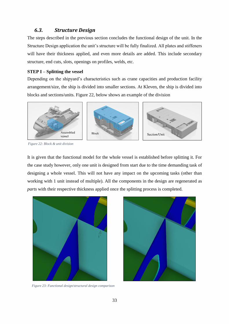
6.3. Structure Design
The steps described in the previous section concludes the functional design of the unit. In the
Structure Design application the unit’s structure will be fully finalized. All plates and stiffeners
will have their thickness applied, and even more details are added. This include secondary
structure, end cuts, slots, openings on profiles, welds, etc.
STEP I – Splitting the vessel
Depending on the shipyard’s characteristics such as crane capacities and production facility
arrangement/size, the ship is divided into smaller sections. At Kleven, the ship is divided into
blocks and sections/units. Figure 22, below shows an example of the division
It is given that the functional model for the whole vessel is established before splitting it. For
the case study however, only one unit is designed from start due to the time demanding task of
designing a whole vessel. This will not have any impact on the upcoming tasks (other than
working with 1 unit instead of multiple). All the components in the design are regenerated as
parts with their respective thickness applied once the splitting process is completed.
Figure 22: Block & unit division
Figure 23: Functional design/structural design comparison

34
STEP II – Finalizing the design
Once the ship has been split into the desired blocks and units, it is time to add the final details
to the design. The Structure Design application provide similar tools and functionalities as the
Structure Functional Design, but fully defines the features upon creation (thickness included).
Plates, openings, stiffeners, breaks/seams, brackets can also be applied here. The process is
however somewhat slower due to more demanding operations for the computer’s hardware, but
less demanding operations such as placing end cuts, slots and collars is a quick procedure. Once
all design features is included and the model is satisfactory it is time to add the connections
(welds).
STEP III – Adding connections
Regarding preparation for sheet metal cutting, defining the connections between the design
features is important in order for the software to understand where edge preparation, attachment
lines and shrinkage compensation is needed during the manufacturing preparation phase.
The Structure Design application features a tool called Weld Management. This is a smart tool
which allows the user to place apply welds manually, or let the software analyse and apply
welds automatically. The project’s database contains various types of welds which can be
applied where applicable.
For the case study the automatic approach is used. This is done by launching the Weld
Management tool and selecting the whole assembly. A list of all “touching” features in the
assembly will appear, showing the pilot part and the joined part. The weld type is then
automatically computed, and applied to the connection.
Figure 24: Weld management tool

35
7. MANUFACTURE PREPARATION
Before the design data is put into production it is necessary to prepare the assembly for the
manufacturing process. 3DEXPERIENCE’s DELMIA features a collection of applications
directed at the shipbuilding industry, called Marine and Offshore Manufacturing Planning
(MOG). For the manufacture preparation of plate cutting/sheet metal cutting, MOG features
two important and highly useful applications named Marine Manufacturing and Marine
Structure Fabrication. This chapter will give a general description of the applications, their
interface and further describe the methodology applied to the case study (app by app). The
methodology will be essential in achieving satisfying quality of the output data (sheet metal
cutting data).
Figure 25: Main manufacture preparation applications
The applications displayed in figure 25 governs digital manufacturing inside a specific
manufacturing environment. Theoretically, any production line, work floor or even a whole
factory can be experienced in a virtual environment. The applications encourage efficiency by
planning and simulating the production processes. This virtual environment allows the
manufacturer to easily address and adjust manufacturing processes so that difficulties and
delays may be avoided at an early stage.
The digital manufacturing environment is built on the theory of Manufacturing Bill Of
Materials (MBOM). The MBOM is derived from the EBOM (explained in chapter 6) and is
defined as a list of parts required to manufacture a part or an assembly. It contains all
information that is present in the corresponding EBOM such as find numbers12, reference
designators, unit of measure, quantity, description and usage. It also contains additional
manufacturing-specific information such as part relation and attachment. [1]
12 An ID that is used on drawings as a “bubble” callout.

36
The digital manufacturing environment is very well visualized due to the integration of 3D
navigation in the applications. The user has the option to review features either in the 3D
environment or more traditionally arranged hierarchically in the tree13. Figure 26 shows an
example of how an assembly breakdown structure is typically visualized in DELMIA.
Complete design unit
Tree
arrangement
3D
arrangement
Figure 26: Unit breakdown structure visualized in DELMIA
The intention of a breakdown structure is to establish a hierarchic “recipe” of how the unit can
be assembled, and imitates the facility’s assembly process. The steps of the assembly is directly
visualized in the 3D environment, where parts and sub-assemblies, called Manufacturing
Assemblies, are placed on square tiles. These represent the “branches” of the tree structure. The
structure is fully customizable by the user and can also be automatically generated.
A separate window called an auxiliary viewer will open on selecting the different
manufacturing assemblies. These can be selected either by navigating in the 3D environment
(clicking the “tiles”), or in the tree. The auxiliary viewer displays an enhanced/zoomed in view
of the manufacturing assembly’s contents, allowing the user to drag and drop the selected
parts/components onto the desired tile/manufacturing assembly. The auxiliary viewer also
features a powerful filtering tool, which is very convenient for larger assemblies with a large
number of parts.
13 A tree structure where content is arranged hierarchically containing product design specifications, logical blocks,
simulation specifications or manufacturing processes.

37
Figure 27: Auxiliary viewer
With a satisfactory breakdown structure established, the user is allowed to edit manufacture
features on the part level. These manufacture features includes shrinkage/distortion planning,
plate connection, orientation and alignment, attached stiffener/profile management, edge
preparation, etc. Some of these features needs to be according to the vessels building standard,
and has to be pre-defined in the data setup application, which were discussed earlier in chapter
5.
The breakdown structure also prove itself convenient regarding the extraction of data for sheet
metal cutting. This is due to clever naming and categorization capabilities the application
provide. With extensive assemblies it can be difficult to keep track of the large amount of parts
if the manufacturing assemblies and parts are not categorized or named properly.
It is also within these applications one applies the welds specified in the Structure Design
application in the modelling stage (CATIA).
In order to minimize the error and achieve high efficiency during the cutting preparation
process, it is necessary divide/sort the different parts of the assembly into an organized
assembly breakdown structure, and is a major part in the process planning step of the
manufacturing of a ship unit.
38
The next sections will focus on the case study, and how the features discussed above is applied.
7.1. Marine Manufacturing
The Marine Manufacturing application enables the user to use the design data created in chapter
6 to plan the manufacturing process of the unit. The ship unit is broken down into sub-
assemblies and parts, and is organized into a satisfying breakdown structure. As mentioned, the
unit basically is broken down in order to find the most advantageous way to assemble it at the
shipyard. Also factors such as crane capacities and facility arrangement is taken into
consideration when the breakdown is performed.
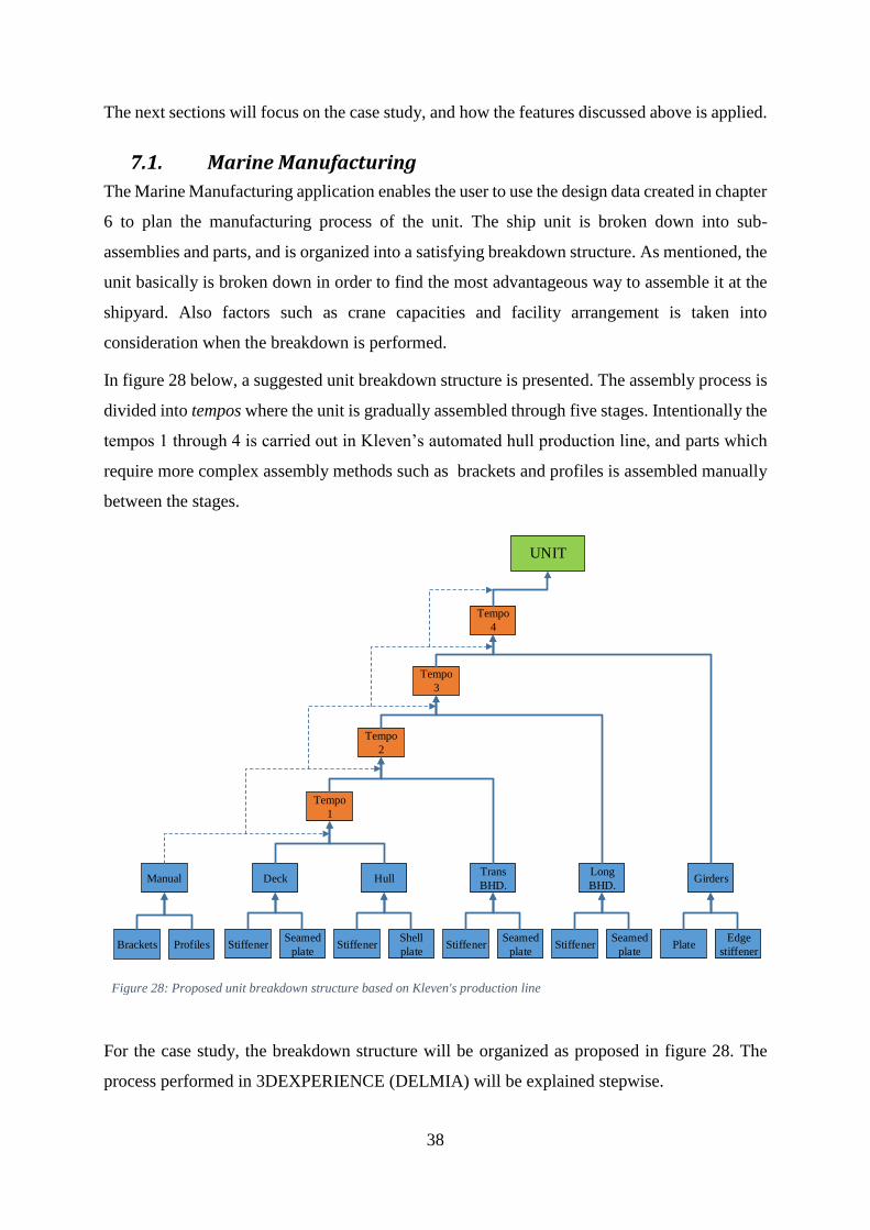
In figure 28 below, a suggested unit breakdown structure is presented. The assembly process is
divided into tempos where the unit is gradually assembled through five stages. Intentionally the
tempos 1 through 4 is carried out in Kleven’s automated hull production line, and parts which
require more complex assembly methods such as brackets and profiles is assembled manually
between the stages.
UNIT
Tempo
4
Tempo
3
Tempo
2
Tempo
1
Deck HullTrans
BHD.
Long
BHD.Girders
StiffenerSeamed
plate
Shell
plate
Seamed
plate
Seamed
plate
Edge
stiffenerStiffener Stiffener Stiffener Plate
Manual
ProfilesBrackets
Figure 28: Proposed unit breakdown structure based on Kleven's production line
For the case study, the breakdown structure will be organized as proposed in figure 28. The
process performed in 3DEXPERIENCE (DELMIA) will be explained stepwise.
39
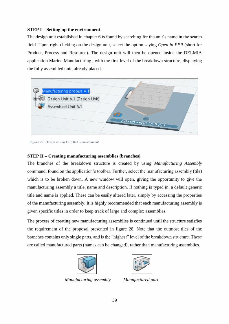
STEP I – Setting up the environment
The design unit established in chapter 6 is found by searching for the unit’s name in the search
field. Upon right clicking on the design unit, select the option saying Open in PPR (short for
Product, Process and Resource). The design unit will then be opened inside the DELMIA
application Marine Manufacturing., with the first level of the breakdown structure, displaying
the fully assembled unit, already placed.
Figure 29: Design unit in DELMIA's environment
STEP II – Creating manufacturing assemblies (branches)
The branches of the breakdown structure is created by using Manufacturing Assembly
command, found on the application’s toolbar. Further, select the manufacturing assembly (tile)
which is to be broken down. A new window will open, giving the opportunity to give the
manufacturing assembly a title, name and description. If nothing is typed in, a default generic
title and name is applied. These can be easily altered later, simply by accessing the properties
of the manufacturing assembly. It is highly recommended that each manufacturing assembly is
given specific titles in order to keep track of large and complex assemblies.
The process of creating new manufacturing assemblies is continued until the structure satisfies
the requirement of the proposal presented in figure 28. Note that the outmost tiles of the
branches contains only single parts, and is the “highest” level of the breakdown structure. These
are called manufactured parts (names can be changed), rather than manufacturing assemblies.
Manufacturing assembly Manufactured part

40
If the assembly does not have one or more of the listed features (girders, brackets, etc.), the
current manufacturing assembly (branch) can be neglected. However, if a standardized structure
is preferred for each project, simply leave the manufacturing assembly empty if no features falls
under the current category.
By accessing the auxiliary viewer explained in the previous section, one can simply drag and
drop design features onto their respective manufacturing assemblies (tiles). Once all features of
the assembly has been assigned to their correct manufacturing assembly, the breakdown of the
unit is completed. The manufacture planning can then be continued in the next application,
Marine Structure Fabrication.
Figure 30 shows how the breakdown structure of the designed unit in DELMIA. As mentioned,
leaving a manufacturing assembly empty has no impact on further work. As the figure shows
this design has no girders included, but the manufacturing assembly named Girders is added in
case these will be added in a design revision.
Figure 30: Unit with the applied breakdown structure – 3D and tree visualization

41
7.2. Marine Structure Fabrication
The final stage of editing the design unit in 3DEXPERIENCE is done in the Marine Structure
Fabrication application. This application allows the user to perform more complex production
planning. Preparations is made on the part level of the assembly, and covers shrinkage and weld
planning, edge preparation, marking and management of structural resources (e.g. pin-jigs).
Once all preparations is complete, commands for extraction of workshop documents such as
drawings (DXF) and plate representations (IGES, XML-code) can be executed. The extraction
of data can include fully defined assembly drawings of the unit, or more relevant in this case;
the plate contours/outline and marking for later import and processing in the nesting/CAM
software.
The appearance and layout of this application is very much similar to the Marine Manufacturing
application. The toolbar, however features a different set of tools, used specifically for the
addition of manufacturing features, managing structural resources and generating
documentation of the sub-assemblies and parts that are to be fabricated.
The following steps will explain how to apply the manufacturing features.
STEP I – Applying welds and updating the manufacturing assemblies
The welds applied to the unit in the Structure Design application is by default not loaded in the
Marine Structure Fabrication application. By launching the Weld Planning tool, the created
welds are applied to the manufacturing assemblies. The welds can be seen in the tree.
Once the welds are loaded, the manufacturing assemblies needs to be updated. This is done by
running the command called Update In-Process Models. This will prepare all the manufacturing
assemblies for the manufacturing features that will further be applied. Once the update is
complete, the appearance of the manufacturing assemblies will change, as seen in figure 31
below.
Figure 31: Appearance on updated manufacturing assembly

42
As shown in figure 31 different coloured lines appears upon updating the manufacturing
assemblies. The colour of the lines represent different types of features. These are as follows:
Colour Linetype Representation
Green Continuous Part contour
Pink Dashed Openings/cut-outs
Yellow Dashed Connection lines
Purple Continuous Attachment lines
Purple Dashed Alignment lines
Table 2: Linetypes in Marine Structure Fabrication
3DEXPERIENCE applies these manufacturing features automatically depending on how
“completed” the design are. For example, if the welds had not been applied correctly, the
stiffener’s attachment lines would not have been visible. However, these lines can be applied
manually by editing the features of the manufacturing assembly
STEP II – Shrinkage compensation
Shrinkage compensated parts are created by launching the Shrinkage Planning command. A
selection window requires selection of one or more manufacturing assemblies that are to be
shrinkage compensated. The command will create a “step” between the manufactured parts and
the first manufacturing assembly in the breakdown structure. This step will have the name
Shrinkage Part by default.
Figure 32: Adding shrinkage steps
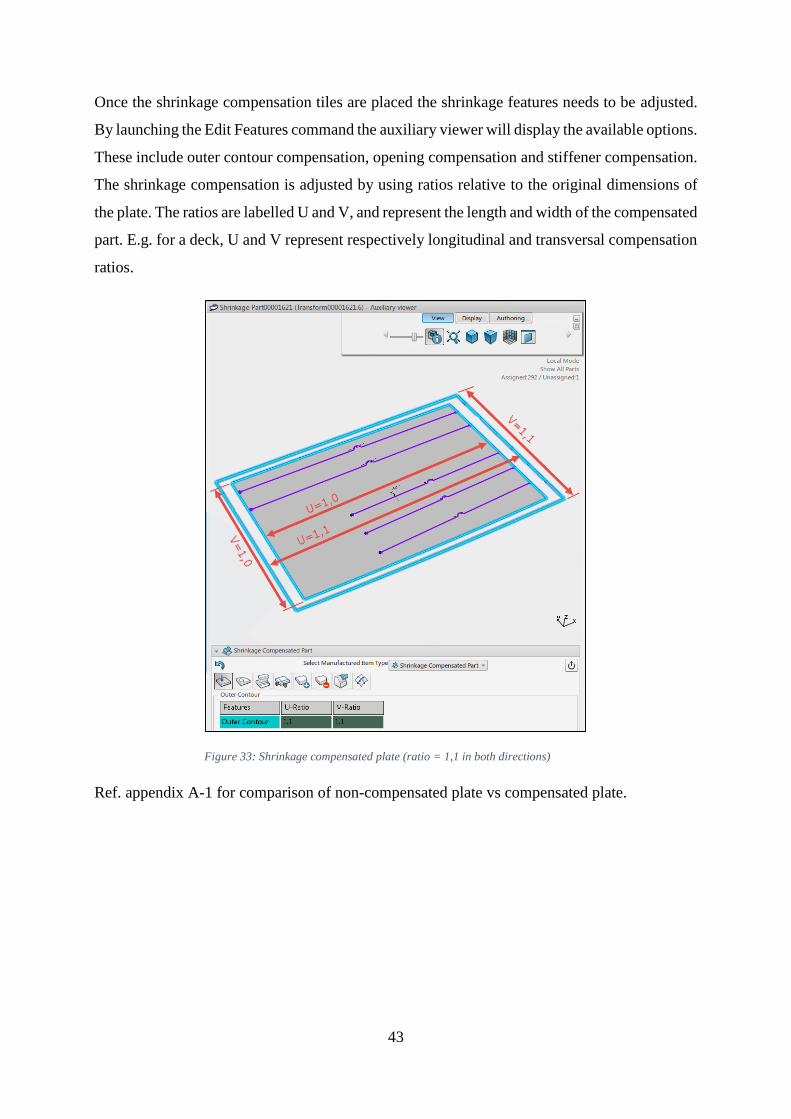
43
Once the shrinkage compensation tiles are placed the shrinkage features needs to be adjusted.
By launching the Edit Features command the auxiliary viewer will display the available options.
These include outer contour compensation, opening compensation and stiffener compensation.
The shrinkage compensation is adjusted by using ratios relative to the original dimensions of
the plate. The ratios are labelled U and V, and represent the length and width of the compensated
part. E.g. for a deck, U and V represent respectively longitudinal and transversal compensation
ratios.
Figure 33: Shrinkage compensated plate (ratio = 1,1 in both directions)
Ref. appendix A-1 for comparison of non-compensated plate vs compensated plate.
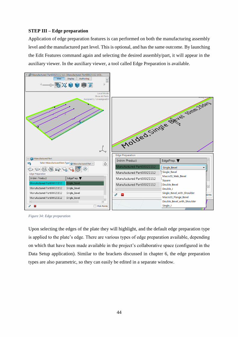
44
STEP III – Edge preparation
Application of edge preparation features is can performed on both the manufacturing assembly
level and the manufactured part level. This is optional, and has the same outcome. By launching
the Edit Features command again and selecting the desired assembly/part, it will appear in the
auxiliary viewer. In the auxiliary viewer, a tool called Edge Preparation is available.
Upon selecting the edges of the plate they will highlight, and the default edge preparation type
is applied to the plate’s edge. There are various types of edge preparation available, depending
on which that have been made available in the project’s collaborative space (configured in the
Data Setup application). Similar to the brackets discussed in chapter 6, the edge preparation
types are also parametric, so they can easily be edited in a separate window.
Figure 34: Edge preparation

45
STEP III – Editing and applying markings
The features of the assembly will have markings such as attachment lines and labels
automatically generated when features are applied. The automatically generated labels are often
generic, and does not provide much information. In that case they have to be edited. For
example; a stiffener may be labelled with only “Deck stiffener”. Then it will be more convenient
to give it a more informative label, for example “Deck Longitudinal Stiffener, HP100x8”. The
labels can be edited by using the Modify/Delete texts tool, when editing features in the auxiliary
viewer. This tools opens a separate window, displaying the concerned part or assembly. All the
visible labels can be edited, deleted and moved to a desired position. The changes are saved
upon closing the window.
Figure 35: Automatically generated labels
Figure 36: Customized labels
Labels is helpful information which can be included in workshop documentation. If included
in the plate cutting program, the labels can also be marked physically on the plates when they
are cut (by the cutting machine’s torch or marking tool). Typical marked labelling is
identification numbers such as position/part numbers or similar.
The attachment lines for stiffeners can be convenient to include on both in the workshop
documentation and physically on the plates. It will aid welders in placing the stiffener correctly
when assembling the panel. Similar to the labelling, these lines can also be included in the
cutting machines CNC program, and marked by the cutting machine’s marking tool.

46
8. DATA EXPORT & IMPORT FOR PROCESSING IN CAM SOFTWARE
The steps explained in the previous chapter concludes the manufacture preparation stage of the
process. The next task is to export the plate data into a format which is compatible the nesting
software Kleven intends to use (ALMA). This chapter focuses on the formats which can be
used when transferring data from 3DEXPERIENCE to ALMA. Chapter 3.4 explained that
ALMA can import formats with 2D, 3D and code interfaces. The file formats IGES (3D), DXF
(2D) and XML (code), and the methods used for export/import is explained and evaluated in
terms of complexity of the export method and the quality of exported data. For description of
export/import procedures see appendix A-2.
8.1. IGES
Initial Graphics Exchange Specification (IGES) is an ANSI based and vendor-neutral file
format designed for the exchange of 2D and 3D data between dissimilar CAD systems. Data
with this format can be full three-dimensional models with associated drawing views and
dimensions. [7]
3DEXPERIENCE can export parts into the IGES file format without problems. For a large ship
unit assembly consisting of many plates, the export process is very time demanding. This is
because each part needs to be opened in a separate model view and be exported one at the time.
ALMA is compatible with the IGES format. When a plate exported into the IGES file format
is imported into ALMA, the both the geometry and thickness of the plate is included.
This export format is suitable only for single plates. If an assembly is exported, ALMA is will
interpret the assembly as one solid, instead of an assembly of multiple parts. Manufacturing
features such as attachment lines, markings/labels and edge preparation will not be included in
the export, resulting in that ALMA only interprets the plate contour (including openings)
Plate model in
3DExperience
Plate model exported
to IGES format
Plate in IGES format
converted to DPR
format Figure 37: IGES representation

47
8.2. DXF
Drawing Exchange Format (DXF) is a 2D CAD data file format developed by Autodesk14.
Much like the IGES, the purpose of the format is to enable data compatibility between different
CAD software. The superiority of CAD software supports DXF, which allows users to
exchange drawings even if they are running different software. [8]
The downside of the files with the DXF-format extracted from 3DEXPERIENCE is that it only
includes 2D-geometry, and no plate thickness. This requires manual input of all plate
thicknesses upon import. The format is however “out-of-the-box” compatible with ALMA,
which means that no further processing before import to ALMA is necessary.
3DEXPERIENCE has features a function which allows extraction of multiple DXF-files of the
plates in an assembly in one operation. This makes the DXF-file extraction from
3DEXPERIENCE a lot more efficient than the extraction to the IGES-format. This format
includes markings/labels and attachment lines, but due to the lack of thickness it does not
include edge preparation, other than the labels describing the feature. Yet, ALMA features
simple functionality to apply edge preparation manually, so this is not a problem.
The labelling of the plates with for example identification numbers will provide the necessary
information such as plate thickness and plate material. The information is located under the
specific identification number in the workshop documentation (typically the bill of materials).
The batch-extraction of data makes this method very efficient compared to the time demanding
method used to export plates in the IGES format. The exported files are lightweight in terms of
file size, and the whole export process is a fairly rapid operation.
Plate model in
3DExperience
Plate model exported
to DXF format
Plate in DXF format
converted to DPR
formatFigure 38: DXF representation
14 A company that makes software specialized for the architecture, engineering and construction industry
(AutoCAD, Inventor, etc.)

48
8.3. XML
Extensible Markup Language (XML) is a markup language that defines a set of rules for
encoding documents in a format which is both human-readable and machine-readable. The
design goals of XML emphasize simplicity, generality and usability across IT-platforms. The
format is based on text supported by Unicode. Although the design of XML focuses on
documents, it is widely used for the representation of arbitrary data structures. However,
representations of CAD geometry is not very common, but it is possible. [9]
Within the data setup of 3DEXPERIENCE it is possible to add a special XML generator. This
generator extracts XML-files of any selected plate of an assembly or sub-assembly, and
includes information about the time of extraction, plate identification and name, material, plate
thickness, markings/labels and most importantly; a representation of the plate geometry
(contours). This is very convenient because ALMA has an integrated function which can import
this kind of XML representation. The software interprets the code in the document, and returns
the contour of the plate, including markings. DPR files are automatically created from the XML
and placed in an automatically generated project library.
Also here, as with the DXF, edge preparation is not applied to the plate, but the label describing
the feature is included.
Also this methods allows export of multiple parts in one operation, making it a very efficient
method for transferring data between the software.
Plate model in
3DExperience
Plate model exported
to code representation
(XML)
XML representation
converted to DPR
formatFigure 39: XML representation

49
9. CAM PROCESSING
With all data is successfully transferred from 3DEXPERIENCE to the DPR format (required in
ALMA), the work in 3DEXPERIENCE is completed and further processing is to advance in
the CAM software, ALMA.
The CAM processing is done in five steps, given that the import explained in appendix A-2 is
done. The steps involve part preparation, launching order creation, nesting, cutting sequence
creation, and NC program and workshop document creation.
This chapter will explain the processing method through steps I to V in ALMA, where the
design from the case study is used as input data.
STEP I – Preparing parts for processing
Before the processing can begin some modification may be required. The data exported from
3DEXPERIENCE is not always completely as desired and parts may require some “cleaning”.
The cleaning involves removing excessive labelling (markings), closing open curves and
trimming away unwanted lines. Cutting lines may also be mistaken for marking lines, and
opposite. These issues is easily fixed in the Drafter application.
Edge preparation is also applied at this stage, and is applied according to the edge preparation
information labelled on the plate. By default these informative labels are set as Marking. These
can also be set to Text, so that they are not physically marked on the plate.
As figure 40 shows, the export has included some of the unwanted features discussed above.
Figure 41 shows the “cleaned” version of the same part where edge preparation is added, curves
are closed, overextended lines are trimmed and excessive markings removed (marking
information is turned into text which is only visible in the DPR).
Figure 40: Unedited geometry

50
NOTE: Remember to save the modifications frequently!
These modifications must be performed on all parts (where necessary) of the assembly before
advancing to the next step.
STEP II – Creating the launching order
Launching orders is needed for separating parts with different thickness or material quality. In
the launching order, raw material (sheets) is added and configured (material and dimensions).
A standard dimension on sheet metal for cutting is selected as 8000x3500 mm, material grading
NVA36.
Launching orders are created by selecting the Launching Order icon, and simply press INS
(insert) on the keyboard. The New launching order-window is displayed. The launching order
is named according to plate thickness. Once created, the new launching order will appear under
the Launching Order-category in the tree with the sub-categories: Parts, sheets and Kit.
Figure 41: "Cleaned" geometry
Figure 42: Creation of a launching order
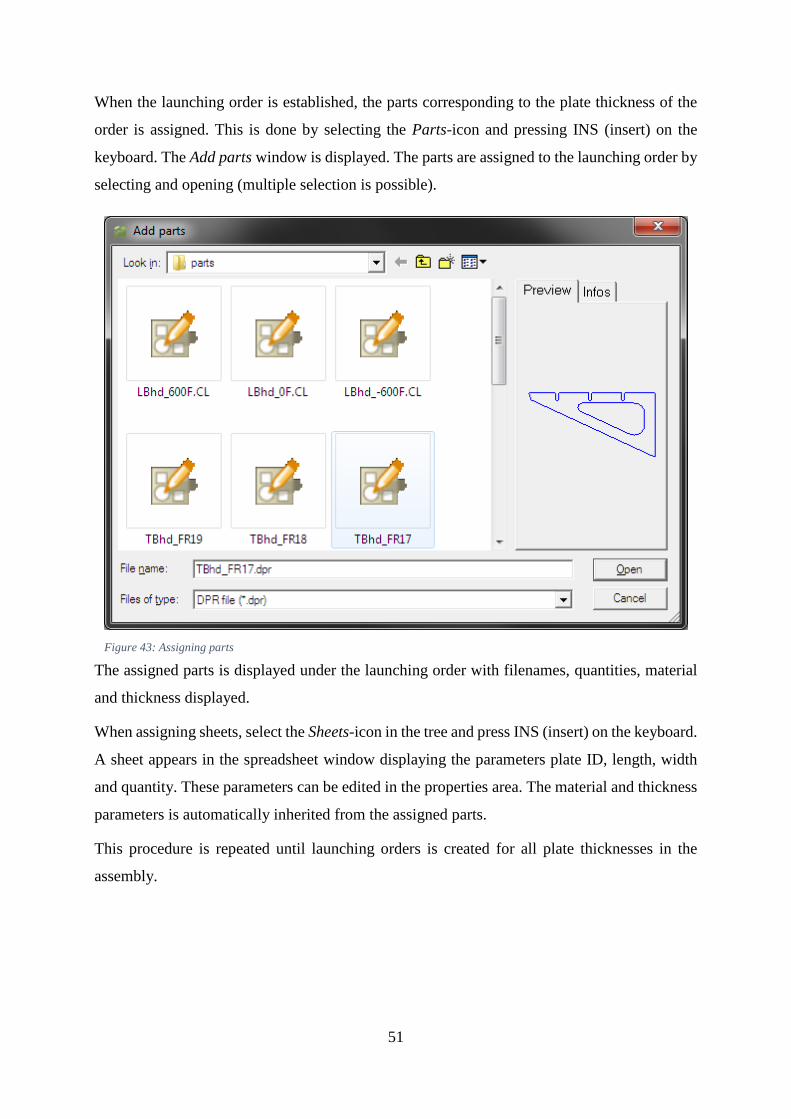
51
When the launching order is established, the parts corresponding to the plate thickness of the
order is assigned. This is done by selecting the Parts-icon and pressing INS (insert) on the
keyboard. The Add parts window is displayed. The parts are assigned to the launching order by
selecting and opening (multiple selection is possible).
Figure 43: Assigning parts
The assigned parts is displayed under the launching order with filenames, quantities, material
and thickness displayed.
When assigning sheets, select the Sheets-icon in the tree and press INS (insert) on the keyboard.
A sheet appears in the spreadsheet window displaying the parameters plate ID, length, width
and quantity. These parameters can be edited in the properties area. The material and thickness
parameters is automatically inherited from the assigned parts.
This procedure is repeated until launching orders is created for all plate thicknesses in the
assembly.

52
Figure 44: Created launching orders with assigned parts and sheets

53
STEP III – Nesting
Nesting is a key procedure of the CAM processing. ALMA provide a powerful nesting tool,
believed to be one of the most efficient and optimal on the market.
Nester is the tool used for this operation, and is found in the application window of ALMA.
Once a launching order is selected and Nester is launched, the application’s window will appear
displaying the 1st empty sheet in the top window and the assigned parts (including quantity) in
the window below.
Figure 45: Launching order loaded in Nester
The nesting process can be performed both manually and automatically. In this case, automatic
nesting is used. It is possible to perform complete the nesting process almost instantly, but then
the application has no time for optimization. Therefore, before initiating the automatic nesting
the application is given a maximum of 60 seconds for optimization. This time value is entered
in the parameters of the optimization tool, which must be active during the nesting process.

54
Once the optimization time value is set, the automatic nesting is initiated by executing the
automatic nesting command. It is possible to nest on one sheet at the time, or on all sheets at
once (one operation). In this case, the nesting on all available sheets is perfromed in one
operation.
Once the nesting process starts it will take approx. 60 seconds for both the nesting and
optimization to complete. A popup window indicates the progress.
When the nesting process is complete the results can be reviewed. Information available is
number of nested parts, remnant (%), used sheets. The nesting itself is displayed in the main
window.
Figure 46: Nesting results
Once a satisfying nesting result is achieved, select File – Save, and close the application. The
same procedure is performed on all launching orders.

55
STEP IV – Cutting sequence planning
After nesting, sequencing is the second most important step in the part machining and cutting
preparation. Sequencing, which precedes the numerical command (NC) program generation,
specifies the cut sequence, which is basically the order in which nested parts are to be cut.
Support bridges15 and connections are also applied here.
The application Pathfinder allows both automatic and manual application of the cutting
sequence. Once a cutting sequence is applied, Pathfinder also allows simulation of the sequence
and adjusting the results if necessary.
Pathfinder is launched by selecting the Pathfinder-icon in the application window. The selected
launching order including the corresponding nesting file(s) is displayed in the Pathfinder
window. By default, a sequence is already applied once the application is launched.
Bridges is the first feature that is applied to the sequence. Bridges can be placed both manually
and automatically. These allows for cutting of multiple parts in one operation, and helps
reducing sheet piercing, heat development and machining time. By default, bridges are applied
automatically, but can be modified manually.
15 A piece of material connecting two or more parts, allowing cutting of multiple parts in one operation. This
minimizes sheet piercing, time and energy consumption, heat.
Figure 47: Bridges applied
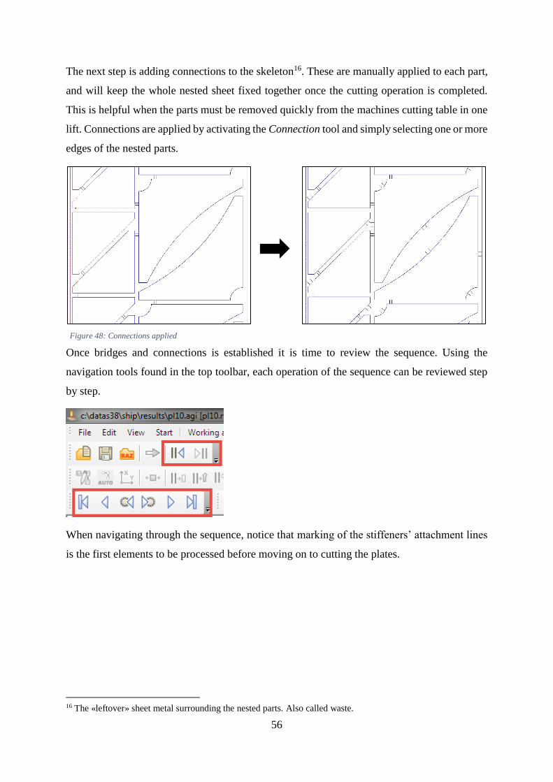
56
The next step is adding connections to the skeleton16. These are manually applied to each part,
and will keep the whole nested sheet fixed together once the cutting operation is completed.
This is helpful when the parts must be removed quickly from the machines cutting table in one
lift. Connections are applied by activating the Connection tool and simply selecting one or more
edges of the nested parts.
Once bridges and connections is established it is time to review the sequence. Using the
navigation tools found in the top toolbar, each operation of the sequence can be reviewed step
by step.
When navigating through the sequence, notice that marking of the stiffeners’ attachment lines
is the first elements to be processed before moving on to cutting the plates.
16 The «leftover» sheet metal surrounding the nested parts. Also called waste.
Figure 48: Connections applied

57
Figure 49: Default cutting sequence
Once a satisfactory cutting sequence is established, the sequence is simulated. While
simulating, the software will automatically generate the NC-program. This has to be done
separately for each nested sheet in the launching order.
Initiate the simulation by selecting the Post Processor - Simulation-icon found on the top
toolbar. The progress throughout the sequence is visualized by the tool path.
When the simulation is completed, save the sequence and close the Pathfinder application. The
NC-program is found under NC files in the tree in ALMA’s main window and can be reviewed
and edited in Notepad (right click on file – Open in Notepad). A NC-program viewer can also
be used to review the program.
STEP V – Generate workshop documents
Workshop documents can be created from the launching orders. These hold information about
basically the whole launching order such as nested parts, sheet dimensions, NC-program
number, cutting length, machining time, bevels, etc.
The document is automatically created by selecting a launching order, and launching the
application DocViewer. See appendix A-3 for a generated workshop document.

58
9.1. Post processing the NC-program
To cut parts from a sheet metal plate using a CNC cutting machine, regardless of cutting
technology, the machine has to be programmed with the path of the desired shape or nest of
shapes. Most parts are originally designed using a CAD software such as AutoCAD,
SOLIDWORKS, CATIA, or similar software where one can export data in a CAD format. But
the exported CAD data cannot be sent directly to the CNC cutting machine without proper
processing. First of all, the data has to be processed by a nesting software, which again generate
the NC-code. This generated NC is somewhat “generic”, and is unreadable to the human eye.
For the NC to be readable, it has to be translated into a language which both the machine and
the programmer can understand. G-code is the most common language, and is described in
section 3.2 earlier in the report.
The “raw” NC-program obtained from the CAM processing in ALMA, is of the generic type,
and needs processing. This output is not configured for any specific machine, and does not
follow the correct syntax.
Figure 50: Raw NC-program generated in ALMA

59
A NC-program viewer can however ensure that the required information is included in the code.
The software Essi Viewer is here used to confirm that the program satisfies the contents of the
generated NC-program
Figure 51: NC-program reviewed in Essi Viewer
Green lines represent cutting, yellow represent marking and red represent rapid torch
positioning.
In ALMA’s Resource Manager it is possible to configure the software to generate machine
specific NC-programs in G-code that is directly compatible with the cutting machine’s interface
and syntax. This is called post processing, and the program performing the operation is called
a post processor. Through dialogue with the distributor of ALMA, it was stated that
development of a post processor is done in cooperation with ALMA and the customer, provided
that the customer has purchased the software (in this thesis a free trial version has been used).
It is also possible to run the NC-program through post processor from an external software
provider. The cutting machine vendors usually offers both nesting and post processing software
alongside with the machines they distribute.

60
10. DISCUSSION
This chapter discuss the resulting method reached in the preceding chapters. In particular, the
discussion will focus on three areas: Firstly the methods concerning establishing a design,
planning the assembly and manufacture preparation in 3DEXPERIENCE. Secondly the
challenges around data export and import. Finally the CAM processing of the data in ALMA.
10.1. Design , assembly planning and manufacture preparation
The data creation during this project is performed using Dassault Systèmes’ 3DEXPERIENCE
as both a design and digital manufacturing tool, respectively CATIA and DELMIA. A more or
less realistic design model is established, including the structural details which is commonly
found in a ship unit. However, in order to achieve an even more realistic case, a functional
design of the whole vessel can be established before moving on to the Structure Design stage.
This would have enlighten possible challenges upon the block and unit division of the model.
In this thesis only a single unit of a vessel is designed, making the division process absent.
Slots and collars are important design features that are to be included in any structural design
model. These are parametric features available in various types, and is found in the project’s
resource library. However, in Kleven’s design environment these design features are not
working properly at the moment, because they have not been configured yet. They should have
been included in the established design, and would have added some extra complexity to the
exported data. Yet, custom made slots is included. These are created with sketches, which is a
very time consuming process. However, they has the same function as the intentional
parametric slots. Collars can also be created using this method (even more time consuming).
Other than these issues, the design process in 3DEXPEIENCE is very intuitive and easy to
operate. The user interface is simple, yet advanced enough for taking on the demanding task of
designing a vessel, and includes the tools and applications to apply all elements required.
The well visualized appearance and simple user interface is present also in 3DEXPERIENCE’s
other applications as well, which can be seen upon the transition from CATIA to DELMIA. In
DELMIA the assembly planning and manufacture preparation is performed. The assembly
planning can be performed automatically, but it is recommended that this is done manually in
order to establish the breakdown structure or assembly procedure which replicates the real life
procedure at the shipyard. If an automatic approach is preferred, the algorithm/program creating
the breakdown structure needs to be altered to output a more desirable structure, standardized
for the company’s newbuilding projects and their production facility.
61
When applying manufacturing features, some of the weak sides of 3DEXPERIENCE is
revealed. The software occasionally crashes, and needs to be restarted. Upon restarting a restore
function offers to restore the previous session. This function does not work, and the software
crashes upon restoring as well. If saving the session is done frequently, this is not a big issue.
However, if not saved, repeating a great amount of the work is the only option. What causes
the crashes is unknown. It may sometimes be experienced upon deleting features, exporting
data or simply just occur.
The shrinkage planning tool may seem a bit “simple”. This considering the compensating is
done by adjusting ratios or the proportionality of the plate size. Integrating a smarter tool which
considers the variables of applied heat, material and dimensions, and then calculates the
required compensation may be more convenient.
Some visual “bugs” is also experienced. Upon applying shrinkage compensation on a plate, the
change is not visualized on the plate’s geometry. But when comparing the original with the
compensated plate (measuring) it is confirmed that the function works as intended.
Apart from these issues, the used digital manufacturing tools in 3DEXPERIENCE performs
very well.
10.2. Data export/import
The manufacture prepared design data is exported from 3DEXPERIENCE using built in tools.
The first challenge is to identify the data formats which is compatible with both
3DEXPERIENCE and the CAM software (ALMA Act/Cut). These has proven to be IGES (3D),
DXF (2D) and XML (code). The three formats has been evaluated in terms of data quality and
the complexity of export/import.
IGES export proved to be the least advantageous. Firstly, the process of exporting is highly
complex, and very time demanding due to the lack of batch export options. Upon import to
ALMA, manufacturing features is not included either. Yet, as this is a 3D format, the plate
thickness is included.
Export in the XML format is a more promising story. Marine Structure Fabrication features a
tool intended for the export in this format, and ALMA features a corresponding tool for the data
import. The whole export operation can be performed in one operation, making it a very
efficient method. Import to ALMA is also performed in one operation, and at the same time the
data is converted to the DPR format (native file format in ALMA). Plate thickness is applied
automatically. However, the quality of the imported data is not satisfactory. Many plates are

62
missing contour, and only showing openings and text marking. Yet, parametric plates such as
brackets is fully defined upon import, which is a bit strange. This may be due to a faulty XML
code generator, which needs to be re-programmed.
DXF proved to be a satisfying export format regarding the data transfer. Also here Marine
Structure Fabrication features a tool for exporting DXF representations of the plates. With a
multiple selection option and lightweight format, the export process is very efficient. The
quality of the data upon import is currently far better than the other formats, but the plate
thickness needs to be applied manually. Some “cleaning” of the imported data is required, such
as removing excessive marking and lines.
10.3. CAM processing
The CAM processing is as mentioned performed in the software ALMA Act/Cut. Much like
3DEXPERIENCE, ALMA offers features applications for various types of technologies, but
for Kleven’s case, plasma cutting is the applicable one. Three applications within this
technology is relevant: Drafter, Nester and Pathfinder.
Drafter is a drafting tool used for import of DXF data, “cleaning” the geometry, applying
thickness and material, and finally saving data in the DPR format. This is a bottleneck process
because all parts of the assembly needs undergo this procedure. However, an algorithm or a
program may be developed to automatically transform the DXF files into DPR
Nester is the where parts with common thickness and material is nested onto their respected
steel sheets. Powerful algorithms ensures that parts are automatically nested in the most optimal
manner, reducing the raw material waste to a minimum. Manual nesting is also an option, and
is recommended in some specific cases.
Pathfinder allows the user to plan the cutting sequence, apply bridges and connections. A
cutting sequence that is the least time consuming and heat developing is applied automatically.
The sequence can also be applied and edited manually. Further, a simulation of the sequence is
launched, and the NC-program and workshop documentation is generated at the same time. The
NC-code output is not readable as is, and will require post processing in order to be used as
machine input. This can be done by modifying ALMA, adding an internal post processor within
the software. ALMA’s distributor informs that this is a task usually performed by their company
once the customer has purchased their product.

63
10.4. Further work
Kleven is currently still running pilot projects on implementing the 3DEXPERIENCE platform
and it is reasonable to believe that it will take some time before they are ready to fully operate
the platform in live newbuilding projects. This means that they will still be working with
purchased design data for a few more years. If this data can be prepared for manufacturing
internally, Kleven will only have to purchase the design, and not the manufacturing data (NC
programs and documentation). Eliminating this major cost element will cause both economic
benefits, and reduce the work of re-processing unsatisfactory data (common with purchased
nesting data).
Manufacture preparation of data that is not native to 3DEXPERIENCE has not yet been tested.
However, purchased data has been used for robot programming for a few years at Kleven. This
is performed in a former version of DELMIA, and has proven to be a feasible solution. With
that in mind, it is absolutely worth the effort to investigate the options of performing
manufacture preparation on this kind of data.

64
11. CONCLUSION
This thesis has focused on developing an applicable method or procedure for design, digital
manufacturing and CAM processing. This in order to establish the information required for the
initiation of sheet metal cutting on the work floor. Through practical research in form of a
realistic case study, focused on Kleven Shipyard’s current situation, a descriptive method has
been developed. Essential variables such as planning for welding distortion, informative
marking of parts and edge preparation has been taken into consideration.
Also data management has been investigated and evaluated. This concerns the export and
import of file formats that have compatibility between the respective software used. Three
formats were evaluated, IGES, DXF and XML. IGES proved to be the least beneficial file
format, due to the complexity of the export operation and lack of included information in the
data. Regarding the XML format, a malfunction in the code generator prevented any applicable
results (however, a successful export using this method has been demonstrated by DS during
the workshop at Kleven). The DXF format proved to be the most feasible export format. It
includes sufficient information and the export of data is a rapid operation.
The results of implementing the methods described in this thesis will bring Kleven one step
closer to performing the respective processes more independently. As the company is today
relying on purchased data from vendors, the method will also contribute to economic benefits
by reducing the cost of purchasing these services. At the same time it will contribute in
educating personnel on the technology and tools the company currently possesses.
In the current case of sheet metal cutting, Kleven has had troubles with the purchased NC-
programs. The nesting has been of a poor quality, forcing them to redo the procedure internally
by using a software called Nestix (compatible with the vendor’s design data). By implementing
the presented method, it is expected that CAM processing in ALMA will bring more
desirable/successful outcome, because it is to be performed by internal personnel which is
familiar with Kleven’s technology, tools and procedures.
The work performed throughout this thesis has been highly educational for the candidate, and
has enlightened areas of digital manufacturing which has earlier been unclear. The resulting
method that is established will hopefully help with contribution to economic benefits and
increased knowledge not only for Kleven and the shipbuilding industry, but also other instances
or industries that may consider 3DEXPERIENCE and ALMA as software solutions.
65
BIBLOGRAPHY
[1] Dassault Systèmes, User Assistance Manual, 3DEXPERIENCE R2015x., 2016.
[2] Alma CAM Software, Act/Cut Learning Guide, 2011.
[3] D. J. Eyres and G. J. Bruce, “Welding distortion,” in Ship Construction, 7 ed., Butterworth-
Heinemann, 2012.
[4] Wikipedia, contributors, “Trial and error,” 2016. [Online]. Available:
https://en.wikipedia.org/wiki/Trial_and_error.
[5] UNSW Australia, “Student support: What is a Case Study?,” 2013. [Online]. Available:
https://student.unsw.edu.au/what-case-study.
[6] Dassault Stystèmes, “Marine & Offshore - Thriving in competitive seas,” 2016. [Online].
Available: http://www.3ds.com/industries/marine-offshore/overview/.
[7] PCmag Encyclopedia, “Definition of: IGES,” 2016. [Online]. Available:
http://www.pcmag.com/encyclopedia/term/44758/iges.
[8] A. Whitton, “Tutorials: AUTOCAD FILE FORMATS,” 2015. [Online]. Available:
http://www.mycadsite.com/tutorials/level_4/autocad-file-formats-4-4.htm.
[9] Wikipedia, contributors, “XML,” 2016. [Online]. Available:
https://en.wikipedia.org/wiki/XML.

66
APPENDIX
A-1 Comparison of shrinkage compensated and original plate
The comparison is done on exported plate data (DXF), and is compensated with a factor of 1,1
in both U and V direction. The comparison is done in AutoCAD 2016.
Figure 52: Original plate (no compensation)
Figure 53: Shrinkage compensated plate

67
A-2 Process description: Export and import of parts
IGES export from 3DEXPERIENCE
1. Make sure the current workbench is DELMIA - Marine Structure Fabrication.
2. Select the desired manufactured part in the breakdown structure. Note: ALMA does not
interpret assemblies/sub-assemblies correctly, so single parts must be selected
(manufactured parts).
3. Select the command called Open Resulting Product. The part will open in a separate
tab.
4. Select the Share function followed by Export.
5. When the export window appears, select IGES3D as format. The file can be exported
to a local directory, or an exchange space (cloud). Select OK. Note: The name of the
file will be assigned a default name, and it is recommended to change this to a more
project specific name.
6. Once the operation is completed, the exported data is found in the target location.

68
IGES import to ALMA
1. Launch ALMA Act/Cut software. In the main window select the Explorer tab and
navigate to the export target location. Make sure file type is set to IGES. The exported
file will appear in the Explorer window.
2. Right click on the IGES-file, and select Open with → Drafter. The drafter application
will start. The part is shown in Drafter.
3. If needed, perform modifications of the part in Drafter. When ready, select File → Save
As. Select desired save directory and type in a desired identifier (name) for the part, and
select DPR as filetype. The material and thickness is automatically applied. Click save.
The DPR file is created and saved under the selected directory.

69
DXF export from 3DEXPERIENCE
1. Make sure the current workbench is DELMIA - Marine Structure Fabrication.
2. Select the command called Extract DXF Documents. A selection window will appear.
3. Select the desired manufacturing assembly (sub-assembly) or manufactured part (single
plate) in the breakdown structure. Multiple selections is possible. Specify the directory
path where the exported files shall be saved, and click the Launch-button
4. Once the operation is completed, the exported data is found in the target location (path).

70
DXF import to ALMA
1. Launch ALMA Act/Cut software. In the main window select the Explorer tab and
navigate to the export target location. Make sure file type is set to DXF. The exported
file will appear in the Explorer window.
2. Right click on the DXF-file, and select Open with → Drafter. The drafter application
will start. The part is shown in Drafter.
3. If needed, perform modifications of the part in Drafter. When ready, select File → Save
As. Select desired save directory and type in a desired identifier (name) for the part, and
select DPR as filetype. Apply material type and thickness manually. Click save.
4. The DPR file is created and saved under the selected directory

71
XML export from 3DEXPERIENCE
1. Make sure the current workbench is DELMIA - Marine Structure Fabrication.
2. Select the command called Plate Job Order List. A selection window will appear.
3. Select the desired manufacturing assembly (sub-assembly) or manufactured part (single
plate) in the breakdown structure. Multiple selections is possible. The fully assembled
unit can also be selected, if all plates are to be exported. The selected plates will appear
on the list, showing the plates’ name, ID number, material, thickness, etc. There is no
selection of target directory for this function. When ready, select Launch.
4. Once the operation is completed, the exported data is found under the directory:
C:\Users\Username\AppData\Local\DassaultSystemes\CATTemp\ALMA\Project title.
Also a spreadsheet containing information on the exported data is automatically
generated and placed in the same directory.

72
XML import to ALMA
1. Navigate to the project’s XML export location. Select all files and copy (include
CopyOut.csv). Navigate to the following directory and paste all copied files:
C:\Datas38\import.
2. Launch ALMA Act/Cut software. Run the application named Import CATIA, found in
the application area. The application will start importing the XML files, and
automatically creates generates the DPR files.
3. The import progress is shown in a popup window. If errors occur upon importing, an
error message is displayed together with a log file.
4. The generated DPR files are now located under the following directory:
C:\Datas38\Project title. The imported XML files are moved to the directory:
C:\Datas38\import\treated.
5. In the main window select the Explorer tab and navigate to the import target location.
Make sure file type is set to DPR. Open the DPR files in Drafter and make necessary
modifications. Save files once the data is satisfactory.

73
A-3 Generated workshop document (ALMA)

74
75
A-4 Article draft: Creating and processing ship design data for sheet metal cutting
Tobias Fiskum
Norwegian University of Science and Technology, Department of Maritime Technology and
Operations
Abstract
The process from the creation of a design to the initiation of production in the shipbuilding industry is
a complex procedure. Recently more and more shipyards has started moving away from traditional
shipbuilding methods. Production processes are being automated, and engineering and design
digitalized.
Kleven is a company that is investing a great amount in modernization and automatization of the
shipyard’s production facility, and is currently working on moving much of the engineering work onto
the digital PLM platform, 3DEXPERIENCE. The development is still a project in progress, yet much
is successfully operational today.
One of the remaining challenges is to figure out to connect 3DEXPEIENCE with the process of sheet
metal cutting on the production floor. Through the development of work methodology for modelling,
digital manufacturing and CAM processing of a ship design data, where the output is documentation
intended for the sheet metal cutting of plates; the initial stage of hull production.
By using state of the art digital tools, a best practice is developed, bringing Kleven one small step
closer to their goal of reducing manual labour in the production and to gain highly valuable
competitive benefits.
1. Introduction
Kleven is a Norwegian shipbuilding company that has for many years outsourced most of the
design and engineering tasks involved in the shipbuilding process. Kleven’s current approach
is to purchase complete design packages from external design companies. Apart from drawings
and 3D data, these packages contains NC programs for sheet metal cutting, completed with
nesting17 and sequencing18. This cutting documentation has proven to be unsatisfactory, and the
work often has to be re-done internally by Kleven’s production department.
Kleven is currently investing a great amount of funds in the development and modernization of
their production plant and engineering platform. By implementing the PLM tool
3DEXPERIENCE developed by Dassault Systemes, Kleven is thriving to perform more of the
design and engineering internally. The implementation is still in development, yet much is
17 Optimized arrangement of parts to be cut from a sheet of metal. The parts are arranged within the boundaries of
the sheet, with a goal of minimizing remnants and waste. 18 Planning of the cutting sequence. Preferably optimized in terms of short machining time and minimizing of sheet
piercing.

76
operational today. One of the remaining objectives is to eliminate the extra work following the
unsatisfactory sheet metal cutting documentation.
This paper focuses on a best practice method on how the shipyard can create ship design data
internally, and further process the data so that it can be used as documentation for the sheet
metal cutting process. The method is to be compatible with the digital engineering tools that is
available at the shipyard; 3DEXPERIENCE as the PLM solution, and ALMA Act/Cut as the
CAM19 solution.
2. Overview of the digital engineering tools
Dassault Systemes’ 3DEXPERIENCE is a state of the art engineering platform. Referred to as
a business experience platform, the software is directed towards a variety of industries such as
transportation, aerospace, marine & offshore, industrial equipment, finance, consumer goods
retail, just to mention a few. 3DEXPERIENCE provide its industry-leading applications under
the brands CATIA (design and engineering), DELMIA (manufacturing and production),
SIMULIA (simulation and analysis) and ENOVIA (cloud based data management20).
3DEXPERIENCE features a unique user interface, consisting of applications provided by
hosted services. These tied together in a single interface, allowing the user to operate all
applications in the same digital environment.
Act/Cut is a CAM software developed by ALMA that specializes on cutting technologies. It
offers compatibility with various shipyard-dedicated design solutions and is able to import 2D-
, 3D- and coded file formats. A simple, yet advanced user interface allows the user to efficiently
perform editing, nesting, sequencing and simulation of the sheet metal cutting procedure.
Workshop documentation and NC programs is automatically generated by the software.
19 Computer Aided Manufacturing 20 “On-demand computing”: Internet based storage solutions which provide users and enterprises with various
capabilities to store and process their data.
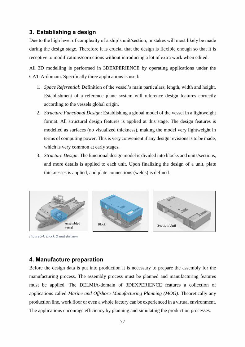
77
3. Establishing a design
Due to the high level of complexity of a ship’s unit/section, mistakes will most likely be made
during the design stage. Therefore it is crucial that the design is flexible enough so that it is
receptive to modifications/corrections without introducing a lot of extra work when edited.
All 3D modelling is performed in 3DEXPERIENCE by operating applications under the
CATIA-domain. Specifically three applications is used:
1. Space Referential: Definition of the vessel’s main particulars; length, width and height.
Establishment of a reference plane system will reference design features correctly
according to the vessels global origin.
2. Structure Functional Design: Establishing a global model of the vessel in a lightweight
format. All structural design features is applied at this stage. The design features is
modelled as surfaces (no visualized thickness), making the model very lightweight in
terms of computing power. This is very convenient if any design revisions is to be made,
which is very common at early stages.
3. Structure Design: The functional design model is divided into blocks and units/sections,
and more details is applied to each unit. Upon finalizing the design of a unit, plate
thicknesses is applied, and plate connections (welds) is defined.
4. Manufacture preparation
Before the design data is put into production it is necessary to prepare the assembly for the
manufacturing process. The assembly process must be planned and manufacturing features
must be applied. The DELMIA-domain of 3DEXPERIENCE features a collection of
applications called Marine and Offshore Manufacturing Planning (MOG). Theoretically any
production line, work floor or even a whole factory can be experienced in a virtual environment.
The applications encourage efficiency by planning and simulating the production processes.
Figure 54: Block & unit division

78
Specifically two applications is used for the manufacture preparation:
1. Marine manufacturing: A “recipe” on how to assemble the unit is established, and must
be in accordance with the physical production line where the assembly is to be done.
The designed unit is broken down into sub-assemblies and parts, and organized
according to the stages of the assembly process.
2. Marine Structure Fabrication: Manufacturing features is applied to the parts. These are
edge preparation21, shrinkage compensation22 and marking/labelling23.
Figure 55: Assembly planning and manufacturing features
5. Data export and import for processing in CAM software
The data processed in ALMA Act/Cut must be in a format called DPR. It is not possible to
extract the data created in 3DEXPERIENCE directly into the DPR-format, so different methods
must be used. Three applicable methods is investigated when it comes to transferring data from
3DEXPERIENCE to ALMA. The three methods features transfer of data in 3D-, 2D- and coded
formats: IGES, DXF and XML. These formats are compatible with both 3DEXPERIENCE and
ALMA.
The IGES export can only be performed on one part at the time, making it a time demanding
operation. Only the plates contour and thickness is included in the export, leaving out the
necessary manufacturing features and material information.
21 Bevel or chamfer edges of a plate to ensure complete penetration of the weld metal. 22 Compensation for welding distortion/shrinkage by cutting a plate slightly larger than its original size 23 A convenient method for identifying plates is by marking them with ID numbers. Also attachment lines for
stiffeners can be marked physically on the plate, aiding the welder in attaching the stiffeners.
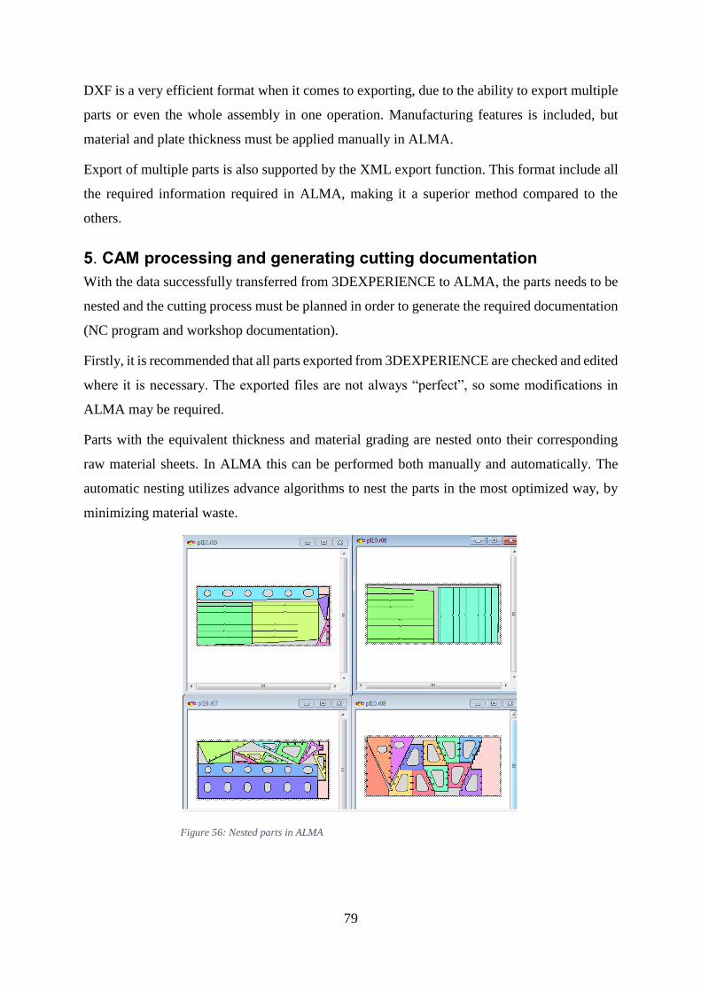
79
DXF is a very efficient format when it comes to exporting, due to the ability to export multiple
parts or even the whole assembly in one operation. Manufacturing features is included, but
material and plate thickness must be applied manually in ALMA.
Export of multiple parts is also supported by the XML export function. This format include all
the required information required in ALMA, making it a superior method compared to the
others.
5. CAM processing and generating cutting documentation
With the data successfully transferred from 3DEXPERIENCE to ALMA, the parts needs to be
nested and the cutting process must be planned in order to generate the required documentation
(NC program and workshop documentation).
Firstly, it is recommended that all parts exported from 3DEXPERIENCE are checked and edited
where it is necessary. The exported files are not always “perfect”, so some modifications in
ALMA may be required.
Parts with the equivalent thickness and material grading are nested onto their corresponding
raw material sheets. In ALMA this can be performed both manually and automatically. The
automatic nesting utilizes advance algorithms to nest the parts in the most optimized way, by
minimizing material waste.
Figure 56: Nested parts in ALMA

80
Sequencing is applied to achieve the most efficient way of cutting the parts from the metal
sheet. This can also be performed manually and automatically. By applying “bridges”, a small
connection between the parts, the machine can cut multiple parts in one operation without
having to pierce the sheet for every part.
Finally, the sequence is simulated in the software. While the simulation is running, the NC
program is generated automatically in the background together with workshop documents.
Once the simulation is complete, the documentation can be reviewed.
5. Post processing the NC program
The “raw” NC program obtained from the CAM processing in ALMA, is of the generic type,
and needs processing. This output is not configured for any specific machine, and does not
follow the correct syntax of the cutting machine.
By running the NC program through a post processing software, it can be translated into the
correct programming language required by the cutting machine. The development of this
software can be done by a software developer, and is a service that must be purchased.
6. Conclusion
This paper describes briefly an applicable best practice method that can be used for establishing
a design, preparing it for manufacturing and generation of documentation intended for sheet
metal cutting. The method has been developed through practical research in form of a realistic
case study, focusing on the resources that Kleven currently possesses at their shipyard.
Further work include the development of a NC program post processor, and investigation of a
similar method for purchased design data (Kleven will continue to purchase design until their
engineering platform is fully operational).
The resulting method that is established will hopefully help with contribution to economic
benefits and increased knowledge not only for Kleven and the shipbuilding industry, but also
other instances or industries that may consider 3DEXPERIENCE and ALMA as software
solutions.