Silicon – Magnesium Alloy Hybrid Composites
71
Properties of Self-Lubricating Silicon Carbide Particle Reinforced Aluminium – Silicon – Magnesium Alloy Hybrid Composites By Mohammad Ismail Student Number: 040811102F This thesis is submitted to the Department of Materials and Metallurgical Engineering (MME) in partial fulfillment of the requirements for the degree of Master of Philosophy in Material Science (M.Phil (Mat. Sci.)) Department of Material and Metallurgical Engineering Bangladesh University of Engineering and Technology, Dhaka March 2015
-
Upload
khangminh22 -
Category
Documents
-
view
0 -
download
0
Transcript of Silicon – Magnesium Alloy Hybrid Composites
Properties of Self-Lubricating Silicon Carbide Particle Reinforced
Aluminium – Silicon – Magnesium Alloy Hybrid Composites
By
Mohammad Ismail
Student Number: 040811102F
This thesis is submitted to the Department of Materials and Metallurgical Engineering (MME)
in partial fulfillment of the requirements for the degree of Master of Philosophy in Material
Science (M.Phil (Mat. Sci.))
Department of Material and Metallurgical Engineering
Bangladesh University of Engineering and Technology, Dhaka
March 2015
ii
Candidate’s Declaration
It is hereby declared that this thesis paper or any part of it has not been submitted anywhere
else for the award of any degree.
Mohammad Ismail

iii

iv
Dedication
Hazrat Mohammad (SM)

v
Acknowledgments
I wishes to express his profound gratitude to his thesis supervisor Dr. A. K. M. Bazlur Rashid,
Professor, Department of Materials and Metallurgical Engineering of Bangladesh University
of Engineering and Technology, Dhaka for his guidance in carrying out this research work as
well as writing this thesis.
I would like to express his gratitude to Dr. Ahmed Sharif, Professor and Head, Department of
Materials and Metallurgical Engineering and Dr. Md. Fakhrul Islam, Professor and Head,
Department of Glass and Ceramic Engineering of Bangladesh University of Engineering and
Technology, Dhaka for providing him with the laboratory facilities for this work.
Sincere thanks are also due to Mr. Mehedi Hasan Rizvi, Mr. Md. Faruk Hossain and Mr. Md.
Abdullah Al Maksud, Mr. Wasim, Mr. ShamsulAlam and and Mr. Ahmedullah for their help
during conduction of experiments for this work.
Above all, I would like to thank all my family members (M. A. Jabber, Jobeda Akther, M.
Jalal Uddin, M. Mohiuddin Khan) and friends, family friends (Prof. Rezaul Karim Ph.D
Fellow UK, Mr Hedayt Islam DMD NICl, Mr. Iqbal Karim AMD IIBL) whose direct indirect
support helped me completing my thesis in time.
Last but not the least, I would like to thank my mother (Mrs. Nur Nahar Begum) for her
undying support, encouragement and endless love throughout my life.
Mohammad Ismail

vi
Abstract
A stir casting process was used to fabricate aluminum – 7% silicon – 0.4% magnesium alloy
(LM25) composites reinforced with various volume fractions of silicon carbide (SiC) and
graphite (G) particulates. Both optical and scanning electron microscopy were used to study
the microstructural characterization of the materials. Hardness, tensile and wear properties of
the unreinforced LM25 alloy and three hybrid composites were examined. It was observed
that the addition of both SiC and G reinforcing particles to LM25 alloys caused a general
increase in the properties, although the properties of the composites were predictably affected
mostly by the hard reinforcing SiC particles. The hardness, tensile strength and resistance to
wear were found to be the maximum in case of HC2 (LM25-5SiC-0G) composite. Addition of
G particles somewhat lowered the tensile properties, while a mixed result was obtained in
case of hardness. The wear resistance was decreased due to the addition of G particles. The
HC1 (LM25-2.5SiC-5G) hybrid composites had the intermediate properties of the two
composites HC2 and HC3 where SiC and G particles were used in isolation. The age
hardening response of all four materials was predictable. Hardness values were generally
increased in case of all materials.

vii
Table of Contents
Acknowledgements ................................................................................................................... v
Abstract ..................................................................................................................................... vi
1. Introduction ..................................................................................................................... 1
2. Theoretical background ................................................................................................. 2
2.1 Aluminum alloy ................................................................................................................ 3
2.1.1 Aluminium alloy systems designation .................................................................. 4
2.1.2 Temper designations ............................................................................................. 7
2.2 Aluminium-Silicon-Magnesiumalloys ............................................................................ 11
2.2.1 Introduction ......................................................................................................... 12
2.2.2 Properties of Al-7Si-Mg (LM25) alloys ............................................................. 18
2.2.3 Heat treatment of LM25alloys ............................................................................ 18
2.3 LM25-Silicon carbide-Graphite hybrid composites ....................................................... 22
2.3.1 Introduction ......................................................................................................... 22
2.3.2. Processing of LM25-SiC-G hybrid composites ................................................. 24
2.3.2.1 Stir casting fabrication method ........................................................... 25
2.3.2.2 Silicon carbide as reinforcement ........................................................ 28
2.3.2.3 Graphite as reinforcement .................................................................. 29
2.4 Literature review ............................................................................................................. 29
2.4.1 Summary of literature review ............................................................................. 33
2.5 Scope of present work ..................................................................................................... 34

viii
3. Experimental procedure ............................................................................................... 35
3.1 Introduction ..................................................................................................................... 36
3.2 Preparation of LM25 master alloy .................................................................................. 36
3.2.1 Raw materials ...................................................................................................... 36
3.2.2 Melting and casting ............................................................................................. 36
3.3 Preparation of LM25-SiC-G hybrid composite .............................................................. 37
3.4 Heat treatment of LM2S-SiC-G hybrid composites ....................................................... 39
3.5 Microstructural observations .......................................................................................... 39
3.6 Hardnessmeasurement .................................................................................................... 39
3.7 Tensile testing ................................................................................................................. 40
3.8 Wear testing .................................................................................................................... 40
4. Results and discussion .................................................................................................. 42
4.1 Manufacture of LM25-SiC-G hybrid composite ............................................................ 43
4.2 Microstructural observations .......................................................................................... 47
4.3 Hardness measurement ................................................................................................... 50
4.4 Tensile properties ............................................................................................................ 51
4.5 Wear properties ............................................................................................................... 52
4.6 Effect of heat treatment ................................................................................................... 55
5. Conclusions .................................................................................................................... 56
5.1 Conclusions ..................................................................................................................... 57
5.2 Suggestions for future work ............................................................................................ 57 List of Table…………………………………………………………………………..............58 List of Figure …………………………………………………………………………………59 References ............................................................................................................................... 60

1
1 Introduction
Aluminium based metal matrix composites (MMCs) have been a very valuable addition to the
field of newer materials for high performance tribological applications. Aluminium
composites based on 2024, 6061, and 7075 wrought alloys and A356 and A357 cast alloys are
being increasingly used in automobile, aerospace, marine and mineral processing industries
owing to their improved specific strength, good wear resistance, higher thermal conductivity
and lower coefficient of thermal expansion. The widely used reinforcing materials for these
composites are silicon carbide (SiC), aluminium oxide (Al2O3) and graphite (Gr) in the form
of particles or whiskers. Aluminium-matrix composites are normally fabricated by liquid
casting or powder metallurgy technique.
Generally lubricant is externally added to reduce wear. This poses problem when the material
needs periodic application of lubricant particularly to wear parts which are difficult to wear.
For such applications self-lubricating materials are preferred. Graphite is one of the most
commonly used lubricant materials, although a loss of strength due to the addition of solid
graphite in aluminium is often reported.
In the present work investigation aluminium-7Silicon-0.4Magnesium (A356 or LM25) alloys
based hybrid composites will be prepared using a hard reinforcing agent (silicon carbide
particles) and a soft reinforcing agent (graphite particles) reinforcing agents using stir casting
method. Then the mechanical and wear properties of the manufactured hybrid composites will
be determined and the effectiveness of the combined addition of these two reinforcement will
be investigated by comparing with the properties of LM25 master alloy.
2
2 Theoretical Background
2. Theoretical background ............................................................................................... 2
2.1 Aluminum alloy ............................................................................................................... 3
2.1.1 Aluminium alloy systems designation ................................................................. 4
2.1.2 Temper designations ............................................................................................ 7
2.2 Aluminium-Silicon-Magnesium alloys .......................................................................... 11
2.2.1 Introduction ........................................................................................................ 12
2.2.2 Properties of Al-7Si-Mg (LM25) alloys ............................................................ 18
2.2.3 Heat treatment of LM25 alloys .......................................................................... 18
2.3 LM25-Silicon carbide-Graphite hybrid composites ...................................................... 22
2.3.1 Introduction ........................................................................................................ 22
2.3.2 Processing of LM25-SiC-G hybrid composites ................................................. 24
2.3.2.1 Stir casting fabrication method .......................................................... 25
2.3.2.2 Silicon carbide as reinforcement ....................................................... 28
2.3.2.3 Graphite as reinforcement ................................................................. 29
2.4 Literature review ............................................................................................................ 29
2.4.1 Summary of literature review ............................................................................ 33
2.5 Scope of present work .................................................................................................... 34
3
2.1 Aluminium Alloys
Aluminium alloys are alloys in which aluminium is the predominant metal. Several properties
set aluminium alloys apart from other metals and alloys. First, aluminium is lighter than all
other engineering metals except magnesium and beryllium. It has a density of about 2700
kg/m3. A second important property of aluminium is its thermal and electrical conductivity. It
has about 60% of the conductivity of pure copper (IACS). Because of its lower density,
aluminium has a higher conductivity than copper per unit mass. The third property that is
responsible for the wide use of aluminium alloys is their corrosion resistance. Aluminium is
not widely used for chemical resistance, but for applications involving atmospheric corrosion
resistance it is probably the most widely used metallic material. Architectural applications of
aluminium are everywhere – railing, windows, frames, doors, flushing, and so on.
The mechanical, physical, and chemical properties of aluminum alloys depend upon
composition and microstructure of the alloy. The addition of selected elements to pure
aluminum greatly enhances its properties and usefulness. Because of this, most applications
for aluminum utilize alloys having one or more elemental additions. The major alloying
additions used with aluminum are copper, manganese, silicon, magnesium, and zinc. The total
amount of these elements can constitute up to 10 wt.% of the alloy composition. Impurity
elements are also present, but their total percentage is usually less than 0.15 wt.% in
aluminum alloys.
It is convenient to divide aluminum alloys into two major categories: wrought compositions
and cast compositions. A further differentiation for each category is based on the primary
mechanism of property development. Many alloys respond to thermal treatment based on
phase solubilities. These treatments include solution heat treatment, quenching, and
precipitation, or age, hardening. For either casting or wrought alloys, such alloys are
described as heat treatable. A large number of other wrought compositions rely instead on
work hardening through mechanical reduction, usually in combination with various annealing
procedures for property development. These alloys are referred to as work hardening. Some
casting alloys are essentially not heat treatable and are used only in as-cast or in thermally
modified conditions unrelated to solution or precipitation effects.
4
About 85% of aluminium is used for wrought products, for example rolled plate, foils and
extrusions. Cast aluminium alloys yield cost-effective products due to the low melting point,
although they generally have lower tensile strengths than wrought alloys. The most important
cast aluminium alloy system is Al–Si, where the high levels of silicon (4.0–13%) contribute to
give good casting characteristics. Aluminium alloys are widely used in engineering structures
and components where light weight or corrosion resistance is required.
Alloys composed mostly of aluminium have been very important in aerospace manufacturing
since the introduction of metal skinned aircraft. Aluminium-magnesium alloys are both lighter
than other aluminium alloys and much less flammable than alloys that contain a very high
percentage of magnesium.
Aluminium alloy surfaces formulate a white, protective layer of aluminium oxide if left
unprotected by anodizing and/or correct painting procedures. In a wet environment, galvanic
corrosion can occur when an aluminium alloy is placed in electrical contact with other metals
with more negative corrosion potentials than aluminium, and an electrolyte is present that
allows ion exchange. Referred to as dissimilar metal corrosion this process can occur as
exfoliation or intergranular corrosion. Aluminium alloys can be improperly heat treated. This
causes internal element separation and the metal corrodes from the inside out. Aircraft
mechanics deal daily with aluminium alloy corrosion.
2.1.1 Aluminium alloy systems designation
Systems for designating aluminum and aluminum alloys that incorporate the product form
(wrought, casting, or foundry ingot), and its respective temper (with the exception of foundry
ingots, which have no temper classification) are covered by American National Standards
Institute (ANSI) standard H35.1. The Aluminum Association is the registrar under ANSI
H35.1 with respect to the designation and composition of aluminum alloys and tempers
registered in the United States.
Cast and wrought alloy nomenclatures have been developed. The Aluminum Association
system is most widely recognized in the United States. Their alloy identification system
employs different nomenclatures for wrought and cast alloys, but divides alloys into families
for simplification.

5
A four-digit numerical designation system is used to identify wrought aluminum and
aluminum alloys. As shown in Table 2.1 (ASM International, 1990), the first digit of the four-
digit designation indicates the group, while the second digit indicates mill control or lack of
same on specific elements. The last two digits have no significance, except in the 1xxx series
they coincide with aluminium content above 99% in hundredths. A 1040 alloy has, thus,
99.4% aluminium. The complete specification of wrought aluminium alloys involves a suffix
that indicates the degree of cold work or thermal treatments.
Table 2.1: Alloy designation system for wrought aluminium alloys
AA Series Description and typical uses of the alloy series
1xxx Controlled unalloyed (pure) composition (Al ≥ 99.00%), used primarily in the electrical and chemical industries
2xxx Alloys in which copper is the principal alloying element, although other elements, notably magnesium, may be specified. 2xxx-series alloys are widely used in aircraft where their high strength (yield strengths as high as 455 MPa, or 66 ksi) are valued.
3xxx Alloys in which manganese is the principal alloying element, used as general-purpose alloys for architectural applications and various products
4xxx Alloys in which silicon is the principal alloying element, used in welding rods and brazing sheet
5xxx Alloys in which magnesium is the principal alloying element, used in boat hulls, gangplanks, and other products exposed to marine environments
6xxx Alloys in which magnesium and silicon are the principal alloying elements, commonly used for architectural extrusions
7xxx Alloys in which zinc is the principal alloying element (although other elements, such as copper, magnesium, chromium, and zirconium, may be specified), used in aircraft structural components and other high-strength applications. The 7xxx series are the strongest aluminum alloys, with yield strengths 500 possible.
8xxx Alloys characterizing miscellaneous compositions. The 8xxx series alloys may contain appreciable amounts of tin, lithium, and/or iron.
9xxx Reserved for future use
Wrought alloys that constitute heat-treatable (precipitation-hardenable) aluminum alloys
include the 2xxx, 6xxx, 7xxx, and some of the 8xxx alloys. The various combinations of
alloying additions and strengthening mechanisms used for wrought aluminum alloys are
shown in Table 2.2 (ASM International, 1993).

6
Table 2.2: Classification of wrought aluminum alloys based on strengthening mechanism.
Work-hardenable alloys: Precipitation-hardenable alloys:
Pure Al 1xxx Al-Cu 2xxx
Al-Mn 3xxx Al-Cu-Mg 2xxx
Al-Si 4xxx Al-Cu-Li 2xxx
Al-Mg 5xxx Al-Mg-Si 6xxx
Al-Fe 8xxx Al-Zn 7xxx
Al-Fe-Ni 8xxx Al-Zn-Mg 7xxx
Al-Zn-Mg-Cu 7xxx
Al-Li-Cu-Mg 8xxx
Casting compositions are described by a three-digit system followed by a decimal value. The
first digit indicates the alloy group. The second and third digits identify an alloy within a
group and the digit after the decimal indicates the product form. The decimal .0 in all cases
pertains to casting alloy limits. Decimals .1, and .2 concern ingot compositions, which after
melting and processing should result in chemistries conforming to casting specification
requirements. Alloy families for casting compositions are given in Table 2.3 (ASM
International, 1993).
Table 2.3: Alloy designation system for cast aluminium alloys.
AA series Description and typical uses of the alloy series
1xx.x Controlled unalloyed (pure) compositions, especially for rotor manufacture
2xx.x Alloys in which copper is the principal alloying element. Other alloying elements may be specified.
3xx.x Alloys in which silicon is the principal alloying element. The other alloying elements such as copper and magnesium are specified. The 3xx.x series comprises nearly 90% of all shaped castings produced.
4xx.x Alloys in which silicon is the principal alloying element.
5xx.x Alloys in which magnesium is the principal alloying element.
6xx.x Unused
7xx.x Alloys in which zinc is the principal alloying element. Other alloying elements such as copper and magnesium may be specified.
8xx.x Alloys in which tin is the principal alloying element.
9xx.x Unused

7
A modification of an original alloy, or of the impurity limits for unalloyed aluminum, is
indicated by a serial letter preceding the numerical designation. The serial letters are assigned
in alphabetical sequence starting with A but omitting I, O, Q, and X, the X being reserved for
experimental alloys. Explicit rules have been established for determining whether a proposed
composition is a modification of an existing alloy or if it is a new alloy. Heat-treatable casting
alloys include the 2xx, 3xx, and 7xx series.
2.1.2 Temper designation
The temper designation system used in the United States for aluminum and aluminum alloys
is used for all product forms (both wrought and cast), with the exception of ingot. The system
is based on the sequences of mechanical or thermal treatments, or both, used to produce the
various tempers. The temper designation follows the alloy designation and is separated from it
by a hyphen. Basic temper designations consist of individual capital letters. Major
subdivisions of basic tempers, where required, are indicated by one or more digits following
the letter. These digits designate specific sequences of treatments that produce specific
combinations of characteristics in the product. Variations in treatment conditions within major
subdivisions are identified by additional digits. The conditions during heat treatment (such as
time, temperature, and quenching rate) used to produce a given temper in one alloy may differ
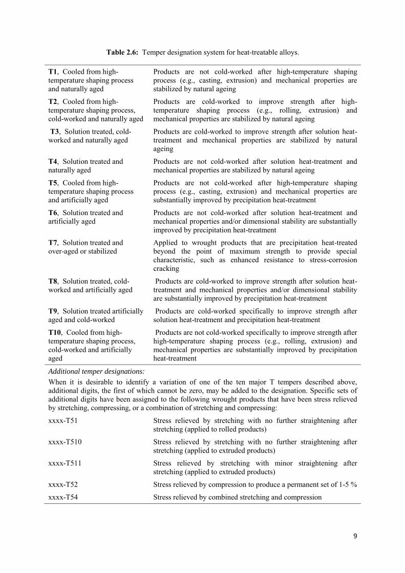
from those employed to produce the same temper in another alloy. Table 2.4 to 2.6 show the
temper designation systems used for aluminium alloys (ASM International, 1990).
Generally, the letter H is followed by one, two or three digits to indicate the type of cold
working (strain hardening), which is again followed by numbers 1 to 8 (where a 1 indicates
the smallest amount of cold work and an 8 indicates maximum cold work or full-hard
conditions). The letter T is followed by one, two or three digits to indicate various thermal
treatments. A complete temper designation systems used for wrought and cast aluminium
alloys is shown in Fig. 2.1.

8
Table 2.4: Basic temper designations.
F, As-Fabricated This is applied to products shaped by cold working, hot working, or casting processes in which no special control over thermal conditions or strain hardening is employed. For wrought products, there are no mechanical property limits.
O, Annealed O applies to wrought products that are annealed to obtain lowest-strength temper and to cast products that are annealed to improve ductility and dimensional stability. The O may be followed by a digit other than zero.
H, Strain-Hardened (wrought products only)
This indicates products that have been strengthened by strain hardening, with or without supplementary thermal treatment to produce some reduction in strength. The H is always followed by two or more digits.
W, Solution Heat-Treated (age hardens naturally)
This is an unstable temper applicable only to alloys whose strength naturally (spontaneously) changes at room temperature over a duration of months or even years after solution heat treatment. The designation is specific only when the period of natural aging is indicated (for example, W h).
T, Solution Heat-Treated
This applies to alloys whose strength is stable within a few weeks of solution heat treatment. The T is always followed by one or more digits
Table 2.5: Temper designation system for strain-hardened products.
H1, Strain-Hardened Only This applies to products that are strain hardened to obtain the desired strength without supplementary thermal treatment.
H2, Strain-Hardened and Partially Annealed
This pertains to products that are strain-hardened more than the desired final amount and then reduced in strength to the desired level by partial annealing
H3, Strain-Hardened and Stabilized
This applies to products that are strain-hardened and whose mechanical properties are stabilized by a low-temperature thermal treatment or as a result of heat introduced during fabrication
H4, Strain-Hardened and Lacquered or Painted
This applies to products that are strain-hardened and that are also subjected to some thermal operation during subsequent painting or lacquering
Additional temper designations:
Digit 1 to 8, following the designation H1, H2, H3, and H4, are used to indicate the degree of strain-hardening as identified by the minimum value of the ultimate tensile strength. The numeral 8 has been assigned to the hardest tempers normally produced.
xxxx-Hx2 Quarter-hard
xxxx-Hx4 Half-hard
xxxx-Hx6 Three-quarter-hard
xxxx-Hx8 Full-hard
9
Table 2.6: Temper designation system for heat-treatable alloys.
T1, Cooled from high-temperature shaping process and naturally aged
Products are not cold-worked after high-temperature shaping process (e.g., casting, extrusion) and mechanical properties are stabilized by natural ageing
T2, Cooled from high-temperature shaping process, cold-worked and naturally aged
Products are cold-worked to improve strength after high-temperature shaping process (e.g., rolling, extrusion) and mechanical properties are stabilized by natural ageing
T3, Solution treated, cold-worked and naturally aged
Products are cold-worked to improve strength after solution heat-treatment and mechanical properties are stabilized by natural ageing
T4, Solution treated and naturally aged
Products are not cold-worked after solution heat-treatment and mechanical properties are stabilized by natural ageing
T5, Cooled from high-temperature shaping process and artificially aged
Products are not cold-worked after high-temperature shaping process (e.g., casting, extrusion) and mechanical properties are substantially improved by precipitation heat-treatment
T6, Solution treated and artificially aged
Products are not cold-worked after solution heat-treatment and mechanical properties and/or dimensional stability are substantially improved by precipitation heat-treatment
T7, Solution treated and over-aged or stabilized
Applied to wrought products that are precipitation heat-treated beyond the point of maximum strength to provide special characteristic, such as enhanced resistance to stress-corrosion cracking
T8, Solution treated, cold-worked and artificially aged
Products are cold-worked to improve strength after solution heat-treatment and mechanical properties and/or dimensional stability are substantially improved by precipitation heat-treatment
T9, Solution treated artificially aged and cold-worked
Products are cold-worked specifically to improve strength after solution heat-treatment and precipitation heat-treatment
T10, Cooled from high-temperature shaping process, cold-worked and artificially aged
Products are not cold-worked specifically to improve strength after high-temperature shaping process (e.g., rolling, extrusion) and mechanical properties are substantially improved by precipitation heat-treatment
Additional temper designations:
When it is desirable to identify a variation of one of the ten major T tempers described above, additional digits, the first of which cannot be zero, may be added to the designation. Specific sets of additional digits have been assigned to the following wrought products that have been stress relieved by stretching, compressing, or a combination of stretching and compressing:
xxxx-T51 Stress relieved by stretching with no further straightening after stretching (applied to rolled products)
xxxx-T510 Stress relieved by stretching with no further straightening after stretching (applied to extruded products)
xxxx-T511 Stress relieved by stretching with minor straightening after stretching (applied to extruded products)
xxxx-T52 Stress relieved by compression to produce a permanent set of 1-5 %
xxxx-T54 Stress relieved by combined stretching and compression

10
Figure 2.1: Detail of aluminium alloy temper designation system.

11
2.2 Aluminium – Silicon – Magnesium alloys
Aluminum casting alloys are the most versatile of all common foundry alloys and generally
have the highest castability ratings. As casting materials, aluminum alloys have the following
favorable characteristics (ASM International, 1998):
• Good fluidity for filling thin sections
• Low melting point relative to those required for many other metals
• Rapid heat transfer from the molten aluminum to the mold, providing shorter casting
cycles
• Hydrogen is the only gas with appreciable solubility in aluminum and aluminum alloys,
and hydrogen solubility in aluminum can be readily controlled by processing methods.
• Many aluminum alloys are relatively free from hot-short cracking and tearing tendencies.
• Chemical stability
• Good as-cast surface finish with lustrous surfaces and little or no blemishes
Aluminum alloy castings are the cost-effective answer to many needs and problems in
construction of machines, equipment, appliances, vehicles and structures, usually serving a
primarily mechanical function, but often combining this with an appearance or decorative
function. This requires cast parts in a great variety of geometric configurations, frequently
combining several different basic forms in an integral or monolithic piece. These parts include
covers and housings, which may be ribbed for reinforcement or finned for heat conduction or
dissipation; frames and boxlike parts; cylindrical or spherical tanks for containment of gases
or fluids; brackets; pistons; wheels; disks; impellers; bulkheads; and clamps. The list of forms
produced is nearly endless, and many such parts have a multitude of cored holes in bosses for
fastening or as passage for fluids.
Aluminium casting is dominated by the automotive industry. Roughly two thirds of all
aluminium castings are used in automotive industries where the use of aluminum castings
continues to grow at the expense of iron castings. Although aluminium castings are
significantly more expensive than ferrous castings, there is a continuing market requirement
to reduce vehicle weight and to increase fuel efficiency. It is this requirement which drives the
replacement of ferrous parts by aluminium. Melting point of Al is 660°C and is light weight,

12
density is about 1/3 that of steel or copper alloys. Certain aluminium have a better strength to
weight ratio than that of high strength steel. Have good malleability and formability, high
corrosion resistance and high electrical and thermal conductivity.
The chemical composition and properties of common cast aluminium alloys are shown in
Table 2.7 (ASM International, 1993).
Commercial cast aluminum-silicon alloys are poly-phase materials of composed
microstructure belonging to the Aluminum Association classification series 3xx.x for
aluminum silicon plus copper and/or magnesium alloys and 4xx.x aluminum silicon alloys.
The silicon content in standardized commercial cast aluminum silicon alloys is in the range of
5 to 23 wt%. The equilibrium phase diagram for the aluminium – silicon system is shown in
Figure 2.2(a) (ASM International, 2004). These alloy system shows a eutectic at 577 C with
12.6 wt.% Si. A solid solution is formed in the alloys, which contains only 1.65 wt.% Si at
the eutectic temperature and about zero per cent at the room temperature. For all practical
purposes, aluminium is not soluble to silicon. Depending on the Si content, the structure of
the alloys can be hypoeutectic, hypereutectic, or eutectic. The properties of a specific Al-Si
alloy can be attributed to the individual physical properties of its main phase components (-
aluminum solid solution and silicon crystals) and to the volume fraction and morphology of
these components.
The microstructure of hypoeutectic Al-Si alloys contain primary aluminium dendrites with
fine eutectic particles, Figure 2.2(b) (ASM International, 2004). The near-eutectic 413.0 alloy
(~12% Si) contains a predominant eutectic phase containing acicular silicon. Hyper-eutectic
Al-Si alloys such as 390.0 and 393.0 containing 15 to 25% Si have chunky primary silicon
particles with eutectic (Figure 2.2(d)) and exhibit excellent wear resistance and low thermal
expansion.
The mechanical properties of cast aluminum-silicon alloys can be improved by cast
technology and heat treatment processes that:
• Increase the strength of soft matrix
• Decrease the brittle fracture risk in the polyphase regions
• Increase the degree of dispersion of the dendritic structure

13
Table 2.7(a): The chemical composition of common cast aluminium alloys.

14
Table 2.7(b): The mechanical properties of common cast aluminium alloys.

15
(a)
(b) (c) (d)
Figure 2.2: Commercial cast aluminum-silicon binary alloys. (a) Al-Si equilibrium diagram. (b) Microstructure of hypoeutectic alloy (<12.6 wt% Si). x150. (c) Microstructure of eutectic alloy (12.6% Si). x400. (d) Microstructure of hypereutectic alloy (>12.6% Si). x150.
An increase in strength of soft matrix of -aluminum solid solution can be achieved by its
hardening with point defects, such as substituted atoms and vacancies or by precipitation
hardening with dispersion particles of the second phase.

16
The ternary Aluminium–7Silicon–Magnesium alloys, commonly known as LM25 alloys (as
per British Standards) or 356 and 357 alloys (as per AA Standards) are mainly used where
good mechanical properties are required in castings of shape or dimensions requiring an alloy
of excellent castability in order to achieve the desired standard of soundness. Alloy 357.0
contains higher Mg level (0.6%) than alloy 356.0 (0.3% Mg). Consequently, heat treated
357.0 alloys have higher tensile strength than 356.0 alloys. A356.0 and A357.0 alloys are
higher purity versions of 356.0 and 357.0 alloys (low Fe levels). B356.0 and B357.0 are even
more purer. Addition of Be also improves properties.
When Mg is added to Al-Si alloys, Mg2Si phase is formed, which then form a somewhat
pseudo-binary phase diagram with the aluminium. Figure 2.3 shows aluminium-rich corner of
the pseudo-binary equilibrium phase diagram of Al-Mg2Si system. This diagram is important
in describing the heat treating behaviour of Al-Mg2Si system.
Figure 2.3: The pseudo-binary Al-Mg2Si phase diagram.
Addition of Mg to Al-Si alloy increases response to precipitation-hardening to yield higher
strengths. In Al-7Si-Mg alloys, Si imparts high fluidity, low shrinkage, good hot cracking
resistance and Mg is the major strengthening element. Addition of 0.2 – 0.4 wt.% Mg
strengthens the alloy by combining with Si to form Mg2Si precipitates in aluminum matrix.

17
Figure 2.4 and 2.5 show the microstructure of LM25 alloys containing 0.3 wt.% Mg (A356)
and 0.60 wt.% Mg (A357), both in unmodified and modified conditions (Gruzlesik, 1990).
The sharp, acicular silicon particles in the eutectics are seen in unmodified conditions. When
silicon presents in this form, they control the mechanical properties of the alloys. Addition of
minute amount of sodium or strontium modifies the silicon particles into round form and,
thereby, improves the mechanical properties.
(a) (b)
Figure 2.4: Microstructure of LM25 (A356) alloy. (a) As-cast (unmodified), (b) Modified with 0.008% Strontium. x100.
(a) (b)
Figure 2.5: Microstructure of LM25 (A357) alloy. (a) As-cast (unmodified), (b) Modified with 0.013% Strontium. x100.

18
2.2.2 Properties of Al-7Si-Mg (LM25) alloys
These alloys can be sand cast or permanent mould cast with excellent castability, pressure
tightness and corrosion resistance. Structure control through eutectic modification and heat
treatment provides a wide range of properties, however, an increased Fe level and slower
solidification rates have negative effect on the mechanical properties. This is attributed to the
formation of coarse iron intermetallics with high aspect ratio.
The alloy is also used where resistance to corrosion is an important consideration, particularly
where high strength is also required. It has good wettability. Consequently LM25 finds
applications in the food, chemical, marine, electrical and many other industries, and above all
- in the automotive industry where it is used for wheels, cylinder blocks and heads. Its
potential uses are increased by its 3 available levels of heat treatment in both sand and chill
castings. It is, in practice, the general purpose high strength gravity die-casting alloy.
Such alloys have good corrosion resistance. Alloys find applications in carburetor parts and
pump castings, automotive, aerospace and many electrical industries based on their good
electrical conductivity.
This alloy conforms to British Standard 1490 LM25. Castings are standardised in the
following conditions – as-cast, LM25-M precipitation treated LM25-TE; solution treated and
stabilized LM25-TB7; and fully heat-treated LM25-TF. Table 2.8–2.10 show typical
composition, properties and applications of these alloys (MRT Castings, 2015).
Table 2.8: Chemical composition range of LM25 alloys.
Copper 0.1 max. Magnesium 0.20-0.60 Silicon 6.50-7.50 Iron 0.5 max. Manganese 0.3 max. Nickel 0.1 max. Zinc 0.1 max. Lead 0.1 max. Tin 0.05 max. Titanium* 0.2 max. Aluminium Remainder
* 0.05% min. if Ti alone used for grain refining.

19
Table 2.9: Physical property range of LM25 alloys.
Coefficient of Thermal Expansion (per °C at 20 -100 °C) 0.000022
Thermal Conductivity (cal/cm2/cm/°C/s at 25°)* 0.36
Electrical Conductivity (% copper standard at 20 °C)* 39
Specific Gravity 2.68
Freezing Range (°C) Approx. 615-550
*Applies to fully heat treated sand castings; values are approximate and for castings in other conditions will depend on their thermal history.
Table 2.10: Mechanical properties of Aluminium-7Silicon-Magnesium alloys.
Properties LM25-M LM25-TE LM25-TB7 LM25-TF
SC* CC* SC CC SC CC SC CC
0.2% Proof Stress, MPa 80-100 80-100 120-150 130-200 80-110 90-110 200-250 220-260
Tensile Stress, MPa 130-150 160-200 150-180 190-250 160 230 230-280 280-320
Elongation, % 2 3 1 2 2.5 5 -- 2
Brinel hardness number 55-65 55-65 70-75 75-95 65-75 65-75 90-110 90-110
Endurance Limit, 5x10⁸ Cycles + MPa 70-100 80-110 55 75 60 95 60 95
Modula’s of Elasticity, x103 MPa 71 71 71 71 75 71 71 71
*SC – Sand cast, CC – Chill cast
2.2.3 Heat treatment of LM25 alloys
Achievement of specified minimum tensile properties is dependent on the magnesium content
of this excellent heat-treatable alloy. Typically, the T6 heat treatment of LM 25 alloys
involved (1) solution treatment at 535°C for 2-6 hours, (2) quenching to room temperature,
and (3) artificial ageing at 150-180°C for 3-5 hours to obtain peak strength. In the ‘as cast
condition’ intermetallic’s appears as coarse precipitates. But after age-hardening treatment, it
becomes finer and evenly distributed and this provides maximum strength.
The sequence of precipitation in Al-Si-Mg alloys can be described as follows (Mohamed and
Samuel, 2012):

20
i. Precipitation of GP zones (needles of about 10 nm long)
ii. Intermediate phase ’’ – Mg2Si (homogeneous precipitation)
iii. Intermetallic phase ’ – Mg2Si (heterogeneous precipitation)
iv. Equilibrium phase – Mg2Si, FCC structure (a = 0.639), rod or plate-shaped
The maximum alloy strength (peak-ageing) is achieved just before the precipitation of the
incoherent -platelets. Apelian et al (1989) studied the ageing behaviour of Al-Si-Mg alloys
and observed that the precipitation of very fine ’–Mg2Si during ageing leads to a pronounced
improvement in strength properties. Both ageing time and temperature determine the final
properties. Their study also established that increasing the ageing temperature by 10 C is
equivalent to increasing the ageing time by a factor of two.
The ageing effect and properties of Al-7Si-Mg alloys are very much dependent on the ratio
between magnesium and silicon in the supersaturated solid solution. The excess silicon (with
respect to the stoichiometry of the Mg2Si phase) can considerably change the kinetics of
precipitation and the phase composition.
The decomposition of the supersaturated solid solution results in precipitation of the
(Mg2Si) phase and free Si. The coherent ’’ (monoclinic) phase is an efficient hardener and
participates in processes of natural and artificial ageing. In the stage of softening, it gives
place to the semicoherent ’ (hexagonal or orthorhombic) phase, which is considerably stable.
The decomposition starts directly with the formation of ’ particles at temperatures above 300
C, and the sole equilibrium (cubic) phase precipitates upon annealing above 400 C (Eskin et
al, 1999).
The composition of the metastable phases, i.e., Mg:Si ratio, is different from that of Mg2Si
(Mg:Si = 2 at.%). The Mg:Si ratio continuously increases in the series GPZ, ’’ , ’, and ’. In
other words, metastable phases are enriched in silicon. The maximum strength is achieved in
alloys with an excess of silicon and in the stage of ’’ precipitation. The silicon-vacancy
complexes acts as nucleation sites for the coherent phase. The transition between the
metastable modifications is likely to occur separately. In other words, coherent precipitates
dissolve, semicoherent particles are formed at dislocations, and the coherent phase may
precipitate on dislocations or grain boundaries.

21
Zones are precipitated very intensely, the precipitation density being 3x10¹⁵ per mm3 and the
size, 6x20-100 nm. The coherent ’’ phase has the same precipitation density with the size
somewhat larger, 5x16-200 nm (Mould and Mapother, 1962). The zone stage lasts from 5 h to
8 min at 150-200 C, respectively, while the transition to the phase requires 200 to 8 h in the
same temperature range (Stroganov et al, 1977).
Alloys with an excess of silicon has one major difference from alloys with Mg:Si ratio lower
than 1.73 wt.%. In these alloys, free silicon precipitates and affects the entire situation. Silicon
accelerates the formation and increases the precipitation density of spherical (Al, Mg, Si)
zones. These zones act like nuclei for the coherent ’’ phase. It is found that the Mg:Si ratio in
the semicoherent ’ phase is lower in the alloys with an excess of silicon, as compared with
balanced alloys (1.21 and 1.75 at.%, respectively).
The sequence of precipitation in the Al-Mg2Si-Si alloys is as follows (in parentheses the
temperature range according to DSC analysis) (Kanno et al, 1978):
Formation of magnesium and silicon segregates in the matrix crystal lattice (below 100 C)
Nucleation of needle-like zones onto these segregates (200-250 C)
Nucleation of free silicon with rapidly lost coherency. The (Al, Mg, Si) zones remain
unchanged (240-320 C)
Formation of the coherent ’’ phase onto (Al, Mg, Si) zones (below 450 C)
Formation of the semicoherent ’ phase (below 450 C)
Formation of the equilibrium phase (above 400 C)
The delay between quenching and artificial ageing in Al-Mg2Si-Si alloys decreases the
hardening effect. However, small copper additions can minimize this effect. Cadmium,
indium, and lead also diminish this effect, but only upon ageing at temperatures below 160-
170 C.
Some Al-Si-Mg alloys contain Sb, Pb or Sn that are added either to modify the Al-Si eutectics
or to improve the machinability of alloys. These elements can considerably worsen the
mechanical properties, binding part of magnesium in insoluble, brittle particles of the Mg2X
type. In this case, the efficient concentration of magnesium in the supersaturated solid
solution is decreased.

22
2.3 LM25-Silicon carbide – Graphite hybrid composite
2.3.1 Introduction
The possibility of taking advantage of particular properties of the constituent materials to
meet specific demands is the most important motivation for the development of composites. A
composite is a material made with several different constituents intimately bonded. This
definition is very large, and includes a lot of materials such as the Roman ways (constituted of
different layers of stones, chalk and sand), wood, human body etc... A more restrictive
definition is used by industries and materials scientists: a composite is a material that consists
of constituents produced via a physical combination of pre-existing ingredient materials to
obtain a new material with unique properties when compared to the monolithic material
properties. This definition distinguishes a composite from other multiphase materials which
are produced by bulk processes where one or more phases result from phase transformation
("in-situ" composites).
The terms matrix and reinforcement are often used. The matrix is a percolating “soft” phase
(with in general excellent ductility, formability and thermal conductivity) in which are
embedded the “hard” reinforcements (high stiffness and low thermal expansion). The
reinforcements can be continuous or discontinuous, orientated or disorientated. The
composites are classified by: (1) their matrix (polymer, ceramic, metal), (2) their
reinforcement, which includes the chemical nature (oxides, carbides, nitrides), shape
(continuous fibers, short fibers, whiskers, particulates) and orientation, (3) their processing
routes.
Metal matrix composites (MMCs) possess significantly improved properties including high
specific strength, specific modulus, damping capacity and good wear resistance compared to
the unreinforced alloys. Aluminum is the most popular matrix for the metal matrix composites
(MMCs). Aluminum alloys are quite attractive for many engineering applications due to their
low density, their capability to be strengthened by precipitation, their good corrosion
resistance, high thermal and electrical conductivity, and their high damping capacity.
However, low hardness and consequently low wear resistance limit their use in some
applications. Aluminum metal matrix composites (Al-MMCs) containing particulate and other

23
reinforcements are considered as the promising solution for imparting better wear resistance
to aluminum alloys.
Aluminum matrix composites (AMCs) have been widely studied since the 1920s and are now
used in sporting goods, electronic packaging, armours and automotive industries. They offer a
large variety of mechanical properties depending on the chemical composition of the Al-
matrix. Aluminium-based metal-matrix composites (MMCs) basically consist of a
nonmetallic reinforcement incorporated into aluminium metallic matrix. The combination of
light weight, corrosion resistance, and useful mechanical properties, which has made
aluminum alloys so popular, lends itself well to aluminum MMCs. The melting point of
aluminum is high enough to satisfy many application requirements, yet is low enough to
render composite processing reasonably convenient.
Aluminum can also accommodate a variety of reinforcing agents. Reinforcements,
characterized as either continuous or discontinuous fibers, typically constitute 20 vol% or
more of the composite. Aluminum matrix composites (AMCs) are usually reinforced by
Al2O3, SiC, C but SiO2, B, BN, B4C, AlN may also be considered. In the 1980s, transportation
industries began to develop discontinuously reinforced AMCs. They are very attractive for
their isotropic mechanical properties (higher than their unreinforced alloys) and their low
costs (cheap processing routes and low prices of some of the discontinuous reinforcement
such as SiC particles or Al2O3 short fibers).
Nowadays, the use of agro/industrial wastes as a secondary reinforcement in the fabrication of
composites is gaining more importance. The advantages of using these wastes are production
of low cost by-products, reduction in the cost of aluminum products (Prasad, 2011), readily
available with less cost and often lower densities in comparison with most technical ceramics.
Many researches have reported the potentials and limitations of the use of wastes as
reinforcements (Ramachandra et al, 2005 and Das et al, 2006).
Hybrid metal matrix composites (HMMCs) are second-generation composites where more
than one type, shape, and sizes of reinforcements are used to obtain better properties
(Matsunaga, 1996). Hybrid composites possess better properties compared with single
reinforced composites as they combine the advantages of their constituent reinforcements
(Thakur, 2007). The addition of silicon carbide particles to aluminum alloys as hard
reinforcing agent (to improve their wear resistance due to high hardness and strength of the

24
reinforcement SiC phase) is often complemented by the addition of graphite as soft
reinforcing agent to improve lubricating and damping properties (Prasad and Asthana, 2006).
2.3.2 Processing of LM25-SiC-G hybrid composites
There are many processes viable to fabricate AMCs; they can be classified in: solid-state,
liquid-state and solid-liquid state (deposition) processes.
In solid-state processes, the most spread method is powder metallurgy PM; it is usually used
for high melting point matrices and avoids segregation effects and brittle reaction product
formation prone to occur in liquid state processes. This method permits to obtain
discontinuously particle reinforced AMCs with the highest mechanical properties. These
AMCs are used for military applications but remain limited for large scale productions.
In liquid-state processes, one can distinguish the infiltration processes where the
reinforcements form a preform which is infiltrated by the alloy melt (1) with pressure applied
by a piston (squeeze-casting) or by an inert gas (gas pressure infiltration) and (2) without
pressure. In the last case, one can distinguish (a) the reactive infiltration processes using the
wetting between reinforcement and melt obtained by reactive atmosphere, elevated
temperature, alloy modification or reinforcement coating (reactive infiltration) and (b) the
dispersion processes, such as stir-casting, where the reinforcements are particles stirred into
the liquid alloy. Process parameters and alloys are to be adjusted to avoid reaction with
particles.
In deposition processes, droplets of molten metal are sprayed together with the reinforcing
phase and collected on a substrate where the metal solidification is completed. This technique
has the main advantage that the matrix microstructure exhibits very fine grain sizes and low
segregation, but has several drawbacks: the technique can only be used with discontinuous
reinforcements, the costs are high, and the products are limited to the simple shapes that by
obtained by extrusion, rolling or forging.

25
2.3.2.1 Stir casting fabrication method
Stir casting is a liquid state method of composite materials fabrication, in which the dispersed
phase(s) is(are) mixed with a molten matrix metal by means of mechanical stirring as shown
in Figure 2.6. The liquid composite material is then cast by conventional casting methods and
may also be processed by conventional metal forming technologies, if necessary. Distribution
of dispersed phase throughout the matrix is not perfectly homogeneous. There are local clouds
(clusters) of the dispersed particles. There may be gravity segregation of the dispersed phase
due to a difference in the densities of the dispersed and matrix phase. The technology is
relatively simple and low cost (Das et al, 2006).
Process variables and their effects on properties
Speed of rotation. The control of speed is very important for successful production of casting.
Rotational speed also influences the structure, the most common effect of increase in speed
being to promote refinement and instability of the liquid mass at very low speed. It is logical
to use the highest speed consistent with the avoidance of tearing. (Das et al, 2006).
Figure 2.6: The schematics of the mixing machine with other setup to prepare the hybrid composite.
Pouring temperature. Pouring temperature exerts a major role on the mode of solidification
and needs to determine partly in relation to type of structure required. Low temperature is
associated with maximum grain refinement and equiaxed structures while higher temperature
1. Motor 2. Shaft 3. Molten aluminium 4. Thermocouple 5. Particle injection chamber 6. Insulation hard board 7. Furnace 8. Graphite crucible

26
promotes columnar growth in many alloys. However practical consideration limits the range.
The pouring temperature must be sufficiently high to ensure satisfactory metal flow and
freedom from cold laps whilst avoiding coarse structures (Das et al, 2006).
Pouring speed. This is governed primarily by the need to finish casting before the metal
become sluggish. Although too high a rate can cause excessive turbulence and rejection. In
practice slow pouring offers number advantages. Directional solidification and feeding are
promoted whilst the slow development of full centrifugal pressure on the other solidification
skin reduces and risk of tearing. Excessive slow pouring rate and low pouring temperature
would lead to form surface lap (Rajan et al, 2007).
Mould temperature. The use of metal die produces marked refinement when compared with
sand cast but mould temperature is only of secondary importance in relation to the structure
formation. Its principal signification lies in the degree of expansion of the die with preheating.
Expansion diminishes the risk of tearing in casting. In nonferrous castings, the mould
temperature should neither be too low or too high. The mould should be at least 25 mm thick
with the thickness increasing with size and weight of casting (Rajan et al, 2007).
Mould coatings. Various types of coating materials are used. The coating material is sprayed
on the inside of the metal mould. The purpose of the coating is to reduce the heat transfer to
the mould. Defects like shrinkage and cracking that are likely to occur in metal moulds can be
eliminated, thus increasing the die life. The role of coating and solidification can be adjusted
to the optimum value for a particular alloy by varying the thickness of coating layer. For
aluminium alloys, the coating is a mixture of silicate and graphite in water.
Mould life. Metal mould in casting is subjected to thermal stresses due to continuous
operation. This may lead to failure of the mould. The magnitude of the stresses depends on
the mould thickness and thickness of the coating layer, both of which influence the production
rate. Deterioration takes place faster in cast iron mould than in steel mould (Rajan et al, 2007).

27
Wettability between reinforcement and matrix alloy
Wettability can be defined as the ability of a liquid to spread on a solid surface. It also
describes the extent of intimate contact between a liquid and a solid. Successful incorporation
of solid ceramic particles into casting requires that the melt should wet the solid ceramic
phase. The basic means used to improve wetting are
(a) Increasing the surface energies of the solid,
(b) Decreasing the surface tension of the liquid matrix alloy, and
(c) Decreasing the solid-liquid interfacial energy at the particles-matrix
Several approaches have been taken to promote the wetting of the reinforcement particles
with a molten matrix alloy, including the coating of the particles, the addition of alloying
elements to the molten matrix alloy, the treatment of the particles, and ultrasonic irradiation of
the melt. In general, the surface of non-metallic particles is not wetted by the metallic metal,
regardless of the cleaning techniques carried out. Wetting has been achieved by coating with a
wet table metal. Metal coating on ceramic particles increases the overall surface energy of the
solid, and improves wetting by enhancing the contacting interface to metal-metal instead of
metal-ceramic (Epstein, 2001).
Nickel and copper are well wetted by many alloys and have been used for a number of low
melting alloys. In general, these coatings are applied for three purposes, viz., to protect the
reinforcement from damage in handling, to improve wetting, and to improve dispensability
before addition to the matrix.
Heat treatment of the particles before dispersion into the melt aids their transfer by causing
desorption of adsorbed gases from the particle surface. Heating silicon carbide particles to
900 C, for example, assists in removing surface impurities and in the desorption of gases, and
alters the surface composition by forming an oxide layer on the surface. Hence a clean surface
provides a better opportunity for melt-particles interaction, and thus, enhances wetting. Thus
results in strong interfacial bonding (Ray and Kerketta, 2010).

28
2.3.2.2 Silicon carbide as reinforcement
Silicon carbide is the only chemical compound of carbon and silicon. It was originally
produced by a high temperature electro-chemical reaction of sand and carbon. Silicon carbide
is an excellent abrasive and has been produced and made into grinding wheels and other
abrasive products for over one hundred years. Today SiC has been developed into a high
quality technical grade ceramic with very good mechanical properties (Divecha et al, 1981).
It is used in abrasives, refractoriness, ceramics, and numerous high-performance applications.
The material can also be made an electrical conductor and has applications in resistance
heating, flame igniters and electronic components. Silicon carbide is composed of tetrahedral
of carbon and silicon atoms with strong bonds in the crystal lattice. This produces a very hard
and strong material (Divecha et al, 1981).
Properties of silicon carbide include:
• Low density
• High strength and high hardness
• High elastic modulus
• Low thermal expansion and thermal conductivity
• Excellent thermal shock resistance
• Superior chemical inertness
Important physical and mechanical properties of silicon carbide are given in Table 2.11
(Accuratus, 2015).
Table 2.11: Properties of silicon carbide.
Property Commercial graphite
Melting point, C 2200 - 2730
Density, kg/m3 3210
Hardness, Mohs 9
Modulus of elasticity, GPa 220 – 250
Compressive strength, MPa 3900
Fracture toughness K1C, MPa.m1/2 4.6
Thermal conductivity, W/m K 120
Specific heat, J/kg K 750

29
2.3.2.3 Graphite as reinforcing materials
There are two main types of graphite, natural and synthetic. Graphite derives its name from
the Greek word “graphein” to write. The material is generally greyish black, opaque and has a
lustrous black sheen. It is unique that it has properties of both a metal and non-metal. It is
flexible but not elastic, and has a high thermal and electrical cconductivity. It is highly
refractory and chemically inert. Table 2.12 shows properties of commercial graphite (Azo
material, 2015). Shape of particles has an important effect on the graphite content to be
incorporated in the alloy.
Table 2.12: Properties of commercial graphite.
Property Commercial graphite
Bulk density, g/cc 1.30 – 1.95
Porosity, % 0.7 – 53
Hardness, Mohs 1 – 2
Modulus of elasticity, GPa 8 – 15
Compressive strength, MPa 20 – 200
Flexural strength, MPa 6.9 – 100
Coef. of thermal expansion, x10– 6 C 1.2 – 8.2
Thermal conductivity, W/m K 25 – 470
Specific heat capacity, J/kg K 710 - 830
2.4 Literature Review
The increased demand of lightweight materials with high specific strength in the aerospace
and automotive industries has led to the development and use of Al alloy-based composites
(mainly Al alloy/SiC composites). The metal matrix composites (MMCs) are slowly replacing
the general light metal alloys such as aluminium alloy in different industrial applications
where strength, low mass and energy savings are the most important criteria. The combination
of various properties like electrical, mechanical, and even chemical can be achieved by the
use of different types of reinforcements, i.e., continuous, discontinuous, short, whiskers, etc.,
with the MMCs.

30
The MMCs are attractive materials for use in structural applications because they combine
favorable mechanical properties, good wear resistance, and low thermal expansion. Particle-
reinforced metal matrix composites (PMMCs) are very promising heterogeneous materials
for structural applications due to their isotropic material properties, low cost, and ability to
be formed using conventional metal forming processes such as rolling, forging, and extrusion
to produce the finished products. However, the indentation characteristics of heterogeneous
material systems in various forms of composites, precipitation- hardened alloys, and
dispersion-strengthened alloys are not known well. Their macroscopic indentation responses
are affected by the mechanical properties of the matrix material and reinforcement as well as
the type, shape, dimension, geometric arrangement, and volume fraction of the reinforcement.
Particulate-reinforced metal matrix composites have paved a new path to produce high
strength and high wear-resistant materials by introducing hard ceramic particles and solid
lubricant in the metal matrix. Hybrid metal matrix composites (HMMCs) are second-
generation composites where more than one type, shape, and sizes of reinforcements are used
to obtain better properties.
Rajan et al (2007) studied the effect of three different stir casting routes on the structure and
properties of fine fly ash particles reinforced Al-7Si-0.35Mg alloy composite is evaluated.
Among liquid metal stir casting, compo casting (semi solid processing), modified compo
casting and modified compo casting followed by squeeze casting routes evaluated, the latter
has resulted in a well-dispersed and relatively agglomerate and porosity free fly ash particle
dispersed campsites. Interfacial reactions between the fly ash particle and the matrix leading
to the formation of MgAl2O4 spinel and iron intermetallics are more in liquid metal stir cast
composites than in compo cast composites.
Garg et al (2012) observed based on the literature review, the machining of hybrid AMMCs
(Al/SiC/Gr and Al/Si10Mg/Fly ash/Gr) composites. These hybrid MMCs can easily be
machined by EDM and a good surface quality can be obtained by controlling the machining
parameters. These AMMCs with multiple reinforcements are finding increased applications
because of improved mechanical and tribological properties and hence are better substitutes
for single reinforced composites. These materials are developed for bushes, bearings and
cylinder liners in cast aluminium engine blocks. The problems encountered during machining
of hybrid MMCs and their amendments by the use of EDM are discussed.

31
Surappa (2003) studied aluminium matrix composites (AMCs) manufactured by different
routes and reinforcements. This paper presents an overview of AMC material systems on
aspects relating to processing, microstructure, properties and applications.
Shorowordi et al (2003) observed the aluminium metal matrix composites containing
reinforcing particles of B4C, SiC and Al2O3 (0-20 vol.%). The stir-casting manufacturing
route followed by hot extrusion was utilized, being one of the cost-effective industrial
methods. A clear interfacial reaction product/layer was found at Al-SiC interface for
composites held for a relatively long processing time (>30 minutes). No reaction product was
observed at Al- B4C and Al-Al2O3 interfaces at the resolution limit of the SEM used. On the
other hand, two secondary phases (alumina and another phase containing aluminium, boron
and carbon) were found in the aluminium matrix away from the interface in Al-B4C
composites. From the fracture surface analysis, B4C reinforced Al composite seemed to
exhibit a better interface bonding compared to the other two composites.
Naher (2004) observed the examination of the liquid and semi-solid stir casting method to
produce Al-SiC composites. In this work stainless steel was chosen as the main crucible and
stirrer material. The machine consisted of a four 45 flat bladed stirrer and a crucible in a
resistance heated furnace chamber. A linear actuator was integrated to this rig to allow the
crucible to be quickly extracted from the furnace for quenching. Stirring speed ranging from
200 to 500 rpm and different shear periods were investigated. Ten percentage volumes of 30
μm sized SiC particles were used. The main research challenge was to get a uniform
distribution of SiC in the aluminium matrix. In the compo casting experiments it was found
that the uniformity of SiC particles in the aluminium matrix were dependent on shear rate,
shear period, cooling rate and volume fraction of primary solid. The quick quench compo
caster system was successful in producing cast MMC samples. The use of clean heat-treated
SiC particles and the quick quench method was sufficient to produce homogeneous
composites. Castings from the liquids condition were found to result in poor incorporation of
SiC particles whereas castings from the semi-solid condition were found to produce a uniform
distribution of SiC particles. However, quicker solidification, after cessation of mixing, was
found to improve the uniformity of the SiC distribution significantly. Characterization of the
MMC samples produced included microstructure recording and image analysis thereof. The
matrix phase size, morphology and distribution of SiC particles throughout the stir castings
were examined.

32
Uthayakumar et al (2013) fabricated the hybrid metal matrix composites consist of a metal or
an alloy matrix with strongly embedded multiple hard reinforcements to enhance the wear
resistance properties. This research study emphasizes on the dry sliding wear behaviour of
aluminium reinforced with 5% SiC and 5% B4C hybrid composite using a pin on disc
tribometer. Wear performance of the hybrid composites was evaluated over a load range of
20-100 N, at the sliding velocities from 1 to 5 m/s. Detailed metallurgical examination and
energy dispersive analysis were carried out to assess the effect of SiC and B4C particles on
the wear mechanisms. The Focused Ion Beam (FIB) technique is used to characterize the
Tribo layers that have been formed at the worn surfaces of composites. The experimental
results show that the hybrid composites retain the wear resistance properties up to 60 N loads
and sliding speed ranges 1-4 m/s. The enhancement of wear resistance with small amount of
SiC and B4C is achieved by the cooperating effect of reinforcement particles.
Suresha et al (2010) focused on the influence of addition of graphite particulates as a second
reinforcement on the tribological behavior of aluminium matrix composites reinforced with
SiC particulates. Dry sliding wear tests have been performed to study the influence of Gr
particulates, load, sliding speed and sliding distance on the wear of hybrid composite
specimens with combined % reinforcement of 2.5%, 5%, 7.5% and 10% with equal weight %
of SiC and Gr particulates. Experiments are also conducted on composites with %
reinforcement of SiC similar to hybrid composites for the sake of comparison. Parametric
studies based on DOE techniques indicate that the wear of hybrid composites decreases from
0.0234 g to 0.0221 g as the % reinforcement increases from 3% to 7.5%. But the wear has a
tendency to increase beyond % reinforcement of 7.5% as its value is 0.0225 g at %
reinforcement of 10%. This trend is absent in case of composites reinforced with SiC alone.
The values of wear of these composites are 0.0323 g, 0.0252 g and 0.0223 g, respectively, at
% reinforcement of 3%, 7.5% and 10% clearly indicating that hybrid composites exhibit
better wear characteristics compared to composites reinforced with SiC alone. Load and
sliding distance show a positive influence on wear implying increase of wear with increase of
either load or sliding distance or both. Whereas speed shows a negative influence on wear
indicating decrease of wear with increase of speed. Interactions among load, sliding speed and
sliding distance are noticed in hybrid composites and this may be attributed to the addition of
Gr particulates. Such interactions are not present in composite reinforced with SiC alone.
Mathematical models are formulated to predict the wear of the composites.

33
Ravindran et al (2012) studied the wear and sliding friction response of a hybrid aluminium
metal matrix composite reinforced with hard ceramic (5 wt. % of SiC) and soft solid lubricant
(0, 5 and 10 wt. % of graphite) fabricated by powder metallurgy. The influence of the
percentages of reinforcement, load, sliding speed and sliding distance on both the wear and
friction coefficient were studied using the pin-on-disc method with tests based on the DOE.
ANOVA was used to investigate the influence of the parameters on both the wear rate and the
coefficient of friction. The hardness of the composites decreases as the % of graphite (Gr)
increases. The wear and friction coefficient were mainly influenced by both the sliding
distance and the load applied. The morphology of the worn out surfaces and the wear debris
was analyzed to understand the wear mechanisms. The wear resistance of the hybrid
composite containing 5 wt. % SiC and 5 wt. % graphite is superior to that of the graphite free
composites and the other hybrid composites. This study reveals that the addition of both and
reinforcement like SiC and soft reinforcement like graphite improves the wear resistance of
aluminium composites significantly.
Basavarajappa et al (2007) investigated the influence of sliding speed on dry sliding wear
behavior and the extent of subsurface deformation in aluminium metal matrix composites,
namely Al 2219/15SiCp and Al 2219/15SiCp-3graphite all fabricated by the liquid metallurgy
route. Dry sliding wear tests were conducted using a pin-on-disc machine. The subsurface
deformation was assessed as a measure of variation in micro-hardness along the depth normal
to the cross-section of the worn surface. The results reveal that with increasing sliding speeds
in the mild wear region the degree of subsurface deformation was also increasing. The
graphite composite exhibited a less degree of subsurface deformation in comparison to the
graphite free composite.
2.4.1 Summary of literature review
The extensive review of literature carried out for the present study reveals that a lot of work
has been reported on Aluminium metal matrix composites through stir casting or by any other
process. A number aluminium alloys, either wrought (6063, 6067, etc.) or cast (LM6, LM24,
LM25, etc.), have been selected as base materials in these research works. Also, the
reinforcing media also varied to a wide extent, both in chemical composition (SiC, Al2O3,
B4C, G, etc.) and form (hard and soft, fibres and particulate). The properties of interest

34
included mechanical (hardness, strength and ductility, fracture toughness) and wear
properties. Little works, however, on heat treated behaviour of aluminium-based composites
are reported.
2.5 Scope of Present Work
In this work, the mechanical behaviour of aluminium-based metal matrix composite (MMC)
with addition of varying percentage composition of SiC particles and Graphite particles to
Al-7Si-Mg (LM25) aluminium alloy will be made. Attempts will be made to manufacture
good quality LM25-SiC-G hybrid composites with a uniform dispersion of reinforcing
particles using stir casting methods. The raw materials will be collected from local market and
then be processed and used to produce hybrid composites using departmental facilities.
The aim of the experiment is to study the effect of variation of the percentage composition of
SiC and G particles, in isolation or in combination, to determine the mechanical properties of
LM25-SiC-G composites. The present work emphasizes the literature review of Al-Si alloys
and its composites and the stir casting technique is selected to prepare the composites. One of
the most important characteristics of LM25 alloys is the ability to enhance their properties
after heat treatment. In this work, the behaviour of LM25-SiC-G after heat treatment will also
be determined.
The objectives of the present work are as follows:
1. To prepare the cost-effective LM25-SiC-G hybrid composites using stir casting technique
by taking LM25 alloy as the matrix, silicon carbide particles as the hard reinforcing phase
and graphite as the soft reinforcing phase.
2. To analyze the microstructural characteristics of the hybrid composite.
3. To determine the mechanical properties (hardness, tensile strength and elongation) and
the wear behaviour of the manufactured hybrid composites.
4. To understand the effect of heat treatment on the mechanical properties of the
composites.

35
3 Experimental Procedure
3.1 Introduction .................................................................................................................... 36
3.2 Preparation of LM25 master alloy ................................................................................. 36
3.2.1 Raw materials ..................................................................................................... 36
3.2.2 Melting and casting ............................................................................................ 36
3.3 Preparation of LM25-SiC-G hybrid composite ............................................................. 37
3.4 Heat treatment of LM2S-SiC-G hybrid composites ...................................................... 39
3.5 Microstructural observations ......................................................................................... 39
3.6 Hardness measurement ................................................................................................... 39
3. 7 Tensile testing ................................................................................................................ 40
3.8 Wear testing ................................................................................................................... 40

36
3.1 Introduction
In this investigation, microstructural and mechanical characterization of aluminium-based
hybrid composites were carried out. Silicon carbide (0 – 5 wt%) and graphite particles (0 – 5
wt%) were incorporated into Aluminium-7Silicon-Magnesium master alloy to form a hybrid
composite, where SiC particles were the hard reinforcing particles used to improve the
mechanical properties, while G particles were used as a soft reinforcing particles to improve
the lubricating properties.
The master alloy, conforming the composition of LM25 was prepared using piston scrap and
pure magnesium ribbon. Both reinforcing particles were ground to -270 mesh and then added
to the master alloy using stir-casting process and cast into metal moulds.
Metallographic examinations of each category of sample were carried out using both optical
and scanning electron microscope. The tensile properties of the specimen were measured by
using an electronic tensile testing machine at room temperature based on ASTM standard.
The polished composite specimens were tested for their Brinell hardness. Finally, a pin-on-
disc wear testing machine was used to evaluate the sliding wear behavior of the composites.
The wear tests were carried out under un-lubricated dry sliding conditions against a cast iron
disc as per ASTM standard.
3.2 Preparation of LM25 master alloy
3.2.1 Raw materials
In the present study, aluminium piston scrap was used as the basic aluminium source. These
were collected from local market, and melted to form a homogenized composition. Pure
magnesium ribbon was used to increase the magnesium content in the melt.
3.2.2 Melting and casting
Calculated amount of scrap pistons and pure aluminium ingot were melted in a gas-fired clay-
bonded graphite crucible and heated to about 750⁰ C till the entire metal in the crucible was

37
melted. Pure magnesium ribbon was added at the bottom of the melt in the requisite amount
to have a target composition of about 0.3% Mg. The liquid was properly degassed and
defluxed using FOSECO Degasser before pouring into sand moulds. Table 3.1 shows the
composition of the master alloy.
Table 3.1: Chemical composition of the raw materials and the master alloy.
Material Chemical composition, wt.%
Si Mg Cu Ni Mn Fe
Piston scrap 7.42 0.11 1.52 0.30 0.15 0.50
LM25 master alloy 7.77 0.44 1.53 0.32 0.18 0.48
3.3 Preparation of LM25-SiC-G hybrid composite
Semi-solid casting process was used to prepare the LM25-SiC-G hybrid composites. Silicon
carbide and graphite particles were used as hard and soft reinforcing agents, respectively, to
prepare the hybrid composites.
The SiC particles have an average composition of 49.8% C and 49.69 % Si. Both SiC and
pure G particles were collected from local market and then crushed and screened to have an
average particles size of -270 mesh.
Three hybrid composites of compositions shown in Table 3.2 were prepared. The master alloy
was charged in about 1.5 kg batches into the graphite crucible and heated to 750⁰ C till the
entire metal in the crucible was melted. The reinforcement SiC particles were pre-heated to
700⁰–800⁰ C for 1 h before incorporation into the melt to remove moisture and to increase the
wetting efficiency. The graphite particles were kept near the melting furnace to have
sufficient temperature.
After complete melting, FOSECO degassing tablet was added to reduce the hydrogen level
and skim off the slags. The crucible with the clean liquid was then placed into a mixing
machine (Fig. 3.1) to incorporate the reinforcing particles. The mixing chamber was
maintained at a constant temperature of about 500⁰ C.

38
Table 3.2: Chemical make-up of the LM25-SiC-G hybrid composites.
Material Chemical composition, wt.%
Silicon carbide (SiC) Graphite (G) LM25 master alloy
MA (Master alloy) -- -- Balance
HC1 (LM25–2.5SiC–5G) 2.50 5.00 Balance
HC2 (LM25–5SiC) 5.00 -- Balance
HC3 (LM25–5G) -- 5.00 Balance
Figure 3.1: The mixing machine with other setup to prepare the hybrid composite.
A stirrer made up of graphite was lowered into the melt slowly to stir the molten metal at a
speed of 700 rpm. The speed of the stirrer can be controlled by means of a regulator provided
on the furnace. During stirring, preheated SiC and the G particles were added at a constant
rate to the vortex created in the melt due to the stirring of the liquid metal. Stirring was
continued for another 5–10 min after the completion of particle feeding. Then the stirrer was
withdrawn and the temperature of the liquid was raised very quickly to about 700⁰ C and the
liquid was poured into a pre-heated metal mould (at about 500⁰ C) to cast a rectangular block.

39
3.4 Heat treatment of LM25-SiC-G hybrid composites
A few composite samples were heat treated to see the effect on mechanical properties. The
heat treatment process involved a solution treatment at 540⁰ C for 8 h, followed by quench in
water at about 30⁰ C, and then artificial aging at 175⁰C for heat treatment, the samples were
kept in a freezer of -15⁰ C till testing.
3.5 Microstructural observation
The microstructure of LM25 and the hybrid composites was examined using an optical
microscope and a Field Emission Scanning Electron Microscope (FESEM) (model JEOL JSM
7600F), equipped with EDS. The metallographic samples were cut from the broken tensile
specimens and ground and polished using standard procedures, and then etched using Keller’s
reagent.
3.6 Hardness measurement
Brinell hardness test was conducted for measuring the hardness of the master alloy and the
composites. The 10 mm steel ball was used as indenter and 500 kg pressure was maintained
for a dwell period of 15 seconds. The hardness values were measured in five locations over
the sample and the average values were taken for analysis. The results obtained from the
hardness test of LM25 master alloy and the three composites, before and after heat treatment,
are tabulated in Table 3.3.
Table 3.3: Hardness test data.
Material Hardness value before
heat treatment, BHN
Hardness value after heat
treatment, BHN
LM25 master alloy 80 82
HC1 (LM25–2.5SiC–5G) 100 96
HC2 (LM25–5SiC) 93 96
HC3 (LM25–5G) 83 94

40
3.7 Tensile properties
Tensile testing of the samples was conducted in accordance with the ASTM Standard
B557M-10. (A=100,B=10,C=32,D=6,E=5 in mm.) The cast composite specimens were
machined using lathe to get the standard dimensions. Tensile samples were prepared from the
separately cast LM25 master alloy and three composites blocks and then tested using an
automated servo-hydraulic testing machine, with cross-head speed set at 3.0 mm/min. The
results obtained from the tensile test of LM25 master alloy and the three composites are
tabulated in Table 3.4.
Figure 3.1 A: Tensile Sample
Table 3.4: Tensile test data.
Material Ultimate Tensile
Strength, MPa Elongation, %
LM25 master alloy 158.1 2.66
HC1 (LM25–2.5SiC–5G) 174.3 3.40
HC2 (LM25–5SiC–0G) 178.4 3.75
HC3 (LM25–0SiC–5G) 156.6 3.15
3.8 Wear testing A pin-on-disc wear testing machine (manufactured locally, Figure 3.2) was used to evaluate the dry
sliding wear behavior of the composites. The wear tests were carried out under un-lubricated dry
sliding conditions (temperature 30±3 °C, RH 55±5%) as per the ASTM standard. The pin (the sample)
of 6 mm x 8 mm in dimension was initially cleaned with acetone and weighed accurately using a
digital electronic balance. During the wear test, the pin was pressed using a load against the
counterpart (100 mm diameter cast iron disc, hardness 63 HRC) rotating at a fixed speed of 200 rpm.
The track radius was fixed at 30 mm and the applied load (F) was varied between 1.0 to 2.5 kg during
the tests. After running through a fixed sliding time of 1 h (equivalent to about 1130 m sliding
distance), the specimen was removed, cleaned with acetone, dried, and weighed to determine the
weight loss due to wear. The wear test data of all samples are reported in Table 3.5.

41
The wear rate was calculated using the equation
Wr = Weight loss, g
Sliding distance, m
and the wear resistance was calculated as the reciprocal of wear rate (m/N). The worn
surfaces of both the sample and the counterpart were investigated after the test using SEM to
understand the mechanism of wear in the sample. he worn surfaces and worn debris of the
unreinforced A356.2 alloy and hybrid composites were examined using scanning electron
micro- scope (SEM) equipped with energy dispersive X-ray analysis (EDX).
Figure 3.2: Wear testing set-up.
Table 3.5: Wear test data.
Material Weight loss at different applied load, g
1.0 kg 1.5 kg 2.0 kg 2.5 kg
LM25 master alloy 0.72 1.05 1.24 1.43
HC1 (LM25–2.5SiC–5G) 0.62 0.72 0.94 0.93
HC2 (LM25–5SiC–0G) 0.99 0.83 0.63 0.78
HC3 (LM25–0SiC–5G) 0.84 0.86 0.90 0.93

42
4 Results and Discussion
4. Results and discussion ................................................................................................. 42
4.1 Manufacture of LM25-SiC-G hybrid composite ........................................................... 43
4.2 Microstructural observations ......................................................................................... 47
4.3 Hardness measurement .................................................................................................. 50
4.4 Tensile properties ........................................................................................................... 51
4.5 Wear properties .............................................................................................................. 52
4.6 Effect of heat treatment .................................................................................................. 55

43
4.1 Manufacture of LM25-SiC-G Hybrid Composite
In the present work, LM25 based hybrid composites were prepared using SiC and G particles
as the reinforcing media by stir casting methods. Silicon carbide and graphite particles were
successfully incorporated into the LM25 matrix after several attempts. The scanning electron
micrographs and the EDX analysis indicating the presence of SiC and G particles are shown
in Figures 4.1 to 4.3.
Figure 4.1: Scanning electron micrograph and EDX analysis of HC1 (LM25-2.5SiC-5G).

44
Figure 4.2: Scanning electron micrograph and EDX analysis of HC2 (LM25-5SiC-0G).

45
Figure 4.3: Scanning electron micrograph and EDX analysis of HC3 (LM25-0SiC-5G).

46
The distribution of reinforcing particles into the matrix, however, was noticeably not uniform.
Further, these figures reveal the some degree of inhomogeneity of the cast composites.
Although homogeneous distribution of the reinforcement in the matrix is essential to form a
composite with uniform mechanical properties, this was not achieved in the present work.
Large agglomeration of particles, particularly graphite particles, along with porosity was seen,
Figure 4.4.
Figure 4.4: Inhomogeneity and agglomeration of silicon carbide and graphite particles
in LM25-SiC-G hybrid composite.
These are attributed to many of the limitations encountered at the foundry shop. Firstly, there
was no heating furnace available at the foundry shop. SiC particles were preheated at the
chemical analysis laboratory and, because of this, the temperature of the particles was
decreased considerably during transport of the pre-heated particles from the chemical analysis
laboratory to the foundry shop. No facility to control atmosphere during stirring of liquid
aluminium was available. As a result formation of oxide and incorporation of hydrogen gas
into the melt can not be prevented. Lack of technical skill and human error were also play
some part in attaining these defects.
Because of these deficiencies, the degree of incorporation of either or the reinforcing agents
was not achieved up to the marks, which significantly affected the ultimate properties of the
composites.

47
4.2 Microstructural Observations
The examination of microstructures is one of the principal means of evaluating alloys and
products to determine the effects of various fabrication and thermal treatments. Figures 4.5 to
4.8 show the optical micrographs of LM25 and the three composites, respectively, while
Figures 4.9 – 4.10 show the scanning electron micrographs of LM25 and the three
composites, respectively. The silicon eutectic particles with iron bearing intermetallics are
visible in both the optical and scanning electron micrographs of all samples. SiC and G
particles can also be identified in these micrographs of the three hybrid composites.
(a) (b)
Figure 4.5: Optical micrograph of LM25 master alloy. (a) x200, (b) x500.
(a) (b)
Figure 4.6: Optical micrograph of HC1 (LM25-2.5SiC-5G) hybrid composite. (a) x200, (b) x500.

48
(a) (b)
Figure 4.7: Optical micrograph of HC2 (LM25-5SiC-0G) hybrid composite. (a) x200, (b) x500.
(a) (b)
Figure 4.8: Optical micrograph of HC3 (LM25-0SiC-5G) hybrid composite. (a) x200, (b) x500.

49
(a) (b)
Figure 4.9: Scanning electron micrograph of (a) LM25 master alloy and
(b) HC1 (LM25-2.5SiC-5G) hybrid composite.
(a) (b)
Figure 4.10: Scanning electron micrograph of (a) HC2 (LM25-5SiC-0G) and
(b) HC3 (LM25-0SiC-5G) hybrid composites.

50
4.3 Hardness measurement
The results obtained from the Brinell hardness test of LM25 master alloy and the three
composites are tabulated earlier in Table 3.3 and cross-plotted here in Figure 4.11. It is clear
form the figure that, the addition of reinforcing agents generally improve the hardness value
of the LM25 master alloy. Composite HC2 contained 5 wt.% hard SiC particles and showed a
maximum of 25% increase the hardness value (from 80 to 100 BHN) of the original LM25
master alloy. This was predicted and also reported by earlier examiners as SiC particles were
used as the hard reinforcing material to improve the mechanical properties.
Figure 4.11: Hardness value of LM25 master alloy and other composites.
Addition of graphite particles also improves the hardness of the aluminium alloy matrix but
not as pronounced as the hard SiC particles. Although supported by many, this is contrary to
the findings of Pandy and Muthusamy (2012) and Suresha and Sridhara (2010) who observed
a decrease in hardness with the addition of graphite particles in 6061 aluminium matrix. They
concluded that this was due to the increase in the porosity level in the matrix with the addition
of graphite particles. The HC3 composite, containing 5 wt.% graphite showed only a minor
increment in hardness (from 80 to 83 BHN). The HC1 hybrid composite containing 2.5% SiC
and 5 wt.% graphite particles showed about 16 % increase in hardness (from 80 to 93 BHN).
The increment was not high because this composite contained only about 2.5 wt.% SiC.
0
20
40
60
80
100
120
LM25 HC 1 HC 2 HC 3
Har
dnes
s Val
ue, B
HN

51
4.3 Tensile properties
The results obtained from the tensile test of LM25 master alloy and the three composites are
tabulated earlier in Table 3.4 and cross-plotted here in Figure 4.12.
A minor increment in tensile strength (of about 10%) was reported due to the addition of 2.5
wt.% SiC and 5 wt.% G in the LM25 master alloy. Tensile strength was increased further (an
another 2 %, 12 % all together) when SiC alone was added to 5wt.%. Decrease in tensile
strength of LM25 due to the addition of 5 wt.% graphite particles was found to be
insignificant (only by about 1 %) and well within the experimental error.
Figure 4.12: Tensile properties of LM25 master alloy and other composites.
The ductility data, measured as the percent elongation at failure, was not clear, as they
followed a similar trend of those of tensile strength data. All of these tensile data
complements the hardness values and the change in mechanical properties that was expected
beforehand due to the addition of hard and soft reinforcing agents, either in isolation and in
combination.
0
2
4
6
8
0
50
100
150
200
LM25 HC 1 HC 2 HC 3
Elo
ngat
ion
at F
ailu
re, %
Ulti
mat
e Te
nsile
Str
engt
h, M
Pa
Tensile strengthElongation
52
4.4 Wear properties
The results obtained from the wear test of LM25 master alloy and the three composites are
tabulated earlier in Table 3.5. Figures 4.13 and 4.14, respectively, show the variation of wear
(weight) loss and wear resistance (reciprocal of wear rate) as a function of normal load for the
unreinforced LM25 alloy and hybrid composites. In general, addition of reinforcing particles
of both SiC and G was found to reduce wear of the matrix material.
It is seen from the plots that, with the addition of SiC reinforcement particles alone in HC2
composites, the wear rate of the composite is decreased. Also, the wear rate (mass loss)
increases as the normal load increases. The increase in wear resistance due to SiC addition
can be attributed to the strengthening of the matrix due to the reinforcement, which results
from an increase in the dislocation density as the percentage of reinforcement’s increases.
The addition of G particles only in HC3 composites was found to slightly increase the rate of
wear. Although this phenomena was also found by Pandi and Muthusamy (2012), this is
contrary to the general behaviour of reducing wear as reported by a majority of researcher.
This is also seen in Figure 4.14, when the wear resistance of the composite against the applied
load is considered. However, Balasubramanya et al (2014) reported that the function of the
graphite particles in decreasing wear is usually become more effective at a higher sliding
speed due to quick formation of lubricating layer which avoids the direct contact between
specimen and disc.
In the HC1 hybrid composites, the wear resistance was increased by the combined effect of
both SiC and G particles. As SiC particles come in contact with sliding disc, that avoids
further wear and graphite particles help to run smoothly on the disc. SiC particles help avoid
cease of the material that occur during the test period. The SiC particles act as load bearing
member and graphite acts as a solid lubricant in LM25 matrix material. G particles also
reduce the subsurface deformation of the matrix thereby reducing the wear rate. It is also clear
from these plots that, the effect of silicon carbide particles in improving the wear resistance is
more pronounced than the graphite particles. The improvement of wear rate for the addition of
SiC is much higher than the reduction in wear rate due to the same amount (i.e., 5 wt.%) of
graphite addition. Thus, the addition of both SiC and G particles to LM25 leads mild wear
regime at higher load thereby inhibiting severe wear, which is seen in LM25 master alloy.

53
Figure 4.13: Variation of wear loss in LM25 master alloy and other composites.
Figure 4.14: Variation of wear resistance in LM25 master alloy and other composites.
0
0.002
0.004
0.006
0.008
0.01
0.012
0.014
0.016
0.018
0.02
1 1.5 2 2.5
Wea
r L
oss,
g
Applied Load, kg
LM25 HC1 HC2 HC3
0
5000
10000
15000
20000
1 1.5 2 2.5
Wea
r R
esis
tanc
e, g
/m/N
Applied Load, kg
LM25 HC1 HC2 HC3
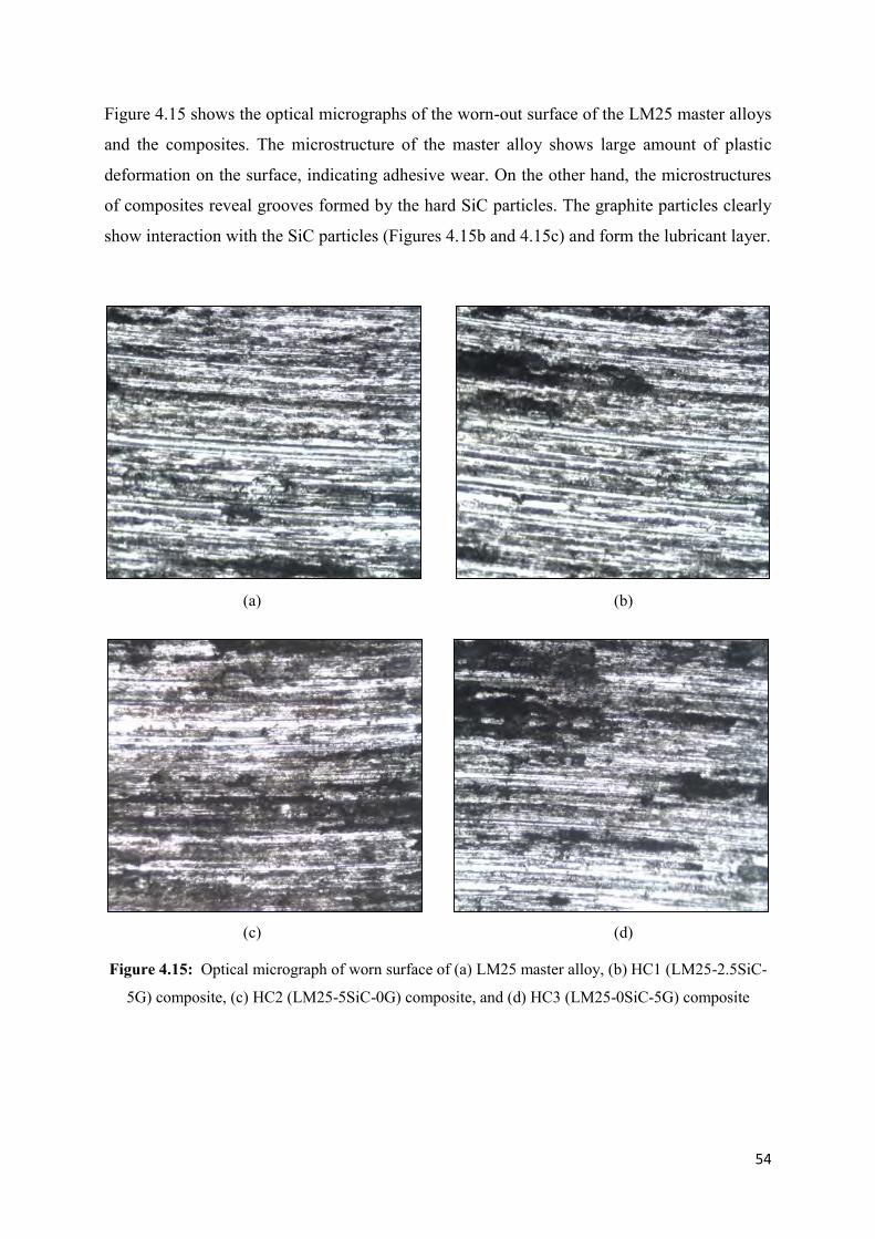
54
Figure 4.15 shows the optical micrographs of the worn-out surface of the LM25 master alloys
and the composites. The microstructure of the master alloy shows large amount of plastic
deformation on the surface, indicating adhesive wear. On the other hand, the microstructures
of composites reveal grooves formed by the hard SiC particles. The graphite particles clearly
show interaction with the SiC particles (Figures 4.15b and 4.15c) and form the lubricant layer.
(a) (b)
(c) (d)
Figure 4.15: Optical micrograph of worn surface of (a) LM25 master alloy, (b) HC1 (LM25-2.5SiC-
5G) composite, (c) HC2 (LM25-5SiC-0G) composite, and (d) HC3 (LM25-0SiC-5G) composite
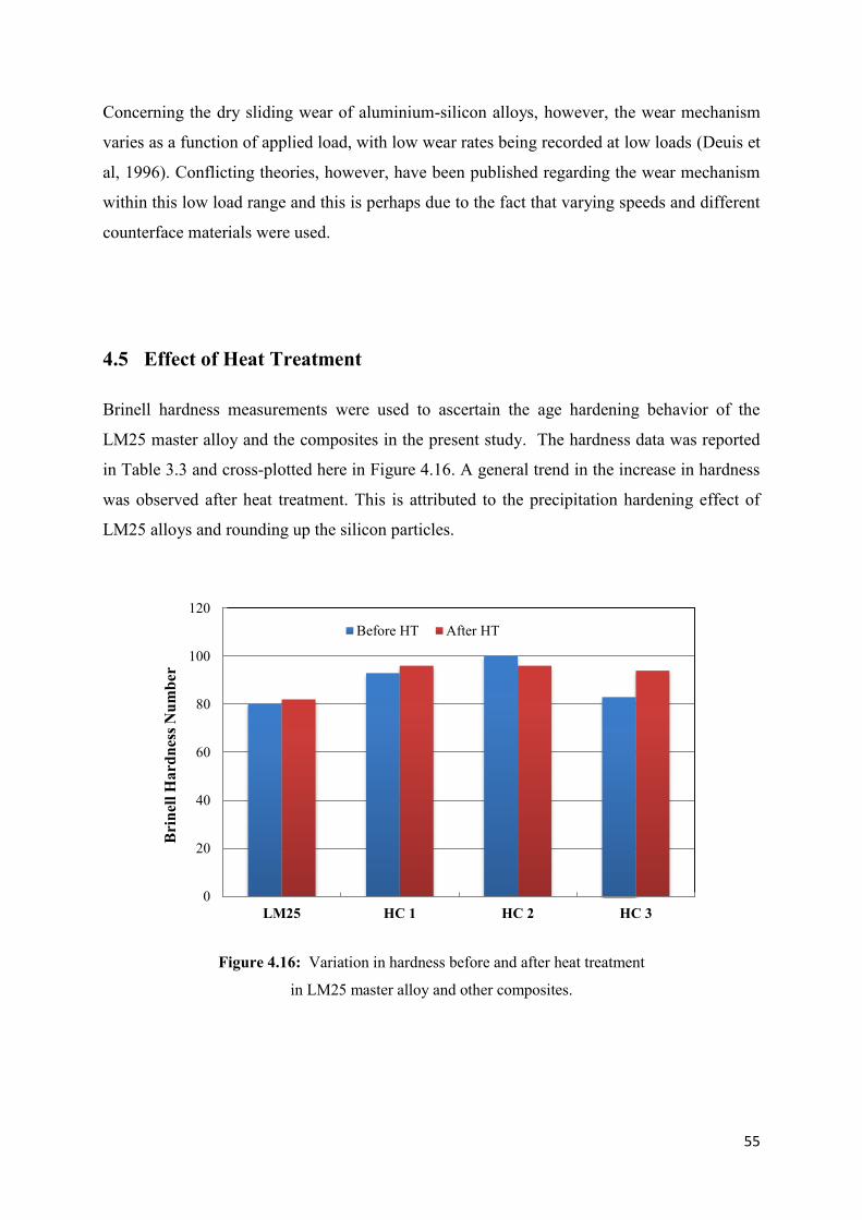
55
Concerning the dry sliding wear of aluminium-silicon alloys, however, the wear mechanism
varies as a function of applied load, with low wear rates being recorded at low loads (Deuis et
al, 1996). Conflicting theories, however, have been published regarding the wear mechanism
within this low load range and this is perhaps due to the fact that varying speeds and different
counterface materials were used.
4.5 Effect of Heat Treatment
Brinell hardness measurements were used to ascertain the age hardening behavior of the
LM25 master alloy and the composites in the present study. The hardness data was reported
in Table 3.3 and cross-plotted here in Figure 4.16. A general trend in the increase in hardness
was observed after heat treatment. This is attributed to the precipitation hardening effect of
LM25 alloys and rounding up the silicon particles.
Figure 4.16: Variation in hardness before and after heat treatment
in LM25 master alloy and other composites.
0
20
40
60
80
100
120
LM25 HC 1 HC 2 HC 3
Bri
nell
Har
dnes
s Num
ber
Before HT After HT

56
5 Conclusions
5. Conclusions ................................................................................................................... 56
5.1 Conclusions .................................................................................................................... 57
5.2 Suggestions for future work ........................................................................................... 57

57
5.1 Conclusions
From this study the following conclusions are drawn:
1. Manufacture of Aluminium–7Silicon–Magnesium alloys (LM25) based hybrid
composites using silicon carbide and graphite particles as reinforcing agents was partly
successful using stir casting process. The distribution of reinforcing particles in the
composites were not uniform and each sample contained a varying degree of porosity.
2. Addition of both SiC and G reinforcing particles to LM25 alloys caused a general
increase in the properties, although the properties of the composites were predictably
affected mostly by the hard reinforcing SiC particles.
3. The hardness, tensile strength and resistance to wear were found to be the maximum in
case of HC2 (LM25-5SiC-0G) composite. Addition of G particles somewhat lowered the
tensile properties, while a mixed result was obtained in case of hardness. The wear
resistance was decreased due to the addition of G particles.
4. The HC1 (LM25-2.5SiC-5G) hybrid composites had the intermediate properties of the
two composites HC2 and HC3 where SiC and G particles were used in isolation. The
hardness, tensile strength and resistance to wear were found to be higher but lower than
those obtained for HC2.
5. The age hardening response of all four materials was predictable. Hardness values were
generally increased in case of all materials.
5.2 Suggestions for future works
Preparation of homogeneous composite with well dispersed reinforcing agent and minimal
porosity is always mandatory to conduct investigation like those mentioned in this work. For
the production of good quality composites, proper equipment and facilities are required.
Use of variable amounts of reinforcing agents and consideration of an increased number of
test parameters (e.g., variable sliding speed, sliding load, sliding time in case or wear) will
help deducing authentic and accurate conclusions.
58
List of table
Page Number
Table 2.1: Alloy designation system for wrought aluminium alloys 5
Table 2.2: Classification of wrought aluminum alloys based on strengthening mechanism. 6
Table 2.3: Alloy designation system for cast aluminium alloys. 7
Table 2.4: Basic temper designations. 8
Table 2.5: Temper designation system for strain-hardened products. 8
Table 2.6: Temper designation system for heat-treatable alloys. 9
Table 2.7(a): The chemical composition of common cast aluminium alloys. 13
Table 2.7(b): The mechanical properties of common cast aluminium alloys. 14
Table 2.8: Chemical composition range of LM25 alloys. 18
Table 2.9: Physical property range of LM25 alloys. 19
Table 2.10: Mechanical properties of Aluminium-7Silicon-Magnesium alloys. 19
Table 2.11: Properties of silicon carbide. 28
Table 2.12: Properties of commercial graphite. 29
Table 3.1: Chemical composition of the raw materials and the master alloy. 37
Table 3.2: Chemical make-up of the LM25-SiC-G hybrid composites. 38
Table 3.3: Hardness test data. 39
Table 3.4: Tensile test data. 40
Table 3.5: Wear test data. 41

59
List of Figure Page number
Figure 2.1: Detail of aluminium alloy temper designation system. 10
Figure 2.2: Commercial cast aluminum-silicon binary alloys. (a) Al-Si equilibrium diagram.
(b) Microstructure of hypoeutectic alloy (<12.6 wt% Si). x150. (c) Microstructure of eutectic alloy
(12.6% Si). x400. (d) Microstructure of hypereutectic alloy (>12.6% Si). x150. 15 Figure 2.3: The pseudo-binary Al-Mg2Si phase diagram. 16
Figure 2.4: Microstructure of LM25 (A356) alloy. (a) As-cast (unmodified), (b) Modified with
0.008% Strontium. x100. 17
Figure 2.5: Microstructure of LM25 (A357) alloy. (a) As-cast (unmodified), (b) Modified with
0.013% Strontium. x100. 17
Figure 2.6: The schematics of the mixing machine with other setup to prepare the hybrid composite. 25 Figure 3.1: The mixing machine with other setup to prepare the hybrid composite. 36 Figure 3.1 A: Tensile Sample 37
Figure 3.2: Wear testing set-up. 38 Figure 4.1: Scanning electron micrograph and EDX analysis of HC1 (LM25-2.5SiC-5G). 43
Figure 4.2: Scanning electron micrograph and EDX analysis of HC2 (LM25-5SiC-0G). 44
Figure 4.3: Scanning electron micrograph and EDX analysis of HC3 (LM25-0SiC-5G). 45
Figure 4.4: Inhomogeneity and agglomeration of silicon carbide and graphite particles
in LM25-SiC-G hybrid composite. 46
Figure 4.5: Optical micrograph of LM25 master alloy. (a) x200, (b) x500. 47
Figure 4.6: Optical micrograph of HC1 (LM25-2.5SiC-5G) hybrid composite. (a) x200, (b) x500. 47 Figure 4.7: Optical micrograph of HC2 (LM25-5SiC-0G) hybrid composite. (a) x200, (b) x500. 48 Figure 4.8: Optical micrograph of HC3 (LM25-0SiC-5G) hybrid composite. (a) x200, (b) x500. 48
Figure 4.9: Scanning electron micrograph of (a) LM25 master alloy and
(b) HC1 (LM25-2.5SiC-5G) hybrid composite. 49
Figure 4.10: Scanning electron micrograph of (a) HC2 (LM25-5SiC-0G) and
(b) HC3 (LM25-0SiC-5G) hybrid composites. 49
Figure 4.11: Hardness value of LM25 master alloy and other composites. 50
Figure 4.12: Tensile properties of LM25 master alloy and other composites. 51
Figure 4.13: Variation of wear loss in LM25 master alloy and other composites. 53
Figure 4.14: Variation of wear resistance in LM25 master alloy and other composites. 53
Figure 4.15: Optical micrograph of worn surface of (a) LM25 master alloy, (b) HC1 (LM25-2.5SiC-
5G) composite, (c) HC2 (LM25-5SiC-0G) composite, and (d) HC3 (LM25-0SiC-5G) composite. 54
Figure 4.16: Variation in hardness before and after heat treatment
in LM25 master alloy and other composites. 55

60
References
Accuratus (2015) “Silicon carbide, SiC ceramic properties,” Accuratus Corporation,
Available from http://accuratus.com/silicar.html [Accessed 7 April 2015].
Apelian D, Shivkumar S and Sigworth G (1989) “Fundamental aspects of heat treatment of
cast Al-Si-Mg alloys,” AFS Transactions, vol. 97, pp. 727-742.
ASM International (1990) “ASM Handbook: Volume 2 – Properties and Selection of
Nonferrous Alloys and Special-Purpose Materials,” ASM International.
ASM International (1993) “ASM Specialty Handbook: Aluminium and Aluminium Alloys”,
ASM International.
ASM International (1998) “Metals Handbook Desk Edition”, 2nd Edition, ASM International.
ASM International (2004) “Aluminium – Silicon Casting Alloys: Atlas of
Microphotographs”, ASM International.
Azo material (2015) “Graphite (C) – Classification, properties and applications of graphite,”
Azo Network, Available form http://azom.com/article.aspx?ArticleID=1630 [Accessed 7
April 2015].
Balasubramanya H S, Basavaraja J S, Srinivas S and Ravikumar V (2014) “Wear rate
behaviour of as-cast and heat treated hybrid metal matrix composites,” Procedia Materials
Science, vol. 5, pp. 1049-1055.
Basavarajappa S, Chandaramohan G, Mahadevan, A, Thangavelu M, Subramanian R and
Gopalakrishnan P (2007) “Influence of sliding speed on the dry sliding wear behaviour and
the subsurface deformation on hybrid metal matrix composite,” Wear, vol. 262 (7), pp. 1007-
1012.
Das S, Udhayabanu V, Das S and Das K (2006) “Synthesis and characterization of Zircon
Sand/Al-4.5 wt% Cu Composite produced by Stir Casting Route”, J Mater Sci (2006)
41:4668–4677.

61
Das S, Udhayabanu V, Das S and Das K (2006) “Synthesis and characterization of zircon/Al–
4.5%Cu composite produced by stir casting route,” Journal of Materials Science, vol. 41, pp.
4668–4677.
Deuis R L, Subramanian C and Yellup J M (1997) “Dry sliding wear of aluminium
composites – a review,” Composite Science and Technology, vol. 57, pp. 415-435.
Divecha A P, Fishman S G, Karmakar S D (1981) “Silicon carbide reinforced aluminum - A
formable composite” Journal of Metals. Vol. 33, pp. 12-17.
Epstein S G (2001) “Aluminium and Its Alloys”, The Aluminium Association.
Eskin D G, Massardier V and Merle (1999) “A study of high-temperature precipitation in Al-
Mg-Si alloys with excess of silicon,” J. Mater Sci., 34(4), pp. 811-820.
Garg H K, Verma K, Manna A and Kumar R (2012) “Hybrid metal matrix composites and
further improvement in their machinability – A review,” International Journal of Latest
Research in Science and Technology, Vol. 1 (1), pp. 36-44.
Gruzlesik J E (1990) “The Treatment of Liquid Aluminium-silicon Alloys,” The American
Foundrymen’s Society Inc.
Higgins R A (1997) “Materials for the Engineering Technicians,” Third Edition, International
Students’ Edition, Arnold.
Kanno M, Suzuki H and Shiraishi (1978) “The age-hardenability of Al-Mg2Si alloys with
excess silicon,” J. Jap. Inst Light Met., 28 (11), pp. 553-557.
Matsunaga T, Kim J K, Hard Castle S, Rohatgi P K (1996) “Casting characteristics of
aluminium alloy, fly ash composites,” Transactions of AFS, vol. 104, pp. 1097−1102.
Mohamed A M A and Samulle F H (2012) “A review on the heat treatment of Al-Si-Cu/Mg
casting alloys,” InTech, Available from: http://dx.doi.org/10.5772/79832 [Accessed 7 April
2015]
Mould R E and Mapother D E (1962) “Effect of precipitation hardening on the
superconducting properties of aluminium,” Phys. Rev., 125(1), pp. 33-43.
62
MRT Castings (2015) “Aluminium Casting Alloy LM25,” MRT Castings, Available from:
http://www.mrt-casting.co.uk/aluminium-alloy-lm25.html [Accessed 7 April 2015].
Naher S (2004) “Examination of the stir-casting method to produce Al-SiC composites,” PhD
Thesis, Dublin City University, Ireland.
Pandi G and Muthusamy S (2012) “A review of mechanical and tribological behaviours of
aluminium hybrid composites,” Procedia Engineering, vol. 38, pp. 1399 – 1408.
Prasad D S and Krishna A R (2011) “Production and mechanical properties of A356.2/RHA
composites,” International Journal of Advanced Science and Technology, vol. 33, pp. 51–57.
Prasad R and Asthana (2006) “Aluminum metal-matrix composites for automotive
applications’ tribological considerations,” Tribol Letters, vol. 17, pp. 445–453.
Rajan T P D, Pillai R M, Pai B C , Satyanarayana and Rohatgi P K (2007) “Fabrication and
characterization of Al-7Si-0.35Mg/fly ash metal matrix composites processed by different stir
casting routes,” Composite Science and Technology, vol. 67, pp. 3369-3377.
Rajan T P D, Pillai R M, Pai B C, Satyanarayana K G, Rohatgi P K (2007) “Fabrication and
characterisation of Al–7Si–0.35Mg/fly ash metal matrix composites processed by different
stir casting routes”, Composites Science and Technology 67 (2007) 3369–3377.
Ramachandra M and Radhakrishna K (2005) “Synthesis-microstructure-mechanical
properties-wear and corrosion behavior of an Al–Si (12%) – Flyash metal matrix composite,”
Journal of Materials Science, vol. 40, pp. 5989–5997.
Ravindran P, Manisekar K, Narayanasamy P, Selvakumar N and Narayanasamy P (2012)
“Application of frictional techniques to study the wear of Al hybrid composites with graphite
addition,” Materials & Design, vol. 39, pp. 42-54.
Ray N and Kerketta D K (2010) “Some Studies on Aluminium Matrix in Situ Composites
Produced by Stir Casting Method”, ME Thesis NIT Rourkela.
Shorowwordi K M, Laoui T, Haseeb A S M A, Celis J P and Froyen L (2003) “Microstructure
and interface characteristics of B4C, SiC and Al2O3 reinforced Al matrix composites: A
comparative study,” Journal of Materials Processing Technology, vol. 142 (3), pp. 738-743.
63
Stroganov G B, Rotenberg V A and Gershman G B (1977) “Alloys of aluminium with
silicon,” Metallurgia, Moscow.
Surappa M K (2003)”Aluminium matrix composites: Challenges and opportunities,” Sadhana,
vol. 28, p. 319.
Suresha S and Sridhara B K (2010) “Effect of addition of graphite particulates on the wear
behaviour in aluminium-silicon carbide-graphite composites,” Materials and Design, vol. 31,
pp. 1804-1812.
Suresha S and Sridhara B K (2012) “Friction characteristics of aluminium silicon carbide
graphite composites,” Materials and Design, vol. 33, pp. 576-583.
Thakur S K, Kwee G T, Gupta M (2007) “Development and characterization of magnesium
composites containing nano-sized silicon carbide and carbon nanotubes as hybrid
reinforcements,” Journal of Material Science, vol. 42, pp. 10040−10046.
Totten G E and MacKenzie D C (eds.) (2003) “Handbook of Aluminium: Volume 1 –
Physical Metallurgy and Processes,” Marcell Dekker Inc., New York.
Uthayakumar M, Aravindan S and Rajkumar K (2013) “Wear performance of Al-SiC-B4C
hybrid composites under dry sliding conditions,” Materials and Design, vol. 47, pp. 456-464.