Steel-Concrete Composite Beams with Precast Hollow ... - MDPI
25
sustainability Article Steel-Concrete Composite Beams with Precast Hollow-Core Slabs: A Sustainable Solution Felipe Piana Vendramell Ferreira 1 , Konstantinos Daniel Tsavdaridis 2, * , Carlos Humberto Martins 3 and Silvana De Nardin 1 Citation: Ferreira, F.P.V.; Tsavdaridis, K.D.; Martins, C.H.; De Nardin, S. Steel-Concrete Composite Beams with Precast Hollow-Core Slabs: A Sustainable Solution. Sustainability 2021, 13, 4230. https://doi.org/ 10.3390/su13084230 Academic Editor: Jorge de Brito Received: 17 March 2021 Accepted: 7 April 2021 Published: 10 April 2021 Publisher’s Note: MDPI stays neutral with regard to jurisdictional claims in published maps and institutional affil- iations. Copyright: © 2021 by the authors. Licensee MDPI, Basel, Switzerland. This article is an open access article distributed under the terms and conditions of the Creative Commons Attribution (CC BY) license (https:// creativecommons.org/licenses/by/ 4.0/). 1 Department of Civil Engineering, Federal University of São Carlos, 13565-905 São Carlos, São Paulo, Brazil; [email protected] (F.P.V.F.); [email protected] (S.D.N.) 2 School of Civil Engineering, Faculty of Engineering and Physical Sciences, University of Leeds, Leeds LS2 9JT, UK 3 Department of Civil Engineering, State University of Maringá, 87020-900 Maringá, Paraná, Brazil; [email protected] * Correspondence: [email protected]; Tel.: +44(0)-113-343-2299 Abstract: Industrialization of construction makes building operation more environmental friendly and sustainable. This change is necessary as it is an industry that demands large consumption of water and energy, as well as being responsible for the disposal of a high volume of waste. However, the transformation of the construction sector is a big challenge worldwide. It is also well known that the largest proportion of the material used in multistory buildings, and thus its carbon impact, is attributed to their slabs being the main contributor of weight. Steel-Concrete composite beams with precast hollow-core slabs (PCHCSs) were developed due to their technical and economic benefits, owing to their high strength and concrete self-weight reduction, making this system economical and with lower environmental footprint, thus reducing carbon emissions. Significant research has been carried out on deep hollow-core slabs due to the need to overcome larger spans that resist high loads. The publication SCI P401, in accordance with Eurocode 4, is however limited to hollow-core slabs with depths from 150 to 250 mm, with or without a concrete topping. This paper aims to investigate hollow-core slabs with a concrete topping to understand their effect on the flexural behavior of Steel-Concrete composite beams, considering the hollow-core-slab depth is greater than the SCI P401 recommendation. Consequently, 150 mm and 265 mm hollow-core units with a concrete topping were considered to assess the increase of the hollow core unit depth. A comprehensive computational parametric study was conducted by varying the in situ infill concrete strength, the transverse reinforcement rate, the shear connector spacing, and the cross-section of steel. Both full and partial interaction models were examined, and in some cases similar resistances were obtained, meaning that the same strength can be obtained for a smaller number of shear studs, i.e., less energy consumption, thus a reduction in the embodied energy. The calculation procedure, according to Eurocode 4 was in favor of safety for the partial-interaction hypothesis. Keywords: composite beams; hollow-core slabs; sustainable; finite element analyses 1. Introduction Researchers have been studying the impact that civil construction causes on the environment. In this context, a concept that has been studied is embodied energy in materials of buildings [1]. In Whitworth and Tsavdaridis [2,3], optimization studies were presented in Steel-Concrete composite beams with the objective of presenting sustainable structural designs by minimizing the embodied energy. The study showed that it is possible to reduce the embodied energy of these structural systems, considering the design recommendations of Eurocode 4 [4]. Conventional Steel-Concrete composite beams have a concrete slab that is placed at the upper flange of the downstand steel profile. In this context, three types of slabs can be Sustainability 2021, 13, 4230. https://doi.org/10.3390/su13084230 https://www.mdpi.com/journal/sustainability
-
Upload
khangminh22 -
Category
Documents
-
view
4 -
download
0
Transcript of Steel-Concrete Composite Beams with Precast Hollow ... - MDPI

sustainability
Article
Steel-Concrete Composite Beams with Precast Hollow-CoreSlabs: A Sustainable Solution
Felipe Piana Vendramell Ferreira 1 , Konstantinos Daniel Tsavdaridis 2,* , Carlos Humberto Martins 3
and Silvana De Nardin 1
�����������������
Citation: Ferreira, F.P.V.; Tsavdaridis,
K.D.; Martins, C.H.; De Nardin, S.
Steel-Concrete Composite Beams
with Precast Hollow-Core Slabs: A
Sustainable Solution. Sustainability
2021, 13, 4230. https://doi.org/
10.3390/su13084230
Academic Editor: Jorge de Brito
Received: 17 March 2021
Accepted: 7 April 2021
Published: 10 April 2021
Publisher’s Note: MDPI stays neutral
with regard to jurisdictional claims in
published maps and institutional affil-
iations.
Copyright: © 2021 by the authors.
Licensee MDPI, Basel, Switzerland.
This article is an open access article
distributed under the terms and
conditions of the Creative Commons
Attribution (CC BY) license (https://
creativecommons.org/licenses/by/
4.0/).
1 Department of Civil Engineering, Federal University of São Carlos, 13565-905 São Carlos, São Paulo, Brazil;[email protected] (F.P.V.F.); [email protected] (S.D.N.)
2 School of Civil Engineering, Faculty of Engineering and Physical Sciences, University of Leeds,Leeds LS2 9JT, UK
3 Department of Civil Engineering, State University of Maringá, 87020-900 Maringá, Paraná, Brazil;[email protected]
* Correspondence: [email protected]; Tel.: +44(0)-113-343-2299
Abstract: Industrialization of construction makes building operation more environmental friendlyand sustainable. This change is necessary as it is an industry that demands large consumption ofwater and energy, as well as being responsible for the disposal of a high volume of waste. However,the transformation of the construction sector is a big challenge worldwide. It is also well known thatthe largest proportion of the material used in multistory buildings, and thus its carbon impact, isattributed to their slabs being the main contributor of weight. Steel-Concrete composite beams withprecast hollow-core slabs (PCHCSs) were developed due to their technical and economic benefits,owing to their high strength and concrete self-weight reduction, making this system economicaland with lower environmental footprint, thus reducing carbon emissions. Significant research hasbeen carried out on deep hollow-core slabs due to the need to overcome larger spans that resist highloads. The publication SCI P401, in accordance with Eurocode 4, is however limited to hollow-coreslabs with depths from 150 to 250 mm, with or without a concrete topping. This paper aims toinvestigate hollow-core slabs with a concrete topping to understand their effect on the flexuralbehavior of Steel-Concrete composite beams, considering the hollow-core-slab depth is greater thanthe SCI P401 recommendation. Consequently, 150 mm and 265 mm hollow-core units with a concretetopping were considered to assess the increase of the hollow core unit depth. A comprehensivecomputational parametric study was conducted by varying the in situ infill concrete strength, thetransverse reinforcement rate, the shear connector spacing, and the cross-section of steel. Both fulland partial interaction models were examined, and in some cases similar resistances were obtained,meaning that the same strength can be obtained for a smaller number of shear studs, i.e., less energyconsumption, thus a reduction in the embodied energy. The calculation procedure, according toEurocode 4 was in favor of safety for the partial-interaction hypothesis.
Keywords: composite beams; hollow-core slabs; sustainable; finite element analyses
1. Introduction
Researchers have been studying the impact that civil construction causes on theenvironment. In this context, a concept that has been studied is embodied energy inmaterials of buildings [1]. In Whitworth and Tsavdaridis [2,3], optimization studies werepresented in Steel-Concrete composite beams with the objective of presenting sustainablestructural designs by minimizing the embodied energy. The study showed that it ispossible to reduce the embodied energy of these structural systems, considering the designrecommendations of Eurocode 4 [4].
Conventional Steel-Concrete composite beams have a concrete slab that is placed atthe upper flange of the downstand steel profile. In this context, three types of slabs can be
Sustainability 2021, 13, 4230. https://doi.org/10.3390/su13084230 https://www.mdpi.com/journal/sustainability

Sustainability 2021, 13, 4230 2 of 25
used: solid, composite or precast hollow-core slabs (PCHCSs). In composite beams withPCHCSs, a cast in situ concrete topping is usually made to provide a smooth and uniformfinish [5]. The concrete topping can increase the strength and stiffness of the structuralsystem [6,7]. Other factors influence the strength of PCHCSs, such as the intensity ofthe actual prestress, the prestress transmission length, the depth of the slab, and filledcores [8]. PCHCSs are widely used in countries with cold climates in the construction ofresidential or industrial buildings due to their fast installation. In Albero et al. [9], theestimate of the number of PCHCS floors installed in Europe was estimated to be close to1 billion square meters. The use of PCHCSs offers advantages; e.g., large spans, speed ofconstruction, and reduced construction costs [5,10–14]. In the European Union, accordingto Ahmed and Tsavdaridis [15], construction and building are responsible for about 40% ofenvironmental impact. In Dong et al. [16], the precast and cast in situ construction methodswere compared using a case study. The authors concluded that the precast constructioncould lead to a 10% carbon reduction for one cubic meter of concrete. The PCHCS is anindustrialized structural element that consumes less energy when constructed in-house incomparison to in situ, and with a minimum waste of concrete, and thus with an overalllower carbon footprint. In terms of sustainability, the PCHCS is a structural element thatcontributes not only to the speed of construction, but also to the significant reduction ofCO2 emissions due to the lower consumption of concrete.
The present study aims to examine the flexural behavior of Steel-Concrete compositebeams with PCHCSs and a concrete topping, considering a hollow core unit (HCU) depthgreater than the SCI P401 recommendation. The finite element (geometrical nonlinearanalysis) model was developed based on tests [17,18]. The results were compared with theSCI P401 procedure [19], and thus analytical models of shear-stud resistance capacity wereemployed [19,20].
2. Background
Lam [17] and Lam et al. [21] presented flexural tests on Steel-Concrete compositebeams with PCHCSs. A four-point bending was considered. In these studies, the concretetopping was not considered. The experimental results showed a sudden failure due tothe shear studs rupturing and the concrete cracking, resulting in a loss of stiffness. Lamet al. [22] complemented the previous studies and carried out a parametric study in whichthey observed that with an increase in the depth of PCHCSs (150 mm to 200–250 mm),there was an increase in the ultimate strength. However, the slab could fail due to excessivecracking. Ellobody and Lam [23] investigated the shear studs and the gap while consideringthe flexural behavior. The authors concluded that the shear-stud resistance increased withthe increase of the gap, and the in situ infill concrete strength influenced the strength ofthe shear studs. In 2003, SCI P287 [24] was published; it is a design criteria for compositebeams with PCHCSs [17]. This publication was subsequently updated to SCI P401 [19].The document gathers recommendations of minimum dimensions, such as arrangement ofthe shear studs and transverse reinforcement. However, some limitations were observed,such as application only for 150–250 mm HCU depths; 12 mm or 16 mm transversereinforcement diameters are recommended for composite construction. For partial shearconnection, 16 mm diameter bars should be provided; for HCUs up to 260 mm, 16 mmdiameter bars should be considered, spaced at 200–350 mm. For full interaction, if theplastic neutral axis (PNA) lies within the slab, the interaction degree must be reduced, orthe size of the steel profile increased. A technical report (COPPETEC, PEC-18541/2016),which was presented by Batista and Landesmann [18], described tests on composite beamswith PCHCSs and concrete topping. According to the authors, at the ultimate strength,the loss of stiffness was due to excessive cracking. In Ferreira et al. [25], a parametricstudy was presented, considering PCHCSs with 150 mm of depth and 50 mm of concretetopping. In this study, the presence of the concrete topping increased the strength of thecomposite beams by at least 7%. As observed, few studies have investigated the behaviorof Steel-Concrete composite beams with PCHCSs [26]. Tawadrous and Morcous [4] and

Sustainability 2021, 13, 4230 3 of 25
El-Sayed et al. [5] showed that, due to the successful use of PCHCSs, deeper HCUs weredeveloped to resist higher loads and to support longer spans. In this scenario, someresearchers carried out tests to investigate the behavior of deeper PCHCSs [12,13,27–32].However, these investigations did not consider composite behavior, i.e., Steel-Concretecomposite beams.
3. Numerical Model: Validation Study
In this section, the methodology of the validation study is described. The ABAQUSsoftware [33] was used. Three types of Steel-Concrete composite beams were modeled,considering symmetry:
1. 150 mm of HCU depth with a chamfered end (Figure 1a);2. 150 mm of HCU depth and 50 mm of concrete topping with a squared end (Figure 1b);3. 265 mm of HCU depth and 50 mm of concrete topping with a squared end (Figure 1c).
Sustainability 2021, 13, x 3 of 24
strength of the composite beams by at least 7%. As observed, few studies have investigated the behavior of Steel-Concrete composite beams with PCHCSs [26]. Tawadrous and Morcous [4] and El-Sayed et al. [5] showed that, due to the successful use of PCHCSs, deeper HCUs were developed to resist higher loads and to support longer spans. In this scenario, some researchers carried out tests to investigate the behavior of deeper PCHCSs [12,13,27–32]. However, these investigations did not consider composite behavior, i.e., Steel-Concrete composite beams.
3. Numerical Model: Validation Study In this section, the methodology of the validation study is described. The ABAQUS
software [33] was used. Three types of Steel-Concrete composite beams were modeled, considering symmetry: 1. 150 mm of HCU depth with a chamfered end (Figure 1a); 2. 150 mm of HCU depth and 50 mm of concrete topping with a squared end (Figure
1b); 3. 265 mm of HCU depth and 50 mm of concrete topping with a squared end (Figure
1c).
(a)
(b)
Figure 1. Cont.

Sustainability 2021, 13, 4230 4 of 25Sustainability 2021, 13, x 4 of 24
(c)
Figure 1. Parts of Steel-Concrete composite beams with a hollow core slab: (a) 150 mm of hollow-core-slab depth with a chamfered end; (b) 150 mm of hollow-core-slab depth and 50 mm of con-crete topping with a squared end; (c) 265 mm of hollow-core-slab depth and 50 mm of concrete topping with a squared end.
Geometrical nonlinear analyses were processed using the Static Riks method. This method was previously used in [25,34–40] and is based on the arc-length method. Resid-ual stresses were not considered. These stresses do not influence the ultimate strength of composite beams subjected to only positive moments. The residual stresses increase the effects of the negative moment [41,42].
3.1. Tests The numerical models were calibrated considering tests on Steel-Concrete composite
beams with PCHCSs, at 150 mm and 265 mm of depth, and with or without a concrete topping. Figure 2 and Table 1 show the details of the tests [18,43], in which d is the steel-beam depth, bf is the steel-flange width, tf is the steel-flange thickness, tw is the steel-web thickness, b is the effective slab width, g is the gap, hc is the depth of the HCU, c is the concrete-topping thickness, Le is the distance between the end of the beam and the sup-port, Lp is the distance between the load application point and the support, Lb is the unre-strained length, φ is the diameter of the transverse reinforcement, fy,f is the yield strength of the flange, fy,w is the yield strength of the web, fy,s is the transverse reinforcement yield strength, fc,HCU is the HCU compressive strength, and fc,in is the in situ infill compressive strength.
(a) (b)
Figure 2. Geometric details of tests (in mm): (a) lateral view; (b) section.
Figure 1. Parts of Steel-Concrete composite beams with a hollow core slab: (a) 150 mm of hollow-core-slab depth with a chamfered end; (b) 150 mm of hollow-core-slab depth and 50 mm of concretetopping with a squared end; (c) 265 mm of hollow-core-slab depth and 50 mm of concrete toppingwith a squared end.
Geometrical nonlinear analyses were processed using the Static Riks method. Thismethod was previously used in [25,34–40] and is based on the arc-length method. Residualstresses were not considered. These stresses do not influence the ultimate strength ofcomposite beams subjected to only positive moments. The residual stresses increase theeffects of the negative moment [41,42].
3.1. Tests
The numerical models were calibrated considering tests on Steel-Concrete compositebeams with PCHCSs, at 150 mm and 265 mm of depth, and with or without a concretetopping. Figure 2 and Table 1 show the details of the tests [18,43], in which d is the steel-beam depth, bf is the steel-flange width, tf is the steel-flange thickness, tw is the steel-webthickness, b is the effective slab width, g is the gap, hc is the depth of the HCU, c is theconcrete-topping thickness, Le is the distance between the end of the beam and the support,Lp is the distance between the load application point and the support, Lb is the unrestrainedlength, ϕ is the diameter of the transverse reinforcement, fy,f is the yield strength of theflange, fy,w is the yield strength of the web, fy,s is the transverse reinforcement yield strength,fc,HCU is the HCU compressive strength, and fc,in is the in situ infill compressive strength.
Table 1. Details of specimens (in mm and MPa).
Model d bf tf tw b g hc c Le Lp Lb ϕ fy,f fy,w fy,s fc,HCU fc,in
CB1 355 171.5 11.5 7.4 1665 65 150 - 150 1500 5700 16 310 355 585 50 a 32 a
CB2 355 171.5 11.5 7.4 1665 65 150 - 150 1500 5700 8 310 355 473 50 a 26 a
CB3 299 306 11 11 1756 156 150 50 185 1915 5830 12.5 345 345 500 45 b 30 b
CB4 299 306 11 11 1756 106 265 50 185 1915 5830 12.5 345 345 500 45 b 30 b
a Cubic resistance; b cylindric resistance.

Sustainability 2021, 13, 4230 5 of 25
Sustainability 2021, 13, x 4 of 24
(c)
Figure 1. Parts of Steel-Concrete composite beams with a hollow core slab: (a) 150 mm of hollow-core-slab depth with a chamfered end; (b) 150 mm of hollow-core-slab depth and 50 mm of con-crete topping with a squared end; (c) 265 mm of hollow-core-slab depth and 50 mm of concrete topping with a squared end.
Geometrical nonlinear analyses were processed using the Static Riks method. This method was previously used in [25,34–40] and is based on the arc-length method. Resid-ual stresses were not considered. These stresses do not influence the ultimate strength of composite beams subjected to only positive moments. The residual stresses increase the effects of the negative moment [41,42].
3.1. Tests The numerical models were calibrated considering tests on Steel-Concrete composite
beams with PCHCSs, at 150 mm and 265 mm of depth, and with or without a concrete topping. Figure 2 and Table 1 show the details of the tests [18,43], in which d is the steel-beam depth, bf is the steel-flange width, tf is the steel-flange thickness, tw is the steel-web thickness, b is the effective slab width, g is the gap, hc is the depth of the HCU, c is the concrete-topping thickness, Le is the distance between the end of the beam and the sup-port, Lp is the distance between the load application point and the support, Lb is the unre-strained length, φ is the diameter of the transverse reinforcement, fy,f is the yield strength of the flange, fy,w is the yield strength of the web, fy,s is the transverse reinforcement yield strength, fc,HCU is the HCU compressive strength, and fc,in is the in situ infill compressive strength.
(a) (b)
Figure 2. Geometric details of tests (in mm): (a) lateral view; (b) section. Figure 2. Geometric details of tests (in mm): (a) lateral view; (b) section.
The shear-stud dimensions were 19 × 125 mm2 (CB1 and CB2) and 19 × 135 mm2
(CB3 and CB4). The shear-stud spacing of the CB1 and CB2 models was 150 mm. Formodels CB3 and CB4, the spacing between the shear studs was 200 mm.
3.2. Materials
The concrete-damage plasticity (CDP) [44–46] model was used. This model is basedon the plastic theory, and can be used to describe the irreversible damage that occurs duringthe fracture process [33], such as cracking and crushing. The concrete-damage plasticitymodel makes use of the yield function of Lubliner et al. [45], with modifications proposedby Lee and Fenves [46]. Concrete, as a brittle material, undergoes considerable volumechange called dilatancy [47], which is caused by inelastic strains. The flow rule followedthe Drucker–Prager model. The concrete-damage plasticity model can be regularized usingviscoplasticity. The regularization of Duvaut-Lions [48] was used. The input parametersfor defining the plastic behavior are presented in Table 2, in which ψ is the dilation angle,ξ is the eccentricity, σb0 is the initial equibiaxial compressive yield stress, σc0 is the initialuniaxial compressive yield stress, Kc is the ratio of the second stress invariant on the tensilemeridian to that on the compressive meridian, and µ is the viscosity parameter.
Table 2. Concrete Damage Plasticity input parameters [25,38,40].
Parameter Value Ref.
Ψ (◦) (In situ concrete) 40 [47,49]Ψ (◦) (HCU concrete) 28 [28]
ξ 0.1 (default) [28,33,47,49]σb0/σc0 1.16 (default) [28,33,47,49]
Kc 2/3 (default) [28,33,47,49]µ (s−1) 0.001 -
The concrete model of Carreira and Chu [50,51] was used for both compression andtension Equations (1)–(3). For steel, the perfect elasto-plastic behavior was considered.
σ
fc=
βc(ε/εc)
βc − 1 + (ε/εc)βc
(1)
σ
ft=
βc(ε/εt)
βc − 1 + (ε/εt)βc
(2)
βc =
(fc
32.4
)3+ 1.55(MPa) (3)

Sustainability 2021, 13, 4230 6 of 25
where εc is the strain corresponding to concrete compressive strength, εt is the straincorresponding to concrete tensile strength, fc is the compressive concrete strength, ft is theconcrete tensile strength, and βc is the stress–strain relationship form factor of concretein compression.
3.3. Interaction
Figure 3 shows the pairs of interactions. The tie constraint technique allowed us tosimulate the perfect bond between the contact surfaces. The contacts between the concreteand the transverse reinforcements were made through the embedded region [33]. Thenormal/tangential behavior was considered between the steel beam and PCHCS, the steelbeam and gap, the actuator and concrete topping, and the shear stud and gap. The shearstuds were located in the gap, using the same technique presented in [52]. The frictioncoefficient was based on the Coulomb friction model. The literature reports some values ofthe friction coefficient [53–55]. Friction coefficients of 0.2 and 0.3 were adopted for the gapand headed stud and the steel beam and slab interfaces, respectively [55].
Sustainability 2021, 13, x 6 of 24
concrete tensile strength, and βc is the stress–strain relationship form factor of concrete in compression.
3.3. Interaction Figure 3 shows the pairs of interactions. The tie constraint technique allowed us to
simulate the perfect bond between the contact surfaces. The contacts between the concrete and the transverse reinforcements were made through the embedded region [33]. The nor-mal/tangential behavior was considered between the steel beam and PCHCS, the steel beam and gap, the actuator and concrete topping, and the shear stud and gap. The shear studs were located in the gap, using the same technique presented in [52]. The friction coefficient was based on the Coulomb friction model. The literature reports some values of the friction coefficient [53–55]. Friction coefficients of 0.2 and 0.3 were adopted for the gap and headed stud and the steel beam and slab interfaces, respectively [55].
Figure 3. Surface-to-surface interactions.
3.4. Boundary Conditions The boundary conditions (Figure 4) were applied considering the symmetry at mid-
span (Uz = URx = URy = 0) [25,37–40]. The vertical displacement was restrained at the sup-ports (Uy = 0) and the lateral displacement at the ends of the slab (Ux = 0). Displacement control was used. The difficulties with softening materials can be avoided by applying a simple form of displacement control [56,57]. The disadvantages in displacement control are related to the selection of the appropriate displacement variable [58]. Thus, the varia-ble selected for the stopping criterion was the midspan vertical displacement.
Figure 3. Surface-to-surface interactions.
3.4. Boundary Conditions
The boundary conditions (Figure 4) were applied considering the symmetry at midspan(Uz = URx = URy = 0) [25,37–40]. The vertical displacement was restrained at the supports(Uy = 0) and the lateral displacement at the ends of the slab (Ux = 0). Displacement controlwas used. The difficulties with softening materials can be avoided by applying a simpleform of displacement control [56,57]. The disadvantages in displacement control are relatedto the selection of the appropriate displacement variable [58]. Thus, the variable selectedfor the stopping criterion was the midspan vertical displacement.

Sustainability 2021, 13, 4230 7 of 25Sustainability 2021, 13, x 7 of 24
Figure 4. Boundary conditions of the CB3 model.
3.5. Discretization The discretization of the elements is shown in Figure 5. The dimension values of the
elements were adopted according to the literature [28,53,54], and with respect to the mas-ter and slave surfaces. The S4R element was a quadrilateral element with four nodes. This element had reduced integration. According to the ABAQUS, Dassault Systèmes, software [33], the C3D8R element had eight nodes, reduced integration, supported plastic analysis with large deformations, and allowed the visualization of the crack in the CDP model. The T3D2 element had 2-node linear displacement.
Figure 5. Discretization.
3.6. Results The results are presented in Figure 6 and Table 3, in which MFE is the bending mo-
ment of finite element model, MTest is the bending moment of experimental tests, δFE is the midspan vertical displacement of the finite element models, and δTest is the mid-pan verti-cal displacement of the tests. It was possible to observe the yielding at the lower flange, and in the CB1 and CB2 models, the cracking was observed in the lower part of the PCHCSs, according to Lam [17]. The behaviors of the CB3 and CB4 models were similar to those presented in Batista and Landesmann [18]; that is, there was a propagation of cracks that started in the central part of the PCHCS and extended over the entire width.
Figure 4. Boundary conditions of the CB3 model.
3.5. Discretization
The discretization of the elements is shown in Figure 5. The dimension values ofthe elements were adopted according to the literature [28,53,54], and with respect to themaster and slave surfaces. The S4R element was a quadrilateral element with four nodes.This element had reduced integration. According to the ABAQUS, Dassault Systèmes,software [33], the C3D8R element had eight nodes, reduced integration, supported plasticanalysis with large deformations, and allowed the visualization of the crack in the CDPmodel. The T3D2 element had 2-node linear displacement.
Sustainability 2021, 13, x 7 of 24
Figure 4. Boundary conditions of the CB3 model.
3.5. Discretization The discretization of the elements is shown in Figure 5. The dimension values of the
elements were adopted according to the literature [28,53,54], and with respect to the mas-ter and slave surfaces. The S4R element was a quadrilateral element with four nodes. This element had reduced integration. According to the ABAQUS, Dassault Systèmes, software [33], the C3D8R element had eight nodes, reduced integration, supported plastic analysis with large deformations, and allowed the visualization of the crack in the CDP model. The T3D2 element had 2-node linear displacement.
Figure 5. Discretization.
3.6. Results The results are presented in Figure 6 and Table 3, in which MFE is the bending mo-
ment of finite element model, MTest is the bending moment of experimental tests, δFE is the midspan vertical displacement of the finite element models, and δTest is the mid-pan verti-cal displacement of the tests. It was possible to observe the yielding at the lower flange, and in the CB1 and CB2 models, the cracking was observed in the lower part of the PCHCSs, according to Lam [17]. The behaviors of the CB3 and CB4 models were similar to those presented in Batista and Landesmann [18]; that is, there was a propagation of cracks that started in the central part of the PCHCS and extended over the entire width.
Figure 5. Discretization.
3.6. Results
The results are presented in Figure 6 and Table 3, in which MFE is the bending momentof finite element model, MTest is the bending moment of experimental tests, δFE is themidspan vertical displacement of the finite element models, and δTest is the mid-panvertical displacement of the tests. It was possible to observe the yielding at the lowerflange, and in the CB1 and CB2 models, the cracking was observed in the lower part of thePCHCSs, according to Lam [17]. The behaviors of the CB3 and CB4 models were similar tothose presented in Batista and Landesmann [18]; that is, there was a propagation of cracksthat started in the central part of the PCHCS and extended over the entire width.

Sustainability 2021, 13, 4230 8 of 25Sustainability 2021, 13, x 8 of 24
(a) (b)
(c) (d)
Figure 6. Validation results: (a) CB1 model; (b) CB2 model; (c) CB3 model; and (d) CB4 model.
Table 3. Comparison of finite element analyses and tests results.
Model MTest
(kN.m) δTest
(mm) MFE
(kN.m) δFE
(mm) MFE/Mtest δFE/δtest
CB1 497 32 496 33 1.00 1.03 CB2 474 35 485 34 0.95 0.97 CB3 846 70 895 71 0.95 1.00 CB4 985 37 1015 35 1.03 0.95
4. Numerical Model: Parametric Study The following were the general considerations for the parametric study:
1. The thickness of the concrete topping was 50 mm; 2. The total transverse reinforcement length was 1000 + g, in mm; 3. A welded steel mesh with 4.2 mm × 100 mm was considered [20,25]; 4. LP26 units (Figure 7), with fc = 40 MPa and g = 70 mm, were considered; 5. For the steel beam, the ASTM A572 Gr.50 steel was adopted (fy = 345 MPa). The
Young’s module and the Poisson’s ratio were 200 GPa and 0.3, respectively; 6. The composite beams were simply supported, and subjected to four-point bending.
The loads were spaced in L/4 from each support. Stiffeners were placed at the support and points of loads;
7. The midspan vertical displacement of a maximum value equal to L/100 was adopted as a stopping criterion [25]. The studied parameters are shown in Table 4.
0
100
200
300
400
500
600
0 10 20 30 40
M (k
N.m
)
Mid-span vertical displacement (mm)
TestFE
0
100
200
300
400
500
600
0 10 20 30 40 50
M (k
N.m
)
Mid-span vertical displacement (mm)
TestFE
0
200
400
600
800
1000
0 20 40 60 80
M (k
N.m
)
Mid-span vertical displacement (mm)
TestFE
0
200
400
600
800
1000
1200
0 20 40 60
M (k
N.m
)
Mid-span vertical displacement (mm)
TestFE
Figure 6. Validation results: (a) CB1 model; (b) CB2 model; (c) CB3 model; and (d) CB4 model.
Table 3. Comparison of finite element analyses and tests results.
Model MTest(kN.m)
δTest(mm)
MFE(kN.m)
δFE(mm) MFE/Mtest δFE/δtest
CB1 497 32 496 33 1.00 1.03CB2 474 35 485 34 0.95 0.97CB3 846 70 895 71 0.95 1.00CB4 985 37 1015 35 1.03 0.95
4. Numerical Model: Parametric Study
The following were the general considerations for the parametric study:
1. The thickness of the concrete topping was 50 mm;2. The total transverse reinforcement length was 1000 + g, in mm;3. A welded steel mesh with 4.2 mm × 100 mm was considered [20,25];4. LP26 units (Figure 7), with fc = 40 MPa and g = 70 mm, were considered;5. For the steel beam, the ASTM A572 Gr.50 steel was adopted (fy = 345 MPa). The
Young’s module and the Poisson’s ratio were 200 GPa and 0.3, respectively;6. The composite beams were simply supported, and subjected to four-point bending.
The loads were spaced in L/4 from each support. Stiffeners were placed at the supportand points of loads;
7. The midspan vertical displacement of a maximum value equal to L/100 was adoptedas a stopping criterion [25].

Sustainability 2021, 13, 4230 9 of 25Sustainability 2021, 13, x 9 of 24
Figure 7. LP26 units (in mm).
Table 4. Parametric study.
Parameters Variation Section W360x51, W460x74, and W530x72
In situ concrete strength (MPa) 25, 30, and 40 Transverse reinforcement diameter (mm) 10, 12.5, and 16
Shear-stud spacing (mm) 125, 175, and 275
5. Results and Discussion In this section, the results are discussed, according to the steel cross-sections that
were analyzed. At the end of this section, the results are compared with the resistant cal-culation procedures for Steel-Concrete composite beams, as well as with the results pre-sented in Ferreira et al. [25], considering a 150 mm depth of the PCHCS with concrete topping.
5.1. W360x51 Section Considering a spacing between shear studs of 120 mm, for the midspan vertical dis-
placement at 15 mm, only the region where the beam was supported reached the yield strength. The maximum von Mises stresses in the lower flange, web, and upper flange were approximately 290 MPa, 260 MPa, and 115 MPa, respectively. When the composite beam reached the ultimate strength, for the midspan vertical displacement at 26 mm, the lower flange and approximately 1/4 of the web depth were in the plastic regime. The yield strength was reached in none of the regions where the shear studs were located. The von Mises stresses in the upper flange were approximately 200 MPa. The ultimate strength was governed by excessive cracking of the PCHCS (Figure 8).
Figure 8. Final configuration for W360x51, fc = 25 MPa, φ = 10 mm, and 120 mm of spacing.
With the variation of the transverse reinforcement rate and in situ concrete strength, there were no differences in the shear-slip and moment-deflection relationships (Figure 9).
Figure 7. LP26 units (in mm).
The studied parameters are shown in Table 4.
Table 4. Parametric study.
Parameters Variation
Section W360x51, W460x74, and W530x72In situ concrete strength (MPa) 25, 30, and 40
Transverse reinforcement diameter (mm) 10, 12.5, and 16Shear-stud spacing (mm) 125, 175, and 275
5. Results and Discussion
In this section, the results are discussed, according to the steel cross-sections that wereanalyzed. At the end of this section, the results are compared with the resistant calculationprocedures for Steel-Concrete composite beams, as well as with the results presented inFerreira et al. [25], considering a 150 mm depth of the PCHCS with concrete topping.
5.1. W360x51 Section
Considering a spacing between shear studs of 120 mm, for the midspan verticaldisplacement at 15 mm, only the region where the beam was supported reached the yieldstrength. The maximum von Mises stresses in the lower flange, web, and upper flangewere approximately 290 MPa, 260 MPa, and 115 MPa, respectively. When the compositebeam reached the ultimate strength, for the midspan vertical displacement at 26 mm, thelower flange and approximately 1/4 of the web depth were in the plastic regime. The yieldstrength was reached in none of the regions where the shear studs were located. The vonMises stresses in the upper flange were approximately 200 MPa. The ultimate strength wasgoverned by excessive cracking of the PCHCS (Figure 8).
Sustainability 2021, 13, x 9 of 24
Figure 7. LP26 units (in mm).
Table 4. Parametric study.
Parameters Variation Section W360x51, W460x74, and W530x72
In situ concrete strength (MPa) 25, 30, and 40 Transverse reinforcement diameter (mm) 10, 12.5, and 16
Shear-stud spacing (mm) 125, 175, and 275
5. Results and Discussion In this section, the results are discussed, according to the steel cross-sections that
were analyzed. At the end of this section, the results are compared with the resistant cal-culation procedures for Steel-Concrete composite beams, as well as with the results pre-sented in Ferreira et al. [25], considering a 150 mm depth of the PCHCS with concrete topping.
5.1. W360x51 Section Considering a spacing between shear studs of 120 mm, for the midspan vertical dis-
placement at 15 mm, only the region where the beam was supported reached the yield strength. The maximum von Mises stresses in the lower flange, web, and upper flange were approximately 290 MPa, 260 MPa, and 115 MPa, respectively. When the composite beam reached the ultimate strength, for the midspan vertical displacement at 26 mm, the lower flange and approximately 1/4 of the web depth were in the plastic regime. The yield strength was reached in none of the regions where the shear studs were located. The von Mises stresses in the upper flange were approximately 200 MPa. The ultimate strength was governed by excessive cracking of the PCHCS (Figure 8).
Figure 8. Final configuration for W360x51, fc = 25 MPa, φ = 10 mm, and 120 mm of spacing.
With the variation of the transverse reinforcement rate and in situ concrete strength, there were no differences in the shear-slip and moment-deflection relationships (Figure 9).
Figure 8. Final configuration for W360x51, fc = 25 MPa, ϕ = 10 mm, and 120 mm of spacing.

Sustainability 2021, 13, 4230 10 of 25
With the variation of the transverse reinforcement rate and in situ concrete strength,there were no differences in the shear-slip and moment-deflection relationships (Figure 9).
Sustainability 2021, 13, x 10 of 24
(a) (b)
(c) (d)
Figure 9. Influence of transverse reinforcement for the W360x51 section with 120 mm of spacing: (a) Shear-slip relationship for fc = 25 MPa; (b) moment-deflection relationship for fc = 25 MPa; (c) shear-slip relationship for fc = 40 MPa; and (d) moment-deflection relationship for fc = 40 MPa.
This can be explained as a function of the depth and area of the steel cross-section in relation to the depth and effective area of the PCHCS and concrete topping. Upon reach-ing the ultimate strength, as shown in Figure 8, the neutral plastic axis (NPA) was in the concrete topping, a factor that generates excessive tensile stresses in the PCHCS. This can be concluded since in the final configuration, the upper part of the PCHCS, which was in the region of pure bending, was damaged. Another important observation was the fragile behavior of the composite beams, since the slip values at the steel-concrete interface were less than 6 mm, a parameter that Eurocode 4 [4] considers to characterize the ductile be-havior (Figure 9). Due to this fragile behavior, with the variation of parameters, such as transverse reinforcement rate and in situ concrete strength, there were no significant dif-ferences in terms of stresses, both in the shear studs and in the transversal reinforcement, considering the ultimate strength. Some examples are illustrated in Figure 10. For the models with fc = 25 MPa, it was observed that the smaller the transverse reinforcement diameter, the lower the von Mises stresses in the shear stud. For fc = 25 MPa, the von Mises stresses in the shear studs showed a variation of only 6 MPa. On the other hand, for fc = 40 MPa, there were no variations between the von Mises stresses in the shear studs with the variation of the transverse reinforcement diameter. The observations for fc = 30 MPa were similar.
0
200
400
600
800
0 1 2 3 4
V (k
N)
Slip (mm)
φ=10 mmφ=12.5 mmφ=16 mm
0
200
400
600
800
1000
0 10 20 30
M (k
N.m
)
Mid-span vertical displacement (mm)
φ=10 mmφ=12.5 mmφ=16 mm
0
200
400
600
800
0 1 2 3 4
V (k
N)
Slip (mm)
φ=10 mmφ=12.5 mmφ=16 mm
0
200
400
600
800
1000
0 10 20 30
M (k
N.m
)
Mid-span vertical displacement (mm)
φ=10 mmφ=12.5 mmφ=16 mm
Figure 9. Influence of transverse reinforcement for the W360x51 section with 120 mm of spacing: (a) Shear-slip relationshipfor fc = 25 MPa; (b) moment-deflection relationship for fc = 25 MPa; (c) shear-slip relationship for fc = 40 MPa; and (d)moment-deflection relationship for fc = 40 MPa.
This can be explained as a function of the depth and area of the steel cross-sectionin relation to the depth and effective area of the PCHCS and concrete topping. Uponreaching the ultimate strength, as shown in Figure 8, the neutral plastic axis (NPA) wasin the concrete topping, a factor that generates excessive tensile stresses in the PCHCS.This can be concluded since in the final configuration, the upper part of the PCHCS, whichwas in the region of pure bending, was damaged. Another important observation was thefragile behavior of the composite beams, since the slip values at the steel-concrete interfacewere less than 6 mm, a parameter that Eurocode 4 [4] considers to characterize the ductilebehavior (Figure 9). Due to this fragile behavior, with the variation of parameters, suchas transverse reinforcement rate and in situ concrete strength, there were no significantdifferences in terms of stresses, both in the shear studs and in the transversal reinforcement,considering the ultimate strength. Some examples are illustrated in Figure 10. For themodels with fc = 25 MPa, it was observed that the smaller the transverse reinforcementdiameter, the lower the von Mises stresses in the shear stud. For fc = 25 MPa, the vonMises stresses in the shear studs showed a variation of only 6 MPa. On the other hand, forfc = 40 MPa, there were no variations between the von Mises stresses in the shear studs withthe variation of the transverse reinforcement diameter. The observations for fc = 30 MPawere similar.

Sustainability 2021, 13, 4230 11 of 25
Sustainability 2021, 13, x 11 of 24
(a) (b)
Figure 10. The von Mises stresses in headed studs for the W360x51 section and spacing of 120 mm: (a) fc = 25 MPa and φ = 10 mm; (b) fc = 40 MPa and φ = 16 mm.
On the other hand, for the shear-stud spacing at 175 mm and 225 mm, for the mid-span vertical displacement at 15 mm, the behavior was similar to the models with 120 mm of spacing. However, at the ultimate strength, the midspan vertical displacements were greater than in the previous situation, with the maximum value equal to 36 mm, consid-ering φ = 16 mm, fc = 40 MPa, and 175 mm of spacing. For the situation in which the spacing was 225 mm, the midspan vertical displacement reached 42 mm, considering φ = 10 mm and fc = 25 MPa. Regarding the ultimate strength, the composite beams with shear-stud spacing of 175 mm and 225 mm made better use of the steel section; that is, approximately half the web depth reached plastification (Figure 11). Then, the greater the spacing be-tween the shear studs, the better the use of the steel section.
(a)
(b)
Figure 10. The von Mises stresses in headed studs for the W360x51 section and spacing of 120 mm: (a) fc = 25 MPa andϕ = 10 mm; (b) fc = 40 MPa and ϕ = 16 mm.
On the other hand, for the shear-stud spacing at 175 mm and 225 mm, for the midspanvertical displacement at 15 mm, the behavior was similar to the models with 120 mmof spacing. However, at the ultimate strength, the midspan vertical displacements weregreater than in the previous situation, with the maximum value equal to 36 mm, consideringϕ = 16 mm, fc = 40 MPa, and 175 mm of spacing. For the situation in which the spacingwas 225 mm, the midspan vertical displacement reached 42 mm, considering ϕ = 10 mmand fc = 25 MPa. Regarding the ultimate strength, the composite beams with shear-studspacing of 175 mm and 225 mm made better use of the steel section; that is, approximatelyhalf the web depth reached plastification (Figure 11). Then, the greater the spacing betweenthe shear studs, the better the use of the steel section.
Sustainability 2021, 13, x 11 of 24
(a) (b)
Figure 10. The von Mises stresses in headed studs for the W360x51 section and spacing of 120 mm: (a) fc = 25 MPa and φ = 10 mm; (b) fc = 40 MPa and φ = 16 mm.
On the other hand, for the shear-stud spacing at 175 mm and 225 mm, for the mid-span vertical displacement at 15 mm, the behavior was similar to the models with 120 mm of spacing. However, at the ultimate strength, the midspan vertical displacements were greater than in the previous situation, with the maximum value equal to 36 mm, consid-ering φ = 16 mm, fc = 40 MPa, and 175 mm of spacing. For the situation in which the spacing was 225 mm, the midspan vertical displacement reached 42 mm, considering φ = 10 mm and fc = 25 MPa. Regarding the ultimate strength, the composite beams with shear-stud spacing of 175 mm and 225 mm made better use of the steel section; that is, approximately half the web depth reached plastification (Figure 11). Then, the greater the spacing be-tween the shear studs, the better the use of the steel section.
(a)
(b)
Figure 11. Final configuration for the W360x51 section: (a) 175 mm of spacing, fc = 40 MPa, andϕ = 16 mm; and (b) 225 mm of spacing, fc = 25 MPa, and ϕ = 10 mm.

Sustainability 2021, 13, 4230 12 of 25
The variation in both the transverse reinforcement rate (Figures 12 and 13) and thein situ concrete strength showed significant differences in the shear-slip and moment-deflection relationships.
Sustainability 2021, 13, x 12 of 24
Figure 11. Final configuration for the W360x51 section: (a) 175 mm of spacing, fc = 40 MPa, and φ = 16 mm; and (b) 225 mm of spacing, fc = 25 MPa, and φ = 10 mm.
The variation in both the transverse reinforcement rate (Figures 12 and 13) and the in situ concrete strength showed significant differences in the shear-slip and moment-deflec-tion relationships.
(a) (b)
Figure 12. Influence of transverse reinforcement for the W360x51 section, fc = 40 MPa and175 mm of spacing: (a) shear-slip relationship; and (b) moment-deflection relationship.
(a) (b)
Figure 13. Influence of transverse reinforcement for the W360x51 section, fc = 40 MPa and 225 mm of spacing: (a) shear-slip relationship; and (b) moment-deflection relationship.
As shown in the illustrations, even with the variation of the transverse reinforcement rate and in situ concrete strength, the initial stiffnesses of the composite beams modeled were sim-ilar, showing that the differences of these relations were significant in the nonlinear branch. Although the ultimate moment had an approximate value for the models illustrated (φ = 10 mm, φ = 12.5 mm, and φ = 16 mm), the models with φ = 10 mm and φ = 12.5 mm showed similar behavior in the shear-slip and moment-deflection relationships, and were different from the model with φ = 16 mm (Figures 12 and 13). According to Lam et al. [22], with the increase in the transverse reinforcement rate, the flexural strength capacity increases, but re-duces the ductility, leading to fragile rupture.
Another important observation was that in no model presented for the W360x51 sec-tion did the composite beams show ductile behavior. Thus, it was possible to conclude that in all models analyzed for W360x51 section, the ultimate strength was characterized as fragile. In most observations for both 175 mm and 225 mm of spacing, the von Mises stresses in the shear studs were less than the models with 120 mm of spacing. For example, for fc = 25 MPa, considering the 175 mm and 225 mm models, the von Mises stresses in the shear studs were lower than the model with 120 mm of spacing. A similar situation oc-curred for fc = 30 MPa. On the other hand, for fc = 40 MPa, there were models in which the von Mises stresses in the shear studs, considering 175 mm and 225 mm of spacings, were greater than the model with 120 mm of spacing. This was observed specifically for trans-versal-reinforcement diameters equal to 10 mm and 12.5 mm.
0
200
400
600
800
0 2 4 6
V (k
N)
Slip (mm)
φ=10 mmφ=12.5 mmφ=16 mm
0
200
400
600
800
1000
0 10 20 30 40
M (k
N.m
)
Mid-span vertical displacement (mm)
φ=10 mmφ=12.5 mmφ=16 mm
0
200
400
600
800
0 2 4 6
V (k
N)
Slip (mm)
φ=10 mmφ=12.5 mmφ=16 mm
0
200
400
600
800
1000
0 20 40
M (k
N.m
)
Mid-span vertical displacement (mm)
φ=10 mmφ=12.5 mmφ=16 mm
Figure 12. Influence of transverse reinforcement for the W360x51 section, fc = 40 MPa and175 mm of spacing: (a) shear-sliprelationship; and (b) moment-deflection relationship.
Sustainability 2021, 13, x 12 of 24
Figure 11. Final configuration for the W360x51 section: (a) 175 mm of spacing, fc = 40 MPa, and φ = 16 mm; and (b) 225 mm of spacing, fc = 25 MPa, and φ = 10 mm.
The variation in both the transverse reinforcement rate (Figures 12 and 13) and the in situ concrete strength showed significant differences in the shear-slip and moment-deflec-tion relationships.
(a) (b)
Figure 12. Influence of transverse reinforcement for the W360x51 section, fc = 40 MPa and175 mm of spacing: (a) shear-slip relationship; and (b) moment-deflection relationship.
(a) (b)
Figure 13. Influence of transverse reinforcement for the W360x51 section, fc = 40 MPa and 225 mm of spacing: (a) shear-slip relationship; and (b) moment-deflection relationship.
As shown in the illustrations, even with the variation of the transverse reinforcement rate and in situ concrete strength, the initial stiffnesses of the composite beams modeled were sim-ilar, showing that the differences of these relations were significant in the nonlinear branch. Although the ultimate moment had an approximate value for the models illustrated (φ = 10 mm, φ = 12.5 mm, and φ = 16 mm), the models with φ = 10 mm and φ = 12.5 mm showed similar behavior in the shear-slip and moment-deflection relationships, and were different from the model with φ = 16 mm (Figures 12 and 13). According to Lam et al. [22], with the increase in the transverse reinforcement rate, the flexural strength capacity increases, but re-duces the ductility, leading to fragile rupture.
Another important observation was that in no model presented for the W360x51 sec-tion did the composite beams show ductile behavior. Thus, it was possible to conclude that in all models analyzed for W360x51 section, the ultimate strength was characterized as fragile. In most observations for both 175 mm and 225 mm of spacing, the von Mises stresses in the shear studs were less than the models with 120 mm of spacing. For example, for fc = 25 MPa, considering the 175 mm and 225 mm models, the von Mises stresses in the shear studs were lower than the model with 120 mm of spacing. A similar situation oc-curred for fc = 30 MPa. On the other hand, for fc = 40 MPa, there were models in which the von Mises stresses in the shear studs, considering 175 mm and 225 mm of spacings, were greater than the model with 120 mm of spacing. This was observed specifically for trans-versal-reinforcement diameters equal to 10 mm and 12.5 mm.
0
200
400
600
800
0 2 4 6
V (k
N)
Slip (mm)
φ=10 mmφ=12.5 mmφ=16 mm
0
200
400
600
800
1000
0 10 20 30 40
M (k
N.m
)
Mid-span vertical displacement (mm)
φ=10 mmφ=12.5 mmφ=16 mm
0
200
400
600
800
0 2 4 6
V (k
N)
Slip (mm)
φ=10 mmφ=12.5 mmφ=16 mm
0
200
400
600
800
1000
0 20 40
M (k
N.m
)
Mid-span vertical displacement (mm)
φ=10 mmφ=12.5 mmφ=16 mm
Figure 13. Influence of transverse reinforcement for the W360x51 section, fc = 40 MPa and 225 mm of spacing: (a) shear-sliprelationship; and (b) moment-deflection relationship.
As shown in the illustrations, even with the variation of the transverse reinforcementrate and in situ concrete strength, the initial stiffnesses of the composite beams modeledwere similar, showing that the differences of these relations were significant in the non-linear branch. Although the ultimate moment had an approximate value for the modelsillustrated (ϕ = 10 mm, ϕ = 12.5 mm, and ϕ = 16 mm), the models with ϕ = 10 mm andϕ = 12.5 mm showed similar behavior in the shear-slip and moment-deflection relation-ships, and were different from the model with ϕ = 16 mm (Figures 12 and 13). According toLam et al. [22], with the increase in the transverse reinforcement rate, the flexural strengthcapacity increases, but reduces the ductility, leading to fragile rupture.
Another important observation was that in no model presented for the W360x51section did the composite beams show ductile behavior. Thus, it was possible to concludethat in all models analyzed for W360x51 section, the ultimate strength was characterizedas fragile. In most observations for both 175 mm and 225 mm of spacing, the von Misesstresses in the shear studs were less than the models with 120 mm of spacing. For example,for fc = 25 MPa, considering the 175 mm and 225 mm models, the von Mises stresses inthe shear studs were lower than the model with 120 mm of spacing. A similar situationoccurred for fc = 30 MPa. On the other hand, for fc = 40 MPa, there were models in whichthe von Mises stresses in the shear studs, considering 175 mm and 225 mm of spacings,

Sustainability 2021, 13, 4230 13 of 25
were greater than the model with 120 mm of spacing. This was observed specifically fortransversal-reinforcement diameters equal to 10 mm and 12.5 mm.
5.2. W460x74 Section
Considering 120 mm of spacing between the shear studs, for the midspan verticaldisplacement at 15 mm, only the region in which the beam was supported reached theyield strength. The von Mises stresses in the lower flange, web, and upper flange were290 MPa, 290 MPa, and 120 MPa, respectively. When the composite beam reached itsultimate strength, the upper flange and approximately 1/4 of the web depth were in theplastic regime. The von Mises stresses in the upper flange were 230 MPa. The ultimatestrength was governed by excessive cracking of the PCHCS (Figure 14).
Sustainability 2021, 13, x 13 of 24
5.2. W460x74 Section Considering 120 mm of spacing between the shear studs, for the midspan vertical
displacement at 15 mm, only the region in which the beam was supported reached the yield strength. The von Mises stresses in the lower flange, web, and upper flange were 290 MPa, 290 MPa, and 120 MPa, respectively. When the composite beam reached its ul-timate strength, the upper flange and approximately 1/4 of the web depth were in the plastic regime. The von Mises stresses in the upper flange were 230 MPa. The ultimate strength was governed by excessive cracking of the PCHCS (Figure 14).
Figure 14. Final configuration for the W460x74 section, fc = 25 MPa, φ = 10 mm, and 120 mm of spacing.
With the transverse reinforcement rate variation and in situ concrete strength, there were no differences in the shear-slip and moment-deflection relationships (Figure 15).
(a) (b)
(c) (d)
Figure 15. Influence of transverse reinforcement for the W460x74 section and 120 mm of spacing: (a) shear-slip relationship for fc = 25 MPa; (b) moment-deflection relationship for fc = 25 MPa; (c) shear-slip relationship for fc = 40 MPa; and (d) moment-deflection relationship for fc = 40 MPa.
As noted, there were no significant differences in the behavior of these analyzed com-posite beams, because the ultimate strength was achieved by excessive cracking of the PCHCS, a situation analogous to the W360x51 section. Another important observation
0
200
400
600
800
1000
0 2 4 6
V (k
N)
Slip (mm)
φ=10 mmφ=12.5 mmφ=16 mm
0200400600800
100012001400
0 10 20 30 40
M (k
N.m
)
Mid-span vertical displacement (mm)
φ=10 mmφ=12.5 mmφ=16 mm
0
200
400
600
800
1000
0 2 4 6
V (k
N)
Slip (mm)
φ=10 mmφ=12.5 mmφ=16 mm
0200400600800
100012001400
0 10 20 30 40
M (k
N.m
)
Mid-span vertical displacement (mm)
φ=10 mmφ=12.5 mmφ=16 mm
Figure 14. Final configuration for the W460x74 section, fc = 25 MPa, ϕ = 10 mm, and 120 mmof spacing.
With the transverse reinforcement rate variation and in situ concrete strength, therewere no differences in the shear-slip and moment-deflection relationships (Figure 15).
As noted, there were no significant differences in the behavior of these analyzedcomposite beams, because the ultimate strength was achieved by excessive cracking of thePCHCS, a situation analogous to the W360x51 section. Another important observation wasthe fragile behavior of the composite beams, a situation similar to the W360x51 section.Due to this fragile behavior, with the variation of the parameters such as transverse rein-forcement rate and in situ concrete strength, there were small differences in the magnitudeof the von Mises stresses, specifically in the shear studs. Some examples are illustrated inFigure 16.

Sustainability 2021, 13, 4230 14 of 25
Sustainability 2021, 13, x 13 of 24
5.2. W460x74 Section Considering 120 mm of spacing between the shear studs, for the midspan vertical
displacement at 15 mm, only the region in which the beam was supported reached the yield strength. The von Mises stresses in the lower flange, web, and upper flange were 290 MPa, 290 MPa, and 120 MPa, respectively. When the composite beam reached its ul-timate strength, the upper flange and approximately 1/4 of the web depth were in the plastic regime. The von Mises stresses in the upper flange were 230 MPa. The ultimate strength was governed by excessive cracking of the PCHCS (Figure 14).
Figure 14. Final configuration for the W460x74 section, fc = 25 MPa, φ = 10 mm, and 120 mm of spacing.
With the transverse reinforcement rate variation and in situ concrete strength, there were no differences in the shear-slip and moment-deflection relationships (Figure 15).
(a) (b)
(c) (d)
Figure 15. Influence of transverse reinforcement for the W460x74 section and 120 mm of spacing: (a) shear-slip relationship for fc = 25 MPa; (b) moment-deflection relationship for fc = 25 MPa; (c) shear-slip relationship for fc = 40 MPa; and (d) moment-deflection relationship for fc = 40 MPa.
As noted, there were no significant differences in the behavior of these analyzed com-posite beams, because the ultimate strength was achieved by excessive cracking of the PCHCS, a situation analogous to the W360x51 section. Another important observation
0
200
400
600
800
1000
0 2 4 6
V (k
N)
Slip (mm)
φ=10 mmφ=12.5 mmφ=16 mm
0200400600800
100012001400
0 10 20 30 40
M (k
N.m
)
Mid-span vertical displacement (mm)
φ=10 mmφ=12.5 mmφ=16 mm
0
200
400
600
800
1000
0 2 4 6
V (k
N)
Slip (mm)
φ=10 mmφ=12.5 mmφ=16 mm
0200400600800
100012001400
0 10 20 30 40
M (k
N.m
)
Mid-span vertical displacement (mm)
φ=10 mmφ=12.5 mmφ=16 mm
Figure 15. Influence of transverse reinforcement for the W460x74 section and 120 mm of spacing: (a) shear-slip relationshipfor fc = 25 MPa; (b) moment-deflection relationship for fc = 25 MPa; (c) shear-slip relationship for fc = 40 MPa; and (d)moment-deflection relationship for fc = 40 MPa.
Sustainability 2021, 13, x 14 of 24
was the fragile behavior of the composite beams, a situation similar to the W360x51 sec-tion. Due to this fragile behavior, with the variation of the parameters such as transverse reinforcement rate and in situ concrete strength, there were small differences in the mag-nitude of the von Mises stresses, specifically in the shear studs. Some examples are illus-trated in Figure 16.
(a) (b)
Figure 16. The von Mises stresses in headed studs for the W460x74 section and 120 mm of spacing: (a) fc = 25 MPa and φ = 10 mm; and (b) fc = 40 MPa and φ = 16 mm.
For the fc = 25 MPa models, the smaller the transverse reinforcement diameter, the lower the von Mises stresses in the shear studs. There was no variation in the stresses in the shear studs for fc = 25 MPa. A similar situation occurred for fc = 30 MPa models. For the fc = 40 MPa models, the von Mises stresses in the shear studs varied with the variation of the transverse reinforcement diameter. Unlike the fc = 25 MPa models, the smaller the transverse reinforcement diameter, the greater the von Mises stresses in the shear studs. This variation reached approximately 20 MPa between φ = 10 mm and φ = 16 mm.
Considering the models with 175 mm and 225 mm of spacing, it was possible to ob-serve two different situations. In relation to the 175 mm of spacing, for the midspan ver-tical displacement at 15 mm, the yield strength was not reached in any region of the steel profile. The maximum von Mises stresses in the lower flange, web, and upper flange were 290 MPa, 290 MPa, and 120 MPa, respectively. When the composite beams reached the ultimate strength, only part of the lower flange was in the plastic regime (Figure 17a). For 225 mm of spacing between shear studs, the ultimate strength was characterized with the lower flange, half the web depth, and part of the upper flange, which were in the region of the loading application point, in the plastic regime (Figure 17b). This was the model in which the composite action took advantage of the strength of the steel profile.
(a)
Figure 16. The von Mises stresses in headed studs for the W460x74 section and 120 mm of spacing: (a) fc = 25 MPa andϕ = 10 mm; and (b) fc = 40 MPa and ϕ = 16 mm.
For the fc = 25 MPa models, the smaller the transverse reinforcement diameter, thelower the von Mises stresses in the shear studs. There was no variation in the stresses inthe shear studs for fc = 25 MPa. A similar situation occurred for fc = 30 MPa models. Forthe fc = 40 MPa models, the von Mises stresses in the shear studs varied with the variationof the transverse reinforcement diameter. Unlike the fc = 25 MPa models, the smaller thetransverse reinforcement diameter, the greater the von Mises stresses in the shear studs.This variation reached approximately 20 MPa between ϕ = 10 mm and ϕ = 16 mm.
Considering the models with 175 mm and 225 mm of spacing, it was possible toobserve two different situations. In relation to the 175 mm of spacing, for the midspan

Sustainability 2021, 13, 4230 15 of 25
vertical displacement at 15 mm, the yield strength was not reached in any region of thesteel profile. The maximum von Mises stresses in the lower flange, web, and upper flangewere 290 MPa, 290 MPa, and 120 MPa, respectively. When the composite beams reachedthe ultimate strength, only part of the lower flange was in the plastic regime (Figure 17a).For 225 mm of spacing between shear studs, the ultimate strength was characterized withthe lower flange, half the web depth, and part of the upper flange, which were in the regionof the loading application point, in the plastic regime (Figure 17b). This was the model inwhich the composite action took advantage of the strength of the steel profile.
Sustainability 2021, 13, x 14 of 24
was the fragile behavior of the composite beams, a situation similar to the W360x51 sec-tion. Due to this fragile behavior, with the variation of the parameters such as transverse reinforcement rate and in situ concrete strength, there were small differences in the mag-nitude of the von Mises stresses, specifically in the shear studs. Some examples are illus-trated in Figure 16.
(a) (b)
Figure 16. The von Mises stresses in headed studs for the W460x74 section and 120 mm of spacing: (a) fc = 25 MPa and φ = 10 mm; and (b) fc = 40 MPa and φ = 16 mm.
For the fc = 25 MPa models, the smaller the transverse reinforcement diameter, the lower the von Mises stresses in the shear studs. There was no variation in the stresses in the shear studs for fc = 25 MPa. A similar situation occurred for fc = 30 MPa models. For the fc = 40 MPa models, the von Mises stresses in the shear studs varied with the variation of the transverse reinforcement diameter. Unlike the fc = 25 MPa models, the smaller the transverse reinforcement diameter, the greater the von Mises stresses in the shear studs. This variation reached approximately 20 MPa between φ = 10 mm and φ = 16 mm.
Considering the models with 175 mm and 225 mm of spacing, it was possible to ob-serve two different situations. In relation to the 175 mm of spacing, for the midspan ver-tical displacement at 15 mm, the yield strength was not reached in any region of the steel profile. The maximum von Mises stresses in the lower flange, web, and upper flange were 290 MPa, 290 MPa, and 120 MPa, respectively. When the composite beams reached the ultimate strength, only part of the lower flange was in the plastic regime (Figure 17a). For 225 mm of spacing between shear studs, the ultimate strength was characterized with the lower flange, half the web depth, and part of the upper flange, which were in the region of the loading application point, in the plastic regime (Figure 17b). This was the model in which the composite action took advantage of the strength of the steel profile.
(a)
Sustainability 2021, 13, x 15 of 24
(b)
Figure 17. Final configuration for the W460x74 section: (a) 175 mm of spacing, fc = 40 MPa, and φ = 10 mm; and (b) 225 mm of spacing, fc = 40 MPa, and φ = 16 mm.
The variation in both the transverse reinforcement rate and the in situ concrete strength (Figures 18 and 19) showed significant differences in the shear-slip and moment-deflection relationships.
(a) (b)
Figure 18. Influence of in situ concrete strength for the W460x74 section, φ = 12.5 mm and 175 mm of spacing: (a) shear-slip relationship; and (b) moment-deflection relationship.
(a) (b)
Figure 19. Influence of in situ concrete strength for the W460x74 section, φ = 16 mm and 225 mm of spacing: (a) shear-slip relationship; and (b) moment-deflection relationship.
These differences were observed for the concrete with the highest strength and trans-versal-reinforcement diameters equal to 12.5 mm and 16 mm. Figure 18 shows that the
0
200
400
600
800
1000
0 2 4 6
V (k
N)
Slip (mm)
fc=25 MPafc=30 MPafc=40 MPa
0200400600800
100012001400
0 10 20 30 40
M (k
N.m
)
Mid-span vertical displacement (mm)
fc=25 MPafc=30 MPafc=40 MPa
0
200
400
600
800
1000
0 2 4 6 8
V (k
N)
Slip (mm)
fc=25 MPafc=30 MPafc=40 MPa
0200400600800
100012001400
0 10 20 30 40 50
M (k
N.m
)
Mid-span vertical displacement (mm)
fc=25 MPafc=30 MPafc=40 MPa
Figure 17. Final configuration for the W460x74 section: (a) 175 mm of spacing, fc = 40 MPa, andϕ = 10 mm; and (b) 225 mm of spacing, fc = 40 MPa, and ϕ = 16 mm.
The variation in both the transverse reinforcement rate and the in situ concretestrength (Figures 18 and 19) showed significant differences in the shear-slip and moment-deflection relationships.

Sustainability 2021, 13, 4230 16 of 25
Sustainability 2021, 13, x 15 of 24
(b)
Figure 17. Final configuration for the W460x74 section: (a) 175 mm of spacing, fc = 40 MPa, and φ = 10 mm; and (b) 225 mm of spacing, fc = 40 MPa, and φ = 16 mm.
The variation in both the transverse reinforcement rate and the in situ concrete strength (Figures 18 and 19) showed significant differences in the shear-slip and moment-deflection relationships.
(a) (b)
Figure 18. Influence of in situ concrete strength for the W460x74 section, φ = 12.5 mm and 175 mm of spacing: (a) shear-slip relationship; and (b) moment-deflection relationship.
(a) (b)
Figure 19. Influence of in situ concrete strength for the W460x74 section, φ = 16 mm and 225 mm of spacing: (a) shear-slip relationship; and (b) moment-deflection relationship.
These differences were observed for the concrete with the highest strength and trans-versal-reinforcement diameters equal to 12.5 mm and 16 mm. Figure 18 shows that the
0
200
400
600
800
1000
0 2 4 6
V (k
N)
Slip (mm)
fc=25 MPafc=30 MPafc=40 MPa
0200400600800
100012001400
0 10 20 30 40
M (k
N.m
)
Mid-span vertical displacement (mm)
fc=25 MPafc=30 MPafc=40 MPa
0
200
400
600
800
1000
0 2 4 6 8
V (k
N)
Slip (mm)
fc=25 MPafc=30 MPafc=40 MPa
0200400600800
100012001400
0 10 20 30 40 50
M (k
N.m
)
Mid-span vertical displacement (mm)
fc=25 MPafc=30 MPafc=40 MPa
Figure 18. Influence of in situ concrete strength for the W460x74 section, ϕ = 12.5 mm and 175 mm of spacing: (a) shear-sliprelationship; and (b) moment-deflection relationship.
Sustainability 2021, 13, x 15 of 24
(b)
Figure 17. Final configuration for the W460x74 section: (a) 175 mm of spacing, fc = 40 MPa, and φ = 10 mm; and (b) 225 mm of spacing, fc = 40 MPa, and φ = 16 mm.
The variation in both the transverse reinforcement rate and the in situ concrete strength (Figures 18 and 19) showed significant differences in the shear-slip and moment-deflection relationships.
(a) (b)
Figure 18. Influence of in situ concrete strength for the W460x74 section, φ = 12.5 mm and 175 mm of spacing: (a) shear-slip relationship; and (b) moment-deflection relationship.
(a) (b)
Figure 19. Influence of in situ concrete strength for the W460x74 section, φ = 16 mm and 225 mm of spacing: (a) shear-slip relationship; and (b) moment-deflection relationship.
These differences were observed for the concrete with the highest strength and trans-versal-reinforcement diameters equal to 12.5 mm and 16 mm. Figure 18 shows that the
0
200
400
600
800
1000
0 2 4 6
V (k
N)
Slip (mm)
fc=25 MPafc=30 MPafc=40 MPa
0200400600800
100012001400
0 10 20 30 40
M (k
N.m
)
Mid-span vertical displacement (mm)
fc=25 MPafc=30 MPafc=40 MPa
0
200
400
600
800
1000
0 2 4 6 8
V (k
N)
Slip (mm)
fc=25 MPafc=30 MPafc=40 MPa
0200400600800
100012001400
0 10 20 30 40 50
M (k
N.m
)
Mid-span vertical displacement (mm)
fc=25 MPafc=30 MPafc=40 MPa
Figure 19. Influence of in situ concrete strength for the W460x74 section, ϕ = 16 mm and 225 mm of spacing: (a) shear-sliprelationship; and (b) moment-deflection relationship.
These differences were observed for the concrete with the highest strength andtransversal-reinforcement diameters equal to 12.5 mm and 16 mm. Figure 18 showsthat the greater the concrete strength, the greater the initial stiffness of the composite beam,although the values for the ultimate moment were analogous, since the ultimate strengthwas governed by the slab. However, as the spacing between the connectors increased;that is, the interaction degree was reduced, as illustrated in Figure 19, the model withfc = 30 MPa showed a different behavior in the shear-slip and moment-deflection relation-ships. This change in behavior was previously presented in Araújo et al. [20] and Ferreiraet al. [25]. The authors reported that when the compressive strength of the in situ concretewas close to 40 MPa, the failure mode could occur in the shear stud, and for resistancevalues below 30 MPa, the failure could be governed by the in situ concrete.
Another important observation was that for models with 225 mm of spacing, consid-ering the W460x51 section, the composite beams showed ductile behavior; that is, the slipat the steel–concrete interface was greater than 6 mm. Thus, it was possible to concludethat in all models analyzed for the W460x51 section and 225 mm of spacing, the behaviorat the steel–concrete interface was characterized as ductile, according to prescriptionsof Eurocode 4. For the fc = 25 MPa models, the von Mises stresses in the shear studs,considering 175 mm and 225 mm of spacing, were greater than the models with 120 mmof spacing. A similar behavior occurred for fc = 30 MPa models. For fc = 40 MPa, therewere models in which the von Mises stresses in the shear studs, considering 175 mm and225 mm of spacings, were much higher than the models with 120 mm of spacing. This wasobserved for all transverse reinforcement diameters analyzed.

Sustainability 2021, 13, 4230 17 of 25
5.3. W530x72 Section
Considering 120 mm of spacing, for the midspan vertical displacement at 15 mm, theregion where the composite beam was supported and the lower flange reached the yieldresistance. The maximum von Mises stresses in the lower flange, web, and upper flangewere 345 MPa, 316 MPa, and 230 MPa, respectively. When the composite beam reached theultimate strength (Figure 20), for the midspan vertical displacement at 22 mm, the lowerflange and approximately 1/4 of the web depth were in the plastic regime.
Sustainability 2021, 13, x 16 of 24
greater the concrete strength, the greater the initial stiffness of the composite beam, alt-hough the values for the ultimate moment were analogous, since the ultimate strength was governed by the slab. However, as the spacing between the connectors increased; that is, the interaction degree was reduced, as illustrated in Figure 19, the model with fc = 30 MPa showed a different behavior in the shear-slip and moment-deflection relationships. This change in behavior was previously presented in Araújo et al. [20] and Ferreira et al. [25]. The authors reported that when the compressive strength of the in situ concrete was close to 40 MPa, the failure mode could occur in the shear stud, and for resistance values below 30 MPa, the failure could be governed by the in situ concrete.
Another important observation was that for models with 225 mm of spacing, consid-ering the W460x51 section, the composite beams showed ductile behavior; that is, the slip at the steel–concrete interface was greater than 6 mm. Thus, it was possible to conclude that in all models analyzed for the W460x51 section and 225 mm of spacing, the behavior at the steel–concrete interface was characterized as ductile, according to prescriptions of Eurocode 4. For the fc = 25 MPa models, the von Mises stresses in the shear studs, consid-ering 175 mm and 225 mm of spacing, were greater than the models with 120 mm of spac-ing. A similar behavior occurred for fc = 30 MPa models. For fc = 40 MPa, there were models in which the von Mises stresses in the shear studs, considering 175 mm and 225 mm of spacings, were much higher than the models with 120 mm of spacing. This was observed for all transverse reinforcement diameters analyzed.
5.3. W530x72 Section Considering 120 mm of spacing, for the midspan vertical displacement at 15 mm, the
region where the composite beam was supported and the lower flange reached the yield resistance. The maximum von Mises stresses in the lower flange, web, and upper flange were 345 MPa, 316 MPa, and 230 MPa, respectively. When the composite beam reached the ultimate strength (Figure 20), for the midspan vertical displacement at 22 mm, the lower flange and approximately 1/4 of the web depth were in the plastic regime.
Figure 20. Final configuration for the W530x72 section, fc = 40 MPa, φ = 16 mm, and 120 mm of spacing.
The ultimate strength was governed by excessive cracking of the slab. It is important to note that in these models, there were a better use of the steel section, in comparison with the previous cross-sections. This was due to the fact that the steel section had a depth and area greater than the other steel sections studied. So, the NPA tended to move in the direction of the steel section, a factor that favored the resistance of the hollow-core slab, thus reducing tension stresses. With the variation of the transverse reinforcement rate and in situ concrete strength, there were no differences in the shear-slip and moment-deflec-tion relationships (similar to previous situations). Regarding the von Mises stresses in the shear studs, there were no significant differences, reaching values between 556 and 570 MPa.
Figure 20. Final configuration for the W530x72 section, fc = 40 MPa, ϕ = 16 mm, and 120 mmof spacing.
The ultimate strength was governed by excessive cracking of the slab. It is importantto note that in these models, there were a better use of the steel section, in comparisonwith the previous cross-sections. This was due to the fact that the steel section had a depthand area greater than the other steel sections studied. So, the NPA tended to move in thedirection of the steel section, a factor that favored the resistance of the hollow-core slab,thus reducing tension stresses. With the variation of the transverse reinforcement rate andin situ concrete strength, there were no differences in the shear-slip and moment-deflectionrelationships (similar to previous situations). Regarding the von Mises stresses in the shearstuds, there were no significant differences, reaching values between 556 and 570 MPa.
On the other hand, considering 175 mm of spacing between the shear studs, for themidspan vertical displacement at 15 mm, only the support region reached the yield strength.The von Mises stresses in the lower flange, web, and upper flange were 316 MPa, 288 MPa,and 116 MPa, respectively. At the ultimate strength (Figure 21a), the midspan verticaldisplacement was 21 mm. In this loading stage, the lower flange was in the plastic regime.
For 225 mm of spacing, with the midspan vertical displacement at 15 mm, the resultswere similar to the previous beam. However, the maximum von Mises stresses in the lowerflange, web, and upper flange were 288 MPa, 288 MPa, and 116 MPa, respectively. Atthe ultimate strength (Figure 21b), with the midspan vertical displacement at 38 mm, thelower flange, half the web depth, and the upper flange were in the plastic regime. Withthe variation of the transverse reinforcement rate and the in situ concrete strength, it waspossible to verify some differences in the shear-slip and moment-deflection relationships(Figures 22 and 23).

Sustainability 2021, 13, 4230 18 of 25
Sustainability 2021, 13, x 17 of 24
On the other hand, considering 175 mm of spacing between the shear studs, for the midspan vertical displacement at 15 mm, only the support region reached the yield strength. The von Mises stresses in the lower flange, web, and upper flange were 316 MPa, 288 MPa, and 116 MPa, respectively. At the ultimate strength (Figure 21a), the midspan vertical displacement was 21 mm. In this loading stage, the lower flange was in the plastic regime.
(a)
(b)
Figure 21. Final configuration for the W530x72 section: (a) 175 mm of spacing, fc = 40 MPa, and φ = 16 mm; and (b) 225 mm of spacing, fc = 40 MPa, and φ = 16 mm.
For 225 mm of spacing, with the midspan vertical displacement at 15 mm, the results were similar to the previous beam. However, the maximum von Mises stresses in the lower flange, web, and upper flange were 288 MPa, 288 MPa, and 116 MPa, respectively. At the ultimate strength (Figure 21b), with the midspan vertical displacement at 38 mm, the lower flange, half the web depth, and the upper flange were in the plastic regime. With the variation of the transverse reinforcement rate and the in situ concrete strength, it was possible to verify some differences in the shear-slip and moment-deflection relationships (Figures 22 and 23).
Figure 21. Final configuration for the W530x72 section: (a) 175 mm of spacing, fc = 40 MPa, and ϕ =16 mm; and (b) 225 mm of spacing, fc = 40 MPa, and ϕ = 16 mm.
Sustainability 2021, 13, x 18 of 24
(a) (b)
Figure 22. Influence of transverse reinforcement for the W530x72 section, fc = 25 MPa and 175 mm of spacing: (a) shear-slip relationship; and (b) moment-deflection relationship.
(a) (b)
(c) (d)
Figure 23. Influence of transverse reinforcement for the W530x72 section and 225 mm of spacing: (a) shear-slip relationship for fc = 25 MPa; (b) moment-deflection relationship for fc = 25 MPa; (c) shear-slip relationship for fc = 30 MPa; and (d) moment-deflection relationship for fc = 30 MPa.
It was observed that for the models with 175 mm of spacing, there were some differ-ences in the relationships presented in Figure 22, considering a transverse reinforcement diameter of 12.5 mm and fc = 25–30 MPa. On the other hand, for the models with 225 mm of spacing, these differences were observed (Figure 23) for a transverse reinforcement di-ameter of 16 mm and similar strength values for concrete. It is important to note that the behaviors shown in Figures 22 and 23 were similar to those presented in Figures 12 and 13.
5.4. Design In this section, the results are presented in a summarized way, considering the ductile
behavior (Figure 24), the maximum midspan vertical displacement for the service limit state for composite floors (Figure 25), and SCI P401 [19] procedure (Figure 26); and con-
0
200
400
600
800
1000
0 2 4 6
V (k
N)
Slip (mm)
φ=10 mmφ=12.5 mmφ=16 mm
0200400600800
100012001400
0 10 20 30 40
M (k
N.m
)
Mid-span vertical displacement (mm)
φ=10 mmφ=12.5 mmφ=16 mm
0
200
400
600
800
1000
0 2 4 6 8 10
V (k
N)
Slip (mm)
φ=10 mmφ=12.5 mmφ=16 mm
0200400600800
100012001400
0 10 20 30 40 50
M (k
N.m
)
Mid-span vertical displacement (mm)
φ=10 mmφ=12.5 mmφ=16 mm
0
200
400
600
800
1000
0 2 4 6 8 10
V (k
N)
Slip (mm)
φ=10 mmφ=12.5 mmφ=16 mm
0200400600800
100012001400
0 10 20 30 40 50
M (k
N.m
)
Mid-span vertical displacement (mm)
φ=10 mmφ=12.5 mmφ=16 mm
Figure 22. Influence of transverse reinforcement for the W530x72 section, fc = 25 MPa and 175 mm of spacing: (a) shear-sliprelationship; and (b) moment-deflection relationship.

Sustainability 2021, 13, 4230 19 of 25
Sustainability 2021, 13, x 18 of 24
(a) (b)
Figure 22. Influence of transverse reinforcement for the W530x72 section, fc = 25 MPa and 175 mm of spacing: (a) shear-slip relationship; and (b) moment-deflection relationship.
(a) (b)
(c) (d)
Figure 23. Influence of transverse reinforcement for the W530x72 section and 225 mm of spacing: (a) shear-slip relationship for fc = 25 MPa; (b) moment-deflection relationship for fc = 25 MPa; (c) shear-slip relationship for fc = 30 MPa; and (d) moment-deflection relationship for fc = 30 MPa.
It was observed that for the models with 175 mm of spacing, there were some differ-ences in the relationships presented in Figure 22, considering a transverse reinforcement diameter of 12.5 mm and fc = 25–30 MPa. On the other hand, for the models with 225 mm of spacing, these differences were observed (Figure 23) for a transverse reinforcement di-ameter of 16 mm and similar strength values for concrete. It is important to note that the behaviors shown in Figures 22 and 23 were similar to those presented in Figures 12 and 13.
5.4. Design In this section, the results are presented in a summarized way, considering the ductile
behavior (Figure 24), the maximum midspan vertical displacement for the service limit state for composite floors (Figure 25), and SCI P401 [19] procedure (Figure 26); and con-
0
200
400
600
800
1000
0 2 4 6
V (k
N)
Slip (mm)
φ=10 mmφ=12.5 mmφ=16 mm
0200400600800
100012001400
0 10 20 30 40
M (k
N.m
)
Mid-span vertical displacement (mm)
φ=10 mmφ=12.5 mmφ=16 mm
0
200
400
600
800
1000
0 2 4 6 8 10
V (k
N)
Slip (mm)
φ=10 mmφ=12.5 mmφ=16 mm
0200400600800
100012001400
0 10 20 30 40 50
M (k
N.m
)
Mid-span vertical displacement (mm)
φ=10 mmφ=12.5 mmφ=16 mm
0
200
400
600
800
1000
0 2 4 6 8 10
V (k
N)
Slip (mm)
φ=10 mmφ=12.5 mmφ=16 mm
0200400600800
100012001400
0 10 20 30 40 50
M (k
N.m
)
Mid-span vertical displacement (mm)
φ=10 mmφ=12.5 mmφ=16 mm
Figure 23. Influence of transverse reinforcement for the W530x72 section and 225 mm of spacing: (a) shear-slip relationshipfor fc = 25 MPa; (b) moment-deflection relationship for fc = 25 MPa; (c) shear-slip relationship for fc = 30 MPa; and (d)moment-deflection relationship for fc = 30 MPa.
It was observed that for the models with 175 mm of spacing, there were some differ-ences in the relationships presented in Figure 22, considering a transverse reinforcementdiameter of 12.5 mm and fc = 25–30 MPa. On the other hand, for the models with 225 mmof spacing, these differences were observed (Figure 23) for a transverse reinforcementdiameter of 16 mm and similar strength values for concrete. It is important to note that thebehaviors shown in Figures 22 and 23 were similar to those presented in Figures 12 and 13.
5.4. Design
In this section, the results are presented in a summarized way, considering the ductilebehavior (Figure 24), the maximum midspan vertical displacement for the service limit statefor composite floors (Figure 25), and SCI P401 [19] procedure (Figure 26); and consideringthe strength models for shear studs presented in [19,20]. Considering full interaction andthat NPA lies in the concrete slab (Equations (4)–(10)), in which Aa is the steel-section cross-sectional area, Cc is the concrete-flange axial strength, fy is the steel-section yield strength, Lis the composite-beam length, Mpl is the plastic moment of the composite section, QR is theshear-connector strength, tc is overall depth of the concrete flange (including the concretetopping), Ta is the axial strength of the steel section in tension, and Lϕ is the transversereinforcement length.
∑ QR ≥ Aa fy (4)
0.85 fcbtc ≥ Aa fy (5)
Cc = 0.85 fcba (6)
b ≤{
L/42Lφ + g
(7)
Ta = Aa fy (8)

Sustainability 2021, 13, 4230 20 of 25
a =Ta
0.85 fcb≤ tc (9)
Mpl = Ta
(d2+ tc −
a2
)(10)
Sustainability 2021, 13, x 19 of 24
sidering the strength models for shear studs presented in [19,20]. Considering full inter-action and that NPA lies in the concrete slab (Equations (4)–(10)), in which Aa is the steel-section cross-sectional area, Cc is the concrete-flange axial strength, fy is the steel-section yield strength, L is the composite-beam length, Mpl is the plastic moment of the composite section, QR is the shear-connector strength, tc is overall depth of the concrete flange (in-cluding the concrete topping), Ta is the axial strength of the steel section in tension, and Lφ is the transverse reinforcement length.
R a yQ A f≥ (4)
0.85 c c a yf bt A f≥ (5)
0.85c cC f ba= (6)
/ 42L
bL gφ
≤ +
(7)
a a yT A f= (8)
0.85a
cc
Ta tf b
= ≤ (9)
2 2pl a cd aM T t = + −
(10)
Figure 24. Maximum steel–concrete interface slips at ultimate behavior.
0
2
4
6
8
10
W360x51:25-10-1.0
W360x51:25-12.5-1.0
W360x51:25-16-1.0
W360x51:30-10-1.0
W360x51:30-12.5-1.0
W360x51:30-16-1.0
W360x51:40-10-1.0
W360x51:40-12.5-1.0
W360x51:40-16-1.0
W360x51:25-10-0.7
W360x51:25-12.5-0.7
W360x51:25-16-0.7
W360x51:30-10-0.7
W360x51:30-12.5-0.7
W360x51:30-16-0.7
W360x51:40-10-0.7
W360x51:40-12.5-0.7
W360x51:40-16-0.7
W360x51:25-10-0.5
W360x51:25-12.5-0.5
W360x51:25-16-0.5
W360x51:30-10-0.5
W360x51:30-12.5-0.5
W360x51:30-16-0.5
W360x51:40-10-0.5
W360x51:40-12.5-0.5
W360x51:40-16-0.5
W460x74:25-10-1.0
W460x74:25-12.5-1.0
W460x74:25-16-1.0
W460x74:30-10-1.0
W460x74:30-12.5-1.0
W460x74:30-16-1.0
W460x74:40-10-1.0
W460x74:40-12.5-1.0
W460x74:40-16-1.0
W460x74:25-10-0.7
W460x74:25-12.5-0.7
W460x74:25-16-0.7
W460x74:30-10-0.7
W460x74:30-12.5-0.7
W460x74:30-16-0.7
W460x74:40-10-0.7
W460x74:40-12.5-0.7
W460x74:40-16-0.7
W460x74:25-10-0.5
W460x74:25-12.5-0.5
W460x74:25-16-0.5
W460x74:30-10-0.5
W460x74:30-12.5-0.5
W460x74:30-16-0.5
W460x74:40-10-0.5
W460x74:40-12.5-0.5
W460x74:40-16-0.5
W530x72:25-10-1.0
W530x72:25-12.5-1.0
W530x72:25-16-1.0
W530x72:30-10-1.0
W530x72:30-12.5-1.0
W530x72:30-16-1.0
W530x72:40-10-1.0
W530x72:40-12.5-1.0
W530x72:40-16-1.0
W530x72:25-10-0.7
W530x72:25-12.5-0.7
W530x72:25-16-0.7
W530x72:30-10-0.7
W530x72:30-12.5-0.7
W530x72:30-16-0.7
W530x72:40-10-0.7
W530x72:40-12.5-0.7
W530x72:40-16-0.7
W530x72:25-10-0.5
W530x72:25-12.5-0.5
W530x72:25-16-0.5
W530x72:30-10-0.5
W530x72:30-12.5-0.5
W530x72:30-16-0.5
W530x72:40-10-0.5
W530x72:40-12.5-0.5
W530x72:40-16-0.5
Slip
(mm
)
"Section":"In situ concrete strength"-"Diameter"-"Interaction degree"
Figure 24. Maximum steel–concrete interface slips at ultimate behavior.Sustainability 2021, 13, x 20 of 24
Figure 25. Maximum midspan vertical displacement at ultimate behavior.
For partial interaction, the linear method was used, according to Eurocode 4 (Equa-tion (11)), in which Mpl,a is the plastic moment of the steel section, Mpl,FULL is the plastic moment of the composite section with full shear connection, and η is the ratio of the sum of the strength of the shear studs provided to the sum of the strength of the shear studs needed for full shear connection.
( ), , ,pl pl a pl FULL pl aM M M M η= + − (11)
For a presentation of the results, a hypothesis of the minimum spacing was made; i.e., 120 mm providing full interaction. On the other hand, for the other spacings, partial interaction was considered. Therefore, for the spacings of 120 mm, 175 mm, 225 mm, the interaction degrees were 1.0, 0.7, and 0.5, respectively. As shown in Figure 24, only one situation for the W360x51 section presented a ductile behavior (fc = 25 MPa, φ = 10 mm, and 225 mm of spacing). On the other hand, for all W460x74 and W530x72 models, con-sidering 225 mm of spacing, ductile behavior was observed. This means that the greater the area of the steel cross-section and the greater the spacing between the shear studs, the greater the sliding in the steel–concrete interface. Respecting the midspan vertical dis-placement limit for floors (L/200), according to Eurocode 4, 52 observations were found below the limit value, specifically for all models of full interaction (Figure 25). Therefore, another observation was that the smaller the interaction degree, the greater the midspan vertical displacement. Finally, considering the calculation procedures mentioned in this section, a total of 60 observations were found in the conservative zone (MFE ≤ MRk). The observations that were shown to be unsafe (MFE > MRk) were verified for models in which full interaction was considered (Figure 26).
0
10
20
30
40
50
W360x51:25-10-1.0
W360x51:25-12.5-1.0
W360x51:25-16-1.0
W360x51:30-10-1.0
W360x51:30-12.5-1.0
W360x51:30-16-1.0
W360x51:40-10-1.0
W360x51:40-12.5-1.0
W360x51:40-16-1.0
W360x51:25-10-0.7
W360x51:25-12.5-0.7
W360x51:25-16-0.7
W360x51:30-10-0.7
W360x51:30-12.5-0.7
W360x51:30-16-0.7
W360x51:40-10-0.7
W360x51:40-12.5-0.7
W360x51:40-16-0.7
W360x51:25-10-0.5
W360x51:25-12.5-0.5
W360x51:25-16-0.5
W360x51:30-10-0.5
W360x51:30-12.5-0.5
W360x51:30-16-0.5
W360x51:40-10-0.5
W360x51:40-12.5-0.5
W360x51:40-16-0.5
W460x74:25-10-1.0
W460x74:25-12.5-1.0
W460x74:25-16-1.0
W460x74:30-10-1.0
W460x74:30-12.5-1.0
W460x74:30-16-1.0
W460x74:40-10-1.0
W460x74:40-12.5-1.0
W460x74:40-16-1.0
W460x74:25-10-0.7
W460x74:25-12.5-0.7
W460x74:25-16-0.7
W460x74:30-10-0.7
W460x74:30-12.5-0.7
W460x74:30-16-0.7
W460x74:40-10-0.7
W460x74:40-12.5-0.7
W460x74:40-16-0.7
W460x74:25-10-0.5
W460x74:25-12.5-0.5
W460x74:25-16-0.5
W460x74:30-10-0.5
W460x74:30-12.5-0.5
W460x74:30-16-0.5
W460x74:40-10-0.5
W460x74:40-12.5-0.5
W460x74:40-16-0.5
W530x72:25-10-1.0
W530x72:25-12.5-1.0
W530x72:25-16-1.0
W530x72:30-10-1.0
W530x72:30-12.5-1.0
W530x72:30-16-1.0
W530x72:40-10-1.0
W530x72:40-12.5-1.0
W530x72:40-16-1.0
W530x72:25-10-0.7
W530x72:25-12.5-0.7
W530x72:25-16-0.7
W530x72:30-10-0.7
W530x72:30-12.5-0.7
W530x72:30-16-0.7
W530x72:40-10-0.7
W530x72:40-12.5-0.7
W530x72:40-16-0.7
W530x72:25-10-0.5
W530x72:25-12.5-0.5
W530x72:25-16-0.5
W530x72:30-10-0.5
W530x72:30-12.5-0.5
W530x72:30-16-0.5
W530x72:40-10-0.5
W530x72:40-12.5-0.5
W530x72:40-16-0.5M
id-s
pan
verti
cal d
ispla
cem
ent (
mm
)
"Section":"In situ concrete strength"-"Diameter"-"Interaction degree"
0
300
600
900
1200
1500
W360x51:25-10-1.0
W360x51:25-12.5-1.0
W360x51:25-16-1.0
W360x51:30-10-1.0
W360x51:30-12.5-1.0
W360x51:30-16-1.0
W360x51:40-10-1.0
W360x51:40-12.5-1.0
W360x51:40-16-1.0
W360x51:25-10-0.7
W360x51:25-12.5-0.7
W360x51:25-16-0.7
W360x51:30-10-0.7
W360x51:30-12.5-0.7
W360x51:30-16-0.7
W360x51:40-10-0.7
W360x51:40-12.5-0.7
W360x51:40-16-0.7
W360x51:25-10-0.5
W360x51:25-12.5-0.5
W360x51:25-16-0.5
W360x51:30-10-0.5
W360x51:30-12.5-0.5
W360x51:30-16-0.5
W360x51:40-10-0.5
W360x51:40-12.5-0.5
W360x51:40-16-0.5
W460x74:25-10-1.0
W460x74:25-12.5-1.0
W460x74:25-16-1.0
W460x74:30-10-1.0
W460x74:30-12.5-1.0
W460x74:30-16-1.0
W460x74:40-10-1.0
W460x74:40-12.5-1.0
W460x74:40-16-1.0
W460x74:25-10-0.7
W460x74:25-12.5-0.7
W460x74:25-16-0.7
W460x74:30-10-0.7
W460x74:30-12.5-0.7
W460x74:30-16-0.7
W460x74:40-10-0.7
W460x74:40-12.5-0.7
W460x74:40-16-0.7
W460x74:25-10-0.5
W460x74:25-12.5-0.5
W460x74:25-16-0.5
W460x74:30-10-0.5
W460x74:30-12.5-0.5
W460x74:30-16-0.5
W460x74:40-10-0.5
W460x74:40-12.5-0.5
W460x74:40-16-0.5
W530x72:25-10-1.0
W530x72:25-12.5-1.0
W530x72:25-16-1.0
W530x72:30-10-1.0
W530x72:30-12.5-1.0
W530x72:30-16-1.0
W530x72:40-10-1.0
W530x72:40-12.5-1.0
W530x72:40-16-1.0
W530x72:25-10-0.7
W530x72:25-12.5-0.7
W530x72:25-16-0.7
W530x72:30-10-0.7
W530x72:30-12.5-0.7
W530x72:30-16-0.7
W530x72:40-10-0.7
W530x72:40-12.5-0.7
W530x72:40-16-0.7
W530x72:25-10-0.5
W530x72:25-12.5-0.5
W530x72:25-16-0.5
W530x72:30-10-0.5
W530x72:30-12.5-0.5
W530x72:30-16-0.5
W530x72:40-10-0.5
W530x72:40-12.5-0.5
W530x72:40-16-0.5
M (k
N.m
)
FESCI P401Araújo et al.
"Section":"In situ concrete strength"-"Diameter"-"Interaction degree"
Figure 25. Maximum midspan vertical displacement at ultimate behavior.
Sustainability 2021, 13, x 20 of 24
Figure 25. Maximum midspan vertical displacement at ultimate behavior.
For partial interaction, the linear method was used, according to Eurocode 4 (Equa-tion (11)), in which Mpl,a is the plastic moment of the steel section, Mpl,FULL is the plastic moment of the composite section with full shear connection, and η is the ratio of the sum of the strength of the shear studs provided to the sum of the strength of the shear studs needed for full shear connection.
( ), , ,pl pl a pl FULL pl aM M M M η= + − (11)
For a presentation of the results, a hypothesis of the minimum spacing was made; i.e., 120 mm providing full interaction. On the other hand, for the other spacings, partial interaction was considered. Therefore, for the spacings of 120 mm, 175 mm, 225 mm, the interaction degrees were 1.0, 0.7, and 0.5, respectively. As shown in Figure 24, only one situation for the W360x51 section presented a ductile behavior (fc = 25 MPa, φ = 10 mm, and 225 mm of spacing). On the other hand, for all W460x74 and W530x72 models, con-sidering 225 mm of spacing, ductile behavior was observed. This means that the greater the area of the steel cross-section and the greater the spacing between the shear studs, the greater the sliding in the steel–concrete interface. Respecting the midspan vertical dis-placement limit for floors (L/200), according to Eurocode 4, 52 observations were found below the limit value, specifically for all models of full interaction (Figure 25). Therefore, another observation was that the smaller the interaction degree, the greater the midspan vertical displacement. Finally, considering the calculation procedures mentioned in this section, a total of 60 observations were found in the conservative zone (MFE ≤ MRk). The observations that were shown to be unsafe (MFE > MRk) were verified for models in which full interaction was considered (Figure 26).
0
10
20
30
40
50
W360x51:25-10-1.0
W360x51:25-12.5-1.0
W360x51:25-16-1.0
W360x51:30-10-1.0
W360x51:30-12.5-1.0
W360x51:30-16-1.0
W360x51:40-10-1.0
W360x51:40-12.5-1.0
W360x51:40-16-1.0
W360x51:25-10-0.7
W360x51:25-12.5-0.7
W360x51:25-16-0.7
W360x51:30-10-0.7
W360x51:30-12.5-0.7
W360x51:30-16-0.7
W360x51:40-10-0.7
W360x51:40-12.5-0.7
W360x51:40-16-0.7
W360x51:25-10-0.5
W360x51:25-12.5-0.5
W360x51:25-16-0.5
W360x51:30-10-0.5
W360x51:30-12.5-0.5
W360x51:30-16-0.5
W360x51:40-10-0.5
W360x51:40-12.5-0.5
W360x51:40-16-0.5
W460x74:25-10-1.0
W460x74:25-12.5-1.0
W460x74:25-16-1.0
W460x74:30-10-1.0
W460x74:30-12.5-1.0
W460x74:30-16-1.0
W460x74:40-10-1.0
W460x74:40-12.5-1.0
W460x74:40-16-1.0
W460x74:25-10-0.7
W460x74:25-12.5-0.7
W460x74:25-16-0.7
W460x74:30-10-0.7
W460x74:30-12.5-0.7
W460x74:30-16-0.7
W460x74:40-10-0.7
W460x74:40-12.5-0.7
W460x74:40-16-0.7
W460x74:25-10-0.5
W460x74:25-12.5-0.5
W460x74:25-16-0.5
W460x74:30-10-0.5
W460x74:30-12.5-0.5
W460x74:30-16-0.5
W460x74:40-10-0.5
W460x74:40-12.5-0.5
W460x74:40-16-0.5
W530x72:25-10-1.0
W530x72:25-12.5-1.0
W530x72:25-16-1.0
W530x72:30-10-1.0
W530x72:30-12.5-1.0
W530x72:30-16-1.0
W530x72:40-10-1.0
W530x72:40-12.5-1.0
W530x72:40-16-1.0
W530x72:25-10-0.7
W530x72:25-12.5-0.7
W530x72:25-16-0.7
W530x72:30-10-0.7
W530x72:30-12.5-0.7
W530x72:30-16-0.7
W530x72:40-10-0.7
W530x72:40-12.5-0.7
W530x72:40-16-0.7
W530x72:25-10-0.5
W530x72:25-12.5-0.5
W530x72:25-16-0.5
W530x72:30-10-0.5
W530x72:30-12.5-0.5
W530x72:30-16-0.5
W530x72:40-10-0.5
W530x72:40-12.5-0.5
W530x72:40-16-0.5M
id-s
pan
verti
cal d
ispla
cem
ent (
mm
)
"Section":"In situ concrete strength"-"Diameter"-"Interaction degree"
0
300
600
900
1200
1500
W360x51:25-10-1.0
W360x51:25-12.5-1.0
W360x51:25-16-1.0
W360x51:30-10-1.0
W360x51:30-12.5-1.0
W360x51:30-16-1.0
W360x51:40-10-1.0
W360x51:40-12.5-1.0
W360x51:40-16-1.0
W360x51:25-10-0.7
W360x51:25-12.5-0.7
W360x51:25-16-0.7
W360x51:30-10-0.7
W360x51:30-12.5-0.7
W360x51:30-16-0.7
W360x51:40-10-0.7
W360x51:40-12.5-0.7
W360x51:40-16-0.7
W360x51:25-10-0.5
W360x51:25-12.5-0.5
W360x51:25-16-0.5
W360x51:30-10-0.5
W360x51:30-12.5-0.5
W360x51:30-16-0.5
W360x51:40-10-0.5
W360x51:40-12.5-0.5
W360x51:40-16-0.5
W460x74:25-10-1.0
W460x74:25-12.5-1.0
W460x74:25-16-1.0
W460x74:30-10-1.0
W460x74:30-12.5-1.0
W460x74:30-16-1.0
W460x74:40-10-1.0
W460x74:40-12.5-1.0
W460x74:40-16-1.0
W460x74:25-10-0.7
W460x74:25-12.5-0.7
W460x74:25-16-0.7
W460x74:30-10-0.7
W460x74:30-12.5-0.7
W460x74:30-16-0.7
W460x74:40-10-0.7
W460x74:40-12.5-0.7
W460x74:40-16-0.7
W460x74:25-10-0.5
W460x74:25-12.5-0.5
W460x74:25-16-0.5
W460x74:30-10-0.5
W460x74:30-12.5-0.5
W460x74:30-16-0.5
W460x74:40-10-0.5
W460x74:40-12.5-0.5
W460x74:40-16-0.5
W530x72:25-10-1.0
W530x72:25-12.5-1.0
W530x72:25-16-1.0
W530x72:30-10-1.0
W530x72:30-12.5-1.0
W530x72:30-16-1.0
W530x72:40-10-1.0
W530x72:40-12.5-1.0
W530x72:40-16-1.0
W530x72:25-10-0.7
W530x72:25-12.5-0.7
W530x72:25-16-0.7
W530x72:30-10-0.7
W530x72:30-12.5-0.7
W530x72:30-16-0.7
W530x72:40-10-0.7
W530x72:40-12.5-0.7
W530x72:40-16-0.7
W530x72:25-10-0.5
W530x72:25-12.5-0.5
W530x72:25-16-0.5
W530x72:30-10-0.5
W530x72:30-12.5-0.5
W530x72:30-16-0.5
W530x72:40-10-0.5
W530x72:40-12.5-0.5
W530x72:40-16-0.5
M (k
N.m
)
FESCI P401Araújo et al.
"Section":"In situ concrete strength"-"Diameter"-"Interaction degree"
Figure 26. Comparison of finite element models vs. analytical procedures.

Sustainability 2021, 13, 4230 21 of 25
For partial interaction, the linear method was used, according to Eurocode 4 (Equation(11)), in which Mpl,a is the plastic moment of the steel section, Mpl,FULL is the plastic momentof the composite section with full shear connection, and η is the ratio of the sum of thestrength of the shear studs provided to the sum of the strength of the shear studs neededfor full shear connection.
Mpl = Mpl,a +(
Mpl,FULL − Mpl,a
)η (11)
For a presentation of the results, a hypothesis of the minimum spacing was made;i.e., 120 mm providing full interaction. On the other hand, for the other spacings, partialinteraction was considered. Therefore, for the spacings of 120 mm, 175 mm, 225 mm, theinteraction degrees were 1.0, 0.7, and 0.5, respectively. As shown in Figure 24, only onesituation for the W360 × 51 section presented a ductile behavior (fc = 25 MPa, ϕ = 10 mm,and 225 mm of spacing). On the other hand, for all W460 × 74 and W530 × 72 models,considering 225 mm of spacing, ductile behavior was observed. This means that the greaterthe area of the steel cross-section and the greater the spacing between the shear studs,the greater the sliding in the steel–concrete interface. Respecting the midspan verticaldisplacement limit for floors (L/200), according to Eurocode 4, 52 observations were foundbelow the limit value, specifically for all models of full interaction (Figure 25). Therefore,another observation was that the smaller the interaction degree, the greater the midspanvertical displacement. Finally, considering the calculation procedures mentioned in thissection, a total of 60 observations were found in the conservative zone (MFE ≤ MRk). Theobservations that were shown to be unsafe (MFE > MRk) were verified for models in whichfull interaction was considered (Figure 26).
5.5. Comparative Analyses
In this section, a comparison of the models developed in the present work wasperformed with those presented by Ferreira et al. [25] (Figure 27).
Sustainability 2021, 13, x 21 of 24
Figure 26. Comparison of finite element models vs. analytical procedures.
5.5. Comparative Analyses In this section, a comparison of the models developed in the present work was per-
formed with those presented by Ferreira et al. [25] (Figure 27).
Figure 27. Comparative analyses between 150 mm and 265 mm PCHCS depth with concrete topping.
As noted, in some models, the higher PCHCS provided greater strength. This differ-ence reached a maximum of 30%, considering the ratio of the 150 mm-depth PCHCS mod-els to the 265 mm-depth PCHCS models. These values were measured considering the W360x51 section. With the increase in the steel cross-section (sections W460x74 and W530x72), this difference was not so significant. This demonstrated that for the models studied, it was not advantageous to increase the depth of the PCHCS, since the collapse was determined by the slab. In addition, the greater the depth of the hollow-core slab, the greater the weight of the structural system due to the higher consumption of concrete, and thus the higher the costs. Therefore, from a sustainable and structural-efficiency point of view, the 150 mm depth PCHCS was the best option of the models studied.
6. Conclusions Steel-Concrete composite beams with precast hollow-core slabs are a sustainable so-
lution, and a better understanding of their parameters will yield more efficient designs. The present study developed a reliable finite element model to investigate some limita-tions imposed in the design recommendations of Steel-Concrete composite beams with precast hollow-core slabs, such as hollow-core-slab depth, transverse reinforcement rate, and shear-stud spacing. A parametric study was carried out, considering a 265 mm hol-low-core unit with a concrete topping, since the SCI P401 recommendation is only appli-cable for 150–250 mm-deep hollow-core units. The parameters investigated were the in situ concrete strength, the transverse reinforcement rate, the interaction degree, and the steel cross-section. In total, 81 models were analyzed. The numerical results were com-pared with models of Steel-Concrete composite beams models, considering a 150 mm hol-low-core unit with a concrete topping. In general, for the models that were considered under the partial-interaction hypothesis, there was a better efficiency of the structural sys-tem, providing greater deformations. Therefore, when designing Steel-Concrete compo-site beams with hollow-core slabs, considering partial interaction is a viable option, since it reduces the cost of the project, due to the smaller number of shear studs to be used, as well as the labor. Specifically, considering the parameters analyzed, it was concluded that: 1. In all models, the ultimate strength was reached by excessive cracking of the precast
hollow-core slab. This occurred because the neutral plastic axis lay within the -core
0
300
600
900
1200
1500
W360x51:25-10-1.0
W360x51:25-12.5-1.0
W360x51:25-16-1.0
W360x51:30-10-1.0
W360x51:30-12.5-1.0
W360x51:30-16-1.0
W360x51:40-10-1.0
W360x51:40-12.5-1.0
W360x51:40-16-1.0
W360x51:25-10-0.7
W360x51:25-12.5-0.7
W360x51:25-16-0.7
W360x51:30-10-0.7
W360x51:30-12.5-0.7
W360x51:30-16-0.7
W360x51:40-10-0.7
W360x51:40-12.5-0.7
W360x51:40-16-0.7
W360x51:25-10-0.5
W360x51:25-12.5-0.5
W360x51:25-16-0.5
W360x51:30-10-0.5
W360x51:30-12.5-0.5
W360x51:30-16-0.5
W360x51:40-10-0.5
W360x51:40-12.5-0.5
W360x51:40-16-0.5
W460x74:25-10-1.0
W460x74:25-12.5-1.0
W460x74:25-16-1.0
W460x74:30-10-1.0
W460x74:30-12.5-1.0
W460x74:30-16-1.0
W460x74:40-10-1.0
W460x74:40-12.5-1.0
W460x74:40-16-1.0
W460x74:25-10-0.7
W460x74:25-12.5-0.7
W460x74:25-16-0.7
W460x74:30-10-0.7
W460x74:30-12.5-0.7
W460x74:30-16-0.7
W460x74:40-10-0.7
W460x74:40-12.5-0.7
W460x74:40-16-0.7
W460x74:25-10-0.5
W460x74:25-12.5-0.5
W460x74:25-16-0.5
W460x74:30-10-0.5
W460x74:30-12.5-0.5
W460x74:30-16-0.5
W460x74:40-10-0.5
W460x74:40-12.5-0.5
W460x74:40-16-0.5
W530x72:25-10-1.0
W530x72:25-12.5-1.0
W530x72:25-16-1.0
W530x72:30-10-1.0
W530x72:30-12.5-1.0
W530x72:30-16-1.0
W530x72:40-10-1.0
W530x72:40-12.5-1.0
W530x72:40-16-1.0
W530x72:25-10-0.7
W530x72:25-12.5-0.7
W530x72:25-16-0.7
W530x72:30-10-0.7
W530x72:30-12.5-0.7
W530x72:30-16-0.7
W530x72:40-10-0.7
W530x72:40-12.5-0.7
W530x72:40-16-0.7
W530x72:25-10-0.5
W530x72:25-12.5-0.5
W530x72:25-16-0.5
W530x72:30-10-0.5
W530x72:30-12.5-0.5
W530x72:30-16-0.5
W530x72:40-10-0.5
W530x72:40-12.5-0.5
W530x72:40-16-0.5
M(k
N.m
)
150 mm265 mm
"Section":"in situ concrete strength"-"Diameter"-"Interaction degree"
Figure 27. Comparative analyses between 150 mm and 265 mm PCHCS depth with concrete topping.
As noted, in some models, the higher PCHCS provided greater strength. This dif-ference reached a maximum of 30%, considering the ratio of the 150 mm-depth PCHCSmodels to the 265 mm-depth PCHCS models. These values were measured considering theW360 × 51 section. With the increase in the steel cross-section (sections W460 × 74 andW530 × 72), this difference was not so significant. This demonstrated that for the modelsstudied, it was not advantageous to increase the depth of the PCHCS, since the collapsewas determined by the slab. In addition, the greater the depth of the hollow-core slab, thegreater the weight of the structural system due to the higher consumption of concrete, and
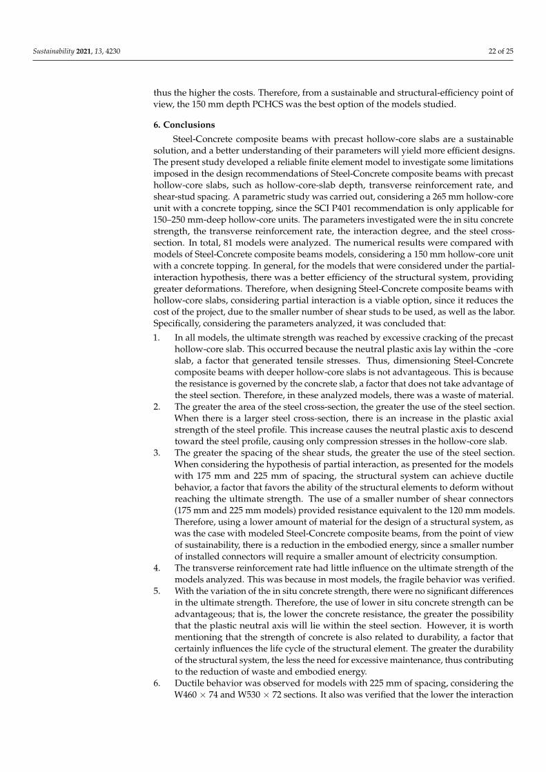
Sustainability 2021, 13, 4230 22 of 25
thus the higher the costs. Therefore, from a sustainable and structural-efficiency point ofview, the 150 mm depth PCHCS was the best option of the models studied.
6. Conclusions
Steel-Concrete composite beams with precast hollow-core slabs are a sustainablesolution, and a better understanding of their parameters will yield more efficient designs.The present study developed a reliable finite element model to investigate some limitationsimposed in the design recommendations of Steel-Concrete composite beams with precasthollow-core slabs, such as hollow-core-slab depth, transverse reinforcement rate, andshear-stud spacing. A parametric study was carried out, considering a 265 mm hollow-coreunit with a concrete topping, since the SCI P401 recommendation is only applicable for150–250 mm-deep hollow-core units. The parameters investigated were the in situ concretestrength, the transverse reinforcement rate, the interaction degree, and the steel cross-section. In total, 81 models were analyzed. The numerical results were compared withmodels of Steel-Concrete composite beams models, considering a 150 mm hollow-core unitwith a concrete topping. In general, for the models that were considered under the partial-interaction hypothesis, there was a better efficiency of the structural system, providinggreater deformations. Therefore, when designing Steel-Concrete composite beams withhollow-core slabs, considering partial interaction is a viable option, since it reduces thecost of the project, due to the smaller number of shear studs to be used, as well as the labor.Specifically, considering the parameters analyzed, it was concluded that:
1. In all models, the ultimate strength was reached by excessive cracking of the precasthollow-core slab. This occurred because the neutral plastic axis lay within the -coreslab, a factor that generated tensile stresses. Thus, dimensioning Steel-Concretecomposite beams with deeper hollow-core slabs is not advantageous. This is becausethe resistance is governed by the concrete slab, a factor that does not take advantage ofthe steel section. Therefore, in these analyzed models, there was a waste of material.
2. The greater the area of the steel cross-section, the greater the use of the steel section.When there is a larger steel cross-section, there is an increase in the plastic axialstrength of the steel profile. This increase causes the neutral plastic axis to descendtoward the steel profile, causing only compression stresses in the hollow-core slab.
3. The greater the spacing of the shear studs, the greater the use of the steel section.When considering the hypothesis of partial interaction, as presented for the modelswith 175 mm and 225 mm of spacing, the structural system can achieve ductilebehavior, a factor that favors the ability of the structural elements to deform withoutreaching the ultimate strength. The use of a smaller number of shear connectors(175 mm and 225 mm models) provided resistance equivalent to the 120 mm models.Therefore, using a lower amount of material for the design of a structural system, aswas the case with modeled Steel-Concrete composite beams, from the point of viewof sustainability, there is a reduction in the embodied energy, since a smaller numberof installed connectors will require a smaller amount of electricity consumption.
4. The transverse reinforcement rate had little influence on the ultimate strength of themodels analyzed. This was because in most models, the fragile behavior was verified.
5. With the variation of the in situ concrete strength, there were no significant differencesin the ultimate strength. Therefore, the use of lower in situ concrete strength can beadvantageous; that is, the lower the concrete resistance, the greater the possibilitythat the plastic neutral axis will lie within the steel section. However, it is worthmentioning that the strength of concrete is also related to durability, a factor thatcertainly influences the life cycle of the structural element. The greater the durabilityof the structural system, the less the need for excessive maintenance, thus contributingto the reduction of waste and embodied energy.
6. Ductile behavior was observed for models with 225 mm of spacing, considering theW460 × 74 and W530 × 72 sections. It also was verified that the lower the interaction

Sustainability 2021, 13, 4230 23 of 25
degree, the greater the midspan vertical displacement, which may exceed the limitof L/200.
7. Regarding the verification of strength with the calculation procedure, some modelsthat considered full interaction proved to be unsafe (MFE ≤ MRk). On the other hand,all observations considering partial interaction proved to be safe (MFE > MRk).
8. The numerical models with a 265 mm hollow-core unit presented greater resistancethan the models with a150 mm hollow-core unit, considering the W360 × 51 section.However, for the W460 × 74 and W530 × 72 sections, there were no significantdifferences. The basic difference between the models compared was 115 mm ofprecast concrete. Therefore, for the numerical models evaluated, using a smalleramount of precast concrete provided a better efficiency of the structural system.The use of a lower volume of concrete in a structural project provides a reductionin the structure’s own weight, and in terms of sustainability, a lower amount ofCO2 emissions.
Author Contributions: Conceptualization, F.P.V.F. and K.D.T.; methodology, F.P.V.F., K.D.T. andS.D.N.; software, F.P.V.F.; validation, F.P.V.F.; investigation, F.P.V.F.; writing—original draft prepa-ration, F.P.V.F., K.D.T., C.H.M. and S.D.N.; writing—review and editing, F.P.V.F., K.D.T., C.H.M.and S.D.N.; visualization, K.D.T., C.H.M. and S.D.N.; supervision, S.D.N.; project administration,S.D.N.; funding acquisition, F.P.V.F. All authors have read and agreed to the published version ofthe manuscript.
Funding: This research was funded by the São Paulo Research Foundation (FAPESP) (grant number#2018/22803-1).
Acknowledgments: The authors would like to thank Construção Metálica—Gerdau Aços Brasil formaking available the data related to COPPETEC, PEC-18541.
Conflicts of Interest: The authors declare no conflict of interest.
References1. Cabeza, L.F.; Boquera, L.; Chàfer, M.; Vérez, D. Embodied energy and embodied carbon of structural building materials:
Worldwide progress and barriers through literature map analysis. Energy Build. 2021, 231, 110612. [CrossRef]2. Whitworth, A.H.; Tsavdaridis, K.D. Genetic algorithm for embodied energy optimisation of steel-concrete composite beams.
Sustainability 2020, 12, 3102. [CrossRef]3. Whitworth, A.; Tsavdaridis, K. Embodied energy optimization of steel-concrete composite beams using a genetic algorithm.
Procedia Manuf. 2020, 44, 417–424. [CrossRef]4. European Committee for Standardization. EN 1994-1-1: Eurocode 4—Design of Composite Steel and Concrete Structures—Part 1-1:
General Rules for Buildings; European Committee for Standardization: Brussels, Belgium, 2004.5. Ibrahim, I.; Elliott, K.; Abdullah, R.; Kueh, A.; Sarbini, N. Experimental study on the shear behaviour of precast concrete hollow
core slabs with concrete topping. Eng. Struct. 2016, 125, 80–90. [CrossRef]6. Baran, E. Effects of cast-in-place concrete topping on flexural response of precast concrete hollow-core slabs. Eng. Struct. 2015, 98,
109–117. [CrossRef]7. Girhammar, U.A.; Pajari, M. Tests and analysis on shear strength of composite slabs of hollow core units and concrete topping.
Constr. Build. Mater. 2008, 22, 1708–1722. [CrossRef]8. Araújo, D.D.L.; Sales, M.W.R.; Silva, R.P.M.; Antunes, C.D.F.M.; Ferreira, M.D.A. Shear strength of prestressed 160 mm deep
hollow core slabs. Eng. Struct. 2020, 218, 110723. [CrossRef]9. Albero, V.; Saura, H.; Hospitaler, A.; Montalvà, J.; Romero, M.L. Optimal design of prestressed concrete hollow core slabs taking
into account its fire resistance. Adv. Eng. Softw. 2018, 122, 81–92. [CrossRef]10. De Nardin, S.; El Debs, A.L. State of the art of Steel-Concrete composite structures in Brazil. Proc. Inst. Civ. Eng. Civ. Eng. 2013,
166, 20–27. [CrossRef]11. Lam, D. Capacities of headed stud shear connectors in composite steel beams with precast hollowcore slabs. J. Constr. Steel Res.
2007, 63, 1160–1174. [CrossRef]12. Tawadrous, R.; Morcous, G. Shear strength of deep hollow-core slabs. ACI Struct. J. 2018, 115, 699–709. [CrossRef]13. Ahmed, K.E.-S.; Abdulrahman, M.; Alhozaimy, A.M. Web shear resistance of prestressed precast deep hollow core slabs. Struct. J.
2016, 116, 139–150. [CrossRef]14. De Souza, P.T.; Kataoka, M.N.; El Debs, A.L.H. Experimental and numerical analysis of the push-out test on shear studs in hollow
core slabs. Eng. Struct. 2017, 147, 398–409. [CrossRef]
Sustainability 2021, 13, 4230 24 of 25
15. Ahmed, I.M.; Tsavdaridis, K.D. Life cycle assessment (LCA) and cost (LCC) studies of lightweight composite flooring systems. J.Build. Eng. 2018, 20, 624–633. [CrossRef]
16. Dong, Y.H.; Jaillon, L.; Chu, P.; Poon, C. Comparing carbon emissions of precast and cast-in-situ construction methods—A casestudy of high-rise private building. Constr. Build. Mater. 2015, 99, 39–53. [CrossRef]
17. Lam, D. Composite Steel Beams Using Precast Concrete Hollow Core Floor Slabs. 1998. Ph.D. Thesis, University of Nottingham,Nottingham, UK, 1998.
18. Batista, E.M.; Landesmann, A. Análise experimental de vigas mistas de aço e concreto compostas por lajes alveolares e perfislaminados. COPPETEC, PEC-18541 2016. Unpublished.
19. Gouchman, G.H. Design of Composite Beams Using Precast Concrete Slabs in Accordance with EUROCODE 4; The Steel ConstructionInstitute: London, UK, 2014.
20. Araújo, D.D.L.; Sales, M.W.R.; de Paulo, S.M.; de Cresce El, A.L. Headed steel stud connectors for composite steel beams withprecast hollow-core slabs with structural topping. Eng. Struct. 2016, 107, 135–150. [CrossRef]
21. Lam, D.; Elliott, K.S.; Nethercot, D.A. Experiments on composite steel beams with precast concrete hollow core floor slabs. Proc.Inst. Civ. Eng. Struct. Build. 2000, 140, 127–138. [CrossRef]
22. Lam, D.; Elliott, K.; Nethercot, D. Parametric study on composite steel beams with precast concrete hollow core floor slabs. J.Constr. Steel Res. 2000, 54, 283–304. [CrossRef]
23. El-Lobody, E.; Lam, D. Modelling of headed stud in steel-precast composite beams. Steel Compos. Struct. 2002, 2,355–378. [CrossRef]
24. Hicks, S.J.; Lawson, R.M. Design of Composite Beams Using Precast Concrete Slabs; The Steel Construction Institute:London, UK, 2003.
25. Ferreira, F.P.V.; Martins, C.H.; De Nardin, S. A parametric study of steel-concrete composite beams with hollow core slabs andconcrete topping. Structures 2020, 28, 276–296. [CrossRef]
26. Ferreira, F.P.V.; Martins, C.H.; De Nardin, S. Advances in composite beams with web openings and composite cellular beams. J.Constr. Steel Res. 2020, 172, 106182. [CrossRef]
27. Walraven, J.C.; Mercx, W.P.M. The bearing capacity of prestressed hollow core slabs. Heron 1983, 28, 1–46.28. Nguyen, T.H.; Tan, K.-H.; Kanda, T. Investigations on web-shear behavior of deep precast, prestressed concrete hollow core slabs.
Eng. Struct. 2019, 183, 579–593. [CrossRef]29. Joo, H.-E.; Han, S.-J.; Park, M.-K.; Kim, K.S. Shear tests of deep hollow core slabs strengthened by core-filling. Appl. Sci. 2020, 10,
1709. [CrossRef]30. Michelini, E.; Bernardi, P.; Cerioni, R.; Belletti, B. Experimental and numerical assessment of flexural and shear behavior of
precast prestressed deep hollow-core slabs. Int. J. Concr. Struct. Mater. 2020, 14, 1–17. [CrossRef]31. Brunesi, E.; Bolognini, D.; Nascimbene, R. Evaluation of the shear capacity of precast-prestressed hollow core slabs: Numerical
and experimental comparisons. Mater. Struct. 2014, 48, 1503–1521. [CrossRef]32. Palmer, K.D.; Schultz, A.E. Experimental investigation of the web-shear strength of deep hollow-core units. PCI J. 2011, 56,
83–104. [CrossRef]33. ABAQUS 6.18 (2016) FEA computer software, Version 6.12, Product.34. Ferreira, F.P.V.; Rossi, A.; Martins, C.H. Lateral-torsional buckling of cellular beams according to the possible updating of EC3. J.
Constr. Steel Res. 2019, 153, 222–242. [CrossRef]35. Ferreira, F.P.V.; Martins, C.H. LRFD for lateral-torsional buckling resistance of cellular beams. Int. J. Civ. Eng. 2019, 18,
303–323. [CrossRef]36. Rossi, A.; Ferreira, F.P.V.; Martins, C.H.; Júnior, E.C.M. Assessment of lateral distortional buckling resistance in welded I-beams. J.
Constr. Steel Res. 2020, 166, 105924. [CrossRef]37. Ferreira, F.P.V.; Martins, C.H.; De Nardin, S. Assessment of web post buckling resistance in steel-concrete composite cellular
beams. Thin-Walled Struct. 2021, 158, 106969. [CrossRef]38. Ferreira, F.P.V.; Martins, C.H.; De Nardin, S. Sensitivity analysis of composite cellular beams to constitutive material models and
concrete fracture. Int. J. Struct. Stab. Dyn. 2021, 21, 2150008. [CrossRef]39. Ferreira, F.P.V.; Tsavdaridis, K.D.; Martins, C.H.; De Nardin, S. Buckling and post-buckling analyses of composite cellular beams.
Compos. Struct. 2021, 262, 113616. [CrossRef]40. Ferreira, F.P.V.; Tsavdaridis, K.D.; Martins, C.H.; De Nardin, S. Ultimate strength prediction of Steel-Concrete composite cellular
beams with PCHCS. Eng. Struct. 2021, 236, 112082. [CrossRef]41. Chen, S.; Jia, Y. Numerical investigation of inelastic buckling of Steel-Concrete composite beams prestressed with external tendons.
Thin-Walled Struct. 2010, 48, 233–242. [CrossRef]42. Zhou, W.-B.; Yan, W.-J. Refined nonlinear finite element modelling towards ultimate bending moment calculation for concrete
composite beams under negative moment. Thin-Walled Struct. 2017, 116, 201–211. [CrossRef]43. El-Lobody, E.; Lam, D. Finite element analysis of steel-concrete composite girders. Adv. Struct. Eng. 2003, 6, 267–281. [CrossRef]44. Hillerborg, A.; Modéer, M.; Petersson, P.-E. Analysis of crack formation and crack growth in concrete by means of fracture
mechanics and finite elements. Cem. Concr. Res. 1976, 6, 773–781. [CrossRef]45. Lubliner, J.; Oliver, J.; Oller, S.; Oñate, E. A plastic-damage model for concrete. Int. J. Solids Struct. 1989, 25, 299–326. [CrossRef]46. Lee, J.; Fenves, G.L. Plastic-damage model for cyclic loading of concrete structures. J. Eng. Mech. 1998, 124, 892–900. [CrossRef]

Sustainability 2021, 13, 4230 25 of 25
47. Genikomsou, A.S.; Polak, M.A. Finite element analysis of punching shear of concrete slabs using damaged plasticity model inABAQUS. Eng. Struct. 2015, 98, 38–48. [CrossRef]
48. Duvaut, G.; Lions, J.L. Inequalities in Mechanics and Physics; Springer: Berlin/Heidelberg, Germany, 1976; Volume 219.49. Behnam, H.; Kuang, J.; Samali, B. Parametric finite element analysis of RC wide beam-column connections. Comput. Struct. 2018,
205, 28–44. [CrossRef]50. Stress-strain relationship for plain concrete in compression. ACI J. Proc. 1985, 82, 797–804. [CrossRef]51. Carreira, D.J.; Chu, K.H. Stress-strain relatonship for reinforced concrete in tension. J. Am. Concr. Inst. 1986, 83, 21–28.52. Pathirana, S.W.; Uy, B.; Mirza, O.; Zhu, X. Flexural behaviour of composite steel–concrete beams utilising blind bolt shear
connectors. Eng. Struct. 2016, 114, 181–194. [CrossRef]53. Liu, X.; Bradford, M.A.; Chen, Q.-J.; Ban, H. Finite element modelling of Steel-Concrete composite beams with high-strength
friction-grip bolt shear connectors. Finite Elem. Anal. Des. 2016, 108, 54–65. [CrossRef]54. Sjaarda, M.; Porter, T.; West, J.S.; Walbridge, S. Fatigue behavior of welded shear studs in precast composite beams. J. Bridge Eng.
2017, 22, 04017089. [CrossRef]55. Guezouli, S.; Lachal, A. Numerical analysis of frictional contact effects in push-out tests. Eng. Struct. 2012, 40, 39–50. [CrossRef]56. Crisfield, M. A fast incremental/iterative solution procedure that handles “snap-through”. Comput. Struct. 1981, 13,
55–62. [CrossRef]57. Crisfield, M.A. Snap-through and snap-back response in concrete structures and the dangers of under-integration. Int. J. Numer.
Methods Eng. 1986, 22, 751–767. [CrossRef]58. Maewal, A.; Nachbar, W. Stable postbuckling equilibria of axially compressed, elastic circular cylindrical shells: A finite-element
analysis and comparison with experiments. J. Appl. Mech. 1977, 44, 475–481. [CrossRef]