Eindhoven University of Technology MASTER Buckling length ...
Upload
khangminh22Category
view
1download
0
LATERAL-TORSIONAL BUCKLING OF BEAMS
ELASTICALLY RESTRAINED AGAINST WARPING
AT SUPPORTS
R. PIOTROWSKI1, A. SZYCHOWSKI2
Abstract
The study presents the results of theoretical investigations into lateral torsional buckling (LTB) of bi-symmetric
I-beams, elastically restrained against warping at supports. Beam loading schemes commonly used in practice are
taken into account. The whole range of stiffness of the support joints, from free warping to warping fully re-
strained, is considered. To determine the critical moment, the energy method is used. The function of the beam
twist angle is described with power polynomials that have simple physical interpretation. Computer programs
written in symbolic language for numerical analysis are developed. General approximation formulas are devised.
Detailed calculations are performed for beams with end-plate joints. Critical moments determined with programs
and approximation formulas are compared with the results obtained by other researchers and with those produced
by FEM. Very good accuracy of results is obtained.
Keywords: critical moment for lateral torsional buckling (LTB), elastic end section restraint
against warping, end-plates, the energy method, power polynomials
1 MSc Eng., Kielce University of Technology, Faculty of Civil Engineering and Architecture, Al. 1000-lecia PP 7, 25-314 Kielce, Poland, e-mail: [email protected].
2 PhD Eng., Kielce University of Technology, Faculty of Civil Engineering and Architecture, Al. 1000-lecia PP 7, 25-314 Kielce, Poland, e-mail: [email protected].
UnauthenticatedDownload Date | 3/23/16 11:19 AM
1. INTRODUCTION
Presently used methods of steel member design tend to account for a number of parameters that
improve the way how real boundary conditions of structural members are represented in the
engineering computational model. The effect of the support elastic restraint against warping on the
critical moment is one of relevant parameters.
The literature on LTB, which is vast, deals with many aspects of this phenomenon. For instance, the
formulas necessary to determine the elastic critical moment of beams with fork support are given,
among others, in studies [1,3,4,16]. The formulas account for effect produced by the height, at
which one type of the transverse load is applied, with respect to the section shear centre. Bijak in
study [1] provided the critical moment formula, in which a few different load types and varied
ordinates of load application over the beam section height were taken into consideration.
In addition to classic solutions for fork support, some studies, including [5,7,8,10,11,12], analyse
the effect of the stiffness of the elastic restraint against warping at the site of the beam support. In
those studies, it was theoretically demonstrated and experimentally verified that increase in the
stiffness of the support sections preventing warping causes an increase in the critical moment of the
beam. Different rib configurations intended to constrain warping in support sections were presented,
e.g. in [6,12].
The present study deals with LTB of bi-symmetric I-beams, elastically restrained against warping at
supports. The energy method is used to determine the critical moments [16]. The function of the
twist angle is approximated by power polynomials. The computational program and approximation
formulas for the estimation of the elastic critical moment are developed. Computations are per-
formed for basic, most frequently found loading schemes. Detailed calculations are performed for
beams stiffened with end-plates. The results obtained are compared with FEM values (LTBeam [4]
and Abaqus software).
2. CRITICAL MOMENT OF THE BEAM STIFFENED WITH END-PLATES
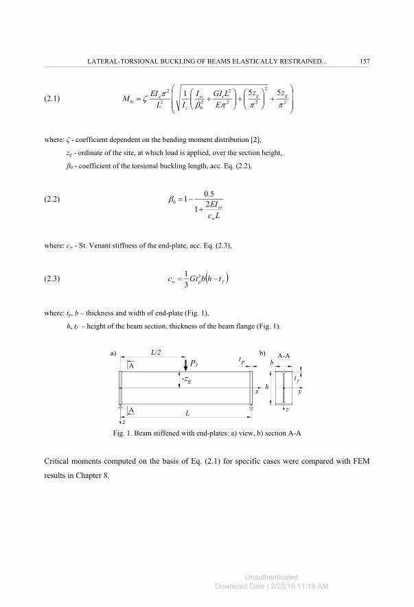
In study [10], Lindner presented Eq. (2.1) for the elastic critical moment of the beam simply
supported against bending, which accounted for the stiffening against warping by using the end-
plates (Fig. 1):
156 R. PIOTROWSKI, A. SZYCHOWSKI
UnauthenticatedDownload Date | 3/23/16 11:19 AM
(2.1) ���
�
�
���
�
����
�
����
����
�
����
��� 2
2
22
2
20
2
2 551...�
.= � ggt
z
zki
zzE
LGIIIL
EIM
where: ζ - coefficient dependent on the bending moment distribution [2],
zg - ordinate of the site, at which load is applied, over the section height,
β0 - coefficient of the torsional buckling length, acc. Eq. (2.2),
(2.2)
LcEIw
�� 21
5.010
���
where: cw - St. Venant stiffness of the end-plate, acc. Eq. (2.3),
(2.3) � �fpw thbGtc �� 3
31
where: tp, b – thickness and width of end-plate (Fig. 1),
h, tf – height of the beam section, thickness of the beam flange (Fig. 1).
L
L/2a) b)
y
z
h
tpPz
z
x
A
A
A-A
-zp
b
t f-zg
Fig. 1. Beam stiffened with end-plates: a) view, b) section A-A
Critical moments computed on the basis of Eq. (2.1) for specific cases were compared with FEM
results in Chapter 8.
LATERAL-TORSIONAL BUCKLING OF BEAMS ELASTICALLY RESTRAINED... 157
UnauthenticatedDownload Date | 3/23/16 11:19 AM

3. DEGREE OF ELASTIC RESTRAINT AGAINST WARPING
The degree of elastic restraint against warping can be described with coefficient ε [8,12] according
to Eq. (3.1):
(3.1) w
w
EIL�� �
where: αw - stiffness of the elastic restraint [8,12], acc. Eq. (3.2):
(3.2) dxd
Bw /
� ��
where: B – bimoment at the site of the beam support; dφ/dx – warping in the support section.
Elastic restraint coefficient ε acc. Eq. (3.1) ranges from ε = 0, for the end free to warp,
to ε = ∞, for warping fully restrained.
Formulas for the estimation of the stiffness of the elastic restraint (αw), depending on how the beam
is stiffened at its support, can be found, among others, in [6,12]. The stiffening types that are most
often analysed are presented in Table 1. It should be noted that for the sake of comparison, No. 1
was used to mark the beam end without any stiffening.
Table 1. Exemplary ways of beam stiffening used to prevent warping [6,12]
Item Scheme of stiffening Item Scheme of stiffening Item Scheme of stiffening
1
z
xy
z
2
z
xy
z
3
z
xy
z
4
z
xy
z
5
z
xy
z
6
z
xy
z
158 R. PIOTROWSKI, A. SZYCHOWSKI
UnauthenticatedDownload Date | 3/23/16 11:19 AM
In the present study, the dimensionless fixity factor κ was derived, acc. Eq. (3.3):
(3.3) LEI
Lww
w
��>
��
2
which ranges from κ = 0, for the end free to warp, to κ = 1, for warping fully restrained.
Known dependences between the coefficient ε and factor κ, are given by Eq. (3.4) [15]:
(3.4) �
�>�
�2
; >
>��
�12
4. FUNCTION OF THE BEAM TWIST ANGLE
In the majority of studies available in literature, e.g. in [1,16], trigonometric series were employed
to approximate the function of the beam twist angle. Compared with FEM (LTBeam) [4], for
symmetric or slightly asymmetric loads (with respect to the beam transverse axis) good results were
obtained, e.g. [1], already when the first term of the sine series was used.
Another approach was proposed in study [13], where power polynomials were successfully applied
to the approximation of the function of the beam twist angle.
In Poland, the idea of using polynomials in the stability analysis of thin-walled members was
promoted by Jakubowski’s studies, e.g. [9]. Also, power polynomials were used to determine
buckling state of thin-walled bars with open section subjected to warping torsion [14].
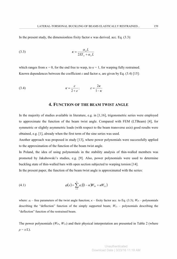
In the present paper, the function of the beam twist angle is approximated with the series:
(4.1) � � � �� �UiPii
i WWax >> ��� ��
13
1
where: ai – free parameters of the twist angle function; κ – fixity factor acc. to Eq. (3.3); WPi – polynomials
describing the “deflection” function of the simply supported beam; WUi – polynomials describing the
“deflection” function of the restrained beam.
The power polynomials (WPi, WUi) and their physical interpretation are presented in Table 2 (where
ρ = x/L).
LATERAL-TORSIONAL BUCKLING OF BEAMS ELASTICALLY RESTRAINED... 159
UnauthenticatedDownload Date | 3/23/16 11:19 AM
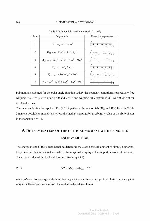
Table 2. Polynomials used in the study (ρ = x/L)
Item Polynomials Physical interpretation1 2 3
1 431 2 ??? ���PW x
z
2 5432 61510 ???? ����PW
x
z
3 65433 24727326 ????? �����PW
x
z
4 4321 2 ??? ���UW x
z
5 54322 254 ???? ����UW x
z
6 654323 92729132 ????? �����UW
x
z
Polynomials, adopted for the twist angle function satisfy the boundary conditions, respectively free
warping WPi (φ = 0, φ” = 0 for x = 0 and x = L) and warping fully restrained WUi (φ = 0, φ’ = 0 for
x = 0 and x = L).
The twist angle function applied, Eq. (4.1), together with polynomials (WPi and WUi) listed in Table
2 make it possible to model elastic restraint against warping for an arbitrary value of the fixity factor
in the range: 0 < κ < 1.
5. DETERMINATION OF THE CRITICAL MOMENT WITH USING THE
ENERGY METHOD
The energy method [16] is used herein to determine the elastic critical moment of simply supported,
bi-symmetric I-beam, where the elastic restrain against warping at the support is taken into account.
The critical value of the load is determined from Eq. (5.1):
(5.1) TUUΠ ss 0�0�0�0 2,1,
where: ∆Us,1 – elastic energy of the beam bending and torsion; ∆Us,2 – energy of the elastic restraint against
warping at the support sections; ∆T – the work done by external forces.
160 R. PIOTROWSKI, A. SZYCHOWSKI
UnauthenticatedDownload Date | 3/23/16 11:19 AM
The elastic energy of the beam bending and torsion is expressed by Eq. (5.2) acc. [16]:
(5.2) ��
�
�
��
�
����
����
���
��
������
�
����
��0 777
LL
t
L
zs dxdxdEIdx
dxdGIdx
dxudEIU
0
2
2
2
0
2
0
2
2
2
1, 21
�
The energy of the beam elastic restraint against warping is determined acc. Eq. (5.3):
(5.3) ���
����
����
�����
��
����0
��
22
02, 2 Lxx
ws dx
ddxdU �
yc=s
z
+zg
- zg
qz
A-A
uL/2z
y
qzz
x
y
A
A
+zg
L φL/2
αw
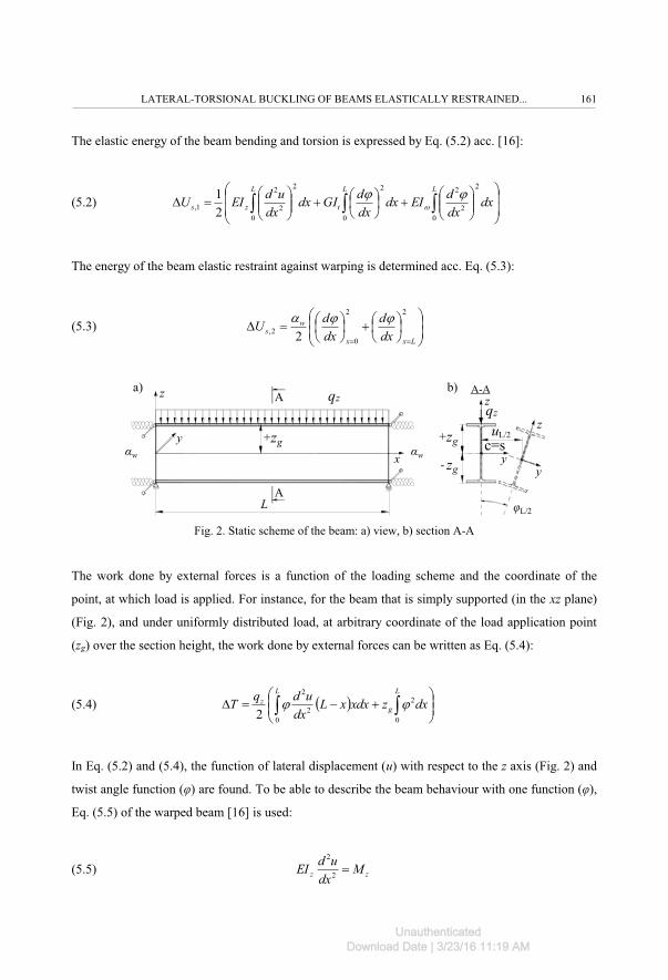
A-Aa) b)
αw
Fig. 2. Static scheme of the beam: a) view, b) section A-A
The work done by external forces is a function of the loading scheme and the coordinate of the
point, at which load is applied. For instance, for the beam that is simply supported (in the xz plane)
(Fig. 2), and under uniformly distributed load, at arbitrary coordinate of the load application point
(zg) over the section height, the work done by external forces can be written as Eq. (5.4):
(5.4) � � ���
����
����0 77
L
g
Lz dxzxdxxL
dxudqT
0
2
02
2
2
In Eq. (5.2) and (5.4), the function of lateral displacement (u) with respect to the z axis (Fig. 2) and
twist angle function (φ) are found. To be able to describe the beam behaviour with one function (φ),
Eq. (5.5) of the warped beam [16] is used:
(5.5) zz Mdx
udEI �2
2
LATERAL-TORSIONAL BUCKLING OF BEAMS ELASTICALLY RESTRAINED... 161
UnauthenticatedDownload Date | 3/23/16 11:19 AM
Using Eq. (5.1) and the twist angle function Eq. (4.1), together with polynomials given in Table 2,
the computational program McrLT_elastic_fix.on.warp.nb., termed MLTB,EL, is developed using
Mathematica® software package. The program makes it possible to determine critical moments for
arbitrary geometric parameters of bi-symmetric I-sections, the loading schemes presented in Tables
3, 4 and 5, an arbitrary value of the coordinate (zg) (Fig. 2) of the point, at which transverse load is
applied (Table 4), and for an arbitrary value of the fixity factor >, Eq. (3.3).
Exemplary specific cases, computed with MLTB,EL program, are presented in Chapter 8.
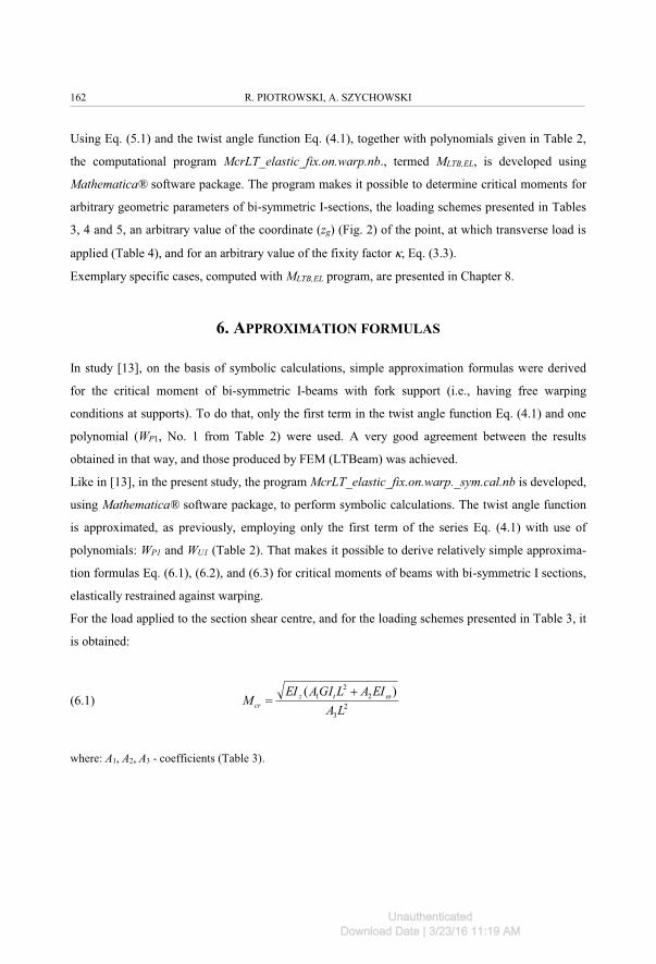
6. APPROXIMATION FORMULAS
In study [13], on the basis of symbolic calculations, simple approximation formulas were derived
for the critical moment of bi-symmetric I-beams with fork support (i.e., having free warping
conditions at supports). To do that, only the first term in the twist angle function Eq. (4.1) and one
polynomial (WP1, No. 1 from Table 2) were used. A very good agreement between the results
obtained in that way, and those produced by FEM (LTBeam) was achieved.
Like in [13], in the present study, the program McrLT_elastic_fix.on.warp._sym.cal.nb is developed,
using Mathematica® software package, to perform symbolic calculations. The twist angle function
is approximated, as previously, employing only the first term of the series Eq. (4.1) with use of
polynomials: WP1 and WU1 (Table 2). That makes it possible to derive relatively simple approxima-
tion formulas Eq. (6.1), (6.2), and (6.3) for critical moments of beams with bi-symmetric I sections,
elastically restrained against warping.
For the load applied to the section shear centre, and for the loading schemes presented in Table 3, it
is obtained:
(6.1) 23
22
1 )(LA
EIALGIAEIM tz
cr��
�
where: A1, A2, A3 - coefficients (Table 3).
162 R. PIOTROWSKI, A. SZYCHOWSKI
UnauthenticatedDownload Date | 3/23/16 11:19 AM
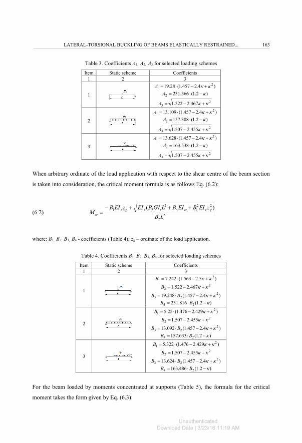
Table 3. Coefficients A1, A2, A3 for selected loading schemes
Item Static scheme Coefficients1 2 3
1
)4.2457.1(28.19 21 >> ����A
)2.1(366.2312 >���A2
3 467.2522.1 >> ���A
2
)4.2457.1(109.13 21 >> ����A
)2.1(308.1572 >���A2
3 455.2507.1 >> ���A
3
)4.2457.1(628.13 21 >> ����A
)2.1(538.1632 >���A2
3 455.2507.1 >> ���A
When arbitrary ordinate of the load application with respect to the shear centre of the beam section
is taken into consideration, the critical moment formula is as follows Eq. (6.2):
(6.2) 22
2214
231 )(
LBzEIBEIBLGIBEIzEIB
M gztzgzcr
����� �
where: B1, B2, B3, B4 - coefficients (Table 4); zg – ordinate of the load application.
Table 4. Coefficients B1, B2, B3, B4 for selected loading schemes
Item Static scheme Coefficients1 2 3
1
)5.2563.1(242.7 21 >> ����B
22 467.2522.1 >> ���B
)4.2457.1(248.19 223 >> ���� BB
)2.1(816.231 24 >��� BB
2
)429.2476.1(25.5 21 >> ����B
22 455.2507.1 >> ���B
)4.2457.1(092.13 223 >> ���� BB
)2.1(633.157 24 >��� BB
3
)429.2476.1(322.5 21 >> ����B
22 455.2507.1 >> ���B
)4.2457.1(624.13 223 >> ���� BB
)2.1(486.163 24 >��� BB
For the beam loaded by moments concentrated at supports (Table 5), the formula for the critical
moment takes the form given by Eq. (6.3):
LATERAL-TORSIONAL BUCKLING OF BEAMS ELASTICALLY RESTRAINED... 163
UnauthenticatedDownload Date | 3/23/16 11:19 AM

(6.3) )1(
)(2
44
3
22
1
))�
���
�CLC
EICLGICEIM tzcr
where: ψ - ratio of concentrated support moments (from 0 to 1); C1, C2, C3, C4 - coefficients (Table 5).
Table 5. Coefficients C1, C2, C3, C4
Item Static scheme Coefficients1 2 3
1
10+@)
)4.2457.1(35 21 >> ����C
)2.1(4202 >���C2
3 417.2462.1 >> ���C
32
4 /)444.2495.1(5.1 CC >> ����
When no stiffening against beam warping is found at the support (κ = 0), formulas in Eq. (6.1),
(6.2), (6.3) are reduced to those presented in study [13].
7. FEM VERIFICATION USING LTBEAM AND ABAQUS
To verify numerical calculations obtained with the MLTB,EL program and analytical results from
approximation formulas (6.2), (6.3) numerical analyses FEM are performed using LTBeam and
Abaqus software.
LTBeam [4] is a widely known, free licence program, which allows engineers to determine critical
moments of arbitrary I-beams with mono- or bi-symmetric sections. The program makes it possible
to assume classical boundary conditions (fork support), and also to account for the beam stiffening
at the support (including restraint of section warping). It should be noted, however, that in the
LTBeam version 1.0.11, which is employed in the paper, errors were revealed in the representation
of the units of the elastic restraint ’. That may lead to incorrect formulation of the warping
stiffness, thus to incorrect estimation of the critical moment.
Abaqus advanced package software, based on FEM, is used mainly for research purposes. In this
study, it is used for the LTB analysis of exemplary beams stiffened with end-plates. In modelling,
volumetric elements (C3D8) with eight nodes and six degrees of freedom in the node are used. The
beam models are discretized, with the mesh size of 10mm. Boundary conditions at the supports
prevent displacements with respect to the principal axes of the section inertia, and along the
164 R. PIOTROWSKI, A. SZYCHOWSKI
UnauthenticatedDownload Date | 3/23/16 11:19 AM

longitudinal axis for one of the supports. The load is applied to the top flange of the beam. Compu-
tations are performed for the elastic range.
IPE300, L = 5m, tp = 10mm
yc=s
z
+zg
Pz
PzPz
Pz
LL/2
+zg
y
z
c=s
Fig. 3. Exemplary beam modelled using the Abaqus software
8. COMPUTATIONAL EXAMPLES
The analysis is applied to the beam section IPE500 (Iz = 2140cm4, Iω = 1249000cm6, It = 91.9cm4,
E = 210GPa, G = 81GPa) , having the span of L = 8 m.
Table 6 presents the comparison of the values of critical moments (MLTB,EL vs. Eq. (6.2) vs.
LTBeam) determined for the loading schemes in Column 2. The critical moment values are
calculated for different values (0, 0.25, 0.5, 0.75 and 1) of the fixity factor (κ), i.e. ranging from 0
(free warping) to 1 (warping fully restrained). The load is applied at the characteristic points of the
beam section (top flange, shear centre, bottom flange). Column 8 shows the percentage differences
between moments estimated from Eq. (6.2) and the values obtained using LTBeam (FEM) (Col-
umns 5 and 7).
The results in Table 6 show that elastic critical moments, estimated with Eq. (6.2), give sufficient
engineering approximation when compared with FEM (differences ranging from +0.1 to +1.4%,
Column 8). The use of the first three terms of the series Eq. (4.1) in the MLTB,EL program produced
the results that differed from FEM not more than -0.6% to +0.4% (Columns 5 and 6). It should be
noted that the results in Column 7 can also be used to verify the correctness of the formula Eq. (6.2)
when it is implemented in a spreadsheet.
LATERAL-TORSIONAL BUCKLING OF BEAMS ELASTICALLY RESTRAINED... 165
UnauthenticatedDownload Date | 3/23/16 11:19 AM
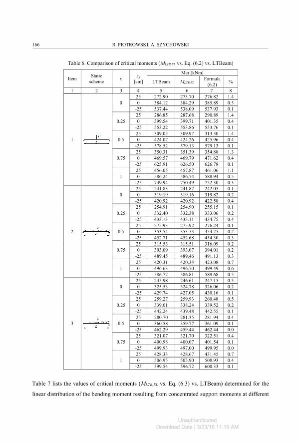
Table 6. Comparison of critical moments (MLTB,EL vs. Eq. (6.2) vs. LTBeam)
Item Staticscheme κ zg
[cm]
Mcr [kNm]
LTBeam MLTB,ELFormula
(6.2) %
1 2 3 4 5 6 7 8
1
025 272.90 273.70 276.82 1.40 384.12 384.29 385.89 0.5
-25 537.44 538.09 537.93 0.1
0.2525 286.85 287.68 290.89 1.40 399.54 399.71 401.35 0.4
-25 553.22 553.86 553.76 0.1
0.525 309.05 309.97 313.30 1.40 424.07 424.26 425.96 0.4
-25 578.52 579.13 579.13 0.1
0.7525 350.31 351.39 354.88 1.30 469.57 469.79 471.62 0.4
-25 625.91 626.50 626.78 0.1
125 456.05 457.87 461.06 1.10 586.24 586.74 588.94 0.5
-25 749.94 750.49 752.30 0.3
2
025 241.83 241.82 242.05 0.10 319.19 319.16 319.82 0.2
-25 420.92 420.92 422.58 0.4
0.2525 254.91 254.90 255.15 0.10 332.40 332.38 333.06 0.2
-25 433.13 433.11 434.75 0.4
0.525 275.93 275.92 276.24 0.10 353.54 353.53 354.25 0.2
-25 452.71 452.68 454.30 0.3
0.7525 315.53 315.51 316.09 0.20 393.09 393.07 394.01 0.2
-25 489.45 489.46 491.13 0.3
125 420.31 420.34 423.08 0.70 496.63 496.70 499.49 0.6
-25 586.72 586.81 589.68 0.5
3
025 245.98 246.61 247.15 0.50 325.53 324.78 326.06 0.2
-25 429.74 427.05 430.16 0.1
0.2525 259.27 259.93 260.48 0.50 339.01 338.24 339.52 0.2
-25 442.24 439.48 442.55 0.1
0.525 280.70 281.35 281.94 0.40 360.58 359.77 361.09 0.1
-25 462.29 459.44 462.44 0.0
0.7525 321.07 321.70 322.51 0.40 400.98 400.07 401.54 0.1
-25 499.93 497.00 499.95 0.0
125 428.33 428.67 431.45 0.70 506.95 505.90 508.93 0.4
-25 599.54 596.72 600.33 0.1
Table 7 lists the values of critical moments (MLTB,EL vs. Eq. (6.3) vs. LTBeam) determined for the
linear distribution of the bending moment resulting from concentrated support moments at different
166 R. PIOTROWSKI, A. SZYCHOWSKI
UnauthenticatedDownload Date | 3/23/16 11:19 AM

values of the fixity factor (κ) (from 0 to 1) and coefficient (ψ) (ranging from 0 to 1). Column 8 gives
percentage differences between moments estimated with Eq. (6.3) and the values obtained with
LTBeam (FEM) (Columns 5 and 7).
Table 7. Comparison of critical moments (MLTB,EL vs. Eq. (6.3) vs. LTBeam)
Item Static scheme κ ψMcr [kNm]
LTBeam MLTB,ELFormula
(6.3) %
1 2 3 4 5 6 7 8
1
0
1 282.17 282.17 282.25 0.00.75 321.81 321.82 322.14 0.10.5 372.07 372.11 373.61 0.4
0.25 436.13 436.20 441.25 1.20 516.69 516.84 530.59 2.6
0.2
1 291.66 291.66 291.72 0.00.75 332.61 332.64 332.96 0.10.5 384.58 384.62 386.19 0.4
0.25 450.84 450.90 456.22 1.20 534.18 534.32 548.92 2.7
0.4
1 305.27 305.28 305.33 0.00.75 348.17 348.18 348.50 0.10.5 402.59 402.61 404.27 0.4
0.25 471.95 472.04 477.77 1.20 559.39 559.54 575.35 2.8
0.6
1 326.54 326.57 326.60 0.00.75 372.44 372.47 372.79 0.10.5 430.69 430.75 432.56 0.4
0.25 505.10 505.19 511.52 1.30 599.06 599.25 616.89 2.9
0.8
1 364.81 364.82 364.84 0.00.75 416.11 416.13 416.48 0.10.5 481.38 481.43 483.48 0.4
0.25 565.03 565.16 572.45 1.30 671.39 671.72 692.37 3.0
1
1 455.72 455.75 455.87 0.00.75 520.02 520.04 520.56 0.10.5 602.45 602.54 605.10 0.4
0.25 709.78 710.02 718.97 1.30 850.04 850.62 876.88 3.1
The results in Table 7 show that the elastic critical moments, estimated using Eq. (6.3), produce
sufficient engineering approximation in comparison with FEM (maximum differences are up to
+3.1%, Column 8). When the full MLTB,EL program and three terms of the series Eq. (4.1) are used
the differences do not exceed +0.2% (Columns 5 and 6).
In further examples, the effect of the stiffening of the end-plates (tp) against warping at the beam
support, on the critical moment is analysed. Calculations are made acc. Eq. (2.1) [10], acc. Eq. (6.2),
and using FEM (LTBeam, Abaqus). Factor κ is determined from Eq. (3.3) by calculating coefficient
LATERAL-TORSIONAL BUCKLING OF BEAMS ELASTICALLY RESTRAINED... 167
UnauthenticatedDownload Date | 3/23/16 11:19 AM
αw from Eq. (3.2). In calculations, two beams are assumed, namely beam section IPE300
(Iz = 604cm4, Iω = 125900cm6, It = 20.7cm4, E = 210GPa, G = 81GPa) with the lengths of L = 5, 6
and 7 m and beam IPE500 (Iz = 2140cm4, Iω = 1249000cm6, It = 91.9cm4, E = 210GPa, G = 81GPa)
with the lengths of L = 8, 9 and 10 m.
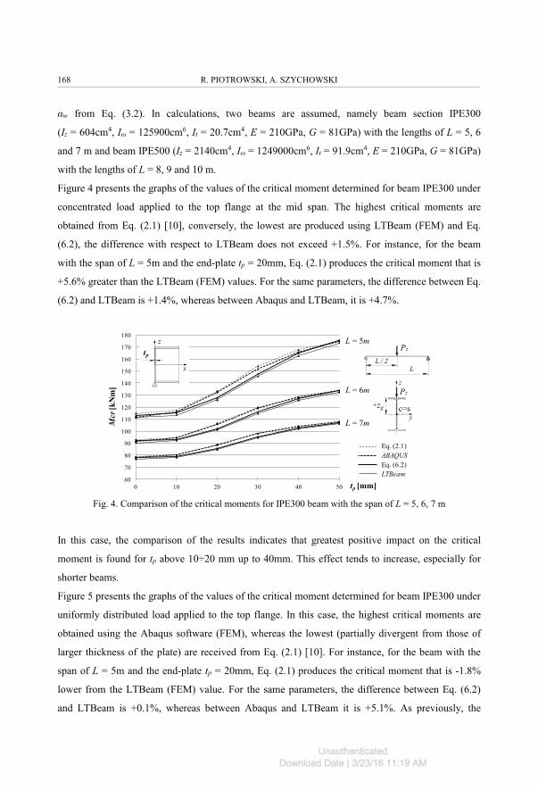
Figure 4 presents the graphs of the values of the critical moment determined for beam IPE300 under
concentrated load applied to the top flange at the mid span. The highest critical moments are
obtained from Eq. (2.1) [10], conversely, the lowest are produced using LTBeam (FEM) and Eq.
(6.2), the difference with respect to LTBeam does not exceed +1.5%. For instance, for the beam
with the span of L = 5m and the end-plate tp = 20mm, Eq. (2.1) produces the critical moment that is
+5.6% greater than the LTBeam (FEM) values. For the same parameters, the difference between Eq.
(6.2) and LTBeam is +1.4%, whereas between Abaqus and LTBeam, it is +4.7%.
60
70
80
90
100
110
120
130
140
150
160
170
180
0 10 20 30 40 50
Mcr
[kN
m]
tep [mm]
L = 5m
L = 6m
L = 7m
LINDNER ABAQUSWzórLTBeam
Pz
yc=s
z
+zg
Pz
tep
z
x
L = 5m
L = 6m
L = 7m
tp [mm]
Mcr
[kN
m]
Mcr
[kN
m]
LTBeamEq. (6.2)
LL / 2
ABAQUSEq. (2.1)
tp
Fig. 4. Comparison of the critical moments for IPE300 beam with the span of L = 5, 6, 7 m
In this case, the comparison of the results indicates that greatest positive impact on the critical
moment is found for tp above 10÷20 mm up to 40mm. This effect tends to increase, especially for
shorter beams.
Figure 5 presents the graphs of the values of the critical moment determined for beam IPE300 under
uniformly distributed load applied to the top flange. In this case, the highest critical moments are
obtained using the Abaqus software (FEM), whereas the lowest (partially divergent from those of
larger thickness of the plate) are received from Eq. (2.1) [10]. For instance, for the beam with the
span of L = 5m and the end-plate tp = 20mm, Eq. (2.1) produces the critical moment that is -1.8%
lower from the LTBeam (FEM) value. For the same parameters, the difference between Eq. (6.2)
and LTBeam is +0.1%, whereas between Abaqus and LTBeam it is +5.1%. As previously, the
168 R. PIOTROWSKI, A. SZYCHOWSKI
UnauthenticatedDownload Date | 3/23/16 11:19 AM
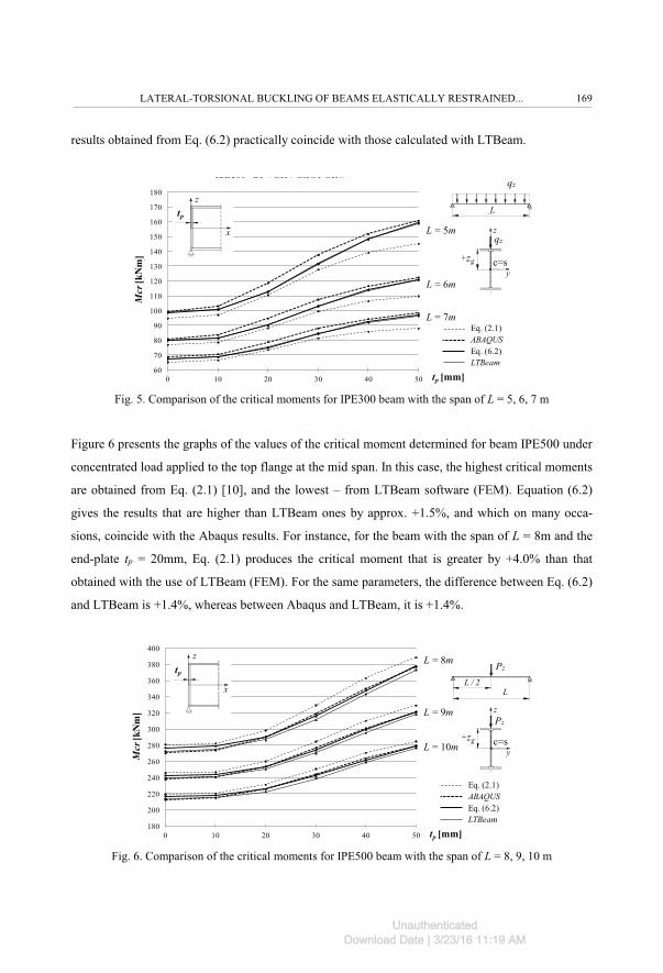
results obtained from Eq. (6.2) practically coincide with those calculated with LTBeam.
60
70
80
90
100
110
120
130
140
150
160
170
180
0 10 20 30 40 50
Mcr
[kN
m]
IPE300 - BLACHA CZOŁOWA
tep [mm]
L = 5m
L = 6m
L = 7mLINDNER ABAQUSWzórLTBeam
yc=s
z
+zg
qz
qz
tep
z
x L = 5m
L = 6m
L = 7m
tep [mm]
Mcr
[kN
m]
Mcr
[kN
m]
LTBeamEq. (6.2)
L
ABAQUSEq. (2.1)
tp [mm]
tp
Fig. 5. Comparison of the critical moments for IPE300 beam with the span of L = 5, 6, 7 m
Figure 6 presents the graphs of the values of the critical moment determined for beam IPE500 under
concentrated load applied to the top flange at the mid span. In this case, the highest critical moments
are obtained from Eq. (2.1) [10], and the lowest – from LTBeam software (FEM). Equation (6.2)
gives the results that are higher than LTBeam ones by approx. +1.5%, and which on many occa-
sions, coincide with the Abaqus results. For instance, for the beam with the span of L = 8m and the
end-plate tp = 20mm, Eq. (2.1) produces the critical moment that is greater by +4.0% than that
obtained with the use of LTBeam (FEM). For the same parameters, the difference between Eq. (6.2)
and LTBeam is +1.4%, whereas between Abaqus and LTBeam, it is +1.4%.
237,50 240,32
253,72
276,45
300,81
321,08
180
200
220
240
260
280
300
320
340
360
380
400
0 10 20 30 40 50
Mcr
[kN
m]
tep [mm]
L = 8m
L = 9m
L = 10m
LINDNER ABAQUSWzórLTBeam
Pz
yc=s
z
+zg
Pz
tep
z
x
L = 8m
L = 9m
L = 10m
tep [mm]
Mcr
[kN
m]
Mcr
[kN
m]
LTBeamEq. (6.2)
LL / 2
ABAQUSEq. (2.1)
tp [mm]
tp
Fig. 6. Comparison of the critical moments for IPE500 beam with the span of L = 8, 9, 10 m
LATERAL-TORSIONAL BUCKLING OF BEAMS ELASTICALLY RESTRAINED... 169
UnauthenticatedDownload Date | 3/23/16 11:19 AM
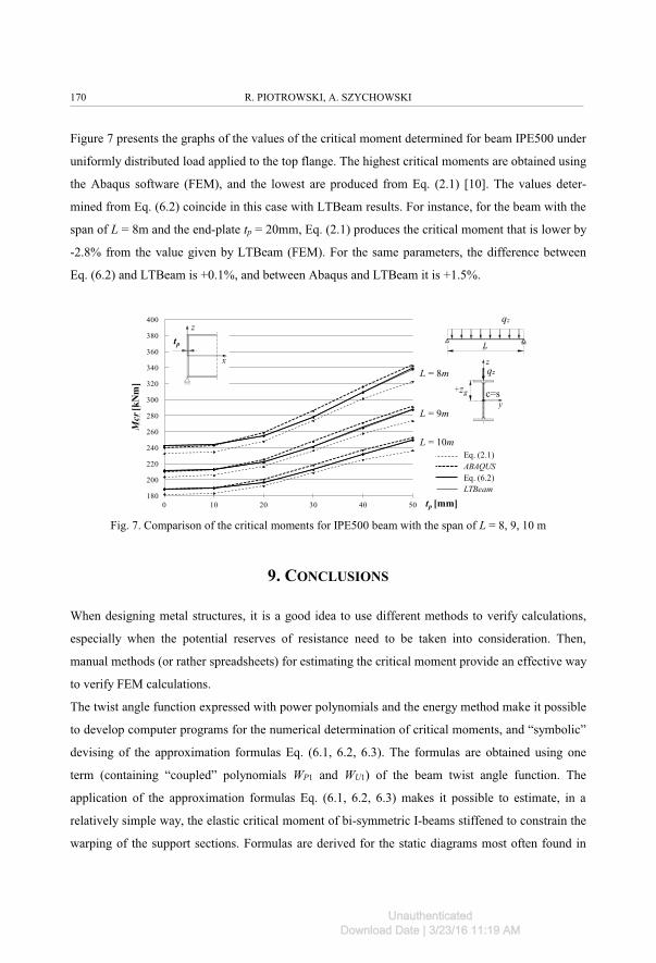
Figure 7 presents the graphs of the values of the critical moment determined for beam IPE500 under
uniformly distributed load applied to the top flange. The highest critical moments are obtained using
the Abaqus software (FEM), and the lowest are produced from Eq. (2.1) [10]. The values deter-
mined from Eq. (6.2) coincide in this case with LTBeam results. For instance, for the beam with the
span of L = 8m and the end-plate tp = 20mm, Eq. (2.1) produces the critical moment that is lower by
-2.8% from the value given by LTBeam (FEM). For the same parameters, the difference between
Eq. (6.2) and LTBeam is +0.1%, and between Abaqus and LTBeam it is +1.5%.
180
200
220
240
260
280
300
320
340
360
380
400
0 10 20 30 40 50
Mcr
[kN
m]
tep [mm]
L = 8m
L = 9m
L = 10m
LINDNER ABAQUSWzórLTBeam
yc=s
z
+zg
qz
qz
tep
z
xL = 8m
L = 9m
L = 10m
tep [mm]
Mcr
[kN
m]
Mcr
[kN
m]
LTBeamEq. (6.2)ABAQUSEq. (2.1)
L
tp [mm]
tp
Fig. 7. Comparison of the critical moments for IPE500 beam with the span of L = 8, 9, 10 m
9. CONCLUSIONS
When designing metal structures, it is a good idea to use different methods to verify calculations,
especially when the potential reserves of resistance need to be taken into consideration. Then,
manual methods (or rather spreadsheets) for estimating the critical moment provide an effective way
to verify FEM calculations.
The twist angle function expressed with power polynomials and the energy method make it possible
to develop computer programs for the numerical determination of critical moments, and “symbolic”
devising of the approximation formulas Eq. (6.1, 6.2, 6.3). The formulas are obtained using one
term (containing “coupled” polynomials WP1 and WU1) of the beam twist angle function. The
application of the approximation formulas Eq. (6.1, 6.2, 6.3) makes it possible to estimate, in a
relatively simple way, the elastic critical moment of bi-symmetric I-beams stiffened to constrain the
warping of the support sections. Formulas are derived for the static diagrams most often found in
170 R. PIOTROWSKI, A. SZYCHOWSKI
UnauthenticatedDownload Date | 3/23/16 11:19 AM
engineering practice.
The comparison of the values of the critical moments indicates good agreement of results between
those obtained from Eq. (6.1), (6.2), (6.3) and from FEM (especially LTBeam). When the beam is
stiffened with end-plates, Eq. (2.1) [10] also produces a good approximation.
Critical moments (Tables 6 and 7) estimated with formulas, Eq. (6.2), (6.3), provide sufficient
engineering approximation when compared with the values obtained with the LTBeam software
(FEM). The results produced with MLTB,EL program, which contains three terms of the series Eq.
(4.1), show very good agreement of with those obtained with FEM. The application of Eq. (2.1) [10]
and FEM (Abaqus, LTBeam) to verify the formula in Eq. (6.2), (Fig. 4, 5, 6, 7) demonstrates good
accuracy of results for beams stiffened with the end-plate at supports.
REFERENCES
1 Bijak R. The lateral buckling moment of simply supported unrestrained symmetric I-shaped beams with free warping (in Polish). XII ICMS Wrocław 2011, 144-151.
2 DIN 18800-2:1990-11. Stahlbauten – Teil 2: Stabilitätsfälle – Knicken von Stäben und Stabwerken.3 ENV-1993-1-1:1993. Design of Steel Structures – Part 1-1: General Rules for Buildings.4 Galéa Y. Moment critique de déversement élastique de pouter fléchies. Présentation du logiciel LTBEAM.
Revue Construction Métallique. CTICM 2003 (2). 5 Giżejowski M. Lateral buckling of steel beams with limited rotation ability at supports (in Polish). Inżynieria i
Budownictwo 10/2001, 589-594.6 Gosowski B. Spatial stability of longitudinally and laterally braced full-walled members of metal structures (in
Polish). Wrocław 1992.7 Gosowski B. Non-uniform torsion of stiffened open thin-walled members of steel structures. JCSR 63 (2007),
849-865.8 Gotluru B.P., Schafer B.W., Peköz T. Torsion in thin-walled cold-formed steel beams. Thin-Walled Structures
37 (2000), 127-145. 9 Jakubowski S. Buckling of Thin-Walled Girders under Compound Load. Thin-Walled Structures 6 (1988),
129-150. 10 Lindner J., Gietzelt R. Stabilisierung von Biegeträgern mit I-Profil durch angeschweiβte Kopfplatten. Stahlbau
3/1984, 69-74. 11 Pałkowski Sz. Steel structures. Selected issues of calculation and design (in Polish). Warszawa 2009.12 Pi B.Y.L., Trahair N.S. Distortion and warping at beam supports. Journal of Structural Engineering 2000, Vol.
126, No. 11, 1279-1287.13 Piotrowski R., Szychowski A. Applying the energy method and polynomials to the determination of the critical
buckling moments in beams (in Polish). Konstrukcje betonowe i metalowe, 249-257. Bydgoszcz 2015. 14 Szychowski A. A theoretical analysis of the local buckling in thin-walled bars with open cross-section subject-
ed to warping torsion. Thin-Walled Structures 76 (2014), 42-55.15 Szychowski A. Stability of cantilever walls of steel thin-walled bars with open cross-section. Thin-Walled
Structures 94 (2015), 348-358. 16 Timoshenko S.P., Gere J.M. Theory of Elastic Stability (in Polish). Warszawa 1963.
Received 25. 08. 2015 Revised 05. 10. 2015
LATERAL-TORSIONAL BUCKLING OF BEAMS ELASTICALLY RESTRAINED... 171
UnauthenticatedDownload Date | 3/23/16 11:19 AM
LIST OF FIGURES AND TABLES:
Fig. 1. Beam stiffened with end-plates: a) view, b) section A-A
Rys. 1. Belka usztywniona blachami czołowymi: a) widok, b) przekrój A-A
Fig. 2. Static scheme of the beam: a) view, b) section A-A
Rys. 2. Schemat statyczny belki: a) widok, b) przekrój A-A
Fig. 3. Exemplary beam modelled using the Abaqus software
Rys. 3. Przykładowa belka zamodelowana w programie Abaqus
Fig. 4. Comparison of the critical moments for IPE300 beam with the span of L = 5, 6, 7 m
Rys. 4. Porównanie momentów krytycznych zwichrzenia dla belki IPE300 o rozpiętości L = 5, 6, 7 m
Fig. 5. Comparison of the critical moments for IPE300 beam with the span of L = 5, 6, 7 m
Rys. 5. Porównanie momentów krytycznych zwichrzenia dla belki IPE300 o rozpiętości L = 5, 6, 7 m
Fig. 6. Comparison of the critical moments for IPE500 beam with the span of L = 8, 9, 10 m
Rys. 6. Porównanie momentów krytycznych zwichrzenia dla belki IPE500 o rozpiętości L = 8, 9, 10 m
Fig. 7. Comparison of the critical moments for IPE500 beam with the span of L = 8, 9, 10 m
Rys. 7. Porównanie momentów krytycznych zwichrzenia dla belki IPE500 o rozpiętości L = 8, 9, 10 m
Tab. 1. Exemplary ways of beam stiffening used to prevent warping [6,12]
Tab. 1. Przykładowe sposoby usztywnienia belek na spaczenie [6,12]
Tab. 2. Polynomials used in the study (ρ = x/L)
Tab. 2. Zastosowane wielomiany (ρ = x/L)
Tab. 3. Coefficients A1, A2, A3 for selected loading schemes
Tab. 3. Współczynniki A1, A2, A3 dla wybranych schematów obciążenia
Tab. 4. Coefficients B1, B2, B3, B4 for selected loading schemes
Tab. 4. Współczynniki B1, B2, B3, B4 dla wybranych schematów obciążenia
Tab. 5. Coefficients C1, C2, C3, C4
Tab. 5. Współczynniki C1, C2, C3, C4
Tab. 6. Comparison of critical moments (MLTB,EL vs. Eq. (6.2) vs. LTBeam)
Tab. 6. Porównanie momentów krytycznych (MLTB,EL vs. (6.2) vs. LTBeam)
Tab. 7. Comparison of critical moments (MLTB,EL vs. Eq. (6.3) vs. LTBeam)
Tab. 7. Porównanie momentów krytycznych (MLTB,EL vs. (6.3) vs. LTBeam)
172 R. PIOTROWSKI, A. SZYCHOWSKI
UnauthenticatedDownload Date | 3/23/16 11:19 AM
ZWICHRZENIE BELEK SPRĘŻYŚCIE ZAMOCOWANYCH PRZECIW SPACZENIU NA PODPORACH
Słowa kluczowe: moment krytyczny zwichrzenia, sprężyste zamocowanie przeciw spaczeniu, blachy czołowe,metoda energetyczna, wielomiany potęgowe
STRESZCZENIE:
Współcześnie stosowane metody projektowania elementów stalowych zmierzają do uwzględnienia szeregu parametrów
poprawiających sposób odwzorowania rzeczywistych warunków pracy konstrukcji w inżynierskim modelu obliczenio-
wym. Jednym z istotnych parametrów jest wpływ sprężystego zamocowania przeciw spaczeniu przekrojów podporo-
wych na moment krytyczny zwichrzenia belek.
W pracy przedstawiono wyniki badań teoretycznych zwichrzenia bisymetrycznych belek dwuteowych sprężyście
zamocowanych przeciw spaczeniu na podporach. Uwzględniono często występujące w praktyce schematy obciążenia.
Stopień sprężystego zamocowania przeciw spaczeniu opisano współczynnikiem ε wg wzoru (3.1) [8,12] uwzględniają-
cym sztywność sprężystego zamocowania αw wg wzoru (3.2) [8,12]. Współczynnik sprężystego zamocowania zmienia
się od ε = 0 dla zupełnej swobody spaczenia, do ε = ∞ dla pełnej blokady spaczenia. W pracy wprowadzono dodatkowo
bezwymiarowy wskaźnik utwierdzenia κ wg wzoru (3.3), zmieniający się od κ = 0 dla zupełnej swobody spaczenia do
κ = 1 dla pełnej blokady spaczenia.
Do wyznaczenia momentu krytycznego zastosowano metodę energetyczną. Funkcję kąta skręcenia φ(x) zawierającą trzy
wyrazy szeregu (4.1) opisano „sprzężonymi” za pomocą wskaźnika κ wielomianami potęgowymi o prostej interpretacji
fizycznej (tab. 2). Na podstawie równania (5.1) opracowano w środowisku pakietu Mathematica® program obliczenio-
wy McrLT_elastic_fix.on.warp.nb., w skrócie MLTB,EL. Program umożliwia wyznaczenie momentów krytycznych
zwichrzenia sprężyście zamocowanych na spaczenie bisymetrycznych belek dwuteowych dla dowolnych parametrów
geometrycznych przekroju i schematów obciążenia zamieszczonych w tabelach 3, 4 i 5 oraz dowolnej wartości
współrzędnej (zg) (rys. 2) punktu przyłożenia obciążenia poprzecznego.
Ponadto wyprowadzono wzory aproksymacyjne do szacowania momentów krytycznych zwichrzenia sprężyście
zamocowanych przeciw spaczeniu na podporach, belek o bisymetrycznym przekroju dwuteowym, dla tych samych
schematów obciążenia. W tym celu opracowano w pakiecie Mathematica® program McrLT_elastic_fix.on.warp._
sym.cal.nb do obliczeń symbolicznych. W tym przypadku funkcję kąta skręcenia aproksymowano tylko pierwszym
wyrazem szeregu (4.1) z zastosowaniem „sprzężonych” wielomianów: WP1 i WU1 (tab. 2). Pozwoliło to na wyprowadze-
nie stosunkowo prostych wzorów aproksymacyjnych (6.1), (6.2) i (6.3) na momenty krytyczne zwichrzenia belek dla
dowolnej wartości wskaźnika utwierdzenia na spaczenie κ przekrojów podporowych.
Uzyskane w pracy wyniki obliczone programem McrLT_elastic_fix.on.warp.nb. oraz za pomocą wzorów aproksymacyj-
nych porównano z obliczeniami MES (LTBeam i Abaqus).
Z porównania momentów krytycznych wyznaczonych programem MLTB,SPR, zawierającym trzy wyrazy szeregu (4.1),
wynikła bardzo dobra zgodność wyników w stosunku do MES (LTBeam), różnice nie przekroczyły +0,5% (tab. 6, 7).
Momenty krytyczne oszacowane za pomocą wzorów (6.2) i (6.3) dały również wystarczające przybliżenie inżynierskie
w stosunku do wartości uzyskanych z programu LTBeam (tab. 6, 7; kol. 8).
LATERAL-TORSIONAL BUCKLING OF BEAMS ELASTICALLY RESTRAINED... 173
UnauthenticatedDownload Date | 3/23/16 11:19 AM
Maksymalne różnice nie przekroczyły +1,4% (tab. 6) oraz +3,1% (tab.7).
Szczegółowe obliczenia momentu krytycznego przeprowadzono dla belek wzmocnionych blachami czołowymi w
przekrojach podporowych. Belki obciążano siłą skupioną w środku rozpiętości lub obciążeniem równomiernie
rozłożonym na całym przęśle. Obciążenia przykładano do półki górnej kształtownika. Otrzymane ze wzoru (6.2) wyniki
porównano z wartościami uzyskanymi z literatury (2.1) [10] oraz MES (Abaqus, LTBeam). We wszystkich przypadkach
otrzymano dobrą z punktu widzenia obliczeń inżynierskich zgodność wyników (rys. 4, 5, 6, 7).
W projektowaniu konstrukcji metalowych warto stosować różne metody weryfikacji obliczeń, zwłaszcza dla przypad-
ków uwzględniających potencjalne zapasy nośności. W tym przypadku ręczne (lub raczej zapisane w arkuszach
kalkulacyjnych) metody szacowania momentów krytycznych zwichrzenia mogą stanowić skuteczne sposoby weryfikacji
obliczeń MES.
174 R. PIOTROWSKI, A. SZYCHOWSKI
UnauthenticatedDownload Date | 3/23/16 11:19 AM
Copyright © 2022 FDOKUMEN