Subregional hippocampal deformations in major depressive disorder
Accepted Manuscript
Title: Torsional deformations in incompressible fibre–reinforced cylindrical pipes
Authors: P. Nardinocchi, T. Svatoň, L. Teresi
PII: S0997-7538(09)00112-0
DOI: 10.1016/j.euromechsol.2009.09.001
Reference: EJMSOL 2547
To appear in: European Journal of Mechanics / A Solids
Received Date: 7 May 2009
Revised Date: 13August2009
Accepted Date: 13 September 2009
Please cite this article as: Nardinocchi, P. Svatoň, T, Teresi, L.,. Torsional deformations inincompressible fibre–reinforced cylindrical pipes, European Journal of Mechanics / A Solids (2009), doi:10.1016/j.euromechsol.2009.09.001
This is a PDF file of an unedited manuscript that has been accepted for publication. As a service toour customers we are providing this early version of the manuscript. The manuscript will undergocopyediting, typesetting, and review of the resulting proof before it is published in its final form. Pleasenote that during the production process errors may be discovered which could affect the content, and alllegal disclaimers that apply to the journal pertain.
MANUSCRIP
T
ACCEPTED
ARTICLE IN PRESS
Torsional deformations in incompressible fibre–reinforced cylindrical pipes
P. Nardinocchi∗,a, T. Svatonb, L. Teresic
aDipartimento di Ingegneria Strutturale e Geotecnica, Universita di Roma “La Sapienza”via Eudossiana 18, I-00147 Roma, Italy,
bUniversity of West Bohemia, Pilsen, Czech RepubliccDipartimento di Strutture, Universita Roma Tre, Roma, Italy
Abstract
The first part of the paper deals with an extension of the classical Rivlin’s solution of the torsion problem of a neo-Hookean pipe. The second part concerns a study of the passive torsional deformation processes in a fibre–reinforcedcylindrical dummy of the beating heart. Especially, the dependence of the torsional and volumetric stiffness of thecylindrical pipe on different geometric and material parameters is discussed through a set of numerical simulations.
Key words: fibre–reinforced non-linearly incompressible elastic solids, finite torsionPACS: 46.05.+b, 46.70.Lk
1. Introduction
In the last few years, fibre–reinforced materials have made a new comeback in a new and more appealing biome-chanical flavour. In fact, quite a few living materials are characterized by mechanical responses which are stronglyanisotropic due to their fibred structure. Accordingly, much attention has been devoted to the modelling issues raisedby fibre-reinforced solids undergoing finite deformations (Merodio and Ogden, 2005; Holzapfel et al., 2005, 2004;Gasser et al., 2006). Specifically, we are involved in an extensive work on the electromechanical modeling of left ven-tricle and a key step of our work concerns the modeling of the passive and active response of cardiac tissue. Typically,myocardium is modeled as an incompressible elastic material reinforced by cardiac muscle fibres which can contractin response to electrophysiological stimuli. As is evident, the overall response of the left ventricle depends on themodeling of both the passive and the active behavior of the cardiac tissue. Here, we deal with the passive behaviour ofa fibre–reinforced cylindrical dummy of the left ventricle under torsional deformations and arrange the paper in two,basically disjoint even if related, parts.
The first part concerns homogeneous torsional deformations of helically wound fibre-reinforced incompressibleelastic pipes and the analysis of the corresponding non linear boundary value problem is developed explicitly. Itis related to the study developed in (Nardinocchi et al., 2009) where the mechanical response of the pipe has beendescribed through the standard quadratic reinforcement model (Merodio and Ogden, 2005). Here, we account for analternative reinforcement model, always proposed and discussed for special homogeneous deformations in (Merodioand Ogden, 2005), more sensitive to shear deformations and discuss the effects of the two different, even if similar,material models on the homogeneous solution of the torsion problem.
The second part is meant as a first step towards the analysis of the torsional deformation underwent by the left ven-tricle during the cardiac cycle; the motivation being provided by the fact that left ventricular torsion has been recentlyrecognized as an important indicator of cardiac function (Taber et al., 1996; Nagel et al., 2000). Nevertheless, from amechanical point of view, little attention has been devoted to the pattern of twist during the cardiac cycle. Specifically,we account for the inhomogeneous torsional deformations induced by a pressure field on the cylinder; still, we do not
∗Corresponding authorEmail addresses: [email protected] (P. Nardinocchi), [email protected] (T. Svaton), [email protected] (L.
Teresi)
Preprint submitted to Elsevier May 7, 2009
MANUSCRIP
T
ACCEPTED
ARTICLE IN PRESS
care of the active behaviour of the muscle fibres (see (DiCarlo et al., 2009)) for the active behavior modeling) anduse the model to study the effects of various material and geometric parameters on the torsional behaviour of the pipewith frozen fibres.
We see that the anisotropy due to the variation in muscle fibre angle across the wall of the pipe induces rotationof one end with respect to the other; nevertheless, rotation is induced in absence of such variation, too, when the fibreangles are fixed across the walls and far from some extreme values. Moreover, the material parameters related to thechoice of the reinforcing model afflict the mechanical response of the pipe, too. We show that there is a considerablechange in volume related to the pressure field which is influenced by the same material parameters, too. Of course, thepure elasticity of the material does not allow to see any pressure–torsion and pressure–volume loops whose formationis basically related to the active nature of the fibres which change when contracted the ground state of the pipe(see (DiCarlo et al., 2009)). To mimic the cardiac situation, the sensitivity of the torsion of the cylindrical pipe tochanges in pipe geometry is studied by simulating two types of excessive development of the cylindrical geometrywith respect to the basic one. The first is characterized by an augmented wall thickness (resembling the ventriculareccentric hypertrophy); the second by an augmented lumen (resembling the ventricular concentric hyperthrophy).
2. Fibre-reinforced bodies
Let {e1, e2, e3} be an orthonormal basis of the translation spaceV of the three–dimensional Euclidean space E andU be the orthogonal complement to span{e3} with respect to V. Fixed an interval I = [0, h] ⊂ R and a pole o ∈ E,we consider the axisymmetric pipe-like region C defined as follows:
C = {p ∈ E : p = o + r n(θ) + ζ e3} , n(θ) = cos θ e1 + sin θ e2 , 0 < θ < 2π , ζ ∈ I , Ri < r < Ro . (2.1)
The boundary ∂C is defined as∂C = D0 ∪Dh ∪Mi ∪Mo , (2.2)
withD0 andDh the bases of the pipe andMi andMo the inner and outer mantle, respectively.A helix-like fibre of pitch b is a curve whose unit tangent vector eb = eb(r, θ) at any p ∈ C is defined as
eb(r, θ) =r
(r2 + b2)12
n,θ (θ) +b
(r2 + b2)12
e3 , (2.3)
with the subscript b remembering the dependence of the unit tangent vector on the pitch b of the helix. So, at anyplace p of a helically wound fibre–reinforced body C, the material fibre (p, eb) with eb as in (2.3) identifies a locus ofmaterial reinforcement; for b = 0 equation (2.3) defines a circumferential uniaxial reinforcement (e0(r, θ) = n,θ (θ)).Sometimes, a different parametrization of the helical curve is referred to, with the pitch b of the helix expressed interms of the angle α defined as
cosα = eb · e0 . (2.4)
With (2.3), it turns out
tanα =br. (2.5)
Specifically, the fibre angle α is a relevant parameter for the ventricular geometry where fibres account for anisotropicreinforcement due to collagene, or may represent muscles fibres. In that case, it is important to account for thelarge variation of the fibres angles across the wall of the left ventricle. Typically, the angle α ranges between −60◦
(on the outer wall) and 60◦ (on the inner wall) and the anisotropy due to the variation amplifies the ventriculartorsion occurring during the cardiac cycle. In (Nardinocchi et al., 2009), we described the material response of theincompressible (J = 1) body through the following strain energy function based on the quadratic reinforcementmodel I4
ψ(C) = c1
(I1(C) − 3 + γ (I4(C) − 1)2
), I1(C) = C · I , I4(C) = Ceb · eb , C = FT F , (2.6)
with γ > 0. In this paper, we consider the strain energy
ψ(C) = c1
(I1(C) − 3) + γ (I5(C) − 1)2
), I5(C) = C2eb · eb , (2.7)
2
MANUSCRIP
T
ACCEPTED
ARTICLE IN PRESS
Zoom at b/h ' 0 Zoom at b/h ' 0
b
ab
a
b
ab
a
b
ab
ab
a
bI4, I5
b/h
I4, I5
b/h0 0.5 1 1.5 2 0 0.5 1 1.5 21.0
1.5
1.9
2.3
1.0
1.5
1.9
2.3
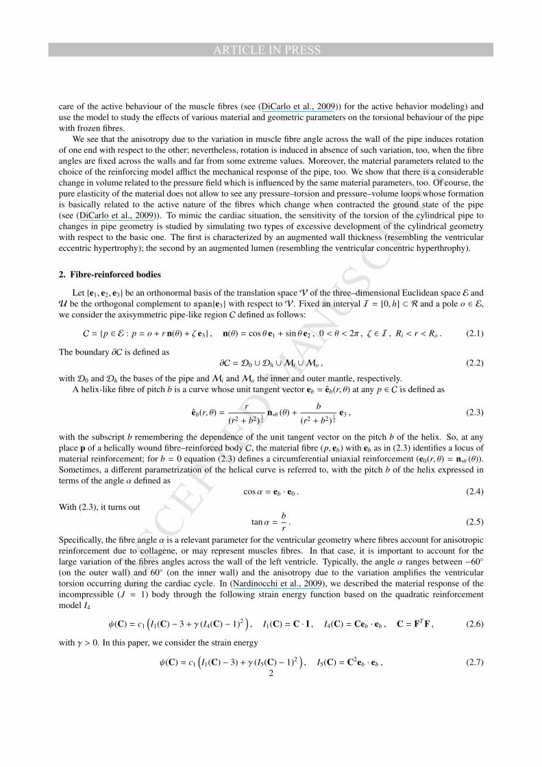
Figure 1: I4 (dashed lines) and I5 (solid lines) VS b/h for two different given torsions: ϕh = π/6 (a, blue), ϕh = π/2 (b, red); values on the innermantle (left), and at the outer mantle (right). Insets at top–right represent a zoom at b/h ' 0
which, as it is well known (Merodio and Ogden, 2005), is more suited to the present context characterized by largeshear deformations. As example, under torsional deformation (Nardinocchi et al., 2009) the quadratic reinforcementtends to become ineffective as the ratio b/h goes to 0, while the reinforcement I5 is effectual even with circumferentialfibres.
3. Pure and homogeneous torsional deformations
As first, we analyze the mechanical response of the helically wound fibre–reinforced incompressible pipe to tor-sional deformations induced through a torsional rotation of one end of the pipe. An extension of the solution of thepure torsional problem studied for isotropic and incompressible cylinders by Rivlin (Rivlin, 1949) to the material pipedescribed by the strain energy (2.7) is performed. The same extension has been performed in (Nardinocchi et al.,2009) in presence of the standard quadratic reinforcement model and a comparison of the solutions clarifies the rolesof the different reinforcement models in presence of torsional deformations.
A concise representation formula of a pure torsional deformation f : C → E is the following
f(p) = ( I + sinϕ e2 ∧ e1 − (1 − cosϕ) I ) (p − o) , ϕ = ζ τ , (3.8)
where e2 ∧ e1 = e2 ⊗ e1 − e1 ⊗ e2, ϕ is the torsion angle, and τ is the unit torsion angle. From now on, we parametrizethe torsional deformation (3.8) through the torsion angle ϕ = h τ ofDh. The geometrical structure of the cylinder–likebody C is retained under the deformation (3.8) and, denoted with x ∈ V the position vector of the place x = f(p) withrespect to o, it holds:
x = xo + ζ e3 , xo = r(cosϕn(θ) + sinϕn,θ (θ)) . (3.9)
The deformation gradient F corresponding to (3.8) may be represented as
F = F + τ x∗o ⊗ e3 + e3 ⊗ e3 , (3.10)
with F ∈ Lin(U) and x∗o ∈ U given by
F = cosϕ I + sinϕ (e2 ∧ e1) , x∗o = e3 × xo . (3.11)
Let us note that deformation (3.8) identically satisfies the incompressibility constraint J = detF = 1. The threeinvariants we are interested in, I1, I4, I5, write as follows
I1 = 3 + r2τ2 , I4 = 1 + r k(r) (2 + b τ) b τ , I5 = I4 + r k(r) (1 + b τ) (2b τ + r2τ2 + r2 b τ3) , (3.12)
where k(r) = r (r2 + b2)−1 is the curvature of the helix. The invariant I4 measures the stretch along the material fibre(p, eb); it is interesting to note that the stretch I4 is not a monotone function of the dimensionless pitch b/h and dependsweakly on the place p ∈ C.
3
MANUSCRIP
T
ACCEPTED
ARTICLE IN PRESS
Figure 1 shows that the behaviour of I4 versus b/h is qualitatively the same at the inner and at the outer radius.Moreover, it shows that for circumferential fibres (b/h = 0) I4 ≡ 1, that is, the fibre length does not change under thetorsional deformation (3.8). On the contrary, the invariant I5 is sensitive to shear deformation too, as it is discussedin (Merodio and Ogden, 2005) for different values of the strength γ of the reinforcement; thus, it happens that I5 isdifferent from 1 at b/h = 0, see zoom in Fig 1. At the end, it is worth noting that at any r between Ri and Ro, thereis a value of the dimensionless pitch b/h which gives the maximum fibre stretch; moreover, the same b/h gives themaximum value of I5, too. When the strain energy function (2.7) is used, the corresponding Cauchy stress is
T = 2c1B + 2c1γ (I5 − 1) (FCeb ⊗ Feb + Feb ⊗ FCeb) − p I , (3.13)
with B = FFT ; the Cauchy stress corresponding to an incompressible neo-Hookean material turns out by settingγ = 0. The balance equation of the body (divT = 0) gives an explicit representation for p
p = p(r, b, τ) = po(b, τ) − c1 (1 − 2γ p1(b, τ)) τ2 r2 − c1 γ (1 + b τ)4τ4 r4
− 2 c1 γ p2(b, τ) log(b2 + r2) − 2 c1 γ p3(b, τ)1
b2 + r2 , (3.14)
where the function po is determined by the boundary conditions, and
p1(b, τ) = (1 + b τ)2 (1 − (1 + b τ)(1 + 4 b τ) − (1 + b τ)2 (1 − 2 b2 τ2)) ,p2(b, τ) = b τ (4 + 13 b τ − b2 τ2 − 31 b3 τ3 − 22 b4 τ4 + 8 b5 τ5 + 12 b6 τ6 + 3 b7 τ7) ,p3(b, τ) = (1 + b τ) (2 + b τ) (2 − b2 τ2) (1 + 2 b τ − b2 τ2 − b3 τ3) b3 τ .
As in (Rivlin, 1949) and (Nardinocchi et al., 2009), the no–traction condition Tm = 0 on Mo turns out po, andcompletely determines the Cauchy stress. Moreover, on the inner mantle Mi there is a traction field Tm = −pi mdifferent from zero with
pi = c1 (R2o − R2
i )(1 + γ (R2
o + R2i ) (1 + b τ)4 τ2 − 2γ p1
)τ2 + 2 c1 γ (log
b2 + R2o
b2 + R2i
p2 −R2
o − R2i
(b2 + R2i )(b2 + R2
o)p3) . (3.15)
On the bases of the cylindrical structure we find a traction field T±e3 with T± denoting the values attained by theCauchy stress field T on the bases Dh and D0, respectively. It consists of an axial stress σ± = T±e3 · e3, the reactionto the kinematical constraint on the axial displacement, and a tangential stress t± = (T±e3 − (T±e3 · e3)e3), responsiblefor the pure torsional deformation. Then, we consider the stress resultants acting on the bases; in particular, we focuson the torque M = Me3, and on the axial force N = Ne3
M =
∫P
xo × t dxo · e3 , N =
∫P
σ dxo . (3.16)
It is possible to obtain an explicit representation of the resultants in terms of the relevant material and geometricalparameters; we find
M = c1 π (R4o − R4
i ) τ + M f (Ri,Ro, b, τ, c1, γ) ,
N = −1/2 c1 π (R2o − R2
i )2 τ2 + N f (Ri,Ro, b, τ, c1, γ) .(3.17)
Detailed representations of M f , N f are given in the appendix. In (3.17)1, the first summand, a linear function of τ,represents the torque competing to an isotropic and incompressible cylinder, thus corresponding to the Rivlin solution.The second summand defines the correction due to the presence of the helicoidal fibres; it is a polynomial function ofτ, up to the power seven, as equation (A.29) shows.
The first summand in (3.17)2, quadratic in τ, defines the axial force competing to the isotropic and incompressiblepipe; it is worth noting that it vanishes in the linear approximation, that is, for small τ. The second summand definesthe contribution to the axial force due to the anisotropy; such term persists in a first order approximation, as therepresentation formula (A.30) shows.
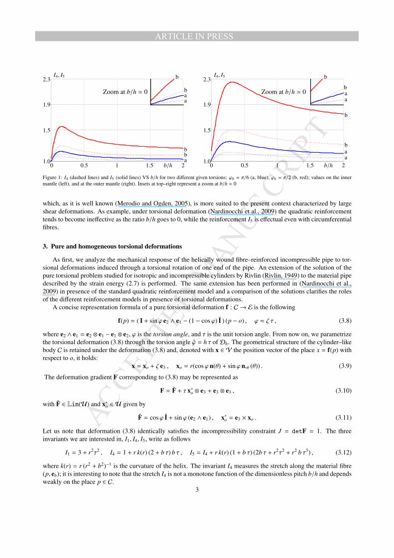
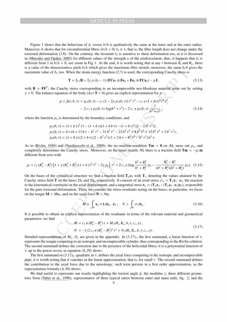
We find useful to represents our results highlighting the torsion angle ϕ, the modulus γ, three different geome-tries from (Taber et al., 1996), representative of three typical ratios between outer and inner radii, fig. 2, and the
4
MANUSCRIP
T
ACCEPTED
ARTICLE IN PRESS
Figure 2: Geometries. From left to right: basic (Ro/h = 0.26 and Ri/Ro = 0.54), eccentric (Ro/h = 0.34 and Ri/Ro = 0.53), concentric(Ro/h = 0.38, and Ri/Ro = 0.37).
b/h = 0 b/h = 0.5 b/h = 1 b/h = 2 b/h = ∞
Figure 3: Different fibre windings.
dimensionless pitch b/h of the helix, fig. 3. Given a basic geometry defined by Ro/h = 0.26 and Ri/Ro = 0.54, weconsider two types of excessive development of the cylindrical geometry with respect to the basic one: the eccentricgeometry, characterized by an augmented wall thickness (resembling the ventricular eccentric hypertrophy), definedby Ro/h = 0.34 and Ri/Ro = 0.53, and the concentric one, showing an augmented lumen (resembling the ventricularconcentric hyperthrophy), defined by Ro/h = 0.38, and Ri/Ro = 0.37.
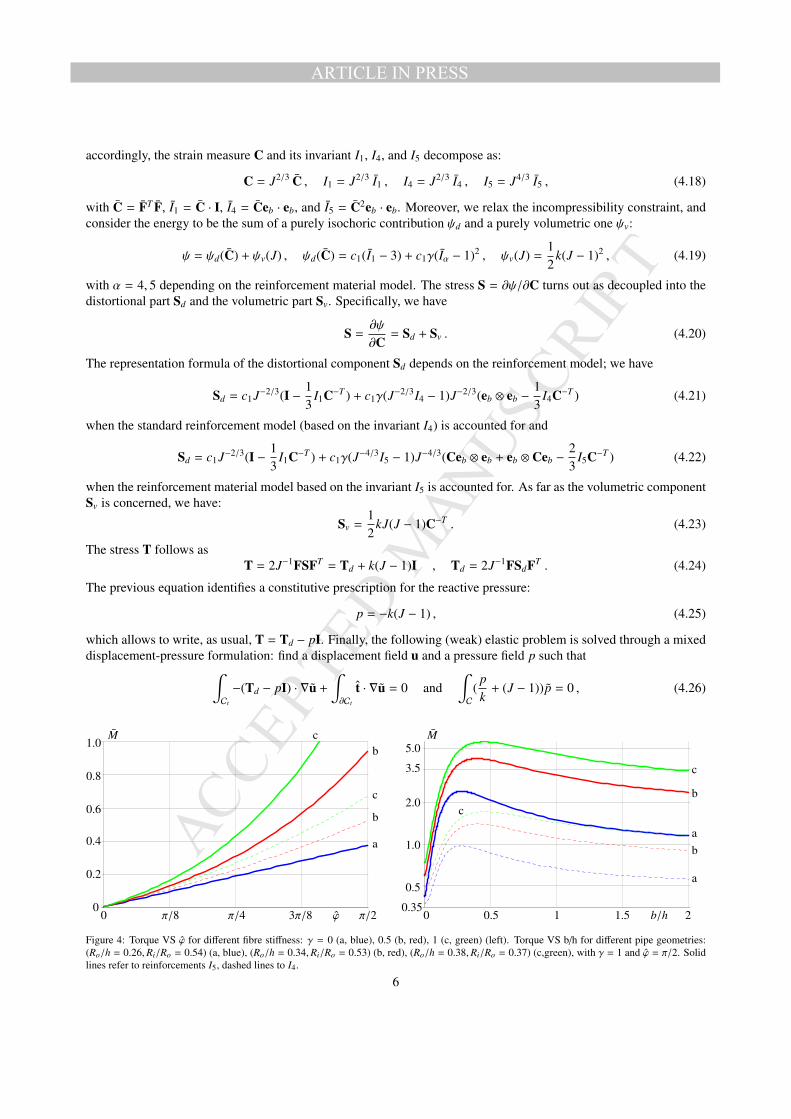
Figures 4 and 5 show the dependence of the torque M and of the axial force N on some relevant material andgeometric parameters, for the two energies we consider; dashed curve correspond to the strain energy (2.6) – I4reinforcement – solid curves to strain energy (2.7) – I5 reinforcement.
Figure 4 on the left shows the behavior of the dimensionless torque M, M = M/πR3oc1 versus torsion angle ϕ for
different fibre stiffness; at right, it shows M versus the winding parameter b/h, for ϕ = π/2, γ = 1, and for threedifferent pipe geometries. The line labeled a represents the isotropic benchmark.
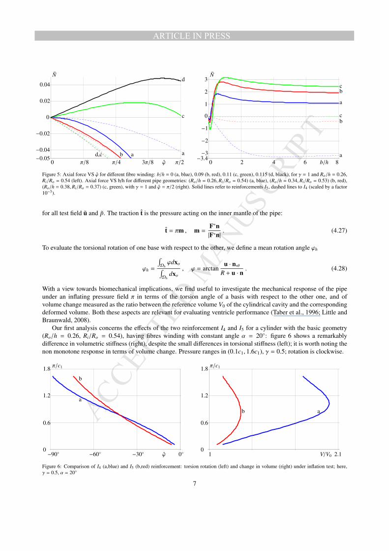
As expected, the reinforcement based on I5 (solid lines) requires larger torques with respect to that based on I4(dashed lines) in order to induce the same torsion angle ϕ; moreover, it turns out that the torque is not a monotonefunction of b/h, (see figure 4, right). Figure 5 shows a remarkable difference in the axial force corresponding to thedifferent energies we used; actually, the axial force corresponding to the I4 reinforcement is scaled down by a factorforce 10−3. Moreover, there is a qualitative difference, too: when the material model associated to the invariant I4 isused, a negative axial force is always associated to the torsion of the pipe for any value of b/h. On the contrary, whenthe material model I5 is used the axial force is still negative for small b/h and positive otherwise revealing a peculiarbehavior of the material model: the transition from a torsion–induced extension (corresponding to low values of b/h)to a torsion–induced shortening (corresponding to large values of b/h).
4. Pressure-induced torsional deformations
This section deals with a specific problem: torsional deformations and volume change induced on the neo-hookeanfibre–reinforced pipe when it is inflated by a uniform pressure field acting on the inner mantle, and the rotation of oneof its bases with respect to the axis of the pipe is constrained. For such a case, it is not possible to give an explicitsolution, thus, we implement and solve the problem using a finite element analysis.
In order to tackle the incompressibility constraint, as suggested in (Ogden, 1978), we decompose the deforma-tion gradient F into a spherical (dilatational), and an unimodular (distortional) part: F = J1/3 F with J = (detF);
5
MANUSCRIP
T
ACCEPTED
ARTICLE IN PRESS
accordingly, the strain measure C and its invariant I1, I4, and I5 decompose as:
C = J2/3 C , I1 = J2/3 I1 , I4 = J2/3 I4 , I5 = J4/3 I5 , (4.18)
with C = FT F, I1 = C · I, I4 = Ceb · eb, and I5 = C2eb · eb. Moreover, we relax the incompressibility constraint, andconsider the energy to be the sum of a purely isochoric contribution ψd and a purely volumetric one ψv:
ψ = ψd(C) + ψv(J) , ψd(C) = c1(I1 − 3) + c1γ(Iα − 1)2 , ψv(J) =12
k(J − 1)2 , (4.19)
with α = 4, 5 depending on the reinforcement material model. The stress S = ∂ψ/∂C turns out as decoupled into thedistortional part Sd and the volumetric part Sv. Specifically, we have
S =∂ψ
∂C= Sd + Sv . (4.20)
The representation formula of the distortional component Sd depends on the reinforcement model; we have
Sd = c1J−2/3(I −13
I1C−T ) + c1γ(J−2/3I4 − 1)J−2/3(eb ⊗ eb −13
I4C−T ) (4.21)
when the standard reinforcement model (based on the invariant I4) is accounted for and
Sd = c1J−2/3(I −13
I1C−T ) + c1γ(J−4/3I5 − 1)J−4/3(Ceb ⊗ eb + eb ⊗ Ceb −23
I5C−T ) (4.22)
when the reinforcement material model based on the invariant I5 is accounted for. As far as the volumetric componentSv is concerned, we have:
Sv =12
kJ(J − 1)C−T . (4.23)
The stress T follows asT = 2J−1FSFT = Td + k(J − 1)I , Td = 2J−1FSdFT . (4.24)
The previous equation identifies a constitutive prescription for the reactive pressure:
p = −k(J − 1) , (4.25)
which allows to write, as usual, T = Td − pI. Finally, the following (weak) elastic problem is solved through a mixeddisplacement-pressure formulation: find a displacement field u and a pressure field p such that∫
Ct
−(Td − pI) · ∇u +
∫∂Ct
t · ∇u = 0 and∫C
(pk
+ (J − 1))p = 0 , (4.26)
a
b
b
c
c
a
b
c
a
b
c
M
ϕ
M
b/h0 π/8 π/4 3π/8 π/2 0 0.5 1 1.5 20
0.2
0.4
0.6
0.8
1.0
0.35
0.5
1.0
2.0
3.5
5.0
Figure 4: Torque VS ϕ for different fibre stiffness: γ = 0 (a, blue), 0.5 (b, red), 1 (c, green) (left). Torque VS b/h for different pipe geometries:(Ro/h = 0.26,Ri/Ro = 0.54) (a, blue), (Ro/h = 0.34,Ri/Ro = 0.53) (b, red), (Ro/h = 0.38,Ri/Ro = 0.37) (c,green), with γ = 1 and ϕ = π/2. Solidlines refer to reinforcements I5, dashed lines to I4.
6
MANUSCRIP
T
ACCEPTED
ARTICLE IN PRESS
a
c
d
ad,c b
a
bc
cb
a
N
ϕ
N
b/h0 π/8 π/4 3π/8 π/2 0 2 4 6 8−0.05−0.04
−0.02
0
0.02
0.04
−3.4−3
−2
−1
0
1
2
3
Figure 5: Axial force VS ϕ for different fibre winding: b/h = 0 (a, blue), 0.09 (b, red), 0.11 (c, green), 0.115 (d, black), for γ = 1 and Ro/h = 0.26,Ri/Ro = 0.54 (left). Axial force VS b/h for different pipe geometries: (Ro/h = 0.26,Ri/Ro = 0.54) (a, blue), (Ro/h = 0.34,Ri/Ro = 0.53) (b, red),(Ro/h = 0.38,Ri/Ro = 0.37) (c, green), with γ = 1 and ϕ = π/2 (right). Solid lines refer to reinforcements I5, dashed lines to I4 (scaled by a factor10−3).
for all test field u and p. The traction t is the pressure acting on the inner mantle of the pipe:
t = πm , m =F∗n|F∗n|
. (4.27)
To evaluate the torsional rotation of one base with respect to the other, we define a mean rotation angle ϕh
ϕh =
∫Dhϕdxo∫
Dhdxo
, ϕ = arctanu · n,θ
R + u · n. (4.28)
With a view towards biomechanical implications, we find useful to investigate the mechanical response of the pipeunder an inflating pressure field π in terms of the torsion angle of a basis with respect to the other one, and ofvolume change measured as the ratio between the reference volume V0 of the cylindrical cavity and the correspondingdeformed volume. Both these aspects are relevant for evaluating ventricle performance (Taber et al., 1996; Little andBraunwald, 2008).
Our first analysis concerns the effects of the two reinforcement I4 and I5 for a cylinder with the basic geometry(Ro/h = 0.26, Ri/Ro = 0.54), having fibres winding with constant angle α = 20◦: figure 6 shows a remarkablydifference in volumetric stiffness (right), despite the small differences in torsional stiffness (left); it is worth noting thenon monotone response in terms of volume change. Pressure ranges in (0.1c1, 1.6c1), γ = 0.5; rotation is clockwise.
a
b
ab
π/c1
ϕ
π/c1
V/V0−90◦ −60◦ −30◦ 0◦ 1 2.10
0.6
1.2
1.8
0
0.6
1.2
1.8
Figure 6: Comparison of I4 (a,blue) and I5 (b,red) reinforcement: torsion rotation (left) and change in volume (right) under inflation test; here,γ = 0.5, α = 20◦
7
MANUSCRIP
T
ACCEPTED
ARTICLE IN PRESS
c b d a
a b c d
π/c1
ϕ
π/c1
V/V0−45◦ −30◦ −15◦ 0◦ 1 1.4 1.8 2.20.0
0.2
0.4
0.6
0.0
0.2
0.4
0.6
Figure 7: Pressure VS torsion angle (left) and pressure VS change in volume (right). Winding angle α = 0◦ (a, blue), 20◦ (b, red), 40◦ (c, green),60◦ (d, black) (left). Reinforcement I5 with γ = 0.5.
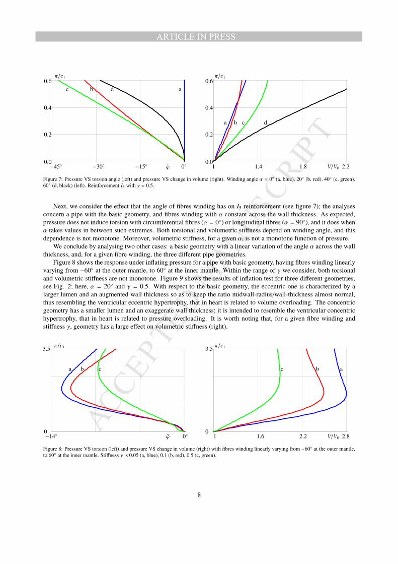
Next, we consider the effect that the angle of fibres winding has on I5 reinforcement (see figure 7); the analysesconcern a pipe with the basic geometry, and fibres winding with α constant across the wall thickness. As expected,pressure does not induce torsion with circumferential fibres (α = 0◦) or longitudinal fibres (α = 90◦), and it does whenα takes values in between such extremes. Both torsional and volumetric stiffness depend on winding angle, and thisdependence is not monotone. Moreover, volumetric stiffness, for a given α, is not a monotone function of pressure.
We conclude by analysing two other cases: a basic geometry with a linear variation of the angle α across the wallthickness, and, for a given fibre winding, the three different pipe geometries.
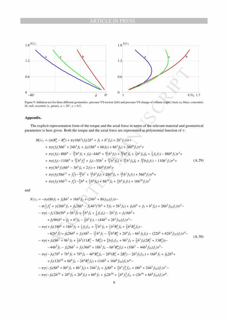
Figure 8 shows the response under inflating pressure for a pipe with basic geometry, having fibres winding linearlyvarying from −60◦ at the outer mantle, to 60◦ at the inner mantle. Within the range of γ we consider, both torsionaland volumetric stiffness are not monotone. Figure 9 shows the results of inflation test for three different geometries,see Fig. 2; here, α = 20◦ and γ = 0.5. With respect to the basic geometry, the eccentric one is characterized by alarger lumen and an augmented wall thickness so as to keep the ratio midwall-radius/wall-thickness almost normal,thus resembling the ventricular eccentric hypertrophy, that in heart is related to volume overloading. The concentricgeometry has a smaller lumen and an exaggerate wall thickness; it is intended to resemble the ventricular concentrichypertrophy, that in heart is related to pressure overloading. It is worth noting that, for a given fibre winding andstiffness γ, geometry has a large effect on volumetric stiffness (right).
a b c abc
π/c1
ϕ
π/c1
V/V0−14◦ 0◦ 1 1.6 2.2 2.80
3.5
0
3.5
Figure 8: Pressure VS torsion (left) and pressure VS change in volume (right) with fibres winding linearly varying from −60◦ at the outer mantle,to 60◦ at the inner mantle. Stiffness γ is 0.05 (a, blue), 0.1 (b, red), 0.5 (c, green).
8
MANUSCRIP
T
ACCEPTED
ARTICLE IN PRESS
a bc a bc
π/c1
ϕ
π/c1
V/V0−80◦ 0◦ 1 1.70
0.6
1.2
1.8
0
0.6
1.2
1.8
Figure 9: Inflation test for three different geometries: pressure VS torsion (left) and pressure VS change of volume (right); basic (a, blue), concentric(b, red), eccentric (c, green), α = 20◦, γ = 0.5.
Appendix.
The explicit representation form of the torque and the axial force in terms of the relevant material and geometricalparameters is here given. Both the torque and the axial force are represented as polynomial function of τ:
M/c1 = (π(R4o − R4
i ) + πγ16b2( f2(2b4 + f5 + b2 f4) + 2b2 f1))τ+
+ πγ( f2(36b7 + 24b3 f5 + f4(18b5 + 6b f5) + 6b3 f6) + 36b5 f1)τ2+
+ πγ( f2(−88b8 − 703 b4 f5 + f4(−44b6 + 62
3 b2 f5) + 623 b4 f6 + 2
3 b2 f4 f6 + 23 f5 f7) − 88b6 f1)τ3+
+ πγ( f2(−110b9 + 553 b5 f 2
3 + f4(−55b7 + 553 b3 f5) + 10
3 b3 f4 f6 + 103 b f5 f7) − 110b7 f1)τ4+
+ πγ(3b2 f3(6b4 − 3b2 f4 + 2 f7) + 18b8 f1)τ5+
+ πγ( f2(56b11 + f 23 (− 28
3 b7 + 143 b5 f4) + 28b9 f4 + 14
3 b3 f5 f7) + 56b9 f1)τ6+
+ πγ( f2(16b12 + f 23 (− 8
3 b8 + 43 b6 f4) + 8b10 f4 + 4
3 b4 f5 f7) + 16b10 f1)τ7
(A.29)
and
N/c1 = −πγ(8b f3 + f88b3 + 16b5 f2 + (24b3 + 8b f10) f1)τ−
− π( 12 f 2
3 + γ(26b2 f3 + f828b4 − f24b2(7b4 + 5 f5 + 5b2 f4) + f9(b4 + f5 + b2 f4) + 26b2 f10 f1))τ2−
− πγ(− f212b(5b6 + 3b2 f5 + 52 b4 f4 + 1
6 f5 f4) − 2b3 f3 + f816b5+
+ f99b(b4 + f5 + b2 f4 − 29 b2 f3) − (44b5 + 2b3 f10) f1)τ3−
− πγ(+ f9(18b6 + 18b2 f5 + 13 f5 f11 + 73
3 b4 f4 + 13 b2R2
i f4 + 23 b2R2
o f4)−
−62b4 f3 − f826b6 + f2(4b8 − 133 b4 f5 − 35
3 b4R4o + 2b6 f4 − 6b2 f5 f4) − (22b6 + 62b4 f10) f1)τ4−
− πγ(+ f9(9b7 + 9b3 f5 + 23 b5(11R2
i − 5R2o) + 4
3 b f5 f11 + 9b5 f4 + 23 b3 f4(2R2
i + 13R2o))−
−44b5 f3 − f826b7 + f2(36b9 + 18b7 f4 − 6b3R4o f4) + (10b7 − 44b5 f10) f1)τ5−
− πγ(− f9(7b8 + 7b4 f5 + 7b6 f4 − 4b4R2o f4 − 2b6(R2
o + 2R2i ) − 2b2 f5 f11) + 16b6 f3 + f82b8+
+ f2(12b10 + 6b8 f4 − 2b4R4i f4) + (14b8 + 16b6 f10) f1)τ6−
− πγ(− f9(8b9 + 8b5 f5 + 8b7 f4) + 24b7 f3 + f88b9 + 43 b3 f 2
3 f11 + (8b9 + 24b7 f10) f1)τ7−
− πγ(− f9(2b10 + 2b6 f5 + 2b8 f4) + 6b8 f3 + f82b10 + 13 b4 f 2
3 f11 + (2b10 + 6b8 f10) f1)τ8 .
(A.30)
9
MANUSCRIP
T
ACCEPTED
ARTICLE IN PRESS
In (A.29) and (A.30), the functions fi, (i = 1, 9) are defined as
f1(Ro,Ri, b) = logb2 + R2
i
b2 + R2o, f2(Ro,Ri, b) =
R2o − R2
i
(b2 + R2i )(b2 + R2
o), f3(Ro,Ri) = R2
o − R2i , (A.31)
f4(Ro,Ri) = R2o + R2
i , f5(Ro,Ri) = R2i R2
o , (A.32)
f6(Ro,Ri) = R4o + R4
i , f7(Ro,Ri) = R4o + R2
oR2i + R4
i , (A.33)
f8(Ro,Ri, b) =R2
o − R2i
b2 + R2o, f9(Ro,Ri, b) =
(R2o − R2
i )2
(b2 + R2i )(b2 + R2
o), (A.34)
f10(Ri, b) = b2 + R2i , f11(Ro,Ri) = R2
i + 2R2o . (A.35)
References
DiCarlo, A., Nardinocchi, P., Svaton, T., Teresi, L., 2009. Passive and active deformation process in cardiac tissue. Proceedings of the Int. Conf. onComputational Methods for Coupled Problems in Science and Engineering (COUPLED PROBLEMS 2009), Eds. B. Schreer, E. Onate and M.Papadrakakis, CIMNE, Barcelona, 2009.
Gasser, T.C., Ogden, R.W., Holzapfel, G.A., (2006). Hyperelastic modelling of arterial layers with distributed collagen fibre orientation. J.R.Soc.Interface, 3, 15–35.
Holzapfel, G.A., Gasser, T.C., Ogden, R.W., 2000. A New Constitutive Framework for Arterial Wall Mechanics and a Comparative Study ofMaterial Models. Journal of Elasticity, 61, 1-48.
Holzapfel, G.A., Gasser, T.C., Ogden, R.W., 2004. Comparison of a Multi-Layer Structural Model for Arterial Walls With a Fung-Type Model, andIssues of Material Stability. Journal of Biomechanical Engineering, 126, 264–275.
Little W.C., Braunwald, E., 2008. Assessment of cardiac function. In: Braunwald’s Heart Disease. A Textbook of Cardiovascular Medicine. EighthEdition. Eds: Libby, P., Bonow, R.O., Mann, D.L., Zipes, D.P., 421–445.
Merodio, J., Ogden, R.W., 2005. Mechanical response of fibre-reinforced incompressible non-linearly elastic solids. International Journal of Non-Linear Mechanics, 40, 213–227.
Nagel, E., Stuber, M., Burkhard, B., Fischer, S.E, Scheidegger, M.B, Boesiger, P., Hess, O.M.. (2000) European Heart Journal, 21(7), 582–589.Nardinocchi, P., Svaton, T., Teresi, L., (2009). Mechanical response of helically wound fibre-reinforced incompressible non-linearly elastic pipes.
In press on Lecture Notes in Applied and Computational Mechanics, Springer.Ogden, R.W., 1978. Nearly isochoric elastic deformations: Application to rubberlike solids. J. Mech. Phys. Solids 26 (1978) 3757. 42.Rivlin, R.S., 1949. A note on the torsion of an incompressible highly-elastic cylinder. Proc. Cambridge Philos. Soc. 45, 485–487.Taber, L.A., Yang, M., Podszus, W.W., (1996). Mechanics of Ventricular Torsion. J. Biomechanics, 29(6), 745–752.
10
Copyright © 2022 FDOKUMEN