
Understanding Shape Memory Alloy Torsional Actuators - MDPI
25
Citation: Sansone, M.; Ameduri, S.; Concilio, A.; Cestino, E. Understanding Shape Memory Alloy Torsional Actuators: From the Conceptual to the Preliminary Design. Actuators 2022, 11, 81. https://doi.org/10.3390/ act11030081 Academic Editor: Kenji Uchino Received: 26 January 2022 Accepted: 4 March 2022 Published: 6 March 2022 Publisher’s Note: MDPI stays neutral with regard to jurisdictional claims in published maps and institutional affil- iations. Copyright: © 2022 by the authors. Licensee MDPI, Basel, Switzerland. This article is an open access article distributed under the terms and conditions of the Creative Commons Attribution (CC BY) license (https:// creativecommons.org/licenses/by/ 4.0/). actuators Article Understanding Shape Memory Alloy Torsional Actuators: From the Conceptual to the Preliminary Design Mario Sansone 1 , Salvatore Ameduri 2 , Antonio Concilio 2 and Enrico Cestino 1, * 1 Department of Mechanical and Aerospace Engineering, Politecnico di Torino, 10129 Turin, Italy; [email protected] 2 Centro Italiano Ricerche Aerospaziali—CIRA, 81043 Capua, Italy; [email protected] (S.A.); [email protected] (A.C.) * Correspondence: [email protected] Abstract: Shape memory alloy actuators have been studied for more than thirty years. Many experi- mental tests have been performed, and several patents have been registered. However, designing such devices is still a challenging task. On the one hand, models are not yet able to provide the accuracy required to replace a substantial portion of the experimental tests; on the other hand, it seems that a gap exists in the literature between the main ideas behind SMA torsional actuators and their actual implementation. This work is a systematic effort to fill this gap, helping researchers and designers in developing SMA torsional actuators with a particular focus on aeronautical applications. This paper reports all the steps toward the preliminary design of such devices, using a state-of-the- art, commercially available FEM software. Moreover, the SMA rods’ behaviour under mechanical and thermal loading is thoroughly examined, looking at monitoring stress, temperature, torque and martensite evolution simultaneously, and thus providing a holistic vision of the macroscopic phenomena involved during phase transformations. Simple aerodynamic load predictions are also performed, using Xfoil for three classes of aircraft (medium size UAV, Four-Seat Aircraft and Regional Transport Aircraft). Keywords: shape memory alloy; torsional actuator; hinge moment; flap; adaptive trailing edge; UAV; Cessna 172; ATR 42; Xfoil; nastran 1. Introduction Shape Memory Alloys are metals capable of undergoing large deformations (up to 10% and beyond) [1] as a consequence of lattice swap and crystallographic reorientation during a solid-state transformation. Moreover, SMAs can recover most of the residual- stress-induced deformation upon heating. This unique property makes them promising candidates as solid-state actuators. The main idea underlying the implementation of shape memory, alloy-based torsional actuators is fairly straightforward. Let us consider an SMA rod, or tube, clamped at one end and deformed under torque in such a way as to rotate its free edge up to a certain angle, enough to induce phase transformation (from an austenite to martensite phase). Heating the specimen to bring it over a so-called activation temperature, until the full-transformation temperature is reached (Austenite finish temperature, or A f ), will bring it back to its original undeformed shape, generating rotary actuation. The main advantage of such devices is a reduced part number, and lower maintenance issues, resulting in them becoming simpler, more efficient, and more reliable. Furthermore, they can be integrated into structures as further load-bearing elements, therefore reducing the added weight. Generally, SMA actuators may provide a way to morph wing technologies’ industrial applications, since they allow distributed actuator arrays to be spread along the aerodynamic surfaces, with minimal impact in terms of volume occupation, general increases in cost, and weight penalties. An essential aspect concerns SMA energy density, which is over 1000 J/kg, [1]. Actuators 2022, 11, 81. https://doi.org/10.3390/act11030081 https://www.mdpi.com/journal/actuators
-
Upload
khangminh22 -
Category
Documents
-
view
2 -
download
0
Transcript of Understanding Shape Memory Alloy Torsional Actuators - MDPI

�����������������
Citation: Sansone, M.; Ameduri,
S.; Concilio, A.; Cestino, E.
Understanding Shape Memory Alloy
Torsional Actuators: From the
Conceptual to the Preliminary
Design. Actuators 2022, 11, 81.
https://doi.org/10.3390/
act11030081
Academic Editor: Kenji Uchino
Received: 26 January 2022
Accepted: 4 March 2022
Published: 6 March 2022
Publisher’s Note: MDPI stays neutral
with regard to jurisdictional claims in
published maps and institutional affil-
iations.
Copyright: © 2022 by the authors.
Licensee MDPI, Basel, Switzerland.
This article is an open access article
distributed under the terms and
conditions of the Creative Commons
Attribution (CC BY) license (https://
creativecommons.org/licenses/by/
4.0/).
actuators
Article
Understanding Shape Memory Alloy Torsional Actuators: Fromthe Conceptual to the Preliminary Design
Mario Sansone 1 , Salvatore Ameduri 2 , Antonio Concilio 2 and Enrico Cestino 1,*
1 Department of Mechanical and Aerospace Engineering, Politecnico di Torino, 10129 Turin, Italy;[email protected]
2 Centro Italiano Ricerche Aerospaziali—CIRA, 81043 Capua, Italy; [email protected] (S.A.);[email protected] (A.C.)
* Correspondence: [email protected]
Abstract: Shape memory alloy actuators have been studied for more than thirty years. Many experi-mental tests have been performed, and several patents have been registered. However, designingsuch devices is still a challenging task. On the one hand, models are not yet able to provide theaccuracy required to replace a substantial portion of the experimental tests; on the other hand, it seemsthat a gap exists in the literature between the main ideas behind SMA torsional actuators and theiractual implementation. This work is a systematic effort to fill this gap, helping researchers anddesigners in developing SMA torsional actuators with a particular focus on aeronautical applications.This paper reports all the steps toward the preliminary design of such devices, using a state-of-the-art, commercially available FEM software. Moreover, the SMA rods’ behaviour under mechanicaland thermal loading is thoroughly examined, looking at monitoring stress, temperature, torqueand martensite evolution simultaneously, and thus providing a holistic vision of the macroscopicphenomena involved during phase transformations. Simple aerodynamic load predictions are alsoperformed, using Xfoil for three classes of aircraft (medium size UAV, Four-Seat Aircraft and RegionalTransport Aircraft).
Keywords: shape memory alloy; torsional actuator; hinge moment; flap; adaptive trailing edge; UAV;Cessna 172; ATR 42; Xfoil; nastran
1. Introduction
Shape Memory Alloys are metals capable of undergoing large deformations (up to10% and beyond) [1] as a consequence of lattice swap and crystallographic reorientationduring a solid-state transformation. Moreover, SMAs can recover most of the residual-stress-induced deformation upon heating. This unique property makes them promisingcandidates as solid-state actuators. The main idea underlying the implementation of shapememory, alloy-based torsional actuators is fairly straightforward. Let us consider an SMArod, or tube, clamped at one end and deformed under torque in such a way as to rotate itsfree edge up to a certain angle, enough to induce phase transformation (from an austenite tomartensite phase). Heating the specimen to bring it over a so-called activation temperature,until the full-transformation temperature is reached (Austenite finish temperature, or A f ),will bring it back to its original undeformed shape, generating rotary actuation. Themain advantage of such devices is a reduced part number, and lower maintenance issues,resulting in them becoming simpler, more efficient, and more reliable. Furthermore, theycan be integrated into structures as further load-bearing elements, therefore reducing theadded weight. Generally, SMA actuators may provide a way to morph wing technologies’industrial applications, since they allow distributed actuator arrays to be spread alongthe aerodynamic surfaces, with minimal impact in terms of volume occupation, generalincreases in cost, and weight penalties. An essential aspect concerns SMA energy density,which is over 1000 J/kg, [1].
Actuators 2022, 11, 81. https://doi.org/10.3390/act11030081 https://www.mdpi.com/journal/actuators

Actuators 2022, 11, 81 2 of 25
Recently, many shape memory, alloy-based actuators have been developed andpatented to improve the overall performance of movable surfaces. Among others, thosepresented by the Boeing Company, and particularly [2–5], may be considered as the mostrelevant examples. Mabe et al. [2] developed an SMA actuator for movable surfaces,including locking mechanisms and a clutch or spline coupling between the driver and thedriven system. This device also includes a spring, which can work together with the lockingmechanism to achieve a faster actuation. Arbogast et al. [3,4] NiTinol actuator is integratedinto the rotor blade as a structural element, controlling the blade twist. The active part ofthe actuator is composed of two parallel SMA torque tubes that simultaneously activateduring each actuation. Thus, by leveraging two-way SME, it is possible to overcome thenecessity for a return spring, which is needed for configurations in which stress-assistedSME is required. Moreover, thermal electric modules and a thermosyphon are used tooptimise temperature management. Calkins et al. [5] developed an Adaptive Trailing Edge(ATE) consisting of a little split-flap of 2% of the local chord, which can deflect in a rangebetween 30 degrees up and 60 degrees down. The overall apparatus is redundant for safetyreasons and includes secondary components that also provide a locking and dampingfunction. A dual-tube design is adopted to control the flap motion from a martensite toaustenite transformation for both deployment and retraction via heating. This device wastested in flight on a Boeing 737–800, leading to maturation from TRL4 to TRL7.
Other remarkable studies in the field were developed by NASA, inside the SpanwiseAdaptive Wing (SAW) programme [6], and by the European Consortium of Universitiesand Research Centers, coordinated by the University of Bristol (Shape Adaptive Bladesfor Rotorcraft Efficiency, SABRE), whose results led to a patent application concerningan SMA actuation system to increase rotor blade efficiency [7]. The SAW programmewas developed to articulate outboard wing sections using SMA torsional actuators. Theproject’s aim is twofold: saving aeroplanes planform space for specific applications asaircraft carrier missions, and augmenting lateral–directional stability. While static actuationwas performed on a full-scale F18 wing, flight tests were carried out on a UAV platform,denominated Area-I PTERA, in 2017. Furthermore, the patent proposal from [7] consistsof a morphing system, based on an SMA solid torsional actuator that can alter the twistlaw of the blade to improve helicopter performance in specific flight regimes (hover andvertical flight), which are generally penalized by the conventional design, in favor of moreextended phases of the flight envelope (cruise).
Speaking of SMA systems modelling, it can be stated that the reference works in thesector are represented by the works reported in [8,9]. Indeed, Auricchio et al. [8] devel-oped a refined and general three-dimensional phenomenological constitutive model forshape memory alloys, accounting for a variety of physical phenomena, such as martensitereorientation and different kinetics between forward- and reverse-phase transformations,as well as smooth thermo-mechanical response, low-stress phase transformations, andtransformation-dependent elastic properties. Moreover, Popov et al. [9] designed a 3Dconstitutive model for SMAs based on a modified phase-transformation diagram. Thismodel considers both the direct conversion of austenite into detwinned martensite and thedetwinning of twinned martensite, making it suitable to predict the behaviour of SMAsundergoing complex thermomechanical loading paths in a stress–temperature space.
If the behaviour of both rods and tubes under torque loading are referenced, a signifi-cant contribution to the literature may be found in [10,11]. In these latter cases, remarkableoriginal models are proposed, based on the same 3D general constitutive law, developedfrom considerations related to the Gibbs free energy.
In the latest thirty years, many design approaches have been presented, and severalmathematical models were developed in response to the increasing demand for accuracy inpredicting SMA behavior. However, despite this effort, the design of such devices still hasunsolved issues. This work presents a novel approach for designing torsional SMA-baseddevices, from the early concept to the preliminary layout definition. Moving from shapememory alloys’ fundamental diagrams, an original interpretation of the actuator diagramsis introduced, and guidelines for implementing a specifically suited design strategy within

Actuators 2022, 11, 81 3 of 25
the commercial software are given. Patterns are introduced to estimate the SMA behaviourin operational conditions and to evaluate the impinging aerodynamic loads. In summary,the paper aims to provide a reference for conceiving shape-memory-alloy-based torsionalactuators with a particular focus on their aeronautical applications; the proposed approachuses preferentially commercial off-the-shelf engineering solutions. A final discussionanalyses both its potential and its current limitations.
2. Materials and Methods2.1. Preliminary Remarks2.1.1. Phase Diagram
Depending on the applied stress and temperature, SMA can exist in two differentphases: austenite, exhibiting a high-symmetry crystal lattice, and martensite, with a low-symmetry monoclinic lattice. While austenite is associated with a unique macroscopicspecimen shape, martensite exhibits different macroscopic shapes according to the amountand direction of the induced deformation strain (i.e., the deformation obtained from latticeswap and crystallographic reorientation). This mechanism is known as detwinning; indeed,reference is made to twinned and detwinned martensite for the states of 0% and 100% ofthe transformation strain associated with the specimen under examination.
The alloy considered in this work is NiTiNol due to its superior performance in termsof mechanical properties and strain recovery, which makes it preferable with respect toother SMAs for the examined application. Within this alloy’s typology, a class with su-perelastic behavior at room temperature and characterized by stress transformation valuesbelow 350 MPa was selected. For typical stress/temperature gradients of 6–7 MPa/◦C,the austenite start and finish temperatures remain in the range between −20 and 30 ◦C atzero stress. As a pre-load is applied, inducing a stress field within the SMA, such transfor-mation temperatures arise well over the maximum operational temperature of a vehicle,typically 80 ◦C.
Phase diagrams, simplified in Figure 1c, show the existence of different phases, de-pending on temperature and stress, for a simple unidirectional loading test. Moreover,their great utility is to show the interdependence between transformation temperaturesand stresses. Indeed, stress-induced phase and shape transformation begins and finishes atdifferent values depending on temperature, and temperature-induced transformation, inthe same way, is influenced by the applied stress.
2.1.2. Stress–Strain Diagram
For a given temperature, it is possible to load and unload an SMA under unidirectionalstress, obtaining a hysteresis loop in the stress–strain diagram, as shown in Figure 1a. Thecorners of the parallelogram are, in order, the martensite start, martensite finish, austenitestart and austenite finish stresses for the investigated temperature. This behaviour, knownas the pseudoelastic effect, occurs because the considered temperature is sufficiently highto activate the strain recovery when the load expires. Changing the temperature will affectthe values of the transformation stresses. The shape memory effect occurs in cases wherethe temperature is low enough that, upon unloading, the strain is not instantly recovered,but a heat source is required.
2.1.3. Strain–Temperature Diagram
A similar hysteresis loop can be represented in the Strain-Temperature field at a givenstress, as illustrated in Figure 1b. In this case, the corners of the parallelogram representthe austenite start, austenite finish, martensite start and martensite finish temperature ata given stress. Again, different stress magnitudes correspond to different transformationtemperatures values.

Actuators 2022, 11, 81 4 of 25
(a) Stress Strain diagram.
(b) Strain Temperature diagram.
(c) Stress Temperature diagram.
Figure 1. Simplified representation of the fundamental diagrams.

Actuators 2022, 11, 81 5 of 25
2.2. Graphical Analysis2.2.1. Theoretical Approach Based on Stiffness Curve Comparison
The three charts mentioned above can be manipulated and combined into what will bereferred to hereafter as the actuator’s diagram. First of all, it is interesting to note that thetorque-angle characteristic of SMA tubes and rods shows a similar behaviour with respectto the stress–strain diagram under unidirectional loading. Similarly, the angle temperatureresponse recalls that of the strain-temperature, again showing a hysteresis loop. It isimportant to underline that, in rods subjected to torque loading, the transition betweenaustenite and martensite begins in the outer section of the component, where the stress ishigher, and subsequently spreads toward the inside of the same, so the linear segmentsof the hysteresis loops should be replaced by smoother curves in both torque-angle andtemperature-angle diagrams. Moreover, the stress in the inner core along the radius of thespecimen will never be high enough to trigger the austenite-to-martensite transformation.As a result, for torque rods, the lines referred to in the 100% martensite phase actuallyrepresent an asymptote. Experimental data on the thermal and mechanical cycle of torqueSMA torque tubes can be found in [12,13]. To provide a more intuitive representation of thephenomena under investigation, the diagrams illustrated below are represented as thosereferring to a unidirectional loading case. Moreover, because stress varies with the radiusin a rod subjected to a torsional load, the applied torque will be reported instead of stressto avoid ambiguity. The actuator’s diagram is built beginning from the torque-angle field.
The following approach consists of a series of steps in which classical torque-anglecharts are manipulated to represent SMA actuators’ behaviour more directly. Figure 2 rep-resents the torque-angle characteristic (C and θ, respectively) for two different componentsin the same reference frame. In particular, the red and orange lines show a simplified SMA,exhibiting a pseudoelastic effect at temperature T1. In particular, red segments representthe loading path, while the orange ones represent the unloading path. The blue line, instead,shows a linear elastic response, such as that of a torsional spring. For the coupled deflectionangles, θ1 and θ2, the reaction torque of the two components is equal and opposite, so thatC1 = C2 in absolute value.
Figure 2. Actuator diagram—Step 1.
A graphical representation of these components is presented in Figure 3, in which,moreover, the torsional spring torque is substituted by its modulus. This representa-

Actuators 2022, 11, 81 6 of 25
tion aims to immediately obtain that the reaction torque of the components is equal inabsolute values.
Figure 3. Actuator diagram—Step 2.
A more functional representation is achieved in Figure 4. Indeed, the origin of theθ axis related to the torsional spring is translated rightward, overlapping θ1 and θ2 intheir respective reference frame. Despite having two θ–axis could appear less intuitive, theadvantage of this representation method is that any change in the equilibrium position θ1,θ2 is immediately recognised for both the SMA and the linear elastic spring.
Figure 4. Actuator diagram—Step 3.
Indeed, as shown in Figure 5, the coupling of the two preloaded components con-strains both of them to rotate on the same angle around the original equilibrium position,upon a perturbation. At this point, thermal-induced transformation comes into play. Astemperature rises, a martensite to austenite transformation occurs. This leads to a modi-

Actuators 2022, 11, 81 7 of 25
fication in the torque-angle SMA characteristic that can be visualised as an upward andrightward translation of the hysteresis loop.
Figure 5. Actuator diagram—Step 4.
Consequently, at a given temperature T2 > T1, a new equilibrium point is established,as shown in Figure 6. The recovery of austenitic shape leads to an angular actuation of ∆θunder a variable load. This representation immediately shows how the SMA componentreturns toward its undeformed configuration while the torsional spring increases its de-formation (note that a rigorous representation of ∆θ sign has been sacrificed for greaterclarity). Consequently, during the forward actuation, the SMA is heating and unloading;meanwhile, in the reverse actuation, the SMA undergoes cooling and loading. This con-sideration is crucial to understand that, upon heating and shape recovery, the equilibriumpoint is obtained from the intersection of the load line with the unloading segment of theSMA loop (M→ A segment), while, during cooling, the loading section (A→ M) has to beconsidered. It is clear at this point that aspects of both thermal-induced and stress-inducedtransformation are involved.
The aspects described above are further illustrated in [14], where SMA elementswere used for the actuation of morphing trailing edges. The actuator design moved fromthe force equilibrium, and the displacements’ congruence conditions, between the shapememory alloy and the driven structure. A graphical tool, overlapping SMA load–unloadcycles and the equivalent structural elastic line, was used to describe the evolution of theworking points of the morphing system vs. the temperature.
The angle-temperature chart and the torque-temperature diagram are included tomonitor torque, rotation and temperature continuously with time. Note that, operating un-der high-stress and -temperature conditions, a simplified version of the stress-temperaturediagram is reported.

Actuators 2022, 11, 81 8 of 25
Figure 6. Actuator diagram—Step 5.
2.2.2. Actuator Architecture
The actuator architecture is a compromise between an overall simplicity of the systemand the accomplishment of real-world loading conditions. Actual actuators usually employtwo torque tubes, avoiding the use of a contrast spring and thus optimizing the systemweight. Moreover, leveraging on the two-way shape memory effect, both tubes can providetorque in both direct and reverse motions. However, aiming to provide a general procedure,and to keep the general architecture as simple as possible, the architecture proposed hereincludes an SMA torque rod and a return torque spring, which are collinearly coupled.In this way, the forward actuation exploits direct transformation (M → A), while thebackward phase transformation is assisted by the applied contrast element force (stress-assisted, two-way memory effect). To achieve real-world loading conditions, a blockingmechanism is encluded that enables the SMA component to cool down once the desiredposition is reached. The principal advantage of this choice is the resulting energy savings;however, even with a simple upgrade, the results are not trivial. Examples of the utilisationof this kind of devices can be found in a flap or adaptive trailing edge. With the intentionof keeping operations simple, the actuator is designed to only provide movement in theforward direction, while a further damped return spring system controls the backwardmotion. A similar solution was implemented in [2]. To deactivate the SMA tube whilemaintaining an unaltered control surface position, a spline coupling system or a clutchis required. These components are essential to decouple the driving SMA rod rotationfrom that of the driven shaft during cool-down. In this way, upon cooling, the SMA canrecover the shape associated with its martensitic phase, while the driven shaft keyed withthe control surface maintains its angular position thanks to the locking mechanism. Uponlocking release, the driven shaft recovers its original position. In the case of an adaptivetrailing edge, in which upward deflection is also needed, the equilibrium position of thereturn mechanism can be set with a certain offset with respect to the hinge zero angulardisplacement, so that the actuator can provide either negative or positive deflections,despite always operating in the same direction. A spline assembly similar to that presentedin [2] and its working scheme is illustrated in Figure 7. Two different configurations areexamined, considering an architecture with and without a clutch, to decouple the driving

Actuators 2022, 11, 81 9 of 25
shaft from the driven one. Figure 8 shows a schematic image of the architecture describedabove.
Figure 7. Spline coupling working principle.
Figure 8. Outline of the SMA actuator under investigation.
2.2.3. Actuator with Clutch
At this point, it is possible to examine the working scheme and the expected re-sponse of the SMA rod during actuation. All the steps are enumerated coherently inFigures 9 and 10, which represent a simplified schematic of the actuator. Note that thenumbers presented on the top of each box represent a hypothetical angle of deflection forthe related assembly, while the red and green dots represent an activated or de-activated

Actuators 2022, 11, 81 10 of 25
locking mechanism, respectively. Moreover, a continuous rectangle between the “SMA+ELbox” and the rest of the system represents a disengaged clutch (the systems are coupled);meanwhile, a discontinuity between the two of them represent that the clutch is engaged(the systems are decoupled). Point 1 represents the initial equilibrium condition betweenthe SMA rod and the driven system, represented by the green line. Upon heating, beforereaching Aσ
s (which indicates the temperature intercepted on the As line for a given stressσ. This kind of notation will often be reported hereafter); no significant changes can beappreciated on the stress–strain diagram (Point 2). Further temperature increases, beyondAσ
s induce the martensite-to-austenite transformation, resulting in the original shape re-covery. Consequently, from point 2 to 3, the SMA rod angle and strain decrease followingthe load line equilibrium condition. This means that the 2→ 3 transformation induced bytemperature rise undergoes a variable load. The yellow shaded lines in stress-temperatureand strain-temperature diagrams are hypothetical paths based on the expected startingand finishing equilibrium points. Note that point 3 also represents the SMA rod’s angularposition at the end of the forward actuation. At this step, the locking system is activated tohold the flap in position, and the clutch is engaged, enabling the SMA rod to cool downand return to its martensitic phase. As the driver and driven systems are decoupled, theoverall torque applied to the SMA drops down to the horizontal load line, as shown inpoints 3 and 4. Simultaneously monitoring all three charts, it is evident that temperaturesremain constant, and stress decreases as well as strain, following the high-temperatureSMA characteristic. Again, the 3→ 4 loading path on stress–strain and strain-temperaturediagrams are based on starting and finishing equilibrium points. Cooling the SMA roddown to Mσ
s does not involve any macroscopic stress–strain change, as shown in points 4and 5. Further decreases in temperature trigger the stress-assisted shape memory effect.The transformation ends on Point 6 as Mσ
f is reached. Strictly speaking, cooling down theSMA from point 6 to 7 under constant torque should induce a further increase in the rodstrain, moving to the 100% martensite characteristic. Still, to simplify this dissertation, itcan be assumed that Points 1 and 7 are sufficiently close to Mσ
f so that no macroscopicaleffects can be observed.
Figure 9. Graphical analysis—Actuator with clutch.

Actuators 2022, 11, 81 11 of 25
Figure 10. Functioning scheme—Actuator with clutch.
2.2.4. Actuator without Clutch
The working scheme and the graphical analysis of the actuator without clutch arereported in Figures 11 and 12. Most of the transformations involved in an actuator withouta clutch are the same as illustrated in the previous section. Indeed, nothing changes up toPoint 3. The spline coupling allows to decouple the SMA rod backward motion from that ofthe driven system, however, the forward motion still remains constrained. Differently fromthe case presented above, upon cooling the SMA rod cannot undergo strain decreasingsince the lower angular position is imposed by the flap position. Consequently, as Aσ
s forthe point 3 stress level is reached, A→ M transformation begins but no strain changes canoccur, since the returning force at this step is not high enough. Further temperature dropincreases the martensitic volume fraction, lowering the component stiffness. As a result,stress must decrease, while strain remains constant during the 4 to 5 transformation. Atstep 5, the returning force is sufficient to trigger the stress-assisted two-way memory effect,so that the original shape is recovered at point 6. The following steps are not different withrespect to the clutch provided actuator. In the light of this working sequence, a big concernemerges. During the transformation 4→ 5 according to established literature, austenite totwinned martensite transformation cannot occur in a high-stress, high-temperature regionof the phase diagram as in this case. On the other hand, 4 → 5 transformations don’tinvolve any macroscopic shape recovery, thus suggesting that detwinned martensite, whichis associated with macroscopic shape deformation, is not forming. Consequently, twopossibilities can be found:
• The 4 → 5 transformation generates twinned martensite, eventually decaying theSMA actuator performance due to retained martensite and the consequent decrease inof transformation strain over time. On the other hand, this would open a new regionin the phase diagram, that has not been considered before.
• The 4 → 5 transformation generates detwinned martensite, even without a macro-scopic shape change, thus preserving the transformation strain and the SMA perfor-mance over time.

Actuators 2022, 11, 81 12 of 25
Figure 11. Graphical analysis—Actuator without clutch.
Figure 12. Functioning scheme—Actuator without clutch.
In this context, Popov and Lagoudas [9] examined a similar situation, obtaining theresponse predicted by their model, considering, for simplicity, a rod in a uniaxial stress state.Under high-stress and -temperature conditions with 100% austenite phase, the specimenis constrained and then gradually cooled. They observed that the transformation strainhas a maximum value that is an order of magnitude greater than the elastic strain (whichis fixed during the cooling). As a result, just a small amount of phase transformationis necessary to produce transformation strains that are comparable to the elastic strain,resulting in a significant reduction in stress. In view of this, the second possibility appearsto be more realistic; however, it is worth mentioning that the results presented above arenot experimental data, but model-predicted. Moreover, it would be a good measure toperform an experimental test on long-term response to dispel any remaining doubt.

Actuators 2022, 11, 81 13 of 25
2.3. FEM Validation2.3.1. FEM Model and Material Validation
The conceptual design based on the graphical analysis was validated, creating originalmodels using MSC Patran and Nastran (v2017.1), which adopts Auricchio’s formulation [15,16].Specific criteria drove their realization. These include the non-linearity of the elements, tosupport the constitutive law of the SMA, and the number of elements along the radius, toadequately describe the stress–strain–martensite phase behaviour within the cross-section.
The shape memory alloys were defined using MATSMA material property [17], origi-nally designated for MSC Marc and compatible with Nastran SOL400 (implicit non-linearstatic solution). The NiTi alloy material parameters for the model under examination wereextrapolated from Taheri et al. [11] and summarized in Table 1.
Table 1. MATSMA entries (N, mm, ton).
1 2 3 4 5 6 7 8 9 10
MATSMA MID MODEL T0 L
Ea νa ρa σASs σAS
f Ca
Em νm ρm σSAs σSA
f Cm
MATSMA 1 1 24 0.023
25× 103 0.330 6.5× 10⁻⁹ 150 325 6.8
15× 103 0.330 6.5× 10⁻⁹ 175 45 7.6
For the specimen discretisation, solid elements CHEXA-20 and CPENTA-15 wereadopted, which are modified isoparametric elements that use selective integration pointsfor different strain components [18]. Moreover, to achieve simple outputs, two RBE2 spiderelements were connected at either end to apply loads and constraints. The subject of thefinite-element analysis is an SMA rod, 200 mm long and with a radius of 5 mm, whoseexpected performance is compatible with a UAV flap actuator device, as shown later in thisarticle. Despite a tube offering higher torque outputs for the same weight, rods are lesssusceptible to buckling effects; moreover, this work aims to discover the SMA behaviour inthe inner radial parts, as the generated lower stress should lead to partial transformations.To validate the model, the FEM results under uniaxial loading at different temperatureswere compared to experimental data from Taheri et al. [11]. As expected, the transformationstresses were accurately predicted. At the same time, the strain seems to be over-estimatedwith respect to the experimental data. It is thought that the main reason behind thesedifferences could derive from the reduced integration method adopted for the CHEXAelement, which could underestimate the element stiffness. As an example, Table 2 comparesthe theoretical transformation stresses with those obtained from the FEM model at 24 ◦C.
Table 2. Theoretical vs. FEM analysis transformation stresses at 24 ◦C.
Th FEM Err%
σM f (MPa) 325 314.5 3.2σMs (MPa) 150 147 2.0σA f (MPa) 175 173.8 0.7σA f (MPa) 45 41.4 8.0
2.3.2. Mechanical and Thermal Cycles
To obtain an idea of the SMA rod behaviour, the torque-angle diagram at differenttemperatures (Figure 13), and the angle-temperature diagram at different torque values(Figure 14), obtained by the FEM analysis, are reported. Note that the angle is measured atthe loaded end of the rod.

Actuators 2022, 11, 81 14 of 25
Figure 13. Torque-Angle diagram at 24 ◦C 40 ◦C and 50 ◦C.
Figure 14. Angle-Temperature diagram under constant torque of 20 Nm, 40 Nm and 60 Nm.
The SMA rod behaviour is thoroughly examined, looking at monitoring stress, temper-ature, torque and martensite evolution simultaneously, thus providing a holistic vision ofthe macroscopic phenomena involved in phase transformations. The torque loading cycleis performed, imposing an angular displacement of 180◦ at 24 ◦C. For the thermal cycle,the rod is loaded to 40 Nm of torque at 10 ◦C; subsequently, a complete thermal cycle isobtained, heating the specimen to 80 ◦C and then cooling it back to 10 ◦C.
The Martensite volume fraction was considered in the element centroid to avoidphysically meaningless results, as in the grid points to higher figures than those thatemerged due to data interpolation. Moreover, to reduce border effects, elements in themid-section along the length of the rod were considered, as shown in Figure 15. Thestress was considered in the same points to match the radial position of the two quantitiesinvolved in this discussion. A polar diagram of the angular displacement is reported tovisualise the rod’s motion. Note that the radial value is normalised to one, and does notrefer to any physical quantity. Figures 16 and 17 show some snapshots of the mechanicaland thermal cycles, respectively.

Actuators 2022, 11, 81 15 of 25
2.3.3. Actuation with and without Clutch
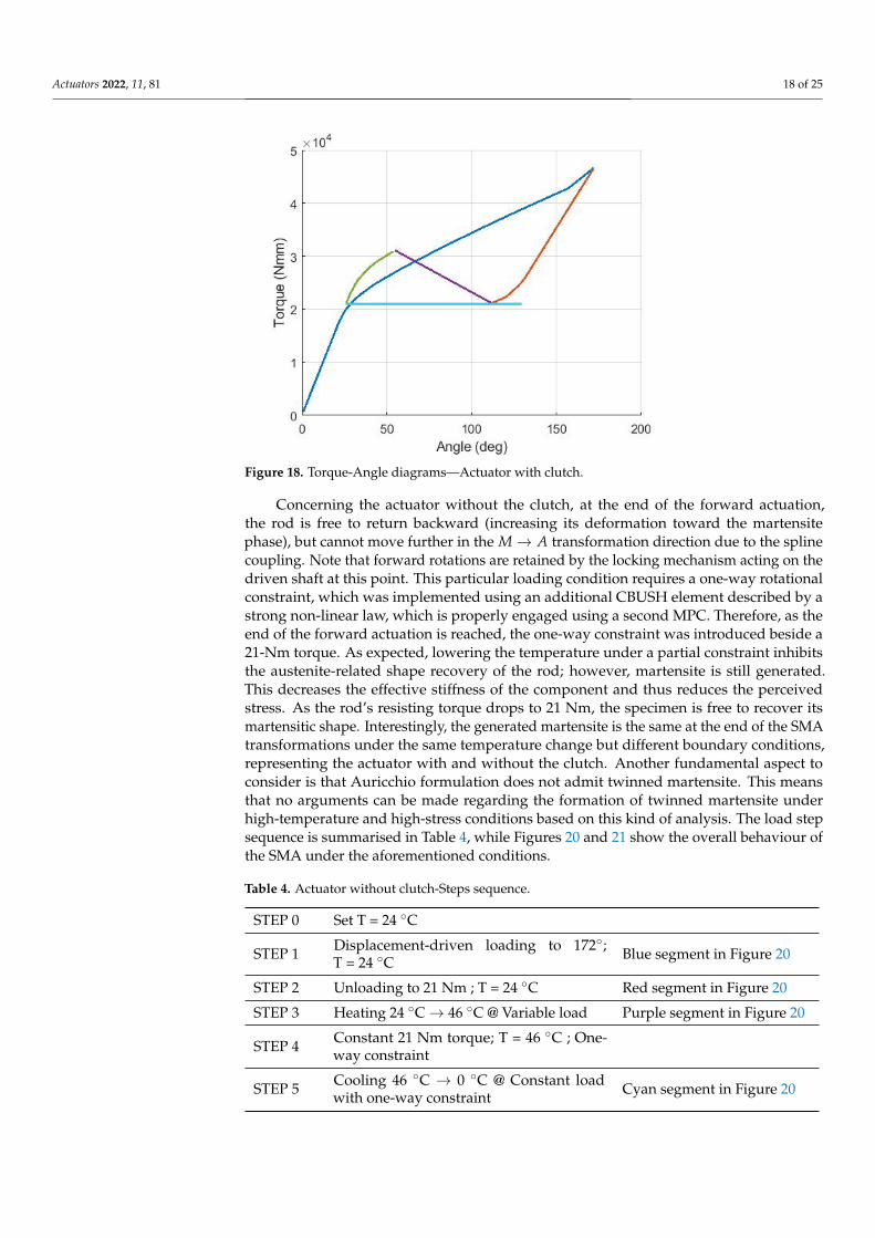
The specimen considered for the actuation simulation is the same as described inthe previous paragraphs. The driven apparatus simulating the return spring and theaerodynamic hinge moment is modelized using a CBUSH element, which is a generalisedspring-damper scalar element, associated in this case with the PBUSH and the PBUSHT bulkdata entries, to define a load-displacement dependency. Note that the linear load, assumedfor simplicity, may be replaced by a generalised loading law acting on the TABLED1 entry.Table 3 summarizes the loading sequence, while Figure 18 shows the torque-angle diagramfor the actuator with a clutch. Moreover, Figure 19 highlights the overall behaviour of theSMA under the aforementioned conditions.
Figure 15. A highlight of relevant sections of the FEM model.
Table 3. Actuator with clutch–Steps sequence.
STEP 0 Set T = 24 ◦C
STEP 1 Displacement-driven loading to 172◦;T = 24 ◦C Blue segment in Figure 18
STEP 2 Unloading to 21 Nm; T = 24 ◦C Red segment in Figure 18
STEP 3 Heating 24 ◦C→ 46 ◦C @ Variable load Purple segment in Figure 18
STEP 4 Unloading to 21 Nm; T = 46 ◦C Green segment in Figure 18
STEP 5 Cooling 46 ◦C→ 0 ◦C @ Constant load Cyan segment in Figure 18

Actuators 2022, 11, 81 16 of 25
Figure 16. SMA rod behaviour under torque loading cycle @24 ◦C-FEM model with 5 elements along the radius.

Actuators 2022, 11, 81 17 of 25
Figure 17. SMA rod behaviour under thermal cycling @40 Nm-FEM model with 5 elements along the radius.
Actuators 2022, 11, 81 18 of 25
Figure 18. Torque-Angle diagrams—Actuator with clutch.
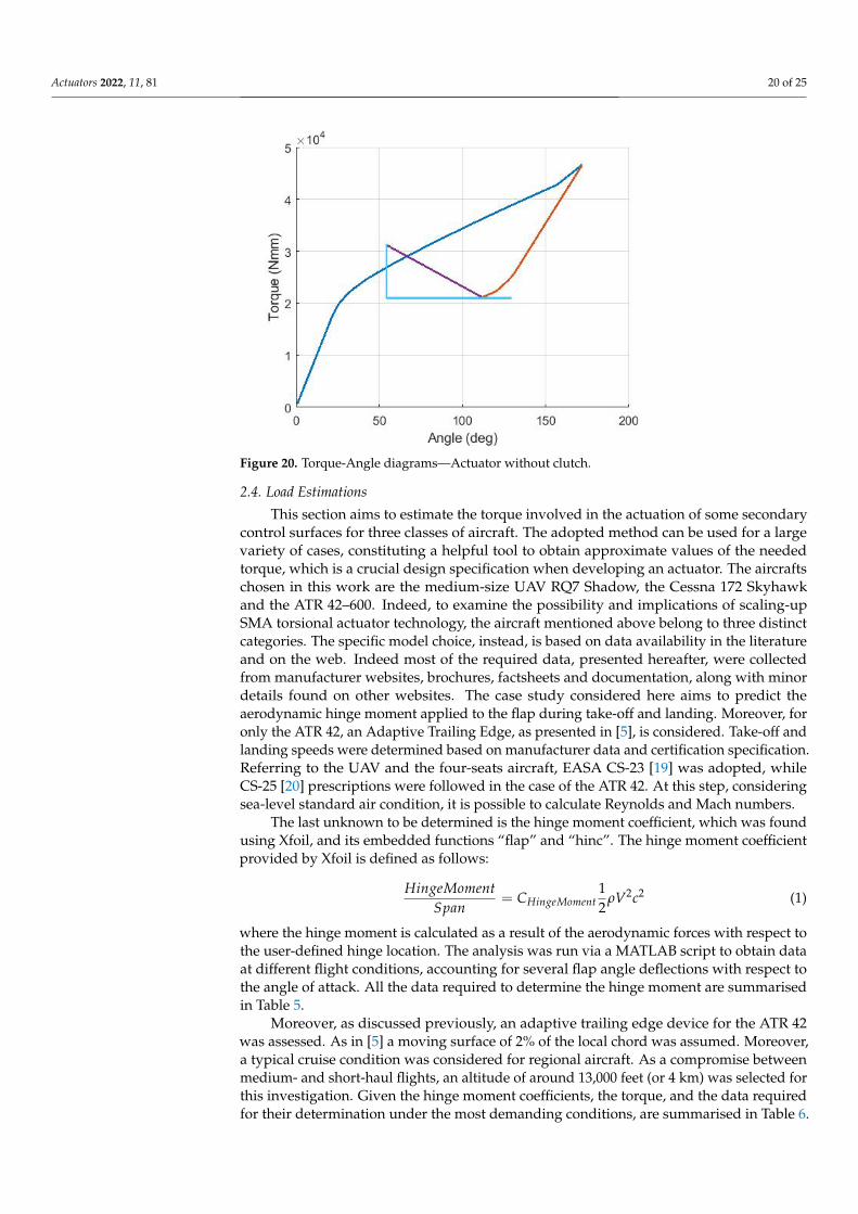
Concerning the actuator without the clutch, at the end of the forward actuation,the rod is free to return backward (increasing its deformation toward the martensitephase), but cannot move further in the M→ A transformation direction due to the splinecoupling. Note that forward rotations are retained by the locking mechanism acting on thedriven shaft at this point. This particular loading condition requires a one-way rotationalconstraint, which was implemented using an additional CBUSH element described by astrong non-linear law, which is properly engaged using a second MPC. Therefore, as theend of the forward actuation is reached, the one-way constraint was introduced beside a21-Nm torque. As expected, lowering the temperature under a partial constraint inhibitsthe austenite-related shape recovery of the rod; however, martensite is still generated.This decreases the effective stiffness of the component and thus reduces the perceivedstress. As the rod’s resisting torque drops to 21 Nm, the specimen is free to recover itsmartensitic shape. Interestingly, the generated martensite is the same at the end of the SMAtransformations under the same temperature change but different boundary conditions,representing the actuator with and without the clutch. Another fundamental aspect toconsider is that Auricchio formulation does not admit twinned martensite. This meansthat no arguments can be made regarding the formation of twinned martensite underhigh-temperature and high-stress conditions based on this kind of analysis. The load stepsequence is summarised in Table 4, while Figures 20 and 21 show the overall behaviour ofthe SMA under the aforementioned conditions.
Table 4. Actuator without clutch-Steps sequence.
STEP 0 Set T = 24 ◦C
STEP 1 Displacement-driven loading to 172◦;T = 24 ◦C Blue segment in Figure 20
STEP 2 Unloading to 21 Nm ; T = 24 ◦C Red segment in Figure 20
STEP 3 Heating 24 ◦C→ 46 ◦C @ Variable load Purple segment in Figure 20
STEP 4 Constant 21 Nm torque; T = 46 ◦C ; One-way constraint
STEP 5 Cooling 46 ◦C → 0 ◦C @ Constant loadwith one-way constraint Cyan segment in Figure 20

Actuators 2022, 11, 81 19 of 25
Figure 19. Martensite, displacement, torque and temperature evolution during actuation—Actuator with clutch. FEM model with 3 elements along the radius.
Actuators 2022, 11, 81 20 of 25
Figure 20. Torque-Angle diagrams—Actuator without clutch.
2.4. Load Estimations
This section aims to estimate the torque involved in the actuation of some secondarycontrol surfaces for three classes of aircraft. The adopted method can be used for a largevariety of cases, constituting a helpful tool to obtain approximate values of the neededtorque, which is a crucial design specification when developing an actuator. The aircraftschosen in this work are the medium-size UAV RQ7 Shadow, the Cessna 172 Skyhawkand the ATR 42–600. Indeed, to examine the possibility and implications of scaling-upSMA torsional actuator technology, the aircraft mentioned above belong to three distinctcategories. The specific model choice, instead, is based on data availability in the literatureand on the web. Indeed most of the required data, presented hereafter, were collectedfrom manufacturer websites, brochures, factsheets and documentation, along with minordetails found on other websites. The case study considered here aims to predict theaerodynamic hinge moment applied to the flap during take-off and landing. Moreover, foronly the ATR 42, an Adaptive Trailing Edge, as presented in [5], is considered. Take-off andlanding speeds were determined based on manufacturer data and certification specification.Referring to the UAV and the four-seats aircraft, EASA CS-23 [19] was adopted, whileCS-25 [20] prescriptions were followed in the case of the ATR 42. At this step, consideringsea-level standard air condition, it is possible to calculate Reynolds and Mach numbers.
The last unknown to be determined is the hinge moment coefficient, which was foundusing Xfoil, and its embedded functions “flap” and “hinc”. The hinge moment coefficientprovided by Xfoil is defined as follows:
HingeMomentSpan
= CHingeMoment12
ρV2c2 (1)
where the hinge moment is calculated as a result of the aerodynamic forces with respect tothe user-defined hinge location. The analysis was run via a MATLAB script to obtain dataat different flight conditions, accounting for several flap angle deflections with respect tothe angle of attack. All the data required to determine the hinge moment are summarisedin Table 5.
Moreover, as discussed previously, an adaptive trailing edge device for the ATR 42was assessed. As in [5] a moving surface of 2% of the local chord was assumed. Moreover,a typical cruise condition was considered for regional aircraft. As a compromise betweenmedium- and short-haul flights, an altitude of around 13,000 feet (or 4 km) was selected forthis investigation. Given the hinge moment coefficients, the torque, and the data requiredfor their determination under the most demanding conditions, are summarised in Table 6.

Actuators 2022, 11, 81 21 of 25
Figure 21. Martensite, displacement, torque and temperature evolution during actuation—Actuator without clutch. FEM model with 3 elements along the radius.

Actuators 2022, 11, 81 22 of 25
Table 5. Data summary-Flap. (1) Reasonable approximation of the actual airfoil. (2) Hypotheti-cal value.
RQ7Shadow Cessna 172 ATR 42 600
Grossweight 170 kg [21] 1111 kg [22] 18,600 kg [23]
Wingspan 3.87 m [21] 11 m [22] 24.57 m [23]
Airfoil NACA4415 [21] NACA
2412 [22] NACA23015
(1)
Root chord 0.42 m [24] 1.63 m [25] 2.624 m [23]Flap chord 0.114 m [24] 0.491 m [25] 0.75 m [23]Flap span 1.012 m [24] 2.043 m [25] 3.498 m [23]
xhinge% 73% [24] 70% [25] 71% [23]δmax 40 ° [21] 30 ° [25] 30 ° [23]
Stall speed(Vs1) 17.5 m/s (2) 24.2 m/s [25] 50.99 m/s
Cruisespeed 36 m/s [21] 62.8 m/s [22] 154.4 m/s [23]
Max speed 55.5 m/s [21] 80 m/s [22]V2 21 m/s 29 m/s 57 m/s [23]V3 22.75 m/s 31.46 m/s 62.72 m/s
VLND 34.12 m/s 47.19 m/s 94.08 m/sReLND 9.95× 10⁵ 5.34× 10⁶ 1.71× 10⁷
MLND 0.099 0.138 0.274VTO 22.75 m/s 31.46 m/s 62.72 m/sReTO 9.19× 10⁵ 4.93× 10⁶ 1.57× 10⁷
MTO 0.092 0.127 0.252
Chinge,max 0.34 0.38 0.37Mhinge,max 3.19 Nm 255.28 Nm 3946.69 NmMhinge,max/
span 3.15 N 124.95 N 1128.27 N
In sum, the maximum hinge moment obtained for the RQ7 shadow is about 3.2 Nm,compatible with the torque output of commercially available UAV actuators. The hingemoment calculated for the Cessna 172 is 225 Nm, close to the values achieved by the refinedoptimisation performed by Florjancic in [26] for the same aircraft (ranging from 332 Nm to267 Nm). The maximum ATR 42 hinge moment was found to be about 3950 Nm. Althoughno reference was found to reasonably validate this data, as a means of comparison, a rotaryactuator adopted for the motion of the Boeing 777 outboard flap develops a max torqueof 12.1 kNm [27]. Finally, a hinge moment of 9.4 Nm was found in the ATE case, which isprobably the less accurate result. However, knowing the SMA torque actuator size usedin [5] and its related average torque performance, a value of the same magnitude is alsoexpected in this case.
Table 6. Data summary—ATE.
ATR 42 600
Airfoil NACA 23015Root chord 2.624 mFlap chord 0.75 mFlap span 3.498 m
xhinge% 98%δmax 20 °
Cruise speed 154.4 m/sRecruise 2.00× 10⁷
Mcruise 0.467Chinge,max 0.1Mhinge,max 9.4 Nm
Mhinge,max/span 2.7 N

Actuators 2022, 11, 81 23 of 25
3. Concluding Remarks
To obtain a sense of the torque involved in moving control surfaces, aerodynamic loadpredictions are performed using Xfoil for three classes of aircraft (medium-size UAV, Four-Seat Aircraft and Regional Transport Aircraft), considering a plain flap and an AdaptiveTrailing Edge device. The analysis was handled using a Matlab script. The obtained datawere compared to those presented in the literature to validate the adopted method.
A general approach based on characteristic curves is provided to conceptually designSMA torsional actuators.
An FEM model is created in MSC Patran and solved by Nastran, which implementsAuricchio’s formulation. This means provides a holistic vision of the macroscopic phenom-ena involved during phase transformations, accomplishing either a general method for thepreliminary design and a helpful educational tool for those approaching the SMA actuators’design for the first time. Indeed, SMA rods’ behaviour under mechanical and thermalloading is thoroughly examined, monitoring stress, temperature, torque and martensiteevolution simultaneously.
Operative loading conditions were investigated considering different actuator designsand simulating a full transformation cycle between martensite and austenite. In particular,the specific case of cooling the prestressed SMA, keeping the twist angle constant, wasinvestigated. Two alternative interpretations were found: the first one is based on theassumption of the formation of twinned martensite at high temperatures, while the secondone implies the formation of detwinned martensite. In the first case, a decay of the actuationperformance is expected, due to the progressive build-up of retained martensite; in thesecond case, the actuation performance is preserved with cycles, with the transformationmartensite remaining constant. This led to a hypothesis regarding the existence of a newregion in SMA phase diagrams in which twinned martensite can be found under high-temperature and high-stress conditions. Long-term experimental tests can be performedconcerning the cooling effect on constrained austenite specimen from a high-stress andhigh-temperature state, to dispel any doubt regarding the formation of twinned martensitein these conditions.
The main limit of the proposed FEM model lies in the fact that Auricchio’s formulationdoes not admit twinned martensite. Moreover, no conclusions can be derived from thetraining effects, since performing a second loading cycle does not present any differencewith respect to the first one. Additionally, for the material considered in this dissertation,FEM data overestimate the transformation strain. Experimental data remain mandatoryfor the final draft and are an indispensable source to understand the governing principlesof SMAs.
Finally, it is worth mentioning that the presented model is easily reconfigurableand can be integrated into an optimization loop. Moreover, thermal aspects should bedeepened to include the time domain and account for inertial effects, even using non-lineartransient solutions.
Author Contributions: All authors conceived the paper and designed the review study. Concep-tualization, M.S., S.A., A.C. and E.C.; methodology, M.S., S.A., A.C. and E.C.; software, M.S. andS.A.; validation, M.S., S.A., A.C. and E.C.; formal analysis, M.S.; investigation, M.S.; resources, M.S.,S.A., A.C. and E.C.; data curation, M.S.; writing—original draft preparation, M.S.; writing—reviewand editing, M.S., S.A., A.C. and E.C.; visualization, M.S.; supervision, S.A., A.C. and E.C.; projectadministration, S.A., A.C. and E.C. All authors have read and agreed to the published version ofthe manuscript.
Funding: This research received no external funding.
Institutional Review Board Statement: Not applicable.
Informed Consent Statement: Not applicable.
Data Availability Statement: The data presented in this study are available on request from thecorresponding author.

Actuators 2022, 11, 81 24 of 25
Acknowledgments: Special thanks to Mauro Linari for his support in the FEM modelization.
Conflicts of Interest: The authors declare no conflict of interest.
AbbreviationsThe following abbreviations are used in this manuscript:
ATE Adaptive Trailing EdgeFEM Finite Element MethodSMA Shape Memory AlloyUAV Unmanned Aerial Vehicle
References1. Calkins, F.T.; Mabe, J.H. Shape memory alloy based morphing aerostructures. J. Mech. Des. 2010, 132, 111012–111019. [CrossRef]2. Mabe, J.H.; Calkins, F.T.; Bushnell, G.S.; Bieniawski, S.R. Shape Memory Alloy Actuator. U.S. Patent No 8,118,264, 21 February 2012.3. Bushnell, G.S.; Arbogast, D.; Ruggeri, R. Shape control of a morphing structure (rotor blade) using a shape memory alloy actuator
system. In Proceedings of the SPIE 6928, Active and Passive Smart Structures and Integrated Systems 2008, 69282A, San Diego,CA, USA, 18 April 2008.
4. Arbogast, D.J.; Ruggeri, R.T.; Bussom, R.C. Development of a 1/4-scale NiTinol actuator for reconfigurable structures. InProceedings of the SPIE 6930, Industrial and Commercial Applications of Smart Structures Technologies 2008, 69300L, San Diego,CA, USA, 19 March 2008.
5. Calkins, F.T.; Mabe, J.H. Flight test of a shape memory alloy actuated adaptive trailing edge flap. In Proceedings of the ASME 2016Conference on Smart Materials, Adaptive Structures and Intelligent Systems, Volume 1: Multifunctional Materials, Mechanicsand Behavior of Active Materials, Integrated System Design and Implementation, Structural Health Monitoring, Stowe, VT, USA,28–30 September 2016.
6. Stroud, H.; Hartl, D. Shape memory alloy torsional actuators: A review of applications, experimental investigations, modeling,and design. Smart Mater. Struct. 2020, 29, 113001–113018. [CrossRef]
7. Ameduri, S.; Ciminello, M.; Concilio, A.; Dimino, I.; Galasso, B.; Guida, M. Structural Module for Fixed and Rotary Wing. EPPatent Application No. 21425028, 25 May 2021.
8. Auricchio, F.; Bonetti, E.; Scalet, G.; Ubertini, F. Theoretical and numerical modeling of shape memory alloys accounting formultiple phase transformations and martensite reorientation. Int. J. Plast. 2014, 59, 30–54. [CrossRef]
9. Popov, P.; Lagoudas, D.C. A 3-D constitutive model for shape memory alloys incorporating pseudoelasticity and detwinning ofself-accommodated martensite. Int. J. Plast. 2007, 23, 1679–1720 . [CrossRef]
10. Mirzaeifar, R.; DesRoches, R.; Yavari, A. Exact solutions for pure torsion of shape memory alloy circular bars. Mech. Mater. 2010,42, 797–806. [CrossRef]
11. Taheri Andani, M.; Alipour, A.; Eshghinejad, A.; Elahinia, M. Modifying the torque–angle behavior of rotary shape memory alloyactuators through axial loading: A semi-analytical study of combined tension–torsion behavior. J. Intell. Mater. Syst. Struct. 2013,24, 1524–1535. [CrossRef]
12. Benafan, O.; Gaydosh, D.J. High Temperature Shape Memory Alloy Ni50.3Ti29.7Hf20 Torque Tube Actuators. Smart Mater. Struct.2017, 26, 95002–95011. [CrossRef]
13. Mabe, J.; Ruggeri, R.; Rosenzweig, E.; Yu, C. NiTinol Performance Characterization and Rotary Actuator Design. In Proceedingsof the SPIE 5388, Smart Structures and Materials 2004: Industrial and Commercial Applications of Smart Structures Technologies,San Diego, CA, USA, 29 July 2004.
14. Pecora, R.; Ameduri, S.; Rea, F. Active Metal Structures. In Morphing Wing Technologies: Large Commercial Aircraft and CivilHelicopters; Ricci, S., Dimino, I., Lecce, L., Pecora, R., Aliabadi Ferri, M.H., Botez, R., Semperlotti, F., Eds.; Butterworth-Heinemann:Oxford, UK, 2018; pp. 302–311.
15. Auricchio, F. A robust integration-algorithm for a finite-strain shape-memory alloy superelastic model. Int. J. Plast. 2001, 17,971–990. [CrossRef]
16. Auricchio, F.; Taylor, R. Shape-memory alloys: Modelling and numerical simulations of the finite-strain superelastic behavior.Comput. Methods Appl. Mech. Eng. 1997, 143, 175–194. [CrossRef]
17. MSC Nastran 2013.1.1-Quick Reference Guide; MSC SOFTWARE, Siemens Industry Software Headquarters Granite Park One 5800Granite Parkway Suite 600: Plano, TX, USA, 2013; pp. 2700–2073.
18. MSC Nastran 2021 Nonlinear (SOL 400)-User’s Guide; MSC SOFTWARE, Siemens Industry Software Headquarters Granite ParkOne 5800 Granite Parkway Suite 600: Plano, TX, USA, 2021; pp. 599–602.
19. Certification Specifications for Normal, Utility, Aerobatic, and Commuter Category Aeroplanes CS-23; EASA Amendment 3, EASAHeadquarter Konrad-Adenauer-Ufer 3: Cologne, Germany, 2012; pp. 1B2–1B10.
20. Certification Specifications for Large Aeroplanes CS-25; EASA, Amendment 3, EASA Headquarter Konrad-Adenauer-Ufer 3: Cologne,Germany 2007; pp. 1B3–1B12.

Actuators 2022, 11, 81 25 of 25
21. AAI RQ-7 Shadow-Specifications (200 Family). Available online: https://en.wikipedia.org/wiki/AAI_RQ-7_Shadow (accessedon 8 May 2021).
22. Cessna 172. Available online: https://en.wikipedia.org/wiki/Cessna_172 (accessed on 8 May 2021).23. ATR 42-600. Available online: https://www.atr-aircraft.com/our-aircraft/atr-42-600/ (accessed on 8 May 2021).24. AAI RQ-7B Shadow 200 Technical Sketch. Available online: https://aviationsmilitaires.net/v3/kb/picture/7236/aai-rq-7b-
shadow-200 (accessed on 8 May 2021).25. Skyhawk Model 172S-Specification & Description. Available online: https://www.aeromecanic.com/Skyhawk_DOC_FR_files/
spec.pdf (accessed on 8 May 2021).26. Florjancic, D. Improved Design of a High Lift System for General Aviation Aircraft. Master Thesis, TU Delft, Delft, The
Netherlands, 25 August 2015.27. Zaccai, D.; Bertels, F.; Vos, R. Design methodology for trailing-edge high-lift mechanisms. CEAS Aeronaut. J. 2016, 7, 521–534.
[CrossRef]