Robot Actuators
29
Robot Actuators
-
Upload
khangminh22 -
Category
Documents
-
view
1 -
download
0
Transcript of Robot Actuators

Robot Actuators


Introduction
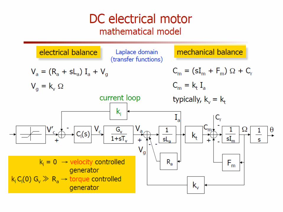
Actuators • Actuation is the process of conversion of energy to mechanical form. A device
that accomplishes this conversion is called actuator.
• Actuator plays a very important role while implementing control. The controller provides command signal to the actuator for actuation.
• The control codes aims at “ deriving the actuator when an event has occurred”
Simple sensor actuator connection [ Mahalik, 2003]

Introduction
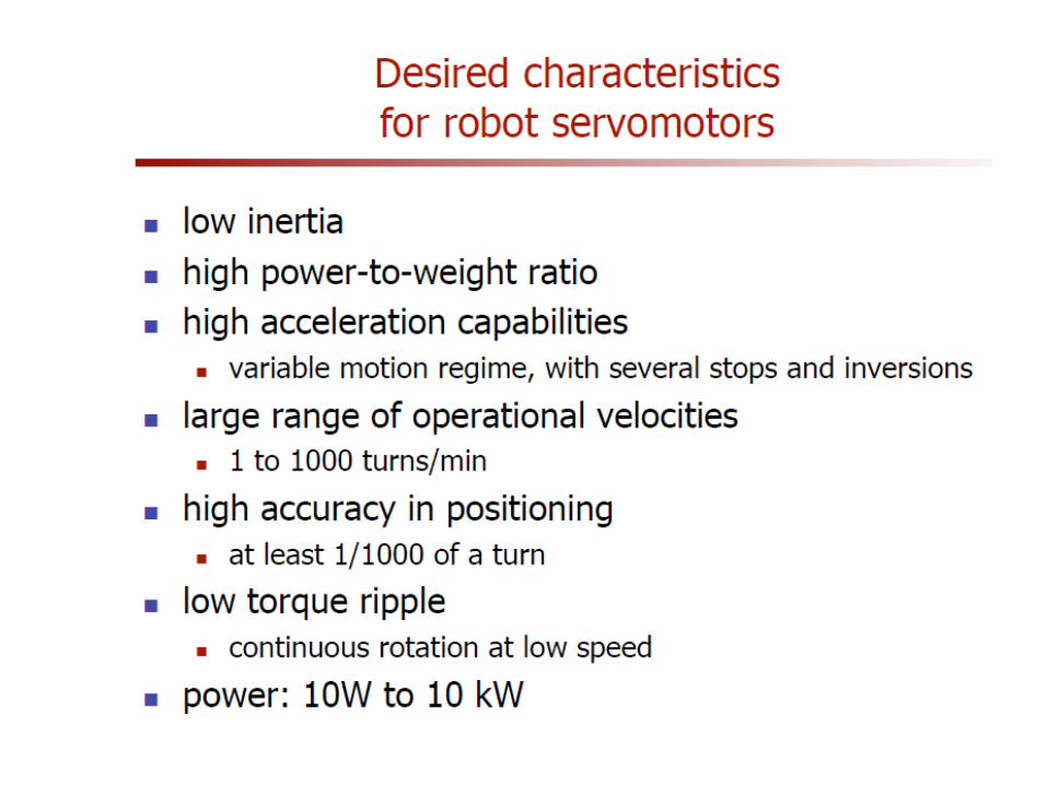
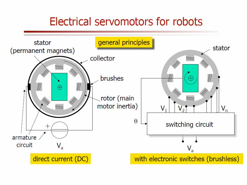
• Actuators are the muscles of robots. There are many types of actuators available depending on the load involved. The term load is associated with many factors including force, torque, speed of operation, accuracy, precision and power consumption:
1- Electric Motors • Servomotors • Stepper motors • Direct-drive electric motors 2- Hydraulic actuators 3- Pneumatic actuators 4-Shape memory metal actuators 5- Magnetostrictive actuators. • Electromechanical actuators convert electrical energy into mechanical
energy. Magnetism is the basis of their principle of operation. They are DC, AC and stepper motors.
• DC motors require a direct current or voltage source as the input signals. • AC motors require an alternating current or voltage source

Introduction
• Stepper motors have capability of achieving precision angular rotation in both directions and are commonly employed to accommodate digital control technology.
• Hydraulic and pneumatic actuators are under fluid power actuators. Fluid power refers to energy that is transmitted via a fluid under pressure. When a pressure is applied to a confined chamber containing a piston, the piston will exert a force causing a motion. The piston will move if the difference in force across the piston is larger than the total load plus the friction forces.
• Materials which undergo some sort of transformations through physical interaction, are referred to as active materials. Piezoelectric (voltage-load), shape-memory alloys (react to heat), magnetostrictive are examples of these materials.

Introduction
Characteristics of actuating systems 1- Weight, Power-to-weight Ratio, Operating pressure • Stepper motors are generally heavier than servomotors for the same power. • The high the voltage of electric motors, the better power-to-weight ratio. • Pneumatic systems delivers the lowest power-to-weight ratio (100-120 psi) • Hydraulic systems have the highest power-to-weight ratio (55-5000 psi). In these systems,
the weight is actually composed of two portions. One is the hydraulic actuators, and the other is the hydraulic power unit (pump, cylinders, rams, reservoirs, filter, and electric motor). If the power unit must also move with the robot, the total power-to-weight ratio will be much less.
2- Stiffness versus Compliance • Stiffness is the resistance of a material against deformation. The stiffer the system, the larger
the load that is needed to deform it. Conversely, the more compliant the system the easier it deforms under the load.
• Stiffness is directly related to the modulus of elasticity of the material. Hydraulic systems are very stiff and non-compliant while pneumatic systems are easily compressed and thus are compliant.
• Stiff systems have a more rapid response to changing loads and pressures and are more accurate.
• Although stiffness causes a more responsive and more accurate systems, it also creates a danger if all things are not always perfect.

Introduction
3- Use of Reduction Gears
• Hydraulic devices produce very large forces with short stroke. This means that the hydraulic arm may be moved very slightly while delivering its full force. As a result, there is no need to use reduction gear trains to increase the torque and to slow it down to manageable speeds.
• Electric motors rotate at high speeds (up to many thousands of revolution per minute) and must be used in conjunction with reduction gears to increase torque and reduce rotation speed. This will increase the cost, number of parts, backlash, and inertia of the rotating body.

Introduction
• Now suppose that, through a set of reduction gears with ratio of N, a load with inertia , is connected to a motor with Inertia (including inertia of reduction gears), as shown in Figure (6.1). The torque and speed ratio between the motor and the load will be:
Inertia and torque relationship between a motor and a load

Introduction


Hydraulic Actuators
• A hydraulic system generally consists of the following parts: 1. Hydraulic linear or rotary cylinders and rams to provide the force or torque
needed to move the joints and are controlled by servo valve or manual valve.
2. A hydraulic pump to provide high pressure fluid to the system 3. Electric motor to operate the hydraulic pump. 4. Cooling system to get rid of heat (cooling fans, radiators, and cooled air). 5. Reservoir to keep fluid supply available to the system. 6. Servo valve which is a very sensitive valve that controls the amount and the
rate of the fluid to the cylinders. The servo valve is generally driven by a hydraulic servomotor.
7. Sensors to control the motion of the cylinders (position, velocity, magnetic, touch,..)
8. Connecting hoses to transport the pressurized fluid. 9. Safety check valves, holding valves.

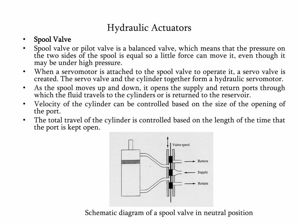
Hydraulic Actuators • Spool Valve • Spool valve or pilot valve is a balanced valve, which means that the pressure on
the two sides of the spool is equal so a little force can move it, even though it may be under high pressure.
• When a servomotor is attached to the spool valve to operate it, a servo valve is created. The servo valve and the cylinder together form a hydraulic servomotor.
• As the spool moves up and down, it opens the supply and return ports through which the fluid travels to the cylinders or is returned to the reservoir.
• Velocity of the cylinder can be controlled based on the size of the opening of the port.
• The total travel of the cylinder is controlled based on the length of the time that the port is kept open.
Schematic diagram of a spool valve in neutral position

Hydraulic Actuators
• The controller sets the current to the servomotor, as well as the duration the current is applied, to control the position of the spool. The controlling procedure is as follows: – Position and velocity should be
calculated by the controller. – Set the amount of current and
its duration to the servomotor. – Controlling the position and
rate of movement of the spool valve.
– Controlling the flow and its rate to the cylinder.
– The cylinder moves the joint. – The sensors provide feedback to
the controller for accurate and continued control.
Schematic diagram of a spool valve in open position. Depending on which ports is open, the
direction of motion of the piston will change

Hydraulic Actuators
• Mechanical Feedback Strategy • As the desired position for the load is set by the set point lever, say up, the
spool valve is opened which will operate the cylinder. This will provide error signal (fluid pressure) to the cylinder.
• The error signal is integrated by the integrator and the error approaches zero.
Schematic diagram of a simple control device with proportional feedback