Robot - Robo Challenge
394
© FANUC CORPORATION, 2012 Dual Check Safety Function R-30+B/R-30+B Mate/R-30+B Plus/R-30+B Mate Plus/ R-30+B Compact Plus/R-30+B Mini Plus CONTROLLER < Robot ! OPERATOR'S MANUAL B-83184EN/12
-
Upload
khangminh22 -
Category
Documents
-
view
2 -
download
0
Transcript of Robot - Robo Challenge

© FANUC CORPORATION, 2012
Dual Check Safety Function
R-30+B/R-30+B Mate/R-30+B Plus/R-30+B Mate Plus/R-30+B Compact Plus/R-30+B Mini Plus CONTROLLER
< Robot !
OPERATOR'S MANUAL
B-83184EN/12

• Original Instructions
Thank you very much for purchasing FANUC Robot. Before using the Robot, be sure to read the "FANUC Robot series SAFETY HANDBOOK (B-80687EN)" and understand the content. • No part of this manual may be reproduced in any form. • All specifications and designs are subject to change without notice. The products in this manual are controlled based on Japan’s “Foreign Exchange and Foreign Trade Law”. The export from Japan may be subject to an export license by the government of Japan. Further, re-export to another country may be subject to the license of the government of the country from where the product is re-exported. Furthermore, the product may also be controlled by re-export regulations of the United States government. Should you wish to export or re-export these products, please contact FANUC for advice. In this manual, we endeavor to include all pertinent matters. There are, however, a very large number of operations that must not or cannot be performed, and if the manual contained them all, it would be enormous in volume. It is, therefore, requested to assume that any operations that are not explicitly described as being possible are "not possible".

B-83184EN/12 SAFETY PRECAUTIONS
s-1
SAFETY PRECAUTIONS This chapter describes the precautions which must be followed to enable the safe use of the robot. Before using the robot, be sure to read this chapter thoroughly. For detailed functions of the robot operation, read the relevant operator's manual to understand fully its specification. For the safety of the operator and the system, follow all safety precautions when operating a robot and its peripheral equipment installed in a work cell. For safe use of FANUC robots, you must read and follow the instructions in “FANUC Robot series SAFETY HANDBOOK (B-80687EN)”.
1 PERSONNEL Personnel can be classified as follows. Operator: • Turns the robot controller power ON/OFF • Starts the robot program from operator panel Programmer or Teaching operator: • Operates the robot • Teaches the robot inside the safeguarded space Maintenance technician: • Operates the robot • Teaches the robot inside the safeguarded space • Performs maintenance (repair, adjustment, replacement) - The operator is not allowed to work in the safeguarded space. - The programmer or teaching operator and maintenance technician are allowed to work in the
safeguarded space. Works carried out in the safeguarded space include transportation, installation, teaching, adjustment, and maintenance.
- To work inside the safeguarded space, the person must be trained on proper robot operation.

SAFETY PRECAUTIONS B-83184EN/12
s-2
Table 1 (a) lists the work outside the safeguarded space. In this table, the symbol “” means the work allowed to be carried out by the specified personnel.
Table 1 (a) List of work outside the Safeguarded Space
Operator Programmer or Teaching operator
Maintenance technician
Turn power ON/OFF to Robot controller Select operating mode (AUTO/T1/T2) Select remote/local mode Select robot program with teach pendant Select robot program with external device Start robot program with operator’s panel Start robot program with teach pendant Reset alarm with operator’s panel Reset alarm with teach pendant Set data on teach pendant Teaching with teach pendant Emergency stop with operator’s panel Emergency stop with teach pendant Operator’s panel maintenance Teach pendant maintenance
During robot operation, programming and maintenance, the operator, programmer, teaching operator and maintenance technician take care of their safety using at least the following safety protectors. • Use clothes, uniform, overall adequate for the work • Safety shoes • Helmet
2 DEFINITION OF SAFETY NOTATIONS To ensure the safety of users and prevent damage to the machine, this manual indicates each precaution on safety with "WARNING" or "CAUTION" according to its severity. Supplementary information is indicated by "NOTE". Read the contents of each "WARNING", "CAUTION" and "NOTE" before using the robot.
Symbol Definitions
WARNING Used if hazard resulting in the death or serious injury of the user will be expected to occur if he or she fails to follow the approved procedure.
CAUTION Used if a hazard resulting in the minor or moderate injury of the user, or equipment damage may be expected to occur if he or she fails to follow the approved procedure.
NOTE Used if a supplementary explanation not related to any of WARNING and CAUTION is to be indicated.

B-83184EN/12 TABLE OF CONTENTS
c-1
TABLE OF CONTENTS SAFETY PRECAUTIONS ............................................................................ s-1 1 OVERVIEW ............................................................................................. 1
1.1 DCS FUNCTION COMPONENTS ................................................................. 1 1.2 CAUTIONS AND LIMITATIONS .................................................................... 4
1.2.1 Hardware .................................................................................................................. 4 1.2.2 Software ................................................................................................................... 5
1.3 APPLY TO DCS PARAMETER ..................................................................... 6 1.4 DCS PARAMETER REPORT FILE ............................................................. 10 1.5 BACKUP / RESTORE DCS SETTING PARAMETER ................................. 10 1.6 INITIAL START, IMAGE RESTORE ............................................................ 12 1.7 STOPPING DISTANCE ............................................................................... 13
2 DCS MENU ............................................................................................ 14 2.1 DCS MENU COMPONENTS ....................................................................... 14 2.2 DCS TOP MENU ......................................................................................... 16 2.3 DCS ROBOT SETUP MENU ....................................................................... 19 2.4 DCS MASTERING PARAMETER MENU .................................................... 21 2.5 DCS CODE NUMBER ................................................................................. 22
2.5.1 DCS Code Number Setup Menu ............................................................................ 23 2.6 DCS SIGNATURE NUMBER ....................................................................... 24
2.6.1 DCS Signature Number Menu ............................................................................... 24 2.6.2 DCS Signature Annunciation Menu ....................................................................... 25
2.6.2.1 DCS signature change management utility setup ............................................... 26 2.6.2.2 DCS signature change management utility operation ........................................ 27
2.6.3 DCS Signature Number Output .............................................................................. 27 2.6.4 Code by Password Function ................................................................................... 28
3 LIMITING A ROBOT WORKSPACE ..................................................... 29 3.1 OVERVIEW ................................................................................................. 29 3.2 LIMITING A ROBOT WORKSPACE BY CARTESIAN POSITION CHECK . 30 3.3 ROBOT STOP POSITION PREDICTION .................................................... 33 3.4 SETUP OF USER MODEL .......................................................................... 34 3.5 4D GRAPHICS DCS DISPLAY .................................................................... 38 3.6 RECOVERY FROM ALARM ........................................................................ 40
4 SWITCHING THE WORKSPACE ......................................................... 41

TABLE OF CONTENTS B-83184EN/12
c-2
4.1 OVERVIEW ................................................................................................. 41 4.2 SETUP OF USER MODEL .......................................................................... 42 4.3 CHECKING IF THERE IS AN OPERATOR ON A SAFE MAT..................... 45 4.4 SETUP OF CARTESIAN POSITION CHECK .............................................. 46
4.4.1 Setup of No.1 Zone ................................................................................................ 47 4.4.2 Setup of No.2 Zone ................................................................................................ 51 4.4.3 Setup of No.3 Zone ................................................................................................ 55
5 CHECKING IF AUXILIARY AXES ARE STATIONARY ....................... 59 5.1 OVERVIEW ................................................................................................. 59 5.2 SETUP STOP CHECK FOR AUXILIARY AXIS 1 ........................................ 60 5.3 SETUP OF POSITION CHECK FOR AUXILIARY AXIS 1 ........................... 63 5.4 SETUP OF STOP CHECK FOR AUXILIARY AXES 2 AND 3 ..................... 66 5.5 LIMITING THE MOTION RANGE OF A TURNTABLE ................................ 71 5.6 SETTING UP THE ROBOT WORKSPACE ................................................. 73
6 SET A SLOWDOWN ZONE .................................................................. 76 6.1 OVERVIEW ................................................................................................. 76 6.2 SETUP OF TOOL MODEL .......................................................................... 77 6.3 SETUP OF CARTESIAN POSITION CHECK .............................................. 82
6.3.1 Setup of No.1 Zone ................................................................................................ 83 6.3.2 Setup of No.2 Zone ................................................................................................ 85 6.3.3 Setup of No.3 Zone ................................................................................................ 88
7 POSITION / SPEED CHECK FUNCTION ............................................. 92 7.1 COMPONENTS OF POSITION / SPEED CHECK FUNCTION ................... 93 7.2 JOINT POSITION CHECK FUNCTION ....................................................... 93
7.2.1 Stop Position Prediction ......................................................................................... 95 7.2.2 DCS Joint Position Check List Menu ..................................................................... 96 7.2.3 DCS Joint Position Check Detail Menu ................................................................. 97
7.3 JOINT SPEED CHECK FUNCTION ............................................................ 98 7.3.1 DCS Joint Speed Check List Menu ........................................................................ 99 7.3.2 DCS Joint Speed Check Detail Menu .................................................................. 100
7.4 ZONE CHECK FUNCTION (CARTESIAN POSITION CHECK FUNCTION) ................................................................................................................... 102 7.4.1 Shape Model ......................................................................................................... 102 7.4.2 Safe Zone .............................................................................................................. 104
7.4.2.1 Define the safe zone ......................................................................................... 105 7.4.2.2 Enable and disable zones by disabling input ................................................... 106

B-83184EN/12 TABLE OF CONTENTS
c-3
7.4.2.3 Define the target shape model .......................................................................... 107 7.4.2.4 Process time factor ........................................................................................... 108 7.4.2.5 Recovery from alarm ....................................................................................... 109 7.4.2.6 Position check temporary disable function ...................................................... 109 7.4.2.7 Approach warning signal output function ........................................................ 110
7.4.3 Stop Position Prediction ....................................................................................... 111 7.4.4 DCS Cartesian Position Speed Check Function ................................................... 113 7.4.5 DCS Cartesian Position Check List Menu ........................................................... 114 7.4.6 DCS Cartesian Position Check (Diagonal) Menu ................................................ 115 7.4.7 DCS Cartesian Position Speed Check Menu ........................................................ 118 7.4.8 DCS Cartesian Position Check (Lines) Menu ...................................................... 119 7.4.9 DCS User Model List Menu ................................................................................. 121 7.4.10 DCS User Model Element List Menu .................................................................. 122 7.4.11 DCS User Model Detail (Point/Line-Seg) Menu ................................................. 123 7.4.12 DCS User Model Element Detail (2 Spheres) Menu ............................................ 124 7.4.13 DCS User Model Element Detail (Box) Menu ..................................................... 125 7.4.14 DCS Cartesian Position Check (Target Model Collision Check ) Menu ............. 125
7.5 ORIENTATION CHECK FUNCTION (CARTESIAN POSITION CHECK FUNCTION) ......................................... 127 7.5.1 DCS Cartesian Position Check (Orientation Fix) Menu ...................................... 127
7.6 BASIC POSITION CHECK FUNCTION ..................................................... 129 7.6.1 Restriction of Basic Position function .................................................................. 129
7.7 CARTESIAN SPEED CHECK FUNCTION ................................................ 129 7.7.1 DCS Cartesian Speed Check List Menu ............................................................... 130 7.7.2 DCS Cartesian Speed Check Detail Menu ........................................................... 131
7.8 T1 MODE SPEED CHECK FUNCTION ..................................................... 133 7.8.1 DCS T1 Mode Speed Check Menu ...................................................................... 134
7.9 DCS TOOL FRAME ................................................................................... 134 7.9.1 Tool Change Function .......................................................................................... 135 7.9.2 DCS Tool Frame Menu ........................................................................................ 136
7.10 DCS USER FRAME ................................................................................... 138 7.10.1 DCS User Frame Menu ........................................................................................ 138
7.11 SETUP STOP POSITION PREDICTION ................................................... 139 7.11.1 DCS Stop Position Prediction Menu .................................................................... 139
7.12 POS./SPEED CHECK SETUP .................................................................. 141 7.12.1 DCS Pos./Speed Check Setup Menu .................................................................... 141 7.12.2 Target Position Check Function ........................................................................... 143

TABLE OF CONTENTS B-83184EN/12
c-4
8 DCS VISUALIZATION ......................................................................... 144 8.1 VIEWING THE ROBOT MODEL ................................................................ 145
8.1.1 Controlling the Simple View ................................................................................ 148 8.1.1.1 Selecting an orthographic view ........................................................................ 148 8.1.1.2 Panning and zooming ....................................................................................... 148 8.1.1.3 Coordinate displays ......................................................................................... 149 8.1.1.4 Persistence ....................................................................................................... 150 8.1.1.5 Robot group select ........................................................................................... 151 8.1.1.6 Exiting the viewer ............................................................................................ 151
8.2 4D GRAPHICS DCS DISPLAY .................................................................. 151 8.2.1 Operation Procedure ............................................................................................. 152
8.3 VIEWING USER MODELS ........................................................................ 154 8.4 VIEWING CARTESIAN POSITION CHECKS ............................................ 156 8.5 VIEWING JOINT POSITION CHECKS ...................................................... 159
8.5.1 Joint Position Check – Simple Viewer ................................................................. 159 8.5.2 Joint Position Check – 4D Graphics Viewer ........................................................ 160
9 SAFE I/O ............................................................................................. 161 9.1 SAFE I/O ................................................................................................... 161
9.1.1 SFDO Pulse Check ............................................................................................... 169 9.1.2 DCS Safe I/O Status Menu ................................................................................... 170
9.2 SAFE I/O CONNECT FUNCTION ............................................................. 171 9.2.1 DCS Safe I/O Connect Menu ............................................................................... 173
9.3 EXAMPLE OF SAFE ZONE SWITCHING BY USING NSI ........................ 174 9.4 ADDITIONAL SAFETY SIGNALS .............................................................. 177
9.4.1 DCS Safe I/O Device Menu ................................................................................. 179
10 DEVICENET SAFETY ......................................................................... 182 10.1 INTRODUCTION ....................................................................................... 182
10.1.1 Overview .............................................................................................................. 182 10.1.2 CIP Safety Requirements ..................................................................................... 182
10.2 INTEGRATED DEVICENET SAFETY (IDNS) ........................................... 184 10.2.1 Overview .............................................................................................................. 184 10.2.2 Robot Configuration ............................................................................................. 185 10.2.3 Safety PLC Configuration .................................................................................... 187
10.2.3.1 GuardLogix safety PLC example configuration .............................................. 187 10.2.3.2 Omron safety PLC example configuration ...................................................... 191
10.2.4 Troubleshooting .................................................................................................... 195 10.2.4.1 CIP-safety status screen ................................................................................... 195 10.2.4.2 Troubleshooting using LEDs ........................................................................... 195

B-83184EN/12 TABLE OF CONTENTS
c-5
10.3 SAFETY I/O CONNECT IN CIP-SAFETY SYSTEM .................................. 196 10.4 BACKUP/RESTORE OF CIP-SAFETY SETTINGS ................................... 197 10.5 EDS FILE ................................................................................................... 197
11 ETHERNET/IP SAFETY ...................................................................... 198 11.1 INTRODUCTION ....................................................................................... 198
11.1.1 Overview .............................................................................................................. 198 11.1.2 CIP Safety Requirements ..................................................................................... 198
11.2 ETHERNET/IP SAFETY (EIP-SAFE) ........................................................ 200 11.2.1 Overview .............................................................................................................. 200 11.2.2 Robot Configuration ............................................................................................. 201 11.2.3 Safety PLC Configuration .................................................................................... 203
11.2.3.1 GuardLogix safety PLC example configuration using AOP ............................ 203 11.2.3.2 GuardLogix safety PLC example configuration without using AOP ............... 209
11.2.4 Troubleshooting .................................................................................................... 214 11.2.4.1 CIP-safety status screen ................................................................................... 214
11.3 SAFETY I/O CONNECT IN CIP-SAFETY SYSTEM .................................. 214 11.4 BACKUP/RESTORE OF CIP-SAFETY SETTINGS ................................... 215 11.5 EDS FILE ................................................................................................... 215
12 PROFINET SAFETY ........................................................................... 216 12.1 INTRODUCTION ....................................................................................... 216 12.2 PROFINET SAFETY FUNCTION .............................................................. 216
12.2.1 Overview .............................................................................................................. 216 12.2.2 Robot Configuration ............................................................................................. 218 12.2.3 Safety PLC Configuration .................................................................................... 224 12.2.4 Operation without Safety PLC (bypass mode) ..................................................... 229 12.2.5 Troubleshooting .................................................................................................... 230
12.2.5.1 PROFINET safety status screen ....................................................................... 230 12.2.5.2 DIAGSAFETY screen ..................................................................................... 231 12.2.5.3 Error indication ................................................................................................ 232
12.3 BACKUP/RESTORE OF PROFINET SAFETY SETTINGS ....................... 232 12.4 GSDML FILE ............................................................................................. 232
13 SAFETY FUNCTION BY FL-net ......................................................... 233 13.1 INTRODUCTION ....................................................................................... 233 13.2 SAFETY FUNCTION BY FL-net ................................................................ 233
13.2.1 Overview .............................................................................................................. 233 13.2.2 Safety Signal......................................................................................................... 234
13.2.2.1 Sending safety signal area ................................................................................ 234

TABLE OF CONTENTS B-83184EN/12
c-6
13.2.2.2 Receiving safety signal area............................................................................. 234
13.2.3 Robot Configuration ............................................................................................. 237 13.2.4 Alarm .................................................................................................................... 242 13.2.5 Temporarily Detaching Some Nodes from the Safety Function by FL-net .......... 243 13.2.6 Troubleshooting .................................................................................................... 244
13.3 BACKUP/RESTORE OF SAFETY FUNCTION BY FL-NET ...................... 246
14 CC-Link IE FIELD SAFETY SLAVE FUNCTION ................................ 247 14.1 INTRODUCTION ....................................................................................... 247 14.2 FUNCTION ................................................................................................ 247
14.2.1 Overview .............................................................................................................. 247 14.2.2 Robot Configuration ............................................................................................. 248 14.2.3 Safety PLC Configuration .................................................................................... 251 14.2.4 Operation for restart ............................................................................................. 252 14.2.5 Operation without Safety PLC (bypass mode) ..................................................... 252 14.2.6 Troubleshooting .................................................................................................... 253
14.2.6.1 CC-Link IE Field safety status screen.............................................................. 253 14.2.6.2 Error indication ................................................................................................ 254
14.3 BACKUP/RESTORE .................................................................................. 254 14.4 CSP+ FILE ................................................................................................. 254
15 SAFETY PMC FUNCTION .................................................................. 255 15.1 OVERVIEW ............................................................................................... 255 15.2 BASIC SPECIFICATION ........................................................................... 256 15.3 PMC ADDRESSES .................................................................................... 257 15.4 BASIC INSTRUCTIONS ............................................................................ 258 15.5 FUNCTIONAL INSTRUCTIONS ................................................................ 259 15.6 FANUC LADDER-III FOR ROBOT PROGRAMMING ................................ 259 15.7 TEACH PENDANT OPERATION .............................................................. 260 15.8 SAFETY PMC EXECUTION (APPLY TO DCS PARAMETER) ................. 261 15.9 DCS SAFETY PMC MENU ........................................................................ 262
16 AUXILIARY AXIS SERVO OFF (LOCAL STOP) FUNCTION ............ 263 16.1 DCS LOCAL STOP MENU ........................................................................ 264
17 TEACH PENDANT HOT SWAP .......................................................... 266 17.1 DCS TEACH PENDANT HOT SWAP MENU ............................................ 267
18 SHARED TEACH PENDANT .............................................................. 268 18.1 CONFIGURATION ..................................................................................... 269
18.1.1 Assignment of IP Address .................................................................................... 270

B-83184EN/12 TABLE OF CONTENTS
c-7
18.1.2 Configuration of Shared Teach Pendant Group ................................................... 271 18.1.3 Configuration of Safety Function by FL-net ........................................................ 273 18.1.4 DCS Configuration of Shared Teach Pendant ...................................................... 275 18.1.5 Creating WEB Page to Switch Robots ................................................................. 277
18.2 OPERATION ............................................................................................. 279 18.2.1 Log into a Robot ................................................................................................... 279 18.2.2 Confirmation of Selected Robot ........................................................................... 281 18.2.3 Operation of Robot ............................................................................................... 282 18.2.4 Bypassing Down Robot ........................................................................................ 282
19 I/O Link i SLAVE FUNCTION ............................................................. 284 19.1 NEEDED HARDWARE CONSTRUCTION ................................................ 285
19.1.1 In Case of using R-30iB or R-30iB Plus .............................................................. 285 19.1.2 In Case of using R-30iB Mate, R-30iB Mate Plus, R-30iB Compact Plus or
R-30iB Mini Plus.................................................................................................. 287 19.2 I/O LINK i SLAVE MENU ........................................................................... 291 19.3 NUMBER OF SAFETY AND NON-SAFETY SIGNALS ............................. 291
19.3.1 Case with Safety Signals ...................................................................................... 291 19.3.2 Case without Safety Signals ................................................................................. 292
19.4 MAPPING OF SAFETY AND NON-SAFETY SIGNALS ............................ 292 19.5 LOADING OF UNSUPPORTED VERSION BACKUP ............................... 293
19.5.1 Loading of Backup to Unsupported Hardware ..................................................... 293 19.5.2 Loading of Backup that is Unsupported Software................................................ 293
20 SAFE I/O CONSISTENCY CHECK FUNCTION ................................. 294 20.1 SAFE I/O CONSISTENCY CHECK MENU ................................................ 294
21 OPERATION WITHOUT MODE SWITCH ........................................... 296 21.1 MODE SELECT MENU ............................................................................. 296
22 SAFETY SIGNALS .............................................................................. 298 22.1 SAFETY SIGNAL INTERFACE ................................................................. 299
22.1.1 In Case of A-cabinet ............................................................................................. 299 22.1.2 In Case of B-cabinet ............................................................................................. 300 22.1.3 In Case of Additional Safety I/O Board (mini-slot) ............................................. 301 22.1.4 In case of I/O Unit-MODEL A ............................................................................. 308
22.2 PERIPHERAL EQUIPMENT AND SAFETY SIGNALS CONNECTION ..... 310 22.2.1 In Case of A-cabinet ............................................................................................. 310 22.2.2 In Case of B-cabinet ............................................................................................. 312 22.2.3 In Case of Additional Safety I/O Board (mini-slot) ............................................. 315

TABLE OF CONTENTS B-83184EN/12
c-8
22.2.4 In Case of I/O Unit-MODEL A ............................................................................ 320 22.3 SAFETY SIGNAL SPECIFICATIONS ........................................................ 325
22.3.1 Safety Input Specifications ................................................................................... 325 22.3.2 Safety Output Specifications ................................................................................ 327
23 DCS SETTINGS WITH THE TABLET UI ............................................ 328 23.1 DCS SCREEN (TABLET UI) ...................................................................... 329
23.1.1 Screen Layout ....................................................................................................... 330 23.1.2 Layout of the Library Screen ................................................................................ 330 23.1.3 Pos./Speed Check Setting Screen Layout ............................................................. 332 23.1.4 Safe I/O Connect .................................................................................................. 336
23.2 SETTING FLOW ........................................................................................ 337 23.2.1 Importing from the Library .................................................................................. 338 23.2.2 Changing the Detailed Settings of the Setting Data ............................................. 339 23.2.3 Applying the Settings to the DCS Parameters ...................................................... 341
23.3 TEMPORARILY RESET ............................................................................ 343
24 ALARM CODES .................................................................................. 345 25 CHECKLIST ........................................................................................ 360
25.1 CHECKLIST OF DCS SYSTEM ................................................................ 360 25.2 CHECKLIST FOR JOINT POSITION CHECK FUNCTION ........................ 362 25.3 CHECKLIST FOR DCS JOINT SPEED CHECK FUNCTION .................... 362 25.4 CHECKLIST FOR DCS CARTESIAN POSITION CHECK FUNCTION ..... 362 25.5 CHECKLIST FOR DCS CARTESIAN SPEED FUNCTION ....................... 364 25.6 CHECKLIST FOR DCS T1 MODE SPEED CHECK .................................. 364 25.7 CHECKLIST FOR DCS USER MODEL ..................................................... 365 25.8 CHECKLIST FOR DCS TOOL FRAME ..................................................... 365 25.9 CHECKLIST FOR DCS USER FRAME ..................................................... 366 25.10 CHECKLIST FOR DCS STOP POSITION PREDICTION .......................... 367 25.11 CHECKLIST FOR DCS POSITION SPEED CHECK SETUP .................... 368 25.12 CHECKLIST FOR DCS SAFE I/O CONNECT FUNCTION ....................... 368 25.13 CHECKLIST FOR DEVICENET SAFETY .................................................. 369 25.14 CHECKLIST FOR ETHERNET/IP SAFETY .............................................. 369 25.15 CHECKLIST FOR PROFINET SAFETY .................................................... 370 25.16 CHECKLIST FOR DCS SAFETY FUNCTION BY FL-net .......................... 370 25.17 CHECKLIST FOR DCS SAFETY PMC FUNCTION .................................. 371 25.18 CHECKLIST FOR DCS LOCAL STOP FUNCTION ................................... 371 25.19 CHECKLIST FOR DCS TEACH PENDANT HOT SWAP FUNCTION ....... 372

B-83184EN/12 TABLE OF CONTENTS
c-9
25.20 CHECKLIST FOR DCS SHARED TEACH PENDANT FUNCTION ........... 372 25.21 CHECKLIST FOR DCS I/O Link i Slave FUNCTION ................................. 372 25.22 CHECKLIST FOR DCS SAFE I/O CONSISTENCY CHECK FUNCTION .. 373 25.23 CHECKLIST FOR DCS MODE SELECT FUNCTION ............................... 373 25.24 CHECKLIST FOR DCS I/O DEVICE ......................................................... 374 25.25 CHECKLIST FOR DCS SIGNATURE NUMBER ....................................... 374


B-83184EN/12 1. OVERVIEW
- 1 -
1 OVERVIEW Dual Check Safety (DCS) Position/Speed Check features check the speed and position data of motors with two independent CPUs in the robot controller. These functions can detect position and speed errors immediately and shut down the motor power by two independent channels. Safety data and processes are cross-checked by two CPUs. Self-diagnosis of safety hardware and software is executed periodically to prevent potential failure accumulation. DCS Position/Speed Check features do not need additional external sensors to monitor speed and position. Only the built-in servo motor sensors are used for this function. (To use safety inputs or safety outputs, external electrical circuits are required.) DCS functions are certified to meet the requirements of International Standard ISO13849-1 and IEC61508 by an internationally accredited certification body.
1.1 DCS FUNCTION COMPONENTS The DCS system consists of the following standard and optional functions. Safety Category, PL(Performance Level), SIL(Safety Integrity Level) are specified in the column of "ISO 13849-1 / IEC61508" in the following table.
DCS function components
Function name Standard / Option ISO13849-1 IEC61508 Description
Emergency Stop function - Operator panel emergency stop - Teach pendant emergency stop - Deadman switch - External emergency stop (EES) - Fence input (EAS) - SVOFF input (EGS) - NTED input - Robot disable switch
Standard Category 4 PL e SIL 3
Turn off servo motor power according to the status of emergency stop input. This manual does not explain this function because it is a standard function of the controller.
Position/Speed Check function - Joint Position Check function - Joint Speed Check function - Cartesian Position Check function - Cartesian Speed Check function - T1 Mode Speed Check function
Option A05B-2600-J567 (Includes Joint Speed check function and Basic Position check function)
Category 3 PL d SIL 2
These functions check robot position and speed. If the robot violates the programmed safety area or exceeds the programmed speed limit, servo motor power is turned off.
Joint Speed Check function Option A05B-2600-J555 (This is the part of Joint Speed Check in the DCS Speed/Position check.)
Category 3 PL d SIL 2
These functions check robot axis speed. If the axis exceeds the programmed speed limit, servo motor power is turned off. This function can be used as Stop check function when the speed limit is 0.

1. OVERVIEW B-83184EN/12
- 2 -
Function name Standard / Option ISO13849-1 IEC61508 Description
Basic Position Check function 7DF4 series or earlier : - Cartesian Speed Check function 7DF5 series or later : - Joint Position Check function - Joint Speed Check function - Cartesian Position Check function
Option A05B-2600-J556 (This is the simplified option of Position/Speed check function.)
Category 3 PL d SIL 2
These functions check robot position and speed. If the robot violates the programmed safety area or exceeds the programmed speed limit, servo motor power is turned off. This function is restricted function of Position/Speed Check function.
Safe I/O Connect function Option A05B-2600-J568
Category 4 PL e SIL 3 (*4)
This function executes logic calculations for safe I/O. For example, users can control safety outputs according to the status of Position/Speed Check functions.
External mode select function Option A05B-2600-J569 (Includes Safe I/O Connect function)
Category 4 PL e SIL 3
Safe I/O SSO[6] and SSO[7] are used to select AUTO/T1/T2 operation mode in place of mode switch on operator panel. To use this option, the operator panel must be “No mode switch” type.
DeviceNet Safety function Option (*1, *3) A05B-2600-J974 (Includes Safe I/O Connect function)
Category 4 PL e SIL 3
The robot controller works as a slave device of a DeviceNet Safety network and communicates safety signals with an external safety master device.
EtherNet/IP Safety function Option (*2, *3) A05B-2600-R713 (Includes Safe I/O Connect function)
Category 4 PL e SIL 3
The robot controller works as an adapter device of an EtherNet/IP Safety network and communicates safety signals with an external safety scanner device.
PROFINET Safety function (*9) Option (*3, *5) A05B-2600-J931 (Includes Safe I/O Connect function)
Category 4 PL e SIL 3
The robot controller works as a F-device of PROFIsafe and communicates safety signals with an external F-Host.
Safety function by FL-net Option (*11) A05B-2600-J586 (Includes Safe I/O Connect function)
Category 4 PL e SIL 3
The robot controller communicates safety signals with the other robot controller or CNC controller.
Safety PMC function (*10) Option (*6) A05B-2600-J764 (Includes Safe I/O Connect function)
Category 4 PL e SIL 3
The robot controller controls the sequence of safe I/O by executing sequence program of ladder language.
Auxiliary axis servo off (local stop) function
Option (*7) A05B-2600-J806
Category 4 PL e SIL 3
This function prevents the unexpected motion of auxiliary axis by cutting off the servo power of the auxiliary axis. This function needs the special hardware.
Safety I/O by additional safety I/O board (*10)
Option A05B-2600-J131
Category 4 PL e SIL 3
This function is able to add safety I/O signals.
Safety I/O by I/O Unit-MODEL A (*10) Option (*8) Category 3 PL d SIL 2
This function is able to add safety I/O signals.

B-83184EN/12 1. OVERVIEW
- 3 -
Function name Standard / Option ISO13849-1 IEC61508 Description
Teach Pendant Hot Swap function Option A05B-2600-J647
Category 4 PL e SIL 3
This function allows to connect / disconnect teach pendant without Emergency Stop alarm. This function requires special hardware for Teach Pendant Hot Swap.
Shared Teach Pendant function Option A05B-2600-R844
Category 4 PL e SIL 3
Teach Pendant is able to operate other controllers in Shared Teach Pendant group. This function requires exclusive hardware.
I/O Link i Slave function Standard (But the exclusive hardware is needed (*12))
Category 3 PL d SIL 2
The robot controller communicates safety signals with CNC controller by I/O Link i.
Safe I/O consistency check function Standard Category 4 PL e SIL 3
This function check consistency of a pair of safe I/O. Servo motor power is turned off on inconsistency status.
CC-Link IE Field Safety slave function Option (*3, *13) A05B-2600-S524 (Includes Safe I/O Connect function)
Category 4 PL e SIL 3
The robot controller works as a safety slave station of CC-Link IE Field Safety and communicates safety signals with an external safety master station.
*1: To use DeviceNet Safety function, one of the following options is needed. A05B-2600-J753 DeviceNet Master&Slave A05B-2600-J754 DeviceNet Slave *2: To use EtherNet/IP Safety function, one of the following options is needed. A05B-2600-R784 EtherNet/IP Adapter A05B-2600-R785 EtherNet/IP Scanner (EtherNet/IP Scanner option includes EtherNet/IP Adapter function) *3: A05B-2600-J974, A05B-2600-R713, A05B-2600-J931 and A05B-2600-S524 are exclusive. Only one
of DeviceNet Safety, EtherNet/IP Safety, PROFINET Safety or CC-Link IE Field Safety slave can be installed.
*4: When SFDO pulse check is enabled, SFDO output is safety function of Category 4, PL e, SIL 3. When it is disabled, SFDO output is safety function of Category 3, PL d, SIL 2.
*5: For R-30iB controller, one of the following options is needed to use PROFINET Safety function. A05B-2600-J930 PROFINET I/O A05B-2600-R834 Dual-Channel PROFINET (7DC3 series is required) These options are exclusive. Either A05B-2600-J930 or A05B-2600-R834 can be ordered.
For R-30iB Plus controller, one of the following options is needed. A05B-2600-J709 PROFINET I-device A05B-2600-R834 Dual-Channel PROFINET A05B-2600-S523 PROFINET FANUC board (7DF4 series is required) These options are exclusive. Either A05B-2600-J709 or A05B-2600-R834 or A05B-2600-S523 can
be ordered. A05B-2600-J930 cannot be ordered. *6: To use Safety PMC function, the following option is needed. A05B-2600-J760 Integrated PMC *7: The complex system such as 3 axes positioner needs Safe I/O connect (A05B-2600-J568) option. *8: To use Safety I/O by I/O Unit-MODEL A, please refer to the connection and maintenance manual of
I/O Unit-MODEL A(B-61813EN). *9: For R-30iB Mate controller, 7DC3 series is required for PROFINET Safety function. Order A05B-
2600-J930 for open air type controller. Order A05B-2600-R834 if it is not open air type controller.

1. OVERVIEW B-83184EN/12
- 4 -
*10: To use Safety PMC function, Safety I/O by additional safety I/O board or Safety I/O by I/O Unit-MODEL A in R-30iB Mate/R-30iB Mate Plus controller, the main board that has PMC function is necessary.
*11: To use Safety function by FL-net, the following option is needed. A05B-2600-J759 FL-net function *12: To use I/O Link i Slave function, the special Main board and CPU card are needed. Please refer to
Section 14.1 in this manual *13: To use CC-Link IE Field Safety slave function, the following function is needed. A05B-2600-J779 CC-Link IE Field slave function Please refer to Table 14.2.1(a) for the controller type and the software version where CC-Link IE Field
Safety slave function is supported.
Safety index Item Value SFF Greater than 99.0%
PFH/h Less than 8.76x10⁻⁸ 1/h
WARNING 1 When Position/Speed Check function is used, adequate risk assessment for the
whole robot system is necessary to verify that a Category 3, PL d, SIL 2 safety function is adequate.
2 When SFDO pulse check is disabled, adequate risk assessment for the whole robot system is necessary to verify that a Category 3, PL d, SIL 2 safety function is adequate. The external device connected to SFDO needs to check the discrepancy of redundant output signals when SFDO pulse check is disabled. If the external device detects the discrepancy in a given time, the system should be turned to the safe state like emergency stop condition.
3 When additional Safety I/O by I/O Unit-MODEL A is used, adequate risk assessment for the whole robot system is necessary to verify that a Category 3, PL d, SIL 2 safety function is adequate.
1.2 CAUTIONS AND LIMITATIONS
1.2.1 Hardware
WARNING At the initial start-up, the operation check and validation of the wiring for safety
signals should be carried out, and then the wiring should be protected by the cable duct.
CAUTION R-30iB/R-30iB Plus, R-30iB Mate/R-30iB Mate Plus, R-30iB Compact Plus and
R-30iB Mini Plus are evaluated as a system with the high demand mode of operation defined in IEC61508. To confirm that the safety function can work correctly, please check the alarm detection by inputting emergency stop twice or more in a year, or please check the system operation by cycling power twice or more in a year.
B-83184EN/12 1. OVERVIEW
- 5 -
1.2.2 Software * Limitations for DCS Position/Speed Check functions is applied to DCS Joint Speed Check function
and DCS Basic Position Check function. Please read "also cannot be used with DCS Joint Speed Check function and DCS Basic Position Check function" as "cannot be used with DCS Position/Speed Check function."
Robot model
DCS Position/Speed Check functions are supported on most, but not all, robot models. Contact your FANUC representative for a list of supported robot models. If DCS Position/Speed Check is loaded into the system of an unsupported robot model, " SYST-218 DCS Unavailable robot model" or "SRVO-364 DCS PRMCRC alarm" occurs. This alarm cannot be cleared until the software option configuration is changed.
Servo gun axis, Independent axis Servo gun axis and Independent axis cannot be used with DCS Position/Speed Check functions. These axes are regarded as EXCLUDED axes.
Positioner axis To use DCS Position/Speed Check functions for a positioner axis of customer make, the positioner (A05B-2600-H896) must be a Basic Positioner with Known Kinematics. If another positioner type is used, the alarm "SYS-218 DOS Unavailable robot model" occurs.
Continuous turn Continuous turn axes are regarded as Speed Only axes, and the axis can be used only for Joint Speed Check function. The continuous turn axis cannot be used for Joint Position Check function. When a motion group includes a continuous turn axis, except when it is an Auxiliary Extended Axis, the motion group cannot be used with the Cartesian Position Check and Cartesian Speed Check functions. The T1 Mode Speed Check function for the motion group checks regards the position of the continuous turn axis is always 0, and checks the DCS TCP speed and the wrist flange center speed. * When the last robot axis (For 6 axis robot, J6) of M-2iA or M-3iA is continuous turn axis, the axis is
regarded as EXCLUDE axis. The continuous turn axis cannot be used for Joint Speed Check function. * In 7DC1 series or 7DD0 series software, the continuous turn axis is regarded as EXCLUDE axis. The
continuous turn axis cannot be used for Joint Speed Check function.
Extended Axis Control Axes configured using the Extended Axis Control option are supported in the Position Check and Speed Check functions. In the case where the Extended Axis is being used as a robot transfer unit (RTU) and is configured as an Integrated Axis, the safe zone of the Cartesian Position Check will remain stationary as the robot moves along the transfer unit. If the Extended Axis is configured as an Auxiliary Axis, the safe zone will travel along the transfer unit with the robot.
RAIL Unit If the robot transfer unit (RTU) is configured as an independent group it should be setup as a Rail Unit (H894). In this case the safe zone will travel along the transfer unit with the robot
CAUTION When the robot is mounted on rail axis, the safe zone is moved if the world
frame of the robot is moved according to the move of the rail axis. To fix the safe zone, the rail axis should be defined as Integrated Rail axis of the same motion group with the robot.

1. OVERVIEW B-83184EN/12
- 6 -
Stopping method of multi group In multi group robot system, when the robot of a group is stopped, the robots of the other groups also stop by the same stop type.
1.3 APPLY TO DCS PARAMETER The parameters for DCS functions (DCS parameters) are stored in a different memory area from the parameters for other functions, and the data integrity is checked. Users cannot change DCS parameters directly. To change DCS parameters, users must change the normal parameters (setting parameters) first, and then copy the parameters from the setting parameters to the DCS parameters. This operation is called "Apply to DCS parameter".
Setting parameter DCS parameter
DCS function DCS menu
Apply (Copy)
Set / Read Read
When an item in a DCS menu is changed, the setting parameter is changed. When the value of setting parameters and the value of DCS parameters are different, the alarm "SYST-212 Need to apply to DCS param" occurs. This alarm cannot be reset until the "Apply to DCS parameter" procedure is done. Normally, the DCS menu is protected because an alarm occurs if a DCS menu item is changed unintentionally. When a numeric key or function key is pressed while in a DCS menu, the message "Do you want to change setting?" is displayed. If [F4(YES)] is pressed, the protection is released, and users can change items in the DCS menu. When the Teach Pendant enable switch is turned off, the DCS menu is also protected. The protection cannot be released when Teach Pendant enable switch is off. Robot setup data and mastering parameters are also referenced by DCS Position/Speed Check functions. These parameters are used for normal motion control as well as setting parameters for the DCS Position/Speed Check functions. These parameters are set by other areas of the controller software and are not changed in the DCS menu. However, if these parameters are changed, they will need to be applied to DCS parameters by using the “Apply to DCS parameter” procedure. When the DCS Position/Speed Check option is loaded, and the mastering data or robot setup data is changed, for example when robot mastering is changed, the alarm "SYST-212 Need to apply to DCS param" occurs. This alarm cannot be reset until the "Apply to DCS parameter" procedure is done. When a backup file (for example SYSVARS.SV or SYSMAST.SV) is loaded, and the setting parameters (including mastering parameters and robot setup data) are changed, the alarm "SYST-212 Need to apply to DCS param" occurs. This alarm cannot be reset until the "Apply to DCS parameter" procedure is done.

B-83184EN/12 1. OVERVIEW
- 7 -
CAUTION 1 If an operator who does not know the code number changes Setting parameters,
Mastering parameters or robot setup data by loading a backup file, the alarm "SYST-212 Need to apply DCS param" occurs, and the system will not work. An operator who knows the code number must change setting parameters, mastering parameters or robot setup data.
2 The "SYST-212 Need to apply to DCS param" alarm is not a safety function. It is intended to guide the operator to apply the modified parameters. There are situations that the alarm can be cleared, but the modified parameters do not take affect until the apply process is complete and the power is cycled on the controller.
3 When user setting the safe area in the DCS position / speed check function, check the safety setting while jogging the robot. If the alarm "SYST-212 Need to apply to DCS param" occurs, the robot can not jog. Operator will be asked to apply and restart to reset the alarm every time operator changes the setting. To avoid such situation, this alarm can be temporarily reset only when the mode switch is T1 and press and hold the [SHIFT] and [RESET] key. If operator releases the [SHIFT] key, the alarm will be occurs again.
NOTE If you removed a battery cable from a motor on a robot, you need to change
mastering parameter. Before the correct mastering data is set and applied to DCS parameter, DCS uses the previous mastering parameter. So, DCS Joint/Cartesian position check function may cause alarm. In this case, please disable the Joint/Cartesian position check to do mastering operation.
The operation to apply DCS parameters is the following.
Operation to apply DCS parameter 1 "MENU"→"SYSTEM"→[F1([TYPE])] →"DCS" shows the DCS top menu. When the DCS top menu
is not displayed, press PREV until it is displayed.
DCS 1/15 1 Safe I/O Status: 2 Safe I/O connect: OK 3 Joint position check: ---- OK 4 Joint speed check: ---- OK 5 Cart. position check: ---- CHGD 6 Cart. speed check: ---- OK 7 T1 mode speed check: OK 8 User\model: CHGD 9 Tool frame: OK 10 User frame: OK 11 Stop position prediction: OK 12 Robot setup: OK 13 Mastering parameter: OK 14 Pos./Speed check setup: OK 15 Signature number: 16 Code number setup: [ TYPE ] APPLY DETAIL UNDO

1. OVERVIEW B-83184EN/12
- 8 -
2 Press [F2(APPLY)] in the DCS top menu. Note: If there is invalid setting (for example, invalid user frame number is used in Cartesian Position
check), the menu page of the invalid parameter is displayed, and message is displayed on prompt line. In this case, please check the setting in the displayed page.
3 The message "Code number(Master):" is displayed. Please enter the 4 digit code number. (Default code number is "1111".) Apply to DCS parameter is not done until the correct code number is entered. When "Master" is displayed in parenthesis, the master code number must be entered. If “Base” or “Position/Speed Check” or “I/O Connect” is displayed in parenthesis, the corresponding local code number or master code number must be entered. (Refer to 2.5 DCS CODE NUMBER)
* At this time, the message " Enter previous code number:" may be displayed. Please refer to 2.5 DCS CODE NUMBER for detail.
CAUTION Make sure to change the code number from the default “1111” setting to prevent
DCS parameters from being changed by unauthorized personnel.
DCS Verify (diff) 1/163 F Number: F00000 VERSION : HandlingTool $VERSION: V9.0044 11/08/2016 DATE: 08-DEC-16 10:14 DCS Version: V4.0.1 --- Cartesian Position Check ----------- Process time factor (Max.1000): 32 No. G M Status Comment 1 ENABLE 1 WD CHGD [ ] 2 DISABLE 1 WD ---- [ ] : : 32 DISABLE 1 WD ---- [ ] No. 1 Status:CHGD 1 Comment: [ ] 2 Enable/Disable: ENABLE 3 Method: Working zone(Diagonal) 4 Group: 1 5 Target model 1: Robot model 6 Target model 2: DISABLE 7 Target model 3: DISABLE 8 User frame: 0 Position(mm): Current Point 1 Point 2 9 X 1827.0 3000.0 -3000.0 10 Y 0.0 3000.0 -3000.0 11 Z 1300.0 2000.0 0.0 12 Stop type: StopCategory 1 13 Speed check <DETAIL> 14 Disabling input: ---[ 0: ] 15 Use Stop Position Prediction: Yes ALL OK QUIT

B-83184EN/12 1. OVERVIEW
- 9 -
4 DCS Verify menu is displayed. The contents of the DCS menus are displayed in the DCS verify menu. Verify the setting values at this time. Pressing [F3] toggles the display between the "DIFF" and "ALL" menu. The “DIFF“ menu only shows the items that were changed after the last verify was performed. The “ALL” menu shows all DCS parameters that are being applied by this operation including unchanged parameters.
5 When the DCS verify menu is displayed, the copy from setting parameter to DCS parameter is completed. The displayed values are read from the copied DCS parameters. The displayed values can be checked to verify that the copy to DCS parameters was achieved correctly. After verifying the displayed values, press [F4(OK)] if the displayed values are correct. If the displayed value are not correct, press [F5(QUIT)], change the settings and do apply operation again. When [F4(OK)] is pressed, it is recorded that the displayed DCS parameters are verified by the operator. If [F5(QUIT)] is pressed, the DCS parameters are updated but the values are not verified yet. In this situation, the alarm "SYST-219 Need to apply to DCS param" is displayed. To clear the alarm, perform the apply to DCS parameter procedure again.
6 After [F4(OK)] is pressed, cycle power on robot controller. Changed parameter values will be used after the cycle power. Until a cycle power is performed, the alarm "SYST-290 Cycle power to use new DCS parameter" will occur.
7 Perform the actual DCS function to verify that the changed parameters are set correctly.
WARNING If a robot is used with an incorrect DCS parameter setting, the safety function
does not work correctly and serious personal injury could result. When the DCS parameter is changed, the value must be verified, and the related DCS functions must be tested again.
1. OVERVIEW B-83184EN/12
- 10 -
1.4 DCS PARAMETER REPORT FILE The DCS parameter values are recorded when DCS parameters are verified. DCS parameter reports for the latest 3 times DCS parameters are verified can be output as a DCS parameter report file. DCS parameter values are recorded when [F4(OK)] is pressed in the DCS verify menu. The current DCS parameters can also be output as a DCS parameter report file. DCS parameter report files are output by selecting "Diagnostic" or "All of above" from the [F4(BACKUP)] key in the file menu. They can also be read from MD: via FTP. The DCS parameter report file is a text file containing the same information as displayed on the DCS verify menu. There are 2 types of DCS parameter report files, one contains the same contents as the DCS verify(ALL) menu and the other contains the same contents as the DCS verify(DIFF) menu.
DCS parameter report files File name Description
DCSVRFY.DG Current "ALL" contents of DCS parameters are written. DCSDIFF.DG Current "DIFF" contents of DCS parameters are written. DCSCHGD01 - 21.DG Verified "DIFF" contents of DCS parameters are written. 01 is last verified "DIFF". Each
time the number gets bigger it will be old data. Normally it will be saved up to 03. You can select the number of files to save with the system variable $DCS_CFG->$NUM_CHDG. Only DCSCHGD1 - 3.DG correspond in R-30iB and R-30iB Mate.
1.5 BACKUP / RESTORE DCS SETTING PARAMETER
Backup DCS setting parameters DCS setting parameters are backed up in the following files.
Backup files for DCS setting parameters File Included DCS setting parameters
DCSPOS.SV Position/Speed Check function (Includes user setting of Stop Position Prediction)
DCSIOC.SV Safe I/O Connect function and user comments of the Safe I/O signals. SYSCIPS.SV DeviceNet Safety or EtherNet/IP Safety (Items in DCS CIP safety menu)
NOTE - DCS parameters set by an external configuration tool are not included. SYSPASS.SV Code numbers SYSPNSF.SV PROFINET Safety (Items in DCS PROFINET safety menu)
NOTE - F-Parameter is not included. SYSMAST.SV Mastering parameters SYSVARS.SV Robot setup data, Robot model, Defaults for Stop Position Prediction, Safe I/O device,
Auxiliary axis servo off (local stop). LADDERS.PMC Safety PMC program. SYSFLSF.SV Safety function by FL-net (Items in DCS Safety function by FL-net menu) SYSCCSF.SV CC-Link IE Field Safety (Items in DCS CC-Link IE Field Safety menu)
Restore DCS setting parameters
A code number is not required to restore DCS setting parameters, but the alarm "SYST-212 Need to apply to DCS param" occurs if the DCS setting parameters restored are different than the current DCS parameters. To reset the alarm, the operation to apply the DCS parameter is needed, including the need to enter the appropriate code number, for this operation.

B-83184EN/12 1. OVERVIEW
- 11 -
CAUTION If an operator who does not know the code number restores DCS Setting
parameters and the alarm "SYST-212 Need to apply DCS param" occurs, the system will not work. An operator who knows the code number must restore DCS setting parameters.
NOTE 1 When DeviceNet Safety function is used, basic devicenet settings (such as Mac
Id, baud rate) are held in SYSDNET.SV. Backup/restore SYSDNET.SV with SYSCIPS.SV if required.
2 If EtherNet/IP Safety is used, standard settings such as IP address and subnet mask will be saved in SYSHOSV.SV. If necessary, SYSHOSV.SV must also be saved with SYSCIPS.SV.
3 In both DeviceNet Safety and EtherNet/IP Safety function, the Safety PLC data set in the robot (eg. SNN) is not included in any application backup. It must be explicitly set on a robot from the Safety PLC configuration software.
4 When PROFINET Safety function is used, basic PROFINET settings (such as I/O Device configuration) are held in PNIO.SV in A05B-2600-J930, or in PMIO.SV in A05B-2600-R834, or in PMIOG2.SV in A05B-2600-J709, or in PNFB.SV in A05B-2600-S523. Backup/restore PNIO.SV or PMIO.SV or PMIOG2.SV or PNFB.SV with SYSPNSF.SV if required.
5 In PROFIsafe, F-Host is supposed to send F-Parameter to F-Device. F-Parameter is not stored in any application backup.
6 When Safety function by FL-net is used, basic FL-net settings (such as area 1/2 configuration) are held in FLNET.SV. Backup/restore FLNET.SV with SYSFLSF.SV if required.
7 When CC-Link IE Field Safety is used, basic CC-Link IE Field slave settings are held in CCIEDEF.SV. Backup/restore CCIEDEF.SV with SYSCCSF.SV if required.
1. OVERVIEW B-83184EN/12
- 12 -
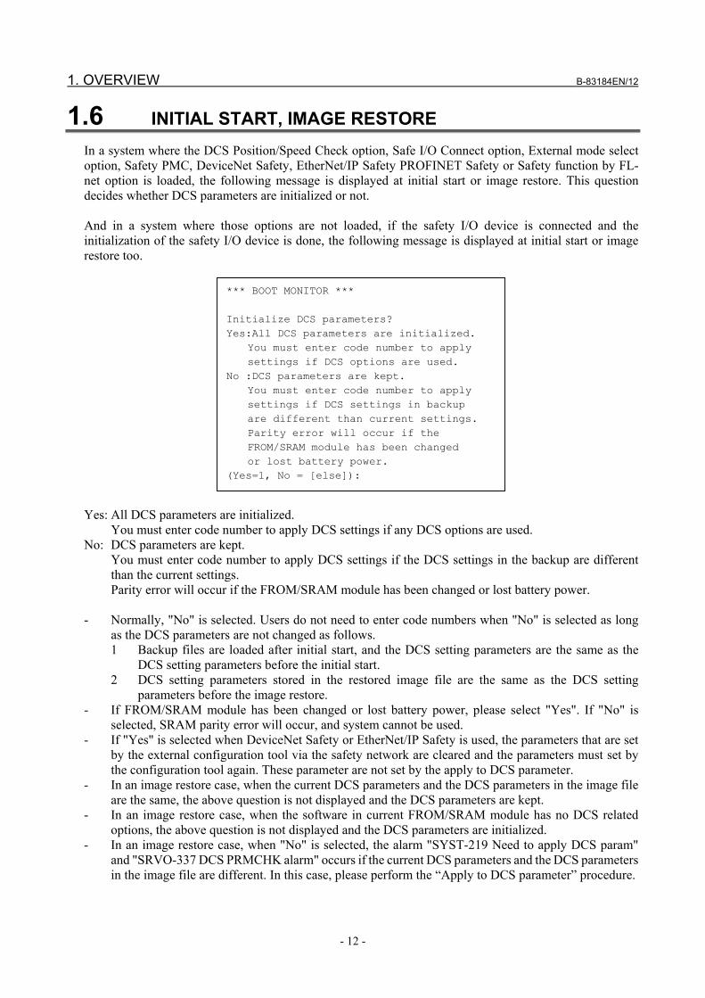
1.6 INITIAL START, IMAGE RESTORE In a system where the DCS Position/Speed Check option, Safe I/O Connect option, External mode select option, Safety PMC, DeviceNet Safety, EtherNet/IP Safety PROFINET Safety or Safety function by FL-net option is loaded, the following message is displayed at initial start or image restore. This question decides whether DCS parameters are initialized or not. And in a system where those options are not loaded, if the safety I/O device is connected and the initialization of the safety I/O device is done, the following message is displayed at initial start or image restore too.
*** BOOT MONITOR *** Initialize DCS parameters? Yes:All DCS parameters are initialized. You must enter code number to apply settings if DCS options are used. No :DCS parameters are kept. You must enter code number to apply settings if DCS settings in backup are different than current settings. Parity error will occur if the FROM/SRAM module has been changed or lost battery power. (Yes=1, No = [else]):
Yes: All DCS parameters are initialized.
You must enter code number to apply DCS settings if any DCS options are used. No: DCS parameters are kept.
You must enter code number to apply DCS settings if the DCS settings in the backup are different than the current settings. Parity error will occur if the FROM/SRAM module has been changed or lost battery power.
- Normally, "No" is selected. Users do not need to enter code numbers when "No" is selected as long
as the DCS parameters are not changed as follows. 1 Backup files are loaded after initial start, and the DCS setting parameters are the same as the
DCS setting parameters before the initial start. 2 DCS setting parameters stored in the restored image file are the same as the DCS setting
parameters before the image restore. - If FROM/SRAM module has been changed or lost battery power, please select "Yes". If "No" is
selected, SRAM parity error will occur, and system cannot be used. - If "Yes" is selected when DeviceNet Safety or EtherNet/IP Safety is used, the parameters that are set
by the external configuration tool via the safety network are cleared and the parameters must set by the configuration tool again. These parameter are not set by the apply to DCS parameter.
- In an image restore case, when the current DCS parameters and the DCS parameters in the image file are the same, the above question is not displayed and the DCS parameters are kept.
- In an image restore case, when the software in current FROM/SRAM module has no DCS related options, the above question is not displayed and the DCS parameters are initialized.
- In an image restore case, when "No" is selected, the alarm "SYST-219 Need to apply DCS param" and "SRVO-337 DCS PRMCHK alarm" occurs if the current DCS parameters and the DCS parameters in the image file are different. In this case, please perform the “Apply to DCS parameter” procedure.

B-83184EN/12 1. OVERVIEW
- 13 -
1.7 STOPPING DISTANCE Dual Check Safety (DCS) stops the robot by shutting down the motor power. When the motor power is shut down while the robot is moving, the robot’s momentum causes it to move some distance before it completely stops. This distance depends on the type of robot, payload, and speed. The default scan time of the Position/Speed Check functions is 8 msec. This scan time might change according to your system configuration. The actual scan time is displayed in the DCS robot SETUP menu (Refer to Section 2.3 DCS Robot Setup Menu). DCS Position/Speed Check functions will detect an alarm within a maximum of one scan time. The stop distance is calculated as follows: (Speed x Scan time) + moving distance through momentum
WARNING 1 The robot stopping distance must be considered when DCS Position/Speed
Check is used. A risk assessment for the whole robot system is necessary. 2 If StopCategory 1 is set as a stop type, motor power shutdown is delayed for a
maximum of 2 seconds. In this case, a risk assessment for the whole robot system is necessary, including the 2 seconds delay.
3 If Safe I/O Connect feature is used, safety signal status could be delayed by a maximum of 2 ms. In this case, a risk assessment for the whole robot system is necessary, including the additional 2 ms delay.
4 If DeviceNet Safety or Ethernet/IP Safety feature is used, safety signal status could be delayed by a maximum of 2 ms. In this case, a risk assessment for the whole robot system is necessary, including the additional 2 ms delay.
5 If PROFINET Safety feature is used, safety signal status could be delayed by a maximum of 4 ms. In this case, a risk assessment for the whole robot system is necessary, including the additional 4 ms delay.
6 If Safety function by FL-net feature is used, safety signal status could be delayed by a maximum of "Timer for receive data + 4" ms. In this case, a risk assessment for the whole robot system is necessary, including the additional "Timer for receive data + 4" ms delay. See item "Timer for receive data" in "Table13.2.3 (b) Parameters in Safety function by FL-net screen" for "Timer for receive data".
7 If Safety PMC feature is used, safety signal status that is output by the Level 1 sequence program could be delayed by a maximum of 2ms. And safety signal status that is output by the Level 2 sequence program could be delayed by a maximum of the execution period of Level 2. The execution period of Level 2 is displayed in DCS Safety PMC menu. In this case, a risk assessment for the whole robot system is necessary, including the additional signal status delay.
8 If CC-Link IE Field Safety feature is used, safety signal status could be delayed by maximum of “Max. trans Interval +8” ms. In this case, a risk assessment for the whole robot system is necessary, including the additional delay of “Max. trans Interval + 8” ms. See item “Max. Trans Interval (128μs)” in Table 14.2.2(a) for more detail.

2. DCS MENU B-83184EN/12
- 14 -
2 DCS MENU In the DCS menu, users can change DCS setting parameters and apply these parameters to DCS parameters. DCS menu is displayed if the option related to DCS function is loaded. In Multi-Arm system, DCS menu is displayed even though no option related to DCS function is loaded, because DCS parameter may need to be changed according to the robot configuration. And DCS menu is displayed even though no option related to DCS function is loaded when new safety I/O device is connected too.
2.1 DCS MENU COMPONENTS
Display DCS menu DCS menu is displayed by the following operation. [MENU] → "SYSTEM" → [F1(TYPE)] → "DCS"
DCS menu components DCS menu consists of the following menus.
DCS Top menu
DCS Safe I/O status menu DCS Safe I/O connect menu or DCS Safety PMC menu DCS Joint position check menu DCS Joint speed check menu DCS Cartesian position check menu DCS Cartesian speed check menu DCS T1 mode speed check menu DCS User model menu DCS Tool frame menu DCS User frame menu DCS Stop position prediction menu DCS Robot setup DCS Mastering parameter menu DCS Pos./Speed check setup menu DCS CIP Safety menu DCS PROFINET Safety menu DCS Safety function by FL-net menu DCS Local stop menu DCS Teach Pendant Hot Swap menu DCS Shared Teach Pendant menu DCS I/O Link i Slave menu DCS Mode Select menu DCS Safe I/O Consistency Check menu DCS Safe I/O device menu DCS Signature number menu DCS Code number setup menu

B-83184EN/12 2. DCS MENU
- 15 -
In this Chapter, the following menus related to general DCS functions are described. - DCS Top menu - DCS Robot setup menu - DCS Mastering parameter menu - DCS Signature number menu - DCS Code number setup menu The following menus are described in "7 POSITION / SPEED CHECK FUNCTION". - DCS Joint position check menu - DCS Joint speed check menu - DCS Cartesian position check - DCS Cartesian speed check - DCS User Model menu - DCS Tool frame menu - DCS User frame menu - DCS Stop position prediction menu - DCS speed check The following menus are described in "9 SAFE I/O" - DCS Safe I/O status menu - DCS Safe I/O connect menu - DCS Safe I/O device menu The following menu is described in "10 DEVICENET SAFETY" and "11 ETHERNET/IP SAFETY" - DCS CIP Safety menu The following menu is described in "12 PROFINET SAFETY" - DCS PROFINET Safety menu The following menu is described in "13 SAFETY FUNCTION BY FL-net". - DCS Safety function by FL-net menu The following menu is described in "15 SAFETY PMC FUNCTION". - DCS Safety PMC function menu The following menu is described in "16 AUXILIARY AXIS SERVO OFF (LOCAL STOP) FUNCTION". - DCS Local stop menu The following menu is described in "17 TEACH PENDANT HOT SWAP". - DCS Teach Pendant Hot Swap menu The following menu is described in "18 SHARED TEACH PENDANT". - DCS Shared Teach Pendant menu The following menu is described in "19 I/O LINK i SLAVE FUNCTION". - DCS I/O Link i Slave menu The following menu is described in "20 SAFE I/O CONSISTENCY CHECK FUNCTION". - DCS Safe I/O Consistency Check menu The following menu is described in "21 OPERATION WITHOUT MODE SWITCH". - DCS Mode Select menu

2. DCS MENU B-83184EN/12
- 16 -
2.2 DCS TOP MENU This is the top level DCS menu and includes the operation to “Apply to DCS parameter”. Each DETAIL menu can be displayed from this menu. The DCS top menu can be displayed by pressing PREV from each DETAIL menu.
DCS Top menu DCS 1/24 1 Safe I/O Status: 2 Safe I/O connect: OK 3 Joint position check: ---- OK 4 Joint speed check: ---- OK 5 Cart. position check: ---- OK 6 Cart. speed check: ---- OK 7 T1 mode speed check: OK 8 User model: OK 9 Tool frame: OK 10 User frame: OK 11 Stop position prediction: OK 12 Robot setup: OK 13 Mastering parameter: OK 14 Pos./Speed check setup OK 15 CIP safety: OK
16 Safety function by FL-net: OK 17 Local Stop Setup: OK 18 Teach Pendant Hot Swap: OK 19 Shared Teach Pendant: OK 20 I/O Link i Slave: OK 21 Mode Select OK 22 Safe I/O consistency check: OK 23 Safe I/O device: OK 24 Signature number: 25 Code number setup: [ TYPE ] APPLY DETAIL UNDO
Items in DCS Top menu
Item Description Safe I/O status When the [ENTER] key or the [F3(DETAIL)] key is pressed on this item, the DCS Safe I/O
Status menu is displayed. This line is displayed when "Safe I/O Connect" or the option that includes it are loaded.
Safe I/O connect When the [ENTER] key or the [F3(DETAIL)] key is pressed on this item, the DCS Safe I/O Connect menu is displayed. This line is displayed when "Safe I/O Connect" or the option that includes it are loaded. When "Safe I/O process" in Safe I/O device menu is set to "Safety PMC", this item is replaced by "Safety PMC".
Safety PMC When the [ENTER] key or the [F3(DETAIL)] key is pressed on this item, the Safety PMC menu is displayed. This line is displayed when "Safety PMC" is loaded and "Safe I/O process" in Safe I/O device menu is set to "Safety PMC".
Joint position check When the [ENTER] key or the [F3(DETAIL)] key is pressed on this item, the DCS Joint Position Check menu is displayed. This line is displayed when "DCS Position/Speed Check" option or "DCS Basic Position Check" option is loaded. (*1)

B-83184EN/12 2. DCS MENU
- 17 -
Item Description Joint speed check When the [ENTER] key or the [F3(DETAIL)] key is pressed on this item, the DCS Joint
Speed Check menu is displayed. This line is displayed when "DCS Position/Speed Check" option or "DCS Basic Position Check" option or "DCS Joint Speed check" option is loaded. (*1)
Cart. position check When the [ENTER] key or the [F3(DETAIL)] key is pressed on this item, the DCS Cartesian Position Check menu is displayed. This line is displayed when "Position/Speed Check" option or "DCS Basic Position Check" option is loaded.
Cart. speed check When the [ENTER] key or the [F3(DETAIL)] key is pressed on this item, the DCS Cartesian Speed Check menu is displayed. This line is displayed when "DCS Position/Speed Check" option is loaded.
T1 mode speed check
When the [ENTER] key or the [F3(DETAIL)] key is pressed on this item, the DCS T1 Mode Speed Check menu is displayed. This line is displayed when "DCS Position/Speed Check" option is loaded.
User model When the [ENTER] key or the [F3(DETAIL)] key is pressed on this item, the DCS User Model menu is displayed. This line is displayed when "DCS Position/Speed Check" option or "DCS Basic Position Check" option is loaded.
Tool frame When the [ENTER] key or the [F3(DETAIL)] key is pressed on this item, the DCS Tool Frame menu is displayed. This line is displayed when "DCS Position/Speed Check" option or "DCS Basic Position Check" option is loaded. (*1)
User frame When the [ENTER] key or the [F3(DETAIL)] key is pressed on this item, the DCS User Frame menu is displayed. This line is displayed when "DCS Position/Speed Check" option is loaded.
Stop position prediction
When the [ENTER] key or the [F3(DETAIL)] key is pressed on this item, the DCS Stop Position Prediction menu is displayed. This line is displayed when "DCS Position/Speed Check" option or "DCS Basic Position Check" option is loaded.
Robot setup When the [ENTER] key or the [F3(DETAIL)] key is pressed on this item, the DCS Robot Setup menu is displayed. This line is displayed when "DCS Position/Speed Check" option or "DCS Joint Speed check" option or "DCS Basic Position Check" option is loaded.
Mastering parameter
When the [ENTER] key or the [F3(DETAIL)] key is pressed on this item, the DCS Mastering Parameter menu is displayed. This line is displayed when "DCS Position/Speed Check" option or "DCS Joint Speed check" option is or "DCS Basic Position Check" option loaded.
Pos./Speed check setup
When the [ENTER] key or the [F3(DETAIL)] key is pressed on this item, the DCSPos./Speed check setup menu is displayed. This line is displayed when "DCS Position/Speed Check" option or "DCS Basic Position Check" option is loaded. This function does not correspond in R-30iB and R-30iB Mate.
CIP Safety When the [ENTER] key or the [F3(DETAIL)] key is pressed on this item, the DCS CIP Safety menu is displayed. This line is displayed when "DeviceNet Safety", or “EtherNet/IP Safety” option is loaded.
PROFINET Safety When the [ENTER] key or the [F3(DETAIL)] key is pressed on this item, the DCS PROFINET Safety menu is displayed. This line is displayed when "PROFINET Safety" option is loaded.
Safety function by FL-net
When the [ENTER] key or the [F3(DETAIL)] key is pressed on this item, the DCS Safety function by FL-net menu is displayed. This line is displayed when "Safety function by FL-net" option is loaded.
Local Stop Setup When the [ENTER] key or the [F3(DETAIL)] key is pressed on this item, the DCS Local stop setup menu is displayed. This line is displayed when "Axiliary axis servo off (local stop) function" option is loaded.

2. DCS MENU B-83184EN/12
- 18 -
Item Description Teach Pendant Hot Swap
When the [ENTER] key or the [F3(DETAIL)] key is pressed on this item, the DCS Teach Pendant Hot Swap menu is displayed. This line is displayed when "Teach Pendant Hot Swap function" option is loaded.
Shared Teach Pendant
When the [ENTER] key or the [F3(DETAIL)] key is pressed on this item, the DCS Shared Teach Pendant menu is displayed. This line is displayed when "Shard Teach Pendant function" option is loaded.
I/O Link i Slave When the [ENTER] key or the [F3(DETAIL)] key is pressed on this item, the DCS I/O Link i Slave menu is displayed. This line is displayed when the special hardware for I/O Link i Slave is used.
Mode Select When the [ENTER] key or the [F3(DETAIL)] key is pressed on this item, the DCS Mode Select menu is displayed. This line is displayed when "TP mode select ” function" option is loaded or controller type is R-30iB Compact Plus or R-30iB Mini Plus.
Safe I/O consistency check
When the [ENTER] key or the [F3(DETAIL)] key is pressed on this item, the DCS Safe I/O consistency check menu is displayed. This line is always displayed.
Safe I/O device When the [ENTER] key or the [F3(DETAIL)] key is pressed on this item, the DCS Safe I/O device menu is displayed. This line is always displayed.
Signature number When the [ENTER] key or the [F3(DETAIL)] key is pressed on this item, the DCS Signature Number menu is displayed. This line is always displayed.
Code number setup When the [ENTER] key or the [F3(DETAIL)] key is pressed on this item, the DCS Code Number Setup menu is displayed. This line is always displayed.
OK / CHGD / PEND
For menus that allow setting parameters to be changed in the detail menu, OK/CHGD/PEND is displayed in the right column. OK: Setting parameter and DCS parameter are the same. CHGD: Setting parameter is changed, but not applied to DCS parameter. PEND: Setting parameter is changed and applied to DCS parameter, but controller power
has not been cycled. ---- / SAFE / UNSF / DSBL
On Joint Position Check and Cartesian Position Check lines, ----/SAFE/UNSF/DSBL is displayed in the second column from the right. ----: Disabled by settings. SAFE: Enabled, and in the safe zone now. UNSF: Enabled, and out of the safe zone now. DSBL: Disabled by disabling input now. DSSF: Disabled by disabling input in the safe zone now. DSUN: Disabled by disabling input out of the safe zone now. DSSF, DSUN are displayed when Disabled CPC Position Check in Pos./Speed check is DISABLE. See "7.12 Pos./Speed check setup".
---- / SAFE / OVER / DSBL
On Joint Speed Check and Cartesian Speed Check lines, ----/SAFE/OVER/DSBL is displayed in the second column from the right. ----: Disabled by settings. SAFE: Enabled, and speed is less than the limit now. OVER: Enabled, and speed is over the limit now. DSBL: Disabled by disabling input now.
*1: In case of "DCS Basic Position Check", item line is not displayed if the software version is 7DF4 series or earlier. Item line is always displayed if the software version is 7DF5 series or later.

B-83184EN/12 2. DCS MENU
- 19 -
Operation in DCS Top menu Operation Description
[F2(APPLY)] Apply to DCS parameters. [F3(DETAIL)] or [ENTER]
Display the detail menu of the highlighted item.
[F5(UNDO)] UNDO all items in the DCS menu except robot setup data, mastering parameters and Safety PMC program, all DCS setting parameters are reset to be the same as the current DCS parameters.
[NEXT→] [F3(4D)]
Display the 4D graphics DCS screen. See "8.2 4D GRAPHICS DCS DISPLAY ".
[NEXT→] [F5(View)]
Display robot model in the Simple view. See "8.1. Viewing the robot model".
2.3 DCS ROBOT SETUP MENU This menu is available when the "DCS Position/Speed Check" option or "DCS Basic Joint Speed check" option or "DCS Basic Position check" option is loaded. This menu displays the robot setup data related to DCS Position/Speed Check functions. When robot setup data is changed in the Maintenance menu at Control Start, CHGD is displayed on the status column of the changed item in this menu. In this situation, "SYST-212 Need to apply to DCS param" occurs and cannot be reset until "Apply to DCS parameter" is done.
DCS Robot setup menu DCS Robot setup menu is displayed by pressing the [ENTER] key or the [F3(DETAIL)] key while on the "Robot setup" item in the DCS Top menu.
DCS Robot setup 1/11 Status 1 Number of groups: 1 OK 2 Scan time: 8 msec OK 3 ---------- Group 1 ---------- 4 Robot: R-2000iB/210F OK 5 Number of axes: 6 OK 6 J1: Servo card - Axis 1 OK 7 J2: Servo card - Axis 2 OK 8 J3: Servo card - Axis 3 OK 9 J4: Servo card - Axis 4 OK 10 J5: Servo card - Axis 5 OK 11 J6: Servo card - Axis 6 OK [ TYPE ]
Items in DCS Robot setup menu Item Description
Number of groups This item indicates the number of DCS motion groups. Scan time This item indicates the scan time of position / speed checking process. Robot This item indicates the robot model name of the group assigned to this DCS motion group.
If it is described as "Excluded!", the motion group is excluded by DCS Position/Speed functions. Since the number of axes is considered to be 0, Cartesian Position Check function and Cartesian Speed Check function and T1 mode Speed Check function can't be used for this action group.
Number of axes This item indicates the number of axes in this motion group.

2. DCS MENU B-83184EN/12
- 20 -
Item Description J1 - J9 This item indicates the hardware configuration of each axis.
Servo card : This axis is connected to axis control card on main board. Axis board : This axis is connected to auxiliary axis board. The slot name that the
auxiliary axis board is inserted is displayed in the parenthesis. Excluded! : This axis is excluded by DCS Position/Speed Check functions. Joint Position
Check and Joint Speed Check cannot be enabled for this axis. When a motion group includes an excluded axis, except when it is an Auxiliary Extended Axis, the motion group cannot be used with the Cartesian Position Check, Cartesian Speed Check and T1 Mode Speed Check functions.
Speed only! : This axis can be used only for Joint Speed Check. Joint Position Check cannot be enabled for this axis. When a motion group includes an speed only axis, except when it is an Auxiliary Extended Axis, the motion group cannot be used with the Cartesian Position Check and Cartesian Speed Check functions. The T1 Mode Speed Check function regards the position of the speed only axis is always 0, and checks the DCS TCP speed and the wrist flange center speed.
Direction This item indicates the direction of the Extended axis or Positioner. [Extended axis] Auxiliary axes : No direction X : X direction, Y : Y direction, Z : Z direction [Positioner axis] +X : +X direction, -X : -X direction +Y : +Y direction, -Y : -Y direction +X : +Z direction, -Z : -Z direction
Arm length This item indicates the arm length of the extended axis Offset This item indicates the offset of the extended axis Offset X Offset Y Offset Z
This item indicates the offset of the positioner axis
Axis type This item indicates the axis type of extended axis, positioner axis or independent axis. Linear axis or Rotary axis.
Motor direction This item indicates the motor direction of extended axis, positioner axis or independent axis Gear ratio This item indicates the gear ratio of extended axis, positioner axis or independent axis Pos. tolerance This item indicates the position tolerance of the extended axis, positioner axis or
independent axis. If the difference between the command position and feedback position exceeds this value, the alarm "SRVO-365 DCS FB_CMP alarm" occurs.
Status This item indicates the status of each item displayed. OK : Robot setting is the same as DCS parameter CHGD : Robot setting is changed but not applied to DCS parameter. The alarm "SYST-
212 Need to apply to DCS param" occurs. PEND : Robot setting is changed and applied to DCS parameter, but controller power is
not cycled yet, and the new setting is not used. Power must be cycled.

B-83184EN/12 2. DCS MENU
- 21 -
2.4 DCS MASTERING PARAMETER MENU This menu is available when the "DCS Position/Speed Check" option or "DCS Basic Joint Speed check" option or "DCS Basic Position check" option is loaded. The mastering parameters of the setting parameters are displayed in this menu, they are not set from this menu. The mastering parameters are changed by the normal mastering procedure. When the standard mastering parameters are changed by mastering procedure, CHGD is displayed on the status column of the changed item in this menu. "SYST-212 Need to apply to DCS param" occurs and cannot be reset until "Apply to DCS parameter" is done.
DCS Mastering Parameter menu DCS Mastering Parameter menu is displayed by pressing the [ENTER] key or the [F3(DETAIL)] key while on the "Mastering Parameter" item in the DCS Top menu.
DCS Mastering parameter 1/7 Axis Position Master count Status 1 ---------- Group 1 ---------- 2 J1 0.000 deg 0 OK 3 J2 0.000 deg 0 OK 4 J3 0.000 deg 0 OK 5 J4 0.000 deg 0 OK 6 J5 0.000 deg 0 OK 7 J6 0.000 deg 0 OK [ TYPE ]
Items in DCS Mastering parameter menu Item Description
Axis This item indicates the axis number. Position This item indicates the current position calculated from the applied mastering parameters.
Verify that the displayed position shows the correct robot position when mastering parameters are applied to DCS parameters.
Master count This item indicates the value of the standard mastering parameters. Status This item indicates the status of each axes’ mastering parameters.
OK : Mastering parameters are the same as DCS parameters CHGD : Mastering parameters are changed but not applied to DCS parameters. The alarm "SYST-212 Need to apply to DCS param" occurs. PEND : Mastering parameters are changed and applied to DCS parameter, but controller power is not cycled yet, and the new setting is not used. Power must be cycled Not displayed: This axis is excluded by DCS Position/Speed Check functions. Mastering parameters of this axis are not copied to DCS parameters.

2. DCS MENU B-83184EN/12
- 22 -
2.5 DCS CODE NUMBER The menu is used to change the DCS code number. DCS parameter must be entered when "Applying to DCS parameter". DCS code number is a 4 digit number. There are 2 types of code numbers, a master code number and local code numbers. Master code number
The master code number can be used to apply any changed parameters. Local code number
There are 3 local code numbers, Base, Position/Speed Check and Safe I/O Connect. Each of these local code numbers only allow changes in each specified area to be applied. When multiple setting parameters are changed, the master code number or all local code numbers corresponding to the changed setting parameters need to be entered to apply to DCS parameter. For example, if setting parameters for Position/Speed Check and setting parameters for Safe I/O Connect are changed, master code number or the local code numbers for both Position/Speed Check and Safe I/O Connect must be entered.
Local code numbers are not defined by default. When the local code number for a changed setting parameter is not defined, the master code number must be used. The default master code number is "1111". In the message to apply to DCS parameter, the name of the required code number is displayed (i.e. "Code number(pos./speed):"). The “Apply to DCS parameter” is not performed until the specified local code number or master code number is entered. To change a code number, the current local code number or master code number must be entered. To clear a local code number, the current master code number must be entered. Code numbers are saved as part of the robot backup in SYSPASS.SV. When code numbers are changed by loading the SYSPASS.SV file, the alarm "SYST-219 Need to apply DCS param" occurs. To clear the alarm, the “Apply to DCS parameter” operation must be performed. In this operation, the previous master code number must be entered as follows. - The message "Previous code number(master):" is displayed, please enter the master code number that
was used before SYSPASS.SV is loaded. - Then the message "Code number(Master)" is displayed, please enter the master code number that is
loaded from the SYSPASS.SV. When code numbers are changed by loading the image file, the alarm "SYST-219 Need to apply DCS param" occurs. To clear the alarm, the “Apply to DCS parameter” operation must be performed. In this operation, the previous master code number must be entered as follows. - The message "Previous code number(master):" is displayed, please enter the master code number that
was used before the image file is loaded. (If Yes was selected for "Initialize DCS parameters?" at image restore, please enter "1111".)
- Then the message "Code number(Master)" is displayed, please enter the master code number that is loaded from the image file.
CAUTION Make sure to change the master code number from the default “1111” setting to
prevent DCS parameters from being changed by an unauthorized personnel.

B-83184EN/12 2. DCS MENU
- 23 -
2.5.1 DCS Code Number Setup Menu The DCS Code Number Setup menu is displayed by pressing the [ENTER] key or the [F3(DETAIL)] key while on the "Code number setup" item in the DCS Top menu.
DCS Code number setup 1/6 1 Master code number Local code number 2 Base UNDEFINED 3 Position/Speed check UNDEFINED 4 I/O connect UNDEFINED Code number by Pass. func. 5 Master code by Pass. ENABLE 6 TP mode select by Pass. ENABLE
Items in DCS code number setup menu Item Description
Master code number When the [ENTER] key is pressed on this item, the master code number can be changed. The current master code number must be entered.
Base The code number to change the DCS parameters for robot setup date, mastering parameter, CIP Safety, PROFINET Safety, Safety function by FL-net and Auxiliary axis servo off (local stop) function. When the [ENTER] key is pressed on this item, the local code number for Base DCS parameters can be changed. The current Base code number or Master code number must be entered. If the Base code number is not defined, "UNDEFINED" is displayed. If the Base code number is defined, "DEFINED" is displayed.
Position/Speed check
The code number to change the DCS parameters for the Position/Speed Check function. When the [ENTER] key is pressed on this item, the local code number for Position/Speed Check DCS parameters can be changed. The current Position/Speed Check code number or Master code number must be entered. If the Position/Speed Check code number is not defined, "UNDEFINED" is displayed. If the Position/Speed Check code number is defined, "DEFINED" is displayed.
I/O connect The code number to change the DCS parameters for the Safe I/O Connect function, Safe I/O device, Safety PMC program, Teach Pendant Hot Swap and Shared Teach Pendant. When the [ENTER] key is pressed on this item, the local code number for Safe I/O Connect DCS parameters can be changed. The current Safe I/O Connect code number or Master code number must be entered. If the Safe I/O Connect code number is not defined, "UNDEFINED" is displayed. If the Safe I/O Connect code number is defined, "DEFINED" is displayed.
Master code by Pass.
If this function is enabled, user can skip to input Master code for DCS apply by using Password Function. For more detail, please refer to “2.6.4 Code by Password Function”.
TP mode select by Pass.
If this function is enabled, user can skip to input Master code for TP mode select by using Password Function. For more detail, please refer to “2.6.4 Code by Password Function”.
Operation in DCS code number setup menu
Operation Description F2(CLEAR) When F2 is pressed on a local code number, the local code number becomes undefined.
The Master code number must be entered. PREV DCS Top menu is displayed.

2. DCS MENU B-83184EN/12
- 24 -
2.6 DCS SIGNATURE NUMBER The DCS Signature Number menu displays the signature numbers of the various types of DCS parameters. A signature number is a CRC of the DCS parameter values. When DCS parameters are changed, the corresponding signature number is also changed. These signature numbers can be used to indicate that DCS parameters have been changed. DCS code numbers are not included as part of the signature numbers. Changing the DCS code numbers will not change the DCS signature numbers.
2.6.1 DCS Signature Number Menu The DCS Signature Number menu is displayed by pressing the [ENTER] key or the [F3(DETAIL)] key while on the "Signature number" item in the DCS Top menu.
DCS Signature number (Dec) Current Latch 1 Total: 357145112 0 Time:27-MAY-09 14:49 None 2 Base: 2084717660 0 Time:26-MAY-09 15:50 None 3 Pos./Speed: 998197839 0 Time:27-MAY-09 14:49 None 4 I/O connect: 273305809 0 Time:26-MAY-09 15:48 None [ TYPE ] Dec/Hex Annun
Items in DCS Signature number menu Item Description
Current This column displays the Current signature numbers. Latch When one of the CCR[1-4] signals are changed from OFF to ON using the Safe I/O Connect
function, the current signature number is copied to the latched signature number. When a current signature number matches its latched signature number, the corresponding CCL[1-4] signal is set ON. When they are different, the corresponding CCL[1-4] signal is set OFF.
Time The Time setting for "Current" signatures is the time that the signature number was changed to this value. The Time setting for "Latch" signatures is the time that the current signature was copied to the latched signature number by using the Safe I/O Connect function. NOTE- In DCS parameter verify menu or in report file, "Changed" is displayed on the "Current" time of the signature that is changed by this APPLY operation. The "Current" time will be set to the time when the new DCS parameter setting is enabled at next power up.
Total Displays the signature number of all DCS parameters. Base Displays the signature number of the DCS parameters for robot setup date, mastering
parameter, CIP Safety, PROFINET Safety, Safety function by FL-net and Auxiliary axis servo off (local stop) function.
Pos./Speed Displays the signature number of the DCS parameters for the Position/Speed Check function. I/O connect Displays the signature number of the DCS parameters for the Safe I/O Connect function, Safe
I/O device, Safety PMC program, Teach Pendant Hot Swap and Shared Teach Pendant.

B-83184EN/12 2. DCS MENU
- 25 -
Operation in DCS Signature number menu Operation Description
[F3(Dec/Hex)] Toggles the display of the signature numbers between decimal and hexadecimal format. [F5 (Annun)] Displays the DCS Signature number annunciation setup menu [PREV] DCS Top menu is displayed.
2.6.2 DCS Signature Annunciation Menu The Dual Check Safety (DCS) Signature Annunciation menu provides a means to see at a glance that DCS settings have been changed. It displays two Parameter Signature numbers with dates, and a Signature Change Annunciation output.
DCS Signature Annunciation Parameter Signature Curr: [11-DEC-09 18:25] -20554788 Prev: [10-DEC-09 12:23] -19745529 1 Signature change annunc: RO[ 1] [ TYPE ] [CHOICE] CNF SIG
The Parameter Signature numbers represent a summary of all DCS parameter values and are equal to the Total signature number on the Signature Number menu. There are two Parameter Signature numbers: a Current number and a Previous number. On initial load of the DCS Position and Speed Check option, the Signature is calculated and displayed as the Current (Curr:) value. The Previous (Prev:) value is uninitialized. After initial load, a new Signature is calculated each power up. If changes have been made to any of the DCS setup parameters, a new value and date are displayed as the Current item. Otherwise, the value and date will remain the same. The Previous value is set by confirming the signature using the CNF SIG function key. See "Procedure 2-6-2 Confirming Changes to the Parameter Signature" for instructions on confirming the current signature. Once confirmed, the Previous signature and date are set equal to the Current values. In addition to the Signatures indicating changes to DCS setup parameters, this feature also indicates changes with a digital output called the Signature Change Annunciation output. Either a Digital output or a Robot output can be selected along with specifying the output index. After this output has been set up, it will turn on and stay on as long as the Current and Previous Signatures are the same. If they are different, the output will turn off. This output can be connected to an annunciating lamp or to a PLC to provide status of the Signatures.
WARNING Signature Change Annunciation output is not a safety function. If the output of
this function is used where a safety function is required, the safety function will not work under some fault conditions and serious personal injury could result. Do not use Signature Change Annunciation output for safety purposes.

2. DCS MENU B-83184EN/12
- 26 -
2.6.2.1 DCS signature change management utility setup It outputs to the Robot or Digital output whether the DCS parameter has been changed. The Current and Previous Signature values will still indicate changes to DCS parameters whether or not you set up a digital output. The only setup required for this function is the selection of a Robot or Digital output that will be used to annunciate changes to the Signature value. If you set up the digital output, and the Current and Previous Signature values change, the digital output will turn on and stay on as long as the values are the same. As soon as the Current and Previous values are different, the output will turn off. Use the following procedure to set up a digital output that will annunciate Signature changes.
WARNING Signature Change Annunciation output is not a safety function. If the output of
this function is used where a safety function is required, the safety function will not work under some fault conditions and serious personal injury could result. Do not use Signature Change Annunciation output for safety purposes.
Procedure 2-6-1 Setting up the DCS Signature Change Management Utility Steps :
1 Press the [MENU] key. 2 Select SYSTEM. 3 Press the F1, [TYPE] key. 4 Select DCS. 5 Press the [ENTER] key or the [F3(DETAIL)] key while on the “Signature Number” item. 6 Press the [F5(Annun)] key. You will see a screen similar to the following:
DCS Signature Annunciation Parameter Signature Curr: [11-DEC-09 18:25] -20554788 Prev: [10-DEC-09 12:23] -19745529 1 Signature change annunc: RO[ 1] [ TYPE ] [CHOICE] CNF SIG
7 Move the cursor to the output field of Signature change annunc which should display DO or RO, and
press [F4(CHOICE)]. Select the output type desired. 8 Move the cursor to the index number in the brackets, and set the desired index number. 9 Cycle power to finalize the setup.

B-83184EN/12 2. DCS MENU
- 27 -
2.6.2.2 DCS signature change management utility operation The Parameter Signature numbers represent a summary of all DCS parameter values and are equal to the Total signature number on the Signature Number menu. There are two Parameter Signature numbers: a Current number and a Previous number. On initial load of the DCS Position and Speed Check option, the Signature is calculated and displayed on the Signature Annunciation menu as the Current (Curr:) value. The Previous (Prev:) value is uninitialized. After initial load, a new Signature is calculated each power up. If changes have been made to any of the DCS setup parameters, a new value and date are displayed as the Current item. Otherwise, the value and date will remain the same. The Previous value is set by confirming the signature using the CNF SIG function key. See "Procedure 2-6-2 Confirming Changes to the Parameter Signature" for instructions on confirming the current signature. Once confirmed, the Previous signature and date are set equal to the Current values.
Procedure 2-6-2 Confirming Changes to the Parameter Signature Steps :
1 On the DCS Signature Annunciation menu, the CNF SIG function key should be displayed when the
cursor is on any item. 2 Press the [F5(CNF SIG)] key. You will be prompted to enter the DCS Code number (master). The
correct code number must be provided to confirm the Signature. You will be prompted to “Confirm new parameter signature?”
3 Press the [F4(YES)] key. The message “New parameter signature saved” will be displayed and the Previous value of the Parameter Signature and date will be changed to equal the value and date of the Current signature. If the annunciating output has been set up, the output will turn on to indicate that the Current and Previous Signature values are the same.
If the Current and Previous Signature values are the same and a Signature Change Annunciator output has been set up, the output will be on. If the Current and Previous Signature values are different, the output will turn off.
2.6.3 DCS Signature Number Output The DCS Signature numbers can be output through normal (non-safe) group outputs. Each 32-bit signature output requires two 16-bit groups. This is configured by setting $DCS_CRC_OUT[x].$START_GRP to the starting group number. There are eight values accessible : - Current Total CRC : $DCS_CRC_OUT[1].$START_GRP - Current Base CRC : $DCS_CRC_OUT[2].$START_GRP - Current Pos/Speed CRC : $DCS_CRC_OUT[3].$START_GRP - Current I/O Connect CRC : $DCS_CRC_OUT[4].$START_GRP - Latch Total CRC : $DCS_CRC_OUT[5].$START_GRP - Latch Base CRC : $DCS_CRC_OUT[6].$START_GRP - Latch Pos/Speed CRC : $DCS_CRC_OUT[7].$START_GRP - Latch I/O Connect CRC : $DCS_CRC_OUT[8].$START_GRP For example, if $DCS_CRC_OUT[1].$START_GRP is set to 1 then GO[1] and GO[2] are set to the lower and upper 16-bits of the Current Total CRC. If the Total Current CRC is 0x46A61511 (hex value) then GO[1] will be set to 0x1511 and GO[2] will be set to 0x46A6.

2. DCS MENU B-83184EN/12
- 28 -
2.6.4 Code by Password Function By using this function, the specified user by password function can skip to input the master code for DCS apply and TP mode select. When “Master code by Pass.” in Code number setup page is enabled, the specified level user can skip to input the master code which is necessary for DCS apply. Every operation level setting is specified by the XML file of password function. A following features tag is used in the XML file.
Features tag for DCS apply Tag Description
const=”25” Permit user to skip inputting master code for DCS apply.
When “TP mode select by Pass.” in Code number setup page is enabled, specified level user can skip to input the master code which is necessary for TP mode select. The setting of every operation level is specified by the XML file of password function. Following features tags are used in the XML file.
Features tag for TP mode select Tag Description
const=”26” Permit user to skip inputting Master code for TP mode select of AUTO/T1 (Need Master code to select T2)
const=”27” Permit user to skip inputting Master code for TP mode select to AUTO/T1/T2
Example) An example of XML file under the following conditions is shown below.
Permit Level 2 user to skip inputting the master code for DCS apply. Permit Level 3 user to skip inputting the master code for DCS apply. Permit Level 3 user to skip inputting the master code for TP mode select to AUTO/T1.
<?xml version="1.0"?> <PASSWORD> <PWD level="2" const="25" access="1"/> <!-- DCS apply permission --> <PWD level="3" const="25" access="1"/> <!-- DCS apply permission --> <PWD level="3" const="26" access="1"/> <!-- AUTO/T1 permission --> </PASSWORD> For more details about password function, please refer to “R-30iB/R-30iB Mate/R-30iB Plus/R-30iB Mate Plus/R-30iB Compact Plus/R-30iB Mini Plus CONTROLLER OPERATOR’S MANUAL (Basic Function) (B-83284) 9.11 PASSWORD FUNCTION”.

B-83184EN/12 3. LIMITING A ROBOT WORKSPACE
- 29 -
3 LIMITING A ROBOT WORKSPACE
3.1 OVERVIEW This chapter describes the method for limiting the workspace of a robot with Dual Check Safety (DCS) functions. The robot stops when it performs an operation which goes beyond the specified workspace. The following picture shows the restricted workspace of the robot.
This chapter describes the setup procedure to limit the robot workspace.
Type Item Description Settings Setup of robot
workspace limit Set the limits of the robot workspace with Cartesian Position Check function
Setup of Stop Position Prediction
Set a robot to stop within the programmed workspace.
Setup of user model Set user models in order to limit the workspace of equipment attached by users, such as hands.
Check Check the DCS zone using 4D graphics
Check the robot shape and robot workspace specified in the DCS function using a three-dimensional display.
Troubleshooting Recovery from alarm Recovering from an alarm when a robot moves out of the workspace.
Setup of robot workspace limit → 3.2
Setup of user model → 3.4

3. LIMITING A ROBOT WORKSPACE B-83184EN/12
- 30 -
3.2 LIMITING A ROBOT WORKSPACE BY CARTESIAN POSITION CHECK
This section describes the procedure to set a robot workspace as shown in the following figure using the DCS Cartesian Position Check function. See Subsection " 7.4.2.1 Define the safe zone" for detailed information.
WARNING If a robot workspace is set up incorrectly, the safety function will not work, and
serious personal injury could result. When a robot workspace is changed, the values must be verified and the function must be tested again.
CAUTION
If the robot is mounted on a rail axis, the robot workspace moves when the world frame of the robot moves along with the movement of the rail axis. To fix the robot workspace, the rail axis should be defined as Integrated Rail axis of the same motion group as the robot.
Point 2
Zone No.1
Point 1

B-83184EN/12 3. LIMITING A ROBOT WORKSPACE
- 31 -
1 Press the [MENU] key on Teach Pendant to display MENU pop up screen. 2 Select "0 -- NEXT --" → "6 SYSTEM" → "DCS", and press the [Enter] key to display DCS top menu.
3 Select "Cart. position check" and press the [Enter] key to display Cartesian Position Check list menu.

3. LIMITING A ROBOT WORKSPACE B-83184EN/12
- 32 -
4 Select any "No." and press the [Enter] key to display Cartesian Position Check menu.
5 Perform the following settings in Cartesian Position Check menu.
Number Item Setting Description 2 Enable/Disable "ENABLE" Enable Cartesian Position Check function of the
displayed No. 3 Method "Working zone
(Diagonal)" ("Diagonal IN" In R-30iB, R-30iB Mate)
Define the robot workspace to be the inside of a box using the Cartesian Position Check function. The setting "Working zone(Diagonal)" defines the coordinates of the two ends of the diagonal of a box.
9 X Point 1 Point 2 Values for the coordinates of the two ends of the diagonal of a box
Defines the coordinates of the two ends of the diagonal of the box for which "Diagonal (IN)" is the robot workspace.
10 Y Point 1 Point 2 11 Z Point 1 Point 2
12 Stop type "Stop Category 0" Configure so that if a robot goes beyond the workspace, robot motor power immediately shuts down and the robot stops.
See Subsection 7.4.5 for detailed information about " DCS Cartesian Position Check List Menu ". 6 Press the [PREV] key two times to display DCS top menu. Setup of a robot workspace is now complete. If a robot arm goes beyond a specified workspace, DCS Cartesian Position Check function limits the robot.

B-83184EN/12 3. LIMITING A ROBOT WORKSPACE
- 33 -
3.3 ROBOT STOP POSITION PREDICTION If only the workspace is set using Cartesian Position Check, the robot stops after it goes beyond the workspace. When the motor power is shut down, the robot’s momentum causes it to move some distance before it completely stops. The actual "Robot Stop Position" will be beyond the workspace. To stop the robot within the robot workspace, use the DCS Stop Position Prediction function. The setup procedure for the Stop Position Prediction function is as follows. See Subsection 7.4.3 for detailed information.
WARNING 1 If Stop Position Prediction is set up incorrectly, the robot will leave the safety
zone, and serious personal injury could result. When Stop Position Prediction is changed, the values must be verified and the function must be tested again.
2 If an axis does not have a mechanical brake, the axis can move freely when the motor power is shut down, and Stop Position Prediction does not work correctly for the axis. In this case, a risk assessment for the whole robot system is necessary, including the free movement of the axis that does not have a mechanical brake.
NOTE If a robot does not need to stop inside a robot restriction zone, the settings in this
section are not required. Go to "3.4 SETUP OF USER MODEL."
1. Select "Stop position prediction" in DCS top menu and press the [Enter] key to display Stop Position
Prediction Menu.

3. LIMITING A ROBOT WORKSPACE B-83184EN/12
- 34 -
2. Perform the following settings in the Stop Position Prediction Menu.
Number Item Setting Description 1 Mode "DEFAULT" Configure using the setting type for the Stop Position
Prediction function, so that default values according to robot type are automatically set to "stop distance" and "speed."
See Subsection 7.11.1 for detailed information about "DCS Stop Position Prediction Menu". Setup of the Stop Position Prediction function is now complete. The robot will stop within the robot workspace when servo power is shut down.
3.4 SETUP OF USER MODEL Since DCS function check is not set for hands, etc. attached to the robot, they are not subject to checking by the DCS function. To limit the workspace of hands, etc. attached to the robot like the ones shown in the following picture, user models must be set. The setup procedure for a user model is as follows. See Subsection 7.4.1 for detailed information about "Shape Model".
Point 1 (-120.0, 0.0, 250.0)
Radius 280mm
Flange frame
Y X
Z

B-83184EN/12 3. LIMITING A ROBOT WORKSPACE
- 35 -
1 Select "User Model" in DCS top menu and press the [Enter] key to display User Model List Menu.
2 Select any "No." and press the [Enter] key to display User Model Detail (Element List) Menu.

3. LIMITING A ROBOT WORKSPACE B-83184EN/12
- 36 -
3 Select any "No." and press the [Enter] key to display User Model Element Detail Menu.
4 Perform the following settings in the User Model Element Detail Menu.
Number Item Setting Description 1 Enable/Disable "ENABLE" Enable the user model elements of the displayed No. 2 Link Number "99" Configure to mount the user model element on a
flange. 4 Tool frame "0" Configure so that the base frame of the element is the
flange frame. 5 Shape "Point" Configure so that the shape of a user model element is
a sphere. 6 Size (mm) "280.0" Configure so that the radius of a user model element is
280 mm. 7 Pos1 X Y Z X: "-120.000"
Y: "0.000" Z: "250.000"
Configure the center point of the sphere of a user model element to be the base frame of the flange frame. Point 2 is not used.
See Subsection 7.4.11 for detailed information about "DCS User Model Detail (Point/Line-Seg) Menu".

B-83184EN/12 3. LIMITING A ROBOT WORKSPACE
- 37 -
Next, to enable the specified user models, set the number of the user model to be the target model for Cartesian Position Check. 5 Press the [Prev] key 3 times to display DCS top menu.
6 Select "Cart. position check" and press the [Enter] key to display Cartesian Position Check list menu.
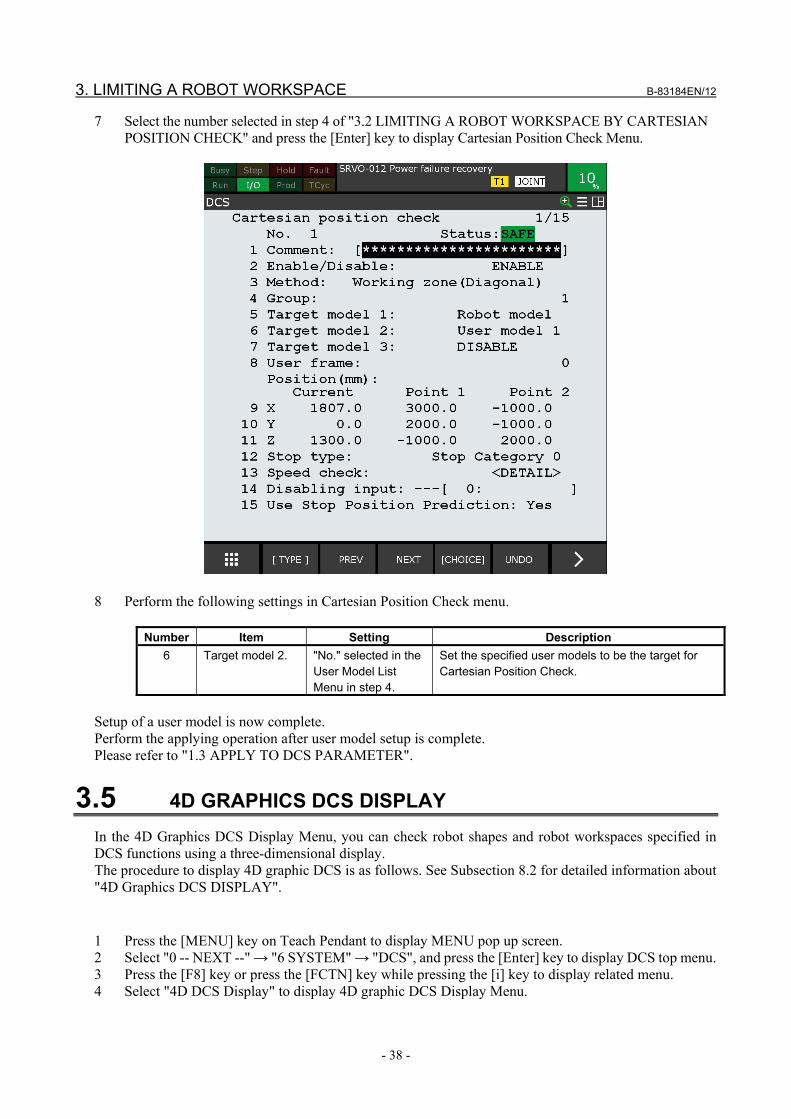
3. LIMITING A ROBOT WORKSPACE B-83184EN/12
- 38 -
7 Select the number selected in step 4 of "3.2 LIMITING A ROBOT WORKSPACE BY CARTESIAN POSITION CHECK" and press the [Enter] key to display Cartesian Position Check Menu.
8 Perform the following settings in Cartesian Position Check menu.
Number Item Setting Description 6 Target model 2. "No." selected in the
User Model List Menu in step 4.
Set the specified user models to be the target for Cartesian Position Check.
Setup of a user model is now complete. Perform the applying operation after user model setup is complete. Please refer to "1.3 APPLY TO DCS PARAMETER".
3.5 4D GRAPHICS DCS DISPLAY In the 4D Graphics DCS Display Menu, you can check robot shapes and robot workspaces specified in DCS functions using a three-dimensional display. The procedure to display 4D graphic DCS is as follows. See Subsection 8.2 for detailed information about "4D Graphics DCS DISPLAY".
1 Press the [MENU] key on Teach Pendant to display MENU pop up screen. 2 Select "0 -- NEXT --" → "6 SYSTEM" → "DCS", and press the [Enter] key to display DCS top menu. 3 Press the [F8] key or press the [FCTN] key while pressing the [i] key to display related menu. 4 Select "4D DCS Display" to display 4D graphic DCS Display Menu.

B-83184EN/12 3. LIMITING A ROBOT WORKSPACE
- 39 -
5 Operate the display.
There are two ways to operate the display. One is key input and the other is touch panel operation. Enlarge / Reduce Press [F3 [ZOOM]] and perform the following operations.
Display Key input Touch panel operation Enlarge the display Press the [↑] (enlarge) key. Touch the upper half of the screen. Reduce the display Press the [↓] (reduce) key. Touch the lower half of the screen.
Pan operation Press [F4 [PAN]] and perform the following operation.
Display Key input Touch panel operation Pan the display Press the [↑] / [↓] / [←] / [→] key. Touch the screen and drag your finger up,
down, left or right. Rotation Press the [F5 [ROTATE] ]and perform the following operation.
Display Key input Touch panel operation Rotate the display Press the [↑] / [↓] / [←] / [→] key. Touch the screen and drag it up, down, left
or right.
CAUTION Please refer to "4D Graphic Function" in "Optional Function OPERATOR'S
MANUAL" (B-83284EN-2) for detailed operation of the "4D Graphics DCS Display" Menu.
Robot model
Workspace
User model

3. LIMITING A ROBOT WORKSPACE B-83184EN/12
- 40 -
3.6 RECOVERY FROM ALARM When a robot moves out of its robot workspace, "SRVO-402 DCS Cart. pos. limit (%d,%s:G%d,M%d) %02x" alarm occurs and the robot stops. Cartesian Position Check number, Comment (If comment was input), Group number, and User Model number (0: robot model) are displayed in order from the left in the alarm. If the Stop Position Prediction function is enabled, the stop position of the robot will be within the robot workspace, and the alarm can be cleared. The alarm cannot be cleared when the robot is outside the robot workspace. The procedure to recover from an alarm is as follows: 1 Set mode switch to [T1] to enable teach pendant. 2 Press the [SHIFT] + [RESET] key to clear the alarm.
CAUTION Keep pressing the [SHIFT] key until the robot has returned to the robot
workspace. If the [SHIFT] key is released while the robot is still outside the robot workspace, the alarm occurs again and the robot stops.
3 Press and hold the [SHIFT] key and jog the robot to move the robot to the robot workspace.
CAUTION As the robot workspace is set in Cartesian Position Check, the position and
orientation of the flange just before the alarm occurs are recorded. The robot can be jogged toward the position and orientation just before where the alarm occurs. If the robot is jogged away from the position and orientation where the alarm occurs, the alarm occurs again and the robot stops.
In the following cases, robots cannot be recovered from alarm with procedure above, since the data for the frame position and orientation just before the alarm occurs are lost. Disable the Cartesian Position Check function settings, recover from the alarm, then enable the settings again. - The motor or Pulse coder is replaced, and the robot position exits the robot workspace. - The Zone or shape model is changed and applied to DCS parameters, power to the controller is cycled,
and the current position exits the robot workspace. - The controller power is turned off while the robot is moving, and the robot exits the robot workspace
by momentum movement. - The mastering parameters or robot setup data are changed and applied to DCS parameters, power to
the controller is cycled, and the robot exits the robot workspace. See Subsection 7.4.2.5 for detailed information about "Recovery from alarm". Operation of recovery from alarm is now complete.

B-83184EN/12 4. SWITCHING THE WORKSPACE
- 41 -
4 SWITCHING THE WORKSPACE
4.1 OVERVIEW This chapter describes the method for enabling and disabling the robot workspace using safety I/O. For an arc welding robot system as shown below, set the robot to weld a workpiece which is not being worked on by the operator when the operator is on a safe mat. When the robot approaches the workpiece which is being worked on by the operator, the robot stops, ensuring the safety of the operator. Safety I/Os are safe signals that can be used in DCS. For example, to switch the zone of the Zone Check Function, the safety input is set to a disabling input for the Zone Check Function. Please refer to "7.4.2.2 Enable and disable zones by disabling input". In this chapter, a safe zone that is not a box shape will be set (a maximum of 8 vertexes from P1 to P8, and upper / lower limits). The Zone Check Function checks if the shape model is within the safe zone.
This chapter describes the setup procedure to change a robot workspace.
Type Item Description Settings Setup of user model Set user models to limit the motion range of equipment
attached by users, such as hands. Setup of safety signal connections Safety I/O checks if there is an operator is on a safe mat.
Connect a safe mat to the safety signals. Setup of Cartesian Position Check Set the Cartesian Position Check zone.
Setup of Cartesian Position Check → 4.4
Setup of user model → 4.2

4. SWITCHING THE WORKSPACE B-83184EN/12
- 42 -
4.2 SETUP OF USER MODEL The setup procedure for the user model for an arc welding torch is as follows. The user model of the torch is set using two "Line_seg" shape elements. Please refer to "7.4.1 Shape Model".
WARNING If a robot workspace is set up incorrectly, the safety function will not work, and
serious personal injury could result. When a robot workspace is changed, the values must be verified and the function must be tested again.
1 Press the [MENU] key on Teach Pendant to display MENU pop up screen. 2 Select "0 -- NEXT --" → "6 SYSTEM" → "DCS", and press the [Enter] key to display DCS top menu.
3 Select "User model" and press the [Enter] key to display User Model List Menu.

B-83184EN/12 4. SWITCHING THE WORKSPACE
- 43 -
4 Select any "No." and press the [Enter] key to display User Model Detail (Element List) Menu.
5 Select any "No." and press the [Enter] key to display User Model Element Detail Menu.
No. Item Setting Description 1 Enable/Disable "ENABLE" Enable the user model elements of the displayed No. 5 Shape "Line_seg" Configure so that the shape of a user model element is line
segment. 6 Size (mm) "60.0" Configure so that the radius of a user model element is 60
mm. 7 Pos1 X Y Z X: "0.000"
Y: "0.000" Z: "0.000"
Set the position of one end on the center line of a user model element.
8 Pos2 X Y Z X: "0.000" Y: "0.000" Z: "280.000"
Specify the position of the other end on the center line of a user model element.
Please refer to "7.4.11 DCS User Model Detail (Point/Line-Seg) Menu".
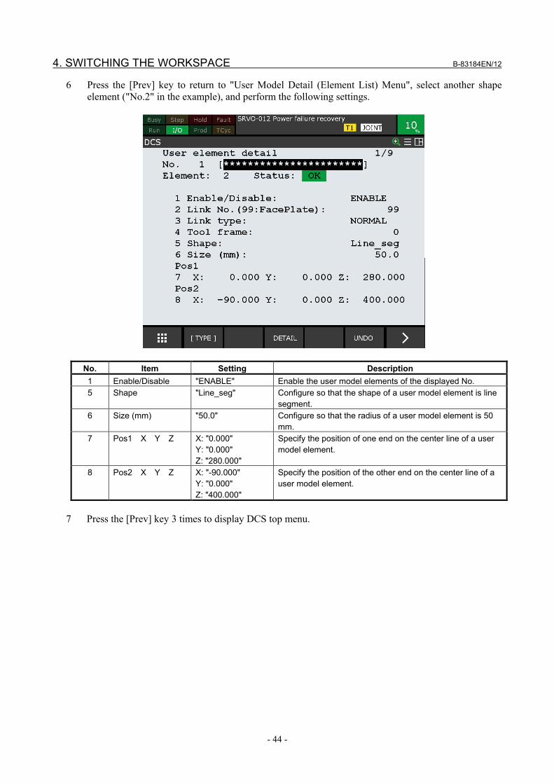
4. SWITCHING THE WORKSPACE B-83184EN/12
- 44 -
6 Press the [Prev] key to return to "User Model Detail (Element List) Menu", select another shape element ("No.2" in the example), and perform the following settings.
No. Item Setting Description 1 Enable/Disable "ENABLE" Enable the user model elements of the displayed No. 5 Shape "Line_seg" Configure so that the shape of a user model element is line
segment. 6 Size (mm) "50.0" Configure so that the radius of a user model element is 50
mm. 7 Pos1 X Y Z X: "0.000"
Y: "0.000" Z: "280.000"
Specify the position of one end on the center line of a user model element.
8 Pos2 X Y Z X: "-90.000" Y: "0.000" Z: "400.000"
Specify the position of the other end on the center line of a user model element.
7 Press the [Prev] key 3 times to display DCS top menu.

B-83184EN/12 4. SWITCHING THE WORKSPACE
- 45 -
DCS check can now be added to a welding torch.
4.3 CHECKING IF THERE IS AN OPERATOR ON A SAFE MAT As a precondition, two safe mats are connected to the emergency stop board as redundant contacts. The left safe mat is connected to SFDI11 and SFDI21, and the state can be referenced by Safety I/O SPI [1]. The right safe mat is connected to SFDI12 and SFDI22, and the state can be referenced by Safety I/O SPI [2]. When there is no operator on a safe mat, both redundant signals (SFDI11 and SFDI21 in case of the left safe mat) are closed and Safety I/O (SFDI [1]) is ON. If either of the redundant signals is open, Safety I/O (SFDI [1]) is turned OFF. Please refer to "9.2 SAFE I/O CONNECT FUNCTION".
CAUTION Refer to "Safety signal connection" in this manual for details on safety signal
connection .
Flange frame Y
X
Z
Z direction 280 mm
Position (0, 0,280)
Z direction 400 mm X direction -90 mm

4. SWITCHING THE WORKSPACE B-83184EN/12
- 46 -
4.4 SETUP OF CARTESIAN POSITION CHECK In Cartesian Position Check setup, three zones, from No. 1 to No. 3, are set up.
Type Setting No.1 A zone that surrounds the whole workspace of the robot. Always active. Disabling input is not set. No.2 A zone that is enabled when an operator is on the left safe mat. If this zone is enabled, the robot
cannot move to the left side. SPI [1], which shows the status of the left safe mat, is set to the disabling input.
No.3 A zone that is enabled when an operator is on the right safe mat. If this zone is enabled, the robot cannot move to the right side. SPI [2], which shows the status of the right safe mat, is set to the disabling input.

B-83184EN/12 4. SWITCHING THE WORKSPACE
- 47 -
4.4.1 Setup of No.1 Zone This section describes the setup method for No.1 zone. No.1 zone is always active, so disabling input is not set. An alarm occurs if the robot exits the zone when there is no operator on a safe mat.
P2
P3
P4
P1

4. SWITCHING THE WORKSPACE B-83184EN/12
- 48 -
1 Select "Cart. position check" in DCS screen and press the [Enter] key to display Cartesian Position Check menu.
2 Select any "No." and press the [Enter] key to display Cartesian Position Check detail menu.

B-83184EN/12 4. SWITCHING THE WORKSPACE
- 49 -
3 Perform the following settings in Cartesian Position Check detail menu.
No. Item Setting Description 1 Enable/Disable "ENABLE" Enable Cartesian Position Check for the displayed No. 3 Method "Working zone (Lines)" The Working zone is defined to be inside the vertexes of
a polygon in the X-Y plane in "Lines." 6 Target model 2 The "No." of the user
model set in "4.2 SETUP OF USER MODEL"
Specify the set user model to be the target for Cartesian Position Check.
9 Number of vertexes
"4" Set the number of vertexes for the polygon in the X-Y plane. Here, we specify it to be "4", the number of vertexes P1 to P4.
10 P1 X: "1500.0" Y: "-1800.0"
Specify the X-Y coordinates of vertex P1.
11 P2 X: "1500.0" Y: "1800.0"
Specify the X-Y coordinates of vertex P2.
12 P3 X: "-1500.0" Y: "1800.0"
Specify the X-Y coordinates of vertex P3.
13 P4 X: "-1500.0" Y: "-1800.0"
Specify the X-Y coordinates of vertex P4.

4. SWITCHING THE WORKSPACE B-83184EN/12
- 50 -
No. Item Setting Description 14 P5 X: "0.0"
Y: "0.0" Specify the X-Y coordinates of vertex P5. As vertex P5 is not used for No.1, "0.0" is specified for both X and Y.
15 P6 X: "0.0" Y: "0.0"
Specify the X-Y coordinates of vertex P6. As vertex P6 is not used for No.1, "0.0" is specified for both X and Y.
16 P7 X: "0.0" Y: "0.0"
Specify the X-Y coordinates of vertex P7. As vertex P7 is not used for No.1, "0.0" is specified for both X and Y.
17 P8 X: "0.0" Y: "0.0"
Specify the X-Y coordinates of vertex P8. As vertex P8 is not used for No.1, "0.0" is specified for both X and Y.
18 Z Z1:”-500.0” Z2:”2000.0”
Specify the Z coordinates of upper and lower limit.
19 Stop type "Stop Category 0" Specify "Stop Category 0", to immediately shut down the motor power.
Please refer to "7.4.8 DCS Cartesian Position Check (Lines) Menu". 4 Press the [Prev] key 3 times to display DCS top menu. Setup of No.1 zone is now complete.

B-83184EN/12 4. SWITCHING THE WORKSPACE
- 51 -
4.4.2 Setup of No.2 Zone This section describes the setup method for No.2 zone. SPI [1], which shows the status of the left safe mat, is set to the disabling input. When there is no operator on the left safe mat, SPI [1] is ON and this zone is disabled. When there is no operator on the left safe mat, this zone is enabled. When the robot is about to exit this zone, it stops.
P4
P2
P5 P3
P1
When an operator is on the left safe mat, this zone is enabled.
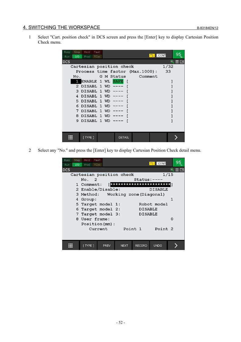
4. SWITCHING THE WORKSPACE B-83184EN/12
- 52 -
1 Select "Cart. position check" in DCS screen and press the [Enter] key to display Cartesian Position Check menu.
2 Select any "No." and press the [Enter] key to display Cartesian Position Check detail menu.

B-83184EN/12 4. SWITCHING THE WORKSPACE
- 53 -
3 Perform the following settings in Cartesian Position Check detail menu.
No. Item Setting Description 1 Enable/Disable "ENABLE" Enable Cartesian Position Check for the displayed No. 3 Method
(Safe side) "Lines (IN) " The Working zone is defined to be inside the vertexes of
a polygon in the X-Y plane in "Lines." 6 Target model 2 The "No." of the user
model set in "4.2 SETUP OF USER MODEL"
Specify the set user model to be the target for Cartesian Position Check.
9 Number of vertexes
"5" Set the number of vertexes for the polygon in the X-Y plane. Here, we specify it to be "5", the number of vertexes P1 to P5.
10 P1 X: "1500.0" Y: "500.0"
Specify the X-Y coordinates of vertex P1.
11 P2 X: "1500.0" Y: "1800.0"
Specify the X-Y coordinates of vertex P2.
12 P3 X: "-1500.0" Y: "1800.0"
Specify the X-Y coordinates of vertex P3.
13 P4 X: "-1500.0" Y: "-750.0"
Specify the X-Y coordinates of vertex P4.
14 P5 X: "500.0" Y: "-750.0"
Specify the X-Y coordinates of vertex P5.

4. SWITCHING THE WORKSPACE B-83184EN/12
- 54 -
No. Item Setting Description 15 P6 X: "0.0"
Y: "0.0" Specify the X-Y coordinates of vertex P6. As vertex P6 is not used for No.2, "0.0" is specified for both X and Y.
16 P7 X: "0.0" Y: "0.0"
Specify the X-Y coordinates of vertex P7. As vertex P7 is not used for No.2, "0.0" is specified for both X and Y.
17 P8 X: "0.0" Y: "0.0"
Specify the X-Y coordinates of vertex P8. As vertex P8 is not used for No.2, "0.0" is specified for both X and Y.
18
Z Z1: ”-500.0” Z2: “2000.0”
Specify the Z coordinates of upper and lower limit.
19 Stop type "Stop Category 0" Specify "Stop Category 0", to immediately shut down the motor power.
21 disabling input "SPI[1]" Specify the Safety I/O that indicates the state of the left safe mat. If the specified Safety I/O is ON, this zone is disabled.
4 Press the [Prev] key 3 times to display DCS top menu. Setup of No.2 zone is now complete.

B-83184EN/12 4. SWITCHING THE WORKSPACE
- 55 -
4.4.3 Setup of No.3 Zone This section describes the setup method for No.3 zone. SPI [2], which shows the status of the right safe mat, is set to the disabling input. When an operator is not on the right safe mat, SPI [2] is turned ON and this zone is disabled. When an operator is on the right safe mat, this zone is enabled. When the robot is about to exit this zone, it stops.
When an operator is on the right safe mat, this zone is enabled.
P1
P2
P3
P4
P5

4. SWITCHING THE WORKSPACE B-83184EN/12
- 56 -
1 Select "Cart. position check" in DCS screen and press the [Enter] key to display Cartesian Position Check menu.
2 Select any "No." and press the [Enter] key to display Cartesian Position Check detail menu.

B-83184EN/12 4. SWITCHING THE WORKSPACE
- 57 -
3 Perform the following settings in Cartesian Position Check detail menu.
No. Item Setting Description 1 Enable/Disable "ENABLE" Enable Cartesian Position Check for the displayed No. 3 Method "Working
zone(Lines )" The Working zone is defined to be inside the vertexes of a polygon in the X-Y plane in "Lines.".
6 Target model 2 The "No." of the user model set in "4.2 SETUP OF USER MODEL"
Specify the set user model to be the target for Cartesian Position Check.
9 Number of vertexes
"5" Set the number of vertexes for the polygon in the X-Y plane. Here, we specify it to be "5", the number of vertexes P1 to P5.
10 P1 X: "1500.0" Y: "-500.0"
Specify the X-Y coordinates of vertex P1.
11 P2 X: "1500.0" Y: "-1800.0"
Specify the X-Y coordinates of vertex P2.
12 P3 X: "-1500.0" Y: "-1800.0"
Specify the X-Y coordinates of vertex P3.
13 P4 X: "-1500.0" Y: "750.0"
Specify the X-Y coordinates of vertex P4.
14 P5 X: "500.0" Y: "750.0"
Specify the X-Y coordinates of vertex P5.

4. SWITCHING THE WORKSPACE B-83184EN/12
- 58 -
No. Item Setting Description 15 P6 X: "0.0"
Y: "0.0" Specify the X-Y coordinates of vertex P6. As vertex P6 is not used for No.3, "0.0" is specified for both X and Y.
16 P7 X: "0.0" Y: "0.0"
Specify the X-Y coordinates of vertex P7. As vertex P7 is not used for No. 3, "0.0" is specified for both X and Y.
17 P8 X: "0.0" Y: "0.0"
Specify the X-Y coordinates of vertex P8. As vertex P8 is not used for No. 3, "0.0" is specified for both X and Y.
18 Z Z1: ”-500.0” Z2: “2000.0”
Specify the Z coordinates of upper and lower limit.
20 Stop type "Power-Off stop" Specify [Power-off stop], to immediately shut down the motor power.
21 disabling input "SPI[2]" Set the Safety I/O that indicates the state of the right safe mat. If the specified Safety I/O is ON, this zone is disabled.
4 Press the [Prev] key 3 times to display DCS top menu. Setup of No.3 zone is now complete. Perform an apply operation after setup for zones No.1 to No.3 is complete. Please refer to "1.3 APPLY TO DCS PARAMETER".

B-83184EN/12 5. CHECKING IF AUXILIARY AXES ARE STATIONARY
- 59 -
5 CHECKING IF AUXILIARY AXES ARE STATIONARY
5.1 OVERVIEW This chapter describes the system that checks if auxiliary axes are stationary. In the case of the arc welding robot shown in the picture below, an operator steps onto the safe mat and replaces Workpiece 2. The robot welds Workpiece 1 while the operator is replacing the workpiece. The robot performs the welding in coordination with auxiliary axis 2. When the operator finishes replacing the workpiece and leaves the safe mat, and the robot finishes welding Workpiece 1, auxiliary axis 1 rotates 180 degrees and Workpiece 1 and Workpiece 2 switch places. After that, the robot welds Workpiece 2 in coordination with auxiliary axis 3, and the operator replaces Workpiece 1. When an operator is on the safe mat, the system checks if auxiliary axis 1 and the auxiliary axis on the side of the safe mat (2 or 3) are stationary. If an auxiliary axis moves while the system is checking for stop, an alarm occurs and the robot and all auxiliary axes stop. See Subsection 7.2 for detailed information about " 7.2 Joint Position Check function.
Safe mat
Auxiliary axis 2
Auxiliary axis 3
Auxiliary axis 1
Workpiece 2
Workpiece 1

5. CHECKING IF AUXILIARY AXES ARE STATIONARY B-83184EN/12
- 60 -
In this chapter, the following settings are performed.
Type Item Description Settings Setup of stop check for auxiliary axis 1 Set the input signal from a safe mat to be disabling input.
Zone setup for auxiliary axis 1 Set the positions of auxiliary axis 1 where both auxiliary axes 2 and 3 are able to move (stop check is disabled).
Setup of stop check for auxiliary axes 2 and 3
Set the signal that represents the status of Joint Position Check (JPC) to be disabling input.
Setup of robot workspace Set up the robot workspace.
5.2 SETUP STOP CHECK FOR AUXILIARY AXIS 1 Specify the following settings in the Joint Speed Check function of the DCS function, to monitor to ensure that auxiliary axis 1 does not rotate when an operator is on a safe mat (plate).
WARNING If a robot workspace is set up incorrectly, the safety function will not work, and
serious personal injury could result. When a robot workspace is changed, the values must be verified and the function must be tested again.
1 Press the [MENU] key on Teach Pendant to display MENU pop up screen. 2 Select "0 -- NEXT --" → "6 SYSTEM" → "DCS", and press the [Enter] key to display DCS top menu.

B-83184EN/12 5. CHECKING IF AUXILIARY AXES ARE STATIONARY
- 61 -
3 Select "Joint speed check" and press the [Enter] key to display Joint Speed Check menu.
4 Select any "No." and press the [Enter] key to display Joint Speed Check detail menu.

5. CHECKING IF AUXILIARY AXES ARE STATIONARY B-83184EN/12
- 62 -
5 Perform the following settings in Joint Speed Check menu.
No. Item Setting Description 2 Enable/Disable "ENABLE" Enable the displayed No. 4 Group "2" Select auxiliary axis 1's group. 5 Axis "1" Select the axis for which auxiliary axis 1 is set. 6 Limit "0" This function can be used as a stop check function when the speed
limit is set to "0." 7 Stop type "Stop
Category 0" Select "Stop Category 0" to instantly shut off power.
11 disabling input "SPI[1]" To enable / disable the Joint Position Check dynamically, a Safety I/O can be set as a disabling input. When the specified Safety I/O is ON, this function disabled. When the specified Safety I/O is OFF, this function is enabled. Here, the condition is connecting so that input signals from safe mats are sent to SPI[1]. When an operator is on a safe mat, SPI[1] is turned OFF and stop check is enabled.
12 Permissible distance
"0.2" Set the permissible movement distance for when checking if the axis is stationary. Set 0.2 deg for the permissible distance here, to permit subtle movements when the servo is ON. An alarm does not occur if the movement is less than the permissible distance, even when the function is checking if the axis is stationary. Decide a suitable permissible distance value for your system through risk assessment.
Please refer to "7.2.3 DCS Joint Position Check Detail Menu". 6 Press the [Prev] key 2 times to display DCS top menu.
After these steps, the DCS Joint Speed Check function is enabled when an operator is on a safe mat, and emergency stop occurs when auxiliary axis 1 moves.

B-83184EN/12 5. CHECKING IF AUXILIARY AXES ARE STATIONARY
- 63 -
5.3 SETUP OF POSITION CHECK FOR AUXILIARY AXIS 1 Set the position of auxiliary axis 1 where both the auxiliary axes 2 and 3 are able to move (stop check is disabled) to Joint Position Check No. 1 and No. 2, respectively.
WARNING If a robot workspace is set up incorrectly, the safety function will not work, and
serious personal injury could result. When a robot workspace is changed, the values must be verified and the function must be tested again.
1 Select "Joint position check" in DCS screen and press the [Enter] key to display Joint Position Check
list menu.
2 Select "No. 1" and press the [Enter] key to display Joint Position Check detail menu.

5. CHECKING IF AUXILIARY AXES ARE STATIONARY B-83184EN/12
- 64 -
3 Perform the following settings in Joint Position Check detail menu.
No. Item Setting Description 2 Enable/Disable "ENABLE" Enable the displayed No. 3 Group "2" Select auxiliary axis 1's group. 4 Axis "1" Select the axis for which auxiliary axis 1 is set. 6 Upper limit "5" Set the upper limit of auxiliary axis 1. Motion of auxiliary
axis 2 becomes available within this range of values. 7 Lower limit "-5" Set the lower limit of auxiliary axis 1. Motion of auxiliary axis
2 becomes available within this range of values. 8 Stop type "Not stop" By selecting "Not stop", an alarm does not occur even when
auxiliary axis 1 exits this motion range. As Safety I/O JPC[1] is ON when the axis is in this zone, this signal is used to enable / disable stop check for auxiliary axis 2.
With this setting, the zone of auxiliary axis 1 where auxiliary axis 2 is able to move is set to Joint Position Check No. 1. Next, set the zone of auxiliary axis 1 where auxiliary axis 3 is able to move to Joint Position Check No. 2.

B-83184EN/12 5. CHECKING IF AUXILIARY AXES ARE STATIONARY
- 65 -
4 Press the [Prev] key to display Joint Position Check list menu.
5 Select "No. 2" and press the [Enter] key to display Joint Position Check detail menu.

5. CHECKING IF AUXILIARY AXES ARE STATIONARY B-83184EN/12
- 66 -
6 Perform the following settings in Joint Position Check detail menu.
No. Item Setting Description 2 Enable/Disable "ENABLE" Enable the displayed No. 3 Group "2" Select auxiliary axis 1's group. 4 Axis "1" Select the axis for which auxiliary axis 1 is set. 6 Upper limit "185" Set the upper limit of auxiliary axis 1. Motion of auxiliary
axis 3 becomes available within this range of values. 7 Lower limit "175" Set the lower limit of auxiliary axis 1. Motion of auxiliary axis
3 becomes available within this range of values. 8 Stop type "Not stop" By selecting "Not stop", an alarm does not occur even when
auxiliary axis 1 exits this motion range. As Safety I/O JPC[1] is ON when the axis is in this zone, this signal is used to enable / disable stop check for auxiliary axis 2.
7 Press the [Prev] key 2 times to display DCS top menu.
5.4 SETUP OF STOP CHECK FOR AUXILIARY AXES 2 AND 3 Set up stop check for auxiliary axes 2 and 3. Set auxiliary axis 2 (Group 3, Axis 1) to Joint Speed Check No. 2. Set the speed limit to 0 and check if the axis is stationary. Set JPC[1], which indicates the state of Joint Position Check No. 1, as disabling input. Set the permissible distance to 0.2 deg. Next, set auxiliary axis 3 (Group 4, Axis 1) to Joint Speed Check No. 3. Set the speed limit to 0 and check if the axis is stationary. Set JPC[2], which indicates the state of Joint Position Check No. 2, as disabling input. Set the permissible distance to 0.2 deg. The workpiece can be rotated only when it is in front of the robot. Whether or not the workpiece is in front of the robot is determined by the position of auxiliary axis 1. The position check of auxiliary axis 1 is already set in No. 1 and 2 of Joint Position Check. Using the result, the stop check for auxiliary axis 2 and 3 is enabled / disabled.
WARNING If a robot workspace is set up incorrectly, the safety function will not work, and
serious personal injury could result. When a robot workspace is changed, the values must be verified and the function must be tested again.

B-83184EN/12 5. CHECKING IF AUXILIARY AXES ARE STATIONARY
- 67 -
1 Select "Joint speed check" in DCS screen and press the [Enter] key to display Joint Speed Check list menu.
2 Select "No. 2" and press the [Enter] key to display Joint Speed Check detail menu.

5. CHECKING IF AUXILIARY AXES ARE STATIONARY B-83184EN/12
- 68 -
3 Perform the following settings in Joint Speed Check detail menu.
No. Item Setting Description 2 Enable/Disable "ENABLE" Enable the displayed No. 4 Group "3" Select auxiliary axis 2's group. 5 Axis "1" Select the axis for which auxiliary axis 2 is set. 6 Limit "0" This function can be used as a stop check function when
the speed limit is set to 0. 7 Stop type "Stop Category 0" Select "Stop Category 0" to immediately shut down the
power. 11 disabling input "JPC[1] " The result of Joint Position Check No. 1 is reflected in this
signal. JPC[1] is ON when auxiliary axis 1 is between -5 deg and 5 deg, and motion of auxiliary axis 2 becomes available when the stop check for auxiliary axis 2 is disabled.
12 Permissible distance
"0.2" Set the permissible movement distance for when checking if the axis is stationary. Set 0.2 deg for the permissible distance here, to permit subtle movements when the servo is ON. An alarm does not occur if the movement is less than the permissible distance, even when the function is checking if the axis is stationary. Decide a suitable permissible distance value for your system through risk assessment.
Next, set up stop check of axis 2 in Joint Speed Check No. 3. Set up Group 4, Axis 1. Set JPC[2] as disabling input. Other items are the same as for No. 2.

B-83184EN/12 5. CHECKING IF AUXILIARY AXES ARE STATIONARY
- 69 -
4 Press the [Prev] key to display Joint Speed Check list menu.
5 Select "No. 3" and press the [Enter] key to display Joint Speed Check detail menu.

5. CHECKING IF AUXILIARY AXES ARE STATIONARY B-83184EN/12
- 70 -
6 Perform the following settings in Joint Speed Check detail menu.
No. Item Setting Description 2 Enable/Disable "ENABLE" Enable the displayed No. 4 Group "4" Select auxiliary axis 3's group. 5 Axis "1" Select the axis for which auxiliary axis 3 is set. 6 Limit "0" This function can be used as a stop check function when
the speed limit is set to 0. 7 Stop type "Stop Category 0" Select "Stop Category 0" to immediately shut down the
power. 11 disabling input "JPC[2] " The result of Joint Position Check No. 2 is reflected to this
signal. JPC[1] is ON when auxiliary axis 1 is between 175 deg to 185 deg, and motion of auxiliary axis 3 becomes available when the stop check for auxiliary axis 3 is disabled.
12 Permissible distance
"0.2" Set the permissible movement distance for when checking if the axis is stationary. Set 0.2 deg for the permissible distance here, to permit subtle movements when the servo is ON. An alarm does not occur if the movement is less than the permissible distance, even when the function is checking if the axis is stationary. Decide a suitable permissible distance value for your system through risk assessment.
7 Press the [Prev] key 2 times to display DCS top menu. The above setting will prevent the workpiece on the side of a safe mat from rotating when an operator is on the safe mat.

B-83184EN/12 5. CHECKING IF AUXILIARY AXES ARE STATIONARY
- 71 -
5.5 LIMITING THE MOTION RANGE OF A TURNTABLE If the motion range of an axis is +-720 or similar degrees, the unsafe side may come to the front even outside the set range. Configure settings to limit the motion range for such cases.
WARNING If a robot workspace is set up incorrectly, the safety function will not work, and
serious personal injury could result. When a robot workspace is changed, the values must be verified and the function must be tested again.
1 Select "Joint position check" in DCS screen and press the [Enter] key to display Joint Speed Check
list menu.
2 Select any "No." and press the [Enter] key to display Joint Position Check detail menu.

5. CHECKING IF AUXILIARY AXES ARE STATIONARY B-83184EN/12
- 72 -
3 Perform the following settings in Joint Position Check detail menu.
No. Item Setting Description 2 Enable/Disable "ENABLE" Enable the displayed No. 3 Group "2" Select auxiliary axis 1's group. 4 Axis "1" Select the axis for which auxiliary axis 1 is set. 6 Upper limit "180" Set the upper limit of auxiliary axis 1. 7 Lower limit "-180" Set the lower limit of auxiliary axis 1. 8 Stop type "Stop Category 0" Select "Stop Category 0" to immediately shut down the
power. 4 Press the [Prev] key 2 times to display DCS top menu. The above settings will allow limiting the motion range of the turntable.

B-83184EN/12 5. CHECKING IF AUXILIARY AXES ARE STATIONARY
- 73 -
5.6 SETTING UP THE ROBOT WORKSPACE Set up Cartesian Position Check and limit the robot workspace, so that the robot does not enter a safe mat side. Set a welding torch model to user model No. 1. Refer to "4. SWITCHING THE WORKSPACE" for details on the setup method.
Set up Cartesian Position Check as follows. 1 Select "Cart. position check" in DCS screen and press the [Enter] key to display Cartesian Position
Check list menu.
Point 2
Point 1
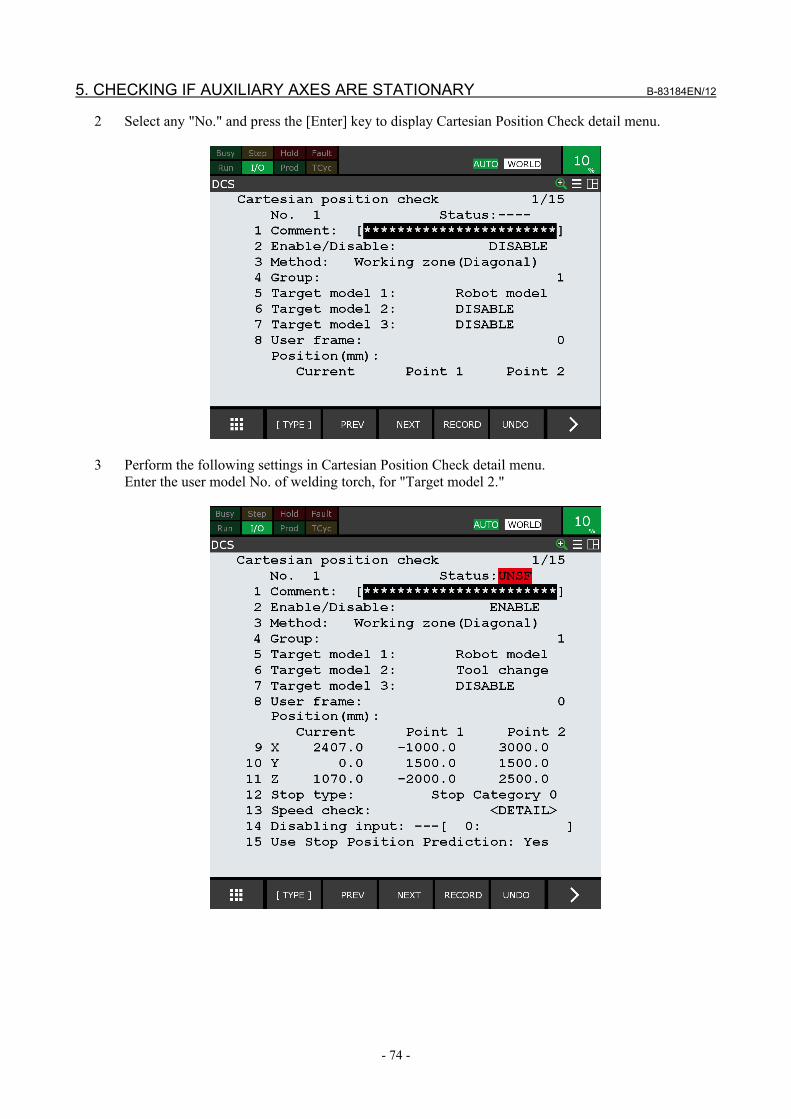
5. CHECKING IF AUXILIARY AXES ARE STATIONARY B-83184EN/12
- 74 -
2 Select any "No." and press the [Enter] key to display Cartesian Position Check detail menu.
3 Perform the following settings in Cartesian Position Check detail menu.
Enter the user model No. of welding torch, for "Target model 2."

B-83184EN/12 5. CHECKING IF AUXILIARY AXES ARE STATIONARY
- 75 -
No. Item Setting Description 2 Enable/Disable "ENABLE" Enable the displayed No. 3 Method "Working
zone(Diagonal )" ("Diagonal (IN)" in R-30iB, R-30iB Mate)
Define the robot workspace to be the inside of a box using the Cartesian Position Check function. The setting "Working zone (Diagonal)" defines the coordinates of the two ends of the diagonal of a box.
9 X Point 1 Point 2 Values for the coordinates of the two ends of the diagonal of a box
Defines the coordinates of the two ends of the diagonal of the box for which "Working zone (Diagonal)" is the robot workspace.
10 Y Point 1 Point 2 11 Z Point 1 Point 2
12 Stop type "Stop Category 0" Configure so that if a robot goes beyond the workspace, robot motor power immediately shuts down and the robot stops.
Perform an applying operation once the settings up to here are complete. Please refer to "1.3 APPLY TO DCS PARAMETER".

6. SET A SLOWDOWN ZONE B-83184EN/12
- 76 -
6 SET A SLOWDOWN ZONE
6.1 OVERVIEW This chapter describes the method to set a slowdown zone. In a Handling robot system as shown below, the robot take a work of this side to a back stand. A danger area is increased by gripping works. For that reason, the robot must set user models in each the case of tool. And only if an operator is in collaborate zone, the robot slowdown to ensure safety of an operator. If the robot exits the working zone where a speed check function enable at a high speed, the robot stops, and work efficiency becomes worse. When Speed Check function becomes to enable, delay that turn enable at time before slowing down. See Subsection 7.4.4 for detailed information about “DCS Cartesian Position Speed Check Function”. This setting is not used in R-30iB, R-30iB Mate.
This chapter describes the setup procedure to change a robot workspace.
Type Item Description Settings Setup of tool model Set the user model in each the case of tool
Setup of Cartesian Position Check
Set the Cartesian Position Check zone
Setup of Cartesian Position Speed Check
Set the stop zone
Setup of Cartesian Position Speed Check
Set the slowdown zone
Setup of CPSC → 6.3.3
Setup of tool model → 6.2
Setup of CPC → 6.3.1
Setup of CPC → 6.3.2

B-83184EN/12 6. SET A SLOWDOWN ZONE
- 77 -
6.2 SETUP OF TOOL MODEL This section describes method that set the user models in each tool states. There are two states that work exists or not. The user model of the tool is set using "box" shape elements.
WARNING If a robot workspace is set up incorrectly, the safety function will not work, and
serious personal injury could result. When a robot workspace is changed, the values must be verified and the function must be tested again.
1 Press the [MENU] key on Teach Pendant to display MENU pop up screen. 2 Select "0 -- NEXT --" → "6 SYSTEM" → "DCS", and press the [Enter] key to display DCS top menu.
3 Select "User model" and press the [Enter] key to display User Model List Menu.

6. SET A SLOWDOWN ZONE B-83184EN/12
- 78 -
4 Select any "No." and press the [Enter] key to display User Model Detail (Element List) Menu.
5 Select any "No." and press the [Enter] key to display User Model Element Detail Menu.

B-83184EN/12 6. SET A SLOWDOWN ZONE
- 79 -
6 Press the item of "5 Shape" and select "Box". Perform following settings in User Element Detail (Box) menu.
No. Item Setting Description 1 Enable/Disable "ENABLE" Enable the user model elements of the displayed No. 5 Shape "Box" Configure so that the shape of a user model element is line
segment. 6 Width (X) (mm) X: "450.0" Set the Width of the box element. 7 Height (Y) (mm) Y: "420.0" Set the Height of the box element. 8 Thick (Z) (mm) Z: "800.0" Set the Thick of the box element. 9 Offset X: “-100.0”
Y: “90.0” Z: “0.0”
Set the position at the center of Width(X) and Height(Y) on the plane of Thick(Z)=0.

6. SET A SLOWDOWN ZONE B-83184EN/12
- 80 -
7 Press the [Prev] key 2 times to display User model list. Select other item and perform following setting in User Element Detail (Box) menu.
No. Item Setting Description 1 Enable/Disable "ENABLE" Enable the user model elements of the displayed No. 5 Shape "Box" Configure so that the shape of a user model element is line
segment. 6 Width (X) (mm) X: "750.0" Set the Width of the box element. 7 Height (Y) (mm) Y: "600.0" Set the Height of the box element. 8 Thick (Z) (mm) Z: "1400.0" Set the Thick of the box element. 9 Offset X: “-50.0”
Y: “100.0” Z: “-200.0”
Set the position at the center of Width(X) and Height(Y) on the plane of Thick(Z)=0.
8 Press the [Prev] key 3 times to DCS top menu. Select Tool frame.

B-83184EN/12 6. SET A SLOWDOWN ZONE
- 81 -
9 Perform following settings in DCS Tool frame menu
Item Setting Description
Tool select 「-1」 Set to Tool Change. Please refer to "7.9.1 Tool Change Function" No. 「1」 Set "Tool frame" corresponding to the model. Model 「1」 Set "User model" corresponding to the tool. Verify I/O 「SPI[1]」 Set safety I / O to be used as switching tool model. No. 「3」 Set "Tool frame" corresponding to the model. Model 「2」 Set "User model" corresponding to the tool. Verify I/O 「SPI[2]」 Set safety I / O to be used as switching tool model.
DCS check can now be added to a tool and a work.
User model 1

6. SET A SLOWDOWN ZONE B-83184EN/12
- 82 -
6.3 SETUP OF CARTESIAN POSITION CHECK In Cartesian Position Check setup, set up 2 zones of No.1 - 3.
Type Setting No.1 A zone that surrounds the whole workspace of the robot. Always active. Disabling input is not set. No.2 A zone that is enabled when an operator is on the safe mat. In this zone is enabled, if the robot
entry in the zone, the robot immediately stops. No.3 A zone that is enabled when an operator is on the safe mat. In this zone is enabled, if the robot
goes out of the zone, Speed Check Function become to enable. SPI [3], which shows the status of the safe mat, is set to the disabling input.
No.2
No.1
No.3
User model 2

B-83184EN/12 6. SET A SLOWDOWN ZONE
- 83 -
6.3.1 Setup of No.1 Zone This section describes the setup method for No.1 zone. No.1 zone is always active, so disabling input is not set.
1 Select "Cart. position check" in DCS screen and press the [Enter] key to display Cartesian Position
Check menu.
P1
P2

6. SET A SLOWDOWN ZONE B-83184EN/12
- 84 -
2 Select any "No." and press the [Enter] key to display Cartesian Position Check detail menu.
3 Perform the following settings in Cartesian Position Check detail menu.
No. Item Setting Description 1 Enable/Disable "ENABLE" Enable Cartesian Position Check for the displayed No. 3 Method
"Working zone (Diagonal)" (In R-30iB, R-30iB Mate, Diagonal zone(Inside).)
The Working zone is defined as the upper and lower limits of X, Y and Z

B-83184EN/12 6. SET A SLOWDOWN ZONE
- 85 -
No. Item Setting Description 5 Target model 1 "Robot model" ("-1" In R-
30iB, R-30iB Mate) Specify the set tool model to be the target for Cartesian Position Check.
6 Target model 2 “Tool change” ("-2" In R-30iB, R-30iB Mate)
Specify the set tool model to be the target for Cartesian Position Check.
9 X Point1: "-2000.0" Point2: "3000.0"
Specify the X coordinates of vertex P1, P2.
10 Y Point1: "-3200.0" Point2: "6000.0"
Specify the Y coordinates of vertex P1, P2.
11 Z Point1: "-500.0" Point2: "2000.0"
Specify the upper and lower .
12 Stop type "Stop Category 0" Specify "Stop Category 0" to immediately shut down the motor power.
4 Press the [Prev] key 3 times to display DCS top menu. Setup of No.1 zone is now complete.
6.3.2 Setup of No.2 Zone This section describes the setup method for No.2 zone. This zone is defined to stop the robot for safe when there is an operator on the safe mat. SPI [3], which shows the status of the safe mat, is set to the disabling input. When there is no operator on the safe mat, SPI [3] is ON and this zone is disabled. When there is no operator on the safe mat, this zone is enabled. When the robot enters this zone, it stops.
When an operator is on the safe mat, The Area of No2 becomes enable.
P2
P1

6. SET A SLOWDOWN ZONE B-83184EN/12
- 86 -
1 Select "Cart. position check" in DCS screen and press the [Enter] key to display Cartesian Position Check menu.
2 Select any "No." and press the [Enter] key to display Cartesian Position Check detail menu.

B-83184EN/12 6. SET A SLOWDOWN ZONE
- 87 -
3 Perform the following settings in Cartesian Position Check detail menu.
No. Item Setting Description 1 Enable/Disable "ENABLE" Enable Cartesian Position Check for the displayed No. 3 Method
"Restricted zone (Diagonal)" (In R-30iB, R-30iB Mate, Diagonal zone(Inside).)
The Restricted zone is defined as the upper and lower limits of X, Y and Z
6 Target model 2 “Tool change” (In R-30iB, R-30iB Mate, "-2")
Specify the set tool model to be the target for Cartesian Position Check.
9 X Point1: "3000.0" Point2: "-2000.0"
Specify the X coordinates of vertex P1,P2.
10 Y Point1: "-3200.0" Point2: "-2000.0"
Specify the Y coordinates of vertex P1,P2.
11 Z Point1: "-500.0" Point2: "2000.0"
Specify the upper and lower .
12 Stop type "Stop Category 0" Specify "Stop Category 0" to immediately shut down the motor power.
14 Disabling input SPI[3] Set Safety I/O show the state of Safety mat. When the set Safety I/O is ON, This function becomes disable.

6. SET A SLOWDOWN ZONE B-83184EN/12
- 88 -
6.3.3 Setup of No.3 Zone This section describes the setup method for No.3 zone. SPI [3], which shows the status of the safe mat, is set to the disabling input. When there is no operator on the safe mat, SPI [3] is ON and this zone is disabled. When there is no operator on the safe mat, this zone is enabled. When the robot exits this zone, it becomes slow.
P2
P1
When an operator is on the safe mat, the area of No.3 becomes enable

B-83184EN/12 6. SET A SLOWDOWN ZONE
- 89 -
1 Select "Cart. position check" in DCS screen and press the [Enter] key to display Cartesian Position Check menu.
2 Select any "No." and press the [Enter] key to display Cartesian Position Check detail menu.

6. SET A SLOWDOWN ZONE B-83184EN/12
- 90 -
3 Perform the following settings in Cartesian Position Check detail menu.
No. Item Setting Description 1 Enable/Disable "ENABLE" Enable Cartesian Position Check for the displayed No. 3 Method
"Working zone (Diagonal)" (In R-30iB, R-30iB Mate, " Diagonal zone(Inside).")
The Working zone is defined as the upper and lower limits of X, Y and Z
6 Target model 2 “Tool change” (In R-30iB, R-30iB Mate, "-2")
Specify the set tool model to be the target for Cartesian Position Check.
9 X Point1: "3000.0" Point2: "-2000.0"
Specify the X coordinates of vertex P1,P2.
10 Y Point1: "1300.0" Point2: "6000.0"
Specify the Y coordinates of vertex P1,P2.
11 Z Point1: "-500.0" Point2: "2000.0"
Specify both ends of the Z coordinates
12 Stop type "Speed check (0)" Out of zone, If current speed exceeds the speed limit, robot motor power immediately shuts down and the robot stops.
14 Disabling input “SPI[3]” There is no operator on safe mat, this function disable.

B-83184EN/12 6. SET A SLOWDOWN ZONE
- 91 -
4 Select any "No." and press the [Enter] key to display Speed Check detail menu. Perform the following setting In Speed check detail menu
No. Item Setting Description 1 Speed control "OVERRIDE" When there is an operator is on the safe mat and when
the robot and models left the zone of No.2, the robot slowdown to ensure safety of an operator.
2 Limit 1 Limit (mm/s):"50 " DSBL:SPI[4] OVERRIDE:"5%"
When SPI[4] is OFF, OVERRIDE is lower than 5% and if current speed exceeds 50mm/s, robot motor power immediately shuts down and the robot stops.
3 Limit2 Limit (mm/s):"100 " DSBL:SPI[5] OVERRIDE:"10%"
When SPI[5] is OFF, OVERRIDE is lower than 10% and if current speed exceeds 100mm/s, robot motor power immediately shuts down and the robot stops.
4 Limit3 Limit (mm/s):"150 " DSBL:SPI[6] OVERRIDE:"15%"
When SPI[6] is OFF, OVERRIDE is lower than 15% and if current speed exceeds 150mm/s, robot motor power immediately shuts down and the robot stops.
5 Limit 4 Limit (mm/s):"250 " DSBL:---[0] OVERRIDE:"25%"
OVERRIDE is lower than 25% and if current speed exceeds 250mm/s, robot motor power immediately shuts down and the robot stops.
6 Delay time 1000msec The robot does not stop for 1000 msec after speed check become "ENABLE"
Setup of No.3 zone is now complete. Perform an apply operation after setup for zones No.1 to No.3 is complete. Please refer to "1.3 APPLY TO DCS PARAMETER".

7. POSITION / SPEED CHECK FUNCTION B-83184EN/12
- 92 -
7 POSITION / SPEED CHECK FUNCTION The Position / Speed Check option checks the position or speed of the robot and shuts down the motor power if these are out of the specified limit. - Joint position and speed can be checked. - It can be checked whether the shape models of robot arm and tool are in the specified zone or not. - Speed of tool center point can be checked. - The difference between current tool orientation and base orientation can be checked. - The checking is enabled / disabled by safe I/O signal.

B-83184EN/12 7. POSITION / SPEED CHECK FUNCTION
- 93 -
7.1 COMPONENTS OF POSITION / SPEED CHECK FUNCTION Position / Speed Check option consists of the following functions.
Components of Position / Speed Check function Function name Description
Joint Position Check function When Joint position is out of the specified safe zone, shut down the motor power.
Joint Speed Check function When Joint speed exceeds the specified limit, shut down the motor power. Cartesian Position Check function
- Zone Check function - Orientation check function - Target model collision check
function
This function includes a zone check function and an orientation check function. Zone check function:
When the shape model mounted on the tool or robot arm is out of the specified safe zone, shut down the motor power.
Orientation check function: When robot orientation (W,P,R) is out of the specified limit, shut down the motor power.
Target model collision When the shape models mounted on the tool or robot arm collision between each other, shut down the motor power.
Cartesian Speed Check function When the TCP speed exceeds the specified limit, shut down the motor power.
T1 Mode Speed Check function When the TCP or Face Plate speed exceeds the specified limit (Max. 250mm/sec), shut down the motor power.
Basic Position Check function This function is restricted function of Position/Speed Check function. Restriction is described in 7.6 Basic Position Check function.
7.2 JOINT POSITION CHECK FUNCTION Joint Position Check checks the Joint position of an axis and shuts down the motor power if the Joint position is outside of the safe zone. The safe zone is configured based on an upper and lower limit. The mode setting can select whether the safe area is INSIDE or OUTSIDE of the specified zone.
Safe zone (OK to move)
Outside of safe zone (Shut down motor power)
Lower limit
Upper limit Safe side : INSIDE
Safe side : OUTSIDE
Outside of safe zone (Shut down motor power)
Outside of safe zone (Shut down motor power)
Safe zone (OK to move)
Safe zone (OK to move)
- Maximum of 40 zones can be defined. - When one of the target axes of the Joint Position Check function is out of the safe zone, the alarm
"SRVO-404 DCS Joint pos. limit" occurs, and motor power is shut down. - When Safe I/O is set as a disabling I/O, it is possible to ENABLE / DISABLE Joint Position Check
by using the safe I/O for each Joint Position check. When the specified Safe I/O is ON, Joint Position Check is disabled. When it is OFF, it is enabled.

7. POSITION / SPEED CHECK FUNCTION B-83184EN/12
- 94 -
- It is possible to set 2 or more zones for one axis. In this case, the Safe zone is the area where all Safe zones are overlapped.
- The status of Joint Position check can be monitored by a DI when the DI is assigned to rack 36, slot 8, start point 1-40. The start point corresponds to the Joint Position check number. When the Joint Position check is enabled and robot is in the safe zone (Status: SAFE), the DI is ON. Otherwise, the DI is OFF.
CAUTION Since DI is not safe signal, it cannot be used for safety purpose.
In the case of rotary axis, positions that differ by 360 degrees such as 150 deg and -210 deg are processed as different positions. For example, when the area from 90 deg to 180 deg is defined as an OUTSIDE safe zone, an alarm occurs at 150 deg, but an alarm does not occur at -210 deg. When setting such the area, safe side is inside, please set safe side to inside and set the area fron -180 deg to 90 deg.
0
150
-90 90
0 90 180 270 -90 -180 -270
150 (Alarm occurs) -210 (Alarm does not occur) -210
Upper limit Lower limit
Safe side : OUTSIDE
180
Out of safe zone (Shut down motor power)
Safe zone (OK to move)
Safe zone (OK to move)
WARNING If Joint Position Check is set incorrectly, the safety function will not work, and
serious personal injury could result. When Joint Position Check is changed, the values must be verified and the function must be tested again.
Recovery from alarm
When the robot is outside of the safe zone, the alarm cannot be cleared. To move the robot to the safe zone, select T1 mode, and enable the Teach pendant and press and hold the [SHIFT] and the [RESET] keys, and jog the robot. If the [SHIFT] key is released while still outside of the safe zone, or the robot moves in a direction away from the safe zone, the alarm occurs again and motor power is shut down. When servo power is turned on, the robot moves slightly. To avoid DCS alarms by this motion, a very short motion is allowed even though the robot moves away from the safe zone. The robot can move slightly away from the safe zone, because the DCS alarm occurs when the moved distance of the robot exceeds the allowed short motion. If the payload setting of the robot is not correct, the motion at the servo power on becomes big, and the DCS alarm may occur. In this case, please check the payload setting or change the setting of the position check to disable temporarily.

B-83184EN/12 7. POSITION / SPEED CHECK FUNCTION
- 95 -
7.2.1 Stop Position Prediction When the motor power is shut down while the robot is moving, the robot’s momentum causes it to move some distance before it completely stops. Stop Position Prediction is a function to predict the stop position according to the current moving direction and speed, and predicts that the axis will exit the safe zone when the predicted stop position is out of the safe zone. In this case, the robot will shut down motor power earlier to minimize the stopping distance beyond the defined safe zone. The stop position prediction is disabled by default. In this case, the alarm occurs when the shape model exits the safe zone, and the stop position of robot is out of the safe zone for the stopping distance. Please refer to "1.7 STOPPING DISTANCE" about stopping distance. To enable the stop position prediction, select "DEFAULT" or "USER" for mode of the target axis in DCS stop position prediction menu.
CAUTION The stop position prediction of Joint Position Check is disabled by default. To
enable the stop position prediction, select "DEFAULT" or "USER" for mode of the target axis in DCS stop position prediction menu.
This distance depends on the type of robot, payload, and speed, but mostly it is proportional to the speed. Stop Position Prediction predicts the stop position so that the stopping distance is 0 mm at 0 mm/sec and is increased proportionally with increased speed. The proportion factor is setup in the DCS Stop Position Prediction menu. The default of the proportion factor is set as 1.5 times the value of the stopping distance at the maximum speed and maximum payload for each robot. When Stop Position Prediction is used with the default setting, motor power is shut off farther away from the border of the zone when speed is increased. The proportion factor is different between Stop Category 0 and Stop Category 1, and set up individually. When the stop type of Joint Position Check is Stop Category 0, the proportion factor of Stop Category 0 is used. When the stop type of Joint Position Check is Stop Category 1, both the proportion factor of Stop Category 0 and Stop Category 1 are used. When the predicted stop position calculated by the proportion factor of Stop Category 1 is out of the safe zone, a Stop Category 1 is performed. When the predicted stop position calculated by the proportion factor of Stop Category 0 is out of the safe zone, a Stop Category 0 is performed. This means that Stop Category 0 is always done if the stopping distance of a Stop Category 0 is greater than a Stop Category 1. When the stop type is set to "Not stop", Stop Position Prediction is not used. Please refer to Section 7.11 SETUP STOP POSITION PREDICTION for details of the Stop Position Prediction menu.

7. POSITION / SPEED CHECK FUNCTION B-83184EN/12
- 96 -
Safe zone
Current position
Lower limit Upper limit
Speed
Predicted stop position
Speed
Stopping distance
WARNING 1 If Stop Position Prediction is set incorrectly, the robot will exit the safety zone,
and serious personal injury could result. When Stop Position Prediction is changed, the values must be verified and the function must be tested again.
2 When an axis does not have mechanical brake, the axis can move freely when motor power is shutdown, and the stop position prediction does not work correctly for the axis. In this case, a risk assessment for the whole robot system is necessary, including the free movement of the axis that does not have mechanical brake.
7.2.2 DCS Joint Position Check List Menu DCS Joint Position Check list menu will be displayed by pressing the [ENTER] key or the [F3 (DETAIL)] key while on the "Joint Position Check" item in DCS Top menu.
DCS Joint Position check 1/40 No. G A Status Comment 1 DISABLE 1 1 ---- [ ] 2 DISABLE 1 1 ---- [ ] 3 DISABLE 1 1 ---- [ ] 4 DISABLE 1 1 ---- [ ] 5 DISABLE 1 1 ---- [ ] 6 DISABLE 1 1 ---- [ ] 7 DISABLE 1 1 ---- [ ] 8 DISABLE 1 1 ---- [ ] 9 DISABLE 1 1 ---- [ ] 10 DISABLE 1 1 ---- [ ] [ TYPE ] DETAIL
Items in DCS Joint Position Check list menu Item Description
No. The Joint Position Check number is displayed. ENABLE/DISABLE The Enable/Disable status of each Joint Position Check is displayed. G The target motion group number is displayed.
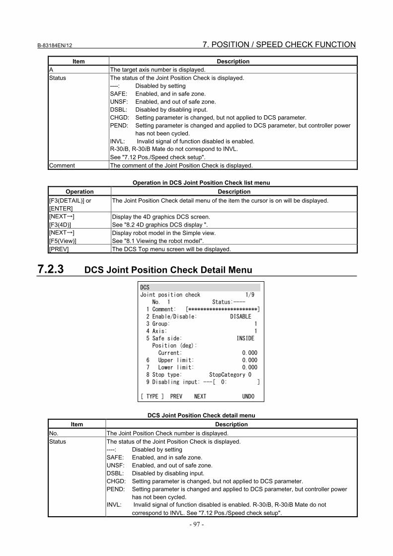
B-83184EN/12 7. POSITION / SPEED CHECK FUNCTION
- 97 -
Item Description A The target axis number is displayed. Status The status of the Joint Position Check is displayed.
----: Disabled by setting SAFE: Enabled, and in safe zone. UNSF: Enabled, and out of safe zone. DSBL: Disabled by disabling input. CHGD: Setting parameter is changed, but not applied to DCS parameter. PEND: Setting parameter is changed and applied to DCS parameter, but controller power
has not been cycled. INVL: Invalid signal of function disabled is enabled. R-30iB, R-30iB Mate do not correspond to INVL. See "7.12 Pos./Speed check setup".
Comment The comment of the Joint Position Check is displayed.
Operation in DCS Joint Position Check list menu Operation Description
[F3(DETAIL)] or [ENTER]
The Joint Position Check detail menu of the item the cursor is on will be displayed.
[NEXT→] [F3(4D)]
Display the 4D graphics DCS screen. See "8.2 4D graphics DCS display ".
[NEXT→] [F5(View)]
Display robot model in the Simple view. See "8.1 Viewing the robot model".
[PREV] The DCS Top menu screen will be displayed.
7.2.3 DCS Joint Position Check Detail Menu
DCS Joint position check 1/9 No. 1 Status:---- 1 Comment: [***********************] 2 Enable/Disable: DISABLE 3 Group: 1 4 Axis: 1 5 Safe side: INSIDE Position (deg): Current: 0.000 6 Upper limit: 0.000 7 Lower limit: 0.000 8 Stop type: StopCategory 0 9 Disabling input: ---[ 0: ] [ TYPE ] PREV NEXT UNDO
DCS Joint Position Check detail menu
Item Description No. The Joint Position Check number is displayed. Status The status of the Joint Position Check is displayed.
----: Disabled by setting SAFE: Enabled, and in safe zone. UNSF: Enabled, and out of safe zone. DSBL: Disabled by disabling input. CHGD: Setting parameter is changed, but not applied to DCS parameter. PEND: Setting parameter is changed and applied to DCS parameter, but controller power
has not been cycled. INVL: Invalid signal of function disabled is enabled. R-30iB, R-30iB Mate do not
correspond to INVL. See "7.12 Pos./Speed check setup".

7. POSITION / SPEED CHECK FUNCTION B-83184EN/12
- 98 -
Item Description Comment Used to set the comment of the Joint Position Check.
The comment set in this menu is also used as the comment of the Safe I/O JPC [ ]. Enable/Disable Used to set the Enable / Disable of the Joint Position Check.
When this is disabled, other settings in this menu are ignored. Group Used to set the target motion group number. Axis Used to set the target axis number.
NOTE – J3 axis limit values are relative to the robot world X-Y plane (similar to the normal axis limits function).
Safe side Used to set the safe side, INSIDE or OUTSIDE Current Current position of the target axis is displayed. Upper limit Lower limit
Used to set the upper and lower limit of the range.
Stop type Used to select the action to be performed when the target axis is out of the safe zone. Stop Category 0: Motor power is shut down immediately. Stop Category 1: Deceleration stop, then motor power is shut down. (Motor power shutdown is delayed for a maximum of 2 seconds.) Not stop: Robot does not stop. The status is set in Safe I/O JPC.
Disabling input To enable / disable the Joint Position Check dynamically, a Safe I/O can be set as a disabling input. When the specified Safe I/O is ON, this function disabled. When the specified Safe I/O is OFF, this function is enabled. When the specified Safe I/O is undefined (--), this function is enabled. NOTE - Safety input (SPI) is hardware option. However, SPI [1-2] are available as standard in A-cabinet controller of R-30iB, R-30iB Plus. NOTE - Zone Status can be used as disabling input; refer to Section 9.1 for zone status (CPC, CSC, JPC, & JSC) definitions
Operation in DCS Joint Position Check detail menu
Operation Description [F2(PREV)] The previous Joint Position Check detail menu screen will be displayed. [F3(NEXT)] The next Joint Position Check detail menu screen will be displayed. [F5(UNDO)] UNDO the items in this menu. The setting parameters become the same as the current DCS
parameters. [NEXT→] [F3(4D)]
Display the 4D graphics DCS screen. See "8.2 4D graphics DCS display ".
[NEXT→] [F5(View)]
Display robot model in the Simple view. See "8.1. Viewing the robot model".
[PREV] The Joint Position Check list menu screen will be displayed.
7.3 JOINT SPEED CHECK FUNCTION The Joint Speed Check function checks the Joint speed of the robot, and shuts down motor power if the Joint speed exceeds the specified limit. - Maximum 40 speed limits can be defined. - When one of the axes exceeds the speed limit, the "SRVO-405 DCS Joint speed limit" alarm occurs,
and motor power is shut down. - This function can be used to check if the axis is stationary by setting the speed limit to 0. False alarms
caused by vibration during servo ON can be avoided by tuning of the Permissible Distance. - When Safe I/O is set as a disabling I/O, it is possible to ENABLE / DISABLE Joint Speed Check by
using safe I/O. It is possible to specify the Safe I/O for each Joint Speed check. When the specified Safe I/O is ON, Joint Speed Check is disabled. When it is OFF, it is enabled.
- The status of Joint Speed check can be monitored by a DI when the DI is assigned to rack 36, slot 9, start point 1-40. The start point corresponds to the Joint Speed check number. When the Joint Speed

B-83184EN/12 7. POSITION / SPEED CHECK FUNCTION
- 99 -
check is enabled and speed does not exceeds the limit (Status: SAFE), the DI is ON. Otherwise, the DI is OFF.
CAUTION : Since DI is not safe signal, it cannot be used for safety purpose. - Speed control function can slow down the robot speed by lowering the override. - When Zero % Override function is enable, If set to 0, Robot stops movement without stopping program. - Joint speed check function can be switched Enable after wait for the Delay time when Joint speed
check function switch Disable to Enable. - Even in the absence of the axis motion command, due to the vibration during servo-on. If set small
value to limit speed, Speed check alarm can occur during servo-on.
WARNING 1 If Joint Speed Check is set incorrectly, the safety function will not work, and
serious personal injury could result. When Joint Speed Check is changed, the values must be verified and the function must be tested again.
2 When the Limit is set to 0 and the Permissible Distance is not set to 0, motor power does not shut down immediately when the axis moves. The stopping distance can be increased by acceleration in the Permissible Distance. Adequate risk assessment for whole robot system is necessary to determine Permissible Distance.
3 Speed control is unsafe function. A risk assessment for the whole robot system is necessary.
4 Even if it moves faster than the speed limit for the set delay time it will not stop.
7.3.1 DCS Joint Speed Check List Menu DCS Joint Speed Check list menu screen will be displayed by pressing the [ENTER] key or the [F3 (DETAIL)] key while on the "Joint Speed Check" item in the DCS Top menu.
DCS Joint speed check 1/40 No. G A Status Comment 1 DISABLE 1 1 ---- [ ] 2 DISABLE 1 1 ---- [ ] 3 DISABLE 1 1 ---- [ ] 4 DISABLE 1 1 ---- [ ] 5 DISABLE 1 1 ---- [ ] 6 DISABLE 1 1 ---- [ ] 7 DISABLE 1 1 ---- [ ] 8 DISABLE 1 1 ---- [ ] 9 DISABLE 1 1 ---- [ ] 10 DISABLE 1 1 ---- [ ] [ TYPE ] DETAIL
DCS Joint Speed Check list menu Item Description
No. The Joint Speed Check number is displayed. ENABLE/DISABLE The Enable/Disable status of each Joint Speed Check is displayed. G The target motion group number is displayed. A The target axis number is displayed.

7. POSITION / SPEED CHECK FUNCTION B-83184EN/12
- 100 -
Item Description Status The status of Joint Speed Check is displayed.
----: Disabled by setting SAFE: Enabled, and less than the limit. OVER: Enabled, and over the limit. DSBL: Disabled by disabling input. CHGD: Setting parameter is changed, but not applied to DCS parameter. PEND: Setting parameter is changed and applied to DCS parameter, but controller power
has not been cycled. INVL: Invalid signal of function disabled is enabled. R-30iB, R-30iB Mate do not
correspond to INVL. See "7.12 Pos./Speed check setup". Comment The comment of the Joint Speed Check is displayed.
Operation of DCS Joint Speed Check list menu
Operation Description [F3(DETAIL)] or [ENTER]
The Joint Speed Check detail menu screen of the item the cursor is on will be displayed.
[PREV] The DCS Top menu will be displayed.
7.3.2 DCS Joint Speed Check Detail Menu
DCS Joint speed check 1/9 No. 1 Status:---- 1 Comment: [***********************] 2 Enable/Disable: DISABLE 3 Direction: ALL 4 Group: 1 5 Axis: 1 Speed(deg/sec): Current: 0.000 6 Limit: 0.000 7 Stop type: Stop Category 0 8 disabling input: ---[ 0: ] 9 Permissible distance (deg): 0.0 [ TYPE ] PREV NEXT UNDO
DCS Joint Speed Check detail menu Item Description
No. The Joint Speed Check number is displayed. Status The status of the Joint Speed Check is displayed.
----: Disabled by setting SAFE: Enabled, and less than the limit. OVER: Enabled, and over the limit. DSBL: Disabled by disabling input. CHGD: Setting parameter is changed, but not applied to DCS parameter. PEND: Setting parameter is changed and applied to DCS parameter, but controller power
has not been cycled. INVL: Invalid signal of function disabled is enabled. R-30iB, R-30iB Mate do not
correspond to INVL. See "7.12 Pos./Speed check setup". Comment Used to set the comment of the Joint Speed Check.
The comment set in this menu is also used as comment of the Safe I/O JSC [ ]. Enable/Disable Used to set the Enable / Disable of the Joint Speed Check.
When this is disable, all other settings in this menu are ignored.

B-83184EN/12 7. POSITION / SPEED CHECK FUNCTION
- 101 -
Item Description Direction Used to set the direction of the speed check.
ALL: Direction is not considered. -: Only - direction speed is checked +: Only + direction speed is checked
Group Used to set the target motion group number. Axis Used to set the target axis number. Current Current speed of the target axis is displayed. Limit Used to set the speed limit.
When it is set to 0, this function checks if the axis is stationary. In this case, the axis movement is detected when the axis moves more than the "Permissible distance".
Stop type Used to select the action to be performed when the target axis speed exceeds the limit Stop Category 0: Motor power is shut down immediately. Stop Category 1: Deceleration stop, then motor power is shut down.
(Motor power shutdown is delayed for a maximum of 2 seconds.) Not stop: Robot does not stop. The status is set in Safe I/O JSC. NOTE - When the robot starts motion from a stopped position with the limit set to 0 and the
stop type set to “Stop Category 1”, motor power is shut down immediately to minimize the robot stopping distance. When the Joint Speed Check is changed from disable to enable by disabling I/O during robot motion, a Stop Category 1 is performed.
NOTE - When the robot starts motion from a stopped position with the limit set to 0 and the stop type set to "Not stop", the state changes to “OVER” when the robot begins motion, but does not change back to "SAFE" if the robot stops later. To return to the "SAFE" status, please turn off motor power, or disable the Joint Speed Check by disabling I/O. To use a “Not Stop” zone to dynamically indicate robot motion in the Safe I/O Connect function without shutting down motor power, set the stop type to “Not Stop” and the speed limit to a small value greater than zero.
Speed control Set upper limit of override and slow down the robot. DISABLE: The robots speed does not decrease. OVERRIDE: The value set OVERRIDE limit will be the upper limit
OVERRIDE limit When Speed control setting is OVERRIDE, set upper limit of OVERRIDE. When Zero % Override function is enable, If set to 0, Robot stops movement without stopping program. It is not supported in R-30iB, R-30iB Mate.
Delay time Joint speed check function can be switched Enable after wait for the Delay time when Joint speed check function switch Disable to Enable.
Disabling input To enable / disable the Joint Speed Check dynamically, a Safe I/O can be set as a disabling input. When the specified Safe I/O is ON, this function disabled. When the specified Safe I/O is OFF, this function is enabled. When the specified Safe I/O is undefined (--), this function is enabled. NOTE - Safety input (SPI) is hardware option. However, SPI [1-2] are available as standard in
A-cabinet controller of R-30iB, R-30iB Plus. NOTE - Zone Status (CPC, CSC, JPC, & JSC) and so on, all safety I/O except for ON, OFF
and NSI can be used as disabling input. Refer to Section 9.1 SAFE I/O. Permissible distance In case of stop check (set the limit speed to 0), set the distance judged to be stopped.
Even in the absence of the axis motion command, due to the vibration during servo-on This item is used to avoid false alarms caused by vibration during servo ON. If the movement is less than the distance set in this item, it is judged to be stopped, so false detection such as servo on can be prevented. Unit: mm for linear axis, deg for rotary axis.

7. POSITION / SPEED CHECK FUNCTION B-83184EN/12
- 102 -
Operation in DCS Joint Position Check menu Operation Description
[F2(PREV)] The previous Joint Speed Check will be displayed. [F3(NEXT)] The next Joint Speed Check will be displayed. [F5(UNDO)] UNDO the items in this menu. The setting parameters become the same as the current DCS
parameters. [PREV] The Joint Speed Check list menu will be displayed.
7.4 ZONE CHECK FUNCTION (CARTESIAN POSITION CHECK FUNCTION)
The Zone Check portion of the Cartesian Position Check function checks the shape models that are mounted on the robot tool or arm and shuts down motor power if the shape model is not in the defined safe zone. - A maximum of 32 zones can be defined. - When one of the target shape models is out of the safe zone, the alarm "SRVO-402 DCS Cart. pos.
limit" occurs, and motor power is shut down. - It is possible to ENABLE / DISABLE Cartesian Position Check by using safe I/O for each safe zone.
When the specified Safe I/O is ON, Cartesian Position Check is disabled. When it is OFF, it is enabled. - The status of Cartesian Position check can be monitored by a DI when the DI is assigned to rack 36,
slot 6, start point 1-32. The start point corresponds to the Cartesian Position check number. When the Cartesian Position check is enabled and robot is in the safe zone (Status: SAFE), the DI is ON. Otherwise, the DI is OFF.
CAUTION : Since DI is not safe signal, it cannot be used for safety purpose. - The model collision check function is check the shape models mounted on the tool or robot arm that
are collision between each other. R-30iB, R-30iB Mate do not correspond.
7.4.1 Shape Model
A shape model is a geometric shape, like a sphere, that is mounted on the robot flange or arm. The Zone Check function checks if the shape model is in the defined safe zone. There are 2 types of shape models, User model and Robot model.
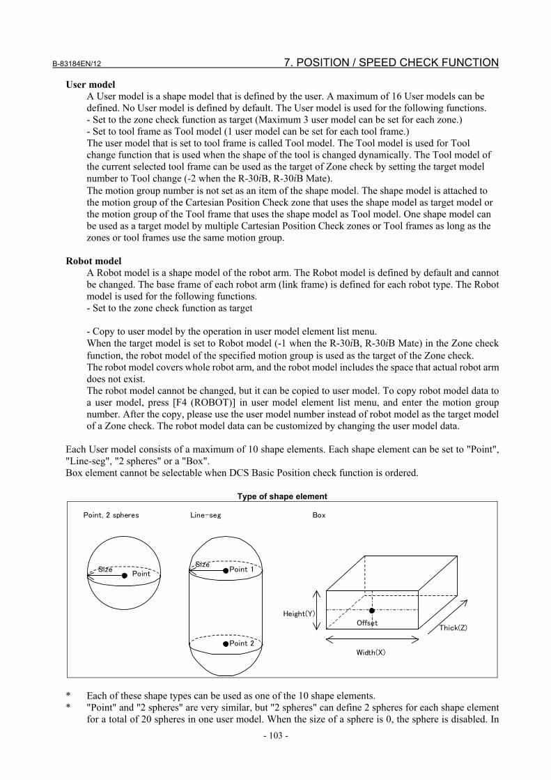
B-83184EN/12 7. POSITION / SPEED CHECK FUNCTION
- 103 -
User model A User model is a shape model that is defined by the user. A maximum of 16 User models can be defined. No User model is defined by default. The User model is used for the following functions. - Set to the zone check function as target (Maximum 3 user model can be set for each zone.) - Set to tool frame as Tool model (1 user model can be set for each tool frame.) The user model that is set to tool frame is called Tool model. The Tool model is used for Tool change function that is used when the shape of the tool is changed dynamically. The Tool model of the current selected tool frame can be used as the target of Zone check by setting the target model number to Tool change (-2 when the R-30iB, R-30iB Mate). The motion group number is not set as an item of the shape model. The shape model is attached to the motion group of the Cartesian Position Check zone that uses the shape model as target model or the motion group of the Tool frame that uses the shape model as Tool model. One shape model can be used as a target model by multiple Cartesian Position Check zones or Tool frames as long as the zones or tool frames use the same motion group.
Robot model A Robot model is a shape model of the robot arm. The Robot model is defined by default and cannot be changed. The base frame of each robot arm (link frame) is defined for each robot type. The Robot model is used for the following functions. - Set to the zone check function as target - Copy to user model by the operation in user model element list menu. When the target model is set to Robot model (-1 when the R-30iB, R-30iB Mate) in the Zone check function, the robot model of the specified motion group is used as the target of the Zone check. The robot model covers whole robot arm, and the robot model includes the space that actual robot arm does not exist. The robot model cannot be changed, but it can be copied to user model. To copy robot model data to a user model, press [F4 (ROBOT)] in user model element list menu, and enter the motion group number. After the copy, please use the user model number instead of robot model as the target model of a Zone check. The robot model data can be customized by changing the user model data.
Each User model consists of a maximum of 10 shape elements. Each shape element can be set to "Point", "Line-seg", "2 spheres" or a "Box". Box element cannot be selectable when DCS Basic Position check function is ordered.
Type of shape element
Point, 2 spheres Line-seg Box
Size Point
Point 1
Point 2
Offset
Size
Height(Y)
Width(X)
Thick(Z)
* Each of these shape types can be used as one of the 10 shape elements. * "Point" and "2 spheres" are very similar, but "2 spheres" can define 2 spheres for each shape element
for a total of 20 spheres in one user model. When the size of a sphere is 0, the sphere is disabled. In

7. POSITION / SPEED CHECK FUNCTION B-83184EN/12
- 104 -
the "Point" case, a total of 10 spheres can be defined in one user model, and the center point is checked when the size is 0.
* Only one box can be used in one User model. * The position of a box is defined as an offset of the position at the center of Width(X) and Height(Y)
on the plane of Thick (Z) =0. Each shape element can be mounted on the robot flange or each individual robot arm (link frame). The mounting point can be specified individually for each shape element. The mounting point is set by link number and link type. When link number is set to 99, the robot flange frame is used as the base frame of the shape element. In this case, link type is not used. When link number is the axis number of the robot, the link frame fixed on the specified robot axis is used as the base frame of the shape element. Some robot types have axes that have two or more link frames. In this case, the link frame is selected by link type. Normally, please set "NORMAL" for link type. The corresponded link frame will be displayed graphically in 4D Graphics DCS display menu when the cursor is on link number or link type item in DCS User Model Element Detail menu. The following system variables show the current position of each link frame. $DCSS_GSTAT[Group No.].$LINK_BASE[Link No.] : Link frame for link type "NORMAL" $DCSS_GSTAT[Group No.].$LINK_BASE_V[Link No.] : Link frame for link type "VERTICAL" $DCSS_GSTAT[Group No.].$LINK_BASE_H[Link No.] : Link frame for link type "HORIZON" To set a shape model on the robot arm, the robot data may be helpful for reference. The robot model data can be read by the copying it to a user model in user model detail menu. When tool frame number is set in shape element setting, the tool frame is used as the base frame of the shape element when link number is set to 99. When link number is not 99 and tool number is set, the base frame of the shape element is the frame that is calculated by applying the matrix of the specified tool frame to the link frame of the specified link number. Please use tool frame when the orientation of a box should be defined. When a tool frame is used, the tool frame must be defined in DCS tool frame menu.
WARNING If a Shape model is set incorrectly, the safety function will not work, and serious
personal injury could result. When a Shape model is changed, the values must be verified and the function must be tested again.
7.4.2 Safe Zone A Safe zone is the fixed zone relative to a user frame. Zone check functions check to see if the shape model is in the defined Safe zone.
CAUTION When the robot is mounted on rail axis, the safe zone is moved if the world
frame of the robot is moved according to the move of the rail axis. To fix the safe zone, the rail axis should be defined as Integrated Rail axis of the same motion group with the robot.

B-83184EN/12 7. POSITION / SPEED CHECK FUNCTION
- 105 -
7.4.2.1 Define the safe zone There are 2 methods to define a safe zone,”Diagonal” and “Lines”. The safe side can be defined as Inside or Outside for each zone individually. A maximum 32 zones can be defined.
Methods to define a Safe zone
X
Y
Z
X
Y
Z
Diagonal Lines
Point 1
Point 2
P1 Z1
Z2
P2
P3 P4
P5
P6
P7
P8
Diagonal The Safe zone is defined as the upper and lower limits of X, Y and Z in the DCS User Frame. This defines the two end points of the diagonal of a box.
Lines The Safe zone is defined as the vertexes of a polygon on the X-Y plane in the DCS User Frame. The maximum number of vertexes is 8. The angle of each corner in the polygon must be less than 180 deg. The upper and lower limits are defined along the Z axis on the DCS User Frame. The following zone cannot be set because the angle of corner A is more than 180 deg. In this case, The message " It is not convex polygon." will be displayed.
A
When two or more zones are combined, the only safe area (allow to move) is the overlapping area of all zones. In the following figure, zone A and zone B are combined. C is the actual safe zone.
A
B C
+

7. POSITION / SPEED CHECK FUNCTION B-83184EN/12
- 106 -
To create the following zone C that has a dent, combine Inside zone A as the surrounding area and Outside zone B as the dent.
A Safe side: Inside
B Safe side:
Outside +
C
WARNING If a Safe zone is set incorrectly, the safety function will not work, and serious
personal injury could result. When a Safe zone is changed, the values must be verified and the function must be tested again.
7.4.2.2 Enable and disable zones by disabling input
Safe zones can be enabled and disabled by using the disabling input. The following figure shows an example of enabling and disabling zones by using Safe I/O (SPI [1]). The two zones A and B are defined, and the disabling input of zone B is set to SPI [1]. When SPI [1] is ON, the Cartesian Position check of zone B is disabled, and only the zone A is used. When SPI [1] is OFF, the Cartesian Position check of zone B is enabled, and the zone C is the safe zone.
A Safe side: Inside
B
+ C
When SPI[1]=OFF
A When SPI[1]=ON
Safe side: Outside
Disabling input: SPI[1]
It is possible to output to the CPC signal whether there is a robot in the area disabled by the invalid signal. Refer to "7.12 Pos./Speed check setup" for setting method. The figure below shows the response of the CPC signals when the area is invalidated by safety I/O. By default, the CPC signal turns OFF regardless of the position of the model as shown on the left. However, if Disabled Cartesian position check is enabled, the same reaction as when Cartesian position check is ENABLE will be taken with no alarm occurred.

B-83184EN/12 7. POSITION / SPEED CHECK FUNCTION
- 107 -
When output the state of safe zone that combined two or more zones to the safe signal, setting the Safe I/O Connect function. For example, output state to SPO[1] that Both CPC[1] and CPC[2] are safe by the following Safe I/O Connect function setting.
Output Input1 Input2
SPO[1] = CPC[1] AND CPC[2]
7.4.2.3 Define the target shape model Each Safe zone can check a maximum of 3 shape models. These target shape models are defined by the target model number as follows. User model
When the target model is User model 1-16 (In R-30iB and R-30iB Mate, Number of 1-16), the user model is checked in the zone check.
Robot model When the target model is Robot model (In R-30iB and R-30iB Mate, Number of -1), the robot model of the target motion group is checked in the zone check.
Tool model Tool model is used when the Tool Change Function is used (refer to 7.9.1 Tool Change Function). When the target model is Tool change (In R-30iB and R-30iB Mate, Number of -2), the tool model of the target motion group is checked in the zone check. In this case, the tool model is the user model that is assigned to the DCS Tool Frame that is currently selected (refer to 7.9 DCS TOOL FRAME). When the Tool Change Function is not used, the target model should not be Tool change, the user model number of the tool shape should be set to the target model directly.
Tool model cannot be selectable when DCS Basic Position check function is ordered.
WARNING If the target model number is set incorrectly, the safety function will not work,
and serious personal injury could result. When the target model number is changed, the values must be verified and the function must be tested again.

7. POSITION / SPEED CHECK FUNCTION B-83184EN/12
- 108 -
7.4.2.4 Process time factor The number of zones and models are limited to prevent processing time from becoming too long when too many zones and models are checked. The following table shows the process time factor of each shape element. The process time factor is different for each method of safe zone to be checked.
Process time factor of Area check target shape elements
Method of safe zone Shape of element Point * Line-seg Box
Working zone(Diagonal) 2 3 20 Restricted zone (Diagonal) 4 7 130 Working zone (Lines) 3 5 30
Restricted zone (Lines) 5 12 220 The table below is the processing time coefficient for each combination of B specified as Target model collision.
Process time factor of Target model collision check target shape elements
Shape of element Shape of element Point * Line-seg Box
Point * 5 8 24 Line-seg 8 24 35
Box 24 35 * In "2 spheres" case, each sphere is regarded as one Point if the size is not 0. * When DeviceNet Safety, EtherNet/IP Safety or PROFINET Safety is used, 400 is added to the process
time factor. * When Safety function by FL-net is used ("Enable/Disable" in DCS Safety function by FL-net menu is
"ENABLE"), 200 is added to the process time factor. * When Safety PMC is used ("Safe I/O process" in DCS Safe I/O device menu is "Safety PMC"), 100
is added to the process time factor. * The process time factor of “Point” type and “2 spheres” type shape elements are calculated as “Line-
seg” type when the “Expand point as line” is set “ENABLE” in stop position prediction menu. * The process time factor of tool change is the maximum process time factor of all selectable tools. * Target model collision check function can not check models including rectangular * User must consider process time factor of robot ‘elements’ as well as tooling. The process time factor of one safe zone is calculated as the total of all the elements in the target model. If the robot model is selected in target model, each element of robot model also consumes process time factor. If you need to know each shape model of the robot arm, you can see each shape model of the robot arm by coping it to user model. For more details how to copy it to user model, please refer to the Subsection 7.4.1, Shape model and refer to the description of Robot model in the subsection. The system total process time factor is the total of the process time factors of all enabled safe zones, including robot model selected in target model. If the system total process time factor is greater than 1000 and you apply DCS parameters, the message "Too many zone or models!" will be displayed. The number displayed with this message is the system total process time factor of the current setting parameters. The system total process time factor is also displayed in the DCS Cartesian Position Check list menu. The process time factor of Box is much greater than Point and Line-seg. To make the process time factor small, it is effective to replace the Box by combination of Point or Line-seg. In Target model collision check function, check each of shape elements of target model 1 and target model 2 by a round robin.

B-83184EN/12 7. POSITION / SPEED CHECK FUNCTION
- 109 -
For example, The shape elements of model 1 are points A and B, and the shape elements of model 2 are line segment A and B. Because collision is checked by a round robin, the processing time of point A: line segment A, point A: line segment B, point B: line segment A, point B: line segment B is required. Point: Line segment (8) x 4 = 32. Please note that a long processing time is required, even if one shape element.
7.4.2.5 Recovery from alarm When any shape model is outside of the defined safe zone, a DCS Cartesian Position Check alarm occurs and cannot be cleared. To move the robot to the safe zone, select T1 mode, and enable the Teach Pendant and press and hold the [SHIFT] and the [RESET] keys, and jog the robot. If the [SHIFT] key is released while the shape model is still outside of the defined safe zone, the alarm occurs again and motor power is shut down. The frame position and orientation just before the DCS Cartesian Position Check alarm occurs is recorded. The robot can be jogged toward the recorded position and orientation, but if the robot moves away from the recorded position, the alarm occurs again and motor power is shut down. But, in R-30iB Plus, the limit to the direction can be canceled, by disabling the direction check. Refer to "7.12 Pos./Speed check setup" for setting method. When a DCS Cartesian Position Check alarm occurs because the DCS Cartesian Position Check is changed from disable to enable by a disabling input, the robot can only return to the position just before the alarm occurred by this operation. If this position is not in the safe zone, the alarm occurs again. To recover from the alarm, DCS Cartesian Position Check should be disabled by the disabling input. In this case, the robot can move as far as the stopping distance when the alarm occurred even out of the safe zone. Please take care especially in the case where the stopping distance is large, for example when stop type is set to Stop Category 1. When servo power is turned on, the robot moves slightly. To avoid DCS alarms by this motion, a very short motion is allowed even though the robot moves away from the recorded position. The robot can move slightly away from the recorded position, because the DCS alarm occurs when the moved distance of the robot exceeds the allowed short motion. If the payload setting of the robot is not correct, the motion at the servo power on becomes big, and the DCS alarm may occur. In this case, please check the payload setting or change the setting of the position check to disable temporarily. The following describe the cases where the recorded position and orientation data are lost and cannot be recovered. To recover from the alarm in these cases, please temporarily disable the Cartesian Position Check. - The motor or Pulsecoder is replaced, and the robot position becomes out of the safe zone.
(In this case, the position check temporary disable function that is explained later can be used.) - The Zone or shape model is changed and applied to DCS parameters, power to the controller is cycled,
and the current position becomes out of the safe zone. - The controller power is turned off while the robot is moving, and the robot exits the safe area by
momentum movement. - The mastering parameters or robot setup data is changed and applied to DCS parameters, power to the
controller is cycled, and the robot becomes out of the safe zone.
7.4.2.6 Position check temporary disable function When the motor or Pulsecoder is replaced and the robot position becomes out of the safe zone, the robot sometimes cannot move far enough to recover from the situation by the above [SHIFT] and [RESET] operation. In this case, the operator needs to disable position check temporarily, then do some operation to recover from the situation such as mastering, then the setting of the position check is restored to enable. The position check temporary disable function supports the operation to recover in this situation by changing the setting of the position check to DISABLE automatically when calibration is not completed (the calibration becomes not completed when the motor or Pulsecoder is replaced), and restoring the setting to ENABLE automatically when the calibration is completed.

7. POSITION / SPEED CHECK FUNCTION B-83184EN/12
- 110 -
This function is disabled by default. To enable this function, please set the system variable $DCSS_SETUP.$CALMD_ENB to 1 (DISABLE is 0). When this function is enabled, the operation to recover the situation is the following. 1. When the calibration of the motion group that is used for the Cartesian position check or the Joint
position check is not completed, the alarm "SYST-212 Need to apply to DCS param" occurs. 2. Do the operation to apply DCS parameter in DCS menu.
At this time, the setting of the all Cartesian position check and the all Joint position check that are setup for the motion group that the calibration is not completed are changed to DISABLE. Please check the setting displayed in the verify menu that is displayed after the code number is entered, and press [F4 (OK)]. (At this time, detail menu of the position check that is disabled automatically shows the message "Not calibrated! DISABLED temporarily!".) If the local code number is defined, the required code number of this operation is "Base" code number. (Because this operation is a part of mastering operation, and the same code number with the operation to change the mastering parameter is used.)
3. Cycle power to the robot controller. 4. The position check function is disabled now. Do the operation to recover the situation such as
mastering. 5. When the calibration is completed, the alarm "SYST-212 Need to apply to DCS param" occurs. 6. Do the operation to apply DCS parameter in DCS menu.
At this time, the setting of the all Cartesian position checks and the all Joint position checks are restored to ENABLE. Please check the setting displayed in the verify menu that is displayed after the code number is entered, and press [F4 (OK)]. (At this time, detail menu of the position check that is restored to enable shows the message "Calibrated! Restored to ENABLE!".) If the local code number is defined, the required code number of this operation is "Base" code number.
7. Cycle power to the robot controller.
CAUTION - When this function is enabled, the alarm "SYST-212 Need to apply to DCS
param" always occurs when the calibration of the motion group that is used for the Cartesian position check or the Joint position check is not completed, and the operation to apply DCS parameter is necessary.
- If any setting of Cartesian position check or Joint position check is changed such as the setting of safe zone, the position check temporary disable function is cancelled. For example, when the setting of the safe zone is changed during the operation of the above step 4, the operation will be the following. 1. The alarm "SYST-212 Need to apply to DCS param" occurs. 2. Do the operation to apply DCS parameter in DCS menu.
At this time, the new safe zone setting is applied, and the setting of the all Cartesian position check and the all Joint position check restored to ENABLE. If the local code number is defined, the required code number of this operation is "Pos/Speed" code number.
3. Cycle power the robot controller. 4. The alarm "SYST-212 Need to apply to DCS param" occurs. (Because the
calibration of the motion group that is used for the Cartesian position check or the Joint position check is not completed.)
After that, go to step 2 in the above operation.
7.4.2.7 Approach warning signal output function This function turns ON a DO signal when the shape model approaches the border of a safe zone in a DCS zone check function. When the distance from the border of the safe zone is less than the specified margin, the DO signal stays ON.

B-83184EN/12 7. POSITION / SPEED CHECK FUNCTION
- 111 -
The index of the DO is set in $DCSS_SETUP.$DO_IDX. The margin is set in $DCSS_SETUP.$DO_MGN. The unit is mm. The default value is 100 mm. When the value is changed, cycle power is necessary to use the new value. Please note the following about the approach warning signal output function. - The approach is checked by the position relationship between the shape model and the safe zone. The
stop position prediction function and operation to recover from alarm does not affect this function. - When the setting of DCS zone check function (safe zone, shape model, tool frame and so on) is invalid,
the approach warning signal output is always set to OFF.
WARNING Approach warning signal output function is not a safety function. If the DO of this
function is used where a safety function is required, the safety function will not work under some fault conditions and serious personal injury could result. Do not use Approach warning signal output function for safety purposes.
7.4.3 Stop Position Prediction When the motor power is shut down while the robot is moving, the robot’s momentum causes it to move some distance before it completely stops. Stop Position Prediction is a function to predict the stop position of each shape model according to the current moving direction and speed, and enlarge the shape model to include both the current position and the predicted stop position, and predicts that the model will exit the safe zone when the enlarged shape model is out of the safe zone. In this case, the robot will shut down motor power earlier to minimize the stopping distance beyond the defined safe zone. The stop position prediction is disabled by default. In this case, the alarm occurs when the shape model exits the safe zone, and the stop position of robot is out of the safe zone for the stopping distance. Please refer to "1.7 STOPPING DISTANCE" about stopping distance. To enable the stop position prediction, select "DEFAULT" or "USER" for mode of Cartesian in DCS stop position prediction menu. Target model collision check function does not correspond to Stop position prediction.
CAUTION 1 The stop position prediction for Cartesian Position Check is disabled by default.
To enable the stop position prediction, select "DEFAULT" or "USER" for mode of Cartesian in DCS stop position prediction menu.
2 Stop position prediction for each zone of Cartesian Position Check can be disabled individually. The stop position prediction for the zone is disabled when “Use Stop Position Prediction” is set “No” in DCS Cartesian Position Check detail menu, even though the mode of Cartesian is set "DEFAULT" or "USER" in DCS stop position prediction menu.
3 The stop position prediction for Cartesian Position Check is disabled when the mode of Cartesian is set "DISABLE" in DCS stop position prediction menu, even though “Use Stop Position Prediction” is set “Yes” in DCS Cartesian Position Check detail menu.
This distance depends on the type of robot, payload, and speed, but mostly it is proportional to the speed. Stop Position Prediction predicts the stop position so that the stopping distance is 0 mm at 0 mm/sec and is increased proportionally with increased speed. The proportion factor is setup in the DCS Stop Position Prediction menu. The default of the proportion factor is set as 1.5 times the value of the stopping distance at the maximum speed and maximum payload for each robot. When Stop Position Prediction is used with the default setting, motor power is shut off farther away from the border of the zone when speed is increased.

7. POSITION / SPEED CHECK FUNCTION B-83184EN/12
- 112 -
The proportion factor is different between Stop Category 0 and Stop Category 1, and set up individually. When the stop type of Cartesian Position Check is Stop Category 0, the proportion factor of Stop Category 0 is used. When the stop type of Cartesian Position Check is Stop Category 1, both the proportion factor of Stop Category 0 and Stop Category 1 are used. When the predicted stop position calculated by the proportion factor of Stop Category 1 is out of the safe zone, a Stop Category 1 is performed. When the predicted stop position calculated by the proportion factor of Stop Category 0 is out of the safe zone, a Stop Category 0 is performed. This means that Stop Category 0 is always done if the stopping distance of a Stop Category 0 is greater than a Stop Category 1. When the stop type is set to "Not stop", Stop Position Prediction is not used. Please refer to Section 7.11 SETUP STOP POSITION PREDICTION for details of the Stop Position Prediction menu. When a shape model moves parallel to the border of a safe zone, alarms may occur due to Stop Position Prediction because the model may also be enlarged to the side direction. In this case, please reduce the motion speed or change the motion path to be farther away from the border of the safe zone. When robot wrist rotates at high speed, a shape element that is far from the robot wrist, for example the end of robot tooling, may be detected to be out of the safe zone by Stop Position Prediction. In this case, please reduce the motion speed or change the motion path to be farther away from the border of the safe zone.
WARNING 1 If Stop Position Prediction is set incorrectly, the robot will exit the safety zone,
and serious personal injury could result. When Stop Position Prediction is changed, the values must be verified and the function must be tested again.
2 When an axis does not have mechanical brake, the axis can move freely when motor power is shutdown, and the stop position prediction does not work correctly for the axis. In this case, a risk assessment for the whole robot system is necessary, including the freely movement of the axis that does not have mechanical brake.
When the “Expand point as line” is set “ENABLE” in DCS stop position prediction menu, shape elements of “Point” type and “2 spheres” type are processed as “Line-seg” type that is expanded to the moving direction as the following figure. In this case, alarm will not occur when the shape element moves parallel with the boarder of the zone that is near to the shape element, because the shape element is not expanded

B-83184EN/12 7. POSITION / SPEED CHECK FUNCTION
- 113 -
to the direction other than the moving direction. But actual direction of the stopping motion can be different from the moving direction, and the stop position can be out of the safe zone.
WARNING When the “Expand point as line” is set “ENABLE” in stop position prediction
menu, actual direction of the stopping motion can be different from the moving direction, and the stop position can be out of the safe zone, and serious personal injury could result. When the “Expand point as line” is set “ENABLE”, a risk assessment for the whole robot system is necessary including the stop position can be out of the safe zone.
CAUTION 1 The shape element expansion process of the stop position prediction for “Point”
type and “2 spheres” type is changed by the setting of the “Expand point as line” in stop position prediction menu, but the process of shape element expansion for “Line-seg” type and “Box” type is not affected.
2 The process time factor of “Point” type and “2 spheres” type shape elements are calculated as “Line-seg” type when the “Expand point as line” is set “ENABLE” in stop position prediction menu.
7.4.4 DCS Cartesian Position Speed Check Function The DCS Cartesian Position Speed Check the speed of DCS TCP (Origin of the DCS Tool flame) of robot when each shape model is out of safe zones. If speed of DCSTCP is over the limit speed, shuts down the motor power - A maximum of 4 Cartesian position speed check can be defined per safe zone. - Cartesian Position Speed Check function checks the speed of the selected DCS TCP (Refer to Section
7.9 DCS TOOL FRAME) - If a motion exceeds the speed limit set by Cartesian Position Speed Check, the alarm "SRVO-488
DCS CPC speed limit" occurs, and the motor power is shut down. - When Safe I/O is set as a disabling I/O, it is possible to ENABLE / DISABLE Cartesian Position
Speed Check by using Safe I/O for each Cartesian Position Speed Check. When the specified Safe I/O is ON, Cartesian Position Speed Check is disabled. When it is OFF, it is enabled.
- Speed control function can slow down the robot speed by lowering the override.

7. POSITION / SPEED CHECK FUNCTION B-83184EN/12
- 114 -
- Cartesian Position Speed check function can be switched Enable after wait for the Delay time when Cartesian Position Speed check function switch Disable to Enable.
- This function can be used to check if the robot is stationary by setting the speed limit to 0. False alarms caused by vibration servo ON can be avoided by turning of the permissible distance.
- Even in the absence of the axis motion command, due to the vibration during servo-on. If set small value to limit speed, Speed check alarm can occur during servo-on.
WARNING 1 If Cartesian Position Speed Check is set incorrectly, the safety function will not
work, and serious personal injury could result. When Cartesian Speed Check is changed, the values must be verified and the function must be tested again.
2 Speed control is unsafe function. A risk assessment for the whole robot system is necessary.
3 Even if it moves faster than the speed limit for the set delay time it will not stop.
7.4.5 DCS Cartesian Position Check List Menu The DCS Cartesian Position Check list menu will be displayed by pressing the [ENTER] key or the [F3(DETAIL)] key while on the "Cartesian Position Check" item in the DCS Top menu.
DCS Cartesian position check 1/32 Process time factor (Max.1000): 36 No. G M Status Comment 1 ENABLE 1 WD CHGD [ ] 2 DISABL 1 WD ---- [ ] 3 DISABL 1 WD ---- [ ] 4 DISABL 1 WD ---- [ ] [ TYPE ] DETAIL
Items in DCS Cartesian Position Check list menu Item Description
Process time factor Process time factor of the current setting parameters. When this value is greater than 1000, DCS parameter changes cannot be applied.
No. The Cartesian Position Check number is displayed. ENABLE/DISABLE The Enable/Disable status of the Cartesian Position Check is displayed. G The target motion group number is displayed. M The method of Cartesian Position Check is displayed.
WD: Working zone Diagonal (In R-30iB and R-30iB Mate, DI: Diagonal (Inside)) RD: Restriction zone Diagonal (In R-30iB and R-30iB Mate, DO: Diagonal (Outside) WL: Working zone(Lines) (In R-30iB and R-30iB Mate, LI: Lines (Inside) RL: Restriction zone(Lines) (In R-30iB and R-30iB Mate, LO: Lines(Outside)) OA: Orientation Fix (ALL) OZ: Orientation Fix (User Z) MC: Target model collision (R-30iB and R-30iB Mate does not correspond.)

B-83184EN/12 7. POSITION / SPEED CHECK FUNCTION
- 115 -
Item Description Status The status of the Cartesian Position Check is displayed.
----: Disabled by setting SAFE: Enabled, and in safe zone. UNSF: Enabled, and out of safe zone. DSBL: Disabled by disabling input. CHGD: Setting parameter is changed, but not applied to DCS parameter. PEND: Setting parameter is changed and applied to DCS parameter, but controller power
has not been cycled INVL: Invalid signal of function disabled is enabled. DSSF: Disabled CPC Position Check is Enable. Cartesian Position Check function is
Disabled by disabling input. Shape model is in safe zone. DSUN: Disabled CPC Position Check is Enable. Cartesian Position Check function is
Disabled by disabling input. Shape model is out of safe zone. R-30iB, R-30iB Mate do not correspond to INVL, DSSF, DSUN. See "7.12 Pos./Speed check setup" for INVL, DSSF, DSUN.
Comment The comment of the Cartesian Position Check is displayed.
Operation in DCS Cartesian Position Check Operation Description
[F3(DETAIL)] or [ENTER]
The Cartesian Position Check detail menu of the item the cursor is on will be displayed.
[NEXT→] [F3(4D)]
Display the 4D graphics DCS screen. See "8.2 4D graphics DCS display ".
[NEXT→] [F5(View)]
Display robot model in the Simple view. See "8.1. Viewing the robot model".
[PREV] The DCS Top menu will be displayed.
7.4.6 DCS Cartesian Position Check (Diagonal) Menu The DCS Cartesian Position Check detail menu will be displayed by pressing the [ENTER] key or the [F3 (DETAIL)] key while in the DCS Cartesian Position Check list menu. When the method is set to "Working zone (Diagonal)" or "Restricted zone (Diagonal)" (In R-30iB, R-30iB Mate, "Diagonal zone(Inside)" or "Diagonal(Outside)".), the DCS Cartesian Position Check (Diagonal) menu will be displayed.
DCS Cartesian position check 1/15 No. 1 Status:CHGD 1 Comment: [***********************] 2 Enable/Disable: ENABLE 3 Method: Working zone(Diagonal) 4 Group: 1 5 Target model 1: Robot model 6 Target model 2: DISABLE 7 Target model 3: DISABLE 8 Base frame: User frame : 0 Position(mm): Current Point 1 Point 2 9 X 1827.0 3000.0 -3000.0 10 Y 0.0 3000.0 -3000.0 11 Z 1300.0 2000.0 0.0 12 Stop type: StopCategory 0 13 Speed check: <DETAIL> 14 Disabling input: ---[ 0: ] 15 Use Stop Position Prediction: Yes [ TYPE ] PREV NEXT RECORD UNDO >

7. POSITION / SPEED CHECK FUNCTION B-83184EN/12
- 116 -
Items in Cartesian Position Check (Diagonal) menu Item Description
No. The Cartesian Position Check number is displayed. Status The status of the Cartesian Position Check is displayed.
----: Disabled by setting SAFE: Enabled, and in safe zone. UNSF: Enabled, and out of safe zone. DSBL: Disabled by disabling input. CHGD: Setting parameter is changed, but not applied to DCS parameter. PEND: Setting parameter is changed and applied to DCS parameter, but controller power
has not been cycled INVL: Invalid signal of function disabled is enabled. DSSF: Disabled CPC Position Check is Enable. Cartesian Position Check function is
Disabled by disabling input. Shape model is in safe zone. DSUN: Disabled CPC Position Check is Enable. Cartesian Position Check function is
Disabled by disabling input. Shape model is out of safe zone. R-30iB, R-30iB Mate do not correspond to INVL, DSSF, DSUN. See "7.12 Pos./Speed check setup" for INVL, DSSF, DSUN.
Comment Used to set the comment of the Cartesian Position Check The comment set in this menu is also used as comment of the Safe I/O CPC[ ].
Enable/Disable Used to set the Enable / Disable of the Cartesian Position Check. When set to disable, all other settings in this menu are ignored.
Method(Safe side) Used to set the method of defining the zone. Working zone(Diagonal): Setup the safe zone using the two end points of the diagonal of a
box in the DCS User Frame. Inside the box is the safe zone. (In R-30iB, R-30iB Mate, Diagonal zone(Inside).)
Restricted zone (Diagonal): Setup the safe zone using the two end points of the diagonal of a box in the DCS User Frame. Outside the box is the safe zone. (In R-30iB, R-30iB Mate, Diagonal zone (Outside).)
Group Used to set the target motion group number. Target model 1-3 Used to set the target shape model that is checked. Set the number of the target shape
model in R-30iB, R-30iB Mate. A maximum of 3 shape models can be defined. When set to Disable (Set to 0 in R-30iB, R-30iB Mate), the target model is disabled. When set to User model 1-16 (Set to 1-16 in R-30iB, R-30iB Mate), the user model is checked. When set to Robot model (Set to -1 in R-30iB, R-30iB Mate), the robot model of the target motion group is checked. When set to Tool change (Set to -2 in R-30iB, R-30iB Mate), the tool model of the target motion group is checked. By standard, Target model 1 is set to "Robot model" (In R-30iB, R-30iB Mate, "-1") and others are set to "Disable"(In R-30iB, R-30iB Mate, "0").
Base frame (In R-30iB, R-30iB Mate, "User flame")
Used to set the user frame number that is used as the base frame of the zone. User frame:When set to 0, the motion group World frame is used.To use a DCS User Frame,
setup the user frame origin and orientation in the DCS User Frame menu. TCP of Group: Displays the group number of the base robot.
Tool frame of Base group is base position of Target robot. User frame of base group is user frame of base robot. The setting can be changed on the pos./speed check setup screen. TCP of Group is set when Allow Robot on Other Group on Pos./speed check setup screen is ENABLE and Group on Cartesian position check screen set the group that set the base group.
Current The current position is displayed. This is the position of the ordinary TCP (not the DCS TCP) and the base frame is the DCS User Frame that is specified in this menu.
Point 1, Point 2 Both ends of the diagonal of the box defined as the safe zone. When the cursor is on this item, the current ordinary TCP position (displayed current position) is recorded to point 1 or point 2 by pressing [SHIFT] + [F4 (RECORD)].

B-83184EN/12 7. POSITION / SPEED CHECK FUNCTION
- 117 -
Item Description Stop type Used to set the action when the target model is out of the defined safe zone.
Stop Category 0: Motor power is shut down immediately. Stop Category 1: Deceleration stop, then motor power is shut down.
(Motor power shutdown is delayed for maximum 2 seconds.) Not stop: Robot does not stop. The status is set in Safe I/O CPC. Speed check 0: When Current TCP Speed is faster than limit speed set by Speed Check,
Do Stop Category 0. R-30iB , R-30iB Mate do not correspond. Speed check 1: When Current TCP Speed is faster than limit speed set by Speed Check,
Do Stop Category 1. R-30iB , R-30iB Mate do not correspond. Speed Check Speed down when Target model leaves safe zone.
R-30iB, R-30iB Mate do not correspond. Please refer to "7.4.7 DCS Cartesian Position Speed Check Menu"
Disabling input To enable / disable the Cartesian Position Check dynamically, a Safe I/O can be set as a disabling input. When the specified Safe I/O is ON, this function disabled. When the specified Safe I/O is OFF, this function is enabled. When the specified Safe I/O is undefined (--), this function is enabled. NOTE - Safety input (SPI) is hardware option. However, SPI [1-2] are available as standard in A-cabinet controller of R-30iB, R-30iB Plus. NOTE - Zone Status can be used as disabling input; refer to Section 9.1 for zone status (CPC, CSC, JPC, & JSC) definitions
Use Stop Position Prediction
Yes: The stop position prediction is enabled for this zone when the mode of Cartesian is set "DEFAULT" or "USER" in DCS stop position prediction menu.
No: The stop position prediction is disabled for this zone.
CAUTION 1 The stop position prediction for Cartesian Position Check is disabled by default.
To enable the stop position prediction, select "DEFAULT" or "USER" for mode of Cartesian in DCS stop position prediction menu.
2 Stop position prediction for each zone of Cartesian Position Check can be disabled individually. The stop position prediction for the zone is disabled when “Use Stop Position Prediction” is set “No” in DCS Cartesian Position Check detail menu, even though the mode of Cartesian is set "DEFAULT" or "USER" in DCS stop position prediction menu.
3 The stop position prediction for Cartesian Position Check is disabled when the mode of Cartesian is set "DISABLE" in DCS stop position prediction menu, even though “Use Stop Position Prediction” is set “Yes” in DCS Cartesian Position Check detail menu.
Operation in Cartesian Position Check (Diagonal) menu
Operation Description [F2(PREV)] The previous Cartesian Position Check will be displayed. [F3(NEXT)] The next Cartesian Position Check will be displayed. [SHIFT]+[F4(RECORD)]
When cursor is on point 1 or point 2, the current position of the ordinary TCP is set.
[F5(UNDO)] UNDO the items in this menu. The setting parameters become the same as the current DCS parameters.
[NEXT→] [F2(Model)]
When Press this key on User model, Display selected user model detail (10 elements) screen.
[NEXT→] [F3(4D)]
Display the 4D graphics DCS screen. See "8.2 4D graphics DCS display ".
[NEXT→] [F5(View)]
Display robot model in the Simple view. See "8.1 Viewing the robot model".

7. POSITION / SPEED CHECK FUNCTION B-83184EN/12
- 118 -
Operation Description [NEXT], [SHIFT]+[F4(MOVETO)]
When the cursor is on point 1 or point 2, the robot (ordinary TCP) moves to that position. The robot moves in linear motion, if the robot cannot reach the position, please jog to a different position and try again. If the [SHIFT] key is released while moving, the robot stops.
[PREV] The Cartesian Position Check list menu will be displayed.
7.4.7 DCS Cartesian Position Speed Check Menu The DCS Cartesian Position Speed Check detail menu will be displayed by pressing the [ENTER] key while Cursor is on speed check. R-30iB , R-30iB Mate do not correspond to DCS Cartesian Position Speed Check function.
DCS Speed check detail 1/7
No. 1 Status:---- 1 Speed control: DISABLE Limit(mm/s) / DSBL input / OVR Lim 2 Limit 1: 250.0 / ---[ 0] / 100 % 3 Limit 2: 250.0 / ---[ 0] / 100 % 4 Limit 3: 250.0 / ---[ 0] / 100 % 5 Limit 4: 250.0 / ---[ 0] / 100 % 6 Delay time: 0 msec 7 Permissible distance(mm): 0
[ 画面 ] [元に戻]
DCS Cartesian Position Speed Check Menu
Item Description No. The Cartesian Position Check number is displayed. Status The status of the Cartesian Position Check is displayed.
----: Disabled by setting SAFE: Enabled, and in safe zone. UNSF: Enabled, and out of safe zone. DSBL: Disabled by disabling input. CHGD: Setting parameter is changed, but not applied to DCS parameter. PEND: Setting parameter is changed and applied to DCS parameter, but controller power has not been cycled INVL: Invalid signal of function disabled is enabled. DSSF: Disabled CPC Position Check is Enable. Cartesian Position Check function is Disabled by disabling input. Shape model is in safe zone. DSUN: Disabled CPC Position Check is Enable. Cartesian Position Check function is Disabled by disabling input. Shape model is out of safe zone. R-30iB, R-30iB Mate do not correspond to INVL, DSSF, DSUN. See "7.12 Pos./Speed check setup" for INVL, DSSF, DSUN.
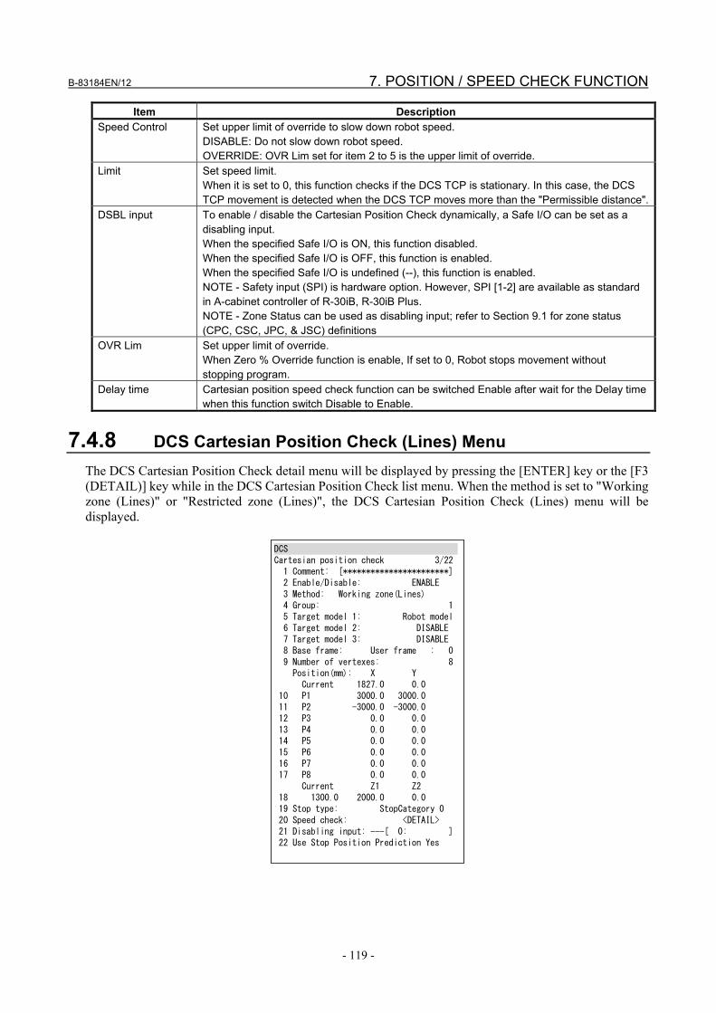
B-83184EN/12 7. POSITION / SPEED CHECK FUNCTION
- 119 -
Item Description Speed Control Set upper limit of override to slow down robot speed.
DISABLE: Do not slow down robot speed. OVERRIDE: OVR Lim set for item 2 to 5 is the upper limit of override.
Limit Set speed limit. When it is set to 0, this function checks if the DCS TCP is stationary. In this case, the DCS TCP movement is detected when the DCS TCP moves more than the "Permissible distance".
DSBL input To enable / disable the Cartesian Position Check dynamically, a Safe I/O can be set as a disabling input. When the specified Safe I/O is ON, this function disabled. When the specified Safe I/O is OFF, this function is enabled. When the specified Safe I/O is undefined (--), this function is enabled. NOTE - Safety input (SPI) is hardware option. However, SPI [1-2] are available as standard in A-cabinet controller of R-30iB, R-30iB Plus. NOTE - Zone Status can be used as disabling input; refer to Section 9.1 for zone status (CPC, CSC, JPC, & JSC) definitions
OVR Lim Set upper limit of override. When Zero % Override function is enable, If set to 0, Robot stops movement without stopping program.
Delay time Cartesian position speed check function can be switched Enable after wait for the Delay time when this function switch Disable to Enable.
7.4.8 DCS Cartesian Position Check (Lines) Menu The DCS Cartesian Position Check detail menu will be displayed by pressing the [ENTER] key or the [F3 (DETAIL)] key while in the DCS Cartesian Position Check list menu. When the method is set to "Working zone (Lines)" or "Restricted zone (Lines)", the DCS Cartesian Position Check (Lines) menu will be displayed.
DCS Cartesian position check 3/22 1 Comment: [***********************] 2 Enable/Disable: ENABLE 3 Method: Working zone(Lines) 4 Group: 1 5 Target model 1: Robot model 6 Target model 2: DISABLE 7 Target model 3: DISABLE 8 Base frame: User frame : 0 9 Number of vertexes: 8 Position(mm): X Y Current 1827.0 0.0 10 P1 3000.0 3000.0 11 P2 -3000.0 -3000.0 12 P3 0.0 0.0 13 P4 0.0 0.0 14 P5 0.0 0.0 15 P6 0.0 0.0 16 P7 0.0 0.0 17 P8 0.0 0.0 Current Z1 Z2 18 1300.0 2000.0 0.0 19 Stop type: StopCategory 0 20 Speed check: <DETAIL> 21 Disabling input: ---[ 0: ] 22 Use Stop Position Prediction Yes

7. POSITION / SPEED CHECK FUNCTION B-83184EN/12
- 120 -
Items in Cartesian Position Check (Lines) menu Item Description
Method(Safe side) Used to set the method of defining the zone Working zone (Lines): Setup the safe zone using 3 to 8 vertexes on the X-Y plane and the
upper and lower limits along the Z axis of the DCS User Frame. The angle of each corner in the polygon must be less than 180 deg. Inside the polygon is the safe zone. (Lines(Inside) inR-30iB, R-30iB Mate)
Restricted zone (Outside): Setup the safe zone using 3 to 8 vertexes on the X-Y plane and the upper and lower limits along the Z axis of the DCS User Frame. The angle of each corner in the polygon must be less than 180 deg. Outside the polygon is the safe zone. (Lines(outside) inR-30iB, R-30iB Mate)
Number of vertexes Number of vertexes of the polygon on the X-Y plane. The range is 3-8. Default is 8.
P1-8 Used to set the position of the vertexes. The polygon is made by connecting the vertexes as P1→ P2→ P3→... →P1 in the X-Y plane. The angle of each corner must be less than 180 deg. Vertexes beyond the number of vertexes are ignored.
NOTE – For items that are not described in this table, please refer to "Items in DCS Cartesian Position
Check (Diagonal) menu".
Operation in Cartesian Position Check (Lines) menu Operation Description
[SHIFT]+F4(RECORD) When cursor is on P1-8, the current position of the ordinary TCP is set. [NEXT], [SHIFT]+F4(MOVETO)
When the cursor is on P1-8, the robot (ordinary TCP) moves to that position. The robot moves in linear motion, if the robot cannot reach the position, please jog to a different position and try again. If the [SHIFT] key is released while during moving, the robot stops.
NOTE - For operations that are not described in this table, please refer to "Items in DCS Cartesian Position
Check (Diagonal) menu".

B-83184EN/12 7. POSITION / SPEED CHECK FUNCTION
- 121 -
7.4.9 DCS User Model List Menu The DCS User Model List menu will be displayed by pressing the [ENTER] key or the [F3 (DETAIL)] key while on the "User model" item in the DCS Top menu.
DCS User model list 1/16 No. Elem Status Comment 1 0 OK [ ] 2 0 OK [ ] 3 0 OK [ ] 4 0 OK [ ] 5 0 OK [ ] 6 0 OK [ ] 7 0 OK [ ] 8 0 OK [ ] 9 0 OK [ ] 10 0 OK [ ] [ TYPE ] DETAIL
Items in DCS User model list menu Item Description
No. The User Model number is displayed Elem The number of elements that are enabled in the User Model is displayed. Status The status of the User model is displayed.
OK: Setting parameter and DCS parameter are the same. CHGD: Setting parameter is changed, but not applied to DCS parameter. PEND: Setting parameter is changed and applied to DCS parameter, but controller power
has not been cycled. Comment The comment of the User Model is displayed.
Operation in DCS User model menu
Operation Description [F3(DETAIL)] or [ENTER]
The DCS User Model Element List menu of the item the cursor is on will be displayed.
[PREV] The DCS Top menu will be displayed.
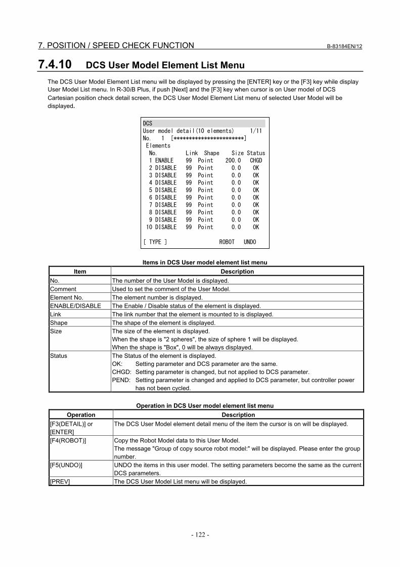
7. POSITION / SPEED CHECK FUNCTION B-83184EN/12
- 122 -
7.4.10 DCS User Model Element List Menu The DCS User Model Element List menu will be displayed by pressing the [ENTER] key or the [F3] key while display User Model List menu. In R-30iB Plus, if push [Next] and the [F3] key when cursor is on User model of DCS Cartesian position check detail screen, the DCS User Model Element List menu of selected User Model will be displayed.
DCS User model detail(10 elements) 1/11 No. 1 [***********************] Elements No. Link Shape Size Status 1 ENABLE 99 Point 200.0 CHGD 2 DISABLE 99 Point 0.0 OK 3 DISABLE 99 Point 0.0 OK 4 DISABLE 99 Point 0.0 OK 5 DISABLE 99 Point 0.0 OK 6 DISABLE 99 Point 0.0 OK 7 DISABLE 99 Point 0.0 OK 8 DISABLE 99 Point 0.0 OK 9 DISABLE 99 Point 0.0 OK 10 DISABLE 99 Point 0.0 OK [ TYPE ] ROBOT UNDO
Items in DCS User model element list menu Item Description
No. The number of the User Model is displayed. Comment Used to set the comment of the User Model. Element No. The element number is displayed. ENABLE/DISABLE The Enable / Disable status of the element is displayed. Link The link number that the element is mounted to is displayed. Shape The shape of the element is displayed. Size The size of the element is displayed.
When the shape is "2 spheres", the size of sphere 1 will be displayed. When the shape is "Box", 0 will be always displayed.
Status The Status of the element is displayed. OK: Setting parameter and DCS parameter are the same. CHGD: Setting parameter is changed, but not applied to DCS parameter. PEND: Setting parameter is changed and applied to DCS parameter, but controller power
has not been cycled.
Operation in DCS User model element list menu Operation Description
[F3(DETAIL)] or [ENTER]
The DCS User Model element detail menu of the item the cursor is on will be displayed.
[F4(ROBOT)] Copy the Robot Model data to this User Model. The message "Group of copy source robot model:" will be displayed. Please enter the group number.
[F5(UNDO)] UNDO the items in this user model. The setting parameters become the same as the current DCS parameters.
[PREV] The DCS User Model List menu will be displayed.

B-83184EN/12 7. POSITION / SPEED CHECK FUNCTION
- 123 -
7.4.11 DCS User Model Detail (Point/Line-Seg) Menu
DCS User element detail 1/9 No. 1 [***********************] Element: 1 Status: CHGD 1 Enable/Disable: ENABLE 2 Link No.(99:FacePlate): 99 3 Link type: NORMAL 4 Tool frame: 0 5 Shape: Point 6 Size (mm): 200.0 Pos1 7 X: 0.000 Y: 0.000 Z: 100.000 Pos2 8 X: 0.000 Y: 0.000 Z: 0.000 [ TYPE ] UNDO
Items in DCS User Model Detail (Point/Line-seg) menu Item Description
No. The User Model number is displayed. Comment Used to set the comment of the User Model. Element The element number is displayed. Status The status of the element is displayed.
OK: Setting parameter and DCS parameter are the same. CHGD: Setting parameter is changed, but not applied to DCS parameter. PEND: Setting parameter is changed and applied to DCS parameter, but controller power has
not been cycled. Enable/Disable Used to set Enable / Disable of the element. Link No. Used to set the link number that the element is mounted to.
When 99 is set, the element is mounted to the flange. The corresponded link frame will be displayed graphically in 4D Graphics DCS display menu when the cursor is on this item.
Link type Used to set the type of the link connection. When link No. is set to 99, this setting is ignored. The available link type of each link is defined by each robot model. Please refer to the robot model setting for the link type setting. The corresponded link frame will be displayed graphically in 4D Graphics DCS display menu when the cursor is on this item.
Tool frame When link No. is 99, this item defines the base tool frame of the element instead of the flange. When DCS tool frame number is set in this item, The DCS tool frame is the reference base frame of the element. When it is set to 0, the element is mounted on the flange. NOTE - When the link No. is not 99, the element applies the specified tool frame values to the
specified link frame. When you set 0, element is placed in frame. This setting can be used to rotate a box element, but care must be taken to ensure that the element is mounted in the correct base frame and tested carefully.
Shape Used to select the shape of the element from "Point", "Line-seg", "2 Spheres" and "Box". When "Point" or "Line-seg" is selected, the DCS User Model Element Detail (Point/Line-seg) menu will be displayed. When "2 Spheres" is selected, DCS User Model Element Detail (2 Spheres) menu will be displayed. When "Box" is selected, DCS User Model Element Detail (Box) menu will be displayed. NOTE - Only one "Box" element is allowed in a User Model. If 2 or more "Box" elements are
defined and enabled, an alarm occurs.

7. POSITION / SPEED CHECK FUNCTION B-83184EN/12
- 124 -
Item Description Size In a "Point" element, this is used to set the radius of the sphere.
In a "Line-seg" element, this is used to set the radius of the cylinder. Pos1 In a "Point" element, this is used to set the center of the sphere.
In a "Line-seg" element, this is used to set one end point of the center line of the cylinder. Pos2 In a "Point" element, this item is ignored.
In a "Line-seg" element, this is used to set the other end point of center line of the cylinder.
Operation in DCS User Model Detail (Point/Line-seg) menu Operation Description
[F5(UNDO)] UNDO the items in this menu. The setting parameters become the same as the current DCS parameters.
[PREV] The DCS User model element list menu will be displayed.
7.4.12 DCS User Model Element Detail (2 Spheres) Menu
DCS User element detail(2 spheres) 6/10 No. 1 [***********************] Element: 1 Status: CHGD 1 Enable/Disable: ENABLE 2 Link No.(99:FacePlate): 99 3 Link type: NORMAL 4 Tool frame: 0 5 Shape: 2spheres Pos1 6 Size (mm): 200.0 7 X: 0.000 Y: 0.000 Z: 100.000 Pos2 8 Size (mm): 0.0 9 X: 0.000 Y: 0.000 Z: 0.000 [ TYPE ] UNDO
Items in DCS User Model Element Detail (2 Spheres) menu Item Description
Pos1 Size Used to set the size of sphere 1. When this is set to 0, sphere 1 is disabled.
Pos1 X,Y,Z Used to set the center position of sphere 1. Pos2 Size Used to set the size of sphere 2.
When this is set to 0, sphere 2 is disabled. Pos2 X,Y,Z Used to set the center position of sphere 2.
NOTE - For items that are not described in this table, please refer to "Items in DCS User model element
detail (Point/Line-seg) menu".

B-83184EN/12 7. POSITION / SPEED CHECK FUNCTION
- 125 -
7.4.13 DCS User Model Element Detail (Box) Menu
DCS User model detail(Box) 6/10 No. 1 [***********************] Element: 1 Status: CHGD 1 Enable/Disable: ENABLE 2 Link No.(99:FacePlate): 99 3 Link type: NORMAL 4 Tool frame: 0 5 Shape: Box Box 6 Width (X) (mm): 0.0 7 Height(Y) (mm): 0.0 8 Thick (Z) (mm): 0.0 Offset 9 X: 0.0 Y: 0.0 Z: 100.0 [ TYPE ] UNDO
Items in DCS User Model Element Detail (Box) menu Item Description
Width(X) Used to set the width (size of X) of the box. Height(Y) Used to set the height (size of Y) of the box. Thick(Z) Used to set the thickness (size of Z) of the box. Offset Used to set the offset of the box.
NOTE - For items that are not described in this table, please refer to "Items in DCS User model element
detail (Point/Line-seg) menu". NOTE - Box element cannot be selectable when DCS Basic Position check function is ordered.
7.4.14 DCS Cartesian Position Check (Target Model Collision Check ) Menu
DCS Cartesian position check 3/9 1 Comment: [***********************] 2 Enable/Disable: ENABLE 3 Method: Target model collision 4 Group: 1 5 Target model 1: Robot model 6 Target model 2: DISABLE 7 Stop type: StopCategory 0 8 Speed check: <DETAIL> 9 Disabling input: ---[ 0: ] Use Stop Position Prediction: No [ TYPE ] PREV NEXT [CHOICE] UNDO >

7. POSITION / SPEED CHECK FUNCTION B-83184EN/12
- 126 -
Items in DCS Cartesian Position Check (Target model collision) list menu Item Description
No. The Cartesian Position Check number is displayed. Status The status of the Cartesian Position Check is displayed.
----: Disabled by setting SAFE: Enabled, and in safe zone. UNSF: Enabled, and out of safe zone. DSBL: Disabled by disabling input. CHGD: Setting parameter is changed, but not applied to DCS parameter. PEND: Setting parameter is changed and applied to DCS parameter, but controller power
has not been cycled INVL: Invalid signal of function disabled is enabled. DSSF: Disabled CPC Position Check is Enable. Cartesian Position Check function is
Disabled by disabling input. Shape model is in safe zone. DSUN: Disabled CPC Position Check is Enable. Cartesian Position Check function is
Disabled by disabling input. Shape model is out of safe zone. Comment Used to set the comment of the Cartesian Position Check
The comment set in this menu is also used as comment of the Safe I/O CPC[ ]. Enable/Disable Used to set the Enable / Disable of the Cartesian Position Check.
When set to disable, all other settings in this menu are ignored. Method(Safe side) Used to set the method of defining the zone. Group Used to set the target motion group number. Target model 1-2 Used to set the target shape model that is checked.
A maximum of 2 shape models can be defined. When set to Disable , the target model is disabled. When set to User model 1-16, the user model is checked. When set to Robot model, the robot model of the target motion group is checked. When set to Tool change, the tool model of the target motion group is checked.
Stop type Used to set the action when the target model is out of the defined safe zone. Stop Category 0: Motor power is shut down immediately. Stop Category 1: Deceleration stop, then motor power is shut down.
(Motor power shutdown is delayed for maximum 2 seconds.) Not stop: Robot does not stop. The status is set in Safe I/O CPC. Speed check 0: When Current TCP Speed is faster than limit speed set by Speed Check,
Do Stop Category 0. Speed check 1: When Current TCP Speed is faster than limit speed set by Speed Check,
Do Stop Category 1. Speed Check Speed down when Target model leaves safe zone. Disabling input To enable / disable the Cartesian Position Check dynamically, a Safe I/O can be set as a
disabling input. When the specified Safe I/O is ON, this function disabled. When the specified Safe I/O is OFF, this function is enabled. When the specified Safe I/O is undefined (--), this function is enabled. NOTE - Safety input (SPI) is hardware option. However, SPI [1-2] are available as standard in
A-cabinet controller of R-30iB, R-30iB Plus. NOTE - Zone Status can be used as disabling input; refer to Section 9.1 for zone status (CPC, CSC, JPC & JSC) definitions
Use Stop Position Prediction
This function does not correspond to stop position prediction. You can not change the setting.
* NOTE – For items that are not described in this table, please refer to "Items in DCS Cartesian Position
Check (Diagonal) menu". * NOTE-If the software version is 7DF4 series or earlier, "DCS Basic Position Check function" does not
correspond to Target model collision function. If the software version is 7DF5 series or later, "DCS Basic Position Check function" corresponds to Target model collision function.
* NOTE-It is not possible to check models including box elements.

B-83184EN/12 7. POSITION / SPEED CHECK FUNCTION
- 127 -
7.5 ORIENTATION CHECK FUNCTION (CARTESIAN POSITION CHECK FUNCTION)
The Orientation Check function checks the difference between the current robot faceplate orientation and the base faceplate orientation, and shuts down the motor power if it is greater than the defined limit. If the software version is 7DF4 series or earlier, "DCS Basic Position Check function" does not correspond to the Orientation Check function. If the software version is 7DF5 series or later, "DCS Basic Position Check function" corresponds to the Orientation Check function. There are 2 modes of the orientation check, "ALL" and "User Z". ALL
Checks if the rotation angle around X, Y, and Z between the current robot faceplate orientation and the base faceplate orientation is greater than the limit.
User Z Checks if the rotation angle around X and Y between the current robot faceplate orientation and the base faceplate orientation is greater than the limit. In this case, it is possible to rotate around the Z axis of the DCS User Frame without causing an alarm while not allowing rotation beyond the defined limit in the X and Y directions.
WARNING If DCS Orientation check is set incorrectly, the safety function will not work, and
serious personal injury could result. When DCS Orientation check is changed, the values must be verified and the function must be tested again.
Recover from alarm
The operation to recover from the alarm is the same as the Zone Check function. (Refer to 7.4 ZONE CHECK FUNCTION (CARTESIAN POSITION CHECK FUNCTION))
7.5.1 DCS Cartesian Position Check (Orientation Fix) Menu The DCS Cartesian Position Check Detail menu will be displayed by pressing the [ENTER] key or the [F3 (DETAIL)] key while in the DCS Cartesian Position Check List menu. When the method is "OrntFix (ALL)" or "OrntFix (UserZ)", the DCS Cartesian Position Check (Orientation Fix) menu will be displayed.

7. POSITION / SPEED CHECK FUNCTION B-83184EN/12
- 128 -
DCS Cartesian position check 3/13 No. 1 Status:CHGD 1 Comment: [***********************] 2 Enable/Disable: ENABLE 3 Method: OrntFix(ALL) 4 Group: 1 5 User frame: 0 6 Tool select: 0 7 (0:FacePlate, -1:Tool change) Tool orientation(deg): Current Base 6 W 180.000 3000.000 7 P -90.000 3000.000 8 R 0.000 2000.000 9 Angle of any direction(deg): Current Limit 90.000 0.000 10 Stop type: StopCategory 0 11 11 Disabling input: ---[ 0: ] [ TYPE ] PREV NEXT [CHOICE] UNDO >
Items in DCS Cartesian Position Check (Orientation Fix) menu
Item Description Method(Safe side) Used to set the method of orientation check.
Orientation Fix (ALL): The difference between the current orientation and the base orientation is checked. Orientation of all directions is checked.
Orientation Fix (UserZ): The difference between the current orientation and the base orientation is checked. Rotation of the Z axis in the DCS User Frame is ignored. Orientation of all other directions is checked.
Tool select Set the tool to be checked orientation. When set to 0, Check orientation of faceplate.
Face plate orientation Current
The current orientation (W,P,R) of the Face Plate is displayed. The values are relative to the DCS User Frame specified in this menu.
Face plate orientation Base
Used to set the Base orientation (W,P,R) of the Face Plate. The values are relative to the DCS User Frame specified in this menu.
Angle Current
The difference between current orientation and the Base orientation is displayed.
Angle Limit
Used to set the limit of the difference between the current orientation and the Base orientation.
NOTE - For items that are not described in this table, please refer to "Items in DCS Cartesian Position
Check (Diagonal) menu".
Operation of DCS Cartesian Position Check (Orientation Fix) menu Operation Description
[SHIFT]+[F4(RECORD)]
When the cursor is on "Face plate orientation, Base", the current orientation is set.
[NEXT], [SHIFT]+[F4(MOVETO)]
When cursor is on "Face plate orientation, Base", the robot moves to that orientation. The robot moves in linear motion, it the robot cannot reach the position, please jog to a different position and try again. If the [SHIFT] key is released while moving, the robot stops.
NOTE - For operations that are not described in this table, please refer to "Items in DCS Cartesian Position
Check (Diagonal) menu".

B-83184EN/12 7. POSITION / SPEED CHECK FUNCTION
- 129 -
7.6 BASIC POSITION CHECK FUNCTION The Basic Position Check function is restricted version of Position/Speed Check function. Refer to the 7.4 Zone Check Function to use.
7.6.1 Restriction of Basic Position function If the software version is 7DF4 series or earlier, Restricted DCS Cartesian Position Check function can be used in the Basic Position Check function. If the software version is 7DF5 series or later, Restricted DCS Cartesian Position Check function, Full DCS Joint Position Check function and Full DCS Joint Speed Check function can be used in the Basic Position Check function. Following functions are restricted in The Basic Position Check function compared to Cartesian Position Check function. - Safe zone is only one if the software version is 7DF4 series or earlier. Safe zone is three if the software
version is 7DF5 series or later. - If the software version is 7DF4 series or earlier, safe zone method is Diagonal (IN/OUT) or Line
(IN/OUT). Orientation method and Target model collision method is not supported. If the software version is 7DF5 series or later, all safe zone methods are supported including
Orientation method and Target model collision method. - Tool Change is not supported. Therefore cannot input tool model as target model. If use tool model,
user model number directory input in target model. - Position check of the robot on TCP of other group does not supported. - User frame is not supported. - Box element is not supported in user model. - Tool frame is not supported if the software version is 7DF4 series or earlier. A maximum of 3 tool
frames can be defined if the software version is 7DF5 series or later. If select unsupported functions, "Need J567(DCS Pos. speed check option" displayed and reset the value.
7.7 CARTESIAN SPEED CHECK FUNCTION The Cartesian Speed Check function checks the DCS TCP (base of the DCS tool frame) speed of the robot and shuts down the motor power if the DCS TCP speed exceeds the speed limit. - A maximum of 16 speed limits can be defined. - Cartesian Speed Check checks the speed of the selected DCS TCP (Refer to Section 7.9 DCS TOOL
FRAME) - If a motion exceeds the speed limit set by Cartesian Speed Check, the alarm “SRVO-403 DCS Cart.
speed limit” occurs, and the motor power is shut down. - This function can be used to check if the robot is stationary by setting the speed limit to 0. False alarms
caused by vibration during servo ON can be avoided by tuning of the permissible distance. - When Safe I/O is set as a disabling I/O, it is possible to ENABLE / DISABLE Cartesian Speed Check
by using Safe I/O for each Cartesian Speed Check. When the specified Safe I/O is ON, Cartesian Speed Check is disabled. When it is OFF, it is enabled.
- The status of Cartesian Speed check can be monitored by a DI when the DI is assigned to rack 36, slot 7, start point 1-16. The start point corresponds to the Cartesian Speed check number. When the Cartesian Speed check is enabled and speed does not exceed the limit (Status: SAFE), the DI is ON. In the other case, the DI is OFF.
CAUTION : Since DI is not safe signal, it cannot be used for safety purpose. - Even in the absence of the axis motion command, due to the vibration during servo-on. If set small
value to limit speed, Speed check alarm can occur during servo-on.

7. POSITION / SPEED CHECK FUNCTION B-83184EN/12
- 130 -
WARNING 1 If Cartesian Speed Check is set incorrectly, the safety function will not work, and
serious personal injury could result. When Cartesian Speed Check is changed, the values must be verified and the function must be tested again.
2 When the Limit is set to 0 and the Permissible distance is not set to 0, the motor power does not shut down immediately when the DCS TCP moves. The stopping distance can be increased by acceleration in Permissible distance. Adequate risk assessment for the whole robot system is necessary to determine Permissible distance.
7.7.1 DCS Cartesian Speed Check List Menu The DCS Cartesian Speed Check list menu will be displayed by pressing the [ENTER] key or the [F3(DETAIL)] key while on the "Cartesian Speed Check" item in the DCS Top menu
DCS Cartesian speed check 1/16 No. G T Status Comment 1 DISABLE 1 0 ---- [ ] 2 DISABLE 1 0 ---- [ ] 3 DISABLE 1 0 ---- [ ] 4 DISABLE 1 0 ---- [ ] 5 DISABLE 1 0 ---- [ ] 6 DISABLE 1 0 ---- [ ] 7 DISABLE 1 0 ---- [ ] 8 DISABLE 1 0 ---- [ ] 9 DISABLE 1 0 ---- [ ] 10 DISABLE 1 0 ---- [ ] [ TYPE ] DETAIL
DCS Cartesian Speed Check list menu
Item Description No. The Cartesian Speed Check number is displayed. ENABLE/DISABLE The Enable/Disable status of the Cartesian Speed Check is displayed. G The Target motion group number is displayed. T The Target DCS Tool Frame number is displayed. Status The Status of the Cartesian Speed Check is displayed.
----: Disabled by setting SAFE: Enabled, and less than the limit. OVER: Enabled, and over the limit. DSBL: Disabled by disabling input. CHGD: Setting parameter is changed, but not applied to DCS parameter. PEND: Setting parameter is changed and applied to DCS parameter, but controller power
has not been cycled. INVL: Invalid signal of function disabled is enabled. R-30iB, R-30iB Mate do not correspond to INVL. See "7.12 Pos./Speed check setup" for INVL.
Comment The comment of Cartesian Speed Check is displayed.
Operation of DCS Cartesian Speed Check list menu Operation Description
[F3(DETAIL)] or [ENTER]
The DCS Cartesian Speed Check detail menu of the item the cursor is on will be displayed.
[PREV] The DCS Top menu will be displayed.

B-83184EN/12 7. POSITION / SPEED CHECK FUNCTION
- 131 -
7.7.2 DCS Cartesian Speed Check Detail Menu
DCS Cartesian speed check 1/13 No. 1 Status:---- 1 Comment: [***********************] 2 Enable/Disable: DISABLE 3 Direction: ALL 4 Group: 1 5 Tool frame: 0 (0:FacePlate, -1:Current tool) 6 Base frame: User frame : 0 Speed of the direction(mm/sec): Current: 0.000 7 Limit: 0.000 8 Stop type: Category 0 9 Speed control: 無効 10 Override limit: 100% 11 Delay time: 0 msec 12 Disabling input: ---[ 0: ] 13 Permissible distance(mm): 0.0 [ TYPE ] PREV NEXT UNDO
DCS Cartesian Speed Check detail menu Item Description
No. The Cartesian Speed Check number is displayed. Status Status of Cartesian Speed Check is displayed.
----: Disabled by setting SAFE: Enabled, and less than the limit. OVER: Enabled, and over the limit. DSBL: Disabled by disabling input. CHGD: Setting parameter is changed, but not applied to DCS parameter. PEND: Setting parameter is changed and applied to DCS parameter, but controller power
has not been cycled. INVL: Invalid signal of function disabled is enabled. R-30iB, R-30iB Mate do not correspond to INVL. See "7.12 Pos./Speed check setup" for INVL.
Comment Used to set the comment of the Cartesian Speed Check. The comment set in this menu is also used as the comment of Safe I/O CSC [ ].
Enable/Disable Used to set Enable / Disable of the Cartesian Speed Check. When this is disabled, all other settings in this menu are ignored.
Direction Used to set the direction of the speed check. ALL: The composite speed is checked (Direction is not considered.) X: Only X direction speed is checked. (+/- is not considered) Y: Only Y direction speed is checked. (+/- is not considered) Z: Only Z direction speed is checked. (+/- is not considered) -X: Only -X direction speed is checked -Y: Only -Y direction speed is checked -Z: Only -Z direction speed is checked +X: Only +X direction speed is checked +Y: Only +Y direction speed is checked +Z: Only +Z direction speed is checked ROTATION: Only rotational speed in WPR direction.
Group Used to set the target motion group number.

7. POSITION / SPEED CHECK FUNCTION B-83184EN/12
- 132 -
Item Description Tool frame Used to set the target DCS Tool Frame number.
When this is set to 0, the target is the Face Plate. When this is set to -1, the target is the DCS Tool Frame that is selected. In this case, the target tool frame is the DCS tool frame specified by "Tool select" in the DCS Tool Frame menu. When "Tool select" in the DCS Tool Frame menu is also -1, the DCS Tool Change function is enabled and the target tool frame is changed when the ordinary TCP is changed.
Base frame Used to set the DCS User Frame number that is used as the base frame of the direction to check when direction is not ALL. User frame: Set the number of the DCS user frame to be the direction criterion. Tool frame:Set the number of the DCS tool frame to be the direction criterion. When tool frame are selected, it synchronizes with the setting of tool frame.
Current The current speed of the target DCS Tool Frame is displayed. Limit Used to set the speed limit.
When it is set to 0, this function checks if the DCS TCP is stationary. In this case, the DCS TCP movement is detected when the DCS TCP moves more than the "Permissible distance".
Stop type Used to set the action when the target DCS TCP speed exceeds the limit Stop Category 0: Motor power is shut down immediately. Stop Category 1: Deceleration stop, then motor power is shut down.
(Motor power shutdown is delayed for maximum 2 seconds.) Not stop: Robot does not stop. The status is set in Safe I/O CSC. NOTE – When the robot starts motion from a stopped position with the limit set to 0 and the stop type set to “Stop Category 1”, motor power is shut down immediately to minimize the robot stopping distance. When the Cartesian Speed Check is changed from disable to enable by disabling I/O during robot motion, a Stop Category 1 is performed. NOTE – When the robot starts motion from a stopped position with the limit set to 0 and the stop type set to “Not Stop”, the state changes to “OVER” when the robot begins motion, but does not change back to "SAFE" if the robot stops later. To return to the "SAFE" status, please turn off motor power, or disable the Cartesian speed check by disabling I/O. To use a “Not Stop” zone to dynamically indicate robot motion in the Safe I/O Connect function without shutting down motor power, set the stop type to “Not Stop” and the speed limit to a small value greater than zero.
Speed Control Set upper limit of override to slow down robot speed. DISABLE: Do not slow down robot speed. OVERRIDE: OVR Lim set for item 2 to 5 is the upper limit of override. It is not supported in R-30iB, R-30iB Mate.
OVR Lim Set upper limit of override. When Zero % Override function is enable, If set to 0, Robot stops movement without stopping program. It is not supported in R-30iB, R-30iB Mate.
Delay time Cartesian position speed check function can be switched Enable after wait for the Delay time when this function switch Disable to Enable. It is not supported in R-30iB, R-30iB Mate.
Disabling input To enable / disable the Cartesian Speed Check dynamically, a Safe I/O can be set as a disabling input. When the specified Safe I/O is ON, this function disabled. When the specified Safe I/O is OFF, this function is enabled. When the specified Safe I/O is undefined (--), this function is enabled. NOTE - Safety input (SPI) is hardware option. However, SPI [1-2] are available as standard in
A-cabinet controller of R-30iB, R-30iB Plus. NOTE - Zone Status can be used as disabling input; refer to Section 9.1 for zone status (CPC, CSC, JPC, & JSC) definitions
Permissible distance This item indicates that if the distance moved is less than the Permissible distance, motor power is not shut down even though the DCS TCP speed exceeds the speed limit. This item is used to avoid false alarms caused by vibration during servo ON. This parameter is used only when the "Limit" is 0. Unit : mm

B-83184EN/12 7. POSITION / SPEED CHECK FUNCTION
- 133 -
Operation in DCS Joint Position Check menu Operation Description
[F2(PREV)] The previous Cartesian Speed Check will be displayed. [F3(NEXT)] The next Cartesian Speed Check will be displayed. [F5(UNDO)] UNDO the items in this menu. The setting parameters become the same as the current DCS
parameters. [PREV] The Cartesian Speed Check list menu will be displayed.
7.8 T1 MODE SPEED CHECK FUNCTION The T1 mode speed check function checks the speed of the currently selected DCS TCP and wrist flange center in the T1 mode and cuts off power to the drive circuit when it exceeds the set speed limit . The standard Robot control software limits the TCP speed and the wrist flange center speed so it does not exceed 250 mm/sec in T1 Mode. In addition, DCS will shut down motor power if the TCP speed or the wrist flange canter speed exceeds 250 mm/sec in T1 Mode. - T1 Mode Speed Check can be enabled / disabled for each motion group. (Default is disable) - The speed limit of the T1 Mode Speed Check can be changed, but it cannot exceed 250mm/sec. - In T1 Mode, when the DCS TCP speed exceeds the specified speed limit, the alarm "SRVO-340 DCS
T1 TCP speed" occurs and motor power is shut down immediately. - In T1 Mode, when the DCS flange center speed exceeds the specified speed limit, the alarm "SRVO-
341 DCS T1 flange speed" occurs and motor power is shut down immediately. - The target TCP is the DCS Tool Frame that is selected by the "Tool select" item in the DCS Tool
frame menu. When "Tool select" in the DCS Tool Frame menu is set to -1, the DCS Tool Change function is enabled and the target tool frame number is changed when the ordinary TCP is changed.
WARNING 1 If T1 Mode Speed Check is set incorrectly, the safety function will not work, and
serious personal injury could result. When T1 Mode Speed Check is changed, the values must be verified and the function must be tested again.
2 Set the most distant point of the end-effector from the wrist flange center as the DCS TCP. If not, a point on the end-effector more distant from the wrist flange center than the DCS TCP might exceed 250 mm/sec.
3 When multiple end-effectors are used, please use dynamic tool change or set the TCP of the largest end-effector as the DCS TCP. If the TCP of a smaller end effector is set as the DCS TCP, the TCP of a larger end-effector might exceed 250mm/sec.
CAUTION 1 When the DCS TCP is different from the ordinary TCP, especially if the DCS
TCP is longer than the ordinary TCP, the T1 Mode Speed Check alarm can occur. In this case, decrease the override.
2 When the limit of T1 Mode Speed Check is set less than 250 mm/s, the alarm occurs if the speed exceeds the specified limit. In this case, decrease the override.

7. POSITION / SPEED CHECK FUNCTION B-83184EN/12
- 134 -
7.8.1 DCS T1 Mode Speed Check Menu The DCS T1 Mode Speed Check menu will be displayed by pressing the [ENTER] key or the [F3(DETAIL)] key while on the "T1 Mode Speed Check" item in the DCS Top menu
DCS T1 mode Speed Check 1/1 Grp Limit(mm/sec) FP-Speed-TCP Status 1 ENABLE 250.0 0.0 0.0 OK [ TYPE ] [CHOICE] UNDO
Items in DCS T1 Mode Speed Check menu Item Description
Grp The motion group number is displayed. ENABLE/DISABLE Used to Enable / Disable T1 Mode Speed Check. Limit Used to set the speed limit
This item cannot be greater than 250mm/sec. FP speed The current flange center speed is displayed. TCP The current TCP speed is displayed. Status The status of T1 Mode Speed Check is displayed.
OK: Setting parameter and DCS parameter are the same. CHGD: Setting parameter is changed, but not applied to DCS parameter. PEND: Setting parameter is changed and applied to DCS parameter, but controller power has
not been cycled.
Operation in DCS T1 Mode Speed Check menu Operation Description
[F5(UNDO)] UNDO the items in this menu. The setting parameters become the same as the current DCS parameters.
[PREV] The DCS Top menu will be displayed.
7.9 DCS TOOL FRAME Some DCS functions use a DCS Tool Frame that is part of the DCS parameters. These tool frames are separate from the standard tool frames. The DCS Tool Frames are used by the following DCS functions. - The target of the Speed Check in Cartesian Speed Check function. - The target of the Speed Check in T1 Mode Speed Check function. - The base frame of the shape element in the Zone Check function. All DCS Tool Frames are disabled (DCS tool frame number is 0 in the DCS Tool Frame Menu) by default. A DCS tool frame is enabled by setting the DCS tool frame number to something other than 0. If the tool frame number is set to a value that corresponds to a standard tool frame, the data from the standard tool frame (X,Y,Z,W,P,R) is then copied to the setting parameters of the DCS tool frame automatically. When the standard tool frame data is changed, the setting parameters of the corresponding DCS tool frame are updated automatically and the alarm "SYST-212 Need to apply to DCS param" occurs. When the DCS tool frame number is set to a value that does not correspond to a standard tool frame number (for example 100), the DCS tool frame data (X,Y,Z,W,P,R) can be manually entered in the DCS Tool Frame menu. A maximum of 16 DCS tool frames can be defined.

B-83184EN/12 7. POSITION / SPEED CHECK FUNCTION
- 135 -
One DCS tool frame is selected as the current DCS tool frame for each motion group. If the target tool frame is set to -1, the DCS Tool Change function is enabled and the tool frame used as the target of the T1 Mode Speed Check function and the Cartesian Speed Check function changes with the status of the Verify I/O signals as described below. The current DCS tool frame is used by the following DCS functions. - The target of the Speed Check in Cartesian Speed Check function when the Tool Frame is set to -1. - The target of the Speed Check in T1 Mode Speed Check function. Each DCS tool frame can have one user model as the tool model. When the target model is set to Tool Model (-2) in the Zone Check function, the tool model of the current DCS tool frame is checked by the Zone check function. It is not necessary to select the same DCS Tool Frame number as the current selected standard tool frame number. Changing the standard tool frame selection does not affect the DCS functions. For example, the target of the Speed Check in Cartesian Speed Check function is not changed even though the standard tool frame selection is changed by program execution. If the software version is 7DF4 series or earlier, DCS tool frame menu is not displayed when "DCS Basic Position check function" is ordered (DCS tool frame number 0 is used). If the software version is 7DF5 series or later, DCS tool frame menu is displayed and a maximum of three tool frames can be defined.
WARNING If the DCS tool frame is set incorrectly, the safety function will not work, and
serious personal injury could result. When the DCS tool frame is changed, the values must be verified and the function must be tested again.
7.9.1 Tool Change Function The DCS Tool Change function switches shape models dynamically, for example to handle a big work piece. The DCS Tool Change function is enabled when "Tool select" in the DCS Tool Frame menu is set to -1. When the DCS Tool Change function is enabled, the DCS Tool Frame is changed dynamically according to the Safe I/O status that is defined as the Verify I/O of the DCS Tool Frames. The shape model assigned to the selected DCS Tool Frame is then enabled. When the DCS Tool Change function is enabled, Safe I/O must be defined as the Verify I/O for all the DCS Tool Frames that can be selected as the current DCS Tool Frame. A DCS Tool Frame is selected when the defined Verify I/O is ON. When all Verify I/O are OFF or two or more Verify I/O are ON, this situation is called "Tool mismatch". If a "Tool mismatch" condition continues for 1 second, the alarm "SRVO-416 DCS Tool mismatch" occurs. To clear the alarm, you need to set the Verify I/O status correctly. In a "Tool mismatch" condition, the current tool becomes the tool that was most recently selected for more than 1sec. When a "Tool mismatch" condition occurs at power up, the current tool becomes 0. Tool 0 means that the TCP is the Face Plate and no Tool model is enabled. Changing the DCS Tool Frame by Tool Change Function does not affect the standard tool frame selection and changing the standard tool frame selection does not affect the DCS Tool Frame selection.

7. POSITION / SPEED CHECK FUNCTION B-83184EN/12
- 136 -
Current tool number according to the Verify I/O status when 3 DCS Tool Frames are used.
Tool 1 Verify I/O OFF ON OFF ON OFF ON OFF ON Tool 2 Verify I/O OFF OFF ON ON OFF OFF ON ON Tool 3 Verify I/O OFF OFF OFF OFF ON ON ON ON
Current tool Tool mismatch
1 2 Tool mismatch
3 Tool mismatch
Tool mismatch
Tool mismatch
WARNING If Tool change is set incorrectly, the safety function will not work, and serious
personal injury could result. When the Tool change setting is changed, the values must be verified and the function must be tested again.
7.9.2 DCS Tool Frame Menu The DCS Tool Frame menu will be displayed by pressing the [ENTER] key or the [F3 (DETAIL)] key while on the "Tool frame" item in the DCS Top menu. In this menu, the DCS tool frame and tool select are setup.
DCS Tool frame 1/12 Group: 1 Status Tool select: 0 OK (0:FacePlate,-1:Tool change) Current Tool: 0 No. Model VerifyI/O 0 0 ---[ 0: ] OK X: 0.0 W: 0.0 Y: 0.0 P: 0.0 Z: 0.0 R: 0.0 0 0 ---[ 0: ] OK X: 0.0 W: 0.0 Y: 0.0 P: 0.0 Z: 0.0 R: 0.0 [ TYPE ] GROUP UNDO

B-83184EN/12 7. POSITION / SPEED CHECK FUNCTION
- 137 -
Items in the DCS Tool frame menu Item Description
Group The motion group number is displayed. Tool select Used to set the DCS tool frame number that is selected for this motion group.
When this is set to 0, the currently selected DCS tool frame is the flange frame and tool model is disabled. When this is set to -1, tool change is enabled. The DCS tool frame is switched dynamically according to the status of the Verify I/O signal. To use tool change, you need to set the Verify I/O for all selectable DCS tool frames, and the Verify I/O must be controlled to be the correct status according to the current tool frame.
Current tool The currently selected DCS tool frame number is displayed. No. Used to set the DCS tool frame number.
If a standard tool frame with the same tool frame number exists, the data (X, Y, Z, W, P, R) is copied from the standard tool frame to the setting parameter of the DCS tool frame.
Model Used to set the user model number that is used as the tool model of this DCS tool frame. When this is set to 0, tool model is disabled. When this DCS tool frame is selected, the tool model is enabled.
Verify I/O Used to set the Safe I/O to be used as the Verify I/O for this DCS tool frame. When tool change is used ("Tool select" is set to -1), all DCS tool frames that can be selected need to have a Verify I/O. The DCS Tool frame whose Verify I/O is ON is selected. NOTE - Safety input (SPI) is hardware option. However, SPI [1-2] are available as standard in
A-cabinet controller of R-30iB, R-30iB Plus. NOTE - Zone Status can be used as disabling input; refer to Section 9.1 for zone status (CPC, CSC, JPC, & JSC) definitions
Status The status of the DCS tool frame is displayed. OK: Setting parameter and DCS parameter are the same. CHGD: Setting parameter is changed, but not applied to DCS parameter. PEND: Setting parameter is changed and applied to DCS parameter, but controller power has
not been cycled. X,Y,Z,W,P,R The data of the DCS tool frame is displayed.
When a standard tool frame which has the same tool frame number exists, these items cannot be changed directly. When a standard tool frame with the same frame number does not exist, these items can be set directly.
Operation of DCS Tool frame menu
Operation Description F2(GROUP) Used to change the motion group F5(UNDO) UNDO the items in this menu. The setting parameters become the same as the current DCS
parameters. [PREV] The DCS Top menu will be displayed.

7. POSITION / SPEED CHECK FUNCTION B-83184EN/12
- 138 -
7.10 DCS USER FRAME Some DCS functions use a DCS User Frame that is part of the DCS parameters. These user frames are separate from the standard user frames. The DCS User Frame is used by the following DCS functions. - The base frame of the safe zone in the Zone Check function - The base frame of the base orientation safe zone in the Orientation Check function - The base frame of the direction in the Cartesian Speed Check function when the direction is not ALL. All DCS User Frames are disabled (DCS user frame number is 0 in the DCS User Frame menu) by default. A DCS User Frame is enabled by setting the DCS user frame number to something other than 0. The standard user frame data (X,Y,Z,W,P,R) of the same user frame number is then copied to the setting parameter of the DCS user frame automatically. When the standard user frame data is changed, the setting parameter of the corresponding DCS user frame is updated automatically and the alarm "SYST-212 Need to apply to DCS param" occurs. When the DCS user frame number is set to a value that does not correspond to a standard user frame number (for example 100), the DCS user frame data (X,Y,Z,W,P,R) can be manually entered in the DCS User Frame menu. A maximum 9 DCS user frames can be defined. DCS user frame menu is not displayed when "DCS Basic Position check function" is ordered (DCS user frame number 0 is used)
WARNING If the DCS user frame is set incorrectly, the safety function will not work, and
serious personal injury could result. When the DCS user frame is changed, the values must be verified and the function must be tested again.
7.10.1 DCS User Frame Menu The DCS User Frame menu will be displayed by pressing the [ENTER] key or the [F3 (DETAIL)] key while on the "User frame" item in the DCS Top menu.
DCS User frame 1/9 Group: 1 No. XYZ(mm) WPR(deg) Status 0 X: 0.0 W: 0.0 OK Y: 0.0 P: 0.0 Z: 0.0 R: 0.0 0 X: 0.0 W: 0.0 OK Y: 0.0 P: 0.0 Z: 0.0 R: 0.0 [ TYPE ] GROUP UNDO
Items in DCS user frame menu Item Description
Group The motion group number is displayed. No. Used to set the DCS user frame number.
If a standard user frame with the same user frame number exists, the data (X,Y,Z,W,P,R) is copied from the standard user frame to the setting parameter of the DCS user frame.

B-83184EN/12 7. POSITION / SPEED CHECK FUNCTION
- 139 -
Item Description Status The status of this DCS user frame is displayed.
OK: Setting parameter and DCS parameter are the same. CHGD: Setting parameter is changed, but not applied to DCS parameter. PEND: Setting parameter is changed and applied to DCS parameter, but controller power has
not been cycled. X,Y,Z,W,P,R The data of the DCS user frame is displayed.
When a standard user frame which has the same user frame number exists, these items cannot be changed directly. When a standard user frame with the same frame number does not exist, these items can be set directly.
Operation of DCS user frame menu
Operation Description F2(GROUP) Used to change the motion group [F5(UNDO)] UNDO the items in this menu. The setting parameters become the same as the current DCS
parameters. [PREV] The DCS Top menu will be displayed.
7.11 SETUP STOP POSITION PREDICTION The Stop Position Prediction parameters for Joint Position Check and Cartesian Position Check are setup in DCS Stop Position Prediction menu. It is impossible to use for Orientation Fix and Target model collision.
7.11.1 DCS Stop Position Prediction Menu The DCS Stop Position Prediction menu will be displayed by pressing the [ENTER] key or the [F3 (DETAIL)] key while on the "Stop position prediction" item in the DCS Top menu.
DCS Stop position prediction 1/50 Group: 1 Status Cartesian 1 Mode: DISABLE OK 2 Expand Point as line: DISABLE OK StopCategory 0 3 Stopping distance (mm): 0.0 OK 4 Speed (mm/sec): 0.0 OK StopCategory 1 5 Stopping distance (mm): 0.0 OK 6 Speed (mm/sec): 0.0 OK Joint J1 7 Mode: DISABLE OK StopCategory 0 8 Stopping distance(deg): 0.0 OK 9 Speed (deg/sec): 0.0 OK StopCategory 1 10 Stopping distance(deg): 0.0 OK 11 Speed (deg/sec): 0.0 OK Joint J2 12 Mode: DISABLE OK StopCategory 0 13 Stopping distance(deg): 0.0 OK [ TYPE ] GROUP [CHOICE] UNDO

7. POSITION / SPEED CHECK FUNCTION B-83184EN/12
- 140 -
Items in DCS Stop Position Prediction menu Item Description
Group The motion group number is displayed Status The status of the Stop Position Prediction is displayed.
OK: Setting parameter and DCS parameter are the same. CHGD: Setting parameter is changed, but not applied to DCS parameter. PEND: Setting parameter is changed and applied to DCS parameter, but controller power has
not been cycled. Expand Point as line When it is set “ENABLE”, shape elements of “Point” type and “2 spheres” type are processed
as “Line-seg” type that is expanded to the moving direction for the stop position prediction. (Refer to 7.4.3 Stop Position Prediction)
Cartesian Used to set the Stop Position Prediction parameters for Cartesian Position Check (Zone check).
Joint J1-J6 Used to set the Stop Position Prediction parameter for Joint Position Check. Stop Category 0 Used to set the parameters to predict the stop position for Stop Category 0. Stop Category 1. Used to set the parameters to predict the stop position for Stop Category 1. Mode DISABLE: Stop Position Prediction is disabled.
DEFAULT: The default setting is used. The default value is defined according to the stopping distance at maximum speed and maximum payload.
USER: The stopping distance and the speed can be changed. * Even if this item is set to "DEFAULT" or "USER", if "Use Stop Position Prediction" is set
to "No" on the DCS Cartesian Position Check Screen, the stop position prediction Will be invalid.
Stopping distance The Stop Position Prediction function predicts the stop position. The stopping distance is proportional to the speed. A user defined proportion factor can be setup by entering a speed and the stopping distance at this speed. When you set the stopping distance value to be greater than the actual stopping distance, the robot will stop in the safe zone. This value can be changed only when "Mode" is set to "USER".
Speed
Operation in DCS Stop Position Prediction menu
Operation Description [F2(GROUP)] Used to change the motion group [F5(UNDO)] UNDO the items in this menu. The setting parameters become the same as the current DCS
parameters. [PREV] The DCS Top menu will be displayed.
WARNING When the “Expand point as line” is set ENABLE in stop position prediction menu,
actual stop position can leave from the moving direction, the stop position can be out of the safe zone, and serious personal injury could result. When the “Expand point as line” is set ENABLE, a risk assessment for the whole robot system is necessary including the stop position can be out of the safe zone.
CAUTION 1 The shape element expansion process of the stop position prediction for “Point”
type and “2 spheres” type is changed by the setting of the “Expand point as line” in stop position prediction menu, but the process of shape element expansion for “Line-seg” type and “Box” type is not affected.
2 The process time factor of “Point” type and “2 spheres” type shape elements are calculated as “Line-seg” type when the “Expand point as line” is set “ENABLE” in stop position prediction menu.

B-83184EN/12 7. POSITION / SPEED CHECK FUNCTION
- 141 -
CAUTION 3 The stop position prediction for Cartesian Position Check is disabled by default.
To enable the stop position prediction, select "DEFAULT" or "USER" for mode of Cartesian in DCS stop position prediction menu.
4 Stop position prediction for each zone of Cartesian Position Check can be disabled individually. The stop position prediction for the zone is disabled when “Use Stop Position Prediction” is set “No” in DCS Cartesian Position Check detail menu, even though the mode of Cartesian is set "DEFAULT" or "USER" in DCS stop position prediction menu.
5 The stop position prediction for Cartesian Position Check is disabled when the mode of Cartesian is set "DISABLE" in DCS stop position prediction menu, even though “Use Stop Position Prediction” is set “Yes” in DCS Cartesian Position Check detail menu.
6 The stop position prediction of Joint Position Check is disabled by default. To enable the stop position prediction, select "DEFAULT" or "USER" for mode of the target axis in DCS stop position prediction menu.
7.12 POS./SPEED CHECK SETUP The Pos./Speed Check can be set.
7.12.1 DCS Pos./Speed Check Setup Menu The DCS Pos./Speed Check Setup menu will be displayed by pressing the [ENTER] key or the [F3] key while display the DCS Top menu.
DCS Pos./speed check setup: 1/17
Enable/Disable DCS Component
1 Position/Speed check Enable SSI[13] Configuration check 2 Disabled JPC DSBL Signal DISABLE 3 Disabled JPC DSBL Signal DISABLE 4 Disabled CPC DSBL Signal DISABLE 5 Disabled CSC DSBL signal DISABLE 6 Invalid Tool Frame DISABLE Position/Speed check setup 7 Disabled CPC Position Check DISABLE 8 Shift+Reset Direction Check DISABLE 9 Allow Robot on Other Group DISABLE Base group Ufrm Tfrm 10 Group 1:Disable ( 0: 0) 11 Group 2:Disable ( 0: 0) 12 Group 3:Disable ( 0: 0) 13 Group 4:Disable ( 0: 0) 14 Group 5:Disable ( 0: 0) 15 Group 6:Disable ( 0: 0) 16 Group 7:Disable ( 0: 0) 17 Group 8:Disable ( 0: 0) Target Position check CPC Target Position Check DISABLE Margin(mm) 10.0
[ TYPE ] Group undo

7. POSITION / SPEED CHECK FUNCTION B-83184EN/12
- 142 -
Item Description Position/Speed check If this setting is enabled, DCS Pos./Speed Check function becomes usable.
If this setting is disabled, DCS Pos./Speed Check function becomes unusable. note: It cannot be restored to the original setting by "undo"
Disabled JPC DSBL Signal
This setting is enabled. SSI [13] is turn off when the disabling input of disabled DCS Joint Position Check is ON. Then status of this item becomes INVL and SYST-347 is occurs.
Disabled JSC DSBL Signal
This setting is enabled. SSI [13] is turn off when the disabling input of disabled DCS Joint Speed Check is ON. Then status of this item becomes INVL and SYST-347 is occurs.
Disabled CPC DSBL Signal
This setting is enabled. SSI [13] is turn off when the disabling input of disabled DCS Cartesian Position Check is ON. Then status of this item becomes INVL and SYST-347 is occurs.
Disabled CSC DSBL Signal
This setting is enabled. SSI [13] is turn off when the disabling input of disabled DCS Cartesian Speed Check is ON. Then status of this item becomes INVL and SYST-347 is occurs.
Invalid Tool Flame This setting is enabled. SSI [13] is turn off when the all parameters of the DCS Tool frame setting Whose No. is other than 0 are 0. Then status of this item becomes INVL and SYST-347 is occurs.
Disabled CPC Position Check
If this setting is enabled, Enabled CPC is always checking the target position even if the disabling input is turn on. And the check result is output to CPC[n]. When the target model is in safe zone, CPC status is DSSF. When the target model is out of safe zone, CPC status is DSUN.
Shift+Reset Direction Check
This item can enable / disable Shift Reset Direction Check function.
Allow Robot on Other Group
Activate the position check function in situations where a robot is on TCP of base group. The base position of the robot placed on TCP of another group will move according to the motion of the base group.
Base group Set TCP of base group to Base position of group of items. Ufrm Set user frame of base group. Tfrm Set tool frame of base group. CPC Target Position Check
If this is enabled, CPC target Position check is enabled. The function checks if the target position is in the DCS safe zone. If the target position is out of a DCS safe zone, the function posts an alarm and stop the TP program execution. Please refer to the next section for details. This item is always displayed if the software version is 7DF5/17 or later.
Margin(mm) Set the margin between actual DCS area and offset area where the alarm happens in CPC Target Position Check. This item is always displayed if the software version is 7DF5/17 or later.

B-83184EN/12 7. POSITION / SPEED CHECK FUNCTION
- 143 -
7.12.2 Target Position Check Function Target Position Check Function checks the target position when the motion instruction is executed. If the target position is outside of a DCS safety zone, the function will post an alarm and suppress the movement. This function will post an “INTP-701 DCS Target Position Check error” if the distance between the target position and a DCS area is smaller than the specified margin. This function can be used if the software version is 7DF5/17 or later. This function is not a safety function, therefore applying DCS parameter operation is not necessary. “SYST-379 Cycle power for new Target Pos. Check parameter” will be posted if the setting is changed. Please restart to use the changed setting. This function only checks the target (destination) position and the active DCS zones when the motion instruction is executed. Therefore, there could be two types of misdetection because of the difference of the detection mechanism of this function and DCS position check. One is that this function will post an alarm even if the actual destination position is inside of the safety zone. The other is that this function will not post an alarm and the robot will start to move, however the actual destination is outside of the safety zone and DCS Position check will post an alarm. Those misdetections could happen in the following cases: - The robot path causes the robot to pass outside of a safety zone during the movement. - The robot does not pass through the taught point due to rounding caused by a term type such as CNT
or CD. - The actual destination position is offset from the taught point due to an offset instruction, tracking
instruction or similar. - The active DCS safety zones have changed since motion started, because safety signals for DCS zone
Disabling Inputs have changed. - The robot moves outside of a safety zone because of overshoot or vibration when the robot stops. - DCS Stop Position Prediction is activated and the destination position is inside of the safety zone but
close to the border. In this case, this function will not post an alarm and the robot will start to move, however DCS Stop Position Prediction may post an alarm depending on the stopping distance and speed setting of DCS Stop Position Prediction.
WARNING Target Position check function is unsafe function. A risk assessment for the whole robot system is necessary.

8. DCS VISUALIZATION B-83184EN/12
- 144 -
8 DCS VISUALIZATION In order to use DCS Visualization please be sure the following software option is loaded: • DCS Speed and Position Check (A05B-2600-J567)
DCS Visualization enables you to view a graphical representation of the DCS settings from many of the menus described above. There are 2 types of DCS visualization views, simple views and 4D Graphics views. The view that is presented relates to the feature currently selected in the DCS Setup menu. The following features provide a graphical view: • DCS Robot setup • DCS User model setup • DCS Cartesian position check • DCS Joint position check The DCS settings that are displayed come from the setup pages so you can view the effects of your changes before they have been applied. The views are also “live”. That is – they update to follow the robot as it moves and reflect the current state of position check zones.
Simple Views Simple views are launched by pressing the [F5 (VIEW)] key on the [NEXT] page of function keys. In the Simple view, the robot, user model and Cartesian position check zones are displayed as wire frames projected in one of the three orthographic planes (X-Y, X-Z or Y-Z). Colors help you discriminate between the robot, user models and Cartesian position check zones. The controls you have for adjusting the simple view are described in the next section entitled “Viewing the Robot Model”. However, they apply to viewing User models and Cartesian position check as well.
4D Graphics Views In the 4D Graphics view, the robot, user model and Cartesian position check zones are displayed as 4D Graphics. Colors help you discriminate between the robot, user models and Cartesian position check zones. The 4D Graphics view is launched as a related view to the DCS Setup menu. Please refer to Subsection "8.2 4D Graphics DCS display" for the operation of the 4D Graphics DCS menu. The 4D Graphics automatically updates as you navigate the DCS Setup menus and make changes.

B-83184EN/12 8. DCS VISUALIZATION
- 145 -
8.1 VIEWING THE ROBOT MODEL You can launch the robot model Simple view from the main DCS menu or DCS Robot Setup menu. Pressing the [F5 (VIEW)] key in the main menu when the cursor is on the Robot Setup line will launch the viewer for the currently selected robot group. Pressing the [F5 (VIEW)] key when in the DCS Robot Setup menu will launch the viewer for the robot group of the parameter selected by the cursor. The robot model is always shown in the 4D Graphics. Its DCS model will be shown as in the figure below whenever it is active and always shown when the current menu is DCS Robot Setup.
All Simple views show orthogonal projections of the wire frame of the models used for DCS calculations. These projections show the robot as if you were looking at the robot in the directions shown by the arrows above.
DCS models the robot using cylinders and spheres so there is much less detail than the real robot. The following pictures demonstrate the three orthogonal views and how the robot model appears in 4D Graphics and Simple view for each. (The R-2000 is shown. Each robot has its own DCS model)

8. DCS VISUALIZATION B-83184EN/12
- 146 -
X-Y plane

B-83184EN/12 8. DCS VISUALIZATION
- 147 -
X-Z plane

8. DCS VISUALIZATION B-83184EN/12
- 148 -
Y-Z plane
8.1.1 Controlling the Simple View
8.1.1.1 Selecting an orthographic view Select the desired orthographic view by pressing the [F1 (X-Y)], [F2 (X-Z)] and [F3 (Y-Z)] function keys.
8.1.1.2 Panning and zooming When a view is first launched, a center coordinate and scale are calculated so that all elements will fit on the screen. The [arrow] keys change the center coordinate in the plane of the view, effectively shifting the picture up and down, left and right. The two function keys [F4 (ZOOM+)] and [F5 (ZOOM-)] change the scale and the display is resized around the center if the display.

B-83184EN/12 8. DCS VISUALIZATION
- 149 -
Pressing and holding the [SHIFT] key while shifting or zooming increases the rate of change by 10X.
8.1.1.3 Coordinate displays You can select the level of detail you want for the display of the active coordinates. Press the [NEXT] show the second page of function keys. Press the [F3 (COORDS)] function key to cycle through the available coordinate display formats.
No coordinates (This is the default.)
Small triad in the center with center and span values.
Span indicates the area of the full display.

8. DCS VISUALIZATION B-83184EN/12
- 150 -
Same as the one above except the coordinate lines extend across the
majority of the display area.
The more traditional coordinate display.
8.1.1.4 Persistence The selected orthogonal view and coordinate display are remembered when you exit the viewing screen and restored when you view the same item again. The center coordinates and span (zoom) are also remembered and restored when you view the same item (zone, model, robot). Pressing the [F4 (FULL)] key resets these so that the full item fits within the display window.
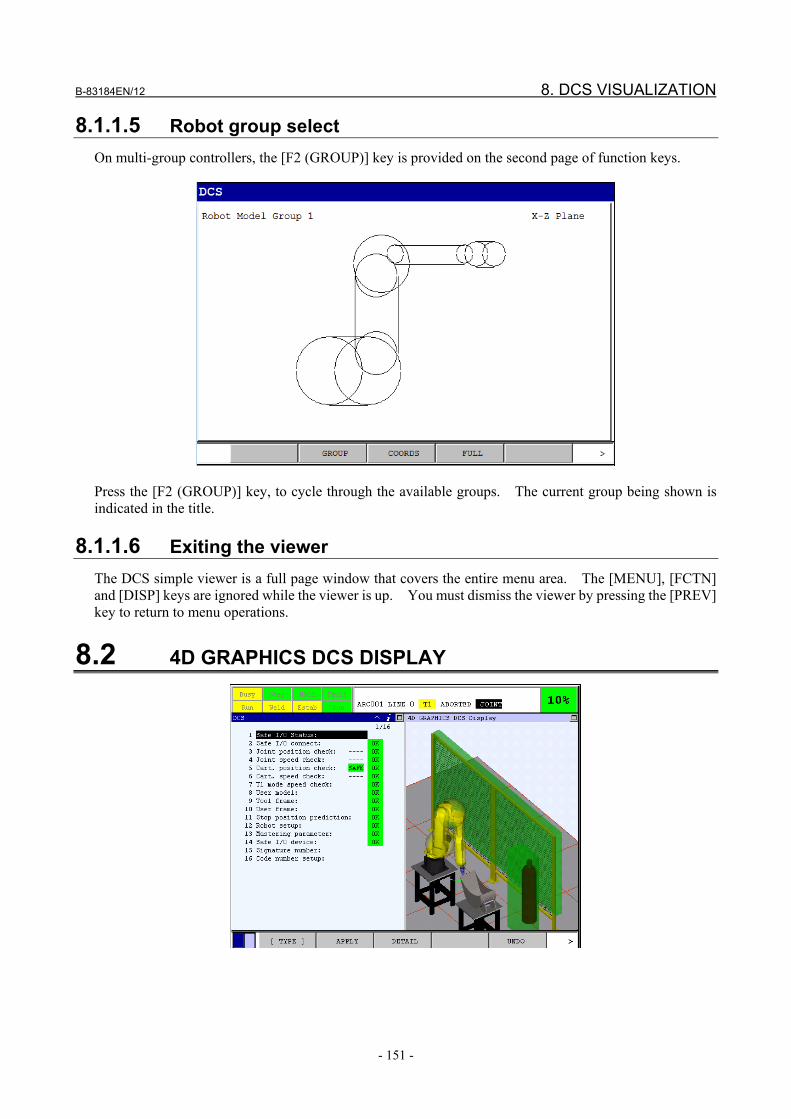
B-83184EN/12 8. DCS VISUALIZATION
- 151 -
8.1.1.5 Robot group select On multi-group controllers, the [F2 (GROUP)] key is provided on the second page of function keys.
Press the [F2 (GROUP)] key, to cycle through the available groups. The current group being shown is indicated in the title.
8.1.1.6 Exiting the viewer The DCS simple viewer is a full page window that covers the entire menu area. The [MENU], [FCTN] and [DISP] keys are ignored while the viewer is up. You must dismiss the viewer by pressing the [PREV] key to return to menu operations.
8.2 4D GRAPHICS DCS DISPLAY

8. DCS VISUALIZATION B-83184EN/12
- 152 -
Procedure 8-2 4D GRAPHICS DCS Step
The following is the operation to display 4D GRAPHICS DCS display. 1 Press the [MENU] key and display MENU pop up screen. 2 Select "0 -- NEXT –" and select "6 SYSTEM". 3 Press the [F1 (TYPE)] key and select "DCS". 4 Press the [i] key and the [FCTN] key on DCS screen. Related View menu will be displayed. 5 Select "4D DCS Display".
8.2.1 Operation Procedure In 4D GRAPHICS screen, view is adjusted by the following operation modes. - ZOOM - PAN - ROTATE And the following functions are prepared. - Preset Views - User Views
ZOOM
ZOOM consists of changing the magnification. Increasing the magnification makes the objects larger but the field of view is narrow. If it is reduced, the target model will be displayed smaller, but the field of view will be wider. Press the [F3 (ZOOM)] key to set the system to zoom mode. Then, the label [F3 (ZOOM)] turns blue in color. There are two ways for ZOOM operation. One is the iPendant key input and the other is touch panel operation. Zoom by iPendant key input Increase the magnification - Press the [up arrow] key on iPendant. - Press the [SHIFT] + [up arrow] key on iPendant. (High magnification) Decrease the magnification - Press the [down arrow] key on iPendant. - Press the [SHIFT] + [down arrow] key on iPendant. (High magnification) Zoom by touch panel Increase the magnification - Touch and release near the top of the screen. - Touch the screen and drag your finger up or right,

B-83184EN/12 8. DCS VISUALIZATION
- 153 -
Decrease the magnification - Touch and release near the bottom of the screen. - Touch the screen and drag your finger down or left,
PAN
PAN consists of moving the view up, down, left and right. Press the [F4 (PAN)] key to set the system to PAN mode. Then, the label F4, PAN turns blue in color. There are two ways for PAN operation. One is the iPendant key input and the other is touch panel operation. PAN by iPendant key input - Press the [arrow] key on iPendant up, down, left and right. PAN by touch panel - Touch the screen and drag your finger up, down, left and right. - Click the screen so the point you click become center on the screen.
ROTATE
ROTATE consists of rotating the view up, down, left and right. Press the [F5 (ROTATE)] key to set the system to ROTATE mode. Then, the label [F5 (ROTATE)] turns blue in color. There are two ways for ROTATE operation. One is the iPendant key input and the other is touch panel operation. ROTATE by iPendant key input - Press the [arrow] key on iPendant up, down, left and right. - Press the [SHIFT] + [arrow] key on iPendant up, down, left and right. (High magnification)

8. DCS VISUALIZATION B-83184EN/12
- 154 -
ROTATE by touch panel - Touch the screen and drag your finger up, down, left and right.
Preset Views
4D GRAPHICS screen provides seven preset views. The default view provides a view from 45 degree. This view is good starting point for setting the view. It also put information back on the screen in the case where it has inadvertently been lost. All preset views will center the floor in the middle of the view. - Default Set the view to default - Front Set the view in front of the robot - Back Set the view behind the robot - Top Set the view right above the robot - Bottom Set the view right below the robot - Right Set the view on the right side of the robot - Left Set the view on the left side of the robot To select Preset Views, press the [NEXT] key and press the [F2 (VIEWS)] key. Select one of the preset views above. Please refer to Section "4D GRAPHICS FUNCTION" in Optional Function OPERATOR'S MANUAL(B-83284EN-2) for details.
8.3 VIEWING USER MODELS F5 (VIEW) is available on the NEXT page of function keys to launch the simple user model viewer from the following user model setup screens: • User Model List menu • User Model Element List menu • User Model Element Detail The 4D Graphics follows your actions in these menus and automatically displays the appropriate detail described below. The user model viewer always displays all enabled elements independent of which model menu you are currently in. When viewed from the Element List menu or Element Detail screen, however, the currently selected element is always displayed whether it is enabled or not and highlighted in a different color.

B-83184EN/12 8. DCS VISUALIZATION
- 155 -
Below is an example of an end-of-arm effector described by a DCS user model and presented by the user model viewer. Both 4D Graphics and Simple views are shown.
There is a great deal of flexibility when defining elements of a model. Each element can be referenced relative to the faceplate or a specific link and be offset by a tool frame. These reference frames are applied when the user model is used in a Cartesian position check setup and associated with a robot group. On multi-group systems, the simple user model viewer does not know this association so it defaults to displaying all elements relative to group 1. You can cycle through groups using [F2 (GROUP)] key on the second page of function keys. The 4D Graphics model viewer looks for where the model is used and selects the related robot group for displaying the user model. If the model has not been referenced in a Cartesian position check zone yet, group 1 is selected.

8. DCS VISUALIZATION B-83184EN/12
- 156 -
8.4 VIEWING CARTESIAN POSITION CHECKS F5 (VIEW) is available on the NEXT page of function keys to launch the simple Cartesian position check (CPC) viewer from the following DCS setup screens: • DCS Main menu • Cartesian Position Check List menu • Cartesian Position Check Detail The 4D Graphics follows your actions in these menus and automatically displays the appropriate detail described below. Viewing CPC status from the DCS main menu when the cursor must is on the DCS Cartesian position check item shows all enabled zones. Zones will appear and disappear if they are enabled and disabled by safety I/O. Multi-group configurations are handled differently between Simple and 4D Graphics. The Simple viewer displays only one group at a time and the 4D Graphics viewer displays all of them simultaneously. When launched from the List menu or Detail screen, the CPC viewer will display the zone even if it is disabled. Zones are displayed in green if they are safe and red if unsafe. In the Simple view, the robot model will be displayed in black if it is being checked by the zone and gray if it is not. The 4D Graphics view always shows the robot image and adds the DCS robot model when that is being checked by the zone. User models being checked by the zone are displayed in blue. The DCS user frame employed is displayed in purple in the Simple viewer. Below is an example of a Cartesian position check zone using the Lines (IN) safe side method checking the robot and one user model. Both 4D Graphics and Simple views are shown.

B-83184EN/12 8. DCS VISUALIZATION
- 157 -
The CPC viewer displays two triads to represent a position check zone that uses the OrntFix (ALL) method. The current orientation of the faceplate is displayed with a blue triad. The zone check orientation is displayed in green or red depending on its safe status. Both 4D Graphics and Simple views of the ALL method are shown below.

8. DCS VISUALIZATION B-83184EN/12
- 158 -
The CPC viewer displays two single line vectors to represent a position check zone that uses the OrntFix (UserZ) method. The vector relative to current orientation of the faceplate is displayed with a blue line. The zone check orientation (normal to the DCS user frame) is displayed in green or red depending on its safe status. Both 4D Graphics and Simple views of the UserZ method are shown below.
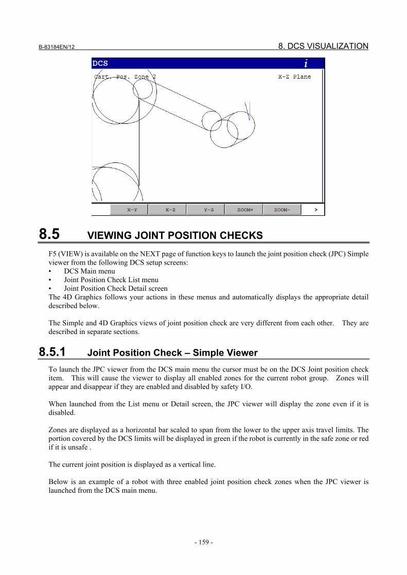
B-83184EN/12 8. DCS VISUALIZATION
- 159 -
8.5 VIEWING JOINT POSITION CHECKS F5 (VIEW) is available on the NEXT page of function keys to launch the joint position check (JPC) Simple viewer from the following DCS setup screens: • DCS Main menu • Joint Position Check List menu • Joint Position Check Detail screen The 4D Graphics follows your actions in these menus and automatically displays the appropriate detail described below. The Simple and 4D Graphics views of joint position check are very different from each other. They are described in separate sections.
8.5.1 Joint Position Check – Simple Viewer To launch the JPC viewer from the DCS main menu the cursor must be on the DCS Joint position check item. This will cause the viewer to display all enabled zones for the current robot group. Zones will appear and disappear if they are enabled and disabled by safety I/O. When launched from the List menu or Detail screen, the JPC viewer will display the zone even if it is disabled.
Zones are displayed as a horizontal bar scaled to span from the lower to the upper axis travel limits. The portion covered by the DCS limits will be displayed in green if the robot is currently in the safe zone or red if it is unsafe . The current joint position is displayed as a vertical line. Below is an example of a robot with three enabled joint position check zones when the JPC viewer is launched from the DCS main menu.

8. DCS VISUALIZATION B-83184EN/12
- 160 -
8.5.2 Joint Position Check – 4D Graphics Viewer JPC settings are displayed when the 4D Graphics DCS Display related view is active and one of the JPC setup screens is selected in the DCS Setup menus. When the cursor is on Joint position check: in the DCS main menu the 4D Graphics will display all enabled JPC zones. Zones will appear and disappear as they are enabled and disabled by safety I/O. When the List menu or Detail screen is active, the 4D Graphics will display the zone even if it is disabled.
JPC zones are displayed as a fan for rotational axes and as a bar for linear axes. These are superimposed on the robot itself and a needle shows the current joint position of the robot. The zone is green if the robot is currently in the safe zone or red if it is unsafe. Below is an example of a robot with a joint position check zone on J4 axis. It is shown when the cursor is on Joint position check: in the DCS main menu.

B-83184EN/12 9. SAFE I/O
- 161 -
9 SAFE I/O
9.1 SAFE I/O Safe I/O are safe signals that can be used in DCS. Safe I/O is expressed by a 3 character type and an index number, such as "SPI[1]". For example, safety input signal SFDI1 is represented as Safe I/O SPI[1]. To switch the safety zone according to SFDI1, set SPI[1] to the disabling I/O. Some Safe I/O show the internal status of DCS. For example, the Safe I/O CPC[1] shows the status of Cartesian Position Check No.1. The status of the Cartesian Position Check can be output to the safety output signal SFDO1 by connecting CPC[1] to SPO[1] in Safe I/O connect function. The following is a list of the Safe I/O types. In the Input/Output column, the safe I/O that can be specified on the left side of an I/O connect is "Output", the other Safe I/O is "Input". The status of the "Output" Safe I/O is set by Safe I/O connect function or Safety PMC only. All "Output" Safe I/O except SSO[1-5] are OFF at power up. SSO[1-5] are ON. Safe I/O has redundancy internally, therefore one safe I/O signal works as safety signal. A Dual channel input signal (Ex. SFDI11 and SFDI21) corresponds to one safe I/O signal (SPI[1]), and the safe I/O signal becomes ON when the both of the dual channel signals are ON. The Safe I/O Connect function is a Cat.4, PL e, SIL 3 function, but some safe I/O are Cat.3, PL d, SIL 2 because the source function is Cat.3, PL d, SIL 2. The column "Cat.,PL,SIL" shows the Cat., PL and SIL of each Safe I/O. The number in "Slot" column is used for " Safe I/O status monitoring" that is described later.
Type of Safe I/O
Type Range of index
Input / Output
Cat. PL SIL
Slot Description
SPI 1-64 or 1-128
Input Cat.4 PL e SIL 3 (Note3)
1 Safe Peripheral Input In B-cabinet controller of R-30iB, R-30iB Plus SPI[1-8] are safety input on Safety I/O board SFDI1-8. Safety I/O board is hardware option. When the hardware is not equipped, SPI[1-8] are always OFF. In A-cabinet controller of R-30iB, R-30iB Plus, SPI[1-2] are safety input SFDI1-2 on emergency stop board. SPI[3-8] are always OFF. In R-30iB Mate, additional safety I/O device is needed to use safety input. In R-30iB Mini Plus, SPI[1-2] are safety input SFDI1-2 on main board. SPI[3-8] are always OFF. ON: Both of dual circuit are CLOSED, OFF: Either circuit is OPEN When additional safety I/O device is connected, the additional safety input signals are assigned to SPI. Please refer to "9.4 ADDITIONAL SAFETY SIGNALS". Range of index is 1-64 in R-30iB and R-30iB Mate. It is 1-128 in R-30iB Plus, R-30iB Mate Plus and R-30iB Compact Plus when the software version is 7DF1/15 or later.

9. SAFE I/O B-83184EN/12
- 162 -
Type Range of index
Input / Output
Cat. PL SIL
Slot Description
SPO 1-64 or 1-128
Output Cat.4 PL e SIL 3 (Note2) (Note3)
2 Safe Peripheral Output In B-cabinet controller of R-30iB, R-30iB Plus SPO[1-8] are safety output on Safety I/O board SFDO1-8. Safety I/O board is hardware option. When the hardware is not equipped, SPO[1-8] are always OFF. In A-cabinet controller of R-30iB, R-30iB Plus, SPO[1-2] are safety output on emergency stop board SFDO1-2. There is no hardware signal corresponded to SPO[3-8]. In R-30iB Mate, R-30iB Mate Plus, R-30iB Compact Plus and R-30iB Mini Plus, additional safety I/O device is needed to use safety output. When additional safety I/O device is connected, the additional safety output signals are assigned to SPO. Please refer to "9.4 ADDITIONAL SAFETY SIGNALS". When SFDO pulse check is disabled, SFDO output is safety function of Category 3, PL d. Actual output becomes OFF in fault situation even though SPO is set to ON.(Note 1) Range of index is 1-64 in R-30iB and R-30iB Mate. It is 1-128 in R-30iB Plus, R-30iB Mate Plus and R-30iB Compact Plus when the software version is 7DF1/15 or later.
SSI 1-14 Input Cat.4 PL e SIL 3
3 Safe System Input Status of system safety information such as emergency stop button. Detail is specified in the table "Detail of SSI". R-30iB, R-30iB Mate do not support to SSI [12][13][14].
SSO 1-7 Output Cat.4 PL e SIL 3
4 Safe System Output Commands to system such as request emergency stop. Detail is specified in the table "Detail of SSO".
SIR 1-64 Output Cat.4 PL e SIL 3
5 Safe Internal Relay Internal relay that can be used in Safe I/O connect. Status is OFF at power up.
CPC 1-32 Input Cat.3 PL d SIL 2
6 Cartesian Position Check Status of Cartesian Position Check functions. When the status is SAFE, it is ON. Otherwise, it is OFF.
CSC 1-16 Input Cat.3 PL d SIL 2
7 Cartesian Speed Check Status of Cartesian Speed Check functions. When the status is SAFE, it is ON. Otherwise, it is OFF.
JPC 1-40 Input Cat.3 PL d SIL 2
8 Joint Position Check Status of Joint Position Check functions. When the status is SAFE, it is ON. Otherwise, it is OFF.
JSC 1-40 Input Cat.3 PL d SIL 2
9 Joint Speed Check Status of Joint Speed Check functions. When the status is SAFE, it is ON. Otherwise, it is OFF.
CSI 1-64 Input Cat.4 PL e SIL 3
10 CIP Safety Input Inputs from the DeviceNet Safety, EtherNet/IP Safety or PROFINET Safety network. It is OFF when safety communication error occurs or the Enable/Bypass setting is BYPASS. OFF should be Safe(Stop) side.
CSO 1-64 Output Cat.4 PL e SIL 3
11 CIP Safety Output Outputs to the DeviceNet Safety, EtherNet/IP Safety or PROFINET Safety network. Actual output becomes OFF in fault situation even though CSO is set to ON.(Note 1)

B-83184EN/12 9. SAFE I/O
- 163 -
Type Range of index
Input / Output
Cat. PL SIL
Slot Description
CCL 1-4 Input Cat.4 PL e SIL 3
12 Configuration Change Latch Shows whether the DCS parameters are changed or not. When the current signature and the latched signature are the same in the DCS signature menu, it is ON. When they are different, it is OFF. Index 1-4 correspond to the items in DCS signature menu as follows. 1: Total (CCL[1] is ON when 2, 3 and 4 are ON even though the
current signature and latched signature are different) 2: Base 3: Pos./Speed 4: I/O Connect
CCR 1-4 Output Cat.4 PL e SIL 3
13 Configuration Change Reset When this Safe I/O is changed from OFF to ON, the current signature is copied to the latched signature for corresponding items in the DCS signature menu and the corresponding CCL is turned ON. The correspondence of the index is the same as CCL. When CCR[1] is changed from OFF to ON, the current signature is copied to the latched signature for all items in the DCS signature menu and all CCL[1-4] are turned ON.
RPI 1-4 Input Cat.4 PL e SIL 3
14 Robot Power Input In the system that two or more robots are connected to the robot controller, RPI shows the status of robot disable switch. ON: The robot disable switch selects enable. OFF: The robot disable switch selects disable. In this case, the servo power of this robot is turned OFF. The index is the robot number of the robot disable switch. The robot number is displayed in DCS Safe I/O device menu.
RPO 1-4 Output Cat.4 PL e SIL 3
15 Robot Power Output When RPO is OFF, the servo power of the corresponded robot is turned OFF. The index is the robot number. RPO works as the same as robot disable switch. The initial value of this signal is ON, and the servo power of robot is not turned off when this signal is not used (this signal is not specified in Safe I/O connect).
FSI 1-272 Input Cat.4 PL e SIL 3
16 Safety function by FL-net Input Inputs from the Safety function by FL-net network.
FSO 1-80 Output Cat.4 PL e SIL 3
17 Safety function by FL-net Output Outputs to the Safety function by FL-net network. Actual output becomes OFF in fault situation even though FSO is set to ON.(Note 1)
SLI 1-64 Input Cat.3 PL d SIL 2
18 Input for I/O Link i Slave Safety input signals for I/O Link i Slave function.
SLO 1-64 Output Cat.3 PL d SIL 2
19 Output for I/O Link i Slave Safety output signals for I/O Link i Slave function. Actual output becomes OFF in fault situation even though SLO is set to ON.(Note 1)

9. SAFE I/O B-83184EN/12
- 164 -
Type Range of index
Input / Output
Cat. PL SIL
Slot Description
--- 0 Not defined. This means no safe I/O is defined.
ON 0 Input Cat.4 PL e SIL 3
Always ON
OFF 0 Input Cat.4 PL e SIL 3
Always OFF
NSI 1-32 Input Non- safety data
0 (DO)
Non-safety input NSI can be assigned to DO as rack 36 slot 0. When the assigned DO is ON, the NSI is ON. When the DO is OFF, the NSI is OFF. NSI is non-safety data. If NSI is used for safety purpose, it will not work as safety function, and serious personal injury could result. Adequate risk assessment for the whole robot system is necessary to use NSI. Please refer to "9.3 EXAMPLE OF SAFE ZONE SWITCHING BY USING NSI".
WARNING 1 NSI is non-safety data. If NSI is used for safety purpose, it will not work as safety
function, and serious personal injury could result. Adequate risk assessment for the whole robot system is necessary to use NSI.
Especially, when operation (AND,OR) is used between NSI and other Safe I/O, the result will be non-safety data. (Ex. "SIR[1]=NSI[1] OR SPI[1]". In this case, SIR[1] is non-safety data.)
When NSI and other Safe I/O are mixed in logic of safe I/O connect function, adequate analysis of logic is necessary.
You can save the current setting of safe I/O connect function to memory card as text file (DCSVRFY.DG) in FILE menu. It may be helpful to analyze the logic, because you can read and print it by PC.
2 If the safety output signals such as SPO, CSO, FSO or SLO is used, the robot system should be designed as that the robot system becomes Safe (Stop) State when these safety output signals are OFF. These safety output signals are forced to OFF when internal fault is detected in robot controller. If the robot system does not become Safe State when these safety output signals are OFF, the safety function will not work, and serious personal injury could result.
Note 1: The actual output of SPO, CSO, FSO and SLO becomes OFF when the following alarm occurs.
SRVO-248 Deadman switch status abnormal SRVO-266 FENCE1 status abnormal SRVO-267 FENCE2 status abnormal SRVO-268 SVOFF1 status abnormal SRVO-269 SVOFF2 status abnormal SRVO-270 EXEMG1 status abnormal SRVO-271 EXEMG2 status abnormal SRVO-274 NTED1 status abnormal SRVO-275 NTED2 status abnormal SRVO-335 DCS OFFCHK alarm i, j SRVO-336 DCS RAMCHK alarm i, j SRVO-337 DCS PRMCHK alarm i, j SRVO-338 DCS FLOW alarm i, j

B-83184EN/12 9. SAFE I/O
- 165 -
SRVO-339 DCS MISC alarm i, j SRVO-344 DCS GRP alarm(G i) j, k SRVO-347 DCS AXS alarm(G i,A j) k, l SRVO-348 DCS MCC OFF alarm i, j SRVO-349 DCS MCC ON alarm i, j SRVO-350 DCS CPU alarm i, j SRVO-351 DCS CRC alarm i, j SRVO-352 DCS COUNT1 alarm i, j SRVO-353 DCS COUNT2 alarm i, j SRVO-354 DCS DICHK alarm i, j SRVO-355 DCS ITP_TIME alarm i, j SRVO-356 DCS ITP_SCAN alarm i, j SRVO-357 DCS ENABLED alarm i, j SRVO-358 DCS INVPRM alarm i, j SRVO-359 DCS SYSTEM alarm i, j SRVO-360 DCS CC_TCP alarm(G i) j, k SRVO-361 DCS CC_FP alarm(G i) j, k SRVO-362 DCS CC_TCPS alarm(G i) j, k SRVO-363 DCS CC_FPS alarm(G i) j, k SRVO-364 DCS PRMCRC alarm(G i) j, k SRVO-365 DCS FB_CMP alarm(G i,A j) k, l SRVO-366 DCS FB_INFO alarm(G i,A j) k, l SRVO-367 DCS CC_JPOS alarm(G i,A j) k, l SRVO-368 DCS CC_JSPD alarm(G i,A j) k, l SRVO-370 SVON1 status abnormal SRVO-371 SVON2 status abnormal SRVO-372 OPEMG1 status abnormal SRVO-373 OPEMG2 status abnormal SRVO-374 MODE11 status abnormal SRVO-375 MODE12 status abnormal SRVO-376 MODE21 status abnormal SRVO-377 MODE22 status abnormal" SRVO-378 SFDIxx status abnormal SRVO-412 DCS COUNT3 alarm i, j SRVO-413 DCS CC_SAFEIO alarm i, j SRVO-414 DCS WORK CRC alarm i, j SRVO-417 DCS APSP_C alarm (G i) j, k SRVO-418 DCS APSP_J alarm (G i, A j) k, l SRVO-447 DCS LS STO-FB alarm SRVO-448 DCS PLSCHK alarm SRVO-449 DCS DOMON alarm SRVO-471 I/O Link i slave(i-j) status abnormal SRVO-473 DCS CLLB CC_EXTF alarm SRVO-477 Calibration data error SRVO-478 Temperature difference too large SRVO-479 Temperature changes too fast SRVO-480 FORCE alarm i, j SRVO-489 Force sensor type error SRVO-490 FORCE alarm 2 i, j SRVO-496 Set initial forces SRVO-497 Initial forces CRC error SRVO-503 Sensor alarm i, j SRVO-504 Sensor type error SRVO-505 Sens Temp change too large

9. SAFE I/O B-83184EN/12
- 166 -
Note 2: Regarding SFDO output, - When SFDO pulse check is enabled, an application involving the SFDO and an external diagnostic
device may achieve cat 4, Pl=e, SIL 3. - When SFDO pulse check is disabled, an application involving the SFDO and an external diagnostic
device may achieve cat 3, Pl=d, SIL 2. Note 3: When SFDI and SFDO of I/O Unit-MODEL A is used, an application involving the SFDI and
SFDO may achieve cat 3, Pl=d, SIL 2.
Detail of SSI Index Name Description SSI[1] SVOFF The status of EGS1 and EGS2 on the emergency stop board.
ON: Both are CLOSED, OFF: Either circuit is OPEN In R-30iB Mate, SSI[1] is always ON.
SSI[2] FENCE The status of EAS1 and EAS2 on the emergency stop board. ON: Both are CLOSED, OFF: Either circuit is OPEN
SSI[3] EXEMG The status of EES1 and EES2 on the emergency stop board. ON: Both are CLOSED, OFF: Either circuit is OPEN In R-30iB Mate, SSI[3] becomes OFF when EES1 or EES2 is OPEN or the Operator Panel E-Stop button is pressed or the Teach Pendant E-Stop button is pressed. In addition, when Shared Teach Pendant function is enabled, SSI[3] becomes OFF in the following case;
- Panel E-Stop button is pressed or the Teach Pendant E-Stop button is pressed. - E-stop occurs in other controllers in Shared Teach Pendant group. In this case SRVO-422 occurred. - SRVO-423, SRVO-424 or SRVO-425 occurs.
SSI[4] Not used. SSI[5] NTED The status of NTED1 and NTED2 on the emergency stop board and the Teach
Pendant deadman (Enable) switches. ON: Both NTED1 and NTED2 are CLOSED, and either deadman switch on the Teach
Pendant is gripped normally. OFF: NTED1 or NTED2 is OPEN or both deadman switches are released or gripped
strongly. SSI[6] OPEMG The status of the Operator Panel Emergency Stop button and the Teach Pendant
Emergency Stop button ON: Both are released., OFF: Either Emergency Stop is pressed. In R-30iB Mate, SSI[6] is always ON. Please use SSI[3].
SSI[7] AUTO ON: AUTO mode, OFF: Not AUTO mode SSI[8] T1 ON: T1 Mode, OFF: Not T1 Mode SSI[9] T2 ON: T2 Mode, OFF: Not T2 Mode
SSI[10] MCC ON: Servo power supply is ON, OFF: Servo power supply is OFF. In the system that two or more robots are connected to the robot controller, This is ON when servo power of one or more robot is turned ON. It is OFF when servo power of all robots are turned OFF.
SSI[11] CSBP CIP Safety By Passed ON: "Enable/Bypass" in DCS CIP safety menu is BYPASS, OFF: Not BYPASS When PROFINET Safety is installed, ON: "Enable/Bypass" in DCS PROFINET safety menu is BYPASS, OFF: Not BYPASS When CC-Link IE Field safety slave function is installed, ON: "Enable/Bypass" in DCS CC-Link IE Field Safety menu is BYPASS, OFF: Not BYPASS
SSI[12] POSSPD CHECK ENB
ON: DCS Position / Speed Check function is ENABLE, OFF: DCS Position /Speed Check function is DISABLE. SSI[12] is not supported in R-30iB, R-30iB Mate.

B-83184EN/12 9. SAFE I/O
- 167 -
Index Name Description SSI[13] CONF_OK ON: Valid setting DCS Position / Speed Check functions is about to be used, when
SSI[13] Configuration check is ENABLE, OFF: SSI[13] Configuration check is DISABLE or invalid setting DCS Position / Speed Check functions is about to be used, when SSI[13] Configuration check is ENABLE, See "7.12 Pos./ Speed Check setup". SSI[13] is not supported in R-30iB, R-30iB Mate.
SSI[14] F_IPAR_CRC SSI[14] is used on PROFINET I-device or PROFINET FANUC board. When F_iPar_CRC is received on PROFINET Safety, the signal changes to ON: the value is not 0, or OFF: the value is 0. If the value is OFF and safety I/O communication is running, it is TEST Mode and check of F_iPar_CRC is skipped. Note that the TEST Mode is not supported on the PROFINET FANUC board, so if F_iPar_CRC is set to 0 on the F-Host, the safety communication cannot be performed. The state of signal is not changed by stopping safety I/O communication. SSI[14] is not supported in R-30iB, R-30iB Mate.
Detail of SSO
Index Name Description SSO[1] C_SVOFF When this Safe I/O is OFF, the robot decelerates then stops and the servo power
supply is turned off. "SRVO-406 DCS SSO SVOFF input" occurs. The initial value of this signal is ON, and the alarm does not occur when this signal is not used (this signal is not specified in Safe I/O connect). SVOFF(EGS) signal on emergency stop board and this signal work independently. When this signal is used instead of SVOFF signal, SVOFF signal should be jumpered.
SSO[2] C_FENCE When this Safe I/O is OFF in AUTO mode, the robot decelerates then stops and the servo power supply is turned off. "SRVO-407 DCS SSO Fence Open" occurs. The initial value of this signal is ON, and the alarm does not occur when this signal is not used (this signal is not specified in Safe I/O connect). FENCE(EAS) signal on emergency stop board and this signal work independently. When this signal is used instead of FENCE signal, FENCE signal should be jumpered.
SSO[3] C_EXEMG When this Safe I/O is OFF, the servo power supply is turned off and the robot stops immediately. "SRVO-408 DCS SSO Ext Emergency Stop" occurs. The initial value of this signal is ON, and the alarm does not occur when this signal is not used (this signal is not specified in Safe I/O connect). External Emergency Stop(EES) signal on emergency stop board and this signal work independently. When this signal is used instead of External Emergency Stop signal, External Emergency Stop signal should be jumpered.
SSO[4] C_SVDISC When this Safe I/O is OFF, the servo power supply is turned off and the robot stops immediately. "SRVO-409 DCS SSO Servo Disconnect" occurs. The initial value of this signal is ON, and the alarm does not occur when this signal is not used (this signal is not specified in Safe I/O connect).
SSO[5] C_NTED When this Safe I/O is OFF in T1 or T2 mode, the servo power supply is turned off and the robot stops immediately. "SRVO-410 DCS SSO NTED input" occurs. The initial value of this signal is ON, and the alarm does not occur when this signal is not used (this signal is not specified in Safe I/O connect). NTED signal on emergency stop board and this signal work independently. When this signal is used instead of NTED signal, NTED signal should be jumpered.

9. SAFE I/O B-83184EN/12
- 168 -
Index Name Description SSO[6] C_T1 SSO[6] and SSO[7] are used to select AUTO/T1/T2 operation mode in place of mode
switch on operator panel. To use SSO[6] and SSO[7], “External mode select” option (A05B-2600-J569) is necessary and the operator panel must be “No mode switch” type. If the option is loaded to the robot controller that the operator panel has mode switch, the alarm “SYST-301 External mode select is not available” occurs. AUTO/T1/T2 mode is selected according to the status of SSO[6] and SSO[7] as follows. SSO[6:C_T1] SSO[7:C_T2] Mode OFF OFF AUTO ON OFF T1 ON ON T2 OFF ON Invalid (SYST-037, SRVO-411) Note: When “External mode select” option is used, a risk assessment for the whole robot system is necessary, including the means to select the operational mode.
SSO[7] C_T2
WARNING When “External mode select” option is used (AUTO/T1/T2 operational mode is
selected by SSO[6] and SSO[7]), a risk assessment for the whole robot system is necessary, including the means to select the operational mode. If a robot is used with an incorrect operational mode, the safety function does not work correctly and serious personal injury result. The means to select the operational mode must fulfil the following requirement.
Operational modes shall be selectable with a mode selector which can be locked in each position (e.g. a key operated switch which can be inserted and extracted in each position). Each position of the selector shall be clearly identifiable and shall exclusively allow one control or operating mode.
Safe I/O status monitoring (Non-safety function)
Safe I/O except NSI can be assigned to digital inputs (DI). To read the status of the Safe I/O, you can monitor the DI that the Safe I/O is assigned to from a TP program, a KAREL program, etc.
Rack: 36 Slot: The number specified in "Slot" column" in the above table Start point: Same as Safe I/O index.
Example: SPI[1-4] can be read as DI[1-4] by the following I/O assignment setting.
RANGE RACK SLOT START DI[ 1- 4] 36 1 1
WARNING Safe I/O status monitoring is not a safety function. If a DI that is assigned to Safe
I/O is used where a safety function is required, the safety function will not work under some fault conditions and serious personal injury could result. Do not use Safe I/O monitoring for safety purposes.
Safe I/O assignment for Integrated PMC function (Non-safety function)
To use the Safe I/O in integrated PMC function, you can assign the Safe I/O in PMC external I/O assignment as follows.
Rack: 36 Slot: The number specified in "Slot" column" in the above table

B-83184EN/12 9. SAFE I/O
- 169 -
- Safe I/O except NSI can be assigned to X of integrated PMC, and the integrated PMC function can
read the Safe I/O. In the following example, SIR[1-64] can be read by X0.0 - X7.7.
Type Rack Slot Size Addr 1 DI 36 5 8 1:X00000
- Non-safety input (NSI) can be assigned to Y of integrated PMC, and the integrated PMC function can
output to NSI. In the following example, NSI[1-64] can be output by Y0.0 - Y7.7.
Type Rack Slot Size Addr 1 DO 36 0 8 1:Y00000
WARNING The integrated PMC function is not a safety function. If the integrated PMC
function is used where a safety function is required, the integrated PMC process will not work under some fault conditions and serious personal injury could result. Do not use the integrated PMC function for safety purposes.
9.1.1 SFDO Pulse Check Safety output signal SFDO is dual channel output signal. And to satisfy safety function of Cat. 4, PL e, SIL 3, the fault diagnosis is needed to avoid the fault accumulation. SFDO pulse check is diagnostic function for that. - SFDO pulse check can be ENABLE or DISABLE by the setting in DCS Safe I/O device menu (default
is ENABLE). - When SFDO pulse check is enabled, SFDO output is safety function of Category 4, PL e, SIL 3. When
it is disabled, SFDO output is safety function of Category 3, PL d, SIL 2. - When SFDO pulse check is enabled, pulse check is performed for all SFDO signals. It is not possible
to enable/disable each SFDO signal individually. - The pulse check is not performed for the safety output signal SFDO of I/O Unit-MODEL A even
though SFDO pulse check is enabled.
WARNING When SFDO pulse check is disabled, adequate risk assessment for the whole
robot system is necessary to verify that a Category 3, PL d, SIL 2 safety function is adequate. The external device connected to SFDO needs to check the discrepancy of redundant output signals when SFDO pulse check is disabled. If the external device detects the discrepancy in a given time, the system should be turned to the safe state like emergency stop condition.
When SFDO pulse check is enabled, OFF pulse is output periodically, and the status of the output signal is monitored. If the monitored signal does not include the pulse, it is diagnosed as trouble in output circuit or cabling.
CAUTION Please check the input response time of the device that is connected to the
safety output not to work unexpectedly by the periodic OFF pulse.

9. SAFE I/O B-83184EN/12
- 170 -
ON
OFF SFDO
1 second
Approx. 530 micro second When trouble is detected, the following alarm occurs, and the servo power is cut off, and all safety outputs turn OFF. The signal name where the trouble is detected is displayed after the alarm message. SRVO-448 DCS PLSCHK alarm
This alarm occurs when the monitored signal of safety output is not OFF even though OFF pulse is output.
SRVO-449 DCS DOMON alarm
This alarm occurs when the monitored signal of safety output is different from the output command.
9.1.2 DCS Safe I/O Status Menu The DCS Safe I/O status menu will be displayed by pressing the [ENTER] key or the [F3(DETAIL)] key while on the "Safe I/O status" item in the DCS Top menu. In the DCS Safe I/O status menu, Safe I/O status and comment are displayed. The Safe I/O comment can be changed in this menu.
DCS Safe I/O status 1/8 Status Comment SPI[ 1] ON [SFDI1 ] SPI[ 2] ON [SFDI2 ] SPI[ 3] ON [SFDI3 ] SPI[ 4] ON [SFDI4 ] SPI[ 5] ON [SFDI5 ] SPI[ 6] ON [SFDI6 ] SPI[ 7] ON [SFDI7 ] SPI[ 8] ON [SFDI8 ] [ TYPE ][ DATA ]
Items in DCS Safe I/O status menu
Item Description Safe I/O name The Safe I/O name is displayed. Status The Safe I/O status (ON, OFF) is displayed. Comment The Safe I/O comment is displayed. Press [ENTER] key to change the comment.
Operation in DCS Safe I/O status
Operation Description [F2(DATA)] A pull-up menu of the Safe I/O types is displayed for selection of which type is displayed in the
menu. [PREV] The DCS Top menu is displayed.

B-83184EN/12 9. SAFE I/O
- 171 -
9.2 SAFE I/O CONNECT FUNCTION The Safe I/O Connect function(A05B-2600-J568) is used to read and set safety inputs and outputs. When the status of safety input signal such as SPI is changed, nothing occurs by default. By the following setting of Safe I/O connect, SPI[1] (SFDI1) is connected to SSO[3] (C_EXEMG). By this setting, when SPI[1] is OFF, SSO[3] becomes OFF, and "SRVO-408 DCS SSO Ext Emergency Stop" alarm occurs, and robot stops as Stop Category 0.
SSO[3:C_EXEMG] = SPI[1:SFDI1]
Safe I/O Connect supports logical operations (AND, OR, NOT) for Safe I/O. By the following setting, only when SPI[1] is ON AND SPI[2] is OFF, robot motion is available.
SSO[3:C_EXEMG] = SPI[1:SFDI1] AND !SPI[2:SFDI2]
One AND or OR operation can be specified in one Safe I/O Connect setting. To process complex logical operations, please use safe internal relay (SIR). By the following setting, only when all of SPI[1] , SPI[2] and SPI[3] are ON, robot motion is available.
SIR[1] = SPI[1:SFDI1] AND SPI[2:SFDI2]
SSO[3:C_EXEMG] = SIR[1] AND SPI[3:SFDI3]
Safe internal relay can be used as disabling input of Position/Speed check function. If SIR[1] is used as disabling input of Position/Speed check, by the following setting, when both SPI[1] and SPI[2] are ON, the Position/Speed check is disabled.
SIR[1] = SPI[1:SFDI1] AND SPI[2:SFDI2]
Safe I/O Connect can control safe outputs according to safety information. By the following setting, when the status of Cartesian Position Check No.1 is "SAFE", the safety output signal SFDO1 is ON. When the "Stop type" of the Cartesian Position Check is set to "Not Stop", the Cartesian Position Check function can be used as the function that the safety output SFDO1 is set according to the robot position. (When the "Stop type" is "Not stop", stop position prediction does not work.)
SPO[1:SFDO1] = CPC[1]
The following is the specification of the Safe I/O Connect function. - Safe I/O connect is defined in the DCS Safe I/O connect menu. - A maximum of 64 Safe I/O Connect settings can be defined. - The lines that the Output (left) item is "---" are ignored. - All Safe I/O Connect logic are processed every 2msec in order from the top of setting menu. - When "Safe I/O process" item in DCS Safe I/O device menu is set to "Safety PMC", Safe I/O connect
function is disabled.

9. SAFE I/O B-83184EN/12
- 172 -
WARNING 1 If Safe I/O connect is set incorrectly, the safety function will not work, and
serious personal injury could result. When Safe I/O connect settings are changed, the values must be verified and the function must be tested again.
2 If Safe I/O Connect feature is used, safety signal status could be delayed by a maximum of 2 ms. In this case, a risk assessment for the whole robot system is necessary, including the additional 2 ms delay.
3 If the safety output signals such as SPO, CSO, FSO or SLO is used, the robot system should be designed as that the robot system becomes Safe (Stop) State when these safety output signals are OFF. These safety output signals are forced to OFF when internal fault is detected in robot controller. If the robot system does not become Safe State when these safety output signals are OFF, the safety function will not work, and serious personal injury could result.
Example of Safe I/O Connect - 1
By the following setting, when SFDI1 is open, robot stops as follows. - In AUTO mode, "SRVO-406 DCS SSO SVOFF input" alarm occurs, and robot stops as Stop Category
1. - In T1/T2 mode, "SRVO-408 DCS SSO Ext Emergency Stop" alarm occurs, and robot stops as Stop
Category 0.
SSO[1:C_SVOFF] = !SSI[7:AUTO] OR SPI[1:SFDI1]
SSO[3:C_EXEMG] = SSI[7:AUTO] OR SPI[1:SFDI1]
Example of Safe I/O Connect - 2
By the following setting, when FENCE signal (EAS) is open in T2 mode, "SRVO-406 DCS SSO SVOFF input" alarm occurs, and robot stops as Stop Category 1. This setting is useful to provide the system a situation where the robot can move only when safety fence is closed in T2 mode.
SSO[1:C_SVOFF] = SSI[2:FENCE] OR !SSI[9:T2]
Example of Safe I/O Connect - 3
By the following setting, the status of Teach pendant deadman (enable) switch is output to the safety output signal SFDO1. When the deamdan switch is gripped, SFDO1 is ON.
SPO[1:SFDO1] = SSI[5:NTED]

B-83184EN/12 9. SAFE I/O
- 173 -
9.2.1 DCS Safe I/O Connect Menu The DCS Safe I/O connect menu is displayed by pressing the [ENTER] key or the [F3 (DETAIL)] key while on the "Safe I/O connect" item in the DCS Top menu.
DCS Safe I/O connect 1/64 Output Input1 Input2 Status SSO[ 1]=! SPI[ 1] AND @SPI[ 2] OK ---[ 0]= ---[ 0] ---[ 0] OK ---[ 0]= ---[ 0] ---[ 0] OK ---[ 0]= ---[ 0] ---[ 0] OK ---[ 0]= ---[ 0] ---[ 0] OK ---[ 0]= ---[ 0] ---[ 0] OK ---[ 0]= ---[ 0] ---[ 0] OK ---[ 0]= ---[ 0] ---[ 0] OK ---[ 0]= ---[ 0] ---[ 0] OK [ TYPE ] CLEAR [CHOICE] UNDO
Items in DCS Safe I/O connect menu Item Description
Output Used to set the Safe I/O that is used for output. When "---" is selected, the line is disabled. When the specified Safe I/O is ON, "@" is displayed on the left side of the Safe I/O name. When the cursor is on this item, the comment of the specified Safe I/O is displayed on the prompt line at the bottom of the screen.
Input 1 Used to set the Safe I/O that is used for input 1. You can specify "!" on the left side of the Safe I/O name, this means the inverse value (NOT) is used. When the specified Safe I/O is ON, "@" is displayed on the left side of the Safe I/O name. When the cursor is on this item, the comment of the specified Safe I/O is displayed on the prompt line at the bottom of the screen.
Input 2 Used to set the Safe I/O that is used for input 2. You can specify "!" on the left side of the Safe I/O name, this means the inverse value (NOT) is used. When the specified Safe I/O is ON, "@" is displayed on the left side of the Safe I/O name. When the cursor is on this item, the comment of the specified Safe I/O is displayed on the prompt line at the bottom of the screen.
Operation Used to set the operation of input 1 and input 2. (Space): No operation. Input 2 is ignored. AND: Logical AND of input 1 and input 2. OR: Logical OR of input 1 and input 2.
Status The status of this Safe I/O connect is displayed. OK: Setting parameter and DCS parameter are the same. CHGD: Setting parameter is changed, but not applied to DCS parameter. PEND: Setting parameter is changed and applied to DCS parameter, but controller power has
not been cycled.
Operation in DCS Safe I/O connect menu Operation Description
[F3(CLEAR)] Clear the items in the line of the cursor. [F5(UNDO)] UNDO the items in this menu. The setting parameters become the same as the current DCS
parameters. [PREV] The DCS Top menu is displayed.

9. SAFE I/O B-83184EN/12
- 174 -
9.3 EXAMPLE OF SAFE ZONE SWITCHING BY USING NSI NSI is Non-Safety Input signal. When NSI is used, the system should be designed so it does not create a dangerous situation even when the NSI has the wrong value. The following is an example of safe zone switching by using NSI.
- This example is to setup DCS so the robot does not go out of the restricted zone. - Two zones, zone 1 and zone 2, are setup in the DCS position check function. Both are INSIDE zones.
The switching of these must be timed properly because the robot goes out of the intersecting area of the two zones when both zones are enabled simultaneously.
- In case 1 of the above figure, only zone 1 is enable, and the robot can move freely in zone 1. In case
2, no alarm occurs even though the both zones are enable, because the robot is in the intersecting area of the two zones. The zones are switched when the robot is in this position. In case 3, only zone 2 is enable, the robot can move forward.
- The timing of the zone switching is controlled from the robot program by using NSI. For example, when DO[1] is assigned to rack 36, slot 0, start port 1, then NSI[1] becomes ON(OFF) when DO[1] is set to ON(OFF). The robot program controls the zone switching by using DO[1].
- The following figure is an example of the setting and program for this system. Zone 1 and zone 2 are switched from the robot program by using DO[1]. The following table shows the status of each signal and zone depends on the DO[1] status.

B-83184EN/12 9. SAFE I/O
- 175 -
DO[1] NSI[1] SIR[1] SIR[2] Zone 1 Zone 2 OFF OFF OFF ON Enable Disable
ON ON ON OFF Disable Enable
- NSI is a Non-safety signal. It may have wrong value because of hardware failure and so on. When
NSI is used, DCS settings must be considered so they do not cause a dangerous situation even though the NSI has the wrong value. A dangerous situation would be the case where both zones are disabled at the same time. In this case, the robot can go out of the restricted zone. In the above setting, there is no possibility that both zones become disable even though the NSI has wrong value when the safety function works normally.
- If NSI[1] becomes ON when the robot is on P[2] in the above figure, zone 2 becomes enabled and the alarm of the DCS Cartesian position check occurs, and the servo power of the robot is cut off, the system becomes safety state.

9. SAFE I/O B-83184EN/12
- 176 -
Example of inappropriate setting The system of the following setting and program work as the same as the above system, but the robot motion is not restricted in the restricted zone when the NSI has wrong value by hardware failure and so on.
Example Program 1: L P[1] 100mm/sec FINE 2: DO[1]=OFF (Enable zone 1) 3: DO[2]=ON (Disable zone 2) 4: L P[2] 100mm/sec FINE 5: L P[1] 100mm/sec FINE 6: DO[2]=OFF (Enable zone 2) 7: DO[1]=ON (Disable zone 1) 8: L P[3] 100mm/sec FINE
P[1]
P[3]
P[2] Zone 1
Zone 2
I/O assignment DO[1] → NSI[1] DO[2] → NSI[2] Safe I/O connect SIR[1] = NSI[1] SIR[2] = NSI[2] Zone 1 Safe side: INSIDE Disabling input: SIR[1] Zone 2 Safe side: INSIDE Disabling input: SIR[2]
DO[1] DO[2] SIR[1] SIR[2] Zone 1 Zone 2 OFF OFF OFF OFF Enable Enable
OFF ON OFF ON Enable Disable
ON OFF ON OFF Disable Enable
ON ON ON ON Disable Disable
When both DO[1] and DO[2] (NSI[1] and NSI[2]) are set to ON (which is the case in the last line of the above table), both zone 1 and zone 2 become disabled, and the robot can go out of the restricted zone. The program controls DO[1] and DO[2] so both are not ON at the same time, but it is not sufficient because program execution is not a safety function.
WARNING NSI is non-safety data. If NSI is used for safety purpose, it will not work as a
safety function, and serious personal injury could result. Adequate risk assessment for the whole robot system is necessary when using NSI. Especially, when an operation (AND,OR) is used between NSI and another Safe I/O, the result will be non-safety data. (Ex. "SIR[1]=NSI[1] OR SPI[1]". In this case, SIR[1] is non-safety data.) When NSI and other Safe I/O are mixed in the logic of a safe I/O connect function, adequate analysis of logic is necessary. You can save the current setting of the safe I/O connect function to memory card as a text file (DCSVRFY.DG) in FILE menu. It may be helpful to analyze the logic, because you can read and print it with a PC.

B-83184EN/12 9. SAFE I/O
- 177 -
9.4 ADDITIONAL SAFETY SIGNALS Safety signals can be added by additional safety I/O board or I/O Unit-MODEL A. The additional safety signals are assigned to SPI and SPO. The slave controller is connected in multi-arm system or some robot models such as M-2000iA. The emergency stop board is in the slave controller, and the safety signals on the emergency stop board is assigned to SPI and SPO. The assignment to SPI and SPO is assigned automatically according to the connected safety I/O device configuration, and the assignment cannot be changed by manual. When new safety I/O device is connected, at first, the INITIALIZATION of the safety I/O device is needed. By the initialization, the added safety I/O device is assigned to SPI and SPO. When the safety I/O device is disconnected after the initialization, the alarm "SRVO-217 E-STOP Board not found" occurs. To remove the additional safety I/O device, the initialization of the safety I/O device is needed. In R-30iB, R-30iB Plus controller, SPI[1-8] and SPO[1-8] are assigned to emergency stop board by default. The additional safety signals are assigned to SPI[9-128] and SPO[9-128]. In R-30iB Mate controller, SPI and SPO are not assigned by default. The additional safety signals are assigned to SPI[1-128] and SPO[1-128]. In R-30iB Mini Plus controller, SPI[1-2] are assigned to safety input on main board and SPO are not assigned by default. The additional safety signals are assigned to SPI[9-128] and SPO[9-128]. To use additional safety I/O in R-30iB Mate controller, the main board that has PMC function is necessary. The safety I/O devices that are used in DCS are the following.
Additional safety I/O board Additional safety I/O board has 8 safety input and 8 safety output. Maximum 3 additional safety I/O boards can be connected in R-30iB, R-30iB Plus (Maximum 4 additional safety I/O boards can be connected in R-30iB Mate, but practically the maximum number of safety I/O boards is 2 because the number of min-slot is 2.). When it is used with I/O Unit-MODEL A, the maximum number of additional safety I/O board is decreased by 1. When the slave controller is connected, the maximum number of additional safety I/O board is decreased by the number of the slave controller. In R-30iB Compact Plus and R-30iB Mini Plus, only 1 additional safety I/O boards can be connected. Please refer to "22.2.3 In Case of Additional Safety I/O Board" about the connection of the additional safety I/O board. For the robot controller that the slave controller is connected such as M-2000iA, when the additional safety I/O board is connected, the alarm "SRVO-217 E-STOP Board not found" occurs. To clear the alarm, the initialization of the safety I/O device is needed.

9. SAFE I/O B-83184EN/12
- 178 -
The assignment of each additional safety I/O board is the following.
Additional safety I/O board
R-30iB, R-30iB Plus R-30iB Mate/ R-30iB Mate Plus Safety input Safety output Safety input Safety output
#1 SPI[9] : SFDI1
: : SPI[16] : SFDI8
SPO[9] : SFDO1
: :
SPO[16] : SFDO8
SPI[1] : SFDI1
: : SPI[8] : SFDI8
SPO[1] : SFDO1
: :
SPO[8] : SFDO8
#2 SPI[17] : SFDI1
: :
SPI[24] : SFDI8
SPO[17] : SFDO1
: :
SPO[24] : SFDO8
SPI[9] : SFDI1
: : SPI[16] : SFDI8
SPO[9] : SFDO1
: :
SPO[16] : SFDO8
#3 SPI[25] : SFDI1
: :
SPI[32] : SFDI8
SPO[25] : SFDO1
: :
SPO[32] : SFDO8
Additional safety I/O
board R-30iB Compact Plus R-30iB Mini Plus
Safety input Safety output Safety input Safety output
#1 SPI[1] : SFDI1
: : SPI[8] : SFDI8
SPO[1] : SFDO1
: :
SPO[8] : SFDO8
SPI[9] : SFDI1
: : SPI[16] : SFDI8
SPO[9] : SFDO1
: :
SPO[16] : SFDO8
I/O Unit-MODEL A
The I/O Unit-MODEL A can add maximum 56 safety input and 56 safety output in R-30iB (maximum 64 safety input and 64 safety output in R-30iB Mate), and can add maximum 120 safety input and 120 safety output in R-30iB Plus (maximum 128 safety input and 128 safety output in R-30iB Mate Plus). When it is used with the additional safety I/O board, the maximum number of safety input and safety output are decreased 8 ports by each one additional safety I/O board. When the slave controller is connected, the maximum number of safety input and safety output are decreased 16 ports by each one slave controller. To use I/O Unit-MODEL A for safety signal, two base units are used. The I/O module configurations on the two base units must be completely same. A pair of the corresponded I/O modules is used as a safety I/O device. The maximum 7 safety I/O devices (pairs of the I/O modules) can be added. But the maximum number of safety signals is limited as the above. When additional safety I/O board or slave controller is connected, the maximum number of the pairs of I/O modules is decreased by the number of these safety I/O devices. The signals on the I/O modules of a pair are used as dual channel safety signal. Please refer to "22.2.4 In case of I/O Unit-MODEL A" about the connection of the I/O Unit-MODEL A. The safety signals of the I/O Unit-MODEL A are safety function of Category 3, PL d, SIL 2. The SFDO pulse check is not performed for the SFDO of the I/O Unit-MODEL A even though the SFDO pulse check is enabled.
WARNING When additional Safety I/O by I/O Unit-MODEL A is used, adequate risk
assessment for the whole robot system is necessary to verify that a Category 3, PL d, SIL 2 safety function is adequate.

B-83184EN/12 9. SAFE I/O
- 179 -
The signals in I/O Unit-MODEL A are assigned to SPI and SPO by the order of slot number. The following is an example of safety I/O assignment for I/O Unit-MODEL A.
Slot Module name R-30iB/R-30iB Plus/
R-30iB Mini Plus R-30iB Mate/ R-30iB Mate Plus/
R-30iB Compact Plus Safety input Safety output Safety input Safety output
1 AOD08D -
SPO[9] : SFDO1
: :
SPO[16] : SFDO8
-
SPO[1] : SFDO1
: :
SPO[8] : SFDO8
2 AOD16D -
SPO[17] : SFDO1
: :
SPO[32] : SFDO16
-
SPO[9] : SFDO1
: :
SPO[24] : SFDO16
3 AID32E1 SPI[9] : SFDI1
: :
SPI[40] : SFDI32
-
SPI[1] : SFDI1
: :
SPI[32] : SFDI32
-
Emergency stop board in slave controller
The safety signals on the emergency stop board in the slave controller are assigned as follows. When the slave controller is A-cabinet, only 2 safety input (SFDI1, SFDI2) and 2 safety output (SFDO1, SFDO2) are available. When the slave controller is B-cabinet, safety signals are not available if safety I/O board (option) is not used. When the slave controller is Mate cabinet, safety signals are not available.
Slave controller Safety input Safety output
#1 SPI[49] : SFDI1
: :
SPI[56] : SFDI8
SPO[49] : SFDO1
: :
SPO[56] : SFDO8
#2 SPI[33] : SFDI1
: :
SPI[40] : SFDI8
SPO[33] : SFDO1
: :
SPO[40] : SFDO8
#3 SPI[17] : SFDI1
: :
SPI[24] : SFDI8
SPO[17] : SFDO1
: :
SPO[24] : SFDO8
9.4.1 DCS Safe I/O Device Menu The DCS Safe I/O device menu is displayed by pressing the [ENTER] key or the [F3(DETAIL)] key while on the "Safe I/O device" item in the DCS Top menu. This menu can setup the following items. - The function to process the safe I/O can be selected. The Safe I/O connect function is selected by
default. The Safety PMC function can be selected when "DSC Safety PMC" option is loaded. - Enable or disable of SFDO pulse check can be set. - Safety I/O device configuration can be initialized to assign safety signals to SPI and SPO when the
safety signals are added. The configuration of the Safe I/O devices connected to the robot controller is displayed in this menu. The assignment of safety I/O signals of each Safe I/O device to SPI/SPO can be checked in this menu. When two or more Safe I/O devices are connected, the Safe I/O device number that the alarm occurs is displayed such as (1) in the last of the message of the alarm that is related to the Safe I/O board (Ex. SRVO-378 SFDIxx status abnormal). The displayed number is the Safe I/O device number that will be displayed in this menu.

9. SAFE I/O B-83184EN/12
- 180 -
By pressing [F2(INIT)], the Safe I/O device configuration is initialized according to the current connected devices. The assignment of SPI and SPO is updated according to the Safe I/O device configuration when the type or order of the connected safety I/O device is changed. The new setting will be used by apply to DCS parameter operation. At the initialization of the safety I/O device configuration, the initialization may be failed with the following message. In this case, please check the configuration or connection of the safety I/O devices.
IO unit model A configuration mismatch. Cause: I/O module configurations of a pair of I/O Unit-MODEL A base unit are not same. Remedy: Check the I/O module configurations of a pair of I/O Unit-MODEL A base unit.
Too many safe I/O device!
Cause: There are too many safety signals or I/O modules on I/O Unit-MODEL A. Remedy: Reduce the number of safety signals or I/O modules of I/O Unit-MODEL A.
E-Stop board configuration mismatch.
Cause: The emergency stop board configuration does not match with robot motion group. Remedy: Check the connection of emergency stop board.
WARNING If Safe I/O device is set incorrectly, the safety function will not work, and serious
personal injury could result. When Safe I/O device settings are changed, the values must be verified and the function must be tested again.
In the DCS safe I/O device menu, the following items are displayed.
DCS Safe I/O device 1/34 1 Safe I/O process: I/O connect OK 2 SFDO pulse check: ENABLE(PL e) OK Configuration --- Device 1 ---------------- 3 Type: E-stop board OK 4 Robot number: 1 OK 5 Input: SPI[ 1 - 8](PL e) OK 6 Output: SPO[ 1 - 8](PL e) OK --- Device 2 ---------------- 7 Type: No device OK 8 Robot number: 0 OK 9 Input: SPI[ 0 - 0](PL e) OK 10 Output: SPO[ 0 - 0](PL e) OK [ TYPE ] INIT UNDO
Items in DCS Safe I/O device menu
Item Description Safe I/O process Select the function to process Safe I/O.
I/O connect: Safe I/O connect function is used (Safety PMC function is not used). Safety PMC: Safety PMC function is used (Safe I/O connect function is not used). To use Safety PMC function, the "DCS Safety PMC" option is needed.
SFDO pulse check ENABLE(PL e): SFDO pulse check is enabled. SFDO is Cat.4, PL e, SIL 3. But the SFDO pulse check is not performed for the SFDO of the I/O Unit-MODEL A even though the SFDO pulse check is enabled. DISABLE(PL d): SFDO pulse check is disabled. SFDO is Cat.3, PL d, SIL 2.

B-83184EN/12 9. SAFE I/O
- 181 -
Item Description Type The type of the safe I/O device is displayed.
No device: Safe I/O device is not connected.
E-stop board: Normally one robot has one emergency stop board. In some robot model, one robot have two emergency stop boards or no emergency stop board.
E-stop board D-SW: Emergency stop board that the robot disable switches are connected. This type is used for the emergency stop board in the 1st slave controller.
Safe I/O board: Additional safety I/O board.
General I/O device: A pair of the corresponded I/O Modules on I/O Unit-MODEL A.
Force Sensor: Force sensor.
Mate Main board: This type is used for the device 1 of R-30iB Mate controller. This device controls the robot 1, but it does not have safety signal assigned to SPI and SPO.
Mate E-stop board: This type of emergency stop board is used in slave controller of Mate cabinet. This device does not have safety signal assigned to SPI and SPO.
Mate E-stop board D-SW: Emergency stop board that the robot disable switches are connected. This type is used for the emergency stop board in the 1st slave controller that is Mate cabinet.
Compact Main board: This type is used for the device 1 of R-30iB Compact Plus controller. This device controls the robot 1, but it does not have safety signal assigned to SPI and SPO.
Mini Main board: This type is used for the device 1 of R-30iB Mini Plus controller. This device controls the robot 1. It have safety signal assigned to SPI[1-8]. (Only SPI[1-2] are available. SPI[3-8] are always OFF.) It does not have safety signal assigned to SPO.
Robot number The robot number that the emergency stop board or main board is connected is displayed. The robot disable switch number is corresponded to the robot number.
Input The SPI index range that the safety input signals of this Safe I/O device is assigned is displayed. The Performance Level (PL d or PL e) of the safety input signal is displayed.
Output The SPO index range that the safety output signals of this Safe I/O device is assigned is displayed. The Performance Level (PL d or PL e) of the safety output signal is displayed.
Status The status of each line is displayed. OK: Setting parameter and DCS parameter are the same. CHGD: Setting parameter is changed, but not applied to DCS parameter. PEND: Setting parameter is changed and applied to DCS parameter, but controller power has
not been cycled. Operation in DCS Safe I/O device menu
Operation Description [F2(INIT)] Initialize Safe I/O device configuration according to the current connected devices. [F5(UNDO)] UNDO the items in this menu. The setting parameters become the same as the current DCS
parameters. [PREV] The DCS Top menu will be displayed.

10. DEVICENET SAFETY B-83184EN/12
- 182 -
10 DEVICENET SAFETY
10.1 INTRODUCTION
10.1.1 Overview CIP-Safety is part of a suite of protocols specified by the Open DeviceNet Vendors Association (www.odva.org). This chapter covers Integrated DeviceNet Safety option that is based on the CIP-Safety protocol. This option allows the robot to act as a slave to a safety plc (such as Rockwell GuardLogix or Omron Safety Controller) exchanging I/O using the CIP-Safety protocol.
WARNING At the initial start-up, the operation check and validation of the wiring for safety
signals should be carried out, and then the wiring should be protected by the cable duct.
10.1.2 CIP Safety Requirements This product has been designed to be a part of larger safety devices/systems, each one having different properties. The robot controller safety configuration is managed locally (generally through the robot teach pendant). This is different from a safety I/O block, for example, that is configured by a Safety Network Configuration Tool (SNCT). If a SNCT configures a device it generates a Safety Configuration Identifier (SCID) which can be used to verify device configuration. A SNCT (eg. RS-Logix5000, Omron Network Configurator safety plc configuration programs) does not configure the robot controller safety behavior. The robot controller safety configuration can be monitored using the following tools : • DCS Signature Number screen found under DCS Menus • Configuration Change Latch and Reset bits (CCL, CCR bits) In the context of the robot acting as a CIP-Safety slave to a safety plc the CCL/CCR bits can be included in the safety I/O exchanged with the safety plc (see Section 9.1 in this manual) to detect any change in the robot safety configuration. The robot’s Total Signature Number (shown in the DCS Signature Number screen) can optionally be manually entered into the SNCT as the Configuration Signature. If configured in the SNCT, the robot’s signature must match what is entered into the SNCT before a safety connection can be established. The associated Date/Time stamp can be configured in the robot as ACTUAL (default) or FIXED. A setting of ACTUAL means the Date/Time stamp used in the Configuration Signature check when a safety connection is being established will be what is shown on the DCS Signature Number screen under Total Signature (offset in the SNCT by the timezone used by the SNCT). A setting of FIXED means the Configuration Signature Date/Time used in the Configuration Signature check when a safety connection is being established will always be 1/1/2009 at 6:00:00.0 am (offset in the SNCT by the timezone used by the SNCT). Please consider the following points :
• The replacement of safety devices requires that the replacement device be configured properly and operation of the replacement device shall be user verified.
• The user should assign SNN numbers for each safety network or safety sub-net that are unique system-wide.
B-83184EN/12 10. DEVICENET SAFETY
- 183 -
• If you choose to configure safety connections with an SCID=0, you are responsible for ensuring that originators and targets have the correct configurations. The robot does not get safety configuration from the safety plc or SNCT, as such, the SNCT has no basis to generate an SCID itself. The robot safety configuration can be managed using the “Signature Number” details screen (under DCS menu on the robot teach pendant) and/or using the “Configuration Change Latch” and “Configuration Change Reset” bits available within the Safety I/O Connect feature (see Chapter 9) to detect any changes in robot configuration from the safety plc. If you manually enter the robot’s Total Signature Number (including time/date stamp) into the SNCT as the Configuration Signature then this will be checked before a connection can be established.
• Please test safety connection configurations after they are applied in an originator to confirm the target connection is operating as intended.
• Please clear any pre-existing configuration from any safety device before installing it onto a safety network.
• Please commission all safety devices with MacId (and Baud Rate if necessary) prior to installing it onto a safety network.
• Please note that originators that have an “automatic” SNN setting feature should only use that feature
when the safety system is not being relied upon. • Please note that LEDs are NOT reliable indicators and cannot be guaranteed to provide accurate
information. They should ONLY be used for general diagnostics during commissioning or troubleshooting. Do not attempt to use LEDs as operational indicators.
The following points are included for informational purposes, and apply to safety targets which contain SNCT-configurable data (i.e. a safety I/O block). Since the robot controller does not contain any such configuration, these rules have no real application in its use or setup:
• Please completely test a device’s operation before setting the Lock Attribute. Since the robot safety configuration is not configured by the safety plc configuration tool the optional Lock attribute is not supported in the robot. Any changes to the robot safety configuration require applying the DCS code number on the robot teach pendant and will result in a change to the configuration signature and state of the appropriate configuration change latch bit.
• Please upload and compare the configuration from each affected safety devices to that which was sent by the SNCT before setting the Lock Attribute in those devices. This does not apply to the robot since the safety configuration is not set by the SNCT (Safety Network Configuration Tool).
• Please visually verify that all configuration data was downloaded correctly. • Please note that user testing is the means by which all downloads are validated. • Please note that the signature should only be considered “verified” after user testing. • Please note that configuring an originator with connection data and/or target configuration data must
be downloaded to the target so it can be tested and verified. Only then can SCIDs from the target be confirmed.

10. DEVICENET SAFETY B-83184EN/12
- 184 -
10.2 INTEGRATED DEVICENET SAFETY (IDNS)
10.2.1 Overview In order to use Integrated DeviceNet Safety please be sure the following software options are loaded : • DeviceNet (A05B-2600-J753 or J754) • Integrated DeviceNet Safety (A05B-2600-J974)
Table 10.2.1(a) DeviceNet Safety and robot controllers Robot Controller Description Software version
R-30iB controller Available 7DC1 series or later
R-30iB Mate controller
Available 7DC2 series or later
R-30iB Plus controller Available 7DF1 series or later
R-30iB Mate Plus controller
Available 7DF1 series or later
R-30iB Mate Plus controller (Open air type)
Not supported. N/A
R-30iB Compact Plus controller
Not supported. N/A
R-30iB Mini Plus controller
Not supported. N/A
The IDNS options requires the DeviceNet hardware to include the “DN4” daughterboard. Please see appendix A in the DeviceNet Setup & Operations manual for a list of assemblies that include the DN4 daughterboard. Please review the CIP-Safety requirements section in this manual (Subsection 10.1.2) for important general guidelines in setting up the network. A DeviceNet channel in the robot can be used for both safety slave and normal slave DeviceNet connections. The channel cannot be a CIP-Safety slave and a DeviceNet master at the same time. If this is needed please use a second DeviceNet channel so that one channel can be configured as a safety slave, and the second channel can be configured as a master for normal I/O. Note that the DCS Safe I/O Connect option (A05B-2600-J568) is automatically loaded when IDNS is loaded. Please see the chapter 9 on DCS Safe I/O Connect for details in using this option. IDNS supports up to 8 bytes in, and 8 bytes out, across the safety connection. The size is configurable. Use the DCS Safe I/O Connect option to map this safe I/O to particular safety signals within the robot. It is important to note that the DeviceNet card labeling shows “HLTH” and “COMM”. The HLTH LED is synonymous with MS (module status). The COMM LED is synonymous with NS (Network Status). The CIP-Safety settings (Safety I/O size, Enable/Bypass setting, which board number is configured for CIP-Safety) are saved in syscips.sv. The basic DeviceNet settings (mac address, baud rate) are saved as part of sysdnet.sv. See Section 1.5 on backup/restore for more information. Configuring a Safety Slave connection involves the following steps : • Configure the robot (safety slave) for proper baud rate, mac address, and safety slave I/O size – see
Subsection 10.2.2. • Configure the Safety PLC to exchange I/O with the robot – see Subsection 10.2.3.

B-83184EN/12 10. DEVICENET SAFETY
- 185 -
10.2.2 Robot Configuration Robot configuration begins with configuring the mac address, baud rate, and enabling the channel for CIP-Safety. This is done within the normal DeviceNet screens and described in procedure 10-2-1. Following this the CIP Safety I/O sizes and Enable/Bypass settings can be reviewed/changed as needed in Procedure 10-2-2.
Procedure 10-2-1 Setting MacId and Baud rate, and enable CIP-Safety channel Conditions :
• You have installed the DeviceNet DN4 hardware in the controller – see procedure 2-1 in the DeviceNet manual for details. Appendix A in the DeviceNet manual includes assembly part numbers and hardware information on the DN4 daughterboard.
• You have installed the DeviceNet Interface (A05B-2600-J753 or J754) and Integrated DeviceNet Safety (A05B-2600-J974) software options - see procedure 2-1 in the DeviceNet manual for details
Steps :
• Follow steps 1-8 in procedure 3-1 in the DeviceNet manual to configure the mac address and baud rate for the appropriate channel. Auto-restart is normally set to TRUE for a slave channel. Table 3-2 in the DeviceNet manual explains the board detail screen items if additional information is needed.
• Set “Integrated CIP-Safety” from False to True while in the board detail screen as shown in the following example. Note that “size of output from master” and “size of input to master” are for the normal (non-safe) slave connection. The channel can be configured to support both safe and normal I/O connections. The safety slave I/O size is set in the DCS menus and is covered later in this procedure.
Board Detail Board: 1 Status: OFFLINE Scanner type: SST 5136-DN4-104 Motherboard: Full-slot 1 MAC-ID: 5 2 Baud-rate: 125 KB 3 Board auto-restart: ON 4 Input resume state (rack 81): ZERO Slave Operation: Slave Status: OFFLINE 5 SLAVE Error Severity: WARN 6 Size of output from master: 0 bytes 7 Size of input to master: 0 bytes 8 Integrated CIP-Safety : True
• Cycle power and verify that there is an “S” next to the board configured for CIP-Safety as shown
below. Board List 1/4 Board Comment Rack Status S 1 [ ] 81 OFFLINE 2 [ ] 82 OFFLINE 3 [ ] 83 OFFLINE 4 [ ] 84 OFFLINE
• Put the board Online by pressing Next and the [F4 (Online)].

10. DEVICENET SAFETY B-83184EN/12
- 186 -
Procedure 10-2-2 Setting the CIP-Safety I/O size, and/or setting the CIP-Safety connection to Enable/Bypass Conditions :
• You have installed the DeviceNet DN4 hardware in the controller – see procedure 2-1 in the DeviceNet manual for details. Appendix A in the DeviceNet manual includes assembly part numbers and hardware information on the DN4 daughterboard.
• You have installed the DeviceNet Interface (A05B-2600-J753 or J754) and Integrated DeviceNet Safety (A05B-2600-J974) software options - see procedure 2-1 in the DeviceNet manual for details
• You have followed procedure 10-2-1 in this manual to configure the DeviceNet board in your system. Steps :
Setting the CIP-Safety I/O size, or setting the connection to bypass is done within the DCS Safety screens. • [MENU] -> SYSTEM -> [F1(Type)] -> DCS
1 Safe I/O Status: 2 Safe I/O connect: OK 3 CIP Safety: CHGD 4 Signature number: 5 Change code number:
• Cursor to CIP Safety and press [ENTER] to see the following screen. Note that the TP must be enabled
before any changes are allowed in this screen. The default safety I/O size is 2 bytes in and 2 bytes out. The Enable/Bypass setting is normally Enabled meaning the CIP-Safety connection must be operating before faults can be cleared in the robot. Bypass may be used during initial integration when a safety plc is not available. See the Safety I/O Connect chapter 9 for how to detect BYPASS mode. The Config Signature Date/Time setting defaults to ACTUAL which is applicable if the safety plc is configured to include a Configuration Signature check as part of connection establishment. Press [PREV] when any changes to CIP-Safety configuration are complete.
CIP Safety 1/4 Status: CHGD 1 Enable/Bypass: ENABLE 2 CIP Safety input size(byte) 2 3 CIP Safety output size(byte) 2 4 Config Signature Date/Time:
ACTUAL
• Use the [F2 (APPLY)] button while in the DCS Setup screen to complete changes. You will be
prompted for the code number. If the clock setting is not valid and the "Config Signature Date/Time" is ACTUAL, the message "Reset system clock or Not use ACTUAL" will be displayed and cannot APPLY to DCS parameter.
DCS 1 Safe I/O Status: 2 Safe I/O connect: OK 3 CIP Safety: CHGD 4 Signature number: 5 Change code number: [TYPE] APPLY DETAIL UNDO

B-83184EN/12 10. DEVICENET SAFETY
- 187 -
• You will then be shown a screen detailing the differences for review (press OK after review). DCS Verify (diff) 1/12 F Number: F00000 VERSION : HandlingTool $VERSION: V7.4307 01/05/2009 DATE: 01-FEB-09 14:59 --- CIP safety ------------------------- Status: CHGD 1 Enable/Bypass: ENABLE 2 CIP Safety input size(byte) 4 ALL OK QUIT
• A power cycle is required to make changes active.
10.2.3 Safety PLC Configuration Please see the appropriate section depending on which safety plc is being used : • Rockwell GuardLogix plc : Subsection 10.2.3.1 • Omron Safety Controller : Subsection 10.2.3.2
CAUTION The information of product other than FANUC written in the document might be
changed without prior notice. Please confirm the latest information and the detail of procedure to the manufacturer.
10.2.3.1 GuardLogix safety PLC example configuration
Please follow documentation provided with Rockwell Guardlogix PLC. The following procedure should be used for reference when configuring the robot as a DeviceNet Safety slave connected to a GuardLogix plc.
Procedure Follow the procedure below after DeviceNet Safety Setting of robot controller is completed.
WARNING The procedure written in the document focuses on the way of setting, and it does
not include any safety precaution. The operator must read manuals provided by Rockwell Automation, and examine them carefully and sufficiently before using the procedure, and take any precaution, if required, in using the procedure.
To add a robot DeviceNet safety slave connection to GuardLogix : • Install Rockwell PLC hardware and software • Launch the RSLogix5000 • In the IO Configuration tree add applicable backplane and modules to configure the system (eg. 1756-
DNB DeviceNet scanner module) • Right click on the appropriate DeviceNet scanner and choose “New Module” (you must be offline to
add a module). • Under Safety choose the “Generic DeviceNet Safety Module”

10. DEVICENET SAFETY B-83184EN/12
- 188 -
Configure the DN Safety Slave in Module Properties under the General Tab (use ‘Change …’ button): • Name’ and ‘Description’ is user defined (can be anything). • Set ‘Node’ to correct MAC_ID. • Set ‘Vendor’, ‘Product Type’, ‘Product Code’, ‘Major Revision’, and ‘Minor Revision’ according to
the table below.
Vendor Product Type Product Code Major revision Minor revision R-30iB, R-30iB Mate
8 140 34 2 2
R-30iB Plus 356 140 40 3 1
• Set ‘Electronic Keying’ to Exact Match. • Set ‘Output’ and ‘Input Data’ to Safety. Set ‘Data Format’ to Integer-SINT. • Set ‘Configuration Instance’ to 1024. • Set ‘Safety Input -> Output Assembly’ to 1024. • Set ‘Safety Output -> Input Assembly’ to 1024. • Set ‘Safety Input -> Input Assembly’ to 768 + size in bytes of robot safety I/O. (i.e. default size of 2
bytes = 770). • Set ‘Safety Output -> Output Assembly’ to 896 + size in bytes of robot safety I/O. (i.e. default size of
2 bytes = 898) • Set 8-bit sizes accordingly (2 bytes if using default safety I/O sizes). The following screen shots are for a safety connection to the robot using the default safety I/O size of 2 bytes in and 2 bytes out. Changing robot safety I/O size is described in Subsection 10.2.2.

B-83184EN/12 10. DEVICENET SAFETY
- 189 -
Under the Safety Tab Configuration Signature setting you can choose to : • Disable checking of configuration signature to skip comparing Configuration Signature during
connection establishment • Enable checking of configuration signature. You must manually enter the robot’s Total Signature
Number (shown on DCS Signature Number screen) in Hex. The Date/Time stamp will be the ACTUAL Date/Time stamp shown on the DCS Signature screen (offset in the SNCT by the timezone) or 1/1/2009 at 6:00:00.000 (offset in the SNCT by the timezone) if FIXED is set for Config Signature Date/Time in the CIP Safety setup screen. The timezone offset in the SNCT can be seen by double clicking on the time in the task bar and looking at the local timezone. As an example if FIXED date/time is used and the SNCT shows GMT-05:00 then instead of 6am the time would be entered as 1am.

10. DEVICENET SAFETY B-83184EN/12
- 190 -
Press OK to add the robot safety slave connection to the safety plc configuration. Download the new configuration to the Safety plc and go online. The new safety connection will fail until the Safety Network Number (SNN) is set. Use the “…” button on the General tab of the robot safety slave module properties to set the SNN. The “SET” button will be active when the safety plc configuration software is online with the safety plc and the robot is on the DeviceNet network configured for a safety connection. Note that the slave only accepts a new SNN when it currently has no SNN (reset back to factory default). The “Reset Ownership” button under the safety tab can be used to reset the SNN if required.
The current SNN set in the robot can be viewed on the CIP-Safety Status screen. See Subsection 10.2.4.1 for details on this screen,

B-83184EN/12 10. DEVICENET SAFETY
- 191 -
10.2.3.2 Omron safety PLC example configuration This section does not replace any part of manuals provided by OMRON. It is based on using the following controller : • OMRON safety controller: NE1A-SCPU01-V1, NE1A-SCPU02 Required configuration software (provided by OMRON): • Network Configurator for DeviceNet Safety Please set $DN_BD_INFO[X].$DN_OPTIONS (where X is board number 1-4 used as safety interface) system variable in the robot from 0 to 2. The Omron Configuration Tool does not support a Configuration Signature Check with the robot and this setting is needed to disable the check. If this check is not disabled by the above setting, the project file of the omron configuration tool can't be opened again when the project file is saved after uploading from robot or from network. Related manuals (provided by OMRON): • DeviceNet Safety System Configuration Manual (Z905) • DeviceNet Safety Network Controller Operation Manual (Z906) • DeviceNet Safety I/O Terminal Operation Manual (Z904) The procedure below is for R-30iB and R-30iB Mate. The procedure is the same for R-30iB Plus except that Product Name is changed to “FANUC Robot Safety Slave”, Vendor is changed to “FANUC Robotics America”, so replace “Molex DN Safety Slave” in the procedure to “FANUC Robot Safety Slave”.
Procedure Follow the procedure below after DeviceNet Safety Setting of robot controller is completed.
WARNING The procedure written in the document focuses on the way of setting, and it does
not include any safety precaution. The operator must read manuals provided by OMRON, and examine them carefully and sufficiently before using the procedure, and take any precaution, if required, in using the procedure.
1 In Network Configurator, create a project for DeviceNet Safety network. Add a OMRON safety
controller to the virtual network.

10. DEVICENET SAFETY B-83184EN/12
- 192 -
2 Select EDS file – Install. Select the EDS file of Molex DN Safety Slave, and press open. The EDS file
will be registered. 3 Look for Molex DN Safety Slave in Hardware List Window. Molex DN Safety Slave is under the
following location in the list. DeviceNet Hardware->Vendor->Woodhead Software & Electronics(SST) ->Safety Communications Adapter 4 Double click Molex DN Safety Slave in Hardware List to add it to the virtual network. 5 Select Molex DN Safety Slave in the Network Configuration pane, and right-click it and select Change
Node Address. Then dialog box will show up. Change the node address and click OK button. 6 Double click OMRON safety controller in the Network Configuration pane to open safety connection
setting window.

B-83184EN/12 10. DEVICENET SAFETY
- 193 -
7 Molex DN Safety Slave is listed in Unregistered Device List(upper pane). Click button. 8 Molex DN Safety Slave is moved to Registered Device List(lower pane). 9 Double click Molex DN Safety Slave in Registered Device List to open the screen for setting safety
connection parameters. 10 Choose Safety Input Assembly with the data size configured as output size in DCS screen of robot
controller. Select "Open only" as Open type. Change other settings as required, and press OK.
CAUTION The input in the setting means input to PLC. The size of input must be equal to the size of CSO.

10. DEVICENET SAFETY B-83184EN/12
- 194 -
11 Double click Molex DN Safety Slave in Registered Device List again. 12 Choose Safety Output Assembly with the data size configured as input size in DCS screen of robot
controller. Select "Open only" as Open type. Change other settings as required, and press OK.
CAUTION The output in the setting means output from PLC. The size of output must be equal to the size of CSI.
13 The parameters required for safety connection with Molex DN Safety Slave have been configured.
The input/output of the connection have become available in the program of OMRON safety controller. 14 Edit the program of the OMRON safety controller. 15 Complete the project for DeviceNet Safety, and save it. 16 Connect the PC to the OMRON safety controller. 17 Select the OMRON safety controller in the Network Configuration pane. Press the right click the
safety controller, and select Parameter – Download. Enter the password, and complete downloading.
CAUTION Don’t select Molex DN Safety Slave because download to the device is not needed.
Don’t use Downloading to All Device if Molex DN Safety Slave is present. 18 After the downloading finishes, select Molex DN Safety Slave in the network configuration pane, and
select Device-Reset from the menu bar. 19 Choose “Return to the out-of-box configuration, and then emulate cycling power”, and press OK.
20 Cycle power the robot controller. 21 After the robot controller starts up and TP screen is available, select the OMRON safety controller in
the Network Configuration pane, and select Device – Change Mode. Select “Run”. The safety connection will be established.
22 Open CIP-Safety Status screen (described in Subsection 10.2.4.1) in the DeviceNet screen of robot controller, and verify SNN is set, and the status becomes ONLINE.

B-83184EN/12 10. DEVICENET SAFETY
- 195 -
10.2.4 Troubleshooting
10.2.4.1 CIP-safety status screen The CIP-Safety Status screen is available under DeviceNet board detail ([MENU] -> I/O -> [F1 (Type)] -> DeviceNet -> Cursor to correct board -> [F4 (Detail)] -> [F2 (CIP-Stat)]. This screen is only available if “Integrated CIP Safety” is set to TRUE in the board detail screen. This screen is read-only and includes : • Safety I/F Stat : Idle, Running. Idle implies the Safety PLC did not or could not make a safety I/O
connection to the robot. Running means there is an active safety I/O connection. • CIP-Safety : Enabled, Bypassed. This is set in DCS menu. • Input Size : 1-8 bytes. This is set in DCS menu. • Output Size : 1-8 bytes. This is set in DCS menu. • SNN : Safety Network Number. This is set from safety plc configuration software. • TX Count : Transmit Count (packets sent to plc). This count is dynamically updated so can be observed
to increment when connection is active. • RX Count : Receive Count (packets received from plc). This count is dynamically updated so can be
observed to increment when connection is active.
I/O DeviceNet CIP-Safety Stats Safety I/F Stat: IDLE CIP-Safety: Enabled Input Size: 2 bytes Output Size: 2 bytes SNN: FFFF_FFFF_FFFF TX Count: 0 RX Count: 0 HELP
Please note that when SNN shows FFFF_FFFF_FFFF it means the SNN has not been set from the Safety PLC configuration software. Please follow the information in Subsection 10.2.3.1 or 10.2.3.2 to set the SNN.
10.2.4.2 Troubleshooting using LEDs Table 10.2.4.2 Troubleshooting using LEDs
Safety Supervisor Status Module LED(HLTH) Network LED(COMM) Causes Not initialized Amber Off Board has not been
initialized. Check dip switches on DeviceNet daughterboard (see appendix A in DeviceNet manual).
Self-Test Flash Red/Green Off Normal behavior during powerup and if board is offline.
Wait for TUNID Flash Red/Green No Override * SNN is not set from Safety PLC configuration software

10. DEVICENET SAFETY B-83184EN/12
- 196 -
Safety Supervisor Status Module LED(HLTH) Network LED(COMM) Causes Wait for TUNID (propose_TUNID service accepted)
Flash Red/Green Flash Red/Green Fast ** Safety PLC configuration software in the process of setting SNN
Critical Fault Red – OR - Flash Red/Off
No Override * If mac address has been changed since SNN was set please update SNN from Safety plc configuration software. Otherwise please contact Technical Support for assistance.
Idle (no safety connection) Flash Green/Off No Override * Normal condition waiting for connection from Safety PLC
Executing (safety connection active)
Green Green Normal condition. Active connection from Safety PLC.
CAUTION 1 No Override means normal network behavior (i.e. Off = Offline, Flash green =
Online and not connected, Green = connected) 2 All flashing means alternating color every 500ms, except for 'fast' which means
alternating every 250ms
10.3 SAFETY I/O CONNECT IN CIP-SAFETY SYSTEM The Safety I/O Connect feature provides a means to tie the CIP-Safety I/O to particular safety signals in the controller. See chapter 9 for detailed information about Safety I/O Connect. The following figure provides a visual representation of Safety I/O and the overall system. Safety I/O Connect logic runs within the Safety I/O area.
The safety I/O Connect setup is saved in DCSIOC.SV. See Section 1.5 on backup/restore for more information.

B-83184EN/12 10. DEVICENET SAFETY
- 197 -
10.4 BACKUP/RESTORE OF CIP-SAFETY SETTINGS CIP-Safety settings are included within the following system files during an application backup : • SYSCIPS.SV – this file includes the Safety I/O size, Enable/Bypass setting, and which Interface is
configured for CIP-Safety. • DCSIOC.SV – this file includes the Safety I/O Connect configuration These files are included under a “Backup – All of the Above” and “Backup – System Files”. These are found on the File Menu under the Backup function key. These files can only be restored at CTRL start.
CAUTION 1 The Safety PLC data set in the robot (eg. SNN) is not included in any application
backup. It must be explicitly set on a robot from the Safety PLC configuration software.
2 Basic DeviceNet settings (such as mac address, baud rate) are held in SYSDNET.SV. Backup/restore SYSDNET.SV with SYSCIPS.SV if needed.
Please see Section 1.5 on backup/restore for more information.
10.5 EDS FILE Please contact your FANUC representative for Information on obtaining the robot CIP-Safety slave EDS file. In North America: Call 1-800-47ROBOT for Information on obtaining the robot CIP-Safety slave EDS file.

11. ETHERNET/IP SAFETY B-83184EN/12
- 198 -
11 ETHERNET/IP SAFETY
11.1 INTRODUCTION
11.1.1 Overview CIP-Safety is part of a suite of protocols specified by the Open DeviceNet Vendors Association (www.odva.org). This chapter covers the EtherNet/IP Safety option that is based on the CIP-Safety protocol. This option allows the robot to act as a slave to a safety PLC (such as Rockwell GuardLogix) exchanging I/O using the CIP-Safety protocol.
WARNING At the initial start-up, the operation check and validation of the wiring for safety
signals should be carried out, and then the wiring should be protected by the cable duct.
11.1.2 CIP Safety Requirements This product has been designed to be a part of larger safety devices/systems, each one having different properties. The robot controller safety configuration is managed locally (generally through the robot teach pendant). This is different from a safety I/O block, for example, that is configured by a Safety Network Configuration Tool (SNCT). If a SNCT configures a device it generates a Safety Configuration Identifier (SCID), which can be used to verify device configuration. A SNCT (eg. RS-Logix5000) does not configure the robot controller safety behavior. The robot controller safety configuration can be monitored using the following tools : • DCS Signature Number screen found under DCS Menus • Configuration Change Latch and Reset bits (CCL, CCR bits) In the context of the robot acting as a CIP-Safety slave to a safety PLC the CCL/CCR bits can be included in the safety I/O exchanged with the safety PLC (see Section 9.1 in this manual) to detect any change in the robot safety configuration. The robot’s Total Signature Number (shown in the DCS Signature Number screen) can optionally be manually entered into the SNCT as the Configuration Signature. If configured in the SNCT, the robot’s signature must match what is entered into the SNCT before a safety connection can be established. The associated Date/Time stamp can be configured in the robot as ACTUAL (default) or FIXED. A setting of ACTUAL means the Date/Time stamp used in the Configuration Signature check when a safety connection is being established will be what is shown on the DCS Signature Number screen under Total Signature (offset in the SNCT by the timezone used by the SNCT). A setting of FIXED means the Configuration Signature Date/Time used in the Configuration Signature check when a safety connection is being established will always be 1/1/2009 at 6:00:00.0 am (offset in the SNCT by the timezone used by the SNCT). Please consider the following points :
• The replacement of safety devices requires that the replacement device be configured properly and operation of the replacement device shall be user verified.
• The user should assign SNN numbers for each safety network or safety sub-net that are unique system-wide.

B-83184EN/12 11. ETHERNET/IP SAFETY
- 199 -
• If you choose to configure safety connections with an SCID=0, you are responsible for ensuring that originators and targets have the correct configurations. The robot does not get safety configuration from the safety PLC or SNCT, as such, the SNCT has no basis to generate an SCID itself. The robot safety configuration can be managed using the “Signature Number” details screen (under DCS menu on the robot teach pendant) and/or using the “Configuration Change Latch” and “Configuration Change Reset” bits available within the Safety I/O Connect feature (see Chapter 9) to detect any changes in robot configuration from the safety PLC. If you manually enter the robot’s Total Signature Number (including time/date stamp) into the SNCT as the Configuration Signature then this will be checked before a connection can be established.
• Please test safety connection configurations after they are applied in an originator to confirm the target connection is operating as intended.
• Please clear any pre-existing configuration from any safety device before installing it onto a safety network.
• Please commission all safety devices with an IP address unique to the subnet on which it will be installed prior to installing it onto a safety network.
• Please note that originators that have an “automatic” SNN setting feature should only use that feature when the safety system is not being relied upon.
• Please note that LEDs are NOT reliable indicators and cannot be guaranteed to provide accurate information. They should ONLY be used for general diagnostics during commissioning or troubleshooting. Do not attempt to use LEDs as operational indicators.
The following points are included for informational purposes, and apply to safety targets that contain SNCT-configurable data (i.e. a safety I/O block). Since the robot controller does not contain any such configuration, these rules have no real application in its use or setup:
• Please completely test a device’s operation before setting the Lock Attribute. Since the robot safety configuration is not configured by the safety PLC configuration tool the optional Lock attribute is not supported in the robot. Any changes to the robot safety configuration require applying the DCS code number on the robot teach pendant and will result in a change to the configuration signature and state of the appropriate configuration change latch bit.
• Please upload and compare the configuration from each affected safety devices to that which was sent by the SNCT before setting the Lock Attribute in those devices. This does not apply to the robot since the safety configuration is not set by the SNCT (Safety Network Configuration Tool).
• Please visually verify that all configuration data was downloaded correctly. • Please note that user testing is the means by which all downloads are validated. • Please note that the signature should only be considered “verified” after user testing. • Please note that configuring an originator with connection data and/or target configuration data must
be downloaded to the target so it can be tested and verified. Only then can SCIDs from the target be confirmed.

11. ETHERNET/IP SAFETY B-83184EN/12
- 200 -
11.2 ETHERNET/IP SAFETY (EIP-SAFE)
11.2.1 Overview In order to use EtherNet/IP Safety please be sure the following software options are loaded: • EtherNet/IP Adapter (A05B-2600-R784) • EtherNet/IP Safety (A05B-2600-R713) Note that the EtherNet/IP Scanner option (A05B-2600-R785) includes the EtherNet/IP Adapter option.
Table 11.2.1(a) EtherNet/IP Safety and robot controllers Robot Controller Description Software version
R-30iB controller Available 7DC1 series or later
R-30iB Mate controller
Available 7DC2 series or later
R-30iB Plus controller Available 7DF1 series or later
R-30iB Mate Plus controller
Available 7DF1 series or later
R-30iB Mate Plus controller (Open air type)
Available 7DF1/17 or later
R-30iB Compact Plus controller
Available 7DF5/10 or later
R-30iB Mini Plus controller
Available 7DF5/05 or later
The EtherNet/IP Safety option requires no additional hardware installed to the robot controller. The Ethernet/IP Safety option can be used with internal port (CD38A or CD38B) on the main board. The Ethernet/IP Safety option cannot be used with internal port CD38C. Please review the CIP-Safety requirements section in this manual (Subsection 11.1.2) for important general guidelines in setting up the network. An Ethernet port in the robot can be used for both safety slave and normal EtherNet/IP connections. The Ethernet port can be used for safe and non-safe EtherNet/IP connections at the same time. Note that the DCS Safe I/O Connect option (A05B-2600-J568) is automatically loaded when EIP-Safe is loaded. Please see the chapter 9 on DCS Safe I/O Connect for details in using this option. Note that the EtherNet/IP Safety option cannot be loaded with the Integrated DeviceNet Safety (IDNS) (A05B-2600-J974) option. These two options are mutually exclusive. EIP-Safe supports up to 8 bytes in, and 8 bytes out, across the safety connection. The size is configurable. Use the DCS Safe I/O Connect option to map this safe I/O to particular safety signals within the robot. The CIP-Safety settings (Safety I/O size, Enable/Bypass setting, which Ethernet interface is configured for CIP-Safety) are saved in syscips.sv. Configuring a Safety Slave connection involves the following steps : • Configure the robot (safety slave) with an IP address and subnet mask on the safety network. Details
on the Ethernet interface and TCP/IP configuration can be found in the Internet Options Setup and Operations Manual.

B-83184EN/12 11. ETHERNET/IP SAFETY
- 201 -
• Configure the robot (safety slave) with a safety Ethernet interface, and safety slave I/O size – see Subsection 11.2.2.
• Configure the Safety PLC to exchange I/O with the robot – see Subsection 11.2.3.
11.2.2 Robot Configuration Robot configuration begins with configuring the IP address, Subnet mask, and enabling the Ethernet interface for CIP-Safety. Details on the Ethernet interface and TCP/IP configuration can be found in the Internet Options Setup and Operations Manual. Configuring the Ethernet interface for CIP-Safety is done within the normal EtherNet/IP screens and described in procedure 11-2-1. Following this the CIP Safety I/O sizes and Enable/Bypass settings can be reviewed/changed as needed in Procedure 11-2-2.
Procedure 11-2-1
Conditions : • The robot controller is properly configured with an IP address and Subnet mask for the safety network.
Details on the Ethernet interface and TCP/IP configuration can be found in the Internet Options Setup and Operations Manual.
• You have installed the EtherNet/IP Adapter (A05B-2600-R784) software option. (Note that the EtherNet/IP Scanner option (A05B-2600-R785) includes the EtherNet/IP Adapter option.)
• You have installed the EtherNet/IP Safety (A05B-2600-R713) software option.
Steps : • From the EtherNet/IP I/O screen, press [F3 (SAFETY)]. • Set “Ethernet Interface” from “Undefined” to either “Port 1” or “Port 2” using the [F4 (CHOICE)]
key. This selection will depend on which Ethernet interface has been configured to be on the safety network. The following example assumes “Port 2” is selected. Note that the “Ethernet Interface” is the only modifiable field in this screen. All other fields are informational only (see Subsection 11.2.4.1). The safety slave I/O size is set in the DCS menus and is covered later in this procedure.
I/O EtherNet/IP
EIP CIP-Safety Operation 1/2 Ethernet Interface: Port 2 Safety I/F Status: PENDING CIP-Safety Operation: DCS: Enable Input Size: 2 Output Size: 2 SNN: ??? TX Count: 0 RX Count: 0
• A power cycle is required to make changes active.

11. ETHERNET/IP SAFETY B-83184EN/12
- 202 -
Procedure 11-2-2 Setting the CIP-Safety I/O size, and/or setting the CIP-Safety connection to Enable/Bypass Conditions :
• You have installed the EtherNet/IP Adapter (A05B-2600-R784) software option. (Note that the EtherNet/IP Scanner option (A05B-2600-R785) includes the EtherNet/IP Adapter option.)
• You have installed the EtherNet/IP Safety (A05B-2600-R713) software option. • You have followed procedure 11-2-1 in this manual to specify the EtherNet/IP Safety Ethernet
Interface in your system.
Steps : Setting the CIP-Safety I/O size, or setting the connection to bypass is done within the DCS Safety screens. • [MENU] -> SYSTEM -> [F1(Type)] -> DCS
1 Safe I/O Status: 2 Safe I/O connect: OK 3 CIP Safety: CHGD 4 Signature number: 5 Change code number:
• Cursor to CIP Safety and press [ENTER] to see the following screen. Note that the TP must be enabled
before any changes are allowed in this screen. The default safety I/O size is 2 bytes in and 2 bytes out. The Enable/Bypass setting is normally Enabled meaning the CIP-Safety connection must be operating before faults can be cleared in the robot. Bypass may be used during initial integration when a safety PLC is not available. See the Safety I/O Connect chapter 9 for how to detect BYPASS mode. The Config Signature Date/Time setting defaults to ACTUAL which is applicable if the safety PLC is configured to include a Configuration Signature check as part of connection establishment. Press [PREV] when any changes to CIP-Safety configuration are complete.
CIP Safety 1/4 Status: CHGD 1 Enable/Bypass: ENABLE 2 CIP Safety input size(byte) 2 3 CIP Safety output size(byte) 2 4 Config Signature Date/Time: ACTUAL
• Use the [F2 (APPLY)] button while in the DCS Setup screen to complete changes. You will be
prompted for the code number. If the clock setting is not valid and the "Config Signature Date/Time" is ACTUAL, the message "Reset system clock or Not use ACTUAL" will be displayed and cannot APPLY to DCS parameter.
DCS 1 Safe I/O Status: 2 Safe I/O connect: OK 3 CIP Safety: CHGD 4 Signature number: 5 Change code number: [TYPE] APPLY DETAIL UNDO

B-83184EN/12 11. ETHERNET/IP SAFETY
- 203 -
• You will then be shown a screen detailing the differences for review (press OK after review).
DCS Verify (diff) 1/12 F Number: F00000 VERSION : HandlingTool $VERSION: V7.4307 01/05/2009 DATE: 01-FEB-09 14:59 --- CIP safety ------------------------- Status: CHGD 1 Enable/Bypass: ENABLE 2 CIP Safety input size(byte) 4 ALL OK QUIT
• A power cycle is required to make changes active.
11.2.3 Safety PLC Configuration Please see the appropriate section depending on which safety PLC is being used : • Rockwell GuardLogix PLC (using AOP) : Subsection 11.2.3.1 • Rockwell GuardLogix PLC (without using AOP) : Subsection 11.2.3.2
CAUTION The information of product other than FANUC written in the document might be
changed without prior notice. Please confirm the latest information and the detail of procedure to the manufacturer.
11.2.3.1 GuardLogix safety PLC example configuration using AOP
When AOP is used, Studio5000 V26 later is needed. Please get FANUC AOP v1.39 later from Rockwell Automation. R-30iB, R-30iB Mate and R-30iB Plus are supported.
WARNING The procedure written in the document focuses on the way of setting, and it does
not include any safety precaution. The operator must read manuals provided by Rockwell Automation, and examine them carefully and sufficiently before using the procedure, and take any precaution, if required, in using the procedure.

11. ETHERNET/IP SAFETY B-83184EN/12
- 204 -
Procedure Standard (4 words) and Safety I/O(2 bytes) example configuration • Open Studio 5000 project, Press “Add Module”. Select “FANUC Robotics America” as a vendor. If R-30iB, R-30iB Mate is used, select “FANUC Robot”. If R-30iB Plus is used, select “FANUC Robot R-30iB Plus”.
• Enter a Name and IP address for the target robot connection.

B-83184EN/12 11. ETHERNET/IP SAFETY
- 205 -
• Click “Change ...” within Module Definition area. Set ‘Electronic Keying’ to Exact Match. Set ‘Revision’ to 2.002, if R-30iB or R-30iB Mate is used. Set ‘Revision’ to 3.001, if R-30iB Plus is used. If Compatible Module is selected to ‘Electronic Keying’, the connection is not accepted by robot.
• Click Connection tab within Module Definition. By default setting, 4 words (8 bytes) are set to
Connection 1 for Non Safety I/O connection to robot. When changing setting, refer to robot’s Ethernet/IP Setup and Operations manual. The default setting is 2 bytes each for input and output about Safety I/O.
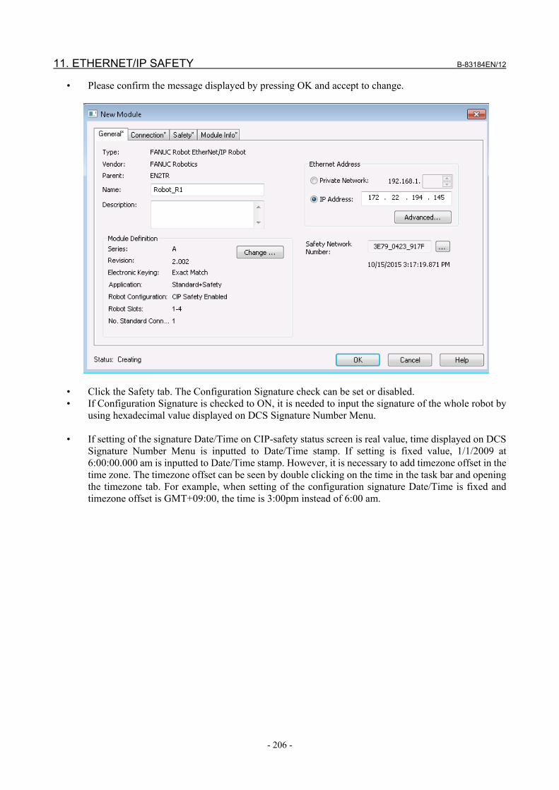
11. ETHERNET/IP SAFETY B-83184EN/12
- 206 -
• Please confirm the message displayed by pressing OK and accept to change.
• Click the Safety tab. The Configuration Signature check can be set or disabled. • If Configuration Signature is checked to ON, it is needed to input the signature of the whole robot by
using hexadecimal value displayed on DCS Signature Number Menu. • If setting of the signature Date/Time on CIP-safety status screen is real value, time displayed on DCS
Signature Number Menu is inputted to Date/Time stamp. If setting is fixed value, 1/1/2009 at 6:00:00.000 am is inputted to Date/Time stamp. However, it is necessary to add timezone offset in the time zone. The timezone offset can be seen by double clicking on the time in the task bar and opening the timezone tab. For example, when setting of the configuration signature Date/Time is fixed and timezone offset is GMT+09:00, the time is 3:00pm instead of 6:00 am.
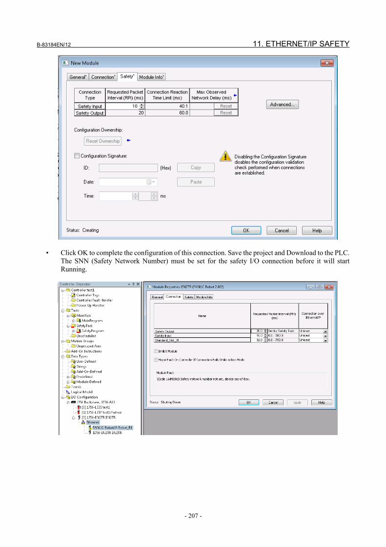
B-83184EN/12 11. ETHERNET/IP SAFETY
- 207 -
• Click OK to complete the configuration of this connection. Save the project and Download to the PLC.
The SNN (Safety Network Number) must be set for the safety I/O connection before it will start Running.

11. ETHERNET/IP SAFETY B-83184EN/12
- 208 -
• Set the SNN under the General Tab by clicking the “…”.
• Click Set. The connection should go to Running within a few seconds. If not, look under the
Connection Tab in the Module Fault area for further information.

B-83184EN/12 11. ETHERNET/IP SAFETY
- 209 -
11.2.3.2 GuardLogix safety PLC example configuration without using AOP
Please follow documentation provided with Rockwell Guardlogix PLC. The following procedure should be used for reference when configuring the robot as an EtherNet/IP Safety slave connected to a GuardLogix PLC. If AOP is not used, there is a limitation when using both safe and standard Ethernet/IP connections with the GuardLogix PLC and the robot. The robot uses the Generic Ethernet/IP Module profile for the standard connection, and the Generic Ethernet/IP Safety Module for the safety connection in RS-Logix5000 configuration software. RS-Logix5000 currently does not support two connections to the same IP address under a single Ethernet Bridge module. If both connections are required it can be dealt with in one of the following ways : • Use a separate Ethernet Bridge module (ENBT) for standard and safety connections. Both ENBT
modules should be configured on the same subnet as the robot port being used. • If a DNS server is available on the network the standard connection can be configured using
HOSTNAME instead of IP address in RS-Logix5000 Generic Ethernet/IP profile. The ENBT in the PLC must be configured with the DNS Server’s IP address so that it can resolve the name into an IP address (the PLC and robot have no problem using the same IP address for both connections, only RS-Logix5000 has this limitation). To configure the ENBT DNS client go to ENBT properties and choose the “Internet Protocol” tab in RS-Logix5000. • A simple DNS server can be configured in the robot if required for this purpose. There is a
system variable called $DNSS_CFG with following fields : • $ENABLED : default false, set true to enable • $IFACE_NUM : defines DNS server function to run on port 0 (upper RJ45) or port 1 (lower
RJ45) • $DOM_NAME : can be left blank. If used must match domain used on ENBT card under
DNS setup. • Changes take effect at powerup. You can add robot names under local or shared host table
so plc can resolve those names with robot. The hostname of the robot acting as DNS server does not need an additional entry in the table. The ENBT card can have primary and secondary DNS server so a second robot can act as backup.

11. ETHERNET/IP SAFETY B-83184EN/12
- 210 -
Procedure Follow the procedure below after the EtherNet/IP Safety Setting of robot controller is completed.
WARNING The procedure written in the document focuses on the way of setting, and it does
not include any safety precaution. The operator must read manuals provided by Rockwell Automation, and examine them carefully and sufficiently before using the procedure, and take any precaution, if required, in using the procedure.
To add a robot EtherNet/IP safety slave connection to GuardLogix : • Install Rockwell PLC hardware and software • Launch the RSLogix5000 • In the IO Configuration tree add applicable backplane and modules to configure the system (eg. 1756-
ENBT/A module) • Right click on the appropriate EtherNet/IP scanner and choose “New Module” (you must be offline to
add a module). • Under Safety choose the “Generic EtherNet/IP Safety Module”
Configure the EtherNet/IP Safety Slave in Module Properties under the General Tab (use ‘Change …’ button): • ‘Name’ and ‘Description’ is user defined (can be anything). • Set ‘IP Address’ to the IP address of the robot’s interface configured for EtherNet/IP Safety. • Set ‘Vendor’, ‘Product Type’, ‘Product Code’, ‘Major Revision’, and ‘Minor Revision’ according to
the table below.
Vendor Product Type Product Code Major revision Minor revision R-30iB, R-30iB Mate
8 140 34 2 2
R-30iB Plus 356 140 40 3 1

B-83184EN/12 11. ETHERNET/IP SAFETY
- 211 -
• Set ‘Electronic Keying’ to Exact Match. • Set ‘Output’ and ‘Input Data’ to Safety. Set ‘Data Format’ to Integer-SINT. • Set ‘Configuration Instance’ to 1024. • Set ‘Safety Input -> Output Assembly’ to 1024. • Set ‘Safety Output -> Input Assembly’ to 1024. • Set ‘Safety Input -> Input Assembly’ to 768 + size in bytes of robot safety I/O. (i.e. default size of 2
bytes = 770). • Set ‘Safety Output -> Output Assembly’ to 896 + size in bytes of robot safety I/O. (i.e. default size of
2 bytes = 898) • Set 8-bit sizes accordingly (2 bytes if using default safety I/O sizes). The following screen shots are for a safety connection to the robot using the default safety I/O size of 2 bytes in and 2 bytes out. Changing robot safety I/O size is described in Subsection 11.2.2.

11. ETHERNET/IP SAFETY B-83184EN/12
- 212 -
Under the Safety Tab ‘Configuration Signature’ setting you can choose to : • Disable checking of configuration signature to skip comparing Configuration Signature during
connection establishment. • Enable checking of configuration signature. You must manually enter the robot’s Total Signature
Number (shown on DCS Signature Number screen) in Hex. The Date/Time stamp will be the ACTUAL Date/Time stamp shown on the DCS Signature screen (offset in the SNCT by the timezone), or 1/1/2009 at 6:00:00.000 (offset in the SNCT by the timezone) if FIXED is set for Config Signature Date/Time in the CIP Safety setup screen. The timezone offset in the SNCT can be seen by double clicking on the time in the task bar and looking at the local timezone. As an example if FIXED date/time is used and the SNCT shows GMT-05:00 then instead of 6am the time would be entered as 1am.
Press OK to add the robot safety slave connection to the safety PLC configuration. Download the new configuration to the Safety PLC and go online. Note that the robot slave will only accept a new SNN when it currently has no SNN (reset back to factory default). The ‘Reset Ownership’ button under the safety tab can be used to reset the SNN if required. This reset ownership must be performed at least once after software load before the robot can be configured with an SNN number.

B-83184EN/12 11. ETHERNET/IP SAFETY
- 213 -
The new safety connection will fail until the Safety Network Number (SNN) is set. Use the “…” button on the General tab of the robot safety slave module properties to set the SNN. The “SET” button will be active when the safety PLC configuration software is online with the safety PLC (the PLC connection must not be inhibited), and the robot is on the network.

11. ETHERNET/IP SAFETY B-83184EN/12
- 214 -
The current SNN set in the robot can be viewed on the CIP-Safety Status screen. See Subsection 11.2.4.1 for details on this screen,
11.2.4 Troubleshooting
11.2.4.1 CIP-safety status screen The CIP-Safety Status screen is available under I/O Ethernet/IP ([MENU] -> I/O -> [F1 (Type)] -> EtherNet/IP -> [F3 (Safety)]. Most of this screen is read-only and includes : • Safety I/F Status : Pending, Idle, Running. Pending implies the configuration steps have not yet been
completed. Idle implies the Safety PLC did not or could not make a safety I/O connection to the robot. Running means there is an active safety I/O connection.
• DCS : Enabled, Bypassed. This is set in DCS menu. • Input Size : 1-8 bytes. This is set in DCS menu. • Output Size : 1-8 bytes. This is set in DCS menu. • SNN : Safety Network Number. This is set from safety PLC configuration software. • TX Count : Transmit Count (packets sent to PLC). This count is dynamically updated so can be
observed to increment when connection is active. • RX Count : Receive Count (packets received from PLC). This count is dynamically updated so can be
observed to increment when connection is active.
I/O EtherNet/IP EIP CIP-Safety Operation 1/2 Ethernet Interface: Port 2 Safety I/F Status: IDLE CIP-Safety Operation: DCS: Enable Input Size: 2 Output Size: 2 SNN: FFFF_FFFF_FFFF TX Count: 0 RX Count: 0
Please note that when SNN shows “FFFF_FFFF_FFFF” or “???” it means the SNN has not been set from the Safety PLC configuration software. If the SNN shows “???”, a “Reset Ownership” must be performed before the SNN can be set. Please follow the information in Subsection 11.2.3.1 or 11.2.3.2 to perform a reset ownership and/or set the SNN.
11.3 SAFETY I/O CONNECT IN CIP-SAFETY SYSTEM The Safety I/O Connect feature provides a means to tie the CIP-Safety I/O to particular safety signals in the controller. See chapter 9 for detailed information about Safety I/O Connect. The following figure provides a visual representation of Safety I/O and the overall system. Safety I/O Connect logic runs within the Safety I/O area.

B-83184EN/12 11. ETHERNET/IP SAFETY
- 215 -
The safety I/O Connect setup is saved in DCSIOC.SV. See Section 1.5 on backup/restore for more information.
11.4 BACKUP/RESTORE OF CIP-SAFETY SETTINGS CIP-Safety settings are included within the following system files during an application backup : • SYSCIPS.SV – this file includes the Safety I/O size, Enable/Bypass setting, and which Interface is
configured for CIP-Safety. • DCSIOC.SV – this file includes the Safety I/O Connect configuration These files are included under a “Backup – All of the Above” and “Backup – System Files”. These are found on the File Menu under the Backup function key. These files can only be restored at CTRL start.
CAUTION 1 The Safety PLC data set in the robot (eg. SNN) is not included in any application
backup. It must be explicitly set on a robot from the Safety PLC configuration software.
2 The basic Ethernet settings, such as IP address and subnet mask, are stored to SYSHOST.SV. As necessary, backup and restore SYSHOST.SV in addition to SYSCIPS.SV.
Please see Section 1.5 on backup/restore for more information.
11.5 EDS FILE Please contact your FANUC representative for Information on obtaining the robot CIP-Safety slave EDS file. In North America: Call 1-800-47ROBOT for Information on obtaining the robot CIP-Safety slave EDS file.

12. PROFINET SAFETY B-83184EN/12
- 216 -
12 PROFINET SAFETY
12.1 INTRODUCTION PROFINET Safety function is an option software that provides the functionality of F-Device function of PROFIsafe V2 to FANUC robot. The robot controller works as an F-device of PROFIsafe and communicates safety signals with an external F-Host.
WARNING At the initial start-up, the operation check and validation of the wiring for safety
signals should be carried out, and then the wiring should be protected by the cable duct.
12.2 PROFINET SAFETY FUNCTION
12.2.1 Overview In order to use the PROFINET Safety, please be sure the following software options are loaded : • PROFINET I/O function (A05B-2600-J930) or Dual-Channel PROFINET (A05B-2600-R834) or
PROFINET I-device function (A05B-2600-J709) or PROFINET FANUC board (A05B-2600-S523) • PROFINET Safety function (A05B-2600-J931)

B-83184EN/12 12. PROFINET SAFETY
- 217 -
Table 12.2.1(a) PROFINET Safety and robot controllers Robot Controller Description Software version
R-30iB controller Order either A05B-2600-J930 or A05B-2600-R834.
A05B-2600-J930 7DC1/06 or later. A05B-2600-R834 7DC3 series.
R-30iB Mate controller
Order A05B-2600-R834. A05B-2600-R834 7DC3 series.
R-30iB Mate controller (Open air type)
Order A05B-2600-J930. A05B-2600-J930 7DC3 series.
R-30iB Plus controller Order either A05B-2600-J930 or A05B-2600-R834 for 7DF1 series or 7DF3 series. Order A05B-2600-S523 for 7DF4 series or 7DF5 series.
A05B-2600-J709 7DF1 series (7DF1/06 or later), 7DF3 series.
A05B-2600-R834 7DF1 series (7DF1/06 or later), 7DF3 series.
A05B-2600-S523 7DF4 series, 7DF5 series(7DF5/10 or later).
R-30iB Mate Plus controller
Order A05B-2600-R834. A05B-2600-R834 7DF1/10 or later.
R-30iB Mate Plus controller (Open air type)
Not supported. N/A N/A
R-30iB Compact Plus controller
Order A05B-2600-R834. A05B-2600-R834 7DF1/10 or later.
R-30iB Mini Plus controller
Not supported. N/A N/A
NOTE 7DF4 series and 7DF5 series support only the PROFIsafe profile V2.6.1. 4-byte
CRC is used in the safety data frame in the new CRC seed mode (F_CRC_Seed = 1) in accordance with PROFIsafe profile V2.6.1. 7DF4 series and 7DF5 series do not support PROFIsafe profile V2.4 at present.
PROFINET I-device option (A05B-2600-J709) needs the SIEMENS configuration tool TIA Portal V14 SP1 or later. The PROFINET Safety option requires the PROFINET hardware including PROFINET board.
Table 12.2.1(b) Hardware for PROFINET Safety Option Description
A05B-2600-J930 CP1604 must be used for PROFINET board. Open air type controller is required for R-30iB Mate controller. As for the firmware version of PROFINET board, it must be V2.5.2.2(1) in 7DC0 series, 7DC1 series and 7DC2 series. In 7DC3 series, use V2.6.0.3.
A05B-2600-R834 For R-30iB controller, the firmware version must be V1.3.1.0. R-30iB Mate controller Open air type hasn’t been supported. For R-30iB Plus controller , the firmware version must be V1.3.3.2. For R-30iB Mate Plus controller and R-30iB Compact Plus controller, the firmware version must be V1.3.3.3.
A05B-2600-J709 Use CP1604 for PROFINET board. In 7DF1 series, V2.7.2.0 must be used for the firmware version of PROFINET board.
A05B-2600-S523 Use PROFINET FANUC BOARD, which is PROFINET board made by FANUC.

12. PROFINET SAFETY B-83184EN/12
- 218 -
The GSDML file for robot is required to configure robot controller as an F-Device. Please contact FANUC for the GSDML file for robot. There are 8 safety modules of different safety I/O size in the GSDML. As for PROFINET I-device option, configuration tool (TIA Portal) generates GSDML. PROFINET I/O Device function must be enabled in order to use PROFINET Safety function because PROFINET I/O Device function manages a safety module together with standard I/O modules. A safety module must be added in the module list of the PROFINET I/O Device function for safety data exchange. Only one safety module can be used, and it can be added in the first slot. The safety data is not exchanged when there is no safety module in the module list. PROFINET I/O Controller function can be enabled, but it exchanges only standard I/O data. Note that the DCS Safe I/O Connect option (A05B-2600-J568) is automatically loaded when PROFINET Safety is loaded. Please see the chapter 9 on the DCS Safe I/O Connect for details in using this option. PROFINET Safety supports up to 8 bytes input, and 8 bytes output, across the safety connection. Use the DCS Safe I/O Connect option to map this safe I/O to particular safety signals within the robot.
NOTE When PROFINET Safety is used with PROFINET FANUC board option (S523)
in 7DF4 series, it supports only 8 bytes input and 8 bytes output. The PROFINET Safety settings (Safety I/O size, Enable/Bypass setting, and F-Address) are saved in syspnsf.sv. The basic PROFINET settings are saved in PNIO.SV or PMIO.SV or PNIOG2.SV. See Section 1.5 on backup/restore for more information. Configuring F-Device involves the following steps : • Configure the robot (F-Device) – see Subsection 12.2.2. • Configure the Safety PLC to exchange safety I/O with the robot – see Subsection 12.2.3.
PROFIsafe Address Type The PROFIsafe address is for the unique identification of source and destination. PROFINET Safety function of FANUC robot is checking the F-destination address only, so it is PROFIsafe Address Type 1.
12.2.2 Robot Configuration Robot configuration begins with configuring the PROFINET I/O Device function and adding a safety module to the module list. • When A05B-2600-J930 is used, see procedure 12-2-1. • When A05B-2600-R834 is used, see procedure 12-2-2. • When A05B-2600-J709 is used, see Subsection 12.2.3 with using configuration tool (TIA Portal). • When A05B-2600-S523 is used, see Subsection 10.5.2 in “PROFINET Function OPERATOR’S
MANUAL” (B-82864EN). Configure I/O size and Enable/Bypass in PROFINET Safety on DCS screen. • See procedure 12-2-3 about configuration and how to confirm. • Configure F_iPar_CRC check function for R-30iB Plus controller.

B-83184EN/12 12. PROFINET SAFETY
- 219 -
Procedure 12-2-1 Setting in Setup PROFINET I/O Device module screen Please refer to “PROFINET Function OPERATOR’S MANUAL” (B-82864EN) for the details of PROFINET I/O Device module list/detail screen.
Steps : • Open the setup PROFINET I/O Device module list screen ([MENU]->6. Setup, [F1
(TYPE)]->PROFINET, [F3 (Other)]->I/O Device, move cursor on <Detail>, press the [Enter] key). • Add the Data Access Point (DAP) as the first module (slot=0, subslot=1, or if the firmware version
is V2.6 or later, slot=1, subslot=1). • Move to the next module, set slot=1, subslot=1, or if the firmware version is V2.6 or later, slot=2,
subslot=1. • Refer to the GSDML for robot to choose a safety module according to the safety slave I/O size. • Set its Module ID and Subslot ID to add the safety module. • If necessary, continue adding standard modules. • A power cycle is required to make changes active. Example : Module ID=0x1008 (The safety slave I/O size = 8 bytes)
Setup PROFINET I/O I/O Device : Module 1 1/6
1 Slot : 1 2 Subslot : 1 Comment : 3 [ ] 4 ModId(hex) 0x00001008 5 SubslotId(hex) 0x00000001 Module I/O type NONE 6 Data size : [ ] 7 Data type : [Digital] [TYPE] list prev next

12. PROFINET SAFETY B-83184EN/12
- 220 -
Procedure 12-2-2 Adding Safety module to I/O Device channel Please refer to “PROFINET Function OPERATOR’S MANUAL” (B-82864EN) for the details of PROFINET I/O Device function.
Steps : • Open the module list of I/O Device ([MENU]->6. Setup, [F1 (TYPE)]->PROFINET(M), move
cursor on Channel2, press the [right-arrow] key to expand tree view and move cursor on I/O Device).
• Press the [DISP] key to move cursor to the right pane, move cursor on slot 1 and press the [F4
(EDIT)].
• Move cursor on Slot Type and press the [F4 (EDIT)]. • Select Safety Slot, and press the [F1 (APPLY)].
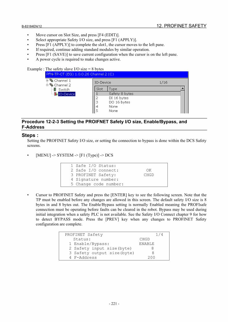
B-83184EN/12 12. PROFINET SAFETY
- 221 -
• Move cursor on Slot Size, and press [F4 (EDIT)]. • Select appropriate Safety I/O size, and press [F1 (APPLY)]. • Press [F1 (APPLY)] to complete the slot1, the cursor moves to the left pane. • If required, continue adding standard modules by similar operation. • Press [F1 (SAVE)] to save current configuration when the cursor is on the left pane. • A power cycle is required to make changes active. Example : The safety slave I/O size = 8 bytes
Procedure 12-2-3 Setting the PROIFNET Safety I/O size, Enable/Bypass, and F-Address
Steps : Setting the PROFINET Safety I/O size, or setting the connection to bypass is done within the DCS Safety screens. • [MENU] -> SYSTEM -> [F1 (Type)] -> DCS
1 Safe I/O Status: 2 Safe I/O connect: OK 3 PROFINET Safety: CHGD 4 Signature number: 5 Change code number:
• Cursor to PROFINET Safety and press the [ENTER] key to see the following screen. Note that the
TP must be enabled before any changes are allowed in this screen. The default safety I/O size is 8 bytes in and 8 bytes out. The Enable/Bypass setting is normally Enabled meaning the PROFIsafe connection must be operating before faults can be cleared in the robot. Bypass may be used during initial integration when a safety PLC is not available. See the Safety I/O Connect chapter 9 for how to detect BYPASS mode. Press the [PREV] key when any changes to PROFINET Safety configuration are complete.
PROFINET Safety 1/4 Status: CHGD 1 Enable/Bypass: ENABLE 2 Safety input size(byte) 8 3 Safety output size(byte) 8 4 F-Address 200

12. PROFINET SAFETY B-83184EN/12
- 222 -
Table 12.2.2(a) The parameters in the DCS PROFINET safety screen Item Description
Enable/Bypass The mode of safety network. Enable : Safety communication must be operating before robot alarm status can be cleared. Bypass : Bypass may be used during initial integration when a safety PLC is not available. There is no safety communication error and robot can move in standalone mode, but all CSI from the safety PLC are ignored. Bypass mode is indicated by SSI[11], which can be interconnected to any CSO to the safety PLC. Refer to 12.2.4 Operation without Safety PLC (bypass mode) when Bypass is used.
Input/Output size The number of safety input/output that is to be allocated in the robot controller. The default value is 8 bytes. This setting must be equal to the number of input/output specified in the configuration of safety PLC, otherwise the system becomes error status (PRIO-604 will show up with PRIO-603 “PROFIsafe hard fail”).
F-Address Logical address designation of F-Device that can be assigned freely but unambiguously (from 1 to 65534). The default value is 200. This setting must be equal to the F-Destination-Address specified in the configuration of safety PLC.
There are configuration items of F_iPar_CRC check function for R-30iB Plus controller.
F_iPar_CRC check: ENABLE F_iPar_CRC received: MATCH 7C94B918 F_iPar_CRC calculation: 7C94B918 5 Use Base: Yes 6 Use Pos./Speed: Yes 7 Use I/O connect: Yes
Table 12.2.2(b) The parameters in the DCS PROFINET safety screen
Item Description F_iPar_CRC check
Enable/Disable of F_iPar_CRC check function. This item is enabled when either PROFINET I-device option A05B-2600-J709 or PROFINET FANUC board option A05B-2600-S523 is ordered. F_iPar_CRC check function is the function that sets the signature calculated from the robot safety parameter to the safety PLC and prevents communication when the parameter is changed. When setting of Safety PLC, robot signature is need to set as F_iPar_CRC. F_iPar_CRC set in safety PLC is sent to robot as part of F-Parameter before Safety I/O connection, and it is compared signature that robot calculate from the current safety parameters. If Safety PLC is set to 0 as F_iPar_CRC, Safe I/O connect starts without comparing. In 7DF4 (V9.36P) series and 7DF5 (V9.40P), please don’t set F_iPar_CRC of Safety PLC to 0. F_iPar_CRC value can be read by using I&M4.

B-83184EN/12 12. PROFINET SAFETY
- 223 -
Item Description F_iPar_CRC received
Display the result s of comparison between safety PLC and robot, and the value of the F_iPar_CRC received from the safety PLC. The results of comparison are as following. ・NO The F-parameter have not been received yet or CRC error of F-Parameter ・MATCH Received F_iPar_CRC matches to the calculated F_iPar_CRC. Safety I/O connection is possible. ・DIFF Received F_iPar_CRC does not match to the calculated F_iPar_CRC. PRIO-685 is posted, because safety I/O connection is not possible (Error code 2). ・TEST Comparison is not done, because the received F_iPar_CRC is 0. Safety I/O connection is possible. ・INVAL Received F-Parameter contains F_iPar_CRC, however this function is invalid. PRIO-685 is posted, because it is contradiction (Error code 4). ・NONE If this function is disabled, It is in a normal state. Safety I/O connection is possible. ・MISS This function is enabled however F_iPar_CRC is not included in the received F-Parameter. PRIO-685 is posted, because it is contradiction (Error code 6).
F_iPar_CRC calculation
The value of the signature that robot calculate from the current safety parameters. Please input the value displayed here when F_iPar_CRC is set to Safety PLC. The range of safety parameters used for the signature calculation is determined by the setting items of ‘Use Base’, ‘Use Pos./Speed’, and ‘Use I/O connect’. If these setting items are changed, signature changes, so please cycle power after applying safety parameter.
Use Base If yes, the safety parameters of the Base are included in the calculation of signature. Use Pos./Speed If yes, the safety parameters of the Pos./Speed are included in the calculation of signature. Use I/O connect If yes, the safety parameters of the I/O connect are included in the calculation of signature.
• Use the [F2 (APPLY)] button while in the DCS Setup screen to complete changes. You will be
prompted for the code number.
DCS 1 Safe I/O Status: 2 Safe I/O connect: OK 3 PROFINET Safety: CHGD 4 Signature number: 5 Change code number: [TYPE] APPLY DETAIL UNDO
• You will then be shown a screen detailing the differences for review (press OK after review).

12. PROFINET SAFETY B-83184EN/12
- 224 -
DCS Verify (diff) 1/12 F Number: F00000 VERSION : HandlingTool $VERSION: V7.6306 12/10/2010 DATE: 27-DEC-10 13:26 --- PROFINET safety ------------------ Status: CHGD 1 Enable/Bypass: ENABLE 2 Safety input size(byte) 4 ALL OK QUIT
• A power cycle is required to make changes active.
12.2.3 Safety PLC Configuration This section provides information for setting up robot as an F-Device of PROFIsafe by using configuration software, such as STEP7 or TIA Portal. First of all, please follow the manuals provided by the manufacturer of the safety PLC. For example, safety engineering system manual and safety programming manual.
CAUTION The information written in the document does not include any safety precaution.
The operator must read manuals provided by the manufacturer of the safety PLC, and examine them carefully and sufficiently before using the information, and take any precaution, if required, in using the information.
Please install the GSDML file for robot in the configuration software. The GSDML file has the information of robot as an F-Device. There are 8 safety modules of different safety I/O size in the GSDML. Only one safety module can be configured, and it can be inserted in only the first slot. The minimum watchdog time of robot as an F-Device is 40ms. The watchdog time may need to be increased depending to the network option software configuration in the robot controller. The process time of the safety PLC should be considered in deciding the watchdog time. Please set the I/O device update time in the PROFINET-I/O system property equal to, or less than 4ms for safety data exchange. The safety parameters (F-Parameter) for an F-Device, for example safety I/O size, are supposed to be configured in configuration software. The value must be equal to that set in procedure 12-2-3, otherwise safety communication can’t be started. Please see also 12.2.5.3.
CAUTION The information of product other than FANUC written in the document might be
changed without prior notice. Please confirm the latest information and the detail of procedure to the manufacturer.
For PROFINET I-device A05B-2600-J709, making GSDML file for robot and setting of safety module of robot are done by using configuration tool (TIA Portal).

B-83184EN/12 12. PROFINET SAFETY
- 225 -
Procedure 12-2-4 Adding Safety module of PROFINET I-device by using TIA Portal
Steps : • Create a network project without safety PLC by using TIA Portal. • Add PC Station and 6GK1 160-4AA01 from Hardware catalog to the first empty slot of PC Station.
• Open Properties of CP1604 on PC Station, and check “IO device” and “Use manually assigned
submodule ID’s” under Operating mode.
• Once IO device is checked, “Enable customization” under Catalog information can be checked.
After this item is checked, vendor ID and Device ID of CP1604 can be changed to those of FANUC R-30iB Plus Robot controller(vendor ID=0x1B7, Device ID=0xE). As for Customer-specific adaptation, it is used for file name etc. of GSDML file of robot. Change the product name if needed, for example, to managed different GSDML files. The followings are the screens before and after the change.

12. PROFINET SAFETY B-83184EN/12
- 226 -
• Add safety module to Transfer areas under Operating mode. Set Type is to F-PS. Set the length to
1-8 byte, which is the length is safety I/O size. Set the sane value for I and Q. Set 0x1000 + safety I/O size (0x1001-0x1008) to Submodule ID. Safety module should only be added to the first slot.

B-83184EN/12 12. PROFINET SAFETY
- 227 -
• If any setting is needed for added safety module, safety module name is displayed under the I-device communication in the tree view of left pane, so please click it and show further information.
• Compile the project, after setting of CP1604. There are settings other than safety modules, such as IP
address, Device name, PROFINET network setting where CP1604 become I/O controller, however these are not explained in the document because they are not safety functions.
• After the compile, click Export button under Export generic station description files (GSD) under
Transfer areas in order to generate GSDML file for robot.
• The dialog for the file name and the file path is opened. Change them if necessary and save GSDML
file.
• Connect online to CP1604 and download the project, because this setting needs to be downloaded to
CP1604.

12. PROFINET SAFETY B-83184EN/12
- 228 -
Procedure 12-2-5 Registering Safety module of robot to safety PLC by using TIA Portal
Steps : • Read in the GSDML file made by Procedure 12-2-4 to TIA Portal.
• When GSDML file is read in, it is added under Hardware catalog.
• When Device overview in CP1604 is opened, there is the safety module in the first slot.
• When Properties of safety module is opened, the configuration of PROFINET is displayed, so please
set this configuration.

B-83184EN/12 12. PROFINET SAFETY
- 229 -
• Registration of safety module of robot is completed. In addition to this setting, it is necessary to set
safety configuration of the CPU on the PLC and create safety program to start the safety connection. So please read the safety system engineering manual provided by the manufacturer of the safety PLC and the instruction manual such as the safety programming manual and follow the instructions.
12.2.4 Operation without Safety PLC (bypass mode) In bypass mode, there is no safety communication error and robot can move in standalone mode, but all CSI from the safety PLC are ignored. Bypass mode is indicated by SSI[11], which can be interconnected to any CSO to the safety PLC. In bypass mode, the following events bring the robot to alarm status to prevent the robot from moving. Operation is required to recover from the alarm status. This feature is only for PROFINET Safety.
Table 12.2.4 (a) Events that bring the robot to alarm status in bypass mode Item Description
Hot/Cold start When the robot controller is turned off in bypass mode, SYST-212 "Need to apply to DCS param" shows up at HOT start or Cold start. The mode of safety network is changed to "Enable", but it has not been applied yet (The actual mode is bypass). The operator should apply the change in the DCS screen by entering the password and cycling power the robot controller. Instead, the operator may use bypass mode by changing the mode back to bypass. The password is not necessary for this operation, and the alarm can be reset without cycling power

12. PROFINET SAFETY B-83184EN/12
- 230 -
Item Description Safety communication gets established to F-Host
Once the safety PLC establishes communication in bypass mode, SYST-212 "Need to apply to DCS param" shows up. The mode of safety network is changed to "Enable" but it has not been applied yet (The actual mode is bypass). The alarm status prevents the operator from continuing on using bypass mode to move the robot. It cannot be cleared until the change is applied and power is cycled. The operator should apply the change in the DCS screen by entering the password and cycling power to the robot controller. However, SYST-212 can temporally be reset by pressing and holding the [SHIFT]+[RESET] keys. SYST-212 shows up again if the [SHIFT] key is released.
The mode switch is changed to T2 or AUTO
SYST-212 "Need to apply to DCS param" shows up when the mode switch is changed to T2 or AUTO in bypass mode. The alarm status prohibits the robot from moving in T2 or AUTO in bypass mode. It cannot be cleared until the mode switch is back to T1 and the reset button is pressed. However, SYST-212 can temporally be reset by pressing and holding the [SHIFT]+[RESET] keys. SYST-212 shows up again if the [SHIFT] key is released.
The following system variables specify which of the events are monitored. The change takes effect immediately (no need to cycle power to apply the change).
Table 12.2.4 (b) System variables to specify which of the events are monitored Item Description
$PNSF_SET.$BY_PWFAIL If the value is not 0, the bypass mode is disabled at “Hot/Cold start”. The default value is 1.
$PNSF_SET.$BY_PLCCON If the value is not 0, the bypass mode is disabled when Safety communication gets established to F-Host. The default value is 1.
$PNSF_SET.$BY_PLCRUN This variable is only used when $PNSF_SET.$BY_PLCCON is not 0. If the value is 0, the bypass mode is disabled when F-Host is connected and F-Device has received valid F-Parameter prior to Safety communication. The default value is 1.
$PNSF_SET.$BY_T1ONLY If this value is not 0, the bypass mode is disabled when the mode is changed to T2 or AUTO. The default value is 1.
12.2.5 Troubleshooting
12.2.5.1 PROFINET safety status screen In A05B-2600-J930 or A05B-2600-J709, the PROFINET Safety Status screen is available under PROFINET Status screen ([MENU] -> 0. Next page -> 4. Status -> [F1 (TYPE)] -> PROFINET -> [F3 (Other)] -> Safety. This screen can be opened when the PROFINET Safety function is installed. This screen is read-only. This screen is not a part of safety functions, and the output of this screen is non-safe.

B-83184EN/12 12. PROFINET SAFETY
- 231 -
PROFINET Status PROFINET Safety Operation 1/1 Safety I/F Status: INIT PROFIsafe Operation: DCS: Enable Input Size: 8 Output Size: 8 Frame Count: 0
[TYPE] [Other]
Table 12.2.5.1 The items in the PROFINET safety status screen
Item Description Safety I/F Status INIT : The configuration steps have not yet been completed.
IDLE : The safety PLC does not or cannot start the safety I/O communication with the robot. RUNNING : The safety I/O communication is active.
DCS This item shows if PROFINET Safety connection is enabled or bypassed. Input/Output size Current setting of input/output size. Frame Count Local counter of PROFIsafe safety process data unit (PDU) in the robot
controller. Only exchange with valid data is counted.
12.2.5.2 DIAGSAFETY screen In A05B-2600-R834, the DIAGSAFETY screen is available under I/O Device. • [MENU] -> 6. Setup -> [F1 (TYPE)] -> PROFINET(M), move cursor on Channel2, press the
[right-arrow] key to expand tree view and move cursor on I/O Device. • Press the [F3 (DIAGSAFETY)] key. This screen can be opened when the PROFINET Safety function is installed. This screen is read-only. This screen is not a part of safety functions, and the output of this screen is non-safe.
Table 12.2.5.2 The items in the DIAGSAFETY screen Item Description
Safety I/F Status INIT : The configuration steps have not yet been completed. IDLE : The safety PLC does not or cannot start the safety I/O communication with the robot. RUNNING : The safety I/O communication is active.
DCS This item shows if PROFINET Safety connection is enabled or bypassed. Input/Output size Current setting of input/output size. Frame Count Local counter of PROFIsafe safety process data unit (PDU) in the robot
controller. Only exchange with valid data is counted.

12. PROFINET SAFETY B-83184EN/12
- 232 -
12.2.5.3 Error indication There are alarms that indicates error state in PROFINET Safety. • In A05B-2600-J930 or A05B-2600-J709, PRIO-604 shows up with PRIO-603 “PROFIsafe hard
fail”, “CRC check error” or “status check error” (the string data in English is displayed as PRIO-603 message).
• In A05B-2600-R834, PRIO-380 shows up. If such alarm shows up, first of all, check whether the configuration of safety PLC and the setting of robot controller matches. Check the size of safety input/output in DCS PROFINET Safety screen, configure the safety PLC again, and cycle power to the controller. If the problem persists, the error is probably due to a hardware problem. Please contact FANUC.
12.3 BACKUP/RESTORE OF PROFINET SAFETY SETTINGS PROFINET Safety settings are included within the following system files during an application backup : • SYSPNSF.SV – this file includes the Safety I/O size, Enable/Bypass setting, and F-Address of
PROFINET Safety • PNIO.SV – In A05B-2600-J930, this file includes the setting of the safety module together with the
standard PROFINET I/O function settings • PMIO.SV – In A05B-2600-R834, this file includes the setting of the safety module together with the
standard PROFINET I/O function settings • PNIOG2.SV – In A05B-2600-J709, this file includes the setting of the safety module together with
the standard PROFINET I/O function settings • PNFB.SV – In A05B-2600-S523, this file includes the setting of the safety module together with the
standard PROFINET I/O function settings. • DCSIOC.SV – this file includes the Safety I/O Connect configuration These files are included under a “Backup – All of the Above” and “Backup – System Files”. These are found on the File Menu under the Backup function key. These files can only be restored at CTRL start.
CAUTION 1 When PROFINET Safety function is used, basic PROFINET settings (such as
I/O Device configuration) are held in PNIO.SV in A05B-2600-J930, or in PMIO.SV in A05B-2600-R834, or in PNIOG2.SV in A05B-2600-J709, or in PNFB.SV in A05B-2600-S523. Backup/restore PNIO.SV or PMIO.SV or PNIOG2.SV or PNFB.SV with SYSPNSF.SV if required.
2 In PROFIsafe, F-Host is supposed to send F-Parameter to F-Device. F-Parameter is not stored in any application backup.
Please see Section 1.5 on backup/restore for more information.
12.4 GSDML FILE Please contact FANUC for the GSDML file for robot. Please inform the type of robot controller (R-30iB, R-30iB Mate and so on), the software version and the order number of PROFINET option (J930 or R834 or S523). As for PROFINET I-device(J709), the configuration tool (TIA Portal) makes GSDML file in, so please see Subsection 12.2.3.

B-83184EN/12 13. SAFETY FUNCTION BY FL-net
- 233 -
13 SAFETY FUNCTION BY FL-net
13.1 INTRODUCTION Safety function by FL-net is option software that provides an ability to exchange safety signals between a robot and other robots or CNCs by FL-net.
WARNING At the initial start-up, the operation check and validation of the wiring for safety
signals should be carried out, and then the wiring should be protected by the cable duct.
13.2 SAFETY FUNCTION BY FL-net
13.2.1 Overview In order to use Safety function by FL-net, please be sure the following software options are loaded. • FL-net Interface (A05B-2600-J759) • Safety function by FL-net (A05B-2600-J586)
Table 13.2.1(a) Safety function by FL-net and robot controllers Robot Controller Description Software version
R-30iB controller Available 7DC1 series or later
R-30iB Mate controller
Available 7DC2 series or later
R-30iB Plus controller Available 7DF1 series or later
R-30iB Mate Plus controller
Available 7DF1 series or later
R-30iB Mate Plus controller (Open air type)
Not supported. N/A
R-30iB Compact Plus controller
Not supported. N/A
R-30iB Mini Plus controller
Available 7DF5/05 or later
DCS Safe I/O Connect option (A05B-2600-J568) is automatically loaded when Safety function by FL-net is loaded. Please see the chapter 9 on the Safe I/O Connect for details in using this option. Safety function by FL-net can be used with internal port (CD38A or CD38B) on main board. FL-net board (A05B-2600-J105) can't be used for Safety function by FL-net. So this function can’t be used in variety 2 of FL-net. Safety function by FL-net has 3 modes for selecting behavior when attending node changed to power OFF. In mode 1, when 1 or more nodes, which attend to Safety function by FL-net, is cycle powered, alarm happens in all nodes, which attend the same Safety function by FL-net network. For resetting this alarm, change power OFF for all nodes. After power off the all nodes, power ON all nodes.

13. SAFETY FUNCTION BY FL-net B-83184EN/12
- 234 -
In mode 2, alarm doesn't happen even when power offed node exists. When Mode 2 is used, a risk assessment for the whole system is necessary, including that alarm doesn't happen even when disconnected node by power off etc. exists. In mode 3, alarm happens when power offed node exists, but the alarm can be reset after all node is connected. Mode of all nodes should be same. Safety function by FL-net supports up to 203 safety inputs, and 70 safety outputs for 1 node. But the number of input + the number of output must be equal or less than 210. Use the DCS Safe I/O Connect function to map this safe I/O to particular safety signals within the robot. Each Safety function by FL-net node has some IDs. 1 ID has 7 safety signals for user and 1 signal reserved for system (total 8 signals). The user can’t use the reserved signal. The range of the ID is 1 to 30. 1 node can have maximum 10 consecutive IDs. The number is called as “IDnum.”. Node having ID is consecutive starting from same ID with own node number and the number of ID is "IDnum.". Output data is comprised of all IDs of the node having ID. . For example, if node number is 11 and IDnum is 5 then the node has ID 11 to 15 which has 35 signals for user and 5 system signals. In this case, node 12 to 15 can not be used in Safety function by FL-net. Maximum 30 nodes, which are Robots and CNCs, can be connected to the network of the Safety function by FL-net, if all nodes occupy only 1 ID (IDnum. = 1). CNC doesn't have IDnum. Setting but it is assumed as IDnum. = 1. IDnum. for CNCs should be set as 1 in robot. CNC (18i-LNB) can’t participate to the network of Safety function by FL-net, to which Robot participating, because safety specification is different. The Safety function by FL-net uses first 6 words * IDnum. of the node’s common memory area 1, which is allocated to the node exclusively, to send the safety data. Therefore, the allocation size of common memory area 1 of the node that composes the network of the Safety function by FL-net should be larger than 6 words * IDnum. Common memory area 1 other than the above-mentioned words and common memory area 2 can be used as a normal data area. So, even when Safety function by FL-net is enabled, standard FL-net data can be exchanged. Safety function by FL-net can use FL-net multicast. Safety function by FL-net settings (Enable/Disable, Own node number, Node, Timer for receive data, Start timer after Power ON) are saved in sysflsf.sv. The limit of cable length is 100m which is same with FL-net.
13.2.2 Safety Signal This section explains the safety signals that are the interface of the DCS Safe I/O connection function and the Safety function by FL-net. OFF should be safety side in safety signals.
13.2.2.1 Sending safety signal area The signal data, which is sent from the DCS Safe I/O connection function to other nodes via Safety function by FL-net, is FSO composed of the 7 safety signals and 1 system signal per ID. There are signal data for 10 IDs in FSO. FSO number is summarized in Table 13.2.2.2 (a). In this table, if node number is 11 and IDnum. = 10, 1st ID is 11 and 10th ID is 20.
13.2.2.2 Receiving safety signal area The signal data ,which is received from other nodes via Safety function by FL-net and passed to the DCS Safe I/O connection function, is FSI, which is composed of 7 safety signals and 1 system signal per ID. There are signal data for 30 IDs in FSI. FSI number is summarized in Table 13.2.2.2 (b).

B-83184EN/12 13. SAFETY FUNCTION BY FL-net
- 235 -
Moreover, the safety function target ID information area (32signals) is allocated after the receiving safety signal area. The 1st signal of the safety function target ID information area is the own node safety effective notification area. Please see Table 13.2.2.2(c).
System signal In mode 1, for example when an error is first detected by the Safety function by FL-net from the data of ID 1, the System signal of the ID 1 is set to ON. If the error is detected from the data of another ID 2 after the first error detected from the data of ID 1, the System signal of the ID 2 is NOT set to ON. System signal of only first error detected ID changes to ON. In mode 2 and 3, when counter error, which happens when other node is disconnected by power off etc., detected after first error is detected from other ID data, this system signal becomes ON. In other error, specification is same with mode1. When other DCS functions detect error, system signal is set to ON for the 1st ID of the node and other FSI for the ID is set to OFF, in all modes. In this case, like mode 1, system signal of 1st ID of only 1st error detected node becomes ON.
Safety function target node information area The safety function target node information area (found after the receiving safety signal area) represents the target node of communication by using the Safety function by FL-net. Each signal from node 1 to node 30 in Table 13.2.2.2 (c) shows status of each node. The logical add of safety parameter ENABLE(0)/DISABLE(1) and safety parameter ENTRY(0)/SEPARATE(1) is reflected to this area. Pay attention ENABLE = 0, DISABLE = 1, ENTRY = 0 and SEPARATE = 1. If the signal is OFF, the communication to that node is executed and if the signal is ON, the communication to that node is NOT executed. The signal that corresponds to the own node becomes ON. Moreover, FSI[241] of the safety function target node information area is the own node safety effective notification area. This signal shows whether the safety function of own node is effective or not. After the validity of the safety parameter is confirmed when the power supply is turned on, safety parameter ENABLE/DISABLE of own node is reflected to this area. OFF shows the safety function is not effective, and ON shows effective.
Table 13.2.2.2 (a) FSO number
Safety Signal ID
1st 2nd 3rd 4th 5th 6th 7th System signal
1st 1 2 3 4 5 6 7 8 2nd 9 10 11 12 13 14 15 16 3rd 17 18 19 20 21 22 23 24 4th 25 26 27 28 29 30 31 32 5th 33 34 35 36 37 38 39 40 6th 41 42 43 44 45 46 47 48 7th 49 50 51 52 53 54 55 56 8th 57 58 59 60 61 62 63 64 9th 65 66 67 68 69 70 71 72 10th 73 74 75 76 77 78 79 80
Table 13.2.2.2 (b) FSI number
Safety
Signal ID
1st 2nd 3rd 4th 5th 6th 7th System signal
1 1 2 3 4 5 6 7 8 2 9 10 11 12 13 14 15 16 3 17 18 19 20 21 22 23 24 4 25 26 27 28 29 30 31 32 5 33 34 35 36 37 38 39 40

13. SAFETY FUNCTION BY FL-net B-83184EN/12
- 236 -
Safety
Signal ID
1st 2nd 3rd 4th 5th 6th 7th System signal
6 41 42 43 44 45 46 47 48 7 49 50 51 52 53 54 55 56 8 57 58 59 60 61 62 63 64 9 65 66 67 68 69 70 71 72 10 73 74 75 76 77 78 79 80 11 81 82 83 84 85 86 87 88 12 89 90 91 92 93 94 95 96 13 97 98 99 100 101 102 103 104 14 105 106 107 108 109 110 111 112 15 113 114 115 116 117 118 119 120 16 121 122 123 124 125 126 127 128 17 129 130 131 132 133 134 135 136 18 137 138 139 140 141 142 143 144 19 145 146 147 148 149 150 151 152 20 153 154 155 156 157 158 159 160 21 161 162 163 164 165 166 167 168 22 169 170 171 172 173 174 175 176 23 177 178 179 180 181 182 183 184 24 185 186 187 188 189 190 191 192 25 193 194 195 196 197 198 199 200 26 201 202 203 204 205 206 207 208 27 209 210 211 212 213 214 215 216 28 217 218 219 220 221 222 223 224 29 225 226 227 228 229 230 231 232 30 233 234 235 236 237 238 239 240
Table 13.2.2.2 (c) Safety function target node information area
(FSI[241] is the own node safety effective notification area) FSI[241] Own node FSI[242] NODE 1 FSI[243] NODE 2 FSI[244] NODE 3 FSI[245] NODE 4 FSI[246] NODE 5 FSI[247] NODE 6 FSI[248] NODE 7 FSI[249] NODE 8 FSI[250] NODE 9 FSI[251] NODE 10 FSI[252] NODE 11 FSI[253] NODE 12 FSI[254] NODE 13 FSI[255] NODE 14 FSI[256] NODE 15 FSI[257] NODE 16 FSI[258] NODE 17 FSI[259] NODE 18 FSI[260] NODE 19 FSI[261] NODE 20 FSI[262] NODE 21

B-83184EN/12 13. SAFETY FUNCTION BY FL-net
- 237 -
FSI[263] NODE 22 FSI[264] NODE 23 FSI[265] NODE 24 FSI[266] NODE 25 FSI[267] NODE 26 FSI[268] NODE 27 FSI[269] NODE 28 FSI[270] NODE 29 FSI[271] NODE 30 FSI[272] (Reserved)
13.2.3 Robot Configuration Robot configuration begins with configuring the FL-net function. This is done within the normal FL-net screens. Procedure 13-2-1 describes settings relate to safety function in normal FL-net screen. Parameters for Safety function by FL-net can be reviewed/changed in procedure 13-2-2.
Procedure 13-2-1 Setting in SETUP FL-NET screen Please refer to FL-net operator’s manual (B-82674EN) for the normal settings of FL-net.
Steps: • Open the FL-NET OWN NODE SETUP screen ([MENU] -> 6. Setup -> [F1 (TYPE)] -> FL-NET ->
[F3 (OTHER)] -> OWN NODE) SETUP FL-NET
FL-NET OWN NODE SETUP 1/29
1 ERROR ONE SHOT : DISABLE
2 MAX DIGITAL PORT NUM : 1024
3 USING PORT :INTERNAL2
IP ADDRESS :[192.168.250. 1]
4 MULTICAST : DISABLE
5 MULTICAST ADDRESS:[239.255.0 .0 ]
6 NODE NAME :[ROBOT ]
7 TOKEN WATCH TIME(msec) : 30
8 FRAME INTERVAL(0.1msec): 20
9 UOP ASSIGNMENT : DISABLE
10 UI ALLOCATION NODE : 2
AREA1 SETUP :
11 AREA1 WORD OFFSET : 0
12 AREA1 WORD SIZE : 70
13 DO BYTE OFFSET1 : 120
14 DO BYTE SIZE1 : 20
15 DO BYTE OFFSET2 : 0
16 DO BYTE SIZE2 : 0
17 WO BYTE OFFSET : 0
18 WO BYTE SIZE : 0
19 WSTK OUT BYTE OFFSET : 0
20 WSTK OUT BYTE SIZE : 0
AREA2 SETUP :
21 AREA2 WORD OFFSET : 0
22 AREA2 WORD SIZE : 45

13. SAFETY FUNCTION BY FL-net B-83184EN/12
- 238 -
23 AO BYTE OFFSET : 0
24 AO CHANNEL NUMBER : 25
25 AO SHIFT LEFT : 0
26 AO RANGE : 16
27 REGISTER BYTE OFFSET : 50
28 REGISTER START : 1
29 REGISTER NUMBER : 10
• Other node settings can be changed from [F3 (OTHER)] -> NODE LIST -> Move cursor to setting
changing node -> [F2 (DETAIL)]. • The following items should be set to use Safety function by FL-net.
Table13.2.3 (a) Basic parameters Parameter name Description
USING PORT BOARD : Using port on FL-net board(Can't use Safety function by FL-net). Use one of following internal port. INTERNAL1 : Using internal Ethernet port1 (CD38A). INTERNAL2 : Using internal Ethernet port2 (CD38B).
IP ADDRESS
IP address of the local node. The host address section (the last numeric value) of this IP address is the node number of the local node. Only an IP address in class C can be specified. If INTERNAL port is selected as USING PORT, set IP address from [MENU] -> “6.SETUP.” -> [F1 (TYPE)] -> Host Comm -> TCP/IP. Change the IP address setting port by [F3 (PORT)]. If the Safety function by FL-net is enabled, the value of “Own node number” in safety parameter should be same with the host address section (the last numeric value) of this IP ADDRESS.
AREA 1 WORD OFFSET Start address of common memory area 1 of the local node. A value from 0 to 511 can be set. See “III-2.3 SAMPLE NODE SETTINGS” in FL-net operator’s manual (B-82674EN) for detail.
AREA 1 WORD SIZE
Data size of common memory area 1 of the local node. A value from 0 to 512 can be set. AREA1 WORD SIZE should be equal or more than (IDnum. * 6). First (IDnum. * 6) word, (IDnum. * 12) byte in other words, is used by Safety function by FL-net. DO/WO/WSTK BYTE OFFSET should be equal or more than (IDnum. * 12). Example: If IDnum. = 10 (The safety I/O size = 80 points), AREA 1 WORD SIZE should be equal or more than 60 and DO/WO/WSTK BYTE OFFSET should be equal or more than 120.

B-83184EN/12 13. SAFETY FUNCTION BY FL-net
- 239 -
Procedure 13-2-2 Setting the Safety function by FL-net Steps :
Setting the Safety function by FL-net is done within the DCS Safety screens. • [MENU] -> 0 -- NEXT -- -> 6 SYSTEM -> [F1 (TYPE)] -> DCS
• Cursor to Safety function by FL-net and press [ENTER] to see the following screen. Note that the TP
must be enabled before any changes are allowed in this screen. Press [PREV] when any changes to Safety function by FL-net configuration are completed.
Table13.2.3 (b) Parameters in Safety function by FL-net screen Item Description
Enable/Disable The mode of safety network. ENABLE : Safety function by FL-net is enabled in this robot. DISABLE: Safety function by FL-net is disabled in this robot.
Own node number [Valid data range] 1 to 30. Set the local node number on FL-net.
Node:ENB/DIS Left hand number 1 to 30 represents a node number. Specify nodes with which safety data communication is to be performed using the Safety function by FL-net. It is necessary for nodes that communicate with each other to mutually set the node parameters. Be sure to set DISABLE to the local node.
Safety function by FL-net
1 Enable/Disable: ENABLE OK
2 Own node number: 1 OK
3 Node:(Set DISABLE for own node)
ENB/DIS ENT/DET IDnum.
1 ENABLE ENTRY 1 OK
2 ENABLE ENTRY 1 OK
3 ENABLE ENTRY 1 OK
…
29 ENABLE ENTRY 1 OK
30 ENABLE ENTRY 1 OK
4 Timer for receive data: 0 OK
5 Start timer after PowerON: 0 OK
6 Mode: 1 OK
1 Safe I/O Status:
2 Safe I/O connect: OK
3 Safety function by FL-net: CHGD
4 SPI/SPO setup: OK 5 Signature number: 6 Code number setup:

13. SAFETY FUNCTION BY FL-net B-83184EN/12
- 240 -
Item Description Node: ENT/DET ENTRY : Participates in the network of Safety function by FL-net.
DETACH : Temporarily detached from the network of Safety function by FL-net. A group of nodes that communicate safety data using the Safety function by FL-net are defined with “Other node: Enable/Disable” parameters. Use ENT/DET if one of the nodes of the Safety function by FL-net is to be temporarily disabled and detached from the group in the process of starting up facilities. For details, please refer to Subsection 13.2.5 " Temporarily detaching some nodes from the Safety function by FL-net". Set DETACH in the place corresponding to the node that is to be temporarily detached from the network of the Safety function by FL-net. If DETACH is set for one or more nodes, alarm “SRVO-468 TmpDetachedNode exists in FLSF" is issued when the power is turned on.
Node: IDnum. [Valid data range] 1 to 10. Set the occupation Data ID number. 1 Data ID has 8 safety signals (7 for user, 1 for system). Max Data ID is 30. If IDnum. In node x is n (n>=2), node x + 1 to node x + n – 1 can’t be used in the Safety function by FL-net network.
Timer for receive data [Unit of data] millisecond [Valid data range] 0 to 500 The FL-net safety function transfers data of independent two safety circuits from the sending node to receiving node. On the receiving node, 2 CPU mutually monitor the data of these two paths. If an inconsistency or no-update is present for more than this parameter-set time, safety alarm (SRVO-420 Safety FL-net comm. error i,j) is issued. If this value is too small, error happens after power-on or after signal changing. This value is recommended to set equal or larger than the following formula (1). “MAX RCM * 3 + 16” - - - formula (1). You can check MAX RCM in FL-net status screen ([MENU] -> STATUS -> FL-NET -> [F3 (OTHER)]” -> NETWORK). You may have to set “Timer for receive data” larger than aforementioned formula because MAX RCM will change by the load of node. An Error is less likely to occur if “Timer for receive data” is larger. But, larger this parameter, larger the time to set safety signal OFF and system signal ON when trouble happens on Safety function by FL-net. This time is maximum "Timer for receive data + 4". Signal duration is recommended to be kept larger than formula (1) millisecond, in other words, if the signal is changed, the signal is recommended not to be changed in formula (1) millisecond. Keep signal as large as possible.
Start timer after powerON
[Unit of data] second [Valid data range] 0 to 255 When this parameter-set time has passed since start of safety function, the Safety function by FL-net starts checking received data. However, when all nodes that participate in the Safety function by FL-net participate in the network, the confirmation of the received data is begun even if the time set to this parameter doesn't pass. The value to be set in this parameter must be longer than the time required for all nodes using the Safety function by FL-net to start up and start FL-net communication. If the setting value is from 0 to 60, 60 seconds are adopted as the start timer.

B-83184EN/12 13. SAFETY FUNCTION BY FL-net
- 241 -
Item Description Mode Default setting of mode is 1.
Mode1: When error happens in Safety function by FL-net, alarm happens. All signal of Safety function by FL-net (FSI [1 - 240]) becomes OFF. But most significant bit of safety signal of 1st error detected data ID becomes ON. Alarm can be reset only after removing the error cause and cycle-power of all nodes. Mode2: Alarm doesn't happen even when disconnected node by power off etc. exists. Safety signal can be exchanged between rests of nodes even after disconnected node exists. Alarm doesn't happen even after counter no update error happens by disconnected node. The counter error doesn't display in the diagnostic screen of Safety function by FL-net. Safety signal from disconnected ID looks like system signal is ON, others are OFF. Node can always attend the safety network. "Start timer after power ON" is ignored and safety function starts just after power ON. Safety signals of data ID, which is set as ENABLE and ENTRY, are followings just after power ON. System signal is ON, others are OFF. Servo can become ON even when no attending node exists just after power ON or after that. Safety signals of the node are recovered automatically when the node attends safety network. Even when mode 2, SEPARATE setting is available and is not ignored. When Mode 2 is used, a risk assessment for the whole system is necessary, including that alarm doesn't happen even when disconnected node by power off etc. exists. Mode3: Alarm happens and servo becomes OFF by counter error by power OFF or disconnection etc. in this mode. Alarm reset and servo ON is enabled after resolving the counter error by connecting the node etc. If disconnected node exists, all signals including from power ON node are looked like OFF. System signal of power OFF ID is looked like ON. Safety signals of all nodes are recovered automatically without reset when all nodes attend network. Alarm can't be reset when power off node, which is set as entry, exists. Alarm can be reset by reset after all nodes become ON. Alarm doesn't reset without reset. To reset alarms of all nodes, do reset on all nodes. Node can always attend safety network. "Start timer after power ON" is ignored, and safety function starts just after power up. Alarm (counter alarm) happens just after power up.
WARNING In Mode 2, alarm doesn't happen even when disconnected node by power off
etc. exists. In this case, a risk assessment for the whole system is necessary, including that alarm doesn't happen even when disconnected node by power off etc. exists.
• Use the [F2 (APPLY)] button while in the DCS Setup screen to complete changes. You will be
prompted for the code number.

13. SAFETY FUNCTION BY FL-net B-83184EN/12
- 242 -
• You will then be shown a screen detailing the differences for review (press OK after review).
• A power cycle is required to make changes active.
WARNING If a parameter of the Safety function by FL-net is set incorrectly, the safety
function will not work, and serious personal injury could result. When a parameter of Safety function by FL-net is changed, the values must be verified and the function must be tested again.
13.2.4 Alarm When 1 or more nodes are cycle powered, all nodes should be cycle powered when mode 1 or reset when mode 3 because of the following reasons. Data transferred to other nodes by the Safety function by FL-net includes the value of a counter that counts up at certain intervals. The receiving node checks the value of the counter. If the value of the counter does not change during the period of time, set in the safety parameter (Timer for receive data), error happens in all nodes when mode 1 or mode 3 because a node is powered off and the counter isn’t updated. The alarm generated by the temporary detachment setting can be released by the reset in all modes.
1 Safe I/O Status:
2 Safe I/O connect: OK
3 Safety function by FL-net: CHGD
4 SPI/SPO setup: OK
5 Signature number:
6 Code number setup:
[TYPE] APPLY DETAIL UNDO
DCS
Verify (diff) 1/18
F Number: F00000
VERSION : HandlingTool
$VERSION: V8.10P10 12/10/2012
DATE: 27-DEC-12 13:26
--- Safety function by FL-net -----------------
-
Status: CHGD
1 Enable/Disable: ENABLE
2 Own node number 21
ALL OK QUIT

B-83184EN/12 13. SAFETY FUNCTION BY FL-net
- 243 -
Table 13.2.4 Alarm Number Message Description
SRVO-420 Safety FL-net comm. error i,j Safety function by FL-net detected the abnormality of the safety data. Please confirm the content of the alarm on the diagnosis screen of the Safety function by FL-net.
SRVO-468 TmpDetachedNode exists in FLSF Temporary detaching parameter of Safety function by FL-net is set to DETACH.
13.2.5 Temporarily Detaching Some Nodes from the Safety Function by FL-net
In the process of starting up facilities with CNCs, needs may arise to configure the system and operate it with some of the nodes being removed. For example, such needs arise if an FL-net network is configured with some nodes disconnected completely from the network and using the remaining nodes only, and if only Safety function by FL-net is to be disabled even if nodes are connected to the network. In such cases in CNC, if the safety parameters in CNC are changed, it is not possible to communicate normal data (not safety data) unless the other values of the FL-net parameters of CNC nodes are adjusted accordingly. (Because differences are generated in the positions of normal data in the PMC area.) To avoid such an inconvenience and temporarily detach some CNC nodes from the Safety function by FL-net, use the temporary detachment settings.
Using the temporary detachment parameters In accordance with the final system configuration planned, set the FL-net safety parameters and FL-net parameters of all nodes, referring to Subsection 13.2.3 “Robot Configuration”. Afterwards, in each node, set the temporarily detaching setting of the corresponding node to DETACH. In the temporarily detaching node, set the temporarily detaching parameter to DETACH of own node and of all nodes composing Safety function by FL-net. This makes it possible to detach the specific node from the network of the Safety function by FL-net without changing the values of other parameters in CNC. The signal of the safety function target node information area that corresponds to the node for which ON is set if the temporary detachment setting is DETACH. Please program the safety logic to ignore the signals transmitted from the node where the safety function target node information is ON. If DETACH is set in any of the temporary detachment settings, “SRVO-468 TmpDetachedNode exists in FLSF” is issued when the power is turned on. To operate the robot, the alarm must be cleared with the reset button. Safety signal from the temporary detaching node is kept to OFF. If sending node is set as temporary detaching but receiving node is NOT set as temporary detaching for sending node, or if sending node is NOT set as temporary detaching but receiving node is set as temporary detaching for sending node, “SRVO-420 Safety FL-net comm. error %x,%x “ is issued.

13. SAFETY FUNCTION BY FL-net B-83184EN/12
- 244 -
13.2.6 Troubleshooting The Safety function by FL-net Status screen is available under FL-net Status screen ([MENU] -> 0 -- NEXT -- -> 4 STATUS -> [F1 (TYPE)] -> FL-NET -> [F3 (OTHER)] -> 5 SAFETY). This screen can be opened when the Safety function by FL-net is installed. This screen is read-only. This screen is not a part of safety functions, and the output of this screen is non-safe. If IDnum. of node x is set as n, ID x to ID x + n - 1 is used by node x.
Table13.2.6 (a) The items in the SAFETY FUNCTION BY FL-NET PAGE1 screen. Item Description
ALARM INFORMATION NO ALARM : Alarm doesn’t happen. SAFETY FUNCTION BY FL-net ERROR: Error happened.
PARAM TRANS COMPLETE When the power is turned on, the parameters related to the Safety function by FL-net are transferred from FROM to DRAM. After completion of transfer, the value is changed from 0 to 1.
FL-net SAFETY START On mode 1, when all nodes that use the Safety function by FL-net participate in the network after the power is turned on, the FL-net safety checking function starts operation. At this time, this value changes from 0 to 1. On mode 2 and 3, this parameter is always 1.
FL-net PARAM ERROR When the value of a parameter related to the Safety function by FL-net is abnormal, the value changes from 0 to 1.
FL-net START TIMEUP On mode 1, when the time set in the safety parameter (Start timer after power ON) has elapsed, the FL-net safety checking function starts operation, regardless of whether all nodes are participating in the network. At this time, the value changes from 0 to 1.
SEND ERR ID The ID number that sent the error is displayed in two digits. "--" is displayed when it is normal.
DETECT ERR ID The ID number that detected the error is displayed in two digits. "--" is displayed when it is normal.
You can change pages between PAGE1 and PAGE2 by the [F2] key. In the following screen ID with * is my ID.
STATUS FL-NET
SAFETY FUNCTION BY FL-NET PAGE1
1 ALARM INFORMATION
SAFETY FUNCTION BY FL-net ERROR
(MAIN/COMM.)
MAIN COMM.
2 PARAM TRANS COMPLETE : 1 1
3 FL-net SAFETY START : 1 1
4 FL-net PARAM ERROR : 0 0
5 FL-net START TIMEUP : 0 0
6 SEND ERR ID : 02 02
7 DETECT ERR ID : 21 21
[ TYPE ] PAGE2 [OTHER ]

B-83184EN/12 13. SAFETY FUNCTION BY FL-net
- 245 -
Table13.2.6 (b) The meaning of EI EI Description
00 No error is detected. nn ID xx detected the alarm at the received data from node nn.
(On the screen of the ID xx, nn is displayed as 00.)
Table13.2.6 (c) The descriptions of errors. Symbol Name Description P Parameter error The safety parameters of Safety function by FL-net are periodically
checked. If parameter error is detected, this error bit is set to 1. C Cross-check error The receiving node cross-checks dual safety data. If a mismatch
lasts longer than the period of time set in safety parameter (Timer for receive data), this error bit is set to 1.
R Corruption error When the safety signal is transmitted to other nodes, the Safety function by FL-net forwards the CRC calculated from safety data together. The receiving node calculates the CRC from the safety data and collates it with received CRC. When abnormality is found, this error bit is set to 1.
T Counter error Data transferred to another node by the Safety function by FL-net includes the value of a counter that counts up at certain intervals. The receiving node monitors the value of the counter. If the value of the counter does not change during the period of time set in the safety parameter (Timer for receive data), this error bit is set to 1.
I ID number error When transferring safety data to another node, the Safety function by FL-net transfers the local node number together with the safety signal data. The receiving node checks the node number. If an error is detected, this error bit is set to 1.
STATUS FL-NET
SAFETY FUNCTION BY FL-NET PAGE2 1/30
MAIN COMM
ID EI UMSITRCP EI UMSITRCP P:PARAM
*01 00 00000000 00 00000000 C:CROSS
*02 00 00000000 00 00000000 R:CORRUPT
*03 00 00000000 00 00000000 T:COUNTER
04 00 00000000 00 00000000 I:ID NUM
05 00 00000000 00 00000000 S:SYS BIT
06 00 00000000 00 00000000 M:RAM CHK
07 00 00000000 00 00000000 U:CPU CHK
08 00 00000000 00 00000000 EI:ERR ID
09 00 00000000 00 00000000
10 00 00000000 00 00000000
:
30 00 00000000 00 00000000
[ TYPE ] PAGE1 [OTHER ]

13. SAFETY FUNCTION BY FL-net B-83184EN/12
- 246 -
13.3 BACKUP/RESTORE OF SAFETY FUNCTION BY FL-NET Settings for Safety function by FL-net are included within the following system files. • SYSFLSF.SV – this file includes the settings in Safety function by FL-net screen. • FLNET.SV – this file includes the setting of the FL-net. • DCSIOC.SV – this file includes the Safety I/O Connect configuration These files are included under “All of above” and “System Files”. These are found on the [F4(BACKUP)] key in File Menu. These files can only be restored at CTRL start. Please see Section 1.5 on backup/restore for more information.
S System bit error Bit 7 of safety signal of the FL-net safety DO data (FSO) in each ID is used by the system. If this bit is set to ON inadvertently, this error bit is set to 1.
M RAM check error Diagnostic function for DCS detects abnormal situation. The cause is the alarm happened at the same time with “SRVO-420 Safety FL-net comm. error i,j”. Handle to the alarm.
U CPU Self check error The Safety function performs the CPU self test. If this test shows an abnormality, this error bit is set to 1.

B-83184EN/12 14. CC-Link IE FIELD SAFETY SLAVE FUNCTION
- 247 -
14 CC-Link IE FIELD SAFETY SLAVE FUNCTION
14.1 INTRODUCTION CC-Link IE Field safety slave function is an option software that provides the functionality of safety slave function of CC-Link IE Field safety (protocol version 0) to FANUC robot.
WARNING At the initial start-up, the operation check and validation of the wiring for safety
signals should be carried out, and then the wiring should be protected by the cable duct.
14.2 FUNCTION
14.2.1 Overview In order to use CC-Link IE Field safety slave, please be sure the following software options are loaded: • CC-Link IE Field slave function (A05B-2600-J779) • CC-Link IE Field safety slave function (A05B-2600-S524)
Table 14.2.1(a) CC-Link IE Field safety slave and robot controllers Robot Controller Description Software version
R-30iB controller Available 7DC3/56 or later
R-30iB Mate controller Not usable because CC-Link IE Field slave board cannot be installed.
N/A
R-30iB Mate controller (Open air type)
Not supported. N/A
R-30iB Plus controller Available 7DF5/10 or later
R-30iB Mate Plus controller Not usable because CC-Link IE Field slave board cannot be installed.
N/A
R-30iB Mate Plus controller (Open air type)
Not usable because CC-Link IE Field slave board cannot be installed.
N/A
R-30iB Compact Plus controller Not supported. N/A R-30iB Mini Plus controller Not supported. N/A
Note that the DCS Safe I/O Connect option (A05B-2600-J568) is automatically loaded when CC-Link IE Field Safety is loaded. Please see the chapter 9 on the DCS Safe I/O Connect for details in using this option. CC-Link IE Field safety slave function requires CC-Link IE Field slave board (A20B-8101-0920). Please refer to CC-Link IE Field Communication Function operator’s manual (B-83674EN) for more details.

14. CC-Link IE FIELD SAFETY SLAVE FUNCTION B-83184EN/12
- 248 -
Robot controller is supposed to be configured as a safety slave in safety PLC configuration by CSP+ file. Please contact FANUC for the CSP+ file. In addition, please make sure the manufacturer of the safety PLC product if the product you are going to use supports the robot controller as a safety slave of CC-Link IE Field safety. Safety Function must be enabled in order to use CC-Link IE safety function in Setup CC-Link IE Field screen because the first 16words of RWr/RWw are used for safety data transfer and the total amount of diginal I/O, analog I/O and registers are reduced by 16words for each when CC-Link IE safety function is enabled. CC-Link IE Field safety slave function supports up to 8 bytes input, and 8 bytes output, across the safety connection. Use the DCS Safe I/O Connect option to map this safe I/O to particular safety signals within the robot. The settings of CC-Link IE Field safety slave function are saved in SYSCCSF.SV. The basic CC-Link IE Field slave settings are saved in CCIEDEF.SV. See Section 1.5 on backup/restore for more information. Configuration operation involves the following steps : • Configure the robot – see Subsection 14.2.2. • Configure the Safety PLC – see Subsection 14.2.3.
14.2.2 Robot Configuration Robot configuration begins from CC-Link IE Field setup screen to enable/disable CC-Link IE Field Safety slave (procedure 14-2-1). • Set “Safety function” to “ENABLE” if CC-Link IE Field safety function is used. • Set “Safety function” to “DISABLE” if CC-Link IE Field safety function is not used. Configure I/O size and Enable/Bypass in CC-Link IE safety on DCS screen (procedure 14-2-2).
Procedure 14-2-1 Setting in Setup CC-Link IE Field screen Please refer to CC-Link IE Field communication function operator’s manual (B-83674EN) for the details of CC-Link IE Field setup screen.
Steps : • Open CC-Link IE Field slave setup screen ([MENU]->6. Setup, [F1 (TYPE)]->CC-Link IE F). • Set “Safety function” to “ENABLE” if CC-Link IE Field safety function is used. “Safety function”
can be changed to “ENABLE” if CC-Link IE Field safety slave function is ordered. • A power cycle is required to make changes active.

B-83184EN/12 14. CC-Link IE FIELD SAFETY SLAVE FUNCTION
- 249 -
Procedure 14-2-2 Setting in CC-Link IE safety screen
Steps : • Setting of CC-Link IE Field safety slave function is done within the DCS Safety screens. • [MENU] -> SYSTEM -> [F1 (Type)] -> DCS
• Cursor to CC-Link IE Field Safety and press the [ENTER] key to see the following screen. Note that the TP must be enabled before any changes are allowed in this screen. The default safety I/O size is 8 bytes in and 8 bytes out. The Enable/Bypass setting is normally Enabled meaning the CC-Link IE Field safety connection must be operating before faults can be cleared in the robot. Bypass may be used during initial integration when a safety PLC is not available. See the Safety I/O Connect chapter 9 for how to detect BYPASS mode. Press the [PREV] key when any changes to CC-Link IE Field safety configuration are complete.

14. CC-Link IE FIELD SAFETY SLAVE FUNCTION B-83184EN/12
- 250 -
Table 14.2.2(a) The parameters in the CC-Link IE Field safety screen Item Description
Enable/Bypass The mode of safety network. Enable: Safety communication must be operating before robot alarm status can be cleared. Bypass: Bypass may be used during initial integration when a safety PLC is not available. There is no safety communication error and robot can move in standalone mode, but all CSI from the safety PLC are ignored. Bypass mode is indicated by SSI[11], which can be interconnected to any CSO to the safety PLC. Refer to 14.2.5 Operation without Safety PLC (bypass mode) when Bypass is used.
Input/Output size The number of safety input/output that is to be allocated in the robot controller. The default value is 8 bytes. This setting must be equal to the number of input/output specified in the configuration of safety PLC.
Master Network No. Master Station No.
Network No. and Station No. of safety master of CC-Link IE Field Safety.
My Network No. My Station No.
Network No. and Station No. of the robot as safety slave of CC-Link IE Field Safety. These setting must be equal to the "Network No." and "Node No." in the CC-Link IE Field slave setup screen.
Max. Trans Interval (128μs)
Max. transmission interval is a safety communication parameter related to safety cycle time (unit 128μs). The minimum setting is 30ms (the value is 234). It must be under 150ms (the value is 1170). This setting must be equal to the number of Max Trans Interval (Sending Interval Monitoring Time [ms]) specified in the configuration of safety PLC.
Table 14.2.2(b) value for max. transmission interval
Time (ms) Value (unit 128μs) 30 234 40 312 50 390 60 468 70 546 80 625
100 781 120 937 150 1170

B-83184EN/12 14. CC-Link IE FIELD SAFETY SLAVE FUNCTION
- 251 -
• Use the [F2 (APPLY)] button while in the DCS Setup screen to complete changes. You will be prompted for the code number.
• You will then be shown a screen detailing the differences for review (press OK after review).
• A power cycle is required to make changes active.
14.2.3 Safety PLC Configuration This section provides information for setting up robot as a CC-Link IE Field safety slave. Safety master station shall be Safety CPU of MELSEC iQ-R series (Mitsubishi-Electric). Refer to “MELSEC iQ-R unit Module Configuration Manual” for type name of Safety CPU and Safety function unit. The products in table 14.2.3(a) shall be used.

14. CC-Link IE FIELD SAFETY SLAVE FUNCTION B-83184EN/12
- 252 -
Table 14.2.3(a) Product and version Unit Firmware version
Safety CPU 18 or later Safety function unit 18 or later
Master station (RJ71GF11-T2) 43 or later Configuration tool (GxWorks3) Ver. 1.065T or later
First of all, please follow the manuals provided by the manufacturer of the safety PLC. For example, safety engineering system manual and safety programming manual.
CAUTION The information written in the document does not include any safety precaution.
The operator must read manuals provided by the manufacturer of the safety PLC, and examine them carefully and sufficiently before using the information, and take any precaution, if required, in using the information.
The followings are typical procedure for CC-Link IE Field Safety Slave function. • Create a project for safety master on an engineering tool. • Install CSP+ file of corresponding robot controller to the engineering tool. • Configure CC-Link IE Field network (non-safety) • Configure CC-Link IE Safety network and safety communication parameters, such as “Sending
Interval monitoring time” and Safety Refresh monitoring time. “Sending Interval Monitoring Time” shall be equal to or under 150ms. The value of “Max. trans interval” in CC-Link IE Safety screen of robot shall be equal to the value of “Sending Interval Monitoring Time”. Please see table 14.2.2(a) for more information.
14.2.4 Operation for restart There are recoverable fault and non-recoverable fault. The following alarm occurs when either of faults occurs. SRVO-500 CCIE Safety comm. error The following alarm occurs when non-recoverable fault occurs. PRIO-705 CCIE Safety hard fail CC-Link IE Field Safety connection is stopped when any of the above alarms occurs. Reset of safety master is needed to recover from recoverable fault. In addition, reset is needed for robot to start recovery of CC-Link IE Field Safety. SRVO-500 cannot be cleared until safety I/O starts to be changed, and it will take a little time. Therefore another reset would be needed to clear SRVO-500.
14.2.5 Operation without Safety PLC (bypass mode) In bypass mode, there is no safety communication error and robot can move in standalone mode, but all CSI from the safety PLC are ignored. Bypass mode is indicated by SSI[11], which can be interconnected to any CSO to the safety PLC.

B-83184EN/12 14. CC-Link IE FIELD SAFETY SLAVE FUNCTION
- 253 -
14.2.6 Troubleshooting
14.2.6.1 CC-Link IE Field safety status screen The CC-Link IE Field safety status screen is available under CC-Link IE Field status screen ([MENU] -> 0. Next page -> 4. Status -> [F1 (TYPE)] -> CC-Link IE F -> [F3 (Other)] -> Safety. This screen can be opened when the CC-Link IE Field safety function is installed. This screen is read-only. This screen is not a part of safety functions, and the output of this screen is non-safe.
Table 14.2.6.1(a) The items in the CC-Link IE Field safety status screen Item Description
Safety I/F Status INIT: The configuration steps have not yet been completed. IDLE: The safety PLC does not or cannot start the safety I/O communication with the robot. RUNNING: The safety I/O communication is active.
Enable/Bypass This item shows if CC-Link IE Safety connection is enabled or bypassed. Input/Output size Current setting of input/output size. Cycle count The counter increases by the number of refresh frame to be sent. Error Code, Detail Code These number specifies the error of CC-Link IE Field. This code is displayed in
decimal. Please convert to hexadecimal. The upper 2-bytes are the error code and the lower 2-bytes are the detail code.
Max. Trans Interval (128μs) The parameter sent from safety master. Receive Update Interval (128μs)
The parameter sent from safety master.
Table 14.2.6.1(b) Error Code
Error Code Description 0x0001 Parameter error 0x0002 Communication error 0x0003 Internal error

14. CC-Link IE FIELD SAFETY SLAVE FUNCTION B-83184EN/12
- 254 -
Table 14.2.6.1(c) Detail Code (Error Code: 0x0002) Error Code Description
0x0018 Timeout error 0x0019 0x001A 0x001B 0x001C 0x001D CRC error 0x001E
14.2.6.2 Error indication
There are alarms that indicate error state in CC-Link IE Field Safety. • SRVO-500 CCIE Safety comm. error If such alarm shows up, first of all, check CC-Link IE Field status screen for the detail of error and then check whether the configuration of safety PLC and the setting of robot controller matches. Check the size of safety input/output in CC-Link IE Field safety screen, configure the safety PLC again, and cycle power to the controller. If the problem persists, the error is probably due to a hardware problem. Please contact FANUC.
14.3 BACKUP/RESTORE CC-Link IE Field safety slave settings are included within the following system files during an application backup: • SYSCCSF.SV – this file includes the Safety I/O size, Enable/Bypass setting, and other setting of CC-
Link IE Field safety slave function. • CCIEDEF.SV – this file includes the communication setting of CC-Link IE Field slave and
“Enable/Disable” of CC-Link IE Field Safety. • DCSIOC.SV – this file includes the Safety I/O Connect configuration These files are included under a “Backup – All of the Above” and “Backup – System Files”. These are found on the File Menu under the Backup function key. These files can only be restored at CTRL start. Please see Section 1.5 on backup/restore for more information.
14.4 CSP+ FILE Please contact FANUC for the CSP+ file for robot. Please inform the type of robot controller (R-30iB etc.) and the software version. The CSP + files used when CC-Link IE Field Safety function is enabled and disabled are different.

B-83184EN/12 15. SAFETY PMC FUNCTION
- 255 -
15 SAFETY PMC FUNCTION Safety PMC function (A05B-2600-J764) is the function to control the sequence of safe I/O by executing sequence program of ladder language. To use Safety PMC function, "Integrated PMC function (A05B-2600-J760)" option and "Safety PMC function (A05B-2600-J764)" option are needed. PMC display menu on teach pendant can display ladder diagram and the sequence program can be changed on teach pendant if "PMC change mode(A05B-2600-R652)" is ordered. To create Safety PMC sequence program, FANUC LADDER-III for Robot is needed. To use safety PMC function in R-30iB Mate controller, the main board that has PMC function is necessary.
15.1 OVERVIEW Safety PMC function can process the Safe I/O instead of Safe I/O connect function. The following is the feature of Safety PMC function comparison with Safe I/O connect function. - Sequence program of ladder language is used. - Maximum 3000 steps sequence program can be executed. - The 1st level and the 2nd level sequence programs are executed. The 1st level sequence program is
executed every 2ms, but the maximum size is 180 steps. The scan time of 2nd level sequence program is increased according to the size of the sequence program. As the same as Integrated PMC function, the 2nd level sequence program uses the 2nd level synchronous input memory for X and F address.
- Fixed timer (TMRB/TMRBF) and Rising/Falling edge detection (DIFU/DIFD) are available. - The 1500 bytes internal relay (R0 - R1499) is available. Only one sequence program is used for Safety PMC, because the Safety PMC function executes the sequence program as dual channel process internally. To use Safety PMC function, set "Safe I/O process" item to "Safety PMC" in DCS Safe I/O device menu. By this setting, Safe I/O connect function is disabled. To disable Safety PMC, set "Safe I/O process" item to "I/O connect" in DCS Safe I/O device menu. The specification of the sequence program and the operation of DCS PMC function are common with Integrated PMC function. This manual describes only the different part from Integrated PMC function. Please refer to " FANUC Robot Series R-30iB Controller Integrated PMC OPERATOR'S MANUAL" (B-83254EN) about the common part with Integrated PMC function. The following is the significant differences of Safety PMC function from Integrated PMC function. - Safety PMC function is the safety function as Category 4, PL e, SIL 3. - Safety PMC function can output to Safe I/O. - The available signals of Safety PMC program is only Safe I/O and internal relay(R). Safety PMC
function cannot use the normal I/O such as DI/DO. - The meaning of PMC address of Safety PMC is fixed. PMC external assignment and PMC internal
assignment are not available. - Basic instructions that require the extended PMC ladder instruction function are not available. - The available functional instructions are only Fixed timer (TMRB/TMRBF) and Rising/Falling edge
detection (DIFU/DIFD).

15. SAFETY PMC FUNCTION B-83184EN/12
- 256 -
- Nonvolatile memory is not available. - The 3rd level sequence program is not available. - Override function is not available. - To change Safety PMC program, apply to DCS parameter is needed. - The execution of Safety PMC program cannot be stopped.
WARNING 1 If Safety PMC program is incorrect, the safety function will not work, and serious
personal injury could result. When Safety PMC program is changed, the Safety PMC program must be verified and the all functions of the Safety PMC program must be tested.
2 If Safety PMC feature is used, safety signal status that is output by the Level 1 sequence program could be delayed by a maximum of 2ms. And safety signal status that is output by the Level 2 sequence program could be delayed by a maximum of the execution period of Level 2. The execution period of Level 2 is displayed in DCS Safety PMC menu. In this case, a risk assessment for the whole robot system is necessary, including the additional signal status delay.
3 If the safety output signals such as SPO, CSO, FSO or SLO is used, the robot system should be designed as that the robot system becomes Safe (Stop) State when these safety output signals are OFF. These safety output signals are forced to OFF when internal fault is detected in robot controller. If the robot system does not become Safe State when these safety output signals are OFF, the safety function will not work, and serious personal injury could result.
15.2 BASIC SPECIFICATION Function Safety PMC
Programming language Ladder Number of ladder levels 2 Level 1 execution period 2ms Processing power - Basic instruction processing speed
500 ns/step
Program capacity - Ladder - Symbol & Comment - Message
Up to about 3000 steps (1st level is 180 steps) At least 1KB At least 8KB
Instructions - Basic instructions - Functional instructions
14 6
Internal I/O interface - Inputs (F) - Outputs (G)
768 bytes 768 bytes
External I/O interface - Inputs (X) - Outputs (Y)
128 bytes 128 bytes
Symbol & Comment - Number of symbol characters - Number of comment characters
40 255
Program storage area (Flash ROM) 128KB PMC Memory - Internal relay (R) 1500 bytes - System Relay (R9000) (None)

B-83184EN/12 15. SAFETY PMC FUNCTION
- 257 -
Function Safety PMC - Extra relay (E) (None) - Message display (A) Display requests Status displays
(None) (None)
Nonvolatile memory - Timer (T) Variable timer Variable timer precision
(None) (None)
- Counter (C) Variable counter Fixed counter
(None) (None)
- Keep relay (K) User area System area
(None) (None)
- Data table (D) (None) - Step sequence Step number (S)
(None)
Functional instructions - Variable timers (TMR) (None) - Fixed timers (TMRB/TMRBF) 100 pieces - Variable counters (CTR) (None) - Fixed counters (CTRB) (None) - Rising/Falling edge detection (DIFU/DIFD) 256 pieces - Labels (LBL) (None) - Subprograms (SP) (None)
15.3 PMC ADDRESSES The available addresses in Safety PMC sequence program are the following. Safe I/O is assigned to X, Y, F and G area. This assignment cannot be changed. The addresses that are not specified in this table are not available in Safety PMC sequence program. The name of Safe I/O assigned to each address is displayed in Bit menu of PMC menu. Letter Type of signal Address range Corresponded Safe I/O
X Input to Safety PMC X0.0 - X15.7 SPI[1-128] X40.0 - X47.7 CSI[1-64] X60.0 - X67.7 SLI[1-64] X80.0 - X113.7 FSI[1-272]
Y Output from Safety PMC Y0.0 - Y15.7 SPO[1-128] Y40.0 - Y47.7 CSO[1-64] Y60.0 - Y67.7 SLO[1-64] Y80.0 – Y89.7 FSO[1-80]
F Input to Safety PMC F0.0 - F1.4 SSI[1-13] F40.0 - F40.3 CCL[1-4] F60.0 - F60.3 RPI[1-4] F80.0 - F83.7 NSI[1-32] F100.0 - F103.7 CPC[1-32] F120.0 - F121.7 CSC[1-16] F140.0 - F144.7 JPC[1-40] F160.0 - F164.7 JSC[1-40]

15. SAFETY PMC FUNCTION B-83184EN/12
- 258 -
Letter Type of signal Address range Corresponded Safe I/O G Output from Safety PMC G0.0 - G0.6 SSO[1-7]
G40.0 - G40.3 CCR[1-4] G60.0 - G60.3 RPO[1-4] G80.0 - G87.7 SIR[1-64]
R Internal relay R0.0 - R1499.7 In PMC menu and FANUC LADDER-III for Robot, the following addresses are available. Some addresses that are not available for Safety PMC sequence program are also available because of the compatibility with Integrated PMC function.
Address PMC menu and FANUC LADDER-III for Robot X0 - X128 Read only. Y0 - Y128 Read only. F0 - F767 Read only. G0 - G767 Read only. R0 - R1499 Read only. R9000 - R9499 Read only. A0 - A249 Read only. A9000 - A9249 Read only. T0 - T79 Read only. T9000 - T9079 Read only. C0 - C79 Read only. C9000 - C9039 Read only. K0 - K19 Read only. K900 - K999 K900.0, K900.1, K900.4 and K900.7 can be changed.
The other address are read only. D0 - D2999 Read only.
15.4 BASIC INSTRUCTIONS The following is the available functional instructions for Safety PMC program. The instructions that require the extended PMC ladder instruction function are not available. The specification of each instruction is the same as Integrated PMC.
Instruction name Required memory size RD 4 bytes RD.NOT 4 bytes WRT 4 bytes WRT.NOT 4 bytes AND 4 bytes AND.NOT 4 bytes OR 4 bytes OR.NOT 4 bytes RD.STK 4 bytes RD.NOT.STK 4 bytes AND.STK 4 bytes OR.STK 4 bytes SET 4 bytes RST 4 bytes

B-83184EN/12 15. SAFETY PMC FUNCTION
- 259 -
15.5 FUNCTIONAL INSTRUCTIONS The following is the available functional instructions for Safety PMC program. The specification of each instruction is the same as Integrated PMC.
Instruction name
SUB No. Processing Required memory
size (byte) TMRB 24 Fixed on-delay timer 12
TMRBF 77 Fixed off-delay timer 12 DIFU 57 Rising-edge detection 8 DIFD 58 Falling-edge detection 8 END1 1 End of first-level program 4 END2 2 End of second-level program 4
15.6 FANUC LADDER-III FOR ROBOT PROGRAMMING Sequence program of Safety PMC is created by FANUC LADDER-III for Robot. The operation to create the sequence program is the same as Integrated PMC function, but the following is different. - Set "PMC type" to "R-30iB ROBOT PMC". - Set "PMC path" to "DCS". - Remove the check of "LEVEL 3 program using". - Remove the check of "Function Block (Extended Symbol)". - Remove the check of "Extended Instruction".
The operation to edit, transfer and so on is the same as Integrated PMC function, but the following are different.
15. SAFETY PMC FUNCTION B-83184EN/12
- 260 -
- Run/Stop of Safety PMC program cannot be controlled. To execute the new transferred Safety PMC program, please apply to DCS parameter.
- When the new Safety PMC program is transferred from FANUC LADDER-III for Robot and the Safety PMC program is not written to F-ROM (Back Up is not done), the Safety PMC program is written to F-ROM automatically by apply to DCS parameter.
- The file name of Safety PMC program is LADDERS.PMC for store and load. - In signal status screen, the data can be displayed, but the data cannot be changed. Only value of K900.0,
K900.1, K900.4 and K900.7can be changed. - In PMC setting parameters screen, only "HIDE PMC PROGRAM" (K900.0), "PROGRAMMER
ENABLE" (K900.1), "RAM WRITE ENABLE" (K900.4) and "HIDE DATA TBL CNTL SCREEN" (K900.7) can be changed. The other items cannot be changed.
15.7 TEACH PENDANT OPERATION The teach pendant operation for Safety PMC function is the same as Integrated PMC function, but the following is different. - To select Safety PMC path in PMC menu, enter 0 in "Change Path" of [F3(FUNC)] menu in PMC
menu. When Safety PMC path is selected, "PMCS" is displayed in the title line of PMC menu. - When Safety PMC path is selected in PMC menu, the execution status is displayed in title line. When
"Safe I/O process" item in DCS Safe I/O device menu is "Safety PMC", "<RUNNING>" is displayed as the execution status. When "I/O connect" is selected, "<STOP>" is displayed.
- When Safety PMC path is selected in PMC menu, "Run/Stop PMC" in [F3(FUNC)] of PMC menu is not available.
- To execute the changed Safety PMC program, please apply to DCS parameter. - The sequence program of Safety PMC path is saved/loaded as LADDERS.PMC. The parameter of
Safety PMC path is saved/loaded as PARAMS.PMC. - When Safety PMC path is selected in PMC menu, the data can be displayed but cannot be changed in
Bit menu and Byte menu. - When Safety PMC path is selected in PMC menu, only "Forbid program disp. K900.0", "Use
Programmer K900.1", "Change address value K900.4" and "Protect data tbl ctl K900.7" can be changed in Parameter menu. The other items cannot be changed.
- In PMC setting menu, there is no setting item about Safety PMC path.

B-83184EN/12 15. SAFETY PMC FUNCTION
- 261 -
15.8 SAFETY PMC EXECUTION (APPLY TO DCS PARAMETER)
To execute Safety PMC program, apply to DCS parameter is needed. Please refer to "1.3APPLY TO DCS PARAMETER" about the operation of apply to DCS parameter.
FANUC LADDER-III for Robot PMC display menu
Apply
(Copy)
LADDERS.PMC
Safety PMC program
for editing
Save / Load
Safety PMC function
DCS parameter
Safety PMC program
for execution
Execute Display / Edit
The sequence program of Safety PMC function can be displayed/edited by FANUC LADDER-III for Robot or PMC menu as the same as the sequence program of Integrated PMC function. At this time, the Safety PMC program for editing is displayed/edited. The Safety PMC program for execution in DCS parameter is executed by Safety PMC function. By apply to DCS parameter, the Safety PMC program for editing is copied to the Safety PMC program for execution in DCS parameter, and the Safety PMC program for execution is executed after cycle power of the robot controller. When the Safety PMC program uses invalid instruction or invalid address, the Safety PMC program cannot be applied to DCS parameter. In this case, please check the occurred warnings in alarm history menu, and correct the Safety PMC program. When the Safety PMC program for editing and the Safety PMC program for execution are different, "SYST-212 Need to apply to DCS param" occurs. This alarm cannot be reset until the "Apply to DCS parameter" procedure is done. In this case, the Safety DCS program displayed in PMC display menu or FANUC LADDER-III for Robot is the Safety PMC program for editing, and it is different from the executing Safety PMC program. When Safety PMC program is changed and applied to DCS parameter, the Safety PMC program must be verified and the all functions of the Safety PMC program must be tested.
WARNING If Safety PMC program is incorrect, the safety function will not work, and serious
personal injury could result. When Safety PMC program is changed, the Safety PMC program must be verified and the all functions of the Safety PMC program must be tested.

15. SAFETY PMC FUNCTION B-83184EN/12
- 262 -
15.9 DCS SAFETY PMC MENU The DCS Safety PMC menu is displayed by pressing the [ENTER] key or the [F3(DETAIL)] key while on the "Safety PMC" item in the DCS Top menu. In this menu, status, size, scan time and signature of the Safety PMC program is displayed.
DCS Safety PMC 1/4 Safety PMC program : OK Size(Byte) : 128 Level1 Scan Time(ms): 2 Level2 Scan Time(ms): 2 Signature(Dec) : 904621889 Signature(Hex) : 35EB6F41
Items in DCS Safety PMC menu
Item Description Safety PMC program The status of Safety PMC program is displayed.
OK: The Safety PMC program for editing and the Safety PMC program for execution are the same.
CHGD: The Safety PMC program for editing is changed, but not applied to the Safety PMC program for execution in DCS parameter.
PEND: The Safety PMC program for editing is changed and applied to the Safety PMC program for execution in DCS parameter, but controller power has not been cycled.
Size(Byte) Size of the Safety PMC program for editing. Level1 Scan Time(ms) Scan Time of Level1. Level2 Scan Time(ms) Scan Time of Level2. Signature(Dec) Signature of the Safety PMC program for editing as decimal value. Signature(Hex) Size of the Safety PMC program for editing as hexadecimal value.
Operation in DCS Safety PMC menu
Operation Description [PREV] The DCS Top menu is displayed.

B-83184EN/12 16. AUXILIARY AXIS SERVO OFF (LOCAL STOP) FUNCTION
- 263 -
16 AUXILIARY AXIS SERVO OFF (LOCAL STOP) FUNCTION
Auxiliary axis servo off (local stop) function (A05B-2600-J806) is the function to prevent the unexpected motion of auxiliary axis by cutting off the servo power of the auxiliary axis. This function needs the special hardware. This manual describes the operation of DCS local stop menu. Please refer to "R-30iB Local Stop function with STO Maintenance and Order Manual" (A-95028E) about the hardware of Auxiliary axis servo off (local stop) function and the setting value of DCS local stop menu according to the hardware configuration. Please refer to chapter "AUXILIARY AXIS SERVO OFF (LOCAL STOP) FUNCTION" in "FANUC Robot Series Option Function OPERATOR'S MANUAL" (B-83284EN-2) about the software except DCS local stop menu. Maximum 8 local stop can be defined in DCS local stop menu. The following items should be setup for each local stop. STO-OUT
Set the safety output signal that commands auxiliary axis servo off. The signal is OFF when auxiliary axis servo off is requested. Set the index of SPO. When the index is set to 0, this local stop is disabled.
STO-FB
Set the input signal to monitor the auxiliary axis servo off status. This signal is ON when auxiliary axis servo is off. The monitoring signal is single channel input, and one channel of the dual channel safety input (SFDI) is used. Set the channel to use as -1 or -2. The SPI that is used for STO-FB cannot be used for the other safety functions such as Safe I/O connect, Safety PMC and Position/Speed check function. And the status of the SPI is always OFF in Safe I/O status menu and so on.
Fence
Set the safety input signal that connected to the safety device that detects an operator is in the working space near the auxiliary axis such as light curtain. Set the Safe I/O type and index. Normally SPI is used as Safe I/O type, but the other Safe I/O type can be used.
The following alarm occurs according to the status of these signals. When auxiliary axis is not servo off and the Safe I/O of Fence is OFF, the alarm "SRVO-446 DCS LS Fence open" occurs and the servo power of all axes are turned off. When auxiliary axis is servo off, the alarm does not occur even though the Safe I/O of Fence is OFF. The stop type of the alarm "SRVO-446 DCS LS Fence open" is selected as "Stop Category 0" or "Stop Category 1". And the alarm can be ignored in T1/T2 mode by setting. When STO-OUT is turned OFF, the auxiliary axis servo off is commended, then STO-FB is turned ON when the auxiliary axis servo is turned OFF. The alarm "SRVO-447 DCS LS STO-FB alarm" occurs when STO-FB is not turned ON for 1 second or more. When STO-OUT is turned ON, the auxiliary axis servo on is commended, then STO-FB is turned OFF when the auxiliary axis servo is turned ON. The alarm "SRVO-447 DCS LS STO-FB alarm" occurs when STO-FB is not turned OFF for 1 second or more.

16. AUXILIARY AXIS SERVO OFF (LOCAL STOP) FUNCTION B-83184EN/12
- 264 -
When the alarm "SRVO-447 DCS LS STO-FB alarm" occurs, please check the hardware connection and the setting of DCS local stop menu. The this alarm occurs, all safety outputs are turned OFF.
WARNING 1 At the initial start-up, the operation check and validation of the wiring for safety
signals should be carried out, and then the wiring should be protected by the cable duct.
2 If local stop setting is set incorrectly, the safety function will not work, and serious personal injury could result. When local stop settings are changed, the values must be verified and the function must be tested again.
16.1 DCS LOCAL STOP MENU The DCS local stop menu will be displayed by pressing the [ENTER] key or the [F3(DETAIL)] key while on the "Local stop setup" item in the DCS Top menu.
DCS Local Stop 1/10 Stop Type : Stop Category 1 OK Fence in T1/T2 mode : ENABLE OK No. STO-OUT STO-FB Fence Status 1 @SPO[ 1] SPI[ 2]-1 @SPI[ 1] OK 2 SPO[ 0] SPI[ 0]-1 SPI[ 0] OK 3 SPO[ 0] SPI[ 0]-1 SPI[ 0] OK 4 SPO[ 0] SPI[ 0]-1 SPI[ 0] OK 5 SPO[ 0] SPI[ 0]-1 SPI[ 0] OK 6 SPO[ 0] SPI[ 0]-1 SPI[ 0] OK 7 SPO[ 0] SPI[ 0]-1 SPI[ 0] OK 8 SPO[ 0] SPI[ 0]-1 SPI[ 0] OK [ TYPE ] UNDO
Items in DCS Local stop menu
Item Description Stop type Used to select the stop type to be performed when the Safe I/O of Fence is OFF in case of the
auxiliary axis is not servo off. Stop Category 0: Motor power is shut down immediately. Stop Category 1: Deceleration stop, then motor power is shut down.
(Motor power shutdown is delayed for a maximum of 2 seconds.) Fence in T1/T2 mode
ENABLE: The alarm occurs regardless of mode when the Safe I/O of Fence is OFF in case of the auxiliary axis is not servo off.
DISABLE: The alarm always occurs in AUTO mode when the Safe I/O of Fence is OFF in case of the auxiliary axis is not servo off, but the alarm does not occur in T1 nor T2 mode.
STO-OUT Set the safety output signal that commands auxiliary axis servo off. The signal is OFF when auxiliary axis servo off is requested. When the specified Safe I/O is ON, "@" will be displayed on the left side of the Safe I/O name.
STO-FB Set the input signal to monitor the auxiliary axis servo off status. This signal is ON when auxiliary axis servo is off. The monitoring signal is single channel input, and one channel of the dual channel safety input (SFDI) is used. Set the channel to use as -1 or -2. When the specified Safe I/O is ON, "@" will be displayed on the left side of the Safe I/O name.
Fence Set the safety input signal that connected to the safety device that detects an operator is in the working space near the auxiliary axis such as light curtain. When the specified Safe I/O is ON, "@" will be displayed on the left side of the Safe I/O name.

B-83184EN/12 16. AUXILIARY AXIS SERVO OFF (LOCAL STOP) FUNCTION
- 265 -
Item Description Status The status of each line is displayed.
OK: Setting parameter and DCS parameter are the same. CHGD: Setting parameter is changed, but not applied to DCS parameter. PEND: Setting parameter is changed and applied to DCS parameter, but controller power has
not been cycled.
Operation in DCS Local stop menu Operation Description
[F5(UNDO)] UNDO the items in this menu. The setting parameters become the same as the current DCS parameters.
[PREV] The DCS Top menu will be displayed.

17. TEACH PENDANT HOT SWAP B-83184EN/12
- 266 -
17 TEACH PENDANT HOT SWAP Teach pendant hot swap function (A05B-2600-J647) allows to connect / disconnect teach pendant without Emergency Stop alarm. Existing Teach pendant disconnect (with E-stop) function causes Emergency stop when teach pendant is connected or disconnected.
CAUTION - A special hardware for hot swap function is needed to use this function. An
alarm occurs when the hardware is not used. - This function uses safety I/O SFDI1 and SFDI2 on the emergency stop board.
These safety I/O cannot be used for other functions or purposes. - This function cannot be used on R-30iB Mate controller. - This option is not needed to user the existing Teach Pendant Disconnect
function (with E-stop). Do not order this option to use it.
Operator panel
TEACH PENDANT CONNECT / DISCONNECT
Teach pendant disconnect switch
Jumper connector Connector
Disconnect Teach pendant
- Select AUTO mode. - Press Teach pendant disconnect switch (hold the switch during the disconnect operation). The power
of the teach pendant is turned off, and the LED on the Teach pendant disconnect switch starts blinking. - Disconnect the teach pendant while the LED is blinking. - Connect the jumper connector, and release the teach pendant disconnect switch. The LED on the teach
pendant disconnect switch is turned off.
Connect Teach pendant - Select AUTO mode. - Release the Emergency stop bottom on the teach pendant. - Press Teach pendant disconnect switch (hold the switch during the connect operation). The LED on
the Teach pendant disconnect switch starts blinking. - Disconnect the jumper connector. - Connect the teach pendant, then the LED on the teach pendant disconnect switch is turned off. Release
the teach pendant disconnect switch, then the power of the teach pendant is turned on, and the communication is started.

B-83184EN/12 17. TEACH PENDANT HOT SWAP
- 267 -
WARNING When Teach pendant is disconnected, an emergency button on the Teach pendant is inactive.
CAUTION 1 Connect / disconnect teach pendant in AUTO mode. If the teach pendant is
disconnected in T1/T2 mode, Emergency stop occurs. 2 Complete the connect / disconnect operation within the time limit (default: 20
seconds). When the time limit is passed, the LED of the tech pendant disconnect switch is turned off. If the teach pendant is disconnected after the time limit, Emergency stop occurs.
3 While the teach pendant is connected, the Emergency stop button on the teach pendant is active.
4 Connect jumper connector when teach pendant is not connected. If the jumper connector is not connected, Emergency stop occurs. The jumper connecter is equipped on the operator panel.
5 When teach pendant is connected / disconnected without pushing disconnect switch, chain alarm of SFDI1 could occur. Connect / disconnect teach pendant with pushing the switch.
6 When teach pendant is connected/ disconnected in T1/T2 mode, chain alarm of SFDI1 could occur. Connect / disconnect teach pendant in AUTO mode.
17.1 DCS TEACH PENDANT HOT SWAP MENU The DCS Teach Pendant Hot Swap menu will be displayed by pressing the [ENTER] key or the [F3(DETAIL)] key while on the "Local stop setup" item in the DCS Top menu.
DCS Teach Pendant Hot Swap 1/1 Status Time Limit for Hot Swap: 20sec OK [ TYPE ] UNDO
Items in DCS Teach Pendant Hot Swap menu
Item Description Time Limit for Hot Swap
Time limit of Teach pendant hot swap operation from the Teach pendant disconnect switch is pressed. When the specified time is passed, the LED of the Teach pendant disconnect switch is turned off, and Emergency stop occurs when the Teach pendant is disconnected. The range is 0 - 60 seconds. Default is 20 seconds.
Status The status of each line is displayed. OK: Setting parameter and DCS parameter are the same. CHGD: Setting parameter is changed, but not applied to DCS parameter. PEND: Setting parameter is changed and applied to DCS parameter, but controller power has
not been cycled.
Operation in DCS Teach Pendant Hot Swap menu Operation Description
[F5(UNDO)] UNDO the items in this menu. The setting parameters become the same as the current DCS parameters.
[PREV] The DCS Top menu will be displayed.

18. SHARED TEACH PENDANT B-83184EN/12
- 268 -
18 SHARED TEACH PENDANT The Shared Teach Pendant option (A05B-2600-R844) provides the capability use a single pendant among multiple robot controllers connected via Ethernet without having to change where it is physically attached. You select and log in to a controller, then operate the teach pendant as if it was physically attached to that controller. The robot controllers are interconnected via Ethernet and configured as a shared Teach Pendant group. Shared Teach Pendant group is defined in all controllers. Up to 16 controllers can be included in a shared Teach Pendant group.
The Shared Teach Pendant option (A05B-2600-R844) is required. It includes the following other robot software options: • DCS Safe I/O connect (J568) • FL-net interface (J759) • Internet Conn/Custo (R558) • Safety func by FL-net (J586)
CAUTION A Teach Pendant disconnect hardware is needed to use this function.
Status of emergency stop, deadman switch and mode are sent and shared in Shared Teach Pendant group via Safety function by FL-net. Each controller handles them and inhibits to operate robot depending on these status.
Emergency Stop Emergency stop are shared in the Shared Teach Pendant group. Teach Pendant emergency stop, Operator Panel emergency stop and External emergency stop effect to all controllers in the group. Emergency stop occurs in all controllers in the group when Emergency stop occurs in either controller in the group. When Emergency stop occurs by a factor of other controllers in the shared Teach Pendant group, “SRVO-422 Shared TP E-stop” occurs.
Safety rated network
Robot 1
Robot 2
Robot N

B-83184EN/12 18. SHARED TEACH PENDANT
- 269 -
Mode Mode is notified to all controllers in Shared Teach Pendant group. Robot operation is inhibited in following case.
• To start production running in Auto mode, modes of all controllers in the Shared Teach Pendant group must be Auto. “SRVO-423 Shared TP: Disconnected state” occurs when any other controllers is not AUTO.
• A robot on T1 mode cannot move if there is T2 mode controller in the Shared Teach Pendant group. “SRVO-424 Shared TP: Mode mismatch” occurs. To move a robot in T1 mode, the modes of other controllers in the group have to be T1 or AUTO.
• A robot on T2 mode cannot move if there is T1 mode controller in the Shared Teach Pendant group. “SRVO-424 Shared TP: Mode mismatch” occurs. To move a robot in T2 mode, the modes of other controllers in the group have to be T2 or AUTO.
Deadman Switch
The Teach Pendant Deadman switch applies to all robot controllers in Shared Teach Pendant group. When Deadman switches are griped in controllers in the group, Deadman switch status in other all controllers is also change to griped status even if Teach Pendant is not wired.
Connection of Teach Pendant If more than one Teach Pendant in the shared Teach Pendant group are wired, the alarm “SYST-311 Shared TP: Multiple TP connection” is raised on all controllers prohibiting any motion. Please disconnect extra Teach Pendant to reset the alarm.
WARNING Confirm that operated robot is certainly selected by Teach pendant. Ensure that you are able to view all robots in Shared Teach Pendant group, and that there are no personnel and obstructions when you start operating a robot. Otherwise, you could injure personnel or damage equipment.
CAUTION The system designer is responsible for designing the robot system to comply with the requirement of the control of multiple robots in ISO 10218.
18.1 CONFIGURATION The robots need to be connected via Ethernet. If the Shared Teach Pendant group contains only two robot controllers, then a direct cable can be used between the two ports. When the shared Teach Pendant group contains more than two robots, a high quality Ethernet switch must be used. The emergency stop status is shared with all controllers in the Shared Teach Pendant group via the Safety function by FL-net. The external emergency stop signal must be wired to all controllers in the group. When some controllers are power down temporary while system-up, these controllers have to be removed from the Shared Teach Pendant group. External E-stop signals that wired to removed controllers do not work for controllers in other Shared Teach Pendant group then. Fence signal is not shared by Shared Teach Pendant function. The fence signal must be wired to all controllers in the group.

18. SHARED TEACH PENDANT B-83184EN/12
- 270 -
WARNING When external emergency stop signal and fence signal is not wired to all controllers in the Shared Teach Pendant group, external emergency stop and fence will not work, and serious personal injury could result. When system is set up, external E-stop signal and fence signal must be tested to ensure works in all cases.
You can configure the Shared Teach Pendant option to turn on a digital output when the Teach Pendant is logged into it. Connecting this output to a beacon on the robot arm will help to identify the robot that is being controlled.
CAUTION When a single teach pendant controls two or more robots, an indication, clearly visible from within the safeguarded space, shall be provided of those robot(s) that have been activated. For this purpose, the digital output signal that is turned on when the Teach Pendant is logged into this controller can be used to comply with the requirements of Clause 5.9.2 of EN ISO 10218-1.
Following settings are needed to use Shared Teach Pendant function.
• Assignment IP address • Configuration for Shared Teach Pendant group and RIPE • Configuration to connect via Safety function by FL-net • Configuration of Safety Shared Teach Pendant group for DCS safety function and assignment of
FL-net ID. To setup Shared Teach Pendant, Teach Pendants that wired each controller are needed. Please wire Teach Pendant to controller directly to setup it.
18.1.1 Assignment of IP Address All robots must be assigned an IP Address and be active on the Ethernet network. We recommend using Ethernet port 2 for the shared Teach Pendant group and FL-net, and dedicate it to the Shared Teach Pendant function. The Safety function by FL-net uses host address, the last number of the IP address, as the node number. If possible, assign IP addresses sequentially from XXX.XXX.XXX.1 to reduce complexity. They must be used IP address in class C.
Procedure 17-1 Assign IP Address
Steps 1 Press the [MENU] key. 2 Move the cursor to ‘SETUP’, and select ‘HOST COMM’ from the fly-out menus. 3 Move the cursor to ‘TCP/IP’, then press the [F3 (DETAIL)] key. TCP/IP detail screen will be
displayed . 4 Press the [F3 (PORT)] key to select the port being assigned. 5 Specify the IP address. Only an IP address in class C can be specified for FL-net function . 6 Enter 255.255.255.0 as the subnet mask.

B-83184EN/12 18. SHARED TEACH PENDANT
- 271 -
SETUP Host Comm TPC/IP 1/40 Robot Name: ROBOT Port#2 IP addr: 192.168.250.1 Subnet Mask: 255.255.255.0
Board address: 00:e0:e4:2b:d9:16 Touter IP addr: *****************
Host Name(LOCAL) Internet Address 1 ************ *********************** 2 ************ *********************** 3 ************ *********************** 4 ************ ***********************
[TYPE] PORT PING HELP >
18.1.2 Configuration of Shared Teach Pendant Group You have to also create a text file named ROSIPCFG.XML to be loaded on all controllers in Shared Teach Pendant group. This file identifies all the controllers that are in the shared Teach Pendant group. Below is an example of the contents of a ROSIPCFG.XML file that defines a Shared Teach Pendant group containing four controllers. We recommend using this example, modifying the count and <MEMBER/> elements to match your configuration. Example: ROSIPCFG.XML <?xml version="1.0"?> <ROSIPCFG> <ROBOTRING count="4" timeslot="400"> <MEMBER name="RC_1" ipadd="192.168.250.1"/> <MEMBER name="RC_2" ipadd="192.168.250.2"/> <MEMBER name="RC_3" ipadd="192.168.250.3"/> <MEMBER name="RC_4" ipadd="192.168.250.4"/> </ROBOTRING> <IPENDANTRING count="4"> <MEMBER name="RC_1" ipadd="192.168.250.1" focusbg="128"
port_type="2" port_num ="30"/> <MEMBER name="RC_2" ipadd="192.168.250.2" focusbg="32768"
port_type="2" port_num ="30"/> <MEMBER name="RC_3" ipadd="192.168.250.3" focusbg="8388736"
port_type="2" port_num ="30"/> <MEMBER name="RC_4" ipadd="192.168.250.4" focusbg="14423100"
port_type="2" port_num ="30"/> </IPENDANTRING> </ROSIPCFG> The ROBOTRING element provides information to the ROS Interface Packets over Ethernet (RIPE) feature. RIPE is used by the Shard Teach Pendant feature for maintaining network status and sharing information between controllers. MEMBER tag is used to define each controller. The attribute name must be lower case. Its numeric value must be enclosed within quotes.

18. SHARED TEACH PENDANT B-83184EN/12
- 272 -
Items of ROBOTRING tag Item Description
count This is the number controller that is the RIPE network. This must always equal the number of MEMBER elements enclosed within the ROBOTRING element.
timeslot This controls how often the system polls a robot to see if it is still on line. This is typically in the range of 100 to 400ms.
Items of MEMBER tag for ROBOTRING
Item Description name This can be any 1 to 10 characters string of your choosing to identify the controller. RIPE
allows names longer than 10 characters but FL-net is limited to 10 and it is less confusing to use the same name for all aspects of the Shared Teach Pendant feature.
ipadd This is the IP Address by which RIPE accesses this controller. It uses the XXX.XXX.XXX.XXX string format.
IPENDNTRING element is use to define a Shared Teach pendant group. MEMBER tag is used to define each controller. Items in below list can be used. The attribute name must be lower case. Its numeric value must be enclosed within quotes.
Items of IPENDANTRING tag Item Description
count This is the number controller that is in the Shared Teach Pendant group. This must always equal the number of MEMBER elements enclosed within the IPENDANTRING element.
Items of MEMBER tag for IPENDNATRING
Item Description name This name identifies the robot controller in the shared TP group. It must be from 1 to 10
characters long. It can be different than the RIPE name but it is less confusing to use the same name for all aspects of the Shared Teach Pendant feature. This name will also be displayed to the left of the menu title on the focus bar on the TP screen, Therefore, it is best to keep it as shorts as possible.
ipadd This is the IP Address by which the controller is accessed within the Shared TP group. It uses the XXX.XXX.XXX.XXX string format.
focusbg This I s the decimal value of the color of the focus bar when logged into this member controller. It is defined as the intensity (0 to 255) of each of the primary colors red, green and blue. Use the following formula to combine the color intensities into a decimal number. focusbg = Red*65536 + Green*256 + Blue
port_type This is optional and if set it identifies an I/O output type to be set ON when the Teach Pendant is logged into this controller. Valid values for this are:
I/O type Value DO 2 F 35
GO 19 RO 9
port_num This Is index of an above I/O output.
Procedure 18-2 Define the Shared Teach Pendant Group Steps
1 Create ROSIPCFG.XML and save to any device. Please refer the above example. 2 Press the [MENU] key and select ‘7 FILE’. File screen will be displayed. 3 Select the device that ROSIPCFG.XML is saved. Move the cursor to ROSIPCFG.XMO and push [F3
(LOAD)]. 4 Cycle power.

B-83184EN/12 18. SHARED TEACH PENDANT
- 273 -
5 Load ROSIPCFG.XML to all controllers in Shared Teach Pendant group by these steps.
18.1.3 Configuration of Safety Function by FL-net For safety operation, safety signals, emergency stop, Deadman switch and mode have to be signify to controllers in the Shared Teach Pendant group. To signify them, Safety function by FL-net must be established to communicate between all controllers in the group. Refer to the following manuals for additional details: • FL-net Interface OPERATOR’S MANUAL (B-82674EN) • Section “9 Safety Function by FL-net” in this manual.
WARNING When setting of Safety function by FL-net is changed, other applications that
using safety function by FL-net are affected. When setting is changed, the values must be verified and these functions and Shared Teach Pendant function must be tested again. Otherwise, serious personal injury could result.
Procedure 18-3 Define FL-net Steps
1 Press the [MENU] key. 2 Move the cursor to ‘SETUP’, and select ‘FL-NET’ from the fly-out menus. FL-net own node setup
screen will be displayed. 3 Set ‘USING PORT’ to ‘INTERNAL2’. 4 Set ‘NODE NAME’ to match the one used in the shared TP group setup for this controller 5 Set ‘AREA1 WORK OFFSET’ and ‘AREA1 WORD SIZE’. ‘AREA1 WORD SIZE’ should be equal
or more than (IDnum. * 6). Shared Teach Pendant function needed to 1 output of Safety function of FL-net. It should be set 6, if Safety function by FL-net is not used for other applications.
6 Set other items if they are needed, See “III. OPERATION” in “FL-net operator’s manual (B-82674EN)” for detail.
SETUP FL-NET FL-NET OWN NODE SETUP 1/31 1 DISPLAY VARIETY : 1 2 TOTAL VARIETY : 2 3 ERROR NOE SHOT : ENABLE 4 MAX DIGITAL PORT NUM : 1024 5 USING PORT : INTERNAL2 IP ADDRESS :[192.168.250.1] 6 MULTICAST :DISABLE 7 NODE NAME :[ROBOT ] … 13 AREA1 WOR OFFSET : 0 14 AREA1 WORD SIZE : 6 15 DO BYTE OFFSET1 : 0 16 DO BYTE SIZE1 : 0 …
[TYPE] [OTHER]
7 Press the [F3 (OTHER)] key, and select ‘NODE LIST’ form the fly-out menu. 8 Move cursor to another node in the shared TP group and press [F2 (DETAIL)]. FL-net node detail
screen is displayed. 9 Set ‘AREA1 WORK OFFSET’ and ‘AREA1 WORD SIZE’. ‘AREA1 WORD SIZE’ should be equal
or more than (IDnum. * 6). Shared Teach Pendant function needed to 1 output ID of Safety function by FL-net. It should be set 6, if Safety function by FL-net is not used for other applications.

18. SHARED TEACH PENDANT B-83184EN/12
- 274 -
10 Set other items if they are needed, See “III. OPERATION” in “FL-net operator’s manual (B-82674EN)” for detail.
SETUP FL-NET FL-NET NODE 2 DETAIL SET 1/25 1 NODE NO. : 2 2 DISCONNECTION ALRM :[STOP ] 3 I/O SAFETY VALUE :[CLEAR ] 4 AREA1 ALLOCATION :ENABLE 5 AREA1 WORD OFFSET : 6 6 AREA1 WORD SIZE : 6 7 DI BYTE OFFSET1 : 0 8 DO BYTE SIZE : 0 …
[TYPE] PREV NEXT
11 Press the [PREV] key to move back to the Node List screen. 12 Repeat steps 7, 8, 9 and 10, for all other nodes in the shared TP group. 13 In Node List screen, set ‘AREA1’ to ‘ENABLE’ for all nodes that you have configured above.
SETUP FL-NET FL-NET NODE LIST 1/254 NO AREA1 AREA2 Comment
1 ENABLE DISABLE [ ] 2 ENABLE DISABLE [ ] 3 ENABLE DISABLE [ ] 4 DISABLE DISABLE [ ] 5 DISABLE DISABLE [ ] 6 DISABLE DISABLE [ ] …
[TYPE] DETAIL [OTHER] ENABLE DISALBE
Procedure 18-4 Define the Safety Function by FL-net Steps
1 Press the [MENU] key. 2 Move the cursor to ‘SYSTEM’, and select ‘DCS’ from the fly-out menus. 3 Select ‘Safety function by FL-net’. The Safety function by FL-net setup screen will be displayed. 4 Set ‘Enable/Disable’ to ‘ENABLE’. 5 Set ‘own node number’ to the numeric value of the last octet in the IP address string. 6 Set ‘ENB/DIS’ of each node in the share Teach Pendant group to ‘ENABLE’. Set all other nodes to
‘DISABLE’. 7 Leave IDnum: at 1 if Safety function by FL-net is not used for other applications. 8 Set ‘Timer of receive data’, ‘Start timer after PowerON’ and ‘Mode’ as needed. Mode 2 has to be
selected if this controller can be placed in bypass.

B-83184EN/12 18. SHARED TEACH PENDANT
- 275 -
DCS Safety function by FL-net 1/35 1 Enable/Disable: ENABLE OK 2 Own node number: 1 OK 3 Node: (Set DISABLE for own node)
ENB/DIS ENT/DST IDnum. 1 DISABLE ENTRY 1 OK 2 ENABLE ENTRY 1 OK 3 ENABLE ENTRY 1 OK … 29 DISABLE ENTRY 1 OK 30 DISABLE ENTRY 1 OK 4 Timer for receive data: 0 OK 5 Start timer after Power ON: 0 OK 6 Mode: 2 OK
[TYPE] UNDO
18.1.4 DCS Configuration of Shared Teach Pendant Setting of connection between ID of FL-net and shared controllers has to be defined in DCS Shared Teach Pendant screen.
DCS screen for Shared Teach Pendant function Shared Teach Pendant screen will be displayed when cursor is moved on ‘Shared Teach Pendant’ and the [ENTER] key or the [F3 (DETAIL)] key is pushed on DCS top screen.
DCS Shared Teach Pendant 1/18 Mode : ENABLE OK Output ID : 1 Robot Input ID Bypass 1 1 ---[ 0] OK 2 2 ---[ 0] OK 3 3 ---[ 0] OK 4 0 ---[ 0] OK 5 0 ---[ 0] OK 6 0 ---[ 0] OK 7 0 ---[ 0] OK 8 0 ---[ 0] OK 9 0 ---[ 0] OK 10 0 ---[ 0] OK 11 0 ---[ 0] OK 12 0 ---[ 0] OK 13 0 ---[ 0] OK 14 0 ---[ 0] OK 15 0 ---[ 0] OK 16 0 ---[ 0] OK
[TYPE] UNDO
Items in DCS Shared Teach Pendant screen
Item Description Mode The mode of Shared Teach Pendant function.
ENABLE: Shared Teach Pendant function is enabled in this robot. DISABLE: Shared Teach Pendant function disabled in this robot.

18. SHARED TEACH PENDANT B-83184EN/12
- 276 -
Item Description Output ID Safety function by FL-net is a general function and other applications can use it even if it was
also used for the Shared Teach Pendant function. Each application is assigned an Output ID. If Safety function by FL-net is used only by the Shared Teach Pendant application, output ID should be set to 1.
Input ID Input ID of Safety function by FL-net. If Safety function by FL-net is not used for other applications, output ID should be as flowing. Input ID = node number + (output ID – 1) Note: Node number and output ID are defined on each controller. Please check each controller’s screen to know node number and output ID. If Safety function by FL-net is not used for other functions, input ID is node number because output ID is 1.
Bypass ON, OFF or safety I/O can be set. If this signal is ON, this robot is removed from the shared TP group temporally. Bypass signal is not used, set to ---. This setting is used when any robot power is down. When ON is specified or the status of the specified safety I/O is ON, it is possible to turn off the power of the robot, and the other robots can be operated. Safety I/O can be used as Bypass signal.
Operation in DCS Shared Teach Pendant screen
Operation Description [F5 (UNDO)] UNDO the items in this menu. The setting parameters become the same as the current DCS
parameters. [PREV] The DCS Top menu will be displayed.
WARNING 1 If setting of safety function is set incorrectly, the safety function will not work,
and serious personal injury could result. When setting of Shared Teach Pendant function is changed, the values must be verified. And Shared Teach pendant function and other applications that using safety function by FL-net must be tested again.
2 When bypass setting is incorrect, safety function will not work, and serious personal injury could result. When bypass setting is changed, the setting must be verified and Shared TP system must be tested.
CAUTION 1 Safety function by FL-net has 3 modes, MODE1, MODE2 and MODE3. To use
Bypass, MODE2 must be used. 2 To remove a controller from shared Teach Pendant group, bypass setting of all
controllers in the group have to be changed.
Procedure 18-5 Define the DCS for Shared Teach Pendant Steps
1 Press the [MENU] key. 2 Move the cursor to ‘6 SYSTEM’, and select ‘DCS’ from the fly-out menus. 3 Select ‘Shared Teach Pendant’. The Shared Teach Pendant setup screen will be displayed. 4 Set ‘Mode’ to ‘ENABLE’. 5 Set ‘Output ID’. It should be set to 1, if only Shared Teach Pendant function uses Safety function by
FL-net. 6 Set ‘Input ID’ of each controller to its FL-net node number. 7 If safety signal is used for bypass control, set the safety signal as bypass and set up the relationships.
If bypass control is not used, setting of bypass have to be “–“ or OFF. 8 Press the [PREV] key to move back to the DCS top screen. 9 Press the [F2 (APPLY)] key to apply DCS parameters. 10 Cycle power of the controller.

B-83184EN/12 18. SHARED TEACH PENDANT
- 277 -
18.1.5 Creating WEB Page to Switch Robots Web pages to switch connected robot can be created. This is not required but you may prefer a graphical picture of the robots in the work cell instead of selecting from the Change Robot list. Please refer “18.2.1 Log into a Robot” if web pages is not used to switch robot. If web page is created, it is possible to create graphical page and to switch robot by touch operation on touch panel. You need a web page to logout. We page is written by HTML format. By specifying target=”_top”, you will log out of the connected robot. Example: logout.htm <html> <body bgcolor="#E0F0FF"> <strong> <center> <font size=3 face="Arial, Helvetica, sans-serif"> <br> <h3>ROBOT SELECTION</h3> <h3>This is Robot01</h3> <p> </font> <a href="http://1.1.0.10/fr/selrobot.htm" target="_top">
<img border="0" src="robot1.jpg" width="120" height="120"> </a> </center> </strong> </body> </html>
You can access your logout web page from the BROWSER menu by setting the appropriate system variables.

18. SHARED TEACH PENDANT B-83184EN/12
- 278 -
Example: You need a web page to select a different robot. Typically this needs on the controllers that Teach Pendants are wired. Notice the web page took over the entire screen. This is because you are now logged out of all robots. While you are logged out, the [RESET], [jog] keys, and other [MENU] keys are not active. Example: selrobot.htm <HTML> <BODY bgColor=#E0F0FF> <center> <strong> <font size=3 face="Arial, Helvetica, sans-serif"> <br> <h3>ROBOT SELECTION</h3> <p> </font> </strong> <table border="0" cellspacing="20"> <tr> <td width="150" height="130"> Robot01<BR/> <a href="http://1.1.0.10:3080/frh/cgtp/cgtp.htm"> <img border="0" src="robot1.jpg" width="120" height="120"> </a> </td> <td width="120" height="130"> Robot02 <BR/> <a href="http://192.168.0.2:3080/frh/cgtp/cgtp.htm"> <img border="0" src="robot1.jpg" width="120" height="120"> </a> </td> </tr> <tr> <td width="120" height="130"> Robot03<BR/> <a href="http://1.1.0.10:3080/frh/cgtp/cgtp.htm"> <img border="0" src="robot3.jpg" width="120" height="120"> </a> </td> <td width="120" height="130"> Robot04 <BR/> <a href="http://192.168.0.2:3080/frh/cgtp/cgtp.htm"> <img border="0" src="robot4.jpg" width="120" height="120"> </a> </td> </tr> </table> </center> </BODY> </HTML>
$tx_screen[1].$destination = '/fr/logout.htm'
$tx_screen[1].$screen_name = 'Change Robot'

B-83184EN/12 18. SHARED TEACH PENDANT
- 279 -
18.2 OPERATION
18.2.1 Log into a Robot You must log into a robot controller in order for the teach pendant to control it. When the teach pendant is first turned on, it automatically logs into the controller to which it is physically connected. When setting of Shred Teach Pendant function is completed, ‘Change Robot’ will be displayed in view menu and Teach Pendant can log in to other controllers.
Procedure 18-6 Log into a robot Steps
1 Connect Teach Pendant cable to outlet on controllers in the Shared Teach Pendant group. Teach Pendant log in to the controller. Color of title bar is set as you defined and robot name is displayed on it.
2 Hold [SHIFT] and press [DISP]. View menu will be displayed.

18. SHARED TEACH PENDANT B-83184EN/12
- 280 -
If there are more than two robots in the shared Teach Pendant group, select the robot you want to log in to from the fly-out menu provided.
3 Select ‘Change Robot’ or required robot name from the drop-down menu. The Teach Pendant logs
into the selected controller and screen of the controller is display. You can check which robot does Teach Pendant long in by color of title bar and the robot name on the title bar.
In below cases, Teach Pendant cannot change connected controller. - ‘Change Robot’ item is not displayed on the menu if these are some mistakes in ROSIPCFG.XML. - Teach Pendant cannot change robot with some warnings if there are some mistakes of Shared Teach
Pendant settings in the controller that Teach Pendant is wired physically. - Teach Pendant cannot log in remote controller if there are some mistakes of Shared Teach Pendant
settings in the remote controller. In this case, the Teach Pendant is disconnected from any controllers and only error message is displayed. Please press the [MEMU] key to log back to the controller that Teach Pendant is wired.
- Teach Pendant cannot log in remote controller if bypass setting for the remote controller is ON. “SYST-315 Shared TP: bypassed setting” occurs.

B-83184EN/12 18. SHARED TEACH PENDANT
- 281 -
- Teach Pendant cannot log in remote controller if bypass setting for controller that Teach Pendant is wired is ON in the remote controller.
18.2.2 Confirmation of Selected Robot Selected robot by Shared Teach Pendant can be confirmed on Teach Pendant screen. Selected robot name is displayed on title bar in Teach Pendant screen and specified color is used for title bar. Please refer to “18.1.2 CONFIGURATION OF SHARED TEACH PENDANT GROUP” to specify displayed robot name and color of title bar.
When any key on Teach Pendant is pushed after power-on robot or changing robot, confirmation of selected robot is displayed on Teach Pendant screen. Please confirm if displayed name is indicated a robot that you would like to operate and push OK button or the [ENTER] key. When any key on the Teach Pendant is pushed after the Teach Pendant is not operated while specified time, the confirmation will be displayed. The default time is 10 minutes and it can be modified by $STP_CFG.$NOOPE_TIME.
A digital output signal can be used to confirm which robot is selected by Teach Pendant. Robot that Teach Pendant selects can be confirmed if the digital output is wired to any indicator, for example a beacon on robot alarm. Please refer to “18.1.2 CONFIGURATION OF SHARED TEACH PENDANT GROUP” to set the signal.
WARNING Confirm that operated robot is certainly selected by Teach pendant. Ensure that you are able to view all robots in Shared Teach Pendant group, and that there are no personnel and obstructions when you start operating a robot. Otherwise, you could injure personnel or damage equipment.

18. SHARED TEACH PENDANT B-83184EN/12
- 282 -
18.2.3 Operation of Robot Teach Pendant can operate robot that is logged in by the Teach Pendant like it normally operate. Teach Pendant provide Teaching, JOG operation, Start programs or etc on T1/T2 mode. USB memory on Teach Pendant appears as UT1: on the Teach Pendant even if the Teach Pendant login other controllers. Controller that Teach Pendant login can use USB memory on the operated Teach Pendant as UT1:. For example, when backup is executed to UT1; backup data of the controller that Teach Pendant login is saved to USB memory on the Teach Pendant. UD1: and MC: show devices on controller that Teach Pendant login, not controller that the Teach Pendant is physically wired. Limitation:
Following operations cannot be performed by shared Teach Pendant that be wired other controllers. Wire Teach Pendant directly to target controllers to perform these operations.
- Display Boot monitor screen and operations in the screen - Display Configuration menu and operations in the menu.
Controlled start on controller that TP is not wired can be performed from Function menu. Selection menu of start mode will be displayed on Teach Pendant, when the [FCTN] key is pushed and ‘CYCLE POWER’ is selected in the function menu. When select ‘CONTROLLED’, the controller is repowered with controlled start.
CAUTION 1 The TP ENABLE switch and the [HOLD] key affect to only the robot controller
which the teach pendant is logged in. 2 Teach pendant cannot operate a robot when multiple Teach Pendants are
connected to controllers in Shared Teach Pendant group.
18.2.4 Bypassing Down Robot When a robot is down, it needs to be bypassed through the safety network to enable the other robots to operate. To operate robots when the controller in shared Teach Pendant group is down, the DCS bypass setting of that robot in all controllers must be changed to ON. When it is ON, the controller is removed from shared Teach Pendant group. Safety I/O can be set as bypass and it can change status of bypass without changing configuration and re-power. Please refer procedure 18-5 to set Safety I/O.
Procedure 18-7 Manually Setting a Robot in Bypass
Steps 1 Press the [MENU] key. 2 Move the cursor to ‘SYSTEM’ and select ‘DCS’ from the fly-out menus. 3 Select ‘Shared Teach Pendant’. The Share Teach Pendant screen will be displayed. 4 Cursor to the robot to be bypassed and select ON. 5 Press the [PREV] key to back to the DCS top screen. 6 Press the [F2 (APPLY)] key to apply DCS parameters. 7 Cycle power of the controller. 8 Set bypass ON on other controllers.

B-83184EN/12 18. SHARED TEACH PENDANT
- 283 -
WARNING When bypass setting is incorrect, safety function will not work, and serious personal injury could result. When bypass setting is changed, the setting must be verified and Shared TP system must be tested.
CAUTION 1 Safety function by FL-net has 3 modes, MODE1, MODE2 and MODE3. To use
Bypass, MODE2 must be used. 2 To the controller is removed from shared Teach Pendant group, bypass setting
of all controllers in the group have to be changed. When bypass statuses are not matched between controllers in shared Teach Pendant group, “SRVO-333 Shared TP: bypass status mismatch(%s)” occurs.

19. I/O Link i SLAVE FUNCTION B-83184EN/12
- 284 -
19 I/O Link i SLAVE FUNCTION The I/O Link i Slave is the function that communicates safety I/O with CNC controller via I/O Link i. The CNC is the master device, and the robot is the slave device of I/O Link i.
- Maximum 64 safety input and 64 safety output are available. - Safety input signals from CNC are accessed as SLI[1-64] by Safety I/O connect or Safety PMC
function. - Safety output signals to CNC are accessed as SLO[1-64] by Safety I/O connect or Safety PMC
function. - When the I/O Link i communication with CNC is not established such as the power of CNC does not
turn on, all input signals from master are OFF because the input signals are not updated. Therefore, SLI[1-64] are OFF.
- When the I/O Link i communication with CNC is lost such as the power of CNC is turned off after the communication is established, all input signals from master are read as OFF. Therefore, SLI[1-64] are turned OFF. User application such as Safety PMC should be designed as that system will be safe state when SLI signals are OFF.
WARNING 1 If I/O Link i Slave setting is set incorrectly, the safety function will not work, and
serious personal injury could result. When I/O Link i Slave settings are changed, the values must be verified and the function must be tested again.
2 If I/O Link i Slave is used, safety signal status could be delayed by a maximum of 2 ms. In this case, a risk assessment for the whole robot system is necessary, including the additional 2 ms delay.
3 If the safety output signal SLO is used, the robot system should be designed as that the robot system becomes Safe (Stop) State when SLO output signals are OFF. This safety output signals are forced to OFF when internal fault is detected in robot controller. If the robot system does not become Safe State when SLO signals are OFF, the safety function will not work, and serious personal injury could result.
4 If the safety input signal SLI is used, the robot system should be designed as that the robot system becomes Safe (Stop) State when SLI input signals are OFF. These safety input signals are forced to OFF when I/O Link i communication does not work correctly. If the robot system does not become Safe State when SLI signals are OFF, the safety function will not work, and serious personal injury could result.
Safety signals input :SLI[1-64] output :SLO[1-64]

B-83184EN/12 19. I/O Link i SLAVE FUNCTION
- 285 -
If you use I/O Link i Slave function, you need to use hardware that I/O Link i Slave function is supported. Software has been supported since 7DC3/14. Software option is not needed, so you can use this function as standard if you use supported hardware.
19.1 NEEDED HARDWARE CONSTRUCTION
19.1.1 In Case of using R-30iB or R-30iB Plus
For R-30iB Plus, this function is supported as standard. For R-30iB, to use the function of I/O Link i slave, both of the Main board and the CPU card must support I/O Link i slave. The software version must be 7DC3/14 or later.
Name Ordering Specification Board Specification Note
Main board (For I/O Link i slave) (For R-30iB)
A05B-2600-H004 A16B-3200-0800 Standard A05B-2600-H005 A16B-3200-0801 With Force sensor A05B-2600-H006 A16B-3200-0802 With Force sensor, High speed
CPU card (For I/O Link i slave) (For R-30iB)
A05B-2600-H026 A17B-3301-0109 Standard / SDRAM 32Mbyte A05B-2600-H027 A17B-3301-0110 Standard / SDRAM 64Mbyte A05B-2600-H028 A17B-3301-0111 Standard / SDRAM 128Mbyte A05B-2600-H029 A17B-3301-0112 High speed / SDRAM 32Mbyte A05B-2600-H030 A17B-3301-0113 High speed / SDRAM 64Mbyte A05B-2600-H031 A17B-3301-0114 High speed / SDRAM 128Mbyte
Main board
(For I/O Link i slave)
CPU card
(For I/O Link i slave)
NOTE The combination of the specification of the mainboard, the CPU card and the software is
limited as below.
[Main board (For I/O Link i slave)] + [CPU card (For I/O Link i slave)] + [Software (7DC3/14 or later)] Except for the above condition, the system does not work correctly as followings. a) [Main board (Non-compliant)] + [CPU card (For I/O Link i slave)]
Neither the function of I/O Link slave nor I/O Link i slave work correctly. So the alarm regarding I/O Link or I/O Link i occur on the master side. And in case the software version is not correct, system does not work correctly.
b) [Main board (For I/O Link i slave)] + [CPU card (Non-compliant)] Neither the function of I/O Link slave nor I/O Link i slave work correctly, so the alarm regarding I/O Link or I/O Link i occurs on the master side.

19. I/O Link i SLAVE FUNCTION B-83184EN/12
- 286 -
The connection of I/O Link i in the R-30iB or R-30iB Plus is shown below.
R-30iB, R-30iB Plus
CNC
JD1A JRL8
Next slave unit
FANUC
I/O Unit etc.
JD1B JD1A
Connection of I/O Link i
Please check it in the following about a connection of the I/O Link cable. 1 Connect the cable according to the system. Be sure to perform shielding.
Shield the cable collectively and ground the shield on the CNC side. 2 Before connection turn off the power.
CAUTION For connection with the CNC with I/O Link i , turn on or off the power of the CNC and
the robot controller at the following timing. a) Slave units and the master must be powered on at the same time. b) If the CNC or robot controller is powered off after startup of the system, an I/O Link i
error occurs. To successfully make connection with I/O Links again, power off all of the units and then power them on at the timing indicated in a).
3 When the R-30iB or R-30iB Plus controller is connected to CNC or preceding I/O Link i slave unit,
use a twisted-pair cable in which wires RXSLCB (Pin No.1 of JRL8) and *RXSLCB (Pin No.3 of JRL8) are paired and wires TXSLCB (Pin No.5 of JRL8) and *TXSLCB (Pin No.7 of JRL8) are paired.
4 When the R-30iB or R-30iB Plus controller is connected to next I/O Link i slave unit, use a twisted-pair cable in which wires RXSLCC (Pin No.6 of JRL8) and *RXSLCC (Pin No.8 of JRL8) are paired and wires TXSLCC (Pin No.9 of JRL8) and *TXSLCC (Pin No.10 of JRL8) are paired.
JRL8
1 RXSLCB 11 *HDI0 2 0V 12 0V 3 *RXSLCB 13 *HDI1 4 0V 14 0V 5 TXSLCB 15 *HDI2 6 RXSLCC 16 0V 7 *TXSLCB 17 *HDI3 8 *RXSLCC 18 0V 9 TXSLCC 19 *HDI4
10 *TXSLCC 20 0V JRL8 Interface

B-83184EN/12 19. I/O Link i SLAVE FUNCTION
- 287 -
The connection of I/O Link i in the R-30iB or R-30iB Plus is shown below.
CNC or Preceding slave unit
JD1A
[RX] SIN (1) [XRX] XSIN (2) [TX] SOUT (3)
[XTX] XSOUT (4) 0V (11) 0V (12) 0V (13) 0V (14) 0V (15) 0V (16)
R-30iB, R-30iB Plus JRL8 (1) RXSLCB (3) XRXSLCB (5) TXSLCB (7) XTXSLCB (2) 0V (4) 0V (12) 0V (14) 0V (16) 0V (18) 0V (6) RXSLCC (8) XRXSLCC (9) TXSLCC (10) XTXSLCC
Next slave unit JD1B (3) [TX] SOUT (4) [XTX] XSOUT (1) [RX] SIN (2) [XRX] XSIN (11) 0V (12) 0V (13) 0V (14) 0V (15) 0V (16) 0V
This connection is not necessary in case of no next slave unit.
19.1.2 In Case of using R-30iB Mate, R-30iB Mate Plus, R-30iB Compact Plus or R-30iB Mini Plus
For R-30iB Mate Plus, R-30iB Compact Plus or R-30iB Mini Plus, this function is supported as standard. For R-30iB Mate to use the function of I/O Link i slave, both of the Main board and the CPU card must support I/O Link i slave. The software version must be 7DC3/14 or later.
Name Ordering Specification Board Specification Note
Main board (For I/O Link i slave) (For R-30iB Mate)
A05B-2650-H004 A20B-8201-0420 Standard Ethernet:1ch A05B-2650-H005 A20B-8201-0421 Ethernet:2ch with Vision I/F,
Force sensor I/F A05B-2650-H006 A20B-8201-0422 Ethernet:2ch with Vision I/F,
Force sensor I/F, PMC, HDI

19. I/O Link i SLAVE FUNCTION B-83184EN/12
- 288 -
Name Ordering Specification Board Specification Note CPU card (For I/O Link i) (For R-30iB Mate)
A05B-2600-H026 A17B-3301-0109 Standard / SDRAM 32Mbyte A05B-2600-H027 A17B-3301-0110 Standard / SDRAM 64Mbyte A05B-2600-H028 A17B-3301-0111 Standard / SDRAM 128Mbyte A05B-2600-H029 A17B-3301-0112 High speed / SDRAM 32Mbyte A05B-2600-H030 A17B-3301-0113 High speed / SDRAM 64Mbyte A05B-2600-H031 A17B-3301-0114 High speed / SDRAM 128Mbyte
CPU card (For I/O Link i slave)
Main Board (For I/O Link i slave)
NOTE The combination of the specification of the mainboard, the CPU card and the software is
limited as below.
[Main board (For I/O Link i slave)] + [CPU card (For I/O Link i slave)] + [Software (7DC3/14 or later)] Except for the above condition, the system does not work correctly as followings. c) [Main board (Non-compliant)] + [CPU card (For I/O Link i slave)]
Neither the function of I/O Link slave nor I/O Link i slave work correctly. So the alarm regarding I/O Link or I/O Link i occur on the master side. And in case the software version is not correct, system does not work correctly.
d) [Main board (For I/O Link i slave)] + [CPU card (Non-compliant)] The system does not work correctly.

B-83184EN/12 19. I/O Link i SLAVE FUNCTION
- 289 -
The connection of I/O Link i in the R-30iB Mate, R-30iB Mate Plus, R-30iB Compact Plus or R-30iB Mini Plus is shown below.
When the R-30iB Mate, R-30iB Mate Plus, R-30iB Compact Plus or R-30iB Mini Plus controller is used as an I/O link i slave (When a CNC is the I/O link master)
R-30iB Mate,
R-30iB Mate Plus,
R-30iB Compact Plus,
R-30iB Mini Plus
CNC
JD1A JRS26
To another I/O link
FANUC
I/O Unit etc.
JD1B JD1A
Connection of I/O Link i
Please check it in the following about a connection of the I/O Link cable. 1 Connect the cable according to the system. Be sure to perform shielding. 2 Before connection turn off the power.
CAUTION For connection with the CNC with I/O Link i, turn on or off the power of the CNC and the
robot controller at the following timing. a) Slave units and the master must be powered on at the same time. b) If the CNC or robot controller is powered off after startup of the system, an I/O Link i error
occurs. To successfully make connection with I/O Links again, power off all of the units and then power them on at the timing indicated in a).
3 When the R-30iB Mate, R-30iB Mate Plus, R-30iB Compact Plus or R-30iB Mini Plus controller is
connected to CNC or preceding I/O Link i slave unit, use a twisted-pair cable in which wires RXSLC1 (Pin No.1 of JRS26) and *RXSLC1 (Pin No.2 of JRS26) are paired and wires TXSLC1 (Pin No.3 of JRS26) and *TXSLC1 (Pin No.4 of JRS26) are paired.
4 When the R-30iB Mate, R-30iB Mate Plus, R-30iB Compact Plus or R-30iB Mini Plus controller is connected to next I/O Link i slave unit, use a twisted-pair cable in which wires RXSLC2 (Pin No.5 of JRS26) and *RXSLC2 (Pin No.6 of JRS26) are paired and wires TXSLC2 (Pin No.7 of JRS26) and *TXSLC2 (Pin No.8 of JRS26) are paired.
JRS26 Interface 11 0V 01 RXSLC1 12 0V 02 *RXSLC1 13 0V 03 TXSLC1 14 0V 04 *TXSLC1 15 0V 05 RXSLC2 16 0V 06 *RXSLC2 17 07 TXSLC2 18 (+5V) 08 *TXSLC2 19 (24V) 09 (+5V) 20 (+5V) 10 (24V)
NOTE: +5V is connected when using the optical I/O Link adapter.
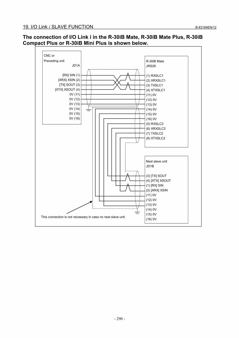
19. I/O Link i SLAVE FUNCTION B-83184EN/12
- 290 -
The connection of I/O Link i in the R-30iB Mate, R-30iB Mate Plus, R-30iB Compact Plus or R-30iB Mini Plus is shown below.
CNC or Preceding unit
JD1A
[RX] SIN (1) [XRX] XSIN (2) [TX] SOUT (3)
[XTX] XSOUT (4) 0V (11) 0V (12) 0V (13) 0V (14) 0V (15) 0V (16)
R-30iB Mate JRS26 (1) RXSLC1 (2) XRXSLC1 (3) TXSLC1 (4) XTXSLC1 (11) 0V (12) 0V (13) 0V (14) 0V (15) 0V (16) 0V (5) RXSLC2 (6) XRXSLC2 (7) TXSLC2 (8) XTXSLC2
Next slave unit JD1B (3) [TX] SOUT (4) [XTX] XSOUT (1) [RX] SIN (2) [XRX] XSIN (11) 0V (12) 0V (13) 0V (14) 0V (15) 0V (16) 0V
This connection is not necessary in case no next slave unit.

B-83184EN/12 19. I/O Link i SLAVE FUNCTION
- 291 -
19.2 I/O LINK i SLAVE MENU The DCS I/O Link i Slave menu will be displayed by pressing the [ENTER] key or the [F3 (DETAIL)] key while on the " I/O Link i Slave" item in the DCS Top menu.
DCS I/O Link i Slave 1/2 Status Input size (byte): 0 OK Output size (byte): 0 OK [ TYPE ] UNDO
Items in I/O Link i Slave menu Item Description
Input size (byte) Output size (byte)
The number of safety signals as byte. Maximum value is 8 byte, in this case, 64 safety signals are available. When both input size and output size are 0, safety signal of I/O Link i slave function is disable. The range is 0 - 8 byte. Default is 0.
Status The status of each line is displayed. OK: Setting parameter and DCS parameter are the same. CHGD: Setting parameter is changed, but not applied to DCS parameter. PEND: Setting parameter is changed and applied to DCS parameter, but controller power has
not been cycled.
Operation in I/O Link i Slave menu Operation Description
[F5 (UNDO)] UNDO the items in this menu. The setting parameters become the same as the current DCS parameters.
[PREV] The DCS Top menu will be displayed.
19.3 NUMBER OF SAFETY AND NON-SAFETY SIGNALS
19.3.1 Case with Safety Signals The number of usable safety signals for I/O Link i Slave function is up to 64 points. The sum of safety and non-safety signals for I/O Link i Slave function is up to 224 points. In other words, if used safety signals are few, usable non-safety signals increase by the amount. The default number of non-safety signal is as the following: - R-30iB, R-30iB Plus : Input is 0 point. Output is 0 point - R-30iB Mate, R-30iB Mate Plus, R-30iB Compact Plus, R-30iB Mini Plus : Input is 72 points. Output is 68 points. The number of non-safety signals is set by the following system variables: - Input : $IOSLAVE.$INPUT_N - Output : $IOSLAVE.$OUTPUT_N If the value of the system variable is over the maximum, error occurs and non-safety signal is not assigned.

19. I/O Link i SLAVE FUNCTION B-83184EN/12
- 292 -
19.3.2 Case without Safety Signals If you don't use safety signals, it is possible for I/O Link i to use 512 points per a group. And Robot Controller has two groups to treat dual signal for safety signals, so 1024 points is usable totally. However, CNC software keeps 16 points (2bytes) out of 512 points for other purpose. So you can use up to 496 points per a group for CNC actually, and 992 points are usable totally. Assignment is as follows if you use two groups for non-safety signals: - 1st group : rack 32, slot 1 - 2nd group : rack 32, slot 2 The system variables to set the number of non-safety signal are as follows: - 1st group : (Input) $IOSLAVE.$INPUT_N, (Output) $IOSLAVE.$OUTPUT_N - 2nd group : (Input) $IOSLAVE.$INPUT_N2, (Output) $IOSLAVE.$OUTPUT_N2 In addition, I/O Unit ID codes for the two groups of Robot Controller are displayed on the I/O DEVICE MONITOR screen of CNC as follows: - 1st group : 56 (R-30iB or R-30iB Plus) or 57 (R-30iB Mate, R-30iB Mate Plus, R-30iB Compact Plus, R-30iB Mini Plus) - 2nd group : 3F
19.4 MAPPING OF SAFETY AND NON-SAFETY SIGNALS When Robot Controller (R-30iB, R-30iB Plus, R-30iB Mate, R-30iB Mate Plus, R-30iB Compact Plus or R-30iB Mini Plus) is connected to CNC by I/O Link i as slave, safety signals for Robot Controller are assigned to start address. And non-safety signals are assigned following those. You have to consider this mapping if you set cross check for CNC. Example ) The case that CNC uses safety signals (Input/Output: 16/8 points) and non-safety signals (Input/Output: 32/24 points) with PMC1 and DCSPMC.
Assignment of signal (PMC1) Physical number Address of CNC Assignment of safety and non-safety signal
for Robot Controller In 1- 8 Yn SLI[ 1- 8] in 9-16 Yn+1 SLI[ 9-16] in 17-24 Yn+2 DI[ 1- 8] in 25-32 Yn+3 DI[ 9-16] in 33-40 Yn+4 DI[17-24] in 41-48 Yn+5 DI[25-32] out 1- 8 Xm SLO[ 1- 8] out 9-16 Xm+1 DO[ 1- 8] out 17-24 Xm+2 DO[ 9-16] out 25-32 Xm+3 DO[17-24]
NOTE: You can change used index of DI/DO as non-safety signal by manual assignment. (as DO[1-8] -> DO[101-108]) Non-safety signals are assigned as rack 32, slot 1.
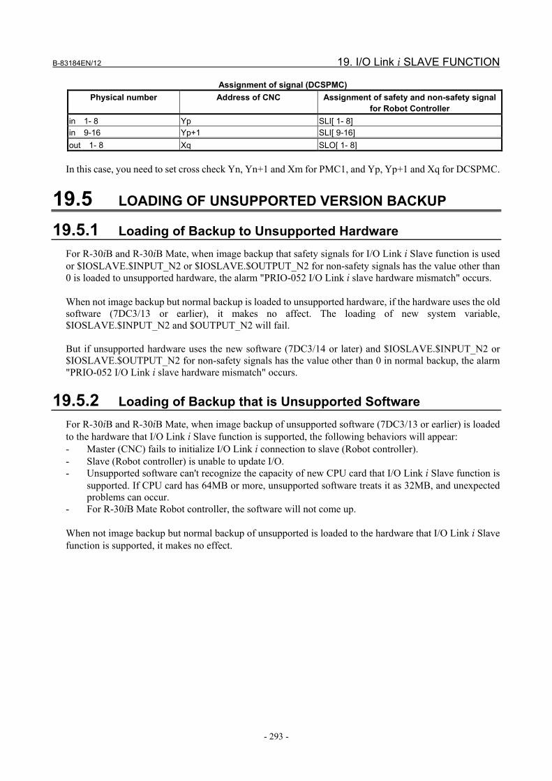
B-83184EN/12 19. I/O Link i SLAVE FUNCTION
- 293 -
Assignment of signal (DCSPMC) Physical number Address of CNC Assignment of safety and non-safety signal
for Robot Controller in 1- 8 Yp SLI[ 1- 8] in 9-16 Yp+1 SLI[ 9-16] out 1- 8 Xq SLO[ 1- 8]
In this case, you need to set cross check Yn, Yn+1 and Xm for PMC1, and Yp, Yp+1 and Xq for DCSPMC.
19.5 LOADING OF UNSUPPORTED VERSION BACKUP
19.5.1 Loading of Backup to Unsupported Hardware For R-30iB and R-30iB Mate, when image backup that safety signals for I/O Link i Slave function is used or $IOSLAVE.$INPUT_N2 or $IOSLAVE.$OUTPUT_N2 for non-safety signals has the value other than 0 is loaded to unsupported hardware, the alarm "PRIO-052 I/O Link i slave hardware mismatch" occurs. When not image backup but normal backup is loaded to unsupported hardware, if the hardware uses the old software (7DC3/13 or earlier), it makes no affect. The loading of new system variable, $IOSLAVE.$INPUT_N2 and $OUTPUT_N2 will fail. But if unsupported hardware uses the new software (7DC3/14 or later) and $IOSLAVE.$INPUT_N2 or $IOSLAVE.$OUTPUT_N2 for non-safety signals has the value other than 0 in normal backup, the alarm "PRIO-052 I/O Link i slave hardware mismatch" occurs.
19.5.2 Loading of Backup that is Unsupported Software For R-30iB and R-30iB Mate, when image backup of unsupported software (7DC3/13 or earlier) is loaded to the hardware that I/O Link i Slave function is supported, the following behaviors will appear: - Master (CNC) fails to initialize I/O Link i connection to slave (Robot controller). - Slave (Robot controller) is unable to update I/O. - Unsupported software can't recognize the capacity of new CPU card that I/O Link i Slave function is
supported. If CPU card has 64MB or more, unsupported software treats it as 32MB, and unexpected problems can occur.
- For R-30iB Mate Robot controller, the software will not come up. When not image backup but normal backup of unsupported is loaded to the hardware that I/O Link i Slave function is supported, it makes no effect.

20. SAFE I/O CONSISTENCY CHECK FUNCTION B-83184EN/12
- 294 -
20 SAFE I/O CONSISTENCY CHECK FUNCTION
The Safe I/O consistency check is the function to check the consistency of a pair of safe I/O. If the pair of Safe I/O status is not consistent for the specified time, servo power is turned off immediately. The servo power cannot be turned on until the pair of Safe I/O status becomes consistent. Maximum 16 pairs of Safe I/O can be checked. The consistent situation is the status of the Safe I/O pair are the same, such as both are ON or both are OFF. When the operator “!” specified, the consistent situation is the status of the Safe I/O pare are different, such as ON and OFF, OFF and ON. In the inconsistency situation, “SRVO-484 Safe I/O consistency alarm %x, %x” occurs. When this alarm occurs, please check the connection of Safe I/O, the setting of “Safe I/O consistency check” menu and failure of hardware that the Safe I/O is connected. To reset the alarm, please remove the factors and cycle power.
WARNING If Safe I/O consistency check setting is set incorrectly, the safety function will not
work, and serious personal injury could result. When settings are changed, the values must be verified and the function must be tested.
20.1 SAFE I/O CONSISTENCY CHECK MENU The DCS Safe/IO consistency check menu will be displayed by pressing the [ENTER] key or the [F3(DETAIL)] key while on the "Safe I/O consistency check" item in the DCS Top menu.
DCS Safe I/O consistency check 1/16 No. Signal 1 Signal 2 time(ms) Status 1 SPI[ 1] ! SPO[ 1] 1000 OK 2 SSI[ 6] SPI[ 2] 1000 OK 3 ---[ 0] ---[ 0] 1000 OK 4 ---[ 0] ---[ 0] 1000 OK 5 ---[ 0] ---[ 0] 1000 OK 6 ---[ 0] ---[ 0] 1000 OK 7 ---[ 0] ---[ 0] 1000 OK 8 ---[ 0] ---[ 0] 1000 OK 9 ---[ 0] ---[ 0] 1000 OK 10 ---[ 0] ---[ 0] 1000 OK 11 ---[ 0] ---[ 0] 1000 OK 12 ---[ 0] ---[ 0] 1000 OK 13 ---[ 0] ---[ 0] 1000 OK 14 ---[ 0] ---[ 0] 1000 OK 15 ---[ 0] ---[ 0] 1000 OK 16 ---[ 0] ---[ 0] 1000 OK [ TYPE ] [CHOICE] UNDO

B-83184EN/12 20. SAFE I/O CONSISTENCY CHECK FUNCTION
- 295 -
Items in DCS Safe I/O consistency check menu Item Description
Signal 1 Used to set the first Safe I/O to check consistency. Signal 2 Used to set the second Safe I/O to check consistency.
You can specify "!" on the signal 2 of the Safe I/O name, this means the inverse value (NOT) is compared. When the operator “!” specified, the consistent situation is the status of the Safe I/O pare are different, such as ON and OFF, OFF and ON.
Time The time limit is set in safety parameter for each pair. The default is 1000ms, and the maximum value is 2000ms.
Stats The status of each line is displayed. OK: Setting parameter and DCS parameter are the same. CHGD: Setting parameter is changed, but not applied to DCS parameter. PEND: Setting parameter is changed and applied to DCS parameter, but controller power has not been cycled.
Operation in DCS Safe I/O consistency check menu
Operation Description [F5(UNDO)] UNDO the items in this menu. The setting parameters become the same as the current DCS
parameters. [PREV] The DCS Top menu will be displayed.

21. OPERATION WITHOUT MODE SWITCH B-83184EN/12
- 296 -
21 OPERATION WITHOUT MODE SWITCH Mode select function has to be selected depend on the system configuration and requirement for the system. To change mode, following functions can be used. - Operator Panel (optional hardware for R-30iB Compact Plus, R-30iB Mini Plus) - TP Mode Select function - External Mode Select function. For R-30iB Compact Plus or R-30iB Mini Plus controller, mode select function can be choice on DCS Mode Select screen. For other controller, Mode is operated by mode switch on operator panel by the default. To use other mode select function, either software option, TP Mode Select option (J768) or External Mode Select option (J569) is needed. And the operator panel must be “No mode switch” type. If the option is loaded and the operator panel has the mode switch, the alarm”SYST-351 Mode select function mismatch” occurs. TP Mode Select function is not supported on R-30iB and R-30iB Mate. Please refer to the chapter “14 OPERATION WITHOUG MODE SWICH” in “OPERATOR’S MANUAL (Basic Operation) (B-83284EN)” for details.
21.1 MODE SELECT MENU If controller type is R-30iB Compact Plus, R-30iB Mini Plus or TP Mode Select option (J768) is ordered, “DCS Mode Select screen” appears in DCS screen.
DCS Mode Select 1/3 Status Mode Select Func.: Teach Pendant OK Select Mode Type: AUTO/T1/T2 OK
Code number for TP Mode Select [ TYPE ] [CHOICE] UNDO

B-83184EN/12 21. OPERATION WITHOUT MODE SWITCH
- 297 -
DCS Mode Select menu Item Description
Mode Select Func. Users can choose method to select mode from three functions, Mode Switch, External Input and Teach Pendant. Modes Switch: Actual Mode Switch on optional switch box is used to select mode. External Input: Safety input signal (SSO[6], and SSO[7]) is used to select mode. It works as same as “External Mode Select function (J569). Teach Pendant: This function (TP mode select function) is used to mode select. This item can be changed if controller type is R-30iB Compact Plus or R-30iB Mini Plus. If TP Mode Select option (J768) is ordered with R-30iB Plus or R-30iB Mate Plus, this items is “Teach Pendant” and user cannot change.
Select Mode Type User can select if T2 button is displayed in the pop-up screen. AUTO/T1: AUTO and T1 buttons are displayed in the pop-up screen. AUTO/T1/T2: AUTO, T1 and T2 buttons are displayed in the pop-up screen. (Default)
Status The status of the User model is displayed. OK: Setting parameter and DCS parameter are the same. CHGD: Setting parameter is changed, but not applied to DCS parameter. PEND: Setting parameter is changed and applied to DCS parameter, but controller power
has not been cycled. Code number for TP Mode Select
A password to protect mode change is change in the DCS Mode Select screen. Only four numbers code can be used for the code to protect mode change as same as other DCS code numbers (For example, 9999, 1234 or etc.). Default numbers is “1111”. To change the code number, it is needed to input DCS master code number.
WARNING If a robot is used with an incorrect setting, the safety function does not work
correctly and serious personal injury could result. When setting of mode select function is changed, the setting must be verified and the function must be tested again.

22. SAFETY SIGNALS B-83184EN/12
- 298 -
22 SAFETY SIGNALS In the R-30iB/R-30iB Plus controller, safety signal interface depends on the type of cabinet. The detail of interface is shown in Table 22(a).
Table 22(a) Safety signal interface
Cabinet Number of I/O points Remarks SFDI (NOTE1) SFDO (NOTE2) 1 R-30iB/R-30iB Plus
A-cabinet 2 pair(POS / NEG
type) 2 pair (POS / POS type) Standard
2 R-30iB/R-30iB Plus B-cabinet
8 pair(POS / NEG type)
8 pair (POS / POS type) Option (NOTE3) (Ordering Specification: A05B-2600-J130)
The following options are able to add the safety I/O signals.
Option Number of I/O points Remarks SFDI (NOTE1) SFDO (NOTE2) 3 Additional safety
I/O board (R-30iB/R-30iB Plus A-cabinet, B-cabinet, R-30iB Mate common)
8 pair(POS / NEG type) 8 pair (POS / POS type) Option (Ordering Specification: A05B-2600-J131) Category 4
Safety I/O conversion board (R-30iB/R-30iB Plus A-cabinet)
This board is used to convert connector for safety I/O signals on safety I/O board to a terminal block Option (Ordering Specification: A05B-2600-J132)
4 I/O Unit-MODEL A (NOTE4) (NOTE4) Category 3
NOTE 1 Polarity of SFDI
NEGative : (Current source type, source type, or Nch) Regard to be ON when input is at Low level.
POSitive : (Current sink type, sink type, or Pch) Regard to be ON when input is at High level. 2 Polarity of SFDO
NEGative : (Current sink type) Output is at Low level when ON. POSative : (Current source type) Output is at High level when ON.
3 If A05B-2600-J130 is not ordered, safety signals (SFDI, SFDO) can not be used in R-30iB/R-30iB Plus B-cabinet.
4 Regarding the number of I/O points and polarity, please refer to the connection and maintenance manual of I/O Unit-MODEL A (B-61813EN).
WARNING At the initial start-up, the operation check and validation of the wiring for safety
signals should be carried out, and then the wiring should be protected by the cable duct.

B-83184EN/12 22. SAFETY SIGNALS
- 299 -
22.1 SAFETY SIGNAL INTERFACE
22.1.1 In Case of A-cabinet In the A-cabinet of R-30iB/R-30iB Plus, safety signals (SFDI, SFDO) are included in CRMB2 connector on the emergency stop board.
CRMB2
Emergency stop board (A-cabinet) CRMB2 Connector
A1 24E B1 0V A2 24E B2 0V A3 SFDI11 B3 SFDI21 A4 SFDI12 B4 SFDI22 A5 SFDO11 B5 SFDO21 A6 SFDO12 B6 SFDO22
The specification of the connectors for cable side is shown below.
Manufacturer : TE Connectivity Housing : 2-1827864-6 Contact : 1939991-2
Safety Inputs (SFDI)
SFDI11 - SFDI21 SFDI12 - SFDI22
Connect duplicitously as in the above combination. Safety Outputs (SFDO)
SFDO11 - SFDO21 SFDO12 - SFDO22
Connect duplicitously as in the above combination.

22. SAFETY SIGNALS B-83184EN/12
- 300 -
22.1.2 In Case of B-cabinet In the B-cabinet of R-30iB/R-30iB Plus, safety signals (SFDI, SFDO) are included in CRMA90 connector on the safety I/O board (option).
CRMA90
Emergency stop board (B-cabinet)
Safety I/O board : A20B-3300-0690 (Ordering Specification : A05B-2600-J130)
Emergency stop board (B-cabinet) and Safety I/O board (Option) CRMA90 Connector
A1 24E B1 0V A2 SFDI11 B2 SFDI21 A3 SFDI12 B3 SFDI22 A4 SFDI13 B4 SFDI23 A5 SFDI14 B5 SFDI24 A6 SFDI15 B6 SFDI25 A7 SFDI16 B7 SFDI26 A8 SFDI17 B8 SFDI27 A9 SFDI18 B9 SFDI28 A10 B10 A11 SFDO11 B11 SFDO21 A12 SFDO12 B12 SFDO22 A13 SFDO13 B13 SFDO23 A14 SFDO14 B14 SFDO24 A15 SFDO15 B15 SFDO25 A16 SFDO16 B16 SFDO26 A17 SFDO17 B17 SFDO27 A18 SFDO18 B18 SFDO28 A19 0V B19 0V A20 0V B20 0V
The specification of the connectors for cable side is shown below. Manufacturer : TE Connectivity Housing : 1-1827863-0 Contact : 1939991-2

B-83184EN/12 22. SAFETY SIGNALS
- 301 -
Safety Inputs (SFDI) SFDI11 - SFDI21 SFDI12 - SFDI22 SFDI13 - SFDI23 SFDI14 - SFDI24 SFDI15 - SFDI25 SFDI16 - SFDI26 SFDI17 - SFDI27 SFDI18 - SFDI28
Connect duplicitously as in the above combination. Safety Outputs (SFDO)
SFDO11 - SFDO21 SFDO12 - SFDO22 SFDO13 - SFDO23 SFDO14 - SFDO24 SFDO15 - SFDO25 SFDO16 - SFDO26 SFDO17 - SFDO27 SFDO18 - SFDO28
Connect duplicitously as in the above combination.
22.1.3 In Case of Additional Safety I/O Board (mini-slot) In the additional safety I/O board, safety signals (SFDI, SFDO) are included in CRMA90 connector on the additional safety I/O board (mini-slot).
Additional safety I/O board (Option)

22. SAFETY SIGNALS B-83184EN/12
- 302 -
CRMA90 Connector A1 24E B1 0V A2 SFDI11 B2 SFDI21 A3 SFDI12 B3 SFDI22 A4 SFDI13 B4 SFDI23 A5 SFDI14 B5 SFDI24 A6 SFDI15 B6 SFDI25 A7 SFDI16 B7 SFDI26 A8 SFDI17 B8 SFDI27 A9 SFDI18 B9 SFDI28 A10 B10 A11 SFDO11 B11 SFDO21 A12 SFDO12 B12 SFDO22 A13 SFDO13 B13 SFDO23 A14 SFDO14 B14 SFDO24 A15 SFDO15 B15 SFDO25 A16 SFDO16 B16 SFDO26 A17 SFDO17 B17 SFDO27 A18 SFDO18 B18 SFDO28 A19 0V B19 0V A20 0V B20 0V
The specification of the connectors for cable side is shown below. Manufacturer : TE Connectivity Housing : 1-1827863-0 Contact : 1939991-2 Safety Inputs (SFDI)
SFDI11 - SFDI21 SFDI12 - SFDI22 SFDI13 - SFDI23 SFDI14 - SFDI24 SFDI15 - SFDI25 SFDI16 - SFDI26 SFDI17 - SFDI27 SFDI18 - SFDI28
Connect duplicitously as in the above combination. Safety Outputs (SFDO)
SFDO11 - SFDO21 SFDO12 - SFDO22 SFDO13 - SFDO23 SFDO14 - SFDO24 SFDO15 - SFDO25 SFDO16 - SFDO26 SFDO17 - SFDO27 SFDO18 - SFDO28
Connect duplicitously as in the above combination.

B-83184EN/12 22. SAFETY SIGNALS
- 303 -
The safety I/O conversion board is used to convert connector for safety I/O signals on safety I/O board to a terminal block.
Safety I/O conversion board (Option)
CRMA98 Connector CRMA99 Connector
A1 SFDI11 B1 SFDI13 A2 SFDI21 B2 SFDI23 A3 SFDI12 B3 SFDI14 A4 SFDI22 B4 SFDI24 A5 SFDO22 B5 SFDO24 A6 SFDO12 B6 SFDO14 A7 SFDO21 B7 SFDO23 A8 SFDO11 B8 SFDO13
A1 SFDO26 B1 SFDO17 A2 SFDO16 B2 SFDO27 A3 SFDO25 B3 SFDO18 A4 SFDO15 B4 SFDO28 A5 0V B5 24E A6 0V B6 0V A7 SFDI15 B7 SFDI28 A8 SFDI25 B8 SFDI18 A9 SFDI16 B9 SFDI27 A10 SFDI26 B10 SFDI17

22. SAFETY SIGNALS B-83184EN/12
- 304 -
TBOP15 Terminal block TBOP16 Terminal block
1 SFDO11 2 SFDO21 3 SFDO12 4 SFDO22 5 SFDO13 6 SFDO23 7 SFDO14 8 SFDO24 9 SFDO15 10 SFDO25 11 SFDO16 12 SFDO26 13 SFDO17 14 SFDO27 15 SFDO18 16 SFDO28
The specification of the terminal block (TBOP15, TBOP16) is shown below. Manufacturer:WAGO Specification:734-116
TBOP17 Terminal block
The specification of the terminal block (TBOP17) is shown below. Manufacturer:WAGO Specification:734-106
1 SFDI28 2 SFDI18 3 SFDI27 4 SFDI17 5 SFDI26 6 SFDI16 7 SFDI25 8 SFDI15 9 SFDI24 10 SFDI14 11 SFDI23 12 SFDI13 13 SFDI22 14 SFDI12 15 SFDI21 16 SFDI11
1 24E 2 24E 3 24E 4 0V 5 0V 6 0V

B-83184EN/12 22. SAFETY SIGNALS
- 305 -
General connection diagram
In case of A-cabinet Additional safety I/O board is connected with I/O Link i as shown in the figure below. E-stop board and additional safety I/O board are defined as “Group” of the I/O Link i. I/O Link i can connect up to 4 Groups.
E-stop Board
JRS20
Main Board JRS19
CRS38A
CRS38B
CRS38A
CRS38B
CRS38A
CRS38B
I/O Link i
Additional safety I/O board #1
Additional safety I/O board #2
Additional safety I/O board #3

22. SAFETY SIGNALS B-83184EN/12
- 306 -
In case using the Safety I/O conversion board, the Safety I/O conversion board is connected as shown below.
E-stop Board
JRS20
Main Board JRS19
CRS38A
CRS38B
CRS38A
CRS38B
CRS38A
CRS38B
I/O Link i
Additional safety I/O board #1
Additional safety I/O board #2
Additional safety I/O board #3 Safety I/O conversion board #3
Safety I/O conversion board #2
CRMA90
CRMA90
CRMA90
CRMA98
CRMA99
CRMA98
CRMA99
CRMA98
CRMA99
Safety I/O conversion board #1

B-83184EN/12 22. SAFETY SIGNALS
- 307 -
In case of B-cabinet Additional safety I/O board is connected with I/O Link i as shown in the figure below. E-stop board and additional safety I/O board are defined as “Group” of the I/O Link i. I/O Link i can connect up to 4 Groups.
E-stop Board
JD1A
Main Board JRS19
CRS38A
CRS38B
CRS38A
CRS38B
CRS38A
CRS38B
I/O Link i
Additional safety I/O board #1
Additional safety I/O board #2
Additional safety I/O board #3
JRS19
In case of R-30iB Mate Additional safety I/O board is connected with I/O Link i as shown in the figure below. Additional safety I/O board is defined as “Group” of the I/O Link i. I/O Link i can connect up to 4 Groups. The maximum number of safety I/O boards in the controller is 2 because the number of mini-slot is 2. To use additional safety I/O board in R-30iB Mate controller, the main board that has PMC function is necessary.
Main Board JD44A
CRS38A
CRS38B
CRS38A
CRS38B I/O Link i
Additional safety I/O board #1
Additional safety I/O board #2

22. SAFETY SIGNALS B-83184EN/12
- 308 -
22.1.4 In case of I/O Unit-MODEL A
General connection diagram
In case of A-cabinet
E-stop Board
JRS20
Main Board JRS19
CPD26
JD1A
JD1B
I/O Unit-MODEL A #1
CPD26
JD1A
JD1B
I/O Unit-MODEL A #2
DC24V
DC24V
About the detail of connection, please refer to the connection and maintenance manual of I/O Unit-MODEL A (B-61813EN).
In case of B-cabinet
E-stop Board
JD1A
Main Board JRS19
CPD26
JD1A
JD1B
I/O Unit-MODEL A #1
CPD26
JD1A
JD1B
I/O Unit-MODEL A #2
DC24V
DC24V
JRS19

B-83184EN/12 22. SAFETY SIGNALS
- 309 -
About the detail of connection, please refer to the connection and maintenance manual of I/O Unit-MODEL A (B-61813EN).
In case of R-30iB Mate
Main Board JD44A
CPD26
JD1A
JD1B
I/O Unit-MODEL A #1
CPD26
JD1A
JD1B
I/O Unit-MODEL A #2
DC24V
DC24V
About the detail of connection, please refer to the connection and maintenance manual of I/O Unit-MODEL A (B-61813EN). To use safety signals by I/O Unit-MODEL A, the main board that has PMC function is necessary.
Available module Table 22.1.4(a), Table 22.1.4(b) and Table 22.1.4(c) shows the details of the available interface safety I/O board of category 3.
Table 22.1.4(a) Detail of available digital input modules of I/O Unit-MODEL A
Module name Option Points Input type AID16C A05B-2450-J402 16 Insulation type DC input AID16K A05B-2450-J410 AID16D A05B-2450-J403 AID16L A05B-2450-J411 AID32E1 A05B-2450-J404 32 AID32E2 A05B-2450-J405 AID32F1 A05B-2450-J406 AID32F2 A05B-2450-J407
Table 22.1.4(b) Detail of available digital output modules of I/O Unit-MODEL A
Module name Option Points Output type AOD08D A05B-2450-J432 8 Insulation type DC output AOD16D A05B-2450-J434 16 AOD16DP A05B-2450-J444 AOD32D1 A05B-2450-J436 32 AOD32D2 A05B-2450-J437

22. SAFETY SIGNALS B-83184EN/12
- 310 -
Module name Option Points Output type AOR08G A05B-2450-J441 8 RELAY output AOR16G A05B-2450-J442 16 AOR16H2 A05B-2450-J443
Table 22.1.4(c) Detail of available interface modules of I/O Unit-MODEL A
Module name Option AIF01E A03B-0826-J016
22.2 PERIPHERAL EQUIPMENT AND SAFETY SIGNALS CONNECTION
22.2.1 In Case of A-cabinet
Example of the Connection diagram
Controller
Emergency stop board Safety circuit
SFDI11 CRMB2 (A3)
Connector pin No.
Receiver circuit
SFDI21 CRMB2 (B3)
SFDI12 CRMB2 (A4)
SFDI22 CRMB2 (B4)
RV
RV
RV
RV
CRMB2 (A1,A2)
SFDO11
CRMB2 (B5)
CRMB2 (A5)
Driver circuit
SFDO21
CRMB2 (A6) SFDO12
CRMB2 (B6) SFDO22
CRMB2 (B1,B2)
0V
DV
DV
DV
Safety Relay Unit
Safety Relay Unit
PSU
DC24V
F3 (7.5A)
DV

B-83184EN/12 22. SAFETY SIGNALS
- 311 -
Signals Description Remarks SFDI11 - SFDI21 SFDI12 - SFDI22
Safety Inputs: Connect redundant contacts to the pair of SFDI.
See Subsection 22.3.1 for detailed information about Safety Input Specifications.
SFDO11 - SFDO21 SFDO12 - SFDO22
Safety Outputs: Connect redundant circuits (e.g. safety relay unit) to the pair of SFDO.
See Subsection 22.3.2 for detailed information about Safety Output Specifications.
WARNING 1 Be sure to use the pair of SFDI11 with SFDI21, and SFDI12 with SFDI22. 2 Be sure to use the pair of SFDO11 with SFDO21, and SFDO12 with SFDO22.
- To use SFDO as safety function of Cat. 4, PL e, SIL 3 defined by ISO13849-1, SFDO pulse check
must be enable to avoid the fault accumulation. See Chapter 9 SAFE I/O for detailed information about SFDO Pulse Check.

22. SAFETY SIGNALS B-83184EN/12
- 312 -
22.2.2 In Case of B-cabinet
Example of the Connection diagram
Controller
Safety circuit
SFDI11 CRMA90(A2)
Connector pin No.
Receiver circuit
SFDI21 CRMA90(B2)
SFDI12 CRMA90(A3)
SFDI22 CRMA90(B3)
RV
RV
RV
RV
CRMA90(A1)
CRMA90(B1)
0V
SFDI13 CRMA90(A4)
SFDI23 CRMA90(B4)
SFDI14 CRMA90(A5)
SFDI24 CRMA90(B5)
RV
RV
RV
RV
RV
RV
RV
RV
RV
RV
RV
RV
SFDI15
SFDI25
SFDI16
SFDI26
SFDI17
SFDI27
SFDI18
SFDI28
CRMA90(A6)
CRMA90(B6)
CRMA90(A7)
CRMA90(B7)
CRMA90(A8)
CRMA90(B8)
CRMA90(A9)
CRMA90(B9)
Emergency stop board
+24E
Safety I/O board
FUSE4 (1.0A)
Signals Description Remarks
SFDI11 - SFDI21 SFDI12 - SFDI22 SFDI13 - SFDI23 SFDI14 - SFDI24 SFDI15 - SFDI25 SFDI16 - SFDI26 SFDI17 - SFDI27 SFDI18 - SFDI28
Safety Inputs: Connect redundant contacts to the pair of SFDI.
See Subsection 22.3.1 for detailed information about Safety Input Specifications.

B-83184EN/12 22. SAFETY SIGNALS
- 313 -
WARNING Be sure to use the pair of SFDI 11 with SFDI 21, SFDI 12 with SFDI 22, SFDI 13 with SFDI 23, SFDI 14 with SFDI 24, SFDI 15 with SFDI 25, SFDI 16 with SFDI 26, SFDI 17 with SFDI 27, and SFDI 18 with SFDI 28.
Example of the Connection diagram
Controller
PSU
Safety I/O board Safety circuit
SFDO11
CRMA90(B11)
CRMA90(A11)
Driver circuit
SFDO21
CRMA90(A12) SFDO12
CRMA90(B12) SFDO22
DC24V
CRMA90(A19,A20,B19,B20)
0V
DV
DV
DV
DV
DV
DV
DV
DV
DV
DV
DV
DV
DV
DV
DV
CRMA90(A13)
CRMA90(B13)
CRMA90(A14)
CRMA90(B14)
CRMA90(A15)
CRMA90(B15)
CRMA90(A16)
CRMA90(B16)
CRMA90(A17)
CRMA90(B17)
CRMA90(A18)
CRMA90(B18)
SFDO13
SFDO23
SFDO14
SFDO24
SFDO15
SFDO25
SFDO16
SFDO26
SFDO17
SFDO27
SFDO18
SFDO28
Safety Relay Unit
Safety Relay Unit
Safety Relay Unit
Safety Relay Unit
Safety Relay Unit
Safety Relay Unit
Safety Relay Unit
Safety Relay Unit
F3 (7.5A)
DV

22. SAFETY SIGNALS B-83184EN/12
- 314 -
Signals Description Remarks SFDO11 - SFDO21 SFDO12 - SFDO22 SFDO13 - SFDO23 SFDO14 - SFDO24 SFDO15 - SFDO25 SFDO16 - SFDO26 SFDO17 - SFDO27 SFDO18 - SFDO28
Safety Outputs: Connect redundant circuits (e.g. safety relay unit) to the pair of SFDO.
See Subsection 22.3.2 for detailed information about Safety Output Specifications.
WARNING Be sure to use the pair of SFDO11 with SFDO21, SFDO12 with SFDO22, SFDO13 with SFDO23, SFDO14 with SFDO24, SFDO15 with SFDO25, SFDO16 with SFDO26, SFDO17 with SFDO27, and SFDO18 with SFDO28.
- To use SFDO as safety function of Cat. 4, PL e, SIL 3 defined by ISO13849-1, SFDO pulse check
must be enable to avoid the fault accumulation. See Chapter 9 SAFE I/O for detailed information about SFDO Pulse Check.

B-83184EN/12 22. SAFETY SIGNALS
- 315 -
22.2.3 In Case of Additional Safety I/O Board (mini-slot)
Example of the Connection diagram
Controller
Safety circuit
SFDI11 CRMA90(A2)
Connector pin No.
Receiver circuit
SFDI21 CRMA90(B2)
SFDI12 CRMA90(A3)
SFDI22 CRMA90(B3)
RV
RV
RV
RV
CRMA90(A1)
CRMA90(B1)
0V
SFDI13 CRMA90(A4)
SFDI23 CRMA90(B4)
SFDI14 CRMA90(A5)
SFDI24 CRMA90(B5)
RV
RV
RV
RV
RV
RV
RV
RV
RV
RV
RV
RV
SFDI15
SFDI25
SFDI16
SFDI26
SFDI17
SFDI27
SFDI18
SFDI28
CRMA90(A6)
CRMA90(B6)
CRMA90(A7)
CRMA90(B7)
CRMA90(A8)
CRMA90(B8)
CRMA90(A9)
CRMA90(B9)
PSU
DC24V
Safety I/O board
FU1 (1.0A)

22. SAFETY SIGNALS B-83184EN/12
- 316 -
Example of the Connection diagram (In case of safety I/O conversion board)
Safety I/O conversion board
Controller
Safety circuit
SFDI11 CRMA90(A2)
Connector pin No.
Receiver circuit
SFDI21 CRMA90(B2)
SFDI12 CRMA90(A3)
SFDI22 CRMA90(B3)
RV
RV
RV
RV
CRMA90(A1)
CRMA90(B1)
0V
SFDI13 CRMA90(A4)
SFDI23 CRMA90(B4)
SFDI14 CRMA90(A5)
SFDI24 CRMA90(B5)
RV
RV
RV
RV
RV
RV
RV
RV
RV
RV
RV
RV
SFDI15
SFDI25
SFDI16
SFDI26
SFDI17
SFDI27
SFDI18
SFDI28
CRMA90(A6)
CRMA90(B6)
CRMA90(A7)
CRMA90(B7)
CRMA90(A8)
CRMA90(B8)
CRMA90(A9)
CRMA90(B9)
PSU
DC24V
Safety I/O board
FU1 (1.0A)
CRMA98(A1)
CRMA98(A2)
CRMA98(A3)
CRMA98(A4)
CRMA99(B5)
CRMA99(B6)
CRMA98(B1) CRMA98(B2)
CRMA98(B3)
CRMA98(B4)
CRMA99(A7)
CRMA99(A8)
CRMA99(A9)
CRMA99(A10)
CRMA99(B10)
CRMA99(B9)
CRMA99(B8)
CRMA99(B7)
TBOP16(16)
TBOP16(15)
TBOP16(14)
TBOP16(13)
TBOP17(1,2,3)
TBOP17(4,5,6)
TBOP16(12) TBOP16(11)
TBOP16(10)
TBOP16(9)
TBOP16(8)
TBOP16(7)
TBOP16(6)
TBOP16(5)
TBOP16(4)
TBOP16(3)
TBOP16(2)
TBOP16(1)
Signals Description Remarks SFDI11 - SFDI21 SFDI12 - SFDI22 SFDI13 - SFDI23 SFDI14 - SFDI24 SFDI15 - SFDI25 SFDI16 - SFDI26 SFDI17 - SFDI27 SFDI18 - SFDI28
Safety Inputs: Connect redundant contacts to the pair of SFDI.
See Subsection 22.3.1 for detailed information about Safety Input Specifications.

B-83184EN/12 22. SAFETY SIGNALS
- 317 -
WARNING Be sure to use the pair of SFDI 11 with SFDI 21, SFDI 12 with SFDI 22, SFDI 13 with SFDI 23, SFDI 14 with SFDI 24, SFDI 15 with SFDI 25, SFDI 16 with SFDI 26, SFDI 17 with SFDI 27, and SFDI 18 with SFDI 28.
Example of the Connection diagram
Controller
PSU
Safety I/O board Safety circuit
SFDO11
CRMA90(B11)
CRMA90(A11)
Driver circuit
SFDO21
CRMA90(A12) SFDO12
CRMA90(B12) SFDO22
DC24V
CRMA90(A19,A20,B19,B20)
0V
DV
DV
DV
DV
DV
DV
DV
DV
DV
DV
DV
DV
DV
DV
DV
CRMA90(A13)
CRMA90(B13)
CRMA90(A14)
CRMA90(B14)
CRMA90(A15)
CRMA90(B15)
CRMA90(A16)
CRMA90(B16)
CRMA90(A17)
CRMA90(B17)
CRMA90(A18)
CRMA90(B18)
SFDO13
SFDO23
SFDO14
SFDO24
SFDO15
SFDO25
SFDO16
SFDO26
SFDO17
SFDO27
SFDO18
SFDO28
Safety Relay Unit
Safety Relay Unit
Safety Relay Unit
Safety Relay Unit
Safety Relay Unit
Safety Relay Unit
Safety Relay Unit
Safety Relay Unit
DV
FU2 (3.2A)

22. SAFETY SIGNALS B-83184EN/12
- 318 -
Example of the Connection diagram (In case of safety I/O conversion board)
Safety I/O conversion board
Controller
PSU
Safety I/O board Safety circuit
SFDO11
CRMA90(B11)
CRMA90(A11)
Driver circuit
SFDO21
CRMA90(A12) SFDO12
CRMA90(B12) SFDO22
DC24V
CRMA90(A20,B20)
0V
DV
DV
DV
DV
DV
DV
DV
DV
DV
DV
DV
DV
DV
DV
DV
CRMA90(A13)
CRMA90(B13)
CRMA90(A14)
CRMA90(B14)
CRMA90(A15)
CRMA90(B15)
CRMA90(A16)
CRMA90(B16)
CRMA90(A17)
CRMA90(B17)
CRMA90(A18)
CRMA90(B18)
SFDO13
SFDO23
SFDO14
SFDO24
SFDO15
SFDO25
SFDO16
SFDO26
SFDO17
SFDO27
SFDO18
SFDO28
Safety Relay Unit
Safety Relay Unit
Safety Relay Unit
Safety Relay Unit
Safety Relay Unit
Safety Relay Unit
Safety Relay Unit
Safety Relay Unit
DV
FU2 (3.2A)
CRMA98(A8)
CRMA98(A6)
CRMA99(B2)
CRMA98(A5)
CRMA98(B8)
CRMA98(B7)
CRMA98(B6)
CRMA98(B5)
CRMA99(A4)
CRMA99(A3)
CRMA99(A2)
CRMA99(A1)
CRMA99(B1)
TBOP15(3)
TBOP15(1)
TBOP15(4)
TBOP15(5)
TBOP15(6)
TBOP15(7)
TBOP15(8)
TBOP15(9)
TBOP15(10)
TBOP15(11)
TBOP15(14)
TBOP15(12)
TBOP15(13)
CRMA98(A7) TBOP15(2)
CRMA99(B3) TBOP15(15)
CRMA99(B4) TBOP15(16)
CRMA99(A5,A6)
TBOP17(4,5,6)
Connector pin No.

B-83184EN/12 22. SAFETY SIGNALS
- 319 -
Signals Description Remarks SFDO11 - SFDO21 SFDO12 - SFDO22 SFDO13 - SFDO23 SFDO14 - SFDO24 SFDO15 - SFDO25 SFDO16 - SFDO26 SFDO17 - SFDO27 SFDO18 - SFDO28
Safety Outputs: Connect redundant circuits (e.g. safety relay unit) to the pair of SFDO.
See Subsection 22.3.2 for detailed information about Safety Output Specifications.
WARNING Be sure to use the pair of SFDO11 with SFDO21, SFDO12 with SFDO22, SFDO13 with SFDO23, SFDO14 with SFDO24, SFDO15 with SFDO25, SFDO16 with SFDO26, SFDO17 with SFDO27, and SFDO18 with SFDO28.
- To use SFDO as safety function of Cat. 4, PL e, SIL 3 defined by ISO13849-1, SFDO pulse check
must be enable to avoid the fault accumulation. See Subsection 9.1.1 for detailed information about SFDO Pulse Check.

22. SAFETY SIGNALS B-83184EN/12
- 320 -
22.2.4 In Case of I/O Unit-MODEL A
In case of using the input module of AID16D (Example 1)
R-30iB/R-30iB Plus Controller Safety circuit
E-stop Unit
JD1A
JRS19
Main Board JRS19
CPD26
JD1A
JD1B
I/O Unit- MODEL A #1
I/O Unit- MODEL A #2
DC24V
DC24V
CPD26
JD1A
JD1B
2
3
4
5
6
7
8
9
2
3
4
5
6
7
8
9
Power supply Unit
DC 24V 0V
SFDI11
SFDI12
SFDI13
SFDI14
SFDI15
SFDI16
SFDI17
SFDI18
SFDI21
SFDI22
SFDI23
SFDI24
SFDI25
SFDI26
SFDI27
SFDI28
1
1
AID16D
AID
16D
・・・・・・・・・・・・・・・
・・・・・・・・・・・・・・・

B-83184EN/12 22. SAFETY SIGNALS
- 321 -
In case of using the input module of AID16D (Example 2)
R-30iB Mate Controller Safety circuit
Main Board JD44A
CPD26
JD1A
JD1B
I/O Unit- MODEL A #1
I/O Unit- MODEL A #2
DC24V
DC24V
CPD26
JD1A
JD1B
2
3
4
5
6
7
8
9
2
3
4
5
6
7
8
9
Power supply Unit
DC 24V 0V
SFDI11
SFDI12
SFDI13
SFDI14
SFDI15
SFDI16
SFDI17
SFDI18
SFDI21
SFDI22
SFDI23
SFDI24
SFDI25
SFDI26
SFDI27
SFDI28
1
1
AID16D
AID
16D
・・・・・・・・・・・・・・・
・・・・・・・・・・・・・・・ NOTE)
I/O Unit-MODEL A, please mount in customer cabinet.

22. SAFETY SIGNALS B-83184EN/12
- 322 -
Signals Description Remarks SFDI11 - SFDI21 SFDI12 - SFDI22 SFDI13 - SFDI23 SFDI14 - SFDI24 SFDI15 - SFDI25 SFDI16 - SFDI26 SFDI17 - SFDI27 SFDI18 - SFDI28 SFDI19 - SFDI29 SFDI110 - SFDI210 SFDI111 - SFDI211 SFDI112 - SFDI212 SFDI113 - SFDI213 SFDI114 - SFDI214 SFDI115 - SFDI215 SFDI116 - SFDI216
Safety Inputs: Connect redundant contacts to the pair of SFDI.
See the connection and maintenance manual of I / O Unit-MODEL A(B-61813EN) for detailed information about Safety Input Specifications.
WARNING Be sure to use the pair of SFDI 11 with SFDI 21, SFDI 12 with SFDI 22, SFDI 13 with SFDI 23, SFDI 14 with SFDI 24, SFDI 15 with SFDI 25, SFDI 16 with SFDI 26, SFDI 17 with SFDI 27, SFDI 18 with SFDI 28, SFDI 19 with SFDI 29, SFDI 110 with SFDI 210, SFDI 111 with SFDI 211, SFDI 112 with SFDI 212, SFDI 113 with SFDI 213, SFDI 114 with SFDI 214, SFDI 115 with SFDI 215, and SFDI 116 with SFDI 216.

B-83184EN/12 22. SAFETY SIGNALS
- 323 -
In case of using the output module of AOD16D (Example 1)
R-30iB/R-30iB Plus Controller Safety circuit
E-stop Unit
JD1A
JRS19
Main Board JRS19
CPD26
JD1A
JD1B
I/O Unit- MODEL A#1
I/O Unit- MODEL A#2
DC24V
DC24V
SFDO11
SFDO12
SFDO13
SFDO14
SFDO15
SFDO16
SFDO17
SFDO18
SFDO21
SFDO22
SFDO23
SFDO24
SFDO25
SFDO26
SFDO27
SFDO28
CPD26
JD1A
JD1B
2
3
4
5
6
7
8
9
10
11
2
3
4
5
6
7
8
9
10
11
Safety Relay Unit
Safety Relay Unit
Safety Relay Unit
Safety Relay Unit
Safety Relay Unit
Safety Relay Unit
Safety Relay Unit
Safety Relay Unit
Safety Relay Unit
Safety Relay Unit
Safety Relay Unit
Safety Relay Unit
Safety Relay Unit
Safety Relay Unit
Safety Relay Unit
Safety Relay Unit
Power supply Unit
DC 24V 0V
1
20
20
1
AOD
16D
AOD
16D
・・・・・・・・・・・・・・・
・・・・・・・・・・・・・・・

22. SAFETY SIGNALS B-83184EN/12
- 324 -
In case of using the output module of AOD16D (Example 2)
R-30iB Mate Controller Safety circuit
Main Board JD44A
CPD26
JD1A
JD1B
I/O Unit- MODEL A#1
I/O Unit- MODEL A#2
DC24V
DC24V
SFDO11
SFDO12
SFDO13
SFDO14
SFDO15
SFDO16
SFDO17
SFDO18
SFDO21
SFDO22
SFDO23
SFDO24
SFDO25
SFDO26
SFDO27
SFDO28
CPD26
JD1A
JD1B
2
3
4
5
6
7
8
9
10
11
2
3
4
5
6
7
8
9
10
11
Safety Relay Unit
Safety Relay Unit
Safety Relay Unit
Safety Relay Unit
Safety Relay Unit
Safety Relay Unit
Safety Relay Unit
Safety Relay Unit
Safety Relay Unit
Safety Relay Unit
Safety Relay Unit
Safety Relay Unit
Safety Relay Unit
Safety Relay Unit
Safety Relay Unit
Safety Relay Unit
Power supply Unit
DC 24V 0V
1
20
20
1
AOD
16D
AOD
16D
・・・・・・・・・・・・・・・
・・・・・・・・・・・・・・・
NOTE) I/O Unit-MODEL A, please mount in customer cabinet.

B-83184EN/12 22. SAFETY SIGNALS
- 325 -
Signals Description Remarks SFDO11 - SFDO21 SFDO12 - SFDO22 SFDO13 - SFDO23 SFDO14 - SFDO24 SFDO15 - SFDO25 SFDO16 - SFDO26 SFDO17 - SFDO27 SFDO18 - SFDO28 SFDO19 - SFDO29 SFDO110 - SFDO210 SFDO111 - SFDO211 SFDO112 - SFDO212 SFDO113 - SFDO213 SFDO114 - SFDO214 SFDO115 - SFDO215 SFDO116 - SFDO216
Safety Outputs: Connect redundant circuits (e.g. safety relay unit) to the pair of SFDO.
See the connection and maintenance manual of I / O Unit-MODEL A (B-61813EN) for detailed information about Safety Output Specifications.
WARNING Be sure to use the pair of SFDO11 with SFDO21, SFDO12 with SFDO22, SFDO13 with SFDO23, SFDO14 with SFDO24, SFDO15 with SFDO25, SFDO16 with SFDO26, SFDO17 with SFDO27, SFDO18 with SFDO28, SFDO19 with SFDO29, SFDO110 with SFDO210, SFDO111 with SFDO211, SFDO112 with SFDO212, SFDO113 with SFDO213, SFDO114 with SFDO214, SFDO115 with SFDO215, and SFDO116 with SFDO216.
22.3 SAFETY SIGNAL SPECIFICATIONS
22.3.1 Safety Input Specifications (a) Electrical specifications of the receiver
Polarity (NOTE 1) POS NEG Applicable signals SFDI11-18 SFDI21-28 Rated input voltage Contact close +20V to +28V
Contact open 0V to +4V Contact close 0V to +4V Contact open +20V to +28V
Maximum applied input voltage
+28VDC
Input impedance 3.0kΩ (approx.) Response Time From SFDI input to software detection: 6ms(Max.)
From software detection to SFDO output: 2ms(Max.) Example of connection
+24E
0V
RV
Receiver circuit
+24E
Receiver circuit
0V
RV

22. SAFETY SIGNALS B-83184EN/12
- 326 -
NOTE 1 Polarity of SFDI
NEGative : (Current source type, source type, or Nch) Regard to be ON when input is at Low level.
POSitive : (Current sink type, sink type, or Pch) Regard to be ON when input is at High level.
(b) Specifications of the peripheral equipment contact
Voltage and Current Open and close of 24VDC 0.1A * Use a contact which minimum load is 5mA or less
Closed circuit resistance 100Ω or less Opened circuit resistance 100kΩ or more
(c) Input timing
Duplicate inputs are used for the SFDI signal so that the safety function works correctly when a single failure occurs. The statuses of these duplicate input signals must always be changed at the same time according to the timing specifications provided in this section. The robot controller always checks that the statuses of the duplicate inputs are the same, and if controller finds a discrepancy, it issues an alarm. If the timing specifications are not satisfied, an alarm may be issued because of a signal discrepancy.
Open
Close SFDI11 SFDI12 SFDI13 SFDI14 SFDI15 SFDI16 SFDI17 SFDI18
TDIF
TOPEN
TOPEN
TDIF
TDIF (input time difference) < 200msec
Open
Close
TOPEN (input hold period) > 2sec
SFDI21 SFDI22 SFDI23 SFDI24 SFDI25 SFDI26 SFDI27 SFDI28

B-83184EN/12 22. SAFETY SIGNALS
- 327 -
22.3.2 Safety Output Specifications (a) Electrical specifications
Polarity (NOTE 1) POS Applicable signals SFDO11-18, SFDO21-28 Rated output voltage 24VDC (±10%) Rated output current 200mA, including momentary variations Maximum voltage decrease ON 28mV (output current is 200mA) Maximum leakage current when OFF 5µA Output protection function Protection against overheat, over current, short-circuiting Delay time The driver delay time is 50µs (maximum)
In addition, I/O Link i transfer time between Main board and Emergency stop board must be considered.
Example of connection +24V Spark killer diode
0.2A or less 0V
NOTE 1 Polarity of SFDO
NEGative : (Current sink type) Output is at Low level when ON. POSative : (Current source type) Output is at High level when ON.
CAUTION 1 The protection function is intended to protect the components internal rather than
external units. 2 No protection function can protect their internal components in all cases. Once any
protection function has worked, remove the cause promptly. If an absolute maximum rating is exceeded, for example, it is likely that protection functions may not work or an IC may break down before the related protection function works, depending on the way or situation in which the modules are used.
3 If an output protection function is defective, it is likely that, if the load current exceeds its rating continuously for a long time, smoke or ignition may occur.
(b) Power supply to output signals
The +24V power supply of R-30iB/R-30iB Plus can be used if the total current of all SFDOs is 0.7A or less.
(c) Spark killer diode
Rated peak reverse voltage : 100V or more Rated effective forward current : 1A or more
(d) Note on use
When adding a relay, solenoid, or the like directly to the circuit, connect a diode for counter electromotive voltage protection in parallel to the load.

23. DCS SETTINGS WITH THE TABLET UI B-83184EN/12
- 328 -
23 DCS SETTINGS WITH THE TABLET UI You can confirm and edit the DCS settings through the tablet UI of the tablet TP. This chapter describes the DCS setting screens of the tablet UI and the flow for configuring the settings. For information about starting up and operating the tablet TP, refer to “TABLET UI OPERATOR’S MANUAL B-84274EN”. To use this function, the following options are required. • CRX series This function is available for the following functions. • Safe I/O Connect • DCS Joint Position Check • DCS Joint Speed Check • DCS Cartesian Position Check • DCS Cartesian Speed Check • DCS Tool Frame • DCS User Frame • Stop Position Prediction

B-83184EN/12 23. DCS SETTINGS WITH THE TABLET UI
- 329 -
23.1 DCS SCREEN (TABLET UI) The DCS screen can be opened with the tablet UI using the following method.
Procedure 23-1 Opening the DCS screen Steps : • On the tablet UI, touch the button. • From the “Setup” menu, select “DCS”.
NOTE With the tablet UI, the same DCS setting menus as iPendant can also be
opened. After opening the menu with the tablet UI, touch the button to open the compatibility menu, and then select “DCS” from the “SYSTEM” menu.

23. DCS SETTINGS WITH THE TABLET UI B-83184EN/12
- 330 -
23.1.1 Screen Layout The DCS screen of the tablet UI is divided into a screen for selecting and importing “Libraries” (templates for typical DCS settings), a screen for setting position / speed check, and a screen for setting Safe I/O. You can switch each screen by touching the “Library”, “Pos./Speed check”, or “Safe I/O” tab on the tablet UI.
23.1.2 Layout of the Library Screen This screen is displayed by touching the “Library” tab on the DCS screen. Initially, a list of libraries is displayed. A detailed explanation of a library is displayed if you touch a library that you want to import into the DCS settings from among the displayed libraries.
Library list
No Item Description 1 Library buttons Switches to a screen with a detailed explanation by touching the button of the
library that you want to import.
1

B-83184EN/12 23. DCS SETTINGS WITH THE TABLET UI
- 331 -
Detailed library explanation When a detailed explanation of a library is displayed, a sample image of the Safe zone and DCS model set in the library is displayed in the 4D-graphics display area. A detailed explanation of the library is displayed in the detailed explanation display area.
No Item Description 1 Setting image display area Displays a sample image of the Safe zone and DCS model set in the library
whose detailed explanation is being displayed. 2 Detailed explanation
display area Displays a detailed explanation of the library.
3 “<” button Displays the detailed explanation of the previous library. 4 “OK” button Displays a screen for setting the import destination of the library whose detailed
explanation is currently being displayed. 5 “Cancel” button Returns to the library list. 6 “>” button Displays the detailed explanation of the next library.
Import destination setting screen
If you press “OK” on the library details screen, the library detailed explanation display area switches to the screen for setting the data import destination.
1
2
5
6
3
4

23. DCS SETTINGS WITH THE TABLET UI B-83184EN/12
- 332 -
No Item Description 1 Import destination setting
area Specify the number of the setting data where the library will be imported. This screen will be displayed with setting data whose “Enable/Disable” is “Disable” automatically specified by default, but the setting can be changed as necessary. When changing the setting from its default, be careful to not specify setting data that you do not want to update.
2 “Import” button Import the library data. The setting data that is specified in the import destination setting area will be overwritten with the contents of the library.
3 “Cancel” button Returns to the library list.
23.1.3 Pos./Speed Check Setting Screen Layout This screen is displayed by touching the “Pos./Speed check” tab.
4D graphics area, tree area, detailed settings area
1
32
2 3
1

B-83184EN/12 23. DCS SETTINGS WITH THE TABLET UI
- 333 -
Details of tree area and detailed settings area
Details of tree area and detailed settings area
No Item Description 1 4D graphics area Displays a DCS model of the setting data that is selected in the tree area.
The DCS model, etc., that is displayed changes according to the item that is selected in the tree area. For specifics about what is displayed, refer to “8 DCS VISUALIZATION”.
2 Tree area Displays the list of DCS setting data in tree format. Setting data in the following functions whose “Enable/Disable” item is “Disable” will be further categorized as “Unused”. - Joint position - Joint speed - Cart. position - Cart. speed - User model
3 Detailed settings area Displays detailed setting items according to the item that is selected in the tree area.
4 “CHGD” lamp This is displayed next to the function name and the item number when the setting data in the following functions is changed. This is displayed until the change is applied. - Joint position - Joint speed - Cart. position - Cart. speed - User model - Tool frame - User frame - Stop pos. prediction
7 8
2
3
5
5
4
5
6

23. DCS SETTINGS WITH THE TABLET UI B-83184EN/12
- 334 -
No Item Description 5 “SAFE / UNSF / DSBL”
lamp This is displayed in Joint Position Check, Joint Speed Check, Cartesian Position Check, and Cartesian Speed Check in the tree area. The lamp displayed next to an item number indicates the state of that item. The lamp displayed next to a function name indicates the overall state of all the items in that function. No indication: Set to disabled. SAFE: For Joint Position Check and Cartesian Position Check, the function is currently enabled and within the safe zone. For Joint Speed Check and Cartesian Speed Check, the function is currently enabled and within the speed limit. UNSF: For Joint Position Check and Cartesian Position Check, the function is currently enabled and outside the safe zone. For Joint Position Check and Cartesian Position Check, the function is currently enabled and exceeding the speed limit. DSBL: Currently set to enabled, but disabled due to a disable signal.
6 “!” icon This is displayed on the upper-right of the item which needs to be checked. This indicates that the tree area/detailed settings area/Apply button is in one of the following states. Tree area: Displayed on the item whose setting has been imported from a library, and indicates that the contents of the detailed setting items have been changed, or setting data needs to be confirmed or modified. Detailed settings area: Indicates that setting items need to be confirmed or modified. “Apply” button: Indicates that changes to the setting data need to be applied to the DCS parameters.
7 “Apply” button Applies changes to the setting data. The DCS code number is required to apply the changes.
8 “Tempolarily reset” toggle button
Temporarily clears an alarm. While the alarm is temporarily cleared, the time remaining for the clear is displayed in the button. If 30 seconds elapse after temporarily clearing the alarm or if the button is tapped again, the system returns to an alarm state. Also, if a new alarm occurs while an alarm is temporarily cleared, the system returns to an alarm state.
The detailed settings area can be used to check and change the settings for the following functions.
List of Setting Screens Function name Details
Joint posiiton When Joint position is out of the specified safe zone, shut down the motor power. For details, refer to “7.2 JOINT POSITION CHECK FUNCTION”.
Joint speed When Joint speed exceeds the specified limit, shut down the motor power. For details, refer to “7.3 JOINT SPEED CHECK FUNCTION”.

B-83184EN/12 23. DCS SETTINGS WITH THE TABLET UI
- 335 -
Function name Details Cart. position The Cartesian Position Check function includes a zone check function, orientation check
function, and target model collision check function. Zone check function: When the shape model mounted on the tool or robot arm is out of the specified safe zone, shut down the motor power. For details, refer to “7.4 ZONE CHECK FUNCTION (CARTESIAN POSITION CHECK FUNCTION)”. Orientation check function: When robot orientation (W,P,R) is out of the specified limit, shut down the motor power. For details, refer to “7.5 ORIENTATION CHECK FUNCTION (CARTESIAN POSITION CHECK FUNCTION)”. Target model collision check function: When the shape models mounted on the tool or robot arm collision between each other, shut down the motor power. For details, refer to “7.4.14 DCS Cartesian Position Check (Target Model Collision Check) Menu”.
Cart. speed When the TCP speed exceeds the specified limit, shut down the motor power. For details, refer to “7.7 CARTESIAN SPEED CHECK FUNCTION”.
User model Set the shape models that are the targets for the zone check function and target model collision check function. For details, refer to “7.4.1 Shape Model”, “7.4.11 DCS User Model Detail (Point/Line-Seg) Menu”, “7.4.12 DCS User Model Element Detail (2 Spheres) Menu”, and “7.4.13 User Model Element Detail (Box) Menu”.
Tool frame This is used by the following functions. - The target of the Speed Check in Cartesian Speed Check function - The target of the Speed Check in T1 Mode Speed Check function - The base frame of the shape element in the zone check function
For details, refer to “7.9 DCS TOOL FRAME”. User frame This is used by the following functions.
- The base frame of the safe zone in the Zone Check function - The base frame of the base orientation safe zone in the Orientation Check function - The base frame of the direction in the Cartesian Speed Check function when the
direction is not ALL For details, refer to “7.10 DCS USER FRAME”.
Stop pos. prediction
This function predicts the stop position according to the current moving direction and speed, and predicts that the axis will exit the safe zone when the predicted stop position is out of the safe zone. For details, refer to “7.2.1 Stop Position Prediction” and “7.11 SETUP STOP POSITION PREDICTION”.

23. DCS SETTINGS WITH THE TABLET UI B-83184EN/12
- 336 -
23.1.4 Safe I/O Connect By touching the “Safe I/O” tab, a list of Safe I/O Connect settings is displayed in the detailed settings area. By touching the “Output”, “Input 1”, “OPR”, and “Input 2” columns in the list, a pop-up is displayed where safe I/O and operators can be set. For details, refer to “9.2 SAFE I/O CONNECT FUNCTION”.
Safe I/O Connect list
“Output” setting pop-up
“Input 1” setting pop-up

B-83184EN/12 23. DCS SETTINGS WITH THE TABLET UI
- 337 -
“OPR” setting pop-up
“Input 2” setting pop-up
23.2 SETTING FLOW DCS settings are configured with the tablet UI using the following flow.
With the tablet UI, library setting data can be imported, unlike when configuring settings with iPendant. The library setting data is not supported by the actual robot system. After importing, adjust the settings following the actual robot system.
CAUTION Before changing the DCS settings, first put the robot within the safe zones and
speed limits that you are planning to set. If the robot is outside the safe zones and speed limits after applying the settings to the DCS parameters, related setting data will become UNSF and an alarm will occur.
3.Applying the Settings to the DCS Parameter
2.Changing the Detailed Setting of the Setting Data
1.Importing from the Library

23. DCS SETTINGS WITH THE TABLET UI B-83184EN/12
- 338 -
23.2.1 Importing from the Library
Procedure 23-2 Importing DCS settings from the library Steps :
• On the DCS screen, open the library list, and touch the button of the library that you want to import.
• Check the detailed library explanation, and if it is acceptable, touch the “OK” button.

B-83184EN/12 23. DCS SETTINGS WITH THE TABLET UI
- 339 -
• Check the setting data number for the import destination, and if it is acceptable, touch the “Import” button. For libraries that require multiple sets of setting data, multiple setting data numbers are displayed. At this time, unused setting data (setting data whose “Enable/Disable” item is set to “Disable”) is automatically selected as the import destination. However, this can be changed as necessary.
CAUTION The setting data that is specified as the import destination will be overwritten
with the library contents. When changing the setting data number from the automatically selected data, be careful to not overwrite any necessary setting data.
23.2.2 Changing the Detailed Settings of the Setting Data The Setting data that has been imported from the library must be changed to match the actual robot system. The “!” icon is displayed in the tree area on the setting data that has been imported from the library. Check the detailed settings of the setting data on which the “!” icon is displayed in the tree area, and change the settings to match the actual robot system.
For example, to match the working zone of the Cartesian Position Check to the actual robot system, use a procedure like the following.

23. DCS SETTINGS WITH THE TABLET UI B-83184EN/12
- 340 -
Procedure 23-3 Changing the working zone When the “Robot Working Zone” library is imported, a box-shaped working zone is set around the robot, but in most cases the actual working zone of the robot differs from the default area.
Steps : • In the tree area, select the setting data that was imported from the library.
• If you look at the detailed setting area, the “!” icon is displayed on the coordinate values of the
reference coordinates (“P1” and “P2”) in “Diagonal”. Change the settings to match the actual robot system. The DCS model in the 4D graphics area is updated to match the new coordinate values. If the area will be made smaller, the coordinate values can also be set by jogging the robot until TCP is at the reference position, and then recording the TCP position as the reference position.

B-83184EN/12 23. DCS SETTINGS WITH THE TABLET UI
- 341 -
For information about the detailed setting items of the setting data, refer to “23.3 DETAILED SETTINGS OF THE SETTING DATA”.
23.2.3 Applying the Settings to the DCS Parameters After the setting data has been confirmed and modified, the changes must be applied to the DCS parameters. Refer to “1.3 APPLY TO DCS PARAMETER” for an overview.
Procedure 23-4 Applying the settings to the DCS parameters Steps :
• On the DCS Setup screen, touch the “Apply” button.
• In the pop-up that will be displayed, enter the DCS master code number.
For details about the master code number, refer to “2.5 DCS CODE NUMBER”.
• When the DCS Setup confirmation screen is displayed, check the contents, and if they are acceptable,
touch “OK”.

23. DCS SETTINGS WITH THE TABLET UI B-83184EN/12
- 342 -
• When the following pop-up is displayed, cycle power of the controller.

B-83184EN/12 23. DCS SETTINGS WITH THE TABLET UI
- 343 -
23.3 TEMPORARILY RESET When the DCS settings are changed, a “SYST-212 Need to apply to DCS param” alarm occurs, and the user is prompted to apply the settings and restart in order to clear the alarm. The robot cannot be operated until the alarm is cleared. If you want to jog the robot while adjusting the settings at this time, you can use the “Temporarily Reset” button. When the robot departs from the working zone, a “SRVO-402 DCS Cart. pos. limit (No:%d,(%s:)G%d,M%d) alarm occurs, and this alarm cannot be cleared while the robot is outside the working zone. The “Temporarily Reset” button is also used to reset this alarm. Select T1 mode and enable the teach pendant, then touch the “Temporarily Reset” button to temporarily reset this alarm. With CRX, it not necessary to switch to T1 mode and enable the teach pendant. While the alarm is temporarily reset, jog the robot and eliminate the cause of the alarm. When the button is touched, the button changes to blue as shown in the figure below, and the alarm is temporarily reset. The limit time is displayed on the button. The limit time is 30 seconds, and the displayed time counts down. When the limit time is reached, the temporary alarm reset is canceled. To temporarily reset the alarm another time, touch the “Temporarily Reset” button again.
The following DCS function alarms can be reset using the “Temporarily reset” button. SYST-212 Need to apply to DCS param SRVO-402 DCS Cart. pos. limit (No. %d: %s, G: %d, M: %d)%02x SRVO-404 DCS Joint pos. limit (No. %d: %s, G: %d, A: %d)%02x If the [SHIFT] key is pressed when the “Temporarily reset” button is touched, the action is the same as when the [RESET] key was pressed. For details, refer to “7.4.2.5 Recovery from alarm”. Following is the recovery procedure when the robot departed from the working zone.
Procedure 23-5 Recovery procedure when the robot departed from the motion area. Steps :
• Display the tablet UI DCS screen. • Touch the “Pos./Speed check” tab and display the Pos./Speed Check Setting screen. • If the robot is not a CRX, set the mode switch to “T1”. For CRX, it is not necessary to set the mode
to “T1”. • Enable the teach pendant. • Touch the “Temporarily Reset” button to activate temporary alarm reset.

23. DCS SETTINGS WITH THE TABLET UI B-83184EN/12
- 344 -
• Touch the “Robot Operation” tab and display the jog panel.
• Jog the robot towards to the direction returning to the robot motion area and make it in the robot
motion area.
NOTE The following non-DCS function alarms are also reset using the “Temporarily
reset” button. SRVO-005 Robot overtravel SRVO-101 Robot overtravel (G:%d) SRVO-006 Hand broken SRVO-050 Collision Detect alarm (G:%d, A:%d) SRVO-491 Collaborative stroke limit (G: %d, A: %s) SSPC-101 (G:%d) is close to target SSPC-103 (G:%d) is near to target

B-83184EN/12 24. ALARM CODES
- 345 -
24 ALARM CODES SYST-212 Need to apply to DCS param
Cause: The setting parameter has been changed, and is now different from DCS parameter. Remedy: Do an "APPLY" operation in DCS menu. Refer to Section 1.3, "Apply to DCS Parameter".
SYST-217 DCS is not available Cause: DCS Function is not available in this hardware. Remedy: 1 Delete DCS option.
2 Change the hardware to one that can be used for DCS function.
SYST-218 DCS Unavailable robot model G:%x Hex Cause: "DCS Position/Speed Check Function" option is loaded, but this robot model is not supported. "i" is a hexadecimal
value and each bit corresponds to a motion group. Remedy: Delete DCS Position/Speed Check option.
This alarm can be cleared by setting $DCS_CFG.$EXCLUDE[motion group] to -1, but in this case, Position/Speed Check function cannot be used in this motion group.
SYST-219 Need to apply DCS param (%d) Cause: 1 : An image backup has been loaded, and now the setting parameter and DCS parameter are different.
2 : F4"OK" has not been pressed in the DCS apply menu. Remedy: Do an "APPLY" operation in DCS menu.
SYST-288 Failed to write DCS parameter(%x) Cause: Failed to write the DCS parameters. Remedy: 1 Check free size of FROM.
2 Change FROM/SRAM module.
SYST-289 Cannot apply to DCS parameter(%x) Cause: Failed to apply DCS parameters. Remedy: If a DCS apply is in progress in another screen, please wait, and try again.
SYST-290 Cycle power to use new DCS parameter Cause: Controller power has not been cycled after doing an apply of the DCS parameters. Remedy: Cycle controller power, and test DCS function with the new DCS parameter setting.
SYST-308 DCS SHIFT+RESET requires T1 mode Cause: Shift Reset is pressed in T2 or AUTO mode. Remedy: To reset DCS alarm, select T1 mode and press Shift Reset.
SYST-311 Shared TP: Multiple TP connection Cause: Robot cannot be operated because multiple Teach Pendants are wired to controllers in Shared Teach Pendant group. Remedy: Disconnect unnecessary Teach Pendant and wire only one Teach Pendant.
SYST-312 Shared TP: FL-net is disabled Cause: Teach Pendant cannot log in to the controller, because Safety Function by FL-net is disabled. Remedy: Check setting of Shared Teach Pendant function.
SYST-313 Shared TP: Shared TP is disabled Cause: Teach Pendant cannot log in to the controller, because Shared Teach Pendant function is disabled. Remedy: Check setting of FL-net function, Safety Function by FL-net and Shared Teach Pendant function.

24. ALARM CODES B-83184EN/12
- 346 -
SYST-314 Shared TP: shared group config error Cause: Teach Pendant cannot log in to the controller, because this controller is not included to Shared Teach Pendant group. Remedy: Refer Section 18.1 and check setting Shared Teach Pendant function.
SYST-315 Shared TP: his robot is bypassed Cause: Teach Pendant cannot log in to the controller, because this robot is bypassed. Remedy: Change bypass setting of the controller to OFF.
SYST-331 Shared TP: config error (%s ) Cause: The controller is offline because Shared TP function or FL-net function is disabled on the controller. Remedy: Refer Section 18.1 and check setting Shared Teach Pendant function.
SYST-332 Shared TP: safety config mismatch (%s) Cause: Safety configurations are not matched between the controller and own controller. Remedy: Refer Section 18.1 and check setting Shared Teach Pendant function.
SYST-333 Shared TP: bypass status mismatch (%s) Cause: Bypass statuses are not matched between the controller and own controller. For example, Robot1 is bypassed Robot2
but Robot is contained Robot2 in Shared Teach Pendant group (not bypassed). Robot cannot be operated when each bypass statutes are consistency.
Remedy: Set the same bypass status on the both controllers.
SYST-334 Shared TP: address error (%s) Cause: Different IP address is used between the controller and own controller (as setting of Ethernet port, ROSIPCFG.XML
and FL-net). Remedy: Refer Section 18.1 and check setting Shared Teach Pendant function.
SYST-335 Shared TP: version mismatch (%s) Cause: Software version is not matched between the controller and own controller. Shared Teach Pendant function cannot be
used. Remedy: Update software and use the same version software on controllers in Shared Teach Pendant group.
SYST-336 Shared TP: TP is already connected Cause: Teach Pendant cannot log in to the controller, because other Teach Pendant already logs in this controller. Remedy: Log out the controller by other Teach pendant witch log in the controller.
SYST-337 Shared TP: %s is offline Cause: Robot cannot be operated the controller is offline. Remedy:
1 Power up the controller. 2 Check if the controller is cabled by Ethernet. 3 Refer Section 18.1 and check setting Shared Teach Pendant function. 4 Set Bypass signals of offline controllers to ON.
SYST-338 Shared TP: E-stop on %s Cause: Emergency stop occurs on the controller. Remedy: Release Teach Pendant, Operator Panel and External emergency stop on the controller.
SYST-373 Shared TP: Preparing to connect Cause: The controller which you try to log in is preparing to connect. Remedy: Please wait a few seconds and then log in to the controller again.
SYST-379 Cycle power for new Target Pos. Check parameter Cause: DCS Target Position Check parameter has been changed. In order to use the new parameter, you need to cycle
controller power. Remedy: Cycle controller power.

B-83184EN/12 24. ALARM CODES
- 347 -
SRVO-217 E-STOP Board not found %s Cause: The emergency stop board or additional Safe I/O device is not found when the controller power is turned on. When two or more Safe I/O devices are connected, the number of the safe I/O device that the alarm occurs is displayed
in the end of the message such as (1). The safe I/O device number is displayed in DCS Safe I/O device menu. Remedy:
1 Check whether fuse FUSE1 on the emergency stop board has blown. If the fuse has blown, check and correct the cause then replace the fuse.
2 Check the cable between emergency stop board and main board. Replace them if necessary. 3 Replace the E-Stop unit. 4 When the additional safety I/O board is connected, for the robot controller that the slave controller is connected
such as M-2000iA, this alarm occurs. In this case, initialize the safety I/O device. 5 Check the cable between additional safe I/O device and emergency stop board. Replace them if necessary. 6 Replace the additional safe I/O device. 7 When controllers are not connected for multi-arm system, for example, there is only single controller for dual-
arm system, this alarm occurs. In this case, connect the proper controllers. Before executing the remedy 8, perform a complete controller back up as image to save all your programs and settings. 8 Replace the main board, and restore the image backup. 9 When the safety I/O device is disconnected after the initialization, this alarm occurs. In this case, press
[F2(INIT)] to initialize the safety I/O device configuration. Refer to the Controller Maintenance Manual for more information.
SRVO-219 Safety I/O brd fuse%d blown %s Cause: A fuse on the additional Safe I/O board has blown. The number of the safe I/O device that the alarm occurs is displayed in the end of the message such as (1). The safe I/O
device number is displayed in DCS Safe I/O device menu. Remedy: Replace the the fuse on the additional Safe I/O board or the additional Safe I/O board. Refer to the Controller
Maintenance Manual for more information.
SRVO-230 Chain 1 abnormal %x,%x %s
SRVO-231 Chain 2 abnormal %x,%x %s Cause:
1 A failure occurred in chain 1 (+24V) / chain2 (0V) of emergency stop circuit. SRVO-230 is issued if such a mismatch that a contact connected on the chain 1 side is closed, and a contact on
the chain 2 side is open occurs. SRVO-231 is issued if such a mismatch that a contact on the chain 1 side is open and a contact on the chain 2 side is closed occurs. If a chain error is detected, correct the cause of the alarm then reset the alarm according to the method described later.
2 There is a possibility that the specification of the teach pendant is incorrect when occurring immediately after turning on of the power supply. For instance, this might occur if the teach pendant of non-RIA/CE specification is connected with the controller of the RIA/CE specification.
There is a possibility that the specification of the teach pendant is incorrect when occurring immediately after turning on of the power supply. For instance, this might occur if the teach pendant of non-RIA/CE specification is connected with the controller of the RIA/CE specification.
Remedy: 1 In the above case 2, connect a correct teach pendant. 2 Confirm the history of the alarm on the Alarm Log screen [4 Alarm / HIST]. If occurring with either 'Operator
panel E-stop', 'Teach pendant E-stop' or 'Deadman switch released', the emergency stop button is released, and it presses again. For deadman switch, the deadman switch is gripped once and it released again. Chain abnormal state was released if occurring SRVO-236 'Chain failure is repaired'. Release the emergency stop button, deadman and press RESET.
3 If this alarm cannot be reset, refer to the Controller Maintenance Manual for more information. After these measures, the release operation of chain abnormal state is necessary. a. Press the emergency stop button on the teach pendant or operator panel once and release it. b. Press F4 [RES_1CH] on the Alarm Active screen [4 Alarm / ACTIVE]. c. Press the RESET.

24. ALARM CODES B-83184EN/12
- 348 -
SRVO-335 DCS OFFCHK alarm %x,%x %s Cause: A failure was detected in the safety signal input circuit.
When two or more Safe I/O devices are connected, the number of the safe I/O device that the alarm occurs is displayed in the end of the message such as (1). The safe I/O device number is displayed in DCS Safe I/O device menu.
Remedy: 1 Replace the emergency stop board. 2 In case of B-cabinet, replace the optional safety I/O board.
Note: You need to cycle power to release this alarm.

B-83184EN/12 24. ALARM CODES
- 349 -
SRVO-336 DCS RAMCHK alarm %x,%x Cause: DRAM failure is detected. Remedy:
1 Check the other alarms for more information. 2 Replace the CPU card. Before executing the remedy 3, perform a complete controller back up as image to save all your programs and settings. 3 Replace the main board, and restore the image backup. Note: You need to cycle power to release this alarm.
SRVO-337 DCS PRMCHK alarm %x,%x Cause: DCS parameter error is detected.
- When controller power is cycled without pressing F4"OK" in the DCS apply menu, this alarm occurs. - When an image restore is done and ‘Yes’ is selected for initialize DCS parameter, this alarm occurs. - When an image restore is done and ‘No’ is selected for initialize DCS parameter, if the previous DCS parameters
are different from what is in the image file, this alarm occurs. - When "SYST-289 Cannot apply to DCS parameter" occurs at APPLY of DCS parameter, this alarm may occur
after cycle power. - When auto software update is done as an item in a DCS menu is changed, the alarm "SYST-212 Need to apply to
DCS param" occurs, and the "Apply to DCS parameter" procedure is not done, this alarm occurs. Remedy:
1 Do an APPLY of the DCS parameters if an image restore was done. 2 Load backup files. 3 Replace the CPU card. Before executing the remedy 4, 5, perform a complete controller back up as image to save all your programs and settings. 4 Replace the FROM/SRAM module, and restore the image backup. 5 Replace the main board, and restore the image backup. Note: You need to cycle power to release this alarm.
SRVO-338 DCS FLOW alarm %x,%x Cause: DCS process error is detected. Remedy: Check the other alarms for more information. Note: You need to cycle power to release this alarm.
SRVO-339 DCS MISC alarm %x,%x Cause: DCS process error is detected. Remedy: Check the other alarms for more information. Note: You need to cycle power to release this alarm.
SRVO-340 DCS T1 TCP speed (G%d) %x,%x Cause: The TCP speed exceeds 250mm/sec in T1 mode.
When robot is moved by Shift+Reset operation to recover from alarm of Position check function, this alarm may occur even though T1 mode speed check function is disabled.
Remedy: Make the override lower.
SRVO-341 DCS T1 flange speed (G%d) %x,%x Cause: The flange speed exceeds 250mm/sec in T1 mode.
When robot is moved by Shift+Reset operation to recover from alarm of Position check function, this alarm may occur even though T1 mode speed check function is disabled.
Remedy: Make the override lower.
SRVO-344 DCS GRP alarm(G%d) %x,%x Cause: A software internal error has occurred. Remedy: Check the other alarms for more information. Note: You need to cycle power to release this alarm.
SRVO-347 DCS AXS alarm(G%d,A%d) %x,%x Cause: A software internal error has occurred.

24. ALARM CODES B-83184EN/12
- 350 -
Remedy: Check the other alarms for more information. Note: You need to cycle power to release this alarm.
SRVO-348 DCS MCC OFF alarm %x,%x %s Cause: A command was issued to turn off the magnetic contactor, but the magnetic contactor was not turned off. When two or more Safe I/O devices are connected, the number of the safe I/O device that the alarm occurs is displayed
in the end of the message such as (1). The safe I/O device number is displayed in DCS Safe I/O device menu. Remedy:
1 If a signal is connected to the E-stop unit CRMA74, check whether there is a problem in the connection destination.
2 Check whether the FUSE4 on emergency stop board is blown. 3 Replace the E-stop unit. Note: You need to cycle power to release this alarm.
SRVO-349 DCS MCC ON alarm %x,%x %s Cause: A command was issued to turn on the magnetic contactor, but the magnetic contactor was not turned on. When two or more Safe I/O devices are connected, the number of the safe I/O device that the alarm occurs is displayed
in the end of the message such as (1). The safe I/O device number is displayed in DCS Safe I/O device menu. Remedy:
1 Replace the E-Stop unit. 2 Replace the servo amplifier. Note: You need to cycle power to release this alarm.
SRVO-350 DCS CPU alarm %x,%x Cause: An error occurred in the RAM self test. Remedy:
1 Replace the CPU card. Before executing the remedy 2, perform a complete controller back up as image to save all your programs and settings. 2 Replace the main board, and restore the image backup. Note: You need to cycle power to release this alarm.
SRVO-351 DCS CRC alarm %x,%x Cause: An error occurred in the safety software CRC test. Remedy:
Before executing the remedy 1, perform a complete controller back up as image to save all your programs and settings. 1 Replace the FROM/SRAM module, and restore the image backup. Note: You need to cycle power to release this alarm.
SRVO-352 DCS COUNT1 alarm %x,%x Cause: The safety software does not run with the proper timing. Remedy: Check the other alarms for more information. Note: You need to cycle power to release this alarm.
SRVO-353 DCS COUNT2 alarm %x,%x Cause: The safety software does not run with the proper timing. Remedy: Check the other alarms for more information. Note: You need to cycle power to release this alarm.
SRVO-354 DCS DICHK alarm %x,%x Cause: The safety software does not run with the proper timing. Remedy: Check the other alarms for more information. Note: You need to cycle power to release this alarm.
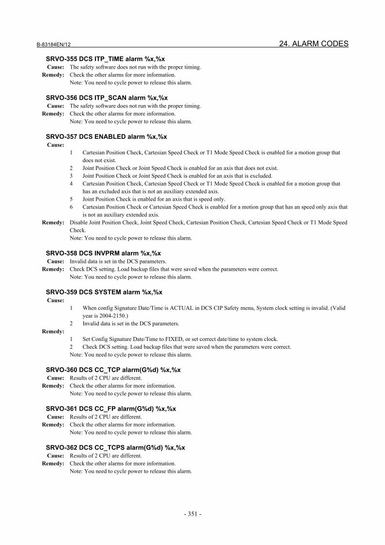
B-83184EN/12 24. ALARM CODES
- 351 -
SRVO-355 DCS ITP_TIME alarm %x,%x Cause: The safety software does not run with the proper timing. Remedy: Check the other alarms for more information. Note: You need to cycle power to release this alarm.
SRVO-356 DCS ITP_SCAN alarm %x,%x Cause: The safety software does not run with the proper timing. Remedy: Check the other alarms for more information. Note: You need to cycle power to release this alarm.
SRVO-357 DCS ENABLED alarm %x,%x Cause:
1 Cartesian Position Check, Cartesian Speed Check or T1 Mode Speed Check is enabled for a motion group that does not exist.
2 Joint Position Check or Joint Speed Check is enabled for an axis that does not exist. 3 Joint Position Check or Joint Speed Check is enabled for an axis that is excluded. 4 Cartesian Position Check, Cartesian Speed Check or T1 Mode Speed Check is enabled for a motion group that
has an excluded axis that is not an auxiliary extended axis. 5 Joint Position Check is enabled for an axis that is speed only. 6 Cartesian Position Check or Cartesian Speed Check is enabled for a motion group that has an speed only axis that
is not an auxiliary extended axis. Remedy: Disable Joint Position Check, Joint Speed Check, Cartesian Position Check, Cartesian Speed Check or T1 Mode Speed
Check. Note: You need to cycle power to release this alarm.
SRVO-358 DCS INVPRM alarm %x,%x Cause: Invalid data is set in the DCS parameters. Remedy: Check DCS setting. Load backup files that were saved when the parameters were correct. Note: You need to cycle power to release this alarm.
SRVO-359 DCS SYSTEM alarm %x,%x Cause:
1 When config Signature Date/Time is ACTUAL in DCS CIP Safety menu, System clock setting is invalid. (Valid year is 2004-2150.)
2 Invalid data is set in the DCS parameters. Remedy:
1 Set Config Signature Date/Time to FIXED, or set correct date/time to system clock. 2 Check DCS setting. Load backup files that were saved when the parameters were correct. Note: You need to cycle power to release this alarm.
SRVO-360 DCS CC_TCP alarm(G%d) %x,%x Cause: Results of 2 CPU are different. Remedy: Check the other alarms for more information. Note: You need to cycle power to release this alarm.
SRVO-361 DCS CC_FP alarm(G%d) %x,%x Cause: Results of 2 CPU are different. Remedy: Check the other alarms for more information. Note: You need to cycle power to release this alarm.
SRVO-362 DCS CC_TCPS alarm(G%d) %x,%x Cause: Results of 2 CPU are different. Remedy: Check the other alarms for more information. Note: You need to cycle power to release this alarm.

24. ALARM CODES B-83184EN/12
- 352 -
SRVO-363 DCS CC_FPS alarm(G%d) %x,%x Cause: Results of 2 CPU are different. Remedy: Check the other alarms for more information. Note: You need to cycle power to release this alarm.
SRVO-364 DCS PRMCRC alarm(G%d) %x,%x Cause: This robot model is not supported.
- When the positioner is not a Basic Positioner with Known Kinematics, this alarm occurs. To use Position/Speed Check function, the positioner must be a Basic Positioner with Known Kinematics.
- When mount angle 2 of Top Mount Robot is not 0, this alarm occurs. To use Position/Speed Check function, set mount angle 2 of Top Mount Robot to 0.
Remedy: Delete ‘DCS Position/Speed Check function’ option. This alarm can be cleared by setting $DCS_CFG.$EXCLUDE[motion group] to -1, but in this case, Position/Speed Check function cannot be used in this motion group.
Note: You need to cycle power to release this alarm.
SRVO-365 DCS FB_CMP alarm(G%d,A%d) %x,%x Cause: Difference between position command and position feedback exceeds position tolerance. The same cause as ‘SRVO-
023 Stop error excess’ or ‘SRVO-024 Move error excess’ is expected. Remedy: See the description for the SRVO-023.
Check the setting data displayed in the DCS robot setup menu.
SRVO-366 DCS FB_INFO alarm(G%d,A%d) %x,%x Cause: Invalid data is set in DCS parameter for axis number. Remedy: Check the setting data displayed in the DCS robot setup menu. Note: You need to cycle power to release this alarm.
SRVO-367 DCS CC_JPOS alarm(G%d,A%d) %x,%x Cause: Results of 2 CPU are different. Remedy: Check the other alarms for more information. Note: You need to cycle power to release this alarm.
SRVO-368 DCS CC_JSPD alarm(G%d,A%d) %x,%x Cause: Results of 2 CPU are different. Remedy: Check the other alarms for more information. Note: You need to cycle power to release this alarm.
SRVO-370 SVON1 status abnormal %s
SRVO-371 SVON2 status abnormal %s Cause: A chain alarm was detected with the emergency stop board internal signal (SVON). When two or more Safe I/O devices are connected, the number of the safe I/O device that the alarm occurs is displayed
in the end of the message such as (1). The safe I/O device number is displayed in DCS Safe I/O device menu. Remedy: Replace the emergency stop board.
Note1: For the procedure of recovery from this alarm, see the descriptions for the SRVO-230 and SRVO-231. Note2: If this alarm is issued, do not reset the chain error alarm until the failure is identified and repaired. If robot use is continued with one of the duplicate circuits being faulty, safety may not be guaranteed when the other circuit fails.

B-83184EN/12 24. ALARM CODES
- 353 -
SRVO-372 OPEMG1 status abnormal
SRVO-373 OPEMG2 status abnormal Cause: A chain alarm was detected with the emergency stop switch on the operator's panel. Remedy:
1 Replace the emergency stop board. 2 Replace the teach pendant cable. 3 Replace the teach pendant. 4 Replace the emergency stop button on the operator's panel. Note1: For the procedure of recovery from this alarm, see the descriptions for the SRVO-230 and SRVO-231. Note2: If this alarm is issued, do not reset the chain error alarm until the failure is identified and repaired. If robot use is continued with one of the duplicate circuits being faulty, safety may not be guaranteed when the other circuit fails.
SRVO-374 MODE11 status abnormal
SRVO-375 MODE12 status abnormal
SRVO-376 MODE21 status abnormal
SRVO-377 MODE22 status abnormal Cause: A chain alarm was detected with the mode switch signal. Remedy:
1 Check the mode switch and its cable. Replace them if a defect is found. 2 Replace the emergency stop board. Note1: For the procedure of recovery from this alarm, see the descriptions for the SRVO-230 and SRVO-231. Note2: If this alarm is issued, do not reset the chain error alarm until the failure is identified and repaired. If robot use is continued with one of the duplicate circuits being faulty, safety may not be guaranteed when the other circuit fails.
SRVO-378 SFDI xx status abnormal %s Cause: A chain alarm was detected with the SFDI signal. The ‘xx’ in the alarm message shows signal name such as ‘SFDI11’.
The detected status is that the displayed signal is open and the other signal for dual channel input is closed. When two or more Safe I/O devices are connected, the number of the safe I/O device that the alarm occurs is displayed
in the end of the message such as (1). The safe I/O device number is displayed in DCS Safe I/O device menu. In the system that has robot disable switch, when the alarm of the following signals occurs in the emergency stop board of 1st slave controller, it means the status abnormal of the robot disable switch. SFDI112 : Robot 1 disable switch chain 1 status abnormal. SFDI212 : Robot 1 disable switch chain 2 status abnormal. SFDI113 : Robot 2 disable switch chain 1 status abnormal. SFDI213 : Robot 2 disable switch chain 2 status abnormal. SFDI114 : Robot 3 disable switch chain 1 status abnormal. SFDI214 : Robot 3 disable switch chain 2 status abnormal. SFDI115 : Robot 4 disable switch chain 1 status abnormal. SFDI215 : Robot 4 disable switch chain 2 status abnormal.
In the system with Teach Pendant Hot Swap function, the alarm of SFDI11 or SFDI21 can occur when Teach Pendant is connected / disconnected without pushing the disconnect switch, or in AUTO mode.
Remedy: In case that the SFDI that the alarm occurs is not robot disable switch: 1 Check whether the circuitry connected to the dual input signal (SFDI) is faulty. 2 Check whether the timing of the dual input signal (SFDI) satisfies the timing specification. 3 In case of B-cabinet, replace the optional safety I/O board. 4 Replace the emergency stop board. In case that the SFDI that the alarm occurs is robot disable switch: 1 Replace robot disable switch. 2 Replace the cable between robot disable switch and emergency stop board. 3 Replace the emergency stop board.

24. ALARM CODES B-83184EN/12
- 354 -
In case that the alarm of SFDI11 or SFDI21 occurs in the system with Teach Pendant Hot Swap function: 1 If Teach Pendant is not connected / disconnected by the correct procedure of Teach Pendant Hot Swap function,
recovery from this alarm by the procedure in the descriptions for the SRVO-230 and SRVO-231. Perform the correct procedure to connect /disconnect Teach Pendant.
2 If the alarm occurred even if Teach Pendant is connected /disconnected by the correct procedure, replace the emergency stop board and Teach Pendant Hot Swap hardware.
Note1: For the procedure of recovery from this alarm, see the descriptions for the SRVO-230 and SRVO-231. Note2: If this alarm is issued, do not reset the chain error alarm until the failure is identified and repaired. If robot use is continued with one of the duplicate circuits being faulty, safety may not be guaranteed when the other circuit fails.
SRVO-401 CIP Safety comm. error %x,%x Cause: CIP Safety communication error occurs. Remedy: Check CIP Safety connection. Investigate the cause of alarms occurred at the same time in alarm history because the
actual output of CSO are forced to OFF and this alarm shows up when internal fault is detected in robot controller. This alarm doesn’t show up when CIP Safety is in Bypass mode. Using bypass mode should be limited to during initial integration when it is required to move the robot without communication with Safety PLC. Refer to the chapter of DeviceNet Safety or EtherNet/IP Safety of the Dual Check Safety operator’s manual.
SRVO-402 DCS Cart. pos. limit(No.%d%s,G%d,M%d) %02x Cause: Cartesian Position Check function detected that a model is out of a safe zone.
No. : Cartesian Position Check No. and comment. G : Group number M : User model number (0: Robot model)
Remedy: If the robot is actually out of the safe zone, press the [SHIFT] key and the [RESET] key, and jog the robot to the safe zone.
This alarm is displayed in R-30iB Plus, R-30iB Mate Plus.
SRVO-403 DCS Cart. speed limit(No. %d%s,G%d) %02x Cause: Cartesian Speed Check function detected over speed.
No. : Cartesian Speed Check No. and comment G : Group number
Remedy: Decrease robot speed. This alarm is displayed in R-30iB Plus, R-30iB Mate Plus.
SRVO-404 DCS Joint pos. limit(No. %d%s,G%d,A%d) %02x Cause: Joint Position Check function detected that an axis is out of a safe zone.
No. : Joint Position Check No. and comment G : Group number A : Axis number
Remedy: If the robot is actually out of the safe zone, press the [SHIFT] key and the [RESET] key, and jog the robot to the safe zone.
This alarm is displayed in R-30iB Plus, R-30iB Mate Plus.
SRVO-405 DCS Joint speed limit(No.%d%s,G%d,A%d) %02x Cause: Joint Speed Check function detected over speed.
No. : Joint Speed Check No. and comment G : Group number A : Axis number
Remedy: Decrease Joint speed. This alarm is displayed in R-30iB Plus, R-30iB Mate Plus.
SRVO-406 DCS SSO SVOFF input %x,%x Cause: SSO[1:C_SVOFF] is OFF.

B-83184EN/12 24. ALARM CODES
- 355 -
Remedy: Check Safe I/O connect setting.
SRVO-407 DCS SSO Fence Open %x,%x Cause: SSO[2:C_FENCE] is OFF. Remedy: Check Safe I/O connect setting.
SRVO-408 DCS SSO Ext Emergency Stop %x,%x Cause: SSO[3:C_EXEMG] is OFF. Remedy: Check Safe I/O connect setting.
SRVO-409 DCS SSO Servo Disconnect %x,%x Cause: SSO[4:C_SVOFF] is OFF. Remedy: Check Safe I/O connect setting.
SRVO-410 DCS SSO NTED input %x,%x Cause: SSO[5:C_NTED] is OFF. Remedy: Check Safe I/O connect setting.
SRVO-411 DCS invalid mode %x,%x Cause: Invalid mode. Remedy: Select AUTO, T1 or T2.
SRVO-412 DCS COUNT3 alarm %x,%x Cause: DCS servo on process is stopped. Remedy: Check the other alarms for more information. Note: You need to cycle power to release this alarm.
SRVO-413 DCS CC_SAFEIO alarm %x,%x Cause: Results of Safe I/O process by 2 CPU are different.
This alarm sometimes occur when the safety input signals on the emergency stop board and Safe I/O board such as External E-STOP or SFDI is changed repeatedly in the very short time.
Remedy: Check the connection of the safety input signals on emergency stop board and Safe I/O board. Check the other alarms for more information.
Note: You need to cycle power to release this alarm.
SRVO-414 DCS WORK CRC alarm %x,%x Cause: DRAM failure is detected. Remedy: Check the other alarms for more information.
Note: You need to cycle power to release this alarm.
SRVO-415 DCS Invalid tool (G%d) %x,%x Cause:
1 Selected DCS tool frame number is not defined. 2 Verify I/O of DCS tool frame is not set in the selected DCS tool frame.
Remedy: Check DCS TCP setting. Note: You need to cycle power to release this alarm.
SRVO-416 DCS Tool mismatch (G%d) %x,%x Cause: All Verify I/O of DCS tool frame are OFF or two or more Verify I/O are ON for more than 1sec. Remedy: Check Verify I/O status.
SRVO-417 DCS APSP_C alarm(G%d) %x,%x Cause: Invalid DCS approach speed check parameter for Cartesian position check. Remedy: Check DCS approach speed check parameter. Note: You need to cycle power to release this alarm.
SRVO-418 DCS APSP_J alarm (G%d,A%d) %x,%x Cause: Invalid DCS approach speed check parameter for Joint position check.

24. ALARM CODES B-83184EN/12
- 356 -
Remedy: Check DCS approach speed check parameter. Note: You need to cycle power to release this alarm.
SRVO-419 DCS PROFIsafe comm. error %x,%x Cause: PROFINET Safety communication error occurs. Remedy: Check PROFINET Safety connection. Investigate the cause of alarms occurred at the same time in alarm history
because the actual output of CSO are forced to OFF and this alarm shows up when internal fault is detected in robot controller. This alarm doesn’t show up when PROFINET Safety is in Bypass mode. Using bypass mode should be limited to during initial integration when it is required to move the robot without communication with Safety PLC. The mode is changed from Bypass to Enable at start up by default setting. Refer to the chapter of PROFINET Safety of the Dual Check Safety operator’s manual.
SRVO-420 Safety FL-net comm. error %x,%x Cause: Safety function by FL-net communication error occurs. Remedy: See “13.2.6 Troubleshooting” in this manual for remedy.
SRVO-422 Shared TP E-Stop Cause: 1 Emergency stop occurs on either controller in Shared Teach Pendant group.
2 Emergency stop occurs, because either controller in Shared Teach Pendant group is powered off. 3 Emergency stop occurs, because Safety function by FL-net does not work. 4 Emergency stop occurs, because configurations of Shared Teach Pendant function are disabled.
Remedy: 1 Release Teach Pendant, Operator Panel and External emergency stop on controllers in Shared Teach Pendant group. 2 Power on all controllers in Shared Teach Pendant group. 3 Check setting of Safety function by FL-net and Shared Teach Pendant function. 4 Check configurations of Shared Teach Pendant function.
SRVO-423 Shared TP: T1/T2 on other robot Cause: This controller is disconnected from Shared Teach Pendant group because mode of all controllers in Shared Teach
Pendant group are not AUTO. This robot cannot be operated. Remedy: Change modes of all controllers in Shared Teach Pendant group to AUTO.
SRVO-424 Shared TP: Mode mismatch Cause: Modes of all controllers in Shared Teach Pendant group are not matched. This robot cannot be operated. Remedy: Change modes of all controllers in Shared Teach Pendant group to match.
SRVO-425 Shared TP: Configuration mismatch Cause: Configurations of Shared Teach Pendant function are not matched among controllers in Shared Teach Pendant group. Remedy: Check and change configurations of Shared Teach Pendant function.
SRVO-446 DCS LS Fence open %x,%x Cause: In Auxiliary axis servo off (Local stop) function, the safe I/O assigned to the fence input is OFF when the auxiliary
axis is not servo off condition. The value displayed in the message shows the No. of local stop that the alarm occurs. The value is hexadecimal, and each bit is corresponded to each item in DCS local stop menu (1:No.1, 2:No.2, 4:No.3: 8:No.4, 10:No.5, 20:No.6, 40:No.7, 80:No.8).
Remedy: Set the safe I/O assigned to the fence input to ON, or set the auxiliary axis servo to off.
SRVO-447 DCS LS STO-FB alarm %x,%x Cause: In Auxiliary axis servo off (Local stop) function, mismatch of STO-OUT and STO-FB is detected. The value displayed
in the message shows the No. of local stop that the alarm occurs. The value is hexadecimal, and each bit is corresponded to each item in DCS local stop menu (1:No.1, 2:No.2, 4:No.3: 8:No.4, 10:No.5, 20:No.6, 40:No.7, 80:No.8).
Remedy: 1 Check the setting of DCS local stop menu. 2 Check the connection between emergency stop board and servo amplifier (αiSV). 3 Replace the cable between emergency stop board and servo amplifier (αiSV). 4 Replace the emergency stop board. 5 Replace the servo amplifier (αiSV). Note: You need to cycle power to release this alarm.

B-83184EN/12 24. ALARM CODES
- 357 -
SRVO-448 DCS PLSCHK alarm (SFDO%d) %s Cause: The monitored signal of safety output is not OFF even though OFF pulse is output. The signal name that the trouble is
detected is displayed after the alarm message. When two or more Safe I/O devices are connected, the number of the safe I/O device that the alarm occurs is displayed
in the end of the message such as (1). The safe I/O device number is displayed in DCS Safe I/O device menu. Remedy:
1 Check the cabling of safety output circuit. 2 In case of B-cabinet, replace the optional safety I/O board. 3 Replace the emergency stop board. Note: You need to cycle power to release this alarm.
SRVO-449 DCS DCS DOMON alarm (SFDO%d) %s Cause: The monitored signal of safety ouput is different from the output command. The signal name that the trouble is
detected is displayed after the alarm message. When two or more Safe I/O devices are connected, the number of the safe I/O device that the alarm occurs is displayed
in the end of the message such as (1). The safe I/O device number is displayed in DCS Safe I/O device menu. Remedy:
1 Check the cabling of safety output circuit. 2 In case of B-cabinet, replace the optional safety I/O board. 3 Replace the emergency stop board. Note: You need to cycle power to release this alarm.
SRVO-468 TmpDetachedNode exists in FLSF Cause: Temporary detached node exists in Safety function by FL-net. Remedy: Change the detached node to ENTRY.
SRVO-469 DCS Safety PMC alarm %x,%x Cause: Safety PMC program has invalid instructions or address. Remedy: Check Safety PMC program. Note: You need to cycle power to release this alarm.
SRVO-471 I/O Link i slave(%d-%d) status abnormal Cause: A mismatch of duplicate input signal for I/O Link i slave was detected over 1 second. Detected signal number is
displayed by a range as (1-8). The range of detection is divided per 8 signals as (1-8), (9-16). Remedy:
1 Check if a timing of duplicate output signal of master is matched. 2 Check if a connection of I/O Link cable is correct. 3 Replace the CPU card. 4 Replace the main board.
SRVO-473 DCS CLLB CC_EXTF alarm Cause: The result is different in 2 CPU for Collaborative Robot. Remedy: Check the other alarms for more information. Note: You need to cycle power to release this alarm.
SRVO-477 Calibration data error Cause: The sensor calibration data of the collaborative robot are wrong. Remedy: Copy "CLLB.CM" file from the CD-R which is appendix of the collaborative robot to a memory card or USB memory.
Perform the same file with a teach pendant, set the sensor calibration parameter. After this change, perform “APPLY TO DCS PARAMETER”. Refer to “1.3 Apply to DCS parameter” for detail. As this file is unique to each collaborative robot, do not use other robot’s file. Check that the serial number which is printed on CD-R is same as the number which is written on collaborative robot sensor.
SRVO-478 Temperature difference too large Cause: The force sensor temperature difference is too large. Remedy: Please make sure that the environment temperature does not change greatly, and then restart the controller. If the error
is not cleared, document the events that led to the error and contact your local FANUC representative.

24. ALARM CODES B-83184EN/12
- 358 -
SRVO-479 Temperature changes too fast Cause: The force sensor temperature changes too fast. Remedy: Please make sure that the environment temperature does not change greatly, and then restart the controller. If the error
is not cleared, document the events that led to the error and contact your local FANUC representative.
SRVO-480 FORCE alarm %x, %x Cause: Force sensor is abnormal. Remedy: Please take the following actions.
1 Restart the controller. 2 Replace the force sensor cable. If the error is not cleared, document the events that led to the error and contact your local FANUC representative.
SRVO-490 FORCE alarm 2 %x, %x Cause: Force sensor is abnormal. Remedy: Please take the following actions.
1 Restart the controller. 2 Replace the force sensor cable. If the error is not cleared, document the events that led to the error and contact your local FANUC representative.
SRVO-484 Safe I/O consistency alarm %x,%x Cause: In Safe I/O consistency check function, consistency of Safe I/O is detected. Remedy:
1 Check the setting of Safety I/O consistency check function. 2 Check the cabling of safety I/O circuit. 3 Check failure of the device that cabled to safety I/O. Note: You need to cycle power to release this alarm.

B-83184EN/12 24. ALARM CODES
- 359 -
SRVO-488 DCS Cartesian Position Speed (No.%d%s,G%d,S%d) %02x Cause: In Safe I/O consistency check function, consistency of Safe I/O is detected. No. : Cartesian Position check function No. and comment.
G : Group number S : Cartesian Position speed check No.
Remedy: Decrease robot speed.
This alarm is displayed in R-30iB Plus, R-30iB Mate Plus.
SRVO-496 Set initial forces Cause: Initial forces for CR-15iA are not set. Remedy: Execute the correct command file.
SRVO-497 Initial forces CRC error Cause: The CRC value of Initial forces for CR-15iA is wrong. Remedy: Execute the correct command file.
SRVO -503 SERVO Sensor alarm %x,%x Cause: An abnormality has occurred in a sensor inside the robot. Remedy: 1. When the number following this alarm is 100, it may have been executed that the power supply is turned on,
turned off, and then turned on again in a short time using the breaker. In this case, wait for at least 10 seconds after the controller’s power is turned off before turning it on again.
2. Check the robot connection cable for any abnormality, and replace it if necessary. 3. Replace the side board. 4. After performing a complete controller back-up to save all your programs and settings, replace the main board. If
the alarm cannot be reset, document the events that led to the alarm and contact your FANUC technical representative.
SRVO-504 SERVO Sensor type error Cause: An abnormality has occurred in a sensor inside the robot. Remedy: Cycle the controller’s power. If the alarm cannot be reset, document the events that led to the alarm and contact your
FANUC technical representative.
SRVO-505 SERVO Sens Temp change too large Cause: The temperature of a sensor inside the robot changes too fast. Remedy: Please make sure that the ambient temperature does not change rapidly, and cycle the controller. If the alarm cannot be
reset, document the events that led to the alarm and contact your FANUC technical representative.
DNET-138 IDNS unsupported H/W, Bd %d Cause: A DevicNet channel has been configured for safety. A safety DeviceNet channel requires DN4 hardware. The detected
hardware is not supported for a safety channel. Remedy: Use DN4 DeviceNet hardware or disable safety on this channel.
PRIO-051 I/O Link i slave comm error %x, %x (hex) Cause: Communication error for I/O Link i slave is detected. Remedy: Check connection and reset alarm or cycle power.
PRIO-052 I/O Link i slave hardware mismatch %x, %x (hex) Cause: Configuration is not for I/O Link i slave. Remedy: Check whether CPU card and Main board are the hardware for I/O Link i slave.
INTP-701 (%s^4, %d^5)DCS Target Position Check Error Cause: DCS Target Position Check detected that the current target position is out of a safe zone. Remedy: Check the target position.

25. CHECKLIST B-83184EN/12
- 360 -
25 CHECKLIST
CAUTION - The checklists here serve merely as examples of checklists for safety
acceptance. It is permissible to carry out and document safety acceptance using user-specific checklists.
- The system integrator is responsible for the design of the cell. The safety maintenance technician uses the values and configurations supplied by the system integrator to configure the robot and tests whether the safety functions work as specified. The safety maintenance technician does not perform a safety assessment of the system.
25.1 CHECKLIST OF DCS SYSTEM - Serial number of the robot: ____________________ - Serial number of the robot controller: ____________________ - Name of system builder: ____________________
No. Activity Yes Not relevant 1 DCS Position/Speed Check option is loaded 2 Code number is defined. 3 DCS mastering parameter shows the correct mastering parameters. 4 DCS robot parameter menu shows the correct number of groups 5 DCS robot parameter menu shows the correct robot model 6 DCS robot parameter menu shows the correct number of axes 7 DCS robot parameter menu shows the correct axes parameters 8 Was the mastering test successful? 9 Was the brake test successful?
10 All items in 25.2 have been satisfied for Joint Position Check function. The correct configuration of the Joint Position check has been checked by moving to all reachable limits. The axis of an axis-specific monitoring space must be moved to the upper and lower limits of the space. The checklist must be completed and confirmed in document for the cell area.
11 All items in 25.3 have been satisfied for Joint Speed Check function. The correct configuration of the Joint Speed Check has been checked by moving to all reachable limits. The checklist must be completed and confirmed in document for the Joint speeds
12 All items in 25.4 have been satisfied for Cartesian Position Check function. The correct configuration of the Cartesian Position Check has been checked by moving to all reachable limits. Each space surface of a Cartesian monitoring space must be addressed in 3 different positions. The checklist must be completed and confirmed in document for each monitoring space used.
13 All items in 25.5 have been satisfied for Cartesian Speed Check function. The correct configuration of the Cartesian Speed Check has been checked by moving to all reachable limits. The checklist must be completed and confirmed in document for each monitoring Cartesian speed check.
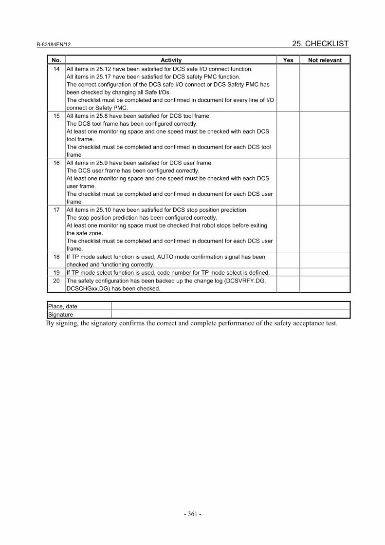
B-83184EN/12 25. CHECKLIST
- 361 -
No. Activity Yes Not relevant 14 All items in 25.12 have been satisfied for DCS safe I/O connect function.
All items in 25.17 have been satisfied for DCS safety PMC function. The correct configuration of the DCS safe I/O connect or DCS Safety PMC has been checked by changing all Safe I/Os. The checklist must be completed and confirmed in document for every line of I/O connect or Safety PMC.
15 All items in 25.8 have been satisfied for DCS tool frame. The DCS tool frame has been configured correctly. At least one monitoring space and one speed must be checked with each DCS tool frame. The checklist must be completed and confirmed in document for each DCS tool frame
16 All items in 25.9 have been satisfied for DCS user frame. The DCS user frame has been configured correctly. At least one monitoring space and one speed must be checked with each DCS user frame. The checklist must be completed and confirmed in document for each DCS user frame
17 All items in 25.10 have been satisfied for DCS stop position prediction. The stop position prediction has been configured correctly. At least one monitoring space must be checked that robot stops before exiting the safe zone. The checklist must be completed and confirmed in document for each DCS user frame.
18 If TP mode select function is used, AUTO mode confirmation signal has been checked and functioning correctly.
19 If TP mode select function is used, code number for TP mode select is defined. 20 The safety configuration has been backed up the change log (DCSVRFY.DG,
DCSCHGxx.DG) has been checked.
Place, date Signature
By signing, the signatory confirms the correct and complete performance of the safety acceptance test.

25. CHECKLIST B-83184EN/12
- 362 -
25.2 CHECKLIST FOR JOINT POSITION CHECK FUNCTION - Serial number of the robot: ____________________ - Serial number of the robot controller: ____________________ - Name of system builder: ____________________
No. Activity Yes Not relevant 1 The Joint Position Check No. 1 – No. 40 has been correctly configured and
checked. Group number: ______ Axis number: ______ Safe side: INSIDE / OUTSIDE Upper axis limit: ______ deg or mm Lower axis limit: ______ deg or mm Stop type: Stop Category 0 / Stop Category 1 / Not Stop Disabling input: ______ Note for this check:
Place, date Signature
By signing, the signatory confirms the correct and complete performance of the safety acceptance test.
25.3 CHECKLIST FOR DCS JOINT SPEED CHECK FUNCTION
- Serial number of the robot: ____________________ - Serial number of the robot controller: ____________________ - Name of system builder: ____________________
No. Activity Yes Not relevant 1 The Joint Speed Check No. 1 - No. 40 has been correctly configured and
checked. Direction: ALL / + / - Group number: ______ Axis number: ______ Speed limit: ______ deg / sec Stop type: Stop Category 0 / Stop Category 1 / Not Stop Speed control: DISABLE / OVERRIDE Override limit: ______ % Delay time: ______ msec Disabling input: ______ Permissible distance: ______ deg Note for this check:
Place, date Signature
By signing, the signatory confirms the correct and complete performance of the safety acceptance test.
25.4 CHECKLIST FOR DCS CARTESIAN POSITION CHECK FUNCTION
- Serial number of the robot: ____________________

B-83184EN/12 25. CHECKLIST
- 363 -
- Serial number of the robot controller: ____________________ - Name of system builder: ____________________
No. Activity Yes Not relevant 1 The Cartesian Position Check No. 1 - No. 32 has been correctly configured and
checked. Method: Working zone(Diagonal) / Restricted zone(Diagonal) / Working zone(Lines) / Restricted zone(Lines) / OrntFix(ALL) / OrntFix(UserZ) / Target model collision Group number: ______ Target model 1: ____________ Target model 2: ____________ Target model 3: ____________ User frame: ______ Position (Diagonal):
Point 1 X: ______ mm Point 2 X: ______ mm Point 1 Y: ______ mm Point 2 Y: ______ mm Point 1 Z: ______ mm Point 2 Z: ______ mm Position (Lines): Number of vertexes: ______ P1 X: ______ mm P1 Y: ______ mm P2 X: ______ mm P2 Y: ______ mm P3 X: ______ mm P3 Y: ______ mm P4 X: ______ mm P4 Y: ______ mm P5 X: ______ mm P5 Y: ______ mm P6 X: ______ mm P6 Y: ______ mm P7 X: ______ mm P7 Y: ______ mm P8 X: ______ mm P8 Y: ______ mm Z1: ______ mm Z2: ______ mm Position (OrntFix): tool select: ______ W: ______ deg P: ______ deg R: ______ deg Limit: ______ deg Stop type: Stop Category 0 / Stop Category 1 / Not Stop / Speed check(0) / Speed check(1) Speed check:
Speed control: DISABLE / OVERRIDE Limit 1 Limit: ______ mm/s Limit 1 DSBL input: ______ Limit 1 OVR Lim: ______ mm/s Limit 2 Limit: ______ mm/s Limit 2 DSBL input: ______ Limit 2 OVR Lim: ______ mm/s Limit 3 Limit: ______ mm/s Limit 3 DSBL input: ______ Limit 3 OVR Lim: ______ mm/s Limit 4 Limit: ______ mm/s Limit 4 DSBL input: ______ Limit 4 OVR Lim: ______ mm/s Delay time: ______ mm Permissible distance: ______ mm Disabling input: ______ Use stop position prediction: No / Yes Note for this check:

25. CHECKLIST B-83184EN/12
- 364 -
Place, date Signature
By signing, the signatory confirms the correct and complete performance of the safety acceptance test.
25.5 CHECKLIST FOR DCS CARTESIAN SPEED FUNCTION - Serial number of the robot: ____________________ - Serial number of the robot controller: ____________________ - Name of system builder: ____________________
No. Activity Yes Not relevant 1 The Cartesian Speed Check No. 1 - No. 16 has been correctly configured and
checked. Direction: ALL / X / Y / Z / +X / +Y / +Z / -X / -Y / -Z / ROTATION Group number: ______ Tool frame: ______ Base frame: User Frame / Tool Frame Speed limit: ______ mm/sec or deg/sec Stop type: Stop Category 0 / Stop Category 1 / Not Stop Speed control: DISABLE / OVERRIDE Override limit: ______ % Delay time: ______ msec Disabling input: ______ Permissible distance: ______ mm Note for this check:
Place, date Signature
By signing, the signatory confirms the correct and complete performance of the safety acceptance test.
25.6 CHECKLIST FOR DCS T1 MODE SPEED CHECK - Serial number of the robot: ____________________ - Serial number of the robot controller: ____________________ - Name of system builder: ____________________
No. Activity Yes Not relevant 1 The T1 mode speed check for Group 1 - Group 8 has been correctly configured
and checked. Limit: ______ mm/sec Note for this check:
Place, date Signature
By signing, the signatory confirms the correct and complete performance of the safety acceptance test.

B-83184EN/12 25. CHECKLIST
- 365 -
25.7 CHECKLIST FOR DCS USER MODEL - Serial number of the robot: ____________________ - Serial number of the robot controller: ____________________ - Name of system builder: ____________________
No. Activity Yes Not relevant 1-1 The User Model No. 1-1 - No. 16-10 has been correctly configured and checked.
Link No.: ______ Link type: NORMAL / VERTICAL / HORIZON Tool frame: ______ Shape: Point / Line_seg / 2spheres / Box Shape (Point):
Size: ______ mm Pos1 X: ______ mm Pos1 Y: ______ mm Pos1 Z: ______ mm Pos2 X: ______ mm Pos2 Y: ______ mm Pos2 Z: ______ mm
Shape (Line_seg): Size: ______ mm Pos1 X: ______ mm Pos1 Y: ______ mm Pos1 Z: ______ mm Pos2 X: ______ mm Pos2 Y: ______ mm Pos2 Z: ______ mm
Shape (2spheres): Pos1 size: ______ mm Pos1 X: ______ mm Pos1 Y: ______ mm Pos1 Z: ______ mm Pos2 size: ______ mm Pos2 X: ______ mm Pos2 Y: ______ mm Pos2 Z: ______ mm
Shape (Box): Width (X): ______ mm Height (Y): ______ mm Thick (Z): ______ mm Offset X: ______ mm Y: ______ mm Z: ______ mm
Note for this check:
Place, date Signature
By signing, the signatory confirms the correct and complete performance of the safety acceptance test.
25.8 CHECKLIST FOR DCS TOOL FRAME - Serial number of the robot: ____________________ - Serial number of the robot controller: ____________________ - Name of system builder: ____________________
No. Activity Yes Not relevant 1 The Tool Frame for Group 1 - Group 8 has been correctly configured and
checked. Tool select: ______ Note for this check:

25. CHECKLIST B-83184EN/12
- 366 -
No. Activity Yes Not relevant 2 The Tool Frame for Group 1 - Group 8 has been correctly configured and
checked. Tool frame No.: ______ Model: ______ Verify I/O: ______ X: ______ Y: ______ Z: ______ W: ______ P: ______ R: ______ Note for this check:
Place, date Signature
By signing, the signatory confirms the correct and complete performance of the safety acceptance test.
25.9 CHECKLIST FOR DCS USER FRAME - Serial number of the robot: ____________________ - Serial number of the robot controller: ____________________ - Name of system builder: ____________________
No. Activity Yes Not relevant 1 The User Frame for Group 1 - Group 8 has been correctly configured and
checked. User frame No.: ______ X: ______ Y: ______ Z: ______ W: ______ P: ______ R: ______ Note for this check:
Place, date Signature
By signing, the signatory confirms the correct and complete performance of the safety acceptance test.

B-83184EN/12 25. CHECKLIST
- 367 -
25.10 CHECKLIST FOR DCS STOP POSITION PREDICTION - Serial number of the robot: ____________________ - Serial number of the robot controller: ____________________ - Name of system builder: ____________________
No. Activity Yes Not relevant 1 The Stop Position Prediction for Group 1 - Group 8 has been correctly configured
and checked. Cartesian:
Mode: DISABLE / DEFAULT / USER Expand Point as line: DISABLE / ENABLE Stop Category 0:
Stopping distance: ______ mm Speed: ______ mm/sec
Stop Category 1: Stopping distance: ______ mm Speed: ______ mm/sec
Note for this check:
2 The Stop Position Prediction for axis J1 – 9 of Group 1 - Group 8 has been correctly configured and checked. J1:
Mode: DISABLE / DEFAULT / USER Stop Category 0:
Stopping distance: ______ deg Speed: ______ deg/sec
Stop Category 1: Stopping distance: ______ deg Speed: ______ deg/sec
Note for this check:
Place, date Signature
By signing, the signatory confirms the correct and complete performance of the safety acceptance test.

25. CHECKLIST B-83184EN/12
- 368 -
25.11 CHECKLIST FOR DCS POSITION SPEED CHECK SETUP
- Serial number of the robot: ____________________ - Serial number of the robot controller: ____________________ - Name of system builder: ____________________
No. Activity Yes Not relevant 1 The Position Speed check setup has been correctly configured and checked.
Position / speed check: DISABLE / ENABLE Disabled JPC DSBL signal: DISABLE / ENABLE Disabled JSC DSBL signal: DISABLE / ENABLE Disabled CPC DSBL signal: DISABLE / ENABLE Disabled CSC DSBL signal: DISABLE / ENABLE Invalid tool frame: DISABLE / ENABLE Disabled CPC position check: DISABLE / ENABLE Shift+Reset direction check: DISABLE / ENABLE Allow robot on other group: DISABLE / ENABLE
Base group Ufrm Tfrm Group 1: ( : ) Group 2: ( : ) Group 3: ( : ) Group 4: ( : ) Group 5: ( : ) Group 6: ( : ) Group 7: ( : ) Group 8: ( : ) Note for this check:
Place, date Signature
By signing, the signatory confirms the correct and complete performance of the safety acceptance test.
25.12 CHECKLIST FOR DCS SAFE I/O CONNECT FUNCTION - Serial number of the robot: ____________________ - Serial number of the robot controller: ____________________ - Name of system builder: ____________________
No. Activity Yes Not relevant 1 The Safe I/O Connect No. 1 - No. 64 has been correctly configured and checked.
Line: Output Input 1 Input 2 = Note for this check:
Place, date Signature
By signing, the signatory confirms the correct and complete performance of the safety acceptance test.

B-83184EN/12 25. CHECKLIST
- 369 -
25.13 CHECKLIST FOR DEVICENET SAFETY - Serial number of the robot: ____________________ - Serial number of the robot controller: ____________________ - Name of system builder: ____________________
No. Activity Yes Not relevant 1 The DEVICENET Safety has been correctly configured and checked.
Enable / Bypass: ENABLE / BYPASS CIP safety input size: ______ byte CIP safety output size: ______ byte Config Signature Date/Time: ACTUAL / FIXED Note for this check:
Place, date Signature
By signing, the signatory confirms the correct and complete performance of the safety acceptance test.
25.14 CHECKLIST FOR ETHERNET/IP SAFETY - Serial number of the robot: ____________________ - Serial number of the robot controller: ____________________ - Name of system builder: ____________________
No. Activity Yes Not relevant 1 The ETHERNET/IP Safety has been correctly configured and checked.
Enable / Bypass: ENABLE / BYPASS CIP safety input size: ______ byte CIP safety output size: ______ byte Config Signature Date/Time: ACTUAL / FIXED Note for this check:
Place, date Signature
By signing, the signatory confirms the correct and complete performance of the safety acceptance test.

25. CHECKLIST B-83184EN/12
- 370 -
25.15 CHECKLIST FOR PROFINET SAFETY - Serial number of the robot: ____________________ - Serial number of the robot controller: ____________________ - Name of system builder: ____________________
No. Activity Yes Not relevant 1 The PROFINET Safety has been correctly configured and checked.
Enable / Bypass: ENABLE / BYPASS Safety input size: ______ byte Safety output size: ______ byte F-Address: ______ Use Base: Yes / No Use Pos./Speed: Yes / No Use I/O connect: Yes / No Note for this check:
Place, date Signature
By signing, the signatory confirms the correct and complete performance of the safety acceptance test.
25.16 CHECKLIST FOR DCS SAFETY FUNCTION BY FL-net - Serial number of the robot: ____________________ - Serial number of the robot controller: ____________________ - Name of system builder: ____________________
No. Activity Yes Not relevant 1 The Safety function by FL-net has been correctly configured and checked.
Enable / Disable: ENABLE / DISABLE Own node number: ______ Timer for receive data: ______ byte Start timer after Power ON: ______ Mode: ______ Note for this check:
2 The Safety function by FL-net for node 1 – 30 has been correctly configured and checked. Node1: Enable / Disable: ENABLE / DISABLE
ENT/DET: ENT / DET IDnum: ______ Note for this check:
Place, date Signature
By signing, the signatory confirms the correct and complete performance of the safety acceptance test.

B-83184EN/12 25. CHECKLIST
- 371 -
25.17 CHECKLIST FOR DCS SAFETY PMC FUNCTION - Serial number of the robot: ____________________ - Serial number of the robot controller: ____________________ - Name of system builder: ____________________
No. Activity Yes Not relevant 1 The Safety PMC has been correctly configured and checked.
Size: ______ byte Level 1 scan time: ______ms Level 2 scan time: ______ ms Signature(Dec): ______ Mode(Hex): ______ Note for this check:
Place, date Signature
By signing, the signatory confirms the correct and complete performance of the safety acceptance test.
25.18 CHECKLIST FOR DCS LOCAL STOP FUNCTION - Serial number of the robot: ____________________ - Serial number of the robot controller: ____________________ - Name of system builder: ____________________
No. Activity Yes Not relevant 1 The Local Stop has been correctly configured and checked.
Stop Type: Stop Category 0 / Stop Category 1 Fence in T1/T2: ENABLE / DISABLE Note for this check:
2 The Local Stop No.1 - 8 has been correctly configured and checked. No.1: STO-OUT STO-FB Fence = Note for this check:
Place, date Signature
By signing, the signatory confirms the correct and complete performance of the safety acceptance test.

25. CHECKLIST B-83184EN/12
- 372 -
25.19 CHECKLIST FOR DCS TEACH PENDANT HOT SWAP FUNCTION
- Serial number of the robot: ____________________ - Serial number of the robot controller: ____________________ - Name of system builder: ____________________
No. Activity Yes Not relevant 1 The Teach pendant hot swap has been correctly configured and checked.
Time Limit for Hot Swap: ______ sec Note for this check:
Place, date Signature
By signing, the signatory confirms the correct and complete performance of the safety acceptance test.
25.20 CHECKLIST FOR DCS SHARED TEACH PENDANT FUNCTION
- Serial number of the robot: ____________________ - Serial number of the robot controller: ____________________ - Name of system builder: ____________________
No. Activity Yes Not relevant 1 The Shared Teach pendant has been correctly configured and checked.
Mode: ENABLE / DISABLE Note for this check:
2 The Shared Teach pendant for robot No. 1 - 16 has been correctly configured and checked. Input ID: ______ Bypass: ______ Note for this check:
Place, date Signature
By signing, the signatory confirms the correct and complete performance of the safety acceptance test.
25.21 CHECKLIST FOR DCS I/O Link i Slave FUNCTION - Serial number of the robot: ____________________ - Serial number of the robot controller: ____________________ - Name of system builder: ____________________
No. Activity Yes Not relevant 1 The I/O Link i Slave has been correctly configured and checked.
Input size: ______byte Output size: ______byte Note for this check:
Place, date Signature

B-83184EN/12 25. CHECKLIST
- 373 -
By signing, the signatory confirms the correct and complete performance of the safety acceptance test.
25.22 CHECKLIST FOR DCS SAFE I/O CONSISTENCY CHECK FUNCTION
- Serial number of the robot: ____________________ - Serial number of the robot controller: ____________________ - Name of system builder: ____________________
No. Activity Yes Not relevant 1 The Safe I/O Consistency No. 1 - No. 16 has been correctly configured and
checked. Line: Signal1 Signal2 time(ms) = Note for this check:
Place, date Signature
By signing, the signatory confirms the correct and complete performance of the safety acceptance test.
25.23 CHECKLIST FOR DCS MODE SELECT FUNCTION - Serial number of the robot: ____________________ - Serial number of the robot controller: ____________________ - Name of system builder: ____________________
No. Activity Yes Not relevant 1 The Mode select has been correctly configured and checked.
mode select func.: Mode Switch / External Input / Teach Pendant select mode type: AUTO/T1 / AUTO/T1/T2 Note for this check:
Place, date Signature
By signing, the signatory confirms the correct and complete performance of the safety acceptance test.

25. CHECKLIST B-83184EN/12
- 374 -
25.24 CHECKLIST FOR DCS I/O DEVICE - Serial number of the robot: ____________________ - Serial number of the robot controller: ____________________ - Name of system builder: ____________________
No. Activity Yes Not relevant 1 The Safe I/O device has been correctly configured and checked.
Safe I/O process: I/O connect / Safety PMC SFDO Pulse check: DISABLE(PL d) / ENABLE(PL e) Note for this check:
The Safe I/O device for device1 - 8 has been correctly configured and checked. Type: No device / E-stop board / E-stop board D-SW / Safe I/O board / General I/O device / Force Sensor / Main board / Mate E-stop board / Mate E-stop board D-SW / (Error) / Mate Main board / Compact Main board / Mini Main board Robot number: ______ Input: ______ Output: ______ Note for this check:
Place, date Signature
By signing, the signatory confirms the correct and complete performance of the safety acceptance test.
25.25 CHECKLIST FOR DCS SIGNATURE NUMBER - Serial number of the robot: ____________________ - Serial number of the robot controller: ____________________ - Name of system builder: ____________________
No. Activity Yes Not relevant 1 The signature number of DCS parameters has been checked.
Total: Current: __________________ Time: __________________
Base: Current: __________________ Time: __________________
Pos./Speed: Current: __________________ Time: __________________
I/O connect: Current: __________________ Time: __________________
Place, date Signature
By signing, the signatory confirms the correct and complete performance of the safety acceptance test.

B-83184EN/12 INDEX
i-1
INDEX
<Number> 4D GRAPHICS DCS DISPLAY ............................. 38,151
<A> ADDITIONAL SAFETY SIGNALS ........................... 177 Alarm ........................................................................... 242 ALARM CODES ......................................................... 345 APPLY TO DCS PARAMETER ..................................... 6 Applying the Settings to the DCS Parameters .............. 341 Approach warning signal output function .................... 110 Assignment of IP Address ............................................ 270 AUXILIARY AXIS SERVO OFF (LOCAL STOP)
FUNCTION .............................................................. 263
<B> BACKUP / RESTORE DCS SETTING PARAMETER 10 BACKUP/RESTORE ................................................... 254 BACKUP/RESTORE OF CIP-SAFETY
SETTINGS ........................................................ 197,215 BACKUP/RESTORE OF PROFINET SAFETY
SETTINGS ............................................................... 232 BACKUP/RESTORE OF SAFETY FUNCTION BY
FL-NET .................................................................... 246 BASIC INSTRUCTIONS ............................................ 258 BASIC POSITION CHECK FUNCTION ................... 129 BASIC SPECIFICATION ............................................ 256 Bypassing Down Robot ................................................ 282
<C> CARTESIAN SPEED CHECK FUNCTION ............... 129 Case with Safety Signals .............................................. 291 Case without Safety Signals ......................................... 292 CAUTIONS AND LIMITATIONS ................................. 4 CC-Link IE FIELD SAFETY SLAVE FUNCTION .... 247 CC-Link IE Field safety status screen .......................... 253 Changing the Detailed Settings of the Setting Data...... 339 CHECKING IF AUXILIARY AXES ARE
STATIONARY .......................................................... 59 CHECKING IF THERE IS AN OPERATOR ON A
SAFE MAT ................................................................ 45 CHECKLIST ................................................................ 360 CHECKLIST FOR DCS CARTESIAN POSITION
CHECK FUNCTION ............................................... 362 CHECKLIST FOR DCS CARTESIAN SPEED
FUNCTION .............................................................. 364 CHECKLIST FOR DCS I/O DEVICE ......................... 374 CHECKLIST FOR DCS I/O Link i Slave
FUNCTION .............................................................. 372 CHECKLIST FOR DCS JOINT SPEED CHECK
FUNCTION .............................................................. 362 CHECKLIST FOR DCS LOCAL STOP FUNCTION . 371 CHECKLIST FOR DCS MODE SELECT
FUNCTION .............................................................. 373
CHECKLIST FOR DCS POSITION SPEED CHECK SETUP...................................................................... 368
CHECKLIST FOR DCS SAFE I/O CONNECT FUNCTION .............................................................. 368
CHECKLIST FOR DCS SAFE I/O CONSISTENCY CHECK FUNCTION ............................................... 373
CHECKLIST FOR DCS SAFETY FUNCTION BY FL-net ....................................................................... 370
CHECKLIST FOR DCS SAFETY PMC FUNCTION 371 CHECKLIST FOR DCS SHARED TEACH
PENDANT FUNCTION .......................................... 372 CHECKLIST FOR DCS SIGNATURE NUMBER ..... 374 CHECKLIST FOR DCS STOP POSITION
PREDICTION .......................................................... 367 CHECKLIST FOR DCS T1 MODE SPEED CHECK . 364 CHECKLIST FOR DCS TEACH PENDANT HOT
SWAP FUNCTION .................................................. 372 CHECKLIST FOR DCS TOOL FRAME .................... 365 CHECKLIST FOR DCS USER FRAME ..................... 366 CHECKLIST FOR DCS USER MODEL .................... 365 CHECKLIST FOR DEVICENET SAFETY ................ 369 CHECKLIST FOR ETHERNET/IP SAFETY ............. 369 CHECKLIST FOR JOINT POSITION CHECK
FUNCTION .............................................................. 362 CHECKLIST FOR PROFINET SAFETY ................... 370 CHECKLIST OF DCS SYSTEM ................................ 360 CIP Safety Requirements ...................................... 182,198 CIP-safety status screen ........................................ 195,214 Code by Password Function ........................................... 28 COMPONENTS OF POSITION / SPEED CHECK
FUNCTION ................................................................ 93 CONFIGURATION ..................................................... 269 Configuration of Safety Function by FL-net ................ 273 Configuration of Shared Teach Pendant Group ........... 271 Confirmation of Selected Robot ................................... 281 Controlling the Simple View ........................................ 148 Coordinate displays ...................................................... 149 Creating WEB Page to Switch Robots ......................... 277 CSP+ FILE ................................................................... 254
<D> DCS Cartesian Position Check (Diagonal) Menu ........ 115 DCS Cartesian Position Check (Lines) Menu .............. 119 DCS Cartesian Position Check (Orientation Fix)
Menu ........................................................................ 127 DCS Cartesian Position Check (Target Model Collision
Check ) Menu ........................................................... 125 DCS Cartesian Position Check List Menu ................... 114 DCS Cartesian Position Speed Check Function ........... 113 DCS Cartesian Position Speed Check Menu ................ 118 DCS Cartesian Speed Check Detail Menu ................... 131 DCS Cartesian Speed Check List Menu ....................... 130 DCS CODE NUMBER .................................................. 22 DCS Code Number Setup Menu .................................... 23 DCS Configuration of Shared Teach Pendant .............. 275

INDEX B-83184EN/12
i-2
DCS FUNCTION COMPONENTS ................................. 1 DCS Joint Position Check Detail Menu ......................... 97 DCS Joint Position Check List Menu ............................. 96 DCS Joint Speed Check Detail Menu ........................... 100 DCS Joint Speed Check List Menu ................................ 99 DCS LOCAL STOP MENU ........................................ 264 DCS MASTERING PARAMETER MENU .................. 21 DCS MENU ................................................................... 14 DCS MENU COMPONENTS ....................................... 14 DCS PARAMETER REPORT FILE ............................. 10 DCS Pos./Speed Check Setup Menu ............................ 141 DCS ROBOT SETUP MENU ........................................ 19 DCS Safe I/O Connect Menu ....................................... 173 DCS Safe I/O Device Menu ......................................... 179 DCS Safe I/O Status Menu ........................................... 170 DCS SAFETY PMC MENU ........................................ 262 DCS SCREEN (TABLET UI) ...................................... 329 DCS SETTINGS WITH THE TABLET UI ................. 328 DCS Signature Annunciation Menu ............................... 25 DCS signature change management utility operation ..... 27 DCS signature change management utility setup ........... 26 DCS SIGNATURE NUMBER ...................................... 24 DCS Signature Number Menu ....................................... 24 DCS Signature Number Output ...................................... 27 DCS Stop Position Prediction Menu ............................ 139 DCS T1 Mode Speed Check Menu .............................. 134 DCS TEACH PENDANT HOT SWAP MENU........... 267 DCS TOOL FRAME .................................................... 134 DCS Tool Frame Menu ................................................ 136 DCS TOP MENU ........................................................... 16 DCS USER FRAME .................................................... 138 DCS User Frame Menu ................................................ 138 DCS User Model Detail (Point/Line-Seg) Menu .......... 123 DCS User Model Element Detail (2 Spheres) Menu .... 124 DCS User Model Element Detail (Box) Menu ............. 125 DCS User Model Element List Menu........................... 122 DCS User Model List Menu ......................................... 121 DCS VISUALIZATION .............................................. 144 Define the safe zone ..................................................... 105 Define the target shape model ...................................... 107 DEVICENET SAFETY ............................................... 182 DIAGSAFETY screen .................................................. 231
<E> EDS FILE .............................................................. 197,215 Enable and disable zones by disabling input ................ 106 Error indication ..................................................... 232,254 ETHERNET/IP SAFETY............................................. 198 ETHERNET/IP SAFETY (EIP-SAFE) ........................ 200 EXAMPLE OF SAFE ZONE SWITCHING BY
USING NSI .............................................................. 174 Exiting the viewer ........................................................ 151
<F> FANUC LADDER-III FOR ROBOT
PROGRAMMING .................................................... 259 FUNCTION ................................................................. 247 FUNCTIONAL INSTRUCTIONS ............................... 259
<G> GSDML FILE .............................................................. 232 GuardLogix safety PLC example configuration ........... 187 GuardLogix safety PLC example configuration using
AOP .......................................................................... 203 GuardLogix safety PLC example configuration without
using AOP ................................................................ 209
<H> Hardware .......................................................................... 4
<I> I/O Link i SLAVE FUNCTION ................................... 284 I/O LINK i SLAVE MENU ......................................... 291 Importing from the Library .......................................... 338 In Case of A-cabinet.............................................. 299,310 In Case of Additional Safety I/O Board (mini-
slot) .................................................................... 301,315 In Case of B-cabinet .............................................. 300,312 In case of I/O Unit-MODEL A.............................. 308,320 In Case of using R-30iB Mate, R-30iB Mate Plus, R-
30iB Compact Plus or R-30iB Mini Plus................. 287 In Case of using R-30iB or R-30iB Plus ...................... 285 INITIAL START, IMAGE RESTORE .......................... 12 INTEGRATED DEVICENET SAFETY (IDNS) ........ 184 INTRODUCTION ........................... 182,198,216,233,247
<J> Joint Position Check – 4D Graphics Viewer ................ 160 Joint Position Check – Simple Viewer ......................... 159 JOINT POSITION CHECK FUNCTION ...................... 93 JOINT SPEED CHECK FUNCTION ............................ 98
<L> Layout of the Library Screen ....................................... 330 LIMITING A ROBOT WORKSPACE .......................... 29 LIMITING A ROBOT WORKSPACE BY
CARTESIAN POSITION CHECK ............................ 30 LIMITING THE MOTION RANGE OF A
TURNTABLE ............................................................ 71 Loading of Backup that is Unsupported Software ........ 293 Loading of Backup to Unsupported Hardware ............. 293 LOADING OF UNSUPPORTED VERSION
BACKUP .................................................................. 293 Log into a Robot .......................................................... 279
<M> MAPPING OF SAFETY AND NON-SAFETY
SIGNALS ................................................................. 292 MODE SELECT MENU .............................................. 296
<N> NEEDED HARDWARE CONSTRUCTION .............. 285 NUMBER OF SAFETY AND NON-SAFETY
SIGNALS ................................................................. 291
<O> Omron safety PLC example configuration ................... 191 OPERATION ............................................................... 279

B-83184EN/12 INDEX
i-3
Operation for restart ..................................................... 252 Operation of Robot ....................................................... 282 Operation Procedure ..................................................... 152 OPERATION WITHOUT MODE SWITCH ............... 296 Operation without Safety PLC (bypass mode) ...... 229,252 ORIENTATION CHECK FUNCTION (CARTESIAN
POSITION CHECK FUNCTION) ........................... 127 OVERVIEW ............ 1,29,41,59,76,182,184,198,200,216, 233,247,255
<P> Panning and zooming ................................................... 148 PERIPHERAL EQUIPMENT AND SAFETY
SIGNALS CONNECTION ...................................... 310 Persistence .................................................................... 150 PMC ADDRESSES...................................................... 257 Pos./Speed Check Setting Screen Layout ..................... 332 POS./SPEED CHECK SETUP ..................................... 141 POSITION / SPEED CHECK FUNCTION ................... 92 Position check temporary disable function ................... 109 Process time factor ....................................................... 108 PROFINET SAFETY ................................................... 216 PROFINET SAFETY FUNCTION .............................. 216 PROFINET safety status screen ................................... 230
<R> Receiving safety signal area ......................................... 234 RECOVERY FROM ALARM ................................ 40,109 Restriction of Basic Position function .......................... 129 Robot Configuration ......................... 185,201,218,237,248 Robot group select ........................................................ 151 ROBOT STOP POSITION PREDICTION .................... 33
<S> SAFE I/O...................................................................... 161 Safe I/O Connect .......................................................... 336 SAFE I/O CONNECT FUNCTION ............................. 171 SAFE I/O CONSISTENCY CHECK FUNCTION ...... 294 SAFE I/O CONSISTENCY CHECK MENU .............. 294 Safe Zone ..................................................................... 104 SAFETY FUNCTION BY FL-net ............................... 233 SAFETY I/O CONNECT IN CIP-SAFETY
SYSTEM ........................................................... 196,214 Safety Input Specifications ........................................... 325 Safety Output Specifications ........................................ 327 Safety PLC Configuration ....................... 187,203,224,251 SAFETY PMC EXECUTION (APPLY TO DCS
PARAMETER) ........................................................ 261 SAFETY PMC FUNCTION ........................................ 255 SAFETY PRECAUTIONS ........................................... s-1 Safety Signal ................................................................ 234 SAFETY SIGNAL INTERFACE ................................ 299 SAFETY SIGNAL SPECIFICATIONS ....................... 325 SAFETY SIGNALS ..................................................... 298 Screen Layout............................................................... 330 Selecting an orthographic view .................................... 148 Sending safety signal area ............................................ 234 SET A SLOWDOWN ZONE ......................................... 76
SETTING FLOW ......................................................... 337 SETTING UP THE ROBOT WORKSPACE ................ 73 SETUP OF CARTESIAN POSITION CHECK ........ 46,82 Setup of No.1 Zone ................................................... 47,83 Setup of No.2 Zone ................................................... 51,85 Setup of No.3 Zone ................................................... 55,88 SETUP OF POSITION CHECK FOR AUXILIARY
AXIS 1 ....................................................................... 63 SETUP OF STOP CHECK FOR AUXILIARY AXES
2 AND 3 ..................................................................... 66 SETUP OF TOOL MODEL ........................................... 77 SETUP OF USER MODEL ...................................... 34,42 SETUP STOP CHECK FOR AUXILIARY AXIS 1 ..... 60 SETUP STOP POSITION PREDICTION ................... 139 SFDO Pulse Check ....................................................... 169 Shape Model ................................................................ 102 SHARED TEACH PENDANT .................................... 268 Software ........................................................................... 5 Stop Position Prediction .......................................... 95,111 STOPPING DISTANCE ................................................ 13 SWITCHING THE WORKSPACE ............................... 41
<T> T1 MODE SPEED CHECK FUNCTION .................... 133 Target Position Check Function ................................... 143 TEACH PENDANT HOT SWAP ................................ 266 TEACH PENDANT OPERATION ............................. 260 Temporarily Detaching Some Nodes from the Safety
Function by FL-net ................................................... 243 TEMPORARILY RESET ............................................ 343 Tool Change Function .................................................. 135 Troubleshooting ............................... 195,214,230,244,253 Troubleshooting using LEDs ....................................... 195
<V> VIEWING CARTESIAN POSITION CHECKS ......... 156 VIEWING JOINT POSITION CHECKS .................... 159 VIEWING THE ROBOT MODEL .............................. 145 VIEWING USER MODELS ........................................ 154
<Z> ZONE CHECK FUNCTION (CARTESIAN
POSITION CHECK FUNCTION) ........................... 102


B-83184EN/12 REVISION RECORD
r-1
REVISION RECORD Edition Date Contents
12 Aug., 2021 • Moved CC-Link IE Field Safety slave to Chapter 14. Add DCS settings with the Tablet UI in Chapter 23.
11 Mar., 2021 • Add controller support status of safety network in Chapter 10, 11, 12, 13 and 24.
10 Jul., 2020 • Changed of PROFINET Safety, addition of CC-Link IE Field Safety slave. • Addition of R-30iB Mini Plus.
09 Mar., 2019 • Addition of Check list. 08 Jun., 2018 • Addition of R-30iB Compact Plus. 07 May, 2017 • Addition of R-30iB Plus. 06 Oct., 2015 • Addition of I/O link i Slave function and Safe I/O Consistency Check function.
05 Nov., 2014 • Addition of Teach Pendant Hot Swap and Shared Teach Pendant, Revision of PROFINET Safety.
04 Apr., 2013 • Addition of Safety function by FL-net. 03 Jan., 2013 • Addition of R-30iB Mate.
02 Oct., 2012 • Addition of additional safety signals, safety PMC function and auxiliary axis servo off (local stop) function.
01 Apr., 2012

B-83184EN/12
* B - 8 3 1 8 4 E N / 1 2 *


![Samenvatting urban challenge[1]](https://static.fdokumen.com/doc/165x107/6313d00f3ed465f0570ad8b4/samenvatting-urban-challenge1.jpg)