SpaceLogic SP90 PIBCV Actuators
40
SpaceLogic SP90 PIBCV Actuators Product Description Schneider Electric SpaceLogic SP90 PIBCV Actuators are high accuracy multi-function field bus actuators, specifically designed for use in combination with SpaceLogic PIBCV in sizes from DN 10…32. The SpaceLogic SP90 Actuator will control hot or chilled water for numerous HVAC equipment. The high positional accuracy of the actuator, together with the accurate linear flow characteristic of the pressure independent SpaceLogic PIBCV valve, allow the SP90 Actuator to be used as a flow indicator. When the SP90 Actuator is connected to temperature sensors across a coil, the heat consumption will also be calculated. Due to its fine accuracy, high functionality and field bus connectivity, this intelligent device combined with Schneider Electric EcoStruXure platform provides powerful engineering efficiency in the install and commissioning process. Setup and Operation Operation efficiency of the plant and service life of the product can all be monitored and captured for maintenance needs. Coupled with the SpaceLogic PIBCV, optimal indoor air comfort is assured, as is the full realization for potential energy savings from reduction in the overflow of hot or chilled water- the SP90 Actuator will also know the heat energy going through the valve. Setup of the SP90 actuator and valve parameters are made via fieldbus. Control is achieved via field bus or analog inputs. Features • Remote commissioning/Pre-set/Flush features. • Flow indication. • LED status. • Auto MAC addressing for and intrinsic alarm reporting for BACnet. • Auto baud rate detection. • Valve blockage alarm. • Broken wire detection on analog control and ground signal. • Mis-wiring protection on any wire up to 30 V. • BACnet MS/TP and Modbus RTU protocol support. Specialist Applications In addition to a traditional valve actuator function, other specialist applications can be controlled with the SP90 Actuator: 6-Way Changeover Valve (not available in North America) • Direct connection from SP90 Actuator into the MB10-24T-PLUG, a 6-Way actuator for change over between heating and cooling circuits in 4 pipe systems. • The regulation of differing design flows for heating and cooling is managed within the SP90 Actuator. • Only one device on the fieldbus network, no physical I/O needed • Feedback on position status and alarms. • 6-Way Changeover is also expandable into Energy valve control and Remote I/O. Energy Valve Application • With the Energy functionality, the SP90 Actuator measures the supply and return temperature and internally calculates energy usage. • The emitted power in Kw or BTU is known providing a heat map of hydronic energy useage. • Delta T control can allow override of the flow control from the BMS to ensure maximum COP into the chiller or boiler. • Power limitation mode can be enabled to limit power emission and save energy. Remote I/O • The SP90 allows connection to other devices, e.g. room thermostat, window contact, CO2 sensor, humidity sensors, 0…10V fan control etc. • Remote I/O functionality allows efficient wiring practices for devices located close to the actuator eliminating long cable runs to the controller. • There is no local control; all sensor and I/O inputs are objects passed over the communication line to the controller. 2 Specifications and Ordering 3 Mounting and Mechanical View 4 Cables and Connections 5 Wiring Considerations 7 Wiring and Cable Types 8 LED Display 10 Specialist Applications 10 6-Way Valve (not available in North America) 13 Energy Valve 16 Remote I/O 17 Quick Setup 20 BACnet Objects 28 Valve Type Selection 29 DIP Switch Settings 30 Modbus RTU Configuration Registers (Table 1) 31 Modbus RTU Configuration Registers (Table 2) 34 Modbus RTU Operating Registers 36 Modbus RTU Information Registers 37 Modbus Alarms & Warnings 39 Temperature Sensors 39 Troubleshooting Contents ©2021 Schneider Electric. All rights reserved. All trademarks are owned by Schneider Electric Industries SAS or its affiliated companies. October, 2021 tc Document Number: F-27972-7 www.schneider-electric.com schneider-electric.com | 1 Product Manual
-
Upload
khangminh22 -
Category
Documents
-
view
0 -
download
0
Transcript of SpaceLogic SP90 PIBCV Actuators
SpaceLogic SP90 PIBCV Actuators
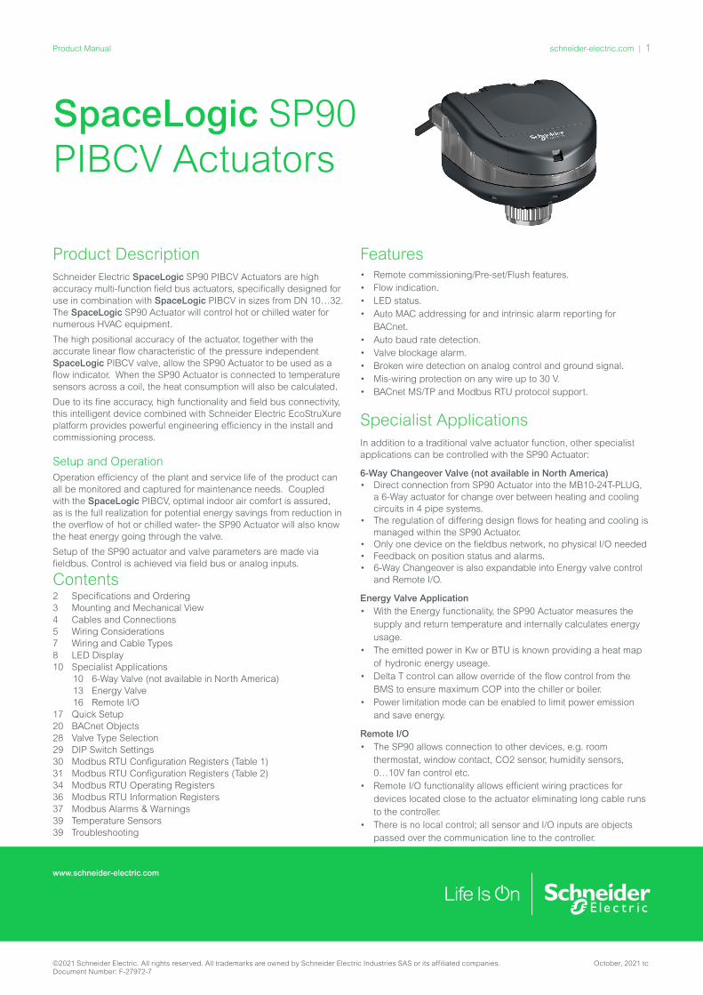
Product DescriptionSchneider Electric SpaceLogic SP90 PIBCV Actuators are high accuracy multi-function field bus actuators, specifically designed for use in combination with SpaceLogic PIBCV in sizes from DN 10…32. The SpaceLogic SP90 Actuator will control hot or chilled water for numerous HVAC equipment.
The high positional accuracy of the actuator, together with the accurate linear flow characteristic of the pressure independent SpaceLogic PIBCV valve, allow the SP90 Actuator to be used as a flow indicator. When the SP90 Actuator is connected to temperature sensors across a coil, the heat consumption will also be calculated.
Due to its fine accuracy, high functionality and field bus connectivity, this intelligent device combined with Schneider Electric EcoStruXure platform provides powerful engineering efficiency in the install and commissioning process.
Setup and OperationOperation efficiency of the plant and service life of the product can all be monitored and captured for maintenance needs. Coupled with the SpaceLogic PIBCV, optimal indoor air comfort is assured, as is the full realization for potential energy savings from reduction in the overflow of hot or chilled water- the SP90 Actuator will also know the heat energy going through the valve.
Setup of the SP90 actuator and valve parameters are made via fieldbus. Control is achieved via field bus or analog inputs.
Features• Remote commissioning/Pre-set/Flush features. • Flow indication. • LED status. • Auto MAC addressing for and intrinsic alarm reporting for
BACnet.• Auto baud rate detection. • Valve blockage alarm. • Broken wire detection on analog control and ground signal. • Mis-wiring protection on any wire up to 30 V. • BACnet MS/TP and Modbus RTU protocol support.
Specialist ApplicationsIn addition to a traditional valve actuator function, other specialist applications can be controlled with the SP90 Actuator:
6-Way Changeover Valve (not available in North America)• Direct connection from SP90 Actuator into the MB10-24T-PLUG,
a 6-Way actuator for change over between heating and cooling circuits in 4 pipe systems.
• The regulation of differing design flows for heating and cooling is managed within the SP90 Actuator.
• Only one device on the fieldbus network, no physical I/O needed• Feedback on position status and alarms.• 6-Way Changeover is also expandable into Energy valve control
and Remote I/O.
Energy Valve Application • With the Energy functionality, the SP90 Actuator measures the
supply and return temperature and internally calculates energy usage.
• The emitted power in Kw or BTU is known providing a heat map of hydronic energy useage.
• Delta T control can allow override of the flow control from the BMS to ensure maximum COP into the chiller or boiler.
• Power limitation mode can be enabled to limit power emission and save energy.
Remote I/O• The SP90 allows connection to other devices, e.g. room
thermostat, window contact, CO2 sensor, humidity sensors, 0…10V fan control etc.
• Remote I/O functionality allows efficient wiring practices for devices located close to the actuator eliminating long cable runs to the controller.
• There is no local control; all sensor and I/O inputs are objects passed over the communication line to the controller.
2 Specifications and Ordering3 Mounting and Mechanical View4 Cables and Connections5 Wiring Considerations7 Wiring and Cable Types8 LED Display10 Specialist Applications
10 6-Way Valve (not available in North America) 13 Energy Valve 16 Remote I/O
17 Quick Setup20 BACnet Objects28 Valve Type Selection29 DIP Switch Settings30 Modbus RTU Configuration Registers (Table 1)31 Modbus RTU Configuration Registers (Table 2)34 Modbus RTU Operating Registers36 Modbus RTU Information Registers 37 Modbus Alarms & Warnings 39 Temperature Sensors39 Troubleshooting
Contents
©2021 Schneider Electric. All rights reserved. All trademarks are owned by Schneider Electric Industries SAS or its affiliated companies. October, 2021 tcDocument Number: F-27972-7
www.schneider-electric.com
schneider-electric.com | 1Product Manual

Specifications and OrderingPart Number SP90-24BMM
Power supply range 24 V ac/dc, ± 25%, 50 / 60 Hz
Power consumption Operating: 2.7 VA @ 24 Vac / 1.2 W @ 24 Vdc
Standby: 1.8 VA @ 24 Vac / 0.7 W @ 24 Vdc
Protection class III safety extra-low voltage
Electrical connection Pre-molded plug connector
Control signal Digital BACnet MS/TP, Modbus RTU0-10 VDC, 0-5 VDC, 2-10 VDC, 5-10 VDC,
2-6 VDC, 6-10 VDC, 0-20 mA, 4-20 mA
Impedance Rin AI:0 >100 kΩ (V); 500 Ω (mA) Rout AO: 1500 Ω
Actuator speed selections (open to close) sec/mm
3, 6, 12, 24, Constant Time
Max. Stroke 7 mm (0.28”)
Force 90 N
Positional accuracy ± 0.005 mm Accuracy, Calculated Energy Usage +/- 15%
Working Ambient temp. range −10°…50 °C
Ambient humidity 98% r.h., non-condensing (according to EN 60730-1)
Max. medium temp. 120 °C (248 °F)
Storage temp. range –40…70 °C (14…158 °F)
Grade of enclosure IP54 (IP40 upside-down)
Weight 0.4 kg (0.88 lb)
Approvals EMC Directive 2004/108/EC, EN 60730-2-14:1997, EN 60730-2-14/A1:2001,
EN60730-1:2011 RoHS Directive 2016/863/EU
Application Software version Firmware Version
4.21…4.29 2.10
BACnet DataBACnet device profile BACnet Application Specific
Controller (B-ASC)
BACnet protocol BACnet Master Slave / Token Passing (MS/TP)
BACnet baud rates sup-ported
Auto baud rate detection / 9600 bps / 19200 bps / 38400 bps / 56700 bps / 76800 bps /
115200bps
Modbus RTU DataSupported baud rates Auto baud rate detection / 9600 bps / 19200
bps / 38400 bps / 56700 bps / 76800 bps / 115200bps
Supported transmission modes
Parity: None (1-8-N-2) / Odd (1-8-O-1) / Even (1-8-E-1) / None (1-8-N-1)
Data format: Parity (Start bit - Data bits - Parity - Stop bits)
Accessory Pockets/Wells for Insertion Probe Sensors
Description Brass Part No. Stainless Steel Part No.
Immersion pocket, 50 mm, G1/2 9121040000 9121050000
Immersion pocket, 100 mm, G1/2 9121041000 9121051000
Immersion pocket, 150 mm, G1/2 9121042000 9121052000
Immersion pocket, 200 mm, G1/2 9121043000 9121053000
Note: 2 x Immersion Pockets/Wells required per device
Ordering
SP90 PIBCV ActuatorDescription Part No.
SP90, PIBCV Actuator SP90-24BMM
MB10 6-Way Change over Actuator 2
Part No. Description
MB10-24T-PLUG1 MB10 with plug for SP90
MB10-24T-ENGY1 MB10 with SP90 plug and Temp. sensors
MB10-24T-FLEX1 MB10 with flexible cable
1 - Basic change over actuator MB10-24T is not designed for connection with SP902 - Not available in North America.
Applicable 6-Way Valves2
Part No. Size Kvs
VB601R-15B DN15 / Rp 1/2 2.4
VB601R-20B DN20 / Rp 3/4 4.0
2 - Not available in North America.
Cable Accessories*
Type Length (m)
Connections Standard Cable 1
Plenum Cable
Digital1.5
bus & power9114401500 9114401500P
10.0 9114410000 9114410000P
Daisy chain
0.5
actuator to actuator
9114500500 9114500500P
1.5 9114501500 9114501500P
5 9114505000 9114505000P
10.0 9114510000 9114510000PAnalogue + I/O
1.5
Multi-core free wire cable
9114601500 9114601500P
Energy
PT1000 surface mount temp sensors
9114701500 9114701500P
PT1000 insertion probe temp sensors
9114801500 9114801500P
Energy, Power and 0…10V I/O
1.5
PT1000 surface mount sensors,Power, 0…10V In and Out
9114901500 2
* Cables not included with actuator and must be ordered separately. 1 - Standard cable material is Halogen free; Energy cable is PVC.2 - Available December 2021
Dimensions94
112
8095.3
112
80
+ =
20
+ =
16
Type L4 H3
DN10 (3/8”)118mm (4.65”)
140mm (5.51”)
DN15 (1/2”)125mm (4.92”)
143mm (5.63”)
DN20 (3/4”)133mm (5.24”)
145mm (5.71”)
DN25 (1”)148mm (5.83”)
153mm (6.02”)
DN32 (1¼”)166mm (6.54)
164mm (6.46”)
L4
110
H3
©2021 Schneider Electric. All rights reserved. All trademarks are owned by Schneider Electric Industries SAS or its affiliated companies. October, 2021 tcDocument Number: F-27972-7
2 | schneider-electric.com Product Manual
UNSCREW AND REMOVE
PULL UP
TURN PUSH DOWN
Max
① ②
③ ④
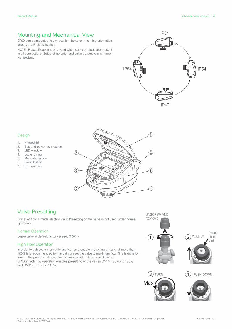
Valve PresettingPreset of flow is made electronically. Presetting on the valve is not used under normal operation.
Normal OperationLeave valve at default factory preset (100%).
High Flow OperationIn order to achieve a more efficient flush and enable presetting of valve of more than 100% it is recommended to manually preset the valve to maximum flow. This is done by turning the preset scale counter-clockwise until it stops. See drawing. SP90 in high flow operation enables presetting of the valves DN10…20 up to 120% and DN 25…32 up to 110%.
①
③
②
④
⑦
⑤
⑥
1. Hinged lid2. Bus and power connection3. LED window4. Locking ring5. Manual override6. Reset button7. DIP switches
Design
Mounting and Mechanical ViewSP90 can be mounted in any position, however mounting orientation affects the IP classification.
NOTE: IP classification is only valid when cable or plugs are present in all connections. Setup of actuator and valve parameters is made via fieldbus.
IP40
IP54
IP54IP54
Preset scale dial
©2021 Schneider Electric. All rights reserved. All trademarks are owned by Schneider Electric Industries SAS or its affiliated companies. October, 2021 tcDocument Number: F-27972-7
schneider-electric.com | 3Product Manual
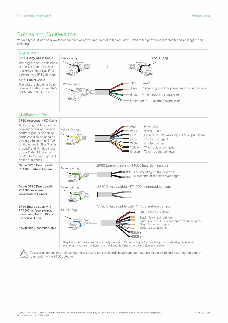
Cables and ConnectionsVarious types of cables allow the connection of power and control to the actuator. Refer to the part number tables for cable lengths and ordering.
Digital PortsSP90 Daisy Chain Cable
The digital daisy chain cable is used to connect power and BACnet/Modbus RTU between two SP90 devices.
Black O-ring Black O-ring
SP90 Digital Cable
The digital cable is used to connect SP90 to other BAC-net/Modbus RTU devices.
Black Common ground for power and bus signal wire
Green ‘+’ non-inverting signal wire
Red Power
Green/White ‘–’ inverting signal wire
White O-ring
Multifunction Ports SP90 Analogue + I/O Cable
The analog cable is used to connect power and analog control signal. The analog cable can also be used as a voltage booster for SP90 on the network. The “Power ground” and “Analog input ground” should be con-nected to the same ground on the Controller.
Yellow O-ringRed Power 24VBlack Power groundBlue Ground T1, T2, V/mA input & V output signalGrey V/mA input signalWhite V output signalYellow T1 or resistance inputOrange T2 or resistance input
Cable SP90 Energy with PT1000 Surface Sensor Green O-ring
SP90 Energy cable - PT1000 Insertion sensors
For mounting on the pipework either side of the heat exchanger
Cable SP90 Energy with PT1000 Insertion Temperature Sensor
Green O-ring SP90 Energy cable - PT1000 immersed sensors
SP90 Energy cable with PT1000 surface sensor, power and the 0…10 Vdc I/O connections.
* Available December 2021
To avoid electrical short-circuiting, ensure that loose cable ends have been connected or isolated before inserting the plug-in connector to the SP90 actuator.
SP90 Energy cable with PT1000 surface sensor
Red Power 24V (in/out)
Black Power ground (in/out)Blue Ground T1, T2, V/mA input & V output signalGrey V/mA input signalWhite V output signal
T1T2
Blue O-ring
Required when the room controller only has a 0…10V output signal for the valve position, allowing the flow and energy analytics are monitored over field-bus via daisy chain to an automation server.
©2021 Schneider Electric. All rights reserved. All trademarks are owned by Schneider Electric Industries SAS or its affiliated companies. October, 2021 tcDocument Number: F-27972-7
4 | schneider-electric.com Product Manual
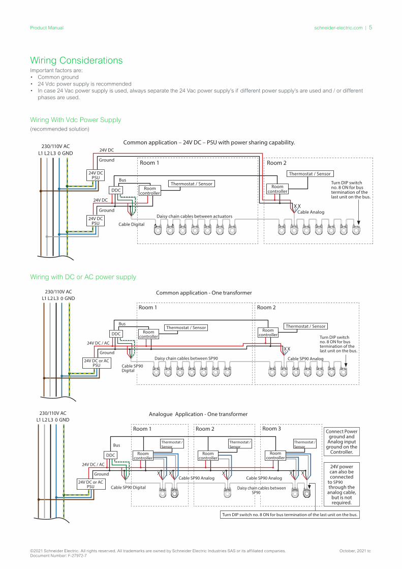
Wiring ConsiderationsImportant factors are: • Common ground • 24 Vdc power supply is recommended• In case 24 Vac power supply is used, always separate the 24 Vac power supply’s if different power supply’s are used and / or different
phases are used.
Wiring With Vdc Power Supply (recommended solution)
Wiring with DC power supply: (recommended solution)
L1 L2 L3 0 GND
24V DCPSU
DDC Roomcontroller
24V DC
Ground
Bus
Cable Digital
Daisy chain cables between actuators
Roomcontroller
X X
Room 1 Room 2
Common application – 24V DC – PSU with power sharing capability.24V DC
Ground
24V DCPSU
Cable Analog
Turn DIP switch no. 8 ON for bus termination of the last unit on the bus.
230/110V AC
Thermostat / Sensor
Thermostat / Sensor
Wiring with DC or AC power supply
230/110V ACL1 L2 L3 0 GND
24V ACPSU
DDC Roomcontroller
Thermostat / Sensor Thermostat / Sensor
24V AC
Ground
Bus
Cable SP90 Digital
Daisy chain cables between SP90
Roomcontroller
X X
Room 1 Room 2
24V AC
Ground
24V ACPSU
Cable SP90 Analog
Common application - Identical transformers, same phase
Turn DIP switch no. 8 ON for bus termination of the last unit on the bus.
230/110V ACL1 L2 L3 0 GND
24V DC or ACPSU
DDC Roomcontroller
Thermostat / Sensor
24V DC / AC
Ground
Bus
Cable SP90Digital
Daisy chain cables between SP90
Roomcontroller
Thermostat / Sensor
X X
Room 1 Room 2
Common application - One transformer
Cable SP90 Analog
Turn DIP switch no. 8 ON for bus termination of the last unit on the bus.
24V power can also be connected
to SP90through the
analog cable, but is not required.
230/110V ACL1 L2 L3 0 GND
DDC Roomcontroller
Thermostat /Sensor
Thermostat /Sensor
Thermostat /Sensor
Ground
Bus
Cable SP90 Digital Daisy chain cables between SP90
Roomcontroller
X X
Room 1 Room 2
Analogue Application - One transformer
Roomcontroller
X X X
Room 3
Cable SP90 Analog Cable SP90 Analog
Connect Power ground and
Analog input ground on the
Controller.
Turn DIP switch no. 8 ON for bus termination of the last unit on the bus.
24V DC / AC
24V DC or ACPSU
230/110V ACL1 L2 L3 0 GND
24V ACPSU
DDC Roomcontroller
Thermostat / Sensor Thermostat / Sensor
24V AC
Ground
Bus
Cable SP90 Digital
Daisy chain cables between SP90
Roomcontroller
X X
Room 1 Room 2
24V AC
Ground
24V ACPSU
Cable SP90 Analog
Common application - Identical transformers, same phase
Turn DIP switch no. 8 ON for bus termination of the last unit on the bus.
230/110V ACL1 L2 L3 0 GND
24V DC or ACPSU
DDC Roomcontroller
Thermostat / Sensor
24V DC / AC
Ground
Bus
Cable SP90Digital
Daisy chain cables between SP90
Roomcontroller
Thermostat / Sensor
X X
Room 1 Room 2
Common application - One transformer
Cable SP90 Analog
Turn DIP switch no. 8 ON for bus termination of the last unit on the bus.
24V power can also be connected
to SP90through the
analog cable, but is not required.
230/110V ACL1 L2 L3 0 GND
DDC Roomcontroller
Thermostat /Sensor
Thermostat /Sensor
Thermostat /Sensor
Ground
Bus
Cable SP90 Digital Daisy chain cables between SP90
Roomcontroller
X X
Room 1 Room 2
Analogue Application - One transformer
Roomcontroller
X X X
Room 3
Cable SP90 Analog Cable SP90 Analog
Connect Power ground and
Analog input ground on the
Controller.
Turn DIP switch no. 8 ON for bus termination of the last unit on the bus.
24V DC / AC
24V DC or ACPSU
©2021 Schneider Electric. All rights reserved. All trademarks are owned by Schneider Electric Industries SAS or its affiliated companies. October, 2021 tcDocument Number: F-27972-7
schneider-electric.com | 5Product Manual

Daisy Chain Wiring DC Power supply (recommended)
When daisy chaining with 10m SP90 cables and using a 24V DC power supply, additional voltage boosters/power supply is needed when 11 SP90s in series is exceeded. See table below.
AC Power supply
When daisy chaining with 10m SP90 cables and using a 24V AC power supply, additional voltage boosters/power supply is needed when 7 SP90s in series is exceeded. See table below.
Important: The power supply used must be able to deliver 60% more power than the nominal rating of SP90.
Use daisy chain connection for SP90.
Remember to enable DIP switch 8 for bus termination on the last SP90 in the daisy chain
Voltage booster / Power supply.
U=24V
Controller and 24 Volt AC or DC Power supply
Wiring with AC power supply
Wires that ends in an "X" must be properly terminated.
230/110V ACL1 L2 L3 0 GND
24V ACPSU
DDC Roomcontroller
24V AC
Ground
Bus
Cable SP90 Digital
Daisy chain cables between SP90
Roomcontroller
X X
Room 1 Room 2
Common application - Identical or dierent transformers with dierent phases, but same ground24V AC
Ground
24V ACPSU
X X
Disconnect Power 24V, but
NOT ground
Cable SP90 Analog Cable Digital
Turn DIP switch no. 8 ON for bus termination of the last unit on the bus.
Thermostat / Sensor
Living Space Temperature Sensor
230/110V ACL1 L2 L3 0 GND
24V ACPSU
DDC Roomcontroller
Thermostat / Sensor Thermostat / Sensor
24V AC
Ground
Bus
Cable SP90 Digital
Daisy chain cables between SP90
Roomcontroller
X X
Room 1 Room 2
24V AC
Ground
24V ACPSU
Cable SP90 Analog
Common application - Identical transformers, same phase
Turn DIP switch no. 8 ON for bus termination of the last unit on the bus.
230/110V ACL1 L2 L3 0 GND
24V DC or ACPSU
DDC Roomcontroller
Thermostat / Sensor
24V DC / AC
Ground
Bus
Cable SP90Digital
Daisy chain cables between SP90
Roomcontroller
Thermostat / Sensor
X X
Room 1 Room 2
Common application - One transformer
Cable SP90 Analog
Turn DIP switch no. 8 ON for bus termination of the last unit on the bus.
24V power can also be connected
to SP90through the
analog cable, but is not required.
230/110V ACL1 L2 L3 0 GND
DDC Roomcontroller
Thermostat /Sensor
Thermostat /Sensor
Thermostat /Sensor
Ground
Bus
Cable SP90 Digital Daisy chain cables between SP90
Roomcontroller
X X
Room 1 Room 2
Analogue Application - One transformer
Roomcontroller
X X X
Room 3
Cable SP90 Analog Cable SP90 Analog
Connect Power ground and
Analog input ground on the
Controller.
Turn DIP switch no. 8 ON for bus termination of the last unit on the bus.
24V DC / AC
24V DC or ACPSU
©2021 Schneider Electric. All rights reserved. All trademarks are owned by Schneider Electric Industries SAS or its affiliated companies. October, 2021 tcDocument Number: F-27972-7
6 | schneider-electric.com Product Manual

Wiring and Cable Types• The wiring of BACnet MS/TP (RS485) must be carried out in
accordance with applicable standard ANSI/TIA/EIA-485-A-1998.• Galvanic separation shall be provided for segments crossing
buildings.• Common ground shall be used for all devices on the same
network inclusive router, gateways etc.• All BACnet bus connections in the cables are made with twisted
wires.
The cable type used for analog, digital and I/O cables is AWG22/0.32mm2. If other cables are used to extend the length, always use twisted pair wire for bus signal and include ground for the bus signal. The recommended cable type is AWG22/0.32 mm2. If used for longer distances please use a AWG20/0.5mm2 or AWG18/0.75mm2 cable.
The cable’s impedance characteristic shall be between 100-130Ω. The capacitance between conductors shall be less than 100 pf per meter.
Digital port
Multifunctional port
Digital port
The length of the cables influence on the communication speed. Longer cable lengths should result in lower baud rates. The total maximum cable length allowed per network is 1200m. Use a mini-mum 20 cm distance between 110V/230V/400V power line cables and bus cables.
SP90 has mis-wiring protection on up to 30 V AC/DC on all wires, but be aware that if 30V AC are connected to the Analog input, the external power supply will see this as a short circuit and blow the fuse in the external power supply.
NOTE: If the SP90 network is supplied with two or more AC power boosters, caution must be observed when disconnecting one of the transformers from the high voltage power line. As the SP90 are connected in a daisy chain, there may be high voltage on the primary side of the disconnected power supply. Disconnect always both the primary and secondary side of the transformer. The power boosters must be protected against overload, otherwise the power booster may be damage if one of the other power boosters in the network is disconnected.
1 2 3 4 5 6 7 8 9 10 11 12 13 14 15 16 17 18 19 20 21 22 23 24 25 26 27 28 29 30 31 32 33 34 35 36 37 38 39 40 41 42 43 44 45 46 47 48 49 50 51 52 53 54 55 56 57 58 59 60 61 62 63 64
Bus communication from the controllerPower supply with daisy chain from controllerUsage of analog cable as voltage boosterSP90
Quantity of SP90 DevicesWhen all devices on the sub-network are SP90, refer to the examples below for guidance of when to have a power boost within the daisy chain network. Note there is an industry limitation of 32 devices per segment, additional devices can be accommodated by the use of RS-485 repeaters.
24 V
olt D
C24
Vol
t AC
Star topology is not recommended according to the RS485 standard and should not be used with SP90.
T-junction connections (stub lines)
These are not recommended but in the event T-junction connec-tions are used, Schneider Electric accepts no responsibility and it is advised to never exceed the following limitations:• max T-junction cable length 1.5m (shortest standard digital cable)• total length of Network max 640m (+ 100m stub length)• max baud rate 76 kb/s 1)
• max number of devices on network 64 1)
• main cable should be standard RS485 bus, twisted pair, min thickness AWG 22
1 - When using less than 32 devices you may attempt to raise the speed to 115 kb/s.
max 1.5m
Daisy chain
T-junction
If the supply voltage to the first device in the daisy chain is lower than 24V AC/DC, or long thin cables other than SP90 cables are
used, then the quantity of devices in the daisy chain may have to be reduced.
The recommended maximum quantities of SP90 are 64 pcs in one daisy chain connection but note there is an industry limitation of 32 devices per segment; additional devices can be accommodated by the use of RS-485 repeaters, to ensure sufficient network speed. Schneider Electric recommends that SP90 should be used on its own sub-network for optimal performance. General requirements:• Use Schneider Electric daisy chain cable to connect two SP90 devices.• Use Schneider Electric digital cable to connect SP90 with another BACnet
device.• The current in cables should not exceed 3 amps at 30°C.• Use the termination resistor (DIP switch 8) at the end of daisy chain.• Use Schneider Electric analog cables as voltage boosters to increase
voltage.• Generally, the same type of power supply is preferred.• If two power supplies are used, they must have the same polarity and the
same common ground.• A common ground must be used for all devices on the same sub-network,
including routers and gateways.• Galvanic separation shall be provided for segments crossing buildings.• Connect Power ground and Analog input ground on the Controller.• Total maximum cable length of sub-network 1200m.
©2021 Schneider Electric. All rights reserved. All trademarks are owned by Schneider Electric Industries SAS or its affiliated companies. October, 2021 tcDocument Number: F-27972-7
schneider-electric.com | 7Product Manual

Optimize BACnet Network Speed: Reducing Unnecessary PollforMaster Traffic
Setting for the last SP90 in the daisy chain:
The MAX_MASTER setting in SP90 shall be set to the number of de-vices (or the highest used MAC address) in the MS/TP sub network. The MAX_MASTER property is found in the Device object and has a default value of 127. It should be noted that the MAX_MASTER prop-erty value should be adjusted accordingly at a later stage if more devices are added to the network and/or the highest MAC address exceeds the MAX_MASTER property value.
Before MAX_MASTER can be set it is needed to ensure all devices are within the MAX_MASTER value. If MAX:MASTER is set to 20 communication will not work with a device, which uses MAC address 22, even though e.g. MAC address 15 is not used.
Allocating Correct INFO_FRAMES
Setting for Controller:
Network Routers and Controller devices that transport traffic in the MS/TP network require a higher number of INFO_FRAMES than SP90. Therefore, these devices should have a higher value than SP90 e.g. A general rule of thumb for the sub network router’s MAX_INFO_FRAMES property value is equal to the amount of MS/TP devices in the router’s sub network. The MAX_INFO_FRAMES prop-erty is found in the Device object of MS/TP devices. SP90’s default MAX_INFO_FRAMES value is 1.
LED Display
BACnet/Modbus RTU (RS485) activity
Position of valve/actuator
BACnet/Modbus RTU (RS485) activityNo light from LED: Actuator sees no activity on the networkLED turn on and off quickly, 10x/second: Normal operation on the network communication is OK.LED turn on and off slowly with green light, 3x/second: Normal operation on the network - communication over longer time directly with this actuator.
BACnet/Modbus RTU (RS485) activity with ERRORS LED turns on and off slowly, 3x/second, with RED color: Actuator sees activity, but with errors. LED turn on and off quickly, 10x/second, with RED color: Communication is OK, EXCEPT that another device may be using the same MAC address.
PIBCV valve is fully closed.
PIBCV is 1-24% open.
PIBCV is 25-49% open.
PIBCV is 50-74% open
PIBCV is 75-99% open.
PIBCV valve is fully open.
Flush is activeAll LEDs turns on/off with specific period.
SP90 is closing the valveAll green LEDs are turned ON, then turned OFF one at the time (repeatedly).
SP90 is opening the valveAll green LEDs are turned OFF, then turned ON one at the time (repeatedly).
Movement of valve/actuator
©2021 Schneider Electric. All rights reserved. All trademarks are owned by Schneider Electric Industries SAS or its affiliated companies. October, 2021 tcDocument Number: F-27972-7
8 | schneider-electric.com Product Manual
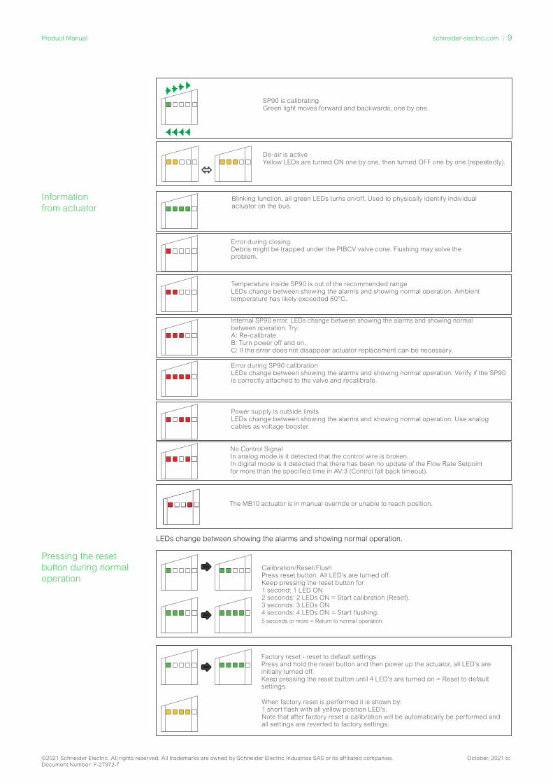
SP90 is calibratingGreen light moves forward and backwards, one by one.
De-air is activeYellow LEDs are turned ON one by one, then turned OFF one by one (repeatedly).
Information from actuator
Blinking function, all green LEDs turns on/off. Used to physically identify individual actuator on the bus.
Error during closingDebris might be trapped under the PIBCV valve cone. Flushing may solve the problem.
Temperature inside SP90 is out of the recommended rangeLEDs change between showing the alarms and showing normal operation. Ambient temperature has likely exceeded 60°C.
Internal SP90 error. LEDs change between showing the alarms and showing normal between operation. Try: A: Re-calibrate.B: Turn power off and on.C: If the error does not disappear actuator replacement can be necessary.
Power supply is outside limitsLEDs change between showing the alarms and showing normal operation. Use analog cables as voltage booster.
No Control SignalIn analog mode is it detected that the control wire is broken.In digital mode is it detected that there has been no update of the Flow Rate Setpoint for more than the specified time in AV:3 (Control fall back timeout).
Error during SP90 calibrationLEDs change between showing the alarms and showing normal operation. Verify if the SP90 is correctly attached to the valve and recalibrate.
LEDs change between showing the alarms and showing normal operation.
Pressing the reset button during normal operation
Factory reset - reset to default settings Press and hold the reset button and then power up the actuator, all LED's are initially turned off.Keep pressing the reset button until 4 LED's are turned on = Reset to default settings.
When factory reset is performed it is shown by:1 short flash with all yellow position LED’s.Note that after factory reset a calibration will be automatically be performed and all settings are reverted to factory settings.
Calibration/Reset/FlushPress reset button. All LED's are turned off. Keep pressing the reset button for 1 second: 1 LED ON 2 seconds: 2 LEDs ON = Start calibration (Reset). 3 seconds: 3 LEDs ON 4 seconds: 4 LEDs ON = Start flushing. 5 seconds or more = Return to normal operation.
The MB10 actuator is in manual override or unable to reach position.
©2021 Schneider Electric. All rights reserved. All trademarks are owned by Schneider Electric Industries SAS or its affiliated companies. October, 2021 tcDocument Number: F-27972-7
schneider-electric.com | 9Product Manual

Specialist Applications In addition to a traditional 2-port PIBCV valve actuator function, other specialist applications are available with the SP90: Application #1: 6-Way Valve (Three variants)
Application #2: Energy Valve Application
Application #3: Remote I/O
Specialist Application #1
6-Way Valve (not available in North America) 1a. 6-way change over valve application - Direct connection from SP90 into 6-Way actuator for change over between heating and cooling cir-cuits in 4-pipe systems. The 6 way change over valve application can also have expansion into Energy Valve control and Remote I/O. Further details of these are covered in the specialist applications 2 and 3.
1b. 6-Way change over valve with energy control - Utilizing Supply and return temperature measurement for calculation and control of energy usage.
1c. 6-Way change over valve with Remote I/O Connection - Connection to other devices, e.g. room thermostat, window contact, CO2 sensor, humidity sensors, 0-10 V fan control etc.
1a. 6-Way Change Over ValveIn the standard 6-way application, the SP90 will connect to the change over actuator MB10T-24T-PLUG from the middle multi-function port. The SP90 is configured for the differing heating and cooling flows, the MB10T-24T-PLUG actuator will provide the change over on the 6-way valve.
DDCFieldbus
Radiant Panels
SetupObject /Register
Write/read value Description
MSV:9 / 32810
6-Way modeWhile in 6-Way mode, the SP90 provides a 0…10V output signals for controlling the MB10-24T-PLUG 6-port valve actuator
MSV:3 / 32802
Valve type ISO valve selected = l/h, °C , kW and kg/m3.
AV:30 / 32796 400 Design flow setting of Heating e.g. 400 l/h
AV:31 / 32798 250 Design flow setting of Cooling e.g. 250 l/h
The VB601R is a 6-port valve with a rotary actuator that switches the flow between heating and cooling. A pressure independent balancing and control valve with the SP90 an actuator is used to balance the system and modulate the flow. Both the SP90 and the MB10-24T-PLUG, MB10-24T-ENGY, MB10-24T-FLEX actuator are represented on the fieldbus network and need no physical I/O for control.
Heating:Cooling:
No mixing and shut offSource 1 open Shut off Source 2 open
©2021 Schneider Electric. All rights reserved. All trademarks are owned by Schneider Electric Industries SAS or its affiliated companies. October, 2021 tcDocument Number: F-27972-7
10 | schneider-electric.com Product Manual
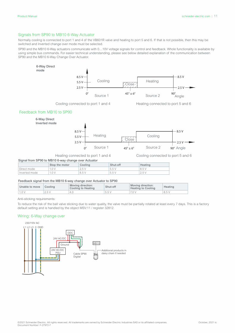
Anti-sticking requirements:
To reduce the risk of the ball valve sticking due to water quality, the valve must be partially rotated at least every 7 days. This is a factory default setting and is handled by the object MSV:11 / register 32812.
Wiring: 6-Way change over
230/110V AC
L1 L2 L3 0 GND
24V AC/DCPSU
DDC
24V AC/DC
Ground
Cable SP90Digital
Additional products in daisy chain if needed
MB10
Example using voltage booster and temperature sensors on the same SP90
230/110V AC
L1 L2 L3 0 GND
24V DC/ACPSU
DDC
24V DC/AC
Ground
Cable SP90Digital
T1 T2 T1 T2 T1 T2 T1 T2 T1 T2
X
XX
X X
XX
X X
XX
X
XX
X
XXBus
An
alo
g +
I/O
ca
ble
X
T1 T2
X
XX
X
Additional products in daisy chain if needed
Cable SP90I/O
Power
24V AC/DC
Room controller
MB10-24T-FLEX
Yellow O-ring
X
XX
X
Signals from SP90 to MB10 6-Way ActuatorNormally cooling is connected to port 1 and 4 of the VB601R valve and heating to port 5 and 6. If that is not possible, then this may be switched and Inverted change over mode must be selected.
SP90 and the MB10 6-Way actuators communicate with 0…10V voltage signals for control and feedback. Whole functionality is available by using simple bus commands. For easier technical understanding, please see below detailed explanation of the communication between SP90 and the MB10 6-Way Change Over Actuator.
Cooling connected to port 1 and 4 Heating connected to port 5 and 6
Source 1 Source 2
6-Way Direct mode
Angle
Close
Feedback from MB10 to SP90
6-Way Direct Inverted mode
Heating connected to port 1 and 4 Cooling connected to port 5 and 6
CoolingHeating
Source 1 Source 2 Angle
Close
Signal from SP90 to MB10 6-way change over ActuatorStop the motor Cooling Shut-off Heating
Direct mode 1.0 V 2.5 V 5.5 V 8.5 VInverted mode 1.0 V 8.5 V 5.5 V 2.5 V
Feedback signal from the MB10 6-way change over Actuator to SP90
Unable to move Cooling Moving direction: Cooling to Heating Shut-off Moving direction:
Heating to Cooling Heating
1.0 V 2.5 V 4.0 5.5 V 7.0 V 8.5 V
HeatingCooling
©2021 Schneider Electric. All rights reserved. All trademarks are owned by Schneider Electric Industries SAS or its affiliated companies. October, 2021 tcDocument Number: F-27972-7
schneider-electric.com | 11Product Manual

1b. 6-Way change over valve with Energy FunctionalityThe 6-Way change over application can be extended to capture and control energy usage, With this application the SP90 will connect to the MB10T-24T-ENGY from the middle multi-function port. The connecting lead from the MB10-24T-ENGY also has strap on pipe temperature sensors that are used to measure the temperature drop across the coil and the energy usage is calculated from the valves flow rate. Also refer to “Specialist Application #2” on page 13.
Setup
Object /Register Write/read value Description
MSV:9 / 32810 6-Way modeWhile in 6-Way mode, the 0…10V input and output signals are used purely for controlling the 6-port valve actuator
AV:32 / 33288Power emission
Calculates energy based on values from flow feedback (AV:2) and temperature (AI:1 and AI:2)
MSV:3 / 32802 Valve type ISO valve selected = l/h, °C , kW and kg/m3.
AI:1 / 33218 Temperature Select between temperature units or ohms
AI:2 / 33220 Temperature Select between temperature units or ohms
AV:30 / 32796 400 Design flow setting of Heating e.g. 400 l/h
AV:31 / 32798 250 Design flow setting of Cooling e.g. 250 l/h
1c. 6-Way change over valve with Remote I/OThe MB10-24T-FLEX allows the 6-Way valve solution to be connected to other devices, such as room thermostats, humidity sensors with the spare RTD inputs that would otherwise be used for energy valve control. This allows for efficient wiring practices for devices mounted close by. The RTD inputs are passed over the BACnet / Modbus RTU communication line as objects and allow the AS controller to command the control of the valve according to the room control requirements. Also refer to specialist application #3.
Wiring
230/110V AC
L1 L2 L3 0 GND
24V AC/DCPSU
DDC
24V AC/DC
Ground
Cable SP90Digital
Additional products in daisy chain if needed
MB10
Example using voltage booster and temperature sensors on the same SP90
230/110V AC
L1 L2 L3 0 GND
24V DC/ACPSU
DDC
24V DC/AC
Ground
Cable SP90Digital
T1 T2 T1 T2 T1 T2 T1 T2 T1 T2
X
XX
X X
XX
X X
XX
X
XX
X
XXBus
An
alo
g +
I/O
ca
ble
X
T1 T2
X
XX
X
Additional products in daisy chain if needed
Cable SP90I/O
Power
24V AC/DC
Room controller
MB10-24T-FLEX
Yellow O-ring
X
XX
X
In this wiring example the feedback of position alarms from the MB10 is sacrificed for the use of a room controller or thermostat with 0-10V signal.
In case a room thermostat is chosen with Pt1000 or NTC 10K type 2 or 3 element connected to the yellow or orange RTD input, alarm feedback from MB10 can be retained.
©2021 Schneider Electric. All rights reserved. All trademarks are owned by Schneider Electric Industries SAS or its affiliated companies. October, 2021 tcDocument Number: F-27972-7
12 | schneider-electric.com Product Manual

Specialist Application #2
Energy Valve • Dedicated energy meters are accurate but costly, but only tell you how much energy you have already consumed; they don’t help to limit
the energy. • The SP90 is able to calculate the energy usage through the valve.• Due to highly accurate positioning of the SP90 actuator and a precise and linear flow curve of the PIBCV, heat emission can be calculated
from the known temperature drop and the known flow rate through the valve.• The SP90 has needed sensor inputs and dedicated cable sets for connecting PT1000 temperature sensors.• The SP90 can not only calculate the energy going through the valve but can actually control flow based on energy. Thus we can either
sacrifice the time taken to reach target temperature or limit energy usage at any particular time. Limiting energy when required may be desirable if there are peak energy constraints and prioritized zones.
• Understanding Delta T also allows us to control Delta T, thus we can ensure the chiller or boiler is operating on optimal coefficient of performance (COP).
Energy Management MSV:13 / 32815
General Information - Energy Limitation States: • For all ‘limitation’ states within MSV:13/32815, a warning will be activated and made visible on the bus to inform the user that SP90 has
taken control of the flow rate through the PIBCV valve. Whilst under SP90 control, the valve will not be closed at any time i.e. closing % constraints are contained within its algorithms, although an external device’s control signal will always be able to close the valve.
• If the energy limitation settings are unobtainable without SP90 closing itself, a warning will be activated to inform the user that the set-point value is ‘out of range’. Please note that SP90 will not automatically relinquish control of the flow rate as soon as the set-point is achieved if the external device e.g. DDC differs greatly with that of SP90’s calculated flow rate/opening %.
• TIP: This information may be used by the user to improve the external control device’s PID.
General Information - Energy Control States:• For all ‘control’ states within MSV:13/32815, SP90 takes full control over the flow rate through the PIBCV valve and will not accept a control
signal from an external device. Whilst under SP90 control, the valve will not be fully closed at any time i.e. closing % constraints are contained within its algorithms. If the energy control settings are unobtainable without SP90 closing or opening itself fully, a warning will be activated to inform the user that the set-point value is ‘out of range’.
Power Manager
State 1: Not active. • Energy management applications are disabled.
State 2: Power limitation (chilled water example) • SP90 calculates the instantaneous hydronic power used and will then, when required, override the DDC control signal and limit the flow
rate / hydronic power according to the user defined values in object / register AV:35 or 36 / 32832 or 32834. The hydronic power is limited by closing the valve until the kW value measured, once again, falls below the defined limit. There are user defined limits for both Cooling Power and Heating Power. When this limitation is active, the warning object BV:23 / bit 23 in register 33536 will be set to ‘on’. Application example: When the “Power” is limited in this way we are able to prevent over consumption (during peak load) and save money.
Time
Time
40kW limit setting
SP90 override period
DDC ControlDDC Control SP90 Control
Energy saving
kW
L/H
Object / Register
Write/read value
Description
MSV:9 / 32810 Digital SP90/PIBCV opening degree command via BUS
MSV:3 / 32802 Selected Valve Type
Selection of the appropriate PIBCV valve.
AV:31 / 32798 Cooling Design flow setting of Cooling e.g. 400 l/h
MSV:13 / 32815 Power Limi-tation
The Cooling max hydronic power value that SP90 will not exceed e.g. 2kW
AV:36 / 32834 Cooling max. power value
The value that SP90 will ensure T2 will not fall below e.g. 13°C
State 3: Power control• Power emission is controlled directly in kW, kBTU or % and not l/hr / GPM. The flowrate through the valve is controlled by the Flow Rate
setpoint AV:1 in kW or kBTU/h (selected in MSV:21 / 32788) and is based on the flowrate and temperature inputs which are used to calculate the power consumption. Application example: Tempering a space (e.g. in storage hall) where we can set and keep the energy output constant.
©2021 Schneider Electric. All rights reserved. All trademarks are owned by Schneider Electric Industries SAS or its affiliated companies. October, 2021 tcDocument Number: F-27972-7
schneider-electric.com | 13Product Manual

Delta T Manager
State 4: Min. Delta T limitation (heating water example)• SP90, when required, overrides the DDC control signal and maintains a minimum temperature difference between the flow and return
temperatures by starting to close the valve when the user defined minimum delta T is not achieved. As the flow temperature increases/decreases, so will the calculated minimum set-point for the return temperature. This always ensures a minimum energy transfer to the FCU irrespective of the flow temperature. This state may also be used in 6 way change over mode and will apply the appropriate value whilst in cooling/heating mode.
• For heating, the delta T value is set in object / register AV:37 / 32836. When conditions allow for this limitation to be activated, the warning object BV:23 / bit 23 in register 33536 will be set to ‘on’. Application example: When we would like to improve the efficiency of boiler/chiller we can define the Minimum Delta T in the system with respect to outside temperatures.
Time
°C
L/H
Time
HW Flow
HW Return
T band se ng
Energy saving
Energy saving
Min. ∆T Setting
SP90 controlDDC Control
DDC Control
DDC Control SP90 control
Object/ Register
Write/ read value
Description
MSV:9 / 32810 Digital SP90/PIBCV opening degree command via BUS
MSV:3 / 32802 Selected Valve Type
Selection of the appropriate PIBCV valve.
MSV:10 / 32811 Heating Any control algorithms used are with AI:1>AI:2 in mind
AV:30 / 32796 250 Design flow setting of Heating e.g. 250 l/h
MSV:13 / 32815 Min. Delta T limitation
Constantly ensures the flow and return tem-perature difference do not fall below a specified value
AV:37 / 32836 Heating Delta T value
The delta T value that SP90 will not fall below e.g. 20°C
State 4: Min. Delta T limitation (chilled water example)• Application example: When we would like to improve the efficiency in the system we can define the Minimum Delta T in the system.
Object/ Register
Write/read value
Description
MSV:9 / 32810 Digital SP90/PIBCV opening degree com-mand via BUS
MSV:3 / 32802
Valve type Selection of the appropriate PIBCV valve.
MSV:10 / 32811 Cooling Any control algorithms used are with AI:1>AI:2 in mind
AV:31 / 32798 400 Design flow setting of Cooling e.g. 400 l/h
MSV:13 / 32815 Min. delta T management
Constantly ensures the flow and return temperature difference do not fall below a specified value
AV:38 / 32838 Cooling Delta T value
The delta T value that SP90 will no fall below e.g. 5°C
State 5: Set Delta T control (heating water example)• SP90 constantly overrides the DDC control signal when activated and maintains a constant temperature difference between the flow and
return temperatures by opening and closing the valve. When the flow temperature increases/decreases, so will the calculated delta T set-point for the return temperature. This always ensures a constant delta T across the FCU irrespective of the flow temperature. This state may also be used in 6 way change over mode and will apply the appropriate value whilst in cooling/heating mode. The constant delta T for heating is set in object / register AV:37 / 32836 and for cooling AV:38 / 32838. Application example: Tempering a space (e.g. in storage hall) where we can set and keep a constant Delta T.
Object/ Register Write/read value
Description
MSV:9 / 32810 Digital SP90/PIBCV opening degree command via BUS
MSV:3 / 32802 Selected Valve Type
Selection of the appropriate PIBCV valve.
MSV:10 / 32811 Heating Any control algorithms used are with AI:1>AI:2 in mind
AV:30 / 32796 250 Design flow setting of Heating e.g. 250 l/h
MSV:13 / 32815 Set Delta T control
Constantly ensures the flow and re-turn temperature difference do not deviate from a specified value
AV:37 / 32836 Heating Delta T value
The delta T value that SP90 will use as setpoint e.g. 20°C
DDC control DDCcontrol
Min ∆Tsetting
Energy saving
Energy saving
return
l/h SP90 Min. ∆T limitation activated
ºC
supply
Time
Time
When this limitation is active, the warning object BV:23 / bit 23 in register 33536 will be set to ‘on’.
°C
l/h
Time
Time
Set ∆T setting
HW Flow
HW Return
©2021 Schneider Electric. All rights reserved. All trademarks are owned by Schneider Electric Industries SAS or its affiliated companies. October, 2021 tcDocument Number: F-27972-7
14 | schneider-electric.com Product Manual
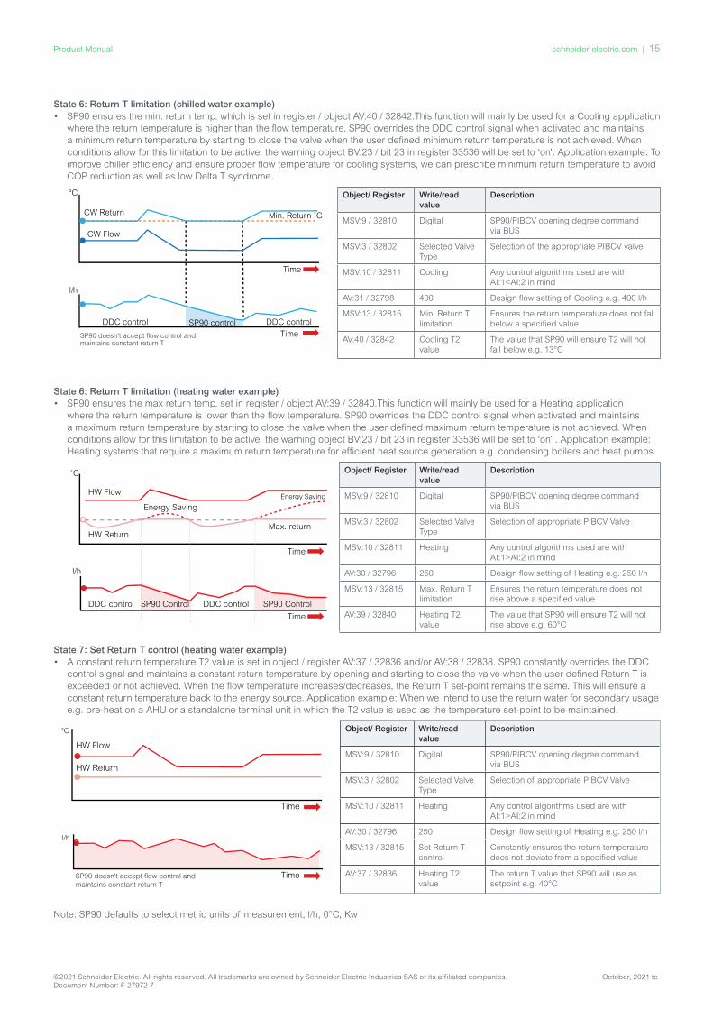
State 6: Return T limitation (chilled water example)• SP90 ensures the min. return temp. which is set in register / object AV:40 / 32842.This function will mainly be used for a Cooling application
where the return temperature is higher than the flow temperature. SP90 overrides the DDC control signal when activated and maintains a minimum return temperature by starting to close the valve when the user defined minimum return temperature is not achieved. When conditions allow for this limitation to be active, the warning object BV:23 / bit 23 in register 33536 will be set to ‘on’. Application example: To improve chiller efficiency and ensure proper flow temperature for cooling systems, we can prescribe minimum return temperature to avoid COP reduction as well as low Delta T syndrome.
Object/ Register Write/read value
Description
MSV:9 / 32810 Digital SP90/PIBCV opening degree command via BUS
MSV:3 / 32802 Selected Valve Type
Selection of the appropriate PIBCV valve.
MSV:10 / 32811 Cooling Any control algorithms used are with AI:1<AI:2 in mind
AV:31 / 32798 400 Design flow setting of Cooling e.g. 400 l/h
MSV:13 / 32815 Min. Return T limitation
Ensures the return temperature does not fall below a specified value
AV:40 / 32842 Cooling T2 value
The value that SP90 will ensure T2 will not fall below e.g. 13°C
State 6: Return T limitation (heating water example) • SP90 ensures the max return temp. set in register / object AV:39 / 32840.This function will mainly be used for a Heating application
where the return temperature is lower than the flow temperature. SP90 overrides the DDC control signal when activated and maintains a maximum return temperature by starting to close the valve when the user defined maximum return temperature is not achieved. When conditions allow for this limitation to be active, the warning object BV:23 / bit 23 in register 33536 will be set to ‘on’ . Application example: Heating systems that require a maximum return temperature for efficient heat source generation e.g. condensing boilers and heat pumps.
Object/ Register Write/read value
Description
MSV:9 / 32810 Digital SP90/PIBCV opening degree command via BUS
MSV:3 / 32802 Selected Valve Type
Selection of appropriate PIBCV Valve
MSV:10 / 32811 Heating Any control algorithms used are with AI:1>AI:2 in mind
AV:30 / 32796 250 Design flow setting of Heating e.g. 250 l/h
MSV:13 / 32815 Max. Return T limitation
Ensures the return temperature does not rise above a specified value
AV:39 / 32840 Heating T2 value
The value that SP90 will ensure T2 will not rise above e.g. 60°C
State 7: Set Return T control (heating water example)• A constant return temperature T2 value is set in object / register AV:37 / 32836 and/or AV:38 / 32838. SP90 constantly overrides the DDC
control signal and maintains a constant return temperature by opening and starting to close the valve when the user defined Return T is exceeded or not achieved. When the flow temperature increases/decreases, the Return T set-point remains the same. This will ensure a constant return temperature back to the energy source. Application example: When we intend to use the return water for secondary usage e.g. pre-heat on a AHU or a standalone terminal unit in which the T2 value is used as the temperature set-point to be maintained.
°C
l/h
HW Flow
SP90 doesn't accept flow control and maintains constant return T
HW Return
Time
Time
Object/ Register Write/read value
Description
MSV:9 / 32810 Digital SP90/PIBCV opening degree command via BUS
MSV:3 / 32802 Selected Valve Type
Selection of appropriate PIBCV Valve
MSV:10 / 32811 Heating Any control algorithms used are with AI:1>AI:2 in mind
AV:30 / 32796 250 Design flow setting of Heating e.g. 250 l/h
MSV:13 / 32815 Set Return T control
Constantly ensures the return temperature does not deviate from a specified value
AV:37 / 32836 Heating T2 value
The return T value that SP90 will use as setpoint e.g. 40°C
Note: SP90 defaults to select metric units of measurement, l/h, 0°C, Kw
°C
l/h
SP90 doesn't accept flow control and maintains constant return T
CW Flow
Min. Return ˚C
DDC controlDDC control SP90 control
Time
Time
CW Return
HW Flow
˚C
l/h
HW Return
DDC control DDC controlSP90 Control SP90 Control
Energy Saving
Max. return
Energy Saving
Time
Time
©2021 Schneider Electric. All rights reserved. All trademarks are owned by Schneider Electric Industries SAS or its affiliated companies. October, 2021 tcDocument Number: F-27972-7
schneider-electric.com | 15Product Manual
Specialist Application #3
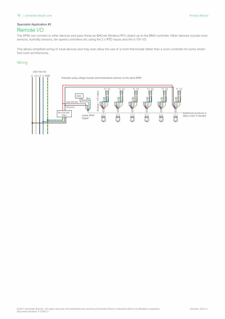
Remote I/OThe SP90 can connect to other devices and pass these as BACnet /Modbus RTU object up to the BMS controller. Other devices include room sensors, humidity sensors, fan speed controllers etc using the 2 x RTD inputs and the 0-10V I/O
This allows simplified wiring of local devices and may even allow the use of a room thermostat rather than a room controller for some simpli-fied room architectures.
Wiring
230/110V AC
L1 L2 L3 0 GND
24V AC/DCPSU
DDC
24V AC/DC
Ground
Cable SP90Digital
Additional products in daisy chain if needed
MB10
Example using voltage booster and temperature sensors on the same SP90
230/110V AC
L1 L2 L3 0 GND
24V DC/ACPSU
DDC
24V DC/AC
Ground
Cable SP90Digital
T1 T2 T1 T2 T1 T2 T1 T2 T1 T2
X
XX
X X
XX
X X
XX
X
XX
X
XXBusA
na
log
+ I
/O c
ab
le
X
T1 T2
X
XX
X
Additional products in daisy chain if needed
Cable SP90I/O
Power
24V AC/DC
Room controller
MB10-24T-FLEX
Yellow O-ring
X
XX
X
©2021 Schneider Electric. All rights reserved. All trademarks are owned by Schneider Electric Industries SAS or its affiliated companies. October, 2021 tcDocument Number: F-27972-7
16 | schneider-electric.com Product Manual
Quick SetupNote: see “BACnet Objects And Modbus RTU Registers” on page 18 for advanced configurations.
Valve SelectionOne of the first and most important selections to be made in the SP90 is the valve type, see P18; this defines the maximum flow rate the SP90 is controlling.
Selection of Units of Flow RateAfter selecting the valve type to be controlled by the actuator, it is important to determine the correct units of the flow rate settings. For Analogue Control this is set with object AV: 0 / 0x8000 Design Flow and AV:1 / 0x8200 Desired Flow.
Under Digital control, use AV: 30 / 0x801C for Heating and AV: 31 / 0x801E for cooling AV:0 /. The default settings are:• For AV:0 / 0x8000, AV:30 / 0x801C, AV31 / 0x801E Design Flow, the default setting is l/hr.• For AV:1 / 0x8200 Desired Flow, the default setting is %.• When the setup is finalized change MSV:0 / 0x8204 to 2 for calibration.
Setting the UnitsIf the default units value (l/h) for the object Design Flow Rate (AV:0), AV:30, AV:31 are not as desired, then the units may be changed by changing the present value of the object BV:4. Note that the value for the object Actual Flow Rate Feedback (AV:2) will also change.• BV:4 = 0 sets the units to L/hr• BV:4 = 1 sets the units to %
If the default units value (%) for the object Desired Flow Rate Input (AV:1) are not as desired, then the units may be changed by changing the present value of the object BV:5.• BV:5 = 0 sets the unit to L/hr• BV:5 = 1 sets the unit to %
Setting the Design Flow RateSet the designed maximum flow rate of the controlled system if the nominal flow of the valve does not correspond. The Design Flow Rate is set by changing the present value of AV:0 / AV:30 / AV:31.
Note: If the Design Flow Rate is set to more than the nominal flow value of the valve, the mechanical pre-setting on the valve should be set to maximum open (100% open is the factory default pre- setting).
Calibration of Actuator to the ValveAfter all basic settings have been set, calibrating the actuator to the valve can occur. The actuator will adjust itself to the exact valve used and all settings will be used correctly. A calibration is started by setting Actuator Mode and Special Features (MSV:0) to calibration. Possible set-tings of present value of MSV:0 are:• 1. Normal (Operation)• 2. Calibration• 3. Flush• 4. De-Air• 5. Alarm (Actuator will only go into this alarm state if it cannot control the motor or some major internal errors are present)
If, and when calibration has finished successfully, MSV:0 will change to the value 1 = Normal. This means the actuator is now ready to run in normal mode and is ready to control the flow through the valve.
Flushing a SystemActuator Mode and Special Features (MSV:0) has an option which allows the user to also used when a system shall be flushed. To start flush of the system set MSV:0 to 3. This will make the actuator open up the valve completely. Flush will end when:• MSV:0 is set back to 1 = Normal operation• Power cycled.• Or flush function times out after 1 hour.
When flush ends, it will under normal conditions, return to normal operation.
De-Air of a systemWith MSV:0 is it also possible to start the De-Air function in the actuator. This function will open an close the valve a number times to help get rid of air trapped in the hydronic system. Start De-Air by setting MSV:0 to 4. De-air will run until it ends and the state of the actuator will go back normal operation, MSV:0 = 1, Normal
Controlling the actuatorUnder normal operation of the actuator, where the flow through a valve is to be controlled, the object Desired Flow Rate Input (AV:1) is used. The default setting for the Desired Flow Rate unit is %. This is the most suitable setting as the controller does not need to know anything about the Design Flow Rate setting of the actuator. The output from the controller only has to be set up so it regulates from 0 to 100% of the Design Flow Rate (AV:1).• To change the flow rate through the valve, the present value of AV:1 is written to in the range 0 – 100 (%).• If the unit selected for AV:1 has to be l/hr, the desired flow rate through the valve must be written to in integers representing l/hr. An
example of this could be a controller writing values to the actuator in the range 0 til 450 l/hr for a DN15 valve.
©2021 Schneider Electric. All rights reserved. All trademarks are owned by Schneider Electric Industries SAS or its affiliated companies. October, 2021 tcDocument Number: F-27972-7
schneider-electric.com | 17Product Manual
BACnet Objects And Modbus RTU RegistersDesign flow rate setting
GeneralThere are simple BACnet and Modbus RTU settings that are essen-tial to the basic setup configuration of SP90 in order to communicate and control. These are contained in the BACnet objects or in decimal
format Modbus RTU registers.
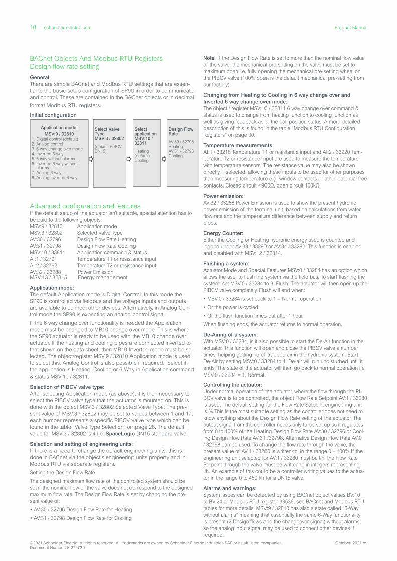
Initial configuration
Advanced configuration and featuresIf the default setup of the actuator isn’t suitable, special attention has to be paid to the following objects: MSV:9 / 32810 Application mode MSV:3 / 32802 Selected Valve Type AV:30 / 32796 Design Flow Rate HeatingAV:31 / 32798 Design Flow Rate CoolingMSV:10 / 33811 Application command & statusAI:1 / 32791 Temperature T1 or resistance inputAI:2 / 32792 Temperature T2 or resistance inputAV:32 / 33288 Power Emission MSV:13 / 32815 Energy management
Application mode:The default Application mode is Digital Control. In this mode the SP90 is controlled via fieldbus and the voltage inputs and outputs are available to connect other devices. Alternatively, in Analog Con-trol mode the SP90 is expecting an analog control signal.
If the 6 way change over functionality is needed the Application mode must be changed to MB10 change over mode. This is where the SP90 actuator is ready to be used with the MB10 change over actuator. If the heating and cooling pipes are connected inverted to that shown on the data sheet, then MB10 Inverted mode must be se-lected. The object/register MSV:9 / 32810 Application mode is used to select this. Analog Control is also possible if required. Select if the application is Heating, Cooling or 6-Way in Application command & status MSV:10 / 32811.
Selection of PIBCV valve type: After selecting Application mode (as above), it is then necessary to select the PIBCV valve type that the actuator is mounted on. This is done with the object MSV:3 / 32802 Selected Valve Type. The pre-sent value of MSV:3 / 32802 may be set to values between 1 and 17, each number represents a specific PIBCV valve type which can be found in the table “Valve Type Selection” on page 28. The default value for MSV:3 / 32802 is 4 i.e. SpaceLogic DN15 standard valve.
Selection and setting of engineering units:If there is a need to change the default engineering units, this is done in BACnet via the object’s engineering units property and in Modbus RTU via separate registers.
Setting the Design Flow Rate
The designed maximum flow rate of the controlled system should be set if the nominal flow of the valve does not correspond to the designed maximum flow rate. The Design Flow Rate is set by changing the pre-sent value of:
• AV:30 / 32796 Design Flow Rate for Heating
• AV:31 / 32798 Design Flow Rate for Cooling
Note: If the Design Flow Rate is set to more than the nominal flow value of the valve, the mechanical pre-setting on the valve must be set to maximum open i.e. fully opening the mechanical pre-setting wheel on the PIBCV valve (100% open is the default mechanical pre-setting from our factory).
Changing from Heating to Cooling in 6 way change over and Inverted 6 way change over mode:The object / register MSV:10 / 32811 6 way change over command & status is used to change from heating function to cooling function as well as giving feedback as to the ball position status. A more detailed description of this is found in the table “Modbus RTU Configuration Registers” on page 30.
Temperature measurements:AI:1 / 33218 Temperature T1 or resistance input and AI:2 / 33220 Tem-perature T2 or resistance input are used to measure the temperature with temperature sensors. The resistance value may also be shown directly if selected, allowing these inputs to be used for other purposes than measuring temperature e.g. window contacts or other potential free contacts. Closed circuit <900Ω, open circuit 100kΩ.
Power emission:AV:32 / 33288 Power Emission is used to show the present hydronic power emission of the terminal unit, based on calculations from water flow rate and the temperature difference between supply and return pipes.
Energy Counter:Either the Cooling or Heating hydronic energy used is counted and logged under AV:33 / 33290 or AV:34 / 33292. This function is enabled and disabled with MSV:12 / 32814.
Flushing a system:Actuator Mode and Special Features MSV:0 / 33284 has an option which allows the user to flush the system via the field bus. To start flushing the system, set MSV:0 / 33284 to 3, Flush. The actuator will then open up the PIBCV valve completely. Flush will end when:
• MSV:0 / 33284 is set back to 1 = Normal operation
• Or the power is cycled.
• Or the flush function times-out after 1 hour.
When flushing ends, the actuator returns to normal operation.
De-Airing of a system:With MSV:0 / 33284, is it also possible to start the De-Air function in the actuator. This function will open and close the PIBCV valve a number times, helping getting rid of trapped air in the hydronic system. Start De-Air by setting MSV:0 / 33284 to 4. De-air will run undisturbed until it ends. The state of the actuator will then go back to normal operation i.e. MSV:0 / 33284 = 1, Normal.
Controlling the actuator: Under normal operation of the actuator, where the flow through the PI-BCV valve is to be controlled, the object Flow Rate Setpoint AV:1 / 33280 is used. The default setting for the Flow Rate Setpoint engineering unit is %.This is the most suitable setting as the controller does not need to know anything about the Design Flow Rate setting of the actuator. The output signal from the controller needs only to be set up so it regulates from 0 to 100% of the Heating Design Flow Rate AV:30 / 32796 or Cool-ing Design Flow Rate AV:31 /32798. Alternative Design Flow Rate AV:0 / 32768 can be used. To change the flow rate through the valve, the present value of AV:1 / 33280 is written-to, in the range 0 – 100%.If the engineering unit selected for AV:1 / 33280 must be l/h, the Flow Rate Setpoint through the valve must be written-to in integers representing l/h. An example of this could be a controller writing values to the actua-tor in the range 0 to 450 l/h for a DN15 valve.
Alarms and warnings:System issues can be detected by using BACnet object values BV:10 to BV:24 or Modbus RTU register 33536, see BACnet and Modbus RTU tables for more details. MSV:9 / 32810 has also a state called “6-Way without alarms” meaning that essentially the same 6-Way functionality is present (2 Design flows and the changeover signal) without alarms, so the analog input signal may be used to connect other devices if required.
Application mode:
MSV:9 / 328101. Digital control (default)2. Analog control3. 6-way change over mode4. Inverted 6-way5. 6-way without alarms6. Inverted 6-way without
alarms7. Analog 6-way 8. Analog inverted 6-way
Select Valve Type MSV:3 / 32802
(default PIBCV DN15)
Select application MSV:10 / 32811
Heating (default) Cooling
Design Flow Rate
AV:30 / 32796 Heating AV:31 / 32798 Cooling
©2021 Schneider Electric. All rights reserved. All trademarks are owned by Schneider Electric Industries SAS or its affiliated companies. October, 2021 tcDocument Number: F-27972-7
18 | schneider-electric.com Product Manual
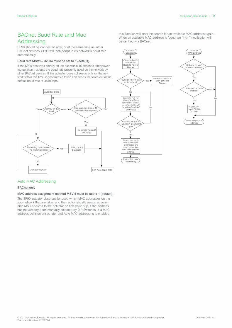
BACnet Baud Rate and Mac Addressing SP90 should be connected after, or at the same time as, other BACnet devices. SP90 will then adapt to it’s network’s baud rate automatically.
Baud rate MSV:6 / 32804 must be set to 1 (default).
If the SP90 observes activity on the bus within 45 seconds after power-ing up, then it adopts the baud rate presently used on the network by other BACnet devices. If the actuator does not see activity on the net-work within this time, it generates a token and sends the token out at the default baud rate of 38400bps.
Auto Baud rate
Activity on the bus?
No
Yes
Has a random time of 45 to 60 seconds elapsed?
Generate Token @ 38400bps
End Auto Baud rate
Yes
Receiving data correct - no framing errors?
Use current baudrate
Change baudrate
No
Yes No
Auto MAC Addressing
BACnet only
MAC address assignment method MSV:5 must be set to 1 (default).
The SP90 actuator observes for used which MAC addresses on the sub-network that are taken and then automatically assign an avail-able MAC address to the actuator on first power up, if the address has not already been manually selected by DIP Switches. If a MAC address collision arises later and Auto MAC addressing is enabled,
this function will start the search for an available MAC address again. When an available MAC address is found, an “I-Am” notification will be sent out via BACnet.
Auto MAC addressing
Observe Poll for Master and
Reply to Poll ForMaster
Found another master on the network
Set MAC address = 1Start generate
TokenNo
Yes
Listen to Poll For Master and Reply for Poll For Master.
Generate table with possible free MAC
addresses
Listened for Poll for Master in a complete
cycle ?
Select randomly one of free MAC addresses and
send out an lam with selected MAC
addres.
End of Auto MAC addressing.
Yes
Collision MAC address
Collision on MAC address detected?
No
Yes
Auto MAC address enabled?
Start Auto MAC Adress
function
End Collision MAC address
YesNo
No
©2021 Schneider Electric. All rights reserved. All trademarks are owned by Schneider Electric Industries SAS or its affiliated companies. October, 2021 tcDocument Number: F-27972-7
schneider-electric.com | 19Product Manual

BACnet Objects
Analogue ValuesIdent Object /
Parameter name
Unit Read/Write
Min Max Default Resolution Description Persistent Yes/No
AV:0 Design Flow Rate
%, L/hr, GPM
R/W Recommended 20% of nominal
flow
Setting Range Maximum from Valve table
Nominal value from the Valve table in L/hr
0.1 Recommended to use AV:30 for Heating and/or AV:31 for cooling Under 6 Way Change Over Control. Pre-set value for the Design Flow Rate when control signal is at 100%, if the Application mode is Analog or Digital control otherwise not used.Units can be changed via the object’s engineering units property and/or MSV:20.
Yes
AV:1 Flow Rate Setpoint
%, L/hr, GPM
R/W 0 100% or Design Flow value
100% 0.01 The Flow Rate Setpoint (max. flow rate) through the PIBCV valve.Units can be changed via the object’s engineering units property and/or MSV: 21.NOTE: For kW or kBTU/h to become active, MSV:13 Power Controller (state:3) must be chosen.
No
AV:2 Actual Flow Rate feedback
%, L/hr, GPM
R 0 If L/hr (GPM) is selected then the valve flow rate is set to the selected valve’s (MSV:3) maximum value. Otherwise 100%
L/hr or GPM depending on the selected valve
0.001 Flow rate indication based on the position of the Actuator stem.Units can be changed via the object’s engineering units property and/or MSV:22.This object is supported by COV.
No
AV:3 Control Fallback Time
Minutes R/W 0 60 10 1 Time before actuator reacts to a missing analog control signal. i.e. when MSV:9=1 Analog control and not receiving an analog control signal.
Yes
AV:4 Alpha Value na R/W 0.05 1.0 1.0 0.01 Value used for shaping the curve in Manual Defined Function (MDF) mode to fit the characteristic curve of a heat exchanger. Linear setting: MDF=1.See curve below table. If AV:1 is in L/hr in Digital mode, the alpha setting is ignored. See Alpha value diagram.
Yes
AV:5 Valve closing or opening time
Seconds R/W 18 700 na 1 The time the actuator needs to move from 0% to 100% of Design Flow Rate. Use with MSV:4.
Yes
AV:6 Rectified voltage measured by the actuator
Volts R 12 50 0 0.01 Rectified voltage which powers the actuator.Too low voltage: 16.1-17.5V.Too high voltage: 38.3-43.4V.
No
AV:7 MAC Address
na R/W 1 126 na 1 MAC Address used for BACnet communication.
Yes
AV:8 Temperature In the Actuator
°C, °F R -20 100 °C 0.5 Temperature measured inside the actuator.Units can be changed via the object’s engineering units property.
No
AV:9 Total Operating Hours
Hours R 0 MAX na 1 Total Operating Hours of the actuator. Yes
AV:10 Minutes since last power-up
Minutes R 0 MAX na 1 Minutes since the last power-up of the actuator.
No
AV:11 Minutes since last calibration
Minutes R 0 MAX na 1 Minutes since the last time the actuator was calibrated to an PIBCV valve.
Yes
AV:12 Minutes since fully closed
Minutes R 0 MAX na 1 Minutes since the last time the PIBCV valve was fully closed.
Yes
AV:13 Minutes Since Fully Opened
Minutes R 0 MAX na 1 Minutes since the last time the PIBCV valve was fully opened.
Yes
AV:14 Life time estimate
na R 0 MAX na 0.01 Calculated percentage of expended lifetime, At 100% the valve and actuator have reached the estimated minimum lifetime. Replacement of Valve and Actuator Recommended
Yes
©2021 Schneider Electric. All rights reserved. All trademarks are owned by Schneider Electric Industries SAS or its affiliated companies. October, 2021 tcDocument Number: F-27972-7
20 | schneider-electric.com Product Manual
Ident Object /Parameter name
Unit Read/Write
Min Max Default Resolution Description Persistent Yes/No
AV:15 Server Message Count
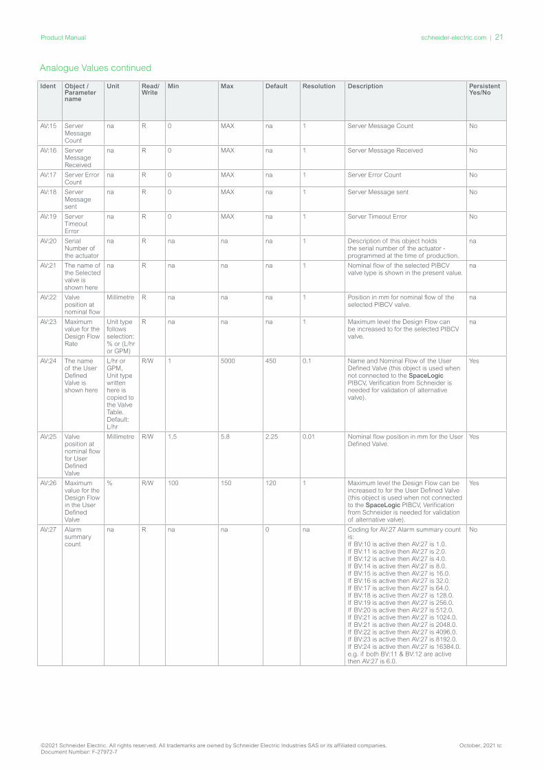
na R 0 MAX na 1 Server Message Count No
AV:16 Server Message Received
na R 0 MAX na 1 Server Message Received No
AV:17 Server Error Count
na R 0 MAX na 1 Server Error Count No
AV:18 Server Message sent
na R 0 MAX na 1 Server Message sent No
AV:19 Server Timeout Error
na R 0 MAX na 1 Server Timeout Error No
AV:20 Serial Number of the actuator
na R na na na 1 Description of this object holds the serial number of the actuator - programmed at the time of production.
na
AV:21 The name of the Selected valve is shown here
na R na na na 1 Nominal flow of the selected PIBCV valve type is shown in the present value.
na
AV:22 Valve position at nominal flow
Millimetre R na na na 1 Position in mm for nominal flow of the selected PIBCV valve.
na
AV:23 Maximum value for the Design Flow Rate
Unit type follows selection: % or (L/hr or GPM)
R na na na 1 Maximum level the Design Flow can be increased to for the selected PIBCV valve.
na
AV:24 The name of the User Defined Valve is shown here
L/hr or GPM, Unit type written here is copied to the Valve Table. Default: L/hr
R/W 1 5000 450 0.1 Name and Nominal Flow of the User Defined Valve (this object is used when not connected to the SpaceLogic PIBCV, Verification from Schneider is needed for validation of alternative valve).
Yes
AV:25 Valve position at nominal flow for User Defined Valve
Millimetre R/W 1.5 5.8 2.25 0.01 Nominal flow position in mm for the User Defined Valve.
Yes
AV:26 Maximum value for the Design Flow in the User Defined Valve
% R/W 100 150 120 1 Maximum level the Design Flow can be increased to for the User Defined Valve (this object is used when not connected to the SpaceLogic PIBCV, Verification from Schneider is needed for validation of alternative valve).
Yes
AV:27 Alarm summary count
na R na na 0 na Coding for AV:27 Alarm summary count is:If BV:10 is active then AV:27 is 1.0. If BV:11 is active then AV:27 is 2.0. If BV:12 is active then AV:27 is 4.0. If BV:14 is active then AV:27 is 8.0. If BV:15 is active then AV:27 is 16.0. If BV:16 is active then AV:27 is 32.0. If BV:17 is active then AV:27 is 64.0. If BV:18 is active then AV:27 is 128.0. If BV:19 is active then AV:27 is 256.0. If BV:20 is active then AV:27 is 512.0. If BV:21 is active then AV:27 is 1024.0. If BV:21 is active then AV:27 is 2048.0.If BV:22 is active then AV:27 is 4096.0.If BV:23 is active then AV:27 is 8192.0.If BV:24 is active then AV:27 is 16384.0.e.g. if both BV:11 & BV:12 are active then AV:27 is 6.0.
No
Analogue Values continued
©2021 Schneider Electric. All rights reserved. All trademarks are owned by Schneider Electric Industries SAS or its affiliated companies. October, 2021 tcDocument Number: F-27972-7
schneider-electric.com | 21Product Manual
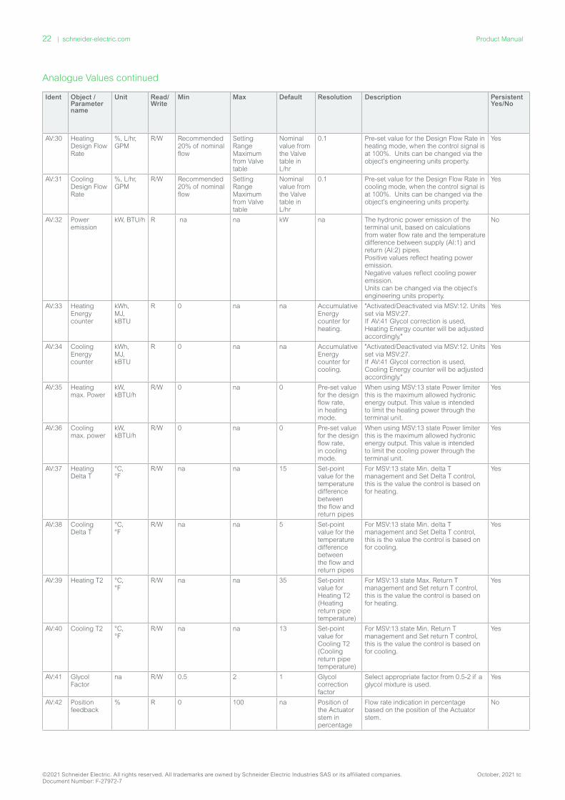
Ident Object /Parameter name
Unit Read/Write
Min Max Default Resolution Description Persistent Yes/No
AV:30 Heating Design Flow Rate
%, L/hr, GPM
R/W Recommended 20% of nominal flow
Setting Range Maximum from Valve table
Nominal value from the Valve table in L/hr
0.1 Pre-set value for the Design Flow Rate in heating mode, when the control signal is at 100%. Units can be changed via the object’s engineering units property.
Yes
AV:31 Cooling Design Flow Rate
%, L/hr, GPM
R/W Recommended 20% of nominal flow
Setting Range Maximum from Valve table
Nominal value from the Valve table in L/hr
0.1 Pre-set value for the Design Flow Rate in cooling mode, when the control signal is at 100%. Units can be changed via the object’s engineering units property.
Yes
AV:32 Power emission
kW, BTU/h R na na kW na The hydronic power emission of the terminal unit, based on calculations from water flow rate and the temperature difference between supply (AI:1) and return (AI:2) pipes.Positive values reflect heating power emission.Negative values reflect cooling power emission.Units can be changed via the object’s engineering units property.
No
AV:33 Heating Energy counter
kWh, MJ, kBTU
R 0 na na Accumulative Energy counter for heating.
"Activated/Deactivated via MSV:12. Units set via MSV:27. If AV:41 Glycol correction is used, Heating Energy counter will be adjusted accordingly."
Yes
AV:34 Cooling Energy counter
kWh, MJ, kBTU
R 0 na na Accumulative Energy counter for cooling.
"Activated/Deactivated via MSV:12. Units set via MSV:27. If AV:41 Glycol correction is used, Cooling Energy counter will be adjusted accordingly."
Yes
AV:35 Heating max. Power
kW, kBTU/h
R/W 0 na 0 Pre-set value for the design flow rate, in heating mode.
When using MSV:13 state Power limiter this is the maximum allowed hydronic energy output. This value is intended to limit the heating power through the terminal unit.
Yes
AV:36 Cooling max. power
kW, kBTU/h
R/W 0 na 0 Pre-set value for the design flow rate, in cooling mode.
When using MSV:13 state Power limiter this is the maximum allowed hydronic energy output. This value is intended to limit the cooling power through the terminal unit.
Yes
AV:37 Heating Delta T
°C, °F
R/W na na 15 Set-point value for the temperature difference between the flow and return pipes
For MSV:13 state Min. delta T management and Set Delta T control, this is the value the control is based on for heating.
Yes
AV:38 Cooling Delta T
°C, °F
R/W na na 5 Set-point value for the temperature difference between the flow and return pipes
For MSV:13 state Min. delta T management and Set Delta T control, this is the value the control is based on for cooling.
Yes
AV:39 Heating T2 °C, °F
R/W na na 35 Set-point value for Heating T2 (Heating return pipe temperature)
For MSV:13 state Max. Return T management and Set return T control, this is the value the control is based on for heating.
Yes
AV:40 Cooling T2 °C, °F
R/W na na 13 Set-point value for Cooling T2 (Cooling return pipe temperature)
For MSV:13 state Min. Return T management and Set return T control, this is the value the control is based on for cooling.
Yes
AV:41 Glycol Factor
na R/W 0.5 2 1 Glycol correction factor
Select appropriate factor from 0.5-2 if a glycol mixture is used.
Yes
AV:42 Position feedback
% R 0 100 na Position of the Actuator stem in percentage
Flow rate indication in percentage based on the position of the Actuator stem.
No
Analogue Values continued
©2021 Schneider Electric. All rights reserved. All trademarks are owned by Schneider Electric Industries SAS or its affiliated companies. October, 2021 tcDocument Number: F-27972-7
22 | schneider-electric.com Product Manual

Ident Object /Parameter name
Unit Read/Write
Min Max Default Resolution Description Persistent Yes/No
AV:47 Control-Gain P
No units R/W na na 7 Set proportional part for control
Sets the proportional part for control of the object MSV:13 Energy management functions.
Yes
AV:48 Control-Gain I
No units R/W na na 0.35 Set integral part for control
"Sets the integral part for control of the object MSV:13 Energy management functions. I parameter in sec. = (Pgain / Igain) * 2 sec. Default: 7/0.35 * 2sec. = 40 sec."
Yes
AV:50 Analog 6 way change over Heating point 100%
No units R/W 0 10 0 Signal point for Analog 6 way change over mode
The control signal for heating 100% open when MSV:9 = State 7 or 8. Overlaping heating and cooling control curves are not accepted.
Yes
AV:51 Analog 6 way change over Heating point 0%
No units R/W 0 10 3.3 Signal point for Analog 6 way change over mode
The control signal for heating 0% open when MSV:9 = State 7 or 8. Overlaping heating and cooling control curves are not accepted.
Yes
AV:52 Analog 6 way change over Cooling point 0%
No units R/W 0 10 6.7 Signal point for Analog 6 way change over mode
The control signal for cooling 0% open when MSV:9 = State 7 or 8. Overlaping heating and cooling control curves are not accepted.
Yes
AV:53 Analog 6 way change over Cooling point 100%
No units R/W 0 10 10 Signal point for Analog 6 way change over mode
The control signal for cooling 100% open when MSV:9 = State 7 or 8. Overlaping heating and cooling control curves are not accepted.
Yes
Note: In the following objects, the engineering units are linked e.g. if engineering units are changed in one object then it will be changes in all: AV:0, AV:30 and AV:31.
Analogue Values continued
AV:4 / 32772 Alpha Value Curve
BV:2 / 32786 Direct or Inverse operation mode
This Alpha Curve adjustment allows the SP90 to adapt to a specific model of heat exchanger curve to ensure a linear response of heat emission according to the valve position/flow rate.
©2021 Schneider Electric. All rights reserved. All trademarks are owned by Schneider Electric Industries SAS or its affiliated companies. October, 2021 tcDocument Number: F-27972-7
schneider-electric.com | 23Product Manual

Ident Object /Parameter name R
ead
/W
rite
State Text Default State
Description Persistent Yes/No
MSV:0 Actuator Mode and special features
R/W 1: Normal2: Calibration3: Flush 1)4: De-Air 2)5: Alarm
1: Normal Shows present mode of actuator. Calibration, flushing and de-air may be started from here.
Yes, except state 3,4 & 5
MSV:1 Analog Control signal type and range
R/W 1: 0-5 Vdc2: 0-10 Vdc3: 2-10 Vdc4: 5-10 Vdc5: 2-6 Vdc6: 6-10 Vdc7: 0-20 mA8: 4-20 mA
2: 0-10 Vdc Used to select the analog control signal input type and range. Yes
MSV:2 Missing Control Signal Fallback Action
R/W 1: No action2: CLOSE3: OPEN4: 50% of Design Flow
1: No action The action that the actuator will commence upon a missing analog control signal.
Yes
MSV:3 Selected Valve Type
R/W See table Valve Type Selection
4: PIBCV DN15 STD Flow
This is the PIBCV valve type that the actuator is set-up to control. Yes
MSV:4 Actuator Speed
R/W 1: 3 sec/mm2: 6 sec/mm3: 12 sec/mm4: 24 sec/mm5: Constant Time
4: 24 sec/mm
The amount of time the actuator takes to move 1mm or alternatively, a specified constant time function (see AV:5).The Constant Time value range is 18-700 seconds.
Yes
MSV:5 MAC Address assignment method
R/W 1: DIP Switch Settings or Auto Addressing2: User configuration over BACnet or Auto Addressing
1: DIP Switch Settings or Auto Ad-dressing
The MAC address selection method.If the MAC address is not set by DIP Switch, the actuator will automati-cally assign itself an available MAC address.
Yes
MSV:6 Baud Rate R/W 1: Auto Baud Rate Detection2: 9600 bps3: 19200 bps4: 38400 bps5: 57600 bps6: 76800 bps7: 115200 bps
1: Auto Baud Rate Detec-tion
Baud Rate used for BACnet communication. Yes
MSV:7 LED Control R/W 1: Normal LED mode2: Show only alarms3: All LED’s OFF4: Blink
1: Normal LED mode
The LED display options. Yes
MSV:8 Select field bus protocol
R/W 1: DIP switch2: BACnet3: Modbus RTU
1: DIP switch Selection of field bus protocol. See also the DIP Switch Settings sec-tion of the data sheet. When the protocol is changed, a power cycle is required to make the actuator adopt the newly selected protocol.
Yes
MSV:9 Application mode
R/W 1: Analog control2: Digital control3: 6 Way Change Over4: Inverted 6 Way Change Over5. 6 Way Change over with Alarms6: Inverted 6 Way Change Over without alarms 7: Analog 6 Way Change Over mode 8: Analog inverted 6 Way Change Over
3: 6 Way Change Over
Select the actuator application mode.State 1: Analog Control. Flow is controlled with an analog signal e.g. 0-10V.Design Flow Rate set via AV:30 Heating and/or AV:31 Cooling. Alterna-tive AV:0 can be used.State 2: Digital Control. AV:1 is used to control the flow. Design Flow Rate set via AV:30 Heating and/or AV:31 Cooling. Alternative AV:0 can be used.State 3: 6 way change over mode. AV:1 is used to control the flow. Heat-ing Design Flow Rate set via AV:30 and AV:31 for Cooling Design Flow Rate. Heating is connected to the 6 way change over valve to ports 5 & 6 and cooling to ports 1 & 4.State 4: Inverted 6 way change over mode. AV:1 is used to control the flow. Heating Design Flow Rate set via AV:30 and AV:31 for Cooling Design Flow Rate. Ports are inverted in relation to State 3.State 5: 6 way change over without alarms. AV:1 is used to control the flow. Heating Design Flow Rate set via AV:30 and AV:31 for Cooling De-sign Flow Rate. This state may be used if the Analog Input is required to be used other than 6 way change over feedback. Be aware that in this state the status for the 6 way change over valve is not shown.State 6: Inverted 6 way change over without alarms. AV:1 is used to control the flow. Heating Design Flow Rate set via AV:30 and AV:31 for Cooling Design Flow Rate. Ports are inverted in relation to State 3. This state may be used if the Analog Input is required to be used other than 6 way change over feedback. Be aware that in this state the status for the 6 way change over valve is not shown.State 7: Analog 6 way change over mode. The flow is controlled from the Room controller via the analog input signal. Heating Design Flow Rate set via AV:30 and AV:31 for Cooling Design Flow Rate. BV:2 is in this case used to switch the control signal. Be aware that in this state the status for the 6 way change over valve is not shown.State 8: Analog inverted 6 way change over mode. The flow is con-trolled from the Room controller via the analog input signal. Heating Design Flow Rate set via AV:30 and AV:31 for Cooling Design Flow Rate.In this state the Cooling and heating is connected opposite of state 7.When changing to this state the values in AV:50-53 are reversed.BV:2 is in this case used to switch the control signal. Be aware that in this state the status for the 6 way change over valve is not shown.
Yes
BACnet Objects and Multi-State Values
©2021 Schneider Electric. All rights reserved. All trademarks are owned by Schneider Electric Industries SAS or its affiliated companies. October, 2021 tcDocument Number: F-27972-7
24 | schneider-electric.com Product Manual

Ident Object /Parameter name R
ead
/W
rite
State Text Default State
Description Persistent Yes/No
MSV:10 Heating / Cooling and MB10 changeover command and status
R/W(1-4)
R(5-9)
1: Heating2: Cooling3: Shut Off 3) 4: Start exercise5: Moving towards Cooling6: Moving towards Heating7: Alarm8: Excercising
1: Heating States 1 and 2 are recommended to be set for the SP90 regardless of whether the MB10 changer over is used or not.
States 1 to 4 are especially relevant for the commands for the MB10 actuator.
States 5 to 8 are feedback from the MB10 actuator.
State 3, shut-off mode may only be used for maintenance and is only possible when the Flow Rate Setpoint is 0%. In Central ChangeOver applications, state 1 and 2 are used to command heating or cooling.
Yes
MSV:11 MB10 auto exercise
R/W 1: ON2: OFF
1: ON ON: MB10 will move the VB601R valve from current position to shut off and back again once per week to maintain free movement.
OFF: Exercising the valve should be handled by BMS.
Yes
MSV:12 Energy coun-ter activation
R/W 1: Off 2: On
1: Off Enable or disable energy counter Yes
MSV:13 Energy management
R/W 1: Not active Power Manager: 2: Power limitation 3: Power control Delta T Manager: 4: Min. Delta T limita-tion 5: Set Delta T control 6: Return T limitation 7: See Return T control
1: Not used Activate functions to optimize system performance. The Energy functions have a limitation at min. 10% of the design flow, except the function Power control that has a limitation at min. 2% of the design flow, regardless of the alpha value. If needed the PI values can be fine tuned in objects AV:47 and AV:48. State 1: Not active State 2: If power is above the set value in AV:35/36, SP90 will regulate to the specified limit AV:35 and/or AV:36. When this limitation is active, the warning BV:23 will be set to ‘on’. State 3: The flowrate through the valve is controlled by AV:1 in %, kW or kBTU/h (selected in MSV:26) and is based on the flowrate and tem-perature inputs calculation. State 4: If delta T value in AV:37 and/or AV:38 is exceeded, SP90 will begin to close the valve until the AV:37 and/or AV:38 values are reached. When this limitation is active, the warning BV:23 will be set to ‘on’. State 5: The constant delta T is set in AV:37 and/or AV:38 and SP90 will regulate within these limits. When this limitation is active, the warning BV:23 will be set to ‘on’. State 6: SP90 ensures the min. or max. return temp. T2 set in AV:39 & AV:40. In MSV:10 / 32811 Heating/cooling application must be selected. When this limitation is active, the warning BV:23 will be set to ‘on’. State 7: A constant T2 value is set in AV:39 and/or AV:40. SP90 will regulate to maintain these values constant.
Yes
MSV:14 Temperature Sensor type
R/W 1: NTC10k Type 2 2: NTC10k Type 3 3: PT1000
3: PT1000 Select the type of Temperature sensor connected. Yes
MSV:20 Units used to set Design Flow Rate
R/W 1: L/h 2: % 3: GPM
1: L/h Engineering Units used for the Design Flow AV:0, AV:30 and AV:31 Yes
MSV:21 Units used to set Flow Rate Setpoint
R/W 1: L/h 2: % 3: GPM 4: kW 5: kBTU/h
2: % Engineering Units used for the desired Flow AV:1. NOTE: If kW or kBTU/h chosen then MSV:13 Power Controller (state:3) also becomes active
Yes
MSV:22 Units used to set Actual Flow feed-back
R/W 1: L/h 2: % 3: GPM
1: L/h Engineering Units used for AV:2 Yes
MSV:23 Units used to set Tempera-ture
R/W 1: °C 2: °F
1: °C Engineering Units used for AV:8, AV:37-40 Yes
MSV:24 Units used to set T1
R/W 1: °C 2: °F 3: Ohm
1: °C Engineering Units used for AI:1 Yes
MSV:25 Units used to set T2
R/W 1: °C 2: °F 3: Ohm
1: °C Engineering Units used for AI:2 Yes
MSV:26 Units used to set Power
R/W 1: kW 2: kBTU/h
1: kW Engineering Units used for AV:32 Yes
MSV:27 Units used to set Energy counter
R/W 1: kWh 2: MJ 3: kBTU
1: kWh Engineering Units used for AV:33 and AV:34 Yes
1 - Opens the valve fully for one hour or until a new state is selected2 - Opens and closes the valve 5 times at maximum speed3 - A zero desired flow command (AV:1) closes the PIBCV, so that there is neither heating nor cooling. Do not use the 6 way change over maintenance shut-off function for this purpose.
The MB10 Change over valve shut-off function should only be used for maintenance and only when the water temperature in terminal unit is equal to ambient temperature or the terminal unit is not mounted. A water temperature change inside of a closed coil could result in rising pressure and possible damage of to the terminal unit.
BACnet Objects and Multi-State Values continued
©2021 Schneider Electric. All rights reserved. All trademarks are owned by Schneider Electric Industries SAS or its affiliated companies. October, 2021 tcDocument Number: F-27972-7
schneider-electric.com | 25Product Manual

Binary ValueIdent Object /
Parameter name
Rea
d/
Wri
te
Act
ive
Text
(1)
Inactive Text (0)
Default Description Persistent Yes/No
BV:2 Direct or Inverse operation Mode
R/W Inverse Direct Direct Selection between Direct and Inverse operation mode. See Direct/Inverse diagram. For the states Analog MB10 mode and Inverted Analog 6 way change over mode this object is used to switch the control signal.
Yes
BV:3 Analog feedback signal R/W Active Inactive Inactive By activating this feature, the analog output signal (AO:0) and the position of the valve opening become linked. The voltage output type and range is linked to the MSV:1 present value. This feature may be used for FCU fan control for example and is only made available when MSV:9Application Mode are in State 1: Analog control or State 2: Digital control.If BV:3 is active and the analog output signal (AO:0) is written to manually it must be relinquished i.e. write “NULL” to return to the original setting of BV:3.
Yes
BV:10 Warning: Temperature of the actuator is out of recommended range
R ON OFF na The Temperature inside the Actuator is out of the recommended range. No
BV:11 Alarm: No Control Signal R ON OFF na The actuator has detected that it has no analog control signal. NoBV:12 Alarm: Error during
ClosingR ON OFF na The actuator is unable to reach it’s intended closing position. Check for
valve blockages.No
BV:13 Warning: Pre-set Conflict R ON OFF na Conflict between the Mechanical PIBCV valve setting and the SP90’s. The mechanical valve setting must be 100% or above. The warning will also be activated if the Selected Valve Type has different stroke than the actu-ally valve used. Validated during calibration.
No
BV:14 Warning: Voltage of power supply is too high
R ON OFF na Voltage of power supply is measured to be too high.When the measured voltage exceeds 43.4V the alarm will be turned ON for too high voltage. When the measured voltage is once more below 38.3V, the alarm will be turned OFF.
No
BV:15 Warning: Voltage of power supply is too low
R ON OFF na Voltage of power supply is measured to be too low.When the measured voltage level drops below 16.5V the alarm will be activated for too low voltage. When the measured voltage level drops below 16.1V the motor will also be turned off. When the measured voltage is once more above 17.5V, the motor will be activated again.
No
BV:16 Alarm: Error during Calibration
R ON OFF na There was an error during calibration of the actuator. e.g. the actuator is not mounted onto the valve or the valve is seized.
No
BV:17 Warning: BACnet MAC-address Conflict was Detected
R ON OFF na Two or more devices on the same BACnet sub-network have the same MAC-address.
No
BV:18 Warning: Faults on the BACnet was detected
R ON OFF na Problems with communication on the network are detected. No
BV:19 Alarm: An internal Error has been detected
R ON OFF na Re-calibrate or power cycle actuator to reset - actuator replacement may be necessary
No
BV:20 Alarm: MB10 6-Way in manual override or MB10 unable to move
R ON OFF na MB10 Actuator is in manual override or is unable to reach position. No
BV:21 Alarm: MB10 6-Way actuator not connected or damaged
R ON OFF na The MB10 Actuator is not connected or is damaged. The SP90 will alarm if the temperature sensors register more than 1’ difference to that which is expected.
No
BV:22 Warning: Temp. sensors are missing or inter-changed
R ON OFF na Temp. sensors are missing or interchanged No
BV:23 Warning: Energy limitation is active
R ON OFF na Limitation is active. E.g. Power limitation, min. delta T or min/max return T management limitation.
No
BV:24 Warning: Energy manage-ment controller out of range
R ON OFF na Power, delta T or return T setpoint out of range or the setpoint can’t be achieved. Action: Check that setpoint is achievable with the given flow rates and temperatures.
No
Device Object
Selected important Device Object properties.
Property Value Read / Write Description Persistent
Yes/NoObject ID Instance Range: 0 to 4194302 R/W This property is normally called Device Instance number or Unique ID. Yes
Object-NameCombination of “SP90” + Type and Object ID
R/W Product name. Max. 25 characters. Yes
Firmware revision Current firmware version R BACnet software revision. YesApplication S/W version
Current Application SW version R Actuator Application Software version. Yes
LocationThis string is empty when actuator is new.
R/WFree text can be used to describe location etc. Max. 50 characters.
Yes
DescriptionSchneider Electric SP90 actuator with BACnet MS/TP
R/WProduct description. Max. 50 characters.
Yes
Segmentation-sup-ported
NO SEGMENTATION R Actuator does not support segmentation. Yes
Max-masterDefault: 127 Range: 0-127
R/WThe MAX_master setting in SP90 should be set to the number of de-vices (or the highest used MAC address) in the MS/TP sub network.
Yes
©2021 Schneider Electric. All rights reserved. All trademarks are owned by Schneider Electric Industries SAS or its affiliated companies. October, 2021 tcDocument Number: F-27972-7
26 | schneider-electric.com Product Manual

Analog InputIdent Object /
Parameter nameUnit Read /
WriteMin Max Default Description Persistent
Yes/No
AI:0 Voltage or Current on analog input
Volts, mA
R 0 10V20mA
Volts Voltage(V) or Current(mA) level on the analog control input,measured by the actuator. Units comes from MSV:1 Analog Con-trol signal type and range. This object is supported by COV.In 6 way change over and Inversed 6 way change over mode mA cannot be selected.
No
AI:1 T1 or resistance input
°C °F,Ohms
R -10°C10°F900Ω
120°C250°F10kΩ
°C Temperature/resistance measured from connected sensors. For Power emission AV:32, AI:1 is temperature on the flow pipe and AI:2 is temperature on the return pipe. When used as potential free contacts: Closed circuit <900Ω,open circuit 100kΩ. Recommended max. cable length 2m. Units can be changed via the object’s engineering units property or via objects MSV:24 and MSV:25. The upper temperature limit for NTC 10k Type 2 sensors is 90°C/194°F. The upper temperature limit for NTC sensor 10k Type 3 is 95°C/203°F. This object is supported by COV.
No
AI:2 T2 or resistance input
Analog Output
Ident Object / Parameter name Unit Read /
Write Min Max Default Description Persistent Yes/No
AO:0Voltage on analog output
Volt R/W 0 10 VoltOutput Voltage value in Digital and Analog mode MSV:9.Note: In MB10 Direct and inverse mode the present value is not writeable.
No
Notification ClassIdent Object / Parameter name Description
NC:0 Alarm Notifier, Subscribe here for alarms Subscribe devices for receiving alarms
NC:0 is an object where other BACnet devices can subscribe to be informed directly from this device if an alarm or warning is activated or cleared. A maximum of 4 devices can subscribe to this service. Subscribers of this object will be informed if any of the Warning or Alarms BV:10 to BV:21 is activated or cleared. When the notification class NC:0 is going to be used to notify about changes with status of Warnings and Alarms (BV:10 – BV21), is it necessary to subscribe for notifications for the entire day and week: From 00:00:00:00 to 23:59:59:99 and all 7 days of the week. This is because the actuator does not have a clock built in and will therefore not be able to handle notifications with respect to time.
Averaging
Ident Object /Parameter name Min. Value Average
value Max. Value Window Interval
Window Sample Description
AVO:0Average rectified voltage measured by the actuator
Updated according to actualmeasurements
1 Day 24Average of the rectified voltage that powers the actuator.
©2021 Schneider Electric. All rights reserved. All trademarks are owned by Schneider Electric Industries SAS or its affiliated companies. October, 2021 tcDocument Number: F-27972-7
schneider-electric.com | 27Product Manual

IndexPart Number
Nominal Flow (l/h) Valve stroke at nominal flow [mm] Setting Range Max. (%)Without T/P Plugs With T/P Plugs
1 VP228E-10BQLNT VP228E-10BQL 150
2.25 1202 VP228E-10BQSNT VP228E-10BQS 275
3 VP228E-15BQLNT VP228E-15BQL 275
4 VP228E-15BQSNT VP228E-15BQS 450
5 VP229E-15BQHNT 1135 4.0 110
6 VP228E-20BQSNT VP228E-20BQS 900 2.25 120
7 VP229E-20BQHNT 1700 4.0 110
8 VP229E-25BQSNT VP229E-25BQS 1700
4.5 1109 VP229E-25BQHNT 2724
10 VP229E-32BQSNT VP229E-32BQS 3200
11 VP229E-32BQHNT 4000
17 "User Defined Valve" NF VPNF SRM
Valve Type SelectionNOTE: Values for flow are valid for water applications. For glycol mixtures, please use correction factor. It is very important to select the correct valve the actuator is mounted on.
BACnet BIBBS ServicesService BIBBs Init/Exe
ReadProperty DS-RP-Bexe
WriteProperty DS-WP-B
Who-Is DM-DDB-A init
Who-Is DM-DDB-B exe
I-Am DM-DDB-B init
I-Am DM-DDB-Aexe
Who-Has DM-DOB-B
I-Have DM-DOB-B init
DeviceCommunicationControl DM-DCC-Bexe
ReinitializeDevice 1) DM-RD-B
ConfirmedEventNotification AE-N-I-Binit
UnconfirmedEventNotification AE-N-I-B
AcknowledgeAlarm AE-ACK-B
exe
GetEventInformation AE-INFO-B
GetAlarmSummary AE-ASUM-B
GetEnrollmentSummary AE-ESUM-B
AddListElement DM-LM-B
RemoveListElement DM-LM-B
ReadPropertyMultiple DS-RPM-B
WritePropertyMultiple DS-WPM-B
ChangeOfValue 2) DS-COV-B
Restart DM-R-B
1 - SP90 supports BACnet warm reset (power cycle) and Cold reset (factory reset). Note that after Cold/factory reset a calibration will be automatically performed and all settings will be reverted to factory settings.2 - COV is implemented for the following: Analog Inputs AI:0, AI:1 and AI:2, and for the following Analog Values AV:2 and AV:27.
©2021 Schneider Electric. All rights reserved. All trademarks are owned by Schneider Electric Industries SAS or its affiliated companies. October, 2021 tcDocument Number: F-27972-7
28 | schneider-electric.com Product Manual

DIP Switch SettingsBACnet: Auto MAC addressing is default. For manual MAC addressing using DIP Switches, MSV:5 must be set to: DIP
Switch Settings.
Modbus RTU: Manual MAC addressing is default. Automatic addressing is not available for Modbus RTU. However, if an address has been assigned in BACnet before switching to Modbus RTU, the address will also be used in Modbus RTU if the DIP Switched are left in the default positions.
DIP Switch Configuration Name OFF state (default) ON state
1.1 2 3 4 5 6 7 8 9 10
ONOFF
BACnet address / Modbus RTU unit ID bit 0
Logic ‘0’ Logic ‘1’
2.1 2 3 4 5 6 7 8 9 10
ONOFF
BACnet address / Modbus RTU unit ID bit 1
3.1 2 3 4 5 6 7 8 9 10
ONOFF
BACnet address / Modbus RTU unit ID bit 2
4.1 2 3 4 5 6 7 8 9 10
ONOFF
BACnet address / Modbus RTU unit ID bit 3
5.1 2 3 4 5 6 7 8 9 10
ONOFF
BACnet address / Modbus RTU unit ID bit 4
6.1 2 3 4 5 6 7 8 9 10
ONOFF
BACnet address / Modbus RTU unit ID bit 5
7.1 2 3 4 5 6 7 8 9 10
ONOFF
BACnet address / Modbus RTU unit ID bit 6
8.1 2 3 4 5 6 7 8 9 10
ONOFF
Termination resistor (120Ω)No
terminationTermination resistor enabled
1)
9.1 2 3 4 5 6 7 8 9 10
ONOFF
Not used
10.1 2 3 4 5 6 7 8 9 10
ONOFF
– BACnet MS/TP 2) Modbus RTU 2)
1 - The actuator possesses a resistor that can be activated in the last actuator on the bus for correct termination of the bus.2 - When protocol is changed on DIP Switch no. 10, a power cycle is required to make the actuator adopt the newly selected protocol.
Manual Addressing
BACnet MAC address/Modbus RTU Slave ID is set by DIP switch 1 to 7.
0 = OFF, 1 = ON
DIP switch
1, 2, 3, 4DIP switch
5,6,70000 1000 0100 1100 0010 1010 0110 1110 0001 1001 0101 1101 0011 1011 0111 1111
0* 1 2 3 4 5 6 7 8 9 10 11 12 13 14 15 000
16 17 18 19 20 21 22 23 24 25 26 27 28 29 30 31 100
32 33 34 35 36 37 38 39 40 41 42 43 44 45 46 47 010
48 49 50 51 52 53 54 55 56 57 58 59 60 61 62 63 110
64 65 66 67 68 69 70 71 72 73 74 75 76 77 78 79 001
80 81 82 83 84 85 86 87 88 89 90 91 92 93 94 95 101
96 97 98 99 100 101 102 103 104 105 106 107 108 109 110 111 011
112 113 114 115 116 117 118 119 120 121 122 123 124 125 126 127* 111
* Addresses no. 0 and 127 must not be used.
Example
Setting MAC address to 37: DIP 1 DIP 2 DIP 3 DIP 4 DIP 5 DIP 6 DIP 7
ON OFF ON OFF OFF ON OFF
©2021 Schneider Electric. All rights reserved. All trademarks are owned by Schneider Electric Industries SAS or its affiliated companies. October, 2021 tcDocument Number: F-27972-7
schneider-electric.com | 29Product Manual

Modbus RTU Configuration Registers (Table 1)Modbus/ register
Read/Write
Modbus Function
Modbus Data Type
Object / Param-eter name
Description Default Unit Description of usage Persistent Yes/No
0x8000 32768
R/W 3,4 & 16
FLOAT Design Flow Rate
Note: It is recommended to use 32796 for heating and/or 32798 for cooling. Pre-set value for the Design Flow Rate when control signal is at 100%. Unit follows 32787
Nominal value from the Valve table in L/hr
%, L/hr, GPM
Design Flow Rate in Litres per hour or in percent i.e. 150 ..450 correspond to 150 …450 L/hr , or 20 … 100 correspond to 20 … 100%. The maximum setting range is depending on the selected valve type. See Valve Type Selection.
Yes
0x8002 32770
R/W 3,4 & 6 WORD Control Fall-back Time
Time before actuator reacts to a missing analog control signal
10 Minutes Control Fallback Time in min-utes, i.e.. 0 … 60 correspond to 0 … 60 minutes
Yes
0x8004 32772
R/W 3,4 & 16 FLOAT Alpha Value Value used for shaping the curve in Manual Defined Function (MDF) mode to fit the characteristics curve of a heat exchanger. If 33280 is in L/hr in Digital mode, the alpha setting is ignored.
1.0 na Alpha Value curve, i.e. 0.05 … 1.00 correspond to 0.05 … 1.00. Alpha = 1.00 is linear. Alpha = 0.2 is equal to the LOG function. See Alpha value diagram.
Yes
0x8006 32774
R/W 3,4 & 16 WORD Valve closing or opening time
The time the actuator needs to move from 0% to 100% of Design Flow Rate. Use with 32803.
na Sec-onds
Valve closing or opening time in seconds i.e.. 18 … 700 correspond to 18 … 700 seconds
Yes
0x8008 32776
R 3,4 & 6 FLOAT Nominal Flow of the user defined valve
Name and Nominal Flow of the User Defined Valve. This object is only used if the SP90 is not used with the SpaceLogic PIBCV. Extreme care should be taken if the SP90 is not used on the Schneider Electric VP228E or VP229E valves.
na L/hr Nominal flow e.g. in Litres per hour i.e. 0 … 450 cor-respond to 0 … 450 L/hr
Yes
0x800A 32778
R 3 & 4 FLOAT Valve position at nominal flow for User Defined Valve
Nominal flow position in mm for the User Defined Valve. This object is only used if the SP90 is not used with the SpaceLogic PIBCV. Extreme care should be taken if the SP90 is not used on the Schneider Electric VP228E or VP229E valves.
4.00 Millime-tre
Valve position for nominal flow in millimetre, i.e. 0.5 … 5.8 correspond to 0.5 … 5.8 millimetre
Yes
0x800C 32780
R/W 3,4 & 6 FLOAT Maximum value for the Design Flow in the User Defined Valve
Maximum level the Design Flow can be increased to for the User Defined Valve This object is only used if the SP90 is not used with the SpaceLogic PIBCV. Extreme care should be taken if the SP90 is not used on the Schneider Electric VP228E or VP229E valves.
100 Unit type follows 32787 selec-tion: % or (L/ hr or GPM)
i.e. 0 ..150 correspond to 0…150 %
Yes
0x8012 32786
R/W 3,4 & 6 WORD Direct or In-verse operation Mode
Selection between Direct and Inverse operation mode. See Direct/Inverse diagram.
0: Direct 0: Direct 1: Inverse
Selection between Direct and Inverse operation mode. See Direct/Inverse diagram.
Yes
0x8013 32787
R/W 3,4 & 6 WORD Units used to set and display the Design Flow
Units used to set and display the Design Flow Rate.
0: L/hr 0: L/hr 1: % 2: GPM
Units used to set and display the Design Flow.
Yes
0x8014 32788
R/W 3,4 & 6 WORD Units used to set and display Flow Rate Setpoint
Units used to set and display Flow Rate Setpoint
1: % 0: L/hr 1: % 2: GPM 3: kW 4: kBTU/h
Engineering units used to set and display the desired Flow 33280. Note if kW or kBTU/h is chosen then 32815 Power Controller (State 3) also becomes active
Yes
0x8015 32789
R/W 3,4 & 6 WORD Units used to set and display the Actual Flow Rate feedback
Units used to set and display the Actual Flow Rate feedback
0: L/hr 0: L/hr 1: % 2: GPM
Engineering units used for 33282
Yes
0x8016 32790
R/W 3,4 & 6 WORD Units used to set temperature
Select between °C or °F to set and display temperature
0: °C 0: °C 1: °F
Engineering units for 33796, 32836, 32838, 32840, 32842
Yes
0x8017 32791
R/W 3,4 & 6 WORD Units used to set and display T1
Units used to read the tem-perature or resistance value.
0: °C 0: °C 1: °F 2: Ohm
Engineering units used for 33218
Yes
©2021 Schneider Electric. All rights reserved. All trademarks are owned by Schneider Electric Industries SAS or its affiliated companies. October, 2021 tcDocument Number: F-27972-7
30 | schneider-electric.com Product Manual
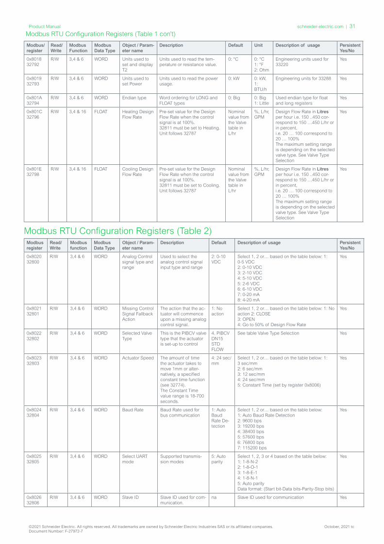
Modbus RTU Configuration Registers (Table 1 con’t)
Modbus/ register
Read/Write
Modbus Function
Modbus Data Type
Object / Param-eter name
Description Default Unit Description of usage Persistent Yes/No
0x8018 32792
R/W 3,4 & 6 WORD Units used to set and display T2
Units used to read the tem-perature or resistance value.
0: °C 0: °C 1: °F 2: Ohm
Engineering units used for 33220
Yes
0x8019 32793
R/W 3,4 & 6 WORD Units used to set Power
Units used to read the power usage.
0: kW 0: kW, 1: BTU/h
Engineering units for 33288 Yes
0x801A 32794
R/W 3,4 & 6 WORD Endian type Word ordering for LONG and FLOAT types
0: Big 0: Big 1: Little
Used endian type for float and long registers
Yes
0x801C 32796
R/W 3,4 & 16 FLOAT Heating Design Flow Rate
Pre-set value for the Design Flow Rate when the control signal is at 100%. 32811 must be set to Heating. Unit follows 32787
Nominal value from the Valve table in L/hr
%, L/hr, GPM
Design Flow Rate in Litres per hour i.e. 150 ..450 cor-respond to 150 …450 L/hr or in percent, i.e. 20 … 100 correspond to 20 … 100% The maximum setting range is depending on the selected valve type. See Valve Type Selection
Yes
0x801E 32798
R/W 3,4 & 16 FLOAT Cooling Design Flow Rate
Pre-set value for the Design Flow Rate when the control signal is at 100%. 32811 must be set to Cooling. Unit follows 32787
Nominal value from the Valve table in L/hr
%, L/hr, GPM
Design Flow Rate in Litres per hour i.e. 150 ..450 cor-respond to 150 …450 L/hr or in percent, i.e. 20 … 100 correspond to 20 … 100% The maximum setting range is depending on the selected valve type. See Valve Type Selection
Yes
Modbus register
Read/ Write
Modbus function
Modbus Data Type
Object / Param-eter name
Description Default Description of usage Persistent Yes/No
0x8020 32800
R/W 3,4 & 6 WORD Analog Control signal type and range
Used to select the analog control signal input type and range
2: 0-10 VDC
Select 1, 2 or… based on the table below: 1: 0-5 VDC 2: 0-10 VDC 3: 2-10 VDC 4: 5-10 VDC 5: 2-6 VDC 6: 6-10 VDC 7: 0-20 mA 8: 4-20 mA
Yes
0x8021 32801
R/W 3,4 & 6 WORD Missing Control Signal Fallback Action
The action that the ac- tuator will commence upon a missing analog control signal.
1: No action
Select 1, 2 or… based on the table below: 1: No action 2: CLOSE 3: OPEN 4: Go to 50% of Design Flow Rate
Yes
0x8022 32802
R/W 3,4 & 6 WORD Selected Valve Type
This is the PIBCV valve type that the actuator is set-up to control
4. PIBCV DN15 STD FLOW
See table Valve Type Selection Yes
0x8023 32803
R/W 3,4 & 6 WORD Actuator Speed The amount of time the actuator takes to move 1mm or alter-natively, a specified constant time function (see 32774). The Constant Time value range is 18-700 seconds.
4: 24 sec/mm
Select 1, 2 or… based on the table below: 1: 3 sec/mm 2: 6 sec/mm 3: 12 sec/mm 4: 24 sec/mm 5: Constant Time (set by register 0x8006)
Yes
0x8024 32804
R/W 3,4 & 6 WORD Baud Rate Baud Rate used for bus communication
1: Auto Baud Rate De-tection
Select 1, 2 or… based on the table below: 1: Auto Baud Rate Detection 2: 9600 bps 3: 19200 bps 4: 38400 bps 5: 57600 bps 6: 76800 bps 7: 115200 bps
Yes
0x8025 32805
R/W 3,4 & 6 WORD Select UART mode
Supported transmis-sion modes
5: Auto parity
Select 1, 2, 3 or 4 based on the table below: 1: 1-8-N-2 2: 1-8-O-1 3: 1-8-E-1 4: 1-8-N-1 5: Auto parity Data format: (Start bit-Data bits-Parity-Stop bits)
Yes
0x8026 32806
R/W 3,4 & 6 WORD Slave ID Slave ID used for com-munication.
na Slave ID used for communication Yes
Modbus RTU Configuration Registers (Table 2)
©2021 Schneider Electric. All rights reserved. All trademarks are owned by Schneider Electric Industries SAS or its affiliated companies. October, 2021 tcDocument Number: F-27972-7
schneider-electric.com | 31Product Manual

Modbus register
Read/ Write
Modbus function
Modbus Data Type
Object / Param-eter name
Description Default Description of usage Persistent Yes/No
0x8027 32807
R/W 3,4 & 6 WORD Slave ID asign-ment method
The Slave ID address selection method.
1: DIP Switch Settings
1: DIP Switch Settings 2: User configuration over Modbus If DIP Switches are in an invalid position the actuator will automatically check if a Slave ID is present in the User Configuration.
Yes
0x8028 32808
R/W 3,4 & 6 WORD BUS protocol Select field bus proto-col to be used. See also the DIP Switch Settings sec-tion of the product manual. When the protocol is changed, a power cycle is re-quired to make the ac-tuator adopt the newly selected protocol.
1: DIP switch
Select 1, 2 or 3 based on the table below: 1: DIP switch 2: BACnet 3: Modbus
Yes
0x8029 32809
R/W 3,4 & 6 WORD LED Control Used to select the LED display required.
1: Normal LED mode
Select 1, 2 or… based on the table below: 1: Normal LED mode 2: Show alarms only 3: All LED’s OFF 4: Blink (can be used to locate the actuator)
Yes
0x802A 32810
R/W 3,4 & 6 WORD Application mode
1: Analog control 2: Digital control 3: 6 way change over mode 3: 6 way change over mode 4: Inverted 6 way change over mode 5: 6 way change over without alarms 6: Inverted 6 way change over without alarms 7: Analog 6 way change over mode 8: Analog inverted 6 way change over mode
2: Digital Select the actuator application mode. State 1: Analog Control. Flow is controlled with an analog signal e.g. 0-10V. Design Flow Rate set via register 32796 Heating and/or 32798 Cooling. Alternative 32738 can be used. State 2: Digital Control. Register 33280 is used to control the flow. Design Flow Rate set via register 32796 Heating and/or 32798 Cooling. Alternative 32738 can be used. State 3: 6 way change over mode. Register 33280 is used to control the flow. Heating Design Flow Rate set via register 32796 and register 32798 for Cooling Design Flow Rate. Heating is connected to the 6 way change over valve to ports 5 & 6 and cooling to ports 1 & 4. State 4: Inverted mode. Register 33280 is used to control the flow. Heating Design Flow Rate set via register 32796 and 32798 for Cooling Design Flow Rate. Ports are inverted in relation to State 3. State 5: without alarms. Register 33280 is used to control the flow. Heating Design Flow Rate set via register 32796 and 32798 for Cooling Design Flow Rate. This state may be used if the Analog Input is required to be used other than feedback. Be aware that in this state the status for the valve is not shown. State 6: Inverted without alarms. Register 33280 is used to control the flow. Heating De-sign Flow Rate set via register 32796 and 32798 for Cooling Design Flow Rate. Ports are inverted in relation to State 3. This state may be used if the Analog Input is required to be used other than feedback. Be aware that in this state the status for the valve is not shown. State 7: Analog mode. The flow is controlled from the Room controller via the analog input signal. Heating Design Flow Rate set via register 32796 and 32798 for Cooling Design Flow Rate. Register 32786 is in this case used to switch the control signal. Be aware that in this state the status for the valve is not shown. State 8: Analog inverted mode. The flow is controlled from the Room controller via the analog input signal. Heating De- sign Flow Rate set via register 32796 and 32798 for Cooling Design Flow Rate. In this state the Cooling and heating is connected opposite of state 7. When changing to this state the values in register 32848-32854 are reversed. Register 32786 is in this case used to switch the control signal. Be aware that in this state the status for the MB10 change over valve is not shown.
Yes
Modbus RTU Configuration Registers (Table 2 con’t)
©2021 Schneider Electric. All rights reserved. All trademarks are owned by Schneider Electric Industries SAS or its affiliated companies. October, 2021 tcDocument Number: F-27972-7
32 | schneider-electric.com Product Manual

Modbus register
Read/ Write
Modbus function
Modbus Data Type
Object / Param-eter name
Description Default Description of usage Persistent Yes/No
0x802B 32811
R/W 3,4 & 6 WORD Application command & status
1: Heating 2: Cooling 3: Shut Off 1) 4: Start exercise 5: Moving towards Cooling 6: Moving to- wards Heating 7: Alarm 8: Exercising
1: Heating States 1 to 4 are commands for the MB10 Change Over Actuator and impact Energy management Application register 32815. States 5 to 8 are feedback from the MB10 Change Over Actuator State 3, shut-off mode may only be used for maintenance and is only possible when the Flow Rate Set- point is 0%. In Central Change Over applications, state 1 and 2 are used to command heating or cooling.
Yes
0x802C 32812
R/W 3,4 & 6 WORD MB10 Auto exercise
1: ON 2: OFF
1: ON 1: ON: The MB10 will move the VB601R from current position to shut off and back again once per week to maintain free movement. 2: OFF: Exercising the valve should be handled by BMS.
Yes
0x802E 32814
R/W 3,4 & 6 WORD Energy counter activation
1: Off 2: On
1: Off Enable or disable energy counter Yes
0x802F 32815
R/W 3,4 & 6 WORD Enery Manage-ment
1: Not active Power Manager: 2: Power limitation 3: Power control Delta T Manager: 4: Min. Delta T limita-tion 5: Set Delta T control 6: Return T limitation 7: Set Return T control
1. Not used
Activate functions to optimize system perfor-mance. The Energy functions have a limitation at min. 10% of the design flow, except the func-tion Power control that has a limitation at min. 2% of the design flow, regardless of the alpha value. If needed the PI values can be fine tuned in register 32856 and 32858. State 1: Not active. State 2: If power is above the set value in regis-ter 32832 or register 32834, SP90 will regulate to the specified limit register 32832 and/or 32834. When this limitation is active, the warn-ing bit 23 in register 33536 will be set to ‘on’. State 3: The flowrate through the valve is con-trolled by register 33280 in %, kW or kBTU/h (selected in 32793) and is based on the flowrate and temperature inputs. State 4: If delta T value in register 32836 and/or 32838 is exceeded, SP90 will begin to close the valve until the register 32836 and/or 32838 values are reached. When this limitation is ac-tive, the warning bit 23 in register 33536 will be set to ‘on’. State 5: The constant delta T is set in register 32836 and/or 32838 and SP90 will regulate within these limits. When this limitation is active, the warning bit 23 in register 33536 will be set to ‘on’. State 6: SP90 ensures the min. or max. return temp. T2 set in 32840 & 32842. In register 32811 Heating/cooling application must be se-lected. When this limitation is active, the warn-ing bit 23 in register 33536 will be set to ‘on’. State 7: A constant T2 value is set in 32840 and/or 32842. SP90 will regulate to maintain these values constant.
Yes
0x8030 32816
R/W 3,4 & 6 WORD Units used to set Energy counter
Units used to set energy counter
0: kWh Engineering Units used for 33290 & 33292. Units: 0: kWh, 1: MJ, 2: kBTU
Yes
0x8031 32817
R/W 3,4 & 6 WORD Analog feed-back signal
Set analog output according to valve position
0: Inactive 0: Inactive 1: Active - By activating this feature, the analog output signal (33286) and the position of the valve opening become linked. The voltage output type and range is linked to the 32800 present value. This feature may be used for FCU fan control for example and is only made available when 32810 Application Mode are in State 1: Analog control or State 2: Digital control. If 32817 is active and the analog output signal (33286 ) must be written to manually, it is neces-sary to change the setting of 32817 to inactive.
Yes
0x8033 32819
R/W 3,4 & 6 WORD Temperature sensor type
Select the type of Temperature sensor connected.
3: PT1000 Select temperature sensor type: 1: NTC10k Type 2 2: NTC10k Type 3 3: PT1000
Yes
0x804C 32844
R/W 3,4 & 16 FLOAT Glycol Factor Glycol correction factor
1 Select appropriate factor from 0.5-2 if a glycol mixture is used.
Yes
0x8050 32848
R/W 3,4 & 16 FLOAT Analog 6 way change over Heating point 100%
Signal point for Analog mode
0 The control signal for heating 100% open when register 32810 = State 7 or 8. Overlaping heating and cooling control curves are not accepted.
Yes
©2021 Schneider Electric. All rights reserved. All trademarks are owned by Schneider Electric Industries SAS or its affiliated companies. October, 2021 tcDocument Number: F-27972-7
schneider-electric.com | 33Product Manual
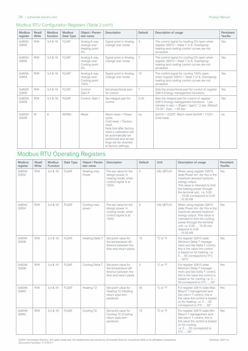
Modbus register
Read/ Write
Modbus function
Modbus Data Type
Object / Param-eter name
Description Default Description of usage Persistent Yes/No
0x8052 32850
R/W 3,4 & 16 FLOAT Analog 6 way change over Heating point 0%
Signal point in Analog change over mode
3 The control signal for heating 0% open when register 32810 = State 7 or 8. Overlaping heating and cooling control curves are not accepted.
Yes
0x8054 32852
R/W 3,4 & 16 FLOAT Analog 6 way change over Cooling point 0%
Signal point in Analog change over mode
7 The control signal for cooling 0% open when register 32810 = State 7 or 8. Overlaping heating and cooling control curves are not accepted.
Yes
0x8056 32854
R/W 3,4 & 16 FLOAT Analog 6 way change over Cooling point 100%
Signal point in Analog change over mode
10 The control signal for cooling 100% open when register 32810 = State 7 or 8. Overlaping heating and cooling control curves are not accepted.
Yes
0x8058 32856
R/W 3,4 & 16 FLOAT Control- Gain P
Set proportional part for control
7 Sets the proportional part for control of register 32815 Energy management functions.
Yes
0x805A 32858
R/W 3,4 & 16 FLOAT Control- Gain I Set integral part for control
0.35 Sets the integral part for control of register 32815 Energy management functions. I pa-rameter in sec. = (Pgain / Igain) * 2 sec. Default: 7/0.35 * 2sec. = 40 sec.
Yes
0x8500 34048
W 6 WORD Reset Warm reset = Power cycle. Cold reset = Factory reset. Note that after factory reset a calibration will be automatically be performed and all set-tings will be reverted to factory settings.
na 0x5741 / 22337: Warm reset 0x434F / 17231: Cold reset.
na
Modbus RTU Operating RegistersModbus register
Read/ Write
Modbus Function
Data Type Object / Param-eter name
Description Default Unit Description of usage Persistent Yes/No
0x8040 32832
R/W 3,4 & 16 FLOAT Heating max. Power
Pre-set value for the design power, in heating mode, when control signal is at 100%
0 kW, kBTU/h When using register 32815 state Power lim- iter this is the maximum allowed hydronic energy output. This value is intended to limit the heating power through the terminal unit. i.e. 0.00 … 10.00 correspond to 0.00 …10.00 kW
Yes
0x8042 32834
R/W 3,4 & 16 FLOAT Cooling max. power
Pre-set value for the design power, in cooling mode, when control signal is at 100%
0 kW, kBTU/h When using register 32815 state Power lim- iter this is the maximum allowed hydronic energy output. This value is intended to limit the cooling power through the terminal unit. i.e. 0.00 … 10.00 cor-respond to 0.00 …10.00 kW
Yes
0x8044 32836
R/W 3,4 & 16 FLOAT Heating Delta T Set-point value for the temperature dif-ference between the flow and return pipes
15 °C or °F For register 32815 state Minimum Delta T manage-ment and Set Delta T control, this is the value the control is based on for heating. i.e. 5 … 50 correspond to 5°C … 50°C
Yes
0x8046 32838
R/W 3,4 & 16 FLOAT Cooling Delta T Set-point value for the temperature dif-ference between the flow and return pipes
5 °C or °F For register 32815 state Minimum Delta T manage-ment and Set Delta T control, this is the value the control is based on for cooling. i.e. 5 … 50 correspond to 5°C … 50°
Yes
0x8048 32840
R/W 3,4 & 16 FLOAT Heating T2 Set-point value for Heating T2 (Heating return pipe tem- perature)
35 °C or °F For register 32815 state Max. Return T management and Set return T control, this is the value the control is based on for heating. i.e. 5 … 50 correspond to 5°C … 50°
Yes
0x804A 32842
R/W 3,4 & 16 FLOAT Cooling T2 Set-point value for Cooling T2 (Cooling return pipe tem- perature)
13 °C or °F For register 32815 state Min. Return T management and Set return T control, this is the value the control is based on for cooling. i.e. 5 … 50 correspond to 5°C … 50°
Yes
Modbus RTU Configuration Registers (Table 2 con’t)
©2021 Schneider Electric. All rights reserved. All trademarks are owned by Schneider Electric Industries SAS or its affiliated companies. October, 2021 tcDocument Number: F-27972-7
34 | schneider-electric.com Product Manual
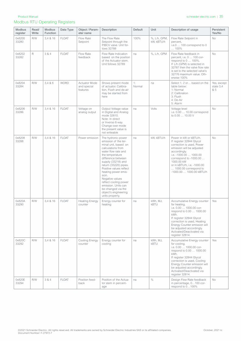
Modbus RTU Operating Registers
Modbus register
Read/ Write
Modbus Function
Data Type Object / Param-eter name
Description Default Unit Description of usage Persistent Yes/No
0x8200 33280
R/W 3,4 & 16 FLOAT Flow Rate Setpoint
The Flow Rate Setpoint through the PIBCV valve. Unit fol-lows 32788
100% %, L/h, GPM, kW, kBTU/h
Flow Rate Setpoint in percent, i.e.0 … 100 correspond to 0 … 100%
No
0x8202 33282
R 3 & 4 FLOAT Flow Rate feedback
Flow Rate Indication based on the position of the Actuator stem. Unit follows 32789
na %, L/h, GPM Flow Rate feedback in percent, i.e. 0 … 100 cor-respond to 0 … 100%. If L/h (GPM) is selected in 32787 then the valve flow rate is set to the selected valve’s 32776 maximum value. Oth-erwise 100%
No
0x8204 33284
R/W 3,4 & 6 WORD Actuator Mode and special features
Shows present mode of actuator. Calibra-tion, Flush and de-air may be started from here
1: Normal
na Select 1, 2 or… based on the table below: 1: Normal 2: Calibration 3: Flush 4: De-Air 5: Alarm
Yes, except state 3,4 & 5
0x8206 33286
R/W 3,4 & 16 FLOAT Voltage on analog output
Output Voltage value in Digital and Analog mode 32810. Note: In direct or Inverse 6-way Change over mode the present value is not writeable
na Volts Voltage level i.e. 0.00 … 10.00 correspond to 0.00 … 10.00 V
No
0x8208 33288
R/W 3,4 & 16 FLOAT Power emission The hydronic power emission of the ter-minal unit, based on calculations from water flow rate and the temperature difference between supply (33218) and return (33220) pipes. Positive values reflect heating power emis-sion. Negative values reflect cooling power emission. Units can be changed via the object’s engineering units property.
na kW, kBTU/h Power in kW or kBTU/h. If register 32844 Glycol correction is used, Power emission will be adjusted accordingly. i.e. -1000.00 … 1000.00 correspond to -1000.00 … 1000.00 kW or in kBTU/h, i.e. -1000.00 … 1000.00 correspond to -1000.00 … 1000.00 kBTU/h
No
0x820A 33290
R/W 3,4 & 16 FLOAT Heating Energy counter
Energy counter for heating
na kWh, MJ, kBTU
Accumulative Energy counter for heating. i.e. 0.00 … 1000.00 cor-respond to 0.00 … 1000.00 kWh. If register 32844 Glycol correction is used, Heating Energy Counter emission will be adjusted accordingly. Activated/Deactivated via register 32814.
Yes
0x820C 33292
R/W 3,4 & 16 FLOAT Cooling Energy counter
Energy counter for cooling
na kWh, MJ, kBTU
Accumulative Energy counter for cooling. i.e. 0.00 … 1000.00 cor-respond to 0.00 … 1000.00 kWh. If register 32844 Glycol correction is used, Cooling Energy Counter emission will be adjusted accordingly. Activated/Deactivated via register 32814.
Yes
0x820E 33294
R/W 3 & 4 FLOAT Position feed-back
Position of the Actua-tor stem in percent-age
na % Design Flow Rate feedback in percentage, 0…100 cor-respond to 0…100%
No
©2021 Schneider Electric. All rights reserved. All trademarks are owned by Schneider Electric Industries SAS or its affiliated companies. October, 2021 tcDocument Number: F-27972-7
schneider-electric.com | 35Product Manual

Modbus register
Read/ Write
Modbus Function
Modbus Data Type
Object / Parameter name
Description Default Unit Description of usage Persistent Yes/No
0x8100 33024
R 3 & 4 FLOAT Nominal flow of the selected valve type
Nominal flow of the selected valve type
450 L/hr or GPM
Nominal flow e.g. in Litres per hour i.e. 0 ..450 correspond to 0 …450 L/hr.
na
0x8102 33026
R 3 & 4 FLOAT Valve position at nominal flow
Position in mm for nominal flow of the selected valve
na Millime-tre
Valve position for nominal flow in millimetre, i.e.. 0.5 … 5.8 corre-spond to 0.5 … 5.8 millimetre.
na
0x8104 33028
R 3 & 4 FLOAT Maximum value of the Design Flow Rate
Maximum level the Design Flow Rate can be increased to for the selected valve
Setting Range Maxi-mum from Valve Table
% Maximum level of the Design Flow Rate e.g. in Litres per hour i.e. 0 ..450 correspond to 0 …450 L/hr.
na
0x8108 33032
R 3 & 4 LONG Product ID Serial number of the actuator
na na Unique Product id. The last part of the serial number.
Yes
0x810A 33034
R 3 & 4 WORD SW ver-sion
Software version of the actuator
na na ASCII coded WORD Yes
0x810B 33035
R 3 & 4 WORD HW ver-sion
Hardware version of the actuator
na na ASCII coded WORD Yes
0x8120 33056
R/W 3 & 4 STRING Device name
Product name SP90 S na ASCII coded STRING Yes
0x8140 33088
R 3 & 4 STRING Model name
Type of the actuator 6 way change over
na ASCII coded STRING Yes
0x8160 33120
R 3 & 4 STRING Vendor name
Name of the Manu-facture
Schneider Electric
na ASCII coded STRING Yes
0x8180 33152
R/W 3, 4 & 16 STRING Location descrip-tion
Free text can be used to describe location etc. E.g. Room 1
na na ASCII coded STRING. Max. 50 characters.
Yes
0x81A0 33184
R 3 & 4 STRING Serial number
Serial number of the actuator
na 1 Description of this object holds the serial number of the actuator, pro-grammed at the production time.
Yes
0x81C0 33216
R 3 & 4 FLOAT Voltage or Current on analog input
Voltage(V) or Current(mA) level on the analog control input, measured by the actuator. In 6 way change over mode, mA cannot be selected.
na Volt / mA Voltage level measured i.e. 0.00 … 10.00 correspond to 0.00 … 10.00 V or in mA, i.e. 0.00 … 20.00 correspond to 0.00 … 20.00 mA
No
0x81C2 33218
R 3 & 4 FLOAT T1 or resistance input
Temperature/resist-ance measured from connected PT1000 sensors. For Power emission 33288, 33218 is temperature on the flow pipe and 33220 is temperature on the return pipe.
°C °C, °F, Ohm
Temperature measured in °C i.e. -10°C …120°C or resistance meas-ured i.e. 900Ω … 10kΩ. The upper temperature limit for NTC 10K Type 2 sensors is 90°C / 194°F. The upper temperature limit for NTC 10K Type 3 sesnsors is 95°C / 203°F. When used as potential free contacts: Closed circuit <900Ω, open circuit 100kΩ. Recommended max. cable length 2m for energy application
No
0x81C4 33220
R 3 & 4 FLOAT T2 or resistance input
Temperature/resist-ance measured from connected PT1000 sensors. For Power emission 33288, 33218 is temperature on the flow pipe and 33220 is temperature on the return pipe.
°C °C, °F, Ohm
Temperature measured in °C i.e. -10°C …120°C or resistance meas-ured i.e. 900Ω … 10kΩ. The upper temperature limit for NTC 10K Type 2 sesnsors is 90°C / 194°F. The upper temperature limit for NTC 10K Type 3 sesnsors is 95°C / 203°F. When used as potential free contacts: Closed circuit <900Ω, open circuit 100kΩ. Recommended max. cable length 2m for energy application
No
0x8402 33794
R 3 & 4 FLOAT Rectified voltage measured by the actuator
Measured rectified voltage which powers the actuator
na Volts Rectified voltage which powers the actuator. Too low voltage: 16.1 … 17.5V Too high voltage: 38.3 … 43.4V
No
0x8404 33796
R 3 & 4 FLOAT Tempera-ture in the actuator
Temperature measured inside the Actuator
na na Temperature measured inside the actuator. Unit is decided by 32790
No
Modbus RTU Information Registers
©2021 Schneider Electric. All rights reserved. All trademarks are owned by Schneider Electric Industries SAS or its affiliated companies. October, 2021 tcDocument Number: F-27972-7
36 | schneider-electric.com Product Manual
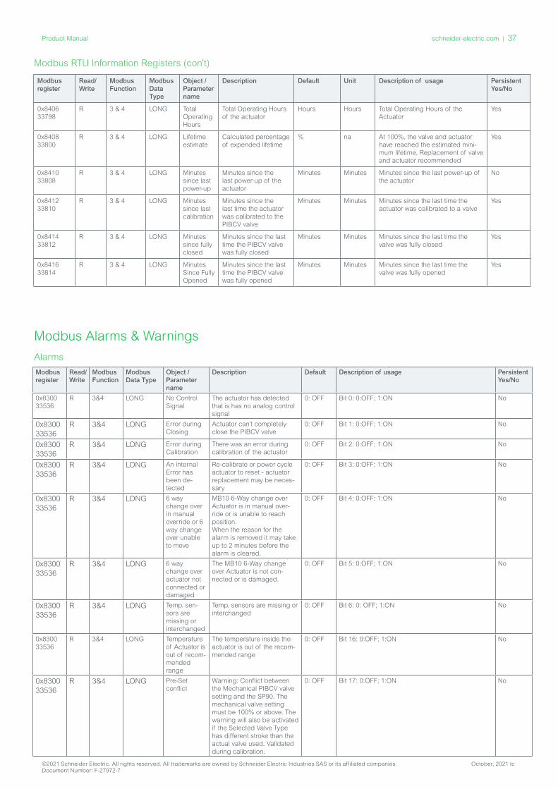
Modbus RTU Information Registers (con’t)
Modbus Alarms & Warnings
Alarms
Modbus register
Read/ Write
Modbus Function
Modbus Data Type
Object / Parameter name
Description Default Unit Description of usage Persistent Yes/No
0x8406 33798
R 3 & 4 LONG Total Operating Hours
Total Operating Hours of the actuator
Hours Hours Total Operating Hours of the Actuator
Yes
0x8408 33800
R 3 & 4 LONG Lifetime estimate
Calculated percentage of expended lifetime
% na At 100%, the valve and actuator have reached the estimated mini-mum lifetime, Replacement of valve and actuator recommended
Yes
0x8410 33808
R 3 & 4 LONG Minutes since last power-up
Minutes since the last power-up of the actuator
Minutes Minutes Minutes since the last power-up of the actuator
No
0x8412 33810
R 3 & 4 LONG Minutes since last calibration
Minutes since the last time the actuator was calibrated to the PIBCV valve
Minutes Minutes Minutes since the last time the actuator was calibrated to a valve
Yes
0x8414 33812
R 3 & 4 LONG Minutes since fully closed
Minutes since the last time the PIBCV valve was fully closed
Minutes Minutes Minutes since the last time the valve was fully closed
Yes
0x8416 33814
R 3 & 4 LONG Minutes Since Fully Opened
Minutes since the last time the PIBCV valve was fully opened
Minutes Minutes Minutes since the last time the valve was fully opened
Yes
Modbus register
Read/ Write
Modbus Function
Modbus Data Type
Object / Parameter name
Description Default Description of usage Persistent Yes/No
0x8300 33536
R 3&4 LONG No Control Signal
The actuator has detected that is has no analog control signal
0: OFF Bit 0: 0:OFF; 1:ON No
0x8300 33536
R 3&4 LONG Error during Closing
Actuator can’t completely close the PIBCV valve
0: OFF Bit 1: 0:OFF; 1:ON No
0x8300 33536
R 3&4 LONG Error during Calibration
There was an error during calibration of the actuator
0: OFF Bit 2: 0:OFF; 1:ON No
0x8300 33536
R 3&4 LONG An internal Error has been de-tected
Re-calibrate or power cycle actuator to reset - actuator replacement may be neces-sary
0: OFF Bit 3: 0:OFF; 1:ON No
0x8300 33536
R 3&4 LONG 6 way change over in manual override or 6 way change over unable to move
MB10 6-Way change over Actuator is in manual over-ride or is unable to reach position. When the reason for the alarm is removed it may take up to 2 minutes before the alarm is cleared.
0: OFF Bit 4: 0:OFF; 1:ON No
0x8300 33536
R 3&4 LONG 6 way change over actuator not connected or damaged
The MB10 6-Way change over Actuator is not con-nected or is damaged.
0: OFF Bit 5: 0:OFF; 1:ON No
0x8300 33536
R 3&4 LONG Temp. sen-sors are missing or interchanged
Temp. sensors are missing or interchanged
0: OFF Bit 6: 0: OFF; 1:ON No
0x8300 33536
R 3&4 LONG Temperature of Actuator is out of recom-mended range
The temperature inside the actuator is out of the recom-mended range
0: OFF Bit 16: 0:OFF; 1:ON No
0x8300 33536
R 3&4 LONG Pre-Set conflict
Warning: Conflict between the Mechanical PIBCV valve setting and the SP90. The mechanical valve setting must be 100% or above. The warning will also be activated if the Selected Valve Type has different stroke than the actual valve used. Validated during calibration.
0: OFF Bit 17: 0:OFF; 1:ON No
©2021 Schneider Electric. All rights reserved. All trademarks are owned by Schneider Electric Industries SAS or its affiliated companies. October, 2021 tcDocument Number: F-27972-7
schneider-electric.com | 37Product Manual
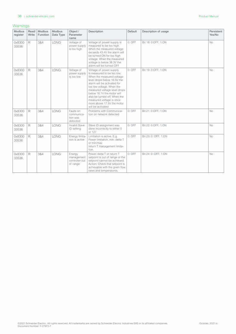
Modbus register
Read/ Write
Modbus Function
Modbus Data Type
Object / Parameter name
Description Default Description of usage Persistent Yes/No
0x8300 33536
R 3&4 LONG Voltage of power supply is too high
Voltage of power supply is measured to be too high. When the measured voltage exceeds 43.4V the alarm will be turned ON for too high voltage. When the measured voltage is below 38.3V the alarm will be turned OFF
0: OFF Bit 18: 0:OFF; 1:ON No
0x8300 33536
R 3&4 LONG Voltage of power supply is too low
Voltage of power supply is measured to be too low. When the measured voltage level drops below 16.5V the alarm will be activated for too low voltage. When the measured voltage level drops below 16.1V the motor will also be turned off. When the measured voltage is once more above 17.5V the motor will be activated
0: OFF Bit 19: 0:OFF; 1:ON No
0x8300 33536
R 3&4 LONG Faults on communica-tion was detected
Problems with Communica-tion on network detected
0: OFF Bit 21: 0:OFF; 1:ON No
0x8300 33536
R 3&4 LONG Invalid Slave ID setting
Slave ID assignment was done incorrectly to either 0 or 127
0: OFF Bit 22: 0:OFF; 1:ON No
0x8300 33536
R 3&4 LONG Energy limita-tion is active
Limitation is active. E.g. Power limitation, min. delta T or min/max return T management limita-tion.
0: OFF Bit 23: 0: OFF; 1:ON No
0x8300 33536
R 3&4 LONG Energy management controller out of range
Power, delta T or return T setpoint is out of range or the setpoint cannot be achieved. Action: Check that setpoint is achievable with the given flow rates and temperatures.
0: OFF Bit 24: 0: OFF; 1:ON No
Warnings
©2021 Schneider Electric. All rights reserved. All trademarks are owned by Schneider Electric Industries SAS or its affiliated companies. October, 2021 tcDocument Number: F-27972-7
38 | schneider-electric.com Product Manual
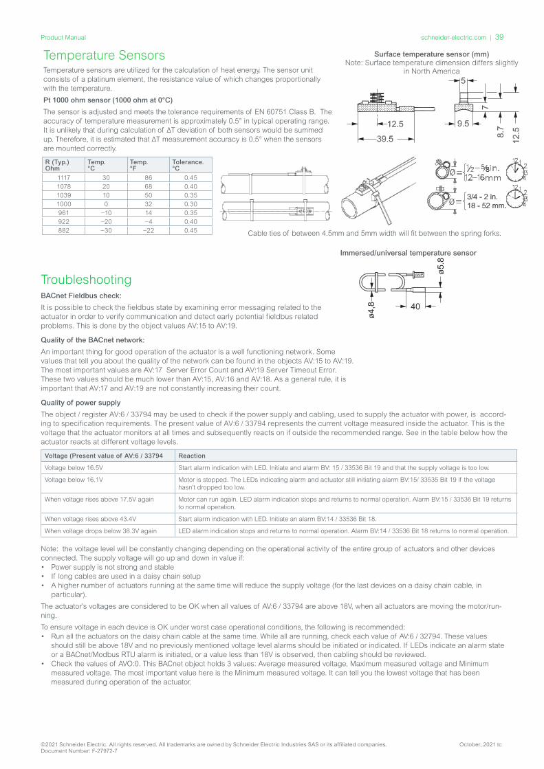
Temperature Sensors
R (Typ.)Ohm
Temp.°C
Temp.°F
Tolerance.°C
1117 30 86 0.451078 20 68 0.401039 10 50 0.351000 0 32 0.30961 −10 14 0.35922 −20 −4 0.40882 −30 −22 0.45
Temperature sensors are utilized for the calculation of heat energy. The sensor unit consists of a platinum element, the resistance value of which changes proportionally with the temperature.
Pt 1000 ohm sensor (1000 ohm at 0°C)
The sensor is adjusted and meets the tolerance requirements of EN 60751 Class B. The accuracy of temperature measurement is approximately 0.5° in typical operating range. It is unlikely that during calculation of ΔT deviation of both sensors would be summed up. Therefore, it is estimated that ΔT measurement accuracy is 0.5° when the sensors are mounted correctly.
Surface temperature sensor (mm) Note: Surface temperature dimension differs slightly
in North America
Immersed/universal temperature sensor
Cable ties of between 4.5mm and 5mm width will fit between the spring forks.
NB!
3/4 - 2 in.18 - 52 mm.
NB!
3/4 - 2 in.18 - 52 mm.
NB!
3/4 - 2 in.18 - 52 mm.
NB!
3/4 - 2 in.18 - 52 mm.
TroubleshootingBACnet Fieldbus check:
It is possible to check the fieldbus state by examining error messaging related to the actuator in order to verify communication and detect early potential fieldbus related problems. This is done by the object values AV:15 to AV:19.
Quality of the BACnet network:
An important thing for good operation of the actuator is a well functioning network. Some values that tell you about the quality of the network can be found in the objects AV:15 to AV:19. The most important values are AV:17 Server Error Count and AV:19 Server Timeout Error. These two values should be much lower than AV:15, AV:16 and AV:18. As a general rule, it is important that AV:17 and AV:19 are not constantly increasing their count.
Quality of power supply
The object / register AV:6 / 33794 may be used to check if the power supply and cabling, used to supply the actuator with power, is accord-ing to specification requirements. The present value of AV:6 / 33794 represents the current voltage measured inside the actuator. This is the voltage that the actuator monitors at all times and subsequently reacts on if outside the recommended range. See in the table below how the actuator reacts at different voltage levels.
Voltage (Present value of AV:6 / 33794 Reaction
Voltage below 16.5V Start alarm indication with LED. Initiate and alarm BV: 15 / 33536 Bit 19 and that the supply voltage is too low.
Voltage below 16.1V Motor is stopped. The LEDs indicating alarm and actuator still initiating alarm BV:15/ 33535 Bit 19 if the voltage hasn’t dropped too low.
When voltage rises above 17.5V again Motor can run again. LED alarm indication stops and returns to normal operation. Alarm BV:15 / 33536 Bit 19 returns to normal operation.
When voltage rises above 43.4V Start alarm indication with LED. Initiate an alarm BV:14 / 33536 Bit 18.
When voltage drops below 38.3V again LED alarm indication stops and returns to normal operation. Alarm BV:14 / 33536 Bit 18 returns to normal operation.
Note: the voltage level will be constantly changing depending on the operational activity of the entire group of actuators and other devices connected. The supply voltage will go up and down in value if:• Power supply is not strong and stable• If long cables are used in a daisy chain setup• A higher number of actuators running at the same time will reduce the supply voltage (for the last devices on a daisy chain cable, in
particular).
The actuator’s voltages are considered to be OK when all values of AV:6 / 33794 are above 18V, when all actuators are moving the motor/run-ning.
To ensure voltage in each device is OK under worst case operational conditions, the following is recommended:• Run all the actuators on the daisy chain cable at the same time. While all are running, check each value of AV:6 / 32794. These values
should still be above 18V and no previously mentioned voltage level alarms should be initiated or indicated. If LEDs indicate an alarm state or a BACnet/Modbus RTU alarm is initiated, or a value less than 18V is observed, then cabling should be reviewed.
• Check the values of AVO:0. This BACnet object holds 3 values: Average measured voltage, Maximum measured voltage and Minimum measured voltage. The most important value here is the Minimum measured voltage. It can tell you the lowest voltage that has been measured during operation of the actuator.
©2021 Schneider Electric. All rights reserved. All trademarks are owned by Schneider Electric Industries SAS or its affiliated companies. October, 2021 tcDocument Number: F-27972-7
schneider-electric.com | 39Product Manual

©2021 Schneider Electric. All rights reserved. All trademarks are owned by Schneider Electric Industries SAS or its affiliated companies. October, 2021 tcDocument Number: F-27972-7
40 | schneider-electric.com Product Manual