Communication Protocol for Intelligent Sensors and Actuators ...
J. Micromech. Microeng. 6 (1996) 320–329. Printed in the UK
Comb-drive actuators for largedisplacements
Rob Legtenberg , A W Groeneveld and M Elwenspoek
MESA Research Institute, University of Twente, PO Box 217, 7500 AE Enschede,The Netherlands
Received 30 November 1995, accepted for publication 4 June 1996
Abstract. The design, fabrication and experimental results of lateral-comb-driveactuators for large displacements at low driving voltages is presented. Acomparison of several suspension designs is given, and the lateral large deflectionbehaviour of clamped–clamped beams and a folded flexure design is modelled. Anexpression for the axial spring constant of folded flexure designs including bendingeffects from lateral displacements, which reduce the axial stiffness, is also derived.The maximum deflection that can be obtained by comb-drive actuators is boundedby electromechanical side instability. Expressions for the side-instability voltageand the resulting displacement at side instability are given. The electromechanicalbehaviour around the resonance frequency is described by an equivalent electriccircuit. Devices are fabricated by polysilicon surface micromachining techniquesusing a one-mask fabrication process. Static and dynamic properties aredetermined experimentally and are compared with theory. Static properties aredetermined by displacement-to-voltage, capacitance-to-voltage and pull-in voltagemeasurements. Using a one-port approach, dynamic properties are extracted frommeasured admittance plots. Typical actuator characteristics are deflections ofabout 30 µm at driving voltages around 20 V, a resonance frequency around1.6 kHz and a quality factor of approximately 3.
1. Introduction
Comb drive actuators consist of two interdigitated fingerstructures, where one comb is fixed and the other isconnected to a compliant suspension. Applying a voltagedifference between the comb structures will result in adeflection of the movable comb structure by electrostaticforces. Comb drive actuators have been used as resonators[1–3], electromechanical filters [4], optical shutters [5–7],microgrippers [8] and voltmeters [9]. They have also beenused as the driving element in, e.g. vibromotors [10] andmicromechanical gears [11].
Voltage controlled comb-drive actuators exert a lateralelectrostatic force which is independent of position makingthem attractive for micropositioning applications, suchas, for instance, xy-microstages [12–14]. Togetherwith nanotools like microtips, integrated systems can befabricated with applications in scanning microscopy anddata storage [15, 16]. In most devices actuator deflectionshave been limited to a few microns but in many casesmicropositioning over larger distances is attractive. Forthis reason the design and fabrication of large displacementcomb-drive actuators is investigated.
A suspension that is compliant in the direction ofdisplacement desired and stiff in the orthogonal directionsis required. Electrostatic forces increase with decreasinggap spacing and an increasing number of comb fingers.However, due to fabrication processes, dimensions are
limited by minimum feature size constraining, e.g., theminimum beam width and gap spacing. These and otherdesign constraints are discussed in order to obtain large-displacement, low-driving-voltage comb-drive actuators.
2. Spring designs
Different types of spring designs have been applied incomb-drive actuators [1, 12, 17]. In this section thefollowing spring designs will be discussed; clamped–clamped beams, a crab-leg flexure and the folded-beamflexure. In most cases it is desirable to have a structurewhich is very compliant in one direction while being verystiff in the orthogonal directions. This can be expressed asa stiffness ratio. Most polysilicon micromechanical flexuresconstrain motion to a rectilinear direction, and are createdfrom straight beams. When a concentrated load is appliedthe linear spring constant is defined as
ki = Fi
δi
(1)
whereFi andδi are respectively the force and the deflectionin the i direction. The lateral spring constants and stiffnessratio of a clamped–clamped beam, a crab-leg flexure anda folded flexure design will be discussed. The analysisassumes that there is no residual stress present in the springstructures.
0960-1317/96/030320+10$19.50 c© 1996 IOP Publishing Ltd
Comb-drive actuators
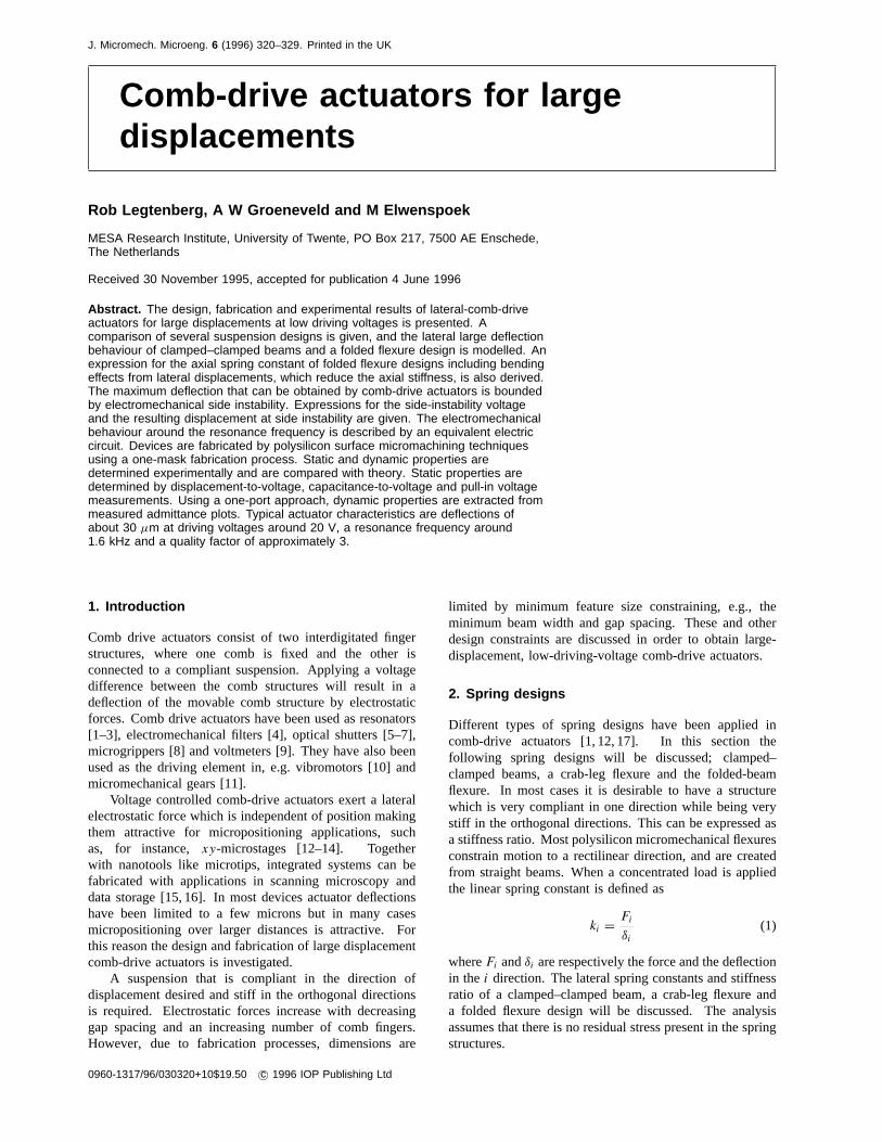
Figure 1. Fixed–fixed beam.
2.1. Clamped–clamped beam
A clamped–clamped beam with rectangular cross sectionis shown in figure 1. A concentrated force is applied tothe centre of the shuttle. The axial displacement alongthe x-axis can be found directly from Hooke’s law andthe lateral displacement along they-axis is obtained fromsmall deflection theory [18]. The spring constants for aconcentrated force in thex- andy-directions are given by:
kx = 2Ebh/L (2)
ky = 2Ehb3/L3 (3)
whereE is Young’s modulus,b is the beam width,h is thebeam thickness andL is the length of one beam segment.The stiffness ratio is:
kx
ky
=(
L
b
)2
. (4)
The stiffness ratio of a clamped–clamped beam can be veryhigh. For example, the stiffness ratio is 1.25 × 10⁵ fora beam of length 500µm and width 2µm. For largedisplacements, however, extensional axial forces develop inthe beam that result in a non-linear force-to-displacementrelation. In this case non-linear effects have to be includedwhich strongly increase the stiffness of the beam withincreasing deflection. This spring design is therefore notsuitable for large deflections. However it is useful inapplications that require measurement of axial forces, forinstance in order to determine residual stresses or measureexternally applied axial stresses as in sensing applications.
A derivation of the large deflection behaviour ofclamped–clamped beams can be found in [19]. The centredeflection for a concentrated loadPy at the centre can befound by simultaneously solving the following equations:
Py = EIh
L3
√8/3u3
(3
2− 1
2tanh2 u − 3
2
tanhu
u
)−1/2
(5)
δy = h√
2/3(u − tanhu)
(3
2− 1
2tanh2 u − 3
2
tanhu
u
)−1/2
(6)
withu =
√N/EI(L/2) (7)
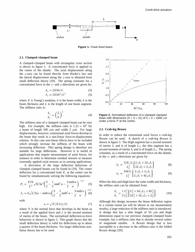
whereN is the normal force that develops in the beam asa result of the applied force andI is the second momentof inertia of the beam. The normalised deflection-to-forcebehaviour is shown in figure 2. This graph shows that thesmall deflection theory is valid for deflections up to abouta quarter of the beam thickness. For larger deflections non-linear theory has to be used.
Figure 2. Normalised deflection of a clamped–clampedbeam with dimensions (h × b × 2L) of 5 × 2 × 1000 µmunder a force P at the centre.
2.2. Crab-leg flexure
In order to reduce the extensional axial forces a crab-legflexure can be used. A sketch of a crab-leg flexure isshown in figure 3. The thigh segment has a second momentof inertia I1 and is of lengthL1; the shin segment has asecond moment of inertiaI2 and is of lengthL2. The springconstants, as a result of a concentrated force on the shuttle,in the x- andy-directions are given by:
kx = 12EyI2
L32
{L1I2 + 2L2I1
2L1I2 + L2I1
}(8)
ky = 24EI1
L31
{L1I2 + L2I1
L1I2 + 4L2I1
}. (9)
When the shin and thigh have the same width and thickness,the stiffnes ratio can be obtained from:
kx
ky
= 1
2
L31
L32
{L2
1 + 6L1L2 + 8L22
2L21 + 3L1L2 + L2
2
}. (10)
Although this design increases the linear deflection regionto a certain extent (as will be shown in our measurementresults), a large reduction of the stiffness ratio is introduced.A design that has a shin length of 50µm and thighdimensions equal to our previous clamped–clamped beamexample, has a stiffness ratio that is already several ordersof magnitude smaller. A flexure design that is lesssusceptible to a decrease in the stiffness ratio is the foldedflexure design [20].
321
R Legtenberg et al
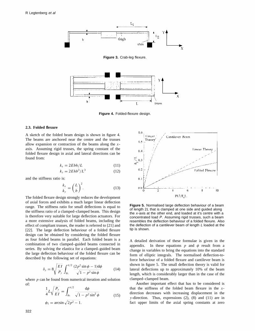
Figure 3. Crab-leg flexure.
Figure 4. Folded-flexure design.
2.3. Folded flexure
A sketch of the folded beam design is shown in figure 4.The beams are anchored near the centre and the trussesallow expansion or contraction of the beams along thex-axis. Assuming rigid trusses, the spring constant of thefolded flexure design in axial and lateral directions can befound from:
kx = 2Ebh/L (11)
ky = 2Ehb3/L3 (12)
and the stiffness ratio is:
kx
ky
=(
L
b
)2
. (13)
The folded flexure design strongly reduces the developmentof axial forces and exhibits a much larger linear deflectionrange. The stiffness ratio for small deflections is equal tothe stiffness ratio of a clamped–clamped beam. This designis therefore very suitable for large deflection actuators. Fora more extensive analysis of folded beams, including theeffect of compliant trusses, the reader is referred to [21] and[22]. The large deflection behaviour of a folded flexuredesign can be obtained by considering the folded flexureas four folded beams in parallel. Each folded beam is acombination of two clamped–guided beams connected inseries. By solving the elastica for a clamped–guided beamthe large deflection behaviour of the folded flexure can bedescribed by the following set of equations:
δy = 8
√EI
Py
∫ π/2
φ1
(2p2 sinφ − 1)dφ√1 − p2 sinφ
(14)
wherep can be found from numerical iteration and solutionof:
1
4L
√Py
EI=
∫ π/2
φ1
dφ√1 − p2 sin2 φ
φ1 = arcsin√
2p2 − 1.
(15)
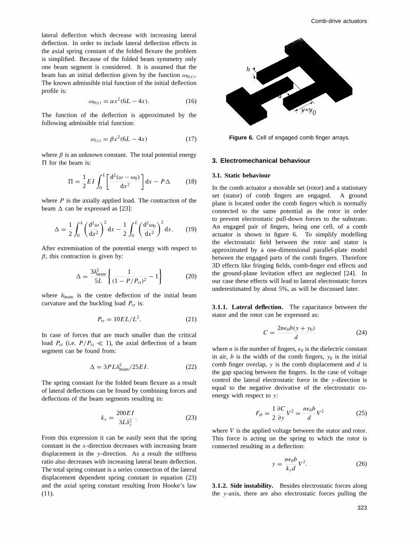
Figure 5. Normalised large deflection behaviour of a beamof length 2L that is clamped at one side and guided alongthe x -axis at the other end, and loaded at it’s centre with aconcentrated load P . Assuming rigid trusses, such a beamresembles the deflection behaviour of a folded flexure. Alsothe deflection of a cantilever beam of length L loaded at thetip is shown.
A detailed derivation of these formulae is given in theappendix. In these equationsp and φ result from achange in variables to bring the equations into the standardform of elliptic integrals. The normalised deflection-to-force behaviour of a folded flexure and cantilever beam isshown in figure 5. The small deflection theory is valid forlateral deflections up to approximately 10% of the beamlength, which is considerably larger than in the case of theclamped–clamped beam.
Another important effect that has to be considered isthat the stiffness of the folded beam flexure in thex-direction decreases with increasing displacement in they-direction. Thus, expressions (2), (8) and (11) are infact upper limits of the axial spring constants at zero
322
Comb-drive actuators
lateral deflection which decrease with increasing lateraldeflection. In order to include lateral deflection effects inthe axial spring constant of the folded flexure the problemis simplified. Because of the folded beam symmetry onlyone beam segment is considered. It is assumed that thebeam has an initial deflection given by the functionω0(x).The known admissible trial function of the initial deflectionprofile is:
ω0(x) = αx2(6L − 4x). (16)
The function of the deflection is approximated by thefollowing admissible trial function:
ω(x) = βx2(6L − 4x) (17)
whereβ is an unknown constant. The total potential energy5 for the beam is:
5 = 1
2EI
∫ L
0
[d2(ω − ω0)
dx2
]dx − P1 (18)
whereP is the axially applied load. The contraction of thebeam1 can be expressed as [23]:
1 = 1
2
∫ L
0
(d2ω
dx2
)2
dx − 1
2
∫ L
0
(d2ω0
dx2
)2
dx. (19)
After extremisation of the potential energy with respect toβ, this contraction is given by:
1 = 3δ2beam
5L
{1
(1 − P/Pcr)2− 1
}(20)
where δbeam is the centre deflection of the initial beamcurvature and the buckling loadPcr is:
Pcr = 10EL/L2. (21)
In case of forces that are much smaller than the criticalload Pcr (i.e. P/Pcr � 1), the axial deflection of a beamsegment can be found from:
1 = 3PLδ2beam/25EI. (22)
The spring constant for the folded beam flexure as a resultof lateral deflections can be found by combining forces anddeflections of the beam segments resulting in:
kx = 200EI
3Lδ2y
. (23)
From this expression it can be easily seen that the springconstant in thex-direction decreases with increasing beamdisplacement in they-direction. As a result the stiffnessratio also decreases with increasing lateral beam deflection.The total spring constant is a series connection of the lateraldisplacement dependent spring constant in equation (23)and the axial spring constant resulting from Hooke’s law(11).
Figure 6. Cell of engaged comb finger arrays.
3. Electromechanical behaviour
3.1. Static behaviour
In the comb actuator a movable set (rotor) and a stationaryset (stator) of comb fingers are engaged. A groundplane is located under the comb fingers which is normallyconnected to the same potential as the rotor in orderto prevent electrostatic pull-down forces to the substrate.An engaged pair of fingers, being one cell, of a combactuator is shown in figure 6. To simplify modellingthe electrostatic field between the rotor and stator isapproximated by a one-dimensional parallel-plate modelbetween the engaged parts of the comb fingers. Therefore3D effects like fringing fields, comb-finger end effects andthe ground-plane levitation effect are neglected [24]. Inour case these effects will lead to lateral electrostatic forcesunderestimated by about 5%, as will be discussed later.
3.1.1. Lateral deflection. The capacitance between thestator and the rotor can be expressed as:
C = 2nε0b(y + y0)
d(24)
wheren is the number of fingers,ε0 is the dielectric constantin air, b is the width of the comb fingers,y0 is the initialcomb finger overlap,y is the comb displacement andd isthe gap spacing between the fingers. In the case of voltagecontrol the lateral electrostatic force in they-direction isequal to the negative derivative of the electrostatic co-energy with respect toy:
Fel = 1
2
∂C
∂yV 2 = nε0b
dV 2 (25)
whereV is the applied voltage between the stator and rotor.This force is acting on the spring to which the rotor isconnected resulting in a deflection:
y = nε0b
kydV 2. (26)
3.1.2. Side instability. Besides electrostatic forces alongthe y-axis, there are also electrostatic forces pulling the
323
R Legtenberg et al
stator and rotor fingers together. The electrostatic force inthe axial direction is:
Fel = nε0b(y + y0)
2(d − x)2V 2 − nε0b(y + y0)
2(d + x)2V 2. (27)
Normally the forces on both sides of the comb fingerscancel each other. However, when the first derivative ofthe electrostatic force with respect tox becomes largerthan the restoring spring constant in thex-direction a side-instability of the comb drive is introduced. Hence stablecomb operation is bounded by:
kx >
[∂E
∂x
]x→0
= 2nε0b(y + y0)
d3V 2. (28)
When the driving voltage exceeds the so-called side-instability voltageVSI the comb drive becomes unstableleading to side sticking of the rotor and stator fingers. Bycombining equations (26) and (28) the voltage at whichside-instability occurs can be expressed as:
V 2SI = d2ky
2ε0bn
(√2kx
ky
+ y20
d2− y0
d
). (29)
In this equation, the spring constantkx refers to that in thedeflected state, since side sticking occurs only when thecomb is actuated (see (23)). By neglecting the second termin the root (whenkx � ky), the maximum deflectionySI
that can be obtained before pull-in will occur is:
ySI = d
√kx
2ky
− y0
2. (30)
From this equation it can be seen that the side-instabilityvoltage and maximum deflection are proportional to thegap spacing and increase with the spring stiffness ratio.This shows that comb drive structures with small gapspacings are more susceptible to side instability [25] andthat spring designs with a large stiffness ratio are preferredfor large-deflection comb drive actuators. Other sources ofinstability may result from sideways pull-in of compliantfingers themselves and pull-in by the finger front endswhen the stator and rotor are almost completely engaged[26]. Instabilities have to be avoided by proper design ofthe comb structure and flexure and supply together withmaximum deflection, driving voltage and minimum featuresize, the main constraints on comb actuator design. Large-deflection comb drive actuators at low driving voltagesshould employ compliant springs with a high stiffness ratioand a large number of comb fingers. In our comb-drivedesign, a folded flexure has been used which is connectedat the centre to a beam that is able to hold a large numberof comb fingers.
3.2. Dynamic behaviour
Using lumped elements the differential equation of motionis given by:
Meqy + αy + kyy = Fel = nε0b
d
[VP + v(t)
]2(31)
where Meq is the equivalent mass of the comb driveactuator,α is the equivalent viscous drag parameter,VP
is the DC polarisation voltage andv(t) the AC voltage.
3.2.1. The fundamental frequency The fundamentalfrequency of the structure can be obtained from Rayleigh’squotient [23, 30]. Using the static deflection profile forthe approximate fundamental mode shape function of thebeams yields the following expression for the fundamentalresonance frequencyω0:
ω0 =√
ky
Mshuttle + 12Mtruss + 96
35Mbeam
(32)
where the denominator of the fraction under the root signresembles the equivalent massMeq in which Mshuttle is themass of the shuttle,Mtruss is the mass of the single trussand Mbeam is the mass of a single beam. The resonantfrequency is ideally independent ofVP andv(t).
3.2.2. Electric admittance—equivalent circuit If thecomb drive is operated in a one-port configuration, the dy-namic behaviour can be described by the electric admittanceY (jω). The voltage is chosen as the independent variablebecause the electrodes define equipotential surfaces mak-ing the voltage independent of position. The constitutiveequations of the electrostatic transducer, describing inter-actions between the mechanical and electrical variables canbe expressed as:[
dq
dF
]=
[ 2nε0b(y0+y00)
d
2nε0bVP
d
− 2nε0bVP
dky
]·[
du
dy
](33)
where dq is the change in charge on the electrodes, dF
is the change in electrostatic force, du is the change involtage, dy is the change in displacement andy00 denotesthe static deflection caused by the polarisation voltageVP .Combining (31) and (33a) the admittance is equal to:
Y (jω) = i
v= jωC0 + jωC1
h(jω)(34)
with
C0 = 2nε0b(y0 + y00)
d(35)
C1 = 4n2ε20b
2u20
kyd2(36)
H(jω) =(
jω
ω0
)2
+ jω
Qω0+ 1 (37)
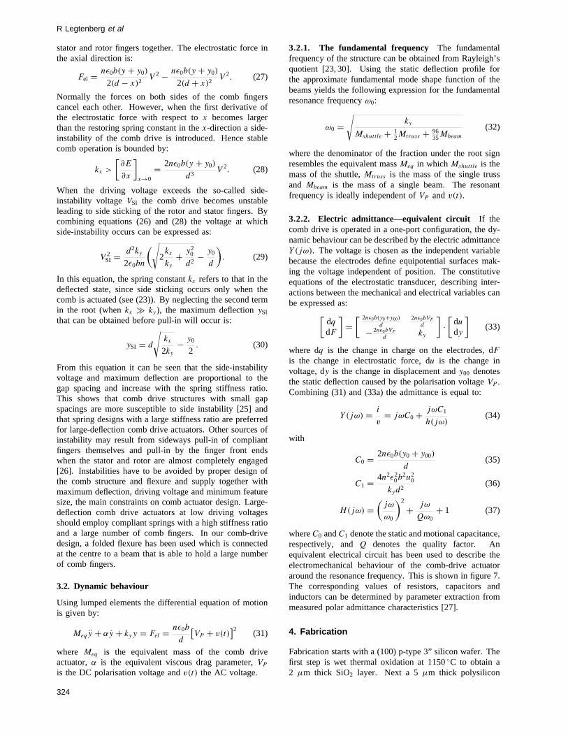
whereC0 andC1 denote the static and motional capacitance,respectively, andQ denotes the quality factor. Anequivalent electrical circuit has been used to describe theelectromechanical behaviour of the comb-drive actuatoraround the resonance frequency. This is shown in figure 7.The corresponding values of resistors, capacitors andinductors can be determined by parameter extraction frommeasured polar admittance characteristics [27].
4. Fabrication
Fabrication starts with a (100) p-type 3” silicon wafer. Thefirst step is wet thermal oxidation at 1150◦C to obtain a2 µm thick SiO2 layer. Next a 5µm thick polysilicon
324
Comb-drive actuators
Figure 7. Equivalent circuit representation of theelectrostatic comb-drive actuator including parasitic loads.L1 = 1/ω2C1, R1 = 1/Q
√L1/C1, Cp = parasitic capacitance,
Rp = parallel resistance, and Rs =series resistance (for C1see (36)).
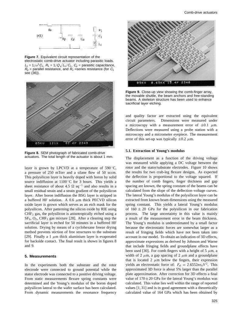
Figure 8. SEM photograph of fabricated comb-driveactuators. The total length of the actuator is about 1 mm.
layer is grown by LPCVD at a temperature of 590◦C,a pressure of 250 mTorr and a silane flow of 50 sccm.This polysilicon layer is heavily doped with boron by solidsource indiffusion at 1100◦C for 3 hours. This yields asheet resistance of about 4.5� sq−1 and also results in asmall residual strain and a strain gradient of the polysiliconlayer. After boron indiffusion the BSG layer is stripped ina buffered HF solution. A 0.6µm thick PECVD siliconoxide layer is grown which serves as an etch mask for thepolysilicon. After patterning the silicon oxide by RIE usingCHF3 gas, the polysilicon is anisotropically etched using aSF6, O2, CHF3 gas mixture [28]. After a cleaning step thesacrificial layer is etched for 50 minutes in a buffered HFsolution. Drying by means of a cyclohexane freeze dryingmethod prevents stiction of free structures to the substrate[29]. Finally a 1µm thick aluminium layer is evaporatedfor backside contact. The final result is shown in figures 8and 9.
5. Measurements
In the experiments both the substrate and the rotorelectrode were connected to ground potential while thestator electrode was connected to a positive driving voltage.From static measurements flexure spring constants weredetermined and the Young’s modulus of the boron dopedpolysilicon lateral to the wafer surface has been calculated.From dynamic measurements the resonance frequency
Figure 9. Close-up view showing the comb-finger array,the movable shuttle, the beam anchors and free-standingbeams. A skeleton structure has been used to enhancesacrificial layer etching.
and quality factor are extracted using the equivalentcircuit parameters. Dimensions were measured undera microscopy with a measurement error of±0.1 µm.Deflections were measured using a probe station with amicroscopy and a micrometer eyepiece. The measurementerror of this set-up was typically±0.2 µm.
5.1. Extraction of Young’s modulus
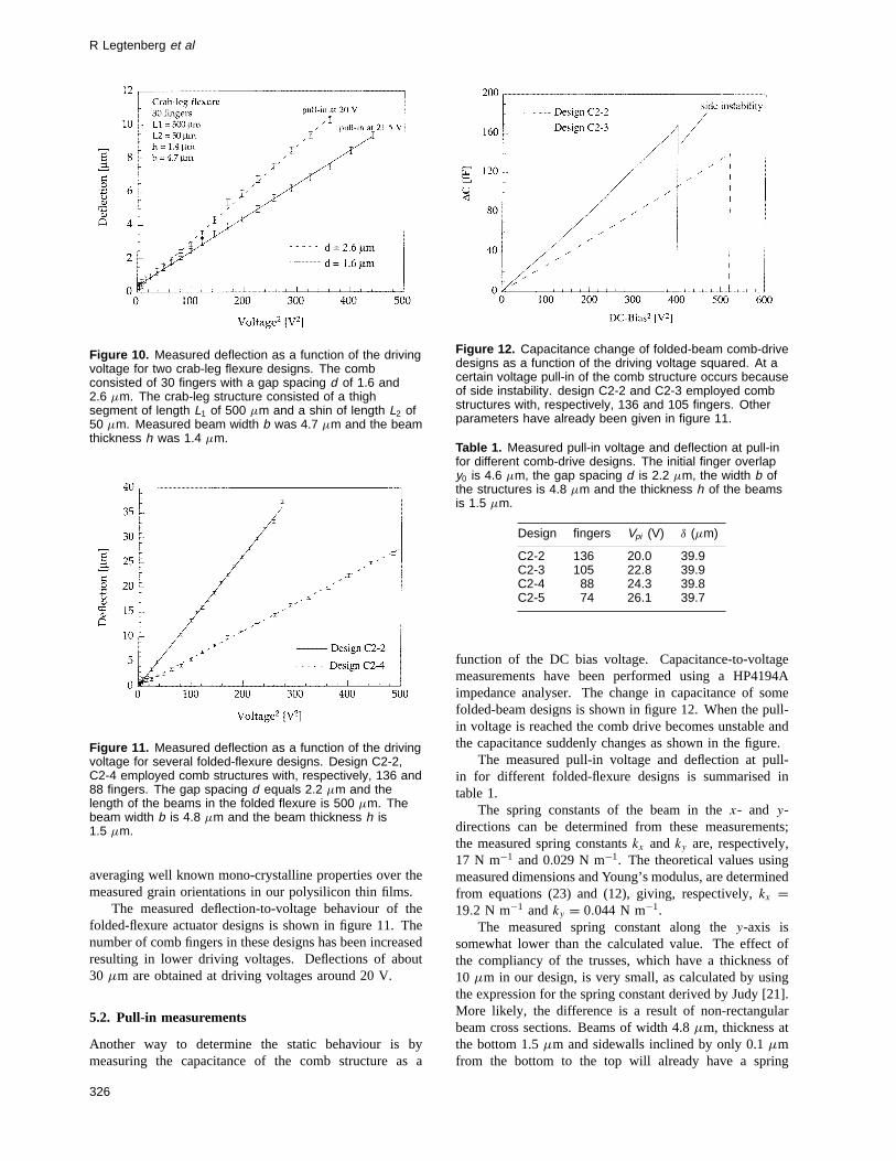
The displacement as a function of the driving voltagewas measured while applying a DC voltage between therotor and the stator/substrate electrodes. Figure 10 showsthe results for two crab-leg flexure designs. As expectedthe deflection is proportional to the voltage squared. Ifthe number of comb fingers, finger thickness and gapspacing are known, the spring constant of the beams can becalculated from the slope of the deflection–voltage curves.The lateral Young’s modulus of the polysilicon layer can beextracted from known beam dimensions using the measuredspring constant. This yields a lateral Young’s modulusof 160 ± 20 GPa for the polysilicon in our fabricationprocess. The large uncertainty in this value is mainlya result of the measurement error in the beam thickness.The Young’s modulus is underestimated by a small factorbecause the electrostatic forces are somewhat larger as aresult of fringing fields which have not been taken intoaccount in our model. To obtain an indication of 3D effects,approximate expressions as derived by Johnson and Warnethat include fringing fields and groundplane effects havebeen used [30]. For comb fingers with a height of 5µm, awidth of 2 µm, a gap spacing of 2µm and a groundplanethat is located 2µm below the fingers, their expressionyields an electrostatic force of:Fel = 2.6552nε0V
2. Thisapproximated 3D force is about 5% larger than the parallelplate approximation. After correction for 3D effects a finalvalue of 170±20 GPa for the lateral Young’s modulus wascalculated. This value lies well within the range of reportedvalues [1, 31] and is in good agreement with a theoreticallycalculated value of 164 GPa which has been obtained by
325
R Legtenberg et al
Figure 10. Measured deflection as a function of the drivingvoltage for two crab-leg flexure designs. The combconsisted of 30 fingers with a gap spacing d of 1.6 and2.6 µm. The crab-leg structure consisted of a thighsegment of length L1 of 500 µm and a shin of length L2 of50 µm. Measured beam width b was 4.7 µm and the beamthickness h was 1.4 µm.
Figure 11. Measured deflection as a function of the drivingvoltage for several folded-flexure designs. Design C2-2,C2-4 employed comb structures with, respectively, 136 and88 fingers. The gap spacing d equals 2.2 µm and thelength of the beams in the folded flexure is 500 µm. Thebeam width b is 4.8 µm and the beam thickness h is1.5 µm.
averaging well known mono-crystalline properties over themeasured grain orientations in our polysilicon thin films.
The measured deflection-to-voltage behaviour of thefolded-flexure actuator designs is shown in figure 11. Thenumber of comb fingers in these designs has been increasedresulting in lower driving voltages. Deflections of about30 µm are obtained at driving voltages around 20 V.
5.2. Pull-in measurements
Another way to determine the static behaviour is bymeasuring the capacitance of the comb structure as a
Figure 12. Capacitance change of folded-beam comb-drivedesigns as a function of the driving voltage squared. At acertain voltage pull-in of the comb structure occurs becauseof side instability. design C2-2 and C2-3 employed combstructures with, respectively, 136 and 105 fingers. Otherparameters have already been given in figure 11.
Table 1. Measured pull-in voltage and deflection at pull-infor different comb-drive designs. The initial finger overlapy0 is 4.6 µm, the gap spacing d is 2.2 µm, the width b ofthe structures is 4.8 µm and the thickness h of the beamsis 1.5 µm.
Design fingers Vpi (V) δ (µm)
C2-2 136 20.0 39.9C2-3 105 22.8 39.9C2-4 88 24.3 39.8C2-5 74 26.1 39.7
function of the DC bias voltage. Capacitance-to-voltagemeasurements have been performed using a HP4194Aimpedance analyser. The change in capacitance of somefolded-beam designs is shown in figure 12. When the pull-in voltage is reached the comb drive becomes unstable andthe capacitance suddenly changes as shown in the figure.
The measured pull-in voltage and deflection at pull-in for different folded-flexure designs is summarised intable 1.
The spring constants of the beam in thex- and y-directions can be determined from these measurements;the measured spring constantskx andky are, respectively,17 N m−1 and 0.029 N m−1. The theoretical values usingmeasured dimensions and Young’s modulus, are determinedfrom equations (23) and (12), giving, respectively,kx =19.2 N m−1 andky = 0.044 N m−1.
The measured spring constant along they-axis issomewhat lower than the calculated value. The effect ofthe compliancy of the trusses, which have a thickness of10 µm in our design, is very small, as calculated by usingthe expression for the spring constant derived by Judy [21].More likely, the difference is a result of non-rectangularbeam cross sections. Beams of width 4.8µm, thickness atthe bottom 1.5µm and sidewalls inclined by only 0.1µmfrom the bottom to the top will already have a spring
326
Comb-drive actuators
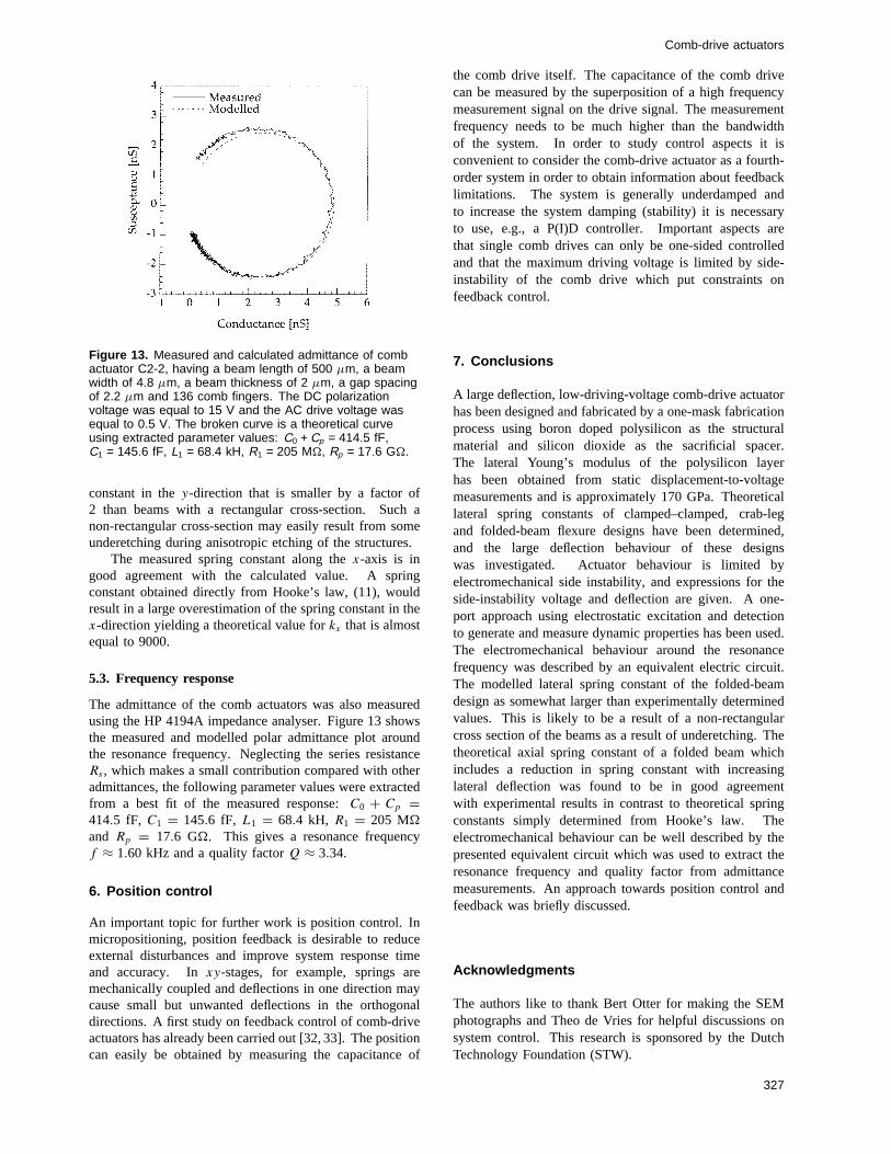
Figure 13. Measured and calculated admittance of combactuator C2-2, having a beam length of 500 µm, a beamwidth of 4.8 µm, a beam thickness of 2 µm, a gap spacingof 2.2 µm and 136 comb fingers. The DC polarizationvoltage was equal to 15 V and the AC drive voltage wasequal to 0.5 V. The broken curve is a theoretical curveusing extracted parameter values: C0 + Cp = 414.5 fF,C1 = 145.6 fF, L1 = 68.4 kH, R1 = 205 M�, Rp = 17.6 G�.
constant in they-direction that is smaller by a factor of2 than beams with a rectangular cross-section. Such anon-rectangular cross-section may easily result from someunderetching during anisotropic etching of the structures.
The measured spring constant along thex-axis is ingood agreement with the calculated value. A springconstant obtained directly from Hooke’s law, (11), wouldresult in a large overestimation of the spring constant in thex-direction yielding a theoretical value forkx that is almostequal to 9000.
5.3. Frequency response
The admittance of the comb actuators was also measuredusing the HP 4194A impedance analyser. Figure 13 showsthe measured and modelled polar admittance plot aroundthe resonance frequency. Neglecting the series resistanceRs , which makes a small contribution compared with otheradmittances, the following parameter values were extractedfrom a best fit of the measured response:C0 + Cp =414.5 fF, C1 = 145.6 fF, L1 = 68.4 kH, R1 = 205 M�
and Rp = 17.6 G�. This gives a resonance frequencyf ≈ 1.60 kHz and a quality factorQ ≈ 3.34.
6. Position control
An important topic for further work is position control. Inmicropositioning, position feedback is desirable to reduceexternal disturbances and improve system response timeand accuracy. Inxy-stages, for example, springs aremechanically coupled and deflections in one direction maycause small but unwanted deflections in the orthogonaldirections. A first study on feedback control of comb-driveactuators has already been carried out [32, 33]. The positioncan easily be obtained by measuring the capacitance of
the comb drive itself. The capacitance of the comb drivecan be measured by the superposition of a high frequencymeasurement signal on the drive signal. The measurementfrequency needs to be much higher than the bandwidthof the system. In order to study control aspects it isconvenient to consider the comb-drive actuator as a fourth-order system in order to obtain information about feedbacklimitations. The system is generally underdamped andto increase the system damping (stability) it is necessaryto use, e.g., a P(I)D controller. Important aspects arethat single comb drives can only be one-sided controlledand that the maximum driving voltage is limited by side-instability of the comb drive which put constraints onfeedback control.
7. Conclusions
A large deflection, low-driving-voltage comb-drive actuatorhas been designed and fabricated by a one-mask fabricationprocess using boron doped polysilicon as the structuralmaterial and silicon dioxide as the sacrificial spacer.The lateral Young’s modulus of the polysilicon layerhas been obtained from static displacement-to-voltagemeasurements and is approximately 170 GPa. Theoreticallateral spring constants of clamped–clamped, crab-legand folded-beam flexure designs have been determined,and the large deflection behaviour of these designswas investigated. Actuator behaviour is limited byelectromechanical side instability, and expressions for theside-instability voltage and deflection are given. A one-port approach using electrostatic excitation and detectionto generate and measure dynamic properties has been used.The electromechanical behaviour around the resonancefrequency was described by an equivalent electric circuit.The modelled lateral spring constant of the folded-beamdesign as somewhat larger than experimentally determinedvalues. This is likely to be a result of a non-rectangularcross section of the beams as a result of underetching. Thetheoretical axial spring constant of a folded beam whichincludes a reduction in spring constant with increasinglateral deflection was found to be in good agreementwith experimental results in contrast to theoretical springconstants simply determined from Hooke’s law. Theelectromechanical behaviour can be well described by thepresented equivalent circuit which was used to extract theresonance frequency and quality factor from admittancemeasurements. An approach towards position control andfeedback was briefly discussed.
Acknowledgments
The authors like to thank Bert Otter for making the SEMphotographs and Theo de Vries for helpful discussions onsystem control. This research is sponsored by the DutchTechnology Foundation (STW).
327
R Legtenberg et al
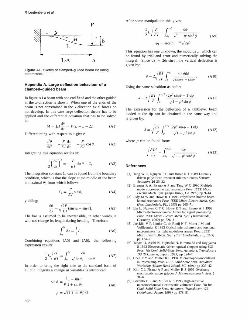
Figure A1. Sketch of clamped–guided beam includingparameters.
Appendix A. Large deflection behaviour of aclamped–guided beam
In figure A1 a beam with one end fixed and the other guidedin the x-direction is shown. When one of the ends of thebeam is not constrained in thex-direction axial forces donot develop. In this case large deflection theory has to beapplied and the differential equation that has to be solvedis:
M = EIdθ
ds= P(L − x − 1). (A1)
Differentiating with respect tos gives:
d2θ
ds2= − P
EI
dx
ds= − P
EIcosθ. (A2)
Integrating this equation results in:
1
2
(dθ
ds
)2
= − P
EIsinθ + Ci. (A3)
The integration constantCi can be found from the boundarycondition, which is that the slope at the middle of the beamis maximalθ0 from which follows
Ci = P
EIsinθ0 (A4)
yielding:dθ
ds=
√2P
EI
(sinθ0 − sinθ
). (A5)
The bar is assumed to be inextensible, in other words, itwill not change its length during bending. Therefore:∫ θ0
0ds = 1
2L. (A6)
Combining equations (A5) and (A6), the followingexpression results:
1
2L
√2P
EI=
∫ θ0
0
dθ√sinθ0 − sinθ
. (A7)
In order to bring the right side to the standard form ofelliptic integrals a change in variables is introduced:
sinφ =√
1 + sinθ
1 + sinθ0
p =√
(1 + sinθ0)/2.
(A8)
After some manipulation this gives:
1
2L
√P
EI=
∫ π/2
φ1
dφ√1 − p2 sin2 φ
φ1 = arcsin −1/2√
2p2.
(A9)
This equation has one unknown, the modulusp, which canbe found by trial and error and numerically solving theintegral. Since dy = 2ds sinθ , the vertical deflection isgiven by:
δ = 2
√EI
2P
∫ θ0
0
sinθdφ√sinθ0 − sinθ
. (A10)
Using the same substition as before:
δ = 2
√EI
P
∫ π/2
φ1
(2p2 sinφ − 1)dφ√1 − p2 sinφ
. (A11)
The expression for the deflection of a cantilever beamloaded at the tip can be obtained in the same way andis given by:
δ =√
EI
P
∫ π/2
φ1
(2p2 sinφ − 1)dφ√1 − p2 sinφ
(A12)
wherep can be found from:√PL2
EI=
∫ π/2
φ1
dφ√1 − p2 sin2 φ
. (A13)
References
[1] Tang W C, Nguyen T C and Howe R T 1989 Laterallydriven polysilicon resonant microstructuresSensorsActuators20 25–32
[2] Brenner R A, Pisano A P and Tang W C 1990 Multiplemode micromechanical resonatorsProc. IEEE MicroElectro Mech. Syst. (Napa Valley, CA 1990)pp 9–14
[3] Judy M W and Howe R T 1993 Polysilicon hollow beamlateral resonatorsProc. IEEE Micro Electro Mech. Syst.(Fort Lauderdale, FL, 1993)pp 265–71
[4] Lin L, Nguyen C T C, Howe R T and Pisano A P 1992Micro-electromechanical filters for signal processingProc. IEEE Micro Electro Mech. Syst. (Travem¨unde,Germany, 1992)pp 226–31
[5] Jaecklin V P, Linder C, de Rooij N F, Moret J M andVuilleumier R 1993 Optical microshutters and torsionalmicromirrors for light modulator arraysProc. IEEEMicro Electro Mech. Syst. (Fort Lauderdale, FL, 1993)pp 124–7
[6] Tabata O, Asahi N, Fujitsuka N, Kimura M and SugiyamaS 1993 Electrostatic driven optical chopper using SOIProc. 7th Conf. Solid-State Sens. Actuators, Transducers’93 (Yokohama, Japan, 1993)pp 124–7
[7] Chen P Y and Muller R S 1994 Microchopper-modulatedIR microlampProc. IEEE Solid-State Sens. ActuatorsWorkshop (Hilton Head Island, SC, 1994)pp 239–42
[8] Kim C J, Pisano A P and Muller R S 1992 Overhungelectrostatic micro gripperJ. Microelectromech. Syst.131–6
[9] Loconto D P and Muller R S 1993 High-sensitivemicromechanical electrostatic voltmeterProc. 7th Int.Conf. Solid-State Sens. Actuators, Transducers ’93(Yokohama, Japan, 1993)pp 878–81
328
Comb-drive actuators
[10] Lee A P and Pisano A P 1992 Polysilicon angularmicrovibromotorsJ. Microelectromech. Syst.1 70–6
[11] Garcia E J and Sniegowski J J 1995 Surfacemicromachined microengine as the driver formicromechanical gears8th Int. Conf. on Solid-State Sens.Actuators, Transducers ’95 (Stockholm, Sweden, 1995)pp 365–8
[12] Jaecklin V P, Linder C, de Rooij N F, Moret J M, BischotR and Rudolf F 1992 Novel polysilicon comb actuatorsfor xy-stagesProc. IEEE Micro Electro Mech. Syst.(Travemunde, Germany, 1992)pp 147–9
[13] Jaecklin V P, Linder C and de Rooij N F 1993 Combactuators forxy-microstagesSensors ActuatorsA3983–9
[14] Jansen H, Verhagen R and Elwenspoek M 1994 The blacksilicon method III: design rules, modelling, optimisationand performance of precision position systems forscanning probe, gripping and other MEMS applicationsSeminar on Handling and Assembly of Microparts(Vienna, Austria, 1994)
[15] Brugger J, Jaecklin V P, Linder C, Blanc N, Indermuhle PF and de Rooij N F 1993 Microfabricated tools fornanoscienceJ. Micromech. Microeng.3 161–7
[16] Xu Y, Mille r S A and MacDonald N C 1995Microelectromechanical scanning tunneling microscopeProc. 8th Int. Conf. Solid-State Sens. Actuators,Transducers ’95 (Stockholm, Sweden,)pp 640–3
[17] Pisano A P and Cho Y H 1990 Mechanical design issues inlaterally-driven microstructuresSensors ActuatorsA21–A23 1060–4
[18] Gere J M and Timoshenko S P 1987Mechanics ofMaterials 2nd edn (Van Nostrand Reinhold)
[19] Frisch-Fay R 1962Flexible bars(London: Butterworths)[20] Tang W C 1990 Electrostatic comb drive for resonant
sensor and actuator applicationsPhD ThesisDepartmentof Electrical Engineering and Computer Sciences,University of California, Berkeley, CA
[21] Judy M W 1994 Micromechanisms using sidewall beamsPhD DissertationFaculty of Electrical Engineering andComputer Sciences, University of California, Berkeley,CA
[22] Fedder G K 1994 Simulation of microelectromechanicalsystemsPhD DissertationFaculty of Electrical
Engineering and Computer Sciences, University ofCalifornia, Berkeley, CA
[23] Shames I H and Dym C L 1985Energy and Finite ElementMethods in Structural Mechanics(New York:McGraw-Hill)
[24] Tang W C, Lim M G and Howe R T 1992 Electrostaticcomb drive levitation and control methodJ.Microelectromech. Syst.1 170–8
[25] Hirano T, Furuhata T, Gabriel K J and Fujita H 1992Design, fabrication and operation of sub-micron gapelectrostatic comb-drive actuatorsJ. Microelectromech.Syst.1 52–9
[26] Jaecklin V P, Linder C, de Rooy N F and Moret J M 1992Micromechanical comb actuators with low drivingvoltageJ. Micromech. Microeng.2 250–5
[27] Tilmans H A C 1993 Micromechanical sensors usingencapsulated built-in resonant strain gaugesPhDDissertationFaculty of Electrical Engineering,University of Twente, Enschede, The Netherlands
[28] Legtenberg R, Jansen H, de Boer M and Elwenspoek M1995 Anisotropic reactive ion etching of silicon usingSF6/O2/CHF3 gas mixturesJ. Electrochem. Soc.1422020–8
[29] Legtenberg R 1996 Electrostatic actuators fabricated bysurface micromachining techniquesPhD ThesisUniversity of Twente, Enschede, The Netherlands
[30] Johnson W A and Warne L K 1995 Electrophysics ofmicromechanical comb actuatorsJ. Microelectromech.Syst.4 49–59
[31] Pratt R I, Johnson G C, Howe R T and Chang J C 1991Micromechanical structures for thin film characterizationProc. Int. Conf. on Solid-State Sens. Actuators,Transducers ’91 (San Francisco, CA, 1991)pp 205–8
[32] Groeneveld A W 1995 Electromechanical behaviour andstudy towards position control of electrostatic combdrive actuatorsMaster ThesisUniversity of Twente,Enschede, The Netherlands
[33] Legtenberg R, Groeneveld A W and Elwenspoek M 1995Towards position control of electrostatic comb drivesProc. 6th Workshop Micromachin. Micromech.Microsyst., MME ’95 (Copenhagen, Denmark, 1995)pp 124–7
329
Copyright © 2022 FDOKUMEN