Dielectric elastomers as next-generation polymeric actuators
14
Dielectric elastomers as next-generation polymeric actuators Ravi Shankar, ac Tushar K. Ghosh cd and Richard J. Spontak* ab Received 16th April 2007, Accepted 6th June 2007 First published as an Advance Article on the web 18th July 2007 DOI: 10.1039/b705737g Due to their versatile properties, robust behavior, facile processability and low cost, organic polymers have become the material of choice for an increasing number of mature and cutting-edge technologies. In the last decade or so, a new class of polymers capable of responding to external electrical stimulation by displaying significant size or shape change has emerged. These responsive materials, collectively referred to as electroactive polymers (EAPs), are broadly classified as electronic or ionic according to their operational mechanism. Electronic EAPs generally exhibit superior performance relative to ionic EAPs in terms of actuation strain, reliability, durability and response time. Among electronic EAPs, dielectric elastomers exhibit the most promising properties that mimic natural muscle for use in advanced robotics and smart prosthetics, as well as in haptic and microfluidic devices. Elastomers derived from homopolymers such as acrylics and silicones have received considerable attention as dielectric EAPs, whereas novel dielectric EAPs based on selectively swollen nanostructured block copolymers with composition-tailorable properties have only recently been reported. Here, we provide an overview of various EAPs in terms of their operational mechanisms, uses and shortcomings, as well as a detailed account of dielectric elastomers as next-generation actuators. I. Introduction to electroactive polymers Fundamental and technological interest in electroactive poly- mers (EAPs), representing a broad class of organic actuators that exhibit large dimensional changes relative to their inorganic counterparts upon electrical stimulation, has grown tremendously over the past decade or so. Electroactive polymers can best be described as soft, flexible materials that are capable of converting electrical energy to mechanical a Department of Materials Science & Engineering, North Carolina State University, Raleigh, NC 27695, USA. E-mail: [email protected] b Department of Chemical & Biomolecular Engineering, North Carolina State University, Raleigh, NC 27695, USA c Fiber and Polymer Science Program, North Carolina State University, Raleigh, NC 27695, USA d Department of Textile & Apparel Technology & Management, North Carolina State University, Raleigh, NC 27695, USA Ravi Shankar: Ravi Shankar is a Ph.D. student majoring in both Fiber & Polymer Science and Materials Science & Engineering at North Carolina State University (NCSU). He received a B.S. degree in Ceramic Engineering and an M.S. degree in Materials Engineering from the National Institute of Technology (India, 2002) and the Indian Institute of Science, (I.I.Sc., 2004), respectively. He is the recipient of the American Chemical Society Richard D. Gilbert Award in Polymer Science (NC Polymer Discussion Group), the Karra Narasimhamurthy Gold Medal for the best graduate thesis at I.I.Sc. and the Best Overall Poster Award at the 15th Annual National Textile Center Forum. He has published 10 research papers, and his work has been featured on the cover of 2 international journals. His research interests focus on electro- active polymers, smart materials, polymeric dielectrics, and structure–property relationships of nanostructured polymers and polymer nanocomposites. Tushar K. Ghosh: Tushar Ghosh is a Professor in the College of Textiles at NCSU. He received a B.Sc.Tech. degree in Textile Technology from the University of Calcutta (1975), an M.Tech. degree in Textile Engineering from the Indian Institute of Technology at New Delhi (1978) and M.S. and Ph.D. degrees in Textile Materials and Management (1984) and Fiber & Polymer Science (1987), respectively, from NCSU. He joined the faculty at NCSU in 1987, and has since been a visiting Professor at the University of Sydney and the Indian Institute of Technology at Bombay. He has been named Outstanding Teacher of the Year and selected for the Circle of Excellence by the National Textile Center. His research activities are devoted to the design and development of functional fibers and fiber-based structures for adaptive and responsive textiles. His current interests include the fabrication of sensors and actuators involving polymer nanocomposites, electroactive polymers, artificial muscle and biomimetic systems. Ravi Shankar Tushar K. Ghosh REVIEW www.rsc.org/softmatter | Soft Matter 1116 | Soft Matter, 2007, 3, 1116–1129 This journal is ß The Royal Society of Chemistry 2007
Transcript of Dielectric elastomers as next-generation polymeric actuators

Dielectric elastomers as next-generation polymeric actuators
Ravi Shankar,ac Tushar K. Ghoshcd and Richard J. Spontak*ab
Received 16th April 2007, Accepted 6th June 2007
First published as an Advance Article on the web 18th July 2007
DOI: 10.1039/b705737g
Due to their versatile properties, robust behavior, facile processability and low cost, organic
polymers have become the material of choice for an increasing number of mature and cutting-edge
technologies. In the last decade or so, a new class of polymers capable of responding to external
electrical stimulation by displaying significant size or shape change has emerged. These responsive
materials, collectively referred to as electroactive polymers (EAPs), are broadly classified as
electronic or ionic according to their operational mechanism. Electronic EAPs generally exhibit
superior performance relative to ionic EAPs in terms of actuation strain, reliability, durability and
response time. Among electronic EAPs, dielectric elastomers exhibit the most promising
properties that mimic natural muscle for use in advanced robotics and smart prosthetics, as well as
in haptic and microfluidic devices. Elastomers derived from homopolymers such as acrylics and
silicones have received considerable attention as dielectric EAPs, whereas novel dielectric EAPs
based on selectively swollen nanostructured block copolymers with composition-tailorable
properties have only recently been reported. Here, we provide an overview of various EAPs in
terms of their operational mechanisms, uses and shortcomings, as well as a detailed account of
dielectric elastomers as next-generation actuators.
I. Introduction to electroactive polymers
Fundamental and technological interest in electroactive poly-
mers (EAPs), representing a broad class of organic actuators
that exhibit large dimensional changes relative to their
inorganic counterparts upon electrical stimulation, has grown
tremendously over the past decade or so. Electroactive
polymers can best be described as soft, flexible materials that
are capable of converting electrical energy to mechanical
aDepartment of Materials Science & Engineering, North Carolina StateUniversity, Raleigh, NC 27695, USA. E-mail: [email protected] of Chemical & Biomolecular Engineering, North CarolinaState University, Raleigh, NC 27695, USAcFiber and Polymer Science Program, North Carolina State University,Raleigh, NC 27695, USAdDepartment of Textile & Apparel Technology & Management, NorthCarolina State University, Raleigh, NC 27695, USA
Ravi Shankar: Ravi Shankar isa Ph.D. student majoring inboth Fiber & Polymer Scienceand Materials Science &Engineering at North CarolinaState University (NCSU). Hereceived a B.S. degree inCeramic Engineering and anM.S. degree in MaterialsEngineering from the NationalInstitute of Technology (India,2002) and the Indian Instituteof Science, (I.I.Sc., 2004),respectively. He is the recipientof the American ChemicalSociety Richard D. Gilbert
Award in Polymer Science (NC Polymer Discussion Group),the Karra Narasimhamurthy Gold Medal for the best graduatethesis at I.I.Sc. and the Best Overall Poster Award at the 15thAnnual National Textile Center Forum. He has published 10research papers, and his work has been featured on the cover of 2international journals. His research interests focus on electro-active polymers, smart materials, polymeric dielectrics, andstructure–property relationships of nanostructured polymers andpolymer nanocomposites.
Tushar K. Ghosh: TusharGhosh is a Professor in theCollege of Textiles at NCSU.He received a B.Sc.Tech.degree in Textile Technologyfrom the University of Calcutta(1975), an M.Tech. degree inTextile Engineering from theIndian Institute of Technologyat New Delhi (1978) and M.S.and Ph.D. degrees in TextileMaterials and Management(1984) and Fiber & PolymerScience (1987), respectively,from NCSU. He joined thefaculty at NCSU in 1987, and
has since been a visiting Professor at the University of Sydneyand the Indian Institute of Technology at Bombay. He has beennamed Outstanding Teacher of the Year and selected for theCircle of Excellence by the National Textile Center. His researchactivities are devoted to the design and development of functionalfibers and fiber-based structures for adaptive and responsivetextiles. His current interests include the fabrication of sensorsand actuators involving polymer nanocomposites, electroactivepolymers, artificial muscle and biomimetic systems.
Ravi Shankar Tushar K. Ghosh
REVIEW www.rsc.org/softmatter | Soft Matter
1116 | Soft Matter, 2007, 3, 1116–1129 This journal is � The Royal Society of Chemistry 2007
energy and thus imparting a force and/or motion.1–4 For this
reason, EAPs are considered ‘‘smart’’ materials due to their
responsive and often tunable properties. These polymers can
be uniquely considered as examples of both sensors and
transducers.2 A sensor is a material or device that is capable of
monitoring changes in a specific system parameter without
altering the parameter, whereas a transducer transforms
energy from one form to another. More specifically, EAPs
behave as actuators since they convert electrical energy into
mechanical energy much in the same fashion as an electric
motor can be used to generate torque. Vast improvements in
actuator performance are becoming increasingly important in
growing fields such as mechatronics, microrobotics, micro-
fluidics and bionics in which case high efficiencies at small
scales, high power-to-weight ratios and large degrees of
compliance must be ultimately realized.5–7
Since EAPs are capable of mechanical actuation induced by
an external electrical potential and since they are also
lightweight, flexible, tough, shape-processable and inexpensive
(unlike their rigid and often fragile inorganic counterparts),
they afford tremendous promise in emerging technologies
ranging from micro air vehicles (MAVs) and flat-panel
speakers2 to active video displays, switchable optics and haptic
devices.2,8 In some cases, the electroresponsive properties of
EAPs mimic biological muscle, which explains why EAPs are
often referred to as artificial muscle. Key material attributes
such as resilience, toughness, actuation strain and stress, non-
hysteretic cycling and vibration damping, coupled with high
fatigue resistance, scalability and reliability,2,3 constitute
critically important considerations in biomimetic efforts
designed to emulate the inherent muscular behavior of animals
and insects. For reasons such as these, EAPs constitute an
exciting class of intelligent materials for use in conjunction
with medical implants, responsive prosthetics and, more
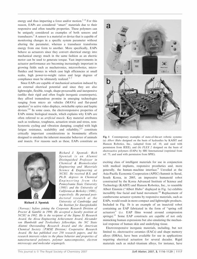
generally, the human–machine interface.9 Unveiled at the
Asia-Pacific Economic Cooperation (APEC) Summit in Seoul,
South Korea, in 2005, an impressive humanoid robot
constructed by the Korea Advanced Institute of Science and
Technology (KAIST) and Hanson Robotics, Inc., to resemble
Albert Einstein (‘‘Albert Hubo’’ displayed in Fig. 1a) exhibits
incredibly fine facial and hand movement.10 Replacement of
cumbersome actuator systems by responsive materials, such as
EAPs, would result in more compact and lightweight products.
Included in Fig. 1b is an example of an insectoid robot
containing an EAP fabricated in the form of ‘‘spring roll
actuators’’ (i.e. EAP films wound around compression
springs).11 Some EAP constructs are capable of not only
mimicking human expressions but also emulating the mechan-
ical response of human skin and underlying tissue.
Electroresponsive inorganic materials, including, but not
limited to, electroactive ceramics (EACs) and shape memory
alloys (SMAs), have been available for use in applications
requiring electrical actuation for several decades. Rigid
materials such as nickel–titanium alloys, for instance, have
Fig. 1 Contemporary examples of state-of-the-art robotic systems:
(a) Albert Hubo designed on the basis of hydraulics by KAIST and
Hanson Robotics, Inc., (adapted from ref. 10, and used with
permission from IEEE), and (b) FLEX 2 designed on the basis of
electroactive polymers (EAPs) by SRI International (reprinted from
ref. 75, and used with permission from SPIE).Richard J. Spontak: RichS p o n t a k i s a n A l u m n iDistinguished Professor inChemical & BiomolecularEngineering and MaterialsScience & Engineering atNCSU. He received B.S. andPh.D. degrees in ChemicalE n g i n e e r i n g f r o m t h ePennsylvania State University(1983) and the University ofCalifornia at Berkeley (1988),respectively. He pursued post-doctoral research at theUniversity of Cambridge andthe Institutt for Energiteknikk
(Norway) before joining the Corporate Research Division ofProcter & Gamble in 1990. He accepted a faculty position atNCSU in 1992. He is the recipient of the Sigma Xi ResearchAward, the Alcoa Engineering Achievement Award, Alexandervon Humboldt and Tewkesbury fellowships, the NC StateAlumni Outstanding Research Award and the AmericanChemical Society (PMSE Division) Cooperative ResearchAward. He has published over 250 research papers, and hisresearch interests relate to the phase behavior and properties ofnanostructured polymers, polymer nanocomposites, electronmicroscopy and molecular organogels.
Richard J. Spontak
This journal is � The Royal Society of Chemistry 2007 Soft Matter, 2007, 3, 1116–1129 | 1117

found extensive use in diverse technologies ranging from
hydraulic line couplers on jet fighters to catheter guides in the
medical field, but they are severely limited by shortcomings
that do not plague EAPs. While SMAs can generate high
forces and displacements, they tend to suffer from slow
response times, large mechanical hysteresis and short cycle
life.6 Ongoing efforts12 aimed at surmounting these limitations
employ an external fuel source that serves to quickly change
surface temperature and thus induce actuation. Similarly,
EACs are effective as compact, rapidly responsive materials,
but they offer relatively little mechanical actuation (,1%
strain), and are typically fragile and expensive.7,13 A compar-
ison among EAC, SMA and EAP properties has been reported
by Bar-Cohen2 and is reproduced in Table 1. Since EAPs
encompass a broad range of materials,1,2 they are routinely
divided into two general categories on the basis of their
physical state or actuation mechanism: ionic (or wet), wherein
the EAPs may require the presence of a liquid medium to
function by ion transport, and electronic (or dry), wherein
the EAPs intrinsically actuate due to Coulombic forces.2 In the
following sections, both EAP categories will be explored on the
bases of mechanism and performance.
II. Ionic EAPs
In this section, three important types of ionic EAPs – carbon
nanotubes (CNTs), conductive polymers (CPs), and ionic
polymer–metal composites (IPMCs) – are surveyed. In some
cases, these materials are more accurately described as either
nanostructured carbons (without the presence of a macro-
molecular species) or hybrid organic–inorganic materials
composed of nanoscale particulates dispersed within a
continuous polymeric matrix. The latter type of EAP may
likewise be considered a polymer nanocomposite, depending
on the characteristic size of the particulates employed.14
Details regarding other ionic EAPs (e.g. electrorheological
fluids and ionic polymer gels) may be found elsewhere.1,2,15,16
A. Carbon nanotubes (CNTs)
With the discovery of CNTs over a decade ago by Iijima,17 this
family of nanostructured carbon remains a subject of
considerable and broad interest due to the intrinsic properties
and functionalization potential of CNTs, as well as materials
containing them. Carbon nanotubes are differentiated on the
basis of their nanostructure as either single-wall (SWNT),
composed of a single graphene layer, or multi-wall (MWNT),
with the former frequently measuring 1 to 20 nm in
diameter.4,18 In the case of MWNTs, the diameter can be
significantly larger and likewise exhibit considerable dispersity,
depending on process conditions and the number of walls/
nanotube thus generated. Excellent reviews18–20 are available
on the subject of CNTs, and a high-resolution transmission
electron microscopy (TEM) image21 and corresponding sche-
matic of an isolated SWNT are shown for illustrative purposes
in Fig. 2a. Even though CNTs exhibit a wide array of
interesting properties ranging from gas storage to molecular
catalysis, our focus in this work is restricted to the efficacy of
CNTs as actuators. Electrical activation3 of CNTs is based on
double-layer charge injection in which individual CNTs or
CNT macrostructures (usually in the form of sheets) are
immersed in an electrolyte solution, and a potential is applied
between the CNTs and a counter electrode, as depicted in
Fig. 2b. Ions residing in a CNT attract oppositely charged
electrolyte ions on the outer CNT surface, which induces a
rearrangement of the CNT electronic structure and accom-
panying Coulombic forces. Taken together, these factors yield
a dimensional change in the CNT.
Baughman et al.4 report that CNTs can be used as bimorph
cantilever actuators capable of electrically-stimulated bending
(cf. Fig. 2c). They have also shown that ‘‘bucky paper,’’
consisting of randomly distributed CNTs, can generate
actuated strains .0.2 %. While MWNTs are intuitively
expected to be less effective than SWNTs as actuators due to
Fig. 2 Demonstration of carbon nanotubes (CNTs) as electroactive
materials. A high-resolution transmission electron microscopy (TEM)
image of a lone SWNT (adapted from ref. 21, and used with
permission from Springer) and a corresponding artistic rendition
(reprinted from en.wikipedia.org/wiki/Wikipedia:Featured_picture_
candidates/February-2006, and used with permission) are displayed
in (a). In (b), the mechanism by which CNT-based actuators operate is
illustrated (reprinted from ref. 11, with permission from Elsevier). In
(c), experimental data confirm that electrically-driven CNT ‘‘paper’’
(15 mm thick) can bend a polymer film measuring y0.2 mm thick
(adapted from ref. 4, and used with permission from the American
Association for the Advancement of Science).
Table 1 Comparison of various inorganic and organic electroactivematerialsa
Property EAC SMA EAP
Actuation strain (%) 0.1–0.3 ,8 .1 (up to .200)Blocking force/MPa 30–40 y700 0.1–3Actuation-speed magnitude/s 1026–1 1–102 1026–102
Mass density/g cm23 6–8 5–6 0.9–2.5Drive voltage/V (field/V mm21) 50–800 5 2–7 (10–150)Consumed power magnitudeb/W 1 1 1023
Mechanical response Fragile Elastic Elastic, resilienta Reproduced with minor alteration from ref. 2. b Powerconsumption is based on devices that are driven by the actuators.
1118 | Soft Matter, 2007, 3, 1116–1129 This journal is � The Royal Society of Chemistry 2007

lower solvent-accessible area and, hence, less exposed surface
area for ion capture,3 recent results provided by Hughes and
Spinks22 indicate that MWNT mats can likewise undergo
comparable strain (y0.2 %) upon actuation. Actuators
fabricated on the basis of CNTs possess the greatest likelihood
of achieving a high work density, that is, the mechanical work
per unit mass of actuator generated upon electrical actuation.4
In fact, the work density of CNTs can be 30 times greater than
any other actuator technology at the present time due to their
incredibly high modulus (the Young’s moduli, Y, of single
SWNTs3 and MWNTs1 are reported to lie between y0.6 and
y1 TPa), because the work density is directly proportional to
the modulus. In the case of operational actuator devices
fabricated from CNT assemblies, Madden et al.23 have
experimentally measured moduli and specific energies of up
to 0.95 GPa and 4.5 kJ kg21, respectively. Another attractive
feature of CNT actuators is the low voltage (y1 V) required
for actuation. Although CNT actuators suffer from poor
electromechanical coupling (i.e. the conversion from electrical
to mechanical work), high manufacturing costs (especially for
SWNTs) and low mass production, ongoing efforts24,25
designed to grow and harvest highly oriented CNTs into
designer yarns and sheets keep this actuator technology on the
research forefront. Of particular interest is the use of CNT
actuators as active noise and vibration reduction materials at
low frequencies.3,4
B. Conductive polymers (CPs)
Inganas and co-workers26,27 have provided the first evidence
that CPs possessing a conjugated organic backbone and
arranged in two layers of conducting electrodes separated by
an electrolyte solution could function as actuators. While two
of the most common CPs presently available are polypyrrole
(PPy) and polyaniline (PANi), other CP candidates identified
to date include polythiophene, poly(p-phenylene vinylene)
(PPV), and trans-polyacetylene (t-PAc).1,3 The mechanism by
which actuation occurs in CP systems proceeds on the basis of
reversible counter-ion uptake and expulsion that occurs during
redox cycling.1–3,11 Electrochemically induced changes in
oxidation state promote a corresponding charge flux along
the polymer backbone, which then triggers a responsive flux of
ions to balance the charge. This ion flux causes the CP to
expand if it is oxidized or contract if it is subsequently reduced,
thereby yielding controllable and cyclic electrical actuation.28
Electrochemical reactions required to initiate this response
commonly require low voltages (1–2 V),3 and resultant
actuation strains range from 1 to ca. 40 %.11,29 A promising
aspect of CP actuators is that their achievable force density,
while measured30 up to y100 MPa, is anticipated28 to be as
high as 450 MPa. However, CP actuators suffer from several
serious drawbacks. They exhibit low efficiencies (on the order
of 1 %) and electromechanical coupling (,1 %),3 in addition to
moderately low linear actuation-strain levels (y12 %).31
Actuation-strain rates are likewise slow due to the diffusion
process required for ions to be absorbed in and expelled from
the polymer,1 as well as internal resistance between the
polymer and electrolyte solution.3 Because of the need for an
electrolyte solution, most CP actuators must be isolated from
the environment through the use of encapsulating materials.32
Further development of solid-state electrolytes,33 however,
precludes the need for encapsulation. Lastly, sputtered metal
films applied to the CP surface are prone to delaminate over
time and repeated use. With these shortcomings notwithstand-
ing, CP actuators represent viable candidates for technologies
requiring low applied voltages and a high energy density/cycle,
examples of which include catheters, as well as automotive and
prosthetic devices.
C. Ionic polymer–metal composites (IPMCs)
Several studies32,34,35 have demonstrated that ionic polymer–
metal composites, also referred to as IPMCs, are ideally suited
as soft actuators for bending and sensing applications. The
materials comprising this class of EAPs are routinely described
as composite laminates, each consisting of a thin (200–300 mm),
water-swollen ion-exchange membrane with thin metal (Pt, Pd,
Ag or Au) or carbon electrodes plated on both faces, as
illustrated in Fig. 3a. Examples of suitable ion-exchange
membranes include perfluorinated ionomers, such as Nafion1
and Flemion1 with anionic-terminated side groups, or
polystyrene ionomers with anionic-substituted phenyl rings.2
Fig. 3 Schematic diagram showing the operational principle of
IPMCs. Prior to actuation, the aqueous IPMC is flat (a).
Application of an electrical potential promotes migration of cations,
thereby causing the IPMC to curve or bend (b). The system eventually
adjusts to the applied electrical potential (c), and can return to (a)
upon removal of the potential (reprinted from ref. 3, with permission
from IEEE).
This journal is � The Royal Society of Chemistry 2007 Soft Matter, 2007, 3, 1116–1129 | 1119

Prior to application of an electric potential, ion clustering
occurs uniformly throughout the IPMC, because the solvated
polymer matrix consists of a hydrophobic polymer backbone
and hydrophilic anionic side groups in the presence of water.
In the case of IPMC actuators, the polymer matrix is normally
negatively charged, in which case counterions (i.e. cations) are
introduced into the matrix. The mobile cations initially
aggregate as clusters in discrete pockets of water throughout
the membrane. As an electrical potential is applied across the
IPMC actuator, however, the cations spatially redistribute as
they diffuse toward the negative electrode, thereby forming a
cation-rich layer along one side of the membrane and depleting
cations from the opposite side (cf. Fig. 3b and 3c). The result
of this process is fast bending of the IPMC toward one
electrode, followed by slow relaxation toward the other
electrode, due to unequal charge accumulation.34,35 As with
the previously described ionic EAPs, IPMC actuators require
relatively low actuation voltages (y1 V).3 In fact, the applied
electromechanical potential must not exceed 1.23 V, to avoid
water electrolysis.1,4 Due to their inherent need for water to
control cation transport and the swollen nature of the mem-
branes, these actuators lack rigidity and exhibit a low work
density3 (y10 W kg21 versus 103 W kg21 for natural muscle).2
With these limitations notwithstanding, IPMC actuators can
be used as catheters and elliptical friction drive elements,
peristaltic pumps and bionic devices for augmenting muscle.
III. Electronic EAPs
In the previous section, the operational mechanisms and
potential applications associated with ionic EAPs have been
explored. This section now focuses on EAPs that respond
directly, without the use of added charge carriers (e.g.
electrolyte solutions), to an external electric field. Such
materials, referred to as electronic EAPs, do not require mass
transport and are therefore not diffusion-limited. The con-
sequence is that electronic EAPs, commonly distinguished on
the basis of their actuation mechanism as either electrostrictive
(ferroelectric polymers) or electrostatic (dielectric elastomers),
generally possess fast response times. These two EAP
categories are discussed below.
A. Ferroelectric polymers
Electrostriction occurs when the dielectric properties of a
material change with strain.1,2 Examples of electrostrictive
polymer actuators include ferroelectric macromolecules such
as polyvinylidene fluoride (PVDF), poly(vinylidene fluoride-
co-trifluoroethylene) (PVDF–TrFE), polyvinyl fluoride (PVF),
odd-numbered nylons (with an odd number of carbon atoms
between amide groups) and polyurethane.1,2 One of the most
extensively investigated materials, PVDF, as well as its
copolymers and terpolymers, is semicrystalline, composed of
crystals dispersed in an amorphous, molten matrix. Reported36
values of the normal melting and glass transition temperatures
for commercial-grade PVDF are 176 and 60 uC, but
copolymerization of PVDF commonly induces a reduction in
these transition temperatures. Upon application of an external
electric field, domains of amorphous polymer become
polarized and align in the direction of the applied field. This
field-induced polarization is permanent, remaining after
cessation of the field.3 A molecular-level representation of
field-induced actuation is provided for PVDF in Fig. 4a, which
depicts the all-trans (T) conformation constituting the b phase.
The electromechanical response of PVDF is attributed to a
phase transformation from ferroelectric (all T) to paraelectric
(a mixture of T and gauche, G).37 It is evident from this figure
that the transformation to the a phase promotes a large change
in the lattice constant, which has been experimentally
confirmed by Tashiro et al.38 The large molecular strains
induced by such a transition are often accompanied by
relatively large strain hysteresis.
Zhang et al.39 have proposed that this problem can be
overcome further by reducing the energy barrier associated
with the conformational transition (polarization switching).
Fig. 4 In (a), molecular depictions of PVDF, an electrostrictive
ferroelectric polymer. The b phase (with an all-T conformation) is
responsible for ferroelectricity, whereas the a phase (with both T and
G conformations) promotes paraelectricity (adapted from ref. 11, and
used with permission from Elsevier). In (b), the transverse strain is
presented as a function of electric field for PVDF–TrFE modified42
with 40 wt% CuPc (6, see inset for the chemical structure) and
PVDF–TrFE–CTFE (#) modified44 with two different concentrations
of PANi (in vol%): 13 (m) and 23 ($). The solid line verifies that the
strain scales as E2 in accord with eqn (3), whereas the dashed and
dotted lines (power-law regressions to the data) deviate from this
expected behavior and thus serve only as guides for the eye.
1120 | Soft Matter, 2007, 3, 1116–1129 This journal is � The Royal Society of Chemistry 2007
To achieve this, they have used high-energy electron radiation
to introduce defects into the crystalline structure of the
PVDF–TrFE copolymer. Such radiation treatment breaks
down domains of coherent polarization and transforms the
polymer into a nanostructured material consisting of nano-
scale polar regions (b phase) embedded in a nonpolar matrix
(a phase).2 The conformational changes generated by an
applied electric field, coupled with a large lattice strain (due to
the difference between the lattice constants of the polar and
nonpolar regions), are responsible for a macroscopically large
electrostrictive strain. More recently, Zhang and co-workers40
have adopted several other approaches to enhance the
actuation performance of PVDF-based actuators. A terpoly-
mer composed of PVDF–TrFE with a small quantity
(y4 mol%) of chlorofluoroethylene (CFE, –CH2–CFCl–) has
been found to exhibit superior electromechanical properties
relative to the parent PVDF–TrFE copolymer. A thickness
strain of 4.5% with a coupling efficiency of 55% has been
achieved at a relatively low electric field (130 V mm21). Starting
with an elastomer, Su et al.41 have chemically grafted
polarizable sequences onto flexible polymer backbones to
generate electrostrictive graft elastomers that can attain strains
of y4% upon actuation.
In another strategy,42 the dielectric constant (e) of the
PVDF–TrFE copolymer has been greatly improved through
the physical addition of a high-e organometallic filler, namely,
copper phthalocyanine (CuPc, with e . 106). In this case,
addition of 40 wt% CuPc, a highly planar compound (depicted
in the inset of Fig. 4b), is observed to increase e of the hybrid
material from 40 to 225. The composition dependence of e in a
PVDF–TrFE copolymer modified with CuPc is shown in
Fig. 4b. Bobnar et al.43 have likewise investigated a multi-
component composite consisting of PVDF–TrFE–CFE
modified with CuPc, whereas Huang et al.44 have studied the
electromechanical behavior of PVDF–TrFE–chlorotrifluoro-
ethylene (CTFE) terpolymer modified with different concen-
trations of PANi (included for comparison in Fig. 4b).
Generally speaking, the advantages of such electrostrictive
EAPs is that moderate strains (up to y7%) can be achieved
under low-frequency fields, but they can also be operated at
frequencies in excess of 100 kHz.3 They can likewise generate
high stresses1 (ca. 45 MPa) due to their high Young’s
modulus40 (.0.4 GPa), and thus produce higher energy
densities relative to piezoelectric ceramics.1 A severe drawback
of electrostrictive EAPs is the high voltage (.1 kV) or,
alternatively, electric field (y150 V mm21) required for
actuation. Due to the relatively high strains that are routinely
achieved with these materials, surface electrodes tend to
fatigue, and the EAPs show signs of considerable hysteresis,
upon cycling.2
B. Dielectric elastomers
In dielectric elastomers (D-EAPs, also referred1–3 to as electro-
elastomers or elecrostatically stricted polymers, ESSPs), the
electric field-induced actuation response is initiated by the
electrostatic attraction between oppositely charged conductive
layers applied to the opposing surfaces of a thin elastomeric
film.45–48 This attraction induces a compressive stress, the
magnitude of which is dictated by the magnitude of the electric
field (E) and e. The level of corresponding strain achieved
upon actuation, on the other hand, depends on Y. To ensure
high actuation and cyclic displacement, these EAPs must (i)
possess shape memory due to chemical or physical cross-
linking, (ii) be flexible with a relatively low Y and (iii) possess a
moderate-to-high dielectric constant (typical e values range
from ca. 3 to 7).2,3 Representative material properties of
previously investigated D-EAPs are listed in Table 1, whereas
corresponding metrics of electromechanical actuation (defined
in the following sections) are provided in Table 2. Introduction
of polar functionalities along the polymer backbone generally
tends to increase the value of e, but does not necessarily ensure
that the electrical actuation response will be improved.
Accompanying changes in Y (due, for instance, to the method
or extent of cross-linking)49,50 and chain entanglement, as well
as the propensity for specific inter/intramolecular interactions,
may adversely affect the ability of an elastomer to respond to
electrical stimulation. Pelrine et al.45 have reported that a
commercial acrylic elastomer with moderate values of e and Y
can exhibit very high displacements when subjected to an
external electric field. While a large number of elastomers
derived from homopolymers (e.g. silicones,45,50 fluoropoly-
mers51 and natural or synthetic rubber)51 have been evaluated
as D-EAPs, this acrylic elastomer has set the benchmark
against which the performance efficacy of this family of
materials is commonly assessed. Recent efforts47,48 have
demonstrated that electroactive nanostructured polymers
(ENPs) composed of a microphase-separated triblock copoly-
mer in a nonpolar midblock-selective solvent can likewise
achieve high actuation strains at much lower electric fields
than the acrylic elastomer. A detailed description of each of
these materials is provided in a later section.
1. Actuation mechanism. As alluded to above, the electro-
mechanical response of dielectric EAPs is attributed to the
development of a Maxwell stress (sM) upon application of an
external electrical field.11,45,47,48 In the context of continuum
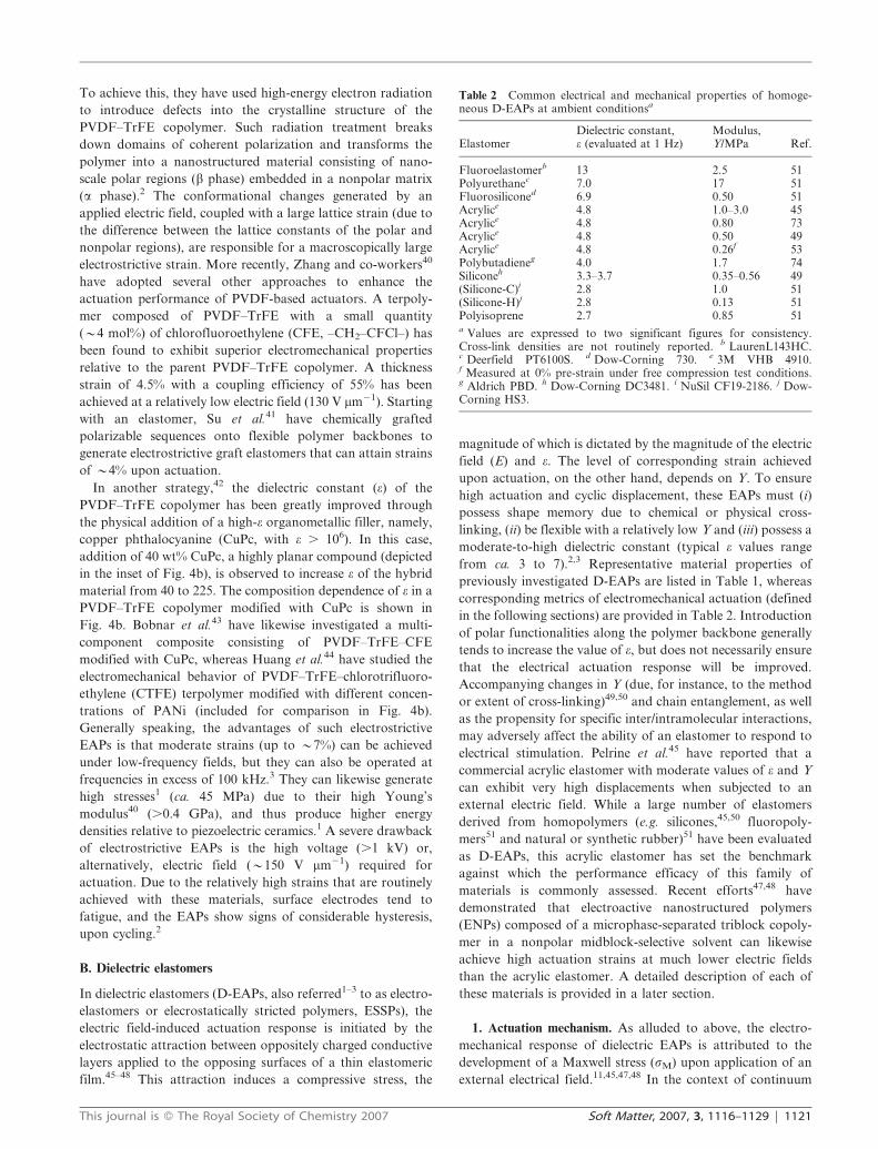
Table 2 Common electrical and mechanical properties of homoge-neous D-EAPs at ambient conditionsa
ElastomerDielectric constant,e (evaluated at 1 Hz)
Modulus,Y/MPa Ref.
Fluoroelastomerb 13 2.5 51Polyurethanec 7.0 17 51Fluorosiliconed 6.9 0.50 51Acrylice 4.8 1.0–3.0 45Acrylice 4.8 0.80 73Acrylice 4.8 0.50 49Acrylice 4.8 0.26f 53Polybutadieneg 4.0 1.7 74Siliconeh 3.3–3.7 0.35–0.56 49(Silicone-C)i 2.8 1.0 51(Silicone-H)j 2.8 0.13 51Polyisoprene 2.7 0.85 51a Values are expressed to two significant figures for consistency.Cross-link densities are not routinely reported. b LaurenL143HC.c Deerfield PT6100S. d Dow-Corning 730. e 3M VHB 4910.f Measured at 0% pre-strain under free compression test conditions.g Aldrich PBD. h Dow-Corning DC3481. i NuSil CF19-2186. j Dow-Corning HS3.
This journal is � The Royal Society of Chemistry 2007 Soft Matter, 2007, 3, 1116–1129 | 1121

mechanics, the Maxwell stress, schematically depicted in Fig. 5,
acts normal to the film surface and thus serves to compress
the film along its thickness (z) and stretch the film laterally
(in x and y). Depending on material properties identified
earlier (e and Y) and the magnitude of E, the resultant
Maxwell stress can induce a significant compressive strain in a
D-EAP (e.g. y70% in the acrylic elastomer).45 Most D-EAP
applications exploit this large dimensional change normal to
the applied electric field. To improve the extent of strain
achieved upon actuation for a given voltage (V), D-EAPs are
routinely pre-strained biaxially or uniaxially to reduce the
initial film thickness (z0) and therefore increase E (= V/z0).48
Conversely, a desired thickness strain can be achieved at a
lower applied voltage. While mechanical pre-strain has also
been observed to (i) enhance the dielectric strength of D-EAPs
by promoting molecular alignment,52 and (ii) reduce the
effective compressive modulus of D-EAPs (which enhances
lateral actuation),53 it requires a rigid support frame for
application purposes and suffers from elastomer relaxation
and adhesive failure over time. Some D-EAPs have recently
been found48 to exhibit adequate electrical actuation without
pre-strain.
2. Actuation characteristics. The key parameters that are
commonly employed to assess actuator performance must be
fully understood prior to a detailed comparison of D-EAP
actuators. It is important to recognize that, despite their
attractively large actuation strains, high energy densities, fast
response times and high coupling efficiencies, not all D-EAPs
may provide the best performance required in all actuator
applications. For this reason, a systematic description of the
metrics needed to evaluate actuation efficacy is required. In
this section, we present and discuss the common characteristic
parameters used to describe D-EAP performance.
a. Maxwell stress and blocking force. The Maxwell stress,
commonly regarded as an electrostatic pressure acting
perpendicular to the D-EAP film surface, describes the
mechanical response of a D-EAP to electrical stimulation.1–3
Upon application of a transverse electric field via compliant
electrodes coated on opposing film surfaces (cf. Fig. 5), the
D-EAP film compresses along the z-direction and expands
laterally due to attractive electrostatic charges across the
electrodes and repulsive like charges along each electrode.
According to Pelrine et al.,45 the Maxwell stress acting along z
can be expressed as:
sM = eeoE2 (1)
where eo is the permittivity of free space. Eqn (6) establishes
that the electric field-induced normal stress introduced during
actuation is proportional to the square of the applied field and
the dielectric constant of the D-EAP, which distinguishes
D-EAP actuators from other electrostatic materials because e
of a polymer can be easily altered (by chemical or physical
means) to increase sM without increasing the operating
voltage. Along a lateral dimension, the blocking force
constitutes the force required to return a fully energized
actuator to zero displacement. In other words, it is the force
generated by a linear actuator under the constraint of constant
length. Kofod et al.54 have derived a relationship between the
blocking force along the y-direction (Fy) and other relevant
actuator attributes for D-EAPs, viz.,
Fy = (x0z0/ay)eeoE2 (2)
where ay (= y/y0) is the film displacement in the y-direction,
while the orthogonal lateral dimension (x0) is held constant.
The blocking stress (sB) is therefore given by Fy/Ay, where Ay
is the cross-sectional area over which Fy acts (cf. Fig. 5).
Spinks et al.55 have examined the effect of preload tension on
Fy in PPy ionic actuators, and provide an analysis by which to
explain their observation that Fy decreases with increasing
preload tension.
b. Actuation displacement. The magnitude and type of strain or
displacement generated by EAPs upon electrical stimulation
constitute critically important design considerations. Different
classes of EAPs exhibit distinct types of strain (e.g. tensile or
bending) with displacements varying by orders of magnitude.
Therefore, it is imperative that the strain be unambiguously
classified on the basis of an EAP’s response to stimulation. As
previously discussed, some EAPs including, but not limited to,
IPMCs, CPs and CNTs undergo a bending strain upon
actuation,1–3 in which case their response must be expressed
accordingly. For D-EAPs, however, the actuation-induced
transverse strain promotes a large in-plane strain, which is
easily measured and often reported.2,3,45 Differences such as
these provide a potential source of confusion, since published
reports tend to compare the actuation performance of different
EAPs on the basis of strain without precisely delineating the
type of actuation strain actually measured. Comparisons must
therefore be made with caution, since areal or in-plane strains
are typically an order or magnitude greater than transverse (or
thickness) strain.45,47
Transverse or thickness strain. This actuation strain reflects a
dimensional change in the thickness direction of an EAP film
due to the normal pressure induced by an electrostatic
Maxwell stress or electrostriction or combination of both.51
Because D-EAPs, in particular, significantly change their
dimensions upon electrical stimulation, this strain establishes a
characteristic signature of a given D-EAP material, and it is
used to determine many other important actuation parameters.
Fig. 5 Schematic illustration showing the operational principle of
D-EAPs. Prior to actuation, the elastomer film of initial thickness z0 is
coated on each side with a compliant electrode. An applied electric
field promotes attraction of the oppositely charged electrodes, thereby
introducing a compressive Maxwell stress (sM) along the transverse
(z) direction. Actuation is normally measured in terms of the lateral
(in-plane) dimensional change, and the blocking force along the
y-direction (Fy), for example, is identified.
1122 | Soft Matter, 2007, 3, 1116–1129 This journal is � The Royal Society of Chemistry 2007
Since bulk D-EAP films evaluated for actuation efficacy are
usually thin (often of the order of 1 mm), direct measurement
of strain along the z-direction can be challenging. For this
reason, the thickness, or transverse, strain is routinely
calculated from experimental measurements of in-plane
(lateral) actuation strain under the assumption of isochoric
deformation. Yang et al.,56 however, have experimentally
measured the transverse strain of silicone and polyurethane
elastomers using laser Doppler interferometer. In most
D-EAPs, the transverse strain, denoted as sz where sz is
defined as (z 2 z0)/z0, arises due to the Maxwell stress
discussed earlier. If the strain is sufficiently small (,20%) so
that the deformation due to actuation can be presumed to be
linearly elastic, Hooke’s law in compression (sM = 2Ysz) can
be used to directly relate the transverse strain to the applied
electric field, viz.,
sz = 2eeo(E2/Y) (3)
While eqn (3) provides a straightforward means by which to
determine the transverse strain from material properties (e and
Y) and field conditions (E) under small strains due to
electrostatic compressive stress, two other scenarios must be
addressed. At large strains, Y itself becomes a function of
strain, in which case eqn (3) is no longer valid. In the limit of
D-EAPs exhibiting large in-plane (lateral) strains, sz can be
discerned from constitutive relations. Under isochoric defor-
mation conditions, the in-plane strains (sx and sy) and the
transverse strain are related by (1 + sx)(1 + sy)(1 + sz) = 1.
If the actuation-induced in-plane deformation is isotropic,
sx = sy = sxy and
sz = (1 + sxy)22 2 1 (4)
In the case of non-piezoelectric materials, such as polyur-
ethane elastomers, the actuation strain along the thickness
direction can be a consequence of either an electrostriction
effect (i.e. direct coupling between molecular polarization and
the mechanical response of the material) or an electrostatic
Maxwell stress or a combination of both. According to Zhang
et al.,57 the transverse strain due to electrostriction (se) is
related to the polarizability (p) of an EAP through |se| = qp2,
where q is the electrostrictive coefficient. For a linear dielectric
medium, p = eo(e 2 1)E so that
|se| = qeo2(e 2 1)2E2 (5)
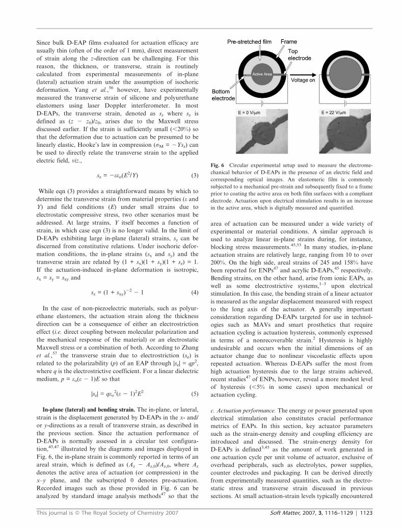
In-plane (lateral) and bending strain. The in-plane, or lateral,
strain is the displacement generated by D-EAPs in the x- and/
or y-directions as a result of transverse strain, as described in
the previous section. Since the actuation performance of
D-EAPs is normally assessed in a circular test configura-
tion,45,47 illustrated by the diagrams and images displayed in
Fig. 6, the in-plane strain is commonly reported in terms of an
areal strain, which is defined as (Az 2 Az,0)/Az,0, where Az
denotes the active area of actuation (or compression) in the
x–y plane, and the subscripted 0 denotes pre-actuation.
Recorded images such as those provided in Fig. 6 can be
analyzed by standard image analysis methods47 so that the
area of actuation can be measured under a wide variety of
experimental or material conditions. A similar approach is
used to analyze linear in-plane strains during, for instance,
blocking stress measurements.45,53 In many studies, in-plane
actuation strains are relatively large, ranging from 10 to over
200%. On the high side, areal strains of 245 and 158% have
been reported for ENPs47 and acrylic D-EAPs,45 respectively.
Bending strains, on the other hand, arise from ionic EAPs, as
well as some electrostrictive systems,1–3 upon electrical
stimulation. In this case, the bending strain of a linear actuator
is measured as the angular displacement measured with respect
to the long axis of the actuator. A generally important
consideration regarding D-EAPs targeted for use in technol-
ogies such as MAVs and smart prosthetics that require
actuation cycling is actuation hysteresis, commonly expressed
in terms of a nonrecoverable strain.2 Hysteresis is highly
undesirable and occurs when the initial dimensions of an
actuator change due to nonlinear viscoelastic effects upon
repeated actuation. Whereas D-EAPs suffer the most from
high actuation hysteresis due to the large strains achieved,
recent studies47 of ENPs, however, reveal a more modest level
of hysteresis (,5% in some cases) upon mechanical or
actuation cycling.
c. Actuation performance. The energy or power generated upon
electrical stimulation also constitutes crucial performance
metrics of EAPs. In this section, key actuator parameters
such as the strain-energy density and coupling efficiency are
introduced and discussed. The strain-energy density for
D-EAPs is defined3,45 as the amount of work generated in
one actuation cycle per unit volume of actuator, exclusive of
overhead peripherals, such as electrolytes, power supplies,
counter electrodes and packaging. It can be derived directly
from experimentally measured quantities, such as the electro-
static stress and transverse strain discussed in previous
sections. At small actuation-strain levels typically encountered
Fig. 6 Circular experimental setup used to measure the electrome-
chanical behavior of D-EAPs in the presence of an electric field and
corresponding optical images. An elastomeric film is commonly
subjected to a mechanical pre-strain and subsequently fixed to a frame
prior to coating the active area on both film surfaces with a compliant
electrode. Actuation upon electrical stimulation results in an increase
in the active area, which is digitally measured and quantified.
This journal is � The Royal Society of Chemistry 2007 Soft Matter, 2007, 3, 1116–1129 | 1123

with ferroelectric EAPs (,10% strain) or D-EAPs actuated
under low electric fields, the stored elastic energy (ES) is given
by 2sMsz/2 on a unit volume basis. In terms of material
properties, ES can be rewritten as:
ES = Ysz2/2 (6)
If large actuation strains are generated, Pelrine et al.45 propose
a description for the elastic energy density based on the
assumptions of isochoric deformation and constant electro-
static stress (sM). Under these conditions, Az relates to sz by
x0y0/(1 + sz), and the corresponding elastic energy density (EL)
can be obtained by integrating the compressive force over the
transverse displacement and putting the result on a unit
volume basis. The closed-form analytical result is:
EL = 2sMln(1 + sz) (7)
An equally useful performance parameter for comparing
D-EAPs is the efficiency (g), which is given by the ratio of
generated work to input energy.3 As anticipated, theoretical
efficiencies are never achieved in practice. According to
Kornbluh et al.,58 the overall efficiency (gt) depends on the
electrical and mechanical efficiencies of the D-EAP (ge and gm,
respectively), as well as the efficiency associated with the
electric driver circuit (gd), by gt = gegmgd, where ge and gm
relate directly to electrical and mechanical loss factors,
respectively. The efficiency of the electric driver circuit, on
the other hand, is given by the electromechanical coupling
efficiency (K2), which is the electrical energy converted into
mechanical work per cycle relative to the electrical energy
applied per cycle or, alternatively, the ratio of stored
mechanical energy to input electrical energy.3,45,47
Calculation of K2 for D-EAPs is based on the electrostatic
model, which presumes that the dielectric constant of the
actuator does not change upon activation. For elastomeric
materials under isochoric conditions, the change in electrical
energy upon actuation is approximately equal to the work
output, in which case K2 can be conveniently written as:51
K2 =22sz 2 sz2 (8)
Materials with a low K2 value are not desirable as actuators
because they require a large amount of electrical energy
relative to the amount of work that can be harnessed.
d. Homogeneous dielectric elastomers. As mentioned earlier, a
wide variety of elastomers derived from chemically cross-
linked homopolymers has been investigated as D-EAPs.
Specific examples include acrylics, silicones (including fluori-
nated silicones), polyurethanes, fluoroelastomers, ethylene–
propylene rubber (EPR), polybutadiene (PB) and polyisoprene
(PI, natural rubber). Relative to other EAPs, these network
polymers must inherently possess both low Y and high e to
maximize sM and sz by eqn (1) and (3), respectively. Although
the polyurethane, fluorosilicone and fluoroelastomer D-EAPs
typically have a higher e compared to the silicones and acrylics
due to the presence of polar functionalities, the acrylics and
silicone elastomers exhibit superior actuator performance
relative to other D-EAPs, as well as EAPs in general.
Introduction of polar functionalities along the polymer back-
bone or as pendant groups may, in fact, adversely influence Y
by inducing changes in cross-link density and chain entangle-
ment, as well as the propensity for inter/intramolecular
interactions. The maximum efficiency afforded by the acrylic
and silicone elastomers, discussed in detail below, compares
favorably with other types of electroactive materials, including
inorganic ones.
Acrylic elastomers. This class of D-EAPs, commercially
available as pressure-sensitive adhesives (cf. Table 2), consti-
tutes one of the most extensively investigated D-EAPs to date
due to its exceptional actuator efficacy.45 Since the precise
composition of these materials has not yet been reported, we
presume here that they are homogeneous for the sake of
classification. These elastomers, manufactured as double-sided
adhesive tapes, are commonly pre-formed to film thicknesses
of 0.5 and 1 mm, in which case they are routinely pre-strained
prior to electrical stimulation.48 An interesting feature of these
acrylics is that their dielectric breakdown strength is reported59
to increase upon pre-strain (which is typically applied
biaxially). This material is mechanically robust and has been
stretched to 36 times its initial area before breaking.52 It is also
reported2 to be thermally stable from 210 to 80 uC. While this
acrylic elastomer is undoubtedly a low-modulus material,
reported values of its elastic modulus vary considerably,
ranging from 1–3 MPa according to Madden et al.3 to much
less than 1 MPa.47,53 This significant variability may reflect
material anisotropy or defects, as well as differences in the
mode of testing (i.e. tension versus compression), as well as the
method (i.e. direct tension/compression versus inflated dia-
phragm) by which the elastic modulus is measured.
Unfortunately, important details such as these are not always
and consistently documented in the literature. Mechanical
measurements conducted in our laboratory yield a tensile
modulus of 0.20 MPa and a compressive modulus of 0.26 MPa.
This acrylic elastomer has been reported to exhibit an
ultrahigh areal actuation strain of 158% and transverse
strains up to ca. 60–70%, depending on the level of pre-strain
applied in the in-plane direction, as indicated in Table 3. A
blocking stress of 7.2 MPa and a corresponding elastic
energy density of 3.4 MJ m23 constitute the highest actuation
metrics reported45 to date for D-EAPs. When such values are
provided, however, care must be exercised in performing a
comparative analysis among D-EAPs. Recall from eqn (1)
that the electrostatic (Maxwell) stress is directly proportional
to E2 and that E is inversely proportional to film thickness.
While most reports of D-EAP actuation calculate E relative to
the initial film thickness, others45 use the instantaneous E
arising from the true film thickness upon actuation. In
addition, material properties such as the modulus are usually
measured prior to pre-strain, but recent results53 indicate that
the modulus can decrease substantially with increasing pre-
strain. Differences such as these will obviously change the
numerical values of actuation metrics, but the benchmark
performance of the acrylic elastomers remains intact. In fact,
these D-EAPs also possess the highest coupling efficiency
(y90%) of all D-EAPs derived from homopolymers
(cf. Table 3).
1124 | Soft Matter, 2007, 3, 1116–1129 This journal is � The Royal Society of Chemistry 2007

Silicone elastomers. Silicones, or polysiloxanes, consist of a
silicon-oxygen backbone (–SiR1R2–O–)n with the side groups
R1 and R2 covalently attached to the Si atoms. The flexibility
associated with Si–O bonds propagates along the main chain,
yielding molten macromolecules with an intrinsically high free
volume and a low glass transition temperature. The most
commonly used commercial silicones derive from polydi-
methylsiloxane, for which R1 = R2 = CH3. These materials
are readily processed into films by spin coating or solution
casting, and, as with the acrylic elastomers, their actuation
efficacy is dictated by the level of pre-strain applied
(cf. Table 3). In fact, Yang et al.60 have demonstrated that
the transverse strain achieved depends delicately on the
geometry of the actuator. Other important considerations
governing actuation performance include (i) the chemistry and
molecular weight of the polysiloxanes to be cross-linked, (ii)
the chemistry (functionality) by which the macromolecules are
cross-linked, and (iii) the extent to which the macromolecules
are cross-linked.49,50 For a given silicone and cross-linking
agent, only (iii) remains variable, but variation in cross-link
density can strongly affect the elastic modulus and, hence,
actuation performance. Therefore, caution must be exercised
in maintaining systematic preparation conditions. Generally
speaking, silicones exhibit marginally lower maximum electro-
mechanical coupling efficiencies (63–79%) but greater thermal
stability (from 265 to 240 uC) than acrylic elastomers, and
they tend to be less sensitive to environmental degradation.52
More importantly, though, they are more biocompatible than
most carbon-based polymers,61 and are therefore ideally suited
for actuation applications at the human–machine interface
(e.g. smart prosthetics).
e. Nanostructured dielectric elastomers. The D-EAPs described
in the previous section derive from chemically cross-linked
homopolymers and are therefore spatially homogeneous.
More recent efforts47,48,53 have begun to explore the use of
nanostructured polymers as physically cross-linked (i.e.
thermally reversible) D-EAPs. The most ubiquitous class of
nanostructured polymers consists of block copolymers, macro-
molecules that can undergo spontaneous molecular self-
organization into a wide variety of periodic and aperiodic
nanoscale morphologies under favorable environmental con-
ditions.62–64 These macromolecules are composed of long
sequences of chemically dissimilar repeat units. If the
sequences (‘‘blocks’’) are sufficiently thermodynamically
incompatible, they microphase-separate into discrete micro-
domains in the same fashion as surfactants.65 In the case of
linear bicomponent block copolymers with three blocks
covalently linked together (generically referred to as an ABA
triblock copolymer), the macromolecules can form a stable 3D
network capable of behaving as an elastic solid.66 An example
of a linear multiblock copolymer with many ‘‘hard’’ (crystal-
line) and ‘‘soft’’ (rubbery) blocks is a segmented polyurethane,
which has been observed67 to exhibit both electrostatic and
electrostrictive actuation, yielding a net actuation stress of
1.9 MPa (Table 3) and an electromechanical coupling
efficiency of 21% upon electrical stimulation.
In this section, however, we focus exclusively on micro-
phase-separated triblock copolymers that form micelle-
stabilized networks in the presence of a nonvolatile,
midblock-selective solvent. The copolymers used here are
commercial poly[styrene-b-(ethylene-co-butylene)-b-styrene]
(SEBS) triblock copolymers, wherein the endblocks are glassy
and the midblock is rubbery at ambient temperature. These
material systems have been previously referred68,69 to as
thermoplastic elastomer gels (TPEGs) to illustrate the nature
of the SEBS copolymer (a thermoplastic elastomer, TPE) and
the copolymer connectivity in the presence of solvent (gel).
Note that this approach fundamentally differs from EAPs such
as IPMCs, in which a liquid is required to facilitate ion
transport. The primary purpose of the extender solvent in
TPEGs is to swell the rubbery EB midblock and reduce the
elastic modulus, but enhance the elasticity and elongation at
break, of the resultant molecular network. The micellar
morphology is clearly visible in the TEM image and
corresponding schematic depiction displayed in Fig. 7. We
have recently demonstrated47 that, in the presence of an
aliphatic/alicyclic mineral oil, SEBS copolymers of comparable
molecular composition but different molecular weight exhibit
ultrahigh actuation displacements (y250 % areal strain) at
relatively low applied fields (22 V mm21) compared to, for
instance, the acrylic elastomer. These electromechanical
Table 3 Common electrical and mechanical properties of homogeneous D-EAPsa
Elastomer Pre-strain (x%, y%) sM/MPa |sz| (%) ES or EL/MJ m23 K2 (%) Ref.
Acrylic 0, 0 0.2 7 0.01 14 48Acrylic 15, 15 0.1 29 0.02 50 45Acrylic 540, 75 2.4 68 1.36 90 45Acrylic 300, 300 7.2 61 3.40 85 45Silicone-C 15, 15 0.6 25 0.09 44 45Silicone-C 45, 45 3.0 39 0.75 63 45Silicone-C 100, 0 0.8 39 0.20 63 45Silicone-H 14, 14 0.1 41 0.03 65 45Silicone-H 68, 68 0.3 48 0.10 73 45Silicone-H 280, 0 0.4 54 0.16 79 45Fluorosilicone 0, 0 0.4 28 0.06 48 51Fluoroelastomer 0, 0 0.1 8 0.00b 15 51Polyurethane 0, 0 1.6 11 0.09 21 51Polyisoprene 0, 0 0.1 11 0.01 21 51Polybutadiene 0, 0 0.4 12 0.03 22 74a Values of the electromechanical coupling efficiency (K2) when not reported are calculated from the transverse strain (sz) by eqn (8).b Reported as 0.0046 MJ m23.
This journal is � The Royal Society of Chemistry 2007 Soft Matter, 2007, 3, 1116–1129 | 1125

responses reflect the low modulus that can be achieved upon
addition of the midblock-selective oil, the elastic network (with
little viscous dissipation) arising from the formation of a
supramolecular (copolymer) network, and the presence of
nanoscale-confined functionalities (phenyl rings) that respond
to the applied electric field. An important consideration with
these physically cross-linked materials (wherein the glassy
micelles serve as cross-link sites) is that their mechanical
properties and actuation behavior can be tuned using several
material-related attributes including, but not limited to,
copolymer composition, copolymer molecular weight and
solvent concentration. The highest value of K2 measured from
these materials, collectively referred to as electroactive
nanostructured polymers (ENPs) to distinguish their structure
relative to conventional D-EAPs, is 92%, which exceeds that of
the acrylic elastomers. Moreover, unlike the chemically cross-
linked homogeneous elastomers discussed earlier, these highly
elastic and reprocessable materials (i) undergo little actuation
hysteresis (,15%) upon cycling (i.e. 100 cycles to 48–60% of
the breakdown electric field),47 (ii) exhibit acceptable actuation
without the need for mechanical pre-strain,48 and (iii) provide
blocking stresses that are comparable to that of the acrylic
elastomer.53
IV. Comparison of EAPs
Although a rigorously quantitative and global comparison of
EAP actuation performance is not straightforward because the
test performed for each type of actuator is different, property-
specific comparisons have been reported by Huber et al.7 and
Wax and Sands,70 as well as by institutions such as SRI
International (USA) and Risø National Laboratory
(Denmark).1,2 Since one of the most important actuation
metrics is voltage- or field-induced displacement, in-plane
actuation strain is presented as a function of voltage for
various EAPs in Fig. 8a and as a function of electric field
primarily for D-EAPs in Fig. 8b. For completeness, the
transverse actuation strains corresponding to the D-EAPs in
Fig. 8b are likewise provided in Fig. 8c. Fig. 8a clearly shows
that the ionic EAPs require the lowest applied voltages,
whereas the electronic EAPs actuate at high voltages (.1 kV).
While this difference is broadly considered to be one of the
practical limitations of electronic EAPs, Pelrine et al.45 have
suggested that compact voltage amplifiers could be designed to
solve this problem. The requirement for high voltage may even
be considered advantageous because less current is needed to
produce a desired power level, thereby allowing efficient
electrical energy transmission through thin wires and thus
reducing concern associated with contact resistance. In all
fairness, however, it must also be recognized that the voltage
to be applied for actuation depends on specimen thickness,
since the actuation performance of electronic EAPs depends
on electric field.
This dependence is evident in Fig. 8b and 8c, which together
confirm that the acrylic elastomer, some silicone elastomers
and the copolymer-based ENPs discussed in the prior section
exhibit the highest in-plane and transverse strains upon
electrical stimulation. These materials are attractive because
of their desirable attributes such as light weight, mechanical
resilience, rapid response and high energy density. Other
Fig. 7 TEM image of an ENP composed of a microphase-separated
SEBS triblock copolymer swollen with a midblock-selective oligomeric
oil. The micellar morphology in this 10/90 w/w SEBS/oil system
consists of swollen EB midblocks that form a molecular network
stabilized by glassy S micelles, which appear electron-opaque (dark)
due to selective staining with the vapor of RuO4(aq.). The inset
illustrates the molecular network stabilized by the glassy micelles.
Fig. 8 Comparison of the actuation-strain levels achieved for (a) various EAPs as a function of electric potential, and (b, c) D-EAPs and a
ferroelectric polymer as a function of electric field. The actuation strains are labeled in each part and include (a) lateral area or length, (b) lateral
area, and (c) transverse. The dotted lines serve as guides for the eye.
1126 | Soft Matter, 2007, 3, 1116–1129 This journal is � The Royal Society of Chemistry 2007

important comparative metrics include the blocking stress and
energy density, which are displayed as a function of actuation
strain in Fig. 9. In Fig. 9, the ionic CP and electrostrictive
ferroelectric polymer (PVDF–TrFE) are seen to exhibit the
highest blocking stresses (ca. 10 to more than 100 MPa) of the
EAPs at relatively low strains, whereas the acrylic elastomer
enjoys both a high blocking stress (between y1 and 10 MPa)
and a high actuation strain (.100 %). The straight lines with a
slope of 21 are identified by discrete energy-density values and
connect actuator classes possessing comparable volumetric
stroke work.7 Included for comparison in Fig. 9 are the
performance metrics for natural muscle, which is most closely
emulated by the IPMC ionic EAP, as well as the dielectric
silicone and ENP elastomers. Actuators located on the right
side of Fig. 9 can provide a high stroke (large actuation
displacement), thereby making them suitable candidates for (i)
biomimetic applications including artificial muscle and micro-
robotics, and (ii) microfluidic and haptic devices requiring
lateral or transverse extension. It should be noted here that
hydraulic actuators, which exhibit similar or slightly larger
actuation strains than natural muscle with considerably higher
blocking stresses (y10–100 MPa), have been used extensively
in robotics.1–3,70 However, the size and weight of the overhead
peripherals (i.e. pumps, piping and supports) required for such
actuators preclude their use in small-scale and lightweight
devices.
Other actuation metrics of EAPs, such as frequency
response (or bandwidth) and specific power, have likewise
been evaluated against those of more established actuator
technologies to deduce the most appropriate and advanta-
geous applications for EAPs. Another performance parameter
of particular interest in this vein is the electromechanical
coupling efficiency, which is included for several EAPs in
Table 3. The ENPs and acrylic D-EAP constitute the most
efficient EAPs to date, outperforming SMAs and comparing
favorably relative to solenoids and, to a lesser extent,
hydraulics. In addition to their displacement and energy
conversion efficiency, actuators must respond quickly if they
are of to be practical use. Sommer-Larsen71 has assembled a
comparison of conventional and EAP actuators and proposes
that, on the basis of actuation time (i.e. the time to full
extension) and power density, actuators such as solenoids,
piezoelectric and magnetostrictive drivers, in addition to
electric motors, CPs and D-EAPs, are well-suited for use in
robotic applications. The response times of CPs and D-EAPs
are on the order of milliseconds, in marked contrast to human
muscle and SMAs, which require at least one and over two
orders of magnitude more time to fully actuate.
V. Technological opportunities
As demonstrated earlier, D-EAPs are in many, but not all,
ways superior to other classes of electroactive materials
because of their tunable mechanical properties, robust and
reliable performance, and net energy efficiency and power
density. Because of their unique combination of attributes,
D-EAPs have been used to design lightweight and compact
actuators. Common actuator configurations containing
D-EAPs are routinely described as tube, rolled, frame-
supported and laminated.2 Because of their light weight
(elastomers typically have a density ,1 g cm23), D-EAP rolls
are more efficient than solenoids and have been used in the
development of snake-like robots, as well as steerable catheters
and endoscopes.2 Optical switches and microlenses designed
around framed D-EAP actuators have also been recently
proposed.11 In this case, optical switching results from
controllable variation in optical density or refractive index as
the actuator thickness changes with applied electrical field.
Moreover, the high actuation-strain levels and energy output
of D-EAPs can be exploited to construct diaphragms capable
of generating large out-of-plane deflection and correspond-
ingly large volume displacements suitable for microfluidic
pumps and valves, as well as loudspeakers and responsive
haptic (e.g. refreshable Braille) displays.2,11,46 Other applica-
tions of D-EAPs include sensors, motors and even a heel-strike
generator that operates in reverse fashion to produce electricity
from compressive deformation. Recently, D-EAPs have been
fabricated72 into prototype fibers that can eventually be used
in active textiles or in bundles to emulate natural muscle. As
previously pointed out, D-EAPs constitute excellent artificial
muscle candidates for biologically inspired robots, animatro-
nics and responsive prosthetics, and prototype devices based
on D-EAPs include a smart pill (i.e. a tube-like structure that
travels like an inchworm inside the gastrointestinal tract),
multi-legged robots and bird-like MAVs.2,11,46
VI. Summary
Electroactive polymers (EAPs) represent an emerging class of
actuator materials that exhibit a tunable dimensional response
to electrical stimulation. They can generate strains that are two
orders of magnitude higher than rigid piezoelectric ceramics,
and they exhibit superior performance than shape-memory
alloys in terms of mechanical resilience, response speed, cyclic
Fig. 9 Dependence of blocking stress on actuation strain for various
electroactive materials and systems: inorganic materials, ionic EAPs,
ferroelectric EAPs, and D-EAPs. The dotted diagonal lines correspond
to different energy densities (labeled), and the highlighted area signifies
the characteristics of human muscle (modified from the NASA Jet
Propulsion Laboratory document posted at http://ndeaa.jpl.nasa.
gov/nasa-nde/lommas/eap/actuators-comp.pdf).
This journal is � The Royal Society of Chemistry 2007 Soft Matter, 2007, 3, 1116–1129 | 1127
hysteresis and light weight. Compared to conventional
hydraulic or pneumatic actuators, EAPs can be used to design
mechanical devices without traditional components such as
gears and bearings once limitations associated with low
actuation forces are overcome. These responsive materials
can be divided into two classifications – ionic and electronic –
on the basis of their actuation mechanism. Ionic EAPs
function due to switchable ion transport, whereas electronic
EAPs respond due to electrostatic or Coulomb forces that
develop upon application of an electric field. Because of this
difference, ionic EAPs typically require a solvent medium for
electrolyte migration and low voltages to achieve actuation
relative to electronic EAPs, which, on the other hand, exhibit
higher actuation strains and greater overall reliability,
durability and efficiency. Among the electronic EAPs reported
thus far, homogeneous dielectric elastomers derived from
acrylics and various silicones, as well as nanostructured
dielectric elastomers generated from block copolymers with
and without an extender solvent (i.e. ENPs and polyurethanes,
respectively), have shown the most promising combination of
mechanical and electrical actuation properties. Compared to
other EAPs, the D-EAPs can produce very high actuation
strains (.200%) upon application of an external electric field
due primarily to the development of an electrostatic (Maxwell)
stress. Furthermore, D-EAPs possess fast response times, high
energy densities and high electromechanical efficiencies.
Although all D-EAPs require high electric fields to achieve
maximum actuation (which undoubtedly poses a practical
challenge), these materials nonetheless constitute viable and
attractive alternatives for use in emerging microrobotic,
aerospace, automotive, haptic, biomimetic and microfluidic
technologies.
Related websites
The following websites provide movie clips of electrical devices
that could or already benefit from advances in EAP design and
actuation performance:
http://eap.jpl.nasa.gov
http://www.artificialmuscle.com
http://www.sri.com/esd/automation/actuators.html
http://www.hansonrobotics.com
http://www.unm.edu/yamri
http://www.electropolymertechnology.com/web1.htm
Acknowledgements
Support for this work has been provided by the U. S.
Department of Commerce through the National Textiles
Center.
References
1 J. L. Pons, Emerging Actuator Technologies: A MicromechatronicApproach, Wiley, NJ, 2005.
2 Y. Bar-Cohen, Electroactive Polymer (EAP) Actuators as ArtificialMuscles: Reality, Potential, and Challenges, SPIE Press,Bellingham, WA, 2004.
3 J. D. W. Madden, N. A. Vandesteeg, P. A. Anquetil, P. G. A.Madden, A. Takshi, R. Z. Pytel, S. R. Lafontaine, P. A. Wieringaand I. W. Hunter, IEEE J. Oceanic Eng., 2004, 29, 706–728.
4 R. H. Baughman, C. Cui, A. A. Zakhidov, Z. Iqbal, J. N. Barisci,G. M. Spinks, G. G. Wallace, A. Mazzoldi, D. De Rossi,A. G. Rinzler, O. Jaschinski, S. Roth and M. Kertesz, Science,1999, 284, 1340–1344.
5 I. R. Sinclair, Sensors and Transducers, Butterworth-Heinemann,Oxford, 2001.
6 M. Fremond and M. Miyazaki, Shape Memory Alloys, Springer,New York, 1996.
7 J. E. Huber, N. A. Fleck and M. F. Ashby, Proc. R. Soc. London,Ser. A, 1997, 453, 2185–2205.
8 Y. Bar-Cohen, Expert Rev. Med. Devices, 2005, 6, 731–740.9 Y. Bar-Cohen, Biomimetics Biology Inspired Technologies, Taylor
& Francis, Boca Raton, FL, 2005.10 J.-H. Oh, D. Hanson, W.-S. Kim, Y. Han, J.-Y. Kim and W. Park,
Proc. 2006 IEEE/RSJ Int. Conf. Intel. Robot. Automat., Beijing,China, 2006, 1428–1433.
11 T. Mirfakhrai, J. D. W. Madden and R. H. Baughman, Mater.Today, 2007, 10, 30–38.
12 V. H. Ebron, Z. W. Yang, D. J. Seyer, M. E. Kozlov, J. Y. Oh,H. Xie, J. Razal, L. J. Hall, J. P. Ferraris, A. G. MacDiarmid andR. H. Baughman, Science, 2006, 311, 1580–1583.
13 A. Moulson and J. Herbert, Electroceramics, Chapman & Hall,London, 1995.
14 J. D. Nam, H. R. Choi, Y. S. Tak and K. J. Kim, Sens. Actuators,A, 2003, 105, 83–90.
15 M. Parthasarathy and D. J. Klingenberg, Mater. Sci. Eng., R,1996, 17, 57–103.
16 M. Doi, M. Matsumoto and Y. Hiroset, Macromolecules, 1992, 25,5504–5511.
17 S. Iijima, Nature, 1991, 354, 56–58.18 P. J. F. Harris, Carbon Nanotubes and Related Structures: New
Materials for the 21st Century, Cambridge University Press,Cambridge, 1999.
19 R. H. Baughman, A. A. Zakhidov and W. A. de Heer, Science,2002, 297, 787–792.
20 S. Niyogi, M. A. Hamon, H. Hu, B. Zhao, P. Bhowmik, R. Sen,M. E. Itkis and R. C. Haddon, Acc. Chem. Res., 2002, 35,1105–1113.
21 Y. Zhang, Y. Li, W. Kim, D. Wang and H. Dai, Appl. Phys. A,2002, 74, 325–328.
22 M. Hughes and G. M. Spinks, Adv. Mater., 2005, 17, 443–446.23 J. D. W. Madden, J. N. Barisci, P. A. Anquetil, G. M. Spinks,
G. G. Wallace, R. H. Baughman and I. W. Hunter, Adv. Mater.,2006, 18, 870–873.
24 Y. L. Li, I. A. Kinloch and A. H. Windle, Science, 2004, 304,276–278.
25 R. H. Baughman, Nat. Nanotechnol., 2006, 1, 94–96.26 Q. Pei and O. Inganas, Adv. Mater., 1992, 4, 277–278.27 E. Smela and O. Inganas, Science, 1995, 268, 1735–1738.28 R. H. Baughman, Synth. Met., 1996, 78, 339–353.29 S. Hara, T. Zama, W. Takashima and K. Kaneto, Synth. Met.,
2006, 156, 351–355.30 G. M. Spinks, V. Mottaghitalab, M. Bahrami-Samani,
P. G. Whitten and G. G. Wallace, Adv. Mater., 2006, 18, 637–640.31 L. Bay, K. West, P. Sommer-Larsen, S. Skaarup and
M. Benslimane, Adv. Mater., 2003, 15, 310–313.32 K. Kaneto, M. Kaneko, Y. Min and A. G. MacDiarmid, Synth.
Met., 1995, 71, 2211–2212.33 T. W. Lewis, L. A. P. Kane-Maguire, A. S. Hutchison, G. M. Spinks
and G. G. Wallace, Synth. Met., 1999, 102, 1317–1318.34 B. J. Akle, M. D. Bennett and D. J. Leo, Sens. Actuators, A, 2006,
126, 173–181.35 S. Nemat-Nasser and Y. X. Wu, J. Appl. Phys., 2003, 93,
5255–5267.36 B.-E. El Mohajir and N. Heymans, Polymer, 2001, 42, 5661–5667.37 C. Huang, R. Klein, F. Xia, H. Li, Q. M. Zhang, F. Bauer and
Z.-Y. Cheng, IEEE Trans., 2004, 11, 299–311.38 K. K. Tashiro, M. Takano, Y. Kobayashi, A. Chatani and
H. Tadokoro, Ferroelectrics, 1984, 57, 297–326.39 Q. M. Zhang, V. Bharti and X. Zhao, Science, 1998, 280,
2101–2104.40 F. Xia, H. Li, C. Huang, M. Y. M. Huang, H. Xu, F. Bauer,
Z.-Y. Cheng and Q. M. Zhang, Proc. SPIE–Int. Soc. Opt. Eng.,2003, 5051, 133–142.
1128 | Soft Matter, 2007, 3, 1116–1129 This journal is � The Royal Society of Chemistry 2007

41 J. Su, J. S. Harrison, T. L. S. Clair, Y. Bar-Cohen and S. Leary,Mater. Res. Soc. Symp. Proc., 1999, 600, 131–136.
42 Q. M. Zhang, H. Li, M. Poh, F. Xia, Z.-Y. Cheng, H. Xu andC. Huang, Nature, 2002, 419, 284–287.
43 V. Bobnar, A. Levstik, C. Huang and Q. M. Zhang, Phys. Rev.Lett., 2004, 92, 047604.
44 C. Huang, Q. M. Zhang and J. Su, Appl. Phys. Lett., 2003, 82,3502–3504.
45 R. Pelrine, R. Kornbluh, Q. Pei and J. Joseph, Science, 2000, 287,836–839.
46 S. Ashley, Sci. Am.,, 2003(October), 53–59.47 R. Shankar, T. K. Ghosh and R. J. Spontak, Adv. Mater., (in press,
doi: 10.1002/adma.).48 R. Shankar, T. K. Ghosh and R. J. Spontak, Macromol. Rapid
Commun., 2007, 28, 1142–1147.49 X. Q. Zhang, M. Wissler, B. Jaehne, R. Broennimann and
G. Kovacs, SPIE Proc. Ser., 2004, 5385, 78–86.50 X. Zhang, C. Lowe, M. Wissler, B. Jahne and G. Kovacs, Adv.
Eng. Mater., 2005, 7, 361–367.51 R. Pelrine, R. Kornbluh, J. Joseph, R. Heydt, Q. Pei and S. Chiba,
Mater. Sci. Eng., C, 2000, 11, 89–100.52 A. O’Halloran and F. O’Malley, in Topics in Bio-Mechanical
Engineering, ed. P. J. Prendergast and P. E. McHugh, TrinityCentre for Bioengineering & the National Centre for BiomedicalEngineering Science, Dublin & Galway, 2004, pp. 184–215.
53 R. Shankar, T. K. Ghosh and R. J. Spontak, Sens. Actuators, A,(submitted).
54 G. Kofod, P. Sommer-Larsen, R. Kornbluh and R. Pelrine,J. Intell. Mater. Syst. Struct., 2003, 14, 787–793.
55 G. M. Spinks, T. E. Campbell and G. G. Wallace, Smart Mater.Struct., 2005, 14, 406–412.
56 G. Yang, W. Ren, B. K. Mukherjee and J. P. Szabo, 14th IEEE Int.Symp., 2004, 237–240.
57 Q. M. Zhang, J. Su, C. H. Kim, R. Ting and R. Capps, J. Appl.Phys., 1997, 81, 2770–2776.
58 R. Kornbluh, R. Pelrine, Q. Pei, S. Oh and J. Joseph, Proc. SPIE–Int. Soc. Opt. Eng., 2000, 3987, 51–64.
59 A. Mazzoldi, F. Carpi and D. D. Rossi, Ann. Chim. Sci. Mater.,2004, 29, 55–64.
60 G. Yang, G. Yao, W. Ren, G. Akhras, J. P. Szabo andB. K. Mukherjee, Proc. SPIE–Int. Soc. Opt. Eng., 2005, 5759,134–143.
61 D. Klee and H. Hocker, Adv. Polym. Sci., 1999, 149, 1–57.62 I. W. Hamley, The Physics of Block Copolymers, Oxford University
Press, New York, 1998.63 I. W. Hamley, Developments in Block Copolymer Science and
Technology, Wiley, New York, 2004.64 M. Lazzari, G. Liu and S. Lecommandoux, Block Copolymers in
Nanoscience, Wiley-VCH, Weinheim, 2007.65 S. Jain and F. S. Bates, Science, 2003, 300, 460–464.66 G. Holden, N. R. Legge, R. Quirk and H. E. Schroeder,
Thermoplastic Elastomers, 2nd edn, Hanser, Munich, 1996.67 J. Su, Q. M. Zhang, C. H. Kim, R. Y. Ting and R. Capps, J. Appl.
Polym. Sci., 1997, 65, 1363–1370.68 J. H. Laurer, J. F. Mulling, S. A. Khan, R. J. Spontak and
R. Bukovnik, J. Polym. Sci., Part B: Polym. Phys., 1998, 36,2379–2391.
69 G. J. van Maanen, S. L. Seeley, M. D. Capracotta, S. A. White,R. R. Bukovnik, J. Hartmann, J. D. Martin and R. J. Spontak,Langmuir, 2005, 21, 3106–3115.
70 S. G. Wax and R. R. Sands, Proc. SPIE–Int. Soc. Opt. Eng., 1999,3669, 2–10.
71 P. Sommer-Larsen, ‘‘Artificial Muscles’’ technical report, RisøNational Laboratory, posted at http://sitecoremedia.risoe.dk/research/artmus/Documents/MIC-ARTI.pdf, 1996.
72 S. Arora, T. Ghosh and J. Muth, Sens. Actuators, A, 2007, 136,321–328.
73 W. Ma and L. E. Cross, Appl. Phys. A, 2004, 78, 1201–1204.74 R. Kornbluh, R. Pelrine, J. Joseph, R. Heydt, Q. Pei and S. Chiba,
Proc. SPIE–Int. Soc. Opt. Eng., 1999, 3669, 149–161.75 R. Pelrine, R. Kornbluh, Q. Pei, S. Stanford, S. Oh, J. Eckerle,
R. Full, M. Rosenthal and K. Meijer, Proc. SPIE–Int. Soc. Opt.Eng., 2002, 4695, 126–137.
This journal is � The Royal Society of Chemistry 2007 Soft Matter, 2007, 3, 1116–1129 | 1129