Cooper Interconnect Non-Explosive Actuators
28
Non-Explosive Actuators Heritage-proven technologies support rapid releases, field-resettable testing, and safe handling and deployment
-
Upload
khangminh22 -
Category
Documents
-
view
1 -
download
0
Transcript of Cooper Interconnect Non-Explosive Actuators

Non-Explosive Actuators
Heritage-proven technologies support rapid releases, field-resettable testing, and safe handling and deployment

2
Non-explosive technologies support safe handling and deployment
Technology and Heritage Overviews . . . . . . . . . . . . . . . . . . . . . . . . . . Page 4
•Technology comparisons Page 4•Program heritage Page 5•Split-spool theory of operation Page 6•Refurbishment capabilities Page 7•Field-resettable test initiators Page 8
Custom Capabilities . . . . . . . . . . . . . . . . . . . . . . . . . . . . . . . . . . . . . . . Page 9
•Design process and resources Page 9•Valves, cable solutions, and actuator-released interconnects Page 10
Pin Pullers and Compression-Release Devices . . . . . . . . . . . . . . . . Page 11
•Standalone and redundant solutions•Structural separation and interconnect-release systems
Separation Nuts . . . . . . . . . . . . . . . . . . . . . . . . . . . . . . . . . . . . . . . . . . Page 14
•4,500 to 9,500 lb. (20 to 42.3kN) standard load ratings•Custom solutions with application-specific load ratings
Cable Release Mechanisms . . . . . . . . . . . . . . . . . . . . . . . . . . . . . . . . Page 18
•8036 Series - 80 to 267 lbs. (0.4 to 1.2kN) per cable•Custom single and dual cable-release solutions

www.cooperinterconnect.com3
Standalone products and integrated solutions
Tension Links . . . . . . . . . . . . . . . . . . . . . . . . . . . . . . . . . . . . . . . . . . . . Page 20
•Circular clamp (Marman and V-band) restraint and release•8014 Series - load ratings to 2,000 lbs. (8.9kN)•Custom load ratings and clamping mechanisms
Tension Releases . . . . . . . . . . . . . . . . . . . . . . . . . . . . . . . . . . . . . . . . . Page 22
•8024 Series - 500 to 1,300 lb. (2.2kN to 5.8kN) standard load ratings•Customer-defined load ratings and tension attachments
Miniaturized Tension Releases . . . . . . . . . . . . . . . . . . . . . . . . . . . . . . Page 24
•1183 Series - standard load ratings to 250 lbs. (1.1kN)•Actuator body less than 1/3 cubic inch (5cm3)
Electrical Switches . . . . . . . . . . . . . . . . . . . . . . . . . . . . . . . . . . . . . . . . Page 26
•Mission-critical power routing and disconnects•Battery cell bypass switches

4
Performance advantages include low shock, rapid operation with low-power consumption
Cooper Interconnect’s non-explosive actuators provide a unique combination of advantages. These low shock devices deliver rapid response times, with low power consumption, across a broad range of operating temperatures.
Safety benefits, and cost savings, include the elimination of safeguards needed to provide protection from operational and accidental activations of the explosive materials used in pyrotechnic devices. Split-spool actuators also eliminate possible safety issues resulting from fragment and debris release during testing and operation.
Cooper Interconnect also provides actuators with field and factory refurbishment capabilities, and optional field resettable mechanical initiators, to provide additional cost savings when compared to the replacement costs of one-shot devices.
Cooper Interconnect Split-Spool
Technologies
ExplosivePyrotechnic
ParaffinWax
ShapeMemory
Alloy
Other Split-Spool
Technologies
No precautions for explosive materials required YES NO YES YES YES
Fragment and debris free operation YES NO YES YES YES
Rapid responses across wide temperature ranges YES YES NO NO YES
Low power consumption YES YES NO NO YES
Field-resettable testing without parts replacement YES NO YES YES NO
Field refurbishment capabilities YES NO YES YES NO
Low imparted shock YES NO YES YES YES

www.cooperinterconnect.com5
Program heritage includes over 12,000 actuations
Cooper Interconnect’s non-explosive actuators have been field qualified for an extensive range of military and aerospace applications and have a forty year track record that includes over 12,000 harsh environment, mission-critical actuations.
The table below provides a listing of selected programs and applications including actuator and electrical switch solutions developed by G&H Technology prior to being acquired by Cooper Industries in 2006.
Markets Agencies Programs Applications
Communicationsand
Scientific
•ULA
•NASA
•Atlas V and Centaur Rockets
•Comsat, multiple constellations
•Discoverer Satellite
•Earth Orbiting Satellites
•Global Positioning Satellites
•International Space Station
•Skylab Space Station
•Small Spacecraft Technology Initiative
•Space Shuttle
•SpaceX Dragon
•Antenna array and solar panel releases
•Battery cell bypass switches
•Connector separations
•Docking cover, nose cone, and parachute door actuations
•Grapple-bar unfastening
•Instrument deployments
•Sub-satellite separations
Deep SpaceExploration
•ESA
•NASA
•Apollo Spacecraft
•Galileo Spacecraft
•Hubble Telescope
•Magellan Spacecraft
•Mars Global Surveyor, Pathfinder, and Viking Lander
•Stardust Spacecraft
•Venus Pioneer
•X-Ray Multi-Mirror Satellite
•Antenna array, boom, and solar panel releases
•Canister, camera, and door actuations
•Connector separations•Instrument deployments•Sub-satellite releases•Telescope mirror-door
actuations
Militaryand
Defense
•BUWEPS
•DoD
•MICOM
•NAVAIR
•USAF
•Exoatmospheric Kill Vehicle
•Harpoon Missile
•Maneuverable Satellite Landing System
•MILSTAR
•Midgetman and Minuteman ICBMs
•Peacekeeper ICBM
•Sea Lance Missile
•Small Diameter and Snakeye Bombs
•Space and Missile Tracking System
•Titan Rockets
•Antenna releases
•Bomb-fin deployments
•Broach-sensor initiators
•Flight termination systems
•Connector separations
•Night vision goggle releases
•Parachute deployments

6
Split spool theory of operation
The split-spool technologies described below are utilized in all of Cooper Interconnect’s standard and custom release mechanisms and electrical switches. The upper image depicts an armed split-spool assembly. The lower image depicts a split-spool assembly after it has initiated load release.
Compression-release devices employ a similar non-explosive initiation sequence that uses the force of an external load to drive the split-spool plunger instead of the compression spring force described in the first bullet point.
Split spool technology initiation sequence 12
3
45
6
The initiator is armed by applying compression spring-force to the plunger. The wrapped spool restrains the plunger until actuation.
Current is applied to the electrical contacts; power requirements are compatible with pyrotechnic actuator circuitry.
Electrical current causes the link wire to open and release the tensile wire wrap.
Radial expansion of the tensile-wire wrap releases tension on the split-spool bobbin.
Separation of the two halves of the spool is facilitated by the forward movement of the spring-loaded plunger.
The forward movement of the plunger initiates pin retraction in pin pullers or release-mechanism activation in other devices.
1
2
3
4
5
6
Image courtesy of NASA

www.cooperinterconnect.com7
Refurbishing can reduce actuator-related test and qualification costs up to 80%
Many of Cooper Interconnect’s products can be field or factory refurbished by replacing the expended initiators. Refurbishment costs are typically less than 20% of the cost of replacing pyrotechnic devices. This can provide significant savings during multiple-actuation testing and qualification.
The refurbishment process depicted below can be performed in less than ten minutes. Split-spool initiators facilitate additional cost savings during testing by eliminating the safety-assurance requirements inherent to firing pyrotechnic actuators.
Replacement split-spool initiators are shipped from the factory ready for drop-in installation.
Split-spool initiator installation after removal of the expended spool
Plunger
Replacement split-spool initiator
Installed initiator assembly
Power cableInitiator connector assembly
Retaining ring

8
Mechanical initiators enable field resetting of actuators in under five minutes
Multiple-test sequences can also be facilitated by field resettable mechanical initiators. These accessory kits are options for many standard products. Mechanical initiator compatibility can also be implemented as a design feature in custom solutions.
Field installation and testing is extremely straight forward and cost effective:
•The split-spool initiator, retaining ring, and cable assembly are removed and replaced with the mechanical initiator and retaining plug.
•Test sequences are triggered by a quarter turn of a standard 3/16-inch wrench.
•The mechanical initiator is reset, no parts replacements are required.
•After testing, the mechanical initiator is removed and the actuator parts are re-installed.
The mechanical initiator imparts considerably less shock than pyrotechnic devices and significantly reduces the potential of damaging sensitive equipment during repeated test sequences.
90° rotation of the wrench flats triggers the mechanical initiator.
Mechanical initiator enlarged to show status indicator detail: green – armed, red – actuated.
Mechanical initiator installation after spool-assembly removal
Plunger
Mechanical initiator
Retaining ring

www.cooperinterconnect.com9
Heritage-proven custom capabilities
Cooper Interconnect combines the industry’s most advanced engineering tools with an extensive array of manufacturing resources to quickly deliver custom solutions. This tightly integrated, design-through-deployment methodology also improves performance, reliability, and cost across a wide range of production volumes.
Designed and manufactured in the U.S.A.
Cooper Interconnect integrates CAD software with a network of CAM resources to concurrently manufacture parts for prototype solutions. In-house environmental test equipment, including
thermal-vacuum chambers, also accelerates prototype development.
A comprehensive range of mission-critical-engineering resources
Extensive experience Cooper Interconnect has an in-depth understanding of the materials, mechanisms, and electronic design required for harsh environment, mission-critical applications.
The DMEDI process New product development is controlled through a defined toll-gate process to ensure consistent, predictable, and successful results.
Technology portfolio An extensive portfolio of field-proven products and technologies satisfies a significant number of customer requirements with only minor modifications.
Modeling and simulation Our design teams utilize SolidWorks to simulate a complete array of harsh-environment mechanical and thermal stresses, as well as simulation of motion.
Image courtesy of NASA

10
Integrated custom solutions
Umbilical connectors and in-flight disconnects are available with integrated pin pullers to facilitate electrically-initiated separations. Configurations include redundant pin pullers and pin pullers with lanyard initiated mechanical redundancy. Please refer to the pin-puller section for more information.
Additional military and aerospace connector capabilities include cryogenic, deadfaced, NATC, lanyard release, high current, and high-speed data. Please refer to www.cooperinterconnect.com for more information.
Cooper Interconnect’s custom capabilities include integrating split-spool-initiator technologies into actuator valves and bottle-piercers. These low-shock solutions provide rapid activations over a wide range of operating temperatures and fluid and gas pressures.
Solutions are available with single or redundant initiation and threaded or welded fluid and gas connections. Actuator valves can be designed in single or multiple port, normally open or closed configurations.
Actuators are available with integrated connector and cable assemblies that are designed to perform in a wide range of harsh environments:
•Extreme high and low temperatures.•Shock and vibration.•Radiation, EMI, and RFI.•Corrosive contaminants.•Vacuum and high pressures. Form, fit, and function cable replacements are also available for existing programs where pyrotechnic actuators are being replaced with non-explosive devices.
Actuator-released interconnects
Valves and bottle piercers
Cable assemblies and wiring harnesses

www.cooperinterconnect.com11
Pin pullers and compression-release devices
Cooper Interconnect can provide pin pullers and compression-release devices in a wide range of configurations – from standalone devices to integrated solutions. Heritage-proven technologies and platforms accelerate solution development and provide a unique combination of design options and performance advantages:•Rapid releases with low power consumption.•Fragment and debris-free operation.•Electrical compatibility with pyro-activation circuits.•No precautions for explosive materials required.•Field refurbishment significantly reduces actuator-related
test and qualification costs (page 7).• Integrated solutions include stage separation and
payload release, flight termination, umbilical connectors, and in-flight disconnects.
Pin puller flight heritage includes the Harpoon Missile and fin deployment on the Small Diameter Bomb.
The compression release depicted above was designed to release the guidance fins on Small Diameter Bombs. This extremely compact solution features a 200 pound (889 newton) load rating.
Additional flight-heritage applications include:
•Antenna, solar panel, instrument, and sub-satellite releases on satellites and spacecraft.
•Connector separation on missiles and satellites including in-flight disconnects with lanyard-release redundancy.
•Missile stage separation including ICBMs.
The cutaway drawing presented below depicts a field-refurbishable pin puller.
•When armed, the split-spool initiator constrains the plunger/pin assembly and prevents retraction.
•Electrical activation of the spool assembly unlocks the plunger/pin assembly allowing pin retraction as the compression spring expands.
Compression-release devices operate in a similar manner to pin pullers with the exception that pin retraction is driven by the external load instead of an internal compression spring.
Theory of operation
Split-spoolinitiator
Electrical cable
Plunger/pinassembly
Compressionspring

12
Pin puller actuated structural separation systems
Cooper Interconnect’s custom capabilities include structural-separation mechanisms that utilize pin pullers for actuation. Applications include stage and payload release and flight termination.
Cooper Interconnect developed the solution depicted below for a flight termination application including the housing, redundant pin pullers, and all of the mechanical components required for restraint and separation.
This heritage-proven design can be used in harsh environment applications that would otherwise use tension links with Marmam clamps less than 15 inches (38cm) in diameter.
This solution joins the two structural sections until electrical actuation initiates separation:
•The two structural sections are held together through wedge segments captured in the cavities of the forward section and a slot in the aft section.
•The wedge segments are held in place with a preload band restrained on both ends by pin pullers.
•Actuation of either pin puller releases the band allowing the wedge segments to move radially outward.
•The expansion of the ejection wave washer initiates release of the forward section from the aft section.
Ejection wave washer
Deployed
Redundant pin pullers
Restraining band
Restrained
Program heritage includes the flight termination system on the Small Diameter Bomb.

www.cooperinterconnect.com13
Umbilical connectors and in-flight disconnects
Cooper Interconnect can leverage a broad range of flight-proven technologies to quickly develop custom interconnect solutions with electrically-initiated separation capabilities.
The umbilical connector depicted above was qualified for the deployment of the Space Shuttle inertial upper stage and Atlas Rocket upper stage.
•A pin puller initiates separation and is integrated with the cable assembly depicted above.
•A lanyard-release plug (upper right image) provides mechanical redundancy.
The pin-puller solution depicted below is qualified for connector separation on the Minuteman III ICBM re-entry vehicle. Two miniature pin pullers support redundant initiation.
The in-flight disconnect depicted above was qualified for the Minuteman ICBM and the Targets and Countermeasures Program. This rendering has the cover removed to show the redundant pin pullers that release the restraining band. After release, the restraining band moves radially outward to initiate connector separation.
1.25”(31.7 mm)
.150”(1.3 mm)
Actuator detail

14
Separation nuts Heritage proven in over 4,000 releases
Heritage includes International Space Station resupply missions, Mars landers, and multiple satellite programs.
Cooper Interconnect’s separation nuts utilize split-spool initiators to provide rapid, low-shock releases. Custom requirements are supported by leveraging a broad range of heritage-proven features and technologies:
•Standard-product load ratings from 4500 to 9500 pounds (20 to 42.2 kilonewtons).
•Rapid releases with low power consumption.•Fragment and debris-free operation.•No precautions for explosive materials required.•Electrical compatibility with pyro-activation circuits.•Field refurbishable by spool replacement (page 7).•Optional mechanical initiators are field resettable and
support multiple test releases (page 8).•Options include cryogenic ratings, nickel platings, and a
wide range of mounting and cable configurations.
The cutaway drawing to the right depicts a separation nut configured with redundant split-spool initiators. Electrical activation of either initiator assembly will release the bolt.
•When armed, the spool assemblies constrain the plungers and rocker preventing the threaded segments from releasing the bolt.
• Initiation of either spool assembly unlocks the plunger and rocker allowing the expanding compression spring to power the release of the bolt.
Theory of operation
Redundant electrical cables
Redundant split-spool initiators
Plungers
Rocker
Compression spring
Threaded segments
Image courtesy of NASA
www.cooperinterconnect.com15
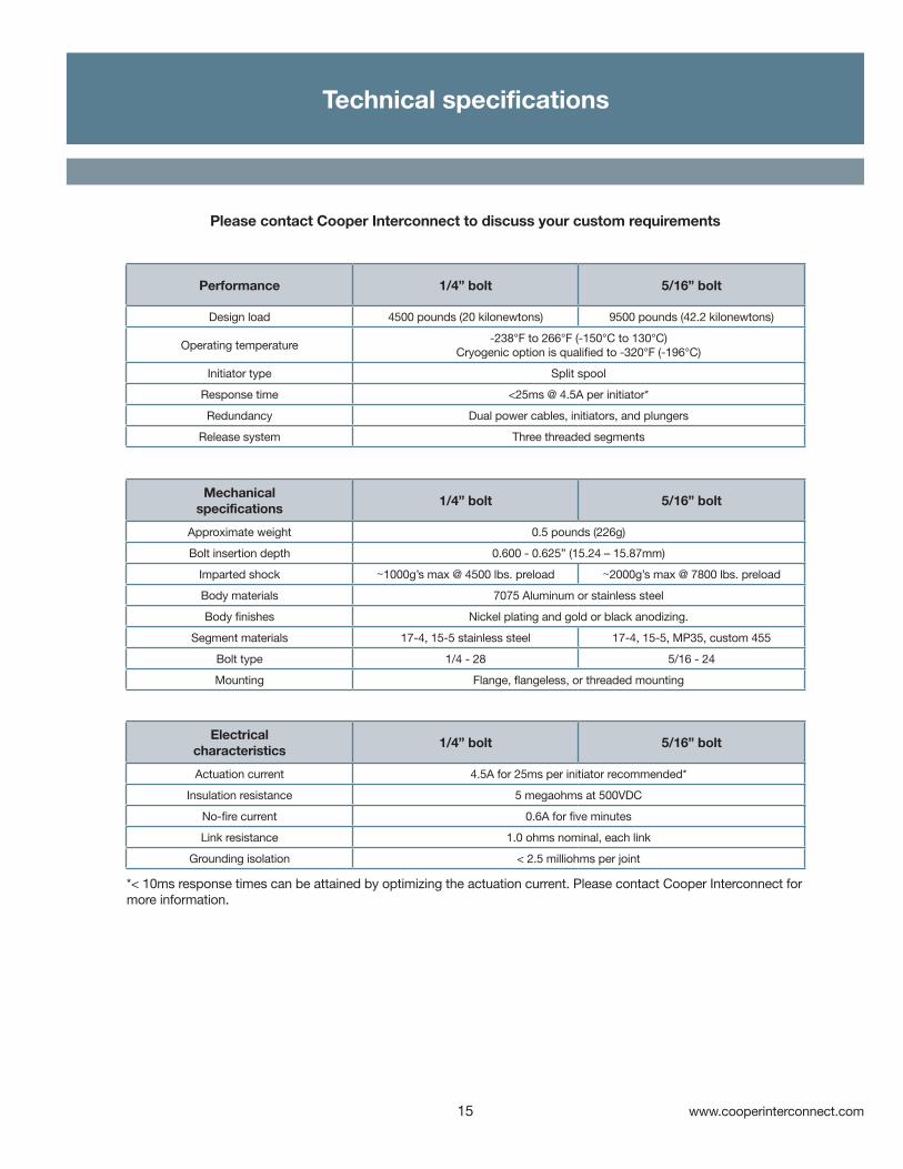
Technical specifications
Performance 1/4” bolt 5/16” bolt
Design load 4500 pounds (20 kilonewtons) 9500 pounds (42.2 kilonewtons)
Operating temperature-238°F to 266°F (-150°C to 130°C)
Cryogenic option is qualified to -320°F (-196°C)
Initiator type Split spool
Response time <25ms @ 4.5A per initiator*
Redundancy Dual power cables, initiators, and plungers
Release system Three threaded segments
Mechanical specifications
1/4” bolt 5/16” bolt
Approximate weight 0.5 pounds (226g)
Bolt insertion depth 0.600 - 0.625” (15.24 – 15.87mm)
Imparted shock ~1000g’s max @ 4500 lbs. preload ~2000g’s max @ 7800 lbs. preload
Body materials 7075 Aluminum or stainless steel
Body finishes Nickel plating and gold or black anodizing.
Segment materials 17-4, 15-5 stainless steel 17-4, 15-5, MP35, custom 455
Bolt type 1/4 - 28 5/16 - 24
Mounting Flange, flangeless, or threaded mounting
Electricalcharacteristics
1/4” bolt 5/16” bolt
Actuation current 4.5A for 25ms per initiator recommended*
Insulation resistance 5 megaohms at 500VDC
No-fire current 0.6A for five minutes
Link resistance 1.0 ohms nominal, each link
Grounding isolation < 2.5 milliohms per joint
Please contact Cooper Interconnect to discuss your custom requirements
*< 10ms response times can be attained by optimizing the actuation current. Please contact Cooper Interconnect for more information.

16
Environmental, development history, and series designations
Environmental 1/4” bolt 5/16” bolt
Mechanical shock (induced) 10,000g’s
Random vibration 40 grms
Maximum humidity < 90% RH
Operating temperature-238°F to 266°F (-150°C to 130°C)
Cryogenic option is qualified to -351°F (-213°C)
Storage life 20 years
Development history 1/4” bolt 5/16” bolt
Development date 1993 2001
Cooper Interconnect’s Mars mission heritage includes separation nuts, pin pullers, and tension releases. Applications include connector and stage separation and deployment of instruments,
antenna arrays, solar panels, and protective covers.
Image courtesy of NASA

www.cooperinterconnect.com17
Mounting and connector configurations
Cooper Interconnect’s separation nuts are available with a wide range of mounting and electrical-connector options. All configurations are designed to deliver a unique combination of high-load ratings, compact-form factors, and mission-critical redundant initiation.
The mechanical drawings presented below provide reference dimensions for a few representative heritage configurations. Actual dimensions are based on customer requirements.
2.0 in.5cm
Across flats
1.04 in. 2.6cm
2.26 to 3.0 in.5.74 to 7.6cm
2.5 to 3.1 in.6.4 to 7.9cm
2.4 in.6.1cm
2.75 in.6.98cm
18
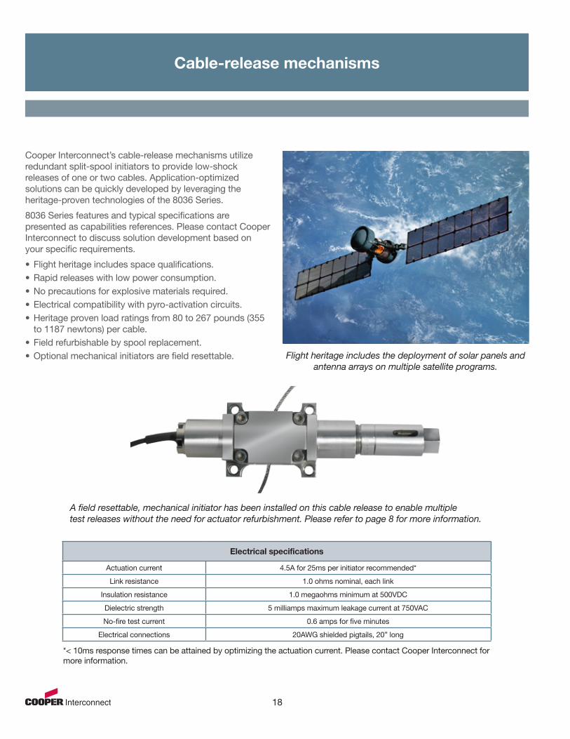
Cable-release mechanisms
Cooper Interconnect’s cable-release mechanisms utilize redundant split-spool initiators to provide low-shock releases of one or two cables. Application-optimized solutions can be quickly developed by leveraging the heritage-proven technologies of the 8036 Series.
8036 Series features and typical specifications are presented as capabilities references. Please contact Cooper Interconnect to discuss solution development based on your specific requirements.
•Flight heritage includes space qualifications.•Rapid releases with low power consumption.•No precautions for explosive materials required.•Electrical compatibility with pyro-activation circuits.•Heritage proven load ratings from 80 to 267 pounds (355
to 1187 newtons) per cable.•Field refurbishable by spool replacement.•Optional mechanical initiators are field resettable. Flight heritage includes the deployment of solar panels and
antenna arrays on multiple satellite programs.
A field resettable, mechanical initiator has been installed on this cable release to enable multiple test releases without the need for actuator refurbishment. Please refer to page 8 for more information.
Electrical specifications
Actuation current 4.5A for 25ms per initiator recommended*
Link resistance 1.0 ohms nominal, each link
Insulation resistance 1.0 megaohms minimum at 500VDC
Dielectric strength 5 milliamps maximum leakage current at 750VAC
No-fire test current 0.6 amps for five minutes
Electrical connections 20AWG shielded pigtails, 20” long
*< 10ms response times can be attained by optimizing the actuation current. Please contact Cooper Interconnect for more information.

www.cooperinterconnect.com19
Mechanical and environmental specifications
5.56 in.14.1cm
3.6 in.9.1cm.
Mechanical & environmental specifications
Initiator type Split-spool initiator, field refurbishable
Redundancy Electrically and mechanically redundant
Separation time <25ms @ 4.5A per initiator*
Tensile load rating80 to 267 pounds (355 to 1187 newtons) per cable standard ratings
Application-specific load ranges are also available
Load connectionsFlexible cables or rigid rods
with .190-24UNF-2A or .190-24UNC-2A threads
Load-axis orientationConfigurations available with the load axis
parallel or perpendicular to the mounting flange
Weight 10.5 ounces (300 grams) typical maximum
Operating temperature -6°F to 217°F (-21°C to 102°C)
*< 10ms response times can be attained by optimizing the actuation current. Please contact Cooper Interconnect for more information.
20
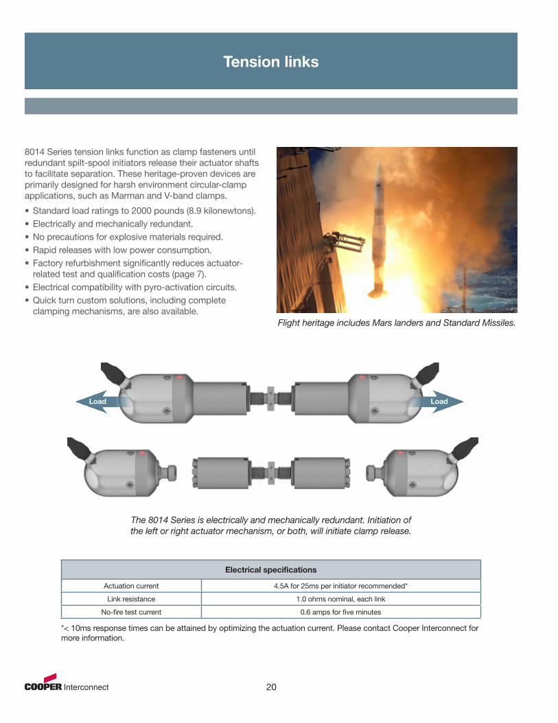
Tension links
8014 Series tension links function as clamp fasteners until redundant spilt-spool initiators release their actuator shafts to facilitate separation. These heritage-proven devices are primarily designed for harsh environment circular-clamp applications, such as Marman and V-band clamps.
•Standard load ratings to 2000 pounds (8.9 kilonewtons).•Electrically and mechanically redundant.•No precautions for explosive materials required.•Rapid releases with low power consumption.•Factory refurbishment significantly reduces actuator-
related test and qualification costs (page 7).•Electrical compatibility with pyro-activation circuits.•Quick turn custom solutions, including complete
clamping mechanisms, are also available.Flight heritage includes Mars landers and Standard Missiles.
Electrical specifications
Actuation current 4.5A for 25ms per initiator recommended*
Link resistance 1.0 ohms nominal, each link
No-fire test current 0.6 amps for five minutes
LoadLoad
The 8014 Series is electrically and mechanically redundant. Initiation of the left or right actuator mechanism, or both, will initiate clamp release.
*< 10ms response times can be attained by optimizing the actuation current. Please contact Cooper Interconnect for more information.

www.cooperinterconnect.com21
Mechanical and environmental
2.37 inches6.02cm
5.2 inches13.2 cm
Mechanical & environmental specifications
Initiator type Split-spool initiator, factory refurbishable
Separation time <25ms @ 4.5A per initiator*
Separation stroke 0.12 inch (3mm) each side
Tensile load 2000 pounds (8.9 kilonewtons)
Minimum required load 15 pounds (66N)
Redundancy Electrically and mechanically redundant
Materials Corrosion-resistant steel, all parts except insulators
Weight 7.5 ounces (213 grams) maximum
Operating temperature -80°F to 220°F (-62°C to 104°C)
*< 10ms response times can be attained by optimizing the actuation current. Please contact Cooper Interconnect for more information.

22
Tension releases
Electrical specifications
Actuation current 4.5A for 25ms recommended*
Link resistance 1.0 ohms nominal
No-fire test current 0.6 amps for five minutes
Electrical connections Two wire, 22AWG leads, 36”(91cm)
8024 Series tension releases utilize split-spool initiation to provide low-shock deployment of loads up to 1300 pounds (5.8 kilonewtons). Additional advantages of these heritage proven, and space qualified, solutions include:
•Fragment and debris-free operation.•Rapid releases with low power consumption.•No precautions for explosive materials required.•Threaded and clevis load attachment options.•Factory refurbishment significantly reduces actuator-
related test and qualification costs (page 7).•Quick-turn custom solutions are also available.
Flight heritage includes Exoatmospheric Kill Vehicles and solar panel and antenna array releases on multiple satellite programs.
The 8024 Series provides a separation stroke of 1.1 inches (28mm).
*< 10ms response times can be attained by optimizing the actuation current. Please contact Cooper Interconnect for more information.

www.cooperinterconnect.com23
Mechanical and environmental
Mechanical & environmental specifications
Initiator type Split-spool initiator
Separation time <25ms @ 4.5A*
Separation stroke 1.1 inches (28mm)
Tensile load 1300 pounds (5.8 kilonewtons)
Minimum load 15 pounds (67 newtons)
Materials Corrosion-resistant steel, except molded-epoxy insulator
Weight 28.3 grams (2.2 ounces)
Operating temperature -200°F to 300°F (-128°C to 149°C)
1.12 in.2.83 cm
Internal loadattachment thread
Please contact Cooper Interconnect to discuss custom mounting flanges, load attachments, and actuator-body configurations.

24
Miniaturized tension releases
Electrical specifications
No-fire test current 4.5A for 25ms recommended*
Link resistance 1.0 ohms nominal
Insulation resistance 10 megaohms
Actuation current 4.5 amps minimum
Electrical connections 22AWG stranded lead wires, 3 inches (7.6cm)
1183 Series miniaturized tension releases utilize low shock, split-spool initiation to deliver a 250-pound (1.1 kilonewton) load rating from an actuator body that occupies less than one third of a cubic inch (five cm3).
Program heritage includes qualification to separate night-vision goggles from a pilot’s helmet prior to emergency ejection. Additional advantages include:
•Fragment and debris-free operation.•Rapid releases with low power consumption.•No precautions for explosive materials required.•Designed for integral mounting to significantly reduce
the size of the host system.•Extremely lightweight: < 12.5 grams (.44 ounces).•Quick turn custom solutions are also available. Program qualifications include emergency detachment
of night-vision systems in combat aircraft.
The 1183 Series provides a separation stroke of 0.25 inches (6.35mm). The compact, symmetrical form factor simplifies integral mounting to
reduce the overall size of the host system.
*< 10ms response times can be attained by optimizing the actuation current. Please contact Cooper Interconnect for more information.

www.cooperinterconnect.com25
Mechanical and environmental
Mechanical & environmental specifications
Initiator type Split-spool initiator
Separation time <25ms @ 4.5A*
Separation stroke 0.25 inch (6.35mm)
Tensile load 250 pounds (1.1 kilonewtons)
Materials Corrosion-resistant steel, except molded-epoxy insulator
Weight < 12.5 grams (.44 ounces)
Operating temperature -29°F to 131°F (-34°C to 55°C)
0.62 in.(15.75 mm.)
0.78 in.(19.81 mm.)
*< 10ms response times can be attained by optimizing the actuation current. Please contact Cooper Interconnect for more information.

26
Electrical switches
Split-spool-initiated switches can be used to permanently open or close single or multiple electrical circuits. Applications include terminating an event or sequence events, bypassing failed battery cells, and disconnecting or rerouting power in response to fault conditions.
When compared to relays, split-spool technologies enable faster response times, reduced weight, and increased reliability especially in high shock and vibration environments.
Additional advantages include:
•Significantly lower voltage drops than diode-bypass systems; < 20mV @ 100A and 40mV @ 200A.
•Rapid releases with low power consumption.•No precautions for explosive materials required.•Fragment and debris-free operation.•Field refurbishable by spool replacement (page 7).•Electrical compatibility with pyro-activation circuits.
Theory of operation
The actuation sequence of the depicted single pole, single throw switch is representative of the operation of all of Cooper Interconnect’s split-spool-initiated switches.
•When armed, the initiator locks the sliding insulator/contact assembly with the insulator positioned between the fixed contacts.
• Initiator actuation unlocks the insulator/contact assembly allowing the sliding contact to mate with the fixed contacts as the compression spring expands.
Flight heritage includes battery power management on GPS and global observation satellites.
Sliding insulator disconnects fixed contacts
Armed initiator
Normally open contacts
Sliding contact mated with fixed contacts
Actuated initiator
Actuated with contacts closed

www.cooperinterconnect.com27
Accelerated custom solution development
2.93 in.(74.42 mm.)
0.85 in.(21.59 mm.)
1.50 in.(38.10 mm.)
Cooper Interconnect’s heritage-proven technologies and design platforms accelerate custom solution development for a broad range of electrical-switch requirements:
•Single-and-multiple pole and throw combinations.•Normally open or closed contacts.•Make before break or break before make switching.•Simultaneous or sequenced multi-pole operation.•Application-specific form factors and materials.
•Customer defined electrical performance including high current ratings - continuous and surge.
•Extreme shock, vibration, corrosive environments, and operating temperatures including cryogenic.
Specifications for the Model 1181 are presented below as capabilities references. The Model 1181 incorporates technologies with flight heritage that can be leveraged for other harsh-environment switch applications.
Model 1181 electrical specifications
Actuation current 4.5A for 25ms recommended*
No-fire test current 0.6 amps for five minutes
Continuous / surge current 200 amps / 350 amps for 120 seconds
Post activation voltage drop < 20mV @ 100A, 40mV @ 200A
Insulation resistance 5 megaohms minimum @ 600VDC
Dielectric withstand voltage 600Vrms, 60Hz at sea level
Link resistance 1.0 ohms nominal
Electrical protection Optional blocking diode prevents current flow in the event of cell reversal
Model 1181 mechanical and environmental specifications
Initiator type Split-spool initiator
Separation time 25ms @ 4.5A*
Operating temperature range -15°C to 40°C (5°F to 104°F)
Random vibration 10.7grms
Shock 1960g’s from 2.5 to 10KHz
Weight 3 ounces (85 grams) maximum
*< 10ms response times can be attained by optimizing the actuation current. Please contact Cooper Interconnect for more information.

Reorder # CI-38999S3-0712
Customer ServiceCooper Interconnect750 West Ventura Blvd.Camarillo, CA 93010Phone: 805.484.0543 or 800.840.0502cicustomer.service@eaton.comwww.cooperinterconnect.com
Cooper Interconnect750 West Ventura Blvd.Camarillo, CA 93010
Cooper U.S., Inc.600 Travis, Ste. 5800Houston, TX 77002-1001713-209-8400www.cooperindustries.com
Cooper Interconnect and the trade names and brand names herein are valuable trademarks of Cooper Industriesin the U.S. and other countries. Use of the Cooper Trademarks with out the prior written consent of Cooper Industries is strictly prohibited. ©2012 Cooper Industries, plc.
Cooper InterconnectCalzada Industrial No. 3 Nogales, MX 41600
Cooper Interconnect Aerospace & Military Manufacturing Locations


![Optical-packet-switched interconnect for supercomputer applications [Invited]](https://static.fdokumen.com/doc/165x107/633648acb5f91cb18a0bc31d/optical-packet-switched-interconnect-for-supercomputer-applications-invited.jpg)