![Optical-packet-switched interconnect for supercomputer applications [Invited]](https://static.fdokumen.com/doc/165x107/633648acb5f91cb18a0bc31d/optical-packet-switched-interconnect-for-supercomputer-applications-invited.jpg)
Optical-packet-switched interconnect for supercomputer applications [Invited]
Upload
khangminh22Category
view
0download
0
Linköpings universitet
SE–581 83 Linköping
+46 13 28 10 00 , www.liu.se
Linköping University | Department of Computer and Information ScienceMaster’s thesis, 30 ECTS | Computer Architecture
2020 | LIU-IDA/LiTH-EX-A–20/072–SE
Verifying Deadlock-Freedom
for Advanced Interconnect
Architectures
Meng Wang
Supervisor : Zeinab Ganjei
Examiner : Ahmed Rezine

Upphovsrätt
Detta dokument hålls tillgängligt på Internet - eller dess framtida ersättare - under 25 år från
publiceringsdatum under förutsättning att inga extraordinära omständigheter uppstår.
Tillgång till dokumentet innebär tillstånd för var och en att läsa, ladda ner, skriva ut enstaka kopior
för enskilt bruk och att använda det oförändrat för ickekommersiell forskning och för undervisning.
Överföring av upphovsrätten vid en senare tidpunkt kan inte upphäva detta tillstånd. All annan
användning av dokumentet kräver upphovsmannens medgivande. För att garantera äktheten,
säkerheten och tillgängligheten finns lösningar av teknisk och administrativ art.
Upphovsmannens ideella rätt innefattar rätt att bli nämnd som upphovsman i den omfattning
som god sed kräver vid användning av dokumentet på ovan beskrivna sätt samt skydd mot att
dokumentet ändras eller presenteras i sådan form eller i sådant sammanhang som är kränkande för
upphovsmannens litterära eller konstnärliga anseende eller egenart.
För ytterligare information om Linköping University Electronic Press se förlagets hemsida
http://www.ep.liu.se/.
Copyright
The publishers will keep this document online on the Internet - or its possible replacement - for a
period of 25 years starting from the date of publication barring exceptional circumstances.
The online availability of the document implies permanent permission for anyone to read, to
download, or to print out single copies for his/hers own use and to use it unchanged for non-
commercial research and educational purpose. Subsequent transfers of copyright cannot revoke this
permission. All other uses of the document are conditional upon the consent of the copyright owner.
The publisher has taken technical and administrative measures to assure authenticity, security and
accessibility.
According to intellectual property law the author has the right to bementionedwhen his/her work
is accessed as described above and to be protected against infringement.
For additional information about the Linköping University Electronic Press and its procedures
for publication and for assurance of document integrity, please refer to its www home page:
http://www.ep.liu.se/.
© Meng Wang

Abstract
Modern advanced Interconnects, such as those orchestrated by the ARM AMBA AXIprotocol, can have fatal deadlocks in the connection between Masters and Slaves if thosetransactions are not properly arranged. There exists some research about the deadlockproblems in an on-chip bus system and also methods to avoid those deadlocks whichcould happen. This project aims to verify those situations could make deadlock happensand also the countermeasures for those deadlocks. In this thesis, the ARM AMBA AXIprotocol and countermeasures are modelled in NuSMV. Based on these models, we verifiedthe non-trivial cycles of transactions could cause deadlocks and also some bus techniqueswhich can mitigate deadlock problems efficiently. The results from model checking severalinstances of the protocol and corresponding countermeasures show the techniques couldindeed avoid deadlocks.

Contents
Abstract iii
Acknowledgments iv
Contents iv
List of Figures v
List of Tables vi
1 Introduction 11.1 Motivations . . . . . . . . . . . . . . . . . . . . . . . . . . . . . . . . . . . . . . 11.2 Aim . . . . . . . . . . . . . . . . . . . . . . . . . . . . . . . . . . . . . . . . . . 11.3 Research Questions . . . . . . . . . . . . . . . . . . . . . . . . . . . . . . . . . . 1
2 Background 22.1 AMBA AXI Protocol . . . . . . . . . . . . . . . . . . . . . . . . . . . . . . . . . 22.2 Model Checking . . . . . . . . . . . . . . . . . . . . . . . . . . . . . . . . . . . . 42.3 Kripke Structure . . . . . . . . . . . . . . . . . . . . . . . . . . . . . . . . . . . 52.4 Computation Tree Logic . . . . . . . . . . . . . . . . . . . . . . . . . . . . . . . 5
3 Literature Review 73.1 Bus Status Graph . . . . . . . . . . . . . . . . . . . . . . . . . . . . . . . . . . 73.2 Existing Techniques to Mitigate Deadlock . . . . . . . . . . . . . . . . . . . . . 8
4 Method 104.1 Formal Modeling of The AMBA AXI Protocol . . . . . . . . . . . . . . . . . . 104.2 Formal Verification of The AMBA AXI protocol . . . . . . . . . . . . . . . . . 13
5 Results 17
6 Conclusion 19
Bibliography 20
iv
List of Figures
2.1 Interface and Interconnect . . . . . . . . . . . . . . . . . . . . . . . . . . . . . . . . 22.2 Transactions and AXI ID . . . . . . . . . . . . . . . . . . . . . . . . . . . . . . . . 32.3 Three handshake processes . . . . . . . . . . . . . . . . . . . . . . . . . . . . . . . 32.4 Deadlock Model . . . . . . . . . . . . . . . . . . . . . . . . . . . . . . . . . . . . . 42.5 Computation Tree . . . . . . . . . . . . . . . . . . . . . . . . . . . . . . . . . . . . 62.6 Four Basic CTL Operators . . . . . . . . . . . . . . . . . . . . . . . . . . . . . . . 6
3.1 Bus Status Graph : a prime edge representsthe earliest request by the ID . . . . . . . . . . . . . . . . . . . . . . . . . . . . . . 7
3.2 BSG example for unsafe states . . . . . . . . . . . . . . . . . . . . . . . . . . . . . 83.3 BSG example for safe states . . . . . . . . . . . . . . . . . . . . . . . . . . . . . . . 8
4.1 An abstraction of our model for one ID . . . . . . . . . . . . . . . . . . . . . . . . 104.2 an abstraction of slave in our model . . . . . . . . . . . . . . . . . . . . . . . . . . 114.3 Countermeasure from NuSMV . . . . . . . . . . . . . . . . . . . . . . . . . . . . . 14
v
List of Tables
5.1 Verification Time for Different Instance . . . . . . . . . . . . . . . . . . . . . . . . 17
vi
Chapter 1
Introduction
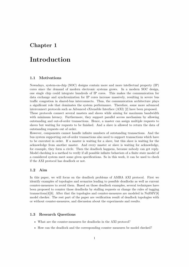
1.1 Motivations
Nowadays, system-on-chip (SOC) designs contain more and more intellectual property (IP)cores since the demand of modern electronic systems grows. In a modern SOC design,one single chip could integrate hundreds of IP cores. This makes the communication fordata exchange and synchronization for IP cores increase massively, resulting in severe bustraffic congestion in shared-bus interconnects. Thus, the communication architecture playsa significant role that dominates the system performance. Therefore, some more advancedinterconnect protocols such as Advanced eXtensible Interface (AXI) [2] have been proposed.These protocols connect several masters and slaves while aiming for maximum bandwidthwith minimum latency. Furthermore, they support parallel access mechanism by allowingoutstanding and out-of-order transactions. Hence, a master can assign multiple requests toslaves but waiting for requests to be finished. And a slave is allowed to return the data ofoutstanding requests out of order.However, components cannot handle infinite numbers of outstanding transactions. And thebus system supporting out-of-order transactions also need to support transactions which haveto be executed in order. If a master is waiting for a slave, but this slave is waiting for theacknowledge from another master. And every master or slave is waiting for acknowledge,for example, they form a circle. Then the deadlock happens, because nobody can get reply.Model checking is a method to verify if all possible infinite behaviors of a finite state model ofa considered system meet some given specifications. So in this work, it can be used to checkif the AXI protocol has deadlock or not.
1.2 Aim
In this paper, we will focus on the deadlock problems of AMBA AXI protocol. First weidentify examples of topologies and scenarios leading to possible deadlocks as well as currentcounter-measures to avoid them. Based on those deadlock examples, several techniques havebeen proposed to counter those deadlocks by stalling requests or change the rules of taggingtransactions[4][6]. After that the topologies and counter-measures are modeled in NuSMV[8]model checker. The rest part of the paper are verification result of deadlock topologies withor without counter-measures, and discussion about the experiments and results.
1.3 Research Questions
• What are the counter-measures for deadlocks in the AXI protocol?
• How can the deadlock and the corresponding counter measures be model checked?
1

Chapter 2
Background
In this chapter, the AMBA AXI protocol, NuSMV, kripke structure and computation treelogic are introduced.
2.1 AMBA AXI Protocol
The AXI protocol provides the definition for the interfaces between a master and theinterconnect, a slave and the interconnect, a master and a slave. Figure 2.1 shows a instanceof AXI protocol system. It consists several masters and slaves connected together throughinterconnect.
Interconnect
Master 1 Master 2 Master 3
Slave 1 Slave 2 Slave 3 Slave 4
Interface
Figure 2.1: Interface and Interconnect
Transaction Model
The AXI ID identifiers are defined in AXI protocol. The IDs are used to tag transactionswhen they are created. All transactions with the same AXI ID value must be completed inorder. But for the transactions with different ID values, no ordering requirements exist, onetransaction may be completed without waiting for earlier transactions. And also, there are norestrictions on the transaction orders from different masters, those transactions can completein any order. In addition, the AXI protocol requires that a slave must respond to requestswith the same ID value in order. [2]As Figure 2.2 shows, transactions T1 and T3 are sent to slave 1 and slave 2 respectively withID value 1. T2 and T4 are sent to slave 2 and slave 1 respectively with ID value 2. Accordingto the restrictions above, T1 must be completed before T3. So even if T3 is returned beforeT1, the master will still wait T1 until it is returned and complete it first.
2

2.1. AMBA AXI Protocol
T1 ID1
T2ID2T4
S1
T3
S2
Requests: T1→T2→T3→T4 ID: 1 2 1 2
Targets: S1 S2 S2 S1
Figure 2.2: Transactions and AXI ID
Handshake Mechanism
The handshake mechanism in the AXI protocol makes both master and slave to control the rateof information transferred. First, both master and slave can be the source or the destination.When a source wants to assign a task to a destination, the source makes the VALID signal tohigh first to indicate that the address, data, or control information is available now. And thedestination pulls up the READY signal to show it is able to accept the incoming information.Then the transaction occurs only when both those two signals, VALID and READY, are high.There has three kind of handshake processes as Figure 2.3 shows.In Figure 2.3 (a), the source provides the address, data or control information after the cycle0 and pulls up the VALID signal and the source must hold the information stable until thetransfer happens. Then the READY signal is generated after the cycle 1 by the destinationand the transfer finishes in the cycle 2. Additionally, the source is not allowed to wait for theREADY signal when it has not generated the VALID signal. And once the VALID signal isgenerated, it has to remain in high until the handshake finishes.In Figure 2.3 (b), the destination generated READY signal after the cycle 5 indicates that it isready to accept the information, and the address, data or control information is not preparedyet. Then the VALID signal is generated after the cycle 6 and the transfer occurs in the cycle7. Moreover, one destination is allowed to wait for the VALID signal before generating thecorresponding READY signal, and it is also allowed to cancel the READY signal before theVALID signal is generated if the READY is already generated.In Figure 2.3 (c), both source and destination pull up the VALID and READY respectively,after the cycle 10, to show that they can transfer information. In this case, the transfer happensat the rising edge of the clock of the cycle 11 when those two signals could be recognized, andit finishes in a single cycle.[2]
0 1 2 3 4 5 6 7 8 9 10 11 12
ACLK
INFORMATION
VALID
READY
VALID Before READY READY Before VALID VALID With READY
(a) (b) (c)
Figure 2.3: Three handshake processes
3

2.2. Model Checking
Deadlocks
The deadlocks may occur in the AXI protocol due to how the AXI supports out-of-ordertransactions. We take the example in Figure 2.2 again now, slaves 1 and 2 are both assignedtasks via ID 1 and 2, and T1 must be serviced before T3, T2 must be serviced before T4. Nowassume slave 1 finishes T4 first and slave 2 finishes T3. But because of the rules mentionedabove, T3 and T4 are not allowed to be completed by master before T1 and T2 have beencompleted. Because the master is waiting for the result from S2, S1 sends the result of T4back to the master but gets no acknowledge back. And the same thing also happens on ID1and S2, S2 sends back the result but the master is waiting for the result from S1. As shownin Figure 2.4, every part is waiting, the system can not move. In another word, the deadlockoccurs.
T1ID1
T2ID2
T4
Waiting
Respond
S1
T3
S2
Waiting
Respond
Figure 2.4: Deadlock Model
There are some intuitive solutions for this deadlock problem such as ensuring masters do notassign requests which may get systems in an unsafe state or limiting the return order of slaves.Moreover, many methods can achieve this intent, but those may over-solve the problem andthus slow down the performance.
2.2 Model Checking
Model checking is a method to check if all possible infinite behaviors of a finite state model ofa considered system satisfy some specifications or properties.
NuSMV
NuSMV is a symbolic model checker. It is redesigned, reimplemented and extended from CMUSMV, which is a BDD-based model checker developed by CMU originally. The main featuresof NuSMV are the following:[8]
• Functionalities. NuSMV allows both synchronous and asynchronous finite state system,and both computation tree logic (CTL) and linear temporal logic (LTL) expressedspecifications.
• Architecture. To reduce the work required to modify and extend NuSMV, the differentcomponents and functions are separated into modules with interfaces between them.
• Quality of the implementation. NuSMV is written by ANSIC, compliant with POSIXand debugged with Purify to detect memory leaks.
4

2.3. Kripke Structure
2.3 Kripke Structure
In order to verify the correctness of the system, first need to figure out the properties of thesystem. Then a formal model of the system should be established, which contains the systemproperties used to verify the correctness, and extracts out those redundant details that haveno effect on the correctness but increase the difficulty of verification.[5]In the AXI bus system, there are three significant properties that need to be captured, state,transition and computation. A state is a temporary description contains certain systemvariables in a piece of time. The transition represents the change that happens in the systemcaused by some action occurs. It is given as a pair of states, one is the state before the changeand another one is after the change. A computation is a path that contains infinite continuoustransitions, which means each state in it is obtained from the previous state through a certaintransition.We use the Kripke structure to capture the behavior of the AXI protocol. A Kripke structurecontains a set of states, a set of transitions and labeling function maps each state to a setof properties that hold in the corresponding state. AP is a set of atomic propositions, i.e.boolean expressions over variables, constants and predicate symbols. And paths in Kripkestructure could model computations of the system. These models are expressive enough tocomprehensively cover the aspects of temporal behaviors to explain the system.A Kripke structure M over AP is a four tuple M = (S, S0, R, L) with following elements[5]:
1) S is a finite set of states.
2) S0 � S is a set of initial states.
3) R � S� S is a transition relation that must be total, which means for each state s P Sthere exists a state s1 P S such that R(s, s1). If some state s has no successor, R(s, s)holds.
4) L : S Ñ 2AP is a labeling function that labels each state with the set of atomicpropositions which are true in that state.
2.4 Computation Tree Logic
The Computation Tree Logic(CTL) describes attributes of computation trees. A computationtree is a rooted tree with vertices and edges, which is formed by unwinding the Kripke structureinto an infinite tree with an initial state of the structure as a root, as illustrated in Figure 2.5.Each vertex represents a single state and each edge represents the transition from one state toanother. The computation tree demonstrates all possible transitions and states.We use φ to represent a specification. There have path quantifiers and temporal operators inthe CTL formulas.Path quantifiers:
• A φ - All: φ must hold on all paths starting from the current state.
• E φ - Exists: there exists at least one path starting from the current state.
Temporal operators:
• X φ - Next: φ holds in the next state of the path.
• F φ - Finally: φ will hold at some state of the path eventually.
• G φ - Globally: φ has to hold at every state on the path.
• φ U ψ - Untill: φ holds every preceding state on the path where the ψ holds some state.
5

2.4. Computation Tree Logic
S1
S2
S3
S1
S2
S1 S3
S2 S1S2
Kripke Structure
Computation Tree
Figure 2.5: Computation Tree
• φ R ψ - Release: ψ needs to holds along the path up to and including the first state heldby φ, while φ has no need to hold eventually.
CTL is a restricted subset of CTL*, and the operators must always be grouped in twoby one path operator followed by a state operator. The model of time in CTL is a tree-likestructure. There are many paths in the future and the future is uncertain, any one path ofthose might be finally realized. There are ten basic CTL operators, AX and EX, AF and EF,AG and EG, AU and EU, AR and ER. And each of these ten operators can be transformedto use only three operators EX, EG and EU:
• AX φ = EX( φ)
• EF φ = E[True U φ]
• AG φ = EF( φ)
• AF φ = EG( φ)
• A[φ U ψ] � E[ ψ U ( φ^ ψ)]^ EG ψ
• A[φ R ψ] � E[ φ U ψ]
• E[φ R ψ] � A[ φ U ψ]
These four operators, EF, AF, EG and AG are used mostly wide as shown in Figure 2.6.The notion M , s |ù φ represents that φ holds at state s in the Kripke structure M .[5]
φ φφ
φ
φ
φ
φ
φ
φ
φ
φ
φ φ φ
M,s0⊨EFφ M,s0⊨AFφ M,s0⊨EGφ M,s0⊨AGφ
Figure 2.6: Four Basic CTL Operators
6

Chapter 3
Literature Review
There already exist some techniques to mitigate the deadlock problem. Three cyclicdependency schemes were proposed in [1], and the deadlock avoidance by least stalling(DALS)and a novel ID assignment mechanism were proposed by Chin-Yao Chang. They will beintroduced in the chapter.
3.1 Bus Status Graph
IDnNon-Prime Edge
Si SjPrime Edge
Non-Prime Edge• • •
Non-Prime Edge
• • •
Figure 3.1: Bus Status Graph : a prime edge representsthe earliest request by the ID
In [4], a BSG (Bus Status Graph) model has been proposed. A BSG consists of severalslave vertices, ID vertices, prime edges and non-prime edges. Each vertex stands for a slaveor an ID value. Each edge in BSG represents an uncompleted transaction request which hasbeen accepted by the slave. The edge comes from an ID to a slave is called a prime edge,and a non-prime edge is the one comes from a slave to an ID, as shown in Figure 3.1. Theprime edge from IDn to Sj shows that the transaction corresponding to this edge is processingby Sj and is assigned earliest with the IDn, which means the master has to complete thisrequest before all the other requests with IDn. A non-prime edge from vertex Si to vertexIDn indicates that this request has been accepted by Si but is not the highest priority request,which means it needs to wait for the other higher priority requests to be completed to returnthe result. Under these definitions, at most one prime edge with a specific ID can exist in aBSG. When a request, which is corresponding to a prime edge, is completed, this prime edgewill disappear, and one of the non-prime edges will become a new prime edge. Additionally,this is not randomly because there is an order queue in master but not showed in BSG.Now we take Figure 2.2 as the example again. In this model, there are two IDs, ID1 and ID2,and two slaves, S1 and S2. When the master assigns a request T1, a prime edge is createdfrom ID1 to S1. As shown in Figure 3.2 (a). Then the master requests T2 to S2 with ID2, aprime edge will appear from ID2 to S2 after S2 accepted this request as shown in Figure 3.2(b). When the master requests T3 to S2 with ID1, there will be a non-prime edge from S2 toID1 as shown in Figure 3.2 (c), because T1 is not completed yet. T3 can be returned afterT1 has been completed. Similarly, a non-prime edge between S1 and ID2 will appear whenthe master requests T4 and S1 accepts it. Now there exists a nontrivial cycle in Figure 3.2 (d)and the system is in unsafe state as we said in section 2.1.If the requests order in Figure 2.2 is T1ÑT4ÑT3ÑT2, as Figure 3.3 (a) and (b) show. No
7

3.2. Existing Techniques to Mitigate Deadlock
T1
ID1
S1 S2
ID2
T1
ID1
S1 S2T2
ID2
T1
ID1
S1T3
S2T2
ID2
T1
ID1
T4
S1T3
S2T2
ID2
(a) (b) (c) (d)
Figure 3.2: BSG example for unsafe states
outstanding requests tagged with ID1 and ID2 exist, so T1 and T4 are prime edges. Then weassume T2 and T3 are requested and accepted when T1 and T4 are not completed yet. Twonon-prime edges will appear as Figure 3.3 (c) and (d) show. In this situation, no cycles in thisBSG, and no matter how those requests are returned by slaves, the system will not get intodeadlock. Hence, the system is in a safe state.
T1
ID1
S1 S2
ID2
T1
ID1
S1 S2T4
ID2
T1
ID1
S1T3
S2T4
ID2
T1
ID1
S1T3
T2
S2T4
ID2
(a) (b) (c) (d)
Figure 3.3: BSG example for safe states
3.2 Existing Techniques to Mitigate Deadlock
In [1], three cyclic dependency schemes for slave interface are proposed to avoid deadlock byallowing slaves to accept or stall new transactions. These are the single slave scheme, theunique ID scheme and the hybrid scheme respectively.
1. The single slave scheme has the following two rules:
• A master can start a transaction to any slave, if this master has no uncompletedtransactions.
• If this master does has uncompleted transactions, it can only request the same slaveas the other uncompleted transactions requested to.
2. The unique ID scheme has the following rules:
• A master can start a transaction to any slave with any ID value if it has nouncompleted transactions.
• If an ID has been tagged to an uncompleted transaction, this ID can not be taggedto the other transactions until it is finished.
3. The hybrid scheme has the following rules:
• A master can start a transaction to any slave with any ID value if this master hasno uncompleted transactions
8

3.2. Existing Techniques to Mitigate Deadlock
• If a master does have uncompleted transactions, it can start a new transaction onlyto the slave that involves in the current uncompleted transactions with any ID. Orit can start a transaction to any slave with one of unused IDs.
In general, it is a natural method to mitigate the deadlock in this context by dropping thecritical transactions. The countermeasure randomly drop is developed from it, the rule ofrandomly drop is:
• Drop the prime request randomly.
In [4], a deadlock avoidance approach, the deadlock avoidance by least stalling(DALS), hasbeen proposed. The only rule of this approach is:
• If a nontrivial cycle in BSG will be formed by starting a request, this request will bestalled.
A novel ID assignment mechanism was proposed in [6], which ensures the assigned transactionswill not bring system into unsafe state and make a considerable reduction in the amount ofstalled transactions. This design will be implemented on each master. And two rules havebeen proposed in this design:
• Exclusive Rule: Slaves are mutually exclusive to each other. The ID assigned to a newtransaction to one slave is not allowed to be the same as IDs already been tagged tooutstanding transactions to the other slaves.
• Priority Rule: if Slave Si has higher priority than Sj, the new transaction to Si can beassigned with one of the IDs of outstanding transactions to Sj.
9
Chapter 4
Method
This chapter shows how we carry out the work, from building FSM till implementing theprotocol and countermeasures by NuSMV.
4.1 Formal Modeling of The AMBA AXI Protocol
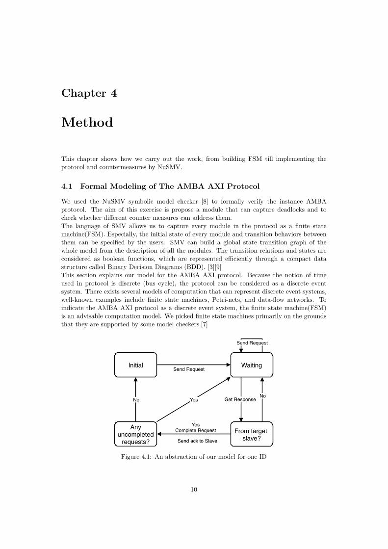
We used the NuSMV symbolic model checker [8] to formally verify the instance AMBAprotocol. The aim of this exercise is propose a module that can capture deadlocks and tocheck whether different counter measures can address them.The language of SMV allows us to capture every module in the protocol as a finite statemachine(FSM). Especially, the initial state of every module and transition behaviors betweenthem can be specified by the users. SMV can build a global state transition graph of thewhole model from the description of all the modules. The transition relations and states areconsidered as boolean functions, which are represented efficiently through a compact datastructure called Binary Decision Diagrams (BDD). [3][9]This section explains our model for the AMBA AXI protocol. Because the notion of timeused in protocol is discrete (bus cycle), the protocol can be considered as a discrete eventsystem. There exists several models of computation that can represent discrete event systems,well-known examples include finite state machines, Petri-nets, and data-flow networks. Toindicate the AMBA AXI protocol as a discrete event system, the finite state machine(FSM)is an advisable computation model. We picked finite state machines primarily on the groundsthat they are supported by some model checkers.[7]
Send RequestInitial
Get Response
Waiting
No
YesComplete Request From target
slave?
No Yes
Anyuncompleted
requests?
Send Request
Send ack to Slave
Figure 4.1: An abstraction of our model for one ID
10

4.1. Formal Modeling of The AMBA AXI Protocol
First of all, we created finite state machines for both master and slave. For the master,we just focus on one of the many IDs, then the other IDs could just follow the same logicas this ID. Figure 4.1 shows an abstraction of our model for one ID. In the beginning, themaster is in the initial state, which means there exist no uncompleted requests with this ID.When it assigns requests to the slave, it goes to the waiting state. During the waiting state,the master is waiting to get a response for the request with the highest priority, which isassigned earliest. And the master could continue sending request during the waiting state.If the master gets the response from the slave assigned with the prime request, it will sendback an acknowledge and then complete this request, otherwise, it will still wait. After that,if there still have uncompleted requests, the master then goes back to the waiting state, waitsfor the new request with the highest priority. If not, it will just go to the initial state.
Get RequestInitial
Return Results
Processing
YesComplete Request Get ack from
Master?
No Yes
Anyuncompleted
requests?
Get Request
No
Figure 4.2: an abstraction of slave in our model
The abstraction of a slave is showed in Figure 4.2. It starts from the initial state, when aslave gets a request from a master, it turns to the processing state. During the processingstate, it still can accept requests from masters. As long as one of these requests is processed,the slave starts to return the result to the specific master. When it gets the acknowledgementfrom the master, it will continue to process the other requests if there still exist any request,otherwise, the slaves will go back to the initial state. If the slave gets no acknowledgementfrom the master, it will keep waiting and block the other uncompleted requests untill theacknowledgement has arrived.
Listing 4.1 shows how we instantiate the master of AMBA AXI protocol in NuSMV. ModuleTag describes the behavior of a master on one ID. It has two inputs, ack and n, ack is theresult returned by slave, and n is the ID value. The variable req is an array of requested slaves,its values indicates which slave is requested. The req[0] is the highest priority request, whenthis get responded, next request will be the next highest priority one, as shown in line 6. Theinput ack is an array that captures whether the slave has responded and if so, to which ID.So ack[req[0]] is the target ID number of the slave associated with the highest request, if itequals to the corresponding ID, then this request is completed. To capture the delay exists inreality, the variable delay is non-deterministic.
1 MODULE Tag(ack, n)2 VAR3 req: array 0..1 of {1, 2, 0};
11

4.1. Formal Modeling of The AMBA AXI Protocol
4 delay : {0, 1}5 TRANS6 case7 req[0] = 0 & delay = 0: next(req[0]) = req[1] ;8 req[0] != 0 & ack[req[0]] = n & delay = 0:9 next(req[0]) = req[1] ;10 TRUE: next(req) = req;11 esac;
Listing 4.1: NuSMV Model for an AMBA AXI Master
Listing 4.2 shows the way we modelled a generic AMBA AXI slave in NuSMV. It has twoinputs, req_array, which is a set consisting all requests sent by the master with different IDvalues, and n stands for the slave number. The array buf and variable index are used to capturethe out-of-order processing in slaves. If a slave gets a request with an ID, it will process it byset the specific position in buf to the ID value, otherwise, the value in that position is null.The variable index is a non-deterministic value, which will change the value randomly everycycle. So the buf[index] returns the random one in the processed requests to ack, which is tobe returned to the master.
1 MODULE Slave(req_array , n)2 VAR3 ack: {0, 1, null};4 buf : array 0..1 of {0, 1, null};5 index : 0..1;6 delay : {0, 1};7 ASSIGN8 init(buf[0]):= null;9 init(buf[1]):= null;10 ASSIGN11 ack := buf[index];12 TRANS13 case14 req_array[0][0] = n | req_array[0][1] = n & delay = 0 :15 next(buf[0]) = 0;16 TRUE: next(buf[0]) = null;17 esac;18 TRANS19 case20 req_array[1][0] = n | req_array[1][1] = n & delay = 0 :21 next(buf[1]) = 1;22 TRUE: next(buf[1]) = null;23 esac;24 TRANS25 case26 buf[index] != null: next(index) = index;27 TRUE: next(index) = (index+1) mod 2;28 esac;
Listing 4.2: NuSMV Model for an AMBA AXI Slave
The interconnect between masters and slaves is modeled in Listing 4.6. The requests withdifferent IDs are assigned to the req_array sent to slaves. The acknowledges from differentslaves are assigned to the ack_array returned to the master.
12

4.2. Formal Verification of The AMBA AXI protocol
1 MODULE main2 VAR3 Tag0: process Tag(ack_array , 0);4 Tag1: process Tag(ack_array , 1);5 slave1 : process Slave(req_array , 1);6 slave2 : process Slave(req_array , 2);78 VAR9 ack_array : array 1..2 of {0, 1, null};10 req_array : array 0..1 of array 0..1 of {1, 2, 0};1112 ASSIGN13 ack_array[1] := slave1.ack;14 ack_array[2] := slave2.ack;15 req_array[0][0] := Tag0.ID[0];16 req_array[0][1] := Tag0.ID[1];17 req_array[1][0] := Tag1.ID[0];18 req_array[1][1] := Tag1.ID[1];
Listing 4.3: NuSMV Model for an AMBA AXI Bus
4.2 Formal Verification of The AMBA AXI protocol
Computational tree logic (CTL)[5] allows us to specify the properties of the instance. Inconcurrency systems, the term deadlock represents where some components freeze becausethey block each other. In our model, the deadlock happens when there exists a cycle in BSG,as shown in Figure 3.2. If there are no transactions with an ID, this ID will not be blocked.So the deadlock always happens when there has some transactions in the system. Therefore, ifthe master can always finish all the transactions with an ID, this ID will not deadlock. In otherwords, the system will not deadlock if all the IDs could arrive the state with no transactions.We can check that this undesirable situation does not occur by assuming the master could goback to the initial state. So the simple CTL property is:
AG EF req o f each Tag = 0
This formula means from any state, it is possible to get to the initial state. If it cannot passthe formal verification, then there exists deadlocks in the model.In this experiment, we use the simplest model, two IDs and two slaves. The result fromNuSMV is that specification AG EF Tagx.req = 0 is false, and the counter examples provethis specification is false is : req_array[0][0] = 1, req_array[0][1] = 2, req_array[1][0] = 2,req_array[1][1] = 1, as shown in Figure 4.3, the prime request with ID 0 is to slave 1 and withID 1 is to slave 2. Meanwhile both of these two IDs have non-prime edge to another slave.There is a cycle in the model then, and deadlock happens under this situation.
Counter measures
After that, we implemented four different counter measures, randomly drop, DALS, singleslave and unique ID. They are introduced in 3.2.Listing 4.4 shows how randomly drop is implemented. The input Dindex is a non-deterministicvalue given by the bus. It decides which prime transaction will be dropped. So when Dindexequals to the ID values, the prime request will update to next.
13

4.2. Formal Verification of The AMBA AXI protocol
req_array[0][0]ID0
S1
ID1
S2
req_array[0][1]
req_array[1][0]req_array[1][1]
Figure 4.3: Countermeasure from NuSMV
1 MODULE Tag(ack, n, Dindex)2 VAR3 req: array 0..1 of {1, 2, 0};4 delay : {0, 1};5 TRANS6 case7 Dindex = n : next(req[0]) = req[1];8 req[0] = 0 & delay = 0 : next(req[0]) = req[1];9 req[0]!= 0 & ack[req[0]] = n & delay = 0 :10 next(req[0]) = req[1];11 TRUE: next(req) = req;12 esac;
Listing 4.4: Master model with randomly drop
The master module implemented with DALS is illustrated in Listing 4.5. The new input Dindexstands for the request with which ID need to be dropped. And another, Dstat representswhether this request should be dropped or not. A new variable waiting_for means the IDthat this ID is waiting to. For example, if the master send requests to slave 1 with ID 0 andID 1, and slave 1 chooses to reply ID 1 first, then we say ID 0 is waiting for ID 1, so the valueof waiting_for in ID 0 is 1. So if there are no prime request with this ID, or the prime requesthas been replied, the waiting_for will be set to null, means this ID is not waiting for any otherIDs. While if there is a prime request with this ID and the target slave replies another ID,then we set the waiting_for with the ID value which is replied.
1 MODULE Tag(ack, n, Dindex , Dstat)2 VAR3 req: array 0..1 of {1, 2, 0};4 waiting_for : {0, 1, null};5 ASSIGN6 init(waiting_for) := null;7 TRANS8 case9 Dindex = n & Dstat = TRUE : next(req[0]) = req[1];10 req[0] = 0 : next(req[0]) = req[1] &11 next(waiting_for) = null;12 req[0] != 0 & ack[req[0]] = n : next(req[0]) = req[1] &13 next(waiting_for) = null ;14 req[0] != 0 & ack[req[0]] != n : next(req) = req &15 next(waiting_for) = ack[req[0]];16 TRUE: next(req) = req & next(waiting_for) = waiting_for;
14

4.2. Formal Verification of The AMBA AXI protocol
17 esac;
Listing 4.5: Master model with DALS
Also, in the main module, which is corresponding to the bus in the interconnect, somemechanism has been added, as shown in Listing 4.6. Here the waiting_for from differentIDs consist the waiting_list, which demonstrates the waiting relation between different IDs.Dindex is a non-deterministic values, it will take 0 or 1 randomly. Then we check is the waitingrelation between this ID and the other IDs exists a cycle. In this example showed below, therejust has 2 IDs so if the waited ID is also waiting for this ID, then there is a cycle. And whena cycle is detected, we keep the value of Dindex, and set the Dstat to true, to drop the primerequest of this ID to open the cycle. Otherwise, the Dstat is just set to false, which means norequests will drop.
1 MODULE main2 VAR3 waiting_list : array 0..1 of {0, 1, null};4 Dindex : {0, 1}; -- Info which ID is gonna drop the request5 Dstat : boolean; -- boolean for Drop or not6 ASSIGN7 waiting_list[0] := Tag0.waiting_for;8 waiting_list[1] := Tag1.waiting_for;9 TRANS10 case11 waiting_list[Dindex] != null &12 waiting_list[waiting_list[Dindex]] = Dindex :13 next(Dstat) = TRUE & next(Dindex) = Dindex;14 TRUE : next(Dstat) = FALSE;15 esac;
Listing 4.6: Main model with DALS
The main module implemented with single slave is showed in Listing 4.7.
1 MODULE main2 VAR3 Tag0: process Tag(ack_array , 0);4 Tag1: process Tag(ack_array , 1);5 slave1 : process Slave(req_array , 1);67 VAR8 ack_array : {0, 1, null};9 req_array : array 0..1 of array 0..1 of {1, 2, 0};1011 ASSIGN12 ack_array := slave1.ack;13 req_array[0][0] := Tag0.ID[0];14 req_array[0][1] := Tag0.ID[1];15 req_array[1][0] := Tag1.ID[0];16 req_array[1][1] := Tag1.ID[1];
Listing 4.7: Main model with single slave
Listing 4.8 shows how we implemented unique ID. As mentioned in section 3.2, each ID canbe tagged with one transaction at the same time maximally.
15

4.2. Formal Verification of The AMBA AXI protocol
1 MODULE Tag(ack, n)2 VAR3 ID: {1, 2, 0};4 delay: {0, 1, 2, 3, 4, 5, 6};5 TRANS6 case7 ID != 0 & ack[ID] != n : next(ID) = ID;8 ID != 0 & ack[ID] = n & delay = 0: next(ID) = 0;9 TRUE: next(ID) = next(ID);10 esac;
Listing 4.8: Master model with unique ID
16

Chapter 5
Results
To generically verify the instance of the AXI protocol, we have captured three systems thatinclude one master and two, three, four slaves. The master randomly tags transactionswith two, three or four IDs. The master plays the role of traffic generator that randomlyassigns transactions to slaves with random IDs and the slaves support out-of-order execution.Maximum number of transactions with same ID is 2. Several countermeasures showed insection 4.2 are captured in models that are model checked. We show that all can mitigate thedeadlock problems.
Number of IDs Number of Slaves Countermeasure Time Consumption Output2 2 no countermeasure 0.1s False2 2 randomly drop 1.6s True2 2 DALS 5m7s True2 2 single slave 0.083s True2 2 unique ID 0.083s True3 3 no countermeasure 6m48s False3 3 randomly drop 3m42s True3 3 DALS more than 20 hrs No3 3 single slave 0.13s True3 3 unique ID 5.75s True4 4 no countermeasure more than 20 hrs No4 4 randomly drop more than 20 hrs No4 4 DALS more than 20 hrs No4 4 single slave 0.42s True4 4 unique ID 49m45s True
Table 5.1: Verification Time for Different Instance
Table 5.1 indicates the verification time with different numbers of IDs and slaves. Weimplemented 4 countermeasures here, randomly drop, DALS, single slave and unique ID.These are mentioned in 4.2. We built it from the simplest case, 2 IDs and 2 slaves and madeit more and more complex. Till the case 4 IDs and 4 slaves, the program would take muchtime to finish. We set 20 hours as time out for verification.
As the table indicates, the size 2 instance of protocol just takes an instant to model checkexcept the one with DALS. It takes around 5 minutes. When there has 3 IDs, 3 slaves and nocountermeasure considered, it takes 7 minutes to get the result, which is as what we expect,NuSMV establishes absence of deadlock for considered instance and countermeasures. Whenthe instance is considered with the randomly drop, the size 3 instance of protocol just takearound 3.5 minutes to finish the model checking, and the instance is safe, no deadlock canhappen. The instance with the single slave or the unique ID finish in 0.1 second. It just takesa few second to verify them, and the result is true, which means it is impossible to make a
17

deadlock. After we adopted the countermeasure DALS in the size 3 instance of protocol, ittakes more than 20 hours, which exceeds the time constraint we set. The size 4 instance ofprotocol also exceeds the time constraint we can accept to verify even with no countermeasuresor with the randomly drop method. Only the instance considered with the single slave or theunique ID can finish in time constraint. The results of these two instances are still true. Theymitigate the deadlock problem successfully. The time consumption for single slave is still lessthan 1 second but for unique ID is around 50 minutes this time.From the result above we can see the model with single slave or unique ID takes much lessverification time. The reason for this is these two countermeasures save many behaviors fromthe original model. The instance considered with DALS takes much more time than theinstances with other countermeasures. It is caused by the calculation of recognizing cycles inthe DALS.
18

Chapter 6
Conclusion
The deadlock problem in the AMBA AXI protocol is studied in this work. The deadlock inAMBA AXI protocol is reflected in a way that some IDs and slaves block each other and cannot finish the handshake because of some non-trivial waiting cycle. Because of the features ofthe out-of-order transaction, the system may sink into an unsafe state which has the possibilityto result in deadlock.
We verified that several countermeasures mitigate the deadlock problem on instances. Firstwe built models of some instances of AMBA AXI system, and the finite state machine of it.The abstraction of master and slave are showed in section 4.1. Then we captures instancesin the NuSMV. The deadlock situation is checked via model checking. After that, severalcountermeasures are captured on those instances, as showed in section 4.2. The deadlock andcountermeasures on these instances are abstractly expressed by the NuSMV model checker.So expand the system into arbitrary many masters and slaves and verify the deadlock problemcould be done in the future.
Exploring the other tools is a way to verify more different configurations, such as spin, it isbetter than NuSMV with the asynchronous models. It will be nice to integrate the techniquein a framework where a designer chooses specific countermeasures for different components, orwants to check whether the model has deadlocks.
19

Bibliography
[1] Technical Reference Manual of PrimeCell AXI Configurable Interconnect (PL300). ARM,2010.
[2] AMBA® AXITM and ACETM Protocol Specification. Arm, 2019.
[3] Bryant. Graph-based algorithms for boolean function manipulation. IEEE Transactionson Computers, C-35(8):677–691, 1986.
[4] Kuen-Jong Lee Chin-Yao Chang. On deadlock problem of on-chip buses supporting out-of-order transactions. IEEE TRANSACTIONS ON VERY LARGE SCALE INTEGRATION(VLSI) SYSTEMS, 22(3), 2014.
[5] Edmund M. Clarke, Orna Grumberg, and Doron A. Peled. Model Checking. MIT Press,1999.
[6] Keng-Hao Yang Jean Tsao Shih-Chieh Chang Wen-Ben Jone Hsuan-Ming Chou, Yi-Chiao Chen and Tien-Fu Chen. High-performance deadlock-free id assignment foradvanced interconnect protocols. IEEE TRANSACTIONS ON VERY LARGE SCALEINTEGRATION (VLSI) SYSTEMS, 24(3), 2016.
[7] Gabor Madl, Sudeep Pasricha, L.A. Bathen, Nikil Dutt, and Qiang Zhu. Formalperformance evaluation of amba-based system-on-chip designs. pages 311–320, 01 2006.
[8] Charles Arthur Jochim-Gavin Keighren Emanuele Olivetti Marco Pistore Marco RoveriRoberto Cavada, Alessandro Cimatti and Andrei Tchaltsev. NuSMV2.6UserManual, 2015.
[9] A. Roychoudhury, T. Mitra, and S. R. Karri. Using formal techniques to debug the ambasystem-on-chip bus protocol. In 2003 Design, Automation and Test in Europe Conferenceand Exhibition, pages 828–833, March 2003.
20
Copyright © 2022 FDOKUMEN